Cylindrical Wormgearings with Progressively Curved Shape of ...
10
Strojniški vestnik - Journal of Mechanical Engineering 55(2009)1, 5-14 Paper received: 15.12.2008 UDC 621.833.38 Paper accepted: 09.02.2009 * Corr. Author's Address: University of Ljubljana, Faculty of Mechanical Engineering, Aškerčeva 6, 1000 Ljubljana, Slovenia, [email protected] 5 Cylindrical Wormgearings with Progressively Curved Shape of Teeth Flanks Gorazd Hlebanja 1,* - Jože Hlebanja 1 - Miro Čarman 2 1 University of Ljubljana, Faculty of Mechanical Engineering 2 Fotona d.d., Ljubljana A wormgearing or a worm gear set, featuring concavely shaped worm contact flanks and convex worm gear teeth is proposed in this paper. Corresponding flank profiles are defined by a mathematical function enabling progressive curvatures of profiles. This function is used to define a basic worm profile in the axial plane, wherefrom worm flank surface and mating worm gear profile and flank surface are derived. Furthermore, cutting tools for manufacturing such wormgearing are defined. Kinematic circum- stances are discussed in detail, thus disclosing the emergence of contact lines (surfaces). The essential characteristics of the proposed wormgearing are that its entire teeth flank surfaces in contact are in- volved in power transmission and that concave-convex contacts exist anywhere on flank surfaces. Thus, improved properties in power transmission and lubrication can be expected, consequently resulting in lower energy losses and lower wear. © 2009 Journal of Mechanical Engineering. All rights reserved. Keywords: gears, worm gearings, power transmission 0 INTRODUCTION Wormgearings are technical devices which date back to the time of Archimedes [1]. Worm drives are often employed in various applications, e.g. elevators, conveyors, presses, rolling mills, mining industry machines, rudders, and manufac- turing machines [2] to [6]. The advantage of worm gearboxes is that they allow a rather high reduction of the rotational speed in the smallest possible space. Modern worm gears are increas- ingly used in machine-tool positioning tables, cutter drives in milling machines, robotics etc. Rotary tables can be equipped with precision duplex wormgearings with adjustable backlash. Continuous improvements in production methods implicate that worm gears can perform precision tasks and have led to greater efficiency in their performance. High-precision wormgearings are also produced for mechanical drives in automo- tive equipment [3] to [6]. This is one of the rea- sons why new worm-gear producers emerge. This is also true for continuous improvements in gear toothing and development of new gear-production and testing machines. 1. ZA-worm gear set, where the shape of worm gear (pair) teeth flanks is defined by a turn- ing cutter profile, which is trapezoidal in the worm’s axial plane. 2. ZN-worm gear set, where the shape of worm gear (pair) teeth flanks is defined by a turn- ing cutter profile, which is trapezoidal in the worm’s normal plane. 3. ZK-worm gear set, where a gearing cutting tool is shaped as a double truncated zone (milling and grinding plate), and its axis is turned against the worm axis for the angle defining a pitch of the worm helix. 4. ZI-worm gear set where a worm is essentially an involute gear with the inclination angle which is complementary to the pitch of its helix; teeth flanks in their front view are in- volute in this case. 5. ZH-worm gear set is characterized by a con- cave circular worm teeth shape and comple- mentary convex worm gear teeth enabling concave-convex contact; these bear the Cavex trademark under the Flender company [4]. 6. Holroyd worm gear set is characterized by a special shape (based on an involute tooth, British standard 7121 [3]) of the worm thread and corresponding worm gear teeth shape; this shape type enables better contact be- tween teeth flanks and thus better lubrication. 7. ZS-worm gear set, where teeth flanks are defined by a specially (S-shaped) designed path of contact [12].
-
Upload
khangminh22 -
Category
Documents
-
view
4 -
download
0
Transcript of Cylindrical Wormgearings with Progressively Curved Shape of ...

Strojniški vestnik - Journal of Mechanical Engineering 55(2009)1, 5-14 Paper received: 15.12.2008 UDC 621.833.38 Paper accepted: 09.02.2009
*Corr. Author's Address: University of Ljubljana, Faculty of Mechanical Engineering, Aškerčeva 6, 1000 Ljubljana, Slovenia, [email protected] 5
Cylindrical Wormgearings with Progressively Curved Shape of Teeth Flanks
Gorazd Hlebanja1,* - Jože Hlebanja1 - Miro Čarman2
1 University of Ljubljana, Faculty of Mechanical Engineering 2 Fotona d.d., Ljubljana
A wormgearing or a worm gear set, featuring concavely shaped worm contact flanks and convex
worm gear teeth is proposed in this paper. Corresponding flank profiles are defined by a mathematical function enabling progressive curvatures of profiles. This function is used to define a basic worm profile in the axial plane, wherefrom worm flank surface and mating worm gear profile and flank surface are derived. Furthermore, cutting tools for manufacturing such wormgearing are defined. Kinematic circum-stances are discussed in detail, thus disclosing the emergence of contact lines (surfaces). The essential characteristics of the proposed wormgearing are that its entire teeth flank surfaces in contact are in-volved in power transmission and that concave-convex contacts exist anywhere on flank surfaces. Thus, improved properties in power transmission and lubrication can be expected, consequently resulting in lower energy losses and lower wear. © 2009 Journal of Mechanical Engineering. All rights reserved. Keywords: gears, worm gearings, power transmission
0 INTRODUCTION Wormgearings are technical devices which
date back to the time of Archimedes [1]. Worm drives are often employed in various applications, e.g. elevators, conveyors, presses, rolling mills, mining industry machines, rudders, and manufac-turing machines [2] to [6]. The advantage of worm gearboxes is that they allow a rather high reduction of the rotational speed in the smallest possible space. Modern worm gears are increas-ingly used in machine-tool positioning tables, cutter drives in milling machines, robotics etc. Rotary tables can be equipped with precision duplex wormgearings with adjustable backlash. Continuous improvements in production methods implicate that worm gears can perform precision tasks and have led to greater efficiency in their performance. High-precision wormgearings are also produced for mechanical drives in automo-tive equipment [3] to [6]. This is one of the rea-sons why new worm-gear producers emerge. This is also true for continuous improvements in gear toothing and development of new gear-production and testing machines. 1. ZA-worm gear set, where the shape of worm
gear (pair) teeth flanks is defined by a turn-ing cutter profile, which is trapezoidal in the worm’s axial plane.
2. ZN-worm gear set, where the shape of worm gear (pair) teeth flanks is defined by a turn-ing cutter profile, which is trapezoidal in the worm’s normal plane.
3. ZK-worm gear set, where a gearing cutting tool is shaped as a double truncated zone (milling and grinding plate), and its axis is turned against the worm axis for the angle defining a pitch of the worm helix.
4. ZI-worm gear set where a worm is essentially an involute gear with the inclination angle which is complementary to the pitch of its helix; teeth flanks in their front view are in-volute in this case.
5. ZH-worm gear set is characterized by a con-cave circular worm teeth shape and comple-mentary convex worm gear teeth enabling concave-convex contact; these bear the Cavex trademark under the Flender company [4].
6. Holroyd worm gear set is characterized by a special shape (based on an involute tooth, British standard 7121 [3]) of the worm thread and corresponding worm gear teeth shape; this shape type enables better contact be-tween teeth flanks and thus better lubrication.
7. ZS-worm gear set, where teeth flanks are defined by a specially (S-shaped) designed path of contact [12].

Strojniški vestnik - Journal of Mechanical Engineering 55(2009)1, 5-14
Hlebanja, G. – Hlebanja, J. – Čarman, M. 6
This paper presents some new possibilities in this area. In this respect a wormgearing ar-rangement with a specially shaped toothing is proposed, featuring an improved concave–convex alignment.
1 WORM TOOTH PROFILE
The proposed wormgearing has been de-
veloped based on experience with external and internal spur gears formed with a curved path of contact [7] to [10]. A worm tooth shape is defined in the worm’s axial plane by the following mathe-matical expression:
⎥⎥
⎦
⎤
⎢⎢
⎣
⎡
⎟⎟⎠
⎞⎜⎜⎝
⎛−−⋅⋅=
n
ppp b
zbay 11
(1)
where y and z are Cartesian coordinates, ap is the height factor, bp is the width factor, and n stands for power exponent.
Eq. (1) represents a generalized higher or-der parabola. Figure 1 depicts the parabola’s point of origin, which coincides with pitch point C and its top in V. The factors ap, bp, and n should be selected according to the required characteristics of the chosen wormgearing. The lower part of the parabola, the part PCA , defines the flank of the worm tooth in the axial plane.
Gear size is usually defined by its modulus m, the tooth pitch p on the reference circle (i.e., the datum circle) divided by π. This is why it seems reasonable to develop the worm tooth flank
shapes of uniform sizes for any standard modulus m, including for wormgearings discussed in this paper. Thus, the proportion between the tooth pitch p and its height h, as well as the space width e and the tooth thickness s should be adopted a priori. However, in order to meet the design crite-ria, to attain wormgearing’s desired performance, parameter selection seems sensible. In this con-text the height factor ap, the width factor bp, and the power n serve to obtain an apropriate tangent inclination range of a worm tooth flank and ap-propriate curvature radii. The worm-tooth profile represented in Fig. 1 was designed with a tangent of inclination alteration and with a radius of cur-vature ρ alteration as presented in the diagrams in Fig. 2.
h= my· h= my· ; =x mρ ·
20 10 30
2 2h
(90-α)
h
0 60 ρ 30
ba
0 0
0,4 0,4
0,8 0,8
1,6 1,6
1,2 1,2
Fig. 2. Properties of the tooth profile: a) tangent
of inclination α; b) radius of curvature ρ
Thus, the inclination of the tangent of the worm-tooth profile α is diminished gradually from the initial 75º at the tooth top in the pitch point C to approximately 600 at the tooth bottom in the point AP as illustrated in Fig. 2a. Similarly, the radius
V
t
n
E
C V’
AP
z
yu
b = 2 mp ·
A
C
Z0i
zu
y
90-A
worm flank zonepath of contact zone90
-
E,
pa ht of contactP0i
worm datum line
active worm tooth flank
theoretical worm tooth flank curve
reference c ri cle
h
G0iU0i
ab
pp
·
Cp
Cg
p0
worm gear tip diameterAU
Fig. 1. The worm tooth basic profile and the corresponding path of contact in the axial section

Strojniški vestnik - Journal of Mechanical Engineering 55(2009)1, 5-14
Cylindrical Wormgearings with Progressively Curved Shape of Teeth Flanks 7
of concave curvature ρ decreases from its maxi-mum at the tooth top in the point C to its mini-mum at the tooth bottom in the point AP as shown in Fig.2b.
The path of contact is generated by a trace of the contact point U0i of the driving worm tooth flank and the driven worm gear tooth flank sur-faces. The contact point U0i moves from the start-ing point AU to the end point, which is in the pitch point C, as illustrated in Fig. 3. For each point P0i, arbitrarily selected on the worm-tooth profile, there is exactly one point U0i in the path of contact, both having the same ordinate y0i and abscissa zUi values, the latter defined by z=y cotα. If the tooth flank profile (with the point P0i) is translated horizontally up to the point U0i, then its normal n to the tangent (to the tooth flank) t in the point U0i runs through the pitch point C. Rotation of U0i around the worm gear axis provides the point G0i located on the worm gear tooth flank. A worm gear flank could also be generated so that for each point P0i of a basic worm tooth profile
there is the point U0i on the path of contact, wherefrom the point G0i rotates and shapes a worm gear tooth profile. A progressively curved profile of the basic worm-tooth profile (see Fig. 3) implies progressive curvature of the path of contact.
Following the basic worm tooth profile as shown in Fig. 1, specific teeth size should be defined appropriately in the axial plane. Thus, for the tooth tip thickness s=0.3·p and for the tooth space width e=0.7·p were selected, where the tooth pitch is p=π·m. Like in spur gears where a basic rack profile is defined, the worm profile (Fig. 3) could in principle be used as a basic rack profile defining the shape of the worm gears as illustrated in Fig. 4. In this arrangement the worm datum line is placed at the worm tooth tip, thus the rack profile rotation along the worm gear reference circle initiates worm gear flanks, par-ticularly inter gear movement in the pitch point C effects by pure rolling.
Ui
C
A
worm datum line
wor
m to
oth
f lan
k
worm
h
sp
e
Fig. 3. Cross-section of a worm in the axial plane
path of cont tacP
C
A
worm datum line
wor
m to
oth
f lan
k
worm
gea
r tooth
fl na k
worm gear reference circle
worm
worm gear, z=24
Fig. 4. Mating worm and worm-gear in the axial plane

Strojniški vestnik - Journal of Mechanical Engineering 55(2009)1, 5-14
Hlebanja, G. – Hlebanja, J. – Čarman, M. 8
2 WORM AND WORM-GEAR PROFILES
The worm and worm-tooth profiles in the
worm-axis plane have been defined in the previ-ous section with Fig. 3 illustrating the rack profile and Fig. 4 a wormgearing. The next question to be addressed is the definition of the worm and worm gear teeth profiles in planes parallel to the y-z plane, i.e. the worm axis plane. The starting point is the basic worm tooth profile defined by Eq. (1) and the corresponding worm gear tooth profile, both located on the worm axis plane. One
can observe the points from P00 to P06 relating to the first and each point of corresponding helical lines in Fig. 5. These helical lines could be re-garded as infinitesimally small helical surfaces whose projections in the axial direction are circu-lar arcs with radii ρi and helical angle γi. The corresponding worm gear tooth profile, desig-nated by points G00 to G 04 is also illustrated in Fig. 5.
Helical lines also correspond to the cutting manufacturing process. Therefore, it could be stated that a helical line belongs to each point of the basic worm tooth profile and that there is a
C
P06
G 01
G 02
G 03
G 04
γ 1
γ 2
γ3
γ4
γ0
ρ 0
ρ1
ρ2
ρ3
ρ4ρ i
yP03
zP03
Ι IΙ IV III
X
y
P 0Ι
P 1Ι
P Ι2
ϕ
0
aI
zP 0Ι
P 01
P 03
P 02
yP0Ι
P Ι3
P Ι4
G 00
b
yPΙ3
P Ι5
zP 3ΙP 05
P 04
zPII0
yPΙI
0
yPΙII
3zP 3IIΙ
zP 3IV
yPΙV
3
Fig. 5. Axial view of the worm tooth flank including helix lines
and worm tooth profiles in parallel planes
Fig. 6. Worm gear profile generation in parallel planes

Strojniški vestnik - Journal of Mechanical Engineering 55(2009)1, 5-14
Cylindrical Wormgearings with Progressively Curved Shape of Teeth Flanks 9
contact point on the worm tooth profile in any parallel plane for each helical line. This way, any P0i could be transformed to a corresponding point of the worm tooth profile in an arbitrary parallel plane; e.g. the helical line 3 runs through P03 on the basic profile and through PI3 on the parallel plane I and also through the corresponding points on the parallel planes II, III and IV. Thus, P03 coordinates in the x-y plane are xP03 and yP03, and those of PI3 are xPI3 and yPI3. A particular helical line is the basic line laid on the worm tip cylinder and running through the pitch point C. The basic helical line has the curvature radius ρ0 in x-y plane and the lead angle γ0. Its axial pitch is p0 = 2 π ρ0 tanγ0. Any other helical line can be de-rived out of the basic helix; however, by using an appropriate radius ρi and a lead angle γi. An arbi-trary point of the worm tooth could be computed in this way. Thus yPki= yP0i-ρi(1-cosωi) and zPki= zP0i-ρi ωi tanγi (2)are the coordinates of an arbitrary point Pki, where k is the index of a parallel plane (x direction) and i the index in y direction; also sinωi=ak/ρi.
Meshing is possible when its counterpart worm gear tooth profile exists for a particular worm tooth. Accordingly, each worm tooth pro-file pk in a parallel plane conjugates with a worm gear tooth profile gk. Definition of such a profile gk in the plane K is based on the prior knowledge of its counterpart pk, which also implies identify-ing both basic profiles, namely p0 and g0, and the path of contact in the worm axis plane as ob-served in Fig. 6. The right side of Fig. 6 shows the axial view of the worm tooth flank profile p0
(z-y plane 0) and the profile pI (parallel z-y plane I), both in the revolved section. The left side, on the other hand, portrays the front view – the worm axis plane, where worm gear tooth profile generation is illustrated.
As illustrated in Fig. 1, there is a point on the path of contact for every point of the basic worm tooth profile, the meshing point U0i of the worm tooth profile p0 and the worm gear tooth profile g0. Therefore, U0i is the contact point where P0i on p0 and G0i on g0 coincide. Since the point U0i is translated in the z-axis direction against the coordinate system origin C, this also implies that the worm profile point P0i is also shifted for zP0i to U0i. Moreover, pure rotation in the opposite direction (without sliding between the worm datum line and the worm gear pitch circle) around the worm gear axis from the point U0i for an arc length corresponding to the transla-tion distance defines the point G0i on the basic worm gear profile; e.g. the point P03 on the worm basic tooth profile p0 is moved for zP03 to U03 and rotation from there for the arc length
( )1 2CC CC=) ) ) )
yields the point G03. Any worm tooth profile pk in any parallel plane belongs to the same worm helical surface; therefore, any geometrical or kinematic relation of such a profile to other gear elements can be calculated either analytically or graphically.
The estimation of profiles in any parallel plane k is similar to the estimation procedure for the path of contact and the teeth profiles in the worm axial plane. Thus, the point Pki is trans-formed in the axial direction for the distance zPki, which is modified due to the changed radius of
C
1
2
3
4
5
y
x
0 I II III IV
gII
gI
g0pII
pI II
pIV
gI IIpI
p0
p worm tooth profilek - g worm gear tooth profilek -
zI
zII
zIII
zIV
gIV
Fig. 7. Worm and worm gear profiles in parallel planes

Strojniški vestnik - Journal of Mechanical Engineering 55(2009)1, 5-14
Hlebanja, G. – Hlebanja, J. – Čarman, M. 10
rotation, to the point Uki, and rotated from there around the worm gear axis O2 to the point Gki on the profile gk. As illustrated in Fig. 6, the point PI3 is shifted to UI3 for zPI3 and rotated to GI3 located on the tooth profile of the worm gear in the paral-lel section - the plane I. Fig. 7 shows profiles of both, the worm and the worm gear in the axial plane and parallel planes I, II, III and IV.
3 MANUFACTURING PROCESS OF CONVEX-CONCAVELY SHAPED
WORM GEARS The manufacturing process of worm gear
tooth profiles is based on the fact that a gear cut-ting edge point can be defined for each point of the path of contact. The cutting edge point forms a helical line on a worm tooth. Consequently, it forms a worm tooth surface when moved in the axial direction, while at the same time a worm rotates in a synchronized manner.
As illustrated in Fig. 8, the point U03 matches the coinciding helical line of the worm and the helical line of the worm gear. The point U03 itself is on the path of contact. The corre-sponding helical lines on both teeth represent the trails of points on cutting tools edges. Although the helical lines overlap, relative motions of cor-responding cutting edges against the correspond-ing teeth flank surfaces differ. The worm tooth flank acquires its shape when a cutting tool pro-ceeds over the worm’s helical line, whereas the worm gear tooth shape emerges by newly gener-ated contact lines due to the relative motion be-
tween the work-piece and the tool, which is illus-trated in Fig. 10. The cutting edge indicated as G in Fig. 10 moves, e.g. along the helical line no. 3 from the right to the left for a left winded worm, and shapes a contact line on the worm gear tooth flank.
Various types of machines and processes can be employed in worm and worm gear manu-facturing; however, always by using tools with appropriate cutting edge profiles. The cutting tool profiles for the proposed wormgearings are illus-trated in Fig. 9. They are characterized by the identical cutting edges (Fig. 8 – view B); how-ever, one is concave and the other convex, the former for a worm gear (Fig. 9a) and the latter
B
B
A
A
datum linegear cutting tool
worm cutting tool
cutting edgetheoretical profile
3
worm gear
worm
worm gear reference circle
V :iew A V B:iew
cutti
ng to
olra
dius
of r
otat
ion
U03U03
Fig. 8. Contact between the worm tooth and worm-gear teeth flanks under manufacturing conditions
theo
retic
alpr
ofile
datum line
a
b
cut it
ng e
dge
(b)
cutti
ng e
dge
(a)
r
Fig. 9. Cutting tool profiles in the normal sec-
tion: a) gear cutting tool profile, b) wormcutting tool profile

Strojniški vestnik - Journal of Mechanical Engineering 55(2009)1, 5-14
Cylindrical Wormgearings with Progressively Curved Shape of Teeth Flanks 11
(Fig. 9b) for a worm. The profiles of the cutting edges are positioned in y-direction in accordance with the worm datum line and oriented as the profiles of the worm tooth and the worm-gear teeth are oriented in the working position.
Fig.10 reveals velocity circumstances of an arbitrary cutting edge designated by G, which is, for the purpose of illustration, positioned at the worm’s outer limit (coincident with the parallel plane II) and on the helical line no. 3. Fig 10a points out the velocity circumstances of the cutting edge G, whereas Fig 10b indicates velocities of the worm gear flank in the axial parallel plane II. It should be noted that the worm tooth flank is ex-posed in the axial view and covers the worm gear tooth flank. However, visible helical lines overlap for both meshing flanks. The cutting edge G rotates around the worm axis with a tangential velocity
vt1 = ϖ13ρ3, (3)where its axial component (in z direction) is
va = vt1.tanγ3. (4)The latter i.e. the system speed of the worm gear, is constant over the entire contact area, while a magnitude of the tangential velocity is constant for any particular helical line.
Fig.10a also demonstrates a vertical com-ponent of the tangential velocity vt1 (y direction)
vt1v = vt1.sin ω (5)and its horizontal component
vt1h = vt1.cos ω. (6)Therefore, the relative velocity vG signify-
ing rotational speed of the cutting edge G around the pitch point C in parallel plane II is
CP.G 2ν ω= × (7)
The relation ϖ1/ϖ2 stands for the transmis-sion ratio of a wormgearing. The cutting edge G contacts the worm gear tooth flank at point P, located on the tooth flank profile pII (see Fig. 7). This is the point where sliding between the worm gear tooth flank and its counterpart worm flank originates in a common tangential direction. The velocity components vt1t and vGt, are in P oriented in opposite directions. Their difference is vg de-noting the cutting edge velocity against the worm gear tooth flank velocity, or the sliding velocity of teeth flanks relatively to each other.
Relative velocity is in this case the veloc-ity of the worm tooth flank (regarded as the cut-ting tool edge) opposite to the worm gear tooth flank. The components of vg are vt1h and va, also the system velocity. Due to the rotation of the cutting tool edge, the tangential velocity vt1 direc-tion varies, its horizontal vt1h and vertical compo-nent vt1v are modified as well with the former having its maximum value in the axial plane and the latter at the contact starting point.
Velocity circumstances in the axial cross-section are revealed in Fig. 10b. The discussed wormgearing is presented in the worm axial plane 0, where the point U03 on the path of contact is located, and in the parallel plane II, where the point P and cutting tool edge G coincide. The point P on the worm gear tooth flank rotates around the gear axis O2 with the tangential veloc-ity vt2 = ϖ23rP, and translates in the axial direction with the velocity va. These two cases are signifi-cant in this context: − if vt1t is greater than vGt in magnitude, |vtvt| >
|vGt|, than power transmission between the worm and the worm gear acts like a screw
to O2
234
C1
5
contact line
pitch pointaxis
to worm axisworm gear tooth flank surface
v t1
threadedmovement
worm tooth flank surface
1’
23
4’
13’ 2’4
2’’3’’
φρ ω1
ω2
vg
vg
ρ
worm
worm gear
IIvt2
va
C
P
U3
vGvG
y
vG
z
vtt1
vt v1
r0
gIIpII
a) b)
vt1hworm and worm gear profile in axial plane 0
va
va
rP
Fig. 10. Formation of contact lines
Strojniški vestnik - Journal of Mechanical Engineering 55(2009)1, 5-14
Hlebanja, G. – Hlebanja, J. – Čarman, M. 12
and a nut – thread like or threaded move-ment.
− When the condition vtvt = vGt is met, then threaded movement reverts to sliding and
− sliding movement if |vtvt|< |vGt|; in this period the cutting tool edge moves perpendicular to the pitch point axis with the velocity vg = |vtvt| - |vGt|.
Based on the above considerations the contact between the worm helical line and the worm gear tooth flank can be reconstructed. Such a worm gear contact line is represented in Fig. 10, in the worm axial view, for the worm helical line no. 3. In this case the contact starts at the point labelled as “1” and moves to “2” in a thread-like manner. From there the sliding movement contin-ues to “3” and finally, a threaded movement pro-longs to the point “4”. It can be observed that by approaching the helical lines to the pitch point C, threaded zones are increasing from both sides and sliding zones are vanishing. The top worm helical line contact enables pure threaded movement, provided that it runs through C.
4 MANUFACTURED WORMGEARING
The manufacturing method described
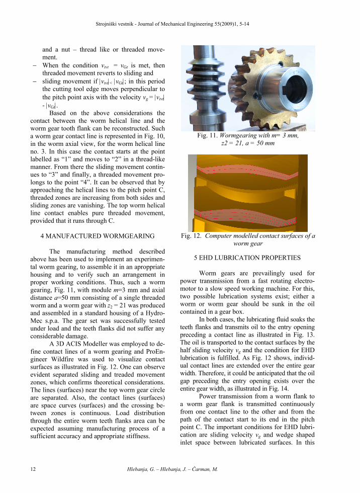
above has been used to implement an experimen-tal worm gearing, to assemble it in an aproppriate housing and to verify such an arrangement in proper working conditions. Thus, such a worm gearing, Fig. 11, with module m=3 mm and axial distance a=50 mm consisting of a single threaded worm and a worm gear with z2 = 21 was produced and assembled in a standard housing of a Hydro-Mec s.p.a. The gear set was successfully tested under load and the teeth flanks did not suffer any considerable damage.
A 3D ACIS Modeller was employed to de-fine contact lines of a worm gearing and ProEn-gineer Wildfire was used to visualize contact surfaces as illustrated in Fig. 12. One can observe evident separated sliding and treaded movement zones, which confirms theoretical considerations. The lines (surfaces) near the top worm gear circle are separated. Also, the contact lines (surfaces) are space curves (surfaces) and the crossing be-tween zones is continuous. Load distribution through the entire worm teeth flanks area can be expected assuming manufacturing process of a sufficient accuracy and appropriate stiffness.
5 EHD LUBRICATION PROPERTIES Worm gears are prevailingly used for
power transmission from a fast rotating electro-motor to a slow speed working machine. For this, two possible lubrication systems exist; either a worm or worm gear should be sunk in the oil contained in a gear box.
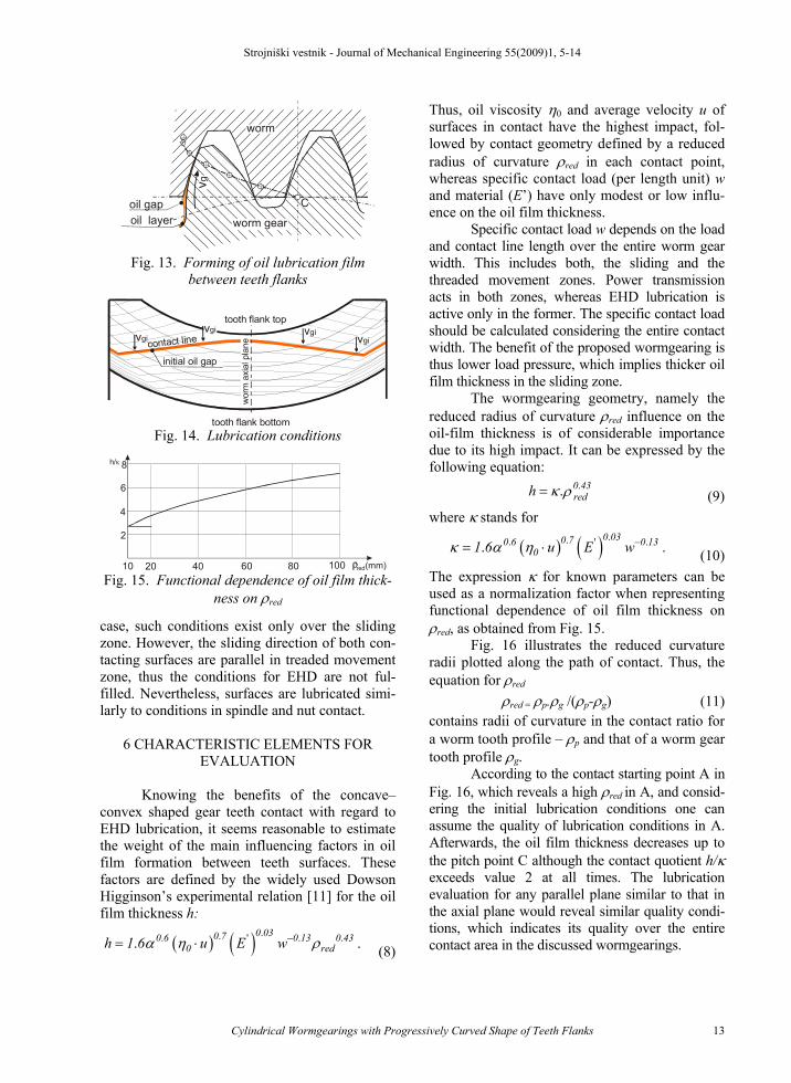
In both cases, the lubricating fluid soaks the teeth flanks and transmits oil to the entry opening preceding a contact line as illustrated in Fig. 13. The oil is transported to the contact surfaces by the half sliding velocity vg and the condition for EHD lubrication is fulfilled. As Fig. 12 shows, individ-ual contact lines are extended over the entire gear width. Therefore, it could be anticipated that the oil gap preceding the entry opening exists over the entire gear width, as illustrated in Fig. 14.
Power transmission from a worm flank to a worm gear flank is transmitted continuously from one contact line to the other and from the path of the contact start to its end in the pitch point C. The important conditions for EHD lubri-cation are sliding velocity vg and wedge shaped inlet space between lubricated surfaces. In this
Fig. 11. Wormgearing with m= 3 mm,
z2 = 21, a = 50 mm
Fig. 12. Computer modelled contact surfaces of a
worm gear
Strojniški vestnik - Journal of Mechanical Engineering 55(2009)1, 5-14
Cylindrical Wormgearings with Progressively Curved Shape of Teeth Flanks 13
case, such conditions exist only over the sliding zone. However, the sliding direction of both con-tacting surfaces are parallel in treaded movement zone, thus the conditions for EHD are not ful-filled. Nevertheless, surfaces are lubricated simi-larly to conditions in spindle and nut contact.
6 CHARACTERISTIC ELEMENTS FOR
EVALUATION
Knowing the benefits of the concave–convex shaped gear teeth contact with regard to EHD lubrication, it seems reasonable to estimate the weight of the main influencing factors in oil film formation between teeth surfaces. These factors are defined by the widely used Dowson Higginson’s experimental relation [11] for the oil film thickness h:
( ) ( ) ... ' . ..0 030 70 6 0 13 0 43
0 redh 1 6 u E wα η ρ−= ⋅ . (8)
Thus, oil viscosity η0 and average velocity u of surfaces in contact have the highest impact, fol-lowed by contact geometry defined by a reduced radius of curvature ρred in each contact point, whereas specific contact load (per length unit) w and material (E’) have only modest or low influ-ence on the oil film thickness.
Specific contact load w depends on the load and contact line length over the entire worm gear width. This includes both, the sliding and the threaded movement zones. Power transmission acts in both zones, whereas EHD lubrication is active only in the former. The specific contact load should be calculated considering the entire contact width. The benefit of the proposed wormgearing is thus lower load pressure, which implies thicker oil film thickness in the sliding zone.
The wormgearing geometry, namely the reduced radius of curvature ρred influence on the oil-film thickness is of considerable importance due to its high impact. It can be expressed by the following equation:
.. 0 43redh κ ρ= (9)
where κ stands for
( ) ( ) ... ' ..0 030 70 6 0 13
01 6 u E wκ α η −= ⋅ . (10)The expression κ for known parameters can be used as a normalization factor when representing functional dependence of oil film thickness on ρred, as obtained from Fig. 15.
Fig. 16 illustrates the reduced curvature radii plotted along the path of contact. Thus, the equation for ρred
ρred = ρp.ρg /(ρp-ρg) (11)contains radii of curvature in the contact ratio for a worm tooth profile – ρp and that of a worm gear tooth profile ρg.
According to the contact starting point A in Fig. 16, which reveals a high ρred in A, and consid-ering the initial lubrication conditions one can assume the quality of lubrication conditions in A. Afterwards, the oil film thickness decreases up to the pitch point C although the contact quotient h/κ exceeds value 2 at all times. The lubrication evaluation for any parallel plane similar to that in the axial plane would reveal similar quality condi-tions, which indicates its quality over the entire contact area in the discussed wormgearings.
C
worm gear
vg oil layer
worm
oil gap
Fig. 13. Forming of oil lubrication film
between teeth flanks
contact linevgivgi vgi
vgi
initial oil gap
tooth flank top
tooth flank bottom
wor
m a
xial
pla
ne
Fig. 14. Lubrication conditions
20 40 60 80 10010
2
4
6
8
red(mm)
h/κ
Fig. 15. Functional dependence of oil film thick-
ness on ρred

Strojniški vestnik - Journal of Mechanical Engineering 55(2009)1, 5-14
Hlebanja, G. – Hlebanja, J. – Čarman, M. 14
7 CONCLUSION
The proposed approach in cylindrical worm gearings design is based on the mathemati-cally defined worm tooth profile in the worm axial plane, wherefrom the worm gear tooth profile derives and profiles in any parallel plane can be calculated. In this way teeth flanks are defined.
Kinematic circumstances are described in detail. The cutting tools and underlying manu-facturing procedure assuring proper teething are discussed as well. Therefore, the contact lines (surfaces) between worm and worm gear teeth are formed as helical lines in any contact position. The profile geometry and the latter consideration lead to a conclusion that the contact area expands over the entire contact area of both teeth flanks, which consequently implies better conditions for power transmission.
The primary feature of the proposed teeth flanks is their progressive curvature and continual concave-convex contact. Worm and worm gear meshing in such an arrangement generates a better lubricating oil film, resulting in better EHD lubri-cation conditions; therefore, reduced energy losses and lower wear damages are anticipated. An ex-perimental wormgearing loaded under working conditions verified theoretical considerations. Computer simulation also confirmed the contact theory of the proposed gearing.
8 REFERENCES
[1] Seherr-Thoss, H.Chr. Graf v. (1965) The Development of the Gearing Technology (in German). Springer Verlag, Berlin, Heidelberg, New York, p. 48.
[2] Niemann., G., Winter, H. (1983) Maschine
Elements, Volume III (in German). Springer Verlag, Berlin, Heidelberg, New York, Tokyo.
[3] Jüngel, H. (1992) Holroyd Tooth Profile for Wormgearings (in German). Antriebstechnik (Mainz, 1982), vol. 31, no.8, p. 58-60.
[4] Flender Worm Gear Units. A.Friedr. Flender AG, http://www.flender.com/.
[5] Renold Worm Gears. Renold plc, http://www.renold.com/.
[6] Predki, W. (1995) Status of worm gear drive development, Gear Transmissions’95, Sofia, Bulgaria.
[7] Hlebanja, G., Hlebanja, J., Okorn, I. (2000) Research of Gears with Progressive Path of Contact. Proceedings of DETC’00, Balti-more, Maryland.
[8] Hlebanja, J., Hlebanja, G. (2002) Lubrication Efficiency of S-Gears. Int. Conf. on Gears, München, VDI Berichte 1665.
[9] Hlebanja, J., Hlebanja, G. (2005) Applicabil-ity of S-gears for Gear Trains – Advances in Non-involute Gears Development. Antrieb-stechnik (Mainz, 1982), vol. 44, no. 2, p. 34-38.
[10] Hlebanja, G., Hlebanja, J. (2005) Tooth Flank Durability of Internal S-Gears. Int. Conf. on Gears, München, VDI Berichte 1904.
[11] Dowson, D., Higginson, G.R. (1977) Elasto-Hydrodynamic Lubrication. SI Edition. Per-gamon Press, Oxford, New York, Toronto, Sydney, Paris, Frankfurt.
[12] Belšak, A., Flašker, J., Vibration Analysis to determine the Condition of Gear Units, Jour-nal of Mechanical Engineering (2008) vol. 54, no.1, p. 11-24.
C
toot
flah
nk o
f wor
m
path of contact of teeth flanks
datum line of worm teeth
top circle of worm gear
C
red
16
23
34
56 mm
10
tooth
lf ank
of w
orm ge
ar
U1
U2
U4
U3
U5
1,2 p.
reference circle of worm gear
P 2
P 3
P 4
P5
P 1
G 2
G 3
G 4
G5
A
Fig. 16. Reduced radii of curvature plotted along the path of contact