Large CNC General Purpose Cylindrical Grinders NAGOYA ...
10
Information presented in this brochure is subject to change without prior notice. Available machines or machines shown may vary depending on optional equipment or periodic design changes. The export of products defined as restricted commodities (or technologies) under Japan's "Foreign Exchange and Foreign Trade Act" requires an export license issued by the Japanese Government. Furthermore, similar licenses may be required for re-transfer, re-sale or re-export of such products, therefore please do not fail to contact JTEKT in advance. In order to observe laws and regulations and prevent inappropriate export, re-sale and relocation, JTEKT has equipped all of our NC machine tools with devices that detect relocation. If this device is activated, the machine will cease operation and will not restart until it has been checked by JTEKT. JTEKT may refuse to restart the machine should it be deemed that such an action would amount to the inappropriate export of a commodity or technology, or violate export regulations. In such a case, JTEKT will not be liable for any damages arising from the refusal to restart machine operation and do not bear any liability to perform services pertaining to product warranty. Please contact your JTEKT representative for details. Always read manuals carefully before using any machinery to ensure safe and proper use. ©JTEKT CORPORATION 2008, 2012 Cat. No. M2006-5E Printed in Japan 120308U This publication was made using recycled paper for the protection of forests. Large CNC General Purpose Cylindrical Grinders NAGOYA HEAD OFFICE No. 7-1, Meieki 4-chome, Nakamura-ku, Nagoya, Aichi Pref., 450-8515, JAPAN TEL: (81)52-527-1900 FAX: (81)52-527-1911 OSAKA HEAD OFFICE No. 5-8, Minamisemba 3-chome, Chuo-ku, Osaka, 542-8502, JAPAN TEL: (81)6-6271-8451 FAX: (81)6-6245-3712 SALES & MARKETING HEADQUARTERS No. 5-8, Minamisemba 3-chome, Chuo-ku, Osaka, 542-8502, JAPAN TEL: (81)6-6245-6087 FAX: (81)6-6244-9007 - GLOBAL NETWORK - MACHINE TOOLS & MECHATRONICS BUSINESS OPERATIONS MACHINE TOOLS & MECHATRONICS OVERSEAS SALES DEPT. 1, Asahimachi 1-chome, Kariya, Aichi Pref., 448-8652, JAPAN TEL: (81)566-25-5171 FAX: (81)566-25-5467 OVERSEAS AFFILIATED COMPANIES TOYODA MACHINERY USA CORP. HEADQUARTERS 316 W.University Drive, Arlington Heights, IL 60004 U.S.A. TEL: (1)847-253-0340 FAX: (1)847-577-4680 TOYODA MACHINERY USA CORP. AUTOMOTIVE PRODUCTS & SPECIAL MACHINES DIVISION 51300 W. Pontiac Trail Wixom, MI. 48393-1003 U.S.A. TEL: (1)248-624-5755 FAX: (1)248-624-8597 TOYODA MACHINERY AND ENGINEERING EUROPE SAS 2 Grande Allee P.A des Petits Carreaux 94380 Bonneuil sur Marne, FRANCE TEL: (33)1-49.56.85.80 FAX: (33)1-43.77.47.50 TOYODA MACHINERY EUROPE GmbH HEADQUARTERS Bischofstr, 118 47809 Krefeld GERMANY TEL: (49)2151-5188-300 FAX: (49)2151-5188-333 TOYODA MACHINERY (DALIAN) CO., LTD. HEADQUARTERS 46 Developing Zone In DaLian, 116600 China Dalian, CHINA TEL: (86) -411-8733-4601 FAX: (86) -411-8733-4602 TOYODA MACHINERY (DALIAN)CO., LTD. BEIJING OFFICE Room 1017, Fortune Building No.5 Dong San Huan North Road Chaoyang, Beijing, 100004 CHINA TEL: (86) -10-6590-9356~58 FAX: (86) -10-6590-9359 TOYODA MACHINERY (DALIAN)CO., LTD. SHANGHAI OFFICE Room 25B3, V-Capital Building 333 Xianxia Road Changning District, Shanghai, 200336 CHINA TEL: (86) -21-5178-1088 FAX: (86) -21-5178-1099 TOYODA MACHINERY (DALIAN)CO., LTD. FOSHAN OFFICE 2 Wushaxinhui Road, Daliang Street Shunde District, Foshan, Guangdong, 52833 CHINA TEL: (86) -757-2232-6651~52 FAX: (86) -757-2232-6650 TOYODA MACHINERY (DALIAN)CO., LTD. CHONGQING OFFICE 701 Lanmei Dadao(Lanmei Averue) Hi-Tech Zone, Chongqing, 400039 CHINA TEL: (86) -23-6171-1133 FAX: (86) -23-6171-1133 TPA ENGINEERING CORP. 84BL-19Lot, Namdong Industrial Complex, 675-18, Gojan-Dong, Namdong-ku, Incheon, KOREA TEL: (82) -032-822-0305 FAX: (82) -032-822-0306 TOYODA Machinery S.E. Asia Co., Ltd. 313, Bangna-Trad Road, KM.1 Kwang Bangna, Khet Bangna, Bangkok, 10260 THAILAND TEL: (66-2)361-8250~1 FAX: (66-2)361-8252 TOYODA KOKI DO BRASIL INDUSTRIA E COMERCIO DE MAQUINAS, LTDA. Rua Rego Barros 1319, Vila Antonieta,Sao Paulo-SP, BRASIL TEL: (55)11-6724-5711 FAX: (55)11-6727-3450 TOYODA MICROMATIC MACHINERY INDIA LIMITED Plot No.550-E, 2nd Floor Place City-II, Sector-37, Gurgaon 122 001 INDIA TEL: (91) -124-4264601/02/03 FAX: (91) -124-4288355
-
Upload
khangminh22 -
Category
Documents
-
view
4 -
download
0
Transcript of Large CNC General Purpose Cylindrical Grinders NAGOYA ...

Information presented in this brochure is subject to change without prior notice.Available machines or machines shown may vary depending on optional equipment or periodic design changes.The export of products defined as restricted commodities (or technologies) under Japan's "Foreign Exchange and Foreign Trade Act" requires an export license issued by the Japanese Government. Furthermore, similar licenses may be required for re-transfer, re-sale or re-export of such products, therefore please do not fail to contact JTEKT in advance. In order to observe laws and regulations and prevent inappropriate export, re-sale and relocation, JTEKT has equipped all of our NC machine tools with devices that detect relocation. If this device is activated, the machine will cease operation and will not restart until it has been checked by JTEKT. JTEKT may refuse to restart the machine should it be deemed that such an action would amount to the inappropriate export of a commodity or technology, or violate export regulations. In such a case, JTEKT will not be liable for any damages arising from the refusal to restart machine operation and do not bear any liability to perform services pertaining to product warranty.Please contact your JTEKT representative for details. Always read manuals carefully before using any machinery to ensure safe and proper use.
©JTEKT CORPORATION 2008, 2012Cat. No. M2006-5E Printed in Japan 120308U
This publication was made using recycled paper for the protection of forests.
Large CNC General Purpose
Cylindrical Grinders
NAGOYA HEAD OFFICENo. 7-1, Meieki 4-chome, Nakamura-ku, Nagoya, Aichi Pref., 450-8515, JAPAN TEL: (81)52-527-1900 FAX: (81)52-527-1911
OSAKA HEAD OFFICENo. 5-8, Minamisemba 3-chome, Chuo-ku, Osaka, 542-8502, JAPAN TEL: (81)6-6271-8451 FAX: (81)6-6245-3712
SALES & MARKETING HEADQUARTERSNo. 5-8, Minamisemba 3-chome, Chuo-ku, Osaka, 542-8502, JAPAN TEL: (81)6-6245-6087 FAX: (81)6-6244-9007
- GLOBAL NETWORK -MACHINE TOOLS & MECHATRONICS BUSINESS OPERATIONS
MACHINE TOOLS & MECHATRONICS OVERSEAS SALES DEPT.1, Asahimachi 1-chome, Kariya, Aichi Pref., 448-8652, JAPANTEL: (81)566-25-5171 FAX: (81)566-25-5467
OVERSEAS AFFILIATED COMPANIES
TOYODA MACHINERY USA CORP.HEADQUARTERS316 W.University Drive, Arlington Heights, IL 60004U.S.A.TEL: (1)847-253-0340FAX: (1)847-577-4680
TOYODA MACHINERY USA CORP.AUTOMOTIVE PRODUCTS & SPECIALMACHINES DIVISION51300 W. Pontiac TrailWixom, MI. 48393-1003U.S.A.TEL: (1)248-624-5755FAX: (1)248-624-8597
TOYODA MACHINERY AND ENGINEERING EUROPE SAS2 Grande Allee P.A des Petits Carreaux 94380 Bonneuil sur Marne, FRANCETEL: (33)1-49.56.85.80FAX: (33)1-43.77.47.50
TOYODA MACHINERY EUROPE GmbHHEADQUARTERS Bischofstr, 118 47809 Krefeld GERMANYTEL: (49)2151-5188-300FAX: (49)2151-5188-333
TOYODA MACHINERY (DALIAN) CO., LTD.HEADQUARTERS46 Developing Zone In DaLian, 116600 ChinaDalian, CHINATEL: (86)-411-8733-4601FAX: (86)-411-8733-4602
TOYODA MACHINERY (DALIAN)CO., LTD.BEIJING OFFICERoom 1017, Fortune Building No.5 Dong San Huan North Road Chaoyang, Beijing, 100004 CHINATEL: (86)-10-6590-9356~58FAX: (86)-10-6590-9359
TOYODA MACHINERY (DALIAN)CO., LTD.SHANGHAI OFFICERoom 25B3, V-Capital Building 333 Xianxia Road Changning District, Shanghai, 200336 CHINATEL: (86)-21-5178-1088FAX: (86)-21-5178-1099
TOYODA MACHINERY (DALIAN)CO., LTD.FOSHAN OFFICE2 Wushaxinhui Road, Daliang Street Shunde District, Foshan, Guangdong, 52833 CHINATEL: (86)-757-2232-6651~52FAX: (86)-757-2232-6650
TOYODA MACHINERY (DALIAN)CO., LTD.CHONGQING OFFICE701 Lanmei Dadao(Lanmei Averue)Hi-Tech Zone, Chongqing, 400039 CHINATEL: (86)-23-6171-1133FAX: (86)-23-6171-1133
TPA ENGINEERING CORP.84BL-19Lot,Namdong Industrial Complex,675-18, Gojan-Dong, Namdong-ku,Incheon, KOREATEL: (82)-032-822-0305FAX: (82)-032-822-0306
TOYODA Machinery S.E. Asia Co., Ltd.313, Bangna-Trad Road, KM.1 Kwang Bangna, Khet Bangna, Bangkok, 10260 THAILANDTEL: (66-2)361-8250~1FAX: (66-2)361-8252
TOYODA KOKI DO BRASIL INDUSTRIAE COMERCIO DE MAQUINAS, LTDA.Rua Rego Barros 1319,Vila Antonieta,Sao Paulo-SP, BRASILTEL: (55)11-6724-5711FAX: (55)11-6727-3450
TOYODA MICROMATIC MACHINERY INDIA LIMITED Plot No.550-E, 2nd FloorPlace City-II, Sector-37, Gurgaon 122 001 INDIA TEL: (91)-124-4264601/02/03 FAX: (91)-124-4288355

GE6-ⅡProduct introduction
Max. loading mass between centers 1,000kg
Max. grinding dia. φ550mm
Max. distance between centers 4,000mm
Presenting the pioneer in large workpiece grinding.
A high performance machine,featuring the ultimate in“User-friendliness”and“Flexibility”
Large rolls, spindle, gear shafts, etc.
Large workpieces
Various shafts for marine and construction equipment, power generationVarious shafts for marine and construction equipment, power generationVarious shafts for marine and construction equipment, power generation
Large CNC general purpose cylindrical grinder
0201
U. S. Patents on the machine : 5,595,525 and others.Photo of a GE6-400Ⅱ. This machine features an elongated ball screw (optional).(This photo includes special specifications regarding painting color, Internal grinding unit, cover, etc.)Standard Painting color: The machine body color comes only in neo white.The hydraulic pump unit, coolant supply unit, etc is dark gray.

B
High accuracy is standard GE6-Ⅱ
Accurate grinding
This is a grinding example using our standard TP. It is not the guaranteed accuracy of the machine.
RoundnessPortion A:0.69μm Portion B:0.62μm
TAYLOR HOBSON is a registered trademarkof TAYLOR HOBSON LIMITED.
5μm 5μm
Cylindricity(microns)
A 0.0 +1.0 +3.0 +5.0 +6.0 +5.0 +3.0 +2.0 0.0
1 2 3 4 5 6 7 8 9
B 0.0 +1.0 +3.0 +5.0 +6.0 +5.0 +3.0 +2.0 0.0
Measured value
0369
(φμm)
Example of plunge grinding[Grinder]GE6-250Ⅱ
■Grinding conditions[Grinding wheel]WA60K(φ610mm)[Grinding wheel surface speed]30m/s
■Workpiece[Name]Standard test piece[Material]SCM435 30 30 30 60
250
BA
GG
φ47
φ47
φ47
φ47
φ47
φ47
(Unit:mm)
Example of traverse grinding [Grinder]GE6-250Ⅱ■Grinding conditions[Grinding wheel]WA60K(φ610mm)[Grinding wheel surface speed]30m/s
■Workpiece[Name]Standard test piece[Material]SCM435
A
2,250130 120
B
G
φ188
φ188
φ188
(Unit:mm)
High rigidity ・ low vibration machine bed of an X-type rib design
Employs the X type rib structure to achieve a low vibration, high rigidity bed. The bed, which serves as the foundation of the machine, boasts 30% higher rigidity than conventional beds and assures high accurate grinding over extended periods of time.Full mold process is adopted as an alternative to using the wooden pattern, due to the characteristics of the X-type rib structure.
High quality & high performance with JTEKT’s proprietary technology
Featuring the JTEKT original TOYODA STAT BEARING as the wheel spindle, the heart of the machine
Equipped with the extremely rigid hybrid-type TOYODA STAT BEARING which provides no metal-to-metal contact and has a high vibration damping capacity, this grinder assures high accuracy and a long service life.High accuracy grinding and longevity of the machine is achieved by using proven JTEKT spindle technology.
Grindingforce
Pressure from pump
Pressure from pump
Hydrostatic pressure
Hydrostatic pressureHydrodynamicpressure
■Spindle at restHydrostatic pressure lifts and holdsthe wheel spindle firmlyat the bearing center position.
■Rotation spindleCombination of hydrostatic and hydrodynamicpressures improves spindle rigidityand vibration absorbing performance.
X-type rib design
Proven technology achievingthe high accuracy grinding of large workpieces
0403
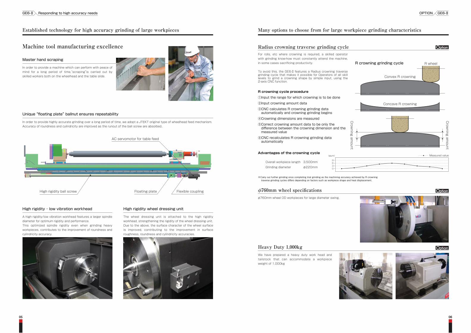
Master hand scraping
Machine tool manufacturing excellence
Flexible couplingHigh rigidity ball screw Floating plate
AC servomotor for table feed
GE6-ⅡOPTIONGE6-Ⅱ Responding to high accuracy needs
0605
Unique “floating plate” ballnut ensures repeatability
In order to provide highly accurate grinding over a long period of time, we adopt a JTEKT original type of wheelhead feed mechanism.Accuracy of roundness and cylindricity are improved as the runout of the ball screw are absorbed..
※Carry out further grinding once completing trial grinding as the machining accuracy achieved by R crowning traverse grinding cycles differs depending on factors such as workpiece shape and heat displacement.
Radius crowning traverse grinding cycle
R crowning grinding cycle
Concave R crowning
Convex R crowning
R wheel
Crowning am
ount
Crowning am
ount
To avoid this, the GE6-Ⅱ features a Radius crowning traverse grinding cycle that makes it possible for Operators of all skill levels to grind a crowning shape by simple input, using the 2-axis CNC function.
For rolls, etc where crowning is required, a skilled operator with grinding know-how must constantly attend the machine, in some cases sacrificing productivity.
R crowning cycle procedure
①Input the range for which crowning is to be done
②Input crowning amount data
③CNC calculates R crowning grinding data automatically and crowning grinding begins
④Crowning dimensions are measured
⑤Correct crowning amount data to be only the difference between the crowning dimension and the measured value
⑥CNC recalculates R crowning grinding data automatically
φ760mm wheel OD workpieces for large diameter swing.
φ760mm wheel specifications
We have prepared a heavy duty work head and tailstock that can accommodate a workpiece weight of 1,000kg
Heavy Duty 1,000kg
High rigidity ・ low vibration workhead
A high rigidity/low vibration workhead features a larger spindle diameter for optimum rigidity and performance.This optimized spindle rigidity even when grinding heavy workpieces, contributes to the improvement of roundness and cylindricity accuracy.
High rigidity wheel dressing unit
The wheel dressing unit is attached to the high rigidity workhead, strengthening the rigidity of the wheel dressing unit.Due to the above, the surface character of the wheel surface is improved, contributing to the improvement in surface roughness, roundness and cylindricity accuracies.
Established technology for high accuracy grinding of large workpieces Many options to choose from for large workpiece grinding characteristics
Advantages of the crowning cycle
0369
(φμm)
Overall workpiece length 3,500mm
Grinding diameter φ220mm
Measured value
In order to provide a machine which can perform with peace of mind for a long period of time,“scraping”is carried out by skilled workers both on the wheelhead and the table slide.
0807
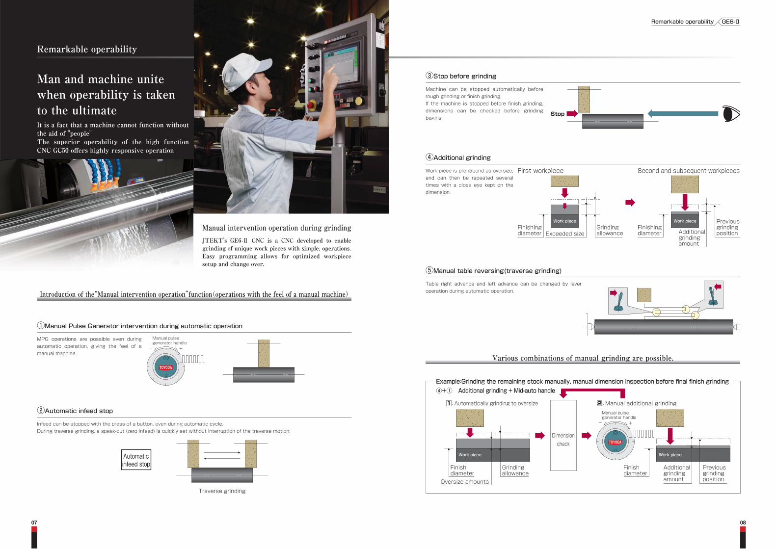
It is a fact that a machine cannot function without the aid of "people"The superior operability of the high function CNC GC50 offers highly responsive operation
Man and machine unitewhen operability is takento the ultimate
Manual intervention operation during grinding
Remarkable operability
JTEKT’s GE6-Ⅱ CNC is a CNC developed to enable grinding of unique work pieces with simple, operations.Easy programming allows for optimized workpiece setup and change over.
Manual pulsegenerator handle
①Manual Pulse Generator intervention during automatic operationMPG operations are possible even during automatic operation, giving the feel of a manual machine.
②Automatic infeed stopInfeed can be stopped with the press of a button, even during automatic cycle.During traverse grinding, a speak-out (zero infeed) is quickly set without interruption of the traverse motion.
Introduction of the“Manual intervention operation”function(operations with the feel of a manual machine)
Various combinations of manual grinding are possible.
Example:Grinding the remaining stock manually, manual dimension inspection before final finish grinding④+① Additional grinding + Mid-auto handle
Automaticinfeed stop Finish
diameterOversize amounts
Grindingallowance
Work piece
Manual pulsegenerator handle
1:Automatically grinding to oversize 2:Manual additional grinding
Dimensioncheck
Traverse grinding
Finishdiameter
Previousgrindingposition
Additionalgrindingamount
Work piece
④Additional grindingWork piece is pre-ground as oversize, and can then be repeated several times with a close eye kept on the dimension.
First workpiece
Finishingdiameter Exceeded size
Grindingallowance
Work piece
Second and subsequent workpieces
Finishingdiameter
PreviousgrindingpositionAdditional
grindingamount
Work piece
③Stop before grindingMachine can be stopped automatically before rough grinding or finish grinding.If the machine is stopped before finish grinding, dimensions can be checked before grinding begins.
Stop
⑤Manual table reversing(traverse grinding)Table right advance and left advance can be changed by lever operation during automatic operation.
GE6-ⅡRemarkable operability

1009
The user friendly GE6-Ⅱ features simplified data entry for easy operation. The CNC can automatically determine grinding conditions that utilize the know-how of JTEKT's grinding specialists.
We offer trouble-free operations to customers new to grinding or customers who have switched fromhydraulic type general-purpose machines but wish to improve production efficiency by ensuringthat accuracy is still easily achieved and the machine is still easy to use.
In pursuit of ‘user-friendliness’ Supporting the customer with easy programming
Efficiency of single workpiece grinding improved by simplified operation
■No time-consuming set ups. The grinding conditions are automatically determined with minimal data input (reduced by 90% in an in-house comparison).
■Up to 8 steps can be entered at a time on one screen; even a beginner can quickly learn how to operate the machine.
■Programming is completed while the first workpiece is ground. The second and subsequent workpieces can be ground automatically.
Drawing marks can be directly entered as they are!
■Fitting marks and dimensional tolerances frequently used in drawing can be entered directly.
Entry is completed in a short time without referring to conversion tables or use of a calculator.
(Extended data entry function)
Finishingdiameter
Stockremoval
Step 1●Grind the green face of the workpieceby turning the handle.
φ230g6 φ200φ210h7●To grind the following workpiece.
■Automatic grinding is possible from the first workpiece with no need of mastering.
Step 2●Measure the workpiece and setthe additional stock removal.
Finishingdiameter
START
Additionalgrindingamount
Stockremoval
Step 3●Start the grinding cycle.The workpiece is automatically groundto the amount just set.
2 Select the grinding method.Plunge Plunge/traverse Traverse
1 Select the workpiece rigidity.
432
1
Operator's experience reflected in the automaticdetermination system
■Parameters for automatic determination can be modified based on the operator's know-how.
Simplified automatic determination system INPUTDimensional data
OUTPUTGrinding conditions
Customized
Automaticdeterminationparameters
Automatic determination logic(theoretical system/rule of thumb)
4 Enter the table position. ●Simplified data entry with position memory button300 1400
Press the start button to start automatic grinding(1 process only)
3 Enter the finishing diameter.
φ210h7
●This complates auto-matic determination of the grinding conditions.●Modify the stock remo- val amount, if necessary.
To the next grinding steps
φ227 -0.010-0.015
22 7 - 0 . 0( 1 , - 0 . 0 1 5 )
22 7 h 7
G
φ227h7
φ226.9770
Drawingindication
Drawingindication
Key operation
Keyoperation
NC program
●Automatic grinding is performed by targeting the median of the tolerance.
●Fitting mark input
●Dimensional tolerance input
Easy longitudinal sizing with displayed coordinate values
■Manual infeed can be performed by referring to the displayed relative coordinate value which can be reset at any position.
(Drawing indication)1,200±0.01
●A relative coordinate value of the table position from where reset is made, is displayed on the screen.
GE6-ⅡIn pursuit of ‘user-friendliness’GE6-Ⅱ In pursuit of ‘user-friendliness’
1:Very rigid 2:Moderately rigid 3:Less rigid

1211
In pursuit of ‘user-friendliness’ Supporting the customer with convincing operations Multi-step continuous grinding Multi-step continuous grinding possible with simple operations
Easy taper adjustment
■By entering measured values, the taper adjustment amount is displayed on the screen.
More efficient multi-step grinding.
■Automatic operation, from multi-step continuous grinding to wheel dressing, is performed by only pressing the start button.
■Up to 64 kinds of grinding data can be stored.
Wheel dressing performed by simplified operation
■No set-up operations, such as diamond holder mounting/removal, wheelhead/table positioning, or table speed adjustment-required.
Straight forward data entry without calculations
■Speed data can be entered the way the operator desires, using the override selector switch. (Speed data proportional compensation function)
■As automatic indexing is performed for the second and subsequent workpieces, no MGP interruption is required.
●Automatically indexed to the manual grinding start position
●To reduce the rough grinding speed slightly:
■In the case of MPG infeed, the wheelhead automatically stops if fed to a prior set position. The machine can be operated safely even if by a beginner.(software positive stop function)
Automaticstop
Safety handle infeed
Easy size compensation
■Entry by pressing a single button avoids grinding data entry mistakes. (Extended entry function)
●To make the finishing diameter greater by 2μm:
Move the cursor to the data you want to modify and press:
(twice)
80%
■Addition, subtraction, multiplication and division are possible during data entry / modification without requiring a calculator. (Extended entry function)
●To make the fine grinding start position greater by φ0.015mm.:
●To reduce the fine grinding workpiece speed slightly:
START
Multi-step continuous grinding
Wheel dressingcycle
2 1 3
Flexibility for process changes
■Changes such as grinding sequence adding/deleting intermediate wheel dressing are simple and easy.
32
5
1
4 6
Wheel dressing before grinding
…Rough grinding
…Finish grinding
1 23
4 5
Grinding sequence changedGrinding process deleted
Intermediate wheeldressing added
Automatic wheel dressing cycle
MeasuredOD values
Longitudinal dimension betweenOD measuring positions
Taper amount/taper adjustment amount
GE6-ⅡMulti-step continuous grindingGE6-Ⅱ In pursuit of ‘user-friendliness’

A
1,180
2,950
Using air pressure to simplify work head and tailstock movement
We have prepared an internal grinding unit to make wheelhead attachment, and OD to internal grinding changeover, a breeze.
Equipped with a highly-rigid, single-piece spindle, GE6II is also capable of grinding deep holes.
Internal grinding unit
1413
Machine layout: top view
Machine specificationsOptions further improving ease of use
The GE6P-Ⅱ uses air to aid movement of the work head and tailstock and reduce the burden on the operator during set-up changeover.
Due to this feature, labor is not only simplified but wear on the table top face is also reduced.
The GE6P-Ⅱ features a tailstock body movement device(rack & pinion type) in order to make movement of the tailstock quick and trouble-free at the time of set-up changeover.
If the air-assisted tailstock movement is used together with these specifications, movement is simplified and table top wear is reduced.
Tailstock body movement device(rack & pinion type)
When grinding a range of work pieces from light(100kg)to heavy(1,000kg), the tailstock center force for heavy work pieces is too great for light work pieces
The GE6P-Ⅱ features a manual tailstock with easily adjustable center pressure force and equipped both with pressure mechanisms for 500kg tailstocks and 1,000kg tailstocks
Manual tailstock with pushing force adjustment simplification
Machine layout: front view
The photo is of a tailstock with 1,000kg specifications
(Unit:mm)※1:In case footstock except manual footstock (standard accessory) in furnished, swiveling angle shall be limited.
(Unit:mm)※The left dimensions assume that the standard coolant supply unit (350 liters, without confirmation unit) is attached.
Machine specifications・Machine layout GE6-ⅡOption・Machine layoutGE6-Ⅱ
Wheel
Wheelhead feed
Workhead
Footstock
Table feed
Drive motors
Tank capacities
Wheel OD × ID
Max. wheel dia.
Surface speed
Rapid feed rate
Type
Center taper
Spindle speed
Type
Center taper
Quill stroke
Rapid feed rate
Swiveling angle※1 (CCW~CW)
Wheel spindle
Work spindle
Wheelhead feed
Table feed
Wheel spindle bearing oil pump
Lubricant pump
Working oil pump unit
Coolant pump
Wheel spindle cooling unit
Magnetic coolant separator
Wheel spindle bearing oil
Lubricant oil
Working oil
Coolant
Swivel type live spindle
MT No.6
Hydraulic
MT No.6
hydraulic 32 + Manual handle type 30
φ760xφ304.8
75(Wide specification 100)
45
1,000
500
φ560
φ0~φ550
φ610xφ254
75(Wide specification 125)
30
φ15
Dead spindle
MT No.5
7~140
Manual lever type
MT No.5
Manual lever 32 + Manual handle type 30
Manual handle type 45
hydraulic 32 + Manual handle type 30
11(4P)
3.5(brushless servomotor)
3.1(brushless servomotor)
5.0(brushless servomotor)
0.5(2P)
0.2(2P)
0.75(2P)
0.25(2P)
0.08
0.025(4P)
14
20
20
350
Power supply voltage 200 Control circuit DC24
MT No.5
MT No.6
Hydraulic
Manual lever type
Manual handle type
Hydraulic
1,600
1,475
13
+3.0~0.0
5.9×2.95
10,000
GE6-160Ⅱ
9.8×2.95
14,000
3,200
3,075
6
+1.6~0.0
GE6-320Ⅱ
11.5×2.45
17,000
4,000
3,875
6
+1.4~0.0
GE6-400Ⅱ
2,500
2,375
8
+2.0~0.0
8.2×2.95
12,000
GE6-250Ⅱ
Max. load between centers
Swing over table
Grinding diameter
Distance between centers
Floor space(width × depth)
Machine weight
Electrical equipment
Item
Common
Common
Common
Common
Common
Common
Common
Common
Common
Common
Common
Common
Common
Common
Common
Common
Common
Option
1,000kgspecifications
Option
1,000kgspecifications
Option
φ760specifications
Option
Option
Standard
Common
Common
Standard
φ610specifications
Standard
Common
Standard
500kgspecifications
Common
Standard
500kgspecifications
500kgspecifications
1,000kgspecifications
Common
Common
Specifications
mm
mm
m/s
kg
kg
mm
mm
mm
mm
m/s
m/min
min-1
mm
mm
mm
Unit
m/min
°
kW
kW
kW
kW
kW
kW
kW
kW
kW
kW
L
L
L
L
m
kg
V
GE6P-250Ⅱ
8,200
GE6P-320Ⅱ
9,800
GE6P-400Ⅱ
11,500
GE6P-160Ⅱ
5,900
Type
A(mm)

Max. load between centers(kg)
Necessary item
Wheel diameter(mm) Necessary item
Center taper
500
MT No.5
φ610
-
-
-
-
-
-
-
-
-
Section 4-4
Section 2-4
1,000
MT No.6
φ760
-
-
-
-
-
-
-
-
-
-
Section 1-10
Section 2-7
Pedal operation for hydraulic tailstock
30m/s 2-speed specifications
45m/s 1-speed specifications
Wheel balance arbor
Wheel balancing stand
Wheel hoist
Dead spindle and live spindle workhead(including center)
Easy traveling of footstock by air type
Dead spindle workhead with infinitely variable speed(including center)
Easy traveling of workhead by air type
Unit name
Wheelhead, wheel spindle
30m/s 1-speed specifications
Manual footstock Manual handle type(including center)
Manual type tailstock(including center)with easily adjustable pushing force
φ760mm specifications Combination of standard and wide width specifications
Wide width wheel flange for φ610mm(round nut: width 75~125mm)
Swivelling-type live spindle workhead(including center)
Manual footstock Manual lever type(including center)
φ610mm standard width specifications
610mm wide width specifications
Wheel flange for φ610mm(round nut: width 33~80mm)
Wheel(φ610x75x φ254mm)for 30m/s 1 set
Wheel(φ610x125x φ254mm)for 30m/s 1 set
Hydraulic footstock(including center)
Tailstock moving unit(rack type)
Wheel flange for φ760mm(round nut: width 50~75mm)
Wide width wheel flange for φ760mm(round nut: width 75~100mm)
Wheel(φ760x75x φ304.8mm)for 30m/s 1 set
Wheel(φ760x100x φ304.8mm)for 45m/s 1 set
Wheel(φ760x100x φ304.8mm)for 30m/s 1 set
Wheel(φ760x75x φ304.8mm)for 45m/s 1 set
Wheel(φ610x125x φ254mm)for 45m/s 1 set
Wheel(φ610x75x φ304.8mm)for 45m/s 1 set
Variable speed control unit(inverter control, manual adjustment, reducing speed control)
Unit name
8
6
7
21
22
23
3
10
1
9
No.
1
5
5
6
4
10
2
4
2
3
9
13
15
7
11
11
12
17
20
19
18
16
14
8
No.
Spindle rpm(7~140min-1)
Including air device
Spindle rpm(7~140min-1)
Including air device
Remarks
Becoming φ610mm/φ760mm specific
Stroke(manual handle adjustment 45mm)
Stroke(For 500kg - lever 40mm + handle 50mm)(For 1,000kg - handle 90mm)
Max. wheel width100mm
Spindle rpm(7~140min-1)
Stroke(manual lever 32mm + manual adjustment 30mm)
Max. wheel width75mm
Max. wheel width125mm
Operating surface speed 30m/s 1 set
When selecting φ610mm wide width specification in section 2-3
Stroke(hydraulic stroke 32mm + manual handle adjustment 30mm)
Max. stroke 2,000mm
Operating surface speed 30m/s 1 set
Operating surface speed 45m/s 1 set
Operating surface speed 30m/s 1 set
Operating surface speed 45m/s 1 set
When selecting φ610mm wide width specification in section 2-3
Operating surface speed 45m/s 1 set
Only when equipping wheel surface speed 45m/s specifications
Remarks
Workhead
Easy set-upchangeover
2.Wheel diameterWheelhead, wheel spindle
Wheel surfacespeed
Parts relatedto wheel
Footstock
Wheel guard
Wheel flange
Wheel
1.Max. loadbetween centers
1615
GE6-Ⅱ List of accessories
1. Accessories per specification type
Photo is of a GE6-320Ⅱ.The machine colors shown in this photo is standard.Standard painting color - The machine body comes only in neo white.The hydraulic pump unit, coolant supply unit, etc is dark gray.Note. Painting color shall be specified by mutual agreement.
2.Common accessories
List of accessories GE6-ⅡList of accessoriesGE6-Ⅱ
□
●:Standard accessory ○:Standard accessory □:Optional B accessory -:Unable to be included(When an optional A accessory is chosen, the correspponding standard one is not supplied.)
●:Standard accessory ○:Standard accessory □:Optional B accessory -:Unable to be included(When an optional A accessory is chosen, the correspponding
standard one is not supplied.)
□
□
□
□
□
□
□
○
○
○
○
○
○
○
○
○
○
○
○
○
○
○
○
●
●
●
●
●
●
●
□
□
□
□
□
□
□
□
□
□
□
□
○
○
○
○
○
○
●
●
●
●
●
●
● ●
●
●
●
●
●
Necessary item
Necessary item
Unit name Remarks3.Operability・workability
Unit name Remarks4.Unit related
Section*
Section 4-4
Section*
Section 4-11
Common
Common
Flexible coolant nozzleCoolant nozzle ●
Wheel dresser(mounted on workhead)Wheel dresser ●
Standard service tool kitTool ●
Manual pulse generator(mounted on operation panel)Control unit ●
Language support(NC screen, etc.)Languages: English, ChineseOverseasspecifications
□
Supporting different voltage □
Table direction selection lever(mounted on operation panel) ●
USB flash drive for GC50(JTEKT-made, one piece of stored backup data) ●
The body comes only with standard color of neo-white. Pump unit, coolant supply unit and the like are painted dark gray. Machine color ●
One set each of machine specifications, operation manual and maintenance manualInstruction manual ●
It is required to use a dead spindle and live spindle workhead (Item 1-3).Internal grinding unit Internal grinding unit is available.
Please refer to the “Internal grinding unit”brochure. □
Lubricant pump unit(20 liters, without confirmation function)Pump unit ●
Front table cover(fixed type)Table ●
Front table cover(insert type) ○
One port coolant nozzle(for standard wheel width) ○
Special color other than standard colorPump unit, coolant supply unit and the like are painted dark gray.
Please contact our sales dept. when changing the colorof the pump unit, coolant tank and control cabinet○
Hydraulic oil pump unit(20 liters, without confirmation function) □
R crowning cycleCycle □
X-axis and Z-axis simultaneous movement is possible.A manual pulse generator on the operation panel is not provided.Corresponding to manual grinding simplification(2-handle spec)Pulse generator □
Magnetic coolant separator(processing capacity 80 L/min) □
Magnetic coolant separator(processing capacity 120 L/min) □
Magnetic coolant separator(processing capacity 150 L/min) □Coolant lower limit confirmation device □
Additional coolant pump(for bed washing and sizer cooling) □
Wheel dresser(mounted on table) □
Wheel dresser(mounted to the tailstock) □
Formed diamond tool □
Single-point diamond tool □
Manual screwed type driving dog(φ22~φ80mm) 6 pieces in the range as 1 set.Driving dog □
Coolant supply unit(350 liters, without confirmation function)Coolant supplyunit
● No washing pump
Coolant supply unit with paper filter(350 liters, without confirmation function) ○ No washing pump
Manual screwed type driving dog(φ80~φ190mm) 7 pieces in the range as 1 set.□
Cam-locked type driving dog(φ20~φ80mm) 4 pieces in the range as 1 set.□
3-jaw scroll chuck Chuck load mass 80kg(including chuck)Chuck □
Independent 4-jaw chuck Chuck load mass 80kg(including chuck)□
4-slot face plate(φ410mm) □
Auto-sizer cooling ●□
Bed and table washing □ ●
Select the contact shoe with the required diameter.(Work piece holder base required)
Contact shoe:φ150~φ180mm □
Work supporting deviceWork supportingdevice
□
Automatic lateral locator(mounted on wheelhead)Lateral locator ●□
Sizing unit for large diameter cylinder(JTEKT-made, CNC built-in amplifier, 3P, φ10~φ160mm)Auto sizer ●□
Jib crane for wheel changes(for 100kg) □
Tools(wrench/spanner) □
Contact shoe:φ180~φ220mm □
Contact shoe:φ220~φ260mm □
Contact shoe:φ260~φ300mm □
Work holder(one for each R and L φ20~φ190mm)Work holder □
Manual pulse generator(mounted on operation panel)Steady rest □
Our standard test piece abrasive(special option)Customer run-off □
Lighting unit(fluorescent lamp) □
USB flash drive for GC50(JTEKT-made) □
100V outlet(mounted on inside - of control box)
No.
No.
14
16
27
39
45
46
40
42
47
50
51
3
1
2
15
48
4
1
2
7
8
910
11
17
18
19
20
21
5
6
22
23
24
25
26
13
12
33
32
31
30
29
28
34
35
36
37
38
49
44
43
41 ●

(OD grinding cycle is used)
TraversePlunge
Item 1 left is used Item 2 left is used
1
2
3
4
5
6
7
8
9
10
11
12
13
14
15
16
17
18
19
20
21
22
23
24
25
26
27
GC50
X-axis(wheelhead feed axis), Z-axis(table feed axis)
Color LCD(Japanese)
Color LCD(English)Structured data management(pregrinding, grinding and maintenance)
●
●
●
○
●
●
●
●
●
●
●
●
●
●
●
○
●
●
●
●
●
●
●
●
●
●
●
Item
28
29
30
31
32
33
34
35
36
37
38
39
40
41
42
43
44
45
46
47
48
49
50
51
52
No. Specifications Accessories AccessoriesNo. Specifications
●
●
●
●
●
●
○
○
●
●
●
●
●
●
●
●
●
●
●
●
●
●
●
●
●
Item
1
2
3
4
5
6
7
8
9
10
11
12
Notes①Up to 5 patterns of wheel shape can be registered.②3 wheel dressing conditions;“rough”,“semi-finish”and“finish”can be set.③The automatic dressing function for internal griding wheels is not provided.Dress them manually using an internal/external diamond tool holder to be mounted on the table.
5. Internal grinding
1817
CNC unit specificationsGrinding cycles
Wheel dressing cycles
2. Traverse(indirect sizing)
3. Plunge/traverse(indirect sizing)
1. Plunge(indirect sizing)
Convex R crowning
Concave R crowning
4. R crowning traverse
R wheel
R wheel
Infeed onboth ends
Infeed onleft end
Infeed onright end
Infeed onboth ends
Infeed onleft end
Infeed onright end
Infeed onleft end
Infeed onright end
Infeed onboth ends
Infeed onboth ends
Infeed onleft end
Infeed onright end
Straight Concave with left R R Taper with straight
Notes①The above grinding cycles can be divided into rough and finish grinding cycles by using the cycle dividing function. ②Face grinding can be performed by manual interrupting operations and manual table axis compensation. ③Direct sizing plunge, direct sizing traverse or direct sizing plunge/traverse grinding cycles are optionally available. ④Please carry out the grinding of the R crowning traverse (option) after performing the R wheel dressing.
⑤Only indirect sizing cycle is available (direct sizing cycle is not available) for the internal grinding cycle.⑥Displayed coordinates for internal grinding do not correspond with the workpiece.⑦Internal multi-step grinding can be performed manually.
CNC specifications(GC50) ●: Standard ○: Option
Grinding data patterns: Max. 64(30processes/pattern, Max. 1,920 processes)
Position memory(various)
Relative coordinates
Backlash compensation
Size compensation
Operation monitor display
Lamp display
Operation procedure display
Inspection, maintenance items
Metric display
Inch display
Canned cycle
Test cycle
Wheel dressing cycle
Return cycle
Single block
Grinding step skip
Rapid feed override 0, 10, 50, 100%
Grinding feed override(X-axis)0-150%, in units of 10%
Grinding feed override(Z-axis)0-150%, in units of 10%
Work spindle override 50~200%, in units of 10%
Handle during automatic operation
Manualinterventionoperation
Auto-sizer
Programmingfunction
Maintenance
Counter
Cycletimedisplay
Others
Taper corrector
Cycle division function
Cycle interruption and manual size compensation
Cycle interruption and infeed function
Software positive stop function
Manual table reverse turning function
Auto-sizer manual additional grinding function
Auto-sizer control unitSimplified automatic determination(only for OD grinding cycle)
Speed data proportional compensation function
Extended data entry function
Operation entry function
Process editing function
Wheel change prediction display
Min. wheel dia. display
Self diagnosis
Alarm history display
Batch saving
Production counter
Wheel dressing interval counter
Machine operation hours
Processing cycle time
Grinding cycle time
Wheel dressing time
Corresponding to USB memory
CNC unit
Controlled axes
CRTdisplay
Filemanagement
Coordinatesetting
Compensationfunction
Display
Operation
Description of main functionsPosition memory
Handle during automatic operation
Taper corrector
Cycle division functionCycle interruption and manualsize compensationCycle interruption and infeedfunction
Software positive stop functionAuto-sizer manual additionalgrinding funtionSpeed data proportionalcompensation function
Extended data entry function
Operation entry function
Grinding cycle editing function
The wheel dia., diamond tool position, and longitudinal workpiece position can be storedby one touch of a button.
M.P.G. operation is validat during automatic operation.By entering values measured at 2 points after manual grinding, the taper compensation amount is displayed on CRT. Automatic indexing to the grinding start position is performed for the second and subsequest workpieces.
A workpiece is automatically ground by dividing the grinding cycle into rough and finish grinding cycles.
Automatic operation is suspended to allow table position compensation and manual shoulder grinding.Automatic operation is suspended to allow finishing dia. compensation by entering the additional infeedamount obtained through comparision with the measured grinding dia.
The wheelhead and table automatically stopped at the preset positions when fed using the M.P.G.
Manual infeed can be performed while referring to the values output from the auto-sizer amplifer.
The infeed speed and traverse speed can be changed using the override selector switch.Drawing mark entry, additional taper grinding amount calculation, addition/subtraction/division/multiplication, and entry by one touch of a button are possible.
The wheelhead and table positioning data can be entered by pressing buttons.The grinding sequence can be changed and intermediate wheel dressing can beaddad/deleted with an easy operation.
CNC unit specifications GE6-ⅡGrinding cycles・Wheel dressing cyclesGE6-Ⅱ