Horizontal Spindle Machining Centers - Leader CNC
20
Horizontal Spindle Machining Centers - GLOBAL NETWORK - MACHINE TOOLS & MECHATRONICS BUSINESS OPERATIONS MACHINE TOOLS & MECHATRONICS OVERSEAS SALES DEPT. 1, Asahimachi 1-chome, Kariya, Aichi Pref., 448-8652, JAPAN TEL: (81)566-25-5171 FAX: (81)566-25-5467 OVERSEAS AFFILIATED COMPANIES JTEKT TOYODA AMERICAS CORP. HEADQUARTERS 316 W. University Drive, Arlington Heights, IL 60004, USA TEL: (1)847-253-0340 FAX: (1)847-253-0540 JTEKT TOYODA AMERICAS CORP. REBUILD PRODUCT DIVISION 51300 West Pontiac Trail Wixom, MI 48393-1003, USA TEL: (1)248-624-5755 FAX: (1)248-624-8597 TOYODA MACHINERY AND ENGINEERING EUROPE SAS 2 Grande Allee P.A des Petits Carreaux 94380 Bonneuil sur Marne, FRANCE TEL: (33)1-49.56.85.80 FAX: (33)1-43.77.47.50 TOYODA MACHINERY EUROPE GmbH HEADQUARTERS Bischofstr, 118 47809 Krefeld GERMANY TEL: (49)2151-5188-300 FAX: (49)2151-5188-333 TOYODA MACHINERY (DALIAN) CO., LTD. HEADQUARTERS 46 Developing Zone In DaLian, 116600 China Dalian, CHINA TEL: (86) -411-8733-4601 FAX: (86) -411-8733-4602 TOYODA MACHINERY (DALIAN)CO., LTD. BEIJING OFFICE Room 1017, Fortune Building No.5 Dong San Huan North Road Chaoyang, Beijing, 100004 CHINA TEL: (86) -10-6590-9356~58 FAX: (86) -10-6590-9359 TOYODA MACHINERY (DALIAN)CO., LTD. SHANGHAI OFFICE Room 25B3, V-Capital Building 333 Xianxia Road Changning District, Shanghai, 200336 CHINA TEL: (86) -21-5178-1088 FAX: (86) -21-5178-1099 TOYODA MACHINERY (DALIAN)CO., LTD. FOSHAN OFFICE 2 Wushaxinhui Road, Daliang Street Shunde District, Foshan, Guangdong, 52833 CHINA TEL: (86) -757-2232-6651~52 FAX: (86) -757-2232-6650 TOYODA MACHINERY (DALIAN)CO., LTD. CHONGQING OFFICE 14-2Room, Block 3, Jinkai Sincere Center, Jinkai Road68#, Northern new District, Chongqing, 401121 CHINA TEL: (86) -23-6305-6070 FAX: (86) -23-6305-6077 TPA ENGINEERING CORP. 84BL-19Lot, Namdong Industrial Complex, 675-18, Gojan-Dong, Namdong-ku, Incheon, KOREA TEL: (82) -032-822-0305 FAX: (82) -032-822-0306 TOYODA MACHINERY S.E. ASIA CO., LTD. 313, Bangna-Trad Road, KM.1 Kwang Bangna, Khet Bangna, Bangkok, 10260 THAILAND TEL: (66-2)361-8250~1 FAX: (66-2)361-8252 PT.JTEKT INDONESIA SALES Jl.Celebration Boulevard Blok AA3/006 Grand Wisata, Desa Lambang Jaya, Kec. Tambun Selatan Kab. Bekasi 17510-Jawa Barat INDONESIA TEL: (62)21-8261 5471 FAX: (62)21-2211 4991 TOYODA KOKI DO BRASIL INDUSTRIA E COMERCIO DE MAQUINAS, LTDA. Alameda Ulderico Ferrari, 100, Itaim Guacu, Itu, SP 13312-655, BRASIL TEL: (55)4023-1730 TOYODA MICROMATIC MACHINERY INDIA PRIVATE LIMITED 506-507, 5th Floor, Suncity Business Tower, Golf Course Road, Sector-54 Gurgaon-122002, Haryana, INDIA TEL: (91) -124-4264602 FAX: (91) -124-4288355 NAGOYA HEAD OFFICE No. 7-1, Meieki 4-chome, Nakamura-ku, Nagoya, Aichi Pref., 450-8515, JAPAN TEL: (81)52-527-1900 FAX: (81)52-527-1911 OSAKA HEAD OFFICE No. 5-8, Minamisemba 3-chome, Chuo-ku, Osaka, 542-8502, JAPAN TEL: (81)6-6271-8451 FAX: (81)6-6245-3712 Information presented in this brochure is subject to change without prior notice. Available machines or machines shown may vary depending on optional equipment or periodic design changes. The export of products defined as restricted commodities (or technologies) under Japan's "Foreign Exchange and Foreign Trade Act" requires an export license issued by the Japanese Government. Furthermore, similar licenses may be required for re-transfer, re-sale or re-export of such products, therefore please do not fail to contact JTEKT in advance. In order to observe laws and regulations and prevent inappropriate export, re-sale and relocation, JTEKT has equipped all of our NC machine tools with devices that detect relocation. If this device is activated, the machine will cease operation and will not restart until it has been checked by JTEKT. JTEKT may refuse to restart the machine should it be deemed that such an action would amount to the inappropriate export of a commodity or technology, or violate export regulations. In such a case, JTEKT will not be liable for any damages arising from the refusal to restart machine operation and do not bear any liability to perform services pertaining to product warranty. Please contact your JTEKT representative for details. Always read manuals carefully before using any machinery to ensure safe and proper use. Type of Machinery: Machining Center Model Number: FH1000SX, FH1250SX, FH1250SW, FH1600SW5i ©JTEKT CORPORATION 2008, 2016 Cat. No. M2088-3E Printed in Japan 161115U This publication was made using recycled paper for the protection of forests. SALES & MARKETING HEADQUARTERS No. 5-8, Minamisemba 3-chome, Chuo-ku, Osaka, 542-8502, JAPAN TEL: (81)6-6245-6087 FAX: (81)6-6244-9007
-
Upload
khangminh22 -
Category
Documents
-
view
0 -
download
0
Transcript of Horizontal Spindle Machining Centers - Leader CNC

Horizontal Spindle Machining Centers
- GLOBAL NETWORK -MACHINE TOOLS & MECHATRONICS BUSINESS OPERATIONS
MACHINE TOOLS & MECHATRONICS OVERSEAS SALES DEPT.1, Asahimachi 1-chome, Kariya, Aichi Pref., 448-8652, JAPANTEL: (81)566-25-5171 FAX: (81)566-25-5467
OVERSEAS AFFILIATED COMPANIES
JTEKT TOYODA AMERICAS CORP.HEADQUARTERS 316 W. University Drive, Arlington Heights, IL 60004, USATEL: (1)847-253-0340FAX: (1)847-253-0540
JTEKT TOYODA AMERICAS CORP.REBUILD PRODUCT DIVISION51300 West Pontiac Trail Wixom, MI 48393-1003, USATEL: (1)248-624-5755FAX: (1)248-624-8597
TOYODA MACHINERY AND ENGINEERING EUROPE SAS2 Grande Allee P.A des Petits Carreaux 94380 Bonneuil sur Marne, FRANCETEL: (33)1-49.56.85.80FAX: (33)1-43.77.47.50
TOYODA MACHINERY EUROPE GmbHHEADQUARTERS Bischofstr, 118 47809 Krefeld GERMANYTEL: (49)2151-5188-300FAX: (49)2151-5188-333
TOYODA MACHINERY (DALIAN) CO., LTD.HEADQUARTERS46 Developing Zone In DaLian, 116600 ChinaDalian, CHINATEL: (86)-411-8733-4601FAX: (86)-411-8733-4602
TOYODA MACHINERY (DALIAN)CO., LTD.BEIJING OFFICERoom 1017, Fortune Building No.5 Dong San Huan North Road Chaoyang, Beijing, 100004 CHINATEL: (86)-10-6590-9356~58FAX: (86)-10-6590-9359
TOYODA MACHINERY (DALIAN)CO., LTD.SHANGHAI OFFICERoom 25B3, V-Capital Building 333 Xianxia Road Changning District, Shanghai, 200336 CHINATEL: (86)-21-5178-1088FAX: (86)-21-5178-1099
TOYODA MACHINERY (DALIAN)CO., LTD.FOSHAN OFFICE2 Wushaxinhui Road, Daliang Street Shunde District, Foshan, Guangdong, 52833 CHINATEL: (86)-757-2232-6651~52FAX: (86)-757-2232-6650
TOYODA MACHINERY (DALIAN)CO., LTD.CHONGQING OFFICE14-2Room, Block 3, Jinkai Sincere Center, Jinkai Road68#, Northern new District, Chongqing, 401121 CHINATEL: (86)-23-6305-6070FAX: (86)-23-6305-6077
TPA ENGINEERING CORP.84BL-19Lot,Namdong Industrial Complex,675-18, Gojan-Dong, Namdong-ku,Incheon, KOREATEL: (82)-032-822-0305FAX: (82)-032-822-0306
TOYODA MACHINERY S.E. ASIA CO., LTD.313, Bangna-Trad Road, KM.1 Kwang Bangna, Khet Bangna, Bangkok, 10260 THAILANDTEL: (66-2)361-8250~1FAX: (66-2)361-8252
PT.JTEKT INDONESIA SALESJl. Celebration Boulevard Blok AA3/006 Grand Wisata,Desa Lambang Jaya, Kec. Tambun SelatanKab. Bekasi 17510-Jawa Barat INDONESIATEL: (62)21-8261 5471 FAX: (62)21-2211 4991
TOYODA KOKI DO BRASIL INDUSTRIAE COMERCIO DE MAQUINAS, LTDA.Alameda Ulderico Ferrari, 100,Itaim Guacu, Itu, SP 13312-655, BRASILTEL: (55)4023-1730
TOYODA MICROMATIC MACHINERY INDIA PRIVATE LIMITED 506-507, 5th Floor, Suncity Business Tower, Golf Course Road, Sector-54 Gurgaon-122002, Haryana, INDIA TEL: (91)-124-4264602FAX: (91)-124-4288355
NAGOYA HEAD OFFICENo. 7-1, Meieki 4-chome, Nakamura-ku, Nagoya, Aichi Pref., 450-8515, JAPAN TEL: (81)52-527-1900 FAX: (81)52-527-1911
OSAKA HEAD OFFICENo. 5-8, Minamisemba 3-chome, Chuo-ku, Osaka, 542-8502, JAPAN TEL: (81)6-6271-8451 FAX: (81)6-6245-3712
Information presented in this brochure is subject to change without prior notice.Available machines or machines shown may vary depending on optional equipment or periodic design changes.The export of products defined as restricted commodities (or technologies) under Japan's "Foreign Exchange and Foreign Trade Act" requires an export license issued by the Japanese Government. Furthermore, similar licenses may be required for re-transfer, re-sale or re-export of such products, therefore please do not fail to contact JTEKT in advance. In order to observe laws and regulations and prevent inappropriate export, re-sale and relocation, JTEKT has equipped all of our NC machine tools with devices that detect relocation. If this device is activated, the machine will cease operation and will not restart until it has been checked by JTEKT. JTEKT may refuse to restart the machine should it be deemed that such an action would amount to the inappropriate export of a commodity or technology, or violate export regulations. In such a case, JTEKT will not be liable for any damages arising from the refusal to restart machine operation and do not bear any liability to perform services pertaining to product warranty.Please contact your JTEKT representative for details. Always read manuals carefully before using any machinery to ensure safe and proper use.
Type of Machinery: Machining Center Model Number: FH1000SX, FH1250SX, FH1250SW, FH1600SW5i©JTEKT CORPORATION 2008, 2016Cat. No. M2088-3E Printed in Japan 161115U
This publication was made using recycled paper for the protection of forests.
SALES & MARKETING HEADQUARTERSNo. 5-8, Minamisemba 3-chome, Chuo-ku, Osaka, 542-8502, JAPAN TEL: (81)6-6245-6087 FAX: (81)6-6244-9007

Optimal for machining large parts for any industry
m a x i m u m & f a s t e s t
Large size horizontal machining center equipped with quill spindle
+ =FH1250SW
FH1600SW5iBridge-typemachining center
Boringmachine
The FH1250SW and FH600SW5i, which are equipped with a quill spindle, have integrated machining processes which in the past would have required a bridge-type machining center as well as a horizontal boring machine. This achievement of integration into a single machine can reduce setup change time and improve production efficiency, in addition to raising the machining accuracy of single-clamp machining. The FH1250SW and FH600SW5i feature a pallet changer, magazine unit that can set multiple tools, feedrate with high-speed performance, and other characteristics of a machining center, and also achieve a high level of productivity through an original JTEKT high-rigidity quill spindle.
Large size horizontal machining centerThe FH1000SX / FH1250SX contains a dual ball screw drive (Y-axis and Z-axis), and a spindle that enables the user to choose from high-speed machining to heavy-duty cutting to suit their needs. In addition, the bed and column maintain sufficient rigidity and accuracy to support fast and highly accurate machining of large workpieces.
m a x i m u m & f a s t e s t
Rapid feed rate, the fastest in the class
More than double speed performance is realized compared with large-size machine tools such as horizontal boring and milling machine and 5-face machining center.
Workpiece range, the largest in the class
Maximum workpiece swing, maximum workpiece height and maximum stroke are realized to be the largest in the class.
or
Energy-related industry, aerospace industry, construction machine and transport machine
Top-level performance in machining large -size parts of every industry
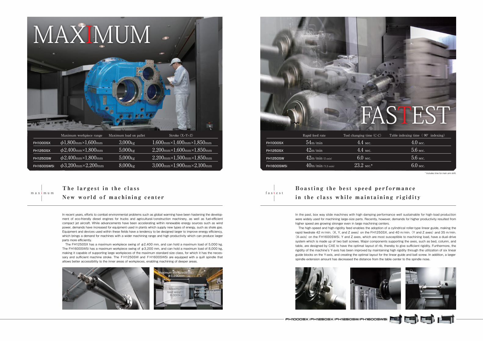
In recent years, efforts to combat environmental problems such as global warming have been hastening the develop-ment of eco-friendly diesel engines for trucks and agricultural/construction machinery, as well as fuel-efficient compact jet aircraft. While advancements have been accelerating within renewable energy sources such as wind power, demands have increased for equipment used in plants which supply new types of energy, such as shale gas. Equipment and devices used within these fields have a tendency to be designed larger to improve energy efficiency, which brings a demand for machines with a wider machining range and high productivity which can produce larger parts more efficiently. The FH1250SX has a maximum workpiece swing of φ2,400 mm, and can hold a maximum load of 5,000 kg. The FH1600SW5i has a maximum workpiece swing of φ3,200 mm, and can hold a maximum load of 8,000 kg, making it capable of supporting large workpieces of the maximum standard size class, for which it has the neces-sary and sufficient machine stroke. The FH1250SW and FH1600SW5i are equipped with a quill spindle that allows better accessibility to the inner areas of workpieces, enabling machining of deeper areas.
The l a rge s t i n t h e c l a s sNew wor ld o f mach in i ng c en t e r
MAXIMUM
FASTEST
Boas t i ng t h e b e s t s p e ed per formancei n t h e c l a s s wh i l e ma in ta i n i ng r i g i d i t y
In the past, box way slide machines with high damping performance well sustainable for high-load production were widely used for machining large-size parts. Recently, however, demands for higher productivity resulted from higher speed are growing stronger even in large machining centers. The high-speed and high-rigidity feed enables the adoption of a cylindrical roller-type linear guide, making the rapid feedrate 42 m/min. (X, Y, and Z axes) on the FH1250SX, and 40 m/min. (Y and Z axes) and 35 m/min.(X-axis) on the FH1600SW5i. Y and Z axes, which are most susceptible to machining load, have a dual-drive system which is made up of two ball screws. Major components supporting the axes, such as bed, column, and table, are designed by CAE to have the optimal layout of rib, thereby to give sufficient rigidity. Furthermore, the rigidity of the machine's Y-axis has been improved by maintaining high rigidity through the utilization of six linear guide blocks on the Y-axis, and creating the optimal layout for the linear guide and ball screw. In addition, a largerspindle extension amount has decreased the distance from the table center to the spindle nose.
FH1000SX
FH1250SX
FH1250SW
FH1600SW5i
Maximum workpiece range
φ1,800mm×1,600mmφ2,400mm×1,800mmφ2,400mm×1,800mmφ3,200mm×2,200mm
Stroke(X×Y×Z)
1,600mm×1,400mm×1,850mm2,200mm×1,600mm×1,850mm2,200mm×1,500mm×1,850mm3,000mm×1,900mm×2,100mm
Maximum load on pallet
3,000kg5,000kg5,000kg8,000kg
FH1000SX
FH1250SX
Rapid feed rate Tool changing time(C-C) Table indexing time( 90°indexing)
FH1250SW
54m/min42m/min42m/min(Z-axis)40m/min(Y,Z-axis)
4.0 sec.5.6 sec.5.6 sec.6.0 sec.
4.4 sec.4.4 sec.6.0 sec.23.2 sec.*FH1600SW5i
Maximum workpiece dia.: φ3,200mm
Maximum load weight: 8,000kg
Maximum workpiece height: 2,200 mm
* Includes time for main arm shift.
f a s t e s tm a x i m u m
06
List of spindles
Best for high-efficiencycutting of cast parts
Best for a wide variety ofproducts with high speedsand large torques
Best for heavy duty cutting at lowspeeds with large diameter cutters
Quill spindle enables optimaldeep hole grinding and boringof iron/cast metal parts
Quill spindle enables optimal deeplarge-diameter hole grinding andboring of iron/cast metal parts
Application
-
-
-
550mm
750mm
Quill spindlestroke
30/22kW
37/30kW
37/30kW
45/37kW
55/37kW
Spindle motor(short-time/continuous)
φ110
φ120
φ110
φ180
φ200
Spindle diameter(front bearing bore)
600N・m
530N・m
1,009N・m
1,313N・m
2,115N・m
Max. torque
FH1000SXFH1250SX
FH1250SW
FH1600SW5i
Applicable models
6,000min-1
15,000min-1
6,000min-1
3,000min-1
4,000min-1
Spindle speed
BT50BBT50
HSK-A100CAT50DIN50
Holdercompatibility
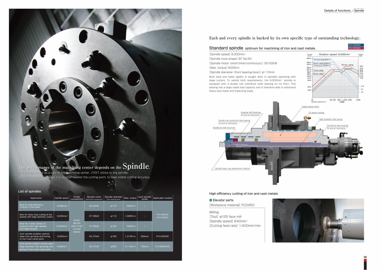
Standard spindle optimum for machining of iron and cast metals[Spindle speed] 6,000min-1
[Spindle nose shape] BT No.50
[Spindle motor (short-time/continuous)] 30/22kW
[Max. torque] 600N・m
[Spindle diameter (front bearing bore)] φ110mmBoth axial and radial rigidity is sought after in spindles operating with large cutters. To satisfy both requirements, the 6,000min-1 spindle is equipped with a double row cylindrical roller bearing on its front. This bearing has a large radial load capacity and is therefore able to withstand heavy duty loads and impacting loads.
High efficiency cutting of iron and cast metals
■ Elevator parts
Milling[Tool] φ125 face mill[Spindle speed] 640min-1
[Cutting feed rate] 1,400mm/min
[Workpiece material] FCD450
Rotation speed: 6,000min-1
1,050
30.0
600.0
420.0353.0
263.0221.0191.0
140.0
189.0157.0
115.084.0
29.4
23.9
20.821.022.0
15.0
17.318.5
15.4
2.2
3.14
1.8
Spindle speed(min-1)50 6,0002,5001,500350 800500
Output(kW)
Torque(N・m)
30-min. rating
15-minute rating(600N・m)
ContinuousContinuous(353N・m)30-min. rating(420N・m)
15-min. rating
30-min. rating
Continuous15-min. rating
30-min. rating
SpindleDetails of functions
Each and every spindle is backed by its own specific type of outstanding technology.
High durability disk spring
Oil jacket cooling
Large torque motor
Double air seal structure
Double row cylindrical roller bearingOil and air lubrication
Spindle taper cap replacement method
Oil and air lubricationAngular ball bearing
Oil and air lubricationCylindrical roller bearing
The performance of the machining center depends on the Spindle.The spindle serves as a core of the machining center. JTEKT sticks to the spindle,
which is important because it is located nearest the cutting point, to keep stable cutting accuracy.
The performance of the machining center depends on the Spindle.The spindle serves as a core of the machining center. JTEKT sticks to the spindle,
which is important because it is located nearest the cutting point, to keep stable cutting accuracy.
FH1250SXFH1000SX

Large torque 6,000min-1 spindle achieving the best performance in its class[Spindle speed] 6,000min-1
[Spindle nose shape] BT No.50
[Spindle motor (short-time/continuous)] 37/30kW
[Max. torque] 1,009N・m
[Spindle diameter (front bearing bore)] φ110mmBoth axial and radial rigidity is sought after in spindles operating with large cutters. To satisfy both requirements, the 6,000min-1 spindle is equipped with a double row cylindrical roller bearing on its front. This bearing has a large radial load capacity and is therefore able to withstand heavy duty loads and impacting loads. This machine has a high-torque spindle of 1,009 Nm, with double the cutting ability in low speed ranges (under 500 min-1) compared to standard spindles.
Best cutting performance in its class with a 1,009N・m large torque spindle
Large torque 15,000min-1 spindleMulti-use spindle that achieves 530N・m in low speed ranges, even with a high-speed spindle
[Spindle speed] 15,000min-1
[Spindle nose shape] BT No.50
[Spindle motor (short-time/continuous)] 37/30kW
[Max. torque] 530N・m
[Spindle diameter (front bearing bore)] φ120mmThis is a multi-use type spindle that boasts high rigidity and rotational accuracy, enabling the machining of a wide range of workpieces, from the slow cutting of steel to the fast cutting of aluminum. This spindle utilizes a newly developed preloading adjustment mechanism that stabilizes high torque in low speed ranges and accuracy in high speed ranges.
[Workpiece material] HPM7
■Milling[Tool] φ160 face mill[Spindle speed] 400min-1
[Feed rate] 1,600mm/min[Depth of cut/width] 6/130mm
■Bore hole machining[Tool] φ92 Boring[Spindle speed] 500min-1
[Feed rate] 200mm/min
■Model piece
Efficient face milling in low speed ranges
9301,248
Standardspindle
6,000min-1
Large torquespindle
6,000min-1
1500
Milling effi
ciency
(cm3/min)
1000
500
0
Minimizes heat generation in the high speed ranges(front bearing exhaust temperature)
Spindlespeed(min-1)
50
Output(kW)
Torque(N・m)
Rotation speed: 15,000min-1
2.82.31.81.51.3
284
22
17.816.3
3531.3
37
18.5
3027
14
26
12.9
44.141.5
51.457.2
239
350
434
2,700
17.219.9
530
660
15,000710740
9501,400
1,8006,500
12,000
Continuous30-min. rating
Continuous
30-min. rating
25%15%
10-min. rating
30-min. rating(284N・m)Continuous(239N・m)
10-min. rating(350N・m)
25%(434N・m)
Continuous30-min. rating
Continuous
30-min. rating
25%10-min. rating
30-min. rating(284N・m)Continuous(239N・m)
10-min. rating(350N・m)
25%(434N・m)
15%(530N・m)
Torque(N・m)
Spindle speed(min-1)50
392350
1,2001,900 6,000500
5,000
Output(kW)
147.0151.0175.0186.0
70.757.352.543.5
707.0
505.0600.0
901.01,009.0
Rotation speed: 6,000min-1
30-min. rating
30-min. rating
15%ED
25%ED15%ED
25%ED
Continuous
30-min. rating
30-min. rating25%ED
Continuous
Continuous 37
33
22
19
30
18.5
23.4
27.3
SpindleDetails of functionsSpindle Details of functions
Double air seal structure
Oil jacket cooling
High durability disk spring
4-row ceramic ball bearingOil and air lubrication
Cylindrical roller bearingOil and air lubrication
Motor
Spindle taper cap replacement method
Variable switching preloading mechanism
High durability disk spring
Oil jacket cooling
Large torque motor
Double air seal structure
Double row cylindrical roller bearingOil and air lubrication
Spindle taper cap replacement method
Oil and air lubricationAngular ball bearing
Oil and air lubricationCylindrical roller bearing
Efficient face milling in low speed ranges
(cm3/min)Milling effi
ciency
930 1,248 1,210
Standardspindle
6,000min-1
Large torquespindle
6,000min-1
Large torquespindle
15,000min-1
1500
1000
500
0
(cm3/min)Milling effi
ciency
5761,210
Conventionalspindle
15,000min-1
Large torquespindle
15,000min-1
1500
1000
500
0Conventionalspindle
15,000min-1
Large torquespindle
15,000min-1
(Index)Temperature rise
1 0.8
1.0
0.5
0
High cutting performance similar tospindle (6,000min-1 large torque spindle) for heavy-duty cutting
Significantly higher cuttingperformance with the conventionalspindle (15,000min-1 wide range spindle)
Achieves both high-rigidityand high-speed rotation(20% reduction in temperature rise)
High-efficiency and high-accuracy machining with 15,000min-1 large torque spindle
■Test piece[Workpiece material] S45C
■Milling [Tool] φ125 face mill [Spindle speed] 800min-1
[Feed rate] 2,688mm/min [Depth of cut/width] 4.5/100mm
FH1250SXFH1000SX
FH1250SXFH1000SX
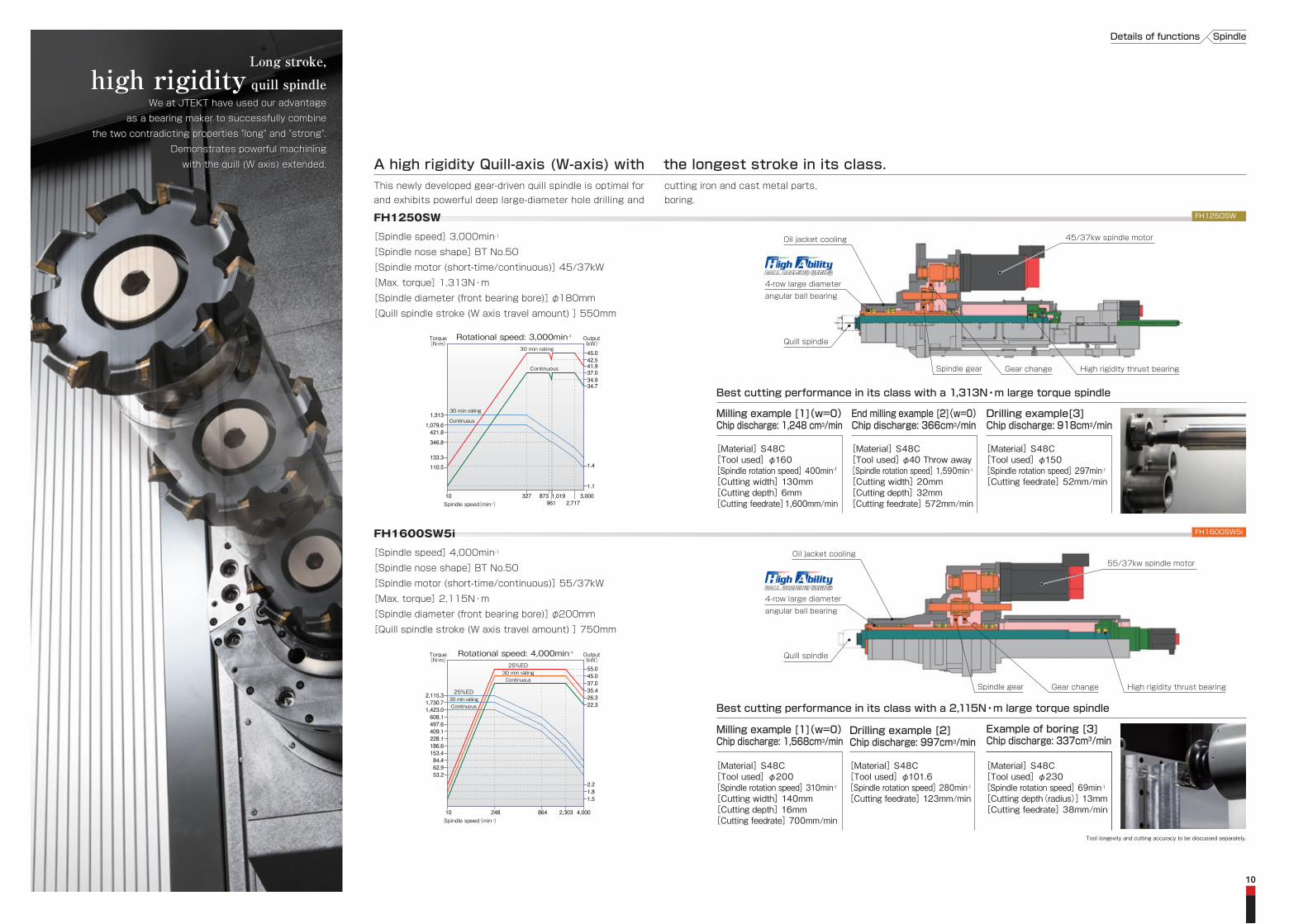
A high rigidity Quill-axis (W-axis) with the longest stroke in its class.
FH1600SW5i FH1600SW5i
FH1250SW FH1250SW
Tool longevity and cutting accuracy to be discussed separately.
[Material] S48C[Tool used] φ200[Spindle rotation speed] 310min-1
[Cutting width] 140mm[Cutting depth] 16mm[Cutting feedrate] 700mm/min
Milling example [1](w=0)Chip discharge: 1,568cm3/min
[Material] S48C[Tool used] φ101.6[Spindle rotation speed] 280min-1
[Cutting feedrate] 123mm/min
Drilling example [2]Chip discharge: 997cm3/min
End milling example [2](w=0)Chip discharge: 366cm3/min
Milling example [1](w=0)Chip discharge: 1,248 cm3/min
[Material] S48C[Tool used] φ160[Spindle rotation speed] 400min-1
[Cutting width] 130mm[Cutting depth] 6mm[Cutting feedrate]1,600mm/min
[Material] S48C[Tool used] φ40 Throw away[Spindle rotation speed] 1,590min-1
[Cutting width] 20mm[Cutting depth] 32mm[Cutting feedrate] 572mm/min
[Material] S48C[Tool used] φ150[Spindle rotation speed] 297min-1
[Cutting feedrate] 52mm/min
Drilling example[3]Chip discharge: 918cm3/min
Best cutting performance in its class with a 2,115N・m large torque spindle
Best cutting performance in its class with a 1,313N・m large torque spindle
[Spindle speed] 3,000min-1
[Spindle nose shape] BT No.50
[Spindle motor (short-time/continuous)] 45/37kW
[Max. torque] 1,313N・m
[Spindle diameter (front bearing bore)] φ180mm
[Quill spindle stroke (W axis travel amount) ] 550mm
[Spindle speed] 4,000min-1
[Spindle nose shape] BT No.50
[Spindle motor (short-time/continuous)] 55/37kW
[Max. torque] 2,115N・m
[Spindle diameter (front bearing bore)] φ200mm
[Quill spindle stroke (W axis travel amount) ] 750mm
[Material] S48C[Tool used] φ230[Spindle rotation speed] 69min-1
[Cutting depth(radius)] 13mm[Cutting feedrate] 38mm/min
Example of boring [3]Chip discharge: 337cm3/min
SpindleDetails of functions
This newly developed gear-driven quill spindle is optimal for cutting iron and cast metal parts, and exhibits powerful deep large-diameter hole drilling and boring.
10
Rotational speed: 4,000min-1
10 248 864 2,303 4,000Spindle speed(min-1)
Output(kW)
Torque(N・m)
53.262.984.4153.4186.6228.1409.1497.6608.11,423.01,730.72,115.3
22.3
2.21.81.5
26.3
55.045.037.035.4
25%ED30 min ratingContinuous
25%ED30 min ratingContinuous
Oil jacket cooling
Oil jacket cooling
45/37kw spindle motor
55/37kw spindle motor
High rigidity thrust bearing
Quill spindle
Gear change
High rigidity thrust bearing
Quill spindle
Spindle gear
Spindle gear Gear change
We at JTEKT have used our advantage
as a bearing maker to successfully combine
the two contradicting properties "long" and "strong".
Demonstrates powerful machining
with the quill (W axis) extended.
Long stroke,high rigidity quill spindle
Long stroke,high rigidity quill spindle
We at JTEKT have used our advantage
as a bearing maker to successfully combine
the two contradicting properties "long" and "strong".
Demonstrates powerful machining
with the quill (W axis) extended.
4-row large diameter angular ball bearing
Spindle speed(min-1)
30 min rating
30 min rating
Continuous
Continuous
Rotational speed: 3,000min-1 Output(kW)
Torque(N・m)
34.7
41.9
421.8
110.5
1,079.6
1,313
42.545.0
37.034.9
1.1
1.4
3,0002,717
1,019961
873 10 327
133.3
346.8
4-row large diameter angular ball bearing
1211
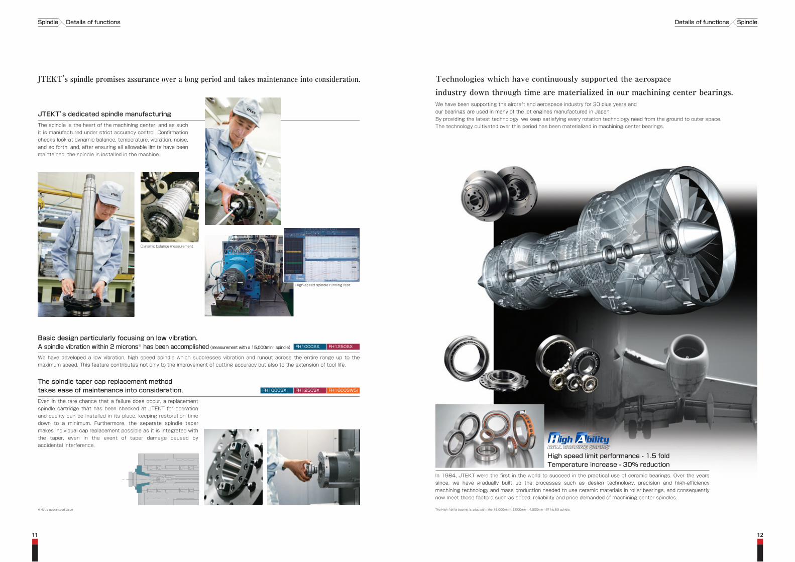
JTEKT’s dedicated spindle manufacturingThe spindle is the heart of the machining center, and as such it is manufactured under strict accuracy control. Confirmation checks look at dynamic balance, temperature, vibration, noise, and so forth. and, after ensuring all allowable limits have been maintained, the spindle is installed in the machine.
JTEKT’s spindle promises assurance over a long period and takes maintenance into consideration.
The spindle taper cap replacement method takes ease of maintenance into consideration.
Even in the rare chance that a failure does occur, a replacement spindle cartridge that has been checked at JTEKT for operation and quality can be installed in its place, keeping restoration time down to a minimum. Furthermore, the separate spindle taper makes individual cap replacement possible as it is integrated with the taper, even in the event of taper damage caused by accidental interference.
Technologies which have continuously supported the aerospaceindustry down through time are materialized in our machining center bearings.We have been supporting the aircraft and aerospace industry for 30 plus years andour bearings are used in many of the jet engines manufactured in Japan.By providing the latest technology, we keep satisfying every rotation technology need from the ground to outer space.The technology cultivated over this period has been materialized in machining center bearings.
High speed limit performance - 1.5 foldTemperature increase - 30% reduction
In 1984, JTEKT were the first in the world to succeed in the practical use of ceramic bearings. Over the years since, we have gradually built up the processes such as design technology, precision and high-efficiency machining technology and mass production needed to use ceramic materials in roller bearings, and consequently now meet those factors such as speed, reliability and price demanded of machining center spindles.
High-speed spindle running rest
Dynamic balance measurement
We have developed a low vibration, high speed spindle which suppresses vibration and runout across the entire range up to the maximum speed. This feature contributes not only to the improvement of cutting accuracy but also to the extension of tool life.
Basic design particularly focusing on low vibration.A spindle vibration within 2 microns※ has been accomplished (measurement with a 15,000min-1 spindle).
※Not a guaranteed value The High Ability bearing is adopted in the 15,000min-1, 3,000min-1, 4,000min-1 BT No.50 spindle.
Spindle Details of functions SpindleDetails of functions
FH1250SXFH1000SX
FH1250SX FH1600SW5iFH1000SX

Platform機能詳細
±7sec±3.5sec
FCD600 columnfeaturing both high speed performance and heavy duty cutting capabilities
JTEKT’s original high casting technology has made it possible to contribute materials which are not only complex in shape but also large, such as the column, to the creation of the FCD600. As a result, it has been possible to create a light weight machine with a rigid column. Furthermore, using FEM technology, the development of a low center-of-gravity column with satisfactory moving performance was completed. With this, high rapid feed rate and high acceleration are accomplished while a high rigidity against cutting forces is maintained.
High grade cast iron high rigid bedkeeping machine level stable over a long period
The bed supporting the moving body is designed using FEM analysis technology. And the bed has sufficient rigidity and substantially improved moving level. This feature makes stable axial feed possible with high speed and high acceleration.
14
A Rigid cylindrical roller slideable to withstand high speed, high acceleration travel while still maintaining rigidity is adopted
Compared to the ball guide, the cylindrical roller slide features less elastic deformation against loads and smaller displacement caused by load variation, as well as possesses superior vibration damping characteristics. This feature makes it possible to position quickly with smaller orientation changes upon sudden acceleration or stoppages, contributing to a higher level of production efficiency.
Because of JTEKT’s assembling technology which allows for strict mounting face accuracies, the rigid cylindrical roller slide offers the best rapid feed rate and acceleration in it’s class.
FH1000SX table cross section FH1250SX/FH1250SW/FH1600SW5itable cross section
High rigidity and high accuracy table able to endure the weight of large workpiecesThe NC indexing table conducts table indexing in units of 0.001º even with a heavy workpiece loaded onto the pallet. The high-rigidity and high-accuracy cross-roller bearing on the FH1000SX and the large sliding slide on the table periphery of the FH1250SX and FH1600SW5i secure the load and counterbalance the weight of large workpieces with suitable support rigidity. These mechanisms minimize vibration on the pallet and enable accurate machining, even with unbalanced load weights and cutting loads.
Maximum load on palletFH1000SX3,000kg
FH1250SX / FH1250SW5,000kg
FH1600SW5i8,000kg
Table indexing repeatabilityTable indexing accuracy
NC indexing table±7sec±3.5sec
±3.5sec±2sec
is a special specification.* The 1º indexing table is not included on the FH1600SW5i.
NC indexing table (with NC encoder) 1º indexing table
A rigid Platform incomparable to any othersassures stable production over a long period.JTEKT’s basic approach towards machine design is to minimize
displacement caused by external forces that may impact on cutting accuracy.
The rigid bed of the FH Series provides the answer towards withstanding large
cutting resistance as well as inertial forces of feed acceleration and deceleration.
-The immobile bed is placed as a solid stationary matter and moving bodies suchas the column is light-weight but at the same time rigid--simple,
yet requiring high level analysis techniques and material technology.
PalletPallet clamper
Rotating table
Cylindrical roller bearings
Brake
Largeslidingslide
Worm gear
Pallet
Pallet clamper
Rotating table
Brake
Crossroller bearings
Worm gear
1.0
2.2~2.7
Ball Cylindricalroller
Rigidity
Rigidity(times)
26
9
Ball Cylindricalroller
Damping tim
e
Damping capacity(ms)
75
132
Ball Cylindricalroller
Cutting performance
End mill cutting performance(S48C)(cm3/min)
Unrivaled rigid platform allowingthe spindle to achieve it’s full performance
1615
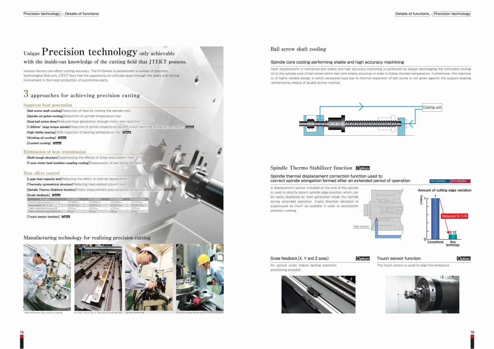
Ball screw shaft cooling
Manufacturing technology for realizing precision cutting
3 approaches for achieving precision cutting
Precision assembling workSpindle balancingAccuracy machining of linear guide mounting faceTable reference face sheet scraping
AccuracyPositioning accuracy (X, Y, Z)Repeatability (X, Y, Z)Table indexing accuracy(B)Table indexing repeatability(B)
FH1000SX±0.002mm±0.001mm±3.5 sec
±2 sec
FH1250SX±0.002mm±0.001mm±3.5 sec
±2 sec
FH1250SW±0.002mm±0.001mm±3.5 sec
±2 sec
FH1600SW5i±0.003mm±0.0015mm±3.5 sec
±2 sec
Elimination of heat transmission [Multi trough structure]Suppressing the effects of chips and coolant heat
[Y-axis motor heat isolation coupling cooling]Suppression of ball screw elongation
Heat effect control [Large heat capacity bed]Reducing the effect of thermal displacement
[Thermally symmetrical structure]Reducing heat-related column twist
[Spindle Thermo Stabilizer function]Direct measurement and correction of spindle elongation
[Scale feedback]
[Touch sensor function]
Suppress heat generation [Ball screw shaft cooling]Reduction of heat by cooling the spindle core
[Spindle oil jacket cooling]Reduction of spindle temperature rise
[Dual ball screw drive]Reduced heat generation through motor size reduction
[1,500min-1 large torque spindle]Reduction of spindle temperature rise with a multi switching preloading mechanism
[High Ability bearing]30% reduction of bearing temperature rise
[Working oil cooling]
[Coolant cooling]
FH1250SXFH1000SX
Precision technologyDetails of functionsPrecision technology Details of functions
Spindle core cooling performing stable and high accuracy machining
Heat displacement is restrained and stable and high accuracy machining is performed by always discharging the controlled cooling oil to the spindle core of ball screw which has core empty structure in order to follow the bed temperature. Furthermore, this machine is of highly reliable design in which excessive load due to thermal expansion of ball screw is not given against the support bearing restrained by means of double anchor method.
Scale feedback(X, Y and Z axes)
An optical scale makes lasting precision positioning possible.
Touch sensor function
The touch sensor is used to align the workpiece.
Spindle Thermo Stabilizer functionSpindle thermal displacement correction function used tocorrect spindle elongation formed after an extended period of operation
A displacement sensor installed at the end of the spindle is used to directly detect spindle edge position, which can be easily displaced by heat generated inside the spindle during extended operation. Z-axis direction deviation is suppressed as much as possible in order to accomplish precision cutting.
Amount of cutting edge variation1
0.12
Conventional Newtechnology
(Index
)
1
0
Reduced to 1/8
Gap sensor
Cooling unit
Unique Precision technology only achievablewith the inside-out knowledge of the cutting field that JTEKT possess.Various factors can effect cutting accuracy. The FH Series is packed with a number of precision technologies that only JTEKT have had the opportunity to cultivate down through the years with strong involvement in the mass production of automotive parts.

Optional partsCoolant cooling, chip box, mist collector and other optional accessories can be added.
Splash gun Oil skimmer
1817
Multi-trough double chip conveyorTo enable smooth processing of chips, three coil conveyors are installed on the FH1000SX, FH1250SX, and FH1250SW, and four coil conveyors are installed on the FH1600SW5i.
External nozzle coolantThe nozzle installed at the spindle nose supplies coolant to the cutting point.
Vertical coverChips are processed efficiently by constructing the machining chamber interior from vertical covers. Futhermore, chip accumulation at the work position is prevented by an operation door with a shape that has been carefully designed.
Reliability starts with chip disposal. The design of a multi trough that makesit possible to deal with chip disposal directly beneath the cutting point.
1
1
2
4
5
2
3
3
Overhead shower coolantThe coolant nozzle installed in the ceiling discharges coolant, keeping chip accumulation inside the machine down to a minimum.
4
Spindle-through coolantCoolant is supplied through the spindle center to the cutting edge.It is effective for lubrication and cooling of the cutting point, chip disposal and extension of tool life. (Delivery pressure: 3MPa and 7MPa are options.)
5
Spindle-through coolant 3MPa
Coolant cooling
Coolant supply unit with take-up chip conveyorChips collected in the center trough are transported outside of the machine by the chip conveyor. Two types of chip conveyors are provided to choose from depending on chip shape and material.
This photo shows FH1250SX.
Scraper Drum filterDrum filter
Standard scraper type coolant supply unit with chip conberyor
Scraper conveyor
Scraper
Chip box
Also supports the disposal of continuous chips.
Two-tiered coolant supply unit with chip conberyor
Bottomscraper conveyor
Topfloor conveyor
Chip box
Reliability Details of functions ReliabilityDetails of functions
19
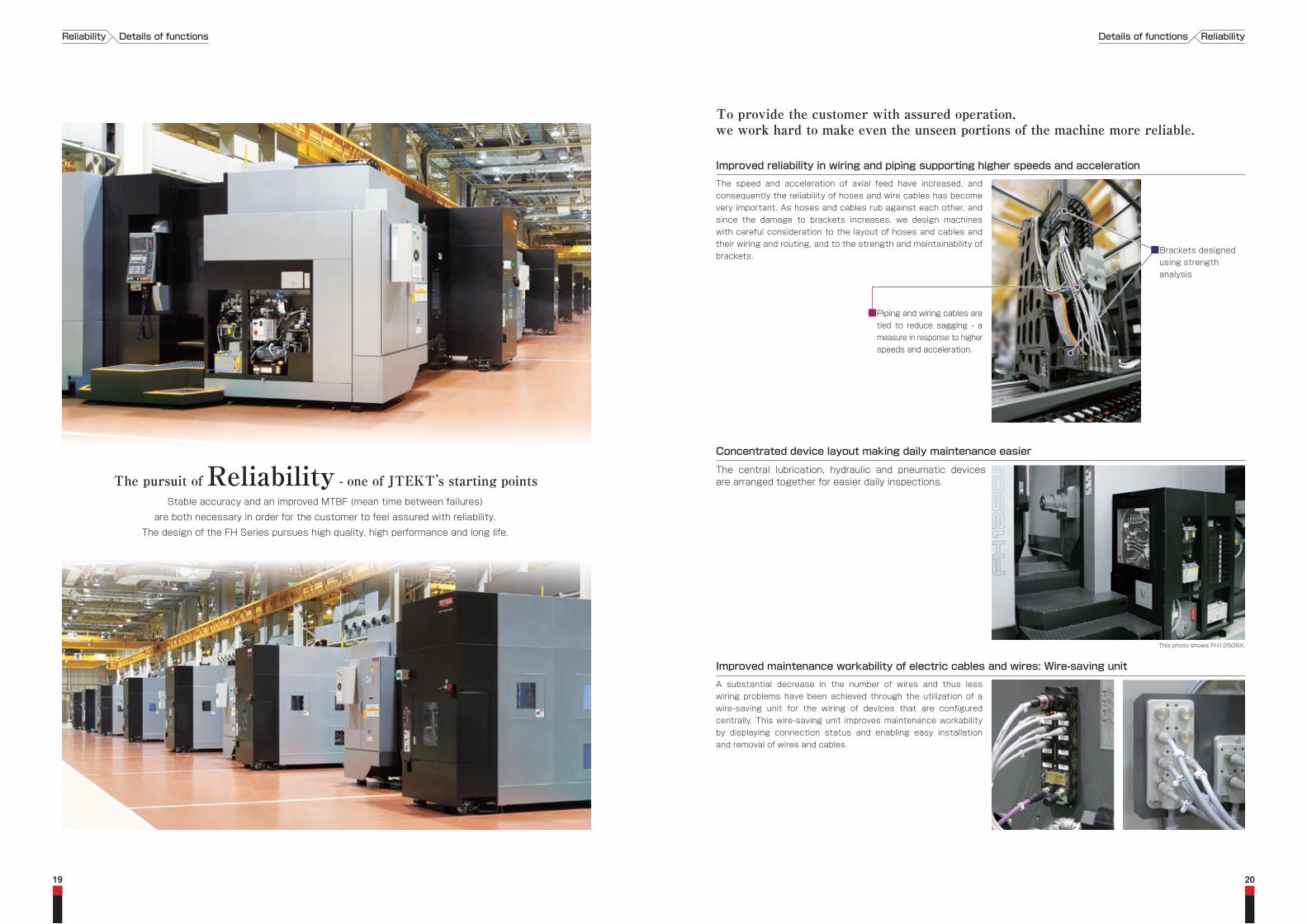
Improved reliability in wiring and piping supporting higher speeds and accelerationThe speed and acceleration of axial feed have increased, and consequently the reliability of hoses and wire cables has become very important. As hoses and cables rub against each other, and since the damage to brackets increases, we design machines with careful consideration to the layout of hoses and cables and their wiring and routing, and to the strength and maintainability of brackets.
To provide the customer with assured operation,we work hard to make even the unseen portions of the machine more reliable.
Improved maintenance workability of electric cables and wires: Wire-saving unitA substantial decrease in the number of wires and thus less wiring problems have been achieved through the utilization of a wire-saving unit for the wiring of devices that are configured centrally. This wire-saving unit improves maintenance workability by displaying connection status and enabling easy installation and removal of wires and cables.
Concentrated device layout making daily maintenance easier
The central lubrication, hydraulic and pneumatic devices are arranged together for easier daily inspections.
This photo shows FH1250SX.
■Brackets designed using strength analysis
■Piping and wiring cables are tied to reduce sagging - a measure in response to higher speeds and acceleration.
20
The pursuit of Reliability - one of JTEKT’s starting pointsStable accuracy and an improved MTBF (mean time between failures)
are both necessary in order for the customer to feel assured with reliability.
The design of the FH Series pursues high quality, high performance and long life.
Reliability Details of functions ReliabilityDetails of functions

Accessible operation doorBy positioning the operation panel on the left-hand side of the machine, we have created a wide opening and reduced the amount of eye travel required. This in turn reduces the physical strain on the operator by not demanding a constrained physical posture.
Securing accessibility and work space
A step providing easy access to the spindleBy bending the bottom portion of the operation door into the inside and installing a work step, the operator is able to stand close to the spindle and work can be performed safely.
In make for easy loading\unloading of large workpieces a platform has been provided at the top of the APC. It is possible to stand close to the pallet and work can be carried out safely.
APC door with good accessibility
Machine center
This photo shows FH1250SX.This photo shows FH1250SX.
This photo shows FH1250SX.
This photo shows FH1250SX.
The FH1000SX step is two steps high.
22
Aiming to perfect a production system both environmentally and people-orientated
At JTEKT, we never lose sight
of our motto `pursue technological dreams to deliver valuable
innovations to you` and are always striving to achieve a style of
manufacturing friendly to both people and the planet.
Aiming to perfect a production system both environmentally and people-orientated
At JTEKT, we never lose sight
of our motto `pursue technological dreams to deliver valuable
innovations to you` and are always striving to achieve a style of
manufacturing friendly to both people and the planet.
WorkabilityWorkability
WorkabilityDetails of functions
2423
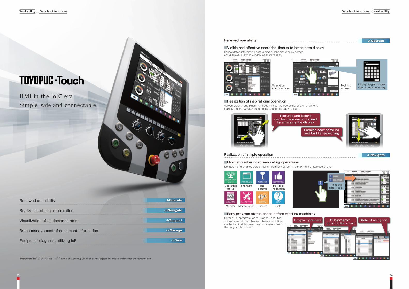
HMI in the IoE* eraSimple, safe and connectable
Operationstatus
Program Toolcontrol
Periodicinspection
HelpMonitor Maintenance System
Press andhold (1 sec.)
Renewed operability
Realization of simple operation
Visualization of equipment status
Batch management of equipment information
Equipment diagnosis utilizing IoE
J-Operate
J-Navigate
J-Support
J-Manage
J-Care
Iconized menu enables screen calling from any screen in a maximum of two operations■Minimal number of screen calling operations
Details, subprogram construction, and tool status can all be checked before starting machining just by selecting a program from the program list screen
■Easy program status check before starting machining
J-OperateRenewed operability
J-NavigateRealization of simple operation
Tool listscreen
Operationstatus screen
Consolidates information onto a single large-size display screen, and displays a keypad window when necessary
■Visible and effective operation thanks to batch data display
Displays keypad windowwhen input is necessary
Program preview State of using toolSub-programconstruction chart
*Rather than "IoT", JTEKT utilizes "IoE" ("Internet of Everything"), in which people, objects, information, and services are interconnected.
Screen swiping and pinching in/out mimics the operability of a smart phone, making the TOYOPUC®-Touch easy to use and easy to learn
■Realization of inspirational operation
Enables page scrollingand fast list searching
Pictures and letterscan be made easier to readby enlarging the display
WorkabilityDetails of functionsWorkability Details of functions
● Notification of inspection periods via messages
● Inspection areas and inspection procedures can be viewed without consulting a manual
● Registration of completed past inspections/measurement results
● Notifies the user of inspections for parts that are nearing the end of their lives
● Minimizes machine stop time through preventive inspection/part preparation
● Inspection areas and inspection procedures can be viewed without consulting a manual
● ON/OFF status of devices can be viewed without having to check devices directly
● Device locations can be identified easily through image enlargement
● Internal ladder circuits can also be viewed easily
● Performance can be viewed easily on graphs and tables, and data entry is also possible
● Current performance can be compared with past performance of the selected period
● Performance can be viewed easily by shift
● Energy usage can be viewed easily on graphs and tables, and data entry is also possible
● Current energy usage can be compared with past energy usage of the selected period
● Effects of enabling/disabling energy saving settings can be viewed
●: Standard /□: Optional
2625
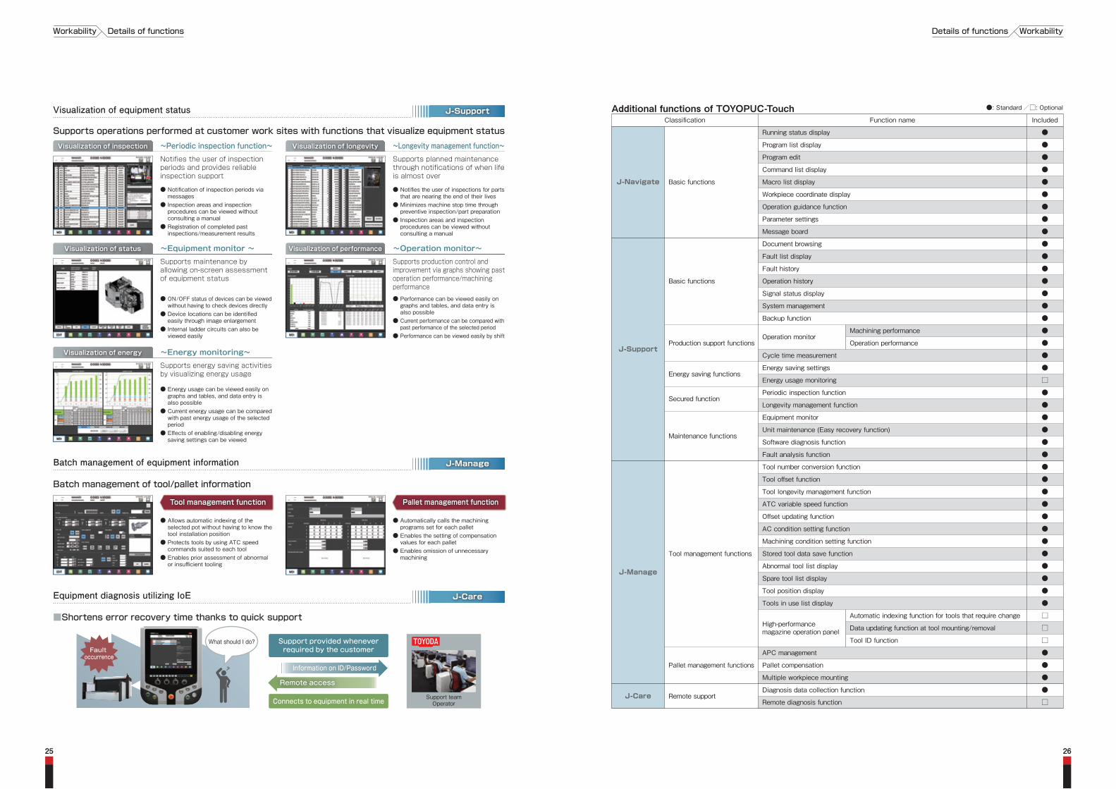
Additional functions of TOYOPUC-Touch
J-Navigate
IncludedFunction nameClassification
J-Support
J-Manage
J-Care
What should I do?
Support teamOperator
■Shortens error recovery time thanks to quick support
Supports operations performed at customer work sites with functions that visualize equipment status
J-SupportVisualization of equipment status
J-CareEquipment diagnosis utilizing IoE
Tool management function Pallet management function
● Allows automatic indexing of the selected pot without having to know the tool installation position
● Protects tools by using ATC speed commands suited to each tool
● Enables prior assessment of abnormal or insufficient tooling
● Automatically calls the machining programs set for each pallet
● Enables the setting of compensation values for each pallet
● Enables omission of unnecessary machining
J-ManageBatch management of equipment information
Batch management of tool/pallet information
Visualization of inspection Visualization of longevity
Notifies the user of inspection periods and provides reliable inspection support
Supports planned maintenance through notifications of when life is almost over
~Periodic inspection function~ ~Longevity management function~
Visualization of status Visualization of performance
Supports maintenance by allowing on-screen assessment of equipment status
Supports production control and improvement via graphs showing past operation performance/machining performance
~Equipment monitor ~ ~Operation monitor~
Visualization of energy
Supports energy saving activities by visualizing energy usage
~Energy monitoring~
●Program list display
●Program edit
●Command list display
●Macro list display
●Workpiece coordinate display
●Operation guidance function
●Parameter settings
●Message board
●Fault list display
●Fault history
●Operation history
●Signal status display
●System management
●Backup function
●Cycle time measurement
□Energy usage monitoring
●Longevity management function
●Unit maintenance (Easy recovery function)
●Software diagnosis function
●Fault analysis function
●Tool offset function
●Tool longevity management function
●ATC variable speed function
●Offset updating function
●AC condition setting function
●Machining condition setting function
●Stored tool data save function
●Abnormal tool list display
●Spare tool list display
●Tool position display
●Tools in use list display
●Pallet compensation
●Multiple workpiece mounting
□Remote diagnosis function
●Running status display
Basic functions
●Document browsing
Basic functions
●Energy saving settingsEnergy saving functions
●Periodic inspection functionSecured function
●Equipment monitor
Maintenance functions
●Tool number conversion function
Tool management functions
●APC management
Pallet management functions
●Diagnosis data collection function Remote support
Production support functionsOperation monitor
●Machining performance
●Operation performance
High-performancemagazine operation panel
□Automatic indexing function for tools that require change
□Data updating function at tool mounting/removal
□Tool ID functionSupport provided wheneverrequired by the customer
Connects to equipment in real time
Information on ID/Password
Remote access
Fault occurrence
WorkabilityDetails of functionsWorkability Details of functions

■Overseas bases
JTAM(United States/Chicago・Detroit)
TKB(Brazil/Sao Paolo)
(China/Dalian・Beijing・Shanghai・Chogqing・Xianshan)TMDTMEE
(France/Bonneuil sur Marne)
(Germany/Krefeld)TMEG
TMI(India/Gurgaon・Pune・Bangalore・Chennai)
JIDS(Indonesia/Jakarta)
TMSEA(Thailand/Bangkok)
TPA(South Korea/Seoul)
● Overseas subsidiaries● Service bases
Hokuriku region support(Ishikawa)
Niigata support(Niigata)
Tohoku regionsupport group
West Japan support group(Osaka)
Hamamatsu support(Hamamatsu)
East Japansupport group(Saitama)
Gunma support(Gunma)
Okayama support(Okayama)
Hiroshima support(Hiroshima)
Kyushu support group(Ogura / Fukuoka)
■Domestic Offices/Bases
Dispatch of serviceperson within 8 hours, Completion of restoration within 48 hours
JTEKT RemoteCare*1 support
100% of urgent parts shipped within 24 hoursShortening of machine stop time due to the change to a unit inventory
Parts manufacturing lineUnit repair line
SPI*2 SystemRepair order
Order of parts shipment
Work order
Dispatch/Restoration
Inquiry correspondence
Shipment of parts
Repair part supplyRepair parts
Customers
Supply of parts
Shipment of repaired parts
Specialized after-service line independent from production line
*1: Remote diagnosis system (option) *2: SPI(Service Parts Inquiry)
Utilizes a high-level search engine and text mining to search and mine large amounts of data from the customer or machine in order to propose optimal solutions in the shortest amount of time.
Dispatch of serviceperson within 8 hours Completion of repairs within 48 hours
Shipment of urgent parts within 24 hours
Global parts management by SPI*2 System
2827
Global service extending throughout the WorldJTEKT shares a strong cooperation with its overseas base offices, and is able through these offices to provide secure and reliable service on a global scale. Our specialists have received rigorous training in order to support customers in every way, all throughout the world
JTEKTMachine Tools &
Mechatronics Headquarters
Support HQ(Kariya)
JTEKT’s Customer Center was opened in Kariya, Aichi Pref. in 1999 as one of the largest permanent exhibition sites in Japan.The sales, before-sales and after-sales service and training school divisions accepting direct contact with customers areintegrally located in this center so that the best solution to meet customer’s requirements can be found.
A convincing before-after sales system centered on a permanent exhibition site
At the customer center the best solution for the customer’srequirements are proposed on a 3 element basis.We hope that you will take the time to visit.
At the customer center the best solution for the customer’srequirements are proposed on a 3 element basis.We hope that you will take the time to visit.
Customer center outlineLocation: 1-1 Asahimachi, Kariya-shi, Aichi Pref.Opened in October 1999Exhibition area: 2,110m2
Permanent exhibition: Grinders, machining centers, cutting machines, etc.
Work display corner according to the industry
Technical introduction by digital display
Machining center corner
Observe
*DE (Digital Engineering)
Processing consultation
Digital engineering room Event scenery
Have discussions *SFC (Sequential Function Chart)
Processing technology corner Training room
SFC*Dojo(training place)
Exhibition
Consultation
Confirm
●Exhibition of cells/machines most suited to the customer ●Introduction to leading edge technologies●Exhibition of total engineering potentials including those of group companies
●Technical exchange meeting by DE* utilization ●Exchange of the latest information through events●Machining consultation before the machines
●Confirmation of technology by carrying out before-sales service tests ●Operation training at the training school ●Education of SFC, personnel training
Touch and confirm
Service systemDetails of functionsService system Details of functions
Speedy and precise customer correspondence.We have established Service Headquarters in Kariya to consolidate the management of customer equipment information, and have arranged a system where call centers allow direct correspondence with customers, and parts can be supplied quickly.
Service headquartersCall center,
technical service,training school, etc.
Service base
Specialized repair service line
Parts center
Free telephone support.24 hour
24 hour
overseas
Free telephone support.
English correspondence available
for customers.

FH1250SW FH1600SW5i
Table&
Pallet
Dimensions&
Weight
Capability&
Performance
VariousCapacities
Item Unit
Tool change time(Tool-to-Tool) sec 2.7(15kg)3.2(15~35kg)
Pull stud MAS P50T-1
Machine height mm 4,520(APC door open)※4
Machine weight kg 49,500
Control voltage V AC100 DC24
Air source capacity NL/min 900
Air source pressure MPa 0.4~0.5
Power supply capacity kVA 69
Spindle coolant L 35
Ballscrew coolant L Also used as spindle coolant
Table L 4
Slide lubricant L 5.5
Spindle oil air L 2.9
Working oil L 63
Specifications of machine Specifications Specifications of machineSpecifications
※1: For detail shape, refer to the tooling data. ※2: The matrix magazine is used for 180-tools or more ※3: For details, refer to the layout plan. ※4: According to our inspection method ※1: For detail shape, refer to the tooling data. ※2: Workpiece swing is limited to 2,950 mm in the X-axis direction. Please refer to the tooling date.※3: The matrix magazine is used for 180-tools or more ※4: For details, refer to the layout plan. ※5: According to our inspection method
Machine specificationsFH1250SXFH1000SX
Pallet height(from floor) mm 1,5001,300
Max load on pallet kg 5,0003,000
Pallet change time sec 8570
Y-axis mm 1,6001,400
Z-axis mm 1,8501,850
Distance between spindle nose and table center mm 200~2,05050~1,900
Distance between spindle center and top of pallet mm 100~1,700100~1,500
Cutting feed rate(X, Y and Z) m/min 0.001~300.001~30
Ball screw diameter(X, Y and Z) mm φ63(X), φ50(Y, Z)φ50
Rapid acceleration(X, Y and Z) m/s2(G) 2.94(0.3)4.9(0.5)
φ110 φ100Spindle diameter(front bearing bore) mm φ110 φ100 φ110 φ110
37/30 30/25Spindle motor, short-time/continuous kW 37/30 30/25 30/22 30/22
Tool selection Absolute addressAbsolute address
Tool mass kg 3535
Tool change time(Tool-to-Tool) sec 2.7(15kg)3.2(15~35kg)
2.7(15kg)3.2(15~35kg)
Tool change time(Chip-to-Chip) sec 4.4(15kg)5.0(15~35kg)
4.4(15kg)5.0(15~35kg)
HolderTools MAS BT50MAS BT50
Pull stud MAS P50T-1MAS P50T-1
Machine height mm 4,5204,051
Machine weight kg 48,00031,000
63 59Power supply capacity kVA 63 59 5959
Spindle coolant L 2020
Ballscrew coolant L Also used as spindle coolantAlso used as spindle coolant
Table L 44
Spindle oil air L 2.92.9
Slide lubricant L 5.55.5
Working oil L 6363
Control voltage V AC100 DC24AC100 DC24
Air source capacity NL/min 900900
Air source pressure MPa 0.4~0.50.4~0.5
UnitItem
X-axis mm 2,2001,600Stroke
Rapid feed rate(X, Y and Z) m/min 4254Feeds
Dimensions&
Weight
VariousCapacities
Table&
Pallet
Capability&
Performance
50~6,000 50~15,000Spindle speed min-1 50~6,000 50~15,000 50~6,00050~6,000Spindle
Table dimensions(pallet dimensions) mm 1,250 × 1,600□1250(Pallet)800 × 1,000 □800(Pallet)
Rotary table indexing angle ° 1°0.001°(NC)0.001°(NC) 1°
Table indexing time(90°indexing) sec 5.35.64.0 3.7
Spindle nose shape HSKBT No.50 BT No.50 HSK
Special specificationsStandard specificationsStandard specifications Special specifications Special specificationsStandard specificationsStandard specifications Special specifications
Positioning accuracy mm ±0.002±0.003±0.003 ±0.002※4
Tool(dia. × length) mm φ120×800φ120×800 ※1 ※1
Max. workpiece swing × Max. workpiece height mm φ2,400 × 1,800 ※1φ1,800 × 1,600 ※1
Floor space(width × depth) mm 6,200 × 9,900 ※35,900 × 9,350 ※3
Repeatability mm ±0.001±0.0015± 0.0015 ±0.001※4
Table indexing repeatability sec ±2(with NC encoder)±3.5± 3.5 ±2(with NC encoder)※4
Table indexing accuracy sec ±3.5(with NC encoder)±7± 7 ±3.5(with NC encoder)※4
Floor space(width × depth) mm 7,450 × 9,900※4
±0.002(X, Y, Z)Positioning accuracy mm ±0.003※5
±0.001(X, Y, Z)Repeatability mm ±0.0015※5
±2(with NC encoder)Table indexing repeatability sec ±3.5※5
±3.5(with NC encoder)Table indexing accuracy sec ±7※5
Tool holding capacity tool 60 60ATC 121, 180, 240, 330121, 180, 240, 330※2 ※2
Feeds Rapid feed rate m/min 32(X, Y), 42(Z), 5(W) 35(X), 40(Y, Z), 20(W)
Tool selection Absolute address Absolute address
Tool change time(Chip-to-Chip) sec 6.0(15kg)6.5(15~35kg)
23.2(~8kg)25.4(~15kg)30.8(~35kg)
1,000
0.4~0.5
Spindle diameter(front bearing bore) mm φ180 φ200
35
20
7.5
16
2.9
100
Spindle nose shape BT No.50 BT No.50
HolderTools MAS BT50 CAT50 MAS BT50
MAS P50T-1
1°Rotary table indexing angle ° 0.001°(NC) 0.001(NC)
Pallet height(from floor) mm 1,500 1,450
Max load on pallet kg 5,000 8,000
5.3Table indexing time(90°indexing) sec 5.6 6.0
Pallet change time sec 85 200
Stroke X-axis mm 2,200 3,000
1,250 × 1,600Table dimensions(pallet dimensions) mm □1250(Pallet) 1,600 × 1,250
Y-axis mm 1,500 1,900
Z-axis mm 1,850 2,100
W-axis mm 550 750Distance between spindle nose and table center mm 260~2,110 400~2,500Distance between spindle center and top of pallet mm 200~1,700 100~2,000Max. workpiece swing × Max. workpiece height mm φ2,400 × 1,800 ※1 φ3,200 × 2,200 ※2
Ball screw diameter(X, Y and Z) mm φ63(X), φ50(Y, Z, W) φ80(X), φ63(Y, Z), φ50(W)
Rapid acceleration(X, Y and Z) m/s2(G) 2.25(0.23G) 1.96(0.2G)
Cutting feed rate m/min 0.001~30(X, Y, Z), 0.001~5(W) 0.001~20
Spindle Spindle speed min-1 10~3,000 10~4,000
W-axis quill dia. mm φ130 φ150
Spindle motor, short-time/continuous kW 45/37 55/37
※3ATC 121, 180, 240, 330 ※3Tool holding capacity tool 60 ※1120 240, 330
Tool(dia. × length) mm φ120 × 800 ※1 ※1φ125 × 800
Tool(dia. × length) kg 35 35
10,100 × 14,600 ※4
5,600(APC door open)※4
75,000
104
AC100 DC24
±0.005 ±0.003(X, Y, Z)
±0.003 ±0.0015(X, Y, Z)
±3.5(with NC encoder)±7
±3.5 ±2(with NC encoder)
3029

31 32
AccessoriesSpecificationsCNC unit Specifications
CNC unit FANUC 31i ● Standard/□ Optional
●●●
●●●Machine lock●●●Absolute position detection□□□Inch/metric switch
●●●Single block●●●Manual handle feed 1 unit□□□Program restart□□□Manual handle interrupt●●●Nano interpolation●●●Positioning(G00)●●●Exact stop mode(G61)●●●Tapping mode(G63)●●●Cutting mode(G64)●●●Exact stop(G09)●●●Linear interpolation(G01)●●●Arc interpolation(G02, G03)●●●Dwell(G04)●●●Helical interpolation●●●Reference point return(G28, G29)●●●Second reference point return(G30)●●●Third and fourth reference point return(G30)
□□□F1-digit feed□□□AI contour controlⅡ(pre-read 200 blocks)
●●●Machine coordinate system(G53)●●●Workpiece coordinate system(G54 to G59)□□□Additional workpiece coordinate systems(48 sets)□□□Additional workpiece coordinate systems(300 sets)●●●Custom macro
●●●Fixed drilling cycle(G73, G74, G76, G80 to G89, G98 and G99)□□□Additional optional block skip(9 pieces)□□□Automatic corner override
□□□Tool corrections(200)□□□Tool corrections(400)□□□Tool corrections(499)□□□Tool corrections(999)●●●Tool position offset●●●Tool diameter and cutter radius compensation●●●Tool length compensation(G43, G44 and G49)
Program storage capacity(128K bytes)□□□Program storage capacity(256K bytes)□□□Program storage capacity(512K bytes)□□□Program storage capacity(1M bytes)□□□Program storage capacity(2M bytes)□□□Program storage capacity(4M bytes)□□□Program storage capacity(8M bytes)●●●Number of registered programs(250)□□□Number of registered programs(500) ※Storage capacity 256K bytes compulsory□□□Number of registered programs(1000)※Storage capacity 512K bytes compulsory□□□Number of registered programs(2000)※Storage capacity 1M bytes compulsory□□□Number of registered programs(4000)※Storage capacity 2M bytes compulsory●●●Simultaneous multi-program editing(incl. background editing)
●●●Min. input increment(0.001mm)Axis controlFH1250SWFH1250SXFH1000SXNameDivision
●●●Dry runOperation
Interpolationfunction
●●●AI contour controlⅠ(pre-read 30 blocks)Feed function
●●●Local coordinate system(G52)Program entry
●●●Rigid tapSpindle function●●●Tool corrections(99)Tool function
Tool correctionfunction
Editingoperation
●●●Touch panel controlData entry/display●●●Built-in EthernetCommunication function●●●19” color LCDOthers
FANUC is a registered trademark of FANUC LTD.
●●●Additional custom macro common variables(#100 to #199, #500 to #999)
Accessories ● Standard accessories/□ Optional accessories
●4,000min-1 BT No. 50(55/37kW) quill spindle(with spindle-through coolant spec)
●3,000min-1 BT No. 50(45/37kW) quill spindle(with spindle-through coolant spec)
Item FH1250SW FH1600SW5iFH1250SXEquipment name FH1000SX
Tool magazine ●●Tool capacity 60 tools ●
Table and pallet ● ●●Indexing table NC indexing table ●
1°indexing table □□□
Rectangular pallet screw hole 1,250 × 1,600 □□
NC indexing table(with encoder) □ □□□
Addition of pallet Single piece screw hole □□□
Rectangular pallet T-groove 1,250 × 1,600 □□ ●
Single piece T-groove □ □□□
JIS □□□
MAS Ⅱ □□□
121 tools □□□
120 tools ●
180 tools □□□
Coolant supply unit(water soluble/with take-up chip conveyor/2-tank type/spindle-through coolant spec/2MPa through pump/with oil skimmer) ●□ □□
Touch sensor function Optical type (without energization): with alignment and datum face correction functions □□□
Wireless type (without energization): with alignment and datum face correction functions ●
Wire type: with alignment, datum face correction, gap elimination, and tool breakage detection functions □□
Automatic tool length measurement function and datum face for measurement(interference area caused) □□□ □
Automatic measurement function □□□ □
Automatic measurement correction function □□□ □
Rotary coordinate system correction function □□□ □
Rotary coordinate axis correction function □ □□□
Spindle Thermo Stabilizer function □□
●●External nozzle coolant ● ●
●●Overhead shower coolant ● ●
●●Chip flushing coolant ● ●
●●Internal multi trough ● ●
●●Splash gun(at APC) ● ●
Coolant supply unit(water soluble/with take-up chip conveyor/2-tank type/spindle-through coolant spec/3MPa through pump/with oil skimmer) □□□ □
Coolant supply unit(water soluble/with take-up chip conveyor/2-tank type/spindle-through coolant spec/7MPa through pump/with oil skimmer) □□□ □
Coolant cooling □□□ □
Chip box □□□ □
Mist collector □ □□□
Air blower External nozzle type □□
15,000min-1 BT No. 50(37/30kW) large torque spindle(with spindle-through coolant spec) □□
6,000min-1 BT No. 50(37/30kW) large torque spindle(with spindle-through coolant spec) □□
HSK specifications □□
Filler block for oil hole holder □□
Positioning block for angle head holder □□
Standard pallet T-groove 800×1,000/□1,250/□1,250 □□□
Pallet screw hole □800 □
Pallet T-groove □800 □
●●Pallet Standard pallet screw hole 800×1,000/□1,250/□1,250 ●
●Spindle relations Speed 6,000min-1 BT No. 50(30/22kW) spindle(with spindle-through coolant spec) ●
BIG PLUS specifications □□□ ●
● ●●Collet MAS Ⅰ ●
240 tools □□□ □
330 tools □□□ □
Coolant supply unit(water soluble/with take-up chip conveyor/scraper type/spindle-thorugh coolant spec/3MPa through pump/with oil skimmer) □□□ □
Coolant supply unit(water soluble/with take-up chip conveyor/scraper type/spindle-thorugh coolant spec/7MPa through pump/with oil skimmer) □□□ □
Coolant supply unit(water soluble/with take-up chip conveyor/2-tank type/spindle-through coolant spec/1MPa through pump/with oil skimmer) □□□ □
Coolant relations ● □●Coolant supply unit Coolant supply unit(water soluble/with take-up chip conveyor/scraper type/spindle-thorugh coolant spec/1MPa through pump/with oil skimmer) ●
Splash guard ●●Enclosure guard ● ●
●●Internal lighting ● ●
Support forhigh accuracy
●●Spindle cooling ● ●
●●Ball screw shaft cooling ● ●
Operation controlfunction, others
Ground fault interrupter □□□ □
Cooler for control cabinet inside □□□ □
Scale feedback(X-, Y- and Z-axes) □□□ □
Holder type □□□ □
●●Door interlock at operating position Electromagnetic lock type ● ●
●●APC door interlock Light curtain ● ●
Labor saving function ● ●●Pallet changer(APC) Shift type, with 2 pallets ●
When the scale feedback is equipped, the model name becomes FH1000SX5-L, FH1250SX5-L, FH1250SW5-L and FH1600SW5i-L.
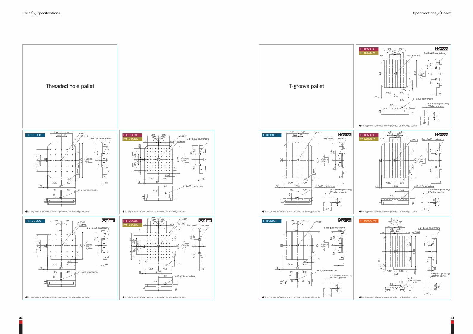
T-groove palletThreaded hole pallet
320
(400)
160
100
100
800
18
400
135
135
800
25
400
400
160
100
(400)100
800
400
100
320 320160160
320
φ18,φ26 counterbore
18
25 400φ18,φ26 counterbore
18
25 400 φ18,φ26 counterbore
18
25 400
φ18,φ26 counterboreφ18,φ26 counterbore
22H8(center groove only)22(other grooves)
24-M16φ50H7
320
160
160
320
100
3816
22
37
22H8(center groove only)22(other grooves)
3816
22
37
800
18
2-φ18,φ26 counterbore
400 135
135
18
2-φ18,φ26 counterbore
2-φ18,φ26 counterbore 2-φ18,φ26 counterbore
φ50H7
1,00
0(50
0)50
0
500
135
135
18
2-φ18,φ26 counterbore
500
135
135
(400)
100
100
800
400
100
320160160
320 320160160
320
24-M16φ50H7
320
160
160
320
100
100
φ50H7
1,00
0
(400)100
800
400 18
1,25
018
250
250
625
18
500375 375250 250
500
80-M20
φ100H7
(625)
125
125
1,250
315
625
625
φ18,φ26 counterbore
18
315
625
92
125 125
500 375
375
250
25050
0
125
125
315
315
800
18
2-φ18,φ26 counterbore
500375 375250 250
500
98-M20
φ100H7
125 125
125
800
1,60
0(80
0)12
5
(625)125
1,250
625
92
500 375
375
250
25050
0625
625
125
500 500
FH1250SXFH1250SW
125
22H8(center groove only)22(other grooves)
3816
22
37
22H8(center groove only)22(other grooves)
3816
22
37
φ18,φ26 counterbore
18
315
625
(625)
1,250
625
92
92
2-φ18,φ26 counterbore
250
250
625
φ18,φ26 counterbore
18
315
625
18
1,25
0
125
375 375250 250
φ100H7125 125
125 315
315
800
2-φ18,φ26 counterbore
18
800
1,60
0(80
0)
φ100H7
500375 375250 250
500
125 125
(625)125
1,250
625
●No alignment reference hole is provided for the edge locator.
●No alignment reference hole is provided for the edge locator. ●No alignment reference hole is provided for the edge locator. ●No alignment reference hole is provided for the edge locator. ●No alignment reference hole is provided for the edge locator.
●No alignment reference hole is provided for the edge locator. ●No alignment reference hole is provided for the edge locator. ●No alignment reference hole is provided for the edge locator. ●No alignment reference hole is provided for the edge locator.
3433
37
18
500 500375 375
315
315
800
125125250250
2-φ18,φ26 counterbore
φ100H7
38
2216
18
315
140
1,250 22H8(center groove only)22(other grooves)
625
1,60
0
(80
0)80
0
(625) 625125
125
φ18,φ26 counterbore
excess
Spindleside
FH1600SW5i
FH1250SXFH1250SW
FH1250SXFH1250SW
FH1000SX
FH1000SX
FH1250SXFH1250SW
FH1250SXFH1250SW
FH1000SX
FH1000SX
PalletSpecificationsPallet Specifications
Spindleside
Spindleside Spindle
sideSpindleside
Spindleside
SpindlesideSpindle
sideSpindleside
35 36
1,600X stroke
4,05
1Cover fu
lly-ra
ised
position
3,40
0
2,505
φ1,800
Max. workp
iece
swing
800
800
1,00
0
6,64
5(18
0/24
0/33
0ATC
)5,90
0(60
/121
ATC
)
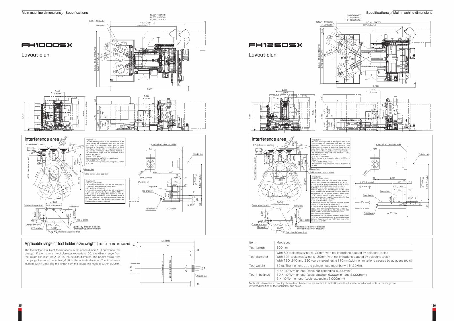
8,927(121ATC)
10,531(180ATC)11,335(240ATC)12,685(330ATC)
7,909(60ATC)
800×1,000pallet
□800pallet
9,350
100
1,400
1,400
Y stro
ke1,400
Y stro
ke
1,850Z stroke
201,30
0Pa
llet h
eight
1,32
0Pa
llet lo
ading
heigh
t
1,60
0Max. w
orkpiec
ehe
ight
906
3,14
5
Main machine dimensions Specifications
φ2,400
Max. workpie
ce swing
6,94
5(18
0/24
0/33
0ATC
)6,20
0(60
/121
ATC
)74
5
10,981(180ATC)11,785(240ATC)13,135(330ATC)
9,314(121ATC)1,250×1,600pallet□1,250pallet 8,276(60ATC)
9,900
1,600
1,250
1,250
3,54
5 1,80
0Max. w
orkpiec
ehe
ight
1,52
5Pa
llet loading
height
1,50
0Pallet h
eigh
t25
1,600
Y stro
ke1,600
1,600
Y stro
ke1,600
100
975
1,850Z stroke
- 0 CT
2,200X stroke
3,100
4,52
0Cover fu
lly-ra
ised
position
3,54
5
Applicable range of tool holder size/weight (JIS・CAT・DIN BT No.50)MAX.800
Gauge line
48
755
φ13
5
45
55
φ35
0(円筒工具)
φ40
0(ボーリング工具)
φ35
0(cylindrical to
ol)
φ40
0(borin
g tool)
φ10
0φ10
0
Layout plan Layout plan
Main machine dimensionsSpecifications
Tool length 800mm
Tool diameter With 121 tools magazine: φ130mm(with no limitations caused by adjacent tools)With 60 tools magazine: φ120mm(with no limitations caused by adjacent tools)
With 180, 240 and 330 tools magazines: φ110mm(with no limitations caused by adjacent tools)
Tool weight 35kg: The moment at the spindle nose must be within 29N・m.
30 × 10-5N・m or less (tools not exceeding 6,000min-1)Tool imbalance 10 × 10-5N・m or less (tools between 6,000min-1 and 8,000min-1)
3 × 10⁻⁵N・m or less (tools exceeding 8,000min-1)
Item Max. spec
Tools with diameters exceeding those described above are subject to limitations in the diameter of adjacent tools in the magazine, key grood position of the tool holder and so on.
The tool holder is subject to limitations in the shape during ATC(automatic tool change). If the maximum tool diameter exceeds φ100, the 48mm range from the gauge line must be φ100 in the outside diameter. The 55mm range from the gauge line must be within φ210 in the outside diameter. The total mass must be within 35kg and the length from the gauge line must be within 800mm.
(Z stroke)
(Max. jig and workpiece swing)
392
1,85
0
50° (2,15
5)
2,37
8 800
800
1,90
0
φ1,800
(Ma
x. wo
rkpiec
eswing)
50
1,600
800800
400
1,40
0
1,60
0(Ma
x. wo
rkpiec
ehe
ight)
φ1,800
100
75.1
8
2,378
1,005 1,005
φ1,167 (800×1,000 pallet swing)
φ1,167 (800×1,000 pallet swing)
XY slide cover position
165(To
ol re
trieval stro
ke)
R450
Change arm axis
ATC position
Spindle axis(upper limit)
Spindle axis(lower limit)(X stroke)
Workpiece
(Y stro
ke)
Top of pallet
φ350
Spindle key direction at spindle orientation(up/down direction)
8008001,0001,000
φ680
Gauge line
<Important 1> The table indexing motion at the negative limit of the Z-axis intrudes the interference area with the Y-axis slide cover. The interference range with the Y-axis slide cover at the negative limit of the Z-axis is shown in the figure. Move the table in the positive direction of the Z-axis out of the range before indexing the table. The interference range with the maximum φ1,800 workpiece is 392mm.<For an □800 pallet>8 mm clearance for a φ1,000 mm pallet swing < For an 800×1,000 pallet>The interference range for a pallet swing of φ1,167mm is 75.1mm.
Table center (zero position)
<Important 2> < For an □800 pallet>It is possible to move the Z-axis the full travel amount(1,850 mm) regardless of the B-axis angle.< For an 800x1,000 pallet>It is possible to move the Z-axis the full travel amount(1,850 mm) only when the B-axis is at 0° or 180°.If the B-axis is at an angle other than 0° or 180°, the rotation range interference check function works in order to secure the clearance between the pallet and XY slide cover, and the Z-axis travel amount and B-axis rotation angle are restrained.
Top of pallet
Gauge line
φ34
4φ25
0
2327
1,850(Z stroke)
Pallet hook
1,40
0(Y stro
ke)
100
35050
400
10030
78
79
250
150
7225
36
800
Spindle axis
Y axis slide cover front side
Z axis
420
Y axis
2-C30
At 0° index
Interference area Interference area
Top of pallet
Gauge line
Spindle axis
φ34
4φ25
0
792327
Y axis slide cover front side
Z axis
92
1,850(Z stroke)
Pallet hook
425200
420
62530
6.8
250
150
7225 36
1,60
0(Y stro
ke)
100
Y axis
1,250
2-C30
At 0° index
Gauge line
<Important 1> The table indexing motion at the negative limit of the Z-axis intrudes the interference area with the Y-axis slide cover. The interference range with the Y-axis slide cover at the negative limit of the Z-axis is shown in the figure. Move the table in the positive direction of the Z-axis out of the range before indexing the table. The interference range with the maximum φ2,400 workpiece is 538mm. <For an □1,250 pallet>The interference range for a pallet swing of φ1,600mm is 138.5mm.< For an 1,250x1,600 pallet>The interference range for a pallet swing of φ1,887mm is 283mm.
Table center (zero position)
<Important 2> <For an □1,250 pallet>It is possible to move the Z-axis the full travel amount (1,850 mm) only when the B-axis is at 0°, 90° or 270°.If the B-axis is at an angle other than 0°, 90° or 270°, the rotation range interference check function of FANUC works in order to secure the clearance between the pallet and XY slide cover, and the Z-axis travel amount and B-axis rotation angle are restrained.For example, the Z-axis travel amount is restrained to 1,787 mm automatically in order to prevent interference between the pallet hook and the XY slide cover when the B-axis is at 180°. < For an 1,250x1,600 pallet>It is possible to move the Z-axis the full travel amount (1,850 mm) only when the B-axis is at 0°.If the B-axis is at an angle other than 0°, the rotation range interference check function works in order to secure the clearance between the pallet and XY slide cover, and the Z-axis travel amount and B-axis rotation angle are restrained.For example, the Z-axis travel amount is restrained to 1,787 mm automatically in order to prevent interference between the pallet hook and the XY slide cover when the B-axis is at 180°.
Spindle axis(lower limit)
Spindle axis(upper limit)
(Y stro
ke)
Workpiece
Top of pallet
(X stroke)
538
283
138.5
φ350
1,85
0
60°
(2,42
5)
1,4001,400
2,800
2,800
800
2,05
0
φ1,887(1,250×1,600pallet swing)
φ1,887(1,250×1,600pallet swing)
φ1,600(□1,250pallet swing)
165(To
ol re
trieval stro
ke)
R450
XY slide cover position
(Z stroke)
200
2,2001,1001,100
100
1,60
0
ATC position Spindle key direction at spindle orientation(up/down direction)
Change arm axisφ680
φ2,400(Max. jig and workpiece swing)
200
1,80
0(Ma
x. wo
rkpiec
ehe
ight)
1,2501,250
1,25
01,25
0
1,6001,600
φ2,400
(Ma
x. work
piece
swing
)
φ2,400
(Ma
x. work
piece
swing
)
1,400
φ1,000 (□800 pallet swing)

3837
Main machine dimensionsSpecifications
Layout plan
Interference area
14225
145.2302
499.2
687
70
125.6
447.2
392
119.2
φ34
0
2230490
350
φ25
0
78.4178.4188.4
φ15
0
750(W stroke)
φ43
6
295
419
100
30400400
8001,600
1,90
0(Y stro
ke)
Top of pallet
Spindle axis
2,100(Z stroke)
Gauge linePallet hook
4901,537.72
403.18
580
556.78
556.78
100100
2,50
0
1,250
1,60
0
350
3,000(X stroke)
1,5001,500
3,50
0
2,10
0(Z stro
ke)
φ1,88
7
φ3,20
0
400
(Quill tra
vel a
mount)
Gauge line
Pallet swing
165(To
ol re
trieval stro
ke)
65
Column bodyColumn body
All columnfaces
φ1,020φ6
70
100
1,90
0(Y stroke
)
φ3,200(Max. jig and workpiece swing)
2,20
0(Ma
x. wo
rkpiec
e heig
ht)
450
Spindle axis(upper limit)Spindle axis(upper limit)
Spindle key direction at spindle orientation
(Left and right directions)
Spindle axis(lower limit)
Top of pallet
Workpiece
Change arm axisMax. tool dia.: φ350Max. tool dia.: φ350
800(Max. GL)
<Important 1> During ATC of tools with a length of 800 mm, 65 mm interference occurs between the maximum workpiece swing and the tool.
3,770
1,50
5
12,967
1,25
0
1,600
3,1004,52
0Cover fu
lly-ra
ised
position
3,54
5
2,200X stroke
Main machine dimensions Specifications
9,900
10,981(180 ATC)11,785(240 ATC)13,135(330 ATC)
1,250 × 1,600 pallet
745
1,250 1,2501,600
7,45
0(60
,121
ATC
)8,19
5(18
0,24
0,330 AT
C)
□1,250 pallet
φ2,400
Max. workp
iece
swingφ2,
400
Max. workp
iece
swing
9,314(121 ATC)8,276(60 ATC)
200
1,70
0
550W stroke
1,850Z stroke
251,50
0Pa
llet h
eight
1,80
0Max. w
orkpiec
ehe
ight
1,52
5Pa
llet lo
ading
heigh
t
975
3,54
5 1,50
0Y stro
ke
Top of palletGauge line
Spindle axis
W axis
Z axis
1,850(Z stroke)
Pallet hook
30625
1,50
0 (Y stro
ke)
60200
φ13
0290
136
6 87
36365260
7 229 32.5
133.5268.5
550
550
275
275
336
317
662
(92)
350200
420
□1,250□1,250
φ34
0φ34
0
φ34
4φ34
4
XY slide cover position
Table center (zero position)
Gauge line
Y axis slide cover front side
1,50
0(Y stro
ke)
Spindle axis(upper limit)
Workpiece
Top of pallet
Spindle key direction at spindleorientation(up/down direction)
Change arm axis
Spindle axis(lower limit)ATC position
ATC position
165(To
ol re
trieval stro
ke)
φ6801,1001,100
200
φ2,400(Max. jig and workpiece swing)
1001,
800
(Ma
x. wo
rkpiec
ehe
ight)
2,200(X軸移動量)
2,200(X stroke)
Y axis
550550
<Important 1> The table indexing motion at the negative limit of the Z-axis intrudes the interference area with the Y-axis slide cover. The interference range with the Y-axis slide cover at the negative limit of the Z-axis is shown in the figure. Move the table in the positive direction of the Z-axis out of the range before indexing the table. The interference range with the maximum φ2,400 workpiece is 538mm.The interference range for a pallet swing of φ1,600mm is 138mm.
<Important 2> It is possible to move the Z-axis the full travel amount (1,850 mm) only when the B-axis is at 0°, 90° or 270°.If the B-axis is at an angle other than 0°, 90° or 270°, the rotation range interference check function of FANUC works in order to secure the clearance between the pallet and XY slide cover, and the Z-axis travel amount and B-axis rotation angle are restrained.For example, the Z-axis travel amount is restrained to 1,787 mm automatically in order to prevent interference between the pallet hook and the XY slide cover when the B-axis is at 180°.
800
2,11
0
260
φ350
538
138
1,85
0(Z stroke)
60°
(2,42
5)
2,8002,800
φ2,400
R450
R450
φ1,887(1,250×1,600 pallet swing)
φ1,600
(□1,250 pallet swing)
φ1,887(1,250×1,600 pallet swing)
φ1,600
(□1,250 pallet swing)
1,6001,600
1,4001,4001,4001,4001,4001,400
□1,250□1,250
606020
020
0
550
(Qu
ill tra
vel a
moun
t)55
0(Qu
ill tra
vel a
moun
t)
653
653
Interference area
Layout plan
3,000X stroke
100
1,90
0Y stro
ke5,60
0Cover fu
lly-ra
ised
position
1,47
5Pa
llet lo
ading
heigh
t
2,20
0Max. w
orkpiec
ehe
ight
4,09
5
251,45
0Pa
llet h
eight
φ3,200Max. workpiece
swing
750W stroke
2,100Z stroke
Applicable range of tool holder size/weight(MAS,CAT,DIN,Big+BT No.50)The tool holder is subject to limitations in the shape during ATC(automatic tool change). If the maximum tool diameter exceeds φ100, the 48mm range from the gauge line must be φ100 in the outside diameter. The 68mm range from the gauge line must be within φ290 in the outside diameter. The total mass must be within 35kg and the length from the gauge line must be within 800mm.
Tool length 800mm
Tool diameterWith 120 tools magazine: φ125mm(with no limitations caused by adjacent tools)
Item Max. spec
68
48755
φ13
5
MAX.800
φ29
0
φ10
0
Gauge line
45
Tool imbalance 30×10-5N・m or less
Tool weight35kg: The moment at the spindle nose must be within 29N・m.Only 10 special chain sockets are compatiblewith 50 N•m
φ35
0(cylindrical to
ol)
φ50
0(borin
g tool)
MAX.800
Gauge line
48755
φ13
5
45
55
φ35
0(cylindrical to
ol)
φ40
0(bo
ring tool)
φ10
0φ10
0
Applicable range of tool holder size/weight (JIS・CAT・DIN BT No.50)The tool holder is subject to limitations in the shape during ATC(automatic tool change). If the maximum tool diameter exceeds φ100, the 48mm range from the gauge line must be φ100 in the outside diameter. The 55mm range from the gauge line must be within φ210 in the outside diameter. The total mass must be within 35kg and the length from the gauge line must be within 800mm. Refer to the tool charts for spindle rotation speed according to the quill position and the tool shape.
Tool length 800mm
Tool diameter With 121 tools magazine: φ130mm(with no limitations caused by adjacent tools)
With 60 tools magazine: φ120mm(with no limitations caused by adjacent tools)
With 180, 240 and 330 tools magazines: φ110mm(with no limitations caused by adjacent tools)
Tool weight 35kg: The moment at the spindle nose must be within 29N・m.
Tool imbalance 30 × 10-5N・m or less
Item Max. spec
Tools with diameters exceeding those described above are subject to limitations in the diameter of adjacent tools in the magazine, key grood position of the tool holder and so on.
Tools with diameters exceeding those described above are subject to limitations in the diameter of adjacent tools in the magazine, key grood position of the tool holder and so on.
14,432(Reference dimensions)
9,90
0(Referen
ce dimen
sion
s)