Series CNC Router Manual
45
Atlas Series Manual Atlas Series NK105 Call: 1-631-648-7481 or Visit: support.technocnc.com 1 Techno CNC Systems, LLC ©2018 01/30/18 This document will provide a quick guide to the set up and operation of the Techno ATLAS CNC router equipped with the NC studio controller. Series CNC Router Manual
-
Upload
khangminh22 -
Category
Documents
-
view
2 -
download
0
Transcript of Series CNC Router Manual
Call: 1-631-648-7481 or Visit: support.technocnc.com 1
Atlas Series Manual
Atlas Series NK105
Call: 1-631-648-7481 or Visit: support.technocnc.com 1
Techno CNC Systems, LLC ©2018 01/30/18
This document will provide a quick guide to the set up and operation of the Techno ATLAS CNC router equipped with the NC studio controller.
Series CNC Router Manual
Call: 1-631-648-7481 or Visit: support.technocnc.com 2
Atlas Series Manual
Atlas Series NK105
TABLE OF CONTENTS Forklift Guide ...........................................................................................................................................Page 3 Safety Instructions ......................................................................................................................................... Page 4 Colleting Guidelines ......................................................................................................................................... Page 5
l ATLAS Series Quick Setup ................................................................................................ Page 6I.I ATLAS Series Installation .......................................................................................... Page 7-9II Vacuum Pump Installation .................................................................................................................. Page 10 ATLAS Series Enabling the Machine ............................................................................................... Page 11II.I ATLAS Series Start Up ................................................................................................................... Page 12 Functions of the Keys ................................................................................................................... Page 13 Shift Commands / Combination Keystrokes ...................................................... Page 14
III Operating Tutorials 3.0- Switching Movement to Step or Jog ....................................................................................Page 15 3.1- Jogging the Machine/Changing from High/Low Jog Speed...................................Page 15 3.2- Stepping the machine .............................................................................................. Page 15 3.3- Modifying the Jog Speed and Step Size ....................................................................................Page 16 3.4- Feedrate Override .............................................................................................. Page 17 3.5- Adjusting the XYZ Position/WCS/User Origin ................................................................... Page 18 3.6-LoadingaG-codefile ..................................................................................................................Page19 3.7- Running a G-code File .............................................................................................. Page 19
IV Advanced Tutorials 4.1- Alternating between Override and Programmed Feedrates ...................................Page 20 4.2-SettingOverridespeedforaG-codefile................................................................................Page21 4.3- Setting the Table Size ........................................................................................... Page 22 ChangingtoDifferentOffset(anewXYZerolocation)...........................................................Page23 NotesontheG-codefile AccelerationSet......................................................................Page24
V Appendix ATLAS Series Settings ......................................................................................................................... .Page 26 - 30 Using the 4th Axis on an ATLAS Machine .......................................................Page 31
VI Atlas Machine Lubrication ...............................................................................................Page 33 Becker Vacuum Pump Manual .......................................................................................Page 34-38 Becker Vacuum Pump Filter Inspection ....................................................................................Page 39 - 41 Becker Vacuum Pump Greasing Process .............................................................. Page 42 - 46VII Warranty ...................................................................................................................................... Page 47
Call: 1-631-648-7481 or Visit: support.technocnc.com 3
Atlas Series Manual
Atlas Series NK105
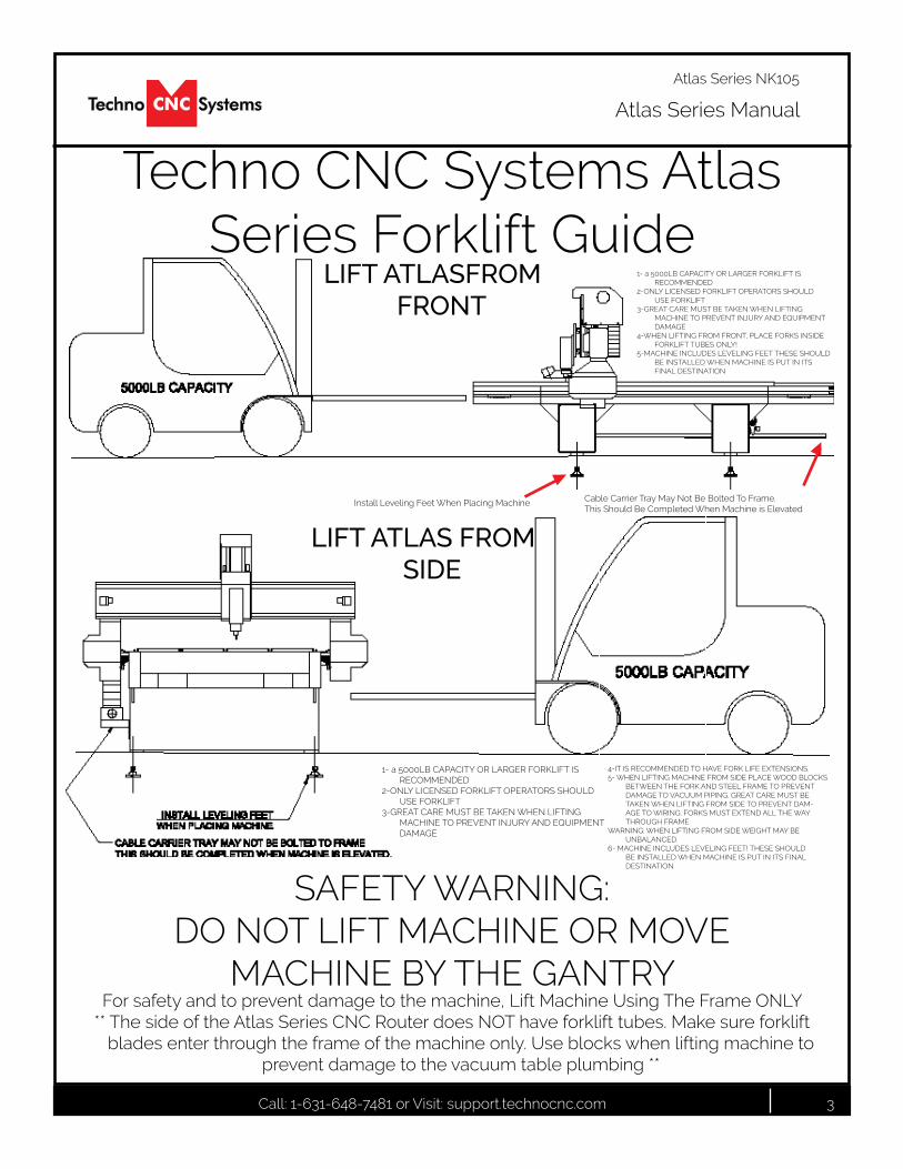
Techno CNC Systems Atlas Series Forklift Guide
SAFETY WARNING: DO NOT LIFT MACHINE OR MOVE
MACHINE BY THE GANTRYFor safety and to prevent damage to the machine, Lift Machine Using The Frame ONLY
** The side of the Atlas Series CNC Router does NOT have forklift tubes. Make sure forklift blades enter through the frame of the machine only. Use blocks when lifting machine to
prevent damage to the vacuum table plumbing **
Install Leveling Feet When Placing Machine Cable Carrier Tray May Not Be Bolted To Frame. This Should Be Completed When Machine is Elevated
LIFT ATLASFROM FRONT
1- a 5000LB CAPACITY OR LARGER FORKLIFT IS RECOMMENDED
2-ONLY LICENSED FORKLIFT OPERATORS SHOULD USE FORKLIFT
3-GREAT CARE MUST BE TAKEN WHEN LIFTING MACHINE TO PREVENT INJURY AND EQUIPMENT DAMAGE
4-WHEN LIFTING FROM FRONT, PLACE FORKS INSIDE FORKLIFT TUBES ONLY!
5-MACHINE INCLUDES LEVELING FEET THESE SHOULD BE INSTALLED WHEN MACHINE IS PUT IN ITS FINAL DESTINATION
LIFT ATLAS FROM SIDE
1- a 5000LB CAPACITY OR LARGER FORKLIFT IS RECOMMENDED
2-ONLY LICENSED FORKLIFT OPERATORS SHOULD USE FORKLIFT
3-GREAT CARE MUST BE TAKEN WHEN LIFTING MACHINE TO PREVENT INJURY AND EQUIPMENT DAMAGE
4-IT IS RECOMMENDED TO HAVE FORK LIFE EXTENSIONS.5- WHEN LIFTING MACHINE FROM SIDE PLACE WOOD BLOCKS
BETWEEN THE FORK AND STEEL FRAME TO PREVENT DAMAGE TO VACUUM PIPING. GREAT CARE MUST BE TAKEN WHEN LIFTING FROM SIDE TO PREVENT DAM-AGE TO WIRING. FORKS MUST EXTEND ALL THE WAY THROUGH FRAME.
WARNING: WHEN LIFTING FROM SIDE WEIGHT MAY BE UNBALANCED.
6- MACHINE INCLUDES LEVELING FEET! THESE SHOULD BE INSTALLED WHEN MACHINE IS PUT IN ITS FINAL DESTINATION
Call: 1-631-648-7481 or Visit: support.technocnc.com 4
Atlas Series Manual
Atlas Series NK105
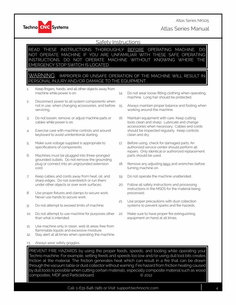
1. Keepfingers,hands,andallotherobjectsawayfrommachine while power is on.
2. Disconnect power to all system components when not in use, when changing accessories, and before servicing.
3. Do not loosen, remove, or adjust machine parts or cables while power is on.
4. Exercise care with machine controls and around keyboard to avoid unintentional starting.
5. Make sure voltage supplied is appropriate to specificationsofcomponents.
6. Machines must be plugged into three-pronged grounded outlets. Do not remove the grounding plug or connect into an ungrounded extension cord.
7. Keep cables and cords away from heat, oil, and sharp edges. Do not overstretch or run them under other objects or over work surfaces.
8. Useproperfixturesandclampstosecurework.Never use hands to secure work.
9. Do not attempt to exceed limits of machine.
10. Do not attempt to use machine for purposes other than what is intended.
11. Use machine only in clean, well-lit areas free from flammableliquidsandexcessivemoisture.
12. Stay alert at all times when operating the machine.
13. Always wear safety goggles.
14. Donotwearloose-fittingclothingwhenoperatingmachine. Long hair should be protected.
15. Always maintain proper balance and footing when working around the machine.
16. Maintain equipment with care. Keep cutting tools clean and sharp. Lubricate and change accessories when necessary. Cables and cords should be inspected regularly. Keep controls clean and dry.
17. Before using, check for damaged parts. An authorized service center should perform all repairs. Only identical or authorized replacement parts should be used.
18. Remove any adjusting keys and wrenches before turning machine on.
19. Do not operate the machine unattended.
20. Follow all safety instructions and processing instructions in the MSDS for the material being processed.
21. Use proper precautions with dust collection systemstopreventsparksandfirehazards.
22. Makesuretohaveproperfireextinguishingequipment on hand at all times.
WARNING: IMPROPER OR UNSAFE OPERATION OF THE MACHINE WILL RESULT IN PERSONAL INJURY AND/OR DAMAGE TO THE EQUIPMENT.
READ THESE INSTRUCTIONS THOROUGHLY BEFORE OPERATING MACHINE. DO NOT OPERATE MACHINE IF YOU ARE UNFAMILIAR WITH THESE SAFE OPERATING INSTRUCTIONS. DO NOT OPERATE MACHINE WITHOUT KNOWING WHERE THE EMERGENCY STOP SWITCH IS LOCATED.
PREVENT FIRE HAZARDS by using the proper feeds, speeds, and tooling while operating your Techno machine. For example, setting feeds and speeds too low and/or using dull tool bits creates friction at the material. The friction generates heat which can result in a fire that can be drawnthrough the vacuum table or dust collector without warning. Fire hazard from friction heating caused by dull tools is possible when cutting certain materials, especially composite material such as wood composites, MDF and Particleboard. © 2012
Safety Instructions
Call: 1-631-648-7481 or Visit: support.technocnc.com 5
Atlas Series Manual
Atlas Series NK105
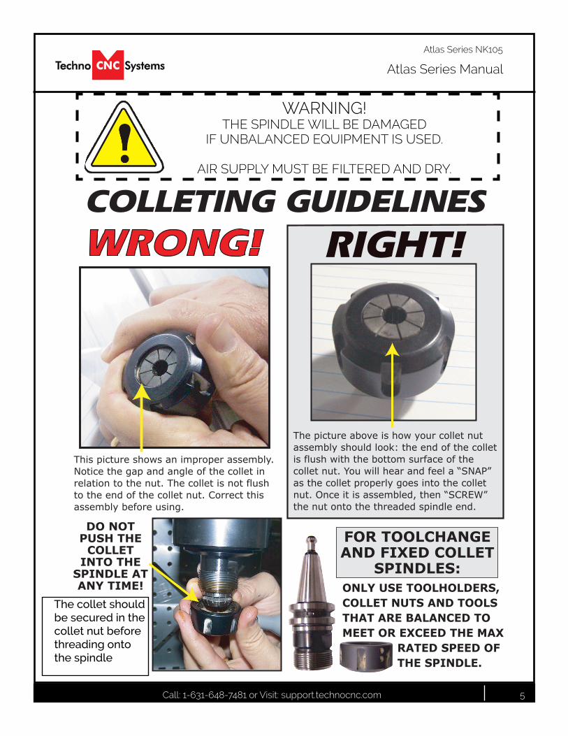
WARNING! THE SPINDLE WILL BE DAMAGED
IF UNBALANCED EQUIPMENT IS USED.
AIR SUPPLY MUST BE FILTERED AND DRY.
The collet should be secured in the collet nut before threading onto the spindle
Call: 1-631-648-7481 or Visit: support.technocnc.com 6
Atlas Series Manual
Atlas Series NK105
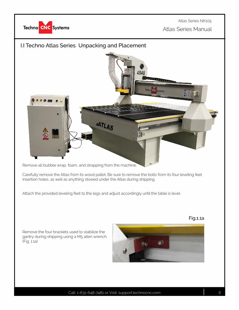
I.I Techno Atlas Series Unpacking and Placement
Remove all bubble wrap, foam, and strapping from the machine.
Carefully remove the Atlas from its wood pallet. Be sure to remove the bolts from its four leveling feet insertion holes, as well as anything stowed under the Atlas during shipping.
Attach the provided leveling feet to the legs and adjust accordingly until the table is level.
Remove the four brackets used to stabilize the gantry during shipping using a M5 allen wrench. (Fig.1.1a)
Fig.1.1a
Call: 1-631-648-7481 or Visit: support.technocnc.com 7
Atlas Series Manual
Atlas Series NK105
L1 L2 L3
Fig. 1.1Enclosure
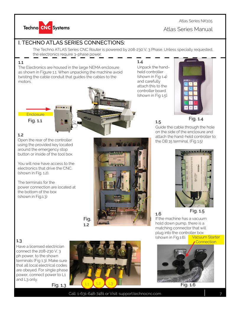
The Techno ATLAS Series CNC Router is powered by 208-230 V, 3 Phase. Unless specially requested, the electronics require 3-phase power.
The Electronics are housed in the large NEMA enclosure as shown in Figure 1.1. When unpacking the machine avoid twisting the cable conduit that guides the cables to the motors.
Have a licensed electrician connect the 208-230 V, 3 ph power, to the shown terminals(Fig1.3).Makesurethat all local electrical codes are obeyed. For single phase power, connect power to L1 and L3 only.
1.1
1.3
I. TECHNO ATLAS SERIES CONNECTIONS:
Unpack the hand-held controller (showninFig1.4) and carefully attach this to the controller board.(showninFig1.5).
1.4
Fig. 1.4
Fig. 1.3
Guide the cable through the hole on the side of the enclosure and attach the hand-held controller to theDB15terminal.(Fig1.5)
1.5
Fig. 1.5
Open the rear of the controller using the provided key located around the emergency stop button or inside of the tool box.
You will now have access to the electronics that drive the CNC. (showninFig.1.2). The terminals for the power connection are located at the bottom of the box (showninFig.1.3)
1.2
Fig. 1.2
1.6If the machine has a vacuum hold down pump, there is a matching connector that will plug into the controller box (showninFig.1.6). Vacuum Starter
Connection
Fig. 1.6
Call: 1-631-648-7481 or Visit: support.technocnc.com 8
Atlas Series Manual
Atlas Series NK105
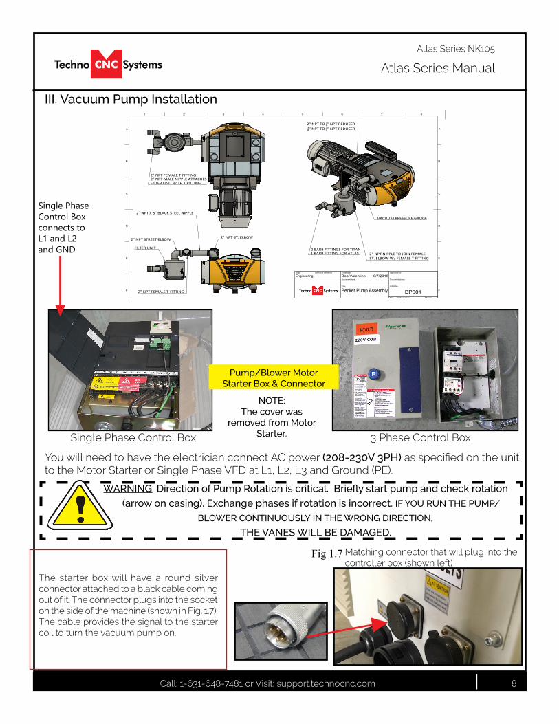
III. Vacuum Pump Installation
WARNING: Direction of Pump Rotation is critical. Briefly start pump and check rotation
(arrow on casing). Exchange phases if rotation is incorrect. IF YOU RUN THE PUMP/
BLOWER CONTINUOUSLY IN THE WRONG DIRECTION, THE VANES WILL BE DAMAGED.
NOTE: The cover was
removed from Motor Starter.
You will need to have the electrician connect AC power (208-230V 3PH)asspecifiedontheunittotheMotorStarterorSinglePhaseVFDatL1,L2,L3andGround(PE).
3 Phase Control BoxSingle Phase Control Box
Pump/Blower MotorStarter Box & Connector
1
A
2 3 4 5 6 7 8
1 2 3 4 5 6 7 8
B
C
D
E
F
A
B
C
D
E
F
Dept. Technical reference Created by Approved by
Document type Document status
Title DWG No.
Rev. Date of issue Sheet
2
6/7/2018
1/1
BP001Becker Pump Assembly
Bob ValentineEngineering
2" NPT ST. ELBOW
2" NPT X 8" BLACK STEEL NIPPLE
2" NPT FEMALE T-FITTING
FILTER UNIT
2" NPT STREET ELBOW
2" NPT FEMALE T FITTING2" NPT MALE NIPPLE ATTACHESFILTER UNIT WITH T FITTING
2 BARB FITTINGS FOR TITAN1 BARB FITTING FOR ATLAS
VACUUM PRESSURE GAUGE
2" NPT NIPPLE TO JOIN FEMALEST. ELBOW W/ FEMALE T FITTING
2" NPT TO 38" NPT REDUCER38" NPT TO 14" NPT REDUCER
Single Phase Control Box connects to L1 and L2 and GND
Matching connector that will plug into the controllerbox(shownleft)
The starter box will have a round silver connector attached to a black cable coming out of it. The connector plugs into the socket onthesideofthemachine(showninFig.1.7).The cable provides the signal to the starter coil to turn the vacuum pump on.
Fig 1.7
Call: 1-631-648-7481 or Visit: support.technocnc.com 9
Atlas Series Manual
Atlas Series NK105
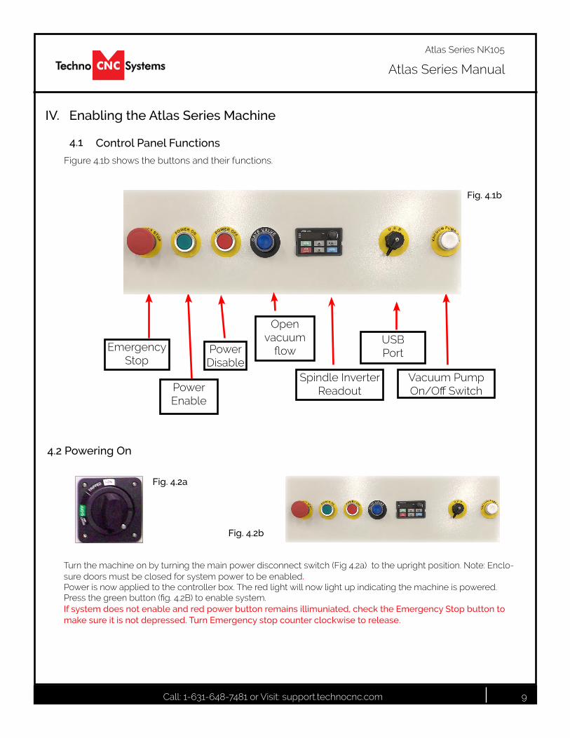
Figure 4.1b shows the buttons and their functions.
Emergency Stop
Power Enable
Power Disable
Spindle Inverter Readout
Vacuum Pump On/OffSwitch
USB Port
Fig. 4.1b
IV. Enabling the Atlas Series Machine
Control Panel Functions4.1
Open vacuum
flow
Turnthemachineonbyturningthemainpowerdisconnectswitch(Fig4.2a)totheuprightposition.Note:Enclo-sure doors must be closed for system power to be enabled. Power is now applied to the controller box. The red light will now light up indicating the machine is powered. Pressthegreenbutton(fig.4.2B)toenablesystem.If system does not enable and red power button remains illimuniated, check the Emergency Stop button to make sure it is not depressed. Turn Emergency stop counter clockwise to release.
Fig. 4.2a
4.2 Powering On
Fig. 4.2b

Call: 1-631-648-7481 or Visit: support.technocnc.com 10
Atlas Series Manual
Atlas Series NK105
Whenthemachinefirstpowerson,the display on the controller will light upandsay“StartingSystem”.(Fig.4.1a)
Once the system has booted it will ask the user “Back to reference point?” Fig 4.2b
Fig. 4.1a Fig. 4.2b
Thisisalsoknownas‘homing’themachine.Itreferstotheprocessofthemachinefindingitsmechanicalhome position.
From this point, the user has two options;Home the machine or cancel the homing process. We recommend that you home the machine every time you start up.
Press “ESC” will skip the homing process. WARNING:Therewillbenoreferencepositionandbreakpoints,offsetsandallfunc-tions that rely on a reference position will be invalid.
Once the machine has moved to the end of travel on each axis, it will stop and enter an IDLE state and will be ready to use.
You should test all machine functions before beginning to cut. The functions are displayed in the next section.
Pressing“OK”willinitiatethehomingprocess.ThemachinewillfirstmovetheZ-axisto the top of travel and then the X and Y axis will move simultaneously until both are at the home / reference position at the front left corner of the machine bed.
NOTE: The homing procedure can be aborted at anytime by pressing ESC.
ADVANCED HOMING:
If you hit “ESC” by accident, or would like to reindicate the axes, there are two ways to “Home” again.
1)PressMenu>3.Operations>1.BackREFPoint>1.AllHome
2)Shortcut
+
4.3 Atlas Startup
Call: 1-631-648-7481 or Visit: support.technocnc.com 11
Atlas Series Manual
Atlas Series NK105
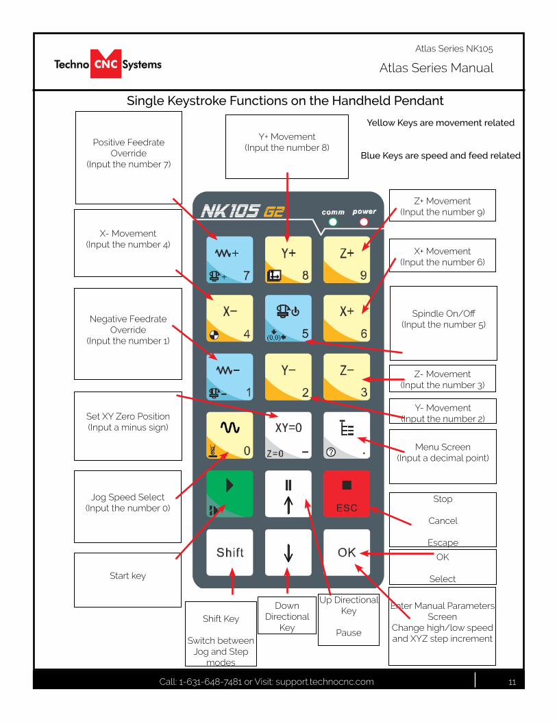
Single Keystroke Functions on the Handheld Pendant
Positive Feedrate Override
(Inputthenumber7)
X- Movement(Inputthenumber4)
Jog Speed Select (Inputthenumber0)
Enter Manual Parameters Screen
Change high/low speed and XYZ step increment
Z+ Movement(Inputthenumber9)
X+ Movement(Inputthenumber6)
Z- Movement(Inputthenumber3)
Menu Screen(Inputadecimalpoint)
Shift Key
Switch between Jog and Step
modes
Down Directional
Key
Set XY Zero Position (Inputaminussign)
Stop
Cancel
Escape
Up Directional Key
Pause
Start key
SpindleOn/Off(Inputthenumber5)
Negative Feedrate Override
(Inputthenumber1)
Y+ Movement (Inputthenumber8)
Y- Movement (Inputthenumber2)
OK
Select
Yellow Keys are movement related
Blue Keys are speed and feed related
Call: 1-631-648-7481 or Visit: support.technocnc.com 12
Atlas Series Manual
Atlas Series NK105
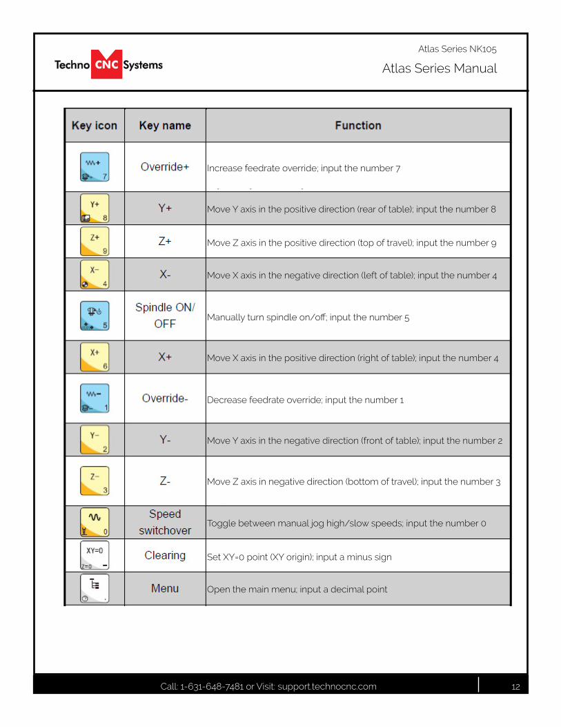
Increase feedrate override; input the number 7
MoveYaxisinthepositivedirection(rearoftable);inputthenumber8
MoveZaxisinthepositivedirection(topoftravel);inputthenumber9
MoveXaxisinthenegativedirection(leftoftable);inputthenumber4
Manuallyturnspindleon/off;inputthenumber5
MoveXaxisinthepositivedirection(rightoftable);inputthenumber4
Decrease feedrate override; input the number 1
MoveYaxisinthenegativedirection(frontoftable);inputthenumber2
MoveZaxisinnegativedirection(bottomoftravel);inputthenumber3
Toggle between manual jog high/slow speeds; input the number 0
SetXY=0point(XYorigin);inputaminussign
Open the main menu; input a decimal point

Call: 1-631-648-7481 or Visit: support.technocnc.com 13
Atlas Series Manual
Atlas Series NK105
Start machining
Pause machining; Up direction arrow when navigating menus
Stop machining; Cancel; Escape
Switch between jog and stepping modes; Auxilliary key
Down direction arrow when navigating menus
OK; Select; Open manual jog/step adjustment screen
Call: 1-631-648-7481 or Visit: support.technocnc.com 14
Atlas Series Manual
Atlas Series NK105
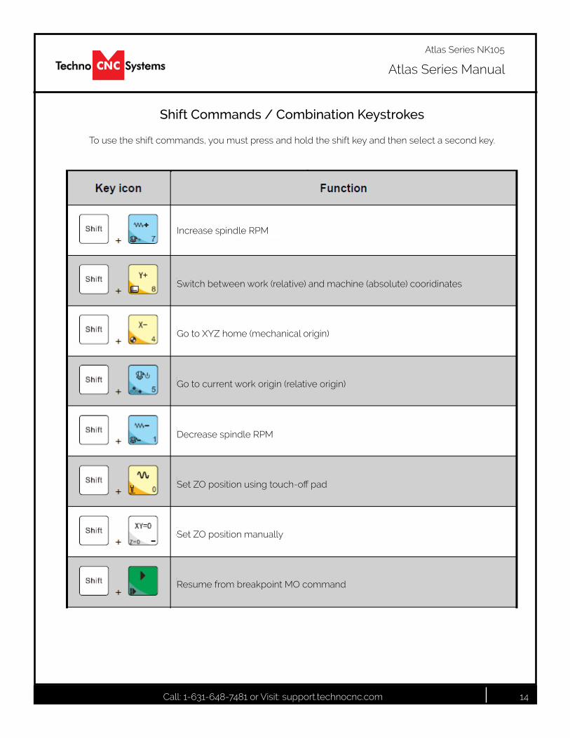
Shift Commands / Combination Keystrokes
To use the shift commands, you must press and hold the shift key and then select a second key.
Increase spindle RPM
Switchbetweenwork(relative)andmachine(absolute)cooridinates
GotoXYZhome(mechanicalorigin)
Gotocurrentworkorigin(relativeorigin)
Decrease spindle RPM
SetZOpositionusingtouch-offpad
Resume from breakpoint MO command
Set ZO position manually
Call: 1-631-648-7481 or Visit: support.technocnc.com 15
Atlas Series Manual
Atlas Series NK105
Select between high and slow Jog speeds
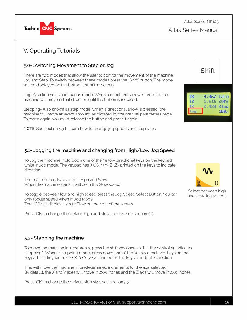
5.1- Jogging the machine and changing from High/Low Jog Speed
To Jog the machine, hold down one of the Yellow directional keys on the keypad while in Jog mode. The keypad has X+,X-,Y+,Y-,Z+,Z- printed on the keys to indicate direction.
The machine has two speeds, High and Slow. When the machine starts it will be in the Slow speed.
To toggle between low and high speed press the Jog Speed Select Button. You can only toggle speed when in Jog Mode. The LCD will display High or Slow on the right of the screen.
Press ‘OK’ to change the default high and slow speeds, see section 5.3.
5.0- Switching Movement to Step or Jog
There are two modes that allow the user to control the movement of the machine: Jog and Step. To switch between these modes press the “Shift” button. The mode will be displayed on the bottom left of the screen.
Jog- Also known as continuous mode. When a directional arrow is pressed, the machine will move in that direction until the button is released.
Stepping- Also known as step mode. When a directional arrow is pressed, the machine will move an exact amount, as dictated by the manual parameters page. To move again, you must release the button and press it again.
NOTE: See section 5.3 to learn how to change jog speeds and step sizes.
5.2- Stepping the machine
To move the machine in increments, press the shift key once so that the controller indicates “stepping” . When in stepping mode, press down one of the Yellow directional keys on the keypad The keypad has X+,X-,Y+,Y-,Z+,Z- printed on the keys to indicate direction.
This will move the machine in predetermined increments for the axis selected.By default, the X and Y axes will move in .005 inches and the Z axis will move in .001 inches.
Press ‘OK’ to change the default step size, see section 5.3
V. Operating Tutorials

Call: 1-631-648-7481 or Visit: support.technocnc.com 16
Atlas Series Manual
Atlas Series NK105
Decrease Feedrate
IncreaseFeedrate
5.3- Modifying the Jog Speed and Step Size
The machine can be jogged at two speeds, slow and high. You can also change the increments in which the machine will move in Step mode. These speeds are set in the Manual Parameters page.
ToaccesstheManualParameterspagepressOKfromtheMainScreen(Notmenu)
Set the High and Slow speed to a suitable value. Adjust the Step value as needed.
To Exit out of this screen and return to the main menu press ESC.
Wheninputtingadecimalincrement,youmustenterthevalueas0.###<Zero+decimal+(yourincrement)>
Low Speed High Speed
Step Sizes
To move the cursor, use the Up and Down directional arrows.Enter a new value. Press OK to accept that value.
5.4- Feedrate Override
WhilerunningaG-Codefile,theusercanmanuallyoverridethefeedrateorcuttingspeedoftheprogram. The range of the override goes from 0% to 120% of the original feedrate.
The user can override the feedrate using the following keys:
Adjust the step size carefully. If you set the step size to an excessive value, the machine will move by that value and could damage the machine.
WARNING:
DO NOT MAKE0% OR
THE MACHINEWILL NOT MOVE
Call: 1-631-648-7481 or Visit: support.technocnc.com 17
Atlas Series Manual
Atlas Series NK105
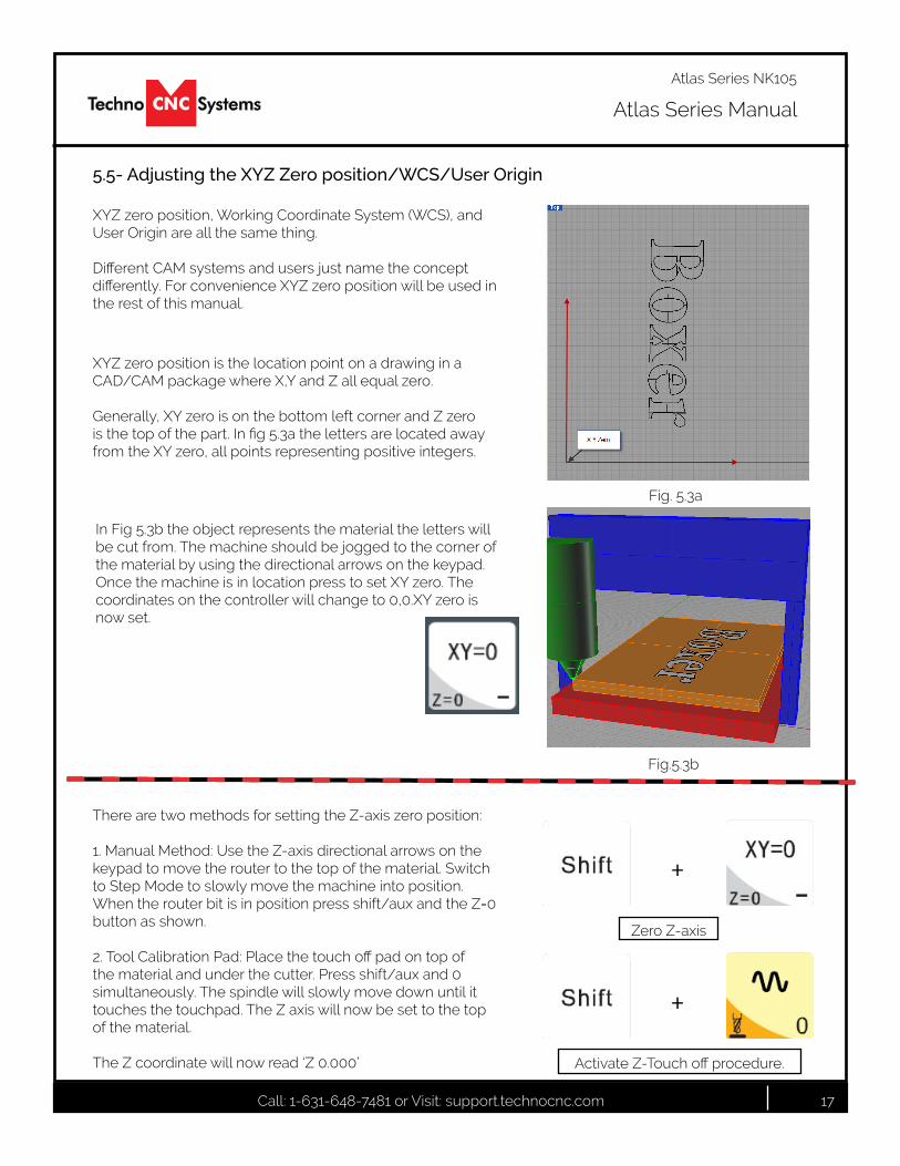
5.5- Adjusting the XYZ Zero position/WCS/User Origin
XYZzeroposition,WorkingCoordinateSystem(WCS),andUser Origin are all the same thing.
DifferentCAMsystemsandusersjustnametheconceptdifferently.ForconvenienceXYZzeropositionwillbeusedinthe rest of this manual.
XYZ zero position is the location point on a drawing in a CAD/CAM package where X,Y and Z all equal zero. Generally, XY zero is on the bottom left corner and Z zero isthetopofthepart.Infig5.3athelettersarelocatedawayfrom the XY zero, all points representing positive integers.
In Fig 5.3b the object represents the material the letters will be cut from. The machine should be jogged to the corner of the material by using the directional arrows on the keypad. Once the machine is in location press to set XY zero. The coordinates on the controller will change to 0,0.XY zero is now set.
Fig.5.3b
Fig. 5.3a
There are two methods for setting the Z-axis zero position:
1. Manual Method: Use the Z-axis directional arrows on the keypad to move the router to the top of the material. Switch to Step Mode to slowly move the machine into position. When the router bit is in position press shift/aux and the Z=0 button as shown.
2.ToolCalibrationPad:Placethetouchoffpadontopofthe material and under the cutter. Press shift/aux and 0 simultaneously. The spindle will slowly move down until it touches the touchpad. The Z axis will now be set to the top of the material.
The Z coordinate will now read ‘Z 0.000’
Zero Z-axis
ActivateZ-Touchoffprocedure.
+
+
Call: 1-631-648-7481 or Visit: support.technocnc.com 18
Atlas Series Manual
Atlas Series NK105
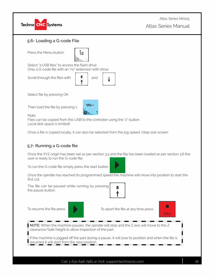
5.6- Loading a G-code File
Press the Menu button. Select“2.USBfiles”toaccesstheflashdrive. OnlyaG-codefilewithan“nc”extensionwithshow. Scrollthroughthefileswith and SelectfilebypressingOK. Thenloadthefilebypressing1. Note: Files can be copied from this USB to the controller using the “2” button Local disk space is limited! Onceafileiscopiedlocally,itcanalsobeselectedfromthejogspeed/stepsizescreen
5.7- Running a G-code file
OncetheXYZoriginhasbeensetaspersection3.4andthefilehasbeenloadedaspersection3.6theuserisreadytoruntheG-codefile.
ToruntheG-codefilesimplypressthestartbutton
Once the spindle has reached its programmed speed the machine will move into position to start the firstcut.
The file can be pausedwhile running by pressingthe pause button.
Toresumethefilepress. Toabortthefileatanytimepress.
NOTE: When the machine pauses, the spindle will stop and the Z axis will move to the Z clearance/Safe height to allow inspection of the part.
Ifthemachineisjoggedoffthepartduringapause,itwillloseitspositionandwhenthefileisresumed it will start from the new position.
Call: 1-631-648-7481 or Visit: support.technocnc.com 19
Atlas Series Manual
Atlas Series NK105
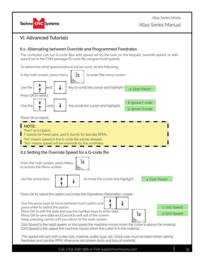
6.1- Alternating between Override and Programmed Feedrates
VI. Advanced Tutorials
ThecontrollercanrunG-codefileswithspeedsetbytheuseronthekeypad,overridespeed,orwithspeedsetintheCAMpackage/G-codefile,programmedspeeds.
To determine what speed protocol will be used, do the following:
In the main screen, press menu to enter the menu screen .
Use the and key to scroll the cursor and highlight Press OK to select.
Use the and key scroll the cursor and highlight
Press OK to select.
4. Oper Param
8. Ignore F code
9. Ignore S code
NOTE:The F or S Option. F stands for Feed rates, and S stands for Spindle RPMs.“No”meansspeedintheG-codefilewillbeobeyed.“Yes” means speed will be overrode by the controller.
6.2 Setting the Override Speed for a G-code file
From the main screen, press Menu to access the Menu screen. Use the arrow keys to move the cursor and highlight
Press OK to select this option and enter the Operations Parameters screen
Use the arrow keys to move between each option and press enter to select the option. Press OK to edit the data and use the number keys to enter data. Press OK to save data and Cancel to exit out of the screen. Keep pressing cancel until you return to the main screen.
G00 Speed is the rapid speed, or the speed the machine moves when the cutter is above the material. GXX Speed is the speed the machine moves when the cutter is in the material.
This speed will vary with cutter size, material, cutter type, etc. Great care must be taken when setting feedrates and spindle RPM, otherwise risk broken tools and loss of material.
4. Oper Param
1. G00 Speed
2. GXX Speed
Call: 1-631-648-7481 or Visit: support.technocnc.com 20
Atlas Series Manual
Atlas Series NK105
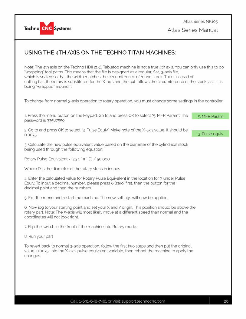
Note: The 4th axis on the Techno HDII 2136 Tabletop machine is not a true 4th axis. You can only use this to do “wrapping”toolpaths.Thismeansthatthefileisdesignedasaregular,flat,3-axisfile,which is scaled so that the width matches the circumference of round stock. Then, instead ofcuttingflat,therotaryissubstitutedfortheX-axisandthecutfollowsthecircumferenceofthestock,asifitisbeing “wrapped” around it.
To change from normal 3-axis operation to rotary operation, you must change some settings in the controller:
1. Press the menu button on the keypad. Go to and press OK to select “5. MFR Param”. Thepassword is 33587550.
2. Go to and press OK to select “3. Pulse Equiv”. Make note of the X-axis value, it should be0.0075.
3. Calculate the new pulse equivalent value based on the diameter of the cylindrical stockbeing used through the following equation:
RotaryPulseEquivalent=(25.4*π*D)/50,000
Where D is the diameter of the rotary stock in inches.
4. Enter the calculated value for Rotary Pulse Equivalent in the location for X under PulseEquiv.Toinputadecimalnumber,pleasepress0(zero)first,thenthebuttonforthedecimal point and then the numbers.
5. Exit the menu and restart the machine. The new settings will now be applied.
6. Now jog to your starting point and set your X and Y origin. This position should be above therotarypart.Note:TheX-axiswillmostlikelymoveatadifferentspeedthannormalandthecoordinates will not look right.
7. Flip the switch in the front of the machine into Rotary mode.
8. Run your part
Torevertbacktonormal3-axisoperation,followthefirsttwostepsandthenputtheoriginalvalue, 0.0075, into the X-axis pulse equivalent variable, then reboot the machine to apply thechanges.
USING THE 4TH AXIS ON THE TECHNO TITAN MACHINES:
5. MFR Param
3. Pulse equiv

Call: 1-631-648-7481 or Visit: support.technocnc.com 21
Atlas Series Manual
Atlas Series NK105
Notes On the G-code File
Ifapartrequiresmultipletools,itisbesttooutputadifferentfileforeachpart.
IftheG-codefilereferencesatoolnumberhigherthanT10,thenthecontrollerwillgiveanerroratthestartofthefile.M6T1toM6T10areallowed.
In general it is best to remove T commands by telling the CAM package that the machine is not a tool changer machine, or insuring that the Tool number does not exceed 10.
G92istheAxispresettingcommand,whenthiscommandisencounteredintheG-codefilethe XYZ zero position is set at the position the machine is in at that time.
IngeneralitisbesttoremovethisfromtheG-codefile,orifitisintheG-codefile,makesurethe machine is at the origin before you press start.
ThecontrollerwillrecogniseG54toG59offsetcommands.
Acceleration Set
Under the menu MFR Params, there is a sub menu called Velocity.
This menu controls the acceleration and cutting motion of the machine.
The Defaults for these parameters are:Jerk 310Single Axis Acc 25Max Turn Acc 100
A low Max Turn Acc will result in arcs that move in a jerky motion or at a slow speed.
Call: 1-631-648-7481 or Visit: support.technocnc.com 22
Atlas Series Manual
Atlas Series NK105
VII. Appendix
HD Settings
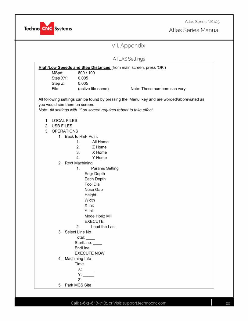
High/Low Speeds and Step Distances (from main screen, press ‘OK’)MSpd: 800 / 100Step XY: 0.005Step Z: 0.005File: (active file name) Note: These numbers can vary.
All following settings can be found by pressing the ‘Menu’ key and are worded/abbreviated as you would see them on screen.Note: All settings with ‘*’ on screen requires reboot to take effect.
1. LOCAL FILES2. USB FILES3. OPERATIONS
1. Back to REF Point1. All Home2. Z Home3. X Home4. Y Home
2. Rect Machining1. Params Setting
Engr DepthEach DepthTool DiaNose GapHeightWidthX InitY InitMode Horiz MillEXECUTE
2. Load the Last3. Select Line No
Total: ____StartLine: ____EndLine:_____EXECUTE NOW
4. Machining InfoTime
X: _____Y: _____Z: _____
5. Park MCS Site
ATLAS Settings
Call: 1-631-648-7481 or Visit: support.technocnc.com 23
Atlas Series Manual
Atlas Series NK105
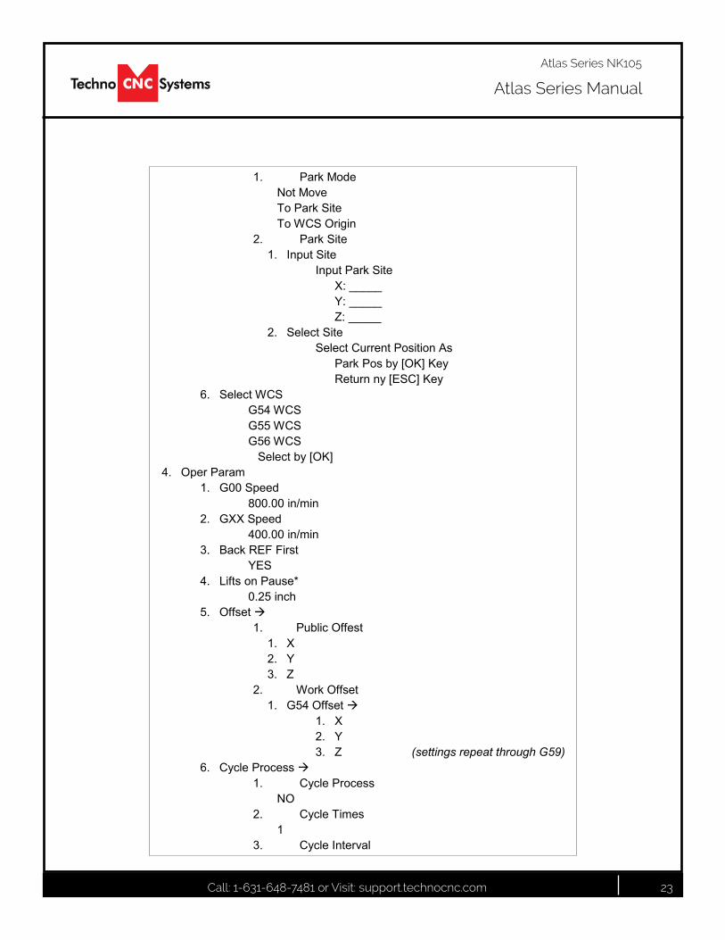
1. Park ModeNot MoveTo Park SiteTo WCS Origin
2. Park Site1. Input Site
Input Park SiteX: _____Y: _____Z: _____
2. Select SiteSelect Current Position As
Park Pos by [OK] KeyReturn ny [ESC] Key
6. Select WCSG54 WCSG55 WCSG56 WCS
Select by [OK]4. Oper Param
1. G00 Speed800.00 in/min
2. GXX Speed400.00 in/min
3. Back REF FirstYES
4. Lifts on Pause*0.25 inch
5. Offset 1. Public Offest
1. X2. Y3. Z
2. Work Offset1. G54 Offset
1. X2. Y3. Z (settings repeat through G59)
6. Cycle Process 1. Cycle Process
NO2. Cycle Times
13. Cycle Interval
Call: 1-631-648-7481 or Visit: support.technocnc.com 24
Atlas Series Manual
Atlas Series NK105
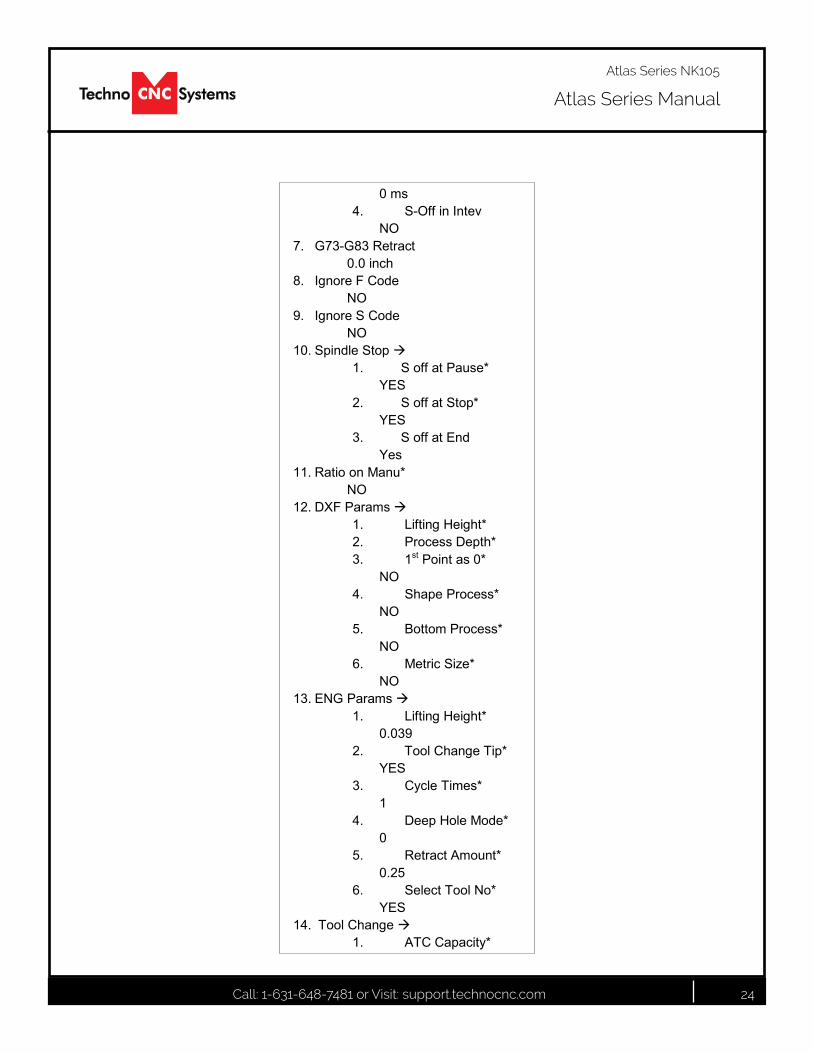
0 ms4. S-Off in Intev
NO7. G73-G83 Retract
0.0 inch8. Ignore F Code
NO9. Ignore S Code
NO10. Spindle Stop
1. S off at Pause*YES
2. S off at Stop*YES
3. S off at EndYes
11. Ratio on Manu*NO
12. DXF Params 1. Lifting Height*2. Process Depth*3. 1st Point as 0*
NO4. Shape Process*
NO5. Bottom Process*
NO6. Metric Size*
NO13. ENG Params
1. Lifting Height*0.039
2. Tool Change Tip*YES
3. Cycle Times*1
4. Deep Hole Mode*0
5. Retract Amount*0.25
6. Select Tool No*YES
14. Tool Change1. ATC Capacity*
Call: 1-631-648-7481 or Visit: support.technocnc.com 25
Atlas Series Manual
Atlas Series NK105
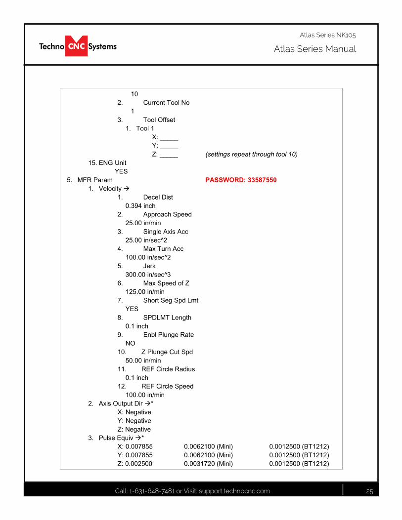
102. Current Tool No
13. Tool Offset
1. Tool 1X: _____Y: _____Z: _____ (settings repeat through tool 10)
15. ENG UnitYES
5. MFR Param PASSWORD: 335875501. Velocity
1. Decel Dist0.394 inch
2. Approach Speed25.00 in/min
3. Single Axis Acc25.00 in/sec^2
4. Max Turn Acc100.00 in/sec^2
5. Jerk300.00 in/sec^3
6. Max Speed of Z125.00 in/min
7. Short Seg Spd LmtYES
8. SPDLMT Length0.1 inch
9. Enbl Plunge RateNO
10. Z Plunge Cut Spd50.00 in/min
11. REF Circle Radius0.1 inch
12. REF Circle Speed100.00 in/min
2. Axis Output Dir *X: NegativeY: NegativeZ: Negative
3. Pulse Equiv *X: 0.007855 0.0062100 (Mini) 0.0012500 (BT1212)Y: 0.007855 0.0062100 (Mini) 0.0012500 (BT1212)Z: 0.002500 0.0031720 (Mini) 0.0012500 (BT1212)
Call: 1-631-648-7481 or Visit: support.technocnc.com 26
Atlas Series Manual
Atlas Series NK105
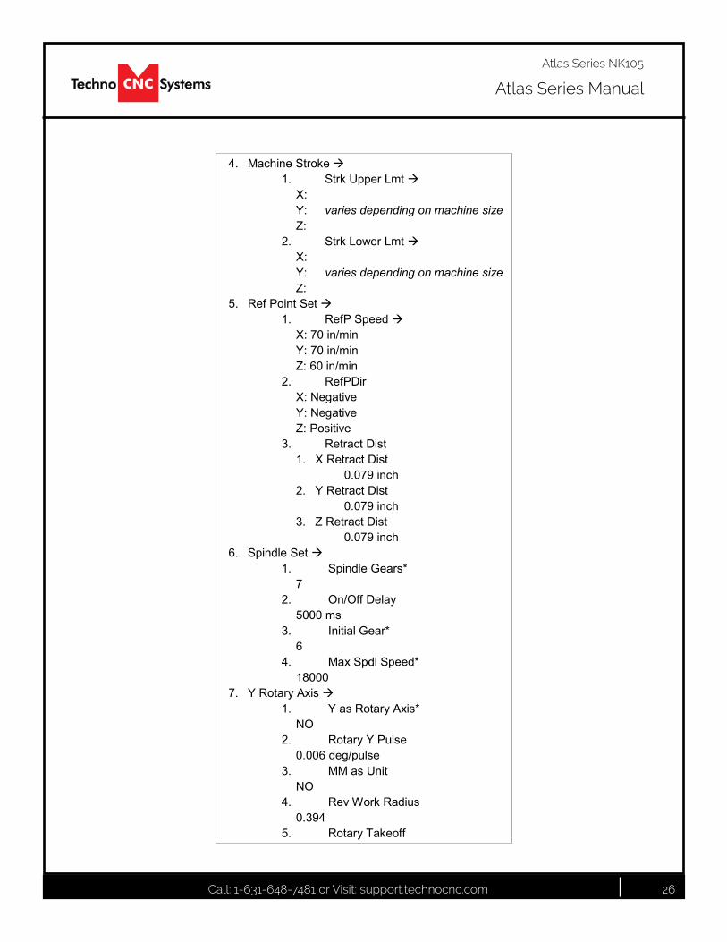
4. Machine Stroke1. Strk Upper Lmt
X:Y: varies depending on machine sizeZ:
2. Strk Lower LmtX:Y: varies depending on machine sizeZ:
5. Ref Point Set 1. RefP Speed
X: 70 in/minY: 70 in/minZ: 60 in/min
2. RefPDirX: NegativeY: NegativeZ: Positive
3. Retract Dist1. X Retract Dist
0.079 inch2. Y Retract Dist
0.079 inch3. Z Retract Dist
0.079 inch6. Spindle Set
1. Spindle Gears*7
2. On/Off Delay5000 ms
3. Initial Gear*6
4. Max Spdl Speed*18000
7. Y Rotary Axis 1. Y as Rotary Axis*
NO2. Rotary Y Pulse
0.006 deg/pulse3. MM as Unit
NO4. Rev Work Radius
0.3945. Rotary Takeoff
Call: 1-631-648-7481 or Visit: support.technocnc.com 27
Atlas Series Manual
Atlas Series NK105
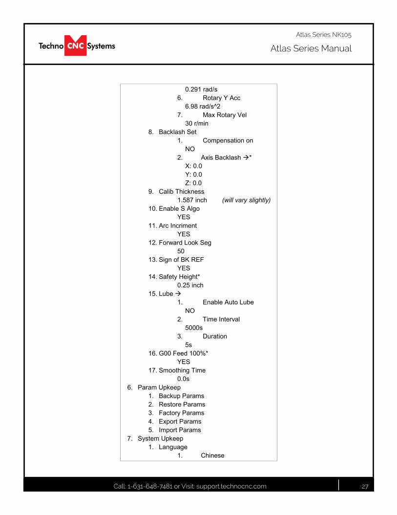
0.291 rad/s6. Rotary Y Acc
6.98 rad/s^27. Max Rotary Vel
30 r/min8. Backlash Set
1. Compensation onNO
2. Axis Backlash *X: 0.0Y: 0.0Z: 0.0
9. Calib Thickness1.587 inch (will vary slightly)
10. Enable S AlgoYES
11. Arc IncrimentYES
12. Forward Look Seg50
13. Sign of BK REFYES
14. Safety Height*0.25 inch
15. Lube1. Enable Auto Lube
NO2. Time Interval
5000s3. Duration
5s16. G00 Feed 100%*
YES17. Smoothing Time
0.0s6. Param Upkeep
1. Backup Params2. Restore Params3. Factory Params4. Export Params5. Import Params
7. System Upkeep1. Language
1. Chinese
Call: 1-631-648-7481 or Visit: support.technocnc.com 28
Atlas Series Manual
Atlas Series NK105
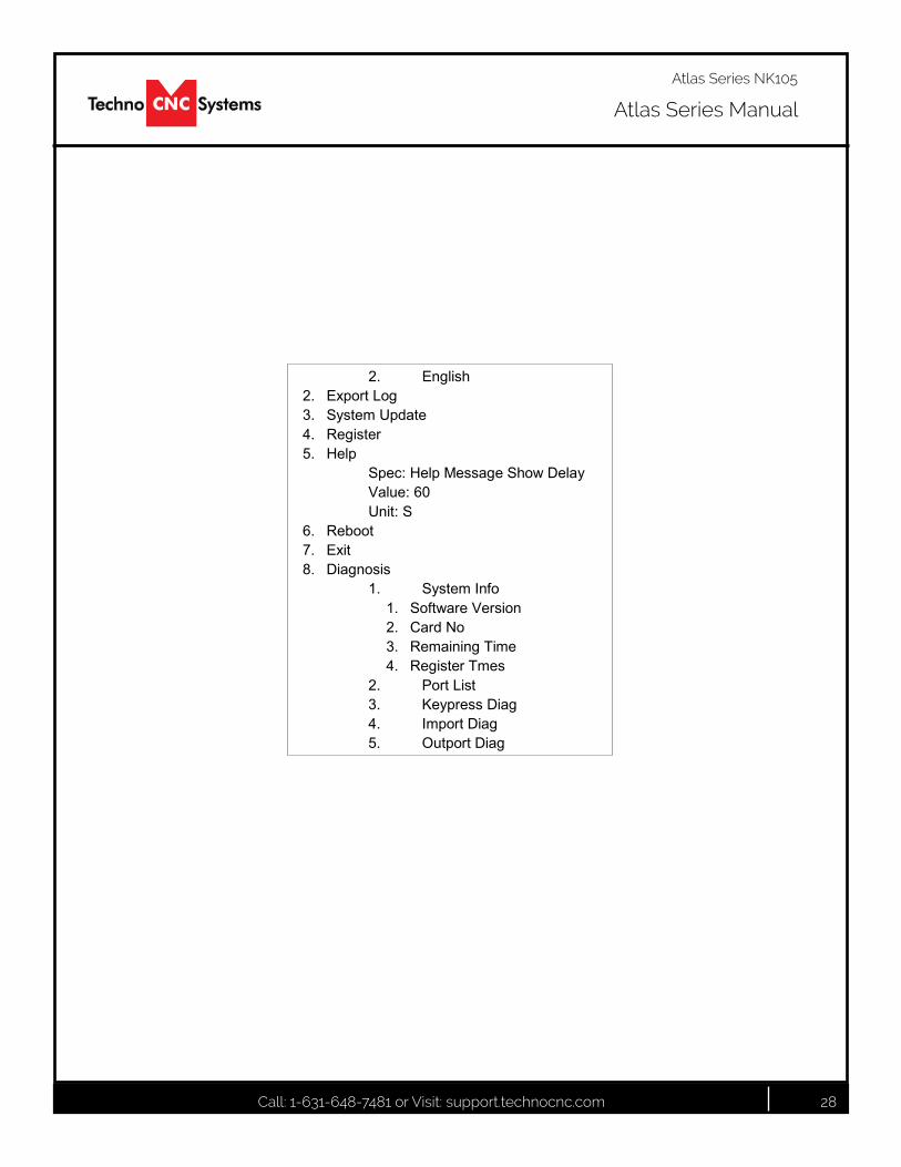
2. English2. Export Log3. System Update4. Register5. Help
Spec: Help Message Show DelayValue: 60Unit: S
6. Reboot7. Exit8. Diagnosis
1. System Info1. Software Version2. Card No3. Remaining Time4. Register Tmes
2. Port List3. Keypress Diag4. Import Diag5. Outport Diag
Call: 1-631-648-7481 or Visit: support.technocnc.com 29
Atlas Series Manual
Atlas Series NK105
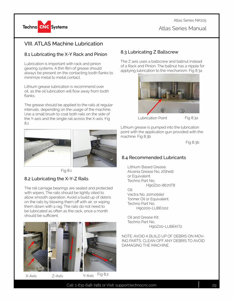
VIII. ATLAS Machine Lubrication
8.1 Lubricating the X-Y Rack and Pinion
Lubrication is important with rack and pinion gearingsystems.Athinfilmofgreaseshouldalwaysbepresentonthecontactingtoothflankstominimize metal to metal contact.
Lithium grease lubrication is recommend over oil,astheoillubricationwillflowawayfromtoothflanks.
The grease should be applied to the rails at regular intervals, depending on the usage of the machine. Use a small brush to coat both rails on the side of the Y-axis and the single rail across the X-axis. Fig 8.1
Fig 8.1
8.2 Lubricating the X-Y-Z Rails
The rail carriage bearings are sealed and protected with wipers. The rails should be lightly oiled to allow smooth operation. Avoid a build up of debris ontherailsbyblowingthemoffwithair,orwipingthem down with a rag. The rails do not need to be lubricated as often as the rack, once a month shouldbesufficient.
X-Axis Z-Axis Y-Axis Fig 8.2
8.3 Lubricating Z Ballscrew The Z axis uses a ballscrew and ballnut instead of a Rack and Pinion. The ballnut has a nipple for applying lubrication to the mechanism. Fig 8.3a
Fig 8.3aLubrication Point
Lithium grease is pumped into the lubrication point with the application gun provided with the machine. Fig 8.3b
Fig 8.3b
8.4 Recommended Lubricants
Lithium Based Grease:AlvaniaGreaseNo.2(Shell) or Equivalent. Techno Part No. H90Z00-8670T8 Oil:VactraNo.2s(mobile) Tonner Oil or Equivalent. Techno Part No. H90200-LUBE002
Oil and Grease Kit: Techno Part No. H90Z00-LUBEKIT2
NOTE: AVOID A BUILD UP OF DEBRIS ON MOV-ING PARTS. CLEAN OFF ANY DEBRIS TO AVOID DAMAGING THE MACHINE.

Call: 1-631-648-7481 or Visit: support.technocnc.com 30
Atlas Series Manual
Atlas Series NK105
250 kg551 lbs
VTLF 2.200VTLF 2.250
MAX.V
m /h3
Mad
e in
Ger
man
y
year
No
min-1
kWm /h3
mbar
type
speedpower required
inlet capacity
max. pressure
Hzfrequency
D-42279 Wuppertalwww.becker-international.com
MAX. V
L = 75-77 dB(A) - 50Hz L = 77-79 dB(A) - 60HzK = 3 dB(A)
pA
pA
pA
DIN EN ISO 2151DIN EN ISO 3744
MAX.
-p
VACUUM mbar
Mad
e in
Ger
man
y
year
No
min-1
kWm /h3
mbar
type
speedpower required
inlet capacity
max. vacuum
Hzfrequency
D-42279 Wuppertalwww.becker-international.com
MAX. VACUUM
A > 400mmA > 16" > 5°C/41°F
< 45°C/113°F
max.800m
max. 90%
%
A
A
A
A
AIR
BP
C 2
8100
0522
02 0
4/09
www.beckerpumps.com
BetriebsanleitungOperating InstructionsInstructions de serviceIstruzioni d’usoHandleidingInstrucciones para el manejoManual de instruçõesNaudojimosi instrukcijaKasutusjuhendLietošanas instrukcijaΟδηγίες χρήσης
DriftsinstruksDriftsinstruktionerKäyttöohjeDriftsvejledningInstrukcja obsługi Kezelési útmutatóNávod k obsluzeNavodilo za uporaboNávod na obsluhuEl KitabiИнструкция по эксплуатации
1 2
98/37 EG2006/95 EG
DIN EN ISO 9001
001929 QM
DIN EN ISO 14001:2005
Call: 1-631-648-7481 or Visit: support.technocnc.com 31
Atlas Series Manual
Atlas Series NK105
www.beckerpumps.com
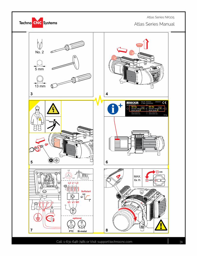
3 4
=OFF
=ON
MAX.6x /h
L1
L2
L3
PTC Bi-metal
optionalM3
u
M3 u
L2 L1 L3
SoftstartI > I > I >
M3
U1 V1 W1
U
t�
8
Mat.Nr. XXXXXX ENXXXX3 Mot. XXXXXXXX
NoUD XXXXXX XX
XX kg
50 Hz XXKWXXX-XXX / XXX-XXX V /YXX-XX / XX-XX A
XXXX-XXXX /mincos 0.XX-0,XX
60 Hz XXKWXXX-XXX / XXX-XXX V /YXX-XX / XX-XX A
XXXX-XXXX /mincos 0.XX-0,XXi +
5 6
7 8
Call: 1-631-648-7481 or Visit: support.technocnc.com 32
Atlas Series Manual
Atlas Series NK105
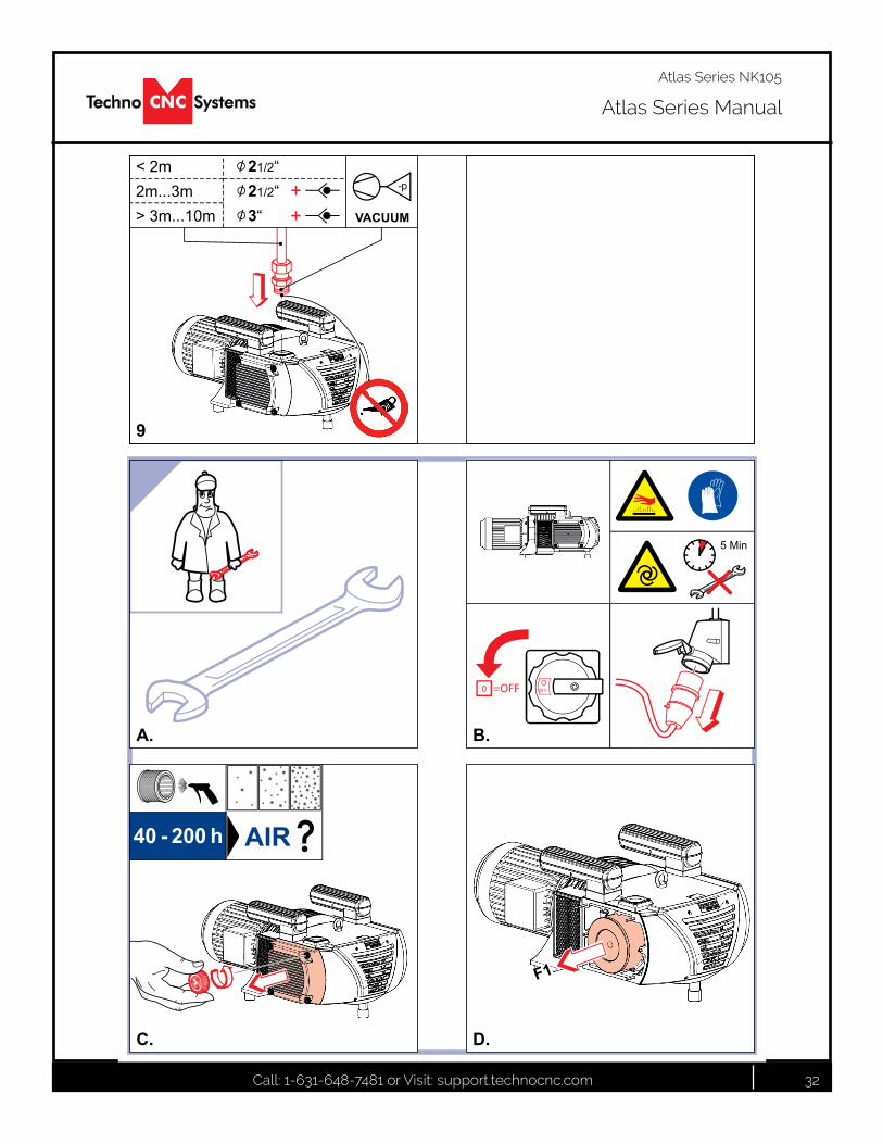
40 - 200 h AIR
F1
OFFO
0 =OFF
5 Min
+
+
< 2m2m...3m> 3m...10m
-p
VACUUM
/ 21/2“/ 21/2“/ 3“
www.beckerpumps.com
9
A.
C. D.
B.
Call: 1-631-648-7481 or Visit: support.technocnc.com 33
Atlas Series Manual
Atlas Series NK105
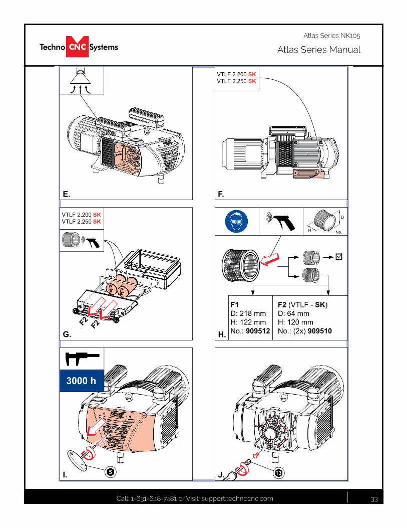
F2 F2
VTLF 2.200 SKVTLF 2.250 SK
VTLF 2.200 SKVTLF 2.250 SK
5
3000 h
13
F2 (VTLF - SK)D: 64 mmH: 120 mmNo.: (2x) 909510
F1D: 218 mmH: 122 mmNo.: 909512
No.
D
xxxx
H
H.
www.beckerpumps.com
E. F.
G.
I. J.
Call: 1-631-648-7481 or Visit: support.technocnc.com 34
Atlas Series Manual
Atlas Series NK105
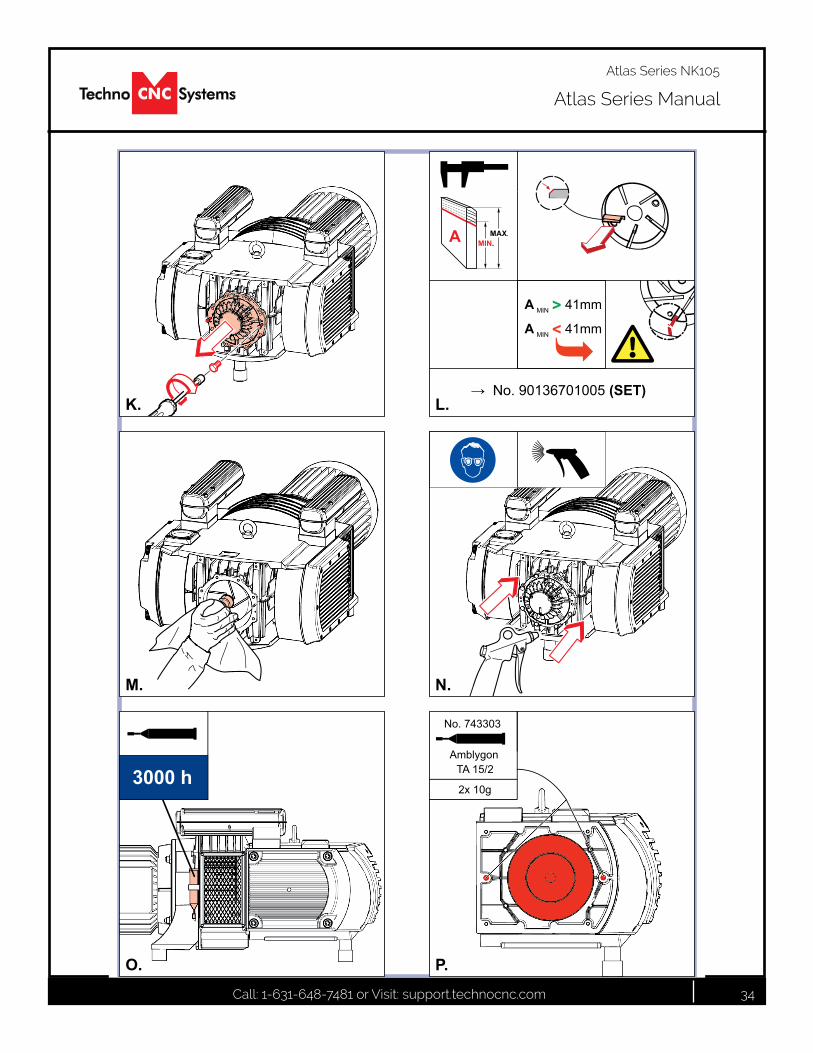
3000 h2x 10g
AmblygonTA 15/2
No. 743303
�→ No. 90136701005 (SET)
MINA > 41mm
MINA < 41mm
MIN.MAX.A
www.beckerpumps.com
K.
M.
O. P.
N.
L.
Call: 1-631-648-7481 or Visit: support.technocnc.com 35
Atlas Series Manual
Atlas Series NK105
Author: Mike RuffBecker Pumps Corp.
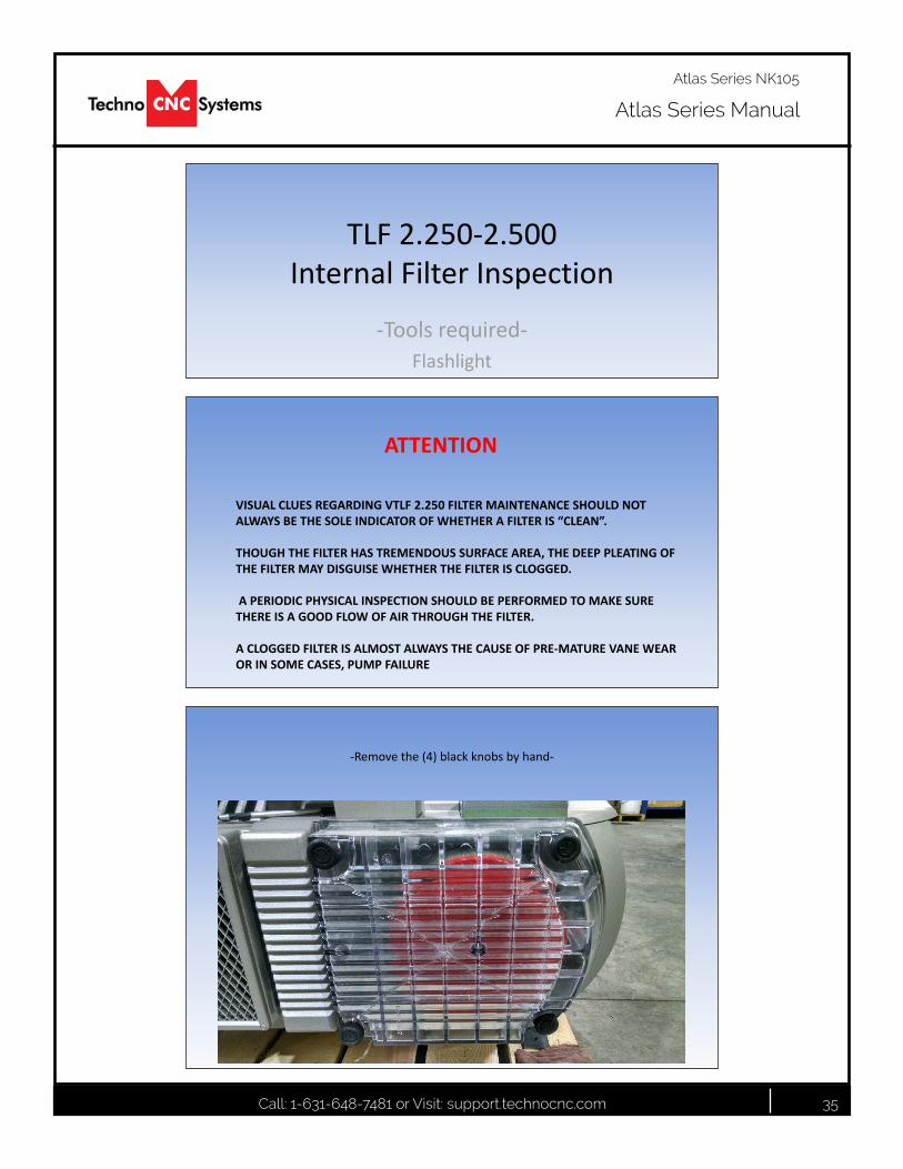
TLF 2.250-2.500Internal Filter Inspection
-Tools required-Flashlight
Author: Mike RuffBecker Pumps Corp.
VISUAL CLUES REGARDING VTLF 2.250 FILTER MAINTENANCE SHOULD NOT ALWAYS BE THE SOLE INDICATOR OF WHETHER A FILTER IS “CLEAN”.
THOUGH THE FILTER HAS TREMENDOUS SURFACE AREA, THE DEEP PLEATING OF THE FILTER MAY DISGUISE WHETHER THE FILTER IS CLOGGED.
A PERIODIC PHYSICAL INSPECTION SHOULD BE PERFORMED TO MAKE SURE THERE IS A GOOD FLOW OF AIR THROUGH THE FILTER.
A CLOGGED FILTER IS ALMOST ALWAYS THE CAUSE OF PRE-MATURE VANE WEAR OR IN SOME CASES, PUMP FAILURE
ATTENTION
Author: Mike RuffBecker Pumps Corp.
-Remove the (4) black knobs by hand-
Call: 1-631-648-7481 or Visit: support.technocnc.com 36
Atlas Series Manual
Atlas Series NK105
Author: Mike RuffBecker Pumps Corp.
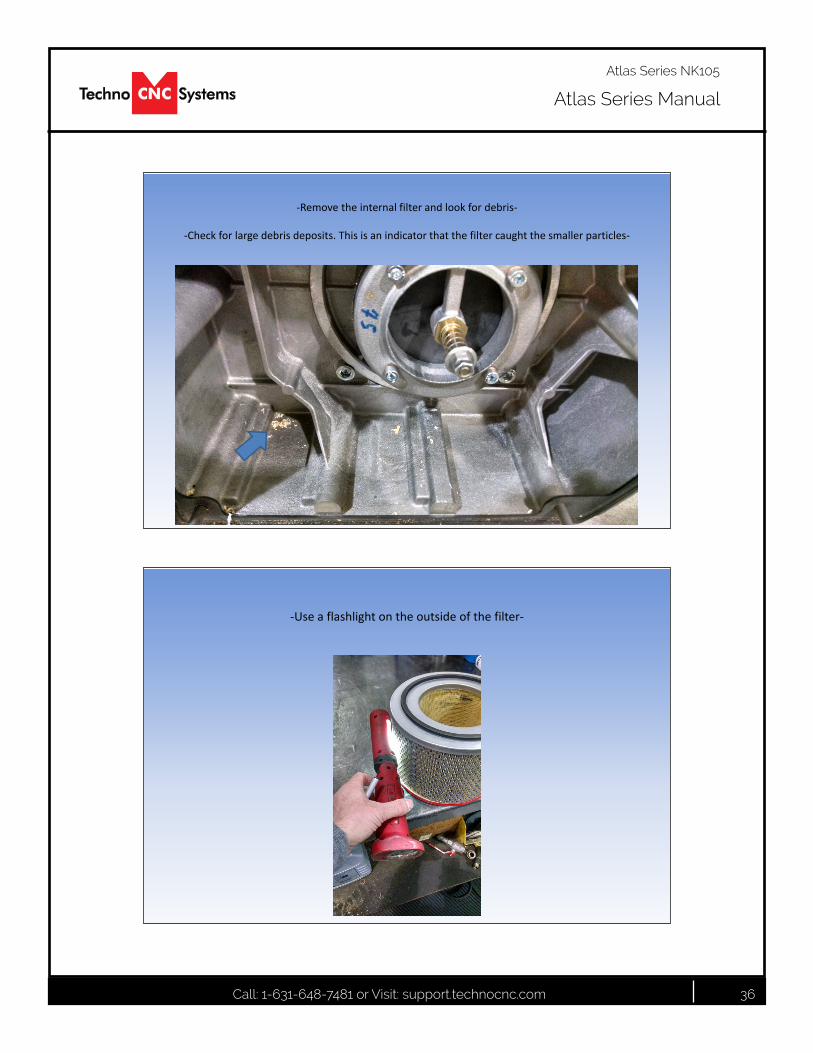
-Remove the internal filter and look for debris-
-Check for large debris deposits. This is an indicator that the filter caught the smaller particles-
Author: Mike RuffBecker Pumps Corp.
-Use a flashlight on the outside of the filter-
Call: 1-631-648-7481 or Visit: support.technocnc.com 37
Atlas Series Manual
Atlas Series NK105
Author: Mike RuffBecker Pumps Corp.
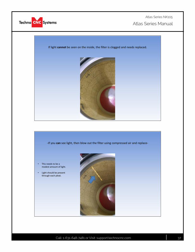
If light cannot be seen on the inside, the filter is clogged and needs replaced.
Author: Mike RuffBecker Pumps Corp.
-If you can see light, then blow out the filter using compressed air and replace-
• This needs to be a modest amount of light.
• Light should be present through each pleat.

Call: 1-631-648-7481 or Visit: support.technocnc.com 38
Atlas Series Manual
Atlas Series NK105
Author: Mike RuffBecker Pumps Corp.
Greasing TLF 2.200-2.360
-Tools required-X1 – 7433050000
(50 gram grease gun)
Author: Mike RuffBecker Pumps Corp.
Greasing instructions
The greasing instructions can be found on step “P.” in the operation manual sent with each pump.
Or they can be found at www.Beckerpumps.com
Bearings are to be grease every 3000 –4000 hours
Call: 1-631-648-7481 or Visit: support.technocnc.com 39
Atlas Series Manual
Atlas Series NK105
Author: Mike RuffBecker Pumps Corp.
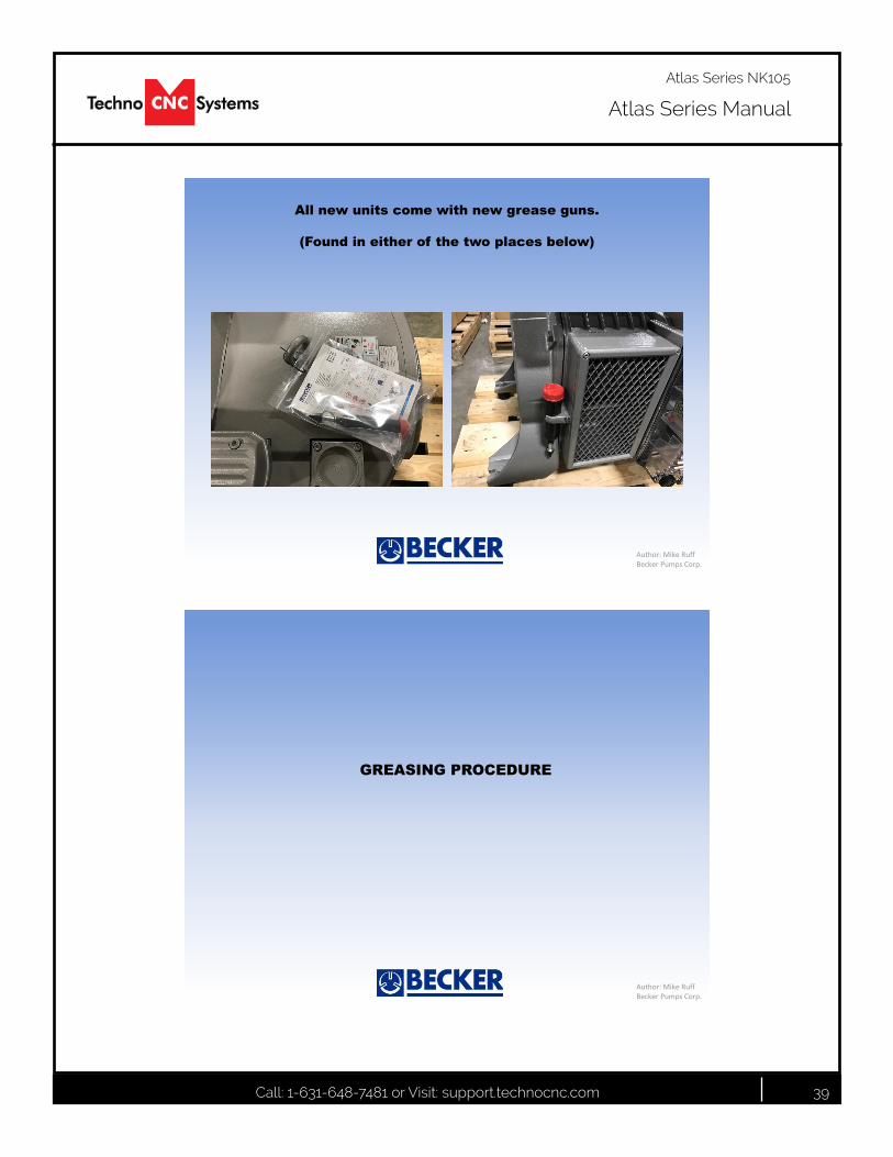
All new units come with new grease guns.
(Found in either of the two places below)
Author: Mike RuffBecker Pumps Corp.
GREASING PROCEDURE
Call: 1-631-648-7481 or Visit: support.technocnc.com 40
Atlas Series Manual
Atlas Series NK105
Author: Mike RuffBecker Pumps Corp.
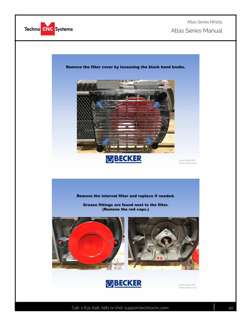
Remove the filter cover by loosening the black hand knobs.
Author: Mike RuffBecker Pumps Corp.
Remove the internal filter and replace if needed.
Grease fittings are found next to the filter. (Remove the red caps.)
Call: 1-631-648-7481 or Visit: support.technocnc.com 41
Atlas Series Manual
Atlas Series NK105
Author: Mike RuffBecker Pumps Corp.
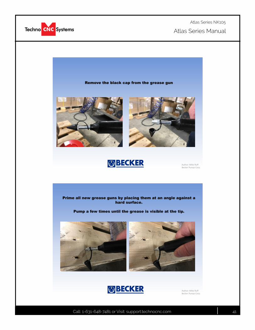
Remove the black cap from the grease gun
Author: Mike RuffBecker Pumps Corp.
Prime all new grease guns by placing them at an angle against a hard surface.
Pump a few times until the grease is visible at the tip.
Call: 1-631-648-7481 or Visit: support.technocnc.com 42
Atlas Series Manual
Atlas Series NK105
Author: Mike RuffBecker Pumps Corp.
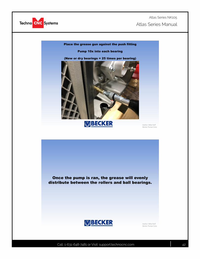
Place the grease gun against the push fitting
Pump 10x into each bearing
(New or dry bearings = 25 times per bearing)
Author: Mike RuffBecker Pumps Corp.
Once the pump is ran, the grease will evenly distribute between the rollers and ball bearings.
Call: 1-631-648-7481 or Visit: support.technocnc.com 43
Atlas Series Manual
Atlas Series NK105
DAILY MAINTENANCE
Check the machine before start up and clean it after every use.
Check to ensure chips and dust are not caught in the X, Y or Z ball screws. Dislodge all chips and thoroughly clean dust.
Make sure the machine bed is clear of obstacles.
REGULAR MAINTENANCE
Generally, this maintenance should be completed every month
Moving parts on the machine may loosen or displace over time from regular operation and dust that forms during regular machine operation will often stick to the lubrication oil used on thhe moving parts of the ma-chine(ballscrew,linearrails).Thisdustcancauseprematurewearinganddamagetotheprecisionbearings.
Inspect the hardware of each component on the machine, checking for loose bolts in case they have loos-ened over time. Pay special attention to linear rails, bearing blocks, spindle plates, limit switches and gantry uprights.
Loose harware can result in the machine going out of square, poor accuracy and repeatbility, damage to components and broken wires.
Check to make sure that any wires are not being pinched or crushed by moving mechanical parts.
Listen for abnormal noises during operation, Grinding noises, squeals and/or banging sounds are NOT nor-mal,
Cleangrimeandanyaccumulatedlubricatingoilofftheguiderailandbearingblocks.
Turn on power to the machine and move it to clean and lubricate everywhere along the guide rail and rack and pinion.
Lubricate ball screw assemblies monthly to ensure peak mechanical performance.
Thoroughly clean components of any excess lubrication before fresh coating.
Ball screw assemblies should be lubricated via the grease nipple using a grease gun.
Check your machine for squareness and for backlash. Out of square machines and machines with backlash are indicative of a crash or loose hardware.

Call: 1-631-648-7481 or Visit: support.technocnc.com 44
Atlas Series Manual
Atlas Series NK105
IX. Atlas Troubleshooting
Problem SolutionHand held controller display is blank with no power Ensure the machine has power and is turned on.
Ensure that the 24V power supply has its green LED indicating it is on.
Make sure the NK105 controller has power.
Make sure the handheld conroller is plugged in.
Make sure the Emergency stop switches are not pushed in
Make sure the wire harness from enclosure is plugged in.
Machine will not jog or move If the handheld controller say “ESTOP” in the top right hand corner, the machine has moved beyond its limit.
Shutdownandmanuallypushthemachineoffitslimit switches
Ensure the feedrate override is not set to 0%
Machine crashes during homing process Toconfirmthelimitswitchesareworkingproperly,placeametalscrewdriveroveranyofthe(3)axislimit switches, and the LED light on the switch itself shouldturnonandoff.
When the machine is moving, ensure its metallic striker plate is passing close enough to the switch for it to trip.
Axis motor has loud bang or grinding sound Motor has stalled, lower speed, re-home
Spindle will not turn on Ensure enclosure is closed
Ensure VFD display does not display error, if so, full power restart
Touchpad is no working, spindle crashes down Ensure touchpad works by touching pad to ground on machine and showing GX16 input tripping
Wire may be broken
Spindle may have worn bearings
Tool may not be suitable for touchpad
Call: 1-631-648-7481 or Visit: support.technocnc.com 45
Atlas Series Manual
Atlas Series NK105
www.technocnc.com (HTT06091113)Tel: 631-648-7481 9/2015
Techno CNC Systems, LLC., Terms and Conditions For Limited Warranty and Repairs Warranty
WARRANTYAll Techno CNC Systems, LLC., mechanical components are warranted against manufacturer’s defects in material and workmanship for a period of one (1) year from the time of shipment from Techno CNC Systems, LLC., facilities. All Techno CNC Systems, LLC., electrical components are similarly warranted for a period of one (1) year from the time of shipment from Techno CNC Systems, LLC., facilities. Techno CNC Systems, LLC.,’s sole obligation under this warranty is limited to repairing the product or, at its option, replacing the product without additional charge, provided the item is properly returned to Techno CNC Systems, LLC., for repair as described below. The provisions of this warranty shall not apply to any product that has been subjected to tampering, abuse, improper setup or operating conditions, misuse, lack of proper maintenance, or unauthorized user adjustment. Techno CNC Systems, LLC., makes no warranty that its products are fit for any use or purpose to which they may be put by the customer, whether or not such use or purpose has been disclosed to Techno CNC Systems, LLC., in specifications or drawings previously or subsequently provided, and whether or not Techno CNC Systems, LLC.,’s products are specifically designed and/or manufactured for such a purpose. NOTE: Drive motors (servo or stepper) are considered “mechanical components”.
THIS WARRANTY IS IN LIEU OF ALL OTHER WARRANTIES EXPRESSED OR IMPLIED. ALL OTHER WARRANTIES, INCLUDING, BUT NOT LIMITED TO, ANY WARRANTY OF MERCHANTABILITY OR FITNESS FOR A PARTICULAR PURPOSE, WHETHER EXPRESSED, IMPLIED, OR ARISING BY OPERATION OF LAW, TRADE USAGE, OR COURSE OF DEALING, ARE HEREBY DISCLAIMED. THERE ARE NO WARRANTIES THAT EXTEND BEYOND THE DESCRIPTION ON THE FACE HEREOF.
LIMITATION OF REMEDYIn no event shall Techno CNC Systems, LLC., be liable for any incidental, consequential, or special damages of any kind or nature whatsoever. Techno CNC Systems, LLC., is in no way liable for any lost profits arising from or connected to this agreement or items sold under this agreement, whether alleged to arise from breach of contract, expressed or implied warranty, or in tort, including, without limitation, negligence, failure to warn, or strict liability.
RETURN PROCEDUREBefore returning any equipment in or out of warranty, the customer must first obtain a return authorization number and packing instructions from Techno CNC Systems, LLC.,. No claim will be allowed nor credit given for products returned without such authorization. Proper packaging and insurance for transportation is solely the customer’s responsibility. After approval from Techno CNC Systems, LLC., the product should be returned with a statement of the problem and transportation prepaid. If, upon examination, warranted defects exist, the product will be repaired or replaced at no charge, and shipped prepaid back to the customer. Return shipment will be by common carrier (i.e., UPS). If rapid delivery is requested by customer, then such transport is at the customer’s expense. If an out-of-warranty situation exists, the customer will be notified of the repair costs immediately. At such time, the customer must issue a purchase order to cover the cost of the repair or authorize the product to be shipped back as is, at the customer’s expense. In any case, a restocking charge of 20% will be charged on all items returned to stock.
FIELD SERVICERepairs are ordinarily done at Techno CNC Systems, LLC.,’s Ronkonkoma, New York facility, where all necessary instrumentation is available. This instrumentation is difficult to transport, so field service is severely limited, and will only be supplied at Techno CNC Systems, LLC.,’s discretion. If field service is required and is performed at Techno CNC Systems, LLC.,’s sole discretion, all relevant expenses, including transportation, travel time, subsistence costs, and the prevailing cost per hour (eight hour minimum) are the responsibility of the customer.
UNFORESEEN CIRCUMSTANCESTechno CNC Systems, LLC., is not liable for delay or failure to perform any obligations hereunder by reason of circumstances beyond its reasonable control. These circumstances include, but are not limited to, accidents, acts of God, strikes or labor disputes, laws, rules, or regulations of any government or government agency, fires, floods, delays or failures in delivery of carriers or suppliers, shortages of materials, and any other event beyond Techno CNC Systems, LLC.,’s control.
ENTIRE AGREEMENT/GOVERNING LAWThe terms and conditions contained herein shall constitute the entire agreement concerning the terms and conditions for the limited warranty described hereunder. No oral or other representations are in effect. This Agreement shall be governed in all respects by the laws of New York State. No legal action may be taken by any party more than one (1) year after the date of purchase.
TECHNO CNC SYSTEMS, LLC., RESERVES THE RIGHT TO CHANGE DESIGNS, SPECIFICATIONS, PRICES, AND ANY APPLICABLE DOCUMENTATION WITHOUT PRIOR NOTICE.