
Series 2000 3G Modem / Router User Manual - Cybertec
188
Series 2000 3G Modem / Router User Manual Document Number: 0013-001-000198 Version: 1.40 (15 October, 2010)
-
Upload
khangminh22 -
Category
Documents
-
view
3 -
download
0
Transcript of Series 2000 3G Modem / Router User Manual - Cybertec

Series 20003G Modem / Router
User Manual
Document Number: 0013-001-000198Version: 1.40 (15 October, 2010)

Cybertec Pty LimitedCopyright c© 2010
Document: 0013-001-000198Series 2000 User Manual
Version: 1.4015 October, 2010
Documentation ControlGeneration Date: October 15, 2010
Copyright c© 2010 Cybertec Pty Limited
All rights Reserved.
No part of this publication may be reproduced, stored in a retrieval system, or transmitted, in any form or by any means,electronic, mechanical, photocopying, recording, or otherwise, without the prior written permission of Cybertec PtyLimited.
Cybertec Pty Limited has intellectual property rights covering subject matter in this document. Except as expresslyprovided in any written license agreement from Cybertec Pty Limited, the furnishing of this document does not give youany license to this intellectual property.
Legal InformationThe contents of this document are provided “as is”. Except as required by applicable law, no warranties of any kind, eitherexpress or implied, including, but not limited to, the implied warranties of merchantability and fitness for a particularpurpose, are made in relation to the accuracy and reliability or contents of this document. Cybertec Pty Ltd reserves theright to revise this document or withdraw it at any time without prior notice.
Under no circumstances shall Cybertec Pty Ltd be responsible for any loss of data or income or any special, incidental,and consequential or indirect damages howsoever caused.
More information about Cybertec can be found at the following Internet address: http://www.cybertec.com.au
Page 1 of 186

Cybertec Pty LimitedCopyright c© 2010
Document: 0013-001-000198Series 2000 User Manual
Version: 1.4015 October, 2010
Contents
1 Introduction 5
1.1 Document Structure . . . . . . . . . . . . . . . . . . . . . . . . . . . . . . . . . . . . . . . . . . . . . . 5
1.2 Conventions Used . . . . . . . . . . . . . . . . . . . . . . . . . . . . . . . . . . . . . . . . . . . . . . . 5
1.3 Manual Updates . . . . . . . . . . . . . . . . . . . . . . . . . . . . . . . . . . . . . . . . . . . . . . . . 6
1.4 Default Configuration . . . . . . . . . . . . . . . . . . . . . . . . . . . . . . . . . . . . . . . . . . . . . 6
2 Safety 6
3 Care Recommendations 6
4 Indicators and Interfaces 7
4.1 Model 2100 . . . . . . . . . . . . . . . . . . . . . . . . . . . . . . . . . . . . . . . . . . . . . . . . . . 7
4.2 Model 2220 . . . . . . . . . . . . . . . . . . . . . . . . . . . . . . . . . . . . . . . . . . . . . . . . . . 7
4.3 Indicators . . . . . . . . . . . . . . . . . . . . . . . . . . . . . . . . . . . . . . . . . . . . . . . . . . . 8
4.4 Ethernet . . . . . . . . . . . . . . . . . . . . . . . . . . . . . . . . . . . . . . . . . . . . . . . . . . . . 9
4.5 Modem / DCE Serial Port . . . . . . . . . . . . . . . . . . . . . . . . . . . . . . . . . . . . . . . . . . . 10
4.6 DTE Serial Ports (Model 2220 Only) . . . . . . . . . . . . . . . . . . . . . . . . . . . . . . . . . . . . . 10
4.7 Digital Inputs & Digital Outputs (Model 2220 Only) . . . . . . . . . . . . . . . . . . . . . . . . . . . . 11
4.8 Factory Default Reset Switch . . . . . . . . . . . . . . . . . . . . . . . . . . . . . . . . . . . . . . . . . 12
5 Installation 13
5.1 Panel Mounting . . . . . . . . . . . . . . . . . . . . . . . . . . . . . . . . . . . . . . . . . . . . . . . . 13
5.2 DIN Rail Mounting . . . . . . . . . . . . . . . . . . . . . . . . . . . . . . . . . . . . . . . . . . . . . . 13
5.3 Installing the SIM Card . . . . . . . . . . . . . . . . . . . . . . . . . . . . . . . . . . . . . . . . . . . . 14
5.4 Antenna . . . . . . . . . . . . . . . . . . . . . . . . . . . . . . . . . . . . . . . . . . . . . . . . . . . . 14
5.5 Power Supply . . . . . . . . . . . . . . . . . . . . . . . . . . . . . . . . . . . . . . . . . . . . . . . . . 15
5.6 Functional Earth . . . . . . . . . . . . . . . . . . . . . . . . . . . . . . . . . . . . . . . . . . . . . . . . 15
6 Accessing the Web Interface 16
6.1 Computer Settings . . . . . . . . . . . . . . . . . . . . . . . . . . . . . . . . . . . . . . . . . . . . . . 16
6.2 Windows PC Network Settings . . . . . . . . . . . . . . . . . . . . . . . . . . . . . . . . . . . . . . . . 16
6.3 Connecting to the Series 2000 Web Server . . . . . . . . . . . . . . . . . . . . . . . . . . . . . . . . . . 18
7 Web Page Layout 20
7.1 Page Layout . . . . . . . . . . . . . . . . . . . . . . . . . . . . . . . . . . . . . . . . . . . . . . . . . . 20
7.2 Menu Structure . . . . . . . . . . . . . . . . . . . . . . . . . . . . . . . . . . . . . . . . . . . . . . . . 20
7.3 Symbols . . . . . . . . . . . . . . . . . . . . . . . . . . . . . . . . . . . . . . . . . . . . . . . . . . . . 24
8 Basic Configuration 25
8.1 Configure the Wireless interface . . . . . . . . . . . . . . . . . . . . . . . . . . . . . . . . . . . . . . . 25
8.2 Configure the LAN interface and DHCP Server . . . . . . . . . . . . . . . . . . . . . . . . . . . . . . . 29
8.3 Configure clients to use the Series 2000 3G Modem / Router . . . . . . . . . . . . . . . . . . . . . . . . 30
Page 2 of 186

Cybertec Pty LimitedCopyright c© 2010
Document: 0013-001-000198Series 2000 User Manual
Version: 1.4015 October, 2010
9 Status 31
9.1 Alarms . . . . . . . . . . . . . . . . . . . . . . . . . . . . . . . . . . . . . . . . . . . . . . . . . . . . . 31
9.2 Wireless . . . . . . . . . . . . . . . . . . . . . . . . . . . . . . . . . . . . . . . . . . . . . . . . . . . . 33
9.3 Local Area Network (LAN) . . . . . . . . . . . . . . . . . . . . . . . . . . . . . . . . . . . . . . . . . . 35
9.4 Virtual Private Network (VPN) . . . . . . . . . . . . . . . . . . . . . . . . . . . . . . . . . . . . . . . . 35
9.5 Serial Server . . . . . . . . . . . . . . . . . . . . . . . . . . . . . . . . . . . . . . . . . . . . . . . . . . 35
9.6 General Purpose Input / Output (GPIO) . . . . . . . . . . . . . . . . . . . . . . . . . . . . . . . . . . . 35
9.7 System Log . . . . . . . . . . . . . . . . . . . . . . . . . . . . . . . . . . . . . . . . . . . . . . . . . . 35
10 System 37
10.1 Administration . . . . . . . . . . . . . . . . . . . . . . . . . . . . . . . . . . . . . . . . . . . . . . . . 37
10.2 Backup & Upgrade . . . . . . . . . . . . . . . . . . . . . . . . . . . . . . . . . . . . . . . . . . . . . . 40
10.3 System Information . . . . . . . . . . . . . . . . . . . . . . . . . . . . . . . . . . . . . . . . . . . . . . 43
10.4 Power . . . . . . . . . . . . . . . . . . . . . . . . . . . . . . . . . . . . . . . . . . . . . . . . . . . . . 43
10.5 General Purpose Inputs and Outputs (GPIO) (Model 2220only) . . . . . . . . . . . . . . . . . . . . . . . 45
11 Wireless 49
11.1 Network Configuration . . . . . . . . . . . . . . . . . . . . . . . . . . . . . . . . . . . . . . . . . . . . 49
11.2 Packet Mode Configuration . . . . . . . . . . . . . . . . . . . . . . . . . . . . . . . . . . . . . . . . . . 52
11.3 Connection Management . . . . . . . . . . . . . . . . . . . . . . . . . . . . . . . . . . . . . . . . . . . 58
11.4 Circuit Switched Data Mode . . . . . . . . . . . . . . . . . . . . . . . . . . . . . . . . . . . . . . . . . 61
11.5 SMS . . . . . . . . . . . . . . . . . . . . . . . . . . . . . . . . . . . . . . . . . . . . . . . . . . . . . . 68
12 Network 79
12.1 LAN Interface . . . . . . . . . . . . . . . . . . . . . . . . . . . . . . . . . . . . . . . . . . . . . . . . . 79
12.2 Configuring the DHCP server . . . . . . . . . . . . . . . . . . . . . . . . . . . . . . . . . . . . . . . . . 81
12.3 Domain Name System (DNS) . . . . . . . . . . . . . . . . . . . . . . . . . . . . . . . . . . . . . . . . 81
12.4 Generic Routing Encapsulation (GRE) . . . . . . . . . . . . . . . . . . . . . . . . . . . . . . . . . . . . 84
12.5 Network Diagnostics . . . . . . . . . . . . . . . . . . . . . . . . . . . . . . . . . . . . . . . . . . . . . 85
13 Routing 86
13.1 Default and Static Routes . . . . . . . . . . . . . . . . . . . . . . . . . . . . . . . . . . . . . . . . . . . 86
13.2 Dynamic Routing . . . . . . . . . . . . . . . . . . . . . . . . . . . . . . . . . . . . . . . . . . . . . . . 91
13.3 Virtual Router Redundancy Protocol . . . . . . . . . . . . . . . . . . . . . . . . . . . . . . . . . . . . . 91
13.4 Policy Routing . . . . . . . . . . . . . . . . . . . . . . . . . . . . . . . . . . . . . . . . . . . . . . . . 94
13.5 Quality of Service Routing . . . . . . . . . . . . . . . . . . . . . . . . . . . . . . . . . . . . . . . . . . 98
14 Firewall 104
14.1 Firewall Setup . . . . . . . . . . . . . . . . . . . . . . . . . . . . . . . . . . . . . . . . . . . . . . . . . 104
14.2 Access Control . . . . . . . . . . . . . . . . . . . . . . . . . . . . . . . . . . . . . . . . . . . . . . . . 105
14.3 DoS Filters . . . . . . . . . . . . . . . . . . . . . . . . . . . . . . . . . . . . . . . . . . . . . . . . . . 106
14.4 Custom Filters . . . . . . . . . . . . . . . . . . . . . . . . . . . . . . . . . . . . . . . . . . . . . . . . . 107
14.5 Port Forwarding . . . . . . . . . . . . . . . . . . . . . . . . . . . . . . . . . . . . . . . . . . . . . . . . 112
14.6 Custom NAT . . . . . . . . . . . . . . . . . . . . . . . . . . . . . . . . . . . . . . . . . . . . . . . . . 115
14.7 MAC Address Filtering . . . . . . . . . . . . . . . . . . . . . . . . . . . . . . . . . . . . . . . . . . . . 120
Page 3 of 186

Cybertec Pty LimitedCopyright c© 2010
Document: 0013-001-000198Series 2000 User Manual
Version: 1.4015 October, 2010
15 Virtual Private Network (VPN) 125
15.1 Internet Protocol Security (IPsec) VPN . . . . . . . . . . . . . . . . . . . . . . . . . . . . . . . . . . . . 125
15.2 Secure Sockets Layer (SSL) VPN . . . . . . . . . . . . . . . . . . . . . . . . . . . . . . . . . . . . . . 139
15.3 PPTP and L2TP . . . . . . . . . . . . . . . . . . . . . . . . . . . . . . . . . . . . . . . . . . . . . . . . 144
15.4 Multiple VPN Tunnels . . . . . . . . . . . . . . . . . . . . . . . . . . . . . . . . . . . . . . . . . . . . 148
15.5 Certificate Management . . . . . . . . . . . . . . . . . . . . . . . . . . . . . . . . . . . . . . . . . . . . 148
16 Serial Server 153
16.1 Selecting a port function . . . . . . . . . . . . . . . . . . . . . . . . . . . . . . . . . . . . . . . . . . . 153
16.2 Common configuration options . . . . . . . . . . . . . . . . . . . . . . . . . . . . . . . . . . . . . . . . 155
16.3 Raw TCP Client/Server . . . . . . . . . . . . . . . . . . . . . . . . . . . . . . . . . . . . . . . . . . . . 157
16.4 Raw UDP . . . . . . . . . . . . . . . . . . . . . . . . . . . . . . . . . . . . . . . . . . . . . . . . . . . 159
16.5 Modem Emulator . . . . . . . . . . . . . . . . . . . . . . . . . . . . . . . . . . . . . . . . . . . . . . . 160
16.6 DNP3 IP-Serial Gateway . . . . . . . . . . . . . . . . . . . . . . . . . . . . . . . . . . . . . . . . . . . 163
16.7 Modbus IP-Serial Gateway . . . . . . . . . . . . . . . . . . . . . . . . . . . . . . . . . . . . . . . . . . 165
16.8 Telnet (RFC 2217) Server . . . . . . . . . . . . . . . . . . . . . . . . . . . . . . . . . . . . . . . . . . . 166
16.9 PPP Server . . . . . . . . . . . . . . . . . . . . . . . . . . . . . . . . . . . . . . . . . . . . . . . . . . 168
16.10PPP Dialout Client . . . . . . . . . . . . . . . . . . . . . . . . . . . . . . . . . . . . . . . . . . . . . . 169
16.11Phone Book . . . . . . . . . . . . . . . . . . . . . . . . . . . . . . . . . . . . . . . . . . . . . . . . . . 171
17 Management 174
17.1 Events . . . . . . . . . . . . . . . . . . . . . . . . . . . . . . . . . . . . . . . . . . . . . . . . . . . . . 174
17.2 SNMP . . . . . . . . . . . . . . . . . . . . . . . . . . . . . . . . . . . . . . . . . . . . . . . . . . . . . 177
17.3 DNP3 . . . . . . . . . . . . . . . . . . . . . . . . . . . . . . . . . . . . . . . . . . . . . . . . . . . . . 178
17.4 SMS . . . . . . . . . . . . . . . . . . . . . . . . . . . . . . . . . . . . . . . . . . . . . . . . . . . . . . 180
17.5 Email . . . . . . . . . . . . . . . . . . . . . . . . . . . . . . . . . . . . . . . . . . . . . . . . . . . . . 184
18 Troubleshooting 186
18.1 Series 2000 does not start. . . . . . . . . . . . . . . . . . . . . . . . . . . . . . . . . . . . . . . . . . . 186
18.2 Cannot connect to web pages . . . . . . . . . . . . . . . . . . . . . . . . . . . . . . . . . . . . . . . . . 186
18.3 Network Status Fault . . . . . . . . . . . . . . . . . . . . . . . . . . . . . . . . . . . . . . . . . . . . . 186
18.4 Connection Status Fault . . . . . . . . . . . . . . . . . . . . . . . . . . . . . . . . . . . . . . . . . . . . 186
Page 4 of 186

Cybertec Pty LimitedCopyright c© 2010
Document: 0013-001-000198Series 2000 User Manual
Version: 1.4015 October, 2010
1 Introduction
This manual provides installation and configuration information for the Cybertec Series 2000 3G Modem / Router. TheCybertec Series 2000 3G Modem / Router are designed for Industrial applications, and are used for Telemetry and SCADAcommunications. The communications interfaces include Ethernet and Serial, in addition some models include digitalinputs and digital outputs. The Series 2000 3G Modem / Router range are designed to operate over a wide range of inputvoltage and an industrial temperature range.
All models are designed for use on 3G cellular networks and provide broadband performance, all models in the Series2000 range support download data rates of up to 7.2Mbps and upload data rates of up to 2Mbps.
Topics covered in this manual include:
• Installation and Connecting to the Series 2000 3G Modem / Router .
• Basic configuration and 3G network connection.
• Operation and status monitoring.
• LAN network configuration.
• Firewall and routing set up.
• Virtual Private Network (VPN) configuration and use.
• Serial server configuration.
• Device management.
1.1 Document Structure
The manual has been designed to introduce the product quickly. The first sections describes the hardware and how toset up and connect to the device. A standard network configuration is then described so that a standard connection canestablished. The configuration sections follow the menu structure of the Series 2000 3G Modem / Router.
1.2 Conventions Used
This manual uses the following typographical conventions:
Italic: Used for ????
www.example.com.au: Used to display URLs (Web addresses).
Menu . Submenu: Used to illustrate menu navigation.
The manual uses the following icons:
Indicates a reference to further information. This may include other documents or informationavailable online.
Indicates a tip, suggestion, or general note relating to the occupying text.
Indicates the text of an SMS.
Indicates a warning or caution relating to the occupying text.
Page 5 of 186

Cybertec Pty LimitedCopyright c© 2010
Document: 0013-001-000198Series 2000 User Manual
Version: 1.4015 October, 2010
1.3 Manual Updates
Improvements and updates to this manual will be made available on the Cybertec website www.cybertec.com.au.There you will also find, further product documentation including application notes, user guides, and other support infor-mation.
1.4 Default Configuration
Unless otherwise stated the manual assumes the configuration of the Series 2000 3G Modem / Router is in the factorydefault state. If the modem has been previously configured it may be necessary to perform a configuration reset to returnthe the configuration to the default state, prior to configuring the device. The procedure to perform a configuration resetis described is Section 4.8.
2 Safety
Please observe the general safety precautions outlined in this manual during all phases ofoperation and service of the Series 2000 3G Modem / Router. If you do not comply with theseprecautions or with specific safety warnings contained elsewhere in this manual or on theproduct itself, you will violate the standards of design, manufacture, and intended use of theproduct. Cybertec does not assume any liability for failure to comply with these precautions.
Read this manual completely and make sure it is understood fully before commencinginstallation. Check that the intended application does not exceed the safe operatingspecifications for this unit. This unit should only be installed by qualified personnel. The powersupply wiring must be sufficiently fused, and if necessary it must be possible to manuallydisconnect the unit from the power supply.
3 Care Recommendations
To maintain correct operation of unit and to fulfill the warranty obligations the following care recommendations shouldbe followed. This unit must not be operated with the covers removed. Do not attempt to disassemble the unit, no userserviceable parts are contained within the unit. Do not drop, knock or shake the unit, rough handling may cause damageto internal circuit boards. Do not use harsh chemicals, cleaning solvents or strong detergents to clean the unit. Do notexpose the unit to any kind of liquids (rain, beverages, etc), the unit is not waterproof. Keep the unit within the specifiedhumidity levels. Do not use or store the unit in dusty, dirty areas, connectors as well as other mechanical part may bedamaged.
Page 6 of 186

Cybertec Pty LimitedCopyright c© 2010
Document: 0013-001-000198Series 2000 User Manual
Version: 1.4015 October, 2010
4 Indicators and Interfaces
This section describes the indicators and interfaces for each of the models in the Series 2000 range. The Series 2000,Model 2100 and Model 2220 differ in that the the Model 2220 has 2 additional serial ports, digital inputs and digitaloutputs.
4.1 Model 2100
The Ethernet ports, serial port indicators are located on the front panel as show in figure 1. The rear panel contains theconnectors for power, and antenna, in addition to the SIM drawer and factory reset switch, as shown in figure 2.
Figure 1: Model 2100 front panel.
Figure 2: Model 2100 rear panel.
4.2 Model 2220
The Ethernet ports, serial ports and indicators are located on the front panel as show in figure 3. The rear panel containsthe connectors for power, digital inputs, digital outputs and antenna, in addition to the SIM drawer and factory resetswitch, as shown in figure 4.
Figure 3: Model 2220 front panel.
Page 7 of 186

Cybertec Pty LimitedCopyright c© 2010
Document: 0013-001-000198Series 2000 User Manual
Version: 1.4015 October, 2010
Figure 4: Model 2220 rear panel.
4.3 Indicators
The Series 2000 has 4 LED indicators on the front panel of the unit, refer to Figure 5 for the locations.
Figure 5: Front panel indicators
4.3.1 Power Indicator
The power indicator will light green when power is applied. If the indicator does not light when power is applied checkthe power supply voltage and connections, refer to Section 5.5 for details.
4.3.2 Network Indicator
The network indicator reports the status of the connection to the network. When powered up the indicator will be off,the indicator will then flash green whilst the unit searches for a network, once connected to the network the indicator willlight green. The possible states are shown in Table 1.
Indicator DescriptionOff Not ready
green flashing Searching for networkgreen (solid) Locked to network
Table 1: Network Indicator.
4.3.3 Status Indicator
The status indicator reports the health of the unit. In normal operation the indicator will be green, if a fault is detectedeither at boot-up or during normal operation the indicator will light red. When the unit is first switched on or is reset the
Page 8 of 186

Cybertec Pty LimitedCopyright c© 2010
Document: 0013-001-000198Series 2000 User Manual
Version: 1.4015 October, 2010
indicator will first light red, then flash red in sequence with the Signal Strength Indicator (refer to section 4.3.4), this isnormal behaviour during boot-up and does not indicate a fault.
Indicator Boot-up behaviour Normal operationRed No Fault Fault
Red Flashing No Fault FaultGreen N/A No Fault
Table 2: Status Indicator.
4.3.4 Signal Strength Indicator
The Signal Strength Indicator reports the level of the received RF signal as well as any network connection faults thatoccur . The signal strength is indicated by the number of green flashes of the indicator within an indicator period. Eachindicator green flash will be followed by a short off time, an extended off time indicates the end of the indicator period.So an indicator period starts with a green flash followed by up to 5 additional flashes, then an extended off time, the cyclewill then repeat. The maximum number of flashes in an indicator period is 6.
The indicator may be red during the extended off time following the green flashes, this indicates a network connectionfault. The indicator will flash red if a SIM card is not present and will be solid red if the RF circuitry is restarting, networkregistration has failed or the RF signal level is too low for a connection.
When the unit is first switched on, or is reset the indicator will first light red, then flash red in sequence with the StatusIndicator (refer to section 4.3.3), this is normal behaviour during boot-up and does not indicate a fault.
Indicator DescriptionGreen Flashing Indication of received signal strength
Green flashing then Red Network connection faultRed flashing SIM card not present or faulty
Red RF circuitry initialising or network registration fault
Table 3: Signal Strength Indicator.
4.4 Ethernet
The Ethernet ports are on the front of the unit and are marked LAN 1 and LAN 2, each port has a LED indicatingthe connection speed and a LED indicating activity as shown in Figure 6. Both ports are capable of auto-negotiation,meaning cross-over cables are not required. The Ethernet ports are switched, allowing more than one Ethernet device tobe connected to the unit at one time.
Figure 6: Ethernet ports.
Page 9 of 186

Cybertec Pty LimitedCopyright c© 2010
Document: 0013-001-000198Series 2000 User Manual
Version: 1.4015 October, 2010
4.5 Modem / DCE Serial Port
The Series 2000 has one Data Communications Equipment (DCE) serial port. The Modem / DCE Serial port is an RS232level serial port, accessed via the front panel DB9 female connector. Refer to Figure 7 and Table 4 for the connections tothis port.
Figure 7: Modem / DCE Serial port.
Pin Name Direction Description1 DCD Out Data Carrier Detect2 RxD Out Receive Data3 TxD In Transmit Data4 DTR In Data Terminal Ready5 SG - Signal Ground6 DSR Out Data Set Ready7 RTS IN Request to Send8 CTS Out Clear to Send9 RI Out Ring Indicator
Table 4: Modem / DCE Serial port connections.
4.6 DTE Serial Ports (Model 2220 Only)
The Series 2000 Model 2220 has two Data Terminal Equipment serial ports. The two DTE serial ports are RS232 levelports, accessed via the two DB9 Male connectors on the front panel of the unit. Refer to Figure 8 and Table 5 for theconnections to these ports.
Figure 8: DTE Serial ports.
Pin Name Direction Description1 DCD In Data Carrier Detect2 RxD In Receive Data3 TxD Out Transmit Data4 DTR Out Data Terminal Ready5 SG - Signal Ground6 DSR In Data Set Ready7 RTS Out Request to Send8 CTS In Clear to Send9 RI In Ring Indicator
Table 5: DTE Serial port connections.
Page 10 of 186

Cybertec Pty LimitedCopyright c© 2010
Document: 0013-001-000198Series 2000 User Manual
Version: 1.4015 October, 2010
4.7 Digital Inputs & Digital Outputs (Model 2220 Only)
The digital inputs and digital outputs are close contact type, the connectors are on the rear of the unit. The digital inputconnector is on the left hand side marked “IN”, the plug should be wired with reference to the circuit diagram shown inFigure 9 and the connections shown in Table 6. The digital output connector is on the right hand side marked “OUT”, theplug should be wired with reference to the circuit diagram shown in Figure figure 10 and the connections shown in Table7.
The Common (C) connection terminals on the Digital Input connector and Digital Outputconnector are at the same potential as the power supply ground.
Figure 9: Digital Input circuit and connector.
Pin Name Direction Description1 C - Common2 1 In Input #13 C - Common4 2 In Input #2
Table 6: Digital Input connections.
Figure 10: Digital Output circuit connector.
Pin Name Direction Description1 C - Common2 1 Out Output #13 C - Common4 2 Out Output #2
Table 7: Digital Output connections.
Page 11 of 186

Cybertec Pty LimitedCopyright c© 2010
Document: 0013-001-000198Series 2000 User Manual
Version: 1.4015 October, 2010
4.8 Factory Default Reset Switch
The factory default reset switch is used to restore the configuration of the Series 2000 to the factory defaults. The switchis accessed through a small hole on the rear of the unit adjacent to the power connector, refer to Figure 11. To reset theconfiguration first power down the unit then using a suitable tool depress the factory default reset switch, restore powerto the unit ensuring the switch remains depressed for approximately 5 seconds after power is applied. The status andsignal strength indicators will flash red then green to indicate the configuration has been reset. The modem will re-bootas normal with the factory default settings.
Figure 11: Factory Default Switch access.
Using the Factory Default Reset Switch will erase all existing configuration settings and restorethe factory default settings. This includes the network connection profile settings APN, username and password.
Page 12 of 186

Cybertec Pty LimitedCopyright c© 2010
Document: 0013-001-000198Series 2000 User Manual
Version: 1.4015 October, 2010
5 Installation
The steps required to install theSeries 2000 3G Modem / Router are described. Although the images used show the Model2100 the instructions apply to all models in the Series 2000 product range.
The Series 2000 3G Modem / Router should be mounted in a clean and dry location, protectedfrom water, excessive dust, corrosive fumes, extremes of temperature and direct sunlight. Theunit uses convection cooling, allow sufficient ventilation to ensure adequate cooling of themodem.
5.1 Panel Mounting
The Series 2000 3G Modem / Router includes integrated mounting flanges and can be attached to a panel or tray by meansof screws, using the slots shown in figure 12.
Do not drill or file the mounting flanges as this may damage the unit and will void the warranty.
Figure 12: Mounting flange.
5.2 DIN Rail Mounting
The Series 2000 may be DIN rail mounted, using the DIN rail mounting kit supplied. The DIN rail clips should be screwedto the mounting flanges as shown in figure 13. The DIN rail clips can then be used to attach the Series 2000 to a DIN rail.
Figure 13: DIN Rail mounting.
Page 13 of 186

Cybertec Pty LimitedCopyright c© 2010
Document: 0013-001-000198Series 2000 User Manual
Version: 1.4015 October, 2010
5.3 Installing the SIM Card
Before removing or inserting the SIM card, ensure that the power has been turned off and thepower connector has been removed from the unit.Damage may result to the unit if excessive force is used to remove the SIM drawer.
• Do not use excessive force when pressing the SIM drawer eject button.
• Do not press or lever the SIM drawer, press only the SIM drawer eject button to remove theSIM drawer and SIM Card.
The SIM card drawer is located on the rear of the unit.
• The SIM card drawer eject button is a small yellow button located next to the SIM drawer on the rear panel of theSeries 2000 . Refer to the image on the left of Figure 14 for the location of the SIM card eject button. To eject theSIM card drawer press the SIM card drawer eject button using a suitable tool and remove the drawer.
Figure 14: SIM card eject button.
• Insert the SIM card into the SIM card drawer with the contacts facing up, as shown on the right of Figure 14.
• Slid the drawer back into the unit ensuring that it locks into place.
5.4 Antenna
The antenna connectors on the Series 2000 are of SMA type and found on the rear of the unit. The supplied antennaeare intended for direct mounting to the SMA connectors. Attach the antenna as shown in Figure 15. Ensure that theconnecting nut is done up tightly in order to make a good connection.
Figure 15: Antenna connected to SMA connector.
Page 14 of 186

Cybertec Pty LimitedCopyright c© 2010
Document: 0013-001-000198Series 2000 User Manual
Version: 1.4015 October, 2010
5.5 Power Supply
The Series 2000 requires a DC power source in the voltage range of +10VDC to +60VDC. The power connector acceptsa screw terminal plug which should be wired as shown in figure 16 and plugged into the power connector on the rear ofthe unit.
Figure 16: Power plug wiring and Power connector.
The Series 2000 is designed to self protect from permanent damage if the voltage exceeds60VDC or if reverse polarity is applied. In the case of either event the modem may need to bereturned for service.The Series 2000 may be damaged if there is any potential difference between the chassis-ground,RS232 signal ground, power (-) input, or antenna shield. Before connecting any wiring, ensureall components are earthed to a common ground point. An external isolator will be required if apositive earth power supply is used.
5.6 Functional Earth
This equipment is intended to be grounded to comply with emission and immunity requirements. Ensure that the func-tional earth lug is connected to earth ground during normal use. Figure 17 shows the location of the Functional earthtermination point.
Figure 17: Functional ground lug.
Page 15 of 186

Cybertec Pty LimitedCopyright c© 2010
Document: 0013-001-000198Series 2000 User Manual
Version: 1.4015 October, 2010
6 Accessing the Web Interface
This section descibes how to connect to the web interface of the Series 2000 3G Modem / Router. As all configuration ofthe Series 2000 3G Modem / Router is performed via the web interface establishing a connection to the web interface isthe first step in configuring the device.
The web interface can be accessed from any interface which supports TCP/IP and provides support for both the HTTPand HTTPS protocols. The description which follows describes accessing the web interface via the Ethernet interface.It is also possible to access the wen interface via the wireless interface however to do this the firewall will need to beconfigured to allow incoming connections.
For best results it is recommend that a modern web browser be used with JavaScript enabled. The webinterface makes use of JavaScript although it is possible to use a browser with JavaScript disabled notall functionality will be supported.
Due to security issue and lack of support for web standards Internet Explorer 6 is not recommened.Although the Series 2000 3G Modem / Router supports IE6 not all features are fully supported.
6.1 Computer Settings
In order to view the web pages a computer with a fixed IP address, on the same sub-net as the Series 2000 3G Modem /Router, will need to be connected to one of the LAN ports.
• The default IP settings of the Series 2000 3G Modem / Router are:
◦ IP Address: 10.10.10.10
◦ Netmask: 255.255.255.0
• The recommended IP settings for the PC used to configure the Series 2000 3G Modem / Router are:
◦ IP Address: 10.10.10.20
◦ Netmask: 255.255.255.0
◦ Default Gateway: 10.10.10.10
◦ Primary DNS: 10.10.10.10
Although it is possible to connect the Series 2000 3G Modem / Router directly to a Local AreaNetwork (LAN) it is recommend that the network configuration as described in this section beperformed prior to doing so.
6.2 Windows PC Network Settings
The following describes how to configure the network settings of a Windows XP PC with the IP settings listed above, sothat it can access the Series 2000 3G Modem / Router.
This procedure will change the network settings of the Windows PC, if the PC is connected to anetwork the connection should be removed before performing the changes. To restore the networksettings of the PC record the current settings at Step 6 in the following procedure, then when the Series2000 3G Modem / Router has been configured following the procedure again and use the recordedvalues at Step 6.
Page 16 of 186
Cybertec Pty LimitedCopyright c© 2010
Document: 0013-001-000198Series 2000 User Manual
Version: 1.4015 October, 2010
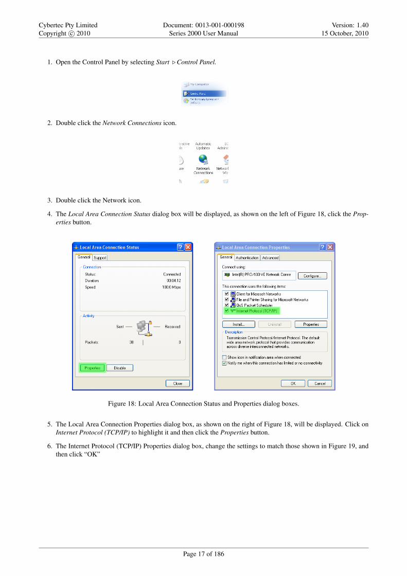
1. Open the Control Panel by selecting Start . Control Panel.
2. Double click the Network Connections icon.
3. Double click the Network icon.
4. The Local Area Connection Status dialog box will be displayed, as shown on the left of Figure 18, click the Prop-erties button.
Figure 18: Local Area Connection Status and Properties dialog boxes.
5. The Local Area Connection Properties dialog box, as shown on the right of Figure 18, will be displayed. Click onInternet Protocol (TCP/IP) to highlight it and then click the Properties button.
6. The Internet Protocol (TCP/IP) Properties dialog box, change the settings to match those shown in Figure 19, andthen click “OK”
Page 17 of 186

Cybertec Pty LimitedCopyright c© 2010
Document: 0013-001-000198Series 2000 User Manual
Version: 1.4015 October, 2010
Figure 19: Internet Protocol (TCP/IP) Properties dialog box showing the recommended IP settings.
Note: If a web browser was open prior to making the network changes, then it will need to closed and re-started beforeattempting to connect to the Series 2000 3G Modem / Router.
6.3 Connecting to the Series 2000 Web Server
• Open a web browser on the PC and browse to 10.10.10.10 (the default Series 2000, IP address) .
• A login box similar to Figure 20 will pop up. If the box fails to display, re-check the cable connections to the unitand the IP address settings of the PC.
• Enter the following login details:
◦ User Name: admin
◦ Password: admin
• The Status summary page will be displayed, it will be similar to Figure 21.
Note: As the unit has not yet been configured it is likely that some faults will be indicated.
Figure 20: Series 2000 Web login box
Page 18 of 186

Cybertec Pty LimitedCopyright c© 2010
Document: 0013-001-000198Series 2000 User Manual
Version: 1.4015 October, 2010
Figure 21: Series 2000 Status summary
Page 19 of 186

Cybertec Pty LimitedCopyright c© 2010
Document: 0013-001-000198Series 2000 User Manual
Version: 1.4015 October, 2010
7 Web Page Layout
This chapter describes the web page layout and menu structure. The pages are arranged in functional groups accessiblevia the main menu. For each main menu a number of sub-menu pages provide access to specific information and setting.When a main menu item is select the first sub-menu page is automatically displayed.
This section does not described how to connect to the web interface of the device. For information on connecting to theweb server of the device refer to Section 6
7.1 Page Layout
To illustrate the page layout the Status web page is shown in figure 22, this is first page to be displayed when a connectionto the web server is established. At the top of the page, under the Cybertec logo is the menu which consists of two rowsof tabs. The top row is the main menu, the sub-menu tab row is directly under the main menu. The main menu tabs areused to select a group of related pages and the sub-menu is used to select a page within that group. When a main menutab is selected the sub-menu option tabs will change allowing individual pages within the group to be selected.
Below the menu is the page title. The title indicates the selected page. Below the title is the page body. This section willcontain information and/or configuration settings for the selected function.
Figure 22: Web Page structure
When a menu item is referenced in the manual it is in the form: Menu . Sub-Menu. For example:Status . Alarms would refer to the Status / Alarms page shown in Figure 22.
7.2 Menu Structure
The section provides a brief description for each of the main menu tabs and for each sub-menu tab.
Page 20 of 186

Cybertec Pty LimitedCopyright c© 2010
Document: 0013-001-000198Series 2000 User Manual
Version: 1.4015 October, 2010
7.2.1 Status
The Status tab is used to report the current operating status of the Series 2000 3G Modem / Router .
Figure 23: Status menu
Alarms A summary of the alarm status.
Wireless Reports the status of the wireless connection.
LAN Information on the LAN settings
VPN Reports the status of any active VPNs
Serial Server Provides and overview of the Serial Server and serial ports.
GPIO (2220 only) Reports state of I/O and sets states of outputs.
System Log A log of the system messages.
7.2.2 System
The System tab provides system level information and configuration for the Series 2000 3G Modem / Router .
Figure 24: System menu
Administration Set hostname, configure the NTP connection, change passwords, set timed re-boot and reboot the mo-dem.
Backup & Upgrade Backup and restore the configuration, upgrade the Series 2000 3G Modem / Router firmware.
System Information Reports model number, serial number, firmware versions, MAC address and wireless IMEI & IMSI.
Power Configure the power controller for automatic power shutdown and start-up.
GPIO (2220 only) Configure the digital I/O.
7.2.3 Wireless
The Wireless tab provides access to the wireless settings of the Series 2000 3G Modem / Router .
Figure 25: Wireless menu
Page 21 of 186

Cybertec Pty LimitedCopyright c© 2010
Document: 0013-001-000198Series 2000 User Manual
Version: 1.4015 October, 2010
Network Operating mode, frequency band selection and SIM card PIN settings.
Packet Mode Profile management and selection, connection state selection.
Connection Management Connection establishment and maintenance options.
Circuit Switched Mode Circuit Switched Data (CSD) mode selection and configuration.
SMS SMS triggers and access control.
7.2.4 Network
The Network tab is used to access the Local Area Network (LAN), Dynamic Host Configuration Protocol (DHCP) andDNS settings.
Figure 26: Network menu
LAN LAN and DHCP settings.
DNS Manual and Dynamic DNS settings.
GRE Generic Routing Protocol settings.
Diagnostics Verify network connectivity with Ping and Traceroute.
7.2.5 Routing
The Series 2000 3G Modem / Router supports static and dynamic routing as well as policy and Quality of Service (QoS)based routing. Routing options are accessed via the Routing tab.
Figure 27: Routing menu
Default & Static Define the default route and static routes.
Dynamic Dynamic routing options.
VRRP Configure the Virtual Routing Redundancy Protocol.
Policy Define policy based routes.
QoS Quality of Service (QoS) options and define QoS routes.
Page 22 of 186

Cybertec Pty LimitedCopyright c© 2010
Document: 0013-001-000198Series 2000 User Manual
Version: 1.4015 October, 2010
7.2.6 Firewall
The Firewall tab allows configuration of the Series 2000 3G Modem / Router firewall settings which include the definitionof port forwards and packet filters.
Figure 28: Firewall menu
Setup Enable NAPT, stateful packet inspection and connection tracking options.
Access Control Define which modem services can be accessed from the wireless interface and VPN tunnels.
DoS Filters Define with Denial of Service filters are enabled.
Custom Filters Define and edit custom packet filters.
Port Forwards Define and edit port forwards.
Custom NAT Define and edit custom Network Address Translation rules.
MAC Filters LAN MAC Address filtering options.
7.2.7 VPN
The VPN tab provides access to the configuration for the SSL, IPsec, PPTP and L2TP VPNs.
Figure 29: VPN menu
IPsec VPN Enable and configure IPsec VPN tunnels.
SSL VPN Enable and configure SSL based VPN (OpenVPN).
PPTP & L2TP Enable and configure PPTP and L2TP VPN tunnels.
Certificate VPN certificate management.
7.2.8 Serial Server
The Serial Server tab is used to access the configuration options for the serial server and each of the available serial ports.
Figure 30: Serial Server menu
Port Setup Configure the serial server port function and configuration options for each of the available serial ports.
Phone Book Modem dial string phone book management.
Page 23 of 186

Cybertec Pty LimitedCopyright c© 2010
Document: 0013-001-000198Series 2000 User Manual
Version: 1.4015 October, 2010
7.2.9 Management
The Management tab provides access to the management settings of the Series 2000 3G Modem / Router .
Figure 31: Serial Server menu
Events Configure the actions taken when an event occurs.
SNMP Configure SNMP parameters.
DNP3 Configure the internal DNP3 outstation.
Email Email server configuration.
7.3 Symbols
The following symbols are used on the web pages:
Edit Icon. Click this icon to edit the indicated setting.
Delete Icon. Click this icon to delete a setting.
Reset Button. Click this button to reset the values on the page to the values prior to editing.
Update Button. Click this button to save changes.
Page 24 of 186

Cybertec Pty LimitedCopyright c© 2010
Document: 0013-001-000198Series 2000 User Manual
Version: 1.4015 October, 2010
8 Basic Configuration
The section explains the procedure to configure the Series 2000 3G Modem / Router for basic packet mode functionality.For details on configuring the modem for Circuit Switched mode and for more advanced configuration refer to the Series2000 3G Modem / Router User Manual.
8.1 Configure the Wireless interface
To access the configuration page for the Wireless interface, click on Wireless, the Wireless Network configuration pagewill be displayed as shown in Figure 32.
Figure 32: Wireless Network configuration.
8.1.1 Network Configuration
The “Network Configuration” section contains the settings for the operational mode of the modem. The default settingswith Operating mode set to Packet mode (HSPA/GPRS) will be adequate for a standard Internet type connection.
8.1.2 Setting the SIM card PIN
The SIM card may have a PIN associated with it and my require the PIN to be entered before the modem can access theSIM. To set the SIM PIN click “Setup”. A dialog box will be displayed, similar to that shown in figure 33, set the fieldmarked “Enter when requested” to “Yes” and enter the PIN in the “New PIN” and “Confirm PIN” entry boxes. Then clickthe “Set” button to save the PIN.
Page 25 of 186

Cybertec Pty LimitedCopyright c© 2010
Document: 0013-001-000198Series 2000 User Manual
Version: 1.4015 October, 2010
Figure 33: SIM PIN control dialog.
8.1.3 Adding a Network Connection Profile
To access the wireless packet mode settings click on the “Packet mode” tab. The screen shown in Figure 34 will bedisplayed. The page shows the connection configuration details and is divided into two sections. The first section showsthe current connection state and the selected profile and the second section lists the available profiles. A connectionprofile groups together the settings required to connect to a provider’s network, theSeries 2000 3G Modem / Routerallows multiple profiles to be configured to allow quick changes to the network connection settings. For most applicationsonly one profile is required.
Figure 34: Wireless Interface Packet mode settings.
To configure a network profile click the “Add new profile” button, a page similar to Figure 35 will be displayed. Thenetwork provider will provide some or all of the configuration items listed below, depending on the type of connectionprovided. The values provided should be entered into the appropriate fields. A standard “Internet” type connection willusually only require the APN.
• APN (Access Point Name)
• Dial string
• Authentication (None / PAP / CHAP)
• Username
• Password
In order to set a password click the check-box marked New. The password can now be entered in thetext field. The password is visible as it is being typed so that it can be checked for errors prior to beingset. Once set the password will no longer be visible.
Page 26 of 186

Cybertec Pty LimitedCopyright c© 2010
Document: 0013-001-000198Series 2000 User Manual
Version: 1.4015 October, 2010
The network service provider may not supply a username and password if network authentication isnot required. In this case set the Authentication to “None”, leave the username blank and do not set apassword.
Figure 35: Adding a new profile.
Once the data has been entered click the “Update” bottom to add the profile. The screen will now change to show thenewly added profile as this is the only profile entered it will be automatically selected as the current profile and the profileentry will be shaded green to indicate that it is the selected profile.
8.1.4 Enable the Wireless Connection
To complete the configuration of the wireless connection, set the Connection state to “Always connect” and click the“Update” button to save the changes. Once the changes have been set, the Series 2000 3G Modem / Router will attemptto establish a connection to a wireless network. The connection time will vary and may take several minutes to complete.Figure 36 shows the completed wireless configuration.
Figure 36: Completed wireless configuration.
Page 27 of 186

Cybertec Pty LimitedCopyright c© 2010
Document: 0013-001-000198Series 2000 User Manual
Version: 1.4015 October, 2010
8.1.5 Connection Status
To check the status of the connection select “Status” from the top level menu and then select “Wireless” from the secondlevel menu. The Wireless status page will be displayed. The status of the connection will change as the modem connectsto the network, first it will report “Checking” then “Connecting” and finally “Connected”. To see the value changing thepage will need to be refreshed. Once connected the Wireless status page will look similar to that shown in Figure 37.
Figure 37: Wireless Status showing a modem in the connected state.
During initialisation the status may be reported as “Error” while the connection is being established. Ifthe error persists check the profile settings have been entered correctly. Refer to Section 8.1.3.
With the Wireless network connection established the Status Alarms page should now indicate no faults as shown inFigure 38.
Figure 38: Status Alarms page.
Page 28 of 186

Cybertec Pty LimitedCopyright c© 2010
Document: 0013-001-000198Series 2000 User Manual
Version: 1.4015 October, 2010
8.2 Configure the LAN interface and DHCP Server
To access the configuration page for the LAN interface and DHCP Server, select Interfaces from the top level menu theLAN interface screen similar to that shown in Figure 39 will be shown.
Figure 39: LAN Interface configuration
8.2.1 Setting the IP Address
If it is desired to change the IP address of the LAN port, follow the steps below:
• Enter the new IP address and netmask in the Interface Configuration table.
• Click Update to set the changes. Once the changes have been set, the IP address of the Series 2000 3G Modem /Router will change. Enter the new address in the browser on the PC. It will be necessary to login again, followingthe procedure described in the previous section.
8.2.2 Enabling DHCP
The DHCP server allows clients on the local network to be automatically allocated IP addresses from the Series 2000 3GModem / Router. DHCP also provides the clients with network settings such as default route and location of DNS servers.
By default the DHCP server is disabled however it has been configured to serve IP addresses in the range 10.10.10.100through 10.10.10.200, and the Default and Maximum lease times have been set to 1440 minutes. So if these values areconsistent with the network to which the Series 2000 3G Modem / Router is connected, then the DHCP server can beenabled by setting the Enabled field to ’Yes’ and clicking the Update button.
If the standard settings are not applicable for the connected network, then refer to Figure 40 and follow the steps below,to configure the DHCP server:
• Choose a group of available IP addresses on the local network. For example, if the IP address of the Series 20003G Modem / Router is 10.10.10.10 with a netmask of 255.255.255.0, a group chosen could be 10.10.10.100 to10.10.10.200. This will provide 101 addresses for clients.
• Under the DHCP Server Configuration table,
◦ Set the Enabled option to Yes.
◦ Enter the first address of the group in the Start Address box.
◦ Enter the last address of the group in the End Address box.
Page 29 of 186
Cybertec Pty LimitedCopyright c© 2010
Document: 0013-001-000198Series 2000 User Manual
Version: 1.4015 October, 2010
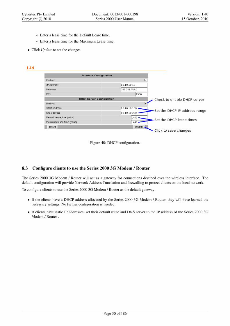
◦ Enter a lease time for the Default Lease time.
◦ Enter a lease time for the Maximum Lease time.
• Click Update to set the changes.
Figure 40: DHCP configuration.
8.3 Configure clients to use the Series 2000 3G Modem / Router
The Series 2000 3G Modem / Router will act as a gateway for connections destined over the wireless interface. Thedefault configuration will provide Network Address Translation and firewalling to protect clients on the local network.
To configure clients to use the Series 2000 3G Modem / Router as the default gateway:
• If the clients have a DHCP address allocated by the Series 2000 3G Modem / Router, they will have learned thenecessary settings. No further configuration is needed.
• If clients have static IP addresses, set their default route and DNS server to the IP address of the Series 2000 3GModem / Router .
Page 30 of 186

Cybertec Pty LimitedCopyright c© 2010
Document: 0013-001-000198Series 2000 User Manual
Version: 1.4015 October, 2010
9 Status
The Status pages provides access to status reporting for various service of the Series 2000 3G Modem / Router . If thedevice is not working correctly these pages will help diagnose the problem. Regular checking and refreshing of thesepages is recommended to ensure all services are operating correctly. To access the status pages click Status on the mainmenu a page similar to the one shown in Figure 42 will be displayed.
Figure 41: Main status page.
9.1 Alarms
The Status Alarms page is the first page displayed default page once connected to the device, it can also be selected at anytime by clicking Status . Alarms. This page provides a summary of the state of the operating services. A service whichis operating correctly will be highlighted green, a service with any error will be highlighted red, services not enabled willbe shown with a gray background.
Page 31 of 186

Cybertec Pty LimitedCopyright c© 2010
Document: 0013-001-000198Series 2000 User Manual
Version: 1.4015 October, 2010
Figure 42: Alarms status page showing Wireless connection status fault.
The page is divided into sections representing the status of system level services, the Wireless and LAN interfaces andother services. If a fault is indicated further information can be obtained from the corresponding status page. For examplein Figure 42 a fault is indicated for Connection Status in the Wireless section, further information on the fault can beobtained by selecting the Status . Wireless page. Details are shown in the next section.
9.1.1 System
Power On Self Test Indicates the result of the self testing done during the boot sequence. An error would usually indicatea hardware fault and the unit should be returned for service.
Temperature Indicates the current, minimum and maximum operating temperatures.
Uptime Indicates the current running time.
9.1.2 Wireless
Network Status Indicates the current wireless network connection status.
Connection Status Indicates the current wireless packet or circuit switched data (CSD) connection status.
Further information can be obtained from the Status . Wireless page.
9.1.3 Network
LAN Indicates the status of the Local Area Network (LAN).
Further information can be obtained from the Status . LAN page.
9.1.4 Services
DHCP Server Indicates the status of the Dynamic Host Configuration Protocol (DHCP) server. Further information canbe obtained from the Status . LAN page.
VPN Indicates the status of the any Virtual Private Networks. Further information can be obtained from the Status .VPN page.
Serial Server Indicates the status of the Serial Server. Further information can be obtained from the Status . Serial Serverpage.
Page 32 of 186

Cybertec Pty LimitedCopyright c© 2010
Document: 0013-001-000198Series 2000 User Manual
Version: 1.4015 October, 2010
9.2 Wireless
The Wireless status page (Status . Wireless) provides details of the current operating state of the wireless interface. Thepage displayed will depend on the wireless operating mode, Figure 43 shows the page for packet mode, while Figure 44for Circuit Switched Data (CSD) mode. For information on the different wireless operating modes refer to Section 11.
9.2.1 Network Status
The network status section is common for both modes of wireless operation.
Network Registration Indicates the network registration state.
RF Level (RSSI) Provides an indication of the RF Level or Received Signal Strength Indication (RSSI). The RSSI is anumber out of 30 which gives and indication of signal received level. The actual received level is also indicated asa value in dBm.
Provider Indicates the network service provider name and service, the location ID and the cell ID.
Figure 43: Wireless status page for packet mode.
9.2.2 Connection Status (Packet Mode)
Status The packet connection status.
Current Session Time Time the current packet session has been active.
Total Session Time The total packet session time since boot.
IP Address The wireless IP address
Packets Received The total number of packets received.
Bytes Received The total number of bytes received.
Packets Transmitted The total number of packets transmitted.
Bytes Transmitted The total number of bytes transmitted.
Page 33 of 186
Cybertec Pty LimitedCopyright c© 2010
Document: 0013-001-000198Series 2000 User Manual
Version: 1.4015 October, 2010
Figure 44: Wireless status page for Circuit Switched Data (CSD) mode.
9.2.3 Connection Status (Packet Mode)
Line State The current status of the connection either offline or connected.
Last Dial Result The result of the last dial attempt.
Data Sessions The number of successful connections.
Current Session Time Time the current connection has been active.
Total Session Time The total time of all connections since boot.
Bytes Received The total number of bytes received.
Bytes Transmitted The total number of bytes transmitted.
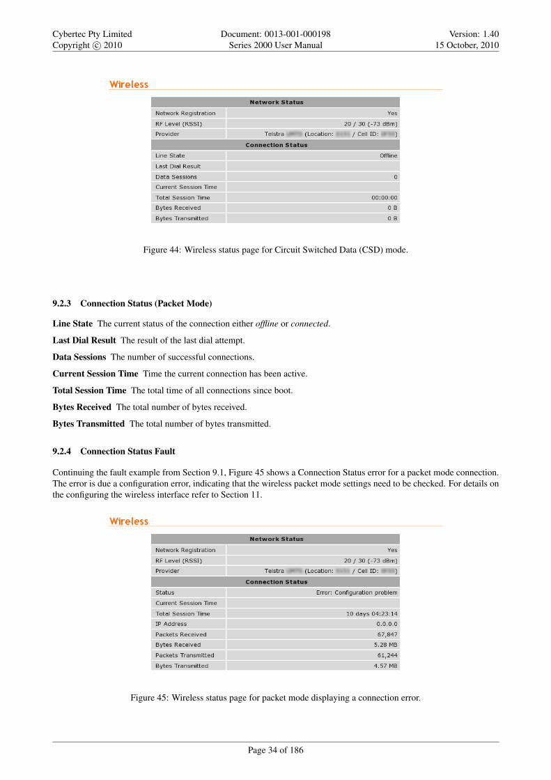
9.2.4 Connection Status Fault
Continuing the fault example from Section 9.1, Figure 45 shows a Connection Status error for a packet mode connection.The error is due a configuration error, indicating that the wireless packet mode settings need to be checked. For details onthe configuring the wireless interface refer to Section 11.
Figure 45: Wireless status page for packet mode displaying a connection error.
Page 34 of 186

Cybertec Pty LimitedCopyright c© 2010
Document: 0013-001-000198Series 2000 User Manual
Version: 1.4015 October, 2010
9.3 Local Area Network (LAN)
The Local Area Network (LAN) status page (Status . LAN) provides details of the current operating state of the LAN orEthernet interface. The page is divided into two sections, the first contains the interface statistics and the second has theDHCP Lease information. The DHCP Lease information will only be displayed if the DHCP server is enabled.
Figure 46: LAN Status page.
9.3.1 LAN Statistics
Status The status of the interface.
IP Address The IP address if the interface
Netmask The netmask of the interface
Packets Received The total number of packets received.
Bytes Received The total number of bytes received.
Packets Transmitted The total number of packets transmitted.
Bytes Transmitted The total number of bytes transmitted.
9.3.2 DHCP Server Leases
IP Address The assigned IP address.
MAC Address The MAC address of the device which requested the lease.
Hostname The reported hostname of the device which requested the lease.
Expires The lease expiry time.
9.4 Virtual Private Network (VPN)
9.5 Serial Server
9.6 General Purpose Input / Output (GPIO)
9.7 System Log
The system log provides a list of messages from various services. The messages are time and date stamped.
Page 35 of 186

Cybertec Pty LimitedCopyright c© 2010
Document: 0013-001-000198Series 2000 User Manual
Version: 1.4015 October, 2010
Figure 47: System Log page.
Page 36 of 186

Cybertec Pty LimitedCopyright c© 2010
Document: 0013-001-000198Series 2000 User Manual
Version: 1.4015 October, 2010
10 System
The System section provides configuration options and access to features to allow the administration and maintenance ofthe Cybertec Series 2000 3G Modem / Router . Options which can be configured include:
• Host-name for the device.
• Time and Date settings.
• Edit users and passwords
• RADIUS server.
• Shut-down and re-boot.
• Save and restore the device configuration.
• Update the device firmware.
• View device information, serial number, MAC address etc.
• Power controller.
• General Purpose Input and Output (GPIO), available on the Model 2220only.
The System pages are accessed by clicking System on the main menu.
10.1 Administration
The main Administration page is the default page and will be displayed when System is selected from the main menu.It can also be selected by the menu combination System . Administration at any time. A page similar to that shown infigure 48 will be displayed.
Figure 48: System Administration page.
Page 37 of 186

Cybertec Pty LimitedCopyright c© 2010
Document: 0013-001-000198Series 2000 User Manual
Version: 1.4015 October, 2010
10.1.1 Setting the system hostname
The hostname for the modem can be set in the Hostname field. The hostname is limited to 32 characters and can onlycontain letters, numbers, hyphens and underscores. The hostname is displayed on this page, reported via SNMP and usedin system-generated SMS messages.
10.1.2 Setting the time and date
The time and date can either be set manually or configured to read the current time from a network time server using theNTP protocol.
To enable NTP, set the checkbox in the Check time with NTP server & address field and enter the IP address or hostnameof an NTP server in the text field. To correctly adjust the time from the NTP server to the local timezone, the Timezonemust be set. Select the appropriate number of hours from the drop-down list.
To manually set the time click the Set Time button, a popup box will be displayed similar to that shown in Figure 49.Adjust the time and date to the desired settings and click the Set button to save.
Figure 49: Manually setting the time and date.
10.1.3 Editing users and passwords
To change the passwords used for modem access or to enable RADIUS authentication, click the icon in the Edit usersand passwords field. A page similar to that shown in Figure x will be displayed.
Figure 50: Administration page to change user passwords and to configure RADIUS.
Page 38 of 186

Cybertec Pty LimitedCopyright c© 2010
Document: 0013-001-000198Series 2000 User Manual
Version: 1.4015 October, 2010
10.1.3.1 Changing basic user passwords
The Series 2000 3G Modem / Router provides two users, each with different access levels:
admin The admin user can view and change the configuration of the modem and view the status.
guest The guest user can view the configuration and status of the modem.
The passwords for these users are set using the Set access passwords table.
To change a user’s password, use the drop-down box in the User column to select the appropriate user. Then, enter theCurrent password for the user, followed by the New password, repeated to avoid errors in the Confirm password field.Click Update to confirm the changes.
10.1.3.2 Enabling RADIUS authentication
The Series 2000 3G Modem / Router can also authenticate users against a RADIUS server. The fields below need tobe correctly configured to enable this feature. The RADIUS server administrator will be able to provide the necessaryinformation.
Enabled Set this field to enable RADIUS authentication.
Server address Enter the IP address of the RADIUS server.
Server port Enter the IP port of the RADIUS server. This is normally 1812 or 1645.
Shared secret This is a password that is used to encrypt traffic sent to the RADIUS server. To set this field, click theNew checkbox and enter the secret in the text field.
Default group to assign users to If the RADIUS server fails to provide information regarding the access level of a newlyauthenticated user, the default set in this field will be used.
RADIUS attribute Service-Type (6) is used to determine the access level of a user. A user with Service-Type set to Administrative-User (6) will be granted the admin access level. A user with Service-Typeset to NAS-Prompt (7) will be granted the guest access level.
10.1.4 Setting a timed reboot
In some applications, it may be desirable for the Series 2000 3G Modem / Router reboot at a timed interval to catch anyerrors that may have occurred. To enable this feature, enter a time (in hours) in the Timed reboot field. Once the modemhas run for the number of hours entered, it will reboot and start the system again. To disable this feature, set the field to 0.
The use of the timed reboot feature is not recommended. The device continuously monitors the operat-ing conditions and network status, if a fault is detected corrective action is taken in order to re-establishnetwork connections. Using the connection management features details in Section 11 will provide amore reliable and stable solution.
10.1.5 Shutdown
A shutdown disconnects the device from the 3G network and terminates all internal processes prior to the power beingremoved. A shutdown of the Series 2000 3G Modem / Router can be initalised by clicking the Shutdown button. This willterminated all processors and close all connections, the power supplies will then be turned off. The complete shutdownwill take approximately 2 minutes. The power will remain off for approximately 1 minute, during this time the powercan safely be removed. After this time if the power is still connected the device will start up again and resume normaloperation.
Page 39 of 186

Cybertec Pty LimitedCopyright c© 2010
Document: 0013-001-000198Series 2000 User Manual
Version: 1.4015 October, 2010
10.1.6 Rebooting the modem
To reboot the Series 2000 3G Modem / Router , click the Reboot button and confirm the action in the dialog box thatappears. The reboot will take around 75 seconds.
The power supplies remain on during a reboot, this differs from a shutdown where the power suppliesare turned off.
10.1.7 Update & Reset
After completing configuration changes, click the Update button to save the changes, or click the Reset button to clearany changes.
10.2 Backup & Upgrade
This section describes how to save the current modem configuration, restore a saved configuration and update the Series2000 3G Modem / Router firmware.
To access the Backup & Upgrade options select System . Backup & Upgrade. The Backup & Upgrade page will bedisplayed as shown in figure 51.
Figure 51: Backup and Upgrade page
10.2.1 Backing up the current configuration
The configuration of the Series 2000 can be saved as a file to a PC. This file can then be used to restore the configurationof the unit at some later time or used to configure multiple units with the same configuration.
To save the current configuration click on the link in the section titled Backup current configuration. A pop-up boxsimilar to that shown in figure 52 will be displayed. Select Save to Disk and click OK. Select a suitable location to savethe file.
Page 40 of 186

Cybertec Pty LimitedCopyright c© 2010
Document: 0013-001-000198Series 2000 User Manual
Version: 1.4015 October, 2010
Figure 52: Saving the configuration
10.2.2 Restoring a saved configuration
To restore a configuration, click the Browse button in the section titled Restore a saved configuration. Select theconfiguration file, which will then be shown in the text box, as shown highlighted in figure 53. Click the Upload buttonto transfer the file to the Series 2000 .
Once the upload is complete, the Series 2000 must be rebooted immediately so the restored con-figuration can take affect. The details for performing a reboot can be found in Section 10.1.6above.Do not make any changes to configuration prior to rebooting.
Figure 53: Restore configuration
10.2.3 Upgrading the modem firmware
The Series 2000 firmware can be upgraded via the web interface.
To upgrade the Series 2000 firmware, click the Browse button in the section titled Upgrade Series 2000 firmware thennavigate to and select the upgrade file. Once selected, the filename will display as shown highlighted in Figure 54.
Page 41 of 186

Cybertec Pty LimitedCopyright c© 2010
Document: 0013-001-000198Series 2000 User Manual
Version: 1.4015 October, 2010
Figure 54: Select firmware upgrade file
To initiate the upload of the file to the Series 2000 click the Upload button. The file will now be uploaded to the Series2000 . The upload may take from several seconds to several minutes depending on the speed of the link the upgrade fileis transferred over. When the upload is complete, information on the upgrade file will be displayed, as shown in Figure55. At this point the you can chose to cancel the upgrade by clicking the Cancel Upgrade button.
Figure 55: Upload the upgrade file
To proceed with the upgrade click the Upgrade button. The page will change to that shown in figure 56. The firmwareupgrade will now proceed.
The upgrade will take several minutes to complete after which time the Series 2000 will reboot.During this time the power to the Series 2000 must not be removed.
Page 42 of 186

Cybertec Pty LimitedCopyright c© 2010
Document: 0013-001-000198Series 2000 User Manual
Version: 1.4015 October, 2010
Figure 56: Upload the upgrade file
10.3 System Information
The Series 2000 System Information is accessed by selecting System . Information. An example of the System Infor-mation page is shown in figure 57. The first section of the page lists the model and serial number of the unit, plus thefirmware and boot loader version. The second part of the page lists the LAN MAC address the IMEI of the wirelessmodule and the wireless IMSI.
Figure 57: System Information page
10.4 Power
The power controller may be used to power the Series 2000 3G Modem / Router on and off at specified times. By usingthe power controller the power consumption can be greatly reduced at times when a network connection is not required.The power controller options are on System . Power page, which is shown in Figure 58.
Page 43 of 186

Cybertec Pty LimitedCopyright c© 2010
Document: 0013-001-000198Series 2000 User Manual
Version: 1.4015 October, 2010
Figure 58: The Power Control Schedule configuration page.
For the power controller to work correctly power must be maintained to the unit at all times. Duringthe power off times the power consumption will drop to approximately 10mA. This power is requiredto maintain the timer circuitry which determines when the unit should again be powered on. If duringan power off time the power is removed from the unit the timer count is lost. When power is re-appliedthe unit will boot as normal, the timer will be re-initalised and determine if it should remain poweredon or enter the power off state.
10.4.1 Configuring Power Control Schedule
The configuration options are:
Enabled Enable the power controller be checking the box.
Cycle time Selected the required cycle time from the drop-down list.
On time Select duration for which the power is on.
Cycle_start_time Select the time, offset from start of the cycle, at which the power is turn on.
Power off maximum offset If enable specifies an offset time which is applied if the unit re-powers prior to the scheduledpower on time.
The controller works on the basis of a cycle, the duration of the cycle can be set for a maximum of 24 hours to a minimumof 30 minutes. Irrespective of the cycle duration the first cycle begins at midnight subsequent cycles begin straight afterthe previous cycle. For example if the cycle time is set to 6 hours, the first cycle starts at 12:00am, the second at 06:00am,the third at 12:00pm, the forth at 6pm and so on.
The period for which the unit is powered is set as the on time this time can be set to a maximum of 5 minutes less then thecycle time. If this value is set to 0 in will default to the maximum on time of 5 minutes less than the cycle time. The timeat which the powered duration begins relative to the start of the cycle is specified as the cycle start time. For example ifthe On time is set to 30 minutes and the Cycle start time is set to 1 hour the unit will be off for the first hour of the cycle,it will then be powered on for 30 minutes and then remain off for the rest of the cycle.
Once the configuration has been completed click Update to save changes.
10.4.2 Power Control Schedule Example
Example 1
The unit is required to powered on at 2:00am and again at 2:00pm for a duration of one hour.
As there are two power on times per day the cycle time required is 12 hours. The On time is 1 hours and the Cycle starttime is 2 hours. The required settings are shown in Figure 59.
Page 44 of 186
Cybertec Pty LimitedCopyright c© 2010
Document: 0013-001-000198Series 2000 User Manual
Version: 1.4015 October, 2010
Figure 59: Power Control Schedule configuration example
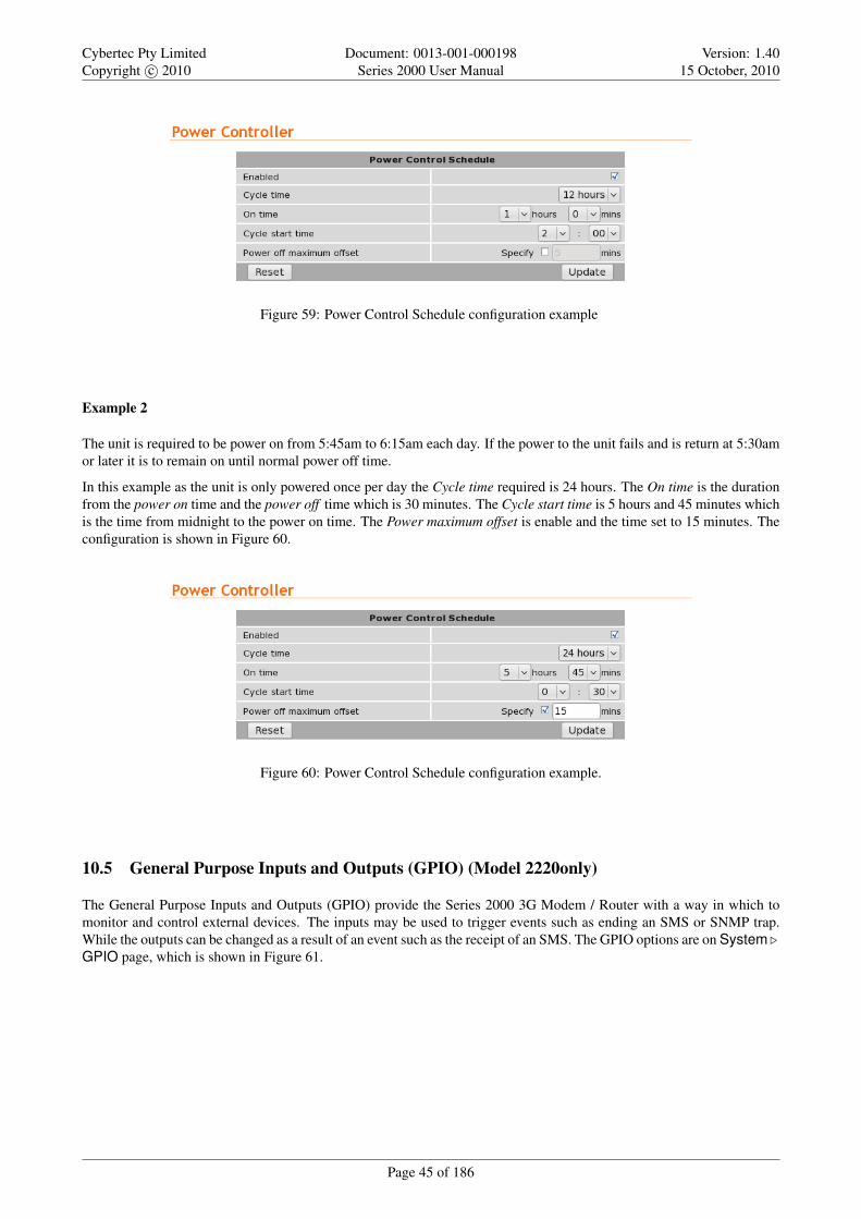
Example 2
The unit is required to be power on from 5:45am to 6:15am each day. If the power to the unit fails and is return at 5:30amor later it is to remain on until normal power off time.
In this example as the unit is only powered once per day the Cycle time required is 24 hours. The On time is the durationfrom the power on time and the power off time which is 30 minutes. The Cycle start time is 5 hours and 45 minutes whichis the time from midnight to the power on time. The Power maximum offset is enable and the time set to 15 minutes. Theconfiguration is shown in Figure 60.
Figure 60: Power Control Schedule configuration example.
10.5 General Purpose Inputs and Outputs (GPIO) (Model 2220only)
The General Purpose Inputs and Outputs (GPIO) provide the Series 2000 3G Modem / Router with a way in which tomonitor and control external devices. The inputs may be used to trigger events such as ending an SMS or SNMP trap.While the outputs can be changed as a result of an event such as the receipt of an SMS. The GPIO options are on System .GPIO page, which is shown in Figure 61.
Page 45 of 186

Cybertec Pty LimitedCopyright c© 2010
Document: 0013-001-000198Series 2000 User Manual
Version: 1.4015 October, 2010
Figure 61: The GPIO configuration page.
10.5.1 GPIO Configuration
The GPIO Configuration of the page is used to configure the individual inputs and outputs. The options are:
Type This field describes the I/O type and is one of:
Input The I/O is an input.
Output The I/O is an output.
Index This is the index of the I/O and is referenced for each type. This index matches the hardware index for the I/O.
Label A text label for the I/O.
Enabled Check to enable to I/O
Default State The default state for an output. This is state the output will transition to when the unit powers up orre-boots. This field is not applicable for inputs. The state can either be:
Open The output is in the open or off state.
Closed The output is in the closed or on state.
Once the configuration has been completed click Update to save changes.
The state of the outputs when the unit is powered off and when it commences the boot process will beopen. The default state will be applied during the boot sequence. This means that if an output is set toa default state of Closed then it will initially be Open then transition to Closed during power up.
When the unit is powered off or in low power mode, refer to Section 10.4 on page 43 the outputs willbe in the Open state.
Page 46 of 186
Cybertec Pty LimitedCopyright c© 2010
Document: 0013-001-000198Series 2000 User Manual
Version: 1.4015 October, 2010
10.5.2 General Configuration
The general configuration is used to configure the way in which the unit will respond to SMS. The options are:
SMS contents on event Should an input or output cause an SMS event to be generated, the value set in this field deter-mines what the contents of the message will be. The values are:
No I/O No information about the current states of the GPIO will be added to the message.
I/O that generated event Only the current states of the GPIO that caused the event will be included in the message.
All I/O The current states of all of the GPIO will be included in the message.
SMS includes Indicates the text which will be sent as standard for each message. The fields are:
Hostname The hostname will be included as the first item in the message.
Extra text If checked the text entered in the text box will be sent as part of the message.
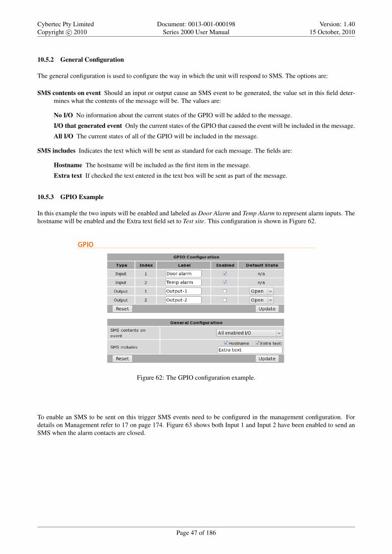
10.5.3 GPIO Example
In this example the two inputs will be enabled and labeled as Door Alarm and Temp Alarm to represent alarm inputs. Thehostname will be enabled and the Extra text field set to Test site. This configuration is shown in Figure 62.
Figure 62: The GPIO configuration example.
To enable an SMS to be sent on this trigger SMS events need to be configured in the management configuration. Fordetails on Management refer to 17 on page 174. Figure 63 shows both Input 1 and Input 2 have been enabled to send anSMS when the alarm contacts are closed.
Page 47 of 186

Cybertec Pty LimitedCopyright c© 2010
Document: 0013-001-000198Series 2000 User Manual
Version: 1.4015 October, 2010
Figure 63: The GPIO SMS event configuration example.
If the alarms inputs are now closed the following SMSes will be sent:
First the Input-1 the Door alarm is closed:
S2000-ff-ff-00: Test site: Door alarm=closed,Temp alarm=open
And now the Input-1 the Temp alarm is closed:
S2000-ff-ff-00: Test site: Door alarm=open,Temp alarm=closed
Page 48 of 186

Cybertec Pty LimitedCopyright c© 2010
Document: 0013-001-000198Series 2000 User Manual
Version: 1.4015 October, 2010
11 Wireless
This section describes the 3G Wireless interface options of the Series 2000 3G Modem / Router . The Series 2000 supportstwo modes of operation: packet mode and Circuit Switched Data (CSD) mode.
The subsections of the configuration are:
Network - Configure the operation mode, select the frequency band of operation and set the SIM PIN.
Packet mode - Configure the packet mode.
Circuit switched mode - Configure the circuit switched data mode.
SMS - Configure the Short Message Service (SMS) functionality of the modem.
11.1 Network Configuration
The Wireless Network options are used to set the operating mode, select the frequency band of operation and set the SIMPIN. To display the Network page select Wireless from the main menu and Network from the sub-menu. The page shouldappear similar to that of figure 64.
Figure 64: Wireless Network configuration
11.1.1 Selecting the wireless operating mode
The Series 1000 support three modes of operation for the wireless interface. The desired mode is set in the Operatingmode field. The options are detailed below.
Packet mode In packet mode the Series 2000 acts as a TCP/IP modem and router. The modem connects to the 3Gprovider’s network and is allocated an IP address. Data can be routed between the LAN ports and the Wireless port.The Serial Server is used to transport serial data over the packet interface.
Page 49 of 186

Cybertec Pty LimitedCopyright c© 2010
Document: 0013-001-000198Series 2000 User Manual
Version: 1.4015 October, 2010
Circuit switched mode Circuit Switched Data mode is similar to a traditional dial-up modem. It is mainly intended forthe transport of serial data. Connections are established by dialing into the modem using a PSTN modem or dialingout a call via AT commands on the serial port.
Disabled The internal RF circuitry of the modem is shutdown. No data connections are possible and the modem will notreceive SMS.
Once the mode has been selected click the Update button the commit the change.
11.1.2 Setting the SIM card PIN
The SIM card will have a PIN associated with it. If PIN checking is enabled on the SIM then in order for the modem toaccess the SIM, the PIN will need to be set in the modem. To set the SIM PIN click Setup in the Set SIM PIN code row.A dialog box as shown in Figure 65 will be displayed.
Figure 65: SIM PIN control dialog
Set the field marked Enter when requested to Yes and enter the PIN in the New PIN and Confirm PIN entry boxes.Click the Set button to save the PIN. As shown in Figure 66.
Figure 66: SIM PIN control dialog
The dialog box will now be as shown in Figure 67, indicating that the current PIN is Set. click the close button to closethe dialog box.
Figure 67: SIM PIN control dialog
Page 50 of 186

Cybertec Pty LimitedCopyright c© 2010
Document: 0013-001-000198Series 2000 User Manual
Version: 1.4015 October, 2010
11.1.3 Selecting the operating frequency bands
The Series 2000 is capable of operating on several frequency bands used by the UMTS (3G) and GSM protocols.
The default setting is for the Series 2000 to operate on all supported frequency bands. This means that when powered onthe Series 2000 will start to search for available networks, checking first for UMTS (3G) networks then falling back toGSM should the modem be unable to register with the network provider.
In some cases, it may be desirable to limit the frequency bands that are searched by the modem. For example, if thenetwork provider only has an 850Mhz UMTS network then the time to register and connect will be reduced if this is theonly band searched.
To facilitate band selection, the modem provides the Frequency Band Selection table. The following modes can be set:
All bands The modem will search all supported frequency bands.
Figure 68: Frequency Band Selection - All bands.
UMTS only The modem will only search supported UMTS (3G) frequency bands.
Figure 69: Frequency Band Selection - UMTS only.
GSM only The modem will only search supported GSM frequency bands.
Figure 70: Frequency Band Selection - GSM only.
Page 51 of 186

Cybertec Pty LimitedCopyright c© 2010
Document: 0013-001-000198Series 2000 User Manual
Version: 1.4015 October, 2010
Custom The user can set checkboxes in the UMTS and GSM rows to select the frequency bands that will be searched.
Figure 71: Frequency Band Selection - Custom
Once any changes have been made to the frequency bands click the Update button the commit the changes.
11.2 Packet Mode Configuration
Before the modem can establish a packet connection, the details of the connection must be set up in a connection profile.This section details the process of adding, editing and deleting a connection. While most configurations will only needone profile, the modem can support multiple profiles. The active profile is selected via the web interface.
To access the packet mode configuration, select Wireless from the main menu and Packet Mode from the sub-menu. Thescreen shown in Figure 72will be displayed.
Figure 72: Wireless Interface Packet mode settings
11.2.1 Adding Connection Profiles
To add a new profile, click the Add new profile button. The add entry page will display as shown in Figure 73.
Figure 73: Adding a new profile
Page 52 of 186

Cybertec Pty LimitedCopyright c© 2010
Document: 0013-001-000198Series 2000 User Manual
Version: 1.4015 October, 2010
The network provider will specify the required settings for completing a connection profile. The settings required arelisted below:
APN (Access Point Name) This is the name of the network provider’s access point.
Dial String The dial string used to establish a connection. This should not need to be changed from *99#.
Authentication For connections requiring a username and password to connect, this field sets the authentication protocolused:
None No authentication is performed.
PAP The Password Authentication Protocol is used.
CHAP The Challenge-Handshake Authentication Protocol is used.
Username For connections with PAP or CHAP selected for authentication, this is the username the modem will use toauthenticate.
Password For connections with PAP or CHAP selected for authentication, this is the password the modem will use toauthenticate. In order to set a password click the check box marked New then enter the password in the adjacenttext field. The password is visible as it is being typed so that it can be checked for errors prior to being set. Onceset the password will no longer be visible.
The provider may not supply a username and password if network authentication is not required. In thiscase set the Authentication to None.
Once the profile has been entered click the Update button to add the profile. The screen will now change to show theadded profile as shown in Figure 74.
Figure 74: Profile added and selected
11.2.2 Enabling a wireless connection
To complete the configuration of the wireless connection, the connection needs to be enabled. This is done by setting theConnection state. There are two connection options available:
Always connect The modem will always attempt to establish a packet connection. This option should suit most applica-tions.
Connect on demand The modem will wait for data to be queued for sending on the wireless port before establishing apacket connection. After a period of inactivity the connection will be closed.
Page 53 of 186

Cybertec Pty LimitedCopyright c© 2010
Document: 0013-001-000198Series 2000 User Manual
Version: 1.4015 October, 2010
Click Update to set the change to the connection state. Once the state has been set, the modem will attempt to establish aconnection.
Figure 75 shows an example of a completed packet mode configuration.
Figure 75: Completed wireless configuration
11.2.3 Adding Further Profiles
Additional profiles may be added by following the same process as above. Figures 76 and 77 show the result of adding asecond profile. Notice that the profile with Index 1 is highlighted green as it is the currently selected profile.
Figure 76: Adding a second profile.
Figure 77: List of profiles now listing 2 profiles.
Page 54 of 186

Cybertec Pty LimitedCopyright c© 2010
Document: 0013-001-000198Series 2000 User Manual
Version: 1.4015 October, 2010
To change the selected profile select the required index number from the Current profile drop down box in the ConnectionConfiguration section and click Update. The page will update and the selected index will now be highlighted. Figure 78is an example with the second profile added above selected.
Figure 78: Second profile selected.
11.2.4 Editing a profile
To edit an existing profile click on the icon located in the Edit for the profile to be edited. Complete the changes to theprofile then click Update to commit the changes. Figure 79illustrates editing of the second profile, in this example theauthentication is changed from None to PAP and a Username and Password are added. The updated profile list is shownin Figure 80.
Figure 79: Editing the second profile.
Figure 80: Profile list after editing the second profile.
Page 55 of 186
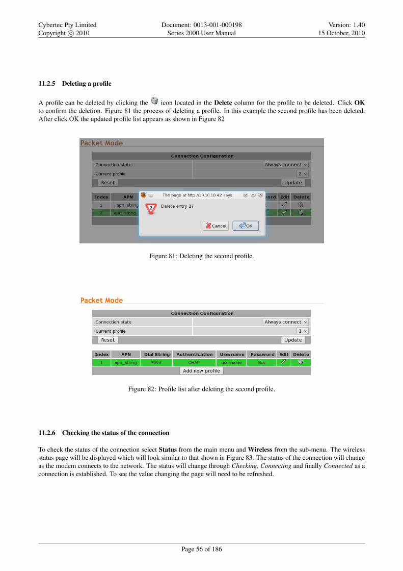
Cybertec Pty LimitedCopyright c© 2010
Document: 0013-001-000198Series 2000 User Manual
Version: 1.4015 October, 2010
11.2.5 Deleting a profile
A profile can be deleted by clicking the icon located in the Delete column for the profile to be deleted. Click OKto confirm the deletion. Figure 81 the process of deleting a profile. In this example the second profile has been deleted.After click OK the updated profile list appears as shown in Figure 82
Figure 81: Deleting the second profile.
Figure 82: Profile list after deleting the second profile.
11.2.6 Checking the status of the connection
To check the status of the connection select Status from the main menu and Wireless from the sub-menu. The wirelessstatus page will be displayed which will look similar to that shown in Figure 83. The status of the connection will changeas the modem connects to the network. The status will change through Checking, Connecting and finally Connected as aconnection is established. To see the value changing the page will need to be refreshed.
Page 56 of 186

Cybertec Pty LimitedCopyright c© 2010
Document: 0013-001-000198Series 2000 User Manual
Version: 1.4015 October, 2010
Figure 83: Wireless Status page
The section tiled Network Status details the quality of the service available from the 3G network.
• The SIM Card field will only be shown if an error with the SIM card has been detected, and will be reported asAbsent or faulty or PIN needed as shown highlighted in Figures 84 and 85.
◦ If the SIM card fault is reported, possible causes include:
• The SIM card has not be inserted correctly. Refer to section 5.3 on page 14, for details on how to insertthe SIM card.
• The SIM card pin number has not been entered or is incorrect. Refer to section 11.1.2 on page 50, fordetails on entering the SIM card PIN.
Figure 84: Wireless Status page showing a SIM Absent fault.
Page 57 of 186

Cybertec Pty LimitedCopyright c© 2010
Document: 0013-001-000198Series 2000 User Manual
Version: 1.4015 October, 2010
Figure 85: Wireless Status page showing a SIM PIN required fault.
• The Network Registration field indicates whether the Series 2000 modem is actively registered to the 3G network.No connection is possible without registration.
◦ If the network registration field is No, possible causes include:
• Poor signal strength. Check the antenna is properly connected and experiment with different locationsfor the Series 2000 to achieve a higher RF Level.
• Problem with the SIM card. Ensure the SIM card fitted to the Series 2000 is currently enabled with thenetwork provider.
• The SIM card is not correctly enabled with the network provider. Verify with the provider that the SIMis currently active.
• The RF Level indicates the current strength of received signal from the network, with a maximum of 30. Any levelover 10 should provide acceptable connection speeds.
The section titled Connection Status shows the statistics for the current connection.
• If the Status item doesn’t show Connected, verify the following:
◦ Connection state is Always connect in the packet mode configuration.
◦ If the Status field always shows Connecting..., a problem with the APN, username or password is likely.Check that the values these settings with the network provider. Refer to Section 11.2.1 for details on how toenter these values into the Series 2000 .
• The remaining fields list the length of time connected, IP address allocated by the network and data counters. Allof this information will reset if a connection is restarted, except the Total Session Time field, which will accumulateacross all sessions.
11.3 Connection Management
The Series 2000 has numerous options for managing the packet mode network connection. The purpose of connectionmanagement is to create and maintain reliable connections that can detect errors and recover as quickly as possible. Theconnection management is divided in two areas:
Connection establishment Determines how the modem manages the establishment of a connection to the network.
Connection_management Determines how the modem manages the connection to the network once established.
Page 58 of 186
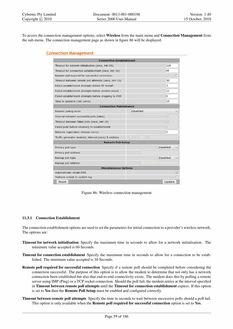
Cybertec Pty LimitedCopyright c© 2010
Document: 0013-001-000198Series 2000 User Manual
Version: 1.4015 October, 2010
To access the connection management options, select Wireless from the main menu and Connection Management fromthe sub-menu. The connection management page as shown in figure 86 will be displayed.
Figure 86: Wireless connection management
11.3.1 Connection Establishment
The connection establishment options are used to set the parameters for initial connection to a provider’s wireless network.The options are:
Timeout for network initialisation Specify the maximum time in seconds to allow for a network initialisation. Theminimum value accepted is 60 Seconds.
Timeout for connection establishment Specify the maximum time in seconds to allow for a connection to be estab-lished. The minimum value accepted is 30 Seconds.
Remote poll required for successful connection Specify if a remote poll should be completed before considering theconnection successful. The purpose of this option is to allow the modem to determine that not only has a networkconnection been established but also that end-to-end connectivity exists. The modem does this by polling a remoteserver using IMP (Ping) or a TCP socket connection. Should the poll fail, the modem retries at the interval specifiedin Timeout between remote poll attempts until the Timeout for connection establishment expires. If this optionis set to Yes then the Remote Poll Setup must be enabled and configured correctly.
Timeout between remote poll attempts Specify the time in seconds to wait between successive polls should a poll fail.This option is only available when the Remote poll required for successful connection option is set to Yes.
Page 59 of 186

Cybertec Pty LimitedCopyright c© 2010
Document: 0013-001-000198Series 2000 User Manual
Version: 1.4015 October, 2010
Failed establishment attempts before RF restart Specify the number of failed connection attempts before restartingthe RF circuitry. Set this value to 0 to disable RF circuitry reset.
Failed establishment attempts before modem reboot Specify the number of failed connection attempts before resettingthe Series 2000 . Set this value to 0 to disable the Series 2000 reset.
Failed establishment attempts before dropping to CSD Specify the number of failed connection attempts before switch-ing to Circuit Switched Data (CSD) mode. Set this value to 0 to disable the fail-over to CSD feature.
Time to spend in CSD Specify a time in minutes to remain in CSD mode before reverting to packet mode and attemptingto establish a connection. This value value is only used if the Failed establishment attempts before dropping toCSD option is set to a value greater than 0.
11.3.2 Connection Maintenance
The connection maintenance refers to the tests employed by the Series 2000 to determine that a valid network connectionis available. Should the connection maintenance test fail then the Series 2000 will attempt to re-establish the connection.
The following options control connection maintenance:
Remote polling mode Specify the connection maintenance operating mode. Four modes are supported:
Disabled Connection maintenance is disabled.
Poll at fixed interval Poll the servers specified in the Remote Poll Setup at the interval specified.
Poll if Rx idle for interval Only poll the servers specified in the Remote Poll Setup when no data has been re-ceived from the wireless interface for the specified interval.
Reconnect if Rx idle for interval Monitor the receive data and reconnect if no data has not been received by thewireless interface for the specified interval. This mode is a good choice for configurations that already employpolling traffic, such as when using the SSL VPN or IPsec VPN with dead peer detection.
Interval between successful polls Specify the time interval in minutes between polls.
Timeout between failed polls Specify the time in seconds between failed polls.
Failed polls before returning to establishment Specify the number of failed polls to declare the link failed and to re-start the establishment process.
11.3.3 Remote Poll Setup
The remote poll setup is used to specify the poll type to use and the address of the server to poll. A primary and backupserver may be specified. The backup server will be used if the primary server cannot be contacted. The options for eachpoll are:
Poll type Specify the poll type. The options are:
Disabled The poll is disabled.
Ping (ICMP) Ping the specified address.
TCP Socket Establish a TCP socket to the specified address and port number. The connection will be terminatedas soon as successfully opened.
Poll address Specify the address of the primary server to poll. The format used depends on the poll type:
Ping (ICMP) Enter an IP address or hostname, eg 192.168.1.1 or www.google.com
TCP Socket Enter an IP address or hostname followed by a colon and the TCP port number, for example 192.168.1.1:80
Page 60 of 186

Cybertec Pty LimitedCopyright c© 2010
Document: 0013-001-000198Series 2000 User Manual
Version: 1.4015 October, 2010
11.3.4 Miscellaneous Options
Automatically obtain DNS If set to Yes the DNS server addresses received when a connection is established will beused by the Series 2000 to direct DNS requests. If this value is set to No a DNS server should be entered manually.
Verbose output to system log If set to Yes verbose connection information will be included in the system log. As thesize of the system log is limited, this option should only be enabled if connection problems are experienced.
11.3.5 Connect on Demand
The connect on demand settings are only valid if the Connection state has been set to Connect on Demand (refer tosection 11.2.2). The options are:
Idle time to disconnect Specify the time in minutes after the last data is received or transmitted to terminate the connec-tion.
Minimum time between reconnections Specify the minimum time in seconds to re-connect to the network after a dis-connect from the network.
11.4 Circuit Switched Data Mode
The Series 2000 can be configured to operate in Circuit Switched Data (CSD) mode. This mode works in a similar mannerto a traditional dial-up modem. Connections are established by dialing into the modem or by dialing out to another modem(PSTN or 3G/GSM). Unlike packet mode, where data is carried over in packets over IP networks, circuit switched modetransports serial data through the telephone network. Typically CSD offers much lower data rates than packet mode (CSDrates are around 9600bps, compared with up to 7.2Mbps in packet mode).
The Series 2000 mode can be configured for one of four different CSD operating modes:
Direct to single port This is the simplest mode and most like a traditional dialup modem. The Series 2000 will providean AT command interface at a single selected serial port. This port can then be attached to a device (eg. PLC) thatexpects to see a basic dial-up modem. If the device wishes to dial out a call, it can do so using standard commands.If an incoming call is received, the modem will indicate this to the device which can choose to answer it.
Multiplexed mode The multiplexed mode allows any one of the available Series 2000 serial ports or the PPP server to beselected at the time of connection. This is achieved through having a virtual console to which the initial connectionis made. The caller can then issue a command to select a port. Once selected, all data will be directed to the selectedport.
PPP server The Series 2000 acts as a PPP remote access server. After dialing in, an IP connection is established betweenthe modem and the calling computer. Once this connection is open, all of the packet services of the modem,including the web server and serial server, can be accessed.
PPP dialout The Series 2000 acts as a PPP client and will connect or dial a remote PPP server. After dialing, an IPconnection is established between the modem and the server. Once this connection is open, all of the packetservices of the modem, including the web server and serial server, can be accessed.
The configuration for CSD mode is accessed by selecting Wireless . Circuit Switched Mode, the main CSD configura-tion page is shown in figure 87.
Page 61 of 186

Cybertec Pty LimitedCopyright c© 2010
Document: 0013-001-000198Series 2000 User Manual
Version: 1.4015 October, 2010
Figure 87: Circuit switched configuration
The number of Ports listed is model dependent. The Model 2220 has 1 serial port so only while serialport will be listed while Model 2220 has 3 serial ports so 3 will be listed.
11.4.1 Setting serial port parameters
Where the chosen CSD operating mode is Direct to single port or Multiplexed mode, it will be necessary to configurethe parameters of the serial ports to match the devices attached to the modems. This configuration is set in the lower table
on the CSD configuration page. To begin editing a port’s setup, click the icon in the row for that port. The port editingpage will display as shown in Figure 88.
Figure 88: Editing serial port configuration
For each port, the following parameters can be set:
Baudrate The port can be configured for any standard baud rate from 300 baud to 230400 baud.
Data bits The port can be configured for operation with 5 to 8 data bits.
Stop bits The port can be configured for operation with 1 or 2 stop bits.
Parity The port can be configured for none, odd or even parity.
Flow control The serial server port can be configured for the following modes:
Page 62 of 186

Cybertec Pty LimitedCopyright c© 2010
Document: 0013-001-000198Series 2000 User Manual
Version: 1.4015 October, 2010
None No flow control is enabled.
Hardware The port will use the RTS and CTS handshake lines to control the flow of data.
Software The port will use XON/XOFF software flow control. The XOFF character is hex 0x11. The XONcharacter is hex 0x13.
Both The port will use both hardware and software flow control.
Port function When the CSD operating mode is Multiplexed, each serial port can be selected to function as follows:
Modem The modem will generate an AT command interface at the serial port. A device attached to the port canuse standard AT commands to dial and receive calls.
Raw No AT command interface will be generated at the serial port. When the port is selected from the virtualconsole, a transparent data pipe is created between the serial port and the wireless port.
Rings until answered For ports configured for Modem mode, this field determines the default number of rings themodem will wait before automatically answering a call. This is equivalent to setting the ATS0 S-Register in aconventional modem.
DCD mode For ports configured for Modem mode, this field determines the default state of the Data Carrier Detect(DCD) handshaking line. The following modes are supported:
Always on Regardless of the online state of the port, the DCD line will be active (equivalent to AT&C0).
Follow carrier The DCD line will be active when the port is in the online state (equivalent to AT&C1).
DTR function For ports configured for Modem mode, this field determines the default response of the modem to changesin the Data Terminal Ready (DTR) handshaking line. The following modes are supported:
Ignore The port will ignore changes to the state of DTR (equivalent to AT&D0).
Command mode If the DTR line transitions from the active to inactive state while the port is on online data mode,the port will drop to AT command mode (equivalent to AT&D1).
Hangup If the DTR line transitions from the active to inactive state while the port is on online data mode, the portwill terminate the current call (equivalent to AT&D2).
Click Update to commit any changes.
11.4.2 Configuring for direct to single port mode
To select direct mode, in the upper table, set the Operating mode to Direct to single port and click Update to set thechange.
On models with more than one serial port, it may be desired to change the port that is selected for direct mode. To dothis, click the pencil icon in the upper table. The port selection page, as shown in Figure 89 will be displayed. Select thedesired port from the dropdown box and click Update to set the change.
Figure 89: Setting the direct mode port
Page 63 of 186

Cybertec Pty LimitedCopyright c© 2010
Document: 0013-001-000198Series 2000 User Manual
Version: 1.4015 October, 2010
11.4.3 Configuring for multiplexed mode
Multiplexed mode allows a remote user to dial in to the modem and select the port they wish to communicate with.Whereas Direct to single port mode fixes the port to be selected, multiplexed mode allows the selection to be madedynamically. This is suited to applications where multiple devices are attached to the modem’s serial ports.
Furthermore, the PPP server (refer to Section 11.4.4 on the next page) is also available as one of the multiplexer selections.This allows applications that normally only use serial data to dial in to the modem and create an IP connection to accessmodem’s web server should any configuration changes need to be made.
Once a call is established in multiplexed mode, the modem will issue the following prompt:
CT Mux >
This indicates the modem is waiting for a port selection. To select a port, issue the command:
PORT=n<CR>
where n is the port number and <CR> is a carriage return. The PPP server is selected using the command:
PORT=PPP<CR>
For applications where the prompt text may interfere with serial protocols, it can be disabled using theMenu visibility option.
The multiplexer can support multiple port selections in a single call. Once a port has been selected, it can be deselectedby issuing a special command sequence called the disconnect sequence. When received, this will cause the multiplexer todrop back to the menu prompt. An example disconnect sequence is
<2 seconds delay>???<2 seconds delay>
The delay and character used in the disconnect sequence are configurable.
To select multiplexed mode, in the upper table of the Circuit Switched Data page, set the Operating mode to Multiplexedand click Update to set the change. The display will update to be similar to that shown in Figure 90, the summary datawill provide a summary of the multiplexed mode settings.
Figure 90: Setting the direct mode port
To configure multiplexed mode, click the icon in the upper table. The multiplexed mode configuration page, as shownin Figure 91 will be displayed.
Page 64 of 186

Cybertec Pty LimitedCopyright c© 2010
Document: 0013-001-000198Series 2000 User Manual
Version: 1.4015 October, 2010
Figure 91: Configuring multiplexed mode
The following options can be configured for multiplexed mode:
Menu visibility Depending on the application, it may not be desirable to have the multiplexer present menu prompts tothe remote modem. This field controls the display of menus:
Verbose The modem will send prompts and status updates to the remote user.
Silent No prompts will be displayed.
Disconnect character This field determines the character used in the disconnect sequence discussed above. The defaultis a question mark (?), which is entered as 3f hex. To disable the disconnect feature, clear all text in this field.
Disconnect guard time This field determines the idle time around the disconnect sequence discussed above. The valueentered is in seconds.
Default port In some applications, it may be desirable to have one of the multiplexer’s ports selected automatically ifno valid PORT= command has been received within a specified amount of time or specified number of bytes. Thisdropdown box selects the default port.
Bytes until default port selected Where Default port is not set to No default, this field determines the number of bytesbefore the default port is selected.
Seconds until default port selected Where Default port is not set to No default, this field determines the seconds thatcan elapse before the default port is selected.
Click Update to save any changes.
11.4.4 Configuring for PPP server mode
To select PPP server mode, in the upper table of the Circuit Switched Data page, set the Operating mode to PPP serverand click Update to set the change. The display will change to that shown in Figure 92, notice the port list is no longerdisplayed. As the connection to the modem is now over a packet based PPP connection the ports must be accessed via theSerial Server. For details on the Serial Server refer to section 16 on page 153.
Page 65 of 186

Cybertec Pty LimitedCopyright c© 2010
Document: 0013-001-000198Series 2000 User Manual
Version: 1.4015 October, 2010
Figure 92: PPP server configuration
To configure PPP server mode, click the icon in the upper table. The PPP server configuration page, as shown in Figure93 will be displayed.
Figure 93: PPP server configuration
The following options can be set for PPP mode:
Local IP address This is the IP address the modem will have in the PPP connection. The address entered should be inIPv4 decimal dotted notation (eg. 10.100.100.1).
Remote IP address This is the IP address the modem will allocate to the connection PPP client. The address enteredshould be in IPv4 decimal dotted notation (eg. 10.100.100.1) and must be different to the Local IP address.
Authentication required This fields sets the required level of authentication for remote users connecting to the modem.Available options are:
None No authentication will be required.
PAP Authentication will be required using the PAP protocol.
CHAP Authentication will be required using the CHAP protocol.
Username Where Authentication is not set to None, this is the username a remote user will be required to authenticatewith.
Password Where Authentication is not set to None, this is the password a remote user will be required to authenticatewith. To set the password, click the New checkbox and enter the password in the adjacent field.
Click Update to save any changes.
11.4.5 PPP dialout
To select PPP dialout mode, in the upper table of the Circuit Switched Data page, set the Operating mode to PPP dialoutand click Update to set the change. The display will change to that shown in Figure 92, notice that as with to PPP serverthe port list is no longer displayed. As the connection to the modem is now over a packet based PPP connection the portsmust be accessed via the Serial Server. For details on the Serial Server refer to section 16 on page 153.
Page 66 of 186

Cybertec Pty LimitedCopyright c© 2010
Document: 0013-001-000198Series 2000 User Manual
Version: 1.4015 October, 2010
Figure 94: PPP dialout configuration.
To configure PPP server mode, click the icon in the upper table. The PPP dialout configuration page, as shown inFigure 95 will be displayed.
Figure 95: PPP dialout configuration.
The following options can be set for PPP Server dialout configuration:
Mode This fields sets the operating mode. Available options are:
Disable Disable dial out.
Manual The connection is controlled manually by clicking the Connect and Disconnect buttons which are addedto the Circuit Switch Data page when this mode is selected.
On demand The connection is made when data is sent to the interface.
Always connect The connection is permanently established.
Care should be taken when selected the operating mode as incorrect setting could result inexcessive data charges.
Phone number The number to call.
Dialing timeout The time in seconds to wait for a connection after dialing.
Page 67 of 186

Cybertec Pty LimitedCopyright c© 2010
Document: 0013-001-000198Series 2000 User Manual
Version: 1.4015 October, 2010
Max. redial attempts before backoff Set the number of failed dialing attempts after which the time between dialing willbe increased. This backoff prevents continuously dialing at a fast rate possibly incurring large call costs.
Min. time to consider a connection successful The minimum connection time in minutes which is considered a suc-cessful connection.
Time between redials The time in minutes to wait after a failed dial attempt before redialing.
Backoff time between redials The time in minutes to wait to redial after the backoff count has been reached.
Idle timeout before hangup The connection is considered idle when no data has been transmitted or received for thistime in minutes. Once the idle time is reached the connection will be terminated.
Enable debugging information If enabled debugging information is written to the log. This can assist in diagnosingconnection problems.
The following options can be set for PPP Configuration:
Local IP address This is the IP address the modem will have in the PPP connection. The address entered should be inIPv4 decimal dotted notation (eg. 10.100.100.1).
Remote IP address This is the IP address the modem will allocate to the connection PPP client. The address enteredshould be in IPv4 decimal dotted notation (eg. 10.100.100.1) and must be different to the Local IP address.
Authentication required This fields sets the required level of authentication for remote users connecting to the modem.Available options are:
None No authentication will be required.
PAP Authentication will be required using the PAP protocol.
CHAP Authentication will be required using the CHAP protocol.
Username Where Authentication is not set to None, this is the username a remote user will be required to authenticatewith.
Password Where Authentication is not set to None, this is the password a remote user will be required to authenticatewith. To set the password, click the New checkbox and enter the password in the adjacent field.
Click Update to save any changes.
11.5 SMS
The Series 2000 provides SMS triggers which can be used to change the Wireless operating mode, reboot the modem andrequest a status summary. Each SMS trigger can individually be enabled and disabled and the text trigger can be definedfor each trigger. Access control is provided to control which numbers have access to the SMS triggers.
To access the SMS Triggers select Wireless . SMS a page similar to that shown in Figure 96 will be displayed for theModel 2100 or Figure for the Model 2220 . The difference being the page for the Model 2220 includes GPIO SMStriggers.
Page 68 of 186

Cybertec Pty LimitedCopyright c© 2010
Document: 0013-001-000198Series 2000 User Manual
Version: 1.4015 October, 2010
Figure 96: SMS Triggers configuration page for the Model 2100.
Figure 97: SMS Triggers configuration page for the Model 2220.
11.5.1 Trigger configuration
The fields below, found in the SMS Triggers table, configure an individual trigger:
Action The SMS actions are separated into several sections, the number of sections varies with each model. The actionsare available:
Page 69 of 186

Cybertec Pty LimitedCopyright c© 2010
Document: 0013-001-000198Series 2000 User Manual
Version: 1.4015 October, 2010
System
Status query Query the current state. An SMS will be returned providing current status information.Reboot Initiate a reboot.
Wireless
Packet mode Switch to packet mode.CSD mode Switch to Circuit Switched Data (CSD) mode.
VPN
VPN control Start, stop and re-start VPNs. The VPN command has 2 parameters, action and tunnel and is ofthe form “VPN <action> <tunnel>”. The parameters are:Action:
start Start then specified tunnel.stop Stop the specified tunnel.restart Stop and then start the specified tunnel.
Tunnel:All Apply the action to all configured tunnels.SSL Apply the action to only the SSL VPN.<label> Apply the action only to the tunnel with the specified label.
GPIO General Purpose Input and Outputs (GPIO), available on the Model 2220only.
Query state Report the current state of the Inputs and Outputs.Set outputs Set the state of the outputs. The output is referenced by its index number, only referenced outputs
will change. The form of the command is: “GPIO set <index>=<o/c>” where:o Sets the output <index> to Open.c Sets the out <index> to Closed.
Enabled Set this checkbox to enable the trigger.
Match on This value determines how an incoming SMS will be searched to find a match for this trigger. The followingmatch modes can be used:
Exact The trigger will match if the content of the SMS is identical to the Trigger field.
Contains The trigger will match if the content of the SMS contains the Trigger field.
Starts with The trigger will match if the content of the SMS starts with the Trigger field.
Trigger This is the text that will be used, in conjunction with the Match on field, to determine whether an SMS is forthis trigger.
Click Update to save any changes.
11.5.2 Access control
When the modem receives an SMS, it also receives the phone number that sent the message. The SMS Access controlallows source phone numbers to be verified to ensure the sender is authorised to access the modem.
Each access control is specified by setting a phone number and an associated action. The action for each control can be:
Drop Messages from the phone number will be dropped and not processed by the modem.
Allow Messages from the phone number will be accepted and processed by the modem.
The default policy determines the action to be taken when no specific access control matches a phone number. The defaultpolicy is Allow, however, this can be set to Drop for stricter control.
Page 70 of 186

Cybertec Pty LimitedCopyright c© 2010
Document: 0013-001-000198Series 2000 User Manual
Version: 1.4015 October, 2010
11.5.2.1 Setting the default policy to allow
This example describes setting the default policy to Allow then adding an entry to blacklist a particular number.
Figure 98: SMS Triggers reject entry
1. In the section titled SMS Access Control set the Action for the Default policy to Accept.
2. Click Update to set the changes.
3. Click the Add new SMS access control button.
4. In the entry form, (Figure 98) enter:
(a) A label for the new entry.
(b) Enter the phone number (this should be entered with the full country prefix eg. +61410000000).
(c) Set the Action to Drop.
5. Click the Update button to set the changes.
6. Repeat the steps above to add further numbers.
When complete the page will include the number to be dropped, as shown in figure 99.
Figure 99: SMS Triggers number to drop added
Page 71 of 186

Cybertec Pty LimitedCopyright c© 2010
Document: 0013-001-000198Series 2000 User Manual
Version: 1.4015 October, 2010
11.5.2.2 Deleting an Entry
To delete an entry click the the icon a dialog box similar to that shown in Figure x will be displayed. Click the OKbutton to remove the entry.
Figure 100: Deleting the Drop entry.
Figure 101: The Drop entry has been deleted.
11.5.2.3 Setting the default policy to drop
This example describes setting the default policy to Drop then adding an entry to allow a specific number.
Page 72 of 186

Cybertec Pty LimitedCopyright c© 2010
Document: 0013-001-000198Series 2000 User Manual
Version: 1.4015 October, 2010
Figure 102: SMS access control default policy set to Drop.
1. In the section titled SMS Access Control set the Action for the Default policy to Drop.
2. Click Update to set the changes. The page will look similar to that shown in Figure 102
3. Click the Add new SMS access control button.
4. In the entry form (Figure 103) enter:
(a) A label for the new entry.
(b) Enter the phone number (this should be entered with the full country prefix eg. +61410000000).
(c) Set the Action to Allow.
5. Click the Update button to set the changes.
6. Repeat the steps above to add further numbers.
Figure 103: SMS Triggers accept entry
When complete the page will include the number to be accepted, as shown in figure 104.
Page 73 of 186

Cybertec Pty LimitedCopyright c© 2010
Document: 0013-001-000198Series 2000 User Manual
Version: 1.4015 October, 2010
Figure 104: SMS Triggers number to accept added
11.5.2.4 Editing an Entry
To edit an entry click the icon. Click the Update button once changes have been completed to save the changes.
11.5.3 SMS Examples
The examples listed below will all use the same configuration of the SMS triggers which is shown in Figure 105 on thefollowing page. A Model 2220/ has been used for so that examples of the GPIO can be demonstrated. All SMS are sentfrom a standard mobile to the phone number of the SIM installed in the unit.
Page 74 of 186

Cybertec Pty LimitedCopyright c© 2010
Document: 0013-001-000198Series 2000 User Manual
Version: 1.4015 October, 2010
Figure 105: SMS Example configuration.
11.5.3.1 Status Query
The status query SMS is issued as follows:
Query status
The modem responds with:
Host:S2000-ff-ff-00, Uptime:14003399,Temp:37.25, RSSI:20, Mode:Pkt,State:Connected (10.192.168.23), LAN:Up(10.10.10.10)
The meaning of the fields within the message are:
Host The host name of the responding unit.
Uptime The up time in seconds.
Temp The current temperature in Celsius.
RSSI The current Receive Signal Strength Indicator (RSSI) reading.
Mode The current operating mode, either packet (Pkt) or Circuit Switched Data (CSD)
State The state of the connection. If the connection mode is packet the wireless IP address is also displayed.
LAN The state and if active the IP address of the LAN.
Page 75 of 186

Cybertec Pty LimitedCopyright c© 2010
Document: 0013-001-000198Series 2000 User Manual
Version: 1.4015 October, 2010
11.5.3.2 Reboot
In this example the Series 2000 3G Modem / Router will be rebooted.
The reboot SMS is issued as follows:
Reboot
The Series 2000 3G Modem / Router will initiate a shutdown and reboot. This will take approximately 5 minutes duringwhich time the Series 2000 3G Modem / Router will be disconnected from the wireless network and not accessible.
11.5.3.3 Wireless Mode
In this example the Series 2000 3G Modem / Router will be switched from packet mode to circuit switched data modeand back to packet mode. From the Status query example above the unit is currently in packet mode so the first SMS willbe to switch to CSD mode.
The Wireless mode SMS is issued as follows:
Mode CSD
Now to check the mode a Query status message is sent:
Query status
The modem responds with:
Host:S2000-ff-ff-00, Uptime:14005447,Temp:37.25, RSSI:20, Mode:CSD,State:Offline, LAN:Up (10.10.10.10)
To switch back to packet mode another Wireless SMS is sent:
Mode packet
Again to check the mode a Query status message is sent:
Query status
The modem responds with:
Host:S2000-ff-ff-00, Uptime:14005664,Temp:37.25, RSSI:20, Mode:Pkt,State:Connected (10.192.168.32), LAN:Up(10.10.10.10)
Page 76 of 186

Cybertec Pty LimitedCopyright c© 2010
Document: 0013-001-000198Series 2000 User Manual
Version: 1.4015 October, 2010
11.5.3.4 VPN Control
The VPN control SMS is issued as follows:
VPN restart ALL
This SMS command will restart all enabled VPNs.
To restart only the VPN labeled test the following SMS command would be issued:
VPN restart test
11.5.3.5 GPIO (Model 2220only)
Two GPIO SMS commands are available the first reports the status of all inputs and outputs while the second providesoutput control.
To report the GPIO status the following SMS command is issued:
GPIO status
The response will be similar to:
S2000-ff-ff-00:Input-1=disabled,Input-2=disabled, Output-1=disabled,Output-2=disabled
In this case all of the inputs and outputs are reported as disabled. If the inputs and outputs are now enabled and the SMSGPIO status command is re-sent the following response is received:
S2000-ff-ff-00:Input-1=open, Input-2=open,Output-1=open, Output-2=open
To change the state of the voluptuous to closed the following command is sent:
GPIO set 1=c 2=c
An status message can now be sent to check on the result:
GPIO status
Page 77 of 186

Cybertec Pty LimitedCopyright c© 2010
Document: 0013-001-000198Series 2000 User Manual
Version: 1.4015 October, 2010
The response will be similar to:
S2000-ff-ff-00:Input-1=open, Input-2=open,Output-1=closed, Output-2=closed
The state of the two outputs has changed from “open” to “closed”.
Page 78 of 186

Cybertec Pty LimitedCopyright c© 2010
Document: 0013-001-000198Series 2000 User Manual
Version: 1.4015 October, 2010
12 Network
This section describes the configuration of the network and LAN settings. This includes setting the IP Address of theSeries 2000 3G Modem / Router , configuring the DHCP server and the DNS settings.
12.1 LAN Interface
The LAN Interface refers to the two switched Ethernet ports located on the front of the Series 2000 3G Modem / Router .To access the LAN Interface settings select Network . LAN. Figure 106 is an example of the LAN settings page.
12.1.1 Changing the IP settings of the LAN Interface
The LAN IP address is the address used to access the modem via the LAN (Ethernet) interface. The default IP settings ofthe Series 2000 3G Modem / Router are:
IP Address 10.10.10.10
Netmask 255.255.255.0
The network settings are contained in the Interface Configuration table (as shown in Figure 106). To change the IPsettings :
1. Ensure that the checkbox for Enabled is set.
2. Enter the new IP address for the LAN interface in the IP Address box.
3. Enter the new netmask in the Netmask box.
4. Click the Update button to commit the changes.
Figure 106: LAN Interface configuration
Page 79 of 186

Cybertec Pty LimitedCopyright c© 2010
Document: 0013-001-000198Series 2000 User Manual
Version: 1.4015 October, 2010
Once the IP address has been changed the new IP address will need to entered into the web browserto access the Series 2000 3G Modem / Router web interface. It will also be necessary to login again.For details on accessing the web pages and logging into the Series 2000 3G Modem / Router refer toSection 6 on page 16.
12.1.2 Disabling the LAN Interface
By default the LAN interface is enabled, however, for installations where the LAN ports are not required once initialconfiguration is complete, the ports can be disabled.
If the LAN ports are disabled then access to the web configuration pages will only be availablevia the wireless interface (if the the firewall settings allow access to the web server, for details onthe Firewall configuration refer to Section 14 on page 104).
To disable the LAN Interface :
1. Unset the Enabled checkbox.
2. A warning dialogue box will be displayed (similar to Figure 107), warning that once the change has been committedthe LAN interface will not be accessible.
3. Click OK.
4. Click the Update button at the bottom of the page to commit the changes.
Figure 107: LAN Interface disable warning
The LAN interface will now be disabled.
To re-enable the LAN ports without accessing the web interface, it will be necessary to perform a factoryreset of the Series 2000 3G Modem / Router modem as described in Section 4.8 on page 12. This willclear all the configuration settings of the Series 2000 3G Modem / Router to the factory default settingsand the LAN ports will be enabled.
Page 80 of 186

Cybertec Pty LimitedCopyright c© 2010
Document: 0013-001-000198Series 2000 User Manual
Version: 1.4015 October, 2010
12.2 Configuring the DHCP server
The DHCP server allows clients on the local network to be automatically allocated IP addresses from the modem. TheSeries 2000 3G Modem / Router will also provide the clients with network settings like their default route and DNSservers.
The default configuration of the DHCP server will serve IP addresses in the range 10.10.10.100 through 10.10.10.200. Ifthe IP address of the modem hasn’t been changes this may be a suitable configuration.
Should the configuration need to be change, the relevant fields are explained below:
Enabled Set the checkbox to enable the DHCP server.
Start address The first IP address in the pool allocated by the DHCP server. This address must be on the same subnet asthe LAN IP address.
End address The last IP address in the pool allocated by the DHCP server. This address must be on the same subnet asthe LAN IP address and greater than the Start address.
Default lease time This field configures the default lease time given to clients. The value entered is in minutes.
Maximum lease time This field configures the maximum lease time given to clients. The value entered is in minutes.
Figure 108: DHCP configuration
Click Update to save any changes.
12.3 Domain Name System (DNS)
The Domain Name System (DNS) is used to resolve domain names to IP addresses.
The Series 2000 3G Modem / Router supports DNS proxy, manual DNS configuration and a dynamic DNS client.
These features can be accessed by selecting Network from the main menu and DNS from the sub-menu. The DNSsettings page is shown if figure 109.
Page 81 of 186

Cybertec Pty LimitedCopyright c© 2010
Document: 0013-001-000198Series 2000 User Manual
Version: 1.4015 October, 2010
Figure 109: Domain Name Service (DNS) configuration
12.3.1 DNS Proxy
The Series 2000 3G Modem / Router functions as a Domain Name Server (DNS) proxy. This means that the Series 20003G Modem / Router passes DNS requests from the LAN interface to an external DNS server, and returns the result toclient which initiated the request. This simplifies configuration of LAN clients, as they only need configure the modemas their DNS server. If the DHCP server of the Series 2000 3G Modem / Router has been enabled then any device that isconnected to the LAN interface and has an IP address from the DHCP server will automatically be given the IP addressof the modem as their DNS server.
12.3.2 Manual DNS Configuration
In the majority of cases, the modem will automatically receive DNS server addresses when establishing a wireless con-nection. In the majority of cases there will be no need to changes this.
Should it be desired to override these values and manually enter server addresses, these can be entered in the ManualDNS Configuration table. The fields are explained below:
Primary DNS Server This is the IP address of the first DNS server to be queried. The value entered should be in IPv4decimal dotted notation.
Secondary DNS Server This is the IP address of the secondary DNS server to be queried. The value entered should bein IPv4 decimal dotted notation.
DNS Domain This domain will be appended to requests without a domain name. It is useful for resolving client nameson the LAN.
Click Update to save any changes.
12.3.3 Dynamic DNS Client Configuration
Dynamic DNS is a system which allows the domain name data held in a name server to be updated in real time. The mostcommon use for this is in allowing an Internet domain name to be assigned to a device with a dynamic IP address.
If the wireless service the modem connects to allocates the modem a public, dynamic IP address, it may be possible to usea dynamic DNS provider to update the address of the modem in the DNS system. Once this address is registered, otherhosts with Internet access can reach the modem at the domain name.
Page 82 of 186

Cybertec Pty LimitedCopyright c© 2010
Document: 0013-001-000198Series 2000 User Manual
Version: 1.4015 October, 2010
Drop-down Option Providerdyndns.com http://www.dyndns.com/no-ip.com http://www.no-ip.com/
zoneedit.com http://zoneedit.com/easydns.com http://www.easydns.com/
Table 8: Dynamic DNS providers
Note: Not all wireless providers allocate public IP addresses. Addresses in the range 10.0.0.0 - 10.255.255.255, 172.16.0.0- 172.31.255.255 and 192.168.0.0 - 192.168.255.255 are not public addresses and will most likely not be suitablefor use with dynamic DNS.
Note: Some wireless providers do not allow inbound connections at all, so even though the dynamic DNS client willconnect and register the IP address provided to the Series 2000 3G Modem / Router unit, all attempts to connect tothat IP address will fail.
In order to use the dynamic DNS feature of the modem, it is first necessary to register at a dynamic DNS provider. Themodem supports the providers listed in table 8.
Once registration is complete, the fields of the Dynamic DNS Client Configuration table must be completed. The fieldsare explained below. Figure 110 shows an example configuration.
Enabled Set this checkbox to enable dynamic DNS updating.
Service Select the appropriate service from the list.
Domain Enter the name of the domain allocated by the dynamic DNS provider.
Username Enter the username for the account with the dynamic DNS provider.
Password Enter the password for the account with the dynamic DNS provider.
Click Update to save any changes.
Figure 110: Dynamic DNS Client configuration
Page 83 of 186

Cybertec Pty LimitedCopyright c© 2010
Document: 0013-001-000198Series 2000 User Manual
Version: 1.4015 October, 2010
12.4 Generic Routing Encapsulation (GRE)
Generic Routing Encapsulation (GRE) is a tunneling protocol which can encapsulate a wide variety of network layerprotocol packet types inside IP tunnels. To access the GRE configuration page select Network . GRE a page similar tothat shown in Figure 111 will be displayed. This page lists all configured tunnels.
Figure 111: GRE Configuration.
To add a new GRE tunnel clock the Add new tunnel button and a page similar to that shown in Figure 112 will bedisplayed.
Figure 112: Add a GRE tunnel.
The available options are:
Label The name or label associated with the tunnel.
Enabled Check to enable this particular tunnel.
Remote Address The IP address to which the tunnel is to connect.
Local Address The local address to which the tunnel terminates.
Tunnel Address The address of the tunnel interface.
Peer Address
TTL Time To Live value.
Page 84 of 186

Cybertec Pty LimitedCopyright c© 2010
Document: 0013-001-000198Series 2000 User Manual
Version: 1.4015 October, 2010
12.5 Network Diagnostics
Ping and Traceroute are two commonly used tools for analysing packet flows and diagnosing network issues. The Series2000 3G Modem / Router can generate ping and traceoute requests via the web interface. To access the diagnostic tools,select Network . Diagnostics. Figure 113 illustrates the available options. The top section is used to select the test typeand enter the host name or IP address. The results are presented in the box below.
Figure 113: Network diagnostics.
To initiate a test, select Ping or Traceroute as appropriate and enter a hostname or IP address in the Host field. ClickStart to begin the test. The web page will refresh every 3 seconds until the test completes. A test can be canceled or theresult box cleared by clicking the Cancel button. Figure 114 shows a completed ping test.
Figure 114: Network diagnostic test
Page 85 of 186

Cybertec Pty LimitedCopyright c© 2010
Document: 0013-001-000198Series 2000 User Manual
Version: 1.4015 October, 2010
13 Routing
The Series 2000 3G Modem / Router has multiple networking interfaces, including the wireless interface, the LANinterface and the VPN tunnels. The routing configuration of the modem determines how packets arriving from the differentinterfaces will be delivered to their destination. The routing options are accessed by clicking Routing on the main menu,the screen will appear similar to that shown in Figure 115.
13.1 Default and Static Routes
The Default & Static Routes are the default routing page and can also be accessed by selecting Routing . Default & Static.Figure 115 illustrates the Default & Static Routes page with no routes configured.
Figure 115: The Default and Static Routes configuration page
13.1.1 Default route
The default route is the network route used by the modem when no known route exists for an IP packet’s destinationaddress. All the packets for destinations not defined in the routing table of the modem are sent to the default route. Thisroute will lead to another router for further routing.
In the default configuration the default route is via the wireless interface (WLS). In the majority of situations there willbe no need to change this.
To change the default route select an option from the drop-down list. The possible interfaces include:
WLS Wireless interface.
SSL VPN The SSL VPN interface. This option is only valid if an SSL VPN has been configured. Refer to Section VirtualPrivate Network (VPN) for details.
Page 86 of 186

Cybertec Pty LimitedCopyright c© 2010
Document: 0013-001-000198Series 2000 User Manual
Version: 1.4015 October, 2010
WLS CSD The wireless circuit switched data interface. This option is only valid if the Series 2000 3G Modem / Routeris operating in Circuit Switched Data (CSD) mode and the PPP server has been enabled.
Serial n The serial port, where n is the number of the port. This option is only valid if the serial port is configured tooperate in one of the PPP modes.
Custom Use the IP address entered in the adjacent field.
Once the required default route has been selected click the Update button to save the change.
13.1.2 Static routes
Static routes instruct the modem on how to direct certain traffic over a network in a fixed or static way. They can beuseful for creating exceptions to the default route or for working in complex LAN environments where the configurationis known and consistent.
The diagram in Figure 116 shows a scenario where static routes can be used. In the example, in addition to the 10.10.10.0subnet the modem is attached to, there is a further subnet (10.10.20.0) reachable via the router at 10.10.10.200. Withouta static route, the modem would not know how to handle packets for the 10.10.20.0 subnet and would send them to thedefault route. With a static route, packets will be correctly forwarded to the router at 10.10.10.200.
Figure 116: Static routing example
13.1.3 Static route options
The static route options are shown when the Add new static route button is pressed or an existing route is edited. Thestatic route options will be displayed as shown in Figure 117.
Figure 117: Static route options
The following options can be set for each static route:
Enabled Set the enabled check box to have the route installed. A route can be temporarily disabled by un-checking thisbox.
Target address This is the network or host the static route will target.
Page 87 of 186

Cybertec Pty LimitedCopyright c© 2010
Document: 0013-001-000198Series 2000 User Manual
Version: 1.4015 October, 2010
Netmask This is the network mask to apply to the static route. The mask entered should be in IPv4 decimal dottednotation. For a host-only route, the netmask is 255.255.255.255.
Gateway Determines the gateway that packets whose destination addresses matched the target address will be routed to.The gateway can be one of the following:
WLS Wireless interface.
SSL VPN The SSL VPN interface. This option is only valid if an SSL VPN has been configured. Refer to SectionVirtual Private Network (VPN) for details.
WLS CSD The wireless circuit switched data interface. This option is only valid if the Series 2000 3G Modem /Router is operating in Circuit Switched Data (CSD) mode and the PPP server has been enabled.
Serial n The serial port, where n is the number of the port. This option is only valid if the serial port is configuredto operate in one of the PPP modes.
Custom Use the IP address entered in the adjacent field.
Insert this entry at position Determines where this entry will be inserted in the list of static routes.
13.1.4 Adding a new static route
From the Default & Static Route page click the Add new static route button. This will select the Add new static routepage. An example of adding a new static route is shown in Figure 118. In this example, a new route is to be created thatroutes all traffic for the 10.10.20.0 subnet via the router at address 10.10.10.200.
Figure 118: Adding a new static route
To save the new route click the Update button. The main Default & Static Route page will again be shown with the newroute listed, as shown in Figure 119.
Figure 119: The static route page with a single route
To add a second route, again click the Add new static route button. In the example shown in Figure 120, a route iscreated which all route all packets destined for the host 192.168.2.100 via the SSL VPN.
Page 88 of 186

Cybertec Pty LimitedCopyright c© 2010
Document: 0013-001-000198Series 2000 User Manual
Version: 1.4015 October, 2010
Figure 120: Adding a new static route
To add the route click the Update button. The main page will again be shown with the new route added, as seen in Figure121.
Figure 121: The static route table with two routes
For the route in this example to work a VPN will need to be configured and established. For details onconfiguring Virtual Private Networks (VPN) refer to Section 15 on page 125
13.1.5 Editing a static route
A static route can be edited by clicking the icon in the Edit column of the route to be changed. Once clicked, thedetails of the route will display in the same table as shown when adding a new route.
As an example, to edit the second route, click the icon in the second row of the table. A page similar to the Addnew route page will be displayed, but now showing the details of route 2. Changes to route to the host 192.168.2.200 areshown in Figure 122.
Figure 122: Editing a static route
To save the changes click the Update button or to lose any changes click the Cancel button. The main page will again bedisplayed as shown in Figure 123, with the changes for route 2 added to the table.
Page 89 of 186

Cybertec Pty LimitedCopyright c© 2010
Document: 0013-001-000198Series 2000 User Manual
Version: 1.4015 October, 2010
Figure 123: The main route table after editing route two
13.1.6 Deleting a static route
A static route can be deleted by clicking the icon in the Delete column of the route to be deleted. A warning box willbe displayed. Click OK to confirm the deletion or Cancel to prevent the route from being deleted.
For example, to delete route two from the table shown in Figure 123, click the icon in row two of the table. A warningbox will now be displayed, as shown if Figure 124. Click OK to confirm.
Figure 124: Deleting a static route
The route table will be displayed with the route removed, as shown in Figure 125.
Figure 125: Static route table with route 2 removed
Page 90 of 186

Cybertec Pty LimitedCopyright c© 2010
Document: 0013-001-000198Series 2000 User Manual
Version: 1.4015 October, 2010
13.2 Dynamic Routing
13.2.1 Description
The Series 2000 3G Modem / Router modem supports the Routing Information Protocol (RIP) for exchanging routinginformation with neighbouring routers. RIP is a dynamic routing protocol used in local and wide area networks and issupported in many routers. To access the dynamic routing page, select Routing . Dynamic a page similar to that shownin Figure 126 will be displayed.
Figure 126: Dynamic routing
13.2.2 Enabling RIP
The RIP function is enabled in the RIP Configuration table. The description below explains the fields:
Enabled When set, the dynamic routing function will be enabled.
RIP Version This field determines the protocol version of RIP to be used. Select the version to match that used byneighbouring routers.
Passive When set, the modem will receive RIP packets on the LAN interface but not actively broadcast them.
Enabled interfaces Select the interfaces for which RIP will be enabled.
Click Update to set any changes.
13.3 Virtual Router Redundancy Protocol
13.3.1 Description
The Virtual Router Redundancy Protocol (VRRP) is designed to increase the availability of the default gateway servicinghosts on a subnet. VRRP is a standardised protocol defined in RFC 3768. Vendors such as Cisco include implementationsin their router products.
VRRP achieves redundancy by creating a “virtual gateway”. At any time, only of the the VRRP-enabled routers functionsas the virtual gateway. The virtual gateway address is configured into hosts on the local network as their default gateway.VRRP routers take part in elections to decide who will become the master router. The master router then assumes the IPaddress of the virtual gateway and becomes the path for network traffic.
Figure 127 shows a two modem setup using VRRP. Router A and Router B communicate via multicast messages todetermine who will be the master router. As Router A has higher priority it will become the master in preference toRouter B. Should Router B detect that Router A is no longer functioning, it will assume the role of the master router.Once Router A returns, it becomes the master again.
The time for Router B to detect that Router A has failed is determined by the advertising interval. The advertising intervaldetermines how frequently the master router notifies other routers of its state. If Router B is not notified of the status ofRouter A for more than 3 times the advertising interval, Router B will assume the failure of Router A and become themaster. The advertising interval can be set to a low value (as short as 1 second), however, the lower the value, the greaterthe volume of broadcast traffic on the local network.
Page 91 of 186

Cybertec Pty LimitedCopyright c© 2010
Document: 0013-001-000198Series 2000 User Manual
Version: 1.4015 October, 2010
Figure 127: VRRP network scenario
To access the VRRP configuration, select Routing . VRRP a page similar to that shown in Figure128 will be displayed.
Figure 128: VRRP configuration
13.3.2 Enabling VRRP
The following fields need to be configured to enable VRRP:
Enabled When set, the VRRP function will be enabled.
Virtual router ID The virtual router ID (VRID) is common to all physical routers that are part of the same virtual routergroup. Set this field to match the ID used by the virtual group.
Virtual router IP address This is the IP address of the virtual gateway. It is common to all physical routers in the samevirtual router group.
Priority This field determines how highly this router will rank in elections for a new master. A router with a higherpriority will be chosen in preference to a router with lower priority. The valid range of priorities is 1 to 254.
Advertising interval This field determines the frequency with which the router will multicast its status to other routerwhile it is the master. The value entered is in seconds.
Only advertise while Wireless available When set, the VRRP function will be disabled until the wireless interface isconnected and available. This prevents the modem from potentially becoming the master router when no onwardconnection is available through the wireless interface.
Click Update to set any changes.
Page 92 of 186

Cybertec Pty LimitedCopyright c© 2010
Document: 0013-001-000198Series 2000 User Manual
Version: 1.4015 October, 2010
Once enabled, VRRP will change the MAC address of the LAN interface. This may make the internalweb server temporarily unavailable until the change in address has propagated.
13.3.3 VRRP Configuration Example
This example will describe the VRRP configuration for the two modems described in the network diagram of Figure 127on the previous page. As the two devices are in the virtual router group the majority of the settings are the same. Theexception is the priority which must be higher for Router A as it is to be the master. The settings for each device is listedbelow and shown in Figure 129 for Router A and Figure 130 for router B.
Enabled Checked to enable.
Virtual router ID Set to 1 (the default).
Virtual router IP address Set to the IP address 10.10.10.254
Priority Router A set to 200 and Router B set to 100 (the default).
Advertising interval Set to 1 second (the default).
Only advertise while Wireless available Check for both devices.
Figure 129: VRRP configuration for Router A
Figure 130: VRRP configuration for Router B.
Page 93 of 186

Cybertec Pty LimitedCopyright c© 2010
Document: 0013-001-000198Series 2000 User Manual
Version: 1.4015 October, 2010
13.4 Policy Routing
13.4.1 Description
Policy routing is an advanced routing feature that allows packets to be routed based on which of the modem’s networkinterfaces they arrive on, the protocol type or the source or destination address. Conceptually a policy route is similar to astatic route, but, as a policy route can match on more attributes than a packet’s destination address, they allow for greaterflexibility.
To access the policy route configuration, select Routing . Policy a page similar to that shown in Figure 131will be dis-played.
Figure 131: Policy route options
13.4.2 Policy route options
The policy route options are shown when the Add new policy route button is pressed or an existing route is edited. Thepolicy route options will be displayed as shown in Figure 132.
Figure 132: Policy route options
The following options can be set for each policy route:
Enabled Set the enabled check box to have the route installed. A route can be temporarily disabled by un-checking thisbox.
Apply to Policy routes can be applied at two separate points in the modem:
• Forwarded packets. The route will be applied to packets that are received from one network interface and thenrouted out another network interface.
Page 94 of 186

Cybertec Pty LimitedCopyright c© 2010
Document: 0013-001-000198Series 2000 User Manual
Version: 1.4015 October, 2010
• Locally generated packets. The route will be applied to packets generated by one of the modem’s internal services.
Incoming interface If selected, packets will be matched based on the network interface they have been received on. Notethat this can’t be applied to Locally generated packets as they have been generated by the modem itself.
Protocol If selected, packets will be matched based on their protocol type. Note that if you wish to match on source ordestination ports, the protocol must be set to TCP or UDP.
Source address If selected, either a single address (for example, 172.16.1.132) or a subnet range (for example, 172.16.0.0/24)can be entered. Only packets matching this source address will have the filter applied to them.
Source port or range If selected, packets will be matched based on their TCP or UDP source port. Either an individualport (for example, 443) or a range of ports (80-143) can be entered.
Destination address Similar to the Source address, but instead matching on the destination address.
Destination port or range Similar to the Source port or range, but instead matching on the destination port.
Gateway Determines the gateway that packets who meet all of the matching criteria for the route will be routed to. Thegateway can be one of the following:
WLS Wireless interface.
SSL VPN The SSL VPN interface. This option is only valid if an SSL VPN has been configured. Refer to SectionVirtual Private Network (VPN) for details.
WLS CSD The wireless circuit switched data interface. This option is only valid if the Series 2000 3G Modem /Router is operating in Circuit Switched Data (CSD) mode and the PPP server has been enabled.
Serial n The serial port, where n is the number of the port. This option is only valid if the serial port is configuredto operate in one of the PPP modes.
Custom Use the IP address entered in the adjacent field.
Insert this entry at position Determines where this entry will be inserted in the list of policy routes.
13.4.3 Adding a new policy route
From the main Policy Route page click the Add new policy route button. This will select the Add new policy route page.An example of adding a new policy route is shown in Figure 133. In this example, a new route is to be created that routesall outgoing mail traffic (SMTP, TCP port 25) received from the LAN interface via the gateway at address 10.10.10.1.
Figure 133: Adding a new policy route
It can be seen in the example that in the centre column, Incoming interface, Protocol and Destination port or range arechecked. This indicates these are the matching criteria that will be applied to packets. All criteria that are unchecked willbe ignored.
Page 95 of 186
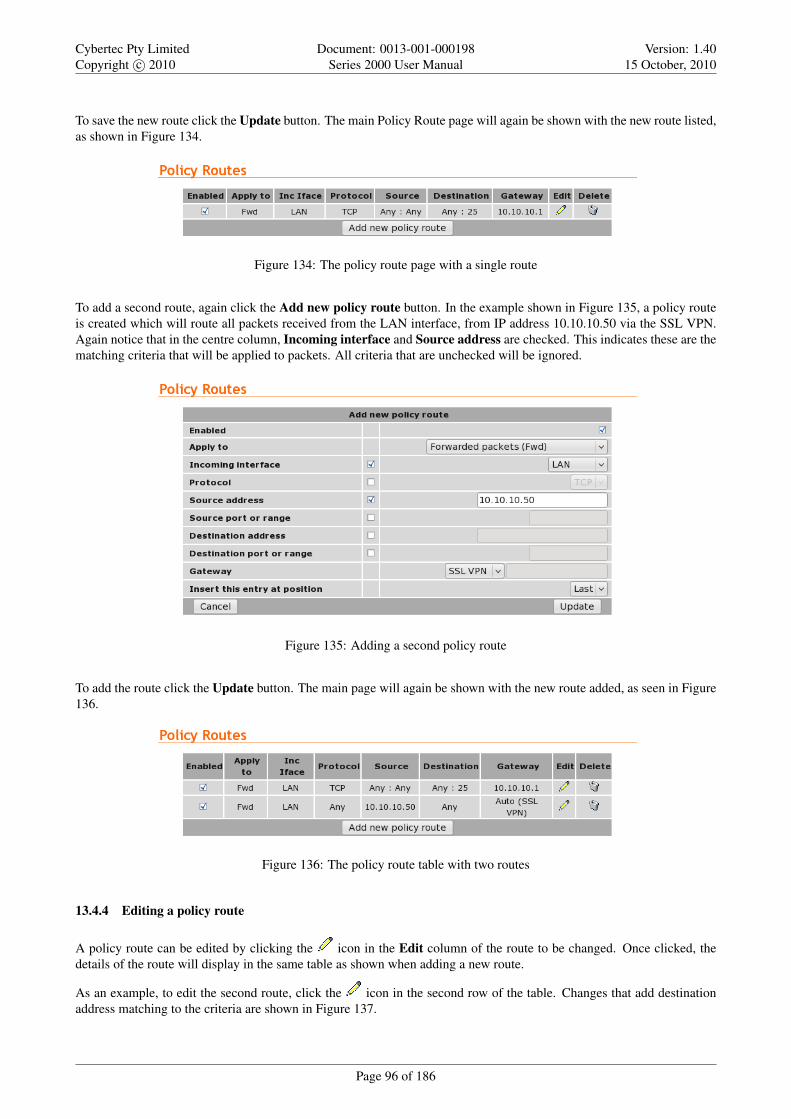
Cybertec Pty LimitedCopyright c© 2010
Document: 0013-001-000198Series 2000 User Manual
Version: 1.4015 October, 2010
To save the new route click the Update button. The main Policy Route page will again be shown with the new route listed,as shown in Figure 134.
Figure 134: The policy route page with a single route
To add a second route, again click the Add new policy route button. In the example shown in Figure 135, a policy routeis created which will route all packets received from the LAN interface, from IP address 10.10.10.50 via the SSL VPN.Again notice that in the centre column, Incoming interface and Source address are checked. This indicates these are thematching criteria that will be applied to packets. All criteria that are unchecked will be ignored.
Figure 135: Adding a second policy route
To add the route click the Update button. The main page will again be shown with the new route added, as seen in Figure136.
Figure 136: The policy route table with two routes
13.4.4 Editing a policy route
A policy route can be edited by clicking the icon in the Edit column of the route to be changed. Once clicked, thedetails of the route will display in the same table as shown when adding a new route.
As an example, to edit the second route, click the icon in the second row of the table. Changes that add destinationaddress matching to the criteria are shown in Figure 137.
Page 96 of 186

Cybertec Pty LimitedCopyright c© 2010
Document: 0013-001-000198Series 2000 User Manual
Version: 1.4015 October, 2010
Figure 137: Editing a policy route
To save the changes click the Update button or to lose any changes click the Cancel button. The main page will again bedisplayed as shown in Figure 138, with the changes for route 2 added to the table.
Figure 138: The main route table after editing route two
13.4.5 Deleting a policy route
A policy route can be deleted by clicking the icon in the Delete column of the route to be deleted. A warning box willbe displayed. Click OK to confirm the deletion or Cancel to prevent the route from being deleted.
For example, to delete route two from the table shown in Figure 138, click the icon in row two of the table. A warningbox will now be displayed, as shown if Figure 139. Click OK to confirm.
Figure 139: Deleting a policy route
The route table will be displayed with the route removed, as shown in Figure 140.
Page 97 of 186

Cybertec Pty LimitedCopyright c© 2010
Document: 0013-001-000198Series 2000 User Manual
Version: 1.4015 October, 2010
Figure 140: Policy route table with route two removed
13.5 Quality of Service Routing
13.5.1 Description
For bandwidth intensive applications, such as live video or Voice-over-IP (VOIP), it may be desirable to have certaintypes of traffic prioritised for transmission out the Wireless interface in preference to other traffic. For example, live videopackets are more time critical than outgoing email and should be prioritised as such.
The modem’s QoS implementation works by dividing the outgoing queue of the Wireless interface into three queue levels:
• High (minimum 60% of bandwidth)
• Standard (minimum 30% of bandwidth)
• Low (minimum 10% of bandwidth)
Where a queue is not using all of its available bandwidth, queues below will expand their bandwidth to ensure full linkutilisation. For example, if there is currently no high priority traffic queued, standard traffic will be able to use up to 90%of the available bandwidth.
Configuring the QoS function is performed in two steps:
• Setting the basic options (enabling QoS and setting the available bandwidth)
• Configuring multiple rules to classify packets into the three different priority queues.
To access the QoS configuration, select Routing . QoS a page similar to that shown in Figure 141 will be displayed.
Figure 141: Quality of Service
13.5.2 Basic QoS options
To enable the QoS feature, the following fields must be set:
QoS enabled When set, QoS is activated for the Wireless interface.
Max uplink rate Set this to the maximum bit rate attainable for the Wireless interface. It is important that this value becorrect, as it will be used to determine the bandwidth allocations for each priority level.
Click Update to save any changes.
Page 98 of 186

Cybertec Pty LimitedCopyright c© 2010
Document: 0013-001-000198Series 2000 User Manual
Version: 1.4015 October, 2010
13.5.3 Basic QoS Configuration
As an example of how to complete the basic QoS configuration, assume the maximum uplink bandwidth is 350kbits/sec.QoS would then be set with the following values:
QoS enabled check to enable QoS
Max uplink rate Set to 350.
Figure 142 illustrates the settings for this example.
Figure 142: Quality of Service configuration with the uplink rate set.
13.5.4 QoS route options
The QoS route options are shown when the Add new QoS route button is pressed or an existing route is edited. The QoSroute options will be displayed as shown in Figure 143.
Figure 143: QoS route options
The following options can be set for each QoS route:
Enabled Set the enabled check box to have the route installed. A route can be temporarily disabled by un-checking thisbox.
Protocol If selected, packets will be matched based on their protocol type. Note that if you wish to match on source ordestination ports, the protocol must be set to TCP or UDP.
Page 99 of 186

Cybertec Pty LimitedCopyright c© 2010
Document: 0013-001-000198Series 2000 User Manual
Version: 1.4015 October, 2010
Source address If selected, either a single address (for example, 172.16.1.132) or a subnet range (for example, 172.16.0.0/24)can be entered. Only packets matching this source address will have the route applied to them.
Source port or range If selected, packets will be matched based on their TCP or UDP source port. Either an individualport (for example, 443) or a range of ports (80-143) can be entered.
Destination address Similar to the Source address, but instead matching on the destination address.
Destination port or range Similar to the Source port or range, but instead matching on the destination port.
Queue Sets the priority queue that packets who meet all of the matching criteria for the route will be assigned to.
Insert this entry at position Determines where this entry will be inserted in the list of QoS routes.
13.5.5 Adding a new QoS route
From the main QoS Route page click the Add new QoS route button. This will select the Add new QoS route page. Anexample of adding a new QoS route is shown in Figure 144. In this example, a new route is to be created that classifiesall traffic from the host 10.10.10.95 with TCP source port 80 to the high priority queue.
Figure 144: Adding a new QoS route
It can be seen in the example that in the centre column Protocol and Source address and Source port or range arechecked. This indicates these are the matching criteria that will be applied to packets. All criteria that are unchecked willbe ignored.
To save the new route click the Update button. The main QoS Route page will again be shown with the new route listed,as shown in Figure 145.
Figure 145: The QoS route page with a single route
To add a second QoS route, again click the Add new QoS route button. In the example shown in Figure 146, a QoSroute is created which will classify all packets destined for an SMTP email server (TCP port 25) to the low priority queue.
Page 100 of 186

Cybertec Pty LimitedCopyright c© 2010
Document: 0013-001-000198Series 2000 User Manual
Version: 1.4015 October, 2010
Again notice that in the centre column, Protocol, Destination address and Destination port or range are checked. Thisindicates these are the matching criteria that will be applied to packets. All criteria that are unchecked will be ignored.
Figure 146: Adding a new QoS route
To add the route click the Update button. The main page will again be shown with the new route added, as seen in Figure147.
Figure 147: The QoS route table with two routes
13.5.6 Editing a QoS route
A QoS route can be edited by clicking the icon in the Edit column of the route to be changed. Once clicked, the detailsof the route will display in the same table as shown when adding a new route.
As an example, to edit the second route, click the icon in the second row of the table. A page similar to the Add newroute page will be displayed, but now showing the details of route 2. Changes that add destination address matching tothe criteria are shown in Figure 148.
Page 101 of 186

Cybertec Pty LimitedCopyright c© 2010
Document: 0013-001-000198Series 2000 User Manual
Version: 1.4015 October, 2010
Figure 148: Editing a QoS route
To save the changes click the Update button or to lose any changes click the Cancel button. The main page will again bedisplayed as shown in Figure 149, with the changes for route 2 added to the table.
Figure 149: The main route table after editing route two
13.5.7 Deleting a QoS route
A QoS route can be deleted by clicking the icon in the Delete column of the route to be deleted. A warning box willbe displayed. Click OK to confirm the deletion or Cancel to prevent the route from being deleted.
For example, to delete route two from the table shown in Figure 149, click the icon in row two of the table. A warningbox will now be displayed, as shown if Figure 150. Click OK to confirm.
Figure 150: Deleting a QoS route
Page 102 of 186

Cybertec Pty LimitedCopyright c© 2010
Document: 0013-001-000198Series 2000 User Manual
Version: 1.4015 October, 2010
The route table will be displayed with the route removed, as shown in Figure 151.
Figure 151: QoS route table with route two removed
Page 103 of 186

Cybertec Pty LimitedCopyright c© 2010
Document: 0013-001-000198Series 2000 User Manual
Version: 1.4015 October, 2010
14 Firewall
The Series 2000 3G Modem / Router has a Stateful Packet Inspection (SPI) Firewall that controls the connections fromthe wireless port to the LAN ports and to the modem itself. The firewall can be used to limit the connections that can beestablished to or via the modem. For example, if the modem is only to be used for serial communications then the firewallcan be set-up to only allow connections through to the serial server (which connects to the serial ports).
14.1 Firewall Setup
The Series 2000 3G Modem / Router firewall configuration is accessed by selecting the Firewall tab from the main menu.When selected the page shown in Figure 152 will be displayed. This page shows and allows configuration of the basicsettings for the firewall.
Figure 152: Basic firewall configuration
14.1.1 Network Address and Port Translation (NAPT)
As connection pass from the LAN network out the wireless port, the firewall can perform Network Address and PortTranslation (NAPT). When set, this option will cause the firewall to substitute the address of the wireless port for thesource address of connections received from the LAN network. This is most useful where the LAN network is a privatenetwork but the wireless port has a public address.
In some cases, for example, if connected to an IP WAN that supports direct routing to the LAN network of the modem, itmay be desirable to disable the NAPT function. This will allow clients on the LAN to be directly addressed without theneed for port forwards. To disable NAPT, uncheck the Connections from LAN checkbox and press Update.
Page 104 of 186

Cybertec Pty LimitedCopyright c© 2010
Document: 0013-001-000198Series 2000 User Manual
Version: 1.4015 October, 2010
14.1.2 Stateful Packet Inspection (SPI)
The firewall in the modem can function in Stateful Packet Inspection (SPI) mode. When enabled, the firewall will trackthe state of each connection passing through it (for example, TCP streams) and only allow packets belonging to a knownconnection to enter from the wireless port. In most cases, SPI should be enabled for greater security. When disabled, thefirewall will allow all incoming packets from the wireless port to be forwarded through to the LAN network.
In some cases, for example, if connected to an IP WAN that supports direct routing to the LAN network of the modem, itmay be desirable to disable the SPI function. This will allow clients on the LAN to be directly addressed without the needfor port forwards. To disable SPI, uncheck the Accept only established destined to LAN checkbox and press Update.
14.1.3 Connection tracking options
The firewall can be configured to optionally provide connection tracking and NAT support for a number of additionalprotocols. The protocols are listed in table 9. To enable support for a protocol, click the checkbox for the protocol andpress Update.
Protocol DescriptionFTP Adds support for active mode File Transfer Protocol
TFTP Adds support for the Trivial File Transfer ProtocolH.323 Adds support for the H.323 voice and videoconferencing protocolPPTP Adds support for the Point-to-point Tunneling ProtocolIRC Adds support for the Internet Relay Chat protocol
Table 9: Firewall Connection tracking options
14.2 Access Control
14.2.1 Description
The Access Control page allows configuration of the firewall to allow or deny access to internal services of the modemfrom the wireless port and VPN tunnels. By default, the firewall will block access from the wireless port to all internalservices such as the web server, and allow access to all internal services from the VPN tunnels. In certain situations itmay be desired to enable access to some services from the wireless port or to disable access to some services from theVPN tunnels, by changing the settings on this page.
The port numbers for internal services are the standard port numbers for the service type, for example, port 80 is used forthe web server. It is possible to change the port number for a particular service. This may be a requirement if a conflictexists with a particular port or service.
To access the Access Controls, select the Firewall tab from the main menu then select the Access Control tab from thesub-menu.
Page 105 of 186

Cybertec Pty LimitedCopyright c© 2010
Document: 0013-001-000198Series 2000 User Manual
Version: 1.4015 October, 2010
Figure 153: Firewall access control options
14.2.2 Accessing modem services from the wireless port or VPN tunnels
The External Access table on the Access Control page is shown in Figure 153. It controls which services can be accessedfrom the wireless port and VPN tunnels. By default, the modem will block all requests received on the wireless port andallow all requests received from VPN tunnels.
There are several modes for determining which services can be accessed:
No access All incoming requests are dropped. Set the Default policy set to Deny and check no boxes in the Allowcolumn.
Restricted access Incoming requests for particular services will be allowed. Set the Default policy to Deny and checkthe boxes for the desired services in the Allow column.
Full access All incoming requests allowed. Set the Default policy to Allow.
To change the port number that a service is received on, change the entry in the Port column for the given service. Forexample, to change the web server to port 8080 on the wireless port, enter 8080 in the WLS column on the Web Serverrow.
14.3 DoS Filters
14.3.1 Description
A denial of service attack (DoS attack) is an attempt to render a network device unavailable to intended users. The mostcommon method of attack involves saturating the target device with external communications requests, such that it cannotrespond to legitimate traffic, or responds so slowly as to be rendered effectively unavailable. The intention of DOS attacksis to cause the targeted device to reset or consume resources to such a level that it is unable to provide the intended service.A consequence of such an attack is that even if the device is able to handle the large number of communications requests,the bandwidth over the communications channel used for the attack may be completely consumed, potentially preventinglegitimate connections to the targeted device.
The firewall has filters that can detect and drop packets that may be part of a Denial of Service (DOS) attack, for example,TCP packets with invalid header information. Options to enable and disable these filters can be found on DoS Filterspage.
Page 106 of 186

Cybertec Pty LimitedCopyright c© 2010
Document: 0013-001-000198Series 2000 User Manual
Version: 1.4015 October, 2010
14.3.2 Enabling the Denial of Service filters
The Filter Description table provides a number of DOS filters, as shown in Figure 154. The filters can be applied topackets received from the LAN port, the wireless port (WLS), and from any VPN tunnel by checking the boxes in theappropriate column.
Figure 154: Firewall DoS filter options
The function of each filter is described below:
Rate limit TCP SYN packets This will limit the number of new TCP connection requests (SYN packets) allowed fromthe given interface. The rate will be limited to 5 per second.
Drop invalid TCP flag combinations Some DOS attacks will send packets that present an invalid combination of TCPflags which may cause problems for some operating systems. The filter will packets with invalid combinationsreceived on the given interface.
Rate limit ICMP requests This will limit the number of ICMP requests (for example, ping requests) allowed from thegiven interface. The rate will be limited to 5 per second.
Accept limited ICMP types The types of ICMP packets that are accepted will be limited to types 0, 3, 8 and 11.
14.4 Custom Filters
14.4.1 Description
Custom Filters allow new rules to be added to the firewall to allow or deny specific packets. Packets can be matchedbased on which of the modem’s network interfaces they arrive on or will leave on, the protocol, the source or destinationaddress.
Some example custom filters are:
• A filter than only allows traffic from a particular host on the WAN to access through to the LAN ports.
• A filter that drops all traffic from a particular host on the WAN.
To select the Custom Filters page select Firewall . Custom Filters, page similar to that shown in Figure 155 will bedisplayed.
Figure 155: Custom Filter main page with no filters configured
Page 107 of 186

Cybertec Pty LimitedCopyright c© 2010
Document: 0013-001-000198Series 2000 User Manual
Version: 1.4015 October, 2010
14.4.2 Custom filter options
The custom filter options are shown when the Add new custom filter button is clicked or an existing route is edited. Thecustom filter options are shown in Figure 156.
Figure 156: Adding a new custom filter
The following options can be set for each custom filter:
Enabled Set the enabled check box to have the rule installed in the firewall. A rule can be temporarily disabled byunchecking this box.
Apply to Custom filters can be applied at three separate points in the modem:
• Forwarded packets. The filter will be applied to packets that are received from one network interface and thenrouted out another network interface.
• Locally destined packets. The filter will be applied to packets destined for the modem’s internal services.
• Locally generated packets. The filter will be applied to packets generated by one of the modem’s internal services.
Incoming interface If selected, packets will be matched based on the network interface they have been received on. Notethat this can’t be applied to Locally generated packets as they have been generated by the modem itself.
Outgoing interface If selected, packets will be matched based on the network interface they will be transmitted on. Notethat this can’t be applied to Locally destined packets as they will be received by the modem itself.
Protocol If selected, packets will be matched based on their protocol type. Note that if you wish to match on source ordestination ports, the protocol must be set to TCP or UDP.
Source address If selected, either a single address (for example, 172.16.1.132) or a subnet range (for example, 172.16.0.0/24)can be entered. Only packets matching this source address will have the filter applied to them.
Source port or range If selected, packets will be matched based on their TCP or UDP source port. Either an individualport (for example, 443) or a range of ports (80-143) can be entered.
Destination address Similar to the Source address, but instead matching on the destination address.
Destination port or range Similar to the Source port or range, but instead matching on the destination port.
Action Determines what action on packets who meet all of the matching criteria for the filter. If set to Deny, the packetwill be dropped. If set to allow, the packet will be passed.
Insert this entry at position Determines where this entry will be inserted in the list of custom filters.
Page 108 of 186

Cybertec Pty LimitedCopyright c© 2010
Document: 0013-001-000198Series 2000 User Manual
Version: 1.4015 October, 2010
14.4.3 Adding a new custom filter
From the main Custom Filters page click the Add new custom filter button. This will select the Add new custom filterpage. An example of adding a new custom filter is shown in Figure 157. In this example, a new filter is to be created toallow packets received via the wireless port, from IP address 112.112.112.112 and destined to the LAN network.
Figure 157: Adding a new custom filter
It can be seen in the example that in the centre column, Incoming interface, Outgoing interface and Source address arechecked. This indicates these are the matching criteria that will be applied to packets. All criteria that are unchecked willbe ignored.
To save the new filter click the Update button. The main Custom Filter page will again be shown with the new filter listed,as shown in Figure 158.
Figure 158: The custom filter page with a single filter
To add a second filter again click the Add new custom filter button. In the example shown in Figure 159, a custom filteris created which will deny packets received from the LAN port, from IP address 211.211.211.211 and destined to thewireless network. Again notice that in the centre column, Incoming interface, Outgoing interface and Source addressare checked. This indicates these are the matching criteria that will be applied to packets. All criteria that are uncheckedwill be ignored.
Page 109 of 186

Cybertec Pty LimitedCopyright c© 2010
Document: 0013-001-000198Series 2000 User Manual
Version: 1.4015 October, 2010
Figure 159: Adding a new custom filter
To add the filter to the filters table click the Update button, the main page will again be shown with the new filter added,as seen in Figure 160.
Figure 160: The custom filter table with 2 filters
14.4.4 Editing a custom filter
A custom filter can be edited by clicking the icon in the Edit column of the filter to be changed. Once clicked, thedetails of the filter will display in the same table as shown when adding a new filter.
As an example, to edit the second filter, click the icon in the second row of the table. A page similar to the Add newfilter page will be displayed, but now showing the details of filter 2. Changes that add protocol and port number matchingto the criteria are shown in Figure 161.
Page 110 of 186

Cybertec Pty LimitedCopyright c© 2010
Document: 0013-001-000198Series 2000 User Manual
Version: 1.4015 October, 2010
Figure 161: Editing a custom filter
To save the changes click the Update button or to lose any changes click the Cancel button. The main page will again bedisplayed as shown in Figure 162, with the changes for filter 2 added to the table.
Figure 162: The main custom filter table after editing filter 2
14.4.5 Deleting a custom filter
A custom filter can be deleted by clicking the icon in the Delete column of the filter to be deleted. A warning box willbe displayed. Click OK to confirm the deletion or Cancel to prevent the filter from being deleted.
For example, to delete filter 2 from the table shown in Figure 162, click the icon in row 2 of the table. A warning boxwill now be displayed, as shown if Figure 163. Click OK to confirm.
Figure 163: Deleting a custom filter
Page 111 of 186

Cybertec Pty LimitedCopyright c© 2010
Document: 0013-001-000198Series 2000 User Manual
Version: 1.4015 October, 2010
The filter table will be displayed with filter removed, as shown in Figure 164.
Figure 164: Custom filter table with filter 2 removed
14.5 Port Forwarding
14.5.1 Description
Port forwarding rules alter the destination address (and optionally the destination port) of packets received on the wirelessport or VPN interfaces of the modem. Port forwards can be used to forward specific services (eg HTTP) to a privatemachine on the LAN network without needing to expose the entire private machine to the public network.
To access the port forward configuration page, select select Firewall . Port Forwards, a page similar to that shown inFigure 165 will be displayed.
Figure 165: Port forward page with no port forwards configured
14.5.2 Port forward options
The port forward options are displayed when the Add new custom filter button is clicked or an existing forward is edited.Figure 166 shows the options for a forward.
Figure 166: Page to add a Port forward
The following options can be set for each port forward:
Enabled Set the enabled check box to have the rule installed in the firewall. A rule can be temporarily disabled byunchecking this box.
Page 112 of 186

Cybertec Pty LimitedCopyright c© 2010
Document: 0013-001-000198Series 2000 User Manual
Version: 1.4015 October, 2010
Protocol The modem is able to forward TCP, UDP, GRE, ESP and AH. Most forwards will be either TCP or UDP. Selectthe appropriate protocol from the list.
Incoming interface Select the interface that the packets to be forwarded on will arrive (in this case, WLS, the wirelessport, is selected).
Source address For greater security, the source addresses that the forward will be applied to can be limited. In this field,either a single address (for example, 172.16.1.132) or a subnet range (for example, 172.16.0.0/24) can be entered.
Original destination port or range This is the port number (80 in the example) but can also be a range (entered as, forexample, 120-150) that the firewall will match on to forward to the new destination address.
New destination address This is the IP address of the server to forward to (10.10.10.50 in the example).
New destination port In addition to changing the destination address, it is also possible to change the destination port.To do so, enter the port in this field. This field can be left blank to keep the port the same.
Insert this entry at position Determines where this entry will be inserted in the list of port forwards.
14.5.3 Adding a new port forward
From the main port forwards page, click the Add new port forward button. This will select the Add new port forwardpage. An example of adding a new port forward is shown in Figure 167. In this example a new port forward is created toforward from port 80 of the wireless port to a HTTP server at address 10.10.10.50.
Figure 167: Adding a port forward
Click Update to save the new port forward. The port forward table will be updated to include the new port forward asshown in Figure 168.
Figure 168: The port forward page with a single port forward
To add a second port forward click the Add new port forward button. In the example shown in Figure 169, a port forwardis created which forward packets received for IP address 112.112.112.112 on port 2200 of the wireless port to LAN IPaddress 10.10.10.72.
Page 113 of 186

Cybertec Pty LimitedCopyright c© 2010
Document: 0013-001-000198Series 2000 User Manual
Version: 1.4015 October, 2010
Figure 169: Adding a second port forward
To add the new port forward to the port forward table click the Update button. The main page will again be shown withthe new port forward added, as seen in Figure 170.
Figure 170: The port forward page with a two port forwards
14.5.4 Editing a port forward
A port forward can be edited by clicking the icon in the Edit column of the port forward to be changed. Once clicked,the details of the port forward will be displayed in the same table as when creating a new port forward.
As an example, to edit the second port forward in the port forward table, click the icon in the second row of the table.A page similar to the Add new port forward page will be displayed but will show the details of port forward 2. Changeswere made so the destination is now port 22 as shown in Figure 171.
Figure 171: Editing a port forward
To save the changes, click the Update button or to lose changes click the Cancel button. The main page will again bedisplayed as shown in Figure 172, with the changes for port forward 2 added to the table.
Page 114 of 186

Cybertec Pty LimitedCopyright c© 2010
Document: 0013-001-000198Series 2000 User Manual
Version: 1.4015 October, 2010
Figure 172: Main port forward page with revised port forward
14.5.5 Deleting a port forward
A port forward can be deleted by clicking the icon in the Delete column of the forward to be deleted. A warning boxwill be displayed. Click OK to confirm the deletion.
For example, to delete port forward 2 from the table shown in Figure 172, click the icon in row 2 of the table. Awarning box will now be displayed as shown if Figure 173. Click OK.
Figure 173: Deleting a port forward
The port forward table will be displayed with the port forward removed, as shown in Figure 174.
Figure 174: Port forward table of deleting a port forward
14.6 Custom NAT
14.6.1 Description
Custom NAT allow new rules to be added to the firewall to carry out Network Address Translation (NAT) that is differentto the usual NAT provided by the firewall. Packets can be matched based on which of the modem’s network interfacesthey arrive on or will leave on, the protocol, the source or destination address. The packets can have Source-NAT (SNAT)applied, where the source address is altered, or Destination-NAT (DNAT) applied, where the destination address is altered.
Some example custom NATs are:
Page 115 of 186

Cybertec Pty LimitedCopyright c© 2010
Document: 0013-001-000198Series 2000 User Manual
Version: 1.4015 October, 2010
• Source-NAT on all packets being transmitted out a VPN tunnel.
• Destination-NAT to redirect packets to a host on the LAN.
To access the Custom NAT configuration page, select Firewall . Custom NAT, a page similar to that shown in Figure 175will be displayed.
Figure 175: Main custom NAT page, with no custom NAT entries in the table
14.6.2 Custom NAT options
The Custom NAT options are displayed when the Add new custom NAT button is clicked or an existing rule is edited.Figure 176 shows the page for entering a custom NAT.
Figure 176: Add new Custom NAT page
The following options can be set for each custom NAT:
Enabled Set the enabled check box to have the rule installed in the firewall. A rule can be temporarily disabled byunchecking this box.
NAT Type Determines the type of NAT the entry will perform.
Apply to When entering a destination NAT, there are two places the NAT can be applied:
Incoming packets The rule will be applied to packets received from the modem’s network interfaces.
Locally generated packets The rule will be applied to packets generated by one of the modem’s internal services.
Incoming interface If selected, packets will be matched based on the network interface they have been received on. Notethat this can only be applied to a Destination NAT on Incoming packets.
Page 116 of 186

Cybertec Pty LimitedCopyright c© 2010
Document: 0013-001-000198Series 2000 User Manual
Version: 1.4015 October, 2010
Outgoing interface If selected, packets will be matched based on the network interface they will be transmitted on. Notethat this can only be applied to a Source NAT.
Protocol If selected, packets will be matched based on their protocol type. Note that if you wish to match on source ordestination ports, the protocol must be set to TCP or UDP.
Source address If selected, either a single address (for example, 172.16.1.132) or a subnet range (for example, 172.16.0.0/24)can be entered. Only packets matching this source address will have the filter applied to them.
Source port or range If selected, packets will be matched based on their TCP or UDP source port. Either an individualport (for example, 443) or a range of ports (80-143) can be entered.
Destination address Similar to the Source address, but instead matching on the destination address.
Destination port or range Similar to the Source port or range, but instead matching on the destination port.
Target address This is the address that the NAT rule will apply to packets. When set to Custom, any IP address can beentered in the text box. If an interface is selected from the dropdown box, the current address of that interface willbe applied to packets.
Target port For rules that specify either the TCP or UDP protocol, it is possible to also alter the port number. If nochange of port number is desired, this field can be left blank.
Insert this entry at position Determines where this entry will be inserted in the list of custom NAT rules.
14.6.3 Adding a new custom NAT
From the main custom NAT page click the Add new custom NAT button. This will select the Add new custom NATpage. An example of adding a new custom NAT is shown in Figure 177. In this example, a new custom NAT is createdwhich will source NAT packets outgoing on the SSL VPN interface to the IP address of the SSL VPN.
Figure 177: Adding a custom NAT
It can be seen in the example that in the centre column only Outgoing interface is checked. This indicates these are thematching criteria that will be applied to packets. In this case, all packets outgoing on the SSL VPN will be source NAT’d.
Click Update to save the new custom NAT. The custom NAT table will be updated to include the new custom NAT asshown in Figure 178.
Page 117 of 186

Cybertec Pty LimitedCopyright c© 2010
Document: 0013-001-000198Series 2000 User Manual
Version: 1.4015 October, 2010
Figure 178: Main custom NAT page showing new custom NAT added to the table
To add a second custom NAT again click the Add new custom NAT button. In the example shown in Figure 179, adestination NAT is created for packets destined for the wireless port.
Figure 179: Adding a custom NAT
To add the new custom NAT click the Update button. The main page will again be shown with the new custom NATadded, as seen in Figure 180.
Figure 180: Main custom NAT page showing new custom NAT added to the table
14.6.4 Editing a custom NAT
A custom NAT can be edited by clicking the icon in the Edit column of the filter to be changed. Once clicked, thedetails of the custom NAT will be displayed in the same table as when creating a new custom NAT.
As an example, to edit the second custom NAT in the Custom NAT table shown in Figure 180, click the icon in thesecond row of the table, A page similar to the new custom NAT page will be displayed but with the details of custom NAT2. To set the protocol for the custom NAT to be UDP, changes were made as shown in Figure 171.
Page 118 of 186

Cybertec Pty LimitedCopyright c© 2010
Document: 0013-001-000198Series 2000 User Manual
Version: 1.4015 October, 2010
Figure 181: Editing a custom NAT
To save the changes click the Update button or to lose the changes click Cancel. The main page will again be displayedas shown in Figure 182, with the changes for custom NAT 2 added to the table.
Figure 182: Main custom NAT page with revised custom NAT 2
14.6.5 Deleting a custom NAT
A custom NAT can be deleted by clicking the icon in the Delete column of the NAT to be deleted. A warning box willbe displayed. Click OK to confirm the deletion.
For example, to delete custom NAT 2 from the table shown in Figure 182, click the icon in row 2 of the table. Awarning box will now be displayed as shown if Figure 173. Click OK.
Page 119 of 186

Cybertec Pty LimitedCopyright c© 2010
Document: 0013-001-000198Series 2000 User Manual
Version: 1.4015 October, 2010
Figure 183: Deleting a custom NAT
The custom NAT table will be displayed with the custom NAT removed, as shown in Figure 174.
Figure 184: Custom NAT table after deleting a custom NAT
14.7 MAC Address Filtering
14.7.1 Description
A unique Media Access Control (MAC) address is assigned to every Ethernet device. This address can be filtered to eitherallow or deny a device access to a network. The Series 2000 3G Modem / Router supports MAC address filtering.
While providing a network with a level of protection, MAC Filtering can be circumvented byscanning the network for a valid MAC and then changing the MAC address of the attackersmachine to a validated one. For this reason if access to the LAN interface of Series 2000 3GModem / Router is to be restricted MAC address filtering should not be used as the only form ofsecurity.
To access the MAC Address Filters configuration page, select Firewall . MAC Filters, a page similar to that shown inFigure 185 will be displayed.
Figure 185: MAC Address filters main page.
Page 120 of 186

Cybertec Pty LimitedCopyright c© 2010
Document: 0013-001-000198Series 2000 User Manual
Version: 1.4015 October, 2010
14.7.2 Default policy
The default policy sets the action to be taken for all MAC addresses not listed in the MAC address table. The options forthis are Allow and Deny. If the default policy is to be set to Deny it is recommended this is done after the Allow rules havebeen added so as to prevent accidental lock-out.
Care should be taken when configuring MAC Filters to ensure the computer being used toconfigure the Series 2000 3G Modem / Router is not denied access if as likely it is connected tothe LAN interface. When changing filters it is recommended to first add a specific filter to allowaccess to the computer being used for configuration. If after configuration is complete the rule isno longer required it can be deleted.If the computer used for configuration is denied access the it will be necessary to perform a factoryreset of the Series 2000 3G Modem / Router as described in Section 4.8 on page 12. This willclear all the configuration settings of the Series 2000 3G Modem / Router to the factory defaultsettings and the LAN ports will be enabled.
If the access via the LAN interface is restricted then access to the web configuration pages may beavailable via the wireless interface if the firewall settings allow access.
14.7.3 MAC Filter options
The MAC Filter options are displayed when the Add new MAC Filter button is clicked or an existing rule is edited.Figure 176 shows the page for entering a custom NAT.
Figure 186: Adding a MAC address filter.
The following options can be set for each custom NAT:
Enabled Set the enabled check box to have the filter active. A filter can be disabled by unchecking this box.
Source MAC address The MAC address on which the filter will be applied.
Action The action to be applied, the options are:
Allow The packet will be allowed to pass the LAN interface.
Deny The packet will be denied access to the LAN interface.
Insert this entry at position Determines where this entry will be inserted in the list of MAC address filters.
14.7.4 Adding a new MAC Filter
From the main custom NAT page click the Add new MAC Filter button. This will select the Add new MAC Filter page.An example of adding a new MAC Filter is shown in Figure 187. In this example, a new MAC filter is added to AllowMAC address 00:11:22:33:44:55 access to the LAN interface.
Page 121 of 186

Cybertec Pty LimitedCopyright c© 2010
Document: 0013-001-000198Series 2000 User Manual
Version: 1.4015 October, 2010
Figure 187: Adding a custom NAT
Click Update to save the new MAC filter. The MAC filter table will be updated to include the MAC filter rule as shownin Figure 188.
Figure 188: MAC filter table with new rule added.
To add a second custom NAT again click the Add new MAC Filter button. In the example shown in Figure 189, a MACfilter has been added to allow MAC address 55:44:33:22:11:00 access to the LAN interface.
Figure 189: Adding a MAC Filter rule.
To add the new MAC filter click the Update button. The main page will again be shown with the new MAC filter ruleadded, as seen in Figure 190.
Figure 190: MAC address table with new rule added
Page 122 of 186

Cybertec Pty LimitedCopyright c© 2010
Document: 0013-001-000198Series 2000 User Manual
Version: 1.4015 October, 2010
14.7.5 Editing a MAC Filter
A MAC Filter can be edited by clicking the icon in the Edit column of the filter to be changed. Once clicked, thedetails of the MAC Filter will be displayed in the same table as when creating a new MAC Filter.
As an example, to edit the second MAC Filter in the MAC Filter table shown in Figure 190, click the icon in thesecond row of the table, A page similar to the new MAC Filter page will be displayed but with the details of MAC Filter2. To change the action for this rule to Deny, changes were made as shown in Figure 171.
Figure 191: Editing a MAC Filter
To save the changes click the Update button or to lose the changes click Cancel. The main page will again be displayedas shown in Figure 192, with the changes for MAC Filter 2 added to the table.
Figure 192: MAC Filter table after changes to MAC filter 2.
14.7.6 Deleting a custom NAT
A MAC Filter can be deleted by clicking the icon in the Delete column of the MAC Filter to be deleted. A warningbox will be displayed. Click OK to confirm the deletion.
For example, if we were to set the default action to Deny then there would no longer be a requirement for MAC Filter 2rule. So first change the default action to Deny as shown in Figure 193, the second rule is no redundant so can be deleted.
Figure 193: MAC Filter page with default action set to deny.
Page 123 of 186
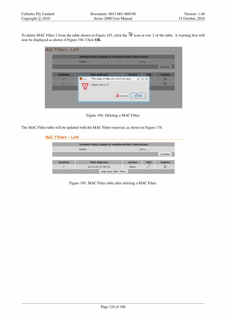
Cybertec Pty LimitedCopyright c© 2010
Document: 0013-001-000198Series 2000 User Manual
Version: 1.4015 October, 2010
To delete MAC Filter 2 from the table shown in Figure 193, click the icon in row 2 of the table. A warning box willnow be displayed as shown if Figure 194. Click OK.
Figure 194: Deleting a MAC Filter.
The MAC Filter table will be updated with the MAC Filter removed, as shown in Figure 174.
Figure 195: MAC Filter table after deleting a MAC Filter.
Page 124 of 186

Cybertec Pty LimitedCopyright c© 2010
Document: 0013-001-000198Series 2000 User Manual
Version: 1.4015 October, 2010
15 Virtual Private Network (VPN)
A virtual private network (VPN) is a communications network tunneled through another network. In the case of the Series2000 3G Modem / Router the secured communications network is tunneled through the 3G wireless network and thenover the Internet or private network to a VPN-capable router or server. The Series 2000 3G Modem / Router has supportfor IPsec, SSL and PPTP/L2TP based VPNs and can be configured for multiple VPN tunnels to operate simultaneously.
15.1 Internet Protocol Security (IPsec) VPN
Internet Protocol Security (IPsec) is a suite of standards and protocols for securing Internet Protocol (IP) communicationsby authenticating and/or encrypting each IP packet in a data stream. Also included within IPsec are protocols for cryp-tographic key establishment. IPsec protocols operate at the network layer (layer 3 of the OSI model). This means thatit can be used for protecting layer 4 protocols, including both TCP and UDP, the most commonly used transport layerprotocols. Using strong encryption and public key cryptography IPsec can secure data links over public networks whichwould otherwise be insecure.
IPsec is a framework which is built in to various security products from companies such as Cisco and Juniper to provideend-to-end security. The Series 2000 3G Modem / Router modem IPsec functionality has been tested for interoperabilitywith the Cisco implementation of IPsec know as Cisco IOS IPsec.
15.1.1 General IPsec configuration
To access the Series 2000 3G Modem / Router IPsec VPN configuration page click VPN . IPsec VPN the page shownin Figure 196 will be displayed. The page contains general IPsec configuration options at the top and a list of configuredtunnels at the bottom.
Figure 196: IPsec based VPN main page
General IPsec configuration
Page 125 of 186

Cybertec Pty LimitedCopyright c© 2010
Document: 0013-001-000198Series 2000 User Manual
Version: 1.4015 October, 2010
Enabled Check the box to enable the IPsec VPN. Default is disabled.
NAT traversal enabled & keepalive period (secs) Check box to enable NAT Traversal and set the keepalive time.
NAT Traversal When passing through a Network Address Translator (NAT) an IP packet is modified in such away that is incompatible with Internet Protocol Security (IPsec). NAT-Traversal protects the original IPsecencoded packet by encapsulating it within another layer of UDP and IP headers. If the wireless interface ofthe Series 2000 3G Modem / Router is allocated a dynamic and private IP address then the connection to theInternet will be via a Network Address Translator (NAT). This will require the use of NAT-Traversal for IPsecto establish a connection.
Keepalive Period NAT keepalives are used to keep the dynamic NAT mapping alive during a connection betweentwo peers. NAT keepalives are UDP packets with an unencrypted payload of 1 byte. Although similar to deadpeer detection (DPD), NAT keepalives are different. DPD is used to detect peer status, while NAT keepalivesare sent if the IPSec entity did not send or receive a packet in a specified period of time.
Overwrite IPsec MTU Maximum Transmission Unit (MTU) is the size (in bytes) of the largest packet which can be sentover the IPsec tunnel. Leave the checkbox un-checked and the value blank to use the default setting. To change theMTU check the checkbox and enter the value.
Click the Update button to save changes.
15.1.2 Adding an IPsec tunnel
To add an IPsec tunnel click the Add new tunnel button. This will display the first of several pages used to configure theIPsec VPN tunnel. The first page is the Tunnel Configuration shown in Figure 197.
Figure 197: IPsec tunnel configuration
15.1.2.1 General Configuration
IPsec general configuration is the first stage in adding a new IPsec tunnel. The options are as follows:
Label Set the label or name for the tunnel. This is used as a reference and is particularly useful when more than onetunnel is configured.
Operating mode Select the operating mode of the IPsec tunnel from the following options:
Tunnel (Default) Tunnel mode encapsulates the entire IP packet to provide a secure connection between two gate-ways. In tunnel mode the payload, the header and the routing information are all encrypted, and then encap-sulated into a new IP packet. This mode is generally used to create a VPN.
Transport Transport mode provides a secure connection between two hosts. Only the payload of the IP packet isencrypted.
Functional mode Select the functional mode of the IPsec tunnel from the following options:
Initiator The tunnel will be initiated, that is it will try and establish a connection with a remote responder.Responder Wait for and respond to incoming connections.
Once configuration is complete on this page click Next to move to the next page Physical Configuration.
Page 126 of 186

Cybertec Pty LimitedCopyright c© 2010
Document: 0013-001-000198Series 2000 User Manual
Version: 1.4015 October, 2010
15.1.2.2 Physical Configuration
The second page is the Physical Configuration page, the options on the page will depend on the functional mode selected,Figure 198 shows the options for the initiator mode while Figure 199 shows the options for the responder mode.
Figure 198: IPsec physical configuration initiator mode.
Figure 199: IPsec physical configuration responder mode.
The options for physical configuration are as follows:
Local interface Select the interface over which to create the tunnel, from the following options:
WLS The wireless interface.
LAN The LAN (Ethernet) interface.
Remote host has fixed address Check if the remote host has a fixed address. (Responder mode only).
Remote host The address of the remote host. The meaning for this option is different for each mode:
Initiator The address of the remote host to which a connection should be established.
Responder The address of the remote host from which to expect connections. This option will only be available ifthe Remote host has fixed address has been checked.
Once configuration is complete on this page click Next to move to the next page Phase 1 Configuration.
15.1.2.3 Phase 1 Configuration
The Phase 1 Configuration is used to set the parameters for the first phase of IPsec Key Exchange (IKE). The first phase isa set-up phase in which the two hosts agree on how to exchange further information securely. The Phase 1 Configurationpage is shown in Figure 200.
Page 127 of 186

Cybertec Pty LimitedCopyright c© 2010
Document: 0013-001-000198Series 2000 User Manual
Version: 1.4015 October, 2010
Figure 200: IPsec Phase 1 configuration
The options for Phase 1configuration are:
Authentication method Select the authentication method from the drop-down list. The options are:
Pre-shared key The Pre-Shared Key (PSK) is a key value which is entered into each host and is used for authenti-cations
Certificate A certificate is an electronic document containing a public key and a digital signature.
Negotiation mode Select the negotiated mode from the drop-down list, the options are:
Main mode Main mode provides identity protection for the hosts initiating the session. Main mode cannot be usedwith pre-shared keys and name-based IDs.
Aggressive mode Aggressive mode is quicker to establish a connection than Main mode but provides no identityprotection. Aggressive mode can be used when there is Network Address Translation (NAT) on the connectionbetween hosts.
Pre-shared key This field is used to enter the Pre-Shared Key if this method of authentication was selected. To enter anew key check the box and enter the key in the text field. During key entry the key will be in clear-text, once thepage is updated the key will no longer be visible. The text immediately prior the check-box will indicate if a keyhas been Set or Not set.
Certificate Select the certificate to use if Certificate authentication has been selected. For information on how to entercertificates refer to Section 15.5 Certificate Management.
Remote ID The remote ID is used to ensure the remote host is in fact the expected remote IPsec entity. The remote IDcan take a number of forms:
IPv4 The remote party will present a standard IP address (eg 123.123.123.123) as its ID. Enter the IP address inthis field.
FQDN Fully Qualified Domain Name. The remote party will present a full hostname as its ID. Enter the name inthis field. Note that hostnames must be able to be resolved through DNS.
FQUN Fully Qualified User Name. The remote party will present a name of the form [email protected] [email protected] as its ID. The domain of this name does not have to be resolveable. Enter the name in thefield, including the ’@’ symbol.
Distinguised Name Where certificate based authentication is used, the Distinguished Name or Subject string ofthe certificate must be entered in this field, preceded by an ’@’ symbol
Local ID The local ID determines how the modem will identify itself to the remote party. The local ID can take a numberof forms:
Page 128 of 186
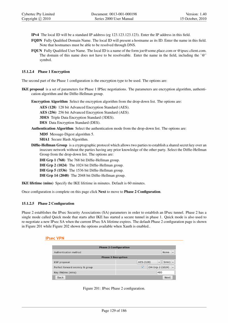
Cybertec Pty LimitedCopyright c© 2010
Document: 0013-001-000198Series 2000 User Manual
Version: 1.4015 October, 2010
IPv4 The local ID will be a standard IP address (eg 123.123.123.123). Enter the IP address in this field.FQDN Fully Qualified Domain Name. The local ID will present a hostname as its ID. Enter the name in this field.
Note that hostnames must be able to be resolved through DNS.FQUN Fully Qualified User Name. The local ID is a name of the form [email protected] or @ipsec.client.com.
The domain of this name does not have to be resolveable. Enter the name in the field, including the ’@’symbol.
15.1.2.4 Phase 1 Encryption
The second part of the Phase 1 configuration is the encryption type to be used. The options are:
IKE proposal is a set of parameters for Phase 1 IPSec negotiations. The parameters are encryption algorithm, authenti-cation algorithm and the Diffie-Hellman group.
Encryption Algorithm Select the encryption algorithm from the drop-down list. The options are:
AES (128) 128 bit Advanced Encryption Standard (AES).AES (256) 256 bit Advanced Encryption Standard (AES).3DES Triple Data Encryption Standard (3DES).DES Data Encryption Standard (DES).
Authentication Algorithm Select the authentication mode from the drop-down list. The options are:
MD5 Message-Digest algorithm 5.SHA1 Secure Hash Algorithm.
Diffie-Hellman Group is a cryptographic protocol which allows two parties to establish a shared secret key over aninsecure network without the parties having any prior knowledge of the other party. Select the Diffie-HellmanGroup from the drop-down list. The options are:
DH Grp 1 (768) The 768 bit Diffie-Hellman group.DH Grp 2 (1024) The 1024 bit Diffie-Hellman group.DH Grp 5 (1536) The 1536 bit Diffie-Hellman group.DH Grp 14 (2048) The 2048 bit Diffie-Hellman group.
IKE lifetime (mins) Specify the IKE lifetime in minutes. Default is 60 minutes.
Once configuration is complete on this page click Next to move to Phase 2 Configuration.
15.1.2.5 Phase 2 Configuration
Phase 2 establishes the IPsec Security Associations (SA) parameters in order to establish an IPsec tunnel. Phase 2 has asingle mode called Quick mode that starts after IKE has started a secure tunnel in phase 1. Quick mode is also used tore-negotiate a new IPsec SA when the current IPsec SA lifetime expires. The default Phase 2 configuration page is shownin Figure 201 while Figure 202 shown the options available when Xauth is enabled..
Figure 201: IPsec Phase 2 configuration.
Page 129 of 186

Cybertec Pty LimitedCopyright c© 2010
Document: 0013-001-000198Series 2000 User Manual
Version: 1.4015 October, 2010
Figure 202: IPsec Phase 2 configuration with Xauth enabled.
The phase 2 options are:
Authentication method Select the extended authentication method, the options are:
None No extended authentication.
XAuth provides an additional level of authentication by allowing the IPSec gateway to request extended authen-tication from remote users, thus forcing remote users to respond with their credentials before being allowedaccess to the VPN.
XAuth username This field is used to enter the XAuth username if this method of authentication was selected.
XAuth password This field is used to enter the XAuth password if this method of authentication was selected. To enter anew password check the box and enter the password in the text field. During key entry the key will be in clear-text,once the page is updated the key will no longer be visible. The text immediately prior the check-box will indicateif a key has been Set or Not set.
15.1.2.6 Phase 2 Encryption
The phase 2 encryption options are:
ESP proposal Encapsulating Security Payload (ESP) is used to encrypt the data transmitted in IP datagrams. The pro-posal establishes the Encryption algorithm and Authentication protocol to use.
Encryption Algorithm Select the encryption algorithm from the drop-down list, the options are:
AES (128) 128 bit Advanced Encryption Standard (AES).AES (256) 256 bit Advanced Encryption Standard (AES).3DES Triple Data Encryption Standard (3DES).Blowfish (128) 128 bit blowfish.Blowfish (256) 256 bit blowfish.
Authentication Algorithm Select the authentication algorithm from the drop-down list, the options are:
MD5 Message-Digest algorithm 5.SHA1 Secure Hash Algorithm.
Perfect forward secrecy & group In an authenticated key-agreement protocol using public key cryptography, such asDiffie-Hellman key exchange, perfect forward secrecy (PFS) is the property that ensures a session key derived froma set of long-term public and private keys will not be compromised if one of the private keys is compromised in thefuture.
Page 130 of 186

Cybertec Pty LimitedCopyright c© 2010
Document: 0013-001-000198Series 2000 User Manual
Version: 1.4015 October, 2010
Perfect forward secrecy Check to enable perfect forward secrecy.
Diffie-Hellman Group Select the Diffie-Hellman Group from the drop-down list, the options are:
DH Grp 1 (768) The 768 bit Diffie-Hellman group.DH Grp 2 (1024) The 1024 bit Diffie-Hellman group.DH Grp 5 (1536) The 1536 bit Diffie-Hellman group.DH Grp 14 (2048) The 2048 bit Diffie-Hellman group.
Key lifetime (mins) Key lifetime in minutes. Default 480 minutes.
Once configuration is complete on this page click Next to move the next page.
15.1.2.7 Tunnel Options
Tunnel options are for configuring how the tunnel renogotiates a connection.
Figure 203: IPsec Tunnel options and Dead Peer Detection configuration.
The options are:
Allow rekeying, margin (mins) & fuzz Rekeying is used to renegotiate the connection encryption keys prior to the pre-vious keys expiring. The options are:
Allow rekeying Check to enable rekeying. Default is On.
Margin The time in minutes prior to the connection expiring at which attempts to negotiate a new connectionbegin. Default 10 Minutes.
Fuzz defines the maximum percentage by which the Margin can be increased in order to randomise rekeyingintervals. Default is 100%.
15.1.2.8 Dead Peer Detection
Dead Peer Detection (DPD) is a method of detecting a dead Internet Key Exchange (IKE) peer. The method uses IPsectraffic patterns to minimise the number of messages required to confirm the availability of the connection. The configura-tion options are:
Enable Check to enable Dead Peer Detection.
Action on failure Specify the action to take when the tunnel is determined to have disconnected. Options are:
None Take no action.
Hold Keep the route open with the understanding that the tunnel will be reestablished. Usually only used when theIP address at each end is fixed.
Page 131 of 186
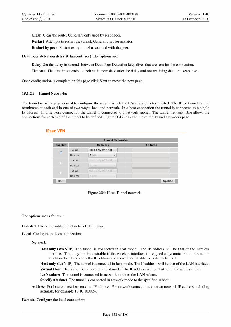
Cybertec Pty LimitedCopyright c© 2010
Document: 0013-001-000198Series 2000 User Manual
Version: 1.4015 October, 2010
Clear Clear the route. Generally only used by responder.
Restart Attempts to restart the tunnel. Generally set for initiator.
Restart by peer Restart every tunnel associated with the peer.
Dead peer detection delay & timeout (sec) The options are:
Delay Set the delay in seconds between Dead Peer Detection keepalives that are sent for the connection.
Timeout The time in seconds to declare the peer dead after the delay and not receiving data or a keepalive.
Once configuration is complete on this page click Next to move the next page.
15.1.2.9 Tunnel Networks
The tunnel network page is used to configure the way in which the IPsec tunnel is terminated. The IPsec tunnel can beterminated at each end in one of two ways: host and network. In a host connection the tunnel is connected to a singleIP address. In a network connection the tunnel is connected to a network subnet. The tunnel network table allows theconnections for each end of the tunnel to be defined. Figure 204 is an example of the Tunnel Networks page.
Figure 204: IPsec Tunnel networks.
The options are as follows:
Enabled Check to enable tunnel network definition.
Local Configure the local connection:
Network
Host only (WAN IP) The tunnel is connected in host mode. The IP address will be that of the wirelessinterface. This may not be desirable if the wireless interface is assigned a dynamic IP address as theremote end will not know the IP address and so will not be able to route traffic to it.
Host only (LAN IP) The tunnel is connected in host mode. The IP address will be that of the LAN interface.Virtual Host The tunnel is connected in host mode. The IP address will be that set in the address field.LAN subnet The tunnel is connected in network mode to the LAN subnet.Specify a subnet The tunnel is connected in network mode to the specified subnet.
Address For host connections enter an IP address. For network connections enter an network IP address includingnetmask, for example 10.10.10.0/24.
Remote Configure the local connection:
Page 132 of 186

Cybertec Pty LimitedCopyright c© 2010
Document: 0013-001-000198Series 2000 User Manual
Version: 1.4015 October, 2010
NetworkNone The tunnel is connected in host mode.Specify a subnet The tunnel is connected to the specified subnet.All traffic All traffic is directed to the IPsec tunnel.
Address For host connections enter an IP address. For network connections enter an network IP address includingnetmask, for example 10.10.10.0/24.
When the configuration is complete click the Update button to add the tunnel.
15.1.3 IPsec configuration example
The following example demonstrates how to add an IPsec tunnel to the Series 2000 3G Modem / Router which willconnect to a remote router. Figure 205 illustrates the connection which will be created in the example. The Series 20003G Modem / Router modem is configured for a standard Internet connection, this means that the IP address assigned toit will be dynamic and private. The example assumes that the router has been configured, has a static IP address and isdirectly accessible from the Internet. The IPsec tunnel will be terminated as a virtual host on the Series 2000 3G Modem/ Router with IP address 11.22.33.44 and will be terminated on a LAN subnet at the router with address 192.168.2.0/24
Figure 205: IPsec configuration example network
15.1.3.1 General Configuration
To start, select the IPsec main page by first clicking VPN . IPsecVPN. Click the Add new tunnel button. The first pageof the IPsec tunnel configuration pages will be displayed, as shown in Figure 206.
Figure 206: IPsec general configuration example.
Page 133 of 186

Cybertec Pty LimitedCopyright c© 2010
Document: 0013-001-000198Series 2000 User Manual
Version: 1.4015 October, 2010
The tunnel will be named Test. It will operate in Tunnel mode and will act as the initiator. The configure settings requiredare:
Label: Test
Operating mode: Tunnel
Functional mode Initiator
Once entered click the Next button to continue to the next page.
15.1.3.2 Physical Configuration
The physical configuration page will now be displayed. Figure 207 illustrates this page with the values for the exampleentered.
Figure 207: IPsec Physical configuration example.
The tunnel is to be configured to use the wireless port and to connect to the remote host address of 123.123.123.123. Thesettings required are:
Local interface WLS
Remote host has fixed address Check if the remote host has a fixed address. (Responder mode only).
Remote host 123.123.123.123
Once entered click the Next button to continue to the next page.
15.1.3.3 Phase 1 Configuration
The Phase 1 Configuration page with the settings required for this example is shown in Figure 208. In this phase theauthentication method is set to pre-shared keys and the key entered. The remote ID is xy.example.com and local IDis ab.example.com. As the wireless IP address is dynamic and private the network provider will use Network AddressTranslation (NAT) so main mode cannot be used for the negotiation mode requiring the negotiating mode to be set toaggressive mode. The IKE proposal will use AES 128 bit as the encryption algorithm, SHA1 for authentication andDiffie-Hellman group 2. The IKE lifetime will be left at the default value of 60 minutes.
Page 134 of 186

Cybertec Pty LimitedCopyright c© 2010
Document: 0013-001-000198Series 2000 User Manual
Version: 1.4015 October, 2010
Figure 208: IPsec phase 1 configuration example.
The required parameters are as follows:
Phase 1 Configuration section
Authentication method: Pre-shared key
Negotiation mode: Aggressive mode
Pre-shared key:
New: Checked
key: abcdef
Remote ID: @ab.example.com
Local ID: @xy.example.com
Phase 1 Encryption section
IKE proposal:
Encryption Algorithm: AES (128)
Authentication Algorithm: SHA1
Diffie-Hellman Group: DH Grp 2 (1024)
IKE lifetime (mins): 60
Once entered click the Next button to continue to the next page.
Phase 2 Configuration
The Phase 2 Configuration page with the settings required for this example is shown in Figure 209. For the Phase 2configuration enhanced authentication will not be used, the ESP proposal encryption algorithm is set to AES 128 bit andthe authentication algorithm set to SHA1. Perfect forward secrecy is enabled and set to Diffie-Hellman group 2, the keylifetime will left at the default value of 480 minutes.
The configuration requires the following parameters to be entered:
Phase 2 Configuration section
Page 135 of 186

Cybertec Pty LimitedCopyright c© 2010
Document: 0013-001-000198Series 2000 User Manual
Version: 1.4015 October, 2010
Figure 209: IPsec phase 2 configuration example.
Authentication method None
Phase 2 Encryption section
ESP proposal:
Encryption Algorithm: AES (128)
Authentication Algorithm: SHA1
Perfect forward secrecy & group:
Perfect forward secrecy: Off (un-checked)
Diffie-Hellman Group: DH Grp 2 (1024) (Non-selectable default value)
Key lifetime (mins): 480
Once entered click the Next button to continue to the next page.
15.1.3.4 Tunnel Options & Dead Peer Detection
The Tunnels Options & Dead Peer Detection page with the settings required for this example is shown in Figure 210. There-keying options are left at the default values. Dead peer detection is enabled with the action set to clear the delay andtimeout values are set to 30 and 120 seconds respectively.
The local tunnel will be configured as a virtual host with the IP address 11.22.33.44 and the remote connection will be tothe LAN 192.168.2.0/24.
Figure 210: IPsec tunnel options and Dead Peer Detection configuration example.
The configuration requires the following parameters to be entered:
Tunnel Options
Page 136 of 186
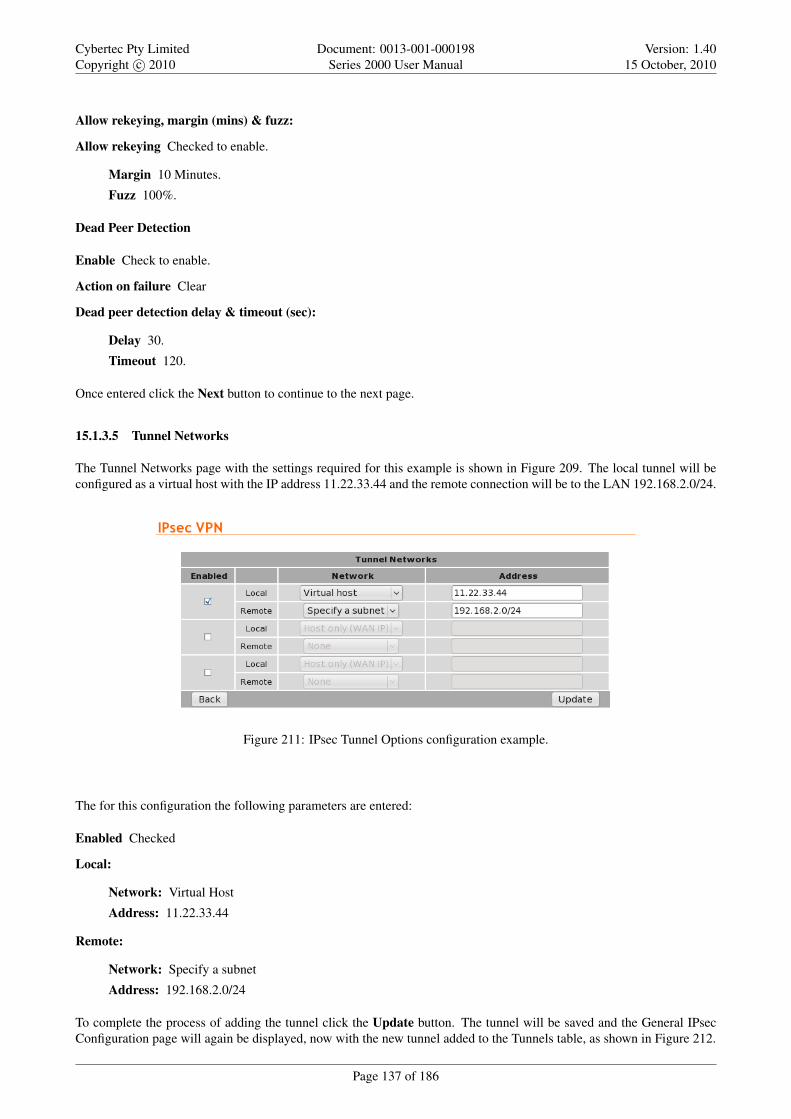
Cybertec Pty LimitedCopyright c© 2010
Document: 0013-001-000198Series 2000 User Manual
Version: 1.4015 October, 2010
Allow rekeying, margin (mins) & fuzz:
Allow rekeying Checked to enable.
Margin 10 Minutes.
Fuzz 100%.
Dead Peer Detection
Enable Check to enable.
Action on failure Clear
Dead peer detection delay & timeout (sec):
Delay 30.
Timeout 120.
Once entered click the Next button to continue to the next page.
15.1.3.5 Tunnel Networks
The Tunnel Networks page with the settings required for this example is shown in Figure 209. The local tunnel will beconfigured as a virtual host with the IP address 11.22.33.44 and the remote connection will be to the LAN 192.168.2.0/24.
Figure 211: IPsec Tunnel Options configuration example.
The for this configuration the following parameters are entered:
Enabled Checked
Local:
Network: Virtual Host
Address: 11.22.33.44
Remote:
Network: Specify a subnet
Address: 192.168.2.0/24
To complete the process of adding the tunnel click the Update button. The tunnel will be saved and the General IPsecConfiguration page will again be displayed, now with the new tunnel added to the Tunnels table, as shown in Figure 212.
Page 137 of 186

Cybertec Pty LimitedCopyright c© 2010
Document: 0013-001-000198Series 2000 User Manual
Version: 1.4015 October, 2010
Figure 212: IPsec table with the newly created entry.
15.1.3.6 Enable IPsec
To complete the configuration in the General IPsec Configuration enable IPsec by checking the Enabled check-box andenable NAT traversal. Click Update to save the settings.
Figure 213: IPsec based VPN main page, with IPsec enabled.
15.1.3.7 IPsec Status
Once the settings have been saved IPsec will start and attempt to establish a tunnel with the remote host. Note that thismay take several minutes to complete. To check the status of the tunnel click Status . VPN. A page similar to that shownin Figure 214will be displayed. If the status of the tunnel is Connected then the tunnel has been established and data canbe passed over it.
To obtain further details on the VPN connection click the link Detailed IPsec status. A page similar to that shown inFigure 215 will be displayed. This information is usually only required if the link is not behaving as expected or if thetunnel is not able to be established.
Page 138 of 186

Cybertec Pty LimitedCopyright c© 2010
Document: 0013-001-000198Series 2000 User Manual
Version: 1.4015 October, 2010
Figure 214: IPsec connection status
The status web pages do not automatically refresh so it may be necessary to refresh the page to obtainthe current status.
Figure 215: IPsec connection status detail
When the detailed page is selected or refreshed it will automatically scroll to the last entry in the log.To view earlier entries the right hand scroll bar can be used.
15.2 Secure Sockets Layer (SSL) VPN
Secure Sockets Layer (SSL) are cryptographic protocols that provide secure communications over a communicationsnetwork. SSL operates at the transport layer (layer 4 of the OSI model). This means that it is can be used to create atunnel through which other layer 4 protocols such as TCP and UDP can pass.
The SSL VPN implementation in the modem is OpenVPN. OpenVPN which is a free and open source virtual privatenetwork (VPN) program for creating point-to-point or server-to-multiclient encrypted tunnels. It is capable of establishingdirect links between computers that are behind NAT firewalls. For information on installing and configuring OpenVPNrefer to the OpenVPN website http://openvpn.net/.
Page 139 of 186

Cybertec Pty LimitedCopyright c© 2010
Document: 0013-001-000198Series 2000 User Manual
Version: 1.4015 October, 2010
15.2.1 SSL VPN configuration
To access the SSL VPN configuration page, select VPN . SSL VPN a page similar to that shown in Figure 216 will bedisplayed.
Figure 216: SSL based VPN configuration web page.
The configuration options are divided into Basic Configuration in the upper section of the page and Advanced Config-uration in the lower section of the page.
15.2.1.1 Basic Configuration
The Basic Configurations options are as follows:
Enabled Check the box to enable the SSL VPN.
Connection Protocol The protocol used will be must match the configuration of the remote VPN server this tunnel willbe established to. Select UDP or TCP as appropriate. Default is UDP.
Transport Type Select the transport type. The transport used must match the configuration of the remote VPN server.
Bridged Bridging is a technique for creating a virtual, wide-area Ethernet LAN, running on a single subnet. Theadvantages of bridging are broadcasts will transverse the VPN which in same situations is desirable, and norouting rules are required. The disadvantages are broadcasts can be problematic on a wireless network as theover-the-air traffic is increased and bridging does not scale well as new devices are added to the network.
Routed Routing will create a separate subnet for each VPN connection. To access one subnet from another requiresrouting rules to be configured at the VPN router. The advantages of routing are efficiency, scalability and nobroadcast traffic. This is particularly important with wireless networks to reduce the over-the-air traffic. Thedisadvantage is that routing rules are required which adds to the configuration.
Remote address Specify the address of the remote VPN server.
Remote port Specify the port number of the remote VPN server. The default OpenVPN port number is 1194.
Certificate Specify the certificate to use for authentication. For details on how to load certificates refer to Section 15.5Certificate Management.
Enable user authentication Check to enable user authentication
Username The user name to use for authentication.
Password The password to use for authentication.
Page 140 of 186

Cybertec Pty LimitedCopyright c© 2010
Document: 0013-001-000198Series 2000 User Manual
Version: 1.4015 October, 2010
15.2.1.2 Advanced Configuration
The advanced options provide more control of the VPN. For most applications the default options do not need to bechanged.
To access the advanced configuration options click the Advanced Configuration + title, the advancedoptions will then drop down as shown in Figure 217.
Figure 217: SSL based VPN configuration web page showing advanced options.
The Advanced Configurations options are as follows:
Ping interval (secs) Specify the interval in seconds at which to ping the remote server. This is used to determine thestatus of the connection.
Ping timeout (secs) Specify the ping timeout in seconds. This is used to determine if the VPN connection has terminated.If this time is exceeded without receiving a ping response from the server the connection will be re-established.
Compression Specify if compression is to be used for the data being transmitted through the VPN tunnel. This mustmatch the compression setting at the remote VPN server. Select one of the following options from the drop-downlist:
Off Compression is disabled.
Adaptive The performance will be measured with compression on and with compression off, the option with thehigher performance will be selected.
On Compression is enabled.
Encryption algorithm Specify the encryption algorithm to use from the drop-down list. The options are:
DES Data Encryption Standard.
Page 141 of 186

Cybertec Pty LimitedCopyright c© 2010
Document: 0013-001-000198Series 2000 User Manual
Version: 1.4015 October, 2010
3DES (192) 192 bit Triple Data Encryption Standard.
Blowfish (128) 128 bit Blowfish (Default).
AES (128) 128 bit Advanced Encryption Standard (AES).
AES (192) 192 bit Advanced Encryption Standard (AES).
AES (256) 256 bit Advanced Encryption Standard (AES).
Tunnel MTU Specify the MTU of the tunnel.
Fragment (0 for off) Used for UDP only. Meant as a last resort when MTU path discovery does not work.
Renegotiation time (secs) The time at which the data channel key will be renegotiated.
15.2.2 Connecting to a VPN server
This section describes an example of connecting to a VPN server. Figure 218 illustrates the network which will be estab-lished. For this example a connection will be established from the Series 2000 3G Modem / Router to an OpenVPN serverusing a routed connection and UDP as the connection protocol. The IP address of the OpenVPN server is 123.123.123.123and the port number is 1194. The certificate supplied for authentication is called demoClient. To ensure the connectionremains connected the ping interval will be set to 30 seconds with a timeout of 120 seconds. Compression will be disabledand the Encryption algorithm will 128 bit Blowfish.
Figure 218: SSL based VPN example network
Select VPN on the main menu to display the the SSL VPN configuration page. Figure 219 shows the SSL VPN configu-ration page with the options set for the example.
Page 142 of 186
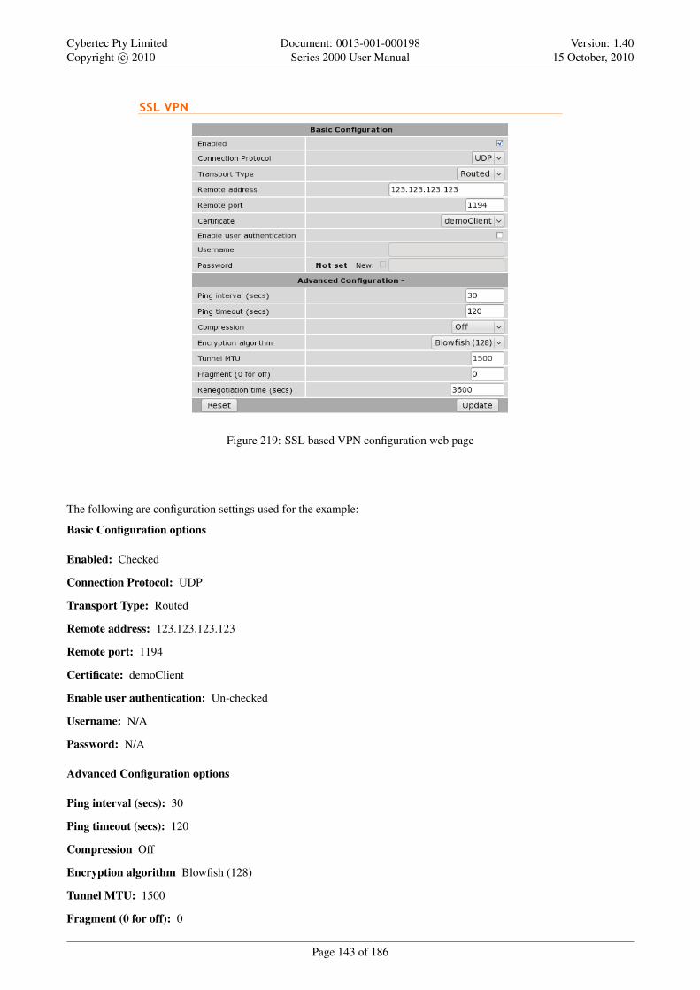
Cybertec Pty LimitedCopyright c© 2010
Document: 0013-001-000198Series 2000 User Manual
Version: 1.4015 October, 2010
Figure 219: SSL based VPN configuration web page
The following are configuration settings used for the example:
Basic Configuration options
Enabled: Checked
Connection Protocol: UDP
Transport Type: Routed
Remote address: 123.123.123.123
Remote port: 1194
Certificate: demoClient
Enable user authentication: Un-checked
Username: N/A
Password: N/A
Advanced Configuration options
Ping interval (secs): 30
Ping timeout (secs): 120
Compression Off
Encryption algorithm Blowfish (128)
Tunnel MTU: 1500
Fragment (0 for off): 0
Page 143 of 186

Cybertec Pty LimitedCopyright c© 2010
Document: 0013-001-000198Series 2000 User Manual
Version: 1.4015 October, 2010
Renegotiation time (secs): 2600
Once the configuration has been completed click the Update button to save the changes. The SSL VPN will now bestarted and it will attempt to establish a connection with the VPN server specified. The status of the VPN can be checkedon the VPN status page. To access this page click Status . VPN page similar to that shown in Figure 220 will be shown.This page indicates that the VPN is connected and lists the local IP address.
Figure 220: SSL VPN status page
In order to test the VPN a ping command can be run from a machine connected to the VPN server. The following is theresult of the ping:
$ ping 10.90.91.30PING 10.90.91.30(10.90.91.30) 56(84) bytes of data.64 bytes from 10.90.91.30: icmp_seq=1 ttl=62 time=141 ms64 bytes from 10.90.91.30: icmp_seq=2 ttl=62 time=122 ms64 bytes from 10.90.91.30: icmp_seq=3 ttl=62 time=120 ms64 bytes from 10.90.91.30: icmp_seq=4 ttl=62 time=121 ms64 bytes from 10.90.91.30: icmp_seq=5 ttl=62 time=121 ms64 bytes from 10.90.91.30: icmp_seq=6 ttl=62 time=122 ms64 bytes from 10.90.91.30: icmp_seq=7 ttl=62 time=123 ms--- 10.90.91.30 ping statistics ---7 packets transmitted, 7 received, 0% packet loss, time 5998msrtt min/avg/max/mdev = 120.620/124.725/141.429/6.867 ms$
The Series 2000 3G Modem / Router has responded to the ping and the byte counters on the status page have increased asseen in Figure 221
Figure 221: SSL VPN status after running Ping, the byte counts have increased
The VPN is now operational as can be used to pass data.
15.3 PPTP and L2TP
15.3.1 Point-to-Point-Tunneling-Protocol
The Point-to-Point-Tunneling-Protocol (PPTP) is used for establishing Virtual Private Network (VPN) tunnels over aninsecure network such as the Internet. PPTP uses a client-server model for establishing the VPN. The Series 2000 3GModem / Router provides a PPTP client. PPTP was developed by Microsoft and is provided with most versions of theWindows operating system. An advantage of PPTP is it is easy to configure.
Page 144 of 186

Cybertec Pty LimitedCopyright c© 2010
Document: 0013-001-000198Series 2000 User Manual
Version: 1.4015 October, 2010
15.3.2 Layer 2 Tunnel Protocol
The Layer 2 Tunnel Protocol (L2TP) is an Internet Engineering Task Force (IETF) standard which combines the best fea-tures of two existing tunneling protocols, Layer 2 Forwarding (L2F) developed by Cisco and the Point-to-Point TunnelingProtocol (PPTP). L2TP can be viewed as an extension to the Point-to-Point Protocol (PPP). One endpoint of an L2TPtunnel is called the L2TP Network Server (LNS), the LNS waits for new tunnels to be established. The other endpoint iscalled the L2TP Access Concentrator (LAC), the LAC initiates tunnel connections to the LNS, the Series 2000 3G Modem/ Router implements an L2TP LAC. Once the L2TP tunnel has been established the traffic over the tunnel is bidirectional.
15.3.3 PPTP and L2TP configuration
To access the PPTP & L2TP configuration page click VPN on the main menu and PPTP & L2TP on the sub-menu. ThePPTP & L2TP page will list the currently configured tunnels. Figure 222 shows the page with no tunnels configured.
Figure 222: The PPTP & L2TP main page
15.3.4 Add a PPTP or L2TP tunnel
To add a new PPTP or L2TP tunnel click the Add new tunnel button. The Add new tunnel page will be displayed asshown in Figure 223
Figure 223: The PPTP & L2TP Add new tunnel page
Add new tunnel options
Label A label or name for the tunnel.
Enabled Check the box to enable the tunnel.
Page 145 of 186

Cybertec Pty LimitedCopyright c© 2010
Document: 0013-001-000198Series 2000 User Manual
Version: 1.4015 October, 2010
Type Select the type of tunnel from the drop-down list, the options are:
PPTP Point-to-Point Tunneling Protocol
l2TP Layer 2 Tunneling Protocol
Remote host Specify then IP address or fully qualified domain name of the remote host.
Domain Specify the Windows network domain. (Optional)
Username The user-name for authentication.
Password Specify the password for connection with the remote host. To set a new password click the New check-boxand then enter the password.
MTU Specify Maximum Transmission Unit (MTU) is the size (in bytes) of the largest packet which can be sent over theIPsec tunnel. Default value is 1400.
Use peer DNS Check the box to enable peer DNS.
15.3.5 PPTP configuration example
The following is an example of connecting a PPTP tunnel to a PPTP VPN server. Figure 224 illustrates the network whichwill be established. For this example a connection will be established from the Series 2000 3G Modem / Router to a PPTPserver. The tunnel will be called test, it is of type PPTP and the remote host is at IP address 123.123.123.123. The domainis x, the username is qwerty and the password password. The MTU setting is left at the default of 1400 and peer DNS isenabled.
Figure 224: PPTP based VPN example network
To access the PPTP & L2TP configuration page click VPN on the main menu and PPTP & L2TP on the sub-menu. ThePPTP & L2TP page will then be displayed. To add a tunnel click the Add new tunnel button on the main PPTP & L2TPpage. The Add new tunnel page will be displayed. Figure 225 illustrates the PPTP add tunnel page with the parametersentered for the configuration described above.
Page 146 of 186

Cybertec Pty LimitedCopyright c© 2010
Document: 0013-001-000198Series 2000 User Manual
Version: 1.4015 October, 2010
Figure 225: The PPTP & L2TP main page
The following settings are used to configured the tunnel as described:
Label: Test
Enabled: On (Checked)
Type: PPTP
Remote host: 123.123.123.123
Domain: x
Username: qwerty
Password: password
MTU: 1400
Use peer DNS: On (Checked)
Once the options have been entered click the Update button to add the tunnel.
The settings will be saved and the main PPTP & L2TP page will be displayed with the new tunnel added to the Tunnelstable, as shown in Figure 226. The Series 2000 3G Modem / Router will now attempt to establish a connection with thePPTP server.
Figure 226: The PPTP & L2TP main page
To check the status of the page click Status on the main menu and VPN on the sub-menu. The VPN status page will thenbe displayed. Figure 227 is the status page for the PPTP VPN created in this example.
Page 147 of 186

Cybertec Pty LimitedCopyright c© 2010
Document: 0013-001-000198Series 2000 User Manual
Version: 1.4015 October, 2010
Figure 227: The PPTP & L2TP main page
The status of the tunnel is connected, indicating that the tunnel has been established and traffic can flow. The status pagealso indicates the local IP address of the tunnels and the number of bytes that have been received and transmitted.
15.4 Multiple VPN Tunnels
The Series 2000 3G Modem / Router allows multiple VPN tunnels to operate simultaneously. One SSL VPN, up to 3IPsec tunnels and up to 3 PPTP/L2TP tunnels can be configure to operate simultaneously. Figure 228 is an example of theVPN Status page with one SSL, one IPsec and one PPTP VPN tunnel operating.
Figure 228: The VPN status page showing 3 active VPN connections
15.5 Certificate Management
Digital certificates are a form of digital identification used for authentication. A digital certificate contains informationthat identifies a device or user. They are issued in the context of a Public Key Infrastructure (PKI), which uses public-key/private-key encryption to ensure security. The Series 2000 3G Modem / Router supports X.509 digital certificates(International Telecommunications Union Recommendation X.509), including SSL (Secure Sockets Layer) certificates.
To access the certificate management page select VPN from the main menu and Certificates from the sub-menu. Thepage shown in Figure 229 will be displayed. The top part of the page lists the currently loaded certificates and secondsection is for uploading a new certificate to the Series 2000 3G Modem / Router .
Page 148 of 186

Cybertec Pty LimitedCopyright c© 2010
Document: 0013-001-000198Series 2000 User Manual
Version: 1.4015 October, 2010
Figure 229: VPN certificate management
15.5.1 Add a certificate
To add a certificate click the Browse button, then navigate to the certificate and select it. In the example shown in Figure230, the file demoClient.p12 is selected which contains the certificate demoClient.
Figure 230: Uploading a VPN certificate
To upload the certificate to the Series 2000 3G Modem / Router click the Upload to Series 2000 3G Modem / Routerbutton. The page will be updated and the certificate will be added to the Certificates table as shown in Figure 231.
Figure 231: VPN certificate table listing the uploaded certificate
Page 149 of 186

Cybertec Pty LimitedCopyright c© 2010
Document: 0013-001-000198Series 2000 User Manual
Version: 1.4015 October, 2010
15.5.2 Checking the certificate details
Once uploaded the details of a certificate can be displayed by clicking view located in the detail column of the table.Figure 232 is an example of the details of a certificate.
Figure 232: VPN certificate details
15.5.3 Adding further certificates
Additional certificates can be uploaded to the Series 2000 3G Modem / Router . The process is the same as adding thefirst certificate. For each additional certificate click the Browse button, navigate to the certificate then click the Uploadto Series 2000 3G Modem / Router button.
Figure 233: Adding a second VPN certificate
An example of adding a second certificate is shown in Figure 233. In this example the file demoClient2.p12 is selected.This file contains the certificate demoClient2. Figure 234 shows the certificate table with the second certificate added.
Page 150 of 186

Cybertec Pty LimitedCopyright c© 2010
Document: 0013-001-000198Series 2000 User Manual
Version: 1.4015 October, 2010
Figure 234: VPN certificate table listing both uploaded certificates
15.5.4 Deleting a certificate
A certificate can be deleted by clicking the bin icon in the Delete column of the certificate to be deleted. When the icon isclicked a warning box will be displayed. Click OK to confirm the deletion or Cancel to prevent the certificate from beingdeleted.
For example, to delete certificate 2 from the table shown in Figure 234, click the bin icon in row 2 of the table. A warningbox will now be displayed as shown if Figure 235, click OK.
Figure 235: Deleting a VPN certificate
The certificate table will be displayed with certificate removed, as shown in Figure 236.
Figure 236: VPN certificate list with the second certificate deleted
Page 151 of 186

Cybertec Pty LimitedCopyright c© 2010
Document: 0013-001-000198Series 2000 User Manual
Version: 1.4015 October, 2010
Page 152 of 186

Cybertec Pty LimitedCopyright c© 2010
Document: 0013-001-000198Series 2000 User Manual
Version: 1.4015 October, 2010
16 Serial Server
The serial server is used to transfer data between a physical serial port and an IP connection. The IP connection can bevia the Ethernet or the wireless connection of the modem. The remote host that connects to the serial server could be aSCADA master, desktop PC or even another modem.
16.1 Selecting a port function
Each port of the serial server can be configured to operate with a different function. The function selected for an appli-cation will be determined by the serial equipment attached to the port and the type of IP connection required. The SerialServer is selected by clicking Serial Server on the main menu, a page similar to that shown Figure 237 will be displayedfor the Series 2000, Model 2100 of Figure 238 for the Model 2220. The difference between models being the number ofports listed.
Figure 237: Serial server main page for Model 2100.
Page 153 of 186

Cybertec Pty LimitedCopyright c© 2010
Document: 0013-001-000198Series 2000 User Manual
Version: 1.4015 October, 2010
Figure 238: Serial server main page for Model 2220.
The table provides a summary of the port settings. The columns have the following meanings:
Port The port number this corresponds the physical port number. Refer to section 4.5 on page 10 and section 4.6 onpage 10 for details.
Function The port function, the following options are available:
Disabled Serial server functionality is disabled for the port.
Raw TCP Client/Server The serial server will function create a transparent pipe between the serial port and aTCP network connection. Example uses of this mode include connecting to a remote PC running serial portredirector software with virtual COM ports or connecting two modems back-to-back to create a serial bridge.
Raw UDP This function is similar to Raw TCP Client/Server mode, but uses UDP as the network transport. UDPhas lower overheads than TCP, but as UDP offers no lost packet detection, this function should only be usedwith serial protocols than can provide the necessary error correction.
Modem Emulator The serial server provides an AT command interface at the serial port that simulates a traditionaldial-up modem. However, instead of dialing out phone calls, the emulator creates TCP network connections.The emulator will also simulate incoming calls if it receives a TCP connection. The function is suited toapplications where equipment attached to the serial port expects to see a dial-up modem.
DNP3 IP-Serial Gateway The serial server will act as a DNP3 outstation to be polled by a SCADA master. Theoutstation mode is configurable as a TCP listen endpoint, TCP dual-function endpoint or UDP endpoint.
Modbus IP-Serial Gateway The serial server will perform conversion from Modbus/TCP to Modbus/RTU orModbus/ASCII, allowing polling by a Modbus/TCP master.
Telnet (RFC 2217) Server The serial server will function as a Telnet server, including the protocol extensionsdefined in RFC 2217. In addition to transporting data, this mode also allows a remote PC with appropriatesoftware to change the port configuration (baud rate etc) and read and write the handshaking lines during asession.
PPP Server The port acts as a PPP server. A device is able to connect to the port and establish a PPP session. Onceestablished the connection acts in a similar way to other packet interfaces.
Page 154 of 186

Cybertec Pty LimitedCopyright c© 2010
Document: 0013-001-000198Series 2000 User Manual
Version: 1.4015 October, 2010
PPP Dialout Client The port establishes a connection to a PPP server. Once established the connection acts in asimilar way to other packet interfaces.
Serial The serial port parameters. Listed in the form <baud> <data bits><parity><stop bits>, For example 19200 8N1this indicates a baud rate of 19200, 8 data bits, Non parity and 1 stop bit. For details on configuring the portparameters refer to section 16.2.1.
Network The network parameters associated with the port. The parameters listed will depend on the mode in which theport is operating.
16.2 Common configuration options
16.2.1 Serial port settings
Regardless of the selected port function, each port needs to be configured to match the parameters of the equipmentattached to the port. As the configuration of a port function is edited, the options displayed in Figure 239 will be shown.
Figure 239: Common port configuration parameters
For each port, the following parameters can be set:
Baudrate The port can be configured for any standard baudrate from 300 baud to 230400 baud.
Databits The port can be configured for operation with 5 to 8 data bits.
Stopbits The port can be configured for operation with 1 or 2 stop bits.
Parity The port can be configured for none, odd or even parity.
Flow control The serial server port can be configured for the following modes:
None No flow control is enabled.
Hardware The port will use the RTS and CTS handshake lines to control the flow of data.
Software The port will use XON/XOFF software flow control. The XOFF character is hex 0x11. The XONcharacter is hex 0x13.
Both The port will use both hardware and software flow control.
Line state when disconnected This field determines the state of the port’s RTS and DTR handshaking lines while theport is disconnected. To set a signal active while disconnected, check the associated box.
Network congestion backoff signal The serial port line RTS and/or DTR to assert when the network is congested andfurther data
Most equipment uses 8 data bits, 1 stop bit and no parity, however, this should be verified against the reference manualfor the equipment.
Page 155 of 186

Cybertec Pty LimitedCopyright c© 2010
Document: 0013-001-000198Series 2000 User Manual
Version: 1.4015 October, 2010
16.2.2 Packet framer settings
The packet framer is available for all port functions that carry raw data (these settings are not available for the DNP3IP-Serial Gateway or Modbus IP-Serial Gateway). The packet framer allows data received from the serial port to bepacketised into larger blocks, reducing the overhead incurred when repeated packets of small sizes are sent over thenetwork.
Figure 240 shows the configuration options for the packet framer.
Figure 240: Packet framing configuration options
The following options control the packet framer:
Maximum packet size This value determines the largest packet size to be passed to the network for transmission. If setto 0, the packet framer will be disabled and data will bypass the packet framer. The value chosen will depend onthe application, however, the value should not be set higher than 1024, so the packet will fit a conventional Ethernetframe.
Minimum size before sending In some applications, it may not be desirable to wait for the exact number of bytes spec-ified in Maximum packet size before sending the packet. The value set in this field, which must be less than orequal to the Maximum packet size, acts as a send threshold. Once the accumulated byte count reaches this value,the packet will be sent.
Timeout before sending The timeout allows data accumulated by the framer to be sent after a specified period of serialreceive inactivity. This prevents data from being held in the framer indefinitely should no more data arrive on theserial port. The timeout is set in 100 millisecond units, so, for example, a one second timeout would be set as avalue of 10.
Immediate send character matching This field allows the framer to be configured so that if certain characters are re-ceived the accumulated data is immediately sent. The character matching can function in two modes:
Match any character If either of the characters set the in Match characters field are received, the data will besent immediately.
Match all characters If both of the characters set in the Match characters field are received in order, the datawill be sent immediately.
Match characters Used in conjunction with the Immediate send character matching field, these characters determinewhat data will cause an immediate send. The values are entered as a hex value, so, for example, a newline (ASCII10) would be entered as 0A. To delete a value, clear the text in the field.
Characters to wait after match Used in conjunction with the Immediate send character matching field, this countdetermines how many additional characters will be received after an immediate match character is detected. This isuseful if some trailing characters always follow the match character.
Enable debug information Check box to enable debugging information to be written to the log file. This can be usefulin debugging.
Page 156 of 186

Cybertec Pty LimitedCopyright c© 2010
Document: 0013-001-000198Series 2000 User Manual
Version: 1.4015 October, 2010
16.3 Raw TCP Client/Server
16.3.1 Description
The serial server will function create a transparent pipe between the serial port and a TCP network connection. Exampleuses of this mode include connecting to a remote PC running serial port redirector software with virtual COM ports orconnecting two modems back-to-back to create a serial bridge.
16.3.2 Selecting the port function
The serial server configuration is accessed by selecting Serial Server . Port Setup. To enable a port for Raw TCPClient/Server function, select Raw TCP Client/Server from the Function column of the appropriate port. Once selected,click Update to confirm the change. Once confirmed, the port will display as shown in Figure 241.
Figure 241: Selecting Raw TCP Client/Server function
16.3.3 Configuring the port function
Once the port function has been selected, click the pencil icon in the Edit column to change the configuration of the port.
Page 157 of 186

Cybertec Pty LimitedCopyright c© 2010
Document: 0013-001-000198Series 2000 User Manual
Version: 1.4015 October, 2010
Figure 242: Raw TCP Client/Server configuration
As shown in Figure 242, the following options can be set for the Raw TCP Client/Server:
Network type The Raw TCP serial server can be configured for three different network modes:
Accept The serial server will listen for TCP connections on the specified port number.
Connect The serial server will establish a TCP connection to the specified address and port number.
Accept and Connect The serial server will normally listen for TCP connections on the specified port number,however, it data is received at the serial port and no connection exists, it will attempt to establish a connectionto the specified address and port number.
Connect address For Connect or Accept and Connect network modes, this is the address the server will attempt toconnect to. The address entered should be in IPv4 decimal dotted notation.
Connect port For Connect or Accept and Connect network modes, this is the TCP port number the server will attemptto connect to. The value entered should be a valid TCP port number.
Timeout after failed connect For Connect or Accept and Connect network modes, if a connection request has failed,the server will wait the amount of time (in seconds) specified in this field before attempting another connectionrequest. While a short timeout may cause the connection to be established more quickly, it may also cause greaternetwork traffic if the remote host is unavailable and repeated attempts fail.
Failed connects before giving up For Accept and Connect network modes, the serial server will attempt to establish aconnection for the number of times specified in this field be giving up and waiting for a connection to be accepted.
Page 158 of 186

Cybertec Pty LimitedCopyright c© 2010
Document: 0013-001-000198Series 2000 User Manual
Version: 1.4015 October, 2010
Accept port For Accept or Accept and Connect network modes, this is the TCP port number that the server will listenfor connections on.
Drop current if new accept For Accept or Accept and Connect network modes, if a TCP connection is currently activeon the serial server, and a new connection request is accepted, this field determines the action that will be taken. Ifset, the new connection will become the active connection and the existing connection will be closed. If not set, theexisting connection will remain active and the newly received connection will be closed.
TCP keepalive time When set to a value greater than 0, TCP keepalives will be enabled for connections, with probessent at the frequency specified (minutes). This may assist in detecting failed connections.
For information on setting the Port Configuration, see section 16.2.1. For information on setting the Packet Framing, seesection 16.2.2.
16.4 Raw UDP
16.4.1 Description
This function is similar to Raw TCP Client/Server mode, but uses UDP as the network transport. UDP has lower overheadsthan TCP, but as UDP offers no lost packet detection, this function should only be used with serial protocols than canprovide the necessary error correction.
16.4.2 Selecting the port function
The serial server configuration is accessed by selecting Serial Server from the main menu and Port Setup from the sub-menu. To enable a port for Raw UDP function, select Raw UDP from the Function column of the appropriate port. Onceselected, click Update to confirm the change. Once confirmed, the port will display as shown in Figure 243.
Figure 243: Selecting Raw UDP function
16.4.3 Configuring the port function
Once the port function has been selected, click the pencil icon in the Edit column to change the configuration of the port.
Page 159 of 186

Cybertec Pty LimitedCopyright c© 2010
Document: 0013-001-000198Series 2000 User Manual
Version: 1.4015 October, 2010
Figure 244: Raw UDP configuration
As shown in Figure 244, the following options can be set for Raw UDP mode:
Send address This is the address the serial server will send UDP packets to. The address entered should be in IPv4decimal dotted notation.
Send port This is the UDP port number the server will send UDP packets to. The value entered should a valid UDP portnumber.
Local receive port This is the UDP port number that UDP packets will be received on at the modem. The value enteredshould a valid UDP port number.
For information on setting the Port Configuration, see section 16.2.1. For information on setting the Packet Framing, seesection 16.2.2.
16.5 Modem Emulator
16.5.1 Description
The serial server provides an AT command interface at the serial port that simulates a traditional dial-up modem. However,instead of dialing out phone calls, the emulator creates TCP network connections. The emulator will also simulateincoming calls if it receives a TCP connection. The function is suited to applications where equipment attached to theserial port expects to see a dial-up modem.
16.5.2 Selecting the port function
The serial server configuration is accessed by selecting Serial Server from the main menu and Port Setup from the sub-menu. To enable a port for the Modem Emulator function, select Modem Emulator from the Function column of theappropriate port. Once selected, click Update to confirm the change. Once confirmed, the port will display as shown inFigure 245.
Page 160 of 186

Cybertec Pty LimitedCopyright c© 2010
Document: 0013-001-000198Series 2000 User Manual
Version: 1.4015 October, 2010
Figure 245: Selecting Modem Emulator function
16.5.3 Configuring the port function
Once the port function has been selected, click the pencil icon in the Edit column to change the configuration of the port.A page similar to that shown in Figure 246, will be displayed.
Figure 246: Modem Emulator configuration.
If the PPP Server Configuration heading is clicked the display will change to include the options shown in Figure 247.
Page 161 of 186

Cybertec Pty LimitedCopyright c© 2010
Document: 0013-001-000198Series 2000 User Manual
Version: 1.4015 October, 2010
Figure 247: Modem Emulator PPP configuration.
Dial out destination address This field determines how the emulator will handle dial requests from the serial port (AT-Dxxxx commands). The dial address may be set by:
Fixed destination Regardless of the value entered after the ATD command, the emulator will always connect tothe host specified in the Fixed destination address and Fixed destination port fields.
From dial string The emulator will parse the ATD command to extract the destination address and port number.The examples below show the two different formats that can be used to create a connection to the address10.10.10.10 and port number 6001.
Dotted Dial string is ATD 10.10.10.10:6001Padded Dial string is ATD 01001001001006001
From phone book When a dial command is entered, the emulator will look up the modem’s phone book andattempt to translate the number to an address and port number. More details on the phone book can be foundin section 16.11.
Accept incoming calls When set, the emulator will listen for TCP connections on the port number specified in the Ac-cept port field. When a connection is received, the emulator will indicate a ring condition at the serial port. Theequipment can then answer the call or wait for the emulator to automatically answer. Once answered, the emulatorwill indicate the connection is open and data will pass between the remote host and the serial port.
Accept port This is the TCP port number that the server will listen for connections on.
On-answer signaling When set, the emulator will behave as follows: When accepting an incoming connection, theemulator will transmit a single byte to the remote host when the call is answered. When establishing an outgoingconnection, the emulator will wait for the first byte of data before signaling that the call has connected at the serialport.
TCP keepalive time When set to a value greater than 0, TCP keepalives will be enabled for connections, with probessent at the frequency specified (minutes). This may assist in detecting failed connections.
Rings until answered This field determines the default number of rings the emulator will wait before automaticallyanswering a call. This is equivalent to setting the ATS0 S-Register in a conventional modem.
DCD mode This field determines the default state of the Data Carrier Detect (DCD) handshaking line. The followingmodes are supported:
Always on Regardless of the online state of the emulator, the DCD line will be active (equivalent to AT&C0).
Follow carrier The DCD line will be active when the emulator is in the online state (equivalent to AT&C1).
DTR function This field determines the default response of the modem to changes in the Data Terminal Ready (DTR)handshaking line. The following modes are supported:
Ignore The emulator will ignore changes to the state of DTR (equivalent to AT&D0).
Page 162 of 186

Cybertec Pty LimitedCopyright c© 2010
Document: 0013-001-000198Series 2000 User Manual
Version: 1.4015 October, 2010
Command mode If the DTR line transitions from the active to inactive state while the emulator is on online datamode, the emulator will drop to AT command mode (equivalent to AT&D1).
Hangup If the DTR line transitions from the active to inactive state while the emulator is on online data mode, theemulator will terminate the current call (equivalent to AT&D2).
For information on setting the Port Configuration, see section 16.2.1. For information on setting the Packet Framing, seesection 16.2.2.
16.6 DNP3 IP-Serial Gateway
16.6.1 Description
The DNP3 IP-Serial Gateway carries out translation between DNP3 Serial and DNP3 TCP protocols. This has severaladvantages:
• DNP3 frames are not fragmented. The translation software identifies and transmits DNP3 link layer frames withoutfragmentation, ensuring reliable transport of the DNP3 data in a single TCP or UDP packet.
• Sever serial port emulation is not required. The SCADA server can communicate with the DNP3 device directlyvia TCP rather than through serial port emulation software. This reduces the complexity and number of softwarelayers required on the SCADA servers.
• Dual function endpoint. The remote station can return unsolicited messages DNP3 serial data to the SCADA server.
16.6.2 Selecting the port function
The serial server configuration is accessed by selecting Serial Server from the main menu and Port Setup from the sub-menu. To enable a port for the DNP3 IP-Serial Gateway function, select DNP3 IP-Serial Gateway from the Functioncolumn of the appropriate port. Once selected, click Update to confirm the change. Once confirmed, the port will displayas shown in Figure 248.
Figure 248: Selecting DNP3 Gateway function
16.6.3 Configuring the port function
Once the port function has been selected, click the pencil icon in the Edit column to change the configuration of the port.
Page 163 of 186

Cybertec Pty LimitedCopyright c© 2010
Document: 0013-001-000198Series 2000 User Manual
Version: 1.4015 October, 2010
Figure 249: DNP3 Gateway configuration
As shown in Figure 249, the following options can be set for the DNP3 Serial-IP Gateway:
Station type The DNP3 IP-Serial Gateway can be configured to operate in three modes:
TCP listen endpoint The serial server will listen for TCP connections on the specified port number.
TCP dual endpoint The serial server will normally listen for TCP connections on the specified port number, how-ever, if a valid DNP packet is received at the serial port and no connection exists, a connection will be estab-lished to the specified master address. This is useful if a SCADA master will poll periodically but facility isrequired to support unsolicited responses.
UDP endpoint The serial server will operate in UDP mode, receiving data on the specified port number and trans-mitting responses to the specified master.
Listen port For all station types, this determines the TCP/UDP port the serial server will listen for connections (TCP)or data (UDP) on. The value entered should be a valid TCP/UDP port number. The default DNP3 port number is20000.
Master address This is the IP address of the SCADA master. The address entered should be in IPv4 decimal dottednotation.
Master port This is the TCP/UDP port the serial server will connect to (TCP) or transmit to (UDP). The value enteredshould be a valid TCP/UDP port number. The default DNP3 port number is 20000.
Only accept data from master IP address When set, this field will cause the serial server to only accept data sourcedfrom the address set in the Master address field.
Timeout for TCP connections For TCP connections only, when this field is set to a value greater than 0, the serial serverwill close connections that have had no receive activity for longer than specified (seconds).
Page 164 of 186

Cybertec Pty LimitedCopyright c© 2010
Document: 0013-001-000198Series 2000 User Manual
Version: 1.4015 October, 2010
Drop existing TCP connection if new received For TCP connections only, if a connection is currently active on theserial server, and a new connection request is accepted, this field determines the action that will be taken. If set, thenew connection will become the active connection and the existing connection will be closed. If not set, the existingconnection will remain active and the newly received connection will be closed.
Timeout between failed TCP connects For TCP dual endpoint only, if a connection request has failed, the server willwait the amount of time (in seconds) specified in this field before attempting another connection request. While ashort timeout may cause the connection to be established more quickly, it may also cause greater network traffic ifthe remote host is unavailable and repeated attempts fail.
Failed TCP connects before giving up For TCP dual endpoint only, the serial server will attempt to establish a con-nection for the number of times specified in this field be giving up and waiting for a connection to be accepted.
Destination address for UDP packets For UDP endpoint only, the serial server can be configured to behave as follows:
Master address and port Packets transmitted over network will always be sent to the address specified in theMaster address and Master port fields.
Address and port of last request Packets transmitted over network will be sent to the source address of the mostrecently received packet. If no packets have been received, packets will be transmitted to the address specifiedin the Master address and Master port fields.
For information on setting the Port Configuration, see section 16.2.1.
16.7 Modbus IP-Serial Gateway
16.7.1 Description
The Modbus IP-Serial Gateway carries out translation between Modbus/TCP and Modbus/RTU or Modbus/ASCII. Thismeans that Modbus serial slaves can be directly attached to the modem’s serial ports without any external protocol con-verters.
16.7.2 Selecting the port function
The serial server configuration is accessed by selecting Serial Server from the main menu and Port Setup from thesub-menu. To enable a port for the Modbus IP-Serial Gateway function, select Modbus IP-Serial Gateway from theFunction column of the appropriate port. Once selected, click Update to confirm the change. Once confirmed, the portwill display as shown in Figure 250.
Figure 250: Selecting Modbus Gateway function
16.7.3 Configuring the port function
Once the port function has been selected, click the pencil icon in the Edit column to change the configuration of the port.
Page 165 of 186

Cybertec Pty LimitedCopyright c© 2010
Document: 0013-001-000198Series 2000 User Manual
Version: 1.4015 October, 2010
Figure 251: Modbus Gateway configuration
As shown in Figure 251, the following options can be set for the Modbus Gateway:
TCP accept port This field determines the TCP port number that the serial server will listen for connections on. Thevalue entered should be a valid TCP port number. The default Modbus/TCP port number is 502.
Drop current if new accept If a connection is currently active on the serial server, and a new connection request isaccepted, this field determines the action that will be taken. If set, the new connection will become the activeconnection and the existing connection will be closed. If not set, the existing connection will remain active and thenewly received connection will be closed.
Connection timeout When this field is set to a value greater than 0, the serial server will close connections that have hadno network receive activity for longer than the specified period
Transmission mode Select RTU or ASCII, based on the Modbus slave equipment attached to the port.
Response timeout This is the timeout (in milliseconds) to wait for a response from a serial slave device before retryingthe request or returning an error to the Modbus master.
RTU framing timeout This is the timeout (in milliseconds) the the serial server will use to determine the boundaries ofModbus/RTU packets received on the serial port.
Retries Should no valid response be received from a Modbus slave, the value in this field determines the number of timesthe serial server will re-transmit requests before giving up.
For information on setting the Port Configuration, see section 16.2.1.
16.8 Telnet (RFC 2217) Server
16.8.1 Description
Telnet server mode is ideal for connecting serial terminal equipment, as a standard Telnet client can be used to connect tothe server.
Page 166 of 186

Cybertec Pty LimitedCopyright c© 2010
Document: 0013-001-000198Series 2000 User Manual
Version: 1.4015 October, 2010
The Telnet sever mode also supports the RFC 2217 extensions, which, when used with a remote PC running appropriateserial port redirector software, allow port configuration changes (such as the baudrate) to be transmitted over the networkto the modem. Changes in modem handshaking lines are also transmitted.
16.8.2 Selecting the port function
The serial server configuration is accessed by selecting Serial Server from the main menu and Port Setup from the sub-menu. To enable a port for the Telnet Server function, select Telnet (RFC 2217) Server from the Function column ofthe appropriate port. Once selected, click Update to confirm the change. Once confirmed, the port will display as shownin Figure 252.
Figure 252: Selecting Telnet Server function
16.8.3 Configuring the port function
Once the port function has been selected, click the pencil icon in the Edit column to change the configuration of the port.
Figure 253: Telnet Server configuration
Page 167 of 186

Cybertec Pty LimitedCopyright c© 2010
Document: 0013-001-000198Series 2000 User Manual
Version: 1.4015 October, 2010
As shown in Figure 253, the following options can be set for the Telnet Server:
Accept port This field determines the TCP port number that the serial server will listen for connections on. The valueentered should be a valid TCP port number.
Drop current if new accept If a connection is currently active on the serial server, and a new connection request isaccepted, this field determines the action that will be taken. If set, the new connection will become the activeconnection and the existing connection will be closed. If not set, the existing connection will remain active and thenewly received connection will be closed.
TCP keepalive time When set to a value greater than 0, TCP keepalives will be enabled for connections, with probessent at the frequency specified (minutes). This may assist in detecting failed connections.
For information on setting the Port Configuration, see section 16.2.1. For information on setting the Packet Framing, seesection 16.2.2.
16.9 PPP Server
16.9.1 Description
PPP Server description.
16.9.2 Selecting the port function
The serial server configuration is accessed by selecting Serial Server from the main menu and Port Setup from the sub-menu. To enable a port for the Telnet Server function, select PPP Server from the Function column of the appropriateport. Once selected, click Update to confirm the change. Once confirmed, the port will display as shown in Figure 254.
Figure 254: Selecting PPP Server function
16.9.3 Configuring the port function
Once the port function has been selected, click the pencil icon in the Edit column to change the configuration of the port.
Page 168 of 186

Cybertec Pty LimitedCopyright c© 2010
Document: 0013-001-000198Series 2000 User Manual
Version: 1.4015 October, 2010
Figure 255: PPP Server configuration
As shown in Figure 255, the following options can be set for the Telnet Server:
Accept port This field determines the TCP port number that the serial server will listen for connections on. The valueentered should be a valid TCP port number.
Drop current if new accept If a connection is currently active on the serial server, and a new connection request isaccepted, this field determines the action that will be taken. If set, the new connection will become the activeconnection and the existing connection will be closed. If not set, the existing connection will remain active and thenewly received connection will be closed.
TCP keepalive time When set to a value greater than 0, TCP keepalives will be enabled for connections, with probessent at the frequency specified (minutes). This may assist in detecting failed connections.
For information on setting the Port Configuration, see section 16.2.1. For information on setting the Packet Framing, seesection 16.2.2.
16.10 PPP Dialout Client
16.10.1 Description
PPP Dialout Client description.
16.10.2 Selecting the port function
The serial server configuration is accessed by selecting Serial Server from the main menu and Port Setup from thesub-menu. To enable a port for the Telnet Server function, select PPP Dialout Client from the Function column of theappropriate port. Once selected, click Update to confirm the change. Once confirmed, the port will display as shown inFigure 256.
Page 169 of 186

Cybertec Pty LimitedCopyright c© 2010
Document: 0013-001-000198Series 2000 User Manual
Version: 1.4015 October, 2010
Figure 256: Selecting Telnet Server function
16.10.3 Configuring the port function
Once the port function has been selected, click the pencil icon in the Edit column to change the configuration of the port.
Figure 257: Telnet Server configuration
As shown in Figure 257, the following options can be set for the Telnet Server:
Accept port This field determines the TCP port number that the serial server will listen for connections on. The valueentered should be a valid TCP port number.
Drop current if new accept If a connection is currently active on the serial server, and a new connection request isaccepted, this field determines the action that will be taken. If set, the new connection will become the activeconnection and the existing connection will be closed. If not set, the existing connection will remain active and thenewly received connection will be closed.
Page 170 of 186

Cybertec Pty LimitedCopyright c© 2010
Document: 0013-001-000198Series 2000 User Manual
Version: 1.4015 October, 2010
TCP keepalive time When set to a value greater than 0, TCP keepalives will be enabled for connections, with probessent at the frequency specified (minutes). This may assist in detecting failed connections.
For information on setting the Port Configuration, see section 16.2.1. For information on setting the Packet Framing, seesection 16.2.2.
16.11 Phone Book
16.11.1 Description
The Phone Book works in conjunction with the Modem Emulator to provide a translation table from traditional phonenumbers to IP addresses and port numbers. This allows the Modem Emulator to be used as a drop in replacement for atraditional dial-up modem and to create IP connections rather than phone calls.
For more information on the Modem Emulator, see section 16.5.
To access the Phone Book configuration, select Serial Server from the main menu and Phone Book from the sub-menu.The page will initially have no entries, as shown in Figure 258.
Figure 258: Phone Book with no entries configured
16.11.2 Phone book options
To access the phone book options click the Add new phone book entry button on the main Phone Book page. Figure259 shows the page for entering a new entry.
Figure 259: Page for adding Phone Book entry
The following options can be set for each entry:
Dial string This is the phone number that the dial command will attempt to match against.
Connect address This is the IP address the serial server will attempt to connect to.
Connect port This is the IP port number the serial server will attempt to connect to.
16.11.3 Adding a new phone book entry
From the main phone book page click the Add new phone book entry button. An example of adding a new entryis shown in Figure 260. In this example a new entry is created that translates dial string 123 to connection address123.123.123.123:123.
Page 171 of 186

Cybertec Pty LimitedCopyright c© 2010
Document: 0013-001-000198Series 2000 User Manual
Version: 1.4015 October, 2010
Figure 260: Adding a Phone Book Entry
Click Update to save the new entry. The phone book table will be updated to include the new entry as shown in Figure261.
Figure 261: The Phone Book page with a single entry
To add a second entry click the Add new phone book entry button. In the example shown in Figure 262, an entry iscreated which translates dial string 234 to connection address 234.234.234.234:234.
Figure 262: Adding a second entry
To commit the new phone book entry to the table, click the Update button. The main page will again be shown with thenew entry added, as seen in Figure 263.
Figure 263: The phone book page with two phone book entries
16.11.4 Editing a phone book entry
A phone book entry can be edited by clicking the icon in the Edit column of the entry to be changed. Once clicked,the details of the entry will be displayed in the same table as when creating a new phone book entry.
As an example, to edit the second phone book entry in the table, click the icon in the second row of the table. Tochange the connect port of the entry to 235, changes were made as shown in Figure 264.
Page 172 of 186

Cybertec Pty LimitedCopyright c© 2010
Document: 0013-001-000198Series 2000 User Manual
Version: 1.4015 October, 2010
Figure 264: Editing a phone book entry
To save the changes click the Update button or to lose any changes click the Cancel button. The main page will again bedisplayed as shown in Figure 265, with the changes for entry 2 added to the table.
Figure 265: Main phone book page with revised entry
16.11.5 Deleting a phone book entry
A phone book entry can be deleted by clicking the icon in the Delete column of the entry to be deleted. A warningbox will be displayed. Click OK to confirm the deletion.
For example, to delete phone book entry 2 from the table shown in Figure 265, click the icon in row 2 of the table. Awarning box will now be displayed as shown if Figure 266. Click OK.
Figure 266: Deleting a phone book entry
The phone book table will be displayed with the entry removed, as shown in Figure 267.
Figure 267: Phone book table after deletion of entry
Page 173 of 186

Cybertec Pty LimitedCopyright c© 2010
Document: 0013-001-000198Series 2000 User Manual
Version: 1.4015 October, 2010
17 Management
The Management section is used to configure the management options of the Series 2000 3G Modem / Router . Man-agement of the Series 2000 3G Modem / Router can be done in several ways, options include SNMP, DNP3, SMS andemail.
17.1 Events
The main management page is called Events and is accessed by clicking the Management tab on the main menu, orManagement . Events. Figure 268 is an example of the main Management page for the Model 2100 while Figure is anexample of the main Management page for the Model 2220. The difference is events for the GPIO on the Model 2220page.
Figure 268: Management main page for Model 2100.
Page 174 of 186

Cybertec Pty LimitedCopyright c© 2010
Document: 0013-001-000198Series 2000 User Manual
Version: 1.4015 October, 2010
Figure 269: Management main page for Model 2220.
17.1.1 Event Types
The events which may generate triggers are listed in the first column of Events table. The events are as follows:
Temperature The nominal operating range of the may be specified. Events may be generated:
Exceeding range Triggered when the temperature is outside the nominal range. That is lower than the low tem-perature to higher than the high temperature as set in the range.
Returning inside range Triggered when the temperature returns within the nominal range limits.
The current temperature is reported on the Status . Alarms page. Refer to Section 9.1 on page 31 fordetails.
Network registration The network registration status. Events may be generated:
On loss Triggered when the network registration moves from the connected state to the disconnected state. Notethis event cannot trigger an SMS as it will not be possible to send an SMS without network registration.
On return Triggered when network registration is established.
RSSI A threshold may be set for the Receive Signal Strength Indicator (RSSI). Events may be generated:
Page 175 of 186

Cybertec Pty LimitedCopyright c© 2010
Document: 0013-001-000198Series 2000 User Manual
Version: 1.4015 October, 2010
Threshold Specify the trigger threshold. Minimum 0, maximum 30
Below threshold Triggered when RSSI falls below the threshold.
Above threshold Triggered when RSSI raises above the threshold.
Packet mode The packet mode status. Event may be generated:
When session connects Triggered when a packet mode session connects.
When session disconnects Triggered when a packet mode session disconnects.
Circuit switched mode The Circuit Switched Data (CSD) mode status. Events may be generated:
When online When CSD connects. This will trigger for both incoming and outgoing connections.
When offline When CSD disconnects.
The current state of the wireless connection can be found on the Status . Wireless page. Refer to Sec-tion 9.2 on page 33 for details.
GPIO The General Purpose Inputs and Outputs. These events are only available for the Model 2220. The followingevents may be generated:
Input 1 (Input-1) GPIO Input 1, the label associated with the input will be shown enclosed by brackets, for exam-ple “(Input 1 label”).
On close Triggered when the input transitions from the open to the closed state.On open Triggered when the input transitions from the closed to the open state.
Input 2 (Input-2) GPIO Input 2, the label associated with the input will be shown enclosed by brackets, for exam-ple “(Input 2 label”).
On close Triggered when the input transitions from the open to the closed state.On open Triggered when the input transitions from the closed to the open state.
Output 1 (Output-1) GPIO Output 1, the label associated with the input will be shown enclosed by brackets, forexample “(Output 1 label”).
On close Triggered when the output transitions from the open to the closed state.On open Triggered when the output transitions from the closed to the open state.
Output 2 (Output-2) GPIO Output 2, the label associated with the input will be shown enclosed by brackets, forexample “(Output 2 label”).
On close Triggered when the output transitions from the open to the closed state.On open Triggered when the output transitions from the closed to the open state.
17.1.2 Trigger Types
When an event condition is met it may generate a trigger which is any of:
None The trigger does not generate any message.
SNMP An SNMP trap is generated.
DNP3 An DNP3 exception is generated.
SMS An SMS is generated.
Email An email is generated.
To select a trigger for an event check the check box for the event row corresponding to the trigger type column. For exam-ple to enable SNMP traps for Network Registration loss and return check the two checkboxes in the Network registrationrow, under the SNMP column. This example is illustrated in Figure 270 with the Network Registration row highlighted.
Page 176 of 186

Cybertec Pty LimitedCopyright c© 2010
Document: 0013-001-000198Series 2000 User Manual
Version: 1.4015 October, 2010
Figure 270: Enabling SNMP traps for the Network Registration events.
17.2 SNMP
The Series 2000 supports the Simple Network Management Protocol (SNMP) for network management of the unit. Thecurrent connection status and RF signal level are examples of status variables accessible through SNMP. The custom MIBfile for the modem is available from Cybertec.
The SNMP configuration options are accessed by selecting System from the main menu and SNMP from the sub-menu.The SNMP configuration page is show in Figure 271.
Figure 271: The SNMP configuration page
17.2.1 Configuring the general SNMP options
The general configuration options are described below:
Location The location reported in the standard SNMP Location field.
Page 177 of 186

Cybertec Pty LimitedCopyright c© 2010
Document: 0013-001-000198Series 2000 User Manual
Version: 1.4015 October, 2010
Contact The contact name reported in the standard SNMP Contact field.
Read-only community The community string expected for read-only access.
Read-write community The community string expected for read-write access.
17.2.2 Configuring an SNMP trap destination
SNMP uses messages called traps to report alerts or asynchronous errors to an SNMP master. The modem can generatetraps on events such as the RF signal level dropping below a threshold.
The Trap Configuration table is used to specify the details of the SNMP master that traps will be sent to.
Click Add new trap destination to add a new entry.
The following fields can be set:
Destination address The IP address of the SNMP master.
Community The community string to send with traps.
Port The IP port of the SNMP master.
Click Update to save the new trap destination.
17.3 DNP3
The modem can be configured to operate as a DNP3 outstation for reporting of the modem’s state. Information such asthe current connection status and RF level are available via DNP3 and, on models with GPIO, the GPIO can also be readand written.
The options for these can be found by selecting System from the main menu and DNP3 from the sub-menu.
The DNP3 page is shown in Figure 272.
Figure 272: The DNP3 outstation configuration page
Page 178 of 186

Cybertec Pty LimitedCopyright c© 2010
Document: 0013-001-000198Series 2000 User Manual
Version: 1.4015 October, 2010
17.3.1 Configuring the outstation
The following can be set for the outstation:
Outstation mode The outstation supports the following outstation modes:
Disabled The outstation will not function.
TCP listen endpoint The outstation will accept TCP connections from a DNP3 master.
TCP dual endpoint The outstation will accept TCP connections from a DNP3 master. It will also establish aconnection should an event occur while no master is connected.
UDP (datagram) endpoint The outstation can be polled by a DNP3 master using UDP. Events will also be trans-mitted to the master via UDP.
DNP3 address This is the DNP3 link-layer address for the outstation.
Default DNP3 master address This is the address that will be used for TCP keepalives if the DNP3 master address fora connection is currently unknown.
Listen port This is the IP port number that the outstation will accept connections. The default DNP3 port number is20000.
Limit connections to listed masters When set, only masters whose IP addresses are listed in the masters table will beallowed to connect.
TCP keepalive interval To detect dead TCP connections, the outstation will periodically send DNP3 polls to request thelink status. If the master fails to respond, the connection will be closed. This field determines after what idle period(in seconds) that link status messages will be generated.
App. confirmation timeout This is the timeout (in seconds) that will be used while waiting to receive an applicationlevel confirmation from a DNP3 master.
App. unsolicited retries This is the number of times the outstation will retry sending unsolicited responses, should noconfirmation be received from a master.
Unsolicited enabled by default When this option is not set, the modem will not send any unsolicited responses untilan ENABLE_UNSOLICITED (function code 20) message is received from a master. With this option set, theoutstation will default to having unsolicited responses enabled.
Time-of-day format This field determines the time format used in events. When set to UTC, the outstation will adjustall times by the system timezone setting (see section 10.1.2).
17.3.2 Adding a DNP3 master
Details of the DNP3 masters can be configured to allow limiting of connections or to enable unsolicited responses.
To configure the information about a new DNP3 master, click the Add new master button.
The following fields can be set for each master:
Master IP address The IP address of the DNP3 master.
Master IP port The IP port number the master receives unsolicited responses on.
DNP3 address The DNP3 link-layer address of the master.
Unsolicited receiver When set, the master will receive unsolicited responses from the outstation.
Click Update to save the new master.
Page 179 of 186

Cybertec Pty LimitedCopyright c© 2010
Document: 0013-001-000198Series 2000 User Manual
Version: 1.4015 October, 2010
17.4 SMS
The SMS page is used to configure the general SMS settings which include the SMS Distribution list and the SMS ratecontrol. The page menu is Management . SMS the page is shown in Figure 273.
Figure 273: The SMS configuration page
17.4.1 SMS Distribution List
The SMS distribution list section lists the current numbers to which SMSes will be sent and allows new numbers to beadded to the list. The filed of the table are:
Label A text label for the entry.
Phone Number The phone to which the SMS will be sent.
Enabled Check to enable this entry.
Edit Click the icon to edit the entry.
Delete Click the icon to delete the entry.
17.4.2 SMS Entry Options
To access the SMS Entry Options click the Add new destination button at the bottom of the SMS distribution list table.The following page will be displayed:
Figure 274: The SMS configuration page
To create a new entry complete the fields which have the following meaning:
Page 180 of 186

Cybertec Pty LimitedCopyright c© 2010
Document: 0013-001-000198Series 2000 User Manual
Version: 1.4015 October, 2010
Label A text label for the entry.
Phone Number The phone to which the SMS will be sent.
The phone number must be in the form +<country code><phone number>. For example +61432123123If a number is entered with a 0 as the first digit +61 will automatically be added to the number and the0 will be removed.
Enabled Check to enable this entry.
When finished click Update to save the changes.
17.4.3 Adding a New SMS Entry
To add a new entry click the Add new destination button at the bottom of the SMS distribution list table. The Add newSMS destination page as shown in Figure 274 will be displayed. An example of an entry is shown in Figure 275, in thiscase the entry will be labeled Test and the phone number is 0411123456.
Figure 275: An example of adding an SMS entry.
Once the changes have made click the Update to save the entry. The SMS distribution list page will be displayed againnow with the new entry as shown in Figure
Figure 276: The SMS entry has been added to the list.
To add a second entry again click the Add new destination button at the bottom of the SMS distribution list table. Anexample of adding a second entry is shown in Figure 277, in this case the label is called Test2 and the phone number is+61432123456.
Page 181 of 186

Cybertec Pty LimitedCopyright c© 2010
Document: 0013-001-000198Series 2000 User Manual
Version: 1.4015 October, 2010
Figure 277: Adding a second SMS entry to the distribution list.
Click update to add the entry to the table. The SMS distribution list will now include the new entry as shown in Figure278.
Figure 278: SMS distribution list showing two entries.
17.4.4 Editing an SMS Entry
An SMS entry can be edited by clicking the icon in the Edit column of the entry to be changed. Once clicked, thedetails of the entry will be displayed in the same table as when creating a new phone book entry.
As an example, to edit the second SMS entry in the table, click the icon in the second row of the table. To change thephone number of the entry to +61432123456, changes were made as shown in Figure 279.
Figure 279: Editing SMS entry.
To save the changes click the Update button or to lose any changes click the Cancel button. The main page will again bedisplayed as shown in Figure 265, with the changes for entry 2 added to the table.
Page 182 of 186

Cybertec Pty LimitedCopyright c© 2010
Document: 0013-001-000198Series 2000 User Manual
Version: 1.4015 October, 2010
Figure 280: List after editing SMS entry.
17.4.5 Deleting an SMS entry
A SMS entry can be deleted by clicking the icon in the Delete column of the entry to be deleted. A warning box willbe displayed. Click OK to confirm the deletion.
For example, to delete SMS entry 2 from the table shown in Figure 265, click the icon in row 2 of the table. A warningbox will now be displayed as shown if Figure 266. Click OK.
Figure 281: Deleting an SMS entry.
Figure 282: SMS distribution list after deleting SMS entry.
Page 183 of 186

Cybertec Pty LimitedCopyright c© 2010
Document: 0013-001-000198Series 2000 User Manual
Version: 1.4015 October, 2010
17.4.6 SMS Distribution Rate Limit
The SMS rate limit settings allow the number of SMSes sent in a specified period to be limited. This can be used toprevent an input or output that changes more frequently than expected from generating a large number of messages. Theoptions are:
Max. The maximum number of messages to be sent during the specified time period.
SMS events per The time period in seconds for which only the number of SMSes specified in Max. can be sent.
17.5 Email
The Model 2220 has two general purpose digital inputs and two general purpose digital outputs. The options for these canbe found by selecting System from the main menu and GPIO from the sub-menu.
The GPIO page is shown in Figure 283.
Figure 283: The General Purpose I/O configuration page
17.5.1 Input / output configuration
For each input or output, the following can be set:
Label A descriptive name for the input or output.
Enabled When set, the input or output will be able to generate events for SNMP, SMS or DNP3.
Default State For outputs, this is the state the modem will set the output to after powerup.
SNMP Traps Determines which events will cause an SNMP trap to be sent. The events are:
On close An event occurs when the input or output transitions from the open to closed state.On open An event occurs when the input or output transitions from the closed to open state.On both An event occurs when the input or output transitions either from closed to open or from open to closed.
SMS Events Determines which events will cause an SMS to be sent. The events have the same meanings as in SNMPTraps.
DNP3 Events Determines which events will cause a DNP3 event to be generated. The events have the same meanings asin SNMP Traps.
Page 184 of 186

Cybertec Pty LimitedCopyright c© 2010
Document: 0013-001-000198Series 2000 User Manual
Version: 1.4015 October, 2010
17.5.2 General configuration
The following are applied to all inputs and outputs:
SNMP trap rate limit The rate limit allows the number of traps sent in a specified period to be limited. This can be usedto prevent an input or output that changes more frequently than expected from generating a high volume of networktraffic.
SMS rate limit The rate limit allows the number of SMSes sent in a specified period to be limited. This can be used toprevent an input or output that changes more frequently than expected from generating a large number of messages.
SMS destination phone number This is the phone number that SMS messages will be sent to if an event occurs on aninput or output with SMS Events enabled. The number should be entered with the full international prefix, forexample, +61410000000.
SMS contents on event Should an input or output cause an SMS event to be generated, the value set in this field deter-mines what the contents of the message will be. The values are:
No I/O No information about the current states of the GPIO will be added to the message.
I/O that generated event Only the current states of the GPIO that caused the event will be included in the message.
All I/O The current states of all of the GPIO will be included in the message.
SMS includes The SMS sent when a GPIO event occurs can optionally include the Hostname of the modem or the Extratext entered in the adjacent field.
17.5.3 SMS trigger configuration
The modem can be queried for the current GPIO states via SMS and can also set the states of the outputs. These optionsare configured in the SMS Trigger table.
The Query status trigger allows a text message to be sent to the modem to request the current state of the GPIO. Themodem will respond with an SMS containing the current states of the GPIO.
The Set outputs trigger allows a text message to be sent to the modem to set the output states.
The following can be set for each trigger:
Enabled When set, the SMS trigger is active and incoming SMSes will be checked to see if they match this trigger.
Match on Determines how an incoming SMS will be searched to find a match for this trigger. The following matchmodes can be used:
Exact The trigger will match if the content of the SMS is identical to the Trigger field.
Contains The trigger will match if the content of the SMS contains the Trigger field.
Starts with The trigger will match of the content of the SMS starts with the Trigger field.
Trigger This is the text that will be used, in conjunction with the Match on field, to determine whether an SMS is forthis trigger.
Table 10 shows some examples of SMSes that could be used to control the GPIO outputs via the Set outputs trigger.
New state for outputs Trigger SMS formatBoth outputs closed GPIO set GPIO set 1=c 2=c
Output 1 open, output 2 closed GPIO set GPIO set 1=o 2=cBoth outputs open GPIO set GPIO set 1=o 2=o
Table 10: Set outputs via SMS examples
Page 185 of 186

Cybertec Pty LimitedCopyright c© 2010
Document: 0013-001-000198Series 2000 User Manual
Version: 1.4015 October, 2010
18 Troubleshooting
The following is a list a potential problems and possible causes.
18.1 Series 2000 does not start.
• Check the power indicator (Refer to Section 4.3.1) is lit green. If not check the power supply is the correct voltageand the connector is wired correctly. Refer to section 5.5.
• Check the front panel indicators for a fault condition, particularly the Status indicator. Refer to Section 4.3.
18.2 Cannot connect to web pages
• Check the Ethernet cabling between the PC and the Series 2000 and check that the connection LED on the Series2000 Ethernet port is lit. Refer to Section 4.4.
• Check the IP address settings of the computer have been set correctly. Refer to section 6.
• The IP address of the Series 2000 may have been changed from the default value. If this is the case then:
◦ Make sure the IP address settings of the computer are correct for the IP address chosen and the correct IPaddress has been entered in the web browser, or
◦ If the IP Address of the Series 2000 is not know then a factory reset will reset the IP address to the defaultvalue. Refer to section 4.8 for details.
• The password may have been changed from the default, if the new password is not know then a factory reset willset the password to the default. Refer to section 4.8 for details.
18.3 Network Status Fault
Check the Wireless Status page for a list of possible faults.
18.3.1 SIM Card Absent or Faulty
• Check that the SIM card has been installed correctly. Refer to Section 5.3.
• Check with the Network provider to ensure that the SIM card has been activated.
• Check that the SIM PIN has been entered correctly. Refer to Section 66
• The SIM card may be faulty, if possible test using an alternative SIM card.
18.3.2 Network Registration Fault
• Check that the antenna has been installed and connected correctly. Refer to Section 5.4.
• If the signal strength is low check the antenna alignment. Refer to Section 5.4.
• Check that the connection profile details have been entered correctly. Refer to section 8.1.3.
18.4 Connection Status Fault
18.4.1 Status Disabled
• Check that the Connection State is set to enabled on the Wireless Packet Mode page. Refer to Section 8.1.4
• Check the profile, APN, Username and password have been set correctly. Refer to section 8.1.3.
Page 186 of 186

Cybertec Pty LimitedABN 72 062 978 474
Unit 11, 41-43 Higginbotham RoadGladesville NSW 2111 Australia
Phone: +612 9807 5911 Fax: +612 9807 2258www.cybertec.com.au