Cisco ASR 9000 Series Aggregation Services Router L2VPN ...
386
LSC-xv Cisco ASR 9000 Series Aggregation Services Router L2VPN and Ethernet Services Configuration Guide OL-26116-02 Preface The Cisco ASR 9000 Series Aggregation Services Router L2VPN and Ethernet Services Configuration Guide preface contains these sections: • Changes to This Document, page LSC-xv • Obtaining Documentation and Submitting a Service Request, page LSC-xv Changes to This Document Table 1 lists the technical changes made to this document since it was first printed. Obtaining Documentation and Submitting a Service Request For information on obtaining documentation, submitting a service request, and gathering additional information, see the monthly What’s New in Cisco Product Documentation, which also lists all new and revised Cisco technical documentation, at: http://www.cisco.com/en/US/docs/general/whatsnew/whatsnew.html Subscribe to the What’s New in Cisco Product Documentation as a Really Simple Syndication (RSS) feed and set content to be delivered directly to your desktop using a reader application. The RSS feeds are a free service and Cisco currently supports RSS version 2.0. Table 1 Changes to This Document Revision Date Change Summary OL-26116-02 June 2012 Documentation was added for the Flow Aware Transport (FAT) Pseudowire feature. OL-26116-01 December 2011 Intial release of this document.
-
Upload
khangminh22 -
Category
Documents
-
view
0 -
download
0
Transcript of Cisco ASR 9000 Series Aggregation Services Router L2VPN ...
LSC-xvCisco ASR 9000 Series Aggregation Services Router L2VPN and Ethernet Services Configuration Guide
OL-26116-02
Preface
The Cisco ASR 9000 Series Aggregation Services Router L2VPN and Ethernet Services Configuration Guide preface contains these sections:
• Changes to This Document, page LSC-xv
• Obtaining Documentation and Submitting a Service Request, page LSC-xv
Changes to This DocumentTable 1 lists the technical changes made to this document since it was first printed.
Obtaining Documentation and Submitting a Service RequestFor information on obtaining documentation, submitting a service request, and gathering additional information, see the monthly What’s New in Cisco Product Documentation, which also lists all new and revised Cisco technical documentation, at:
http://www.cisco.com/en/US/docs/general/whatsnew/whatsnew.html
Subscribe to the What’s New in Cisco Product Documentation as a Really Simple Syndication (RSS) feed and set content to be delivered directly to your desktop using a reader application. The RSS feeds are a free service and Cisco currently supports RSS version 2.0.
Table 1 Changes to This Document
Revision Date Change Summary
OL-26116-02 June 2012 Documentation was added for the Flow Aware Transport (FAT) Pseudowire feature.
OL-26116-01 December 2011 Intial release of this document.

Preface
LSC-xviCisco ASR 9000 Series Aggregation Services Router L2VPN and Ethernet Services Configuration Guide
OL-26116-02
LSC-17Cisco ASR 9000 Series Aggregation Services Router L2VPN and Ethernet Services Configuration Guide
OL-26116-02
The Cisco ASR 9000 Series Routers Carrier Ethernet Model
This module introduces you to Layer 2 (L2) features and standards. This module also describes how to configure L2VPN features on the Cisco ASR 9000 Series Aggregation Services Routers supporting Cisco IOS XR software.
The distributed Gigabit Ethernet and 10-Gigabit Ethernet architecture and features deliver network scalability and performance, while enabling service providers to offer high-density, high-bandwidth networking solutions designed to interconnect the router with other systems in POPs, including core and edge routers and L2 and Layer 3 (L3) switches.
Note This module does not include configuration information for Management Ethernet interfaces. To set up a Management Ethernet interface and enable Telnet servers, see the Cisco ASR 9000 Series Aggregation Services Routers Getting Started Guide. To configure a Management Ethernet interface for routing or to modify the configuration of a Management Ethernet interface, see the Advanced Configuration and Modification of the Management Ethernet Interface on the Cisco ASR 9000 Series Router module.
Feature History for Configuring Ethernet Interfaces on the Cisco ASR 9000 Series Routers
Contents• Prerequisites for Configuring Layer 2 Ethernet Interfaces, page 18
• Cisco ASR 9000 Series Routers Layer 2 Theory and Standards Adherence, page 18
• How to Configure Layer 2 Features on Ethernet Interfaces, page 35
• Configuration Examples, page 54
• Where to Go Next, page 58
• Additional References, page 58
Release Modification
Release 3.7.2 This feature was introduced on the Cisco ASR 9000 Series Routers.
Release 4.1.1 Scalability of EFPs on bundle interfaces was introduced.
The Cisco ASR 9000 Series Routers Carrier Ethernet ModelPrerequisites for Configuring Layer 2 Ethernet Interfaces
LSC-18Cisco ASR 9000 Series Aggregation Services Router L2VPN and Ethernet Services Configuration Guide
OL-26116-02
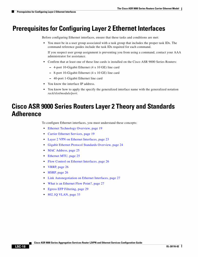
Prerequisites for Configuring Layer 2 Ethernet InterfacesBefore configuring Ethernet interfaces, ensure that these tasks and conditions are met:
• You must be in a user group associated with a task group that includes the proper task IDs. The command reference guides include the task IDs required for each command.
If you suspect user group assignment is preventing you from using a command, contact your AAA administrator for assistance.
• Confirm that at least one of these line cards is installed on the Cisco ASR 9000 Series Routers:
– 4-port 10-Gigabit Ethernet (4 x 10 GE) line card
– 8-port 10-Gigabit Ethernet (4 x 10 GE) line card
– 40-port 1-Gigabit Ethernet line card
• You know the interface IP address.
• You know how to apply the specify the generalized interface name with the generalized notation rack/slot/module/port.
Cisco ASR 9000 Series Routers Layer 2 Theory and Standards Adherence
To configure Ethernet interfaces, you must understand these concepts:
• Ethernet Technology Overview, page 19
• Carrier Ethernet Services, page 19
• Layer 2 VPN on Ethernet Interfaces, page 23
• Gigabit Ethernet Protocol Standards Overview, page 24
• MAC Address, page 25
• Ethernet MTU, page 25
• Flow Control on Ethernet Interfaces, page 26
• VRRP, page 26
• HSRP, page 26
• Link Autonegotiation on Ethernet Interfaces, page 27
• What is an Ethernet Flow Point?, page 27
• Egress EFP Filtering, page 29
• 802.1Q VLAN, page 33
The Cisco ASR 9000 Series Routers Carrier Ethernet ModelCisco ASR 9000 Series Routers Layer 2 Theory and Standards Adherence
LSC-19Cisco ASR 9000 Series Aggregation Services Router L2VPN and Ethernet Services Configuration Guide
OL-26116-02
Ethernet Technology OverviewEthernet is defined by the IEEE 802.3 international standard. It enables the connection of up to 1024 nodes over coaxial, twisted-pair, or fiber-optic cable.
The Cisco ASR 9000 Series Routers supports Gigabit Ethernet (1000 Mbps) and 10-Gigabit Ethernet (10 Gbps) interfaces.
Carrier Ethernet Services Cisco and the Metro Ethernet Forum (MEF) endorse these main L2 Ethernet service types. The names of the services differ, but their functionality is the same. These are the services:
• Ethernet Wire Service (EWS)
• Ethernet Relay Service (ERS)
• Ethernet Multipoint Service (EMS)
• Ethernet Flow Point (EFP)
• Ethernet Virtual Connection (EVC)
When discussing an Ethernet WAN (EWAN), these terminologies should be used:
• CE (customer edge): The customer device connecting to the service provider
• PE (provider edge): The service provider device connecting to the customer
• UNI: The connection between the CE and PE
• AC: The physical or virtual circuit attaching a CE to a PE.
• Multiplexed UNI: A UNI supporting multiple VLAN flows
• Pseudowire: A term used to indicate an end-to-end path in a service provider network
The Cisco ASR 9000 Series Routers Carrier Ethernet ModelCisco ASR 9000 Series Routers Layer 2 Theory and Standards Adherence
LSC-20Cisco ASR 9000 Series Aggregation Services Router L2VPN and Ethernet Services Configuration Guide
OL-26116-02
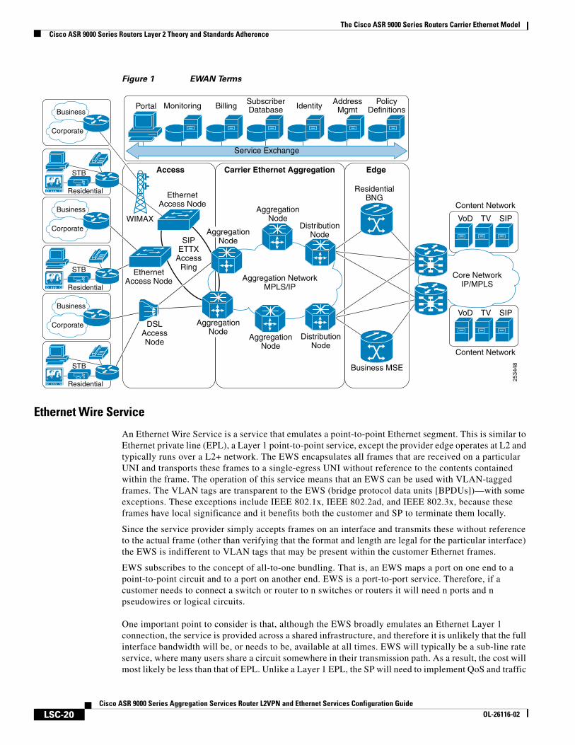
Figure 1 EWAN Terms
Ethernet Wire Service
An Ethernet Wire Service is a service that emulates a point-to-point Ethernet segment. This is similar to Ethernet private line (EPL), a Layer 1 point-to-point service, except the provider edge operates at L2 and typically runs over a L2+ network. The EWS encapsulates all frames that are received on a particular UNI and transports these frames to a single-egress UNI without reference to the contents contained within the frame. The operation of this service means that an EWS can be used with VLAN-tagged frames. The VLAN tags are transparent to the EWS (bridge protocol data units [BPDUs])—with some exceptions. These exceptions include IEEE 802.1x, IEEE 802.2ad, and IEEE 802.3x, because these frames have local significance and it benefits both the customer and SP to terminate them locally.
Since the service provider simply accepts frames on an interface and transmits these without reference to the actual frame (other than verifying that the format and length are legal for the particular interface) the EWS is indifferent to VLAN tags that may be present within the customer Ethernet frames.
EWS subscribes to the concept of all-to-one bundling. That is, an EWS maps a port on one end to a point-to-point circuit and to a port on another end. EWS is a port-to-port service. Therefore, if a customer needs to connect a switch or router to n switches or routers it will need n ports and n pseudowires or logical circuits.
One important point to consider is that, although the EWS broadly emulates an Ethernet Layer 1 connection, the service is provided across a shared infrastructure, and therefore it is unlikely that the full interface bandwidth will be, or needs to be, available at all times. EWS will typically be a sub-line rate service, where many users share a circuit somewhere in their transmission path. As a result, the cost will most likely be less than that of EPL. Unlike a Layer 1 EPL, the SP will need to implement QoS and traffic
Content Network
VoD TV SIP
Content Network
VoD TV SIP
2534
48
AggregationNode
AggregationNode
DistributionNode
DistributionNode
ResidentialBNG
Business MSE
Aggregation NetworkMPLS/IP
Core NetworkIP/MPLS
Carrier Ethernet Aggregation EdgeAccess
EthernetAccess Node
AggregationNode
DSLAccessNode
AggregationNode
EthernetAccess Node
SIPETTX
AccessRing
Corporate
Business
Residential
Corporate
Business
Corporate
Business
STB
Residential
STB
WIMAX
Residential
STB
Portal Monitoring Billing SubscriberDatabase Identity Address
MgmtPolicy
Definitions
Service Exchange
The Cisco ASR 9000 Series Routers Carrier Ethernet ModelCisco ASR 9000 Series Routers Layer 2 Theory and Standards Adherence
LSC-21Cisco ASR 9000 Series Aggregation Services Router L2VPN and Ethernet Services Configuration Guide
OL-26116-02
engineering to meet the specific objectives of a particular contract. However, if the customer's application requires a true wire rate transparent service, then an EPL service—delivered using optical transmission devices such as DWDM (dense wavelength division multiplexing), CDWM (coarse wavelength division multiplexing), or SONET/SDH—should be considered.
Ethernet Relay Service
Ethernet Relay Service is similar to EWS in that it offers point-to-point connectivity. The key differentiation between EWS and ERS is that an ERS uses a VLAN tag to multiplex several, non-same-destination pseudowires to one port. That is, unlike EPL and EWS, ERS is a one-to-many multiplexed service. Service multiplexing simply means that multiple pseudowires utilize a single access interface or UNI. These circuits can terminate within an L2VPN or on, for example, an Internet gateway. From the service user's perspective, this service multiplexing capability offers more efficient interface utilization, simplification of cable plant, and reduced maintenance costs associated with additional interfaces.
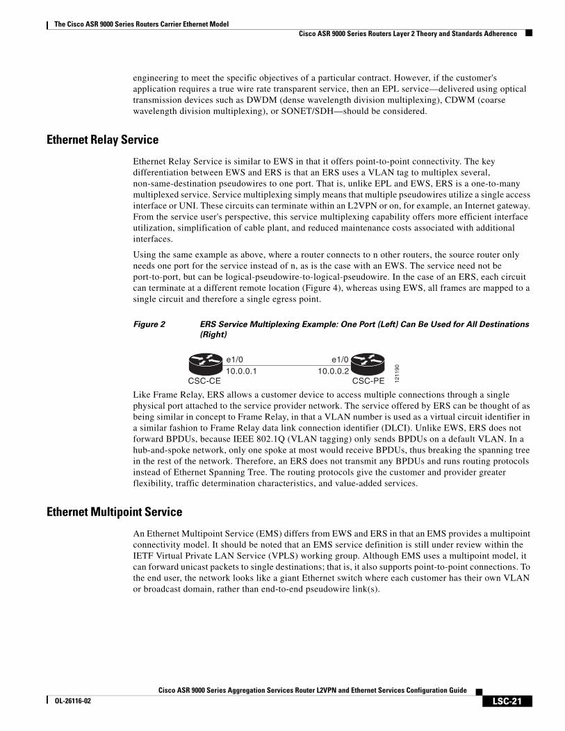
Using the same example as above, where a router connects to n other routers, the source router only needs one port for the service instead of n, as is the case with an EWS. The service need not be port-to-port, but can be logical-pseudowire-to-logical-pseudowire. In the case of an ERS, each circuit can terminate at a different remote location (Figure 4), whereas using EWS, all frames are mapped to a single circuit and therefore a single egress point.
Figure 2 ERS Service Multiplexing Example: One Port (Left) Can Be Used for All Destinations
(Right)
Like Frame Relay, ERS allows a customer device to access multiple connections through a single physical port attached to the service provider network. The service offered by ERS can be thought of as being similar in concept to Frame Relay, in that a VLAN number is used as a virtual circuit identifier in a similar fashion to Frame Relay data link connection identifier (DLCI). Unlike EWS, ERS does not forward BPDUs, because IEEE 802.1Q (VLAN tagging) only sends BPDUs on a default VLAN. In a hub-and-spoke network, only one spoke at most would receive BPDUs, thus breaking the spanning tree in the rest of the network. Therefore, an ERS does not transmit any BPDUs and runs routing protocols instead of Ethernet Spanning Tree. The routing protocols give the customer and provider greater flexibility, traffic determination characteristics, and value-added services.
Ethernet Multipoint Service
An Ethernet Multipoint Service (EMS) differs from EWS and ERS in that an EMS provides a multipoint connectivity model. It should be noted that an EMS service definition is still under review within the IETF Virtual Private LAN Service (VPLS) working group. Although EMS uses a multipoint model, it can forward unicast packets to single destinations; that is, it also supports point-to-point connections. To the end user, the network looks like a giant Ethernet switch where each customer has their own VLAN or broadcast domain, rather than end-to-end pseudowire link(s).
CSC-CE
e1/0 e1/010.0.0.1 10.0.0.2
CSC-PE 1211
90
The Cisco ASR 9000 Series Routers Carrier Ethernet ModelCisco ASR 9000 Series Routers Layer 2 Theory and Standards Adherence
LSC-22Cisco ASR 9000 Series Aggregation Services Router L2VPN and Ethernet Services Configuration Guide
OL-26116-02
EMS Example
An EMS does not map an interface or VLAN to a specific point-to-point pseudowire. Instead, it models the operation of a virtual Ethernet switch: EMS uses the customer's MAC address to forward frames to the correct egress UNI within the service provider's network. An EMS emulates the service attributes of an Ethernet switch and learns source MAC to interface associations, floods unknown broadcast and multicast frames, and (optionally) monitors the service user's spanning tree protocol. One important point to note is that although the service provider may utilize spanning tree within the transport network, there is no interaction with the service user's spanning tree.
This service works similar to an MPLS VPN, except it functions at L2 instead of L3. While a VPLS EMS is a viable solution, its scalability and QoS control are suspect compared to that of MPLS VPNs. In addition, it is much more difficult, and may be impossible, for the service provider to offer value-added Layer 3 services (this is discussed later in the document).
Ethernet Flow Point
An Ethernet Flow Point (EFP) is a substream partition of a main interface. On Cisco ASR 9000 Series Routers, the EFP is implemented as an L2 subinterface with an encapsulation statement.
Ethernet Virtual Circuit
An Ethernet Virtual Circuit (EVC) is a point-to-point tunnel. On Cisco ASR 9000 Series Routers, the EVC is implemented as a pseudowire (PW).
Ethernet OAM Protocols
Ethernet as a Metro Area Network (MAN) or a Wide Area Network (WAN) technology benefits greatly from the implementation of Operations, Administration and Maintenance (OAM) features. OAM features allow Service Providers to monitor the quality of the connections on a MAN or WAN. Service providers can monitor specific events, take actions on events, and if necessary, put specific interfaces into loopback mode for troubleshooting. Ethernet OAM features can be configured to monitor either side or both sides of a link.
For more information on Ethernet OAM protocols, refer to the Configuring Ethernet Interfaces on the Cisco ASR 9000 Series Router module of the Cisco ASR 9000 Series Aggregation Services Router Interface and Hardware Component Configuration Guide.
The Cisco ASR 9000 Series Routers Carrier Ethernet ModelCisco ASR 9000 Series Routers Layer 2 Theory and Standards Adherence
LSC-23Cisco ASR 9000 Series Aggregation Services Router L2VPN and Ethernet Services Configuration Guide
OL-26116-02
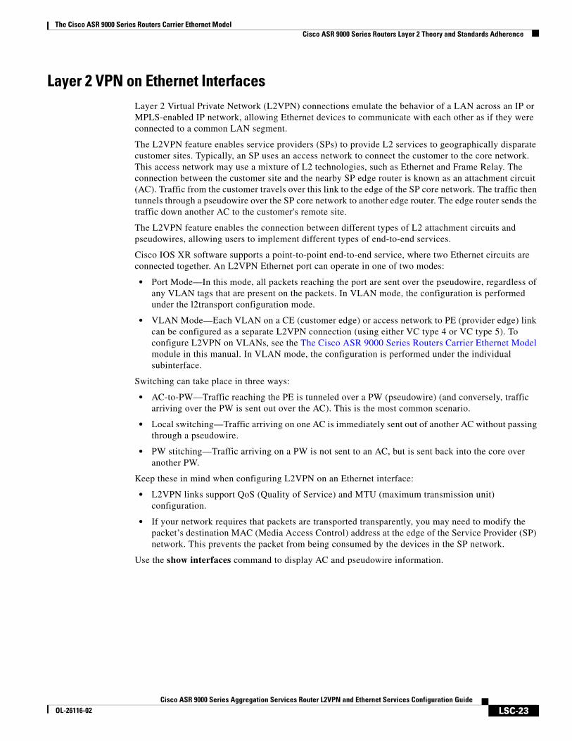
Layer 2 VPN on Ethernet InterfacesLayer 2 Virtual Private Network (L2VPN) connections emulate the behavior of a LAN across an IP or MPLS-enabled IP network, allowing Ethernet devices to communicate with each other as if they were connected to a common LAN segment.
The L2VPN feature enables service providers (SPs) to provide L2 services to geographically disparate customer sites. Typically, an SP uses an access network to connect the customer to the core network. This access network may use a mixture of L2 technologies, such as Ethernet and Frame Relay. The connection between the customer site and the nearby SP edge router is known as an attachment circuit (AC). Traffic from the customer travels over this link to the edge of the SP core network. The traffic then tunnels through a pseudowire over the SP core network to another edge router. The edge router sends the traffic down another AC to the customer's remote site.
The L2VPN feature enables the connection between different types of L2 attachment circuits and pseudowires, allowing users to implement different types of end-to-end services.
Cisco IOS XR software supports a point-to-point end-to-end service, where two Ethernet circuits are connected together. An L2VPN Ethernet port can operate in one of two modes:
• Port Mode—In this mode, all packets reaching the port are sent over the pseudowire, regardless of any VLAN tags that are present on the packets. In VLAN mode, the configuration is performed under the l2transport configuration mode.
• VLAN Mode—Each VLAN on a CE (customer edge) or access network to PE (provider edge) link can be configured as a separate L2VPN connection (using either VC type 4 or VC type 5). To configure L2VPN on VLANs, see the The Cisco ASR 9000 Series Routers Carrier Ethernet Model module in this manual. In VLAN mode, the configuration is performed under the individual subinterface.
Switching can take place in three ways:
• AC-to-PW—Traffic reaching the PE is tunneled over a PW (pseudowire) (and conversely, traffic arriving over the PW is sent out over the AC). This is the most common scenario.
• Local switching—Traffic arriving on one AC is immediately sent out of another AC without passing through a pseudowire.
• PW stitching—Traffic arriving on a PW is not sent to an AC, but is sent back into the core over another PW.
Keep these in mind when configuring L2VPN on an Ethernet interface:
• L2VPN links support QoS (Quality of Service) and MTU (maximum transmission unit) configuration.
• If your network requires that packets are transported transparently, you may need to modify the packet’s destination MAC (Media Access Control) address at the edge of the Service Provider (SP) network. This prevents the packet from being consumed by the devices in the SP network.
Use the show interfaces command to display AC and pseudowire information.
The Cisco ASR 9000 Series Routers Carrier Ethernet ModelCisco ASR 9000 Series Routers Layer 2 Theory and Standards Adherence
LSC-24Cisco ASR 9000 Series Aggregation Services Router L2VPN and Ethernet Services Configuration Guide
OL-26116-02
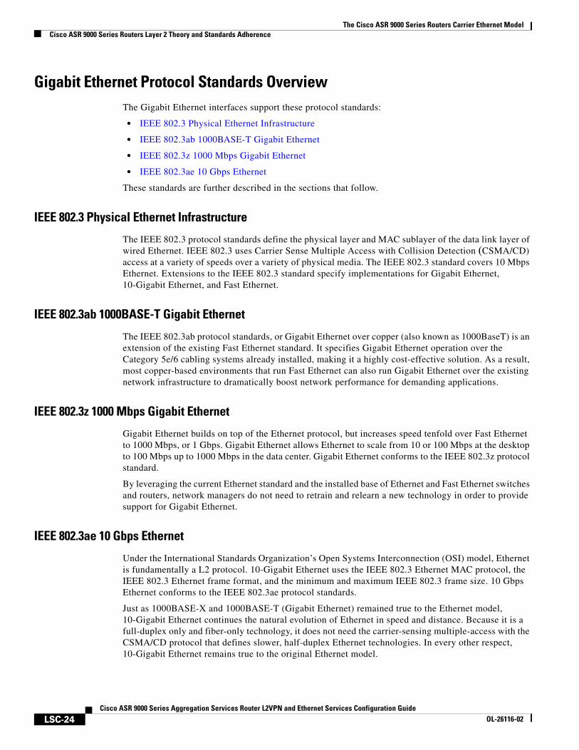
Gigabit Ethernet Protocol Standards OverviewThe Gigabit Ethernet interfaces support these protocol standards:
• IEEE 802.3 Physical Ethernet Infrastructure
• IEEE 802.3ab 1000BASE-T Gigabit Ethernet
• IEEE 802.3z 1000 Mbps Gigabit Ethernet
• IEEE 802.3ae 10 Gbps Ethernet
These standards are further described in the sections that follow.
IEEE 802.3 Physical Ethernet Infrastructure
The IEEE 802.3 protocol standards define the physical layer and MAC sublayer of the data link layer of wired Ethernet. IEEE 802.3 uses Carrier Sense Multiple Access with Collision Detection (CSMA/CD) access at a variety of speeds over a variety of physical media. The IEEE 802.3 standard covers 10 Mbps Ethernet. Extensions to the IEEE 802.3 standard specify implementations for Gigabit Ethernet, 10-Gigabit Ethernet, and Fast Ethernet.
IEEE 802.3ab 1000BASE-T Gigabit Ethernet
The IEEE 802.3ab protocol standards, or Gigabit Ethernet over copper (also known as 1000BaseT) is an extension of the existing Fast Ethernet standard. It specifies Gigabit Ethernet operation over the Category 5e/6 cabling systems already installed, making it a highly cost-effective solution. As a result, most copper-based environments that run Fast Ethernet can also run Gigabit Ethernet over the existing network infrastructure to dramatically boost network performance for demanding applications.
IEEE 802.3z 1000 Mbps Gigabit Ethernet
Gigabit Ethernet builds on top of the Ethernet protocol, but increases speed tenfold over Fast Ethernet to 1000 Mbps, or 1 Gbps. Gigabit Ethernet allows Ethernet to scale from 10 or 100 Mbps at the desktop to 100 Mbps up to 1000 Mbps in the data center. Gigabit Ethernet conforms to the IEEE 802.3z protocol standard.
By leveraging the current Ethernet standard and the installed base of Ethernet and Fast Ethernet switches and routers, network managers do not need to retrain and relearn a new technology in order to provide support for Gigabit Ethernet.
IEEE 802.3ae 10 Gbps Ethernet
Under the International Standards Organization’s Open Systems Interconnection (OSI) model, Ethernet is fundamentally a L2 protocol. 10-Gigabit Ethernet uses the IEEE 802.3 Ethernet MAC protocol, the IEEE 802.3 Ethernet frame format, and the minimum and maximum IEEE 802.3 frame size. 10 Gbps Ethernet conforms to the IEEE 802.3ae protocol standards.
Just as 1000BASE-X and 1000BASE-T (Gigabit Ethernet) remained true to the Ethernet model, 10-Gigabit Ethernet continues the natural evolution of Ethernet in speed and distance. Because it is a full-duplex only and fiber-only technology, it does not need the carrier-sensing multiple-access with the CSMA/CD protocol that defines slower, half-duplex Ethernet technologies. In every other respect, 10-Gigabit Ethernet remains true to the original Ethernet model.
The Cisco ASR 9000 Series Routers Carrier Ethernet ModelCisco ASR 9000 Series Routers Layer 2 Theory and Standards Adherence
LSC-25Cisco ASR 9000 Series Aggregation Services Router L2VPN and Ethernet Services Configuration Guide
OL-26116-02
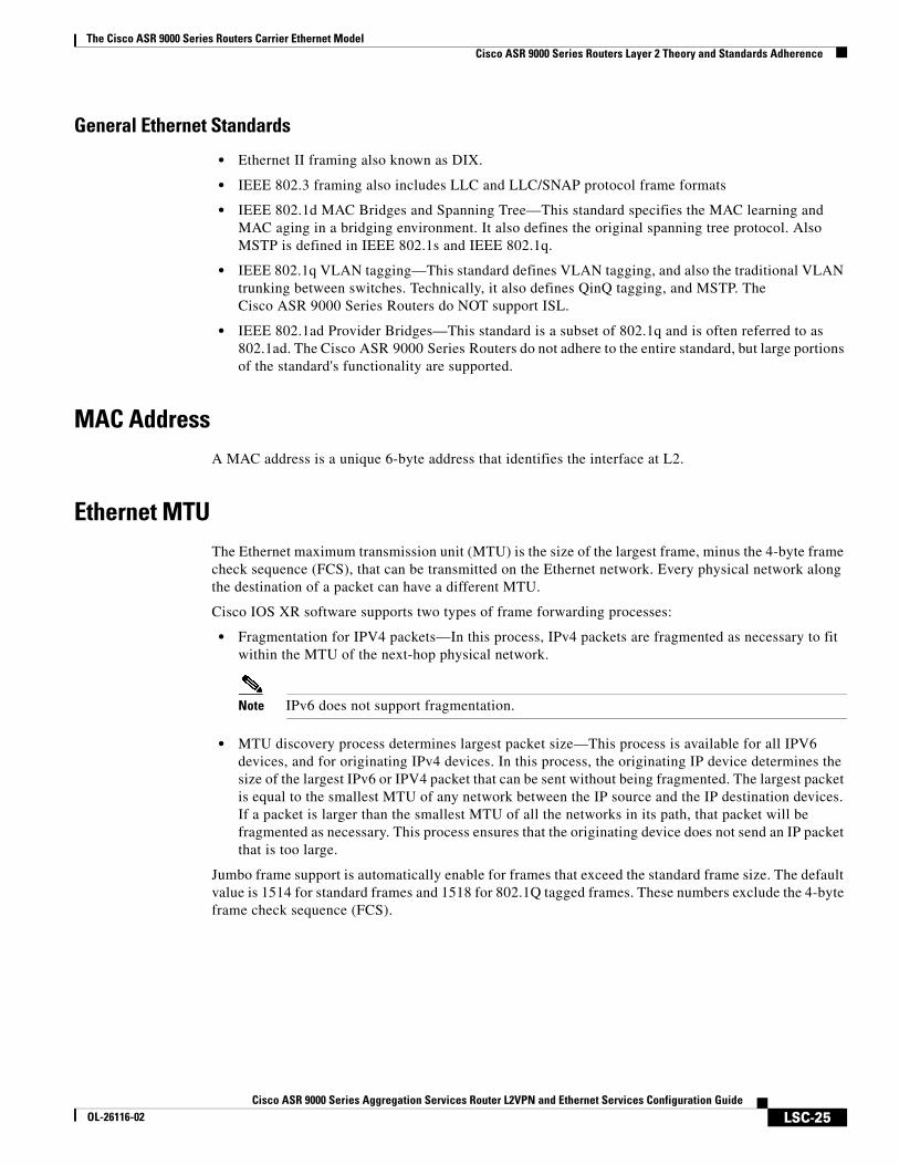
General Ethernet Standards
• Ethernet II framing also known as DIX.
• IEEE 802.3 framing also includes LLC and LLC/SNAP protocol frame formats
• IEEE 802.1d MAC Bridges and Spanning Tree—This standard specifies the MAC learning and MAC aging in a bridging environment. It also defines the original spanning tree protocol. Also MSTP is defined in IEEE 802.1s and IEEE 802.1q.
• IEEE 802.1q VLAN tagging—This standard defines VLAN tagging, and also the traditional VLAN trunking between switches. Technically, it also defines QinQ tagging, and MSTP. The Cisco ASR 9000 Series Routers do NOT support ISL.
• IEEE 802.1ad Provider Bridges—This standard is a subset of 802.1q and is often referred to as 802.1ad. The Cisco ASR 9000 Series Routers do not adhere to the entire standard, but large portions of the standard's functionality are supported.
MAC AddressA MAC address is a unique 6-byte address that identifies the interface at L2.
Ethernet MTUThe Ethernet maximum transmission unit (MTU) is the size of the largest frame, minus the 4-byte frame check sequence (FCS), that can be transmitted on the Ethernet network. Every physical network along the destination of a packet can have a different MTU.
Cisco IOS XR software supports two types of frame forwarding processes:
• Fragmentation for IPV4 packets—In this process, IPv4 packets are fragmented as necessary to fit within the MTU of the next-hop physical network.
Note IPv6 does not support fragmentation.
• MTU discovery process determines largest packet size—This process is available for all IPV6 devices, and for originating IPv4 devices. In this process, the originating IP device determines the size of the largest IPv6 or IPV4 packet that can be sent without being fragmented. The largest packet is equal to the smallest MTU of any network between the IP source and the IP destination devices. If a packet is larger than the smallest MTU of all the networks in its path, that packet will be fragmented as necessary. This process ensures that the originating device does not send an IP packet that is too large.
Jumbo frame support is automatically enable for frames that exceed the standard frame size. The default value is 1514 for standard frames and 1518 for 802.1Q tagged frames. These numbers exclude the 4-byte frame check sequence (FCS).
The Cisco ASR 9000 Series Routers Carrier Ethernet ModelCisco ASR 9000 Series Routers Layer 2 Theory and Standards Adherence
LSC-26Cisco ASR 9000 Series Aggregation Services Router L2VPN and Ethernet Services Configuration Guide
OL-26116-02
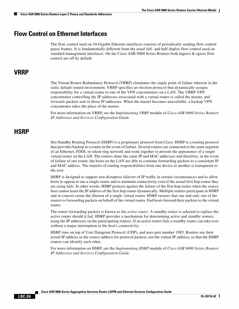
Flow Control on Ethernet InterfacesThe flow control used on 10-Gigabit Ethernet interfaces consists of periodically sending flow control pause frames. It is fundamentally different from the usual full- and half-duplex flow control used on standard management interfaces. On the Cisco ASR 9000 Series Routers both ingress & egress flow control are off by default.
VRRPThe Virtual Router Redundancy Protocol (VRRP) eliminates the single point of failure inherent in the static default routed environment. VRRP specifies an election protocol that dynamically assigns responsibility for a virtual router to one of the VPN concentrators on a LAN. The VRRP VPN concentrator controlling the IP addresses associated with a virtual router is called the master, and forwards packets sent to those IP addresses. When the master becomes unavailable, a backup VPN concentrator takes the place of the master.
For more information on VRRP, see the Implementing VRRP module of Cisco ASR 9000 Series Routers IP Addresses and Services Configuration Guide.
HSRPHot Standby Routing Protocol (HSRP) is a proprietary protocol from Cisco. HSRP is a routing protocol that provides backup to a router in the event of failure. Several routers are connected to the same segment of an Ethernet, FDDI, or token-ring network and work together to present the appearance of a single virtual router on the LAN. The routers share the same IP and MAC addresses and therefore, in the event of failure of one router, the hosts on the LAN are able to continue forwarding packets to a consistent IP and MAC address. The transfer of routing responsibilities from one device to another is transparent to the user.
HSRP is designed to support non disruptive failover of IP traffic in certain circumstances and to allow hosts to appear to use a single router and to maintain connectivity even if the actual first hop router they are using fails. In other words, HSRP protects against the failure of the first hop router when the source host cannot learn the IP address of the first hop router dynamically. Multiple routers participate in HSRP and in concert create the illusion of a single virtual router. HSRP ensures that one and only one of the routers is forwarding packets on behalf of the virtual router. End hosts forward their packets to the virtual router.
The router forwarding packets is known as the active router. A standby router is selected to replace the active router should it fail. HSRP provides a mechanism for determining active and standby routers, using the IP addresses on the participating routers. If an active router fails a standby router can take over without a major interruption in the host's connectivity.
HSRP runs on top of User Datagram Protocol (UDP), and uses port number 1985. Routers use their actual IP address as the source address for protocol packets, not the virtual IP address, so that the HSRP routers can identify each other.
For more information on HSRP, see the Implementing HSRP module of Cisco ASR 9000 Series Routers IP Addresses and Services Configuration Guide.
The Cisco ASR 9000 Series Routers Carrier Ethernet ModelCisco ASR 9000 Series Routers Layer 2 Theory and Standards Adherence
LSC-27Cisco ASR 9000 Series Aggregation Services Router L2VPN and Ethernet Services Configuration Guide
OL-26116-02
Link Autonegotiation on Ethernet InterfacesLink autonegotiation ensures that devices that share a link segment are automatically configured with the highest performance mode of interoperation. Use the negotiation auto command in interface configuration mode to enable link autonegotiation on an Ethernet interface. On line card Ethernet interfaces, link autonegotiation is disabled by default.
Note The negotiation auto command is available on Gigabit Ethernet interfaces only.
What is an Ethernet Flow Point?An Ethernet flow point (EFP) is a Layer 2 logical subinterface used to classify traffic under a physical or a bundle interface.
A physical interface can be a Gigabit Ethernet 0/0/0/1 or a 10 Gigabit Ethernet 0/0/0/0 interface and has ports on the line card. A bundle interface is a virtual interface, created by grouping physical interfaces together.
For example, physical interfaces such as Gigabit Ethernet 0/0/0/1 and 10 Gigabit Ethernet 0/0/0/0 can be configured as members of a bundle interface.
Grouping physical interfaces together can:
• Reduce the routing entries
• Increase the bandwidth of the bundle interface
• Balance the traffic on the bundle members
EFP has the following characteristics:
• An EFP represents a logical demarcation point of an Ethernet virtual connection (EVC) on an interface. For an EVC associating two or more UNIs, there is a flow point on each interface of every device, through which that EVC passes.
• An EFP can be regarded as an instantiation of a particular service. An EFP is defined by a set of filters. These filters are applied to all the ingress traffic to classify the frames that belong to a particular EFP. An EFP filter is a set of entries, where each entry looks similar to the start of a packet (ignoring source/destination MAC address). Each entry usually contains 0, 1 or 2 VLAN tags. A packet that starts with the same tags as an entry in the filter is said to match the filter; if the start of the packet does not correspond to any entry in the filter then the packet does not match the filter.
• An EFP serves four purposes:
– Identifies all frames that belong to a particular flow on a given interface
– Performs ingress and egress Ethernet header manipulations
– Adds features to the identified frames
– Optionally define how to forward those frames in the data path
You can perform a variety of operations on the traffic flows when a router is configured with EFPs on various interfaces. Also, you can bridge or tunnel the traffic by many ways from one or more of the router’s ingress EFPs to one or more egress EFPs. This traffic is a mixture of VLAN IDs, single or double (QinQ) encapsulation, and ethertypes.
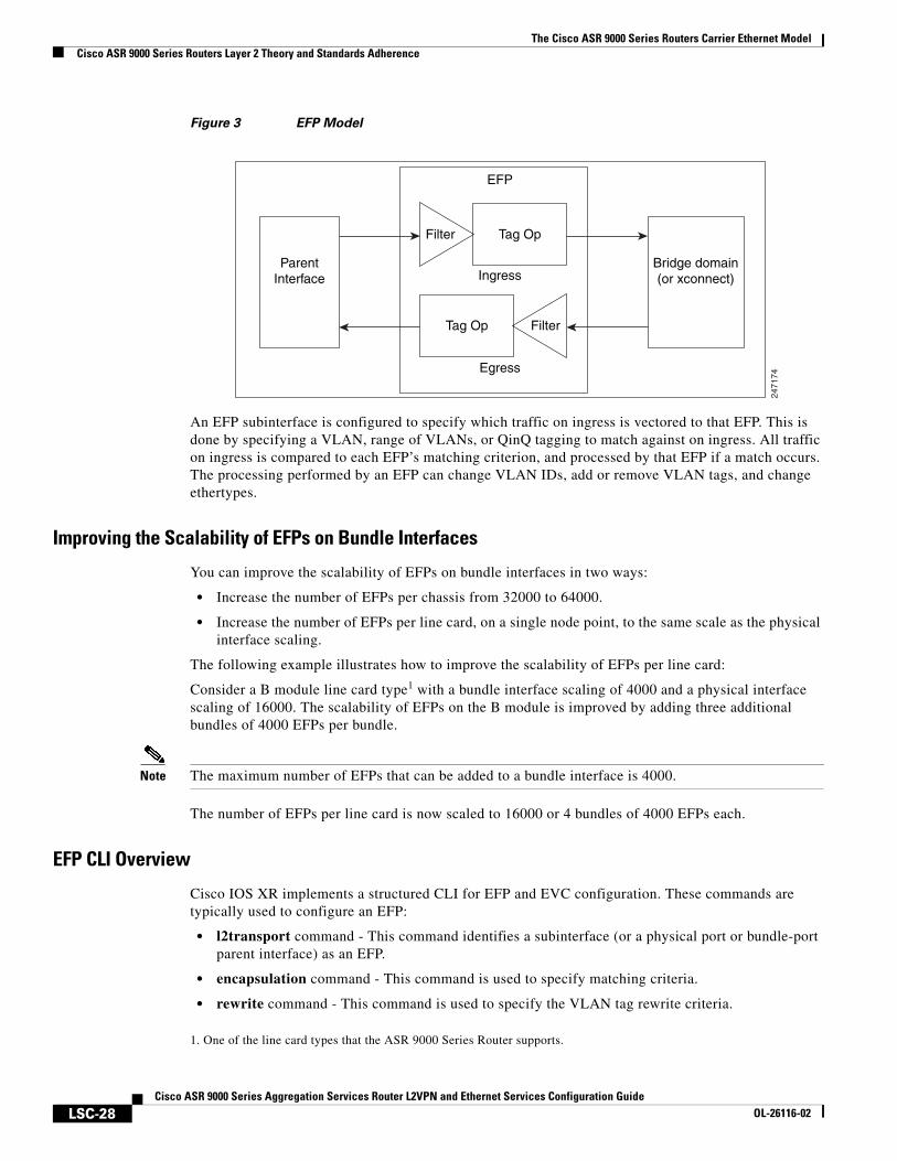
Figure 3 shows the EFP model.
The Cisco ASR 9000 Series Routers Carrier Ethernet ModelCisco ASR 9000 Series Routers Layer 2 Theory and Standards Adherence
LSC-28Cisco ASR 9000 Series Aggregation Services Router L2VPN and Ethernet Services Configuration Guide
OL-26116-02
Figure 3 EFP Model
An EFP subinterface is configured to specify which traffic on ingress is vectored to that EFP. This is done by specifying a VLAN, range of VLANs, or QinQ tagging to match against on ingress. All traffic on ingress is compared to each EFP’s matching criterion, and processed by that EFP if a match occurs. The processing performed by an EFP can change VLAN IDs, add or remove VLAN tags, and change ethertypes.
Improving the Scalability of EFPs on Bundle Interfaces
You can improve the scalability of EFPs on bundle interfaces in two ways:
• Increase the number of EFPs per chassis from 32000 to 64000.
• Increase the number of EFPs per line card, on a single node point, to the same scale as the physical interface scaling.
The following example illustrates how to improve the scalability of EFPs per line card:
Consider a B module line card type1 with a bundle interface scaling of 4000 and a physical interface scaling of 16000. The scalability of EFPs on the B module is improved by adding three additional bundles of 4000 EFPs per bundle.
Note The maximum number of EFPs that can be added to a bundle interface is 4000.
The number of EFPs per line card is now scaled to 16000 or 4 bundles of 4000 EFPs each.
EFP CLI Overview
Cisco IOS XR implements a structured CLI for EFP and EVC configuration. These commands are typically used to configure an EFP:
• l2transport command - This command identifies a subinterface (or a physical port or bundle-port parent interface) as an EFP.
• encapsulation command - This command is used to specify matching criteria.
• rewrite command - This command is used to specify the VLAN tag rewrite criteria.
2471
74
ParentInterface
EFP
Ingress
Egress
Filter Tag Op
Bridge domain(or xconnect)
FilterTag Op
1. One of the line card types that the ASR 9000 Series Router supports.
The Cisco ASR 9000 Series Routers Carrier Ethernet ModelCisco ASR 9000 Series Routers Layer 2 Theory and Standards Adherence
LSC-29Cisco ASR 9000 Series Aggregation Services Router L2VPN and Ethernet Services Configuration Guide
OL-26116-02
Egress EFP FilteringThe Egress EFP Filtering feature implements a means of filtering EFP egress traffic, ensuring that all the given EFP’s egress traffic complies with the ingress matching criterion.
An ingress EFP is similar to an egress EFP. The router is configured to send traffic on the EFP, that matches that EFP’s ingress matching criterion. It is possible to configure a router so that this does not occur, and there is no safeguard to prevent such mismatching egress EFP traffic from exiting the router.
The Cisco ASR 9000 Series Routers allows for different VLANs on different ports within the same bridge domain. This allows a bridge to forward a packet out of a port not configured for the VLAN tag on the packet. Egress EFP filtering checks this and drops invalid packets at the egress port.
Identifying Frames of an EFP
The EFP identifies frames belonging to a particular flow on a given port, independent of their Ethernet encapsulation. An EFP can flexibly map frames into a flow or EFP based on the fields in the frame header.
The frames can be matched to an EFP using
• VLAN tag or tags
• MAC address (source address, destination address, or both)
• 802.1p CoS bits
• Logical conjunction of two or more of the above: VLAN, MAC, and CoS
• Default match (that is, any other traffic that has not matched a more specific EFP)
• Protocol ethertype
The frames cannot be matched to an EFP through use of any of these:
• Any information outside the outermost Ethernet frame header and its associated tags such as
– IPv4, IPv6, or MPLS tag header data
– C-DMAC, C-SMAC, or C-VLAN
• Logical disjunction of the valid frame matches above: VLAN, MAC, and CoS
The specific match criteria are covered in more detail in these sections.
VLAN Tag Matching
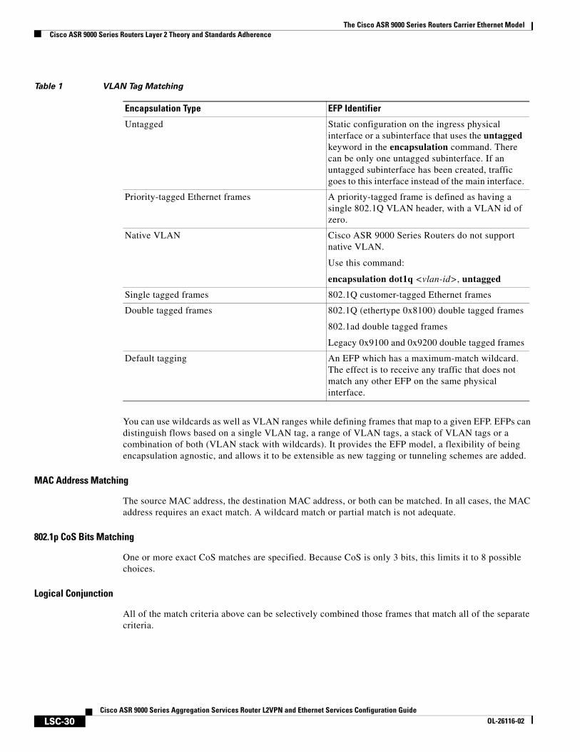
Table 1 describes the different encapsulation types and the EFP identifier corresponding to each.
The Cisco ASR 9000 Series Routers Carrier Ethernet ModelCisco ASR 9000 Series Routers Layer 2 Theory and Standards Adherence
LSC-30Cisco ASR 9000 Series Aggregation Services Router L2VPN and Ethernet Services Configuration Guide
OL-26116-02
You can use wildcards as well as VLAN ranges while defining frames that map to a given EFP. EFPs can distinguish flows based on a single VLAN tag, a range of VLAN tags, a stack of VLAN tags or a combination of both (VLAN stack with wildcards). It provides the EFP model, a flexibility of being encapsulation agnostic, and allows it to be extensible as new tagging or tunneling schemes are added.
MAC Address Matching
The source MAC address, the destination MAC address, or both can be matched. In all cases, the MAC address requires an exact match. A wildcard match or partial match is not adequate.
802.1p CoS Bits Matching
One or more exact CoS matches are specified. Because CoS is only 3 bits, this limits it to 8 possible choices.
Logical Conjunction
All of the match criteria above can be selectively combined those frames that match all of the separate criteria.
Table 1 VLAN Tag Matching
Encapsulation Type EFP Identifier
Untagged Static configuration on the ingress physical interface or a subinterface that uses the untagged keyword in the encapsulation command. There can be only one untagged subinterface. If an untagged subinterface has been created, traffic goes to this interface instead of the main interface.
Priority-tagged Ethernet frames A priority-tagged frame is defined as having a single 802.1Q VLAN header, with a VLAN id of zero.
Native VLAN Cisco ASR 9000 Series Routers do not support native VLAN.
Use this command:
encapsulation dot1q <vlan-id>, untagged
Single tagged frames 802.1Q customer-tagged Ethernet frames
Double tagged frames 802.1Q (ethertype 0x8100) double tagged frames
802.1ad double tagged frames
Legacy 0x9100 and 0x9200 double tagged frames
Default tagging An EFP which has a maximum-match wildcard. The effect is to receive any traffic that does not match any other EFP on the same physical interface.
The Cisco ASR 9000 Series Routers Carrier Ethernet ModelCisco ASR 9000 Series Routers Layer 2 Theory and Standards Adherence
LSC-31Cisco ASR 9000 Series Aggregation Services Router L2VPN and Ethernet Services Configuration Guide
OL-26116-02
Default Match
A single EFP can be defined that matches all other traffic that has not been matched by a more specific EFP.
Match Precedence and Config Verification
Overlapping EFPs are allowed to be configured, where it is possible to determine an order in which they should be used for matching. But EFPs that conflict with other EFPs or subinterfaces on the parent trunk interface should be blocked at config verification.
An ordering precedence is used for how EFP matches are applied in hardware. The model is for matches that are more specific to be processed before matches that are less specific.
Egress Behavior
The EFP matching criteria can also be used on egress to police the frames that can egress from the EFP, based on the platform support. Frames that do not match the criteria (source/destination MAC match criteria are reversed) are dropped.
Applying Features
After the frames are matched to a particular EFP, any appropriate features can be applied. In this context, “features” means any frame manipulations specified by the configuration as well as things such as QoS and ACLs. The Ethernet infrastructure provides an appropriate interface to allow the feature owners to apply their features to an EFP. Hence, IM interface handles are used to represent EFPs, allowing feature owners to manage their features on EFPs in the same way the features are managed on regular interfaces or subinterfaces.
The only L2 features that can be applied on an EFP that is part of the Ethernet infrastructure are the L2 header encapsulation modifications. The L2 features are described in this section.
The Cisco ASR 9000 Series Routers Carrier Ethernet ModelCisco ASR 9000 Series Routers Layer 2 Theory and Standards Adherence
LSC-32Cisco ASR 9000 Series Aggregation Services Router L2VPN and Ethernet Services Configuration Guide
OL-26116-02
Encapsulation Modifications
EFP supports these L2 header encapsulation modifications on both ingress and egress:
• Push 1 or 2 VLAN tags
• Pop 1 or 2 VLAN tags
Note This modification can only pop tags that are matched as part of the EFP.
• Rewrite 1 or 2 VLAN tags:
– Rewrite outer tag
– Rewrite outer 2 tags
– Rewrite outer tag and push an additional tag
– Remove outer tag and rewrite inner tag
For each of the VLAN ID manipulations, these can be specified:
• The VLAN tag type, that is, C-VLAN, S-VLAN, or I-TAG. The ethertype of the 802.1Q C-VLAN tag is defined by the dot1q tunneling type command.
• The VLAN ID. 0 can be specified for an outer VLAN tag to generate a priority-tagged frame.
Note For tag rewrites, the CoS bits from the previous tag should be preserved in the same way as the DEI bit for 802.1ad encapsulated frames.
Defining Data-Forwarding Behavior
The EFP can be used to designate the frames belonging to a particular Ethernet flow forwarded in the data path. These forwarding cases are supported for EFPs in Cisco IOS XR software:
• L2 Switched Service (Bridging)—The EFP is mapped to a bridge domain, where frames are switched based on their destination MAC address. This includes multipoint services:
– Ethernet to Ethernet Bridging
– Virtual Private LAN Service (VPLS)
• L2 Stitched Service (AC to AC xconnect)—This covers point-to-point L2 associations that are statically established and do not require a MAC address lookup.
– Ethernet to Ethernet Local Switching—The EFP is mapped to an S-VLAN either on the same port or on another port. The S-VLANs can be identical or different.
• Tunneled Service (xconnect)—The EFP is mapped to a Layer 3 tunnel. This covers point-to-point services only:
– EoMPLS
– L2TPv3
• L2 Terminated Service (Ethernet access to Layer 3 service)—The EFP is mapped to an IP interface that has a global address or belongs to a VRF (includes both IP and MPLS Layer 3 VPNs).
The Cisco ASR 9000 Series Routers Carrier Ethernet ModelCisco ASR 9000 Series Routers Layer 2 Theory and Standards Adherence
LSC-33Cisco ASR 9000 Series Aggregation Services Router L2VPN and Ethernet Services Configuration Guide
OL-26116-02
802.1Q VLANA VLAN is a group of devices on one or more LANs that are configured so that they can communicate as if they were attached to the same wire, when in fact they are located on a number of different LAN segments. Because VLANs are based on logical instead of physical connections, it is very flexible for user and host management, bandwidth allocation, and resource optimization.
The IEEE's 802.1Q protocol standard addresses the problem of breaking large networks into smaller parts so broadcast and multicast traffic does not consume more bandwidth than necessary. The standard also helps provide a higher level of security between segments of internal networks.
The 802.1Q specification establishes a standard method for inserting VLAN membership information into Ethernet frames.
Cisco IOS XR software supports VLAN subinterface configuration on Gigabit Ethernet and10-Gigabit Ethernet interfaces.
802.1Q Tagged Frames
The IEEE 802.1Q tag-based VLAN uses an extra tag in the MAC header to identify the VLAN membership of a frame across bridges. This tag is used for VLAN and quality of service (QoS) priority identification. The VLANs can be created statically by manual entry or dynamically through Generic Attribute Registration Protocol (GARP) VLAN Registration Protocol (GVRP). The VLAN ID associates a frame with a specific VLAN and provides the information that switches must process the frame across the network. A tagged frame is four bytes longer than an untagged frame and contains two bytes of Tag Protocol Identifier (TPID) residing within the type and length field of the Ethernet frame and two bytes of Tag Control Information (TCI) which starts after the source address field of the Ethernet frame.
Subinterfaces
Subinterfaces are logical interfaces created on a hardware interface. These software-defined interfaces allow for segregation of traffic into separate logical channels on a single hardware interface as well as allowing for better utilization of the available bandwidth on the physical interface.
Subinterfaces are distinguished from one another by adding an extension on the end of the interface name and designation. For instance, the Ethernet subinterface 23 on the physical interface designated TenGigE 0/1/0/0 would be indicated by TenGigE 0/1/0/0.23.
Before a subinterface is allowed to pass traffic it must have a valid tagging protocol encapsulation and VLAN identifier assigned. All Ethernet subinterfaces always default to the 802.1Q VLAN encapsulation. However, the VLAN identifier must be explicitly defined.
Subinterface MTU
The subinterface maximum transmission unit (MTU) is inherited from the physical interface with an additional four bytes allowed for the 802.1Q VLAN tag.
The Cisco ASR 9000 Series Routers Carrier Ethernet ModelCisco ASR 9000 Series Routers Layer 2 Theory and Standards Adherence
LSC-34Cisco ASR 9000 Series Aggregation Services Router L2VPN and Ethernet Services Configuration Guide
OL-26116-02
VLAN Subinterfaces on Ethernet Bundles
An Ethernet bundle is a group of one or more Ethernet ports that are aggregated together and treated as a single link. Multiple VLAN subinterfaces can be added to a single Ethernet bundle.
For more information about configuring Ethernet bundles, see the Configuring Link Bundles module in this document. The procedure for creating VLAN subinterfaces on an Ethernet bundle is exactly the same as the procedure for creating VLAN subinterfaces on a physical Ethernet interface.
To create a VLAN subinterface on an Ethernet bundle, see the Configuring 802.1Q VLAN Interfaces, page 47 section later in this module.
Layer 2 VPN on VLANs
The Layer 2 Virtual Private Network (L2VPN) feature enables Service Providers (SPs) to provide L2 services to geographically disparate customer sites, as described in the Layer 2 VPN on Ethernet Interfaces, page 23 section of the Configuring Ethernet Interfaces, page 37 module earlier in this manual.
The configuration model for configuring VLAN attachment circuits (ACs) is similar to the model used for configuring basic VLANs, where the user first creates a VLAN subinterface, and then configures that VLAN in subinterface configuration mode. To create an Attachment Circuit, you need to include the l2transport keyword in the interface command string to specify that the interface is a L2 interface.
VLAN ACs support three modes of L2VPN operation:
• Basic Dot1Q Attachment Circuit—The Attachment Circuit covers all frames that are received and sent with a specific VLAN tag.
• QinQ Attachment Circuit—The Attachment Circuit covers all frames received and sent with a specific outer VLAN tag and a specific inner VLAN tag. QinQ is an extension to Dot1Q that uses a stack of two tags.
• Q-in-Any Attachment Circuit—The Attachment Circuit covers all frames received and sent with a specific outer VLAN tag and any inner VLAN tag, as long as that inner VLAN tag is not Layer 3 terminated. Q-in-Any is an extension to QinQ that uses wildcarding to match any second tag.
Note The Q-in-Any mode is a variation of the basic Dot1Q mode. In Q-in-Any mode, the frames have a basic QinQ encapsulation; however, in Q-in-Any mode the inner tag is not relevant, except for the fact that a few specific inner VLAN tags are siphoned for specific services. For example, a tag may be used to provide L3 services for general internet access.
Each VLAN on a CE-to-PE link can be configured as a separate L2VPN connection (using either VC type 4 or VC type 5). To configure L2VPN on VLANs, see the “Removing an 802.1Q VLAN Subinterface” section on page 52.
The Cisco ASR 9000 Series Routers Carrier Ethernet ModelHow to Configure Layer 2 Features on Ethernet Interfaces
LSC-35Cisco ASR 9000 Series Aggregation Services Router L2VPN and Ethernet Services Configuration Guide
OL-26116-02
Keep these in mind when configuring L2VPN on a VLAN:
• Cisco IOS XR software supports 4000 Attachment Circuits per line card.
• In a point-to-point connection, the two Attachment Circuits do not have to be of the same type. For example, a port mode Ethernet Attachment Circuit can be connected to a Dot1Q Ethernet Attachment Circuit.
• Pseudowires can run in VLAN mode or in port mode. A pseudowire running in VLAN mode has a single Dot1Q tag, while a pseudo-wire running in port mode has no tags. Some interworking is required to connect these different types of circuits together. This interworking takes the form of popping, pushing, and rewriting tags. The advantage of L2VPN is that is simplifies the interworking required to connect completely different media types together.
• The Attachment Circuits on either side of an MPLS pseudowire can be different types. In this case, the appropriate conversion is carried out at one or both ends of the Attachment Circuit to pseudowire connection.
Use the show interfaces command to display Attachment Circuit and pseudowire information.
Note For more information on the show interfaces command, refer to the Cisco ASR 9000 Series Aggregation Services Router Interface and Hardware Component Command Reference.
How to Configure Layer 2 Features on Ethernet InterfacesThese tasks are described in this section:
• Default Configuration Values for Gigabit Ethernet and 10-Gigabit Ethernet, page 35
• Configuring Ethernet Interfaces, page 37
• Configuring a Gigabit Ethernet Interface, page 39
• Configuring an Attachment Circuit on an Ethernet Port, page 42
• Configuring Egress EFP Filtering, page 45
• Configuring 802.1Q VLAN Interfaces, page 47
Note For more information on configuring interfaces, refer to the Cisco ASR 9000 Series Aggregation Services Router Interface and Hardware Component Configuration Guide.
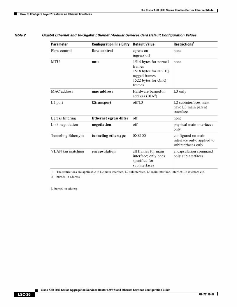
Default Configuration Values for Gigabit Ethernet and 10-Gigabit EthernetTable 2 describes the default interface configuration parameters that are present when an interface is enabled on a Gigabit Ethernet or 10-Gigabit Ethernet modular services card and its associated PLIM.
Note You must use the shutdown command to bring an interface administratively down. The interface default is no shutdown. When a modular services card is first inserted into the router, if there is no established preconfiguration for it, the configuration manager adds a shutdown item to its configuration. This shutdown can be removed only be entering the no shutdown command.
The Cisco ASR 9000 Series Routers Carrier Ethernet ModelHow to Configure Layer 2 Features on Ethernet Interfaces
LSC-36Cisco ASR 9000 Series Aggregation Services Router L2VPN and Ethernet Services Configuration Guide
OL-26116-02
1. burned-in address
Table 2 Gigabit Ethernet and 10-Gigabit Ethernet Modular Services Card Default Configuration Values
Parameter Configuration File Entry Default Value Restrictions1
1. The restrictions are applicable to L2 main interface, L2 subinterface, L3 main interface, interflex L2 interface etc.
Flow control flow-control egress oningress off
none
MTU mtu 1514 bytes for normal frames1518 bytes for 802.1Q tagged frames1522 bytes for QinQ frames
none
MAC address mac address Hardware burned-in address (BIA2)
2. burned-in address
L3 only
L2 port l2transport off/L3 L2 subinterfaces must have L3 main parent interface
Egress filtering Ethernet egress-filter off none
Link negotiation negotiation off physical main interfaces only
Tunneling Ethertype tunneling ethertype 0X8100 configured on main interface only; applied to subinterfaces only
VLAN tag matching encapsulation all frames for main interface; only ones specified for subinterfaces
encapsulation command only subinterfaces
The Cisco ASR 9000 Series Routers Carrier Ethernet ModelHow to Configure Layer 2 Features on Ethernet Interfaces
LSC-37Cisco ASR 9000 Series Aggregation Services Router L2VPN and Ethernet Services Configuration Guide
OL-26116-02
Configuring Ethernet InterfacesThese tasks are described in this section:
• Configuring a 10-Gigabit Ethernet Interface
• Configuring a Gigabit Ethernet Interface
For more information on configuring Ethernet interfaces, see the Cisco ASR 9000 Series Aggregation Services Router Interface and Hardware Component Configuration Guide.
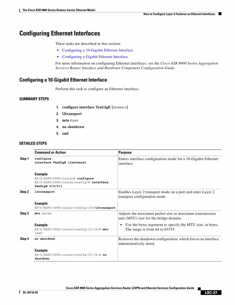
Configuring a 10-Gigabit Ethernet Interface
Perform this task to configure an Ethernet interface:
SUMMARY STEPS
1. configure interface TenGigE [instance]
2. l2transport
3. mtu bytes
4. no shutdown
5. end
DETAILED STEPS
Command or Action Purpose
Step 1 configureinterface TenGigE [instance]
Example:RP/0/RSP0/CPU0:router# configureRP/0/RSP0/CPU0:router(config)# interface TenGigE 0/0/0/1
Enters interface configuration mode for a 10-Gigabit Ethernet interface.
Step 2 l2transport
Example:RP/0/RSP0/CPU0:router(config-if)#l2transport
Enables Layer 2 transport mode on a port and enter Layer 2 transport configuration mode.
Step 3 mtu bytes
Example:RP/0/RSP0/CPU0:router(config-if-l2)# mtu 1448
Adjusts the maximum packet size or maximum transmission unit (MTU) size for the bridge domain.
• Use the bytes argument to specify the MTU size, in bytes. The range is from 64 to 65535.
Step 4 no shutdown
Example:RP/0/RSP0/CPU0:router(config-if-l2)# no shutdown
Removes the shutdown configuration, which forces an interface administratively down.
The Cisco ASR 9000 Series Routers Carrier Ethernet ModelHow to Configure Layer 2 Features on Ethernet Interfaces
LSC-38Cisco ASR 9000 Series Aggregation Services Router L2VPN and Ethernet Services Configuration Guide
OL-26116-02
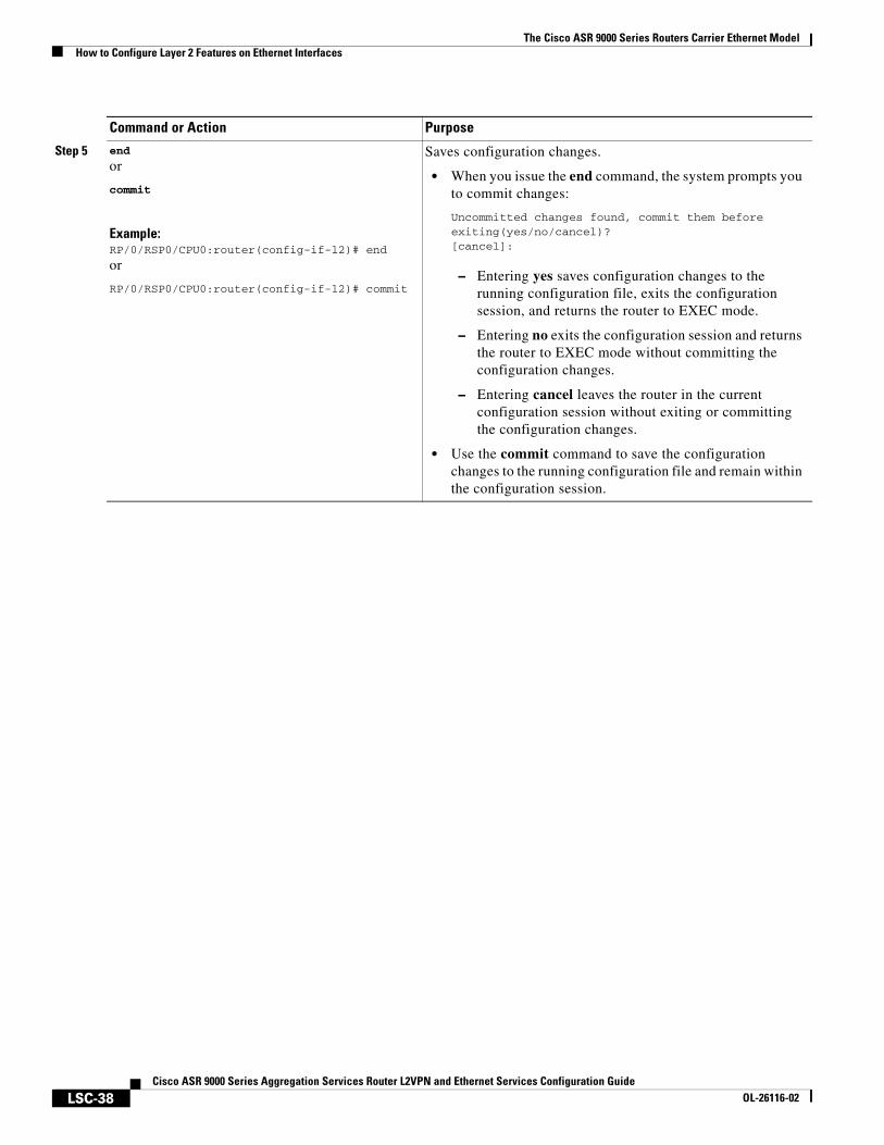
Step 5 end
or
commit
Example:RP/0/RSP0/CPU0:router(config-if-l2)# end
or
RP/0/RSP0/CPU0:router(config-if-l2)# commit
Saves configuration changes.
• When you issue the end command, the system prompts you to commit changes:
Uncommitted changes found, commit them before exiting(yes/no/cancel)? [cancel]:
– Entering yes saves configuration changes to the running configuration file, exits the configuration session, and returns the router to EXEC mode.
– Entering no exits the configuration session and returns the router to EXEC mode without committing the configuration changes.
– Entering cancel leaves the router in the current configuration session without exiting or committing the configuration changes.
• Use the commit command to save the configuration changes to the running configuration file and remain within the configuration session.
Command or Action Purpose
The Cisco ASR 9000 Series Routers Carrier Ethernet ModelHow to Configure Layer 2 Features on Ethernet Interfaces
LSC-39Cisco ASR 9000 Series Aggregation Services Router L2VPN and Ethernet Services Configuration Guide
OL-26116-02
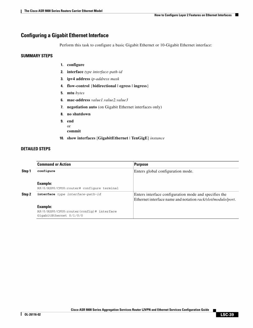
Configuring a Gigabit Ethernet Interface
Perform this task to configure a basic Gigabit Ethernet or 10-Gigabit Ethernet interface:
SUMMARY STEPS
1. configure
2. interface type interface-path-id
3. ipv4 address ip-address mask
4. flow-control {bidirectional | egress | ingress}
5. mtu bytes
6. mac-address value1.value2.value3
7. negotiation auto (on Gigabit Ethernet interfaces only)
8. no shutdown
9. endorcommit
10. show interfaces [GigabitEthernet | TenGigE] instance
DETAILED STEPS
Command or Action Purpose
Step 1 configure
Example:RP/0/RSP0/CPU0:router# configure terminal
Enters global configuration mode.
Step 2 interface type interface-path-id
Example:RP/0/RSP0/CPU0:router(config)# interfaceGigabitEthernet 0/1/0/0
Enters interface configuration mode and specifies the Ethernet interface name and notation rack/slot/module/port.
The Cisco ASR 9000 Series Routers Carrier Ethernet ModelHow to Configure Layer 2 Features on Ethernet Interfaces
LSC-40Cisco ASR 9000 Series Aggregation Services Router L2VPN and Ethernet Services Configuration Guide
OL-26116-02
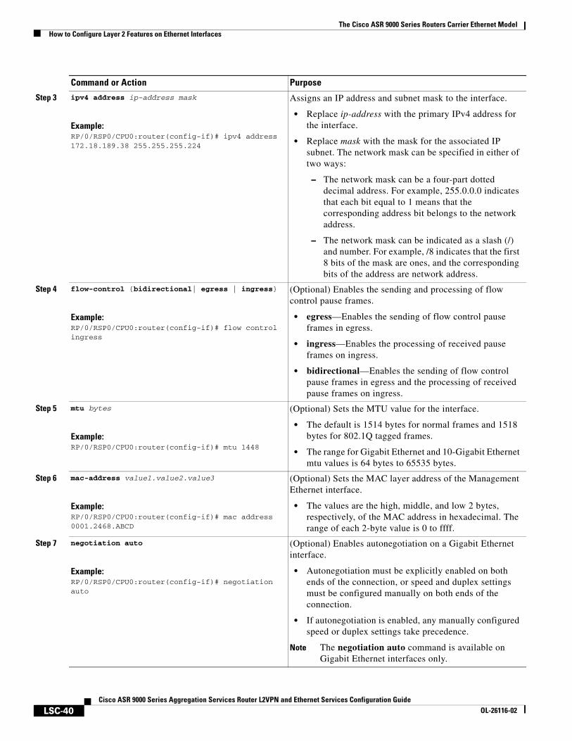
Step 3 ipv4 address ip-address mask
Example:RP/0/RSP0/CPU0:router(config-if)# ipv4 address 172.18.189.38 255.255.255.224
Assigns an IP address and subnet mask to the interface.
• Replace ip-address with the primary IPv4 address for the interface.
• Replace mask with the mask for the associated IP subnet. The network mask can be specified in either of two ways:
– The network mask can be a four-part dotted decimal address. For example, 255.0.0.0 indicates that each bit equal to 1 means that the corresponding address bit belongs to the network address.
– The network mask can be indicated as a slash (/) and number. For example, /8 indicates that the first 8 bits of the mask are ones, and the corresponding bits of the address are network address.
Step 4 flow-control {bidirectional| egress | ingress}
Example:RP/0/RSP0/CPU0:router(config-if)# flow control ingress
(Optional) Enables the sending and processing of flow control pause frames.
• egress—Enables the sending of flow control pause frames in egress.
• ingress—Enables the processing of received pause frames on ingress.
• bidirectional—Enables the sending of flow control pause frames in egress and the processing of received pause frames on ingress.
Step 5 mtu bytes
Example:RP/0/RSP0/CPU0:router(config-if)# mtu 1448
(Optional) Sets the MTU value for the interface.
• The default is 1514 bytes for normal frames and 1518 bytes for 802.1Q tagged frames.
• The range for Gigabit Ethernet and 10-Gigabit Ethernet mtu values is 64 bytes to 65535 bytes.
Step 6 mac-address value1.value2.value3
Example:RP/0/RSP0/CPU0:router(config-if)# mac address 0001.2468.ABCD
(Optional) Sets the MAC layer address of the Management Ethernet interface.
• The values are the high, middle, and low 2 bytes, respectively, of the MAC address in hexadecimal. The range of each 2-byte value is 0 to ffff.
Step 7 negotiation auto
Example:RP/0/RSP0/CPU0:router(config-if)# negotiation auto
(Optional) Enables autonegotiation on a Gigabit Ethernet interface.
• Autonegotiation must be explicitly enabled on both ends of the connection, or speed and duplex settings must be configured manually on both ends of the connection.
• If autonegotiation is enabled, any manually configured speed or duplex settings take precedence.
Note The negotiation auto command is available on Gigabit Ethernet interfaces only.
Command or Action Purpose
The Cisco ASR 9000 Series Routers Carrier Ethernet ModelHow to Configure Layer 2 Features on Ethernet Interfaces
LSC-41Cisco ASR 9000 Series Aggregation Services Router L2VPN and Ethernet Services Configuration Guide
OL-26116-02
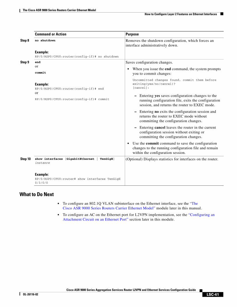
What to Do Next
• To configure an 802.1Q VLAN subinterface on the Ethernet interface, see the “The Cisco ASR 9000 Series Routers Carrier Ethernet Model” module later in this manual.
• To configure an AC on the Ethernet port for L2VPN implementation, see the “Configuring an Attachment Circuit on an Ethernet Port” section later in this module.
Step 8 no shutdown
Example:RP/0/RSP0/CPU0:router(config-if)# no shutdown
Removes the shutdown configuration, which forces an interface administratively down.
Step 9 end
or
commit
Example:RP/0/RSP0/CPU0:router(config-if)# end
or
RP/0/RSP0/CPU0:router(config-if)# commit
Saves configuration changes.
• When you issue the end command, the system prompts you to commit changes:
Uncommitted changes found, commit them before exiting(yes/no/cancel)? [cancel]:
– Entering yes saves configuration changes to the running configuration file, exits the configuration session, and returns the router to EXEC mode.
– Entering no exits the configuration session and returns the router to EXEC mode without committing the configuration changes.
– Entering cancel leaves the router in the current configuration session without exiting or committing the configuration changes.
• Use the commit command to save the configuration changes to the running configuration file and remain within the configuration session.
Step 10 show interfaces [GigabitEthernet | TenGigE] instance
Example:RP/0/RSP0/CPU0:router# show interfaces TenGigE 0/3/0/0
(Optional) Displays statistics for interfaces on the router.
Command or Action Purpose
The Cisco ASR 9000 Series Routers Carrier Ethernet ModelHow to Configure Layer 2 Features on Ethernet Interfaces
LSC-42Cisco ASR 9000 Series Aggregation Services Router L2VPN and Ethernet Services Configuration Guide
OL-26116-02
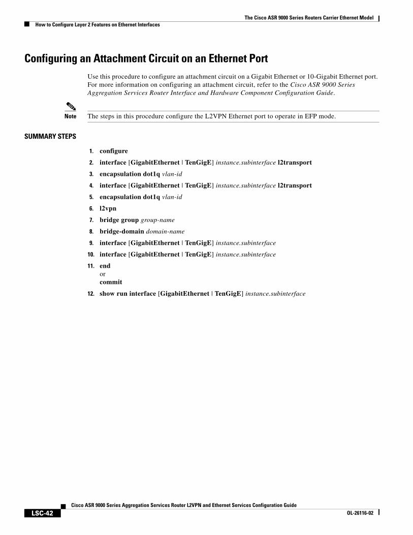
Configuring an Attachment Circuit on an Ethernet PortUse this procedure to configure an attachment circuit on a Gigabit Ethernet or 10-Gigabit Ethernet port. For more information on configuring an attachment circuit, refer to the Cisco ASR 9000 Series Aggregation Services Router Interface and Hardware Component Configuration Guide.
Note The steps in this procedure configure the L2VPN Ethernet port to operate in EFP mode.
SUMMARY STEPS
1. configure
2. interface [GigabitEthernet | TenGigE] instance.subinterface l2transport
3. encapsulation dot1q vlan-id
4. interface [GigabitEthernet | TenGigE] instance.subinterface l2transport
5. encapsulation dot1q vlan-id
6. l2vpn
7. bridge group group-name
8. bridge-domain domain-name
9. interface [GigabitEthernet | TenGigE] instance.subinterface
10. interface [GigabitEthernet | TenGigE] instance.subinterface
11. endorcommit
12. show run interface [GigabitEthernet | TenGigE] instance.subinterface
The Cisco ASR 9000 Series Routers Carrier Ethernet ModelHow to Configure Layer 2 Features on Ethernet Interfaces
LSC-43Cisco ASR 9000 Series Aggregation Services Router L2VPN and Ethernet Services Configuration Guide
OL-26116-02
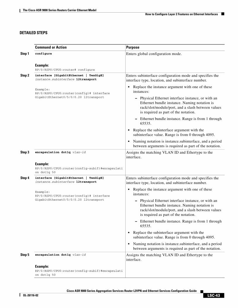
DETAILED STEPS
Command or Action Purpose
Step 1 configure
Example:RP/0/RSP0/CPU0:router# configure
Enters global configuration mode.
Step 2 interface [GigabitEthernet | TenGigE] instance.subinterface l2transport
Example:RP/0/RSP0/CPU0:router(config)# interface GigabitEthernet0/5/0/0.20 l2transport
Enters subinterface configuration mode and specifies the interface type, location, and subinterface number.
• Replace the instance argument with one of these instances:
– Physical Ethernet interface instance, or with an Ethernet bundle instance. Naming notation is rack/slot/module/port, and a slash between values is required as part of the notation.
– Ethernet bundle instance. Range is from 1 through 65535.
• Replace the subinterface argument with the subinterface value. Range is from 0 through 4095.
• Naming notation is instance.subinterface, and a period between arguments is required as part of the notation.
Step 3 encapsulation dot1q vlan-id
Example:RP/0/RSP0/CPU0:router(config-subif)#encapsulation dot1q 50
Assigns the matching VLAN ID and Ethertype to the interface.
Step 4 interface [GigabitEthernet | TenGigE] instance.subinterface l2transport
Example:RP/0/RSP0/CPU0:router(config)# interface GigabitEthernet0/5/0/0.20 l2transport
Enters subinterface configuration mode and specifies the interface type, location, and subinterface number.
• Replace the instance argument with one of these instances:
– Physical Ethernet interface instance, or with an Ethernet bundle instance. Naming notation is rack/slot/module/port, and a slash between values is required as part of the notation.
– Ethernet bundle instance. Range is from 1 through 65535.
• Replace the subinterface argument with the subinterface value. Range is from 0 through 4095.
• Naming notation is instance.subinterface, and a period between arguments is required as part of the notation.
Step 5 encapsulation dot1q vlan-id
Example:RP/0/RSP0/CPU0:router(config-subif)#encapsulation dot1q 50
Assigns the matching VLAN ID and Ethertype to the interface.
The Cisco ASR 9000 Series Routers Carrier Ethernet ModelHow to Configure Layer 2 Features on Ethernet Interfaces
LSC-44Cisco ASR 9000 Series Aggregation Services Router L2VPN and Ethernet Services Configuration Guide
OL-26116-02
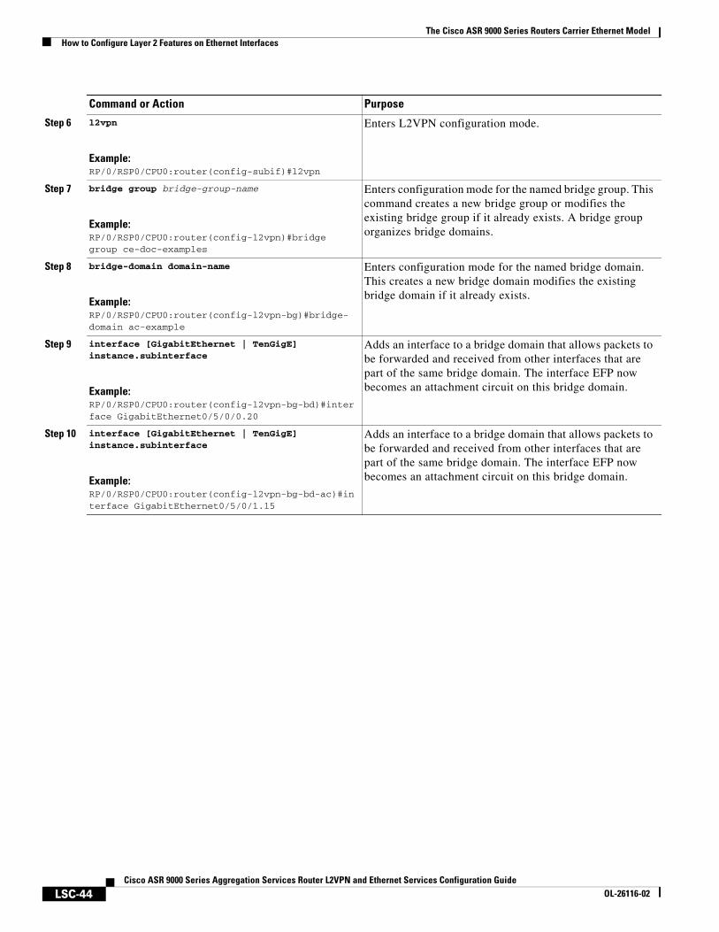
Step 6 l2vpn
Example:RP/0/RSP0/CPU0:router(config-subif)#l2vpn
Enters L2VPN configuration mode.
Step 7 bridge group bridge-group-name
Example:RP/0/RSP0/CPU0:router(config-l2vpn)#bridge group ce-doc-examples
Enters configuration mode for the named bridge group. This command creates a new bridge group or modifies the existing bridge group if it already exists. A bridge group organizes bridge domains.
Step 8 bridge-domain domain-name
Example:RP/0/RSP0/CPU0:router(config-l2vpn-bg)#bridge-domain ac-example
Enters configuration mode for the named bridge domain. This creates a new bridge domain modifies the existing bridge domain if it already exists.
Step 9 interface [GigabitEthernet | TenGigE] instance.subinterface
Example:RP/0/RSP0/CPU0:router(config-l2vpn-bg-bd)#interface GigabitEthernet0/5/0/0.20
Adds an interface to a bridge domain that allows packets to be forwarded and received from other interfaces that are part of the same bridge domain. The interface EFP now becomes an attachment circuit on this bridge domain.
Step 10 interface [GigabitEthernet | TenGigE] instance.subinterface
Example:RP/0/RSP0/CPU0:router(config-l2vpn-bg-bd-ac)#interface GigabitEthernet0/5/0/1.15
Adds an interface to a bridge domain that allows packets to be forwarded and received from other interfaces that are part of the same bridge domain. The interface EFP now becomes an attachment circuit on this bridge domain.
Command or Action Purpose
The Cisco ASR 9000 Series Routers Carrier Ethernet ModelHow to Configure Layer 2 Features on Ethernet Interfaces
LSC-45Cisco ASR 9000 Series Aggregation Services Router L2VPN and Ethernet Services Configuration Guide
OL-26116-02
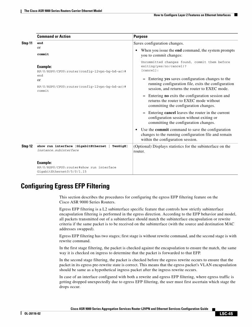
Configuring Egress EFP FilteringThis section describes the procedures for configuring the egress EFP filtering feature on the Cisco ASR 9000 Series Routers.
Egress EFP filtering is a L2 subinterface specific feature that controls how strictly subinterface encapsulation filtering is performed in the egress direction. According to the EFP behavior and model, all packets transmitted out of a subinterface should match the subinterface encapsulation or rewrite criteria if the same packet is to be received on the subinterface (with the source and destination MAC addresses swapped).
Egress EFP filtering has two stages; first stage is without rewrite command, and the second stage is with rewrite command.
In the first stage filtering, the packet is checked against the encapsulation to ensure the match, the same way it is checked on ingress to determine that the packet is forwarded to that EFP.
In the second stage filtering, the packet is checked before the egress rewrite occurs to ensure that the packet in its egress pre-rewrite state is correct. This means that the egress packet's VLAN encapsulation should be same as a hypothetical ingress packet after the ingress rewrite occurs.
In case of an interface configured with both a rewrite and egress EFP filtering, where egress traffic is getting dropped unexpectedly due to egress EFP filtering, the user must first ascertain which stage the drops occur.
Step 11 end
or
commit
Example:RP/0/RSP0/CPU0:router(config-l2vpn-bg-bd-ac)# end
or
RP/0/RSP0/CPU0:router(config-l2vpn-bg-bd-ac)# commit
Saves configuration changes.
• When you issue the end command, the system prompts you to commit changes:
Uncommitted changes found, commit them before exiting(yes/no/cancel)? [cancel]:
– Entering yes saves configuration changes to the running configuration file, exits the configuration session, and returns the router to EXEC mode.
– Entering no exits the configuration session and returns the router to EXEC mode without committing the configuration changes.
– Entering cancel leaves the router in the current configuration session without exiting or committing the configuration changes.
• Use the commit command to save the configuration changes to the running configuration file and remain within the configuration session.
Step 12 show run interface [GigabitEthernet | TenGigE] instance.subinterface
Example:RP/0/RSP0/CPU0:router#show run interface GigabitEthernet0/5/0/1.15
(Optional) Displays statistics for the subinterface on the router.
Command or Action Purpose
The Cisco ASR 9000 Series Routers Carrier Ethernet ModelHow to Configure Layer 2 Features on Ethernet Interfaces
LSC-46Cisco ASR 9000 Series Aggregation Services Router L2VPN and Ethernet Services Configuration Guide
OL-26116-02
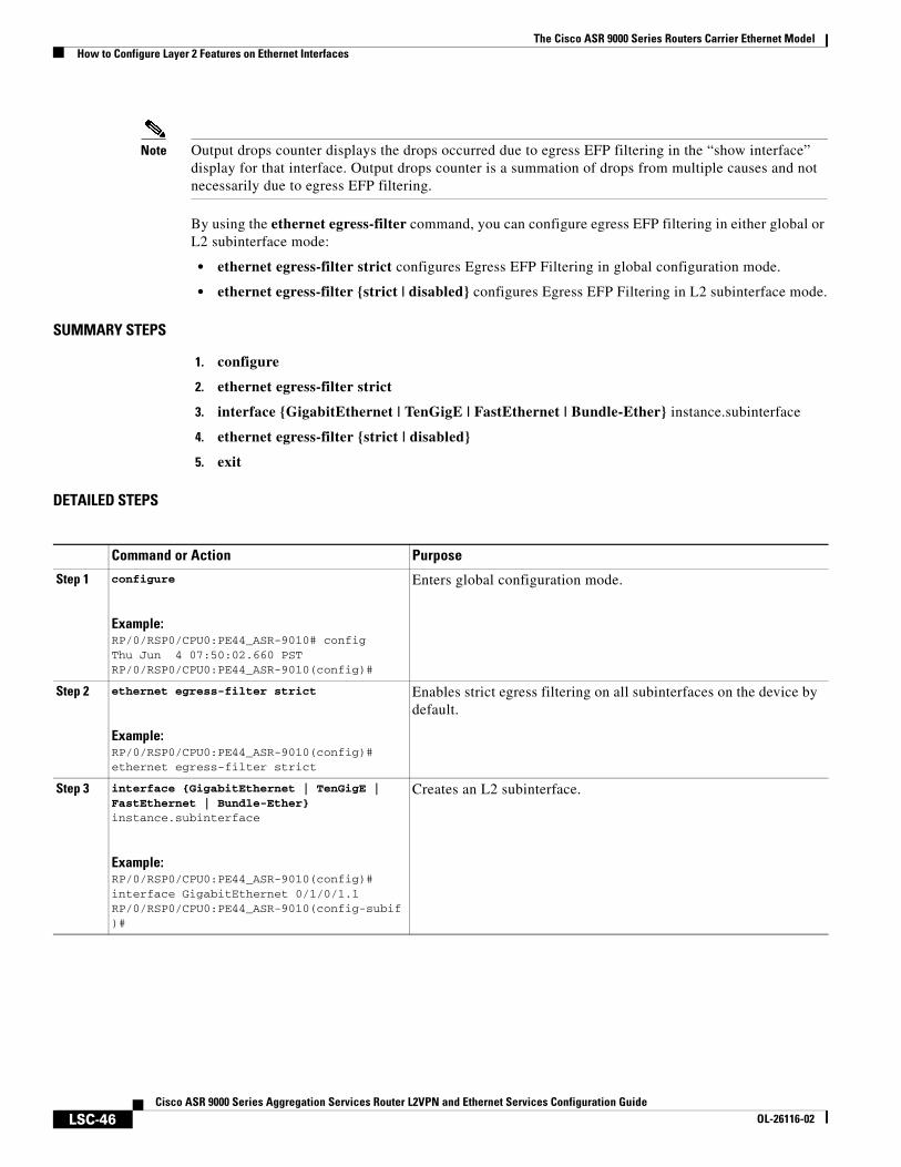
Note Output drops counter displays the drops occurred due to egress EFP filtering in the “show interface” display for that interface. Output drops counter is a summation of drops from multiple causes and not necessarily due to egress EFP filtering.
By using the ethernet egress-filter command, you can configure egress EFP filtering in either global or L2 subinterface mode:
• ethernet egress-filter strict configures Egress EFP Filtering in global configuration mode.
• ethernet egress-filter {strict | disabled} configures Egress EFP Filtering in L2 subinterface mode.
SUMMARY STEPS
1. configure
2. ethernet egress-filter strict
3. interface {GigabitEthernet | TenGigE | FastEthernet | Bundle-Ether} instance.subinterface
4. ethernet egress-filter {strict | disabled}
5. exit
DETAILED STEPS
Command or Action Purpose
Step 1 configure
Example:RP/0/RSP0/CPU0:PE44_ASR-9010# configThu Jun 4 07:50:02.660 PSTRP/0/RSP0/CPU0:PE44_ASR-9010(config)#
Enters global configuration mode.
Step 2 ethernet egress-filter strict
Example:RP/0/RSP0/CPU0:PE44_ASR-9010(config)# ethernet egress-filter strict
Enables strict egress filtering on all subinterfaces on the device by default.
Step 3 interface {GigabitEthernet | TenGigE | FastEthernet | Bundle-Ether} instance.subinterface
Example:RP/0/RSP0/CPU0:PE44_ASR-9010(config)# interface GigabitEthernet 0/1/0/1.1RP/0/RSP0/CPU0:PE44_ASR-9010(config-subif)#
Creates an L2 subinterface.

The Cisco ASR 9000 Series Routers Carrier Ethernet ModelHow to Configure Layer 2 Features on Ethernet Interfaces
LSC-47Cisco ASR 9000 Series Aggregation Services Router L2VPN and Ethernet Services Configuration Guide
OL-26116-02
Configuring 802.1Q VLAN InterfacesThis section contains these procedures:
• Configuring 802.1Q VLAN Subinterfaces, page 47
• Configuring Native VLAN, page 49
• Removing an 802.1Q VLAN Subinterface, page 52
• Removing an 802.1Q VLAN Subinterface, page 52
Configuring 802.1Q VLAN Subinterfaces
This task explains how to configure 802.1Q VLAN subinterfaces. To remove these subinterfaces, see the “Removing an 802.1Q VLAN Subinterface” section of this module.
SUMMARY STEPS
1. configure
2. interface {GigabitEthernet | TenGigE | Bundle-Ether} instance.subinterface
3. l2transport
4. encapsulation dot1q vlan-id
5. ethernet egress-filter strict
6. endorcommit
7. show ethernet trunk bundle-ether instance (Optional)
Step 4 ethernet egress-filter {strict | disabled}
Example:RP/0/RSP0/CPU0:PE44_ASR-9010(config-subif)# ethernet egress-filter strict
Allows egress filtering to be explicitly enabled or disabled on any L2 subinterface. It can also be used to override global settings.
Step 5 exit
Example:RP/0/RSP0/CPU0:PE44_ASR-9010(config-subif)# exitRP/0/RSP0/CPU0:PE44_ASR-9010(config)# exit
Exit from the configuration mode.
Command or Action Purpose
The Cisco ASR 9000 Series Routers Carrier Ethernet ModelHow to Configure Layer 2 Features on Ethernet Interfaces
LSC-48Cisco ASR 9000 Series Aggregation Services Router L2VPN and Ethernet Services Configuration Guide
OL-26116-02
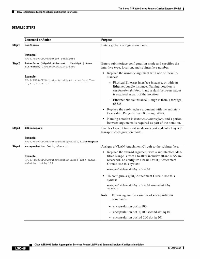
DETAILED STEPS
Command or Action Purpose
Step 1 configure
Example:RP/0/RSP0/CPU0:router# configure
Enters global configuration mode.
Step 2 interface {GigabitEthernet | TenGigE | Bun-dle-Ether} instance.subinterface
Example:RP/0/RSP0/CPU0:router(config)# interface Ten-GigE 0/2/0/4.10
Enters subinterface configuration mode and specifies the interface type, location, and subinterface number.
• Replace the instance argument with one of these in-stances:
– Physical Ethernet interface instance, or with an Ethernet bundle instance. Naming notation is rack/slot/module/port, and a slash between values is required as part of the notation.
– Ethernet bundle instance. Range is from 1 through 65535.
• Replace the subinterface argument with the subinter-face value. Range is from 0 through 4095.
• Naming notation is instance.subinterface, and a period between arguments is required as part of the notation.
Step 3 l2transport
Example:RP/0/RSP0/CPU0:router(config-subif)#l2transport
Enables Layer 2 transport mode on a port and enter Layer 2 transport configuration mode.
Step 4 encapsulation dot1q vlan-id
Example:RP/0/RSP0/CPU0:router(config-subif-l2)# encap-sulation dot1q 100
Assigns a VLAN Attachment Circuit to the subinterface.
• Replace the vlan-id argument with a subinterface iden-tifier. Range is from 1 to 4094 inclusive (0 and 4095 are reserved). To configure a basic Dot1Q Attachment Circuit, use this syntax:
encapsulation dot1q vlan-id
• To configure a QinQ Attachment Circuit, use this syntax:
encapsulation dot1q vlan-id second-dot1q vlan-id
Note Following are the varieties of encapsulation commands:
– encapsulation dot1q 100
– encapsulation dot1q 100 second-dot1q 101
– encapsulation dot1ad 200 dot1q 201
The Cisco ASR 9000 Series Routers Carrier Ethernet ModelHow to Configure Layer 2 Features on Ethernet Interfaces
LSC-49Cisco ASR 9000 Series Aggregation Services Router L2VPN and Ethernet Services Configuration Guide
OL-26116-02
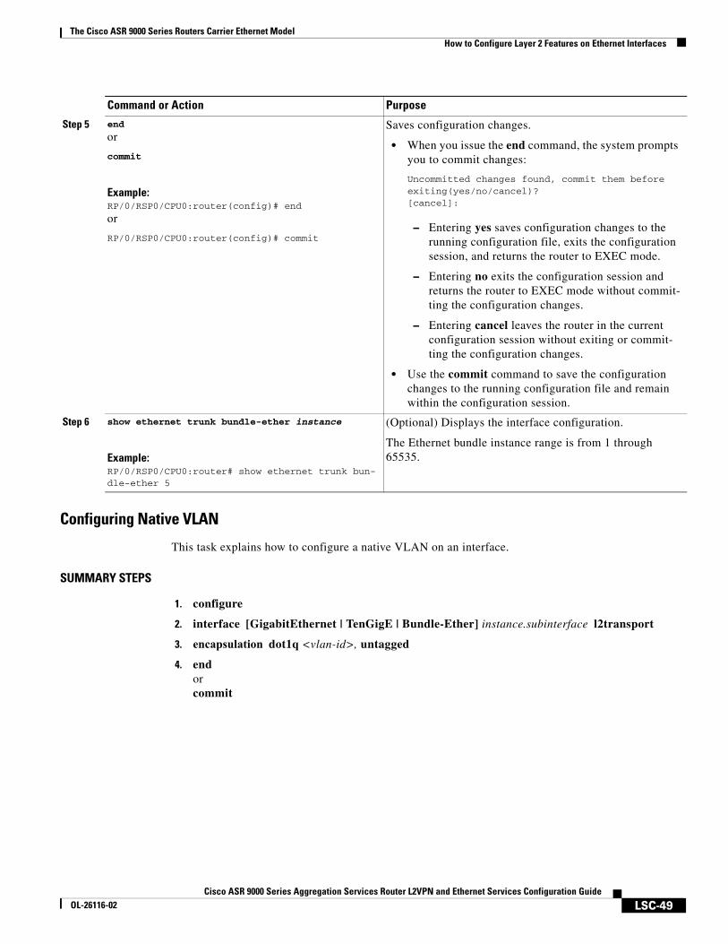
Configuring Native VLAN
This task explains how to configure a native VLAN on an interface.
SUMMARY STEPS
1. configure
2. interface [GigabitEthernet | TenGigE | Bundle-Ether] instance.subinterface l2transport
3. encapsulation dot1q <vlan-id>, untagged
4. endorcommit
Step 5 end
or
commit
Example:RP/0/RSP0/CPU0:router(config)# end
or
RP/0/RSP0/CPU0:router(config)# commit
Saves configuration changes.
• When you issue the end command, the system prompts you to commit changes:
Uncommitted changes found, commit them before exiting(yes/no/cancel)? [cancel]:
– Entering yes saves configuration changes to the running configuration file, exits the configuration session, and returns the router to EXEC mode.
– Entering no exits the configuration session and returns the router to EXEC mode without commit-ting the configuration changes.
– Entering cancel leaves the router in the current configuration session without exiting or commit-ting the configuration changes.
• Use the commit command to save the configuration changes to the running configuration file and remain within the configuration session.
Step 6 show ethernet trunk bundle-ether instance
Example:RP/0/RSP0/CPU0:router# show ethernet trunk bun-dle-ether 5
(Optional) Displays the interface configuration.
The Ethernet bundle instance range is from 1 through 65535.
Command or Action Purpose
The Cisco ASR 9000 Series Routers Carrier Ethernet ModelHow to Configure Layer 2 Features on Ethernet Interfaces
LSC-50Cisco ASR 9000 Series Aggregation Services Router L2VPN and Ethernet Services Configuration Guide
OL-26116-02
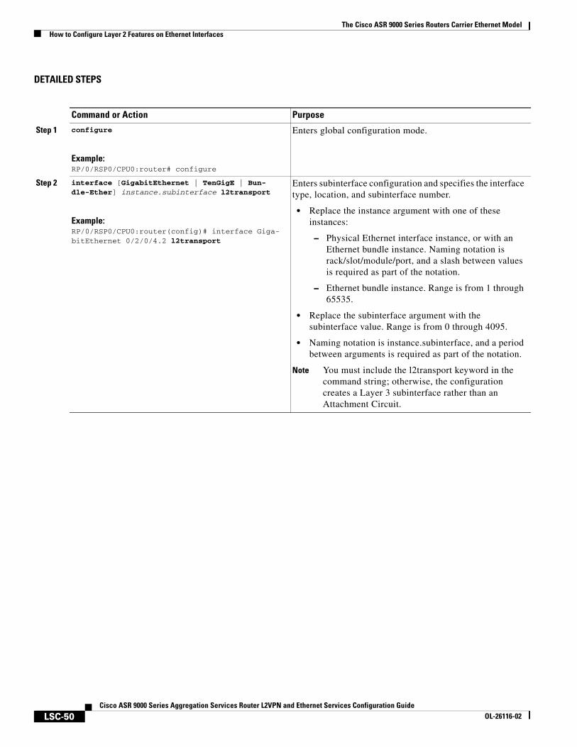
DETAILED STEPS
Command or Action Purpose
Step 1 configure
Example:RP/0/RSP0/CPU0:router# configure
Enters global configuration mode.
Step 2 interface [GigabitEthernet | TenGigE | Bun-dle-Ether] instance.subinterface l2transport
Example:RP/0/RSP0/CPU0:router(config)# interface Giga-bitEthernet 0/2/0/4.2 l2transport
Enters subinterface configuration and specifies the interface type, location, and subinterface number.
• Replace the instance argument with one of these instances:
– Physical Ethernet interface instance, or with an Ethernet bundle instance. Naming notation is rack/slot/module/port, and a slash between values is required as part of the notation.
– Ethernet bundle instance. Range is from 1 through 65535.
• Replace the subinterface argument with the subinterface value. Range is from 0 through 4095.
• Naming notation is instance.subinterface, and a period between arguments is required as part of the notation.
Note You must include the l2transport keyword in the command string; otherwise, the configuration creates a Layer 3 subinterface rather than an Attachment Circuit.
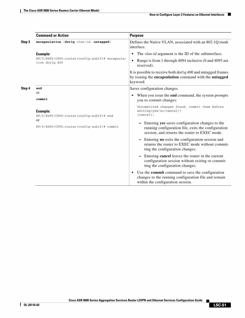
The Cisco ASR 9000 Series Routers Carrier Ethernet ModelHow to Configure Layer 2 Features on Ethernet Interfaces
LSC-51Cisco ASR 9000 Series Aggregation Services Router L2VPN and Ethernet Services Configuration Guide
OL-26116-02
Step 3 encapsulation [dot1q vlan-id, untagged]
Example:RP/0/RSP0/CPU0:router(config-subif)# encapsula-tion dot1q 400
Defines the Native VLAN, associated with an 802.1Q trunk interface.
• The vlan-id argument is the ID of the subinterface.
• Range is from 1 through 4094 inclusive (0 and 4095 are reserved).
It is possible to receive both dot1q 400 and untagged frames by issuing the encapsulation command with the untagged keyword.
Step 4 end
or
commit
Example:RP/0/RSP0/CPU0:router(config-subif)# end
or
RP/0/RSP0/CPU0:router(config-subif)# commit
Saves configuration changes.
• When you issue the end command, the system prompts you to commit changes:
Uncommitted changes found, commit them before exiting(yes/no/cancel)? [cancel]:
– Entering yes saves configuration changes to the running configuration file, exits the configuration session, and returns the router to EXEC mode.
– Entering no exits the configuration session and returns the router to EXEC mode without commit-ting the configuration changes.
– Entering cancel leaves the router in the current configuration session without exiting or commit-ting the configuration changes.
• Use the commit command to save the configuration changes to the running configuration file and remain within the configuration session.
Command or Action Purpose
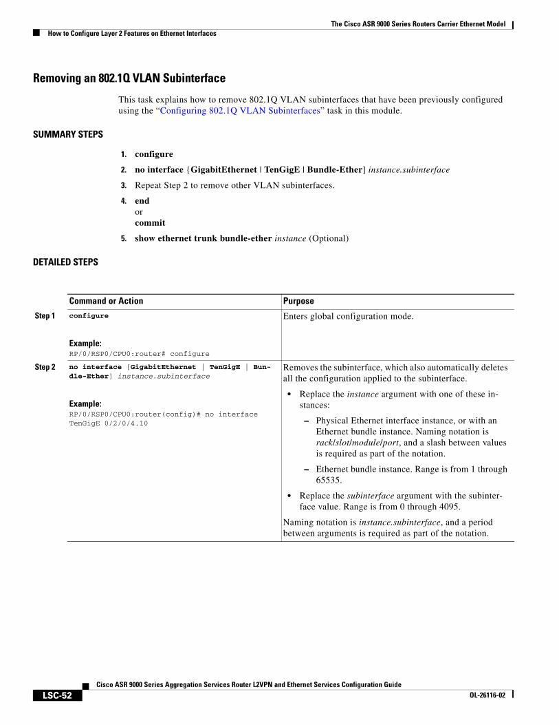
The Cisco ASR 9000 Series Routers Carrier Ethernet ModelHow to Configure Layer 2 Features on Ethernet Interfaces
LSC-52Cisco ASR 9000 Series Aggregation Services Router L2VPN and Ethernet Services Configuration Guide
OL-26116-02
Removing an 802.1Q VLAN Subinterface
This task explains how to remove 802.1Q VLAN subinterfaces that have been previously configured using the “Configuring 802.1Q VLAN Subinterfaces” task in this module.
SUMMARY STEPS
1. configure
2. no interface {GigabitEthernet | TenGigE | Bundle-Ether] instance.subinterface
3. Repeat Step 2 to remove other VLAN subinterfaces.
4. endorcommit
5. show ethernet trunk bundle-ether instance (Optional)
DETAILED STEPS
Command or Action Purpose
Step 1 configure
Example:RP/0/RSP0/CPU0:router# configure
Enters global configuration mode.
Step 2 no interface [GigabitEthernet | TenGigE | Bun-dle-Ether] instance.subinterface
Example:RP/0/RSP0/CPU0:router(config)# no interface TenGigE 0/2/0/4.10
Removes the subinterface, which also automatically deletes all the configuration applied to the subinterface.
• Replace the instance argument with one of these in-stances:
– Physical Ethernet interface instance, or with an Ethernet bundle instance. Naming notation is rack/slot/module/port, and a slash between values is required as part of the notation.
– Ethernet bundle instance. Range is from 1 through 65535.
• Replace the subinterface argument with the subinter-face value. Range is from 0 through 4095.
Naming notation is instance.subinterface, and a period between arguments is required as part of the notation.
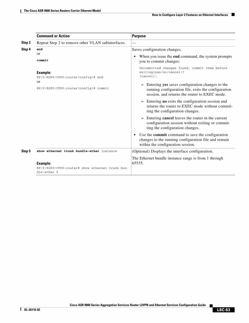
The Cisco ASR 9000 Series Routers Carrier Ethernet ModelHow to Configure Layer 2 Features on Ethernet Interfaces
LSC-53Cisco ASR 9000 Series Aggregation Services Router L2VPN and Ethernet Services Configuration Guide
OL-26116-02
Step 3 Repeat Step 2 to remove other VLAN subinterfaces. —
Step 4 end
or
commit
Example:RP/0/RSP0/CPU0:router(config)# end
or
RP/0/RSP0/CPU0:router(config)# commit
Saves configuration changes.
• When you issue the end command, the system prompts you to commit changes:
Uncommitted changes found, commit them before exiting(yes/no/cancel)? [cancel]:
– Entering yes saves configuration changes to the running configuration file, exits the configuration session, and returns the router to EXEC mode.
– Entering no exits the configuration session and returns the router to EXEC mode without commit-ting the configuration changes.
– Entering cancel leaves the router in the current configuration session without exiting or commit-ting the configuration changes.
• Use the commit command to save the configuration changes to the running configuration file and remain within the configuration session.
Step 5 show ethernet trunk bundle-ether instance
Example:RP/0/RSP0/CPU0:router# show ethernet trunk bun-dle-ether 5
(Optional) Displays the interface configuration.
The Ethernet bundle instance range is from 1 through 65535.
Command or Action Purpose
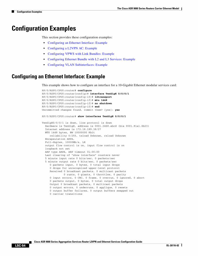
The Cisco ASR 9000 Series Routers Carrier Ethernet ModelConfiguration Examples
LSC-54Cisco ASR 9000 Series Aggregation Services Router L2VPN and Ethernet Services Configuration Guide
OL-26116-02
Configuration ExamplesThis section provides these configuration examples:
• Configuring an Ethernet Interface: Example
• Configuring a L2VPN AC: Example
• Configuring VPWS with Link Bundles: Example
• Configuring Ethernet Bundle with L2 and L3 Services: Example
• Configuring VLAN Subinterfaces: Example
Configuring an Ethernet Interface: ExampleThis example shows how to configure an interface for a 10-Gigabit Ethernet modular services card:
RP/0/RSP0/CPU0:router# configureRP/0/RSP0/CPU0:router(config)# interface TenGigE 0/0/0/1RP/0/RSP0/CPU0:router(config-if)# l2transportRP/0/RSP0/CPU0:router(config-if)# mtu 1448RP/0/RSP0/CPU0:router(config-if)# no shutdownRP/0/RSP0/CPU0:router(config-if)# endUncommitted changes found, commit them? [yes]: yes
RP/0/RSP0/CPU0:router# show interfaces TenGigE 0/0/0/1
TenGigE0/0/0/1 is down, line protocol is down Hardware is TenGigE, address is 0001.2468.abcd (bia 0001.81a1.6b23) Internet address is 172.18.189.38/27 MTU 1448 bytes, BW 10000000 Kbit reliability 0/255, txload Unknown, rxload Unknown Encapsulation ARPA, Full-duplex, 10000Mb/s, LR output flow control is on, input flow control is on loopback not set ARP type ARPA, ARP timeout 01:00:00 Last clearing of "show interface" counters never 5 minute input rate 0 bits/sec, 0 packets/sec 5 minute output rate 0 bits/sec, 0 packets/sec 0 packets input, 0 bytes, 0 total input drops 0 drops for unrecognized upper-level protocol Received 0 broadcast packets, 0 multicast packets 0 runts, 0 giants, 0 throttles, 0 parity 0 input errors, 0 CRC, 0 frame, 0 overrun, 0 ignored, 0 abort 0 packets output, 0 bytes, 0 total output drops Output 0 broadcast packets, 0 multicast packets 0 output errors, 0 underruns, 0 applique, 0 resets 0 output buffer failures, 0 output buffers swapped out 0 carrier transitions
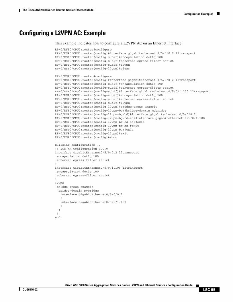
The Cisco ASR 9000 Series Routers Carrier Ethernet ModelConfiguration Examples
LSC-55Cisco ASR 9000 Series Aggregation Services Router L2VPN and Ethernet Services Configuration Guide
OL-26116-02
Configuring a L2VPN AC: ExampleThis example indicates how to configure a L2VPN AC on an Ethernet interface:
RP/0/RSP0/CPU0:router#configureRP/0/RSP0/CPU0:router(config)#interface gigabitethernet 0/5/0/0.2 l2transportRP/0/RSP0/CPU0:router(config-subif)#encapsulation dot1q 100RP/0/RSP0/CPU0:router(config-subif)#ethernet egress-filter strictRP/0/RSP0/CPU0:router(config-subif)#l2vpnRP/0/RSP0/CPU0:router(config-l2vpn)#clear
RP/0/RSP0/CPU0:router#configureRP/0/RSP0/CPU0:router(config)#interface gigabitethernet 0/5/0/0.2 l2transportRP/0/RSP0/CPU0:router(config-subif)#encapsulation dot1q 100RP/0/RSP0/CPU0:router(config-subif)#ethernet egress-filter strictRP/0/RSP0/CPU0:router(config-subif)#interface gigabitethernet 0/5/0/1.100 l2transportRP/0/RSP0/CPU0:router(config-subif)#encapsulation dot1q 100RP/0/RSP0/CPU0:router(config-subif)#ethernet egress-filter strictRP/0/RSP0/CPU0:router(config-subif)#l2vpnRP/0/RSP0/CPU0:router(config-l2vpn)#bridge group exampleRP/0/RSP0/CPU0:router(config-l2vpn-bg)#bridge-domain mybridgeRP/0/RSP0/CPU0:router(config-l2vpn-bg-bd)#interface gigabitethernet 0/5/0/0.2RP/0/RSP0/CPU0:router(config-l2vpn-bg-bd-ac)#interface gigabitethernet 0/5/0/1.100RP/0/RSP0/CPU0:router(config-l2vpn-bg-bd-ac)#exitRP/0/RSP0/CPU0:router(config-l2vpn-bg-bd)#exitRP/0/RSP0/CPU0:router(config-l2vpn-bg)#exitRP/0/RSP0/CPU0:router(config-l2vpn)#exitRP/0/RSP0/CPU0:router(config)#show
Building configuration...!! IOS XR Configuration 0.0.0interface GigabitEthernet0/5/0/0.2 l2transport encapsulation dot1q 100 ethernet egress-filter strict!interface GigabitEthernet0/5/0/1.100 l2transport encapsulation dot1q 100 ethernet egress-filter strict!l2vpn bridge group example bridge-domain mybridge interface GigabitEthernet0/5/0/0.2 ! interface GigabitEthernet0/5/0/1.100 ! ! !end
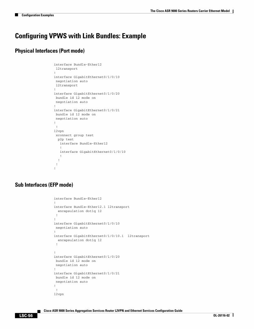
The Cisco ASR 9000 Series Routers Carrier Ethernet ModelConfiguration Examples
LSC-56Cisco ASR 9000 Series Aggregation Services Router L2VPN and Ethernet Services Configuration Guide
OL-26116-02
Configuring VPWS with Link Bundles: Example
Physical Interfaces (Port mode)
interface Bundle-Ether12 l2transport!interface GigabitEthernet0/1/0/10 negotiation auto l2transport!interface GigabitEthernet0/1/0/20 bundle id 12 mode on negotiation auto!interface GigabitEthernet0/1/0/21 bundle id 12 mode on negotiation auto! !l2vpn xconnect group test p2p test interface Bundle-Ether12 ! interface GigabitEthernet0/1/0/10 ! ! !!
Sub Interfaces (EFP mode)
interface Bundle-Ether12!interface Bundle-Ether12.1 l2transport encapsulation dot1q 12 ! !interface GigabitEthernet0/1/0/10 negotiation auto!interface GigabitEthernet0/1/0/10.1 l2transport encapsulation dot1q 12 !
!interface GigabitEthernet0/1/0/20 bundle id 12 mode on negotiation auto!interface GigabitEthernet0/1/0/21 bundle id 12 mode on negotiation auto! !l2vpn
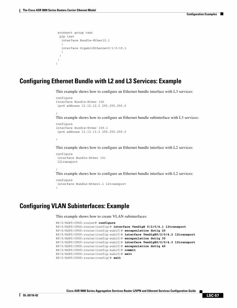
The Cisco ASR 9000 Series Routers Carrier Ethernet ModelConfiguration Examples
LSC-57Cisco ASR 9000 Series Aggregation Services Router L2VPN and Ethernet Services Configuration Guide
OL-26116-02
xconnect group test p2p test interface Bundle-Ether12.1 ! interface GigabitEthernet0/1/0/10.1 ! ! !!
Configuring Ethernet Bundle with L2 and L3 Services: ExampleThis example shows how to configure an Ethernet bundle interface with L3 services:
configureinterface Bundle-Ether 100ipv4 address 12.12.12.2 255.255.255.0
!
This example shows how to configure an Ethernet bundle subinterface with L3 services:
configureinterface Bundle-Ether 100.1ipv4 address 13.13.13.2 255.255.255.0
!
This example shows how to configure an Ethernet bundle interface with L2 services:
configureinterface Bundle-Ether 101l2transport
!
This example shows how to configure an Ethernet bundle interface with L2 services:
configureinterface Bundle-Ether1.1 l2transport!
Configuring VLAN Subinterfaces: ExampleThis example shows how to create VLAN subinterfaces:
RP/0/RSP0/CPU0:router# configureRP/0/RSP0/CPU0:router(config)# interface TenGigE 0/2/0/4.1 l2transportRP/0/RSP0/CPU0:router(config-subif)# encapsulation dot1q 20RP/0/RSP0/CPU0:router(config-subif)# interface TenGigE0/2/0/4.2 l2transportRP/0/RSP0/CPU0:router(config-subif)# encapsulation dot1q 30RP/0/RSP0/CPU0:router(config-subif)# interface TenGigE0/2/0/4.3 l2transportRP/0/RSP0/CPU0:router(config-subif)# encapsulation dot1q 40RP/0/RSP0/CPU0:router(config-subif)# commitRP/0/RSP0/CPU0:router(config-subif)# exitRP/0/RSP0/CPU0:router(config)# exit
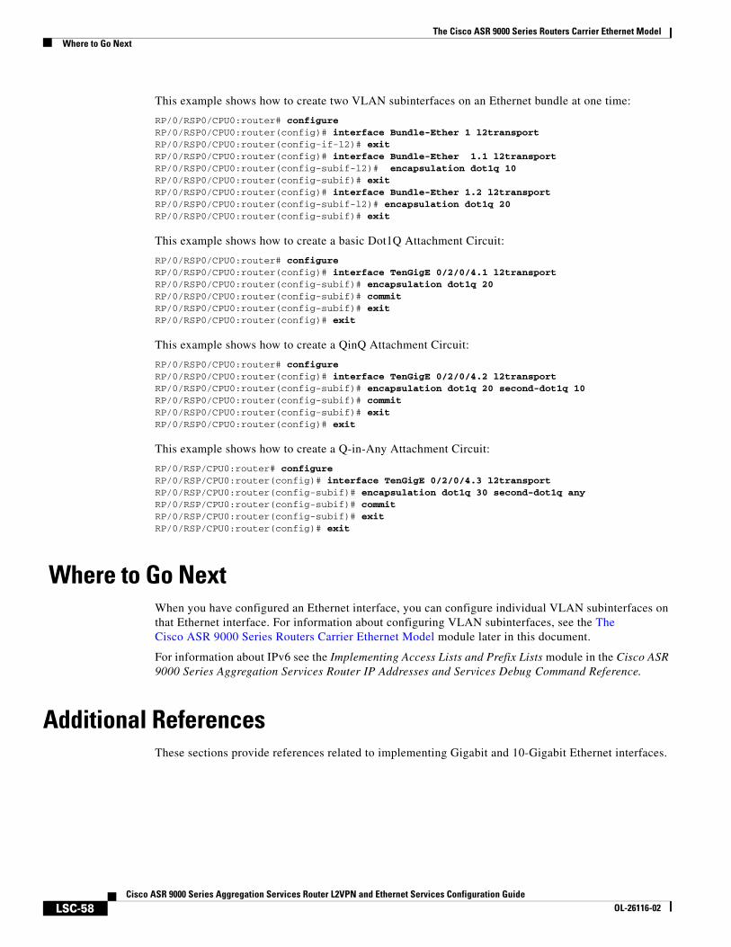
The Cisco ASR 9000 Series Routers Carrier Ethernet ModelWhere to Go Next
LSC-58Cisco ASR 9000 Series Aggregation Services Router L2VPN and Ethernet Services Configuration Guide
OL-26116-02
This example shows how to create two VLAN subinterfaces on an Ethernet bundle at one time:
RP/0/RSP0/CPU0:router# configureRP/0/RSP0/CPU0:router(config)# interface Bundle-Ether 1 l2transportRP/0/RSP0/CPU0:router(config-if-l2)# exitRP/0/RSP0/CPU0:router(config)# interface Bundle-Ether 1.1 l2transportRP/0/RSP0/CPU0:router(config-subif-l2)# encapsulation dot1q 10RP/0/RSP0/CPU0:router(config-subif)# exitRP/0/RSP0/CPU0:router(config)# interface Bundle-Ether 1.2 l2transportRP/0/RSP0/CPU0:router(config-subif-l2)# encapsulation dot1q 20RP/0/RSP0/CPU0:router(config-subif)# exit
This example shows how to create a basic Dot1Q Attachment Circuit:
RP/0/RSP0/CPU0:router# configureRP/0/RSP0/CPU0:router(config)# interface TenGigE 0/2/0/4.1 l2transportRP/0/RSP0/CPU0:router(config-subif)# encapsulation dot1q 20RP/0/RSP0/CPU0:router(config-subif)# commitRP/0/RSP0/CPU0:router(config-subif)# exitRP/0/RSP0/CPU0:router(config)# exit
This example shows how to create a QinQ Attachment Circuit:
RP/0/RSP0/CPU0:router# configureRP/0/RSP0/CPU0:router(config)# interface TenGigE 0/2/0/4.2 l2transportRP/0/RSP0/CPU0:router(config-subif)# encapsulation dot1q 20 second-dot1q 10RP/0/RSP0/CPU0:router(config-subif)# commitRP/0/RSP0/CPU0:router(config-subif)# exitRP/0/RSP0/CPU0:router(config)# exit
This example shows how to create a Q-in-Any Attachment Circuit:
RP/0/RSP/CPU0:router# configureRP/0/RSP/CPU0:router(config)# interface TenGigE 0/2/0/4.3 l2transportRP/0/RSP/CPU0:router(config-subif)# encapsulation dot1q 30 second-dot1q anyRP/0/RSP/CPU0:router(config-subif)# commitRP/0/RSP/CPU0:router(config-subif)# exitRP/0/RSP/CPU0:router(config)# exit
Where to Go NextWhen you have configured an Ethernet interface, you can configure individual VLAN subinterfaces on that Ethernet interface. For information about configuring VLAN subinterfaces, see the The Cisco ASR 9000 Series Routers Carrier Ethernet Model module later in this document.
For information about IPv6 see the Implementing Access Lists and Prefix Lists module in the Cisco ASR 9000 Series Aggregation Services Router IP Addresses and Services Debug Command Reference.
Additional ReferencesThese sections provide references related to implementing Gigabit and 10-Gigabit Ethernet interfaces.
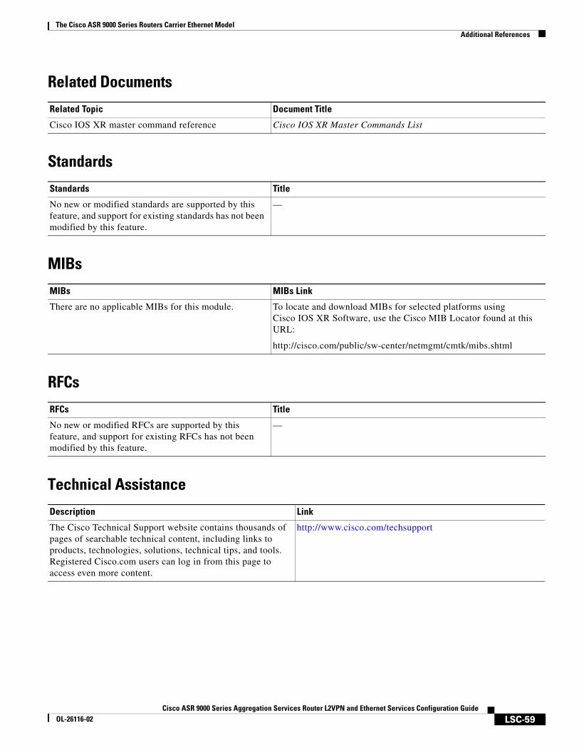
The Cisco ASR 9000 Series Routers Carrier Ethernet ModelAdditional References
LSC-59Cisco ASR 9000 Series Aggregation Services Router L2VPN and Ethernet Services Configuration Guide
OL-26116-02
Related Documents
Standards
MIBs
RFCs
Technical Assistance
Related Topic Document Title
Cisco IOS XR master command reference Cisco IOS XR Master Commands List
Standards Title
No new or modified standards are supported by this feature, and support for existing standards has not been modified by this feature.
—
MIBs MIBs Link
There are no applicable MIBs for this module. To locate and download MIBs for selected platforms using Cisco IOS XR Software, use the Cisco MIB Locator found at this URL:
http://cisco.com/public/sw-center/netmgmt/cmtk/mibs.shtml
RFCs Title
No new or modified RFCs are supported by this feature, and support for existing RFCs has not been modified by this feature.
—
Description Link
The Cisco Technical Support website contains thousands of pages of searchable technical content, including links to products, technologies, solutions, technical tips, and tools. Registered Cisco.com users can log in from this page to access even more content.
http://www.cisco.com/techsupport

The Cisco ASR 9000 Series Routers Carrier Ethernet ModelAdditional References
LSC-60Cisco ASR 9000 Series Aggregation Services Router L2VPN and Ethernet Services Configuration Guide
OL-26116-02
LSC-61Cisco ASR 9000 Series Aggregation Services Router L2VPN and Ethernet Services Configuration Guide
OL-26116-02
Ethernet Features
This module describes how to configure Layer 2 (L2) Ethernet features on the Cisco ASR 9000 Series Aggregation Services Routers supporting Cisco IOS XR software.
For more information on configuring Ethernet interfaces, refer to The Cisco ASR 9000 Series Routers Carrier Ethernet Model module of this configuration guide.
Feature History for Configuring Ethernet Interfaces on the Cisco ASR 9000 Series Routers
Contents• Prerequisites for Implementing Ethernet Features, page 61
• Information About Implementing Ethernet Features, page 62
• How to Implement Ethernet Features, page 69
• Configuration Examples, page 75
• Additional References, page 78
Prerequisites for Implementing Ethernet FeaturesYou must be in a user group associated with a task group that includes the proper task IDs. The command reference guides include the task IDs required for each command.
If you suspect user group assignment is preventing you from using a command, contact your AAA administrator for assistance.
Release Modification
Release 3.9.1 Support for Policy Based Forwarding and Layer 2 Protocol Tunneling features was added.
Ethernet FeaturesInformation About Implementing Ethernet Features
LSC-62Cisco ASR 9000 Series Aggregation Services Router L2VPN and Ethernet Services Configuration Guide
OL-26116-02
Information About Implementing Ethernet FeaturesTo configure 10-Gigabit Ethernet interfaces, you must understand these concepts:
• Policy Based Forwarding, page 62
• Layer 2 Protocol Tunneling, page 62
Policy Based ForwardingThe Cisco ASR 9000 Series Routers allow a single MAC address to be mapped to a VLAN that is different from the port’s configured VLAN. To separate the traffic entering two different EFPs, you must define an EFP using the source VLAN tag and the source MAC address.
Layer 2 Protocol TunnelingLayer 2 Protocol Tunneling (L2PT) is a Cisco proprietary protocol for tunneling Ethernet protocol frames across Layer 2 (L2) switching domains.
When an L2 protocol frame enters the interface of an L2 switching device, the switch or router performs one of these actions on the frame:
• forward—the frame is switched or routed with no exceptional handling.
• drop—the frame is discarded on the router.
• terminate—the router recognizes that the frame is an L2 protocol frame, and therefore sends it to the router's control plane for protocol processing.
• tunnel—the router encapsulates the frame to hide its identity as a protocol frame. This prevents the frame from being terminated on other routers. The opposite end of the tunnel performs a decapsulation, returning the frame to its original state.
L2PT Features
The Cisco ASR 9000 Series Routers offer these functions:
• Tunnels these protocols:
– Cisco Discovery Protocol (CDP)
– Spanning Tree Protocol (STP and its derivatives)
– Virtual Trunking Protocol (VTP)
• Supports these modes of tunneling
– Forward
– Reverse
• L2PT encapsulates and decapsulates protocol frames that have VLAN headers.
• Supports capability of handling enormous frame rates. The Cisco ASR 9000 Series Routers perform L2PT encapsulation and decapsulation at the interface line rates.
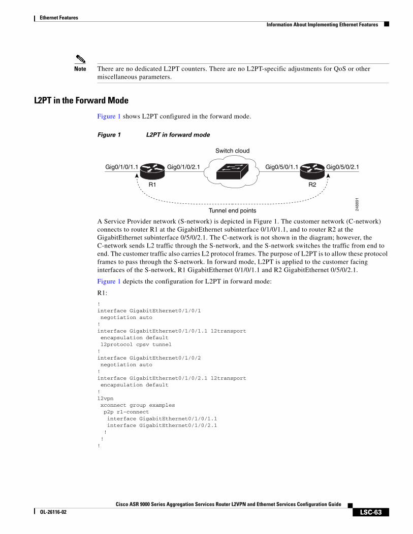
Ethernet FeaturesInformation About Implementing Ethernet Features
LSC-63Cisco ASR 9000 Series Aggregation Services Router L2VPN and Ethernet Services Configuration Guide
OL-26116-02
Note There are no dedicated L2PT counters. There are no L2PT-specific adjustments for QoS or other miscellaneous parameters.
L2PT in the Forward Mode
Figure 1 shows L2PT configured in the forward mode.
Figure 1 L2PT in forward mode
A Service Provider network (S-network) is depicted in Figure 1. The customer network (C-network) connects to router R1 at the GigabitEthernet subinterface 0/1/0/1.1, and to router R2 at the GigabitEthernet subinterface 0/5/0/2.1. The C-network is not shown in the diagram; however, the C-network sends L2 traffic through the S-network, and the S-network switches the traffic from end to end. The customer traffic also carries L2 protocol frames. The purpose of L2PT is to allow these protocol frames to pass through the S-network. In forward mode, L2PT is applied to the customer facing interfaces of the S-network, R1 GigabitEthernet 0/1/0/1.1 and R2 GigabitEthernet 0/5/0/2.1.
Figure 1 depicts the configuration for L2PT in forward mode:
R1:
!interface GigabitEthernet0/1/0/1 negotiation auto!interface GigabitEthernet0/1/0/1.1 l2transport encapsulation default l2protocol cpsv tunnel!interface GigabitEthernet0/1/0/2 negotiation auto!interface GigabitEthernet0/1/0/2.1 l2transport encapsulation default!l2vpn xconnect group examples p2p r1-connect interface GigabitEthernet0/1/0/1.1 interface GigabitEthernet0/1/0/2.1 ! !!
2488
91
Gig0/1/0/1.1
R1
Tunnel end points
Switch cloud
R2
Gig0/1/0/2.1 Gig0/5/0/1.1 Gig0/5/0/2.1
Ethernet FeaturesInformation About Implementing Ethernet Features
LSC-64Cisco ASR 9000 Series Aggregation Services Router L2VPN and Ethernet Services Configuration Guide
OL-26116-02
R2:
!interface GigabitEthernet0/5/0/1 negotiation auto!interface GigabitEthernet0/5/0/1.1 l2transport encapsulation default!interface GigabitEthernet0/5/0/2 negotiation auto!interface GigabitEthernet0/5/0/2.1 l2transport encapsulation default l2protocol cpsv tunnel!l2vpn xconnect group examples p2p r2-connect interface GigabitEthernet0/5/0/1.1 interface GigabitEthernet0/5/0/2.1 ! !!
Protocol traffic enters router R1 at the GigabitEthernet subinterface 0/1/0/1.1. Router R1 detects the frames as protocol frames, and performs L2PT encapsulation at the customer facing interface. Inside R1, the local connection r1-connect connects R1's customer-facing and service provider-facing interfaces. The traffic then flows out of router R1 on GigabitEthernet subinterface 0/1/0/2.1 through several other service provider network routers or switches (switch cloud) into router R2 at GigabitEthernet subinterface 0/5/0/1.1. Router R2 connects the customer-facing and service provider-facing interfaces through a local connection r2-connect. Therefore, traffic is sent to the customer-facing interface GigabitEthernet 0/5/0/2.1. At this interface, an L2PT decapsulation occurs and the protocol traffic flows out of router R2 into the customer network.
Without L2PT being configured the customer protocol frames that are sent into R1 are terminated. The customer traffic can consist of a variety of traffic; the protocol frames comprise a small percentage of the overall traffic stream.
L2PT in the Reverse Mode with Protocol Frame Tagging
The Cisco ASR 9000 Series Routers can perform L2PT encapsulation and decapsulation on supported L2 protocol frames that have VLAN headers. The L2 protocol frames do not have VLAN headers. However, in a service provider (SP) network that transports customer protocol traffic from one customer campus to another, this capability can be put to use within the SP network.
Figure 2 shows L2PT configured in the reverse mode. Assume that the customer traffic that enters R1 is trunked, that is all traffic is tagged. The only untagged traffic is the protocol traffic, that comes from the customer network.
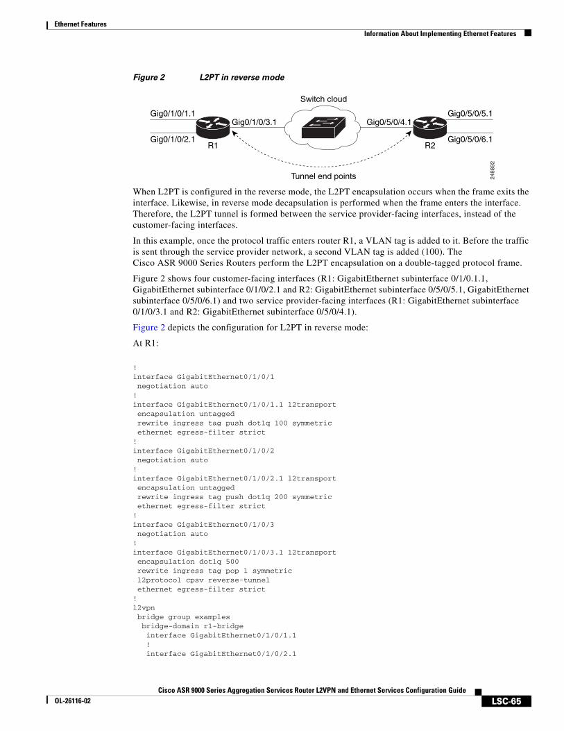
Ethernet FeaturesInformation About Implementing Ethernet Features
LSC-65Cisco ASR 9000 Series Aggregation Services Router L2VPN and Ethernet Services Configuration Guide
OL-26116-02
Figure 2 L2PT in reverse mode
When L2PT is configured in the reverse mode, the L2PT encapsulation occurs when the frame exits the interface. Likewise, in reverse mode decapsulation is performed when the frame enters the interface. Therefore, the L2PT tunnel is formed between the service provider-facing interfaces, instead of the customer-facing interfaces.
In this example, once the protocol traffic enters router R1, a VLAN tag is added to it. Before the traffic is sent through the service provider network, a second VLAN tag is added (100). The Cisco ASR 9000 Series Routers perform the L2PT encapsulation on a double-tagged protocol frame.
Figure 2 shows four customer-facing interfaces (R1: GigabitEthernet subinterface 0/1/0.1.1, GigabitEthernet subinterface 0/1/0/2.1 and R2: GigabitEthernet subinterface 0/5/0/5.1, GigabitEthernet subinterface 0/5/0/6.1) and two service provider-facing interfaces (R1: GigabitEthernet subinterface 0/1/0/3.1 and R2: GigabitEthernet subinterface 0/5/0/4.1).
Figure 2 depicts the configuration for L2PT in reverse mode:
At R1:
!interface GigabitEthernet0/1/0/1 negotiation auto!interface GigabitEthernet0/1/0/1.1 l2transport encapsulation untagged rewrite ingress tag push dot1q 100 symmetric ethernet egress-filter strict!interface GigabitEthernet0/1/0/2 negotiation auto!interface GigabitEthernet0/1/0/2.1 l2transport encapsulation untagged rewrite ingress tag push dot1q 200 symmetric ethernet egress-filter strict!interface GigabitEthernet0/1/0/3 negotiation auto!interface GigabitEthernet0/1/0/3.1 l2transport encapsulation dot1q 500 rewrite ingress tag pop 1 symmetric l2protocol cpsv reverse-tunnel ethernet egress-filter strict!l2vpn bridge group examples bridge-domain r1-bridge interface GigabitEthernet0/1/0/1.1 ! interface GigabitEthernet0/1/0/2.1
2488
92
Gig0/1/0/1.1
R1
Tunnel end points
Switch cloud
R2
Gig0/1/0/3.1 Gig0/5/0/4.1Gig0/5/0/5.1
Gig0/1/0/2.1 Gig0/5/0/6.1
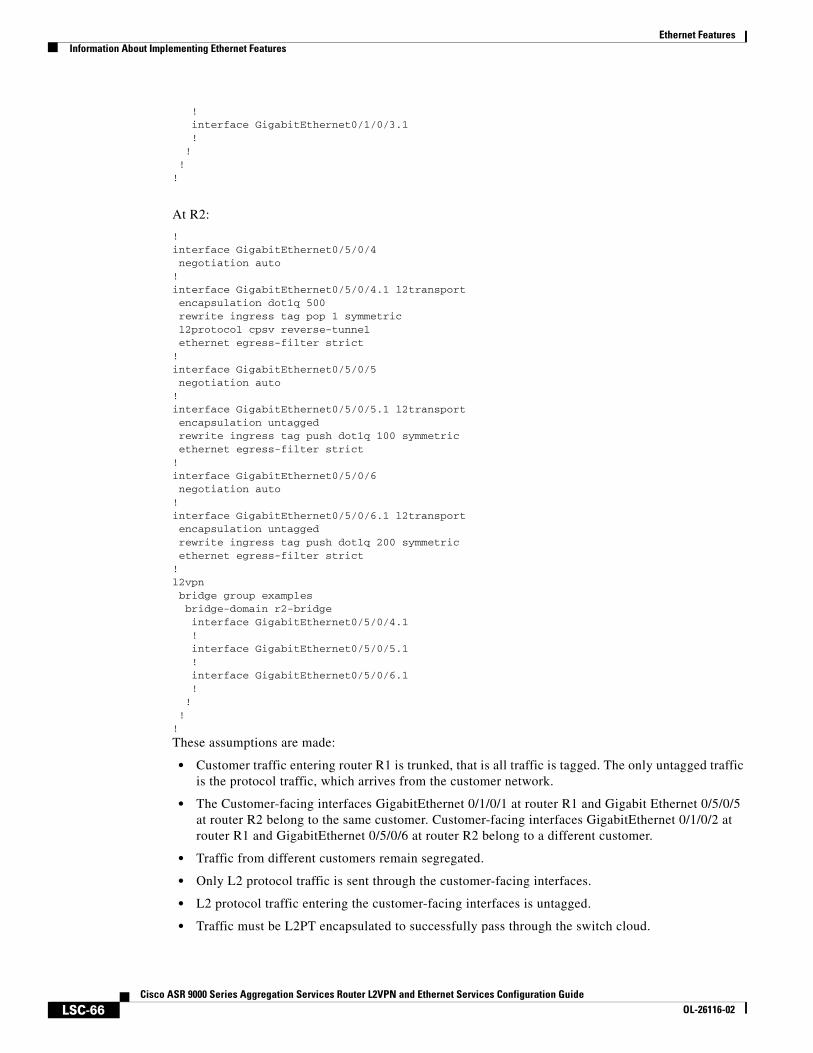
Ethernet FeaturesInformation About Implementing Ethernet Features
LSC-66Cisco ASR 9000 Series Aggregation Services Router L2VPN and Ethernet Services Configuration Guide
OL-26116-02
! interface GigabitEthernet0/1/0/3.1 ! ! !!
At R2:
!interface GigabitEthernet0/5/0/4 negotiation auto!interface GigabitEthernet0/5/0/4.1 l2transport encapsulation dot1q 500 rewrite ingress tag pop 1 symmetric l2protocol cpsv reverse-tunnel ethernet egress-filter strict!interface GigabitEthernet0/5/0/5 negotiation auto!interface GigabitEthernet0/5/0/5.1 l2transport encapsulation untagged rewrite ingress tag push dot1q 100 symmetric ethernet egress-filter strict!interface GigabitEthernet0/5/0/6 negotiation auto!interface GigabitEthernet0/5/0/6.1 l2transport encapsulation untagged rewrite ingress tag push dot1q 200 symmetric ethernet egress-filter strict!l2vpn bridge group examples bridge-domain r2-bridge interface GigabitEthernet0/5/0/4.1 ! interface GigabitEthernet0/5/0/5.1 ! interface GigabitEthernet0/5/0/6.1 ! ! !!
These assumptions are made:
• Customer traffic entering router R1 is trunked, that is all traffic is tagged. The only untagged traffic is the protocol traffic, which arrives from the customer network.
• The Customer-facing interfaces GigabitEthernet 0/1/0/1 at router R1 and Gigabit Ethernet 0/5/0/5 at router R2 belong to the same customer. Customer-facing interfaces GigabitEthernet 0/1/0/2 at router R1 and GigabitEthernet 0/5/0/6 at router R2 belong to a different customer.
• Traffic from different customers remain segregated.
• Only L2 protocol traffic is sent through the customer-facing interfaces.
• L2 protocol traffic entering the customer-facing interfaces is untagged.
• Traffic must be L2PT encapsulated to successfully pass through the switch cloud.
Ethernet FeaturesInformation About Implementing Ethernet Features
LSC-67Cisco ASR 9000 Series Aggregation Services Router L2VPN and Ethernet Services Configuration Guide
OL-26116-02
The purpose of this topology is that router R1 and R2 must receive customer protocol traffic from multiple customer interfaces, and multiplex the traffic across a single service provider interface and link. At the decapsulation end, the reverse is performed. Traffic entering router R1 on the GigabitEthernet subinterface 0/1/0/1.1 exits router R2 from the GigabitEthernet subinterface 0/5/0/5.1 only while traffic entering router R1 at GigabitEthernet subinterface 0/1/0/2.1 exits router R2 from GigabitEthernet subinterface 0/5/0/6.1 only.
A protocol frame entering router R1 on GigabitEthernet interface 0/1/0/1 travels through the network in this manner:
• The protocol frame is directed to GigabitEthernet subinterface 0/1/0/1.1, as the frame is untagged.
• The rewrite statement with GigabitEthernet subinterface 0/1/0/1.1 causes a tag of ID 100 to be added to the frame.
• The frame enters router R1’s bridge domain r1-bridge.
• The bridge (r1-bridge) floods the frame to all attachment circuits (AC) on the bridge domain, except the originating AC (split horizon AC).
• Ethernet egress filtering on GigabitEthernet subinterface 0/1/0/2.1 detects a tag ID mismatch, and drops the frame. In this way, the bridge domain’s flooded traffic is prevented from exiting other customer interfaces.
• A flooded copy of the frame is sent to GigabitEthernet subinterface 0/1/0/3.1.
• GigabitEthernet subinterface 0/1/0/3.1 adds a second tag.
• The frame receives an L2PT encapsulation by GigabitEthernet subinterface 0/1/0/3.1 before it leaves router R1 through the GigabitEthernet interface 0/1/0/3.
Note The frame is now double-tagged (100 inner, 500 outer) and has the L2PT MAC DA.
• The frame passes to router R2 GigabitEthernet interface 0/5/0/4 because of the L2PT encapsulation.
• The frame after having entered router R2 on GigabitEthernet interface 0/5/0/4 is directed to GigabitEthernet subinterface 0/5/0/4.1.
• On entering GigabitEthernet subinterface 0/5/0/4.1, an L2PT decapsulation operation is performed on the frame.
• The outer tag ID 500 is removed by GigabitEthernet subinterface 0/5/0/4.1
• Router R2’s bridge (r2-bridge) floods the frames to all ACs.
• Ethernet egress filtering drops the frames on all ACs except the AC through which the frame exits.
• As the frame exits router R2 from GigabitEthernet subinterface 0/5/0/5.1, the tag of ID 100 is removed.
• The frame that exits router R2 from GigabitEthernet interface 0/5/0/5 is identical to the original frame that entered router R1 through GigabitEthernet interface 0/1/0/1.
Ethernet FeaturesInformation About Implementing Ethernet Features
LSC-68Cisco ASR 9000 Series Aggregation Services Router L2VPN and Ethernet Services Configuration Guide
OL-26116-02
L2PT Configuration Notes
Keep these points in mind while configuring L2PT:
• The l2protocol command can be configured on either a main or L2 subinterface.
• The l2protocol command can be configured on physical or bundle interfaces.
• When the l2protocol and ethernet filtering commands are configured on the same interface, L2PT encapsulation occurs before ethernet filtering. This means that L2PT prevents the CDP, STP, and VTP protocol frames from being dropped by ethernet filtering.
• When L2PT is configured with other interface features, L2PT encapsulation occurs before the processing for other interface features.
• L2PT encapsulation and decapsulation is supported for untagged protocol frames, single-tagged, and double-tagged frames. Tag Ethertypes of 0x8100, 0x88A8, and 0x9100 are supported, however, 0x9200 is not.
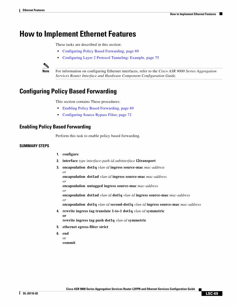
Ethernet FeaturesHow to Implement Ethernet Features
LSC-69Cisco ASR 9000 Series Aggregation Services Router L2VPN and Ethernet Services Configuration Guide
OL-26116-02
How to Implement Ethernet FeaturesThese tasks are described in this section:
• Configuring Policy Based Forwarding, page 69
• Configuring Layer 2 Protocol Tunneling: Example, page 75
Note For information on configuring Ethernet interfaces, refer to the Cisco ASR 9000 Series Aggregation Services Router Interface and Hardware Component Configuration Guide.
Configuring Policy Based ForwardingThis section contains These procedures:
• Enabling Policy Based Forwarding, page 69
• Configuring Source Bypass Filter, page 72
Enabling Policy Based Forwarding
Perform this task to enable policy based forwarding.
SUMMARY STEPS
1. configure
2. interface type interface-path-id.subinterface l2transport
3. encapsulation dot1q vlan-id ingress source-mac mac-addressorencapsulation dot1ad vlan-id ingress source-mac mac-addressorencapsulation untagged ingress source-mac mac-addressorencapsulation dot1ad vlan-id dot1q vlan-id ingress source-mac mac-addressorencapsulation dot1q vlan-id second-dot1q vlan-id ingress source-mac mac-address
4. rewrite ingress tag translate 1-to-1 dot1q vlan-id symmetricorrewrite ingress tag push dot1q vlan-id symmetric
5. ethernet egress-filter strict
6. endorcommit
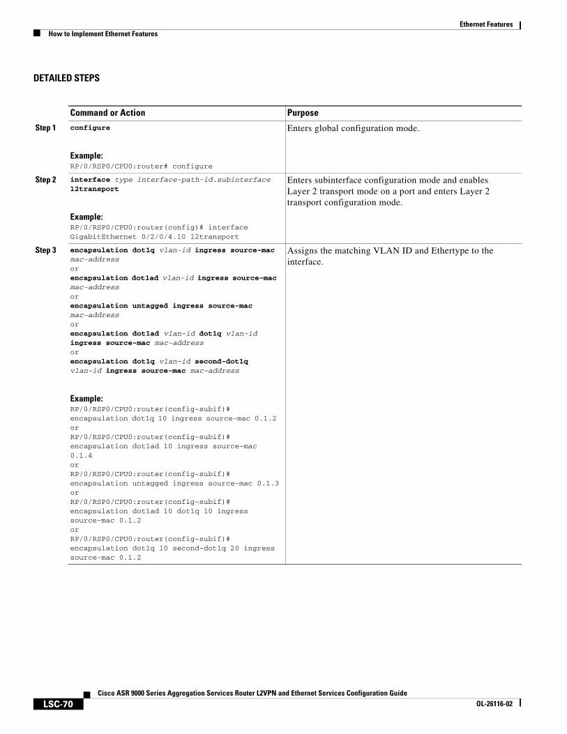
Ethernet FeaturesHow to Implement Ethernet Features
LSC-70Cisco ASR 9000 Series Aggregation Services Router L2VPN and Ethernet Services Configuration Guide
OL-26116-02
DETAILED STEPS
Command or Action Purpose
Step 1 configure
Example:RP/0/RSP0/CPU0:router# configure
Enters global configuration mode.
Step 2 interface type interface-path-id.subinterface l2transport
Example:RP/0/RSP0/CPU0:router(config)# interface GigabitEthernet 0/2/0/4.10 l2transport
Enters subinterface configuration mode and enables Layer 2 transport mode on a port and enters Layer 2 transport configuration mode.
Step 3 encapsulation dot1q vlan-id ingress source-mac mac-addressorencapsulation dot1ad vlan-id ingress source-mac mac-addressorencapsulation untagged ingress source-mac mac-addressorencapsulation dot1ad vlan-id dot1q vlan-id ingress source-mac mac-addressorencapsulation dot1q vlan-id second-dot1q vlan-id ingress source-mac mac-address
Example:RP/0/RSP0/CPU0:router(config-subif)#encapsulation dot1q 10 ingress source-mac 0.1.2 orRP/0/RSP0/CPU0:router(config-subif)#encapsulation dot1ad 10 ingress source-mac 0.1.4 orRP/0/RSP0/CPU0:router(config-subif)#encapsulation untagged ingress source-mac 0.1.3orRP/0/RSP0/CPU0:router(config-subif)#encapsulation dot1ad 10 dot1q 10 ingress source-mac 0.1.2orRP/0/RSP0/CPU0:router(config-subif)#encapsulation dot1q 10 second-dot1q 20 ingress source-mac 0.1.2
Assigns the matching VLAN ID and Ethertype to the interface.
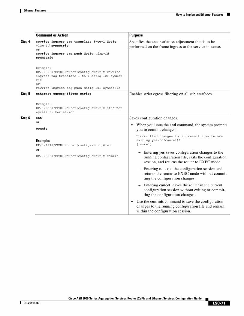
Ethernet FeaturesHow to Implement Ethernet Features
LSC-71Cisco ASR 9000 Series Aggregation Services Router L2VPN and Ethernet Services Configuration Guide
OL-26116-02
Step 4 rewrite ingress tag translate 1-to-1 dot1q vlan-id symmetricorrewrite ingress tag push dot1q vlan-id symmetric
Example:RP/0/RSP0/CPU0:router(config-subif)# rewrite ingress tag translate 1-to-1 dot1q 100 symmet-ric orrewrite ingress tag push dot1q 101 symmetric
Specifies the encapsulation adjustment that is to be performed on the frame ingress to the service instance.
Step 5 ethernet egress-filter strict
Example:RP/0/RSP0/CPU0:router(config-subif)# ethernet egress-filter strict
Enables strict egress filtering on all subinterfaces.
Step 6 end
or
commit
Example:RP/0/RSP0/CPU0:router(config-subif)# end
or
RP/0/RSP0/CPU0:router(config-subif)# commit
Saves configuration changes.
• When you issue the end command, the system prompts you to commit changes:
Uncommitted changes found, commit them before exiting(yes/no/cancel)? [cancel]:
– Entering yes saves configuration changes to the running configuration file, exits the configuration session, and returns the router to EXEC mode.
– Entering no exits the configuration session and returns the router to EXEC mode without commit-ting the configuration changes.
– Entering cancel leaves the router in the current configuration session without exiting or commit-ting the configuration changes.
• Use the commit command to save the configuration changes to the running configuration file and remain within the configuration session.
Command or Action Purpose
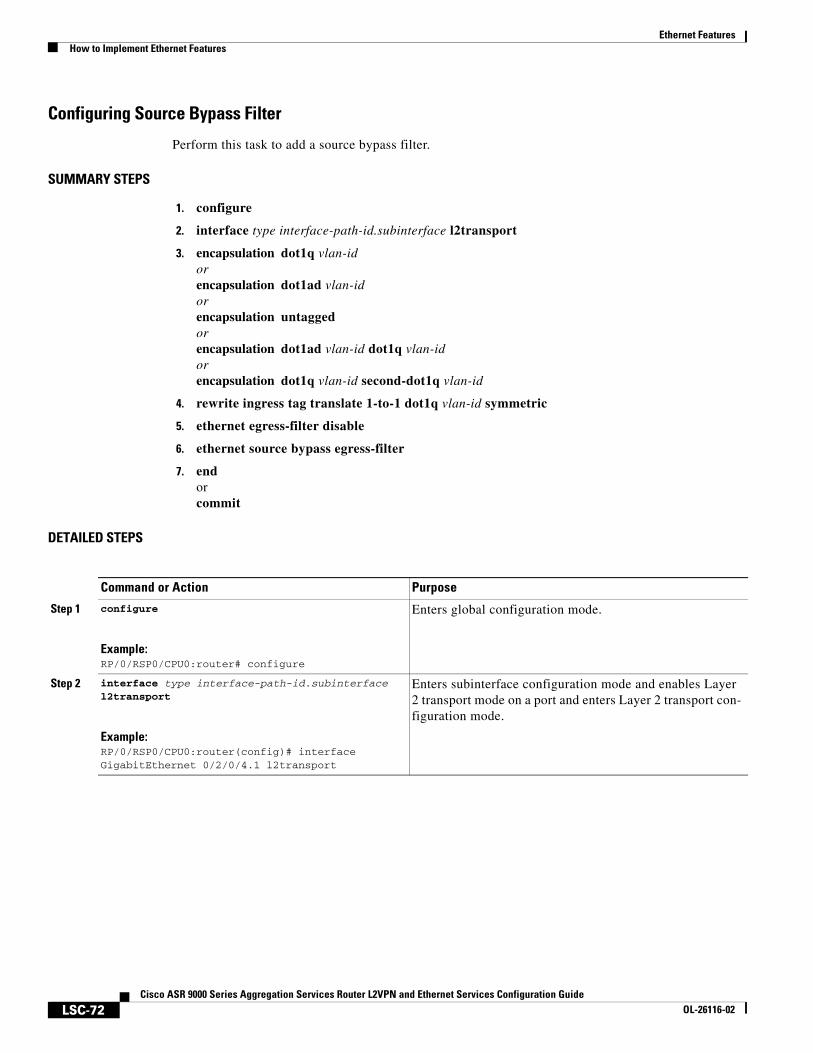
Ethernet FeaturesHow to Implement Ethernet Features
LSC-72Cisco ASR 9000 Series Aggregation Services Router L2VPN and Ethernet Services Configuration Guide
OL-26116-02
Configuring Source Bypass Filter
Perform this task to add a source bypass filter.
SUMMARY STEPS
1. configure
2. interface type interface-path-id.subinterface l2transport
3. encapsulation dot1q vlan-id orencapsulation dot1ad vlan-id orencapsulation untagged orencapsulation dot1ad vlan-id dot1q vlan-id orencapsulation dot1q vlan-id second-dot1q vlan-id
4. rewrite ingress tag translate 1-to-1 dot1q vlan-id symmetric
5. ethernet egress-filter disable
6. ethernet source bypass egress-filter
7. endorcommit
DETAILED STEPS
Command or Action Purpose
Step 1 configure
Example:RP/0/RSP0/CPU0:router# configure
Enters global configuration mode.
Step 2 interface type interface-path-id.subinterface l2transport
Example:RP/0/RSP0/CPU0:router(config)# interface GigabitEthernet 0/2/0/4.1 l2transport
Enters subinterface configuration mode and enables Layer 2 transport mode on a port and enters Layer 2 transport con-figuration mode.
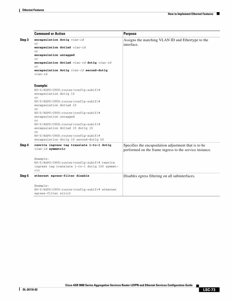
Ethernet FeaturesHow to Implement Ethernet Features
LSC-73Cisco ASR 9000 Series Aggregation Services Router L2VPN and Ethernet Services Configuration Guide
OL-26116-02
Step 3 encapsulation dot1q vlan-id orencapsulation dot1ad vlan-id orencapsulation untagged orencapsulation dot1ad vlan-id dot1q vlan-idorencapsulation dot1q vlan-id second-dot1q vlan-id
Example:RP/0/RSP0/CPU0:router(config-subif)#encapsulation dot1q 10 orRP/0/RSP0/CPU0:router(config-subif)#encapsulation dot1ad 10 orRP/0/RSP0/CPU0:router(config-subif)#encapsulation untagged orRP/0/RSP0/CPU0:router(config-subif)#encapsulation dot1ad 10 dot1q 10 orRP/0/RSP0/CPU0:router(config-subif)#encapsulation dot1q 10 second-dot1q 20
Assigns the matching VLAN ID and Ethertype to the interface.
Step 4 rewrite ingress tag translate 1-to-1 dot1q vlan-id symmetric
Example:RP/0/RSP0/CPU0:router(config-subif)# rewrite ingress tag translate 1-to-1 dot1q 100 symmet-ric
Specifies the encapsulation adjustment that is to be performed on the frame ingress to the service instance.
Step 5 ethernet egress-filter disable
Example:RP/0/RSP0/CPU0:router(config-subif)# ethernet egress-filter strict
Disables egress filtering on all subinterfaces.
Command or Action Purpose
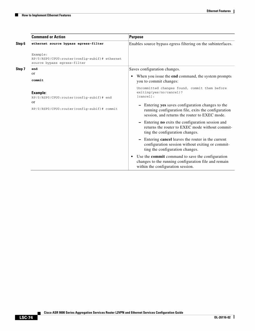
Ethernet FeaturesHow to Implement Ethernet Features
LSC-74Cisco ASR 9000 Series Aggregation Services Router L2VPN and Ethernet Services Configuration Guide
OL-26116-02
Step 6 ethernet source bypass egress-filter
Example:RP/0/RSP0/CPU0:router(config-subif)# ethernet source bypass egress-filter
Enables source bypass egress filtering on the subinterfaces.
Step 7 end
or
commit
Example:RP/0/RSP0/CPU0:router(config-subif)# end
or
RP/0/RSP0/CPU0:router(config-subif)# commit
Saves configuration changes.
• When you issue the end command, the system prompts you to commit changes:
Uncommitted changes found, commit them before exiting(yes/no/cancel)? [cancel]:
– Entering yes saves configuration changes to the running configuration file, exits the configuration session, and returns the router to EXEC mode.
– Entering no exits the configuration session and returns the router to EXEC mode without commit-ting the configuration changes.
– Entering cancel leaves the router in the current configuration session without exiting or commit-ting the configuration changes.
• Use the commit command to save the configuration changes to the running configuration file and remain within the configuration session.
Command or Action Purpose
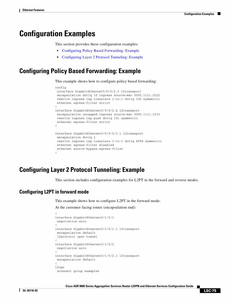
Ethernet FeaturesConfiguration Examples
LSC-75Cisco ASR 9000 Series Aggregation Services Router L2VPN and Ethernet Services Configuration Guide
OL-26116-02
Configuration ExamplesThis section provides these configuration examples:
• Configuring Policy Based Forwarding: Example
• Configuring Layer 2 Protocol Tunneling: Example
Configuring Policy Based Forwarding: ExampleThis example shows how to configure policy based forwarding:
configinterface GigabitEthernet0/0/0/2.3 l2transport encapsulation dot1q 10 ingress source-mac 0000.1111.2222 rewrite ingress tag translate 1-to-1 dot1q 100 symmetric ethernet egress-filter strict!interface GigabitEthernet0/0/0/2.4 l2transport encapsulation untagged ingress source-mac 0000.1111.3333 rewrite ingress tag push dot1q 101 symmetric ethernet egress-filter strict!
interface GigabitEthernet0/0/0/0/3.1 l2transport encapsulation dot1q 1 rewrite ingress tag translate 1-to-1 dot1q 4094 symmetric ethernet egress-filter disabled ethernet source-bypass-egress-filter!
Configuring Layer 2 Protocol Tunneling: ExampleThis section includes configuration examples for L2PT in the forward and reverse modes.
Configuring L2PT in forward mode
This example shows how to configure L2PT in the forward mode:
At the customer facing router (encapsulation end):
!interface GigabitEthernet0/1/0/1 negotiation auto!interface GigabitEthernet0/1/0/1.1 l2transport encapsulation default l2protocol cpsv tunnel!interface GigabitEthernet0/1/0/2 negotiation auto!interface GigabitEthernet0/1/0/2.1 l2transport encapsulation default!l2vpn xconnect group examples
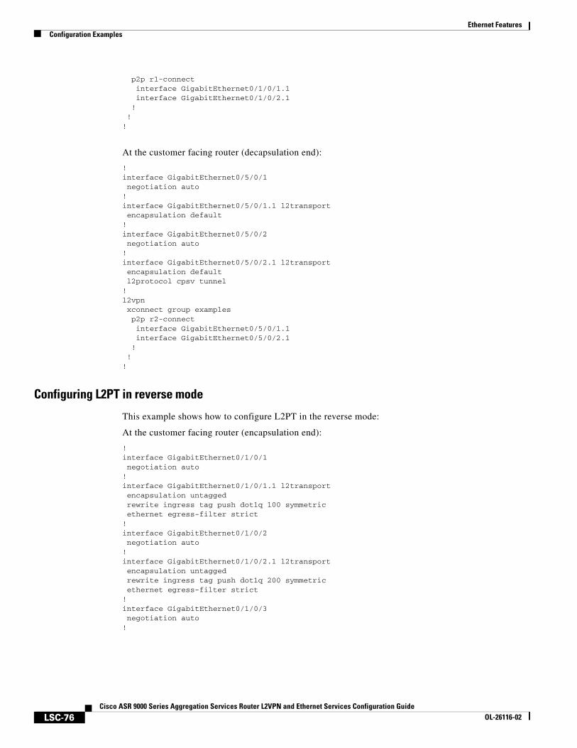
Ethernet FeaturesConfiguration Examples
LSC-76Cisco ASR 9000 Series Aggregation Services Router L2VPN and Ethernet Services Configuration Guide
OL-26116-02
p2p r1-connect interface GigabitEthernet0/1/0/1.1 interface GigabitEthernet0/1/0/2.1 ! !!
At the customer facing router (decapsulation end):
!interface GigabitEthernet0/5/0/1 negotiation auto!interface GigabitEthernet0/5/0/1.1 l2transport encapsulation default!interface GigabitEthernet0/5/0/2 negotiation auto!interface GigabitEthernet0/5/0/2.1 l2transport encapsulation default l2protocol cpsv tunnel!l2vpn xconnect group examples p2p r2-connect interface GigabitEthernet0/5/0/1.1 interface GigabitEthernet0/5/0/2.1 ! !!
Configuring L2PT in reverse mode
This example shows how to configure L2PT in the reverse mode:
At the customer facing router (encapsulation end):
!interface GigabitEthernet0/1/0/1 negotiation auto!interface GigabitEthernet0/1/0/1.1 l2transport encapsulation untagged rewrite ingress tag push dot1q 100 symmetric ethernet egress-filter strict!interface GigabitEthernet0/1/0/2 negotiation auto!interface GigabitEthernet0/1/0/2.1 l2transport encapsulation untagged rewrite ingress tag push dot1q 200 symmetric ethernet egress-filter strict!interface GigabitEthernet0/1/0/3 negotiation auto!

Ethernet FeaturesConfiguration Examples
LSC-77Cisco ASR 9000 Series Aggregation Services Router L2VPN and Ethernet Services Configuration Guide
OL-26116-02
interface GigabitEthernet0/1/0/3.1 l2transport encapsulation dot1q 500 rewrite ingress tag pop 1 symmetric l2protocol cpsv reverse-tunnel ethernet egress-filter strict!l2vpn bridge group examples bridge-domain r1-bridge interface GigabitEthernet0/1/0/1.1 ! interface GigabitEthernet0/1/0/2.1 ! interface GigabitEthernet0/1/0/3.1 ! ! !!
At the customer facing router (decapsulation end):
!interface GigabitEthernet0/5/0/4 negotiation auto!interface GigabitEthernet0/5/0/4.1 l2transport encapsulation dot1q 500 rewrite ingress tag pop 1 symmetric l2protocol cpsv reverse-tunnel ethernet egress-filter strict!interface GigabitEthernet0/5/0/5 negotiation auto!interface GigabitEthernet0/5/0/5.1 l2transport encapsulation untagged rewrite ingress tag push dot1q 100 symmetric ethernet egress-filter strict!interface GigabitEthernet0/5/0/6 negotiation auto!interface GigabitEthernet0/5/0/6.1 l2transport encapsulation untagged rewrite ingress tag push dot1q 200 symmetric ethernet egress-filter strict!l2vpn bridge group examples bridge-domain r2-bridge interface GigabitEthernet0/5/0/4.1 ! interface GigabitEthernet0/5/0/5.1 ! interface GigabitEthernet0/5/0/6.1 ! ! !!
Ethernet FeaturesAdditional References
LSC-78Cisco ASR 9000 Series Aggregation Services Router L2VPN and Ethernet Services Configuration Guide
OL-26116-02
Additional ReferencesThese sections provide references related to implementing Gigabit and 10-Gigabit Ethernet interfaces.
Related Documents
Standards
MIBs
RFCs
Technical Assistance
Related Topic Document Title
Cisco IOS XR master command reference Cisco IOS XR Master Commands List
Standards Title
No new or modified standards are supported by this feature, and support for existing standards has not been modified by this feature.
—
MIBs MIBs Link
There are no applicable MIBs for this module. To locate and download MIBs for selected platforms using Cisco IOS XR Software, use the Cisco MIB Locator found at this URL:
http://cisco.com/public/sw-center/netmgmt/cmtk/mibs.shtml
RFCs Title
No new or modified RFCs are supported by this feature, and support for existing RFCs has not been modified by this feature.
—
Description Link
The Cisco Technical Support website contains thousands of pages of searchable technical content, including links to products, technologies, solutions, technical tips, and tools. Registered Cisco.com users can log in from this page to access even more content.
http://www.cisco.com/techsupport
LSC-79Cisco ASR 9000 Series Aggregation Services Router L2VPN and Ethernet Services Configuration Guide
OL-26116-02
Configuring Link Bundles
On the Cisco ASR 9000 Series Aggregation Services Routers, a bundle is a group of one or more ports that are aggregated together and treated as a single link. The different links within a single bundle can have varying speeds, where the fastest link can be a maximum of four times greater than the slowest link. Each bundle has a single MAC, a single IP address, and a single configuration set (such as ACLs or QoS).
The Cisco ASR 9000 Series Routers supports bundling for these types of interfaces:
• Ethernet interfaces
• VLAN subinterfaces
Note Bundles do not have a one-to-one modular services card association.
Feature History for Configuring Link Bundling on Cisco IOS XR Software
ContentsThis chapter includes these sections:
• Prerequisites for Configuring Link Bundles, page 80
• Information About Configuring Link Bundles, page 80
• How to Configure Link Bundling, page 86
• Configuration Examples for Link Bundles, page 96
• Additional References, page 102
Release Modification
Release 3.7.2 This feature was introduced on the Cisco ASR 9000 Series Routers.

Configuring Link BundlesPrerequisites for Configuring Link Bundles
LSC-80Cisco ASR 9000 Series Aggregation Services Router L2VPN and Ethernet Services Configuration Guide
OL-26116-02
Prerequisites for Configuring Link BundlesBefore configuring Link Bundling, be sure that these tasks and conditions are met:
• You must be in a user group associated with a task group that includes the proper task IDs. The command reference guides include the task IDs required for each command.
If you suspect user group assignment is preventing you from using a command, contact your AAA administrator for assistance.
• You know the interface IP address.
• You know which links should be included in the bundle you are configuring.
• If you are configuring an Ethernet link bundle, you have at least one of these Ethernet line cards installed in the router:
– 2-port 10-Gigabit Ethernet line card
– 4-port 10-Gigabit Ethernet line card
– 8-port 10-Gigabit Ethernet line card
– 16-port 10-Gigabit Ethernet line card
– 20-port Gigabit Ethernet line card
– 40-port Gigabit Ethernet line card
Note For more information about physical interfaces, PLIMs, and modular services cards, refer to the Cisco ASR 9000 Series Routers Hardware Installation Guide.
Information About Configuring Link BundlesTo implement the Link Bundling feature, you must understand these concepts:
• Link Bundling Overview, page 81
• Characteristics of Cisco ASR 9000 Series Routers Link Bundles, page 81
• Link Aggregation Through LACP, page 82
• QoS and Link Bundling, page 83
• VLANs on an Ethernet Link Bundle, page 84
• Link Bundle Configuration Overview, page 84
• Nonstop Forwarding During Card Failover, page 84
• Link Failover, page 85
• Bundle Interfaces: Redundancy, Load Sharing, Aggregation, page 85
Configuring Link BundlesInformation About Configuring Link Bundles
LSC-81Cisco ASR 9000 Series Aggregation Services Router L2VPN and Ethernet Services Configuration Guide
OL-26116-02
Link Bundling OverviewA link bundle is simply a group of ports that are bundled together and act as a single link. The advantages of link bundles are these:
• Multiple links can span several line cards to form a single interface. Thus, the failure of a single link does not cause a loss of connectivity.
• Bundled interfaces increase bandwidth availability, because traffic is forwarded over all available members of the bundle. Therefore, traffic can flow on the available links if one of the links within a bundle fails. Bandwidth can be added without interrupting packet flow.
Although the individual links within a single bundle can have varying speeds, all links within a bundle must be of the same type.
Cisco IOS XR software supports these methods of forming bundles of Ethernet interfaces:
• IEEE 802.3ad—Standard technology that employs a Link Aggregation Control Protocol (LACP) to ensure that all the member links in a bundle are compatible. Links that are incompatible or have failed are automatically removed from a bundle.
• EtherChannel—Cisco proprietary technology that allows the user to configure links to join a bundle, but has no mechanisms to check whether the links in a bundle are compatible.
Characteristics of Cisco ASR 9000 Series Routers Link BundlesThis list describes the properties and limitations of link bundles on Cisco ASR 9000 Series Routerss:
• Any type of Ethernet interfaces can be bundled, with or without the use of LACP (Link Aggregation Control Protocol).
• Bundle membership can span across several line cards that are installed in a single router.
• A single bundle supports maximum of 64 physical links.
• A single Cisco ASR 9000 Series Routers supports a maximum of 128 bundles.
• Different link speeds are allowed within a single bundle, with a maximum of four times the speed difference between the members of the bundle.
• Physical layer and link layer configuration are performed on individual member links of a bundle.
• Configuration of network layer protocols and higher layer applications is performed on the bundle itself.
• A bundle can be administratively enabled or disabled.
• Each individual link within a bundle can be administratively enabled or disabled.
• Ethernet link bundles are created in the same way as Ethernet channels, where the user enters the same configuration on both end systems.
• The MAC address that is set on the bundle becomes the MAC address of the links within that bundle.
• When LACP configured, each link within a bundle can be configured to allow different keepalive periods on different members.
• Load balancing (the distribution of data between member links) is done by flow instead of by packet. Data is distributed to a link in proportion to the bandwidth of the link in relation to its bundle.
• QoS is supported and is applied proportionally on each bundle member.
• Link layer protocols, such as CDP and HDLC keepalives, work independently on each link within a bundle.
Configuring Link BundlesInformation About Configuring Link Bundles
LSC-82Cisco ASR 9000 Series Aggregation Services Router L2VPN and Ethernet Services Configuration Guide
OL-26116-02
• Upper layer protocols, such as routing updates and hellos, are sent over any member link of an interface bundle.
• Bundled interfaces are point to point.
• A link must be in the up state before it can be in distributing state in a bundle.
• All links within a single bundle must be configured either to run 802.3ad (LACP) or Etherchannel (non-LACP). Mixed links within a single bundle are not supported.
• A bundle interface can contain physical links and VLAN subinterfaces only.
• Access Control List (ACL) configuration on link bundles is identical to ACL configuration on regular interfaces.
• Multicast traffic is load balanced over the members of a bundle. For a given flow, internal processes select the member link and all traffic for that flow is sent over that member.
Link Aggregation Through LACPAggregating interfaces on different modular services cards provides redundancy, allowing traffic to be quickly redirected to other member links when an interface or modular services card failure occurs.
The optional Link Aggregation Control Protocol (LACP) is defined in the IEEE 802 standard. LACP communicates between two directly connected systems (or peers) to verify the compatibility of bundle members. For the Cisco ASR 9000 Series Routers, the peer can be either another router or a switch. LACP monitors the operational state of link bundles to ensure these:
• All links terminate on the same two systems.
• Both systems consider the links to be part of the same bundle.
• All links have the appropriate settings on the peer.
LACP transmits frames containing the local port state and the local view of the partner system’s state. These frames are analyzed to ensure both systems are in agreement.
IEEE 802.3ad Standard
The IEEE 802.3ad standard typically defines a method of forming Ethernet link bundles.
For each link configured as bundle member, this information is exchanged between the systems that host each end of the link bundle:
• A globally unique local system identifier
• An identifier (operational key) for the bundle of which the link is a member
• An identifier (port ID) for the link
• The current aggregation status of the link
This information is used to form the link aggregation group identifier (LAG ID). Links that share a common LAG ID can be aggregated. Individual links have unique LAG IDs.
The system identifier distinguishes one router from another, and its uniqueness is guaranteed through the use of a MAC address from the system. The bundle and link identifiers have significance only to the router assigning them, which must guarantee that no two links have the same identifier, and that no two bundles have the same identifier.
The information from the peer system is combined with the information from the local system to determine the compatibility of the links configured to be members of a bundle.
Configuring Link BundlesInformation About Configuring Link Bundles
LSC-83Cisco ASR 9000 Series Aggregation Services Router L2VPN and Ethernet Services Configuration Guide
OL-26116-02
Bundle MAC addresses in the Cisco ASR 9000 Series Routers come from a set of reserved MAC addresses in the backplane.This MAC address stays with the bundle as long as the bundle interface exists. The bundle uses this MAC address until the user configures a different MAC address. The bundle MAC address is used by all member links when passing bundle traffic. Any unicast or multicast addresses set on the bundle are also set on all the member links.
Note We recommend that you avoid modifying the MAC address, because changes in the MAC address can affect packet forwarding.
QoS and Link BundlingOn the ingress direction, QoS is applied to the local instance of a bundle. Each bundle is associated with a set of queues. QoS is applied to the various network layer protocols that are configured on the bundle.
On the egress direction, QoS is applied on the bundle with a reference to the member links. QoS is applied based on the sum of the member bandwidths.
When QoS is applied on the bundle for either the ingress or egress direction, QoS is applied at each member interface.
The Link Bundling feature supports all the QoS features described in the Cisco ASR 9000 Series Aggregation Services Router Modular Quality of Service Configuration Guide.
The Link Bundling feature supports these QoS features:
• hi priority /lo priority—Maximum bandwidth is calculated as a percentage of the bundle interface bandwidth. This percentage is then applied to every member link on the egress, or to the local bundle instance on ingress.
• guaranteed bandwidth—Provided in percentage and applied to every member link.
• traffic shaping—Provided in percentage and applied to every member link.
• WRED—Minimum and maximum parameters are converted to the right proportion per member link or bundle instance, and then are applied to the bundle.
• marking—Process of changing the packet QoS level according to a policy.
• tail drop— Packets are dropped when the queue is full.
Configuring Link BundlesInformation About Configuring Link Bundles
LSC-84Cisco ASR 9000 Series Aggregation Services Router L2VPN and Ethernet Services Configuration Guide
OL-26116-02
VLANs on an Ethernet Link Bundle 802.1Q VLAN subinterfaces can be configured on 802.3ad Ethernet link bundles. Keep this information in mind when adding VLANs on an Ethernet link bundle:
• The maximum number of VLANs allowed per bundle is 4000.
• The maximum number of bundled VLANs allowed per router is 16000.
Note The memory requirement for bundle VLANs is slightly higher than standard physical interfaces.
To create a VLAN subinterface on a bundle, include the VLAN subinterface instance with the interface Bundle-Ether command:
interface Bundle-Ether instance.subinterface
After you create a VLAN on an Ethernet link bundle, all physical VLAN subinterface configuration is supported on that link bundle.
Link Bundle Configuration OverviewThese steps provide a general overview of the link bundle configuration process. Keep in mind that a link must be cleared of all previous network layer configuration before it can be added to a bundle:
1. In global configuration mode, create a link bundle. To create an Ethernet link bundle, enter the interface Bundle-Ether command.
2. Assign an IP address and subnet mask to the virtual interface using the ipv4 address command.
3. Add interfaces to the bundle you created in Step 1 with the bundle id command in the interface configuration submode. You can add up to 32 links to a single bundle.
Note A link is configured to be a member of a bundle from the interface configuration submode for that link.
Nonstop Forwarding During Card FailoverCisco IOS XR software supports nonstop forwarding during failover between active and standby paired RSP cards. Nonstop forwarding ensures that there is no change in the state of the link bundles when a failover occurs.
For example, if an active RSP fails, the standby RSP becomes operational. The configuration, node state, and checkpoint data of the failed RSP are replicated to the standby RSP. The bundled interfaces will all be present when the standby RSP becomes the active RSP.
Note Failover is always onto the standby RSP.
Note You do not need to configure anything to guarantee that the standby interface configurations are maintained.
Configuring Link BundlesInformation About Configuring Link Bundles
LSC-85Cisco ASR 9000 Series Aggregation Services Router L2VPN and Ethernet Services Configuration Guide
OL-26116-02
Link FailoverWhen one member link in a bundle fails, traffic is redirected to the remaining operational member links and traffic flow remains uninterrupted.
Bundle Interfaces: Redundancy, Load Sharing, AggregationOn the Cisco ASR 9000 Series Aggregation Services Routers, a bundle is a group of one or more ports that are aggregated together and treated as a single link. The different links within a single bundle can have varying speeds, where the fastest link can be a maximum of four times greater than the slowest link. Each bundle has a single MAC, a single IP address, and a single configuration set (such as ACLs or QoS).
The Cisco ASR 9000 Series Routers supports bundling for these types of interfaces:
• Ethernet interfaces
• VLAN subinterfaces
Configuring Link BundlesHow to Configure Link Bundling
LSC-86Cisco ASR 9000 Series Aggregation Services Router L2VPN and Ethernet Services Configuration Guide
OL-26116-02
How to Configure Link BundlingThis section contains these procedures:
• Configuring Ethernet Link Bundles, page 86
• Configuring VLAN Bundles, page 90
Configuring Ethernet Link BundlesThis section describes how to configure a Ethernet link bundle.
Note MAC accounting is not supported on Ethernet link bundles.
Note In order for an Ethernet bundle to be active, you must perform the same configuration on both connection endpoints of the bundle.
SUMMARY STEPS
The creation of an Ethernet link bundle involves creating a bundle and adding member interfaces to that bundle, as shown in the steps that follow.
1. configure
2. interface Bundle-Ether bundle-id
3. ipv4 address ipv4-address mask
4. bundle minimum-active bandwidth kbps (Optional)
5. bundle minimum-active links links (Optional)
6. bundle maximum-active links links (Optional)
7. bundle maximum-active links links hot-standby (Optional)
8. exit
9. interface {GigabitEthernet | TenGigE} instance
10. bundle id bundle-id [mode {active | on | passive}
11. no shutdown
12. exit
13. Repeat Step 8 through Step 11 to add more links to the bundle you created in Step 2.
14. endorcommit
15. exit
16. exit
17. Perform Step 1 through Step 15 on the remote end of the connection.
18. show bundle Bundle-Ether bundle-id [reasons]
19. show lacp Bundle-Ether bundle-id
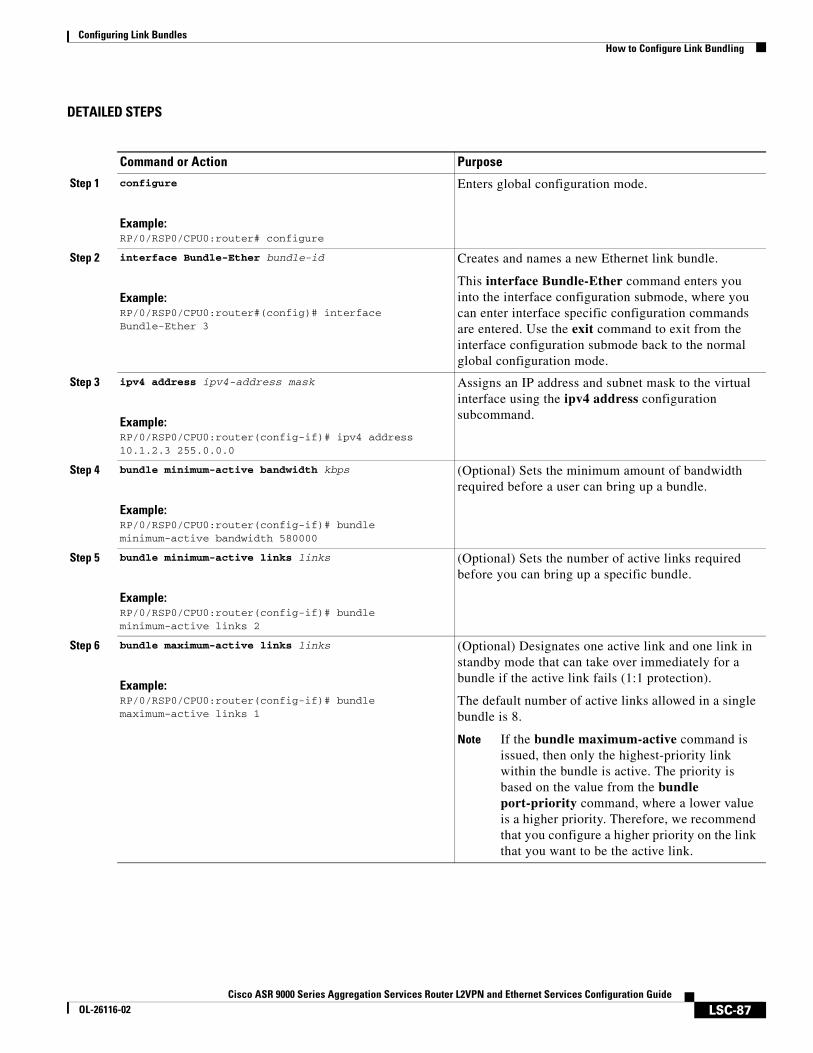
Configuring Link BundlesHow to Configure Link Bundling
LSC-87Cisco ASR 9000 Series Aggregation Services Router L2VPN and Ethernet Services Configuration Guide
OL-26116-02
DETAILED STEPS
Command or Action Purpose
Step 1 configure
Example:RP/0/RSP0/CPU0:router# configure
Enters global configuration mode.
Step 2 interface Bundle-Ether bundle-id
Example:RP/0/RSP0/CPU0:router#(config)# interface Bundle-Ether 3
Creates and names a new Ethernet link bundle.
This interface Bundle-Ether command enters you into the interface configuration submode, where you can enter interface specific configuration commands are entered. Use the exit command to exit from the interface configuration submode back to the normal global configuration mode.
Step 3 ipv4 address ipv4-address mask
Example:RP/0/RSP0/CPU0:router(config-if)# ipv4 address 10.1.2.3 255.0.0.0
Assigns an IP address and subnet mask to the virtual interface using the ipv4 address configuration subcommand.
Step 4 bundle minimum-active bandwidth kbps
Example:RP/0/RSP0/CPU0:router(config-if)# bundle minimum-active bandwidth 580000
(Optional) Sets the minimum amount of bandwidth required before a user can bring up a bundle.
Step 5 bundle minimum-active links links
Example:RP/0/RSP0/CPU0:router(config-if)# bundle minimum-active links 2
(Optional) Sets the number of active links required before you can bring up a specific bundle.
Step 6 bundle maximum-active links links
Example:RP/0/RSP0/CPU0:router(config-if)# bundle maximum-active links 1
(Optional) Designates one active link and one link in standby mode that can take over immediately for a bundle if the active link fails (1:1 protection).
The default number of active links allowed in a single bundle is 8.
Note If the bundle maximum-active command is issued, then only the highest-priority link within the bundle is active. The priority is based on the value from the bundle port-priority command, where a lower value is a higher priority. Therefore, we recommend that you configure a higher priority on the link that you want to be the active link.
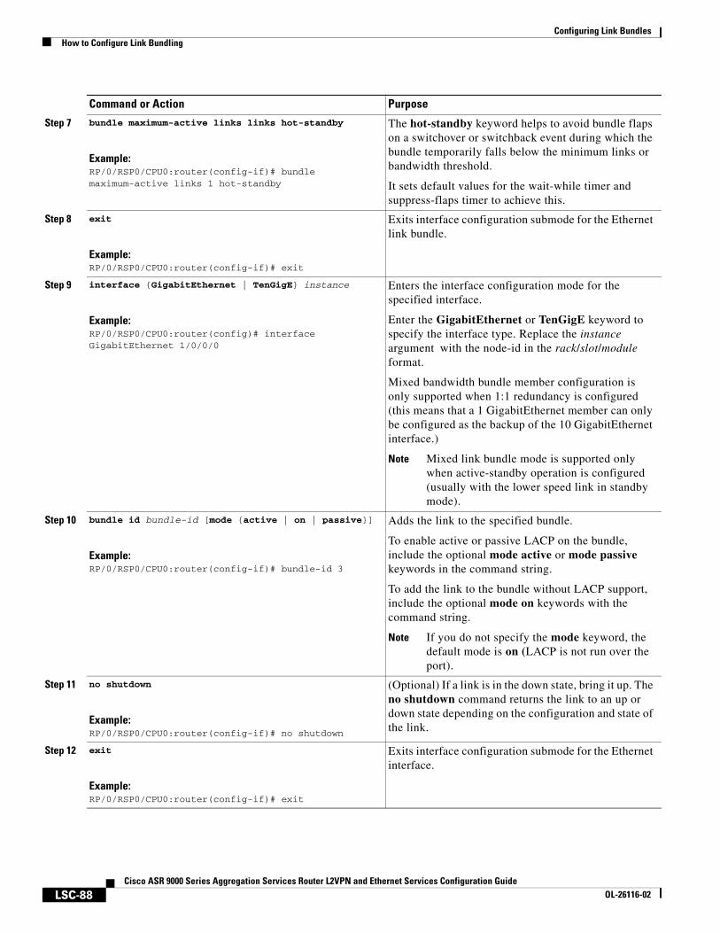
Configuring Link BundlesHow to Configure Link Bundling
LSC-88Cisco ASR 9000 Series Aggregation Services Router L2VPN and Ethernet Services Configuration Guide
OL-26116-02
Step 7 bundle maximum-active links links hot-standby
Example:RP/0/RSP0/CPU0:router(config-if)# bundle maximum-active links 1 hot-standby
The hot-standby keyword helps to avoid bundle flaps on a switchover or switchback event during which the bundle temporarily falls below the minimum links or bandwidth threshold.
It sets default values for the wait-while timer and suppress-flaps timer to achieve this.
Step 8 exit
Example:RP/0/RSP0/CPU0:router(config-if)# exit
Exits interface configuration submode for the Ethernet link bundle.
Step 9 interface {GigabitEthernet | TenGigE} instance
Example:RP/0/RSP0/CPU0:router(config)# interface GigabitEthernet 1/0/0/0
Enters the interface configuration mode for the specified interface.
Enter the GigabitEthernet or TenGigE keyword to specify the interface type. Replace the instance argument with the node-id in the rack/slot/module format.
Mixed bandwidth bundle member configuration is only supported when 1:1 redundancy is configured (this means that a 1 GigabitEthernet member can only be configured as the backup of the 10 GigabitEthernet interface.)
Note Mixed link bundle mode is supported only when active-standby operation is configured (usually with the lower speed link in standby mode).
Step 10 bundle id bundle-id [mode {active | on | passive}]
Example:RP/0/RSP0/CPU0:router(config-if)# bundle-id 3
Adds the link to the specified bundle.
To enable active or passive LACP on the bundle, include the optional mode active or mode passive keywords in the command string.
To add the link to the bundle without LACP support, include the optional mode on keywords with the command string.
Note If you do not specify the mode keyword, the default mode is on (LACP is not run over the port).
Step 11 no shutdown
Example:RP/0/RSP0/CPU0:router(config-if)# no shutdown
(Optional) If a link is in the down state, bring it up. The no shutdown command returns the link to an up or down state depending on the configuration and state of the link.
Step 12 exit
Example:RP/0/RSP0/CPU0:router(config-if)# exit
Exits interface configuration submode for the Ethernet interface.
Command or Action Purpose
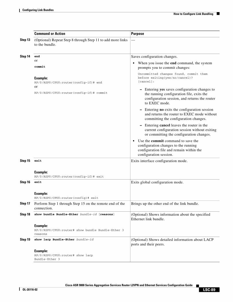
Configuring Link BundlesHow to Configure Link Bundling
LSC-89Cisco ASR 9000 Series Aggregation Services Router L2VPN and Ethernet Services Configuration Guide
OL-26116-02
Step 13 (Optional) Repeat Step 8 through Step 11 to add more links to the bundle.
—
Step 14 end
or
commit
Example:RP/0/RSP0/CPU0:router(config-if)# end
or
RP/0/RSP0/CPU0:router(config-if)# commit
Saves configuration changes.
• When you issue the end command, the system prompts you to commit changes:
Uncommitted changes found, commit them before exiting(yes/no/cancel)? [cancel]:
– Entering yes saves configuration changes to the running configuration file, exits the configuration session, and returns the router to EXEC mode.
– Entering no exits the configuration session and returns the router to EXEC mode without committing the configuration changes.
– Entering cancel leaves the router in the current configuration session without exiting or committing the configuration changes.
• Use the commit command to save the configuration changes to the running configuration file and remain within the configuration session.
Step 15 exit
Example:RP/0/RSP0/CPU0:router(config-if)# exit
Exits interface configuration mode.
Step 16 exit
Example:RP/0/RSP0/CPU0:router(config)# exit
Exits global configuration mode.
Step 17 Perform Step 1 through Step 15 on the remote end of the connection.
Brings up the other end of the link bundle.
Step 18 show bundle Bundle-Ether bundle-id [reasons]
Example:RP/0/RSP0/CPU0:router# show bundle Bundle-Ether 3 reasons
(Optional) Shows information about the specified Ethernet link bundle.
Step 19 show lacp Bundle-Ether bundle-id
Example:RP/0/RSP0/CPU0:router# show lacp Bundle-Ether 3
(Optional) Shows detailed information about LACP ports and their peers.
Command or Action Purpose
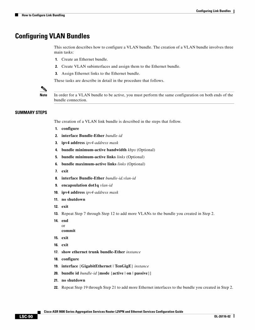
Configuring Link BundlesHow to Configure Link Bundling
LSC-90Cisco ASR 9000 Series Aggregation Services Router L2VPN and Ethernet Services Configuration Guide
OL-26116-02
Configuring VLAN BundlesThis section describes how to configure a VLAN bundle. The creation of a VLAN bundle involves three main tasks:
1. Create an Ethernet bundle.
2. Create VLAN subinterfaces and assign them to the Ethernet bundle.
3. Assign Ethernet links to the Ethernet bundle.
These tasks are describe in detail in the procedure that follows.
Note In order for a VLAN bundle to be active, you must perform the same configuration on both ends of the bundle connection.
SUMMARY STEPS
The creation of a VLAN link bundle is described in the steps that follow.
1. configure
2. interface Bundle-Ether bundle-id
3. ipv4 address ipv4-address mask
4. bundle minimum-active bandwidth kbps (Optional)
5. bundle minimum-active links links (Optional)
6. bundle maximum-active links links (Optional)
7. exit
8. interface Bundle-Ether bundle-id.vlan-id
9. encapsulation dot1q vlan-id
10. ipv4 address ipv4-address mask
11. no shutdown
12. exit
13. Repeat Step 7 through Step 12 to add more VLANs to the bundle you created in Step 2.
14. endorcommit
15. exit
16. exit
17. show ethernet trunk bundle-Ether instance
18. configure
19. interface {GigabitEthernet | TenGigE} instance
20. bundle id bundle-id [mode {active | on | passive}]
21. no shutdown
22. Repeat Step 19 through Step 21 to add more Ethernet interfaces to the bundle you created in Step 2.
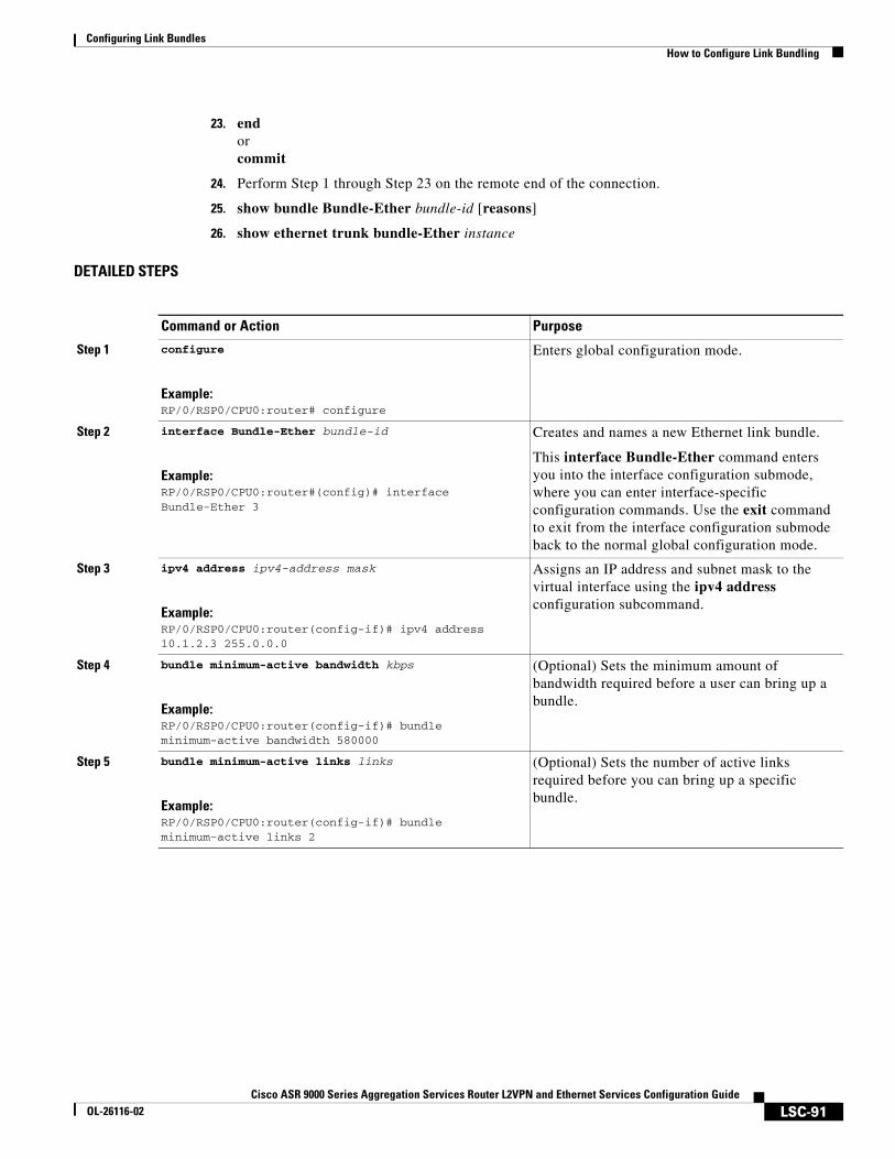
Configuring Link BundlesHow to Configure Link Bundling
LSC-91Cisco ASR 9000 Series Aggregation Services Router L2VPN and Ethernet Services Configuration Guide
OL-26116-02
23. endorcommit
24. Perform Step 1 through Step 23 on the remote end of the connection.
25. show bundle Bundle-Ether bundle-id [reasons]
26. show ethernet trunk bundle-Ether instance
DETAILED STEPS
Command or Action Purpose
Step 1 configure
Example:RP/0/RSP0/CPU0:router# configure
Enters global configuration mode.
Step 2 interface Bundle-Ether bundle-id
Example:RP/0/RSP0/CPU0:router#(config)# interface Bundle-Ether 3
Creates and names a new Ethernet link bundle.
This interface Bundle-Ether command enters you into the interface configuration submode, where you can enter interface-specific configuration commands. Use the exit command to exit from the interface configuration submode back to the normal global configuration mode.
Step 3 ipv4 address ipv4-address mask
Example:RP/0/RSP0/CPU0:router(config-if)# ipv4 address 10.1.2.3 255.0.0.0
Assigns an IP address and subnet mask to the virtual interface using the ipv4 address configuration subcommand.
Step 4 bundle minimum-active bandwidth kbps
Example:RP/0/RSP0/CPU0:router(config-if)# bundle minimum-active bandwidth 580000
(Optional) Sets the minimum amount of bandwidth required before a user can bring up a bundle.
Step 5 bundle minimum-active links links
Example:RP/0/RSP0/CPU0:router(config-if)# bundle minimum-active links 2
(Optional) Sets the number of active links required before you can bring up a specific bundle.
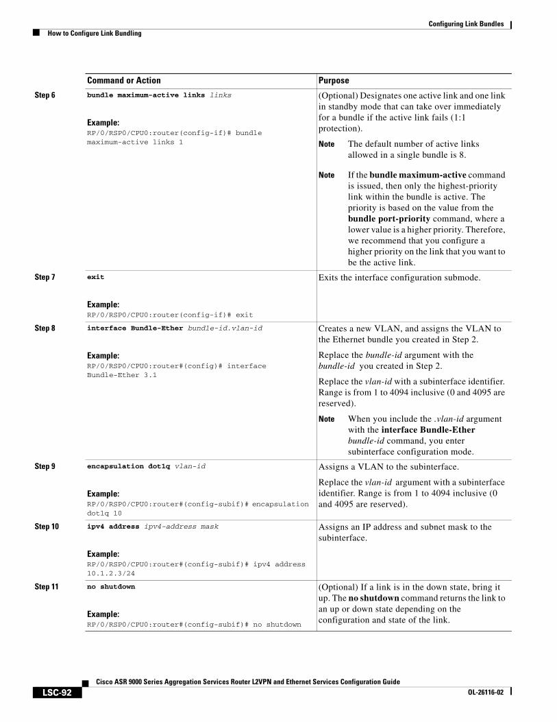
Configuring Link BundlesHow to Configure Link Bundling
LSC-92Cisco ASR 9000 Series Aggregation Services Router L2VPN and Ethernet Services Configuration Guide
OL-26116-02
Step 6 bundle maximum-active links links
Example:RP/0/RSP0/CPU0:router(config-if)# bundle maximum-active links 1
(Optional) Designates one active link and one link in standby mode that can take over immediately for a bundle if the active link fails (1:1 protection).
Note The default number of active links allowed in a single bundle is 8.
Note If the bundle maximum-active command is issued, then only the highest-priority link within the bundle is active. The priority is based on the value from the bundle port-priority command, where a lower value is a higher priority. Therefore, we recommend that you configure a higher priority on the link that you want to be the active link.
Step 7 exit
Example:RP/0/RSP0/CPU0:router(config-if)# exit
Exits the interface configuration submode.
Step 8 interface Bundle-Ether bundle-id.vlan-id
Example:RP/0/RSP0/CPU0:router#(config)# interface Bundle-Ether 3.1
Creates a new VLAN, and assigns the VLAN to the Ethernet bundle you created in Step 2.
Replace the bundle-id argument with the bundle-id you created in Step 2.
Replace the vlan-id with a subinterface identifier. Range is from 1 to 4094 inclusive (0 and 4095 are reserved).
Note When you include the .vlan-id argument with the interface Bundle-Ether bundle-id command, you enter subinterface configuration mode.
Step 9 encapsulation dot1q vlan-id
Example:RP/0/RSP0/CPU0:router#(config-subif)# encapsulation dot1q 10
Assigns a VLAN to the subinterface.
Replace the vlan-id argument with a subinterface identifier. Range is from 1 to 4094 inclusive (0 and 4095 are reserved).
Step 10 ipv4 address ipv4-address mask
Example:RP/0/RSP0/CPU0:router#(config-subif)# ipv4 address 10.1.2.3/24
Assigns an IP address and subnet mask to the subinterface.
Step 11 no shutdown
Example:RP/0/RSP0/CPU0:router#(config-subif)# no shutdown
(Optional) If a link is in the down state, bring it up. The no shutdown command returns the link to an up or down state depending on the configuration and state of the link.
Command or Action Purpose
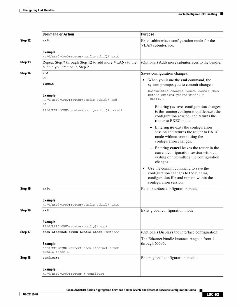
Configuring Link BundlesHow to Configure Link Bundling
LSC-93Cisco ASR 9000 Series Aggregation Services Router L2VPN and Ethernet Services Configuration Guide
OL-26116-02
Step 12 exit
Example:RP/0/RSP0/CPU0:router(config-subif)# exit
Exits subinterface configuration mode for the VLAN subinterface.
Step 13 Repeat Step 7 through Step 12 to add more VLANs to the bundle you created in Step 2.
(Optional) Adds more subinterfaces to the bundle.
Step 14 end
or
commit
Example:RP/0/RSP0/CPU0:router(config-subif)# end
or
RP/0/RSP0/CPU0:router(config-subif)# commit
Saves configuration changes.
• When you issue the end command, the system prompts you to commit changes:
Uncommitted changes found, commit them before exiting(yes/no/cancel)? [cancel]:
– Entering yes saves configuration changes to the running configuration file, exits the configuration session, and returns the router to EXEC mode.
– Entering no exits the configuration session and returns the router to EXEC mode without committing the configuration changes.
– Entering cancel leaves the router in the current configuration session without exiting or committing the configuration changes.
• Use the commit command to save the configuration changes to the running configuration file and remain within the configuration session.
Step 15 exit
Example:RP/0/RSP0/CPU0:router(config-subif)# exit
Exits interface configuration mode.
Step 16 exit
Example:RP/0/RSP0/CPU0:router(config)# exit
Exits global configuration mode.
Step 17 show ethernet trunk bundle-ether instance
Example:RP/0/RP0/CPU0:router# show ethernet trunk bundle-ether 5
(Optional) Displays the interface configuration.
The Ethernet bundle instance range is from 1 through 65535.
Step 18 configure
Example:RP/0/RSP0/CPU0:router # configure
Enters global configuration mode.
Command or Action Purpose
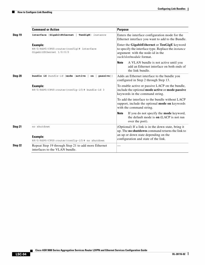
Configuring Link BundlesHow to Configure Link Bundling
LSC-94Cisco ASR 9000 Series Aggregation Services Router L2VPN and Ethernet Services Configuration Guide
OL-26116-02
Step 19 interface {GigabitEthernet | TenGigE} instance
Example:RP/0/RSP0/CPU0:router(config)# interface GigabitEthernet 1/0/0/0
Enters the interface configuration mode for the Ethernet interface you want to add to the Bundle.
Enter the GigabitEthernet or TenGigE keyword to specify the interface type. Replace the instance argument with the node-id in the rack/slot/module format.
Note A VLAN bundle is not active until you add an Ethernet interface on both ends of the link bundle.
Step 20 bundle id bundle-id [mode {active | on | passive}]
Example:RP/0/RSP0/CPU0:router(config-if)# bundle-id 3
Adds an Ethernet interface to the bundle you configured in Step 2 through Step 13.
To enable active or passive LACP on the bundle, include the optional mode active or mode passive keywords in the command string.
To add the interface to the bundle without LACP support, include the optional mode on keywords with the command string.
Note If you do not specify the mode keyword, the default mode is on (LACP is not run over the port).
Step 21 no shutdown
Example:RP/0/RSP0/CPU0:router(config-if)# no shutdown
(Optional) If a link is in the down state, bring it up. The no shutdown command returns the link to an up or down state depending on the configuration and state of the link.
Step 22 Repeat Step 19 through Step 21 to add more Ethernet interfaces to the VLAN bundle.
—
Command or Action Purpose

Configuring Link BundlesHow to Configure Link Bundling
LSC-95Cisco ASR 9000 Series Aggregation Services Router L2VPN and Ethernet Services Configuration Guide
OL-26116-02
Step 23 end
or
commit
Example:RP/0/RSP0/CPU0:router(config-subif)# end
or
RP/0/RSP0/CPU0:router(config-subif)# commit
Saves configuration changes.
• When you issue the end command, the system prompts you to commit changes:
Uncommitted changes found, commit them before exiting(yes/no/cancel)? [cancel]:
– Entering yes saves configuration changes to the running configuration file, exits the configuration session, and returns the router to EXEC mode.
– Entering no exits the configuration session and returns the router to EXEC mode without committing the configuration changes.
– Entering cancel leaves the router in the current configuration session without exiting or committing the configuration changes.
• Use the commit command to save the configuration changes to the running configuration file and remain within the configuration session.
Step 24 Perform Step 1 through Step 23 on the remote end of the VLAN bundle connection.
Brings up the other end of the link bundle.
Step 25 show bundle Bundle-Ether bundle-id [reasons]
Example:RP/0/RSP0/CPU0:router# show bundle Bundle-Ether 3 reasons
(Optional) Shows information about the specified Ethernet link bundle.
The show bundle Bundle-Ether command displays information about the specified bundle. If your bundle has been configured properly and is carrying traffic, the State field in the show bundle Bundle-Ether command output will show the number “4,” which means the specified VLAN bundle port is “distributing.”
Step 26 show ethernet trunk bundle-ether instance
Example:RP/0/RP0/CPU0:router# show ethernet trunk bundle-ether 5
(Optional) Displays the interface configuration.
The Ethernet bundle instance range is from 1 through 65535.
Command or Action Purpose
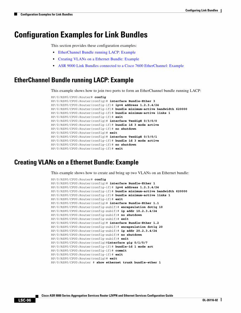
Configuring Link BundlesConfiguration Examples for Link Bundles
LSC-96Cisco ASR 9000 Series Aggregation Services Router L2VPN and Ethernet Services Configuration Guide
OL-26116-02
Configuration Examples for Link BundlesThis section provides these configuration examples:
• EtherChannel Bundle running LACP: Example
• Creating VLANs on a Ethernet Bundle: Example
• ASR 9000 Link Bundles connected to a Cisco 7600 EtherChannel: Example
EtherChannel Bundle running LACP: ExampleThis example shows how to join two ports to form an EtherChannel bundle running LACP:
RP/0/RSP0/CPU0:Router# configRP/0/RSP0/CPU0:Router(config)# interface Bundle-Ether 3RP/0/RSP0/CPU0:Router(config-if)# ipv4 address 1.2.3.4/24RP/0/RSP0/CPU0:Router(config-if)# bundle minimum-active bandwidth 620000RP/0/RSP0/CPU0:Router(config-if)# bundle minimum-active links 1RP/0/RSP0/CPU0:Router(config-if)# exitRP/0/RSP0/CPU0:Router(config)# interface TenGigE 0/3/0/0RP/0/RSP0/CPU0:Router(config-if)# bundle id 3 mode activeRP/0/RSP0/CPU0:Router(config-if)# no shutdownRP/0/RSP0/CPU0:Router(config)# exitRP/0/RSP0/CPU0:Router(config)# interface TenGigE 0/3/0/1RP/0/RSP0/CPU0:Router(config-if)# bundle id 3 mode activeRP/0/RSP0/CPU0:Router(config-if)# no shutdownRP/0/RSP0/CPU0:Router(config-if)# exit
Creating VLANs on a Ethernet Bundle: ExampleThis example shows how to create and bring up two VLANs on an Ethernet bundle:
RP/0/RSP0/CPU0:Router# configRP/0/RSP0/CPU0:Router(config)# interface Bundle-Ether 1RP/0/RSP0/CPU0:Router(config-if)# ipv4 address 1.2.3.4/24RP/0/RSP0/CPU0:Router(config-if)# bundle minimum-active bandwidth 620000RP/0/RSP0/CPU0:Router(config-if)# bundle minimum-active links 1RP/0/RSP0/CPU0:Router(config-if)# exitRP/0/RSP0/CPU0:Router(config)# interface Bundle-Ether 1.1RP/0/RSP0/CPU0:Router(config-subif)# encapsulation dot1q 10RP/0/RSP0/CPU0:Router(config-subif)# ip addr 10.2.3.4/24RP/0/RSP0/CPU0:Router(config-subif)# no shutdownRP/0/RSP0/CPU0:Router(config-subif)# exitRP/0/RSP0/CPU0:Router(config)# interface Bundle-Ether 1.2RP/0/RSP0/CPU0:Router(config-subif)# encapsulation dot1q 20RP/0/RSP0/CPU0:Router(config-subif)# ip addr 20.2.3.4/24RP/0/RSP0/CPU0:Router(config-subif)# no shutdownRP/0/RSP0/CPU0:Router(config-subif)# exitRP/0/RSP0/CPU0:Router(config)#interface gig 0/1/5/7RP/0/RSP0/CPU0:Router(config-if)# bundle-id 1 mode actRP/0/RSP0/CPU0:Router(config-if)# commitRP/0/RSP0/CPU0:Router(config-if)# exitRP/0/RSP0/CPU0:Router(config)# exitRP/0/RSP0/CPU0:Router # show ethernet trunk bundle-ether 1
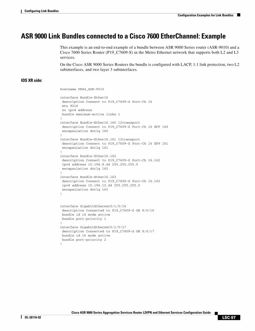
Configuring Link BundlesConfiguration Examples for Link Bundles
LSC-97Cisco ASR 9000 Series Aggregation Services Router L2VPN and Ethernet Services Configuration Guide
OL-26116-02
ASR 9000 Link Bundles connected to a Cisco 7600 EtherChannel: ExampleThis example is an end-to-end example of a bundle between ASR 9000 Series router (ASR-9010) and a Cisco 7600 Series Router (P19_C7609-S) in the Metro Ethernet network that supports both L2 and L3 services.
On the Cisco ASR 9000 Series Routers the bundle is configured with LACP, 1:1 link protection, two L2 subinterfaces, and two layer 3 subinterfaces.
IOS XR side:
hostname PE44_ASR-9010
interface Bundle-Ether16 description Connect to P19_C7609-S Port-Ch 16 mtu 9216 no ipv4 address bundle maximum-active links 1!interface Bundle-Ether16.160 l2transport description Connect to P19_C7609-S Port-Ch 16 EFP 160 encapsulation dot1q 160!interface Bundle-Ether16.161 l2transport description Connect to P19_C7609-S Port-Ch 16 EFP 161 encapsulation dot1q 161! interface Bundle-Ether16.162 description Connect to P19_C7609-S Port-Ch 16.162 ipv4 address 10.194.8.44 255.255.255.0 encapsulation dot1q 162! interface Bundle-Ether16.163 description Connect to P19_C7609-S Port-Ch 16.163 ipv4 address 10.194.12.44 255.255.255.0 encapsulation dot1q 163!
interface GigabitEthernet0/1/0/16 description Connected to P19_C7609-S GE 8/0/16 bundle id 16 mode active bundle port-priority 1!interface GigabitEthernet0/1/0/17 description Connected to P19_C7609-S GE 8/0/17 bundle id 16 mode active bundle port-priority 2!
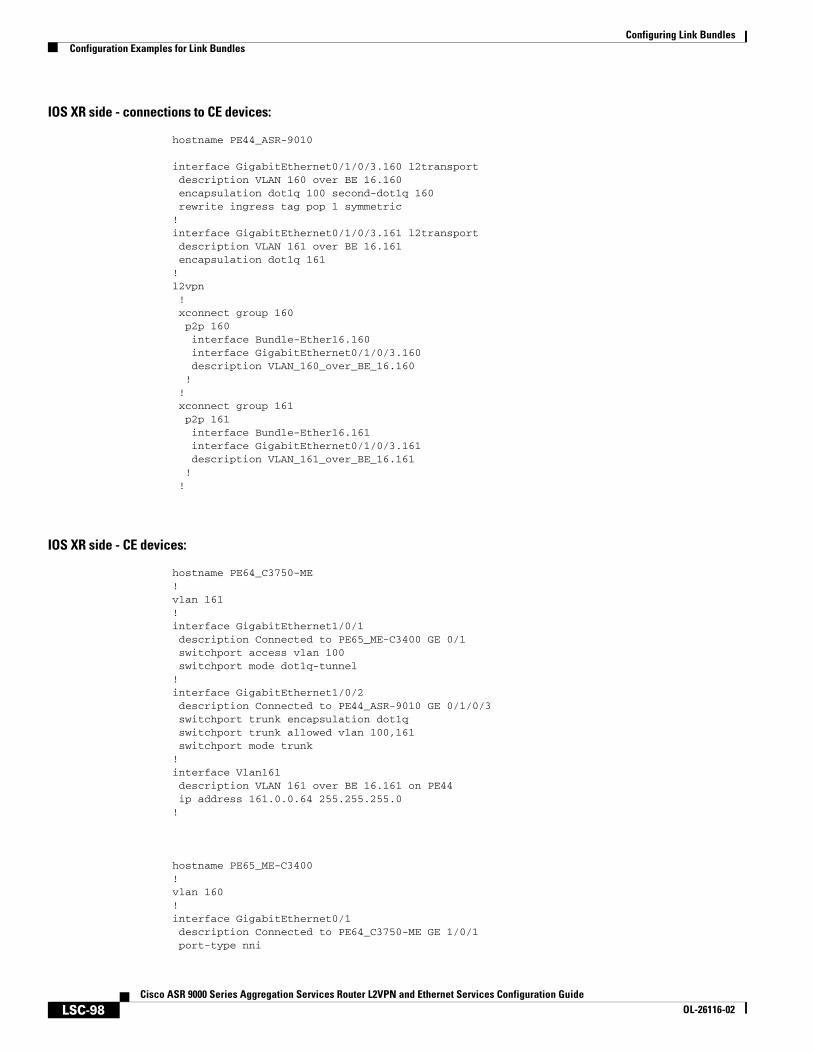
Configuring Link BundlesConfiguration Examples for Link Bundles
LSC-98Cisco ASR 9000 Series Aggregation Services Router L2VPN and Ethernet Services Configuration Guide
OL-26116-02
IOS XR side - connections to CE devices:
hostname PE44_ASR-9010
interface GigabitEthernet0/1/0/3.160 l2transport description VLAN 160 over BE 16.160 encapsulation dot1q 100 second-dot1q 160 rewrite ingress tag pop 1 symmetric!interface GigabitEthernet0/1/0/3.161 l2transport description VLAN 161 over BE 16.161 encapsulation dot1q 161!l2vpn ! xconnect group 160 p2p 160 interface Bundle-Ether16.160 interface GigabitEthernet0/1/0/3.160 description VLAN_160_over_BE_16.160 ! ! xconnect group 161 p2p 161 interface Bundle-Ether16.161 interface GigabitEthernet0/1/0/3.161 description VLAN_161_over_BE_16.161 ! !
IOS XR side - CE devices:
hostname PE64_C3750-ME!vlan 161!interface GigabitEthernet1/0/1 description Connected to PE65_ME-C3400 GE 0/1 switchport access vlan 100 switchport mode dot1q-tunnel!interface GigabitEthernet1/0/2 description Connected to PE44_ASR-9010 GE 0/1/0/3 switchport trunk encapsulation dot1q switchport trunk allowed vlan 100,161 switchport mode trunk!interface Vlan161 description VLAN 161 over BE 16.161 on PE44 ip address 161.0.0.64 255.255.255.0!
hostname PE65_ME-C3400!vlan 160!interface GigabitEthernet0/1 description Connected to PE64_C3750-ME GE 1/0/1 port-type nni
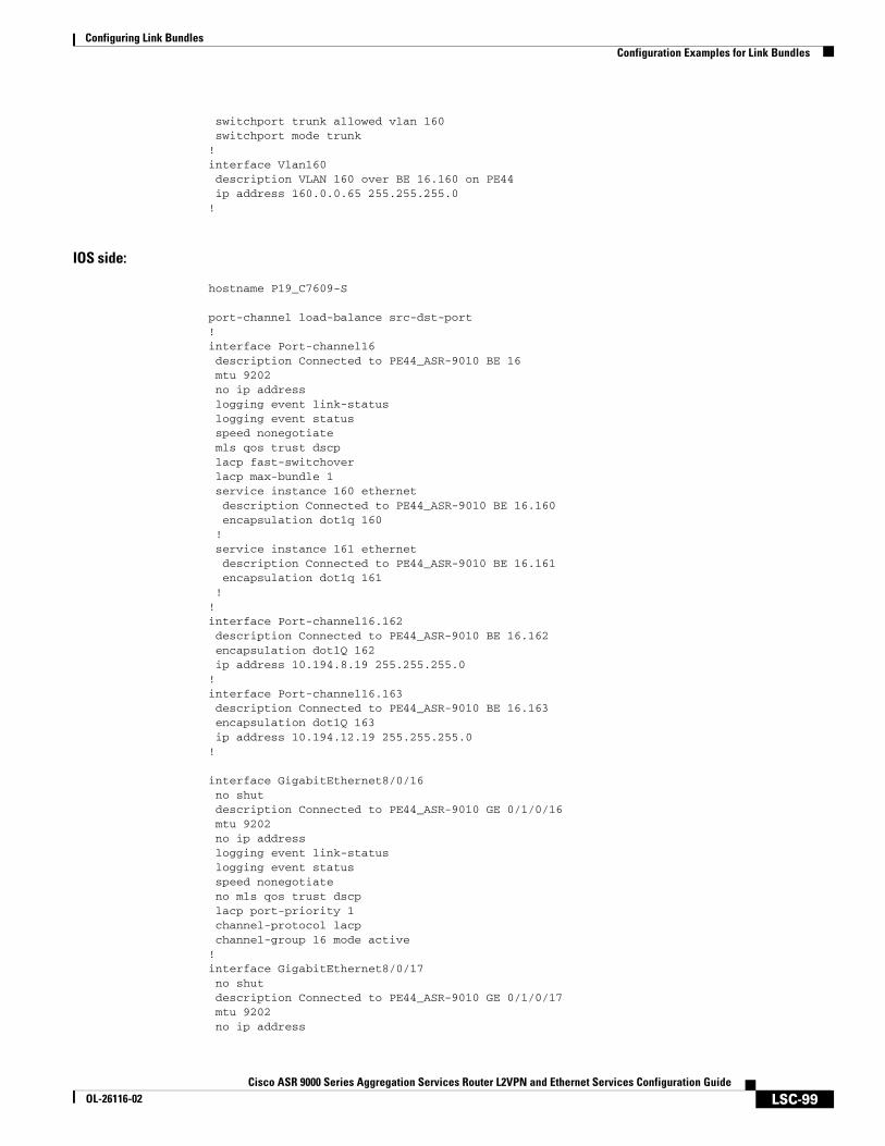
Configuring Link BundlesConfiguration Examples for Link Bundles
LSC-99Cisco ASR 9000 Series Aggregation Services Router L2VPN and Ethernet Services Configuration Guide
OL-26116-02
switchport trunk allowed vlan 160 switchport mode trunk!interface Vlan160 description VLAN 160 over BE 16.160 on PE44 ip address 160.0.0.65 255.255.255.0!
IOS side:
hostname P19_C7609-S
port-channel load-balance src-dst-port!interface Port-channel16 description Connected to PE44_ASR-9010 BE 16 mtu 9202 no ip address logging event link-status logging event status speed nonegotiate mls qos trust dscp lacp fast-switchover lacp max-bundle 1 service instance 160 ethernet description Connected to PE44_ASR-9010 BE 16.160 encapsulation dot1q 160 ! service instance 161 ethernet description Connected to PE44_ASR-9010 BE 16.161 encapsulation dot1q 161 ! ! interface Port-channel16.162 description Connected to PE44_ASR-9010 BE 16.162 encapsulation dot1Q 162 ip address 10.194.8.19 255.255.255.0! interface Port-channel16.163 description Connected to PE44_ASR-9010 BE 16.163 encapsulation dot1Q 163 ip address 10.194.12.19 255.255.255.0!
interface GigabitEthernet8/0/16 no shut description Connected to PE44_ASR-9010 GE 0/1/0/16 mtu 9202 no ip address logging event link-status logging event status speed nonegotiate no mls qos trust dscp lacp port-priority 1 channel-protocol lacp channel-group 16 mode active!interface GigabitEthernet8/0/17 no shut description Connected to PE44_ASR-9010 GE 0/1/0/17 mtu 9202 no ip address
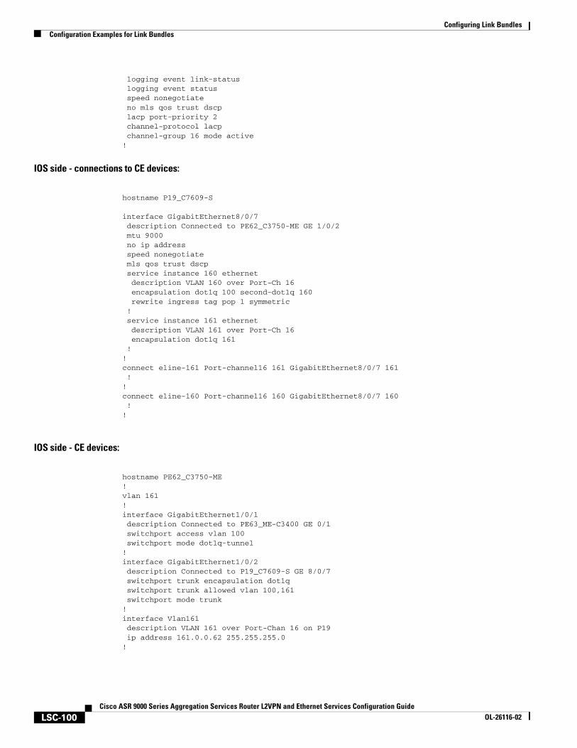
Configuring Link BundlesConfiguration Examples for Link Bundles
LSC-100Cisco ASR 9000 Series Aggregation Services Router L2VPN and Ethernet Services Configuration Guide
OL-26116-02
logging event link-status logging event status speed nonegotiate no mls qos trust dscp lacp port-priority 2 channel-protocol lacp channel-group 16 mode active!
IOS side - connections to CE devices:
hostname P19_C7609-S
interface GigabitEthernet8/0/7 description Connected to PE62_C3750-ME GE 1/0/2 mtu 9000 no ip address speed nonegotiate mls qos trust dscp service instance 160 ethernet description VLAN 160 over Port-Ch 16 encapsulation dot1q 100 second-dot1q 160 rewrite ingress tag pop 1 symmetric ! service instance 161 ethernet description VLAN 161 over Port-Ch 16 encapsulation dot1q 161 !!connect eline-161 Port-channel16 161 GigabitEthernet8/0/7 161 !!connect eline-160 Port-channel16 160 GigabitEthernet8/0/7 160 !!
IOS side - CE devices:
hostname PE62_C3750-ME!vlan 161!interface GigabitEthernet1/0/1 description Connected to PE63_ME-C3400 GE 0/1 switchport access vlan 100 switchport mode dot1q-tunnel!interface GigabitEthernet1/0/2 description Connected to P19_C7609-S GE 8/0/7 switchport trunk encapsulation dot1q switchport trunk allowed vlan 100,161 switchport mode trunk!interface Vlan161 description VLAN 161 over Port-Chan 16 on P19 ip address 161.0.0.62 255.255.255.0!
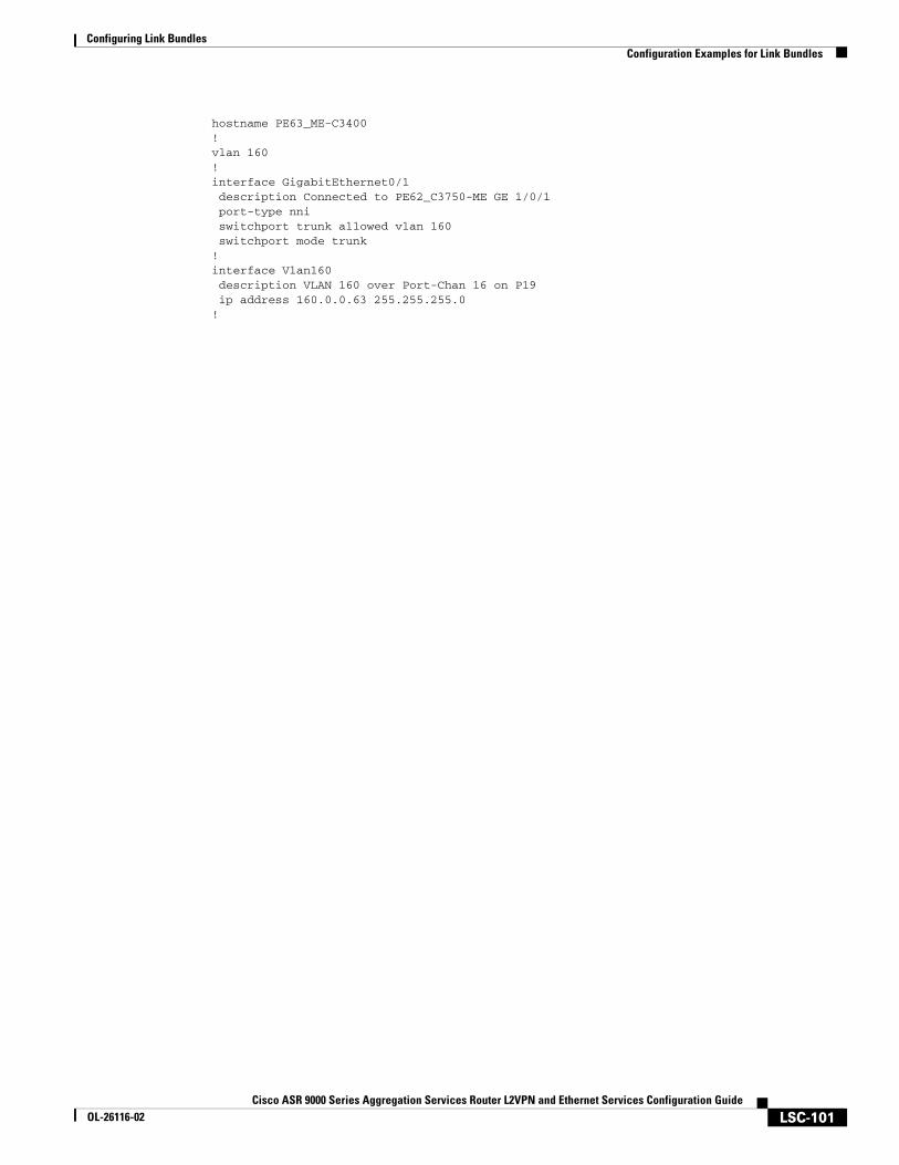
Configuring Link BundlesConfiguration Examples for Link Bundles
LSC-101Cisco ASR 9000 Series Aggregation Services Router L2VPN and Ethernet Services Configuration Guide
OL-26116-02
hostname PE63_ME-C3400!vlan 160!interface GigabitEthernet0/1 description Connected to PE62_C3750-ME GE 1/0/1 port-type nni switchport trunk allowed vlan 160 switchport mode trunk!interface Vlan160 description VLAN 160 over Port-Chan 16 on P19 ip address 160.0.0.63 255.255.255.0!
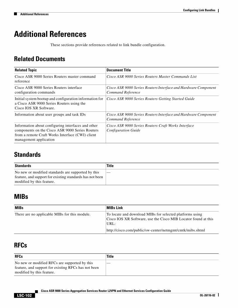
Configuring Link BundlesAdditional References
LSC-102Cisco ASR 9000 Series Aggregation Services Router L2VPN and Ethernet Services Configuration Guide
OL-26116-02
Additional ReferencesThese sections provide references related to link bundle configuration.
Related Documents
Standards
MIBs
RFCs
Related Topic Document Title
Cisco ASR 9000 Series Routers master command reference
Cisco ASR 9000 Series Routers Master Commands List
Cisco ASR 9000 Series Routers interface configuration commands
Cisco ASR 9000 Series Routers Interface and Hardware Component Command Reference
Initial system bootup and configuration information for a Cisco ASR 9000 Series Routers using the Cisco IOS XR Software.
Cisco ASR 9000 Series Routers Getting Started Guide
Information about user groups and task IDs Cisco ASR 9000 Series Routers Interface and Hardware Component Command Reference
Information about configuring interfaces and other components on the Cisco ASR 9000 Series Routers from a remote Craft Works Interface (CWI) client management application
Cisco ASR 9000 Series Routers Craft Works Interface Configuration Guide
Standards Title
No new or modified standards are supported by this feature, and support for existing standards has not been modified by this feature.
—
MIBs MIBs Link
There are no applicable MIBs for this module. To locate and download MIBs for selected platforms using Cisco IOS XR Software, use the Cisco MIB Locator found at this URL:
http://cisco.com/public/sw-center/netmgmt/cmtk/mibs.shtml
RFCs Title
No new or modified RFCs are supported by this feature, and support for existing RFCs has not been modified by this feature.
—
Configuring Link BundlesAdditional References
LSC-103Cisco ASR 9000 Series Aggregation Services Router L2VPN and Ethernet Services Configuration Guide
OL-26116-02
Technical Assistance
Description Link
The Cisco Technical Support website contains thousands of pages of searchable technical content, including links to products, technologies, solutions, technical tips, and tools. Registered Cisco.com users can log in from this page to access even more content.
http://www.cisco.com/techsupport

Configuring Link BundlesAdditional References
LSC-104Cisco ASR 9000 Series Aggregation Services Router L2VPN and Ethernet Services Configuration Guide
OL-26116-02
LSC-105Cisco ASR 9000 Series Aggregation Services Router L2VPN and Ethernet Services Configuration Guide
OL-26116-02
Implementing Point to Point Layer 2 Services
This module provides conceptual and configuration information for point-to-point Layer 2 (L2) connectivity on Cisco ASR 9000 Series Aggregation Services Routers.
These point-to-point services are supported:
• local switching—A point-to-point circuit internal to a single Cisco ASR 9000 Series Router, also known as local connect.
• pseudowires—A virtual point-to-point circuit from a Cisco ASR 9000 Series Router. Pseudowires are implemented over MPLS.
Note For more information about MPLS Layer 2 VPN on the Cisco ASR 9000 Series Router and for descriptions of the commands listed in this module, see the “Related Documents” section. To locate documentation for other commands that might appear while executing a configuration task, search online in the Cisco IOS XR software master command index.
Feature History for Implementing MPLS Layer 2 VPN on Cisco ASR 9000 Series Routers
Release Modification
Release 3.7.2 This feature was introduced on Cisco ASR 9000 Series Routers.
Release 3.9.0 Scale enhancements were introduced. See Table 4 on page 391 for more information on scale enhancements.
Release 4.0.0 Support was added for Any Transport over MPLS (AToM) features.
Release 4.0.1 Support was added for these features:
• Pseudowire Load Balancing
• Any Transport over MPLS (AToM) features:
– HDLC over MPLS (HDLCoMPLS)
– PPP over MPLS (PPPoMPLS)
Release 4.1.0 Support was added for the Flexible Router ID feature.
Release 4.2.0 Support was added for these features:
• MPLS Transport Profile
• Circuit EMulation (CEM) over Packet
Implementing Point to Point Layer 2 ServicesContents
LSC-106Cisco ASR 9000 Series Aggregation Services Router L2VPN and Ethernet Services
OL-26116-02
Contents• Prerequisites for Implementing Point to Point Layer 2 Services, page LSC-106
• Information About Implementing Point to Point Layer 2 Services, page LSC-106
• How to Implement Point to Point Layer 2 Services, page LSC-123
• Configuration Examples for Point to Point Layer 2 Services, page LSC-168
• Additional References, page LSC-181
Prerequisites for Implementing Point to Point Layer 2 ServicesYou must be in a user group associated with a task group that includes the proper task IDs. The command reference guides include the task IDs required for each command.
If you suspect user group assignment is preventing you from using a command, contact your AAA administrator for assistance.
Information About Implementing Point to Point Layer 2 ServicesTo implement Point to Point Layer 2 Services, you should understand These concepts:
• Layer 2 Virtual Private Network Overview, page LSC-106
• ATMoMPLS with L2VPN Overview, page LSC-107
• Virtual Circuit Connection Verification on L2VPN, page LSC-107
• Ethernet over MPLS, page LSC-108
• Quality of Service, page LSC-111
• High Availability, page LSC-112
• Preferred Tunnel Path, page LSC-112
• Multisegment Pseudowire, page LSC-113
• Pseudowire Redundancy, page LSC-113
• Any Transport over MPLS, page LSC-117
• MPLS Transport Profile, page LSC-119
• Circuit Emulation Over Packet Switched Network, page LSC-121
Layer 2 Virtual Private Network OverviewLayer 2 Virtual Private Network (L2VPN) emulates the behavior of a LAN across an L2 switched, IP or MPLS-enabled IP network, allowing Ethernet devices to communicate with each other as they would when connected to a common LAN segment. Point-to-point L2 connections are vital when creating L2VPNs.
Implementing Point to Point Layer 2 ServicesInformation About Implementing Point to Point Layer 2 Services
LSC-107Cisco ASR 9000 Series Aggregation Services Router L2VPN and Ethernet Services
OL-26116-02
As Internet service providers (ISPs) look to replace their Frame Relay or Asynchronous Transfer Mode (ATM) infrastructures with an IP infrastructure, there is a need to provide standard methods of using an L2 switched, IP or MPLS-enabled IP infrastructure. These methods provide a serviceable L2 interface to customers; specifically, to provide virtual circuits between pairs of customer sites.
Building a L2VPN system requires coordination between the ISP and the customer. The ISP provides L2 connectivity; the customer builds a network using data link resources obtained from the ISP. In an L2VPN service, the ISP does not require information about a the customer's network topology, policies, routing information, point-to-point links, or network point-to-point links from other ISPs.
The ISP requires provider edge (PE) routers with these capabilities:
• Encapsulation of L2 protocol data units (PDU) into Layer 3 (L3) packets.
• Interconnection of any-to-any L2 transports.
• Emulation of L2 quality-of-service (QoS) over a packet switch network.
• Ease of configuration of the L2 service.
• Support for different types of tunneling mechanisms (MPLS, IPSec, GRE, and others).
• L2VPN process databases include all information related to circuits and their connections.
Layer 2 Local Switching OverviewLocal switching allows you to switch L2 data between two interfaces of the same type, (for example, Ethernet to Ethernet) and on the same router. The interfaces can be on the same line card, or on two different line cards. During these types of switching, Layer 2 address is used instead of the Layer 3 address. A local switching connection switches L2 traffic from one attachment circuit (AC) to the other. The two ports configured in a local switching connection are ACs with respect to that local connection. A local switching connection works like a bridge domain that has only two bridge ports; traffic enters one port of the local connection and leaves the other. However, because there is no bridging involved in a local connection, there is neither MAC learning nor flooding. Also, the ACs in a local connection are not in the UP state if the interface state is DOWN. (This behavior is also different when compared to that of a bridge domain.)
Local switching ACs utilize a full variety of L2 interfaces, including L2 trunk (main) interfaces, bundle interfaces, and EFPs.
Additionally, same-port local switching allows you to switch Layer 2 data between two circuits on the same interface.
ATMoMPLS with L2VPN OverviewATMoMPLS is a type of Layer 2 point-to-point connection over an MPLS core.
To implement the ATMoMPLS feature, the Cisco ASR 9000 Series Router plays the role of provider edge (PE) router at the edge of a provider network in which customer edge (CE) devices are connected to the Cisco ASR 9000 Series Routers.
Virtual Circuit Connection Verification on L2VPNVirtual Circuit Connection Verification (VCCV) is an L2VPN Operations, Administration, and Maintenance (OAM) feature that allows network operators to run IP-based provider edge-to-provider edge (PE-to-PE) keepalive protocol across a specified pseudowire to ensure that the pseudowire data
Implementing Point to Point Layer 2 ServicesInformation About Implementing Point to Point Layer 2 Services
LSC-108Cisco ASR 9000 Series Aggregation Services Router L2VPN and Ethernet Services
OL-26116-02
path forwarding does not contain any faults. The disposition PE receives VCCV packets on a control channel, which is associated with the specified pseudowire. The control channel type and connectivity verification type, which are used for VCCV, are negotiated when the pseudowire is established between the PEs for each direction.
Two types of packets can arrive at the disposition egress:
• Type 1—Specifies normal Ethernet-over-MPLS (EoMPLS) data packets.
• Type 2—Specifies VCCV packets.
Cisco ASR 9000 Series Routers supports Label Switched Path (LSP) VCCV Type 1, which uses an inband control word if enabled during signaling. The VCCV echo reply is sent as IPv4 that is the reply mode in IPv4. The reply is forwarded as IP, MPLS, or a combination of both.
VCCV pings counters that are counted in MPLS forwarding on the egress side. However, on the ingress side, they are sourced by the route processor and do not count as MPLS forwarding counters.
Ethernet over MPLSEthernet-over-MPLS (EoMPLS) provides a tunneling mechanism for Ethernet traffic through an MPLS-enabled L3 core and encapsulates Ethernet protocol data units (PDUs) inside MPLS packets (using label stacking) to forward them across the MPLS network.
EoMPLS features are described in These subsections:
• Ethernet Port Mode, page LSC-108
• VLAN Mode, page LSC-109
• Inter-AS Mode, page LSC-110
• QinQ Mode, page LSC-110
• QinAny Mode, page LSC-111
Ethernet Port Mode
In Ethernet port mode, both ends of a pseudowire are connected to Ethernet ports. In this mode, the port is tunneled over the pseudowire or, using local switching (also known as an attachment circuit-to-attachment circuit cross-connect) switches packets or frames from one attachment circuit (AC) to another AC attached to the same PE node.
Figure 1 provides an example of Ethernet port mode.
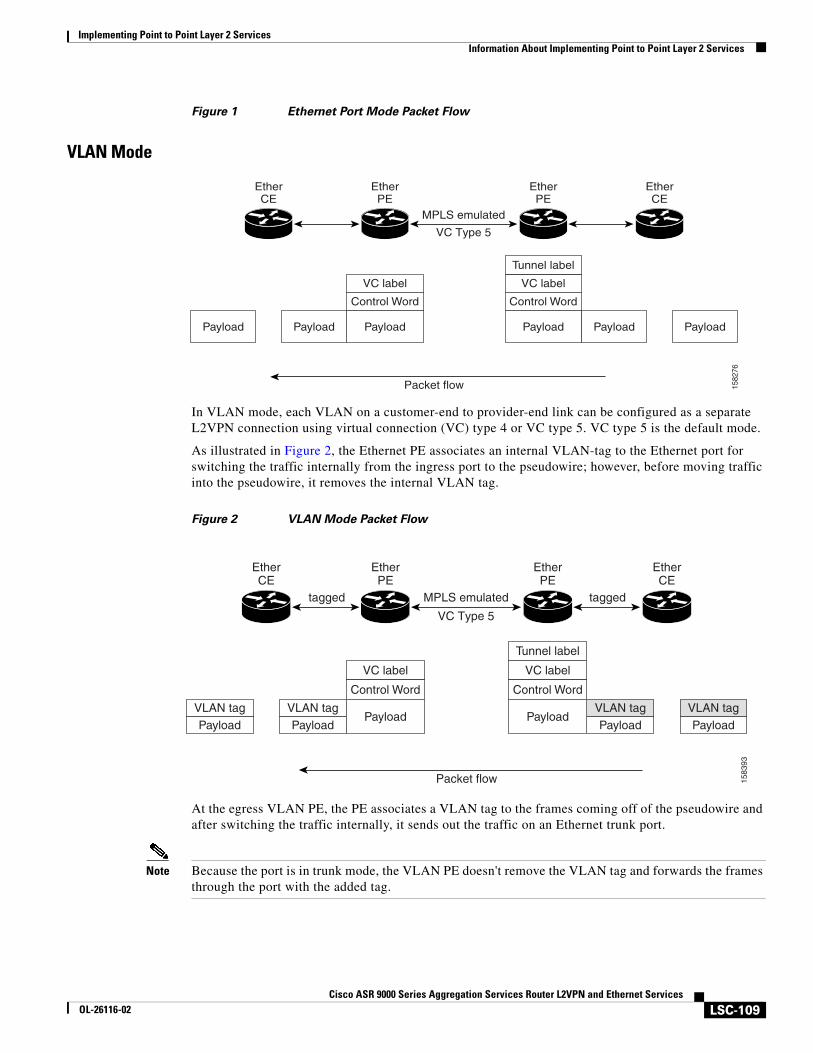
Implementing Point to Point Layer 2 ServicesInformation About Implementing Point to Point Layer 2 Services
LSC-109Cisco ASR 9000 Series Aggregation Services Router L2VPN and Ethernet Services
OL-26116-02
Figure 1 Ethernet Port Mode Packet Flow
VLAN Mode
In VLAN mode, each VLAN on a customer-end to provider-end link can be configured as a separate L2VPN connection using virtual connection (VC) type 4 or VC type 5. VC type 5 is the default mode.
As illustrated in Figure 2, the Ethernet PE associates an internal VLAN-tag to the Ethernet port for switching the traffic internally from the ingress port to the pseudowire; however, before moving traffic into the pseudowire, it removes the internal VLAN tag.
Figure 2 VLAN Mode Packet Flow
At the egress VLAN PE, the PE associates a VLAN tag to the frames coming off of the pseudowire and after switching the traffic internally, it sends out the traffic on an Ethernet trunk port.
Note Because the port is in trunk mode, the VLAN PE doesn't remove the VLAN tag and forwards the frames through the port with the added tag.
EtherPE
EtherCE
EtherCE
EtherPE
MPLS emulated
VC Type 5
Packet flow
VC label
Control Word
PayloadPayloadPayload
VC label
Tunnel label
Control Word
Payload PayloadPayload
1582
76
EtherPE
EtherCE
EtherCE
EtherPE
MPLS emulatedtagged
VC Type 5
Packet flow
tagged
VC label
Control Word
VLAN tagPayload
VLAN tagPayload
VLAN tagPayload
VLAN tagPayload
Payload
VC label
Tunnel label
Control Word
Payload
1583
93
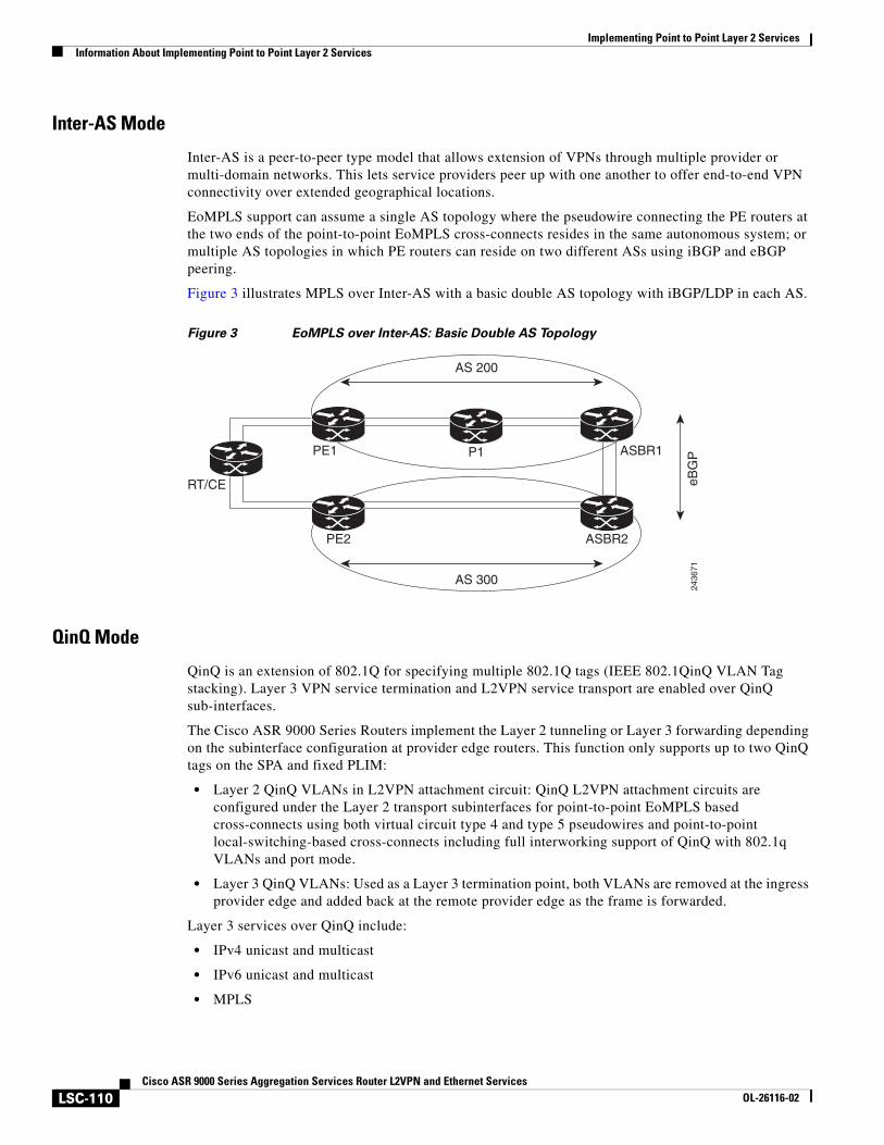
Implementing Point to Point Layer 2 ServicesInformation About Implementing Point to Point Layer 2 Services
LSC-110Cisco ASR 9000 Series Aggregation Services Router L2VPN and Ethernet Services
OL-26116-02
Inter-AS Mode
Inter-AS is a peer-to-peer type model that allows extension of VPNs through multiple provider or multi-domain networks. This lets service providers peer up with one another to offer end-to-end VPN connectivity over extended geographical locations.
EoMPLS support can assume a single AS topology where the pseudowire connecting the PE routers at the two ends of the point-to-point EoMPLS cross-connects resides in the same autonomous system; or multiple AS topologies in which PE routers can reside on two different ASs using iBGP and eBGP peering.
Figure 3 illustrates MPLS over Inter-AS with a basic double AS topology with iBGP/LDP in each AS.
Figure 3 EoMPLS over Inter-AS: Basic Double AS Topology
QinQ Mode
QinQ is an extension of 802.1Q for specifying multiple 802.1Q tags (IEEE 802.1QinQ VLAN Tag stacking). Layer 3 VPN service termination and L2VPN service transport are enabled over QinQ sub-interfaces.
The Cisco ASR 9000 Series Routers implement the Layer 2 tunneling or Layer 3 forwarding depending on the subinterface configuration at provider edge routers. This function only supports up to two QinQ tags on the SPA and fixed PLIM:
• Layer 2 QinQ VLANs in L2VPN attachment circuit: QinQ L2VPN attachment circuits are configured under the Layer 2 transport subinterfaces for point-to-point EoMPLS based cross-connects using both virtual circuit type 4 and type 5 pseudowires and point-to-point local-switching-based cross-connects including full interworking support of QinQ with 802.1q VLANs and port mode.
• Layer 3 QinQ VLANs: Used as a Layer 3 termination point, both VLANs are removed at the ingress provider edge and added back at the remote provider edge as the frame is forwarded.
Layer 3 services over QinQ include:
• IPv4 unicast and multicast
• IPv6 unicast and multicast
• MPLS
RT/CE
PE1
PE2
ASBR1P1
AS 200
AS 300
eBG
P
ASBR2
2436
71
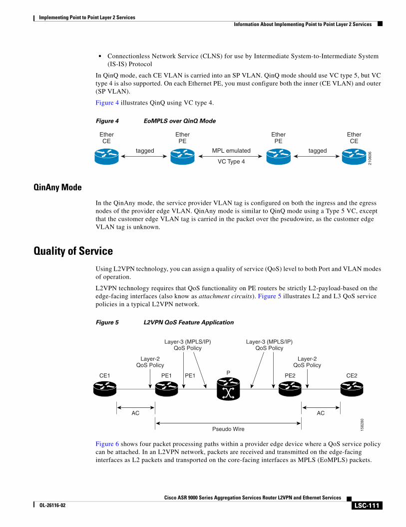
Implementing Point to Point Layer 2 ServicesInformation About Implementing Point to Point Layer 2 Services
LSC-111Cisco ASR 9000 Series Aggregation Services Router L2VPN and Ethernet Services
OL-26116-02
• Connectionless Network Service (CLNS) for use by Intermediate System-to-Intermediate System (IS-IS) Protocol
In QinQ mode, each CE VLAN is carried into an SP VLAN. QinQ mode should use VC type 5, but VC type 4 is also supported. On each Ethernet PE, you must configure both the inner (CE VLAN) and outer (SP VLAN).
Figure 4 illustrates QinQ using VC type 4.
Figure 4 EoMPLS over QinQ Mode
QinAny Mode
In the QinAny mode, the service provider VLAN tag is configured on both the ingress and the egress nodes of the provider edge VLAN. QinAny mode is similar to QinQ mode using a Type 5 VC, except that the customer edge VLAN tag is carried in the packet over the pseudowire, as the customer edge VLAN tag is unknown.
Quality of ServiceUsing L2VPN technology, you can assign a quality of service (QoS) level to both Port and VLAN modes of operation.
L2VPN technology requires that QoS functionality on PE routers be strictly L2-payload-based on the edge-facing interfaces (also know as attachment circuits). Figure 5 illustrates L2 and L3 QoS service policies in a typical L2VPN network.
Figure 5 L2VPN QoS Feature Application
Figure 6 shows four packet processing paths within a provider edge device where a QoS service policy can be attached. In an L2VPN network, packets are received and transmitted on the edge-facing interfaces as L2 packets and transported on the core-facing interfaces as MPLS (EoMPLS) packets.
EtherPE
tagged
EtherPE
EtherCE
EtherCE
taggedMPL emulated
VC Type 4 2106
06PE1CE1 PE1
AC
Layer-2QoS Policy
P
Pseudo Wire
CE2PE2
AC
Layer-3 (MPLS/IP)QoS Policy
Layer-3 (MPLS/IP)QoS Policy
Layer-2QoS Policy
1582
80
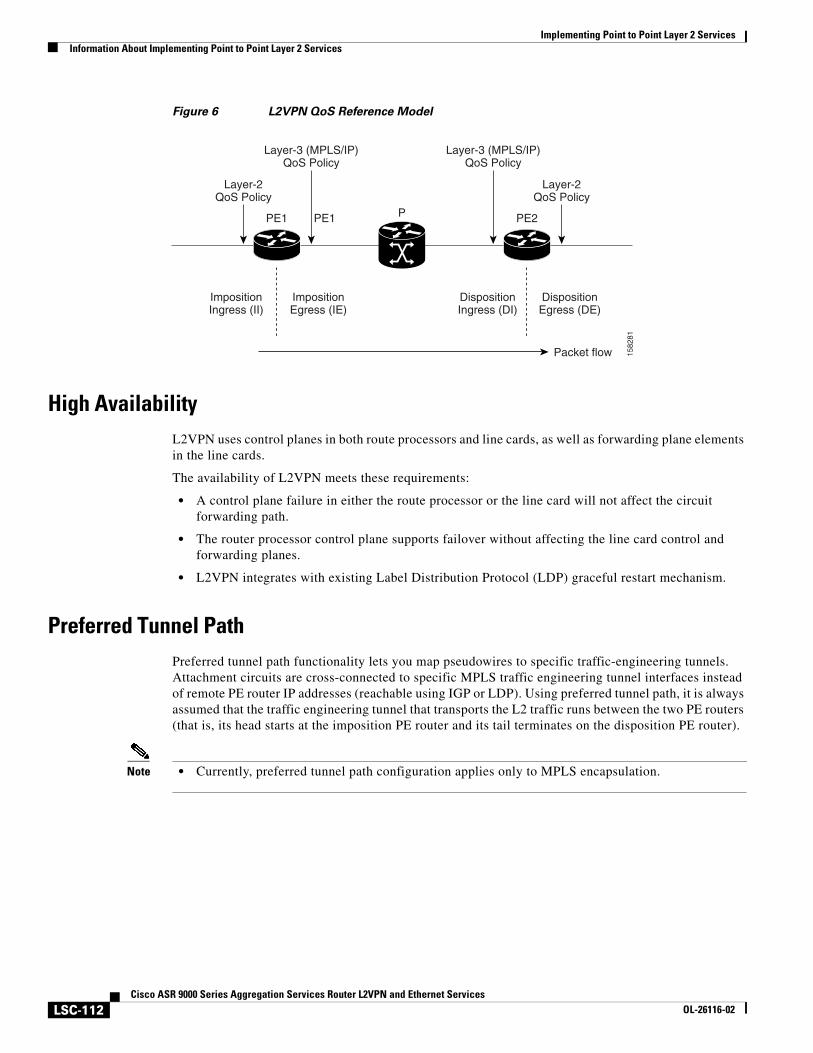
Implementing Point to Point Layer 2 ServicesInformation About Implementing Point to Point Layer 2 Services
LSC-112Cisco ASR 9000 Series Aggregation Services Router L2VPN and Ethernet Services
OL-26116-02
Figure 6 L2VPN QoS Reference Model
High AvailabilityL2VPN uses control planes in both route processors and line cards, as well as forwarding plane elements in the line cards.
The availability of L2VPN meets these requirements:
• A control plane failure in either the route processor or the line card will not affect the circuit forwarding path.
• The router processor control plane supports failover without affecting the line card control and forwarding planes.
• L2VPN integrates with existing Label Distribution Protocol (LDP) graceful restart mechanism.
Preferred Tunnel PathPreferred tunnel path functionality lets you map pseudowires to specific traffic-engineering tunnels. Attachment circuits are cross-connected to specific MPLS traffic engineering tunnel interfaces instead of remote PE router IP addresses (reachable using IGP or LDP). Using preferred tunnel path, it is always assumed that the traffic engineering tunnel that transports the L2 traffic runs between the two PE routers (that is, its head starts at the imposition PE router and its tail terminates on the disposition PE router).
Note • Currently, preferred tunnel path configuration applies only to MPLS encapsulation.
PE1PE1
Layer-2QoS Policy
P PE2
Packet flow
Layer-3 (MPLS/IP)QoS Policy
ImpositionIngress (II)
ImpositionEgress (IE)
DispositionIngress (DI)
DispositionEgress (DE)
Layer-3 (MPLS/IP)QoS Policy
Layer-2QoS Policy
1582
81
Implementing Point to Point Layer 2 ServicesInformation About Implementing Point to Point Layer 2 Services
LSC-113Cisco ASR 9000 Series Aggregation Services Router L2VPN and Ethernet Services
OL-26116-02
Multisegment PseudowirePseudowires transport Layer 2 protocol data units (PDUs) across a public switched network (PSN). A multisegment pseudowire is a static or dynamically configured set of two or more contiguous pseudowire segments. These segments act as a single pseudowire, allowing you to:
• Manage the end-to-end service by separating administrative or provisioning domains.
• Keep IP addresses of provider edge (PE) nodes private across interautonomous system (inter-AS) boundaries. Use IP address of autonomous system boundary routers (ASBRs) and treat them as pseudowire aggregation routers. The ASBRs join the pseudowires of the two domains.
A multisegment pseudowire can span either an inter-AS boundary or two multiprotocol label switching (MPLS) networks.
A pseudowire is a tunnel between two PE nodes. There are two types of PE nodes:
• A Switching PE (S-PE) node
– Terminates PSN tunnels of the preceding and succeeding pseudowire segments in a multisegment pseudowire.
– Switches control and data planes of the preceding and succeeding pseudowire segments of the multisegment pseudowire.
• A Terminating PE (T-PE) node
– Located at both the first and last segments of a multisegment pseudowire.
– Where customer-facing attachment circuits (ACs) are bound to a pseudowire forwarder.
Pseudowire RedundancyPseudowire redundancy allows you to configure your network to detect a failure in the network and reroute the Layer 2 service to another endpoint that can continue to provide service. This feature provides the ability to recover from a failure of either the remote provider edge (PE) router or the link between the PE and customer edge (CE) routers.
L2VPNs can provide pseudowire resiliency through their routing protocols. When connectivity between end-to-end PE routers fails, an alternative path to the directed LDP session and the user data takes over. However, there are some parts of the network in which this rerouting mechanism does not protect against interruptions in service.
Pseudowire redundancy enables you to set up backup pseudowires. You can configure the network with redundant pseudowires and redundant network elements.
Prior to the failure of the primary pseudowire, the ability to switch traffic to the backup pseudowire is used to handle a planned pseudowire outage, such as router maintenance.
Note Pseudowire redundancy is provided only for point-to-point Virtual Private Wire Service (VPWS) pseudowires.
Implementing Point to Point Layer 2 ServicesInformation About Implementing Point to Point Layer 2 Services
LSC-114Cisco ASR 9000 Series Aggregation Services Router L2VPN and Ethernet Services
OL-26116-02
Pseudowire Load BalancingTo maximize networks while maintaining redundancy typically requires traffic load balancing over multiple links. To achieve better and more uniformed distribution, load balancing on the traffic flows that are part of the provisioned pipes is desirable. Load balancing can be flow based according to the IP addresses, Mac addresses, or a combination of those. Load balancing can be flow based according to source or destination IP addresses, or source or destination MAC addresses. Traffic falls back to default flow based MAC addresses if the IP header cannot proceed or IPv6 is be flow based.
This feature applies to pseudowires under L2VPN; this includes both VPWS and VPLS.
Note Enabling virtual circuit (VC) label based load balancing for a pseudowire class overrides global flow based load balancing under L2VPN.
Ethernet Wire ServiceAn Ethernet Wire Service is a service that emulates a point-to-point Ethernet segment. This is similar to Ethernet private line (EPL), a Layer 1 point-to-point service, except the provider edge operates at Layer 2 and typically runs over a Layer 2 network. The EWS encapsulates all frames that are received on a particular UNI and transports these frames to a single-egress UNI without reference to the contents contained within the frame. The operation of this service means that an EWS can be used with VLAN-tagged frames. The VLAN tags are transparent to the EWS (bridge protocol data units [BPDUs])—with some exceptions. These exceptions include IEEE 802.1x, IEEE 802.2ad, and IEEE 802.3x, because these frames have local significance and it benefits both the customer and the Service Provider to terminate them locally.
The customer side has these types:
• Untagged
• Single tagged
• Double tagged
• 802.1q
• 802.1ad
E-Line Service
E-Line service provides a point-to-point EVC between two UNIs. There are two types of E-Line services:
• Ethernet Private Line (EPL)
– No service multiplexing allowed
– Transparent
– No coordination between customer and SP on VLAN ID map
• Ethernet Virtual Private Line (EVPL)
– Allows service multiplexing
– No need for full transparency of service frames
Implementing Point to Point Layer 2 ServicesInformation About Implementing Point to Point Layer 2 Services
LSC-115Cisco ASR 9000 Series Aggregation Services Router L2VPN and Ethernet Services
OL-26116-02
Ethernet LAN (E-LAN) Service
E-LAN service provides multipoint connectivity (can connect two or more UNIs). All sites have Ethernet connectivity with each other (inside the cloud is a multipoint-to-multipoint EVC).
Types of E-LAN services:
Transparent LAN Service (TLS)
• Bundled service
Ethernet Virtual Connection Service (EVCS)
• Per-VLAN service-multiplexed service
The Cisco Ethernet Relay Service concept corresponds to the MEF Ethernet Virtual Private Line concept. The Cisco Ethernet Wire Service concept corresponds to the MEF Ethernet Private Line concept. The Cisco Multipoint Service concept corresponds to the MEF Transparent LAN Service concept. The Cisco Multipoint Relay Service concept corresponds to the MEF Ethernet Virtual Connection Service concept. A UNI is the demarcation between the CE and the provider edge (PE).
Ethernet service is what the Service Provider provides between UNIs.
• Ethernet Line service (E-Line) point-to-point
• Ethernet LAN service (E-LAN) multipoint
• Ethernet Tree service (E-Tree) point-to-multipoint
This is Carrier Ethernet. This can replace Frame Relay/ATM within the cloud with the benefits including faster speeds (GigE and 10GigE). VPLS (Virtual Private LAN Service) is an end-to-end architecture that allows MPLS networks to provide Multipoint Ethernet services. It is “Virtual” because multiple instances of this service share the same physical infrastructure. It is “Private” because each instance of the service is independent and isolated from one another. It is “LAN Service” because it emulates Layer 2 multipoint connectivity between subscribers.
IGMP Snooping
IGMP snooping provides a way to constrain multicast traffic at Layer 2. By snooping the IGMP membership reports sent by hosts in the bridge domain, the IGMP snooping application can set up Layer 2 multicast forwarding tables to deliver traffic only to ports with at least one interested member, significantly reducing the volume of multicast traffic.
Configured at Layer 3, IGMP provides a means for hosts in an IPv4 multicast network to indicate which multicast traffic they are interested in and for routers to control and limit the flow of multicast traffic in the network (at Layer 3).
IGMP snooping uses the information in IGMP membership report messages to build corresponding information in the forwarding tables to restrict IP multicast traffic at Layer 2. The forwarding table entries are in the form <Route, OIF List>, where:
• Route is a <*, G> route or <S, G> route.
• OIF List comprises all bridge ports that have sent IGMP membership reports for the specified route plus all Multicast Router (mrouter) ports in the bridge domain.
The IGMP snooping feature can provide these benefits to a multicast network:
• Basic IGMP snooping reduces bandwidth consumption by reducing multicast traffic that would otherwise flood an entire VPLS bridge domain.
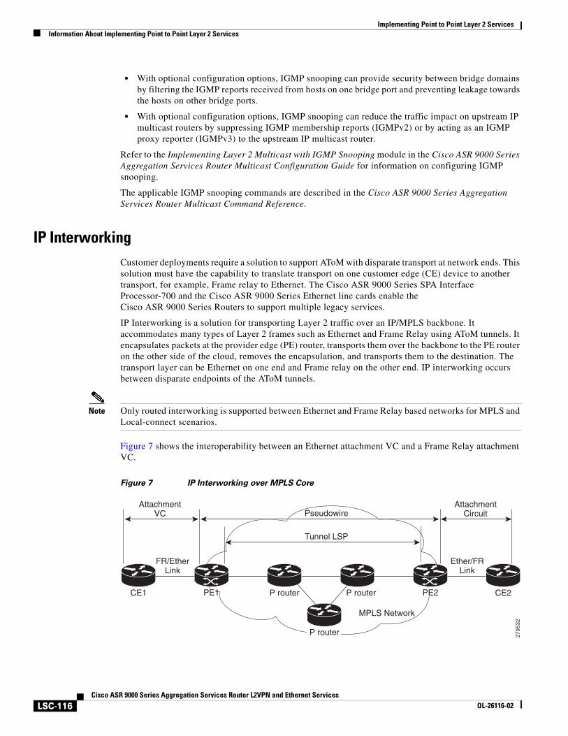
Implementing Point to Point Layer 2 ServicesInformation About Implementing Point to Point Layer 2 Services
LSC-116Cisco ASR 9000 Series Aggregation Services Router L2VPN and Ethernet Services
OL-26116-02
• With optional configuration options, IGMP snooping can provide security between bridge domains by filtering the IGMP reports received from hosts on one bridge port and preventing leakage towards the hosts on other bridge ports.
• With optional configuration options, IGMP snooping can reduce the traffic impact on upstream IP multicast routers by suppressing IGMP membership reports (IGMPv2) or by acting as an IGMP proxy reporter (IGMPv3) to the upstream IP multicast router.
Refer to the Implementing Layer 2 Multicast with IGMP Snooping module in the Cisco ASR 9000 Series Aggregation Services Router Multicast Configuration Guide for information on configuring IGMP snooping.
The applicable IGMP snooping commands are described in the Cisco ASR 9000 Series Aggregation Services Router Multicast Command Reference.
IP InterworkingCustomer deployments require a solution to support AToM with disparate transport at network ends. This solution must have the capability to translate transport on one customer edge (CE) device to another transport, for example, Frame relay to Ethernet. The Cisco ASR 9000 Series SPA Interface Processor-700 and the Cisco ASR 9000 Series Ethernet line cards enable the Cisco ASR 9000 Series Routers to support multiple legacy services.
IP Interworking is a solution for transporting Layer 2 traffic over an IP/MPLS backbone. It accommodates many types of Layer 2 frames such as Ethernet and Frame Relay using AToM tunnels. It encapsulates packets at the provider edge (PE) router, transports them over the backbone to the PE router on the other side of the cloud, removes the encapsulation, and transports them to the destination. The transport layer can be Ethernet on one end and Frame relay on the other end. IP interworking occurs between disparate endpoints of the AToM tunnels.
Note Only routed interworking is supported between Ethernet and Frame Relay based networks for MPLS and Local-connect scenarios.
Figure 7 shows the interoperability between an Ethernet attachment VC and a Frame Relay attachment VC.
Figure 7 IP Interworking over MPLS Core
MPLS Network
2795
32Pseudowire
Tunnel LSP
AttachmentVC
AttachmentCircuit
CE2CE1 P router P router PE2PE1
FR/EtherLink
Ether/FRLink
P router
Implementing Point to Point Layer 2 ServicesInformation About Implementing Point to Point Layer 2 Services
LSC-117Cisco ASR 9000 Series Aggregation Services Router L2VPN and Ethernet Services
OL-26116-02
An attachment circuit (AC) is a physical or logical port or circuit that connects a CE device to a PE device. A pseudowire (PW) is a bidirectional virtual connection (VC) connecting two ACs. In an MPLS network, PWs are carried inside an LSP tunnel. The core facing line card on the PE1 and PE2 could be a Cisco ASR 9000 Series SPA Interface Processor-700 or a Cisco ASR 9000 Series Ethernet line card.
In the IP Interworking mode, the Layer 2 (L2) header is removed from the packets received on an ingress PE, and only the IP payload is transmitted to the egress PE. On the egress PE, an L2 header is appended before the packet is transmitted out of the egress port.
In Figure 7, CE1 and CE2 could be a Frame Relay (FR) interface or a GigabitEthernet (GigE) interface. Assuming CE1 is a FR and CE2 is either a GigE or dot1q, or QinQ. For packets arriving from an Ethernet CE (CE2), ingress LC on the PE (PE2) facing the CE removes L2 framing and forwards the packet to egress PE (PE1) using IPoMPLS encapsulation over a pseudowire. The core facing line card on egress PE removes the MPLS labels but preserves the control word and transmits it to the egress line card facing FR CE (CE1). At the FR PE, after label disposition, the Layer 3 (L3) packets are encapsulated over FR.
Similarly, IP packets arriving from the FR CE are translated into IPoMPLS encapsulation over the pseudowire. At the Ethernet PE side, after label disposition, the PE adds L2 Ethernet packet header back to the packet before transmitting it to the CE, as the packets coming out from the core carry only the IP payload.
These modes support IP Interworking on AToM:
• Ethernet to Frame Relay
Packets arriving from the Ethernet CE device have MAC (port-mode, untagged, single, double tag), IPv4 header and data. The Ethernet line card removes the L2 framing and then forwards the L3 packet to the egress line card. The egress line card adds the FR L2 header before transmitting it from the egress port.
• Ethernet to Ethernet
Both the CE devices are Ethernet. Each ethernet interface can be port-mode, untagged, single, or double tag, although this is not a typical scenario for IP interworking.
Any Transport over MPLS Any Transport over MPLS (AToM) transports Layer 2 packets over a Multiprotocol Label Switching (MPLS) backbone. This enables service providers to connect customer sites with existing Layer 2 networks by using a single, integrated, packet-based network infrastructure. Using this feature, service providers can deliver Layer 2 connections over an MPLS backbone, instead of using separate networks.
AToM encapsulates Layer 2 frames at the ingress PE router, and sends them to a corresponding PE router at the other end of a pseudowire, which is a connection between the two PE routers. The egress PE removes the encapsulation and sends out the Layer 2 frame.
The successful transmission of the Layer 2 frames between PE routers is due to the configuration of the PE routers. You set up a connection, called a pseudowire, between the routers. You specify this information on each PE router:
• The type of Layer 2 data that will be transported across the pseudowire, such as Ethernet and Frame Relay.
• The IP address of the loopback interface of the peer PE router, which enables the PE routers to communicate
• A unique combination of peer PE IP address and VC ID that identifies the pseudowire
Implementing Point to Point Layer 2 ServicesInformation About Implementing Point to Point Layer 2 Services
LSC-118Cisco ASR 9000 Series Aggregation Services Router L2VPN and Ethernet Services
OL-26116-02
Control Word Processing
The control word contains forward explicit congestion notification (FECN), backward explicit congestion notification (BECN) and DE bits in case of frame relay connection.
Control word is mandatory for:
• Frame Relay
• ATM AAL5
• Frame Relay to Ethernet bridged interworking
• cHDLC/PPP IP interworking
• CEM (Circuit Emulation)
The system does not map bits from one transport end point to another across an AToM IP Interworking connection.
Whenever supported, control word is also recommended for pseudowires, as it enables proper load balancing without packet desequencing independent of L2VPN packet content. Without control word the heuristics used to perform load balancing cannot achieve optimal results in all cases.
High-level Data Link Control over MPLS
The attachment circuit (AC) is a main interface configured with HDLC encapsulation. Packets to or from the AC are transported using an AToM pseudowire (PW) of VC type 0x6 to or from the other provider edge (PE) router over the MPLS core network.
With HDLC over MPLS, the entire HDLC packet is transported. The ingress PE router removes only the HDLC flags and FCS bits.
PPP over MPLS
The attachment circuit (AC) is a main interface configured with PPP encapsulation. Packets to or from the AC are transported through an AToM PW of VC type 0x7 to or from the other provider edge (PE) routers over the MPLS core network.
With PPP over MPLS, the ingress PE router removes the flags, address, control field, and the FCS bits.
Frame Relay over MPLSFrame Relay over MPLS (FRoMPLS) provides leased line type of connectivity between two Frame Relay islands. Frame Relay traffic is transported over the MPLS network.
Note The Data Link Connection Identifier (DLCI) DCLI-DLCI mode is supported. A control word (required for DLCI-DLCI mode) is used to carry additional control information.
When a Provider Edge (PE) router receives a Frame Relay protocol packet from a subscriber site, it removes the Frame Relay header and Frame Check Sequence (FCS) and appends the appropriate Virtual Circuit (VC) label. The removed Backward Explicit Congestion Notification (BECN), Forward Explicit Congestion Notification (FECN), Discard Eligible (DE) and Command/Response (C/R) bits are (for DLCI-DLCI mode) sent separately using a control word.
Implementing Point to Point Layer 2 ServicesInformation About Implementing Point to Point Layer 2 Services
LSC-119Cisco ASR 9000 Series Aggregation Services Router L2VPN and Ethernet Services
OL-26116-02
MPLS Transport ProfileMPLS transport profile (MPLS-TP) tunnels provide the transport network service layer over which IP and MPLS traffic traverse. Within the MPLS-TP environment, pseudowires (PWs) use MPLS-TP tunnels as the transport mechanism. MPLS-TP tunnels help transition from SONET/SDH TDM technologies to packet switching, to support services with high bandwidth utilization and low cost. Transport networks are connection oriented, statically provisioned, and have long-lived connections. Transport networks usually avoid control protocols that change identifiers (like labels). MPLS-TP tunnels provide this functionality through statically provisioned bidirectional label switched paths (LSPs).
For more information on configuring MPLS transport profile, refer to the Cisco ASR 9000 Series Aggregation Services Router MPLS Configuration Guide.
Implementing Point to Point Layer 2 ServicesInformation About Implementing Point to Point Layer 2 Services
LSC-120Cisco ASR 9000 Series Aggregation Services Router L2VPN and Ethernet Services
OL-26116-02
MPLS-TP supports these combinations of static and dynamic multisegment pseudowires:
• Static-static
• Static-dynamic
• Dynamic-static
• Dynamic-dynamic
MPLS-TP supports one-to-one L2VPN pseudowire redundancy for these combinations of static and dynamic pseudowires:
• Static pseudowire with a static backup pseudowire
• Static pseudowire with a dynamic backup pseudowire
• Dynamic pseudowire with a static backup pseudowire
• Dynamic pseudowire with a dynamic backup pseudowire
The existing TE preferred path feature is used to pin down a PW to an MPLS-TP transport tunnel. See Configuring Preferred Tunnel Path, page LSC-150 for more information on configuring preferred tunnel path. For a dynamic pseudowire, PW status is exchanged through LDP whereas for static PW, status is transported in PW OAM message. See Configuring PW Status OAM, page LSC-152 for more information on configuring PW status OAM. By default, alarms are not generated when the state of a PW changes due to change in the state of MPLS TP tunnel carrying that PW. See Configuring Pseudowire Event Suppression, page LSC-153 for more information on configuring PW event suppression.
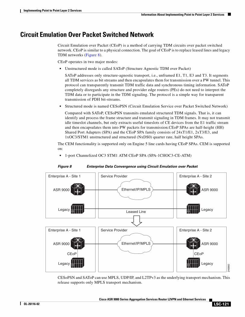
Implementing Point to Point Layer 2 ServicesInformation About Implementing Point to Point Layer 2 Services
LSC-121Cisco ASR 9000 Series Aggregation Services Router L2VPN and Ethernet Services
OL-26116-02
Circuit Emulation Over Packet Switched NetworkCircuit Emulation over Packet (CEoP) is a method of carrying TDM circuits over packet switched network. CEoP is similar to a physical connection. The goal of CEoP is to replace leased lines and legacy TDM networks (Figure 8).
CEoP operates in two major modes:
• Unstructured mode is called SAToP (Structure Agnostic TDM over Packet)
SAToP addresses only structure-agnostic transport, i.e., unframed E1, T1, E3 and T3. It segments all TDM services as bit streams and then encapsulates them for transmission over a PW tunnel. This protocol can transparently transmit TDM traffic data and synchronous timing information. SAToP completely disregards any structure and provider edge routers (PEs) do not need to interpret the TDM data or to participate in the TDM signaling. The protocol is a simple way for transparent transmission of PDH bit-streams.
• Structured mode is named CESoPSN (Circuit Emulation Service over Packet Switched Network)
Compared with SAToP, CESoPSN transmits emulated structured TDM signals. That is, it can identify and process the frame structure and transmit signaling in TDM frames. It may not transmit idle timeslot channels, but only extracts useful timeslots of CE devices from the E1 traffic stream and then encapsulates them into PW packets for transmission.CEoP SPAs are half-height (HH) Shared Port Adapters (SPA) and the CEoP SPA family consists of 24xT1/E1, 2xT3/E3, and 1xOC3/STM1 unstructured and structured (NxDS0) quarter rate, half height SPAs.
The CEM functionality is supported only on Engine 5 line cards having CEoP SPAs. CEM is supported on:
• 1-port Channelized OC3 STM1 ATM CEoP SPA (SPA-1CHOC3-CE-ATM)
Figure 8 Enterprise Data Convergence using Circuit Emulation over Packet
CESoPSN and SAToP can use MPLS, UDP/IP, and L2TPv3 as the underlying transport mechanism. This release supports only MPLS transport mechanism.
2468
60
Enterprise A - Site 1 Service Provider
Legacy
ASR 9000
Leased Line
Enterprise A - Site 2
Legacy
ASR 9000
Enterprise A - Site 1 Service Provider
Legacy
CEoP CEoP
ASR 9000
Enterprise A - Site 2
Legacy
ASR 9000
Ethernet/IP/MPLS
Ethernet/IP/MPLS
Implementing Point to Point Layer 2 ServicesInformation About Implementing Point to Point Layer 2 Services
LSC-122Cisco ASR 9000 Series Aggregation Services Router L2VPN and Ethernet Services
OL-26116-02
CEoP SPA supports these modes of operation:
• Circuit Emulation Mode (CEM)
• ATM Mode
• IMA Mode
Note Only CEM mode is supported.
Benefits of Circuit Emulation over Packet Switched Network
CEM offers thse benefits to the service provider and end-users:
• Saving cost in installing equipment.
• Saving cost in network operations; as leased lines are expensive, limiting their usage to access only mode saves significant costs.
• Ensuring low maintenance cost because only the core network needs to be maintained.
• Utilizing the core network resources more efficiently with packet switched network, while keeping investment in access network intact.
• Providing cheaper services to the end-user.
Implementing Point to Point Layer 2 ServicesHow to Implement Point to Point Layer 2 Services
LSC-123Cisco ASR 9000 Series Aggregation Services Router L2VPN and Ethernet Services
OL-26116-02
How to Implement Point to Point Layer 2 ServicesThis section describes the tasks required to implement L2VPN:
• Configuring an Interface or Connection for L2VPN, page LSC-123
• Configuring Local Switching, page LSC-126
• Configuring Local Connection Redundancy, page LSC-127
• Configuring Static Point-to-Point Cross-Connects, page LSC-130
• Configuring Dynamic Point-to-Point Cross-Connects, page LSC-132
• Configuring Inter-AS, page LSC-133
• Configuring L2VPN Quality of Service, page LSC-134
• Configuring Multisegment Pseudowire, page LSC-138
• Configuring Pseudowire Redundancy, page LSC-145
• Configuring Preferred Tunnel Path, page LSC-150
• Configuring PW Status OAM, page LSC-152
• Enabling Flow-based Load Balancing, page LSC-153
• Enabling Flow-based Load Balancing for a Pseudowire Class, page LSC-154
• Setting Up Your Multicast Connections, page LSC-157
• Configuring AToM IP Interworking, page LSC-159
• Configuring Circuit Emulation Over Packet Switched Network, page LSC-160
Configuring an Interface or Connection for L2VPNPerform this task to configure an interface or a connection for L2VPN.
SUMMARY STEPS
1. configure
2. interface type interface-path-id
3. l2transport
4. exit
5. interface type interface-path-id
6. endorcommit
7. show interface type interface-id
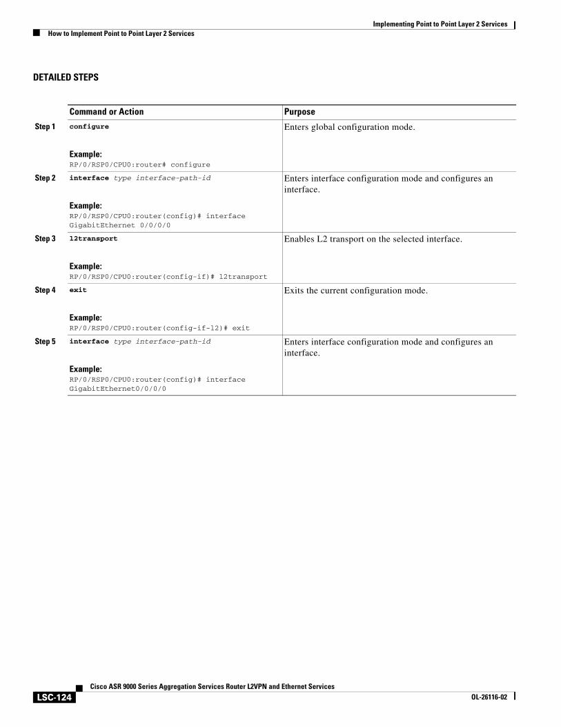
Implementing Point to Point Layer 2 ServicesHow to Implement Point to Point Layer 2 Services
LSC-124Cisco ASR 9000 Series Aggregation Services Router L2VPN and Ethernet Services
OL-26116-02
DETAILED STEPS
Command or Action Purpose
Step 1 configure
Example:RP/0/RSP0/CPU0:router# configure
Enters global configuration mode.
Step 2 interface type interface-path-id
Example:RP/0/RSP0/CPU0:router(config)# interface GigabitEthernet 0/0/0/0
Enters interface configuration mode and configures an interface.
Step 3 l2transport
Example:RP/0/RSP0/CPU0:router(config-if)# l2transport
Enables L2 transport on the selected interface.
Step 4 exit
Example:RP/0/RSP0/CPU0:router(config-if-l2)# exit
Exits the current configuration mode.
Step 5 interface type interface-path-id
Example:RP/0/RSP0/CPU0:router(config)# interface GigabitEthernet0/0/0/0
Enters interface configuration mode and configures an interface.
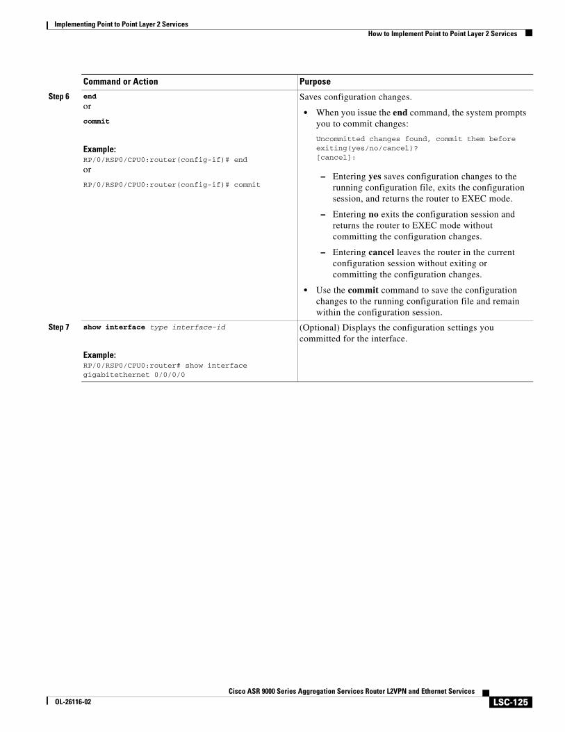
Implementing Point to Point Layer 2 ServicesHow to Implement Point to Point Layer 2 Services
LSC-125Cisco ASR 9000 Series Aggregation Services Router L2VPN and Ethernet Services
OL-26116-02
Step 6 end
or
commit
Example:RP/0/RSP0/CPU0:router(config-if)# end
or
RP/0/RSP0/CPU0:router(config-if)# commit
Saves configuration changes.
• When you issue the end command, the system prompts you to commit changes:
Uncommitted changes found, commit them before exiting(yes/no/cancel)?[cancel]:
– Entering yes saves configuration changes to the running configuration file, exits the configuration session, and returns the router to EXEC mode.
– Entering no exits the configuration session and returns the router to EXEC mode without committing the configuration changes.
– Entering cancel leaves the router in the current configuration session without exiting or committing the configuration changes.
• Use the commit command to save the configuration changes to the running configuration file and remain within the configuration session.
Step 7 show interface type interface-id
Example:RP/0/RSP0/CPU0:router# show interface gigabitethernet 0/0/0/0
(Optional) Displays the configuration settings you committed for the interface.
Command or Action Purpose
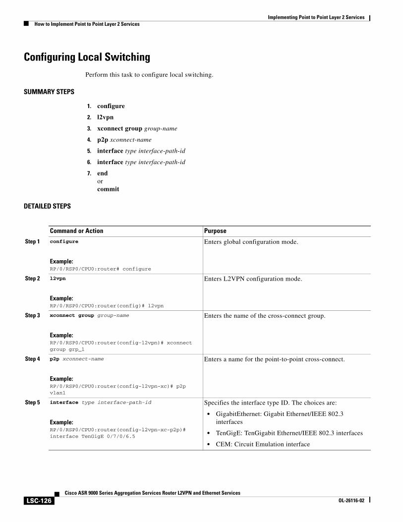
Implementing Point to Point Layer 2 ServicesHow to Implement Point to Point Layer 2 Services
LSC-126Cisco ASR 9000 Series Aggregation Services Router L2VPN and Ethernet Services
OL-26116-02
Configuring Local SwitchingPerform this task to configure local switching.
SUMMARY STEPS
1. configure
2. l2vpn
3. xconnect group group-name
4. p2p xconnect-name
5. interface type interface-path-id
6. interface type interface-path-id
7. endorcommit
DETAILED STEPS
Command or Action Purpose
Step 1 configure
Example:RP/0/RSP0/CPU0:router# configure
Enters global configuration mode.
Step 2 l2vpn
Example:RP/0/RSP0/CPU0:router(config)# l2vpn
Enters L2VPN configuration mode.
Step 3 xconnect group group-name
Example:RP/0/RSP0/CPU0:router(config-l2vpn)# xconnect group grp_1
Enters the name of the cross-connect group.
Step 4 p2p xconnect-name
Example:RP/0/RSP0/CPU0:router(config-l2vpn-xc)# p2p vlan1
Enters a name for the point-to-point cross-connect.
Step 5 interface type interface-path-id
Example:RP/0/RSP0/CPU0:router(config-l2vpn-xc-p2p)# interface TenGigE 0/7/0/6.5
Specifies the interface type ID. The choices are:
• GigabitEthernet: Gigabit Ethernet/IEEE 802.3 interfaces
• TenGigE: TenGigabit Ethernet/IEEE 802.3 interfaces
• CEM: Circuit Emulation interface
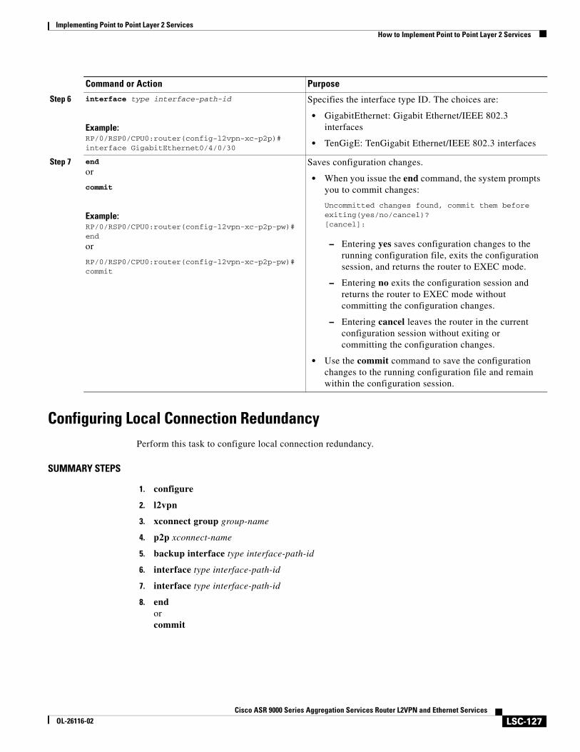
Implementing Point to Point Layer 2 ServicesHow to Implement Point to Point Layer 2 Services
LSC-127Cisco ASR 9000 Series Aggregation Services Router L2VPN and Ethernet Services
OL-26116-02
Configuring Local Connection RedundancyPerform this task to configure local connection redundancy.
SUMMARY STEPS
1. configure
2. l2vpn
3. xconnect group group-name
4. p2p xconnect-name
5. backup interface type interface-path-id
6. interface type interface-path-id
7. interface type interface-path-id
8. endorcommit
Step 6 interface type interface-path-id
Example:RP/0/RSP0/CPU0:router(config-l2vpn-xc-p2p)# interface GigabitEthernet0/4/0/30
Specifies the interface type ID. The choices are:
• GigabitEthernet: Gigabit Ethernet/IEEE 802.3 interfaces
• TenGigE: TenGigabit Ethernet/IEEE 802.3 interfaces
Step 7 end
or
commit
Example:RP/0/RSP0/CPU0:router(config-l2vpn-xc-p2p-pw)#end
or
RP/0/RSP0/CPU0:router(config-l2vpn-xc-p2p-pw)# commit
Saves configuration changes.
• When you issue the end command, the system prompts you to commit changes:
Uncommitted changes found, commit them before exiting(yes/no/cancel)?[cancel]:
– Entering yes saves configuration changes to the running configuration file, exits the configuration session, and returns the router to EXEC mode.
– Entering no exits the configuration session and returns the router to EXEC mode without committing the configuration changes.
– Entering cancel leaves the router in the current configuration session without exiting or committing the configuration changes.
• Use the commit command to save the configuration changes to the running configuration file and remain within the configuration session.
Command or Action Purpose
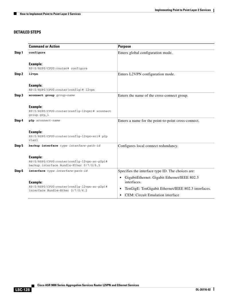
Implementing Point to Point Layer 2 ServicesHow to Implement Point to Point Layer 2 Services
LSC-128Cisco ASR 9000 Series Aggregation Services Router L2VPN and Ethernet Services
OL-26116-02
DETAILED STEPS
Command or Action Purpose
Step 1 configure
Example:RP/0/RSP0/CPU0:router# configure
Enters global configuration mode.
Step 2 l2vpn
Example:RP/0/RSP0/CPU0:router(config)# l2vpn
Enters L2VPN configuration mode.
Step 3 xconnect group group-name
Example:RP/0/RSP0/CPU0:router(config-l2vpn)# xconnect group grp_1
Enters the name of the cross-connect group.
Step 4 p2p xconnect-name
Example:RP/0/RSP0/CPU0:router(config-l2vpn-xc)# p2p vlan1
Enters a name for the point-to-point cross-connect.
Step 5 backup interface type interface-path-id
Example:RP/0/RSP0/CPU0:router(config-l2vpn-xc-p2p)# backup interface Bundle-Ether 0/7/0/6.5
Configures local connect redundancy.
Step 6 interface type interface-path-id
Example:RP/0/RSP0/CPU0:router(config-l2vpn-xc-p2p)# interface Bundle-Ether 0/7/0/6.2
Specifies the interface type ID. The choices are:
• GigabitEthernet: Gigabit Ethernet/IEEE 802.3 interfaces.
• TenGigE: TenGigabit Ethernet/IEEE 802.3 interfaces.
• CEM: Circuit Emulation interface
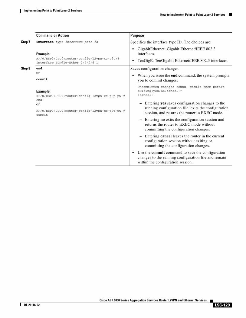
Implementing Point to Point Layer 2 ServicesHow to Implement Point to Point Layer 2 Services
LSC-129Cisco ASR 9000 Series Aggregation Services Router L2VPN and Ethernet Services
OL-26116-02
Step 7 interface type interface-path-id
Example:RP/0/RSP0/CPU0:router(config-l2vpn-xc-p2p)# interface Bundle-Ether 0/7/0/6.1
Specifies the interface type ID. The choices are:
• GigabitEthernet: Gigabit Ethernet/IEEE 802.3 interfaces.
• TenGigE: TenGigabit Ethernet/IEEE 802.3 interfaces.
Step 8 end
or
commit
Example:RP/0/RSP0/CPU0:router(config-l2vpn-xc-p2p-pw)#end
or
RP/0/RSP0/CPU0:router(config-l2vpn-xc-p2p-pw)# commit
Saves configuration changes.
• When you issue the end command, the system prompts you to commit changes:
Uncommitted changes found, commit them before exiting(yes/no/cancel)?[cancel]:
– Entering yes saves configuration changes to the running configuration file, exits the configuration session, and returns the router to EXEC mode.
– Entering no exits the configuration session and returns the router to EXEC mode without committing the configuration changes.
– Entering cancel leaves the router in the current configuration session without exiting or committing the configuration changes.
• Use the commit command to save the configuration changes to the running configuration file and remain within the configuration session.
Command or Action Purpose
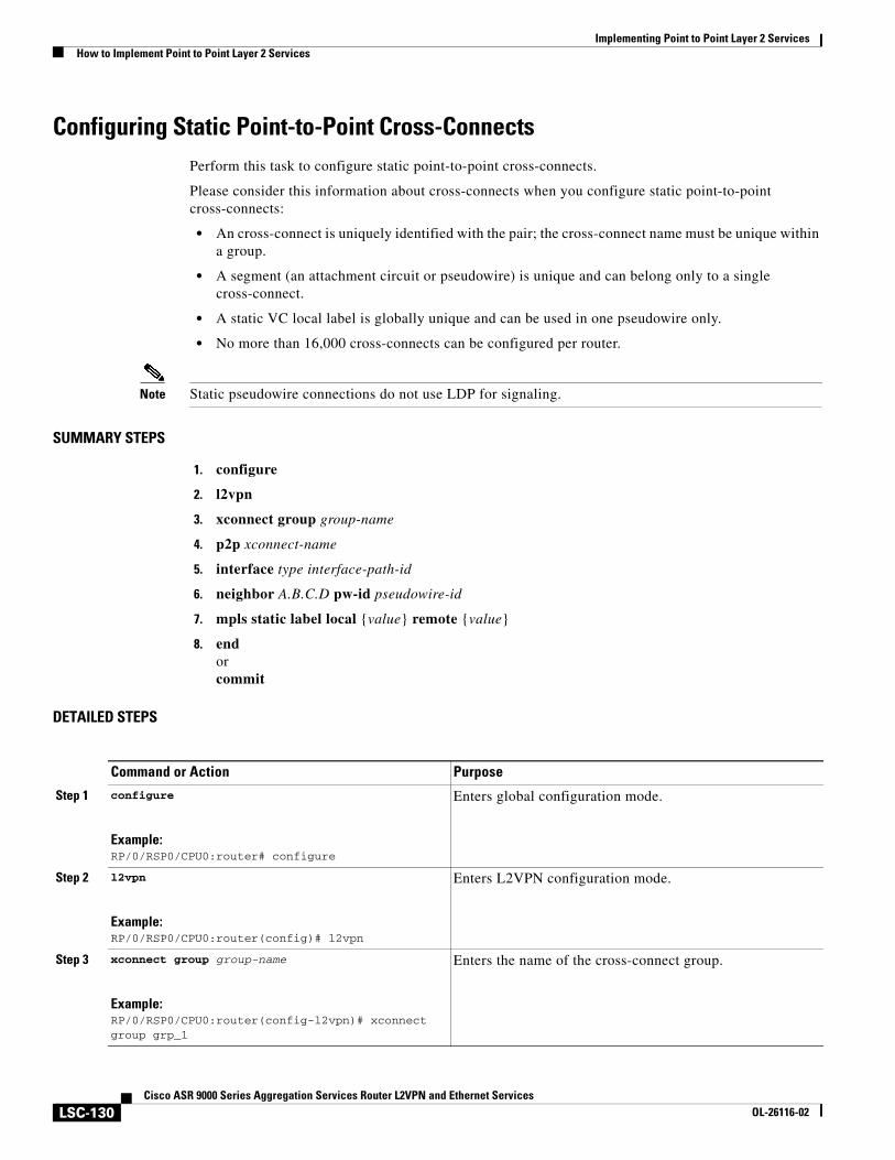
Implementing Point to Point Layer 2 ServicesHow to Implement Point to Point Layer 2 Services
LSC-130Cisco ASR 9000 Series Aggregation Services Router L2VPN and Ethernet Services
OL-26116-02
Configuring Static Point-to-Point Cross-ConnectsPerform this task to configure static point-to-point cross-connects.
Please consider this information about cross-connects when you configure static point-to-point cross-connects:
• An cross-connect is uniquely identified with the pair; the cross-connect name must be unique within a group.
• A segment (an attachment circuit or pseudowire) is unique and can belong only to a single cross-connect.
• A static VC local label is globally unique and can be used in one pseudowire only.
• No more than 16,000 cross-connects can be configured per router.
Note Static pseudowire connections do not use LDP for signaling.
SUMMARY STEPS
1. configure
2. l2vpn
3. xconnect group group-name
4. p2p xconnect-name
5. interface type interface-path-id
6. neighbor A.B.C.D pw-id pseudowire-id
7. mpls static label local {value} remote {value}
8. endorcommit
DETAILED STEPS
Command or Action Purpose
Step 1 configure
Example:RP/0/RSP0/CPU0:router# configure
Enters global configuration mode.
Step 2 l2vpn
Example:RP/0/RSP0/CPU0:router(config)# l2vpn
Enters L2VPN configuration mode.
Step 3 xconnect group group-name
Example:RP/0/RSP0/CPU0:router(config-l2vpn)# xconnect group grp_1
Enters the name of the cross-connect group.
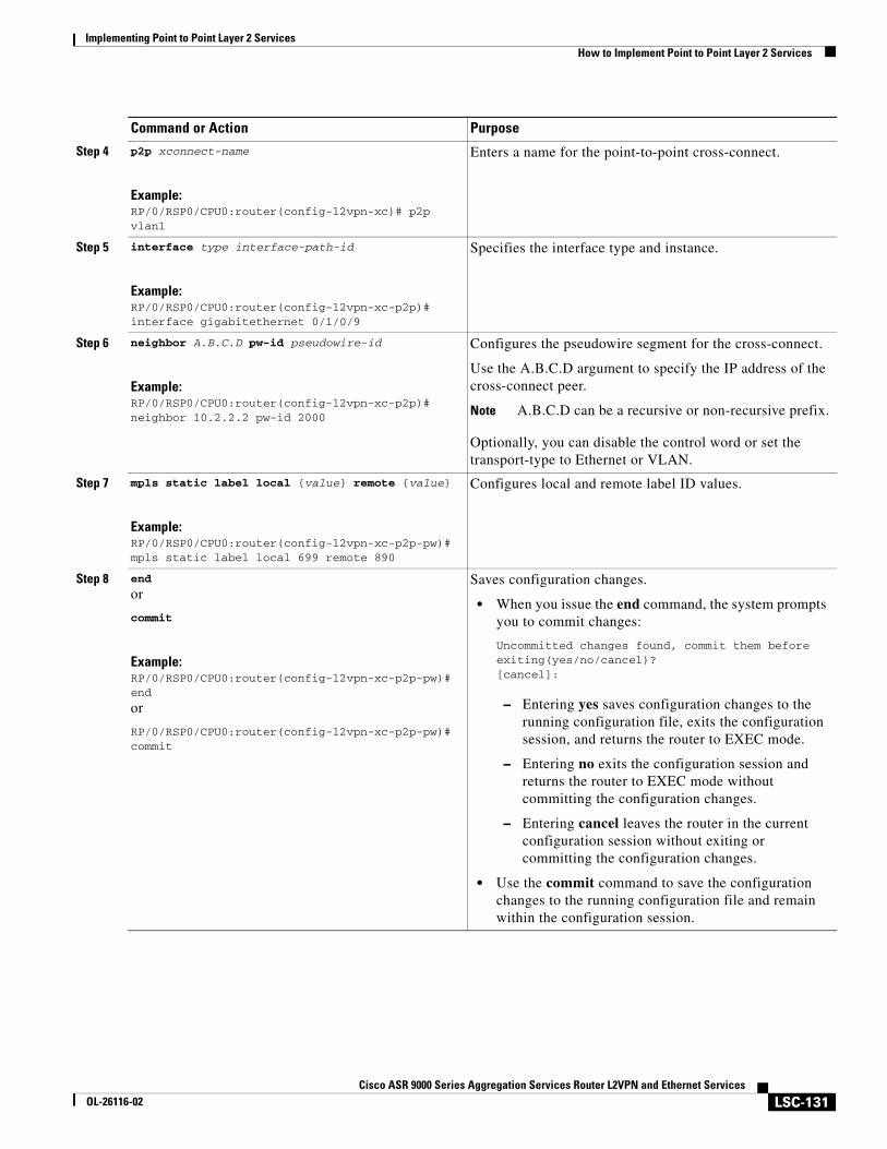
Implementing Point to Point Layer 2 ServicesHow to Implement Point to Point Layer 2 Services
LSC-131Cisco ASR 9000 Series Aggregation Services Router L2VPN and Ethernet Services
OL-26116-02
Step 4 p2p xconnect-name
Example:RP/0/RSP0/CPU0:router(config-l2vpn-xc)# p2p vlan1
Enters a name for the point-to-point cross-connect.
Step 5 interface type interface-path-id
Example:RP/0/RSP0/CPU0:router(config-l2vpn-xc-p2p)# interface gigabitethernet 0/1/0/9
Specifies the interface type and instance.
Step 6 neighbor A.B.C.D pw-id pseudowire-id
Example:RP/0/RSP0/CPU0:router(config-l2vpn-xc-p2p)# neighbor 10.2.2.2 pw-id 2000
Configures the pseudowire segment for the cross-connect.
Use the A.B.C.D argument to specify the IP address of the cross-connect peer.
Note A.B.C.D can be a recursive or non-recursive prefix.
Optionally, you can disable the control word or set the transport-type to Ethernet or VLAN.
Step 7 mpls static label local {value} remote {value}
Example:RP/0/RSP0/CPU0:router(config-l2vpn-xc-p2p-pw)# mpls static label local 699 remote 890
Configures local and remote label ID values.
Step 8 end
or
commit
Example:RP/0/RSP0/CPU0:router(config-l2vpn-xc-p2p-pw)#end
or
RP/0/RSP0/CPU0:router(config-l2vpn-xc-p2p-pw)# commit
Saves configuration changes.
• When you issue the end command, the system prompts you to commit changes:
Uncommitted changes found, commit them before exiting(yes/no/cancel)?[cancel]:
– Entering yes saves configuration changes to the running configuration file, exits the configuration session, and returns the router to EXEC mode.
– Entering no exits the configuration session and returns the router to EXEC mode without committing the configuration changes.
– Entering cancel leaves the router in the current configuration session without exiting or committing the configuration changes.
• Use the commit command to save the configuration changes to the running configuration file and remain within the configuration session.
Command or Action Purpose
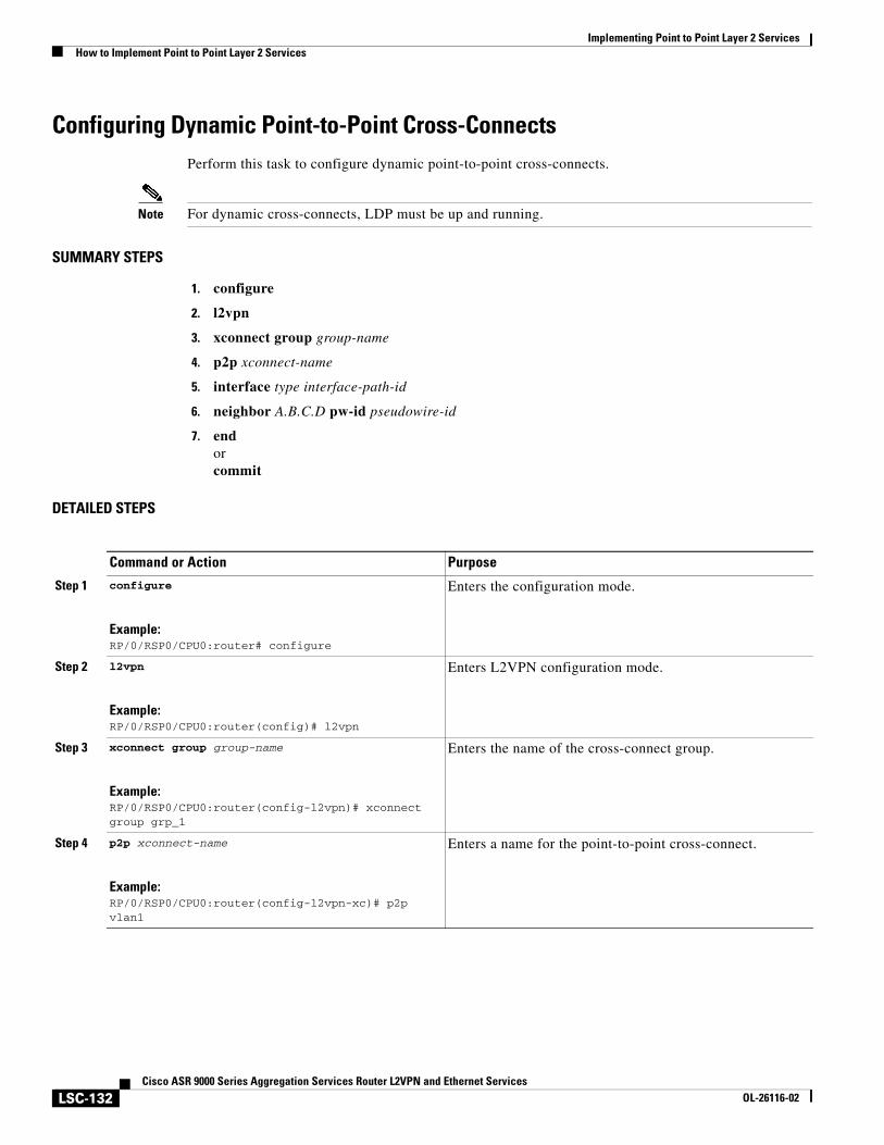
Implementing Point to Point Layer 2 ServicesHow to Implement Point to Point Layer 2 Services
LSC-132Cisco ASR 9000 Series Aggregation Services Router L2VPN and Ethernet Services
OL-26116-02
Configuring Dynamic Point-to-Point Cross-ConnectsPerform this task to configure dynamic point-to-point cross-connects.
Note For dynamic cross-connects, LDP must be up and running.
SUMMARY STEPS
1. configure
2. l2vpn
3. xconnect group group-name
4. p2p xconnect-name
5. interface type interface-path-id
6. neighbor A.B.C.D pw-id pseudowire-id
7. endorcommit
DETAILED STEPS
Command or Action Purpose
Step 1 configure
Example:RP/0/RSP0/CPU0:router# configure
Enters the configuration mode.
Step 2 l2vpn
Example:RP/0/RSP0/CPU0:router(config)# l2vpn
Enters L2VPN configuration mode.
Step 3 xconnect group group-name
Example:RP/0/RSP0/CPU0:router(config-l2vpn)# xconnect group grp_1
Enters the name of the cross-connect group.
Step 4 p2p xconnect-name
Example:RP/0/RSP0/CPU0:router(config-l2vpn-xc)# p2p vlan1
Enters a name for the point-to-point cross-connect.
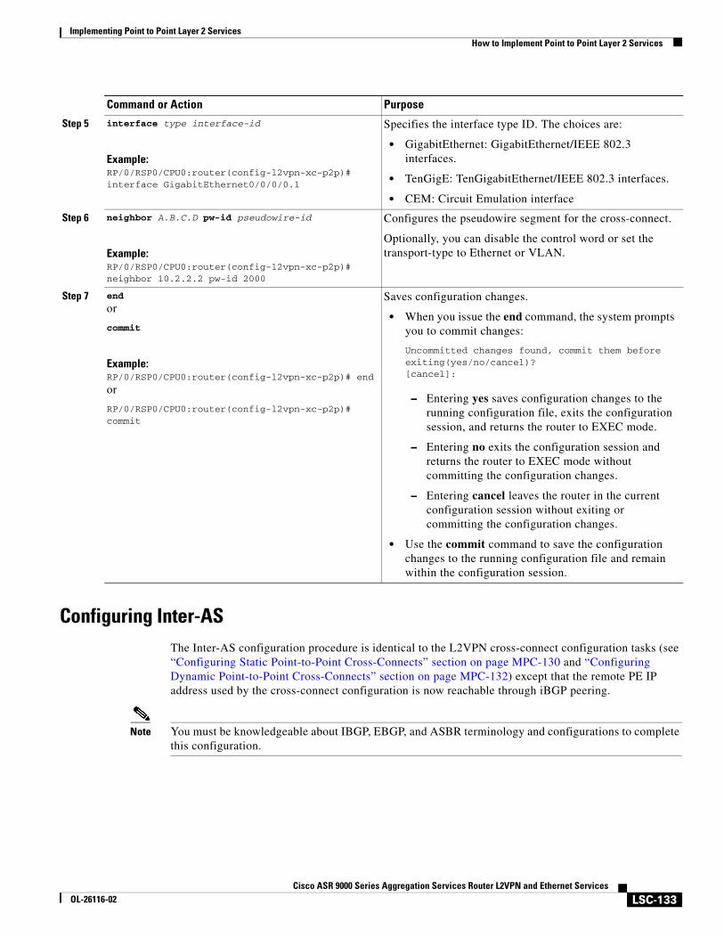
Implementing Point to Point Layer 2 ServicesHow to Implement Point to Point Layer 2 Services
LSC-133Cisco ASR 9000 Series Aggregation Services Router L2VPN and Ethernet Services
OL-26116-02
Configuring Inter-ASThe Inter-AS configuration procedure is identical to the L2VPN cross-connect configuration tasks (see “Configuring Static Point-to-Point Cross-Connects” section on page MPC-130 and “Configuring Dynamic Point-to-Point Cross-Connects” section on page MPC-132) except that the remote PE IP address used by the cross-connect configuration is now reachable through iBGP peering.
Note You must be knowledgeable about IBGP, EBGP, and ASBR terminology and configurations to complete this configuration.
Step 5 interface type interface-id
Example:RP/0/RSP0/CPU0:router(config-l2vpn-xc-p2p)# interface GigabitEthernet0/0/0/0.1
Specifies the interface type ID. The choices are:
• GigabitEthernet: GigabitEthernet/IEEE 802.3 interfaces.
• TenGigE: TenGigabitEthernet/IEEE 802.3 interfaces.
• CEM: Circuit Emulation interface
Step 6 neighbor A.B.C.D pw-id pseudowire-id
Example:RP/0/RSP0/CPU0:router(config-l2vpn-xc-p2p)# neighbor 10.2.2.2 pw-id 2000
Configures the pseudowire segment for the cross-connect.
Optionally, you can disable the control word or set the transport-type to Ethernet or VLAN.
Step 7 end
or
commit
Example:RP/0/RSP0/CPU0:router(config-l2vpn-xc-p2p)# end
or
RP/0/RSP0/CPU0:router(config-l2vpn-xc-p2p)# commit
Saves configuration changes.
• When you issue the end command, the system prompts you to commit changes:
Uncommitted changes found, commit them before exiting(yes/no/cancel)?[cancel]:
– Entering yes saves configuration changes to the running configuration file, exits the configuration session, and returns the router to EXEC mode.
– Entering no exits the configuration session and returns the router to EXEC mode without committing the configuration changes.
– Entering cancel leaves the router in the current configuration session without exiting or committing the configuration changes.
• Use the commit command to save the configuration changes to the running configuration file and remain within the configuration session.
Command or Action Purpose
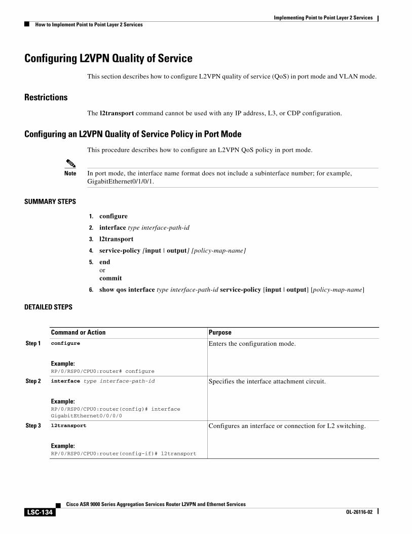
Implementing Point to Point Layer 2 ServicesHow to Implement Point to Point Layer 2 Services
LSC-134Cisco ASR 9000 Series Aggregation Services Router L2VPN and Ethernet Services
OL-26116-02
Configuring L2VPN Quality of Service This section describes how to configure L2VPN quality of service (QoS) in port mode and VLAN mode.
Restrictions
The l2transport command cannot be used with any IP address, L3, or CDP configuration.
Configuring an L2VPN Quality of Service Policy in Port Mode
This procedure describes how to configure an L2VPN QoS policy in port mode.
Note In port mode, the interface name format does not include a subinterface number; for example, GigabitEthernet0/1/0/1.
SUMMARY STEPS
1. configure
2. interface type interface-path-id
3. l2transport
4. service-policy [input | output] [policy-map-name]
5. endorcommit
6. show qos interface type interface-path-id service-policy [input | output] [policy-map-name]
DETAILED STEPS
Command or Action Purpose
Step 1 configure
Example:RP/0/RSP0/CPU0:router# configure
Enters the configuration mode.
Step 2 interface type interface-path-id
Example:RP/0/RSP0/CPU0:router(config)# interface GigabitEthernet0/0/0/0
Specifies the interface attachment circuit.
Step 3 l2transport
Example:RP/0/RSP0/CPU0:router(config-if)# l2transport
Configures an interface or connection for L2 switching.
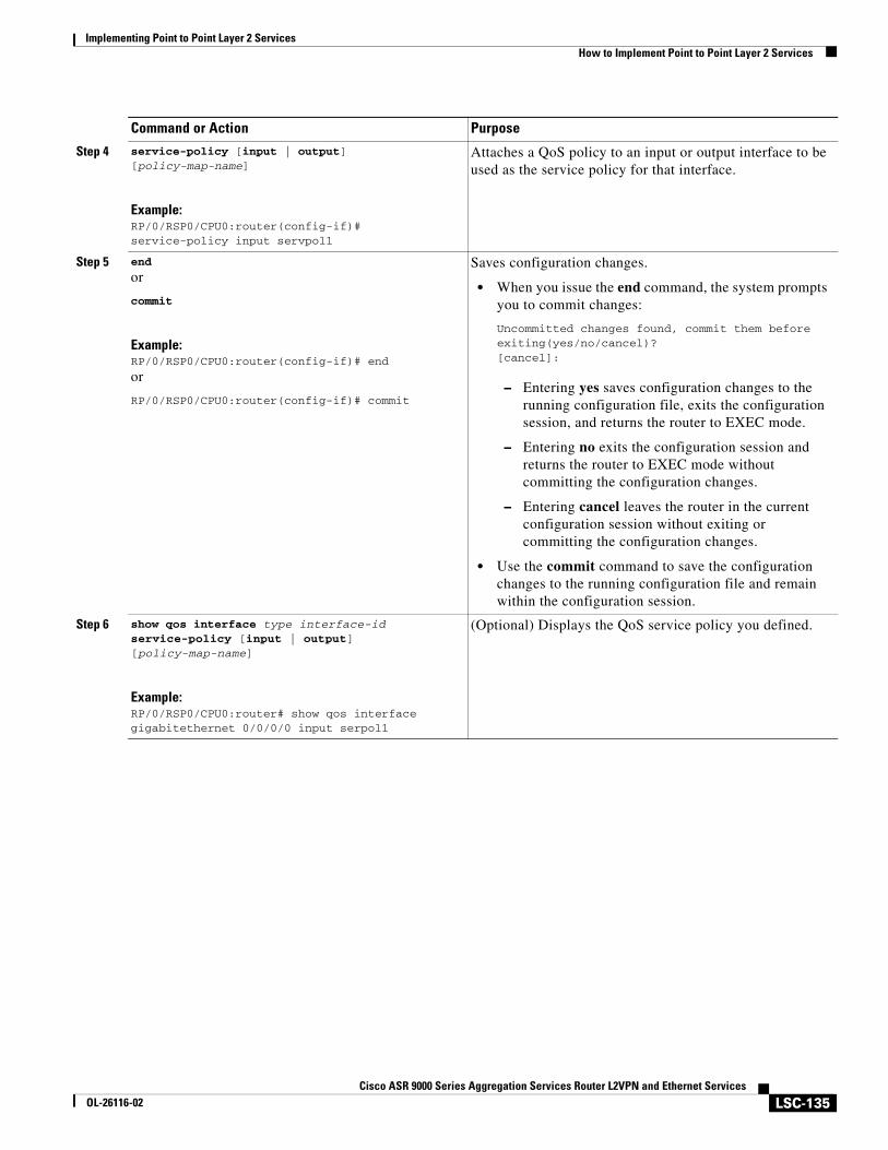
Implementing Point to Point Layer 2 ServicesHow to Implement Point to Point Layer 2 Services
LSC-135Cisco ASR 9000 Series Aggregation Services Router L2VPN and Ethernet Services
OL-26116-02
Step 4 service-policy [input | output] [policy-map-name]
Example:RP/0/RSP0/CPU0:router(config-if)# service-policy input servpol1
Attaches a QoS policy to an input or output interface to be used as the service policy for that interface.
Step 5 end
or
commit
Example:RP/0/RSP0/CPU0:router(config-if)# end
or
RP/0/RSP0/CPU0:router(config-if)# commit
Saves configuration changes.
• When you issue the end command, the system prompts you to commit changes:
Uncommitted changes found, commit them before exiting(yes/no/cancel)?[cancel]:
– Entering yes saves configuration changes to the running configuration file, exits the configuration session, and returns the router to EXEC mode.
– Entering no exits the configuration session and returns the router to EXEC mode without committing the configuration changes.
– Entering cancel leaves the router in the current configuration session without exiting or committing the configuration changes.
• Use the commit command to save the configuration changes to the running configuration file and remain within the configuration session.
Step 6 show qos interface type interface-id service-policy [input | output] [policy-map-name]
Example:RP/0/RSP0/CPU0:router# show qos interface gigabitethernet 0/0/0/0 input serpol1
(Optional) Displays the QoS service policy you defined.
Command or Action Purpose
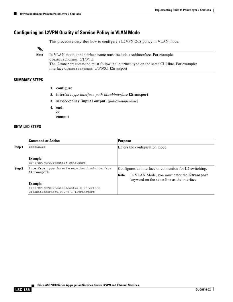
Implementing Point to Point Layer 2 ServicesHow to Implement Point to Point Layer 2 Services
LSC-136Cisco ASR 9000 Series Aggregation Services Router L2VPN and Ethernet Services
OL-26116-02
Configuring an L2VPN Quality of Service Policy in VLAN Mode
This procedure describes how to configure a L2VPN QoS policy in VLAN mode.
Note In VLAN mode, the interface name must include a subinterface. For example: GigabitEthernet 0/1/0/1.1 The l2transport command must follow the interface type on the same CLI line. For example:interface GigabitEthernet 0/0/0/0.1 l2transport
SUMMARY STEPS
1. configure
2. interface type interface-path-id.subinterface l2transport
3. service-policy [input | output] [policy-map-name]
4. endorcommit
DETAILED STEPS
Command or Action Purpose
Step 1 configure
Example:RP/0/RP0/CPU0:router# configure
Enters the configuration mode.
Step 2 interface type interface-path-id.subinterface l2transport
Example:RP/0/RP0/CPU0:router(config)# interface GigabitEthernet0/0/0/0.1 l2transport
Configures an interface or connection for L2 switching.
Note In VLAN Mode, you must enter the l2transport keyword on the same line as the interface.
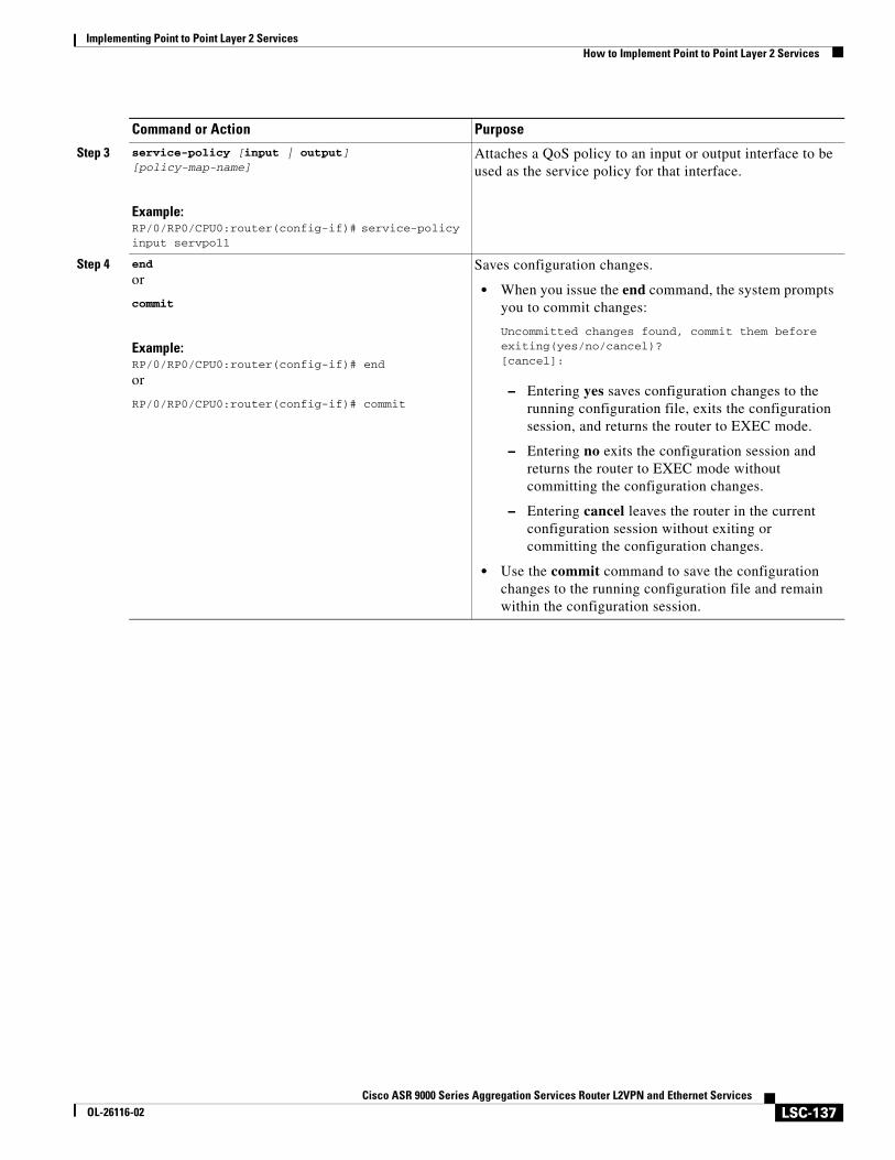
Implementing Point to Point Layer 2 ServicesHow to Implement Point to Point Layer 2 Services
LSC-137Cisco ASR 9000 Series Aggregation Services Router L2VPN and Ethernet Services
OL-26116-02
Step 3 service-policy [input | output] [policy-map-name]
Example:RP/0/RP0/CPU0:router(config-if)# service-policy input servpol1
Attaches a QoS policy to an input or output interface to be used as the service policy for that interface.
Step 4 end
or
commit
Example:RP/0/RP0/CPU0:router(config-if)# end
or
RP/0/RP0/CPU0:router(config-if)# commit
Saves configuration changes.
• When you issue the end command, the system prompts you to commit changes:
Uncommitted changes found, commit them before exiting(yes/no/cancel)?[cancel]:
– Entering yes saves configuration changes to the running configuration file, exits the configuration session, and returns the router to EXEC mode.
– Entering no exits the configuration session and returns the router to EXEC mode without committing the configuration changes.
– Entering cancel leaves the router in the current configuration session without exiting or committing the configuration changes.
• Use the commit command to save the configuration changes to the running configuration file and remain within the configuration session.
Command or Action Purpose
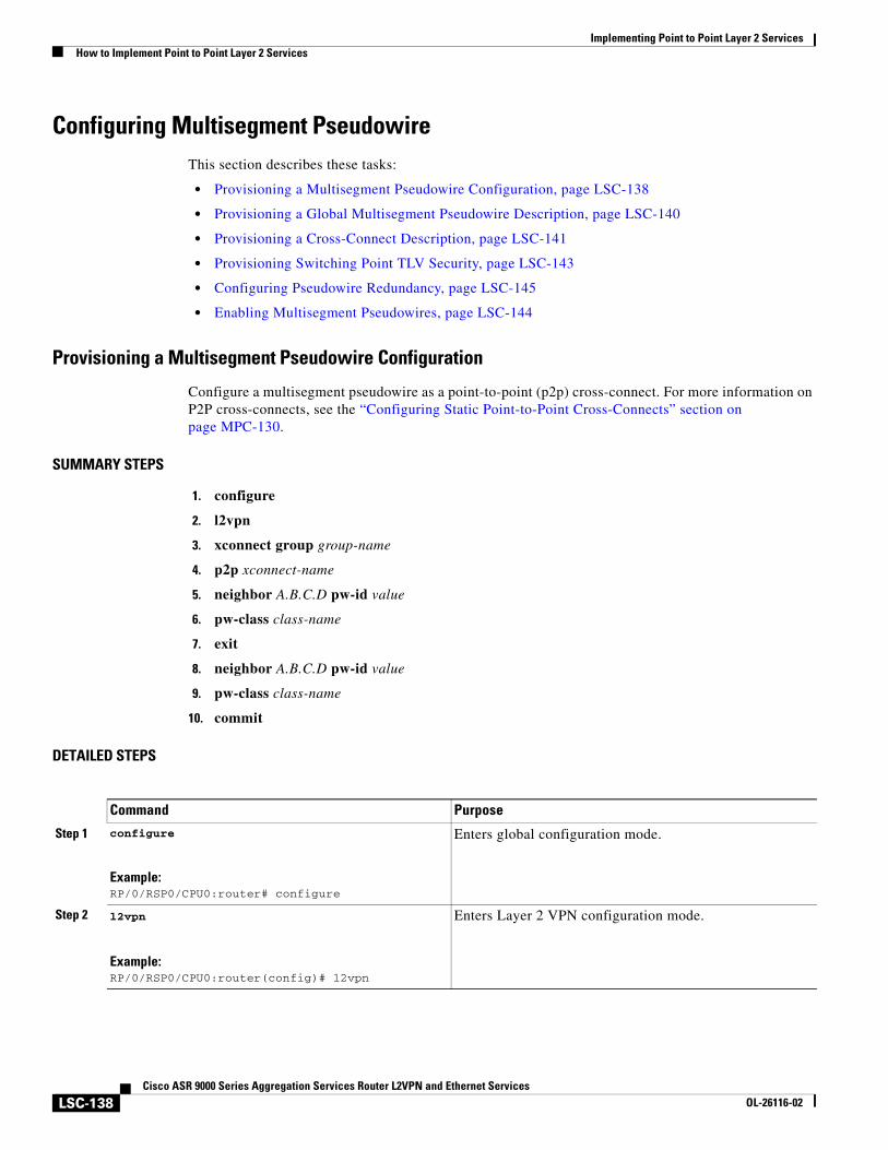
Implementing Point to Point Layer 2 ServicesHow to Implement Point to Point Layer 2 Services
LSC-138Cisco ASR 9000 Series Aggregation Services Router L2VPN and Ethernet Services
OL-26116-02
Configuring Multisegment PseudowireThis section describes these tasks:
• Provisioning a Multisegment Pseudowire Configuration, page LSC-138
• Provisioning a Global Multisegment Pseudowire Description, page LSC-140
• Provisioning a Cross-Connect Description, page LSC-141
• Provisioning Switching Point TLV Security, page LSC-143
• Configuring Pseudowire Redundancy, page LSC-145
• Enabling Multisegment Pseudowires, page LSC-144
Provisioning a Multisegment Pseudowire Configuration
Configure a multisegment pseudowire as a point-to-point (p2p) cross-connect. For more information on P2P cross-connects, see the “Configuring Static Point-to-Point Cross-Connects” section on page MPC-130.
SUMMARY STEPS
1. configure
2. l2vpn
3. xconnect group group-name
4. p2p xconnect-name
5. neighbor A.B.C.D pw-id value
6. pw-class class-name
7. exit
8. neighbor A.B.C.D pw-id value
9. pw-class class-name
10. commit
DETAILED STEPS
Command Purpose
Step 1 configure
Example:RP/0/RSP0/CPU0:router# configure
Enters global configuration mode.
Step 2 l2vpn
Example:RP/0/RSP0/CPU0:router(config)# l2vpn
Enters Layer 2 VPN configuration mode.
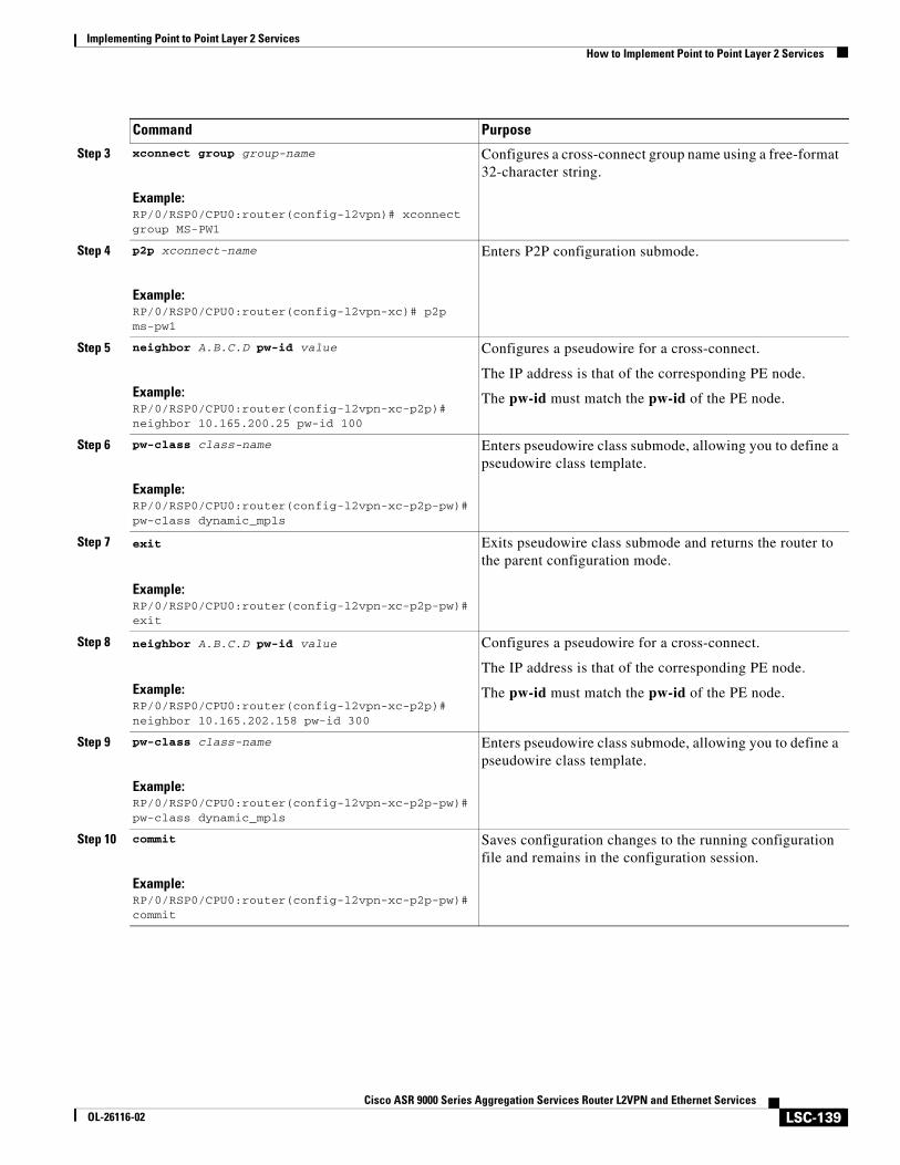
Implementing Point to Point Layer 2 ServicesHow to Implement Point to Point Layer 2 Services
LSC-139Cisco ASR 9000 Series Aggregation Services Router L2VPN and Ethernet Services
OL-26116-02
Step 3 xconnect group group-name
Example:RP/0/RSP0/CPU0:router(config-l2vpn)# xconnect group MS-PW1
Configures a cross-connect group name using a free-format 32-character string.
Step 4 p2p xconnect-name
Example:RP/0/RSP0/CPU0:router(config-l2vpn-xc)# p2p ms-pw1
Enters P2P configuration submode.
Step 5 neighbor A.B.C.D pw-id value
Example:RP/0/RSP0/CPU0:router(config-l2vpn-xc-p2p)# neighbor 10.165.200.25 pw-id 100
Configures a pseudowire for a cross-connect.
The IP address is that of the corresponding PE node.
The pw-id must match the pw-id of the PE node.
Step 6 pw-class class-name
Example:RP/0/RSP0/CPU0:router(config-l2vpn-xc-p2p-pw)# pw-class dynamic_mpls
Enters pseudowire class submode, allowing you to define a pseudowire class template.
Step 7 exit
Example:RP/0/RSP0/CPU0:router(config-l2vpn-xc-p2p-pw)# exit
Exits pseudowire class submode and returns the router to the parent configuration mode.
Step 8 neighbor A.B.C.D pw-id value
Example:RP/0/RSP0/CPU0:router(config-l2vpn-xc-p2p)# neighbor 10.165.202.158 pw-id 300
Configures a pseudowire for a cross-connect.
The IP address is that of the corresponding PE node.
The pw-id must match the pw-id of the PE node.
Step 9 pw-class class-name
Example:RP/0/RSP0/CPU0:router(config-l2vpn-xc-p2p-pw)# pw-class dynamic_mpls
Enters pseudowire class submode, allowing you to define a pseudowire class template.
Step 10 commit
Example:RP/0/RSP0/CPU0:router(config-l2vpn-xc-p2p-pw)# commit
Saves configuration changes to the running configuration file and remains in the configuration session.
Command Purpose
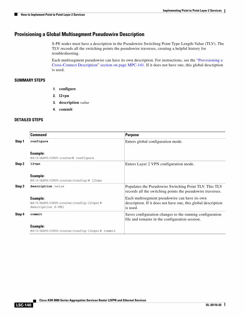
Implementing Point to Point Layer 2 ServicesHow to Implement Point to Point Layer 2 Services
LSC-140Cisco ASR 9000 Series Aggregation Services Router L2VPN and Ethernet Services
OL-26116-02
Provisioning a Global Multisegment Pseudowire Description
S-PE nodes must have a description in the Pseudowire Switching Point Type-Length-Value (TLV). The TLV records all the switching points the pseudowire traverses, creating a helpful history for troubleshooting.
Each multisegment pseudowire can have its own description. For instructions, see the “Provisioning a Cross-Connect Description” section on page MPC-141. If it does not have one, this global description is used.
SUMMARY STEPS
1. configure
2. l2vpn
3. description value
4. commit
DETAILED STEPS
Command Purpose
Step 1 configure
Example:RP/0/RSP0/CPU0:router# configure
Enters global configuration mode.
Step 2 l2vpn
Example:RP/0/RSP0/CPU0:router(config)# l2vpn
Enters Layer 2 VPN configuration mode.
Step 3 description value
Example:RP/0/RSP0/CPU0:router(config-l2vpn)# description S-PE1
Populates the Pseudowire Switching Point TLV. This TLV records all the switching points the pseudowire traverses.
Each multisegment pseudowire can have its own description. If it does not have one, this global description is used.
Step 4 commit
Example:RP/0/RSP0/CPU0:router(config-l2vpn)# commit
Saves configuration changes to the running configuration file and remains in the configuration session.
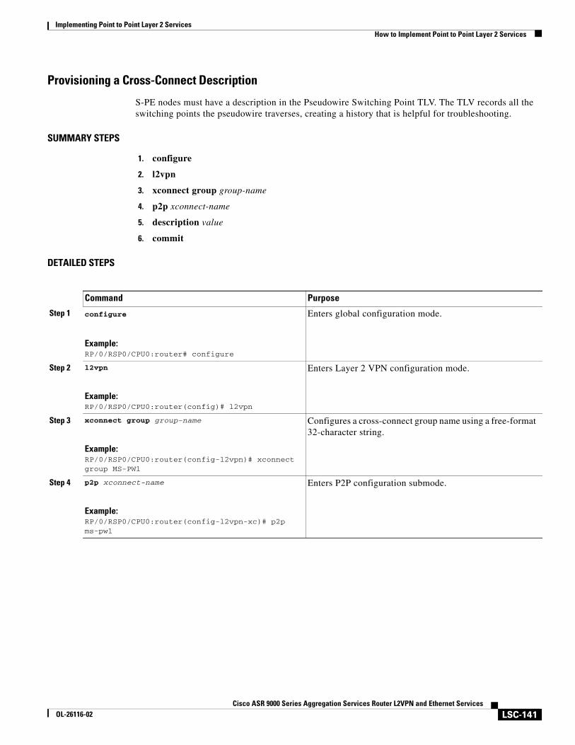
Implementing Point to Point Layer 2 ServicesHow to Implement Point to Point Layer 2 Services
LSC-141Cisco ASR 9000 Series Aggregation Services Router L2VPN and Ethernet Services
OL-26116-02
Provisioning a Cross-Connect Description
S-PE nodes must have a description in the Pseudowire Switching Point TLV. The TLV records all the switching points the pseudowire traverses, creating a history that is helpful for troubleshooting.
SUMMARY STEPS
1. configure
2. l2vpn
3. xconnect group group-name
4. p2p xconnect-name
5. description value
6. commit
DETAILED STEPS
Command Purpose
Step 1 configure
Example:RP/0/RSP0/CPU0:router# configure
Enters global configuration mode.
Step 2 l2vpn
Example:RP/0/RSP0/CPU0:router(config)# l2vpn
Enters Layer 2 VPN configuration mode.
Step 3 xconnect group group-name
Example:RP/0/RSP0/CPU0:router(config-l2vpn)# xconnect group MS-PW1
Configures a cross-connect group name using a free-format 32-character string.
Step 4 p2p xconnect-name
Example:RP/0/RSP0/CPU0:router(config-l2vpn-xc)# p2p ms-pw1
Enters P2P configuration submode.
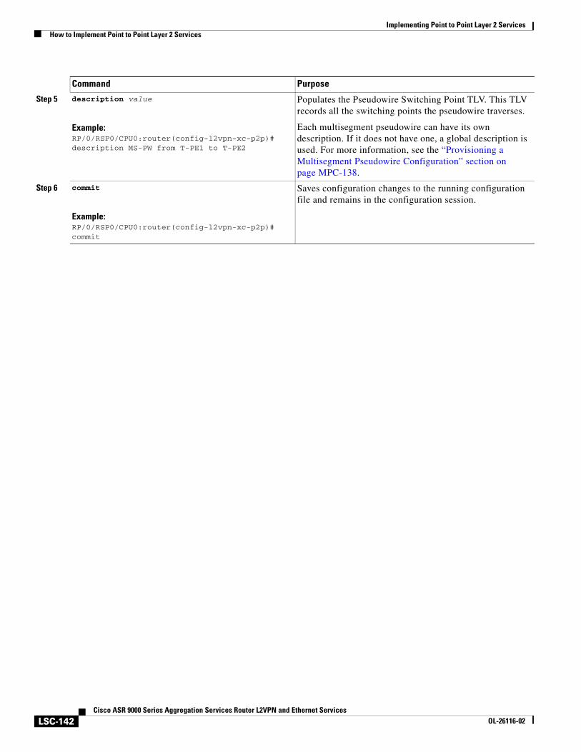
Implementing Point to Point Layer 2 ServicesHow to Implement Point to Point Layer 2 Services
LSC-142Cisco ASR 9000 Series Aggregation Services Router L2VPN and Ethernet Services
OL-26116-02
Step 5 description value
Example:RP/0/RSP0/CPU0:router(config-l2vpn-xc-p2p)# description MS-PW from T-PE1 to T-PE2
Populates the Pseudowire Switching Point TLV. This TLV records all the switching points the pseudowire traverses.
Each multisegment pseudowire can have its own description. If it does not have one, a global description is used. For more information, see the “Provisioning a Multisegment Pseudowire Configuration” section on page MPC-138.
Step 6 commit
Example:RP/0/RSP0/CPU0:router(config-l2vpn-xc-p2p)# commit
Saves configuration changes to the running configuration file and remains in the configuration session.
Command Purpose
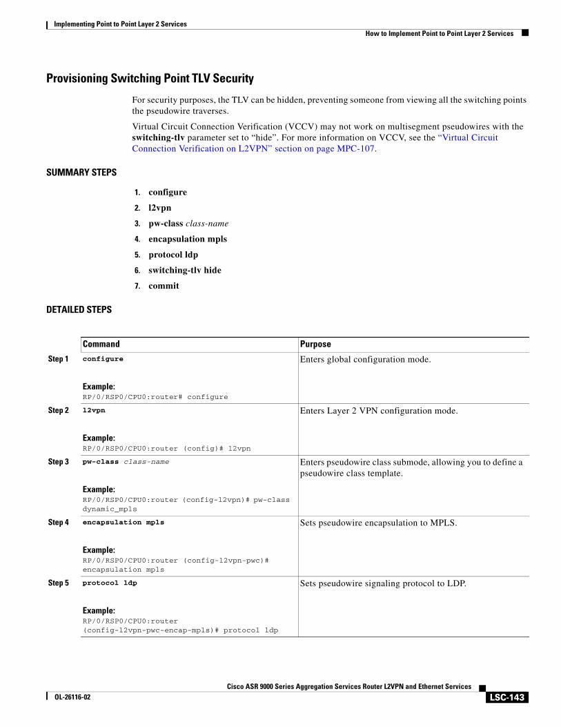
Implementing Point to Point Layer 2 ServicesHow to Implement Point to Point Layer 2 Services
LSC-143Cisco ASR 9000 Series Aggregation Services Router L2VPN and Ethernet Services
OL-26116-02
Provisioning Switching Point TLV Security
For security purposes, the TLV can be hidden, preventing someone from viewing all the switching points the pseudowire traverses.
Virtual Circuit Connection Verification (VCCV) may not work on multisegment pseudowires with the switching-tlv parameter set to “hide”. For more information on VCCV, see the “Virtual Circuit Connection Verification on L2VPN” section on page MPC-107.
SUMMARY STEPS
1. configure
2. l2vpn
3. pw-class class-name
4. encapsulation mpls
5. protocol ldp
6. switching-tlv hide
7. commit
DETAILED STEPS
Command Purpose
Step 1 configure
Example:RP/0/RSP0/CPU0:router# configure
Enters global configuration mode.
Step 2 l2vpn
Example:RP/0/RSP0/CPU0:router (config)# l2vpn
Enters Layer 2 VPN configuration mode.
Step 3 pw-class class-name
Example:RP/0/RSP0/CPU0:router (config-l2vpn)# pw-class dynamic_mpls
Enters pseudowire class submode, allowing you to define a pseudowire class template.
Step 4 encapsulation mpls
Example:RP/0/RSP0/CPU0:router (config-l2vpn-pwc)# encapsulation mpls
Sets pseudowire encapsulation to MPLS.
Step 5 protocol ldp
Example:RP/0/RSP0/CPU0:router (config-l2vpn-pwc-encap-mpls)# protocol ldp
Sets pseudowire signaling protocol to LDP.
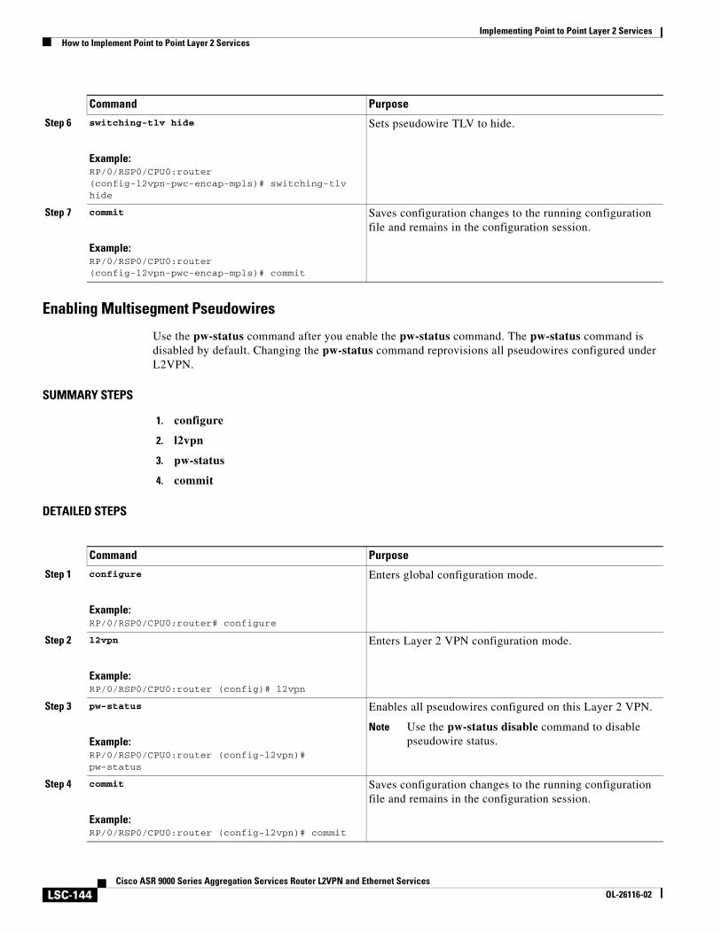
Implementing Point to Point Layer 2 ServicesHow to Implement Point to Point Layer 2 Services
LSC-144Cisco ASR 9000 Series Aggregation Services Router L2VPN and Ethernet Services
OL-26116-02
Enabling Multisegment Pseudowires
Use the pw-status command after you enable the pw-status command. The pw-status command is disabled by default. Changing the pw-status command reprovisions all pseudowires configured under L2VPN.
SUMMARY STEPS
1. configure
2. l2vpn
3. pw-status
4. commit
DETAILED STEPS
Step 6 switching-tlv hide
Example:RP/0/RSP0/CPU0:router (config-l2vpn-pwc-encap-mpls)# switching-tlv hide
Sets pseudowire TLV to hide.
Step 7 commit
Example:RP/0/RSP0/CPU0:router (config-l2vpn-pwc-encap-mpls)# commit
Saves configuration changes to the running configuration file and remains in the configuration session.
Command Purpose
Command Purpose
Step 1 configure
Example:RP/0/RSP0/CPU0:router# configure
Enters global configuration mode.
Step 2 l2vpn
Example:RP/0/RSP0/CPU0:router (config)# l2vpn
Enters Layer 2 VPN configuration mode.
Step 3 pw-status
Example:RP/0/RSP0/CPU0:router (config-l2vpn)# pw-status
Enables all pseudowires configured on this Layer 2 VPN.
Note Use the pw-status disable command to disable pseudowire status.
Step 4 commit
Example:RP/0/RSP0/CPU0:router (config-l2vpn)# commit
Saves configuration changes to the running configuration file and remains in the configuration session.
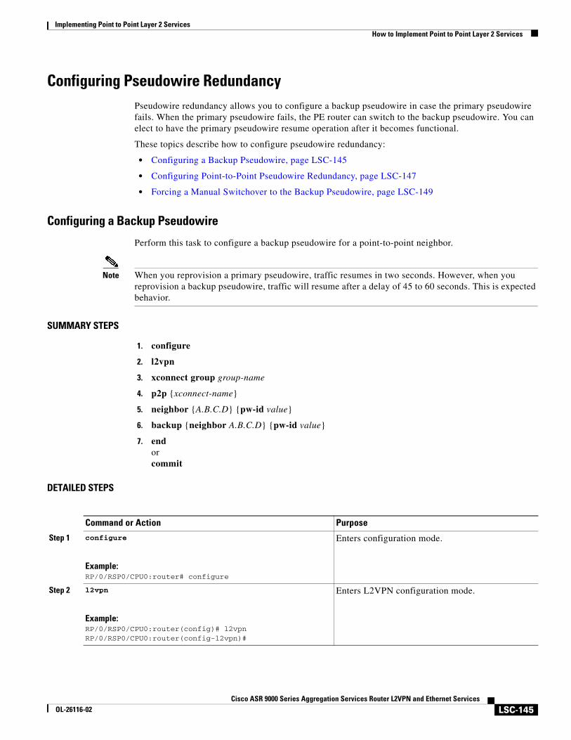
Implementing Point to Point Layer 2 ServicesHow to Implement Point to Point Layer 2 Services
LSC-145Cisco ASR 9000 Series Aggregation Services Router L2VPN and Ethernet Services
OL-26116-02
Configuring Pseudowire RedundancyPseudowire redundancy allows you to configure a backup pseudowire in case the primary pseudowire fails. When the primary pseudowire fails, the PE router can switch to the backup pseudowire. You can elect to have the primary pseudowire resume operation after it becomes functional.
These topics describe how to configure pseudowire redundancy:
• Configuring a Backup Pseudowire, page LSC-145
• Configuring Point-to-Point Pseudowire Redundancy, page LSC-147
• Forcing a Manual Switchover to the Backup Pseudowire, page LSC-149
Configuring a Backup Pseudowire
Perform this task to configure a backup pseudowire for a point-to-point neighbor.
Note When you reprovision a primary pseudowire, traffic resumes in two seconds. However, when you reprovision a backup pseudowire, traffic will resume after a delay of 45 to 60 seconds. This is expected behavior.
SUMMARY STEPS
1. configure
2. l2vpn
3. xconnect group group-name
4. p2p {xconnect-name}
5. neighbor {A.B.C.D} {pw-id value}
6. backup {neighbor A.B.C.D} {pw-id value}
7. endorcommit
DETAILED STEPS
Command or Action Purpose
Step 1 configure
Example:RP/0/RSP0/CPU0:router# configure
Enters configuration mode.
Step 2 l2vpn
Example:RP/0/RSP0/CPU0:router(config)# l2vpnRP/0/RSP0/CPU0:router(config-l2vpn)#
Enters L2VPN configuration mode.
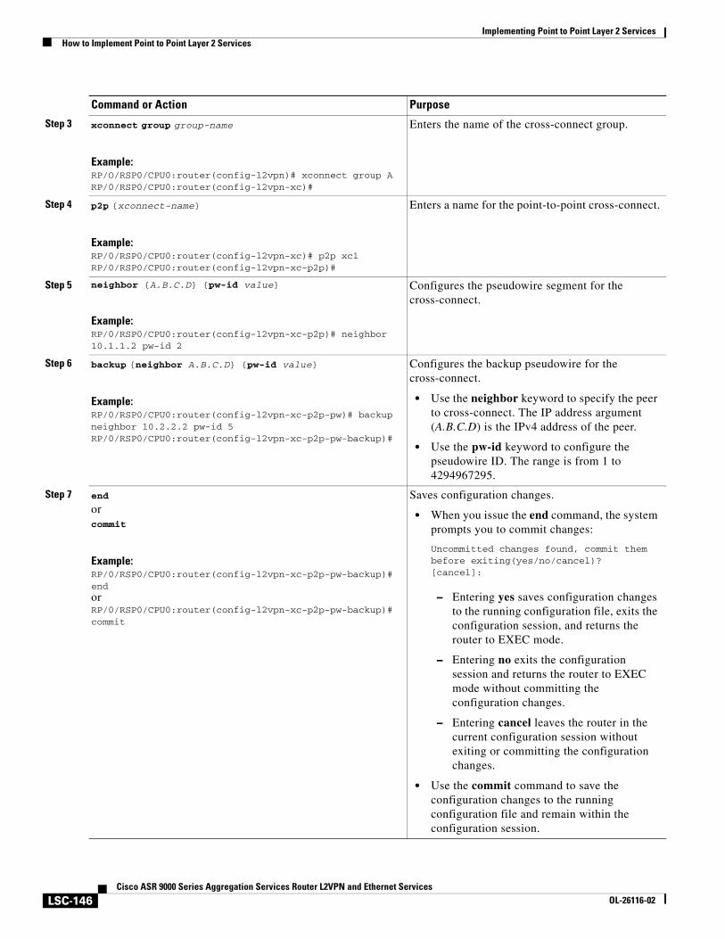
Implementing Point to Point Layer 2 ServicesHow to Implement Point to Point Layer 2 Services
LSC-146Cisco ASR 9000 Series Aggregation Services Router L2VPN and Ethernet Services
OL-26116-02
Step 3 xconnect group group-name
Example:RP/O/RSP0/CPU0:router(config-l2vpn)# xconnect group ARP/0/RSP0/CPU0:router(config-l2vpn-xc)#
Enters the name of the cross-connect group.
Step 4 p2p {xconnect-name}
Example:RP/0/RSP0/CPU0:router(config-l2vpn-xc)# p2p xc1RP/0/RSP0/CPU0:router(config-l2vpn-xc-p2p)#
Enters a name for the point-to-point cross-connect.
Step 5 neighbor {A.B.C.D} {pw-id value}
Example:RP/0/RSP0/CPU0:router(config-l2vpn-xc-p2p)# neighbor 10.1.1.2 pw-id 2
Configures the pseudowire segment for the cross-connect.
Step 6 backup {neighbor A.B.C.D} {pw-id value}
Example:RP/0/RSP0/CPU0:router(config-l2vpn-xc-p2p-pw)# backup neighbor 10.2.2.2 pw-id 5RP/0/RSP0/CPU0:router(config-l2vpn-xc-p2p-pw-backup)#
Configures the backup pseudowire for the cross-connect.
• Use the neighbor keyword to specify the peer to cross-connect. The IP address argument (A.B.C.D) is the IPv4 address of the peer.
• Use the pw-id keyword to configure the pseudowire ID. The range is from 1 to 4294967295.
Step 7 end
orcommit
Example:RP/0/RSP0/CPU0:router(config-l2vpn-xc-p2p-pw-backup)# endorRP/0/RSP0/CPU0:router(config-l2vpn-xc-p2p-pw-backup)# commit
Saves configuration changes.
• When you issue the end command, the system prompts you to commit changes:
Uncommitted changes found, commit them before exiting(yes/no/cancel)?[cancel]:
– Entering yes saves configuration changes to the running configuration file, exits the configuration session, and returns the router to EXEC mode.
– Entering no exits the configuration session and returns the router to EXEC mode without committing the configuration changes.
– Entering cancel leaves the router in the current configuration session without exiting or committing the configuration changes.
• Use the commit command to save the configuration changes to the running configuration file and remain within the configuration session.
Command or Action Purpose
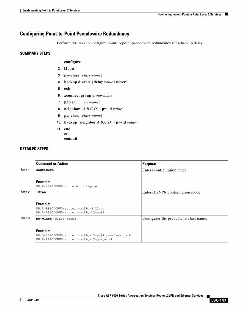
Implementing Point to Point Layer 2 ServicesHow to Implement Point to Point Layer 2 Services
LSC-147Cisco ASR 9000 Series Aggregation Services Router L2VPN and Ethernet Services
OL-26116-02
Configuring Point-to-Point Pseudowire Redundancy
Perform this task to configure point-to-point pseudowire redundancy for a backup delay.
SUMMARY STEPS
1. configure
2. l2vpn
3. pw-class {class-name}
4. backup disable {delay value | never}
5. exit
6. xconnect group group-name
7. p2p {xconnect-name}
8. neighbor {A.B.C.D} {pw-id value}
9. pw-class {class-name}
10. backup {neighbor A.B.C.D} {pw-id value}
11. endorcommit
DETAILED STEPS
Command or Action Purpose
Step 1 configure
Example:RP/0/RSP0/CPU0:router# configure
Enters configuration mode.
Step 2 l2vpn
Example:RP/0/RSP0/CPU0:router(config)# l2vpnRP/0/RSP0/CPU0:router(config-l2vpn)#
Enters L2VPN configuration mode.
Step 3 pw-class {class-name}
Example:RP/O/RSP0/CPU0:router(config-l2vpn)# pw-class path1RP/0/RSP0/CPU0:router(config-l2vpn-pwc)#
Configures the pseudowire class name.
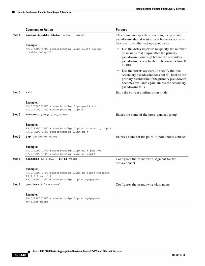
Implementing Point to Point Layer 2 ServicesHow to Implement Point to Point Layer 2 Services
LSC-148Cisco ASR 9000 Series Aggregation Services Router L2VPN and Ethernet Services
OL-26116-02
Step 4 backup disable {delay value | never}
Example:RP/0/RSP0/CPU0:router(config-l2vpn-pwc)# backup disable delay 20
This command specifies how long the primary pseudowire should wait after it becomes active to take over from the backup pseudowire.
• Use the delay keyword to specify the number of seconds that elapse after the primary pseudowire comes up before the secondary pseudowire is deactivated. The range is from 0 to 180.
• Use the never keyword to specify that the secondary pseudowire does not fall back to the primary pseudowire if the primary pseudowire becomes available again, unless the secondary pseudowire fails.
Step 5 exit
Example:RP/0/RSP0/CPU0:router(config-l2vpn-pwc)# exitRP/O/RSP0/CPU0:router(config-l2vpn)#
Exits the current configuration mode.
Step 6 xconnect group group-name
Example:RP/0/RSP0/CPU0:router(config-l2vpn)# xconnect group ARP/0/RSP0/CPU0:router(config-l2vpn-xc)#
Enters the name of the cross-connect group.
Step 7 p2p {xconnect-name}
Example:RP/0/RSP0/CPU0:router(config-l2vpn-xc)# p2p xc1RP/0/RSP0/CPU0:router(config-l2vpn-xc-p2p)#
Enters a name for the point-to-point cross-connect.
Step 8 neighbor {A.B.C.D} {pw-id value}
Example:RP/0/RSP0/CPU0:router(config-l2vpn-xc-p2p)# neighbor 10.1.1.2 pw-id 2RP/0/RSP0/CPU0:router(config-l2vpn-xc-p2p-pw)#
Configures the pseudowire segment for the cross-connect.
Step 9 pw-class {class-name}
Example:RP/0/RSP0/CPU0:router(config-l2vpn-xc-p2p-pw)# pw-class path1
Configures the pseudowire class name.
Command or Action Purpose
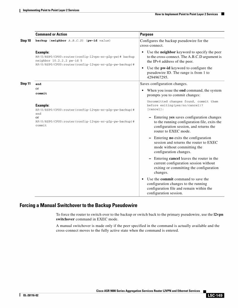
Implementing Point to Point Layer 2 ServicesHow to Implement Point to Point Layer 2 Services
LSC-149Cisco ASR 9000 Series Aggregation Services Router L2VPN and Ethernet Services
OL-26116-02
Forcing a Manual Switchover to the Backup Pseudowire
To force the router to switch over to the backup or switch back to the primary pseudowire, use the l2vpn switchover command in EXEC mode.
A manual switchover is made only if the peer specified in the command is actually available and the cross-connect moves to the fully active state when the command is entered.
Step 10 backup {neighbor A.B.C.D} {pw-id value}
Example:RP/0/RSP0/CPU0:router(config-l2vpn-xc-p2p-pw)# backup neighbor 10.2.2.2 pw-id 5RP/0/RSP0/CPU0:router(config-l2vpn-xc-p2p-pw-backup)#
Configures the backup pseudowire for the cross-connect.
• Use the neighbor keyword to specify the peer to the cross-connect. The A.B.C.D argument is the IPv4 address of the peer.
• Use the pw-id keyword to configure the pseudowire ID. The range is from 1 to 4294967295.
Step 11 end
orcommit
Example:RP/0/RSP0/CPU0:router(config-l2vpn-xc-p2p-pw-backup)# endorRP/0/RSP0/CPU0:router(config-l2vpn-xc-p2p-pw-backup)# commit
Saves configuration changes.
• When you issue the end command, the system prompts you to commit changes:
Uncommitted changes found, commit them before exiting(yes/no/cancel)?[cancel]:
– Entering yes saves configuration changes to the running configuration file, exits the configuration session, and returns the router to EXEC mode.
– Entering no exits the configuration session and returns the router to EXEC mode without committing the configuration changes.
– Entering cancel leaves the router in the current configuration session without exiting or committing the configuration changes.
• Use the commit command to save the configuration changes to the running configuration file and remain within the configuration session.
Command or Action Purpose
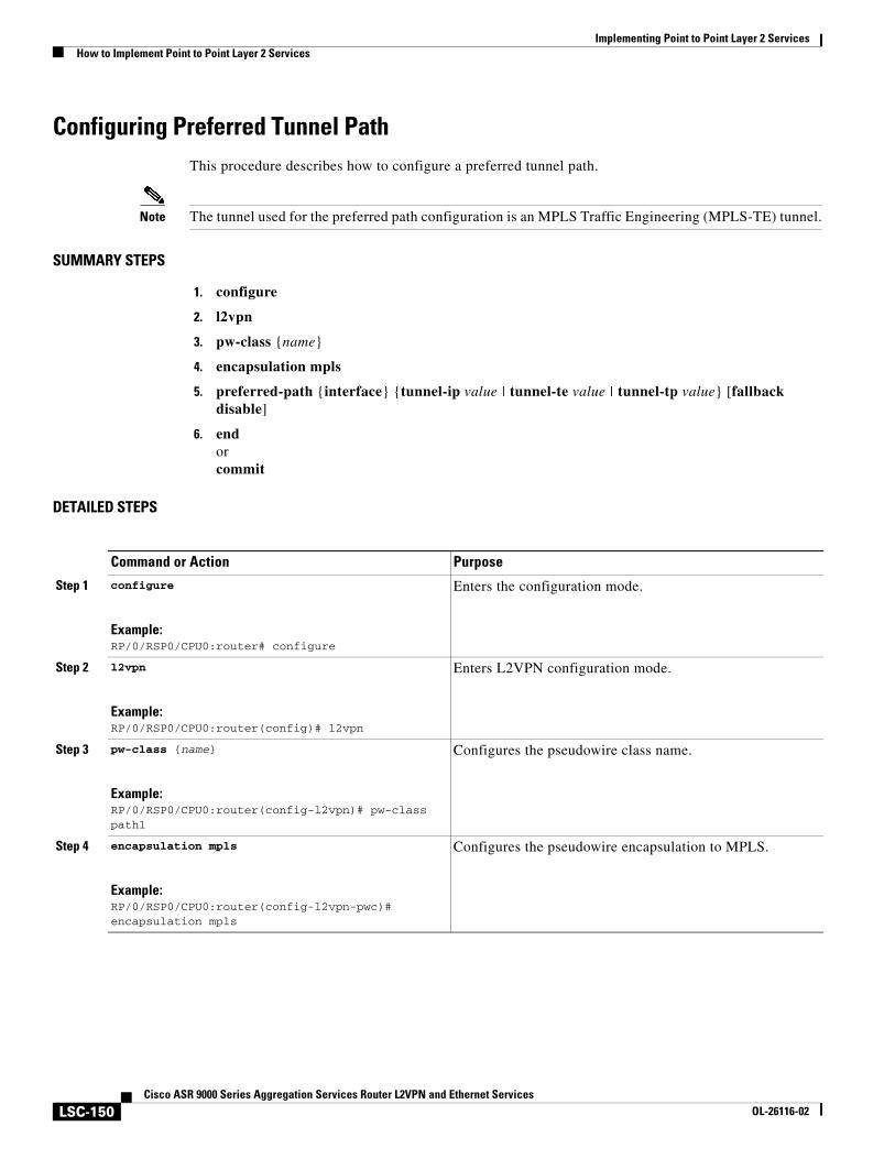
Implementing Point to Point Layer 2 ServicesHow to Implement Point to Point Layer 2 Services
LSC-150Cisco ASR 9000 Series Aggregation Services Router L2VPN and Ethernet Services
OL-26116-02
Configuring Preferred Tunnel PathThis procedure describes how to configure a preferred tunnel path.
Note The tunnel used for the preferred path configuration is an MPLS Traffic Engineering (MPLS-TE) tunnel.
SUMMARY STEPS
1. configure
2. l2vpn
3. pw-class {name}
4. encapsulation mpls
5. preferred-path {interface} {tunnel-ip value | tunnel-te value | tunnel-tp value} [fallback disable]
6. endorcommit
DETAILED STEPS
Command or Action Purpose
Step 1 configure
Example:RP/0/RSP0/CPU0:router# configure
Enters the configuration mode.
Step 2 l2vpn
Example:RP/0/RSP0/CPU0:router(config)# l2vpn
Enters L2VPN configuration mode.
Step 3 pw-class {name}
Example:RP/0/RSP0/CPU0:router(config-l2vpn)# pw-class path1
Configures the pseudowire class name.
Step 4 encapsulation mpls
Example:RP/0/RSP0/CPU0:router(config-l2vpn-pwc)# encapsulation mpls
Configures the pseudowire encapsulation to MPLS.
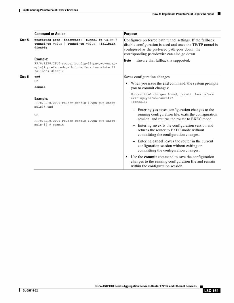
Implementing Point to Point Layer 2 ServicesHow to Implement Point to Point Layer 2 Services
LSC-151Cisco ASR 9000 Series Aggregation Services Router L2VPN and Ethernet Services
OL-26116-02
Step 5 preferred-path {interface} {tunnel-ip value | tunnel-te value | tunnel-tp value} [fallback disable]
Example:RP/0/RSP0/CPU0:router(config-l2vpn-pwc-encap-mpls)# preferred-path interface tunnel-te 11 fallback disable
Configures preferred path tunnel settings. If the fallback disable configuration is used and once the TE/TP tunnel is configured as the preferred path goes down, the corresponding pseudowire can also go down.
Note Ensure that fallback is supported.
Step 6 end
or
commit
Example:RP/0/RSP0/CPU0:router(config-l2vpn-pwc-encap-mpls)# end
or
RP/0/RSP0/CPU0:router(config-l2vpn-pwc-encap-mpls-if)# commit
Saves configuration changes.
• When you issue the end command, the system prompts you to commit changes:
Uncommitted changes found, commit them before exiting(yes/no/cancel)?[cancel]:
– Entering yes saves configuration changes to the running configuration file, exits the configuration session, and returns the router to EXEC mode.
– Entering no exits the configuration session and returns the router to EXEC mode without committing the configuration changes.
– Entering cancel leaves the router in the current configuration session without exiting or committing the configuration changes.
• Use the commit command to save the configuration changes to the running configuration file and remain within the configuration session.
Command or Action Purpose
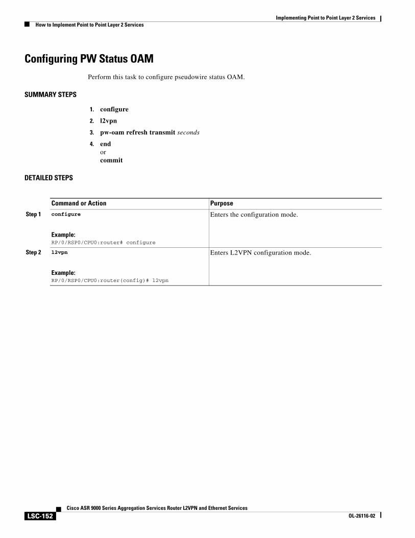
Implementing Point to Point Layer 2 ServicesHow to Implement Point to Point Layer 2 Services
LSC-152Cisco ASR 9000 Series Aggregation Services Router L2VPN and Ethernet Services
OL-26116-02
Configuring PW Status OAMPerform this task to configure pseudowire status OAM.
SUMMARY STEPS
1. configure
2. l2vpn
3. pw-oam refresh transmit seconds
4. endorcommit
DETAILED STEPS
Command or Action Purpose
Step 1 configure
Example:RP/0/RSP0/CPU0:router# configure
Enters the configuration mode.
Step 2 l2vpn
Example:RP/0/RSP0/CPU0:router(config)# l2vpn
Enters L2VPN configuration mode.
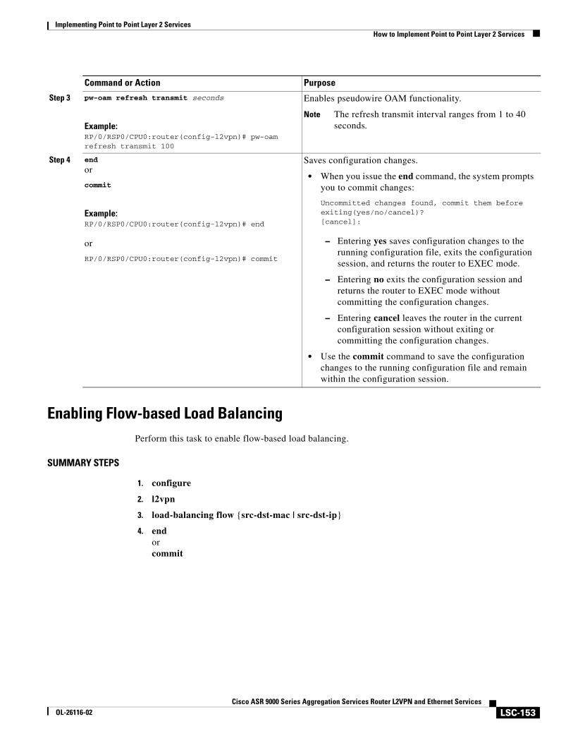
Implementing Point to Point Layer 2 ServicesHow to Implement Point to Point Layer 2 Services
LSC-153Cisco ASR 9000 Series Aggregation Services Router L2VPN and Ethernet Services
OL-26116-02
Enabling Flow-based Load BalancingPerform this task to enable flow-based load balancing.
SUMMARY STEPS
1. configure
2. l2vpn
3. load-balancing flow {src-dst-mac | src-dst-ip}
4. endorcommit
Step 3 pw-oam refresh transmit seconds
Example:RP/0/RSP0/CPU0:router(config-l2vpn)# pw-oam refresh transmit 100
Enables pseudowire OAM functionality.
Note The refresh transmit interval ranges from 1 to 40 seconds.
Step 4 end
or
commit
Example:RP/0/RSP0/CPU0:router(config-l2vpn)# end
or
RP/0/RSP0/CPU0:router(config-l2vpn)# commit
Saves configuration changes.
• When you issue the end command, the system prompts you to commit changes:
Uncommitted changes found, commit them before exiting(yes/no/cancel)?[cancel]:
– Entering yes saves configuration changes to the running configuration file, exits the configuration session, and returns the router to EXEC mode.
– Entering no exits the configuration session and returns the router to EXEC mode without committing the configuration changes.
– Entering cancel leaves the router in the current configuration session without exiting or committing the configuration changes.
• Use the commit command to save the configuration changes to the running configuration file and remain within the configuration session.
Command or Action Purpose
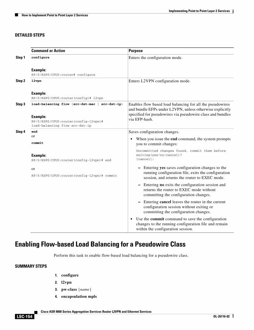
Implementing Point to Point Layer 2 ServicesHow to Implement Point to Point Layer 2 Services
LSC-154Cisco ASR 9000 Series Aggregation Services Router L2VPN and Ethernet Services
OL-26116-02
DETAILED STEPS
Enabling Flow-based Load Balancing for a Pseudowire ClassPerform this task to enable flow-based load balancing for a pseudowire class.
SUMMARY STEPS
1. configure
2. l2vpn
3. pw-class {name}
4. encapsulation mpls
Command or Action Purpose
Step 1 configure
Example:RP/0/RSP0/CPU0:router# configure
Enters the configuration mode.
Step 2 l2vpn
Example:RP/0/RSP0/CPU0:router(config)# l2vpn
Enters L2VPN configuration mode.
Step 3 load-balancing flow {src-dst-mac | src-dst-ip}
Example:RP/0/RSP0/CPU0:router(config-l2vpn)# load-balancing flow src-dst-ip
Enables flow based load balancing for all the pseudowires and bundle EFPs under L2VPN, unless otherwise explicitly specified for pseudowires via pseudowire class and bundles via EFP-hash.
Step 4 end
or
commit
Example:RP/0/RSP0/CPU0:router(config-l2vpn)# end
or
RP/0/RSP0/CPU0:router(config-l2vpn)# commit
Saves configuration changes.
• When you issue the end command, the system prompts you to commit changes:
Uncommitted changes found, commit them before exiting(yes/no/cancel)?[cancel]:
– Entering yes saves configuration changes to the running configuration file, exits the configuration session, and returns the router to EXEC mode.
– Entering no exits the configuration session and returns the router to EXEC mode without committing the configuration changes.
– Entering cancel leaves the router in the current configuration session without exiting or committing the configuration changes.
• Use the commit command to save the configuration changes to the running configuration file and remain within the configuration session.
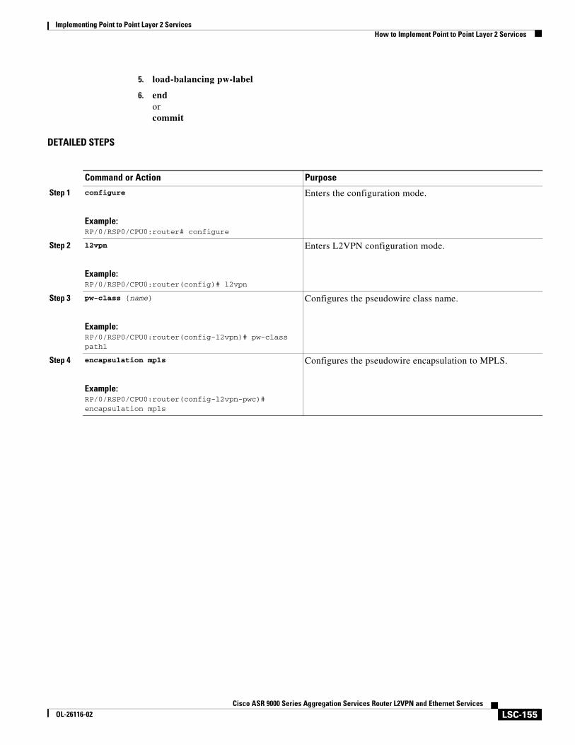
Implementing Point to Point Layer 2 ServicesHow to Implement Point to Point Layer 2 Services
LSC-155Cisco ASR 9000 Series Aggregation Services Router L2VPN and Ethernet Services
OL-26116-02
5. load-balancing pw-label
6. endorcommit
DETAILED STEPS
Command or Action Purpose
Step 1 configure
Example:RP/0/RSP0/CPU0:router# configure
Enters the configuration mode.
Step 2 l2vpn
Example:RP/0/RSP0/CPU0:router(config)# l2vpn
Enters L2VPN configuration mode.
Step 3 pw-class {name}
Example:RP/0/RSP0/CPU0:router(config-l2vpn)# pw-class path1
Configures the pseudowire class name.
Step 4 encapsulation mpls
Example:RP/0/RSP0/CPU0:router(config-l2vpn-pwc)# encapsulation mpls
Configures the pseudowire encapsulation to MPLS.
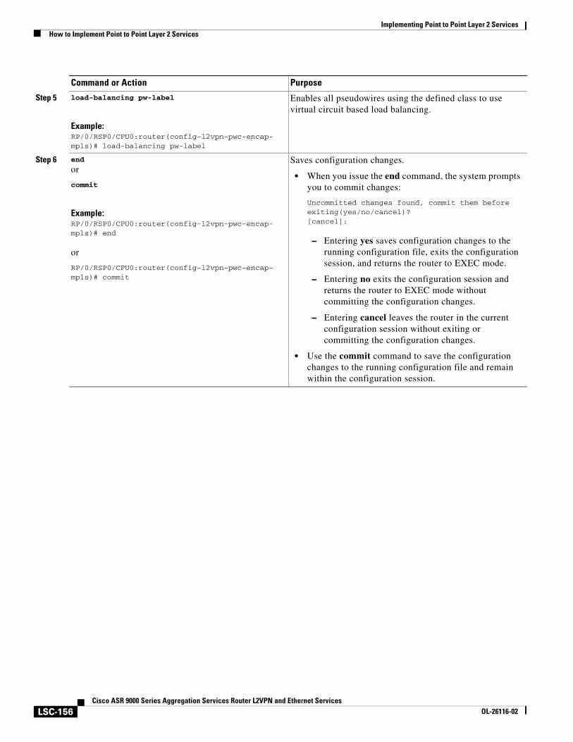
Implementing Point to Point Layer 2 ServicesHow to Implement Point to Point Layer 2 Services
LSC-156Cisco ASR 9000 Series Aggregation Services Router L2VPN and Ethernet Services
OL-26116-02
Step 5 load-balancing pw-label
Example:RP/0/RSP0/CPU0:router(config-l2vpn-pwc-encap-mpls)# load-balancing pw-label
Enables all pseudowires using the defined class to use virtual circuit based load balancing.
Step 6 end
or
commit
Example:RP/0/RSP0/CPU0:router(config-l2vpn-pwc-encap-mpls)# end
or
RP/0/RSP0/CPU0:router(config-l2vpn-pwc-encap-mpls)# commit
Saves configuration changes.
• When you issue the end command, the system prompts you to commit changes:
Uncommitted changes found, commit them before exiting(yes/no/cancel)?[cancel]:
– Entering yes saves configuration changes to the running configuration file, exits the configuration session, and returns the router to EXEC mode.
– Entering no exits the configuration session and returns the router to EXEC mode without committing the configuration changes.
– Entering cancel leaves the router in the current configuration session without exiting or committing the configuration changes.
• Use the commit command to save the configuration changes to the running configuration file and remain within the configuration session.
Command or Action Purpose
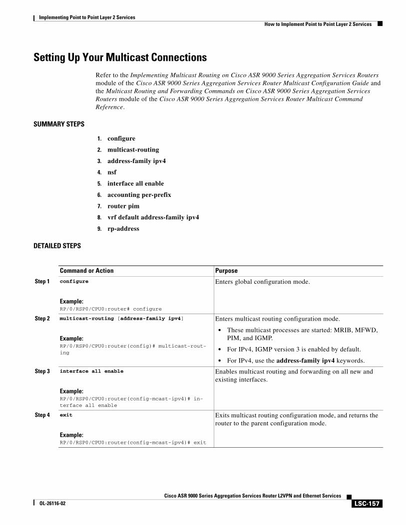
Implementing Point to Point Layer 2 ServicesHow to Implement Point to Point Layer 2 Services
LSC-157Cisco ASR 9000 Series Aggregation Services Router L2VPN and Ethernet Services
OL-26116-02
Setting Up Your Multicast ConnectionsRefer to the Implementing Multicast Routing on Cisco ASR 9000 Series Aggregation Services Routers module of the Cisco ASR 9000 Series Aggregation Services Router Multicast Configuration Guide and the Multicast Routing and Forwarding Commands on Cisco ASR 9000 Series Aggregation Services Routers module of the Cisco ASR 9000 Series Aggregation Services Router Multicast Command Reference.
SUMMARY STEPS
1. configure
2. multicast-routing
3. address-family ipv4
4. nsf
5. interface all enable
6. accounting per-prefix
7. router pim
8. vrf default address-family ipv4
9. rp-address
DETAILED STEPS
Command or Action Purpose
Step 1 configure
Example:RP/0/RSP0/CPU0:router# configure
Enters global configuration mode.
Step 2 multicast-routing [address-family ipv4]
Example:RP/0/RSP0/CPU0:router(config)# multicast-rout-ing
Enters multicast routing configuration mode.
• These multicast processes are started: MRIB, MFWD, PIM, and IGMP.
• For IPv4, IGMP version 3 is enabled by default.
• For IPv4, use the address-family ipv4 keywords.
Step 3 interface all enable
Example:RP/0/RSP0/CPU0:router(config-mcast-ipv4)# in-terface all enable
Enables multicast routing and forwarding on all new and existing interfaces.
Step 4 exit
Example:RP/0/RSP0/CPU0:router(config-mcast-ipv4)# exit
Exits multicast routing configuration mode, and returns the router to the parent configuration mode.
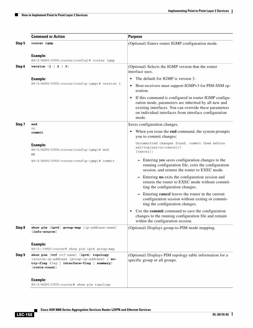
Implementing Point to Point Layer 2 ServicesHow to Implement Point to Point Layer 2 Services
LSC-158Cisco ASR 9000 Series Aggregation Services Router L2VPN and Ethernet Services
OL-26116-02
Step 5 router igmp
Example:RP/0/RSP0/CPU0:router(config)# router igmp
(Optional) Enters router IGMP configuration mode.
Step 6 version {1 | 2 | 3}
Example:RP/0/RSP0/CPU0:router(config-igmp)# version 3
(Optional) Selects the IGMP version that the router interface uses.
• The default for IGMP is version 3.
• Host receivers must support IGMPv3 for PIM-SSM op-eration.
• If this command is configured in router IGMP configu-ration mode, parameters are inherited by all new and existing interfaces. You can override these parameters on individual interfaces from interface configuration mode.
Step 7 endorcommit
Example:RP/0/RSP0/CPU0:router(config-igmp)# end
or
RP/0/RSP0/CPU0:router(config-igmp)# commit
Saves configuration changes.
• When you issue the end command, the system prompts you to commit changes:
Uncommitted changes found, commit them before exiting(yes/no/cancel)?[cancel]:
– Entering yes saves configuration changes to the running configuration file, exits the configuration session, and returns the router to EXEC mode.
– Entering no exits the configuration session and returns the router to EXEC mode without commit-ting the configuration changes.
– Entering cancel leaves the router in the current configuration session without exiting or commit-ting the configuration changes.
• Use the commit command to save the configuration changes to the running configuration file and remain within the configuration session.
Step 8 show pim [ipv4] group-map [ip-address-name] [info-source]
Example:RP/0//CPU0:router# show pim ipv4 group-map
(Optional) Displays group-to-PIM mode mapping.
Step 9 show pim [vrf vrf-name] [ipv4] topology [source-ip-address [group-ip-address] | en-try-flag flag | interface-flag | summary] [route-count]
Example:RP/0/RSP0/CPU0:router# show pim topology
(Optional) Displays PIM topology table information for a specific group or all groups.
Command or Action Purpose
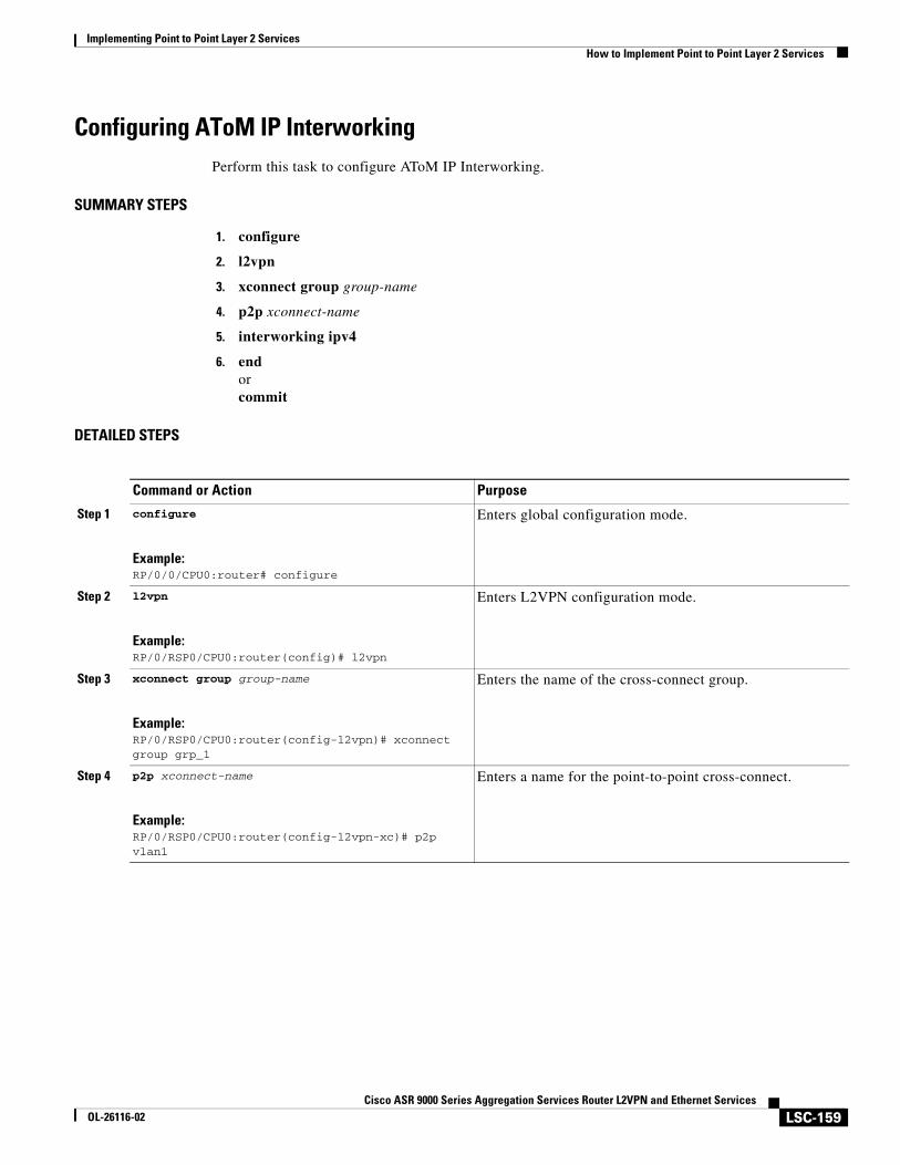
Implementing Point to Point Layer 2 ServicesHow to Implement Point to Point Layer 2 Services
LSC-159Cisco ASR 9000 Series Aggregation Services Router L2VPN and Ethernet Services
OL-26116-02
Configuring AToM IP InterworkingPerform this task to configure AToM IP Interworking.
SUMMARY STEPS
1. configure
2. l2vpn
3. xconnect group group-name
4. p2p xconnect-name
5. interworking ipv4
6. endorcommit
DETAILED STEPS
Command or Action Purpose
Step 1 configure
Example:RP/0/0/CPU0:router# configure
Enters global configuration mode.
Step 2 l2vpn
Example:RP/0/RSP0/CPU0:router(config)# l2vpn
Enters L2VPN configuration mode.
Step 3 xconnect group group-name
Example:RP/0/RSP0/CPU0:router(config-l2vpn)# xconnect group grp_1
Enters the name of the cross-connect group.
Step 4 p2p xconnect-name
Example:RP/0/RSP0/CPU0:router(config-l2vpn-xc)# p2p vlan1
Enters a name for the point-to-point cross-connect.
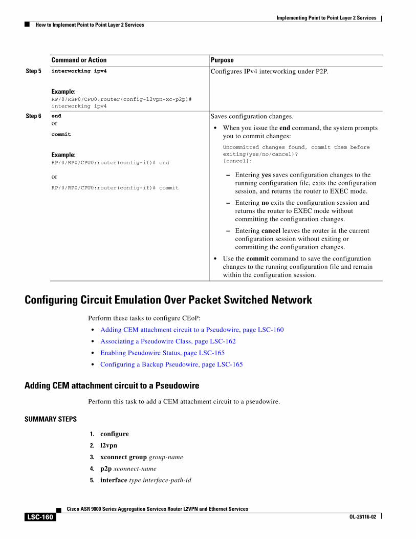
Implementing Point to Point Layer 2 ServicesHow to Implement Point to Point Layer 2 Services
LSC-160Cisco ASR 9000 Series Aggregation Services Router L2VPN and Ethernet Services
OL-26116-02
Configuring Circuit Emulation Over Packet Switched NetworkPerform these tasks to configure CEoP:
• Adding CEM attachment circuit to a Pseudowire, page LSC-160
• Associating a Pseudowire Class, page LSC-162
• Enabling Pseudowire Status, page LSC-165
• Configuring a Backup Pseudowire, page LSC-165
Adding CEM attachment circuit to a Pseudowire
Perform this task to add a CEM attachment circuit to a pseudowire.
SUMMARY STEPS
1. configure
2. l2vpn
3. xconnect group group-name
4. p2p xconnect-name
5. interface type interface-path-id
Step 5 interworking ipv4
Example:RP/0/RSP0/CPU0:router(config-l2vpn-xc-p2p)# interworking ipv4
Configures IPv4 interworking under P2P.
Step 6 end
or
commit
Example:RP/0/RP0/CPU0:router(config-if)# end
or
RP/0/RP0/CPU0:router(config-if)# commit
Saves configuration changes.
• When you issue the end command, the system prompts you to commit changes:
Uncommitted changes found, commit them before exiting(yes/no/cancel)?[cancel]:
– Entering yes saves configuration changes to the running configuration file, exits the configuration session, and returns the router to EXEC mode.
– Entering no exits the configuration session and returns the router to EXEC mode without committing the configuration changes.
– Entering cancel leaves the router in the current configuration session without exiting or committing the configuration changes.
• Use the commit command to save the configuration changes to the running configuration file and remain within the configuration session.
Command or Action Purpose
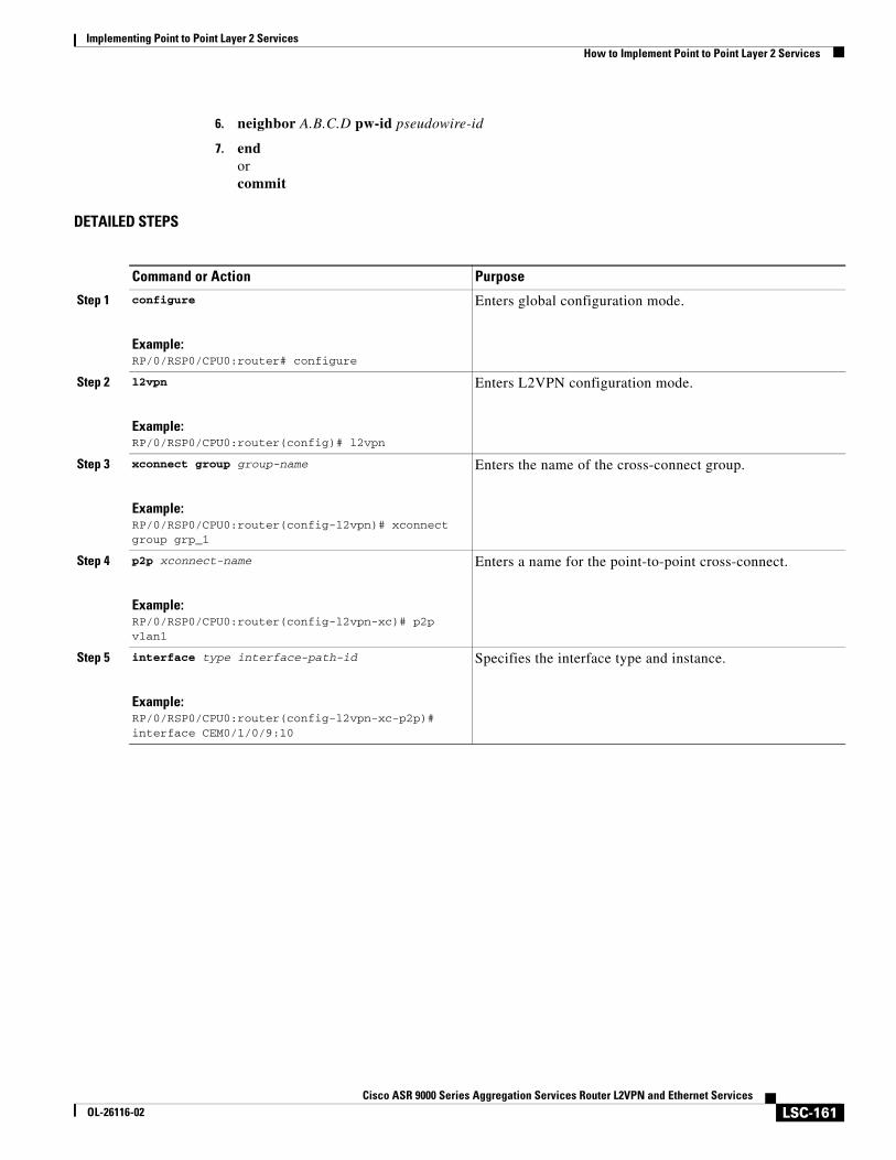
Implementing Point to Point Layer 2 ServicesHow to Implement Point to Point Layer 2 Services
LSC-161Cisco ASR 9000 Series Aggregation Services Router L2VPN and Ethernet Services
OL-26116-02
6. neighbor A.B.C.D pw-id pseudowire-id
7. endorcommit
DETAILED STEPS
Command or Action Purpose
Step 1 configure
Example:RP/0/RSP0/CPU0:router# configure
Enters global configuration mode.
Step 2 l2vpn
Example:RP/0/RSP0/CPU0:router(config)# l2vpn
Enters L2VPN configuration mode.
Step 3 xconnect group group-name
Example:RP/0/RSP0/CPU0:router(config-l2vpn)# xconnect group grp_1
Enters the name of the cross-connect group.
Step 4 p2p xconnect-name
Example:RP/0/RSP0/CPU0:router(config-l2vpn-xc)# p2p vlan1
Enters a name for the point-to-point cross-connect.
Step 5 interface type interface-path-id
Example:RP/0/RSP0/CPU0:router(config-l2vpn-xc-p2p)# interface CEM0/1/0/9:10
Specifies the interface type and instance.
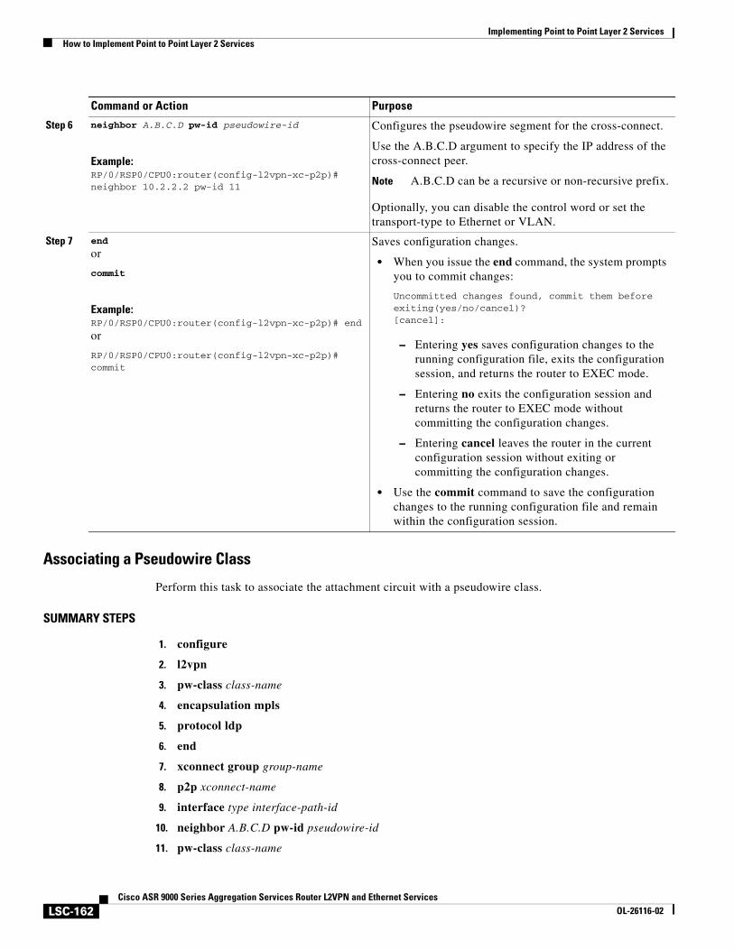
Implementing Point to Point Layer 2 ServicesHow to Implement Point to Point Layer 2 Services
LSC-162Cisco ASR 9000 Series Aggregation Services Router L2VPN and Ethernet Services
OL-26116-02
Associating a Pseudowire Class
Perform this task to associate the attachment circuit with a pseudowire class.
SUMMARY STEPS
1. configure
2. l2vpn
3. pw-class class-name
4. encapsulation mpls
5. protocol ldp
6. end
7. xconnect group group-name
8. p2p xconnect-name
9. interface type interface-path-id
10. neighbor A.B.C.D pw-id pseudowire-id
11. pw-class class-name
Step 6 neighbor A.B.C.D pw-id pseudowire-id
Example:RP/0/RSP0/CPU0:router(config-l2vpn-xc-p2p)# neighbor 10.2.2.2 pw-id 11
Configures the pseudowire segment for the cross-connect.
Use the A.B.C.D argument to specify the IP address of the cross-connect peer.
Note A.B.C.D can be a recursive or non-recursive prefix.
Optionally, you can disable the control word or set the transport-type to Ethernet or VLAN.
Step 7 end
or
commit
Example:RP/0/RSP0/CPU0:router(config-l2vpn-xc-p2p)# end
or
RP/0/RSP0/CPU0:router(config-l2vpn-xc-p2p)# commit
Saves configuration changes.
• When you issue the end command, the system prompts you to commit changes:
Uncommitted changes found, commit them before exiting(yes/no/cancel)?[cancel]:
– Entering yes saves configuration changes to the running configuration file, exits the configuration session, and returns the router to EXEC mode.
– Entering no exits the configuration session and returns the router to EXEC mode without committing the configuration changes.
– Entering cancel leaves the router in the current configuration session without exiting or committing the configuration changes.
• Use the commit command to save the configuration changes to the running configuration file and remain within the configuration session.
Command or Action Purpose
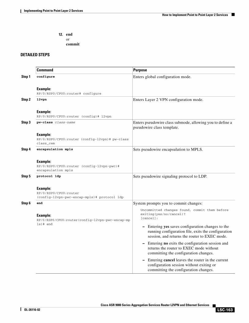
Implementing Point to Point Layer 2 ServicesHow to Implement Point to Point Layer 2 Services
LSC-163Cisco ASR 9000 Series Aggregation Services Router L2VPN and Ethernet Services
OL-26116-02
12. endorcommit
DETAILED STEPS
Command Purpose
Step 1 configure
Example:RP/0/RSP0/CPU0:router# configure
Enters global configuration mode.
Step 2 l2vpn
Example:RP/0/RSP0/CPU0:router (config)# l2vpn
Enters Layer 2 VPN configuration mode.
Step 3 pw-class class-name
Example:RP/0/RSP0/CPU0:router (config-l2vpn)# pw-class class_cem
Enters pseudowire class submode, allowing you to define a pseudowire class template.
Step 4 encapsulation mpls
Example:RP/0/RSP0/CPU0:router (config-l2vpn-pwc)# encapsulation mpls
Sets pseudowire encapsulation to MPLS.
Step 5 protocol ldp
Example:RP/0/RSP0/CPU0:router (config-l2vpn-pwc-encap-mpls)# protocol ldp
Sets pseudowire signaling protocol to LDP.
Step 6 end
Example:RP/0/RSP0/CPU0:router(config-l2vpn-pwc-encap-mpls)# end
System prompts you to commit changes:
Uncommitted changes found, commit them before exiting(yes/no/cancel)?[cancel]:
– Entering yes saves configuration changes to the running configuration file, exits the configuration session, and returns the router to EXEC mode.
– Entering no exits the configuration session and returns the router to EXEC mode without committing the configuration changes.
– Entering cancel leaves the router in the current configuration session without exiting or committing the configuration changes.
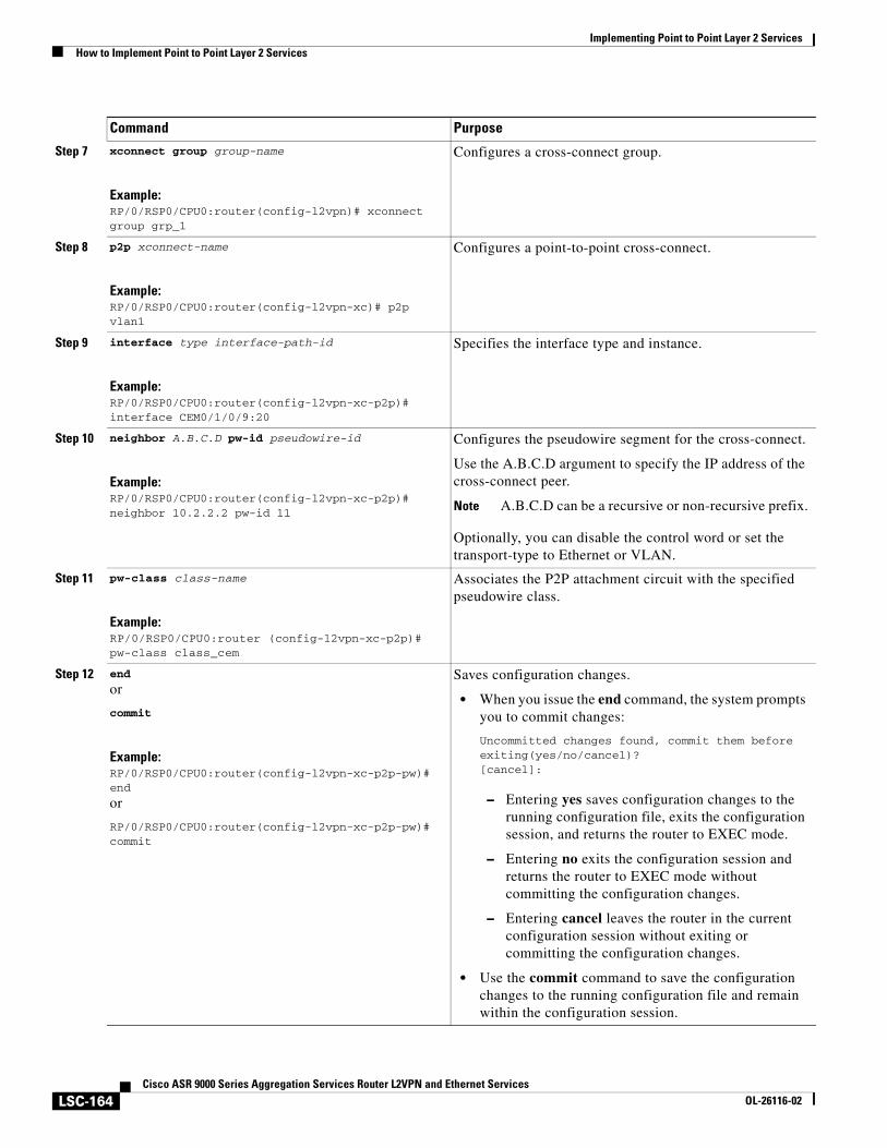
Implementing Point to Point Layer 2 ServicesHow to Implement Point to Point Layer 2 Services
LSC-164Cisco ASR 9000 Series Aggregation Services Router L2VPN and Ethernet Services
OL-26116-02
Step 7 xconnect group group-name
Example:RP/0/RSP0/CPU0:router(config-l2vpn)# xconnect group grp_1
Configures a cross-connect group.
Step 8 p2p xconnect-name
Example:RP/0/RSP0/CPU0:router(config-l2vpn-xc)# p2p vlan1
Configures a point-to-point cross-connect.
Step 9 interface type interface-path-id
Example:RP/0/RSP0/CPU0:router(config-l2vpn-xc-p2p)# interface CEM0/1/0/9:20
Specifies the interface type and instance.
Step 10 neighbor A.B.C.D pw-id pseudowire-id
Example:RP/0/RSP0/CPU0:router(config-l2vpn-xc-p2p)# neighbor 10.2.2.2 pw-id 11
Configures the pseudowire segment for the cross-connect.
Use the A.B.C.D argument to specify the IP address of the cross-connect peer.
Note A.B.C.D can be a recursive or non-recursive prefix.
Optionally, you can disable the control word or set the transport-type to Ethernet or VLAN.
Step 11 pw-class class-name
Example:RP/0/RSP0/CPU0:router (config-l2vpn-xc-p2p)# pw-class class_cem
Associates the P2P attachment circuit with the specified pseudowire class.
Step 12 end
or
commit
Example:RP/0/RSP0/CPU0:router(config-l2vpn-xc-p2p-pw)#end
or
RP/0/RSP0/CPU0:router(config-l2vpn-xc-p2p-pw)# commit
Saves configuration changes.
• When you issue the end command, the system prompts you to commit changes:
Uncommitted changes found, commit them before exiting(yes/no/cancel)?[cancel]:
– Entering yes saves configuration changes to the running configuration file, exits the configuration session, and returns the router to EXEC mode.
– Entering no exits the configuration session and returns the router to EXEC mode without committing the configuration changes.
– Entering cancel leaves the router in the current configuration session without exiting or committing the configuration changes.
• Use the commit command to save the configuration changes to the running configuration file and remain within the configuration session.
Command Purpose
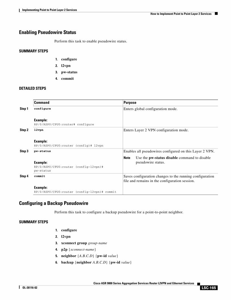
Implementing Point to Point Layer 2 ServicesHow to Implement Point to Point Layer 2 Services
LSC-165Cisco ASR 9000 Series Aggregation Services Router L2VPN and Ethernet Services
OL-26116-02
Enabling Pseudowire Status
Perform this task to enable pseudowire status.
SUMMARY STEPS
1. configure
2. l2vpn
3. pw-status
4. commit
DETAILED STEPS
Configuring a Backup Pseudowire
Perform this task to configure a backup pseudowire for a point-to-point neighbor.
SUMMARY STEPS
1. configure
2. l2vpn
3. xconnect group group-name
4. p2p {xconnect-name}
5. neighbor {A.B.C.D} {pw-id value}
6. backup {neighbor A.B.C.D} {pw-id value}
Command Purpose
Step 1 configure
Example:RP/0/RSP0/CPU0:router# configure
Enters global configuration mode.
Step 2 l2vpn
Example:RP/0/RSP0/CPU0:router (config)# l2vpn
Enters Layer 2 VPN configuration mode.
Step 3 pw-status
Example:RP/0/RSP0/CPU0:router (config-l2vpn)# pw-status
Enables all pseudowires configured on this Layer 2 VPN.
Note Use the pw-status disable command to disable pseudowire status.
Step 4 commit
Example:RP/0/RSP0/CPU0:router (config-l2vpn)# commit
Saves configuration changes to the running configuration file and remains in the configuration session.
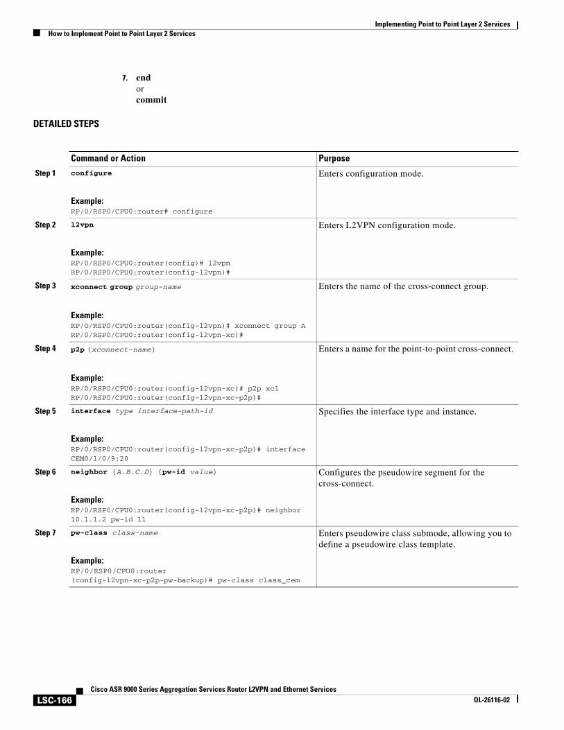
Implementing Point to Point Layer 2 ServicesHow to Implement Point to Point Layer 2 Services
LSC-166Cisco ASR 9000 Series Aggregation Services Router L2VPN and Ethernet Services
OL-26116-02
7. endorcommit
DETAILED STEPS
Command or Action Purpose
Step 1 configure
Example:RP/0/RSP0/CPU0:router# configure
Enters configuration mode.
Step 2 l2vpn
Example:RP/0/RSP0/CPU0:router(config)# l2vpnRP/0/RSP0/CPU0:router(config-l2vpn)#
Enters L2VPN configuration mode.
Step 3 xconnect group group-name
Example:RP/O/RSP0/CPU0:router(config-l2vpn)# xconnect group ARP/0/RSP0/CPU0:router(config-l2vpn-xc)#
Enters the name of the cross-connect group.
Step 4 p2p {xconnect-name}
Example:RP/0/RSP0/CPU0:router(config-l2vpn-xc)# p2p xc1RP/0/RSP0/CPU0:router(config-l2vpn-xc-p2p)#
Enters a name for the point-to-point cross-connect.
Step 5 interface type interface-path-id
Example:RP/0/RSP0/CPU0:router(config-l2vpn-xc-p2p)# interface CEM0/1/0/9:20
Specifies the interface type and instance.
Step 6 neighbor {A.B.C.D} {pw-id value}
Example:RP/0/RSP0/CPU0:router(config-l2vpn-xc-p2p)# neighbor 10.1.1.2 pw-id 11
Configures the pseudowire segment for the cross-connect.
Step 7 pw-class class-name
Example:RP/0/RSP0/CPU0:router (config-l2vpn-xc-p2p-pw-backup)# pw-class class_cem
Enters pseudowire class submode, allowing you to define a pseudowire class template.
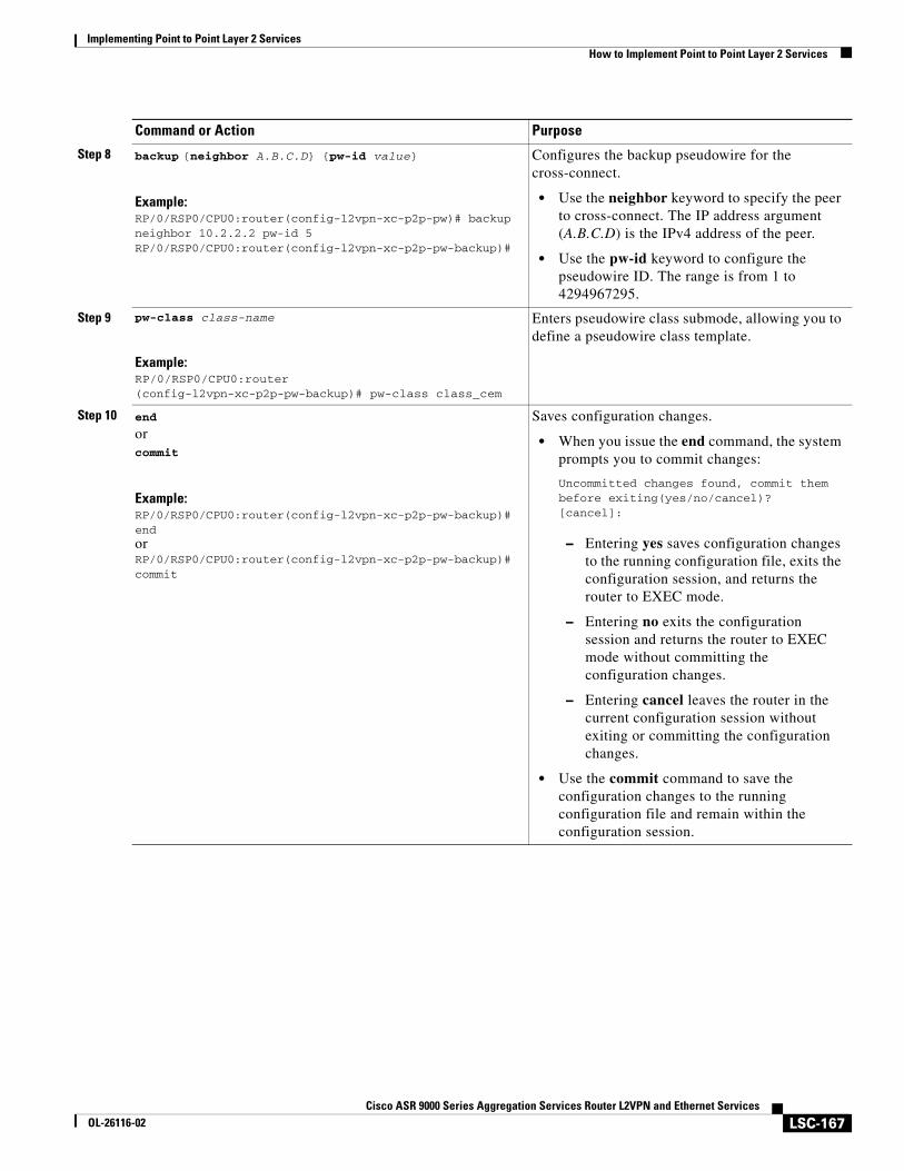
Implementing Point to Point Layer 2 ServicesHow to Implement Point to Point Layer 2 Services
LSC-167Cisco ASR 9000 Series Aggregation Services Router L2VPN and Ethernet Services
OL-26116-02
Step 8 backup {neighbor A.B.C.D} {pw-id value}
Example:RP/0/RSP0/CPU0:router(config-l2vpn-xc-p2p-pw)# backup neighbor 10.2.2.2 pw-id 5RP/0/RSP0/CPU0:router(config-l2vpn-xc-p2p-pw-backup)#
Configures the backup pseudowire for the cross-connect.
• Use the neighbor keyword to specify the peer to cross-connect. The IP address argument (A.B.C.D) is the IPv4 address of the peer.
• Use the pw-id keyword to configure the pseudowire ID. The range is from 1 to 4294967295.
Step 9 pw-class class-name
Example:RP/0/RSP0/CPU0:router (config-l2vpn-xc-p2p-pw-backup)# pw-class class_cem
Enters pseudowire class submode, allowing you to define a pseudowire class template.
Step 10 end
orcommit
Example:RP/0/RSP0/CPU0:router(config-l2vpn-xc-p2p-pw-backup)# endorRP/0/RSP0/CPU0:router(config-l2vpn-xc-p2p-pw-backup)# commit
Saves configuration changes.
• When you issue the end command, the system prompts you to commit changes:
Uncommitted changes found, commit them before exiting(yes/no/cancel)?[cancel]:
– Entering yes saves configuration changes to the running configuration file, exits the configuration session, and returns the router to EXEC mode.
– Entering no exits the configuration session and returns the router to EXEC mode without committing the configuration changes.
– Entering cancel leaves the router in the current configuration session without exiting or committing the configuration changes.
• Use the commit command to save the configuration changes to the running configuration file and remain within the configuration session.
Command or Action Purpose
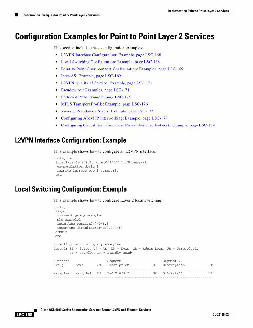
Implementing Point to Point Layer 2 ServicesConfiguration Examples for Point to Point Layer 2 Services
LSC-168Cisco ASR 9000 Series Aggregation Services Router L2VPN and Ethernet Services
OL-26116-02
Configuration Examples for Point to Point Layer 2 ServicesThis section includes these configuration examples:
• L2VPN Interface Configuration: Example, page LSC-168
• Local Switching Configuration: Example, page LSC-168
• Point-to-Point Cross-connect Configuration: Examples, page LSC-169
• Inter-AS: Example, page LSC-169
• L2VPN Quality of Service: Example, page LSC-171
• Pseudowires: Examples, page LSC-171
• Preferred Path: Example, page LSC-175
• MPLS Transport Profile: Example, page LSC-176
• Viewing Pseudowire Status: Example, page LSC-177
• Configuring AToM IP Interworking: Example, page LSC-179
• Configuring Circuit Emulation Over Packet Switched Network: Example, page LSC-179
L2VPN Interface Configuration: ExampleThis example shows how to configure an L2VPN interface:
configureinterface GigabitEthernet0/0/0/0.1 l2transportencapsulation dot1q 1rewrite ingress pop 1 symmetricend
Local Switching Configuration: ExampleThis example shows how to configure Layer 2 local switching:
configurel2vpnxconnect group examplesp2p example1interface TenGigE0/7/0/6.5interface GigabitEthernet0/4/0/30commitend
show l2vpn xconnect group examplesLegend: ST = State, UP = Up, DN = Down, AD = Admin Down, UR = Unresolved, SB = Standby, SR = Standby Ready
XConnect Segment 1 Segment 2Group Name ST Description ST Description ST------------------------ ------------------------- -------------------------examples example1 UP Te0/7/0/6.5 UP Gi0/4/0/30 UP--------------------------------------------------------------------------------
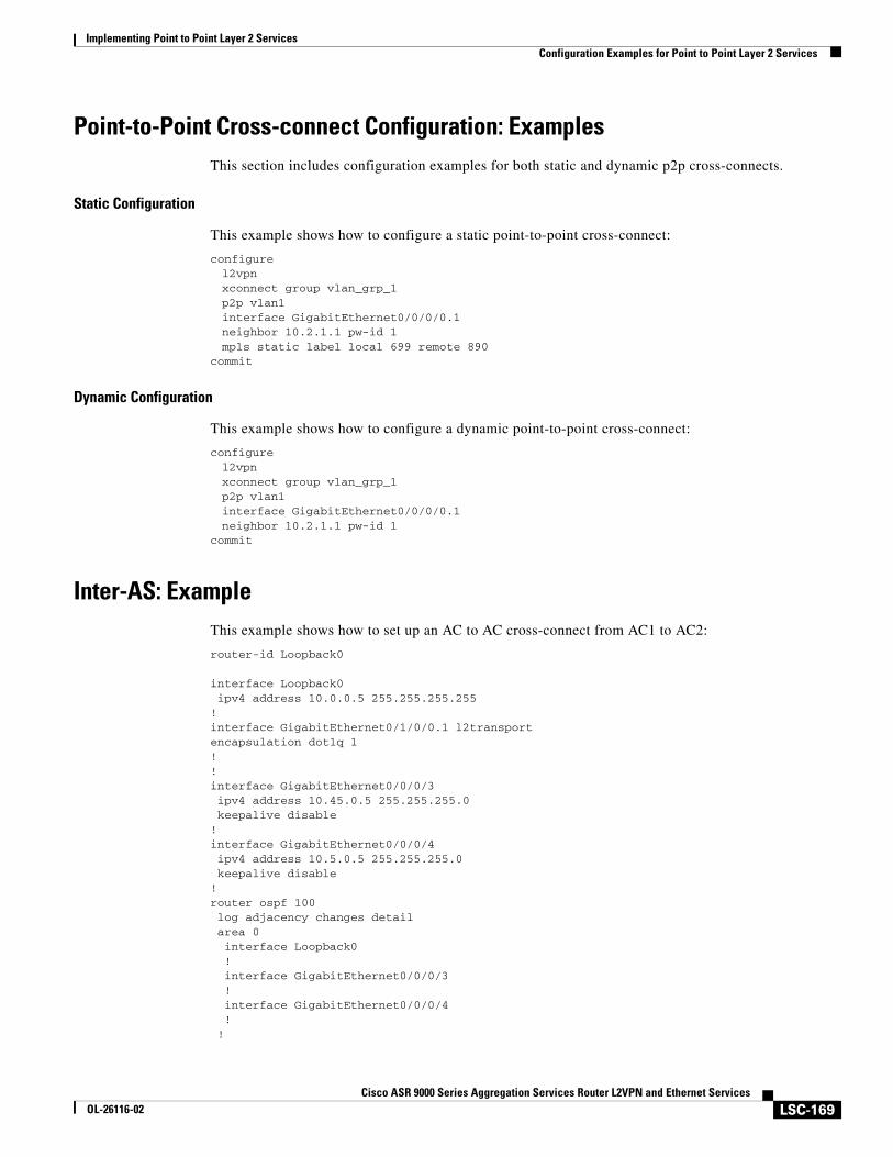
Implementing Point to Point Layer 2 ServicesConfiguration Examples for Point to Point Layer 2 Services
LSC-169Cisco ASR 9000 Series Aggregation Services Router L2VPN and Ethernet Services
OL-26116-02
Point-to-Point Cross-connect Configuration: ExamplesThis section includes configuration examples for both static and dynamic p2p cross-connects.
Static Configuration
This example shows how to configure a static point-to-point cross-connect:
configurel2vpnxconnect group vlan_grp_1p2p vlan1interface GigabitEthernet0/0/0/0.1neighbor 10.2.1.1 pw-id 1mpls static label local 699 remote 890
commit
Dynamic Configuration
This example shows how to configure a dynamic point-to-point cross-connect:
configurel2vpnxconnect group vlan_grp_1p2p vlan1interface GigabitEthernet0/0/0/0.1neighbor 10.2.1.1 pw-id 1
commit
Inter-AS: ExampleThis example shows how to set up an AC to AC cross-connect from AC1 to AC2:
router-id Loopback0
interface Loopback0 ipv4 address 10.0.0.5 255.255.255.255!interface GigabitEthernet0/1/0/0.1 l2transport encapsulation dot1q 1!!interface GigabitEthernet0/0/0/3 ipv4 address 10.45.0.5 255.255.255.0 keepalive disable!interface GigabitEthernet0/0/0/4 ipv4 address 10.5.0.5 255.255.255.0 keepalive disable!router ospf 100 log adjacency changes detail area 0 interface Loopback0 ! interface GigabitEthernet0/0/0/3 ! interface GigabitEthernet0/0/0/4 ! !
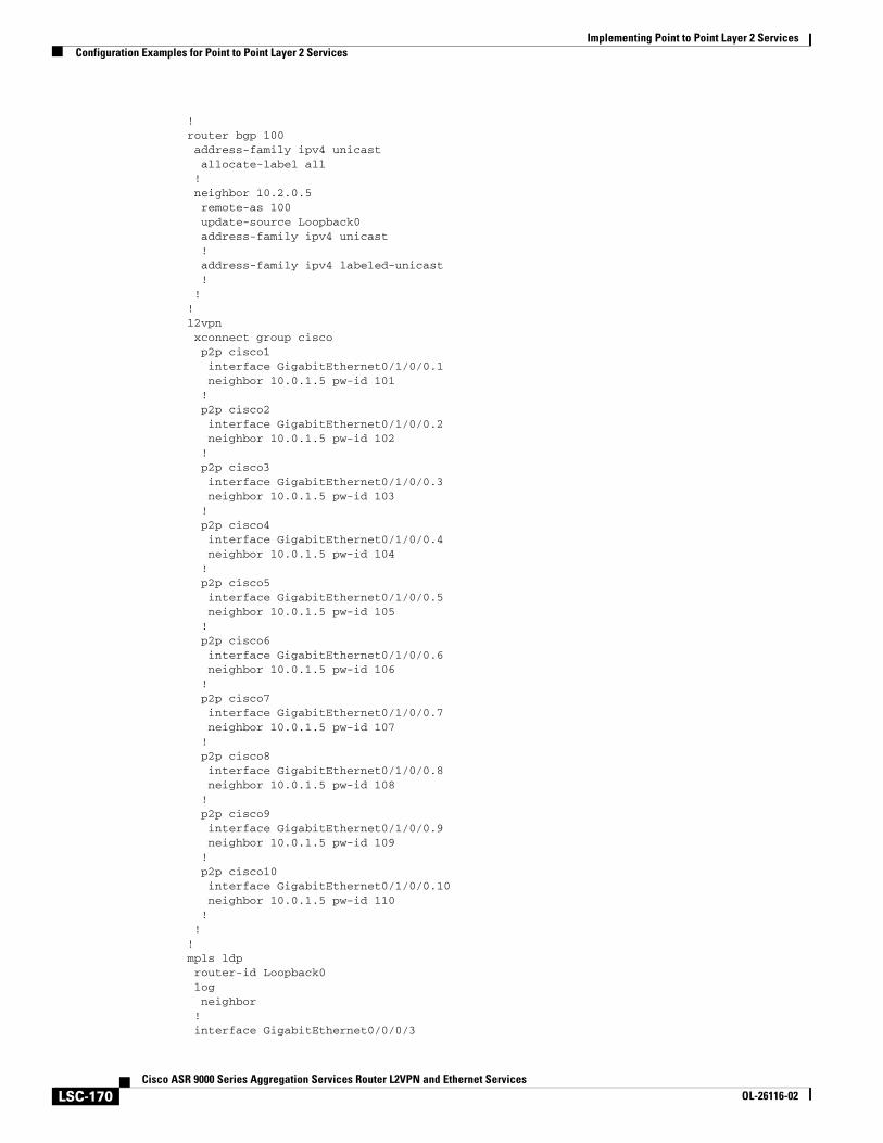
Implementing Point to Point Layer 2 ServicesConfiguration Examples for Point to Point Layer 2 Services
LSC-170Cisco ASR 9000 Series Aggregation Services Router L2VPN and Ethernet Services
OL-26116-02
!router bgp 100 address-family ipv4 unicast allocate-label all ! neighbor 10.2.0.5 remote-as 100 update-source Loopback0 address-family ipv4 unicast ! address-family ipv4 labeled-unicast ! !!l2vpn xconnect group cisco p2p cisco1 interface GigabitEthernet0/1/0/0.1 neighbor 10.0.1.5 pw-id 101 ! p2p cisco2 interface GigabitEthernet0/1/0/0.2 neighbor 10.0.1.5 pw-id 102 ! p2p cisco3 interface GigabitEthernet0/1/0/0.3 neighbor 10.0.1.5 pw-id 103 ! p2p cisco4 interface GigabitEthernet0/1/0/0.4 neighbor 10.0.1.5 pw-id 104 ! p2p cisco5 interface GigabitEthernet0/1/0/0.5 neighbor 10.0.1.5 pw-id 105 ! p2p cisco6 interface GigabitEthernet0/1/0/0.6 neighbor 10.0.1.5 pw-id 106 ! p2p cisco7 interface GigabitEthernet0/1/0/0.7 neighbor 10.0.1.5 pw-id 107 ! p2p cisco8 interface GigabitEthernet0/1/0/0.8 neighbor 10.0.1.5 pw-id 108 ! p2p cisco9 interface GigabitEthernet0/1/0/0.9 neighbor 10.0.1.5 pw-id 109 ! p2p cisco10 interface GigabitEthernet0/1/0/0.10 neighbor 10.0.1.5 pw-id 110 ! !!mpls ldp router-id Loopback0 log neighbor ! interface GigabitEthernet0/0/0/3
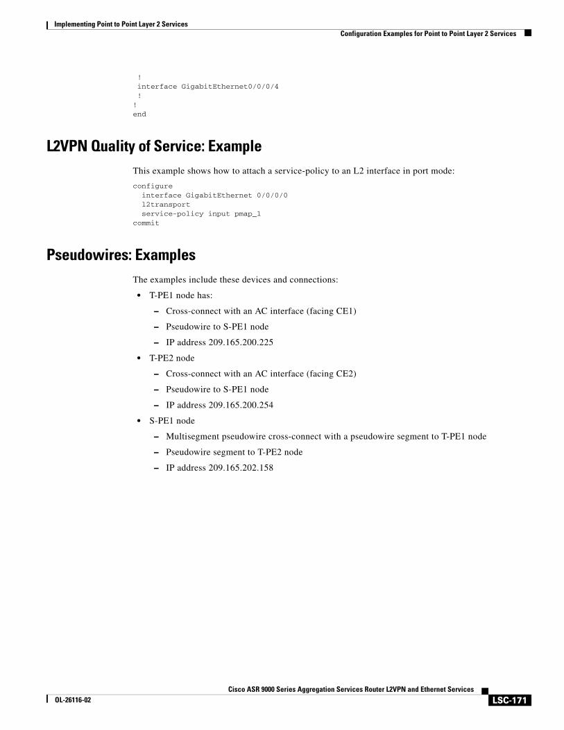
Implementing Point to Point Layer 2 ServicesConfiguration Examples for Point to Point Layer 2 Services
LSC-171Cisco ASR 9000 Series Aggregation Services Router L2VPN and Ethernet Services
OL-26116-02
! interface GigabitEthernet0/0/0/4 !!end
L2VPN Quality of Service: ExampleThis example shows how to attach a service-policy to an L2 interface in port mode:
configureinterface GigabitEthernet 0/0/0/0l2transportservice-policy input pmap_1
commit
Pseudowires: ExamplesThe examples include these devices and connections:
• T-PE1 node has:
– Cross-connect with an AC interface (facing CE1)
– Pseudowire to S-PE1 node
– IP address 209.165.200.225
• T-PE2 node
– Cross-connect with an AC interface (facing CE2)
– Pseudowire to S-PE1 node
– IP address 209.165.200.254
• S-PE1 node
– Multisegment pseudowire cross-connect with a pseudowire segment to T-PE1 node
– Pseudowire segment to T-PE2 node
– IP address 209.165.202.158
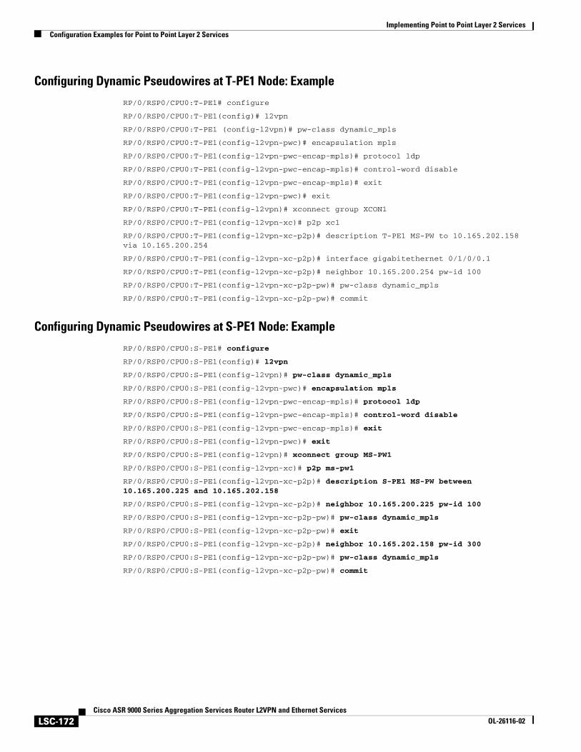
Implementing Point to Point Layer 2 ServicesConfiguration Examples for Point to Point Layer 2 Services
LSC-172Cisco ASR 9000 Series Aggregation Services Router L2VPN and Ethernet Services
OL-26116-02
Configuring Dynamic Pseudowires at T-PE1 Node: Example
RP/0/RSP0/CPU0:T-PE1# configure
RP/0/RSP0/CPU0:T-PE1(config)# l2vpn
RP/0/RSP0/CPU0:T-PE1 (config-l2vpn)# pw-class dynamic_mpls
RP/0/RSP0/CPU0:T-PE1(config-l2vpn-pwc)# encapsulation mpls
RP/0/RSP0/CPU0:T-PE1(config-l2vpn-pwc-encap-mpls)# protocol ldp
RP/0/RSP0/CPU0:T-PE1(config-l2vpn-pwc-encap-mpls)# control-word disable
RP/0/RSP0/CPU0:T-PE1(config-l2vpn-pwc-encap-mpls)# exit
RP/0/RSP0/CPU0:T-PE1(config-l2vpn-pwc)# exit
RP/0/RSP0/CPU0:T-PE1(config-l2vpn)# xconnect group XCON1
RP/0/RSP0/CPU0:T-PE1(config-l2vpn-xc)# p2p xc1
RP/0/RSP0/CPU0:T-PE1(config-l2vpn-xc-p2p)# description T-PE1 MS-PW to 10.165.202.158 via 10.165.200.254
RP/0/RSP0/CPU0:T-PE1(config-l2vpn-xc-p2p)# interface gigabitethernet 0/1/0/0.1
RP/0/RSP0/CPU0:T-PE1(config-l2vpn-xc-p2p)# neighbor 10.165.200.254 pw-id 100
RP/0/RSP0/CPU0:T-PE1(config-l2vpn-xc-p2p-pw)# pw-class dynamic_mpls
RP/0/RSP0/CPU0:T-PE1(config-l2vpn-xc-p2p-pw)# commit
Configuring Dynamic Pseudowires at S-PE1 Node: Example
RP/0/RSP0/CPU0:S-PE1# configure
RP/0/RSP0/CPU0:S-PE1(config)# l2vpn
RP/0/RSP0/CPU0:S-PE1(config-l2vpn)# pw-class dynamic_mpls
RP/0/RSP0/CPU0:S-PE1(config-l2vpn-pwc)# encapsulation mpls
RP/0/RSP0/CPU0:S-PE1(config-l2vpn-pwc-encap-mpls)# protocol ldp
RP/0/RSP0/CPU0:S-PE1(config-l2vpn-pwc-encap-mpls)# control-word disable
RP/0/RSP0/CPU0:S-PE1(config-l2vpn-pwc-encap-mpls)# exit
RP/0/RSP0/CPU0:S-PE1(config-l2vpn-pwc)# exit
RP/0/RSP0/CPU0:S-PE1(config-l2vpn)# xconnect group MS-PW1
RP/0/RSP0/CPU0:S-PE1(config-l2vpn-xc)# p2p ms-pw1
RP/0/RSP0/CPU0:S-PE1(config-l2vpn-xc-p2p)# description S-PE1 MS-PW between 10.165.200.225 and 10.165.202.158
RP/0/RSP0/CPU0:S-PE1(config-l2vpn-xc-p2p)# neighbor 10.165.200.225 pw-id 100
RP/0/RSP0/CPU0:S-PE1(config-l2vpn-xc-p2p-pw)# pw-class dynamic_mpls
RP/0/RSP0/CPU0:S-PE1(config-l2vpn-xc-p2p-pw)# exit
RP/0/RSP0/CPU0:S-PE1(config-l2vpn-xc-p2p)# neighbor 10.165.202.158 pw-id 300
RP/0/RSP0/CPU0:S-PE1(config-l2vpn-xc-p2p-pw)# pw-class dynamic_mpls
RP/0/RSP0/CPU0:S-PE1(config-l2vpn-xc-p2p-pw)# commit
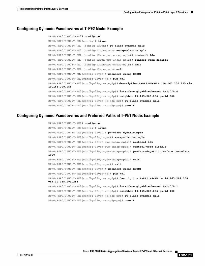
Implementing Point to Point Layer 2 ServicesConfiguration Examples for Point to Point Layer 2 Services
LSC-173Cisco ASR 9000 Series Aggregation Services Router L2VPN and Ethernet Services
OL-26116-02
Configuring Dynamic Pseudowires at T-PE2 Node: Example
RP/0/RSP0/CPU0:T-PE2# configure
RP/0/RSP0/CPU0:T-PE2(config)# l2vpn
RP/0/RSP0/CPU0:T-PE2 (config-l2vpn)# pw-class dynamic_mpls
RP/0/RSP0/CPU0:T-PE2 (config-l2vpn-pwc)# encapsulation mpls
RP/0/RSP0/CPU0:T-PE2 (config-l2vpn-pwc-encap-mpls)# protocol ldp
RP/0/RSP0/CPU0:T-PE2 (config-l2vpn-pwc-encap-mpls)# control-word disable
RP/0/RSP0/CPU0:T-PE2 (config-l2vpn-pwc-encap-mpls)# exit
RP/0/RSP0/CPU0:T-PE2 (config-l2vpn-pwc)# exit
RP/0/RSP0/CPU0:T-PE2(config-l2vpn)# xconnect group XCON1
RP/0/RSP0/CPU0:T-PE2(config-l2vpn-xc)# p2p xc1
RP/0/RSP0/CPU0:T-PE2(config-l2vpn-xc-p2p)# description T-PE2 MS-PW to 10.165.200.225 via 10.165.200.254
RP/0/RSP0/CPU0:T-PE2(config-l2vpn-xc-p2p)# interface gigabitethernet 0/2/0/0.4
RP/0/RSP0/CPU0:T-PE2(config-l2vpn-xc-p2p)# neighbor 10.165.200.254 pw-id 300
RP/0/RSP0/CPU0:T-PE2(config-l2vpn-xc-p2p-pw)# pw-class dynamic_mpls
RP/0/RSP0/CPU0:T-PE2(config-l2vpn-xc-p2p-pw)# commit
Configuring Dynamic Pseudowires and Preferred Paths at T-PE1 Node: Example
RP/0/RSP0/CPU0:T-PE1# configure
RP/0/RSP0/CPU0:T-PE1(config)# l2vpn
RP/0/RSP0/CPU0:T-PE1(config-l2vpn)# pw-class dynamic_mpls
RP/0/RSP0/CPU0:T-PE1(config-l2vpn-pwc)# encapsulation mpls
RP/0/RSP0/CPU0:T-PE1(config-l2vpn-pwc-encap-mpls)# protocol ldp
RP/0/RSP0/CPU0:T-PE1(config-l2vpn-pwc-encap-mpls)# control-word disable
RP/0/RSP0/CPU0:T-PE1(config-l2vpn-pwc-encap-mpls)# preferred-path interface tunnel-te 1000
RP/0/RSP0/CPU0:T-PE1(config-l2vpn-pwc-encap-mpls)# exit
RP/0/RSP0/CPU0:T-PE1(config-l2vpn-pwc)# exit
RP/0/RSP0/CPU0:T-PE1(config-l2vpn)# xconnect group XCON1
RP/0/RSP0/CPU0:T-PE1(config-l2vpn-xc)# p2p xc1
RP/0/RSP0/CPU0:T-PE1(config-l2vpn-xc-p2p)# description T-PE1 MS-PW to 10.165.202.158 via 10.165.200.254
RP/0/RSP0/CPU0:T-PE1(config-l2vpn-xc-p2p)# interface gigabitethernet 0/1/0/0.1
RP/0/RSP0/CPU0:T-PE1(config-l2vpn-xc-p2p)# neighbor 10.165.200.254 pw-id 100
RP/0/RSP0/CPU0:T-PE1(config-l2vpn-xc-p2p-pw)# pw-class dynamic_mpls
RP/0/RSP0/CPU0:T-PE1(config-l2vpn-xc-p2p-pw)# commit
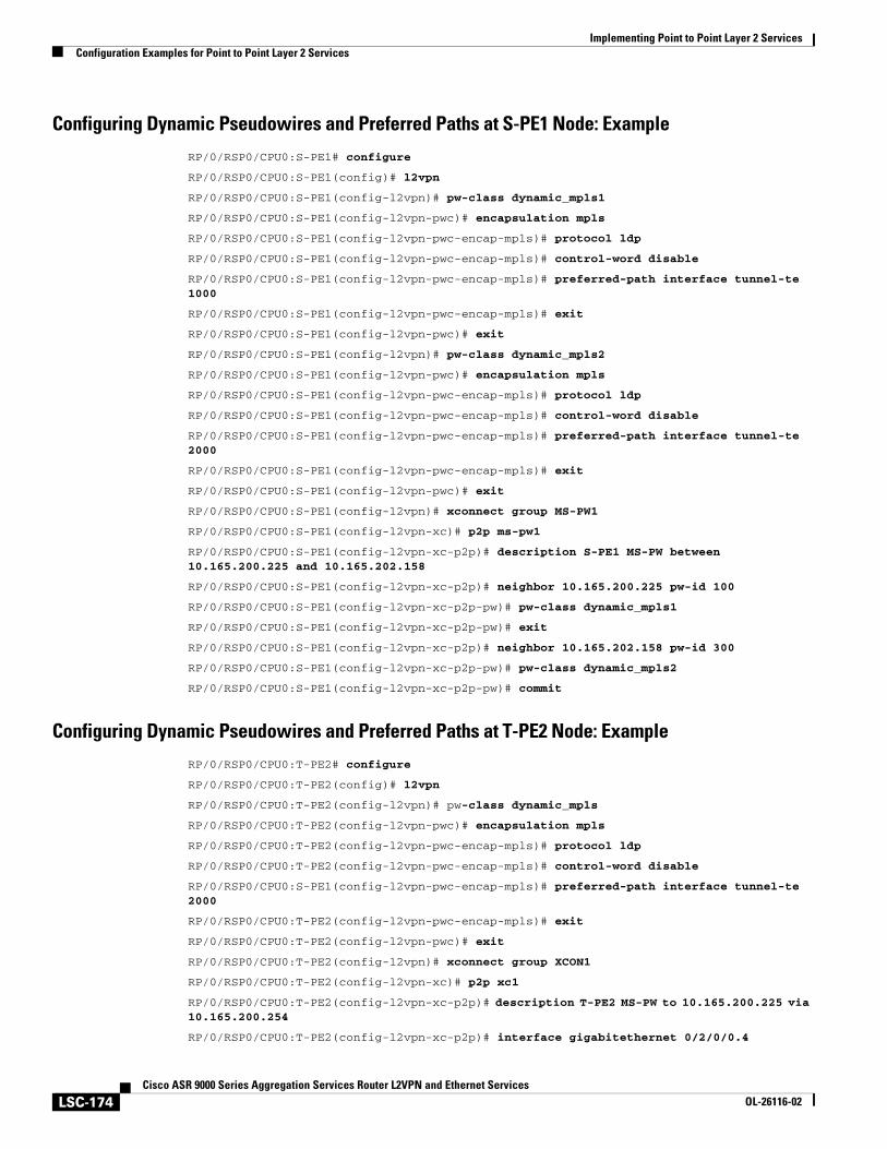
Implementing Point to Point Layer 2 ServicesConfiguration Examples for Point to Point Layer 2 Services
LSC-174Cisco ASR 9000 Series Aggregation Services Router L2VPN and Ethernet Services
OL-26116-02
Configuring Dynamic Pseudowires and Preferred Paths at S-PE1 Node: Example
RP/0/RSP0/CPU0:S-PE1# configure
RP/0/RSP0/CPU0:S-PE1(config)# l2vpn
RP/0/RSP0/CPU0:S-PE1(config-l2vpn)# pw-class dynamic_mpls1
RP/0/RSP0/CPU0:S-PE1(config-l2vpn-pwc)# encapsulation mpls
RP/0/RSP0/CPU0:S-PE1(config-l2vpn-pwc-encap-mpls)# protocol ldp
RP/0/RSP0/CPU0:S-PE1(config-l2vpn-pwc-encap-mpls)# control-word disable
RP/0/RSP0/CPU0:S-PE1(config-l2vpn-pwc-encap-mpls)# preferred-path interface tunnel-te 1000
RP/0/RSP0/CPU0:S-PE1(config-l2vpn-pwc-encap-mpls)# exit
RP/0/RSP0/CPU0:S-PE1(config-l2vpn-pwc)# exit
RP/0/RSP0/CPU0:S-PE1(config-l2vpn)# pw-class dynamic_mpls2
RP/0/RSP0/CPU0:S-PE1(config-l2vpn-pwc)# encapsulation mpls
RP/0/RSP0/CPU0:S-PE1(config-l2vpn-pwc-encap-mpls)# protocol ldp
RP/0/RSP0/CPU0:S-PE1(config-l2vpn-pwc-encap-mpls)# control-word disable
RP/0/RSP0/CPU0:S-PE1(config-l2vpn-pwc-encap-mpls)# preferred-path interface tunnel-te 2000
RP/0/RSP0/CPU0:S-PE1(config-l2vpn-pwc-encap-mpls)# exit
RP/0/RSP0/CPU0:S-PE1(config-l2vpn-pwc)# exit
RP/0/RSP0/CPU0:S-PE1(config-l2vpn)# xconnect group MS-PW1
RP/0/RSP0/CPU0:S-PE1(config-l2vpn-xc)# p2p ms-pw1
RP/0/RSP0/CPU0:S-PE1(config-l2vpn-xc-p2p)# description S-PE1 MS-PW between 10.165.200.225 and 10.165.202.158
RP/0/RSP0/CPU0:S-PE1(config-l2vpn-xc-p2p)# neighbor 10.165.200.225 pw-id 100
RP/0/RSP0/CPU0:S-PE1(config-l2vpn-xc-p2p-pw)# pw-class dynamic_mpls1
RP/0/RSP0/CPU0:S-PE1(config-l2vpn-xc-p2p-pw)# exit
RP/0/RSP0/CPU0:S-PE1(config-l2vpn-xc-p2p)# neighbor 10.165.202.158 pw-id 300
RP/0/RSP0/CPU0:S-PE1(config-l2vpn-xc-p2p-pw)# pw-class dynamic_mpls2
RP/0/RSP0/CPU0:S-PE1(config-l2vpn-xc-p2p-pw)# commit
Configuring Dynamic Pseudowires and Preferred Paths at T-PE2 Node: Example
RP/0/RSP0/CPU0:T-PE2# configure
RP/0/RSP0/CPU0:T-PE2(config)# l2vpn
RP/0/RSP0/CPU0:T-PE2(config-l2vpn)# pw-class dynamic_mpls
RP/0/RSP0/CPU0:T-PE2(config-l2vpn-pwc)# encapsulation mpls
RP/0/RSP0/CPU0:T-PE2(config-l2vpn-pwc-encap-mpls)# protocol ldp
RP/0/RSP0/CPU0:T-PE2(config-l2vpn-pwc-encap-mpls)# control-word disable
RP/0/RSP0/CPU0:S-PE1(config-l2vpn-pwc-encap-mpls)# preferred-path interface tunnel-te 2000
RP/0/RSP0/CPU0:T-PE2(config-l2vpn-pwc-encap-mpls)# exit
RP/0/RSP0/CPU0:T-PE2(config-l2vpn-pwc)# exit
RP/0/RSP0/CPU0:T-PE2(config-l2vpn)# xconnect group XCON1
RP/0/RSP0/CPU0:T-PE2(config-l2vpn-xc)# p2p xc1
RP/0/RSP0/CPU0:T-PE2(config-l2vpn-xc-p2p)# description T-PE2 MS-PW to 10.165.200.225 via 10.165.200.254
RP/0/RSP0/CPU0:T-PE2(config-l2vpn-xc-p2p)# interface gigabitethernet 0/2/0/0.4
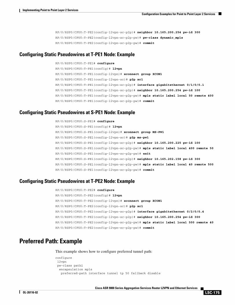
Implementing Point to Point Layer 2 ServicesConfiguration Examples for Point to Point Layer 2 Services
LSC-175Cisco ASR 9000 Series Aggregation Services Router L2VPN and Ethernet Services
OL-26116-02
RP/0/RSP0/CPU0:T-PE2(config-l2vpn-xc-p2p)# neighbor 10.165.200.254 pw-id 300
RP/0/RSP0/CPU0:T-PE2(config-l2vpn-xc-p2p-pw)# pw-class dynamic_mpls
RP/0/RSP0/CPU0:T-PE2(config-l2vpn-xc-p2p-pw)# commit
Configuring Static Pseudowires at T-PE1 Node: Example
RP/0/RSP0/CPU0:T-PE1# configure
RP/0/RSP0/CPU0:T-PE1(config)# l2vpn
RP/0/RSP0/CPU0:T-PE1(config-l2vpn)# xconnect group XCON1
RP/0/RSP0/CPU0:T-PE1(config-l2vpn-xc)# p2p xc1
RP/0/RSP0/CPU0:T-PE1(config-l2vpn-xc-p2p)# interface gigabitethernet 0/1/0/0.1
RP/0/RSP0/CPU0:T-PE1(config-l2vpn-xc-p2p)# neighbor 10.165.200.254 pw-id 100
RP/0/RSP0/CPU0:T-PE1(config-l2vpn-xc-p2p-pw)# mpls static label local 50 remote 400
RP/0/RSP0/CPU0:T-PE1(config-l2vpn-xc-p2p-pw)# commit
Configuring Static Pseudowires at S-PE1 Node: Example
RP/0/RSP0/CPU0:S-PE1# configure
RP/0/RSP0/CPU0:S-PE1(config)# l2vpn
RP/0/RSP0/CPU0:S-PE1(config-l2vpn)# xconnect group MS-PW1
RP/0/RSP0/CPU0:S-PE1(config-l2vpn-xc)# p2p ms-pw1
RP/0/RSP0/CPU0:S-PE1(config-l2vpn-xc-p2p)# neighbor 10.165.200.225 pw-id 100
RP/0/RSP0/CPU0:S-PE1(config-l2vpn-xc-p2p-pw)# mpls static label local 400 remote 50
RP/0/RSP0/CPU0:S-PE1(config-l2vpn-xc-p2p-pw)# exit
RP/0/RSP0/CPU0:S-PE1(config-l2vpn-xc-p2p)# neighbor 10.165.202.158 pw-id 300
RP/0/RSP0/CPU0:S-PE1(config-l2vpn-xc-p2p-pw)# mpls static label local 40 remote 500
RP/0/RSP0/CPU0:S-PE1(config-l2vpn-xc-p2p-pw)# commit
Configuring Static Pseudowires at T-PE2 Node: Example
RP/0/RSP0/CPU0:T-PE2# configure
RP/0/RSP0/CPU0:T-PE2(config)# l2vpn
RP/0/RSP0/CPU0:T-PE2(config-l2vpn)# xconnect group XCON1
RP/0/RSP0/CPU0:T-PE2(config-l2vpn-xc)# p2p xc1
RP/0/RSP0/CPU0:T-PE2(config-l2vpn-xc-p2p)# interface gigabitethernet 0/2/0/0.4
RP/0/RSP0/CPU0:T-PE2(config-l2vpn-xc-p2p)# neighbor 10.165.200.254 pw-id 300
RP/0/RSP0/CPU0:T-PE2(config-l2vpn-xc-p2p-pw)# mpls static label local 500 remote 40
RP/0/RSP0/CPU0:T-PE2(config-l2vpn-xc-p2p-pw)# commit
Preferred Path: ExampleThis example shows how to configure preferred tunnel path:
configurel2vpn
pw-class path1 encapsulation mpls preferred-path interface tunnel tp 50 fallback disable
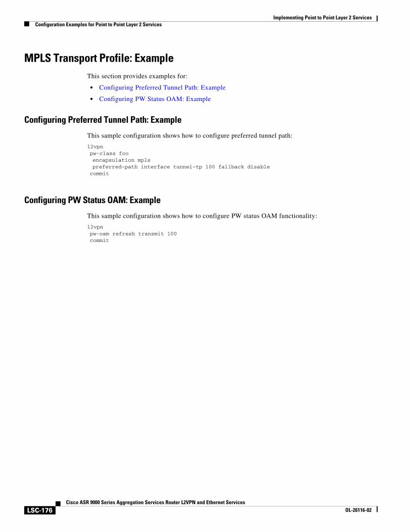
Implementing Point to Point Layer 2 ServicesConfiguration Examples for Point to Point Layer 2 Services
LSC-176Cisco ASR 9000 Series Aggregation Services Router L2VPN and Ethernet Services
OL-26116-02
MPLS Transport Profile: ExampleThis section provides examples for:
• Configuring Preferred Tunnel Path: Example
• Configuring PW Status OAM: Example
Configuring Preferred Tunnel Path: Example
This sample configuration shows how to configure preferred tunnel path:
l2vpnpw-class fooencapsulation mplspreferred-path interface tunnel-tp 100 fallback disablecommit
Configuring PW Status OAM: Example
This sample configuration shows how to configure PW status OAM functionality:
l2vpnpw-oam refresh transmit 100commit
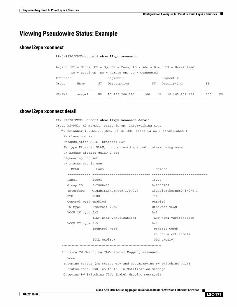
Implementing Point to Point Layer 2 ServicesConfiguration Examples for Point to Point Layer 2 Services
LSC-177Cisco ASR 9000 Series Aggregation Services Router L2VPN and Ethernet Services
OL-26116-02
Viewing Pseudowire Status: Example
show l2vpn xconnect
RP/0/RSP0/CPU0:router# show l2vpn xconnect
Legend: ST = State, UP = Up, DN = Down, AD = Admin Down, UR = Unresolved,
LU = Local Up, RU = Remote Up, CO = Connected
XConnect Segment 1 Segment 2
Group Name ST Description ST Description ST
------------------------ ------------------------- -------------------------
MS-PW1 ms-pw1 UP 10.165.200.225 100 UP 10.165.202.158 300 UP
--------------------------------------------------------------------------------
show l2vpn xconnect detail
RP/0/RSP0/CPU0:router# show l2vpn xconnect detail
Group MS-PW1, XC ms-pw1, state is up; Interworking none
PW: neighbor 10.165.200.225, PW ID 100, state is up ( established )
PW class not set
Encapsulation MPLS, protocol LDP
PW type Ethernet VLAN, control word enabled, interworking none
PW backup disable delay 0 sec
Sequencing not set
PW Status TLV in use
MPLS Local Remote
------------ ------------------------------ -----------------------------
Label 16004 16006
Group ID 0x2000400 0x2000700
Interface GigabitEthernet0/1/0/2.2 GigabitEthernet0/1/0/0.3
MTU 1500 1500
Control word enabled enabled
PW type Ethernet VLAN Ethernet VLAN
VCCV CV type 0x2 0x2
(LSP ping verification) (LSP ping verification)
VCCV CC type 0x5 0x7
(control word) (control word)
(router alert label)
(TTL expiry) (TTL expiry)
------------ ------------------------------ -----------------------------
Incoming PW Switching TLVs (Label Mapping message):
None
Incoming Status (PW Status TLV and accompanying PW Switching TLV):
Status code: 0x0 (no fault) in Notification message
Outgoing PW Switching TLVs (Label Mapping message):
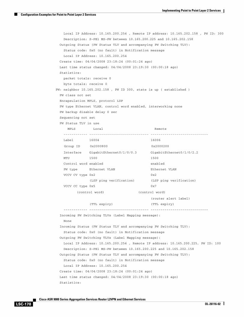
Implementing Point to Point Layer 2 ServicesConfiguration Examples for Point to Point Layer 2 Services
LSC-178Cisco ASR 9000 Series Aggregation Services Router L2VPN and Ethernet Services
OL-26116-02
Local IP Address: 10.165.200.254 , Remote IP address: 10.165.202.158 , PW ID: 300
Description: S-PE1 MS-PW between 10.165.200.225 and 10.165.202.158
Outgoing Status (PW Status TLV and accompanying PW Switching TLV):
Status code: 0x0 (no fault) in Notification message
Local IP Address: 10.165.200.254
Create time: 04/04/2008 23:18:24 (00:01:24 ago)
Last time status changed: 04/04/2008 23:19:30 (00:00:18 ago)
Statistics:
packet totals: receive 0
byte totals: receive 0
PW: neighbor 10.165.202.158 , PW ID 300, state is up ( established )
PW class not set
Encapsulation MPLS, protocol LDP
PW type Ethernet VLAN, control word enabled, interworking none
PW backup disable delay 0 sec
Sequencing not set
PW Status TLV in use
MPLS Local Remote
------------ ------------------------------ -----------------------------
Label 16004 16006
Group ID 0x2000800 0x2000200
Interface GigabitEthernet0/1/0/0.3 GigabitEthernet0/1/0/2.2
MTU 1500 1500
Control word enabled enabled
PW type Ethernet VLAN Ethernet VLAN
VCCV CV type 0x2 0x2
(LSP ping verification) (LSP ping verification)
VCCV CC type 0x5 0x7
(control word) (control word)
(router alert label)
(TTL expiry) (TTL expiry)
------------ ------------------------------ -----------------------------
Incoming PW Switching TLVs (Label Mapping message):
None
Incoming Status (PW Status TLV and accompanying PW Switching TLV):
Status code: 0x0 (no fault) in Notification message
Outgoing PW Switching TLVs (Label Mapping message):
Local IP Address: 10.165.200.254 , Remote IP address: 10.165.200.225, PW ID: 100
Description: S-PE1 MS-PW between 10.165.200.225 and 10.165.202.158
Outgoing Status (PW Status TLV and accompanying PW Switching TLV):
Status code: 0x0 (no fault) in Notification message
Local IP Address: 10.165.200.254
Create time: 04/04/2008 23:18:24 (00:01:24 ago)
Last time status changed: 04/04/2008 23:19:30 (00:00:18 ago)
Statistics:
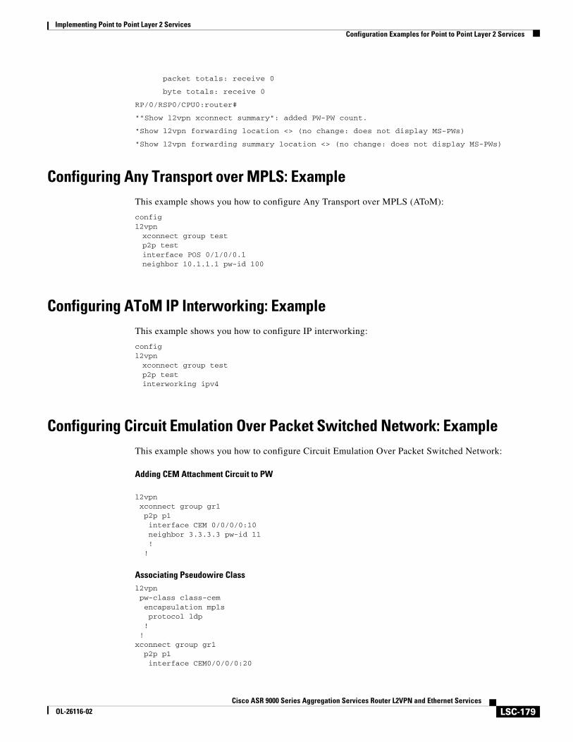
Implementing Point to Point Layer 2 ServicesConfiguration Examples for Point to Point Layer 2 Services
LSC-179Cisco ASR 9000 Series Aggregation Services Router L2VPN and Ethernet Services
OL-26116-02
packet totals: receive 0
byte totals: receive 0
RP/0/RSP0/CPU0:router#
""Show l2vpn xconnect summary": added PW-PW count.
"Show l2vpn forwarding location <> (no change: does not display MS-PWs)
"Show l2vpn forwarding summary location <> (no change: does not display MS-PWs)
Configuring Any Transport over MPLS: ExampleThis example shows you how to configure Any Transport over MPLS (AToM):
configl2vpnxconnect group testp2p testinterface POS 0/1/0/0.1neighbor 10.1.1.1 pw-id 100
Configuring AToM IP Interworking: ExampleThis example shows you how to configure IP interworking:
configl2vpnxconnect group testp2p testinterworking ipv4
Configuring Circuit Emulation Over Packet Switched Network: ExampleThis example shows you how to configure Circuit Emulation Over Packet Switched Network:
Adding CEM Attachment Circuit to PW
l2vpn xconnect group gr1 p2p p1 interface CEM 0/0/0/0:10 neighbor 3.3.3.3 pw-id 11 ! !
Associating Pseudowire Classl2vpn pw-class class-cem encapsulation mpls protocol ldp ! ! xconnect group gr1 p2p p1 interface CEM0/0/0/0:20
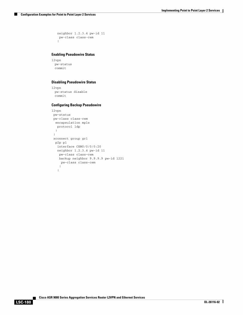
Implementing Point to Point Layer 2 ServicesConfiguration Examples for Point to Point Layer 2 Services
LSC-180Cisco ASR 9000 Series Aggregation Services Router L2VPN and Ethernet Services
OL-26116-02
neighbor 1.2.3.4 pw-id 11 pw-class class-cem !
Enabling Pseudowire Statusl2vpnpw-statuscommit
Disabling Pseudowire Statusl2vpnpw-status disablecommit
Configuring Backup Pseudowirel2vpn pw-status pw-class class-cem encapsulation mpls protocol ldp ! ! xconnect group gr1 p2p p1 interface CEM0/0/0/0:20 neighbor 1.2.3.4 pw-id 11 pw-class class-cem backup neighbor 9.9.9.9 pw-id 1221 pw-class class-cem ! !
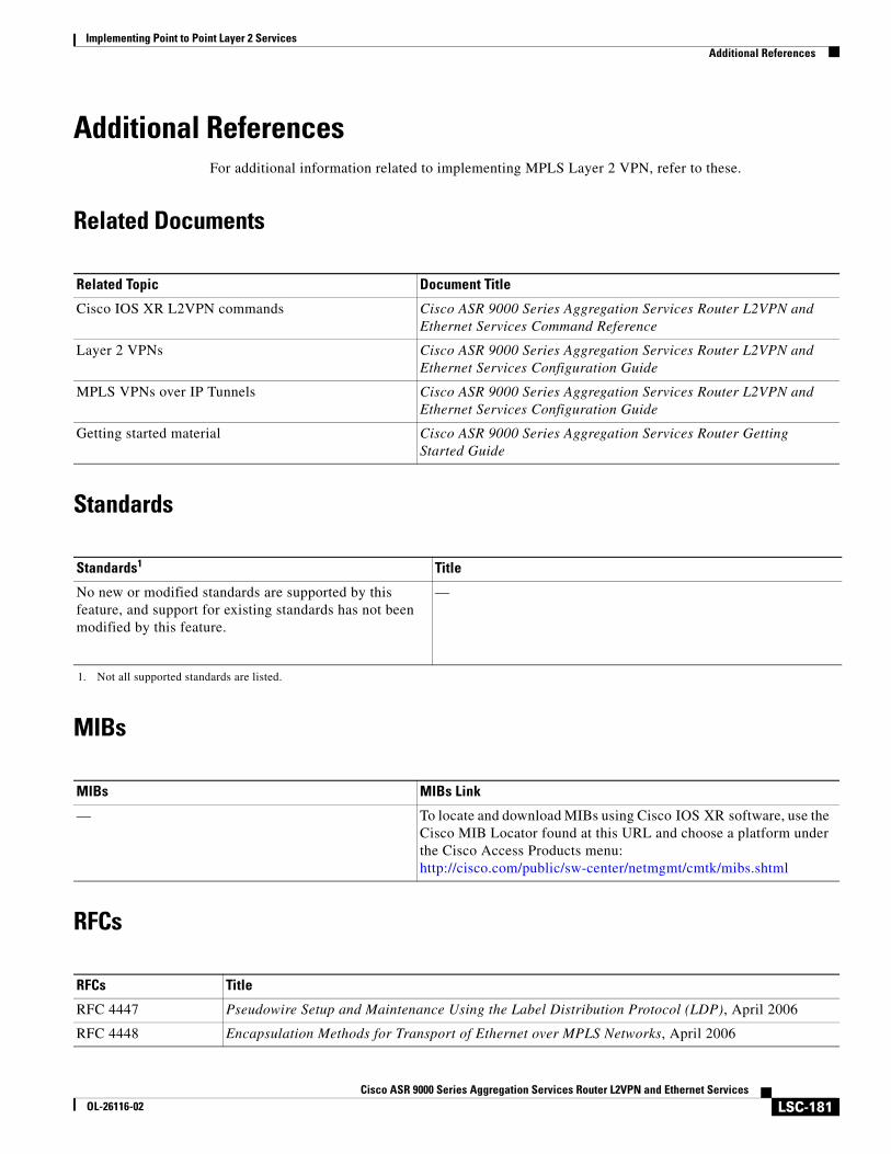
Implementing Point to Point Layer 2 ServicesAdditional References
LSC-181Cisco ASR 9000 Series Aggregation Services Router L2VPN and Ethernet Services
OL-26116-02
Additional ReferencesFor additional information related to implementing MPLS Layer 2 VPN, refer to these.
Related Documents
Standards
MIBs
RFCs
Related Topic Document Title
Cisco IOS XR L2VPN commands Cisco ASR 9000 Series Aggregation Services Router L2VPN and Ethernet Services Command Reference
Layer 2 VPNs Cisco ASR 9000 Series Aggregation Services Router L2VPN and Ethernet Services Configuration Guide
MPLS VPNs over IP Tunnels Cisco ASR 9000 Series Aggregation Services Router L2VPN and Ethernet Services Configuration Guide
Getting started material Cisco ASR 9000 Series Aggregation Services Router Getting Started Guide
Standards1
1. Not all supported standards are listed.
Title
No new or modified standards are supported by this feature, and support for existing standards has not been modified by this feature.
—
MIBs MIBs Link
— To locate and download MIBs using Cisco IOS XR software, use the Cisco MIB Locator found at this URL and choose a platform under the Cisco Access Products menu: http://cisco.com/public/sw-center/netmgmt/cmtk/mibs.shtml
RFCs Title
RFC 4447 Pseudowire Setup and Maintenance Using the Label Distribution Protocol (LDP), April 2006
RFC 4448 Encapsulation Methods for Transport of Ethernet over MPLS Networks, April 2006
Implementing Point to Point Layer 2 ServicesAdditional References
LSC-182Cisco ASR 9000 Series Aggregation Services Router L2VPN and Ethernet Services
OL-26116-02
Technical Assistance
Description Link
The Cisco Technical Support website contains thousands of pages of searchable technical content, including links to products, technologies, solutions, technical tips, and tools. Registered Cisco.com users can log in from this page to access even more content.
http://www.cisco.com/techsupport
LSC-183Cisco ASR 9000 Series Aggregation Services Router L2VPN and Ethernet Services Configuration Guide
OL-26116-02
Implementing Multipoint Layer 2 Services
This module provides the conceptual and configuration information for Multipoint Layer 2 Bridging Services, also called Virtual Private LAN Services (VPLS) on Cisco ASR 9000 Series Aggregation Services Routers. VPLS supports Layer 2 VPN technology and provides transparent multipoint Layer 2 connectivity for customers.
Note This approach enables service providers to host a multitude of new services such as broadcast TV and Layer 2 VPNs.For more information about MPLS Layer 2 VPN on Cisco ASR 9000 Series Routers and for descriptions of the commands listed in this module, see the “Related Documents” section. To locate documentation for other commands that might appear while executing a configuration task, search online in the Cisco IOS XR software master command index.
Feature History for Implementing Multipoint Layer 2 Services on Cisco ASR 9000 Series Routers
Release Modification
Release 3.7.2 This feature was introduced on Cisco ASR 9000 Series Routers.
Release 3.9.0 These features were added:
• Blocking unknown unicast flooding.
• Disabling MAC flush.
• Multiple Spanning Tree Access Gateway
• Scale enhancements were introduced. See Table 4 on page 391 for more information on scale enhancements.
Release 3.9.1 Support for VPLS with BGP Autodiscovery and LDP Signaling was added.
Release 4.0.1 Support was added for the following features:
• Dynamic ARP Inspection
• IP SourceGuard
• MAC Address Security
Implementing Multipoint Layer 2 Services
LSC-184Cisco ASR 9000 Series Aggregation Services Router L2VPN and Ethernet Services
OL-26116-02
Release 4.1.0 Support was added for these VPLS features on the ASR 9000 SIP-700 line card:
• MAC learning and forwarding
• MAC address aging support
• MAC Limiting
• Split Horizon Group
• MAC address Withdrawal
• Flooding of unknown unicast, broadcast and multicast packets
• Access pseudowire
• H-VPLS PW-access
• PW redundancy
Support was added for the G.8032 Ethernet Ring Protection feature.
Release 4.2.1 Support was added for Flow Aware Transport (FAT) Pseudowire feature.
Implementing Multipoint Layer 2 ServicesContents
LSC-185Cisco ASR 9000 Series Aggregation Services Router L2VPN and Ethernet Services
OL-26116-02
Contents• Prerequisites for Implementing Multipoint Layer 2 Services, page LSC-185
• Information About Implementing Multipoint Layer 2 Services, page LSC-185
• How to Implement Multipoint Layer 2 Services, page LSC-205
• Configuration Examples for Multipoint Layer 2 Services, page LSC-277
• Additional References, page LSC-301
Prerequisites for Implementing Multipoint Layer 2 ServicesBefore configuring VPLS, ensure that these tasks and conditions are met:
• You must be in a user group associated with a task group that includes the proper task IDs. The command reference guides include the task IDs required for each command.
If you suspect user group assignment is preventing you from using a command, contact your AAA administrator for assistance.
• Configure IP routing in the core so that the provider edge (PE) routers can reach each other through IP.
• Configure a loopback interface to originate and terminate Layer 2 traffic. Make sure that the PE routers can access the other router's loopback interface.
Note The loopback interface is not needed in all cases. For example, tunnel selection does not need a loopback interface when VPLS is directly mapped to a TE tunnel.
• Configure MPLS and Label Distribution Protocol (LDP) in the core so that a label switched path (LSP) exists between the PE routers.
Information About Implementing Multipoint Layer 2 ServicesTo implement Virtual Private LAN Services (VPLS), you should understand these concepts:
• Virtual Private LAN Services Overview, page LSC-186
• VPLS for an MPLS-based Provider Core, page LSC-188
• VPLS Discovery and Signaling, page LSC-190
• MAC Address-related Parameters, page LSC-193
• LSP Ping over VPWS and VPLS, page LSC-196
• Split Horizon Groups, page LSC-197
• Layer 2 Security, page LSC-197
• G.8032 Ethernet Ring Protection, page LSC-199
• Flow Aware Transport Pseudowire (FAT PW) Overview, page LSC-204
Implementing Multipoint Layer 2 ServicesInformation About Implementing Multipoint Layer 2 Services
LSC-186Cisco ASR 9000 Series Aggregation Services Router L2VPN and Ethernet Services
OL-26116-02
Virtual Private LAN Services OverviewVirtual Private LAN Service (VPLS) enables geographically separated local-area network (LAN) segments to be interconnected as a single bridged domain over an MPLS network. The full functions of the traditional LAN such as MAC address learning, aging, and switching are emulated across all the remotely connected LAN segments that are part of a single bridged domain.
Some of the components present in a VPLS network are described in these sections.
Bridge Domain
The native bridge domain refers to a Layer 2 broadcast domain consisting of a set of physical or virtual ports (including VFI). Data frames are switched within a bridge domain based on the destination MAC address. Multicast, broadcast, and unknown destination unicast frames are flooded within the bridge domain. In addition, the source MAC address learning is performed on all incoming frames on a bridge domain. A learned address is aged out. Incoming frames are mapped to a bridge domain, based on either the ingress port or a combination of both an ingress port and a MAC header field.
By default, split horizon is enabled for pseudowires under the same VFI. However, in the default configuration, split horizon is not enabled on the attachment circuits (interfaces or pseudowires).
Flood Optimization
A Cisco ASR 9000 Series Router, while bridging traffic in a bridge domain, minimizes the amount of traffic that floods unnecessarily. The Flood Optimization feature accomplishes this functionality. However, in certain failure recovery scenarios, extra flooding is actually desirable in order to prevent traffic loss. Traffic loss occurs during a temporary interval when one of the bridge port links becomes inactive, and a standby link replaces it.
In some configurations, optimizations to minimize traffic flooding is achieved at the expense of traffic loss during the short interval in which one of the bridge's links fails, and a standby link replaces it. Therefore, Flood Optimization can be configured in different modes to specify a particular flooding behavior suitable for your configuration.
These flood optimization modes can be configured:
• Bandwidth Optimization Mode
• Convergence Mode
• TE FRR Optimized Mode
Bandwidth Optimization Mode
Flooded traffic is sent only to the line cards on which a bridge port or pseudowire that is attached to the bridge domain resides. This is the default mode.
Convergence Mode
Flooded traffic is sent to all line cards in the system. Traffic is flooded regardless of whether they have a bridge port or a pseudowire that is attached to the bridge domain. If there are multiple Equal Cost MPLS Paths (ECMPs) attached to that bridge domain, traffic is flooded to all ECMPs.
The purpose of Convergence Mode is to ensure that an absolute minimum amount of traffic is lost during the short interval of a bridge link change due to a failure.
Implementing Multipoint Layer 2 ServicesInformation About Implementing Multipoint Layer 2 Services
LSC-187Cisco ASR 9000 Series Aggregation Services Router L2VPN and Ethernet Services
OL-26116-02
TE FRR Optimized Mode
The Traffic Engineering Fast Reroute (TE FRR) Optimized Mode is similar to the Bandwidth Optimized Mode, except for the flooding behavior with respect to any TE FRR pseudowires attached to the bridge domain. In TE FRR Optimized Mode, traffic is flooded to both the primary and backup FRR interfaces. This mode is used to minimize traffic loss during an FRR failover, thus ensuring that the bridge traffic complies with the FRR recovery time constraints.
Dynamic ARP Inspection
Dynamic ARP Inspection (DAI) is a method of providing protection against address resolution protocol (ARP) spoofing attacks. It intercepts, logs, and discards ARP packets with invalid IP-to-MAC address bindings. This capability protects the network from certain man-in-the-middle attacks. The DAI feature is disabled by default.
ARP enables IP communication within a Layer 2 broadcast domain by mapping an IP address to a MAC address. Spoofing attacks occur because ARP allows a response from a host even when an ARP request is not actually received. After an attack occurs, all traffic, from the device under attack, first flows through the attacker's system, and then to the router, switch, or the host. An ARP spoofing attack affects the devices connected to your Layer 2 network by sending false information to the ARP caches of the devices connected to the subnet. The sending of false information to an ARP cache is known as ARP cache poisoning.
The Dynamic ARP Inspection feature ensures that only valid ARP requests and responses are relayed. There are two types of ARP inspection:
• Mandatory inspection—The sender’s MAC address, IPv4 address, receiving bridge port XID and bridge are checked.
• Optional inspection—The following items are validated:
– Source MAC: The sender’s and source MACs are checked. The check is performed on all ARP or RARP packets.
– Destination MAC: The target and destination MACs are checked. The check is performed on all Reply or Reply Reverse packets.
– IPv4 Address: For ARP requests, a check is performed to verify if the sender’s IPv4 address is 0.0.0.0, a multicast address or a broadcast address. For ARP Reply and ARP Reply Reverse, a check is performed to verify if the target IPv4 address is 0.0.0.0, a multicast address or a broadcast address. This check is performed on Request, Reply and Reply Reverse packets.
Note The DAI feature is supported on attachment circuits and EFPs. Currently, the DAI feature is not supported on pseudowires.
IP Source Guard
IP source guard (IPSG) is a security feature that filters traffic based on the DHCP snooping binding database and on manually configured IP source bindings in order to restrict IP traffic on non-routed Layer 2 interfaces.
The IPSG feature provides source IP address filtering on a Layer 2 port, to prevent a malicious hosts from manipulating a legitimate host by assuming the legitimate host's IP address. This feature uses dynamic DHCP snooping and static IP source binding to match IP addresses to hosts.
Implementing Multipoint Layer 2 ServicesInformation About Implementing Multipoint Layer 2 Services
LSC-188Cisco ASR 9000 Series Aggregation Services Router L2VPN and Ethernet Services
OL-26116-02
Initially, all IP traffic, except for DHCP packets, on the EFP configured for IPSG is blocked. After a client receives an IP address from the DHCP server, or after static IP source binding is configured by the administrator, all traffic with that IP source address is permitted from that client. Traffic from other hosts is denied. This filtering limits a host's ability to attack the network by claiming a neighbor host's IP address.
Note The IPSG feature is supported on attachment circuits and EFPs. Currently, the IPSG feature is not supported on pseudowires.
Pseudowires
A pseudowire is a point-to-point connection between pairs of PE routers. Its primary function is to emulate services like Ethernet over an underlying core MPLS network through encapsulation into a common MPLS format. By encapsulating services into a common MPLS format, a pseudowire allows carriers to converge their services to an MPLS network.
DHCP Snooping over Pseudowire
The Cisco ASR 9000 Series Routers provide the ability to perform DHCP snooping, where the DHCP server is reachable on a pseudowire. The Pseudowire is considered as a trusted interface.
The dhcp ipv4 snoop profile {dhcp-snooping-profile1} command is provided under the bridge domain to enable DHCP snooping on a bridge and to attach a DHCP snooping profile to the bridge.
Virtual Forwarding Instance
VPLS is based on the characteristic of virtual forwarding instance (VFI). A VFI is a virtual bridge port that is capable of performing native bridging functions, such as forwarding, based on the destination MAC address, source MAC address learning and aging, and so forth.
A VFI is created on the PE router for each VPLS instance. The PE routers make packet-forwarding decisions by looking up the VFI of a particular VPLS instance. The VFI acts like a virtual bridge for a given VPLS instance. More than one attachment circuit belonging to a given VPLS are connected to the VFI. The PE router establishes emulated VCs to all the other PE routers in that VPLS instance and attaches these emulated VCs to the VFI. Packet forwarding decisions are based on the data structures maintained in the VFI.
VPLS for an MPLS-based Provider CoreVPLS is a multipoint Layer 2 VPN technology that connects two or more customer devices using bridging techniques. A bridge domain, which is the building block for multipoint bridging, is present on each of the PE routers. The access connections to the bridge domain on a PE router are called attachment circuits. The attachment circuits can be a set of physical ports, virtual ports, or both that are connected to the bridge at each PE device in the network.
After provisioning attachment circuits, neighbor relationships across the MPLS network for this specific instance are established through a set of manual commands identifying the end PEs. When the neighbor association is complete, a full mesh of pseudowires is established among the network-facing provider edge devices, which is a gateway between the MPLS core and the customer domain.
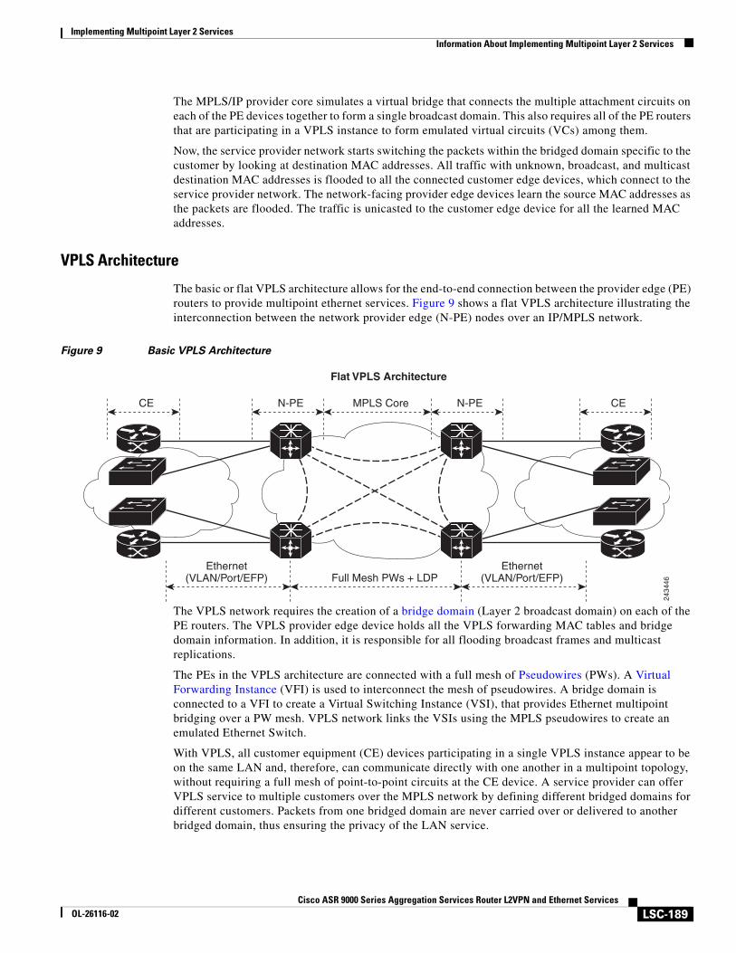
Implementing Multipoint Layer 2 ServicesInformation About Implementing Multipoint Layer 2 Services
LSC-189Cisco ASR 9000 Series Aggregation Services Router L2VPN and Ethernet Services
OL-26116-02
The MPLS/IP provider core simulates a virtual bridge that connects the multiple attachment circuits on each of the PE devices together to form a single broadcast domain. This also requires all of the PE routers that are participating in a VPLS instance to form emulated virtual circuits (VCs) among them.
Now, the service provider network starts switching the packets within the bridged domain specific to the customer by looking at destination MAC addresses. All traffic with unknown, broadcast, and multicast destination MAC addresses is flooded to all the connected customer edge devices, which connect to the service provider network. The network-facing provider edge devices learn the source MAC addresses as the packets are flooded. The traffic is unicasted to the customer edge device for all the learned MAC addresses.
VPLS Architecture
The basic or flat VPLS architecture allows for the end-to-end connection between the provider edge (PE) routers to provide multipoint ethernet services. Figure 9 shows a flat VPLS architecture illustrating the interconnection between the network provider edge (N-PE) nodes over an IP/MPLS network.
Figure 9 Basic VPLS Architecture
The VPLS network requires the creation of a bridge domain (Layer 2 broadcast domain) on each of the PE routers. The VPLS provider edge device holds all the VPLS forwarding MAC tables and bridge domain information. In addition, it is responsible for all flooding broadcast frames and multicast replications.
The PEs in the VPLS architecture are connected with a full mesh of Pseudowires (PWs). A Virtual Forwarding Instance (VFI) is used to interconnect the mesh of pseudowires. A bridge domain is connected to a VFI to create a Virtual Switching Instance (VSI), that provides Ethernet multipoint bridging over a PW mesh. VPLS network links the VSIs using the MPLS pseudowires to create an emulated Ethernet Switch.
With VPLS, all customer equipment (CE) devices participating in a single VPLS instance appear to be on the same LAN and, therefore, can communicate directly with one another in a multipoint topology, without requiring a full mesh of point-to-point circuits at the CE device. A service provider can offer VPLS service to multiple customers over the MPLS network by defining different bridged domains for different customers. Packets from one bridged domain are never carried over or delivered to another bridged domain, thus ensuring the privacy of the LAN service.
Flat VPLS Architecture
N-PE N-PEMPLS Core CECE
Ethernet(VLAN/Port/EFP)
Ethernet(VLAN/Port/EFP)Full Mesh PWs + LDP
2434
46
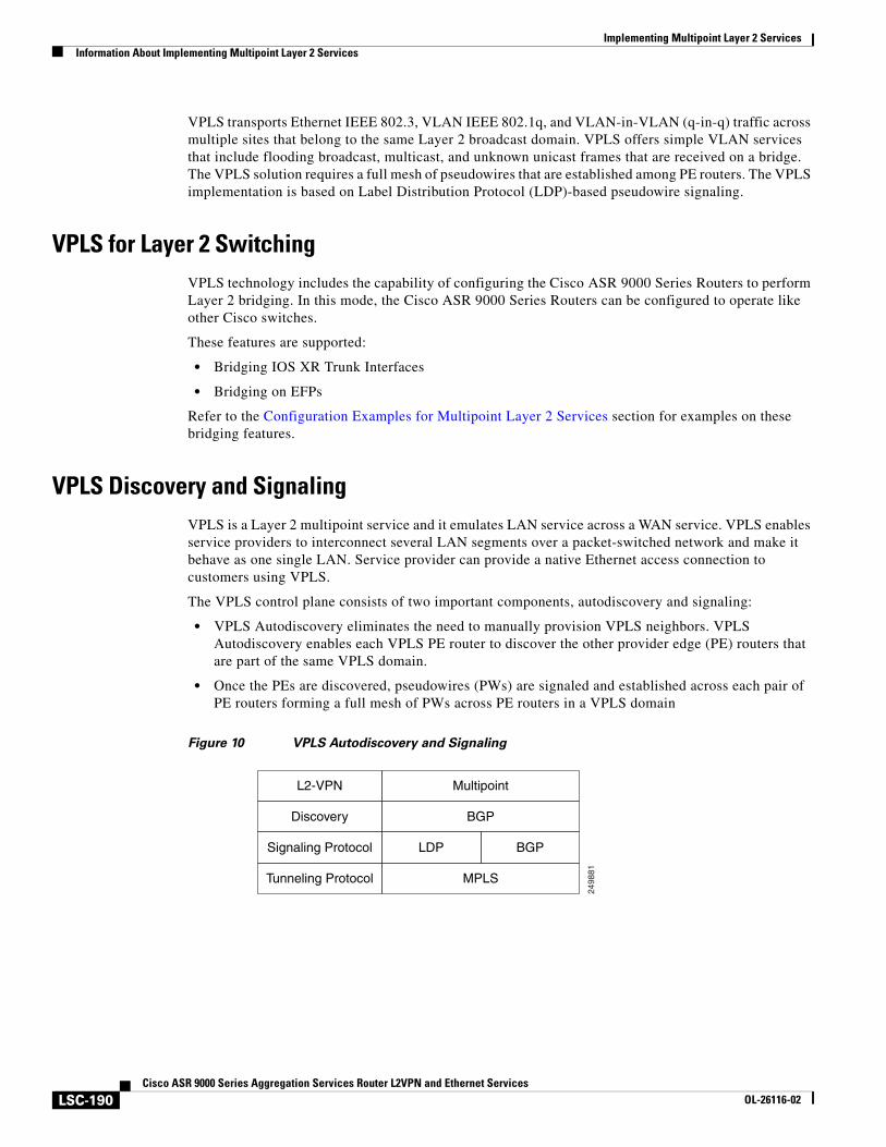
Implementing Multipoint Layer 2 ServicesInformation About Implementing Multipoint Layer 2 Services
LSC-190Cisco ASR 9000 Series Aggregation Services Router L2VPN and Ethernet Services
OL-26116-02
VPLS transports Ethernet IEEE 802.3, VLAN IEEE 802.1q, and VLAN-in-VLAN (q-in-q) traffic across multiple sites that belong to the same Layer 2 broadcast domain. VPLS offers simple VLAN services that include flooding broadcast, multicast, and unknown unicast frames that are received on a bridge. The VPLS solution requires a full mesh of pseudowires that are established among PE routers. The VPLS implementation is based on Label Distribution Protocol (LDP)-based pseudowire signaling.
VPLS for Layer 2 SwitchingVPLS technology includes the capability of configuring the Cisco ASR 9000 Series Routers to perform Layer 2 bridging. In this mode, the Cisco ASR 9000 Series Routers can be configured to operate like other Cisco switches.
These features are supported:
• Bridging IOS XR Trunk Interfaces
• Bridging on EFPs
Refer to the Configuration Examples for Multipoint Layer 2 Services section for examples on these bridging features.
VPLS Discovery and SignalingVPLS is a Layer 2 multipoint service and it emulates LAN service across a WAN service. VPLS enables service providers to interconnect several LAN segments over a packet-switched network and make it behave as one single LAN. Service provider can provide a native Ethernet access connection to customers using VPLS.
The VPLS control plane consists of two important components, autodiscovery and signaling:
• VPLS Autodiscovery eliminates the need to manually provision VPLS neighbors. VPLS Autodiscovery enables each VPLS PE router to discover the other provider edge (PE) routers that are part of the same VPLS domain.
• Once the PEs are discovered, pseudowires (PWs) are signaled and established across each pair of PE routers forming a full mesh of PWs across PE routers in a VPLS domain
Figure 10 VPLS Autodiscovery and Signaling
2498
81
L2-VPN Multipoint
Discovery BGP
Signaling Protocol LDP BGP
Tunneling Protocol MPLS
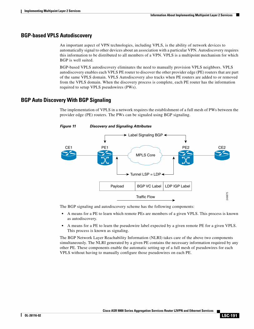
Implementing Multipoint Layer 2 ServicesInformation About Implementing Multipoint Layer 2 Services
LSC-191Cisco ASR 9000 Series Aggregation Services Router L2VPN and Ethernet Services
OL-26116-02
BGP-based VPLS Autodiscovery
An important aspect of VPN technologies, including VPLS, is the ability of network devices to automatically signal to other devices about an association with a particular VPN. Autodiscovery requires this information to be distributed to all members of a VPN. VPLS is a multipoint mechanism for which BGP is well suited.
BGP-based VPLS autodiscovery eliminates the need to manually provision VPLS neighbors. VPLS autodiscovery enables each VPLS PE router to discover the other provider edge (PE) routers that are part of the same VPLS domain. VPLS Autodiscovery also tracks when PE routers are added to or removed from the VPLS domain. When the discovery process is complete, each PE router has the information required to setup VPLS pseudowires (PWs).
BGP Auto Discovery With BGP Signaling
The implementation of VPLS in a network requires the establishment of a full mesh of PWs between the provider edge (PE) routers. The PWs can be signaled using BGP signaling.
Figure 11 Discovery and Signaling Attributes
The BGP signaling and autodiscovery scheme has the following components:
• A means for a PE to learn which remote PEs are members of a given VPLS. This process is known as autodiscovery.
• A means for a PE to learn the pseudowire label expected by a given remote PE for a given VPLS. This process is known as signaling.
The BGP Network Layer Reachability Information (NLRI) takes care of the above two components simultaneously. The NLRI generated by a given PE contains the necessary information required by any other PE. These components enable the automatic setting up of a full mesh of pseudowires for each VPLS without having to manually configure those pseudowires on each PE.
2498
75
Payload BGP VC Label LDP IGP Label
MPLS Core
Label Signaling BGP
Tunnel LSP = LDP
Traffic Flow
CE1 PE1 PE2 CE2
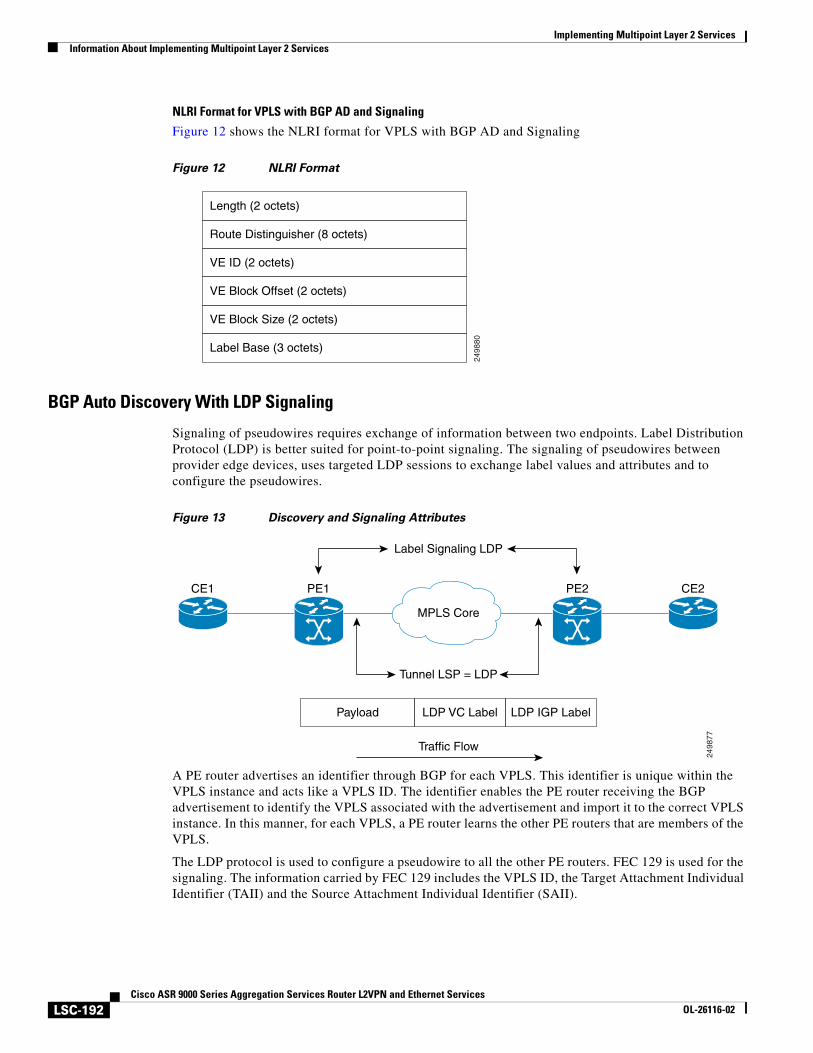
Implementing Multipoint Layer 2 ServicesInformation About Implementing Multipoint Layer 2 Services
LSC-192Cisco ASR 9000 Series Aggregation Services Router L2VPN and Ethernet Services
OL-26116-02
NLRI Format for VPLS with BGP AD and Signaling
Figure 12 shows the NLRI format for VPLS with BGP AD and Signaling
Figure 12 NLRI Format
BGP Auto Discovery With LDP Signaling
Signaling of pseudowires requires exchange of information between two endpoints. Label Distribution Protocol (LDP) is better suited for point-to-point signaling. The signaling of pseudowires between provider edge devices, uses targeted LDP sessions to exchange label values and attributes and to configure the pseudowires.
Figure 13 Discovery and Signaling Attributes
A PE router advertises an identifier through BGP for each VPLS. This identifier is unique within the VPLS instance and acts like a VPLS ID. The identifier enables the PE router receiving the BGP advertisement to identify the VPLS associated with the advertisement and import it to the correct VPLS instance. In this manner, for each VPLS, a PE router learns the other PE routers that are members of the VPLS.
The LDP protocol is used to configure a pseudowire to all the other PE routers. FEC 129 is used for the signaling. The information carried by FEC 129 includes the VPLS ID, the Target Attachment Individual Identifier (TAII) and the Source Attachment Individual Identifier (SAII).
2498
80
Length (2 octets)
Route Distinguisher (8 octets)
VE ID (2 octets)
VE Block Offset (2 octets)
VE Block Size (2 octets)
Label Base (3 octets)
2498
77Payload LDP VC Label LDP IGP Label
MPLS Core
Label Signaling LDP
Tunnel LSP = LDP
Traffic Flow
CE1 PE1 PE2 CE2
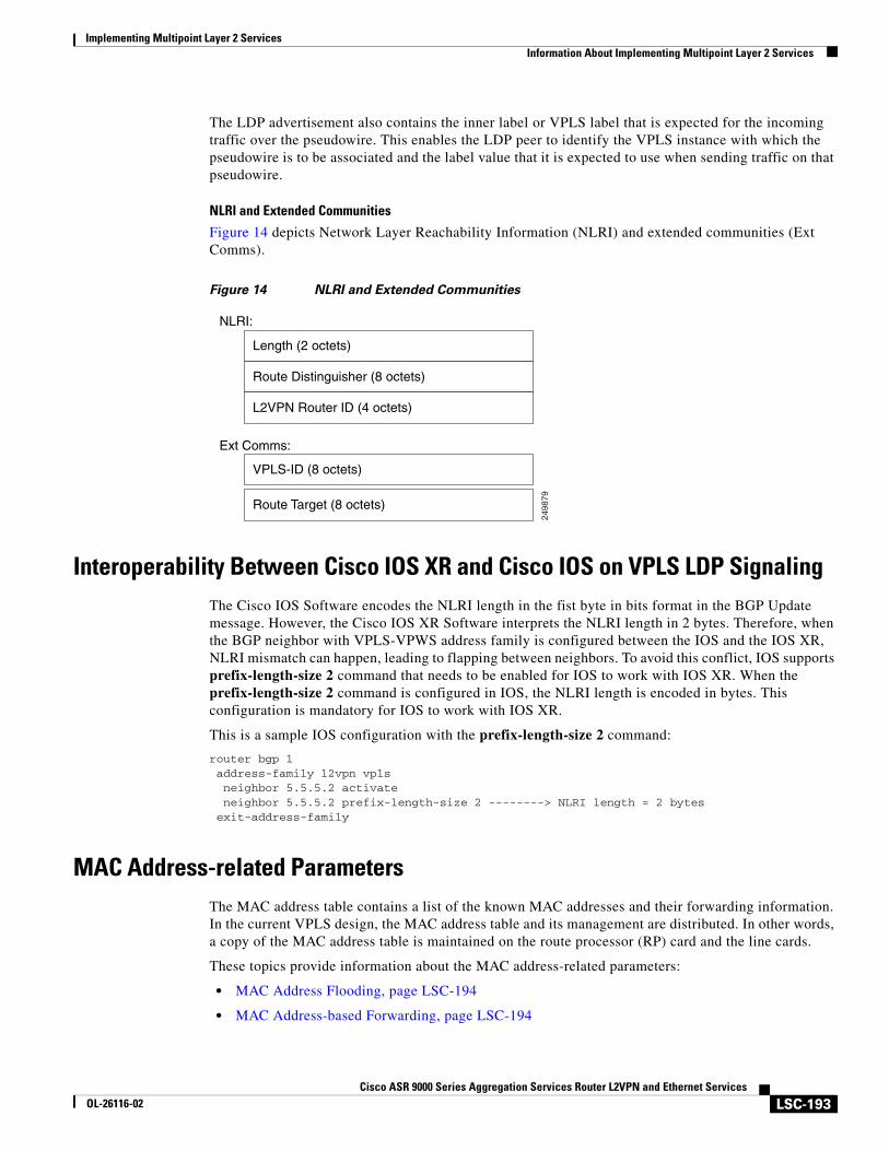
Implementing Multipoint Layer 2 ServicesInformation About Implementing Multipoint Layer 2 Services
LSC-193Cisco ASR 9000 Series Aggregation Services Router L2VPN and Ethernet Services
OL-26116-02
The LDP advertisement also contains the inner label or VPLS label that is expected for the incoming traffic over the pseudowire. This enables the LDP peer to identify the VPLS instance with which the pseudowire is to be associated and the label value that it is expected to use when sending traffic on that pseudowire.
NLRI and Extended Communities
Figure 14 depicts Network Layer Reachability Information (NLRI) and extended communities (Ext Comms).
Figure 14 NLRI and Extended Communities
Interoperability Between Cisco IOS XR and Cisco IOS on VPLS LDP SignalingThe Cisco IOS Software encodes the NLRI length in the fist byte in bits format in the BGP Update message. However, the Cisco IOS XR Software interprets the NLRI length in 2 bytes. Therefore, when the BGP neighbor with VPLS-VPWS address family is configured between the IOS and the IOS XR, NLRI mismatch can happen, leading to flapping between neighbors. To avoid this conflict, IOS supports prefix-length-size 2 command that needs to be enabled for IOS to work with IOS XR. When the prefix-length-size 2 command is configured in IOS, the NLRI length is encoded in bytes. This configuration is mandatory for IOS to work with IOS XR.
This is a sample IOS configuration with the prefix-length-size 2 command:
router bgp 1 address-family l2vpn vpls neighbor 5.5.5.2 activate neighbor 5.5.5.2 prefix-length-size 2 --------> NLRI length = 2 bytes exit-address-family
MAC Address-related ParametersThe MAC address table contains a list of the known MAC addresses and their forwarding information. In the current VPLS design, the MAC address table and its management are distributed. In other words, a copy of the MAC address table is maintained on the route processor (RP) card and the line cards.
These topics provide information about the MAC address-related parameters:
• MAC Address Flooding, page LSC-194
• MAC Address-based Forwarding, page LSC-194
2498
79
Length (2 octets)
Route Distinguisher (8 octets)
L2VPN Router ID (4 octets)
VPLS-ID (8 octets)
Ext Comms:
NLRI:
Route Target (8 octets)
Implementing Multipoint Layer 2 ServicesInformation About Implementing Multipoint Layer 2 Services
LSC-194Cisco ASR 9000 Series Aggregation Services Router L2VPN and Ethernet Services
OL-26116-02
• MAC Address Source-based Learning, page LSC-194
• MAC Address Aging, page LSC-195
• MAC Address Limit, page LSC-195
• MAC Address Withdrawal, page LSC-196
• MAC Address Security, page LSC-196
Note After you modify the MAC limit or action at the bridge domain level, ensure that you shut and unshut the bridge domain for the action to take effect. If you modify the MAC limit or action on an attachment circuit (through which traffic is passing), the attachment circuit must be shut and unshut for the action to take effect.
MAC Address Flooding
Ethernet services require that frames that are sent to broadcast addresses and to unknown destination addresses be flooded to all ports. To obtain flooding within VPLS broadcast models, all unknown unicast, broadcast, and multicast frames are flooded over the corresponding pseudowires and to all attachment circuits. Therefore, a PE must replicate packets across both attachment circuits and pseudowires.
MAC Address-based Forwarding
To forward a frame, a PE must associate a destination MAC address with a pseudowire or attachment circuit. This type of association is provided through a static configuration on each PE or through dynamic learning, which is flooded to all bridge ports.
Note Split horizon forwarding applies in this case, for example, frames that are coming in on an attachment circuit or pseudowire are sent out of the same pseudowire. The pseudowire frames, which are received on one pseudowire, are not replicated on other pseudowires in the same virtual forwarding instance (VFI).
MAC Address Source-based Learning
When a frame arrives on a bridge port (for example, pseudowire or attachment circuit) and the source MAC address is unknown to the receiving PE router, the source MAC address is associated with the pseudowire or attachment circuit. Outbound frames to the MAC address are forwarded to the appropriate pseudowire or attachment circuit.
MAC address source-based learning uses the MAC address information that is learned in the hardware forwarding path. The updated MAC tables are sent to all line cards (LCs) and program the hardware for the router.
The number of learned MAC addresses is limited through configurable per-port and per-bridge domain MAC address limits.
Implementing Multipoint Layer 2 ServicesInformation About Implementing Multipoint Layer 2 Services
LSC-195Cisco ASR 9000 Series Aggregation Services Router L2VPN and Ethernet Services
OL-26116-02
MAC Address Aging
A MAC address in the MAC table is considered valid only for the duration of the MAC address aging time. When the time expires, the relevant MAC entries are repopulated. When the MAC aging time is configured only under a bridge domain, all the pseudowires and attachment circuits in the bridge domain use that configured MAC aging time.
A bridge forwards, floods, or drops packets based on the bridge table. The bridge table maintains both static entries and dynamic entries. Static entries are entered by the network manager or by the bridge itself. Dynamic entries are entered by the bridge learning process. A dynamic entry is automatically removed after a specified length of time, known as aging time, from the time the entry was created or last updated.
If hosts on a bridged network are likely to move, decrease the aging-time to enable the bridge to adapt to the change quickly. If hosts do not transmit continuously, increase the aging time to record the dynamic entries for a longer time, thus reducing the possibility of flooding when the hosts transmit again.
MAC Address Limit
The MAC address limit is used to limit the number of learned MAC addresses. The limit is set at the bridge domain level and at the port level. The bridge domain level limit is always configured and cannot be disabled. The default value of the bridge domain level limit is 4000 and can be changed in the range of 5-512000.
Note Cisco ASR 9000 Series Routers support MAC limits on bridge port only when they are set on all the ports in a bridge domain. In this case, the bridge domain limit must be set to the value higher than the sum of limits on all ports in the bridge domain.
When the MAC address limit is violated, the system is configured to take one of the actions that are listed in Table 1.
When a limit is exceeded, the system is configured to perform these notifications:
• Syslog (default)
• Simple Network Management Protocol (SNMP) trap
• Syslog and SNMP trap
• None (no notification)
To clear the MAC limit condition, the number of MACs must go below 75 percent of the configured limit.
Table 1 MAC Address Limit Actions
Action Description
Limit flood Discards the new MAC addresses.
Limit no-flood Discards the new MAC addresses. Flooding of unknown unicast packets is disabled.
Limit shutdown Disables forwarding MAC addresses.
Implementing Multipoint Layer 2 ServicesInformation About Implementing Multipoint Layer 2 Services
LSC-196Cisco ASR 9000 Series Aggregation Services Router L2VPN and Ethernet Services
OL-26116-02
MAC Address Withdrawal
For faster VPLS convergence, you can remove or unlearn the MAC addresses that are learned dynamically. The Label Distribution Protocol (LDP) Address Withdrawal message is sent with the list of MAC addresses, which need to be withdrawn to all other PEs that are participating in the corresponding VPLS service.
For the Cisco IOS XR VPLS implementation, a portion of the dynamically learned MAC addresses are cleared by using the MAC addresses aging mechanism by default. The MAC address withdrawal feature is added through the LDP Address Withdrawal message. To enable the MAC address withdrawal feature, use the withdrawal command in l2vpn bridge group bridge domain MAC configuration mode. To verify that the MAC address withdrawal is enabled, use the show l2vpn bridge-domain command with the detail keyword.
Note By default, the LDP MAC Withdrawal feature is enabled on Cisco IOS XR.
The LDP MAC Withdrawal feature is generated due to these events:
• Attachment circuit goes down. You can remove or add the attachment circuit through the CLI.
• MAC withdrawal messages are received over a VFI pseudowire and are not propagated over access pseudowires. RFC 4762 specifies that both wildcards (by means of an empty Type, Length and Value [TLV]) and a specific MAC address withdrawal. Cisco IOS XR software supports only a wildcard MAC address withdrawal.
MAC Address Security
You can configure MAC address security at the interfaces and at the bridge access ports (subinterfaces) levels. However, MAC security configured under an interface takes precedence to MAC security configured at the bridge domain level. When a MAC address is first learned, on an EFP that is configured with MAC security and then, the same MAC address is learned on another EFP, these events occur:
• the packet is dropped
• the second EFP is shutdown
• the packet is learned and the MAC from the original EFP is flushed
LSP Ping over VPWS and VPLSFor Cisco IOS XR software, the existing support for the Label Switched Path (LSP) ping and traceroute verification mechanisms for point-to-point pseudowires (signaled using LDP FEC128) is extended to cover the pseudowires that are associated with the VFI (VPLS). Currently, the support for the LSP ping and traceroute is limited to manually configured VPLS pseudowires (signaled using LDP FEC128). For information about Virtual Circuit Connection Verification (VCCV) support and the ping mpls pseudowire command, see the Cisco ASR 9000 Series Aggregation Services Router MPLS Command Reference.
Implementing Multipoint Layer 2 ServicesInformation About Implementing Multipoint Layer 2 Services
LSC-197Cisco ASR 9000 Series Aggregation Services Router L2VPN and Ethernet Services
OL-26116-02
Split Horizon Groups An IOS XR bridge domain aggregates attachment circuits (ACs) and pseudowires (PWs) in one of three groups called Split Horizon Groups. When applied to bridge domains, Split Horizon refers to the flooding and forwarding behavior between members of a Split Horizon group. In general, frames received on one member of a split horizon group are not flooded out to the other members of the same group.
Bridge Domain traffic is either unicast or multicast.
Flooding traffic consists of unknown unicast destination MAC address frames; frames sent to Ethernet multicast addresses (Spanning Tree BPDUs, etc.); Ethernet broadcast frames (MAC address FF-FF-FF-FF-FF-FF).
Known Unicast traffic consists of frames sent to bridge ports that were learned from that port using MAC learning.
Traffic flooding is performed for broadcast, multicast and unknown unicast destination address. Unicast traffic consists of frames sent to bridge ports that were learned using MAC learning.
.
Important notes on Split Horizon Groups:
• All bridge ports or PWs that are members of a bridge domain must belong to one of the three groups.
• By default, all bridge ports or PWs are members of group 0.
• The VFI configuration submode under a bridge domain configuration indicates that members under this domain are included in group 1.
• A PW that is configured in group 0 is called an Access Pseudowire.
• The split-horizon group command is used to designate bridge ports or PWs as members of group 2.
• The ASR9000 only supports one VFI group.
Layer 2 SecurityThese topics describe the Layer 2 VPN extensions to support Layer 2 security:
• Port Security, page LSC-198
• Dynamic Host Configuration Protocol Snooping, page LSC-199
Table 2 Split Horizon Groups Supported in Cisco IOS-XR
Split Horizon Group Who belongs to this Group? Multicast within Group Unicast within Group
0 Default—any member not covered by groups 1 or 2.
Yes Yes
1 Any PW configured under VFI. No No
2 Any AC or PW configured with split-horizon keyword.
No No
Implementing Multipoint Layer 2 ServicesInformation About Implementing Multipoint Layer 2 Services
LSC-198Cisco ASR 9000 Series Aggregation Services Router L2VPN and Ethernet Services
OL-26116-02
Port Security
Use port security with dynamically learned and static MAC addresses to restrict a port’s ingress traffic by limiting the MAC addresses that are allowed to send traffic into the port. When secure MAC addresses are assigned to a secure port, the port does not forward ingress traffic that has source addresses outside the group of defined addresses. If the number of secure MAC addresses is limited to one and assigned a single secure MAC address, the device attached to that port has the full bandwidth of the port.
These port security features are supported:
• Limits the MAC table size on a bridge or a port.
• Facilitates actions and notifications for a MAC address.
• Enables the MAC aging time and mode for a bridge or a port.
• Filters static MAC addresses on a bridge or a port.
• Marks ports as either secure or nonsecure.
• Enables or disables flooding on a bridge or a port.
Implementing Multipoint Layer 2 ServicesInformation About Implementing Multipoint Layer 2 Services
LSC-199Cisco ASR 9000 Series Aggregation Services Router L2VPN and Ethernet Services
OL-26116-02
After you have set the maximum number of secure MAC addresses on a port, you can configure port security to include the secure addresses in the address table in one of these ways:
• Statically configure all secure MAC addresses by using the static-address command.
• Allow the port to dynamically configure secure MAC addresses with the MAC addresses of connected devices.
• Statically configure a number of addresses and allow the rest to be dynamically configured.
Dynamic Host Configuration Protocol Snooping
Dynamic Host Configuration Protocol (DHCP) snooping is a security feature that acts like a firewall between untrusted hosts and trusted DHCP servers. The DHCP snooping feature performs these activities:
• Validates DHCP messages received from untrusted sources and filters out invalid messages.
• Rate-limits DHCP traffic from trusted and untrusted sources.
• Builds and maintains the binding database of DHCP snooping, which contains information about untrusted hosts with leased IP addresses.
• Utilizes the binding database of DHCP snooping to validate subsequent requests from untrusted hosts.
For additional information regarding DHCP, see the Cisco ASR 9000 Series Aggregation Services Router IP Addresses and Services Configuration Guide.
G.8032 Ethernet Ring ProtectionEthernet Ring Protection (ERP) protocol, defined in ITU-T G.8032, provides protection for Ethernet traffic in a ring topology, while ensuring that there are no loops within the ring at the Ethernet layer. The loops are prevented by blocking either a pre-determined link or a failed link.
Overview
Each Ethernet ring node is connected to adjacent Ethernet ring nodes participating in the Ethernet ring using two independent links. A ring link never allows formation of loops that affect the network. The Ethernet ring uses a specific link to protect the entire Ethernet ring. This specific link is called the ring protection link (RPL). A ring link is bound by two adjacent Ethernet ring nodes and a port for a ring link (also known as a ring port).
Note The minimum number of Ethernet ring nodes in an Ethernet ring is two.
The fundamentals of ring protection switching are:
• the principle of loop avoidance
• the utilization of learning, forwarding, and Filtering Database (FDB) mechanisms
Loop avoidance in an Ethernet ring is achieved by ensuring that, at any time, traffic flows on all but one of the ring links which is the RPL. Multiple nodes are used to form a ring:
• RPL owner—It is responsible for blocking traffic over the RPL so that no loops are formed in the Ethernet traffic. There can be only one RPL owner in a ring.
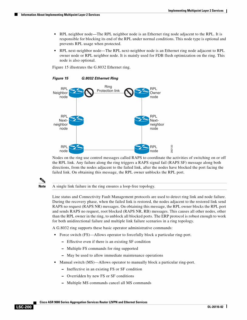
Implementing Multipoint Layer 2 ServicesInformation About Implementing Multipoint Layer 2 Services
LSC-200Cisco ASR 9000 Series Aggregation Services Router L2VPN and Ethernet Services
OL-26116-02
• RPL neighbor node—The RPL neighbor node is an Ethernet ring node adjacent to the RPL. It is responsible for blocking its end of the RPL under normal conditions. This node type is optional and prevents RPL usage when protected.
• RPL next-neighbor node—The RPL next-neighbor node is an Ethernet ring node adjacent to RPL owner node or RPL neighbor node. It is mainly used for FDB flush optimization on the ring. This node is also optional.
Figure 15 illustrates the G.8032 Ethernet ring.
Figure 15 G.8032 Ethernet Ring
Nodes on the ring use control messages called RAPS to coordinate the activities of switching on or off the RPL link. Any failure along the ring triggers a RAPS signal fail (RAPS SF) message along both directions, from the nodes adjacent to the failed link, after the nodes have blocked the port facing the failed link. On obtaining this message, the RPL owner unblocks the RPL port.
Note A single link failure in the ring ensures a loop-free topology.
Line status and Connectivity Fault Management protocols are used to detect ring link and node failure. During the recovery phase, when the failed link is restored, the nodes adjacent to the restored link send RAPS no request (RAPS NR) messages. On obtaining this message, the RPL owner blocks the RPL port and sends RAPS no request, root blocked (RAPS NR, RB) messages. This causes all other nodes, other than the RPL owner in the ring, to unblock all blocked ports. The ERP protocol is robust enough to work for both unidirectional failure and multiple link failure scenarios in a ring topology.
A G.8032 ring supports these basic operator administrative commands:
• Force switch (FS)—Allows operator to forcefully block a particular ring-port.
– Effective even if there is an existing SF condition
– Multiple FS commands for ring supported
– May be used to allow immediate maintenance operations
• Manual switch (MS)—Allows operator to manually block a particular ring-port.
– Ineffective in an existing FS or SF condition
– Overridden by new FS or SF conditions
– Multiple MS commands cancel all MS commands
RingProtection link RPL
Ownernode
RPLnode
RPLNext-neighbornode
RPLNeighbor
node
RPLnode
RPLNext-
neighbornode
2821
33
Implementing Multipoint Layer 2 ServicesInformation About Implementing Multipoint Layer 2 Services
LSC-201Cisco ASR 9000 Series Aggregation Services Router L2VPN and Ethernet Services
OL-26116-02
• Clear—Cancels an existing FS or MS command on the ring-port
– Used (at RPL Owner) to clear non-revertive mode
A G.8032 ring can support multiple instances. An instance is a logical ring running over a physical ring. Such instances are used for various reasons, such as load balancing VLANs over a ring. For example, odd VLANs may go in one direction of the ring, and even VLANs may go in the other direction. Specific VLANs can be configured under only one instance. They cannot overlap multiple instances. Otherwise, data traffic or RAPS packet can cross logical rings, and that is not desirable.
G.8032 ERP provides a new technology that relies on line status and Connectivity Fault Management (CFM) to detect link failure. By running CFM Continuity Check Messages (CCM) messages at an interval of 100ms, it is possible to achieve SONET-like switching time performance and loop free traffic.
For more information about Ethernet Connectivity Fault Management (CFM) and Ethernet Fault Detection (EFD) configuration, refer to the Configuring Ethernet OAM on the Cisco ASR 9000 Series Router module in the Cisco ASR 9000 Series Aggregation Services Router Interface and Hardware Component Configuration Guide.
Timers
G.8032 ERP specifies the use of different timers to avoid race conditions and unnecessary switching operations:
• Delay Timers—used by the RPL Owner to verify that the network has stabilized before blocking the RPL
– After SF condition, Wait-to-Restore (WTR) timer is used to verify that SF is not intermittent. The WTR timer can be configured by the operator, and the default time interval is 5 minutes. The time interval ranges from 1 to 12 minutes.
– After FS/MS command, Wait-to-Block timer is used to verify that no background condition exists.
Note Wait-to-Block timer may be shorter than the Wait-to-Restore timer.
• Guard Timer—used by all nodes when changing state; it blocks latent outdated messages from causing unnecessary state changes. The Guard timer can be configured and the default time interval is 500 ms. The time interval ranges from 10 to 2000 ms.
• Hold-off timers—used by underlying Ethernet layer to filter out intermittent link faults. The hold-off timer can be configured and the default time interval is 0 seconds. The time interval ranges from 0 to 10 seconds.
– Faults are reported to the ring protection mechanism, only if this timer expires.
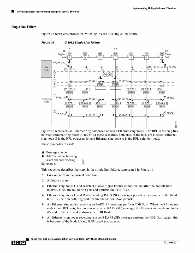
Implementing Multipoint Layer 2 ServicesInformation About Implementing Multipoint Layer 2 Services
LSC-202Cisco ASR 9000 Series Aggregation Services Router L2VPN and Ethernet Services
OL-26116-02
Single Link Failure
Figure 16 represents protection switching in case of a single link failure.
Figure 16 G.8032 Single Link Failure
Figure 16 represents an Ethernet ring composed of seven Ethernet ring nodes. The RPL is the ring link between Ethernet ring nodes A and G. In these scenarios, both ends of the RPL are blocked. Ethernet ring node G is the RPL owner node, and Ethernet ring node A is the RPL neighbor node.
These symbols are used:
This sequence describes the steps in the single link failure, represented in Figure 16:
1. Link operates in the normal condition.
2. A failure occurs.
3. Ethernet ring nodes C and D detect a local Signal Failure condition and after the holdoff time interval, block the failed ring port and perform the FDB flush.
4. Ethernet ring nodes C and D start sending RAPS (SF) messages periodically along with the (Node ID, BPR) pair on both ring ports, while the SF condition persists.
5. All Ethernet ring nodes receiving an RAPS (SF) message perform FDB flush. When the RPL owner node G and RPL neighbor node A receive an RAPS (SF) message, the Ethernet ring node unblocks it’s end of the RPL and performs the FDB flush.
6. All Ethernet ring nodes receiving a second RAPS (SF) message perform the FDB flush again; this is because of the Node ID and BPR-based mechanism.
62,0 89, 1 62,0 89, 162,0 89, 1 89, 1 62,0 89, 1 62,0 89, 1 62,0 89, 1
75, 1 75, 1
75, 1 89, 1 62,0 75 1 62,0 75 1 62,0 89, 1
62,0
PendingState
ProtectionState
IdleState
2821
36
A
81
B
26
75, 175, 1 75, 1 75, 1 75, 1
C
89
D
62
E
71
F
31
G
75
A
B
C
DE
F
G
1 0 1 0 1 0 1 0 1 0 1 0
0 RPL 1RPL
NeighborNode
RPLOwnerNode
SF (62, 0)
SF (89, 1)
SF (89, 1)
NR, RB (75, 1)
NR, RB (75, 1)
SF (62, 0)
failure
Flush Flush Flush
Flush Flush
Flush Flush Flush Flush
SF (89, 1)
SF (89, 1) SF (62, 0)
SF (89, 1) SF (62, 0)
SF (62, 0)
NR, RB (75, 1)
Flush Flush Flush Flush Flush
Message sourceR-APS channel blockingClient channel blockingNode ID 28
2135
n
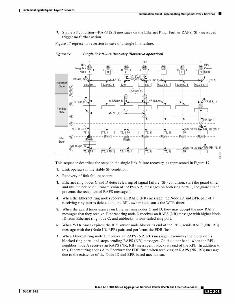
Implementing Multipoint Layer 2 ServicesInformation About Implementing Multipoint Layer 2 Services
LSC-203Cisco ASR 9000 Series Aggregation Services Router L2VPN and Ethernet Services
OL-26116-02
7. Stable SF condition—RAPS (SF) messages on the Ethernet Ring. Further RAPS (SF) messages trigger no further action.
Figure 17 represents reversion in case of a single link failure.
Figure 17 Single link failure Recovery (Revertive operation)
This sequence describes the steps in the single link failure recovery, as represented in Figure 17:
1. Link operates in the stable SF condition.
2. Recovery of link failure occurs.
3. Ethernet ring nodes C and D detect clearing of signal failure (SF) condition, start the guard timer and initiate periodical transmission of RAPS (NR) messages on both ring ports. (The guard timer prevents the reception of RAPS messages).
4. When the Ethernet ring nodes receive an RAPS (NR) message, the Node ID and BPR pair of a receiving ring port is deleted and the RPL owner node starts the WTR timer.
5. When the guard timer expires on Ethernet ring nodes C and D, they may accept the new RAPS messages that they receive. Ethernet ring node D receives an RAPS (NR) message with higher Node ID from Ethernet ring node C, and unblocks its non-failed ring port.
6. When WTR timer expires, the RPL owner node blocks its end of the RPL, sends RAPS (NR, RB) message with the (Node ID, BPR) pair, and performs the FDB flush.
7. When Ethernet ring node C receives an RAPS (NR, RB) message, it removes the block on its blocked ring ports, and stops sending RAPS (NR) messages. On the other hand, when the RPL neighbor node A receives an RAPS (NR, RB) message, it blocks its end of the RPL. In addition to this, Ethernet ring nodes A to F perform the FDB flush when receiving an RAPS (NR, RB) message, due to the existence of the Node ID and BPR based mechanism.
62,0 89, 1
75, 1 75, 1 75, 1 75, 1 75, 175, 1 75, 1
75, 1 75, 1 75, 1 75, 1 75, 1 75, 1 75, 175, 1 75, 1
62,0 89, 1 62,0 89, 1 62,0 89, 1 62,0 89, 1 89, 162,0 Protection
State
PendingState
IdleState
2821
34
A
81
B
26
C
89
D
62
E
71
F
31
G
75
A
B
C
D
E
F
G
H
1 0 1 0 1 0 1 0 1 0 1 0
0 RPL 1RPL
NeighborNode
RPLOwnerNode
recovery
SF (62, 0)
NR (62, 0)
NR, RB (75, 1) NR, RB (75, 1)
NR, RB (75, 1) NR, RB (75, 1)
NR (62, 0)
NR (89, 1)
NR (89, 1)
SF (62, 0)SF (89, 1) SF (89, 1)failure
FlushFlush
FlushFlush Flush Flush Flush
NR (89, 1)
NR (89, 1)
NR, RB (75, 1)
NR, RB (75, 1)
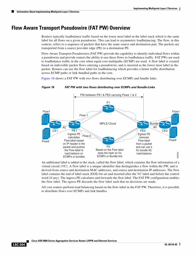
Implementing Multipoint Layer 2 ServicesInformation About Implementing Multipoint Layer 2 Services
LSC-204Cisco ASR 9000 Series Aggregation Services Router L2VPN and Ethernet Services
OL-26116-02
Flow Aware Transport Pseudowire (FAT PW) OverviewRouters typically loadbalance traffic based on the lower most label in the label stack which is the same label for all flows on a given pseudowire. This can lead to asymmetric loadbalancing. The flow, in this context, refers to a sequence of packets that have the same source and destination pair. The packets are transported from a source provider edge (PE) to a destination PE.
Flow-Aware Transport Pseudowires (FAT PW) provide the capability to identify individual flows within a pseudowire and provide routers the ability to use these flows to loadbalance traffic. FAT PWs are used to loadbalance traffic in the core when equal cost multipaths (ECMP) are used. A flow label is created based on indivisible packet flows entering a pseudowire; and is inserted as the lower most label in the packet. Routers can use the flow label for loadbalancing which provides a better traffic distribution across ECMP paths or link-bundled paths in the core.
Figure 18 shows a FAT PW with two flows distributing over ECMPs and bundle links.
Figure 18 FAT PW with two flows distributing over ECMPs and Bundle-Links
An additional label is added to the stack, called the flow label, which contains the flow information of a virtual circuit (VC). A flow label is a unique identifier that distinguishes a flow within the PW, and is derived from source and destination MAC addresses, and source and destination IP addresses. The flow label contains the end of label stack (EOS) bit set and inserted after the VC label and before the control word (if any). The ingress PE calculates and forwards the flow label. The FAT PW configuration enables the flow label. The egress PE discards the flow label such that no decisions are made.
All core routers perform load balancing based on the flow-label in the FAT PW. Therefore, it is possible to distribute flows over ECMPs and link bundles.
CE2PE1
P1
MPLS Cloud
P2
Flow1
Flow2
Flow1
Flow2
CE1 PE2AC AC
Bundle
Flow-2
Flow-1
PW between PE1 & PE2 carrying Flows 1 & 2
Based on the Flow labeldoes the hash on it’s
ECMPs or Bundle link
Ingress PEcalculates
Flow-label basedon IP header in thepacket and pushesthe Flow label toload balance on
ECMPs or bundles
Egress PEremoves
Flow-labelfrom a packetand can use itfor bundle ACload-balance
2830
02
Implementing Multipoint Layer 2 ServicesHow to Implement Multipoint Layer 2 Services
LSC-205Cisco ASR 9000 Series Aggregation Services Router L2VPN and Ethernet Services
OL-26116-02
How to Implement Multipoint Layer 2 ServicesThis section describes the tasks that are required to implement VPLS:
• Configuring a Bridge Domain, page LSC-205
• Configuring Layer 2 Security, page LSC-221
• Configuring a Layer 2 Virtual Forwarding Instance, page LSC-225
• Configuring the MAC Address-related Parameters, page LSC-237
• Configuring an Attachment Circuit to the AC Split Horizon Group, page LSC-252
• Adding an Access Pseudowire to the AC Split Horizon Group, page LSC-254
• Configuring VPLS with BGP Autodiscovery and Signaling, page LSC-255
• Configuring VPLS with BGP Autodiscovery and LDP Signaling, page LSC-258
• Configuring G.8032 Ethernet Ring Protection, page LSC-261
• Configuring Flow Aware Transport Pseudowire, page LSC-270
Configuring a Bridge DomainThese topics describe how to configure a bridge domain:
• Creating a Bridge Domain, page LSC-205
• Configuring a Pseudowire, page LSC-207
• Associating Members with a Bridge Domain, page LSC-210
• Configuring Bridge Domain Parameters, page LSC-212
• Disabling a Bridge Domain, page LSC-215
• Blocking Unknown Unicast Flooding, page LSC-217
• Changing the Flood Optimization Mode, page LSC-218
Creating a Bridge Domain
Perform this task to create a bridge domain .
SUMMARY STEPS
1. configure
2. l2vpn
3. bridge group bridge-group-name
4. bridge-domain bridge-domain-name
5. endorcommit
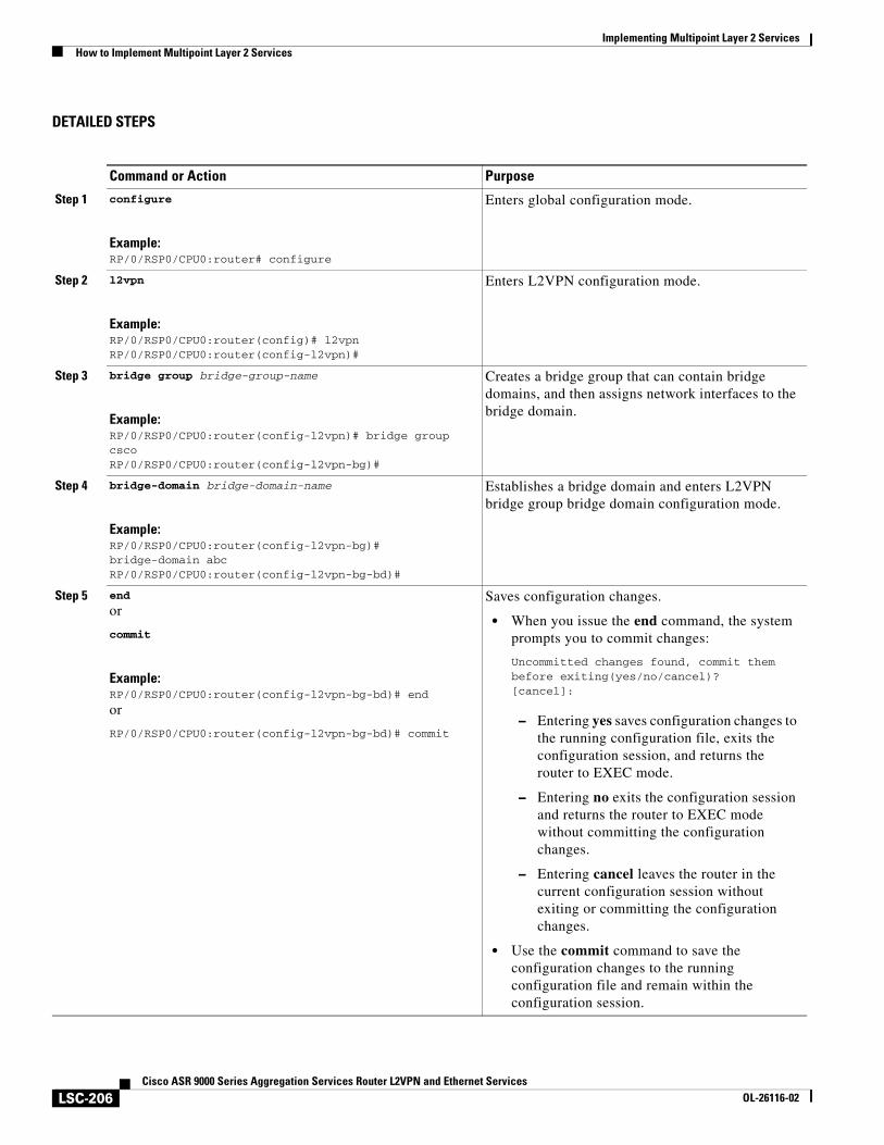
Implementing Multipoint Layer 2 ServicesHow to Implement Multipoint Layer 2 Services
LSC-206Cisco ASR 9000 Series Aggregation Services Router L2VPN and Ethernet Services
OL-26116-02
DETAILED STEPS
Command or Action Purpose
Step 1 configure
Example:RP/0/RSP0/CPU0:router# configure
Enters global configuration mode.
Step 2 l2vpn
Example:RP/0/RSP0/CPU0:router(config)# l2vpnRP/0/RSP0/CPU0:router(config-l2vpn)#
Enters L2VPN configuration mode.
Step 3 bridge group bridge-group-name
Example:RP/0/RSP0/CPU0:router(config-l2vpn)# bridge group cscoRP/0/RSP0/CPU0:router(config-l2vpn-bg)#
Creates a bridge group that can contain bridge domains, and then assigns network interfaces to the bridge domain.
Step 4 bridge-domain bridge-domain-name
Example:RP/0/RSP0/CPU0:router(config-l2vpn-bg)# bridge-domain abcRP/0/RSP0/CPU0:router(config-l2vpn-bg-bd)#
Establishes a bridge domain and enters L2VPN bridge group bridge domain configuration mode.
Step 5 end
or
commit
Example:RP/0/RSP0/CPU0:router(config-l2vpn-bg-bd)# end
or
RP/0/RSP0/CPU0:router(config-l2vpn-bg-bd)# commit
Saves configuration changes.
• When you issue the end command, the system prompts you to commit changes:
Uncommitted changes found, commit them before exiting(yes/no/cancel)?[cancel]:
– Entering yes saves configuration changes to the running configuration file, exits the configuration session, and returns the router to EXEC mode.
– Entering no exits the configuration session and returns the router to EXEC mode without committing the configuration changes.
– Entering cancel leaves the router in the current configuration session without exiting or committing the configuration changes.
• Use the commit command to save the configuration changes to the running configuration file and remain within the configuration session.
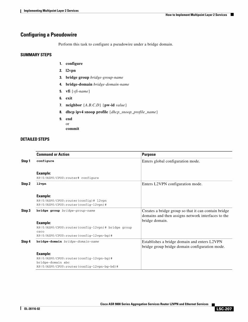
Implementing Multipoint Layer 2 ServicesHow to Implement Multipoint Layer 2 Services
LSC-207Cisco ASR 9000 Series Aggregation Services Router L2VPN and Ethernet Services
OL-26116-02
Configuring a Pseudowire
Perform this task to configure a pseudowire under a bridge domain.
SUMMARY STEPS
1. configure
2. l2vpn
3. bridge group bridge-group-name
4. bridge-domain bridge-domain-name
5. vfi {vfi-name}
6. exit
7. neighbor {A.B.C.D} {pw-id value}
8. dhcp ipv4 snoop profile {dhcp_snoop_profile_name}
9. endorcommit
DETAILED STEPS
Command or Action Purpose
Step 1 configure
Example:RP/0/RSP0/CPU0:router# configure
Enters global configuration mode.
Step 2 l2vpn
Example:RP/0/RSP0/CPU0:router(config)# l2vpnRP/0/RSP0/CPU0:router(config-l2vpn)#
Enters L2VPN configuration mode.
Step 3 bridge group bridge-group-name
Example:RP/0/RSP0/CPU0:router(config-l2vpn)# bridge group cscoRP/0/RSP0/CPU0:router(config-l2vpn-bg)#
Creates a bridge group so that it can contain bridge domains and then assigns network interfaces to the bridge domain.
Step 4 bridge-domain bridge-domain-name
Example:RP/0/RSP0/CPU0:router(config-l2vpn-bg)# bridge-domain abcRP/0/RSP0/CPU0:router(config-l2vpn-bg-bd)#
Establishes a bridge domain and enters L2VPN bridge group bridge domain configuration mode.
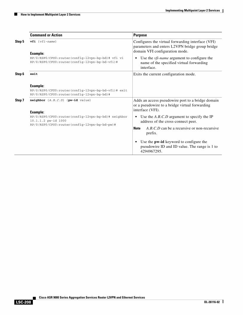
Implementing Multipoint Layer 2 ServicesHow to Implement Multipoint Layer 2 Services
LSC-208Cisco ASR 9000 Series Aggregation Services Router L2VPN and Ethernet Services
OL-26116-02
Step 5 vfi {vfi-name}
Example:RP/0/RSP0/CPU0:router(config-l2vpn-bg-bd)# vfi v1RP/0/RSP0/CPU0:router(config-l2vpn-bg-bd-vfi)#
Configures the virtual forwarding interface (VFI) parameters and enters L2VPN bridge group bridge domain VFI configuration mode.
• Use the vfi-name argument to configure the name of the specified virtual forwarding interface.
Step 6 exit
Example:RP/0/RSP0/CPU0:router(config-l2vpn-bg-bd-vfi)# exitRP/0/RSP0/CPU0:router(config-l2vpn-bg-bd)#
Exits the current configuration mode.
Step 7 neighbor {A.B.C.D} {pw-id value}
Example:RP/0/RSP0/CPU0:router(config-l2vpn-bg-bd)# neighbor 10.1.1.2 pw-id 1000RP/0/RSP0/CPU0:router(config-l2vpn-bg-bd-pw)#
Adds an access pseudowire port to a bridge domain or a pseudowire to a bridge virtual forwarding interface (VFI).
• Use the A.B.C.D argument to specify the IP address of the cross-connect peer.
Note A.B.C.D can be a recursive or non-recursive prefix.
• Use the pw-id keyword to configure the pseudowire ID and ID value. The range is 1 to 4294967295.
Command or Action Purpose
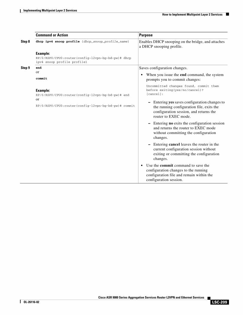
Implementing Multipoint Layer 2 ServicesHow to Implement Multipoint Layer 2 Services
LSC-209Cisco ASR 9000 Series Aggregation Services Router L2VPN and Ethernet Services
OL-26116-02
Step 8 dhcp ipv4 snoop profile {dhcp_snoop_profile_name}
Example:RP/0/RSP0/CPU0:router(config-l2vpn-bg-bd-pw)# dhcp ipv4 snoop profile profile1
Enables DHCP snooping on the bridge, and attaches a DHCP snooping profile.
Step 9 end
or
commit
Example:RP/0/RSP0/CPU0:router(config-l2vpn-bg-bd-pw)# end
or
RP/0/RSP0/CPU0:router(config-l2vpn-bg-bd-pw)# commit
Saves configuration changes.
• When you issue the end command, the system prompts you to commit changes:
Uncommitted changes found, commit them before exiting(yes/no/cancel)?[cancel]:
– Entering yes saves configuration changes to the running configuration file, exits the configuration session, and returns the router to EXEC mode.
– Entering no exits the configuration session and returns the router to EXEC mode without committing the configuration changes.
– Entering cancel leaves the router in the current configuration session without exiting or committing the configuration changes.
• Use the commit command to save the configuration changes to the running configuration file and remain within the configuration session.
Command or Action Purpose
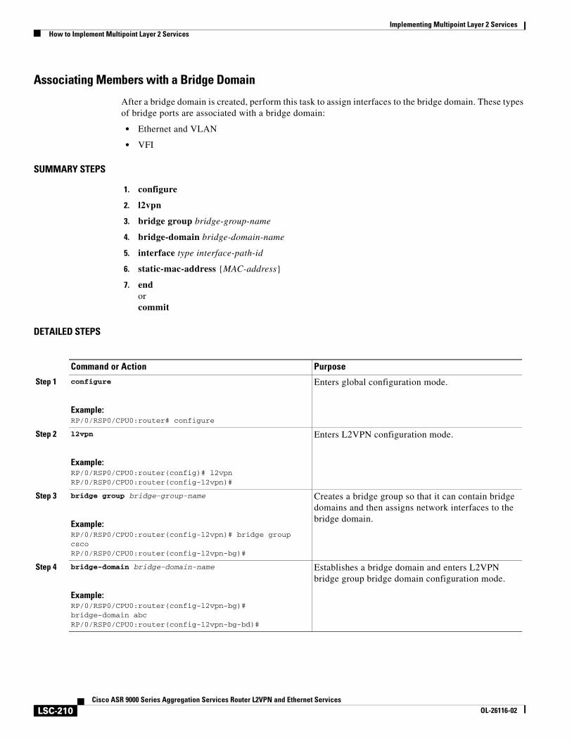
Implementing Multipoint Layer 2 ServicesHow to Implement Multipoint Layer 2 Services
LSC-210Cisco ASR 9000 Series Aggregation Services Router L2VPN and Ethernet Services
OL-26116-02
Associating Members with a Bridge Domain
After a bridge domain is created, perform this task to assign interfaces to the bridge domain. These types of bridge ports are associated with a bridge domain:
• Ethernet and VLAN
• VFI
SUMMARY STEPS
1. configure
2. l2vpn
3. bridge group bridge-group-name
4. bridge-domain bridge-domain-name
5. interface type interface-path-id
6. static-mac-address {MAC-address}
7. endorcommit
DETAILED STEPS
Command or Action Purpose
Step 1 configure
Example:RP/0/RSP0/CPU0:router# configure
Enters global configuration mode.
Step 2 l2vpn
Example:RP/0/RSP0/CPU0:router(config)# l2vpnRP/0/RSP0/CPU0:router(config-l2vpn)#
Enters L2VPN configuration mode.
Step 3 bridge group bridge-group-name
Example:RP/0/RSP0/CPU0:router(config-l2vpn)# bridge group cscoRP/0/RSP0/CPU0:router(config-l2vpn-bg)#
Creates a bridge group so that it can contain bridge domains and then assigns network interfaces to the bridge domain.
Step 4 bridge-domain bridge-domain-name
Example:RP/0/RSP0/CPU0:router(config-l2vpn-bg)# bridge-domain abcRP/0/RSP0/CPU0:router(config-l2vpn-bg-bd)#
Establishes a bridge domain and enters L2VPN bridge group bridge domain configuration mode.
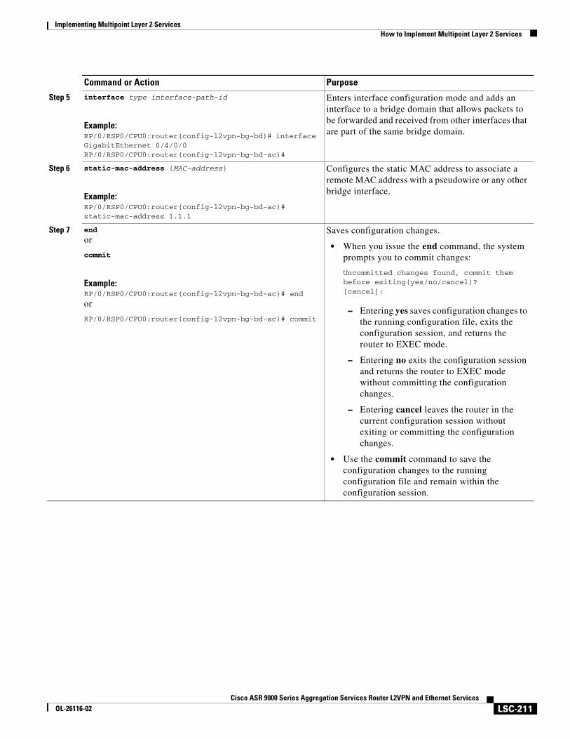
Implementing Multipoint Layer 2 ServicesHow to Implement Multipoint Layer 2 Services
LSC-211Cisco ASR 9000 Series Aggregation Services Router L2VPN and Ethernet Services
OL-26116-02
Step 5 interface type interface-path-id
Example:RP/0/RSP0/CPU0:router(config-l2vpn-bg-bd)# interface GigabitEthernet 0/4/0/0RP/0/RSP0/CPU0:router(config-l2vpn-bg-bd-ac)#
Enters interface configuration mode and adds an interface to a bridge domain that allows packets to be forwarded and received from other interfaces that are part of the same bridge domain.
Step 6 static-mac-address {MAC-address}
Example:RP/0/RSP0/CPU0:router(config-l2vpn-bg-bd-ac)# static-mac-address 1.1.1
Configures the static MAC address to associate a remote MAC address with a pseudowire or any other bridge interface.
Step 7 end
or
commit
Example:RP/0/RSP0/CPU0:router(config-l2vpn-bg-bd-ac)# end
or
RP/0/RSP0/CPU0:router(config-l2vpn-bg-bd-ac)# commit
Saves configuration changes.
• When you issue the end command, the system prompts you to commit changes:
Uncommitted changes found, commit them before exiting(yes/no/cancel)?[cancel]:
– Entering yes saves configuration changes to the running configuration file, exits the configuration session, and returns the router to EXEC mode.
– Entering no exits the configuration session and returns the router to EXEC mode without committing the configuration changes.
– Entering cancel leaves the router in the current configuration session without exiting or committing the configuration changes.
• Use the commit command to save the configuration changes to the running configuration file and remain within the configuration session.
Command or Action Purpose
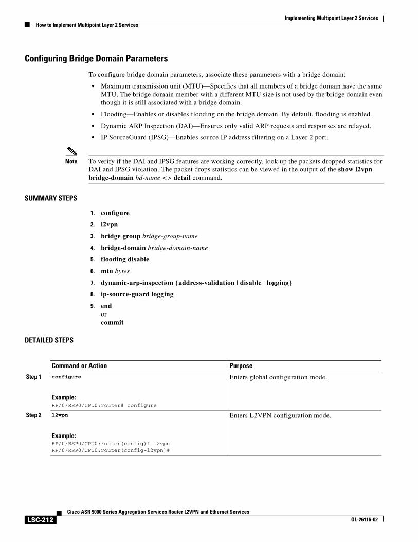
Implementing Multipoint Layer 2 ServicesHow to Implement Multipoint Layer 2 Services
LSC-212Cisco ASR 9000 Series Aggregation Services Router L2VPN and Ethernet Services
OL-26116-02
Configuring Bridge Domain Parameters
To configure bridge domain parameters, associate these parameters with a bridge domain:
• Maximum transmission unit (MTU)—Specifies that all members of a bridge domain have the same MTU. The bridge domain member with a different MTU size is not used by the bridge domain even though it is still associated with a bridge domain.
• Flooding—Enables or disables flooding on the bridge domain. By default, flooding is enabled.
• Dynamic ARP Inspection (DAI)—Ensures only valid ARP requests and responses are relayed.
• IP SourceGuard (IPSG)—Enables source IP address filtering on a Layer 2 port.
Note To verify if the DAI and IPSG features are working correctly, look up the packets dropped statistics for DAI and IPSG violation. The packet drops statistics can be viewed in the output of the show l2vpn bridge-domain bd-name <> detail command.
SUMMARY STEPS
1. configure
2. l2vpn
3. bridge group bridge-group-name
4. bridge-domain bridge-domain-name
5. flooding disable
6. mtu bytes
7. dynamic-arp-inspection {address-validation | disable | logging}
8. ip-source-guard logging
9. endorcommit
DETAILED STEPS
Command or Action Purpose
Step 1 configure
Example:RP/0/RSP0/CPU0:router# configure
Enters global configuration mode.
Step 2 l2vpn
Example:RP/0/RSP0/CPU0:router(config)# l2vpnRP/0/RSP0/CPU0:router(config-l2vpn)#
Enters L2VPN configuration mode.
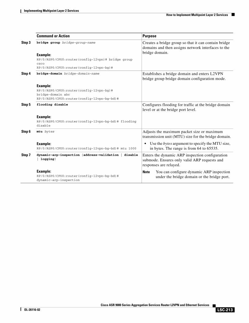
Implementing Multipoint Layer 2 ServicesHow to Implement Multipoint Layer 2 Services
LSC-213Cisco ASR 9000 Series Aggregation Services Router L2VPN and Ethernet Services
OL-26116-02
Step 3 bridge group bridge-group-name
Example:RP/0/RSP0/CPU0:router(config-l2vpn)# bridge group cscoRP/0/RSP0/CPU0:router(config-l2vpn-bg)#
Creates a bridge group so that it can contain bridge domains and then assigns network interfaces to the bridge domain.
Step 4 bridge-domain bridge-domain-name
Example:RP/0/RSP0/CPU0:router(config-l2vpn-bg)# bridge-domain abcRP/0/RSP0/CPU0:router(config-l2vpn-bg-bd)#
Establishes a bridge domain and enters L2VPN bridge group bridge domain configuration mode.
Step 5 flooding disable
Example:RP/0/RSP0/CPU0:router(config-l2vpn-bg-bd)# flooding disable
Configures flooding for traffic at the bridge domain level or at the bridge port level.
Step 6 mtu bytes
Example:RP/0/RSP0/CPU0:router(config-l2vpn-bg-bd)# mtu 1000
Adjusts the maximum packet size or maximum transmission unit (MTU) size for the bridge domain.
• Use the bytes argument to specify the MTU size, in bytes. The range is from 64 to 65535.
Step 7 dynamic-arp-inspection {address-validation | disable | logging}
Example:RP/0/RSP0/CPU0:router(config-l2vpn-bg-bd)# dynamic-arp-inspection
Enters the dynamic ARP inspection configuration submode. Ensures only valid ARP requests and responses are relayed.
Note You can configure dynamic ARP inspection under the bridge domain or the bridge port.
Command or Action Purpose
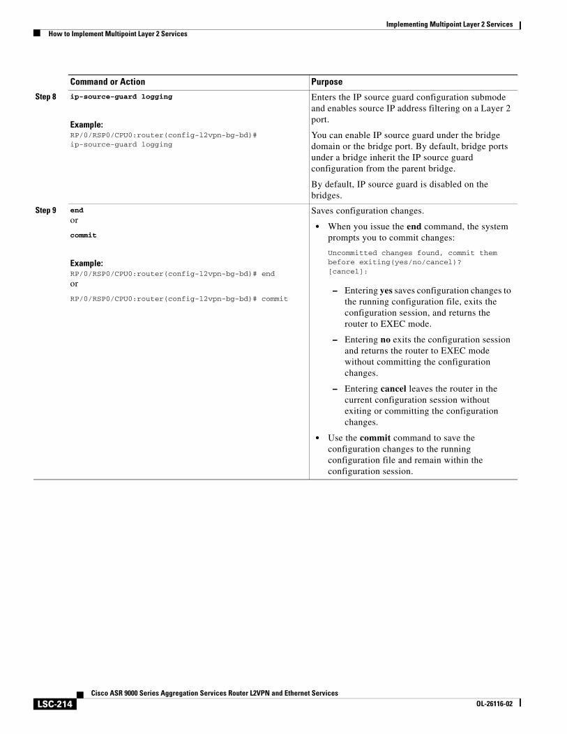
Implementing Multipoint Layer 2 ServicesHow to Implement Multipoint Layer 2 Services
LSC-214Cisco ASR 9000 Series Aggregation Services Router L2VPN and Ethernet Services
OL-26116-02
Step 8 ip-source-guard logging
Example:RP/0/RSP0/CPU0:router(config-l2vpn-bg-bd)# ip-source-guard logging
Enters the IP source guard configuration submode and enables source IP address filtering on a Layer 2 port.
You can enable IP source guard under the bridge domain or the bridge port. By default, bridge ports under a bridge inherit the IP source guard configuration from the parent bridge.
By default, IP source guard is disabled on the bridges.
Step 9 end
or
commit
Example:RP/0/RSP0/CPU0:router(config-l2vpn-bg-bd)# end
or
RP/0/RSP0/CPU0:router(config-l2vpn-bg-bd)# commit
Saves configuration changes.
• When you issue the end command, the system prompts you to commit changes:
Uncommitted changes found, commit them before exiting(yes/no/cancel)?[cancel]:
– Entering yes saves configuration changes to the running configuration file, exits the configuration session, and returns the router to EXEC mode.
– Entering no exits the configuration session and returns the router to EXEC mode without committing the configuration changes.
– Entering cancel leaves the router in the current configuration session without exiting or committing the configuration changes.
• Use the commit command to save the configuration changes to the running configuration file and remain within the configuration session.
Command or Action Purpose
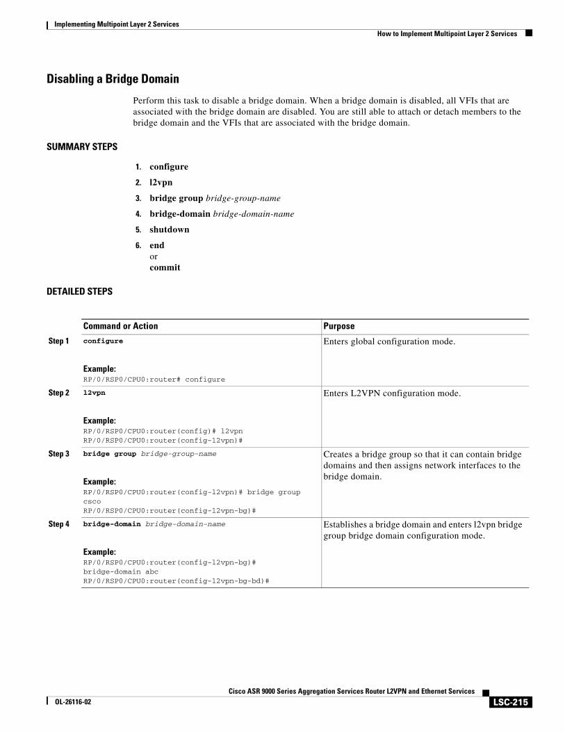
Implementing Multipoint Layer 2 ServicesHow to Implement Multipoint Layer 2 Services
LSC-215Cisco ASR 9000 Series Aggregation Services Router L2VPN and Ethernet Services
OL-26116-02
Disabling a Bridge Domain
Perform this task to disable a bridge domain. When a bridge domain is disabled, all VFIs that are associated with the bridge domain are disabled. You are still able to attach or detach members to the bridge domain and the VFIs that are associated with the bridge domain.
SUMMARY STEPS
1. configure
2. l2vpn
3. bridge group bridge-group-name
4. bridge-domain bridge-domain-name
5. shutdown
6. endorcommit
DETAILED STEPS
Command or Action Purpose
Step 1 configure
Example:RP/0/RSP0/CPU0:router# configure
Enters global configuration mode.
Step 2 l2vpn
Example:RP/0/RSP0/CPU0:router(config)# l2vpnRP/0/RSP0/CPU0:router(config-l2vpn)#
Enters L2VPN configuration mode.
Step 3 bridge group bridge-group-name
Example:RP/0/RSP0/CPU0:router(config-l2vpn)# bridge group cscoRP/0/RSP0/CPU0:router(config-l2vpn-bg)#
Creates a bridge group so that it can contain bridge domains and then assigns network interfaces to the bridge domain.
Step 4 bridge-domain bridge-domain-name
Example:RP/0/RSP0/CPU0:router(config-l2vpn-bg)# bridge-domain abcRP/0/RSP0/CPU0:router(config-l2vpn-bg-bd)#
Establishes a bridge domain and enters l2vpn bridge group bridge domain configuration mode.
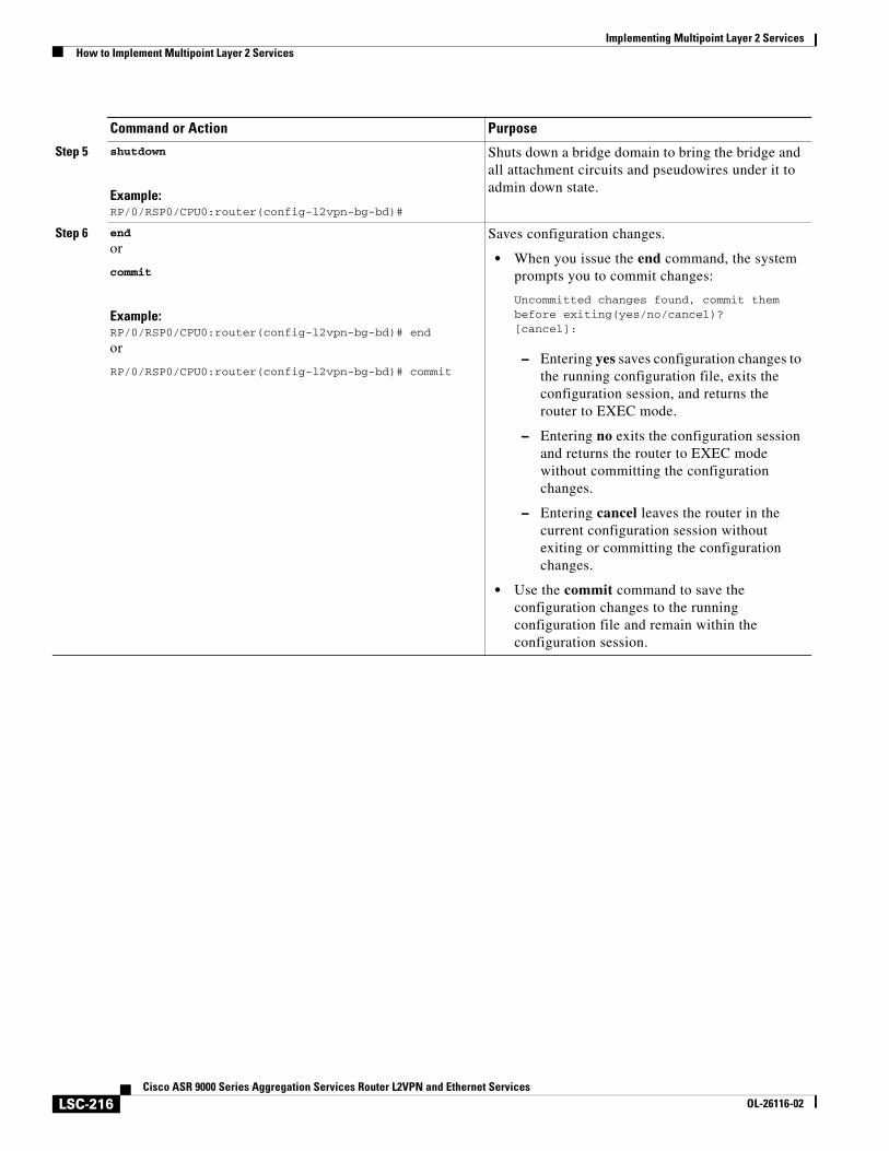
Implementing Multipoint Layer 2 ServicesHow to Implement Multipoint Layer 2 Services
LSC-216Cisco ASR 9000 Series Aggregation Services Router L2VPN and Ethernet Services
OL-26116-02
Step 5 shutdown
Example:RP/0/RSP0/CPU0:router(config-l2vpn-bg-bd)#
Shuts down a bridge domain to bring the bridge and all attachment circuits and pseudowires under it to admin down state.
Step 6 end
or
commit
Example:RP/0/RSP0/CPU0:router(config-l2vpn-bg-bd)# end
or
RP/0/RSP0/CPU0:router(config-l2vpn-bg-bd)# commit
Saves configuration changes.
• When you issue the end command, the system prompts you to commit changes:
Uncommitted changes found, commit them before exiting(yes/no/cancel)?[cancel]:
– Entering yes saves configuration changes to the running configuration file, exits the configuration session, and returns the router to EXEC mode.
– Entering no exits the configuration session and returns the router to EXEC mode without committing the configuration changes.
– Entering cancel leaves the router in the current configuration session without exiting or committing the configuration changes.
• Use the commit command to save the configuration changes to the running configuration file and remain within the configuration session.
Command or Action Purpose
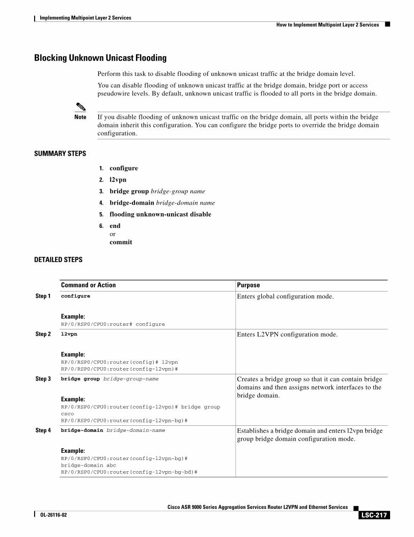
Implementing Multipoint Layer 2 ServicesHow to Implement Multipoint Layer 2 Services
LSC-217Cisco ASR 9000 Series Aggregation Services Router L2VPN and Ethernet Services
OL-26116-02
Blocking Unknown Unicast Flooding
Perform this task to disable flooding of unknown unicast traffic at the bridge domain level.
You can disable flooding of unknown unicast traffic at the bridge domain, bridge port or access pseudowire levels. By default, unknown unicast traffic is flooded to all ports in the bridge domain.
Note If you disable flooding of unknown unicast traffic on the bridge domain, all ports within the bridge domain inherit this configuration. You can configure the bridge ports to override the bridge domain configuration.
SUMMARY STEPS
1. configure
2. l2vpn
3. bridge group bridge-group name
4. bridge-domain bridge-domain name
5. flooding unknown-unicast disable
6. endorcommit
DETAILED STEPS
Command or Action Purpose
Step 1 configure
Example:RP/0/RSP0/CPU0:router# configure
Enters global configuration mode.
Step 2 l2vpn
Example:RP/0/RSP0/CPU0:router(config)# l2vpnRP/0/RSP0/CPU0:router(config-l2vpn)#
Enters L2VPN configuration mode.
Step 3 bridge group bridge-group-name
Example:RP/0/RSP0/CPU0:router(config-l2vpn)# bridge group cscoRP/0/RSP0/CPU0:router(config-l2vpn-bg)#
Creates a bridge group so that it can contain bridge domains and then assigns network interfaces to the bridge domain.
Step 4 bridge-domain bridge-domain-name
Example:RP/0/RSP0/CPU0:router(config-l2vpn-bg)# bridge-domain abcRP/0/RSP0/CPU0:router(config-l2vpn-bg-bd)#
Establishes a bridge domain and enters l2vpn bridge group bridge domain configuration mode.
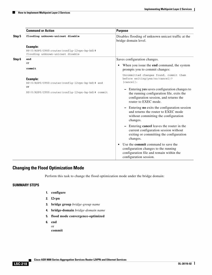
Implementing Multipoint Layer 2 ServicesHow to Implement Multipoint Layer 2 Services
LSC-218Cisco ASR 9000 Series Aggregation Services Router L2VPN and Ethernet Services
OL-26116-02
Changing the Flood Optimization Mode
Perform this task to change the flood optimization mode under the bridge domain:
SUMMARY STEPS
1. configure
2. l2vpn
3. bridge group bridge-group name
4. bridge-domain bridge-domain name
5. flood mode convergence-optimized
6. endorcommit
Step 5 flooding unknown-unicast disable
Example:RP/0/RSP0/CPU0:router(config-l2vpn-bg-bd)#flooding unknown-unicast disable
Disables flooding of unknown unicast traffic at the bridge domain level.
Step 6 end
or
commit
Example:RP/0/RSP0/CPU0:router(config-l2vpn-bg-bd)# end
or
RP/0/RSP0/CPU0:router(config-l2vpn-bg-bd)# commit
Saves configuration changes.
• When you issue the end command, the system prompts you to commit changes:
Uncommitted changes found, commit them before exiting(yes/no/cancel)?[cancel]:
– Entering yes saves configuration changes to the running configuration file, exits the configuration session, and returns the router to EXEC mode.
– Entering no exits the configuration session and returns the router to EXEC mode without committing the configuration changes.
– Entering cancel leaves the router in the current configuration session without exiting or committing the configuration changes.
• Use the commit command to save the configuration changes to the running configuration file and remain within the configuration session.
Command or Action Purpose
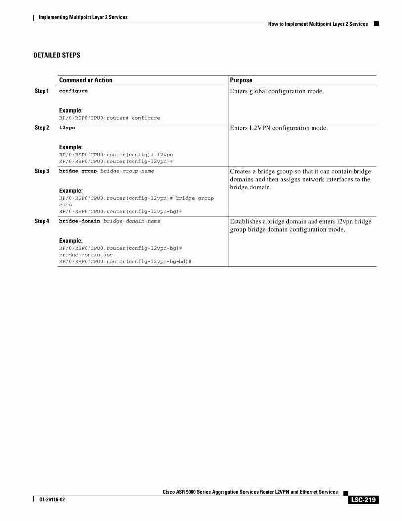
Implementing Multipoint Layer 2 ServicesHow to Implement Multipoint Layer 2 Services
LSC-219Cisco ASR 9000 Series Aggregation Services Router L2VPN and Ethernet Services
OL-26116-02
DETAILED STEPS
Command or Action Purpose
Step 1 configure
Example:RP/0/RSP0/CPU0:router# configure
Enters global configuration mode.
Step 2 l2vpn
Example:RP/0/RSP0/CPU0:router(config)# l2vpnRP/0/RSP0/CPU0:router(config-l2vpn)#
Enters L2VPN configuration mode.
Step 3 bridge group bridge-group-name
Example:RP/0/RSP0/CPU0:router(config-l2vpn)# bridge group cscoRP/0/RSP0/CPU0:router(config-l2vpn-bg)#
Creates a bridge group so that it can contain bridge domains and then assigns network interfaces to the bridge domain.
Step 4 bridge-domain bridge-domain-name
Example:RP/0/RSP0/CPU0:router(config-l2vpn-bg)# bridge-domain abcRP/0/RSP0/CPU0:router(config-l2vpn-bg-bd)#
Establishes a bridge domain and enters l2vpn bridge group bridge domain configuration mode.
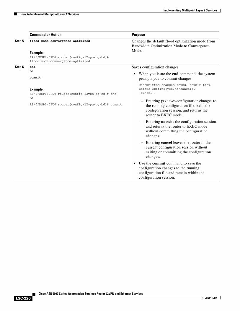
Implementing Multipoint Layer 2 ServicesHow to Implement Multipoint Layer 2 Services
LSC-220Cisco ASR 9000 Series Aggregation Services Router L2VPN and Ethernet Services
OL-26116-02
Step 5 flood mode convergence-optimized
Example:RP/0/RSP0/CPU0:router(config-l2vpn-bg-bd)#flood mode convergence-optimized
Changes the default flood optimization mode from Bandwidth Optimization Mode to Convergence Mode.
Step 6 end
or
commit
Example:RP/0/RSP0/CPU0:router(config-l2vpn-bg-bd)# end
or
RP/0/RSP0/CPU0:router(config-l2vpn-bg-bd)# commit
Saves configuration changes.
• When you issue the end command, the system prompts you to commit changes:
Uncommitted changes found, commit them before exiting(yes/no/cancel)?[cancel]:
– Entering yes saves configuration changes to the running configuration file, exits the configuration session, and returns the router to EXEC mode.
– Entering no exits the configuration session and returns the router to EXEC mode without committing the configuration changes.
– Entering cancel leaves the router in the current configuration session without exiting or committing the configuration changes.
• Use the commit command to save the configuration changes to the running configuration file and remain within the configuration session.
Command or Action Purpose
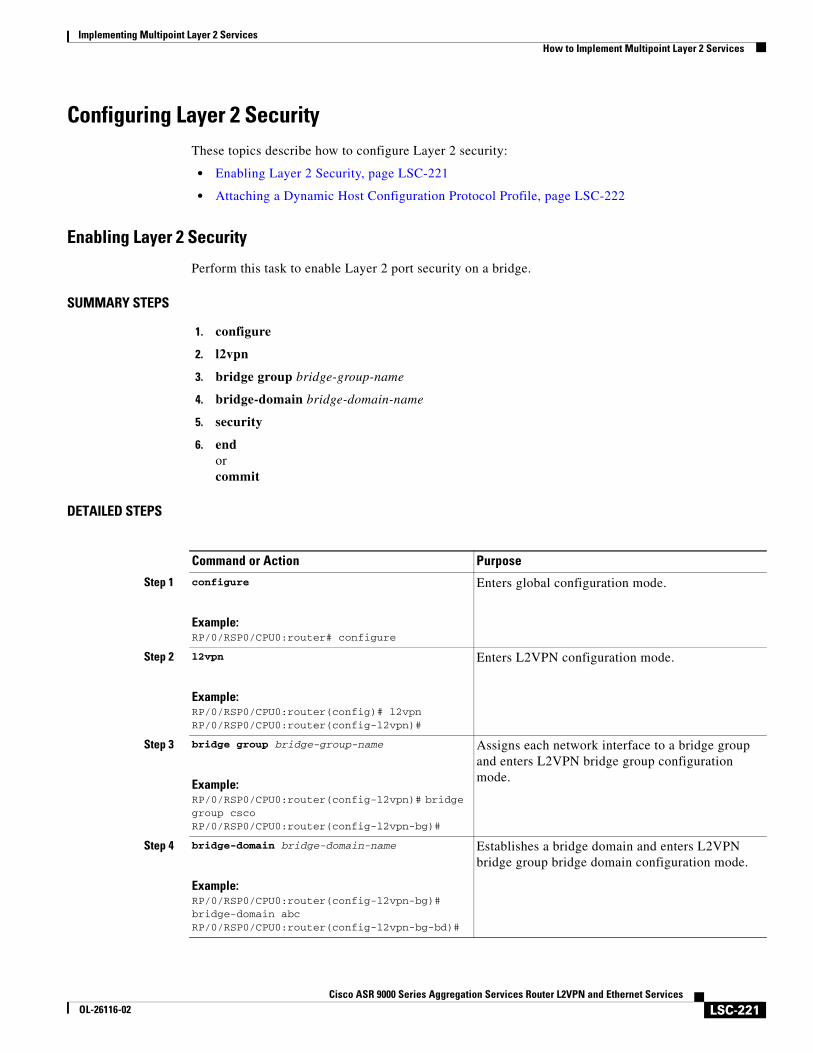
Implementing Multipoint Layer 2 ServicesHow to Implement Multipoint Layer 2 Services
LSC-221Cisco ASR 9000 Series Aggregation Services Router L2VPN and Ethernet Services
OL-26116-02
Configuring Layer 2 SecurityThese topics describe how to configure Layer 2 security:
• Enabling Layer 2 Security, page LSC-221
• Attaching a Dynamic Host Configuration Protocol Profile, page LSC-222
Enabling Layer 2 Security
Perform this task to enable Layer 2 port security on a bridge.
SUMMARY STEPS
1. configure
2. l2vpn
3. bridge group bridge-group-name
4. bridge-domain bridge-domain-name
5. security
6. endorcommit
DETAILED STEPS
Command or Action Purpose
Step 1 configure
Example:RP/0/RSP0/CPU0:router# configure
Enters global configuration mode.
Step 2 l2vpn
Example:RP/0/RSP0/CPU0:router(config)# l2vpnRP/0/RSP0/CPU0:router(config-l2vpn)#
Enters L2VPN configuration mode.
Step 3 bridge group bridge-group-name
Example:RP/0/RSP0/CPU0:router(config-l2vpn)# bridge group cscoRP/0/RSP0/CPU0:router(config-l2vpn-bg)#
Assigns each network interface to a bridge group and enters L2VPN bridge group configuration mode.
Step 4 bridge-domain bridge-domain-name
Example:RP/0/RSP0/CPU0:router(config-l2vpn-bg)# bridge-domain abcRP/0/RSP0/CPU0:router(config-l2vpn-bg-bd)#
Establishes a bridge domain and enters L2VPN bridge group bridge domain configuration mode.
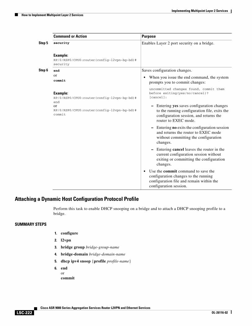
Implementing Multipoint Layer 2 ServicesHow to Implement Multipoint Layer 2 Services
LSC-222Cisco ASR 9000 Series Aggregation Services Router L2VPN and Ethernet Services
OL-26116-02
Attaching a Dynamic Host Configuration Protocol Profile
Perform this task to enable DHCP snooping on a bridge and to attach a DHCP snooping profile to a bridge.
SUMMARY STEPS
1. configure
2. l2vpn
3. bridge group bridge-group-name
4. bridge-domain bridge-domain-name
5. dhcp ipv4 snoop {profile profile-name}
6. endorcommit
Step 5 security
Example:RP/0/RSP0/CPU0:router(config-l2vpn-bg-bd)# security
Enables Layer 2 port security on a bridge.
Step 6 end
orcommit
Example:RP/0/RSP0/CPU0:router(config-l2vpn-bg-bd)# endorRP/0/RSP0/CPU0:router(config-l2vpn-bg-bd)# commit
Saves configuration changes.
• When you issue the end command, the system prompts you to commit changes:
uncommitted changes found, commit them before exiting(yes/no/cancel)?[cancel]:
– Entering yes saves configuration changes to the running configuration file, exits the configuration session, and returns the router to EXEC mode.
– Entering no exits the configuration session and returns the router to EXEC mode without committing the configuration changes.
– Entering cancel leaves the router in the current configuration session without exiting or committing the configuration changes.
• Use the commit command to save the configuration changes to the running configuration file and remain within the configuration session.
Command or Action Purpose
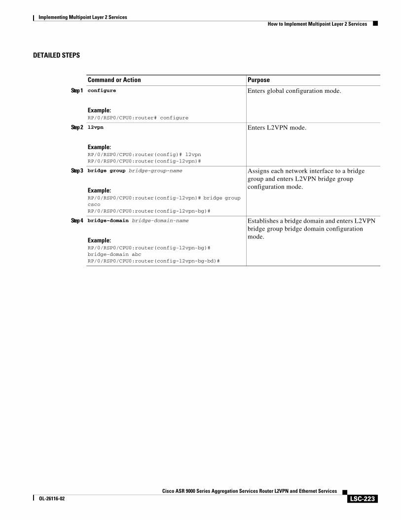
Implementing Multipoint Layer 2 ServicesHow to Implement Multipoint Layer 2 Services
LSC-223Cisco ASR 9000 Series Aggregation Services Router L2VPN and Ethernet Services
OL-26116-02
DETAILED STEPS
Command or Action Purpose
Step 1 configure
Example:RP/0/RSP0/CPU0:router# configure
Enters global configuration mode.
Step 2 l2vpn
Example:RP/0/RSP0/CPU0:router(config)# l2vpnRP/0/RSP0/CPU0:router(config-l2vpn)#
Enters L2VPN mode.
Step 3 bridge group bridge-group-name
Example:RP/0/RSP0/CPU0:router(config-l2vpn)# bridge group cscoRP/0/RSP0/CPU0:router(config-l2vpn-bg)#
Assigns each network interface to a bridge group and enters L2VPN bridge group configuration mode.
Step 4 bridge-domain bridge-domain-name
Example:RP/0/RSP0/CPU0:router(config-l2vpn-bg)# bridge-domain abcRP/0/RSP0/CPU0:router(config-l2vpn-bg-bd)#
Establishes a bridge domain and enters L2VPN bridge group bridge domain configuration mode.
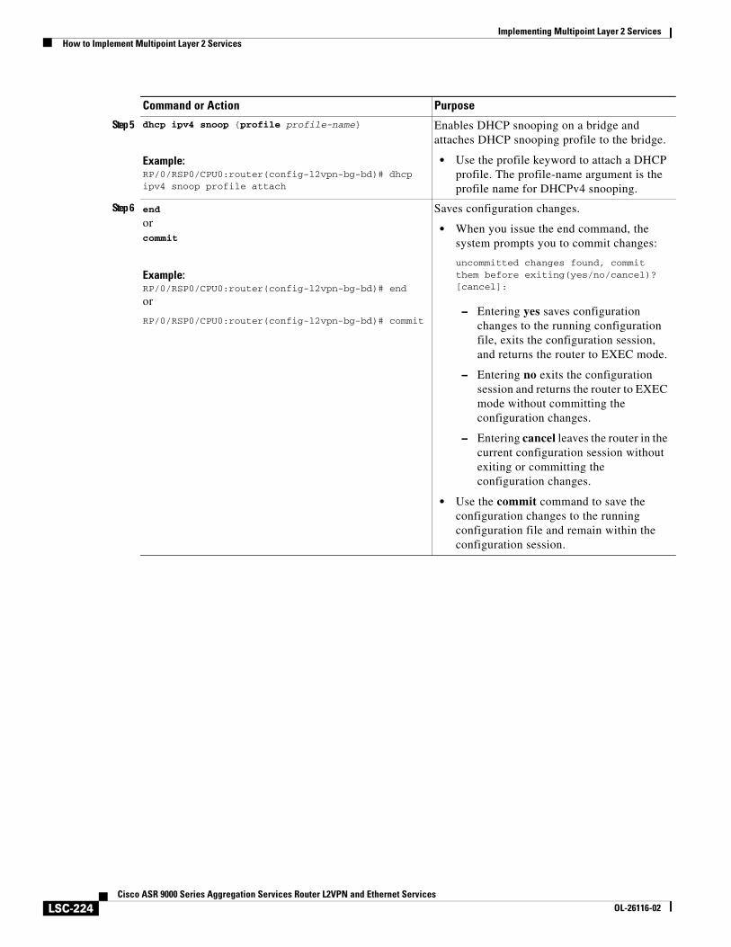
Implementing Multipoint Layer 2 ServicesHow to Implement Multipoint Layer 2 Services
LSC-224Cisco ASR 9000 Series Aggregation Services Router L2VPN and Ethernet Services
OL-26116-02
Step 5 dhcp ipv4 snoop {profile profile-name}
Example:RP/0/RSP0/CPU0:router(config-l2vpn-bg-bd)# dhcp ipv4 snoop profile attach
Enables DHCP snooping on a bridge and attaches DHCP snooping profile to the bridge.
• Use the profile keyword to attach a DHCP profile. The profile-name argument is the profile name for DHCPv4 snooping.
Step 6 end
orcommit
Example:RP/0/RSP0/CPU0:router(config-l2vpn-bg-bd)# end
or
RP/0/RSP0/CPU0:router(config-l2vpn-bg-bd)# commit
Saves configuration changes.
• When you issue the end command, the system prompts you to commit changes:
uncommitted changes found, commit them before exiting(yes/no/cancel)?[cancel]:
– Entering yes saves configuration changes to the running configuration file, exits the configuration session, and returns the router to EXEC mode.
– Entering no exits the configuration session and returns the router to EXEC mode without committing the configuration changes.
– Entering cancel leaves the router in the current configuration session without exiting or committing the configuration changes.
• Use the commit command to save the configuration changes to the running configuration file and remain within the configuration session.
Command or Action Purpose
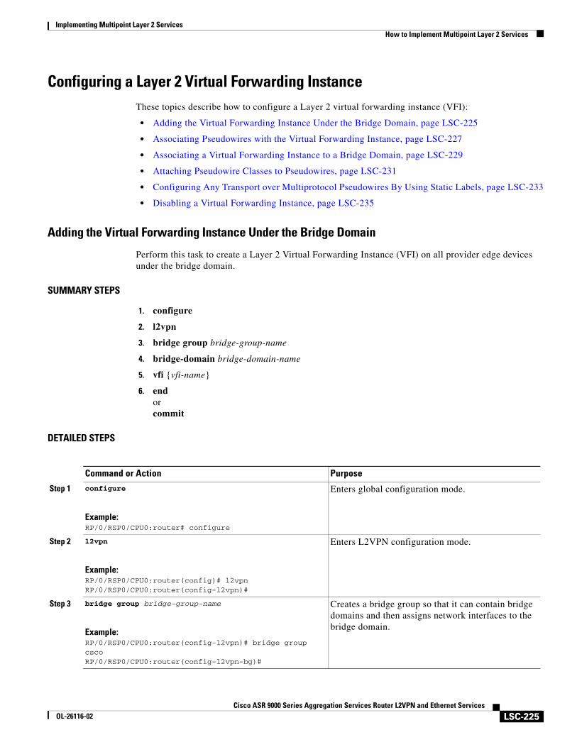
Implementing Multipoint Layer 2 ServicesHow to Implement Multipoint Layer 2 Services
LSC-225Cisco ASR 9000 Series Aggregation Services Router L2VPN and Ethernet Services
OL-26116-02
Configuring a Layer 2 Virtual Forwarding InstanceThese topics describe how to configure a Layer 2 virtual forwarding instance (VFI):
• Adding the Virtual Forwarding Instance Under the Bridge Domain, page LSC-225
• Associating Pseudowires with the Virtual Forwarding Instance, page LSC-227
• Associating a Virtual Forwarding Instance to a Bridge Domain, page LSC-229
• Attaching Pseudowire Classes to Pseudowires, page LSC-231
• Configuring Any Transport over Multiprotocol Pseudowires By Using Static Labels, page LSC-233
• Disabling a Virtual Forwarding Instance, page LSC-235
Adding the Virtual Forwarding Instance Under the Bridge Domain
Perform this task to create a Layer 2 Virtual Forwarding Instance (VFI) on all provider edge devices under the bridge domain.
SUMMARY STEPS
1. configure
2. l2vpn
3. bridge group bridge-group-name
4. bridge-domain bridge-domain-name
5. vfi {vfi-name}
6. endorcommit
DETAILED STEPS
Command or Action Purpose
Step 1 configure
Example:RP/0/RSP0/CPU0:router# configure
Enters global configuration mode.
Step 2 l2vpn
Example:RP/0/RSP0/CPU0:router(config)# l2vpnRP/0/RSP0/CPU0:router(config-l2vpn)#
Enters L2VPN configuration mode.
Step 3 bridge group bridge-group-name
Example:RP/0/RSP0/CPU0:router(config-l2vpn)# bridge group cscoRP/0/RSP0/CPU0:router(config-l2vpn-bg)#
Creates a bridge group so that it can contain bridge domains and then assigns network interfaces to the bridge domain.
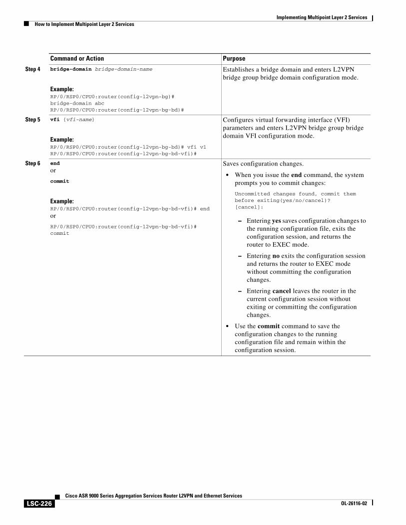
Implementing Multipoint Layer 2 ServicesHow to Implement Multipoint Layer 2 Services
LSC-226Cisco ASR 9000 Series Aggregation Services Router L2VPN and Ethernet Services
OL-26116-02
Step 4 bridge-domain bridge-domain-name
Example:RP/0/RSP0/CPU0:router(config-l2vpn-bg)# bridge-domain abcRP/0/RSP0/CPU0:router(config-l2vpn-bg-bd)#
Establishes a bridge domain and enters L2VPN bridge group bridge domain configuration mode.
Step 5 vfi {vfi-name}
Example:RP/0/RSP0/CPU0:router(config-l2vpn-bg-bd)# vfi v1RP/0/RSP0/CPU0:router(config-l2vpn-bg-bd-vfi)#
Configures virtual forwarding interface (VFI) parameters and enters L2VPN bridge group bridge domain VFI configuration mode.
Step 6 end
or
commit
Example:RP/0/RSP0/CPU0:router(config-l2vpn-bg-bd-vfi)# end
or
RP/0/RSP0/CPU0:router(config-l2vpn-bg-bd-vfi)# commit
Saves configuration changes.
• When you issue the end command, the system prompts you to commit changes:
Uncommitted changes found, commit them before exiting(yes/no/cancel)?[cancel]:
– Entering yes saves configuration changes to the running configuration file, exits the configuration session, and returns the router to EXEC mode.
– Entering no exits the configuration session and returns the router to EXEC mode without committing the configuration changes.
– Entering cancel leaves the router in the current configuration session without exiting or committing the configuration changes.
• Use the commit command to save the configuration changes to the running configuration file and remain within the configuration session.
Command or Action Purpose
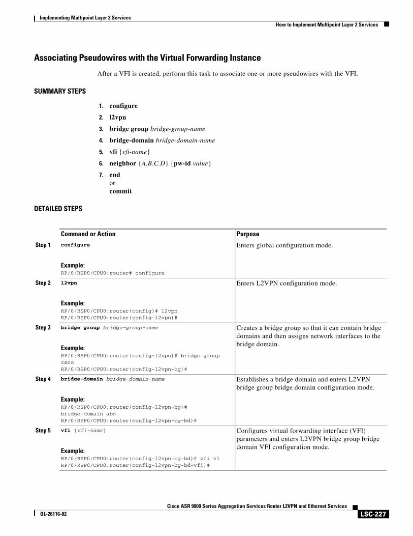
Implementing Multipoint Layer 2 ServicesHow to Implement Multipoint Layer 2 Services
LSC-227Cisco ASR 9000 Series Aggregation Services Router L2VPN and Ethernet Services
OL-26116-02
Associating Pseudowires with the Virtual Forwarding Instance
After a VFI is created, perform this task to associate one or more pseudowires with the VFI.
SUMMARY STEPS
1. configure
2. l2vpn
3. bridge group bridge-group-name
4. bridge-domain bridge-domain-name
5. vfi {vfi-name}
6. neighbor {A.B.C.D} {pw-id value}
7. endorcommit
DETAILED STEPS
Command or Action Purpose
Step 1 configure
Example:RP/0/RSP0/CPU0:router# configure
Enters global configuration mode.
Step 2 l2vpn
Example:RP/0/RSP0/CPU0:router(config)# l2vpnRP/0/RSP0/CPU0:router(config-l2vpn)#
Enters L2VPN configuration mode.
Step 3 bridge group bridge-group-name
Example:RP/0/RSP0/CPU0:router(config-l2vpn)# bridge group cscoRP/0/RSP0/CPU0:router(config-l2vpn-bg)#
Creates a bridge group so that it can contain bridge domains and then assigns network interfaces to the bridge domain.
Step 4 bridge-domain bridge-domain-name
Example:RP/0/RSP0/CPU0:router(config-l2vpn-bg)# bridge-domain abcRP/0/RSP0/CPU0:router(config-l2vpn-bg-bd)#
Establishes a bridge domain and enters L2VPN bridge group bridge domain configuration mode.
Step 5 vfi {vfi-name}
Example:RP/0/RSP0/CPU0:router(config-l2vpn-bg-bd)# vfi v1RP/0/RSP0/CPU0:router(config-l2vpn-bg-bd-vfi)#
Configures virtual forwarding interface (VFI) parameters and enters L2VPN bridge group bridge domain VFI configuration mode.
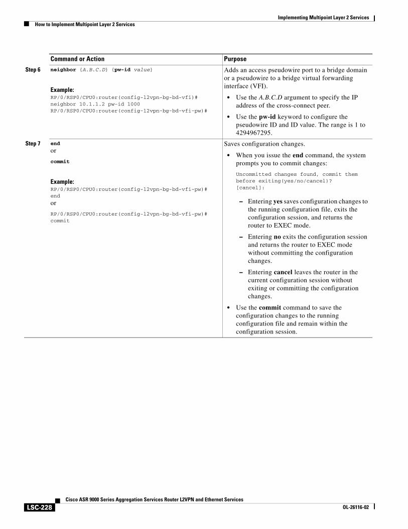
Implementing Multipoint Layer 2 ServicesHow to Implement Multipoint Layer 2 Services
LSC-228Cisco ASR 9000 Series Aggregation Services Router L2VPN and Ethernet Services
OL-26116-02
Step 6 neighbor {A.B.C.D} {pw-id value}
Example:RP/0/RSP0/CPU0:router(config-l2vpn-bg-bd-vfi)# neighbor 10.1.1.2 pw-id 1000RP/0/RSP0/CPU0:router(config-l2vpn-bg-bd-vfi-pw)#
Adds an access pseudowire port to a bridge domain or a pseudowire to a bridge virtual forwarding interface (VFI).
• Use the A.B.C.D argument to specify the IP address of the cross-connect peer.
• Use the pw-id keyword to configure the pseudowire ID and ID value. The range is 1 to 4294967295.
Step 7 end
or
commit
Example:RP/0/RSP0/CPU0:router(config-l2vpn-bg-bd-vfi-pw)# end
or
RP/0/RSP0/CPU0:router(config-l2vpn-bg-bd-vfi-pw)# commit
Saves configuration changes.
• When you issue the end command, the system prompts you to commit changes:
Uncommitted changes found, commit them before exiting(yes/no/cancel)?[cancel]:
– Entering yes saves configuration changes to the running configuration file, exits the configuration session, and returns the router to EXEC mode.
– Entering no exits the configuration session and returns the router to EXEC mode without committing the configuration changes.
– Entering cancel leaves the router in the current configuration session without exiting or committing the configuration changes.
• Use the commit command to save the configuration changes to the running configuration file and remain within the configuration session.
Command or Action Purpose

Implementing Multipoint Layer 2 ServicesHow to Implement Multipoint Layer 2 Services
LSC-229Cisco ASR 9000 Series Aggregation Services Router L2VPN and Ethernet Services
OL-26116-02
Associating a Virtual Forwarding Instance to a Bridge Domain
Perform this task to associate a VFI to be a member of a bridge domain.
SUMMARY STEPS
1. configure
2. l2vpn
3. bridge group bridge-group-name
4. bridge-domain bridge-domain-name
5. vfi {vfi-name}
6. neighbor {A.B.C.D} {pw-id value}
7. static-mac-address {MAC-address}
8. endorcommit
DETAILED STEPS
Command or Action Purpose
Step 1 configure
Example:RP/0/RSP0/CPU0:router# configure
Enters global configuration mode.
Step 2 l2vpn
Example:RP/0/RSP0/CPU0:router(config)# l2vpnRP/0/RSP0/CPU0:router(config-l2vpn)#
Enters L2VPN configuration mode.
Step 3 bridge group bridge-group-name
Example:RP/0/RSP0/CPU0:router(config-l2vpn)# bridge group cscoRP/0/RSP0/CPU0:router(config-l2vpn-bg)#
Creates a bridge group so that it can contain bridge domains and then assigns network interfaces to the bridge domain.
Step 4 bridge-domain bridge-domain-name
Example:RP/0/RSP0/CPU0:router(config-l2vpn-bg)# bridge-domain abcRP/0/RSP0/CPU0:router(config-l2vpn-bg-bd)#
Establishes a bridge domain and enters L2VPN bridge group bridge domain configuration mode.
Step 5 vfi {vfi-name}
Example:RP/0/RSP0/CPU0:router(config-l2vpn-bg-bd)# vfi v1RP/0/RSP0/CPU0:router(config-l2vpn-bg-bd-vfi)#
Configures virtual forwarding interface (VFI) parameters and enters L2VPN bridge group bridge domain VFI configuration mode.
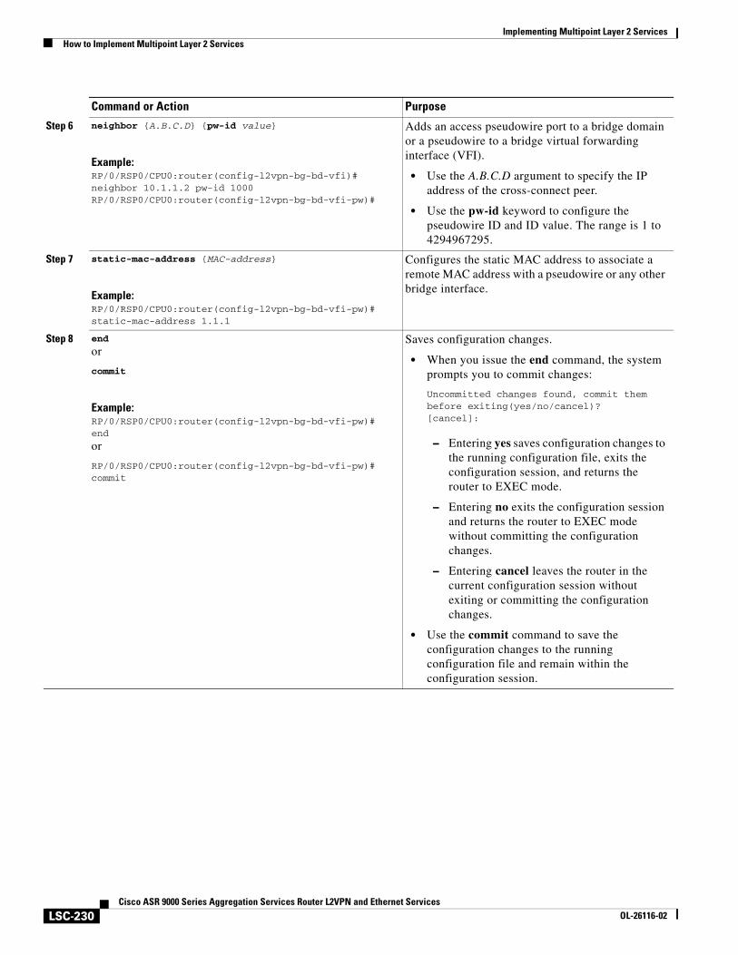
Implementing Multipoint Layer 2 ServicesHow to Implement Multipoint Layer 2 Services
LSC-230Cisco ASR 9000 Series Aggregation Services Router L2VPN and Ethernet Services
OL-26116-02
Step 6 neighbor {A.B.C.D} {pw-id value}
Example:RP/0/RSP0/CPU0:router(config-l2vpn-bg-bd-vfi)# neighbor 10.1.1.2 pw-id 1000RP/0/RSP0/CPU0:router(config-l2vpn-bg-bd-vfi-pw)#
Adds an access pseudowire port to a bridge domain or a pseudowire to a bridge virtual forwarding interface (VFI).
• Use the A.B.C.D argument to specify the IP address of the cross-connect peer.
• Use the pw-id keyword to configure the pseudowire ID and ID value. The range is 1 to 4294967295.
Step 7 static-mac-address {MAC-address}
Example:RP/0/RSP0/CPU0:router(config-l2vpn-bg-bd-vfi-pw)# static-mac-address 1.1.1
Configures the static MAC address to associate a remote MAC address with a pseudowire or any other bridge interface.
Step 8 end
or
commit
Example:RP/0/RSP0/CPU0:router(config-l2vpn-bg-bd-vfi-pw)# end
or
RP/0/RSP0/CPU0:router(config-l2vpn-bg-bd-vfi-pw)# commit
Saves configuration changes.
• When you issue the end command, the system prompts you to commit changes:
Uncommitted changes found, commit them before exiting(yes/no/cancel)?[cancel]:
– Entering yes saves configuration changes to the running configuration file, exits the configuration session, and returns the router to EXEC mode.
– Entering no exits the configuration session and returns the router to EXEC mode without committing the configuration changes.
– Entering cancel leaves the router in the current configuration session without exiting or committing the configuration changes.
• Use the commit command to save the configuration changes to the running configuration file and remain within the configuration session.
Command or Action Purpose
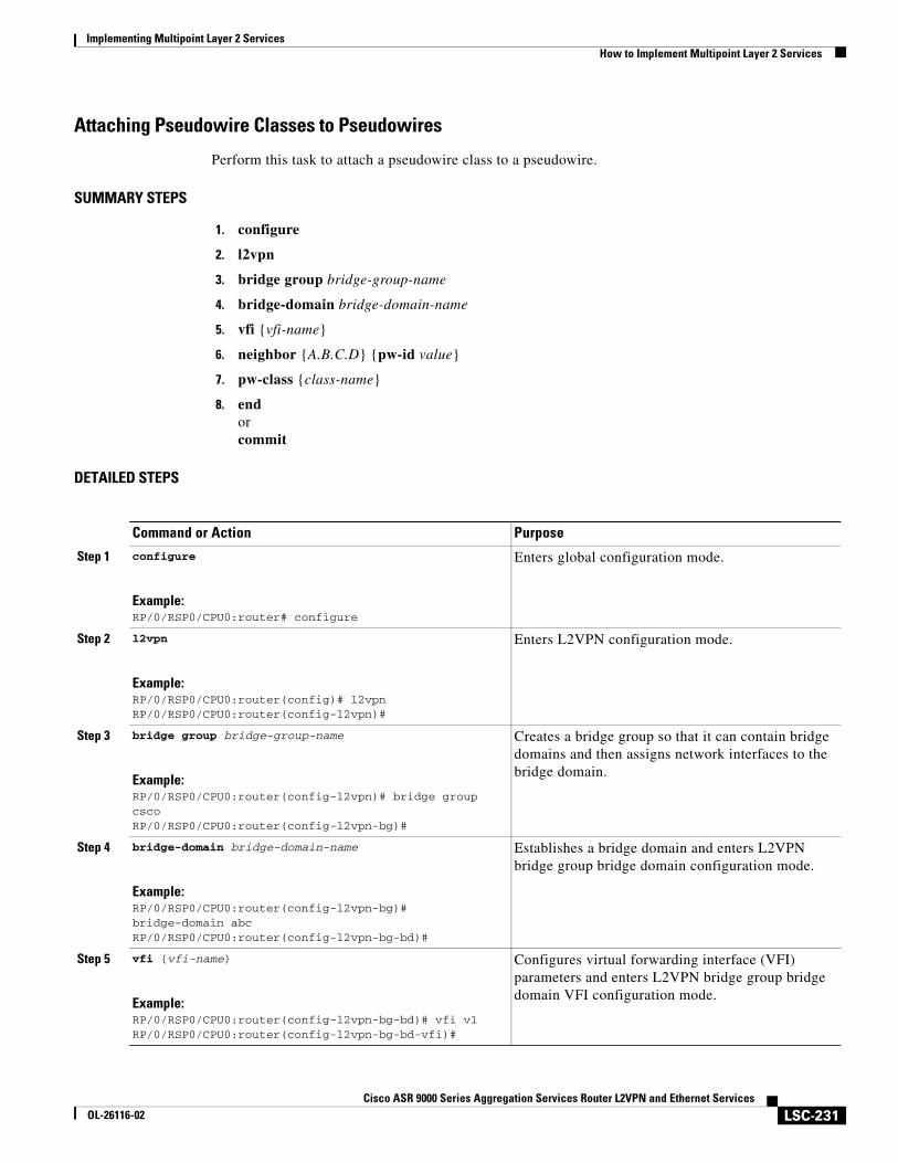
Implementing Multipoint Layer 2 ServicesHow to Implement Multipoint Layer 2 Services
LSC-231Cisco ASR 9000 Series Aggregation Services Router L2VPN and Ethernet Services
OL-26116-02
Attaching Pseudowire Classes to Pseudowires
Perform this task to attach a pseudowire class to a pseudowire.
SUMMARY STEPS
1. configure
2. l2vpn
3. bridge group bridge-group-name
4. bridge-domain bridge-domain-name
5. vfi {vfi-name}
6. neighbor {A.B.C.D} {pw-id value}
7. pw-class {class-name}
8. endorcommit
DETAILED STEPS
Command or Action Purpose
Step 1 configure
Example:RP/0/RSP0/CPU0:router# configure
Enters global configuration mode.
Step 2 l2vpn
Example:RP/0/RSP0/CPU0:router(config)# l2vpnRP/0/RSP0/CPU0:router(config-l2vpn)#
Enters L2VPN configuration mode.
Step 3 bridge group bridge-group-name
Example:RP/0/RSP0/CPU0:router(config-l2vpn)# bridge group cscoRP/0/RSP0/CPU0:router(config-l2vpn-bg)#
Creates a bridge group so that it can contain bridge domains and then assigns network interfaces to the bridge domain.
Step 4 bridge-domain bridge-domain-name
Example:RP/0/RSP0/CPU0:router(config-l2vpn-bg)# bridge-domain abcRP/0/RSP0/CPU0:router(config-l2vpn-bg-bd)#
Establishes a bridge domain and enters L2VPN bridge group bridge domain configuration mode.
Step 5 vfi {vfi-name}
Example:RP/0/RSP0/CPU0:router(config-l2vpn-bg-bd)# vfi v1RP/0/RSP0/CPU0:router(config-l2vpn-bg-bd-vfi)#
Configures virtual forwarding interface (VFI) parameters and enters L2VPN bridge group bridge domain VFI configuration mode.
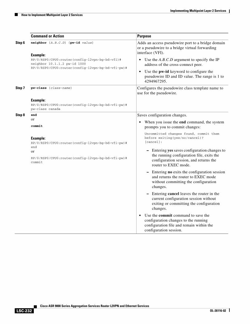
Implementing Multipoint Layer 2 ServicesHow to Implement Multipoint Layer 2 Services
LSC-232Cisco ASR 9000 Series Aggregation Services Router L2VPN and Ethernet Services
OL-26116-02
Step 6 neighbor {A.B.C.D} {pw-id value}
Example:RP/0/RSP0/CPU0:router(config-l2vpn-bg-bd-vfi)# neighbor 10.1.1.2 pw-id 1000RP/0/RSP0/CPU0:router(config-l2vpn-bg-bd-vfi-pw)#
Adds an access pseudowire port to a bridge domain or a pseudowire to a bridge virtual forwarding interface (VFI).
• Use the A.B.C.D argument to specify the IP address of the cross-connect peer.
• Use the pw-id keyword to configure the pseudowire ID and ID value. The range is 1 to 4294967295.
Step 7 pw-class {class-name}
Example:RP/0/RSP0/CPU0:router(config-l2vpn-bg-bd-vfi-pw)# pw-class canada
Configures the pseudowire class template name to use for the pseudowire.
Step 8 end
or
commit
Example:RP/0/RSP0/CPU0:router(config-l2vpn-bg-bd-vfi-pw)# end
or
RP/0/RSP0/CPU0:router(config-l2vpn-bg-bd-vfi-pw)# commit
Saves configuration changes.
• When you issue the end command, the system prompts you to commit changes:
Uncommitted changes found, commit them before exiting(yes/no/cancel)?[cancel]:
– Entering yes saves configuration changes to the running configuration file, exits the configuration session, and returns the router to EXEC mode.
– Entering no exits the configuration session and returns the router to EXEC mode without committing the configuration changes.
– Entering cancel leaves the router in the current configuration session without exiting or committing the configuration changes.
• Use the commit command to save the configuration changes to the running configuration file and remain within the configuration session.
Command or Action Purpose
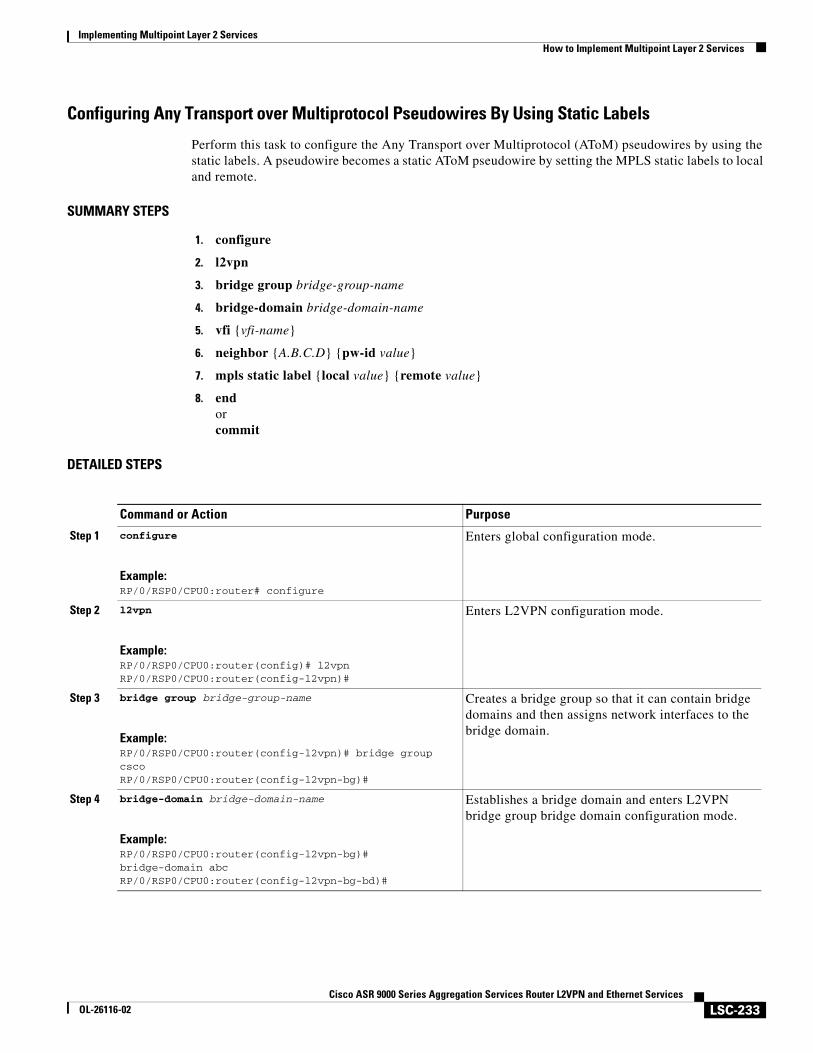
Implementing Multipoint Layer 2 ServicesHow to Implement Multipoint Layer 2 Services
LSC-233Cisco ASR 9000 Series Aggregation Services Router L2VPN and Ethernet Services
OL-26116-02
Configuring Any Transport over Multiprotocol Pseudowires By Using Static Labels
Perform this task to configure the Any Transport over Multiprotocol (AToM) pseudowires by using the static labels. A pseudowire becomes a static AToM pseudowire by setting the MPLS static labels to local and remote.
SUMMARY STEPS
1. configure
2. l2vpn
3. bridge group bridge-group-name
4. bridge-domain bridge-domain-name
5. vfi {vfi-name}
6. neighbor {A.B.C.D} {pw-id value}
7. mpls static label {local value} {remote value}
8. endorcommit
DETAILED STEPS
Command or Action Purpose
Step 1 configure
Example:RP/0/RSP0/CPU0:router# configure
Enters global configuration mode.
Step 2 l2vpn
Example:RP/0/RSP0/CPU0:router(config)# l2vpnRP/0/RSP0/CPU0:router(config-l2vpn)#
Enters L2VPN configuration mode.
Step 3 bridge group bridge-group-name
Example:RP/0/RSP0/CPU0:router(config-l2vpn)# bridge group cscoRP/0/RSP0/CPU0:router(config-l2vpn-bg)#
Creates a bridge group so that it can contain bridge domains and then assigns network interfaces to the bridge domain.
Step 4 bridge-domain bridge-domain-name
Example:RP/0/RSP0/CPU0:router(config-l2vpn-bg)# bridge-domain abcRP/0/RSP0/CPU0:router(config-l2vpn-bg-bd)#
Establishes a bridge domain and enters L2VPN bridge group bridge domain configuration mode.
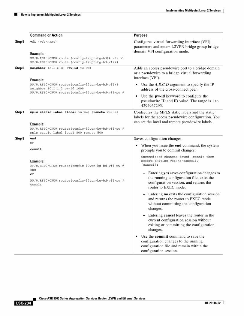
Implementing Multipoint Layer 2 ServicesHow to Implement Multipoint Layer 2 Services
LSC-234Cisco ASR 9000 Series Aggregation Services Router L2VPN and Ethernet Services
OL-26116-02
Step 5 vfi {vfi-name}
Example:RP/0/RSP0/CPU0:router(config-l2vpn-bg-bd)# vfi v1RP/0/RSP0/CPU0:router(config-l2vpn-bg-bd-vfi)#
Configures virtual forwarding interface (VFI) parameters and enters L2VPN bridge group bridge domain VFI configuration mode.
Step 6 neighbor {A.B.C.D} {pw-id value}
Example:RP/0/RSP0/CPU0:router(config-l2vpn-bg-bd-vfi)# neighbor 10.1.1.2 pw-id 1000RP/0/RSP0/CPU0:router(config-l2vpn-bg-bd-vfi-pw)#
Adds an access pseudowire port to a bridge domain or a pseudowire to a bridge virtual forwarding interface (VFI).
• Use the A.B.C.D argument to specify the IP address of the cross-connect peer.
• Use the pw-id keyword to configure the pseudowire ID and ID value. The range is 1 to 4294967295.
Step 7 mpls static label {local value} {remote value}
Example:RP/0/RSP0/CPU0:router(config-l2vpn-bg-bd-vfi-pw)# mpls static label local 800 remote 500
Configures the MPLS static labels and the static labels for the access pseudowire configuration. You can set the local and remote pseudowire labels.
Step 8 end
or
commit
Example:RP/0/RSP0/CPU0:router(config-l2vpn-bg-bd-vfi-pw)# end
or
RP/0/RSP0/CPU0:router(config-l2vpn-bg-bd-vfi-pw)# commit
Saves configuration changes.
• When you issue the end command, the system prompts you to commit changes:
Uncommitted changes found, commit them before exiting(yes/no/cancel)?[cancel]:
– Entering yes saves configuration changes to the running configuration file, exits the configuration session, and returns the router to EXEC mode.
– Entering no exits the configuration session and returns the router to EXEC mode without committing the configuration changes.
– Entering cancel leaves the router in the current configuration session without exiting or committing the configuration changes.
• Use the commit command to save the configuration changes to the running configuration file and remain within the configuration session.
Command or Action Purpose
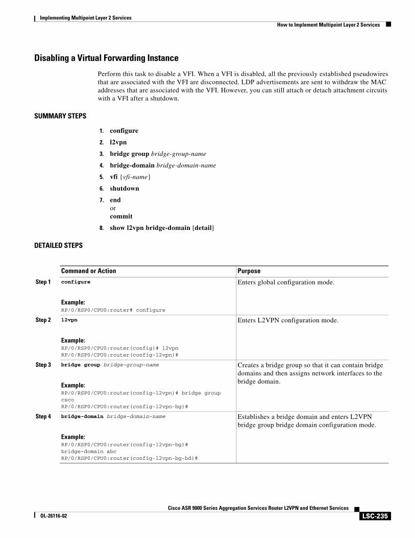
Implementing Multipoint Layer 2 ServicesHow to Implement Multipoint Layer 2 Services
LSC-235Cisco ASR 9000 Series Aggregation Services Router L2VPN and Ethernet Services
OL-26116-02
Disabling a Virtual Forwarding Instance
Perform this task to disable a VFI. When a VFI is disabled, all the previously established pseudowires that are associated with the VFI are disconnected. LDP advertisements are sent to withdraw the MAC addresses that are associated with the VFI. However, you can still attach or detach attachment circuits with a VFI after a shutdown.
SUMMARY STEPS
1. configure
2. l2vpn
3. bridge group bridge-group-name
4. bridge-domain bridge-domain-name
5. vfi {vfi-name}
6. shutdown
7. endorcommit
8. show l2vpn bridge-domain [detail]
DETAILED STEPS
Command or Action Purpose
Step 1 configure
Example:RP/0/RSP0/CPU0:router# configure
Enters global configuration mode.
Step 2 l2vpn
Example:RP/0/RSP0/CPU0:router(config)# l2vpnRP/0/RSP0/CPU0:router(config-l2vpn)#
Enters L2VPN configuration mode.
Step 3 bridge group bridge-group-name
Example:RP/0/RSP0/CPU0:router(config-l2vpn)# bridge group cscoRP/0/RSP0/CPU0:router(config-l2vpn-bg)#
Creates a bridge group so that it can contain bridge domains and then assigns network interfaces to the bridge domain.
Step 4 bridge-domain bridge-domain-name
Example:RP/0/RSP0/CPU0:router(config-l2vpn-bg)# bridge-domain abcRP/0/RSP0/CPU0:router(config-l2vpn-bg-bd)#
Establishes a bridge domain and enters L2VPN bridge group bridge domain configuration mode.
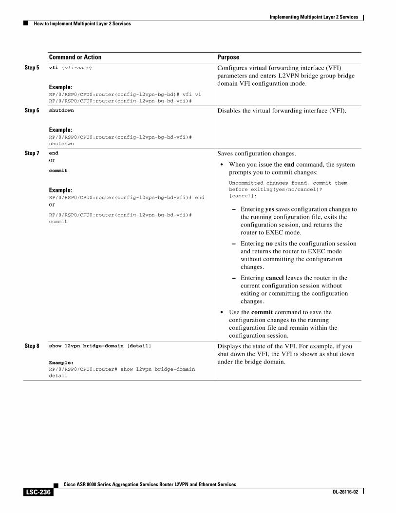
Implementing Multipoint Layer 2 ServicesHow to Implement Multipoint Layer 2 Services
LSC-236Cisco ASR 9000 Series Aggregation Services Router L2VPN and Ethernet Services
OL-26116-02
Step 5 vfi {vfi-name}
Example:RP/0/RSP0/CPU0:router(config-l2vpn-bg-bd)# vfi v1RP/0/RSP0/CPU0:router(config-l2vpn-bg-bd-vfi)#
Configures virtual forwarding interface (VFI) parameters and enters L2VPN bridge group bridge domain VFI configuration mode.
Step 6 shutdown
Example:RP/0/RSP0/CPU0:router(config-l2vpn-bg-bd-vfi)# shutdown
Disables the virtual forwarding interface (VFI).
Step 7 end
or
commit
Example:RP/0/RSP0/CPU0:router(config-l2vpn-bg-bd-vfi)# end
or
RP/0/RSP0/CPU0:router(config-l2vpn-bg-bd-vfi)# commit
Saves configuration changes.
• When you issue the end command, the system prompts you to commit changes:
Uncommitted changes found, commit them before exiting(yes/no/cancel)?[cancel]:
– Entering yes saves configuration changes to the running configuration file, exits the configuration session, and returns the router to EXEC mode.
– Entering no exits the configuration session and returns the router to EXEC mode without committing the configuration changes.
– Entering cancel leaves the router in the current configuration session without exiting or committing the configuration changes.
• Use the commit command to save the configuration changes to the running configuration file and remain within the configuration session.
Step 8 show l2vpn bridge-domain [detail]
Example:RP/0/RSP0/CPU0:router# show l2vpn bridge-domain detail
Displays the state of the VFI. For example, if you shut down the VFI, the VFI is shown as shut down under the bridge domain.
Command or Action Purpose
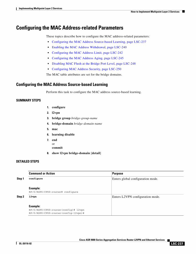
Implementing Multipoint Layer 2 ServicesHow to Implement Multipoint Layer 2 Services
LSC-237Cisco ASR 9000 Series Aggregation Services Router L2VPN and Ethernet Services
OL-26116-02
Configuring the MAC Address-related ParametersThese topics describe how to configure the MAC address-related parameters:
• Configuring the MAC Address Source-based Learning, page LSC-237
• Enabling the MAC Address Withdrawal, page LSC-240
• Configuring the MAC Address Limit, page LSC-242
• Configuring the MAC Address Aging, page LSC-245
• Disabling MAC Flush at the Bridge Port Level, page LSC-248
• Configuring MAC Address Security, page LSC-250
The MAC table attributes are set for the bridge domains.
Configuring the MAC Address Source-based Learning
Perform this task to configure the MAC address source-based learning.
SUMMARY STEPS
1. configure
2. l2vpn
3. bridge group bridge-group-name
4. bridge-domain bridge-domain-name
5. mac
6. learning disable
7. endorcommit
8. show l2vpn bridge-domain [detail]
DETAILED STEPS
Command or Action Purpose
Step 1 configure
Example:RP/0/RSP0/CPU0:router# configure
Enters global configuration mode.
Step 2 l2vpn
Example:RP/0/RSP0/CPU0:router(config)# l2vpnRP/0/RSP0/CPU0:router(config-l2vpn)#
Enters L2VPN configuration mode.
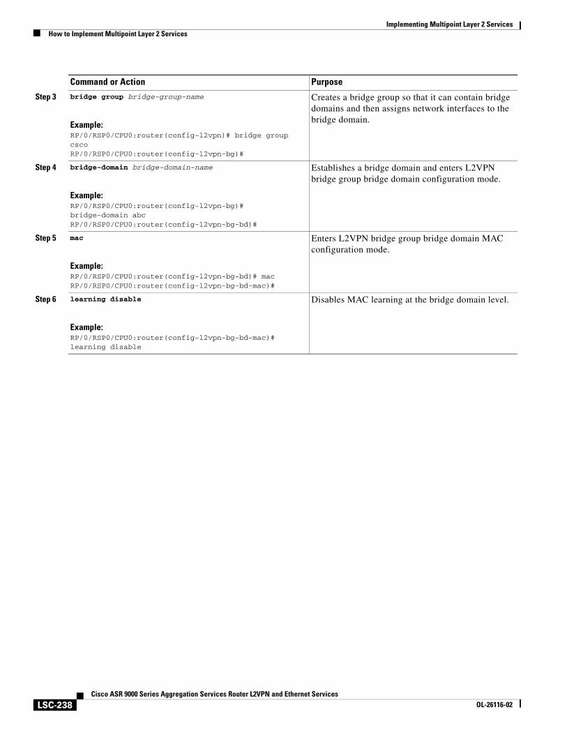
Implementing Multipoint Layer 2 ServicesHow to Implement Multipoint Layer 2 Services
LSC-238Cisco ASR 9000 Series Aggregation Services Router L2VPN and Ethernet Services
OL-26116-02
Step 3 bridge group bridge-group-name
Example:RP/0/RSP0/CPU0:router(config-l2vpn)# bridge group cscoRP/0/RSP0/CPU0:router(config-l2vpn-bg)#
Creates a bridge group so that it can contain bridge domains and then assigns network interfaces to the bridge domain.
Step 4 bridge-domain bridge-domain-name
Example:RP/0/RSP0/CPU0:router(config-l2vpn-bg)# bridge-domain abcRP/0/RSP0/CPU0:router(config-l2vpn-bg-bd)#
Establishes a bridge domain and enters L2VPN bridge group bridge domain configuration mode.
Step 5 mac
Example:RP/0/RSP0/CPU0:router(config-l2vpn-bg-bd)# macRP/0/RSP0/CPU0:router(config-l2vpn-bg-bd-mac)#
Enters L2VPN bridge group bridge domain MAC configuration mode.
Step 6 learning disable
Example:RP/0/RSP0/CPU0:router(config-l2vpn-bg-bd-mac)# learning disable
Disables MAC learning at the bridge domain level.
Command or Action Purpose
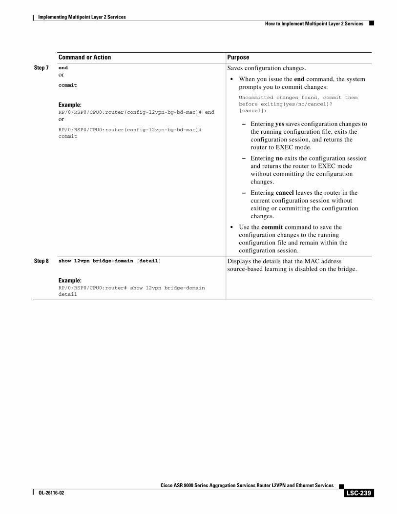
Implementing Multipoint Layer 2 ServicesHow to Implement Multipoint Layer 2 Services
LSC-239Cisco ASR 9000 Series Aggregation Services Router L2VPN and Ethernet Services
OL-26116-02
Step 7 end
or
commit
Example:RP/0/RSP0/CPU0:router(config-l2vpn-bg-bd-mac)# end
or
RP/0/RSP0/CPU0:router(config-l2vpn-bg-bd-mac)# commit
Saves configuration changes.
• When you issue the end command, the system prompts you to commit changes:
Uncommitted changes found, commit them before exiting(yes/no/cancel)?[cancel]:
– Entering yes saves configuration changes to the running configuration file, exits the configuration session, and returns the router to EXEC mode.
– Entering no exits the configuration session and returns the router to EXEC mode without committing the configuration changes.
– Entering cancel leaves the router in the current configuration session without exiting or committing the configuration changes.
• Use the commit command to save the configuration changes to the running configuration file and remain within the configuration session.
Step 8 show l2vpn bridge-domain [detail]
Example:RP/0/RSP0/CPU0:router# show l2vpn bridge-domain detail
Displays the details that the MAC address source-based learning is disabled on the bridge.
Command or Action Purpose
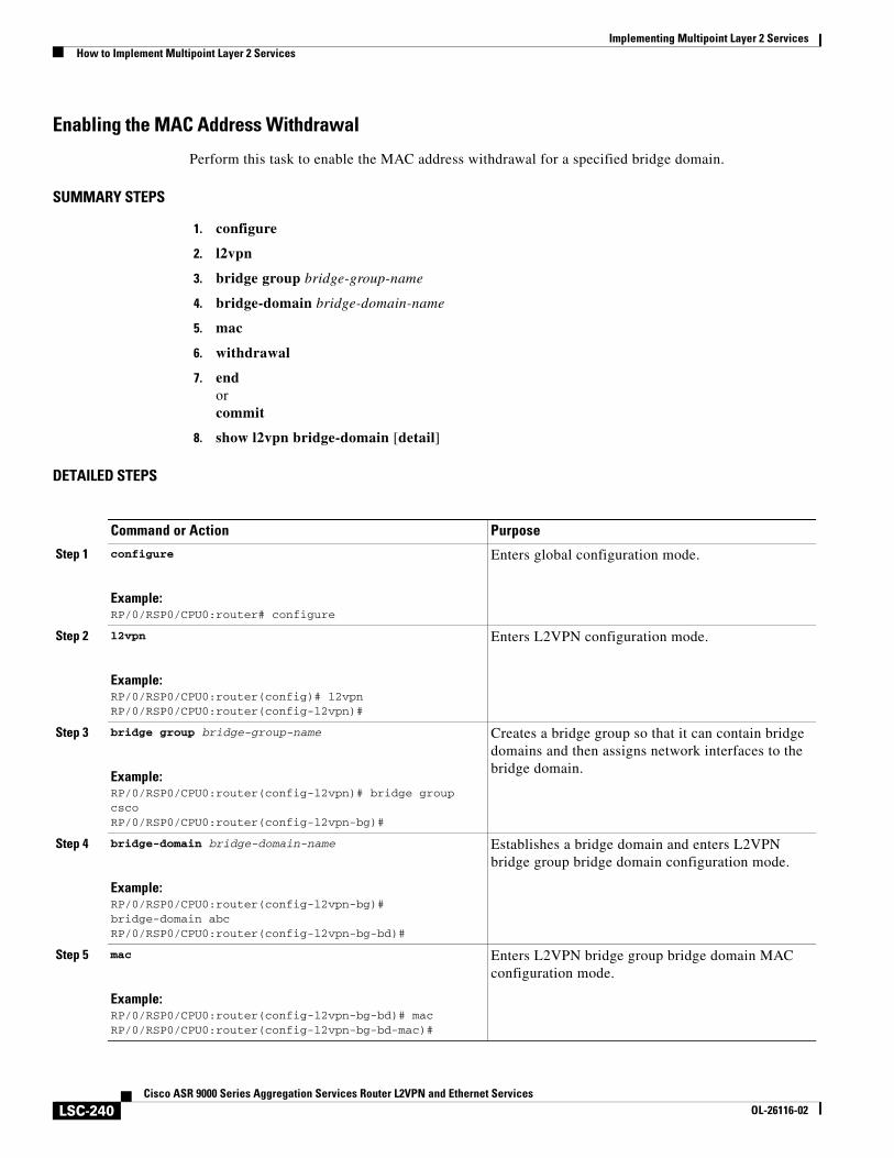
Implementing Multipoint Layer 2 ServicesHow to Implement Multipoint Layer 2 Services
LSC-240Cisco ASR 9000 Series Aggregation Services Router L2VPN and Ethernet Services
OL-26116-02
Enabling the MAC Address Withdrawal
Perform this task to enable the MAC address withdrawal for a specified bridge domain.
SUMMARY STEPS
1. configure
2. l2vpn
3. bridge group bridge-group-name
4. bridge-domain bridge-domain-name
5. mac
6. withdrawal
7. endorcommit
8. show l2vpn bridge-domain [detail]
DETAILED STEPS
Command or Action Purpose
Step 1 configure
Example:RP/0/RSP0/CPU0:router# configure
Enters global configuration mode.
Step 2 l2vpn
Example:RP/0/RSP0/CPU0:router(config)# l2vpnRP/0/RSP0/CPU0:router(config-l2vpn)#
Enters L2VPN configuration mode.
Step 3 bridge group bridge-group-name
Example:RP/0/RSP0/CPU0:router(config-l2vpn)# bridge group cscoRP/0/RSP0/CPU0:router(config-l2vpn-bg)#
Creates a bridge group so that it can contain bridge domains and then assigns network interfaces to the bridge domain.
Step 4 bridge-domain bridge-domain-name
Example:RP/0/RSP0/CPU0:router(config-l2vpn-bg)# bridge-domain abcRP/0/RSP0/CPU0:router(config-l2vpn-bg-bd)#
Establishes a bridge domain and enters L2VPN bridge group bridge domain configuration mode.
Step 5 mac
Example:RP/0/RSP0/CPU0:router(config-l2vpn-bg-bd)# macRP/0/RSP0/CPU0:router(config-l2vpn-bg-bd-mac)#
Enters L2VPN bridge group bridge domain MAC configuration mode.
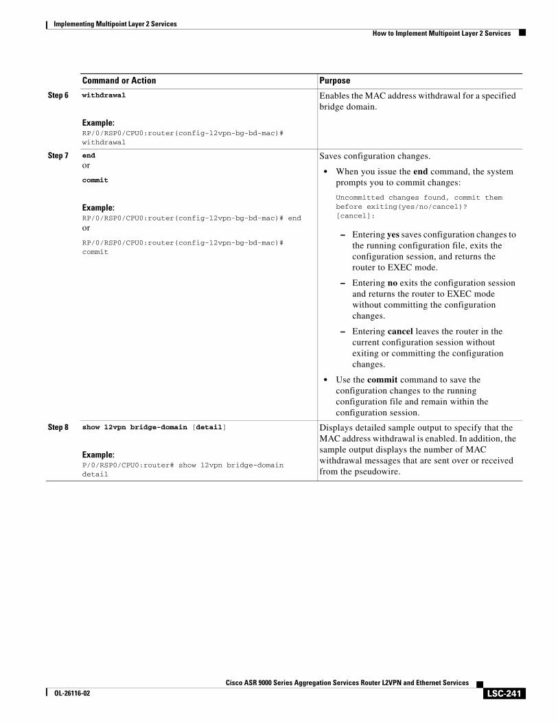
Implementing Multipoint Layer 2 ServicesHow to Implement Multipoint Layer 2 Services
LSC-241Cisco ASR 9000 Series Aggregation Services Router L2VPN and Ethernet Services
OL-26116-02
Step 6 withdrawal
Example:RP/0/RSP0/CPU0:router(config-l2vpn-bg-bd-mac)# withdrawal
Enables the MAC address withdrawal for a specified bridge domain.
Step 7 end
or
commit
Example:RP/0/RSP0/CPU0:router(config-l2vpn-bg-bd-mac)# end
or
RP/0/RSP0/CPU0:router(config-l2vpn-bg-bd-mac)# commit
Saves configuration changes.
• When you issue the end command, the system prompts you to commit changes:
Uncommitted changes found, commit them before exiting(yes/no/cancel)?[cancel]:
– Entering yes saves configuration changes to the running configuration file, exits the configuration session, and returns the router to EXEC mode.
– Entering no exits the configuration session and returns the router to EXEC mode without committing the configuration changes.
– Entering cancel leaves the router in the current configuration session without exiting or committing the configuration changes.
• Use the commit command to save the configuration changes to the running configuration file and remain within the configuration session.
Step 8 show l2vpn bridge-domain [detail]
Example:P/0/RSP0/CPU0:router# show l2vpn bridge-domain detail
Displays detailed sample output to specify that the MAC address withdrawal is enabled. In addition, the sample output displays the number of MAC withdrawal messages that are sent over or received from the pseudowire.
Command or Action Purpose
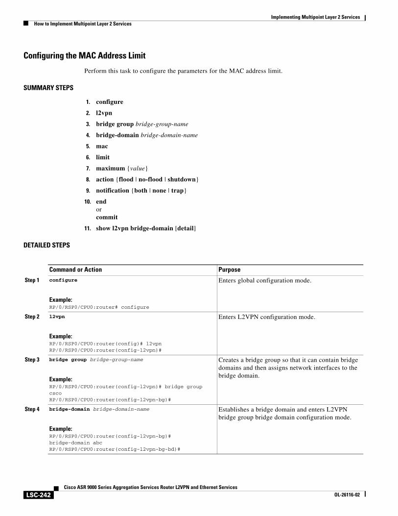
Implementing Multipoint Layer 2 ServicesHow to Implement Multipoint Layer 2 Services
LSC-242Cisco ASR 9000 Series Aggregation Services Router L2VPN and Ethernet Services
OL-26116-02
Configuring the MAC Address Limit
Perform this task to configure the parameters for the MAC address limit.
SUMMARY STEPS
1. configure
2. l2vpn
3. bridge group bridge-group-name
4. bridge-domain bridge-domain-name
5. mac
6. limit
7. maximum {value}
8. action {flood | no-flood | shutdown}
9. notification {both | none | trap}
10. endorcommit
11. show l2vpn bridge-domain [detail]
DETAILED STEPS
Command or Action Purpose
Step 1 configure
Example:RP/0/RSP0/CPU0:router# configure
Enters global configuration mode.
Step 2 l2vpn
Example:RP/0/RSP0/CPU0:router(config)# l2vpnRP/0/RSP0/CPU0:router(config-l2vpn)#
Enters L2VPN configuration mode.
Step 3 bridge group bridge-group-name
Example:RP/0/RSP0/CPU0:router(config-l2vpn)# bridge group cscoRP/0/RSP0/CPU0:router(config-l2vpn-bg)#
Creates a bridge group so that it can contain bridge domains and then assigns network interfaces to the bridge domain.
Step 4 bridge-domain bridge-domain-name
Example:RP/0/RSP0/CPU0:router(config-l2vpn-bg)# bridge-domain abcRP/0/RSP0/CPU0:router(config-l2vpn-bg-bd)#
Establishes a bridge domain and enters L2VPN bridge group bridge domain configuration mode.
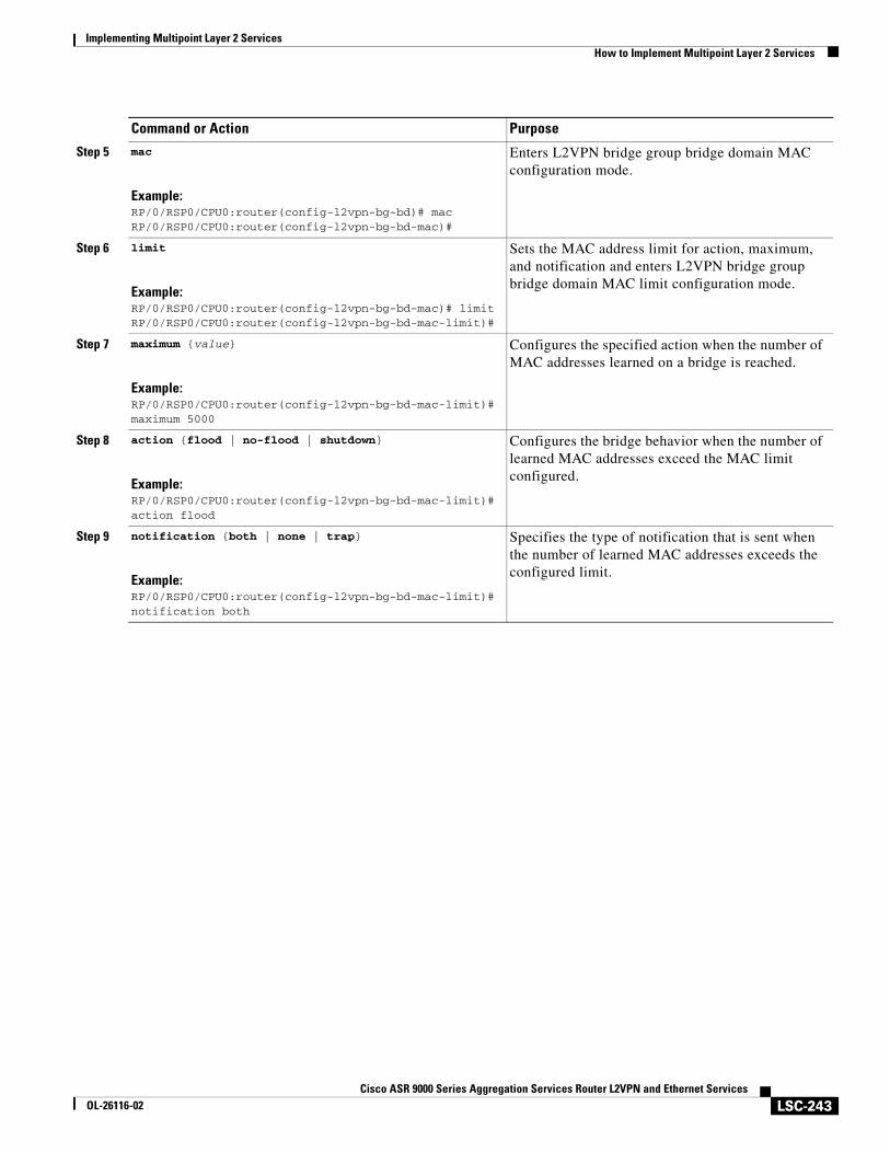
Implementing Multipoint Layer 2 ServicesHow to Implement Multipoint Layer 2 Services
LSC-243Cisco ASR 9000 Series Aggregation Services Router L2VPN and Ethernet Services
OL-26116-02
Step 5 mac
Example:RP/0/RSP0/CPU0:router(config-l2vpn-bg-bd)# macRP/0/RSP0/CPU0:router(config-l2vpn-bg-bd-mac)#
Enters L2VPN bridge group bridge domain MAC configuration mode.
Step 6 limit
Example:RP/0/RSP0/CPU0:router(config-l2vpn-bg-bd-mac)# limitRP/0/RSP0/CPU0:router(config-l2vpn-bg-bd-mac-limit)#
Sets the MAC address limit for action, maximum, and notification and enters L2VPN bridge group bridge domain MAC limit configuration mode.
Step 7 maximum {value}
Example:RP/0/RSP0/CPU0:router(config-l2vpn-bg-bd-mac-limit)# maximum 5000
Configures the specified action when the number of MAC addresses learned on a bridge is reached.
Step 8 action {flood | no-flood | shutdown}
Example:RP/0/RSP0/CPU0:router(config-l2vpn-bg-bd-mac-limit)# action flood
Configures the bridge behavior when the number of learned MAC addresses exceed the MAC limit configured.
Step 9 notification {both | none | trap}
Example:RP/0/RSP0/CPU0:router(config-l2vpn-bg-bd-mac-limit)# notification both
Specifies the type of notification that is sent when the number of learned MAC addresses exceeds the configured limit.
Command or Action Purpose
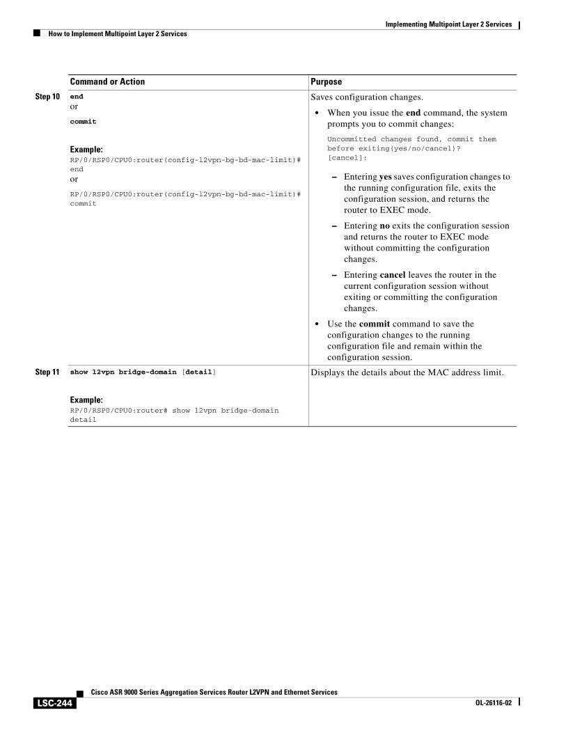
Implementing Multipoint Layer 2 ServicesHow to Implement Multipoint Layer 2 Services
LSC-244Cisco ASR 9000 Series Aggregation Services Router L2VPN and Ethernet Services
OL-26116-02
Step 10 end
or
commit
Example:RP/0/RSP0/CPU0:router(config-l2vpn-bg-bd-mac-limit)# end
or
RP/0/RSP0/CPU0:router(config-l2vpn-bg-bd-mac-limit)# commit
Saves configuration changes.
• When you issue the end command, the system prompts you to commit changes:
Uncommitted changes found, commit them before exiting(yes/no/cancel)?[cancel]:
– Entering yes saves configuration changes to the running configuration file, exits the configuration session, and returns the router to EXEC mode.
– Entering no exits the configuration session and returns the router to EXEC mode without committing the configuration changes.
– Entering cancel leaves the router in the current configuration session without exiting or committing the configuration changes.
• Use the commit command to save the configuration changes to the running configuration file and remain within the configuration session.
Step 11 show l2vpn bridge-domain [detail]
Example:RP/0/RSP0/CPU0:router# show l2vpn bridge-domain detail
Displays the details about the MAC address limit.
Command or Action Purpose
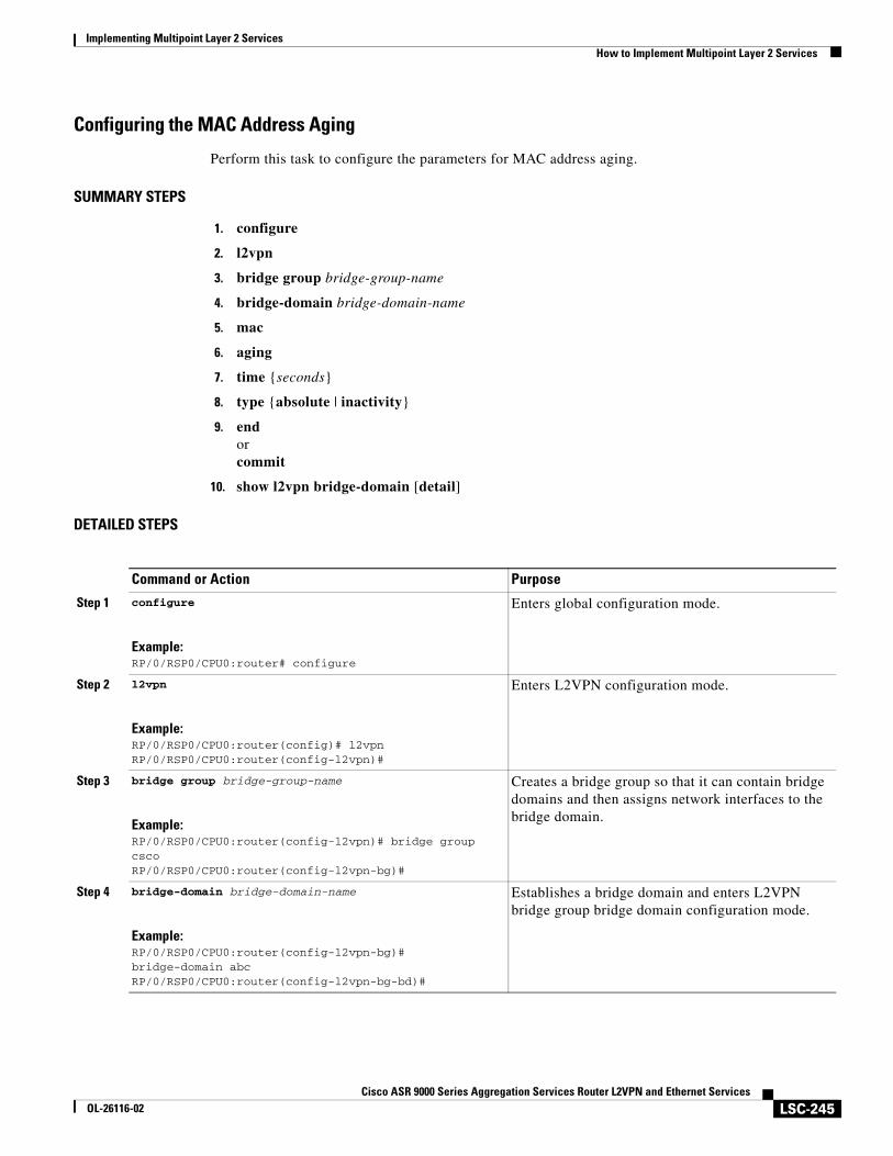
Implementing Multipoint Layer 2 ServicesHow to Implement Multipoint Layer 2 Services
LSC-245Cisco ASR 9000 Series Aggregation Services Router L2VPN and Ethernet Services
OL-26116-02
Configuring the MAC Address Aging
Perform this task to configure the parameters for MAC address aging.
SUMMARY STEPS
1. configure
2. l2vpn
3. bridge group bridge-group-name
4. bridge-domain bridge-domain-name
5. mac
6. aging
7. time {seconds}
8. type {absolute | inactivity}
9. endorcommit
10. show l2vpn bridge-domain [detail]
DETAILED STEPS
Command or Action Purpose
Step 1 configure
Example:RP/0/RSP0/CPU0:router# configure
Enters global configuration mode.
Step 2 l2vpn
Example:RP/0/RSP0/CPU0:router(config)# l2vpnRP/0/RSP0/CPU0:router(config-l2vpn)#
Enters L2VPN configuration mode.
Step 3 bridge group bridge-group-name
Example:RP/0/RSP0/CPU0:router(config-l2vpn)# bridge group cscoRP/0/RSP0/CPU0:router(config-l2vpn-bg)#
Creates a bridge group so that it can contain bridge domains and then assigns network interfaces to the bridge domain.
Step 4 bridge-domain bridge-domain-name
Example:RP/0/RSP0/CPU0:router(config-l2vpn-bg)# bridge-domain abcRP/0/RSP0/CPU0:router(config-l2vpn-bg-bd)#
Establishes a bridge domain and enters L2VPN bridge group bridge domain configuration mode.
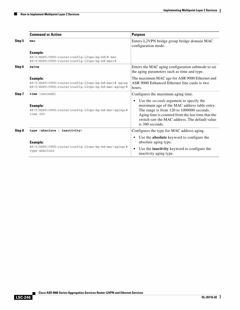
Implementing Multipoint Layer 2 ServicesHow to Implement Multipoint Layer 2 Services
LSC-246Cisco ASR 9000 Series Aggregation Services Router L2VPN and Ethernet Services
OL-26116-02
Step 5 mac
Example:RP/0/RSP0/CPU0:router(config-l2vpn-bg-bd)# macRP/0/RSP0/CPU0:router(config-l2vpn-bg-bd-mac)#
Enters L2VPN bridge group bridge domain MAC configuration mode.
Step 6 aging
Example:RP/0/RSP0/CPU0:router(config-l2vpn-bg-bd-mac)# agingRP/0/RSP0/CPU0:router(config-l2vpn-bg-bd-mac-aging)#
Enters the MAC aging configuration submode to set the aging parameters such as time and type.
The maximum MAC age for ASR 9000 Ethernet and ASR 9000 Enhanced Ethernet line cards is two hours.
Step 7 time {seconds}
Example:RP/0/RSP0/CPU0:router(config-l2vpn-bg-bd-mac-aging)# time 300
Configures the maximum aging time.
• Use the seconds argument to specify the maximum age of the MAC address table entry. The range is from 120 to 1000000 seconds. Aging time is counted from the last time that the switch saw the MAC address. The default value is 300 seconds.
Step 8 type {absolute | inactivity}
Example:RP/0/RSP0/CPU0:router(config-l2vpn-bg-bd-mac-aging)# type absolute
Configures the type for MAC address aging.
• Use the absolute keyword to configure the absolute aging type.
• Use the inactivity keyword to configure the inactivity aging type.
Command or Action Purpose
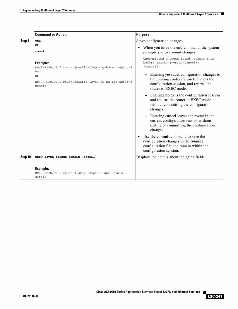
Implementing Multipoint Layer 2 ServicesHow to Implement Multipoint Layer 2 Services
LSC-247Cisco ASR 9000 Series Aggregation Services Router L2VPN and Ethernet Services
OL-26116-02
Step 9 end
or
commit
Example:RP/0/RSP0/CPU0:router(config-l2vpn-bg-bd-mac-aging)# end
or
RP/0/RSP0/CPU0:router(config-l2vpn-bg-bd-mac-aging)# commit
Saves configuration changes.
• When you issue the end command, the system prompts you to commit changes:
Uncommitted changes found, commit them before exiting(yes/no/cancel)?[cancel]:
– Entering yes saves configuration changes to the running configuration file, exits the configuration session, and returns the router to EXEC mode.
– Entering no exits the configuration session and returns the router to EXEC mode without committing the configuration changes.
– Entering cancel leaves the router in the current configuration session without exiting or committing the configuration changes.
• Use the commit command to save the configuration changes to the running configuration file and remain within the configuration session.
Step 10 show l2vpn bridge-domain [detail]
Example:RP/0/RSP0/CPU0:router# show l2vpn bridge-domain detail
Displays the details about the aging fields.
Command or Action Purpose
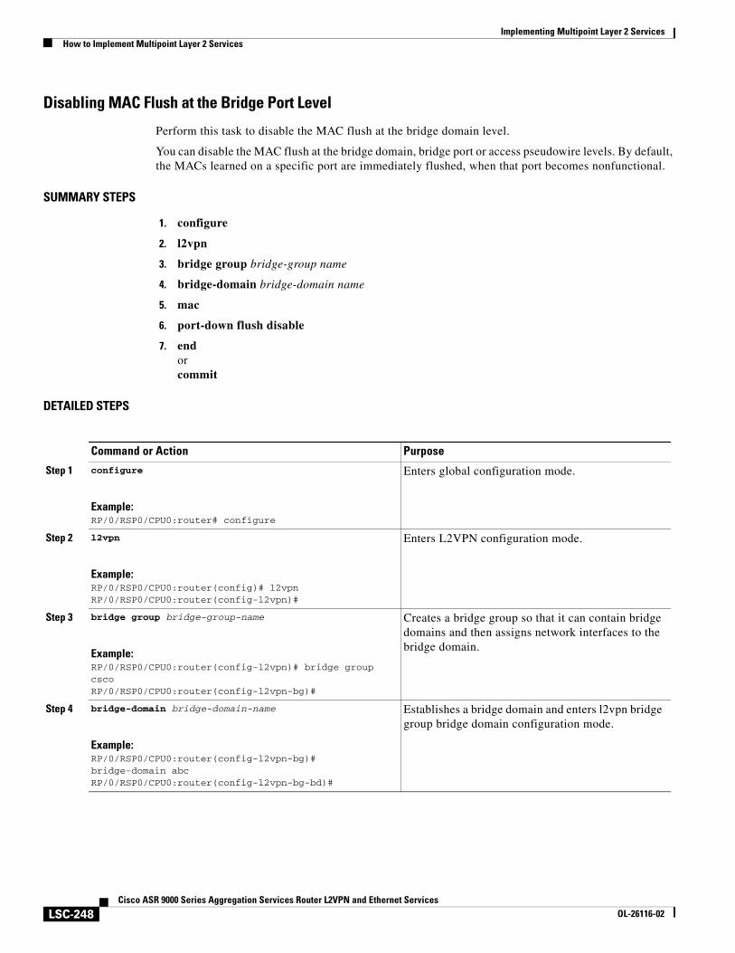
Implementing Multipoint Layer 2 ServicesHow to Implement Multipoint Layer 2 Services
LSC-248Cisco ASR 9000 Series Aggregation Services Router L2VPN and Ethernet Services
OL-26116-02
Disabling MAC Flush at the Bridge Port Level
Perform this task to disable the MAC flush at the bridge domain level.
You can disable the MAC flush at the bridge domain, bridge port or access pseudowire levels. By default, the MACs learned on a specific port are immediately flushed, when that port becomes nonfunctional.
SUMMARY STEPS
1. configure
2. l2vpn
3. bridge group bridge-group name
4. bridge-domain bridge-domain name
5. mac
6. port-down flush disable
7. endorcommit
DETAILED STEPS
Command or Action Purpose
Step 1 configure
Example:RP/0/RSP0/CPU0:router# configure
Enters global configuration mode.
Step 2 l2vpn
Example:RP/0/RSP0/CPU0:router(config)# l2vpnRP/0/RSP0/CPU0:router(config-l2vpn)#
Enters L2VPN configuration mode.
Step 3 bridge group bridge-group-name
Example:RP/0/RSP0/CPU0:router(config-l2vpn)# bridge group cscoRP/0/RSP0/CPU0:router(config-l2vpn-bg)#
Creates a bridge group so that it can contain bridge domains and then assigns network interfaces to the bridge domain.
Step 4 bridge-domain bridge-domain-name
Example:RP/0/RSP0/CPU0:router(config-l2vpn-bg)# bridge-domain abcRP/0/RSP0/CPU0:router(config-l2vpn-bg-bd)#
Establishes a bridge domain and enters l2vpn bridge group bridge domain configuration mode.
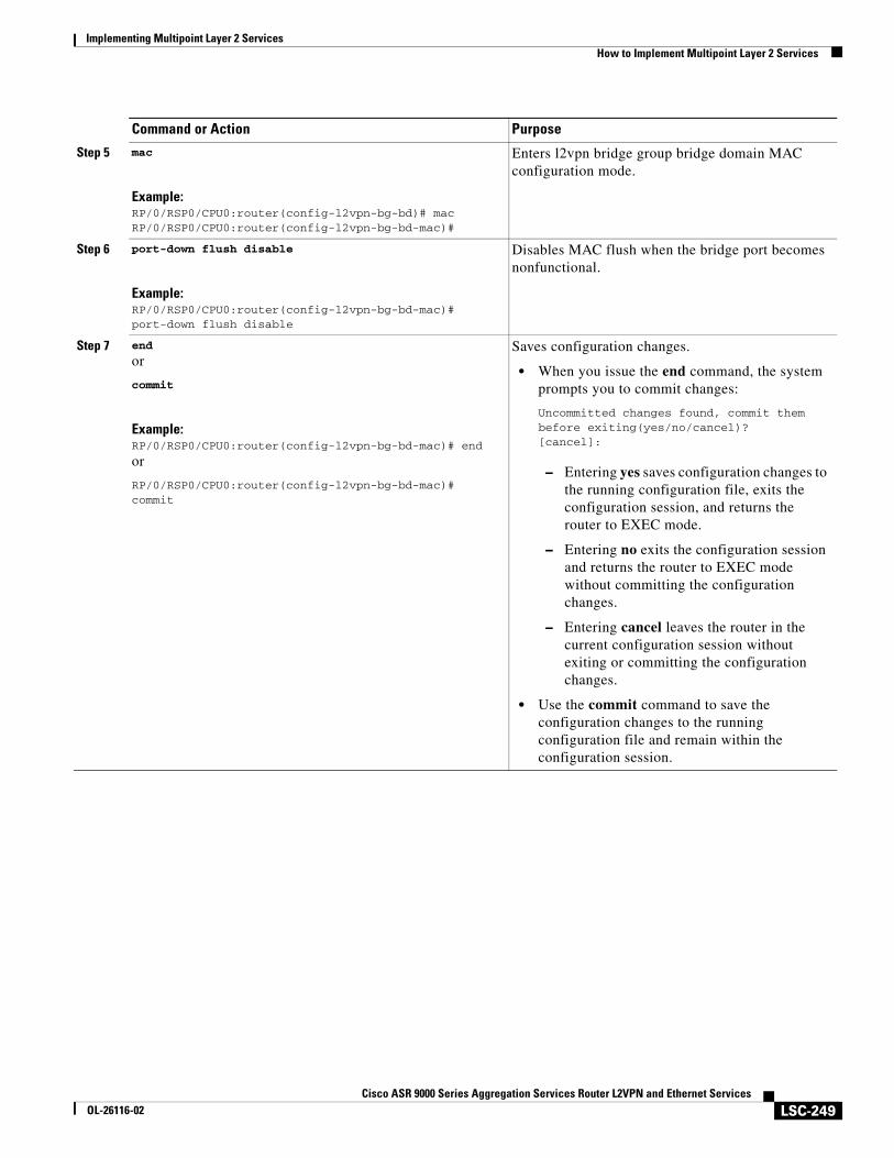
Implementing Multipoint Layer 2 ServicesHow to Implement Multipoint Layer 2 Services
LSC-249Cisco ASR 9000 Series Aggregation Services Router L2VPN and Ethernet Services
OL-26116-02
Step 5 mac
Example:RP/0/RSP0/CPU0:router(config-l2vpn-bg-bd)# macRP/0/RSP0/CPU0:router(config-l2vpn-bg-bd-mac)#
Enters l2vpn bridge group bridge domain MAC configuration mode.
Step 6 port-down flush disable
Example:RP/0/RSP0/CPU0:router(config-l2vpn-bg-bd-mac)#port-down flush disable
Disables MAC flush when the bridge port becomes nonfunctional.
Step 7 end
or
commit
Example:RP/0/RSP0/CPU0:router(config-l2vpn-bg-bd-mac)# end
or
RP/0/RSP0/CPU0:router(config-l2vpn-bg-bd-mac)# commit
Saves configuration changes.
• When you issue the end command, the system prompts you to commit changes:
Uncommitted changes found, commit them before exiting(yes/no/cancel)?[cancel]:
– Entering yes saves configuration changes to the running configuration file, exits the configuration session, and returns the router to EXEC mode.
– Entering no exits the configuration session and returns the router to EXEC mode without committing the configuration changes.
– Entering cancel leaves the router in the current configuration session without exiting or committing the configuration changes.
• Use the commit command to save the configuration changes to the running configuration file and remain within the configuration session.
Command or Action Purpose
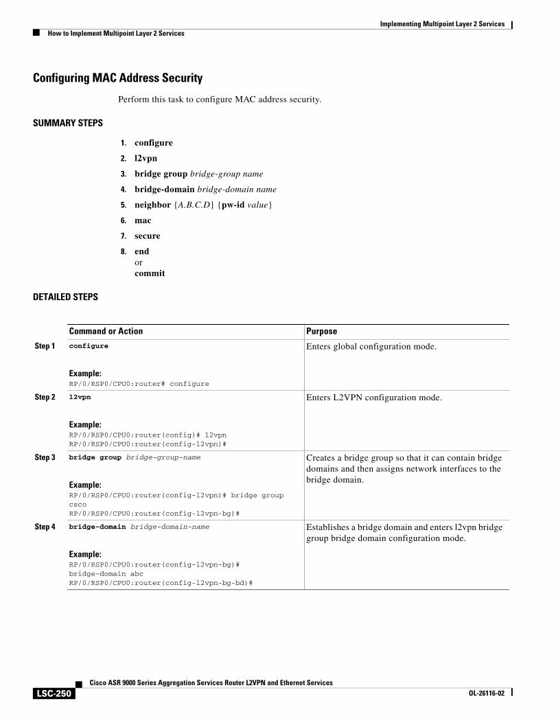
Implementing Multipoint Layer 2 ServicesHow to Implement Multipoint Layer 2 Services
LSC-250Cisco ASR 9000 Series Aggregation Services Router L2VPN and Ethernet Services
OL-26116-02
Configuring MAC Address Security
Perform this task to configure MAC address security.
SUMMARY STEPS
1. configure
2. l2vpn
3. bridge group bridge-group name
4. bridge-domain bridge-domain name
5. neighbor {A.B.C.D} {pw-id value}
6. mac
7. secure
8. endorcommit
DETAILED STEPS
Command or Action Purpose
Step 1 configure
Example:RP/0/RSP0/CPU0:router# configure
Enters global configuration mode.
Step 2 l2vpn
Example:RP/0/RSP0/CPU0:router(config)# l2vpnRP/0/RSP0/CPU0:router(config-l2vpn)#
Enters L2VPN configuration mode.
Step 3 bridge group bridge-group-name
Example:RP/0/RSP0/CPU0:router(config-l2vpn)# bridge group cscoRP/0/RSP0/CPU0:router(config-l2vpn-bg)#
Creates a bridge group so that it can contain bridge domains and then assigns network interfaces to the bridge domain.
Step 4 bridge-domain bridge-domain-name
Example:RP/0/RSP0/CPU0:router(config-l2vpn-bg)# bridge-domain abcRP/0/RSP0/CPU0:router(config-l2vpn-bg-bd)#
Establishes a bridge domain and enters l2vpn bridge group bridge domain configuration mode.
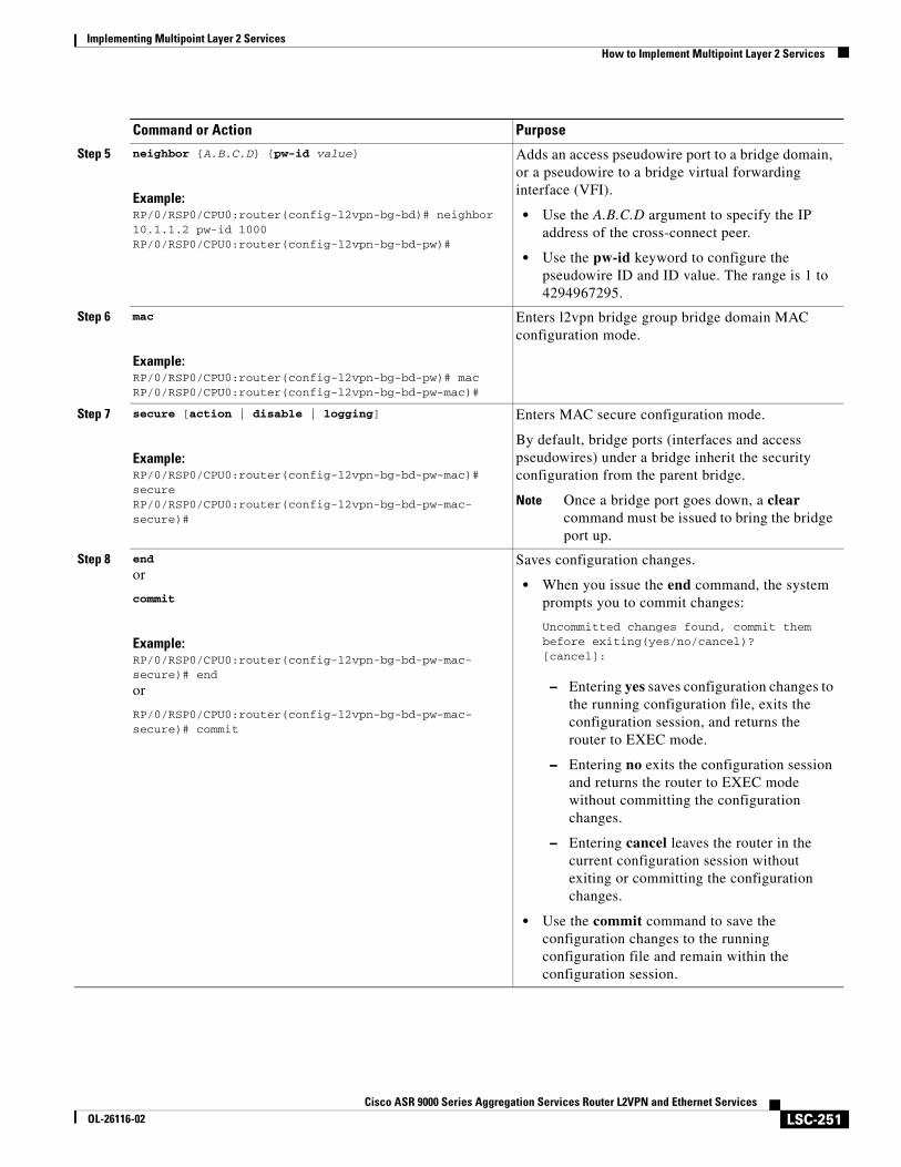
Implementing Multipoint Layer 2 ServicesHow to Implement Multipoint Layer 2 Services
LSC-251Cisco ASR 9000 Series Aggregation Services Router L2VPN and Ethernet Services
OL-26116-02
Step 5 neighbor {A.B.C.D} {pw-id value}
Example:RP/0/RSP0/CPU0:router(config-l2vpn-bg-bd)# neighbor 10.1.1.2 pw-id 1000RP/0/RSP0/CPU0:router(config-l2vpn-bg-bd-pw)#
Adds an access pseudowire port to a bridge domain, or a pseudowire to a bridge virtual forwarding interface (VFI).
• Use the A.B.C.D argument to specify the IP address of the cross-connect peer.
• Use the pw-id keyword to configure the pseudowire ID and ID value. The range is 1 to 4294967295.
Step 6 mac
Example:RP/0/RSP0/CPU0:router(config-l2vpn-bg-bd-pw)# macRP/0/RSP0/CPU0:router(config-l2vpn-bg-bd-pw-mac)#
Enters l2vpn bridge group bridge domain MAC configuration mode.
Step 7 secure [action | disable | logging]
Example:RP/0/RSP0/CPU0:router(config-l2vpn-bg-bd-pw-mac)#secureRP/0/RSP0/CPU0:router(config-l2vpn-bg-bd-pw-mac-secure)#
Enters MAC secure configuration mode.
By default, bridge ports (interfaces and access pseudowires) under a bridge inherit the security configuration from the parent bridge.
Note Once a bridge port goes down, a clear command must be issued to bring the bridge port up.
Step 8 end
or
commit
Example:RP/0/RSP0/CPU0:router(config-l2vpn-bg-bd-pw-mac-secure)# end
or
RP/0/RSP0/CPU0:router(config-l2vpn-bg-bd-pw-mac-secure)# commit
Saves configuration changes.
• When you issue the end command, the system prompts you to commit changes:
Uncommitted changes found, commit them before exiting(yes/no/cancel)?[cancel]:
– Entering yes saves configuration changes to the running configuration file, exits the configuration session, and returns the router to EXEC mode.
– Entering no exits the configuration session and returns the router to EXEC mode without committing the configuration changes.
– Entering cancel leaves the router in the current configuration session without exiting or committing the configuration changes.
• Use the commit command to save the configuration changes to the running configuration file and remain within the configuration session.
Command or Action Purpose
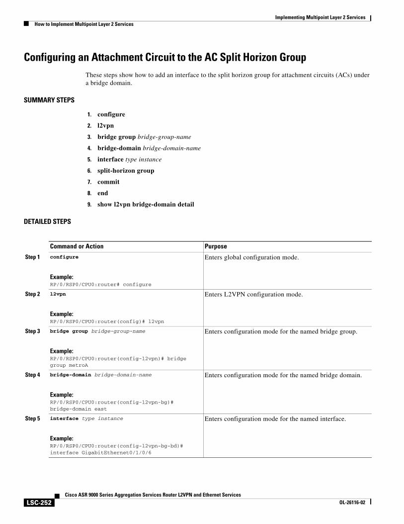
Implementing Multipoint Layer 2 ServicesHow to Implement Multipoint Layer 2 Services
LSC-252Cisco ASR 9000 Series Aggregation Services Router L2VPN and Ethernet Services
OL-26116-02
Configuring an Attachment Circuit to the AC Split Horizon GroupThese steps show how to add an interface to the split horizon group for attachment circuits (ACs) under a bridge domain.
SUMMARY STEPS
1. configure
2. l2vpn
3. bridge group bridge-group-name
4. bridge-domain bridge-domain-name
5. interface type instance
6. split-horizon group
7. commit
8. end
9. show l2vpn bridge-domain detail
DETAILED STEPS
Command or Action Purpose
Step 1 configure
Example:RP/0/RSP0/CPU0:router# configure
Enters global configuration mode.
Step 2 l2vpn
Example:RP/0/RSP0/CPU0:router(config)# l2vpn
Enters L2VPN configuration mode.
Step 3 bridge group bridge-group-name
Example:RP/0/RSP0/CPU0:router(config-l2vpn)# bridge group metroA
Enters configuration mode for the named bridge group.
Step 4 bridge-domain bridge-domain-name
Example:RP/0/RSP0/CPU0:router(config-l2vpn-bg)# bridge-domain east
Enters configuration mode for the named bridge domain.
Step 5 interface type instance
Example:RP/0/RSP0/CPU0:router(config-l2vpn-bg-bd)# interface GigabitEthernet0/1/0/6
Enters configuration mode for the named interface.
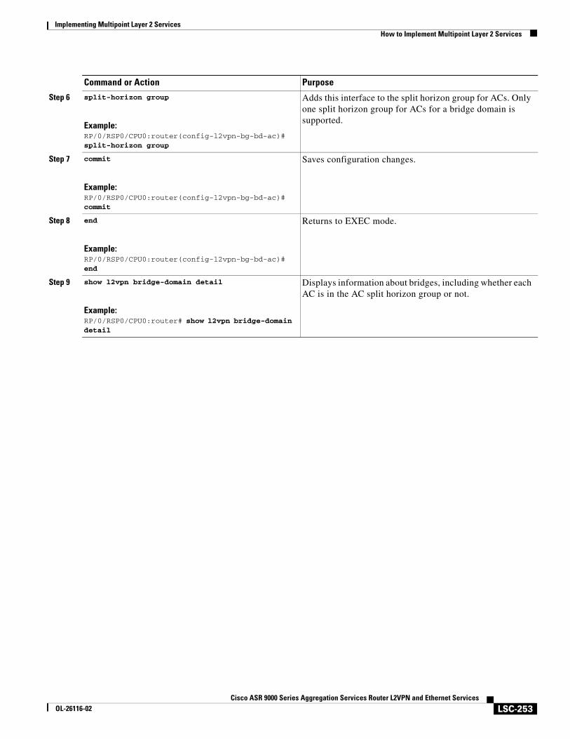
Implementing Multipoint Layer 2 ServicesHow to Implement Multipoint Layer 2 Services
LSC-253Cisco ASR 9000 Series Aggregation Services Router L2VPN and Ethernet Services
OL-26116-02
Step 6 split-horizon group
Example:RP/0/RSP0/CPU0:router(config-l2vpn-bg-bd-ac)# split-horizon group
Adds this interface to the split horizon group for ACs. Only one split horizon group for ACs for a bridge domain is supported.
Step 7 commit
Example:RP/0/RSP0/CPU0:router(config-l2vpn-bg-bd-ac)# commit
Saves configuration changes.
Step 8 end
Example:RP/0/RSP0/CPU0:router(config-l2vpn-bg-bd-ac)# end
Returns to EXEC mode.
Step 9 show l2vpn bridge-domain detail
Example:RP/0/RSP0/CPU0:router# show l2vpn bridge-domain detail
Displays information about bridges, including whether each AC is in the AC split horizon group or not.
Command or Action Purpose
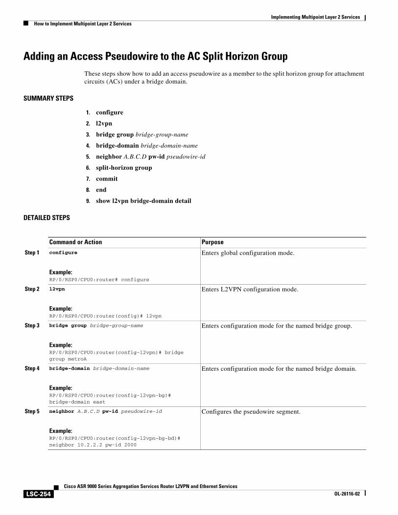
Implementing Multipoint Layer 2 ServicesHow to Implement Multipoint Layer 2 Services
LSC-254Cisco ASR 9000 Series Aggregation Services Router L2VPN and Ethernet Services
OL-26116-02
Adding an Access Pseudowire to the AC Split Horizon GroupThese steps show how to add an access pseudowire as a member to the split horizon group for attachment circuits (ACs) under a bridge domain.
SUMMARY STEPS
1. configure
2. l2vpn
3. bridge group bridge-group-name
4. bridge-domain bridge-domain-name
5. neighbor A.B.C.D pw-id pseudowire-id
6. split-horizon group
7. commit
8. end
9. show l2vpn bridge-domain detail
DETAILED STEPS
Command or Action Purpose
Step 1 configure
Example:RP/0/RSP0/CPU0:router# configure
Enters global configuration mode.
Step 2 l2vpn
Example:RP/0/RSP0/CPU0:router(config)# l2vpn
Enters L2VPN configuration mode.
Step 3 bridge group bridge-group-name
Example:RP/0/RSP0/CPU0:router(config-l2vpn)# bridge group metroA
Enters configuration mode for the named bridge group.
Step 4 bridge-domain bridge-domain-name
Example:RP/0/RSP0/CPU0:router(config-l2vpn-bg)# bridge-domain east
Enters configuration mode for the named bridge domain.
Step 5 neighbor A.B.C.D pw-id pseudowire-id
Example:RP/0/RSP0/CPU0:router(config-l2vpn-bg-bd)# neighbor 10.2.2.2 pw-id 2000
Configures the pseudowire segment.
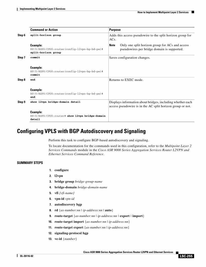
Implementing Multipoint Layer 2 ServicesHow to Implement Multipoint Layer 2 Services
LSC-255Cisco ASR 9000 Series Aggregation Services Router L2VPN and Ethernet Services
OL-26116-02
Configuring VPLS with BGP Autodiscovery and SignalingPerform this task to configure BGP-based autodiscovery and signaling.
To locate documentation for the commands used in this configuration, refer to the Multipoint Layer 2 Services Commands module in the Cisco ASR 9000 Series Aggregation Services Router L2VPN and Ethernet Services Command Reference.
SUMMARY STEPS
1. configure
2. l2vpn
3. bridge group bridge-group-name
4. bridge-domain bridge-domain-name
5. vfi {vfi-name}
6. vpn-id vpn-id
7. autodiscovery bgp
8. rd {as-number:nn | ip-address:nn | auto}
9. route-target {as-number:nn | ip-address:nn | export | import}
10. route-target import {as-number:nn | ip-address:nn}
11. route-target export {as-number:nn | ip-address:nn}
12. signaling-protocol bgp
13. ve-id {number}
Step 6 split-horizon group
Example:RP/0/RSP0/CPU0:router(config-l2vpn-bg-bd-pw)# split-horizon group
Adds this access pseudowire to the split horizon group for ACs.
Note Only one split horizon group for ACs and access pseudowires per bridge domain is supported.
Step 7 commit
Example:RP/0/RSP0/CPU0:router(config-l2vpn-bg-bd-pw)# commit
Saves configuration changes.
Step 8 end
Example:RP/0/RSP0/CPU0:router(config-l2vpn-bg-bd-pw)# end
Returns to EXEC mode.
Step 9 show l2vpn bridge-domain detail
Example:RP/0/RSP0/CPU0:router# show l2vpn bridge-domain detail
Displays information about bridges, including whether each access pseudowire is in the AC split horizon group or not.
Command or Action Purpose
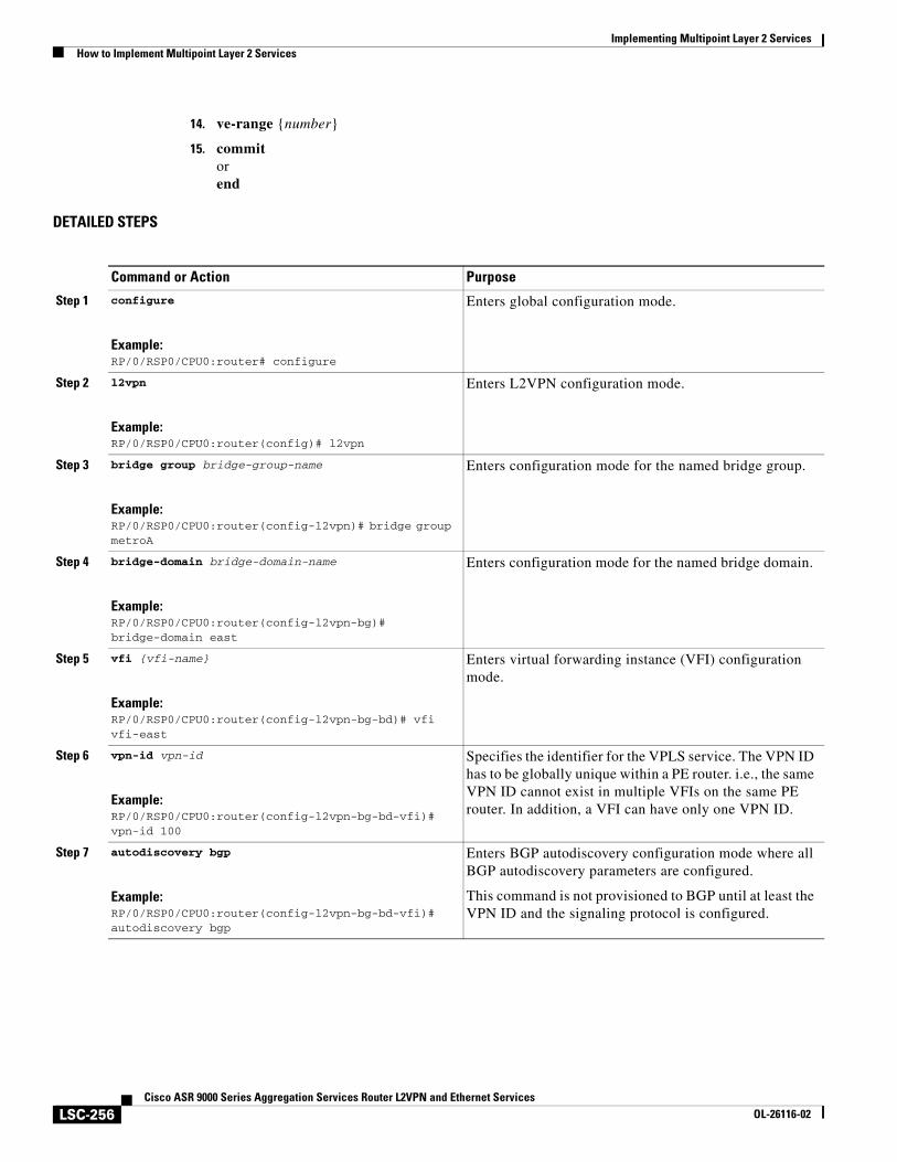
Implementing Multipoint Layer 2 ServicesHow to Implement Multipoint Layer 2 Services
LSC-256Cisco ASR 9000 Series Aggregation Services Router L2VPN and Ethernet Services
OL-26116-02
14. ve-range {number}
15. commit orend
DETAILED STEPS
Command or Action Purpose
Step 1 configure
Example:RP/0/RSP0/CPU0:router# configure
Enters global configuration mode.
Step 2 l2vpn
Example:RP/0/RSP0/CPU0:router(config)# l2vpn
Enters L2VPN configuration mode.
Step 3 bridge group bridge-group-name
Example:RP/0/RSP0/CPU0:router(config-l2vpn)# bridge group metroA
Enters configuration mode for the named bridge group.
Step 4 bridge-domain bridge-domain-name
Example:RP/0/RSP0/CPU0:router(config-l2vpn-bg)# bridge-domain east
Enters configuration mode for the named bridge domain.
Step 5 vfi {vfi-name}
Example:RP/0/RSP0/CPU0:router(config-l2vpn-bg-bd)# vfi vfi-east
Enters virtual forwarding instance (VFI) configuration mode.
Step 6 vpn-id vpn-id
Example:RP/0/RSP0/CPU0:router(config-l2vpn-bg-bd-vfi)# vpn-id 100
Specifies the identifier for the VPLS service. The VPN ID has to be globally unique within a PE router. i.e., the same VPN ID cannot exist in multiple VFIs on the same PE router. In addition, a VFI can have only one VPN ID.
Step 7 autodiscovery bgp
Example:RP/0/RSP0/CPU0:router(config-l2vpn-bg-bd-vfi)# autodiscovery bgp
Enters BGP autodiscovery configuration mode where all BGP autodiscovery parameters are configured.
This command is not provisioned to BGP until at least the VPN ID and the signaling protocol is configured.
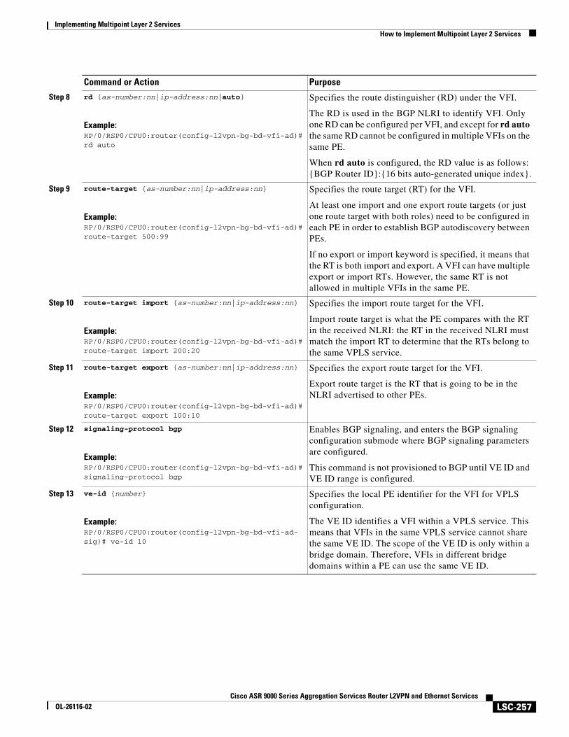
Implementing Multipoint Layer 2 ServicesHow to Implement Multipoint Layer 2 Services
LSC-257Cisco ASR 9000 Series Aggregation Services Router L2VPN and Ethernet Services
OL-26116-02
Step 8 rd {as-number:nn|ip-address:nn|auto}
Example:RP/0/RSP0/CPU0:router(config-l2vpn-bg-bd-vfi-ad)# rd auto
Specifies the route distinguisher (RD) under the VFI.
The RD is used in the BGP NLRI to identify VFI. Only one RD can be configured per VFI, and except for rd auto the same RD cannot be configured in multiple VFIs on the same PE.
When rd auto is configured, the RD value is as follows: {BGP Router ID}:{16 bits auto-generated unique index}.
Step 9 route-target {as-number:nn|ip-address:nn}
Example:RP/0/RSP0/CPU0:router(config-l2vpn-bg-bd-vfi-ad)# route-target 500:99
Specifies the route target (RT) for the VFI.
At least one import and one export route targets (or just one route target with both roles) need to be configured in each PE in order to establish BGP autodiscovery between PEs.
If no export or import keyword is specified, it means that the RT is both import and export. A VFI can have multiple export or import RTs. However, the same RT is not allowed in multiple VFIs in the same PE.
Step 10 route-target import {as-number:nn|ip-address:nn}
Example:RP/0/RSP0/CPU0:router(config-l2vpn-bg-bd-vfi-ad)# route-target import 200:20
Specifies the import route target for the VFI.
Import route target is what the PE compares with the RT in the received NLRI: the RT in the received NLRI must match the import RT to determine that the RTs belong to the same VPLS service.
Step 11 route-target export {as-number:nn|ip-address:nn}
Example:RP/0/RSP0/CPU0:router(config-l2vpn-bg-bd-vfi-ad)# route-target export 100:10
Specifies the export route target for the VFI.
Export route target is the RT that is going to be in the NLRI advertised to other PEs.
Step 12 signaling-protocol bgp
Example:RP/0/RSP0/CPU0:router(config-l2vpn-bg-bd-vfi-ad)# signaling-protocol bgp
Enables BGP signaling, and enters the BGP signaling configuration submode where BGP signaling parameters are configured.
This command is not provisioned to BGP until VE ID and VE ID range is configured.
Step 13 ve-id {number}
Example:RP/0/RSP0/CPU0:router(config-l2vpn-bg-bd-vfi-ad-sig)# ve-id 10
Specifies the local PE identifier for the VFI for VPLS configuration.
The VE ID identifies a VFI within a VPLS service. This means that VFIs in the same VPLS service cannot share the same VE ID. The scope of the VE ID is only within a bridge domain. Therefore, VFIs in different bridge domains within a PE can use the same VE ID.
Command or Action Purpose
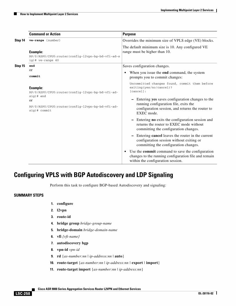
Implementing Multipoint Layer 2 ServicesHow to Implement Multipoint Layer 2 Services
LSC-258Cisco ASR 9000 Series Aggregation Services Router L2VPN and Ethernet Services
OL-26116-02
Configuring VPLS with BGP Autodiscovery and LDP SignalingPerform this task to configure BGP-based Autodiscovery and signaling:
SUMMARY STEPS
1. configure
2. l2vpn
3. route-id
4. bridge group bridge-group-name
5. bridge-domain bridge-domain-name
6. vfi {vfi-name}
7. autodiscovery bgp
8. vpn-id vpn-id
9. rd {as-number:nn | ip-address:nn | auto}
10. route-target {as-number:nn | ip-address:nn | export | import}
11. route-target import {as-number:nn | ip-address:nn}
Step 14 ve-range {number}
Example:RP/0/RSP0/CPU0:router(config-l2vpn-bg-bd-vfi-ad-sig)# ve-range 40
Overrides the minimum size of VPLS edge (VE) blocks.
The default minimum size is 10. Any configured VE range must be higher than 10.
Step 15 end
or
commit
Example:RP/0/RSP0/CPU0:router(config-l2vpn-bg-bd-vfi-ad-sig)# end
or
RP/0/RSP0/CPU0:router(config-l2vpn-bg-bd-vfi-ad-sig)# commit
Saves configuration changes.
• When you issue the end command, the system prompts you to commit changes:
Uncommitted changes found, commit them before exiting(yes/no/cancel)?[cancel]:
– Entering yes saves configuration changes to the running configuration file, exits the configuration session, and returns the router to EXEC mode.
– Entering no exits the configuration session and returns the router to EXEC mode without committing the configuration changes.
– Entering cancel leaves the router in the current configuration session without exiting or committing the configuration changes.
• Use the commit command to save the configuration changes to the running configuration file and remain within the configuration session.
Command or Action Purpose
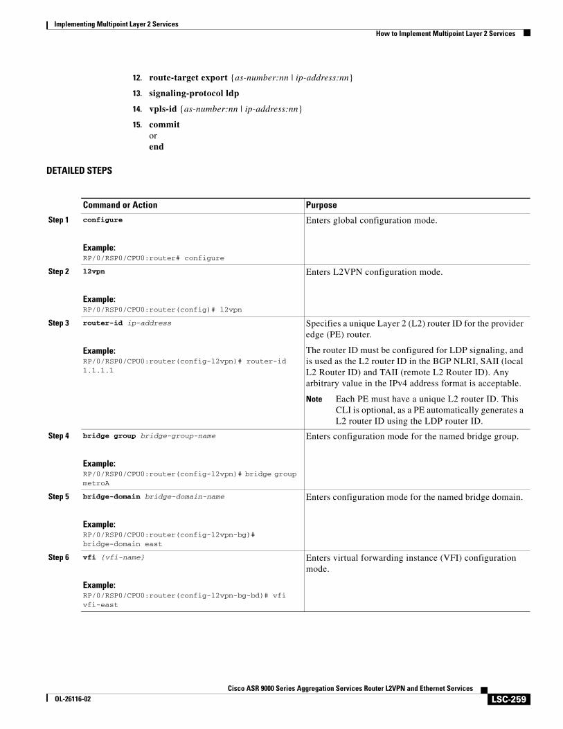
Implementing Multipoint Layer 2 ServicesHow to Implement Multipoint Layer 2 Services
LSC-259Cisco ASR 9000 Series Aggregation Services Router L2VPN and Ethernet Services
OL-26116-02
12. route-target export {as-number:nn | ip-address:nn}
13. signaling-protocol ldp
14. vpls-id {as-number:nn | ip-address:nn}
15. commit orend
DETAILED STEPS
Command or Action Purpose
Step 1 configure
Example:RP/0/RSP0/CPU0:router# configure
Enters global configuration mode.
Step 2 l2vpn
Example:RP/0/RSP0/CPU0:router(config)# l2vpn
Enters L2VPN configuration mode.
Step 3 router-id ip-address
Example:RP/0/RSP0/CPU0:router(config-l2vpn)# router-id 1.1.1.1
Specifies a unique Layer 2 (L2) router ID for the provider edge (PE) router.
The router ID must be configured for LDP signaling, and is used as the L2 router ID in the BGP NLRI, SAII (local L2 Router ID) and TAII (remote L2 Router ID). Any arbitrary value in the IPv4 address format is acceptable.
Note Each PE must have a unique L2 router ID. This CLI is optional, as a PE automatically generates a L2 router ID using the LDP router ID.
Step 4 bridge group bridge-group-name
Example:RP/0/RSP0/CPU0:router(config-l2vpn)# bridge group metroA
Enters configuration mode for the named bridge group.
Step 5 bridge-domain bridge-domain-name
Example:RP/0/RSP0/CPU0:router(config-l2vpn-bg)# bridge-domain east
Enters configuration mode for the named bridge domain.
Step 6 vfi {vfi-name}
Example:RP/0/RSP0/CPU0:router(config-l2vpn-bg-bd)# vfi vfi-east
Enters virtual forwarding instance (VFI) configuration mode.
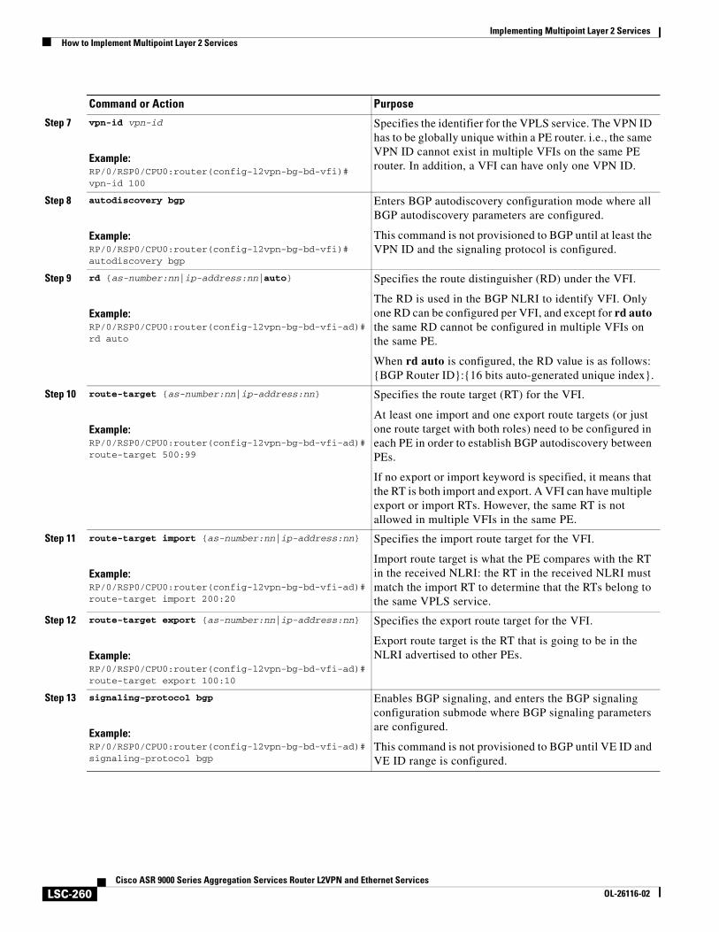
Implementing Multipoint Layer 2 ServicesHow to Implement Multipoint Layer 2 Services
LSC-260Cisco ASR 9000 Series Aggregation Services Router L2VPN and Ethernet Services
OL-26116-02
Step 7 vpn-id vpn-id
Example:RP/0/RSP0/CPU0:router(config-l2vpn-bg-bd-vfi)# vpn-id 100
Specifies the identifier for the VPLS service. The VPN ID has to be globally unique within a PE router. i.e., the same VPN ID cannot exist in multiple VFIs on the same PE router. In addition, a VFI can have only one VPN ID.
Step 8 autodiscovery bgp
Example:RP/0/RSP0/CPU0:router(config-l2vpn-bg-bd-vfi)# autodiscovery bgp
Enters BGP autodiscovery configuration mode where all BGP autodiscovery parameters are configured.
This command is not provisioned to BGP until at least the VPN ID and the signaling protocol is configured.
Step 9 rd {as-number:nn|ip-address:nn|auto}
Example:RP/0/RSP0/CPU0:router(config-l2vpn-bg-bd-vfi-ad)# rd auto
Specifies the route distinguisher (RD) under the VFI.
The RD is used in the BGP NLRI to identify VFI. Only one RD can be configured per VFI, and except for rd auto the same RD cannot be configured in multiple VFIs on the same PE.
When rd auto is configured, the RD value is as follows: {BGP Router ID}:{16 bits auto-generated unique index}.
Step 10 route-target {as-number:nn|ip-address:nn}
Example:RP/0/RSP0/CPU0:router(config-l2vpn-bg-bd-vfi-ad)# route-target 500:99
Specifies the route target (RT) for the VFI.
At least one import and one export route targets (or just one route target with both roles) need to be configured in each PE in order to establish BGP autodiscovery between PEs.
If no export or import keyword is specified, it means that the RT is both import and export. A VFI can have multiple export or import RTs. However, the same RT is not allowed in multiple VFIs in the same PE.
Step 11 route-target import {as-number:nn|ip-address:nn}
Example:RP/0/RSP0/CPU0:router(config-l2vpn-bg-bd-vfi-ad)# route-target import 200:20
Specifies the import route target for the VFI.
Import route target is what the PE compares with the RT in the received NLRI: the RT in the received NLRI must match the import RT to determine that the RTs belong to the same VPLS service.
Step 12 route-target export {as-number:nn|ip-address:nn}
Example:RP/0/RSP0/CPU0:router(config-l2vpn-bg-bd-vfi-ad)# route-target export 100:10
Specifies the export route target for the VFI.
Export route target is the RT that is going to be in the NLRI advertised to other PEs.
Step 13 signaling-protocol bgp
Example:RP/0/RSP0/CPU0:router(config-l2vpn-bg-bd-vfi-ad)# signaling-protocol bgp
Enables BGP signaling, and enters the BGP signaling configuration submode where BGP signaling parameters are configured.
This command is not provisioned to BGP until VE ID and VE ID range is configured.
Command or Action Purpose
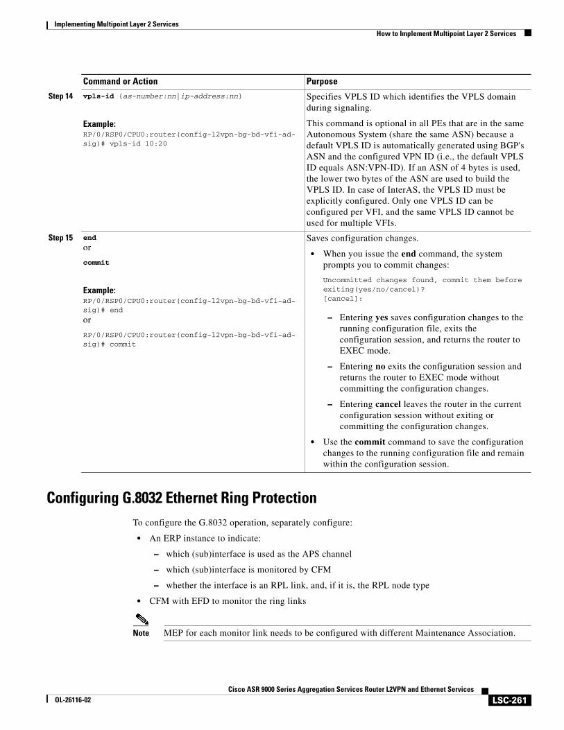
Implementing Multipoint Layer 2 ServicesHow to Implement Multipoint Layer 2 Services
LSC-261Cisco ASR 9000 Series Aggregation Services Router L2VPN and Ethernet Services
OL-26116-02
Configuring G.8032 Ethernet Ring ProtectionTo configure the G.8032 operation, separately configure:
• An ERP instance to indicate:
– which (sub)interface is used as the APS channel
– which (sub)interface is monitored by CFM
– whether the interface is an RPL link, and, if it is, the RPL node type
• CFM with EFD to monitor the ring links
Note MEP for each monitor link needs to be configured with different Maintenance Association.
Step 14 vpls-id {as-number:nn|ip-address:nn}
Example:RP/0/RSP0/CPU0:router(config-l2vpn-bg-bd-vfi-ad-sig)# vpls-id 10:20
Specifies VPLS ID which identifies the VPLS domain during signaling.
This command is optional in all PEs that are in the same Autonomous System (share the same ASN) because a default VPLS ID is automatically generated using BGP's ASN and the configured VPN ID (i.e., the default VPLS ID equals ASN:VPN-ID). If an ASN of 4 bytes is used, the lower two bytes of the ASN are used to build the VPLS ID. In case of InterAS, the VPLS ID must be explicitly configured. Only one VPLS ID can be configured per VFI, and the same VPLS ID cannot be used for multiple VFIs.
Step 15 end
or
commit
Example:RP/0/RSP0/CPU0:router(config-l2vpn-bg-bd-vfi-ad-sig)# end
or
RP/0/RSP0/CPU0:router(config-l2vpn-bg-bd-vfi-ad-sig)# commit
Saves configuration changes.
• When you issue the end command, the system prompts you to commit changes:
Uncommitted changes found, commit them before exiting(yes/no/cancel)?[cancel]:
– Entering yes saves configuration changes to the running configuration file, exits the configuration session, and returns the router to EXEC mode.
– Entering no exits the configuration session and returns the router to EXEC mode without committing the configuration changes.
– Entering cancel leaves the router in the current configuration session without exiting or committing the configuration changes.
• Use the commit command to save the configuration changes to the running configuration file and remain within the configuration session.
Command or Action Purpose
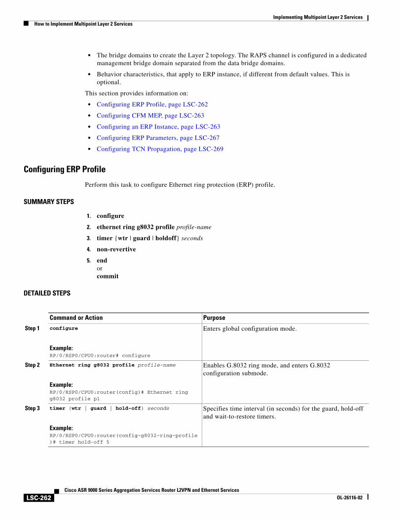
Implementing Multipoint Layer 2 ServicesHow to Implement Multipoint Layer 2 Services
LSC-262Cisco ASR 9000 Series Aggregation Services Router L2VPN and Ethernet Services
OL-26116-02
• The bridge domains to create the Layer 2 topology. The RAPS channel is configured in a dedicated management bridge domain separated from the data bridge domains.
• Behavior characteristics, that apply to ERP instance, if different from default values. This is optional.
This section provides information on:
• Configuring ERP Profile, page LSC-262
• Configuring CFM MEP, page LSC-263
• Configuring an ERP Instance, page LSC-263
• Configuring ERP Parameters, page LSC-267
• Configuring TCN Propagation, page LSC-269
Configuring ERP Profile
Perform this task to configure Ethernet ring protection (ERP) profile.
SUMMARY STEPS
1. configure
2. ethernet ring g8032 profile profile-name
3. timer {wtr | guard | holdoff} seconds
4. non-revertive
5. endorcommit
DETAILED STEPS
Command or Action Purpose
Step 1 configure
Example:RP/0/RSP0/CPU0:router# configure
Enters global configuration mode.
Step 2 Ethernet ring g8032 profile profile-name
Example:RP/0/RSP0/CPU0:router(config)# Ethernet ring g8032 profile p1
Enables G.8032 ring mode, and enters G.8032 configuration submode.
Step 3 timer {wtr | guard | hold-off} seconds
Example:RP/0/RSP0/CPU0:router(config-g8032-ring-profile)# timer hold-off 5
Specifies time interval (in seconds) for the guard, hold-off and wait-to-restore timers.
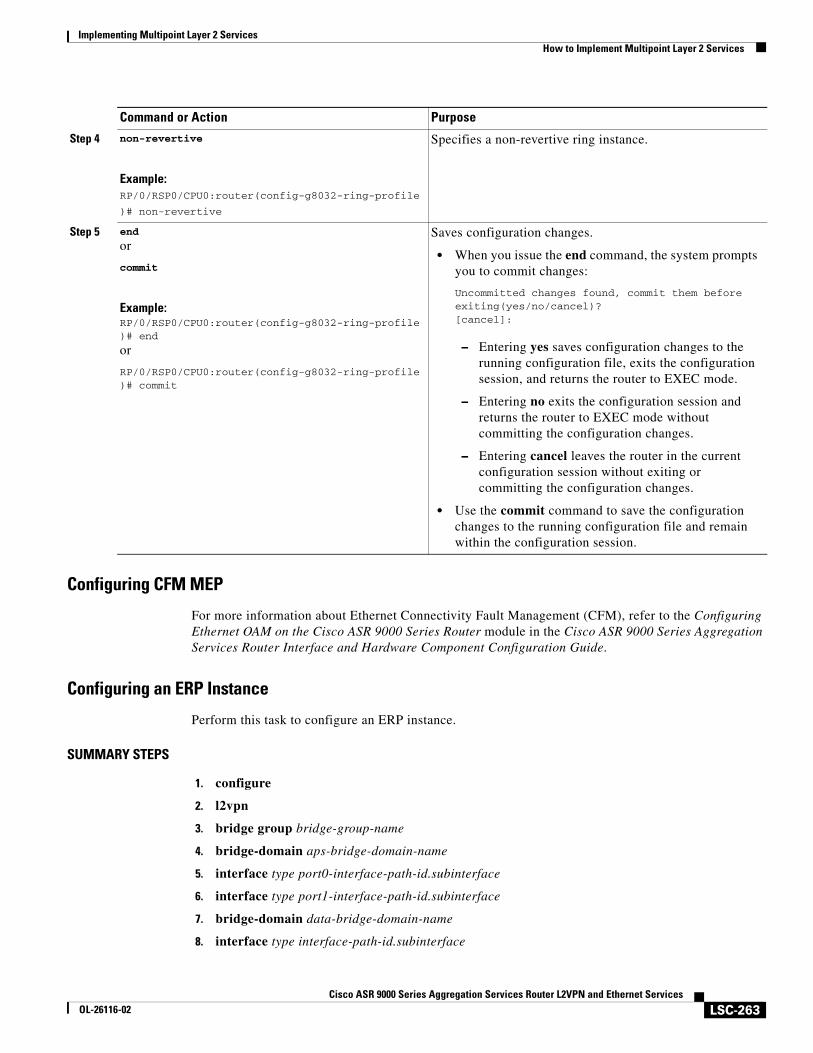
Implementing Multipoint Layer 2 ServicesHow to Implement Multipoint Layer 2 Services
LSC-263Cisco ASR 9000 Series Aggregation Services Router L2VPN and Ethernet Services
OL-26116-02
Configuring CFM MEP
For more information about Ethernet Connectivity Fault Management (CFM), refer to the Configuring Ethernet OAM on the Cisco ASR 9000 Series Router module in the Cisco ASR 9000 Series Aggregation Services Router Interface and Hardware Component Configuration Guide.
Configuring an ERP Instance
Perform this task to configure an ERP instance.
SUMMARY STEPS
1. configure
2. l2vpn
3. bridge group bridge-group-name
4. bridge-domain aps-bridge-domain-name
5. interface type port0-interface-path-id.subinterface
6. interface type port1-interface-path-id.subinterface
7. bridge-domain data-bridge-domain-name
8. interface type interface-path-id.subinterface
Step 4 non-revertive
Example:RP/0/RSP0/CPU0:router(config-g8032-ring-profile
)# non-revertive
Specifies a non-revertive ring instance.
Step 5 end
or
commit
Example:RP/0/RSP0/CPU0:router(config-g8032-ring-profile)# end
or
RP/0/RSP0/CPU0:router(config-g8032-ring-profile)# commit
Saves configuration changes.
• When you issue the end command, the system prompts you to commit changes:
Uncommitted changes found, commit them before exiting(yes/no/cancel)?[cancel]:
– Entering yes saves configuration changes to the running configuration file, exits the configuration session, and returns the router to EXEC mode.
– Entering no exits the configuration session and returns the router to EXEC mode without committing the configuration changes.
– Entering cancel leaves the router in the current configuration session without exiting or committing the configuration changes.
• Use the commit command to save the configuration changes to the running configuration file and remain within the configuration session.
Command or Action Purpose
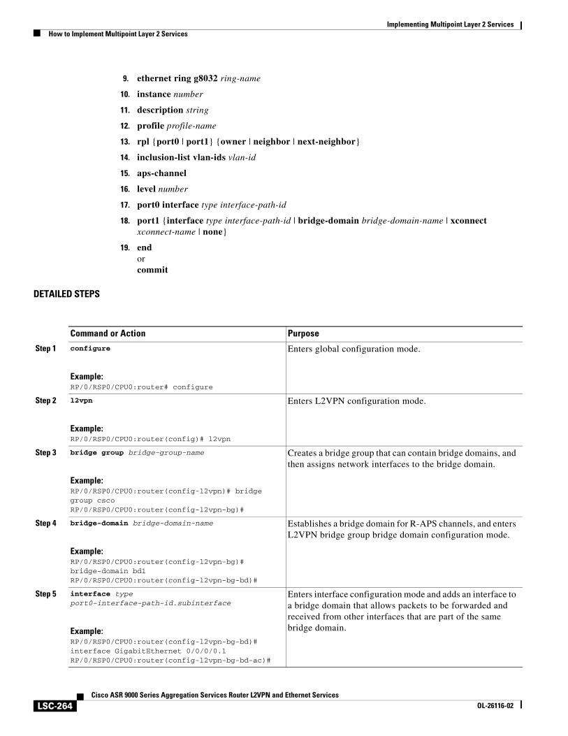
Implementing Multipoint Layer 2 ServicesHow to Implement Multipoint Layer 2 Services
LSC-264Cisco ASR 9000 Series Aggregation Services Router L2VPN and Ethernet Services
OL-26116-02
9. ethernet ring g8032 ring-name
10. instance number
11. description string
12. profile profile-name
13. rpl {port0 | port1} {owner | neighbor | next-neighbor}
14. inclusion-list vlan-ids vlan-id
15. aps-channel
16. level number
17. port0 interface type interface-path-id
18. port1 {interface type interface-path-id | bridge-domain bridge-domain-name | xconnect xconnect-name | none}
19. endorcommit
DETAILED STEPS
Command or Action Purpose
Step 1 configure
Example:RP/0/RSP0/CPU0:router# configure
Enters global configuration mode.
Step 2 l2vpn
Example:RP/0/RSP0/CPU0:router(config)# l2vpn
Enters L2VPN configuration mode.
Step 3 bridge group bridge-group-name
Example:RP/0/RSP0/CPU0:router(config-l2vpn)# bridge group cscoRP/0/RSP0/CPU0:router(config-l2vpn-bg)#
Creates a bridge group that can contain bridge domains, and then assigns network interfaces to the bridge domain.
Step 4 bridge-domain bridge-domain-name
Example:RP/0/RSP0/CPU0:router(config-l2vpn-bg)# bridge-domain bd1RP/0/RSP0/CPU0:router(config-l2vpn-bg-bd)#
Establishes a bridge domain for R-APS channels, and enters L2VPN bridge group bridge domain configuration mode.
Step 5 interface type port0-interface-path-id.subinterface
Example:RP/0/RSP0/CPU0:router(config-l2vpn-bg-bd)# interface GigabitEthernet 0/0/0/0.1RP/0/RSP0/CPU0:router(config-l2vpn-bg-bd-ac)#
Enters interface configuration mode and adds an interface to a bridge domain that allows packets to be forwarded and received from other interfaces that are part of the same bridge domain.
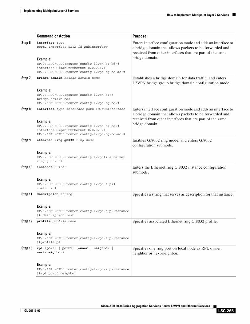
Implementing Multipoint Layer 2 ServicesHow to Implement Multipoint Layer 2 Services
LSC-265Cisco ASR 9000 Series Aggregation Services Router L2VPN and Ethernet Services
OL-26116-02
Step 6 interface type port1-interface-path-id.subinterface
Example:RP/0/RSP0/CPU0:router(config-l2vpn-bg-bd)# interface GigabitEthernet 0/0/0/1.1RP/0/RSP0/CPU0:router(config-l2vpn-bg-bd-ac)#
Enters interface configuration mode and adds an interface to a bridge domain that allows packets to be forwarded and received from other interfaces that are part of the same bridge domain.
Step 7 bridge-domain bridge-domain-name
Example:RP/0/RSP0/CPU0:router(config-l2vpn-bg)# bridge-domain bd2RP/0/RSP0/CPU0:router(config-l2vpn-bg-bd)#
Establishes a bridge domain for data traffic, and enters L2VPN bridge group bridge domain configuration mode.
Step 8 interface type interface-path-id.subinterface
Example:RP/0/RSP0/CPU0:router(config-l2vpn-bg-bd)# interface GigabitEthernet 0/0/0/0.10RP/0/RSP0/CPU0:router(config-l2vpn-bg-bd-ac)#
Enters interface configuration mode and adds an interface to a bridge domain that allows packets to be forwarded and received from other interfaces that are part of the same bridge domain.
Step 9 ethernet ring g8032 ring-name
Example:RP/0/RSP0/CPU0:router(config-l2vpn)# ethernet ring g8032 r1
Enables G.8032 ring mode, and enters G.8032 configuration submode.
Step 10 instance number
Example:RP/0/RSP0/CPU0:router(config-l2vpn-erp)# instance 1
Enters the Ethernet ring G.8032 instance configuration submode.
Step 11 description string
Example:RP/0/RSP0/CPU0:router(config-l2vpn-erp-instance)# description test
Specifies a string that serves as description for that instance.
Step 12 profile profile-name
Example:RP/0/RSP0/CPU0:router(config-l2vpn-erp-instance)#profile p1
Specifies associated Ethernet ring G.8032 profile.
Step 13 rpl {port0 | port1} {owner | neighbor | next-neighbor}
Example:RP/0/RSP0/CPU0:router(config-l2vpn-erp-instance)#rpl port0 neighbor
Specifies one ring port on local node as RPL owner, neighbor or next-neighbor.
Command or Action Purpose
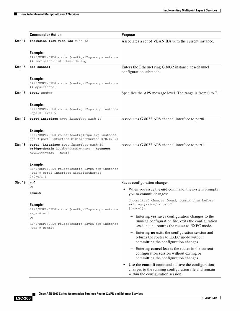
Implementing Multipoint Layer 2 ServicesHow to Implement Multipoint Layer 2 Services
LSC-266Cisco ASR 9000 Series Aggregation Services Router L2VPN and Ethernet Services
OL-26116-02
Step 14 inclusion-list vlan-ids vlan-id
Example:RP/0/RSP0/CPU0:router(config-l2vpn-erp-instance)# inclusion-list vlan-ids e-g
Associates a set of VLAN IDs with the current instance.
Step 15 aps-channel
Example:RP/0/RSP0/CPU0:router(config-l2vpn-erp-instance)# aps-channel
Enters the Ethernet ring G.8032 instance aps-channel configuration submode.
Step 16 level number
Example:RP/0/RSP0/CPU0:router(config-l2vpn-erp-instance-aps)# level 5
Specifies the APS message level. The range is from 0 to 7.
Step 17 port0 interface type interface-path-id
Example:RP/0/RSP0/CPU0:router(configl2vpn-erp-instance-aps)# port0 interface GigabitEthernet 0/0/0/0.1
Associates G.8032 APS channel interface to port0.
Step 18 port1 {interface type interface-path-id | bridge-domain bridge-domain-name | xconnect xconnect-name | none}
Example:RP/0/RSP0/CPU0:router(config-l2vpn-erp-instance-aps)# port1 interface GigabitEthernet 0/0/0/1.1
Associates G.8032 APS channel interface to port1.
Step 19 end
or
commit
Example:RP/0/RSP0/CPU0:router(config-l2vpn-erp-instance-aps)# end
or
RP/0/RSP0/CPU0:router(config-l2vpn-erp-instance-aps)# commit
Saves configuration changes.
• When you issue the end command, the system prompts you to commit changes:
Uncommitted changes found, commit them before exiting(yes/no/cancel)?[cancel]:
– Entering yes saves configuration changes to the running configuration file, exits the configuration session, and returns the router to EXEC mode.
– Entering no exits the configuration session and returns the router to EXEC mode without committing the configuration changes.
– Entering cancel leaves the router in the current configuration session without exiting or committing the configuration changes.
• Use the commit command to save the configuration changes to the running configuration file and remain within the configuration session.
Command or Action Purpose
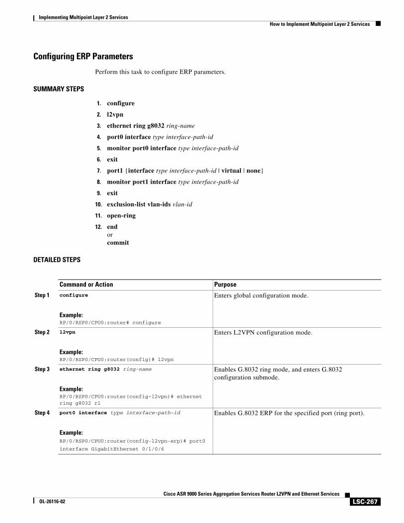
Implementing Multipoint Layer 2 ServicesHow to Implement Multipoint Layer 2 Services
LSC-267Cisco ASR 9000 Series Aggregation Services Router L2VPN and Ethernet Services
OL-26116-02
Configuring ERP Parameters
Perform this task to configure ERP parameters.
SUMMARY STEPS
1. configure
2. l2vpn
3. ethernet ring g8032 ring-name
4. port0 interface type interface-path-id
5. monitor port0 interface type interface-path-id
6. exit
7. port1 {interface type interface-path-id | virtual | none}
8. monitor port1 interface type interface-path-id
9. exit
10. exclusion-list vlan-ids vlan-id
11. open-ring
12. endorcommit
DETAILED STEPS
Command or Action Purpose
Step 1 configure
Example:RP/0/RSP0/CPU0:router# configure
Enters global configuration mode.
Step 2 l2vpn
Example:RP/0/RSP0/CPU0:router(config)# l2vpn
Enters L2VPN configuration mode.
Step 3 ethernet ring g8032 ring-name
Example:RP/0/RSP0/CPU0:router(config-l2vpn)# ethernet ring g8032 r1
Enables G.8032 ring mode, and enters G.8032 configuration submode.
Step 4 port0 interface type interface-path-id
Example:RP/0/RSP0/CPU0:router(config-l2vpn-erp)# port0
interface GigabitEthernet 0/1/0/6
Enables G.8032 ERP for the specified port (ring port).
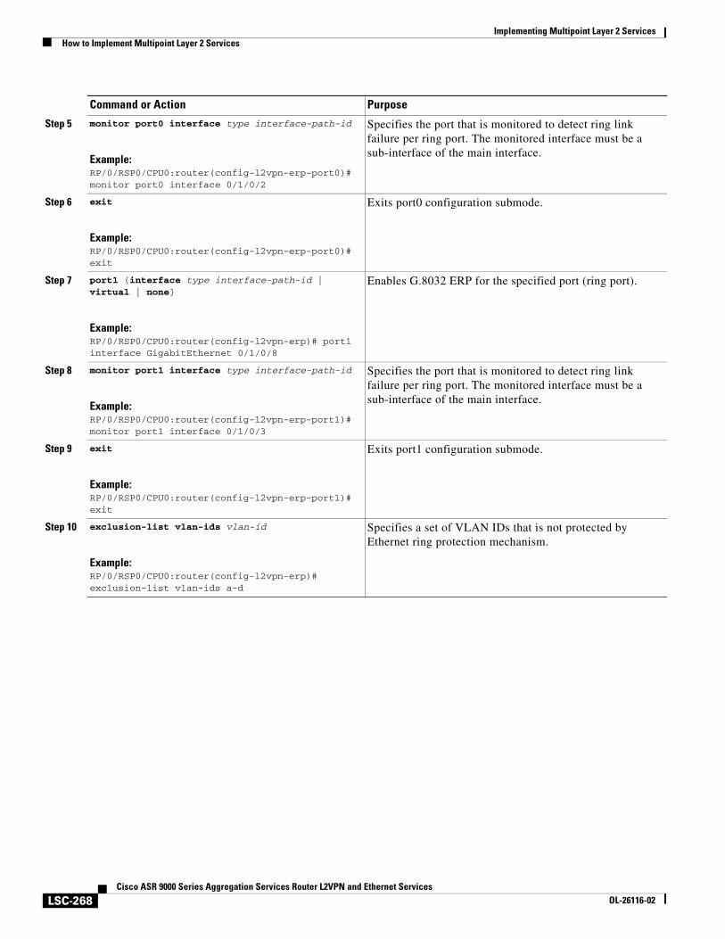
Implementing Multipoint Layer 2 ServicesHow to Implement Multipoint Layer 2 Services
LSC-268Cisco ASR 9000 Series Aggregation Services Router L2VPN and Ethernet Services
OL-26116-02
Step 5 monitor port0 interface type interface-path-id
Example:RP/0/RSP0/CPU0:router(config-l2vpn-erp-port0)# monitor port0 interface 0/1/0/2
Specifies the port that is monitored to detect ring link failure per ring port. The monitored interface must be a sub-interface of the main interface.
Step 6 exit
Example:RP/0/RSP0/CPU0:router(config-l2vpn-erp-port0)# exit
Exits port0 configuration submode.
Step 7 port1 {interface type interface-path-id | virtual | none}
Example:RP/0/RSP0/CPU0:router(config-l2vpn-erp)# port1 interface GigabitEthernet 0/1/0/8
Enables G.8032 ERP for the specified port (ring port).
Step 8 monitor port1 interface type interface-path-id
Example:RP/0/RSP0/CPU0:router(config-l2vpn-erp-port1)# monitor port1 interface 0/1/0/3
Specifies the port that is monitored to detect ring link failure per ring port. The monitored interface must be a sub-interface of the main interface.
Step 9 exit
Example:RP/0/RSP0/CPU0:router(config-l2vpn-erp-port1)# exit
Exits port1 configuration submode.
Step 10 exclusion-list vlan-ids vlan-id
Example:RP/0/RSP0/CPU0:router(config-l2vpn-erp)# exclusion-list vlan-ids a-d
Specifies a set of VLAN IDs that is not protected by Ethernet ring protection mechanism.
Command or Action Purpose
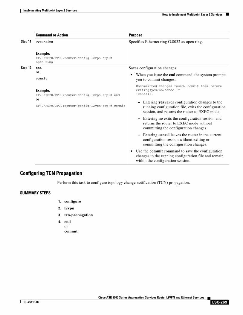
Implementing Multipoint Layer 2 ServicesHow to Implement Multipoint Layer 2 Services
LSC-269Cisco ASR 9000 Series Aggregation Services Router L2VPN and Ethernet Services
OL-26116-02
Configuring TCN Propagation
Perform this task to configure topology change notification (TCN) propagation.
SUMMARY STEPS
1. configure
2. l2vpn
3. tcn-propagation
4. endorcommit
Step 11 open-ring
Example:RP/0/RSP0/CPU0:router(config-l2vpn-erp)# open-ring
Specifies Ethernet ring G.8032 as open ring.
Step 12 end
or
commit
Example:RP/0/RSP0/CPU0:router(config-l2vpn-erp)# end
or
RP/0/RSP0/CPU0:router(config-l2vpn-erp)# commit
Saves configuration changes.
• When you issue the end command, the system prompts you to commit changes:
Uncommitted changes found, commit them before exiting(yes/no/cancel)?[cancel]:
– Entering yes saves configuration changes to the running configuration file, exits the configuration session, and returns the router to EXEC mode.
– Entering no exits the configuration session and returns the router to EXEC mode without committing the configuration changes.
– Entering cancel leaves the router in the current configuration session without exiting or committing the configuration changes.
• Use the commit command to save the configuration changes to the running configuration file and remain within the configuration session.
Command or Action Purpose
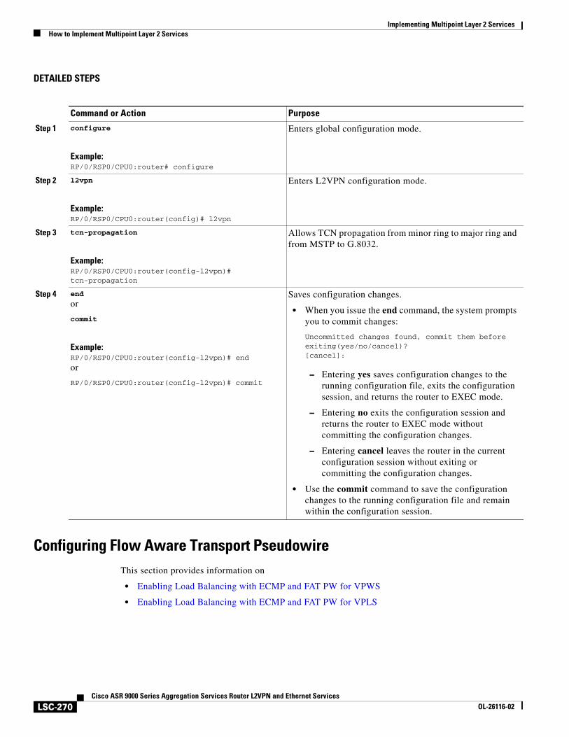
Implementing Multipoint Layer 2 ServicesHow to Implement Multipoint Layer 2 Services
LSC-270Cisco ASR 9000 Series Aggregation Services Router L2VPN and Ethernet Services
OL-26116-02
DETAILED STEPS
Configuring Flow Aware Transport PseudowireThis section provides information on
• Enabling Load Balancing with ECMP and FAT PW for VPWS
• Enabling Load Balancing with ECMP and FAT PW for VPLS
Command or Action Purpose
Step 1 configure
Example:RP/0/RSP0/CPU0:router# configure
Enters global configuration mode.
Step 2 l2vpn
Example:RP/0/RSP0/CPU0:router(config)# l2vpn
Enters L2VPN configuration mode.
Step 3 tcn-propagation
Example:RP/0/RSP0/CPU0:router(config-l2vpn)# tcn-propagation
Allows TCN propagation from minor ring to major ring and from MSTP to G.8032.
Step 4 end
or
commit
Example:RP/0/RSP0/CPU0:router(config-l2vpn)# end
or
RP/0/RSP0/CPU0:router(config-l2vpn)# commit
Saves configuration changes.
• When you issue the end command, the system prompts you to commit changes:
Uncommitted changes found, commit them before exiting(yes/no/cancel)?[cancel]:
– Entering yes saves configuration changes to the running configuration file, exits the configuration session, and returns the router to EXEC mode.
– Entering no exits the configuration session and returns the router to EXEC mode without committing the configuration changes.
– Entering cancel leaves the router in the current configuration session without exiting or committing the configuration changes.
• Use the commit command to save the configuration changes to the running configuration file and remain within the configuration session.
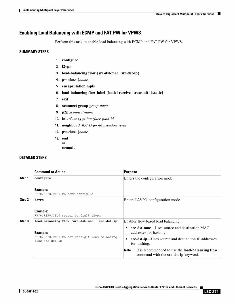
Implementing Multipoint Layer 2 ServicesHow to Implement Multipoint Layer 2 Services
LSC-271Cisco ASR 9000 Series Aggregation Services Router L2VPN and Ethernet Services
OL-26116-02
Enabling Load Balancing with ECMP and FAT PW for VPWS
Perform this task to enable load balancing with ECMP and FAT PW for VPWS.
SUMMARY STEPS
1. configure
2. l2vpn
3. load-balancing flow {src-dst-mac | src-dst-ip}
4. pw-class {name}
5. encapsulation mpls
6. load-balancing flow-label {both | receive | transmit} [static]
7. exit
8. xconnect group group-name
9. p2p xconnect-name
10. interface type interface-path-id
11. neighbor A.B.C.D pw-id pseudowire-id
12. pw-class {name}
13. endorcommit
DETAILED STEPS
Command or Action Purpose
Step 1 configure
Example:RP/0/RSP0/CPU0:router# configure
Enters the configuration mode.
Step 2 l2vpn
Example:RP/0/RSP0/CPU0:router(config)# l2vpn
Enters L2VPN configuration mode.
Step 3 load-balancing flow {src-dst-mac | src-dst-ip}
Example:RP/0/RSP0/CPU0:router(config)# load-balancing flow src-dst-ip
Enables flow based load balancing.
• src-dst-mac—Uses source and destination MAC addresses for hashing.
• src-dst-ip—Uses source and destination IP addresses for hashing.
Note It is recommended to use the load-balancing flow command with the src-dst-ip keyword.
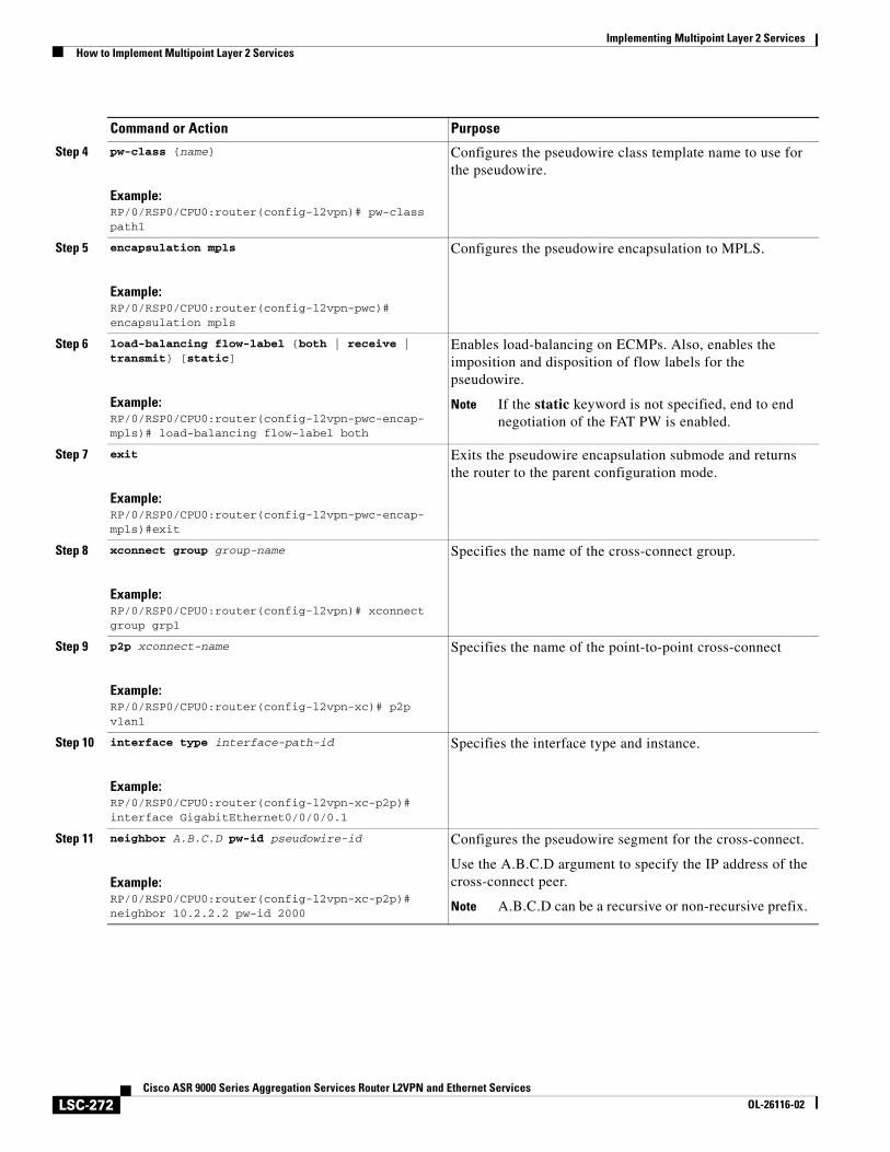
Implementing Multipoint Layer 2 ServicesHow to Implement Multipoint Layer 2 Services
LSC-272Cisco ASR 9000 Series Aggregation Services Router L2VPN and Ethernet Services
OL-26116-02
Step 4 pw-class {name}
Example:RP/0/RSP0/CPU0:router(config-l2vpn)# pw-class path1
Configures the pseudowire class template name to use for the pseudowire.
Step 5 encapsulation mpls
Example:RP/0/RSP0/CPU0:router(config-l2vpn-pwc)# encapsulation mpls
Configures the pseudowire encapsulation to MPLS.
Step 6 load-balancing flow-label {both | receive | transmit} [static]
Example:RP/0/RSP0/CPU0:router(config-l2vpn-pwc-encap-mpls)# load-balancing flow-label both
Enables load-balancing on ECMPs. Also, enables the imposition and disposition of flow labels for the pseudowire.
Note If the static keyword is not specified, end to end negotiation of the FAT PW is enabled.
Step 7 exit
Example:RP/0/RSP0/CPU0:router(config-l2vpn-pwc-encap-mpls)#exit
Exits the pseudowire encapsulation submode and returns the router to the parent configuration mode.
Step 8 xconnect group group-name
Example:RP/0/RSP0/CPU0:router(config-l2vpn)# xconnect group grp1
Specifies the name of the cross-connect group.
Step 9 p2p xconnect-name
Example:RP/0/RSP0/CPU0:router(config-l2vpn-xc)# p2p vlan1
Specifies the name of the point-to-point cross-connect
Step 10 interface type interface-path-id
Example:RP/0/RSP0/CPU0:router(config-l2vpn-xc-p2p)# interface GigabitEthernet0/0/0/0.1
Specifies the interface type and instance.
Step 11 neighbor A.B.C.D pw-id pseudowire-id
Example:RP/0/RSP0/CPU0:router(config-l2vpn-xc-p2p)# neighbor 10.2.2.2 pw-id 2000
Configures the pseudowire segment for the cross-connect.
Use the A.B.C.D argument to specify the IP address of the cross-connect peer.
Note A.B.C.D can be a recursive or non-recursive prefix.
Command or Action Purpose
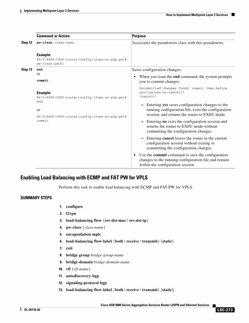
Implementing Multipoint Layer 2 ServicesHow to Implement Multipoint Layer 2 Services
LSC-273Cisco ASR 9000 Series Aggregation Services Router L2VPN and Ethernet Services
OL-26116-02
Enabling Load Balancing with ECMP and FAT PW for VPLS
Perform this task to enable load balancing with ECMP and FAT PW for VPLS.
SUMMARY STEPS
1. configure
2. l2vpn
3. load-balancing flow {src-dst-mac | src-dst-ip}
4. pw-class {class-name}
5. encapsulation mpls
6. load-balancing flow-label {both | receive | transmit} [static]
7. exit
8. bridge group bridge-group-name
9. bridge-domain bridge-domain-name
10. vfi {vfi-name}
11. autodiscovery bgp
12. signaling-protocol bgp
13. load-balancing flow-label {both | receive | transmit} [static]
Step 12 pw-class class-name
Example:RP/0/RSP0/CPU0:router(config-l2vpn-xc-p2p-pw)# pw-class path1
Associates the pseudowire class with this pseudowire.
Step 13 end
or
commit
Example:RP/0/RSP0/CPU0:router(config-l2vpn-xc-p2p-pw)#end
or
RP/0/RSP0/CPU0:router(config-l2vpn-xc-p2p-pw)# commit
Saves configuration changes.
• When you issue the end command, the system prompts you to commit changes:
Uncommitted changes found, commit them before exiting(yes/no/cancel)?[cancel]:
– Entering yes saves configuration changes to the running configuration file, exits the configuration session, and returns the router to EXEC mode.
– Entering no exits the configuration session and returns the router to EXEC mode without committing the configuration changes.
– Entering cancel leaves the router in the current configuration session without exiting or committing the configuration changes.
• Use the commit command to save the configuration changes to the running configuration file and remain within the configuration session.
Command or Action Purpose
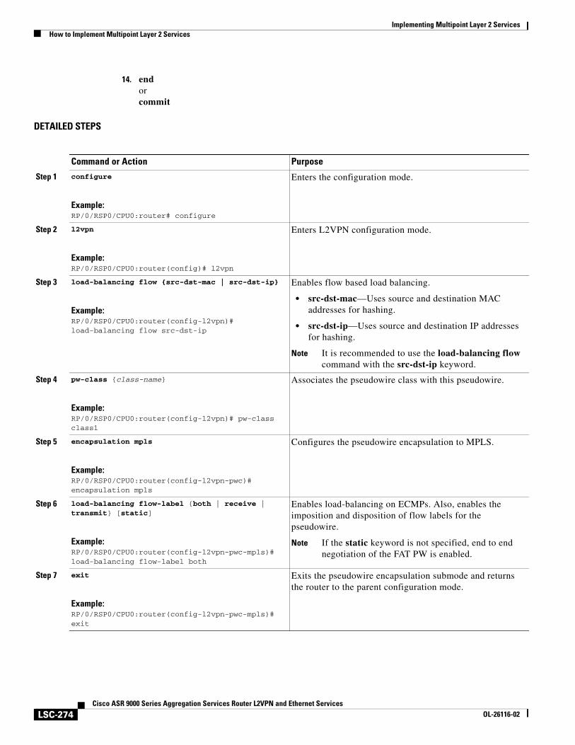
Implementing Multipoint Layer 2 ServicesHow to Implement Multipoint Layer 2 Services
LSC-274Cisco ASR 9000 Series Aggregation Services Router L2VPN and Ethernet Services
OL-26116-02
14. endorcommit
DETAILED STEPS
Command or Action Purpose
Step 1 configure
Example:RP/0/RSP0/CPU0:router# configure
Enters the configuration mode.
Step 2 l2vpn
Example:RP/0/RSP0/CPU0:router(config)# l2vpn
Enters L2VPN configuration mode.
Step 3 load-balancing flow {src-dst-mac | src-dst-ip}
Example:RP/0/RSP0/CPU0:router(config-l2vpn)# load-balancing flow src-dst-ip
Enables flow based load balancing.
• src-dst-mac—Uses source and destination MAC addresses for hashing.
• src-dst-ip—Uses source and destination IP addresses for hashing.
Note It is recommended to use the load-balancing flow command with the src-dst-ip keyword.
Step 4 pw-class {class-name}
Example:RP/0/RSP0/CPU0:router(config-l2vpn)# pw-class class1
Associates the pseudowire class with this pseudowire.
Step 5 encapsulation mpls
Example:RP/0/RSP0/CPU0:router(config-l2vpn-pwc)# encapsulation mpls
Configures the pseudowire encapsulation to MPLS.
Step 6 load-balancing flow-label {both | receive | transmit} [static]
Example:RP/0/RSP0/CPU0:router(config-l2vpn-pwc-mpls)# load-balancing flow-label both
Enables load-balancing on ECMPs. Also, enables the imposition and disposition of flow labels for the pseudowire.
Note If the static keyword is not specified, end to end negotiation of the FAT PW is enabled.
Step 7 exit
Example:RP/0/RSP0/CPU0:router(config-l2vpn-pwc-mpls)#exit
Exits the pseudowire encapsulation submode and returns the router to the parent configuration mode.
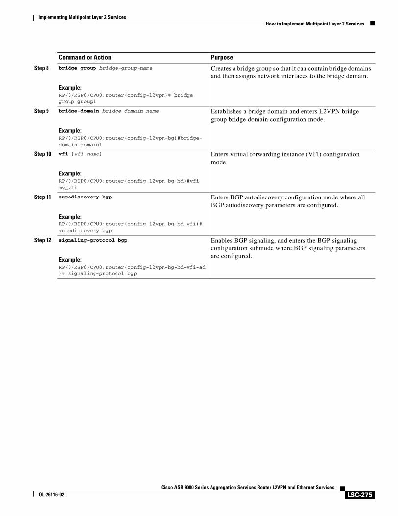
Implementing Multipoint Layer 2 ServicesHow to Implement Multipoint Layer 2 Services
LSC-275Cisco ASR 9000 Series Aggregation Services Router L2VPN and Ethernet Services
OL-26116-02
Step 8 bridge group bridge-group-name
Example:RP/0/RSP0/CPU0:router(config-l2vpn)# bridge group group1
Creates a bridge group so that it can contain bridge domains and then assigns network interfaces to the bridge domain.
Step 9 bridge-domain bridge-domain-name
Example:RP/0/RSP0/CPU0:router(config-l2vpn-bg)#bridge-domain domain1
Establishes a bridge domain and enters L2VPN bridge group bridge domain configuration mode.
Step 10 vfi {vfi-name}
Example:RP/0/RSP0/CPU0:router(config-l2vpn-bg-bd)#vfi my_vfi
Enters virtual forwarding instance (VFI) configuration mode.
Step 11 autodiscovery bgp
Example:RP/0/RSP0/CPU0:router(config-l2vpn-bg-bd-vfi)# autodiscovery bgp
Enters BGP autodiscovery configuration mode where all BGP autodiscovery parameters are configured.
Step 12 signaling-protocol bgp
Example:RP/0/RSP0/CPU0:router(config-l2vpn-bg-bd-vfi-ad)# signaling-protocol bgp
Enables BGP signaling, and enters the BGP signaling configuration submode where BGP signaling parameters are configured.
Command or Action Purpose
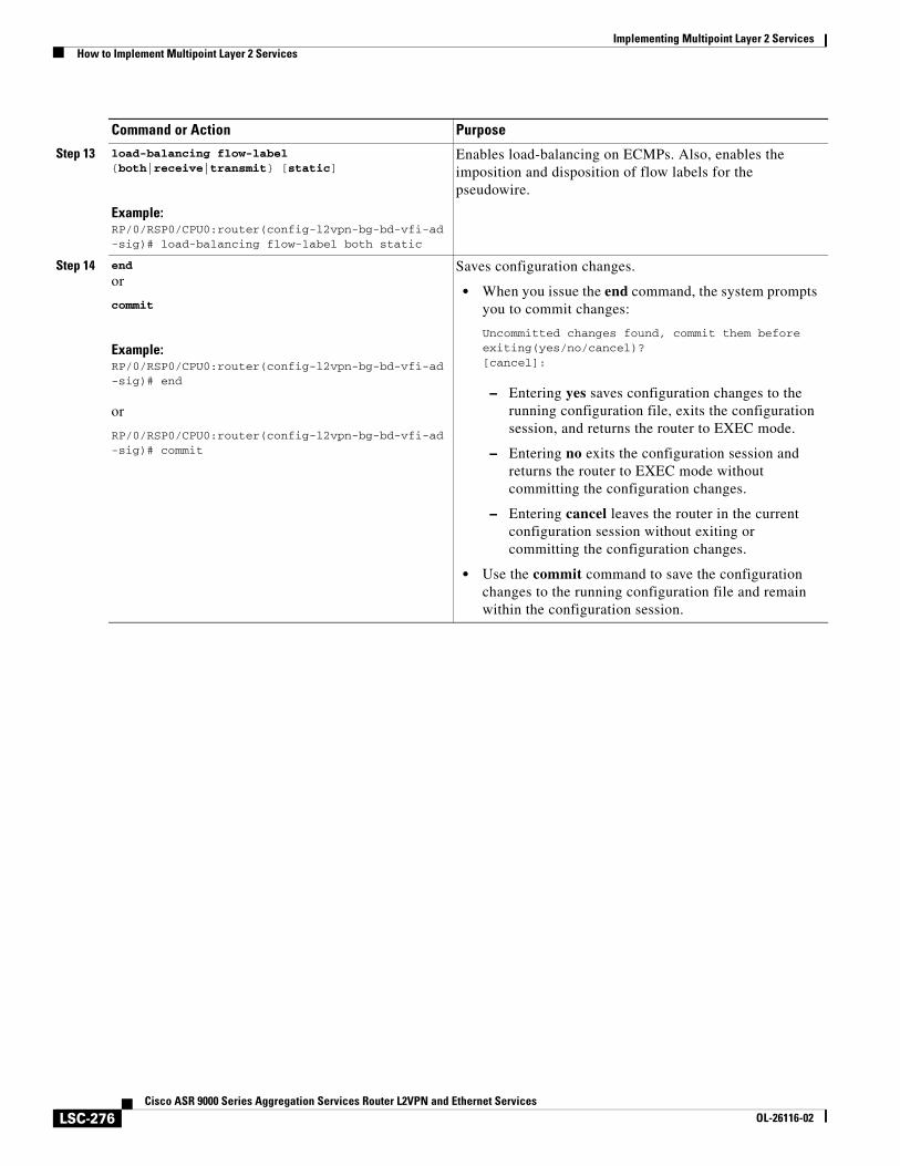
Implementing Multipoint Layer 2 ServicesHow to Implement Multipoint Layer 2 Services
LSC-276Cisco ASR 9000 Series Aggregation Services Router L2VPN and Ethernet Services
OL-26116-02
Step 13 load-balancing flow-label {both|receive|transmit} [static]
Example:RP/0/RSP0/CPU0:router(config-l2vpn-bg-bd-vfi-ad-sig)# load-balancing flow-label both static
Enables load-balancing on ECMPs. Also, enables the imposition and disposition of flow labels for the pseudowire.
Step 14 end
or
commit
Example:RP/0/RSP0/CPU0:router(config-l2vpn-bg-bd-vfi-ad-sig)# end
or
RP/0/RSP0/CPU0:router(config-l2vpn-bg-bd-vfi-ad-sig)# commit
Saves configuration changes.
• When you issue the end command, the system prompts you to commit changes:
Uncommitted changes found, commit them before exiting(yes/no/cancel)?[cancel]:
– Entering yes saves configuration changes to the running configuration file, exits the configuration session, and returns the router to EXEC mode.
– Entering no exits the configuration session and returns the router to EXEC mode without committing the configuration changes.
– Entering cancel leaves the router in the current configuration session without exiting or committing the configuration changes.
• Use the commit command to save the configuration changes to the running configuration file and remain within the configuration session.
Command or Action Purpose
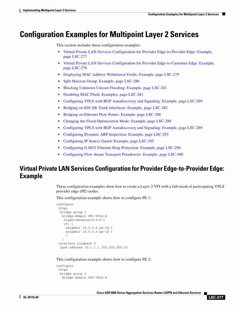
Implementing Multipoint Layer 2 ServicesConfiguration Examples for Multipoint Layer 2 Services
LSC-277Cisco ASR 9000 Series Aggregation Services Router L2VPN and Ethernet Services
OL-26116-02
Configuration Examples for Multipoint Layer 2 ServicesThis section includes these configuration examples:
• Virtual Private LAN Services Configuration for Provider Edge-to-Provider Edge: Example, page LSC-277
• Virtual Private LAN Services Configuration for Provider Edge-to-Customer Edge: Example, page LSC-278
• Displaying MAC Address Withdrawal Fields: Example, page LSC-279
• Split Horizon Group: Example, page LSC-280
• Blocking Unknown Unicast Flooding: Example, page LSC-281
• Disabling MAC Flush: Examples, page LSC-281
• Configuring VPLS with BGP Autodiscovery and Signaling: Example, page LSC-289
• Bridging on IOS XR Trunk Interfaces: Example, page LSC-282
• Bridging on Ethernet Flow Points: Example, page LSC-286
• Changing the Flood Optimization Mode: Example, page LSC-288
• Configuring VPLS with BGP Autodiscovery and Signaling: Example, page LSC-289
• Configuring Dynamic ARP Inspection: Example, page LSC-293
• Configuring IP Source Guard: Example, page LSC-295
• Configuring G.8032 Ethernet Ring Protection: Example, page LSC-296
• Configuring Flow Aware Transport Pseudowire: Example, page LSC-300
Virtual Private LAN Services Configuration for Provider Edge-to-Provider Edge: Example
These configuration examples show how to create a Layer 2 VFI with a full-mesh of participating VPLS provider edge (PE) nodes.
This configuration example shows how to configure PE 1:
configurel2vpnbridge group 1bridge-domain PE1-VPLS-AGigabitEthernet0/0/0/1vfi 1neighbor 10.2.2.2 pw-id 1neighbor 10.3.3.3 pw-id 1!
!interface loopback 0ipv4 address 10.1.1.1 255.255.255.25
This configuration example shows how to configure PE 2:
configurel2vpnbridge group 1bridge-domain PE2-VPLS-A
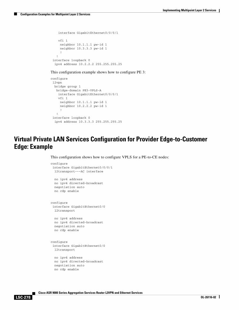
Implementing Multipoint Layer 2 ServicesConfiguration Examples for Multipoint Layer 2 Services
LSC-278Cisco ASR 9000 Series Aggregation Services Router L2VPN and Ethernet Services
OL-26116-02
interface GigabitEthernet0/0/0/1
vfi 1neighbor 10.1.1.1 pw-id 1neighbor 10.3.3.3 pw-id 1!
!interface loopback 0ipv4 address 10.2.2.2 255.255.255.25
This configuration example shows how to configure PE 3:
configurel2vpnbridge group 1bridge-domain PE3-VPLS-Ainterface GigabitEthernet0/0/0/1vfi 1neighbor 10.1.1.1 pw-id 1neighbor 10.2.2.2 pw-id 1!
!interface loopback 0ipv4 address 10.3.3.3 255.255.255.25
Virtual Private LAN Services Configuration for Provider Edge-to-Customer Edge: Example
This configuration shows how to configure VPLS for a PE-to-CE nodes:
configureinterface GigabitEthernet0/0/0/1l2transport---AC interface
no ipv4 addressno ipv4 directed-broadcastnegotiation autono cdp enable
configureinterface GigabitEthernet0/0l2transport
no ipv4 addressno ipv4 directed-broadcastnegotiation autono cdp enable
configureinterface GigabitEthernet0/0l2transport
no ipv4 addressno ipv4 directed-broadcastnegotiation autono cdp enable
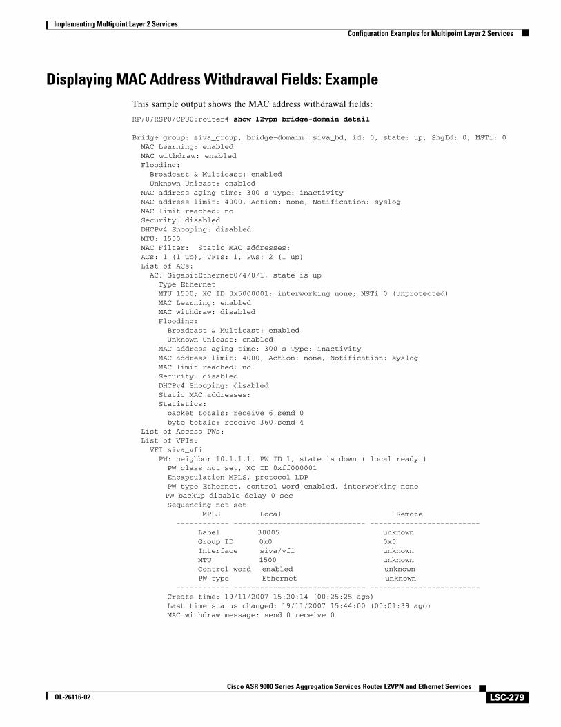
Implementing Multipoint Layer 2 ServicesConfiguration Examples for Multipoint Layer 2 Services
LSC-279Cisco ASR 9000 Series Aggregation Services Router L2VPN and Ethernet Services
OL-26116-02
Displaying MAC Address Withdrawal Fields: ExampleThis sample output shows the MAC address withdrawal fields:
RP/0/RSP0/CPU0:router# show l2vpn bridge-domain detail
Bridge group: siva_group, bridge-domain: siva_bd, id: 0, state: up, ShgId: 0, MSTi: 0 MAC Learning: enabled MAC withdraw: enabled Flooding: Broadcast & Multicast: enabled Unknown Unicast: enabled MAC address aging time: 300 s Type: inactivity MAC address limit: 4000, Action: none, Notification: syslog MAC limit reached: no Security: disabled DHCPv4 Snooping: disabled MTU: 1500 MAC Filter: Static MAC addresses: ACs: 1 (1 up), VFIs: 1, PWs: 2 (1 up) List of ACs: AC: GigabitEthernet0/4/0/1, state is up Type Ethernet MTU 1500; XC ID 0x5000001; interworking none; MSTi 0 (unprotected) MAC Learning: enabled MAC withdraw: disabled Flooding: Broadcast & Multicast: enabled Unknown Unicast: enabled MAC address aging time: 300 s Type: inactivity MAC address limit: 4000, Action: none, Notification: syslog MAC limit reached: no Security: disabled DHCPv4 Snooping: disabled Static MAC addresses: Statistics: packet totals: receive 6,send 0 byte totals: receive 360,send 4 List of Access PWs: List of VFIs: VFI siva_vfi PW: neighbor 10.1.1.1, PW ID 1, state is down ( local ready ) PW class not set, XC ID 0xff000001 Encapsulation MPLS, protocol LDP PW type Ethernet, control word enabled, interworking none
PW backup disable delay 0 sec Sequencing not set MPLS Local Remote ------------ ------------------------------ ------------------------- Label 30005 unknown Group ID 0x0 0x0 Interface siva/vfi unknown MTU 1500 unknown Control word enabled unknown PW type Ethernet unknown ------------ ------------------------------ ------------------------- Create time: 19/11/2007 15:20:14 (00:25:25 ago) Last time status changed: 19/11/2007 15:44:00 (00:01:39 ago) MAC withdraw message: send 0 receive 0
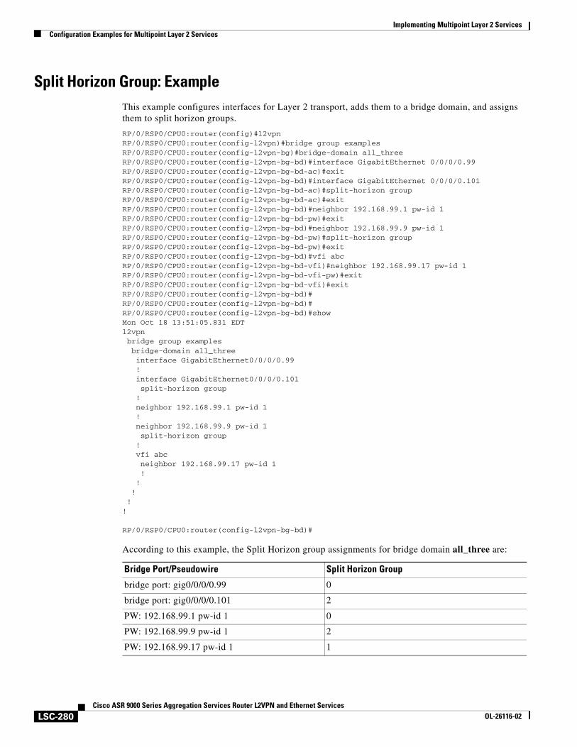
Implementing Multipoint Layer 2 ServicesConfiguration Examples for Multipoint Layer 2 Services
LSC-280Cisco ASR 9000 Series Aggregation Services Router L2VPN and Ethernet Services
OL-26116-02
Split Horizon Group: ExampleThis example configures interfaces for Layer 2 transport, adds them to a bridge domain, and assigns them to split horizon groups.
RP/0/RSP0/CPU0:router(config)#l2vpnRP/0/RSP0/CPU0:router(config-l2vpn)#bridge group examplesRP/0/RSP0/CPU0:router(config-l2vpn-bg)#bridge-domain all_threeRP/0/RSP0/CPU0:router(config-l2vpn-bg-bd)#interface GigabitEthernet 0/0/0/0.99RP/0/RSP0/CPU0:router(config-l2vpn-bg-bd-ac)#exitRP/0/RSP0/CPU0:router(config-l2vpn-bg-bd)#interface GigabitEthernet 0/0/0/0.101RP/0/RSP0/CPU0:router(config-l2vpn-bg-bd-ac)#split-horizon groupRP/0/RSP0/CPU0:router(config-l2vpn-bg-bd-ac)#exitRP/0/RSP0/CPU0:router(config-l2vpn-bg-bd)#neighbor 192.168.99.1 pw-id 1RP/0/RSP0/CPU0:router(config-l2vpn-bg-bd-pw)#exitRP/0/RSP0/CPU0:router(config-l2vpn-bg-bd)#neighbor 192.168.99.9 pw-id 1RP/0/RSP0/CPU0:router(config-l2vpn-bg-bd-pw)#split-horizon groupRP/0/RSP0/CPU0:router(config-l2vpn-bg-bd-pw)#exitRP/0/RSP0/CPU0:router(config-l2vpn-bg-bd)#vfi abcRP/0/RSP0/CPU0:router(config-l2vpn-bg-bd-vfi)#neighbor 192.168.99.17 pw-id 1RP/0/RSP0/CPU0:router(config-l2vpn-bg-bd-vfi-pw)#exitRP/0/RSP0/CPU0:router(config-l2vpn-bg-bd-vfi)#exitRP/0/RSP0/CPU0:router(config-l2vpn-bg-bd)#RP/0/RSP0/CPU0:router(config-l2vpn-bg-bd)#RP/0/RSP0/CPU0:router(config-l2vpn-bg-bd)#showMon Oct 18 13:51:05.831 EDTl2vpn bridge group examples bridge-domain all_three interface GigabitEthernet0/0/0/0.99 ! interface GigabitEthernet0/0/0/0.101 split-horizon group ! neighbor 192.168.99.1 pw-id 1 ! neighbor 192.168.99.9 pw-id 1 split-horizon group ! vfi abc neighbor 192.168.99.17 pw-id 1 ! ! ! !!
RP/0/RSP0/CPU0:router(config-l2vpn-bg-bd)#
According to this example, the Split Horizon group assignments for bridge domain all_three are:
Bridge Port/Pseudowire Split Horizon Group
bridge port: gig0/0/0/0.99 0
bridge port: gig0/0/0/0.101 2
PW: 192.168.99.1 pw-id 1 0
PW: 192.168.99.9 pw-id 1 2
PW: 192.168.99.17 pw-id 1 1
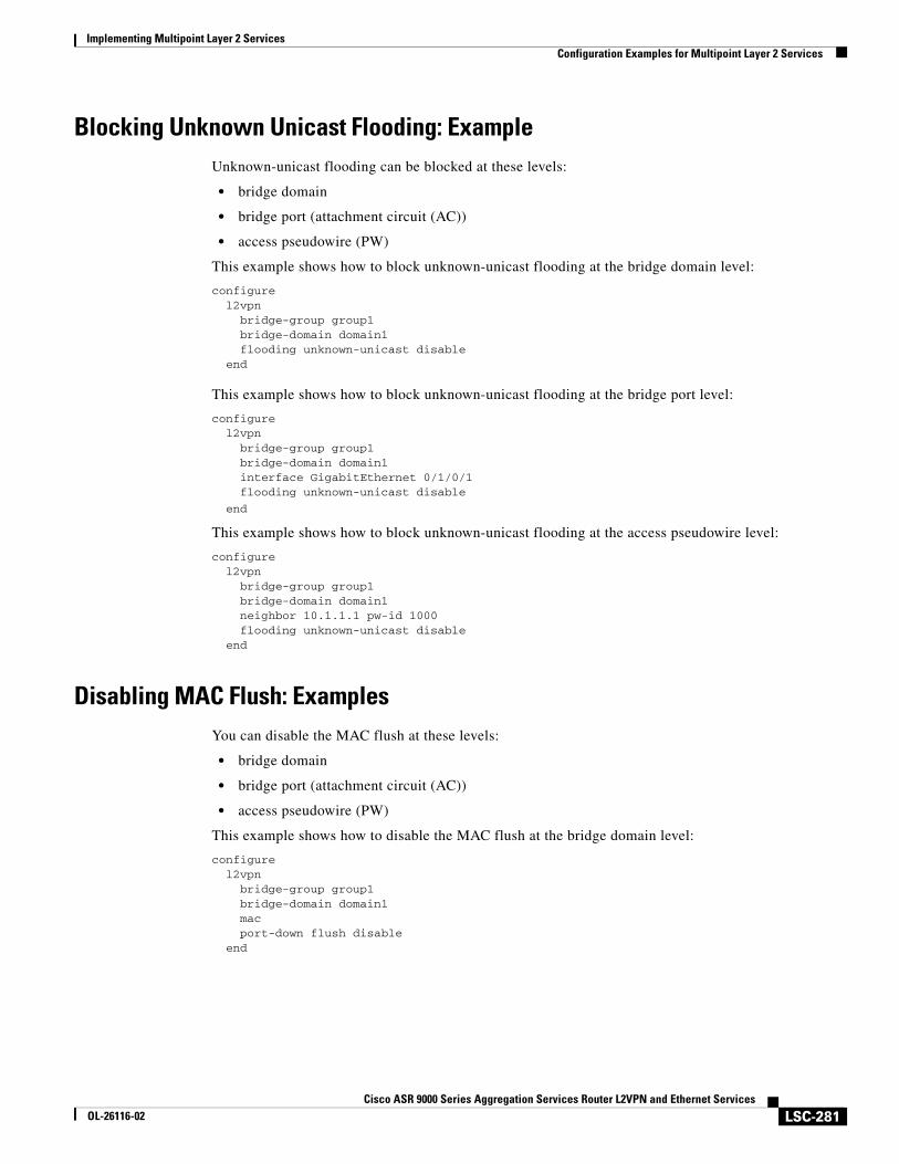
Implementing Multipoint Layer 2 ServicesConfiguration Examples for Multipoint Layer 2 Services
LSC-281Cisco ASR 9000 Series Aggregation Services Router L2VPN and Ethernet Services
OL-26116-02
Blocking Unknown Unicast Flooding: ExampleUnknown-unicast flooding can be blocked at these levels:
• bridge domain
• bridge port (attachment circuit (AC))
• access pseudowire (PW)
This example shows how to block unknown-unicast flooding at the bridge domain level:
configurel2vpn
bridge-group group1bridge-domain domain1flooding unknown-unicast disable
end
This example shows how to block unknown-unicast flooding at the bridge port level:
configurel2vpn
bridge-group group1bridge-domain domain1interface GigabitEthernet 0/1/0/1flooding unknown-unicast disable
end
This example shows how to block unknown-unicast flooding at the access pseudowire level:
configurel2vpn
bridge-group group1bridge-domain domain1neighbor 10.1.1.1 pw-id 1000flooding unknown-unicast disable
end
Disabling MAC Flush: ExamplesYou can disable the MAC flush at these levels:
• bridge domain
• bridge port (attachment circuit (AC))
• access pseudowire (PW)
This example shows how to disable the MAC flush at the bridge domain level:
configurel2vpn
bridge-group group1bridge-domain domain1 macport-down flush disable
end
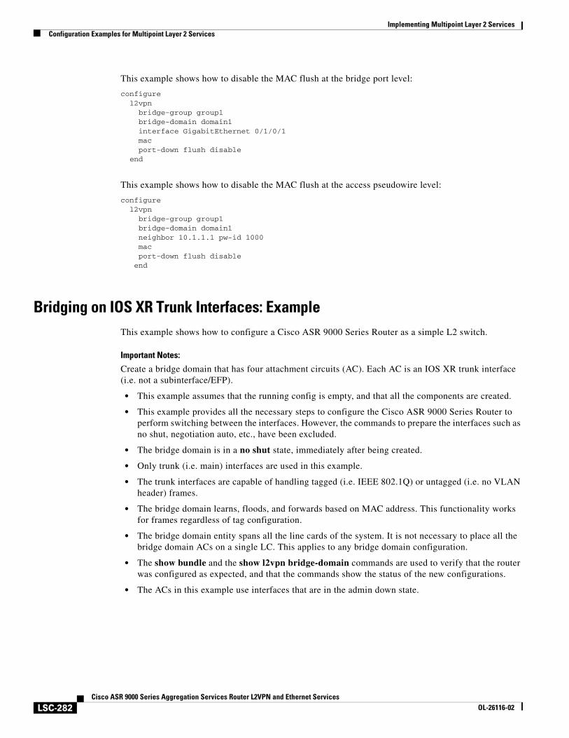
Implementing Multipoint Layer 2 ServicesConfiguration Examples for Multipoint Layer 2 Services
LSC-282Cisco ASR 9000 Series Aggregation Services Router L2VPN and Ethernet Services
OL-26116-02
This example shows how to disable the MAC flush at the bridge port level:
configurel2vpn
bridge-group group1bridge-domain domain1 interface GigabitEthernet 0/1/0/1macport-down flush disable
end
This example shows how to disable the MAC flush at the access pseudowire level:
configurel2vpn
bridge-group group1bridge-domain domain1 neighbor 10.1.1.1 pw-id 1000macport-down flush disable
end
Bridging on IOS XR Trunk Interfaces: ExampleThis example shows how to configure a Cisco ASR 9000 Series Router as a simple L2 switch.
Important Notes:
Create a bridge domain that has four attachment circuits (AC). Each AC is an IOS XR trunk interface (i.e. not a subinterface/EFP).
• This example assumes that the running config is empty, and that all the components are created.
• This example provides all the necessary steps to configure the Cisco ASR 9000 Series Router to perform switching between the interfaces. However, the commands to prepare the interfaces such as no shut, negotiation auto, etc., have been excluded.
• The bridge domain is in a no shut state, immediately after being created.
• Only trunk (i.e. main) interfaces are used in this example.
• The trunk interfaces are capable of handling tagged (i.e. IEEE 802.1Q) or untagged (i.e. no VLAN header) frames.
• The bridge domain learns, floods, and forwards based on MAC address. This functionality works for frames regardless of tag configuration.
• The bridge domain entity spans all the line cards of the system. It is not necessary to place all the bridge domain ACs on a single LC. This applies to any bridge domain configuration.
• The show bundle and the show l2vpn bridge-domain commands are used to verify that the router was configured as expected, and that the commands show the status of the new configurations.
• The ACs in this example use interfaces that are in the admin down state.
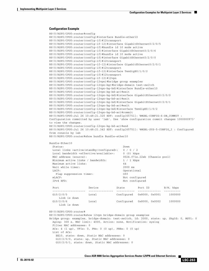
Implementing Multipoint Layer 2 ServicesConfiguration Examples for Multipoint Layer 2 Services
LSC-283Cisco ASR 9000 Series Aggregation Services Router L2VPN and Ethernet Services
OL-26116-02
Configuration ExampleRP/0/RSP0/CPU0:router#config RP/0/RSP0/CPU0:router(config)#interface Bundle-ether10 RP/0/RSP0/CPU0:router(config-if)#l2transportRP/0/RSP0/CPU0:router(config-if-l2)#interface GigabitEthernet0/2/0/5 RP/0/RSP0/CPU0:router(config-if)#bundle id 10 mode active RP/0/RSP0/CPU0:router(config-if)#interface GigabitEthernet0/2/0/6 RP/0/RSP0/CPU0:router(config-if)#bundle id 10 mode active RP/0/RSP0/CPU0:router(config-if)#interface GigabitEthernet0/2/0/0 RP/0/RSP0/CPU0:router(config-if)#l2transportRP/0/RSP0/CPU0:router(config-if-l2)#interface GigabitEthernet0/2/0/1 RP/0/RSP0/CPU0:router(config-if)#l2transportRP/0/RSP0/CPU0:router(config-if-l2)#interface TenGigE0/1/0/2 RP/0/RSP0/CPU0:router(config-if)#l2transportRP/0/RSP0/CPU0:router(config-if-l2)#l2vpnRP/0/RSP0/CPU0:router(config-l2vpn)#bridge group examples RP/0/RSP0/CPU0:router(config-l2vpn-bg)#bridge-domain test-switch RP/0/RSP0/CPU0:router(config-l2vpn-bg-bd)#interface Bundle-ether10 RP/0/RSP0/CPU0:router(config-l2vpn-bg-bd-ac)#exitRP/0/RSP0/CPU0:router(config-l2vpn-bg-bd)#interface GigabitEthernet0/2/0/0 RP/0/RSP0/CPU0:router(config-l2vpn-bg-bd-ac)#exitRP/0/RSP0/CPU0:router(config-l2vpn-bg-bd)#interface GigabitEthernet0/2/0/1 RP/0/RSP0/CPU0:router(config-l2vpn-bg-bd-ac)#exitRP/0/RSP0/CPU0:router(config-l2vpn-bg-bd)#interface TenGigE0/1/0/2 RP/0/RSP0/CPU0:router(config-l2vpn-bg-bd-ac)#commitRP/0/RSP0/CPU0:Jul 26 10:48:21.320 EDT: config[65751]: %MGBL-CONFIG-6-DB_COMMIT : Configuration committed by user 'lab'. Use 'show configuration commit changes 1000000973' to view the changes.RP/0/RSP0/CPU0:router(config-l2vpn-bg-bd-ac)#endRP/0/RSP0/CPU0:Jul 26 10:48:21.342 EDT: config[65751]: %MGBL-SYS-5-CONFIG_I : Configured from console by labRP/0/RSP0/CPU0:router#show bundle Bundle-ether10
Bundle-Ether10 Status: Down Local links <active/standby/configured>: 0 / 0 / 2 Local bandwidth <effective/available>: 0 (0) kbps MAC address (source): 0024.f71e.22eb (Chassis pool) Minimum active links / bandwidth: 1 / 1 kbps Maximum active links: 64 Wait while timer: 2000 ms LACP: Operational Flap suppression timer: Off mLACP: Not configured IPv4 BFD: Not configured
Port Device State Port ID B/W, kbps -------------------- --------------- ----------- -------------- ---------- Gi0/2/0/5 Local Configured 0x8000, 0x0001 1000000 Link is down Gi0/2/0/6 Local Configured 0x8000, 0x0002 1000000 Link is down
RP/0/RSP0/CPU0:router#RP/0/RSP0/CPU0:router#show l2vpn bridge-domain group examples Bridge group: examples, bridge-domain: test-switch, id: 2000, state: up, ShgId: 0, MSTi: 0 Aging: 300 s, MAC limit: 4000, Action: none, Notification: syslog Filter MAC addresses: 0 ACs: 4 (1 up), VFIs: 0, PWs: 0 (0 up), PBBs: 0 (0 up) List of ACs: BE10, state: down, Static MAC addresses: 0 Gi0/2/0/0, state: up, Static MAC addresses: 0 Gi0/2/0/1, state: down, Static MAC addresses: 0
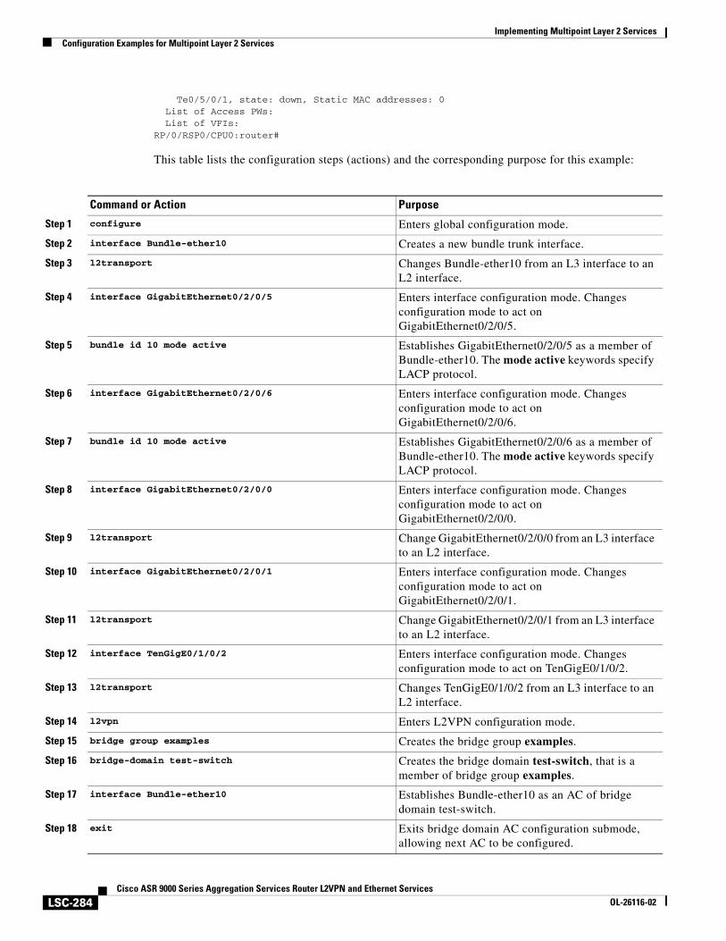
Implementing Multipoint Layer 2 ServicesConfiguration Examples for Multipoint Layer 2 Services
LSC-284Cisco ASR 9000 Series Aggregation Services Router L2VPN and Ethernet Services
OL-26116-02
Te0/5/0/1, state: down, Static MAC addresses: 0 List of Access PWs: List of VFIs:RP/0/RSP0/CPU0:router#
This table lists the configuration steps (actions) and the corresponding purpose for this example:
Command or Action Purpose
Step 1 configure Enters global configuration mode.
Step 2 interface Bundle-ether10 Creates a new bundle trunk interface.
Step 3 l2transport Changes Bundle-ether10 from an L3 interface to an L2 interface.
Step 4 interface GigabitEthernet0/2/0/5 Enters interface configuration mode. Changes configuration mode to act on GigabitEthernet0/2/0/5.
Step 5 bundle id 10 mode active Establishes GigabitEthernet0/2/0/5 as a member of Bundle-ether10. The mode active keywords specify LACP protocol.
Step 6 interface GigabitEthernet0/2/0/6 Enters interface configuration mode. Changes configuration mode to act on GigabitEthernet0/2/0/6.
Step 7 bundle id 10 mode active Establishes GigabitEthernet0/2/0/6 as a member of Bundle-ether10. The mode active keywords specify LACP protocol.
Step 8 interface GigabitEthernet0/2/0/0 Enters interface configuration mode. Changes configuration mode to act on GigabitEthernet0/2/0/0.
Step 9 l2transport Change GigabitEthernet0/2/0/0 from an L3 interface to an L2 interface.
Step 10 interface GigabitEthernet0/2/0/1 Enters interface configuration mode. Changes configuration mode to act on GigabitEthernet0/2/0/1.
Step 11 l2transport Change GigabitEthernet0/2/0/1 from an L3 interface to an L2 interface.
Step 12 interface TenGigE0/1/0/2 Enters interface configuration mode. Changes configuration mode to act on TenGigE0/1/0/2.
Step 13 l2transport Changes TenGigE0/1/0/2 from an L3 interface to an L2 interface.
Step 14 l2vpn Enters L2VPN configuration mode.
Step 15 bridge group examples Creates the bridge group examples.
Step 16 bridge-domain test-switch Creates the bridge domain test-switch, that is a member of bridge group examples.
Step 17 interface Bundle-ether10 Establishes Bundle-ether10 as an AC of bridge domain test-switch.
Step 18 exit Exits bridge domain AC configuration submode, allowing next AC to be configured.
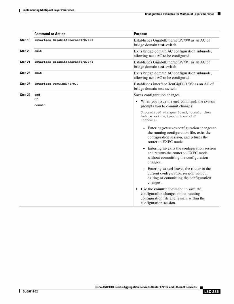
Implementing Multipoint Layer 2 ServicesConfiguration Examples for Multipoint Layer 2 Services
LSC-285Cisco ASR 9000 Series Aggregation Services Router L2VPN and Ethernet Services
OL-26116-02
Step 19 interface GigabitEthernet0/2/0/0 Establishes GigabitEthernet0/2/0/0 as an AC of bridge domain test-switch.
Step 20 exit Exits bridge domain AC configuration submode, allowing next AC to be configured.
Step 21 interface GigabitEthernet0/2/0/1 Establishes GigabitEthernet0/2/0/1 as an AC of bridge domain test-switch.
Step 22 exit Exits bridge domain AC configuration submode, allowing next AC to be configured.
Step 23 interface TenGigE0/1/0/2 Establishes interface TenGigE0/1/0/2 as an AC of bridge domain test-switch.
Step 24 end
or
commit
Saves configuration changes.
• When you issue the end command, the system prompts you to commit changes:
Uncommitted changes found, commit them before exiting(yes/no/cancel)?[cancel]:
– Entering yes saves configuration changes to the running configuration file, exits the configuration session, and returns the router to EXEC mode.
– Entering no exits the configuration session and returns the router to EXEC mode without committing the configuration changes.
– Entering cancel leaves the router in the current configuration session without exiting or committing the configuration changes.
• Use the commit command to save the configuration changes to the running configuration file and remain within the configuration session.
Command or Action Purpose
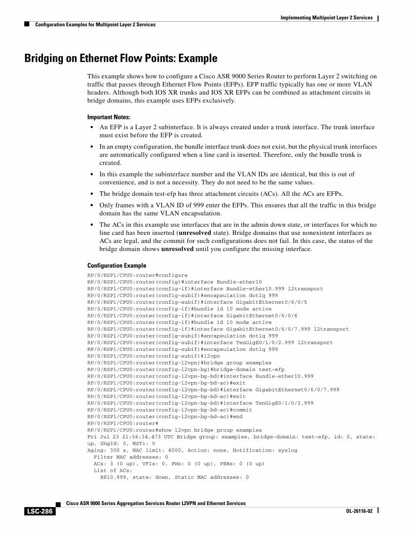
Implementing Multipoint Layer 2 ServicesConfiguration Examples for Multipoint Layer 2 Services
LSC-286Cisco ASR 9000 Series Aggregation Services Router L2VPN and Ethernet Services
OL-26116-02
Bridging on Ethernet Flow Points: ExampleThis example shows how to configure a Cisco ASR 9000 Series Router to perform Layer 2 switching on traffic that passes through Ethernet Flow Points (EFPs). EFP traffic typically has one or more VLAN headers. Although both IOS XR trunks and IOS XR EFPs can be combined as attachment circuits in bridge domains, this example uses EFPs exclusively.
Important Notes:
• An EFP is a Layer 2 subinterface. It is always created under a trunk interface. The trunk interface must exist before the EFP is created.
• In an empty configuration, the bundle interface trunk does not exist, but the physical trunk interfaces are automatically configured when a line card is inserted. Therefore, only the bundle trunk is created.
• In this example the subinterface number and the VLAN IDs are identical, but this is out of convenience, and is not a necessity. They do not need to be the same values.
• The bridge domain test-efp has three attachment circuits (ACs). All the ACs are EFPs.
• Only frames with a VLAN ID of 999 enter the EFPs. This ensures that all the traffic in this bridge domain has the same VLAN encapsulation.
• The ACs in this example use interfaces that are in the admin down state, or interfaces for which no line card has been inserted (unresolved state). Bridge domains that use nonexistent interfaces as ACs are legal, and the commit for such configurations does not fail. In this case, the status of the bridge domain shows unresolved until you configure the missing interface.
Configuration ExampleRP/0/RSP1/CPU0:router#configureRP/0/RSP1/CPU0:router(config)#interface Bundle-ether10 RP/0/RSP1/CPU0:router(config-if)#interface Bundle-ether10.999 l2transport RP/0/RSP1/CPU0:router(config-subif)#encapsulation dot1q 999 RP/0/RSP1/CPU0:router(config-subif)#interface GigabitEthernet0/6/0/5 RP/0/RSP1/CPU0:router(config-if)#bundle id 10 mode active RP/0/RSP1/CPU0:router(config-if)#interface GigabitEthernet0/6/0/6 RP/0/RSP1/CPU0:router(config-if)#bundle id 10 mode active RP/0/RSP1/CPU0:router(config-if)#interface GigabitEthernet0/6/0/7.999 l2transport RP/0/RSP1/CPU0:router(config-subif)#encapsulation dot1q 999 RP/0/RSP1/CPU0:router(config-subif)#interface TenGigE0/1/0/2.999 l2transport RP/0/RSP1/CPU0:router(config-subif)#encapsulation dot1q 999 RP/0/RSP1/CPU0:router(config-subif)#l2vpnRP/0/RSP1/CPU0:router(config-l2vpn)#bridge group examples RP/0/RSP1/CPU0:router(config-l2vpn-bg)#bridge-domain test-efp RP/0/RSP1/CPU0:router(config-l2vpn-bg-bd)#interface Bundle-ether10.999 RP/0/RSP1/CPU0:router(config-l2vpn-bg-bd-ac)#exitRP/0/RSP1/CPU0:router(config-l2vpn-bg-bd)#interface GigabitEthernet0/6/0/7.999 RP/0/RSP1/CPU0:router(config-l2vpn-bg-bd-ac)#exitRP/0/RSP1/CPU0:router(config-l2vpn-bg-bd)#interface TenGigE0/1/0/2.999 RP/0/RSP1/CPU0:router(config-l2vpn-bg-bd-ac)#commitRP/0/RSP1/CPU0:router(config-l2vpn-bg-bd-ac)#endRP/0/RSP1/CPU0:router#RP/0/RSP1/CPU0:router#show l2vpn bridge group examples Fri Jul 23 21:56:34.473 UTC Bridge group: examples, bridge-domain: test-efp, id: 0, state: up, ShgId: 0, MSTi: 0Aging: 300 s, MAC limit: 4000, Action: none, Notification: syslog Filter MAC addresses: 0 ACs: 3 (0 up), VFIs: 0, PWs: 0 (0 up), PBBs: 0 (0 up) List of ACs: BE10.999, state: down, Static MAC addresses: 0
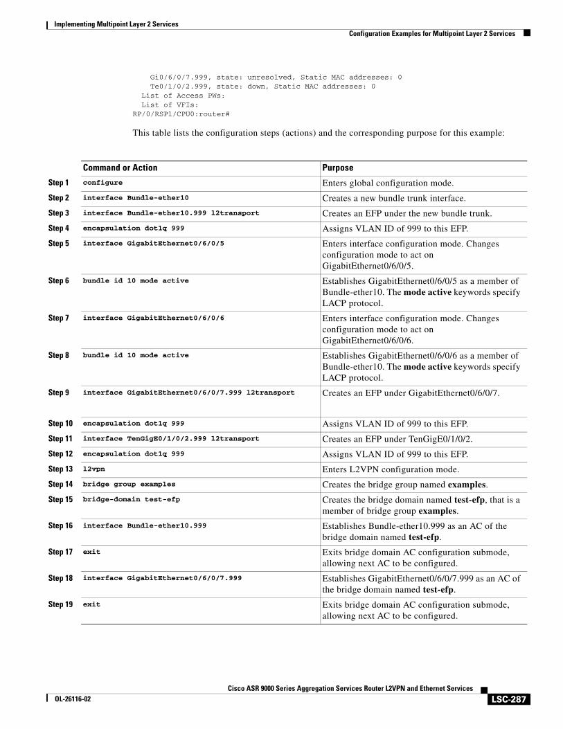
Implementing Multipoint Layer 2 ServicesConfiguration Examples for Multipoint Layer 2 Services
LSC-287Cisco ASR 9000 Series Aggregation Services Router L2VPN and Ethernet Services
OL-26116-02
Gi0/6/0/7.999, state: unresolved, Static MAC addresses: 0 Te0/1/0/2.999, state: down, Static MAC addresses: 0 List of Access PWs: List of VFIs:RP/0/RSP1/CPU0:router#
This table lists the configuration steps (actions) and the corresponding purpose for this example:
Command or Action Purpose
Step 1 configure Enters global configuration mode.
Step 2 interface Bundle-ether10 Creates a new bundle trunk interface.
Step 3 interface Bundle-ether10.999 l2transport Creates an EFP under the new bundle trunk.
Step 4 encapsulation dot1q 999 Assigns VLAN ID of 999 to this EFP.
Step 5 interface GigabitEthernet0/6/0/5 Enters interface configuration mode. Changes configuration mode to act on GigabitEthernet0/6/0/5.
Step 6 bundle id 10 mode active Establishes GigabitEthernet0/6/0/5 as a member of Bundle-ether10. The mode active keywords specify LACP protocol.
Step 7 interface GigabitEthernet0/6/0/6 Enters interface configuration mode. Changes configuration mode to act on GigabitEthernet0/6/0/6.
Step 8 bundle id 10 mode active Establishes GigabitEthernet0/6/0/6 as a member of Bundle-ether10. The mode active keywords specify LACP protocol.
Step 9 interface GigabitEthernet0/6/0/7.999 l2transport Creates an EFP under GigabitEthernet0/6/0/7.
Step 10 encapsulation dot1q 999 Assigns VLAN ID of 999 to this EFP.
Step 11 interface TenGigE0/1/0/2.999 l2transport Creates an EFP under TenGigE0/1/0/2.
Step 12 encapsulation dot1q 999 Assigns VLAN ID of 999 to this EFP.
Step 13 l2vpn Enters L2VPN configuration mode.
Step 14 bridge group examples Creates the bridge group named examples.
Step 15 bridge-domain test-efp Creates the bridge domain named test-efp, that is a member of bridge group examples.
Step 16 interface Bundle-ether10.999 Establishes Bundle-ether10.999 as an AC of the bridge domain named test-efp.
Step 17 exit Exits bridge domain AC configuration submode, allowing next AC to be configured.
Step 18 interface GigabitEthernet0/6/0/7.999 Establishes GigabitEthernet0/6/0/7.999 as an AC of the bridge domain named test-efp.
Step 19 exit Exits bridge domain AC configuration submode, allowing next AC to be configured.
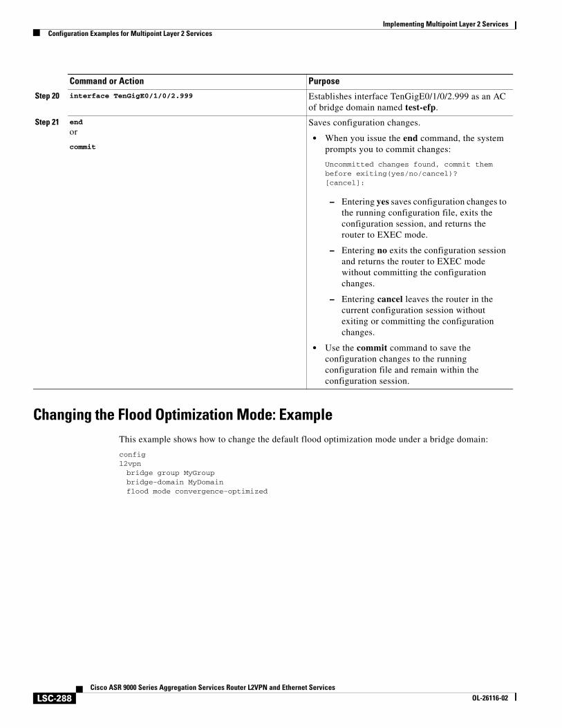
Implementing Multipoint Layer 2 ServicesConfiguration Examples for Multipoint Layer 2 Services
LSC-288Cisco ASR 9000 Series Aggregation Services Router L2VPN and Ethernet Services
OL-26116-02
Changing the Flood Optimization Mode: ExampleThis example shows how to change the default flood optimization mode under a bridge domain:
configl2vpnbridge group MyGroupbridge-domain MyDomainflood mode convergence-optimized
Step 20 interface TenGigE0/1/0/2.999 Establishes interface TenGigE0/1/0/2.999 as an AC of bridge domain named test-efp.
Step 21 end
or
commit
Saves configuration changes.
• When you issue the end command, the system prompts you to commit changes:
Uncommitted changes found, commit them before exiting(yes/no/cancel)?[cancel]:
– Entering yes saves configuration changes to the running configuration file, exits the configuration session, and returns the router to EXEC mode.
– Entering no exits the configuration session and returns the router to EXEC mode without committing the configuration changes.
– Entering cancel leaves the router in the current configuration session without exiting or committing the configuration changes.
• Use the commit command to save the configuration changes to the running configuration file and remain within the configuration session.
Command or Action Purpose
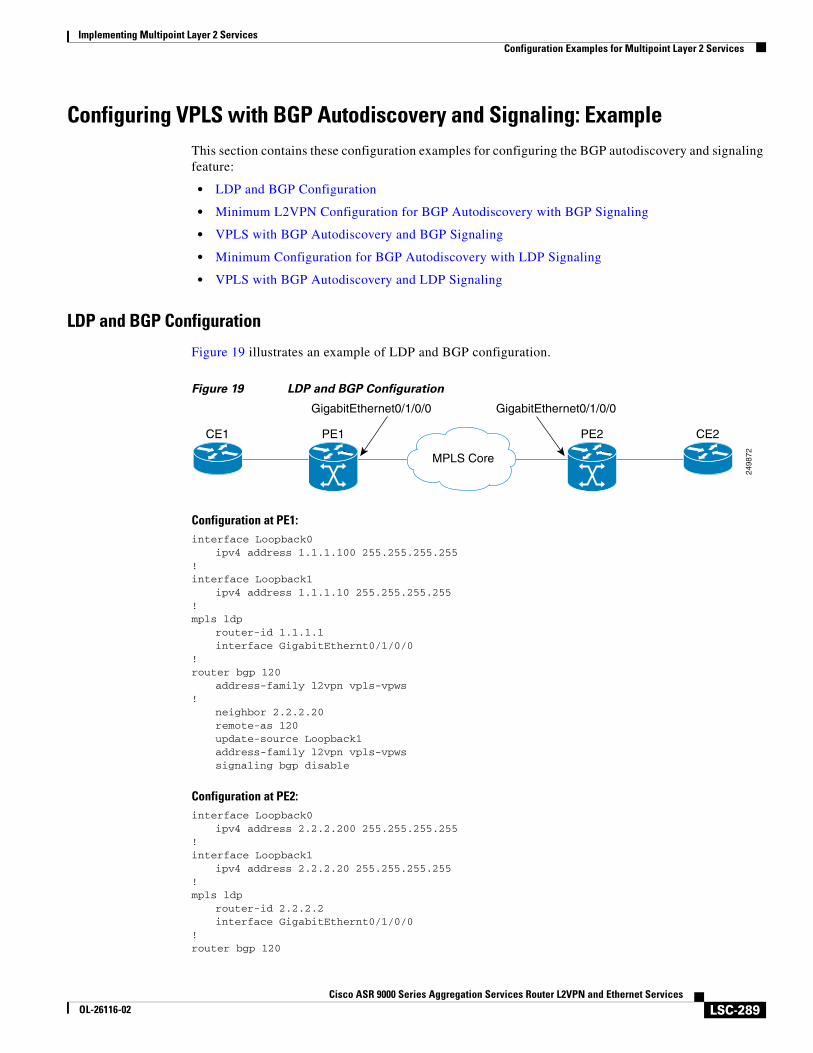
Implementing Multipoint Layer 2 ServicesConfiguration Examples for Multipoint Layer 2 Services
LSC-289Cisco ASR 9000 Series Aggregation Services Router L2VPN and Ethernet Services
OL-26116-02
Configuring VPLS with BGP Autodiscovery and Signaling: ExampleThis section contains these configuration examples for configuring the BGP autodiscovery and signaling feature:
• LDP and BGP Configuration
• Minimum L2VPN Configuration for BGP Autodiscovery with BGP Signaling
• VPLS with BGP Autodiscovery and BGP Signaling
• Minimum Configuration for BGP Autodiscovery with LDP Signaling
• VPLS with BGP Autodiscovery and LDP Signaling
LDP and BGP Configuration
Figure 19 illustrates an example of LDP and BGP configuration.
Figure 19 LDP and BGP Configuration
Configuration at PE1:interface Loopback0
ipv4 address 1.1.1.100 255.255.255.255!interface Loopback1
ipv4 address 1.1.1.10 255.255.255.255!mpls ldp
router-id 1.1.1.1interface GigabitEthernt0/1/0/0
!router bgp 120
address-family l2vpn vpls-vpws!
neighbor 2.2.2.20remote-as 120update-source Loopback1address-family l2vpn vpls-vpwssignaling bgp disable
Configuration at PE2:interface Loopback0
ipv4 address 2.2.2.200 255.255.255.255!interface Loopback1
ipv4 address 2.2.2.20 255.255.255.255!mpls ldp
router-id 2.2.2.2interface GigabitEthernt0/1/0/0
!router bgp 120
2498
72MPLS Core
CE1 PE1 PE2 CE2
GigabitEthernet0/1/0/0 GigabitEthernet0/1/0/0
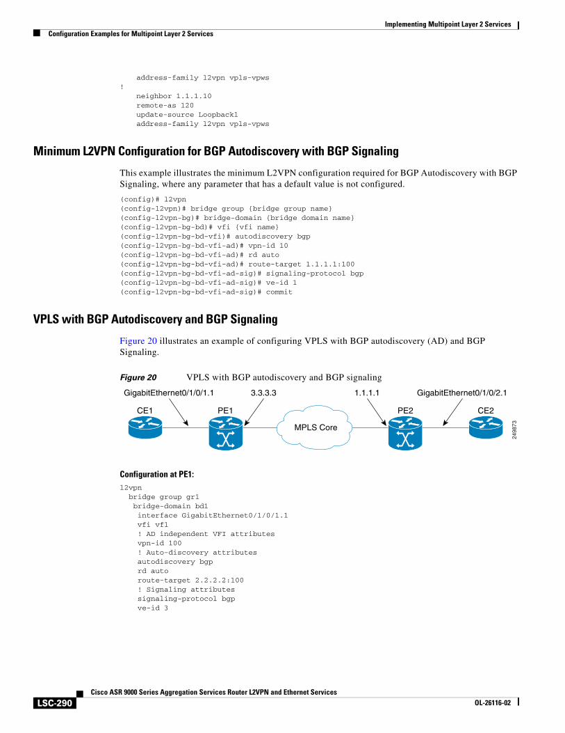
Implementing Multipoint Layer 2 ServicesConfiguration Examples for Multipoint Layer 2 Services
LSC-290Cisco ASR 9000 Series Aggregation Services Router L2VPN and Ethernet Services
OL-26116-02
address-family l2vpn vpls-vpws!
neighbor 1.1.1.10remote-as 120update-source Loopback1address-family l2vpn vpls-vpws
Minimum L2VPN Configuration for BGP Autodiscovery with BGP Signaling
This example illustrates the minimum L2VPN configuration required for BGP Autodiscovery with BGP Signaling, where any parameter that has a default value is not configured.
(config)# l2vpn(config-l2vpn)# bridge group {bridge group name}(config-l2vpn-bg)# bridge-domain {bridge domain name}(config-l2vpn-bg-bd)# vfi {vfi name}(config-l2vpn-bg-bd-vfi)# autodiscovery bgp(config-l2vpn-bg-bd-vfi-ad)# vpn-id 10(config-l2vpn-bg-bd-vfi-ad)# rd auto(config-l2vpn-bg-bd-vfi-ad)# route-target 1.1.1.1:100(config-l2vpn-bg-bd-vfi-ad-sig)# signaling-protocol bgp(config-l2vpn-bg-bd-vfi-ad-sig)# ve-id 1(config-l2vpn-bg-bd-vfi-ad-sig)# commit
VPLS with BGP Autodiscovery and BGP Signaling
Figure 20 illustrates an example of configuring VPLS with BGP autodiscovery (AD) and BGP Signaling.
Figure 20 VPLS with BGP autodiscovery and BGP signaling
Configuration at PE1:l2vpn bridge group gr1 bridge-domain bd1 interface GigabitEthernet0/1/0/1.1 vfi vf1 ! AD independent VFI attributes vpn-id 100 ! Auto-discovery attributes autodiscovery bgp rd auto route-target 2.2.2.2:100 ! Signaling attributes signaling-protocol bgp ve-id 3
2498
73MPLS Core
CE1 PE1 PE2 CE2
3.3.3.3GigabitEthernet0/1/0/1.1 1.1.1.1 GigabitEthernet0/1/0/2.1
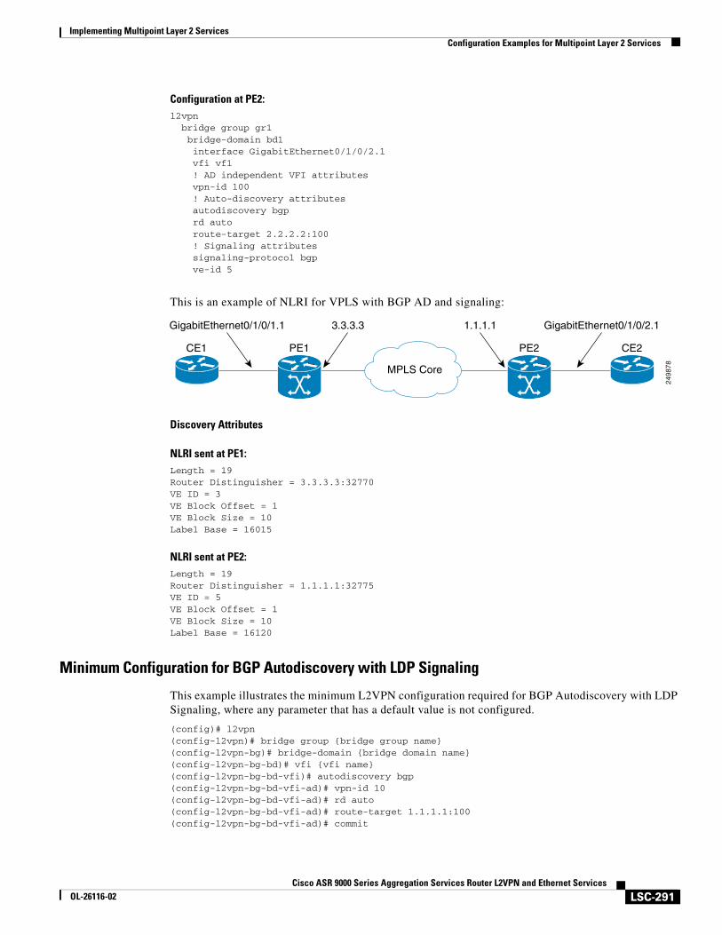
Implementing Multipoint Layer 2 ServicesConfiguration Examples for Multipoint Layer 2 Services
LSC-291Cisco ASR 9000 Series Aggregation Services Router L2VPN and Ethernet Services
OL-26116-02
Configuration at PE2:l2vpn bridge group gr1 bridge-domain bd1 interface GigabitEthernet0/1/0/2.1 vfi vf1 ! AD independent VFI attributes vpn-id 100 ! Auto-discovery attributes autodiscovery bgp rd auto route-target 2.2.2.2:100 ! Signaling attributes signaling-protocol bgp ve-id 5
This is an example of NLRI for VPLS with BGP AD and signaling:
Discovery Attributes
NLRI sent at PE1:Length = 19Router Distinguisher = 3.3.3.3:32770VE ID = 3VE Block Offset = 1VE Block Size = 10Label Base = 16015
NLRI sent at PE2:Length = 19Router Distinguisher = 1.1.1.1:32775VE ID = 5VE Block Offset = 1VE Block Size = 10Label Base = 16120
Minimum Configuration for BGP Autodiscovery with LDP Signaling
This example illustrates the minimum L2VPN configuration required for BGP Autodiscovery with LDP Signaling, where any parameter that has a default value is not configured.
(config)# l2vpn(config-l2vpn)# bridge group {bridge group name}(config-l2vpn-bg)# bridge-domain {bridge domain name}(config-l2vpn-bg-bd)# vfi {vfi name}(config-l2vpn-bg-bd-vfi)# autodiscovery bgp(config-l2vpn-bg-bd-vfi-ad)# vpn-id 10(config-l2vpn-bg-bd-vfi-ad)# rd auto(config-l2vpn-bg-bd-vfi-ad)# route-target 1.1.1.1:100(config-l2vpn-bg-bd-vfi-ad)# commit
2498
78MPLS Core
CE1 PE1 PE2 CE2
3.3.3.3GigabitEthernet0/1/0/1.1 1.1.1.1 GigabitEthernet0/1/0/2.1
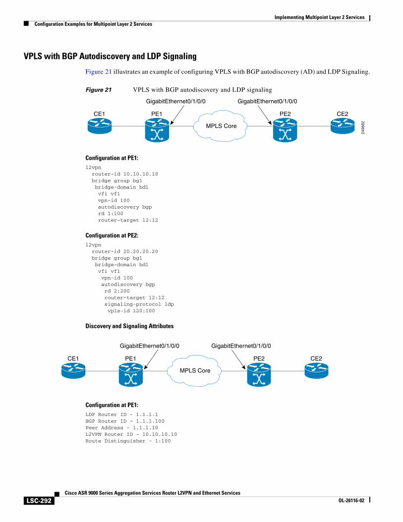
Implementing Multipoint Layer 2 ServicesConfiguration Examples for Multipoint Layer 2 Services
LSC-292Cisco ASR 9000 Series Aggregation Services Router L2VPN and Ethernet Services
OL-26116-02
VPLS with BGP Autodiscovery and LDP Signaling
Figure 21 illustrates an example of configuring VPLS with BGP autodiscovery (AD) and LDP Signaling.
Figure 21 VPLS with BGP autodiscovery and LDP signaling
Configuration at PE1:l2vpn router-id 10.10.10.10 bridge group bg1 bridge-domain bd1 vfi vf1 vpn-id 100 autodiscovery bgp rd 1:100 router-target 12:12
Configuration at PE2:l2vpn router-id 20.20.20.20 bridge group bg1 bridge-domain bd1 vfi vf1 vpn-id 100 autodiscovery bgp rd 2:200 router-target 12:12 signaling-protocol ldp vpls-id 120:100
Discovery and Signaling Attributes
Configuration at PE1:LDP Router ID - 1.1.1.1BGP Router ID - 1.1.1.100Peer Address - 1.1.1.10L2VPN Router ID - 10.10.10.10Route Distinguisher - 1:100
2498
82MPLS Core
CE1 PE1 PE2 CE2
GigabitEthernet0/1/0/0 GigabitEthernet0/1/0/0
MPLS Core
CE1 PE1 PE2 CE2
GigabitEthernet0/1/0/0 GigabitEthernet0/1/0/0
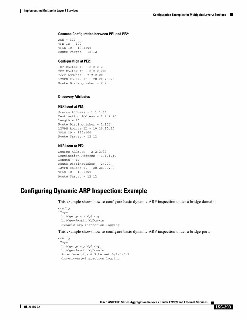
Implementing Multipoint Layer 2 ServicesConfiguration Examples for Multipoint Layer 2 Services
LSC-293Cisco ASR 9000 Series Aggregation Services Router L2VPN and Ethernet Services
OL-26116-02
Common Configuration between PE1 and PE2:ASN - 120VPN ID - 100VPLS ID - 120:100Route Target - 12:12
Configuration at PE2:LDP Router ID - 2.2.2.2BGP Router ID - 2.2.2.200Peer Address - 2.2.2.20L2VPN Router ID - 20.20.20.20Route Distinguisher - 2:200
Discovery Attributes
NLRI sent at PE1:Source Address - 1.1.1.10Destination Address - 2.2.2.20Length - 14Route Distinguisher - 1:100L2VPN Router ID - 10.10.10.10VPLS ID - 120:100Route Target - 12:12
NLRI sent at PE2:Source Address - 2.2.2.20Destination Address - 1.1.1.10Length - 14Route Distinguisher - 2:200L2VPN Router ID - 20.20.20.20VPLS ID - 120:100
Route Target - 12:12
Configuring Dynamic ARP Inspection: ExampleThis example shows how to configure basic dynamic ARP inspection under a bridge domain:
configl2vpnbridge group MyGroupbridge-domain MyDomain
dynamic-arp-inspection logging
This example shows how to configure basic dynamic ARP inspection under a bridge port:
configl2vpnbridge group MyGroupbridge-domain MyDomaininterface gigabitEthernet 0/1/0/0.1dynamic-arp-inspection logging
Implementing Multipoint Layer 2 ServicesConfiguration Examples for Multipoint Layer 2 Services
LSC-294Cisco ASR 9000 Series Aggregation Services Router L2VPN and Ethernet Services
OL-26116-02
This example shows how to configure optional dynamic ARP inspection under a bridge domain:
l2vpn bridge group SECURE bridge-domain SECURE-DAI dynamic-arp-inspection logging address-validation src-mac dst-mac ipv4
This example shows how to configure optional dynamic ARP inspection under a bridge port:
l2vpn bridge group SECURE bridge-domain SECURE-DAI interface GigabitEthernet0/0/0/1.10 dynamic-arp-inspection logging address-validation src-mac dst-mac ipv4
This example shows the output of the show l2vpn bridge-domain bd-name SECURE-DAI detail command:
#show l2vpn bridge-domain bd-name SECURE-DAI detailBridge group: SECURE, bridge-domain: SECURE-DAI, id: 2, state: up, …Dynamic ARP Inspection: enabled, Logging: enabledDynamic ARP Inspection Address Validation: IPv4 verification: enabled Source MAC verification: enabled Destination MAC verification: enabled…List of ACs: AC: GigabitEthernet0/0/0/1.10, state is up… Dynamic ARP Inspection: enabled, Logging: enabled Dynamic ARP Inspection Address Validation: IPv4 verification: enabled Source MAC verification: enabled Destination MAC verification: enabled IP Source Guard: enabled, Logging: enabled
… Dynamic ARP inspection drop counters: packets: 1000, bytes: 64000
This example shows the output of the show l2vpn forwarding interface interface-name detail location location-name command:
#show l2vpn forwarding interface g0/0/0/1.10 det location 0/0/CPU0Local interface: GigabitEthernet0/0/0/1.10, Xconnect id: 0x40001, Status: up
… Dynamic ARP Inspection: enabled, Logging: enabled Dynamic ARP Inspection Address Validation: IPv4 verification: enabled Source MAC verification: enabled Destination MAC verification: enabled IP Source Guard: enabled, Logging: enabled
Implementing Multipoint Layer 2 ServicesConfiguration Examples for Multipoint Layer 2 Services
LSC-295Cisco ASR 9000 Series Aggregation Services Router L2VPN and Ethernet Services
OL-26116-02
…
This example shows the logging display:
LC/0/0/CPU0:Jun 16 13:28:28.697 : l2fib[188]: %L2-L2FIB-5-SECURITY_DAI_VIOLATION_AC : Dynamic ARP inspection in AC GigabitEthernet0_0_0_7.1000 detected violated packet - source MAC: 0000.0000.0065, destination MAC: 0000.0040.0000, sender MAC: 0000.0000.0064, target MAC: 0000.0000.0000, sender IP: 5.6.6.6, target IP: 130.10.3.2
LC/0/5/CPU0:Jun 16 13:28:38.716 : l2fib[188]: %L2-L2FIB-5-SECURITY_DAI_VIOLATION_AC : Dynamic ARP inspection in AC Bundle-Ether100.103 detected violated packet - source MAC: 0000.0000.0067, destination MAC: 0000.2300.0000, sender MAC: 0000.7800.0034, target MAC: 0000.0000.0000, sender IP: 130.2.5.1, target IP: 50.5.1.25
Configuring IP Source Guard: ExampleThis example shows how to configure basic IP source guard under a bridge domain:
configl2vpnbridge group MyGroupbridge-domain MyDomainip-source-guard logging
This example shows how to configure basic IP source guard under a bridge port:
configl2vpnbridge group MyGroupbridge-domain MyDomaininterface gigabitEthernet 0/1/0/0.1ip-source-guard logging
This example shows how to configure optional IP source guard under a bridge domain:
l2vpn bridge group SECURE bridge-domain SECURE-IPSG ip-source-guard logging
This example shows how to configure optional IP source guard under a bridge port:
l2vpn bridge group SECURE bridge-domain SECURE-IPSG interface GigabitEthernet0/0/0/1.10 ip-source-guard logging
This example shows the output of the show l2vpn bridge-domain bd-name ipsg-name detail command:
# show l2vpn bridge-domain bd-name SECURE-IPSG detailBridge group: SECURE, bridge-domain: SECURE-IPSG, id: 2, state: up, … IP Source Guard: enabled, Logging: enabled…List of ACs: AC: GigabitEthernet0/0/0/1.10, state is up…
IP Source Guard: enabled, Logging: enabled… IP source guard drop counters:
Implementing Multipoint Layer 2 ServicesConfiguration Examples for Multipoint Layer 2 Services
LSC-296Cisco ASR 9000 Series Aggregation Services Router L2VPN and Ethernet Services
OL-26116-02
packets: 1000, bytes: 64000
This example shows the output of the show l2vpn forwarding interface interface-name detail location location-name command:
# show l2vpn forwarding interface g0/0/0/1.10 detail location 0/0/CPU0Local interface: GigabitEthernet0/0/0/1.10, Xconnect id: 0x40001, Status: up
… IP Source Guard: enabled, Logging: enabled
This example shows the logging display:LC/0/0/CPU0:Jun 16 13:32:25.334 : l2fib[188]: %L2-L2FIB-5-SECURITY_IPSG_VIOLATION_AC : IP source guard in AC GigabitEthernet0_0_0_7.1001 detected violated packet - source MAC: 0000.0000.0200, destination MAC: 0000.0003.0000, source IP: 130.0.0.1, destination IP: 125.34.2.5
LC/0/5/CPU0:Jun 16 13:33:25.530 : l2fib[188]: %L2-L2FIB-5-SECURITY_IPSG_VIOLATION_AC : IP source guard in AC Bundle-Ether100.100 detected violated packet - source MAC: 0000.0000.0064, destination MAC: 0000.0040.0000, source IP: 14.5.1.3, destination IP: 45.1.1.10
Configuring G.8032 Ethernet Ring Protection: ExampleThis sample configuration illustrates the elements that a complete G.8032 configuration includes:
# Configure the ERP profile characteristics if ERP instance behaviors are non-default.ethernet ring g8032 profile ERP-profile timer wtr 60 timer guard 100 timer hold-off 1 non-revertive # Configure CFM MEPs and configure to monitor the ring links.ethernet cfm domain domain1 service link1 down-meps
continuity-check interval 100ms efd
mep crosscheckmep-id 2
domain domain2 service link2 down-meps
continuity-check interval 100ms efd protection-switching
mep crosscheckmep id 2
Interface Gig 0/0/0/0 ethernet cfm mep domain domain1 service link1 mep-id 1Interface Gig 1/1/0/0 ethernet cfm mep domain domain2 service link2 mep-id 1
# Configure the ERP instance under L2VPNl2vpn ethernet ring g8032 RingA port0 interface g0/0/0/0 port1 interface g0/1/0/0 instance 1
Implementing Multipoint Layer 2 ServicesConfiguration Examples for Multipoint Layer 2 Services
LSC-297Cisco ASR 9000 Series Aggregation Services Router L2VPN and Ethernet Services
OL-26116-02
description BD2-ring profile ERP-profile rpl port0 owner vlan-ids 10-100 aps channel level 3 port0 interface g0/0/0/0.1 port1 interface g1/1/0/0.1
# Set up the bridge domainsbridge group ABC bridge-domain BD2 interface Gig 0/0/0/0.2 interface Gig 0/1/0/0.2 interface Gig 0/2/0/0.2
bridge-domain BD2-APS interface Gig 0/0/0/0.1 interface Gig 1/1/0/0.1
# EFPs configurationinterface Gig 0/0/0/0.1 l2transport encapsulation dot1q 5
interface Gig 1/1/0/0.1 l2transport encapsulation dot1q 5
interface g 0/0/0/0.2 l2transport encapsulation dot1q 10-100
interface g 0/1/0/0.2 l2transport encapsulation dot1q 10-100
interface g 0/2/0/0.2 l2transport encapsulation dot1q 10-100
Configuring Interconnection Node: Example
This example shows you how to configure an interconnection node. Figure 22 illustrates an open ring scenario.
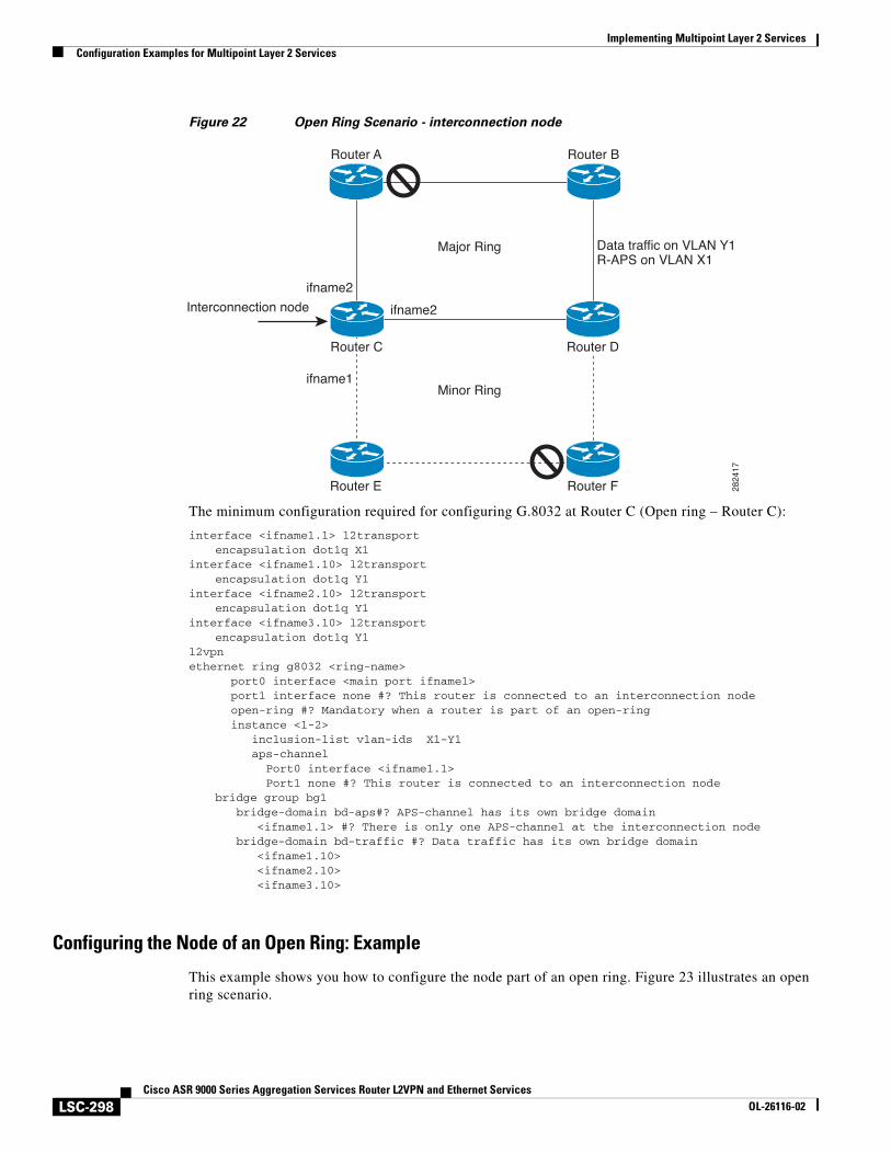
Implementing Multipoint Layer 2 ServicesConfiguration Examples for Multipoint Layer 2 Services
LSC-298Cisco ASR 9000 Series Aggregation Services Router L2VPN and Ethernet Services
OL-26116-02
Figure 22 Open Ring Scenario - interconnection node
The minimum configuration required for configuring G.8032 at Router C (Open ring – Router C):
interface <ifname1.1> l2transportencapsulation dot1q X1
interface <ifname1.10> l2transportencapsulation dot1q Y1
interface <ifname2.10> l2transportencapsulation dot1q Y1
interface <ifname3.10> l2transportencapsulation dot1q Y1
l2vpnethernet ring g8032 <ring-name> port0 interface <main port ifname1> port1 interface none #? This router is connected to an interconnection node open-ring #? Mandatory when a router is part of an open-ring instance <1-2> inclusion-list vlan-ids X1-Y1 aps-channel Port0 interface <ifname1.1> Port1 none #? This router is connected to an interconnection node
bridge group bg1 bridge-domain bd-aps#? APS-channel has its own bridge domain <ifname1.1> #? There is only one APS-channel at the interconnection node bridge-domain bd-traffic #? Data traffic has its own bridge domain <ifname1.10> <ifname2.10> <ifname3.10>
Configuring the Node of an Open Ring: Example
This example shows you how to configure the node part of an open ring. Figure 23 illustrates an open ring scenario.
Major Ring
Minor Ring
Router A
Router C Router D
Router E Router F
Router B
Interconnection node
2824
17
ifname2
ifname1
ifname2
Data traffic on VLAN Y1R-APS on VLAN X1
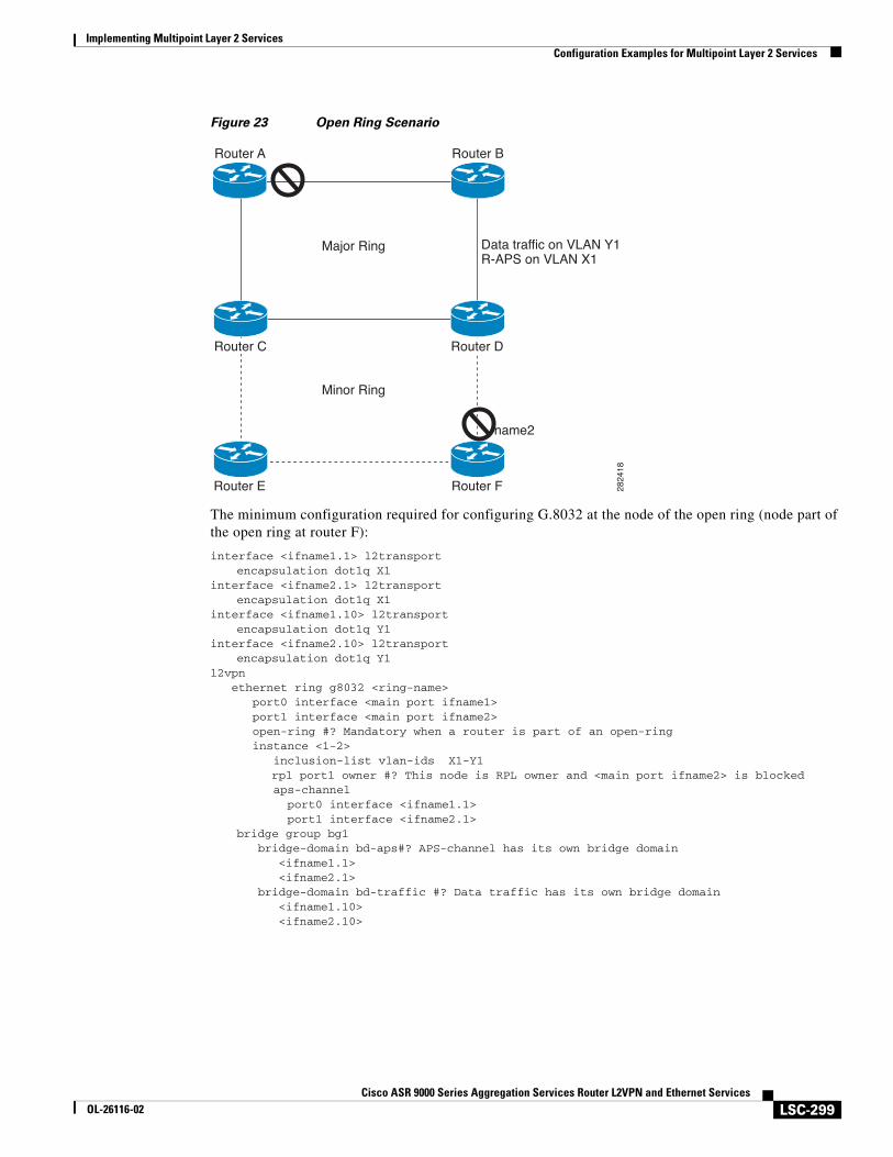
Implementing Multipoint Layer 2 ServicesConfiguration Examples for Multipoint Layer 2 Services
LSC-299Cisco ASR 9000 Series Aggregation Services Router L2VPN and Ethernet Services
OL-26116-02
Figure 23 Open Ring Scenario
The minimum configuration required for configuring G.8032 at the node of the open ring (node part of the open ring at router F):
interface <ifname1.1> l2transportencapsulation dot1q X1
interface <ifname2.1> l2transportencapsulation dot1q X1
interface <ifname1.10> l2transportencapsulation dot1q Y1
interface <ifname2.10> l2transportencapsulation dot1q Y1
l2vpn ethernet ring g8032 <ring-name> port0 interface <main port ifname1> port1 interface <main port ifname2> open-ring #? Mandatory when a router is part of an open-ring instance <1-2> inclusion-list vlan-ids X1-Y1
rpl port1 owner #? This node is RPL owner and <main port ifname2> is blocked aps-channel port0 interface <ifname1.1> port1 interface <ifname2.1>
bridge group bg1 bridge-domain bd-aps#? APS-channel has its own bridge domain <ifname1.1> <ifname2.1> bridge-domain bd-traffic #? Data traffic has its own bridge domain <ifname1.10> <ifname2.10>
Major Ring
Minor Ring
Router A
Router C Router D
Router E Router F
Router B
2824
18
name2
Data traffic on VLAN Y1R-APS on VLAN X1
Implementing Multipoint Layer 2 ServicesConfiguration Examples for Multipoint Layer 2 Services
LSC-300Cisco ASR 9000 Series Aggregation Services Router L2VPN and Ethernet Services
OL-26116-02
Configuring Flow Aware Transport Pseudowire: ExampleThis sample configuration shows how to enable load balancing with FAT PW for VPWS.
l2vpnpw-class class1 encapsulation mpls load-balancing flow-label transmit ! !pw-class class2 encapsulation mpls load-balancing flow-label both
!
xconnect group group1 p2p p1 interface GigabitEthernet 0/0/0/0.1 neighbor 1.1.1.1 pw-id 1 pw-class class1 ! !!
This sample configuration shows how to enable load balancing with FAT PW for VPLS.
Note For VPLS, the configuration at the bridge-domain level is applied to all PWs (access and VFI PWs). Pseudowire classes are defined to override the configuration for manual PWs.
l2vpnpw-class class1encapsulation mplsload-balancing flow-label both
bridge group group1 bridge-domain domain1
vfi vfi2-auto-bgp autodiscovery bgp signaling-protocol bgp load-balancing flow-label both static ! ! ! ! bridge-domain domain2 vfi vfi2-auto-ldp autodiscovery bgp signaling-protocol ldp load-balancing flow-label both static ! ! ! !!
Implementing Multipoint Layer 2 ServicesAdditional References
LSC-301Cisco ASR 9000 Series Aggregation Services Router L2VPN and Ethernet Services
OL-26116-02
Additional ReferencesFor additional information related to implementing VPLS, refer to these:
Related Documents
Standards
MIBs
Related Topic Document Title
Cisco IOS XR L2VPN commands Point to Point Layer 2 Services Commands module in the Cisco ASR 9000 Series Aggregation Services Router L2VPN and Ethernet Services Command Reference
MPLS VPLS-related commands Multipoint Layer 2 Services Commands module in the Cisco ASR 9000 Series Aggregation Services Router L2VPN and Ethernet Services Command Reference
Getting started material Cisco ASR 9000 Series Aggregation Services Router Getting Started Guide
Traffic storm control on VPLS bridges Traffic Storm Control under VPLS Bridges on Cisco ASR 9000 Series Routers module in the Cisco ASR 9000 Series Aggregation Services Router System Security Configuration Guide
Layer 2 multicast on VPLS bridges Layer 2 Multicast Using IGMP Snooping module in the Cisco ASR 9000 Series Aggregation Services Router Multicast Configuration Guide
Standards1
1. Not all supported standards are listed.
Title
draft-ietf-l2vpn-vpls-ldp-09 Virtual Private LAN Services Using LDP
MIBs MIBs Link
— To locate and download MIBs using Cisco IOS XR software, use the Cisco MIB Locator found at this URL and choose a platform under the Cisco Access Products menu: http://cisco.com/public/sw-center/netmgmt/cmtk/mibs.shtml
Implementing Multipoint Layer 2 ServicesAdditional References
LSC-302Cisco ASR 9000 Series Aggregation Services Router L2VPN and Ethernet Services
OL-26116-02
RFCs
Technical Assistance
RFCs Title
RFC 4447 Pseudowire Setup and Maintenance Using the Label Distribution Protocol (LDP), April 2006
RFC 4448 Encapsulation Methods for Transport of Ethernet over MPLS Networks, April 2006
RFC 4762 Virtual Private LAN Service (VPLS) Using Label Distribution Protocol (LDP) Signaling
Description Link
The Cisco Technical Support website contains thousands of pages of searchable technical content, including links to products, technologies, solutions, technical tips, and tools. Registered Cisco.com users can log in from this page to access even more content.
http://www.cisco.com/techsupport
LSC-303Cisco ASR 9000 Series Aggregation Services Router L2VPN and Ethernet Services Configuration Guide
OL-26116-02
Implementing IEEE 802.1ah Provider Backbone Bridge
This module provides conceptual and configuration information for IEEE 802.1ah Provider Backbone Bridge on Cisco ASR 9000 Series Routers. The IEEE 802.1ah standard (Ref [4]) provides a means for interconnecting multiple provider bridged networks to build a large scale end-to-end Layer 2 provider bridged network.
Feature History for Implementing IEEE 802.1ah Provider Backbone Bridge
Contents• Prerequisites for Implementing 802.1ah Provider Backbone Bridge, page 304
• Information About Implementing 802.1ah Provider Backbone Bridge, page 304
• How to Implement 802.1ah Provider Backbone Bridge, page 309
• Configuration Examples for Implementing 802.1ah Provider Backbone Bridge, page 323
• Additional References, page 325
Release Modification
Release 3.9.1 This feature was introduced on Cisco ASR 9000 Series Routers.
Implementing IEEE 802.1ah Provider Backbone BridgePrerequisites for Implementing 802.1ah Provider Backbone Bridge
LSC-304Cisco ASR 9000 Series Aggregation Services Router L2VPN and Ethernet Services Configuration Guide
OL-26116-02
Prerequisites for Implementing 802.1ah Provider Backbone Bridge
This prerequisite applies to implementing 802.1ah Provider Backbone Bridge:
• You must be in a user group associated with a task group that includes the proper task IDs. The command reference guides include the task IDs required for each command.
If you suspect user group assignment is preventing you from using a command, contact your AAA administrator for assistance.
• You must be familiar with the multipoint bridging concepts. Refer to the Implementing Multipoint Layer 2 Services module.
Information About Implementing 802.1ah Provider Backbone Bridge
To implement 802.1ah, you must understand these concepts:
• Benefits of IEEE 802.1ah standard, page 304
• IEEE 802.1ah Standard for Provider Backbone Bridging Overview, page 305
• Backbone Edge Bridges, page 307
• IB-BEB, page 308
Benefits of IEEE 802.1ah standardThe benefits of IEEE 802.1ah provider backbone bridges are as follows:
• Increased service instance scalability
• MAC address scalability
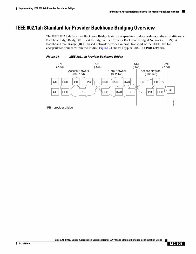
Implementing IEEE 802.1ah Provider Backbone BridgeInformation About Implementing 802.1ah Provider Backbone Bridge
LSC-305Cisco ASR 9000 Series Aggregation Services Router L2VPN and Ethernet Services Configuration Guide
OL-26116-02
IEEE 802.1ah Standard for Provider Backbone Bridging OverviewThe IEEE 802.1ah Provider Backbone Bridge feature encapsulates or decapsulates end-user traffic on a Backbone Edge Bridge (BEB) at the edge of the Provider Backbone Bridged Network (PBBN). A Backbone Core Bridge (BCB) based network provides internal transport of the IEEE 802.1ah encapsulated frames within the PBBN. Figure 24 shows a typical 802.1ah PBB network.
Figure 24 IEEE 802.1ah Provider Backbone Bridge
Access Network(802.1ad)
Access Network(802.1ad)
UNI(.1ad)
UNI(.1ah)
UNI(.1ah)
UNI(.1ad)
Core Network(802.1ah)
CE PEB PB PB PB
CECE
PEB PEBPB PB
PB BEB
BEB BEB
BCB
BCB
BCB
PB - provider bridge
2817
89
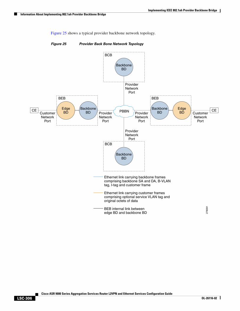
Implementing IEEE 802.1ah Provider Backbone BridgeInformation About Implementing 802.1ah Provider Backbone Bridge
LSC-306Cisco ASR 9000 Series Aggregation Services Router L2VPN and Ethernet Services Configuration Guide
OL-26116-02
Figure 25 shows a typical provider backbone network topology.
Figure 25 Provider Back Bone Network Topology
Ethernet link carrying backbone framescomprising backbone SA and DA, B-VLANtag, I-tag and customer frame
Ethernet link carrying customer framescomprising optional service VLAN tag andoriginal octets of data
BEB internal link betweenedge BD and backbone BD 27
8091
BackboneBD
BEB BEB
CE CEBackboneBD
EdgeBD
BackboneBD
EdgeBD
BackboneBD
BCB
BCB
ProviderNetwork
Port
ProviderNetwork
Port
ProviderNetwork
Port
ProviderNetwork
Port
CustomerNetwork
Port
CustomerNetwork
Port
PBBN
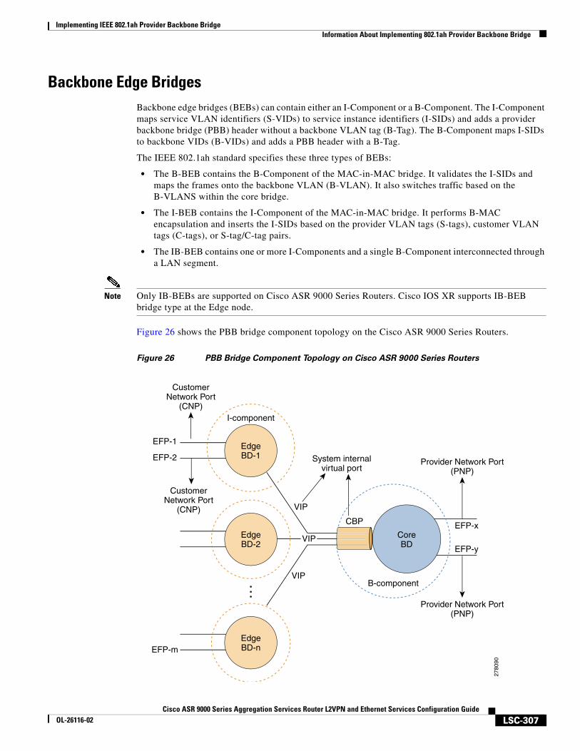
Implementing IEEE 802.1ah Provider Backbone BridgeInformation About Implementing 802.1ah Provider Backbone Bridge
LSC-307Cisco ASR 9000 Series Aggregation Services Router L2VPN and Ethernet Services Configuration Guide
OL-26116-02
Backbone Edge BridgesBackbone edge bridges (BEBs) can contain either an I-Component or a B-Component. The I-Component maps service VLAN identifiers (S-VIDs) to service instance identifiers (I-SIDs) and adds a provider backbone bridge (PBB) header without a backbone VLAN tag (B-Tag). The B-Component maps I-SIDs to backbone VIDs (B-VIDs) and adds a PBB header with a B-Tag.
The IEEE 802.1ah standard specifies these three types of BEBs:
• The B-BEB contains the B-Component of the MAC-in-MAC bridge. It validates the I-SIDs and maps the frames onto the backbone VLAN (B-VLAN). It also switches traffic based on the B-VLANS within the core bridge.
• The I-BEB contains the I-Component of the MAC-in-MAC bridge. It performs B-MAC encapsulation and inserts the I-SIDs based on the provider VLAN tags (S-tags), customer VLAN tags (C-tags), or S-tag/C-tag pairs.
• The IB-BEB contains one or more I-Components and a single B-Component interconnected through a LAN segment.
Note Only IB-BEBs are supported on Cisco ASR 9000 Series Routers. Cisco IOS XR supports IB-BEB bridge type at the Edge node.
Figure 26 shows the PBB bridge component topology on the Cisco ASR 9000 Series Routers.
Figure 26 PBB Bridge Component Topology on Cisco ASR 9000 Series Routers
I-component
Provider Network Port(PNP)
CoreBD
B-component
CBP
VIP
VIP
VIP
EdgeBD-1
EdgeBD-2
EdgeBD-n
Provider Network Port(PNP)
EFP-x
EFP-y
EFP-1
EFP-2
EFP-m
System internalvirtual port
CustomerNetwork Port
(CNP)
CustomerNetwork Port
(CNP)
2780
90
Implementing IEEE 802.1ah Provider Backbone BridgeInformation About Implementing 802.1ah Provider Backbone Bridge
LSC-308Cisco ASR 9000 Series Aggregation Services Router L2VPN and Ethernet Services Configuration Guide
OL-26116-02
IB-BEBThe IB-BEB contains both the I-Component and the B-Component. The bridge selects the B-MAC and inserts the I-SID based on the provider VLAN tag (S-tag), the customer VLAN tag (C-tag), or both the S-tag and the C-tag. It validates the I-SIDs and it transmits and receives frames on the B-VLAN.
The IEEE 802.1ah on Provider Backbone Bridges feature supports all services mandated by the IEEE 802.1ah standard and extends the services to provides these additional functionalities:
• S-Tagged Service:
– In multiplexed environments each S-tag maps to an I-SID and may be retained or removed.
– In bundled environments multiple S-tags map to the same I-SID and the S-tags must be retained.
• C-Tagged Service:
– In multiplexed environments each C-tag maps to an I-SID and may be retained or removed.
– In bundled environments multiple C-tags map to the same I-SID and the C-tags must be retained.
• S/C-Tagged Service:
– In multiplexed environments each S-tag/C-tag pair maps to an I-SID. The S-tag or the S-tag/C-tag pair may be retained or removed.
– In bundled environments multiple S-tag/C-tags pairs map to the same I-SID and the S-tag/C-tag pair must be retained.
• Port-based Service
– A port-based service interface is delivered on a Customer Network Port (CNP). A port-based service interface may attach to a C-VLAN Bridge, 802.1d bridge, router or end-station. The service provided by this interface forwards all frames without an S-Tag over the backbone on a single backbone service instance. A port-based interface discards all frames with an S-Tag that have non-null VLAN IDs.
This example shows how to configure a port-based service:
interface GigabitEthernet0/0/0/10.100 l2transport encapsulation untagged
--> Creates an EFP for untagged frames.
interface GigabitEthernet0/0/0/10.101 l2transportencapsulation dot1ad priority-tagged
--> Creates an EFP for null S-tagged frames.
interface GigabitEthernet0/0/0/10.102 l2transportencapsulation dot1q priority-tagged
--> Creates an EFP for null C-tagged frames:
interface GigabitEthernet0/0/0/10.103 l2transportencapsulation dot1q any
--> Creates an EFP for C-tagged frames:
Note To configure a port-based service, all the above EFPs must be added to the same edge bridge domain.
Implementing IEEE 802.1ah Provider Backbone BridgeHow to Implement 802.1ah Provider Backbone Bridge
LSC-309Cisco ASR 9000 Series Aggregation Services Router L2VPN and Ethernet Services Configuration Guide
OL-26116-02
How to Implement 802.1ah Provider Backbone BridgeThis section contains these procedures:
• Restrictions for Implementing 802.1ah Provider Backbone Bridge, page 309
• Configuring Ethernet Flow Points on CNP and PNP Ports, page 309
• Configuring PBB Edge Bridge Domain and Service Instance ID, page 311
• Configuring the PBB Core Bridge Domain, page 313
• Configuring Backbone VLAN Tag under the PBB Core Bridge Domain, page 314
• Configuring Backbone Source MAC Address, page 316 (optional)
• Configuring Unknown Unicast Backbone MAC under PBB Edge Bridge Domain, page 319 (optional)
• Configuring Static MAC addresses under PBB Edge Bridge Domain, page 321 (optional)
Restrictions for Implementing 802.1ah Provider Backbone BridgeThese features are not supported:
• Cross-connect based point to point services over MAC-in-MAC
• One Edge bridge to multiple Core bridge mapping
• I type backbone edge bridge (I-BEB) and B type backbone edge bridge (B-BEB)
• IEEE 802.1ah over VPLS
• Multiple source B-MAC addresses per chassis
• Direct encapsulation of 802.1ah formatted packets natively over an MPLS LSP encapsulation
Configuring Ethernet Flow Points on CNP and PNP PortsPerform this task to configure an Ethernet flow point (EFP) on the customer network port (CNP) or the provider network port (PNP).
SUMMARY STEPS
1. configure
2. interface type interface-path-id.subinterface l2transport
3. encapsulation dot1q vlan-idorencapsulation dot1ad vlan-idorencapsulation dot1ad vlan-id dot1q vlan-id
4. endorcommit
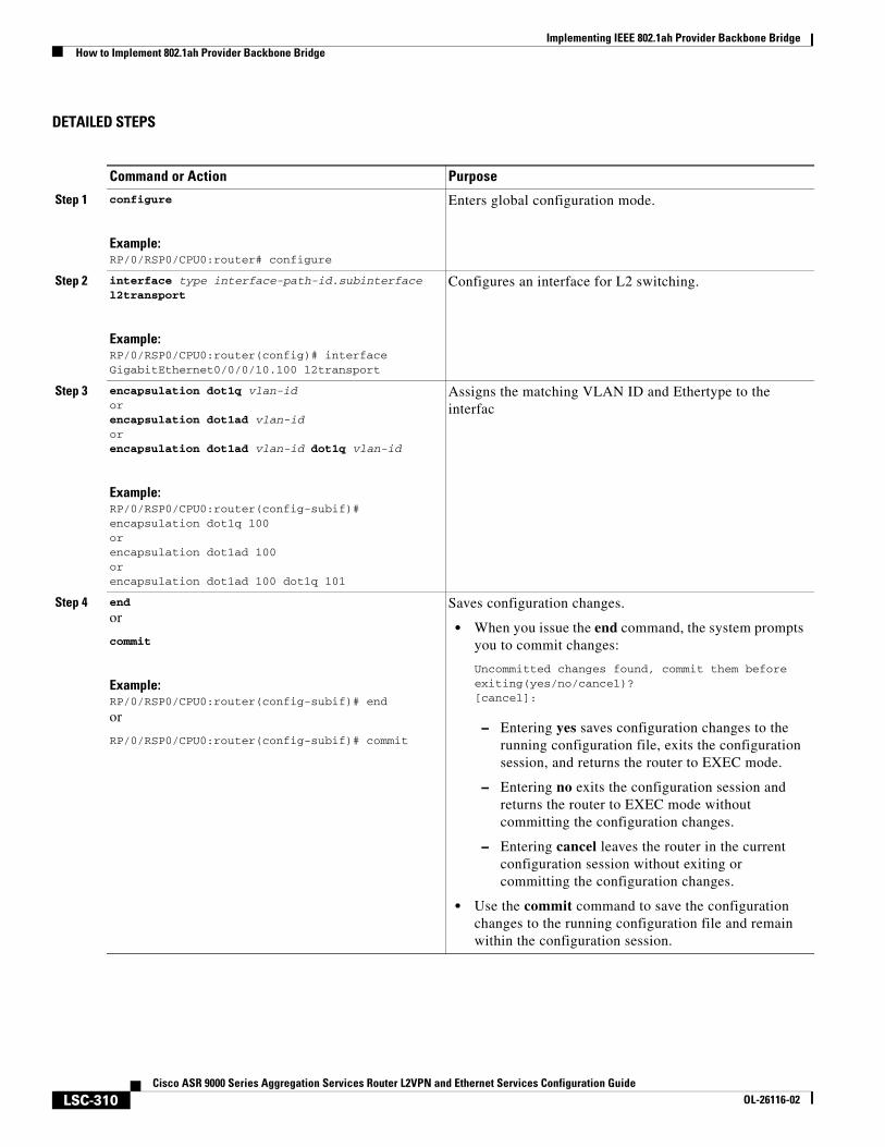
Implementing IEEE 802.1ah Provider Backbone BridgeHow to Implement 802.1ah Provider Backbone Bridge
LSC-310Cisco ASR 9000 Series Aggregation Services Router L2VPN and Ethernet Services Configuration Guide
OL-26116-02
DETAILED STEPS
Command or Action Purpose
Step 1 configure
Example:RP/0/RSP0/CPU0:router# configure
Enters global configuration mode.
Step 2 interface type interface-path-id.subinterface l2transport
Example:RP/0/RSP0/CPU0:router(config)# interface GigabitEthernet0/0/0/10.100 l2transport
Configures an interface for L2 switching.
Step 3 encapsulation dot1q vlan-idorencapsulation dot1ad vlan-idorencapsulation dot1ad vlan-id dot1q vlan-id
Example:RP/0/RSP0/CPU0:router(config-subif)# encapsulation dot1q 100orencapsulation dot1ad 100orencapsulation dot1ad 100 dot1q 101
Assigns the matching VLAN ID and Ethertype to the interfac
Step 4 end
or
commit
Example:RP/0/RSP0/CPU0:router(config-subif)# end
or
RP/0/RSP0/CPU0:router(config-subif)# commit
Saves configuration changes.
• When you issue the end command, the system prompts you to commit changes:
Uncommitted changes found, commit them before exiting(yes/no/cancel)?[cancel]:
– Entering yes saves configuration changes to the running configuration file, exits the configuration session, and returns the router to EXEC mode.
– Entering no exits the configuration session and returns the router to EXEC mode without committing the configuration changes.
– Entering cancel leaves the router in the current configuration session without exiting or committing the configuration changes.
• Use the commit command to save the configuration changes to the running configuration file and remain within the configuration session.
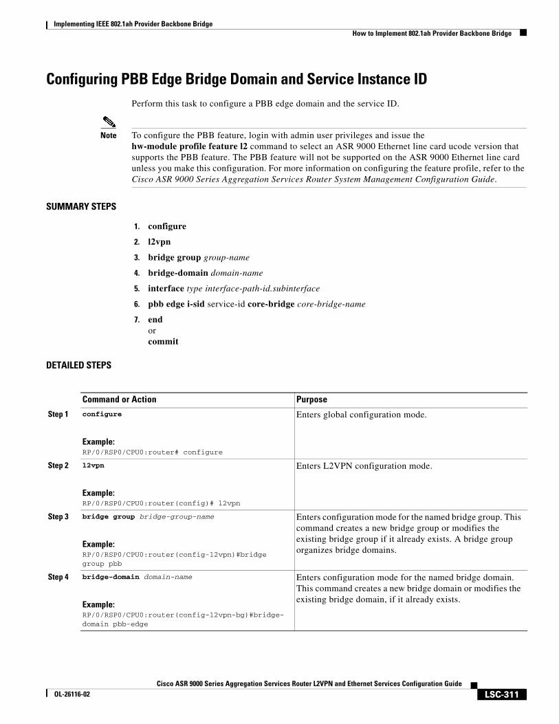
Implementing IEEE 802.1ah Provider Backbone BridgeHow to Implement 802.1ah Provider Backbone Bridge
LSC-311Cisco ASR 9000 Series Aggregation Services Router L2VPN and Ethernet Services Configuration Guide
OL-26116-02
Configuring PBB Edge Bridge Domain and Service Instance IDPerform this task to configure a PBB edge domain and the service ID.
Note To configure the PBB feature, login with admin user privileges and issue the hw-module profile feature l2 command to select an ASR 9000 Ethernet line card ucode version that supports the PBB feature. The PBB feature will not be supported on the ASR 9000 Ethernet line card unless you make this configuration. For more information on configuring the feature profile, refer to the Cisco ASR 9000 Series Aggregation Services Router System Management Configuration Guide.
SUMMARY STEPS
1. configure
2. l2vpn
3. bridge group group-name
4. bridge-domain domain-name
5. interface type interface-path-id.subinterface
6. pbb edge i-sid service-id core-bridge core-bridge-name
7. endorcommit
DETAILED STEPS
Command or Action Purpose
Step 1 configure
Example:RP/0/RSP0/CPU0:router# configure
Enters global configuration mode.
Step 2 l2vpn
Example:RP/0/RSP0/CPU0:router(config)# l2vpn
Enters L2VPN configuration mode.
Step 3 bridge group bridge-group-name
Example:RP/0/RSP0/CPU0:router(config-l2vpn)#bridge group pbb
Enters configuration mode for the named bridge group. This command creates a new bridge group or modifies the existing bridge group if it already exists. A bridge group organizes bridge domains.
Step 4 bridge-domain domain-name
Example:RP/0/RSP0/CPU0:router(config-l2vpn-bg)#bridge-domain pbb-edge
Enters configuration mode for the named bridge domain. This command creates a new bridge domain or modifies the existing bridge domain, if it already exists.
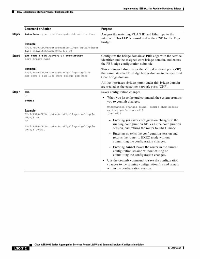
Implementing IEEE 802.1ah Provider Backbone BridgeHow to Implement 802.1ah Provider Backbone Bridge
LSC-312Cisco ASR 9000 Series Aggregation Services Router L2VPN and Ethernet Services Configuration Guide
OL-26116-02
Step 5 interface type interface-path-id.subinterface
Example:RP/0/RSP0/CPU0:router(config-l2vpn-bg-bd)#interface GigabitEthernet0/5/0/0.20
Assigns the matching VLAN ID and Ethertype to the interface. This EFP is considered as the CNP for the Edge bridge.
Step 6 pbb edge i-sid service-id core-bridge core-bridge-name
Example:RP/0/RSP0/CPU0:router(config-l2vpn-bg-bd)#pbb edge i-sid 1000 core-bridge pbb-core
Configures the bridge domain as PBB edge with the service identifier and the assigned core bridge domain, and enters the PBB edge configuration submode.
This command also creates the Virtual instance port (VIP) that associates the PBB Edge bridge domain to the specified Core bridge domain.
All the interfaces (bridge ports) under this bridge domain are treated as the customer network ports (CNP).
Step 7 end
or
commit
Example:RP/0/RSP0/CPU0:router(config-l2vpn-bg-bd-pbb-edge)# end
or
RP/0/RSP0/CPU0:router(config-l2vpn-bg-bd-pbb-edge)# commit
Saves configuration changes.
• When you issue the end command, the system prompts you to commit changes:
Uncommitted changes found, commit them before exiting(yes/no/cancel)?[cancel]:
– Entering yes saves configuration changes to the running configuration file, exits the configuration session, and returns the router to EXEC mode.
– Entering no exits the configuration session and returns the router to EXEC mode without committing the configuration changes.
– Entering cancel leaves the router in the current configuration session without exiting or committing the configuration changes.
• Use the commit command to save the configuration changes to the running configuration file and remain within the configuration session.
Command or Action Purpose
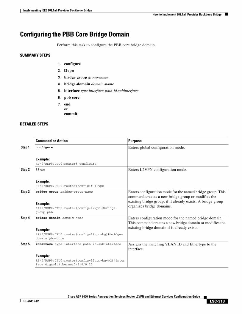
Implementing IEEE 802.1ah Provider Backbone BridgeHow to Implement 802.1ah Provider Backbone Bridge
LSC-313Cisco ASR 9000 Series Aggregation Services Router L2VPN and Ethernet Services Configuration Guide
OL-26116-02
Configuring the PBB Core Bridge DomainPerform this task to configure the PBB core bridge domain.
SUMMARY STEPS
1. configure
2. l2vpn
3. bridge group group-name
4. bridge-domain domain-name
5. interface type interface-path-id.subinterface
6. pbb core
7. endorcommit
DETAILED STEPS
Command or Action Purpose
Step 1 configure
Example:RP/0/RSP0/CPU0:router# configure
Enters global configuration mode.
Step 2 l2vpn
Example:RP/0/RSP0/CPU0:router(config)# l2vpn
Enters L2VPN configuration mode.
Step 3 bridge group bridge-group-name
Example:RP/0/RSP0/CPU0:router(config-l2vpn)#bridge group pbb
Enters configuration mode for the named bridge group. This command creates a new bridge group or modifies the existing bridge group, if it already exists. A bridge group organizes bridge domains.
Step 4 bridge-domain domain-name
Example:RP/0/RSP0/CPU0:router(config-l2vpn-bg)#bridge-domain pbb-core
Enters configuration mode for the named bridge domain. This command creates a new bridge domain or modifies the existing bridge domain if it already exists.
Step 5 interface type interface-path-id.subinterface
Example:RP/0/RSP0/CPU0:router(config-l2vpn-bg-bd)#interface GigabitEthernet0/5/0/0.20
Assigns the matching VLAN ID and Ethertype to the interface.
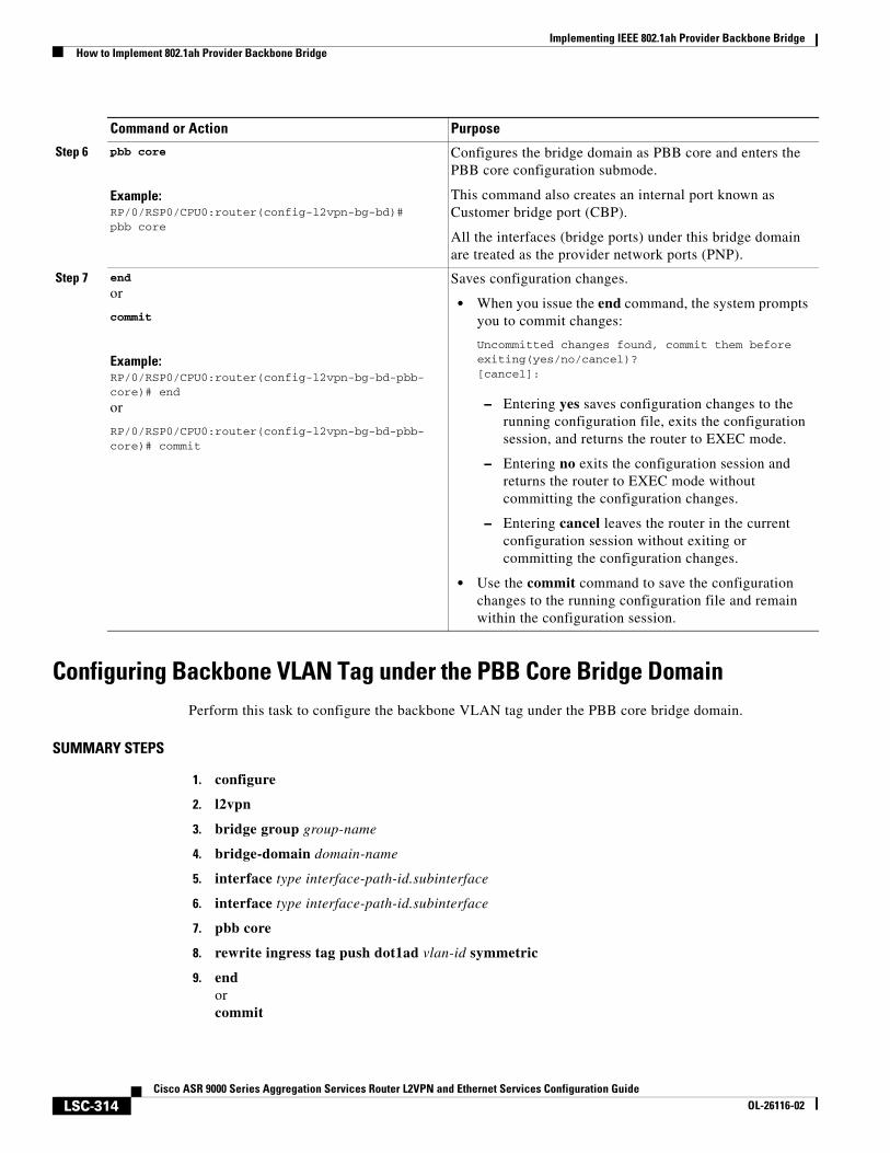
Implementing IEEE 802.1ah Provider Backbone BridgeHow to Implement 802.1ah Provider Backbone Bridge
LSC-314Cisco ASR 9000 Series Aggregation Services Router L2VPN and Ethernet Services Configuration Guide
OL-26116-02
Configuring Backbone VLAN Tag under the PBB Core Bridge DomainPerform this task to configure the backbone VLAN tag under the PBB core bridge domain.
SUMMARY STEPS
1. configure
2. l2vpn
3. bridge group group-name
4. bridge-domain domain-name
5. interface type interface-path-id.subinterface
6. interface type interface-path-id.subinterface
7. pbb core
8. rewrite ingress tag push dot1ad vlan-id symmetric
9. endorcommit
Step 6 pbb core
Example:RP/0/RSP0/CPU0:router(config-l2vpn-bg-bd)#pbb core
Configures the bridge domain as PBB core and enters the PBB core configuration submode.
This command also creates an internal port known as Customer bridge port (CBP).
All the interfaces (bridge ports) under this bridge domain are treated as the provider network ports (PNP).
Step 7 end
or
commit
Example:RP/0/RSP0/CPU0:router(config-l2vpn-bg-bd-pbb-core)# end
or
RP/0/RSP0/CPU0:router(config-l2vpn-bg-bd-pbb-core)# commit
Saves configuration changes.
• When you issue the end command, the system prompts you to commit changes:
Uncommitted changes found, commit them before exiting(yes/no/cancel)?[cancel]:
– Entering yes saves configuration changes to the running configuration file, exits the configuration session, and returns the router to EXEC mode.
– Entering no exits the configuration session and returns the router to EXEC mode without committing the configuration changes.
– Entering cancel leaves the router in the current configuration session without exiting or committing the configuration changes.
• Use the commit command to save the configuration changes to the running configuration file and remain within the configuration session.
Command or Action Purpose
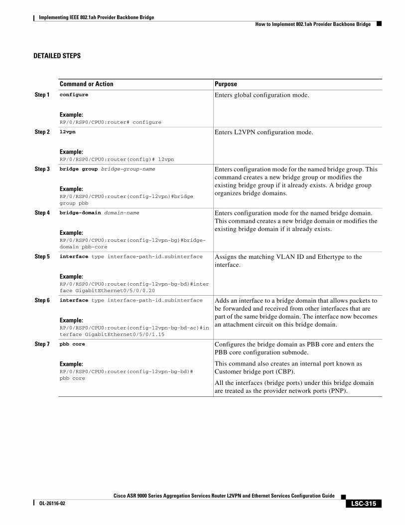
Implementing IEEE 802.1ah Provider Backbone BridgeHow to Implement 802.1ah Provider Backbone Bridge
LSC-315Cisco ASR 9000 Series Aggregation Services Router L2VPN and Ethernet Services Configuration Guide
OL-26116-02
DETAILED STEPS
Command or Action Purpose
Step 1 configure
Example:RP/0/RSP0/CPU0:router# configure
Enters global configuration mode.
Step 2 l2vpn
Example:RP/0/RSP0/CPU0:router(config)# l2vpn
Enters L2VPN configuration mode.
Step 3 bridge group bridge-group-name
Example:RP/0/RSP0/CPU0:router(config-l2vpn)#bridge group pbb
Enters configuration mode for the named bridge group. This command creates a new bridge group or modifies the existing bridge group if it already exists. A bridge group organizes bridge domains.
Step 4 bridge-domain domain-name
Example:RP/0/RSP0/CPU0:router(config-l2vpn-bg)#bridge-domain pbb-core
Enters configuration mode for the named bridge domain. This command creates a new bridge domain or modifies the existing bridge domain if it already exists.
Step 5 interface type interface-path-id.subinterface
Example:RP/0/RSP0/CPU0:router(config-l2vpn-bg-bd)#interface GigabitEthernet0/5/0/0.20
Assigns the matching VLAN ID and Ethertype to the interface.
Step 6 interface type interface-path-id.subinterface
Example:RP/0/RSP0/CPU0:router(config-l2vpn-bg-bd-ac)#interface GigabitEthernet0/5/0/1.15
Adds an interface to a bridge domain that allows packets to be forwarded and received from other interfaces that are part of the same bridge domain. The interface now becomes an attachment circuit on this bridge domain.
Step 7 pbb core
Example:RP/0/RSP0/CPU0:router(config-l2vpn-bg-bd)#pbb core
Configures the bridge domain as PBB core and enters the PBB core configuration submode.
This command also creates an internal port known as Customer bridge port (CBP).
All the interfaces (bridge ports) under this bridge domain are treated as the provider network ports (PNP).
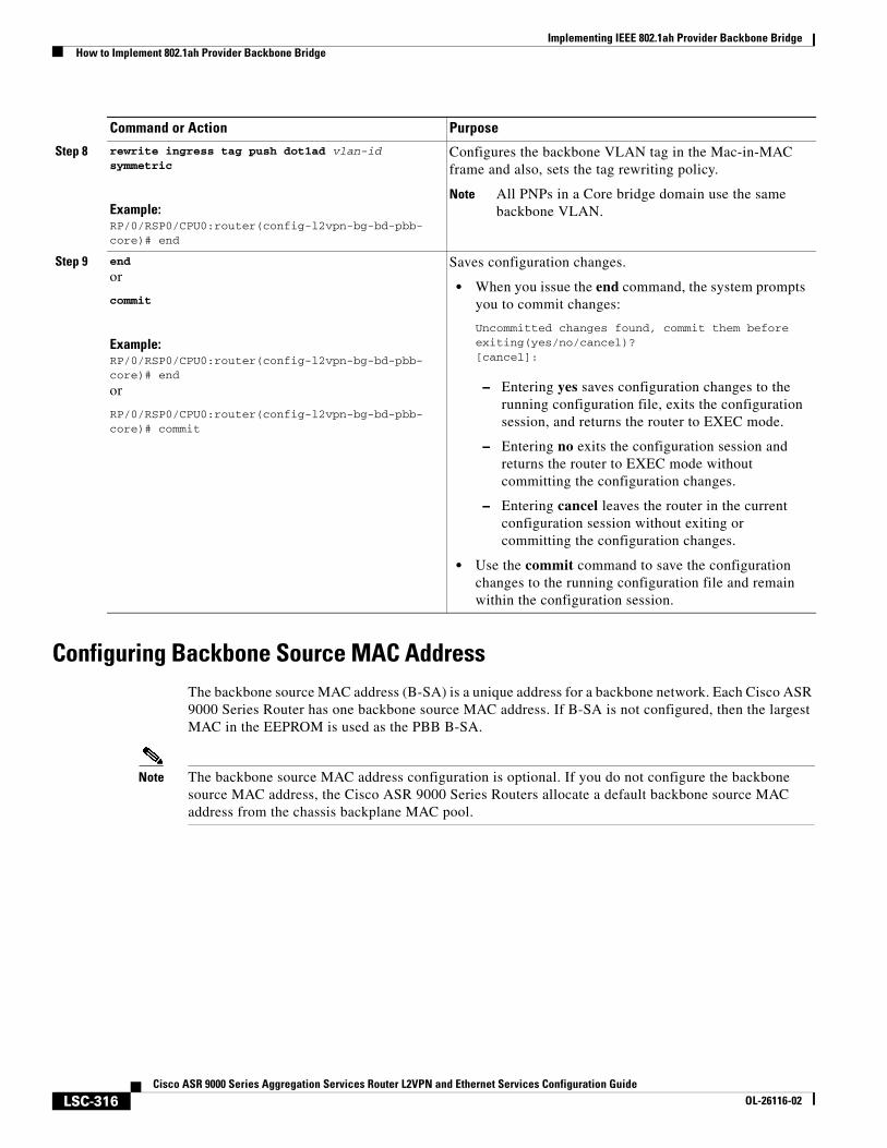
Implementing IEEE 802.1ah Provider Backbone BridgeHow to Implement 802.1ah Provider Backbone Bridge
LSC-316Cisco ASR 9000 Series Aggregation Services Router L2VPN and Ethernet Services Configuration Guide
OL-26116-02
Configuring Backbone Source MAC AddressThe backbone source MAC address (B-SA) is a unique address for a backbone network. Each Cisco ASR 9000 Series Router has one backbone source MAC address. If B-SA is not configured, then the largest MAC in the EEPROM is used as the PBB B-SA.
Note The backbone source MAC address configuration is optional. If you do not configure the backbone source MAC address, the Cisco ASR 9000 Series Routers allocate a default backbone source MAC address from the chassis backplane MAC pool.
Step 8 rewrite ingress tag push dot1ad vlan-id symmetric
Example:RP/0/RSP0/CPU0:router(config-l2vpn-bg-bd-pbb-core)# end
Configures the backbone VLAN tag in the Mac-in-MAC frame and also, sets the tag rewriting policy.
Note All PNPs in a Core bridge domain use the same backbone VLAN.
Step 9 end
or
commit
Example:RP/0/RSP0/CPU0:router(config-l2vpn-bg-bd-pbb-core)# end
or
RP/0/RSP0/CPU0:router(config-l2vpn-bg-bd-pbb-core)# commit
Saves configuration changes.
• When you issue the end command, the system prompts you to commit changes:
Uncommitted changes found, commit them before exiting(yes/no/cancel)?[cancel]:
– Entering yes saves configuration changes to the running configuration file, exits the configuration session, and returns the router to EXEC mode.
– Entering no exits the configuration session and returns the router to EXEC mode without committing the configuration changes.
– Entering cancel leaves the router in the current configuration session without exiting or committing the configuration changes.
• Use the commit command to save the configuration changes to the running configuration file and remain within the configuration session.
Command or Action Purpose
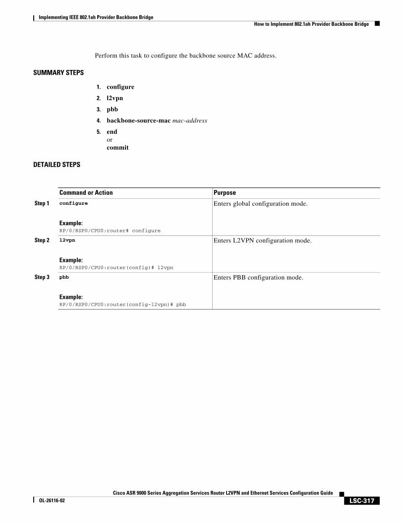
Implementing IEEE 802.1ah Provider Backbone BridgeHow to Implement 802.1ah Provider Backbone Bridge
LSC-317Cisco ASR 9000 Series Aggregation Services Router L2VPN and Ethernet Services Configuration Guide
OL-26116-02
Perform this task to configure the backbone source MAC address.
SUMMARY STEPS
1. configure
2. l2vpn
3. pbb
4. backbone-source-mac mac-address
5. endorcommit
DETAILED STEPS
Command or Action Purpose
Step 1 configure
Example:RP/0/RSP0/CPU0:router# configure
Enters global configuration mode.
Step 2 l2vpn
Example:RP/0/RSP0/CPU0:router(config)# l2vpn
Enters L2VPN configuration mode.
Step 3 pbb
Example:RP/0/RSP0/CPU0:router(config-l2vpn)# pbb
Enters PBB configuration mode.
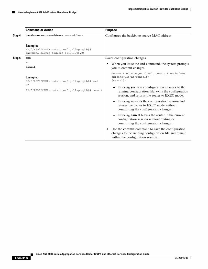
Implementing IEEE 802.1ah Provider Backbone BridgeHow to Implement 802.1ah Provider Backbone Bridge
LSC-318Cisco ASR 9000 Series Aggregation Services Router L2VPN and Ethernet Services Configuration Guide
OL-26116-02
Step 4 backbone-source-address mac-address
Example:RP/0/RSP0/CPU0:router(config-l2vpn-pbb)# backbone-source-address 0045.1200.04
Configures the backbone source MAC address.
Step 5 end
or
commit
Example:RP/0/RSP0/CPU0:router(config-l2vpn-pbb)# end
or
RP/0/RSP0/CPU0:router(config-l2vpn-pbb)# commit
Saves configuration changes.
• When you issue the end command, the system prompts you to commit changes:
Uncommitted changes found, commit them before exiting(yes/no/cancel)?[cancel]:
– Entering yes saves configuration changes to the running configuration file, exits the configuration session, and returns the router to EXEC mode.
– Entering no exits the configuration session and returns the router to EXEC mode without committing the configuration changes.
– Entering cancel leaves the router in the current configuration session without exiting or committing the configuration changes.
• Use the commit command to save the configuration changes to the running configuration file and remain within the configuration session.
Command or Action Purpose
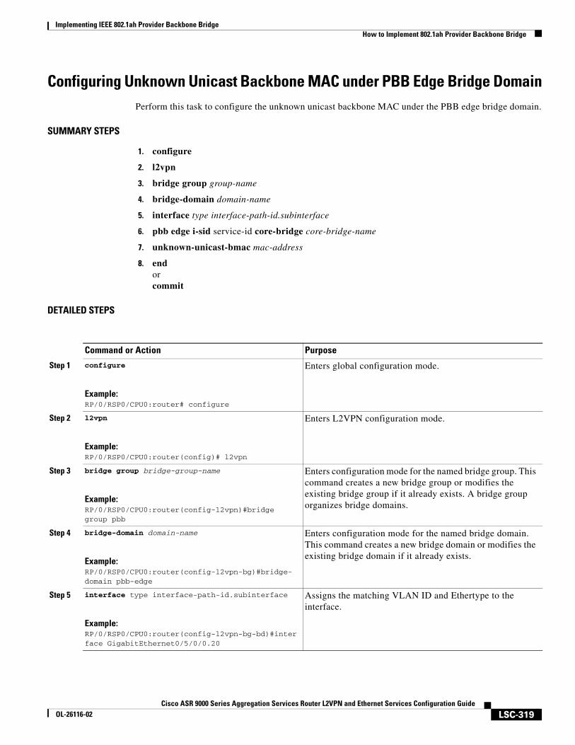
Implementing IEEE 802.1ah Provider Backbone BridgeHow to Implement 802.1ah Provider Backbone Bridge
LSC-319Cisco ASR 9000 Series Aggregation Services Router L2VPN and Ethernet Services Configuration Guide
OL-26116-02
Configuring Unknown Unicast Backbone MAC under PBB Edge Bridge DomainPerform this task to configure the unknown unicast backbone MAC under the PBB edge bridge domain.
SUMMARY STEPS
1. configure
2. l2vpn
3. bridge group group-name
4. bridge-domain domain-name
5. interface type interface-path-id.subinterface
6. pbb edge i-sid service-id core-bridge core-bridge-name
7. unknown-unicast-bmac mac-address
8. endorcommit
DETAILED STEPS
Command or Action Purpose
Step 1 configure
Example:RP/0/RSP0/CPU0:router# configure
Enters global configuration mode.
Step 2 l2vpn
Example:RP/0/RSP0/CPU0:router(config)# l2vpn
Enters L2VPN configuration mode.
Step 3 bridge group bridge-group-name
Example:RP/0/RSP0/CPU0:router(config-l2vpn)#bridge group pbb
Enters configuration mode for the named bridge group. This command creates a new bridge group or modifies the existing bridge group if it already exists. A bridge group organizes bridge domains.
Step 4 bridge-domain domain-name
Example:RP/0/RSP0/CPU0:router(config-l2vpn-bg)#bridge-domain pbb-edge
Enters configuration mode for the named bridge domain. This command creates a new bridge domain or modifies the existing bridge domain if it already exists.
Step 5 interface type interface-path-id.subinterface
Example:RP/0/RSP0/CPU0:router(config-l2vpn-bg-bd)#interface GigabitEthernet0/5/0/0.20
Assigns the matching VLAN ID and Ethertype to the interface.
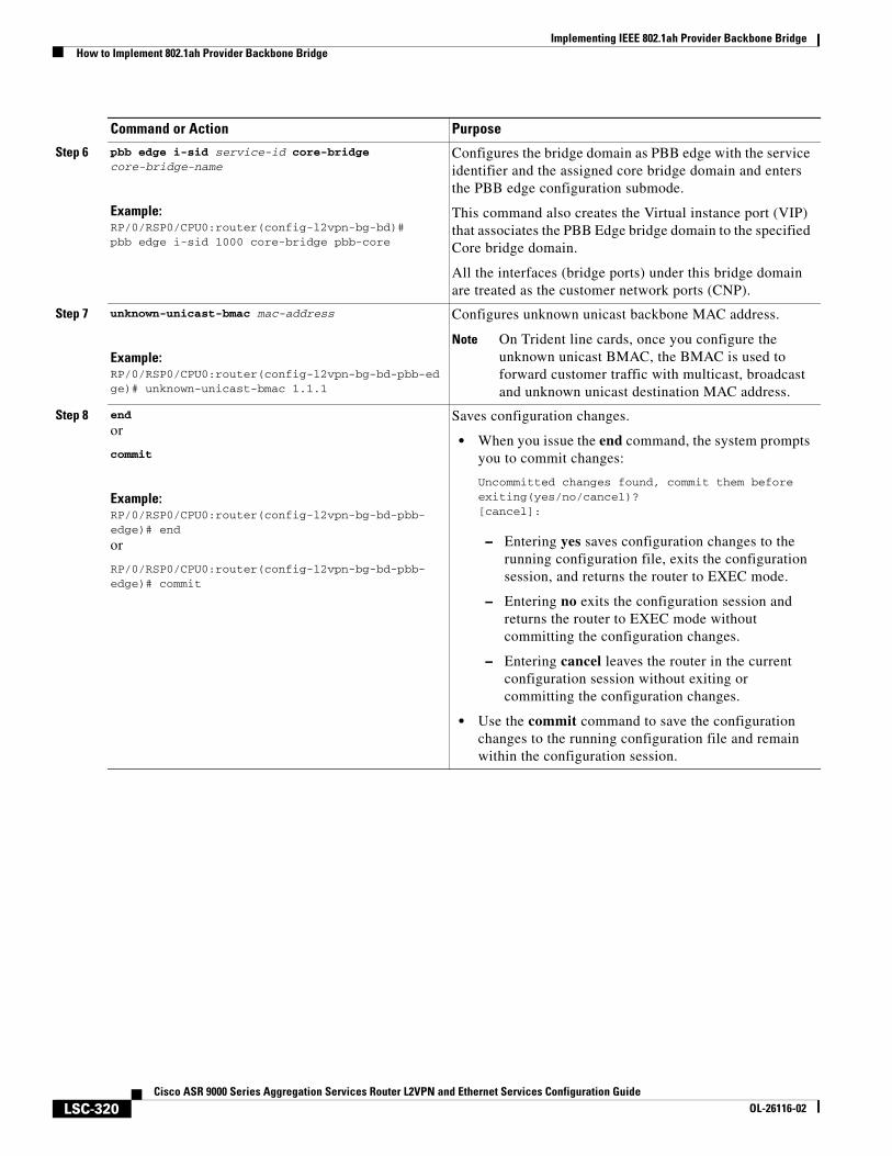
Implementing IEEE 802.1ah Provider Backbone BridgeHow to Implement 802.1ah Provider Backbone Bridge
LSC-320Cisco ASR 9000 Series Aggregation Services Router L2VPN and Ethernet Services Configuration Guide
OL-26116-02
Step 6 pbb edge i-sid service-id core-bridge core-bridge-name
Example:RP/0/RSP0/CPU0:router(config-l2vpn-bg-bd)#pbb edge i-sid 1000 core-bridge pbb-core
Configures the bridge domain as PBB edge with the service identifier and the assigned core bridge domain and enters the PBB edge configuration submode.
This command also creates the Virtual instance port (VIP) that associates the PBB Edge bridge domain to the specified Core bridge domain.
All the interfaces (bridge ports) under this bridge domain are treated as the customer network ports (CNP).
Step 7 unknown-unicast-bmac mac-address
Example:RP/0/RSP0/CPU0:router(config-l2vpn-bg-bd-pbb-edge)# unknown-unicast-bmac 1.1.1
Configures unknown unicast backbone MAC address.
Note On Trident line cards, once you configure the unknown unicast BMAC, the BMAC is used to forward customer traffic with multicast, broadcast and unknown unicast destination MAC address.
Step 8 end
or
commit
Example:RP/0/RSP0/CPU0:router(config-l2vpn-bg-bd-pbb-edge)# end
or
RP/0/RSP0/CPU0:router(config-l2vpn-bg-bd-pbb-edge)# commit
Saves configuration changes.
• When you issue the end command, the system prompts you to commit changes:
Uncommitted changes found, commit them before exiting(yes/no/cancel)?[cancel]:
– Entering yes saves configuration changes to the running configuration file, exits the configuration session, and returns the router to EXEC mode.
– Entering no exits the configuration session and returns the router to EXEC mode without committing the configuration changes.
– Entering cancel leaves the router in the current configuration session without exiting or committing the configuration changes.
• Use the commit command to save the configuration changes to the running configuration file and remain within the configuration session.
Command or Action Purpose
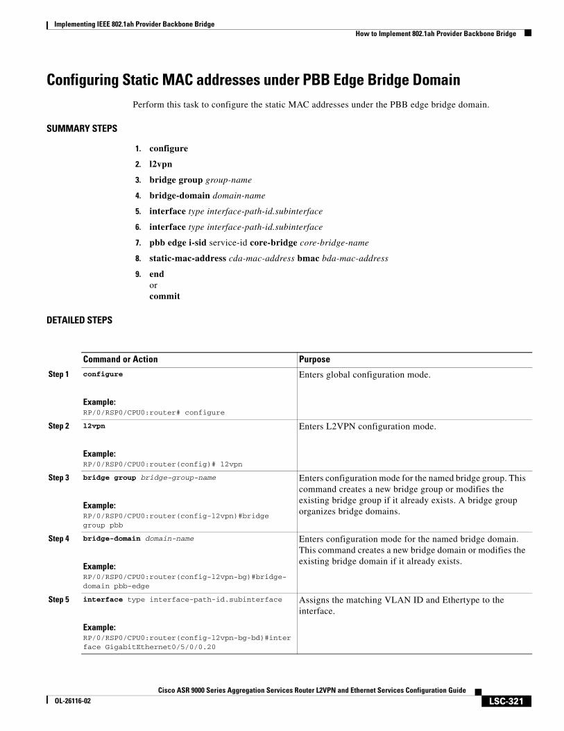
Implementing IEEE 802.1ah Provider Backbone BridgeHow to Implement 802.1ah Provider Backbone Bridge
LSC-321Cisco ASR 9000 Series Aggregation Services Router L2VPN and Ethernet Services Configuration Guide
OL-26116-02
Configuring Static MAC addresses under PBB Edge Bridge DomainPerform this task to configure the static MAC addresses under the PBB edge bridge domain.
SUMMARY STEPS
1. configure
2. l2vpn
3. bridge group group-name
4. bridge-domain domain-name
5. interface type interface-path-id.subinterface
6. interface type interface-path-id.subinterface
7. pbb edge i-sid service-id core-bridge core-bridge-name
8. static-mac-address cda-mac-address bmac bda-mac-address
9. endorcommit
DETAILED STEPS
Command or Action Purpose
Step 1 configure
Example:RP/0/RSP0/CPU0:router# configure
Enters global configuration mode.
Step 2 l2vpn
Example:RP/0/RSP0/CPU0:router(config)# l2vpn
Enters L2VPN configuration mode.
Step 3 bridge group bridge-group-name
Example:RP/0/RSP0/CPU0:router(config-l2vpn)#bridge group pbb
Enters configuration mode for the named bridge group. This command creates a new bridge group or modifies the existing bridge group if it already exists. A bridge group organizes bridge domains.
Step 4 bridge-domain domain-name
Example:RP/0/RSP0/CPU0:router(config-l2vpn-bg)#bridge-domain pbb-edge
Enters configuration mode for the named bridge domain. This command creates a new bridge domain or modifies the existing bridge domain if it already exists.
Step 5 interface type interface-path-id.subinterface
Example:RP/0/RSP0/CPU0:router(config-l2vpn-bg-bd)#interface GigabitEthernet0/5/0/0.20
Assigns the matching VLAN ID and Ethertype to the interface.
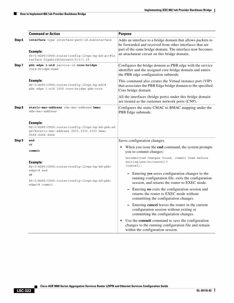
Implementing IEEE 802.1ah Provider Backbone BridgeHow to Implement 802.1ah Provider Backbone Bridge
LSC-322Cisco ASR 9000 Series Aggregation Services Router L2VPN and Ethernet Services Configuration Guide
OL-26116-02
Step 6 interface type interface-path-id.subinterface
Example:RP/0/RSP0/CPU0:router(config-l2vpn-bg-bd-ac)#interface GigabitEthernet0/5/0/1.15
Adds an interface to a bridge domain that allows packets to be forwarded and received from other interfaces that are part of the same bridge domain. The interface now becomes an attachment circuit on this bridge domain.
Step 7 pbb edge i-sid service-id core-bridge core-bridge-name
Example:RP/0/RSP0/CPU0:router(config-l2vpn-bg-bd)#pbb edge i-sid 1000 core-bridge pbb-core
Configures the bridge domain as PBB edge with the service identifier and the assigned core bridge domain and enters the PBB edge configuration submode.
This command also creates the Virtual instance port (VIP) that associates the PBB Edge bridge domain to the specified Core bridge domain.
All the interfaces (bridge ports) under this bridge domain are treated as the customer network ports (CNP).
Step 8 static-mac-address cda-mac-address bmac bda-mac-address
Example:RP/0/RSP0/CPU0:router(config-l2vpn-bg-bd-pbb-edge)#static-mac-address 0033.3333.3333 bmac 0044.4444.4444
Configures the static CMAC to BMAC mapping under the PBB Edge submode.
Step 9 end
or
commit
Example:RP/0/RSP0/CPU0:router(config-l2vpn-bg-bd-pbb-edge)# end
or
RP/0/RSP0/CPU0:router(config-l2vpn-bg-bd-pbb-edge)# commit
Saves configuration changes.
• When you issue the end command, the system prompts you to commit changes:
Uncommitted changes found, commit them before exiting(yes/no/cancel)?[cancel]:
– Entering yes saves configuration changes to the running configuration file, exits the configuration session, and returns the router to EXEC mode.
– Entering no exits the configuration session and returns the router to EXEC mode without committing the configuration changes.
– Entering cancel leaves the router in the current configuration session without exiting or committing the configuration changes.
• Use the commit command to save the configuration changes to the running configuration file and remain within the configuration session.
Command or Action Purpose
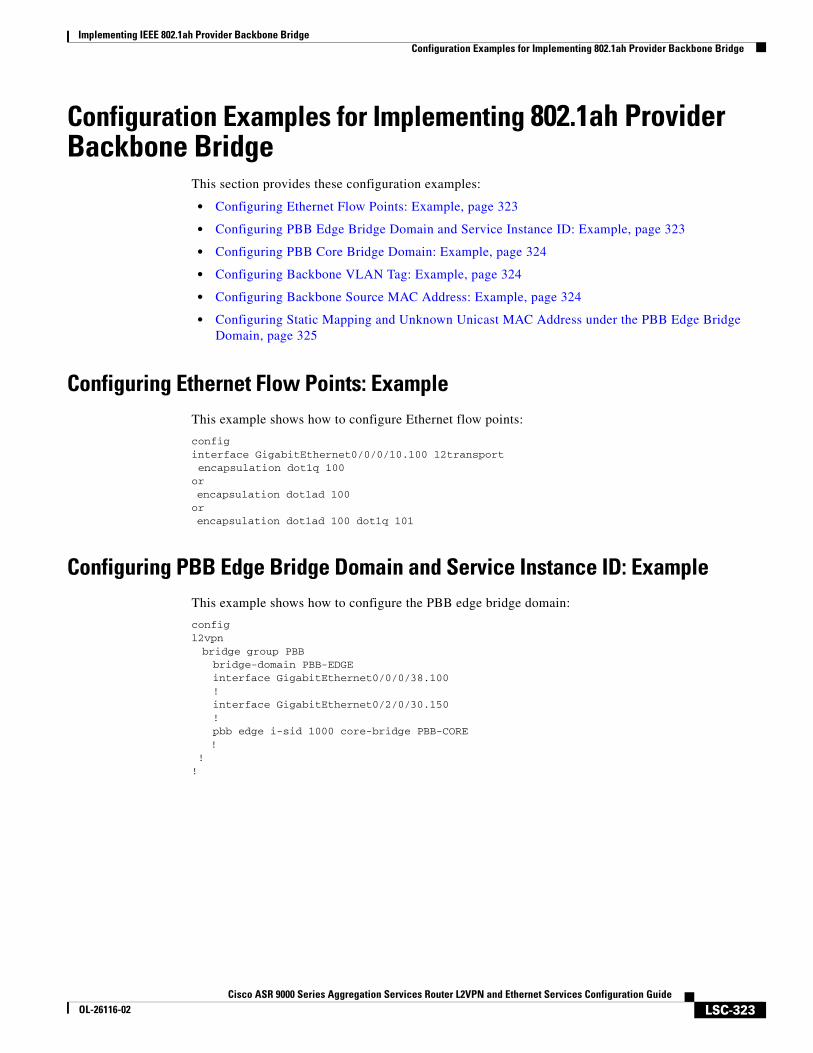
Implementing IEEE 802.1ah Provider Backbone BridgeConfiguration Examples for Implementing 802.1ah Provider Backbone Bridge
LSC-323Cisco ASR 9000 Series Aggregation Services Router L2VPN and Ethernet Services Configuration Guide
OL-26116-02
Configuration Examples for Implementing 802.1ah Provider Backbone Bridge
This section provides these configuration examples:
• Configuring Ethernet Flow Points: Example, page 323
• Configuring PBB Edge Bridge Domain and Service Instance ID: Example, page 323
• Configuring PBB Core Bridge Domain: Example, page 324
• Configuring Backbone VLAN Tag: Example, page 324
• Configuring Backbone Source MAC Address: Example, page 324
• Configuring Static Mapping and Unknown Unicast MAC Address under the PBB Edge Bridge Domain, page 325
Configuring Ethernet Flow Points: ExampleThis example shows how to configure Ethernet flow points:
configinterface GigabitEthernet0/0/0/10.100 l2transport encapsulation dot1q 100orencapsulation dot1ad 100or encapsulation dot1ad 100 dot1q 101
Configuring PBB Edge Bridge Domain and Service Instance ID: ExampleThis example shows how to configure the PBB edge bridge domain:
configl2vpnbridge group PBBbridge-domain PBB-EDGEinterface GigabitEthernet0/0/0/38.100!interface GigabitEthernet0/2/0/30.150!pbb edge i-sid 1000 core-bridge PBB-CORE
! !!
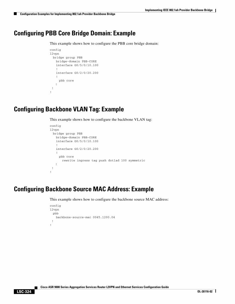
Implementing IEEE 802.1ah Provider Backbone BridgeConfiguration Examples for Implementing 802.1ah Provider Backbone Bridge
LSC-324Cisco ASR 9000 Series Aggregation Services Router L2VPN and Ethernet Services Configuration Guide
OL-26116-02
Configuring PBB Core Bridge Domain: ExampleThis example shows how to configure the PBB core bridge domain:
configl2vpnbridge group PBBbridge-domain PBB-COREinterface G0/5/0/10.100!interface G0/2/0/20.200!pbb core
! !!
Configuring Backbone VLAN Tag: ExampleThis example shows how to configure the backbone VLAN tag:
configl2vpnbridge group PBBbridge-domain PBB-COREinterface G0/5/0/10.100!interface G0/2/0/20.200!pbb corerewrite ingress tag push dot1ad 100 symmetric
! !!
Configuring Backbone Source MAC Address: ExampleThis example shows how to configure the backbone source MAC address:
configl2vpnpbbbackbone-source-mac 0045.1200.04
!!
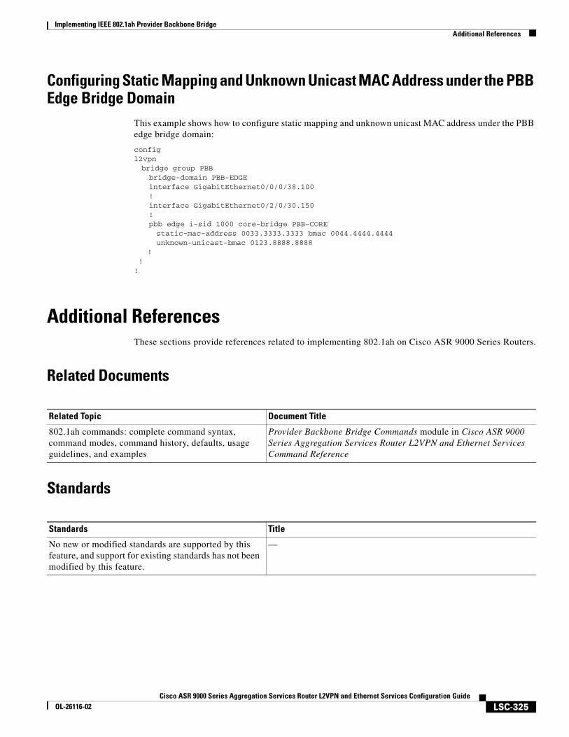
Implementing IEEE 802.1ah Provider Backbone BridgeAdditional References
LSC-325Cisco ASR 9000 Series Aggregation Services Router L2VPN and Ethernet Services Configuration Guide
OL-26116-02
Configuring Static Mapping and Unknown Unicast MAC Address under the PBB Edge Bridge Domain
This example shows how to configure static mapping and unknown unicast MAC address under the PBB edge bridge domain:
configl2vpnbridge group PBBbridge-domain PBB-EDGEinterface GigabitEthernet0/0/0/38.100!interface GigabitEthernet0/2/0/30.150!pbb edge i-sid 1000 core-bridge PBB-COREstatic-mac-address 0033.3333.3333 bmac 0044.4444.4444unknown-unicast-bmac 0123.8888.8888
! !!
Additional ReferencesThese sections provide references related to implementing 802.1ah on Cisco ASR 9000 Series Routers.
Related Documents
Standards
Related Topic Document Title
802.1ah commands: complete command syntax, command modes, command history, defaults, usage guidelines, and examples
Provider Backbone Bridge Commands module in Cisco ASR 9000 Series Aggregation Services Router L2VPN and Ethernet Services Command Reference
Standards Title
No new or modified standards are supported by this feature, and support for existing standards has not been modified by this feature.
—
Implementing IEEE 802.1ah Provider Backbone BridgeAdditional References
LSC-326Cisco ASR 9000 Series Aggregation Services Router L2VPN and Ethernet Services Configuration Guide
OL-26116-02
MIBs
RFCs
Technical Assistance
MIBs MIBs Link
— To locate and download MIBs using Cisco IOS XR software, use the Cisco MIB Locator found at this URL and choose a platform under the Cisco Access Products menu: http://cisco.com/public/sw-center/netmgmt/cmtk/mibs.shtml
RFCs Title
No new or modified RFCs are supported by this feature, and support for existing RFCs has not been modified by this feature.
—
Description Link
The Cisco Technical Support website contains thousands of pages of searchable technical content, including links to products, technologies, solutions, technical tips, and tools. Registered Cisco.com users can log in from this page to access even more content.
http://www.cisco.com/techsupport
LSC-327Cisco ASR 9000 Series Aggregation Services Router L2VPN and Ethernet Services Configuration Guide
OL-26116-02
Implementing Multiple Spanning Tree Protocol
This module provides conceptual and configuration information for Multiple Spanning Tree Protocol on Cisco ASR 9000 Series Routers. Multiple Spanning Tree Protocol (MSTP) is a spanning-tree protocol used to prevent loops in bridge configurations. Unlike other types of STPs, MSTP can block ports selectively by VLAN.
Feature History for Implementing Multiple Spanning Tree Protocol
Contents• Prerequisites for Implementing Multiple Spanning Tree Protocol, page 328
• Information About Implementing Multiple Spanning Tree Protocol, page 328
• How to Implement Multiple Spanning Tree Protocol, page 342
• Configuration Examples for Implementing MSTP, page 365
• Additional References, page 374
Release Modification
Release 3.7.3 This feature was introduced on Cisco ASR 9000 Series Routers.
Release 3.9.1 Support for MSTP over Bundles feature was added.
Release 4.0.1 Support for PVST+ and PVSTAG features was added.
Release 4.1.0 Support for MSTAG Edge Mode feature was added.
Implementing Multiple Spanning Tree ProtocolPrerequisites for Implementing Multiple Spanning Tree Protocol
LSC-328Cisco ASR 9000 Series Aggregation Services Router L2VPN and Ethernet Services Configuration Guide
OL-26116-02
Prerequisites for Implementing Multiple Spanning Tree Protocol
This prerequisite applies to implementing MSTP:
You must be in a user group associated with a task group that includes the proper task IDs. The command reference guides include the task IDs required for each command.
If you suspect user group assignment is preventing you from using a command, contact your AAA administrator for assistance.
Information About Implementing Multiple Spanning Tree Protocol
To implement Ethernet services access lists, you must understand these concepts:
• Spanning Tree Protocol Overview
• Multiple Spanning Tree Protocol Overview
• MSTP Supported Features
• Restrictions for configuring MSTP
• Access Gateway
• Multiple VLAN Registration Protocol
Spanning Tree Protocol OverviewEthernet is no longer just a link-layer technology used to interconnect network vehicles and hosts. Its low cost and wide spectrum of bandwidth capabilities coupled with a simple plug and play provisioning philosophy have transformed Ethernet into a legitimate technique for building networks, particularly in the access and aggregation regions of service provider networks.
Ethernet networks lacking a TTL field in the Layer 2 (L2) header and, encouraging or requiring multicast traffic network-wide, are susceptible to broadcast storms if loops are introduced. However, loops are a desirable property as they provide redundant paths. Spanning tree protocols (STP) are used to provide a loop free topology within Ethernet networks, allowing redundancy within the network to deal with link failures.
There are many variants of STP; however, they work on the same basic principle. Within a network that may contain loops, a sufficient number of interfaces are disabled by STP so as to ensure that there is a loop-free spanning tree, that is, there is exactly one path between any two devices in the network. If there is a fault in the network that affects one of the active links, the protocol recalculates the spanning tree so as to ensure that all devices continue to be reachable. STP is transparent to end stations which cannot detect whether they are connected to a single LAN segment or to a switched LAN containing multiple segments and using STP to ensure there are no loops.
Implementing Multiple Spanning Tree ProtocolInformation About Implementing Multiple Spanning Tree Protocol
LSC-329Cisco ASR 9000 Series Aggregation Services Router L2VPN and Ethernet Services Configuration Guide
OL-26116-02
STP Protocol Operation
All variants of STP operate in a similar fashion: STP frames (known as bridge protocol data units (BPDUs)) are exchanged at regular intervals over Layer 2 LAN segments, between network devices participating in STP. Such network devices do not forward these frames, but use the information to construct a loop free spanning tree.
The spanning tree is constructed by first selecting a device which is the root of the spanning tree (known as the root bridge), and then by determining a loop free path from the root bridge to every other device in the network. Redundant paths are disabled by setting the appropriate ports into a blocked state, where STP frames can still be exchanged but data traffic is never forwarded. If a network segment fails and a redundant path exists, the STP protocol recalculates the spanning tree topology and activates the redundant path, by unblocking the appropriate ports.
The selection of the root bridge within an STP network is determined by the configured priority and the embedded bridge ID of each device. The device with the lowest priority, or with equal lowest priority but the lowest bridge ID, is selected as the root bridge.
The selection of the active path among a set of redundant paths is determined primarily by the port path cost. The port path cost represents the cost of transiting between that port and the root bridge - the further the port is from the root bridge, the higher the cost. The cost is incremented for each link in the path, by an amount that is (by default) dependent on the media speed. Where two paths from a given LAN segment have an equal cost, the selection is further determined by the priority and bridge ID of the attached devices, and in the case of two attachments to the same device, by the configured port priority and port ID of the attached ports.
Once the active paths have been selected, any ports that do not form part of the active topology are moved to the blocking state.
Topology Changes
Network devices in a switched LAN perform MAC learning; that is, they use received data traffic to associate unicast MAC addresses with the interface out of which frames destined for that MAC address should be sent. If STP is used, then a recalculation of the spanning tree (for example, following a failure in the network) can invalidate this learned information. The protocol therefore includes a mechanism to notify topology changes around the network, so that the stale information can be removed (flushed) and new information can be learned based on the new topology.
A Topology Change notification is sent whenever STP moves a port from the blocking state to the forwarding state. When it is received, the receiving device flushes the MAC learning entries for all ports that are not blocked other than the one where the notification was received, and also sends its own topology change notification out of those ports. In this way, it is guaranteed that stale information is removed from all the devices in the network.
Variants of STP
There are many variants of the Spanning Tree Protocol:
• Legacy STP (STP)—The original STP protocol was defined in IEEE 802.1D-1998. This creates a single spanning tree which is used for all VLANs and most of the convergence is timer-based.
• Rapid STP (RSTP)—This is an enhancement defined in IEEE 802.1D-2004 to provide more event-based, and hence faster, convergence. However, it still creates a single spanning tree for all VLANs.
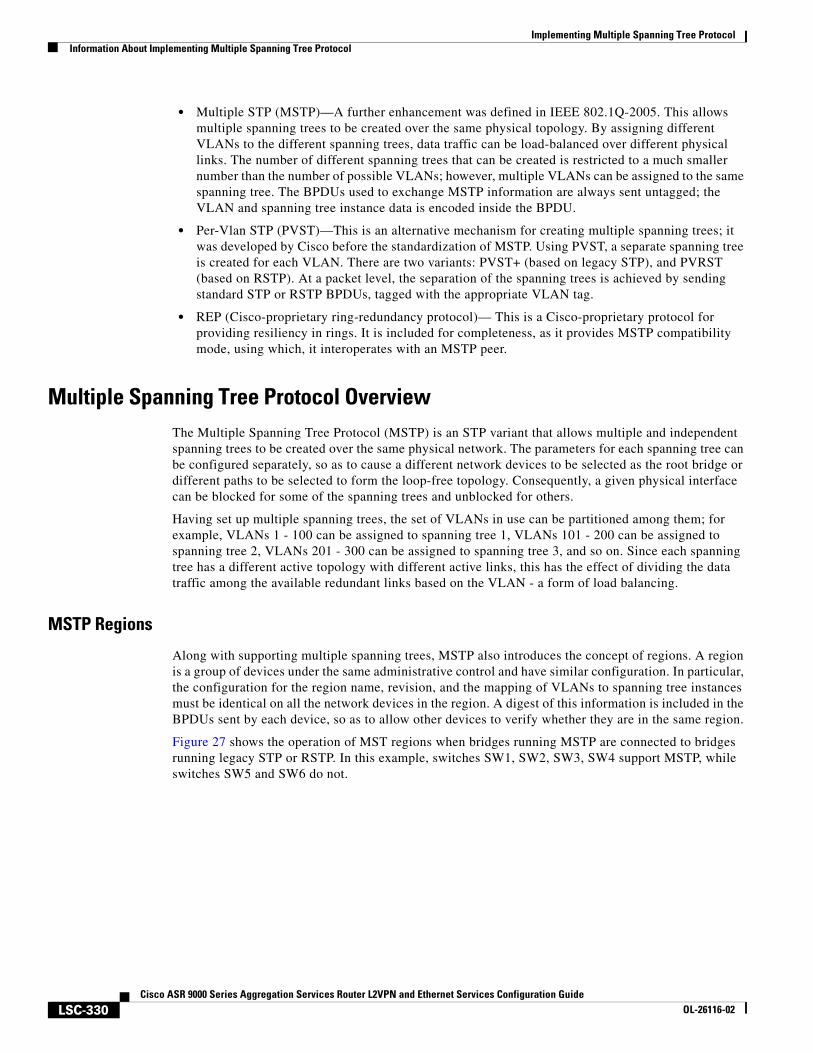
Implementing Multiple Spanning Tree ProtocolInformation About Implementing Multiple Spanning Tree Protocol
LSC-330Cisco ASR 9000 Series Aggregation Services Router L2VPN and Ethernet Services Configuration Guide
OL-26116-02
• Multiple STP (MSTP)—A further enhancement was defined in IEEE 802.1Q-2005. This allows multiple spanning trees to be created over the same physical topology. By assigning different VLANs to the different spanning trees, data traffic can be load-balanced over different physical links. The number of different spanning trees that can be created is restricted to a much smaller number than the number of possible VLANs; however, multiple VLANs can be assigned to the same spanning tree. The BPDUs used to exchange MSTP information are always sent untagged; the VLAN and spanning tree instance data is encoded inside the BPDU.
• Per-Vlan STP (PVST)—This is an alternative mechanism for creating multiple spanning trees; it was developed by Cisco before the standardization of MSTP. Using PVST, a separate spanning tree is created for each VLAN. There are two variants: PVST+ (based on legacy STP), and PVRST (based on RSTP). At a packet level, the separation of the spanning trees is achieved by sending standard STP or RSTP BPDUs, tagged with the appropriate VLAN tag.
• REP (Cisco-proprietary ring-redundancy protocol)— This is a Cisco-proprietary protocol for providing resiliency in rings. It is included for completeness, as it provides MSTP compatibility mode, using which, it interoperates with an MSTP peer.
Multiple Spanning Tree Protocol OverviewThe Multiple Spanning Tree Protocol (MSTP) is an STP variant that allows multiple and independent spanning trees to be created over the same physical network. The parameters for each spanning tree can be configured separately, so as to cause a different network devices to be selected as the root bridge or different paths to be selected to form the loop-free topology. Consequently, a given physical interface can be blocked for some of the spanning trees and unblocked for others.
Having set up multiple spanning trees, the set of VLANs in use can be partitioned among them; for example, VLANs 1 - 100 can be assigned to spanning tree 1, VLANs 101 - 200 can be assigned to spanning tree 2, VLANs 201 - 300 can be assigned to spanning tree 3, and so on. Since each spanning tree has a different active topology with different active links, this has the effect of dividing the data traffic among the available redundant links based on the VLAN - a form of load balancing.
MSTP Regions
Along with supporting multiple spanning trees, MSTP also introduces the concept of regions. A region is a group of devices under the same administrative control and have similar configuration. In particular, the configuration for the region name, revision, and the mapping of VLANs to spanning tree instances must be identical on all the network devices in the region. A digest of this information is included in the BPDUs sent by each device, so as to allow other devices to verify whether they are in the same region.
Figure 27 shows the operation of MST regions when bridges running MSTP are connected to bridges running legacy STP or RSTP. In this example, switches SW1, SW2, SW3, SW4 support MSTP, while switches SW5 and SW6 do not.
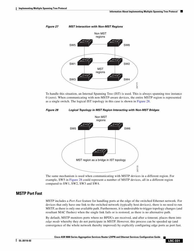
Implementing Multiple Spanning Tree ProtocolInformation About Implementing Multiple Spanning Tree Protocol
LSC-331Cisco ASR 9000 Series Aggregation Services Router L2VPN and Ethernet Services Configuration Guide
OL-26116-02
Figure 27 MST Interaction with Non-MST Regions
To handle this situation, an Internal Spanning Tree (IST) is used. This is always spanning tree instance 0 (zero). When communicating with non-MSTP-aware devices, the entire MSTP region is represented as a single switch. The logical IST topology in this case is shown in Figure 28.
Figure 28 Logical Topology in MST Region Interacting with Non-MST Bridges
The same mechanism is used when communicating with MSTP devices in a different region. For example, SW5 in Figure 28 could represent a number of MSTP devices, all in a different region compared to SW1, SW2, SW3 and SW4.
MSTP Port Fast
MSTP includes a Port Fast feature for handling ports at the edge of the switched Ethernet network. For devices that only have one link to the switched network (typically host devices), there is no need to run MSTP, as there is only one available path. Furthermore, it is undesirable to trigger topology changes (and resultant MAC flushes) when the single link fails or is restored, as there is no alternative path.
By default, MSTP monitors ports where no BPDUs are received, and after a timeout, places them into edge mode whereby they do not participate in MSTP. However, this process can be speeded up (and convergence of the whole network thereby improved) by explicitly configuring edge ports as port fast.
2471
71
Non MSTregions
MSTregions
SW6SW5
SW2SW1
SW4SW3
2471
72
Non MSTregions
MST region as a bridge in IST topology
SW6SW5
Implementing Multiple Spanning Tree ProtocolInformation About Implementing Multiple Spanning Tree Protocol
LSC-332Cisco ASR 9000 Series Aggregation Services Router L2VPN and Ethernet Services Configuration Guide
OL-26116-02
Note Port Fast is implemented as a Cisco-proprietary extension in Cisco implementations of legacy STP. However, it is encompassed in the standards for RSTP and MSTP, where it is known as Edge Port.
MSTP Root Guard
In networks with shared administrative control, it may be desirable for the network administrator to enforce aspects of the network topology and in particular, the location of the root bridge. By default, any device can become the root bridge for a spanning tree, if it has a lower priority or bridge ID. However, a more optimal forwarding topology can be achieved by placing the root bridge at a specific location in the centre of the network.
Note The administrator can set the root bridge priority to 0 in an effort to secure the root bridge position; however, this is no guarantee against another bridge which also has a priority of 0 and has a lower bridge ID.
The root guard feature provides a mechanism that allows the administrator to enforce the location of the root bridge. When root guard is configured on an interface, it prevents that interface from becoming a root port (that is, a port via which the root can be reached). If superior information is received via BPDUs on the interface that would normally cause it to become a root port, it instead becomes a backup or alternate port. In this case, it is placed in the blocking state and no data traffic is forwarded.
The root bridge itself has no root ports. Thus, by configuring root guard on every interface on a device, the administrator forces the device to become the root, and interfaces receiving conflicting information are blocked.
Note Root Guard is implemented as a Cisco-proprietary extension in Cisco implementations of legacy STP and RSTP. However, it is encompassed in the standard for MSTP, where it is known as Restricted Role.
MSTP Topology Change Guard
In certain situations, it may be desirable to prevent topology changes originating at or received at a given port from being propagated to the rest of the network. This may be the case, for example, when the network is not under a single administrative control and it is desirable to prevent devices external to the core of the network from causing MAC address flushing in the core. This behavior can be enabled by configuring Topology Change Guard on the port.
Note Topology Change Guard is known as Restricted TCN in the MSTP standard.
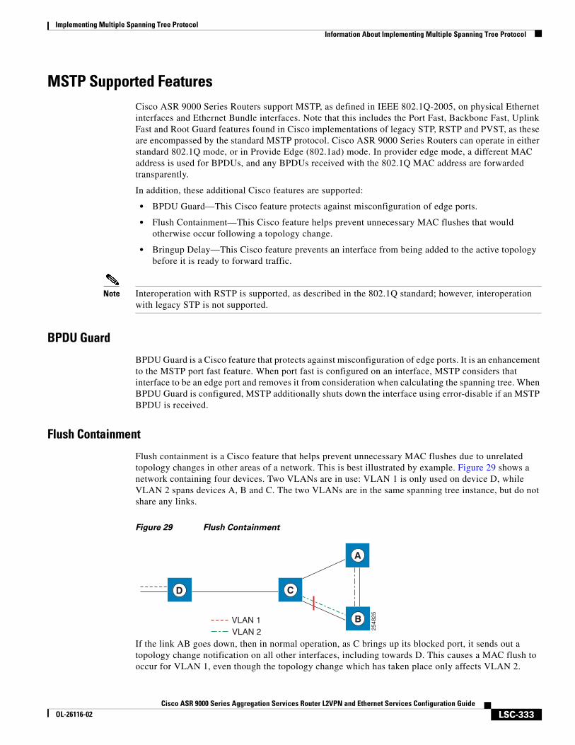
Implementing Multiple Spanning Tree ProtocolInformation About Implementing Multiple Spanning Tree Protocol
LSC-333Cisco ASR 9000 Series Aggregation Services Router L2VPN and Ethernet Services Configuration Guide
OL-26116-02
MSTP Supported FeaturesCisco ASR 9000 Series Routers support MSTP, as defined in IEEE 802.1Q-2005, on physical Ethernet interfaces and Ethernet Bundle interfaces. Note that this includes the Port Fast, Backbone Fast, Uplink Fast and Root Guard features found in Cisco implementations of legacy STP, RSTP and PVST, as these are encompassed by the standard MSTP protocol. Cisco ASR 9000 Series Routers can operate in either standard 802.1Q mode, or in Provide Edge (802.1ad) mode. In provider edge mode, a different MAC address is used for BPDUs, and any BPDUs received with the 802.1Q MAC address are forwarded transparently.
In addition, these additional Cisco features are supported:
• BPDU Guard—This Cisco feature protects against misconfiguration of edge ports.
• Flush Containment—This Cisco feature helps prevent unnecessary MAC flushes that would otherwise occur following a topology change.
• Bringup Delay—This Cisco feature prevents an interface from being added to the active topology before it is ready to forward traffic.
Note Interoperation with RSTP is supported, as described in the 802.1Q standard; however, interoperation with legacy STP is not supported.
BPDU Guard
BPDU Guard is a Cisco feature that protects against misconfiguration of edge ports. It is an enhancement to the MSTP port fast feature. When port fast is configured on an interface, MSTP considers that interface to be an edge port and removes it from consideration when calculating the spanning tree. When BPDU Guard is configured, MSTP additionally shuts down the interface using error-disable if an MSTP BPDU is received.
Flush Containment
Flush containment is a Cisco feature that helps prevent unnecessary MAC flushes due to unrelated topology changes in other areas of a network. This is best illustrated by example. Figure 29 shows a network containing four devices. Two VLANs are in use: VLAN 1 is only used on device D, while VLAN 2 spans devices A, B and C. The two VLANs are in the same spanning tree instance, but do not share any links.
Figure 29 Flush Containment
If the link AB goes down, then in normal operation, as C brings up its blocked port, it sends out a topology change notification on all other interfaces, including towards D. This causes a MAC flush to occur for VLAN 1, even though the topology change which has taken place only affects VLAN 2.
VLAN 1VLAN 2 25
4825
A
B
CD
Implementing Multiple Spanning Tree ProtocolInformation About Implementing Multiple Spanning Tree Protocol
LSC-334Cisco ASR 9000 Series Aggregation Services Router L2VPN and Ethernet Services Configuration Guide
OL-26116-02
Flush containment helps deal with this problem by preventing topology change notifications from being sent on interfaces on which no VLANs are configured for the MSTI in question. In the example network this would mean no topology change notifications would be sent from C to D, and the MAC flushes which take place would be confined to the right hand side of the network.
Note Flush containment is enabled by default, but can be disabled by configuration, thus restoring the behavior described in the IEEE 802.1Q standard.
Bringup Delay
Bringup delay is a Cisco feature that stops MSTP from considering an interface when calculating the spanning tree, if the interface is not yet ready to forward traffic. This is useful when a line card first boots up, as the system may declare that the interfaces on that card are Up before the dataplane is fully ready to forward traffic. According to the standard, MSTP considers the interfaces as soon as they are declared Up, and this may cause it to move other interfaces into the blocking state if the new interfaces are selected instead.
Bringup delay solves this problem by adding a configurable delay period which occurs as interfaces that are configured with MSTP first come into existence. Until this delay period ends, the interfaces remain in blocking state, and are not considered when calculating the spanning tree.
Bringup delay only takes place when interfaces which are already configured with MSTP are created, for example, on a card reload. No delay takes place if an interface which already exists is later configured with MSTP.
Restrictions for configuring MSTPThese restrictions apply when using MSTP:
• MSTP must only be enabled on interfaces where the interface itself (if it is in L2 mode) or all of the subinterfaces have a simple encapsulation configured. These encapsulation matching criteria are considered simple:
– Single-tagged 802.1Q frames
– Double-tagged Q-in-Q frames (only the outermost tag is examined)
– 802.1ad frames (if MSTP is operating in Provider Bridge mode)
– Ranges or lists of tags (any of the above)
Note Subinterfaces with a default and untagged encapsulation are not supported.
• If an L2 interface or subinterface is configured with an encapsulation that matches multiple VLANs, then all of those VLANs must be mapped to the same spanning tree instance. There is therefore a single spanning tree instance associated with each L2 interface or subinterface.
• All the interfaces or subinterfaces in a given bridge domain must be associated with the same spanning tree instance.
• Multiple subinterfaces on the same interface must not be associated with the same spanning tree instance, unless those subinterfaces are in the same split horizon group. In other words, hair-pinning is not possible.
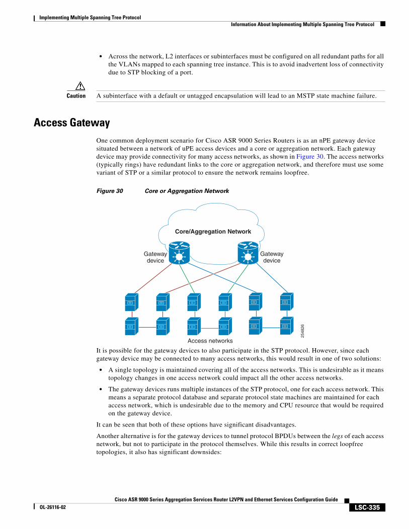
Implementing Multiple Spanning Tree ProtocolInformation About Implementing Multiple Spanning Tree Protocol
LSC-335Cisco ASR 9000 Series Aggregation Services Router L2VPN and Ethernet Services Configuration Guide
OL-26116-02
• Across the network, L2 interfaces or subinterfaces must be configured on all redundant paths for all the VLANs mapped to each spanning tree instance. This is to avoid inadvertent loss of connectivity due to STP blocking of a port.
Caution A subinterface with a default or untagged encapsulation will lead to an MSTP state machine failure.
Access GatewayOne common deployment scenario for Cisco ASR 9000 Series Routers is as an nPE gateway device situated between a network of uPE access devices and a core or aggregation network. Each gateway device may provide connectivity for many access networks, as shown in Figure 30. The access networks (typically rings) have redundant links to the core or aggregation network, and therefore must use some variant of STP or a similar protocol to ensure the network remains loopfree.
Figure 30 Core or Aggregation Network
It is possible for the gateway devices to also participate in the STP protocol. However, since each gateway device may be connected to many access networks, this would result in one of two solutions:
• A single topology is maintained covering all of the access networks. This is undesirable as it means topology changes in one access network could impact all the other access networks.
• The gateway devices runs multiple instances of the STP protocol, one for each access network. This means a separate protocol database and separate protocol state machines are maintained for each access network, which is undesirable due to the memory and CPU resource that would be required on the gateway device.
It can be seen that both of these options have significant disadvantages.
Another alternative is for the gateway devices to tunnel protocol BPDUs between the legs of each access network, but not to participate in the protocol themselves. While this results in correct loopfree topologies, it also has significant downsides:
Core/Aggregation Network
2548
26
Access networks
Gatewaydevice
Gatewaydevice
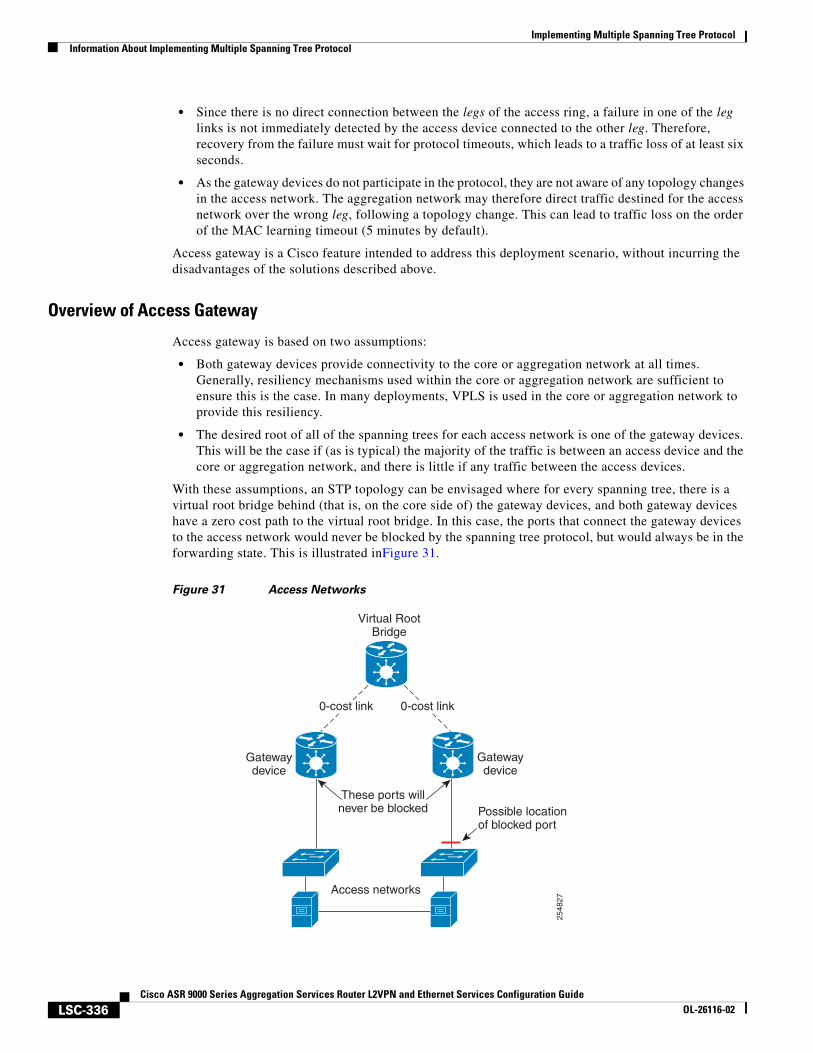
Implementing Multiple Spanning Tree ProtocolInformation About Implementing Multiple Spanning Tree Protocol
LSC-336Cisco ASR 9000 Series Aggregation Services Router L2VPN and Ethernet Services Configuration Guide
OL-26116-02
• Since there is no direct connection between the legs of the access ring, a failure in one of the leg links is not immediately detected by the access device connected to the other leg. Therefore, recovery from the failure must wait for protocol timeouts, which leads to a traffic loss of at least six seconds.
• As the gateway devices do not participate in the protocol, they are not aware of any topology changes in the access network. The aggregation network may therefore direct traffic destined for the access network over the wrong leg, following a topology change. This can lead to traffic loss on the order of the MAC learning timeout (5 minutes by default).
Access gateway is a Cisco feature intended to address this deployment scenario, without incurring the disadvantages of the solutions described above.
Overview of Access Gateway
Access gateway is based on two assumptions:
• Both gateway devices provide connectivity to the core or aggregation network at all times. Generally, resiliency mechanisms used within the core or aggregation network are sufficient to ensure this is the case. In many deployments, VPLS is used in the core or aggregation network to provide this resiliency.
• The desired root of all of the spanning trees for each access network is one of the gateway devices. This will be the case if (as is typical) the majority of the traffic is between an access device and the core or aggregation network, and there is little if any traffic between the access devices.
With these assumptions, an STP topology can be envisaged where for every spanning tree, there is a virtual root bridge behind (that is, on the core side of) the gateway devices, and both gateway devices have a zero cost path to the virtual root bridge. In this case, the ports that connect the gateway devices to the access network would never be blocked by the spanning tree protocol, but would always be in the forwarding state. This is illustrated inFigure 31.
Figure 31 Access Networks
These ports willnever be blocked
Virtual RootBridge
Possible locationof blocked port
2548
27
Access networks
Gatewaydevice
Gatewaydevice
0-cost link 0-cost link
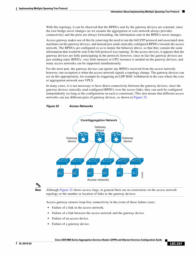
Implementing Multiple Spanning Tree ProtocolInformation About Implementing Multiple Spanning Tree Protocol
LSC-337Cisco ASR 9000 Series Aggregation Services Router L2VPN and Ethernet Services Configuration Guide
OL-26116-02
With this topology, it can be observed that the BPDUs sent by the gateway devices are constant: since the root bridge never changes (as we assume the aggregation or core network always provides connectivity) and the ports are always forwarding, the information sent in the BPDUs never changes.
Access gateway makes use of this by removing the need to run the full STP protocol and associated state machines on the gateway devices, and instead just sends statically configured BPDUs towards the access network. The BPDUs are configured so as to mimic the behavior above, so that they contain the same information that would be sent if the full protocol was running. To the access devices, it appears that the gateway devices are fully participating in the protocol; however, since in fact the gateway devices are just sending static BPDUs, very little memory or CPU resource is needed on the gateway devices, and many access networks can be supported simultaneously.
For the most part, the gateway devices can ignore any BPDUs received from the access network; however, one exception is when the access network signals a topology change. The gateway devices can act on this appropriately, for example by triggering an LDP MAC withdrawal in the case where the core or aggregation network uses VPLS.
In many cases, it is not necessary to have direct connectivity between the gateway devices; since the gateway devices statically send configured BPDUs over the access links, they can each be configured independently (so long as the configuration on each is consistent). This also means that different access networks can use different pairs of gateway devices, as shown in Figure 32.
Figure 32 Access Networks
Note Although Figure 32 shows access rings, in general there are no restrictions on the access network topology or the number or location of links to the gateway devices.
Access gateway ensures loop-free connectivity in the event of these failure cases:
• Failure of a link in the access network.
• Failure of a link between the access network and the gateway device.
• Failure of an access device.
• Failure of a gateway device.
Core/Aggregation Network
2548
28
Access networks
Gatewaydevice
Gatewaydevice
Gatewaydevice
Implementing Multiple Spanning Tree ProtocolInformation About Implementing Multiple Spanning Tree Protocol
LSC-338Cisco ASR 9000 Series Aggregation Services Router L2VPN and Ethernet Services Configuration Guide
OL-26116-02
Topology Change Propagation
There is one case where the two gateway devices need to exchange BPDUs between each other, and this is to handle topology changes in the access network. If a failure in the access network results in a topology change that causes a previously blocked port to move to forwarding, the access device sends a topology change notification out on that port, so as to notify the rest of the network about the change and trigger the necessary MAC learning flushes. Typically, the topology change notification is sent towards the root bridge, in the case of access gateway, that means it is sent to one of the gateway devices.
As described above, this causes the gateway device itself to take any necessary action; however, if the failure caused the access network to become partitioned, it may also be necessary to propagate the topology change notification to the rest of the access network, that is, the portion connected to the other gateway device. This can be achieved by ensuring there is connectivity between the gateway devices, so that each gateway device can propagate any topology change notifications it receives from the access network to the other device. When a gateway device receives a BPDU from the other gateway device that indicates a topology change, it signals this in the static BPDUs (that it is sending towards the access network).
Topology Change Propagation is only necessary when these two conditions are met:
• The access network contains three or more access devices. If there are fewer than three devices, then any possible failure must be detected by all the devices.
• The access devices send traffic to each other, and not just to or from the core or aggregation network. If all the traffic is to or from the core or aggregation network, then all the access devices must either already be sending traffic in the right direction, or will learn about the topology change from the access device that originates it.
Preempt Delay
One of the assumptions underpinning access gateway is that the gateway devices are always available to provide connectivity to the core or aggregation network. However, there is one situation where this assumption may not hold, which is at bringup time. At bringup, it may be the case that the access facing interface is available before all of the necessary signaling and convergence has completed that means traffic can successfully be forwarded into the core or aggregation network. Since access gateway starts sending BPDUs as soon as the interface comes up, this could result in the access devices sending traffic to the gateway device before it is ready to receive it. To avoid this problem, the preempt delay feature is used.
The preempt delay feature causes access gateway to send out inferior BPDUs for some period of time after the interface comes up, before reverting to the normal values. These inferior BPDUs can be configured such that the access network directs all traffic to the other gateway device, unless the other gateway device is also down. If the other gateway device is unavailable, it is desirable for the traffic to be sent to this device, even if it is only partially available, rather than being dropped completely. For this reason, inferior BPDUs are sent during the preempt delay time, rather than sending no BPDUs at all.
Implementing Multiple Spanning Tree ProtocolInformation About Implementing Multiple Spanning Tree Protocol
LSC-339Cisco ASR 9000 Series Aggregation Services Router L2VPN and Ethernet Services Configuration Guide
OL-26116-02
Supported Access Gateway Protocols
Access Gateway is supported on Cisco ASR 9000 Series Routers when the following protocols are used in the access network.
MSTAG Edge Mode
An access gateway is used in a Layer 2 (L2) environment to ensure that for each Multiple Spanning Tree Instance (MSTI), each access device has one path to the core or aggregation network. The core or aggregation network provides L2 (Ethernet) connectivity between two gateway devices. Therefore, when there are no failures, there must be at least one blocked port in the access network for each MSTI. In the case of an access ring, there should be one blocked port in the access ring. For each MSTI – this is typically one of the uplink ports that connects to one of the gateway devices. This is achieved by configuring MSTAG in such a way that the gateway devices appear to have the best path to the best possible Multiple Spanning Tree Protocol (MSTP) root node. Thus, the access devices always use the gateway devices to reach the root, and the ports on the gateway devices are always in the designated forwarding state.
In a mixed Layer 2-Layer 3 environment, the L2 access network is used to provide a Layer 2 service on certain VLANs and a Layer 3 (L3) service on other VLANs. In the access network, a different MSTI is used for the L2 service and the L3 service. For the L2 VLANs, the core or aggregation network provides L2 connectivity between the gateway devices. However, for the L3 service, the gateway devices terminate the L2 network and perform L3 routing. Typically, an L3 redundancy mechanism such as HSRP or VRRP is used to allow the end hosts to route to the correct gateway.
In this scenario, the use of MSTAG alone does not achieve the desired behavior for the L3 MSTI. This is because it results in one of the ports in the access network being blocked, even though there is actually no loop. (This, in turn, is because there is no L2 connectivity between the gateway devices for the L3 VLANs.) In fact, because the gateway devices terminate the L2 network for the L3 VLANs, the desirable behavior is for the MSTP root to be located in the access network, and for the gateway devices to appear as leaf nodes with a single connection. This can be achieved by reversing the MSTAG configuration; that is, setting the gateway devices to advertise the worst possible path to the worst possible root. This forces the access devices to elect one of the access devices as the root, and therefore, no ports are blocked. In this case, the ports on the gateway devices are always in root forwarding state. The MSTAG Edge mode feature enables this scenario by changing the role advertised by the gateway devices from designated to root. Figure 33 illustrates this scenario.
Table 3 Protocols
Access Network Protocol Access Gateway Variant
MSTP MST Access Gateway (MSTAG)
REP REP Access gateway (REPAG)1
PVST+ PVST+ Access Gateway (PVSTAG)2
PVRST PVRST Access Gateway (PVRSTAG)3
1. REP Access Gateway is supported when the access device interfaces that connect to the gateway devices are configured with REP MSTP Compatibility mode.
2. Topology Change Propagation is not supported for PVSTAG.
3. Topology Change Propagation is not supported for PVRSTAG.
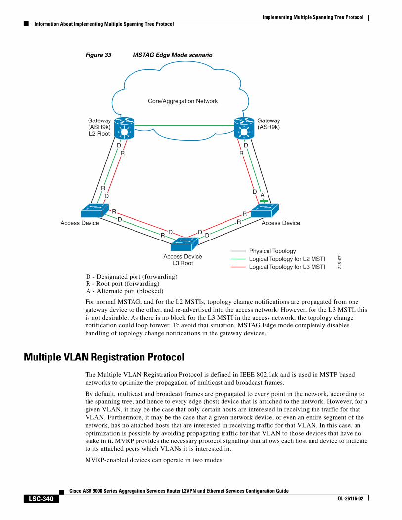
Implementing Multiple Spanning Tree ProtocolInformation About Implementing Multiple Spanning Tree Protocol
LSC-340Cisco ASR 9000 Series Aggregation Services Router L2VPN and Ethernet Services Configuration Guide
OL-26116-02
Figure 33 MSTAG Edge Mode scenario
For normal MSTAG, and for the L2 MSTIs, topology change notifications are propagated from one gateway device to the other, and re-advertised into the access network. However, for the L3 MSTI, this is not desirable. As there is no block for the L3 MSTI in the access network, the topology change notification could loop forever. To avoid that situation, MSTAG Edge mode completely disables handling of topology change notifications in the gateway devices.
Multiple VLAN Registration ProtocolThe Multiple VLAN Registration Protocol is defined in IEEE 802.1ak and is used in MSTP based networks to optimize the propagation of multicast and broadcast frames.
By default, multicast and broadcast frames are propagated to every point in the network, according to the spanning tree, and hence to every edge (host) device that is attached to the network. However, for a given VLAN, it may be the case that only certain hosts are interested in receiving the traffic for that VLAN. Furthermore, it may be the case that a given network device, or even an entire segment of the network, has no attached hosts that are interested in receiving traffic for that VLAN. In this case, an optimization is possible by avoiding propagating traffic for that VLAN to those devices that have no stake in it. MVRP provides the necessary protocol signaling that allows each host and device to indicate to its attached peers which VLANs it is interested in.
MVRP-enabled devices can operate in two modes:
D - Designated port (forwarding)R - Root port (forwarding)A - Alternate port (blocked)
Core/Aggregation Network
2461
97
Gateway(ASR9k)L2 Root
DR
RD
D
D D
R
RR
R D
DR
D A
Gateway(ASR9k)
Access Device Access Device
Access DeviceL3 Root
Physical TopologyLogical Topology for L2 MSTILogical Topology for L3 MSTI
Implementing Multiple Spanning Tree ProtocolInformation About Implementing Multiple Spanning Tree Protocol
LSC-341Cisco ASR 9000 Series Aggregation Services Router L2VPN and Ethernet Services Configuration Guide
OL-26116-02
• Static mode—In this mode, the device initiates MVRP messages declaring interest in a statically configured set of VLANs. Note that the protocol is still dynamic with respect to the MSTP topology; it is the set of VLANs that is static.
• Dynamic mode—In this mode, the device processes MVRP messages received on different ports, and aggregates them dynamically to determine the set of VLANs it is interested in. It sends MVRP messages declaring interest in this set. In dynamic mode, the device also uses the received MVRP messages to prune the traffic sent out of each port so that traffic is only sent for the VLANs that the attached device has indicated it is interested in.
Cisco ASR 9000 Series Routers support operating in static mode. This is known as MVRP-lite.
Implementing Multiple Spanning Tree ProtocolHow to Implement Multiple Spanning Tree Protocol
LSC-342Cisco ASR 9000 Series Aggregation Services Router L2VPN and Ethernet Services Configuration Guide
OL-26116-02
How to Implement Multiple Spanning Tree ProtocolThis section contains these procedures:
• Configuring MSTP
• Configuring MSTAG or REPAG
• Configuring PVSTAG or PVRSTAG
• Configuring MVRP-lite
Configuring MSTPThis section describes the procedure for configuring MSTP:
• Enabling MSTP
• Configuring MSTP parameters
• Verifying MSTP
Note This section does not describe how to configure data switching. Refer to the Implementing Multipoint Layer 2 Services module for more information.
Enabling MSTP
By default, STP is disabled on all interfaces. MSTP should be explicitly enabled by configuration on each physical or Ethernet Bundle interface. When MSTP is configured on an interface, all the subinterfaces of that interface are automatically MSTP-enabled.
Configuring MSTP parameters
The MSTP Standard defines a number of configurable parameters. The global parameters are:
• Region Name and Revision
• Bringup Delay
• Forward Delay
• Max Age or Hops
• Transmit Hold Count
• Provider Bridge mode
• Flush Containment
• VLAN IDs (per spanning-tree instance)
• Bridge Priority (per spanning-tree instance)
The per-interface parameters are:
• External port path cost
• Hello Time
• Link Type
Implementing Multiple Spanning Tree ProtocolHow to Implement Multiple Spanning Tree Protocol
LSC-343Cisco ASR 9000 Series Aggregation Services Router L2VPN and Ethernet Services Configuration Guide
OL-26116-02
• Port Fast and BPDU Guard
• Root Guard and Topology Change Guard
• Port priority (per spanning-tree instance)
• Internal port path cost (per spanning-tree instance)
Per-interface configuration takes place in an interface submode within the MST configuration submode.
Note The configuration steps listed in the following sections show all of the configurable parameters. However, in general, most of these can be retained with the default value.
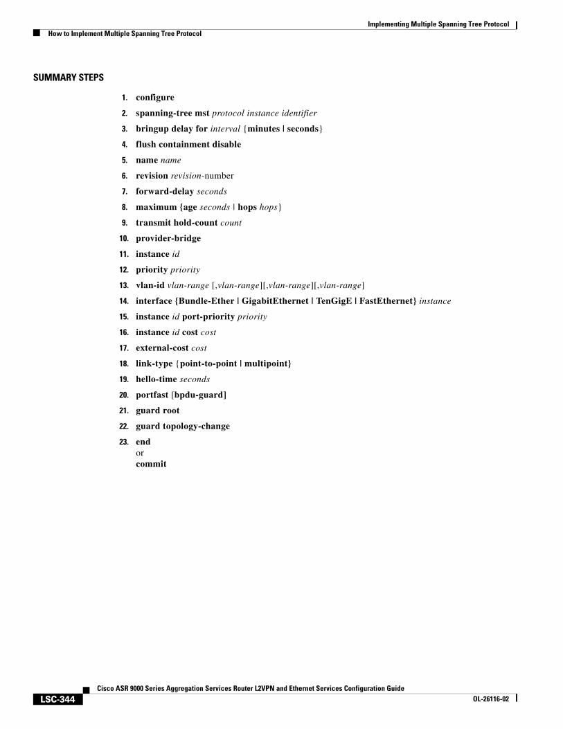
Implementing Multiple Spanning Tree ProtocolHow to Implement Multiple Spanning Tree Protocol
LSC-344Cisco ASR 9000 Series Aggregation Services Router L2VPN and Ethernet Services Configuration Guide
OL-26116-02
SUMMARY STEPS
1. configure
2. spanning-tree mst protocol instance identifier
3. bringup delay for interval {minutes | seconds}
4. flush containment disable
5. name name
6. revision revision-number
7. forward-delay seconds
8. maximum {age seconds | hops hops}
9. transmit hold-count count
10. provider-bridge
11. instance id
12. priority priority
13. vlan-id vlan-range [,vlan-range][,vlan-range][,vlan-range]
14. interface {Bundle-Ether | GigabitEthernet | TenGigE | FastEthernet} instance
15. instance id port-priority priority
16. instance id cost cost
17. external-cost cost
18. link-type {point-to-point | multipoint}
19. hello-time seconds
20. portfast [bpdu-guard]
21. guard root
22. guard topology-change
23. endorcommit
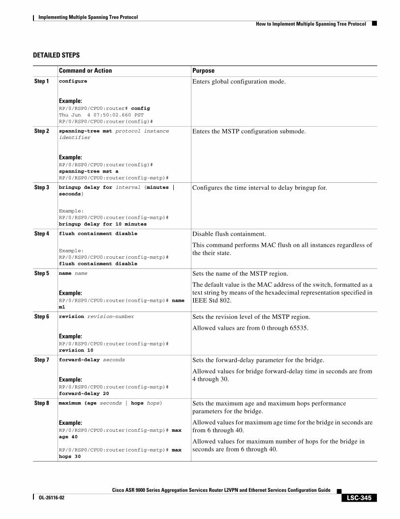
Implementing Multiple Spanning Tree ProtocolHow to Implement Multiple Spanning Tree Protocol
LSC-345Cisco ASR 9000 Series Aggregation Services Router L2VPN and Ethernet Services Configuration Guide
OL-26116-02
DETAILED STEPS
Command or Action Purpose
Step 1 configure
Example:RP/0/RSP0/CPU0:router# configThu Jun 4 07:50:02.660 PSTRP/0/RSP0/CPU0:router(config)#
Enters global configuration mode.
Step 2 spanning-tree mst protocol instance identifier
Example:RP/0/RSP0/CPU0:router(config)# spanning-tree mst aRP/0/RSP0/CPU0:router(config-mstp)#
Enters the MSTP configuration submode.
Step 3 bringup delay for interval {minutes | seconds}
Example:RP/0/RSP0/CPU0:router(config-mstp)#bringup delay for 10 minutes
Configures the time interval to delay bringup for.
Step 4 flush containment disable
Example:RP/0/RSP0/CPU0:router(config-mstp)#flush containment disable
Disable flush containment.
This command performs MAC flush on all instances regardless of the their state.
Step 5 name name
Example:RP/0/RSP0/CPU0:router(config-mstp)# name m1
Sets the name of the MSTP region.
The default value is the MAC address of the switch, formatted as a text string by means of the hexadecimal representation specified in IEEE Std 802.
Step 6 revision revision-number
Example:RP/0/RSP0/CPU0:router(config-mstp)# revision 10
Sets the revision level of the MSTP region.
Allowed values are from 0 through 65535.
Step 7 forward-delay seconds
Example:RP/0/RSP0/CPU0:router(config-mstp)# forward-delay 20
Sets the forward-delay parameter for the bridge.
Allowed values for bridge forward-delay time in seconds are from 4 through 30.
Step 8 maximum {age seconds | hops hops}
Example:RP/0/RSP0/CPU0:router(config-mstp)# max age 40
RP/0/RSP0/CPU0:router(config-mstp)# max hops 30
Sets the maximum age and maximum hops performance parameters for the bridge.
Allowed values for maximum age time for the bridge in seconds are from 6 through 40.
Allowed values for maximum number of hops for the bridge in seconds are from 6 through 40.
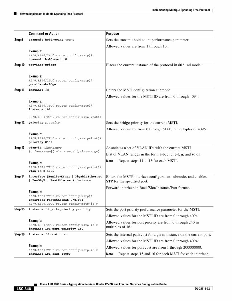
Implementing Multiple Spanning Tree ProtocolHow to Implement Multiple Spanning Tree Protocol
LSC-346Cisco ASR 9000 Series Aggregation Services Router L2VPN and Ethernet Services Configuration Guide
OL-26116-02
Step 9 transmit hold-count count
Example:RP/0/RSP0/CPU0:router(config-mstp)# transmit hold-count 8
Sets the transmit hold count performance parameter.
Allowed values are from 1 through 10.
Step 10 provider-bridge
Example:RP/0/RSP0/CPU0:router(config-mstp)# provider-bridge
Places the current instance of the protocol in 802.1ad mode.
Step 11 instance id
Example:RP/0/RSP0/CPU0:router(config-mstp)# instance 101
RP/0/RSP0/CPU0:router(config-mstp-inst)#
Enters the MSTI configuration submode.
Allowed values for the MSTI ID are from 0 through 4094.
Step 12 priority priority
Example:RP/0/RSP0/CPU0:router(config-mstp-inst)# priority 8192
Sets the bridge priority for the current MSTI.
Allowed values are from 0 through 61440 in multiples of 4096.
Step 13 vlan-id vlan-range [,vlan-range][,vlan-range][,vlan-range]
Example:RP/0/RSP0/CPU0:router(config-mstp-inst)# vlan-id 2-1005
Associates a set of VLAN IDs with the current MSTI.
List of VLAN ranges in the form a-b, c, d, e-f, g, and so on.
Note Repeat steps 11 to 13 for each MSTI.
Step 14 interface {Bundle-Ether | GigabitEthernet | TenGigE | FastEthernet} instance
Example:RP/0/RSP0/CPU0:router(config-mstp)# interface FastEthernet 0/0/0/1RP/0/RSP0/CPU0:router(config-mstp-if)#
Enters the MSTP interface configuration submode, and enables STP for the specified port.
Forward interface in Rack/Slot/Instance/Port format.
Step 15 instance id port-priority priority
Example:RP/0/RSP0/CPU0:router(config-mstp-if)# instance 101 port-priority 160
Sets the port priority performance parameter for the MSTI.
Allowed values for the MSTI ID are from 0 through 4094.
Allowed values for port priority are from 0 through 240 in multiples of 16.
Step 16 instance id cost cost
Example:RP/0/RSP0/CPU0:router(config-mstp-if)# instance 101 cost 10000
Sets the internal path cost for a given instance on the current port.
Allowed values for the MSTI ID are from 0 through 4094.
Allowed values for port cost are from 1 through 200000000.
Note Repeat steps 15 and 16 for each MSTI for each interface.
Command or Action Purpose
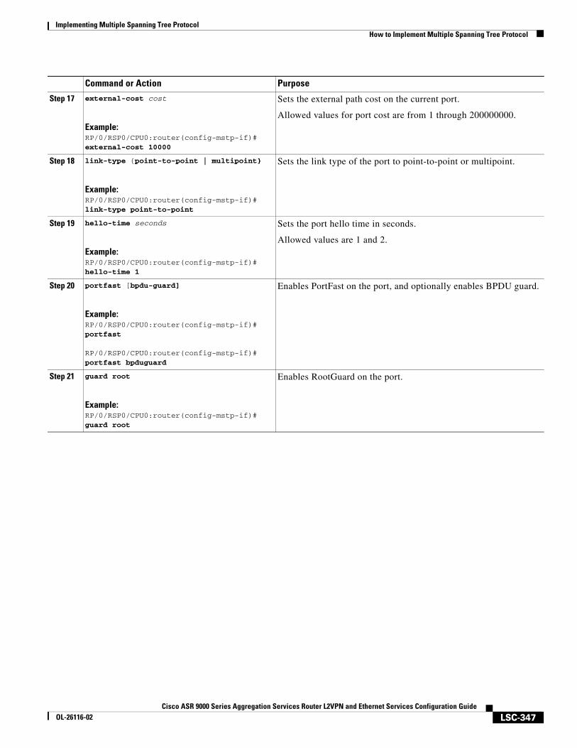
Implementing Multiple Spanning Tree ProtocolHow to Implement Multiple Spanning Tree Protocol
LSC-347Cisco ASR 9000 Series Aggregation Services Router L2VPN and Ethernet Services Configuration Guide
OL-26116-02
Step 17 external-cost cost
Example:RP/0/RSP0/CPU0:router(config-mstp-if)# external-cost 10000
Sets the external path cost on the current port.
Allowed values for port cost are from 1 through 200000000.
Step 18 link-type {point-to-point | multipoint}
Example:RP/0/RSP0/CPU0:router(config-mstp-if)# link-type point-to-point
Sets the link type of the port to point-to-point or multipoint.
Step 19 hello-time seconds
Example:RP/0/RSP0/CPU0:router(config-mstp-if)# hello-time 1
Sets the port hello time in seconds.
Allowed values are 1 and 2.
Step 20 portfast [bpdu-guard]
Example:RP/0/RSP0/CPU0:router(config-mstp-if)# portfast
RP/0/RSP0/CPU0:router(config-mstp-if)# portfast bpduguard
Enables PortFast on the port, and optionally enables BPDU guard.
Step 21 guard root
Example:RP/0/RSP0/CPU0:router(config-mstp-if)# guard root
Enables RootGuard on the port.
Command or Action Purpose
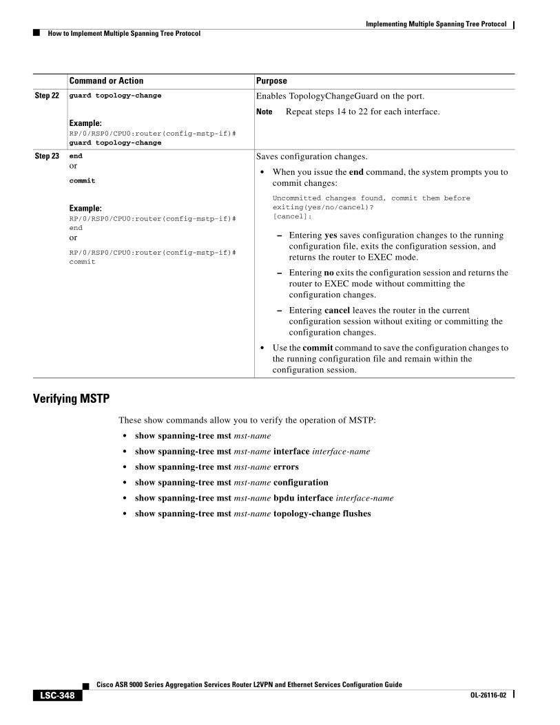
Implementing Multiple Spanning Tree ProtocolHow to Implement Multiple Spanning Tree Protocol
LSC-348Cisco ASR 9000 Series Aggregation Services Router L2VPN and Ethernet Services Configuration Guide
OL-26116-02
Verifying MSTP
These show commands allow you to verify the operation of MSTP:
• show spanning-tree mst mst-name
• show spanning-tree mst mst-name interface interface-name
• show spanning-tree mst mst-name errors
• show spanning-tree mst mst-name configuration
• show spanning-tree mst mst-name bpdu interface interface-name
• show spanning-tree mst mst-name topology-change flushes
Step 22 guard topology-change
Example:RP/0/RSP0/CPU0:router(config-mstp-if)# guard topology-change
Enables TopologyChangeGuard on the port.
Note Repeat steps 14 to 22 for each interface.
Step 23 end
or
commit
Example:RP/0/RSP0/CPU0:router(config-mstp-if)# end
or
RP/0/RSP0/CPU0:router(config-mstp-if)# commit
Saves configuration changes.
• When you issue the end command, the system prompts you to commit changes:
Uncommitted changes found, commit them before exiting(yes/no/cancel)?[cancel]:
– Entering yes saves configuration changes to the running configuration file, exits the configuration session, and returns the router to EXEC mode.
– Entering no exits the configuration session and returns the router to EXEC mode without committing the configuration changes.
– Entering cancel leaves the router in the current configuration session without exiting or committing the configuration changes.
• Use the commit command to save the configuration changes to the running configuration file and remain within the configuration session.
Command or Action Purpose
Implementing Multiple Spanning Tree ProtocolHow to Implement Multiple Spanning Tree Protocol
LSC-349Cisco ASR 9000 Series Aggregation Services Router L2VPN and Ethernet Services Configuration Guide
OL-26116-02
Configuring MSTAG or REPAGThis section describes the procedures for configuring MSTAG:
• Configuring an untagged subinterface
• Enabling MSTAG
• Configuring MSTAG parameters
• Configuring MSTAG Topology Change Propagation
• Verifying MSTAG
Note The procedures for configuring REPAG are identical.
This section does not describe how to configure data switching. Refer to the Implementing Multipoint Layer 2 Services module for more information.
Configuring an untagged subinterface
In order to enable MSTAG on a physical or Bundle Ethernet interface, an L2 subinterface must first be configured which matches untagged packets, using the encapsulation untagged command. Refer to The Cisco ASR 9000 Series Routers Carrier Ethernet Model module for more information about configuring L2 subinterfaces.
Enabling MSTAG
MSTAG is enabled on a physical or Bundle Ethernet interface by explicitly configuring it on the corresponding untagged subinterface. When MSTAG is configured on the untagged subinterface, it is automatically enabled on the physical or Bundle Ethernet interface and on all other subinterfaces on that physical or Bundle Ethernet subinterface.
Configuring MSTAG parameters
MSTAG parameters are configured separately on each interface, and MSTAG runs completely independently on each interface. There is no interaction between the MSTAG parameters on different interfaces (unless they are connected to the same access network).
These parameters are configurable for each interface:
• Region Name and Revision
• Bridge ID
• Port ID
• External port path cost
• Max Age
• Provide Bridge mode
• Hello Time
Implementing Multiple Spanning Tree ProtocolHow to Implement Multiple Spanning Tree Protocol
LSC-350Cisco ASR 9000 Series Aggregation Services Router L2VPN and Ethernet Services Configuration Guide
OL-26116-02
The following MSTAG parameters are configurable for each interface, for each spanning tree instance:
• VLAN IDs
• Root Bridge Priority and ID
• Bridge Priority
• Port Priority
• Internal Port Path Cost
To ensure consistent operation across the access network, these guidelines should be used when configuring:
• Both gateway devices should be configured with a Root Bridge Priority and ID (for each spanning tree instance) that is better (lower) than the Bridge Priority and Bridge ID of any device in the access network. It is recommended to set the Root Bridge Priority and ID to 0 on the gateway devices.
Note To avoid an STP dispute being detected by the access devices, the same root priority and ID should be configured on both gateway devices.
• Both gateway devices should be configured with a Port Path Cost of 0.
• For each spanning tree instance, one gateway device should be configured with the bridge priority and ID that is higher than the root bridge priority and ID, but lower than the bridge priority and ID of any other device in the network (including the other gateway device). It is recommended to set the bridge priority to 0.
• For each spanning tree instance, the second gateway device should be configured with a bridge priority and ID that is higher than the root bridge priority and ID and the first gateway device bridge priority and ID, but lower than the bridge priority and ID of any device in the access network. It is recommended to set the bridge priority to 4096 (this is the lowest allowable value greater than 0).
• All of the access devices should be configured with a higher bridge priority than the gateway devices. It is recommended to use values of 8192 or higher.
• For each spanning tree instance, the port path cost and other parameters may be configured on the access devices so as to ensure the desired port is put into the blocked state when all links are up.
Caution There are no checks on MSTAG configuration—misconfiguration may result in incorrect operation of the MSTP protocol in the access devices (for example, an STP dispute being detected).
The guidelines above are illustrated in Figure 34.
Note These guidelines do not apply to REPAG, as in that case the access devices ignore the information received from the gateway devices apart from when a topology change is signalled.
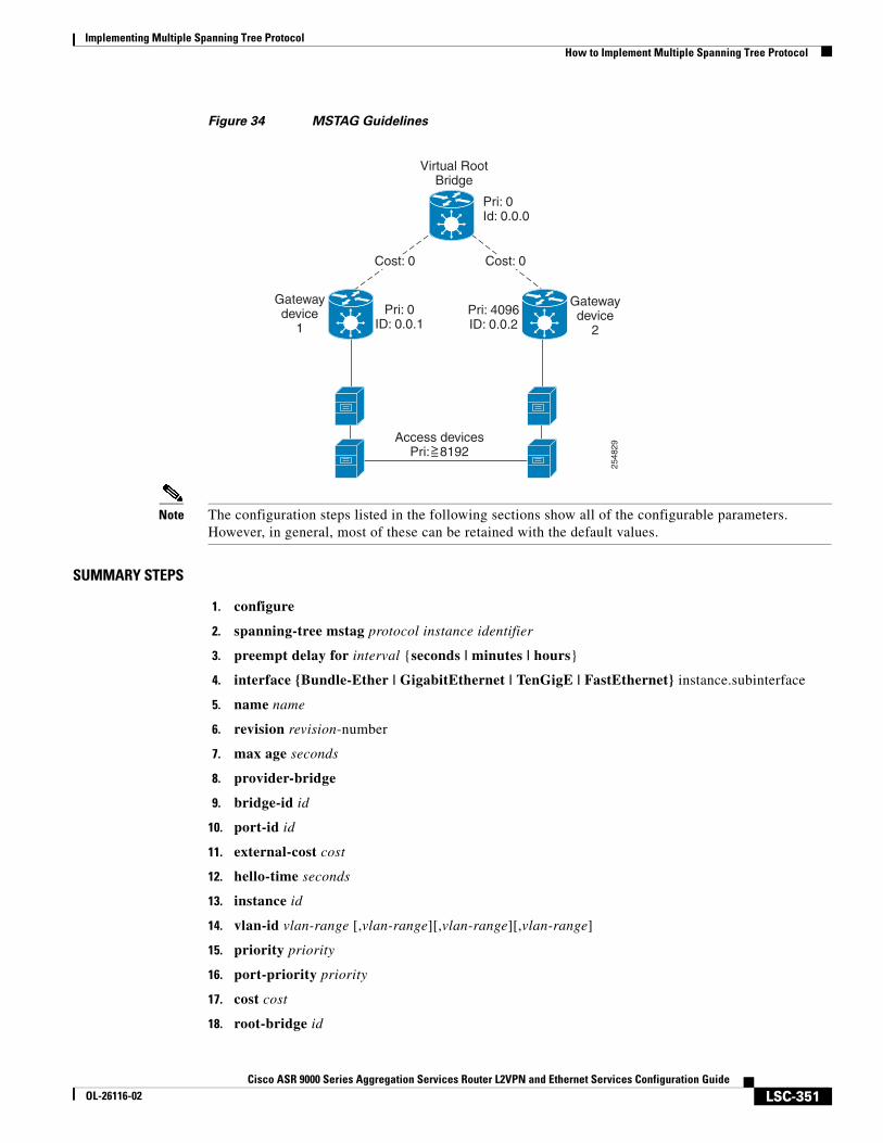
Implementing Multiple Spanning Tree ProtocolHow to Implement Multiple Spanning Tree Protocol
LSC-351Cisco ASR 9000 Series Aggregation Services Router L2VPN and Ethernet Services Configuration Guide
OL-26116-02
Figure 34 MSTAG Guidelines
Note The configuration steps listed in the following sections show all of the configurable parameters. However, in general, most of these can be retained with the default values.
SUMMARY STEPS
1. configure
2. spanning-tree mstag protocol instance identifier
3. preempt delay for interval {seconds | minutes | hours}
4. interface {Bundle-Ether | GigabitEthernet | TenGigE | FastEthernet} instance.subinterface
5. name name
6. revision revision-number
7. max age seconds
8. provider-bridge
9. bridge-id id
10. port-id id
11. external-cost cost
12. hello-time seconds
13. instance id
14. vlan-id vlan-range [,vlan-range][,vlan-range][,vlan-range]
15. priority priority
16. port-priority priority
17. cost cost
18. root-bridge id
Virtual RootBridge
2548
29
Access devicesPri: 8192
Gatewaydevice
1
Gatewaydevice
2
Cost: 0
Pri: 0Id: 0.0.0
Pri: 0ID: 0.0.1
Pri: 4096ID: 0.0.2
Cost: 0
>=
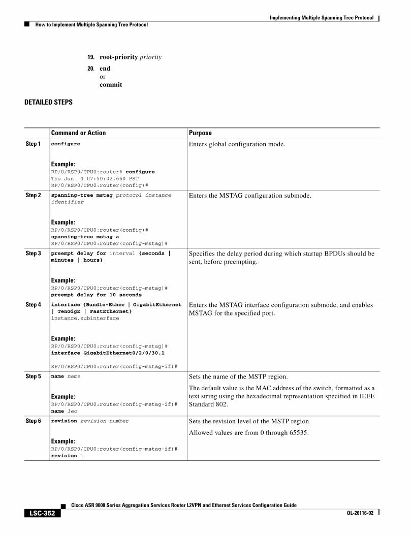
Implementing Multiple Spanning Tree ProtocolHow to Implement Multiple Spanning Tree Protocol
LSC-352Cisco ASR 9000 Series Aggregation Services Router L2VPN and Ethernet Services Configuration Guide
OL-26116-02
19. root-priority priority
20. endorcommit
DETAILED STEPS
Command or Action Purpose
Step 1 configure
Example:RP/0/RSP0/CPU0:router# configureThu Jun 4 07:50:02.660 PSTRP/0/RSP0/CPU0:router(config)#
Enters global configuration mode.
Step 2 spanning-tree mstag protocol instance identifier
Example:RP/0/RSP0/CPU0:router(config)# spanning-tree mstag aRP/0/RSP0/CPU0:router(config-mstag)#
Enters the MSTAG configuration submode.
Step 3 preempt delay for interval {seconds | minutes | hours}
Example:RP/0/RSP0/CPU0:router(config-mstag)#preempt delay for 10 seconds
Specifies the delay period during which startup BPDUs should be sent, before preempting.
Step 4 interface {Bundle-Ether | GigabitEthernet | TenGigE | FastEthernet} instance.subinterface
Example:RP/0/RSP0/CPU0:router(config-mstag)# interface GigabitEthernet0/2/0/30.1
RP/0/RSP0/CPU0:router(config-mstag-if)#
Enters the MSTAG interface configuration submode, and enables MSTAG for the specified port.
Step 5 name name
Example:RP/0/RSP0/CPU0:router(config-mstag-if)# name leo
Sets the name of the MSTP region.
The default value is the MAC address of the switch, formatted as a text string using the hexadecimal representation specified in IEEE Standard 802.
Step 6 revision revision-number
Example:RP/0/RSP0/CPU0:router(config-mstag-if)# revision 1
Sets the revision level of the MSTP region.
Allowed values are from 0 through 65535.
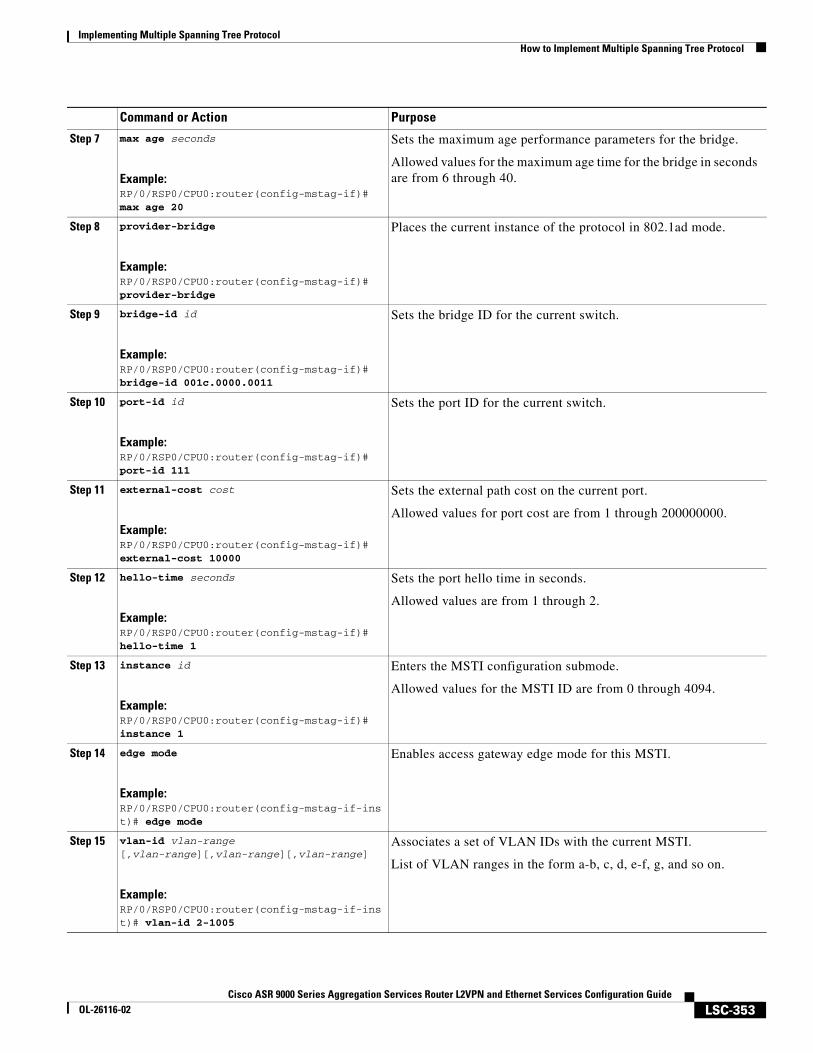
Implementing Multiple Spanning Tree ProtocolHow to Implement Multiple Spanning Tree Protocol
LSC-353Cisco ASR 9000 Series Aggregation Services Router L2VPN and Ethernet Services Configuration Guide
OL-26116-02
Step 7 max age seconds
Example:RP/0/RSP0/CPU0:router(config-mstag-if)# max age 20
Sets the maximum age performance parameters for the bridge.
Allowed values for the maximum age time for the bridge in seconds are from 6 through 40.
Step 8 provider-bridge
Example:RP/0/RSP0/CPU0:router(config-mstag-if)# provider-bridge
Places the current instance of the protocol in 802.1ad mode.
Step 9 bridge-id id
Example:RP/0/RSP0/CPU0:router(config-mstag-if)# bridge-id 001c.0000.0011
Sets the bridge ID for the current switch.
Step 10 port-id id
Example:RP/0/RSP0/CPU0:router(config-mstag-if)# port-id 111
Sets the port ID for the current switch.
Step 11 external-cost cost
Example:RP/0/RSP0/CPU0:router(config-mstag-if)# external-cost 10000
Sets the external path cost on the current port.
Allowed values for port cost are from 1 through 200000000.
Step 12 hello-time seconds
Example:RP/0/RSP0/CPU0:router(config-mstag-if)# hello-time 1
Sets the port hello time in seconds.
Allowed values are from 1 through 2.
Step 13 instance id
Example:RP/0/RSP0/CPU0:router(config-mstag-if)# instance 1
Enters the MSTI configuration submode.
Allowed values for the MSTI ID are from 0 through 4094.
Step 14 edge mode
Example:RP/0/RSP0/CPU0:router(config-mstag-if-inst)# edge mode
Enables access gateway edge mode for this MSTI.
Step 15 vlan-id vlan-range [,vlan-range][,vlan-range][,vlan-range]
Example:RP/0/RSP0/CPU0:router(config-mstag-if-inst)# vlan-id 2-1005
Associates a set of VLAN IDs with the current MSTI.
List of VLAN ranges in the form a-b, c, d, e-f, g, and so on.
Command or Action Purpose
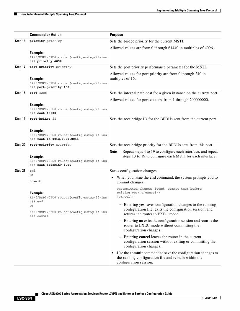
Implementing Multiple Spanning Tree ProtocolHow to Implement Multiple Spanning Tree Protocol
LSC-354Cisco ASR 9000 Series Aggregation Services Router L2VPN and Ethernet Services Configuration Guide
OL-26116-02
Step 16 priority priority
Example:RP/0/RSP0/CPU0:router(config-mstag-if-inst)# priority 4096
Sets the bridge priority for the current MSTI.
Allowed values are from 0 through 61440 in multiples of 4096.
Step 17 port-priority priority
Example:RP/0/RSP0/CPU0:router(config-mstag-if-inst)# port-priority 160
Sets the port priority performance parameter for the MSTI.
Allowed values for port priority are from 0 through 240 in multiples of 16.
Step 18 cost cost
Example:RP/0/RSP0/CPU0:router(config-mstag-if-inst)# cost 10000
Sets the internal path cost for a given instance on the current port.
Allowed values for port cost are from 1 through 200000000.
Step 19 root-bridge id
Example:RP/0/RSP0/CPU0:router(config-mstag-if-inst)# root-id 001c.0000.0011
Sets the root bridge ID for the BPDUs sent from the current port.
Step 20 root-priority priority
Example:RP/0/RSP0/CPU0:router(config-mstag-if-inst)# root-priority 4096
Sets the root bridge priority for the BPDUs sent from this port.
Note Repeat steps 4 to 19 to configure each interface, and repeat steps 13 to 19 to configure each MSTI for each interface.
Step 21 end
or
commit
Example:RP/0/RSP0/CPU0:router(config-mstag-if-inst)# end
or
RP/0/RSP0/CPU0:router(config-mstag-if-inst)# commit
Saves configuration changes.
• When you issue the end command, the system prompts you to commit changes:
Uncommitted changes found, commit them before exiting(yes/no/cancel)?[cancel]:
– Entering yes saves configuration changes to the running configuration file, exits the configuration session, and returns the router to EXEC mode.
– Entering no exits the configuration session and returns the router to EXEC mode without committing the configuration changes.
– Entering cancel leaves the router in the current configuration session without exiting or committing the configuration changes.
• Use the commit command to save the configuration changes to the running configuration file and remain within the configuration session.
Command or Action Purpose
Implementing Multiple Spanning Tree ProtocolHow to Implement Multiple Spanning Tree Protocol
LSC-355Cisco ASR 9000 Series Aggregation Services Router L2VPN and Ethernet Services Configuration Guide
OL-26116-02
Configuring MSTAG Topology Change Propagation
MSTAG Topology Change Propagation is configured simply by configuring connectivity between the MSTAG-enabled interfaces on the two gateway devices:
1. Configure MSTAG as described above. Take note of the untagged subinterface that is used.
2. Configure connectivity between the gateway devices. This may be via an MPLS Pseudowire, or may be a VLAN subinterface if there is a direct physical link.
3. Configure a point-to-point (P2P) cross-connect on each gateway device that contains the untagged subinterface and the link (PW or subinterface) to the other gateway device.
Once the untagged subinterface that is configured for MSTAG is added to the P2P cross-connect, MSTAG Topology Change Propagation is automatically enabled. MSTAG forwards BDPUs via the cross-connect to the other gateway device, so as to signal when a topology change has been detected.
For more information on configuring MPLS pseudowire or P2P cross-connects, refer to the Implementing Point to Point Layer 2 Services module.
Verifying MSTAG
These show commands allow you to verify the operation of MSTAG:
• show spanning-tree mstag mst-name
• show spanning-tree mstag mst-name bpdu interface interface-name
• show spanning-tree mstag mst-name topology-change flushes
Analogous commands are available for REPAG.
Configuring PVSTAG or PVRSTAGThis section describes the procedures for configuring PVSTAG:
• Enabling PVSTAG
• Configuring PVSTAG parameters
• Configuring Subinterfaces
• Verifying PVSTAG
The procedures for configuring PVRSTAG are identical.
Note This section does not describe how to configure data switching. Refer to the Implementing Multipoint Layer 2 Services module for more information.
Enabling PVSTAG
PVSTAG is enabled for a particular VLAN, on a physical interface, by explicit configuration of that physical interface and VLAN for PVSTAG.
Implementing Multiple Spanning Tree ProtocolHow to Implement Multiple Spanning Tree Protocol
LSC-356Cisco ASR 9000 Series Aggregation Services Router L2VPN and Ethernet Services Configuration Guide
OL-26116-02
Configuring PVSTAG parameters
The configurable PVSTAG parameters for each interface on each VLAN are:
• Root Priority and ID
• Root cost
• Bridge Priority and ID
• Port priority and ID
• Max Age
• Hello Time
For correct operation, these guidelines must be followed when configuring PVSTAG.
• Both gateway devices should be configured with a root bridge priority and ID that is better (lower) than the bridge priority and Bridge ID of any device in the access network. It is recommended that you set the root bridge priority and ID to 0 on the gateway devices.
• Both gateway devices should be configured with a root cost of 0.
• One gateway device should be configured with the bridge priority and ID that is higher than the root bridge priority and ID, but lower than the bridge priority and ID of any other device in the network (including the other gateway device). It is recommended that you set the bridge priority to 0.
• The second gateway device should be configured with a bridge priority and ID that is higher than the root bridge priority and ID and the first gateway device bridge priority and ID, but lower than the bridge priority and ID of any device in the access network. It is recommended that you set the bridge priority to 1 for PVSTAG or 4096 for PVRSTAG. (For PVRSTAG, this is the lowest allowable value greater than 0.)
• All access devices must be configured with a higher bridge priority than the gateway devices. It is recommended that you use values of 2 or higher for PVSTAG, or 8192 or higher for PVRSTAG.
• For each spanning tree instance, the port path cost and other parameters may be configured on the access devices, so as to ensure the desired port is placed into the blocked state when all links are up.
Caution There are no checks on PVSTAG configuration—misconfiguration may result in incorrect operation of the PVST protocol in the access devices (for example, an STP dispute being detected).
These guidelines are illustrated in Figure 35.
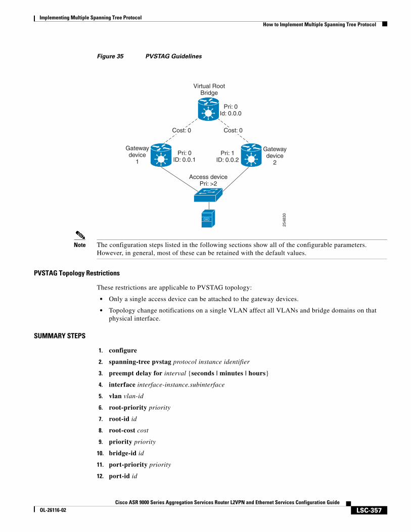
Implementing Multiple Spanning Tree ProtocolHow to Implement Multiple Spanning Tree Protocol
LSC-357Cisco ASR 9000 Series Aggregation Services Router L2VPN and Ethernet Services Configuration Guide
OL-26116-02
Figure 35 PVSTAG Guidelines
Note The configuration steps listed in the following sections show all of the configurable parameters. However, in general, most of these can be retained with the default values.
PVSTAG Topology Restrictions
These restrictions are applicable to PVSTAG topology:
• Only a single access device can be attached to the gateway devices.
• Topology change notifications on a single VLAN affect all VLANs and bridge domains on that physical interface.
SUMMARY STEPS
1. configure
2. spanning-tree pvstag protocol instance identifier
3. preempt delay for interval {seconds | minutes | hours}
4. interface interface-instance.subinterface
5. vlan vlan-id
6. root-priority priority
7. root-id id
8. root-cost cost
9. priority priority
10. bridge-id id
11. port-priority priority
12. port-id id
Virtual RootBridge
2548
30
Access devicePri: >2
Gatewaydevice
1
Gatewaydevice
2
Cost: 0
Pri: 0Id: 0.0.0
Pri: 0ID: 0.0.1
Pri: 1ID: 0.0.2
Cost: 0

Implementing Multiple Spanning Tree ProtocolHow to Implement Multiple Spanning Tree Protocol
LSC-358Cisco ASR 9000 Series Aggregation Services Router L2VPN and Ethernet Services Configuration Guide
OL-26116-02
13. hello-time seconds
14. max age seconds
15. endorcommit
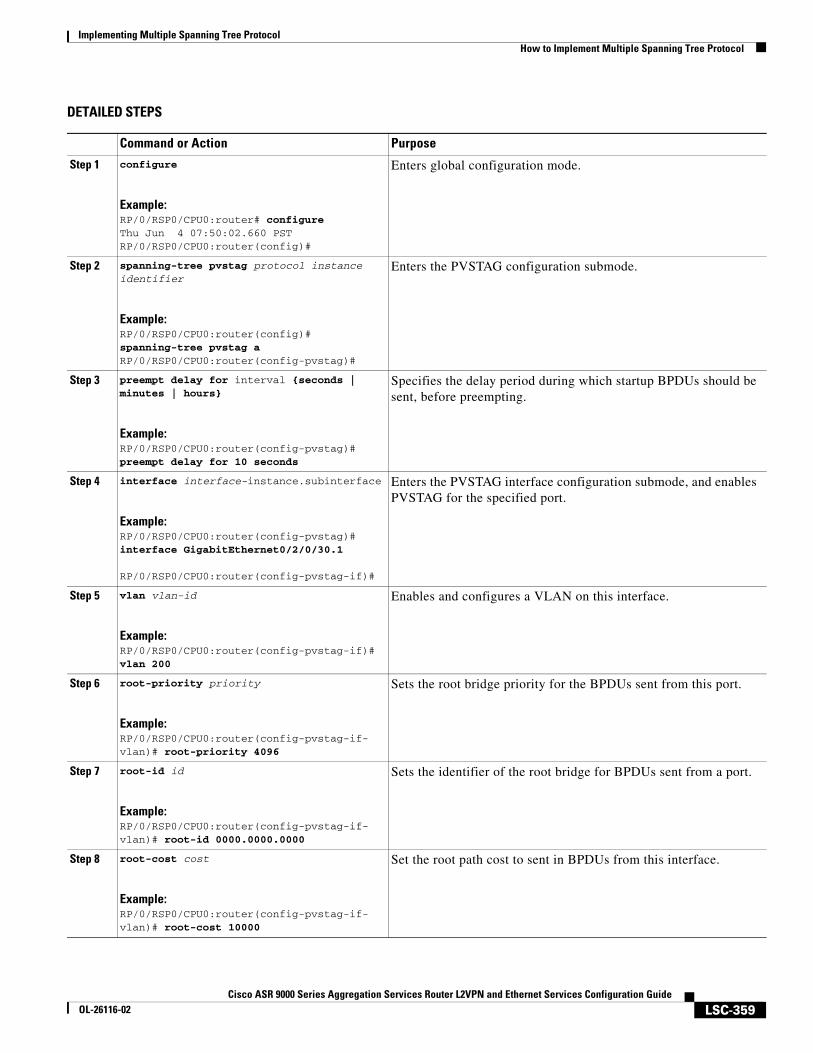
Implementing Multiple Spanning Tree ProtocolHow to Implement Multiple Spanning Tree Protocol
LSC-359Cisco ASR 9000 Series Aggregation Services Router L2VPN and Ethernet Services Configuration Guide
OL-26116-02
DETAILED STEPS
Command or Action Purpose
Step 1 configure
Example:RP/0/RSP0/CPU0:router# configureThu Jun 4 07:50:02.660 PSTRP/0/RSP0/CPU0:router(config)#
Enters global configuration mode.
Step 2 spanning-tree pvstag protocol instance identifier
Example:RP/0/RSP0/CPU0:router(config)# spanning-tree pvstag aRP/0/RSP0/CPU0:router(config-pvstag)#
Enters the PVSTAG configuration submode.
Step 3 preempt delay for interval {seconds | minutes | hours}
Example:RP/0/RSP0/CPU0:router(config-pvstag)#preempt delay for 10 seconds
Specifies the delay period during which startup BPDUs should be sent, before preempting.
Step 4 interface interface-instance.subinterface
Example:RP/0/RSP0/CPU0:router(config-pvstag)# interface GigabitEthernet0/2/0/30.1
RP/0/RSP0/CPU0:router(config-pvstag-if)#
Enters the PVSTAG interface configuration submode, and enables PVSTAG for the specified port.
Step 5 vlan vlan-id
Example:RP/0/RSP0/CPU0:router(config-pvstag-if)# vlan 200
Enables and configures a VLAN on this interface.
Step 6 root-priority priority
Example:RP/0/RSP0/CPU0:router(config-pvstag-if-vlan)# root-priority 4096
Sets the root bridge priority for the BPDUs sent from this port.
Step 7 root-id id
Example:RP/0/RSP0/CPU0:router(config-pvstag-if-vlan)# root-id 0000.0000.0000
Sets the identifier of the root bridge for BPDUs sent from a port.
Step 8 root-cost cost
Example:RP/0/RSP0/CPU0:router(config-pvstag-if-vlan)# root-cost 10000
Set the root path cost to sent in BPDUs from this interface.
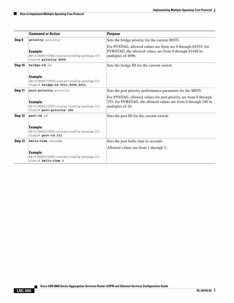
Implementing Multiple Spanning Tree ProtocolHow to Implement Multiple Spanning Tree Protocol
LSC-360Cisco ASR 9000 Series Aggregation Services Router L2VPN and Ethernet Services Configuration Guide
OL-26116-02
Step 9 priority priority
Example:RP/0/RSP0/CPU0:router(config-pvstag-if-vlan)# priority 4096
Sets the bridge priority for the current MSTI.
For PVSTAG, allowed values are from are 0 through 65535; for PVRSTAG, the allowed values are from 0 through 61440 in multiples of 4096.
Step 10 bridge-id id
Example:RP/0/RSP0/CPU0:router(config-pvstag-if-vlan)# bridge-id 001c.0000.0011
Sets the bridge ID for the current switch.
Step 11 port-priority priority
Example:RP/0/RSP0/CPU0:router(config-pvstag-if-vlan)# port-priority 160
Sets the port priority performance parameter for the MSTI.
For PVSTAG, allowed values for port priority are from 0 through 255; for PVRSTAG, the allowed values are from 0 through 240 in multiples of 16.
Step 12 port-id id
Example:RP/0/RSP0/CPU0:router(config-pvstag-if-vlan)# port-id 111
Sets the port ID for the current switch.
Step 13 hello-time seconds
Example:RP/0/RSP0/CPU0:router(config-pvstag-if-vlan)# hello-time 1
Sets the port hello time in seconds.
Allowed values are from 1 through 2.
Command or Action Purpose
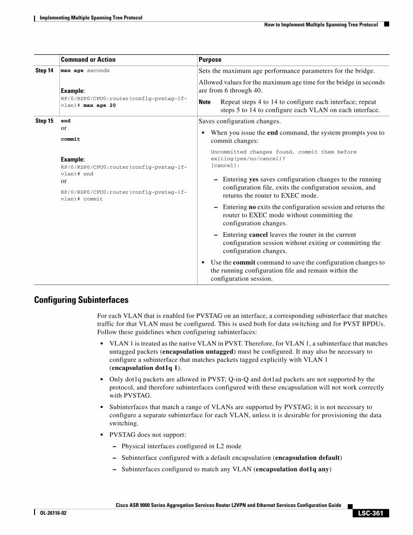
Implementing Multiple Spanning Tree ProtocolHow to Implement Multiple Spanning Tree Protocol
LSC-361Cisco ASR 9000 Series Aggregation Services Router L2VPN and Ethernet Services Configuration Guide
OL-26116-02
Configuring Subinterfaces
For each VLAN that is enabled for PVSTAG on an interface, a corresponding subinterface that matches traffic for that VLAN must be configured. This is used both for data switching and for PVST BPDUs. Follow these guidelines when configuring subinterfaces:
• VLAN 1 is treated as the native VLAN in PVST. Therefore, for VLAN 1, a subinterface that matches untagged packets (encapsulation untagged) must be configured. It may also be necessary to configure a subinterface that matches packets tagged explicitly with VLAN 1 (encapsulation dot1q 1).
• Only dot1q packets are allowed in PVST; Q-in-Q and dot1ad packets are not supported by the protocol, and therefore subinterfaces configured with these encapsulation will not work correctly with PVSTAG.
• Subinterfaces that match a range of VLANs are supported by PVSTAG; it is not necessary to configure a separate subinterface for each VLAN, unless it is desirable for provisioning the data switching.
• PVSTAG does not support:
– Physical interfaces configured in L2 mode
– Subinterface configured with a default encapsulation (encapsulation default)
– Subinterfaces configured to match any VLAN (encapsulation dot1q any)
Step 14 max age seconds
Example:RP/0/RSP0/CPU0:router(config-pvstag-if-vlan)# max age 20
Sets the maximum age performance parameters for the bridge.
Allowed values for the maximum age time for the bridge in seconds are from 6 through 40.
Note Repeat steps 4 to 14 to configure each interface; repeat steps 5 to 14 to configure each VLAN on each interface.
Step 15 end
or
commit
Example:RP/0/RSP0/CPU0:router(config-pvstag-if-vlan)# end
or
RP/0/RSP0/CPU0:router(config-pvstag-if-vlan)# commit
Saves configuration changes.
• When you issue the end command, the system prompts you to commit changes:
Uncommitted changes found, commit them before exiting(yes/no/cancel)?[cancel]:
– Entering yes saves configuration changes to the running configuration file, exits the configuration session, and returns the router to EXEC mode.
– Entering no exits the configuration session and returns the router to EXEC mode without committing the configuration changes.
– Entering cancel leaves the router in the current configuration session without exiting or committing the configuration changes.
• Use the commit command to save the configuration changes to the running configuration file and remain within the configuration session.
Command or Action Purpose
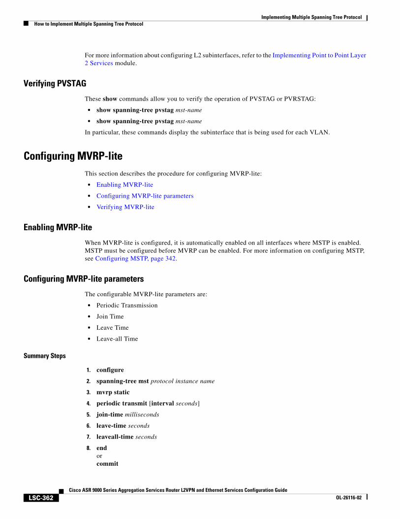
Implementing Multiple Spanning Tree ProtocolHow to Implement Multiple Spanning Tree Protocol
LSC-362Cisco ASR 9000 Series Aggregation Services Router L2VPN and Ethernet Services Configuration Guide
OL-26116-02
For more information about configuring L2 subinterfaces, refer to the Implementing Point to Point Layer 2 Services module.
Verifying PVSTAG
These show commands allow you to verify the operation of PVSTAG or PVRSTAG:
• show spanning-tree pvstag mst-name
• show spanning-tree pvstag mst-name
In particular, these commands display the subinterface that is being used for each VLAN.
Configuring MVRP-liteThis section describes the procedure for configuring MVRP-lite:
• Enabling MVRP-lite
• Configuring MVRP-lite parameters
• Verifying MVRP-lite
Enabling MVRP-lite
When MVRP-lite is configured, it is automatically enabled on all interfaces where MSTP is enabled. MSTP must be configured before MVRP can be enabled. For more information on configuring MSTP, see Configuring MSTP, page 342.
Configuring MVRP-lite parameters
The configurable MVRP-lite parameters are:
• Periodic Transmission
• Join Time
• Leave Time
• Leave-all Time
Summary Steps
1. configure
2. spanning-tree mst protocol instance name
3. mvrp static
4. periodic transmit [interval seconds]
5. join-time milliseconds
6. leave-time seconds
7. leaveall-time seconds
8. endorcommit
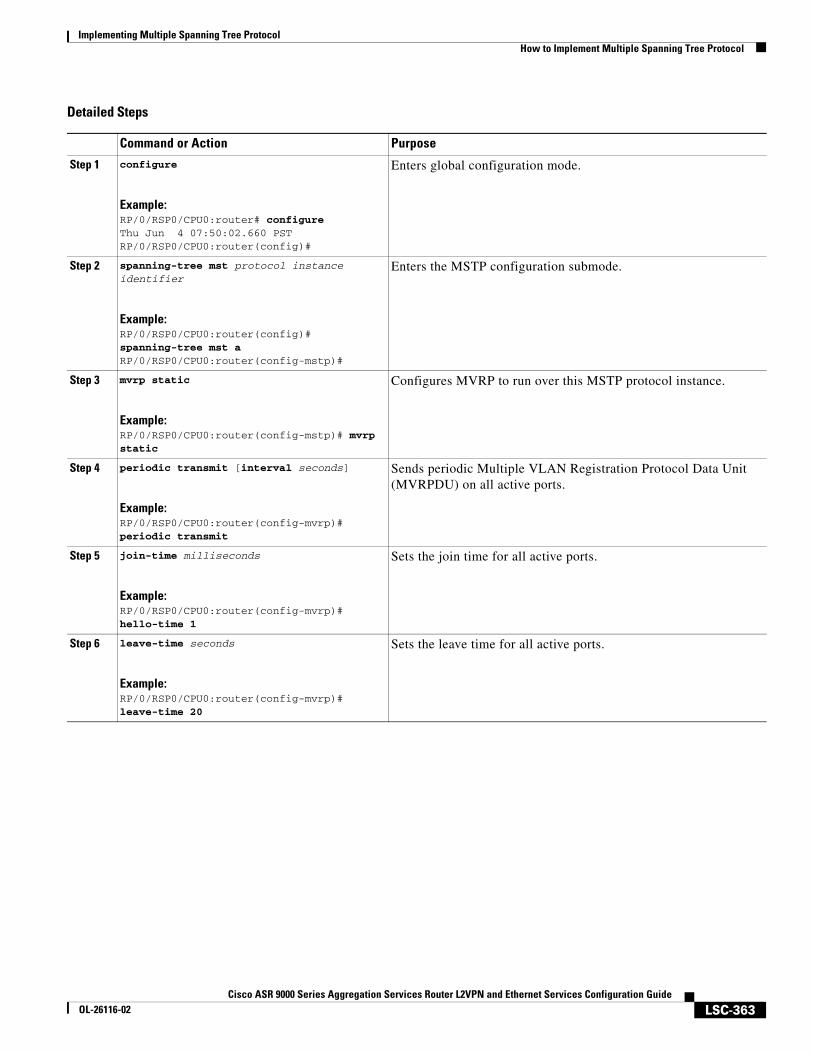
Implementing Multiple Spanning Tree ProtocolHow to Implement Multiple Spanning Tree Protocol
LSC-363Cisco ASR 9000 Series Aggregation Services Router L2VPN and Ethernet Services Configuration Guide
OL-26116-02
Detailed Steps
Command or Action Purpose
Step 1 configure
Example:RP/0/RSP0/CPU0:router# configureThu Jun 4 07:50:02.660 PSTRP/0/RSP0/CPU0:router(config)#
Enters global configuration mode.
Step 2 spanning-tree mst protocol instance identifier
Example:RP/0/RSP0/CPU0:router(config)# spanning-tree mst aRP/0/RSP0/CPU0:router(config-mstp)#
Enters the MSTP configuration submode.
Step 3 mvrp static
Example:RP/0/RSP0/CPU0:router(config-mstp)# mvrp static
Configures MVRP to run over this MSTP protocol instance.
Step 4 periodic transmit [interval seconds]
Example:RP/0/RSP0/CPU0:router(config-mvrp)# periodic transmit
Sends periodic Multiple VLAN Registration Protocol Data Unit (MVRPDU) on all active ports.
Step 5 join-time milliseconds
Example:RP/0/RSP0/CPU0:router(config-mvrp)# hello-time 1
Sets the join time for all active ports.
Step 6 leave-time seconds
Example:RP/0/RSP0/CPU0:router(config-mvrp)# leave-time 20
Sets the leave time for all active ports.
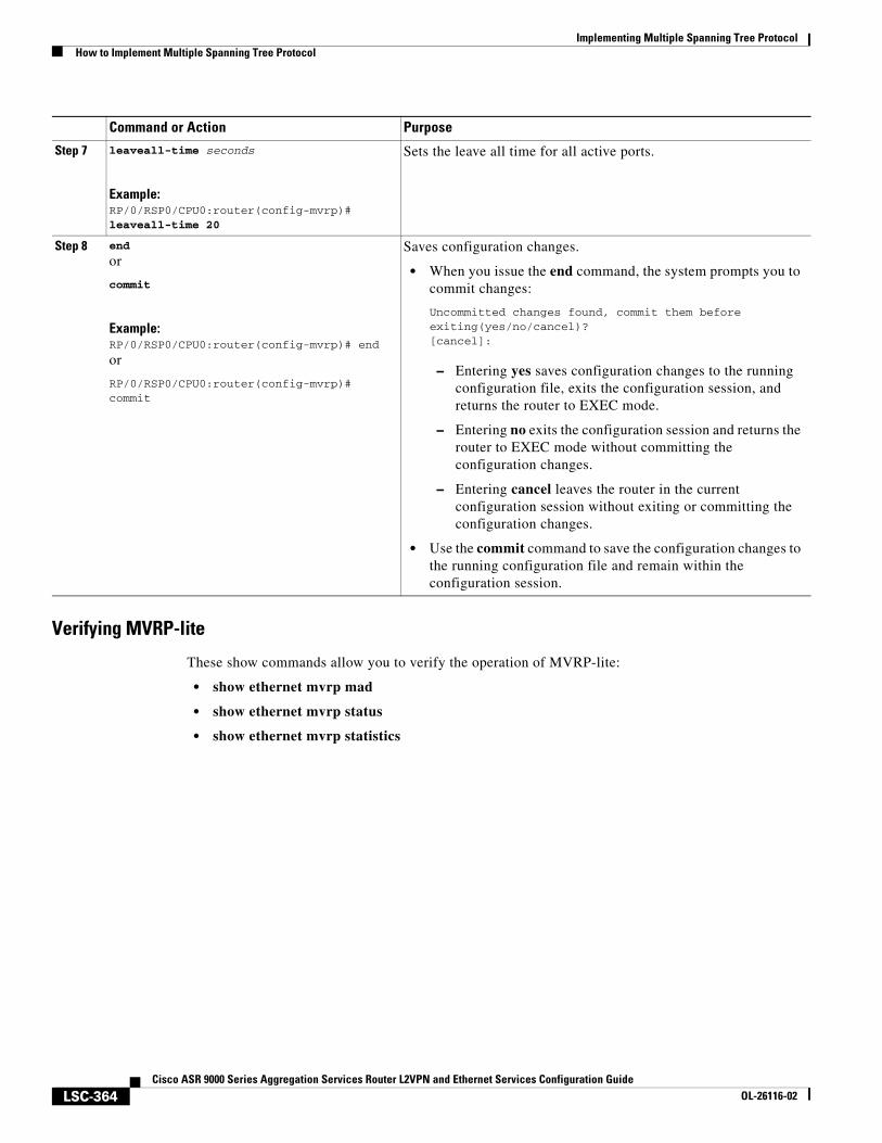
Implementing Multiple Spanning Tree ProtocolHow to Implement Multiple Spanning Tree Protocol
LSC-364Cisco ASR 9000 Series Aggregation Services Router L2VPN and Ethernet Services Configuration Guide
OL-26116-02
Verifying MVRP-lite
These show commands allow you to verify the operation of MVRP-lite:
• show ethernet mvrp mad
• show ethernet mvrp status
• show ethernet mvrp statistics
Step 7 leaveall-time seconds
Example:RP/0/RSP0/CPU0:router(config-mvrp)# leaveall-time 20
Sets the leave all time for all active ports.
Step 8 end
or
commit
Example:RP/0/RSP0/CPU0:router(config-mvrp)# end
or
RP/0/RSP0/CPU0:router(config-mvrp)# commit
Saves configuration changes.
• When you issue the end command, the system prompts you to commit changes:
Uncommitted changes found, commit them before exiting(yes/no/cancel)?[cancel]:
– Entering yes saves configuration changes to the running configuration file, exits the configuration session, and returns the router to EXEC mode.
– Entering no exits the configuration session and returns the router to EXEC mode without committing the configuration changes.
– Entering cancel leaves the router in the current configuration session without exiting or committing the configuration changes.
• Use the commit command to save the configuration changes to the running configuration file and remain within the configuration session.
Command or Action Purpose
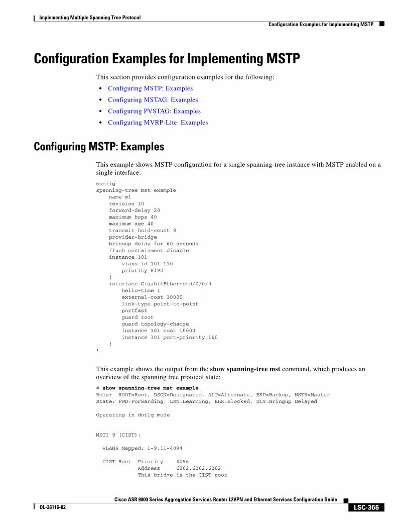
Implementing Multiple Spanning Tree ProtocolConfiguration Examples for Implementing MSTP
LSC-365Cisco ASR 9000 Series Aggregation Services Router L2VPN and Ethernet Services Configuration Guide
OL-26116-02
Configuration Examples for Implementing MSTPThis section provides configuration examples for the following:
• Configuring MSTP: Examples
• Configuring MSTAG: Examples
• Configuring PVSTAG: Examples
• Configuring MVRP-Lite: Examples
Configuring MSTP: ExamplesThis example shows MSTP configuration for a single spanning-tree instance with MSTP enabled on a single interface:
configspanning-tree mst example name m1 revision 10 forward-delay 20 maximum hops 40 maximum age 40 transmit hold-count 8 provider-bridge bringup delay for 60 seconds flush containment disable instance 101 vlans-id 101-110 priority 8192 ! interface GigabitEthernet0/0/0/0 hello-time 1 external-cost 10000 link-type point-to-point portfast guard root guard topology-change instance 101 cost 10000 instance 101 port-priority 160 !!
This example shows the output from the show spanning-tree mst command, which produces an overview of the spanning tree protocol state:
# show spanning-tree mst exampleRole: ROOT=Root, DSGN=Designated, ALT=Alternate, BKP=Backup, MSTR=MasterState: FWD=Forwarding, LRN=Learning, BLK=Blocked, DLY=Bringup Delayed
Operating in dot1q mode
MSTI 0 (CIST):
VLANS Mapped: 1-9,11-4094
CIST Root Priority 4096 Address 6262.6262.6262 This bridge is the CIST root
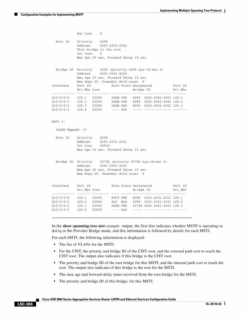
Implementing Multiple Spanning Tree ProtocolConfiguration Examples for Implementing MSTP
LSC-366Cisco ASR 9000 Series Aggregation Services Router L2VPN and Ethernet Services Configuration Guide
OL-26116-02
Ext Cost 0
Root ID Priority 4096 Address 6262.6262.6262 This bridge is the root Int Cost 0 Max Age 20 sec, Forward Delay 15 sec
Bridge ID Priority 4096 (priority 4096 sys-id-ext 0) Address 6262.6262.6262 Max Age 20 sec, Forward Delay 15 sec Max Hops 20, Transmit Hold count 6Interface Port ID Role State Designated Port ID Pri.Nbr Cost Bridge ID Pri.Nbr ------------ ------- --------- ---- ----- -------------------- -------Gi0/0/0/0 128.1 20000 DSGN FWD 4096 6262.6262.6262 128.1 Gi0/0/0/1 128.2 20000 DSGN FWD 4096 6262.6262.6262 128.2 Gi0/0/0/2 128.3 20000 DSGN FWD 4096 6262.6262.6262 128.3 Gi0/0/0/3 128.4 20000 ---- BLK ----- -------------- -------
MSTI 1:
VLANS Mapped: 10
Root ID Priority 4096 Address 6161.6161.6161 Int Cost 20000 Max Age 20 sec, Forward Delay 15 sec
Bridge ID Priority 32768 (priority 32768 sys-id-ext 0) Address 6262.6262.6262 Max Age 20 sec, Forward Delay 15 sec Max Hops 20, Transmit Hold count 6
Interface Port ID Role State Designated Port ID Pri.Nbr Cost Bridge ID Pri.Nbr ------------ ------- --------- ---- ----- -------------------- -------Gi0/0/0/0 128.1 20000 ROOT FWD 4096 6161.6161.6161 128.1 Gi0/0/0/1 128.2 20000 ALT BLK 4096 6161.6161.6161 128.2 Gi0/0/0/2 128.3 20000 DSGN FWD 32768 6262.6262.6262 128.3 Gi0/0/0/3 128.4 20000 ---- BLK ----- -------------- -------
=========================================================================
In the show spanning-tree mst example output, the first line indicates whether MSTP is operating in dot1q or the Provider Bridge mode, and this information is followed by details for each MSTI.
For each MSTI, the following information is displayed:
• The list of VLANs for the MSTI.
• For the CIST, the priority and bridge ID of the CIST root, and the external path cost to reach the CIST root. The output also indicates if this bridge is the CIST root.
• The priority and bridge ID of the root bridge for this MSTI, and the internal path cost to reach the root. The output also indicates if this bridge is the root for the MSTI.
• The max age and forward delay times received from the root bridge for the MSTI.
• The priority and bridge ID of this bridge, for this MSTI.
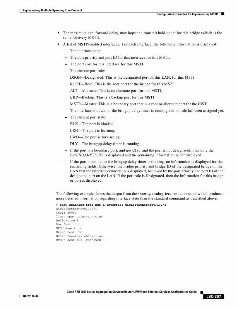
Implementing Multiple Spanning Tree ProtocolConfiguration Examples for Implementing MSTP
LSC-367Cisco ASR 9000 Series Aggregation Services Router L2VPN and Ethernet Services Configuration Guide
OL-26116-02
• The maximum age, forward delay, max hops and transmit hold-count for this bridge (which is the same for every MSTI).
• A list of MSTP-enabled interfaces. For each interface, the following information is displayed:
– The interface name
– The port priority and port ID for this interface for this MSTI.
– The port cost for this interface for this MSTI.
– The current port role:
DSGN—Designated: This is the designated port on this LAN, for this MSTI
ROOT—Root: This is the root port for the bridge for this MSTI.
ALT—Alternate: This is an alternate port for this MSTI.
BKP—Backup: This is a backup port for this MSTI
MSTR—Master: This is a boundary port that is a root or alternate port for the CIST.
The interface is down, or the bringup delay timer is running and no role has been assigned yet.
– The current port state:
BLK—The port is blocked.
LRN—The port is learning.
FWD—The port is forwarding.
DLY—The bringup-delay timer is running.
– If the port is a boundary port, and not CIST and the port is not designated, then only the BOUNDARY PORT is displayed and the remaining information is not displayed.
– If the port is not up, or the bringup delay timer is running, no information is displayed for the remaining fields. Otherwise, the bridge priority and bridge ID of the designated bridge on the LAN that the interface connects to is displayed, followed by the port priority and port ID of the designated port on the LAN. If the port role is Designated, then the information for this bridge or port is displayed.
The following example shows the output from the show spanning-tree mst command, which produces more detailed information regarding interface state than the standard command as described above:
# show spanning-tree mst a interface GigabitEthernet0/1/2/1GigabitEthernet0/1/2/1 Cost: 20000link-type: point-to-pointhello-time 1Portfast: noBPDU Guard: noGuard root: noGuard topology change: noBPDUs sent 492, received 3
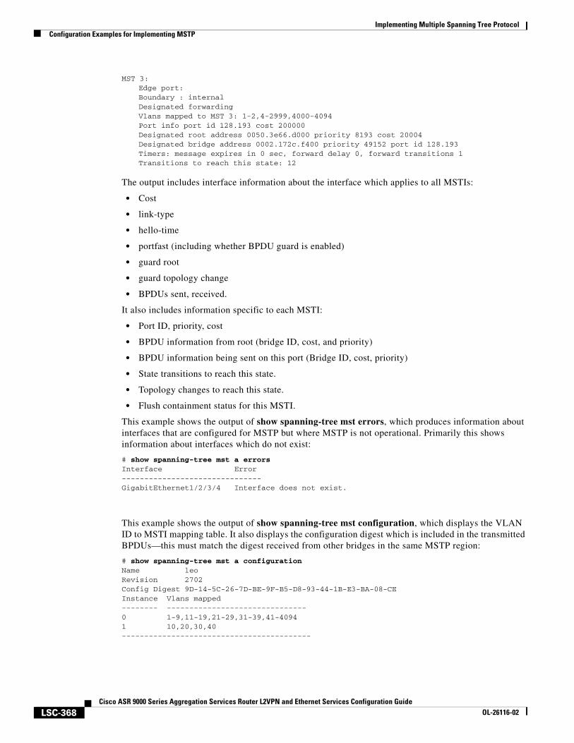
Implementing Multiple Spanning Tree ProtocolConfiguration Examples for Implementing MSTP
LSC-368Cisco ASR 9000 Series Aggregation Services Router L2VPN and Ethernet Services Configuration Guide
OL-26116-02
MST 3:Edge port: Boundary : internalDesignated forwarding Vlans mapped to MST 3: 1-2,4-2999,4000-4094 Port info port id 128.193 cost 200000 Designated root address 0050.3e66.d000 priority 8193 cost 20004 Designated bridge address 0002.172c.f400 priority 49152 port id 128.193 Timers: message expires in 0 sec, forward delay 0, forward transitions 1 Transitions to reach this state: 12
The output includes interface information about the interface which applies to all MSTIs:
• Cost
• link-type
• hello-time
• portfast (including whether BPDU guard is enabled)
• guard root
• guard topology change
• BPDUs sent, received.
It also includes information specific to each MSTI:
• Port ID, priority, cost
• BPDU information from root (bridge ID, cost, and priority)
• BPDU information being sent on this port (Bridge ID, cost, priority)
• State transitions to reach this state.
• Topology changes to reach this state.
• Flush containment status for this MSTI.
This example shows the output of show spanning-tree mst errors, which produces information about interfaces that are configured for MSTP but where MSTP is not operational. Primarily this shows information about interfaces which do not exist:
# show spanning-tree mst a errorsInterface Error-------------------------------GigabitEthernet1/2/3/4 Interface does not exist.
This example shows the output of show spanning-tree mst configuration, which displays the VLAN ID to MSTI mapping table. It also displays the configuration digest which is included in the transmitted BPDUs—this must match the digest received from other bridges in the same MSTP region:
# show spanning-tree mst a configurationName leoRevision 2702Config Digest 9D-14-5C-26-7D-BE-9F-B5-D8-93-44-1B-E3-BA-08-CE Instance Vlans mapped-------- -------------------------------0 1-9,11-19,21-29,31-39,41-40941 10,20,30,40------------------------------------------
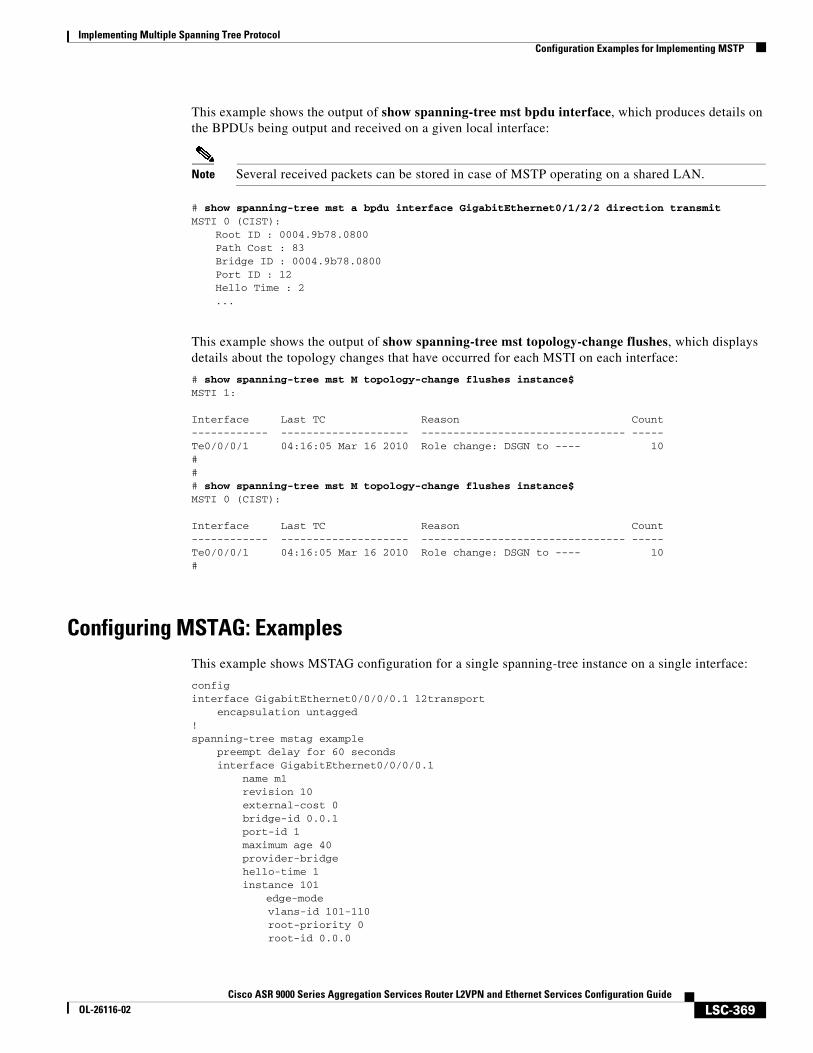
Implementing Multiple Spanning Tree ProtocolConfiguration Examples for Implementing MSTP
LSC-369Cisco ASR 9000 Series Aggregation Services Router L2VPN and Ethernet Services Configuration Guide
OL-26116-02
This example shows the output of show spanning-tree mst bpdu interface, which produces details on the BPDUs being output and received on a given local interface:
Note Several received packets can be stored in case of MSTP operating on a shared LAN.
# show spanning-tree mst a bpdu interface GigabitEthernet0/1/2/2 direction transmitMSTI 0 (CIST):
Root ID : 0004.9b78.0800Path Cost : 83Bridge ID : 0004.9b78.0800Port ID : 12Hello Time : 2...
This example shows the output of show spanning-tree mst topology-change flushes, which displays details about the topology changes that have occurred for each MSTI on each interface:
# show spanning-tree mst M topology-change flushes instance$MSTI 1: Interface Last TC Reason Count------------ -------------------- -------------------------------- -----Te0/0/0/1 04:16:05 Mar 16 2010 Role change: DSGN to ---- 10### show spanning-tree mst M topology-change flushes instance$MSTI 0 (CIST): Interface Last TC Reason Count------------ -------------------- -------------------------------- -----Te0/0/0/1 04:16:05 Mar 16 2010 Role change: DSGN to ---- 10#
Configuring MSTAG: ExamplesThis example shows MSTAG configuration for a single spanning-tree instance on a single interface:
configinterface GigabitEthernet0/0/0/0.1 l2transport encapsulation untagged!spanning-tree mstag example preempt delay for 60 seconds interface GigabitEthernet0/0/0/0.1 name m1 revision 10 external-cost 0 bridge-id 0.0.1 port-id 1 maximum age 40 provider-bridge hello-time 1 instance 101
edge-mode vlans-id 101-110 root-priority 0 root-id 0.0.0
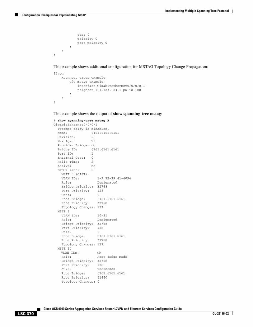
Implementing Multiple Spanning Tree ProtocolConfiguration Examples for Implementing MSTP
LSC-370Cisco ASR 9000 Series Aggregation Services Router L2VPN and Ethernet Services Configuration Guide
OL-26116-02
cost 0 priority 0 port-priority 0 ! !!
This example shows additional configuration for MSTAG Topology Change Propagation:
l2vpn xconnect group example p2p mstag-example interface GigabitEthernet0/0/0/0.1 neighbor 123.123.123.1 pw-id 100 ! !!
This example shows the output of show spanning-tree mstag:
# show spanning-tree mstag AGigabitEthernet0/0/0/1 Preempt delay is disabled. Name: 6161:6161:6161 Revision: 0 Max Age: 20 Provider Bridge: no Bridge ID: 6161.6161.6161 Port ID: 1 External Cost: 0 Hello Time: 2 Active: no BPDUs sent: 0 MSTI 0 (CIST): VLAN IDs: 1-9,32-39,41-4094 Role: Designated Bridge Priority: 32768 Port Priority: 128 Cost: 0 Root Bridge: 6161.6161.6161 Root Priority: 32768 Topology Changes: 123 MSTI 2 VLAN IDs: 10-31 Role: Designated Bridge Priority: 32768 Port Priority: 128 Cost: 0 Root Bridge: 6161.6161.6161 Root Priority: 32768 Topology Changes: 123 MSTI 10
VLAN IDs: 40 Role: Root (Edge mode) Bridge Priority: 32768 Port Priority: 128 Cost: 200000000 Root Bridge: 6161.6161.6161 Root Priority: 61440 Topology Changes: 0
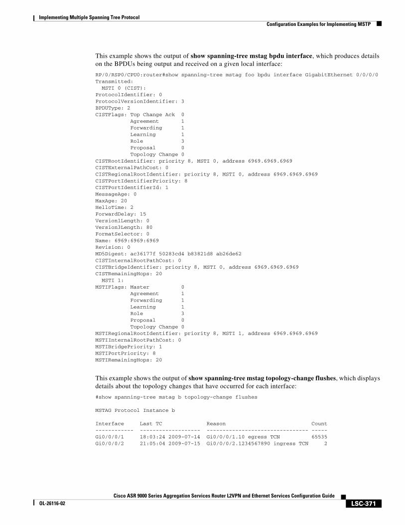
Implementing Multiple Spanning Tree ProtocolConfiguration Examples for Implementing MSTP
LSC-371Cisco ASR 9000 Series Aggregation Services Router L2VPN and Ethernet Services Configuration Guide
OL-26116-02
This example shows the output of show spanning-tree mstag bpdu interface, which produces details on the BPDUs being output and received on a given local interface:
RP/0/RSP0/CPU0:router#show spanning-tree mstag foo bpdu interface GigabitEthernet 0/0/0/0Transmitted: MSTI 0 (CIST):ProtocolIdentifier: 0ProtocolVersionIdentifier: 3BPDUType: 2CISTFlags: Top Change Ack 0 Agreement 1 Forwarding 1 Learning 1 Role 3 Proposal 0 Topology Change 0CISTRootIdentifier: priority 8, MSTI 0, address 6969.6969.6969CISTExternalPathCost: 0CISTRegionalRootIdentifier: priority 8, MSTI 0, address 6969.6969.6969CISTPortIdentifierPriority: 8CISTPortIdentifierId: 1MessageAge: 0MaxAge: 20HelloTime: 2ForwardDelay: 15Version1Length: 0Version3Length: 80FormatSelector: 0Name: 6969:6969:6969Revision: 0MD5Digest: ac36177f 50283cd4 b83821d8 ab26de62CISTInternalRootPathCost: 0CISTBridgeIdentifier: priority 8, MSTI 0, address 6969.6969.6969CISTRemainingHops: 20 MSTI 1:MSTIFlags: Master 0 Agreement 1 Forwarding 1 Learning 1 Role 3 Proposal 0 Topology Change 0MSTIRegionalRootIdentifier: priority 8, MSTI 1, address 6969.6969.6969MSTIInternalRootPathCost: 0MSTIBridgePriority: 1MSTIPortPriority: 8MSTIRemainingHops: 20
This example shows the output of show spanning-tree mstag topology-change flushes, which displays details about the topology changes that have occurred for each interface:
#show spanning-tree mstag b topology-change flushes
MSTAG Protocol Instance b
Interface Last TC Reason Count------------ ------------------- -------------------------------- -----Gi0/0/0/1 18:03:24 2009-07-14 Gi0/0/0/1.10 egress TCN 65535Gi0/0/0/2 21:05:04 2009-07-15 Gi0/0/0/2.1234567890 ingress TCN 2
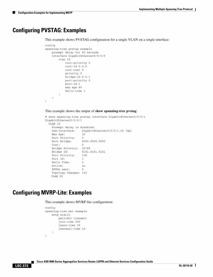
Implementing Multiple Spanning Tree ProtocolConfiguration Examples for Implementing MSTP
LSC-372Cisco ASR 9000 Series Aggregation Services Router L2VPN and Ethernet Services Configuration Guide
OL-26116-02
Configuring PVSTAG: ExamplesThis example shows PVSTAG configuration for a single VLAN on a single interface:
configspanning-tree pvstag example preempt delay for 60 seconds interface GigabitEthernet0/0/0/0 vlan 10 root-priority 0 root-id 0.0.0 root-cost 0 priority 0 bridge-id 0.0.1 port-priority 0 port-id 1 max age 40 hello-time 1 ! !!
This example shows the output of show spanning-tree pvstag:
# show spanning-tree pvstag interface GigabitEthernet0/0/0/1GigabitEthernet0/0/0/1 VLAN 10 Preempt delay is disabled. Sub-interface: GigabitEthernet0/0/0/1.20 (Up) Max Age: 20 Root Priority: 0 Root Bridge: 0000.0000.0000 Cost: 0 Bridge Priority: 32768 Bridge ID: 6161.6161.6161 Port Priority: 128 Port ID: 1 Hello Time: 2 Active: no BPDUs sent: 0 Topology Changes: 123 VLAN 20
Configuring MVRP-Lite: ExamplesThis example shows MVRP-lite configuration:
configspanning-tree mst example mvrp static periodic transmit join-time 200 leave-time 30 leaveall-time 10 !!
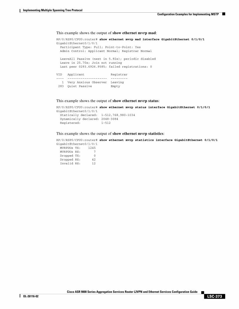
Implementing Multiple Spanning Tree ProtocolConfiguration Examples for Implementing MSTP
LSC-373Cisco ASR 9000 Series Aggregation Services Router L2VPN and Ethernet Services Configuration Guide
OL-26116-02
This example shows the output of show ethernet mvrp mad:
RP/0/RSP0/CPU0:router# show ethernet mvrp mad interface GigabitEthernet 0/1/0/1GigabitEthernet0/1/0/1 Participant Type: Full; Point-to-Point: Yes Admin Control: Applicant Normal; Registrar Normal
LeaveAll Passive (next in 5.92s); periodic disabled Leave in 25.70s; Join not running Last peer 0293.6926.9585; failed registrations: 0
VID Applicant Registrar---- --------------------- --------- 1 Very Anxious Observer Leaving 283 Quiet Passive Empty
This example shows the output of show ethernet mvrp status:
RP/0/RSP0/CPU0:router# show ethernet mvrp status interface GigabitEthernet 0/1/0/1GigabitEthernet0/1/0/1 Statically declared: 1-512,768,980-1034 Dynamically declared: 2048-3084 Registered: 1-512
This example shows the output of show ethernet mvrp statistics:
RP/0/RSP0/CPU0:router# show ethernet mvrp statistics interface GigabitEthernet 0/1/0/1GigabitEthernet0/1/0/1 MVRPDUs TX: 1245 MVRPDUs RX: 7 Dropped TX: 0 Dropped RX: 42 Invalid RX: 12
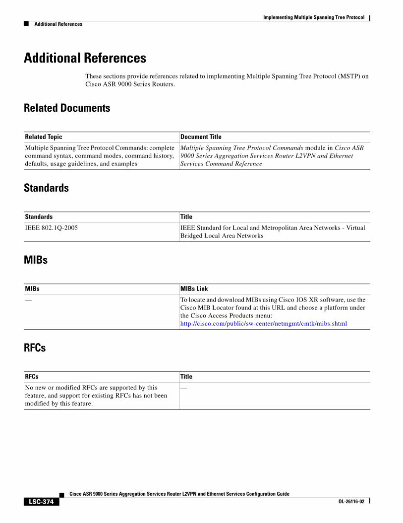
Implementing Multiple Spanning Tree ProtocolAdditional References
LSC-374Cisco ASR 9000 Series Aggregation Services Router L2VPN and Ethernet Services Configuration Guide
OL-26116-02
Additional ReferencesThese sections provide references related to implementing Multiple Spanning Tree Protocol (MSTP) on Cisco ASR 9000 Series Routers.
Related Documents
Standards
MIBs
RFCs
Related Topic Document Title
Multiple Spanning Tree Protocol Commands: complete command syntax, command modes, command history, defaults, usage guidelines, and examples
Multiple Spanning Tree Protocol Commands module in Cisco ASR 9000 Series Aggregation Services Router L2VPN and Ethernet Services Command Reference
Standards Title
IEEE 802.1Q-2005 IEEE Standard for Local and Metropolitan Area Networks - Virtual Bridged Local Area Networks
MIBs MIBs Link
— To locate and download MIBs using Cisco IOS XR software, use the Cisco MIB Locator found at this URL and choose a platform under the Cisco Access Products menu: http://cisco.com/public/sw-center/netmgmt/cmtk/mibs.shtml
RFCs Title
No new or modified RFCs are supported by this feature, and support for existing RFCs has not been modified by this feature.
—
Implementing Multiple Spanning Tree ProtocolAdditional References
LSC-375Cisco ASR 9000 Series Aggregation Services Router L2VPN and Ethernet Services Configuration Guide
OL-26116-02
Technical Assistance
Description Link
The Cisco Technical Support website contains thousands of pages of searchable technical content, including links to products, technologies, solutions, technical tips, and tools. Registered Cisco.com users can log in from this page to access even more content.
http://www.cisco.com/techsupport

Implementing Multiple Spanning Tree ProtocolAdditional References
LSC-376Cisco ASR 9000 Series Aggregation Services Router L2VPN and Ethernet Services Configuration Guide
OL-26116-02
LSC-377Cisco ASR 9000 Series Aggregation Services Router L2VPN and Ethernet Services Configuration Guide
OL-26116-02
Implementing Layer 2 Access Lists
An Ethernet services access control list (ACL) consists of one or more access control entries (ACE) that collectively define the Layer 2 network traffic profile. This profile can then be referenced by Cisco IOS XR software features. Each Ethernet services ACL includes an action element (permit or deny) based on criteria such as source and destination address, Class of Service (CoS), or VLAN ID.
This module describes tasks required to implement Ethernet services access lists on your Cisco ASR 9000 Series Aggregation Services Router.
Note For a complete description of the Ethernet services access list commands listed in this module, refer to the Ethernet Services (Layer 2) Access List Commands on Cisco ASR 9000 Series Routers module in the Cisco ASR 9000 Series Aggregation Services Router IP Addresses and Services Command Reference publication. To locate documentation of other commands that appear in this chapter, use the command reference master index, or search online.
Feature History for Implementing Ethernet Services Access Lists on Cisco ASR 9000 Series Routers
Contents• Prerequisites for Implementing Layer 2 Access Lists, page 378
• Information About Implementing Layer 2 Access Lists, page 378
• How to Implement Layer 2 Access Lists, page 380
• Configuration Examples for Implementing Layer 2 Access Lists, page 387
• Additional References, page 388
Release Modification
Release 3.7.2 This feature was introduced on Cisco ASR 9000 Series Routers.
Implementing Layer 2 Access ListsPrerequisites for Implementing Layer 2 Access Lists
LSC-378Cisco ASR 9000 Series Aggregation Services Router L2VPN and Ethernet Services Configuration Guide
OL-26116-02
Prerequisites for Implementing Layer 2 Access ListsThis prerequisite applies to implementing access lists and prefix lists:
You must be in a user group associated with a task group that includes the proper task IDs. The command reference guides include the task IDs required for each command.
If you suspect user group assignment is preventing you from using a command, contact your AAA administrator for assistance.
Information About Implementing Layer 2 Access ListsTo implement Ethernet services access lists, you must understand these concepts:
• Ethernet Services Access Lists Feature Highlights, page 378
• Purpose of Ethernet Services Access Lists, page 378
• How an Ethernet Services Access List Works, page 378
• Ethernet Services Access List Entry Sequence Numbering, page 380
Ethernet Services Access Lists Feature HighlightsEthernet services access lists have these feature highlights:
• The ability to clear counters for an access list using a specific sequence number.
• The ability to copy the contents of an existing access list to another access list.
• Allows users to apply sequence numbers to permit or deny statements and to resequence, add, or remove such statements from a named access list.
• Provides packet filtering on interfaces to forward packets.
• Ethernet services ACLs can be applied on interfaces, VLAN subinterfaces, bundle-Ethernet interfaces, EFPs, and EFPs over bundle-Ethernet interfaces. Atomic replacement of Ethernet services ACLs is supported on these physical interfaces.
Purpose of Ethernet Services Access ListsUsing ACL-based forwarding (ABF), Ethernet services access lists perform packet filtering to control which packets move through the network and where. Such controls help to limit incoming and outgoing network traffic and restrict the access of users and devices to the network at the port level.
How an Ethernet Services Access List WorksAn Ethernet services access list is a sequential list consisting of permit and deny statements that apply to Layer 2 configurations. The access list has a name by which it is referenced.
An access list can be configured and named, but it is not in effect until the access list is referenced by a command that accepts an access list. Multiple commands can reference the same access list. An access list can control Layer 2 traffic arriving at the router or leaving the router, but not traffic originating at the router.
Implementing Layer 2 Access ListsInformation About Implementing Layer 2 Access Lists
LSC-379Cisco ASR 9000 Series Aggregation Services Router L2VPN and Ethernet Services Configuration Guide
OL-26116-02
Ethernet Services Access List Process and Rules
Use this process and rules when configuring an Ethernet services access list:
• The software tests the source or destination address of each packet being filtered against the conditions in the access list, one condition (permit or deny statement) at a time.
• If a packet does not match an access list statement, the packet is then tested against the next statement in the list.
• If a packet and an access list statement match, the remaining statements in the list are skipped and the packet is permitted or denied as specified in the matched statement. The first entry that the packet matches determines whether the software permits or denies the packet. That is, after the first match, no subsequent entries are considered.
• If the access list denies the address or protocol, the software discards the packet.
• If no conditions match, the software drops the packet because each access list ends with an unwritten or implicit deny statement. That is, if the packet has not been permitted or denied by the time it was tested against each statement, it is denied.
• The access list should contain at least one permit statement or else all packets are denied.
• Because the software stops testing conditions after the first match, the order of the conditions is critical. The same permit or deny statements specified in a different order could result in a packet being passed under one circumstance and denied in another circumstance.
• Inbound access lists process packets arriving at the router. Incoming packets are processed before being routed to an outbound interface. An inbound access list is efficient because it saves the overhead of routing lookups if the packet is to be discarded because it is denied by the filtering tests. If the packet is permitted by the tests, it is then processed for routing. For inbound lists, permit means continue to process the packet after receiving it on an inbound interface; deny means discard the packet.
• Outbound access lists process packets before they leave the router. Incoming packets are routed to the outbound interface and then processed through the outbound access list. For outbound lists, permit means send it to the output buffer; deny means discard the packet.
• An access list can not be removed if that access list is being applied by an access group in use. To remove an access list, remove the access group that is referencing the access list and then remove the access list.
• An access list must exist before you can use the ethernet-services access-group command.
Helpful Hints for Creating Ethernet Services Access Lists
Consider these when creating an Ethernet services access list:
• Create the access list before applying it to an interface.
• Organize your access list so that more specific references appear before more general ones.
Source and Destination Addresses
Source MAC address and destination MAC address are two of the most typical fields on which to base an access list. Specify source MAC addresses to control packets from certain networking devices or hosts. Specify destination MAC addresses to control packets being sent to certain networking devices or hosts.
Implementing Layer 2 Access ListsHow to Implement Layer 2 Access Lists
LSC-380Cisco ASR 9000 Series Aggregation Services Router L2VPN and Ethernet Services Configuration Guide
OL-26116-02
Ethernet Services Access List Entry Sequence NumberingThe ability to apply sequence numbers to Ethernet services access-list entries simplifies access list changes. The access list entry sequence numbering feature allows you to add sequence numbers to access-list entries and resequence them. When you add a new entry, you choose the sequence number so that it is in a desired position in the access list. If necessary, entries currently in the access list can be resequenced to create room to insert the new entry.
Sequence Numbering Behavior
These details the sequence numbering behavior:
• If entries with no sequence numbers are applied, the first entry is assigned a sequence number of 10, and successive entries are incremented by 10. The maximum sequence number is 2147483646. If the generated sequence number exceeds this maximum number, this message is displayed:
Exceeded maximum sequence number.
• If you provide an entry without a sequence number, it is assigned a sequence number that is 10 greater than the last sequence number in that access list and is placed at the end of the list.
• ACL entries can be added without affecting traffic flow and hardware performance.
• Distributed support is provided so that the sequence numbers of entries in the route-switch processor (RSP) and interface card are synchronized at all times.
How to Implement Layer 2 Access ListsThis section contains these procedures:
• Restrictions for Implementing Layer 2 Access Lists, page 380
• Configuring Ethernet Services Access Lists, page 381 (optional)
• Applying Ethernet Services Access Lists, page 382 (optional)
• Resequencing Access-List Entries, page 385 (optional)
Restrictions for Implementing Layer 2 Access ListsThese restrictions apply to implementing Ethernet services access lists:
• Ethernet services access lists are not supported over management interfaces.
• NetIO (software slow path) is not supported for Ethernet services access lists.
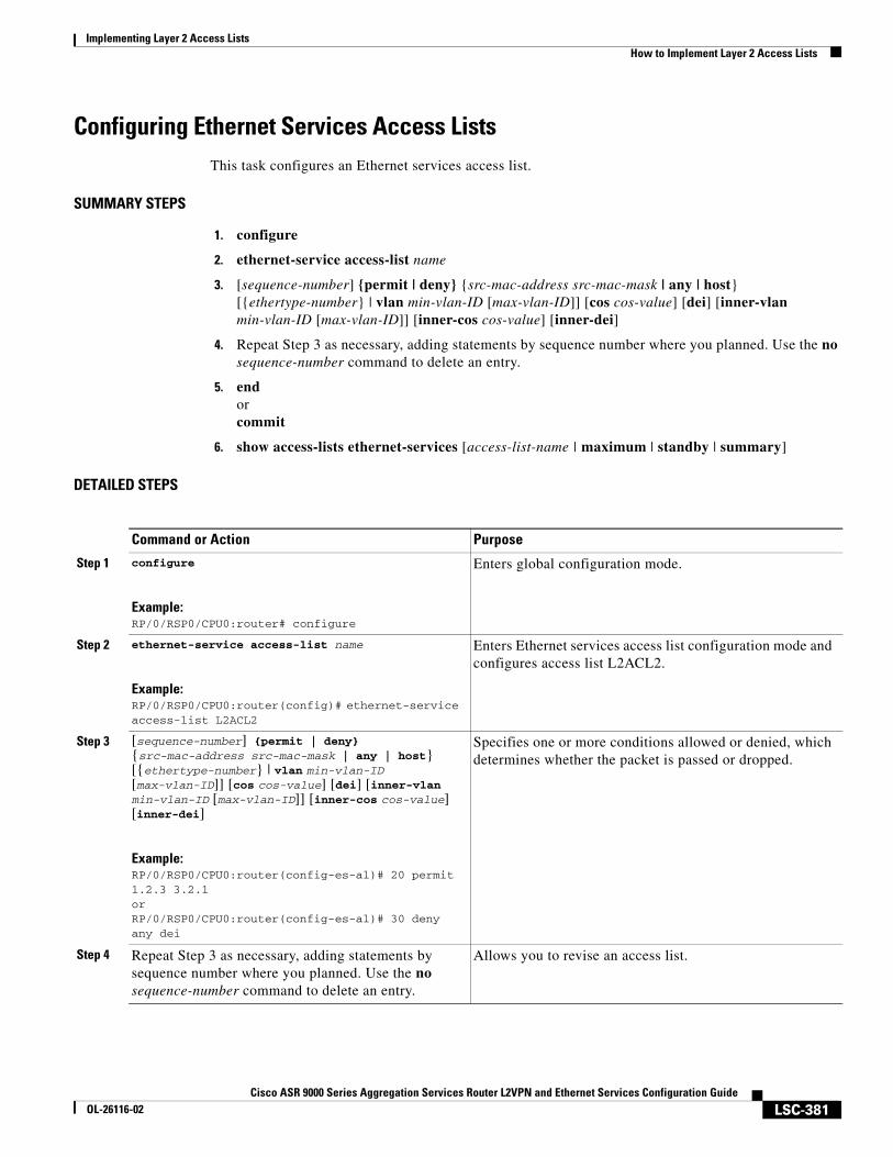
Implementing Layer 2 Access ListsHow to Implement Layer 2 Access Lists
LSC-381Cisco ASR 9000 Series Aggregation Services Router L2VPN and Ethernet Services Configuration Guide
OL-26116-02
Configuring Ethernet Services Access ListsThis task configures an Ethernet services access list.
SUMMARY STEPS
1. configure
2. ethernet-service access-list name
3. [sequence-number] {permit | deny} {src-mac-address src-mac-mask | any | host} [{ethertype-number} | vlan min-vlan-ID [max-vlan-ID]] [cos cos-value] [dei] [inner-vlan min-vlan-ID [max-vlan-ID]] [inner-cos cos-value] [inner-dei]
4. Repeat Step 3 as necessary, adding statements by sequence number where you planned. Use the no sequence-number command to delete an entry.
5. endorcommit
6. show access-lists ethernet-services [access-list-name | maximum | standby | summary]
DETAILED STEPS
Command or Action Purpose
Step 1 configure
Example:RP/0/RSP0/CPU0:router# configure
Enters global configuration mode.
Step 2 ethernet-service access-list name
Example:RP/0/RSP0/CPU0:router(config)# ethernet-service access-list L2ACL2
Enters Ethernet services access list configuration mode and configures access list L2ACL2.
Step 3 [sequence-number] {permit | deny} {src-mac-address src-mac-mask | any | host} [{ethertype-number} | vlan min-vlan-ID [max-vlan-ID]] [cos cos-value] [dei] [inner-vlan min-vlan-ID [max-vlan-ID]] [inner-cos cos-value] [inner-dei]
Example:RP/0/RSP0/CPU0:router(config-es-al)# 20 permit 1.2.3 3.2.1orRP/0/RSP0/CPU0:router(config-es-al)# 30 deny any dei
Specifies one or more conditions allowed or denied, which determines whether the packet is passed or dropped.
Step 4 Repeat Step 3 as necessary, adding statements by sequence number where you planned. Use the no sequence-number command to delete an entry.
Allows you to revise an access list.
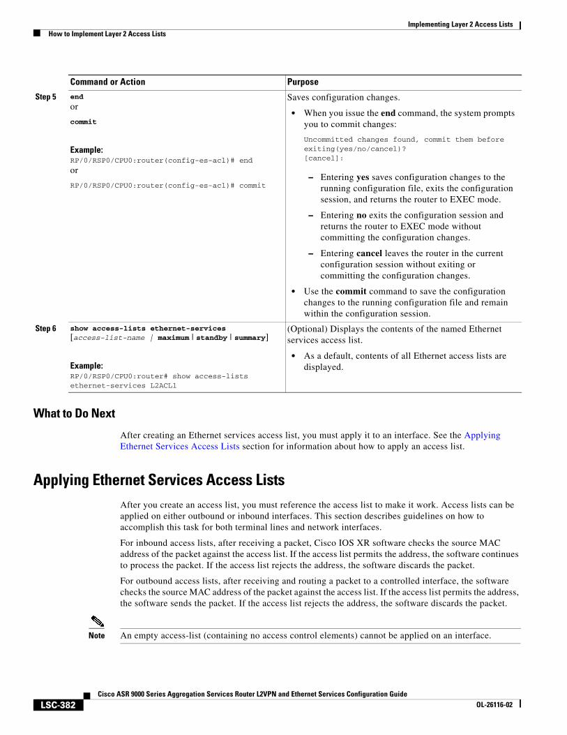
Implementing Layer 2 Access ListsHow to Implement Layer 2 Access Lists
LSC-382Cisco ASR 9000 Series Aggregation Services Router L2VPN and Ethernet Services Configuration Guide
OL-26116-02
What to Do Next
After creating an Ethernet services access list, you must apply it to an interface. See the Applying Ethernet Services Access Lists section for information about how to apply an access list.
Applying Ethernet Services Access ListsAfter you create an access list, you must reference the access list to make it work. Access lists can be applied on either outbound or inbound interfaces. This section describes guidelines on how to accomplish this task for both terminal lines and network interfaces.
For inbound access lists, after receiving a packet, Cisco IOS XR software checks the source MAC address of the packet against the access list. If the access list permits the address, the software continues to process the packet. If the access list rejects the address, the software discards the packet.
For outbound access lists, after receiving and routing a packet to a controlled interface, the software checks the source MAC address of the packet against the access list. If the access list permits the address, the software sends the packet. If the access list rejects the address, the software discards the packet.
Note An empty access-list (containing no access control elements) cannot be applied on an interface.
Step 5 end
or
commit
Example:RP/0/RSP0/CPU0:router(config-es-acl)# end
or
RP/0/RSP0/CPU0:router(config-es-acl)# commit
Saves configuration changes.
• When you issue the end command, the system prompts you to commit changes:
Uncommitted changes found, commit them before exiting(yes/no/cancel)?[cancel]:
– Entering yes saves configuration changes to the running configuration file, exits the configuration session, and returns the router to EXEC mode.
– Entering no exits the configuration session and returns the router to EXEC mode without committing the configuration changes.
– Entering cancel leaves the router in the current configuration session without exiting or committing the configuration changes.
• Use the commit command to save the configuration changes to the running configuration file and remain within the configuration session.
Step 6 show access-lists ethernet-services [access-list-name | maximum | standby | summary]
Example:RP/0/RSP0/CPU0:router# show access-lists ethernet-services L2ACL1
(Optional) Displays the contents of the named Ethernet services access list.
• As a default, contents of all Ethernet access lists are displayed.
Command or Action Purpose
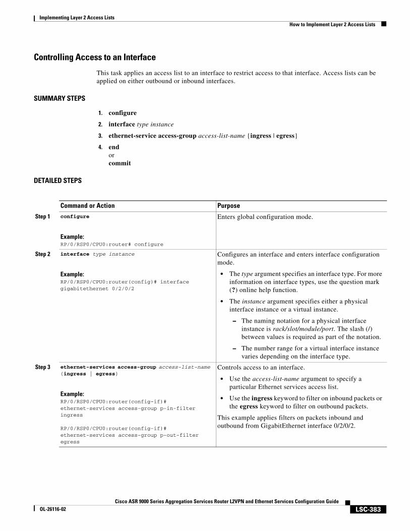
Implementing Layer 2 Access ListsHow to Implement Layer 2 Access Lists
LSC-383Cisco ASR 9000 Series Aggregation Services Router L2VPN and Ethernet Services Configuration Guide
OL-26116-02
Controlling Access to an Interface
This task applies an access list to an interface to restrict access to that interface. Access lists can be applied on either outbound or inbound interfaces.
SUMMARY STEPS
1. configure
2. interface type instance
3. ethernet-service access-group access-list-name {ingress | egress}
4. endorcommit
DETAILED STEPS
Command or Action Purpose
Step 1 configure
Example:RP/0/RSP0/CPU0:router# configure
Enters global configuration mode.
Step 2 interface type instance
Example:RP/0/RSP0/CPU0:router(config)# interface gigabitethernet 0/2/0/2
Configures an interface and enters interface configuration mode.
• The type argument specifies an interface type. For more information on interface types, use the question mark (?) online help function.
• The instance argument specifies either a physical interface instance or a virtual instance.
– The naming notation for a physical interface instance is rack/slot/module/port. The slash (/) between values is required as part of the notation.
– The number range for a virtual interface instance varies depending on the interface type.
Step 3 ethernet-services access-group access-list-name {ingress | egress}
Example:RP/0/RSP0/CPU0:router(config-if)# ethernet-services access-group p-in-filter ingress
RP/0/RSP0/CPU0:router(config-if)# ethernet-services access-group p-out-filter egress
Controls access to an interface.
• Use the access-list-name argument to specify a particular Ethernet services access list.
• Use the ingress keyword to filter on inbound packets or the egress keyword to filter on outbound packets.
This example applies filters on packets inbound and outbound from GigabitEthernet interface 0/2/0/2.
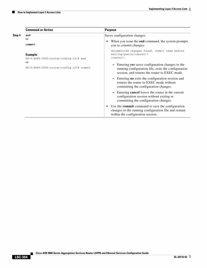
Implementing Layer 2 Access ListsHow to Implement Layer 2 Access Lists
LSC-384Cisco ASR 9000 Series Aggregation Services Router L2VPN and Ethernet Services Configuration Guide
OL-26116-02
Step 4 end
or
commit
Example:RP/0/RSP0/CPU0:router(config-if)# end
or
RP/0/RSP0/CPU0:router(config-if)# commit
Saves configuration changes.
• When you issue the end command, the system prompts you to commit changes:
Uncommitted changes found, commit them before exiting(yes/no/cancel)?[cancel]:
– Entering yes saves configuration changes to the running configuration file, exits the configuration session, and returns the router to EXEC mode.
– Entering no exits the configuration session and returns the router to EXEC mode without committing the configuration changes.
– Entering cancel leaves the router in the current configuration session without exiting or committing the configuration changes.
• Use the commit command to save the configuration changes to the running configuration file and remain within the configuration session.
Command or Action Purpose
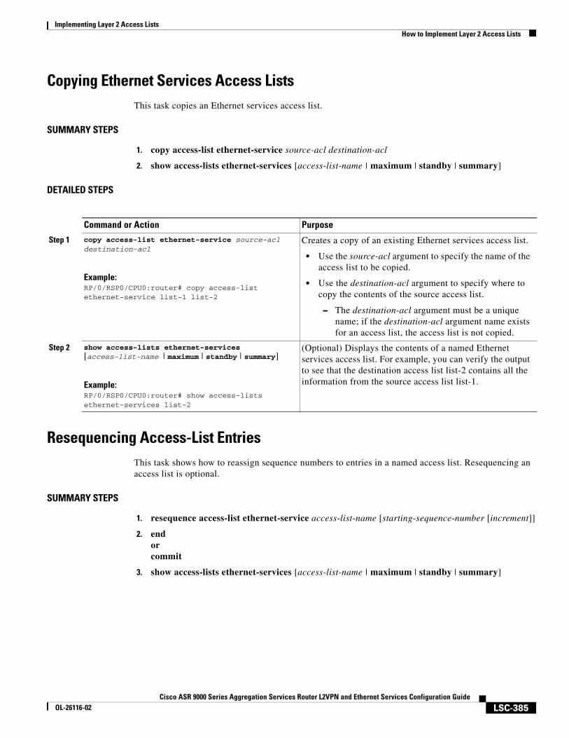
Implementing Layer 2 Access ListsHow to Implement Layer 2 Access Lists
LSC-385Cisco ASR 9000 Series Aggregation Services Router L2VPN and Ethernet Services Configuration Guide
OL-26116-02
Copying Ethernet Services Access Lists This task copies an Ethernet services access list.
SUMMARY STEPS
1. copy access-list ethernet-service source-acl destination-acl
2. show access-lists ethernet-services [access-list-name | maximum | standby | summary]
DETAILED STEPS
Resequencing Access-List EntriesThis task shows how to reassign sequence numbers to entries in a named access list. Resequencing an access list is optional.
SUMMARY STEPS
1. resequence access-list ethernet-service access-list-name [starting-sequence-number [increment]]
2. endorcommit
3. show access-lists ethernet-services [access-list-name | maximum | standby | summary]
Command or Action Purpose
Step 1 copy access-list ethernet-service source-acl destination-acl
Example:RP/0/RSP0/CPU0:router# copy access-list ethernet-service list-1 list-2
Creates a copy of an existing Ethernet services access list.
• Use the source-acl argument to specify the name of the access list to be copied.
• Use the destination-acl argument to specify where to copy the contents of the source access list.
– The destination-acl argument must be a unique name; if the destination-acl argument name exists for an access list, the access list is not copied.
Step 2 show access-lists ethernet-services [access-list-name | maximum | standby | summary]
Example:RP/0/RSP0/CPU0:router# show access-lists ethernet-services list-2
(Optional) Displays the contents of a named Ethernet services access list. For example, you can verify the output to see that the destination access list list-2 contains all the information from the source access list list-1.
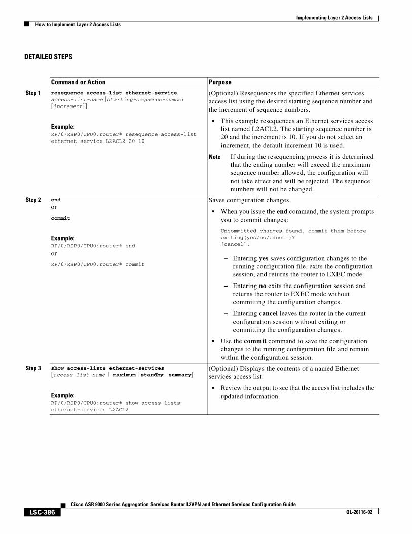
Implementing Layer 2 Access ListsHow to Implement Layer 2 Access Lists
LSC-386Cisco ASR 9000 Series Aggregation Services Router L2VPN and Ethernet Services Configuration Guide
OL-26116-02
DETAILED STEPS
Command or Action Purpose
Step 1 resequence access-list ethernet-service access-list-name [starting-sequence-number [increment]]
Example:RP/0/RSP0/CPU0:router# resequence access-list ethernet-service L2ACL2 20 10
(Optional) Resequences the specified Ethernet services access list using the desired starting sequence number and the increment of sequence numbers.
• This example resequences an Ethernet services access list named L2ACL2. The starting sequence number is 20 and the increment is 10. If you do not select an increment, the default increment 10 is used.
Note If during the resequencing process it is determined that the ending number will exceed the maximum sequence number allowed, the configuration will not take effect and will be rejected. The sequence numbers will not be changed.
Step 2 end
or
commit
Example:RP/0/RSP0/CPU0:router# end
or
RP/0/RSP0/CPU0:router# commit
Saves configuration changes.
• When you issue the end command, the system prompts you to commit changes:
Uncommitted changes found, commit them before exiting(yes/no/cancel)?[cancel]:
– Entering yes saves configuration changes to the running configuration file, exits the configuration session, and returns the router to EXEC mode.
– Entering no exits the configuration session and returns the router to EXEC mode without committing the configuration changes.
– Entering cancel leaves the router in the current configuration session without exiting or committing the configuration changes.
• Use the commit command to save the configuration changes to the running configuration file and remain within the configuration session.
Step 3 show access-lists ethernet-services [access-list-name | maximum | standby | summary]
Example:RP/0/RSP0/CPU0:router# show access-lists ethernet-services L2ACL2
(Optional) Displays the contents of a named Ethernet services access list.
• Review the output to see that the access list includes the updated information.
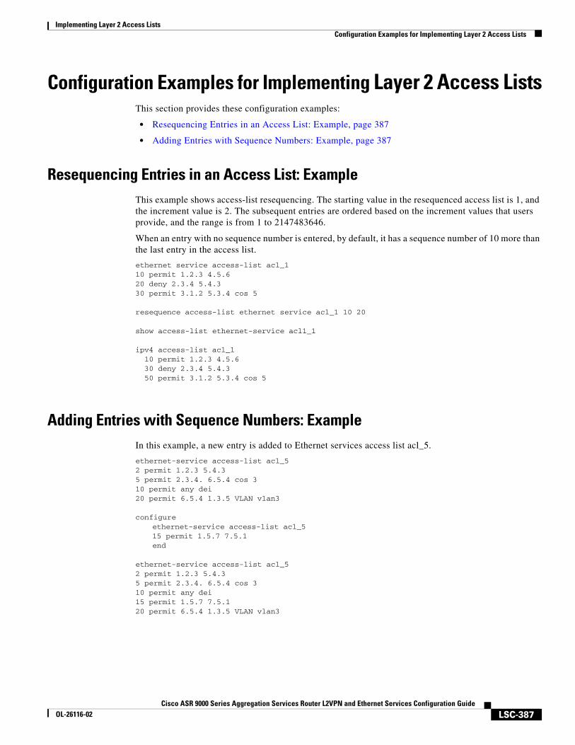
Implementing Layer 2 Access ListsConfiguration Examples for Implementing Layer 2 Access Lists
LSC-387Cisco ASR 9000 Series Aggregation Services Router L2VPN and Ethernet Services Configuration Guide
OL-26116-02
Configuration Examples for Implementing Layer 2 Access ListsThis section provides these configuration examples:
• Resequencing Entries in an Access List: Example, page 387
• Adding Entries with Sequence Numbers: Example, page 387
Resequencing Entries in an Access List: ExampleThis example shows access-list resequencing. The starting value in the resequenced access list is 1, and the increment value is 2. The subsequent entries are ordered based on the increment values that users provide, and the range is from 1 to 2147483646.
When an entry with no sequence number is entered, by default, it has a sequence number of 10 more than the last entry in the access list.
ethernet service access-list acl_110 permit 1.2.3 4.5.620 deny 2.3.4 5.4.330 permit 3.1.2 5.3.4 cos 5
resequence access-list ethernet service acl_1 10 20
show access-list ethernet-service acl1_1
ipv4 access-list acl_110 permit 1.2.3 4.5.630 deny 2.3.4 5.4.350 permit 3.1.2 5.3.4 cos 5
Adding Entries with Sequence Numbers: ExampleIn this example, a new entry is added to Ethernet services access list acl_5.
ethernet-service access-list acl_5 2 permit 1.2.3 5.4.35 permit 2.3.4. 6.5.4 cos 310 permit any dei20 permit 6.5.4 1.3.5 VLAN vlan3
configureethernet-service access-list acl_515 permit 1.5.7 7.5.1 end
ethernet-service access-list acl_5 2 permit 1.2.3 5.4.35 permit 2.3.4. 6.5.4 cos 310 permit any dei15 permit 1.5.7 7.5.120 permit 6.5.4 1.3.5 VLAN vlan3
Implementing Layer 2 Access ListsAdditional References
LSC-388Cisco ASR 9000 Series Aggregation Services Router L2VPN and Ethernet Services Configuration Guide
OL-26116-02
Additional ReferencesThese sections provide references related to implementing Ethernet services access lists on Cisco ASR 9000 Series Routers.
Related Documents
Standards
MIBs
RFCs
Related Topic Document Title
Ethernet services access list commands: complete command syntax, command modes, command history, defaults, usage guidelines, and examples
Ethernet Services (Layer 2) Access List Commands on Cisco ASR 9000 Series Routers module in Cisco ASR 9000 Series Aggregation Services Router IP Addresses and Services Command Reference
Standards Title
No new or modified standards are supported by this feature, and support for existing standards has not been modified by this feature.
—
MIBs MIBs Link
— To locate and download MIBs using Cisco IOS XR software, use the Cisco MIB Locator found at this URL and choose a platform under the Cisco Access Products menu: http://cisco.com/public/sw-center/netmgmt/cmtk/mibs.shtml
RFCs Title
No new or modified RFCs are supported by this feature, and support for existing RFCs has not been modified by this feature.
—
Implementing Layer 2 Access ListsAdditional References
LSC-389Cisco ASR 9000 Series Aggregation Services Router L2VPN and Ethernet Services Configuration Guide
OL-26116-02
Technical Assistance
Description Link
The Cisco Technical Support website contains thousands of pages of searchable technical content, including links to products, technologies, solutions, technical tips, and tools. Registered Cisco.com users can log in from this page to access even more content.
http://www.cisco.com/techsupport

Implementing Layer 2 Access ListsAdditional References
LSC-390Cisco ASR 9000 Series Aggregation Services Router L2VPN and Ethernet Services Configuration Guide
OL-26116-02
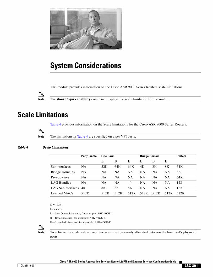
LSC-391Cisco ASR 9000 Series Aggregation Services Router L2VPN and Ethernet Services Configuration Guide
OL-26116-02
System Considerations
This module provides information on the Cisco ASR 9000 Series Routers scale limitations.
Note The show l2vpn capability command displays the scale limitation for the router.
Scale LimitationsTable 4 provides information on the Scale limitations for the Cisco ASR 9000 Series Routers.
Note The limitations in Table 4 are specified on a per VFI basis.
Table 4 Scale Limitations
K = 1024
Line cards:
L—Low Queue Line card, for example: A9K-40GE-L
B—Base Line card, for example: A9K-40GE-B
E—Extended Line card, for example: A9K-40GE-E
Note To achieve the scale values, subinterfaces must be evenly allocated between the line card’s physical ports.
Port/Bundle Line Card Bridge Domain System
L B E L B E
Subinterfaces NA 32K 64K 64K 4K 8K 8K 64K
Bridge Domains NA NA NA NA NA NA NA 8K
Pseudowires NA NA NA NA NA NA NA 64K
LAG Bundles NA NA NA 40 NA NA NA 128
LAG Subinterfaces 4K 8K 8K 8K NA NA NA 16K
Learned MACs 512K 512K 512K 512K 512K 512K 512K 512K
System ConsiderationsAdditional References
LSC-392Cisco ASR 9000 Series Aggregation Services Router L2VPN and Ethernet Services Configuration Guide
OL-26116-02
For more information on Ethernet line cards, see Table 1-3 of the Cisco ASR 9000 Series Aggregation Services Router Ethernet Line Card Installation Guide.
Additional ReferencesThese sections provide references related to implementing Ethernet services access lists on Cisco ASR 9000 Series Routers.
Related Documents
Standards
MIBs
RFCs
Related Topic Document Title
Ethernet services access list commands: complete command syntax, command modes, command history, defaults, usage guidelines, and examples
Ethernet Services (Layer 2) Access List Commands on Cisco ASR 9000 Series Routers module in Cisco ASR 9000 Series Aggregation Services Router IP Addresses and Services Command Reference
Standards Title
No new or modified standards are supported by this feature, and support for existing standards has not been modified by this feature.
—
MIBs MIBs Link
— To locate and download MIBs using Cisco IOS XR software, use the Cisco MIB Locator found at this URL and choose a platform under the Cisco Access Products menu: http://cisco.com/public/sw-center/netmgmt/cmtk/mibs.shtml
RFCs Title
No new or modified RFCs are supported by this feature, and support for existing RFCs has not been modified by this feature.
—

System ConsiderationsAdditional References
LSC-393Cisco ASR 9000 Series Aggregation Services Router L2VPN and Ethernet Services Configuration Guide
OL-26116-02
Technical Assistance
Description Link
The Cisco Technical Support website contains thousands of pages of searchable technical content, including links to products, technologies, solutions, technical tips, and tools. Registered Cisco.com users can log in from this page to access even more content.
http://www.cisco.com/techsupport

System ConsiderationsAdditional References
LSC-394Cisco ASR 9000 Series Aggregation Services Router L2VPN and Ethernet Services Configuration Guide
OL-26116-02
AR Cisco ASR 9000 Series Aggregation Services Router Advanced System Command Reference
HR Cisco ASR 9000 Series Aggregation Services Router Interface and Hardware Component Command Reference
IR Cisco ASR 9000 Series Aggregation Services Router IP Addresses and Services Command Reference
MCR Cisco ASR 9000 Series Aggregation Services Router Multicast Command Reference
MNR Cisco ASR 9000 Series Aggregation Services Router System Monitoring Command Reference
MPR Cisco ASR 9000 Series Aggregation Services Router MPLS Command Reference
QR Cisco ASR 9000 Series Aggregation Services Router Modular Quality of Service Command Reference
RR Cisco ASR 9000 Series Aggregation Services Router Routing Command Reference
SMR Cisco ASR 9000 Series Aggregation Services Router System Management Command Reference
SR Cisco ASR 9000 Series Aggregation Services Router System Security Command Reference
LSR Cisco ASR 9000 Series Aggregation Services Router L2VPN and Ethernet Services Command Reference
LSC-395Cisco ASR 9000 Series Aggregation Services Router L2VPN and Ethernet Services Configuration Guide
OL-26116-02
I N D E X
A
access
lists
applying LSC-382
inbound or outbound interfaces, applying on LSC-382
Access Gateway LSC-335
Configuring MSTAG or REPAG LSC-349
Configuring PVSTAG or PVRSTAG LSC-355
MSTAG Edge Mode LSC-339
Overview LSC-336
Preempt Delay LSC-338
Supported Protocols LSC-339
Topology Change Propagation LSC-338
aging, MAC address
how to configure LSC-245
how to define LSC-195
Any Transport over Multiprotocol (AToM)
static labels, how to use LSC-233
static pseudowire LSC-233
Asynchronous Transfer Mode (ATM)
MPLS L2VPN LSC-107
attachment circuits
how to define LSC-188
B
bridge domain
how to associate members LSC-210
how to configure parameters LSC-212
how to configure pseudowire LSC-207
how to create LSC-205
how to disable LSC-215
overview LSC-186
Bundle-Ether command LSC-84
bundle id command LSC-84
bundle-POS LSC-88, LSC-94
bundle-id command
bundle-POS LSC-89
D
dot1q native vlan command LSC-51
dot1q vlan command LSC-48
E
encapsulation command LSC-48, LSC-49
Index
LSC-396Cisco ASR 9000 Series Aggregation Services Router L2VPN and Ethernet Services Configuration Guide
OL-26116-02
EoMPLS
ethernet port mode LSC-108
inter-as port mode LSC-110
overview LSC-108
QinAny mode LSC-111
QinQ mode LSC-111
Ethernet Features LSC-61
L2PT LSC-62
policy based forwarding LSC-62
Ethernet interface
configuring an attachment circuit LSC-42
configuring flow control LSC-36
configuring the IP address and subnet mask LSC-40
configuring the MAC address LSC-36, LSC-40
configuring the MTU LSC-36, LSC-40
default settings
flow control LSC-36
MAC address LSC-36
mtu LSC-36
displaying Ethernet interfaces LSC-41
enabling flow-control LSC-40
Gigabit Ethernet standards LSC-24
IEEE 802.3ab 1000BASE-T Gigabit Ethernet LSC-24
IEEE 802.3ae 10 Gbps Ethernet LSC-24
IEEE 802.3 Physical Ethernet Infrastructure LSC-24
IEEE 802.3z 1000 Mbps Gigabit Ethernet LSC-24
Layer 2 VPN
overview LSC-23
preparing a port for Layer 2 VPN LSC-42
VLAN support LSC-34
using the flow-control command LSC-36, LSC-40
using the interface command LSC-39, LSC-310
using the ipv4 address command LSC-40
using the mac address command LSC-36, LSC-40
using the mtu command LSC-36, LSC-40
using the negotiation auto command LSC-40
using the no shutdown command LSC-41
VLANs
802.1Q frames tagging LSC-33
assigning a VLAN AC LSC-48
configuring native VLAN LSC-49
configuring subinterfaces LSC-47
configuring the native VLAN LSC-51
displaying VLAN interfaces LSC-49, LSC-53, LSC-93, LSC-95
MTU inheritance LSC-33
removing a subinterface LSC-52
subinterface overview LSC-33
using the dot1q native vlan command LSC-51
using the dot1q vlan command LSC-48
using the interface command LSC-50
using the show vlan interfaces command LSC-49, LSC-53, LSC-93, LSC-95
ethernet port mode LSC-108
F
failover LSC-84
flooding
MAC address LSC-194
Flow Aware Transport Pseudowire LSC-204
flow-control command LSC-36, LSC-40
frame relay, MPLS L2VPN LSC-107
G
G.8032 Ethernet Ring Protection LSC-199
Configuration Example LSC-296
Configuring G.8032 Ethernet Ring Protection LSC-261
Overview LSC-199
Single Link Failure LSC-202
Timers LSC-201
Generic Routing Encapsulation Overview (L2VPN) LSC-113
Index
LSC-397Cisco ASR 9000 Series Aggregation Services Router L2VPN and Ethernet Services Configuration Guide
OL-26116-02
I
IEEE 802.1ah Provider Backbone Bridge LSC-303
IEEE 802.3ad standard LSC-82
if submode
bundle id command LSC-88, LSC-94
bundle-id command LSC-89
ip address command LSC-87, LSC-91, LSC-92
no shutdown command LSC-88, LSC-92, LSC-94
Inter-AS configurations
L2VPN quality of service LSC-132
Inter-AS mode LSC-110
interface Bundle-Ether command LSC-87, LSC-91
interface command LSC-39, LSC-50, LSC-310
for VLAN subinterfaces LSC-48
Link Bundling LSC-88, LSC-94
interfaces
Link Bundling LSC-79, LSC-85
configuring LSC-86
link failover LSC-85
prerequisites LSC-80
QoS LSC-83
IP
access lists LSC-382
ip address command
bundle-POS LSC-87, LSC-91, LSC-92
IP Interworking LSC-116
ipv4 address command LSC-40, LSC-84, LSC-87, LSC-91
ISP requirements, MPLS L2VPN LSC-107
L
L2VPN
See Layer 2 VPN LSC-23
L2VPN, QoS restrictions LSC-133
Layer 2 VPN
configuring an attachment circuit LSC-42
overview LSC-23
limit, MAC address
actions, types of LSC-195
how to configure LSC-242
Link Aggregation Control Protocol LSC-81, LSC-82
link bundling
configuring VLAN bundles LSC-34
link failover LSC-85
M
MAC address
aging LSC-195
flooding LSC-194
forwarding LSC-194
limit actions LSC-195
related parameters LSC-193
source-based learning LSC-194
withdrawal LSC-196
mac address command LSC-36, LSC-40
MPLS L2VPN
high availability LSC-112
interface or connection, how to configure LSC-122
ISP requirements LSC-107
Quality of service (QoS) LSC-111
VLAN mode, how to configure LSC-135
mtu command LSC-36, LSC-40
multicast-routing command LSC-156
multicast-routing submode
interface all enable command LSC-156
See multicast-routing command
Multiple Spanning Tree Protocol LSC-330
BPDU Guard LSC-333
Bringup Delay LSC-334
Flush Containment LSC-333
MSTP Port Fast LSC-331
MSTP Regions LSC-330
MSTP Root Guard LSC-332
MSTP Topology Change Guard LSC-332
Restrictions for configuring MSTP LSC-334
Supported MSTP Features LSC-333
Index
LSC-398Cisco ASR 9000 Series Aggregation Services Router L2VPN and Ethernet Services Configuration Guide
OL-26116-02
Multiple VLAN Registration Protocol LSC-340
N
negotiation auto command LSC-40
no interface command LSC-52
Nonstop forwarding LSC-84
no shutdown command
bundle-POS LSC-88, LSC-92, LSC-94
for Ethernet interfaces LSC-41
P
PBB LSC-303
backbone source MAC, how to configure LSC-316
backbone VLAN tag, how to configure LSC-314
benefits LSC-304
bridge domain, how to configure LSC-311
core bridge domain, how to configure LSC-313
EFP, how to configure LSC-309
Overview LSC-305
Prerequisites LSC-304
Restrictions LSC-309
service instance, how to configure LSC-311
port mode, MPLS L2VPN LSC-133
pseudowire (PW)
bridge domain, how to configure LSC-207
MPLS L2VPN LSC-108
Q
QinAny mode LSC-111
QinQ mode LSC-111
QoS (quality of service)
how to configure L2VPN LSC-133
MPLS L2VPN LSC-111
port mode, how to configure LSC-133
R
router igmp command LSC-157
router igmp submode
version command LSC-157
router mld command LSC-157
router mld submode
version command LSC-157
S
sequence numbering behavior LSC-380
show bundle Bundle-Ether command LSC-89, LSC-95
show interfaces command
for Ethernet interfaces LSC-41, LSC-45
show lacp bundle Bundle-Ether command LSC-89
show pim group-map command LSC-157
show pim topology command LSC-157
show vlan command LSC-49, LSC-53, LSC-93, LSC-95
signaling
VPLS LSC-191
source-based learning, how to configure MAC address LSC-237
Spanning Tree Protocol LSC-328
STP Protocol Operation LSC-329
Topology Changes LSC-329
Variants of STP LSC-329
static
point-to-point xconnects LSC-129
T
tasks
access lists, applying LSC-382
V
VFI (Virtual Forwarding Instance)
AToM pseudowires, how to configure LSC-233
Index
LSC-399Cisco ASR 9000 Series Aggregation Services Router L2VPN and Ethernet Services Configuration Guide
OL-26116-02
bridge domain member, how to associate LSC-229
functions LSC-188
how to add under bridge domain LSC-225
how to disable LSC-235
pseudowire classes to pseudowires, how to attach LSC-231
pseudowires, how to associate LSC-227
VLAN
figure, mode packet flow LSC-109
mode LSC-109
VLANs
802.1Q frames tagging LSC-33
assigning a VLAN AC LSC-48
configuring bundles LSC-34
configuring native VLAN LSC-49
configuring subinterfaces LSC-47
configuring the native VLAN LSC-51
displaying VLAN interfaces LSC-49, LSC-53, LSC-93, LSC-95
Layer 2 VPN support LSC-34
MTU inheritance LSC-33
removing a VLAN subinterface LSC-52
subinterface overview LSC-33
using the dot1q native vlan command LSC-51
using the dot1q vlan command LSC-48
using the no interfawn command LSC-52
using the show vlan interfaces command LSC-49, LSC-53, LSC-93, LSC-95
VPLS (Virtual Private LAN Services)
attachment circuits LSC-188
bridge domain, how to define LSC-186
overview LSC-186
signaling, how to define LSC-191
virtual bridge, how to simulate LSC-189
VPLS (virtual private LAN services)
Layer 2 VPN, architecture LSC-188
W
withdrawal, MAC address
defining LSC-196
fields LSC-279
how to define LSC-196
how to enable LSC-240

Index
LSC-400Cisco ASR 9000 Series Aggregation Services Router L2VPN and Ethernet Services Configuration Guide
OL-26116-02