SMART CNC PLOTTER.pdf
70
Sudan University of Science and Technology College of Engineering School of Electrical and Nuclear Engineering SMART CNC PLOTTER A Project Submitted In Partial Fulfillment for the Requirements of the Degree of B.Sc. (Honor) In Electrical Engineering Prepared By: 1. Ghifar Ahmed Rahal Makin. 2. Mohammed Omer Hamed ALshiek. 3. Mohammed Emad Eldeen Fadlallah Hassan. 4. Nasir Kamal Mohammed Ahmed Nasir. Supervised By: Ust. Omer Mohammed Slama. November 2020
-
Upload
khangminh22 -
Category
Documents
-
view
1 -
download
0
Transcript of SMART CNC PLOTTER.pdf

Sudan University of Science and
Technology
College of Engineering
School of Electrical and Nuclear
Engineering
SMART CNC PLOTTER
A Project Submitted In Partial Fulfillment for the Requirements of
the Degree of B.Sc. (Honor) In Electrical Engineering
Prepared By:
1. Ghifar Ahmed Rahal Makin.
2. Mohammed Omer Hamed ALshiek.
3. Mohammed Emad Eldeen Fadlallah Hassan.
4. Nasir Kamal Mohammed Ahmed Nasir.
Supervised By:
Ust. Omer Mohammed Slama.
November 2020

I

II
وقضى ربك ألا تعبدوا إلا إيااه وبالوالدين إحسانا إماا يبمغنا عندك الكبر
ما وقل لهما قول كريما أحدهما أو كلهما فل تقل لهما أف ول تنهره

III
DEDICATION
We dedicate this study to our great families and friends
who exerted valuable efforts to enrich our spirits and
reinforce our wills and energies and constantly work to
support us.
In particular, we extend our gratefulness and
thankfulness to who did not preserve any effort to
ensure our success in all that we have done, who was a
great source of motivation and courage for us.
To all the engineers whose knowledge and wisdom
represented a rich source of illumination and ideas for
us
and skillfully guided us through this study in the same
way our families guided us through
life, we highly appreciate their efforts and energies that
they spent to raise and improve our skills and
capabilities.
To all those we forgot to mention
Thank you

IV
ACKNOWLEDGEMENT
As we firmly believe, our successful and valuable
graduation project accurately summarizes the
knowledge, skills and capabilities we acquired
throughout the past fruitful five years. Therefore, we
would like to acknowledge and highly appreciate the
great and priceless efforts spent in educating us and
enriching our thirsty minds for information and
knowledge about a field we willfully decided to choose
as our career.
To the Electrical Engineering department, to all the
professors, teachers and assistants who energetically
and enthusiastically helped and prompted us to expand
and deepen our knowledge and skills through
discussions, lectures and other forms of support.
To all those who accompanied us on this path and those
who will come after us. To those who sincerely and
genuinely helped us with their time and effort.
To Ust.Omer Mohammed Slama who jointly
supervised this project.

V
TABLE OF CONTENT Topic Page
NO
I اآلية
DEDICATION II
ACKNOWLEDGEMENT III
TABLE OF CONTENT IV
LIST OF FIGURES VII
LIST OF TABLE VIII
LIST OF ABBREVIATIONS IX
ABSTRACT X
XI سحخص
CHAPTER ONE
INTRODUCTION
1.1 General Overview 1
1.2 Problem Statement 3
1.3 Objectives 4
1.4 Methodology 3
1.5 Project Layout 3
CHAPTER TWO
LITERATURE REVIEW
2.1 Introduction 2
2.2 Previous Studies 2
2.2.1 Design and Analysis Mini CNC Plotter Machine 2
2.2.2 Design and Implementation of a Microcontroller Based
Low Cost Computer Numerical Control (CNC) Plotter using
Motor Driver Controller
8

VI
CHAPTER THREE
REQUIREMENT ANALYSIS
3.1 Hardware Requirements 14
3.1.1 CD / DVD Writers 14
3.1.2 Arduino Uno 14
3.1.3 Servomotors 15
3.1.3.1 Definition 16
3.1.4 L293D IC and Motor Driver 16
3.1.5 Stepper Motor 16
3.1.5.1 Work of Stepper Motor 18
3.2 Software Requirements 19
3.2.1 Arduino Software 19
3.2.2 Inkscape 20
3.2.3 Processing 21
CHAPTER FOUR
IMPLEMENTATION
4.1 Step 1: Disassembly DVD/CD Drives 23
4.2 Step 2: X and Y xis 23
4.3 Step 3: The Z Axis 24
4.4 Step 4: Paper Base 25
4.5 Step 5: The Circuit 26
4.6 Step 6: Testing X and Y Axis Movement 26
4.7 Step 7: Uploading the CNC Code 26
4.8 Step 8: The GCTRL Program 27
4.9 Step 9: Make Your Own G Code File 27
CHAPTER FIVE
CONCLUSION AND
RECOMMENDATIONS
5.1 Conclusion 29
5.2 Recommendations 29
REFERENCES 30

VII
APPENDIX 54
LIST OF FIGURE
Topic Page
NO
Figure 2.1 Electronic circuit 6
Figure 2.2 Wiring of CNC Plotter Machine 7
Figure 2.3 Flowchart of the system 10
Figure 2.4 Sketching image of a Gear 12
Figure 3.1 CD/DVD writer 14
Figure 3.2 Arduino Uno 15
Figure 3.3 Servo motor 15
Figure 3.4 L293D IC and Motor Driver 16
Figure 3.5 Stepper motor 18
Figure 3.6 Arduino software 20
Figure 3.7 Inkscape 21
Figure .8 Processing 22
Figure 4.1 Disassembly 23
Figure 4.2 X axis 24
Figure 4.3 The Y axis 24
Figure 4.4 Z axis 25
Figure 4.5 Paper bace 25
Figure 4.6 Circuit 26

VIII
LIST OF ABBREVIATION
CNC Computer Numerical Control
PC Personal Computer
CD Compact Disc
CAD Computer Aided Design
MID Massachusetts Institute of Technology
CAM Computer Aided Manufacturing

IX
ABSTRACT
The main idea behind this project is to design and implement a cheap,
smaller size, easily operable, easy interface and flexible 3-axis Computer
Numerical Control (CNC) plotter machine.
The lower cost is achieved by using 2 CD drives from old PC’s with
their stepper motors as the main structure for the hardware.
The two stepper motors already found in the CD drives used to control
the pen movements onto X and Y axis and one servo motor on the Z axis.
An Arduino Uno microcontroller is used to controls the proper
synchronization of these three motors during printing/drawing process.
The Arduino Uno is programmed with G-Code parser from PC that is
connected to the Arduino via a USB cable to control the motors movement
and synchronization.
The plotter machine is implemented and tested by printed different
images and texts on papers (40mm × 40mm) using a pen, the small size of
the papers because of the small plotter size.
The motors winding voltages were displayed on the oscilloscope during
the printing process to investigate the synchronization between the three
motors.
The design of the circuit is simple, inexpensive and can be
accomplished using commercially available components the project is very
useful for printing and sketching.

X
المستخلص
حجررر بسررررش س رررةص جفةرررز افىرررشل اشيةسرررةة ساا رررزا اصرررش ررر ج رررة
سا رررة رررةآل حررر سفررر ة ةرررة اجرررة رررة شرررة رحصررر ة يىررر ررر اش صررر ة
.شب ىبةج شل اححى ا
طة رررر األلرررشال اارررة ررر حرررشو يرررح جحمةرررك احىفرررة اخفارررة ب ررررحخذا
.صش ةى سيةس و لحشن اخط أجضل اىبةجش امذية ع
فررر امرررشل ااررر ط اسرررحخذة رررححى فررر خطرررل عرررح حشوررر ا ح ررريح ايررر
.Z حشن ةشف احذ عح احس Y احسX احس حشو ت ام ع
احررضا ا ررحةذ ررز احشورر ت ا ةررة فرر ررححىة اسديرر ارر سررحخذ ححىررج
ررر G-Code ب ررحخذا حرر جررة اسدياررأةرر ا عةررة اطب عررة م اش ررر. جررث بش
رررححى فررر حشورررة احشوررر ت USB عبرررش و بررر سدي ح ررر بررر اىبةرررجش اصخ ررر
احضا.
ررر 4(0سق عرررحخحفرررة رررل آرررة اشا رررة فرررزت ا حبرررشت بطب عرررة صرررس
لررررذ حجرررر صرررر ةش اشا ررررة. ( ب ررررحخذا أامرررر صرررر ش حجرررر األساق بسررررب رررر 4 0×
عةرررررة اطب عرررررة ررررر ي oscilloscope جررررر عرررررح حشوررررر ت عشضرررررث فحررررر ت اررررر
بة احشو ت ا ةة. ححمك اضاة
اىرررر ت ررررحخذا ب ص جررررا غةررررش ىرررر يىرررر وررررزه اررررذايشل بسررررة ج ررررة
اصش فةذ جذا ش . اح حة جج سي

1
CHAPTER ONE INTRODUCTION
1.1 General overview CNC Machining is a process uses computers to control machine tools such as plotters, lathes mills, machines ... etc for the manufacturing proc-ess. Nowadays, CNC machine expands its application to other tasks like in cutting, welding and assembling robots which are used in cars manufact-uring factories. Due to the great developments in the personal computers (PC), it becomes easy to add new features to the modern CNC machines such as new sensors and actuators and it becomes easy to change and de-velop the control algorithms these facilities are not previously observed in the design phase of the older CNC machines [1]. The CNC stands for Computer Numerical Control inspiring from this CNC technology and revolutionary change in the world of digital electronics & microcontroller. Because of the high relative cost and versatility of the conventional CNC machine it remains as a staple of industry and this makes difficult for the companies to manufacture large quantities of these CNC machines especially when a high-quality goods

CHAPTER ONE INTRODUCTION
2
one are required [2]. The MIT Servomechanisms laboratory invent the first numerical control programming language in the late 1950s, they used G-code in the implementation. G-code (a.k.a. RS-274) is the most widely used language in the numerical control programming to control CNC machine tools. G programming language is a language that’s make the programmer control the speed and directions of the cutting tool in the CNC machine and makes the motors follow the path that is predefined in the program. The same concept included for the other machines that’s used drawing, burnishing, forming and 3D printing tools. However, many different projects were implemented for small low-cost CNC machines such as in [3] where Anita Pinheiro et al implemented three axis Mini CNC Plotter using stepper motor, microcontroller and motor control software. The microcontroller is connected to the PC through serial communication port DB9, no information about the software is mentioned. Sundar Pandian and S. Raj Pandian presented the results of development of a low-cost three-axis vertical CNC mill suitable for adoption in undergraduate mechanical engineering laboratory setting, the total cost of their developed
CHAPTER ONE INTRODUCTION
3
system is just about 1/20th of the existing commercial CNC machine used currently in the laboratory [4]. Kajal J. Madekar et al showed that the used of Code programming to control the motors for small CNC machines give better accuracy such as in large CNC machines and a small machine brings a flexibility to do work [2]. The main idea in this paper is to implement a small low-cost CNC plotter machine which can draw images or pictures on a small paper; it uses two stepper motors as linear actuators on each axis X, Y and servo motor on axis Z. The Arduino Uno microcontroller controls the proper synchronization of these three axes during printing / drawing. 1.1 Problem statement
Nowadays, the world is becoming highly technology with a lot of things become smaller and thinner. Even now the things especially in engineering and technology have the things in nano and micro size. Same goes to CNC Machine; this machine is now having variety of size in the market. All type of machine has own purpose, even though the size is big or small. The usual CNC machine can machine the big workpiece depends on the machine specification. The mini CNC machine only can machine the small

CHAPTER ONE INTRODUCTION
4
workpiece depend on the machine specification. This project is about to overcome the problem of machining the small part. Even the usual CNC machine can machine the small workpiece, it will increase the time on setup the workpiece to the machine to get the accurate result. The mini CNC machine will give the small area of setup the workpiece and it will be easier to get the accurate place or result for the workpiece. 1.2 RESEARCH OBJECTIVES There are several objectives to be achieved, which are: 1. To design and develop CNC 3 axis machine. 2. To verify the controller validity. 3. To generate some difficult shape on work piece easily and with high accuracy 4. To make CNC machine a user friendly machine. 5. To increase production rate and profit with help of cheap , fast and automatic CNC machine. 1.3 METHODOLOGY The Arduino is supplied with current by USB DATA cable to transfer Data from Computer to Arduino Board , Here used 3 Stepper Drivers to supply the G codes in Sequence to the stepper motors. Arduino mounted on CNC shield. CNC shield distributed the Current in the command of Arduino. CNC shield converted the command of
CHAPTER ONE INTRODUCTION
5
G codes in digital pulse by Stepper motor. In X direction Stepper motor moved left and Right, Y direction stepper motor moved in front and back direction, Z direction Stepper motor moved in Up and down. Much difficult design is made by using this machine. The accuracy of this machines result is very high. So, it used in industry to reduce the cost of design printing and maintain accuracy level. Drafting and Scaling of CNC Plotter machine is very precious. 1.4 LAYOUT PROJECT The project consists of five chapters: Chapter one gives an introduction about CNC machine, and a brief problem statement, objectives and methodology. Chapter two gives literature review history of CNC machine including two types for previous studies. Chapter three gives an introduction about the hardware and software requirements, details of project components. Chapter four includes the implementation of project. Finally, chapter five includes the conclusion, recommendation and references

CHAPTER TWO LITERATURE REVIEW
6
CHAPTER TWO
Literature Review 2.1 Introduction The idea of numerical control began when the automation of machine tools originally incorporated specific concepts of programmable logic [7]. In the beginning, the first machines were constructed in the 1940s. But more advanced machines came along in the 1950s. These new NC machines were built based on existing tools that were modified with motors designed to move machine's controls. These first mechanisms were soon improved with both analog and digital computers [8][9]. After World War II, specifically in 1949, John Parsons found methods to improve aircraft by creating stiffened skins for them. This led to important Air Force research projects, which conducted at the Massachusetts Institute of Technology (MIT). After the research phases, an experimental milling machine was designed at MIT. Professor J.F. Reintjes with his team of researchers were involved in this project. In the 1960s and 1970, a very familiar form of a CNC machine started taking

CHAPTER TWO LITERATURE REVIEW
7
shape. Digital technology then entered the fray, and automation in production processes became more efficient than ever [10]. 2.2 Previous Studies 2.2.1 Design and Analysis Mini CNC Plotter Machine This study shows how to design and building low cost Arduino plotter machine based on the open source hardware and software. The Arduino plotter machine has been dependent on the principle of Computer Numerical Control with limited area depends on the motion X, Y and Z axes. The objectives of this project are to design the Plotter and to develop open source software for control the machine. Basically, the system of this plotter machine is modeling by solid work software to work with three axes stepper motors (as X, Y and Z axes), these three stepper motors are controlled by shield for movement (X, Y and Z axes). This machine’s movement on the X axis is 215 mm and Y axis is 235 mm. Length of travel means the linear movement of stepper motors that control for X, Y and Z axes from point to another point. The left and right movement controlled by X axis

CHAPTER TWO LITERATURE REVIEW
8
stepper motor, front-back movement controlled by Y axis stepper motor and the pen is up-down that is controlled by Z axis stepper motor. material used is one Arduino UNO R3, one CNC V3 Shield with A4988 Driver Module with Heatsink for Arduino, stepper motors, D.C. power supply, pen holder, some wires and USB to serial adapter. The wiring of the various components of electronics system is represented in the Fig., shown below. The microcontroller of Arduino board is connected to the computer system through the USB serial port. The Stepper Motors of three axes (X, Y and Z) are connected with CNC shield driver board as Figures 1 and 2 shown below. D.C. Power supply is provided for all the components of electronics system.
Figure 2.1 Electronic circuit

CHAPTER TWO LITERATURE REVIEW
9
Figure 2.2 Wiring of CNC Plotter Machine

CHAPTER TWO LITERATURE REVIEW
10
"The open-source Arduino Software (IDE) makes it easy to write code and upload it to the board"(https://www.arduino.cc). It is simplified C/C++ functions language based programming can be download functionality with a rich set of library functions. After download and install on pc can be write the program by C language and from tools and port must be choose the port connection between computer and Arduino through USB.
After this step can be verify the program by error checking and the message is done compiling when it finished and no error. After this step can be upload the program on the Arduino. To make the CNC plotter machine plot and write needing a software tools to design the graphs and then convert this graph to G-code because CNC machine operate and understanding G language, this tools can be achieved by easel software tools, this software must be setting material dimensions X is 235 mm, Y is 215 mm, Z is 1 mm and set Bit to 0.15 mm because Z axis is pen. Through this software can be set positions of X, Y and Z axes, also can be control on the speed of CNC machine mm/min from feed rate. After finishing
CHAPTER TWO LITERATURE REVIEW
11
the complete build-up of the machine, it is necessary to calibrate the movement of the axes. Stepper motor calculations equation is: 360 degree/1 revolution /degree/step = step/1 revolution Test code for stepper motor is used where steps per revolution is 200 steps were allowed for the motor to move. On running the code, it is found that the motor is travelling 40 mm which is indicating that the stepper motor takes 5 steps to cover 1mm. This is calibration for both X and Y axes [11]. 2.2.2 Design and Implementation of a Microcontroller Based Low Cost Computer Numerical Control (CNC) Plotter using Motor Driver Controller Sketching a picture is now also belongs to technology. Computer Numerical Control or CNC Plotter sketches picturecontrolled by a computer. CNC plotter is a 3D controlled machine which sketches a 2D picture of an object. It is used in different industry, workshop, factory where need to sketch any complex design or need to cut different metal in precise shape. The complete system of a CNC machine is large, costly and difficult to move from one place to another. In this paper, a low-cost CNC plotter is designed to mitigate the difficulties. To

CHAPTER TWO LITERATURE REVIEW
12
design this system three axis controlling unit is needed to control X, Y and Z axis position. X and Y axis can be controlled by two stepper motor and Z axis can be controlled by servo motor. To control this machine, a computer has been used to create and load G-code which sets the coordinates of X, Y and Z axis. Arduino IDE is used as the programming software and CAMotics software is used to generate G-code. Processing software is used to process GCTRL code to Arduino. G-code can be loaded to and the three motors operate as the instruction from a processor through motor driver. devices took place to draw pictures, circuit, fabric design. A plotter is a special type of device that used for printing a complex design using a pen or pencil or drawing tool. CNC means Computer Numerical Control. It refers to computer that controls a machine tool to draw any design precisely. This computer-based machine creates G-code of an object. The G-code of an image is generated by using Computer Aided Design/Computer Aided Manufacturing (CAD/CAM) software and it is processed by processing software. Processing software used to send GCTRL code to

CHAPTER TWO LITERATURE REVIEW
13
CNC plotter. CNC machine used different industrial and big workshop which is very large size CNC machine. Those machine’s weight, height, size is very high and those can’t move easily. Manufacture cost of them also the high and running process is very complicated. Those machines development software’s are started.Net platform using C# developing terms and after passing time used LAB view. Further design CAD (Computer Aided Design) software and CAM (Computer Aided Manufacturing) software used to make an image’s g-code which g-code is processing image to sketching machine. Now advance software to make a g code easily as single software which name inscape. Software became easily but hardware is larger. It is needed to reduce hardware sizes which can easy movement and reduce height, weight. To improving design which solved those problems. This small CNC plotter cost quite less easily carries and friendly worked. It is also n eeded to choose a method which can proceed to the main goal. After considering all limitation, a CNC plotting system has been designed with low cost which provided better plotting system and reduces a considerable

CHAPTER TWO LITERATURE REVIEW
14
area of this machine. The next chapter will be discussed about the literature review on the related topic about CNC machine. The aim of this system is to design and implement a Low-Cost CNC plotter. In this plotter, three motors have been used for sketching a picture. A motor driver module is used for controlling motors. Arduino ATmega328P is used as a processor. Two motor driver circuits using L293D have been used for controlling two stepper motor as X-axis and Y-axis. A mini servo motor is controlled Z axis to mitigate the physical shape of the plotter. In this system, Arduino IDE V1.6.0 used as the programming software and CAM tics used as the G-code generator. Figure 1 demonstrates the functional block diagram of this system. Power is supplied to Arduino Uno. A computer used as the control unit is connected to Arduino Uno to control the whole operation. A motor driver controller is used to drive the motors which is connected with X, Y and Z axis. By controlling different positions of these three motors via computer, a photo has been sketched.

CHAPTER TWO LITERATURE REVIEW
15
Figure 2.3 Flowchart of the system

CHAPTER TWO LITERATURE REVIEW
16
The system processor is based on ATmega328P. For the development purpose, Arduino Uno has been utilized which is It is connected with two motor drivers L293D. Pin 10, 11, 12, 13of the Arduino Uno is connected with a L293D motor driver which is set to drive a stepper motor for X-axis. Pin 4, 5, 6, 7 of the Arduino Uno is connected with another L293D motor
driver to drive another stepper motor for Y-axis. Motor drivers 3, 6, 11, 14 no pin is connected by stepper motors. Pin 9 of
the Arduino Uno is connected with a servo motor Z axis. In this system, the L293D motor driver controller has been used which
is a quadruple high-current half-H bridge driver designed to drive high-current and high-voltage loads including DC and
bipolar stepping motor[]. To sketch a picture the system needs to create G-code of a picture which is loaded Arduino Uno
later. G-code of a picture can be created by using CA Miotics software. It is a set of information which indicates the position of X, Y and Z axis. Once a G-code is loaded to Arduino Uno from the computer, Processor sets to operate the motors. The motor drivers are enabled in pairs. When an enable input is
high, the associated drivers are enabled, and their outputs are

CHAPTER TWO LITERATURE REVIEW
17
active and in phase with their inputs. When the enable input is low, those drivers are disabled, and their outputs are off and in
the high impedance state. G-code instructs X axis to travel along forward and backward direction and instructs also Y axis
to travel long left and right direction. A pen or a pencil or a drawing tool is attached with servo motor which actsas Z axis.
Figure 2.4 Sketching image of a Gear

CHAPTER TWO LITERATURE REVIEW
18
illustrates the flow chart of the system. The system starts with analyzing hardware. It checks for any hardware initializations error and in the very next step, G code is being sent to the microcontroller through PC. The system will check for any error in X-axis, Y-Axis, and Z Axis. If any error is found it jumps back to the initial position to repeat the operation again. If no error is found, the CNC machine sets to operate the motors from their initial position. If the position of the corresponding motor is right, each motor starts to operate according to thein struction sent from the processor. Once the instruction is completed the device ends its operation. Figure 3 shows thesketching of a gear on CNC plotter. The efficiency of the device is not hundred percent, though the result is satisfactory in case of a low-cost device. The implemented device was calibrated properly before testing and is tested with different modes and tested on different objects like text file, image file todetermine its accuracy. Total gear sketching time was 2.4minutes which is comparatively less than other commercial products available in the market. There were some limitations also noticed which indicates minor error on final image output file. It is due to the fact of moving mechanism and vibration of the motors.

CHAPTER TWO LITERATURE REVIEW
19
The current implementation is based on manual controlling which can be controlled from distance using Internet of things technology. Both Wifi and Bluetooth module can be utilized to develop remote controlling capability [12].
14
CHAPTER THREE
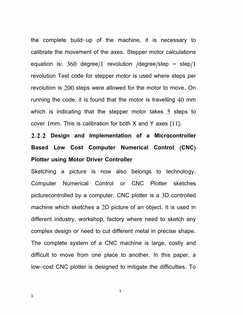
REQUIREMENT ANALYSIS 3.1 Hardware Requirement 3.1.1 CD / DVD Writers The sketching pen in the CNC 2D sketching unit requires movements along X-axis and Yaxis so as to print or draw the desired sketch on A4 sheet. These movements can be achieved by using two stepper motors from old working CD / DVD writers as shown in figure
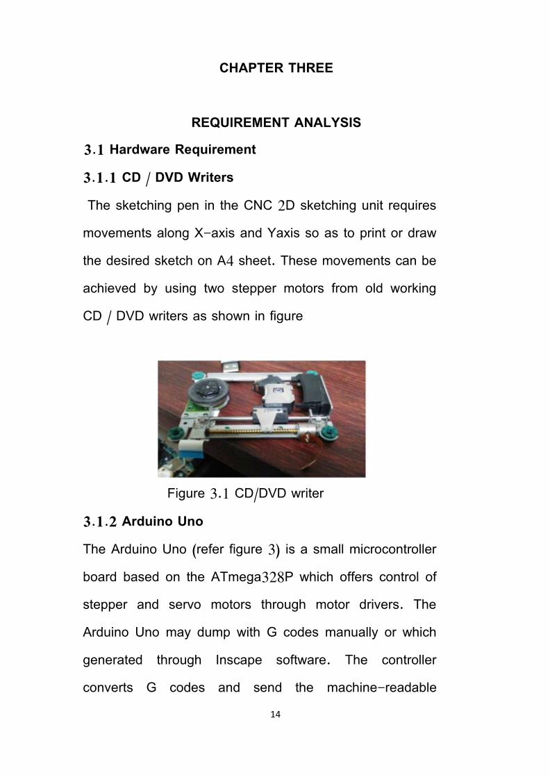
Figure 3.1 CD/DVD writer 3.1.2 Arduino Uno The Arduino Uno (refer figure 3) is a small microcontroller board based on the ATmega328P which offers control of stepper and servo motors through motor drivers. The Arduino Uno may dump with G codes manually or which generated through Inscape software. The controller converts G codes and send the machine-readable
15
instructions to all the components in the CNC 2D sketcher.
Figure 3.2 Arduino Uno
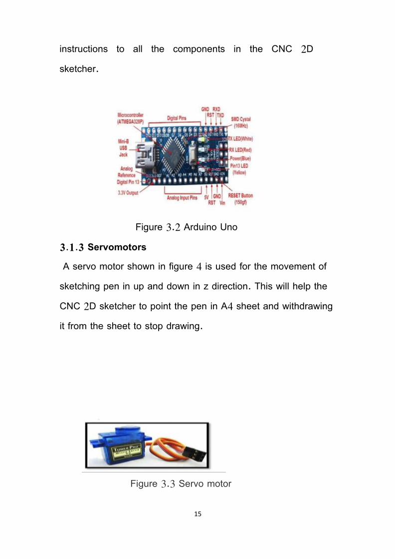
3.1.3 Servomotors A servo motor shown in figure 4 is used for the movement of sketching pen in up and down in z direction. This will help the CNC 2D sketcher to point the pen in A4 sheet and withdrawing it from the sheet to stop drawing.
Figure 3.3 Servo motor
16
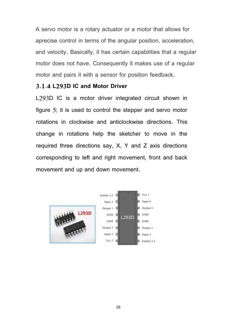
A servo motor is a rotary actuator or a motor that allows for aprecise control in terms of the angular position, acceleration, and velocity. Basically, it has certain capabilities that a regular motor does not have. Consequently it makes use of a regular motor and pairs it with a sensor for position feedback. 3.1.4 L293D IC and Motor Driver L293D IC is a motor driver integrated circuit shown in figure 5; it is used to control the stepper and servo motor rotations in clockwise and anticlockwise directions. This change in rotations help the sketcher to move in the required three directions say, X, Y and Z axis directions corresponding to left and right movement, front and back movement and up and down movement.

17
Figure 3.4 L293D IC and Motor Driver
3.1.5 Stepper Motor Stepper motors are DC motors that move in discretesteps. They have multiple coils that are organized in groups called "phases". By energizing ephain sequence, the motor will rotate, one step at a time. With a computer controlled stepping you can achieve very precise positioning and/or speed control. For this reason, stepper motors are the motor of choice for many precision motion control applications stepper motor is a brushless, synchronous electric motor that converts digital pulses into mechanical shaft rotation. Its normal shaft motion consists of discrete angular movements of discrete angular movements of essentially uniform magnitude when driven from sequentially switched DC power supply.

18
The stepper motor is a digital input-output device. It is particularly well suited to the type of application where control signals appear as digital pulses rather than analog voltages. One digital pulse to a stepper motor drive or translator causes the motor to increment one. precise angle of motion. As the digital pulses increase in frequency, the step movement changes into continuous rotation. There are two types of steppers, Unipolar and Bipolar, and it is very important to know which type you are working with. For each of the motors, there is a different circuit. The example code will control both kinds of motors. See the unipolar and bipolar motor schematics for information on how to wire up your motor
Figure 3.5 Stepper motor
19
Every revolution of the stepper motor is divided into a discrete number of steps, in many cases 200 steps, and the motor must be sent a separate pulse for each step. The stepper motor can only take one step at a time and each step is the same size. Since each pulse causes the motor to rotate a precise angle, typically 1.8°, the motor's position can be controlled without any feedback mechanism. As the digital pulses increase in frequency, the step movement changes into continuous rotation, with the speed of rotation directly proportional to the frequency of the pulses. A wide range of rotational speeds can be realized as the speed is proportional to the frequency of the input pulses. Choosing a Stepper Motor and the controller The choice of a stepper motor depends on the application's torque and speed requirements. Use the motor's torque-speed curve (found in each drive's specifications) to select a motor that will do the job.

20
The recommended motor list is based on extensive testing by the manufacturer to ensure optimal performance of the stepper motor and controller combination 3.2 Software Requirements 3.2.1 Arduino Software We use Arduino software to handle cnc machine by uploading proper command (program) in Arduino uno. Arduino is an open-source electronics platform based on easy-to-use hardware and software. Arduino board are able to read inputs - light on a sensor, a finger on a button, or a Twitter message - and turn it into an output - activating a motor, turning on an LED, publishing something online. You can tell your board what to do by sending a set of instructions to the microcontroller on the board. To do so you use the Arduino programming language (based on Wiring), and the Arduino Software (IDE), based on Processing.
Over the years Arduino has been the brain of thousands of projects, from everyday objects to complex scientific instruments. A worldwide community of makers - students, hobbyists, artists, programmers, and professionals - has gathered around this open-source platform, their contributions have added up to an incredible amount of Accessible

21
knowledge that can be of great help to novices and experts alike.
Figure 3.6 Arduino software 3.2.2 Inkscape Inkscape is used to design the plotted diagram or text. In this project by using this software G-code file of a selected image or text is created G-code is a commonly

22
used numerical control programming language which includes X, Y, Z coordinates. Screenshot is shown in figure 3.7
Figure 3.7 Inkscape
3.2.3 Processing Processing is open source programming language software which is used for electronic drawings. GTCRL processing program is used to send G-code file from user interface to CNC plotter. The Fig. 6 shows the user interface of processing 2.2.1 software after running GTCRL program. The port of

23
Arduino Uno is selected by pressing „P‟ button on keyboard hence G button is used to upload our desired G-code file. Immediately CNC machine will start sketching selected G-code file. Sketching can be stopped by pressing X button.
Figure 3.8 Processing

24
CHAPTER FOUR IMPLEMENTATION
4.1 Step 1: Disassembly DVD/CD Drives First step to start building this CNC machine is to disassemble two DVD/CD drives and take off them the stepper motors. Use the screwdriver to open them and take off them the rails. Next step is to choose our base for this CNC machine. I used one surface from remaining DVD garbage' stuff. Finally we will need to find something to attach the one of the stepper-rails vertically to our construction. (you will understand what I mean in our next step) Watch the above image.
Figure 4.1 Disassembly

25
4.2 Step 2: X and Y Axis In first image above you will see the Y axis of our CNC machine. Attach it on your surface, in this part you will need some screws and nuts in second image you will see the X and Y axis. The X axis is attached to two plastic parts that I took from remaining 'garbage' stuff. I cut it to fit the construction. This is an easy procedure. Just make sure to put the Y axis straight to CNC base and the X axis vertically in this (90 )degree
. .
Figure 4.2 X axis 4.3 Step 3: The Z Axis That's the most difficult part of our construction. You will need something to attach it on X axis, a flat surface. On that surface you will attach the servo motor (Z axis) and the pen base. Pen (or pencil) must be able to move up and down with the help of servo motor.

26
Figure 4.3 The Y axis Watch the above image to understand what you need to do to build Z axis Image Notes 1. Servo motor must be able to move up and down the pen.
Figure 4.4 Z axis

27
4.4 Step 4: Paper Base Now you will have to attach a wood (or plastic) surface on Y axis (4x4cm will be fine). On this you will put the paper piece to print your texts or images Remember, printing area is 4x4cm
Figure 4.5 Paper base
4.5 Step 5: The Circuit Now that we have our contraction ready, it’s time to build the circuit and test stepper motors (X and Y axis). Watch the above image with breadboard circuit schematic. Steppers motors wiring is something that need patient. On next step you will find a ‘testing’ code for x and y axis. If

28
yours steppers doesn’t work properly you must find correct working combination by changing the cables between them and the L293D IC On mine CNC, X axis motor connection are: L293 A: Pins 1 and 3 & B: 2 and 4, but on Y axis motor connection are A: 1 and 2 & B: 3 and 4
Figure 4.6 Circuit
4.6 Step 6: Testing X and Y Axis Movement Here is the X and Y axis testing code embedded using code bender For X axis: For Y axis: If you see any movement here that means that the stepper motors wiring is correct! if you don't, try to change the cables. 4.7 Step 7: Uploading the CNC Code Here is the main CNC code embedded using code bender In this part you will see your pen goes up. If don't, change pen Up and pen Down variables that controlling the servo

29
motor. Press the "Run on Arduino" button and program your board from your browser! 4.8 Step 8: The GCTRL Program Now we are ready to print our first image! To do this we will use the gctrl.pde processing program. This program sends 'G code' images to the CNC plotter. What is G code? G code is a file with X,Y and Z coordinates. Header of this file is set to: M300 S30.00 (Servo down) G1 X10.00 Y10.00 F2500.00 G1 X20.00 Y10.00 F2500.00 M300 S50.00 (Servo up) Download Processing from here, now download and open GCTRL.pde application. Click the "play" icon/button to start the program. ~Watch the above image~ Now press 'p' and select your Arduino serial port. Press 'g' and select the 'drawing g code' file 4.9 Step 9: Make Your Own G Code File To make g code files that are compatible with this CNC machine you have to use the Inkscape. Inkscape is professional quality vector graphics software which runs on Windows, Mac OS X and Linux. It is used by design professionals and hobbyists worldwide, for creating a wide variety of graphics such as illustrations, icons, logos, diagrams, maps and web graphics. Inkscape uses the W3C open standard SVG (Scalable Vector Graphics) as its native format, and is free and open-source software. Download and install Inkscape from here (Important: download 0.48.5 version) Now

30
you need to install an Add-on that enables the export images to g code files. This add on can be found here with installation notes. Setup Inkscape for first use Open the Inkscape, go to File menu and click "Document Properties". See the 1st image above and make the changes, make sure to change first to "cm". Now close this window. We will use the area within 4 to 4 cm. See the 2nd image above. How to print texts Put text, change font to Times New Roman and size to 22. Now click on cursor icon and center the text like the 3rd image above. Select Path from menu and "Object to Path". How to print images This is more difficult than texts. Images must have a transparent background. Drag and drop the Arduino logo image (download it from files) in Inkscape. Click ok to the next window. Now you have to re-size the image to fit our printing area, see the 4th image above. Click Path from menu and "Trace Bitmap". Make changes as the 5th image above. Click ok and close the window. Now, move the gray scale image, and delete the color one behind it. Move the grey image to the correct place again and click from Path menu "Object to path". The 6th image above shows how to delete image outline. Export as g code Final, go to file menu, click save as and select g code. Click ok on next window. That's it! Ready to go! Use the gctrl.pde app to print the g code file on your new Arduino CNC Plotter.

31
CHAPTER FIVE CONCLUSION AND RECOMMENDATION
5.1 Conclusion In this project we have presented the concept of a low cost three-axis mini CNC plotter. The existing CNC machines are of high cost, difficult to maintain and requires highly skilled operators. Our CNC plotter overcomes these problems. It is of low cost and easy to control and there is no need of highly skilled operators. It can be used for long hours at a stretch which is not possible in existing ones. It is hoped to extend this work for future development. 5.2 Recommendation The pen of the machine can be replace by a leaser to make it work like a leaser cutting machine engraving machine can be use on wood the pen can also be replace with a powerful drill so that it can be used for both drilling and milling purposes the servo can be replace with a stepper motor and pen with a 3D pen to make it a 3D printer which can print object with dimension by extrapolation of the axis the working area of the machine can be extended keeping the algorithm unaltered Further the applications of proposed CNC 2D sketcher can also

32
be extended in the field of printed circuit board PCB drawing and drilling electrical dis-charge machining (EDM), metal removal and fabrication lettering and logo designs or engraving as well.

33
REFERENCES [1] Paulo A. Sherring da Rocha Jr., Rogério D. S. Souza and M. Emília de Lima Tostes, "Prototype CNC Machine Design", Journal of Energy and Power Engineering 6 (2012) 1884-1890, November 30, 2012. [2] Kajal J. Madekar, Kranti R. Nanaware, Pooja R. Phadtare, Vikas S. Mane, "Automatic mini CNC machine for PCB drawing and drilling", International Research Journal of Engineering and Technology (IRJET), Volume: 03 Issue: 02 Feb 2016. [3] Aneeta Pinhiero, Beljo Jose, Tinsemon Chacko, Nazim TN, “Mini CNC Plotter”, International Journal of Innovative Research in Electrical, Electronics, Instrumentation and Control Engineering (IJIREEICE), Vol. 4, Issue 4, April 2016 [4] Sundar Pandian, S. Raj Pandian,"A Low-Cost Build-Your Own Three Axis CNC Mill Prototype", International
Journal on Mechanical Engineering and Robotics (IJMER), Volume-2, Issue-1, 2014.
[5] V.K. Pabolu and K.N.H. Shrinivas, "Design and implementation of a three -dimensional CNC machine", Int. J. Computer Science and Engineering, vol. 2,pp.
2567-2570 2010 .

34
[6] I. Nae and T. Andrei, "Designing and building a CNC router using stepper motors", Serial Technical, vo. LXII, pp. 55-62, 2010. [7] Pahole I., Rataj L., Ficko M., Klancnik S., Brezovnik S., Brezocnik M. and Balic J. 2009 .Construction and evaluation of low-cost table CNC milling machine. Scientific Bulletin, Series C, Mehcanics, Tribology, Machine Manufacturing Technology, Vol.XXIII, 143- 148. [8] Yesaswi Ch.S., Subrahmanyam, T., Karthik, G.S., Sudheer, N .S. and Farooq, S. B. 2017.Modeling and Analysis of A CNC Milling Machine Bed with Nano Material (Graphene). IJMET, 8(5), 372–379. [9] Saifee A.M. and Mehta S.U. 2016. Design and Implementation of FPGA Based G Code Compatible CNC Lathe Controller. IJECET, 7(1), 2016, pp. 87-100.
[10] Computer Numerical Control, http://www.cnc.com/thehistory-of-computer-numerical-
control-cnc/ [11] Web site: qu.edu.iq [12] Web site: researchgate.net

35
APPENDIX ARDUINO CODING #include <Servo.h> #include <AFMotor.h> #define LINE_BUFFER_LENGTH 512 char STEP = MICROSTEP ; // Servo position for Up and Down const int penZUp = 115; const int penZDown = 83; // Servo on PWM pin 10 const int penServoPin =10 ; // Should be right for DVD steppers, but is not too important here const int stepsPerRevolution = 48; // create servo object to control a servo Servo penServo;
36
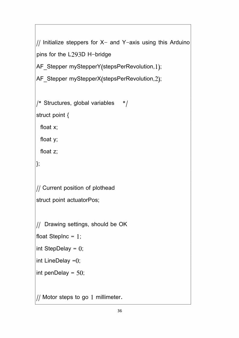
// Initialize steppers for X- and Y-axis using this Arduino pins for the L293D H-bridge AF_Stepper myStepperY(stepsPerRevolution,1); AF_Stepper myStepperX(stepsPerRevolution,2); /* Structures, global variables */ struct point { float x; float y; float z; }; // Current position of plothead struct point actuatorPos; // Drawing settings, should be OK float StepInc = 1; int StepDelay = 0; int LineDelay =0; int penDelay = 50; // Motor steps to go 1 millimeter.

37
// Use test sketch to go 100 steps. Measure the length of line. // Calculate steps per mm. Enter here. float StepsPerMillimeterX = 100.0; float StepsPerMillimeterY = 100.0; // Drawing robot limits, in mm // OK to start with. Could go up to 50 mm if calibrated well. float Xmin = 0; float Xmax = 40; float Ymin = 0; float Ymax = 40; float Zmin = 0; float Zmax = 1; float Xpos = Xmin; float Ypos = Ymin; float Zpos = Zmax; // Set to true to get debug output. boolean verbose = false;

38
// Needs to interpret // G1 for moving // G4 P300 (wait 150ms) // M300 S30 (pen down) // M300 S50 (pen up) // Discard anything with a ( // Discard any other command! /********************** * void setup() - Initialisations ***********************/ void setup() { // Setup Serial.begin( 9600 ); penServo.attach(penServoPin); penServo.write(penZUp); delay(100); // Decrease if necessary myStepperX.setSpeed(600);

39
myStepperY.setSpeed(600); // Set & move to initial default position // TBD // Notifications!!! Serial.println("Mini CNC Plotter alive and kicking!"); Serial.print("X range is from "); Serial.print(Xmin); Serial.print(" to "); Serial.print(Xmax); Serial.println(" mm."); Serial.print("Y range is from "); Serial.print(Ymin); Serial.print(" to "); Serial.print(Ymax); Serial.println(" mm."); } /********************** * void loop() - Main loop ***********************/

40
void loop() { delay(100); char line[ LINE_BUFFER_LENGTH ]; char c; int lineIndex; bool lineIsComment, lineSemiColon; lineIndex = 0; lineSemiColon = false; lineIsComment = false; while (1) { // Serial reception - Mostly from Grbl, added semicolon support while ( Serial.available()>0 ) { c = Serial.read(); if (( c == '\n') || (c == '\r') ) { // End of line reached if ( lineIndex > 0 ) { // Line is complete. Then execute!

41
line[ lineIndex ] = '\0'; // Terminate string if (verbose) { Serial.print( "Received : "); Serial.println( line ); } processIncomingLine( line, lineIndex ); lineIndex = 0; } else { // Empty or comment line. Skip block. } lineIsComment = false; lineSemiColon = false; Serial.println("ok"); } else { if ( (lineIsComment) || (lineSemiColon) ) { // Throw away all comment characters if ( c == ')' ) lineIsComment = false; // End of comment. Resume line. } else {

42
if ( c <= ' ' ) { // Throw away whitepace and control characters } else if ( c == '/' ) { // Block delete not supported. Ignore character. } else if ( c == '(' ) { // Enable comments flag and ignore all characters until ')' or EOL. lineIsComment = true; } else if ( c == ';' ) { lineSemiColon = true; } else if ( lineIndex >= LINE_BUFFER_LENGTH-1 ) { Serial.println( "ERROR - lineBuffer overflow" ); lineIsComment = false; lineSemiColon = false; } else if ( c >= 'a' && c <= 'z' ) { // Upcase lowercase line[ lineIndex++ ] = c-'a'+'A'; }

43
else { line[ lineIndex++ ] = c; } } } } } } void processIncomingLine( char* line, int charNB ) { int currentIndex = 0; char buffer[ 64 ]; // Hope that 64 is enough for 1 parameter struct point newPos; newPos.x = 0.0; newPos.y = 0.0; // Needs to interpret // G1 for moving // G4 P300 (wait 150ms) // G1 X60 Y30 // G1 X30 Y50

44
// M300 S30 (pen down) // M300 S50 (pen up) // Discard anything with a ( // Discard any other command! while( currentIndex < charNB ) { switch ( line[ currentIndex++ ] ) { // Select command, if any case 'U': penUp(); break; case 'D': penDown(); break; case 'G': buffer[0] = line[ currentIndex++ ]; // /!\ Dirty - Only works with 2 digit commands // buffer[1] = line[ currentIndex++ ]; // buffer[2] = '\0'; buffer[1] = '\0'; switch ( atoi( buffer ) ){ // Select G command

45
case 0: // G00 & G01 - Movement or fast movement. Same here case 1: // /!\ Dirty - Suppose that X is before Y char* indexX = strchr( line+currentIndex, 'X' ); // Get X/Y position in the string (if any) char* indexY = strchr( line+currentIndex, 'Y' ); if ( indexY <= 0 ) { newPos.x = atof( indexX + 1); newPos.y = actuatorPos.y; } else if ( indexX <= 0 ) { newPos.y = atof( indexY + 1); newPos.x = actuatorPos.x; } else { newPos.y = atof( indexY + 1); indexY = '\0'; newPos.x = atof( indexX + 1); } drawLine(newPos.x, newPos.y ); // Serial.println("ok"); actuatorPos.x = newPos.x;

46
actuatorPos.y = newPos.y; break; } break; case 'M': buffer[0] = line[ currentIndex++ ]; // /!\ Dirty - Only works with 3 digit commands buffer[1] = line[ currentIndex++ ]; buffer[2] = line[ currentIndex++ ]; buffer[3] = '\0'; switch ( atoi( buffer ) ){ case 300: { char* indexS = strchr( line+currentIndex, 'S' ); float Spos = atof( indexS + 1); // Serial.println("ok"); if (Spos == 30) { penDown(); } if (Spos == 50) { penUp(); } break;

47
} case 114: // M114 - Repport position Serial.print( "Absolute position : X = " ); Serial.print( actuatorPos.x ); Serial.print( " - Y = " ); Serial.println( actuatorPos.y ); break; default: Serial.print( "Command not recognized : M"); Serial.println( buffer ); } } } } /********************************* * Draw a line from (x0;y0) to (x1;y1). * int (x1;y1) : Starting coordinates

48
* int (x2;y2) : Ending coordinates **********************************/ void drawLine(float x1, float y1) { if (verbose) { Serial.print("fx1, fy1: "); Serial.print(x1); Serial.print(","); Serial.print(y1); Serial.println(""); } // Bring instructions within limits if (x1 >= Xmax) { x1 = Xmax; } if (x1 <= Xmin) { x1 = Xmin; } if (y1 >= Ymax) { y1 = Ymax; }

49
if (y1 <= Ymin) { y1 = Ymin; } if (verbose) { Serial.print("Xpos, Ypos: "); Serial.print(Xpos); Serial.print(","); Serial.print(Ypos); Serial.println(""); } if (verbose) { Serial.print("x1, y1: "); Serial.print(x1); Serial.print(","); Serial.print(y1); Serial.println(""); } // Convert coordinates to steps
50
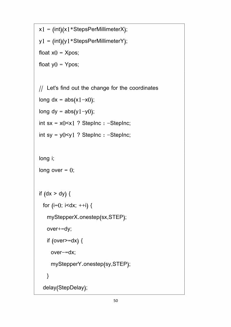
x1 = (int)(x1*StepsPerMillimeterX); y1 = (int)(y1*StepsPerMillimeterY); float x0 = Xpos; float y0 = Ypos; // Let's find out the change for the coordinates long dx = abs(x1-x0); long dy = abs(y1-y0); int sx = x0<x1 ? StepInc : -StepInc; int sy = y0<y1 ? StepInc : -StepInc; long i; long over = 0; if (dx > dy) { for (i=0; i<dx; ++i) { myStepperX.onestep(sx,STEP); over+=dy; if (over>=dx) { over-=dx; myStepperY.onestep(sy,STEP); } delay(StepDelay);

51
} } else { for (i=0; i<dy; ++i) { myStepperY.onestep(sy,STEP); over+=dx; if (over>=dy) { over-=dy; myStepperX.onestep(sx,STEP); } delay(StepDelay); } } if (verbose) { Serial.print("dx, dy:"); Serial.print(dx); Serial.print(","); Serial.print(dy); Serial.println(""); }
52
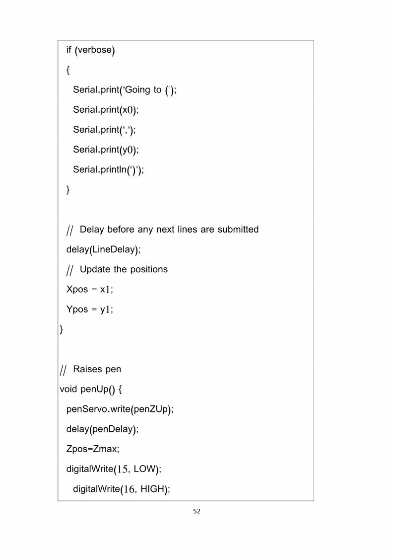
if (verbose) { Serial.print("Going to ("); Serial.print(x0); Serial.print(","); Serial.print(y0); Serial.println(")"); } // Delay before any next lines are submitted delay(LineDelay); // Update the positions Xpos = x1; Ypos = y1; } // Raises pen void penUp() { penServo.write(penZUp); delay(penDelay); Zpos=Zmax; digitalWrite(15, LOW); digitalWrite(16, HIGH);

53
if (verbose) { Serial.println("Pen up!"); } } // Lowers pen void penDown() { penServo.write(penZDown); delay(penDelay); Zpos=Zmin; digitalWrite(15, HIGH); digitalWrite(16, LOW); if (verbose) { Serial.println("Pen down."); } }