CNC 8070. CNC variables. - Fagor Automation
614
(Ref: 2102) 8070 CNC CNC variables.
-
Upload
khangminh22 -
Category
Documents
-
view
1 -
download
0
Transcript of CNC 8070. CNC variables. - Fagor Automation

(Ref: 2102)
8070CNCCNC variables.

BLANK PAGE
ꞏ2ꞏ
MACHINE SAFETY
It is up to the machine manufacturer to make sure that the safety of the machineis enabled in order to prevent personal injury and damage to the CNC or to theproducts connected to it. On start-up and while validating CNC parameters, itchecks the status of the following safety elements. If any of them is disabled, theCNC shows the following warning message.
• Feedback alarm for analog axes.
• Software limits for analog and sercos linear axes.
• Following error monitoring for analog and sercos axes (except the spindle)both at the CNC and at the drives.
• Tendency test on analog axes.
FAGOR AUTOMATION shall not be held responsible for any personal injuries orphysical damage caused or suffered by the CNC resulting from any of the safetyelements being disabled.
DUAL-USE PRODUCTS
Products manufactured by FAGOR AUTOMATION since April 1st 2014 willinclude "-MDU" in their identification if they are included on the list of dual-useproducts according to regulation UE 428/2009 and require an export licensedepending on destination.
TRANSLATION OF THE ORIGINAL MANUAL
This manual is a translation of the original manual. This manual, as well as thedocuments derived from it, have been drafted in Spanish. In the event of anycontradictions between the document in Spanish and its translations, the wordingin the Spanish version shall prevail. The original manual will be labeled with thetext "ORIGINAL MANUAL".
HARDWARE EXPANSIONS
FAGOR AUTOMATION shall not be held responsible for any personal injuries orphysical damage caused or suffered by the CNC resulting from any hardwaremanipulation by personnel unauthorized by Fagor Automation.
If the CNC hardware is modified by personnel unauthorized by FagorAutomation, it will no longer be under warranty.
COMPUTER VIRUSES
FAGOR AUTOMATION guarantees that the software installed contains nocomputer viruses. It is up to the user to keep the unit virus free in order toguarantee its proper operation. Computer viruses at the CNC may cause it tomalfunction.
FAGOR AUTOMATION shall not be held responsible for any personal injuries orphysical damage caused or suffered by the CNC due a computer virus in thesystem.
If a computer virus is found in the system, the unit will no longer be under warranty.
All rights reserved. No part of this documentation may be transmitted,transcribed, stored in a backup device or translated into another languagewithout Fagor Automation’s consent. Unauthorized copying or distributing of thissoftware is prohibited.
The information described in this manual may be subject to changes due totechnical modifications. Fagor Automation reserves the right to change thecontents of this manual without prior notice.
All the trade marks appearing in the manual belong to the corresponding owners.The use of these marks by third parties for their own purpose could violate therights of the owners.
It is possible that CNC can execute more functions than those described in itsassociated documentation; however, Fagor Automation does not guarantee thevalidity of those applications. Therefore, except under the express permissionfrom Fagor Automation, any CNC application that is not described in thedocumentation must be considered as "impossible". In any case, FagorAutomation shall not be held responsible for any personal injuries or physicaldamage caused or suffered by the CNC if it is used in any way other than asexplained in the related documentation.
The content of this manual and its validity for the product described here has beenverified. Even so, involuntary errors are possible, hence no absolute match isguaranteed. However, the contents of this document are regularly checked andupdated implementing the necessary corrections in a later edition. We appreciateyour suggestions for improvement.
The examples described in this manual are for learning purposes. Before usingthem in industrial applications, they must be properly adapted making sure thatthe safety regulations are fully met.

CNC variables.
CNC 8070
ꞏ3ꞏ
(REF: 2102)
I N D E X
About the product - CNC 8070 ....................................................................................................11Declaration of CE conformity and warranty conditions ............................................................... 17Safety conditions ........................................................................................................................ 19Returning conditions ................................................................................................................... 23CNC maintenance ...................................................................................................................... 25New features............................................................................................................................... 27
CHAPTER 1 CNC VARIABLES.
1.1 Understanding how variables work. ............................................................................... 331.1.1 Accessing numeric variables from the PLC. .............................................................. 351.2 Variables in a single-channel system............................................................................. 361.3 Variables in a multi-channel system. ............................................................................. 39
CHAPTER 2 VARIABLES RELATED TO MACHINE PARAMETERS.
2.1 Variables related to general machine parameters. ........................................................ 432.1.1 Channel configuration. ............................................................................................... 432.1.2 Configuring the axes of the system............................................................................ 432.1.3 Configuration of a tandem system. ............................................................................ 442.1.4 Configuration of a gantry axis.. .................................................................................. 472.1.5 Configuration of a multi-axis group. ........................................................................... 492.1.6 Configuring the spindles of the system ...................................................................... 502.1.7 Time setting (system)................................................................................................. 502.1.8 Sercos bus configuration............................................................................................ 512.1.9 Mechatrolink bus configuration. ................................................................................. 522.1.10 CAN bus configuration. .............................................................................................. 532.1.11 Serial line configuration.............................................................................................. 542.1.12 MODBUS. .................................................................................................................. 552.1.13 Default conditions (sytem).......................................................................................... 562.1.14 Arithmetic parameters. ............................................................................................... 572.1.15 Cross compensation table.......................................................................................... 592.1.16 Volumetric compensation tables. ............................................................................... 622.1.17 Execution times.......................................................................................................... 642.1.18 Numbering of the digital inputs (CANfagor bus)......................................................... 652.1.19 Numbering of the digital outputs (CANfagor bus). ..................................................... 652.1.20 Numbering of the digital inputs (CANopen bus)......................................................... 662.1.21 Numbering of the digital outputs (CANopen bus)....................................................... 672.1.22 Numbering of analog inputs for temperature sensors PT100. ................................... 682.1.23 Probe setting. ............................................................................................................. 692.1.24 Shared PLC memory.................................................................................................. 712.1.25 Management of local I/O. ........................................................................................... 712.1.26 Synchronized switching.............................................................................................. 722.1.27 PWM (Pulse-Width Modulation). ................................................................................ 732.1.28 Power control. ............................................................................................................ 742.1.29 Gap control................................................................................................................. 752.1.30 Leapfrog. .................................................................................................................... 792.1.31 CO2 laser path dispersion compensation. ................................................................. 802.1.32 Backup of non-volatile data........................................................................................ 822.1.33 Tool offset and wear................................................................................................... 822.1.34 Spindle synchronization. ............................................................................................ 832.1.35 Define the number of jog panels and their relationship with the channels. ................ 832.1.36 PLC type. ................................................................................................................... 842.1.37 Rename the axes and the spindles............................................................................ 842.1.38 Zero offsets. ............................................................................................................... 842.1.39 Remote module RCS-S (Sercos Counter). ................................................................ 852.2 Variables related to the machine parameters of the channels. ...................................... 862.2.1 Channel configuration. ............................................................................................... 862.2.2 Configuring the axes of the channel........................................................................... 872.2.3 Configuring the spindles of the channel. .................................................................... 892.2.4 Configuration of the C axis......................................................................................... 902.2.5 Time setting (channel)................................................................................................ 902.2.6 Configuration of the HSC mode (channel). ................................................................ 912.2.7 Virtual tool axis........................................................................................................... 942.2.8 Default conditions (channel)....................................................................................... 952.2.9 Arc center correction. ............................................................................................... 103

CNC variables.
CNC 8070
ꞏ4ꞏ
(REF: 2102)
2.2.10 Behavior of the feedrate and the feedrate override. ................................................ 1042.2.11 Override of the dynamics for HSC. .......................................................................... 1062.2.12 DMC configuration. .................................................................................................. 1072.2.13 Movement of the independent axes......................................................................... 1082.2.14 Definition of the subroutines. ................................................................................... 1092.2.15 Tabletop probe position. .......................................................................................... 1112.2.16 Block search. ........................................................................................................... 1132.2.17 Interruption subroutines. .......................................................................................... 1132.2.18 Machining feedrate. ................................................................................................. 1142.2.19 Rapid traverse for the automatic mode. ................................................................... 1152.2.20 Maximum acceleration and jerk on the tool path. .................................................... 1162.2.21 Maximun frequency on the tool path. ....................................................................... 1162.2.22 Resonance frequency of the machine. .................................................................... 1162.2.23 "Retrace" function. ................................................................................................... 1172.2.24 Tool withdrawal. ....................................................................................................... 1182.2.25 Master spindle.......................................................................................................... 1182.3 Variables related to axis and spindle machine parameters. ........................................ 1192.3.1 Belonging to the channel. ........................................................................................ 1192.3.2 Type of axis and drive.............................................................................................. 1202.3.3 Configuring a Sercos drive....................................................................................... 1222.3.4 Hirth axis configuration. ........................................................................................... 1252.3.5 Axis configuration for lathe type machines. ............................................................. 1262.3.6 Configuration of the rotary axes............................................................................... 1272.3.7 Module configuration (rotary axes and spindle). ...................................................... 1292.3.8 Activating the spindle for DMC................................................................................. 1292.3.9 Configuration of the C axis....................................................................................... 1302.3.10 Configuration of the spindle. .................................................................................... 1322.3.11 Synchronization of axes and spindles...................................................................... 1372.3.12 Software axis limits. ................................................................................................. 1392.3.13 Work zones. ............................................................................................................. 1402.3.14 Override change while threading. ............................................................................ 1412.3.15 Runaway protection and tendency test. ................................................................... 1422.3.16 PLC offset. ............................................................................................................... 1432.3.17 Dwell for dead axes. ................................................................................................ 1432.3.18 Programming in radius or diameters. ....................................................................... 1442.3.19 Home search............................................................................................................ 1452.3.20 Configuration of the probing movement. .................................................................. 1472.3.21 Repositioning of the axes in tool inspection............................................................. 1492.3.22 Configuration of the independent axis. .................................................................... 1492.3.23 Configure the maximum safety limit for the feedrate and for the speed. ................. 1502.3.24 JOG mode. Continuous jog...................................................................................... 1512.3.25 JOG mode. Incremental jog. .................................................................................... 1532.3.26 JOG mode. Handwheels. ......................................................................................... 1542.3.27 JOG mode. Manual intervention. ............................................................................. 1552.3.28 Leadscrew error compensation................................................................................ 1572.3.29 Filters to eliminate frequencies. ............................................................................... 1612.3.30 Parameter sets......................................................................................................... 1642.4 Variables related to the sets of machine parameters. ................................................. 1652.4.1 Feedback resolution................................................................................................. 1652.4.2 Feedback alarm. ...................................................................................................... 1702.4.3 Loop setting. ............................................................................................................ 1712.4.4 Backlash compensation. .......................................................................................... 1732.4.5 Backlash compensation with an additional command pulse.................................... 1742.4.6 Adjustment of rapid traverse G00 and maximum speed. ......................................... 1772.4.7 Rapid traverse for the automatic mode. ................................................................... 1802.4.8 Gain setting.............................................................................................................. 1812.4.9 Linear acceleration................................................................................................... 1852.4.10 Trapezoidal and square sine acceleration. .............................................................. 1872.4.11 Enable specific acceleration values for movements in G0....................................... 1892.4.12 Linear acceleration (G0 movements). ...................................................................... 1902.4.13 Trapezoidal and square sine acceleration (G0 movements). .................................. 1922.4.14 Configuration of the HSC mode. .............................................................................. 1942.4.15 Home search............................................................................................................ 1982.4.16 Following error. ........................................................................................................ 2042.4.17 Axis lubrication......................................................................................................... 2082.4.18 Module configuration (rotary axes and spindle). ...................................................... 2092.4.19 Spindle speed. ......................................................................................................... 2112.4.20 Analog command setting. ........................................................................................ 2132.4.21 Number of the analog output and of the feedback input associated with the axis. .. 2142.4.22 Set the drive associated with the axes of a multi-axis group. .................................. 2172.4.23 Feedback type of the RCS-S module. ..................................................................... 2182.4.24 Delay estimate at the drive. ..................................................................................... 2262.5 Variables related to machine parameters for JOG mode. ........................................... 2272.5.1 Handwheel configuration. ........................................................................................ 2272.5.2 Configure the jog keys. ............................................................................................ 229

CNC variables.
CNC 8070
ꞏ5ꞏ
(REF: 2102)
2.5.3 Configure the user keys as jog keys ........................................................................ 2312.6 Variables related to machine parameters for M functions............................................ 2332.7 Variables related to kinematic machine parameters. ................................................... 2352.7.1 Kinematics configuration. ......................................................................................... 2352.7.2 Configuration of angular transformations. ................................................................ 2392.8 Variables related to machine parameters for the tool magazine.................................. 2412.9 Variables related to OEM machine parameters. .......................................................... 2442.9.1 Generic OEM parameters. ....................................................................................... 2442.9.2 Reading drive variables............................................................................................ 246
CHAPTER 3 PLC RELATED VARIABLES.
3.1 Variables associated with the status and resources of the PLC. ................................. 2473.1.1 PLC status................................................................................................................ 2473.1.2 PLC Resources. ....................................................................................................... 2483.1.3 PLC messages......................................................................................................... 2503.1.4 PLC errors................................................................................................................ 2513.1.5 PLC clocks. .............................................................................................................. 2523.2 PLC consulting logic signals; general. ......................................................................... 2533.3 PLC consulting logic signals; axes and spindles. ........................................................ 2653.4 PLC consulting logic signals; spindles. ........................................................................ 2703.5 PLC consulting logic signals; independent interpolator. .............................................. 2723.6 PLC consulting logic signals; laser. ............................................................................. 2743.6.1 Piercing enabled. ..................................................................................................... 2743.6.2 Active cutting............................................................................................................ 2743.6.3 Technology tables. ................................................................................................... 2753.6.4 Gap control............................................................................................................... 2763.6.5 Leapfrog. .................................................................................................................. 2763.7 PLC consulting logic signals; tool manager. ................................................................ 2773.8 PLC consulting logic signals; keys............................................................................... 2803.9 PLC modifiable logic signals; general. ......................................................................... 2813.10 PLC modifiable logic signals; axes and spindles. ........................................................ 2913.11 PLC modifiable logic signals; spindles......................................................................... 2983.12 PLC modifiable logic signals; independent interpolator. .............................................. 3003.13 PLC modifiable logic signals; laser. ............................................................................. 3013.13.1 Laser status.............................................................................................................. 3013.13.2 PWM active from the PLC........................................................................................ 3023.13.3 Power control. .......................................................................................................... 3033.13.4 Gap control............................................................................................................... 3043.13.5 Leapfrog. .................................................................................................................. 3043.14 PLC modifiable logic signals; tool manager. ................................................................ 3053.15 PLC modifiable logic signals; keys............................................................................... 310
CHAPTER 4 VARIABLES RELATED TO THE MACHINE CONFIGURATION.
4.1 Variables associated with the channels, axes and spindles. ....................................... 3134.1.1 Name of the axes and spindles................................................................................ 3134.1.2 Logic number of the axes and spindles of the channel. ........................................... 3164.1.3 Number of the channels, axes and spindles. ........................................................... 3174.1.4 Current channel of the axis or of the spindle............................................................ 3194.1.5 Parameter set of the axis or spindle......................................................................... 3204.1.6 Travel limits of linear and rotary axes. ..................................................................... 3214.1.7 Kinetimatics dimensions........................................................................................... 3224.1.8 Change the turning direction assigned to M3 and M4.............................................. 3234.1.9 Number of pulses sent by the handwheel. ............................................................... 3244.1.10 Modify the simulation speed via PLC. ...................................................................... 3244.2 Variables related to volumetric compensation. ............................................................ 3254.3 Variables associated with the Mechatrolink bus. ........................................................ 3264.3.1 Status of communication and of the Mechatrolink devices. ..................................... 3264.4 Multi-turn absolute encoder. ........................................................................................ 3284.4.1 Variables. Number of overshots in the feedback range. .......................................... 328
CHAPTER 5 VARIABLES RELATED TO LASER.
5.1 Active material. ............................................................................................................ 3295.2 Active cutting................................................................................................................ 3295.3 Active piercing.............................................................................................................. 3305.4 Laser power. Power programming............................................................................... 3315.5 Laser power. Power in G97. ........................................................................................ 3325.6 Laser power. Power limit.............................................................................................. 3345.7 Laser power. Power percentage (override).................................................................. 3365.8 Variables associated with gas pressure....................................................................... 3385.9 Position and dimensions of the minimum rectangle containing the drawing................ 3395.10 PWM (pulse-width modulation). ................................................................................... 341

CNC variables.
CNC 8070
ꞏ6ꞏ
(REF: 2102)
5.11 Power control via an analog output. ............................................................................ 3435.12 Power control via the PWM duty cycle. ....................................................................... 3455.13 Power control through the PWM frequency. ................................................................ 3475.14 Control the power as a function of the feedrate defined in a variable.......................... 3495.15 Leapfrog....................................................................................................................... 3505.16 Synchronized switching. .............................................................................................. 3525.17 CO2 laser dispersion compensation. ........................................................................... 3545.18 Gap control. ................................................................................................................. 355
CHAPTER 6 VARIABLES RELATED TO CYCLE TIME.
6.1 Analysis of the loop time (cycle time) at the CNC........................................................ 3576.2 Analysis of the loop time (cycle time) in the channel. .................................................. 358
CHAPTER 7 VARIABLES ASSOCIATED WITH THE FEEDBACK INPUTS FOR ANALOG AXES.
7.1 Feedback inputs associated with the analog axes. ..................................................... 3597.2 Local feedback inputs (ICU/MCU). .............................................................................. 361
CHAPTER 8 VARIABLES ASSOCIATED WITH THE ANALOG INPUTS AND OUTPUTS.
8.1 Remote analog inputs and outputs. ............................................................................. 3638.2 Remote module RCS-S (Sercos counter).................................................................... 363
CHAPTER 9 VARIABLES ASSOCIATED WITH THE VELOCITY COMMAND AND THE FEEDBACK OF THE DRIVE.
9.1 Velocity command and torque for Sercos axes. .......................................................... 3659.2 Feedback of the analog or Sercos drive. ..................................................................... 366
CHAPTER 10 VARIABLES RELATED TO THE CHANGE OF GEAR AND SET OF THE SERCOS DRIVE.
10.1 Change of gear and set of the Sercos drive. ............................................................... 367
CHAPTER 11 VARIABLES RELATED TO LOOP ADJUSTMENT.
11.1 Coordinate related variables........................................................................................ 36911.2 Position increment and sampling period. ..................................................................... 37211.3 Fine adjustment of feedrate, acceleration and jerk. ..................................................... 37411.4 Gain setting via PLC. ................................................................................................... 37711.5 Variables related to the loop of the axis or of the tandem spindle. .............................. 379
CHAPTER 12 VARIABLES RELATED TO USER TABLES.
12.1 Zero offset table. .......................................................................................................... 38312.1.1 Zero offset table (without fine setting of the absolute zero offset). .......................... 38512.1.2 Zero offset table (with fine setting of the absolute zero offset). ............................... 38712.2 Variables related to user tables (fixture table). ............................................................ 39012.3 Variables related to user tables (arithmetic parameters table). ................................... 39212.3.1 Local arithmetic parameters..................................................................................... 39212.3.2 Global arithmetic parameters. .................................................................................. 39412.3.3 Common arithmetic parameters............................................................................... 395
CHAPTER 13 VARIABLES ASSOCIATED WITH THE TECHNOLOGICAL TABLES.
13.1 Generic technology tables. .......................................................................................... 39713.2 Common parameters. ................................................................................................. 39913.3 Piercing parameters. ................................................................................................... 40013.4 Cutting parameters. .................................................................................................... 403
CHAPTER 14 VARIABLES RELATED TO THE POSITION OF THE AXES.
14.1 Programmed coordinates. ........................................................................................... 40714.2 Position in part coordinates. ........................................................................................ 40914.3 Position in machine coordinates. ................................................................................. 41114.4 Position read in the internal feedback (motor feedback). ............................................ 41314.5 Following error of the axis............................................................................................ 41414.6 Distance left (to go) for the axis to reach the programmed coordinate. ....................... 416
CHAPTER 15 VARIABLES RELATED TO SPINDLE POSITION.
15.1 Spindle position. .......................................................................................................... 417

CNC variables.
CNC 8070
ꞏ7ꞏ
(REF: 2102)
15.2 Spindle following error. ................................................................................................ 419
CHAPTER 16 FEEDRATE RELATED VARIABLES.
16.1 Feedrate active in the channel..................................................................................... 42116.2 Feedrate active in the block. ........................................................................................ 42316.3 Programming the feedrate in G94................................................................................ 42416.4 Programming the feedrate in G95................................................................................ 42516.5 Programming the machining time. ............................................................................... 42616.6 Percentage of feedrate (feedrate override).................................................................. 42716.7 Percentage of feedrate in G00..................................................................................... 429
CHAPTER 17 VARIABLES ASSOCIATED WITH ACCELERATION AND JERK ON THE TOOL PATH.
17.1 Acceleration on the tool path. ...................................................................................... 43117.2 Jerk on the tool path. ................................................................................................... 431
CHAPTER 18 VARIABLES RELATED TO MANAGING THE HSC MODE.
18.1 Variables related to block preparation. ........................................................................ 43318.2 Analysis of the programmed error................................................................................ 43418.3 Feedrate limitation at the block being executed........................................................... 43518.4 Limitation of the feedrate at the corner. ....................................................................... 43618.5 Modify the dynamics of all the axes of the channel. .................................................... 437
CHAPTER 19 VARIABLES RELATED TO SPINDLE SPEED.
19.1 Programming the speed............................................................................................... 43919.2 Spindle speed in G97................................................................................................... 44019.3 Spindle speed in G96 (CSS)........................................................................................ 44219.4 Spindle speed in M19. ................................................................................................. 44419.5 Speed limit. .................................................................................................................. 44619.6 Percentage of spindle speed (spindle speed override)................................................ 447
CHAPTER 20 VARIABLES ASSOCIATED WITH TOOL MAGAZINE AND TOOLS.
20.1 Variables associated with the tool manager. ............................................................... 44920.2 Variables related to managing the tool magazine and the tool changer arm............... 45120.2.1 Relationship between the tool magazine and the channel....................................... 45120.2.2 Tool location in the magazine. ................................................................................. 45220.2.3 Tool location in the tool changer arm. ...................................................................... 45220.3 Variables related to the active tool and to the next one. .............................................. 45320.3.1 Tool and active offset. .............................................................................................. 45320.3.2 Next tool and tool offset. .......................................................................................... 45420.3.3 Status of the active tool............................................................................................ 45420.3.4 Family of the active tool. .......................................................................................... 45520.3.5 Active tool monitoring............................................................................................... 45620.3.6 "CUSTOM" data of the active tool. ........................................................................... 45720.3.7 Tool geometry. ......................................................................................................... 45820.3.8 Cancel the preset turning direction of the tool.......................................................... 46720.4 Variables associated with any tool............................................................................... 46820.4.1 Tool status................................................................................................................ 46820.4.2 Family of the tool...................................................................................................... 46820.4.3 Tool monitoring. ....................................................................................................... 46920.4.4 "CUSTOM" data of the tool. ..................................................................................... 47020.4.5 Tool geometry. ......................................................................................................... 47120.5 Variables associated with the tool being prepared. ..................................................... 47920.5.1 Tool and active offset. .............................................................................................. 47920.5.2 Next tool and tool offset. .......................................................................................... 48020.5.3 Tool status................................................................................................................ 48020.5.4 Family of the tool...................................................................................................... 48120.5.5 "CUSTOM" data of the tool. ..................................................................................... 48120.5.6 Tool monitoring. ....................................................................................................... 48220.5.7 Tool geometry. ......................................................................................................... 483
CHAPTER 21 VARIABLES RELATED TO JOG MODE.
21.1 Movement allowed in jog mode. .................................................................................. 48921.2 Type of movement active in the channel. .................................................................... 49021.3 Type of movement active on an axis. .......................................................................... 49221.4 Switch position in handwheel mode............................................................................. 49421.5 Switch position in incremental jog mode...................................................................... 49621.6 JOG feedrates.............................................................................................................. 498

CNC variables.
CNC 8070
ꞏ8ꞏ
(REF: 2102)
CHAPTER 22 VARIABLES RELATED TO THE PROGRAMMED FUNCTIONS.
22.1 Movement of axes and spindles. ................................................................................. 49922.2 Work plane and axes. .................................................................................................. 50222.3 "G" and "M" functions................................................................................................... 50522.3.1 Status of the functions "G" and "M".......................................................................... 50522.3.2 Functions "G" and "M" to be displayed in the history. .............................................. 50722.3.3 Subroutine associated with M3, M4, M5, M19 and M41-M44. ................................. 50922.4 Canned cycles. ............................................................................................................ 51022.5 Canned cycle calling parameters................................................................................. 51322.6 Subroutine calling parameters. .................................................................................... 51522.7 Arc related. .................................................................................................................. 51622.8 Polar origin................................................................................................................... 51822.9 Geometric assistance. Mirror image. ........................................................................... 51922.10 Geometric assistance. Scaling factor. ......................................................................... 51922.11 Geometric assistance. Coordinate system rotation. .................................................... 52022.12 Block repetition. ........................................................................................................... 52122.13 Axis slaving.................................................................................................................. 52122.14 HSC function................................................................................................................ 52222.15 Active probe................................................................................................................. 52222.16 Status of the local probes. ........................................................................................... 52322.17 Probing (G100/G101/G102)......................................................................................... 52422.18 Manual intervention. .................................................................................................... 52822.19 Status of the angular transformation............................................................................ 52922.20 Tangential control status.............................................................................................. 53022.21 Synchronization of channels. ....................................................................................... 53222.22 Feed-Forward and AC-Forward................................................................................... 53322.23 Errors and warnings..................................................................................................... 53522.24 Repositioning of axes and spindles. ............................................................................ 53622.25 Active zero offset. ........................................................................................................ 53722.26 Withdraw the axes after interrupting a threading. ........................................................ 53722.27 Monitoring the precision of rigid tapping. ..................................................................... 53822.28 Work zones.................................................................................................................. 53922.28.1 Safety distance of the limits of the work zones. ....................................................... 53922.28.2 Set lower and upper limits of a work zone. .............................................................. 54022.28.3 Set circular limits of the work zone. ......................................................................... 54122.28.4 Monitoring of a work zone........................................................................................ 54322.28.5 Enable and disable the work zones. ........................................................................ 54322.29 DMC function.. ............................................................................................................. 54422.29.1 Commands of the #DMC ON statement. ................................................................. 54422.29.2 Status and response from DMC............................................................................... 54622.30 FCAS (Fagor Collision Avoidance System). ................................................................ 54822.31 Error code for #OPEN, #WRITE or #CLOSE statements. ........................................... 54922.32 From the part-program (#MSGVAR) change the HMI variables. ................................. 553
CHAPTER 23 VARIABLES RELATED TO THE ELECTRONIC CAM.
23.1 Electronic cam. ............................................................................................................ 555
CHAPTER 24 VARIABLES RELATED TO THE INDEPENDENT AXES.
24.1 Independent interpolator. ............................................................................................. 55724.2 Independent axis in execution. .................................................................................... 55724.3 Percentage of feedrate (feedrate override).................................................................. 55824.4 Positioning move. ........................................................................................................ 55924.5 Synchronization movement. ........................................................................................ 56124.6 Coordinate latching with the help of a probe or a digital input. .................................... 565
CHAPTER 25 VARIABLES ASSOCIATED WITH THE VIRTUAL TOOL AXIS.
25.1 Virtual tool axis. ........................................................................................................... 567
CHAPTER 26 VARIABLES RELATED TO THE KINEMATICS.
26.1 Selection of the kinematics. ......................................................................................... 56926.2 Variables related to the active kinematics. .................................................................. 57026.3 Position of the rotary axes of the kinematics. .............................................................. 57326.4 Selecting the positioning rotary axes in type-52 kinematics. ....................................... 57526.5 Working with RTCP in spindle+table kinematics. ........................................................ 576
CHAPTER 27 VARIABLES RELATED TO THE COORDINATE TRANSFORMATION.
27.1 Inclined planes............................................................................................................. 57727.2 Active tool length compensation. ................................................................................. 578

CNC variables.
CNC 8070
ꞏ9ꞏ
(REF: 2102)
27.3 Variables related to the CSROT option........................................................................ 57927.4 Variables related to the KINORG option. ..................................................................... 58227.5 Die resulting from the inclined plane............................................................................ 582
CHAPTER 28 VARIABLES DEFINED BY THE USER.
28.1 User variables. ............................................................................................................. 58328.1.1 User variables for the program and local subroutines.............................................. 58328.1.2 User variables for the CNC session. ........................................................................ 58328.2 Array user variables. .................................................................................................... 58428.2.1 User variables for the program and local subroutines.............................................. 58428.2.2 User variables for the CNC session. ........................................................................ 584
CHAPTER 29 GENERAL VARIABLES OF THE CNC.
29.1 CNC model. ................................................................................................................. 58529.2 Hardware type.............................................................................................................. 58629.3 Software version. ......................................................................................................... 58629.4 Identifying the installation folder................................................................................... 58729.5 Identification of the language selected in the CNC. ..................................................... 58729.6 Emergency relay. ......................................................................................................... 58829.7 Date, time and amount of time of turned on................................................................. 58829.8 Information about the channels.................................................................................... 58929.9 Key simulation.............................................................................................................. 589
CHAPTER 30 VARIABLES RELATED TO CNC STATUS.
30.1 CNC status................................................................................................................... 59130.2 Selected axes. ............................................................................................................. 59330.3 Detailed CNC status in jog mode................................................................................. 59430.4 Detailed CNC status in automatic mode. ..................................................................... 596
CHAPTER 31 VARIABLES ASSOCIATED WITH THE PART-PROGRAM BEING EXECUTED.
31.1 Part-program information. ............................................................................................ 59931.2 Information on program execution. .............................................................................. 60131.3 Executing options; single block, rapid, etc.. ................................................................. 603
CHAPTER 32 INTERFACE RELATED VARIABLES.
32.1 Status of the power-up and power-down process........................................................ 60532.2 Status of the temporary user license. .......................................................................... 60532.3 Interface. ...................................................................................................................... 60632.4 User log........................................................................................................................ 609

BLANK PAGE
ꞏ10ꞏ

CNC variables.
CNC 8070
ꞏ11ꞏ
(REF: 2102)
ABOUT THE PRODUCT - CNC 8070
BASIC CHARACTERISTICS.
(*) TTL / Differential TTL / Sinusoidal 1 Vpp / SSI protocol / FeeDat / EnDat
Basic characteristics. ꞏBLꞏ ꞏOLꞏ ꞏLꞏ
Number of axes. 3 to 7 3 to 31 3 to 31
Number of spindles. 1 1 to 6 1 to 6
Number of tool magazines. 1 1 to 4 1 to 4
Number of execution channels. 1 1 to 4 1 to 4
Number of interpolated axes (maximum). 4 3 to 31 3 to 31
Number of handwheels. 1 to 12
Type of servo system. Analog / Digital SercosDigital Mechatrolink
AnalogSercos Digital
Communications. RS485 / RS422 / RS232Ethernet
PCI expansion. No Option No
Integrated PLC. PLC execution time.Digital inputs / Digital outputs.Marks / Registers.Timers / Counters.Symbols.
< 1ms/K1024 / 10248192 / 1024
512 / 256Unlimited
Block processing time. < 1 ms < 1 ms
Remote modules. RIOW RIO5 RIOR RCS-S RIOW-EInline
Communication with the remote modules. CANopen CANopen CANopen Sercos EtherCAT
Digital inputs per module. 8 24 / 48 48 - - - 8
Digital outputs per module. 8 16 / 32 32 - - - 8
Analog inputs per module. 4 4 2 - - - 4
Analog outputs per module. 4 4 4 4 2
Inputs for PT100 temperature sensors. 2 2 2 - - - - - -
Feedback inputs. - - - - - - - - - 4 (*) - - -
Customizing.
PC-based open system, fully customizable.INI configuration files.Tool for display configuration FGUIM.Visual Basic®, Visual C++®, etc.Internal databases in Microsoft® Access.OPC compatible interface

CNC variables.
CNC 8070
ꞏ12ꞏ
(REF: 2102)
SOFTWARE OPTIONS.
Some of the features described in this manual are dependent on the acquired software options. The activesoftware options for the CNC can be consulted in the diagnostics mode (accessible from the task windowby pressing [CTRL] [A]), under software options. Consult Fagor Automation regarding the software optionsavailable for your model.
Software option Description.
SOFT ADDIT AXES Option to add axes to the default configuration.
SOFT ADDIT SPINDLES Option to add spindles to the default configuration.
SOFT ADDIT TOOL MAGAZ Option to add magazines to the default configuration.
SOFT ADDIT CHANNELS Option to add channels to the default configuration.
SOFT 4 AXES INTERPOLATION LIMIT Limited to 4 interpolated axes.
SOFT DIGITAL SERCOS Option for a Sercos digital bus.
SOFT DIGIT NO FAGOR Option for a non-Fagor digital servo.
SOFT THIRD PARTY I/Os Option to enable non-Fagor remote modules.
SOFT OPEN SYSTEM Option for open systems. The CNC is a closed system thatoffers all the features needed to machine parts.Nevertheless, at times there are some customers who usethird-party applications to take measurements, performstatistics or other tasks apart from machining a part.This feature must be active when installing this type ofapplication, even if they are Office files. Once theapplication has been installed, it is recommended to closethe CNC in order to prevent the operators from installingother kinds of applications that could slow the systemdown and affect the machining operations.
SOFT i4.0 CONNECTIVITY PACK Options for Industry 4.0 connectivity. This option providesvarious data exchange standards (for example, OPC UA),which allows the CNC (and therefore the machine tool) tobe integrated into a data acquisition network or into a MESor SCADA system.
SOFT EDIT/SIMUL Option to enable edisimu mode (edition and simulation)on the CNC, which can edit, modify and simulate partprograms.

CNC variables.
CNC 8070
ꞏ13ꞏ
(REF: 2102)
SOFT TOOL RADIUS COMP Opt ion to enab le rad ius compensa t i on . Th iscompensation programs the contour to be machinedbased on part dimensions without taking into account thedimensions of the tool that will be used later on. Thisavoids having to calculate and define the tool paths basedon the tool radius.
SOFT PROFILE EDITOR Option to enable the profile editor in edisimu mode and inthe cycle editor. This editor can graphically, and in aguided way, define rectangular, circular profiles or anyprofile made up of straight and circular sections an it canalso import dxf files. After defining the profile, the CNCgenerates the required blocks and add them to theprogram.
SOFT RTCP Option to enable dynamic RTCP (Rotating Tool CenterPoint) required to machine with 4, 5 and 6 axis kinematics;for example, angular and orthogonal spindles, tiltingtables, etc. The RTCP orientation of the tool may bechanged without modifying the position occupied by thetool tip on the part.
SOFT C AXIS Option to enable C-axis kinematics and associatedcanned cycles. The machine parameters of each axis orspindle indicate whether it can operate as a C axis or not.For this reason, it is not necessary to add specific axes tothe configuration.
SOFT TANDEM AXES Option to enable tandem axle control. A tandem axisconsists of two motors mechanically coupled to eachother forming a single transmission system (axis orspindle). A tandem axis helps provide the necessarytorque to move an axis when a single motor is not capableof supplying enough torque to do it.When activating this feature, it should be kept in mind thatfor each tandem axis of the machine, another axis mustbe added to the entire configuration. For example, on alarge 3-axis lathe (X Z and tailstock), if the tailstock is atandem axis, the final purchase order for the machinemust indicate 4 axes.
SOFT SYNCHRONISM Option to enable the synchronization of paired axes andspindles, in speed or position, and through a given ratio.
SOFT HSSA II MACHINING SYSTEM Option to enable the HSSA-II (High Speed SurfaceAccuracy) algorithm for high speed machining (HSC).This new HSSA algorithm allows for high speedmachining optimization, where higher cutting speeds,smoother contours, a better surface finishing and greaterprecision are achieved. The HSSA-II algorithm has thefollowing advantages compared to the HSSA-I algorithm.
• Advanced algorithm for point preprocessing in realtime.
• Extended curvature algorithm with dynamiclimitations. Improved acceleration and jerk control.
• Greater number of pre-processed points.• Filters to smooth out the dynamic machine behavior.
SOFT TANGENTIAL CONTROL Option to enable tangential control. "Tangential Control"maintains a rotary axis always in the same orientation withrespect to the programmed tool path. The machining pathis defined on the axes of the active plane and the CNCmaintains the orientation of the rotary axis along the entiretool path.
SOFT DRILL CYCL OL Option to enable ISO drilling cycles (G80, G81, G82,G83).
SOFT PROBE Option to enable functions G100, G103 and G104 (forprobe movements) and probe canned cycles (which helpto measure part surfaces and to calibrate tools). For thelaser model, it only activates the non-cycle function G100.The CNC may have two probes; usually a tabletop probeto calibrate tools and a measuring probe to measure thepart.
Software option Description.

CNC variables.
CNC 8070
ꞏ14ꞏ
(REF: 2102)
SOFT FVC STANDARDSOFT FVC UP TO 10m3SOFT FVC MORE TO 10m3
Options to enable volumetric compensation. Theprecision of the parts is l imited by the machinemanufactur ing to lerances, wear, the e f fec t o ftemperature, etc., especially on 5-axis machines.Volumetric compensation corrects these geometric errorsto a larger extent, thus improving the precision of thepositioning. The volume to be compensated is defined bya point cloud and for each point theerror to be corrected is measured. When mapping the totalwork volume of the machine, the CNC knows the exactposition of the tool at all times.There are 3 options, which depend on the size of themachine.
• FVC STANDARD: Compensation for 15625 points(maximum 1000 points per axis). Quick calibration(time), but less precise than the other two, butsufficient for the desired tolerances.
• FVC UP TO 10m3: Volume compensation up to 10 m³.More accurate than FVC STANDARD, but requires amore accurate calibration using a Tracer or Trackerlaser).
• FVC MORE TO 10m3: Volume compensation greaterthan 10 m³. More accurate than FVC STANDARD, butrequires a more accurate calibration using a Tracer orTracker laser.
SOFT PWM CONTROL Option to enable PWM (Pulse - Width Modulation) controlon laser machines. This feature is essential for cuttingvery thick sheets, where the CNC must create a series ofPWM pulses to control laser power when drilling the initialpoint. This function is only available for Sercos bus controlsystems and must also use one of the two fast digitaloutputs available from the central unit.
SOFT GAP CONTROL Option to enable gap control, which makes it possible toset a fixed distance between the laser nozzle and thesheet surface with the use of a sensor. The CNCcompensates the difference between the distancemeasured by the sensor and the programmed distancewith additional movements on the axis programmed forthe gap.
SOFT DMC Option to enable the DMC (Dynamic Machining Control).DMC adapts the feedrate during machining to maintainthe cutting power as close as possible to ideal machiningconditions.
SOFT FMC Option to enable the FMC (Fagor Machining Calculator).The FMC application consists of a database of materialsto be machined and machining operations, with aninterface to choose suitable cutting conditions for theseoperations.
SOFT FFC Option to enable the FFC (Fagor Feed Control). Duringthe execution of a canned cycle of the editor, the FFCfunction makes it possible to replace the feedrate andspeed programmed in the cycle with the active values ofthe execution, which are acted upon by the feed overrideand speed override.
SOFT 60/65/70 OPERATING TERMS Option to enable a temporary user license for the CNC,which is valid until the date set by the OEM. While thelicense is valid, the CNC will be fully operational(according to the purchased software options).
SOFT MANUAL NESTING Option to enable nesting in the automatic option. Nestingconsists of creating a pattern on the sheet material usingpreviously defined figures (in dxf, dwg or parametric files),so as to use most of the sheet as possible. Once thepattern has been defined, the CNC creates a program.During manual nesting, the operator distributes the partson top of the sheet material.
Software option Description.

CNC variables.
CNC 8070
ꞏ15ꞏ
(REF: 2102)
SOFT AUTO NESTING Option to enable nesting in the automatic option. Nestingconsists of creating a pattern on the sheet material usingpreviously defined figures (in dxf, dwg or parametric files),so as to use most of the sheet as possible. Once thepattern has been defined, the CNC creates a program.During automatic nesting, the application distributes thefigures on the sheet material and optimizes the spaces.
SOFT IEC 61131 LANGUAGE IEC 61131 is a PLC programming language that is verypopular in alternative markets, which is slowly enteringinto the machine-tool market. With this feature, the PLCmay be programmed either in the usual Fagor languageor in IEC 61131 format.
Software option Description.

BLANK PAGE
ꞏ16ꞏ

CNC variables.
CNC 8070
ꞏ17ꞏ
(REF: 2102)
DECLARATION OF CE CONFORMITY AND WARRANTY CONDITIONS
DECLARATION OF CONFORMITY
The declaration of conformity for the CNC is available in the downloads section of FAGOR’S corporatewebsite. http://www.fagorautomation.com. (Type of file: Declaration of conformity).
WARRANTY TERMS
The warranty conditions for the CNC are available in the downloads section of FAGOR’s corporate website.http://www.fagorautomation.com. (Type of file: General sales-warranty conditions.

BLANK PAGE
ꞏ18ꞏ

CNC variables.
CNC 8070
ꞏ19ꞏ
(REF: 2102)
SAFETY CONDITIONS
Read the following safety measures in order to prevent harming people or damage to this product and thoseproducts connected to it. Fagor Automation shall not be held responsible of any physical or material damageoriginated from not complying with these basic safety rules.
PRECAUTIONS BEFORE CLEANING THE UNIT
PRECAUTIONS DURING REPAIRS
In case of a malfunction or failure, disconnect it and call the technical service.
PRECAUTIONS AGAINST PERSONAL HARM
Before start-up, verify that the machine that integrates this CNC meets the 2006/42/EC Directive.
Do not get into the inside of the unit. Only personnel authorized by Fagor Automation may access theinterior of this unit.
Do not handle the connectors with the unitconnected to AC power.
Before handling these connectors (I/O, feedback, etc.), make surethat the unit is not powered.
Do not get into the inside of the unit. Only personnel authorized by Fagor Automation may access theinterior of this unit.
Do not handle the connectors with the unitconnected to AC power.
Before handling these connectors (I/O, feedback, etc.), make surethat the unit is not powered.
Interconnection of modules. Use the connection cables provided with the unit.
Use proper cables. To prevent risks, only use cables and Sercos fiber recommended forthis unit. To prevent a risk of electrical shock at the central unit, use the properconnector (supplied by Fagor); use a three-prong power cable (oneof them being ground).
Avoid electric shocks. To prevent electrical shock and fire risk, do not apply electrical voltageout of the indicated range.
Ground connection. In order to avoid electrical discharges, connect the ground terminalsof all the modules to the main ground terminal. Also, beforeconnecting the inputs and outputs of this product, make sure that theground connection has been done.In order to avoid electrical shock, before turning the unit on verify thatthe ground connection is properly made.
Do not work in humid environments. In order to avoid electrical discharges, always work with a relativehumidity (non-condensing).
Do not work in explosive environments. In order to avoid risks, harm or damages, do not work in explosiveenvironments.

CNC variables.
CNC 8070
ꞏ20ꞏ
(REF: 2102)
PRECAUTIONS AGAINST DAMAGE TO THE PRODUCT
SAFETY SYMBOLS
Symbols that may appear in the manual.
Work environment. This unit is ready to be used in industrial environments complying withthe directives and regulations effective in the European Community.Fagor Automation shall not be held responsible for any damagesuffered or caused by the CNC when installed in other environments(residential, homes, etc.).
Install this unit in the proper place. It is recommended, whenever possible, to install the CNC away fromcoolants, chemical product, blows, etc. that could damage it.This unit meets the European directives on electromagneticcompatibility. Nevertheless, it is recommended to keep it away fromsources of electromagnetic disturbance such as:
Powerful loads connected to the same mains as the unit.Nearby portable transmitters (radio-telephones, Ham radiotransmitters).Nearby radio / TC transmitters.Nearby arc welding machines.Nearby high voltage lines.
Enclosures. It is up to the manufacturer to guarantee that the enclosure where theunit has been installed meets all the relevant directives of theEuropean Union.
Avoid disturbances coming from themachine.
The machine must have all the interference generating elements(relay coils, contactors, motors, etc.) uncoupled.
Use the proper power supply. Use an external regulated 24 Vdc power supply for the keyboard,operator panel and the remote modules.
Connecting the power supply to ground. The zero Volt point of the external power supply must be connectedto the main ground point of the machine.
Analog inputs and outputs connection. Use shielded cables connecting all their meshes to the correspondingpin.
Ambient conditions. Maintain the CNC within the recommended temperature range, bothwhen running and not running. See the corresponding chapter in thehardware manual.
Central unit enclosure. To maintain the right ambient conditions in the enclosure of the centralunit, it must meet the requirements indicated by Fagor. See thecorresponding chapter in the hardware manual.
Power switch. This switch must be easy to access and at a distance between 0.7 and1.7 m (2.3 and 5.6 ft) off the floor.
Danger or prohibition symbol.This symbol indicates actions or operations that may hurt people or damage products.
Warning or caution symbol.This symbol indicates situations that certain operations could cause and the suggested actions to preventthem.
Obligation symbol. This symbol indicates actions and operations that must be carried out.
Information symbol.This symbol indicates notes, warnings and advises.
Symbol for additional documentation.This symbol indicates that there is another document with more detailed and specific information.
i

CNC variables.
CNC 8070
ꞏ21ꞏ
(REF: 2102)
Symbols that the product may carry.
Ground symbol.This symbol indicates that that point must be under voltage.
ESD components.This symbol identifies the cards as ESD components (sensitive to electrostatic discharges).

BLANK PAGE
ꞏ22ꞏ

CNC variables.
CNC 8070
ꞏ23ꞏ
(REF: 2102)
RETURNING CONDITIONS
Pack it in its original package along with its original packaging material. If you do not have the originalpackaging material, pack it as follows:
1 Get a cardboard box whose 3 inside dimensions are at least 15 cm (6 inches) larger than those of theunit itself. The cardboard being used to make the box must have a resistance of 170 Kg (375 lb.).
2 Attach a label to the device indicating the owner of the device along with contact information (address,telephone number, email, name of the person to contact, type of device, serial number, etc.). In caseof malfunction also indicate symptom and a brief description of the problem.
3 Protect the unit wrapping it up with a roll of polyethylene or with similar material. When sending a centralunit with monitor, protect especially the screen.
4 Pad the unit inside the cardboard box with polyurethane foam on all sides.
5 Seal the cardboard box with packaging tape or with industrial staples.

BLANK PAGE
ꞏ24ꞏ

CNC variables.
CNC 8070
ꞏ25ꞏ
(REF: 2102)
CNC MAINTENANCE
CLEANING
The accumulated dirt inside the unit may act as a screen preventing the proper dissipation of the heatgenerated by the internal circuitry which could result in a harmful overheating of the unit and, consequently,possible malfunctions. Accumulated dirt can sometimes act as an electrical conductor and short-circuit theinternal circuitry, especially under high humidity conditions.
To clean the operator panel and the monitor, a smooth cloth should be used which has been dipped intode-ionized water and /or non abrasive dish-washer soap (liquid, never powder) or 75º alcohol. Never useair compressed at high pressure to clean the unit because it could cause the accumulation of electrostaticcharges that could result in electrostatic shocks.
The plastics used on the front panel are resistant to grease and mineral oils, bases and bleach, dissolveddetergents and alcohol. Avoid the action of solvents such as chlorine hydrocarbons, venzole, esters andether which can damage the plastics used to make the unit’s front panel.
PRECAUTIONS BEFORE CLEANING THE UNIT
Fagor Automation shall not be held responsible for any material or physical damage derived from theviolation of these basic safety requirements.
• Do not handle the connectors with the unit supplied with power. Before handling these connectors (I/O,feedback, etc.), make sure that the unit is not powered.
• Do not get into the inside of the unit. Only personnel authorized by Fagor Automation may access theinterior of this unit.

BLANK PAGE
ꞏ26ꞏ

CNC variables.
CNC 8070
ꞏ27ꞏ
(REF: 2102)
Below is a list of the features added in this software version and the manuals that describe them.
NEW FEATURES.
Manual reference: (Ref: 2102)
Date of publication: February, 2021
Associated software: v6.21.12
List of features. Manual
Unified version for milling machine, lathe and laser.
New integrated CNC 8058 model, with 10K monitor. [HARD]
SO W10. New Windows 10 operating system. The CNC must meet the following requirements.
• 16 GB NandFlash.
• 4 GB FRAM memory.
OPC UA protocol.
“Lantek Expert Inside ” application.
New RIOS-E Inline modules.
• IB IL 24 DI 32/HD-PAC
• IB IL 24 DO 32/HD-PAC
[RIOS-E]
This version must be installed in administrator mode, so that the process properly registers thenew FCombo.ocx control.
[INST]
Incompatibility in gap control. With version v6.20, the CNC always considers the approachcoordinate in absolute coordinates, regardless of the active G90/G91 function. To program theapproach coordinate in incremental coordinates, add the “INC” command to the #GAPCTRLinstruction.
[INST]
Incompatibility in the leapfrog. With version v6.20, the CNC always considers the coordinateprogrammed in the “POS” command in absolute coordinates, regardless of the G90/G91command. To program the coordinate at the end of the leap in incremental coordinates, use the“INCPOS” command.
[INST]
New language for the HMI. Turkish.
• Machine parameters: LANGUAGE
[INST]
The HEADREF parameter values have changed to "Tool base" (previously "Yes"), "Head base"(previously "No") and there is a new "Auto tool base" value. With the new "Auto Tool Base" value,on activating the CNC kinematics, calculate the value of TDATA13/TDATA14/TDATA15 (non-vectorial kinematics) or TDATA1/TDATA2/TDATA3 (vectorial kinematics), in case any TDATAhas changed manually.
[INST]
[CYC-M] ............. Machining canned cycles (ꞏMꞏ model).[CYC-T]..............Machining canned cycles (ꞏTꞏ model).[HARD]...............Hardware configuration.[FGUIM] ............. Customizing guide (FGUIM & API).[INST]................. Installation manual.[LSR].................. Operating and programming manual (ꞏLꞏ model).[OPT] .................Operating manual.[OPT-MC]........... Operating manual (MC option).[OPT-TC]............Operating manual (TC option).[PRG] .................Programming manual.[RIOS-E] ............EtherCAT remote modules (RIOW-E Inline)[VAR].................. CNC variables.

CNC variables.
CNC 8070
ꞏ28ꞏ
(REF: 2102)
If a movement smaller than the INPOSW parameter is programmed on a dead axis, the CNC doesnot enable or move the axis.
• Machine parameters: INPOSW
[INST]
New TMOPERATION=12 operation for asynchronous magazine. Leave the spindle tool in themagazine and take a tool from the same magazine (as TMOPERATION=5). It is an optimisedoperation, valid when both tools are special and can collide in the arm or when it is not desirablefor them to coincide in the changer arm.
[INST]
For a multi-axis where the same motor controls several axes, the CNC allows dynamicmanagement of the multi-axis. This type of management consists of activating the axes of thegroup as they are programmed. To carry out the dynamic management of a multi-axis group, theaxes of the group should be configured as dead axes and the DWELL>0 parameter defined. Theaxes use the DWELL parameter as a waiting time before giving an error for not having theSWITCH mark active. The PLC monitors that the ENABLE mark is active in order to engage thataxis and activate its mark SWITCH, SERVOON, SPENA and DRENA mark.
[INST]
Gap control at the drive.
• Parameters: GAPANAINTYPEGAPANAINID
[INST]
Connect the gap sensor via the EtherCAT.
• Parameters: GAPANAINTYPEGAPANAINID
[INST]
Increases the limit of PDEF symbols. The PDEF directing instruction can define up to 200 symbolsand can be used in the PLC program, a PLC subroutine in C language, part program (usingvariables) or external application.
[INST]
Subroutines in C language support DEF/PDEF symbols. Every time the PLC compiles theprogram, it generates the file plc_pdef.h with the #define of all the symbols defined in the PLCprogram. The file is saved in the folder ..\MTB\PLC\Project.
[INST]
Changing the FFGAIN for the drive (PP216) in synchronous mode. [INST]
DMC. Power peak detection.
• Machine parameters: DMCPEAKSIZE
• Variable: (V.)[ch].MPG.DMCPEAKSIZE
[INST] [VAR]
DMC. Detection of excessive power consumption.
• Machine parameters: DMCPWRFACTOR
• Variable: (V.)[ch].MPG.DMCPWRFACTOR
[INST] [VAR]
Customisation of the user cycle header. The “Data” control has a new property called “Addparameter in cycle first line”. If this property is checked, the cycle adds the data to the cycle headeras “Variable=Value”. The variable will take on the name of the property “Subroutine parameter”.
+#CYCLE BEGIN (1-Simple screw) (V.C.TOOL=1 V.C.SPEED=100) (CW_V_1_0)
[FGUIM]
Association of a help text to user cycle data. The “Data” control has the new “HelpTxt” propertythat defines the help text appearing on the CNC when selecting the data.
[FGUIM]
New FCombo control to manage profiles in user cycles. [FGUIM]
New API functions for common technology tables. [FGUIM]
Fguim allows changes to be made to the interface while the CNC is running. Any changes madeby Fguim are updated in the CNC during the next startup. For the changes to be assumed at theCNC, they must be previously saved from the Fguim.
[FGUIM]
Translator 8055. Translation of the G72+G16+G15 sequence. [OPT]
"Intel Graphics Control Panel" application. Configuring the brightness and contrast of themonitors.
[OPT]
Utilities mode. Encryption of scripts (scp files) and subroutines associated with user cycles. [OPT]
When calibrating kinematics in Setup mode, if the calculated value is equal to the sum ofTDATA+Offset saved, the CNC will not offer to update TDATA and set the offset to 0.
[OPT]
Kinematics calibration. The cycle only allows part of the travel of the rotary axes module to becalibrated. The part of the non-calibrated path is not compensated.
Lathe HD graphics take into account offsets in the X axis of part zero.
List of features. Manual
[CYC-M] .............Machining canned cycles (ꞏMꞏ model).[CYC-T]..............Machining canned cycles (ꞏTꞏ model).[HARD]...............Hardware configuration.[FGUIM] .............Customizing guide (FGUIM & API).[INST]................. Installation manual.[LSR]..................Operating and programming manual (ꞏLꞏ model).[OPT] .................Operating manual.[OPT-MC] ...........Operating manual (MC option).[OPT-TC]............Operating manual (TC option).[PRG] .................Programming manual.[RIOS-E] ............EtherCAT remote modules (RIOW-E Inline)[VAR]..................CNC variables.

CNC variables.
CNC 8070
ꞏ29ꞏ
(REF: 2102)
Active offsets table. The user tables offer a new table for showing the active values in differentfunctions; G92, G159, G201, etc.
[OPT]
Mini-numeric keypad. By clicking on the top center of the status bar (name of the selectedprogram), the CNC displays a mini numeric keypad to make it easier to enter data by using thetouch screen.
[OPT]
Logging data and events in a user log.
• Variable: (V.)E.USERLOG
[OPT]
In programs that include #SET AX (change configuration of axes) and #DEFGRAF (load graphicconfiguration), the CNC will allow the program to be simulated after executing a #SET AX in MDIdifferent to that of the program.
If the CNC reaches the end of a program without an M02/M30, then it ends the execution withoutprompting a warning.
[PRG]
If the execution of an interruption subroutine (marks INT1/INT4 of the PLC) ends with M30, thenthe program execution also ends. If the execution of an interruption subroutine ends with #RET,then the program execution continues.
[INST] [PRG]
Table+spindle kinematics (type 52). From this version onwards, the CNC does not take intoaccount the axes of the table that are not programmed.
• Statement: #SELECT ORI.
[PRG]
Table+spindle kinematics (type 52). Take into account the position of the table when orientingthe tool. ALL command.
• Statement: #SELECT ORI.
[PRG]
Table+spindle kinematics (type 52). When activating the RTCP, define the part of the kinematics(table or spindle) to be used and the type of RTCP (static or dynamic). HEAD, TABLE commands
• Statement: #RTCP.
[PRG]
Table+spindle kinematics (type 52). When activating the RTCP, define the part of the kinematics(table or spindle) to be used and the type of RTCP (static or dynamic). HEAD, TABLE commands.
• Statement: #RTCP.
[PRG]
Table+spindle kinematics (type 52). Activation of the RTCP according to the values defined inthe machine parameters (TDATA). CLEAR command.
• Statement: #RTCP.
[PRG]
Table+spindle kinematics (type 52). Rotate the part coordinate system when rotating the table.COROT command.
• Statement: #RTCP.
[PRG]
List of features. Manual
[CYC-M] ............. Machining canned cycles (ꞏMꞏ model).[CYC-T]..............Machining canned cycles (ꞏTꞏ model).[HARD]...............Hardware configuration.[FGUIM] ............. Customizing guide (FGUIM & API).[INST]................. Installation manual.[LSR].................. Operating and programming manual (ꞏLꞏ model).[OPT] .................Operating manual.[OPT-MC]........... Operating manual (MC option).[OPT-TC]............Operating manual (TC option).[PRG] .................Programming manual.[RIOS-E] ............EtherCAT remote modules (RIOW-E Inline)[VAR].................. CNC variables.

CNC variables.
CNC 8070
ꞏ30ꞏ
(REF: 2102)
Management of discontinuities in the orientation of rotary axes. Orient the tool in the programmeddirection of the main or secondary rotary axis. DIRF, DIRS commands.
• Statement: #DEFROT.
[PRG]
OEM subroutines for kinematics calibration can execute motions in two axes at the same time.
New mode for defining a tilted plane (MODE 7). Mode for defining an inclined plane rotating firstaround the third axis of the part, then on the second axis of the new plane and finally on the firstaxis of the new plane.
• Statement: #CS / #ACS.
[PRG]
Activate a kinematic displaying the tool tip dimensions. TIP command.
• Statement: #KIN ID.
• Variable: (V.)G.KINIDMODE
[PRG] [VAR]
Defining the path and the name of a program in a macro.
• Statement: #DEF.
[PRG]
Does not prompt an error for operations using #OPEN, #WRITE y #CLOSE. New commandMUTED.
• Statement: #OPEN.
[PRG]
New access mode R(READ). Verify if the file exists.
• Statement: #OPEN.
[PRG]
Change the HMI variables from the workpiece programme.
• Statement: #MSGVAR.
[PRG]
DMC. If a minimum and maximum override with value 100 is programmed, the DMC monitorsthe power but without changing the override to keep the power constant. The actions to take whenincreasing the power will be defined by the OEM, for example, from the PLC.
• Statement: #DMC.
[PRG]
Identifying the installation folder.
• Variable: (V.)G.FOLDERID.
[VAR]
Identification of the language selected in the CNC.
• Variable: (V.)G.LANGUAGEID.
[VAR]
Error code for #OPEN, #WRITE or #CLOSE statements.
• Variable: (V.)G.FILEERRNO
[VAR]
From the part-program (#MSGVAR) change the HMI variables.
• Variable: (V.)G.CNCMSG[num]
[VAR]
Working with RTCP in spindle+table kinematics.
• Variable: (V.)G.RTCPMODE
[VAR]
Softkey to hide the Fagor cycles from the editor and conversational mode. [CYC-M] [CYC-T]
[OPT-MC] [OPT-TC]
The canned cycles may be defined by the CZ plane. [CYC-M] [CYC-T]
[OPT-MC] [OPT-TC]
The #CYL instruction admits programming of the CZ plane (#CYL[C,Z]).
The profile editor shows the CZ plane oriented correctly.
The #PLC instruction allows symbols defined by the PLC program (PDEF command).
• Instruction #PLC.
[LSR]
Gap control. The CNC always considers the approach coordinate in absolute coordinates,regardless of the active G90/G91 function. To program the approach coordinate in incrementalcoordinates, add the “INC” command to the #GAPCTRL instruction.
• Statement: #GAPCTRL
[LSR]
Leapfrog. The CNC always considers the coordinate programmed in the “POS” command inabsolute coordinates, regardless of the G90/G91 command. To program the coordinate at theend of the leap in incremental coordinates, use the “INCPOS” command.
• Instruction #LEAP.
[LSR]
Power control through the PWM frequency (FREQ command).
• Instruction #PWRCTRL.
• Variables: (V.)G.PWRFREQON(V.)G.PWRFREQOVRMIN(V.)G.PWRFREQOVRMAX(V.)G.PWRFREQFMIN(V.)G.PWRFREQFMAX
[LSR]
Power control set by the OEM (FMASTER command). When the laser cut has a configurationwhere the feedrate between the nozzle and the sheet is not dependent on the XY axes (forexample, tube cutting where only one axis is rotated), the feedrate can be defined from the PLCby writing in the G.FEEDPWRCTRL variable and activating the power control through theFMASTER command.
• Instruction #PWRCTRL.
• Variable: (V.)G.FEEDPWRCTRL
[LSR]
List of features. Manual
[CYC-M] .............Machining canned cycles (ꞏMꞏ model).[CYC-T]..............Machining canned cycles (ꞏTꞏ model).[HARD]...............Hardware configuration.[FGUIM] .............Customizing guide (FGUIM & API).[INST]................. Installation manual.[LSR]..................Operating and programming manual (ꞏLꞏ model).[OPT] .................Operating manual.[OPT-MC] ...........Operating manual (MC option).[OPT-TC]............Operating manual (TC option).[PRG] .................Programming manual.[RIOS-E] ............EtherCAT remote modules (RIOW-E Inline)[VAR]..................CNC variables.

CNC variables.
CNC 8070
ꞏ31ꞏ
(REF: 2102)
Generic technology tables in the laser model.
• Instruction #TECHTABLE.
• Variables: (V.)TT.tableName_varName(V.)[ch].G.ACTIVEMATERIAL(V.)[ch].G.TECHTABLE
• Subroutines: nombreTablaON.fstnombreTablaOFF.fst
[LSR]
Technology tables. Adding a parameter after the selected position. [LSR]
Improved refresh speed of the CUT_VIEW. [LSR]
CUT_VIEW mode. Improving the graphic display with many piercing points. [LSR]
CUT_VIEW mode. New method for selecting piercing points; “Restart PP”. [LSR]
CUT_VIEW mode. Select the current point as the piercing point. [LSR]
Change the orientation of the XY axes of the CUT_VIEW. [LSR]
Refresh the CUT_VIEW.
• CVIEWREFRESH mark.
[INST] [LSR]
Executing within a piercing point selection. [LSR]
Keep in mind that the angle of the sheet when resuming the cut using “Break PP” or “Restart PP”. [LSR]
The CNC can limit the preview of the program to a specific area by using the instructions#PREVIEW BEGIN and #PREVIEW END. The #PREVIEW BEGIN instruction defines the startof the cut preview and the #PREVIEW END instruction the end of the cut preview, both for theprogram selector and in the CUT_VIEW page in automatic mode.
• Instruction #PREVIEW BEGIN.
[LSR]
Automatic mode. “Verify nozzle” softkey. [LSR]
Position and dimensions of the minimum rectangle containing the drawing.
• Variables: (V.)G.FRAMEOFF1(V.)G.FRAMEOFF2(V.)G.INCMAX1(V.)G.INCMAX2
[LSR]
G137 as the new default value for the transition between blocks (parameter IRCOMP). For lasermodels, the default value is G137; for other models it is G136.
[LSR]
New algorithm for G137 machining. [LSR]
Defining a profile (#PIERCING and #CUTTING). Before now, the beginning of a laser profilestarted with transition G0 to G1 and ended with transition G1 to G0. And from now on, theinstructions #PIERCING and #CUTTING ON indicate the beginning of a profile (it is only possibleto program one of these) and #CUTTING OFF is to end the profile.
[LSR]
Cutting of several sheets in a single program. To cut several sheets on the same table, each witha different angle, different programs can be executed for each sheet using the #EXEC instruction.If the execution is interrupted and resumed using a “Break PP”, then the CNC will recall therotation of the corresponding program.
[LSR]
Cutting sheets longer than the table feed. [LSR]
List of features. Manual
[CYC-M] ............. Machining canned cycles (ꞏMꞏ model).[CYC-T]..............Machining canned cycles (ꞏTꞏ model).[HARD]...............Hardware configuration.[FGUIM] ............. Customizing guide (FGUIM & API).[INST]................. Installation manual.[LSR].................. Operating and programming manual (ꞏLꞏ model).[OPT] .................Operating manual.[OPT-MC]........... Operating manual (MC option).[OPT-TC]............Operating manual (TC option).[PRG] .................Programming manual.[RIOS-E] ............EtherCAT remote modules (RIOW-E Inline)[VAR].................. CNC variables.

BLANK PAGE
ꞏ32ꞏ

CNC 8070
1
ꞏ33ꞏ
(REF: 2102)
1. CNC VARIABLES.
1.1 Understanding how variables work.
Accessing the variables.
The internal CNC variables may be accessed from the part program, MDI/MDA, PLC andfrom any application or external interface (for example FGUIM). Each variable must indicatewhether it can only be read or read and written.
Access the variables from a part-program. Accessing during execution or duringblock preparation.
The CNC reads several blocks ahead of the one being executed in order to calculate inadvance the path to follow. This prior reading is known as "block preparation".
The CNC checks certain variables during block preparation and others during execution. Thevariables that use the execution value interrupt block preparation temporarily and the CNCresumes it when it is done reading/writing the variable. Accessing the variables from the PLCor from an external interface never interrupts block preparation.
Be careful with the variables that interrupt block preparation because when they are insertedbetween machining blocks with compensation may cause undesired profiles. Interruptingblock preparation may result in compensated paths different from the one programmed,undesired joints when working with very short moves, etc.
In any case, it is possible to use the #FLUSH instruction to force the evaluation of a variablewhen it is being executed. This instruction interrupts block preparation in advance, executesthe last prepared blocs, synchronizes the preparation and execution of blocks and then goeson with the execution of the program and block preparation.
Accessing the variables. from the PLC. Synchronous or asynchronous access.
PLC access to the variable, both for reading and writing, may be either synchronous orasynchronous. A synchronous access is resolved immediately whereas an asynchronousaccess takes several PLC cycles to resolve.
The tool variables will be read asynchronously when the tool is neither the active one norin the magazine. The tool variables will be written asynchronously whether the tool is theactive one or not.
Example of how to access asynchronous variables.Reading of the radius value of offset ꞏ1ꞏ of tool ꞏ9ꞏ when it is not in the tool magazine.
<condition> AND NOT M11 = CNCRD (TM.TORT.[9][1], R11, M11)The PLC activates mark M11 when the operation begins and keeps it active until the operationends.DFD M11 AND CPS R11 EQ 3 = ···It waits for the consultation to end before evaluating the data.

CNC variables.
CNC 8070
1.
CN
C V
AR
IAB
LE
S.
Und
erst
and
ing
how
var
iabl
es w
ork.
ꞏ34ꞏ
(REF: 2102)
Accessing the variables. from the PLC. Accessing numeric variables
When the PLC accesses numeric variables that can have decimals, the values will be givenin PLC units.
Example of how to access synchronous variables.
Reading the actual (real) feedrate. <condition> = CNCRD (G.FREAL, R12, M12)The PLC activates mark M12 when the operation begins and keeps it active until the operationends.CPS R12 GT 2000 = ···There is no need to wait for consulting the data because the synchronous variables are resolvedimmediately.
It resets the clock enabled by the PLC with the value contained in register R13.<condition> = CNCWR (R13, PLC.TIMER, M13)

CNC variables.
CNC 8070
CN
C V
AR
IAB
LE
S.
1.
Und
erst
and
ing
how
var
iabl
es w
ork.
ꞏ35ꞏ
(REF: 2102)
1.1.1 Accessing numeric variables from the PLC.
When the PLC accesses numeric variables that can have decimals, the values will be givenas follows.
• The coordinates will be given in ten-thousandths if they are in mm or hundred-thousandths if they are in inches.
• The feedrate of the axes is given in tenth-thousandths if mm or in hundred-thousandthsif inches.
• The spindle speed will be given in ten-thousandths.
• The percentages will be given with the real value, in tenths or in hundredths dependingon the variable. If not indicated otherwise, the PLC will read the actual value. If not so,it will indicate if the variable will be read in tenths (x10) or in hundredths (x100).
• Time will be given in thousandths.
• Voltage will given as follows. The variables associated with the machine parameter tablereturn the actual value (in millivolts). For the rest of the variables (in volts), the readingwill appear in ten-thousandths.
Units. Reading from the PLC.
1 millimeter. 10000.
1 inch. 100000.
1 degree. 10000.
Units. Reading from the PLC.
1 millimeter/minute. 10000.
1 inch/minute. 100000.
1 degree/minute. 10000.
Units. Reading from the PLC.
G97. 1 rpm. 10000.
G96. 1 meter/minute. 10000.
G96. 1 foot/minute. 10000.
G192. 1 rpm. 10000.
M19. 1 degree/minute. 10000.
Units. Reading from the PLC.
1 %. 1.
1 % (x10). 10.
1 % (x100). 100.
Units. Reading from the PLC.
1 second. 1000.
Units. Reading from the PLC.
1 volt. 10000.

CNC variables.
CNC 8070
1.
CN
C V
AR
IAB
LE
S.
Var
iabl
es
in a
sin
gle
-ch
ann
el s
yste
m.
ꞏ36ꞏ
(REF: 2102)
1.2 Variables in a single-channel system.
The generic mnemonic associated with the variables is written as follows.
(V.){prefix}.{variable}(V.){prefijo}.{variable}.{eje/cabezal}
The –V.– indicator.
Programming the -V.- indicator depends on where the variable is used. To access thevariables from the part-program or in MDI/MDA mode, the mnemonic begins with theindicator -V.- Accessing the variables from the PLC or from an external interface requiresNOT using the -V.- indicator.
All mnemonics in this manual show this indicator as (V.), indicating that it must only beprogrammed when necessary.
Prefixes of the variables.
The prefix must always be programmed. Prefixes make it possible to easily identify the groupthe variable belongs to.
Axis and spindle variables.
Axis and spindle variables are identified with the prefix –A.–. When these variables refer toa spindle, they may also be accessed with the prefix –SP.–.
(V.)A.{variable}.{axis/spindle}(V.)SP.{variable}.{spindle}(V.)SP.{variable}
The variables of the axis machine parameters (–MPA.– prefix) can also be accessed usingthe –SP– prefix when referring to a spindle.
(V.)MPA.{variable}.{axis/spindle}(V.)SP.{variable}.{spindle}(V.)SP.{variable}
Mnemoni. Part-program.MDI/MDA mode.
PLC.External interface.
(V.)MPG.NAXIS V.MPG.NAXIS MPG.NAXIS
Prefix. Meaning.
A Axis and/or spindle variables.
C Canned cycle or subroutine calling parameters.
E Interface related variables.
G General variables.
MPA Variables related to axis and/or spindle machine parameters.
MPG Variables related to general machine parameters.
MPK Variables related to kinematic machine parameters.
MPM Variables related to machine parameters for M functions.
MPMAN Variables related to machine parameters for JOG mode.
MTB Variables related to OEM machine parameters.
P User local variables.
PLC PLC related variables.
S User global variables.
SP Spindle related variables.
TM Variables related to tools or tool magazines.

CNC variables.
CNC 8070
CN
C V
AR
IAB
LE
S.
1.
Var
iabl
es
in a
sin
gle
-ch
ann
el s
yste
m.
ꞏ37ꞏ
(REF: 2102)
Identifying the axes and the spindles in the variables.
In these variables one must indicate which axis or spindle they refer to. The axis may bereferred to by its name or logic number; the spindle may be referred to by its name, logicnumber or index in the spindle system.
In these variables one must indicate which axis or spindle they refer to. In variables with theprefix –A.– and –MPA.–, the axes and the spindles are identified with their name or logicnumber. In variables with the prefix –SP.–, the spindles are identified with their name orspindle index. If no spindle is selected in the variables with -SP.- prefix, the variable refersto the master spindle.
The logic number of the axes is determined by the order in which they have been definedin the machine parameter table (AXISNAME). The first axis of the table will be logic axis -1- and so on.
The logic number of the spindles is determined by the order in which they have been definedin the machine parameter table (NAXIS + SPDLNAME). The logic numbering of the spindlescontinues from the last logic axis; hence, in a 5-axis system, the first spindle of the table willbe logic spindle ꞏ6ꞏ and so on.
The index of a spindle in the system is determined by the order in which they have beendefined in the machine parameter table (SPDLNAME). The index of the first spindle of thetable will be ꞏ1ꞏ and so on.
Mnemoni. Meaning when the variable is executed by the part-program, the MDI/MDA mode or the PLC.
V.MPA.variable.ZV.A.variable.Z
Z axis.
V.MPA.variable.SV.A.variable.SV.SP.variable.S
Spindle S.
V.MPA.variable.4V.A.variable.4
Axis or spindle with logic number ꞏ4ꞏ.
V.SP.variable.2 Spindle with index ꞏ2ꞏ in the system.
V.SP.variable Master spindle.
Mnemoni. Meaning when the variable is executed by an externalinterface.
V.MPA.variable.ZV.A.variable.Z
Z axis.
V.MPA.variable.SV.A.variable.SV.SP.variable.S
Spindle S.
V.MPA.variable.4V.A.variable.4
Axis with logic number ꞏ4ꞏ.
V.SP.variable.2 Spindle with index ꞏ2ꞏ in the system.
V.SP.variable Master spindle.
AXISNAME SPDLNAME Logic order. Index of the spindle in thesystem.
AXISNAME 1 Logic number 1.
AXISNAME 2 Logic number 2.
AXISNAME 3 Logic number 3.
AXISNAME 4 Logic number 4.
AXISNAME 5 Logic number 5.
SPDLNAME 1 Logic number 6. Index 1.
SPDLNAME 2 Logic number 7. Index 2.

CNC variables.
CNC 8070
1.
CN
C V
AR
IAB
LE
S.
Var
iabl
es
in a
sin
gle
-ch
ann
el s
yste
m.
ꞏ38ꞏ
(REF: 2102)
Variables of the master spindle.
In a multi-spindle system, the master spindle is the main spindle, the one receiving thecommands when no specific spindle is mentioned. In a single-spindle channel, that will beits master spindle.
The variables of the master spindle are identified with the prefix –SP.– but without indicatingthe spindle. These variables may be used to access the data of the master spindle withoutknowing its name or logic number. These variables are meant for displaying data andprogramming cycles.

CNC variables.
CNC 8070
CN
C V
AR
IAB
LE
S.
1.
Va
riabl
es
in a
mul
ti-ch
ann
el s
yste
m.
ꞏ39ꞏ
(REF: 2102)
1.3 Variables in a multi-channel system.
The generic mnemonic associated with the variables is written as follows.
(V.)[channel].{prefix}.{variable}(V.)[canal].{prefix}.{variable}.{axis/spindle}
The –V.– indicator.
Programming the -V.- indicator depends on where the variable is used. To access thevariables from the part-program or in MDI/MDA mode, the mnemonic begins with theindicator -V.- Accessing the variables from the PLC or from an external interface requiresNOT using the -V.- indicator.
All mnemonics in this manual show this indicator as (V.), indicating that it must only beprogrammed when necessary.
Programming the channel.
Programming the channel makes it possible to access the variables of the channel itself oranother channel from a channel. The first channel is identified with the number 1, "0" is nota valid number.
Programming the channel number is optional; if not programmed, it works as followsdepending on who executes the variable. The following table does not apply to the axis andspindle variables.
Prefixes of the variables.
The prefix must always be programmed. Prefixes make it possible to easily identify the groupthe variable belongs to.
Mnemoni. Part-program.MDI/MDA mode.
PLC.External interface.
(V.)[2].MPG.NAXIS V.[2].MPG.NAXIS [2].MPG.NAXIS
Where they are executed. Meaning when no channel has been programmed.
Part-program.MDI/MDA mode.
Channel that is executing the variable.
PLC First channel or main channel.
External interface. Active channel.
Prefix. Meaning.
A Axis and/or spindle variables.
C Canned cycle or subroutine calling parameters.
E Interface related variables.
G General variables.
MPA Variables related to axis and/or spindle machine parameters.
MPG Variables related to general machine parameters.
MPK Variables related to kinematic machine parameters.
MPM Variables related to machine parameters for M functions.
MPMAN Variables related to machine parameters for JOG mode.
MTB Variables related to OEM machine parameters.
P User local variables.
PLC PLC related variables.

CNC variables.
CNC 8070
1.
CN
C V
AR
IAB
LE
S.
Va
riabl
es
in a
mul
ti-ch
ann
el s
yste
m.
ꞏ40ꞏ
(REF: 2102)
Axis and spindle variables.
Axis and spindle variables are identified with the prefix –A.–. When these variables refer toa spindle, they may also be accessed with the prefix –SP.–.
(V.)[channel].A.{variable}.{axis/spindle}(V.)[channel].SP.{variable}.{spindle}(V.)[channel].SP.{variable}
The variables of the axis machine parameters (–MPA.– prefix) can also be accessed usingthe –SP– prefix when referring to a spindle.
(V.)[channel].MPA.{variable}.{axis/spindle}(V.)[channel].SP.{variable}.{spindle}(V.)[channel].SP.{variable}
Identifying the axes and the spindles in the variables.
In these variables one must indicate which axis or spindle they refer to. In variables with theprefix –A.– and –MPA.–, the axes and the spindles are identified with their name, logicnumber or index in the channel. In variables with the prefix –SP.–, the spindles are identifiedwith their name, index in the channel or spindle index. If no spindle is selected in the variableswith -SP.- prefix, the variable refers to the master spindle.
S User global variables.
SP Spindle related variables.
TM Variables related to tools or tool magazines.
Mnemoni. Meaning when the variable is executed by the part-program, the MDI/MDA mode or the PLC.
V.MPA.variable.ZV.A.variable.Z
Z axis.
V.MPA.variable.SV.A.variable.SV.SP.variable.S
Spindle S.
V.MPA.variable.4V.A.variable.4
Axis or spindle with logic number ꞏ4ꞏ.
V.[2].MPA.variable.4V.[2].A.variable.4
Axis with index ꞏ4ꞏ in the channel ꞏ2ꞏ.
V.SP.variable.2 Spindle with index ꞏ2ꞏ in the system.
V.[2].SP.variable.1 Spindle with index ꞏ1ꞏ in the channel ꞏ2ꞏ.
V.SP.variable Master spindle of the channel. If the variable is executed bythe PLC, spindle master of the first channel.
V.[2].SP.variable Master spindle of channel ꞏ2ꞏ.
Mnemoni. Meaning when the variable is executed by an externalinterface.
V.MPA.variable.ZV.A.variable.Z
Z axis.
V.MPA.variable.SV.A.variable.SV.SP.variable.S
Spindle S.
V.MPA.variable.4V.A.variable.4
Axis with logic number ꞏ4ꞏ.
V.[2].MPA.variable.4V.[2].A.variable.4
Axis with index ꞏ4ꞏ in the channel ꞏ2ꞏ.
V.SP.variable.2 Spindle with index ꞏ2ꞏ in the active channel.
V.[2].SP.variable.1 Spindle with index ꞏ1ꞏ in the channel ꞏ2ꞏ.
V.SP.variable Master spindle of the active channel.
V.[2].SP.variable Master spindle of channel ꞏ2ꞏ.
Prefix. Meaning.

CNC variables.
CNC 8070
CN
C V
AR
IAB
LE
S.
1.
Va
riabl
es
in a
mul
ti-ch
ann
el s
yste
m.
ꞏ41ꞏ
(REF: 2102)
When referring to the axis or spindle by its name, programming the channel they are in isnot a determining factor; thus, programming them in this case is irrelevant. Whenprogramming the channel, if the axis or spindle is not in it, its programming is ignored.
The logic number of the axes is determined by the order in which they have been definedin the machine parameter table (AXISNAME). The first axis of the table will be logic axis -1- and so on.
The logic number of the spindles is determined by the order in which they have been definedin the machine parameter table (NAXIS + SPDLNAME). The logic numbering of the spindlescontinues from the last logic axis; hence, in a 5-axis system, the first spindle of the table willbe logic spindle ꞏ6ꞏ and so on.
The index of a spindle in the system is determined by the order in which they have beendefined in the machine parameter table (SPDLNAME). The index of the first spindle of thetable will be ꞏ1ꞏ and so on.
The index of an axis in the channel is determined by the order in which they have been definedin the machine parameter table (CHAXISNAME). The index of the first axis of the table willbe ꞏ1ꞏ and so on.
The index of a spindle in the channel is determined by the order in which they have beendefined in the machine parameter table (CHSPDLNAME). The index of the first spindle ofthe table will be ꞏ1ꞏ and so on.
Variables of the master spindle.
In a multi-spindle system, the master spindle is the main spindle of the channel, the onereceiving the commands when no specific spindle is mentioned. Each channel has a masterspindle. In a single-spindle channel, that will always be the master spindle.
The variables of the master spindle are identified with the prefix –SP.– but without indicatingthe spindle. These variables may be used to access the data of the master spindle withoutknowing its name or logic number. These variables are meant for displaying data andprogramming cycles.
Programming the channel number is optional; if not programmed, it works as followsdepending on who executes the variable.
AXISNAME SPDLNAME Logic order. Index of the spindle in thesystem.
AXISNAME 1 Logic number 1.
AXISNAME 2 Logic number 2.
AXISNAME 3 Logic number 3.
AXISNAME 4 Logic number 4.
AXISNAME 5 Logic number 5.
SPDLNAME 1 Logic number 6. Index 1.
SPDLNAME 2 Logic number 7. Index 2.
CHAXISNAMECHSPDLNAME
Index of the axis in the channel. Index of the spindle in the channel.
CHAXISNAME 1 Index 1.
CHAXISNAME 2 Index 2.
CHAXISNAME 3 Index 3.
CHSPDLNAME 1 Index 1.
CHSPDLNAME 2 Index 2.
Where they are executed. Meaning when no channel has been programmed.
Part-program.MDI/MDA mode.
Channel that is executing the variable.
PLC First channel or main channel.
External interface. Active channel.

CNC variables.
CNC 8070
1.
CN
C V
AR
IAB
LE
S.
Va
riabl
es
in a
mul
ti-ch
ann
el s
yste
m.
ꞏ42ꞏ
(REF: 2102)

CNC 8070
2
ꞏ43ꞏ
(REF: 2102)
2. VARIABLES RELATED TO MACHINE PARAMETERS.
2.1 Variables related to general machine parameters.
2.1.1 Channel configuration.
(V.)MPG.NCHANNELVariable that can only be read from the program, PLC and interface.The variable returns the value of block preparation.
Number of CNC channels.
2.1.2 Configuring the axes of the system.
(V.)MPG.NAXISVariable that can only be read from the program, PLC and interface.The variable returns the value of block preparation.
Number of axes governed by the CNC (spindles not included).
(V.)MPG.AXISNAMEnVariable to be read via interface.
Name of logic axis "n".
Syntax.
Replace the "n" letter with the axis logic number.
Remarks.
The logic number of the axes is determined by the order in which the axes have been definedin the machine parameter table. The first axis of the table will be logic axis -1- and so on.
V.MPG.NCHANNEL
V.MPG.NAXIS
MPG.AXISNAME2 Axis with logic number ꞏ2ꞏ.

CNC variables.
CNC 8070
2.
VA
RIA
BL
ES
RE
LA
TE
D T
O M
AC
HIN
E P
AR
AM
ET
ER
S.
Va
riabl
es r
ela
ted
to g
ener
al m
achi
ne
para
met
ers.
ꞏ44ꞏ
(REF: 2102)
2.1.3 Configuration of a tandem system.
(V.)MPG.TMASTERAXIS[nb]Variable that can only be read from the program, PLC and interface.The variable returns the value of block preparation.
Tandem pair [nb]. Logic number of the master axis/spindle.
If no axis has been defined, the variable will return a ꞏ0ꞏ value.
Syntax.
ꞏnbꞏ Number of the tandem pair
(V.)MPG.TSLAVEAXIS[nb]Variable that can only be read from the program, PLC and interface.The variable returns the value of block preparation.
Tandem pair [nb]. Logic number of the slave axis/spindle.
If no axis has been defined, the variable will return a ꞏ0ꞏ value.
Syntax.
ꞏnbꞏ Number of the tandem pair
(V.)MPG.TORQDIST[nb]Variable that can only be read from the program, PLC and interface.The variable returns the value of block preparation.
Tandem pair [nb]. Torque distribution (percentage required from the master motor).
By torque distribution, we mean the torque percentage supplied by each motor to obtain thetotal necessary torque in the tandem. This variable shows the percentage of the total torqueto be supplied by the master axis. The difference between this value and 100% will be thepercentage to be supplied by the slave motor.
Syntax.
ꞏnbꞏ Number of the tandem pair
Remarks.
The reading from the PLC will be given in hundredths (x100); i.e. if the parameter value isꞏ10ꞏ, the PLC reading will return a value of ꞏ1000ꞏ.
(V.)MPG.PRELOAD[nb]Variable that can only be read from the program, PLC and interface.Variable that may be modified from the environment of the oscilloscope and setup.The variable returns the execution value; reading it interrupts block preparation.
Tandem pair [nb]. Preload between both motors.
Preload is the torque difference to be applied between the master motor and the slave motor.The preload sets a traction between both motors in order to eliminate the backlash whenthe tandem is in rest position. This variable shows the percentage of the rated torque of themaster motor that is applied as preload.
If the variable returns a ꞏ0ꞏ value, it means that preload is disabled.
V.MPG.TMASTERAXIS[2] Second tandem pair.
V.MPG.TSLAVEAXIS[2] Second tandem pair.
V.MPG.TORQDIST[2] Second tandem pair.

CNC variables.
CNC 8070
VA
RIA
BL
ES
RE
LA
TE
D T
O M
AC
HIN
E P
AR
AM
ET
ER
S.
2.
Va
riabl
es r
ela
ted
to g
ener
al m
achi
ne
para
met
ers.
ꞏ45ꞏ
(REF: 2102)
Syntax.
ꞏnbꞏ Number of the tandem pair
Remarks.
The reading from the PLC will be given in hundredths (x100); i.e. if the parameter value isꞏ10ꞏ, the PLC reading will return a value of ꞏ1000ꞏ.
(V.)MPG.PRELFITI[nb]Variable that can only be read from the program, PLC and interface.Variable that may be modified from the environment of the oscilloscope and setup.The variable returns the execution value; reading it interrupts block preparation.
Tandem pair [nb]. Filter time to apply the preload.
This filter sets the time during which preload is applied gradually. If the variable returns aꞏ0ꞏ value, it means that the filter is disabled.
Syntax.
ꞏnbꞏ Number of the tandem pair
(V.)MPG.TPROGAIN[nb]Variable that can be read from the program and interface and write from the PLC.Variable that may be modified from the environment of the oscilloscope and setup.The variable returns the execution value; reading it interrupts block preparation.
Tandem pair [nb]. Proportional gain (Kp) for the tandem.
The proportional controller generates an output proportional to the torque error between thetwo motors. If the variable returns a ꞏ0ꞏ value, it means that no proportional gain is applied.
Syntax.
ꞏnbꞏ Number of the tandem pair
Remarks.
If the variable with value ꞏ0ꞏ is defined from the PLC, no integral gain is applied.
The reading from the PLC will be given in hundredths (x100); i.e. if the parameter value isꞏ10ꞏ, the PLC reading will return a value of ꞏ1000ꞏ.
(V.)MPG.TINTIME[nb]Variable that can only be read from the program, PLC and interface.Variable that may be modified from the environment of the oscilloscope and setup.The variable returns the execution value; reading it interrupts block preparation.
Tandem pair [nb]. Integral gain (Ki) for the tandem.
The integral controller generates an output proportional to the integral of the torque errorbetween the two motors. If the variable returns a ꞏ0ꞏ value, it means that no integral gain isapplied.
Syntax.
ꞏnbꞏ Number of the tandem pair
V.MPG.PRELOAD[2] Second tandem pair.
V.MPG.PRELFITI[2] Second tandem pair.
V.MPG.TPROGAIN[2] Second tandem pair.
V.MPG.TINTIME[2] Second tandem pair.

CNC variables.
CNC 8070
2.
VA
RIA
BL
ES
RE
LA
TE
D T
O M
AC
HIN
E P
AR
AM
ET
ER
S.
Va
riabl
es r
ela
ted
to g
ener
al m
achi
ne
para
met
ers.
ꞏ46ꞏ
(REF: 2102)
(V.)MPG.TCOMPLIM[nb]Variable that can only be read from the program, PLC and interface.Variable that may be modified from the environment of the oscilloscope and setup.The variable returns the execution value; reading it interrupts block preparation.
Tandem pair [nb]. Compensation limit.
Syntax.
ꞏnbꞏ Number of the tandem pair
Remarks.
The reading from the PLC will be given in hundredths (x100); i.e. if the parameter value isꞏ10ꞏ, the PLC reading will return a value of ꞏ1000ꞏ.
(V.)MPG.TORQMODE[nb]Variable that can only be read from the program, PLC and interface.Variable that may be modified from the environment of the oscilloscope and setup.The variable returns the execution value; reading it interrupts block preparation.
Tandem pair [nb]. Torque control mode.
Syntax.
ꞏnbꞏ Number of the tandem pair.
Values of the variable.
This variable returns one of the following values.
V.MPG.TCOMPLIM[2] Second tandem pair.
V.MPG.TORQMODE[2] Second tandem pair.
Value. Meaning.
0 With torque control.
1 Without torque control.

CNC variables.
CNC 8070
VA
RIA
BL
ES
RE
LA
TE
D T
O M
AC
HIN
E P
AR
AM
ET
ER
S.
2.
Va
riabl
es r
ela
ted
to g
ener
al m
achi
ne
para
met
ers.
ꞏ47ꞏ
(REF: 2102)
2.1.4 Configuration of a gantry axis..
(V.)MPG.MASTERAXIS[nb]Variable that can only be read from the program, PLC and interface.The variable returns the value of block preparation.
Gantry axis [nb]. Logic number of the master axis.
If no axis has been defined, the variable will return a ꞏ0ꞏ value.
Syntax.
ꞏnbꞏ Number of the gantry pair
(V.)MPG.SLAVEAXIS[nb]Variable that can only be read from the program, PLC and interface.The variable returns the value of block preparation.
Gantry axis [nb]. Logic number of the slave axis.
If no axis has been defined, the variable will return a ꞏ0ꞏ value.
Syntax.
ꞏnbꞏ Number of the gantry pair
(V.)MPG.WARNCOUPE[nb]Variable that can only be read from the program, PLC and interface.The variable returns the value of block preparation.
Gantry axis [nb]. Difference between the following errors of both axes for issuing a warning.
This variable shows the maximum difference allowed between the following errors of bothaxes for issuing a warning.
Syntax.
ꞏnbꞏ Number of the gantry pair
(V.)MPG.MAXCOUPE[nb]Variable that can only be read from the program, PLC and interface.The variable returns the value of block preparation.
Gantry axis [nb]. Maximum difference allowed between the following errors of both axes.
This variable shows the maximum difference allowed between the following errors of bothaxes.
Syntax.
ꞏnbꞏ Number of the gantry pair
(V.)MPG.DIFFCOMP[nb]Variable that can only be read from the program, PLC and interface.The variable returns the value of block preparation.
Gantry axis [nb]. Compensate for the coordinate (position) difference between the two axesafter G74.
V.MPG.MASTERAXIS[2] Second gantry pair.
V.MPG.SLAVEAXIS[2] Second gantry pair.
V.MPG.WARNCOUPE[2] Second gantry pair.
V.MPG.MAXCOUPE[2] Second gantry pair.

CNC variables.
CNC 8070
2.
VA
RIA
BL
ES
RE
LA
TE
D T
O M
AC
HIN
E P
AR
AM
ET
ER
S.
Va
riabl
es r
ela
ted
to g
ener
al m
achi
ne
para
met
ers.
ꞏ48ꞏ
(REF: 2102)
Syntax.
ꞏnbꞏ Number of the gantry pair
Values of the variable.
This variable returns one of the following values.
(V.)MPG.MAXDIFF[nb]Variable that can only be read from the program, PLC and interface.The variable returns the value of block preparation.
Gantry axis [nb]. Maximum position value (coordinate) difference between both axes tocompensate for.
Syntax.
ꞏnbꞏ Number of the gantry pair
V.MPG.DIFFCOMP[2] Second gantry pair.
Value. Meaning.
0 No.
1 Yes.
V.MPG.MAXDIFF[2] Second gantry pair.

CNC variables.
CNC 8070
VA
RIA
BL
ES
RE
LA
TE
D T
O M
AC
HIN
E P
AR
AM
ET
ER
S.
2.
Va
riabl
es r
ela
ted
to g
ener
al m
achi
ne
para
met
ers.
ꞏ49ꞏ
(REF: 2102)
2.1.5 Configuration of a multi-axis group.
(V.)MPG.MULNGROUPVariable that can only be read from the program, PLC and interface.The variable returns the value of block preparation.
Number of multi-axis groups in the system.
(V.)MPG.MULNAXIS[nb]Variable that can only be read from the program, PLC and interface.The variable returns the value of block preparation.
Number of axes and/or spindles making up the multi-axis group.
Syntax.
ꞏnbꞏ Multi-axis group number.
(V.)MPG.MULAXISNAMExn[nb]Variable that can only be read from the program, PLC and interface.The variable returns the value of block preparation.
Name of the axes and/or spindles that make up the multi-axis group.
Syntax.
ꞏnbꞏ Multi-axis group number.
ꞏxnꞏ Name of the axis and/or spindle within the multi-axis group.
Values of the variable.
The values returned by this variable are encoded as follows.
(V.)MPG.KEEPPOSxn[nb]Variable that can only be read from the program, PLC and interface.The variable returns the value of block preparation.
The deactivated axis maintains its coordinate regardless of the active axis.
Syntax.
ꞏnbꞏ Multi-axis group number.
ꞏxnꞏ Name of the axis and/or spindle within the multi-axis group.
V.MPG.MULNGROUP
V.MPG.MULNAXIS[2] Second multi-axis group.
V.MPG.MULAXISNAME4[2] Fourth axis of the second multi-axis group.
X=10 X1=11 X2=12 X3=13 X4=14 ... X9=19
Y=20 Y1=21 Y2=22 Y3=23 Y4=24 ... Y9=29
Z=30 Z1=31 Z2=32 Z3=33 Z4=34 ... Z9=39
U=40 U1=41 U2=42 U3=43 U4=44 ... U9=49
V=50 V1=51 V2=52 V3=53 V4=54 ... V9=59
W=60 W1=61 W2=62 W3=63 W4=64 ... W9=69
A=70 A1=71 A2=72 A3=73 A4=74 ... A9=79
B=80 B1=81 B2=82 B3=83 B4=84 ... B9=89
C=90 C1=91 C2=92 C3=93 C4=94 ... C9=99
S=100 S1=101 S2=102 S3=103 S4=104 ... S9=109
V.MPG.KEEPPOS4[2] Fourth axis of the second multi-axis group.

CNC variables.
CNC 8070
2.
VA
RIA
BL
ES
RE
LA
TE
D T
O M
AC
HIN
E P
AR
AM
ET
ER
S.
Va
riabl
es r
ela
ted
to g
ener
al m
achi
ne
para
met
ers.
ꞏ50ꞏ
(REF: 2102)
2.1.6 Configuring the spindles of the system
(V.)MPG.NSPDLVariable that can only be read from the program, PLC and interface.The variable returns the value of block preparation.
Number of spindles governed by the CNC.
(V.)MPG.SPDLNAMEnVariable to be read via interface.
Name of logic spindle "n".
Syntax.
Replace the "n" letter with the spindle logic number.
Remarks.
The logic number of the spindles is determined by the order in which they have been definedin the machine parameter table. The logic numbering of the spindles continues from the lastlogic axis; hence, in a 5-axis system, the first spindle of the table will be logic spindle ꞏ6ꞏ andso on.
2.1.7 Time setting (system).
(V.)MPG.LOOPTIMEVariable that can only be read from the program, PLC and interface.The variable returns the value of block preparation.
CNC cycle (loop) time in milliseconds.
(V.)MPG.PRGFREQVariable that can only be read from the program, PLC and interface.The variable returns the value of block preparation.
Frequency of the PLC's PRG module (in cycles).
The frequency of the module means how often (every how many CNC cycles) a full scanof the PLC program is executed.
V.MPG.NSPDL
MPG.SPDLNAME2 Spindle with logic number ꞏ2ꞏ.
V.MPG.LOOPTIME
V.MPG.PRGFREQ

CNC variables.
CNC 8070
VA
RIA
BL
ES
RE
LA
TE
D T
O M
AC
HIN
E P
AR
AM
ET
ER
S.
2.
Va
riabl
es r
ela
ted
to g
ener
al m
achi
ne
para
met
ers.
ꞏ51ꞏ
(REF: 2102)
2.1.8 Sercos bus configuration
(V.)MPG.SERBRATEVariable that can only be read from the program, PLC and interface.The variable returns the value of block preparation.
Sercos transmission speed
Values of the variable.
This variable returns one of the following values.
(V.)MPG.SERPOWSEVariable that can only be read from the program, PLC and interface.The variable returns the value of block preparation.
Sercos optical power.
V.MPG.SERBRATE
Value. Meaning.
0 4 Mbps.
1 2 Mbps.
2 16 Mbps.
3 8 Mbps.
V.MPG.SERPOWSE

CNC variables.
CNC 8070
2.
VA
RIA
BL
ES
RE
LA
TE
D T
O M
AC
HIN
E P
AR
AM
ET
ER
S.
Va
riabl
es r
ela
ted
to g
ener
al m
achi
ne
para
met
ers.
ꞏ52ꞏ
(REF: 2102)
2.1.9 Mechatrolink bus configuration.
(V.)MPG.MLINKVariable that can only be read from the program, PLC and interface.The variable returns the value of block preparation.
Mechatrolink mode.
Values of the variable.
This variable returns one of the following values.
(V.)MPG.DATASIZEVariable that can only be read from the program, PLC and interface.The variable returns the value of block preparation.
Telegram size in Mlink-II mode.
Values of the variable.
This variable returns one of the following values.
V.MPG.MLINK
Value. Meaning.
0 No.
1 Mlink-I
2 Mlink-II
V.MPG.DATASIZE
Value. Meaning.
0 17 bytes.
1 32 bytes.

CNC variables.
CNC 8070
VA
RIA
BL
ES
RE
LA
TE
D T
O M
AC
HIN
E P
AR
AM
ET
ER
S.
2.
Va
riabl
es r
ela
ted
to g
ener
al m
achi
ne
para
met
ers.
ꞏ53ꞏ
(REF: 2102)
2.1.10 CAN bus configuration.
(V.)MPG.CANMODEVariable that can only be read from the program, PLC and interface.The variable returns the value of block preparation.
CAN bus protocol.
Values of the variable.
This variable returns one of the following values.
(V.)MPG.CANLENGTHVariable that can only be read from the program, PLC and interface.The variable returns the value of block preparation.
CANfagor bus cable length (in meters)
Values of the variable.
This variable returns one of the following values.
(V.)MPG.CANOPENFREQVariable that can only be read from the program, PLC and interface.The variable returns the value of block preparation.
CANopen bus communication frequency.
Values of the variable.
This variable returns one of the following values.
V.MPG.CANMODE
Value. Meaning.
1 CANfagor protocol.
2 CANopen protocol.
V.MPG.CANLENGTH
Value. Meaning. Value. Meaning.
0 Up to 20 meters. 7 Up to 90 meters.
1 Up to 30 meters. 8 Up to 100 meters.
2 Up to 40 meters. 9 Up to 110 meters.
3 Up to 50 meters. 10 Up to 120 meters.
4 Up to 60 meters. 11 Up to 130 meters.
5 Up to 70 meters. 12 More than 130 meters.
6 Up to 80 meters.
V.MPG.CANOPENFREQ
Value. Meaning.
1 1 Mbps.
2 800 kbps.
3 500 kbps.
4 250 kbps.

CNC variables.
CNC 8070
2.
VA
RIA
BL
ES
RE
LA
TE
D T
O M
AC
HIN
E P
AR
AM
ET
ER
S.
Va
riabl
es r
ela
ted
to g
ener
al m
achi
ne
para
met
ers.
ꞏ54ꞏ
(REF: 2102)
2.1.11 Serial line configuration.
(V.)MPG.RSTYPEVariable that can only be read from the program, PLC and interface.The variable returns the value of block preparation.
Type of serial line.
Values of the variable.
This variable returns one of the following values.
V.MPG.RSTYPE
Value. Meaning.
1 RS232.
2 RS485.
3 RS422.

CNC variables.
CNC 8070
VA
RIA
BL
ES
RE
LA
TE
D T
O M
AC
HIN
E P
AR
AM
ET
ER
S.
2.
Va
riabl
es r
ela
ted
to g
ener
al m
achi
ne
para
met
ers.
ꞏ55ꞏ
(REF: 2102)
2.1.12 MODBUS.
(V.)MPG.MODBUSSVRTCPVariable that can only be read from the program, PLC and interface.The variable returns the value of block preparation.
Activate the ModBUS sever on TCP.
Values of the variable.
This variable returns one of the following values.
(V.)MPG.MODBUSSVRRSVariable that can only be read from the program, PLC and interface.The variable returns the value of block preparation.
Activate the ModBUS sever on RS485.
Values of the variable.
This variable returns one of the following values.
(V.)MPG.MODSVRIDVariable that can only be read from the program, PLC and interface.The variable returns the value of block preparation.
Identifier of the ModBUS sever on RS485.
(V.)MPG.MODBRATEVariable that can only be read from the program, PLC and interface.The variable returns the value of block preparation.
Communication speed of the ModBUS sever on RS485.
(V.)MPG.MODBUSSVRTCP
Value. Meaning.
0 No.
1 Yes.
(V.)MPG.MODBUSSVRRS
Value. Meaning.
0 No.
1 Yes.
(V.)MPG.MODSVRID
(V.)MPG.MODBRATE

CNC variables.
CNC 8070
2.
VA
RIA
BL
ES
RE
LA
TE
D T
O M
AC
HIN
E P
AR
AM
ET
ER
S.
Va
riabl
es r
ela
ted
to g
ener
al m
achi
ne
para
met
ers.
ꞏ56ꞏ
(REF: 2102)
2.1.13 Default conditions (sytem).
(V.)MPG.INCHESVariable that can only be read from the program, PLC and interface.The variable returns the value of block preparation.
Default measuring units.
Values of the variable.
This variable returns one of the following values.
(V.)MPG.PRESSUREVariable that can only be read from the program, PLC and interface.The variable returns the value of block preparation.Units: Value listed.
Default pressure units.
Values of the variable.
V.MPG.INCHES
Value. Meaning.
0 Millimeters.
1 Inches.
V.MPG.PRESSURE
Value. Meaning.
0 Bar.
1 Psi.

CNC variables.
CNC 8070
VA
RIA
BL
ES
RE
LA
TE
D T
O M
AC
HIN
E P
AR
AM
ET
ER
S.
2.
Va
riabl
es r
ela
ted
to g
ener
al m
achi
ne
para
met
ers.
ꞏ57ꞏ
(REF: 2102)
2.1.14 Arithmetic parameters.
(V.)MPG.MAXLOCPVariable that can only be read from the program, PLC and interface.The variable returns the value of block preparation.
Upper limit for local arithmetic parameters.
(V.)MPG.MINLOCPVariable that can only be read from the program, PLC and interface.The variable returns the value of block preparation.
Lower limit for local arithmetic parameters.
(V.)MPG.MAXGLBPVariable that can only be read from the program, PLC and interface.The variable returns the value of block preparation.
Upper limit for global arithmetic parameters.
(V.)MPG.MINGLBPVariable that can only be read from the program, PLC and interface.The variable returns the value of block preparation.
Lower limit for global arithmetic parameters.
(V.)MPG.ROPARMINVariable that can only be read from the program, PLC and interface.The variable returns the value of block preparation.
Lower limit for global read-only arithmetic parameters.
The variable will return a ꞏ0ꞏ if no range has been defined or the range is wrong.
(V.)MPG.ROPARMAXVariable that can only be read from the program, PLC and interface.The variable returns the value of block preparation.
Upper limit for global read-only arithmetic parameters.
The variable will return a ꞏ0ꞏ if no range has been defined or the range is wrong.
(V.)MPG.MAXCOMPVariable that can only be read from the program, PLC and interface.The variable returns the value of block preparation.
Upper limit for common arithmetic parameters.
V.MPG.MAXLOCP
V.MPG.MINLOCP
V.MPG.MAXGLBP
V.MPG.MINGLBP
V.MPG.ROPARMIN
V.MPG.ROPARMAX
V.MPG.MAXCOMP

CNC variables.
CNC 8070
2.
VA
RIA
BL
ES
RE
LA
TE
D T
O M
AC
HIN
E P
AR
AM
ET
ER
S.
Va
riabl
es r
ela
ted
to g
ener
al m
achi
ne
para
met
ers.
ꞏ58ꞏ
(REF: 2102)
(V.)MPG.MINCOMPVariable that can only be read from the program, PLC and interface.The variable returns the value of block preparation.
Lower limit for common arithmetic parameters.
(V.)MPG.BKUPCUPVariable that can only be read from the program, PLC and interface.The variable returns the value of block preparation.
Number of common non-volatile arithmetic parameters.
V.MPG.MINCOMP
V.MPG.BKUPCUP

CNC variables.
CNC 8070
VA
RIA
BL
ES
RE
LA
TE
D T
O M
AC
HIN
E P
AR
AM
ET
ER
S.
2.
Va
riabl
es r
ela
ted
to g
ener
al m
achi
ne
para
met
ers.
ꞏ59ꞏ
(REF: 2102)
2.1.15 Cross compensation table.
(V.)MPG.MOVAXIS[tbl]Variable that can only be read from the program, PLC and interface.The variable returns the value of block preparation.
Cross compensation table [tbl]. Logic number of the master axis.
The variable will return a ꞏ0ꞏ value if the table has not been defined.
Syntax.
ꞏtblꞏ Table number.
(V.)MPG.COMPAXIS[tbl]Variable that can only be read from the program, PLC and interface.The variable returns the value of block preparation.
Cross compensation table [tbl]. Logic number of the compensated axis.
The variable will return a ꞏ0ꞏ value if the table has not been defined.
Syntax.
ꞏtblꞏ Table number.
(V.)MPG.NPCROSS[tbl]Variable that can only be read from the program, PLC and interface.The variable returns the value of block preparation.
Cross compensation table [tbl]. Number of points in the table.
Syntax.
ꞏtblꞏ Table number.
(V.)MPG.TYPCROSS[tbl]Variable that can only be read from the program, PLC and interface.The variable returns the value of block preparation.
Cross compensation table [tbl]. Type of compensation (type of coordinates).
Syntax.
ꞏtblꞏ Table number.
Values of the variable.
This variable returns one of the following values.
V.MPG.MOVAXIS[3] Third cross compensation table.
V.MPG.COMPAXIS[3] Third cross compensation table.
V.MPG.NPCROSS[3] Third cross compensation table.
V.MPG.TYPCROSS[3] Third cross compensation table.
Value. Meaning.
0 Compensation is applied using realcoordinates.
1 Compensation is applied using theoreticalcoordinates.

CNC variables.
CNC 8070
2.
VA
RIA
BL
ES
RE
LA
TE
D T
O M
AC
HIN
E P
AR
AM
ET
ER
S.
Va
riabl
es r
ela
ted
to g
ener
al m
achi
ne
para
met
ers.
ꞏ60ꞏ
(REF: 2102)
(V.)MPG.BIDIR[tbl]Variable that can only be read from the program, PLC and interface.The variable returns the value of block preparation.
Cross compensation table [tbl]. Bi-directional compensation.
When using bi-directional compensation, the table permits using a different compensationfor each moving direction. If the compensation is not bidirectional, it applies the samecompensation in both directions.
Syntax.
ꞏtblꞏ Table number.
Values of the variable.
This variable returns one of the following values.
(V.)MPG.REFNEED[tbl]Variable that can only be read from the program, PLC and interface.The variable returns the value of block preparation.
Cross compensation table [tbl]. Both axes must be homed in order to apply thecompensation.
Syntax.
ꞏtblꞏ Table number.
Values of the variable.
This variable returns one of the following values.
(V.)MPG.POSITION[tbl][pt]Variable that can only be read from the program, PLC and interface.The variable returns the value of block preparation.
Cross compensation table [tbl]; point [pt] Position of the master axis.
Syntax.
ꞏtblꞏ Table number.
ꞏptꞏ Point in the table.
(V.)MPG.POSERROR[tbl][pt]Variable that can only be read from the program, PLC and interface.The variable returns the value of block preparation.
Cross compensation table [tbl]; point [pt] Amount of error to compensate when moving inthe positive direction.
If there is no bi-directional, it indicates the amount of error to compensate in both directions.
V.MPG.BIDIR[3] Third cross compensation table.
Value. Meaning.
0 No.
1 Yes.
V.MPG.REFNEED[3] Third cross compensation table.
Value. Meaning.
0 No.
1 Yes.
V.MPG.POSITION[3][14] Point 14 of the third cross compensation table.

CNC variables.
CNC 8070
VA
RIA
BL
ES
RE
LA
TE
D T
O M
AC
HIN
E P
AR
AM
ET
ER
S.
2.
Va
riabl
es r
ela
ted
to g
ener
al m
achi
ne
para
met
ers.
ꞏ61ꞏ
(REF: 2102)
Syntax.
ꞏtblꞏ Table number.
ꞏptꞏ Point in the table.
(V.)MPG.NEGERROR[tbl][pt]Variable that can only be read from the program, PLC and interface.The variable returns the value of block preparation.
Cross compensation table [tbl]; point [pt] Amount of error to compensate when moving inthe negative direction.
Syntax.
ꞏtblꞏ Table number.
ꞏptꞏ Point in the table.
V.MPG.POSERROR[3][14] Point 14 of the third cross compensation table.
V.MPG.NEGERROR[3][14] Point 14 of the third cross compensation table.
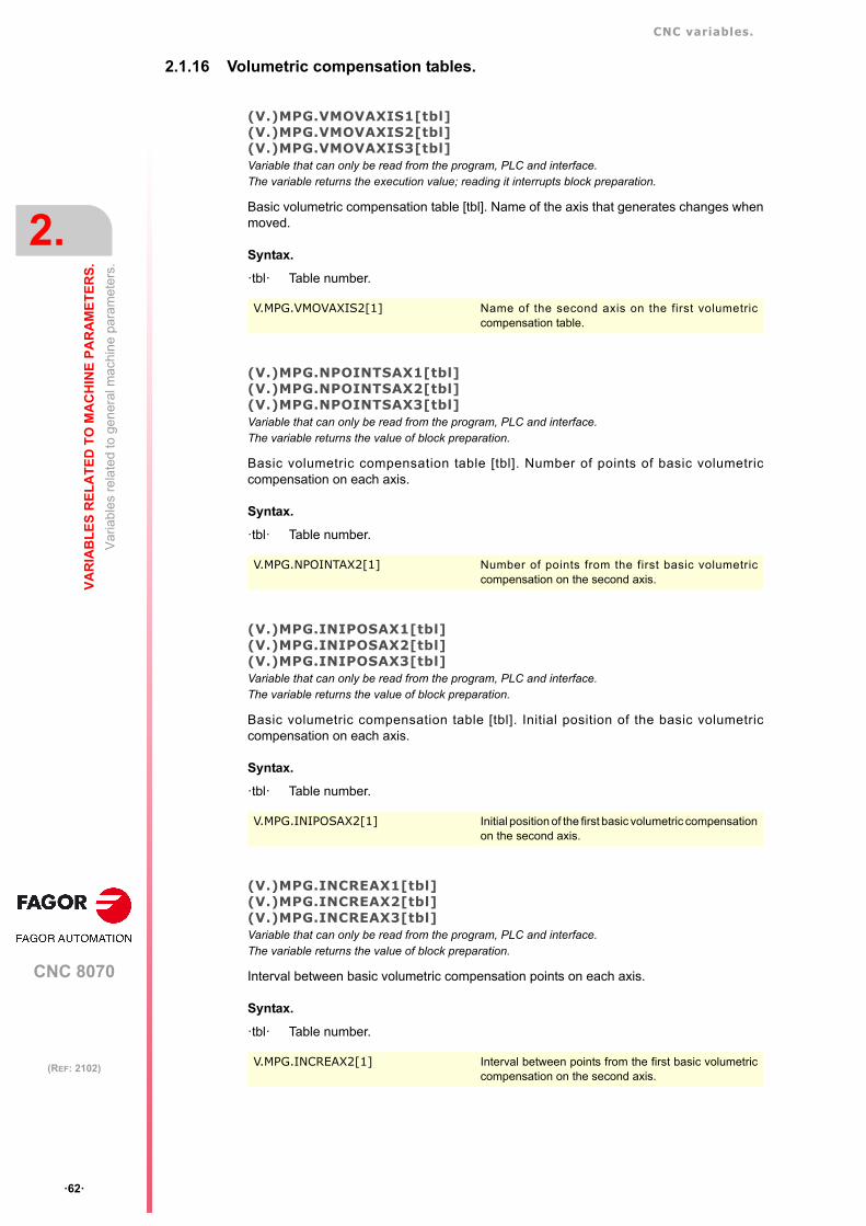
CNC variables.
CNC 8070
2.
VA
RIA
BL
ES
RE
LA
TE
D T
O M
AC
HIN
E P
AR
AM
ET
ER
S.
Va
riabl
es r
ela
ted
to g
ener
al m
achi
ne
para
met
ers.
ꞏ62ꞏ
(REF: 2102)
2.1.16 Volumetric compensation tables.
(V.)MPG.VMOVAXIS1[tbl](V.)MPG.VMOVAXIS2[tbl](V.)MPG.VMOVAXIS3[tbl]Variable that can only be read from the program, PLC and interface.The variable returns the execution value; reading it interrupts block preparation.
Basic volumetric compensation table [tbl]. Name of the axis that generates changes whenmoved.
Syntax.
ꞏtblꞏ Table number.
(V.)MPG.NPOINTSAX1[tbl](V.)MPG.NPOINTSAX2[tbl](V.)MPG.NPOINTSAX3[tbl]Variable that can only be read from the program, PLC and interface.The variable returns the value of block preparation.
Basic volumetric compensation table [tbl]. Number of points of basic volumetriccompensation on each axis.
Syntax.
ꞏtblꞏ Table number.
(V.)MPG.INIPOSAX1[tbl](V.)MPG.INIPOSAX2[tbl](V.)MPG.INIPOSAX3[tbl]Variable that can only be read from the program, PLC and interface.The variable returns the value of block preparation.
Basic volumetric compensation table [tbl]. Initial position of the basic volumetriccompensation on each axis.
Syntax.
ꞏtblꞏ Table number.
(V.)MPG.INCREAX1[tbl](V.)MPG.INCREAX2[tbl](V.)MPG.INCREAX3[tbl]Variable that can only be read from the program, PLC and interface.The variable returns the value of block preparation.
Interval between basic volumetric compensation points on each axis.
Syntax.
ꞏtblꞏ Table number.
V.MPG.VMOVAXIS2[1] Name of the second axis on the first volumetriccompensation table.
V.MPG.NPOINTAX2[1] Number of points from the first basic volumetriccompensation on the second axis.
V.MPG.INIPOSAX2[1] Initial position of the first basic volumetric compensationon the second axis.
V.MPG.INCREAX2[1] Interval between points from the first basic volumetriccompensation on the second axis.

CNC variables.
CNC 8070
VA
RIA
BL
ES
RE
LA
TE
D T
O M
AC
HIN
E P
AR
AM
ET
ER
S.
2.
Va
riabl
es r
ela
ted
to g
ener
al m
achi
ne
para
met
ers.
ꞏ63ꞏ
(REF: 2102)
(V.)MPG.VCOMPAXIS1[tbl](V.)MPG.VCOMPAXIS2[tbl](V.)MPG.VCOMPAXIS3[tbl]Variable that can only be read from the program, PLC and interface.The variable returns the execution value; reading it interrupts block preparation.
Volumetric compensation table [tbl]. Axis to be compensated.
Syntax.
ꞏtblꞏ Table number.
(V.)MPG.VCOMPFILE[tbl]Variable to be read via interface.The variable returns the value of block preparation.
Volumetric compensation table [tbl]. File containing volumetric compensation data.
Syntax.
ꞏtblꞏ Table number.
V.MPG.VCOMPAXIS2[1] Second axis to be compensated in the first volumetriccompensation table.
V.MPG.VCOMPFILE[1] File for defining the first volumetric compensation.

CNC variables.
CNC 8070
2.
VA
RIA
BL
ES
RE
LA
TE
D T
O M
AC
HIN
E P
AR
AM
ET
ER
S.
Va
riabl
es r
ela
ted
to g
ener
al m
achi
ne
para
met
ers.
ꞏ64ꞏ
(REF: 2102)
2.1.17 Execution times.
(V.)MPG.MINAENDWVariable that can only be read from the program, PLC and interface.The variable returns the value of block preparation.
Minimum duration of the AUXEND signal (in milliseconds).
(V.)MPG.REFTIMEVariable that can only be read from the program, PLC and interface.The variable returns the value of block preparation.
Estimated home searching time (in milliseconds).
(V.)MPG.HTIMEVariable that can only be read from the program, PLC and interface.The variable returns the value of block preparation.
Estimated time for an "H" function (in milliseconds).
(V.)MPG.DTIMEVariable that can only be read from the program, PLC and interface.The variable returns the value of block preparation.
Estimated time for an "D" function (in milliseconds).
(V.)MPG.TTIMEVariable that can only be read from the program, PLC and interface.The variable returns the value of block preparation.
Estimated time for an "T" function (in milliseconds).
V.MPG.MINAENDW
V.MPG.REFTIME
V.MPG.HTIME
V.MPG.DTIME
V.MPG.TTIME
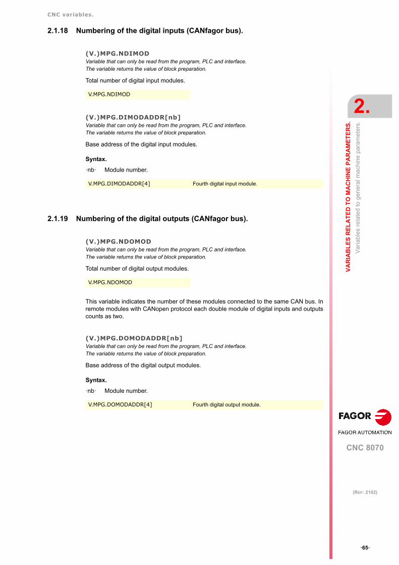
CNC variables.
CNC 8070
VA
RIA
BL
ES
RE
LA
TE
D T
O M
AC
HIN
E P
AR
AM
ET
ER
S.
2.
Va
riabl
es r
ela
ted
to g
ener
al m
achi
ne
para
met
ers.
ꞏ65ꞏ
(REF: 2102)
2.1.18 Numbering of the digital inputs (CANfagor bus).
(V.)MPG.NDIMODVariable that can only be read from the program, PLC and interface.The variable returns the value of block preparation.
Total number of digital input modules.
(V.)MPG.DIMODADDR[nb]Variable that can only be read from the program, PLC and interface.The variable returns the value of block preparation.
Base address of the digital input modules.
Syntax.
ꞏnbꞏ Module number.
2.1.19 Numbering of the digital outputs (CANfagor bus).
(V.)MPG.NDOMODVariable that can only be read from the program, PLC and interface.The variable returns the value of block preparation.
Total number of digital output modules.
This variable indicates the number of these modules connected to the same CAN bus. Inremote modules with CANopen protocol each double module of digital inputs and outputscounts as two.
(V.)MPG.DOMODADDR[nb]Variable that can only be read from the program, PLC and interface.The variable returns the value of block preparation.
Base address of the digital output modules.
Syntax.
ꞏnbꞏ Module number.
V.MPG.NDIMOD
V.MPG.DIMODADDR[4] Fourth digital input module.
V.MPG.NDOMOD
V.MPG.DOMODADDR[4] Fourth digital output module.

CNC variables.
CNC 8070
2.
VA
RIA
BL
ES
RE
LA
TE
D T
O M
AC
HIN
E P
AR
AM
ET
ER
S.
Va
riabl
es r
ela
ted
to g
ener
al m
achi
ne
para
met
ers.
ꞏ66ꞏ
(REF: 2102)
2.1.20 Numbering of the digital inputs (CANopen bus).
(V.)MPG.NDIMODVariable that can only be read from the program, PLC and interface.The variable returns the value of block preparation.
Total number of digital input logic blocks.
(V.)MPG.DIMODNODE[nb]Variable that can only be read from the program, PLC and interface.The variable returns the value of block preparation.
Node number of the header to which the I/O logic block belongs.
Syntax.
ꞏnbꞏ Number of the logic block.
(V.)MPG.DIMODBLOCK[nb]Variable that can only be read from the program, PLC and interface.The variable returns the value of block preparation.
Number of the logic block.
Syntax.
ꞏnbꞏ Number of the logic block.
(V.)MPG.DIMODADDRESS[nb]Variable that can only be read from the program, PLC and interface.The variable returns the value of block preparation.
Base address of the logic block.
Syntax.
ꞏnbꞏ Number of the logic block.
(V.)MPG.DIMODNDI[nb]Variable that can only be read from the program, PLC and interface.The variable returns the value of block preparation.
Number of digital inputs of the logic block.
Syntax.
ꞏnbꞏ Number of the logic block.
V.MPG.NDIMOD
V.MPG.DIMODNODE[nb] Fourth digital input logic block.
V.MPG.DIMODBLOCK[nb] Fourth digital input logic block.
V.MPG.DIMODADDRESS[nb] Fourth digital input logic block.
V.MPG.DIMODNDI[nb] Fourth digital input logic block.
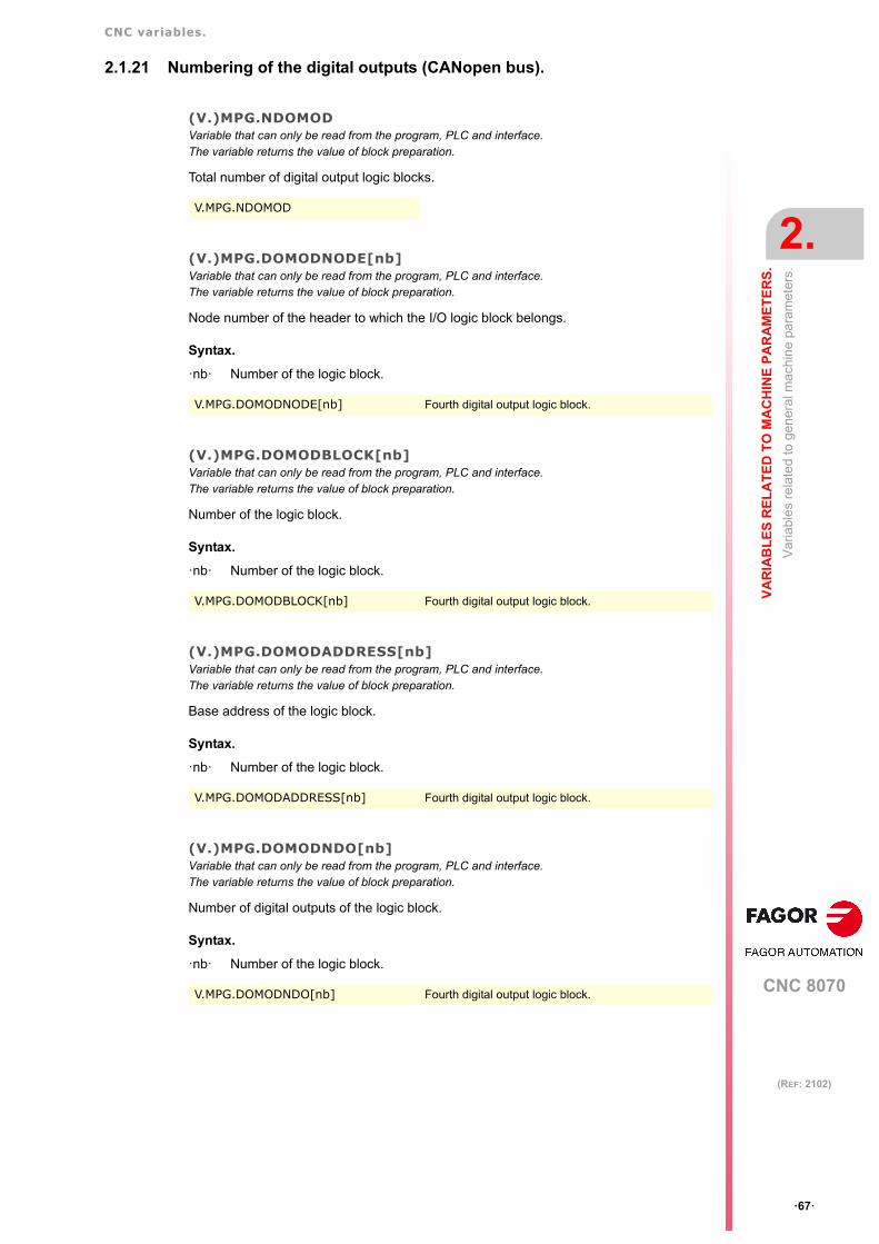
CNC variables.
CNC 8070
VA
RIA
BL
ES
RE
LA
TE
D T
O M
AC
HIN
E P
AR
AM
ET
ER
S.
2.
Va
riabl
es r
ela
ted
to g
ener
al m
achi
ne
para
met
ers.
ꞏ67ꞏ
(REF: 2102)
2.1.21 Numbering of the digital outputs (CANopen bus).
(V.)MPG.NDOMODVariable that can only be read from the program, PLC and interface.The variable returns the value of block preparation.
Total number of digital output logic blocks.
(V.)MPG.DOMODNODE[nb]Variable that can only be read from the program, PLC and interface.The variable returns the value of block preparation.
Node number of the header to which the I/O logic block belongs.
Syntax.
ꞏnbꞏ Number of the logic block.
(V.)MPG.DOMODBLOCK[nb]Variable that can only be read from the program, PLC and interface.The variable returns the value of block preparation.
Number of the logic block.
Syntax.
ꞏnbꞏ Number of the logic block.
(V.)MPG.DOMODADDRESS[nb]Variable that can only be read from the program, PLC and interface.The variable returns the value of block preparation.
Base address of the logic block.
Syntax.
ꞏnbꞏ Number of the logic block.
(V.)MPG.DOMODNDO[nb]Variable that can only be read from the program, PLC and interface.The variable returns the value of block preparation.
Number of digital outputs of the logic block.
Syntax.
ꞏnbꞏ Number of the logic block.
V.MPG.NDOMOD
V.MPG.DOMODNODE[nb] Fourth digital output logic block.
V.MPG.DOMODBLOCK[nb] Fourth digital output logic block.
V.MPG.DOMODADDRESS[nb] Fourth digital output logic block.
V.MPG.DOMODNDO[nb] Fourth digital output logic block.

CNC variables.
CNC 8070
2.
VA
RIA
BL
ES
RE
LA
TE
D T
O M
AC
HIN
E P
AR
AM
ET
ER
S.
Va
riabl
es r
ela
ted
to g
ener
al m
achi
ne
para
met
ers.
ꞏ68ꞏ
(REF: 2102)
2.1.22 Numbering of analog inputs for temperature sensors PT100.
(V.)MPG.NPT100Variable that can only be read from the program, PLC and interface.The variable returns the value of block preparation.
Total number of active PT100 inputs.
(V.)MPG.PT100[nb]Variable that can only be read from the program, PLC and interface.The variable returns the value of block preparation.
Analog input associated with the PT100 input.
Syntax.
ꞏnbꞏ PT100 input number.
V.MPG.NPT100
V.MPG.PT100[3] Third PT100 input.

CNC variables.
CNC 8070
VA
RIA
BL
ES
RE
LA
TE
D T
O M
AC
HIN
E P
AR
AM
ET
ER
S.
2.
Va
riabl
es r
ela
ted
to g
ener
al m
achi
ne
para
met
ers.
ꞏ69ꞏ
(REF: 2102)
2.1.23 Probe setting.
(V.)MPG.PROBEVariable that can only be read from the program, PLC and interface.The variable returns the value of block preparation.
There is a probe.
Values of the variable.
This variable returns one of the following values.
(V.)MPG.PROBETYPE1Variable that can only be read from the program, PLC and interface.The variable returns the value of block preparation.
Probe type 1, depending on where it is connected.
Values of the variable.
This variable returns one of the following values.
(V.)MPG.PROBETYPE2Variable that can only be read from the program, PLC and interface.The variable returns the value of block preparation.
Probe type 2, depending on where it is connected.
Values of the variable.
This variable returns one of the following values.
(V.)MPG.PRBDI1Variable that can only be read from the program, PLC and interface.The variable returns the value of block preparation.
Number of the input associated with probe 1.
For remote probes, this parameter indicates the digital input number; for local probes, itindicates the local probe input number. The variable will return a ꞏ0ꞏ value if no digital inputhas been defined.
V.MPG.PROBE
Value. Meaning.
0 No.
1 Yes.
V.MPG.PROBETYPE1
Value. Meaning.
0 Remote probe.
1 Local probe.
V.MPG.PROBETYPE2
Value. Meaning.
0 Remote probe.
1 Local probe.
V.MPG.PRBDI1

CNC variables.
CNC 8070
2.
VA
RIA
BL
ES
RE
LA
TE
D T
O M
AC
HIN
E P
AR
AM
ET
ER
S.
Va
riabl
es r
ela
ted
to g
ener
al m
achi
ne
para
met
ers.
ꞏ70ꞏ
(REF: 2102)
(V.)MPG.PRBDI2Variable that can only be read from the program, PLC and interface.The variable returns the value of block preparation.
Number of the input associated with probe 2.
For remote probes, this parameter indicates the digital input number; for local probes, itindicates the local probe input number. The variable will return a ꞏ0ꞏ value if no digital inputhas been defined.
(V.)MPG.PRBPULSE1Variable that can only be read from the program, PLC and interface.The variable returns the value of block preparation.
Logic level to activate probe 1.
Values of the variable.
This variable returns one of the following values.
(V.)MPG.PRBPULSE2Variable that can only be read from the program, PLC and interface.The variable returns the value of block preparation.
Logic level to activate probe 2.
Values of the variable.
This variable returns one of the following values.
V.MPG.PRBDI2
V.MPG.PRBPULSE1
Value. Meaning.
0 Low logic level (0 V).
1 High logic level (5 V / 24 V).
V.MPG.PRBPULSE2
Value. Meaning.
0 Low logic level (0 V).
1 High logic level (5 V / 24 V).
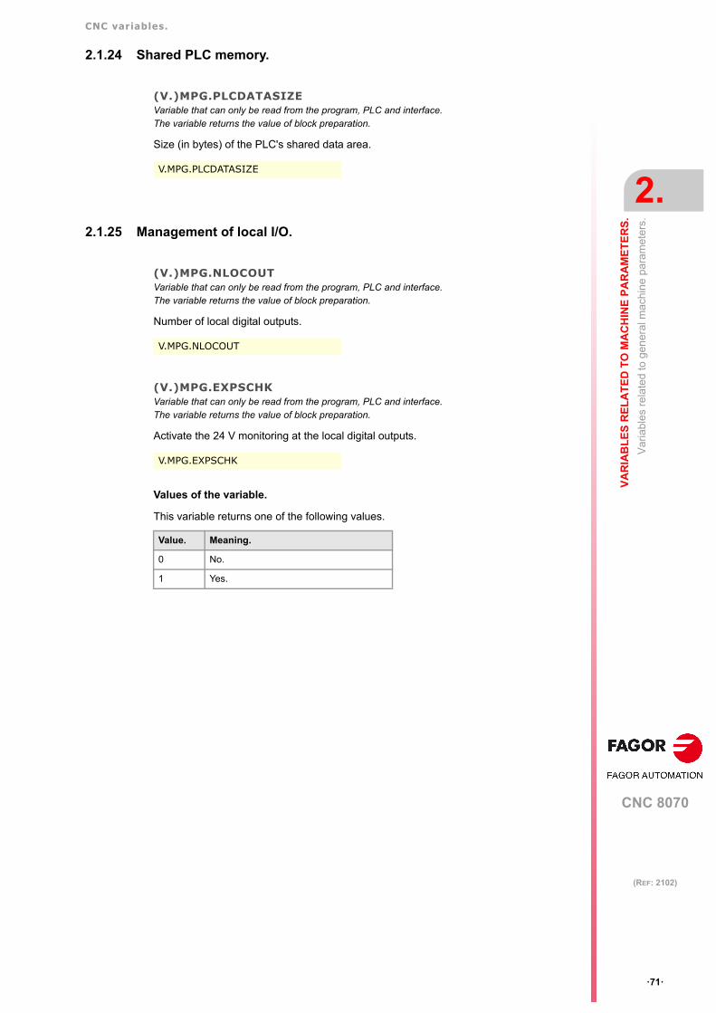
CNC variables.
CNC 8070
VA
RIA
BL
ES
RE
LA
TE
D T
O M
AC
HIN
E P
AR
AM
ET
ER
S.
2.
Va
riabl
es r
ela
ted
to g
ener
al m
achi
ne
para
met
ers.
ꞏ71ꞏ
(REF: 2102)
2.1.24 Shared PLC memory.
(V.)MPG.PLCDATASIZEVariable that can only be read from the program, PLC and interface.The variable returns the value of block preparation.
Size (in bytes) of the PLC's shared data area.
2.1.25 Management of local I/O.
(V.)MPG.NLOCOUTVariable that can only be read from the program, PLC and interface.The variable returns the value of block preparation.
Number of local digital outputs.
(V.)MPG.EXPSCHKVariable that can only be read from the program, PLC and interface.The variable returns the value of block preparation.
Activate the 24 V monitoring at the local digital outputs.
Values of the variable.
This variable returns one of the following values.
V.MPG.PLCDATASIZE
V.MPG.NLOCOUT
V.MPG.EXPSCHK
Value. Meaning.
0 No.
1 Yes.

CNC variables.
CNC 8070
2.
VA
RIA
BL
ES
RE
LA
TE
D T
O M
AC
HIN
E P
AR
AM
ET
ER
S.
Va
riabl
es r
ela
ted
to g
ener
al m
achi
ne
para
met
ers.
ꞏ72ꞏ
(REF: 2102)
2.1.26 Synchronized switching.
(V.)MPG.SWTOUTPUTVariable that can only be read from the program, PLC and interface.The variable returns the value of block preparation.Units: - .
Local digital output associated with synchronized switching.
(V.)MPG.SWTDELAYVariable that can be read and written from the interface and read from the program and from the PLC.The variable returns the execution value; reading it interrupts block preparation.Variable modifiable from the oscilloscope.Units: Milliseconds.
Delay of the device associated with synchronized switching.
(V.)MPG.SWTG0FEEDVariable that can only be read from the program, PLC and interface.The variable returns the value of block preparation.Units: - .
Observe the G00 feedrate during synchronized switching.
Values of the variable.
Remarks.
The behavior can be modified from the part program with the instruction #SWTOUT.
V.MPG.SWTOUTPUT
V.MPG.SWTDELAY
V.MPG.SWTG0FEED
Value. Meaning.
0 No. The cut is made at a constant feedrate(wi th the feedrate o f the prev iousG1/G2/G3), without accelerating in the G0sections.
1 Yes. Movements in G0 are carried out at arapid feedrate (parameter G00FEED).

CNC variables.
CNC 8070
VA
RIA
BL
ES
RE
LA
TE
D T
O M
AC
HIN
E P
AR
AM
ET
ER
S.
2.
Va
riabl
es r
ela
ted
to g
ener
al m
achi
ne
para
met
ers.
ꞏ73ꞏ
(REF: 2102)
2.1.27 PWM (Pulse-Width Modulation).
(V.)MPG.PWMOUTPUTVariable that can only be read from the program, PLC and interface.The variable returns the value of block preparation.Units: Value listed.
Local digital output associated with the PWM.
Values of the variable.
(V.)MPG.PWMCANCELVariable that can only be read from the program, PLC and interface.The variable returns the value of block preparation.Units: Value listed.
Cancel the PWM after an M30 or a reset.
Values of the variable.
V.MPG.PWMOUTPUT
Value. Meaning.
0 PWM missing.
1 Local output 1 (pin LI/O1).
2 Local output 2 (pin LI/O2).
V.MPG.PWMCANCEL
Value. Meaning.
0 No.
1 Yes.
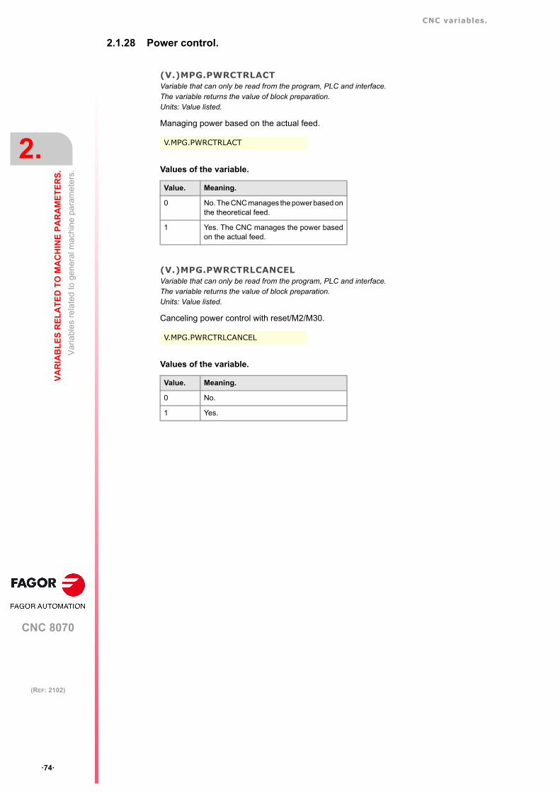
CNC variables.
CNC 8070
2.
VA
RIA
BL
ES
RE
LA
TE
D T
O M
AC
HIN
E P
AR
AM
ET
ER
S.
Va
riabl
es r
ela
ted
to g
ener
al m
achi
ne
para
met
ers.
ꞏ74ꞏ
(REF: 2102)
2.1.28 Power control.
(V.)MPG.PWRCTRLACTVariable that can only be read from the program, PLC and interface.The variable returns the value of block preparation.Units: Value listed.
Managing power based on the actual feed.
Values of the variable.
(V.)MPG.PWRCTRLCANCELVariable that can only be read from the program, PLC and interface.The variable returns the value of block preparation.Units: Value listed.
Canceling power control with reset/M2/M30.
Values of the variable.
V.MPG.PWRCTRLACT
Value. Meaning.
0 No. The CNC manages the power based onthe theoretical feed.
1 Yes. The CNC manages the power basedon the actual feed.
V.MPG.PWRCTRLCANCEL
Value. Meaning.
0 No.
1 Yes.

CNC variables.
CNC 8070
VA
RIA
BL
ES
RE
LA
TE
D T
O M
AC
HIN
E P
AR
AM
ET
ER
S.
2.
Va
riabl
es r
ela
ted
to g
ener
al m
achi
ne
para
met
ers.
ꞏ75ꞏ
(REF: 2102)
2.1.29 Gap control.
(V.)MPG.GAPANAINTYPEVariable that can only be read from the program, PLC and interface.The variable returns the value of block preparation.Units: Value listed.
Type of analog input connected to the sensor.
Values of the variable.
(V.)MPG.GAPANAINIDVariable that can only be read from the program, PLC and interface.The variable returns the value of block preparation.Units: Value listed.
Number of the analog input connected to the sensor.
Values of the variable.
(V.)MPG.GAPDISTLIMITVariable that can only be read from the program, PLC and interface.The variable returns the value of block preparation.Units: mm or inches.
Distance corresponding to the limit analog signal of the sensor.
(V.)MPG.GAPVOLTLIMITVariable that can only be read from the program, PLC and interface.The variable returns the value of block preparation.Units: Millivolts.
Voltage (in millivolts) corresponding to the limit path of the sensor (parameterGAPDISTLIMIT).
V.MPG.GAPANAINTYPE
Value. Meaning.
0 Remote CAN.
2 Drive.
V.MPG.GAPANAINID
Value. Meaning.
1 - 60 The analog input is in the remote modules.The variable returns the number of theanalog output.
101 -132201 - 232
The analog input is in a Sercos drive. Thefirst digit indicates the analog output to beused (1 or 2) and the other two digitsindicate the logic address of the drive (1through 32).
V.MPG.GAPDISTLIMIT
V.MPG.GAPVOLTLIMIT

CNC variables.
CNC 8070
2.
VA
RIA
BL
ES
RE
LA
TE
D T
O M
AC
HIN
E P
AR
AM
ET
ER
S.
Va
riabl
es r
ela
ted
to g
ener
al m
achi
ne
para
met
ers.
ꞏ76ꞏ
(REF: 2102)
(V.)MPG.GAPSENSOROFFSETVariable that can only be read from the program, PLC and interface.The variable returns the value of block preparation.Units: Millivolts.
Offset (in millivolts) to apply to the sensor from the CNC.
(V.)MPG.GAPSENSORCHVariable that can only be read from the program, PLC and interface.The variable returns the value of block preparation.Units: Value listed.
Change the sensor signal sign.
Values of the variable.
(V.)MPG.GAPGAINVariable that can only be read from the program, PLC and interface.The variable returns the value of block preparation.Units: - .
Proportional gain applied to the signal sensor, in position.
(V.)MPG.ORDERVariable that can only be read from the program, PLC and interface.The variable returns the execution value; reading it interrupts block preparation.Units: - .
Sensor filter. The higher the order number, the greater the slope of attenuation. An order 2is recommended.
(V.)MPG.TYPEVariable that can only be read from the program, PLC and interface.The variable returns the execution value; reading it interrupts block preparation.Units: Value listed.Sensor filter. Filter type.
Values of the variable.
(V.)MPG.FREQUENCYVariable that can only be read from the program, PLC and interface.The variable returns the execution value; reading it interrupts block preparation.Units: Herz.
Sensor filter. Filter cutoff frequency. A value of 30 Hz is recommended.
V.MPG.GAPSENSOROFFSET
V.MPG.GAPSENSORCH
Value. Meaning.
0 No.
1 Yes.
V.MPG.GAPGAIN
V.MPG.ORDER
Value. Meaning.
1 Low Passing.
V.MPG.FREQUENCY

CNC variables.
CNC 8070
VA
RIA
BL
ES
RE
LA
TE
D T
O M
AC
HIN
E P
AR
AM
ET
ER
S.
2.
Va
riabl
es r
ela
ted
to g
ener
al m
achi
ne
para
met
ers.
ꞏ77ꞏ
(REF: 2102)
(V.)MPG.GAPSENSORDELAYVariable that can only be read from the program, PLC and interface.The variable returns the value of block preparation.Units: Milliseconds.
Delay (in milliseconds) of the sensor signal regarding the axis position.
(V.)MPG.GAPERRORCANCELVariable that can only be read from the program, PLC and interface.The variable returns the value of block preparation.Units: Value listed.
Canceling the gap error outside the range defined by GAPMIN/GAPMAX.
Values of the variable.
(V.)MPG.GAPMINVariable that can only be read from the program, PLC and interface.The variable returns the value of block preparation.Units: mm or inches.
Minimum sensor limit.
(V.)MPG.GAPMAXVariable that can only be read from the program, PLC and interface.The variable returns the value of block preparation.Units: mm or inches.
Maximum sensor limit.
(V.)MPG.GAPTOLCANCELVariable that can only be read from the program, PLC and interface.The variable returns the value of block preparation.Units: Value listed.
Canceling the gap error outside the range defined by GAPTOL.
V.MPG.GAPSENSORDELAY
V.MPG.GAPERRORCANCEL
Value. Meaning.
0 No.
1 Yes.
V.MPG.GAPMIN
V.MPG.GAPMAX
V.MPG.GAPTOLCANCEL

CNC variables.
CNC 8070
2.
VA
RIA
BL
ES
RE
LA
TE
D T
O M
AC
HIN
E P
AR
AM
ET
ER
S.
Va
riabl
es r
ela
ted
to g
ener
al m
achi
ne
para
met
ers.
ꞏ78ꞏ
(REF: 2102)
Values of the variable.
(V.)MPG.GAPTOLVariable that can only be read from the program, PLC and interface.The variable returns the value of block preparation.Units: mm or inches.
Error tolerance margin.
(V.)MPG.GAPCOLLISIONMODEVariable that can only be read from the program, PLC and interface.The variable returns the value of block preparation.Units: Value listed.
CNC behavior in the event of a sensor collision.
Values of the variable.
(V.)MPG.GAPTONEGVariable that can only be read from the program, PLC and interface.The variable returns the value of block preparation.Units: Value listed.
Movement block in #GAPCTRL towards descending coordinate.
Values of the variable.
Value. Meaning.
0 No.
1 Yes.
V.MPG.GAPTOL
V.MPG.GAPCOLLISIONMODE
Value. Meaning.
0 Not displaying an error.
1 Displaying an error.
V.MPG.GAPTONEG
Value. Meaning.
0 No. The positive direction of the Z axis isdown and the negative direction is up(inverted Z axis). The axis moves in apositive direction (down) to reach the gap.
1 Yes. The positive direction of the Z axis isup and the negative is down (under normalconditions). The axis moves in the negativedirection (down) to reach the gap.

CNC variables.
CNC 8070
VA
RIA
BL
ES
RE
LA
TE
D T
O M
AC
HIN
E P
AR
AM
ET
ER
S.
2.
Va
riabl
es r
ela
ted
to g
ener
al m
achi
ne
para
met
ers.
ꞏ79ꞏ
(REF: 2102)
2.1.30 Leapfrog.
(V.)MPG.LEAPDYNOVRVariable that can only be read from the program, PLC and interface.The variable returns the value of block preparation.Units: Percentage.
Dynamic response of the leap during the leapfrog.
V.MPG.LEAPDYNOVR
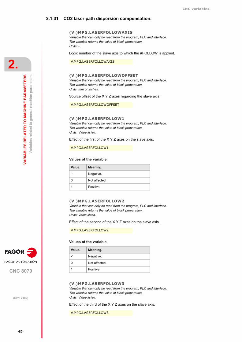
CNC variables.
CNC 8070
2.
VA
RIA
BL
ES
RE
LA
TE
D T
O M
AC
HIN
E P
AR
AM
ET
ER
S.
Va
riabl
es r
ela
ted
to g
ener
al m
achi
ne
para
met
ers.
ꞏ80ꞏ
(REF: 2102)
2.1.31 CO2 laser path dispersion compensation.
(V.)MPG.LASERFOLLOWAXISVariable that can only be read from the program, PLC and interface.The variable returns the value of block preparation.Units: - .
Logic number of the slave axis to which the #FOLLOW is applied.
(V.)MPG.LASERFOLLOWOFFSETVariable that can only be read from the program, PLC and interface.The variable returns the value of block preparation.Units: mm or inches.
Source offset of the X Y Z axes regarding the slave axis.
(V.)MPG.LASERFOLLOW1Variable that can only be read from the program, PLC and interface.The variable returns the value of block preparation.Units: Value listed.
Effect of the first of the X Y Z axes on the slave axis.
Values of the variable.
(V.)MPG.LASERFOLLOW2Variable that can only be read from the program, PLC and interface.The variable returns the value of block preparation.Units: Value listed.
Effect of the second of the X Y Z axes on the slave axis.
Values of the variable.
(V.)MPG.LASERFOLLOW3Variable that can only be read from the program, PLC and interface.The variable returns the value of block preparation.Units: Value listed.
Effect of the third of the X Y Z axes on the slave axis.
V.MPG.LASERFOLLOWAXIS
V.MPG.LASERFOLLOWOFFSET
V.MPG.LASERFOLLOW1
Value. Meaning.
-1 Negative.
0 Not affected.
1 Positive.
V.MPG.LASERFOLLOW2
Value. Meaning.
-1 Negative.
0 Not affected.
1 Positive.
V.MPG.LASERFOLLOW3

CNC variables.
CNC 8070
VA
RIA
BL
ES
RE
LA
TE
D T
O M
AC
HIN
E P
AR
AM
ET
ER
S.
2.
Va
riabl
es r
ela
ted
to g
ener
al m
achi
ne
para
met
ers.
ꞏ81ꞏ
(REF: 2102)
Values of the variable.
Value. Meaning.
-1 Negative.
0 Not affected.
1 Positive.

CNC variables.
CNC 8070
2.
VA
RIA
BL
ES
RE
LA
TE
D T
O M
AC
HIN
E P
AR
AM
ET
ER
S.
Va
riabl
es r
ela
ted
to g
ener
al m
achi
ne
para
met
ers.
ꞏ82ꞏ
(REF: 2102)
2.1.32 Backup of non-volatile data.
(V.)MPG.BKUPREGVariable that can only be read from the program, PLC and interface.The variable returns the value of block preparation.
Number of non-volatile PLC registers.
(V.)MPG.BKUPCOUNVariable that can only be read from the program, PLC and interface.The variable returns the value of block preparation.
Number of non-volatile PLC counters.
2.1.33 Tool offset and wear.
(V.)MPG.TOOLOFSGVariable that can only be read from the program, PLC and interface.The variable returns the value of block preparation.
Sign criteria for tool offsets and tool wear.
The offsets are used to define the tool dimensions in each axis. The dimensions of the turningtools are defined using these offsets; either these offsets or tool length and radius may beused for the dimensions of the rest of the tools.
Values of the variable.
This variable returns one of the following values.
V.MPG.BKUPREG
V.MPG.BKUPCOUN
V.MPG.TOOLOFSG
Value. Meaning.
0 Positive.
1 Negative.

CNC variables.
CNC 8070
VA
RIA
BL
ES
RE
LA
TE
D T
O M
AC
HIN
E P
AR
AM
ET
ER
S.
2.
Va
riabl
es r
ela
ted
to g
ener
al m
achi
ne
para
met
ers.
ꞏ83ꞏ
(REF: 2102)
2.1.34 Spindle synchronization.
(V.)MPG.SYNCCANCELVariable that can only be read from the program, PLC and interface.The variable returns the value of block preparation.
Cancel the spindle synchronization.
This parameter indicates whether the CNC cancels spindle synchronization or not afterexecuting M02, M30 or after an error or reset.
Values of the variable.
This variable returns one of the following values.
2.1.35 Define the number of jog panels and their relationship with the channels.
(V.)MPG.NKEYBDVariable that can only be read from the program, PLC and interface.The variable returns the value of block preparation.
Number of jog panels.
(V.)MPG.KEYBDCH[jog]Variable that can only be read from the program, PLC and interface.The variable returns the value of block preparation.
Channel to which the jog panel is assigned.
Syntax.
ꞏjogꞏ Number of jog panel.
Values of the variable.
This variable returns one of the following values.
Remarks.
The CNC numbers the operator panels following the order (sequence) that they occupy inthe CAN bus (Address switch). The first jog panel will be the one with the lowest numberand so on.
V.MPG.SYNCCANCEL
Value. Meaning.
0 No.
1 Yes.
V.MPG.NKEYBD
V.MPG.KEYBDCH[2] Jog panel ꞏ2ꞏ.
Value. Meaning.
0 Active channel.
1 Channel ꞏ1ꞏ.
2 Channel ꞏ2ꞏ.
3 Channel ꞏ3ꞏ.
4 Channel ꞏ4ꞏ.

CNC variables.
CNC 8070
2.
VA
RIA
BL
ES
RE
LA
TE
D T
O M
AC
HIN
E P
AR
AM
ET
ER
S.
Va
riabl
es r
ela
ted
to g
ener
al m
achi
ne
para
met
ers.
ꞏ84ꞏ
(REF: 2102)
2.1.36 PLC type.
(V.)MPG.PLCTYPEVariable that can only be read from the program, PLC and interface.The variable returns the value of block preparation.
PLC type.
Values of the variable.
This variable returns one of the following values.
2.1.37 Rename the axes and the spindles.
(V.)MPG.RENAMECANCELVariable that can only be read from the program, PLC and interface.The variable returns the value of block preparation.
Cancel the name change for the axes and the spindles.
Values of the variable.
This variable returns one of the following values.
2.1.38 Zero offsets.
(V.)MPG.FINEORGVariable that can only be read from the program, PLC and interface.The variable returns the value of block preparation.
Fine definition of zero offsets.
Values of the variable.
This variable returns one of the following values.
V.MPG.PLCTYPE
Value. Meaning.
0 IEC.
1 IEC+Fagor.
2 Fagor.
V.MPG.RENAMECANCEL
Value. Meaning.
0 No.
1 Yes.
V.MPG.FINEORG
Value. Meaning.
0 No.
1 Yes.

CNC variables.
CNC 8070
VA
RIA
BL
ES
RE
LA
TE
D T
O M
AC
HIN
E P
AR
AM
ET
ER
S.
2.
Va
riabl
es r
ela
ted
to g
ener
al m
achi
ne
para
met
ers.
ꞏ85ꞏ
(REF: 2102)
2.1.39 Remote module RCS-S (Sercos Counter).
(V.)MPG.NSERCOUNTVariable that can only be read from the program, PLC and interface.The variable returns the value of block preparation.
Number of RCS-S modules in the bus.
(V.)MPG.SERCOUNTID[num]Variable that can only be read from the program, PLC and interface.The variable returns the value of block preparation.
Thumbwheel identifiers associated with Sercos counters.
Syntax.
ꞏnumꞏ RCS-S module number.
V.MPG.NSERCOUNT
V.MPG.SERCOUNTID[2] Module RCS-S ꞏ2ꞏ.

CNC variables.
CNC 8070
2.
VA
RIA
BL
ES
RE
LA
TE
D T
O M
AC
HIN
E P
AR
AM
ET
ER
S.
Va
riabl
es r
ela
ted
to th
e m
ach
ine
para
met
ers
of t
he
chan
nel
s.
ꞏ86ꞏ
(REF: 2102)
2.2 Variables related to the machine parameters of the channels.
2.2.1 Channel configuration.
(V.)[ch].MPG.GROUPIDVariable that can only be read from the program, PLC and interface.The variable returns the value of block preparation.
Channel [ch]. Group the channel belongs to.
If the variable returns a ꞏ0ꞏ value, it means that the channel is not associated with any group.
Syntax.
ꞏchꞏ Channel number.
(V.)[ch].MPG.CHTYPEVariable that can only be read from the program, PLC and interface.The variable returns the value of block preparation.
Channel [ch]. Channel type.
A channel may be governed from the CNC, from the PLC or from both. Channels governedby the PLC are not displayed in automatic, jog or edisimu modes. The tables can beaccessed.
Syntax.
ꞏchꞏ Channel number.
Values of the variable.
This variable returns one of the following values.
(V.)[ch].MPG.HIDDENCHVariable that can only be read from the program, PLC and interface.The variable returns the value of block preparation.
Channel [ch]. Hidden channel.
Hidden channels are not displayed and cannot be selected.
Syntax.
ꞏchꞏ Channel number.
Values of the variable.
This variable returns one of the following values.
V.[2].MPG.GROUPID Channel ꞏ2ꞏ.
V.[2].MPG.CHTYPE Channel ꞏ2ꞏ.
Value. Meaning.
0 CNC channel.
1 PLC channel.
2 CNC and PLC channel.
V.[2].MPG.HIDDENCH Channel ꞏ2ꞏ.
Value. Meaning.
0 No.
1 Yes.
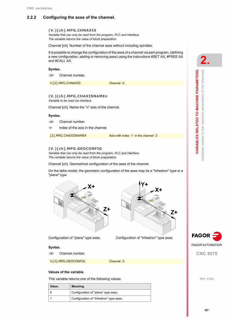
CNC variables.
CNC 8070
VA
RIA
BL
ES
RE
LA
TE
D T
O M
AC
HIN
E P
AR
AM
ET
ER
S.
2.
Va
riabl
es r
ela
ted
to th
e m
ach
ine
para
met
ers
of t
he
chan
nel
s.
ꞏ87ꞏ
(REF: 2102)
2.2.2 Configuring the axes of the channel.
(V.)[ch].MPG.CHNAXISVariable that can only be read from the program, PLC and interface.The variable returns the value of block preparation.
Channel [ch]. Number of the channel axes without including spindles.
It is possible to change the configuration of the axes of a channel via part-program, (defininga new configuration, adding or removing axes) using the instructions #SET AX, #FREE AXand #CALL AX.
Syntax.
ꞏchꞏ Channel number.
(V.)[ch].MPG.CHAXISNAMEnVariable to be read via interface.
Channel [ch]. Name the "n" axis of the channel.
Syntax.
ꞏchꞏ Channel number.
ꞏnꞏ Index of the axis in the channel.
(V.)[ch].MPG.GEOCONFIGVariable that can only be read from the program, PLC and interface.The variable returns the value of block preparation.
Channel [ch]. Geometrical configuration of the axes of the channel.
On the lathe model, the geometric configuration of the axes may be a "trihedron" type or a"plane" type.
Syntax.
ꞏchꞏ Channel number.
Values of the variable.
This variable returns one of the following values.
V.[2].MPG.CHNAXIS Channel ꞏ2ꞏ.
[2].MPG.CHAXISNAME4 Axis with index ꞏ1ꞏ in the channel ꞏ2ꞏ.
Configuration of "plane" type axes. Configuration of "trihedron" type axes.
V.[2].MPG.GEOCONFIG Channel ꞏ2ꞏ.
Value. Meaning.
0 Configuration of "plane" type axes.
1 Configuration of "trihedron" type axes.
X+
Z+
X+
Z+
Y+

CNC variables.
CNC 8070
2.
VA
RIA
BL
ES
RE
LA
TE
D T
O M
AC
HIN
E P
AR
AM
ET
ER
S.
Va
riabl
es r
ela
ted
to th
e m
ach
ine
para
met
ers
of t
he
chan
nel
s.
ꞏ88ꞏ
(REF: 2102)
Remarks.
Configuration. Configuration properties.
"Trihedron" type. In this configuration, there are three axes forming a Cartesian XYZ typetrihedron like on a milling machine. There may be more axes besides thoseforming the trihedron. With this configuration, the planes behave in the same way as on a millingmachine except that the usual work plane will be G18 (if it has beenconfigured like that).
"plane" type. In this configuration, there are two axes forming the usual work plane. Theremay be more axes, but they cannot be part of the trihedron; there must beauxiliary, rotary, etc.With this configuration, the work plane is always G18 and will be formed bythe first two axes defined in the channel. In this configuration, the second axisof the channel is considered as longitudinal axis. If the X (first) and Z (second) axes have been defined, the work plane willbe the ZX (Z as abscissa and X as ordinate) and Z the longitudinal axis.Tool length compensation is applied on this longitudinal axis when usingmilling tools. With lathe tools, tool length compensation is applied on all theaxes where a tool offset has been defined.

CNC variables.
CNC 8070
VA
RIA
BL
ES
RE
LA
TE
D T
O M
AC
HIN
E P
AR
AM
ET
ER
S.
2.
Va
riabl
es r
ela
ted
to th
e m
ach
ine
para
met
ers
of t
he
chan
nel
s.
ꞏ89ꞏ
(REF: 2102)
2.2.3 Configuring the spindles of the channel.
(V.)[ch].MPG.CHNSPDLVariable that can only be read from the program, PLC and interface.The variable returns the value of block preparation.
Channel [ch]. Number of spindles of the channel.
It is possible to change the configuration of the spindles of a channel via part-program,(defining a new configuration, adding or remove spindles) using the instructions #SET SP,#FREE SP and #CALL SP.
Syntax.
ꞏchꞏ Channel number.
(V.)[ch].MPG.CHSPDLNAMEnVariable to be read via interface.
Channel [ch]. Name the "n" spindle of the channel.
Syntax.
ꞏchꞏ Channel number.
ꞏnꞏ Index of the spindle in the channel.
V.[2].MPG.CHSPDL Channel ꞏ2ꞏ.
[2].MPG.CHSPDLNAME1 Spindle with index ꞏ1ꞏ in the channel ꞏ2ꞏ.

CNC variables.
CNC 8070
2.
VA
RIA
BL
ES
RE
LA
TE
D T
O M
AC
HIN
E P
AR
AM
ET
ER
S.
Va
riabl
es r
ela
ted
to th
e m
ach
ine
para
met
ers
of t
he
chan
nel
s.
ꞏ90ꞏ
(REF: 2102)
2.2.4 Configuration of the C axis.
(V.)[ch].MPG.CAXNAMEVariable to be read via interface.
Channel [ch]. Name of the axis working as "C" axis (by default).
When setting more than one C axis, use the program instruction #CAX to indicate the onethat is active. Only one C axis may be active in each channel.
Syntax.
ꞏchꞏ Channel number.
(V.)[ch].MPG.ALIGNCVariable that can only be read from the program, PLC and interface.The variable returns the value of block preparation.
Channel [ch]. "C" axis alignment for diametrical machining.
This parameter indicates whether the C axis must be aligned for diameter machining(ALIGNC = Yes) or the tool can machine the whole surface diametrically in a single fixturingoperation (ALIGNC = NO).
Syntax.
ꞏchꞏ Channel number.
Values of the variable.
This variable returns one of the following values.
2.2.5 Time setting (channel).
(V.)[ch].MPG.PREPFREQVariable that can only be read from the program, PLC and interface.The variable returns the value of block preparation.
Channel [ch]. Maximum number of blocks to prepare per cycle.
Syntax.
ꞏchꞏ Channel number.
(V.)[ch].MPG.ANTIMEVariable that can only be read from the program, PLC and interface.The variable returns the value of block preparation.
Channel [ch]. Anticipation time.
Syntax.
ꞏchꞏ Channel number.
[2].MPG.CAXNAME Channel ꞏ2ꞏ.
V.[2].MPG.ALIGNC Channel ꞏ2ꞏ.
Value. Meaning.
0 No.
1 Yes.
V.[2].MPG.PREPFREQ Channel ꞏ2ꞏ.
V.[2].MPG.ANTIME Channel ꞏ2ꞏ.

CNC variables.
CNC 8070
VA
RIA
BL
ES
RE
LA
TE
D T
O M
AC
HIN
E P
AR
AM
ET
ER
S.
2.
Va
riabl
es r
ela
ted
to th
e m
ach
ine
para
met
ers
of t
he
chan
nel
s.
ꞏ91ꞏ
(REF: 2102)
2.2.6 Configuration of the HSC mode (channel).
(V.)[ch].MPG.FEEDAVRGVariable that can only be read from the program, PLC and interface.The variable returns the value of block preparation.
Channel [ch]. Calculating feedrate average.
Syntax.
ꞏchꞏ Channel number.
Values of the variable.
This variable returns one of the following values.
(V.)[ch].MPG.SMOOTHFREQVariable that can only be read from the program, PLC and interface.The variable returns the value of block preparation.
Channel [ch]. Smoothing frequency in the interpolation.
Syntax.
ꞏchꞏ Channel number.
(V.)[ch].MPG.CORNERVariable that can only be read from the program, PLC and interface.The variable returns the value of block preparation.
Channel [ch]. Maximum angle of the corner to machine it in square corner mode.
Syntax.
ꞏchꞏ Channel number.
(V.)[ch].MPG.HSCFILTFREQVariable that can only be read from the program, PLC and interface.The variable returns the value of block preparation.
Channel [ch]. Filter frequency (CONTERROR mode).
Syntax.
ꞏchꞏ Channel number.
(V.)[ch].MPG.FASTFACTORVariable that can only be read from the program, PLC and interface.The variable returns the value of block preparation.
Channel [ch]. Default aceleration percentage (FAST mode).
V.[2].MPG.FEEDAVRG Channel ꞏ2ꞏ.
Value. Meaning.
0 No.
1 Yes.
V.[2].MPG.SMOOTHFREQ Channel ꞏ2ꞏ.
V.[2].MPG.CORNER Channel ꞏ2ꞏ.
V.[2].MPG.HSCFILTFREQ Channel ꞏ2ꞏ.

CNC variables.
CNC 8070
2.
VA
RIA
BL
ES
RE
LA
TE
D T
O M
AC
HIN
E P
AR
AM
ET
ER
S.
Va
riabl
es r
ela
ted
to th
e m
ach
ine
para
met
ers
of t
he
chan
nel
s.
ꞏ92ꞏ
(REF: 2102)
Syntax.
ꞏchꞏ Channel number.
(V.)[ch].MPG.FTIMELIMVariable that can only be read from the program, PLC and interface.The variable returns the value of block preparation.
Channel [ch]. Time difference permitted in feedrate interpolation (FAST and SURFACEmodes).
Syntax.
ꞏchꞏ Channel number.
(V.)[ch].MPG.MINCORFEEDVariable that can only be read from the program, PLC and interface.The variable returns the value of block preparation.
Channel [ch]. Minimum feedrate at the corners.
Syntax.
ꞏchꞏ Channel number.
(V.)[ch].MPG.FSMOOTHFREQVariable that can only be read from the program, PLC and interface.The variable returns the value of block preparation.
Channel [ch]. Smoothing frequency in the interpolation (FAST and SURFACE modes).
Syntax.
ꞏchꞏ Channel number.
(V.)[ch].MPG.FASTFILTFREQVariable that can only be read from the program, PLC and interface.The variable returns the value of block preparation.
Channel [ch]. Filter frequency (FAST mode).
Syntax.
ꞏchꞏ Channel number.
(V.)[ch].MPG.FREQRESVariable that can only be read from the program, PLC and interface.The variable returns the value of block preparation.
Channel [ch]. First resonance frequency of the machine.
Syntax.
ꞏchꞏ Channel number.
V.[2].MPG.FASTFACTOR Channel ꞏ2ꞏ.
V.[2].MPG.FTIMELIM Channel ꞏ2ꞏ.
V.[2].MPG.MINCORFEED Channel ꞏ2ꞏ.
V.[2].MPG.FSMOOTHFREQ Channel ꞏ2ꞏ.
V.[2].MPG.FASTFILTFREQ Channel ꞏ2ꞏ.
V.[2].MPG.FREQRES Channel ꞏ2ꞏ.

CNC variables.
CNC 8070
VA
RIA
BL
ES
RE
LA
TE
D T
O M
AC
HIN
E P
AR
AM
ET
ER
S.
2.
Va
riabl
es r
ela
ted
to th
e m
ach
ine
para
met
ers
of t
he
chan
nel
s.
ꞏ93ꞏ
(REF: 2102)
(V.)[ch].MPG.SOFTFREQVariable that can only be read from the program, PLC and interface.The variable returns the value of block preparation.
Channel [ch]. Path filter frequency for profiles of linear acceleration.
Syntax.
ꞏchꞏ Channel number.
(V.)[ch].MPG.HSCROUNDVariable that can only be read from the program, PLC and interface.The variable returns the value of block preparation.
Channel [ch]. Default value of the maximum path error in HSC.
Syntax.
ꞏchꞏ Channel number.
(V.)[ch].MPG.SURFFILTFREQVariable that can only be read from the program, PLC and interface.The variable returns the value of block preparation.
Axis filter frequency (SURFACE mode).
Syntax.
ꞏchꞏ Channel number.
(V.)[ch].MPG.HSCDEFAULTMODEVariable that can only be read from the program, PLC and interface.The variable returns the value of block preparation.
Default mode when programming #HSC ON.
Syntax.
ꞏchꞏ Channel number.
Values of the variable.
This variable returns one of the following values.
(V.)[ch].MPG.ORISMOOTHVariable that can only be read from the program, PLC and interface.The variable returns the value of block preparation.
Orientation smoothing of the rotary axes working with RTCP.
Syntax.
ꞏchꞏ Channel number.
V.[2].MPG.SOFTFREQ Channel ꞏ2ꞏ.
V.[2].MPG.HSCROUND Channel ꞏ2ꞏ.
V.[2].MPG.SURFFILFREQ Channel ꞏ2ꞏ.
V.[2].MPG.HSCDEFAULTMODE Channel ꞏ2ꞏ.
Value. Meaning.
0 SURFACE
1 CONTERROR
2 FAST
V.[2].MPG.ORISMOOTH Channel ꞏ2ꞏ.

CNC variables.
CNC 8070
2.
VA
RIA
BL
ES
RE
LA
TE
D T
O M
AC
HIN
E P
AR
AM
ET
ER
S.
Va
riabl
es r
ela
ted
to th
e m
ach
ine
para
met
ers
of t
he
chan
nel
s.
ꞏ94ꞏ
(REF: 2102)
2.2.7 Virtual tool axis.
(V.)[ch].MPG.VIRTAXISNAMEVariable that can only be read from the program, PLC and interface.The variable returns the value of block preparation.
Channel [ch]. Name of the virtual tool axis.
Syntax.
ꞏchꞏ Channel number.
Values of the variable.
The values returned by this variable are encoded as follows.
(V.)[ch].MPG.VIRTAXCANCELVariable that can only be read from the program, PLC and interface.The variable returns the value of block preparation.
Channel [ch]. Cancel the virtual tool axis after an M30 and reset.
Syntax.
ꞏchꞏ Channel number.
Values of the variable.
This variable returns one of the following values.
V.[2].MPG.VIRTAXISNAME Channel ꞏ2ꞏ.
X=10 X1=11 X2=12 X3=13 X4=14 ... X9=19
Y=20 Y1=21 Y2=22 Y3=23 Y4=24 ... Y9=29
Z=30 Z1=31 Z2=32 Z3=33 Z4=34 ... Z9=39
U=40 U1=41 U2=42 U3=43 U4=44 ... U9=49
V=50 V1=51 V2=52 V3=53 V4=54 ... V9=59
W=60 W1=61 W2=62 W3=63 W4=64 ... W9=69
A=70 A1=71 A2=72 A3=73 A4=74 ... A9=79
B=80 B1=81 B2=82 B3=83 B4=84 ... B9=89
C=90 C1=91 C2=92 C3=93 C4=94 ... C9=99
V.[2].MPG.VIRTAXCANCEL Channel ꞏ2ꞏ.
Value. Meaning.
0 No.
1 Yes.

CNC variables.
CNC 8070
VA
RIA
BL
ES
RE
LA
TE
D T
O M
AC
HIN
E P
AR
AM
ET
ER
S.
2.
Va
riabl
es r
ela
ted
to th
e m
ach
ine
para
met
ers
of t
he
chan
nel
s.
ꞏ95ꞏ
(REF: 2102)
2.2.8 Default conditions (channel).
(V.)[ch].MPG.KINIDVariable that can only be read from the program, PLC and interface.The variable returns the value of block preparation.
Channel [ch]. Default kinematics number.
The channel assumes the default value on power-up, after executing an M02 or M30 or aftera reset. To select another kinematics from the part-program, use the #KIN ID instruction.
Syntax.
ꞏchꞏ Channel number.
Values of the variable.
This variable returns one of the following values.
(V.)[ch].MPG.CSCANCELVariable that can only be read from the program, PLC and interface.The variable returns the value of block preparation.
Channel [ch]. Cancel the inclined plane on start-up.
This parameter indicates whether on start-up the CNC cancels the inclined plane(#CS/#ACS) that was active when the CNC was turned off.
Syntax.
ꞏchꞏ Channel number.
Values of the variable.
This variable returns one of the following values.
(V.)[ch].MPG.LINKCANCELVariable that can only be read from the program, PLC and interface.The variable returns the value of block preparation.
Channel [ch]. Cancel axis coupling by default.
The channel assumes the default value after executing an M02 or M30, after an emergencyor a reset. To couple axes from the part-program, use the #LINK instruction.
Syntax.
ꞏchꞏ Channel number.
V.[2].MPG.KINID Channel ꞏ2ꞏ.
Value. Meaning.
0 The CNC restores the last kinematics active.
1ꞏꞏ6 Default kinematics number.
255 There is no default kinematics.
V.[2].MPG.CSCANCEL Channel ꞏ2ꞏ.
Value. Meaning.
0 No.
1 Yes.
V.[2].MPG.LINKCANCEL Channel ꞏ2ꞏ.

CNC variables.
CNC 8070
2.
VA
RIA
BL
ES
RE
LA
TE
D T
O M
AC
HIN
E P
AR
AM
ET
ER
S.
Va
riabl
es r
ela
ted
to th
e m
ach
ine
para
met
ers
of t
he
chan
nel
s.
ꞏ96ꞏ
(REF: 2102)
Values of the variable.
This variable returns one of the following values.
(V.)[ch].MPG.MIRRORCANCELVariable that can only be read from the program, PLC and interface.The variable returns the value of block preparation.
Channel [ch]. Cancel mirror image (G11/G12/G13/G14) after M30 and reset.
Syntax.
ꞏchꞏ Channel number.
Values of the variable.
This variable returns one of the following values.
(V.)[ch].MPG.SLOPETYPEVariable that can only be read from the program, PLC and interface.Variable that may be modified during setup.The variable returns the execution value; reading it interrupts block preparation.
Channel [ch]. Default acceleration type.
It indicates the type of acceleration applied by default in automatic movements. Whenworking in manual (JOG) mode, the CNC always applies linear acceleration.
The channel assumes the default value on power-up, after executing an M02 or M30 or aftera reset. To select another acceleration from the part-program, use the #SLOPE instruction.
Syntax.
ꞏchꞏ Channel number.
Values of the variable.
This variable returns one of the following values.
(V.)[ch].MPG.IPLANEVariable that can only be read from the program, PLC and interface.The variable returns the value of block preparation.
Channel [ch]. Main work plane (G17/G18) by default.
The channel assumes the default value on power-up, after executing an M02 or M30 or aftera reset. To change the work plane via part-program, use function G17, G18, G19 or G20.
Value. Meaning.
0 No.
1 Yes.
V.[2].MPG.MIRRORCANCEL Channel ꞏ2ꞏ.
Value. Meaning.
0 No.
1 Yes.
V.[2].MPG.SLOPETYPE Channel ꞏ2ꞏ.
Value. Meaning.
1 Linear acceleration.
2 Trapezoidal acceleration.
3 Square sine (bell shaped) acceleration.

CNC variables.
CNC 8070
VA
RIA
BL
ES
RE
LA
TE
D T
O M
AC
HIN
E P
AR
AM
ET
ER
S.
2.
Va
riabl
es r
ela
ted
to th
e m
ach
ine
para
met
ers
of t
he
chan
nel
s.
ꞏ97ꞏ
(REF: 2102)
Syntax.
ꞏchꞏ Channel number.
Values of the variable.
This variable returns one of the following values.
(V.)[ch].MPG.ISYSTEMVariable that can only be read from the program, PLC and interface.The variable returns the value of block preparation.
Channel [ch]. Default type of coordinates (G90/G91).
The coordinates of a point may be defined either in absolute coordinates (G90) referred topart zero or in incremental coordinates (G91) referred to the current position.
The channel assumes the default value on power-up, after executing an M02 or M30 or aftera reset. To change the type of coordinates via part-program, use function G90 or G91.
Syntax.
ꞏchꞏ Channel number.
Values of the variable.
This variable returns one of the following values.
(V.)[ch].MPG.IMOVEVariable that can only be read from the program, PLC and interface.The variable returns the value of block preparation.
Channel [ch]. Default type of movement (G0/G1).
The channel assumes the default value on power-up, after executing an M02 or M30 or aftera reset. To change the type of movement via part-program, use function G0 or G1.
Syntax.
ꞏchꞏ Channel number.
Values of the variable.
This variable returns one of the following values.
V.[2].MPG.IPLANE Channel ꞏ2ꞏ.
Value. Meaning.
0 G17.
1 G18.
V.[2].MPG.ISYSTEM Channel ꞏ2ꞏ.
Value. Meaning.
0 G90.
1 G91.
V.[2].MPG.IMOVE Channel ꞏ2ꞏ.
Value. Meaning.
0 G00.
1 G01.

CNC variables.
CNC 8070
2.
VA
RIA
BL
ES
RE
LA
TE
D T
O M
AC
HIN
E P
AR
AM
ET
ER
S.
Va
riabl
es r
ela
ted
to th
e m
ach
ine
para
met
ers
of t
he
chan
nel
s.
ꞏ98ꞏ
(REF: 2102)
(V.)[ch].MPG.G0MODALVariable that can only be read from the program, PLC and interface.The variable returns the value of block preparation.
Channel [ch]. Programming for G0 remains as modal.
Syntax.
ꞏchꞏ Channel number.
Values of the variable.
This variable returns one of the following values.
(V.)[ch].MPG.G2G3MODALVariable that can only be read from the program, PLC and interface.The variable returns the value of block preparation.
Channel [ch]. Programming in G2/G3 remains as modal.
Syntax.
ꞏchꞏ Channel number.
Values of the variable.
This variable returns one of the following values.
(V.)[ch].MPG.IFEEDVariable that can only be read from the program, PLC and interface.The variable returns the value of block preparation.
Channel [ch]. Default type of feedrate (G94/G95).
The channel assumes the default value on power-up, after executing an M02 or M30 or aftera reset. To change the type of feedrate via part-program, use function G93 or G94.
Syntax.
ꞏchꞏ Channel number.
Values of the variable.
This variable returns one of the following values.
V.[2].MPG.G0MODAL Channel ꞏ2ꞏ.
Value. Meaning.
0 No.
1 Yes.
V.[2].MPG.G2G3MODAL Channel ꞏ2ꞏ.
Value. Meaning.
0 No.
1 Yes.
V.[2].MPG.IFEED Channel ꞏ2ꞏ.
Value. Meaning.
0 G94.
1 G95.

CNC variables.
CNC 8070
VA
RIA
BL
ES
RE
LA
TE
D T
O M
AC
HIN
E P
AR
AM
ET
ER
S.
2.
Va
riabl
es r
ela
ted
to th
e m
ach
ine
para
met
ers
of t
he
chan
nel
s.
ꞏ99ꞏ
(REF: 2102)
(V.)[ch].MPG.FPRMANVariable that can only be read from the program, PLC and interface.The variable returns the value of block preparation.
Channel [ch]. Function G95 admitted in jog mode.
Syntax.
ꞏchꞏ Channel number.
Values of the variable.
This variable returns one of the following values.
(V.)[ch].MPG.LCOMPTYPVariable that can only be read from the program, PLC and interface.The variable returns the value of block preparation.
Channel [ch]. Keep the longitudinal axis when changing planes (G17/G18/G19).
Syntax.
ꞏchꞏ Channel number.
Values of the variable.
This variable returns one of the following values.
(V.)[ch].MPG.PLANECANCELVariable that can only be read from the program, PLC and interface.The variable returns the value of block preparation.
Channel [ch]. Assume IPLANE as active plane after M30/RESET or keep the active one.
Syntax.
ꞏchꞏ Channel number.
Values of the variable.
This variable returns one of the following values.
V.[2].MPG.FPRMAN Channel ꞏ2ꞏ.
Value. Meaning.
0 No.
1 Yes.
V.[2].MPG.LCOMPTYP Channel ꞏ2ꞏ.
Value. Meaning.
0 No.
1 Yes.
V.[2].MPG.PLANECANCEL Channel ꞏ2ꞏ.
Value. Meaning.
0 On power-up, the CNC assumes the plane defined in parameter IPLANE; afterexecuting an M02 or M30, and after a reset, the CNC maintains the main active plane.
1 On power-up, after executing an M02 or M30, and after a reset, the CNC assumesthe plane defined in parameter IPLANE.

CNC variables.
CNC 8070
2.
VA
RIA
BL
ES
RE
LA
TE
D T
O M
AC
HIN
E P
AR
AM
ET
ER
S.
Va
riabl
es r
ela
ted
to th
e m
ach
ine
para
met
ers
of t
he
chan
nel
s.
ꞏ100ꞏ
(REF: 2102)
(V.)[ch].MPG.ICORNERVariable that can only be read from the program, PLC and interface.The variable returns the value of block preparation.
Channel [ch]. Default type of corner (G5/G7/G50).
The channel assumes the default value on power-up, after executing an M02 or M30 or aftera reset. To change the type of corner via part-program, use function G5, G7 or G50.
Syntax.
ꞏchꞏ Channel number.
Values of the variable.
This variable returns one of the following values.
(V.)[ch].MPG.IRCOMPVariable that can only be read from the program, PLC and interface.The variable returns the value of block preparation.
Channel [ch]. Tool radius compensation mode (G136/G137) by default
The channel assumes the default value on power-up, after executing an M02 or M30 or aftera reset. To change the type of tool radius compensation via part-program, use function G136or G137.
Syntax.
ꞏchꞏ Channel number.
Values of the variable.
This variable returns one of the following values.
(V.)[ch].MPG.COMPCANCELVariable that can only be read from the program, PLC and interface.The variable returns the value of block preparation.
Channel [ch]. How to cancel tool radius compensation.
This parameter indicates whether tool radius compensation is canceled in the first motionblock, even if the plane axes are not involved, or if it requires a movement of the plane axes.
Syntax.
ꞏchꞏ Channel number.
V.[2].MPG.ICORNER Channel ꞏ2ꞏ.
Value. Meaning.
0 G50.
1 G05.
2 G07.
V.[2].MPG.IRCOMP Channel ꞏ2ꞏ.
Value. Meaning.
0 G136.
1 G137.
V.[2].MPG.COMPCANCEL Channel ꞏ2ꞏ.

CNC variables.
CNC 8070
VA
RIA
BL
ES
RE
LA
TE
D T
O M
AC
HIN
E P
AR
AM
ET
ER
S.
2.
Va
riabl
es r
ela
ted
to th
e m
ach
ine
para
met
ers
of t
he
chan
nel
s.
ꞏ101ꞏ
(REF: 2102)
Values of the variable.
This variable returns one of the following values.
(V.)[ch].MPG.G00COMPVariable that can only be read from the program, PLC and interface.The variable returns the value of block preparation.
Channel [ch]. Apply tool radius compensation in G00.
Syntax.
ꞏchꞏ Channel number.
Values of the variable.
This variable returns one of the following values.
(V.)[ch].MPG.ROUNDTYPEVariable that can only be read from the program, PLC and interface.The variable returns the value of block preparation.
Channel [ch]. Default rounding type in G5.
The rounding may be executed by limiting the chordal error or the feedrate. The chordal error(#ROUNDPAR [1]) defines the maximum deviation allowed between the programmed pointand the resulting profile. The feedrate (#ROUNDPAR [2]) defines the percentage of theactive feedrate to be used for machining.
The channel assumes the default value on power-up, after executing an M02 or M30 or aftera reset. To change the type of rounding via program, use the #ROUNDPAR instruction.
Syntax.
ꞏchꞏ Channel number.
Values of the variable.
This variable returns one of the following values.
(V.)[ch].MPG.MAXROUNDVariable that can only be read from the program, PLC and interface.The variable returns the value of block preparation.
Channel [ch]. Maximum rounding error in G5.
Value. Meaning.
0 Without moving the plane axes.
1 Moving the plane axes.
V.[2].MPG.G00COMP Channel ꞏ2ꞏ.
Value. Meaning.
0 No.
1 Yes.
V.[2].MPG.ROUNDTYPE Channel ꞏ2ꞏ.
Value. Meaning.
0 Chordal error.
1 Percentage of feedrate.

CNC variables.
CNC 8070
2.
VA
RIA
BL
ES
RE
LA
TE
D T
O M
AC
HIN
E P
AR
AM
ET
ER
S.
Va
riabl
es r
ela
ted
to th
e m
ach
ine
para
met
ers
of t
he
chan
nel
s.
ꞏ102ꞏ
(REF: 2102)
Syntax.
ꞏchꞏ Channel number.
(V.)[ch].MPG.ROUNDFEEDVariable that can only be read from the program, PLC and interface.The variable returns the value of block preparation.
Channel [ch]. Percentage of feedrate in G5.
Syntax.
ꞏchꞏ Channel number.
V.[2].MPG.MAXROUND Channel ꞏ2ꞏ.
V.[2].MPG.ROUNDFEED Channel ꞏ2ꞏ.

CNC variables.
CNC 8070
VA
RIA
BL
ES
RE
LA
TE
D T
O M
AC
HIN
E P
AR
AM
ET
ER
S.
2.
Va
riabl
es r
ela
ted
to th
e m
ach
ine
para
met
ers
of t
he
chan
nel
s.
ꞏ103ꞏ
(REF: 2102)
2.2.9 Arc center correction.
(V.)[ch].MPG.CIRINERRVariable that can only be read from the program, PLC and interface.The variable returns the value of block preparation.
Channel [ch]. Maximum absolute radius error permitted.
Syntax.
ꞏchꞏ Channel number.
(V.)[ch].MPG.CIRINFACTVariable that can only be read from the program, PLC and interface.The variable returns the value of block preparation.
Channel [ch]. Maximum relative radius error permitted.
The relative error is given as a percentage over the radius.
Syntax.
ꞏchꞏ Channel number.
Remarks.
The reading from the PLC will be given in tenths (x10); i.e. if the parameter value is ꞏ10ꞏ,the PLC reading will return a value of ꞏ100ꞏ.
V.[2].MPG.CIRINERR Channel ꞏ2ꞏ.
V.[2].MPG.CIRINFACT Channel ꞏ2ꞏ.

CNC variables.
CNC 8070
2.
VA
RIA
BL
ES
RE
LA
TE
D T
O M
AC
HIN
E P
AR
AM
ET
ER
S.
Va
riabl
es r
ela
ted
to th
e m
ach
ine
para
met
ers
of t
he
chan
nel
s.
ꞏ104ꞏ
(REF: 2102)
2.2.10 Behavior of the feedrate and the feedrate override.
(V.)[ch].MPG.MAXOVRVariable that can only be read from the program, PLC and interface.The variable returns the value of block preparation.
Channel [ch]. Maximum override (%) permitted.
Syntax.
ꞏchꞏ Channel number.
Remarks.
The reading from the PLC will be given in tenths (x10); i.e. if the parameter value is ꞏ10ꞏ,the PLC reading will return a value of ꞏ100ꞏ.
(V.)[ch].MPG.RAPIDOVRVariable that can only be read from the program, PLC and interface.The variable returns the value of block preparation.
Channel [ch]. Override acts in G00 (from 0 to 100%).
This parameter indicates whether the feedrate % may be modified (between 0% and 100%)or not when working in G0; if not possible, it will stay fixed at 100%.
Regardless of the value assigned to this parameter, the override always attends to the 0%position and never acts over 100%. It is always possible to change the % of feedrate whenmoving in jog mode.
Syntax.
ꞏchꞏ Channel number.
Values of the variable.
This variable returns one of the following values.
(V.)[ch].MPG.FEEDNDVariable that can only be read from the program, PLC and interface.The variable returns the value of block preparation.
Channel [ch]. Apply the programmed feedrate to all the axes of the channel
This parameter indicates whether the programmed feedrate is applied to all the axes of thechannel or only to the main axes. If it is only applied to the main axes, the rest of the axesmove at their corresponding feedrate to end the movement of them all at the same time.
Syntax.
ꞏchꞏ Channel number.
V.[2].MPG.MAXOVR Channel ꞏ2ꞏ.
V.[2].MPG.RAPIDOVR Channel ꞏ2ꞏ.
Value. Meaning.
0 No.
1 Yes.
V.[2].MPG.FEEDND Channel ꞏ2ꞏ.

CNC variables.
CNC 8070
VA
RIA
BL
ES
RE
LA
TE
D T
O M
AC
HIN
E P
AR
AM
ET
ER
S.
2.
Va
riabl
es r
ela
ted
to th
e m
ach
ine
para
met
ers
of t
he
chan
nel
s.
ꞏ105ꞏ
(REF: 2102)
Values of the variable.
This variable returns one of the following values.
Value. Meaning.
0 No. The programmed feedrate is only applied to the mainaxes.
1 Yes. The programmed feedrate is applied to all the axes ofthe channel.

CNC variables.
CNC 8070
2.
VA
RIA
BL
ES
RE
LA
TE
D T
O M
AC
HIN
E P
AR
AM
ET
ER
S.
Va
riabl
es r
ela
ted
to th
e m
ach
ine
para
met
ers
of t
he
chan
nel
s.
ꞏ106ꞏ
(REF: 2102)
2.2.11 Override of the dynamics for HSC.
(V.)[ch].MPG.MINDYNOVRVariable that can only be read from the program, PLC and interface.The variable returns the value of block preparation.
Channel [ch]. Minimum override for the dynamics in HSC.
Syntax.
ꞏchꞏ Channel number.
(V.)[ch].MPG.MAXDYNOVRVariable that can only be read from the program, PLC and interface.The variable returns the value of block preparation.
Channel [ch]. Maximum override for the dynamics in HSC.
Syntax.
ꞏchꞏ Channel number.
V.[2].MPG.MINDYNOVR Channel ꞏ2ꞏ.
V.[2].MPG.MAXDYNOVR Channel ꞏ2ꞏ.

CNC variables.
CNC 8070
VA
RIA
BL
ES
RE
LA
TE
D T
O M
AC
HIN
E P
AR
AM
ET
ER
S.
2.
Va
riabl
es r
ela
ted
to th
e m
ach
ine
para
met
ers
of t
he
chan
nel
s.
ꞏ107ꞏ
(REF: 2102)
2.2.12 DMC configuration.
(V.)[ch].MPG.MINDMCOVRVariable that can only be read from the program, PLC and interface.The variable returns the value of block preparation.Units: Percentage.
Minimum DMC override of all channel axes.
Syntax.
ꞏchꞏ Channel number.
(V.)[ch].MPG.MAXDMCOVRVariable that can only be read from the program, PLC and interface.The variable returns the value of block preparation.Units: Percentage.
Maximum DMC override of all channel axes.
Syntax.
ꞏchꞏ Channel number.
(V.)[ch].MPG.DMCPEAKSIZEVariable that can only be read from the program, PLC and interface.The variable returns the value of block preparation.Units: Percentage.
Excess power percentage for monitoring the power peaks in the DMC. With value "0", peaksare not monitored.
Syntax.
ꞏchꞏ Channel number.
(V.)[ch].MPG.DMCPWRFACTORVariable that can only be read from the program, PLC and interface.The variable returns the value of block preparation.Units: -.
Multiplication factor of the target power for monitoring the excess power consumed in theDMC. With a value smaller than or equal to "1", power consumption will not be monitored.
Syntax.
ꞏchꞏ Channel number.
V.[2].MPG.MINDMCOVR Channel ꞏ2ꞏ.
V.[2].MPG.MAXDMCOVR Channel ꞏ2ꞏ.
V.[2].MPG.DMCPEAKSIZE Channel ꞏ2ꞏ.
V.[2].MPG.DMCPWRFACTOR Channel ꞏ2ꞏ.

CNC variables.
CNC 8070
2.
VA
RIA
BL
ES
RE
LA
TE
D T
O M
AC
HIN
E P
AR
AM
ET
ER
S.
Va
riabl
es r
ela
ted
to th
e m
ach
ine
para
met
ers
of t
he
chan
nel
s.
ꞏ108ꞏ
(REF: 2102)
2.2.13 Movement of the independent axes.
(V.)[ch].MPG.IMOVEMACHVariable that can only be read from the program, PLC and interface.The variable returns the value of block preparation.
Channel [ch]. Movement of the independent axis referred to machine coordinates.
Syntax.
ꞏchꞏ Channel number.
Values of the variable.
This variable returns one of the following values.
(V.)[ch].MPG.XFITOINDVariable that can only be read from the program, PLC and interface.The variable returns the value of block preparation.
Channel [ch]. The transfer inhibit of the channel affects the independent axes.
This parameter indicates whether the transfer inhibit of the channel (_XFERINH mark)affects the independent axis or not.
Syntax.
ꞏchꞏ Channel number.
Values of the variable.
This variable returns one of the following values.
V.[2].MPG.IMOVEMACH Channel ꞏ2ꞏ.
Value. Meaning.
0 No.
1 Yes.
V.[2].MPG.XFITOIND Channel ꞏ2ꞏ.
Value. Meaning.
0 No.
1 Yes.

CNC variables.
CNC 8070
VA
RIA
BL
ES
RE
LA
TE
D T
O M
AC
HIN
E P
AR
AM
ET
ER
S.
2.
Va
riabl
es r
ela
ted
to th
e m
ach
ine
para
met
ers
of t
he
chan
nel
s.
ꞏ109ꞏ
(REF: 2102)
2.2.14 Definition of the subroutines.
(V.)[ch].MPG.TOOLSUBVariable to be read via interface.
Channel [ch]. Subroutine associated with "T".
Syntax.
ꞏchꞏ Channel number.
(V.)[ch].MPG.REFPSUBVariable to be read via interface.
Channel [ch]. Subroutine associated with function G74.
Syntax.
ꞏchꞏ Channel number.
(V.)[ch].MPG.INT1SUB··(V.)[ch].MPG.INT4SUBVariable to be read via interface.
Channel [ch]. Interruption subroutines.
Syntax.
ꞏchꞏ Channel number.
(V.)[ch].MPG.INITIALSUBVariable to be read via interface.Units: Text.
Channel [ch]. Subroutine associated with the command #INITIALSUB.
Syntax.
ꞏchꞏ Channel number.
(V.)[ch].MPG.PIERCINGVariable to be read via interface.Units: Text.
Channel [ch]. Subroutine associated with the command #PIERCING.
Syntax.
ꞏchꞏ Channel number.
(V.)[ch].MPG.CUTTINGONVariable to be read via interface.Units: Text.
Channel [ch]. Subroutine associated with the command #CUTTING ON.
[2].MPG.TOOLSUB Channel ꞏ2ꞏ.
[2].MPG.REFPSUB Channel ꞏ2ꞏ.
[2].MPG.INT1SUB Channel ꞏ2ꞏ.
[2].MPG.INTIALSUB Channel ꞏ2ꞏ.
[2].MPG.PIERCING Channel ꞏ2ꞏ.

CNC variables.
CNC 8070
2.
VA
RIA
BL
ES
RE
LA
TE
D T
O M
AC
HIN
E P
AR
AM
ET
ER
S.
Va
riabl
es r
ela
ted
to th
e m
ach
ine
para
met
ers
of t
he
chan
nel
s.
ꞏ110ꞏ
(REF: 2102)
Syntax.
ꞏchꞏ Channel number.
(V.)[ch].MPG.CUTTINGOFFVariable to be read via interface.Units: Text.
Channel [ch]. Subroutine associated with the command #CUTTING OFF.
Syntax.
ꞏchꞏ Channel number.
(V.)[ch].MPG.FINALSUBVariable to be read via interface.Units: Text.
Channel [ch]. Subroutine associated with the command #FINALSUB.
Syntax.
ꞏchꞏ Channel number.
(V.)[ch].MPG.OEMSUB1··(V.)[ch].MPG.OEMSUB10Variable to be read via interface.
Channel [ch]. Subroutines associated with G180 through G189.
Syntax.
ꞏchꞏ Channel number.
(V.)[ch].MPG.OEMSUB11··(V.)[ch].MPG.OEMSUB30Variable to be read via interface.
Channel [ch]. Subroutines associated with G380 through G399.
Syntax.
ꞏchꞏ Channel number.
(V.)[ch].MPG.SUBPATHVariable to be read via interface.
Channel [ch]. Path of the program subroutines.
Syntax.
ꞏchꞏ Channel number.
[2].MPG.CUTTINGON Channel ꞏ2ꞏ.
[2].MPG.CUTTINGOFF Channel ꞏ2ꞏ.
[2].MPG.FINALSUB Channel ꞏ2ꞏ.
[2].MPG.OEMSUB1 Channel ꞏ2ꞏ.
[2].MPG.OEMSUB11 Channel ꞏ2ꞏ.
[2].MPG.SUBPATH Channel ꞏ2ꞏ.

CNC variables.
CNC 8070
VA
RIA
BL
ES
RE
LA
TE
D T
O M
AC
HIN
E P
AR
AM
ET
ER
S.
2.
Va
riabl
es r
ela
ted
to th
e m
ach
ine
para
met
ers
of t
he
chan
nel
s.
ꞏ111ꞏ
(REF: 2102)
2.2.15 Tabletop probe position.
(V.)[ch].MPG.PRB1MINVariable that can only be read from the program, PLC and interface.The variable returns the value of block preparation.
Channel [ch]. Minimum probe coordinate (abscissa axis).
Syntax.
ꞏchꞏ Channel number.
(V.)[ch].MPG.PRB1MAXVariable that can only be read from the program, PLC and interface.The variable returns the value of block preparation.
Channel [ch]. Maximum probe coordinate (abscissa axis).
Syntax.
ꞏchꞏ Channel number.
(V.)[ch].MPG.PRB2MINVariable that can only be read from the program, PLC and interface.The variable returns the value of block preparation.
Channel [ch]. Minimum probe coordinate (ordinate axis).
Syntax.
ꞏchꞏ Channel number.
(V.)[ch].MPG.PRB2MAXVariable that can only be read from the program, PLC and interface.The variable returns the value of block preparation.
Channel [ch]. Maximum probe coordinate (ordinate axis).
Syntax.
ꞏchꞏ Channel number.
(V.)[ch].MPG.PRB3MINVariable that can only be read from the program, PLC and interface.The variable returns the value of block preparation.
Channel [ch]. Minimum probe coordinate (axis perpendicular to the plane).
Syntax.
ꞏchꞏ Channel number.
(V.)[ch].MPG.PRB3MAXVariable that can only be read from the program, PLC and interface.The variable returns the value of block preparation.
Channel [ch]. Maximum probe coordinate (axis perpendicular to the plane).
V.[2].MPG.PRB1MIN Channel ꞏ2ꞏ.
V.[2].MPG.PRB1MAX Channel ꞏ2ꞏ.
V.[2].MPG.PRB2MIN Channel ꞏ2ꞏ.
V.[2].MPG.PRB2MAX Channel ꞏ2ꞏ.
V.[2].MPG.PRB3MIN Channel ꞏ2ꞏ.

CNC variables.
CNC 8070
2.
VA
RIA
BL
ES
RE
LA
TE
D T
O M
AC
HIN
E P
AR
AM
ET
ER
S.
Va
riabl
es r
ela
ted
to th
e m
ach
ine
para
met
ers
of t
he
chan
nel
s.
ꞏ112ꞏ
(REF: 2102)
Syntax.
ꞏchꞏ Channel number.
V.[2].MPG.PRB3MAX Channel ꞏ2ꞏ.

CNC variables.
CNC 8070
VA
RIA
BL
ES
RE
LA
TE
D T
O M
AC
HIN
E P
AR
AM
ET
ER
S.
2.
Va
riabl
es r
ela
ted
to th
e m
ach
ine
para
met
ers
of t
he
chan
nel
s.
ꞏ113ꞏ
(REF: 2102)
2.2.16 Block search.
(V.)[ch].MPG.FUNPLCVariable that can only be read from the program, PLC and interface.The variable returns the value of block preparation.
Channel [ch]. Send the M, H, S functions to the PLC during block search.
Syntax.
ꞏchꞏ Channel number.
Values of the variable.
This variable returns one of the following values.
2.2.17 Interruption subroutines.
(V.)[ch].MPG.SUBINTSTOPVariable that can only be read from the program, PLC and interface.The variable returns the value of block preparation.
Channel [ch]. Execute interruption subroutines while the program is stopped or while noprogram is in execution.
Syntax.
ꞏchꞏ Channel number.
Values of the variable.
This variable returns one of the following values.
V.[2].MPG.FUNPLC Channel ꞏ2ꞏ.
Value. Meaning.
0 No.
1 Yes.
V.[2].MPG.SUBINTSTOP Channel ꞏ2ꞏ.
Value. Meaning.
0 No.
1 Yes.

CNC variables.
CNC 8070
2.
VA
RIA
BL
ES
RE
LA
TE
D T
O M
AC
HIN
E P
AR
AM
ET
ER
S.
Va
riabl
es r
ela
ted
to th
e m
ach
ine
para
met
ers
of t
he
chan
nel
s.
ꞏ114ꞏ
(REF: 2102)
2.2.18 Machining feedrate.
(V.)[ch].MPG.MAXFEEDVariable that can only be read from the program, PLC and interface.The variable returns the value of block preparation.
Channel [ch]. Maximum machining feedrate.
If the variable returns a ꞏ0ꞏ value, the machining feedrate is not limited, the CNC assumesfor all the movements the one set in machine parameter G00FEED as the maximumfeedrate.
Syntax.
ꞏchꞏ Channel number.
(V.)[ch].MPG.DEFAULTFEEDVariable that can only be read from the program, PLC and interface.The variable returns the value of block preparation.
Channel [ch]. Assume MAXFEED for movements in G1/G2/G3 without active feedrate
If parameter MAXFEED = 0, the variable will always return a 0 value.
Syntax.
ꞏchꞏ Channel number.
Values of the variable.
This variable returns one of the following values.
V.[2].MPG.MAXFEED Channel ꞏ2ꞏ.
V.[2].MPG.DEFAULTFEED Channel ꞏ2ꞏ.
Value. Meaning.
0 No.
1 Yes.

CNC variables.
CNC 8070
VA
RIA
BL
ES
RE
LA
TE
D T
O M
AC
HIN
E P
AR
AM
ET
ER
S.
2.
Va
riabl
es r
ela
ted
to th
e m
ach
ine
para
met
ers
of t
he
chan
nel
s.
ꞏ115ꞏ
(REF: 2102)
2.2.19 Rapid traverse for the automatic mode.
(V.)[ch].MPG.RAPIDENVariable that can only be read from the program, PLC and interface.The variable returns the value of block preparation.
Channel [ch]. It may be used to enable the rapid traverse for the automatic mode whileexecuting a program.
Syntax.
ꞏchꞏ Channel number.
Values of the variable.
This variable returns one of the following values.
(V.)[ch].MPG.FRAPIDENVariable that can only be read from the program, PLC and interface.The variable returns the value of block preparation.
Channel [ch]. Rapid traverse in the channel when rapid traverse for the automatic mode isactive (parameter RAPIDEN). If the parameter is set with a "0" value, the feedrate is notlimited.
This parameter does not the movements programmed in G00 or the threads. Movementsin G0 are carried out at the feedrate set in parameter G00FEED. The threads are executedat the programmed feedrate.
Syntax.
ꞏchꞏ Channel number.
Remarks.
Rapid traverse cannot exceed the value set in axis parameters G00FEED and FRAPIDENor the maximum feedrate set by PLC (variable (V.)PLC.G00FEED). Rapid traverse cannotexceed the value set in axis parameter MAXFEED of the channel and the active feedrateset by PLC (variable (V.)PLC.F).
V.[2].MPG.RAPIDEN Channel ꞏ2ꞏ.
Value. Meaning.
0 Disabled. Rapid traverse is not available for the automatic mode.
1 EXRAPID or rapid key.To activate the rapid feed, just activate the PLC mark EXRAPID or press the "rapid"key of the jog panel.
2 EXRAPID and rapid key.To activate the rapid feed, just activate the PLC mark EXRAPID and press the "rapid"key of the jog panel.
V.[2].MPG.FRAPIDEN Channel ꞏ2ꞏ.

CNC variables.
CNC 8070
2.
VA
RIA
BL
ES
RE
LA
TE
D T
O M
AC
HIN
E P
AR
AM
ET
ER
S.
Va
riabl
es r
ela
ted
to th
e m
ach
ine
para
met
ers
of t
he
chan
nel
s.
ꞏ116ꞏ
(REF: 2102)
2.2.20 Maximum acceleration and jerk on the tool path.
(V.)[ch].MPG.MAXACCELVariable that can only be read from the program, PLC and interface.The variable returns the value of block preparation.
Channel [ch]. Maximum acceleration on the machining path.
Syntax.
ꞏchꞏ Channel number.
(V.)[ch].MPG.MAXJERKVariable that can only be read from the program, PLC and interface.The variable returns the value of block preparation.
Channel [ch]. Maximum jerk on the machining path.
Syntax.
ꞏchꞏ Channel number.
2.2.21 Maximun frequency on the tool path.
(V.)[ch].MPG.MAXFREQVariable that can only be read from the program, PLC and interface.The variable returns the value of block preparation.
Channel [ch]. Maximum frequency generated on the machining path.
Syntax.
ꞏchꞏ Channel number.
2.2.22 Resonance frequency of the machine.
(V.)[ch].MPG.CURVFREQRESPossible values: From 0 to 500.0000 HzDefault value: 0.Associated variable: (V.)[ch].MPG.CURVFREQRES
Channel [ch]. First resonance frequency of the machine in the arcs.
Syntax.
ꞏchꞏ Channel number.
V.[2].MPG.MAXACCEL Channel ꞏ2ꞏ.
V.[2].MPG.MAXJERK Channel ꞏ2ꞏ.
V.[2].MPG.MAXFREQ Channel ꞏ2ꞏ.
V.[2].MPG.CURVFREQRES Channel ꞏ2ꞏ.

CNC variables.
CNC 8070
VA
RIA
BL
ES
RE
LA
TE
D T
O M
AC
HIN
E P
AR
AM
ET
ER
S.
2.
Va
riabl
es r
ela
ted
to th
e m
ach
ine
para
met
ers
of t
he
chan
nel
s.
ꞏ117ꞏ
(REF: 2102)
2.2.23 "Retrace" function.
(V.)[ch].MPG.RETRACACVariable that can only be read from the program, PLC and interface.The variable returns the value of block preparation.
Channel [ch]. Permit enabling the "retrace" function
Syntax.
ꞏchꞏ Channel number.
Values of the variable.
This variable returns one of the following values.
(V.)[ch].MPG.NRETBLKVariable that can only be read from the program, PLC and interface.The variable returns the value of block preparation.
Channel [ch]. Maximum number of blocks allowed for the "retrace" function.
Syntax.
ꞏchꞏ Channel number.
(V.)[ch].MPG.RETMFUNCVariable that can only be read from the program, PLC and interface.The variable returns the value of block preparation.
Channel [ch]. Treatment of the M functions with the "retrace" function.
This parameter sets the behavior of the "retrace" function when executing M functions. Whenthe CNC finds an M function, it can either ignore it and keep executing blocks in retrace orcancel the "retrace" function.
Syntax.
ꞏchꞏ Channel number.
Values of the variable.
This variable returns one of the following values.
Remarks.
This parameter does not affect the following "M" functions.
• Functions M00 and M01 are always executed; they are sent to the PLC and [CYCLESTART] must be pressed to resume execution in retrace.
• Functions M03 and M04 are always ignored; the CNC does not start the spindle nor doesit change its turning direction.
• Function M05 cancels the "retrace" function; the CNC does not stop the spindle.
V.[2].MPG.RETRACAC Channel ꞏ2ꞏ.
Value. Meaning.
0 No.
1 Yes.
V.[2].MPG.NRETBLK Channel ꞏ2ꞏ.
V.[2].MPG.RETMFUNC Channel ꞏ2ꞏ.
Value. Meaning.
0 Ignore the M function and go on.
1 Turn the retrace function off.

CNC variables.
CNC 8070
2.
VA
RIA
BL
ES
RE
LA
TE
D T
O M
AC
HIN
E P
AR
AM
ET
ER
S.
Va
riabl
es r
ela
ted
to th
e m
ach
ine
para
met
ers
of t
he
chan
nel
s.
ꞏ118ꞏ
(REF: 2102)
2.2.24 Tool withdrawal.
(V.)[ch].MPG.RETRACTTHREADVariable that can only be read from the program, PLC and interface.The variable returns the value of block preparation.
Channel [ch]. Enable tool withdrawal (retraction) in threading.
This parameter defines the CNC behavior when interrupting a threading ([STOP] key or PLCmark _FEEDHOL).
Syntax.
ꞏchꞏ Channel number.
Values of the variable.
This variable returns one of the following values.
2.2.25 Master spindle.
(V.)[ch].MPG.MASTERSPDLVariable that can only be read from the program, PLC and interface.The variable returns the value of block preparation.
Channel [ch]. Master spindle maintained.
This parameter indicates whether the master spindle of a channel maintains its mastercondition or not after executing M02, M30 or after an emergency or reset or restarting theCNC.
Syntax.
ꞏchꞏ Channel number.
Values of the variable.
This variable returns one of the following values.
V.[2].MPG.RETRACTTHREAD Channel ꞏ2ꞏ.
Value. Meaning.
0 The CNC stops the axes at the end of the pass.
1 • In electronic threading (G33/G34), function G233 defines the distance that theaxes withdraw from the part. If G233 is not active, the axes stop at the end of thepass.
• In threading canned cycles, (-T- model), both ISO and conversational, the CNCwithdraws the axes from the part. The distance that the tool withdraws dependson how the cycle is programmed.
V.[2].MPG.MASTERSPDL Channel ꞏ2ꞏ.
Value. Meaning.
0 Temporary.
1 Maintained.
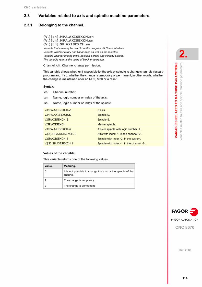
CNC variables.
CNC 8070
VA
RIA
BL
ES
RE
LA
TE
D T
O M
AC
HIN
E P
AR
AM
ET
ER
S.
2.
Var
iabl
es
rela
ted
to a
xis
and
spin
dle
mac
hin
e pa
ram
eter
s.
ꞏ119ꞏ
(REF: 2102)
2.3 Variables related to axis and spindle machine parameters.
2.3.1 Belonging to the channel.
(V.)[ch].MPA.AXISEXCH.xn(V.)[ch].MPA.AXISEXCH.sn(V.)[ch].SP.AXISEXCH.snVariable that can only be read from the program, PLC and interface.Variable valid for rotary and linear axes as well as for spindles.Variable valid for analog drive, position Sercos and velocity Sercos.The variable returns the value of block preparation.
Channel [ch]. Channel change permission.
This variable shows whether it is possible for the axis or spindle to change channels via part-program and, if so, whether the change is temporary or permanent; in other words, whetherthe change is maintained after an M02, M30 or a reset.
Syntax.
ꞏchꞏ Channel number.
ꞏxnꞏ Name, logic number or index of the axis.
ꞏsnꞏ Name, logic number or index of the spindle.
Values of the variable.
This variable returns one of the following values.
V.MPA.AXISEXCH.Z Z axis.
V.MPA.AXISEXCH.S Spindle S.
V.SP.AXISEXCH.S Spindle S.
V.SP.AXISEXCH Master spindle.
V.MPA.AXISEXCH.4 Axis or spindle with logic number ꞏ4ꞏ.
V.[2].MPA.AXISEXCH.1 Axis with index ꞏ1ꞏ in the channel ꞏ2ꞏ.
V.SP.AXISEXCH.2 Spindle with index ꞏ2ꞏ in the system.
V.[2].SP.AXISEXCH.1 Spindle with index ꞏ1ꞏ in the channel ꞏ2ꞏ.
Value. Meaning.
0 It is not possible to change the axis or the spindle of thechannel.
1 The change is temporary.
2 The change is permanent.

CNC variables.
CNC 8070
2.
VA
RIA
BL
ES
RE
LA
TE
D T
O M
AC
HIN
E P
AR
AM
ET
ER
S.
Var
iabl
es
rela
ted
to a
xis
and
spin
dle
mac
hin
e pa
ram
eter
s.
ꞏ120ꞏ
(REF: 2102)
2.3.2 Type of axis and drive.
(V.)[ch].MPA.AXISTYPE.xnVariable that can only be read from the program, PLC and interface.Variable valid for rotary and linear axes as well as for spindles.Variable valid for analog drive, position Sercos and velocity Sercos.The variable returns the execution value; reading it interrupts block preparation.
Channel [ch]. Type of axis.
Syntax.
ꞏchꞏ Channel number.
ꞏxnꞏ Name, logic number or index of the axis.
Values of the variable.
This variable returns one of the following values.
(V.)[ch].MPA.DRIVETYPE.xn(V.)[ch].MPA.DRIVETYPE.sn(V.)[ch].SP.DRIVETYPE.snVariable that can only be read from the program, PLC and interface.Variable that may be modified during setup.Variable valid for rotary and linear axes as well as for spindles.Variable valid for an analog, position-Sercos, velocity-Sercos and Mechatrolink drive.The variable returns the execution value; reading it interrupts block preparation.
Channel [ch]. Type of drive.
Syntax.
ꞏchꞏ Channel number.
ꞏxnꞏ Name, logic number or index of the axis.
ꞏsnꞏ Name, logic number or index of the spindle.
V.MPA.AXISTYPE.Z Z axis.
V.MPA.AXISTYPE.4 Axis with logic number ꞏ4ꞏ.
V.[2].MPA.AXISTYPE.1 Axis with index ꞏ1ꞏ in the channel ꞏ2ꞏ.
Value. Meaning.
1 Linear axis.
2 Rotary axis.
4 Spindle.
V.MPA.DRIVETYPE.Z Z axis.
V.MPA.DRIVETYPE.S Spindle S.
V.SP.DRIVETYPE.S Spindle S.
V.SP.DRIVETYPE Master spindle.
V.MPA.DRIVETYPE.4 Axis or spindle with logic number ꞏ4ꞏ.
V.[2].MPA.DRIVETYPE.1 Axis with index ꞏ1ꞏ in the channel ꞏ2ꞏ.
V.SP.DRIVETYPE.2 Spindle with index ꞏ2ꞏ in the system.
V.[2].SP.DRIVETYPE.1 Spindle with index ꞏ1ꞏ in the channel ꞏ2ꞏ.

CNC variables.
CNC 8070
VA
RIA
BL
ES
RE
LA
TE
D T
O M
AC
HIN
E P
AR
AM
ET
ER
S.
2.
Var
iabl
es
rela
ted
to a
xis
and
spin
dle
mac
hin
e pa
ram
eter
s.
ꞏ121ꞏ
(REF: 2102)
Values of the variable.
This variable returns one of the following values.
(V.)[ch].MPA.POSUNITS.xn(V.)[ch].MPA.POSUNITS.sn(V.)[ch].SP.POSUNITS.snVariable that can only be read from the program, PLC and interface.Variable valid for rotary and linear axes as well as for spindles.Variable valid for a position-Sercos, velocity-Servos and Mechatrolink drive.The variable returns the value of block preparation.
Channel [ch]. Units systgen used by the feedback system.
Syntax.
ꞏchꞏ Channel number.
ꞏxnꞏ Name, logic number or index of the axis.
ꞏsnꞏ Name, logic number or index of the spindle.
Values of the variable.
This variable returns one of the following values.
Value. Meaning.
1 Analog drive.
2 Sercos drive.
16 Simulated drive.
32 Mechatrolink drive.
V.MPA.POSUNITS.Z Z axis.
V.MPA.POSUNITS.S Spindle S.
V.SP.POSUNITS.S Spindle S.
V.SP.POSUNITS Master spindle.
V.MPA.POSUNITS.4 Axis or spindle with logic number ꞏ4ꞏ.
V.[2].MPA.POSUNITS.1 Axis with index ꞏ1ꞏ in the channel ꞏ2ꞏ.
V.SP.POSUNITS.2 Spindle with index ꞏ2ꞏ in the system.
V.[2].SP.POSUNITS.1 Spindle with index ꞏ1ꞏ in the channel ꞏ2ꞏ.
Value. Meaning.
0 Measurement (mm or degrees).
1 Pulses.

CNC variables.
CNC 8070
2.
VA
RIA
BL
ES
RE
LA
TE
D T
O M
AC
HIN
E P
AR
AM
ET
ER
S.
Var
iabl
es
rela
ted
to a
xis
and
spin
dle
mac
hin
e pa
ram
eter
s.
ꞏ122ꞏ
(REF: 2102)
2.3.3 Configuring a Sercos drive.
(V.)[ch].MPA.DRIVEID.xn(V.)[ch].MPA.DRIVEID.sn(V.)[ch].SP.DRIVEID.snVariable that can only be read from the program, PLC and interface.Variable that may be modified during setup.Variable valid for rotary and linear axes as well as for spindles.Variable valid for a position-Sercos, velocity-Servos and Mechatrolink drive.The variable returns the execution value; reading it interrupts block preparation.
Channel [ch]. Address (node) of the drive.
Syntax.
ꞏchꞏ Channel number.
ꞏxnꞏ Name, logic number or index of the axis.
ꞏsnꞏ Name, logic number or index of the spindle.
(V.)[ch].MPA.OPMODEP.xn(V.)[ch].MPA.OPMODEP.sn(V.)[ch].SP.OPMODEP.snVariable that can only be read from the program, PLC and interface.Variable that may be modified during setup.Variable valid for rotary and linear axes as well as for spindles.Variable valid for a position-Sercos, velocity-Servos and Mechatrolink drive.The variable returns the execution value; reading it interrupts block preparation.
Channel [ch]. Main operating mode of the Sercos drive or Mechatrolink device.
Syntax.
ꞏchꞏ Channel number.
ꞏxnꞏ Name, logic number or index of the axis.
ꞏsnꞏ Name, logic number or index of the spindle.
V.MPA.DRIVEID.Z Z axis.
V.MPA.DRIVEID.S Spindle S.
V.SP.DRIVEID.S Spindle S.
V.SP.DRIVEID Master spindle.
V.MPA.DRIVEID.4 Axis or spindle with logic number ꞏ4ꞏ.
V.[2].MPA.DRIVEID.1 Axis with index ꞏ1ꞏ in the channel ꞏ2ꞏ.
V.SP.DRIVEID.2 Spindle with index ꞏ2ꞏ in the system.
V.[2].SP.DRIVEID.1 Spindle with index ꞏ1ꞏ in the channel ꞏ2ꞏ.
V.MPA.OPMODEP.Z Z axis.
V.MPA.OPMODEP.S Spindle S.
V.SP.OPMODEP.S Spindle S.
V.SP.OPMODEP Master spindle.
V.MPA.OPMODEP.4 Axis or spindle with logic number ꞏ4ꞏ.
V.[2].MPA.OPMODEP.1 Axis with index ꞏ1ꞏ in the channel ꞏ2ꞏ.
V.SP.OPMODEP.2 Spindle with index ꞏ2ꞏ in the system.
V.[2].SP.OPMODEP.1 Spindle with index ꞏ1ꞏ in the channel ꞏ2ꞏ.

CNC variables.
CNC 8070
VA
RIA
BL
ES
RE
LA
TE
D T
O M
AC
HIN
E P
AR
AM
ET
ER
S.
2.
Var
iabl
es
rela
ted
to a
xis
and
spin
dle
mac
hin
e pa
ram
eter
s.
ꞏ123ꞏ
(REF: 2102)
Values of the variable.
This variable returns one of the following values.
(V.)[ch].MPA.OPTION.xn(V.)[ch].MPA.OPTION.sn(V.)[ch].SP.OPTION.snVariable that can only be read from the program, PLC and interface.Variable valid for rotary and linear axes as well as for spindles.Variable valid for Mechatrolink drive.The variable returns the execution value; reading it interrupts block preparation.
Channel [ch]. Activate the drive options.
The drive options are coded in 16-bit format. Refer to the drive manual for the meaning ofeach bit.
Syntax.
ꞏchꞏ Channel number.
ꞏxnꞏ Name, logic number or index of the axis.
ꞏsnꞏ Name, logic number or index of the spindle.
(V.)[ch].MPA.FBACKSRC.xn(V.)[ch].MPA.FBACKSRC.sn(V.)[ch].SP.FBACKSRC.snVariable that can only be read from the program, PLC and interface.Variable valid for rotary and linear axes as well as for spindles.Variable valid for position-Sercos drives and velocity-Sercos drives.The variable returns the value of block preparation.
Channel [ch]. Type of feedback.
Syntax.
ꞏchꞏ Channel number.
ꞏxnꞏ Name, logic number or index of the axis.
ꞏsnꞏ Name, logic number or index of the spindle.
Value. Meaning.
0 Sercos drive or Mechatrolink servo. Position command.
1 Sercos drive or Mechatrolink servo. Velocity command.
2 Inverter Mechatrolink.
V.MPA.OPTION.Z Z axis.
V.MPA.OPTION.S Spindle S.
V.SP.OPTION.S Spindle S.
V.SP.OPTION Master spindle.
V.MPA.OPTION.4 Axis or spindle with logic number ꞏ4ꞏ.
V.[2].MPA.OPTION.1 Axis with index ꞏ1ꞏ in the channel ꞏ2ꞏ.
V.SP.OPTION.2 Spindle with index ꞏ2ꞏ in the system.
V.[2].SP.OPTION.1 Spindle with index ꞏ1ꞏ in the channel ꞏ2ꞏ.
V.MPA.FBACKSRC.Z Z axis.
V.MPA.FBACKSRC.S Spindle S.
V.SP.FBACKSRC.S Spindle S.
V.SP.FBACKSRC Master spindle.
V.MPA.FBACKSRC.4 Axis or spindle with logic number ꞏ4ꞏ.
V.[2].MPA.FBACKSRC.1 Axis with index ꞏ1ꞏ in the channel ꞏ2ꞏ.
V.SP.FBACKSRC.2 Spindle with index ꞏ2ꞏ in the system.
V.[2].SP.FBACKSRC.1 Spindle with index ꞏ1ꞏ in the channel ꞏ2ꞏ.

CNC variables.
CNC 8070
2.
VA
RIA
BL
ES
RE
LA
TE
D T
O M
AC
HIN
E P
AR
AM
ET
ER
S.
Var
iabl
es
rela
ted
to a
xis
and
spin
dle
mac
hin
e pa
ram
eter
s.
ꞏ124ꞏ
(REF: 2102)
Values of the variable.
This variable returns one of the following values.
(V.)[ch].MPA.FBACKDIFF.xn(V.)[ch].MPA.FBACKDIFF.sn(V.)[ch].SP.FBACKDIFF.snVariable that can only be read from the program, PLC and interface.Variable valid for rotary and linear axes as well as for spindles.Variable valid for position Sercos drives.The variable returns the value of block preparation.
Channel [ch]. Maximum difference between feedbacks.
Syntax.
ꞏchꞏ Channel number.
ꞏxnꞏ Name, logic number or index of the axis.
ꞏsnꞏ Name, logic number or index of the spindle.
(V.)[ch].MPA.FBMIXTIME.xn(V.)[ch].MPA.FBMIXTIME.sn(V.)[ch].SP.FBMIXTIME.snVariable that can only be read from the program, PLC and interface.Variable valid for rotary and linear axes as well as for spindles.Variable valid for position Sercos drives.The variable returns the value of block preparation.
Channel [ch]. Time constant for combined feedback.
Syntax.
ꞏchꞏ Channel number.
ꞏxnꞏ Name, logic number or index of the axis.
ꞏsnꞏ Name, logic number or index of the spindle.
Value. Meaning.
0 Internal feedback (motor feedback).
1 External feedback (direct feedback).
2 Combined feedback (internal + external).
V.MPA.FBACKDIFF.Z Z axis.
V.MPA.FBACKDIFF.S Spindle S.
V.SP.FBACKDIFF.S Spindle S.
V.SP.FBACKDIFF Master spindle.
V.MPA.FBACKDIFF.4 Axis or spindle with logic number ꞏ4ꞏ.
V.[2].MPA.FBACKDIFF.1 Axis with index ꞏ1ꞏ in the channel ꞏ2ꞏ.
V.SP.FBACKDIFF.2 Spindle with index ꞏ2ꞏ in the system.
V.[2].SP.FBACKDIFF.1 Spindle with index ꞏ1ꞏ in the channel ꞏ2ꞏ.
V.MPA.FBMIXTIME.Z Z axis.
V.MPA.FBMIXTIME.S Spindle S.
V.SP.FBMIXTIME.S Spindle S.
V.SP.FBMIXTIME Master spindle.
V.MPA.FBMIXTIME.4 Axis or spindle with logic number ꞏ4ꞏ.
V.[2].MPA.FBMIXTIME.1 Axis with index ꞏ1ꞏ in the channel ꞏ2ꞏ.
V.SP.FBMIXTIME.2 Spindle with index ꞏ2ꞏ in the system.
V.[2].SP.FBMIXTIME.1 Spindle with index ꞏ1ꞏ in the channel ꞏ2ꞏ.

CNC variables.
CNC 8070
VA
RIA
BL
ES
RE
LA
TE
D T
O M
AC
HIN
E P
AR
AM
ET
ER
S.
2.
Var
iabl
es
rela
ted
to a
xis
and
spin
dle
mac
hin
e pa
ram
eter
s.
ꞏ125ꞏ
(REF: 2102)
2.3.4 Hirth axis configuration.
(V.)[ch].MPA.HIRTH.xnVariable that can only be read from the program, PLC and interface.Variable valid for rotary and linear axes.Variable valid for analog drive, position Sercos and velocity Sercos.The variable returns the value of block preparation.
Channel [ch]. Hirth toothed axis.
A Hirth axis is the one that can only be positioned at positions multiple of a given value.
Syntax.
ꞏchꞏ Channel number.
ꞏxnꞏ Name, logic number or index of the axis.
Values of the variable.
This variable returns one of the following values.
(V.)[ch].MPA.HPITCH.xnVariable that can only be read from the program, PLC and interface.Variable valid for rotary and linear axes.Variable valid for analog drive, position Sercos and velocity Sercos.The variable returns the value of block preparation.
Channel [ch]. Hirth axis pitch.
Syntax.
ꞏchꞏ Channel number.
ꞏxnꞏ Name, logic number or index of the axis.
V.MPA.HIRTH.Z Z axis.
V.MPA.HIRTH.4 Axis with logic number ꞏ4ꞏ.
V.[2].MPA.HIRTH.1 Axis with index ꞏ1ꞏ in the channel ꞏ2ꞏ.
Value. Meaning.
0 No.
1 Yes.
V.MPA.HPITCH.Z Z axis.
V.MPA.HPITCH.4 Axis with logic number ꞏ4ꞏ.
V.[2].MPA.HPITCH.1 Axis with index ꞏ1ꞏ in the channel ꞏ2ꞏ.
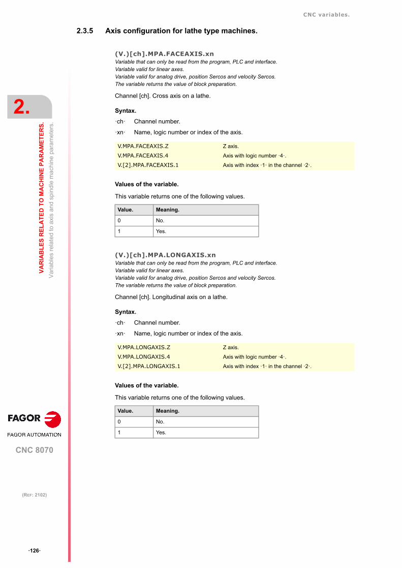
CNC variables.
CNC 8070
2.
VA
RIA
BL
ES
RE
LA
TE
D T
O M
AC
HIN
E P
AR
AM
ET
ER
S.
Var
iabl
es
rela
ted
to a
xis
and
spin
dle
mac
hin
e pa
ram
eter
s.
ꞏ126ꞏ
(REF: 2102)
2.3.5 Axis configuration for lathe type machines.
(V.)[ch].MPA.FACEAXIS.xnVariable that can only be read from the program, PLC and interface.Variable valid for linear axes.Variable valid for analog drive, position Sercos and velocity Sercos.The variable returns the value of block preparation.
Channel [ch]. Cross axis on a lathe.
Syntax.
ꞏchꞏ Channel number.
ꞏxnꞏ Name, logic number or index of the axis.
Values of the variable.
This variable returns one of the following values.
(V.)[ch].MPA.LONGAXIS.xnVariable that can only be read from the program, PLC and interface.Variable valid for linear axes.Variable valid for analog drive, position Sercos and velocity Sercos.The variable returns the value of block preparation.
Channel [ch]. Longitudinal axis on a lathe.
Syntax.
ꞏchꞏ Channel number.
ꞏxnꞏ Name, logic number or index of the axis.
Values of the variable.
This variable returns one of the following values.
V.MPA.FACEAXIS.Z Z axis.
V.MPA.FACEAXIS.4 Axis with logic number ꞏ4ꞏ.
V.[2].MPA.FACEAXIS.1 Axis with index ꞏ1ꞏ in the channel ꞏ2ꞏ.
Value. Meaning.
0 No.
1 Yes.
V.MPA.LONGAXIS.Z Z axis.
V.MPA.LONGAXIS.4 Axis with logic number ꞏ4ꞏ.
V.[2].MPA.LONGAXIS.1 Axis with index ꞏ1ꞏ in the channel ꞏ2ꞏ.
Value. Meaning.
0 No.
1 Yes.

CNC variables.
CNC 8070
VA
RIA
BL
ES
RE
LA
TE
D T
O M
AC
HIN
E P
AR
AM
ET
ER
S.
2.
Var
iabl
es
rela
ted
to a
xis
and
spin
dle
mac
hin
e pa
ram
eter
s.
ꞏ127ꞏ
(REF: 2102)
2.3.6 Configuration of the rotary axes.
(V.)[ch].MPA.AXISMODE.xnVariable that can only be read from the program, PLC and interface.Variable that may be modified during setup.Variable valid for rotary axes.Variable valid for analog drive, position Sercos and velocity Sercos.The variable returns the execution value; reading it interrupts block preparation.
Channel [ch]. Working method with the rotary axis.
This variable indicates how the rotary axis will behave in relation to the number of turns andposition display.
Syntax.
ꞏchꞏ Channel number.
ꞏxnꞏ Name, logic number or index of the axis.
Values of the variable.
This variable returns one of the following values.
(V.)[ch].MPA.UNIDIR.xnVariable that can only be read from the program, PLC and interface.Variable that may be modified during setup.Variable valid for rotary axes.Variable valid for analog drive, position Sercos and velocity Sercos.The variable returns the execution value; reading it interrupts block preparation.
Channel [ch]. Unidirectional rotation.
Syntax.
ꞏchꞏ Channel number.
ꞏxnꞏ Name, logic number or index of the axis.
Values of the variable.
This variable returns one of the following values.
V.MPA.AXISMODE.Z Z axis.
V.MPA.AXISMODE.4 Axis with logic number ꞏ4ꞏ.
V.[2].MPA.AXISMODE.1 Axis with index ꞏ1ꞏ in the channel ꞏ2ꞏ.
Value. Meaning.
0 "Module" type rotary axis.
1 "Linearlike" type rotary axis.
V.MPA.UNIDIR.Z Z axis.
V.MPA.UNIDIR.4 Axis with logic number ꞏ4ꞏ.
V.[2].MPA.UNIDIR.1 Axis with index ꞏ1ꞏ in the channel ꞏ2ꞏ.
Value. Meaning.
0 No.
1 Yes.

CNC variables.
CNC 8070
2.
VA
RIA
BL
ES
RE
LA
TE
D T
O M
AC
HIN
E P
AR
AM
ET
ER
S.
Var
iabl
es
rela
ted
to a
xis
and
spin
dle
mac
hin
e pa
ram
eter
s.
ꞏ128ꞏ
(REF: 2102)
(V.)[ch].MPA.SHORTESTWAY.xnVariable that can only be read from the program, PLC and interface.Variable that may be modified during setup.Variable valid for rotary axes.Variable valid for analog drive, position Sercos and velocity Sercos.The variable returns the execution value; reading it interrupts block preparation.
Channel [ch]. Positioning via shortest way.
Syntax.
ꞏchꞏ Channel number.
ꞏxnꞏ Name, logic number or index of the axis.
Values of the variable.
This variable returns one of the following values.
V.MPA.SHORTESTWAY.Z Z axis.
V.MPA.SHORTESTWAY.4 Axis with logic number ꞏ4ꞏ.
V.[2].MPA.SHORTESTWAY.1 Axis with index ꞏ1ꞏ in the channel ꞏ2ꞏ.
Value. Meaning.
0 No.
1 Yes.

CNC variables.
CNC 8070
VA
RIA
BL
ES
RE
LA
TE
D T
O M
AC
HIN
E P
AR
AM
ET
ER
S.
2.
Var
iabl
es
rela
ted
to a
xis
and
spin
dle
mac
hin
e pa
ram
eter
s.
ꞏ129ꞏ
(REF: 2102)
2.3.7 Module configuration (rotary axes and spindle).
(V.)[ch].MPA.MODCOMP.xn(V.)[ch].MPA.MODCOMP.sn(V.)[ch].SP.MODCOMP.snVariable that can only be read from the program, PLC and interface.Variable that may be modified during setup.Variable valid for rotary axes and spindles.Variable valid for analog drives and velocity-Sercos drives.The variable returns the execution value; reading it interrupts block preparation.
Channel [ch]. Module compensation.
Syntax.
ꞏchꞏ Channel number.
ꞏxnꞏ Name, logic number or index of the axis.
ꞏsnꞏ Name, logic number or index of the spindle.
Values of the variable.
This variable returns one of the following values.
2.3.8 Activating the spindle for DMC.
(V.)[ch].MPA.DMCDPDL.sn(V.)[ch].SP.DMCDPDL.snVariable that can only be read from the program, PLC and interface.The variable returns the value of block preparation.Units: -.
Spindle with enabled power control.
Syntax.
ꞏchꞏ Channel number.
ꞏsnꞏ Name, logic number or index of the spindle.
V.MPA.MODCOMP.Z Z axis.
V.MPA.MODCOMP.S Spindle S.
V.SP.MODCOMP.S Spindle S.
V.SP.MODCOMP Master spindle.
V.MPA.MODCOMP.4 Axis or spindle with logic number ꞏ4ꞏ.
V.[2].MPA.MODCOMP.1 Axis with index ꞏ1ꞏ in the channel ꞏ2ꞏ.
V.SP.MODCOMP.2 Spindle with index ꞏ2ꞏ in the system.
V.[2].SP.MODCOMP.1 Spindle with index ꞏ1ꞏ in the channel ꞏ2ꞏ.
Value. Meaning.
0 No.
1 Yes.
V.MPA.DMCSPDL.S Spindle S.
V.SP.DMCSPDL.S Spindle S.
V.SP.DMCSPDL Master spindle.
V.MPA.DMCSPDL.4 Spindle with logic number ꞏ4ꞏ.
V.SP.DMCSPDL.2 Spindle with index ꞏ2ꞏ in the system.
V.[2].SP.DMCSPDL.1 Spindle with index ꞏ1ꞏ in the channel ꞏ2ꞏ.

CNC variables.
CNC 8070
2.
VA
RIA
BL
ES
RE
LA
TE
D T
O M
AC
HIN
E P
AR
AM
ET
ER
S.
Var
iabl
es
rela
ted
to a
xis
and
spin
dle
mac
hin
e pa
ram
eter
s.
ꞏ130ꞏ
(REF: 2102)
2.3.9 Configuration of the C axis.
(V.)[ch].MPA.CAXIS.xn(V.)[ch].MPA.CAXIS.sn(V.)[ch].SP.CAXIS.snVariable that can only be read from the program, PLC and interface.Variable valid for rotary axes and spindles.Variable valid for analog drive, position Sercos and velocity Sercos.The variable returns the value of block preparation.
Channel [ch]. Possibility of working as C axis.
Syntax.
ꞏchꞏ Channel number.
ꞏxnꞏ Name, logic number or index of the axis.
ꞏsnꞏ Name, logic number or index of the spindle.
Values of the variable.
This variable returns one of the following values.
(V.)[ch].MPA.CAXSET.xn(V.)[ch].MPA.CAXSET.sn(V.)[ch].SP.CAXSET.snVariable that can only be read from the program, PLC and interface.Variable valid for rotary axes and spindles.Variable valid for analog drive, position Sercos and velocity Sercos.The variable returns the value of block preparation.
Channel [ch]. Set of parameters for working as C axis.
Syntax.
ꞏchꞏ Channel number.
ꞏxnꞏ Name, logic number or index of the axis.
ꞏsnꞏ Name, logic number or index of the spindle.
V.MPA.CAXIS.Z Z axis.
V.MPA.CAXIS.S Spindle S.
V.SP.CAXIS.S Spindle S.
V.SP.CAXIS Master spindle.
V.MPA.CAXIS.4 Axis or spindle with logic number ꞏ4ꞏ.
V.[2].MPA.CAXIS.1 Axis with index ꞏ1ꞏ in the channel ꞏ2ꞏ.
V.SP.CAXIS.2 Spindle with index ꞏ2ꞏ in the system.
V.[2].SP.CAXIS.1 Spindle with index ꞏ1ꞏ in the channel ꞏ2ꞏ.
Value. Meaning.
0 No.
1 Yes.
V.MPA.CAXSET.Z Z axis.
V.MPA.CAXSET.S Spindle S.
V.SP.CAXSET.S Spindle S.
V.SP.CAXSET Master spindle.
V.MPA.CAXSET.4 Axis or spindle with logic number ꞏ4ꞏ.
V.[2].MPA.CAXSET.1 Axis with index ꞏ1ꞏ in the channel ꞏ2ꞏ.
V.SP.CAXSET.2 Spindle with index ꞏ2ꞏ in the system.
V.[2].SP.CAXSET.1 Spindle with index ꞏ1ꞏ in the channel ꞏ2ꞏ.

CNC variables.
CNC 8070
VA
RIA
BL
ES
RE
LA
TE
D T
O M
AC
HIN
E P
AR
AM
ET
ER
S.
2.
Var
iabl
es
rela
ted
to a
xis
and
spin
dle
mac
hin
e pa
ram
eter
s.
ꞏ131ꞏ
(REF: 2102)
(V.)[ch].MPA.PERCAX.xn(V.)[ch].MPA.PERCAX.sn(V.)[ch].SP.PERCAX.snVariable that can only be read from the program, PLC and interface.Variable valid for rotary axes and spindles.Variable valid for analog drive, position Sercos and velocity Sercos.The variable returns the value of block preparation.
Channel [ch]. C axis kept active after end of program, emergency or reset.
Syntax.
ꞏchꞏ Channel number.
ꞏxnꞏ Name, logic number or index of the axis.
ꞏsnꞏ Name, logic number or index of the spindle.
Values of the variable.
This variable returns one of the following values.
V.MPA.PERCAX.Z Z axis.
V.MPA.PERCAX.S Spindle S.
V.SP.PERCAX.S Spindle S.
V.SP.PERCAX Master spindle.
V.MPA.PERCAX.4 Axis or spindle with logic number ꞏ4ꞏ.
V.[2].MPA.PERCAX.1 Axis with index ꞏ1ꞏ in the channel ꞏ2ꞏ.
V.SP.PERCAX.2 Spindle with index ꞏ2ꞏ in the system.
V.[2].SP.PERCAX.1 Spindle with index ꞏ1ꞏ in the channel ꞏ2ꞏ.
Value. Meaning.
0 No.
1 Yes.

CNC variables.
CNC 8070
2.
VA
RIA
BL
ES
RE
LA
TE
D T
O M
AC
HIN
E P
AR
AM
ET
ER
S.
Var
iabl
es
rela
ted
to a
xis
and
spin
dle
mac
hin
e pa
ram
eter
s.
ꞏ132ꞏ
(REF: 2102)
2.3.10 Configuration of the spindle.
(V.)[ch].MPA.AUTOGEAR.sn(V.)[ch].SP.AUTOGEAR.snVariable that can only be read from the program, PLC and interface.Variable valid for spindles.Variable valid for analog drive, position Sercos and velocity Sercos.The variable returns the value of block preparation.
Channel [ch]. Automatic gear change.
Syntax.
ꞏchꞏ Channel number.
ꞏsnꞏ Name, logic number or index of the spindle.
Values of the variable.
This variable returns one of the following values.
(V.)[ch].MPA.LOSPDLIM.sn(V.)[ch].SP.LOSPDLIM.snVariable that can only be read from the program, PLC and interface.Variable valid for spindles.Variable valid for analog drive, position Sercos and velocity Sercos.The variable returns the value of block preparation.
Channel [ch]. Lower "rpm OK" percentage.
Syntax.
ꞏchꞏ Channel number.
ꞏsnꞏ Name, logic number or index of the spindle.
Remarks.
The reading from the PLC will be given in tenths (x10); i.e. if the parameter value is ꞏ10ꞏ,the PLC reading will return a value of ꞏ100ꞏ.
V.MPA.AUTOGEAR.S Spindle S.
V.SP.AUTOGEAR.S Spindle S.
V.SP.AUTOGEAR Master spindle.
V.MPA.AUTOGEAR.4 Spindle with logic number ꞏ4ꞏ.
V.SP.AUTOGEAR.2 Spindle with index ꞏ2ꞏ in the system.
V.[2].SP.AUTOGEAR.1 Spindle with index ꞏ1ꞏ in the channel ꞏ2ꞏ.
Value. Meaning.
0 No.
1 Yes.
V.MPA.LOSPDLIM.S Spindle S.
V.SP.LOSPDLIM.S Spindle S.
V.SP.LOSPDLIM Master spindle.
V.MPA.LOSPDLIM.4 Spindle with logic number ꞏ4ꞏ.
V.SP.LOSPDLIM.2 Spindle with index ꞏ2ꞏ in the system.
V.[2].SP.LOSPDLIM.1 Spindle with index ꞏ1ꞏ in the channel ꞏ2ꞏ.

CNC variables.
CNC 8070
VA
RIA
BL
ES
RE
LA
TE
D T
O M
AC
HIN
E P
AR
AM
ET
ER
S.
2.
Var
iabl
es
rela
ted
to a
xis
and
spin
dle
mac
hin
e pa
ram
eter
s.
ꞏ133ꞏ
(REF: 2102)
(V.)[ch].MPA.UPSPDLIM.sn(V.)[ch].SP.UPSPDLIM.snVariable that can only be read from the program, PLC and interface.Variable valid for spindles.Variable valid for analog drive, position Sercos and velocity Sercos.The variable returns the value of block preparation.
Channel [ch]. Upper "rpm OK" percentage.
Syntax.
ꞏchꞏ Channel number.
ꞏsnꞏ Name, logic number or index of the spindle.
Remarks.
The reading from the PLC will be given in tenths (x10); i.e. if the parameter value is ꞏ10ꞏ,the PLC reading will return a value of ꞏ100ꞏ.
(V.)[ch].MPA.SPDLTIME.sn(V.)[ch].SP.SPDLTIME.snVariable that can only be read from the program, PLC and interface.Variable valid for spindles.Variable valid for analog drive, position Sercos and velocity Sercos.The variable returns the value of block preparation.
Channel [ch]. Estimated time for an S function.
Syntax.
ꞏchꞏ Channel number.
ꞏsnꞏ Name, logic number or index of the spindle.
(V.)[ch].MPA.SPDLSTOP.sn(V.)[ch].SP.SPDLSTOP.snVariable that can only be read from the program, PLC and interface.Variable valid for spindles.Variable valid for analog drive, position Sercos and velocity Sercos.The variable returns the value of block preparation.
Channel [ch]. Functions M2 and M30, an error or a reset stop the spindle.
Syntax.
ꞏchꞏ Channel number.
ꞏsnꞏ Name, logic number or index of the spindle.
V.MPA.UPSPDLIM.S Spindle S.
V.SP.UPSPDLIM.S Spindle S.
V.SP.UPSPDLIM Master spindle.
V.MPA.UPSPDLIM.4 Spindle with logic number ꞏ4ꞏ.
V.SP.UPSPDLIM.2 Spindle with index ꞏ2ꞏ in the system.
V.[2].SP.UPSPDLIM.1 Spindle with index ꞏ1ꞏ in the channel ꞏ2ꞏ.
V.MPA.SPDLTIME.S Spindle S.
V.SP.SPDLTIME.S Spindle S.
V.SP.SPDLTIME Master spindle.
V.MPA.SPDLTIME.4 Spindle with logic number ꞏ4ꞏ.
V.SP.SPDLTIME.2 Spindle with index ꞏ2ꞏ in the system.
V.[2].SP.SPDLTIME.1 Spindle with index ꞏ1ꞏ in the channel ꞏ2ꞏ.
V.MPA.SPDLSTOP.S Spindle S.
V.SP.SPDLSTOP.S Spindle S.
V.SP.SPDLSTOP Master spindle.

CNC variables.
CNC 8070
2.
VA
RIA
BL
ES
RE
LA
TE
D T
O M
AC
HIN
E P
AR
AM
ET
ER
S.
Var
iabl
es
rela
ted
to a
xis
and
spin
dle
mac
hin
e pa
ram
eter
s.
ꞏ134ꞏ
(REF: 2102)
Values of the variable.
This variable returns one of the following values.
(V.)[ch].MPA.SREVM05.sn(V.)[ch].SP.SREVM05.snVariable that can only be read from the program, PLC and interface.Variable valid for spindles.Variable valid for analog drive, position Sercos and velocity Sercos.The variable returns the value of block preparation.
Channel [ch]. With G84, the spindle must be stopped to change the turning direction.
Syntax.
ꞏchꞏ Channel number.
ꞏsnꞏ Name, logic number or index of the spindle.
Values of the variable.
This variable returns one of the following values.
(V.)[ch].MPA.M19SPDLEREV.sn(V.)[ch].SP.M19SPDLEREV.snVariable that can only be read from the program, PLC and interface.Variable valid for spindles.Variable valid for analog drives.The variable returns the value of block preparation.
Channel [ch]. The SPDLEREV mark (reverse turning direction) affects the spindle in M19.
Syntax.
ꞏchꞏ Channel number.
ꞏsnꞏ Name, logic number or index of the spindle.
V.MPA.SPDLSTOP.4 Spindle with logic number ꞏ4ꞏ.
V.SP.SPDLSTOP.2 Spindle with index ꞏ2ꞏ in the system.
V.[2].SP.SPDLSTOP.1 Spindle with index ꞏ1ꞏ in the channel ꞏ2ꞏ.
Value. Meaning.
0 No.
1 Yes.
V.MPA.SREVM05.S Spindle S.
V.SP.SREVM05.S Spindle S.
V.SP.SREVM05 Master spindle.
V.MPA.SREVM05.4 Spindle with logic number ꞏ4ꞏ.
V.SP.SREVM05.2 Spindle with index ꞏ2ꞏ in the system.
V.[2].SP.SREVM05.1 Spindle with index ꞏ1ꞏ in the channel ꞏ2ꞏ.
Value. Meaning.
0 No.
1 Yes.
V.MPA.M19SPDLEREV.S Spindle S.
V.SP.M19SPDLEREV.S Spindle S.
V.SP.M19SPDLEREV Master spindle.
V.MPA.M19SPDLEREV.4 Spindle with logic number ꞏ4ꞏ.
V.SP.M19SPDLEREV.2 Spindle with index ꞏ2ꞏ in the system.
V.[2].SP.M19SPDLEREV.1 Spindle with index ꞏ1ꞏ in the channel ꞏ2ꞏ.

CNC variables.
CNC 8070
VA
RIA
BL
ES
RE
LA
TE
D T
O M
AC
HIN
E P
AR
AM
ET
ER
S.
2.
Var
iabl
es
rela
ted
to a
xis
and
spin
dle
mac
hin
e pa
ram
eter
s.
ꞏ135ꞏ
(REF: 2102)
Values of the variable.
This variable returns one of the following values.
(V.)[ch].MPA.STEPOVR.sn(V.)[ch].SP.STEPOVR.snVariable that can only be read from the program, PLC and interface.Variable valid for spindles.Variable valid for analog drive, position Sercos and velocity Sercos.The variable returns the value of block preparation.
Channel [ch]. Spindle override step.
Syntax.
ꞏchꞏ Channel number.
ꞏsnꞏ Name, logic number or index of the spindle.
Remarks.
The reading from the PLC will be given in tenths (x10); i.e. if the parameter value is ꞏ10ꞏ,the PLC reading will return a value of ꞏ100ꞏ.
(V.)[ch].MPA.MINOVR.sn(V.)[ch].SP.MINOVR.snVariable that can only be read from the program, PLC and interface.Variable valid for spindles.Variable valid for analog drive, position Sercos and velocity Sercos.The variable returns the value of block preparation.
Channel [ch]. Minimum override (%) permitted for the spindle.
Syntax.
ꞏchꞏ Channel number.
ꞏsnꞏ Name, logic number or index of the spindle.
Remarks.
The reading from the PLC will be given in tenths (x10); i.e. if the parameter value is ꞏ10ꞏ,the PLC reading will return a value of ꞏ100ꞏ.
Value. Meaning.
0 No.
1 Yes.
V.MPA.STEPOVR.S Spindle S.
V.SP.STEPOVR.S Spindle S.
V.SP.STEPOVR Master spindle.
V.MPA.STEPOVR.4 Spindle with logic number ꞏ4ꞏ.
V.SP.STEPOVR.2 Spindle with index ꞏ2ꞏ in the system.
V.[2].SP.STEPOVR.1 Spindle with index ꞏ1ꞏ in the channel ꞏ2ꞏ.
V.MPA.MINOVR.S Spindle S.
V.SP.MINOVR.S Spindle S.
V.SP.MINOVR Master spindle.
V.MPA.MINOVR.4 Spindle with logic number ꞏ4ꞏ.
V.SP.MINOVR.2 Spindle with index ꞏ2ꞏ in the system.
V.[2].SP.MINOVR.1 Spindle with index ꞏ1ꞏ in the channel ꞏ2ꞏ.

CNC variables.
CNC 8070
2.
VA
RIA
BL
ES
RE
LA
TE
D T
O M
AC
HIN
E P
AR
AM
ET
ER
S.
Var
iabl
es
rela
ted
to a
xis
and
spin
dle
mac
hin
e pa
ram
eter
s.
ꞏ136ꞏ
(REF: 2102)
(V.)[ch].MPA.MAXOVR.sn(V.)[ch].SP.MAXOVR.snVariable that can only be read from the program, PLC and interface.Variable valid for spindles.Variable valid for analog drive, position Sercos and velocity Sercos.The variable returns the value of block preparation.
Channel [ch]. Maximum override (%) permitted for the spindle.
Syntax.
ꞏchꞏ Channel number.
ꞏsnꞏ Name, logic number or index of the spindle.
Remarks.
The reading from the PLC will be given in tenths (x10); i.e. if the parameter value is ꞏ10ꞏ,the PLC reading will return a value of ꞏ100ꞏ.
V.MPA.MAXOVR.S Spindle S.
V.SP.MAXOVR.S Spindle S.
V.SP.MAXOVR Master spindle.
V.MPA.MAXOVR.4 Spindle with logic number ꞏ4ꞏ.
V.SP.MAXOVR.2 Spindle with index ꞏ2ꞏ in the system.
V.[2].SP.MAXOVR.1 Spindle with index ꞏ1ꞏ in the channel ꞏ2ꞏ.
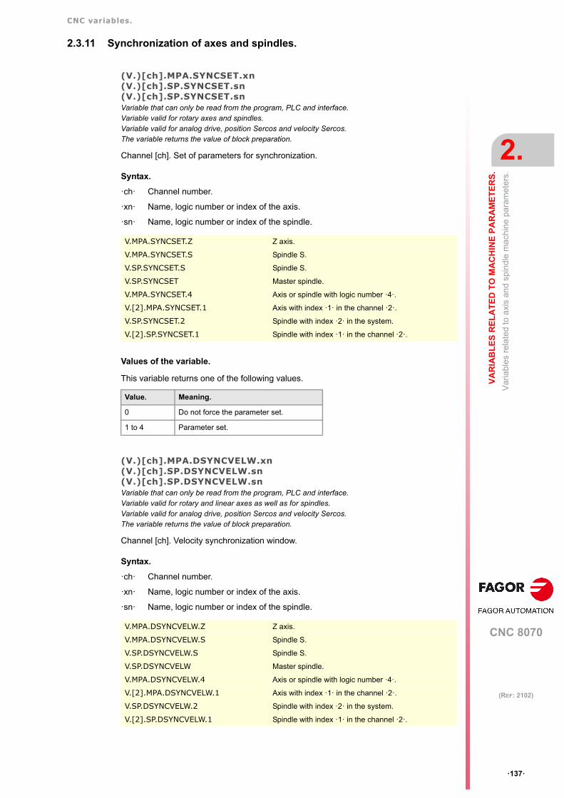
CNC variables.
CNC 8070
VA
RIA
BL
ES
RE
LA
TE
D T
O M
AC
HIN
E P
AR
AM
ET
ER
S.
2.
Var
iabl
es
rela
ted
to a
xis
and
spin
dle
mac
hin
e pa
ram
eter
s.
ꞏ137ꞏ
(REF: 2102)
2.3.11 Synchronization of axes and spindles.
(V.)[ch].MPA.SYNCSET.xn(V.)[ch].SP.SYNCSET.sn(V.)[ch].SP.SYNCSET.snVariable that can only be read from the program, PLC and interface.Variable valid for rotary axes and spindles.Variable valid for analog drive, position Sercos and velocity Sercos.The variable returns the value of block preparation.
Channel [ch]. Set of parameters for synchronization.
Syntax.
ꞏchꞏ Channel number.
ꞏxnꞏ Name, logic number or index of the axis.
ꞏsnꞏ Name, logic number or index of the spindle.
Values of the variable.
This variable returns one of the following values.
(V.)[ch].MPA.DSYNCVELW.xn(V.)[ch].SP.DSYNCVELW.sn(V.)[ch].SP.DSYNCVELW.snVariable that can only be read from the program, PLC and interface.Variable valid for rotary and linear axes as well as for spindles.Variable valid for analog drive, position Sercos and velocity Sercos.The variable returns the value of block preparation.
Channel [ch]. Velocity synchronization window.
Syntax.
ꞏchꞏ Channel number.
ꞏxnꞏ Name, logic number or index of the axis.
ꞏsnꞏ Name, logic number or index of the spindle.
V.MPA.SYNCSET.Z Z axis.
V.MPA.SYNCSET.S Spindle S.
V.SP.SYNCSET.S Spindle S.
V.SP.SYNCSET Master spindle.
V.MPA.SYNCSET.4 Axis or spindle with logic number ꞏ4ꞏ.
V.[2].MPA.SYNCSET.1 Axis with index ꞏ1ꞏ in the channel ꞏ2ꞏ.
V.SP.SYNCSET.2 Spindle with index ꞏ2ꞏ in the system.
V.[2].SP.SYNCSET.1 Spindle with index ꞏ1ꞏ in the channel ꞏ2ꞏ.
Value. Meaning.
0 Do not force the parameter set.
1 to 4 Parameter set.
V.MPA.DSYNCVELW.Z Z axis.
V.MPA.DSYNCVELW.S Spindle S.
V.SP.DSYNCVELW.S Spindle S.
V.SP.DSYNCVELW Master spindle.
V.MPA.DSYNCVELW.4 Axis or spindle with logic number ꞏ4ꞏ.
V.[2].MPA.DSYNCVELW.1 Axis with index ꞏ1ꞏ in the channel ꞏ2ꞏ.
V.SP.DSYNCVELW.2 Spindle with index ꞏ2ꞏ in the system.
V.[2].SP.DSYNCVELW.1 Spindle with index ꞏ1ꞏ in the channel ꞏ2ꞏ.

CNC variables.
CNC 8070
2.
VA
RIA
BL
ES
RE
LA
TE
D T
O M
AC
HIN
E P
AR
AM
ET
ER
S.
Var
iabl
es
rela
ted
to a
xis
and
spin
dle
mac
hin
e pa
ram
eter
s.
ꞏ138ꞏ
(REF: 2102)
(V.)[ch].MPA.DSYNCPOSW.xn(V.)[ch].SP.DSYNCPOSW.sn(V.)[ch].SP.DSYNCPOSW.snVariable that can only be read from the program, PLC and interface.Variable valid for rotary and linear axes as well as for spindles.Variable valid for analog drive, position Sercos and velocity Sercos.The variable returns the value of block preparation.
Channel [ch]. Position synchronization window.
Syntax.
ꞏchꞏ Channel number.
ꞏxnꞏ Name, logic number or index of the axis.
ꞏsnꞏ Name, logic number or index of the spindle.
V.MPA.DSYNCPOSW.Z Z axis.
V.MPA.DSYNCPOSW.S Spindle S.
V.SP.DSYNCPOSW.S Spindle S.
V.SP.DSYNCPOSW Master spindle.
V.MPA.DSYNCPOSW.4 Axis or spindle with logic number ꞏ4ꞏ.
V.[2].MPA.DSYNCPOSW.1 Axis with index ꞏ1ꞏ in the channel ꞏ2ꞏ.
V.SP.DSYNCPOSW.2 Spindle with index ꞏ2ꞏ in the system.
V.[2].SP.DSYNCPOSW.1 Spindle with index ꞏ1ꞏ in the channel ꞏ2ꞏ.
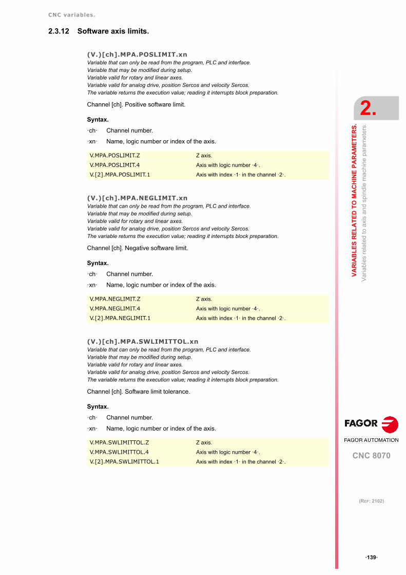
CNC variables.
CNC 8070
VA
RIA
BL
ES
RE
LA
TE
D T
O M
AC
HIN
E P
AR
AM
ET
ER
S.
2.
Var
iabl
es
rela
ted
to a
xis
and
spin
dle
mac
hin
e pa
ram
eter
s.
ꞏ139ꞏ
(REF: 2102)
2.3.12 Software axis limits.
(V.)[ch].MPA.POSLIMIT.xnVariable that can only be read from the program, PLC and interface.Variable that may be modified during setup.Variable valid for rotary and linear axes.Variable valid for analog drive, position Sercos and velocity Sercos.The variable returns the execution value; reading it interrupts block preparation.
Channel [ch]. Positive software limit.
Syntax.
ꞏchꞏ Channel number.
ꞏxnꞏ Name, logic number or index of the axis.
(V.)[ch].MPA.NEGLIMIT.xnVariable that can only be read from the program, PLC and interface.Variable that may be modified during setup.Variable valid for rotary and linear axes.Variable valid for analog drive, position Sercos and velocity Sercos.The variable returns the execution value; reading it interrupts block preparation.
Channel [ch]. Negative software limit.
Syntax.
ꞏchꞏ Channel number.
ꞏxnꞏ Name, logic number or index of the axis.
(V.)[ch].MPA.SWLIMITTOL.xnVariable that can only be read from the program, PLC and interface.Variable that may be modified during setup.Variable valid for rotary and linear axes.Variable valid for analog drive, position Sercos and velocity Sercos.The variable returns the execution value; reading it interrupts block preparation.
Channel [ch]. Software limit tolerance.
Syntax.
ꞏchꞏ Channel number.
ꞏxnꞏ Name, logic number or index of the axis.
V.MPA.POSLIMIT.Z Z axis.
V.MPA.POSLIMIT.4 Axis with logic number ꞏ4ꞏ.
V.[2].MPA.POSLIMIT.1 Axis with index ꞏ1ꞏ in the channel ꞏ2ꞏ.
V.MPA.NEGLIMIT.Z Z axis.
V.MPA.NEGLIMIT.4 Axis with logic number ꞏ4ꞏ.
V.[2].MPA.NEGLIMIT.1 Axis with index ꞏ1ꞏ in the channel ꞏ2ꞏ.
V.MPA.SWLIMITTOL.Z Z axis.
V.MPA.SWLIMITTOL.4 Axis with logic number ꞏ4ꞏ.
V.[2].MPA.SWLIMITTOL.1 Axis with index ꞏ1ꞏ in the channel ꞏ2ꞏ.

CNC variables.
CNC 8070
2.
VA
RIA
BL
ES
RE
LA
TE
D T
O M
AC
HIN
E P
AR
AM
ET
ER
S.
Var
iabl
es
rela
ted
to a
xis
and
spin
dle
mac
hin
e pa
ram
eter
s.
ꞏ140ꞏ
(REF: 2102)
2.3.13 Work zones.
(V.)[ch].MPA.ZONELIMITTOL.xnVariable that can only be read from the program, PLC and interface.Variable valid for rotary and linear axes.Variable valid for analog drive, position Sercos and velocity Sercos.The variable returns the execution value; reading it interrupts block preparation.
Channel [ch]. Safety distance (set in parameter ZONELIMITTOL) applied by the CNC to theaxis with respect to the limit of the work zone.
Syntax.
ꞏchꞏ Channel number.
ꞏxnꞏ Name, logic number or index of the axis.
V.MPA.ZONELIMITTOL.Z Z axis.
V.MPA.ZONELIMITTOL.4 Axis with logic number ꞏ4ꞏ.
V.[2].MPA.ZONELIMITTOL.1 Axis with index ꞏ1ꞏ in the channel ꞏ2ꞏ.

CNC variables.
CNC 8070
VA
RIA
BL
ES
RE
LA
TE
D T
O M
AC
HIN
E P
AR
AM
ET
ER
S.
2.
Var
iabl
es
rela
ted
to a
xis
and
spin
dle
mac
hin
e pa
ram
eter
s.
ꞏ141ꞏ
(REF: 2102)
2.3.14 Override change while threading.
(V.)[ch].MPA.THREADOVR.sn(V.)[ch].SP.THREADOVR.snVariable that can only be read from the program, PLC and interface.Variable valid for spindles.Variable valid for analog drive, position Sercos and velocity Sercos.The variable returns the value of block preparation.
Channel [ch]. Maximum variation allowed for the override while threading.
Syntax.
ꞏchꞏ Channel number.
ꞏsnꞏ Name, logic number or index of the spindle.
(V.)[ch].MPA.OVRFILTER.sn(V.)[ch].SP.OVRFILTER.snVariable that can only be read from the program, PLC and interface.Variable valid for spindles.Variable valid for analog drive, position Sercos and velocity Sercos.The variable returns the value of block preparation.
Channel [ch]. Time to make the override change effective.
Syntax.
ꞏchꞏ Channel number.
ꞏsnꞏ Name, logic number or index of the spindle.
V.MPA.THREADOVR.S Spindle S.
V.SP.THREADOVR.S Spindle S.
V.SP.THREADOVR Master spindle.
V.MPA.THREADOVR.4 Spindle with logic number ꞏ4ꞏ.
V.SP.THREADOVR.2 Spindle with index ꞏ2ꞏ in the system.
V.[2].SP.THREADOVR.1 Spindle with index ꞏ1ꞏ in the channel ꞏ2ꞏ.
V.MPA.OVRFILTER.S Spindle S.
V.SP.OVRFILTER.S Spindle S.
V.SP.OVRFILTER Master spindle.
V.MPA.OVRFILTER.4 Spindle with logic number ꞏ4ꞏ.
V.SP.OVRFILTER.2 Spindle with index ꞏ2ꞏ in the system.
V.[2].SP.OVRFILTER.1 Spindle with index ꞏ1ꞏ in the channel ꞏ2ꞏ.

CNC variables.
CNC 8070
2.
VA
RIA
BL
ES
RE
LA
TE
D T
O M
AC
HIN
E P
AR
AM
ET
ER
S.
Var
iabl
es
rela
ted
to a
xis
and
spin
dle
mac
hin
e pa
ram
eter
s.
ꞏ142ꞏ
(REF: 2102)
2.3.15 Runaway protection and tendency test.
(V.)[ch].MPA.TENDENCY.xn(V.)[ch].SP.TENDENCY.sn(V.)[ch].SP.TENDENCY.snVariable that can only be read from the program, PLC and interface.Variable that may be modified during setup.Variable valid for rotary and linear axes as well as for spindles.Variable valid for analog drives.The variable returns the execution value; reading it interrupts block preparation.
Channel [ch]. Activation of tendency test.
Syntax.
ꞏchꞏ Channel number.
ꞏxnꞏ Name, logic number or index of the axis.
ꞏsnꞏ Name, logic number or index of the spindle.
Values of the variable.
This variable returns one of the following values.
(V.)[ch].MPA.TENDTIME.xn(V.)[ch].SP.TENDTIME.sn(V.)[ch].SP.TENDTIME.snVariable that can only be read from the program, PLC and interface.Variable valid for rotary and linear axes as well as for spindles.Variable valid for analog drives.The variable returns the execution value; reading it interrupts block preparation.
Channel [ch]. Time to detect axis runaway.
Syntax.
ꞏchꞏ Channel number.
ꞏxnꞏ Name, logic number or index of the axis.
ꞏsnꞏ Name, logic number or index of the spindle.
V.MPA.TENDENCY.Z Z axis.
V.MPA.TENDENCY.S Spindle S.
V.SP.TENDENCY.S Spindle S.
V.SP.TENDENCY Master spindle.
V.MPA.TENDENCY.4 Axis or spindle with logic number ꞏ4ꞏ.
V.[2].MPA.TENDENCY.1 Axis with index ꞏ1ꞏ in the channel ꞏ2ꞏ.
V.SP.TENDENCY.2 Spindle with index ꞏ2ꞏ in the system.
V.[2].SP.TENDENCY.1 Spindle with index ꞏ1ꞏ in the channel ꞏ2ꞏ.
Value. Meaning.
0 No.
1 Yes.
V.MPA.TENDTIME.Z Z axis.
V.MPA.TENDTIME.S Spindle S.
V.SP.TENDTIME.S Spindle S.
V.SP.TENDTIME Master spindle.
V.MPA.TENDTIME.4 Axis or spindle with logic number ꞏ4ꞏ.
V.[2].MPA.TENDTIME.1 Axis with index ꞏ1ꞏ in the channel ꞏ2ꞏ.
V.SP.TENDTIME.2 Spindle with index ꞏ2ꞏ in the system.
V.[2].SP.TENDTIME.1 Spindle with index ꞏ1ꞏ in the channel ꞏ2ꞏ.

CNC variables.
CNC 8070
VA
RIA
BL
ES
RE
LA
TE
D T
O M
AC
HIN
E P
AR
AM
ET
ER
S.
2.
Var
iabl
es
rela
ted
to a
xis
and
spin
dle
mac
hin
e pa
ram
eter
s.
ꞏ143ꞏ
(REF: 2102)
2.3.16 PLC offset.
(V.)[ch].MPA.PLCOINC.xn(V.)[ch].MPA.PLCOINC.sn(V.)[ch].SP.PLCOINC.snVariable that can only be read from the program, PLC and interface.Variable valid for rotary and linear axes as well as for spindles.Variable valid for analog drive, position Sercos and velocity Sercos.The variable returns the value of block preparation.
Channel [ch]. PLC offset increment per cycle.
Syntax.
ꞏchꞏ Channel number.
ꞏxnꞏ Name, logic number or index of the axis.
ꞏsnꞏ Name, logic number or index of the spindle.
2.3.17 Dwell for dead axes.
(V.)[ch].MPA.DWELL.xn(V.)[ch].MPA.DWELL.sn(V.)[ch].SP.DWELL.snVariable that can only be read from the program, PLC and interface.Variable valid for rotary and linear axes as well as for spindles.Variable valid for analog drive, position Sercos and velocity Sercos.The variable returns the value of block preparation.
Channel [ch]. Dwell for dead axes.
Syntax.
ꞏchꞏ Channel number.
ꞏxnꞏ Name, logic number or index of the axis.
ꞏsnꞏ Name, logic number or index of the spindle.
V.MPA.PLCOINC.Z Z axis.
V.MPA.PLCOINC.S Spindle S.
V.SP.PLCOINC.S Spindle S.
V.SP.PLCOINC Master spindle.
V.MPA.PLCOINC.4 Axis or spindle with logic number ꞏ4ꞏ.
V.[2].MPA.PLCOINC.1 Axis with index ꞏ1ꞏ in the channel ꞏ2ꞏ.
V.SP.PLCOINC.2 Spindle with index ꞏ2ꞏ in the system.
V.[2].SP.PLCOINC.1 Spindle with index ꞏ1ꞏ in the channel ꞏ2ꞏ.
V.MPA.DWELL.Z Z axis.
V.MPA.DWELL.S Spindle S.
V.SP.DWELL.S Spindle S.
V.SP.DWELL Master spindle.
V.MPA.DWELL.4 Axis or spindle with logic number ꞏ4ꞏ.
V.[2].MPA.DWELL.1 Axis with index ꞏ1ꞏ in the channel ꞏ2ꞏ.
V.SP.DWELL.2 Spindle with index ꞏ2ꞏ in the system.
V.[2].SP.DWELL.1 Spindle with index ꞏ1ꞏ in the channel ꞏ2ꞏ.

CNC variables.
CNC 8070
2.
VA
RIA
BL
ES
RE
LA
TE
D T
O M
AC
HIN
E P
AR
AM
ET
ER
S.
Var
iabl
es
rela
ted
to a
xis
and
spin
dle
mac
hin
e pa
ram
eter
s.
ꞏ144ꞏ
(REF: 2102)
2.3.18 Programming in radius or diameters.
(V.)[ch].MPA.DIAMPROG.xnVariable that can only be read from the program, PLC and interface.Variable valid for linear axes.Variable valid for analog drive, position Sercos and velocity Sercos.The variable returns the value of block preparation.
Channel [ch]. Programming in diameters.
Syntax.
ꞏchꞏ Channel number.
ꞏxnꞏ Name, logic number or index of the axis.
Values of the variable.
This variable returns one of the following values.
V.MPA.DIAMPROG.Z Z axis.
V.MPA.DIAMPROG.4 Axis with logic number ꞏ4ꞏ.
V.[2].MPA.DIAMPROG.1 Axis with index ꞏ1ꞏ in the channel ꞏ2ꞏ.
Value. Meaning.
0 No.
1 Yes.

CNC variables.
CNC 8070
VA
RIA
BL
ES
RE
LA
TE
D T
O M
AC
HIN
E P
AR
AM
ET
ER
S.
2.
Var
iabl
es
rela
ted
to a
xis
and
spin
dle
mac
hin
e pa
ram
eter
s.
ꞏ145ꞏ
(REF: 2102)
2.3.19 Home search.
(V.)[ch].MPA.REFDIREC.xn(V.)[ch].MPA.REFDIREC.sn(V.)[ch].SP.REFDIREC.snVariable that can only be read from the program, PLC and interface.Variable that may be modified during setup.Variable valid for rotary and linear axes as well as for spindles.Variable valid for analog drive, position Sercos and velocity Sercos.The variable returns the execution value; reading it interrupts block preparation.
Channel [ch]. Direction of the search.
Syntax.
ꞏchꞏ Channel number.
ꞏxnꞏ Name, logic number or index of the axis.
ꞏsnꞏ Name, logic number or index of the spindle.
Values of the variable.
This variable returns one of the following values.
(V.)[ch].MPA.REFMODE.xn(V.)[ch].MPA.REFMODE.sn(V.)[ch].SP.REFMODE.snVariable that can only be read from the program, PLC and interface.Variable valid for rotary and linear axes as well as for spindles.Variable valid for position Sercos drives.The variable returns the execution value; reading it interrupts block preparation.
Channel [ch]. Home search mode.
Syntax.
ꞏchꞏ Channel number.
ꞏxnꞏ Name, logic number or index of the axis.
ꞏsnꞏ Name, logic number or index of the spindle.
V.MPA.REFDIREC.Z Z axis.
V.MPA.REFDIREC.S Spindle S.
V.SP.REFDIREC.S Spindle S.
V.SP.REFDIREC Master spindle.
V.MPA.REFDIREC.4 Axis or spindle with logic number ꞏ4ꞏ.
V.[2].MPA.REFDIREC.1 Axis with index ꞏ1ꞏ in the channel ꞏ2ꞏ.
V.SP.REFDIREC.2 Spindle with index ꞏ2ꞏ in the system.
V.[2].SP.REFDIREC.1 Spindle with index ꞏ1ꞏ in the channel ꞏ2ꞏ.
Value. Meaning.
0 Movement in the negative direction.
1 Movement in the positive direction.
V.MPA.REFMODE.Z Z axis.
V.MPA.REFMODE.S Spindle S.
V.SP.REFMODE.S Spindle S.
V.SP.REFMODE Master spindle.
V.MPA.REFMODE.4 Axis or spindle with logic number ꞏ4ꞏ.
V.[2].MPA.REFMODE.1 Axis with index ꞏ1ꞏ in the channel ꞏ2ꞏ.
V.SP.REFMODE.2 Spindle with index ꞏ2ꞏ in the system.
V.[2].SP.REFMODE.1 Spindle with index ꞏ1ꞏ in the channel ꞏ2ꞏ.

CNC variables.
CNC 8070
2.
VA
RIA
BL
ES
RE
LA
TE
D T
O M
AC
HIN
E P
AR
AM
ET
ER
S.
Var
iabl
es
rela
ted
to a
xis
and
spin
dle
mac
hin
e pa
ram
eter
s.
ꞏ146ꞏ
(REF: 2102)
Values of the variable.
This variable returns one of the following values.
(V.)[ch].MPA.DECINPUT.xn(V.)[ch].MPA.DECINPUT.sn(V.)[ch].SP.DECINPUT.snVariable that can only be read from the program, PLC and interface.Variable that may be modified during setup.Variable valid for rotary and linear axes as well as for spindles.Variable valid for analog drive, position Sercos and velocity Sercos.The variable returns the execution value; reading it interrupts block preparation.
Channel [ch]. The axis/spindle has a home switch.
Syntax.
ꞏchꞏ Channel number.
ꞏxnꞏ Name, logic number or index of the axis.
ꞏsnꞏ Name, logic number or index of the spindle.
Values of the variable.
This variable returns one of the following values.
(V.)[ch].MPA.REFINI.sn(V.)[ch].SP.REFINI.snVariable that can only be read from the program, PLC and interface.Variable valid for spindles.Variable valid for analog drive, position Sercos and velocity Sercos.The variable returns the value of block preparation.
Channel [ch]. Home search in the first movement
Syntax.
ꞏchꞏ Channel number.
ꞏsnꞏ Name, logic number or index of the spindle.
Value. Meaning.
0 Drive.
1 CNC.
V.MPA.DECINPUT.Z Z axis.
V.MPA.DECINPUT.S Spindle S.
V.SP.DECINPUT.S Spindle S.
V.SP.DECINPUT Master spindle.
V.MPA.DECINPUT.4 Axis or spindle with logic number ꞏ4ꞏ.
V.[2].MPA.DECINPUT.1 Axis with index ꞏ1ꞏ in the channel ꞏ2ꞏ.
V.SP.DECINPUT.2 Spindle with index ꞏ2ꞏ in the system.
V.[2].SP.DECINPUT.1 Spindle with index ꞏ1ꞏ in the channel ꞏ2ꞏ.
Value. Meaning.
0 No.
1 Yes.
V.MPA.REFINI.S Spindle S.
V.SP.REFINI.S Spindle S.
V.SP.REFINI Master spindle.
V.MPA.REFINI.4 Spindle with logic number ꞏ4ꞏ.
V.SP.REFINI.2 Spindle with index ꞏ2ꞏ in the system.
V.[2].SP.REFINI.1 Spindle with index ꞏ1ꞏ in the channel ꞏ2ꞏ.

CNC variables.
CNC 8070
VA
RIA
BL
ES
RE
LA
TE
D T
O M
AC
HIN
E P
AR
AM
ET
ER
S.
2.
Var
iabl
es
rela
ted
to a
xis
and
spin
dle
mac
hin
e pa
ram
eter
s.
ꞏ147ꞏ
(REF: 2102)
2.3.20 Configuration of the probing movement.
(V.)[ch].MPA.PROBEAXIS.xnVariable that can only be read from the program, PLC and interface.Variable valid for rotary and linear axes.Variable valid for analog drive, position Sercos and velocity Sercos.The variable returns the value of block preparation.
Channel [ch]. The axis can participate in probing movements.
Syntax.
ꞏchꞏ Channel number.
ꞏxnꞏ Name, logic number or index of the axis.
Values of the variable.
This variable returns one of the following values.
(V.)[ch].MPA.PROBERANGE.xnVariable that can only be read from the program, PLC and interface.Variable valid for rotary and linear axes.Variable valid for analog drive, position Sercos and velocity Sercos.The variable returns the value of block preparation.
Channel [ch]. Maximum braking distance.
Syntax.
ꞏchꞏ Channel number.
ꞏxnꞏ Name, logic number or index of the axis.
(V.)[ch].MPA.PROBEFEED.xnVariable that can only be read from the program, PLC and interface.Variable valid for rotary and linear axes.Variable valid for analog drive, position Sercos and velocity Sercos.The variable returns the value of block preparation.
Channel [ch]. Maximum probing feedrate.
Syntax.
ꞏchꞏ Channel number.
ꞏxnꞏ Name, logic number or index of the axis.
V.MPA.PROBEAXIS.Z Z axis.
V.MPA.PROBEAXIS.4 Axis with logic number ꞏ4ꞏ.
V.[2].MPA.PROBEAXIS.1 Axis with index ꞏ1ꞏ in the channel ꞏ2ꞏ.
Value. Meaning.
0 No.
1 Yes.
V.MPA.PROBERANGE.Z Z axis.
V.MPA.PROBERANGE.4 Axis with logic number ꞏ4ꞏ.
V.[2].MPA.PROBERANGE.1 Axis with index ꞏ1ꞏ in the channel ꞏ2ꞏ.
V.MPA.PROBEFEED.Z Z axis.
V.MPA.PROBEFEED.4 Axis with logic number ꞏ4ꞏ.
V.[2].MPA.PROBEFEED.1 Axis with index ꞏ1ꞏ in the channel ꞏ2ꞏ.

CNC variables.
CNC 8070
2.
VA
RIA
BL
ES
RE
LA
TE
D T
O M
AC
HIN
E P
AR
AM
ET
ER
S.
Var
iabl
es
rela
ted
to a
xis
and
spin
dle
mac
hin
e pa
ram
eter
s.
ꞏ148ꞏ
(REF: 2102)
(V.)[ch].MPA.PROBEDELAY.xnVariable that can only be read from the program, PLC and interface.Variable valid for rotary and linear axes.Variable valid for analog drive, position Sercos and velocity Sercos.The variable returns the value of block preparation.
Channel [ch]. Delay for the "probe 1" signal.
Syntax.
ꞏchꞏ Channel number.
ꞏxnꞏ Name, logic number or index of the axis.
(V.)[ch].MPA.PROBEDELAY2.xnVariable that can only be read from the program, PLC and interface.Variable valid for rotary and linear axes.Variable valid for analog drive, position Sercos and velocity Sercos.The variable returns the value of block preparation.
Channel [ch]. Delay for the "probe 2" signal.
Syntax.
ꞏchꞏ Channel number.
ꞏxnꞏ Name, logic number or index of the axis.
V.MPA.PROBEDELAY.Z Z axis.
V.MPA.PROBEDELAY.4 Axis with logic number ꞏ4ꞏ.
V.[2].MPA.PROBEDELAY.1 Axis with index ꞏ1ꞏ in the channel ꞏ2ꞏ.
V.MPA.PROBEDELAY2.Z Z axis.
V.MPA.PROBEDELAY2.4 Axis with logic number ꞏ4ꞏ.
V.[2].MPA.PROBEDELAY2.1 Axis with index ꞏ1ꞏ in the channel ꞏ2ꞏ.

CNC variables.
CNC 8070
VA
RIA
BL
ES
RE
LA
TE
D T
O M
AC
HIN
E P
AR
AM
ET
ER
S.
2.
Var
iabl
es
rela
ted
to a
xis
and
spin
dle
mac
hin
e pa
ram
eter
s.
ꞏ149ꞏ
(REF: 2102)
2.3.21 Repositioning of the axes in tool inspection.
(V.)[ch].MPA.REPOSFEED.xnVariable that can only be read from the program, PLC and interface.Variable that may be modified during setup.Variable valid for rotary and linear axes.Variable valid for analog drive, position Sercos and velocity Sercos.The variable returns the execution value; reading it interrupts block preparation.
Channel [ch]. Maximum repositioning feedrate.
Syntax.
ꞏchꞏ Channel number.
ꞏxnꞏ Name, logic number or index of the axis.
2.3.22 Configuration of the independent axis.
(V.)[ch].MPA.POSFEED.xn(V.)[ch].MPA.POSFEED.sn(V.)[ch].SP.POSFEED.snVariable that can only be read from the program, PLC and interface.Variable valid for rotary and linear axes as well as for spindles.Variable valid for analog drive, position Sercos and velocity Sercos.The variable returns the value of block preparation.
Channel [ch]. Positioning feedrate
Syntax.
ꞏchꞏ Channel number.
ꞏxnꞏ Name, logic number or index of the axis.
ꞏsnꞏ Name, logic number or index of the spindle.
V.MPA.REPOSFEED.Z Z axis.
V.MPA.REPOSFEED.4 Axis with logic number ꞏ4ꞏ.
V.[2].MPA.REPOSFEED.1 Axis with index ꞏ1ꞏ in the channel ꞏ2ꞏ.
V.MPA.POSFEED.Z Z axis.
V.MPA.POSFEED.S Spindle S.
V.SP.POSFEED.S Spindle S.
V.SP.POSFEED Master spindle.
V.MPA.POSFEED.4 Axis or spindle with logic number ꞏ4ꞏ.
V.[2].MPA.POSFEED.1 Axis with index ꞏ1ꞏ in the channel ꞏ2ꞏ.
V.SP.POSFEED.2 Spindle with index ꞏ2ꞏ in the system.
V.[2].SP.POSFEED.1 Spindle with index ꞏ1ꞏ in the channel ꞏ2ꞏ.
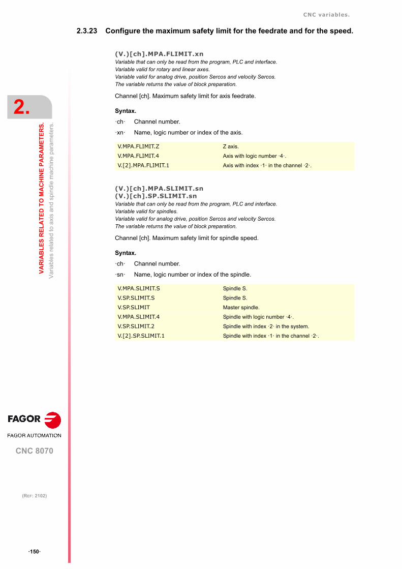
CNC variables.
CNC 8070
2.
VA
RIA
BL
ES
RE
LA
TE
D T
O M
AC
HIN
E P
AR
AM
ET
ER
S.
Var
iabl
es
rela
ted
to a
xis
and
spin
dle
mac
hin
e pa
ram
eter
s.
ꞏ150ꞏ
(REF: 2102)
2.3.23 Configure the maximum safety limit for the feedrate and for the speed.
(V.)[ch].MPA.FLIMIT.xnVariable that can only be read from the program, PLC and interface.Variable valid for rotary and linear axes.Variable valid for analog drive, position Sercos and velocity Sercos.The variable returns the value of block preparation.
Channel [ch]. Maximum safety limit for axis feedrate.
Syntax.
ꞏchꞏ Channel number.
ꞏxnꞏ Name, logic number or index of the axis.
(V.)[ch].MPA.SLIMIT.sn(V.)[ch].SP.SLIMIT.snVariable that can only be read from the program, PLC and interface.Variable valid for spindles.Variable valid for analog drive, position Sercos and velocity Sercos.The variable returns the value of block preparation.
Channel [ch]. Maximum safety limit for spindle speed.
Syntax.
ꞏchꞏ Channel number.
ꞏsnꞏ Name, logic number or index of the spindle.
V.MPA.FLIMIT.Z Z axis.
V.MPA.FLIMIT.4 Axis with logic number ꞏ4ꞏ.
V.[2].MPA.FLIMIT.1 Axis with index ꞏ1ꞏ in the channel ꞏ2ꞏ.
V.MPA.SLIMIT.S Spindle S.
V.SP.SLIMIT.S Spindle S.
V.SP.SLIMIT Master spindle.
V.MPA.SLIMIT.4 Spindle with logic number ꞏ4ꞏ.
V.SP.SLIMIT.2 Spindle with index ꞏ2ꞏ in the system.
V.[2].SP.SLIMIT.1 Spindle with index ꞏ1ꞏ in the channel ꞏ2ꞏ.

CNC variables.
CNC 8070
VA
RIA
BL
ES
RE
LA
TE
D T
O M
AC
HIN
E P
AR
AM
ET
ER
S.
2.
Var
iabl
es
rela
ted
to a
xis
and
spin
dle
mac
hin
e pa
ram
eter
s.
ꞏ151ꞏ
(REF: 2102)
2.3.24 JOG mode. Continuous jog.
(V.)[ch].MPA.JOGFEED.xnVariable that can only be read from the program, PLC and interface.Variable that may be modified during setup.Variable valid for rotary and linear axes.Variable valid for analog drive, position Sercos and velocity Sercos.The variable returns the execution value; reading it interrupts block preparation.
Channel [ch]. Feedrate in continuous jog.
Syntax.
ꞏchꞏ Channel number.
ꞏxnꞏ Name, logic number or index of the axis.
(V.)[ch].MPA.JOGRAPFEED.xnVariable that can only be read from the program, PLC and interface.Variable that may be modified during setup.Variable valid for rotary and linear axes.Variable valid for analog drive, position Sercos and velocity Sercos.The variable returns the execution value; reading it interrupts block preparation.
Channel [ch]. Rapid feedrate in continuous jog.
Syntax.
ꞏchꞏ Channel number.
ꞏxnꞏ Name, logic number or index of the axis.
(V.)[ch].MPA.MAXMANFEED.xnVariable that can only be read from the program, PLC and interface.Variable that may be modified during setup.Variable valid for rotary and linear axes.Variable valid for analog drive, position Sercos and velocity Sercos.The variable returns the execution value; reading it interrupts block preparation.
Channel [ch]. Maximum feedrate in continuous jog.
Syntax.
ꞏchꞏ Channel number.
ꞏxnꞏ Name, logic number or index of the axis.
(V.)[ch].MPA.MAXMANACC.xnVariable that can only be read from the program, PLC and interface.Variable valid for rotary and linear axes.Variable valid for analog drive, position Sercos and velocity Sercos.The variable returns the value of block preparation.
Channel [ch]. Maximum acceleration in continuous JOG.
V.MPA.JOGFEED.Z Z axis.
V.MPA.JOGFEED.4 Axis with logic number ꞏ4ꞏ.
V.[2].MPA.JOGFEED.1 Axis with index ꞏ1ꞏ in the channel ꞏ2ꞏ.
V.MPA.JOGRAPFEED.Z Z axis.
V.MPA.JOGRAPFEED.4 Axis with logic number ꞏ4ꞏ.
V.[2].MPA.JOGRAPFEED.1 Axis with index ꞏ1ꞏ in the channel ꞏ2ꞏ.
V.MPA.MAXMANFEED.Z Z axis.
V.MPA.MAXMANFEED.4 Axis with logic number ꞏ4ꞏ.
V.[2].MPA.MAXMANFEED.1 Axis with index ꞏ1ꞏ in the channel ꞏ2ꞏ.
CNC variables.
CNC 8070
2.
VA
RIA
BL
ES
RE
LA
TE
D T
O M
AC
HIN
E P
AR
AM
ET
ER
S.
Var
iabl
es
rela
ted
to a
xis
and
spin
dle
mac
hin
e pa
ram
eter
s.
ꞏ152ꞏ
(REF: 2102)
Syntax.
ꞏchꞏ Channel number.
ꞏxnꞏ Name, logic number or index of the axis.
V.MPA.MAXMANACC.Z Z axis.
V.MPA.MAXMANACC.4 Axis with logic number ꞏ4ꞏ.
V.[2].MPA.MAXMANACC.1 Axis with index ꞏ1ꞏ in the channel ꞏ2ꞏ.

CNC variables.
CNC 8070
VA
RIA
BL
ES
RE
LA
TE
D T
O M
AC
HIN
E P
AR
AM
ET
ER
S.
2.
Var
iabl
es
rela
ted
to a
xis
and
spin
dle
mac
hin
e pa
ram
eter
s.
ꞏ153ꞏ
(REF: 2102)
2.3.25 JOG mode. Incremental jog.
(V.)[ch].MPA.INCJOGDIST[pos].xnVariable that can only be read from the program, PLC and interface.Variable valid for rotary and linear axes.Variable valid for analog drive, position Sercos and velocity Sercos.The variable returns the value of block preparation.
Channel [ch]. Distance to move in incremental jog, [pos] dial position.
pos=1 for position ꞏ1ꞏ, pos=2 for position ꞏ10ꞏ and so on.
Syntax.
ꞏchꞏ Channel number.
ꞏposꞏ Position of the switch on the operator panel for incremental jog.
ꞏxnꞏ Name, logic number or index of the axis..
(V.)[ch].MPA.INCJOGFEED[pos].xnVariable that can only be read from the program, PLC and interface.Variable valid for rotary and linear axes.Variable valid for analog drive, position Sercos and velocity Sercos.The variable returns the value of block preparation.
Channel [ch]. Feedrate in incremental jog, [pos] dial position.
pos=1 for position ꞏ1ꞏ, pos=2 for position ꞏ10ꞏ and so on.
Syntax.
ꞏchꞏ Channel number.
ꞏposꞏ Position of the switch on the operator panel for incremental jog.
ꞏxnꞏ Name, logic number or index of the axis.
V.MPA.INCJOGDIST[4].Z Z axis.
V.MPA.INCJOGDIST[4].4 Axis with logic number ꞏ4ꞏ.
V.[2].MPA.INCJOGDIST[4].1 Axis with index ꞏ1ꞏ in the channel ꞏ2ꞏ.
V.MPA.INCJOGFEED[4].Z Z axis.
V.MPA.INCJOGFEED[4].4 Axis with logic number ꞏ4ꞏ.
V.[2].MPA.INCJOGFEDD[4].1 Axis with index ꞏ1ꞏ in the channel ꞏ2ꞏ.

CNC variables.
CNC 8070
2.
VA
RIA
BL
ES
RE
LA
TE
D T
O M
AC
HIN
E P
AR
AM
ET
ER
S.
Var
iabl
es
rela
ted
to a
xis
and
spin
dle
mac
hin
e pa
ram
eter
s.
ꞏ154ꞏ
(REF: 2102)
2.3.26 JOG mode. Handwheels.
(V.)[ch].MPA.MPGRESOL[pos].xnVariable that can only be read from the program, PLC and interface.Variable valid for rotary and linear axes.Variable valid for analog drive, position Sercos and velocity Sercos.The variable returns the value of block preparation.
Channel [ch]. Resolution of the handwheel, in the [pos] position.
pos=1 for position ꞏ1ꞏ, pos=2 for position ꞏ10ꞏ and pos=3 for ꞏ100ꞏ.
Syntax.
ꞏchꞏ Channel number.
ꞏposꞏ Position of the switch on the operator panel for the handwheel mode.
ꞏxnꞏ Name, logic number or index of the axis.
(V.)[ch].MPA.MPGFILTER.xnVariable that can only be read from the program, PLC and interface.Variable valid for rotary and linear axes.Variable valid for analog drive, position Sercos and velocity Sercos.The variable returns the value of block preparation.
Channel [ch]. Filter time for the handwheel.
Syntax.
ꞏchꞏ Channel number.
ꞏposꞏ Position of the switch on the operator panel for the handwheel mode.
ꞏxnꞏ Name, logic number or index of the axis.
V.MPA.MPGRESOL[2].Z Z axis.
V.MPA.MPGRESOL[2].4 Axis with logic number ꞏ4ꞏ.
V.[2].MPA.MPGRESOL[2].1 Axis with index ꞏ1ꞏ in the channel ꞏ2ꞏ.
V.MPA.MPGFILTER[2].Z Z axis.
V.MPA.MPGFILTER[2].4 Axis with logic number ꞏ4ꞏ.
V.[2].MPA.MPGFILTER[2].1 Axis with index ꞏ1ꞏ in the channel ꞏ2ꞏ.

CNC variables.
CNC 8070
VA
RIA
BL
ES
RE
LA
TE
D T
O M
AC
HIN
E P
AR
AM
ET
ER
S.
2.
Var
iabl
es
rela
ted
to a
xis
and
spin
dle
mac
hin
e pa
ram
eter
s.
ꞏ155ꞏ
(REF: 2102)
2.3.27 JOG mode. Manual intervention.
(V.)[ch].MPA.MANPOSSW.xnVariable that can only be read from the program, PLC and interface.Variable valid for rotary and linear axes.Variable valid for analog drive, position Sercos and velocity Sercos.The variable returns the value of block preparation.
Channel [ch]. Maximum positive travel with G201.
Syntax.
ꞏchꞏ Channel number.
ꞏxnꞏ Name, logic number or index of the axis.
(V.)[ch].MPA.MANNEGSW.xnVariable that can only be read from the program, PLC and interface.Variable valid for rotary and linear axes.Variable valid for analog drive, position Sercos and velocity Sercos.The variable returns the value of block preparation.
Channel [ch]. Maximum negative travel with G201.
Syntax.
ꞏchꞏ Channel number.
ꞏxnꞏ Name, logic number or index of the axis.
(V.)[ch].MPA.MANFEEDP.xnVariable that can only be read from the program, PLC and interface.Variable valid for rotary and linear axes.Variable valid for analog drive, position Sercos and velocity Sercos.The variable returns the value of block preparation.
Channel [ch]. Maximum % of jog feedrate in G201.
Syntax.
ꞏchꞏ Channel number.
ꞏxnꞏ Name, logic number or index of the axis.
(V.)[ch].MPA.IPOFEEDP.xnVariable that can only be read from the program, PLC and interface.Variable valid for rotary and linear axes.Variable valid for analog drive, position Sercos and velocity Sercos.The variable returns the value of block preparation.
Channel [ch]. Maximum % of execution feedrate in G201.
Syntax.
ꞏchꞏ Channel number.
V.MPA.MANPOSSW.Z Z axis.
V.MPA.MANPOSSW.4 Axis with logic number ꞏ4ꞏ.
V.[2].MPA.MANPOSSW.1 Axis with index ꞏ1ꞏ in the channel ꞏ2ꞏ.
V.MPA.MANNEGSW.Z Z axis.
V.MPA.MANNEGSW.4 Axis with logic number ꞏ4ꞏ.
V.[2].MPA.MANNEGSW.1 Axis with index ꞏ1ꞏ in the channel ꞏ2ꞏ.
V.MPA.MANFEEDP.Z Z axis.
V.MPA.MANFEEDP.4 Axis with logic number ꞏ4ꞏ.
V.[2].MPA.MANFEEDP.1 Axis with index ꞏ1ꞏ in the channel ꞏ2ꞏ.

CNC variables.
CNC 8070
2.
VA
RIA
BL
ES
RE
LA
TE
D T
O M
AC
HIN
E P
AR
AM
ET
ER
S.
Var
iabl
es
rela
ted
to a
xis
and
spin
dle
mac
hin
e pa
ram
eter
s.
ꞏ156ꞏ
(REF: 2102)
ꞏxnꞏ Name, logic number or index of the axis.
(V.)[ch].MPA.MANACCP.xnVariable that can only be read from the program, PLC and interface.Variable valid for rotary and linear axes.Variable valid for analog drive, position Sercos and velocity Sercos.The variable returns the value of block preparation.
Channel [ch]. Maximum % of jog acceleration in G201.
Syntax.
ꞏchꞏ Channel number.
ꞏxnꞏ Name, logic number or index of the axis.
(V.)[ch].MPA.IPOACCP.xnVariable that can only be read from the program, PLC and interface.Variable valid for rotary and linear axes.Variable valid for analog drive, position Sercos and velocity Sercos.The variable returns the value of block preparation.
Channel [ch]. Maximum % of execution acceleration in G201.
Syntax.
ꞏchꞏ Channel number.
ꞏxnꞏ Name, logic number or index of the axis.
V.MPA.IPOFEEDP.Z Z axis.
V.MPA.IPOFEEDP.4 Axis with logic number ꞏ4ꞏ.
V.[2].MPA.IPOFEEDP.1 Axis with index ꞏ1ꞏ in the channel ꞏ2ꞏ.
V.MPA.MANACCP.Z Z axis.
V.MPA.MANACCP.4 Axis with logic number ꞏ4ꞏ.
V.[2].MPA.MANACCP.1 Axis with index ꞏ1ꞏ in the channel ꞏ2ꞏ.
V.MPA.IPOACCP.Z Z axis.
V.MPA.IPOACCP.4 Axis with logic number ꞏ4ꞏ.
V.[2].MPA.IPOACCP.1 Axis with index ꞏ1ꞏ in the channel ꞏ2ꞏ.

CNC variables.
CNC 8070
VA
RIA
BL
ES
RE
LA
TE
D T
O M
AC
HIN
E P
AR
AM
ET
ER
S.
2.
Var
iabl
es
rela
ted
to a
xis
and
spin
dle
mac
hin
e pa
ram
eter
s.
ꞏ157ꞏ
(REF: 2102)
2.3.28 Leadscrew error compensation.
(V.)[ch].MPA.LSCRWCOMP.xn(V.)[ch].MPA.LSCRWCOMP.sn(V.)[ch].SP.LSCRWCOMP.snVariable that can only be read from the program, PLC and interface.Variable valid for rotary and linear axes as well as for spindles.Variable valid for analog drive, position Sercos and velocity Sercos.The variable returns the value of block preparation.
Channel [ch]. Leadscrew error compensation.
Syntax.
ꞏchꞏ Channel number.
ꞏxnꞏ Name, logic number or index of the axis.
ꞏsnꞏ Name, logic number or index of the spindle.
Values of the variable.
This variable returns one of the following values.
(V.)[ch].MPA.NPOINTS.xn(V.)[ch].MPA.NPOINTS.sn(V.)[ch].SP.NPOINTS.snVariable that can only be read from the program, PLC and interface.Variable valid for rotary and linear axes as well as for spindles.Variable valid for analog drive, position Sercos and velocity Sercos.The variable returns the value of block preparation.
Channel [ch]. Number of points in the table.
Syntax.
ꞏchꞏ Channel number.
ꞏxnꞏ Name, logic number or index of the axis.
ꞏsnꞏ Name, logic number or index of the spindle.
V.MPA.LSCRWCOMP.Z Z axis.
V.MPA.LSCRWCOMP.S Spindle S.
V.SP.LSCRWCOMP.S Spindle S.
V.SP.LSCRWCOMP Master spindle.
V.MPA.LSCRWCOMP.4 Axis or spindle with logic number ꞏ4ꞏ.
V.[2].MPA.LSCRWCOMP.1 Axis with index ꞏ1ꞏ in the channel ꞏ2ꞏ.
V.SP.LSCRWCOMP.2 Spindle with index ꞏ2ꞏ in the system.
V.[2].SP.LSCRWCOMP.1 Spindle with index ꞏ1ꞏ in the channel ꞏ2ꞏ.
Value. Meaning.
0 No.
1 Yes.
V.MPA.NPOINTS.Z Z axis.
V.MPA.NPOINTS.S Spindle S.
V.SP.NPOINTS.S Spindle S.
V.SP.NPOINTS Master spindle.
V.MPA.NPOINTS.4 Axis or spindle with logic number ꞏ4ꞏ.
V.[2].MPA.NPOINTS.1 Axis with index ꞏ1ꞏ in the channel ꞏ2ꞏ.
V.SP.NPOINTS.2 Spindle with index ꞏ2ꞏ in the system.
V.[2].SP.NPOINTS.1 Spindle with index ꞏ1ꞏ in the channel ꞏ2ꞏ.

CNC variables.
CNC 8070
2.
VA
RIA
BL
ES
RE
LA
TE
D T
O M
AC
HIN
E P
AR
AM
ET
ER
S.
Var
iabl
es
rela
ted
to a
xis
and
spin
dle
mac
hin
e pa
ram
eter
s.
ꞏ158ꞏ
(REF: 2102)
(V.)[ch].MPA.TYPLSCRW.xn(V.)[ch].MPA.TYPLSCRW.sn(V.)[ch].SP.TYPLSCRW.snVariable that can only be read from the program, PLC and interface.Variable valid for rotary and linear axes as well as for spindles.Variable valid for analog drive, position Sercos and velocity Sercos.The variable returns the value of block preparation.
Channel [ch]. Type of compensation (type of coordinates).
Syntax.
ꞏchꞏ Channel number.
ꞏxnꞏ Name, logic number or index of the axis.
ꞏsnꞏ Name, logic number or index of the spindle.
Values of the variable.
This variable returns one of the following values.
(V.)[ch].MPA.BIDIR.xn(V.)[ch].MPA.BIDIR.sn(V.)[ch].SP.BIDIR.snVariable that can only be read from the program, PLC and interface.Variable valid for rotary and linear axes as well as for spindles.Variable valid for analog drive, position Sercos and velocity Sercos.The variable returns the value of block preparation.
Channel [ch]. Bi-directional compensation.
Syntax.
ꞏchꞏ Channel number.
ꞏxnꞏ Name, logic number or index of the axis.
ꞏsnꞏ Name, logic number or index of the spindle.
V.MPA.TYPLSCRW.Z Z axis.
V.MPA.TYPLSCRW.S Spindle S.
V.SP.TYPLSCRW.S Spindle S.
V.SP.TYPLSCRW Master spindle.
V.MPA.TYPLSCRW.4 Axis or spindle with logic number ꞏ4ꞏ.
V.[2].MPA.TYPLSCRW.1 Axis with index ꞏ1ꞏ in the channel ꞏ2ꞏ.
V.SP.TYPLSCRW.2 Spindle with index ꞏ2ꞏ in the system.
V.[2].SP.TYPLSCRW.1 Spindle with index ꞏ1ꞏ in the channel ꞏ2ꞏ.
Value. Meaning.
0 Compensation is applied using real coordinates.
1 Compensation is applied using theoretical coordinates.
V.MPA.BIDIR.Z Z axis.
V.MPA.BIDIR.S Spindle S.
V.SP.BIDIR.S Spindle S.
V.SP.BIDIR Master spindle.
V.MPA.BIDIR.4 Axis or spindle with logic number ꞏ4ꞏ.
V.[2].MPA.BIDIR.1 Axis with index ꞏ1ꞏ in the channel ꞏ2ꞏ.
V.SP.BIDIR.2 Spindle with index ꞏ2ꞏ in the system.
V.[2].SP.BIDIR.1 Spindle with index ꞏ1ꞏ in the channel ꞏ2ꞏ.

CNC variables.
CNC 8070
VA
RIA
BL
ES
RE
LA
TE
D T
O M
AC
HIN
E P
AR
AM
ET
ER
S.
2.
Var
iabl
es
rela
ted
to a
xis
and
spin
dle
mac
hin
e pa
ram
eter
s.
ꞏ159ꞏ
(REF: 2102)
Values of the variable.
This variable returns one of the following values.
(V.)[ch].MPA.REFNEED.xn(V.)[ch].MPA.REFNEED.sn(V.)[ch].SP.REFNEED.snVariable that can only be read from the program, PLC and interface.Variable valid for rotary and linear axes as well as for spindles.Variable valid for analog drive, position Sercos and velocity Sercos.The variable returns the value of block preparation.
Channel [ch]. The axis must be homed in order to apply the compensation.
Syntax.
ꞏchꞏ Channel number.
ꞏxnꞏ Name, logic number or index of the axis.
ꞏsnꞏ Name, logic number or index of the spindle.
Values of the variable.
This variable returns one of the following values.
(V.)[ch].MPA.POSITION[pt].xn(V.)[ch].MPA.POSITION[pt].sn(V.)[ch].SP.POSITION[pt].snVariable that can only be read from the program, PLC and interface.Variable valid for rotary and linear axes as well as for spindles.Variable valid for analog drive, position Sercos and velocity Sercos.The variable returns the value of block preparation.
Channel [ch]. Master axis position for point [pt]
Syntax.
ꞏchꞏ Channel number.
ꞏxnꞏ Name, logic number or index of the axis.
ꞏsnꞏ Name, logic number or index of the spindle.
ꞏptꞏ Point in the table.
Value. Meaning.
0 No.
1 Yes.
V.MPA.REFNEED.Z Z axis.
V.MPA.REFNEED.S Spindle S.
V.SP.REFNEED.S Spindle S.
V.SP.REFNEED Master spindle.
V.MPA.REFNEED.4 Axis or spindle with logic number ꞏ4ꞏ.
V.[2].MPA.REFNEED.1 Axis with index ꞏ1ꞏ in the channel ꞏ2ꞏ.
V.SP.REFNEED.2 Spindle with index ꞏ2ꞏ in the system.
V.[2].SP.REFNEED.1 Spindle with index ꞏ1ꞏ in the channel ꞏ2ꞏ.
Value. Meaning.
0 No.
1 Yes.
V.MPA.POSITION[13].Z Z axis.
V.MPA.POSITION[13].S Spindle S.
V.SP.POSITION[13].S Spindle S.
V.SP.POSITION[13] Master spindle.

CNC variables.
CNC 8070
2.
VA
RIA
BL
ES
RE
LA
TE
D T
O M
AC
HIN
E P
AR
AM
ET
ER
S.
Var
iabl
es
rela
ted
to a
xis
and
spin
dle
mac
hin
e pa
ram
eter
s.
ꞏ160ꞏ
(REF: 2102)
(V.)[ch].MPA.POSERROR[pt].xn(V.)[ch].MPA.POSERROR[pt].sn(V.)[ch].SP.POSERROR[pt].snVariable that can only be read from the program, PLC and interface.Variable valid for rotary and linear axes as well as for spindles.Variable valid for analog drive, position Sercos and velocity Sercos.The variable returns the value of block preparation.
Channel [ch]. Amount of error at point [pt] in the positive direction
Syntax.
ꞏchꞏ Channel number.
ꞏxnꞏ Name, logic number or index of the axis.
ꞏsnꞏ Name, logic number or index of the spindle.
ꞏptꞏ Point in the table.
(V.)[ch].MPA.NEGERROR[pt].xn(V.)[ch].MPA.NEGERROR[pt].sn(V.)[ch].SP.NEGERROR[pt].snVariable that can only be read from the program, PLC and interface.Variable valid for rotary and linear axes as well as for spindles.Variable valid for analog drive, position Sercos and velocity Sercos.The variable returns the value of block preparation.
Channel [ch]. Amount of error at point [pt] in the negative direction.
Syntax.
ꞏchꞏ Channel number.
ꞏxnꞏ Name, logic number or index of the axis.
ꞏsnꞏ Name, logic number or index of the spindle.
ꞏptꞏ Point in the table.
V.MPA.POSITION[13].4 Axis or spindle with logic number ꞏ4ꞏ.
V.[2].MPA.POSITION[13].1 Axis with index ꞏ1ꞏ in the channel ꞏ2ꞏ.
V.SP.POSITION[13].2 Spindle with index ꞏ2ꞏ in the system.
V.[2].SP.POSITION[13].1 Spindle with index ꞏ1ꞏ in the channel ꞏ2ꞏ.
V.MPA.POSERROR[13].Z Z axis.
V.MPA.POSERROR[13].S Spindle S.
V.SP.POSERROR[13].S Spindle S.
V.SP.POSERROR[13] Master spindle.
V.MPA.POSERROR[13].4 Axis or spindle with logic number ꞏ4ꞏ.
V.[2].MPA.POSERROR[13].1 Axis with index ꞏ1ꞏ in the channel ꞏ2ꞏ.
V.SP.POSERROR[13].2 Spindle with index ꞏ2ꞏ in the system.
V.[2].SP.POSERROR[13].1 Spindle with index ꞏ1ꞏ in the channel ꞏ2ꞏ.
V.MPA.NEGERROR[13].Z Z axis.
V.MPA.NEGERROR[13].S Spindle S.
V.SP.NEGERROR[13].S Spindle S.
V.SP.NEGERROR[13] Master spindle.
V.MPA.NEGERROR[13].4 Axis or spindle with logic number ꞏ4ꞏ.
V.[2].MPA.NEGERROR[13].1 Axis with index ꞏ1ꞏ in the channel ꞏ2ꞏ.
V.SP.NEGERROR[13].2 Spindle with index ꞏ2ꞏ in the system.
V.[2].SP.NEGERROR[13].1 Spindle with index ꞏ1ꞏ in the channel ꞏ2ꞏ.

CNC variables.
CNC 8070
VA
RIA
BL
ES
RE
LA
TE
D T
O M
AC
HIN
E P
AR
AM
ET
ER
S.
2.
Var
iabl
es
rela
ted
to a
xis
and
spin
dle
mac
hin
e pa
ram
eter
s.
ꞏ161ꞏ
(REF: 2102)
2.3.29 Filters to eliminate frequencies.
(V.)[ch].MPA.ORDER[nb].xn(V.)[ch].MPA.ORDER[nb].sn(V.)[ch].SP.ORDER[nb].snVariable that can only be read from the program, PLC and interface.Variable valid for rotary and linear axes as well as for spindles.Variable valid for analog drive, position Sercos and velocity Sercos.The variable returns the value of block preparation.
Channel [ch]. Filter order.
Syntax.
ꞏchꞏ Channel number.
ꞏnbꞏ Filter number.
ꞏxnꞏ Name, logic number or index of the axis.
ꞏsnꞏ Name, logic number or index of the spindle.
(V.)[ch].MPA.TYPE[nb].xn(V.)[ch].MPA.TYPE[nb].sn(V.)[ch].SP.TYPE[nb].snVariable that can only be read from the program, PLC and interface.Variable valid for rotary and linear axes as well as for spindles.Variable valid for analog drive, position Sercos and velocity Sercos.The variable returns the value of block preparation.
Channel [ch]. Type of filter.
Syntax.
ꞏchꞏ Channel number.
ꞏnbꞏ Filter number.
ꞏxnꞏ Name, logic number or index of the axis.
ꞏsnꞏ Name, logic number or index of the spindle.
V.MPA.ORDER[3].Z Z axis.
V.MPA.ORDER[3].S Spindle S.
V.SP.ORDER[3].S Spindle S.
V.SP.ORDER[3] Master spindle.
V.MPA.ORDER[3].4 Axis or spindle with logic number ꞏ4ꞏ.
V.[2].MPA.ORDER[3].1 Axis with index ꞏ1ꞏ in the channel ꞏ2ꞏ.
V.SP.ORDER[3].2 Spindle with index ꞏ2ꞏ in the system.
V.[2].SP.ORDER[3].1 Spindle with index ꞏ1ꞏ in the channel ꞏ2ꞏ.
V.MPA.TYPE[3].Z Z axis.
V.MPA.TYPE[3].S Spindle S.
V.SP.TYPE[3].S Spindle S.
V.SP.TYPE[3] Master spindle.
V.MPA.TYPE[3].4 Axis or spindle with logic number ꞏ4ꞏ.
V.[2].MPA.TYPE[3].1 Axis with index ꞏ1ꞏ in the channel ꞏ2ꞏ.
V.SP.TYPE[3].2 Spindle with index ꞏ2ꞏ in the system.
V.[2].SP.TYPE[3].1 Spindle with index ꞏ1ꞏ in the channel ꞏ2ꞏ.

CNC variables.
CNC 8070
2.
VA
RIA
BL
ES
RE
LA
TE
D T
O M
AC
HIN
E P
AR
AM
ET
ER
S.
Var
iabl
es
rela
ted
to a
xis
and
spin
dle
mac
hin
e pa
ram
eter
s.
ꞏ162ꞏ
(REF: 2102)
Values of the variable.
This variable returns one of the following values.
(V.)[ch].MPA.FREQUENCY[nb].xn(V.)[ch].MPA.FREQUENCY[nb].sn(V.)[ch].SP.FREQUENCY[nb].snVariable that can only be read from the program, PLC and interface.Variable valid for rotary and linear axes as well as for spindles.Variable valid for analog drive, position Sercos and velocity Sercos.The variable returns the value of block preparation.
Channel [ch]. Cutoff or center frequency
Syntax.
ꞏchꞏ Channel number.
ꞏnbꞏ Filter number.
ꞏxnꞏ Name, logic number or index of the axis.
ꞏsnꞏ Name, logic number or index of the spindle.
(V.)[ch].MPA.NORBWIDTH[nb].xn(V.)[ch].MPA.NORBWIDTH[nb].sn(V.)[ch].SP.NORBWIDTH[nb].snVariable that can only be read from the program, PLC and interface.Variable valid for rotary and linear axes as well as for spindles.Variable valid for analog drive, position Sercos and velocity Sercos.The variable returns the value of block preparation.
Channel [ch]. Normal bandwidth.
Syntax.
ꞏchꞏ Channel number.
ꞏnbꞏ Filter number.
ꞏxnꞏ Name, logic number or index of the axis.
ꞏsnꞏ Name, logic number or index of the spindle.
Value. Meaning.
1 Low passing filter.
2 Anti-resonance Filter.
3 FAGOR low passing filter.
V.MPA.FREQUENCY[3].Z Z axis.
V.MPA.FREQUENCY[3].S Spindle S.
V.SP.FREQUENCY[3].S Spindle S.
V.SP.FREQUENCY[3] Master spindle.
V.MPA.FREQUENCY[3].4 Axis or spindle with logic number ꞏ4ꞏ.
V.[2].MPA.FREQUENCY[3].1 Axis with index ꞏ1ꞏ in the channel ꞏ2ꞏ.
V.SP.FREQUENCY[3].2 Spindle with index ꞏ2ꞏ in the system.
V.[2].SP.FREQUENCY[3].1 Spindle with index ꞏ1ꞏ in the channel ꞏ2ꞏ.
V.MPA.NORBWIDTH[3].Z Z axis.
V.MPA.NORBWIDTH[3].S Spindle S.
V.SP.NORBWIDTH[3].S Spindle S.
V.SP.NORBWIDTH[3] Master spindle.
V.MPA.NORBWIDTH[3].4 Axis or spindle with logic number ꞏ4ꞏ.
V.[2].MPA.NORBWIDTH[3].1 Axis with index ꞏ1ꞏ in the channel ꞏ2ꞏ.
V.SP.NORBWIDTH[3].2 Spindle with index ꞏ2ꞏ in the system.
V.[2].SP.NORBWIDTH[3].1 Spindle with index ꞏ1ꞏ in the channel ꞏ2ꞏ.

CNC variables.
CNC 8070
VA
RIA
BL
ES
RE
LA
TE
D T
O M
AC
HIN
E P
AR
AM
ET
ER
S.
2.
Var
iabl
es
rela
ted
to a
xis
and
spin
dle
mac
hin
e pa
ram
eter
s.
ꞏ163ꞏ
(REF: 2102)
(V.)[ch].MPA.SHARE[nb].xn(V.)[ch].MPA.SHARE[nb].sn(V.)[ch].SP.SHARE[nb].snVariable that can only be read from the program, PLC and interface.Variable valid for rotary and linear axes as well as for spindles.Variable valid for analog drive, position Sercos and velocity Sercos.The variable returns the value of block preparation.
Channel [ch]. Percentage of signal going through the filter.
Syntax.
ꞏchꞏ Channel number.
ꞏnbꞏ Filter number.
ꞏxnꞏ Name, logic number or index of the axis.
ꞏsnꞏ Name, logic number or index of the spindle.
V.MPA.SHARE[3].Z Z axis.
V.MPA.SHARE[3].S Spindle S.
V.SP.SHARE[3].S Spindle S.
V.SP.SHARE[3] Master spindle.
V.MPA.SHARE[3].4 Axis or spindle with logic number ꞏ4ꞏ.
V.[2].MPA.SHARE[3].1 Axis with index ꞏ1ꞏ in the channel ꞏ2ꞏ.
V.SP.SHARE[3].2 Spindle with index ꞏ2ꞏ in the system.
V.[2].SP.SHARE[3].1 Spindle with index ꞏ1ꞏ in the channel ꞏ2ꞏ.

CNC variables.
CNC 8070
2.
VA
RIA
BL
ES
RE
LA
TE
D T
O M
AC
HIN
E P
AR
AM
ET
ER
S.
Var
iabl
es
rela
ted
to a
xis
and
spin
dle
mac
hin
e pa
ram
eter
s.
ꞏ164ꞏ
(REF: 2102)
2.3.30 Parameter sets.
(V.)[ch].MPA.NPARSETS.xn(V.)[ch].MPA.NPARSETS.sn(V.)[ch].SP.NPARSETS.snVariable that can only be read from the program, PLC and interface.Variable valid for rotary and linear axes as well as for spindles.Variable valid for analog drive, position Sercos and velocity Sercos.The variable returns the value of block preparation.
Channel [ch]. Number of parameter sets available.
Syntax.
ꞏchꞏ Channel number.
ꞏxnꞏ Name, logic number or index of the axis.
ꞏsnꞏ Name, logic number or index of the spindle.
(V.)[ch].MPA.DEFAULTSET.xn(V.)[ch].MPA.DEFAULTSET.sn(V.)[ch].SP.DEFAULTSET.snVariable that can only be read from the program, PLC and interface.Variable valid for rotary and linear axes as well as for spindles.Variable valid for analog drive, position Sercos and velocity Sercos.The variable returns the value of block preparation.
Channel [ch]. Default parameter set on power-up.
Syntax.
ꞏchꞏ Channel number.
ꞏxnꞏ Name, logic number or index of the axis.
ꞏsnꞏ Name, logic number or index of the spindle.
V.MPA.NPARSETS.Z Z axis.
V.MPA.NPARSETS.S Spindle S.
V.SP.NPARSETS.S Spindle S.
V.SP.NPARSETS Master spindle.
V.MPA.NPARSETS.4 Axis or spindle with logic number ꞏ4ꞏ.
V.[2].MPA.NPARSETS.1 Axis with index ꞏ1ꞏ in the channel ꞏ2ꞏ.
V.SP.NPARSETS.2 Spindle with index ꞏ2ꞏ in the system.
V.[2].SP.NPARSETS.1 Spindle with index ꞏ1ꞏ in the channel ꞏ2ꞏ.
V.MPA.DEFAULTSET.Z Z axis.
V.MPA.DEFAULTSET.S Spindle S.
V.SP.DEFAULTSET.S Spindle S.
V.SP.DEFAULTSET Master spindle.
V.MPA.DEFAULTSET.4 Axis or spindle with logic number ꞏ4ꞏ.
V.[2].MPA.DEFAULTSET.1 Axis with index ꞏ1ꞏ in the channel ꞏ2ꞏ.
V.SP.DEFAULTSET.2 Spindle with index ꞏ2ꞏ in the system.
V.[2].SP.DEFAULTSET.1 Spindle with index ꞏ1ꞏ in the channel ꞏ2ꞏ.
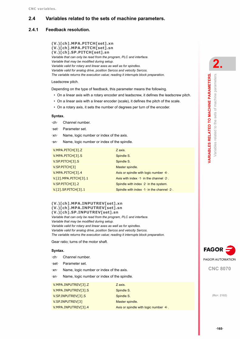
CNC variables.
CNC 8070
VA
RIA
BL
ES
RE
LA
TE
D T
O M
AC
HIN
E P
AR
AM
ET
ER
S.
2.
Var
iabl
es r
ela
ted
to th
e se
ts o
f mac
hin
e pa
ram
eter
s.
ꞏ165ꞏ
(REF: 2102)
2.4 Variables related to the sets of machine parameters.
2.4.1 Feedback resolution.
(V.)[ch].MPA.PITCH[set].xn(V.)[ch].MPA.PITCH[set].sn(V.)[ch].SP.PITCH[set].snVariable that can only be read from the program, PLC and interface.Variable that may be modified during setup.Variable valid for rotary and linear axes as well as for spindles.Variable valid for analog drive, position Sercos and velocity Sercos.The variable returns the execution value; reading it interrupts block preparation.
Leadscrew pitch.
Depending on the type of feedback, this parameter means the following.
• On a linear axis with a rotary encoder and leadscrew, it defines the leadscrew pitch.
• On a linear axis with a linear encoder (scale), it defines the pitch of the scale.
• On a rotary axis, it sets the number of degrees per turn of the encoder.
Syntax.
ꞏchꞏ Channel number.
ꞏsetꞏ Parameter set.
ꞏxnꞏ Name, logic number or index of the axis.
ꞏsnꞏ Name, logic number or index of the spindle.
(V.)[ch].MPA.INPUTREV[set].xn(V.)[ch].MPA.INPUTREV[set].sn(V.)[ch].SP.INPUTREV[set].snVariable that can only be read from the program, PLC and interface.Variable that may be modified during setup.Variable valid for rotary and linear axes as well as for spindles.Variable valid for analog drive, position Sercos and velocity Sercos.The variable returns the execution value; reading it interrupts block preparation.
Gear ratio; turns of the motor shaft.
Syntax.
ꞏchꞏ Channel number.
ꞏsetꞏ Parameter set.
ꞏxnꞏ Name, logic number or index of the axis.
ꞏsnꞏ Name, logic number or index of the spindle.
V.MPA.PITCH[3].Z Z axis.
V.MPA.PITCH[3].S Spindle S.
V.SP.PITCH[3].S Spindle S.
V.SP.PITCH[3] Master spindle.
V.MPA.PITCH[3].4 Axis or spindle with logic number ꞏ4ꞏ.
V.[2].MPA.PITCH[3].1 Axis with index ꞏ1ꞏ in the channel ꞏ2ꞏ.
V.SP.PITCH[3].2 Spindle with index ꞏ2ꞏ in the system.
V.[2].SP.PITCH[3].1 Spindle with index ꞏ1ꞏ in the channel ꞏ2ꞏ.
V.MPA.INPUTREV[3].Z Z axis.
V.MPA.INPUTREV[3].S Spindle S.
V.SP.INPUTREV[3].S Spindle S.
V.SP.INPUTREV[3] Master spindle.
V.MPA.INPUTREV[3].4 Axis or spindle with logic number ꞏ4ꞏ.

CNC variables.
CNC 8070
2.
VA
RIA
BL
ES
RE
LA
TE
D T
O M
AC
HIN
E P
AR
AM
ET
ER
S.
Var
iabl
es r
ela
ted
to th
e se
ts o
f mac
hin
e pa
ram
eter
s.
ꞏ166ꞏ
(REF: 2102)
(V.)[ch].MPA.OUTPUTREV[set].xn(V.)[ch].MPA.OUTPUTREV[set].sn(V.)[ch].SP.OUTPUTREV[set].snVariable that can only be read from the program, PLC and interface.Variable that may be modified during setup.Variable valid for rotary and linear axes as well as for spindles.Variable valid for analog drive, position Sercos and velocity Sercos.The variable returns the execution value; reading it interrupts block preparation.
Gear ratio; turns of the machine shaft.
Syntax.
ꞏchꞏ Channel number.
ꞏsetꞏ Parameter set.
ꞏxnꞏ Name, logic number or index of the axis.
ꞏsnꞏ Name, logic number or index of the spindle.
(V.)[ch].MPA.NPULSES[set].xn(V.)[ch].MPA.NPULSES[set].sn(V.)[ch].SP.NPULSES[set].snVariable that can only be read from the program, PLC and interface.Variable that may be modified during setup.Variable valid for rotary and linear axes as well as for spindles.Variable valid for analog drives and velocity-Sercos drives.The variable returns the execution value; reading it interrupts block preparation.
Number of encoder pulses.
With linear encoders (scales), this parameter will be set to ꞏ0ꞏ. When using a gear reductionon the axis, the whole assembly must be taken into account when defining the number ofpulses per turn.
Syntax.
ꞏchꞏ Channel number.
ꞏsetꞏ Parameter set.
ꞏxnꞏ Name, logic number or index of the axis.
ꞏsnꞏ Name, logic number or index of the spindle.
V.[2].MPA.INPUTREV[3].1 Axis with index ꞏ1ꞏ in the channel ꞏ2ꞏ.
V.SP.INPUTREV[3].2 Spindle with index ꞏ2ꞏ in the system.
V.[2].SP.INPUTREV[3].1 Spindle with index ꞏ1ꞏ in the channel ꞏ2ꞏ.
V.MPA.OUTPUTREV[3].Z Z axis.
V.MPA.OUTPUTREV[3].S Spindle S.
V.SP.OUTPUTREV[3].S Spindle S.
V.SP.OUTPUTREV[3] Master spindle.
V.MPA.OUTPUTREV[3].4 Axis or spindle with logic number ꞏ4ꞏ.
V.[2].MPA.OUTPUTREV[3].1 Axis with index ꞏ1ꞏ in the channel ꞏ2ꞏ.
V.SP.OUTPUTREV[3].2 Spindle with index ꞏ2ꞏ in the system.
V.[2].SP.OUTPUTREV[3].1 Spindle with index ꞏ1ꞏ in the channel ꞏ2ꞏ.
V.MPA.NPULSES[3].Z Z axis.
V.MPA.NPULSES[3].S Spindle S.
V.SP.NPULSES[3].S Spindle S.
V.SP.NPULSES[3] Master spindle.
V.MPA.NPULSES[3].4 Axis or spindle with logic number ꞏ4ꞏ.
V.[2].MPA.NPULSES[3].1 Axis with index ꞏ1ꞏ in the channel ꞏ2ꞏ.
V.SP.NPULSES[3].2 Spindle with index ꞏ2ꞏ in the system.
V.[2].SP.NPULSES[3].1 Spindle with index ꞏ1ꞏ in the channel ꞏ2ꞏ.

CNC variables.
CNC 8070
VA
RIA
BL
ES
RE
LA
TE
D T
O M
AC
HIN
E P
AR
AM
ET
ER
S.
2.
Var
iabl
es r
ela
ted
to th
e se
ts o
f mac
hin
e pa
ram
eter
s.
ꞏ167ꞏ
(REF: 2102)
(V.)[ch].MPA.PITCH2[set].xn(V.)[ch].MPA.PITCH2[set].sn(V.)[ch].SP.PITCH2[set].snVariable that can only be read from the program, PLC and interface.Variable that may be modified during setup.Variable valid for rotary and linear axes as well as for spindles.Variable valid for position-Sercos drives and velocity-Sercos drives.The variable returns the execution value; reading it interrupts block preparation.
Leadscrew pitch (external feedback).
Depending on the type of feedback, this parameter means the following.
• On a linear axis with a rotary encoder and leadscrew, it defines the leadscrew pitch.
• On a linear axis with a linear encoder (scale), it defines the pitch of the scale.
• On a rotary axis, it sets the number of degrees per turn of the encoder.
Syntax.
ꞏchꞏ Channel number.
ꞏsetꞏ Parameter set.
ꞏxnꞏ Name, logic number or index of the axis.
ꞏsnꞏ Name, logic number or index of the spindle.
(V.)[ch].MPA.INPUTREV2[set].xn(V.)[ch].MPA.INPUTREV2[set].sn(V.)[ch].SP.INPUTREV2[set].snVariable that can only be read from the program, PLC and interface.Variable that may be modified during setup.Variable valid for rotary and linear axes as well as for spindles.Variable valid for position-Sercos drives and velocity-Sercos drives.The variable returns the execution value; reading it interrupts block preparation.
Gear ratio; turns of the motor shaft (external feedback).
Syntax.
ꞏchꞏ Channel number.
ꞏsetꞏ Parameter set.
ꞏxnꞏ Name, logic number or index of the axis.
ꞏsnꞏ Name, logic number or index of the spindle.
V.MPA.PITCH2[3].Z Z axis.
V.MPA.PITCH2[3].S Spindle S.
V.SP.PITCH2[3].S Spindle S.
V.SP.PITCH2[3] Master spindle.
V.MPA.PITCH2[3].4 Axis or spindle with logic number ꞏ4ꞏ.
V.[2].MPA.PITCH2[3].1 Axis with index ꞏ1ꞏ in the channel ꞏ2ꞏ.
V.SP.PITCH2[3].2 Spindle with index ꞏ2ꞏ in the system.
V.[2].SP.PITCH2[3].1 Spindle with index ꞏ1ꞏ in the channel ꞏ2ꞏ.
V.MPA.INPUTREV2[3].Z Z axis.
V.MPA.INPUTREV2[3].S Spindle S.
V.SP.INPUTREV2[3].S Spindle S.
V.SP.INPUTREV2[3] Master spindle.
V.MPA.INPUTREV2[3].4 Axis or spindle with logic number ꞏ4ꞏ.
V.[2].MPA.INPUTREV2[3].1 Axis with index ꞏ1ꞏ in the channel ꞏ2ꞏ.
V.SP.INPUTREV2[3].2 Spindle with index ꞏ2ꞏ in the system.
V.[2].SP.INPUTREV2[3].1 Spindle with index ꞏ1ꞏ in the channel ꞏ2ꞏ.

CNC variables.
CNC 8070
2.
VA
RIA
BL
ES
RE
LA
TE
D T
O M
AC
HIN
E P
AR
AM
ET
ER
S.
Var
iabl
es r
ela
ted
to th
e se
ts o
f mac
hin
e pa
ram
eter
s.
ꞏ168ꞏ
(REF: 2102)
(V.)[ch].MPA.OUTPUTREV2[set].xn(V.)[ch].MPA.OUTPUTREV2[set].sn(V.)[ch].SP.OUTPUTREV2[set].snVariable that can only be read from the program, PLC and interface.Variable that may be modified during setup.Variable valid for rotary and linear axes as well as for spindles.Variable valid for position-Sercos drives and velocity-Sercos drives.The variable returns the execution value; reading it interrupts block preparation.
Gear ratio; turns of the machine shaft (external feedback).
Syntax.
ꞏchꞏ Channel number.
ꞏsetꞏ Parameter set.
ꞏxnꞏ Name, logic number or index of the axis.
ꞏsnꞏ Name, logic number or index of the spindle.
(V.)[ch].MPA.NPULSES2[set].xn(V.)[ch].MPA.NPULSES2[set].sn(V.)[ch].SP.NPULSES2[set].snVariable that can only be read from the program, PLC and interface.Variable that may be modified during setup.Variable valid for rotary and linear axes as well as for spindles.Variable valid for position-Sercos drives and velocity-Sercos drives.The variable returns the execution value; reading it interrupts block preparation.
Number of pulses per turn of the encoder (external feedback).
With linear encoders (scales), this parameter will be set to ꞏ0ꞏ. When using a gear reductionon the axis, the whole assembly must be taken into account when defining the number ofpulses per turn.
Syntax.
ꞏchꞏ Channel number.
ꞏsetꞏ Parameter set.
ꞏxnꞏ Name, logic number or index of the axis.
ꞏsnꞏ Name, logic number or index of the spindle.
V.MPA.OUTPUTREV2[3].Z Z axis.
V.MPA.OUTPUTREV2[3].S Spindle S.
V.SP.OUTPUTREV2[3].S Spindle S.
V.SP.OUTPUTREV2[3] Master spindle.
V.MPA.OUTPUTREV2[3].4 Axis or spindle with logic number ꞏ4ꞏ.
V.[2].MPA.OUTPUTREV2[3].1 Axis with index ꞏ1ꞏ in the channel ꞏ2ꞏ.
V.SP.OUTPUTREV2[3].2 Spindle with index ꞏ2ꞏ in the system.
V.[2].SP.OUTPUTREV2[3].1 Spindle with index ꞏ1ꞏ in the channel ꞏ2ꞏ.
V.MPA.NPULSES2[3].Z Z axis.
V.MPA.NPULSES2[3].S Spindle S.
V.SP.NPULSES2[3].S Spindle S.
V.SP.NPULSES2[3] Master spindle.
V.MPA.NPULSES2[3].4 Axis or spindle with logic number ꞏ4ꞏ.
V.[2].MPA.NPULSES2[3].1 Axis with index ꞏ1ꞏ in the channel ꞏ2ꞏ.
V.SP.NPULSES2[3].2 Spindle with index ꞏ2ꞏ in the system.
V.[2].SP.NPULSES2[3].1 Spindle with index ꞏ1ꞏ in the channel ꞏ2ꞏ.

CNC variables.
CNC 8070
VA
RIA
BL
ES
RE
LA
TE
D T
O M
AC
HIN
E P
AR
AM
ET
ER
S.
2.
Var
iabl
es r
ela
ted
to th
e se
ts o
f mac
hin
e pa
ram
eter
s.
ꞏ169ꞏ
(REF: 2102)
(V.)[ch].MPA.SINMAGNI[set].xn(V.)[ch].MPA.SINMAGNI[set].sn(V.)[ch].SP.SINMAGNI[set].snVariable that can only be read from the program, PLC and interface.Variable that may be modified during setup.Variable valid for rotary and linear axes as well as for spindles.Variable valid for analog drive, position Sercos and velocity Sercos.The variable returns the execution value; reading it interrupts block preparation.
Multiplying factor for sinusoidal feedback signal.
For square feedback signals, it will be set to ꞏ0ꞏ; the CNC applies a x4 factor.
Syntax.
ꞏchꞏ Channel number.
ꞏsetꞏ Parameter set.
ꞏxnꞏ Name, logic number or index of the axis.
ꞏsnꞏ Name, logic number or index of the spindle.
(V.)[ch].MPA.ABSFEEDBACK[set].xn(V.)[ch].MPA.ABSFEEDBACK[set].sn(V.)[ch].SP.ABSFEEDBACK[set].snVariable that can only be read from the program, PLC and interface.Variable that may be modified during setup.Variable valid for rotary and linear axes as well as for spindles.Variable valid for analog drive, position Sercos and velocity Sercos.The variable returns the execution value; reading it interrupts block preparation.
Absolute feedback system.
Syntax.
ꞏchꞏ Channel number.
ꞏsetꞏ Parameter set.
ꞏxnꞏ Name, logic number or index of the axis.
ꞏsnꞏ Name, logic number or index of the spindle.
Values of the variable.
V.MPA.SINMAGNI[3].Z Z axis.
V.MPA.SINMAGNI[3].S Spindle S.
V.SP.SINMAGNI[3].S Spindle S.
V.SP.SINMAGNI[3] Master spindle.
V.MPA.SINMAGNI[3].4 Axis or spindle with logic number ꞏ4ꞏ.
V.[2].MPA.SINMAGNI[3].1 Axis with index ꞏ1ꞏ in the channel ꞏ2ꞏ.
V.SP.SINMAGNI[3].2 Spindle with index ꞏ2ꞏ in the system.
V.[2].SP.SINMAGNI[3].1 Spindle with index ꞏ1ꞏ in the channel ꞏ2ꞏ.
V.MPA.ABDFEEDBACK[3].Z Z axis.
V.MPA.ABDFEEDBACK[3].S Spindle S.
V.SP.ABDFEEDBACK[3].S Spindle S.
V.SP.ABDFEEDBACK[3] Master spindle.
V.MPA.ABDFEEDBACK[3].4 Axis or spindle with logic number ꞏ4ꞏ.
V.[2].MPA.ABDFEEDBACK[3].1 Axis with index ꞏ1ꞏ in the channel ꞏ2ꞏ.
V.SP.ABDFEEDBACK[3].2 Spindle with index ꞏ2ꞏ in the system.
V.[2].SP.ABDFEEDBACK[3].1 Spindle with index ꞏ1ꞏ in the channel ꞏ2ꞏ.
Value. Meaning.
0 No.
1 Yes.

CNC variables.
CNC 8070
2.
VA
RIA
BL
ES
RE
LA
TE
D T
O M
AC
HIN
E P
AR
AM
ET
ER
S.
Var
iabl
es r
ela
ted
to th
e se
ts o
f mac
hin
e pa
ram
eter
s.
ꞏ170ꞏ
(REF: 2102)
2.4.2 Feedback alarm.
(V.)[ch].MPA.FBACKAL[set].xn(V.)[ch].MPA.FBACKAL[set].sn(V.)[ch].SP.FBACKAL[set].snVariable that can only be read from the program, PLC and interface.Variable that may be modified during setup.Variable valid for rotary and linear axes as well as for spindles.Variable valid for analog drives.The variable returns the execution value; reading it interrupts block preparation.
Activate feedback alarm.
Syntax.
ꞏchꞏ Channel number.
ꞏsetꞏ Parameter set.
ꞏxnꞏ Name, logic number or index of the axis.
ꞏsnꞏ Name, logic number or index of the spindle.
Values of the variable.
This variable returns one of the following values.
V.MPA.FBACKAL[3].Z Z axis.
V.MPA.FBACKAL[3].S Spindle S.
V.SP.FBACKAL[3].S Spindle S.
V.SP.FBACKAL[3] Master spindle.
V.MPA.FBACKAL[3].4 Axis or spindle with logic number ꞏ4ꞏ.
V.[2].MPA.FBACKAL[3].1 Axis with index ꞏ1ꞏ in the channel ꞏ2ꞏ.
V.SP.FBACKAL[3].2 Spindle with index ꞏ2ꞏ in the system.
V.[2].SP.FBACKAL[3].1 Spindle with index ꞏ1ꞏ in the channel ꞏ2ꞏ.
Value. Meaning.
0 No.
1 Yes.

CNC variables.
CNC 8070
VA
RIA
BL
ES
RE
LA
TE
D T
O M
AC
HIN
E P
AR
AM
ET
ER
S.
2.
Var
iabl
es r
ela
ted
to th
e se
ts o
f mac
hin
e pa
ram
eter
s.
ꞏ171ꞏ
(REF: 2102)
2.4.3 Loop setting.
(V.)[ch].MPA.LOOPCH[set].xn(V.)[ch].MPA.LOOPCH[set].sn(V.)[ch].SP.LOOPCH[set].snVariable that can only be read from the program, PLC and interface.Variable that may be modified during setup.Variable valid for rotary and linear axes as well as for spindles.Variable valid for analog drive, position Sercos and velocity Sercos.The variable returns the execution value; reading it interrupts block preparation.
Velocity command sign change.
Syntax.
ꞏchꞏ Channel number.
ꞏsetꞏ Parameter set.
ꞏxnꞏ Name, logic number or index of the axis.
ꞏsnꞏ Name, logic number or index of the spindle.
Values of the variable.
This variable returns one of the following values.
(V.)[ch].MPA.AXISCH[set].xn(V.)[ch].MPA.AXISCH[set].sn(V.)[ch].SP.AXISCH[set].snVariable that can only be read from the program, PLC and interface.Variable that may be modified during setup.Variable valid for rotary and linear axes as well as for spindles.Variable valid for analog drive, position Sercos and velocity Sercos.The variable returns the execution value; reading it interrupts block preparation.
Feedback sign change.
Syntax.
ꞏchꞏ Channel number.
ꞏsetꞏ Parameter set.
ꞏxnꞏ Name, logic number or index of the axis.
ꞏsnꞏ Name, logic number or index of the spindle.
V.MPA.LOOPCH[3].Z Z axis.
V.MPA.LOOPCH[3].S Spindle S.
V.SP.LOOPCH[3].S Spindle S.
V.SP.LOOPCH[3] Master spindle.
V.MPA.LOOPCH[3].4 Axis or spindle with logic number ꞏ4ꞏ.
V.[2].MPA.LOOPCH[3].1 Axis with index ꞏ1ꞏ in the channel ꞏ2ꞏ.
V.SP.LOOPCH[3].2 Spindle with index ꞏ2ꞏ in the system.
V.[2].SP.LOOPCH[3].1 Spindle with index ꞏ1ꞏ in the channel ꞏ2ꞏ.
Value. Meaning.
0 No.
1 Yes.
V.MPA.AXISCH[3].Z Z axis.
V.MPA.AXISCH[3].S Spindle S.
V.SP.AXISCH[3].S Spindle S.
V.SP.AXISCH[3] Master spindle.
V.MPA.AXISCH[3].4 Axis or spindle with logic number ꞏ4ꞏ.

CNC variables.
CNC 8070
2.
VA
RIA
BL
ES
RE
LA
TE
D T
O M
AC
HIN
E P
AR
AM
ET
ER
S.
Var
iabl
es r
ela
ted
to th
e se
ts o
f mac
hin
e pa
ram
eter
s.
ꞏ172ꞏ
(REF: 2102)
Values of the variable.
This variable returns one of the following values.
(V.)[ch].MPA.INPOSW[set].xn(V.)[ch].MPA.INPOSW[set].sn(V.)[ch].SP.INPOSW[set].snVariable that can only be read from the program, PLC and interface.Variable that may be modified from the environment of the oscilloscope and setup.Variable valid for rotary and linear axes as well as for spindles.Variable valid for analog drive, position Sercos and velocity Sercos.The variable returns the execution value; reading it interrupts block preparation.
In-position zone.
Syntax.
ꞏchꞏ Channel number.
ꞏsetꞏ Parameter set.
ꞏxnꞏ Name, logic number or index of the axis.
ꞏsnꞏ Name, logic number or index of the spindle.
V.[2].MPA.AXISCH[3].1 Axis with index ꞏ1ꞏ in the channel ꞏ2ꞏ.
V.SP.AXISCH[3].2 Spindle with index ꞏ2ꞏ in the system.
V.[2].SP.AXISCH[3].1 Spindle with index ꞏ1ꞏ in the channel ꞏ2ꞏ.
Value. Meaning.
0 No.
1 Yes.
V.MPA.INPOSW[3].Z Z axis.
V.MPA.INPOSW[3].S Spindle S.
V.SP.INPOSW[3].S Spindle S.
V.SP.INPOSW[3] Master spindle.
V.MPA.INPOSW[3].4 Axis or spindle with logic number ꞏ4ꞏ.
V.[2].MPA.INPOSW[3].1 Axis with index ꞏ1ꞏ in the channel ꞏ2ꞏ.
V.SP.INPOSW[3].2 Spindle with index ꞏ2ꞏ in the system.
V.[2].SP.INPOSW[3].1 Spindle with index ꞏ1ꞏ in the channel ꞏ2ꞏ.

CNC variables.
CNC 8070
VA
RIA
BL
ES
RE
LA
TE
D T
O M
AC
HIN
E P
AR
AM
ET
ER
S.
2.
Var
iabl
es r
ela
ted
to th
e se
ts o
f mac
hin
e pa
ram
eter
s.
ꞏ173ꞏ
(REF: 2102)
2.4.4 Backlash compensation.
(V.)[ch].MPA.BACKLASH[set].xn(V.)[ch].MPA.BACKLASH[set].sn(V.)[ch].SP.BACKLASH[set].snVariable that can only be read from the program, PLC and interface.Variable that may be modified from the environment of the oscilloscope and setup.Variable valid for rotary and linear axes as well as for spindles.Variable valid for analog drive, position Sercos and velocity Sercos.The variable returns the execution value; reading it interrupts block preparation.
Amount of backlash to be compensated in movement reversal.
With linear encoders (scales), this parameter will be set to ꞏ0ꞏ.
Syntax.
ꞏchꞏ Channel number.
ꞏsetꞏ Parameter set.
ꞏxnꞏ Name, logic number or index of the axis.
ꞏsnꞏ Name, logic number or index of the spindle.
V.MPA.BACKLASH[3].Z Z axis.
V.MPA.BACKLASH[3].S Spindle S.
V.SP.BACKLASH[3].S Spindle S.
V.SP.BACKLASH[3] Master spindle.
V.MPA.BACKLASH[3].4 Axis or spindle with logic number ꞏ4ꞏ.
V.[2].MPA.BACKLASH[3].1 Axis with index ꞏ1ꞏ in the channel ꞏ2ꞏ.
V.SP.BACKLASH[3].2 Spindle with index ꞏ2ꞏ in the system.
V.[2].SP.BACKLASH[3].1 Spindle with index ꞏ1ꞏ in the channel ꞏ2ꞏ.

CNC variables.
CNC 8070
2.
VA
RIA
BL
ES
RE
LA
TE
D T
O M
AC
HIN
E P
AR
AM
ET
ER
S.
Var
iabl
es r
ela
ted
to th
e se
ts o
f mac
hin
e pa
ram
eter
s.
ꞏ174ꞏ
(REF: 2102)
2.4.5 Backlash compensation with an additional command pulse.
(V.)[ch].MPA.BAKANOUT[set].xn(V.)[ch].MPA.BAKANOUT[set].sn(V.)[ch].SP.BAKANOUT[set].snVariable that can only be read from the program, PLC and interface.Variable that may be modified from the environment of the oscilloscope and setup.Variable valid for rotary and linear axes as well as for spindles.Variable valid for analog drive, position Sercos and velocity Sercos.The variable returns the execution value; reading it interrupts block preparation.
Additional velocity command pulse.
• With digital drives, the additional velocity command is given in rpm.
• With an analog drive, the additional velocity command is given in units of the D/Aconverter with an integer within ± 32767. - 10 V for a value of -32767 and +10V for a valueof 32767.
Syntax.
ꞏchꞏ Channel number.
ꞏsetꞏ Parameter set.
ꞏxnꞏ Name, logic number or index of the axis.
ꞏsnꞏ Name, logic number or index of the spindle.
(V.)[ch].MPA.BAKTIME[set].xn(V.)[ch].MPA.BAKTIME[set].sn(V.)[ch].SP.BAKTIME[set].snVariable that can only be read from the program, PLC and interface.Variable that may be modified from the environment of the oscilloscope and setup.Variable valid for rotary and linear axes as well as for spindles.Variable valid for analog drive, position Sercos and velocity Sercos.The variable returns the execution value; reading it interrupts block preparation.
Duration of the additional velocity command pulse.
Syntax.
ꞏchꞏ Channel number.
ꞏsetꞏ Parameter set.
ꞏxnꞏ Name, logic number or index of the axis.
ꞏsnꞏ Name, logic number or index of the spindle.
V.MPA.BAKANOUT[3].Z Z axis.
V.MPA.BAKANOUT[3].S Spindle S.
V.SP.BAKANOUT[3].S Spindle S.
V.SP.BAKANOUT[3] Master spindle.
V.MPA.BAKANOUT[3].4 Axis or spindle with logic number ꞏ4ꞏ.
V.[2].MPA.BAKANOUT[3].1 Axis with index ꞏ1ꞏ in the channel ꞏ2ꞏ.
V.SP.BAKANOUT[3].2 Spindle with index ꞏ2ꞏ in the system.
V.[2].SP.BAKANOUT[3].1 Spindle with index ꞏ1ꞏ in the channel ꞏ2ꞏ.
V.MPA.BAKTIME[3].Z Z axis.
V.MPA.BAKTIME[3].S Spindle S.
V.SP.BAKTIME[3].S Spindle S.
V.SP.BAKTIME[3] Master spindle.
V.MPA.BAKTIME[3].4 Axis or spindle with logic number ꞏ4ꞏ.
V.[2].MPA.BAKTIME[3].1 Axis with index ꞏ1ꞏ in the channel ꞏ2ꞏ.
V.SP.BAKTIME[3].2 Spindle with index ꞏ2ꞏ in the system.
V.[2].SP.BAKTIME[3].1 Spindle with index ꞏ1ꞏ in the channel ꞏ2ꞏ.

CNC variables.
CNC 8070
VA
RIA
BL
ES
RE
LA
TE
D T
O M
AC
HIN
E P
AR
AM
ET
ER
S.
2.
Var
iabl
es r
ela
ted
to th
e se
ts o
f mac
hin
e pa
ram
eter
s.
ꞏ175ꞏ
(REF: 2102)
(V.)[ch].MPA.ACTBAKAN[set].xn(V.)[ch].MPA.ACTBAKAN[set].sn(V.)[ch].SP.ACTBAKAN[set].snVariable that can only be read from the program, PLC and interface.Variable valid for rotary and linear axes as well as for spindles.Variable valid for analog drive, position Sercos and velocity Sercos.The variable returns the value of block preparation.
Application of the additional velocity command pulse.
Syntax.
ꞏchꞏ Channel number.
ꞏsetꞏ Parameter set.
ꞏxnꞏ Name, logic number or index of the axis.
ꞏsnꞏ Name, logic number or index of the spindle.
Values of the variable.
This variable returns one of the following values.
(V.)[ch].MPA.PEAKDISP[set].xn(V.)[ch].MPA.PEAKDISP[set].sn(V.)[ch].SP.PEAKDISP[set].snVariable that can only be read from the program, PLC and interface.Variable valid for rotary and linear axes as well as for spindles.Variable valid for analog drive, position Sercos and velocity Sercos.The variable returns the value of block preparation.
Backlash peak cuttoff distance.
Syntax.
ꞏchꞏ Channel number.
ꞏsetꞏ Parameter set.
ꞏxnꞏ Name, logic number or index of the axis.
ꞏsnꞏ Name, logic number or index of the spindle.
V.MPA.ACTBAKAN[3].Z Z axis.
V.MPA.ACTBAKAN[3].S Spindle S.
V.SP.ACTBAKAN[3].S Spindle S.
V.SP.ACTBAKAN[3] Master spindle.
V.MPA.ACTBAKAN[3].4 Axis or spindle with logic number ꞏ4ꞏ.
V.[2].MPA.ACTBAKAN[3].1 Axis with index ꞏ1ꞏ in the channel ꞏ2ꞏ.
V.SP.ACTBAKAN[3].2 Spindle with index ꞏ2ꞏ in the system.
V.[2].SP.ACTBAKAN[3].1 Spindle with index ꞏ1ꞏ in the channel ꞏ2ꞏ.
Value. Meaning.
0 In G02 / G03 positioning.
1 Always.
V.MPA.PEAKDISP[3].Z Z axis.
V.MPA.PEAKDISP[3].S Spindle S.
V.SP.PEAKDISP[3].S Spindle S.
V.SP.PEAKDISP[3] Master spindle.
V.MPA.PEAKDISP[3].4 Axis or spindle with logic number ꞏ4ꞏ.
V.[2].MPA.PEAKDISP[3].1 Axis with index ꞏ1ꞏ in the channel ꞏ2ꞏ.
V.SP.PEAKDISP[3].2 Spindle with index ꞏ2ꞏ in the system.
V.[2].SP.PEAKDISP[3].1 Spindle with index ꞏ1ꞏ in the channel ꞏ2ꞏ.

CNC variables.
CNC 8070
2.
VA
RIA
BL
ES
RE
LA
TE
D T
O M
AC
HIN
E P
AR
AM
ET
ER
S.
Var
iabl
es r
ela
ted
to th
e se
ts o
f mac
hin
e pa
ram
eter
s.
ꞏ176ꞏ
(REF: 2102)
(V.)[ch].MPA.REVEHYST[set].xn(V.)[ch].MPA.REVEHYST[set].sn(V.)[ch].SP.REVEHYST[set].snVariable that can only be read from the program, PLC and interface.Variable valid for rotary and linear axes as well as for spindles.Variable valid for analog drive, position Sercos and velocity Sercos.The variable returns the value of block preparation.
Hysteresis for applying the additional command pulse in movement reversals.
Syntax.
ꞏchꞏ Channel number.
ꞏsetꞏ Parameter set.
ꞏxnꞏ Name, logic number or index of the axis.
ꞏsnꞏ Name, logic number or index of the spindle.
V.MPA.REVEHYST[3].Z Z axis.
V.MPA.REVEHYST[3].S Spindle S.
V.SP.REVEHYST[3].S Spindle S.
V.SP.REVEHYST[3] Master spindle.
V.MPA.REVEHYST[3].4 Axis or spindle with logic number ꞏ4ꞏ.
V.[2].MPA.REVEHYST[3].1 Axis with index ꞏ1ꞏ in the channel ꞏ2ꞏ.
V.SP.REVEHYST[3].2 Spindle with index ꞏ2ꞏ in the system.
V.[2].SP.REVEHYST[3].1 Spindle with index ꞏ1ꞏ in the channel ꞏ2ꞏ.

CNC variables.
CNC 8070
VA
RIA
BL
ES
RE
LA
TE
D T
O M
AC
HIN
E P
AR
AM
ET
ER
S.
2.
Var
iabl
es r
ela
ted
to th
e se
ts o
f mac
hin
e pa
ram
eter
s.
ꞏ177ꞏ
(REF: 2102)
2.4.6 Adjustment of rapid traverse G00 and maximum speed.
(V.)[ch].MPA.G00FEED[set].xn(V.)[ch].MPA.G00FEED[set].sn(V.)[ch].SP.G00FEED[set].snVariable that can only be read from the program, PLC and interface.Variable that may be modified from the environment of the oscilloscope and setup.Variable valid for rotary and linear axes as well as for spindles.Variable valid for analog drive, position Sercos and velocity Sercos.The variable returns the execution value; reading it interrupts block preparation.
Feedrate in G00.
Syntax.
ꞏchꞏ Channel number.
ꞏsetꞏ Parameter set.
ꞏxnꞏ Name, logic number or index of the axis.
ꞏsnꞏ Name, logic number or index of the spindle.
(V.)[ch].MPA.MAXFEED[set].xn(V.)[ch].MPA.MAXFEED[set].sn(V.)[ch].SP.MAXFEED[set].snVariable that can only be read from the program, PLC and interface.Variable valid for rotary and linear axes as well as for spindles.Variable valid for analog drive, position Sercos and velocity Sercos.The variable returns the value of block preparation.
Channel [ch]. Maximum axis machining feedrate.
If the variable returns a ꞏ0ꞏ value, the machining feedrate is not limited, the CNC assumesfor all the movements the one set in machine parameter G00FEED as the maximumfeedrate.
Syntax.
ꞏchꞏ Channel number.
ꞏsetꞏ Parameter set.
ꞏxnꞏ Name, logic number or index of the axis.
ꞏsnꞏ Name, logic number or index of the spindle.
V.MPA.G00FEED[3].Z Z axis.
V.MPA.G00FEED[3].S Spindle S.
V.SP.G00FEED[3].S Spindle S.
V.SP.G00FEED[3] Master spindle.
V.MPA.G00FEED[3].4 Axis or spindle with logic number ꞏ4ꞏ.
V.[2].MPA.G00FEED[3].1 Axis with index ꞏ1ꞏ in the channel ꞏ2ꞏ.
V.SP.G00FEED[3].2 Spindle with index ꞏ2ꞏ in the system.
V.[2].SP.G00FEED[3].1 Spindle with index ꞏ1ꞏ in the channel ꞏ2ꞏ.
V.MPA.MAXFEED[3].Z Z axis.
V.MPA.MAXFEED[3].S Spindle S.
V.SP.MAXFEED[3].S Spindle S.
V.SP.MAXFEED[3] Master spindle.
V.MPA.MAXFEED[3].4 Axis or spindle with logic number ꞏ4ꞏ.
V.[2].MPA.MAXFEED[3].1 Axis with index ꞏ1ꞏ in the channel ꞏ2ꞏ.
V.SP.MAXFEED[3].2 Spindle with index ꞏ2ꞏ in the system.
V.[2].SP.MAXFEED[3].1 Spindle with index ꞏ1ꞏ in the channel ꞏ2ꞏ.

CNC variables.
CNC 8070
2.
VA
RIA
BL
ES
RE
LA
TE
D T
O M
AC
HIN
E P
AR
AM
ET
ER
S.
Var
iabl
es r
ela
ted
to th
e se
ts o
f mac
hin
e pa
ram
eter
s.
ꞏ178ꞏ
(REF: 2102)
(V.)[ch].MPA.MAXVOLT[set].xn(V.)[ch].MPA.MAXVOLT[set].sn(V.)[ch].SP.MAXVOLT[set].snVariable that can only be read from the program, PLC and interface.Variable that may be modified from the environment of the oscilloscope and setup.Variable valid for rotary and linear axes as well as for spindles.Variable valid for analog drives and velocity-Sercos drives.The variable returns the execution value; reading it interrupts block preparation.
Velocity command to reach G00FEED
Syntax.
ꞏchꞏ Channel number.
ꞏsetꞏ Parameter set.
ꞏxnꞏ Name, logic number or index of the axis.
ꞏsnꞏ Name, logic number or index of the spindle.
(V.)[ch].MPA.MAXFREQ[set].sn(V.)[ch].SP.MAXFREQ[set].snVariable that can only be read from the program, PLC and interface.Variable that may be modified from the environment of the oscilloscope and setup.Variable valid for spindles.Variable valid for Mechatrolink drive.The variable returns the execution value; reading it interrupts block preparation.
This is the frequency the CNC must provide for the spindle to reach the maximum speedset by parameter G00FEED.
Syntax.
ꞏchꞏ Channel number.
ꞏsetꞏ Parameter set.
ꞏsnꞏ Name, logic number or index of the spindle.
(V.)[ch].MPA.MAXRPM[set].xn(V.)[ch].MPA.MAXRPM[set].sn(V.)[ch].SP.MAXRPM[set].snVariable that can only be read from the program, PLC and interface.Variable valid for rotary and linear axes as well as for spindles.Variable valid for Mechatrolink drive.The variable returns the execution value; reading it interrupts block preparation.
Maximum motor rpm.
Syntax.
ꞏchꞏ Channel number.
V.MPA.MAXVOLT[3].Z Z axis.
V.MPA.MAXVOLT[3].S Spindle S.
V.SP.MAXVOLT[3].S Spindle S.
V.SP.MAXVOLT[3] Master spindle.
V.MPA.MAXVOLT[3].4 Axis or spindle with logic number ꞏ4ꞏ.
V.[2].MPA.MAXVOLT[3].1 Axis with index ꞏ1ꞏ in the channel ꞏ2ꞏ.
V.SP.MAXVOLT[3].2 Spindle with index ꞏ2ꞏ in the system.
V.[2].SP.MAXVOLT[3].1 Spindle with index ꞏ1ꞏ in the channel ꞏ2ꞏ.
V.MPA.MAXFREQ[3].S Spindle S.
V.SP.MAXFREQ[3].S Spindle S.
V.SP.MAXFREQ[3] Master spindle.
V.MPA.MAXFREQ[3].4 Spindle with logic number ꞏ4ꞏ.
V.SP.MAXFREQ[3].2 Spindle with index ꞏ2ꞏ in the system.
V.[2].SP.MAXFREQ[3].1 Spindle with index ꞏ1ꞏ in the channel ꞏ2ꞏ.

CNC variables.
CNC 8070
VA
RIA
BL
ES
RE
LA
TE
D T
O M
AC
HIN
E P
AR
AM
ET
ER
S.
2.
Var
iabl
es r
ela
ted
to th
e se
ts o
f mac
hin
e pa
ram
eter
s.
ꞏ179ꞏ
(REF: 2102)
ꞏsetꞏ Parameter set.
ꞏxnꞏ Name, logic number or index of the axis.
ꞏsnꞏ Name, logic number or index of the spindle.
V.MPA.MAXRPM[3].Z Z axis.
V.MPA.MAXRPM[3].S Spindle S.
V.SP.MAXRPM[3].S Spindle S.
V.SP.MAXRPM[3] Master spindle.
V.MPA.MAXRPM[3].4 Axis or spindle with logic number ꞏ4ꞏ.
V.[2].MPA.MAXRPM[3].1 Axis with index ꞏ1ꞏ in the channel ꞏ2ꞏ.
V.SP.MAXRPM[3].2 Spindle with index ꞏ2ꞏ in the system.
V.[2].SP.MAXRPM[3].1 Spindle with index ꞏ1ꞏ in the channel ꞏ2ꞏ.

CNC variables.
CNC 8070
2.
VA
RIA
BL
ES
RE
LA
TE
D T
O M
AC
HIN
E P
AR
AM
ET
ER
S.
Var
iabl
es r
ela
ted
to th
e se
ts o
f mac
hin
e pa
ram
eter
s.
ꞏ180ꞏ
(REF: 2102)
2.4.7 Rapid traverse for the automatic mode.
(V.)[ch].MPA.FRAPIDEN[set].xn(V.)[ch].MPA.FRAPIDEN[set].sn(V.)[ch].SP.FRAPIDEN[set].snVariable that can only be read from the program, PLC and interface.Variable valid for rotary and linear axes as well as for spindles.Variable valid for analog drive, position Sercos and velocity Sercos.The variable returns the value of block preparation.
Rapid traverse of the axis when the rapid traverse for the automatic mode is active(parameter RAPIDEN). If the parameter is set with a "0" value, the feedrate is not limited.
This parameter does not the movements programmed in G00 or the threads. Movementsin G0 are carried out at the feedrate set in parameter G00FEED. The threads are executedat the programmed feedrate.
Syntax.
ꞏchꞏ Channel number.
ꞏsetꞏ Parameter set.
ꞏxnꞏ Name, logic number or index of the axis.
ꞏsnꞏ Name, logic number or index of the spindle.
Remarks.
The rapid traverse cannot exceed the value set in axis parameters G00FEED or FRAPIDENof the channel or the maximum feedrate set by PLC (variable (V.)PLC.G00FEED). Rapidtraverse cannot exceed the value set in axis parameter MAXFEED of the channel and theactive feedrate set by PLC (variable (V.)PLC.F).
V.MPA.FRAPIDEN[3].Z Z axis.
V.MPA.FRAPIDEN[3].S Spindle S.
V.SP.FRAPIDEN[3].S Spindle S.
V.SP.FRAPIDEN[3] Master spindle.
V.MPA.FRAPIDEN[3].4 Axis or spindle with logic number ꞏ4ꞏ.
V.[2].MPA.FRAPIDEN[3].1 Axis with index ꞏ1ꞏ in the channel ꞏ2ꞏ.
V.SP.FRAPIDEN[3].2 Spindle with index ꞏ2ꞏ in the system.
V.[2].SP.FRAPIDEN[3].1 Spindle with index ꞏ1ꞏ in the channel ꞏ2ꞏ.
Variable. Machine parameters. Rapid feed.
(V.)PLC.G00FEED G00FEED (axis) FRAPIDEN (axis) G00 G01, G02, ꞏꞏꞏ
0 10000 0 10000 10000
0 10000 6000 10000 6000
4000 10000 6000 4000 4000
7000 10000 6000 7000 6000
12000 10000 6000 10000 6000

CNC variables.
CNC 8070
VA
RIA
BL
ES
RE
LA
TE
D T
O M
AC
HIN
E P
AR
AM
ET
ER
S.
2.
Var
iabl
es r
ela
ted
to th
e se
ts o
f mac
hin
e pa
ram
eter
s.
ꞏ181ꞏ
(REF: 2102)
2.4.8 Gain setting.
(V.)[ch].MPA.PROGAIN[set].xn(V.)[ch].MPA.PROGAIN[set].sn(V.)[ch].SP.PROGAIN[set].snVariable that can only be read from the program, PLC and interface.Variable that may be modified from the environment of the oscilloscope and setup.Variable valid for rotary and linear axes as well as for spindles.Variable valid for analog drive, position Sercos and velocity Sercos.The variable returns the execution value; reading it interrupts block preparation.
Proportional gain. It sets the following error (difference between the theoreticalinstantaneous position and the actual - real - axis position) for a particular feedrate.
Syntax.
ꞏchꞏ Channel number.
ꞏsetꞏ Parameter set.
ꞏxnꞏ Name, logic number or index of the axis.
ꞏsnꞏ Name, logic number or index of the spindle.
Remarks.
The reading from the PLC will be given in thousandths (x1000); i.e. if the parameter valueis ꞏ10ꞏ, the PLC reading will return a value of ꞏ10000ꞏ.
(V.)[ch].MPA.FFWTYPE[set].xn(V.)[ch].MPA.FFWTYPE[set].sn(V.)[ch].SP.FFWTYPE[set].snVariable that can only be read from the program, PLC and interface.Variable that may be modified during setup.Variable valid for rotary and linear axes as well as for spindles.Variable valid for analog drive, position Sercos and velocity Sercos.The variable returns the execution value; reading it interrupts block preparation.
Pre-control type
Syntax.
ꞏchꞏ Channel number.
ꞏsetꞏ Parameter set.
ꞏxnꞏ Name, logic number or index of the axis.
ꞏsnꞏ Name, logic number or index of the spindle.
V.MPA.PROGAIN[3].Z Z axis.
V.MPA.PROGAIN[3].S Spindle S.
V.SP.PROGAIN[3].S Spindle S.
V.SP.PROGAIN[3] Master spindle.
V.MPA.PROGAIN[3].4 Axis or spindle with logic number ꞏ4ꞏ.
V.[2].MPA.PROGAIN[3].1 Axis with index ꞏ1ꞏ in the channel ꞏ2ꞏ.
V.SP.PROGAIN[3].2 Spindle with index ꞏ2ꞏ in the system.
V.[2].SP.PROGAIN[3].1 Spindle with index ꞏ1ꞏ in the channel ꞏ2ꞏ.
V.MPA.FFWTYPE[3].Z Z axis.
V.MPA.FFWTYPE[3].S Spindle S.
V.SP.FFWTYPE[3].S Spindle S.
V.SP.FFWTYPE[3] Master spindle.
V.MPA.FFWTYPE[3].4 Axis or spindle with logic number ꞏ4ꞏ.
V.[2].MPA.FFWTYPE[3].1 Axis with index ꞏ1ꞏ in the channel ꞏ2ꞏ.
V.SP.FFWTYPE[3].2 Spindle with index ꞏ2ꞏ in the system.
V.[2].SP.FFWTYPE[3].1 Spindle with index ꞏ1ꞏ in the channel ꞏ2ꞏ.

CNC variables.
CNC 8070
2.
VA
RIA
BL
ES
RE
LA
TE
D T
O M
AC
HIN
E P
AR
AM
ET
ER
S.
Var
iabl
es r
ela
ted
to th
e se
ts o
f mac
hin
e pa
ram
eter
s.
ꞏ182ꞏ
(REF: 2102)
Values of the variable.
This variable returns one of the following values.
(V.)[ch].MPA.FFGAIN[set].xn(V.)[ch].MPA.FFGAIN[set].sn(V.)[ch].SP.FFGAIN[set].snVariable that can only be read from the program, PLC and interface.Variable that may be modified from the environment of the oscilloscope and setup.Variable valid for rotary and linear axes as well as for spindles.Variable valid for analog drive, position Sercos and velocity Sercos.The variable returns the execution value; reading it interrupts block preparation.
Percentage of Feed-Forward in automatic.
It sets the part of the velocity commmand that is proportional to the programmed feedrate.The rest will be proportional to the following error.
Syntax.
ꞏchꞏ Channel number.
ꞏsetꞏ Parameter set.
ꞏxnꞏ Name, logic number or index of the axis.
ꞏsnꞏ Name, logic number or index of the spindle.
Remarks.
The reading from the PLC will be given in hundredths (x100); i.e. if the parameter value isꞏ10ꞏ, the PLC reading will return a value of ꞏ1000ꞏ.
Although the parameter may be set with up to 4 decimals, only 2 decimals will be used whenreading the variable.
(V.)[ch].MPA.MANFFGAIN[set].xn(V.)[ch].MPA.MANFFGAIN[set].sn(V.)[ch].SP.MANFFGAIN[set].snVariable that can only be read from the program, PLC and interface.Variable that may be modified from the environment of the oscilloscope and setup.Variable valid for rotary and linear axes as well as for spindles.Variable valid for analog drive, position Sercos and velocity Sercos.The variable returns the execution value; reading it interrupts block preparation.
Percentage of Feed-Forward in JOG
Syntax.
ꞏchꞏ Channel number.
ꞏsetꞏ Parameter set.
Value. Meaning.
0 Without pre-control.
1 Feed forward.
2 AC-forward
3 Feed-Forward and AC-Forward.
V.MPA.FFGAIN[3].Z Z axis.
V.MPA.FFGAIN[3].S Spindle S.
V.SP.FFGAIN[3].S Spindle S.
V.SP.FFGAIN[3] Master spindle.
V.MPA.FFGAIN[3].4 Axis or spindle with logic number ꞏ4ꞏ.
V.[2].MPA.FFGAIN[3].1 Axis with index ꞏ1ꞏ in the channel ꞏ2ꞏ.
V.SP.FFGAIN[3].2 Spindle with index ꞏ2ꞏ in the system.
V.[2].SP.FFGAIN[3].1 Spindle with index ꞏ1ꞏ in the channel ꞏ2ꞏ.

CNC variables.
CNC 8070
VA
RIA
BL
ES
RE
LA
TE
D T
O M
AC
HIN
E P
AR
AM
ET
ER
S.
2.
Var
iabl
es r
ela
ted
to th
e se
ts o
f mac
hin
e pa
ram
eter
s.
ꞏ183ꞏ
(REF: 2102)
ꞏxnꞏ Name, logic number or index of the axis.
ꞏsnꞏ Name, logic number or index of the spindle.
Remarks.
The reading from the PLC will be given in hundredths (x100); i.e. if the parameter value isꞏ10ꞏ, the PLC reading will return a value of ꞏ1000ꞏ.
Although the parameter may be set with up to 4 decimals, only 2 decimals will be used whenreading the variable.
(V.)[ch].MPA.ACFWFACTOR[set].xn(V.)[ch].MPA.ACFWFACTOR[set].sn(V.)[ch].SP.ACFWFACTOR[set].snVariable that can only be read from the program, PLC and interface.Variable that may be modified from the environment of the oscilloscope and setup.Variable valid for rotary and linear axes as well as for spindles.Variable valid for analog drives and velocity-Sercos drives.The variable returns the execution value; reading it interrupts block preparation.
Acceleration time constant.
Syntax.
ꞏchꞏ Channel number.
ꞏsetꞏ Parameter set.
ꞏxnꞏ Name, logic number or index of the axis.
ꞏsnꞏ Name, logic number or index of the spindle.
(V.)[ch].MPA.ACFGAIN[set].xn(V.)[ch].MPA.ACFGAIN[set].sn(V.)[ch].SP.ACFGAIN[set].snVariable that can only be read from the program, PLC and interface.Variable that may be modified from the environment of the oscilloscope and setup.Variable valid for rotary and linear axes as well as for spindles.Variable valid for analog drive, position Sercos and velocity Sercos.The variable returns the execution value; reading it interrupts block preparation.
Percentage of Feed-Forward in automatic.
Syntax.
ꞏchꞏ Channel number.
ꞏsetꞏ Parameter set.
V.MPA.MANFFGAIN[3].Z Z axis.
V.MPA.MANFFGAIN[3].S Spindle S.
V.SP.MANFFGAIN[3].S Spindle S.
V.SP.MANFFGAIN[3] Master spindle.
V.MPA.MANFFGAIN[3].4 Axis or spindle with logic number ꞏ4ꞏ.
V.[2].MPA.MANFFGAIN[3].1 Axis with index ꞏ1ꞏ in the channel ꞏ2ꞏ.
V.SP.MANFFGAIN[3].2 Spindle with index ꞏ2ꞏ in the system.
V.[2].SP.MANFFGAIN[3].1 Spindle with index ꞏ1ꞏ in the channel ꞏ2ꞏ.
V.MPA.ACFWFACTOR[3].Z Z axis.
V.MPA.ACFWFACTOR[3].S Spindle S.
V.SP.ACFWFACTOR[3].S Spindle S.
V.SP.ACFWFACTOR[3] Master spindle.
V.MPA.ACFWFACTOR[3].4 Axis or spindle with logic number ꞏ4ꞏ.
V.[2].MPA.ACFWFACTOR[3].1 Axis with index ꞏ1ꞏ in the channel ꞏ2ꞏ.
V.SP.ACFWFACTOR[3].2 Spindle with index ꞏ2ꞏ in the system.
V.[2].SP.ACFWFACTOR[3].1 Spindle with index ꞏ1ꞏ in the channel ꞏ2ꞏ.

CNC variables.
CNC 8070
2.
VA
RIA
BL
ES
RE
LA
TE
D T
O M
AC
HIN
E P
AR
AM
ET
ER
S.
Var
iabl
es r
ela
ted
to th
e se
ts o
f mac
hin
e pa
ram
eter
s.
ꞏ184ꞏ
(REF: 2102)
ꞏxnꞏ Name, logic number or index of the axis.
ꞏsnꞏ Name, logic number or index of the spindle.
Remarks.
The reading from the PLC will be given in tenths (x10); i.e. if the parameter value is ꞏ10ꞏ,the PLC reading will return a value of ꞏ100ꞏ.
Although the parameter may be set with up to 4 decimals, only the first decimal will be usedwhen reading the variable.
(V.)[ch].MPA.MANACFGAIN[set].xn(V.)[ch].MPA.MANACFGAIN[set].sn(V.)[ch].SP.MANACFGAIN[set].snVariable that can only be read from the program, PLC and interface.Variable that may be modified from the environment of the oscilloscope and setup.Variable valid for rotary and linear axes as well as for spindles.Variable valid for analog drive, position Sercos and velocity Sercos.The variable returns the execution value; reading it interrupts block preparation.
Percentage of Feed-Forward in jog mode.
Syntax.
ꞏchꞏ Channel number.
ꞏsetꞏ Parameter set.
ꞏxnꞏ Name, logic number or index of the axis.
ꞏsnꞏ Name, logic number or index of the spindle.
Remarks.
The reading from the PLC will be given in tenths (x10); i.e. if the parameter value is ꞏ10ꞏ,the PLC reading will return a value of ꞏ100ꞏ.
Although the parameter may be set with up to 4 decimals, only the first decimal will be usedwhen reading the variable.
V.MPA.ACFGAIN[3].Z Z axis.
V.MPA.ACFGAIN[3].S Spindle S.
V.SP.ACFGAIN[3].S Spindle S.
V.SP.ACFGAIN[3] Master spindle.
V.MPA.ACFGAIN[3].4 Axis or spindle with logic number ꞏ4ꞏ.
V.[2].MPA.ACFGAIN[3].1 Axis with index ꞏ1ꞏ in the channel ꞏ2ꞏ.
V.SP.ACFGAIN[3].2 Spindle with index ꞏ2ꞏ in the system.
V.[2].SP.ACFGAIN[3].1 Spindle with index ꞏ1ꞏ in the channel ꞏ2ꞏ.
V.MPA.MANACFGAIN[3].Z Z axis.
V.MPA.MANACFGAIN[3].S Spindle S.
V.SP.MANACFGAIN[3].S Spindle S.
V.SP.MANACFGAIN[3] Master spindle.
V.MPA.MANACFGAIN[3].4 Axis or spindle with logic number ꞏ4ꞏ.
V.[2].MPA.MANACFGAIN[3].1 Axis with index ꞏ1ꞏ in the channel ꞏ2ꞏ.
V.SP.MANACFGAIN[3].2 Spindle with index ꞏ2ꞏ in the system.
V.[2].SP.MANACFGAIN[3].1 Spindle with index ꞏ1ꞏ in the channel ꞏ2ꞏ.

CNC variables.
CNC 8070
VA
RIA
BL
ES
RE
LA
TE
D T
O M
AC
HIN
E P
AR
AM
ET
ER
S.
2.
Var
iabl
es r
ela
ted
to th
e se
ts o
f mac
hin
e pa
ram
eter
s.
ꞏ185ꞏ
(REF: 2102)
2.4.9 Linear acceleration.
(V.)[ch].MPA.LACC1[set].xn(V.)[ch].MPA.LACC1[set].sn(V.)[ch].SP.LACC1[set].snVariable that can only be read from the program, PLC and interface.Variable that may be modified from the environment of the oscilloscope and setup.Variable valid for rotary and linear axes as well as for spindles.Variable valid for analog drive, position Sercos and velocity Sercos.The variable returns the execution value; reading it interrupts block preparation.
Acceleration of the first section.
Syntax.
ꞏchꞏ Channel number.
ꞏsetꞏ Parameter set.
ꞏxnꞏ Name, logic number or index of the axis.
ꞏsnꞏ Name, logic number or index of the spindle.
(V.)[ch].MPA.LACC2[set].xn(V.)[ch].MPA.LACC2[set].sn(V.)[ch].SP.LACC2[set].snVariable that can only be read from the program, PLC and interface.Variable that may be modified from the environment of the oscilloscope and setup.Variable valid for rotary and linear axes as well as for spindles.Variable valid for analog drive, position Sercos and velocity Sercos.The variable returns the execution value; reading it interrupts block preparation.
Acceleration of the second section.
Syntax.
ꞏchꞏ Channel number.
ꞏsetꞏ Parameter set.
ꞏxnꞏ Name, logic number or index of the axis.
ꞏsnꞏ Name, logic number or index of the spindle.
V.MPA.LACC1[3].Z Z axis.
V.MPA.LACC1[3].S Spindle S.
V.SP.LACC1[3].S Spindle S.
V.SP.LACC1[3] Master spindle.
V.MPA.LACC1[3].4 Axis or spindle with logic number ꞏ4ꞏ.
V.[2].MPA.LACC1[3].1 Axis with index ꞏ1ꞏ in the channel ꞏ2ꞏ.
V.SP.LACC1[3].2 Spindle with index ꞏ2ꞏ in the system.
V.[2].SP.LACC1[3].1 Spindle with index ꞏ1ꞏ in the channel ꞏ2ꞏ.
V.MPA.LACC2[3].Z Z axis.
V.MPA.LACC2[3].S Spindle S.
V.SP.LACC2[3].S Spindle S.
V.SP.LACC2[3] Master spindle.
V.MPA.LACC2[3].4 Axis or spindle with logic number ꞏ4ꞏ.
V.[2].MPA.LACC2[3].1 Axis with index ꞏ1ꞏ in the channel ꞏ2ꞏ.
V.SP.LACC2[3].2 Spindle with index ꞏ2ꞏ in the system.
V.[2].SP.LACC2[3].1 Spindle with index ꞏ1ꞏ in the channel ꞏ2ꞏ.

CNC variables.
CNC 8070
2.
VA
RIA
BL
ES
RE
LA
TE
D T
O M
AC
HIN
E P
AR
AM
ET
ER
S.
Var
iabl
es r
ela
ted
to th
e se
ts o
f mac
hin
e pa
ram
eter
s.
ꞏ186ꞏ
(REF: 2102)
(V.)[ch].MPA.LFEED[set].xn(V.)[ch].SP.LFEED[set].sn(V.)[ch].SP.LFEED[set].snVariable that can only be read from the program, PLC and interface.Variable that may be modified from the environment of the oscilloscope and setup.Variable valid for rotary and linear axes as well as for spindles.Variable valid for analog drive, position Sercos and velocity Sercos.The variable returns the execution value; reading it interrupts block preparation.
Change speed.
Syntax.
ꞏchꞏ Channel number.
ꞏsetꞏ Parameter set.
ꞏxnꞏ Name, logic number or index of the axis.
ꞏsnꞏ Name, logic number or index of the spindle.
V.MPA.LFEED[3].Z Z axis.
V.MPA.LFEED[3].S Spindle S.
V.SP.LFEED[3].S Spindle S.
V.SP.LFEED[3] Master spindle.
V.MPA.LFEED[3].4 Axis or spindle with logic number ꞏ4ꞏ.
V.[2].MPA.LFEED[3].1 Axis with index ꞏ1ꞏ in the channel ꞏ2ꞏ.
V.SP.LFEED[3].2 Spindle with index ꞏ2ꞏ in the system.
V.[2].SP.LFEED[3].1 Spindle with index ꞏ1ꞏ in the channel ꞏ2ꞏ.

CNC variables.
CNC 8070
VA
RIA
BL
ES
RE
LA
TE
D T
O M
AC
HIN
E P
AR
AM
ET
ER
S.
2.
Var
iabl
es r
ela
ted
to th
e se
ts o
f mac
hin
e pa
ram
eter
s.
ꞏ187ꞏ
(REF: 2102)
2.4.10 Trapezoidal and square sine acceleration.
(V.)[ch].MPA.ACCEL[set].xn(V.)[ch].MPA.ACCEL[set].sn(V.)[ch].SP.ACCEL[set].snVariable that can only be read from the program, PLC and interface.Variable that may be modified from the environment of the oscilloscope and setup.Variable valid for rotary and linear axes as well as for spindles.Variable valid for analog drive, position Sercos and velocity Sercos.The variable returns the execution value; reading it interrupts block preparation.
Acceleration.
Syntax.
ꞏchꞏ Channel number.
ꞏsetꞏ Parameter set.
ꞏxnꞏ Name, logic number or index of the axis.
ꞏsnꞏ Name, logic number or index of the spindle.
(V.)[ch].MPA.DECEL[set].xn(V.)[ch].MPA.DECEL[set].sn(V.)[ch].SP.DECEL[set].snVariable that can only be read from the program, PLC and interface.Variable that may be modified from the environment of the oscilloscope and setup.Variable valid for rotary and linear axes as well as for spindles.Variable valid for analog drive, position Sercos and velocity Sercos.The variable returns the execution value; reading it interrupts block preparation.
Deceleration.
Syntax.
ꞏchꞏ Channel number.
ꞏsetꞏ Parameter set.
ꞏxnꞏ Name, logic number or index of the axis.
ꞏsnꞏ Name, logic number or index of the spindle.
V.MPA.ACCEL[3].Z Z axis.
V.MPA.ACCEL[3].S Spindle S.
V.SP.ACCEL[3].S Spindle S.
V.SP.ACCEL[3] Master spindle.
V.MPA.ACCEL[3].4 Axis or spindle with logic number ꞏ4ꞏ.
V.[2].MPA.ACCEL[3].1 Axis with index ꞏ1ꞏ in the channel ꞏ2ꞏ.
V.SP.ACCEL[3].2 Spindle with index ꞏ2ꞏ in the system.
V.[2].SP.ACCEL[3].1 Spindle with index ꞏ1ꞏ in the channel ꞏ2ꞏ.
V.MPA.DECEL[3].Z Z axis.
V.MPA.DECEL[3].S Spindle S.
V.SP.DECEL[3].S Spindle S.
V.SP.DECEL[3] Master spindle.
V.MPA.DECEL[3].4 Axis or spindle with logic number ꞏ4ꞏ.
V.[2].MPA.DECEL[3].1 Axis with index ꞏ1ꞏ in the channel ꞏ2ꞏ.
V.SP.DECEL[3].2 Spindle with index ꞏ2ꞏ in the system.
V.[2].SP.DECEL[3].1 Spindle with index ꞏ1ꞏ in the channel ꞏ2ꞏ.
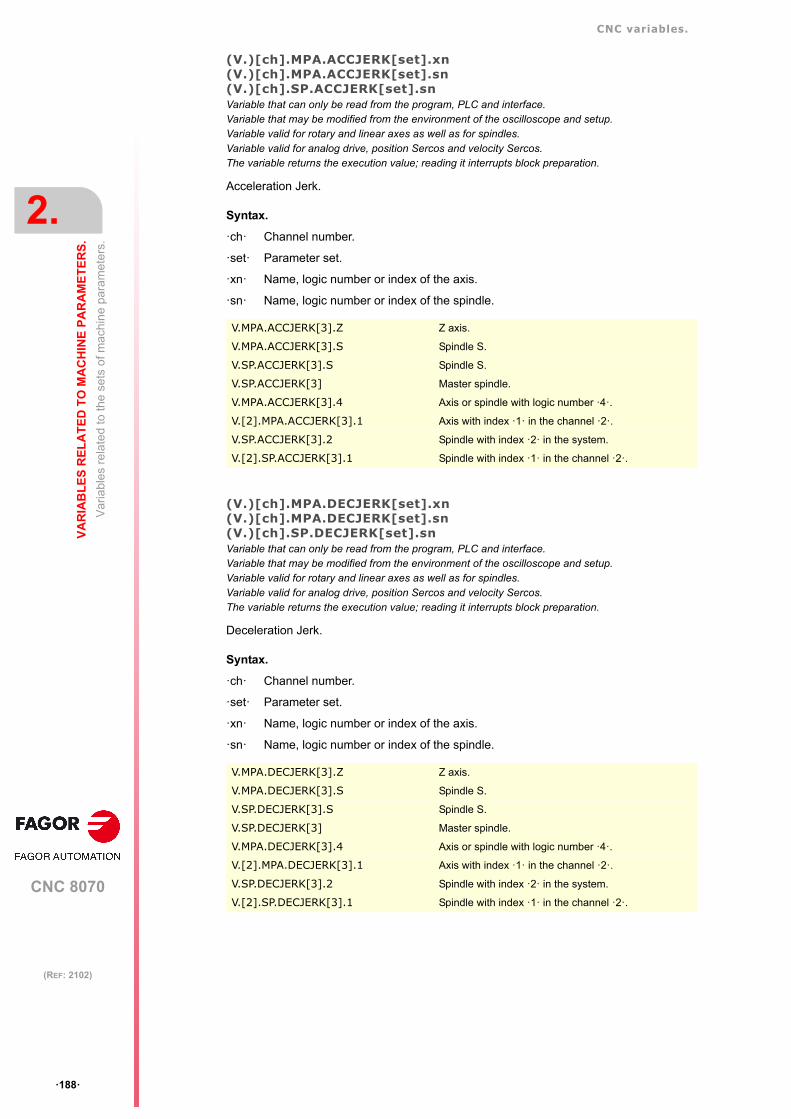
CNC variables.
CNC 8070
2.
VA
RIA
BL
ES
RE
LA
TE
D T
O M
AC
HIN
E P
AR
AM
ET
ER
S.
Var
iabl
es r
ela
ted
to th
e se
ts o
f mac
hin
e pa
ram
eter
s.
ꞏ188ꞏ
(REF: 2102)
(V.)[ch].MPA.ACCJERK[set].xn(V.)[ch].MPA.ACCJERK[set].sn(V.)[ch].SP.ACCJERK[set].snVariable that can only be read from the program, PLC and interface.Variable that may be modified from the environment of the oscilloscope and setup.Variable valid for rotary and linear axes as well as for spindles.Variable valid for analog drive, position Sercos and velocity Sercos.The variable returns the execution value; reading it interrupts block preparation.
Acceleration Jerk.
Syntax.
ꞏchꞏ Channel number.
ꞏsetꞏ Parameter set.
ꞏxnꞏ Name, logic number or index of the axis.
ꞏsnꞏ Name, logic number or index of the spindle.
(V.)[ch].MPA.DECJERK[set].xn(V.)[ch].MPA.DECJERK[set].sn(V.)[ch].SP.DECJERK[set].snVariable that can only be read from the program, PLC and interface.Variable that may be modified from the environment of the oscilloscope and setup.Variable valid for rotary and linear axes as well as for spindles.Variable valid for analog drive, position Sercos and velocity Sercos.The variable returns the execution value; reading it interrupts block preparation.
Deceleration Jerk.
Syntax.
ꞏchꞏ Channel number.
ꞏsetꞏ Parameter set.
ꞏxnꞏ Name, logic number or index of the axis.
ꞏsnꞏ Name, logic number or index of the spindle.
V.MPA.ACCJERK[3].Z Z axis.
V.MPA.ACCJERK[3].S Spindle S.
V.SP.ACCJERK[3].S Spindle S.
V.SP.ACCJERK[3] Master spindle.
V.MPA.ACCJERK[3].4 Axis or spindle with logic number ꞏ4ꞏ.
V.[2].MPA.ACCJERK[3].1 Axis with index ꞏ1ꞏ in the channel ꞏ2ꞏ.
V.SP.ACCJERK[3].2 Spindle with index ꞏ2ꞏ in the system.
V.[2].SP.ACCJERK[3].1 Spindle with index ꞏ1ꞏ in the channel ꞏ2ꞏ.
V.MPA.DECJERK[3].Z Z axis.
V.MPA.DECJERK[3].S Spindle S.
V.SP.DECJERK[3].S Spindle S.
V.SP.DECJERK[3] Master spindle.
V.MPA.DECJERK[3].4 Axis or spindle with logic number ꞏ4ꞏ.
V.[2].MPA.DECJERK[3].1 Axis with index ꞏ1ꞏ in the channel ꞏ2ꞏ.
V.SP.DECJERK[3].2 Spindle with index ꞏ2ꞏ in the system.
V.[2].SP.DECJERK[3].1 Spindle with index ꞏ1ꞏ in the channel ꞏ2ꞏ.

CNC variables.
CNC 8070
VA
RIA
BL
ES
RE
LA
TE
D T
O M
AC
HIN
E P
AR
AM
ET
ER
S.
2.
Var
iabl
es r
ela
ted
to th
e se
ts o
f mac
hin
e pa
ram
eter
s.
ꞏ189ꞏ
(REF: 2102)
2.4.11 Enable specific acceleration values for movements in G0.
(V.)[ch].MPA.G0ACDCJERK[set].xn(V.)[ch].MPA.G0ACDCJERK[set].sn(V.)[ch].SP.G0ACDCJERK[set].snVariable that can only be read from the program, PLC and interface.Variable valid for rotary and linear axes as well as for spindles.Variable valid for analog drive, position Sercos and velocity Sercos.The variable returns the execution value; reading it interrupts block preparation.
More parameters if G0.
Syntax.
ꞏchꞏ Channel number.
ꞏsetꞏ Parameter set.
ꞏxnꞏ Name, logic number or index of the axis.
ꞏsnꞏ Name, logic number or index of the spindle.
Values of the variable.
This variable returns one of the following values.
V.MPA.G0ACDCJERK[3].Z Z axis.
V.MPA.G0ACDCJERK[3].S Spindle S.
V.SP.G0ACDCJERK[3].S Spindle S.
V.SP.G0ACDCJERK[3] Master spindle.
V.MPA.G0ACDCJERK[3].4 Axis or spindle with logic number ꞏ4ꞏ.
V.[2].MPA.G0ACDCJERK[3].1 Axis with index ꞏ1ꞏ in the channel ꞏ2ꞏ.
V.SP.G0ACDCJERK[3].2 Spindle with index ꞏ2ꞏ in the system.
V.[2].SP.G0ACDCJERK[3].1 Spindle with index ꞏ1ꞏ in the channel ꞏ2ꞏ.
Value. Meaning.
0 No.
1 Yes.

CNC variables.
CNC 8070
2.
VA
RIA
BL
ES
RE
LA
TE
D T
O M
AC
HIN
E P
AR
AM
ET
ER
S.
Var
iabl
es r
ela
ted
to th
e se
ts o
f mac
hin
e pa
ram
eter
s.
ꞏ190ꞏ
(REF: 2102)
2.4.12 Linear acceleration (G0 movements).
(V.)[ch].MPA.LACC1G0[set].xn(V.)[ch].MPA.LACC1G0[set].sn(V.)[ch].SP.LACC1G0[set].snVariable that can only be read from the program, PLC and interface.Variable that may be modified from the environment of the oscilloscope and setup.Variable valid for rotary and linear axes as well as for spindles.Variable valid for analog drive, position Sercos and velocity Sercos.The variable returns the execution value; reading it interrupts block preparation.
Acceleration of the first section (G0 movements).
Syntax.
ꞏchꞏ Channel number.
ꞏsetꞏ Parameter set.
ꞏxnꞏ Name, logic number or index of the axis.
ꞏsnꞏ Name, logic number or index of the spindle.
(V.)[ch].MPA.LACC2G0[set].xn(V.)[ch].MPA.LACC2G0[set].sn(V.)[ch].SP.LACC2G0[set].snVariable that can only be read from the program, PLC and interface.Variable that may be modified from the environment of the oscilloscope and setup.Variable valid for rotary and linear axes as well as for spindles.Variable valid for analog drive, position Sercos and velocity Sercos.The variable returns the execution value; reading it interrupts block preparation.
Acceleration of the second section (G0 movements).
Syntax.
ꞏchꞏ Channel number.
ꞏsetꞏ Parameter set.
ꞏxnꞏ Name, logic number or index of the axis.
ꞏsnꞏ Name, logic number or index of the spindle.
V.MPA.LACC1G0[3].Z Z axis.
V.MPA.LACC1G0[3].S Spindle S.
V.SP.LACC1G0[3].S Spindle S.
V.SP.LACC1G0[3] Master spindle.
V.MPA.LACC1G0[3].4 Axis or spindle with logic number ꞏ4ꞏ.
V.[2].MPA.LACC1G0[3].1 Axis with index ꞏ1ꞏ in the channel ꞏ2ꞏ.
V.SP.LACC1G0[3].2 Spindle with index ꞏ2ꞏ in the system.
V.[2].SP.LACC1G0[3].1 Spindle with index ꞏ1ꞏ in the channel ꞏ2ꞏ.
V.MPA.LACC2G0[3].Z Z axis.
V.MPA.LACC2G0[3].S Spindle S.
V.SP.LACC2G0[3].S Spindle S.
V.SP.LACC2G0[3] Master spindle.
V.MPA.LACC2G0[3].4 Axis or spindle with logic number ꞏ4ꞏ.
V.[2].MPA.LACC2G0[3].1 Axis with index ꞏ1ꞏ in the channel ꞏ2ꞏ.
V.SP.LACC2G0[3].2 Spindle with index ꞏ2ꞏ in the system.
V.[2].SP.LACC2G0[3].1 Spindle with index ꞏ1ꞏ in the channel ꞏ2ꞏ.

CNC variables.
CNC 8070
VA
RIA
BL
ES
RE
LA
TE
D T
O M
AC
HIN
E P
AR
AM
ET
ER
S.
2.
Var
iabl
es r
ela
ted
to th
e se
ts o
f mac
hin
e pa
ram
eter
s.
ꞏ191ꞏ
(REF: 2102)
(V.)[ch].MPA.LFEEDG0[set].xn(V.)[ch].SP.LFEEDG0[set].sn(V.)[ch].SP.LFEEDG0[set].snVariable that can only be read from the program, PLC and interface.Variable that may be modified from the environment of the oscilloscope and setup.Variable valid for rotary and linear axes as well as for spindles.Variable valid for analog drive, position Sercos and velocity Sercos.The variable returns the execution value; reading it interrupts block preparation.
Acceleration changing speed (G0 movements).
Syntax.
ꞏchꞏ Channel number.
ꞏsetꞏ Parameter set.
ꞏxnꞏ Name, logic number or index of the axis.
ꞏsnꞏ Name, logic number or index of the spindle.
V.MPA.LFEEDG0[3].Z Z axis.
V.MPA.LFEEDG0[3].S Spindle S.
V.SP.LFEEDG0[3].S Spindle S.
V.SP.LFEEDG0[3] Master spindle.
V.MPA.LFEEDG0[3].4 Axis or spindle with logic number ꞏ4ꞏ.
V.[2].MPA.LFEEDG0[3].1 Axis with index ꞏ1ꞏ in the channel ꞏ2ꞏ.
V.SP.LFEEDG0[3].2 Spindle with index ꞏ2ꞏ in the system.
V.[2].SP.LFEEDG0[3].1 Spindle with index ꞏ1ꞏ in the channel ꞏ2ꞏ.

CNC variables.
CNC 8070
2.
VA
RIA
BL
ES
RE
LA
TE
D T
O M
AC
HIN
E P
AR
AM
ET
ER
S.
Var
iabl
es r
ela
ted
to th
e se
ts o
f mac
hin
e pa
ram
eter
s.
ꞏ192ꞏ
(REF: 2102)
2.4.13 Trapezoidal and square sine acceleration (G0 movements).
(V.)[ch].MPA.ACCELG0[set].xn(V.)[ch].MPA.ACCELG0[set].sn(V.)[ch].SP.ACCELG0[set].snVariable that can only be read from the program, PLC and interface.Variable that may be modified from the environment of the oscilloscope and setup.Variable valid for rotary and linear axes as well as for spindles.Variable valid for analog drive, position Sercos and velocity Sercos.The variable returns the execution value; reading it interrupts block preparation.
Acceleration (G0 movements).
Syntax.
ꞏchꞏ Channel number.
ꞏsetꞏ Parameter set.
ꞏxnꞏ Name, logic number or index of the axis.
ꞏsnꞏ Name, logic number or index of the spindle.
(V.)[ch].MPA.DECELG0[set].xn(V.)[ch].MPA.DECELG0[set].sn(V.)[ch].SP.DECELG0[set].snVariable that can only be read from the program, PLC and interface.Variable that may be modified from the environment of the oscilloscope and setup.Variable valid for rotary and linear axes as well as for spindles.Variable valid for analog drive, position Sercos and velocity Sercos.The variable returns the execution value; reading it interrupts block preparation.
Deceleration (G0 movements).
Syntax.
ꞏchꞏ Channel number.
ꞏsetꞏ Parameter set.
ꞏxnꞏ Name, logic number or index of the axis.
ꞏsnꞏ Name, logic number or index of the spindle.
V.MPA.ACCELG0[3].Z Z axis.
V.MPA.ACCELG0[3].S Spindle S.
V.SP.ACCELG0[3].S Spindle S.
V.SP.ACCELG0[3] Master spindle.
V.MPA.ACCELG0[3].4 Axis or spindle with logic number ꞏ4ꞏ.
V.[2].MPA.ACCELG0[3].1 Axis with index ꞏ1ꞏ in the channel ꞏ2ꞏ.
V.SP.ACCELG0[3].2 Spindle with index ꞏ2ꞏ in the system.
V.[2].SP.ACCELG0[3].1 Spindle with index ꞏ1ꞏ in the channel ꞏ2ꞏ.
V.MPA.DECELG0[3].Z Z axis.
V.MPA.DECELG0[3].S Spindle S.
V.SP.DECELG0[3].S Spindle S.
V.SP.DECELG0[3] Master spindle.
V.MPA.DECELG0[3].4 Axis or spindle with logic number ꞏ4ꞏ.
V.[2].MPA.DECELG0[3].1 Axis with index ꞏ1ꞏ in the channel ꞏ2ꞏ.
V.SP.DECELG0[3].2 Spindle with index ꞏ2ꞏ in the system.
V.[2].SP.DECELG0[3].1 Spindle with index ꞏ1ꞏ in the channel ꞏ2ꞏ.

CNC variables.
CNC 8070
VA
RIA
BL
ES
RE
LA
TE
D T
O M
AC
HIN
E P
AR
AM
ET
ER
S.
2.
Var
iabl
es r
ela
ted
to th
e se
ts o
f mac
hin
e pa
ram
eter
s.
ꞏ193ꞏ
(REF: 2102)
(V.)[ch].MPA.ACCJERKG0[set].xn(V.)[ch].MPA.ACCJERKG0[set].sn(V.)[ch].SP.ACCJERKG0[set].snVariable that can only be read from the program, PLC and interface.Variable that may be modified from the environment of the oscilloscope and setup.Variable valid for rotary and linear axes as well as for spindles.Variable valid for analog drive, position Sercos and velocity Sercos.The variable returns the execution value; reading it interrupts block preparation.
Acceleration jerk (G0 movements).
Syntax.
ꞏchꞏ Channel number.
ꞏsetꞏ Parameter set.
ꞏxnꞏ Name, logic number or index of the axis.
ꞏsnꞏ Name, logic number or index of the spindle.
(V.)[ch].MPA.DECJERKG0[set].xn(V.)[ch].MPA.DECJERKG0[set].sn(V.)[ch].SP.DECJERKG0[set].snVariable that can only be read from the program, PLC and interface.Variable that may be modified from the environment of the oscilloscope and setup.Variable valid for rotary and linear axes as well as for spindles.Variable valid for analog drive, position Sercos and velocity Sercos.The variable returns the execution value; reading it interrupts block preparation.
Deceleration jerk (G0 movements).
Syntax.
ꞏchꞏ Channel number.
ꞏsetꞏ Parameter set.
ꞏxnꞏ Name, logic number or index of the axis.
ꞏsnꞏ Name, logic number or index of the spindle.
V.MPA.ACCJERKG0[3].Z Z axis.
V.MPA.ACCJERKG0[3].S Spindle S.
V.SP.ACCJERKG0[3].S Spindle S.
V.SP.ACCJERKG0[3] Master spindle.
V.MPA.ACCJERKG0[3].4 Axis or spindle with logic number ꞏ4ꞏ.
V.[2].MPA.ACCJERKG0[3].1 Axis with index ꞏ1ꞏ in the channel ꞏ2ꞏ.
V.SP.ACCJERKG0[3].2 Spindle with index ꞏ2ꞏ in the system.
V.[2].SP.ACCJERKG0[3].1 Spindle with index ꞏ1ꞏ in the channel ꞏ2ꞏ.
V.MPA.DECJERKG0[3].Z Z axis.
V.MPA.DECJERKG0[3].S Spindle S.
V.SP.DECJERKG0[3].S Spindle S.
V.SP.DECJERKG0[3] Master spindle.
V.MPA.DECJERKG0[3].4 Axis or spindle with logic number ꞏ4ꞏ.
V.[2].MPA.DECJERKG0[3].1 Axis with index ꞏ1ꞏ in the channel ꞏ2ꞏ.
V.SP.DECJERKG0[3].2 Spindle with index ꞏ2ꞏ in the system.
V.[2].SP.DECJERKG0[3].1 Spindle with index ꞏ1ꞏ in the channel ꞏ2ꞏ.

CNC variables.
CNC 8070
2.
VA
RIA
BL
ES
RE
LA
TE
D T
O M
AC
HIN
E P
AR
AM
ET
ER
S.
Var
iabl
es r
ela
ted
to th
e se
ts o
f mac
hin
e pa
ram
eter
s.
ꞏ194ꞏ
(REF: 2102)
2.4.14 Configuration of the HSC mode.
(V.)[ch].MPA.CORNERACC[set].xn(V.)[ch].MPA.CORNERACC[set].sn(V.)[ch].SP.CORNERACC[set].snVariable that can only be read from the program, PLC and interface.Variable valid for rotary and linear axes as well as for spindles.Variable valid for analog drive, position Sercos and velocity Sercos.The variable returns the value of block preparation.
Maximum acceleration permitted at the corners.
Syntax.
ꞏchꞏ Channel number.
ꞏsetꞏ Parameter set.
ꞏxnꞏ Name, logic number or index of the axis.
ꞏsnꞏ Name, logic number or index of the spindle.
(V.)[ch].MPA.CURVACC[set].xn(V.)[ch].MPA.CURVACC[set].sn(V.)[ch].SP.CURVACC[set].snVariable that can only be read from the program, PLC and interface.Variable valid for rotary and linear axes as well as for spindles.Variable valid for analog drive, position Sercos and velocity Sercos.The variable returns the value of block preparation.
Maximum contouring acceleration permitted.
Syntax.
ꞏchꞏ Channel number.
ꞏsetꞏ Parameter set.
ꞏxnꞏ Name, logic number or index of the axis.
ꞏsnꞏ Name, logic number or index of the spindle.
V.MPA.CORNERACC[3].Z Z axis.
V.MPA.CORNERACC[3].S Spindle S.
V.SP.CORNERACC[3].S Spindle S.
V.SP.CORNERACC[3] Master spindle.
V.MPA.CORNERACC[3].4 Axis or spindle with logic number ꞏ4ꞏ.
V.[2].MPA.CORNERACC[3].1 Axis with index ꞏ1ꞏ in the channel ꞏ2ꞏ.
V.SP.CORNERACC[3].2 Spindle with index ꞏ2ꞏ in the system.
V.[2].SP.CORNERACC[3].1 Spindle with index ꞏ1ꞏ in the channel ꞏ2ꞏ.
V.MPA.CURVACC[3].Z Z axis.
V.MPA.CURVACC[3].S Spindle S.
V.SP.CURVACC[3].S Spindle S.
V.SP.CURVACC[3] Master spindle.
V.MPA.CURVACC[3].4 Axis or spindle with logic number ꞏ4ꞏ.
V.[2].MPA.CURVACC[3].1 Axis with index ꞏ1ꞏ in the channel ꞏ2ꞏ.
V.SP.CURVACC[3].2 Spindle with index ꞏ2ꞏ in the system.
V.[2].SP.CURVACC[3].1 Spindle with index ꞏ1ꞏ in the channel ꞏ2ꞏ.

CNC variables.
CNC 8070
VA
RIA
BL
ES
RE
LA
TE
D T
O M
AC
HIN
E P
AR
AM
ET
ER
S.
2.
Var
iabl
es r
ela
ted
to th
e se
ts o
f mac
hin
e pa
ram
eter
s.
ꞏ195ꞏ
(REF: 2102)
(V.)[ch].MPA.CORNERJERK[set].xn(V.)[ch].MPA.CORNERJERK[set].sn(V.)[ch].SP.CORNERJERK[set].snVariable that can only be read from the program, PLC and interface.Variable valid for rotary and linear axes as well as for spindles.Variable valid for analog drive, position Sercos and velocity Sercos.The variable returns the value of block preparation.
Maximum Jerk permitted at the corners.
Syntax.
ꞏchꞏ Channel number.
ꞏsetꞏ Parameter set.
ꞏxnꞏ Name, logic number or index of the axis.
ꞏsnꞏ Name, logic number or index of the spindle.
(V.)[ch].MPA.CURVJERK[set].xn(V.)[ch].MPA.CURVJERK[set].sn(V.)[ch].SP.CURVJERK[set].snVariable that can only be read from the program, PLC and interface.Variable valid for rotary and linear axes as well as for spindles.Variable valid for analog drive, position Sercos and velocity Sercos.The variable returns the value of block preparation.
Maximum contouring Jerk permitted.
Syntax.
ꞏchꞏ Channel number.
ꞏsetꞏ Parameter set.
ꞏxnꞏ Name, logic number or index of the axis.
ꞏsnꞏ Name, logic number or index of the spindle.
(V.)[ch].MPA.FASTACC[set].xn(V.)[ch].MPA.FASTACC[set].sn(V.)[ch].SP.FASTACC[set].snVariable that can only be read from the program, PLC and interface.Variable valid for rotary and linear axes as well as for spindles.Variable valid for analog drive, position Sercos and velocity Sercos.The variable returns the value of block preparation.
Maximum acceleration permitted (FAST mode).
V.MPA.CORNERJERK[3].Z Z axis.
V.MPA.CORNERJERK[3].S Spindle S.
V.SP.CORNERJERK[3].S Spindle S.
V.SP.CORNERJERK[3] Master spindle.
V.MPA.CORNERJERK[3].4 Axis or spindle with logic number ꞏ4ꞏ.
V.[2].MPA.CORNERJERK[3].1 Axis with index ꞏ1ꞏ in the channel ꞏ2ꞏ.
V.SP.CORNERJERK[3].2 Spindle with index ꞏ2ꞏ in the system.
V.[2].SP.CORNERJERK[3].1 Spindle with index ꞏ1ꞏ in the channel ꞏ2ꞏ.
V.MPA.CURVJERK[3].Z Z axis.
V.MPA.CURVJERK[3].S Spindle S.
V.SP.CURVJERK[3].S Spindle S.
V.SP.CURVJERK[3] Master spindle.
V.MPA.CURVJERK[3].4 Axis or spindle with logic number ꞏ4ꞏ.
V.[2].MPA.CURVJERK[3].1 Axis with index ꞏ1ꞏ in the channel ꞏ2ꞏ.
V.SP.CURVJERK[3].2 Spindle with index ꞏ2ꞏ in the system.
V.[2].SP.CURVJERK[3].1 Spindle with index ꞏ1ꞏ in the channel ꞏ2ꞏ.

CNC variables.
CNC 8070
2.
VA
RIA
BL
ES
RE
LA
TE
D T
O M
AC
HIN
E P
AR
AM
ET
ER
S.
Var
iabl
es r
ela
ted
to th
e se
ts o
f mac
hin
e pa
ram
eter
s.
ꞏ196ꞏ
(REF: 2102)
Syntax.
ꞏchꞏ Channel number.
ꞏsetꞏ Parameter set.
ꞏxnꞏ Name, logic number or index of the axis.
ꞏsnꞏ Name, logic number or index of the spindle.
(V.)[ch].MPA.MAXERROR[set].xn(V.)[ch].MPA.MAXERROR[set].sn(V.)[ch].SP.MAXERROR[set].snVariable that can only be read from the program, PLC and interface.Variable valid for rotary and linear axes as well as for spindles.Variable valid for analog drive, position Sercos and velocity Sercos.The variable returns the value of block preparation.
Maximum axis position error in HSC when working outside the plane/trihedron.
Syntax.
ꞏchꞏ Channel number.
ꞏsetꞏ Parameter set.
ꞏxnꞏ Name, logic number or index of the axis.
ꞏsnꞏ Name, logic number or index of the spindle.
(V.)[ch].MPA.CONTERROR[set].xn(V.)[ch].MPA.CONTERROR[set].sn(V.)[ch].SP.CONTERROR[set].snVariable that can only be read from the program, PLC and interface.Variable valid for rotary and linear axes as well as for spindles.Variable valid for analog drive, position Sercos and velocity Sercos.The variable returns the value of block preparation.
Tolerance per axis for smoothing the generated n-dimensional path.
Syntax.
ꞏchꞏ Channel number.
ꞏsetꞏ Parameter set.
ꞏxnꞏ Name, logic number or index of the axis.
V.MPA.FASTACC[3].Z Z axis.
V.MPA.FASTACC[3].S Spindle S.
V.SP.FASTACC[3].S Spindle S.
V.SP.FASTACC[3] Master spindle.
V.MPA.FASTACC[3].4 Axis or spindle with logic number ꞏ4ꞏ.
V.[2].MPA.FASTACC[3].1 Axis with index ꞏ1ꞏ in the channel ꞏ2ꞏ.
V.SP.FASTACC[3].2 Spindle with index ꞏ2ꞏ in the system.
V.[2].SP.FASTACC[3].1 Spindle with index ꞏ1ꞏ in the channel ꞏ2ꞏ.
V.MPA.MAXERROR[3].Z Z axis.
V.MPA.MAXERROR[3].S Spindle S.
V.SP.MAXERROR[3].S Spindle S.
V.SP.MAXERROR[3] Master spindle.
V.MPA.MAXERROR[3].4 Axis or spindle with logic number ꞏ4ꞏ.
V.[2].MPA.MAXERROR[3].1 Axis with index ꞏ1ꞏ in the channel ꞏ2ꞏ.
V.SP.MAXERROR[3].2 Spindle with index ꞏ2ꞏ in the system.
V.[2].SP.MAXERROR[3].1 Spindle with index ꞏ1ꞏ in the channel ꞏ2ꞏ.

CNC variables.
CNC 8070
VA
RIA
BL
ES
RE
LA
TE
D T
O M
AC
HIN
E P
AR
AM
ET
ER
S.
2.
Var
iabl
es r
ela
ted
to th
e se
ts o
f mac
hin
e pa
ram
eter
s.
ꞏ197ꞏ
(REF: 2102)
ꞏsnꞏ Name, logic number or index of the spindle.
V.MPA.CONTERROR[3].Z Z axis.
V.MPA.CONTERROR[3].S Spindle S.
V.SP.CONTERROR[3].S Spindle S.
V.SP.CONTERROR[3] Master spindle.
V.MPA.CONTERROR[3].4 Axis or spindle with logic number ꞏ4ꞏ.
V.[2].MPA.CONTERROR[3].1 Axis with index ꞏ1ꞏ in the channel ꞏ2ꞏ.
V.SP.CONTERROR[3].2 Spindle with index ꞏ2ꞏ in the system.
V.[2].SP.CONTERROR[3].1 Spindle with index ꞏ1ꞏ in the channel ꞏ2ꞏ.

CNC variables.
CNC 8070
2.
VA
RIA
BL
ES
RE
LA
TE
D T
O M
AC
HIN
E P
AR
AM
ET
ER
S.
Var
iabl
es r
ela
ted
to th
e se
ts o
f mac
hin
e pa
ram
eter
s.
ꞏ198ꞏ
(REF: 2102)
2.4.15 Home search.
(V.)[ch].MPA.I0TYPE[set].xn(V.)[ch].MPA.I0TYPE[set].sn(V.)[ch].SP.I0TYPE[set].snVariable that can only be read from the program, PLC and interface.Variable that may be modified during setup.Variable valid for rotary and linear axes as well as for spindles.Variable valid for analog drive, position Sercos and velocity Sercos.The variable returns the execution value; reading it interrupts block preparation.
Reference mark (I0) type
Syntax.
ꞏchꞏ Channel number.
ꞏsetꞏ Parameter set.
ꞏxnꞏ Name, logic number or index of the axis.
ꞏsnꞏ Name, logic number or index of the spindle.
Values of the variable.
This variable returns one of the following values.
(V.)[ch].MPA.REFVALUE[set].xn(V.)[ch].MPA.REFVALUE[set].sn(V.)[ch].SP.REFVALUE[set].snVariable that can only be read from the program, PLC and interface.Variable that may be modified during setup.Variable valid for rotary and linear axes as well as for spindles.Variable valid for analog drive, position Sercos and velocity Sercos.The variable returns the execution value; reading it interrupts block preparation.
Home position.
Syntax.
ꞏchꞏ Channel number.
ꞏsetꞏ Parameter set.
ꞏxnꞏ Name, logic number or index of the axis.
ꞏsnꞏ Name, logic number or index of the spindle.
V.MPA.I0TYPE[3].Z Z axis.
V.MPA.I0TYPE[3].S Spindle S.
V.SP.I0TYPE[3].S Spindle S.
V.SP.I0TYPE[3] Master spindle.
V.MPA.I0TYPE[3].4 Axis or spindle with logic number ꞏ4ꞏ.
V.[2].MPA.I0TYPE[3].1 Axis with index ꞏ1ꞏ in the channel ꞏ2ꞏ.
V.SP.I0TYPE[3].2 Spindle with index ꞏ2ꞏ in the system.
V.[2].SP.I0TYPE[3].1 Spindle with index ꞏ1ꞏ in the channel ꞏ2ꞏ.
Value. Meaning.
0 Incremental (Not distance-coded)
1 Increasing distance-coded referencemark.
2 Decreasing distance-coded referencemark.
V.MPA.REFVALUE[3].Z Z axis.
V.MPA.REFVALUE[3].S Spindle S.
V.SP.REFVALUE[3].S Spindle S.

CNC variables.
CNC 8070
VA
RIA
BL
ES
RE
LA
TE
D T
O M
AC
HIN
E P
AR
AM
ET
ER
S.
2.
Var
iabl
es r
ela
ted
to th
e se
ts o
f mac
hin
e pa
ram
eter
s.
ꞏ199ꞏ
(REF: 2102)
(V.)[ch].MPA.REFSHIFT[set].xn(V.)[ch].MPA.REFSHIFT[set].sn(V.)[ch].SP.REFSHIFT[set].snVariable that can only be read from the program, PLC and interface.Variable that may be modified during setup.Variable valid for rotary and linear axes as well as for spindles.Variable valid for analog drive, position Sercos and velocity Sercos.The variable returns the execution value; reading it interrupts block preparation.
Offset of the reference point (home)
Syntax.
ꞏchꞏ Channel number.
ꞏsetꞏ Parameter set.
ꞏxnꞏ Name, logic number or index of the axis.
ꞏsnꞏ Name, logic number or index of the spindle.
(V.)[ch].MPA.REFFEED1[set].xn(V.)[ch].MPA.REFFEED1[set].sn(V.)[ch].SP.REFFEED1[set].snVariable that can only be read from the program, PLC and interface.Variable that may be modified during setup.Variable valid for rotary and linear axes as well as for spindles.Variable valid for analog drive, position Sercos and velocity Sercos.The variable returns the execution value; reading it interrupts block preparation.
Fast home searching feedrate.
Syntax.
ꞏchꞏ Channel number.
ꞏsetꞏ Parameter set.
ꞏxnꞏ Name, logic number or index of the axis.
ꞏsnꞏ Name, logic number or index of the spindle.
V.SP.REFVALUE[3] Master spindle.
V.MPA.REFVALUE[3].4 Axis or spindle with logic number ꞏ4ꞏ.
V.[2].MPA.REFVALUE[3].1 Axis with index ꞏ1ꞏ in the channel ꞏ2ꞏ.
V.SP.REFVALUE[3].2 Spindle with index ꞏ2ꞏ in the system.
V.[2].SP.REFVALUE[3].1 Spindle with index ꞏ1ꞏ in the channel ꞏ2ꞏ.
V.MPA.REFSHIFT[3].Z Z axis.
V.MPA.REFSHIFT[3].S Spindle S.
V.SP.REFSHIFT[3].S Spindle S.
V.SP.REFSHIFT[3] Master spindle.
V.MPA.REFSHIFT[3].4 Axis or spindle with logic number ꞏ4ꞏ.
V.[2].MPA.REFSHIFT[3].1 Axis with index ꞏ1ꞏ in the channel ꞏ2ꞏ.
V.SP.REFSHIFT[3].2 Spindle with index ꞏ2ꞏ in the system.
V.[2].SP.REFSHIFT[3].1 Spindle with index ꞏ1ꞏ in the channel ꞏ2ꞏ.
V.MPA.REFFEED1[3].Z Z axis.
V.MPA.REFFEED1[3].S Spindle S.
V.SP.REFFEED1[3].S Spindle S.
V.SP.REFFEED1[3] Master spindle.
V.MPA.REFFEED1[3].4 Axis or spindle with logic number ꞏ4ꞏ.
V.[2].MPA.REFFEED1[3].1 Axis with index ꞏ1ꞏ in the channel ꞏ2ꞏ.
V.SP.REFFEED1[3].2 Spindle with index ꞏ2ꞏ in the system.
V.[2].SP.REFFEED1[3].1 Spindle with index ꞏ1ꞏ in the channel ꞏ2ꞏ.

CNC variables.
CNC 8070
2.
VA
RIA
BL
ES
RE
LA
TE
D T
O M
AC
HIN
E P
AR
AM
ET
ER
S.
Var
iabl
es r
ela
ted
to th
e se
ts o
f mac
hin
e pa
ram
eter
s.
ꞏ200ꞏ
(REF: 2102)
(V.)[ch].MPA.REFFEED2[set].xn(V.)[ch].MPA.REFFEED2[set].sn(V.)[ch].SP.REFFEED2[set].snVariable that can only be read from the program, PLC and interface.Variable that may be modified during setup.Variable valid for rotary and linear axes as well as for spindles.Variable valid for analog drive, position Sercos and velocity Sercos.The variable returns the execution value; reading it interrupts block preparation.
Slow home searching feedrate.
Syntax.
ꞏchꞏ Channel number.
ꞏsetꞏ Parameter set.
ꞏxnꞏ Name, logic number or index of the axis.
ꞏsnꞏ Name, logic number or index of the spindle.
(V.)[ch].MPA.REFPULSE[set].xn(V.)[ch].MPA.REFPULSE[set].sn(V.)[ch].SP.REFPULSE[set].snVariable that can only be read from the program, PLC and interface.Variable valid for rotary and linear axes as well as for spindles.Variable valid for analog drive, position Sercos and velocity Sercos.The variable returns the value of block preparation.
Type of I0 pulse.
Syntax.
ꞏchꞏ Channel number.
ꞏsetꞏ Parameter set.
ꞏxnꞏ Name, logic number or index of the axis.
ꞏsnꞏ Name, logic number or index of the spindle.
Values of the variable.
This variable returns one of the following values.
V.MPA.REFFEED2[3].Z Z axis.
V.MPA.REFFEED2[3].S Spindle S.
V.SP.REFFEED2[3].S Spindle S.
V.SP.REFFEED2[3] Master spindle.
V.MPA.REFFEED2[3].4 Axis or spindle with logic number ꞏ4ꞏ.
V.[2].MPA.REFFEED2[3].1 Axis with index ꞏ1ꞏ in the channel ꞏ2ꞏ.
V.SP.REFFEED2[3].2 Spindle with index ꞏ2ꞏ in the system.
V.[2].SP.REFFEED2[3].1 Spindle with index ꞏ1ꞏ in the channel ꞏ2ꞏ.
V.MPA.REFPULSE[3].Z Z axis.
V.MPA.REFPULSE[3].S Spindle S.
V.SP.REFPULSE[3].S Spindle S.
V.SP.REFPULSE[3] Master spindle.
V.MPA.REFPULSE[3].4 Axis or spindle with logic number ꞏ4ꞏ.
V.[2].MPA.REFPULSE[3].1 Axis with index ꞏ1ꞏ in the channel ꞏ2ꞏ.
V.SP.REFPULSE[3].2 Spindle with index ꞏ2ꞏ in the system.
V.[2].SP.REFPULSE[3].1 Spindle with index ꞏ1ꞏ in the channel ꞏ2ꞏ.
Value. Meaning.
0 Negative pulse.
1 Positive pulse.

CNC variables.
CNC 8070
VA
RIA
BL
ES
RE
LA
TE
D T
O M
AC
HIN
E P
AR
AM
ET
ER
S.
2.
Var
iabl
es r
ela
ted
to th
e se
ts o
f mac
hin
e pa
ram
eter
s.
ꞏ201ꞏ
(REF: 2102)
(V.)[ch].MPA.POSINREF[set].xnVariable that can only be read from the program, PLC and interface.Variable valid for rotary and linear axes.Variable valid for analog drive, position Sercos and velocity Sercos.The variable returns the value of block preparation.
Home search moving the axis to the reference point.
Syntax.
ꞏchꞏ Channel number.
ꞏsetꞏ Parameter set.
ꞏxnꞏ Name, logic number or index of the axis.
Values of the variable.
This variable returns one of the following values.
(V.)[ch].MPA.MAXDIFREF[set].xnVariable that can only be read from the program, PLC and interface.Variable valid for rotary and linear axes.Variable valid for analog drive, position Sercos and velocity Sercos.The variable returns the value of block preparation.
Maximum position difference allowed to consider that there is no need to home again.
Syntax.
ꞏchꞏ Channel number.
ꞏsetꞏ Parameter set.
ꞏxnꞏ Name, logic number or index of the axis.
Values of the variable.
This variable returns one of the following values.
(V.)[ch].MPA.ABSOFF[set].xn(V.)[ch].MPA.ABSOFF[set].sn(V.)[ch].SP.ABSOFF[set].snVariable that can only be read from the program, PLC and interface.Variable valid for rotary and linear axes as well as for spindles.Variable valid for analog drive, position Sercos and velocity Sercos.The variable returns the value of block preparation.
Offset with respect to the distance-coded ref. mark.
V.MPA.POSINREF[3].Z Z axis.
V.MPA.POSINREF[3].4 Axis with logic number ꞏ4ꞏ.
V.[2].MPA.POSINREF[3].1 Axis with index ꞏ1ꞏ in the channel ꞏ2ꞏ.
Value. Meaning.
0 No.
1 Yes.
V.MPA.MAXDIFREF[3].Z Z axis.
V.MPA.MAXDIFREF[3].4 Axis with logic number ꞏ4ꞏ.
V.[2].MPA.MAXDIFREF[3].1 Axis with index ꞏ1ꞏ in the channel ꞏ2ꞏ.
Value. Meaning.
0 No.
1 Yes.

CNC variables.
CNC 8070
2.
VA
RIA
BL
ES
RE
LA
TE
D T
O M
AC
HIN
E P
AR
AM
ET
ER
S.
Var
iabl
es r
ela
ted
to th
e se
ts o
f mac
hin
e pa
ram
eter
s.
ꞏ202ꞏ
(REF: 2102)
Syntax.
ꞏchꞏ Channel number.
ꞏsetꞏ Parameter set.
ꞏxnꞏ Name, logic number or index of the axis.
ꞏsnꞏ Name, logic number or index of the spindle.
(V.)[ch].MPA.EXTMULT[set].xn(V.)[ch].MPA.EXTMULT[set].sn(V.)[ch].SP.EXTMULT[set].snVariable that can only be read from the program, PLC and interface.Variable valid for rotary and linear axes as well as for spindles.Variable valid for analog drives.The variable returns the value of block preparation.
External factor for distance-coded reference marks.
Syntax.
ꞏchꞏ Channel number.
ꞏsetꞏ Parameter set.
ꞏxnꞏ Name, logic number or index of the axis.
ꞏsnꞏ Name, logic number or index of the spindle.
(V.)[ch].MPA.I0CODDI1[set].xn(V.)[ch].MPA.I0CODDI1[set].sn(V.)[ch].SP.I0CODDI1[set].snVariable that can only be read from the program, PLC and interface.Variable valid for rotary and linear axes as well as for spindles.Variable valid for analog drive, position Sercos and velocity Sercos.The variable returns the value of block preparation.
Pitch between 2 fixed distance-coded reference marks.
Syntax.
ꞏchꞏ Channel number.
ꞏsetꞏ Parameter set.
ꞏxnꞏ Name, logic number or index of the axis.
V.MPA.ABSOFF[3].Z Z axis.
V.MPA.ABSOFF[3].S Spindle S.
V.SP.ABSOFF[3].S Spindle S.
V.SP.ABSOFF[3] Master spindle.
V.MPA.ABSOFF[3].4 Axis or spindle with logic number ꞏ4ꞏ.
V.[2].MPA.ABSOFF[3].1 Axis with index ꞏ1ꞏ in the channel ꞏ2ꞏ.
V.SP.ABSOFF[3].2 Spindle with index ꞏ2ꞏ in the system.
V.[2].SP.ABSOFF[3].1 Spindle with index ꞏ1ꞏ in the channel ꞏ2ꞏ.
V.MPA.EXTMULT[3].Z Z axis.
V.MPA.EXTMULT[3].S Spindle S.
V.SP.EXTMULT[3].S Spindle S.
V.SP.EXTMULT[3] Master spindle.
V.MPA.EXTMULT[3].4 Axis or spindle with logic number ꞏ4ꞏ.
V.[2].MPA.EXTMULT[3].1 Axis with index ꞏ1ꞏ in the channel ꞏ2ꞏ.
V.SP.EXTMULT[3].2 Spindle with index ꞏ2ꞏ in the system.
V.[2].SP.EXTMULT[3].1 Spindle with index ꞏ1ꞏ in the channel ꞏ2ꞏ.

CNC variables.
CNC 8070
VA
RIA
BL
ES
RE
LA
TE
D T
O M
AC
HIN
E P
AR
AM
ET
ER
S.
2.
Var
iabl
es r
ela
ted
to th
e se
ts o
f mac
hin
e pa
ram
eter
s.
ꞏ203ꞏ
(REF: 2102)
ꞏsnꞏ Name, logic number or index of the spindle.
(V.)[ch].MPA.I0CODDI2[set].xn(V.)[ch].MPA.I0CODDI2[set].sn(V.)[ch].SP.I0CODDI2[set].snVariable that can only be read from the program, PLC and interface.Variable valid for rotary and linear axes as well as for spindles.Variable valid for analog drive, position Sercos and velocity Sercos.The variable returns the value of block preparation.
Pitch between 2 variable distance-coded reference marks.
Syntax.
ꞏchꞏ Channel number.
ꞏsetꞏ Parameter set.
ꞏxnꞏ Name, logic number or index of the axis.
ꞏsnꞏ Name, logic number or index of the spindle.
V.MPA.I0CODDI1[3].Z Z axis.
V.MPA.I0CODDI1[3].S Spindle S.
V.SP.I0CODDI1[3].S Spindle S.
V.SP.I0CODDI1[3] Master spindle.
V.MPA.I0CODDI1[3].4 Axis or spindle with logic number ꞏ4ꞏ.
V.[2].MPA.I0CODDI1[3].1 Axis with index ꞏ1ꞏ in the channel ꞏ2ꞏ.
V.SP.I0CODDI1[3].2 Spindle with index ꞏ2ꞏ in the system.
V.[2].SP.I0CODDI1[3].1 Spindle with index ꞏ1ꞏ in the channel ꞏ2ꞏ.
V.MPA.I0CODDI2[3].Z Z axis.
V.MPA.I0CODDI2[3].S Spindle S.
V.SP.I0CODDI2[3].S Spindle S.
V.SP.I0CODDI2[3] Master spindle.
V.MPA.I0CODDI2[3].4 Axis or spindle with logic number ꞏ4ꞏ.
V.[2].MPA.I0CODDI2[3].1 Axis with index ꞏ1ꞏ in the channel ꞏ2ꞏ.
V.SP.I0CODDI2[3].2 Spindle with index ꞏ2ꞏ in the system.
V.[2].SP.I0CODDI2[3].1 Spindle with index ꞏ1ꞏ in the channel ꞏ2ꞏ.

CNC variables.
CNC 8070
2.
VA
RIA
BL
ES
RE
LA
TE
D T
O M
AC
HIN
E P
AR
AM
ET
ER
S.
Var
iabl
es r
ela
ted
to th
e se
ts o
f mac
hin
e pa
ram
eter
s.
ꞏ204ꞏ
(REF: 2102)
2.4.16 Following error.
(V.)[ch].MPA.FLWEMONITOR[set].xn(V.)[ch].MPA.FLWEMONITOR[set].sn(V.)[ch].SP.FLWEMONITOR[set].snVariable that can only be read from the program, PLC and interface.Variable valid for rotary and linear axes as well as for spindles.Variable valid for analog drive, position Sercos and velocity Sercos.The variable returns the value of block preparation.
Type of monitoring of the following error (axis lag).
The CNC offers two types of monitoring of the following error (axis lag). The "standard"monitoring type performs a continuous supervision of the following error whereas the "linear"monitoring performs a dynamic supervision
Syntax.
ꞏchꞏ Channel number.
ꞏsetꞏ Parameter set.
ꞏxnꞏ Name, logic number or index of the axis.
ꞏsnꞏ Name, logic number or index of the spindle.
Values of the variable.
This variable returns one of the following values.
(V.)[ch].MPA.MINFLWE[set].xn(V.)[ch].MPA.MINFLWE[set].sn(V.)[ch].SP.MINFLWE[set].snVariable that can only be read from the program, PLC and interface.Variable that may be modified during setup.Variable valid for rotary and linear axes as well as for spindles.Variable valid for analog drive, position Sercos and velocity Sercos.The variable returns the execution value; reading it interrupts block preparation.
Maximum following error when stopped.
Syntax.
ꞏchꞏ Channel number.
ꞏsetꞏ Parameter set.
ꞏxnꞏ Name, logic number or index of the axis.
ꞏsnꞏ Name, logic number or index of the spindle.
V.MPA.FLWEMONITOR[3].Z Z axis.
V.MPA.FLWEMONITOR[3].S Spindle S.
V.SP.FLWEMONITOR[3].S Spindle S.
V.SP.FLWEMONITOR[3] Master spindle.
V.MPA.FLWEMONITOR[3].4 Axis or spindle with logic number ꞏ4ꞏ.
V.[2].MPA.FLWEMONITOR[3].1 Axis with index ꞏ1ꞏ in the channel ꞏ2ꞏ.
V.SP.FLWEMONITOR[3].2 Spindle with index ꞏ2ꞏ in the system.
V.[2].SP.FLWEMONITOR[3].1 Spindle with index ꞏ1ꞏ in the channel ꞏ2ꞏ.
Value. Meaning.
0 No monitoring.
1 Standard monitoring.
2 Linear monitoring.
V.MPA.MINFLWE[3].Z Z axis.
V.MPA.MINFLWE[3].S Spindle S.
V.SP.MINFLWE[3].S Spindle S.

CNC variables.
CNC 8070
VA
RIA
BL
ES
RE
LA
TE
D T
O M
AC
HIN
E P
AR
AM
ET
ER
S.
2.
Var
iabl
es r
ela
ted
to th
e se
ts o
f mac
hin
e pa
ram
eter
s.
ꞏ205ꞏ
(REF: 2102)
(V.)[ch].MPA.MAXFLWE[set].xn(V.)[ch].MPA.MAXFLWE[set].sn(V.)[ch].SP.MAXFLWE[set].snVariable that can only be read from the program, PLC and interface.Variable that may be modified during setup.Variable valid for rotary and linear axes as well as for spindles.Variable valid for analog drive, position Sercos and velocity Sercos.The variable returns the execution value; reading it interrupts block preparation.
Maximum following error when moving.
With "standard" monitoring, this variable indicates the maximum amount of following errorallowed when the axis is moving; with "linear" monitoring, it indicates when dynamicsupervision begins (starting at which amount of following error).
Syntax.
ꞏchꞏ Channel number.
ꞏsetꞏ Parameter set.
ꞏxnꞏ Name, logic number or index of the axis.
ꞏsnꞏ Name, logic number or index of the spindle.
(V.)[ch].MPA.FEDYNFAC[set].xn(V.)[ch].MPA.FEDYNFAC[set].sn(V.)[ch].SP.FEDYNFAC[set].snVariable that can only be read from the program, PLC and interface.Variable that may be modified during setup.Variable valid for rotary and linear axes as well as for spindles.Variable valid for analog drive, position Sercos and velocity Sercos.The variable returns the execution value; reading it interrupts block preparation.
Percentage of following error deviation allowed.
Syntax.
ꞏchꞏ Channel number.
ꞏsetꞏ Parameter set.
ꞏxnꞏ Name, logic number or index of the axis.
ꞏsnꞏ Name, logic number or index of the spindle.
V.SP.MINFLWE[3] Master spindle.
V.MPA.MINFLWE[3].4 Axis or spindle with logic number ꞏ4ꞏ.
V.[2].MPA.MINFLWE[3].1 Axis with index ꞏ1ꞏ in the channel ꞏ2ꞏ.
V.SP.MINFLWE[3].2 Spindle with index ꞏ2ꞏ in the system.
V.[2].SP.MINFLWE[3].1 Spindle with index ꞏ1ꞏ in the channel ꞏ2ꞏ.
V.MPA.MAXFLWE[3].Z Z axis.
V.MPA.MAXFLWE[3].S Spindle S.
V.SP.MAXFLWE[3].S Spindle S.
V.SP.MAXFLWE[3] Master spindle.
V.MPA.MAXFLWE[3].4 Axis or spindle with logic number ꞏ4ꞏ.
V.[2].MPA.MAXFLWE[3].1 Axis with index ꞏ1ꞏ in the channel ꞏ2ꞏ.
V.SP.MAXFLWE[3].2 Spindle with index ꞏ2ꞏ in the system.
V.[2].SP.MAXFLWE[3].1 Spindle with index ꞏ1ꞏ in the channel ꞏ2ꞏ.
V.MPA.FEDYNFAC[3].Z Z axis.
V.MPA.FEDYNFAC[3].S Spindle S.
V.SP.FEDYNFAC[3].S Spindle S.
V.SP.FEDYNFAC[3] Master spindle.
V.MPA.FEDYNFAC[3].4 Axis or spindle with logic number ꞏ4ꞏ.

CNC variables.
CNC 8070
2.
VA
RIA
BL
ES
RE
LA
TE
D T
O M
AC
HIN
E P
AR
AM
ET
ER
S.
Var
iabl
es r
ela
ted
to th
e se
ts o
f mac
hin
e pa
ram
eter
s.
ꞏ206ꞏ
(REF: 2102)
(V.)[ch].MPA.ESTDELAY[set].xn(V.)[ch].MPA.ESTDELAY[set].sn(V.)[ch].SP.ESTDELAY[set].snVariable that can only be read from the program, PLC and interface.Variable that may be modified from the environment of the oscilloscope and setup.Variable valid for rotary and linear axes as well as for spindles.Variable valid for analog drive, position Sercos and velocity Sercos.The variable returns the execution value; reading it interrupts block preparation.
Following error delay.
Syntax.
ꞏchꞏ Channel number.
ꞏsetꞏ Parameter set.
ꞏxnꞏ Name, logic number or index of the axis.
ꞏsnꞏ Name, logic number or index of the spindle.
(V.)[ch].MPA.INPOMAX[set].xn(V.)[ch].MPA.INPOMAX[set].sn(V.)[ch].SP.INPOMAX[set].snVariable that can only be read from the program, PLC and interface.Variable that may be modified during setup.Variable valid for rotary and linear axes as well as for spindles.Variable valid for analog drive, position Sercos and velocity Sercos.The variable returns the execution value; reading it interrupts block preparation.
Time to get in position.
Syntax.
ꞏchꞏ Channel number.
ꞏsetꞏ Parameter set.
ꞏxnꞏ Name, logic number or index of the axis.
ꞏsnꞏ Name, logic number or index of the spindle.
V.[2].MPA.FEDYNFAC[3].1 Axis with index ꞏ1ꞏ in the channel ꞏ2ꞏ.
V.SP.FEDYNFAC[3].2 Spindle with index ꞏ2ꞏ in the system.
V.[2].SP.FEDYNFAC[3].1 Spindle with index ꞏ1ꞏ in the channel ꞏ2ꞏ.
V.MPA.ESTDELAY[3].Z Z axis.
V.MPA.ESTDELAY[3].S Spindle S.
V.SP.ESTDELAY[3].S Spindle S.
V.SP.ESTDELAY[3] Master spindle.
V.MPA.ESTDELAY[3].4 Axis or spindle with logic number ꞏ4ꞏ.
V.[2].MPA.ESTDELAY[3].1 Axis with index ꞏ1ꞏ in the channel ꞏ2ꞏ.
V.SP.ESTDELAY[3].2 Spindle with index ꞏ2ꞏ in the system.
V.[2].SP.ESTDELAY[3].1 Spindle with index ꞏ1ꞏ in the channel ꞏ2ꞏ.
V.MPA.INPOMAX[3].Z Z axis.
V.MPA.INPOMAX[3].S Spindle S.
V.SP.INPOMAX[3].S Spindle S.
V.SP.INPOMAX[3] Master spindle.
V.MPA.INPOMAX[3].4 Axis or spindle with logic number ꞏ4ꞏ.
V.[2].MPA.INPOMAX[3].1 Axis with index ꞏ1ꞏ in the channel ꞏ2ꞏ.
V.SP.INPOMAX[3].2 Spindle with index ꞏ2ꞏ in the system.
V.[2].SP.INPOMAX[3].1 Spindle with index ꞏ1ꞏ in the channel ꞏ2ꞏ.

CNC variables.
CNC 8070
VA
RIA
BL
ES
RE
LA
TE
D T
O M
AC
HIN
E P
AR
AM
ET
ER
S.
2.
Var
iabl
es r
ela
ted
to th
e se
ts o
f mac
hin
e pa
ram
eter
s.
ꞏ207ꞏ
(REF: 2102)
(V.)[ch].MPA.INPOTIME[set].xn(V.)[ch].MPA.INPOTIME[set].sn(V.)[ch].SP.INPOTIME[set].snVariable that can only be read from the program, PLC and interface.Variable that may be modified during setup.Variable valid for rotary and linear axes as well as for spindles.Variable valid for analog drive, position Sercos and velocity Sercos.The variable returns the execution value; reading it interrupts block preparation.
Minimum time to stay in position.
Syntax.
ꞏchꞏ Channel number.
ꞏsetꞏ Parameter set.
ꞏxnꞏ Name, logic number or index of the axis.
ꞏsnꞏ Name, logic number or index of the spindle.
V.MPA.INPOTIME[3].Z Z axis.
V.MPA.INPOTIME[3].S Spindle S.
V.SP.INPOTIME[3].S Spindle S.
V.SP.INPOTIME[3] Master spindle.
V.MPA.INPOTIME[3].4 Axis or spindle with logic number ꞏ4ꞏ.
V.[2].MPA.INPOTIME[3].1 Axis with index ꞏ1ꞏ in the channel ꞏ2ꞏ.
V.SP.INPOTIME[3].2 Spindle with index ꞏ2ꞏ in the system.
V.[2].SP.INPOTIME[3].1 Spindle with index ꞏ1ꞏ in the channel ꞏ2ꞏ.

CNC variables.
CNC 8070
2.
VA
RIA
BL
ES
RE
LA
TE
D T
O M
AC
HIN
E P
AR
AM
ET
ER
S.
Var
iabl
es r
ela
ted
to th
e se
ts o
f mac
hin
e pa
ram
eter
s.
ꞏ208ꞏ
(REF: 2102)
2.4.17 Axis lubrication.
(V.)[ch].MPA.DISTLUBRI[set].xn(V.)[ch].MPA.DISTLUBRI[set].sn(V.)[ch].SP.DISTLUBRI[set].snVariable that can only be read from the program, PLC and interface.Variable valid for rotary and linear axes as well as for spindles.Variable valid for analog drive, position Sercos and velocity Sercos.The variable returns the execution value; reading it interrupts block preparation.
Distance to move to lubricate the axis.
Syntax.
ꞏchꞏ Channel number.
ꞏsetꞏ Parameter set.
ꞏxnꞏ Name, logic number or index of the axis.
ꞏsnꞏ Name, logic number or index of the spindle.
V.MPA.DISTLUBRI[3].Z Z axis.
V.MPA.DISTLUBRI[3].S Spindle S.
V.SP.DISTLUBRI[3].S Spindle S.
V.SP.DISTLUBRI[3] Master spindle.
V.MPA.DISTLUBRI[3].4 Axis or spindle with logic number ꞏ4ꞏ.
V.[2].MPA.DISTLUBRI[3].1 Axis with index ꞏ1ꞏ in the channel ꞏ2ꞏ.
V.SP.DISTLUBRI[3].2 Spindle with index ꞏ2ꞏ in the system.
V.[2].SP.DISTLUBRI[3].1 Spindle with index ꞏ1ꞏ in the channel ꞏ2ꞏ.
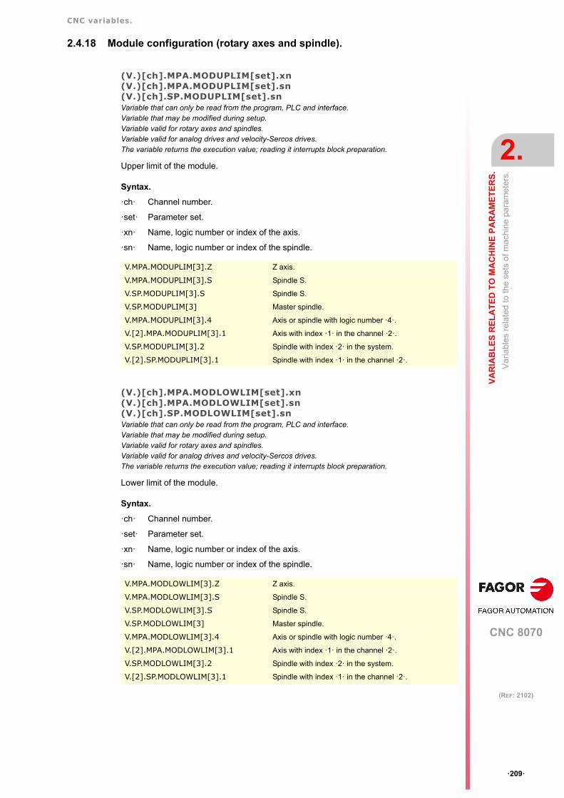
CNC variables.
CNC 8070
VA
RIA
BL
ES
RE
LA
TE
D T
O M
AC
HIN
E P
AR
AM
ET
ER
S.
2.
Var
iabl
es r
ela
ted
to th
e se
ts o
f mac
hin
e pa
ram
eter
s.
ꞏ209ꞏ
(REF: 2102)
2.4.18 Module configuration (rotary axes and spindle).
(V.)[ch].MPA.MODUPLIM[set].xn(V.)[ch].MPA.MODUPLIM[set].sn(V.)[ch].SP.MODUPLIM[set].snVariable that can only be read from the program, PLC and interface.Variable that may be modified during setup.Variable valid for rotary axes and spindles.Variable valid for analog drives and velocity-Sercos drives.The variable returns the execution value; reading it interrupts block preparation.
Upper limit of the module.
Syntax.
ꞏchꞏ Channel number.
ꞏsetꞏ Parameter set.
ꞏxnꞏ Name, logic number or index of the axis.
ꞏsnꞏ Name, logic number or index of the spindle.
(V.)[ch].MPA.MODLOWLIM[set].xn(V.)[ch].MPA.MODLOWLIM[set].sn(V.)[ch].SP.MODLOWLIM[set].snVariable that can only be read from the program, PLC and interface.Variable that may be modified during setup.Variable valid for rotary axes and spindles.Variable valid for analog drives and velocity-Sercos drives.The variable returns the execution value; reading it interrupts block preparation.
Lower limit of the module.
Syntax.
ꞏchꞏ Channel number.
ꞏsetꞏ Parameter set.
ꞏxnꞏ Name, logic number or index of the axis.
ꞏsnꞏ Name, logic number or index of the spindle.
V.MPA.MODUPLIM[3].Z Z axis.
V.MPA.MODUPLIM[3].S Spindle S.
V.SP.MODUPLIM[3].S Spindle S.
V.SP.MODUPLIM[3] Master spindle.
V.MPA.MODUPLIM[3].4 Axis or spindle with logic number ꞏ4ꞏ.
V.[2].MPA.MODUPLIM[3].1 Axis with index ꞏ1ꞏ in the channel ꞏ2ꞏ.
V.SP.MODUPLIM[3].2 Spindle with index ꞏ2ꞏ in the system.
V.[2].SP.MODUPLIM[3].1 Spindle with index ꞏ1ꞏ in the channel ꞏ2ꞏ.
V.MPA.MODLOWLIM[3].Z Z axis.
V.MPA.MODLOWLIM[3].S Spindle S.
V.SP.MODLOWLIM[3].S Spindle S.
V.SP.MODLOWLIM[3] Master spindle.
V.MPA.MODLOWLIM[3].4 Axis or spindle with logic number ꞏ4ꞏ.
V.[2].MPA.MODLOWLIM[3].1 Axis with index ꞏ1ꞏ in the channel ꞏ2ꞏ.
V.SP.MODLOWLIM[3].2 Spindle with index ꞏ2ꞏ in the system.
V.[2].SP.MODLOWLIM[3].1 Spindle with index ꞏ1ꞏ in the channel ꞏ2ꞏ.

CNC variables.
CNC 8070
2.
VA
RIA
BL
ES
RE
LA
TE
D T
O M
AC
HIN
E P
AR
AM
ET
ER
S.
Var
iabl
es r
ela
ted
to th
e se
ts o
f mac
hin
e pa
ram
eter
s.
ꞏ210ꞏ
(REF: 2102)
(V.)[ch].MPA.MODNROT[set].xn(V.)[ch].MPA.MODNROT[set].sn(V.)[ch].SP.MODNROT[set].snVariable that can only be read from the program, PLC and interface.Variable that may be modified during setup.Variable valid for rotary axes and spindles.Variable valid for analog drives and velocity-Sercos drives.The variable returns the execution value; reading it interrupts block preparation.
Module error. Number of turns.
Syntax.
ꞏchꞏ Channel number.
ꞏsetꞏ Parameter set.
ꞏxnꞏ Name, logic number or index of the axis.
ꞏsnꞏ Name, logic number or index of the spindle.
(V.)[ch].MPA.MODERR[set].xn(V.)[ch].MPA.MODERR[set].sn(V.)[ch].SP.MODERR[set].snVariable that can only be read from the program, PLC and interface.Variable that may be modified during setup.Variable valid for rotary axes and spindles.Variable valid for analog drives and velocity-Sercos drives.The variable returns the execution value; reading it interrupts block preparation.
Module error. Number of increments.
Syntax.
ꞏchꞏ Channel number.
ꞏsetꞏ Parameter set.
ꞏxnꞏ Name, logic number or index of the axis.
ꞏsnꞏ Name, logic number or index of the spindle.
V.MPA.MODNROT[3].Z Z axis.
V.MPA.MODNROT[3].S Spindle S.
V.SP.MODNROT[3].S Spindle S.
V.SP.MODNROT[3] Master spindle.
V.MPA.MODNROT[3].4 Axis or spindle with logic number ꞏ4ꞏ.
V.[2].MPA.MODNROT[3].1 Axis with index ꞏ1ꞏ in the channel ꞏ2ꞏ.
V.SP.MODNROT[3].2 Spindle with index ꞏ2ꞏ in the system.
V.[2].SP.MODNROT[3].1 Spindle with index ꞏ1ꞏ in the channel ꞏ2ꞏ.
V.MPA.MODERR[3].Z Z axis.
V.MPA.MODERR[3].S Spindle S.
V.SP.MODERR[3].S Spindle S.
V.SP.MODERR[3] Master spindle.
V.MPA.MODERR[3].4 Axis or spindle with logic number ꞏ4ꞏ.
V.[2].MPA.MODERR[3].1 Axis with index ꞏ1ꞏ in the channel ꞏ2ꞏ.
V.SP.MODERR[3].2 Spindle with index ꞏ2ꞏ in the system.
V.[2].SP.MODERR[3].1 Spindle with index ꞏ1ꞏ in the channel ꞏ2ꞏ.

CNC variables.
CNC 8070
VA
RIA
BL
ES
RE
LA
TE
D T
O M
AC
HIN
E P
AR
AM
ET
ER
S.
2.
Var
iabl
es r
ela
ted
to th
e se
ts o
f mac
hin
e pa
ram
eter
s.
ꞏ211ꞏ
(REF: 2102)
2.4.19 Spindle speed.
(V.)[ch].MPA.SZERO[set].sn(V.)[ch].SP.SZERO[set].snVariable that can only be read from the program, PLC and interface.Variable valid for spindles.Variable valid for position-Sercos drives and velocity-Sercos drives.The variable returns the value of block preparation.
Speed considered "0 rpm".
Syntax.
ꞏchꞏ Channel number.
ꞏsetꞏ Parameter set.
ꞏsnꞏ Name, logic number or index of the spindle.
(V.)[ch].MPA.POLARM3[set].sn(V.)[ch].SP.POLARM3[set].snVariable that can only be read from the program, PLC and interface.Variable valid for spindles.Variable valid for velocity-Sercos drives.The variable returns the value of block preparation.
Sign of the velocity command for M3.
Syntax.
ꞏchꞏ Channel number.
ꞏsetꞏ Parameter set.
ꞏsnꞏ Name, logic number or index of the spindle.
Values of the variable.
This variable returns one of the following values.
(V.)[ch].MPA.POLARM4[set].sn(V.)[ch].SP.POLARM4[set].snVariable that can only be read from the program, PLC and interface.Variable valid for spindles.Variable valid for velocity-Sercos drives.The variable returns the value of block preparation.
Sign of the velocity command for M4.
V.MPA.SZERO[3].S Spindle S.
V.SP.SZERO[3].S Spindle S.
V.SP.SZERO[3] Master spindle.
V.MPA.SZERO[3].4 Spindle with logic number ꞏ4ꞏ.
V.SP.SZERO[3].2 Spindle with index ꞏ2ꞏ in the system.
V.[2].SP.SZERO[3].1 Spindle with index ꞏ1ꞏ in the channel ꞏ2ꞏ.
V.MPA.POLARM3[3].S Spindle S.
V.SP.POLARM3[3].S Spindle S.
V.SP.POLARM3[3] Master spindle.
V.MPA.POLARM3[3].4 Spindle with logic number ꞏ4ꞏ.
V.SP.POLARM3[3].2 Spindle with index ꞏ2ꞏ in the system.
V.[2].SP.POLARM3[3].1 Spindle with index ꞏ1ꞏ in the channel ꞏ2ꞏ.
Value. Meaning.
0 Negative.
1 Positive.

CNC variables.
CNC 8070
2.
VA
RIA
BL
ES
RE
LA
TE
D T
O M
AC
HIN
E P
AR
AM
ET
ER
S.
Var
iabl
es r
ela
ted
to th
e se
ts o
f mac
hin
e pa
ram
eter
s.
ꞏ212ꞏ
(REF: 2102)
Syntax.
ꞏchꞏ Channel number.
ꞏsetꞏ Parameter set.
ꞏsnꞏ Name, logic number or index of the spindle.
Values of the variable.
This variable returns one of the following values.
V.MPA.POLARM4[3].S Spindle S.
V.SP.POLARM4[3].S Spindle S.
V.SP.POLARM4[3] Master spindle.
V.MPA.POLARM4[3].4 Spindle with logic number ꞏ4ꞏ.
V.SP.POLARM4[3].2 Spindle with index ꞏ2ꞏ in the system.
V.[2].SP.POLARM4[3].1 Spindle with index ꞏ1ꞏ in the channel ꞏ2ꞏ.
Value. Meaning.
0 Negative.
1 Positive.

CNC variables.
CNC 8070
VA
RIA
BL
ES
RE
LA
TE
D T
O M
AC
HIN
E P
AR
AM
ET
ER
S.
2.
Var
iabl
es r
ela
ted
to th
e se
ts o
f mac
hin
e pa
ram
eter
s.
ꞏ213ꞏ
(REF: 2102)
2.4.20 Analog command setting.
(V.)[ch].MPA.SERVOOFF[set].xn(V.)[ch].MPA.SERVOOFF[set].sn(V.)[ch].SP.SERVOOFF[set].snVariable that can only be read from the program, PLC and interface.Variable that may be modified from the environment of the oscilloscope and setup.Variable valid for rotary and linear axes as well as for spindles.Variable valid for analog drives.The variable returns the execution value; reading it interrupts block preparation.
Offset compensation.
The velocity command is given in D/A converter units which could be any integer within±32767 where a value of ±32767 corresponds to ±10V.
Syntax.
ꞏchꞏ Channel number.
ꞏsetꞏ Parameter set.
ꞏxnꞏ Name, logic number or index of the axis.
ꞏsnꞏ Name, logic number or index of the spindle.
(V.)[ch].MPA.MINANOUT[set].xn(V.)[ch].MPA.MINANOUT[set].sn(V.)[ch].SP.MINANOUT[set].snVariable that can only be read from the program, PLC and interface.Variable that may be modified from the environment of the oscilloscope and setup.Variable valid for rotary and linear axes as well as for spindles.Variable valid for analog drives.The variable returns the execution value; reading it interrupts block preparation.
Minimum velocity command.
The velocity command is given in D/A converter units which could be any integer within±32767 where a value of ±32767 corresponds to ±10V.
Syntax.
ꞏchꞏ Channel number.
ꞏsetꞏ Parameter set.
ꞏxnꞏ Name, logic number or index of the axis.
ꞏsnꞏ Name, logic number or index of the spindle.
V.MPA.SERVOOFF[3].Z Z axis.
V.MPA.SERVOOFF[3].S Spindle S.
V.SP.SERVOOFF[3].S Spindle S.
V.SP.SERVOOFF[3] Master spindle.
V.MPA.SERVOOFF[3].4 Axis or spindle with logic number ꞏ4ꞏ.
V.[2].MPA.SERVOOFF[3].1 Axis with index ꞏ1ꞏ in the channel ꞏ2ꞏ.
V.SP.SERVOOFF[3].2 Spindle with index ꞏ2ꞏ in the system.
V.[2].SP.SERVOOFF[3].1 Spindle with index ꞏ1ꞏ in the channel ꞏ2ꞏ.
V.MPA.MINANOUT[3].Z Z axis.
V.MPA.MINANOUT[3].S Spindle S.
V.SP.MINANOUT[3].S Spindle S.
V.SP.MINANOUT[3] Master spindle.
V.MPA.MINANOUT[3].4 Axis or spindle with logic number ꞏ4ꞏ.
V.[2].MPA.MINANOUT[3].1 Axis with index ꞏ1ꞏ in the channel ꞏ2ꞏ.
V.SP.MINANOUT[3].2 Spindle with index ꞏ2ꞏ in the system.
V.[2].SP.MINANOUT[3].1 Spindle with index ꞏ1ꞏ in the channel ꞏ2ꞏ.

CNC variables.
CNC 8070
2.
VA
RIA
BL
ES
RE
LA
TE
D T
O M
AC
HIN
E P
AR
AM
ET
ER
S.
Var
iabl
es r
ela
ted
to th
e se
ts o
f mac
hin
e pa
ram
eter
s.
ꞏ214ꞏ
(REF: 2102)
2.4.21 Number of the analog output and of the feedback input associated withthe axis.
(V.)[ch].MPA.ANAOUTTYPE[set].xn(V.)[ch].MPA.ANAOUTTYPE[set].sn(V.)[ch].SP.ANAOUTTYPE[set].snVariable that can only be read from the program, PLC and interface.Variable valid for rotary and linear axes as well as for spindles.Variable valid for analog drives.The variable returns the value of block preparation.
Type of analog output associated with the axis.
Syntax.
ꞏchꞏ Channel number.
ꞏsetꞏ Parameter set.
ꞏxnꞏ Name, logic number or index of the axis.
ꞏsnꞏ Name, logic number or index of the spindle.
Values of the variable.
This variable returns one of the following values.
(V.)[ch].MPA.ANAOUTID[set].xn(V.)[ch].MPA.ANAOUTID[set].sn(V.)[ch].SP.ANAOUTID[set].snVariable that can only be read from the program, PLC and interface.Variable valid for rotary and linear axes as well as for spindles.Variable valid for analog drives.The variable returns the value of block preparation.
Number of the analog output associated with the axis.
The velocity command for an analog axis may be taken from an analog output of the remotemodules or of the Sercos drive.
Syntax.
ꞏchꞏ Channel number.
ꞏsetꞏ Parameter set.
ꞏxnꞏ Name, logic number or index of the axis.
ꞏsnꞏ Name, logic number or index of the spindle.
V.MPA.ANAOUTTYPE[3].Z Z axis.
V.MPA.ANAOUTTYPE[3].S Spindle S.
V.SP.ANAOUTTYPE[3].S Spindle S.
V.SP.ANAOUTTYPE[3] Master spindle.
V.MPA.ANAOUTTYPE[3].4 Axis or spindle with logic number ꞏ4ꞏ.
V.[2].MPA.ANAOUTTYPE[3].1 Axis with index ꞏ1ꞏ in the channel ꞏ2ꞏ.
V.SP.ANAOUTTYPE[3].2 Spindle with index ꞏ2ꞏ in the system.
V.[2].SP.ANAOUTTYPE[3].1 Spindle with index ꞏ1ꞏ in the channel ꞏ2ꞏ.
Value. Meaning.
0 The analog output is in the remote modules.
1 The analog output is in a Sercos drive.
2 The analog output is in a RCS-S module.
V.MPA.ANAOUTID[3].Z Z axis.
V.MPA.ANAOUTID[3].S Spindle S.
V.SP.ANAOUTID[3].S Spindle S.

CNC variables.
CNC 8070
VA
RIA
BL
ES
RE
LA
TE
D T
O M
AC
HIN
E P
AR
AM
ET
ER
S.
2.
Var
iabl
es r
ela
ted
to th
e se
ts o
f mac
hin
e pa
ram
eter
s.
ꞏ215ꞏ
(REF: 2102)
Values of the variable.
This variable returns one of the following values.
(V.)[ch].MPA.COUNTERTYPE[set].xn(V.)[ch].MPA.COUNTERTYPE[set].sn(V.)[ch].SP.COUNTERTYPE[set].snVariable that can only be read from the program, PLC and interface.Variable valid for rotary and linear axes as well as for spindles.Variable valid for analog drives and velocity-Sercos drives. The variable returns the value of block preparation.
Type of feedback input for the axis.
Syntax.
ꞏchꞏ Channel number.
ꞏsetꞏ Parameter set.
ꞏxnꞏ Name, logic number or index of the axis.
ꞏsnꞏ Name, logic number or index of the spindle.
Values of the variable.
This variable returns one of the following values.
V.SP.ANAOUTID[3] Master spindle.
V.MPA.ANAOUTID[3].4 Axis or spindle with logic number ꞏ4ꞏ.
V.[2].MPA.ANAOUTID[3].1 Axis with index ꞏ1ꞏ in the channel ꞏ2ꞏ.
V.SP.ANAOUTID[3].2 Spindle with index ꞏ2ꞏ in the system.
V.[2].SP.ANAOUTID[3].1 Spindle with index ꞏ1ꞏ in the channel ꞏ2ꞏ.
Value. Meaning.
1 - 16 The analog command is taken from the remote modules. The variable returns thenumber of the analog output.
101 -132201 - 232
The analog command is taken from a Sercos drive. The first digit indicates the analogoutput to be used (1 or 2) and the other two digits indicate the logic address of thedrive (1 through 32).
1 - 32 The analog command is taken from an RCS-S module.. The variable returns thenumber of the analog output.
V.MPA.COUNTERTYPE[3].Z Z axis.
V.MPA.COUNTERTYPE[3].S Spindle S.
V.SP.COUNTERTYPE[3].S Spindle S.
V.SP.COUNTERTYPE[3] Master spindle.
V.MPA.COUNTERTYPE[3].4 Axis or spindle with logic number ꞏ4ꞏ.
V.[2].MPA.COUNTERTYPE[3].1 Axis with index ꞏ1ꞏ in the channel ꞏ2ꞏ.
V.SP.COUNTERTYPE[3].2 Spindle with index ꞏ2ꞏ in the system.
V.[2].SP.COUNTERTYPE[3].1 Spindle with index ꞏ1ꞏ in the channel ꞏ2ꞏ.
Value. Meaning.
0 Remote feedback input.
1 Local feedback input.
2 Feedback input of a Sercos drive.
3 Feedback input of an RCS-S module.

CNC variables.
CNC 8070
2.
VA
RIA
BL
ES
RE
LA
TE
D T
O M
AC
HIN
E P
AR
AM
ET
ER
S.
Var
iabl
es r
ela
ted
to th
e se
ts o
f mac
hin
e pa
ram
eter
s.
ꞏ216ꞏ
(REF: 2102)
(V.)[ch].MPA.COUNTERID[set].xn(V.)[ch].MPA.COUNTERID[set].sn(V.)[ch].SP.COUNTERID[set].snVariable that can only be read from the program, PLC and interface.Variable valid for rotary and linear axes as well as for spindles.Variable valid for analog drives and velocity-Sercos drives. The variable returns the value of block preparation.
Number of the feedback input associated with the axis.
Syntax.
ꞏchꞏ Channel number.
ꞏsetꞏ Parameter set.
ꞏxnꞏ Name, logic number or index of the axis.
ꞏsnꞏ Name, logic number or index of the spindle.
Values of the variable.
This variable returns one of the following values.
V.MPA.COUNTERID[3].Z Z axis.
V.MPA.COUNTERID[3].S Spindle S.
V.SP.COUNTERID[3].S Spindle S.
V.SP.COUNTERID[3] Master spindle.
V.MPA.COUNTERID[3].4 Axis or spindle with logic number ꞏ4ꞏ.
V.[2].MPA.COUNTERID[3].1 Axis with index ꞏ1ꞏ in the channel ꞏ2ꞏ.
V.SP.COUNTERID[3].2 Spindle with index ꞏ2ꞏ in the system.
V.[2].SP.COUNTERID[3].1 Spindle with index ꞏ1ꞏ in the channel ꞏ2ꞏ.
Value. Meaning.
1 - 40 Number of the remote feedback input.
1 - 32 Address of the Sercos drive (always the second feedback input).
1 - 2 Number of the local feedback input.
1 - 32 Number of the RCS-S module input.

CNC variables.
CNC 8070
VA
RIA
BL
ES
RE
LA
TE
D T
O M
AC
HIN
E P
AR
AM
ET
ER
S.
2.
Var
iabl
es r
ela
ted
to th
e se
ts o
f mac
hin
e pa
ram
eter
s.
ꞏ217ꞏ
(REF: 2102)
2.4.22 Set the drive associated with the axes of a multi-axis group.
(V.)[ch].MPA.DRIVESET[set].xn(V.)[ch].MPA.DRIVESET[set].sn(V.)[ch].SP.DRIVESET[set].snVariable that can only be read from the program, PLC and interface.Variable valid for rotary and linear axes as well as for spindles.Variable valid for position-Sercos drives and velocity-Sercos drives.The variable returns the value of block preparation.
At the axes that belong to a multi-axis group, parameter DRIVESET indicates the set to beactivated at the drive after a set or gear change at the CNC (G112 and M41 to M44).
Syntax.
ꞏchꞏ Channel number.
ꞏsetꞏ Parameter set.
ꞏxnꞏ Name, logic number or index of the axis.
ꞏsnꞏ Name, logic number or index of the spindle.
V.MPA.DRIVESET[3].Z Z axis.
V.MPA.DRIVESET[3].S Spindle S.
V.SP.DRIVESET[3].S Spindle S.
V.SP.DRIVESET[3] Master spindle.
V.MPA.DRIVESET[3].4 Axis or spindle with logic number ꞏ4ꞏ.
V.[2].MPA.DRIVESET[3].1 Axis with index ꞏ1ꞏ in the channel ꞏ2ꞏ.
V.SP.DRIVESET[3].2 Spindle with index ꞏ2ꞏ in the system.
V.[2].SP.DRIVESET[3].1 Spindle with index ꞏ1ꞏ in the channel ꞏ2ꞏ.

CNC variables.
CNC 8070
2.
VA
RIA
BL
ES
RE
LA
TE
D T
O M
AC
HIN
E P
AR
AM
ET
ER
S.
Var
iabl
es r
ela
ted
to th
e se
ts o
f mac
hin
e pa
ram
eter
s.
ꞏ218ꞏ
(REF: 2102)
2.4.23 Feedback type of the RCS-S module.
(V.)[ch].MPA.FEEDBACKTYPE[set].xn(V.)[ch].MPA.FEEDBACKTYPE[set].sn(V.)[ch].SP.FEEDBACKTYPE[set].snVariable that can only be read from the program, PLC and interface.Variable valid for rotary and linear axes as well as for spindles.Variable valid for velocity-Sercos drives.The variable returns the value of block preparation.
Feedback type of the RCS-S module.
Syntax.
ꞏchꞏ Channel number.
ꞏsetꞏ Parameter set.
ꞏxnꞏ Name, logic number or index of the axis.
ꞏsnꞏ Name, logic number or index of the spindle.
(V.)[ch].MPA.SSITYPE[set].xn(V.)[ch].MPA.SSITYPE[set].sn(V.)[ch].SP.SSITYPE[set].snVariable that can only be read from the program, PLC and interface.Variable valid for rotary and linear axes as well as for spindles.Variable valid for velocity-Sercos drives.The variable returns the value of block preparation.
Feedback type connected to the corresponding feedback.
Syntax.
ꞏchꞏ Channel number.
ꞏsetꞏ Parameter set.
ꞏxnꞏ Name, logic number or index of the axis.
ꞏsnꞏ Name, logic number or index of the spindle.
V.MPA.FEEDBACKTYPE[3].Z Z axis.
V.MPA.FEEDBACKTYPE[3].S Spindle S.
V.SP.FEEDBACKTYPE[3].S Spindle S.
V.SP.FEEDBACKTYPE[3] Master spindle.
V.MPA.FEEDBACKTYPE[3].4 Axis or spindle with logic number ꞏ4ꞏ.
V.[2].MPA.FEEDBACKTYPE[3].1 Axis with index ꞏ1ꞏ in the channel ꞏ2ꞏ.
V.SP.FEEDBACKTYPE[3].2 Spindle with index ꞏ2ꞏ in the system.
V.[2].SP.FEEDBACKTYPE[3].1 Spindle with index ꞏ1ꞏ in the channel ꞏ2ꞏ.
V.MPA.SSITYPE[3].Z Z axis.
V.MPA.SSITYPE[3].S Spindle S.
V.SP.SSITYPE[3].S Spindle S.
V.SP.SSITYPE[3] Master spindle.
V.MPA.SSITYPE[3].4 Axis or spindle with logic number ꞏ4ꞏ.
V.[2].MPA.SSITYPE[3].1 Axis with index ꞏ1ꞏ in the channel ꞏ2ꞏ.
V.SP.SSITYPE[3].2 Spindle with index ꞏ2ꞏ in the system.
V.[2].SP.SSITYPE[3].1 Spindle with index ꞏ1ꞏ in the channel ꞏ2ꞏ.

CNC variables.
CNC 8070
VA
RIA
BL
ES
RE
LA
TE
D T
O M
AC
HIN
E P
AR
AM
ET
ER
S.
2.
Var
iabl
es r
ela
ted
to th
e se
ts o
f mac
hin
e pa
ram
eter
s.
ꞏ219ꞏ
(REF: 2102)
Values of the variable.
This variable returns one of the following values.
(V.)[ch].MPA.SSICLKFREQ[set].xn(V.)[ch].MPA.SSICLKFREQ[set].sn(V.)[ch].SP.SSICLKFREQ[set].snVariable that can only be read from the program, PLC and interface.Variable valid for rotary and linear axes as well as for spindles.Variable valid for velocity-Sercos drives.The variable returns the value of block preparation.
SSI communication frequency.
Syntax.
ꞏchꞏ Channel number.
ꞏsetꞏ Parameter set.
ꞏxnꞏ Name, logic number or index of the axis.
ꞏsnꞏ Name, logic number or index of the spindle.
(V.)[ch].MPA.SSIDATALENGTH[set].xn(V.)[ch].MPA.SSIDATALENGTH[set].sn(V.)[ch].SP.SSIDATALENGTH[set].snVariable that can only be read from the program, PLC and interface.Variable valid for rotary and linear axes as well as for spindles.Variable valid for velocity-Sercos drives.The variable returns the value of block preparation.
Number of bits of the SSI transmission that make up the position value (coordinate).
Syntax.
ꞏchꞏ Channel number.
ꞏsetꞏ Parameter set.
ꞏxnꞏ Name, logic number or index of the axis.
Value. Meaning.
0 Fagor LA
1 Fagor GA SA SVA
2 Fagor HA-27-D200
3 Fagor HA-23-D90 SA-23-D90 SA-23-D170
4 ABSIND (inductosyn LIN+ABS)
5 ABSIND (inductosyn ROT+ABS)
6 ABSIND (resolver)
7 ABSIND (inductosyn LIN)
8 ABSIND (inductosyn ROT)
9 G user
10 User
V.MPA.SSICLKFREQ[3].Z Z axis.
V.MPA.SSICLKFREQ[3].S Spindle S.
V.SP.SSICLKFREQ[3].S Spindle S.
V.SP.SSICLKFREQ[3] Master spindle.
V.MPA.SSICLKFREQ[3].4 Axis or spindle with logic number ꞏ4ꞏ.
V.[2].MPA.SSICLKFREQ[3].1 Axis with index ꞏ1ꞏ in the channel ꞏ2ꞏ.
V.SP.SSICLKFREQ[3].2 Spindle with index ꞏ2ꞏ in the system.
V.[2].SP.SSICLKFREQ[3].1 Spindle with index ꞏ1ꞏ in the channel ꞏ2ꞏ.

CNC variables.
CNC 8070
2.
VA
RIA
BL
ES
RE
LA
TE
D T
O M
AC
HIN
E P
AR
AM
ET
ER
S.
Var
iabl
es r
ela
ted
to th
e se
ts o
f mac
hin
e pa
ram
eter
s.
ꞏ220ꞏ
(REF: 2102)
ꞏsnꞏ Name, logic number or index of the spindle.
(V.)[ch].MPA.SSIPACKFORMAT[set].xn(V.)[ch].MPA.SSIPACKFORMAT[set].sn(V.)[ch].SP.SSIPACKFORMAT[set].snVariable that can only be read from the program, PLC and interface.Variable valid for rotary and linear axes as well as for spindles.Variable valid for velocity-Sercos drives.The variable returns the value of block preparation.
Syntax.
ꞏchꞏ Channel number.
ꞏsetꞏ Parameter set.
ꞏxnꞏ Name, logic number or index of the axis.
ꞏsnꞏ Name, logic number or index of the spindle.
Values of the variable.
This variable returns one of the following values.
V.MPA.SSIDATALENGTH[3].Z Z axis.
V.MPA.SSIDATALENGTH[3].S Spindle S.
V.SP.SSIDATALENGTH[3].S Spindle S.
V.SP.SSIDATALENGTH[3] Master spindle.
V.MPA.SSIDATALENGTH[3].4 Axis or spindle with logic number ꞏ4ꞏ.
V.[2].MPA.SSIDATALENGTH[3].1 Axis with index ꞏ1ꞏ in the channel ꞏ2ꞏ.
V.SP.SSIDATALENGTH[3].2 Spindle with index ꞏ2ꞏ in the system.
V.[2].SP.SSIDATALENGTH[3].1 Spindle with index ꞏ1ꞏ in the channel ꞏ2ꞏ.
V.MPA.SSIPACKFORMAT[3].Z Z axis.
V.MPA.SSIPACKFORMAT[3].S Spindle S.
V.SP.SSIPACKFORMAT[3].S Spindle S.
V.SP.SSIPACKFORMAT[3] Master spindle.
V.MPA.SSIPACKFORMAT[3].4 Axis or spindle with logic number ꞏ4ꞏ.
V.[2].MPA.SSIPACKFORMAT[3].1 Axis with index ꞏ1ꞏ in the channel ꞏ2ꞏ.
V.SP.SSIPACKFORMAT[3].2 Spindle with index ꞏ2ꞏ in the system.
V.[2].SP.SSIPACKFORMAT[3].1 Spindle with index ꞏ1ꞏ in the channel ꞏ2ꞏ.
Value. Meaning.
0 Data.
1 Data-CRC.
2 CRC-Data.
3 Data-Alarm.
4 Alarm-Data.
5 Data-CRC-Alarm
6 Alarm-Data-CRC.
7 Data-Alarm-CRC.
8 Alarm-CRC-Data.
9 CRC-Data-Alarm.
10 CRC-Alarm-Data.
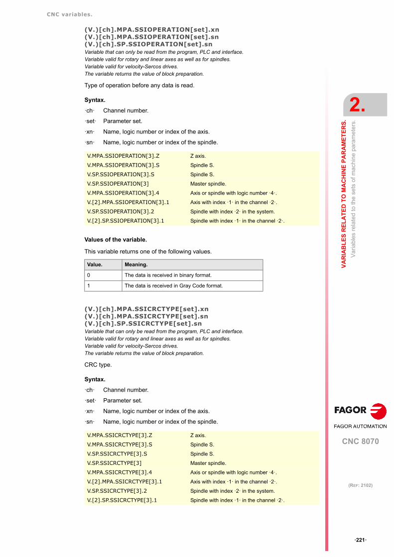
CNC variables.
CNC 8070
VA
RIA
BL
ES
RE
LA
TE
D T
O M
AC
HIN
E P
AR
AM
ET
ER
S.
2.
Var
iabl
es r
ela
ted
to th
e se
ts o
f mac
hin
e pa
ram
eter
s.
ꞏ221ꞏ
(REF: 2102)
(V.)[ch].MPA.SSIOPERATION[set].xn(V.)[ch].MPA.SSIOPERATION[set].sn(V.)[ch].SP.SSIOPERATION[set].snVariable that can only be read from the program, PLC and interface.Variable valid for rotary and linear axes as well as for spindles.Variable valid for velocity-Sercos drives.The variable returns the value of block preparation.
Type of operation before any data is read.
Syntax.
ꞏchꞏ Channel number.
ꞏsetꞏ Parameter set.
ꞏxnꞏ Name, logic number or index of the axis.
ꞏsnꞏ Name, logic number or index of the spindle.
Values of the variable.
This variable returns one of the following values.
(V.)[ch].MPA.SSICRCTYPE[set].xn(V.)[ch].MPA.SSICRCTYPE[set].sn(V.)[ch].SP.SSICRCTYPE[set].snVariable that can only be read from the program, PLC and interface.Variable valid for rotary and linear axes as well as for spindles.Variable valid for velocity-Sercos drives.The variable returns the value of block preparation.
CRC type.
Syntax.
ꞏchꞏ Channel number.
ꞏsetꞏ Parameter set.
ꞏxnꞏ Name, logic number or index of the axis.
ꞏsnꞏ Name, logic number or index of the spindle.
V.MPA.SSIOPERATION[3].Z Z axis.
V.MPA.SSIOPERATION[3].S Spindle S.
V.SP.SSIOPERATION[3].S Spindle S.
V.SP.SSIOPERATION[3] Master spindle.
V.MPA.SSIOPERATION[3].4 Axis or spindle with logic number ꞏ4ꞏ.
V.[2].MPA.SSIOPERATION[3].1 Axis with index ꞏ1ꞏ in the channel ꞏ2ꞏ.
V.SP.SSIOPERATION[3].2 Spindle with index ꞏ2ꞏ in the system.
V.[2].SP.SSIOPERATION[3].1 Spindle with index ꞏ1ꞏ in the channel ꞏ2ꞏ.
Value. Meaning.
0 The data is received in binary format.
1 The data is received in Gray Code format.
V.MPA.SSICRCTYPE[3].Z Z axis.
V.MPA.SSICRCTYPE[3].S Spindle S.
V.SP.SSICRCTYPE[3].S Spindle S.
V.SP.SSICRCTYPE[3] Master spindle.
V.MPA.SSICRCTYPE[3].4 Axis or spindle with logic number ꞏ4ꞏ.
V.[2].MPA.SSICRCTYPE[3].1 Axis with index ꞏ1ꞏ in the channel ꞏ2ꞏ.
V.SP.SSICRCTYPE[3].2 Spindle with index ꞏ2ꞏ in the system.
V.[2].SP.SSICRCTYPE[3].1 Spindle with index ꞏ1ꞏ in the channel ꞏ2ꞏ.

CNC variables.
CNC 8070
2.
VA
RIA
BL
ES
RE
LA
TE
D T
O M
AC
HIN
E P
AR
AM
ET
ER
S.
Var
iabl
es r
ela
ted
to th
e se
ts o
f mac
hin
e pa
ram
eter
s.
ꞏ222ꞏ
(REF: 2102)
Values of the variable.
This variable returns one of the following values.
(V.)[ch].MPA.SSICRCBITS[set].xn(V.)[ch].MPA.SSICRCBITS[set].sn(V.)[ch].SP.SSICRCBITS[set].snVariable that can only be read from the program, PLC and interface.Variable valid for rotary and linear axes as well as for spindles.Variable valid for velocity-Sercos drives.The variable returns the value of block preparation.
Number of CRC bits of the SSI transmission to check that the transmission is valid.
Syntax.
ꞏchꞏ Channel number.
ꞏsetꞏ Parameter set.
ꞏxnꞏ Name, logic number or index of the axis.
ꞏsnꞏ Name, logic number or index of the spindle.
(V.)[ch].MPA.SSISTARTBITS[set].xn(V.)[ch].MPA.SSISTARTBITS[set].sn(V.)[ch].SP.SSISTARTBITS[set].snVariable that can only be read from the program, PLC and interface.Variable valid for rotary and linear axes as well as for spindles.Variable valid for velocity-Sercos drives.The variable returns the value of block preparation.
Number of start bits.
Syntax.
ꞏchꞏ Channel number.
ꞏsetꞏ Parameter set.
ꞏxnꞏ Name, logic number or index of the axis.
ꞏsnꞏ Name, logic number or index of the spindle.
Value. Meaning.
0 "Do not calculate CRC"
1 Fagor checksum.
2 INDUCTOSYN checksum.
V.MPA.SSICRCBITS[3].Z Z axis.
V.MPA.SSICRCBITS[3].S Spindle S.
V.SP.SSICRCBITS[3].S Spindle S.
V.SP.SSICRCBITS[3] Master spindle.
V.MPA.SSICRCBITS[3].4 Axis or spindle with logic number ꞏ4ꞏ.
V.[2].MPA.SSICRCBITS[3].1 Axis with index ꞏ1ꞏ in the channel ꞏ2ꞏ.
V.SP.SSICRCBITS[3].2 Spindle with index ꞏ2ꞏ in the system.
V.[2].SP.SSICRCBITS[3].1 Spindle with index ꞏ1ꞏ in the channel ꞏ2ꞏ.
V.MPA.SSISTARTBITS[3].Z Z axis.
V.MPA.SSISTARTBITS[3].S Spindle S.
V.SP.SSISTARTBITS[3].S Spindle S.
V.SP.SSISTARTBITS[3] Master spindle.
V.MPA.SSISTARTBITS[3].4 Axis or spindle with logic number ꞏ4ꞏ.
V.[2].MPA.SSISTARTBITS[3].1 Axis with index ꞏ1ꞏ in the channel ꞏ2ꞏ.
V.SP.SSISTARTBITS[3].2 Spindle with index ꞏ2ꞏ in the system.
V.[2].SP.SSISTARTBITS[3].1 Spindle with index ꞏ1ꞏ in the channel ꞏ2ꞏ.

CNC variables.
CNC 8070
VA
RIA
BL
ES
RE
LA
TE
D T
O M
AC
HIN
E P
AR
AM
ET
ER
S.
2.
Var
iabl
es r
ela
ted
to th
e se
ts o
f mac
hin
e pa
ram
eter
s.
ꞏ223ꞏ
(REF: 2102)
(V.)[ch].MPA.SSIALARMBITS[set].xn(V.)[ch].MPA.SSIALARMBITS[set].sn(V.)[ch].SP.SSIALARMBITS[set].snVariable that can only be read from the program, PLC and interface.Variable valid for rotary and linear axes as well as for spindles.Variable valid for velocity-Sercos drives.The variable returns the value of block preparation.
Number of alarm bits.
Syntax.
ꞏchꞏ Channel number.
ꞏsetꞏ Parameter set.
ꞏxnꞏ Name, logic number or index of the axis.
ꞏsnꞏ Name, logic number or index of the spindle.
(V.)[ch].MPA.SSIALARMLEVEL[set].xn(V.)[ch].MPA.SSIALARMLEVEL[set].sn(V.)[ch].SP.SSIALARMLEVEL[set].snVariable that can only be read from the program, PLC and interface.Variable valid for rotary and linear axes as well as for spindles.Variable valid for velocity-Sercos drives.The variable returns the value of block preparation.
Level of the alarm bits to issue an error.
Syntax.
ꞏchꞏ Channel number.
ꞏsetꞏ Parameter set.
ꞏxnꞏ Name, logic number or index of the axis.
ꞏsnꞏ Name, logic number or index of the spindle.
(V.)[ch].MPA.SSIDATAMODE[set].xn(V.)[ch].MPA.SSIDATAMODE[set].sn(V.)[ch].SP.SSIDATAMODE[set].snVariable that can only be read from the program, PLC and interface.Variable valid for rotary and linear axes as well as for spindles.Variable valid for velocity-Sercos drives.The variable returns the value of block preparation.
Transmission mode.
V.MPA.SSIALARMBITS[3].Z Z axis.
V.MPA.SSIALARMBITS[3].S Spindle S.
V.SP.SSIALARMBITS[3].S Spindle S.
V.SP.SSIALARMBITS[3] Master spindle.
V.MPA.SSIALARMBITS[3].4 Axis or spindle with logic number ꞏ4ꞏ.
V.[2].MPA.SSIALARMBITS[3].1 Axis with index ꞏ1ꞏ in the channel ꞏ2ꞏ.
V.SP.SSIALARMBITS[3].2 Spindle with index ꞏ2ꞏ in the system.
V.[2].SP.SSIALARMBITS[3].1 Spindle with index ꞏ1ꞏ in the channel ꞏ2ꞏ.
V.MPA.SSIALARMLEVEL[3].Z Z axis.
V.MPA.SSIALARMLEVEL[3].S Spindle S.
V.SP.SSIALARMLEVEL[3].S Spindle S.
V.SP.SSIALARMLEVEL[3] Master spindle.
V.MPA.SSIALARMLEVEL[3].4 Axis or spindle with logic number ꞏ4ꞏ.
V.[2].MPA.SSIALARMLEVEL[3].1 Axis with index ꞏ1ꞏ in the channel ꞏ2ꞏ.
V.SP.SSIALARMLEVEL[3].2 Spindle with index ꞏ2ꞏ in the system.
V.[2].SP.SSIALARMLEVEL[3].1 Spindle with index ꞏ1ꞏ in the channel ꞏ2ꞏ.

CNC variables.
CNC 8070
2.
VA
RIA
BL
ES
RE
LA
TE
D T
O M
AC
HIN
E P
AR
AM
ET
ER
S.
Var
iabl
es r
ela
ted
to th
e se
ts o
f mac
hin
e pa
ram
eter
s.
ꞏ224ꞏ
(REF: 2102)
Syntax.
ꞏchꞏ Channel number.
ꞏsetꞏ Parameter set.
ꞏxnꞏ Name, logic number or index of the axis.
ꞏsnꞏ Name, logic number or index of the spindle.
Values of the variable.
This variable returns one of the following values.
(V.)[ch].MPA.STARTDELAY[set].xn(V.)[ch].MPA.STARTDELAY[set].sn(V.)[ch].SP.STARTDELAY[set].snVariable that can only be read from the program, PLC and interface.Variable valid for rotary and linear axes as well as for spindles.Variable valid for velocity-Sercos drives.The variable returns the value of block preparation.
Number of clocks to wait between the first down flank and the first up flank.
Syntax.
ꞏchꞏ Channel number.
ꞏsetꞏ Parameter set.
ꞏxnꞏ Name, logic number or index of the axis.
ꞏsnꞏ Name, logic number or index of the spindle.
(V.)[ch].MPA.SSIRESOL[set].xn(V.)[ch].MPA.SSIRESOL[set].sn(V.)[ch].SP.SSIRESOL[set].snVariable that can only be read from the program, PLC and interface.Variable valid for rotary and linear axes as well as for spindles.Variable valid for velocity-Sercos drives.The variable returns the value of block preparation.
Digital counting (feedback) resolution.
V.MPA.SSIDATAMODE[3].Z Z axis.
V.MPA.SSIDATAMODE[3].S Spindle S.
V.SP.SSIDATAMODE[3].S Spindle S.
V.SP.SSIDATAMODE[3] Master spindle.
V.MPA.SSIDATAMODE[3].4 Axis or spindle with logic number ꞏ4ꞏ.
V.[2].MPA.SSIDATAMODE[3].1 Axis with index ꞏ1ꞏ in the channel ꞏ2ꞏ.
V.SP.SSIDATAMODE[3].2 Spindle with index ꞏ2ꞏ in the system.
V.[2].SP.SSIDATAMODE[3].1 Spindle with index ꞏ1ꞏ in the channel ꞏ2ꞏ.
Value. Meaning.
0 The LSB (Least Significant Bit) is the first one.
1 The MSB (Most Significant Bit) is the first one.
V.MPA.STARTDELAY[3].Z Z axis.
V.MPA.STARTDELAY[3].S Spindle S.
V.SP.STARTDELAY[3].S Spindle S.
V.SP.STARTDELAY[3] Master spindle.
V.MPA.STARTDELAY[3].4 Axis or spindle with logic number ꞏ4ꞏ.
V.[2].MPA.STARTDELAY[3].1 Axis with index ꞏ1ꞏ in the channel ꞏ2ꞏ.
V.SP.STARTDELAY[3].2 Spindle with index ꞏ2ꞏ in the system.
V.[2].SP.STARTDELAY[3].1 Spindle with index ꞏ1ꞏ in the channel ꞏ2ꞏ.

CNC variables.
CNC 8070
VA
RIA
BL
ES
RE
LA
TE
D T
O M
AC
HIN
E P
AR
AM
ET
ER
S.
2.
Var
iabl
es r
ela
ted
to th
e se
ts o
f mac
hin
e pa
ram
eter
s.
ꞏ225ꞏ
(REF: 2102)
Syntax.
ꞏchꞏ Channel number.
ꞏsetꞏ Parameter set.
ꞏxnꞏ Name, logic number or index of the axis.
ꞏsnꞏ Name, logic number or index of the spindle.
V.MPA.SSIRESOL[3].Z Z axis.
V.MPA.SSIRESOL[3].S Spindle S.
V.SP.SSIRESOL[3].S Spindle S.
V.SP.SSIRESOL[3] Master spindle.
V.MPA.SSIRESOL[3].4 Axis or spindle with logic number ꞏ4ꞏ.
V.[2].MPA.SSIRESOL[3].1 Axis with index ꞏ1ꞏ in the channel ꞏ2ꞏ.
V.SP.SSIRESOL[3].2 Spindle with index ꞏ2ꞏ in the system.
V.[2].SP.SSIRESOL[3].1 Spindle with index ꞏ1ꞏ in the channel ꞏ2ꞏ.

CNC variables.
CNC 8070
2.
VA
RIA
BL
ES
RE
LA
TE
D T
O M
AC
HIN
E P
AR
AM
ET
ER
S.
Var
iabl
es r
ela
ted
to th
e se
ts o
f mac
hin
e pa
ram
eter
s.
ꞏ226ꞏ
(REF: 2102)
2.4.24 Delay estimate at the drive.
(V.)[ch].MPA.AXDELAY[set].xn(V.)[ch].MPA.AXDELAY[set].sn(V.)[ch].SP.AXDELAY[set].snVariable that can only be read from the program, PLC and interface.Variable valid for rotary and linear axes as well as for spindles.Variable valid for analog drive, position Sercos and velocity Sercos.The variable returns the value of block preparation.
Parameter AXDELAY is an estimate of the drive's delay when applying the velocity commandsent by the CNC.
Syntax.
ꞏchꞏ Channel number.
ꞏsetꞏ Parameter set.
ꞏxnꞏ Name, logic number or index of the axis.
ꞏsnꞏ Name, logic number or index of the spindle.
Values of the variable.
This variable returns one of the following values.
V.MPA.AXDELAY[3].Z Z axis.
V.MPA.AXDELAY[3].S Spindle S.
V.SP.AXDELAY[3].S Spindle S.
V.SP.AXDELAY[3] Master spindle.
V.MPA.AXDELAY[3].4 Axis or spindle with logic number ꞏ4ꞏ.
V.[2].MPA.AXDELAY[3].1 Axis with index ꞏ1ꞏ in the channel ꞏ2ꞏ.
V.SP.AXDELAY[3].2 Spindle with index ꞏ2ꞏ in the system.
V.[2].SP.AXDELAY[3].1 Spindle with index ꞏ1ꞏ in the channel ꞏ2ꞏ.
Value. Meaning.
Standard. For Fagor drives, that do not require any delay compensation.
0. The CNC does not apply delay compensation at the drive.
1 to 127. Delay cycles at the drive. The CNC automatically compensates for the delaydifferences between the axes of the channel.

CNC variables.
CNC 8070
VA
RIA
BL
ES
RE
LA
TE
D T
O M
AC
HIN
E P
AR
AM
ET
ER
S.
2.
Va
riabl
es r
ela
ted
to m
ach
ine
par
amet
ers
for
JOG
mo
de.
ꞏ227ꞏ
(REF: 2102)
2.5 Variables related to machine parameters for JOG mode.
2.5.1 Handwheel configuration.
(V.)MPMAN.NMPGVariable that can only be read from the program, PLC and interface.The variable returns the value of block preparation.
Number of handwheels connected to the CNC.
(V.)MPMAN.COUNTERTYPE[hw]Variable that can only be read from the program, PLC and interface.The variable returns the value of block preparation.
Handwheel [hw]. Type of handwheel feedback input.
Syntax.
ꞏhwꞏ Handwheel number.
Values of the variable.
This variable returns one of the following values.
(V.)MPMAN.COUNTERID[hw]Variable that can only be read from the program, PLC and interface.The variable returns the value of block preparation.
Handwheel [hw]. Feedback input associated with the handwheel.
Syntax.
ꞏhwꞏ Handwheel number.
Values of the variable.
This variable returns one of the following values.
V.MPMAN.NMPG
V.MPMAN.COUNTERTYPE[1] Handwheel ꞏ1ꞏ.
Value. Meaning.
0 Handwheel connected to the remote feedback modules.
1 Handwheel connected to the keyboards.
2 Handwheel connected to the local feedback inputs.
3 Handwheel connected to an RCS-S module.
V.MPMAN.COUNTERID[1] Handwheel ꞏ1ꞏ.
Value. Meaning.
-1 -2 -3 Handwheel connected to the first keyboard.
-4 -5 -6 Handwheel connected to the second keyboard.
-7 -8 -9 Handwheel connected to the third keyboard.
1 ꞏꞏ 40 Feedback input of the remote modules.
1 ꞏꞏ 2 Local feedback input.
1 ꞏꞏ 32 Feedback input of the RCS-S module.

CNC variables.
CNC 8070
2.
VA
RIA
BL
ES
RE
LA
TE
D T
O M
AC
HIN
E P
AR
AM
ET
ER
S.
Va
riabl
es r
ela
ted
to m
ach
ine
par
amet
ers
for
JOG
mo
de.
ꞏ228ꞏ
(REF: 2102)
(V.)MPMAN.HWFBTYPE[hw]Variable that can only be read from the program, PLC and interface.The variable returns the value of block preparation.Possible values: TTL / TTLDIFF.
Handwheel [hw]. Feedback type associated with the handwheel input,
Syntax.
ꞏhwꞏ Handwheel number.
Values of the variable.
This variable returns one of the following values.
(V.)MPMAN.MPGAXIS[hw]Variable that can only be read from the program, PLC and interface.The variable returns the value of block preparation.
Handwheel [hw]. Logic number of the axis associated with the handwheel.
If the variable returns a ꞏ0ꞏ value, it means that it is a general handwheel that may be usedto move any axis.
Syntax.
ꞏhwꞏ Handwheel number.
Remarks.
The logic number of the axes is determined by the order in which the axes have been definedin the machine parameter table. The first axis of the table will be logic axis -1- and so on.
V.MPMAN.HWFBTYPE[1] Handwheel ꞏ1ꞏ.
Value. Meaning.
0 TTL.
1 TTLDIFF.
V.MPMAN.MPGAXIS[1] Handwheel ꞏ1ꞏ.

CNC variables.
CNC 8070
VA
RIA
BL
ES
RE
LA
TE
D T
O M
AC
HIN
E P
AR
AM
ET
ER
S.
2.
Va
riabl
es r
ela
ted
to m
ach
ine
par
amet
ers
for
JOG
mo
de.
ꞏ229ꞏ
(REF: 2102)
2.5.2 Configure the jog keys.
(V.)MPMAN.JOGKEYDEF[jk](V.)MPMAN.JOGKEYBD1DEF[jk](V.)MPMAN.JOGKEYBD2DEF[jk]··(V.)MPMAN.JOGKEYBD8DEF[jk]Variable that can only be read from the program, PLC and interface.The variable returns the value of block preparation.
Jog key [jk]. Axis and moving direction.
Syntax.
ꞏjkꞏ Jog key number.
Values of the variable.
This variable returns one of the following values.
Remarks.
The logic number of the axes is determined by the order in which the axes have been definedin the machine parameter table. The first axis of the table will be logic axis -1- and so on.
JOG-PANEL LCD-10K
V.MPMAN.JOGKEYDEF[11] Jog key ꞏ11ꞏ of first keyboard.
V.MPMAN.JOGKEYBD3DEF[11] Jog key ꞏ11ꞏ of third keyboard.
Value. Meaning.
0 The key has no function assigned to it.
1 ꞏꞏ 16 The key is assigned to the logic axis 1, 2, ꞏꞏ, 16 for movements in the positive direction.
-1 ꞏꞏ -16 The key is assigned to the logic axis 1, 2, ꞏꞏ, 16 for movements in the negativedirection.
101 ꞏꞏ 116 The key is assigned to the logic axis 1, 2, ꞏꞏ, 16.
300 The key is assigned to the rapid movement.
301 The key is assigned to the movement in the positive direction.
302 The key is assigned to the movement in the negative direction.
1
4
2
5
3
6
7 8 9
10 11 12
13 14 15
1 2 3
7 8 9
4 5 6
US
ER
KE
YS

CNC variables.
CNC 8070
2.
VA
RIA
BL
ES
RE
LA
TE
D T
O M
AC
HIN
E P
AR
AM
ET
ER
S.
Va
riabl
es r
ela
ted
to m
ach
ine
par
amet
ers
for
JOG
mo
de.
ꞏ230ꞏ
(REF: 2102)
(V.)MPMAN.JOGTYPEVariable that can only be read from the program, PLC and interface.The variable returns the value of block preparation.
Behavior of the JOG keys.
Values of the variable.
This variable returns one of the following values.
V.MPMAN.JOGTYPE
Value. Meaning.
0 Pressed axis. The axis will move while both keys are pressed, the axis key and thedirection key.
1 Selected axis. Pressing the axis key selects the axis. The axis will move while thedirection key is kept pressed.

CNC variables.
CNC 8070
VA
RIA
BL
ES
RE
LA
TE
D T
O M
AC
HIN
E P
AR
AM
ET
ER
S.
2.
Va
riabl
es r
ela
ted
to m
ach
ine
par
amet
ers
for
JOG
mo
de.
ꞏ231ꞏ
(REF: 2102)
2.5.3 Configure the user keys as jog keys
(V.)MPMAN.USERKEYDEF[uk](V.)MPMAN.USERKEYBD1DEF[uk](V.)MPMAN.USERKEYBD2DEF[uk]··(V.)MPMAN.USERKEYBD8DEF[uk]Variable that can only be read from the program, PLC and interface.The variable returns the value of block preparation.
User key [uk] as jog key.
Syntax.
ꞏukꞏ User key number.
Values of the variable.
This variable returns one of the following values.
Remarks.
The logic number of the axes is determined by the order in which the axes have been definedin the machine parameter table. The first axis of the table will be logic axis -1- and so on.
JOG-PANEL LCD-10K
V.MPMAN.USERKEYDEF[7] User key ꞏ7ꞏ of first keyboard.
V.MPMAN.USERKEYBD3DEF[7] User key ꞏ7ꞏ of third keyboard.
Value. Meaning.
0 The key has no function assigned to it.
1 ꞏꞏ 16 The key is assigned to the logic axis 1, 2, ꞏꞏ, 16 for movements in the positive direction.
-1 ꞏꞏ -16 The key is assigned to the logic axis 1, 2, ꞏꞏ, 16 for movements in the negativedirection.
101 ꞏꞏ 116 The key is assigned to the logic axis 1, 2, ꞏꞏ, 16.
300 The key is assigned to the rapid movement.
301 The key is assigned to the movement in the positive direction.
302 The key is assigned to the movement in the negative direction.
1 2 15 16
JOGKEYS
1 2
3 4
5 6JOGKEYS

CNC variables.
CNC 8070
2.
VA
RIA
BL
ES
RE
LA
TE
D T
O M
AC
HIN
E P
AR
AM
ET
ER
S.
Va
riabl
es r
ela
ted
to m
ach
ine
par
amet
ers
for
JOG
mo
de.
ꞏ232ꞏ
(REF: 2102)
(V.)MPMAN.HBLSVariable that can only be read from the program, PLC and interface.The variable returns the value of block preparation.
This parameter indicates whether there is a portable panel HBLS connected to the CNCthrough the serial line or not.
Values of the variable.
This variable returns one of the following values.
V.MPMAN.HBLS
Value. Meaning.
0 No.
1 Yes.

CNC variables.
CNC 8070
VA
RIA
BL
ES
RE
LA
TE
D T
O M
AC
HIN
E P
AR
AM
ET
ER
S.
2.
Var
iabl
es r
elat
ed to
mac
hine
par
amet
ers
for
M fu
nctio
ns.
ꞏ233ꞏ
(REF: 2102)
2.6 Variables related to machine parameters for M functions.
(V.)MPM.MTABLESIZEVariable that can only be read from the program, PLC and interface.The variable returns the value of block preparation.
"M" function table. Number of table elements.
(V.)MPM.MNUM[pos]Variable that can only be read from the program, PLC and interface.The variable returns the value of block preparation.
Position [pos] of the "M" function table. "M" function number.
If the variable returns a ꞏ-1ꞏ value, it means that no "M" function has been defined in thatposition.
Syntax.
ꞏposꞏ Position inside the "M" function table.
(V.)MPM.SYNCHTYPE[pos]Variable that can only be read from the program, PLC and interface.The variable returns the value of block preparation.
Position [pos] of the "M" function table. Type of synchronism.
Since the M functions may be programmed together with the movement of the axes, in thesame block, it must be indicated when the function is to be sent out to the PLC and whenit will be checked that it has been already executed (synchronization). The M functions maybe sent and/or synchronized before or after the movement.
Syntax.
ꞏposꞏ Position inside the "M" function table.
Values of the variable.
This variable returns one of the following values.
(V.)MPM.MPROGNAME[pos]Variable to be read via interface.
Position [pos] of the "M" function table. Name of the associated subroutine.
(V.)MPM.MTIME[pos]Variable that can only be read from the program, PLC and interface.The variable returns the value of block preparation.
Position [pos] of the "M" function table. Estimated execution time (in milliseconds).
V.MPM.MTABLESIZE
V.MPM.MNUM[12] Position ꞏ12ꞏ of the "M" function table.
V.MPM.SYNCHTYPE[12] Position ꞏ12ꞏ of the "M" function table.
Value. Meaning.
0 Without synchronization.
2 The M function is both sent to the PLC and synchronized before the movement.
4 The M function is sent to the PLC before the movement and synchronized after themovement.
8 The M function is both sent to the PLC and synchronized after the movement.
MPM.MPROGNAME[12] Position ꞏ12ꞏ of the "M" function table.

CNC variables.
CNC 8070
2.
VA
RIA
BL
ES
RE
LA
TE
D T
O M
AC
HIN
E P
AR
AM
ET
ER
S.
Var
iabl
es r
elat
ed to
mac
hine
par
amet
ers
for
M fu
nctio
ns.
ꞏ234ꞏ
(REF: 2102)
Syntax.
ꞏposꞏ Position inside the "M" function table.
(V.)MPM.MPLC[pos]Variable that can only be read from the program, PLC and interface.The variable returns the value of block preparation.
Position [pos] of the "M" function table. Send the M function to the PLC during block search.
Syntax.
ꞏposꞏ Position inside the "M" function table.
Values of the variable.
This variable returns one of the following values.
V.MPM.MTIME[12] Position ꞏ12ꞏ of the "M" function table.
V.MPM.MPLC[12] Position ꞏ12ꞏ of the "M" function table.
Value. Meaning.
0 No.
1 Yes.

CNC variables.
CNC 8070
VA
RIA
BL
ES
RE
LA
TE
D T
O M
AC
HIN
E P
AR
AM
ET
ER
S.
2.
Va
riabl
es r
ela
ted
to k
inem
atic
mac
hin
e pa
ram
eter
s.
ꞏ235ꞏ
(REF: 2102)
2.7 Variables related to kinematic machine parameters.
2.7.1 Kinematics configuration.
(V.)MPK.NKINVariable that can only be read from the program, PLC and interface.The variable returns the value of block preparation.
Kinematics table. Number of kinematics defined.
(V.)MPK.TYPE[kin]Variable that can only be read from the program, PLC and interface.The variable returns the value of block preparation.
Kinematics [kin]. Kinematics type.
Syntax.
ꞏkinꞏ Number of the kinematics.
Values of the variable.
This variable returns one of the following values.
V.MPK.NKIN
V.MPK.TYPE[3] Kinematics ꞏ3ꞏ.
Value. Meaning.
1 Orthogonal or spherical spindle head YX.
2 Orthogonal or spherical spindle head ZX.
3 Orthogonal or spherical spindle head XY.
4 Orthogonal or spherical spindle head ZY.
5 Swivel (angular) spindle XZ.
6 Swivel (angular) spindle YZ.
7 Swivel (angular) spindle ZX.
8 Swivel (angular) spindle ZY.
9 Rotary table AB.
10 Rotary table AC.
11 Rotary table BA.
12 Rotary table BC.
13 Spindle - table AB.
14 Spindle - table AC.
15 Spindle - table BA.
16 Spindle - table BC.
17 Orthogonal spindle with three rotary axes ABA.
18 Orthogonal spindle with three rotary axes ACA.
19 Orthogonal spindle with three rotary axes ACB.
20 Orthogonal spindle with three rotary axes BAB.
21 Orthogonal spindle with three rotary axes BCA.
22 Orthogonal spindle with three rotary axes BCB.
23 Orthogonal spindle with three rotary axes CAB.
24 Orthogonal spindle with three rotary axes CBA.
41 "C" axis. Machining on the face of the part when ALIGNC = YES.
42 "C" axis. Machining on the face of the part when ALIGNC = NO.

CNC variables.
CNC 8070
2.
VA
RIA
BL
ES
RE
LA
TE
D T
O M
AC
HIN
E P
AR
AM
ET
ER
S.
Va
riabl
es r
ela
ted
to k
inem
atic
mac
hin
e pa
ram
eter
s.
ꞏ236ꞏ
(REF: 2102)
(V.)MPK.TDATAkin[nb]Variable that can only be read from the program, PLC and interface.The variable returns the value of block preparation.
Kinematics [kin]. Value of parameter TDATA [nb].
Syntax.
ꞏkinꞏ Number of the kinematics.
ꞏnbꞏ Parameter number.
(V.)MPK.TDATAFkin[nb]Variable that can only be read from the program, PLC and interface.The variable returns the value of block preparation.
Kinematics [kin]. Value of parameter TDATA [nb] (value x10000).
Syntax.
ꞏkinꞏ Number of the kinematics.
ꞏnbꞏ Parameter number.
(V.)MPK.TDATA_Ikin[nb]Variable that can only be read from the program, PLC and interface.The variable returns the value of block preparation.
Kinematics [kin]. Value of parameter TDATA_I [nb].
Syntax.
ꞏkinꞏ Number of the kinematics.
ꞏnbꞏ Parameter number.
(V.)MPK.MAXOFTDATAkin[nb]Variable that can only be read from the program, PLC and interface.The variable returns the value of block preparation.
Kinematics [kin]. Maximum offset allowed for parameter TDATA [nb].
Syntax.
ꞏkinꞏ Number of the kinematics.
ꞏnbꞏ Parameter number.
43 "C" axis. Machining of the turning side of the part.
50 Vectorial definition of spindle kinematics.
51 Vectorial definition of table kinematics.
52 Vectorial definition of spindle-table kinematics.
100 ꞏꞏ 105 OEM Kinematics.
V.MPK.TDATA2[34] Kinematics ꞏ2ꞏ. Value of parameter TDATA34.
V.MPK.TDATAF2[34] Kinematics ꞏ2ꞏ. Value of parameter TDATA34.
V.MPK.TDATA_I2[23] Kinematics ꞏ2ꞏ. Value of parameter TDATA_I23.
V.MPK.MAXOFTDATA2[34] Kinematics ꞏ2ꞏ. Parameter TDATA34.
Value. Meaning.

CNC variables.
CNC 8070
VA
RIA
BL
ES
RE
LA
TE
D T
O M
AC
HIN
E P
AR
AM
ET
ER
S.
2.
Va
riabl
es r
ela
ted
to k
inem
atic
mac
hin
e pa
ram
eter
s.
ꞏ237ꞏ
(REF: 2102)
(V.)MPK.MAXOFTDATAFkin[nb]Variable that can only be read from the program, PLC and interface.The variable returns the value of block preparation.
Kinematics [kin]. Maximum offset allowed for parameter TDATA [nb] (value x10000).
Syntax.
ꞏkinꞏ Number of the kinematics.
ꞏnbꞏ Parameter number.
(V.)MPK.MAXOFTDATA_Ikin[nb]Variable that can only be read from the program, PLC and interface.The variable returns the value of block preparation.
Kinematics [kin]. Maximum offset allowed for parameter TDATA_I [nb].
Syntax.
ꞏkinꞏ Number of the kinematics.
ꞏnbꞏ Parameter number.
(V.)MPK.NKINAX[kin]Variable that can only be read from the program, PLC and interface.The variable returns the value of block preparation.
Kinematics [kin]. Number of axes of the kinematics.
Syntax.
ꞏkinꞏ Number of the kinematics.
(V.)MPK.PARAM_D_SIZE[kin]Variable that can only be read from the program, PLC and interface.The variable returns the value of block preparation.
Kinematics [kin]. Number of parameters in decimal format
Syntax.
ꞏkinꞏ Number of the kinematics.
(V.)MPK.PARAM_I_SIZE[kin]Variable that can only be read from the program, PLC and interface.The variable returns the value of block preparation.
Kinematics [kin]. Number of parameters in integer format.
Syntax.
ꞏkinꞏ Number of the kinematics.
(V.)MPK.AUXCTE_SIZE[kin]Variable that can only be read from the program, PLC and interface.The variable returns the value of block preparation.
Kinematics [kin]. Size of the area of auxiliary variables.
V.MPK.MAXOFTDATAF2[34] Kinematics ꞏ2ꞏ. Parameter TDATA34.
V.MPK.MAXOFTDATA_I2[34] Kinematics ꞏ2ꞏ. Parameter TDATA34.
V.MPK.NKINAX[2] Kinematics ꞏ2ꞏ.
V.MPK.PARAM_D_SIZE[2] Kinematics ꞏ2ꞏ.
V.MPK.PARAM_I_SIZE[2] Kinematics ꞏ2ꞏ.
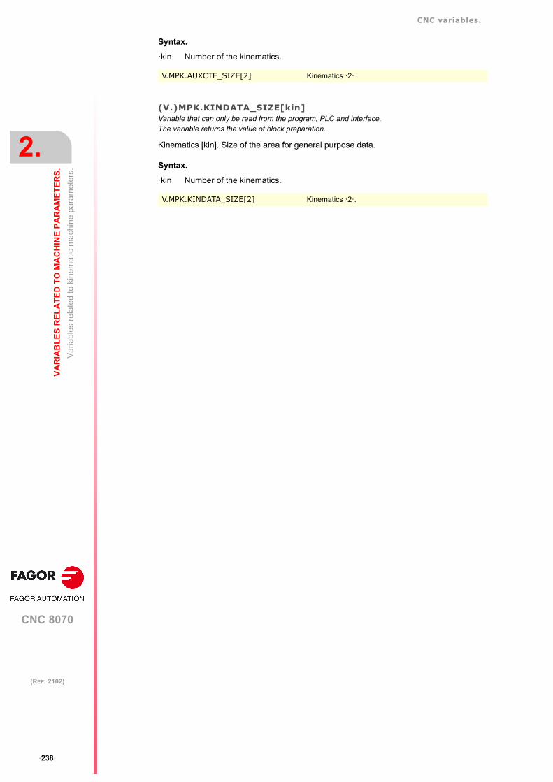
CNC variables.
CNC 8070
2.
VA
RIA
BL
ES
RE
LA
TE
D T
O M
AC
HIN
E P
AR
AM
ET
ER
S.
Va
riabl
es r
ela
ted
to k
inem
atic
mac
hin
e pa
ram
eter
s.
ꞏ238ꞏ
(REF: 2102)
Syntax.
ꞏkinꞏ Number of the kinematics.
(V.)MPK.KINDATA_SIZE[kin]Variable that can only be read from the program, PLC and interface.The variable returns the value of block preparation.
Kinematics [kin]. Size of the area for general purpose data.
Syntax.
ꞏkinꞏ Number of the kinematics.
V.MPK.AUXCTE_SIZE[2] Kinematics ꞏ2ꞏ.
V.MPK.KINDATA_SIZE[2] Kinematics ꞏ2ꞏ.

CNC variables.
CNC 8070
VA
RIA
BL
ES
RE
LA
TE
D T
O M
AC
HIN
E P
AR
AM
ET
ER
S.
2.
Va
riabl
es r
ela
ted
to k
inem
atic
mac
hin
e pa
ram
eter
s.
ꞏ239ꞏ
(REF: 2102)
2.7.2 Configuration of angular transformations.
(V.)MPK.NANGVariable that can only be read from the program, PLC and interface.The variable returns the value of block preparation.
Number of angular transformations defined.
(V.)MPK.ANGAXNA[ang]Variable that can only be read from the program, PLC and interface.The variable returns the value of block preparation.
Angular transformation [ang]. Logic number of the angular axis.
Syntax.
ꞏangꞏ Number of the angular transformation.
Remarks.
The logic number of the axes is determined by the order in which the axes have been definedin the machine parameter table. The first axis of the table will be logic axis -1- and so on.
(V.)MPK.ORTAXNA[ang]Variable that can only be read from the program, PLC and interface.The variable returns the value of block preparation.
Angular transformation [ang]. Logic number of the orthogonal axis.
Syntax.
ꞏangꞏ Number of the angular transformation.
Remarks.
The logic number of the axes is determined by the order in which the axes have been definedin the machine parameter table. The first axis of the table will be logic axis -1- and so on.
(V.)MPK.ANGANTR[ang]Variable that can only be read from the program, PLC and interface.The variable returns the value of block preparation.
Angular transformation [ang]. Angle between the Cartesian axis and the incline axis.
Syntax.
ꞏangꞏ Number of the angular transformation.
V.MPK.NANG
V.MPK.ANGAXNA[2] Angular transformation ꞏ2ꞏ.
V.MPK.ORTAXNA[2] Angular transformation ꞏ2ꞏ.
V.MPK.ORTAXNA[2] Angular transformation ꞏ2ꞏ.

CNC variables.
CNC 8070
2.
VA
RIA
BL
ES
RE
LA
TE
D T
O M
AC
HIN
E P
AR
AM
ET
ER
S.
Va
riabl
es r
ela
ted
to k
inem
atic
mac
hin
e pa
ram
eter
s.
ꞏ240ꞏ
(REF: 2102)
(V.)MPK.OFFANGAX[ang]Variable that can only be read from the program, PLC and interface.The variable returns the value of block preparation.
Angular transformation [ang]. Offset of the origin of the angular transformation.
Syntax.
ꞏangꞏ Number of the angular transformation.
V.MPK.OFFANGAX[2] Angular transformation ꞏ2ꞏ.
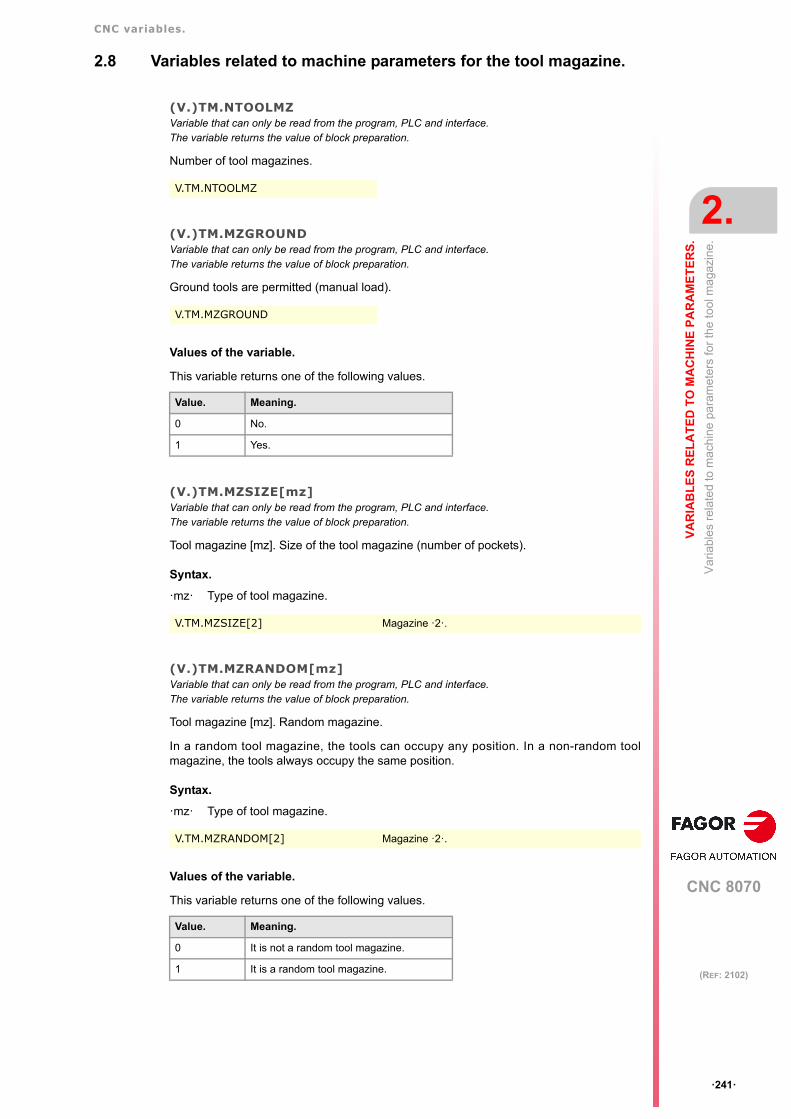
CNC variables.
CNC 8070
VA
RIA
BL
ES
RE
LA
TE
D T
O M
AC
HIN
E P
AR
AM
ET
ER
S.
2.
Va
riabl
es
rela
ted
to m
ach
ine
pa
ram
eter
s fo
r th
e to
ol m
agaz
ine.
ꞏ241ꞏ
(REF: 2102)
2.8 Variables related to machine parameters for the tool magazine.
(V.)TM.NTOOLMZVariable that can only be read from the program, PLC and interface.The variable returns the value of block preparation.
Number of tool magazines.
(V.)TM.MZGROUNDVariable that can only be read from the program, PLC and interface.The variable returns the value of block preparation.
Ground tools are permitted (manual load).
Values of the variable.
This variable returns one of the following values.
(V.)TM.MZSIZE[mz]Variable that can only be read from the program, PLC and interface.The variable returns the value of block preparation.
Tool magazine [mz]. Size of the tool magazine (number of pockets).
Syntax.
ꞏmzꞏ Type of tool magazine.
(V.)TM.MZRANDOM[mz]Variable that can only be read from the program, PLC and interface.The variable returns the value of block preparation.
Tool magazine [mz]. Random magazine.
In a random tool magazine, the tools can occupy any position. In a non-random toolmagazine, the tools always occupy the same position.
Syntax.
ꞏmzꞏ Type of tool magazine.
Values of the variable.
This variable returns one of the following values.
V.TM.NTOOLMZ
V.TM.MZGROUND
Value. Meaning.
0 No.
1 Yes.
V.TM.MZSIZE[2] Magazine ꞏ2ꞏ.
V.TM.MZRANDOM[2] Magazine ꞏ2ꞏ.
Value. Meaning.
0 It is not a random tool magazine.
1 It is a random tool magazine.

CNC variables.
CNC 8070
2.
VA
RIA
BL
ES
RE
LA
TE
D T
O M
AC
HIN
E P
AR
AM
ET
ER
S.
Va
riabl
es
rela
ted
to m
ach
ine
pa
ram
eter
s fo
r th
e to
ol m
agaz
ine.
ꞏ242ꞏ
(REF: 2102)
(V.)TM.MZTYPE[mz]Variable that can only be read from the program, PLC and interface.The variable returns the value of block preparation.
Tool magazine [mz]. Type of magazine.
Syntax.
ꞏmzꞏ Type of tool magazine.
Values of the variable.
This variable returns one of the following values.
(V.)TM.MZCYCLIC[mz]Variable that can only be read from the program, PLC and interface.The variable returns the value of block preparation.
Tool magazine [mz]. Cyclic tool changer.
A cyclic tool changer requires a tool change command (function M06) after searching a tooland before searching the next one. In a non-cyclic magazine, it is possible to perform severalconsecutive tool searches without necessarily having to change the tool.
Syntax.
ꞏmzꞏ Type of tool magazine.
Values of the variable.
This variable returns one of the following values.
(V.)TM.MZOPTIMIZED[mz]Variable that can only be read from the program, PLC and interface.The variable returns the value of block preparation.
Tool magazine [mz]. Tool management.
When programming several T's in a row without M06, a magazine with optimizedmanagement only looks for the tool to be changed; a magazine without optimizedmanagement looks for all the tools.
Syntax.
ꞏmzꞏ Type of tool magazine.
V.TM.MZTYPE[2] Magazine ꞏ2ꞏ.
Value. Meaning.
1 Asynchronous.
2 Synchronous.
3 Turret
4 Synchronous with 2 arms.
5 Synchronous with 1 arm.
V.TM.MZCYCLIC[2] Magazine ꞏ2ꞏ.
Value. Meaning.
0 It is not a cyclic tool magazine.
1 It is a cyclic tool magazine.
V.TM.MZOPTIMIZED[2] Magazine ꞏ2ꞏ.

CNC variables.
CNC 8070
VA
RIA
BL
ES
RE
LA
TE
D T
O M
AC
HIN
E P
AR
AM
ET
ER
S.
2.
Va
riabl
es
rela
ted
to m
ach
ine
pa
ram
eter
s fo
r th
e to
ol m
agaz
ine.
ꞏ243ꞏ
(REF: 2102)
Values of the variable.
This variable returns one of the following values.
(V.)TM.MZRESPECTSIZES[mz]Variable that can only be read from the program, PLC and interface.The variable returns the value of block preparation.
Tool magazine [mz]. In the random magazine, look for pockets of the same size.
Syntax.
ꞏmzꞏ Type of tool magazine.
(V.)TM.MZM6ALONE[mz]Variable that can only be read from the program, PLC and interface.The variable returns the value of block preparation.
Tool magazine [mz]. Action after executing an M6 without having selected a tool.
Syntax.
ꞏmzꞏ Type of tool magazine.
Values of the variable.
This variable returns one of the following values.
Value. Meaning.
0 The tool magazine has no optimized management.
1 The tool magazine has optimized management.
V.TM.MZRESPECTSIZES[2] Magazine ꞏ2ꞏ.
V.TM.MZM6ALONE[2] Magazine ꞏ2ꞏ.
Value. Meaning.
0 No action is carried out.
1 The CNC issues a warning.
2 The CNC issues an error message.

CNC variables.
CNC 8070
2.
VA
RIA
BL
ES
RE
LA
TE
D T
O M
AC
HIN
E P
AR
AM
ET
ER
S.
Var
iabl
es r
ela
ted
to O
EM
mac
hin
e pa
ram
eter
s.
ꞏ244ꞏ
(REF: 2102)
2.9 Variables related to OEM machine parameters.
2.9.1 Generic OEM parameters.
(V.)MTB.SIZEVariable that can only be read from the program, PLC and interface.The variable returns the value of block preparation.
Number of OEM parameters.
(V.)MTB.P[i]Variable that can be read and written via program, PLC and interface.The variable returns the execution value; reading it interrupts block preparation.
Value of the OEM parameter [nb]
Syntax.
ꞏnbꞏ Parameter number.
Remarks.
When reading this variable from the PLC, it truncates the decimal side. If the value of theparameter is 54.9876, when read from the PLC, it will return the value 54.
It must be borne in mind that reading and writing these variables interrupts block preparationaffecting program execution time. If the value of the parameter is not going to be changedduring execution, it is recommended to read the MTB variables at the beginning of theprogram using arithmetic parameters (local or global) and use the global ones throughoutthe program.
(V.)MTB.PF[i]Variable that can be read and written via program, PLC and interface.The variable returns the execution value; reading it interrupts block preparation.
Value of the OEM parameter [nb] Value per 10000.
Syntax.
ꞏnbꞏ Parameter number.
Remarks.
When reading this variable from the PLC, it returns the value in ten-thousandths. If the valueof the parameter is 54.9876, when read from the PLC, it will return the value 549876.
It must be borne in mind that reading and writing these variables interrupts block preparationaffecting program execution time. If the value of the parameter is not going to be changedduring execution, it is recommended to read the MTB variables at the beginning of the
V.MPB.SIZE
V.MTB.P[10] Value of the OEM parameter P10.
Machine parameter. Reading from the PLC.MTB.P[0]
Reading from the PLC.V.MTB.PF[0]
P0 = 54.9876 54 549876
P0 = -34.1234 -34 -341234
V.MTB.PF[10] Value of the OEM parameter P10.
Machine parameter. Reading from the PLC.MTB.P[0]
Reading from the PLC.V.MTB.PF[0]
P0 = 54.9876 54 549876
P0 = -34.1234 -34 -341234
CNC variables.
CNC 8070
VA
RIA
BL
ES
RE
LA
TE
D T
O M
AC
HIN
E P
AR
AM
ET
ER
S.
2.
Var
iabl
es r
ela
ted
to O
EM
mac
hin
e pa
ram
eter
s.
ꞏ245ꞏ
(REF: 2102)
program using arithmetic parameters (local or global) and use the global ones throughoutthe program.

CNC variables.
CNC 8070
2.
VA
RIA
BL
ES
RE
LA
TE
D T
O M
AC
HIN
E P
AR
AM
ET
ER
S.
Var
iabl
es r
ela
ted
to O
EM
mac
hin
e pa
ram
eter
s.
ꞏ246ꞏ
(REF: 2102)
2.9.2 Reading drive variables.
(V.)DRV.SIZEVariable that can only be read from the program, PLC and interface.The variable returns the value of block preparation.
Number of variables to be consulted at the drive.
(V.)DRV.name(V.)DRV.name.xn(V.)DRV.name.snVariable that can be read and written via program, PLC and interface.The variable returns the execution value; reading it interrupts block preparation.
Variables defined in parameter DRIVEVAR that grant access to the variables and/orparameters of the digital drives.
Syntax.
ꞏnameꞏMnemonic name set at the machine parameters.
ꞏxnꞏ Axis name.
ꞏsnꞏ Spindle name.
V.DRV.SIZE
• Sercos. DRV variables can access the variables of the drive. These variablesmay be read-only or read and written.
• Mechatrolink. DRV variables can access the variables and/or parameters of thedrive. The variables of the drive can only be read, whereas theparameters may be read or written.
V.DRV.FEED Value of the variable defined as FEED.
V.DRV.AXISFEED.Z Value of the variable defined as AXISFEED for the Z axis.
V.DRV.AXISFEED.S Value of the variable defined as AXISFEED for the spindle S.

CNC 8070
3
ꞏ247ꞏ
(REF: 2102)
3. PLC RELATED VARIABLES.
3.1 Variables associated with the status and resources of the PLC.
3.1.1 PLC status.
(V.)PLC.STATUSVariable that can only be read from the program and interface.The variable returns the execution value; reading it interrupts block preparation.Report variable (to be used from the scripts).
PLC status.
Values of the variable.
This variable returns one of the following values.
V.PLC.STATUS
Value. Meaning.
0 PLC stopped.
1 PLC in execution (running).

CNC variables.
CNC 8070
3.
PL
C R
EL
AT
ED
VA
RIA
BL
ES
.
Var
iab
les
asso
cia
ted
with
the
sta
tus
and
reso
urc
es o
f the
PLC
.
ꞏ248ꞏ
(REF: 2102)
3.1.2 PLC Resources.
(V.)PLC.I[nb]Variable that can be read and written via program and interface.The variable returns the execution value; reading it interrupts block preparation.
Status of PLC digital input [nb].
Syntax.
ꞏnbꞏ Number of the digital input.
(V.)PLC.O[nb]Variable that can be read and written via program and interface.The variable returns the execution value; reading it interrupts block preparation.
Status of PLC digital output [nb].
Syntax.
ꞏnbꞏ Number of the digital output.
(V.)PLC.LI[nb]Variable that can be read and written via program and interface.The variable returns the execution value; reading it interrupts block preparation.
Status of PLC local digital input [nb].
Syntax.
ꞏnbꞏ Number of the digital input.
(V.)PLC.LO[nb]Variable that can be read and written via program and interface.The variable returns the execution value; reading it interrupts block preparation.
Status of PLC local digital output [nb].
Syntax.
ꞏnbꞏ Number of the digital output.
(V.)PLC.M[nb]Variable that can be read and written via program and interface.The variable returns the execution value; reading it interrupts block preparation.
Status of PLC mark [nb].
Syntax.
ꞏnbꞏ Mark number.
(V.)PLC.R[nb]Variable that can be read and written via program and interface.The variable returns the execution value; reading it interrupts block preparation.
Status of PLC register [nb].
V.PLC.I[122] Status of PLC digital input ꞏ122ꞏ.
V.PLC.O[243] Status of PLC digital output ꞏ243ꞏ.
V.PLC.LI[2] Status of PLC local digital input ꞏ2ꞏ.
V.PLC.LO[3] Status of PLC local digital output ꞏ3ꞏ.
V.PLC.M[111] Status of PLC mark ꞏ111ꞏ.

CNC variables.
CNC 8070
PL
C R
EL
AT
ED
VA
RIA
BL
ES
.
3.
Var
iab
les
asso
cia
ted
with
the
sta
tus
and
reso
urc
es o
f the
PLC
.
ꞏ249ꞏ
(REF: 2102)
Syntax.
ꞏnbꞏ Register number.
(V.)PLC.T[nb]Variable that can be read and written from the interface and read from the program.The variable returns the execution value; reading it interrupts block preparation.
Status of PLC timer [nb]
Syntax.
ꞏnbꞏ Timer number.
(V.)PLC.C[nb]Variable that can be read and written from the interface and read from the program.The variable returns the execution value; reading it interrupts block preparation.
Status of PLC counter [nb].
Syntax.
ꞏnbꞏ Counter number.
V.PLC.R[200] Status of PLC register ꞏ200ꞏ.
V.PLC.T[8] Status of PLC timer ꞏ8ꞏ.
V.PLC.C[16] Status of PLC counter ꞏ16ꞏ.

CNC variables.
CNC 8070
3.
PL
C R
EL
AT
ED
VA
RIA
BL
ES
.
Var
iab
les
asso
cia
ted
with
the
sta
tus
and
reso
urc
es o
f the
PLC
.
ꞏ250ꞏ
(REF: 2102)
3.1.3 PLC messages.
(V.)PLC.MSG[msg]Variable that can be read and written via program and interface.The variable returns the execution value; reading it interrupts block preparation.
Status of PLC message [msg].
Syntax.
ꞏmsgꞏ Message number.
Values of the variable.
This variable returns one of the following values.
(V.)PLC.PRIORMSGVariable that can only be read from the program and interface.The variable returns the execution value; reading it interrupts block preparation.Report variable (to be used from the scripts).
Active message with the highest priority (the one with the lowest number among the activeones).
(V.)PLC.EMERGMSGVariable that can only be read from the program and interface.The variable returns the execution value; reading it interrupts block preparation.Report variable (to be used from the scripts).
Active emerging message (the one shown at full screen).
V.PLC.MSG[87] Status of message 87.
Value. Meaning.
0 Message off.
1 Message on.
V.PLC.PRIORMSG
V.PLC.EMERGMSG

CNC variables.
CNC 8070
PL
C R
EL
AT
ED
VA
RIA
BL
ES
.
3.
Var
iab
les
asso
cia
ted
with
the
sta
tus
and
reso
urc
es o
f the
PLC
.
ꞏ251ꞏ
(REF: 2102)
3.1.4 PLC errors.
(V.)PLC.ERR[err]Variable that can be read and written via program and interface.The variable returns the execution value; reading it interrupts block preparation.
Status of PLC error [err].
Syntax.
ꞏerrꞏ Error number.
Values of the variable.
This variable returns one of the following values.
(V.)PLC.PRIORERRVariable that can only be read from the program and interface.The variable returns the execution value; reading it interrupts block preparation.Report variable (to be used from the scripts).
Active error with the highest priority (the one with the lowest number among the active ones).
V.PLC.ERR[62] Status of error 62.
Value. Meaning.
0 Error off.
1 Error on.
V.PLC.PRIORERR

CNC variables.
CNC 8070
3.
PL
C R
EL
AT
ED
VA
RIA
BL
ES
.
Var
iab
les
asso
cia
ted
with
the
sta
tus
and
reso
urc
es o
f the
PLC
.
ꞏ252ꞏ
(REF: 2102)
3.1.5 PLC clocks.
(V.)PLC.TIMERVariable that can be read and written via program, PLC and interface.The variable returns the execution value; reading it interrupts block preparation.Report variable (to be used from the scripts).
Value of the freely available clock (in seconds).
This variable may be used to consult and/or modify the timing of the clock. Value in seconds.
Remarks.
The PLC "TIMER" is enabled or disabled with the PLC mark TIMERON. This clock is timingwhen TIMERON=1.
(V.)PLC.CLKnbVariable that can be read and written via program and interface.The variable returns the execution value; reading it interrupts block preparation.
Status of PLC clock nb.
Values of the variable.
This variable returns one of the following values.
V.PLC.TIMER
V.PLC.CLK128
Value. Meaning.
0 Clock off.
1 Clock on.

CNC variables.
CNC 8070
PL
C R
EL
AT
ED
VA
RIA
BL
ES
.
3.
PL
C c
ons
ultin
g lo
gic
sig
nals
; gen
era
l.
ꞏ253ꞏ
(REF: 2102)
3.2 PLC consulting logic signals; general.
(V.)PLC.CNCREADYVariable that can only be read from the program and interface.The variable returns the execution value; reading it interrupts block preparation.Report variable (to be used from the scripts).
This variable reflects the status of the mark CNCREADY of the PLC. The CNC activates themark when it is not in an error state.
(V.)PLC.READYVariable that can only be read from the program and interface.The variable returns the execution value; reading it interrupts block preparation.Report variable (to be used from the scripts).
This variable reflects the status of the mark READY of the PLC. The channel activates themark when it is not in an error state.
(V.)PLC.SERCOSRDYVariable that can only be read from the program, PLC and interface.The variable returns the execution value; reading it interrupts block preparation.Report variable (to be used from the scripts).
This variable reflects the status of the mark SERCOSREADY of the PLC. The CNC activatesthe mark when the Sercos ring has been initialized properly.
(V.)PLC.STARTVariable that can only be read from the program and interface.The variable returns the execution value; reading it interrupts block preparation.Report variable (to be used from the scripts).
This variable reflects the status of the mark START of the PLC. The channel activates thismark when the [START] key has been pressed.
(V.)PLC.RESETOUTVariable that can only be read from the program and interface.The variable returns the execution value; reading it interrupts block preparation.Report variable (to be used from the scripts).
This variable reflects the status of the mark RESETOUT of the PLC. When pressing the[RESET] key or when the PLC activates the RESETIN mark, the CNC assumes the initialconditions and activates the RESETOUT mark.
V.PLC.CNCREADY
V.PLC.READYC1 Channel ꞏ1ꞏ.
V.PLC.READYC2 Channel ꞏ2ꞏ.
V.PLC.READYC3 Channel ꞏ3ꞏ.
V.PLC.READYC4 Channel ꞏ4ꞏ.
V.PLC.SERCOSRDY
V.PLC.START Channel ꞏ1ꞏ.
V.PLC.STARTC1 Channel ꞏ1ꞏ.
V.PLC.STARTC2 Channel ꞏ2ꞏ.
V.PLC.STARTC3 Channel ꞏ3ꞏ.
V.PLC.STARTC4 Channel ꞏ4ꞏ.
V.PLC.RESETOUT Channel ꞏ1ꞏ.
V.PLC.RESETOUTC1 Channel ꞏ1ꞏ.

CNC variables.
CNC 8070
3.
PL
C R
EL
AT
ED
VA
RIA
BL
ES
.
PL
C c
ons
ultin
g lo
gic
sig
nals
; gen
era
l.
ꞏ254ꞏ
(REF: 2102)
(V.)PLC.FHOUTVariable that can only be read from the program and interface.The variable returns the execution value; reading it interrupts block preparation.Report variable (to be used from the scripts).
This variable reflects the status of the mark FHOUT of the PLC. The CNC channel activatesthis mark when the execution of the part-program is interrupted.
(V.)PLC._ALARMVariable that can only be read from the program and interface.The variable returns the execution value; reading it interrupts block preparation.Report variable (to be used from the scripts).
This variable reflects the status of the mark _ALARM of the PLC. The channel turns this markoff when there is an alarm or an emergency in the channel.
(V.)PLC.MANUALVariable that can only be read from the program and interface.The variable returns the execution value; reading it interrupts block preparation.Report variable (to be used from the scripts).
This variable reflects the status of the mark MANUAL of the PLC. The channel activates themark when the jog mode is selected.
(V.)PLC.AUTOMATVariable that can only be read from the program and interface.The variable returns the execution value; reading it interrupts block preparation.Report variable (to be used from the scripts).
This variable reflects the status of the mark AUTOMAT of the PLC. The channel activatesthe mark when the automatic mode is selected.
V.PLC.RESETOUTC2 Channel ꞏ2ꞏ.
V.PLC.RESETOUTC3 Channel ꞏ3ꞏ.
V.PLC.RESETOUTC4 Channel ꞏ4ꞏ.
V.PLC.FHOUT Channel ꞏ1ꞏ.
V.PLC.FHOUTC1 Channel ꞏ1ꞏ.
V.PLC.FHOUTC2 Channel ꞏ2ꞏ.
V.PLC.FHOUTC3 Channel ꞏ3ꞏ.
V.PLC.FHOUTC4 Channel ꞏ4ꞏ.
V.PLC._ALARM Channel ꞏ1ꞏ.
V.PLC._ALARMC1 Channel ꞏ1ꞏ.
V.PLC._ALARMC2 Channel ꞏ2ꞏ.
V.PLC._ALARMC3 Channel ꞏ3ꞏ.
V.PLC._ALARMC4 Channel ꞏ4ꞏ.
V.PLC.MANUAL Channel ꞏ1ꞏ.
V.PLC.MANUALC1 Channel ꞏ1ꞏ.
V.PLC.MANUALC2 Channel ꞏ2ꞏ.
V.PLC.MANUALC3 Channel ꞏ3ꞏ.
V.PLC.MANUALC4 Channel ꞏ4ꞏ.
V.PLC.AUTOMAT Channel ꞏ1ꞏ.
V.PLC.AUTOMATC1 Channel ꞏ1ꞏ.
V.PLC.AUTOMATC2 Channel ꞏ2ꞏ.
V.PLC.AUTOMATC3 Channel ꞏ3ꞏ.
V.PLC.AUTOMATC4 Channel ꞏ4ꞏ.

CNC variables.
CNC 8070
PL
C R
EL
AT
ED
VA
RIA
BL
ES
.
3.
PL
C c
ons
ultin
g lo
gic
sig
nals
; gen
era
l.
ꞏ255ꞏ
(REF: 2102)
(V.)PLC.MDIVariable that can only be read from the program and interface.The variable returns the execution value; reading it interrupts block preparation.Report variable (to be used from the scripts).
This variable reflects the status of the mark MDI of the PLC. The channel activates the markwhen the MDI/MDA mode is selected.
(V.)PLC.SBOUTVariable that can only be read from the program and interface.The variable returns the execution value; reading it interrupts block preparation.Report variable (to be used from the scripts).
This variable reflects the status of the mark SBOUT of the PLC. The channel activates themark when the single-block mode is selected.
(V.)PLC.INCYCLEVariable that can only be read from the program and interface.The variable returns the execution value; reading it interrupts block preparation.Report variable (to be used from the scripts).
This variable reflects the status of the mark INCYCLE of the PLC. The channel activates themark when it is executing a block or moving an axis.
(V.)PLC.RAPIDVariable that can only be read from the program and interface.The variable returns the execution value; reading it interrupts block preparation.Report variable (to be used from the scripts).
This variable reflects the status of the mark RAPID of the PLC. The channel activates themark when it is executing a rapid positioning (G00).
V.PLC.MDI Channel ꞏ1ꞏ.
V.PLC.MDIC1 Channel ꞏ1ꞏ.
V.PLC.MDIC2 Channel ꞏ2ꞏ.
V.PLC.MDIC3 Channel ꞏ3ꞏ.
V.PLC.MDIC4 Channel ꞏ4ꞏ.
V.PLC.SBOUT Channel ꞏ1ꞏ.
V.PLC.SBOUTC1 Channel ꞏ1ꞏ.
V.PLC.SBOUTC2 Channel ꞏ2ꞏ.
V.PLC.SBOUTC3 Channel ꞏ3ꞏ.
V.PLC.SBOUTC4 Channel ꞏ4ꞏ.
V.PLC.INCYCLE Channel ꞏ1ꞏ.
V.PLC.INCYCLEC1 Channel ꞏ1ꞏ.
V.PLC.INCYCLEC2 Channel ꞏ2ꞏ.
V.PLC.INCYCLEC3 Channel ꞏ3ꞏ.
V.PLC.INCYCLEC4 Channel ꞏ4ꞏ.
V.PLC.RAPID Channel ꞏ1ꞏ.
V.PLC.RAPIDC1 Channel ꞏ1ꞏ.
V.PLC.RAPIDC2 Channel ꞏ2ꞏ.
V.PLC.RAPIDC3 Channel ꞏ3ꞏ.
V.PLC.RAPIDC4 Channel ꞏ4ꞏ.

CNC variables.
CNC 8070
3.
PL
C R
EL
AT
ED
VA
RIA
BL
ES
.
PL
C c
ons
ultin
g lo
gic
sig
nals
; gen
era
l.
ꞏ256ꞏ
(REF: 2102)
(V.)PLC.ZEROVariable that can only be read from the program and interface.The variable returns the execution value; reading it interrupts block preparation.Report variable (to be used from the scripts).
This variable reflects the status of the mark ZERO of the PLC. The channel activates thismark when searching home (G74).
(V.)PLC.PROBEVariable that can only be read from the program and interface.The variable returns the execution value; reading it interrupts block preparation.Report variable (to be used from the scripts).
This variable reflects the status of the mark PROBE of the PLC. The channel activates themark when it is executing a probing movement (G100).
(V.)PLC.THREADVariable that can only be read from the program and interface.The variable returns the execution value; reading it interrupts block preparation.Report variable (to be used from the scripts).
This variable reflects the status of the mark THREAD of the PLC. The channel activates themark when it is executing an electronic threading (G33).
(V.)PLC.TAPPINGVariable that can only be read from the program and interface.The variable returns the execution value; reading it interrupts block preparation.Report variable (to be used from the scripts).
This variable reflects the status of the mark TAPPING of the PLC. The channel activates themark when it is executing a tapping canned cycle.
V.PLC.ZERO Channel ꞏ1ꞏ.
V.PLC.ZEROC1 Channel ꞏ1ꞏ.
V.PLC.ZEROC2 Channel ꞏ2ꞏ.
V.PLC.ZEROC3 Channel ꞏ3ꞏ.
V.PLC.ZEROC4 Channel ꞏ4ꞏ.
V.PLC.PROBE Channel ꞏ1ꞏ.
V.PLC.PROBEC1 Channel ꞏ1ꞏ.
V.PLC.PROBEC2 Channel ꞏ2ꞏ.
V.PLC.PROBEC3 Channel ꞏ3ꞏ.
V.PLC.PROBEC4 Channel ꞏ4ꞏ.
V.PLC.THREAD Channel ꞏ1ꞏ.
V.PLC.THREADC1 Channel ꞏ1ꞏ.
V.PLC.THREADC2 Channel ꞏ2ꞏ.
V.PLC.THREADC3 Channel ꞏ3ꞏ.
V.PLC.THREADC4 Channel ꞏ4ꞏ.
V.PLC.TAPPING Channel ꞏ1ꞏ.
V.PLC.TAPPINGC1 Channel ꞏ1ꞏ.
V.PLC.TAPPINGC2 Channel ꞏ2ꞏ.
V.PLC.TAPPINGC3 Channel ꞏ3ꞏ.
V.PLC.TAPPINGC4 Channel ꞏ4ꞏ.

CNC variables.
CNC 8070
PL
C R
EL
AT
ED
VA
RIA
BL
ES
.
3.
PL
C c
ons
ultin
g lo
gic
sig
nals
; gen
era
l.
ꞏ257ꞏ
(REF: 2102)
(V.)PLC.RIGIDVariable that can only be read from the program and interface.The variable returns the execution value; reading it interrupts block preparation.Report variable (to be used from the scripts).
This variable reflects the status of the mark RIGID of the PLC. The channel activates themark when it is executing a rigid tapping cycle (G63).
(V.)PLC.CSSVariable that can only be read from the program and interface.The variable returns the execution value; reading it interrupts block preparation.Report variable (to be used from the scripts).
This variable reflects the status of the mark CSS of the PLC. The channel activates this markwhen constant surface speed (G96 ) is active.
(V.)PLC.INTERENDVariable that can only be read from the program and interface.The variable returns the execution value; reading it interrupts block preparation.Report variable (to be used from the scripts).
This variable reflects the status of the mark INTEREND of the PLC. The channel activatesthe mark when the theoretical movement of the axes is completed.
(V.)PLC.INPOSIVariable that can only be read from the program and interface.The variable returns the execution value; reading it interrupts block preparation.Report variable (to be used from the scripts).
This variable reflects the status of the mark INPOSI of the PLC. The channel activates themark when the axes are in position. This mark also remains active during the movement ofindependent axes.
V.PLC.RIGID Channel ꞏ1ꞏ.
V.PLC.RIGIDC1 Channel ꞏ1ꞏ.
V.PLC.RIGIDC2 Channel ꞏ2ꞏ.
V.PLC.RIGIDC3 Channel ꞏ3ꞏ.
V.PLC.RIGIDC4 Channel ꞏ4ꞏ.
V.PLC.CSS Channel ꞏ1ꞏ.
V.PLC.CSSC1 Channel ꞏ1ꞏ.
V.PLC.CSSC2 Channel ꞏ2ꞏ.
V.PLC.CSSC3 Channel ꞏ3ꞏ.
V.PLC.CSSC4 Channel ꞏ4ꞏ.
V.PLC.INTEREND Channel ꞏ1ꞏ.
V.PLC.INTERENDC1 Channel ꞏ1ꞏ.
V.PLC.INTERENDC2 Channel ꞏ2ꞏ.
V.PLC.INTERENDC3 Channel ꞏ3ꞏ.
V.PLC.INTERENDC4 Channel ꞏ4ꞏ.
V.PLC.INPOSI Channel ꞏ1ꞏ.
V.PLC.INPOSIC1 Channel ꞏ1ꞏ.
V.PLC.INPOSIC2 Channel ꞏ2ꞏ.
V.PLC.INPOSIC3 Channel ꞏ3ꞏ.
V.PLC.INPOSIC4 Channel ꞏ4ꞏ.

CNC variables.
CNC 8070
3.
PL
C R
EL
AT
ED
VA
RIA
BL
ES
.
PL
C c
ons
ultin
g lo
gic
sig
nals
; gen
era
l.
ꞏ258ꞏ
(REF: 2102)
(V.)PLC.SPN1(V.)PLC.SPN2(V.)PLC.SPN3(V.)PLC.SPN4(V.)PLC.SPN5(V.)PLC.SPN6(V.)PLC.SPN7Variable that can only be read from the program and interface.The variable returns the execution value; reading it interrupts block preparation.Report variable (to be used from the scripts).
These variables reflect the value of the registers SPN1 to SPN7 of the PLC. The channelindicates in these registers which spindle of the channel the M functions pending executionare addressed to. There is a register for each channel. Here is an example of the mnemonicsfor SPN1; it is the same for the rest of the registers.
(V.)PLC.MFUN1(V.)PLC.MFUN2(V.)PLC.MFUN3(V.)PLC.MFUN4(V.)PLC.MFUN5(V.)PLC.MFUN6(V.)PLC.MFUN7Variable that can only be read from the program and interface.The variable returns the execution value; reading it interrupts block preparation.Report variable (to be used from the scripts).
These variables reflect the value of the registers MFUN1 to MFUN7 of the PLC. The channelindicates in these registers the H functions pending execution. There is a register for eachchannel. Here is an example of the mnemonics for MFUN1; it is the same for the rest of theregisters.
(V.)PLC.HFUN1(V.)PLC.HFUN2(V.)PLC.HFUN3(V.)PLC.HFUN4(V.)PLC.HFUN5(V.)PLC.HFUN6(V.)PLC.HFUN7Variable that can only be read from the program and interface.The variable returns the execution value; reading it interrupts block preparation.Report variable (to be used from the scripts).
These variables reflect the value of the registers HFUN1 to HFUN7 of the PLC. The channelindicates in these registers the H functions pending execution. There is a register for eachchannel. Here is an example of the mnemonics for HFUN1; it is the same for the rest of theregisters.
V.PLC.SPN1C1 Channel ꞏ1ꞏ.
V.PLC.SPN1C2 Channel ꞏ2ꞏ.
V.PLC.SPN1C3 Channel ꞏ3ꞏ.
V.PLC.SPN1C4 Channel ꞏ4ꞏ.
V.PLC.MFUN1 Channel ꞏ1ꞏ.
V.PLC.MFUN1C1 Channel ꞏ1ꞏ.
V.PLC.MFUN1C2 Channel ꞏ2ꞏ.
V.PLC.MFUN1C3 Channel ꞏ3ꞏ.
V.PLC.MFUN1C4 Channel ꞏ4ꞏ.
V.PLC.HFUN1 Channel ꞏ1ꞏ.
V.PLC.HFUN1C1 Channel ꞏ1ꞏ.
V.PLC.HFUN1C2 Channel ꞏ2ꞏ.
V.PLC.HFUN1C3 Channel ꞏ3ꞏ.
V.PLC.HFUN1C4 Channel ꞏ4ꞏ.

CNC variables.
CNC 8070
PL
C R
EL
AT
ED
VA
RIA
BL
ES
.
3.
PL
C c
ons
ultin
g lo
gic
sig
nals
; gen
era
l.
ꞏ259ꞏ
(REF: 2102)
(V.)PLC.MSTROBEVariable that can only be read from the program and interface.The variable returns the execution value; reading it interrupts block preparation.Report variable (to be used from the scripts).
This variable reflects the status of the mark MSTROBE of the PLC. The channel activatesthis mark to indicate to the PLC that it must execute the M functions indicated in MFUN1through MFUN7.
(V.)PLC.HSTROBEVariable that can only be read from the program and interface.The variable returns the execution value; reading it interrupts block preparation.Report variable (to be used from the scripts).
This variable reflects the status of the mark HSTROBE of the PLC. The channel activatesthis mark to indicate to the PLC that it must execute the H functions indicated in HFUN1through HFUN7.
(V.)PLC.SFUN1(V.)PLC.SFUN2(V.)PLC.SFUN3(V.)PLC.SFUN4(V.)PLC.SFUN5(V.)PLC.SFUN6Variable that can only be read from the program and interface.The variable returns the execution value; reading it interrupts block preparation.Report variable (to be used from the scripts).
These variables reflect the value of the registers SFUN1 to SFUN6 of the PLC. The channelindicates in these registers the speed programmed in each spindle.
(V.)PLC.SSTROBEVariable that can only be read from the program and interface.The variable returns the execution value; reading it interrupts block preparation.Report variable (to be used from the scripts).
This variable reflects the status of the mark SSTROBE of the PLC. The channel activatesthis mark to indicate to the PLC that a new spindle speed has been selected in registersSFUN1 through SFUN6.
V.PLC.MSTROBE Channel ꞏ1ꞏ.
V.PLC.MSTROBEC1 Channel ꞏ1ꞏ.
V.PLC.MSTROBEC2 Channel ꞏ2ꞏ.
V.PLC.MSTROBEC3 Channel ꞏ3ꞏ.
V.PLC.MSTROBEC4 Channel ꞏ4ꞏ.
V.PLC.HSTROBE Channel ꞏ1ꞏ.
V.PLC.HSTROBEC1 Channel ꞏ1ꞏ.
V.PLC.HSTROBEC2 Channel ꞏ2ꞏ.
V.PLC.HSTROBEC3 Channel ꞏ3ꞏ.
V.PLC.HSTROBEC4 Channel ꞏ4ꞏ.
V.PLC.SFUN1 Spindle ꞏ1ꞏ.
V.PLC.SFUN2 Spindle ꞏ2ꞏ.
V.PLC.SFUN3 Spindle ꞏ3ꞏ.
V.PLC.SFUN4 Spindle ꞏ4ꞏ.
V.PLC.SFUN5 Spindle ꞏ5ꞏ.
V.PLC.SFUN6 Spindle ꞏ6ꞏ
V.PLC.SSTROBE Spindle ꞏ1ꞏ.
V.PLC.SSTROBE1 Spindle ꞏ1ꞏ.
V.PLC.SSTROBE2 Spindle ꞏ2ꞏ.
V.PLC.SSTROBE3 Spindle ꞏ3ꞏ.

CNC variables.
CNC 8070
3.
PL
C R
EL
AT
ED
VA
RIA
BL
ES
.
PL
C c
ons
ultin
g lo
gic
sig
nals
; gen
era
l.
ꞏ260ꞏ
(REF: 2102)
(V.)PLC.DM00(V.)PLC.DM01(V.)PLC.DM02(V.)PLC.DM06(V.)PLC.DM08(V.)PLC.DM09(V.)PLC.DM30Variable that can only be read from the program and interface.The variable returns the execution value; reading it interrupts block preparation.Report variable (to be used from the scripts).
These variables reflect the status of the marks DM00, DM01, DM02, DM06, DM08, DM09,DM30 of the PLC. The CNC indicates in these marks the status of the M functions. This markis active if the M function is active. Each one of functions M00, M01, M02, M06, M08, M09,M30 has a mark for each channel. Here is an example of the mnemonics for DM00; it is thesame for the rest of the marks (DM01, DM02, DM06, DM08, DM09, DM30).
(V.)PLC.DM03(V.)PLC.DM04(V.)PLC.DM05(V.)PLC.DM19(V.)PLC.DM41(V.)PLC.DM42(V.)PLC.DM43(V.)PLC.DM44Variable that can only be read from the program and interface.The variable returns the execution value; reading it interrupts block preparation.Report variable (to be used from the scripts).
These variables reflect the status of the marks DM00, DM01, DM02, DM06, DM08, DM09,DM30 of the PLC. The CNC indicates in these marks the status of the spindle M functions.This mark is active if the M function is active. Each one of functions M03, M04, M05, M19,M41, M42, M43, M44 has a mark for each spindle. Here is an example of the mnemonicsfor DM03; it is the same for the rest of the marks (DM04, DM05, DM19, DM41, DM42, DM43,DM44).
V.PLC.SSTROBE4 Spindle ꞏ4ꞏ.
V.PLC.SSTROBE5 Spindle ꞏ5ꞏ.
V.PLC.SSTROBE6 Spindle ꞏ6ꞏ
V.PLC.DM00 Channel ꞏ1ꞏ.
V.PLC.DM00C1 Channel ꞏ1ꞏ.
V.PLC.DM00C2 Channel ꞏ2ꞏ.
V.PLC.DM00C3 Channel ꞏ3ꞏ.
V.PLC.DM00C4 Channel ꞏ4ꞏ.
V.PLC.DM03 Spindle ꞏ1ꞏ.
V.PLC.DM03SP1 Spindle ꞏ1ꞏ.
V.PLC.DM03SP2 Spindle ꞏ2ꞏ.
V.PLC.DM03SP3 Spindle ꞏ3ꞏ.
V.PLC.DM03SP4 Spindle ꞏ4ꞏ.
V.PLC.DM03SP5 Spindle ꞏ5ꞏ.
V.PLC.DM03SP6 Spindle ꞏ6ꞏ.

CNC variables.
CNC 8070
PL
C R
EL
AT
ED
VA
RIA
BL
ES
.
3.
PL
C c
ons
ultin
g lo
gic
sig
nals
; gen
era
l.
ꞏ261ꞏ
(REF: 2102)
(V.)PLC.BLKSEARCHVariable that can only be read from the program and interface.The variable returns the execution value; reading it interrupts block preparation.Report variable (to be used from the scripts).
This variable reflects the status of the mark BLKSEARCH of the PLC. The channel activatesthe mark when the block-search mode is active.
(V.)PLC.ADVINPOSVariable that can only be read from the program and interface.The variable returns the execution value; reading it interrupts block preparation.Report variable (to be used from the scripts).
This variable reflects the status of the mark ADVINPOS of the PLC. The channel activatesa certain amount of time before the axes reach position. The amount of time is set byparameter ANTIME.
(V.)PLC.CAXISVariable that can only be read from the program and interface.The variable returns the execution value; reading it interrupts block preparation.Report variable (to be used from the scripts).
This variable reflects the status of the mark CAXIS of the PLC. The channel activates themark when there is a spindle working as C axis.
(V.)PLC.FREEVariable that can only be read from the program and interface.The variable returns the execution value; reading it interrupts block preparation.Report variable (to be used from the scripts).
This variable reflects the status of the mark FREE of the PLC. The channel activates the markwhen it can accept a block sent with CNCEX.
V.PLC.BLKSEARCH Channel ꞏ1ꞏ.
V.PLC.BLKSEARCHC1 Channel ꞏ1ꞏ.
V.PLC.BLKSEARCHC2 Channel ꞏ2ꞏ.
V.PLC.BLKSEARCHC3 Channel ꞏ3ꞏ.
V.PLC.BLKSEARCHC4 Channel ꞏ4ꞏ.
V.PLC.ADVINPOS Channel ꞏ1ꞏ.
V.PLC.ADVINPOSC1 Channel ꞏ1ꞏ.
V.PLC.ADVINPOSC2 Channel ꞏ2ꞏ.
V.PLC.ADVINPOSC3 Channel ꞏ3ꞏ.
V.PLC.ADVINPOSC4 Channel ꞏ4ꞏ.
V.PLC.CAXIS Channel ꞏ1ꞏ.
V.PLC.CAXISC1 Channel ꞏ1ꞏ.
V.PLC.CAXISC2 Channel ꞏ2ꞏ.
V.PLC.CAXISC3 Channel ꞏ3ꞏ.
V.PLC.CAXISC4 Channel ꞏ4ꞏ.
V.PLC.FREEC1 Channel ꞏ1ꞏ.
V.PLC.FREEC2 Channel ꞏ2ꞏ.
V.PLC.FREEC3 Channel ꞏ3ꞏ.
V.PLC.FREEC4 Channel ꞏ4ꞏ.

CNC variables.
CNC 8070
3.
PL
C R
EL
AT
ED
VA
RIA
BL
ES
.
PL
C c
ons
ultin
g lo
gic
sig
nals
; gen
era
l.
ꞏ262ꞏ
(REF: 2102)
(V.)PLC.WAITOUTVariable that can only be read from the program and interface.The variable returns the execution value; reading it interrupts block preparation.Report variable (to be used from the scripts).
This variable reflects the status of the mark WAITOUT of the PLC. The channel activatesthe mark when it is waiting for a synchronism signal.
(V.)PLC.MMCWDGVariable that can only be read from the program, PLC and interface.The variable returns the execution value; reading it interrupts block preparation.Report variable (to be used from the scripts).
This variable reflects the status of the mark MMCWDG of the PLC. The CNC activates thismark when the operating system is locked up.
(V.)PLC.RETRAENDVariable that can only be read from the program and interface.The variable returns the execution value; reading it interrupts block preparation.Report variable (to be used from the scripts).
This variable reflects the status of the mark RETRAEND of the PLC. The channel activatesthis mark to cancel the retrace function.
(V.)PLC.TANGACTIVVariable that can only be read from the program and interface.The variable returns the execution value; reading it interrupts block preparation.Report variable (to be used from the scripts).
This variable reflects the status of the mark TANGACTIV of the PLC. The channel activatesthe mark when a tangential control is active.
(V.)PLC.PSWSETVariable that can only be read from the program and interface.The variable returns the execution value; reading it interrupts block preparation.Report variable (to be used from the scripts).
This variable reflects the status of the mark PSWSET of the PLC. The CNC activates thismark when there is an OEM password.
V.PLC.WAITOUTC1 Channel ꞏ1ꞏ.
V.PLC.WAITOUTC2 Channel ꞏ2ꞏ.
V.PLC.WAITOUTC3 Channel ꞏ3ꞏ.
V.PLC.WAITOUTC4 Channel ꞏ4ꞏ.
V.PLC.MMCWDG
V.PLC.RETRAENDC1 Channel ꞏ1ꞏ.
V.PLC.RETRAENDC2 Channel ꞏ2ꞏ.
V.PLC.RETRAENDC3 Channel ꞏ3ꞏ.
V.PLC.RETRAENDC4 Channel ꞏ4ꞏ.
V.PLC.TANGACTIVC1 Channel ꞏ1ꞏ.
V.PLC.TANGACTIVC2 Channel ꞏ2ꞏ.
V.PLC.TANGACTIVC3 Channel ꞏ3ꞏ.
V.PLC.TANGACTIVC4 Channel ꞏ4ꞏ.
V.PLC.PSWSET

CNC variables.
CNC 8070
PL
C R
EL
AT
ED
VA
RIA
BL
ES
.
3.
PL
C c
ons
ultin
g lo
gic
sig
nals
; gen
era
l.
ꞏ263ꞏ
(REF: 2102)
(V.)PLC.DINDISTC1(V.)PLC.DINDISTC2(V.)PLC.DINDISTC3(V.)PLC.DINDISTC4Variable that can only be read from the program and interface.The variable returns the execution value; reading it interrupts block preparation.Report variable (to be used from the scripts).
These variables reflect the status of the marks DINDISTC1 to DINDISTC4 of the PLC. Thesemarks are related to the dynamic machining distribution between channels (#DINDISTinstruction), for the option to distribute passes between channels. During the roughingoperation of the cycle, the CNC channel activates these marks to indicate which channelhas the cycle been programmed in and which are the channels involved in the distributionof the passes. During the finishing operation, the CNC channel cancels all these marks.
(V.)PLC.SERPLCACVariable that can only be read from the program and interface.The variable returns the execution value; reading it interrupts block preparation.Report variable (to be used from the scripts).
This variable reflects the status of the mark SERPLCAC of the PLC. This mark is related tothe change of the work set or of the parameter set of a Sercos drive (variable(V.)[ch].A.SETGE.xn). The CNC activates the mark to indicate that the requested changeis being carried out.
(V.)PLC.OVERTEMPVariable that can only be read from the program and interface.The variable returns the execution value; reading it interrupts block preparation.Report variable (to be used from the scripts).
This variable reflects the status of the mark OVERTEMP of the PLC. This mark indicatesthe temperature status of the CNC. This mark is deactivated while the CNC temperature iscorrect. When the CNC temperature exceeds the maximum allowed, the CNC activates thismark and issues a warning to indicate this situation. The CNC will deactivate this mark whenthe temperature of the unit goes below the maximum allowed.
(V.)PLC.MLINKRDYVariable that can only be read from the program, PLC and interface.The variable returns the execution value; reading it interrupts block preparation.Report variable (to be used from the scripts).
This variable reflects the status of the mark MLINKRDY of the PLC. The CNC activates themark when the Mechatrolink bus has been initialized properly.
(V.)PLC.RETRACTVariable that can only be read from the program, PLC and interface.The variable returns the execution value; reading it interrupts block preparation.Report variable (to be used from the scripts).
This variable reflects the status of the mark RETRACT of the PLC. The CNC uses this markwhen it withdraws the axes from the part after interrupting a threading operation ([STOP] key
(V.)PLC.DINDISTC1
(V.)PLC.DINDISTC2
(V.)PLC.DINDISTC3
(V.)PLC.DINDISTC4
V.PLC.SERPLCAC
V.PLC.OVERTEMP
V.PLC.MLINKRDY
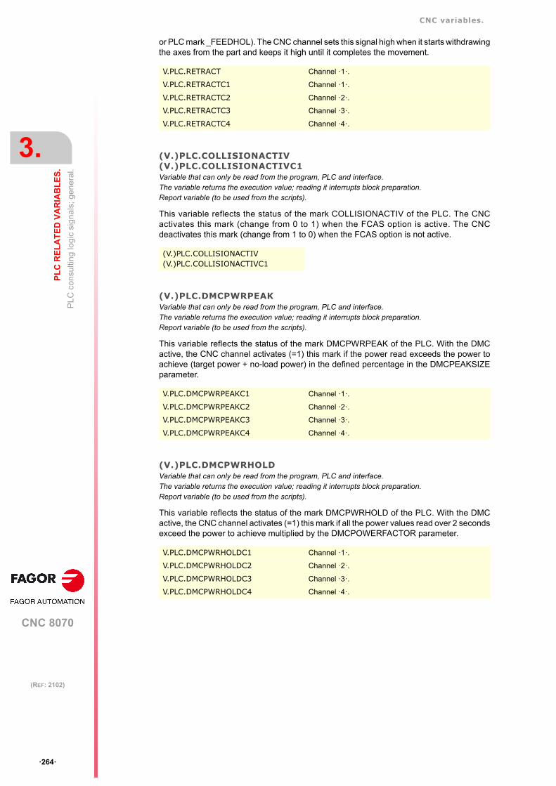
CNC variables.
CNC 8070
3.
PL
C R
EL
AT
ED
VA
RIA
BL
ES
.
PL
C c
ons
ultin
g lo
gic
sig
nals
; gen
era
l.
ꞏ264ꞏ
(REF: 2102)
or PLC mark _FEEDHOL). The CNC channel sets this signal high when it starts withdrawingthe axes from the part and keeps it high until it completes the movement.
(V.)PLC.COLLISIONACTIV(V.)PLC.COLLISIONACTIVC1Variable that can only be read from the program, PLC and interface.The variable returns the execution value; reading it interrupts block preparation.Report variable (to be used from the scripts).
This variable reflects the status of the mark COLLISIONACTIV of the PLC. The CNCactivates this mark (change from 0 to 1) when the FCAS option is active. The CNCdeactivates this mark (change from 1 to 0) when the FCAS option is not active.
(V.)PLC.DMCPWRPEAKVariable that can only be read from the program, PLC and interface.The variable returns the execution value; reading it interrupts block preparation.Report variable (to be used from the scripts).
This variable reflects the status of the mark DMCPWRPEAK of the PLC. With the DMCactive, the CNC channel activates (=1) this mark if the power read exceeds the power toachieve (target power + no-load power) in the defined percentage in the DMCPEAKSIZEparameter.
(V.)PLC.DMCPWRHOLDVariable that can only be read from the program, PLC and interface.The variable returns the execution value; reading it interrupts block preparation.Report variable (to be used from the scripts).
This variable reflects the status of the mark DMCPWRHOLD of the PLC. With the DMCactive, the CNC channel activates (=1) this mark if all the power values read over 2 secondsexceed the power to achieve multiplied by the DMCPOWERFACTOR parameter.
V.PLC.RETRACT Channel ꞏ1ꞏ.
V.PLC.RETRACTC1 Channel ꞏ1ꞏ.
V.PLC.RETRACTC2 Channel ꞏ2ꞏ.
V.PLC.RETRACTC3 Channel ꞏ3ꞏ.
V.PLC.RETRACTC4 Channel ꞏ4ꞏ.
(V.)PLC.COLLISIONACTIV(V.)PLC.COLLISIONACTIVC1
V.PLC.DMCPWRPEAKC1 Channel ꞏ1ꞏ.
V.PLC.DMCPWRPEAKC2 Channel ꞏ2ꞏ.
V.PLC.DMCPWRPEAKC3 Channel ꞏ3ꞏ.
V.PLC.DMCPWRPEAKC4 Channel ꞏ4ꞏ.
V.PLC.DMCPWRHOLDC1 Channel ꞏ1ꞏ.
V.PLC.DMCPWRHOLDC2 Channel ꞏ2ꞏ.
V.PLC.DMCPWRHOLDC3 Channel ꞏ3ꞏ.
V.PLC.DMCPWRHOLDC4 Channel ꞏ4ꞏ.

CNC variables.
CNC 8070
PL
C R
EL
AT
ED
VA
RIA
BL
ES
.
3.
PLC
con
sulti
ng lo
gic
sign
als
; axe
s an
d sp
ind
les.
ꞏ265ꞏ
(REF: 2102)
3.3 PLC consulting logic signals; axes and spindles.
(V.)PLC.ENABLExn(V.)PLC.ENABLEsnVariable that can only be read from the program, PLC and interface.Variable valid for rotary and linear axes as well as for spindles.The variable returns the execution value; reading it interrupts block preparation.Report variable (to be used from the scripts).
This variable reflects the status of the mark ENABLE of the PLC. The CNC activates thismark to allow moving the axis or the spindle.
Syntax.
ꞏxnꞏ Name or logic number of the axis.
ꞏsnꞏ Name or logic number of the spindle.
(V.)PLC.DIRxn(V.)PLC.DIRsnVariable that can only be read from the program, PLC and interface.Variable valid for rotary and linear axes as well as for spindles.The variable returns the execution value; reading it interrupts block preparation.Report variable (to be used from the scripts).
This variable reflects the status of the mark DIR of the PLC. The CNC turns this mark onwhen moving the axis in the negative direction and turns it off when moving the axis in thepositive direction. When the axis is stopped, the mark keeps its last value.
Syntax.
ꞏxnꞏ Name or logic number of the axis.
ꞏsnꞏ Name or logic number of the spindle.
(V.)PLC.REFPOINxn(V.)PLC.REFPOINsnVariable that can only be read from the program and interface.Variable valid for rotary and linear axes as well as for spindles.The variable returns the execution value; reading it interrupts block preparation.Report variable (to be used from the scripts).
This variable reflects the status of the mark REFPOIN of the PLC. The CNC activates thismark after a home search.
Syntax.
ꞏxnꞏ Name or logic number of the axis.
ꞏsnꞏ Name or logic number of the spindle.
V.PLC.ENABLEX X axis.
V.PLC.ENABLES Spindle S.
V.PLC.ENABLE3 Axis or spindle with logic number ꞏ3ꞏ.
V.PLC.DIRX X axis.
V.PLC.DIRS Spindle S.
V.PLC.DIR3 Axis or spindle with logic number ꞏ3ꞏ.
V.PLC.REFPOINX X axis.
V.PLC.REFPOINS Spindle S.
V.PLC.REFPOIN3 Axis or spindle with logic number ꞏ3ꞏ.
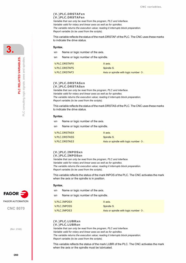
CNC variables.
CNC 8070
3.
PL
C R
EL
AT
ED
VA
RIA
BL
ES
.
PLC
con
sulti
ng lo
gic
sign
als
; axe
s an
d sp
ind
les.
ꞏ266ꞏ
(REF: 2102)
(V.)PLC.DRSTAFxn(V.)PLC.DRSTAFsnVariable that can only be read from the program, PLC and interface.Variable valid for rotary and linear axes as well as for spindles.The variable returns the execution value; reading it interrupts block preparation.Report variable (to be used from the scripts).
This variable reflects the status of the mark DRSTAF of the PLC. The CNC uses these marksto indicate the drive status.
Syntax.
ꞏxnꞏ Name or logic number of the axis.
ꞏsnꞏ Name or logic number of the spindle.
(V.)PLC.DRSTASxn(V.)PLC.DRSTASsnVariable that can only be read from the program, PLC and interface.Variable valid for rotary and linear axes as well as for spindles.The variable returns the execution value; reading it interrupts block preparation.Report variable (to be used from the scripts).
This variable reflects the status of the mark DRSTAS of the PLC. The CNC uses these marksto indicate the drive status.
Syntax.
ꞏxnꞏ Name or logic number of the axis.
ꞏsnꞏ Name or logic number of the spindle.
(V.)PLC.INPOSxn(V.)PLC.INPOSsnVariable that can only be read from the program, PLC and interface.Variable valid for rotary and linear axes as well as for spindles.The variable returns the execution value; reading it interrupts block preparation.Report variable (to be used from the scripts).
This variable reflects the status of the mark INPOS of the PLC. The CNC activates the markwhen the axis or the spindle is in position.
Syntax.
ꞏxnꞏ Name or logic number of the axis.
ꞏsnꞏ Name or logic number of the spindle.
(V.)PLC.LUBRxn(V.)PLC.LUBRsnVariable that can only be read from the program, PLC and interface.Variable valid for rotary and linear axes as well as for spindles.The variable returns the execution value; reading it interrupts block preparation.Report variable (to be used from the scripts).
This variable reflects the status of the mark LUBR of the PLC. The CNC activates the markwhen the axis or the spindle must be lubricated.
V.PLC.DRSTAFX X axis.
V.PLC.DRSTAFS Spindle S.
V.PLC.DRSTAF3 Axis or spindle with logic number ꞏ3ꞏ.
V.PLC.DRSTASX X axis.
V.PLC.DRSTASS Spindle S.
V.PLC.DRSTAS3 Axis or spindle with logic number ꞏ3ꞏ.
V.PLC.INPOSX X axis.
V.PLC.INPOSS Spindle S.
V.PLC.INPOS3 Axis or spindle with logic number ꞏ3ꞏ.

CNC variables.
CNC 8070
PL
C R
EL
AT
ED
VA
RIA
BL
ES
.
3.
PLC
con
sulti
ng lo
gic
sign
als
; axe
s an
d sp
ind
les.
ꞏ267ꞏ
(REF: 2102)
Syntax.
ꞏxnꞏ Name or logic number of the axis.
ꞏsnꞏ Name or logic number of the spindle.
(V.)PLC.HIRTHONxn(V.)PLC.HIRTHONsnVariable that can only be read from the program, PLC and interface.Variable valid for rotary and linear axes as well as for spindles.The variable returns the execution value; reading it interrupts block preparation.Report variable (to be used from the scripts).
This variable reflects the status of the mark HIRTHON of the PLC. The CNC activates themark when the axis or the spindle works as Hirth axis.
Syntax.
ꞏxnꞏ Name or logic number of the axis.
ꞏsnꞏ Name or logic number of the spindle.
(V.)PLC.MATCHxn(V.)PLC.MATCHsnVariable that can only be read from the program, PLC and interface.Variable valid for rotary and linear axes as well as for spindles.The variable returns the execution value; reading it interrupts block preparation.Report variable (to be used from the scripts).
This variable reflects the status of the mark MATCH of the PLC. The CNC activates the markwhen the Hirth axis or spindle is positioned properly.
Syntax.
ꞏxnꞏ Name or logic number of the axis.
ꞏsnꞏ Name or logic number of the spindle.
(V.)PLC.PARKxn(V.)PLC.PARKsnVariable that can only be read from the program, PLC and interface.Variable valid for rotary and linear axes as well as for spindles.The variable returns the execution value; reading it interrupts block preparation.Report variable (to be used from the scripts).
This variable reflects the status of the mark PARK of the PLC. The CNC activates the markwhen it is parking the axis or the spindle.
Syntax.
ꞏxnꞏ Name or logic number of the axis.
ꞏsnꞏ Name or logic number of the spindle.
V.PLC.LUBRX X axis.
V.PLC.LUBRS Spindle S.
V.PLC.LUBR3 Axis or spindle with logic number ꞏ3ꞏ.
V.PLC.HIRTHX X axis.
V.PLC.HIRTHS Spindle S.
V.PLC.HIRTH3 Axis or spindle with logic number ꞏ3ꞏ.
V.PLC.MATCHX X axis.
V.PLC.MATCHS Spindle S.
V.PLC.MATCH3 Axis or spindle with logic number ꞏ3ꞏ.
V.PLC.PARKX X axis.
V.PLC.PARKS Spindle S.
V.PLC.PARK3 Axis or spindle with logic number ꞏ3ꞏ.

CNC variables.
CNC 8070
3.
PL
C R
EL
AT
ED
VA
RIA
BL
ES
.
PLC
con
sulti
ng lo
gic
sign
als
; axe
s an
d sp
ind
les.
ꞏ268ꞏ
(REF: 2102)
(V.)PLC.UNPARKxn(V.)PLC.UNPARKsnVariable that can only be read from the program, PLC and interface.Variable valid for rotary and linear axes as well as for spindles.The variable returns the execution value; reading it interrupts block preparation.Report variable (to be used from the scripts).
This variable reflects the status of the mark UNPARK of the PLC. The CNC activates themark when it is unparking the axis or the spindle.
Syntax.
ꞏxnꞏ Name or logic number of the axis.
ꞏsnꞏ Name or logic number of the spindle.
(V.)PLC.ACTFBACKxn(V.)PLC.ACTFBACKsnVariable that can only be read from the program, PLC and interface.Variable valid for rotary and linear axes as well as for spindles.The variable returns the execution value; reading it interrupts block preparation.Report variable (to be used from the scripts).
This variable reflects the status of the mark ACTFBACK of the PLC. In systems withexternal+internal feedback, the CNC turns this mark on when it is using the external feedbackand turns it off when it is using the internal feedback.
Syntax.
ꞏxnꞏ Name or logic number of the axis.
ꞏsnꞏ Name or logic number of the spindle.
(V.)PLC.TANGACTxn(V.)PLC.TANGACTsnVariable that can only be read from the program, PLC and interface.Variable valid for rotary and linear axes as well as for spindles.The variable returns the execution value; reading it interrupts block preparation.Report variable (to be used from the scripts).
This variable reflects the status of the mark TANGACT of the PLC. The CNC activates themark when tangential control is active on the axis or spindle.
Syntax.
ꞏxnꞏ Name or logic number of the axis.
ꞏsnꞏ Name or logic number of the spindle.
V.PLC.UNPARKX X axis.
V.PLC.UNPARKS Spindle S.
V.PLC.UNPARK3 Axis or spindle with logic number ꞏ3ꞏ.
V.PLC.ACTFBACKX X axis.
V.PLC.ACTFBACKS Spindle S.
V.PLC.ACTFBACK3 Axis or spindle with logic number ꞏ3ꞏ.
V.PLC.TANGACTX X axis.
V.PLC.TANGACTS Spindle S.
V.PLC.TANGACT3 Axis or spindle with logic number ꞏ3ꞏ.

CNC variables.
CNC 8070
PL
C R
EL
AT
ED
VA
RIA
BL
ES
.
3.
PLC
con
sulti
ng lo
gic
sign
als
; axe
s an
d sp
ind
les.
ꞏ269ꞏ
(REF: 2102)
(V.)PLC.LOPENxn(V.)PLC.LOPENsnVariable that can only be read from the program, PLC and interface.Variable valid for rotary and linear axes as well as for spindles.The variable returns the execution value; reading it interrupts block preparation.Report variable (to be used from the scripts).
This variable reflects the status of the mark LOPEN of the PLC. The CNC activates this markto inform the PLC that the axis position loop is open.
Syntax.
ꞏxnꞏ Name or logic number of the axis.
ꞏsnꞏ Name or logic number of the spindle.
(V.)PLC.MAXDIFFxnVariable that can only be read from the program, PLC and interface.Variable valid for rotary and linear axes.The variable returns the execution value; reading it interrupts block preparation.
This variable reflects the status of the mark MAXDIFF of the PLC. The CNC cannot correctthe position difference between the master axis and the slave axis.
Syntax.
ꞏxnꞏ Name or logic number of the axis.
ꞏsnꞏ Name or logic number of the spindle.
V.PLC.LOPENX X axis.
V.PLC.LOPENS Spindle S.
V.PLC.LOPEN3 Axis or spindle with logic number ꞏ3ꞏ.
V.PLC.LOPENX X axis.
V.PLC.LOPEN3 Axis with logic number ꞏ3ꞏ.

CNC variables.
CNC 8070
3.
PL
C R
EL
AT
ED
VA
RIA
BL
ES
.
PLC
co
nsul
ting
logi
c si
gna
ls; s
pind
les.
ꞏ270ꞏ
(REF: 2102)
3.4 PLC consulting logic signals; spindles.
(V.)PLC.REVOKVariable that can only be read from the program and interface.The variable returns the execution value; reading it interrupts block preparation.Report variable (to be used from the scripts).
This variable reflects the status of the mark REVOK of the PLC. The spindle turns this markon when it reaches the programmed rpm. The mark is also on when the spindle is stopped(M05) or in position (M19, G63).
(V.)PLC.SYNCMASTERVariable that can only be read from the program and interface.The variable returns the execution value; reading it interrupts block preparation.Report variable (to be used from the scripts).
This variable reflects the status of the mark SYNCMASTER of the PLC. The master spindleactivates this mark when it has a spindle synchronized using #SYNC.
(V.)PLC.SYNCHRONVariable that can only be read from the program and interface.The variable returns the execution value; reading it interrupts block preparation.Report variable (to be used from the scripts).
This variable reflects the status of the mark SUNCHRON of the PLC. The slave spindleactivates this mark at the beginning of a synchronization using #SYNC.
(V.)PLC.SYNCHRONPVariable that can only be read from the program and interface.The variable returns the execution value; reading it interrupts block preparation.Report variable (to be used from the scripts).
This variable reflects the status of the mark SYNCHRONP of the PLC. The slave spindleactivates this mark at the beginning of a synchronization in position.
V.PLC.REVOK Spindle ꞏ1ꞏ.
V.PLC.REVOK1 Spindle ꞏ1ꞏ.
V.PLC.REVOK2 Spindle ꞏ2ꞏ.
V.PLC.REVOK3 Spindle ꞏ3ꞏ.
V.PLC.REVOK4 Spindle ꞏ4ꞏ.
V.PLC.REVOK5 Spindle ꞏ5ꞏ.
V.PLC.REVOK6 Spindle ꞏ6ꞏ.
V.PLC.SYNCMASTER1 Spindle ꞏ1ꞏ.
V.PLC.SYNCMASTER2 Spindle ꞏ2ꞏ.
V.PLC.SYNCMASTER3 Spindle ꞏ3ꞏ.
V.PLC.SYNCMASTER4 Spindle ꞏ4ꞏ.
V.PLC.SYNCMASTER5 Spindle ꞏ5ꞏ.
V.PLC.SYNCMASTER6 Spindle ꞏ6ꞏ.
V.PLC.SYNCHRON1 Spindle ꞏ1ꞏ.
V.PLC.SYNCHRON2 Spindle ꞏ2ꞏ.
V.PLC.SYNCHRON3 Spindle ꞏ3ꞏ.
V.PLC.SYNCHRON4 Spindle ꞏ4ꞏ.
V.PLC.SYNCHRON5 Spindle ꞏ5ꞏ.
V.PLC.SYNCHRON6 Spindle ꞏ6ꞏ.
V.PLC.SYNCHRONP1 Spindle ꞏ1ꞏ.
V.PLC.SYNCHRONP2 Spindle ꞏ2ꞏ.
V.PLC.SYNCHRONP3 Spindle ꞏ3ꞏ.

CNC variables.
CNC 8070
PL
C R
EL
AT
ED
VA
RIA
BL
ES
.
3.
PLC
co
nsul
ting
logi
c si
gna
ls; s
pind
les.
ꞏ271ꞏ
(REF: 2102)
(V.)PLC.SYNSPEEDVariable that can only be read from the program and interface.The variable returns the execution value; reading it interrupts block preparation.Report variable (to be used from the scripts).
This variable reflects the status of the mark SYNSPEED of the PLC. The slave spindleactivates this mark when it is synchronized in velocity.
(V.)PLC.SYNCPOSIVariable that can only be read from the program and interface.The variable returns the execution value; reading it interrupts block preparation.Report variable (to be used from the scripts).
This variable reflects the status of the mark SYNCPOSI of the PLC. The slave spindleactivates this mark when it is synchronized in position.
(V.)PLC.GEAROKVariable that can only be read from the program and interface.The variable returns the execution value; reading it interrupts block preparation.Report variable (to be used from the scripts).
This variable reflects the status of the mark GEAROK of the PLC. The spindle activates thismark when the parameter set selected at the CNC and at the PLC are the same.
V.PLC.SYNCHRONP4 Spindle ꞏ4ꞏ.
V.PLC.SYNCHRONP5 Spindle ꞏ5ꞏ.
V.PLC.SYNCHRONP6 Spindle ꞏ6ꞏ.
V.PLC.SYNSPEED1 Spindle ꞏ1ꞏ.
V.PLC.SYNSPEED2 Spindle ꞏ2ꞏ.
V.PLC.SYNSPEED3 Spindle ꞏ3ꞏ.
V.PLC.SYNSPEED4 Spindle ꞏ4ꞏ.
V.PLC.SYNSPEED5 Spindle ꞏ5ꞏ.
V.PLC.SYNSPEED6 Spindle ꞏ6ꞏ.
V.PLC.SYNCPOSI1 Spindle ꞏ1ꞏ.
V.PLC.SYNCPOSI2 Spindle ꞏ2ꞏ.
V.PLC.SYNCPOSI3 Spindle ꞏ3ꞏ.
V.PLC.SYNCPOSI4 Spindle ꞏ4ꞏ.
V.PLC.SYNCPOSI5 Spindle ꞏ5ꞏ.
V.PLC.SYNCPOSI6 Spindle ꞏ6ꞏ.
V.PLC.GEAROK Spindle ꞏ1ꞏ.
V.PLC.GEAROK1 Spindle ꞏ1ꞏ.
V.PLC.GEAROK2 Spindle ꞏ2ꞏ.
V.PLC.GEAROK3 Spindle ꞏ3ꞏ.
V.PLC.GEAROK4 Spindle ꞏ4ꞏ.
V.PLC.GEAROK5 Spindle ꞏ5ꞏ.
V.PLC.GEAROK6 Spindle ꞏ6ꞏ.

CNC variables.
CNC 8070
3.
PL
C R
EL
AT
ED
VA
RIA
BL
ES
.
PLC
con
sulti
ng
logi
c si
gna
ls; i
ndep
ende
nt i
nter
pol
ator
.
ꞏ272ꞏ
(REF: 2102)
3.5 PLC consulting logic signals; independent interpolator.
(V.)PLC.IBUSYxnVariable that can only be read from the program, PLC and interface.Variable valid for rotary and linear axes as well as for spindles.The variable returns the execution value; reading it interrupts block preparation.Report variable (to be used from the scripts).
This variable reflects the status of the mark IBUSYxn of the PLC. The interpolator is activewhen there is an instruction pending execution.
Syntax.
ꞏxnꞏ Name or logic number of the axis.
(V.)PLC.IFREExnVariable that can only be read from the program, PLC and interface.Variable valid for rotary and linear axes as well as for spindles.The variable returns the execution value; reading it interrupts block preparation.Report variable (to be used from the scripts).
This variable reflects the status of the mark IFREExn of the PLC. The interpolator turns thismark on when it is ready to accept a motion block.
Syntax.
ꞏxnꞏ Name or logic number of the axis.
(V.)PLC.IFHOUTxnVariable that can only be read from the program, PLC and interface.Variable valid for rotary and linear axes as well as for spindles.The variable returns the execution value; reading it interrupts block preparation.Report variable (to be used from the scripts).
This variable reflects the status of the mark IFHOUTxn of the PLC. The interpolator turnsthis mark on when the execution is interrupted.
Syntax.
ꞏxnꞏ Name or logic number of the axis.
(V.)PLC.IENDxnVariable that can only be read from the program, PLC and interface.Variable valid for rotary and linear axes as well as for spindles.The variable returns the execution value; reading it interrupts block preparation.Report variable (to be used from the scripts).
This variable reflects the status of the mark IENDxn of the PLC. The interpolator turns thismark on when the axis movement has finished and it has reached its the final position.
Syntax.
ꞏxnꞏ Name or logic number of the axis.
V.PLC.IBUSYX X axis.
V.PLC.IBUSY3 Axis with logic number ꞏ3ꞏ.
V.PLC.IFREEX X axis.
V.PLC.IFREE3 Axis with logic number ꞏ3ꞏ.
V.PLC.IFHOUTX X axis.
V.PLC.IFHOUT3 Axis with logic number ꞏ3ꞏ.
V.PLC.IENDX X axis.
V.PLC.IEND3 Axis with logic number ꞏ3ꞏ.

CNC variables.
CNC 8070
PL
C R
EL
AT
ED
VA
RIA
BL
ES
.
3.
PLC
con
sulti
ng
logi
c si
gna
ls; i
ndep
ende
nt i
nter
pol
ator
.
ꞏ273ꞏ
(REF: 2102)
(V.)PLC.INSYNCxnVariable that can only be read from the program, PLC and interface.Variable valid for rotary and linear axes as well as for spindles.The variable returns the execution value; reading it interrupts block preparation.Report variable (to be used from the scripts).
This variable reflects the status of the mark INSYNCxn of the PLC. The interpolator turnsthis mark on when the axis or the cam has reached synchronism.
Syntax.
ꞏxnꞏ Name or logic number of the axis.
V.PLC.INSYNCX X axis.
V.PLC.INSYNC3 Axis with logic number ꞏ3ꞏ.

CNC variables.
CNC 8070
3.
PL
C R
EL
AT
ED
VA
RIA
BL
ES
.
PL
C c
ons
ultin
g lo
gic
sig
nals
; las
er.
ꞏ274ꞏ
(REF: 2102)
3.6 PLC consulting logic signals; laser.
3.6.1 Piercing enabled.
(V.)PLC.PIERCINGVariable that can be read and written via program and interface.The variable returns the execution value; reading it interrupts block preparation.Report variable (to be used from the scripts).Units: Value listed.
Piercing enabled. The status of this variable is displayed in the PIERCING mark of the PLC.
Values of the variable.
Remarks.
The OEM can use this variable in the subroutine associated with piercing (by default,Piercing.fst) to change the status of the PIERCING mark and indicate to the PLC when tostart (value 1) and end (valor 0) the piercing operation. Entering this variable interrupts theblock preparation.
The instruction #PLC also enables a PLC mark to be managed from the part program orsubroutine without interrupting the block preparation.
3.6.2 Active cutting.
(V.)PLC.CUTTINGVariable that can be read and written via program and interface.The variable returns the execution value; reading it interrupts block preparation.Report variable (to be used from the scripts).Units: Value listed.
Active cutting. The status of this variable is displayed in the CUTTING mark of the PLC.
Values of the variable.
Remarks.
The OEM can use this variable in the subroutines associated with cutting (by default,Cutting.fst / Cuttingoff.fst) to change the status of the CUTTING mark and indicate to the PLCwhen to start (value 1) and end (valor 0) the cutting operation. Entering this variable interruptsthe block preparation.
The instruction #PLC also enables a PLC mark to be managed from the part program orsubroutine without interrupting the block preparation.
V.PLC.PIERCING
Value. Meaning.
0 Not active.
1 Active.
V.PLC.CUTTING
Value. Meaning.
0 Not active.
1 Active.

CNC variables.
CNC 8070
PL
C R
EL
AT
ED
VA
RIA
BL
ES
.
3.
PL
C c
ons
ultin
g lo
gic
sig
nals
; las
er.
ꞏ275ꞏ
(REF: 2102)
3.6.3 Technology tables.
(V.)PLC.COMVARACT
The CNC activates this mark when the user validates the common parameters of the activepiercing or cutting table. The PLC should disable this mark when management with thesevariables is complete.
(V.)PLC.CUTVARACTVariable that can be read and written via program and interface.The variable returns the execution value; reading it interrupts block preparation.Report variable (to be used from the scripts).Units: - .
The CNC activates this mark when the user validates the cutting parameters of the activetable. The PLC should disable this mark when management with these variables is complete.
Remarks.
When the subroutine Cuttingon.fst changes the cutting type (#CUTTING ON), the CNC doesnot activate this mark, as the synchronization with the PLC is implemented through Mfunctions.
(V.)PLC.PIRVARACTVariable that can be read and written via program and interface.The variable returns the execution value; reading it interrupts block preparation.Report variable (to be used from the scripts).Units: - .
The CNC activates this mark when the user validates the piercing parameters of the activetable. The PLC should disable this mark when management with these variables is complete.
Remarks.
When the subroutine Piercing.fst changes the piercing type (#PIERCING), the CNC doesnot activate this mark, as the synchronization with the PLC is implemented through Mfunctions.
V.PLC.COMVARACT
V.PLC.CUTVARACT
V.PLC.PIRVARACT

CNC variables.
CNC 8070
3.
PL
C R
EL
AT
ED
VA
RIA
BL
ES
.
PL
C c
ons
ultin
g lo
gic
sig
nals
; las
er.
ꞏ276ꞏ
(REF: 2102)
3.6.4 Gap control.
(V.)PLC.INPOSGAPVariable that can be read and written via program and interface.The variable returns the execution value; reading it interrupts block preparation.Report variable (to be used from the scripts).Units: - .
The CNC activates this mark if the gap is within the range defined by the parametersGAPMIN-GAPMAX.
(V.)PLC.INTOLVariable that can be read and written via program and interface.The variable returns the execution value; reading it interrupts block preparation.Report variable (to be used from the scripts).Units: - .
The CNC activates this mark if the gap is within the tolerance limit defined by the parameterGAPTOL regarding the gap value programmed.
3.6.5 Leapfrog.
(V.)PLC.INPOSLIMITVariable that can be read and written via program and interface.The variable returns the execution value; reading it interrupts block preparation.Units: - .
The CNC activates this mark (changes from 0 to 1) when the leap programmed with a #LEAPreaches the highest point (POSLIMIT command). The CNC deactivates this mark (changesfrom 1 to 0) when the leap starts to lower from this point.
Remarks.
If the leap does not reach the highest point due to lack of space, the CNC will not activatethis mark. In the event of any error, the CNC will deactivate this mark.
V.PLC.INPOSGAP
V.PLC.INTOL
V.PLC.INPOSLIMIT

CNC variables.
CNC 8070
PL
C R
EL
AT
ED
VA
RIA
BL
ES
.
3.
PLC
con
sulti
ng lo
gic
sig
nals
; too
l man
age
r.
ꞏ277ꞏ
(REF: 2102)
3.7 PLC consulting logic signals; tool manager.
(V.)PLC.TMOPERATIONVariable that can only be read from the program and interface.The variable returns the execution value; reading it interrupts block preparation.Report variable (to be used from the scripts).
This variable reflects the status of the mark TMOPERATION of the PLC. The managerindicates in this register the type of operation to be carried out by the PLC.
Values of the variable.
This variable returns one of the following values.
(V.)PLC.TMOPSTROBEVariable that can only be read from the program and interface.The variable returns the execution value; reading it interrupts block preparation.Report variable (to be used from the scripts).
This variable reflects the status of the mark TMOPSTROBE of the PLC. The manager turnsthis mark on to let the PLC know that it must execute the operation indicated byTMOPERATION.
V.PLC.TMOPERATION Channel ꞏ1ꞏ.
V.PLC.TMOPERATIONC1 Channel ꞏ1ꞏ.
V.PLC.TMOPERATIONC2 Channel ꞏ2ꞏ.
V.PLC.TMOPERATIONC3 Channel ꞏ3ꞏ.
V.PLC.TMOPERATIONC4 Channel ꞏ4ꞏ.
Value. Meaning.
0 Do nothing.
1 Take a tool from the magazine and insert it in the spindle.
2 Leave the spindle tool in the magazine.
3 Insert a ground tool in the spindle.
4 Leave the spindle tool on the ground.
5 Leave the spindle tool in the magazine and take another one from the magazine.
6 Leave the spindle tool in the magazine and take another one from ground.
7 Leave the spindle tool on the ground and take another one from the magazine.
8 Leave the spindle tool on the ground and take another one from ground.
9 Take a ground tool to the magazine going through the spindle.
10 Take a tool from the magazine and leave on the ground going through the spindle.
11 Orient the magazine.
12 Leave the spindle tool in the magazine and take another one from the samemagazine. Special for a synchronous magazine in the following cases:
• Non-random having a tool changer arm with two claws.• Random when having special tools.
13 Orienting two magazines
14 Leave the spindle tool in a magazine and take another one from another magazine.
V.PLC.TMOPSTROBE Channel ꞏ1ꞏ.
V.PLC.TMOPSTROBEC1 Channel ꞏ1ꞏ.
V.PLC.TMOPSTROBEC2 Channel ꞏ2ꞏ.
V.PLC.TMOPSTROBEC3 Channel ꞏ3ꞏ.
V.PLC.TMOPSTROBEC4 Channel ꞏ4ꞏ.

CNC variables.
CNC 8070
3.
PL
C R
EL
AT
ED
VA
RIA
BL
ES
.
PLC
con
sulti
ng lo
gic
sig
nals
; too
l man
age
r.
ꞏ278ꞏ
(REF: 2102)
(V.)PLC.LEAVEPOSVariable that can only be read from the program and interface.The variable returns the execution value; reading it interrupts block preparation.Report variable (to be used from the scripts).
This variable reflects the status of the mark LEAVEPOS of the PLC. The manager indicatesin this register the magazine position to leave the tool.
(V.)PLC.TAKEPOSVariable that can only be read from the program and interface.The variable returns the execution value; reading it interrupts block preparation.Report variable (to be used from the scripts).
This variable reflects the status of the mark TAKEPOS of the PLC. The manager indicatesin this register the magazine position of the tool to be picked up.
(V.)PLC.NEXTPOSVariable that can only be read from the program and interface.The variable returns the execution value; reading it interrupts block preparation.Report variable (to be used from the scripts).
This variable reflects the status of the mark NEXTPOS of the PLC. The manager indicatesin this register the magazine position of the next tool.
(V.)PLC.TWORNOUTVariable that can only be read from the program and interface.The variable returns the execution value; reading it interrupts block preparation.Report variable (to be used from the scripts).
This variable reflects the status of the mark TWORNOUT of the PLC. The manager turnsthis mark on when it has rejected the tool.
V.PLC.LEAVEPOS Magazine ꞏ1ꞏ.
V.PLC.LEAVEPOSMZ1 Magazine ꞏ1ꞏ.
V.PLC.LEAVEPOSMZ2 Magazine ꞏ2ꞏ.
V.PLC.LEAVEPOSMZ3 Magazine ꞏ3ꞏ.
V.PLC.LEAVEPOSMZ4 Magazine ꞏ4ꞏ.
V.PLC.TAKEPOS Magazine ꞏ1ꞏ.
V.PLC.TAKEPOSMZ1 Magazine ꞏ1ꞏ.
V.PLC.TAKEPOSMZ2 Magazine ꞏ2ꞏ.
V.PLC.TAKEPOSMZ3 Magazine ꞏ3ꞏ.
V.PLC.TAKEPOSMZ4 Magazine ꞏ4ꞏ.
V.PLC.NEXTPOS Magazine ꞏ1ꞏ.
V.PLC.NEXTPOSMZ1 Magazine ꞏ1ꞏ.
V.PLC.NEXTPOSMZ2 Magazine ꞏ2ꞏ.
V.PLC.NEXTPOSMZ3 Magazine ꞏ3ꞏ.
V.PLC.NEXTPOSMZ4 Magazine ꞏ4ꞏ.
V.PLC.TWONRNOUT Channel ꞏ1ꞏ.
V.PLC.TWONRNOUTC1 Channel ꞏ1ꞏ.
V.PLC.TWONRNOUTC2 Channel ꞏ2ꞏ.
V.PLC.TWONRNOUTC3 Channel ꞏ3ꞏ.
V.PLC.TWONRNOUTC4 Channel ꞏ4ꞏ.

CNC variables.
CNC 8070
PL
C R
EL
AT
ED
VA
RIA
BL
ES
.
3.
PLC
con
sulti
ng lo
gic
sig
nals
; too
l man
age
r.
ꞏ279ꞏ
(REF: 2102)
(V.)PLC.TMINEMVariable that can only be read from the program and interface.The variable returns the execution value; reading it interrupts block preparation.Report variable (to be used from the scripts).
This variable reflects the status of the mark TMINEM of the PLC. The manager activates themark when it is in an error state.
(V.)PLC.MZIDVariable that can only be read from the program and interface.The variable returns the execution value; reading it interrupts block preparation.Report variable (to be used from the scripts).
This variable reflects the status of the mark MZID of the PLC. The manager indicates in thisregister the magazine that has the requested tool. When two magazines are involved in atool change, the lower portion of this register indicates the destination magazine for the tooland the higher portion the source magazine for the tool.
V.PLC.TMINEM Magazine ꞏ1ꞏ.
V.PLC.TMINEMZ1 Magazine ꞏ1ꞏ.
V.PLC.TMINEMZ2 Magazine ꞏ2ꞏ.
V.PLC.TMINEMZ3 Magazine ꞏ3ꞏ.
V.PLC.TMINEMZ4 Magazine ꞏ4ꞏ.
V.PLC.MZID Channel ꞏ1ꞏ.
V.PLC.MZIDC1 Channel ꞏ1ꞏ.
V.PLC.MZIDC2 Channel ꞏ2ꞏ.
V.PLC.MZIDC3 Channel ꞏ3ꞏ.
V.PLC.MZIDC4 Channel ꞏ4ꞏ.
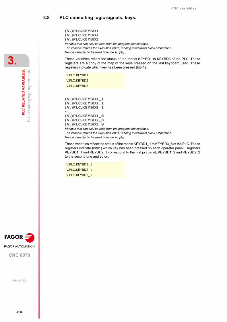
CNC variables.
CNC 8070
3.
PL
C R
EL
AT
ED
VA
RIA
BL
ES
.
PLC
con
sulti
ng lo
gic
sign
als;
key
s.
ꞏ280ꞏ
(REF: 2102)
3.8 PLC consulting logic signals; keys.
(V.)PLC.KEYBD1(V.)PLC.KEYBD2(V.)PLC.KEYBD3Variable that can only be read from the program and interface.The variable returns the execution value; reading it interrupts block preparation.Report variable (to be used from the scripts).
These variables reflect the status of the marks KEYBD1 to KEYBD3 of the PLC. Theseregisters are a copy of the map of the keys pressed on the last keyboard used. Theseregisters indicate which key has been pressed (bit=1).
(V.)PLC.KEYBD1_1(V.)PLC.KEYBD2_1(V.)PLC.KEYBD3_1··(V.)PLC.KEYBD1_8(V.)PLC.KEYBD2_8(V.)PLC.KEYBD3_8Variable that can only be read from the program and interface.The variable returns the execution value; reading it interrupts block preparation.Report variable (to be used from the scripts).
These variables reflect the status of the marks KEYBD1_1 to KEYBD3_8 of the PLC. Theseregisters indicate (bit=1) which key has been pressed on each operator panel. RegistersKEYBD1_1 and KEYBD2_1 correspond to the first jog panel, KEYBD1_2 and KEYBD2_2to the second one and so on.
V.PLC.KEYBD1
V.PLC.KEYBD2
V.PLC.KEYBD3
V.PLC.KEYBD1_1
V.PLC.KEYBD2_1
V.PLC.KEYBD3_1

CNC variables.
CNC 8070
PL
C R
EL
AT
ED
VA
RIA
BL
ES
.
3.
PLC
mod
ifiab
le lo
gic
sig
nals
; gen
era
l.
ꞏ281ꞏ
(REF: 2102)
3.9 PLC modifiable logic signals; general.
(V.)PLC._EMERGENVariable that can be read and written from the interface and read from the program.The variable returns the execution value; reading it interrupts block preparation.Report variable (to be used from the scripts).
This variable reflects the status of the mark _EMERGEN of the PLC. If the PLC turns thismark off, the channel stops the axes and spindles and issues an error message. While themark is off, the channel does not allow executing programs and aborts attempt to move theaxes or start the spindle.
(V.)PLC._STOPVariable that can be read and written from the interface and read from the program.The variable returns the execution value; reading it interrupts block preparation.Report variable (to be used from the scripts).
This variable reflects the status of the mark _STOP of the PLC. If the PLC turns this markoff, the channel stops the execution of the program, but keeps the spindles turning. Thestatus of this mark does not affect the independent axes.
(V.)PLC._XFERINHVariable that can be read and written from the interface and read from the program.The variable returns the execution value; reading it interrupts block preparation.Report variable (to be used from the scripts).
This variable reflects the status of the mark _XFERINH of the PLC. If the PLC turns this markoff, the prevents the execution of the next block, but it lets complete the execution of thecurrent block.
(V.)PLC._FEEDHOLVariable that can be read and written from the interface and read from the program.The variable returns the execution value; reading it interrupts block preparation.Report variable (to be used from the scripts).
This variable reflects the status of the mark _FEEDHOL of the PLC. If the PLC turns this markoff, the channel stops the axes, but keeps the spindles turning. The status of this mark doesnot affect the independent axes.
V.PLC._EMERGEN Channel ꞏ1ꞏ.
V.PLC._EMERGENC1 Channel ꞏ1ꞏ.
V.PLC._EMERGENC2 Channel ꞏ2ꞏ.
V.PLC._EMERGENC3 Channel ꞏ3ꞏ.
V.PLC._EMERGENC4 Channel ꞏ4ꞏ.
V.PLC._STOP Channel ꞏ1ꞏ.
V.PLC._STOPC1 Channel ꞏ1ꞏ.
V.PLC._STOPC2 Channel ꞏ2ꞏ.
V.PLC._STOPC3 Channel ꞏ3ꞏ.
V.PLC._STOPC4 Channel ꞏ4ꞏ.
V.PLC._XFERINH Channel ꞏ1ꞏ.
V.PLC._XFERINHC1 Channel ꞏ1ꞏ.
V.PLC._XFERINHC2 Channel ꞏ2ꞏ.
V.PLC._XFERINHC3 Channel ꞏ3ꞏ.
V.PLC._XFERINHC4 Channel ꞏ4ꞏ.
V.PLC._FEEDHOL Channel ꞏ1ꞏ.
V.PLC._FEEDHOLC1 Channel ꞏ1ꞏ.

CNC variables.
CNC 8070
3.
PL
C R
EL
AT
ED
VA
RIA
BL
ES
.
PLC
mod
ifiab
le lo
gic
sig
nals
; gen
era
l.
ꞏ282ꞏ
(REF: 2102)
(V.)PLC.CYSTARTVariable that can be read and written from the interface and read from the program.The variable returns the execution value; reading it interrupts block preparation.Report variable (to be used from the scripts).
This variable reflects the status of the mark CYSTART of the PLC. If the PLC turns this markon, the execution of the part-program begins.
(V.)PLC.SBLOCKVariable that can be read and written from the interface and read from the program.The variable returns the execution value; reading it interrupts block preparation.Report variable (to be used from the scripts).
This variable reflects the status of the mark SBLOCK of the PLC. If the PLC turns this markon, the channel activates the single-block mode.
(V.)PLC.MANRAPIDVariable that can be read and written from the interface and read from the program.The variable returns the execution value; reading it interrupts block preparation.Report variable (to be used from the scripts).
This variable reflects the status of the mark MANRAPID of the PLC. If the PLC turns this markon, the CNC selects the rapid traverse for jog movements.
(V.)PLC.OVRCANVariable that can be read and written from the interface and read from the program.The variable returns the execution value; reading it interrupts block preparation.Report variable (to be used from the scripts).
This variable reflects the status of the mark OVRCAN of the PLC. If the PLC turns this markon, the channel applies 100% of the feedrate in all work mode.
V.PLC._FEEDHOLC2 Channel ꞏ2ꞏ.
V.PLC._FEEDHOLC3 Channel ꞏ3ꞏ.
V.PLC._FEEDHOLC4 Channel ꞏ4ꞏ.
V.PLC.CYSTART Channel ꞏ1ꞏ.
V.PLC.CYSTARTC1 Channel ꞏ1ꞏ.
V.PLC.CYSTARTC2 Channel ꞏ2ꞏ.
V.PLC.CYSTARTC3 Channel ꞏ3ꞏ.
V.PLC.CYSTARTC4 Channel ꞏ4ꞏ.
V.PLC.SBLOCK Channel ꞏ1ꞏ.
V.PLC.SBLOCKC1 Channel ꞏ1ꞏ.
V.PLC.SBLOCKC2 Channel ꞏ2ꞏ.
V.PLC.SBLOCKC3 Channel ꞏ3ꞏ.
V.PLC.SBLOCKC4 Channel ꞏ4ꞏ.
V.PLC.MANRAPID Channel ꞏ1ꞏ.
V.PLC.MANRAPIDC1 Channel ꞏ1ꞏ.
V.PLC.MANRAPIDC2 Channel ꞏ2ꞏ.
V.PLC.MANRAPIDC3 Channel ꞏ3ꞏ.
V.PLC.MANRAPIDC4 Channel ꞏ4ꞏ.
V.PLC.OVRCAN Channel ꞏ1ꞏ.
V.PLC.OVRCANC1 Channel ꞏ1ꞏ.
V.PLC.OVRCANC2 Channel ꞏ2ꞏ.
V.PLC.OVRCANC3 Channel ꞏ3ꞏ.
V.PLC.OVRCANC4 Channel ꞏ4ꞏ.

CNC variables.
CNC 8070
PL
C R
EL
AT
ED
VA
RIA
BL
ES
.
3.
PLC
mod
ifiab
le lo
gic
sig
nals
; gen
era
l.
ꞏ283ꞏ
(REF: 2102)
(V.)PLC.LATCHMVariable that can be read and written from the interface and read from the program.The variable returns the execution value; reading it interrupts block preparation.Report variable (to be used from the scripts).
This variable reflects the status of the mark LATCHM of the PLC. With this mark, it is possibleto select how the JOG keys will work in JOG mode.
If this mark is off, the axes will move while the corresponding JOG key kept pressed. If thismark is on, the axes will move from the instant the JOG key is pressed until the softwarelimits are reached or the [STOP] key is pressed or another JOG key is pressed (in this casethe new axis will start moving).
(V.)PLC.RESETINVariable that can be read and written from the interface and read from the program.The variable returns the execution value; reading it interrupts block preparation.Report variable (to be used from the scripts).
This variable reflects the status of the mark RESETIN of the PLC. If the PLC turns this markon, the channel assumes the initial conditions.
(V.)PLC.AUXENDVariable that can be read and written from the interface and read from the program.The variable returns the execution value; reading it interrupts block preparation.Report variable (to be used from the scripts).
This variable reflects the status of the mark AUXEND of the PLC. The PLC uses this markwhen executing functions S and M with synchronization.
(V.)PLC.BLKSKIP1Variable that can be read and written from the interface and read from the program.The variable returns the execution value; reading it interrupts block preparation.Report variable (to be used from the scripts).
This variable reflects the status of the mark BLKSKIP of the PLC. If the PLC turns this markon, the channel considers the block-skip condition.
V.PLC.LATCHM
V.PLC.RESETIN Channel ꞏ1ꞏ.
V.PLC.RESETINC1 Channel ꞏ1ꞏ.
V.PLC.RESETINC2 Channel ꞏ2ꞏ.
V.PLC.RESETINC3 Channel ꞏ3ꞏ.
V.PLC.RESETINC4 Channel ꞏ4ꞏ.
V.PLC.AUXEND Channel ꞏ1ꞏ.
V.PLC.AUXENDC1 Channel ꞏ1ꞏ.
V.PLC.AUXENDC2 Channel ꞏ2ꞏ.
V.PLC.AUXENDC3 Channel ꞏ3ꞏ.
V.PLC.AUXENDC4 Channel ꞏ4ꞏ.
V.PLC.BLKSKIP1 Channel ꞏ1ꞏ.
V.PLC.BLKSKIP1C1 Channel ꞏ1ꞏ.
V.PLC.BLKSKIP1C2 Channel ꞏ2ꞏ.
V.PLC.BLKSKIP1C3 Channel ꞏ3ꞏ.
V.PLC.BLKSKIP1C4 Channel ꞏ4ꞏ.

CNC variables.
CNC 8070
3.
PL
C R
EL
AT
ED
VA
RIA
BL
ES
.
PLC
mod
ifiab
le lo
gic
sig
nals
; gen
era
l.
ꞏ284ꞏ
(REF: 2102)
(V.)PLC.M01STOPVariable that can be read and written from the interface and read from the program.The variable returns the execution value; reading it interrupts block preparation.Report variable (to be used from the scripts).
This variable reflects the status of the mark M01STOP of the PLC. If the PLC turns this markon, the channel considers the block-skips.
(V.)PLC.TIMERONVariable that can be read and written from the interface and read from the program.The variable returns the execution value; reading it interrupts block preparation.Report variable (to be used from the scripts).
This variable reflects the status of the mark TIMERON of the PLC. If the PLC turns this markon, the CNC enables the freely available clock.
(V.)PLC.PLCREADYVariable that can be read and written from the interface and read from the program.The variable returns the execution value; reading it interrupts block preparation.Report variable (to be used from the scripts).
This variable reflects the status of the mark PLCREADY of the PLC. If the PLC turns thismark off, it interrupts the execution of the PLC program and issues an error message.
(V.)PLC.NOWAITVariable that can be read and written from the interface and read from the program.The variable returns the execution value; reading it interrupts block preparation.Report variable (to be used from the scripts).
This variable reflects the status of the mark NOWAIT of the PLC. The PLC turns this markon to cancel the channel synchronizations programmed with #WAIT.
(V.)PLC.DISCROSS1··(V.)PLC.DISCROSS17Variable that can only be read from the program and interface.The variable returns the execution value; reading it interrupts block preparation.Report variable (to be used from the scripts).
These variables reflect the status of the marks DISCROSS1 to DISCROSS17 of the PLC.The PLC this mark on to disable the cross compensation table.
V.PLC.M01STOP Channel ꞏ1ꞏ.
V.PLC.M01STOPC1 Channel ꞏ1ꞏ.
V.PLC.M01STOPC2 Channel ꞏ2ꞏ.
V.PLC.M01STOPC3 Channel ꞏ3ꞏ.
V.PLC.M01STOPC4 Channel ꞏ4ꞏ.
V.PLC.TIMERON
V.PLC.PLCREADY
V.PLC.NOWAITC1 Channel ꞏ1ꞏ.
V.PLC.NOWAITC2 Channel ꞏ2ꞏ.
V.PLC.NOWAITC3 Channel ꞏ3ꞏ.
V.PLC.NOWAITC4 Channel ꞏ4ꞏ.
V.PLC.DISCROSS1 Cross compensation table ꞏ1ꞏ.
V.PLC.DISCROSS2 Cross compensation table ꞏ2ꞏ.

CNC variables.
CNC 8070
PL
C R
EL
AT
ED
VA
RIA
BL
ES
.
3.
PLC
mod
ifiab
le lo
gic
sig
nals
; gen
era
l.
ꞏ285ꞏ
(REF: 2102)
(V.)PLC.PLCABORTVariable that can be read and written from the interface and read from the program.The variable returns the execution value; reading it interrupts block preparation.Report variable (to be used from the scripts).
This variable reflects the status of the mark PLCABORT of the PLC. If the PLC turns thismark on, the channel aborts the CNCEX command launched from the PLC. This mark doesnot set the initial conditions in the channel and keeps the history.
(V.)PLC.NEXTMPGAXISVariable that can be read and written from the interface and read from the program.The variable returns the execution value; reading it interrupts block preparation.Report variable (to be used from the scripts).
This variable reflects the status of the mark NEXTMPGAXIS of the PLC. Every time the PLCturns this mark on, the CNC selects an axis to be moved with the handwheel.
(V.)PLC.PANELOFF1··(V.)PLC.PANELOFF8Variable that can be read and written from the interface and read from the program.The variable returns the execution value; reading it interrupts block preparation.Report variable (to be used from the scripts).
These variables reflect the status of the marks PANELOFF1 to PANELOFF8 of the PLC. Ifthe PLC activates one of these marks the CNC disables the corresponding jog panel.
(V.)PLC.SYNCVariable that can be read and written from the interface and read from the program.The variable returns the execution value; reading it interrupts block preparation.Report variable (to be used from the scripts).
This variable reflects the status of the mark SYNC of the PLC. The PLC indicates in thisregister the spindle to be used for synchronization. The channel uses this spindle withfunction G33 to thread a particular spindle and with G95 to program the feedrate accordingto a particular spindle.
(V.)PLC.RETRACEVariable that can be read and written from the interface and read from the program.The variable returns the execution value; reading it interrupts block preparation.Report variable (to be used from the scripts).
This variable reflects the status of the mark RETRACE of the PLC. If the PLC turns this markon while a program is being executed, the channel turns the retrace function on.
V.PLC.PLCABORT Channel ꞏ1ꞏ.
V.PLC.PLCABORTC1 Channel ꞏ1ꞏ.
V.PLC.PLCABORTC2 Channel ꞏ2ꞏ.
V.PLC.PLCABORTC3 Channel ꞏ3ꞏ.
V.PLC.PLCABORTC4 Channel ꞏ4ꞏ.
V.PLC.NEXTMPGAXIS
V.PLC.PANELOFF1 Disable operator panel ꞏ1ꞏ.
V.PLC.PANELOFF8 Disable operator panel ꞏ8ꞏ.
V.PLC.SYNC1 Channel ꞏ1ꞏ.
V.PLC.SYNC2 Channel ꞏ2ꞏ.
V.PLC.SYNC3 Channel ꞏ3ꞏ.
V.PLC.SYNC4 Channel ꞏ4ꞏ.
V.PLC.RETRACEC1 Channel ꞏ1ꞏ.
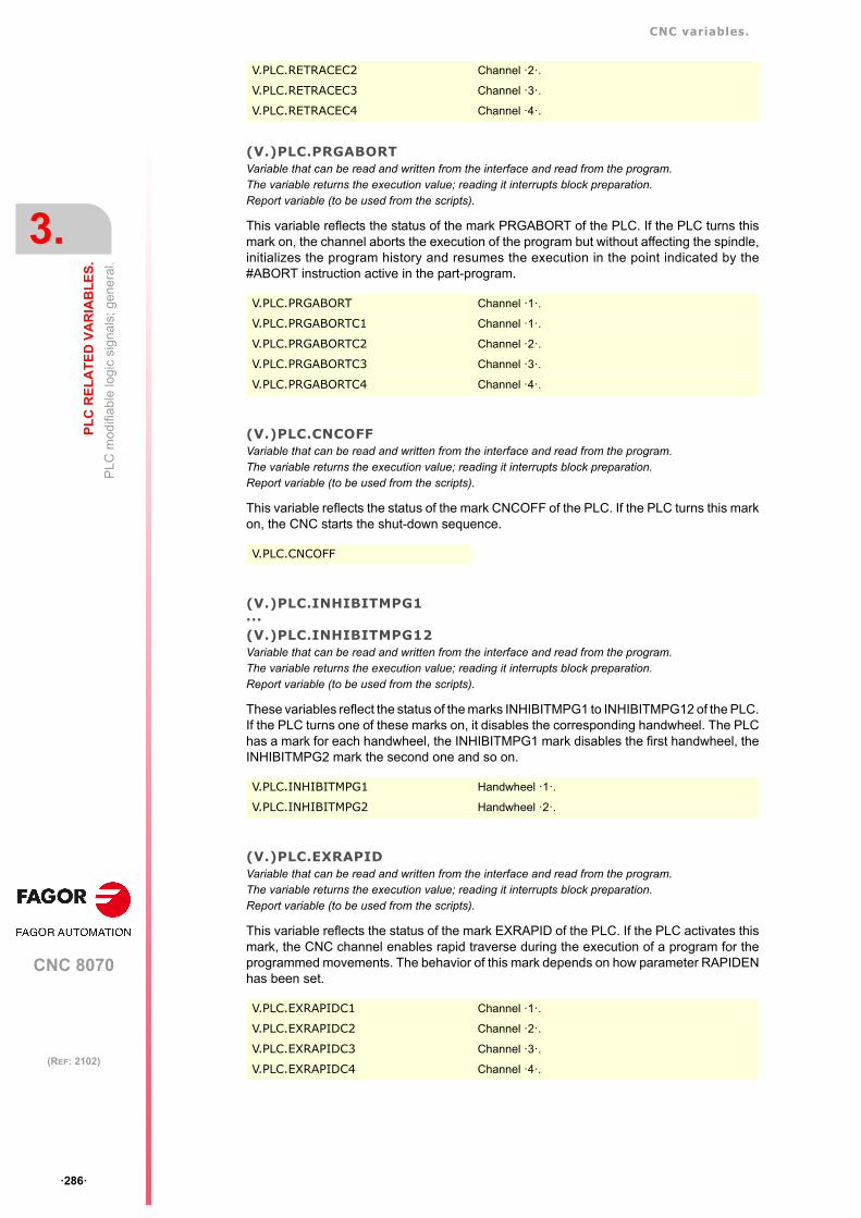
CNC variables.
CNC 8070
3.
PL
C R
EL
AT
ED
VA
RIA
BL
ES
.
PLC
mod
ifiab
le lo
gic
sig
nals
; gen
era
l.
ꞏ286ꞏ
(REF: 2102)
(V.)PLC.PRGABORTVariable that can be read and written from the interface and read from the program.The variable returns the execution value; reading it interrupts block preparation.Report variable (to be used from the scripts).
This variable reflects the status of the mark PRGABORT of the PLC. If the PLC turns thismark on, the channel aborts the execution of the program but without affecting the spindle,initializes the program history and resumes the execution in the point indicated by the#ABORT instruction active in the part-program.
(V.)PLC.CNCOFFVariable that can be read and written from the interface and read from the program.The variable returns the execution value; reading it interrupts block preparation.Report variable (to be used from the scripts).
This variable reflects the status of the mark CNCOFF of the PLC. If the PLC turns this markon, the CNC starts the shut-down sequence.
(V.)PLC.INHIBITMPG1···(V.)PLC.INHIBITMPG12Variable that can be read and written from the interface and read from the program.The variable returns the execution value; reading it interrupts block preparation.Report variable (to be used from the scripts).
These variables reflect the status of the marks INHIBITMPG1 to INHIBITMPG12 of the PLC.If the PLC turns one of these marks on, it disables the corresponding handwheel. The PLChas a mark for each handwheel, the INHIBITMPG1 mark disables the first handwheel, theINHIBITMPG2 mark the second one and so on.
(V.)PLC.EXRAPIDVariable that can be read and written from the interface and read from the program.The variable returns the execution value; reading it interrupts block preparation.Report variable (to be used from the scripts).
This variable reflects the status of the mark EXRAPID of the PLC. If the PLC activates thismark, the CNC channel enables rapid traverse during the execution of a program for theprogrammed movements. The behavior of this mark depends on how parameter RAPIDENhas been set.
V.PLC.RETRACEC2 Channel ꞏ2ꞏ.
V.PLC.RETRACEC3 Channel ꞏ3ꞏ.
V.PLC.RETRACEC4 Channel ꞏ4ꞏ.
V.PLC.PRGABORT Channel ꞏ1ꞏ.
V.PLC.PRGABORTC1 Channel ꞏ1ꞏ.
V.PLC.PRGABORTC2 Channel ꞏ2ꞏ.
V.PLC.PRGABORTC3 Channel ꞏ3ꞏ.
V.PLC.PRGABORTC4 Channel ꞏ4ꞏ.
V.PLC.CNCOFF
V.PLC.INHIBITMPG1 Handwheel ꞏ1ꞏ.
V.PLC.INHIBITMPG2 Handwheel ꞏ2ꞏ.
V.PLC.EXRAPIDC1 Channel ꞏ1ꞏ.
V.PLC.EXRAPIDC2 Channel ꞏ2ꞏ.
V.PLC.EXRAPIDC3 Channel ꞏ3ꞏ.
V.PLC.EXRAPIDC4 Channel ꞏ4ꞏ.

CNC variables.
CNC 8070
PL
C R
EL
AT
ED
VA
RIA
BL
ES
.
3.
PLC
mod
ifiab
le lo
gic
sig
nals
; gen
era
l.
ꞏ287ꞏ
(REF: 2102)
(V.)PLC.KEYBD1CH··(V.)PLC.KEYBD8CHVariable that can be read and written from the interface and read from the program.The variable returns the execution value; reading it interrupts block preparation.Report variable (to be used from the scripts).
These variables reflect the value of the registers KEYBD1CH to KEYBD8CH of the PLC.These registers may be used to change the default behavior of the keyboards with respectto the channels, set by machine parameters.
Values of the variable.
This variable returns one of the following values.
(V.)PLC.VOLCOMP1··(V.)PLC.VOLCOMP4Variable that can be read and written from the interface and read from the program.The variable returns the execution value; reading it interrupts block preparation.Report variable (to be used from the scripts).
These variables reflect the status of the marks VOLCOMP1 to VOLCOMP4 of the PLC. Ifthe PLC activates one of these marks (changing it from 0 to 1), the CNC activates thecorresponding volumetric compensation (parameter VOLCOMP).
(V.)PLC.QWERTYOFF1··(V.)PLC.QWERTYOFF8Variable that can be read and written from the interface and read from the program.The variable returns the execution value; reading it interrupts block preparation.Report variable (to be used from the scripts).
These variables reflect the status of the marks QWERTYOFF1 to QWERTYOFF8 of thePLC. If the PLC turns one of these marks on, it disables the corresponding alphanumerickeyboard.
V.PLC.KEYBD1CH Operator panel ꞏ1ꞏ.
V.PLC.KEYBD2CH Operator panel ꞏ2ꞏ.
Value. Meaning.
0 Configuration defined in the machine parameters.
1 Jog panel assigned to channel 1.
2 Jog panel assigned to channel 2.
3 Jog panel assigned to channel 3.
4 Jog panel assigned to channel 4.
FF Jog panel assigned to the active channel.
V.PLC.VOLCOMP1 Volumetric compensation ꞏ1ꞏ.
V.PLC.VOLCOMP2 Volumetric compensation ꞏ2ꞏ.
V.PLC.VOLCOMP3 Volumetric compensation ꞏ3ꞏ.
V.PLC.VOLCOMP4 Volumetric compensation ꞏ4ꞏ.
V.PLC.QWERTYOFF1 Disable keyboard ꞏ1ꞏ.
V.PLC.QWERTYOFF2 Disable keyboard ꞏ2ꞏ.

CNC variables.
CNC 8070
3.
PL
C R
EL
AT
ED
VA
RIA
BL
ES
.
PLC
mod
ifiab
le lo
gic
sig
nals
; gen
era
l.
ꞏ288ꞏ
(REF: 2102)
(V.)PLC.FLIMITACVariable that can be read and written from the interface and read from the program.The variable returns the execution value; reading it interrupts block preparation.Report variable (to be used from the scripts).
This variable reflects the status of the mark FLIMITAC of the PLC. If the PLC activates thismark, the CNC activates the feedrate safety limits (parameter FLIMIT) on all the axes of thesystem.
(V.)PLC.FLIMITACCHVariable that can be read and written from the interface and read from the program.The variable returns the execution value; reading it interrupts block preparation.Report variable (to be used from the scripts).
This variable reflects the status of the mark FLIMITACCH of the PLC. If the PLC activatesthis mark, the CNC activates the feedrate safety limits (parameter FLIMIT) on all the axesof the channel.
(V.)PLC.SLIMITACVariable that can be read and written from the interface and read from the program.The variable returns the execution value; reading it interrupts block preparation.Report variable (to be used from the scripts).
This variable reflects the status of the mark SLIMITAC of the PLC. If the PLC activates thismark, the CNC activates the speed safety limits (parameter SLIMIT) on all the spindles ofthe system.
(V.)PLC.INT1··(V.)PLC.INT4Variable that can be read and written from the interface and read from the program.The variable returns the execution value; reading it interrupts block preparation.Report variable (to be used from the scripts).
These variables reflect the status of the marks INT1 to INT4 of the PLC. If the PLC activatesone of these marks, the channel executes the corresponding interruption subroutine.
(V.)PLC.PWMONVariable that can be read and written from the interface and read from the program.The variable returns the execution value; reading it interrupts block preparation.Report variable (to be used from the scripts).
This variable reflects the status of the mark PWMON of the PLC. This mark may be usedto activate and deactivate the PWM via PLC.
V.PLC.FLIMITAC
V.PLC.FLIMITAC Channel ꞏ1ꞏ.
V.PLC.FLIMITACCH1 Channel ꞏ1ꞏ.
V.PLC.FLIMITACCH2 Channel ꞏ2ꞏ.
V.PLC.FLIMITACCH3 Channel ꞏ3ꞏ.
V.PLC.FLIMITACCH4 Channel ꞏ4ꞏ.
V.PLC.SLIMITAC
V.PLC.INT1 Channel ꞏ1ꞏ.
V.PLC.INT1C1 Channel ꞏ1ꞏ.
V.PLC.INT1C2 Channel ꞏ2ꞏ.
V.PLC.INT1C3 Channel ꞏ3ꞏ.
V.PLC.INT1C4 Channel ꞏ4ꞏ.
V.PLC.PWMON

CNC variables.
CNC 8070
PL
C R
EL
AT
ED
VA
RIA
BL
ES
.
3.
PLC
mod
ifiab
le lo
gic
sig
nals
; gen
era
l.
ꞏ289ꞏ
(REF: 2102)
(V.)PLC.PROBE1ENA(V.)PLC.PROBE2ENAVariable that can be read and written from the interface and read from the program.The variable returns the execution value; reading it interrupts block preparation.Report variable (to be used from the scripts).
These variables reflect the status of the marks PROBE1ENA to PROBE2ENA of the PLC.These mark indicate that the probe has is enabled.
(V.)PLC.PROBE1MONIT(V.)PLC.PROBE2MONITVariable that can be read and written from the interface and read from the program.The variable returns the execution value; reading it interrupts block preparation.Report variable (to be used from the scripts).
These variables reflect the status of the marks PROBE1MONIT and PROBE2MONIT of thePLC. If the mark is active, the probe is in safe mode monitoring collisions.
(V.)PLC.PT100OFF1··(V.)PLC.PT100OFF20Variable that can be read and written from the interface and read from the program.The variable returns the execution value; reading it interrupts block preparation.Report variable (to be used from the scripts).
These variables reflect the status of the marks PT100OFF1 to PT100OFF20 of the PLC. Ifthe PLC activates one of these marks, the CNC disables the corresponding sensor(parameter PT100 n).
(V.)PLC.LCOUNTALARMOFF1(V.)PLC.LCOUNTALARMOFF2Variable that can be read and written from the interface and read from the program.The variable returns the execution value; reading it interrupts block preparation.Report variable (to be used from the scripts).
These var iables ref lect the status of the marks LCOUNTALARMOFF1 andLCOUNTALARMOFF2 of the PLC. If the PLC activates one of these marks (by changing itfrom 0 to 1), it disables the corresponding local feedback input. If the PLC deactivates oneof these marks (by changing it from 1 to 0), it enables the feedback alarms.
V.PLC.PROBE1ENA Enable probe ꞏ1ꞏ.
V.PLC.PROBE2ENA Enable probe ꞏ2ꞏ.
V.PLC.PROBE1ENA Probe 1ꞏin safe mode.
V.PLC.PROBE2ENA Probe 2ꞏin safe mode.
V.PLC.PT100OFF1 Disable the PT100 ꞏ1ꞏ sensor.
V.PLC.PT100OFF2 Disable the PT100 ꞏ2ꞏ sensor.
V.PLC.LCOUNTALARMOFF1 Local input ꞏ1ꞏ.
V.PLC.LCOUNTALARMOFF2 Local input ꞏ2ꞏ.

CNC variables.
CNC 8070
3.
PL
C R
EL
AT
ED
VA
RIA
BL
ES
.
PLC
mod
ifiab
le lo
gic
sig
nals
; gen
era
l.
ꞏ290ꞏ
(REF: 2102)
(V.)PLC.DMCONVariable that can be read and written from the interface and read from the program.The variable returns the execution value; reading it interrupts block preparation.Report variable (to be used from the scripts).
This variable reflects the status of the mark DMCON of the PLC. With a down flank of thismark (a change from 1 to 0), the CNC deactivates DMC. With an up flank of this mark (achange from 0 to 1), the CNC reactivates DMC.
V.PLC.DMCONC1 Channel ꞏ1ꞏ.
V.PLC.DMCONC2 Channel ꞏ2ꞏ.
V.PLC.DMCONC3 Channel ꞏ3ꞏ.
V.PLC.DMCONC4 Channel ꞏ4ꞏ.

CNC variables.
CNC 8070
PL
C R
EL
AT
ED
VA
RIA
BL
ES
.
3.
PLC
mod
ifia
ble
logi
c si
gna
ls; a
xes
and
spin
dle
s.
ꞏ291ꞏ
(REF: 2102)
3.10 PLC modifiable logic signals; axes and spindles.
(V.)PLC.LIMITPOSxn(V.)PLC.LIMITPOSsnVariable that can be read and written from the interface and read from the program and from the PLC.Variable valid for rotary and linear axes as well as for spindles.The variable returns the execution value; reading it interrupts block preparation.Report variable (to be used from the scripts).
This variable reflects the status of the mark LIMITPOS of the PLC. The PLC must turn thismark on to indicate that the axis or the spindle has exceeded the positive travel limit.
Syntax.
ꞏxnꞏ Name or logic number of the axis.
ꞏsnꞏ Name or logic number of the spindle.
(V.)PLC.LIMITNEGxn(V.)PLC.LIMITNEGsnVariable that can be read and written from the interface and read from the program and from the PLC.Variable valid for rotary and linear axes as well as for spindles.The variable returns the execution value; reading it interrupts block preparation.Report variable (to be used from the scripts).
This variable reflects the status of the mark LIMITNEG of the PLC. The PLC must turn thismark on to indicate that the axis or the spindle has exceeded the negative travel limit.
Syntax.
ꞏxnꞏ Name or logic number of the axis.
ꞏsnꞏ Name or logic number of the spindle.
(V.)PLC.DECELxn(V.)PLC.DECELsnVariable that can be read and written from the interface and read from the program and from the PLC.Variable valid for rotary and linear axes as well as for spindles.The variable returns the execution value; reading it interrupts block preparation.Report variable (to be used from the scripts).
This variable reflects the status of the mark DECEL of the PLC. The PLC must turn this markon to indicate that the home switch is pressed.
Syntax.
ꞏxnꞏ Name or logic number of the axis.
ꞏsnꞏ Name or logic number of the spindle.
V.PLC.LIMITPOSX X axis.
V.PLC.LIMITPOSS Spindle S.
V.PLC.LIMITPOS3 Axis or spindle with logic number ꞏ3ꞏ.
V.PLC.LIMITNEGX X axis.
V.PLC.LIMITNEGS Spindle S.
V.PLC.LIMITNEG3 Axis or spindle with logic number ꞏ3ꞏ.
V.PLC.DECELX X axis.
V.PLC.DECELS Spindle S.
V.PLC.DECEL3 Axis or spindle with logic number ꞏ3ꞏ.

CNC variables.
CNC 8070
3.
PL
C R
EL
AT
ED
VA
RIA
BL
ES
.
PLC
mod
ifia
ble
logi
c si
gna
ls; a
xes
and
spin
dle
s.
ꞏ292ꞏ
(REF: 2102)
(V.)PLC.INHIBITxn(V.)PLC.INHIBITsnVariable that can be read and written from the interface and read from the program and from the PLC.Variable valid for rotary and linear axes as well as for spindles.The variable returns the execution value; reading it interrupts block preparation.Report variable (to be used from the scripts).
This variable reflects the status of the mark INHIBIT of the PLC. If the PLC turns this markon, the CNC inhibits any movement of the axis or spindle.
For independent axes and electronic cam, if the PLC turns this mark on, it interrupts thesynchronization movement switching to zero speed. The system waits for the signal todeactivate before resuming the execution and the movement from the interruption point.
Syntax.
ꞏxnꞏ Name or logic number of the axis.
ꞏsnꞏ Name or logic number of the spindle.
(V.)PLC.AXISPOSxn(V.)PLC.AXISPOSsnVariable that can be read and written from the interface and read from the program and from the PLC.Variable valid for rotary and linear axes as well as for spindles.The variable returns the execution value; reading it interrupts block preparation.Report variable (to be used from the scripts).
This variable reflects the status of the mark AXISPOS of the PLC. If the PLC turns this markon while the CNC is in jog mode, the CNC moves the axis or the spindle in the positivedirection.
Syntax.
ꞏxnꞏ Name or logic number of the axis.
ꞏsnꞏ Name or logic number of the spindle.
(V.)PLC.AXISNEGxn(V.)PLC.AXISNEGsnVariable that can be read and written from the interface and read from the program and from the PLC.Variable valid for rotary and linear axes as well as for spindles.The variable returns the execution value; reading it interrupts block preparation.Report variable (to be used from the scripts).
This variable reflects the status of the mark AXISNEG of the PLC. If the PLC turns this markon while the CNC is in jog mode, the CNC moves the axis or the spindle in the positivedirection.
Syntax.
ꞏxnꞏ Name or logic number of the axis.
ꞏsnꞏ Name or logic number of the spindle.
V.PLC.INHIBITX X axis.
V.PLC.INHIBITS Spindle S.
V.PLC.INHIBIT3 Axis or spindle with logic number ꞏ3ꞏ.
V.PLC.AXISPOSX X axis.
V.PLC.AXISPOSS Spindle S.
V.PLC.AXISPOS3 Axis or spindle with logic number ꞏ3ꞏ.
V.PLC.AXISNEGX X axis.
V.PLC.AXISNEGS Spindle S.
V.PLC.AXISNEG3 Axis or spindle with logic number ꞏ3ꞏ.

CNC variables.
CNC 8070
PL
C R
EL
AT
ED
VA
RIA
BL
ES
.
3.
PLC
mod
ifia
ble
logi
c si
gna
ls; a
xes
and
spin
dle
s.
ꞏ293ꞏ
(REF: 2102)
(V.)PLC.SERVOxnON(V.)PLC.SERVOsnONVariable that can be read and written from the interface and read from the program and from the PLC.Variable valid for rotary and linear axes as well as for spindles.The variable returns the execution value; reading it interrupts block preparation.Report variable (to be used from the scripts).
This variable reflects the status of the mark SERVOON of the PLC. The PLC must turn thismark on to allow moving the axis or the spindle.
Syntax.
ꞏxnꞏ Name or logic number of the axis.
ꞏsnꞏ Name or logic number of the spindle.
(V.)PLC.DROxn(V.)PLC.DROsnVariable that can be read and written from the interface and read from the program and from the PLC.Variable valid for rotary and linear axes as well as for spindles.The variable returns the execution value; reading it interrupts block preparation.Report variable (to be used from the scripts).
This variable reflects the status of the mark DRO of the PLC. The PLC must turn this markon for the axis or the spindle to work in DRO mode.
Syntax.
ꞏxnꞏ Name or logic number of the axis.
ꞏsnꞏ Name or logic number of the spindle.
(V.)PLC.SPENAxn(V.)PLC.SPENAsnVariable that can be read and written from the interface and read from the program and from the PLC.Variable valid for rotary and linear axes as well as for spindles.The variable returns the execution value; reading it interrupts block preparation.Report variable (to be used from the scripts).
This variable reflects the status of the mark SPENA of the PLC. The PLC must turn this markon to enable the speed enable signal of the drive.
Syntax.
ꞏxnꞏ Name or logic number of the axis.
ꞏsnꞏ Name or logic number of the spindle.
(V.)PLC.DRENAxn(V.)PLC.DRENAsnVariable that can be read and written from the interface and read from the program and from the PLC.Variable valid for rotary and linear axes as well as for spindles.The variable returns the execution value; reading it interrupts block preparation.Report variable (to be used from the scripts).
This variable reflects the status of the mark DRENA of the PLC. The PLC must turn this markon to enable the drive enable signal of the drive.
V.PLC.SERVOXON X axis.
V.PLC.SERVOSON Spindle S.
V.PLC.SERVO3ON Axis or spindle with logic number ꞏ3ꞏ.
V.PLC.DROX X axis.
V.PLC.DROS Spindle S.
V.PLC.DRO3 Axis or spindle with logic number ꞏ3ꞏ.
V.PLC.SPENAX X axis.
V.PLC.SPENAS Spindle S.
V.PLC.SPENA3 Axis or spindle with logic number ꞏ3ꞏ.

CNC variables.
CNC 8070
3.
PL
C R
EL
AT
ED
VA
RIA
BL
ES
.
PLC
mod
ifia
ble
logi
c si
gna
ls; a
xes
and
spin
dle
s.
ꞏ294ꞏ
(REF: 2102)
Syntax.
ꞏxnꞏ Name or logic number of the axis.
ꞏsnꞏ Name or logic number of the spindle.
(V.)PLC.LIMxnOFF(V.)PLC.LIMsnOFFVariable that can be read and written from the interface and read from the program and from the PLC.Variable valid for rotary and linear axes as well as for spindles.The variable returns the execution value; reading it interrupts block preparation.Report variable (to be used from the scripts).
This variable reflects the status of the mark LIMOFF of the PLC. If the PLC turns this markon, the CNC ignores the software travel limits.
Syntax.
ꞏxnꞏ Name or logic number of the axis.
ꞏsnꞏ Name or logic number of the spindle.
(V.)PLC.PARKEDxn(V.)PLC.PARKEDsnVariable that can be read and written from the interface and read from the program and from the PLC.Variable valid for rotary and linear axes as well as for spindles.The variable returns the execution value; reading it interrupts block preparation.Report variable (to be used from the scripts).
This variable reflects the status of the mark PARKED of the PLC. The PLC turns this markon when the axis or the spindle is parked.
Syntax.
ꞏxnꞏ Name or logic number of the axis.
ꞏsnꞏ Name or logic number of the spindle.
(V.)PLC.LUBRENAxn(V.)PLC.LUBRENAsnVariable that can be read and written from the interface and read from the program and from the PLC.Variable valid for rotary and linear axes as well as for spindles.The variable returns the execution value; reading it interrupts block preparation.Report variable (to be used from the scripts).
This variable reflects the status of the mark LUBRENA of the PLC. The PLC turns this markon to enable the lubrication of the axis or the spindle.
Syntax.
ꞏxnꞏ Name or logic number of the axis.
ꞏsnꞏ Name or logic number of the spindle.
V.PLC.DRENAX X axis.
V.PLC.DRENAS Spindle S.
V.PLC.DRENA3 Axis or spindle with logic number ꞏ3ꞏ.
V.PLC.LIMXOFF X axis.
V.PLC.LIMSOFF Spindle S.
V.PLC.LIM3OFF Axis or spindle with logic number ꞏ3ꞏ.
V.PLC.PARKEDX X axis.
V.PLC.PARKEDS Spindle S.
V.PLC.PARKED3 Axis or spindle with logic number ꞏ3ꞏ.
V.PLC.LUBRENAX X axis.
V.PLC.LUBRENAS Spindle S.
V.PLC.LUBRENA3 Axis or spindle with logic number ꞏ3ꞏ.

CNC variables.
CNC 8070
PL
C R
EL
AT
ED
VA
RIA
BL
ES
.
3.
PLC
mod
ifia
ble
logi
c si
gna
ls; a
xes
and
spin
dle
s.
ꞏ295ꞏ
(REF: 2102)
(V.)PLC.LUBROKxn(V.)PLC.LUBROKsnVariable that can be read and written from the interface and read from the program and from the PLC.Variable valid for rotary and linear axes as well as for spindles.The variable returns the execution value; reading it interrupts block preparation.Report variable (to be used from the scripts).
This variable reflects the status of the mark LUBROK of the PLC. The PLC turns this markon to indicate that the axis lubrication is done.
Syntax.
ꞏxnꞏ Name or logic number of the axis.
ꞏsnꞏ Name or logic number of the spindle.
(V.)PLC.DIFFCOMPxn(V.)PLC.DIFFCOMPsnVariable that can only be read from the program, PLC and interface.Variable valid for rotary and linear axes as well as for spindles.The variable returns the execution value; reading it interrupts block preparation.Report variable (to be used from the scripts).
This variable reflects the status of the mark DIFFCOMP of the PLC. The PLC uses this markon Gantry axes to correct the position difference between the two axes.
Syntax.
ꞏxnꞏ Name or logic number of the axis.
ꞏsnꞏ Name or logic number of the spindle.
(V.)PLC.FBACKSELxn(V.)PLC.FBACKSELsnVariable that can be read and written from the interface and read from the program and from the PLC.Variable valid for rotary and linear axes as well as for spindles.The variable returns the execution value; reading it interrupts block preparation.Report variable (to be used from the scripts).
This variable reflects the status of the mark FBACKSEL of the PLC. In systems withexternal+internal feedback, the PLC turns this mark on to use the external feedback andturns it off to use the internal feedback.
Syntax.
ꞏxnꞏ Name or logic number of the axis.
ꞏsnꞏ Name or logic number of the spindle.
V.PLC.LUBROKX X axis.
V.PLC.LUBROKS Spindle S.
V.PLC.LUBROK3 Axis or spindle with logic number ꞏ3ꞏ.
V.PLC.DIFFCOMPX X axis.
V.PLC.DIFFCOMPS Spindle S.
V.PLC.DIFFCOMP3 Axis or spindle with logic number ꞏ3ꞏ.
V.PLC.FBACKSELX X axis.
V.PLC.FBACKSELS Spindle S.
V.PLC.FBACKSEL3 Axis or spindle with logic number ꞏ3ꞏ.

CNC variables.
CNC 8070
3.
PL
C R
EL
AT
ED
VA
RIA
BL
ES
.
PLC
mod
ifia
ble
logi
c si
gna
ls; a
xes
and
spin
dle
s.
ꞏ296ꞏ
(REF: 2102)
(V.)PLC.DEADxn(V.)PLC.DEADsnVariable that can be read and written from the program and interface and read from the PLC.Variable valid for rotary and linear axes as well as for spindles.The variable returns the execution value; reading it interrupts block preparation.Report variable (to be used from the scripts).
This variable reflects the status of the mark DEAD of the PLC. In systems with dead axes,the PLC uses this mark to indicate to the CNC how to handle the path joints when a deadaxis is involved.
Syntax.
ꞏxnꞏ Name or logic number of the axis.
ꞏsnꞏ Name or logic number of the spindle.
(V.)PLC.SWITCHxn(V.)PLC.SWITCHsnVariable that can be read and written from the program and interface and read from the PLC.Variable valid for rotary and linear axes as well as for spindles.The variable returns the execution value; reading it interrupts block preparation.Report variable (to be used from the scripts).
This variable reflects the status of the mark SWITCH of the PLC. When the system has multi-axis groups, this mark may be used to toggle between the various axes or spindles of thegroup.
Syntax.
ꞏxnꞏ Name or logic number of the axis.
ꞏsnꞏ Name or logic number of the spindle.
(V.)PLC.TANDEMOFFxn(V.)PLC.TANDEMOFFsnVariable that can be read and written from the program and interface and read from the PLC.Variable valid for rotary and linear axes as well as for spindles.The variable returns the execution value; reading it interrupts block preparation.Report variable (to be used from the scripts).
This variable reflects the status of the mark TANDEMOFF of the PLC. This mark may be usedto temporarily decouple (unslave) the loop of the axes or spindles involved in the tandemso they can be move separately.
Syntax.
ꞏxnꞏ Name or logic number of the axis.
ꞏsnꞏ Name or logic number of the spindle.
V.PLC.DEADX X axis.
V.PLC.DEADS Spindle S.
V.PLC.DEAD3 Axis or spindle with logic number ꞏ3ꞏ.
V.PLC.SWITCHX X axis.
V.PLC.SWITCHS Spindle S.
V.PLC.SWITCH3 Axis or spindle with logic number ꞏ3ꞏ.
V.PLC.TANDEMOFFX X axis.
V.PLC.TANDEMOFFS Spindle S.
V.PLC.TANDEMOFF3 Axis or spindle with logic number ꞏ3ꞏ.

CNC variables.
CNC 8070
PL
C R
EL
AT
ED
VA
RIA
BL
ES
.
3.
PLC
mod
ifia
ble
logi
c si
gna
ls; a
xes
and
spin
dle
s.
ꞏ297ꞏ
(REF: 2102)
(V.)PLC.GANTRYOFFxnVariable that can be read and written from the interface and read from the program and from the PLC.Variable valid for linear axes.The variable returns the execution value; reading it interrupts block preparation.Report variable (to be used from the scripts).
This variable reflects the status of the mark GANTRYOFF of the PLC. This tag refers to thegantry slave axis. If the PLC activates this mark (change from 0 to 1), the CNC will decouplethe gantry axis and allow for only the master axis to be moved.
Syntax.
ꞏxnꞏ Name or logic number of the axis.
V.PLC.GANTRYOFFX X axis.
V.PLC.GANTRYOFFX Axis with logic number ꞏ3ꞏ.
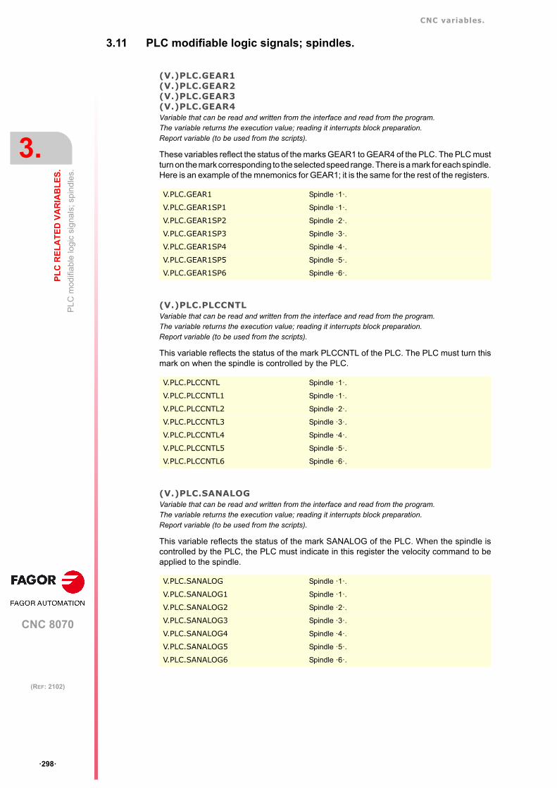
CNC variables.
CNC 8070
3.
PL
C R
EL
AT
ED
VA
RIA
BL
ES
.
PL
C m
odifi
able
logi
c si
gna
ls; s
pind
les.
ꞏ298ꞏ
(REF: 2102)
3.11 PLC modifiable logic signals; spindles.
(V.)PLC.GEAR1(V.)PLC.GEAR2(V.)PLC.GEAR3(V.)PLC.GEAR4Variable that can be read and written from the interface and read from the program.The variable returns the execution value; reading it interrupts block preparation.Report variable (to be used from the scripts).
These variables reflect the status of the marks GEAR1 to GEAR4 of the PLC. The PLC mustturn on the mark corresponding to the selected speed range. There is a mark for each spindle.Here is an example of the mnemonics for GEAR1; it is the same for the rest of the registers.
(V.)PLC.PLCCNTLVariable that can be read and written from the interface and read from the program.The variable returns the execution value; reading it interrupts block preparation.Report variable (to be used from the scripts).
This variable reflects the status of the mark PLCCNTL of the PLC. The PLC must turn thismark on when the spindle is controlled by the PLC.
(V.)PLC.SANALOGVariable that can be read and written from the interface and read from the program.The variable returns the execution value; reading it interrupts block preparation.Report variable (to be used from the scripts).
This variable reflects the status of the mark SANALOG of the PLC. When the spindle iscontrolled by the PLC, the PLC must indicate in this register the velocity command to beapplied to the spindle.
V.PLC.GEAR1 Spindle ꞏ1ꞏ.
V.PLC.GEAR1SP1 Spindle ꞏ1ꞏ.
V.PLC.GEAR1SP2 Spindle ꞏ2ꞏ.
V.PLC.GEAR1SP3 Spindle ꞏ3ꞏ.
V.PLC.GEAR1SP4 Spindle ꞏ4ꞏ.
V.PLC.GEAR1SP5 Spindle ꞏ5ꞏ.
V.PLC.GEAR1SP6 Spindle ꞏ6ꞏ.
V.PLC.PLCCNTL Spindle ꞏ1ꞏ.
V.PLC.PLCCNTL1 Spindle ꞏ1ꞏ.
V.PLC.PLCCNTL2 Spindle ꞏ2ꞏ.
V.PLC.PLCCNTL3 Spindle ꞏ3ꞏ.
V.PLC.PLCCNTL4 Spindle ꞏ4ꞏ.
V.PLC.PLCCNTL5 Spindle ꞏ5ꞏ.
V.PLC.PLCCNTL6 Spindle ꞏ6ꞏ.
V.PLC.SANALOG Spindle ꞏ1ꞏ.
V.PLC.SANALOG1 Spindle ꞏ1ꞏ.
V.PLC.SANALOG2 Spindle ꞏ2ꞏ.
V.PLC.SANALOG3 Spindle ꞏ3ꞏ.
V.PLC.SANALOG4 Spindle ꞏ4ꞏ.
V.PLC.SANALOG5 Spindle ꞏ5ꞏ.
V.PLC.SANALOG6 Spindle ꞏ6ꞏ.
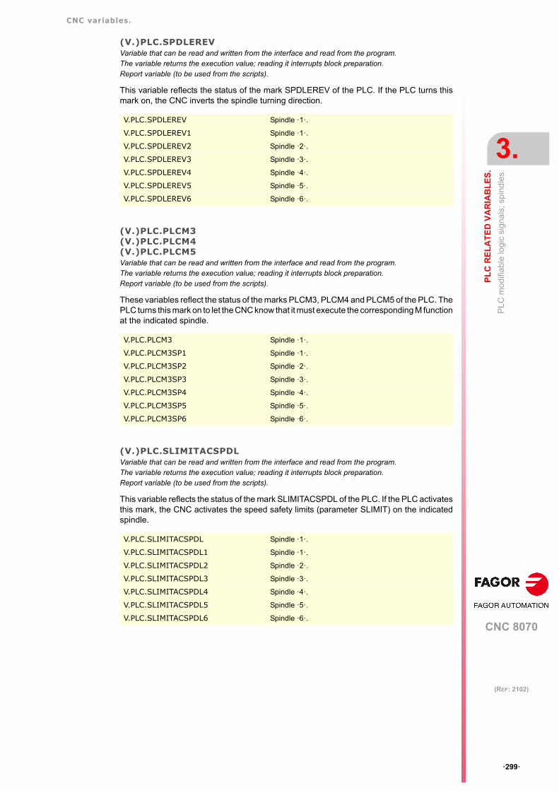
CNC variables.
CNC 8070
PL
C R
EL
AT
ED
VA
RIA
BL
ES
.
3.
PL
C m
odifi
able
logi
c si
gna
ls; s
pind
les.
ꞏ299ꞏ
(REF: 2102)
(V.)PLC.SPDLEREVVariable that can be read and written from the interface and read from the program.The variable returns the execution value; reading it interrupts block preparation.Report variable (to be used from the scripts).
This variable reflects the status of the mark SPDLEREV of the PLC. If the PLC turns thismark on, the CNC inverts the spindle turning direction.
(V.)PLC.PLCM3(V.)PLC.PLCM4(V.)PLC.PLCM5Variable that can be read and written from the interface and read from the program.The variable returns the execution value; reading it interrupts block preparation.Report variable (to be used from the scripts).
These variables reflect the status of the marks PLCM3, PLCM4 and PLCM5 of the PLC. ThePLC turns this mark on to let the CNC know that it must execute the corresponding M functionat the indicated spindle.
(V.)PLC.SLIMITACSPDLVariable that can be read and written from the interface and read from the program.The variable returns the execution value; reading it interrupts block preparation.Report variable (to be used from the scripts).
This variable reflects the status of the mark SLIMITACSPDL of the PLC. If the PLC activatesthis mark, the CNC activates the speed safety limits (parameter SLIMIT) on the indicatedspindle.
V.PLC.SPDLEREV Spindle ꞏ1ꞏ.
V.PLC.SPDLEREV1 Spindle ꞏ1ꞏ.
V.PLC.SPDLEREV2 Spindle ꞏ2ꞏ.
V.PLC.SPDLEREV3 Spindle ꞏ3ꞏ.
V.PLC.SPDLEREV4 Spindle ꞏ4ꞏ.
V.PLC.SPDLEREV5 Spindle ꞏ5ꞏ.
V.PLC.SPDLEREV6 Spindle ꞏ6ꞏ.
V.PLC.PLCM3 Spindle ꞏ1ꞏ.
V.PLC.PLCM3SP1 Spindle ꞏ1ꞏ.
V.PLC.PLCM3SP2 Spindle ꞏ2ꞏ.
V.PLC.PLCM3SP3 Spindle ꞏ3ꞏ.
V.PLC.PLCM3SP4 Spindle ꞏ4ꞏ.
V.PLC.PLCM3SP5 Spindle ꞏ5ꞏ.
V.PLC.PLCM3SP6 Spindle ꞏ6ꞏ.
V.PLC.SLIMITACSPDL Spindle ꞏ1ꞏ.
V.PLC.SLIMITACSPDL1 Spindle ꞏ1ꞏ.
V.PLC.SLIMITACSPDL2 Spindle ꞏ2ꞏ.
V.PLC.SLIMITACSPDL3 Spindle ꞏ3ꞏ.
V.PLC.SLIMITACSPDL4 Spindle ꞏ4ꞏ.
V.PLC.SLIMITACSPDL5 Spindle ꞏ5ꞏ.
V.PLC.SLIMITACSPDL6 Spindle ꞏ6ꞏ.

CNC variables.
CNC 8070
3.
PL
C R
EL
AT
ED
VA
RIA
BL
ES
.
PL
C m
odifi
able
logi
c si
gna
ls; i
ndep
ende
nt i
nter
pol
ator
.
ꞏ300ꞏ
(REF: 2102)
3.12 PLC modifiable logic signals; independent interpolator.
(V.)PLC._IXFERINHxnVariable that can be read and written from the program and interface and read from the PLC.Variable valid for rotary and linear axes as well as for spindles.The variable returns the execution value; reading it interrupts block preparation.Report variable (to be used from the scripts).
This variable reflects the status of the mark IXFERINH of the PLC. If the PLC deactivatesthis mark, the movements of the independent axis remain waiting for the PLC to activate thismark again.
Syntax.
ꞏxnꞏ Name or logic number of the axis.
(V.)PLC.IRESETxnVariable that can be read and written from the program and interface and read from the PLC.Variable valid for rotary and linear axes as well as for spindles.The variable returns the execution value; reading it interrupts block preparation.Report variable (to be used from the scripts).
This variable reflects the status of the mark IRESET of the PLC. If the PLC turns this markon, the independent interpolator interrupts the instruction being executed and eliminates theinstructions pending execution.
Syntax.
ꞏxnꞏ Name or logic number of the axis.
(V.)PLC.IABORTxnVariable that can be read and written from the program and interface and read from the PLC.Variable valid for rotary and linear axes as well as for spindles.The variable returns the execution value; reading it interrupts block preparation.Report variable (to be used from the scripts).
This variable reflects the status of the mark IABORT of the PLC. If the PLC turns this markon, the independent interpolator interrupts the positioning block being executed (if any)eliminating also the rest of the positioning blocks pending execution.
Syntax.
ꞏxnꞏ Name or logic number of the axis.
V.PLC._IXFERINHX X axis.
V.PLC._IXFERINH3 Axis with logic number ꞏ3ꞏ.
V.PLC.IRESETX X axis.
V.PLC.IRESET3 Axis with logic number ꞏ3ꞏ.
V.PLC.IABORTX X axis.
V.PLC.IABORT3 Axis with logic number ꞏ3ꞏ.

CNC variables.
CNC 8070
PL
C R
EL
AT
ED
VA
RIA
BL
ES
.
3.
PLC
mod
ifiab
le lo
gic
sig
nals
; las
er.
ꞏ301ꞏ
(REF: 2102)
3.13 PLC modifiable logic signals; laser.
3.13.1 Laser status.
(V.)PLC.LASERONVariable that can be read and written via program and interface.The variable returns the execution value; reading it interrupts block preparation.Report variable (to be used from the scripts).Units: - .
This variable reflects the status of the mark LASERON of the PLC. The PLC activates thismark to indicate that the laser is on.
(V.)PLC.SHUTTERONVariable that can be read and written via program and interface.The variable returns the execution value; reading it interrupts block preparation.Report variable (to be used from the scripts).Units: - .
This variable reflects the status of the mark SHUTTERON of the PLC. The PLC activatesthis mark to indicate that the laser source shutter is open.
(V.)PLC.LASERREADYVariable that can be read and written via program and interface.The variable returns the execution value; reading it interrupts block preparation.Report variable (to be used from the scripts).Units: - .
This variable reflects the status of the mark ASERREADY of the PLC. The PLC activatesthis mark to indicate that the laser is ready.
V.PLC.LASERON
V.PLC.SHUTTERON
V.PLC.LASERREADY

CNC variables.
CNC 8070
3.
PL
C R
EL
AT
ED
VA
RIA
BL
ES
.
PLC
mod
ifiab
le lo
gic
sig
nals
; las
er.
ꞏ302ꞏ
(REF: 2102)
3.13.2 PWM active from the PLC.
(V.)PLC.PWMONVariable that can be read and written from the interface and read from the program.The variable returns the execution value; reading it interrupts block preparation.Report variable (to be used from the scripts).Units: - .
This mark may be used to activate and deactivate the PWM via PLC. Activating the PWMvia PLC has priority over activating it from the CNC.
(V.)PLC.PWMFREQVariable that can be read and written from the interface and read from the program.The variable returns the execution value; reading it interrupts block preparation.Report variable (to be used from the scripts).Units: Herz.
PWM frequency, when the PWM has been activated via PLC. This variable only works whenthe Laser has been activated via PLC.
Remarks.
The changes from the variable are updated (refreshed) in the next loop; the intermediatetimes between loops will be ignored.
(V.)PLC.PWMDUTYVariable that can be read and written from the interface and read from the program.The variable returns the execution value; reading it interrupts block preparation.Report variable (to be used from the scripts).Units: Percentage.
PWM duty cycle, when the PWM has been activated via PLC. This variable only works whenthe Laser has been activated via PLC.
Remarks.
The changes from the variable are updated (refreshed) in the next loop; the intermediatetimes between loops will be ignored.
The reading from the CNC will be divided by 10; i.e. for the value of ꞏ1ꞏ, the CNC readingwill return a value of ꞏ0.1ꞏ.
V.PLC.PWMON
V.PLC.PWMFREQ
V.PLC.PWMDUTY

CNC variables.
CNC 8070
PL
C R
EL
AT
ED
VA
RIA
BL
ES
.
3.
PLC
mod
ifiab
le lo
gic
sig
nals
; las
er.
ꞏ303ꞏ
(REF: 2102)
3.13.3 Power control.
(V.)PLC.ENABLEPWROUTVariable that can be read and written from the interface and read from the program.The variable returns the execution value; reading it interrupts block preparation.Report variable (to be used from the scripts).Units: - .
This mark is active by default. This mark is associated with the power control via an analogoutput associated with the spindle (#PWRCTRL ON [OUT]). The PLC deactivates this markto disable the active power control. The PLC activates this mark to enable the active powercontrol in the CNC; if no power control is active, this mark does nothing.
(V.)PLC.ENABLEPWRDUTYVariable that can be read and written from the interface and read from the program.The variable returns the execution value; reading it interrupts block preparation.Report variable (to be used from the scripts).Units: - .
This mark is active by default. This mark is associated with the power control via a PWMduty (#PWRCTRL ON [DUTY]). The PLC deactivates this mark to disable the active powercontrol. The PLC activates this mark to enable the active power control in the CNC; if nopower control is active, this mark does nothing.
(V.)PLC.ENABLEPWRFREQ
This mark is active by default. This mark is associated with the PWM power control(#PWRCTRL ON [FREQ]). The PLC deactivates this mark to disable the active powercontrol. The PLC activates this mark to enable the active power control in the CNC; if nopower control is active, this mark does nothing.
V.PLC.ENABLEPWROUT
V.PLC.ENABLEPWRDUTY
V.PLC.ENABLEPWRFREQ

CNC variables.
CNC 8070
3.
PL
C R
EL
AT
ED
VA
RIA
BL
ES
.
PLC
mod
ifiab
le lo
gic
sig
nals
; las
er.
ꞏ304ꞏ
(REF: 2102)
3.13.4 Gap control.
(V.)PLC.ENABLEGAPVariable that can be read and written via program and interface.The variable returns the execution value; reading it interrupts block preparation.Report variable (to be used from the scripts).Units: - .
This mark is active by default. The PLC deactivates this mark to disable the active gapcontrol. The PLC activates this mark to enable the active gap control in the CNC; if no gapcontrol is active, this mark does nothing.
(V.)PLC.GAPCOLLISIONVariable that can be read and written via program and interface.The variable returns the execution value; reading it interrupts block preparation.Report variable (to be used from the scripts).Units: - .
The PLC activates this mark to indicate that the collision sensor has been activated. Thismark is not kept in memory. With this mark active, the CNC behavior depends on the machineparameter GAPCOLLISION.
3.13.5 Leapfrog.
(V.)PLC.ENABLELEAPVariable that can be read and written via program and interface.The variable returns the execution value; reading it interrupts block preparation.Report variable (to be used from the scripts).Units: - .
The PLC deactivates this mark to disable the active leapfrog. The PLC activates this markto enable the active leapfrog in the CNC; if no gap control is active, this mark does nothing.
V.PLC.ENABLEGAP
V.PLC.GAPCOLLISION
V.PLC.ENABLELEAP

CNC variables.
CNC 8070
PL
C R
EL
AT
ED
VA
RIA
BL
ES
.
3.
PLC
mo
difia
ble
log
ic s
igna
ls; t
ool m
ana
ger.
ꞏ305ꞏ
(REF: 2102)
3.14 PLC modifiable logic signals; tool manager.
(V.)PLC.SETTMEMVariable that can be read and written from the interface and read from the program.The variable returns the execution value; reading it interrupts block preparation.Report variable (to be used from the scripts).
This variable reflects the status of the mark SETMEM of the PLC. The PLC must turn thismark on to activate the emergency of the tool manager.
(V.)PLC.RESTMEMVariable that can be read and written from the interface and read from the program.The variable returns the execution value; reading it interrupts block preparation.Report variable (to be used from the scripts).
This variable reflects the status of the mark RESTMEM of the PLC. The PLC must turn thismark on to cancel the emergency of the tool manager.
(V.)PLC.CUTTINGONVariable that can be read and written from the interface and read from the program.The variable returns the execution value; reading it interrupts block preparation.Report variable (to be used from the scripts).
This variable reflects the status of the mark CUTTINGON of the PLC. The PLC must turnthis mark on to indicate that the tool is machining (cutting).
(V.)PLC.TREJECTVariable that can be read and written from the interface and read from the program.The variable returns the execution value; reading it interrupts block preparation.Report variable (to be used from the scripts).
This variable reflects the status of the mark TREJECT of the PLC. The PLC must turn thismark on to reject the tool.
V.PLC.SETTMEM Magazine ꞏ1ꞏ.
V.PLC.SETTMEMZ1 Magazine ꞏ1ꞏ.
V.PLC.SETTMEMZ2 Magazine ꞏ2ꞏ.
V.PLC.SETTMEMZ3 Magazine ꞏ3ꞏ.
V.PLC.SETTMEMZ4 Magazine ꞏ4ꞏ.
V.PLC.RESTMEM Magazine ꞏ1ꞏ.
V.PLC.RESTMEMZ1 Magazine ꞏ1ꞏ.
V.PLC.RESTMEMZ2 Magazine ꞏ2ꞏ.
V.PLC.RESTMEMZ3 Magazine ꞏ3ꞏ.
V.PLC.RESTMEMZ4 Magazine ꞏ4ꞏ.
V.PLC.CUTTINGON Channel ꞏ1ꞏ.
V.PLC.CUTTINGON1 Channel ꞏ1ꞏ.
V.PLC.CUTTINGON2 Channel ꞏ2ꞏ.
V.PLC.CUTTINGON3 Channel ꞏ3ꞏ.
V.PLC.CUTTINGON4 Channel ꞏ4ꞏ.
V.PLC.TREJECT Channel ꞏ1ꞏ.
V.PLC.TREJECTC1 Channel ꞏ1ꞏ.
V.PLC.TREJECTC2 Channel ꞏ2ꞏ.
V.PLC.TREJECTC3 Channel ꞏ3ꞏ.
V.PLC.TREJECTC4 Channel ꞏ4ꞏ.

CNC variables.
CNC 8070
3.
PL
C R
EL
AT
ED
VA
RIA
BL
ES
.
PLC
mo
difia
ble
log
ic s
igna
ls; t
ool m
ana
ger.
ꞏ306ꞏ
(REF: 2102)
(V.)PLC.MZTOCH1Variable that can be read and written from the interface and read from the program.The variable returns the execution value; reading it interrupts block preparation.Report variable (to be used from the scripts).
This variable reflects the status of the mark MZTOCH1 of the PLC. The PLC must turn thismark on after taking the tool from the magazine to the claw 1 of the tool changer arm.
(V.)PLC.CH1TOSPDLVariable that can be read and written from the interface and read from the program.The variable returns the execution value; reading it interrupts block preparation.Report variable (to be used from the scripts).
This variable reflects the status of the mark CH1TOSPDL of the PLC. The PLC must turnthis mark on after taking the tool from the claw 1 of the tool changer arm to the spindle.
(V.)PLC.SPDLTOCH1Variable that can be read and written from the interface and read from the program.The variable returns the execution value; reading it interrupts block preparation.Report variable (to be used from the scripts).
This variable reflects the status of the mark SPDLTOCH1 of the PLC. The PLC must turnthis mark on after taking the tool from the spindle to the claw 1 of the tool changer arm.
(V.)PLC.SPDLTOCH2Variable that can be read and written from the interface and read from the program.The variable returns the execution value; reading it interrupts block preparation.Report variable (to be used from the scripts).
This variable reflects the status of the mark SPDLTOCH2 of the PLC. The PLC must turnthis mark on after taking the tool from the spindle to the claw 2 of the tool changer arm.
V.PLC.MZTOCH1 Magazine ꞏ1ꞏ.
V.PLC.MZTOCH1MZ1 Magazine ꞏ1ꞏ.
V.PLC.MZTOCH1MZ2 Magazine ꞏ2ꞏ.
V.PLC.MZTOCH1MZ3 Magazine ꞏ3ꞏ.
V.PLC.MZTOCH1MZ4 Magazine ꞏ4ꞏ.
V.PLC.CH1TOSPDL Magazine ꞏ1ꞏ.
V.PLC.CH1TOSPDLMZ1 Magazine ꞏ1ꞏ.
V.PLC.CH1TOSPDLMZ2 Magazine ꞏ2ꞏ.
V.PLC.CH1TOSPDLMZ3 Magazine ꞏ3ꞏ.
V.PLC.CH1TOSPDLMZ4 Magazine ꞏ4ꞏ.
V.PLC.SPDLTOCH1 Magazine ꞏ1ꞏ.
V.PLC.SPDLTOCH1MZ1 Magazine ꞏ1ꞏ.
V.PLC.SPDLTOCH1MZ2 Magazine ꞏ2ꞏ.
V.PLC.SPDLTOCH1MZ3 Magazine ꞏ3ꞏ.
V.PLC.SPDLTOCH1MZ4 Magazine ꞏ4ꞏ.
V.PLC.SPDLTOCH1 Magazine ꞏ1ꞏ.
V.PLC.SPDLTOCH2MZ1 Magazine ꞏ1ꞏ.
V.PLC.SPDLTOCH2MZ2 Magazine ꞏ2ꞏ.
V.PLC.SPDLTOCH2MZ3 Magazine ꞏ3ꞏ.
V.PLC.SPDLTOCH2MZ4 Magazine ꞏ4ꞏ.

CNC variables.
CNC 8070
PL
C R
EL
AT
ED
VA
RIA
BL
ES
.
3.
PLC
mo
difia
ble
log
ic s
igna
ls; t
ool m
ana
ger.
ꞏ307ꞏ
(REF: 2102)
(V.)PLC.CH1TOMZVariable that can be read and written from the interface and read from the program.The variable returns the execution value; reading it interrupts block preparation.Report variable (to be used from the scripts).
This variable reflects the status of the mark CH1TOMZ of the PLC. The PLC must turn thismark on after taking the tool from the claw 1 of the tool changer arm to the magazine.
(V.)PLC.CH2TOMZVariable that can be read and written from the interface and read from the program.The variable returns the execution value; reading it interrupts block preparation.Report variable (to be used from the scripts).
This variable reflects the status of the mark CH2TOMZ of the PLC. The PLC must turn thismark on after taking the tool from the claw 2 of the tool changer arm to the magazine.
(V.)PLC.SPDLTOGRVariable that can be read and written from the interface and read from the program.The variable returns the execution value; reading it interrupts block preparation.Report variable (to be used from the scripts).
This variable reflects the status of the mark SPDLTOGR of the PLC. The PLC must turn thismark on after taking the tool from the spindle to ground.
(V.)PLC.GRTOSPDLVariable that can be read and written from the interface and read from the program.The variable returns the execution value; reading it interrupts block preparation.Report variable (to be used from the scripts).
This variable reflects the status of the mark GRTOSPDL of the PLC. The PLC must turn thismark on after taking the tool from the ground to the spindle.
V.PLC.CH1TOMZ Magazine ꞏ1ꞏ.
V.PLC.CH1TOMZ1 Magazine ꞏ1ꞏ.
V.PLC.CH1TOMZ2 Magazine ꞏ2ꞏ.
V.PLC.CH1TOMZ3 Magazine ꞏ3ꞏ.
V.PLC.CH1TOMZ4 Magazine ꞏ4ꞏ.
V.PLC.CH2TOMZ Magazine ꞏ1ꞏ.
V.PLC.CH2TOMZ1 Magazine ꞏ1ꞏ.
V.PLC.CH2TOMZ2 Magazine ꞏ2ꞏ.
V.PLC.CH2TOMZ3 Magazine ꞏ3ꞏ.
V.PLC.CH2TOMZ4 Magazine ꞏ4ꞏ.
V.PLC.SPDLTOGR Channel ꞏ1ꞏ.
V.PLC.SPDLTOGRC1 Channel ꞏ1ꞏ.
V.PLC.SPDLTOGRC2 Channel ꞏ2ꞏ.
V.PLC.SPDLTOGRC3 Channel ꞏ3ꞏ.
V.PLC.SPDLTOGRC4 Channel ꞏ4ꞏ.
V.PLC.GRTOSPDL Channel ꞏ1ꞏ.
V.PLC.GRTOSPDLC1 Channel ꞏ1ꞏ.
V.PLC.GRTOSPDLC2 Channel ꞏ2ꞏ.
V.PLC.GRTOSPDLC3 Channel ꞏ3ꞏ.
V.PLC.GRTOSPDLC4 Channel ꞏ4ꞏ.

CNC variables.
CNC 8070
3.
PL
C R
EL
AT
ED
VA
RIA
BL
ES
.
PLC
mo
difia
ble
log
ic s
igna
ls; t
ool m
ana
ger.
ꞏ308ꞏ
(REF: 2102)
(V.)PLC.MZTOSPDLVariable that can be read and written from the interface and read from the program.The variable returns the execution value; reading it interrupts block preparation.Report variable (to be used from the scripts).
This variable reflects the status of the mark MZTOSPDL of the PLC. The PLC must turn thismark on after taking the tool from the magazine to the spindle.
(V.)PLC.SPDLTOMZVariable that can be read and written from the interface and read from the program.The variable returns the execution value; reading it interrupts block preparation.Report variable (to be used from the scripts).
This variable reflects the status of the mark SPDLTOMZ of the PLC. The PLC must turn thismark on after taking the tool from the spindle to the magazine.
(V.)PLC.MZROTVariable that can be read and written from the interface and read from the program.The variable returns the execution value; reading it interrupts block preparation.Report variable (to be used from the scripts).
This variable reflects the status of the mark MZROT of the PLC. The PLC must turn this markon to rotate the turret.
(V.)PLC.TCHANGEOKVariable that can be read and written from the interface and read from the program.The variable returns the execution value; reading it interrupts block preparation.Report variable (to be used from the scripts).
This variable reflects the status of the mark TCHANGEOK of the PLC. The PLC must turnthis mark on when the tool change is done.
V.PLC.MZTOSPDL Magazine ꞏ1ꞏ.
V.PLC.MZTOSPDLMZ1 Magazine ꞏ1ꞏ.
V.PLC.MZTOSPDLMZ2 Magazine ꞏ2ꞏ.
V.PLC.MZTOSPDLMZ3 Magazine ꞏ3ꞏ.
V.PLC.MZTOSPDLMZ4 Magazine ꞏ4ꞏ.
V.PLC.SPDLTOMZ Magazine ꞏ1ꞏ.
V.PLC.SPDLTOMZ1 Magazine ꞏ1ꞏ.
V.PLC.SPDLTOMZ2 Magazine ꞏ2ꞏ.
V.PLC.SPDLTOMZ3 Magazine ꞏ3ꞏ.
V.PLC.SPDLTOMZ4 Magazine ꞏ4ꞏ.
V.PLC.MZROT Magazine ꞏ1ꞏ.
V.PLC.MZROTMZ1 Magazine ꞏ1ꞏ.
V.PLC.MZROTMZ2 Magazine ꞏ2ꞏ.
V.PLC.MZROTMZ3 Magazine ꞏ3ꞏ.
V.PLC.MZROTMZ4 Magazine ꞏ4ꞏ.
V.PLC.TCHANGEOK Magazine ꞏ1ꞏ.
V.PLC.TCHANGEOKMZ1 Magazine ꞏ1ꞏ.
V.PLC.TCHANGEOKMZ2 Magazine ꞏ2ꞏ.
V.PLC.TCHANGEOKMZ3 Magazine ꞏ3ꞏ.
V.PLC.TCHANGEOKMZ4 Magazine ꞏ4ꞏ.

CNC variables.
CNC 8070
PL
C R
EL
AT
ED
VA
RIA
BL
ES
.
3.
PLC
mo
difia
ble
log
ic s
igna
ls; t
ool m
ana
ger.
ꞏ309ꞏ
(REF: 2102)
(V.)PLC.MZPOSVariable that can be read and written from the interface and read from the program.The variable returns the execution value; reading it interrupts block preparation.Report variable (to be used from the scripts).
This variable reflects the status of the mark MZPOS of the PLC. The PLC must indicate inthis register the current magazine position.
V.PLC.MZPOS Magazine ꞏ1ꞏ.
V.PLC.MZPOSMZ1 Magazine ꞏ1ꞏ.
V.PLC.MZPOSMZ2 Magazine ꞏ2ꞏ.
V.PLC.MZPOSMZ3 Magazine ꞏ3ꞏ.
V.PLC.MZPOSMZ4 Magazine ꞏ4ꞏ.

CNC variables.
CNC 8070
3.
PL
C R
EL
AT
ED
VA
RIA
BL
ES
.
PLC
mod
ifia
ble
logi
c si
gna
ls; k
eys.
ꞏ310ꞏ
(REF: 2102)
3.15 PLC modifiable logic signals; keys.
(V.)PLC.KEYLED1(V.)PLC.KEYLED2Variable that can be read and written from the interface and read from the program.The variable returns the execution value; reading it interrupts block preparation.Report variable (to be used from the scripts).
These variables reflect the value of the registers KEYLED1 to KEYLED2 of the PLC. Theseregisters control the LED's (lamps) of the keys of all the operator panels at the same time.
(V.)PLC.KEYLED1_1(V.)PLC.KEYLED2_1··(V.)PLC.KEYLED1_8(V.)PLC.KEYLED2_8Variable that can be read and written from the interface and read from the program.The variable returns the execution value; reading it interrupts block preparation.Report variable (to be used from the scripts).
These variables reflect the value of the registers KEYLED1_1 to KEYLED2_8 of the PLC.These registers control the LED's (lamps) of the keys of each operator panel. RegistersKEYLED1_1 and KEYLED2_1 correspond to the first jog panel, KEYLED1_2 andKEYLED2_2 to the second one and so on.
(V.)PLC.KEYDIS1··(V.)PLC.KEYDIS4Variable that can be read and written from the interface and read from the program.The variable returns the execution value; reading it interrupts block preparation.Report variable (to be used from the scripts).
These variables reflect the value of the registers KEYDIS1 to KEYDIS4 of the PLC. Theseregisters inhibit (bit=1) the keys and the switches on all operator panels at the same time.
(V.)PLC.KEYDIS1_1(V.)PLC.KEYDIS2_1(V.)PLC.KEYDIS3_1(V.)PLC.KEYDIS4_1··(V.)PLC.KEYDIS1_8(V.)PLC.KEYDIS2_8(V.)PLC.KEYDIS3_8(V.)PLC.KEYDIS4_8Variable that can be read and written from the interface and read from the program.The variable returns the execution value; reading it interrupts block preparation.Report variable (to be used from the scripts).
These variables reflect the value of the registers KEYDIS1_1 to KEYDIS4_8 of the PLC.These registers inhibit (bit=1) the keys and the switches on each operator panel. RegistersKEYDIS1_1 to KEYDIS3_1 correspond to the first jog panel, KEYDIS1_2 to KEYDIS3_2 tothe second one and so on.
V.PLC.KEYLED1
V.PLC.KEYLED2
V.PLC.KEYLED1_1
V.PLC.KEYLED2_1
V.PLC.KEYDIS1
V.PLC.KEYDIS1_1

CNC variables.
CNC 8070
PL
C R
EL
AT
ED
VA
RIA
BL
ES
.
3.
PLC
mod
ifia
ble
logi
c si
gna
ls; k
eys.
ꞏ311ꞏ
(REF: 2102)
V.PLC.KEYDIS2_1
V.PLC.KEYDIS3_1
V.PLC.KEYDIS4_1

CNC variables.
CNC 8070
3.
PL
C R
EL
AT
ED
VA
RIA
BL
ES
.
PLC
mod
ifia
ble
logi
c si
gna
ls; k
eys.
ꞏ312ꞏ
(REF: 2102)

CNC 8070
4
ꞏ313ꞏ
(REF: 2102)
4. VARIABLES RELATED TO THE MACHINE CONFIGURATION.
4.1 Variables associated with the channels, axes and spindles.
4.1.1 Name of the axes and spindles.
(V.)G.GAXISNAMEnVariable that can only be read from the program, PLC and interface.The variable returns the execution value; reading it interrupts block preparation.Report variable (to be used from the scripts).
Name of the axis, encoded in numerical format; name based on its logical number.
Syntax.
Replace the "n" letter with the axis logic number.
Values of the variable.
The values returned by this variable are encoded as follows.
Remarks.
The logic number of the axes is determined by the order in which the axes have been definedin the machine parameter table. The first axis of the table will be the logic axis ꞏ1ꞏ, the secondwill be logic axis ꞏ2ꞏ, and so on.
When some axes are parked, it is a good idea to know which axes are available. This variableindicates which axes are available, if an axis is not available, this variable returns a "?".
V.G.GAXISNAME2 Axis name with logic number ꞏ2ꞏ.
X=10 X1=11 X2=12 X3=13 X4=14 ... X9=19
Y=20 Y1=21 Y2=22 Y3=23 Y4=24 ... Y9=29
Z=30 Z1=31 Z2=32 Z3=33 Z4=34 ... Z9=39
U=40 U1=41 U2=42 U3=43 U4=44 ... U9=49
V=50 V1=51 V2=52 V3=53 V4=54 ... V9=59
W=60 W1=61 W2=62 W3=63 W4=64 ... W9=69
A=70 A1=71 A2=72 A3=73 A4=74 ... A9=79
B=80 B1=81 B2=82 B3=83 B4=84 ... B9=89
C=90 C1=91 C2=92 C3=93 C4=94 ... C9=99
E=110 E1=111 E2=112 E3=113 E4=114 ... E9=119

CNC variables.
CNC 8070
4.
VA
RIA
BL
ES
RE
LA
TE
D T
O T
HE
MA
CH
INE
CO
NF
IGU
RA
TIO
N.
Var
iabl
es a
ssoc
iate
d w
ith th
e c
han
nels
, axe
s an
d sp
ind
les.
ꞏ314ꞏ
(REF: 2102)
(V.)G.GSPDLNAMEnVariable that can only be read from the program, PLC and interface.The variable returns the value of execution or preparation depending on the spindle.Report variable (to be used from the scripts).
Name of the spindle, encoded in numerical format; name based on its index on the channel.
Syntax.
Replace the "n" letter with the spindle logic number.
Values of the variable.
The values returned by this variable are encoded as follows.
Remarks.
The variable returns the value of execution or preparation as follows. If the spindle belongsto the channel requesting the variable, it returns the preparation value; if the spindle belongsto a different channel, the variable returns the execution value and interrupts blockpreparation.
The logic number of the spindles is determined by the order in which they have been definedin the machine parameter table. The logic numbering of the spindles continues from the lastlogic axis; hence, in a 5-axis system, the first spindle of the table will be logic spindle ꞏ6ꞏ andso on.
(V.)[ch].G.AXISNAMEnVariable that can only be read from the program, PLC and interface.The variable returns the value of block preparation.Report variable (to be used from the scripts).
Name of the axis, encoded in numerical format; name based on its index on the channel.
Syntax.
ꞏchꞏ Channel number.
Values of the variable.
The values returned by this variable are encoded as follows.
Remarks.
When some axes are parked, it is a good idea to know which axes are available. This variableindicates which axes are available, if an axis is not available, this variable returns a "?".
V.G.GSPDLNAME2 Name of spindle with logic number ꞏ2ꞏ.
S=100 S1=101 S2=102 S3=103 S4=104 ... S9=109
V.[2].G.AXISNAME1 Channel ꞏ2ꞏ.
X=10 X1=11 X2=12 X3=13 X4=14 ... X9=19
Y=20 Y1=21 Y2=22 Y3=23 Y4=24 ... Y9=29
Z=30 Z1=31 Z2=32 Z3=33 Z4=34 ... Z9=39
U=40 U1=41 U2=42 U3=43 U4=44 ... U9=49
V=50 V1=51 V2=52 V3=53 V4=54 ... V9=59
W=60 W1=61 W2=62 W3=63 W4=64 ... W9=69
A=70 A1=71 A2=72 A3=73 A4=74 ... A9=79
B=80 B1=81 B2=82 B3=83 B4=84 ... B9=89
C=90 C1=91 C2=92 C3=93 C4=94 ... C9=99
E=110 E1=111 E2=112 E3=113 E4=114 ... E9=119

CNC variables.
CNC 8070
VA
RIA
BL
ES
RE
LA
TE
D T
O T
HE
MA
CH
INE
CO
NF
IGU
RA
TIO
N.
4.
Var
iabl
es a
ssoc
iate
d w
ith th
e c
han
nels
, axe
s an
d sp
ind
les.
ꞏ315ꞏ
(REF: 2102)
(V.)[ch].G.SPDLNAMEnVariable that can only be read from the program, PLC and interface.The variable returns the value of block preparation.Report variable (to be used from the scripts).
Name of the spindle, encoded in numerical format; name based on its index on the channel.
Syntax.
ꞏchꞏ Channel number.
Values of the variable.
The values returned by this variable are encoded as follows.
(V.)[ch].A.AXISNAME.xnVariable that can only be read from the program and interface.Variable valid for rotary and linear axes.The variable returns the value of block preparation.
Name of the axis in text format.
Syntax.
ꞏchꞏ Channel number.
ꞏxnꞏ Name, logic number or index of the axis.
Remarks.
This variable can be used to include the name of the axis in the instructions #WRITE, #MSG,#WARNING, #WARNINGSTOP and #ERROR, while using the identifier %s.
(V.)[ch].A.SPDLNAME.sn(V.)[ch].SP.SPDLNAME.snVariable that can only be read from the program and interface.Variable valid for spindles.The variable returns the value of block preparation.
Name of the spindle in text format.
Syntax.
ꞏchꞏ Channel number.
ꞏsnꞏ Name, logic number or index of the spindle.
Remarks.
This variable can be used to include the name of the spindle in the instructions #WRITE,#MSG, #WARNING, #WARNINGSTOP and #ERROR, while using the identifier %s.
V.[2].G.SPDLNAME1 Channel ꞏ2ꞏ.
S=100 S1=101 S2=102 S3=103 S4=104 ... S9=109
V.A.AXISNAME.4 Axis name with logic number ꞏ4ꞏ.
V.[2].A.AXISNAME.1 Name of first axis on channel ꞏ2ꞏ.
V.SP.SPDLNAME.1 Name of first spindle for spindle system.
V.[2].SP.SPDLNAME.1 Name of the first spindle on channel ꞏ2ꞏ.
V.A.SPDLNAME.1 Name of spindle with logic number ꞏ1ꞏ.
V.[2].A.SPDLNAME.1 Name of spindle with logic number ꞏ1ꞏ.
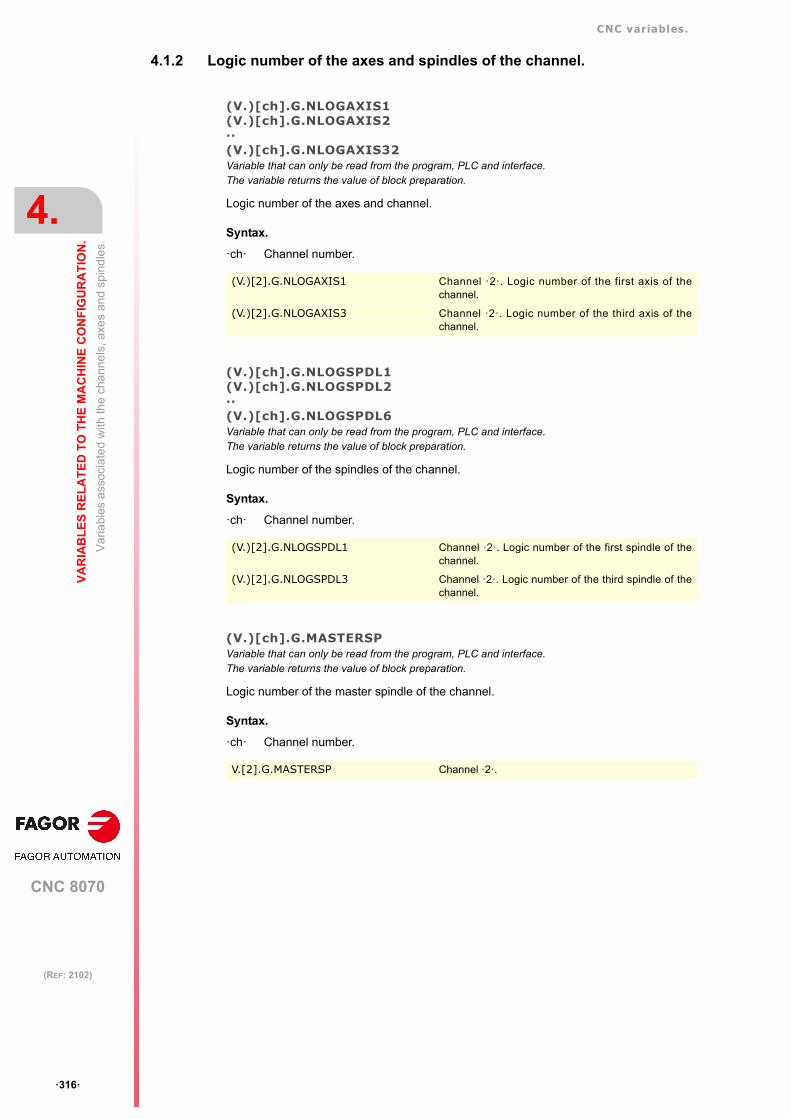
CNC variables.
CNC 8070
4.
VA
RIA
BL
ES
RE
LA
TE
D T
O T
HE
MA
CH
INE
CO
NF
IGU
RA
TIO
N.
Var
iabl
es a
ssoc
iate
d w
ith th
e c
han
nels
, axe
s an
d sp
ind
les.
ꞏ316ꞏ
(REF: 2102)
4.1.2 Logic number of the axes and spindles of the channel.
(V.)[ch].G.NLOGAXIS1(V.)[ch].G.NLOGAXIS2··(V.)[ch].G.NLOGAXIS32Variable that can only be read from the program, PLC and interface.The variable returns the value of block preparation.
Logic number of the axes and channel.
Syntax.
ꞏchꞏ Channel number.
(V.)[ch].G.NLOGSPDL1(V.)[ch].G.NLOGSPDL2··(V.)[ch].G.NLOGSPDL6Variable that can only be read from the program, PLC and interface.The variable returns the value of block preparation.
Logic number of the spindles of the channel.
Syntax.
ꞏchꞏ Channel number.
(V.)[ch].G.MASTERSPVariable that can only be read from the program, PLC and interface.The variable returns the value of block preparation.
Logic number of the master spindle of the channel.
Syntax.
ꞏchꞏ Channel number.
(V.)[2].G.NLOGAXIS1 Channel ꞏ2ꞏ. Logic number of the first axis of thechannel.
(V.)[2].G.NLOGAXIS3 Channel ꞏ2ꞏ. Logic number of the third axis of thechannel.
(V.)[2].G.NLOGSPDL1 Channel ꞏ2ꞏ. Logic number of the first spindle of thechannel.
(V.)[2].G.NLOGSPDL3 Channel ꞏ2ꞏ. Logic number of the third spindle of thechannel.
V.[2].G.MASTERSP Channel ꞏ2ꞏ.

CNC variables.
CNC 8070
VA
RIA
BL
ES
RE
LA
TE
D T
O T
HE
MA
CH
INE
CO
NF
IGU
RA
TIO
N.
4.
Var
iabl
es a
ssoc
iate
d w
ith th
e c
han
nels
, axe
s an
d sp
ind
les.
ꞏ317ꞏ
(REF: 2102)
4.1.3 Number of the channels, axes and spindles.
(V.)G.NUMCHVariable that can only be read from the program, PLC and interface.The variable returns the value of block preparation.
Number of channels.
(V.)[ch].G.AXISVariable that can only be read from the program, PLC and interface.The variable returns the value of block preparation.Report variable (to be used from the scripts).
Number of axes of the channel.
Syntax.
ꞏchꞏ Channel number.
(V.)[ch].G.NAXISVariable that can only be read from the program, PLC and interface.The variable returns the value of block preparation.Report variable (to be used from the scripts).
Number of axes of the channel including the empty positions of the yielded axes.
Syntax.
ꞏchꞏ Channel number.
(V.)[ch].G.NSPDLVariable that can only be read from the program, PLC and interface.The variable returns the value of block preparation.Report variable (to be used from the scripts).
Number of spindles of the channel.
Syntax.
ꞏchꞏ Channel number.
(V.)[ch].G.AXISCHVariable to be read via interface.Report variable (to be used from the scripts).
Axes of the system that belong to the channel.
Syntax.
ꞏchꞏ Channel number.
V.G.NUMCH
V.[2].G.AXIS Channel ꞏ2ꞏ.
V.[2].G.NAXIS Channel ꞏ2ꞏ.
V.[2].G.NSPDL Channel ꞏ2ꞏ.
[2].G.AXISCH Channel ꞏ2ꞏ.

CNC variables.
CNC 8070
4.
VA
RIA
BL
ES
RE
LA
TE
D T
O T
HE
MA
CH
INE
CO
NF
IGU
RA
TIO
N.
Var
iabl
es a
ssoc
iate
d w
ith th
e c
han
nels
, axe
s an
d sp
ind
les.
ꞏ318ꞏ
(REF: 2102)
Values of the variable.
The variable returns a 32-bit value where each bit represents one axis; the least significantbit corresponds to the axis with the lowest logic number. Each bit indicates whether the axisbelongs to the channel (bit = 1) or not (bit = 0).
AXISNAME. Channel ꞏ1ꞏ. Channel ꞏ2ꞏ. Reading the variables.
X (Logic axis ꞏ1ꞏ.)Y (Logic axis ꞏ2ꞏ.)Z (Logic axis ꞏ3ꞏ.)X2 (Logic axis ꞏ4ꞏ.)Y2 (Logic axis ꞏ5ꞏ.)Z2 (Logic axis ꞏ6ꞏ.)
XYZ
X2Y2Z2
[1].G.AXISCH = $7[2].G.AXISCH = $38

CNC variables.
CNC 8070
VA
RIA
BL
ES
RE
LA
TE
D T
O T
HE
MA
CH
INE
CO
NF
IGU
RA
TIO
N.
4.
Var
iabl
es a
ssoc
iate
d w
ith th
e c
han
nels
, axe
s an
d sp
ind
les.
ꞏ319ꞏ
(REF: 2102)
4.1.4 Current channel of the axis or of the spindle.
(V.)[ch].A.ACTCH.xn(V.)[ch].A.ACTCH.sn(V.)[ch].SP.ACTCH.snVariable that can only be read from the program, PLC and interface.Variable valid for rotary and linear axes as well as for spindles.The variable returns the value of execution or preparation depending on the axis or spindle.
Current channel of the axis or of the spindle.
Syntax.
ꞏchꞏ Channel number.
ꞏxnꞏ Name, logic number or index of the axis.
ꞏsnꞏ Name, logic number or index of the spindle.
Remarks.
The variable returns the value of execution or preparation as follows. If the spindle belongsto the channel requesting the variable, it returns the preparation value; if the axis or spindlebelongs to a different channel, the variable returns the execution value and interrupts blockpreparation.
V.A.ACTCH.Z Z axis.
V.A.ACTCH.S Spindle S.
V.SP.ACTCH.S Spindle S.
V.SP.ACTCH Master spindle.
V.A.ACTCH.4 Axis or spindle with logic number ꞏ4ꞏ.
V.[2].A.ACTCH.1 Axis with index ꞏ1ꞏ in the channel ꞏ2ꞏ.
V.SP.ACTCH.2 Spindle with index ꞏ2ꞏ in the system.
V.[2].SP.ACTCH.1 Spindle with index ꞏ1ꞏ in the channel ꞏ2ꞏ.

CNC variables.
CNC 8070
4.
VA
RIA
BL
ES
RE
LA
TE
D T
O T
HE
MA
CH
INE
CO
NF
IGU
RA
TIO
N.
Var
iabl
es a
ssoc
iate
d w
ith th
e c
han
nels
, axe
s an
d sp
ind
les.
ꞏ320ꞏ
(REF: 2102)
4.1.5 Parameter set of the axis or spindle.
(V.)[ch].A.ACTIVSET.xn(V.)[ch].A.ACTIVSET.sn(V.)[ch].SP.ACTIVSET.snVariable that can only be read from the program, PLC and interface.Variable valid for rotary and linear axes as well as for spindles.The variable returns the value of execution or preparation depending on the axis or spindle.
Parameter set active at the axis or spindle.
Syntax.
ꞏchꞏ Channel number.
ꞏxnꞏ Name, logic number or index of the axis.
ꞏsnꞏ Name, logic number or index of the spindle.
Remarks.
The variable returns the value of execution or preparation as follows. If the spindle belongsto the channel requesting the variable, it returns the preparation value; if the axis or spindlebelongs to a different channel, the variable returns the execution value and interrupts blockpreparation.
V.A.ACTIVSET.Z Z axis.
V.A.ACTIVSET.S Spindle S.
V.SP.ACTIVSET.S Spindle S.
V.SP.ACTIVSET Master spindle.
V.A.ACTIVSET.4 Axis or spindle with logic number ꞏ4ꞏ.
V.[2].A.ACTIVSET.1 Axis with index ꞏ1ꞏ in the channel ꞏ2ꞏ.
V.SP.ACTIVSET.2 Spindle with index ꞏ2ꞏ in the system.
V.[2].SP.ACTIVSET.1 Spindle with index ꞏ1ꞏ in the channel ꞏ2ꞏ.

CNC variables.
CNC 8070
VA
RIA
BL
ES
RE
LA
TE
D T
O T
HE
MA
CH
INE
CO
NF
IGU
RA
TIO
N.
4.
Var
iabl
es a
ssoc
iate
d w
ith th
e c
han
nels
, axe
s an
d sp
ind
les.
ꞏ321ꞏ
(REF: 2102)
4.1.6 Travel limits of linear and rotary axes.
(V.)[ch].G.SOFTLIMITVariable that can only be read from the program, PLC and interface.The variable returns the execution value; reading it interrupts block preparation.Report variable (to be used from the scripts).
Software limits reached.
Syntax.
ꞏchꞏ Channel number.
(V.)[ch].A.POSLIMIT.xn(V.)[ch].A.NEGLIMIT.xnVariable that can be read and written from the program and read from the PLC and from the interface.Variable valid for rotary and linear axes.The variable returns the value of block preparation.
Positive and negative software limit.
Syntax.
ꞏchꞏ Channel number.
ꞏxnꞏ Name, logic number or index of the axis.
Remarks.
These variables correspond to the limits set by machine parameters. When modifying thesevariables, the CNC assumes those values as the new limits from then on.
These variables keep their value after a Reset, they are initialized with the values of themachine parameters when validating them and when turning the CNC on.
(V.)[ch].A.RTPOSLIMIT.xn(V.)[ch].A.RTNEGLIMIT.xnVariable that can be read and written via program, PLC and interface.Variable valid for rotary and linear axes.The variable returns the execution value; reading it interrupts block preparation.
Second positive and negative software limit.
Syntax.
ꞏchꞏ Channel number.
ꞏxnꞏ Name, logic number or index of the axis.
Remarks.
There are two software limits; the CNC always applies the most restrictive one.
These variables keep their value after a Reset, they are initialized with the maximum valuepossible when turning the CNC on.
V.[2].G.SOFTLIMIT Channel ꞏ2ꞏ.
V.A.POSLIMIT.Z Z axis.
V.A.POSLIMIT.4 Axis with logic number ꞏ4ꞏ.
V.[2].A.POSLIMIT.1 Axis with index ꞏ1ꞏ in the channel ꞏ2ꞏ.
V.A.RTPOSLIMIT.Z Z axis.
V.A.RTPOSLIMIT.4 Axis with logic number ꞏ4ꞏ.
V.[2].A.RTPOSLIMIT.1 Axis with index ꞏ1ꞏ in the channel ꞏ2ꞏ.

CNC variables.
CNC 8070
4.
VA
RIA
BL
ES
RE
LA
TE
D T
O T
HE
MA
CH
INE
CO
NF
IGU
RA
TIO
N.
Var
iabl
es a
ssoc
iate
d w
ith th
e c
han
nels
, axe
s an
d sp
ind
les.
ꞏ322ꞏ
(REF: 2102)
4.1.7 Kinetimatics dimensions.
(V.)[ch].A.HEADOF.xnVariable that can only be read from the program, PLC and interface.Variable valid for rotary and linear axes.The variable returns the execution or preparation value.
Dimension in each axis of the kinematics.
Syntax.
ꞏchꞏ Channel number.
ꞏxnꞏ Name, logic number or index of the axis.
Remarks.
The variable returns the value of execution or preparation as follows. If the axis is consultedthrough its logic number, the variable always returns the preparation value. In the rest of thecases, if the axis belongs to the channel requesting the variable, it returns the preparationvalue; if the axis belongs to a different channel, the variable returns the execution value andinterrupts block preparation.
This variable returns the resulting measurement of the active kinematics on that axis. It maybe a particular value of TDATA (kinematics table) or the combination of several of themdepending on the type of kinematics.
V.A.HEADOF.Z Z axis.
V.A.HEADOF.4 Axis with logic number ꞏ4ꞏ.
V.[2].A.HEADOF.1 Axis with index ꞏ1ꞏ in the channel ꞏ2ꞏ.

CNC variables.
CNC 8070
VA
RIA
BL
ES
RE
LA
TE
D T
O T
HE
MA
CH
INE
CO
NF
IGU
RA
TIO
N.
4.
Var
iabl
es a
ssoc
iate
d w
ith th
e c
han
nels
, axe
s an
d sp
ind
les.
ꞏ323ꞏ
(REF: 2102)
4.1.8 Change the turning direction assigned to M3 and M4.
(V.)[ch].A.POLARITY.sn(V.)[ch].SP.POLARITY.snVariable that can be read and written via program, PLC and interface.Variable valid for rotary and linear axes as well as for spindles.The variable returns the execution value; reading it interrupts block preparation.
This variable may be used to reverse the meaning of spindle parameters POLARM3 andPOLARM4 that set the spindle turning direction for M3 and M4. The variable does not modifythe values of the machine parameters.
If the spindle is turning in open loop (M3/M4), the CNC does not apply the changes of thisvariable immediately; the CNC applies the changes the next time a speed or an M3/M4 isprogrammed.
Syntax.
ꞏchꞏ Channel number.
ꞏsnꞏ Name, logic number or index of the spindle.
Values of the variable.
Remarks.
The variable keeps its value between programs and after a reset; it is initialized to ꞏ0ꞏ whenturning the CNC on.
Every time the part-program writes or reads this variable, the CNC synchronizes the blockpreparation and the execution. If it is the PLC who modifies the variable, it must be bornein mind that block preparation takes its value into account every time it detects a change inthe spindle movement (Function G63, change of speed or of the turning direction, etc.);therefore, before preparing those blocks, the PLC must have written this variable.
V.A.POLARITY.S Spindle S.
V.SP.POLARITY.S Spindle S.
V.SP.POLARITY Master spindle.
V.A.POLARITY.4 Spindle with logic number ꞏ4ꞏ.
V.SP.POLARITY.2 Spindle with index ꞏ2ꞏ in the system.
V.[2].SP.POLARITY.1 Spindle with index ꞏ1ꞏ in the channel ꞏ2ꞏ.
Value. Meaning.
0 For the M3/M4 functions, the CNC applies parametersPOLARM3 and POLARM4.
1 For the M3/M4 functions, the CNC reverses the meaning ofparameters POLARM3 and POLARM4.

CNC variables.
CNC 8070
4.
VA
RIA
BL
ES
RE
LA
TE
D T
O T
HE
MA
CH
INE
CO
NF
IGU
RA
TIO
N.
Var
iabl
es a
ssoc
iate
d w
ith th
e c
han
nels
, axe
s an
d sp
ind
les.
ꞏ324ꞏ
(REF: 2102)
4.1.9 Number of pulses sent by the handwheel.
(V.)G.HANDP[hw]Variable that can only be read from the program, PLC and interface.The variable returns the execution value; reading it interrupts block preparation.
Number of pulses sent by the handwheel since the system was started up. While thehandwheel is disabled from the PLC (marks INHIBITMPG1 through INHIBITMPG12), thevariable does not save the pulses sent by the handwheel.
Syntax.
ꞏhwꞏ Handwheel number.
Remarks.
The PLC can use these variables to control the machining feedrate depending on how fastthe handwheel is turned, for example when machining a part for the first time or to move backin the machining operation when the retrace function is active. Depending on the handwheelpulses read by the variable, it is possible to calculate from the PLC the right feedrate overridepercentage and set it for the machining operation. This handwheel mode is known as "feedhandwheel".
4.1.10 Modify the simulation speed via PLC.
(V.)PLC.SIMUSPEEDVariable that can be read and written from the PLC and read from the program and from the interface.The variable returns the execution value; reading it interrupts block preparation.Report variable (to be used from the scripts).
Percentage of simulation speed (between 0% and 100%).
Currently, the simulation displays a horizontal bar on the screen to change the simulationspeed. This variable may be used to change its value via PLC. In some cases, the OEM cantransfer via PLC the feedrate override value to this variable to control the simulation speed.
(V.)G.HANDP[1] Handwheel ꞏ1ꞏ.
V.PLC.SIMUSPEED
The execution and simulation channels can work simultaneously in which case, the feedrate overrideswitch will affect both. It is up to the OEM to use this variable in the right contexts so it only affects oneof the channels.

CNC variables.
CNC 8070
VA
RIA
BL
ES
RE
LA
TE
D T
O T
HE
MA
CH
INE
CO
NF
IGU
RA
TIO
N.
4.
Va
riabl
es r
ela
ted
to v
olu
met
ric c
ompe
nsa
tion.
ꞏ325ꞏ
(REF: 2102)
4.2 Variables related to volumetric compensation.
(V.)[ch].A.VOLCOMP.xnVariable that can only be read from the program, PLC and interface.Variable valid for analog drive, position Sercos and velocity Sercos.The variable returns the execution value; reading it interrupts block preparation.
Channel [ch]. Value that the volumetric compensation is adding to the axis. If the volumetriccompensation is not active or the axis is outside the volume to be compensated, the variablereturns the value to 0 (zero).
Reading this variable from the oscilloscope allows watching the evolution of the volumetriccompensation.
Syntax.
ꞏchꞏ Channel number.
ꞏxnꞏ Name, logic number or index of the axis.
(V.)[ch].A.PIVOT.xnVariable that can only be read from the program, PLC and interface.Parameter valid for linear and rotary axes and spindles.Variable valid for analog drive, position Sercos and velocity Sercos.The variable returns the execution value; reading it interrupts block preparation.
Channel [ch]. Distance from the pivot center to the tool tip in machine coordinates. Thisvariable returns the sum of the spindle offsets (parameters TDATA) and the tool offset.
This variable is only valid for the medium and large volumetric compensations; it has nofunction on the basic volumetric compensation.
Syntax.
ꞏchꞏ Channel number.
ꞏxnꞏ Name, logic number or index of the axis.
V.A.VOLCOMP.Z Z axis.
V.A.VOLCOMP.3 Axis with logic number ꞏ3ꞏ.
V.[2].A.VOLCOMP.3 Axis with index ꞏ3ꞏ in the channel ꞏ2ꞏ.
V.A.PIVOT.Z Z axis.
V.A.PIVOT.3 Axis with logic number ꞏ3ꞏ.
V.[2].A.PIVOT.3 Axis with index ꞏ3ꞏ in the channel ꞏ2ꞏ.
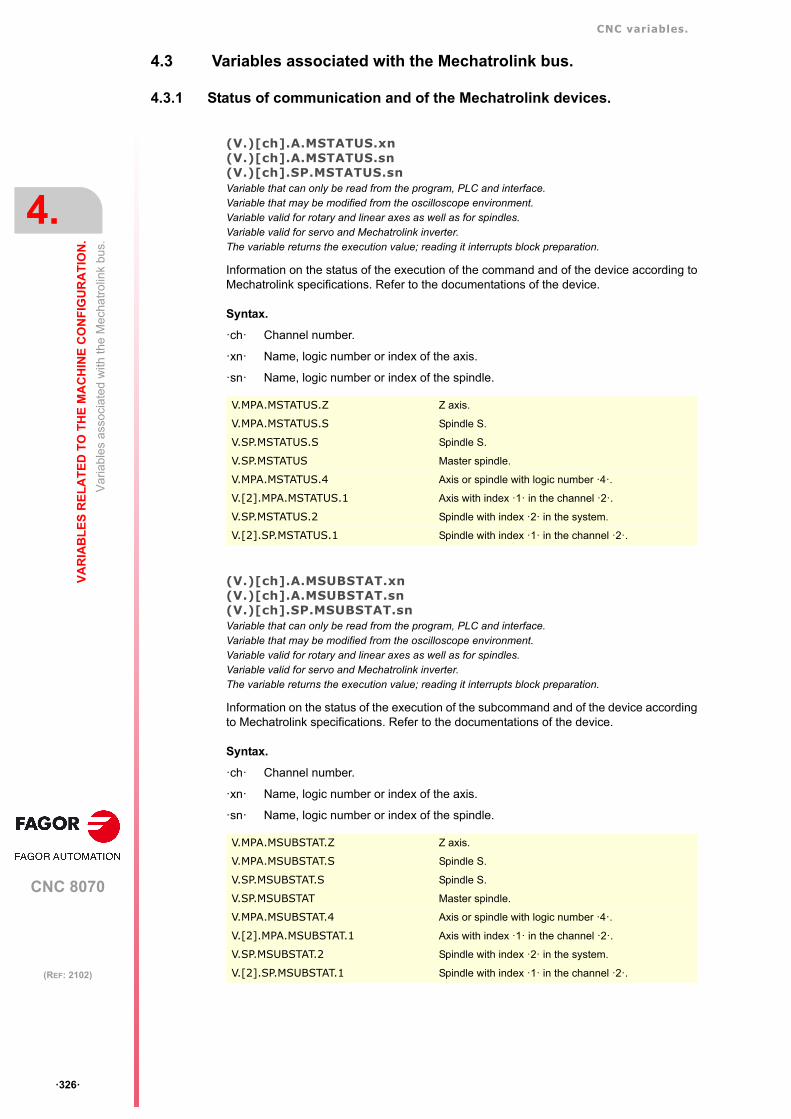
CNC variables.
CNC 8070
4.
VA
RIA
BL
ES
RE
LA
TE
D T
O T
HE
MA
CH
INE
CO
NF
IGU
RA
TIO
N.
Va
riabl
es a
ssoc
iate
d w
ith th
e M
echa
trol
ink
bus.
ꞏ326ꞏ
(REF: 2102)
4.3 Variables associated with the Mechatrolink bus.
4.3.1 Status of communication and of the Mechatrolink devices.
(V.)[ch].A.MSTATUS.xn(V.)[ch].A.MSTATUS.sn(V.)[ch].SP.MSTATUS.snVariable that can only be read from the program, PLC and interface.Variable that may be modified from the oscilloscope environment.Variable valid for rotary and linear axes as well as for spindles.Variable valid for servo and Mechatrolink inverter.The variable returns the execution value; reading it interrupts block preparation.
Information on the status of the execution of the command and of the device according toMechatrolink specifications. Refer to the documentations of the device.
Syntax.
ꞏchꞏ Channel number.
ꞏxnꞏ Name, logic number or index of the axis.
ꞏsnꞏ Name, logic number or index of the spindle.
(V.)[ch].A.MSUBSTAT.xn(V.)[ch].A.MSUBSTAT.sn(V.)[ch].SP.MSUBSTAT.snVariable that can only be read from the program, PLC and interface.Variable that may be modified from the oscilloscope environment.Variable valid for rotary and linear axes as well as for spindles.Variable valid for servo and Mechatrolink inverter.The variable returns the execution value; reading it interrupts block preparation.
Information on the status of the execution of the subcommand and of the device accordingto Mechatrolink specifications. Refer to the documentations of the device.
Syntax.
ꞏchꞏ Channel number.
ꞏxnꞏ Name, logic number or index of the axis.
ꞏsnꞏ Name, logic number or index of the spindle.
V.MPA.MSTATUS.Z Z axis.
V.MPA.MSTATUS.S Spindle S.
V.SP.MSTATUS.S Spindle S.
V.SP.MSTATUS Master spindle.
V.MPA.MSTATUS.4 Axis or spindle with logic number ꞏ4ꞏ.
V.[2].MPA.MSTATUS.1 Axis with index ꞏ1ꞏ in the channel ꞏ2ꞏ.
V.SP.MSTATUS.2 Spindle with index ꞏ2ꞏ in the system.
V.[2].SP.MSTATUS.1 Spindle with index ꞏ1ꞏ in the channel ꞏ2ꞏ.
V.MPA.MSUBSTAT.Z Z axis.
V.MPA.MSUBSTAT.S Spindle S.
V.SP.MSUBSTAT.S Spindle S.
V.SP.MSUBSTAT Master spindle.
V.MPA.MSUBSTAT.4 Axis or spindle with logic number ꞏ4ꞏ.
V.[2].MPA.MSUBSTAT.1 Axis with index ꞏ1ꞏ in the channel ꞏ2ꞏ.
V.SP.MSUBSTAT.2 Spindle with index ꞏ2ꞏ in the system.
V.[2].SP.MSUBSTAT.1 Spindle with index ꞏ1ꞏ in the channel ꞏ2ꞏ.

CNC variables.
CNC 8070
VA
RIA
BL
ES
RE
LA
TE
D T
O T
HE
MA
CH
INE
CO
NF
IGU
RA
TIO
N.
4.
Va
riabl
es a
ssoc
iate
d w
ith th
e M
echa
trol
ink
bus.
ꞏ327ꞏ
(REF: 2102)
(V.)[ch].A.MALARM.xn(V.)[ch].A.MALARM.sn(V.)[ch].SP.MALARM.snVariable that can only be read from the program, PLC and interface.Variable that may be modified from the oscilloscope environment.Variable valid for rotary and linear axes as well as for spindles.Variable valid for servo and Mechatrolink inverter.The variable returns the execution value; reading it interrupts block preparation.
Alarm or error code of the device. Refer to the documentations of the device.
Syntax.
ꞏchꞏ Channel number.
ꞏxnꞏ Name, logic number or index of the axis.
ꞏsnꞏ Name, logic number or index of the spindle.
(V.)[ch].A.MIOMON.xn(V.)[ch].A.MIOMON.sn(V.)[ch].SP.MIOMON.snVariable that can only be read from the program, PLC and interface.Variable that may be modified from the oscilloscope environment.Variable valid for rotary and linear axes as well as for spindles.Variable valid for Mechatrolink servo.The variable returns the execution value; reading it interrupts block preparation.
Status of the device inputs and outputs.
Syntax.
ꞏchꞏ Channel number.
ꞏxnꞏ Name, logic number or index of the axis.
ꞏsnꞏ Name, logic number or index of the spindle.
V.MPA.MALARM.Z Z axis.
V.MPA.MALARM.S Spindle S.
V.SP.MALARM.S Spindle S.
V.SP.MALARM Master spindle.
V.MPA.MALARM.4 Axis or spindle with logic number ꞏ4ꞏ.
V.[2].MPA.MALARM.1 Axis with index ꞏ1ꞏ in the channel ꞏ2ꞏ.
V.SP.MALARM.2 Spindle with index ꞏ2ꞏ in the system.
V.[2].SP.MALARM.1 Spindle with index ꞏ1ꞏ in the channel ꞏ2ꞏ.
V.MPA.MIOMON.Z Z axis.
V.MPA.MIOMON.S Spindle S.
V.SP.MIOMON.S Spindle S.
V.SP.MIOMON Master spindle.
V.MPA.MIOMON.4 Axis or spindle with logic number ꞏ4ꞏ.
V.[2].MPA.MIOMON.1 Axis with index ꞏ1ꞏ in the channel ꞏ2ꞏ.
V.SP.MIOMON.2 Spindle with index ꞏ2ꞏ in the system.
V.[2].SP.MIOMON.1 Spindle with index ꞏ1ꞏ in the channel ꞏ2ꞏ.

CNC variables.
CNC 8070
4.
VA
RIA
BL
ES
RE
LA
TE
D T
O T
HE
MA
CH
INE
CO
NF
IGU
RA
TIO
N.
Mul
ti-tu
rn a
bso
lute
en
code
r.
ꞏ328ꞏ
(REF: 2102)
4.4 Multi-turn absolute encoder.
4.4.1 Variables. Number of overshots in the feedback range.
(V.)[ch].A.COUNTEROVER.xn(V.)[ch].A.COUNTEROVER.sn(V.)[ch].SP.COUNTEROVER.snVariable that can only be read from the program, PLC and interface.Variable valid for rotary and linear axes as well as for spindles.The variable returns the execution value; reading it interrupts block preparation.
Number of overshots in the feedback range, for a multi-turn absolute encoder.
Syntax.
ꞏchꞏ Channel number.
ꞏxnꞏ Name, logic number or index of the axis.
ꞏsnꞏ Name, logic number or index of the spindle.
Remarks.
The CNC stores the number of overshoots of the encoder counting range. At startup, theCNC takes into account the number of overshoots to calculate the real coordinate.
V.A.COUNTEROVER.Z Z axis.
V.A.COUNTEROVER.S Spindle S.
V.SP.COUNTEROVER.S Spindle S.
V.SP.COUNTEROVER Master spindle.
V.A.COUNTEROVER.4 Axis or spindle with logic number ꞏ4ꞏ.
V.[2].A.COUNTEROVER.1 Axis with index ꞏ1ꞏ in the channel ꞏ2ꞏ.
V.SP.COUNTEROVER.2 Spindle with index ꞏ2ꞏ in the system.
V.[2].SP.COUNTEROVER.1 Spindle with index ꞏ1ꞏ in the channel ꞏ2ꞏ.

CNC 8070
5
ꞏ329ꞏ
(REF: 2102)
5. VARIABLES RELATED TO LASER.
5.1 Active material.
(V.)[ch].G.ACTIVEMATERIALVariable to be read via interface.Units: Text.
Name of the active technological table.
Syntax.
ꞏchꞏ Channel number.
5.2 Active cutting.
(V.)[ch].G.CUTTINGTYPEVariable that can only be read from the program, PLC and interface.The variable returns the value of block preparation.Report variable (to be used from the scripts).Units: - .
Cutting type.
Syntax.
ꞏchꞏ Channel number.
Remarks.
• If there is no active material, the variable will return a ꞏ0ꞏ value.
• After powering up the CNC, if there is any active material, the variable will return a 1 value.
• After a reset or M30, the variable maintains its value.
V.[2].G.ACTIVEMATERIAL Channel ꞏ2ꞏ.
V.[2].G.CUTTINGTYPE Channel ꞏ2ꞏ.

CNC variables.
CNC 8070
5.
VA
RIA
BL
ES
RE
LA
TE
D T
O L
AS
ER
.
Act
ive
pier
cing
.
ꞏ330ꞏ
(REF: 2102)
5.3 Active piercing.
(V.)[ch].G.PIERCINGTYPEVariable that can only be read from the program, PLC and interface.The variable returns the value of block preparation.Report variable (to be used from the scripts).Units: - .
Piercing type.
Syntax.
ꞏchꞏ Channel number.
Remarks.
• If there is no active material, the variable will return a ꞏ0ꞏ value.
• After powering up the CNC, if there is any active material, the variable will return a 1 value.
• After a reset or M30, the variable maintains its value.
(V.)G.SELECTEDPPVariable that can be read and written via program, PLC and interface.The variable returns the execution value; reading/writing it interrupts block preparation.Units: -.
The execution is within a piercing point selection; “Initial PP”, “Final PP”, “Single PP”,“Break PP”, “Restart PP” and “Inplace”.
Syntax.
Values of the variable.
V.[2].G.PIERCINGTYPE Channel ꞏ2ꞏ.
V.G.SELECTEDPP
Value. Meaning.
0 No.
1 Yes.

CNC variables.
CNC 8070
VA
RIA
BL
ES
RE
LA
TE
D T
O L
AS
ER
.
5.
Las
er p
owe
r. P
ower
pro
gra
mm
ing.
ꞏ331ꞏ
(REF: 2102)
5.4 Laser power. Power programming.
(V.)[ch].A.SREAL.sn(V.)[ch].SP.SREAL.snVariable that can only be read from the program, PLC and interface.The variable returns the execution value; reading it interrupts block preparation.Units: Watts.
Channel [ch]. Actual power.
Syntax.
ꞏchꞏ Channel number.
ꞏsnꞏ Name, logic number or index of the spindle.
V.A.SREAL.S Spindle S.
V.SP.SREAL.S Spindle S.
V.SP.SREAL Master spindle.
V.A.SREAL.5 Spindle with logic number ꞏ5ꞏ.
V.SP.SREAL.2 Spindle with index ꞏ2ꞏ in the system.
V.[2].SP.SREAL.1 Spindle with index ꞏ1ꞏ in the channel ꞏ2ꞏ.

CNC variables.
CNC 8070
5.
VA
RIA
BL
ES
RE
LA
TE
D T
O L
AS
ER
.
Las
er p
owe
r. P
ower
in G
97.
ꞏ332ꞏ
(REF: 2102)
5.5 Laser power. Power in G97.
(V.)[ch].A.SPEED.sn(V.)[ch].SP.SPEED.snVariable that can only be read from the program, PLC and interface.The variable returns the execution value; reading it interrupts block preparation.Units: Watts.
Channel [ch]. Active power in G97.
Syntax.
ꞏchꞏ Channel number.
ꞏsnꞏ Name, logic number or index of the spindle.
Remarks.
The power may be set by program or by PLC; the one set by PLC has the highest priority.
(V.)[ch].PLC.S.snVariable that can be read and written from the PLC and read from the program and from the interface.The variable returns the execution value; reading it interrupts block preparation.Units: Watts.
Channel [ch]. Active power by PLC for G97.
The power programmed by PLC prevails over the one programmed by program or MDI. Tocancel the power by PLC, set the variable to ꞏ0ꞏ; the CNC applies the power active byprogram.
Syntax.
ꞏchꞏ Channel number.
ꞏsnꞏ Name, logic number or index of the spindle.
V.A.SPEED.S Spindle S.
V.SP.SPEED.S Spindle S.
V.SP.SPEED Master spindle.
V.A.SPEED.5 Spindle with logic number ꞏ5ꞏ.
V.SP.SPEED.2 Spindle with index ꞏ2ꞏ in the system.
V.[2].SP.SPEED.1 Spindle with index ꞏ1ꞏ in the channel ꞏ2ꞏ.
Defined power. (V.)PLC.S.sn (V.)A.PRGS.sn (V.)A.SPEED.sn
By program; S5000.By PLC; none.
0 5000 5000
By program; S5000.By PLC; S9000.
9000 5000 9000
By program; S5000.By PLC; S3000.
3000 5000 3000
By program; S5000.By PLC; none.By MDI; S8000.
0 8000 8000
By program; S5000.By PLC; S9000.By MDI; S8000.
9000 8000 9000
By program; S5000.By PLC; S3000.By MDI; S8000.
3000 8000 3000
V.PLC.S.S2 Spindle S2.
V.PLC.S.5 Spindle with logic number ꞏ5ꞏ.
V.[2].PLC.S.1 Spindle with index ꞏ1ꞏ in the channel ꞏ2ꞏ.

CNC variables.
CNC 8070
VA
RIA
BL
ES
RE
LA
TE
D T
O L
AS
ER
.
5.
Las
er p
owe
r. P
ower
in G
97.
ꞏ333ꞏ
(REF: 2102)
(V.)[ch].A.PRGS.sn(V.)[ch].SP.PRGS.snVariable that can only be read from the program, PLC and interface.The variable returns the value of block preparation.Units: Watts.
Channel [ch]. Active power by program for G97.
With G97 active, programming in MDI mode of the new power updates the value of thisvariable.
Syntax.
ꞏchꞏ Channel number.
ꞏsnꞏ Name, logic number or index of the spindle.
V.A.PRGS.S Spindle S.
V.SP.PRGS.S Spindle S.
V.SP.PRGS Master spindle.
V.A.PRGS.5 Spindle with logic number ꞏ5ꞏ.
V.SP.PRGS.2 Spindle with index ꞏ2ꞏ in the system.
V.[2].SP.PRGS.1 Spindle with index ꞏ1ꞏ in the channel ꞏ2ꞏ.

CNC variables.
CNC 8070
5.
VA
RIA
BL
ES
RE
LA
TE
D T
O L
AS
ER
.
Las
er p
owe
r. P
ower
lim
it.
ꞏ334ꞏ
(REF: 2102)
5.6 Laser power. Power limit.
(V.)[ch].A.SLIMIT.sn(V.)[ch].SP.SLIMIT.snVariable that can only be read from the program, PLC and interface.The variable returns the execution value; reading it interrupts block preparation.Units: Watts.
Channel [ch]. Active power limit.
Syntax.
ꞏchꞏ Channel number.
ꞏsnꞏ Name, logic number or index of the spindle.
Remarks.
The maximum speed may be set by program or by PLC; the one set by PLC has the highestpriority.
(V.)[ch].PLC.SL.snVariable that can be read and written from the PLC and read from the program and from the interface.The variable returns the execution value; reading it interrupts block preparation.Units: Watts.
Channel [ch]. Active power limit by PLC.
The power programmed by PLC prevails over the one programmed by program or MDI. Tocancel the power by PLC, set the variable to ꞏ0ꞏ; the CNC applies the power active byprogram.
Syntax.
ꞏchꞏ Channel number.
ꞏsnꞏ Name, logic number or index of the spindle.
V.A.SLIMIT.S Spindle S.
V.SP.SLIMIT.S Spindle S.
V.SP.SLIMIT Master spindle.
V.A.SLIMIT.5 Spindle with logic number ꞏ5ꞏ.
V.SP.SLIMIT.2 Spindle with index ꞏ2ꞏ in the system.
V.[2].SP.SLIMIT.1 Spindle with index ꞏ1ꞏ in the channel ꞏ2ꞏ.
V.PLC.SL.S2 Spindle S2.
V.PLC.SL.5 Spindle with logic number ꞏ5ꞏ.
V.[2].PLC.SL.1 Spindle with index ꞏ1ꞏ in the channel ꞏ2ꞏ.

CNC variables.
CNC 8070
VA
RIA
BL
ES
RE
LA
TE
D T
O L
AS
ER
.
5.
Las
er p
owe
r. P
ower
lim
it.
ꞏ335ꞏ
(REF: 2102)
(V.)[ch].A.PRGSL.sn(V.)[ch].SP.PRGSL.snVariable that can only be read from the program, PLC and interface.The variable returns the value of block preparation.Units: Watts.
Channel [ch]. Active power limit by program.
Syntax.
ꞏchꞏ Channel number.
ꞏsnꞏ Name, logic number or index of the spindle.
V.A.PRGSL.S Spindle S.
V.SP.PRGSL.S Spindle S.
V.SP.PRGSL Master spindle.
V.A.PRGSL.5 Spindle with logic number ꞏ5ꞏ.
V.SP.PRGSL.2 Spindle with index ꞏ2ꞏ in the system.
V.[2].SP.PRGSL.1 Spindle with index ꞏ1ꞏ in the channel ꞏ2ꞏ.

CNC variables.
CNC 8070
5.
VA
RIA
BL
ES
RE
LA
TE
D T
O L
AS
ER
.
Lase
r po
wer
. Pow
er
per
cent
age
(ov
err
ide)
.
ꞏ336ꞏ
(REF: 2102)
5.7 Laser power. Power percentage (override).
(V.)[ch].A.SSO.sn(V.)[ch].SP.SSO.snVariable that can only be read from the program, PLC and interface.The variable returns the execution value; reading it interrupts block preparation.Units: Percentage.
Channel [ch]. Active power percentage.
Syntax.
ꞏchꞏ Channel number.
ꞏsnꞏ Name, logic number or index of the spindle.
Remarks.
The power speed (override) percentage may be set by program, by PLC or from the controlpanel; the one set by program has the highest priority and the one selected from the controlpanel has the lowest.
(V.)[ch].PLC.SSO.snVariable that can be read and written from the PLC and read from the program and from the interface.The variable returns the execution value; reading it interrupts block preparation.Units: Percentage.
Channel [ch]. Power percentage by PLC.
The percentage set by PLC has higher priority than the one set from the control panel, butlower priority than the one set by program.. To cancel the value set by PLC, set the variableto ꞏ0ꞏ.
Syntax.
ꞏchꞏ Channel number.
ꞏsnꞏ Name, logic number or index of the spindle.
V.A.SSO.S Spindle S.
V.SP.SSO.S Spindle S.
V.SP.SSO Master spindle.
V.A.SSO.5 Spindle with logic number ꞏ5ꞏ.
V.SP.SSO.2 Spindle with index ꞏ2ꞏ in the system.
V.[2].SP.SSO.1 Spindle with index ꞏ1ꞏ in the channel ꞏ2ꞏ.
(V.)A.PRGSSO.sn(V.)SP.PRGSSO.sn
(V.)PLC.SSO.sn (V.)A.CNCSSO.sn(V.)SP.CNCSSO.sn
(V.)A.SSO.sn(V.)SP.SSO.sn
0 0 100 % 100 %
0 80 % 100 % 80 %
110 % 80% 100 % 110 %
70 % 80 % 100 % 70 %
70 % 0 100 % 70 %
V.PLC.SSO.S2 Spindle S2.
V.PLC.SSO.5 Spindle with logic number ꞏ5ꞏ.
V.[2].PLC.SSO.1 Spindle with index ꞏ1ꞏ in the channel ꞏ2ꞏ.

CNC variables.
CNC 8070
VA
RIA
BL
ES
RE
LA
TE
D T
O L
AS
ER
.
5.
Lase
r po
wer
. Pow
er
per
cent
age
(ov
err
ide)
.
ꞏ337ꞏ
(REF: 2102)
(V.)[ch].A.PRGSSO.sn(V.)[ch].SP.PRGSSO.snVariable that can be read and written from the program and read from the PLC and from the interface.The variable returns the value of block preparation.Units: Percentage.
Channel [ch]. Power percentage by program.
The percentage set by program has higher priority than the one set by PLC or from the controlpanel. To cancel the value set by program, set the variable to ꞏ0ꞏ.
Syntax.
ꞏchꞏ Channel number.
ꞏsnꞏ Name, logic number or index of the spindle.
(V.)[ch].A.CNCSSO.sn(V.)[ch].SP.CNCSSO.snVariable that can be read and written (asynchronous writing) from the interface and read from theprogram and from the PLC.The variable returns the execution value; reading it interrupts block preparation.Units: Percentage.
Channel [ch]. Power percentage on the control panel.
The percentage set from the control panel has lower priority than the one set by PLC or byprogram.
Syntax.
ꞏchꞏ Channel number.
ꞏsnꞏ Name, logic number or index of the spindle.
V.A.PRGSSO.S Spindle S.
V.SP.PRGSSO.S Spindle S.
V.SP.PRGSSO Master spindle.
V.A.PRGSSO.5 Spindle with logic number ꞏ5ꞏ.
V.SP.PRGSSO.2 Spindle with index ꞏ2ꞏ in the system.
V.[2].SP.PRGSSO.1 Spindle with index ꞏ1ꞏ in the channel ꞏ2ꞏ.
V.A.CNCSSO.S Spindle S.
V.SP.CNCSSO.S Spindle S.
V.SP.CNCSSO Master spindle.
V.A.CNCSSO.5 Spindle with logic number ꞏ5ꞏ.
V.SP.CNCSSO.2 Spindle with index ꞏ2ꞏ in the system.
V.[2].SP.CNCSSO.1 Spindle with index ꞏ1ꞏ in the channel ꞏ2ꞏ.

CNC variables.
CNC 8070
5.
VA
RIA
BL
ES
RE
LA
TE
D T
O L
AS
ER
.
Var
iabl
es a
ssoc
iate
d w
ith g
as p
ress
ure.
ꞏ338ꞏ
(REF: 2102)
5.8 Variables associated with gas pressure.
(V.)[ch].G.GASPRESSUREVariable that can be read and written from the PLC and read from the program and from the interface.The variable returns the execution value; reading it interrupts block preparation.Units: Watts.
Channel [ch]. Actual gas pressure.
Syntax.
ꞏchꞏ Channel number.
V.[2].G.GASPRESSURE Channel ꞏ2ꞏ.
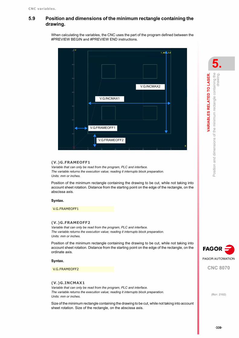
CNC variables.
CNC 8070
VA
RIA
BL
ES
RE
LA
TE
D T
O L
AS
ER
.
5.
Pos
ition
and
dim
ensi
ons
of th
e m
inim
um r
ect
angl
e c
onta
inin
g th
edr
awin
g.
ꞏ339ꞏ
(REF: 2102)
5.9 Position and dimensions of the minimum rectangle containing thedrawing.
When calculating the variables, the CNC uses the part of the program defined between the#PREVIEW BEGIN and #PREVIEW END instructions.
(V.)G.FRAMEOFF1Variable that can only be read from the program, PLC and interface.The variable returns the execution value; reading it interrupts block preparation.Units: mm or inches.
Position of the minimum rectangle containing the drawing to be cut, while not taking intoaccount sheet rotation. Distance from the starting point on the edge of the rectangle, on theabscissa axis.
Syntax.
(V.)G.FRAMEOFF2Variable that can only be read from the program, PLC and interface.The variable returns the execution value; reading it interrupts block preparation.Units: mm or inches.
Position of the minimum rectangle containing the drawing to be cut, while not taking intoaccount sheet rotation. Distance from the starting point on the edge of the rectangle, on theordinate axis.
Syntax.
(V.)G.INCMAX1Variable that can only be read from the program, PLC and interface.The variable returns the execution value; reading it interrupts block preparation.Units: mm or inches.
Size of the minimum rectangle containing the drawing to be cut, while not taking into accountsheet rotation. Size of the rectangle, on the abscissa axis.
V.G.FRAMEOFF1
V.G.FRAMEOFF2
V.G.FRAMEOFF1
V.G.FRAMEOFF2
V.G.INCMAX1
V.G.INCMAX2

CNC variables.
CNC 8070
5.
VA
RIA
BL
ES
RE
LA
TE
D T
O L
AS
ER
.
Pos
ition
and
dim
ensi
ons
of th
e m
inim
um r
ect
angl
e c
onta
inin
g th
edr
awin
g.
ꞏ340ꞏ
(REF: 2102)
Syntax.
(V.)G.INCMAX2Variable that can only be read from the program, PLC and interface.The variable returns the execution value; reading it interrupts block preparation.Units: mm or inches.
Size of the minimum rectangle containing the drawing to be cut, while not taking into accountsheet rotation. Size of the rectangle, on the ordinate axis.
Syntax.
V.G.INCMAX1
V.G.INCMAX2

CNC variables.
CNC 8070
VA
RIA
BL
ES
RE
LA
TE
D T
O L
AS
ER
.
5.
PW
M (
pul
se-w
idth
mo
dula
tion)
.
ꞏ341ꞏ
(REF: 2102)
5.10 PWM (pulse-width modulation).
(V.)G.PWMONVariable that can only be read from the program, PLC and interface.The variable returns the value of block preparation.Units: Value listed.
PWM status, when it has been activated via CNC.
Syntax.
Values of the variable.
Remarks.
Activating the Laser via PLC has priority over activating it from the CNC.
(V.)G.PWMFREQVariable that can only be read from the program, PLC and interface.The variable returns the value of block preparation.Units: Herz.
PWM frequency, when the PWM has been activated via CNC. Variable associated with thecommand PWMFREQ of the instruction #PWMOUT. This variable only works when theLaser is active via CNC.
Syntax.
(V.)G.PWMDUTYVariable that can only be read from the program, PLC and interface.The variable returns the value of block preparation.Units: Percentage.
PWM duty cycle, when the PWM has been activated via CNC. Variable associated with thecommand PWMFREQ of the instruction #PWMOUT. This variable only works when theLaser is active via CNC.
Syntax.
Remarks.
The reading from the PLC will be given in tenths (x10); i.e. for a value ꞏ0.1ꞏ, the PLC readingwill return a value of ꞏ1ꞏ. For a value of ꞏ100ꞏ, the reading from the PLC will return a valueof ꞏ1000ꞏ.
V.G.PWMON
Value. Meaning.
0 PWM off.
1 PWM active.
PWM status from theCNC.
PWM status from thePLC.
PWM status.
Off. Off. PWM off.
Active. Off. PWM active from the CNC.
Off. Active. PWM active from the PLC.
Active. Active. PWM active from the PLC.
V.G.PWMFREQ
V.G.PWMDUTY

CNC variables.
CNC 8070
5.
VA
RIA
BL
ES
RE
LA
TE
D T
O L
AS
ER
.
PW
M (
pul
se-w
idth
mo
dula
tion)
.
ꞏ342ꞏ
(REF: 2102)
(V.)G.PWMBTIMEVariable that can only be read from the program, PLC and interface.The variable returns the value of block preparation.Units: Milliseconds.
Amount of time (in ms rounded up to loop units) that PWM stays active in burst mode. Variableassociated with the command PWMBTIME of the instruction #PWMOUT.
(V.)G.PWMBENDVariable that can only be read from the program, PLC and interface.The variable returns the value of block preparation.Units: Value listed.
PWM status after completing the burst mode. Variable associated with the commandPWMBEND of the instruction #PWMOUT.
Values of the variable.
V.G.PWMBTIME
V.G.PWMBEND
Value. Meaning.
0 PWM off.
1 PWM active.

CNC variables.
CNC 8070
VA
RIA
BL
ES
RE
LA
TE
D T
O L
AS
ER
.
5.
Pow
er c
ontr
ol v
ia a
n a
nalo
g ou
tpu
t.
ꞏ343ꞏ
(REF: 2102)
5.11 Power control via an analog output.
(V.)G.PWROUTONVariable that can only be read from the program, PLC and interface.The variable returns the value of block preparation.Units: Value listed.
Power control status (#PWRCTRL ON [OUT]). This variable is also affected by the markENABLEPWROUT of the PLC.
Values of the variable.
(V.)G.PWROUTOVRMINVariable that can be read and written from the PLC and read from the program and from the interface.The variable returns the value of block preparation.Units: Percentage.
Minimum percentage to be applied. Variable associated with the command OVRMIN of theinstruction #PWRCTRL ON [OUT].
Remarks.
• The variable assumes the values programmed in the instruction #PWRCTRL duringblock preparation. If the PLC modifies these variables during the execution of a program,the CNC maintains the values calculated during block preparation.
• This variable is activated when programming the command #PWRCTRL from theprogram. When the power control is activated from the PLC (CNCEX command), thisvariable does not update its value.
(V.)G.PWROUTOVRMAXVariable that can be read and written from the PLC and read from the program and from the interface.The variable returns the value of block preparation.Units: Percentage.
Maximum percentage to be applied. Variable associated with the command OVRMAX of theinstruction #PWRCTRL ON [OUT].
Remarks.
• The variable assumes the values programmed in the instruction #PWRCTRL duringblock preparation. If the PLC modifies these variables during the execution of a program,the CNC maintains the values calculated during block preparation.
• This variable is activated when programming the command #PWRCTRL from theprogram. When the power control is activated from the PLC (CNCEX command), thisvariable does not update its value.
V.G.PWROUTON
Value. Meaning.
0 Not active.
1 Active.
V.G.PWROUTOVRMIN
V.G.PWROUTOVRMAX

CNC variables.
CNC 8070
5.
VA
RIA
BL
ES
RE
LA
TE
D T
O L
AS
ER
.
Pow
er c
ontr
ol v
ia a
n a
nalo
g ou
tpu
t.
ꞏ344ꞏ
(REF: 2102)
(V.)G.PWROUTFMINVariable that can be read and written from the PLC and read from the program and from the interface.The variable returns the value of block preparation.Units: In millimeters/minute or inches/minute.
Feed below which the CNC applies the OVRMIN percentage to the power. Variableassociated with the command FMIN of the instruction #PWRCTRL ON [OUT].
Remarks.
• The variable assumes the values programmed in the instruction #PWRCTRL duringblock preparation. If the PLC modifies these variables during the execution of a program,the CNC maintains the values calculated during block preparation.
• This variable is activated when programming the command #PWRCTRL from theprogram. When the power control is activated from the PLC (CNCEX command), thisvariable does not update its value.
(V.)G.PWROUTFMAXVariable that can be read and written from the PLC and read from the program and from the interface.The variable returns the value of block preparation.Units: In millimeters/minute or inches/minute.
Feed above which the CNC applies the OVRMIN percentage to the power. Variableassociated with the command FMAX of the instruction #PWRCTRL ON [OUT].
Remarks.
• The variable assumes the values programmed in the instruction #PWRCTRL duringblock preparation. If the PLC modifies these variables during the execution of a program,the CNC maintains the values calculated during block preparation.
• This variable is activated when programming the command #PWRCTRL from theprogram. When the power control is activated from the PLC (CNCEX command), thisvariable does not update its value.
V.G.PWROUTFMIN
V.G.PWROUTFMAX

CNC variables.
CNC 8070
VA
RIA
BL
ES
RE
LA
TE
D T
O L
AS
ER
.
5.
Pow
er c
ontr
ol v
ia t
he P
WM
dut
y cy
cle.
ꞏ345ꞏ
(REF: 2102)
5.12 Power control via the PWM duty cycle.
(V.)G.PWRDUTYONVariable that can only be read from the program, PLC and interface.The variable returns the value of block preparation.Units: Value listed.
Power control status (#PWRCTRL ON [DUTY]). This variable is also affected by the markENABLEPWRDUTY of the PLC.
Values of the variable.
Remarks.
The variable assumes the values programmed in the instruction #PWRCTRL during blockpreparation. If the PLC modifies these variables during the execution of a program, the CNCmaintains the values calculated during block preparation.
(V.)G.PWRDUTYOVRMINVariable that can be read and written from the PLC and read from the program and from the interface.The variable returns the value of block preparation.Units: Percentage.
Minimum percentage to be applied. Variable associated with the command OVRMIN of theinstruction #PWRCTRL ON [DUTY].
Remarks.
• The variable assumes the values programmed in the instruction #PWRCTRL duringblock preparation. If the PLC modifies these variables during the execution of a program,the CNC maintains the values calculated during block preparation.
• This variable is activated when programming the command #PWRCTRL from theprogram. When the power control is activated from the PLC (CNCEX command), thisvariable does not update its value.
(V.)G.PWRDUTYOVRMAXVariable that can be read and written from the PLC and read from the program and from the interface.The variable returns the value of block preparation.Units: Percentage.
Maximum percentage to be applied. Variable associated with the command OVRMAX of theinstruction #PWRCTRL ON [DUTY].
Remarks.
• The variable assumes the values programmed in the instruction #PWRCTRL duringblock preparation. If the PLC modifies these variables during the execution of a program,the CNC maintains the values calculated during block preparation.
• This variable is activated when programming the command #PWRCTRL from theprogram. When the power control is activated from the PLC (CNCEX command), thisvariable does not update its value.
V.G.PWRDUTYON
Value. Meaning.
0 Not active.
1 Active.
V.G.PWRDUTYOVRMIN
V.G.PWRDUTYOVRMAX

CNC variables.
CNC 8070
5.
VA
RIA
BL
ES
RE
LA
TE
D T
O L
AS
ER
.
Pow
er c
ontr
ol v
ia t
he P
WM
dut
y cy
cle.
ꞏ346ꞏ
(REF: 2102)
(V.)G.PWRDUTYFMINVariable that can be read and written from the PLC and read from the program and from the interface.The variable returns the value of block preparation.Units: In millimeters/minute or inches/minute.
Feed below which the CNC applies the OVRMIN percentage to the power. Variableassociated with the command FMIN of the instruction #PWRCTRL ON [DUTY].
Remarks.
• The variable assumes the values programmed in the instruction #PWRCTRL duringblock preparation. If the PLC modifies these variables during the execution of a program,the CNC maintains the values calculated during block preparation.
• This variable is activated when programming the command #PWRCTRL from theprogram. When the power control is activated from the PLC (CNCEX command), thisvariable does not update its value.
(V.)G.PWRDUTYFMAXVariable that can be read and written from the PLC and read from the program and from the interface.The variable returns the value of block preparation.Units: In millimeters/minute or inches/minute.
Feed above which the CNC applies the OVRMIN percentage to the power. Variableassociated with the command FMAX of the instruction #PWRCTRL ON [DUTY].
Remarks.
• The variable assumes the values programmed in the instruction #PWRCTRL duringblock preparation. If the PLC modifies these variables during the execution of a program,the CNC maintains the values calculated during block preparation.
• This variable is activated when programming the command #PWRCTRL from theprogram. When the power control is activated from the PLC (CNCEX command), thisvariable does not update its value.
V.G.PWRDUTYFMIN
V.G.PWRDUTYFMAX

CNC variables.
CNC 8070
VA
RIA
BL
ES
RE
LA
TE
D T
O L
AS
ER
.
5.
Pow
er c
ontr
ol th
rou
gh th
e P
WM
freq
uen
cy.
ꞏ347ꞏ
(REF: 2102)
5.13 Power control through the PWM frequency.
(V.)G.PWRFREQONVariable that can only be read from the program, PLC and interface.The variable returns the value of block preparation.Units: Value listed.
Power control status (#PWRCTRL ON [FREQ]). This variable is also affected by the markENABLEPWRFREQ of the PLC.
Values of the variable.
Remarks.
The variable assumes the values programmed in the instruction #PWRCTRL during blockpreparation. If the PLC modifies these variables during the execution of a program, the CNCmaintains the values calculated during block preparation.
(V.)G.PWRFREQOVRMINVariable that can be read and written from the PLC and read from the program and from the interface.The variable returns the value of block preparation.Units: Percentage.
Minimum percentage to be applied. Variable associated with the command OVRMIN of theinstruction #PWRCTRL ON [FREQ].
Remarks.
• The variable assumes the values programmed in the instruction #PWRCTRL duringblock preparation. If the PLC modifies these variables during the execution of a program,the CNC maintains the values calculated during block preparation.
• This variable is activated when programming the command #PWRCTRL from theprogram. When the power control is activated from the PLC (CNCEX command), thisvariable does not update its value.
(V.)G.PWRFREQOVRMAXVariable that can be read and written from the PLC and read from the program and from the interface.The variable returns the value of block preparation.Units: Percentage.
Maximum percentage to be applied. Variable associated with the OVRMAX command of the#PWRCTRL ON [FREQ] instruction.
Remarks.
• The variable assumes the values programmed in the instruction #PWRCTRL duringblock preparation. If the PLC modifies these variables during the execution of a program,the CNC maintains the values calculated during block preparation.
• This variable is activated when programming the command #PWRCTRL from theprogram. When the power control is activated from the PLC (CNCEX command), thisvariable does not update its value.
V.G.PWRFREQON
Value. Meaning.
0 Not active.
1 Active.
V.G.PWRFREQOVRMIN
V.G.PWRFREQOVRMAX

CNC variables.
CNC 8070
5.
VA
RIA
BL
ES
RE
LA
TE
D T
O L
AS
ER
.
Pow
er c
ontr
ol th
rou
gh th
e P
WM
freq
uen
cy.
ꞏ348ꞏ
(REF: 2102)
(V.)G.PWRFREQFMINVariable that can be read and written from the PLC and read from the program and from the interface.The variable returns the value of block preparation.Units: In millimeters/minute or inches/minute.
Feed below which the CNC applies the OVRMIN percentage to the power. Variableassociated with the FMIN command of the #PWRCTRL ON [FREQ] instruction.
Remarks.
• The variable assumes the values programmed in the instruction #PWRCTRL duringblock preparation. If the PLC modifies these variables during the execution of a program,the CNC maintains the values calculated during block preparation.
• This variable is activated when programming the command #PWRCTRL from theprogram. When the power control is activated from the PLC (CNCEX command), thisvariable does not update its value.
(V.)G.PWRFREQFMAXVariable that can be read and written from the PLC and read from the program and from the interface.The variable returns the value of block preparation.Units: In millimeters/minute or inches/minute.
Feed above which the CNC applies the OVRMIN percentage to the power. Variableassociated with the FMAX command of the #PWRCTRL ON [FREQ] instruction.
Remarks.
• The variable assumes the values programmed in the instruction #PWRCTRL duringblock preparation. If the PLC modifies these variables during the execution of a program,the CNC maintains the values calculated during block preparation.
• This variable is activated when programming the command #PWRCTRL from theprogram. When the power control is activated from the PLC (CNCEX command), thisvariable does not update its value.
V.G.PWRFREQFMIN
V.G.PWRFREQFMAX

CNC variables.
CNC 8070
VA
RIA
BL
ES
RE
LA
TE
D T
O L
AS
ER
.
5.
Con
trol
the
po
wer
as
a fu
nctio
n of
the
feed
rate
def
ine
d in
a v
aria
ble.
ꞏ349ꞏ
(REF: 2102)
5.14 Control the power as a function of the feedrate defined in a variable.
(V.)G.FEEDPWRCTRLVariable that can be read and written from the PLC and read from the program and from the interface.The variable returns the value of block preparation.Units: In millimeters/minute or inches/minute.
Feedrate for the power control.
V.G.FEEDPWRCTRL

CNC variables.
CNC 8070
5.
VA
RIA
BL
ES
RE
LA
TE
D T
O L
AS
ER
.
Lea
pfro
g.
ꞏ350ꞏ
(REF: 2102)
5.15 Leapfrog.
(V.)[ch].G.LEAPONVariable that can only be read from the program, PLC and interface.The variable returns the value of block preparation.Units: Value listed.
Channel [ch]. Leapfrog status.
Syntax.
ꞏchꞏ Channel number.
Values of the variable.
Remarks.
The variable assumes value 1 only during the movement associated with the block.
(V.)[ch].G.LEAPG91Variable that can only be read from the program, PLC and interface.The variable returns the value of block preparation.Units: Value listed.
Channel [ch]. Type of coordinates for the leap coordinate, absolute (if G90) or incremental(if G91).
Syntax.
ꞏchꞏ Channel number.
Values of the variable.
(V.)[ch].G.LEAPPOSVariable that can only be read from the program, PLC and interface.The variable returns the value of block preparation.Units: mm or inches.
Channel [ch]. Longitudinal axis position (usually Z) at the end of the leap.
Syntax.
ꞏchꞏ Channel number.
V.[2].G.LEAPON Channel ꞏ2ꞏ.
Value. Meaning.
0 Inactive.
1 Active.
V.[2].G.LEAPG91 Channel ꞏ2ꞏ.
Value. Meaning.
0 G90.
1 G91.
V.[2].G.LEAPPOS Channel ꞏ2ꞏ.

CNC variables.
CNC 8070
VA
RIA
BL
ES
RE
LA
TE
D T
O L
AS
ER
.
5.
Lea
pfro
g.
ꞏ351ꞏ
(REF: 2102)
(V.)[ch].G.LEAPPOSLIMITVariable that can only be read from the program, PLC and interface.The variable returns the value of block preparation.Units: mm or inches.
Channel [ch]. Maximum coordinate to be reached by the longitudinal axis (usually Z) duringthe leap.
Syntax.
ꞏchꞏ Channel number.
(V.)[ch].G.LEAPTIMEVariable that can only be read from the program, PLC and interface.The variable returns the value of block preparation.Units: Seconds.
Channel [ch]. Dwell before the leap.
Syntax.
ꞏchꞏ Channel number.
V.[2].G.LEAPPOSLIMIT Channel ꞏ2ꞏ.
V.[2].G.LEAPTIME Channel ꞏ2ꞏ.

CNC variables.
CNC 8070
5.
VA
RIA
BL
ES
RE
LA
TE
D T
O L
AS
ER
.
Syn
chro
nize
d s
witc
hing
.
ꞏ352ꞏ
(REF: 2102)
5.16 Synchronized switching.
(V.)[ch].G.TONVariable that can be read and written via program, PLC and interface.The variable returns the execution value; reading/writing it interrupts block preparation.Units: Milliseconds.
Time shift (milliseconds) to anticipate the activation of the digital output. Variable associatedwith the command TON of the instruction #SWTOUT.
Syntax.
ꞏchꞏ Channel number.
Remarks.
See "(V.)[ch].G.POF" on page 353.
(V.)[ch].G.TOFVariable that can be read and written via program, PLC and interface.The variable returns the execution value; reading/writing it interrupts block preparation.Units: Milliseconds.
Time shift (milliseconds) to anticipate the deactivation of the digital output. Variableassociated with the command TOF of the instruction #SWTOUT.
Syntax.
ꞏchꞏ Channel number.
Remarks.
See "(V.)[ch].G.POF" on page 353.
(V.)[ch].G.PONVariable that can be read and written via program, PLC and interface.The variable returns the execution value; reading/writing it interrupts block preparation.Units: mm or inches.
Distance shift (offset, mm(inches) to anticipate the activation of the digital output. Variableassociated with the command PON of the instruction #SWTOUT.
Syntax.
ꞏchꞏ Channel number.
Remarks.
See "(V.)[ch].G.POF" on page 353.
V.[2].G.TON Channel ꞏ2ꞏ.
V.[2].G.TOF Channel ꞏ2ꞏ.
V.[2].G.PON Channel ꞏ2ꞏ.

CNC variables.
CNC 8070
VA
RIA
BL
ES
RE
LA
TE
D T
O L
AS
ER
.
5.
Syn
chro
nize
d s
witc
hing
.
ꞏ353ꞏ
(REF: 2102)
(V.)[ch].G.POFVariable that can be read and written via program, PLC and interface.The variable returns the execution value; reading/writing it interrupts block preparation.Units: mm or inches.
Distance shift (offset, mm(inches) to anticipate the deactivation of the digital output. Variableassociated with the command POF of the instruction #SWTOUT.
Syntax.
ꞏchꞏ Channel number.
Remarks.
(V.)[ch].G.TON (V.)[ch].G.TOF (V.)[ch].G.PON (V.)[ch].G.POF
The value of these variables is equivalent to the one programmed in the parameters of theinstruction #SWTOUT. When executing the instruction without parameters and the variableshave a value assigned to it, the CNC assumes these latter values as active. Likewise, whenprogramming the parameters of the instruction, the variables assume these values as theirown.
On CNC power-up, the offset wears are set to zero. After power-up, the values programmedfor the offsets (using the instruction #SWTOUT or the variables) are maintained even afteran error, a reset or an M30.
These variables interrupt block preparation. To modify the offset values without interruptingblock preparation, change these values from the PLC or use the parameters of the instruction#SWTOUT. If these variables are changed from the PLC, the new values are assumed whenexecuting the instruction #SWTOUT. If the instruction is active when changing the valuesfrom the PLC, it assumes the new values.
(V.)[ch].G.LASEROTMONVariable that can only be read from the program, PLC and interface.The variable returns the execution value; reading/writing it interrupts block preparation.Units: 0.5 µs cycles.
Time remaining (0.5 µs cycles) to activate the laser output.
Syntax.
ꞏchꞏ Channel number.
(V.)[ch].G.LASEROTMOFFVariable that can only be read from the program, PLC and interface.The variable returns the execution value; reading/writing it interrupts block preparation.Units: 0.5 µs cycles.
Time remaining (0.5 µs cycles) to deactivate the laser output.
Syntax.
ꞏchꞏ Channel number.
V.[2].G.POF Channel ꞏ2ꞏ.
V.[2].G.LASEROTMON Channel ꞏ2ꞏ.
V.[2].G.LASEROTMOFF Channel ꞏ2ꞏ.

CNC variables.
CNC 8070
5.
VA
RIA
BL
ES
RE
LA
TE
D T
O L
AS
ER
.
CO
2 la
ser
dis
pers
ion
com
pens
atio
n.
ꞏ354ꞏ
(REF: 2102)
5.17 CO2 laser dispersion compensation.
(V.)[ch].A.FLWMASTER.xnVariable that can be read and written via program, PLC and interface.The variable returns the execution value; reading it interrupts block preparation.Units: - .
Generic variable for an axis follow-up.
Syntax.
ꞏchꞏ Channel number.
ꞏxnꞏ Name, logic number or index of the axis.
Remarks.
When the CNC uses this variable to compensate the laser dispersion, the CNC updates itin each position loop.
If the CNC uses this variable for other applications, by entering its valor from the PLC, theupdate will be defined by the PLC times. If you wish to set the update for each loop, programthe PLC to enter each loop or use a periodic period subroutine equal to the cycle time of theCNC (parameter LOOPTIME). In these cases, after reaching the slave axis, the initialsynchronization attempts to follow the variable values in each loop. The axis follows thevariable without any filtering process, so if these values are not filtered when the PLC entersthem, the slave axis may move abruptly.
V.A.FLWMASTER.Z Z axis.
V.A.FLWMASTER.4 Axis with logic number ꞏ4ꞏ.
V.[2].A.FLWMASTER.1 Axis with index ꞏ1ꞏ in the channel ꞏ2ꞏ.

CNC variables.
CNC 8070
VA
RIA
BL
ES
RE
LA
TE
D T
O L
AS
ER
.
5.
Ga
p co
ntro
l.
ꞏ355ꞏ
(REF: 2102)
5.18 Gap control.
(V.)G.GAPCTRLONVariable that can only be read from the program, PLC and interface.The variable returns the execution value; reading/writing it interrupts block preparation.Units: Value listed.
Gap control status. This variable is also affected by the mark ENABLEGAP of the PLC.
Values of the variable.
Remarks.
During tool inspection with the active gap control, when moving the axis associated with thesensor (MDI or manual mode), the CNC deactivates it (the variable assumes value 0). TheCNC reactivates the gap control (the variable assumes value 1) when completing inspection,after completing repositioning of the axis associated with the sensor.
During the leapfrog, the CNC deactivates the gap control and reactivates it after the leap.
(V.)[ch].G.GAPAXISPOSVariable that can only be read from the program, PLC and interface.The variable returns the value of block preparation.Units: mm or inches.
Approach coordinate. Variable associated with the command X..C of the instruction#GAPCTRL.
Syntax.
ꞏchꞏ Channel number.
(V.)[ch].G.GAPPRGVariable that can only be read from the program, PLC and interface.The variable returns the value of block preparation.Units: mm or inches.
Distance (gap) to be kept from the surface. Variable associated with the command GAP ofthe instruction #GAPCTRL.
Syntax.
ꞏchꞏ Channel number.
(V.)[ch].G.GAPVariable that can only be read from the program, PLC and interface.The variable returns the execution value; reading/writing it interrupts block preparation.Units: mm or inches.
Actual gap value, detected by the sensor.
Syntax.
ꞏchꞏ Channel number.
V.G.GAPCTRLON
Value. Meaning.
0 Not active.
1 Active.
V.[2].G.GAPAXISPOS Channel ꞏ2ꞏ.
V.[2].G.GAPPRG Channel ꞏ2ꞏ.
V.[2].G.GAP Channel ꞏ2ꞏ.

CNC variables.
CNC 8070
5.
VA
RIA
BL
ES
RE
LA
TE
D T
O L
AS
ER
.
Ga
p co
ntro
l.
ꞏ356ꞏ
(REF: 2102)
(V.)[ch].A.GAPCOMP.xnVariable that can only be read from the program, PLC and interface.The variable returns the execution value; reading/writing it interrupts block preparation.Units: Millivolts.
Value that the gap compensation is adding to the axis. Compensation (offset) applied to theaxis associated with the sensor to control the GAPCTRL.
Syntax.
ꞏchꞏ Channel number.
ꞏxnꞏ Name, logic number or index of the axis.
(V.)[ch].A.GAPONLYUP.xnVariable that can only be read from the program, PLC and interface.The variable returns the execution value; reading/writing it interrupts block preparation.Units: Millivolts.
Control of the frozen gap in the negative direction.
Syntax.
ꞏchꞏ Channel number.
ꞏxnꞏ Name, logic number or index of the axis.
Values of the variable.
V.A.GAPCOMP.Z Z axis.
V.A.GAPCOMP.4 Axis with logic number ꞏ4ꞏ.
V.[2].A.GAPCOMP.1 Axis with index ꞏ1ꞏ in the channel ꞏ2ꞏ.
V.A.GAPCOMP.Z Z axis.
V.A.GAPCOMP.4 Axis with logic number ꞏ4ꞏ.
V.[2].A.GAPCOMP.1 Axis with index ꞏ1ꞏ in the channel ꞏ2ꞏ.
Value. Meaning.
0 Not active.
1 Active.

CNC 8070
6
ꞏ357ꞏ
(REF: 2102)
6. VARIABLES RELATED TO CYCLE TIME.
6.1 Analysis of the loop time (cycle time) at the CNC.
(V.)G.NCTIMERATEVariable that can only be read from the program, PLC and interface.The variable returns the execution value; reading it interrupts block preparation.
Percentage of loop time (cycle time) used by the real time portion of the CNC.
This variable serves to evaluate the load of the system and the time that the periodicinterruption that controls the movement of the axes leaves the operating time to manageother applications that may be executed in parallel with the CNC. Applications that need timeof the operating system are, for example, displaying the screens, user interface applications,refreshing variables on the screen, file management (subroutines or programs that areopened and closed while machining), etc.
If there isn't enough free time for the applications, it is possible to decrease parameterPREPFREQ, increase parameter LOOPTIME, group the subroutines in a the same file orreduce the number of external applications
(V.)G.LOOPTIMERATEVariable that can only be read from the program, PLC and interface.The variable returns the execution value; reading it interrupts block preparation.
Percentage of loop time (cycle time) used by the position loop.
This variable serves as reference to know whether the consumption of interruption time isdue to the number of axes or to the path preparation process itself.
If the position loop uses most of the interruption time, it means that the system is overloadedby the axes and, therefore, you will have to evaluate the possibility to increase theLOOPTIME parameter.
(V.)G.PLCTIMERATEVariable that can only be read from the program, PLC and interface.The variable returns the execution value; reading it interrupts block preparation.
Percentage of loop time (cycle time) used by the PLC.
If the time used by the PLC is too long, depending on the particular requirements of the PLC,it is possible increase parameter PRGFREQ or LOOPTIME.
V.G.NCTIMERATE
V.G.LOOPTIMERATE
V.G.PLCTIMERATE

CNC variables.
CNC 8070
6.
VA
RIA
BL
ES
RE
LA
TE
D T
O C
YC
LE
TIM
E.
Ana
lysi
s of
the
loop
tim
e (c
ycle
tim
e) in
the
chan
nel.
ꞏ358ꞏ
(REF: 2102)
6.2 Analysis of the loop time (cycle time) in the channel.
(V.)[ch].G.CHTIMERATEVariable that can only be read from the program, PLC and interface.The variable returns the execution value; reading it interrupts block preparation.
Percentage of loop time (cycle time) used by the channel.
This variable helps determine whether the particular execution of a channel is taking up toomuch time.
Syntax.
ꞏchꞏ Channel number.
(V.)[ch].G.PREPTIMERATEVariable that can only be read from the program, PLC and interface.The variable returns the execution value; reading it interrupts block preparation.
Percentage of loop time (cycle time) used by the channel for block preparation.
This variable serves to evaluate the load in path preparation and to know whether it ispossible to increase the PREPFREQ parameter or not.
Syntax.
ꞏchꞏ Channel number.
(V.)[ch].G.IPOTIMERATEVariable that can only be read from the program, PLC and interface.The variable returns the execution value; reading it interrupts block preparation.
Percentage of loop time (cycle time) used by the interpolator of the channel.
This variable serves to evaluate the overload in the path generating algorithm and thesmoothing algorithm.
Syntax.
ꞏchꞏ Channel number.
(V.)[ch].G.TRAYTIMERATEVariable that can only be read from the program, PLC and interface.The variable returns the execution value; reading it interrupts block preparation.
Percentage of loop time (cycle time) used by the dynamic preparation of the tool path.
Syntax.
ꞏchꞏ Channel number.
V.[2].G.CHTIMERATE Channel ꞏ2ꞏ.
V.[2].G.PREPTIMERATE Channel ꞏ2ꞏ.
V.[2].G.IPOTIMERATE Channel ꞏ2ꞏ.
V.[2].G.TRAYTIMERATE Channel ꞏ2ꞏ.

CNC 8070
7
ꞏ359ꞏ
(REF: 2102)
7. VARIABLES ASSOCIATED WITH THE FEEDBACK INPUTS FOR ANALOG AXES.
7.1 Feedback inputs associated with the analog axes.
(V.)[ch].A.COUNTERST.xn(V.)[ch].A.COUNTERST.sn(V.)[ch].SP.COUNTERST.snVariable that can only be read from the program, PLC and interface.Variable valid for rotary and linear axes as well as for spindles.The variable returns the execution value; reading it interrupts block preparation.
Status of the feedback input.
For a feedback input to be active, it must have an analog axis associated with it.
Syntax.
ꞏchꞏ Channel number.
ꞏxnꞏ Name, logic number or index of the axis.
ꞏsnꞏ Name, logic number or index of the spindle.
(V.)[ch].A.COUNTER.xn(V.)[ch].A.COUNTER.sn(V.)[ch].SP.COUNTER.snVariable that can only be read from the program, PLC and interface.Variable valid for rotary and linear axes as well as for spindles.The variable returns the execution value; reading it interrupts block preparation.
Feedback input pulses (integer side + fraction side).
Syntax.
ꞏchꞏ Channel number.
ꞏxnꞏ Name, logic number or index of the axis.
ꞏsnꞏ Name, logic number or index of the spindle.
V.A.COUNTERST.Z Z axis.
V.A.COUNTERST.S Spindle S.
V.SP.COUNTERST.S Spindle S.
V.SP.COUNTERST Master spindle.
V.A.COUNTERST.4 Axis or spindle with logic number ꞏ4ꞏ.
V.[2].A.COUNTERST.1 Axis with index ꞏ1ꞏ in the channel ꞏ2ꞏ.
V.SP.COUNTERST.2 Spindle with index ꞏ2ꞏ in the system.
V.[2].SP.COUNTERST.1 Spindle with index ꞏ1ꞏ in the channel ꞏ2ꞏ.
V.A.COUNTER.Z Z axis.
V.A.COUNTER.S Spindle S.
V.SP.COUNTER.S Spindle S.
V.SP.COUNTER Master spindle.
V.A.COUNTER.4 Axis or spindle with logic number ꞏ4ꞏ.

CNC variables.
CNC 8070
7.
VA
RIA
BL
ES
AS
SO
CIA
TE
D W
ITH
TH
E F
EE
DB
AC
K IN
PU
TS
FO
R
Fee
dba
ck in
puts
ass
ocia
ted
with
the
ana
log
axes
.
ꞏ360ꞏ
(REF: 2102)
(V.)[ch].A.ASINUS.xn(V.)[ch].A.ASINUS.sn(V.)[ch].SP.ASINUS.snVariable that can only be read from the program, PLC and interface.Variable valid for rotary and linear axes as well as for spindles.The variable returns the execution value; reading it interrupts block preparation.
Fraction side of the A signal.
Syntax.
ꞏchꞏ Channel number.
ꞏxnꞏ Name, logic number or index of the axis.
ꞏsnꞏ Name, logic number or index of the spindle.
(V.)[ch].A.BSINUS.xn(V.)[ch].A.BSINUS.sn(V.)[ch].SP.BSINUS.snVariable that can only be read from the program, PLC and interface.Variable valid for rotary and linear axes as well as for spindles.The variable returns the execution value; reading it interrupts block preparation.
Fraction side of the B signal.
Syntax.
ꞏchꞏ Channel number.
ꞏxnꞏ Name, logic number or index of the axis.
ꞏsnꞏ Name, logic number or index of the spindle.
V.[2].A.COUNTER.1 Axis with index ꞏ1ꞏ in the channel ꞏ2ꞏ.
V.SP.COUNTER.2 Spindle with index ꞏ2ꞏ in the system.
V.[2].SP.COUNTER.1 Spindle with index ꞏ1ꞏ in the channel ꞏ2ꞏ.
V.A.ASINUS.Z Z axis.
V.A.ASINUS.S Spindle S.
V.SP.ASINUS.S Spindle S.
V.SP.ASINUS Master spindle.
V.A.ASINUS.4 Axis or spindle with logic number ꞏ4ꞏ.
V.[2].A.ASINUS.1 Axis with index ꞏ1ꞏ in the channel ꞏ2ꞏ.
V.SP.ASINUS.2 Spindle with index ꞏ2ꞏ in the system.
V.[2].SP.ASINUS.1 Spindle with index ꞏ1ꞏ in the channel ꞏ2ꞏ.
V.A.BSINUS.Z Z axis.
V.A.BSINUS.S Spindle S.
V.SP.BSINUS.S Spindle S.
V.SP.BSINUS Master spindle.
V.A.BSINUS.4 Axis or spindle with logic number ꞏ4ꞏ.
V.[2].A.BSINUS.1 Axis with index ꞏ1ꞏ in the channel ꞏ2ꞏ.
V.SP.BSINUS.2 Spindle with index ꞏ2ꞏ in the system.
V.[2].SP.BSINUS.1 Spindle with index ꞏ1ꞏ in the channel ꞏ2ꞏ.

CNC variables.
CNC 8070
VA
RIA
BL
ES
AS
SO
CIA
TE
D W
ITH
TH
E F
EE
DB
AC
K IN
PU
TS
FO
R
7.
Loc
al fe
edb
ack
inpu
ts (
ICU
/MC
U).
ꞏ361ꞏ
(REF: 2102)
7.2 Local feedback inputs (ICU/MCU).
(V.)G.LCOUNTER1Variable that can only be read from the program, PLC and interface.The variable returns the execution value; reading it interrupts block preparation.
Value of the local count-up 1 input.
(V.)G.LCOUNTER2Variable that can only be read from the program, PLC and interface.The variable returns the execution value; reading it interrupts block preparation.
Value of the local count-up 2 input.
V.G.LCOUNTER1
V.G.LCOUNTER2

CNC variables.
CNC 8070
7.
VA
RIA
BL
ES
AS
SO
CIA
TE
D W
ITH
TH
E F
EE
DB
AC
K IN
PU
TS
FO
R
Loc
al fe
edb
ack
inpu
ts (
ICU
/MC
U).
ꞏ362ꞏ
(REF: 2102)

CNC 8070
8
ꞏ363ꞏ
(REF: 2102)
8. VARIABLES ASSOCIATED WITH THE ANALOG INPUTS AND OUTPUTS.
8.1 Remote analog inputs and outputs.
(V.)G.ANAI[n]Variable that can only be read from the program, PLC and interface.The variable returns the execution value; reading it interrupts block preparation.
Voltage in volts of analog input [n] or temperature in tenths of a degree if it is a temperaturesensor PT100.
Syntax.
ꞏnꞏ Number of the analog input.
(V.)G.ANAO[n]Variable that can be read from the interface and written from the program and from the PLC.The variable returns the execution value; reading it interrupts block preparation.
[n] output voltage (in volts).
Syntax.
ꞏnꞏ Number of the analog input.
8.2 Remote module RCS-S (Sercos counter).
(V.)G.ANASO[n]Variable that can be read from the interface and written from the program and from the PLC.The variable returns the execution value; reading it interrupts block preparation.
Volts of output [n] of the RCS-S module. Analog outputs are numbered according toparameter SERCOUNTID.
Syntax.
ꞏnꞏ Number of the analog input.
V.G.ANAI[3] Voltage of the analog input ꞏ3ꞏ.
V.G.ANAO[3] Voltage of the analog output ꞏ3ꞏ.
V.G.ANASO[3] Voltage of the analog output ꞏ3ꞏ.

CNC variables.
CNC 8070
8.
VA
RIA
BL
ES
AS
SO
CIA
TE
D W
ITH
TH
E A
NA
LO
G IN
PU
TS
AN
D
Rem
ote
mo
dule
RC
S-S
(S
erco
s co
unte
r).
ꞏ364ꞏ
(REF: 2102)

CNC 8070
9
ꞏ365ꞏ
(REF: 2102)
9. VARIABLES ASSOCIATED WITH THE VELOCITY COMMAND AND THE FEEDBACK OF THE DRIVE.
9.1 Velocity command and torque for Sercos axes.
(V.)[ch].A.FTEO.xn(V.)[ch].A.FTEO.sn(V.)[ch].SP.FTEO.snVariable that can only be read from the program, PLC and interface.Variable valid for rotary and linear axes as well as for spindles.The variable returns the execution value; reading it interrupts block preparation.
Velocity command for Sercos (in rpm).
Syntax.
ꞏchꞏ Channel number.
ꞏxnꞏ Name, logic number or index of the axis.
ꞏsnꞏ Name, logic number or index of the spindle.
(V.)[ch].A.POSCMD.xn(V.)[ch].A.POSCMD.sn(V.)[ch].SP.POSCMD.snVariable that can only be read from the program, PLC and interface.Variable valid for rotary and linear axes as well as for spindles.The variable returns the execution value; reading it interrupts block preparation.
Position command for Sercos.
Syntax.
ꞏchꞏ Channel number.
ꞏxnꞏ Name, logic number or index of the axis.
ꞏsnꞏ Name, logic number or index of the spindle.
V.A.FTEO.Z Z axis.
V.A.FTEO.S Spindle S.
V.SP.FTEO.S Spindle S.
V.SP.FTEO Master spindle.
V.A.FTEO.4 Axis or spindle with logic number ꞏ4ꞏ.
V.[2].A.FTEO.1 Axis with index ꞏ1ꞏ in the channel ꞏ2ꞏ.
V.SP.FTEO.2 Spindle with index ꞏ2ꞏ in the system.
V.[2].SP.FTEO.1 Spindle with index ꞏ1ꞏ in the channel ꞏ2ꞏ.
V.A.POSCMD.Z Z axis.
V.A.POSCMD.S Spindle S.
V.SP.POSCMD.S Spindle S.
V.SP.POSCMD Master spindle.
V.A.POSCMD.4 Axis or spindle with logic number ꞏ4ꞏ.
V.[2].A.POSCMD.1 Axis with index ꞏ1ꞏ in the channel ꞏ2ꞏ.
V.SP.POSCMD.2 Spindle with index ꞏ2ꞏ in the system.
V.[2].SP.POSCMD.1 Spindle with index ꞏ1ꞏ in the channel ꞏ2ꞏ.

CNC variables.
CNC 8070
9.
VA
RIA
BL
ES
AS
SO
CIA
TE
D W
ITH
TH
E V
EL
OC
ITY
CO
MM
AN
D
Fe
edba
ck o
f th
e an
alog
or
Ser
cos
driv
e.
ꞏ366ꞏ
(REF: 2102)
9.2 Feedback of the analog or Sercos drive.
(V.)[ch].A.POSNC.xn(V.)[ch].A.POSNC.sn(V.)[ch].SP.POSNC.snVariable that can only be read from the program, PLC and interface.Variable valid for rotary and linear axes as well as for spindles.The variable returns the execution value; reading it interrupts block preparation.
Position feedback.
Syntax.
ꞏchꞏ Channel number.
ꞏxnꞏ Name, logic number or index of the axis.
ꞏsnꞏ Name, logic number or index of the spindle.
V.A.POSNC.Z Z axis.
V.A.POSNC.S Spindle S.
V.SP.POSNC.S Spindle S.
V.SP.POSNC Master spindle.
V.A.POSNC.4 Axis or spindle with logic number ꞏ4ꞏ.
V.[2].A.POSNC.1 Axis with index ꞏ1ꞏ in the channel ꞏ2ꞏ.
V.SP.POSNC.2 Spindle with index ꞏ2ꞏ in the system.
V.[2].SP.POSNC.1 Spindle with index ꞏ1ꞏ in the channel ꞏ2ꞏ.
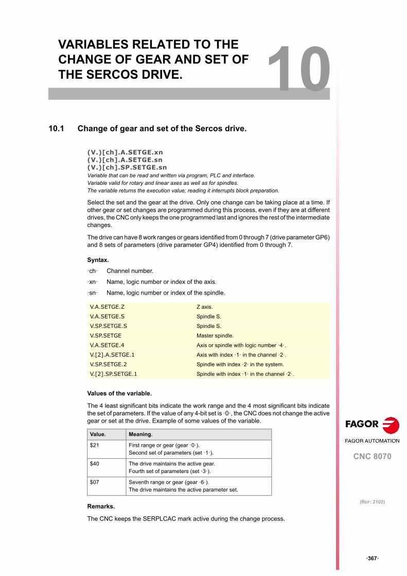
CNC 8070
10
ꞏ367ꞏ
(REF: 2102)
10.VARIABLES RELATED TO THE CHANGE OF GEAR AND SET OF THE SERCOS DRIVE.
10.1 Change of gear and set of the Sercos drive.
(V.)[ch].A.SETGE.xn(V.)[ch].A.SETGE.sn(V.)[ch].SP.SETGE.snVariable that can be read and written via program, PLC and interface.Variable valid for rotary and linear axes as well as for spindles.The variable returns the execution value; reading it interrupts block preparation.
Select the set and the gear at the drive. Only one change can be taking place at a time. Ifother gear or set changes are programmed during this process, even if they are at differentdrives, the CNC only keeps the one programmed last and ignores the rest of the intermediatechanges.
The drive can have 8 work ranges or gears identified from 0 through 7 (drive parameter GP6)and 8 sets of parameters (drive parameter GP4) identified from 0 through 7.
Syntax.
ꞏchꞏ Channel number.
ꞏxnꞏ Name, logic number or index of the axis.
ꞏsnꞏ Name, logic number or index of the spindle.
Values of the variable.
The 4 least significant bits indicate the work range and the 4 most significant bits indicatethe set of parameters. If the value of any 4-bit set is ꞏ0ꞏ, the CNC does not change the activegear or set at the drive. Example of some values of the variable.
Remarks.
The CNC keeps the SERPLCAC mark active during the change process.
V.A.SETGE.Z Z axis.
V.A.SETGE.S Spindle S.
V.SP.SETGE.S Spindle S.
V.SP.SETGE Master spindle.
V.A.SETGE.4 Axis or spindle with logic number ꞏ4ꞏ.
V.[2].A.SETGE.1 Axis with index ꞏ1ꞏ in the channel ꞏ2ꞏ.
V.SP.SETGE.2 Spindle with index ꞏ2ꞏ in the system.
V.[2].SP.SETGE.1 Spindle with index ꞏ1ꞏ in the channel ꞏ2ꞏ.
Value. Meaning.
$21 First range or gear (gear ꞏ0ꞏ).Second set of parameters (set ꞏ1ꞏ).
$40 The drive maintains the active gear.Fourth set of parameters (set ꞏ3ꞏ).
$07 Seventh range or gear (gear ꞏ6ꞏ).The drive maintains the active parameter set.

CNC variables.
CNC 8070
10.
VA
RIA
BL
ES
RE
LA
TE
D T
O T
HE
CH
AN
GE
OF
GE
AR
AN
D S
ET
OF
Ch
ange
of g
ear
and
set
of t
he S
erco
s dr
ive.
ꞏ368ꞏ
(REF: 2102)

CNC 8070
11
ꞏ369ꞏ
(REF: 2102)
11.VARIABLES RELATED TO LOOP ADJUSTMENT.
11.1 Coordinate related variables.
(V.)[ch].A.IPOPOS.xn(V.)[ch].A.IPOPOS.sn(V.)[ch].SP.IPOPOS.snVariable that can only be read from the program, PLC and interface.Variable valid for rotary and linear axes as well as for spindles.The variable returns the execution value; reading it interrupts block preparation.
Theoretical position value (coordinate) at the output of the interpolator, before thetransformation; i.e. in part coordinates.
Syntax.
ꞏchꞏ Channel number.
ꞏxnꞏ Name, logic number or index of the axis.
ꞏsnꞏ Name, logic number or index of the spindle.
(V.)[ch].A.FILTERIN.xn(V.)[ch].A.FILTERIN.sn(V.)[ch].SP.FILTERIN.snVariable that can only be read from the program, PLC and interface.Variable valid for rotary and linear axes as well as for spindles.The variable returns the execution value; reading it interrupts block preparation.
Theoretical coordinate of the interpolator before the filter.
Syntax.
ꞏchꞏ Channel number.
ꞏxnꞏ Name, logic number or index of the axis.
ꞏsnꞏ Name, logic number or index of the spindle.
V.A.IPOPOS.Z Z axis.
V.A.IPOPOS.S Spindle S.
V.SP.IPOPOS.S Spindle S.
V.SP.IPOPOS Master spindle.
V.A.IPOPOS.4 Axis or spindle with logic number ꞏ4ꞏ.
V.[2].A.IPOPOS.1 Axis with index ꞏ1ꞏ in the channel ꞏ2ꞏ.
V.SP.IPOPOS.2 Spindle with index ꞏ2ꞏ in the system.
V.[2].SP.IPOPOS.1 Spindle with index ꞏ1ꞏ in the channel ꞏ2ꞏ.
V.A.FILTERIN.Z Z axis.
V.A.FILTERIN.S Spindle S.
V.SP.FILTERIN.S Spindle S.
V.SP.FILTERIN Master spindle.
V.A.FILTERIN.4 Axis or spindle with logic number ꞏ4ꞏ.
V.[2].A.FILTERIN.1 Axis with index ꞏ1ꞏ in the channel ꞏ2ꞏ.
V.SP.FILTERIN.2 Spindle with index ꞏ2ꞏ in the system.
V.[2].SP.FILTERIN.1 Spindle with index ꞏ1ꞏ in the channel ꞏ2ꞏ.

CNC variables.
CNC 8070
11.
VA
RIA
BL
ES
RE
LA
TE
D T
O L
OO
P A
DJU
ST
ME
NT
.
Coo
rdin
ate
rel
ated
var
iab
les.
ꞏ370ꞏ
(REF: 2102)
(V.)[ch].A.FILTEROUT.xn(V.)[ch].A.FILTEROUT.sn(V.)[ch].SP.FILTEROUT.snVariable that can only be read from the program, PLC and interface.Variable valid for rotary and linear axes as well as for spindles.The variable returns the execution value; reading it interrupts block preparation.
Theoretical coordinate of the interpolator after the filter.
Syntax.
ꞏchꞏ Channel number.
ꞏxnꞏ Name, logic number or index of the axis.
ꞏsnꞏ Name, logic number or index of the spindle.
(V.)[ch].A.LOOPTPOS.xn(V.)[ch].A.LOOPTPOS.sn(V.)[ch].SP.LOOPTPOS.snVariable that can only be read from the program, PLC and interface.Variable valid for rotary and linear axes as well as for spindles.The variable returns the execution value; reading it interrupts block preparation.
Theoretical coordinate at the input of the position loop.
Syntax.
ꞏchꞏ Channel number.
ꞏxnꞏ Name, logic number or index of the axis.
ꞏsnꞏ Name, logic number or index of the spindle.
V.A.FILTEROUT.Z Z axis.
V.A.FILTEROUT.S Spindle S.
V.SP.FILTEROUT.S Spindle S.
V.SP.FILTEROUT Master spindle.
V.A.FILTEROUT.4 Axis or spindle with logic number ꞏ4ꞏ.
V.[2].A.FILTEROUT.1 Axis with index ꞏ1ꞏ in the channel ꞏ2ꞏ.
V.SP.FILTEROUT.2 Spindle with index ꞏ2ꞏ in the system.
V.[2].SP.FILTEROUT.1 Spindle with index ꞏ1ꞏ in the channel ꞏ2ꞏ.
V.A.LOOPTPOS.Z Z axis.
V.A.LOOPTPOS.S Spindle S.
V.SP.LOOPTPOS.S Spindle S.
V.SP.LOOPTPOS Master spindle.
V.A.LOOPTPOS.4 Axis or spindle with logic number ꞏ4ꞏ.
V.[2].A.LOOPTPOS.1 Axis with index ꞏ1ꞏ in the channel ꞏ2ꞏ.
V.SP.LOOPTPOS.2 Spindle with index ꞏ2ꞏ in the system.
V.[2].SP.LOOPTPOS.1 Spindle with index ꞏ1ꞏ in the channel ꞏ2ꞏ.

CNC variables.
CNC 8070
VA
RIA
BL
ES
RE
LA
TE
D T
O L
OO
P A
DJU
ST
ME
NT
.
11.
Coo
rdin
ate
rel
ated
var
iab
les.
ꞏ371ꞏ
(REF: 2102)
(V.)[ch].A.LOOPPOS.xn(V.)[ch].A.LOOPPOS.sn(V.)[ch].SP.LOOPPOS.snVariable that can only be read from the program, PLC and interface.Variable valid for rotary and linear axes as well as for spindles.The variable returns the execution value; reading it interrupts block preparation.
Real coordinate at the input of the position loop.
Syntax.
ꞏchꞏ Channel number.
ꞏxnꞏ Name, logic number or index of the axis.
ꞏsnꞏ Name, logic number or index of the spindle.
V.A.LOOPPOS.Z Z axis.
V.A.LOOPPOS.S Spindle S.
V.SP.LOOPPOS.S Spindle S.
V.SP.LOOPPOS Master spindle.
V.A.LOOPPOS.4 Axis or spindle with logic number ꞏ4ꞏ.
V.[2].A.LOOPPOS.1 Axis with index ꞏ1ꞏ in the channel ꞏ2ꞏ.
V.SP.LOOPPOS.2 Spindle with index ꞏ2ꞏ in the system.
V.[2].SP.LOOPPOS.1 Spindle with index ꞏ1ꞏ in the channel ꞏ2ꞏ.

CNC variables.
CNC 8070
11.
VA
RIA
BL
ES
RE
LA
TE
D T
O L
OO
P A
DJU
ST
ME
NT
.
Pos
ition
incr
em
ent a
nd s
ampl
ing
perio
d.
ꞏ372ꞏ
(REF: 2102)
11.2 Position increment and sampling period.
(V.)[ch].A.POSINC.xn(V.)[ch].A.POSINC.sn(V.)[ch].SP.POSINC.snVariable that can only be read from the program, PLC and interface.Variable valid for rotary and linear axes as well as for spindles.The variable returns the execution value; reading it interrupts block preparation.
Real position increment of the current sampling period.
Syntax.
ꞏchꞏ Channel number.
ꞏxnꞏ Name, logic number or index of the axis.
ꞏsnꞏ Name, logic number or index of the spindle.
(V.)[ch].A.TPOSINC.xn(V.)[ch].A.TPOSINC.sn(V.)[ch].SP.TPOSINC.snVariable that can only be read from the program, PLC and interface.Variable valid for rotary and linear axes as well as for spindles.The variable returns the execution value; reading it interrupts block preparation.
Theoretical position increment of the current sampling period.
Syntax.
ꞏchꞏ Channel number.
ꞏxnꞏ Name, logic number or index of the axis.
ꞏsnꞏ Name, logic number or index of the spindle.
V.A.POSINC.Z Z axis.
V.A.POSINC.S Spindle S.
V.SP.POSINC.S Spindle S.
V.SP.POSINC Master spindle.
V.A.POSINC.4 Axis or spindle with logic number ꞏ4ꞏ.
V.[2].A.POSINC.1 Axis with index ꞏ1ꞏ in the channel ꞏ2ꞏ.
V.SP.POSINC.2 Spindle with index ꞏ2ꞏ in the system.
V.[2].SP.POSINC.1 Spindle with index ꞏ1ꞏ in the channel ꞏ2ꞏ.
V.A.TPOSINC.Z Z axis.
V.A.TPOSINC.S Spindle S.
V.SP.TPOSINC.S Spindle S.
V.SP.TPOSINC Master spindle.
V.A.TPOSINC.4 Axis or spindle with logic number ꞏ4ꞏ.
V.[2].A.TPOSINC.1 Axis with index ꞏ1ꞏ in the channel ꞏ2ꞏ.
V.SP.TPOSINC.2 Spindle with index ꞏ2ꞏ in the system.
V.[2].SP.TPOSINC.1 Spindle with index ꞏ1ꞏ in the channel ꞏ2ꞏ.

CNC variables.
CNC 8070
VA
RIA
BL
ES
RE
LA
TE
D T
O L
OO
P A
DJU
ST
ME
NT
.
11.
Pos
ition
incr
em
ent a
nd s
ampl
ing
perio
d.
ꞏ373ꞏ
(REF: 2102)
(V.)[ch].A.PREVPOSINC.xn(V.)[ch].A.PREVPOSINC.sn(V.)[ch].SP.PREVPOSINC.snVariable that can only be read from the program, PLC and interface.Variable valid for rotary and linear axes as well as for spindles.The variable returns the execution value; reading it interrupts block preparation.
Real position increment of the previous sampling period.
Syntax.
ꞏchꞏ Channel number.
ꞏxnꞏ Name, logic number or index of the axis.
ꞏsnꞏ Name, logic number or index of the spindle.
V.A.PREVPOSINC.Z Z axis.
V.A.PREVPOSINC.S Spindle S.
V.SP.PREVPOSINC.S Spindle S.
V.SP.PREVPOSINC Master spindle.
V.A.PREVPOSINC.4 Axis or spindle with logic number ꞏ4ꞏ.
V.[2].A.PREVPOSINC.1 Axis with index ꞏ1ꞏ in the channel ꞏ2ꞏ.
V.SP.PREVPOSINC.2 Spindle with index ꞏ2ꞏ in the system.
V.[2].SP.PREVPOSINC.1 Spindle with index ꞏ1ꞏ in the channel ꞏ2ꞏ.

CNC variables.
CNC 8070
11.
VA
RIA
BL
ES
RE
LA
TE
D T
O L
OO
P A
DJU
ST
ME
NT
.
Fin
e a
djus
tmen
t of f
eed
rate
, acc
eler
atio
n a
nd je
rk.
ꞏ374ꞏ
(REF: 2102)
11.3 Fine adjustment of feedrate, acceleration and jerk.
(V.)[ch].A.TFEED.xn(V.)[ch].A.TFEED.sn(V.)[ch].SP.TFEED.snVariable that can only be read from the program, PLC and interface.Variable valid for rotary and linear axes as well as for spindles.The variable returns the execution value; reading it interrupts block preparation.
Instantaneous theoretical speed value at the input of the position loop.
Syntax.
ꞏchꞏ Channel number.
ꞏxnꞏ Name, logic number or index of the axis.
ꞏsnꞏ Name, logic number or index of the spindle.
(V.)[ch].A.FEED.xn(V.)[ch].A.FEED.sn(V.)[ch].SP.FEED.snVariable that can only be read from the program, PLC and interface.Variable valid for rotary and linear axes as well as for spindles.The variable returns the execution value; reading it interrupts block preparation.
Instantaneous real speed value at the input of the position loop.
Syntax.
ꞏchꞏ Channel number.
ꞏxnꞏ Name, logic number or index of the axis.
ꞏsnꞏ Name, logic number or index of the spindle.
V.A.TFEED.Z Z axis.
V.A.TFEED.S Spindle S.
V.SP.TFEED.S Spindle S.
V.SP.TFEED Master spindle.
V.A.TFEED.4 Axis or spindle with logic number ꞏ4ꞏ.
V.[2].A.TFEED.1 Axis with index ꞏ1ꞏ in the channel ꞏ2ꞏ.
V.SP.TFEED.2 Spindle with index ꞏ2ꞏ in the system.
V.[2].SP.TFEED.1 Spindle with index ꞏ1ꞏ in the channel ꞏ2ꞏ.
V.A.FEED.Z Z axis.
V.A.FEED.S Spindle S.
V.SP.FEED.S Spindle S.
V.SP.FEED Master spindle.
V.A.FEED.4 Axis or spindle with logic number ꞏ4ꞏ.
V.[2].A.FEED.1 Axis with index ꞏ1ꞏ in the channel ꞏ2ꞏ.
V.SP.FEED.2 Spindle with index ꞏ2ꞏ in the system.
V.[2].SP.FEED.1 Spindle with index ꞏ1ꞏ in the channel ꞏ2ꞏ.

CNC variables.
CNC 8070
VA
RIA
BL
ES
RE
LA
TE
D T
O L
OO
P A
DJU
ST
ME
NT
.
11.
Fin
e a
djus
tmen
t of f
eed
rate
, acc
eler
atio
n a
nd je
rk.
ꞏ375ꞏ
(REF: 2102)
(V.)[ch].A.TACCEL.xn(V.)[ch].A.TACCEL.sn(V.)[ch].SP.TACCEL.snVariable that can only be read from the program, PLC and interface.Variable valid for rotary and linear axes as well as for spindles.The variable returns the execution value; reading it interrupts block preparation.
Theoretical instantaneous acceleration value.
Syntax.
ꞏchꞏ Channel number.
ꞏxnꞏ Name, logic number or index of the axis.
ꞏsnꞏ Name, logic number or index of the spindle.
(V.)[ch].A.ACCEL.xn(V.)[ch].A.ACCEL.sn(V.)[ch].SP.ACCEL.snVariable that can only be read from the program, PLC and interface.Variable valid for rotary and linear axes as well as for spindles.The variable returns the execution value; reading it interrupts block preparation.
Real instantaneous acceleration value.
Syntax.
ꞏchꞏ Channel number.
ꞏxnꞏ Name, logic number or index of the axis.
ꞏsnꞏ Name, logic number or index of the spindle.
V.A.TACCEL.Z Z axis.
V.A.TACCEL.S Spindle S.
V.SP.TACCEL.S Spindle S.
V.SP.TACCEL Master spindle.
V.A.TACCEL.4 Axis or spindle with logic number ꞏ4ꞏ.
V.[2].A.TACCEL.1 Axis with index ꞏ1ꞏ in the channel ꞏ2ꞏ.
V.SP.TACCEL.2 Spindle with index ꞏ2ꞏ in the system.
V.[2].SP.TACCEL.1 Spindle with index ꞏ1ꞏ in the channel ꞏ2ꞏ.
V.A.ACCEL.Z Z axis.
V.A.ACCEL.S Spindle S.
V.SP.ACCEL.S Spindle S.
V.SP.ACCEL Master spindle.
V.A.ACCEL.4 Axis or spindle with logic number ꞏ4ꞏ.
V.[2].A.ACCEL.1 Axis with index ꞏ1ꞏ in the channel ꞏ2ꞏ.
V.SP.ACCEL.2 Spindle with index ꞏ2ꞏ in the system.
V.[2].SP.ACCEL.1 Spindle with index ꞏ1ꞏ in the channel ꞏ2ꞏ.

CNC variables.
CNC 8070
11.
VA
RIA
BL
ES
RE
LA
TE
D T
O L
OO
P A
DJU
ST
ME
NT
.
Fin
e a
djus
tmen
t of f
eed
rate
, acc
eler
atio
n a
nd je
rk.
ꞏ376ꞏ
(REF: 2102)
(V.)[ch].A.TJERK.xn(V.)[ch].A.TJERK.sn(V.)[ch].SP.TJERK.snVariable that can only be read from the program, PLC and interface.Variable valid for rotary and linear axes as well as for spindles.The variable returns the execution value; reading it interrupts block preparation.
Theoretical instantaneous jerk value.
Syntax.
ꞏchꞏ Channel number.
ꞏxnꞏ Name, logic number or index of the axis.
ꞏsnꞏ Name, logic number or index of the spindle.
(V.)[ch].A.JERK.xn(V.)[ch].A.JERK.sn(V.)[ch].SP.JERK.snVariable that can only be read from the program, PLC and interface.Variable valid for rotary and linear axes as well as for spindles.The variable returns the execution value; reading it interrupts block preparation.
Real instantaneous jerk value.
Syntax.
ꞏchꞏ Channel number.
ꞏxnꞏ Name, logic number or index of the axis.
ꞏsnꞏ Name, logic number or index of the spindle.
V.A.TJERK.Z Z axis.
V.A.TJERK.S Spindle S.
V.SP.TJERK.S Spindle S.
V.SP.TJERK Master spindle.
V.A.TJERK.4 Axis or spindle with logic number ꞏ4ꞏ.
V.[2].A.TJERK.1 Axis with index ꞏ1ꞏ in the channel ꞏ2ꞏ.
V.SP.TJERK.2 Spindle with index ꞏ2ꞏ in the system.
V.[2].SP.TJERK.1 Spindle with index ꞏ1ꞏ in the channel ꞏ2ꞏ.
V.A.JERK.Z Z axis.
V.A.JERK.S Spindle S.
V.SP.JERK.S Spindle S.
V.SP.JERK Master spindle.
V.A.JERK.4 Axis or spindle with logic number ꞏ4ꞏ.
V.[2].A.JERK.1 Axis with index ꞏ1ꞏ in the channel ꞏ2ꞏ.
V.SP.JERK.2 Spindle with index ꞏ2ꞏ in the system.
V.[2].SP.JERK.1 Spindle with index ꞏ1ꞏ in the channel ꞏ2ꞏ.

CNC variables.
CNC 8070
VA
RIA
BL
ES
RE
LA
TE
D T
O L
OO
P A
DJU
ST
ME
NT
.
11.
Ga
in s
ettin
g vi
a P
LC.
ꞏ377ꞏ
(REF: 2102)
11.4 Gain setting via PLC.
(V.)[ch].A.PLCFFGAIN.xn(V.)[ch].A.PLCFFGAIN.sn(V.)[ch].SP.PLCFFGAIN.snVariable that can be read and written from the PLC and read from the program and from the interface.Variable valid for rotary and linear axes as well as for spindles.The variable returns the execution value; reading it interrupts block preparation.
Percentage of feed-forward programmed from the PLC.
Syntax.
ꞏchꞏ Channel number.
ꞏxnꞏ Name, logic number or index of the axis.
ꞏsnꞏ Name, logic number or index of the spindle.
Remarks.
In order for the feed-forward and the AC-forward defined this way to be taken into account,they must be active by machine parameter; i.e. by means of machine parameter FFWTYPEif it is an analog drive or a simulated drive or parameter OPMODEP if it is a Sercos drive.
The values defined by these variables prevail over the ones defined by machine parametersor by program. Setting the variables with a negative value cancels their effect ("0" is a validvalue). These variables are initialized neither by a reset nor when validating the parameters.
The reading from the PLC will be given in hundredths (x100); i.e. if the parameter value isꞏ10ꞏ, the PLC reading will return a value of ꞏ1000ꞏ.
(V.)[ch].A.PLCACFGAIN.xn(V.)[ch].A.PLCACFGAIN.sn(V.)[ch].SP.PLCACFGAIN.snVariable that can be read and written from the PLC and read from the program and from the interface.Variable valid for rotary and linear axes as well as for spindles.The variable returns the execution value; reading it interrupts block preparation.
Percentage of AC-forward programmed from the PLC.
Syntax.
ꞏchꞏ Channel number.
ꞏxnꞏ Name, logic number or index of the axis.
ꞏsnꞏ Name, logic number or index of the spindle.
V.A.PLCFFGAIN.Z Z axis.
V.A.PLCFFGAIN.S Spindle S.
V.SP.PLCFFGAIN.S Spindle S.
V.SP.PLCFFGAIN Master spindle.
V.A.PLCFFGAIN.4 Axis or spindle with logic number ꞏ4ꞏ.
V.[2].A.PLCFFGAIN.1 Axis with index ꞏ1ꞏ in the channel ꞏ2ꞏ.
V.SP.PLCFFGAIN.2 Spindle with index ꞏ2ꞏ in the system.
V.[2].SP.PLCFFGAIN.1 Spindle with index ꞏ1ꞏ in the channel ꞏ2ꞏ.
V.A.PLCACFGAIN.Z Z axis.
V.A.PLCACFGAIN.S Spindle S.
V.SP.PLCACFGAIN.S Spindle S.
V.SP.PLCACFGAIN Master spindle.
V.A.PLCACFGAIN.4 Axis or spindle with logic number ꞏ4ꞏ.
V.[2].A.PLCACFGAIN.1 Axis with index ꞏ1ꞏ in the channel ꞏ2ꞏ.
V.SP.PLCACFGAIN.2 Spindle with index ꞏ2ꞏ in the system.
V.[2].SP.PLCACFGAIN.1 Spindle with index ꞏ1ꞏ in the channel ꞏ2ꞏ.

CNC variables.
CNC 8070
11.
VA
RIA
BL
ES
RE
LA
TE
D T
O L
OO
P A
DJU
ST
ME
NT
.
Ga
in s
ettin
g vi
a P
LC.
ꞏ378ꞏ
(REF: 2102)
Remarks.
In order for the feed-forward and the AC-forward defined this way to be taken into account,they must be active by machine parameter; i.e. by means of machine parameter FFWTYPEif it is an analog drive or a simulated drive or parameter OPMODEP if it is a Sercos drive.
The values defined by these variables prevail over the ones defined by machine parametersor by program. Setting the variables with a negative value cancels their effect ("0" is a validvalue). These variables are initialized neither by a reset nor when validating the parameters.
The reading from the PLC will be given in tenths (x10); i.e. if the parameter value is ꞏ10ꞏ,the PLC reading will return a value of ꞏ100ꞏ.
(V.)[ch].A.PLCPROGAIN.xn(V.)[ch].A.PLCPROGAIN.sn(V.)[ch].SP.PLCPROGAIN.snVariable that can be read and written from the PLC and read from the program and from the interface.Variable valid for rotary and linear axes as well as for spindles.The variable returns the execution value; reading it interrupts block preparation.
Proportional gain programmed from the PLC.
Syntax.
ꞏchꞏ Channel number.
ꞏxnꞏ Name, logic number or index of the axis.
ꞏsnꞏ Name, logic number or index of the spindle.
Remarks.
The values defined by these variables prevail over the ones defined by machine parametersor by program. Setting the variables with a negative value cancels their effect ("0" is a validvalue). These variables are initialized neither by a reset nor when validating the parameters.
V.A.PLCPROGAIN.Z Z axis.
V.A.PLCPROGAIN.S Spindle S.
V.SP.PLCPROGAIN.S Spindle S.
V.SP.PLCPROGAIN Master spindle.
V.A.PLCPROGAIN.4 Axis or spindle with logic number ꞏ4ꞏ.
V.[2].A.PLCPROGAIN.1 Axis with index ꞏ1ꞏ in the channel ꞏ2ꞏ.
V.SP.PLCPROGAIN.2 Spindle with index ꞏ2ꞏ in the system.
V.[2].SP.PLCPROGAIN.1 Spindle with index ꞏ1ꞏ in the channel ꞏ2ꞏ.

CNC variables.
CNC 8070
VA
RIA
BL
ES
RE
LA
TE
D T
O L
OO
P A
DJU
ST
ME
NT
.
11.
Var
iabl
es r
ela
ted
to th
e lo
op
of th
e a
xis
or o
f the
tan
dem
sp
ind
le.
ꞏ379ꞏ
(REF: 2102)
11.5 Variables related to the loop of the axis or of the tandem spindle.
(V.)[ch].A.TPIIN.xn(V.)[ch].A.TPIIN.sn(V.)[ch].SP.TPIIN.snVariable that can only be read from the program, PLC and interface.Variable valid for rotary and linear axes as well as for spindles.The variable returns the execution value; reading it interrupts block preparation.
Input of the PI of the master axis of the tandem (in rpm).
Syntax.
ꞏchꞏ Channel number.
ꞏxnꞏ Name, logic number or index of the axis.
ꞏsnꞏ Name, logic number or index of the spindle.
(V.)[ch].A.TPIOUT.xn(V.)[ch].A.TPIOUT.sn(V.)[ch].SP.TPIOUT.snVariable that can only be read from the program, PLC and interface.Variable valid for rotary and linear axes as well as for spindles.The variable returns the execution value; reading it interrupts block preparation.
Output of the PI of the master axis of the tandem (in rpm).
Syntax.
ꞏchꞏ Channel number.
ꞏxnꞏ Name, logic number or index of the axis.
ꞏsnꞏ Name, logic number or index of the spindle.
V.A.TPIIN.Z Z axis.
V.A.TPIIN.S Spindle S.
V.SP.TPIIN.S Spindle S.
V.SP.TPIIN Master spindle.
V.A.TPIIN.4 Axis or spindle with logic number ꞏ4ꞏ.
V.[2].A.TPIIN.1 Axis with index ꞏ1ꞏ in the channel ꞏ2ꞏ.
V.SP.TPIIN.2 Spindle with index ꞏ2ꞏ in the system.
V.[2].SP.TPIIN.1 Spindle with index ꞏ1ꞏ in the channel ꞏ2ꞏ.
V.A.TPIOUT.Z Z axis.
V.A.TPIOUT.S Spindle S.
V.SP.TPIOUT.S Spindle S.
V.SP.TPIOUT Master spindle.
V.A.TPIOUT.4 Axis or spindle with logic number ꞏ4ꞏ.
V.[2].A.TPIOUT.1 Axis with index ꞏ1ꞏ in the channel ꞏ2ꞏ.
V.SP.TPIOUT.2 Spindle with index ꞏ2ꞏ in the system.
V.[2].SP.TPIOUT.1 Spindle with index ꞏ1ꞏ in the channel ꞏ2ꞏ.

CNC variables.
CNC 8070
11.
VA
RIA
BL
ES
RE
LA
TE
D T
O L
OO
P A
DJU
ST
ME
NT
.
Var
iabl
es r
ela
ted
to th
e lo
op
of th
e a
xis
or o
f the
tan
dem
sp
ind
le.
ꞏ380ꞏ
(REF: 2102)
(V.)[ch].A.TFILTOUT.xn(V.)[ch].A.TFILTOUT.sn(V.)[ch].SP.TFILTOUT.snVariable that can only be read from the program, PLC and interface.Variable valid for rotary and linear axes as well as for spindles.The variable returns the execution value; reading it interrupts block preparation.
Output of the pre-load filter of the tandem.
Syntax.
ꞏchꞏ Channel number.
ꞏxnꞏ Name, logic number or index of the axis.
ꞏsnꞏ Name, logic number or index of the spindle.
(V.)[ch].A.PRELOAD.xn(V.)[ch].A.PRELOAD.sn(V.)[ch].SP.PRELOAD.snVariable that can be read and written via program, PLC and interface.Variable valid for rotary and linear axes as well as for spindles.The variable returns the execution value; reading it interrupts block preparation.
Preload in the tandem.
Syntax.
ꞏchꞏ Channel number.
ꞏxnꞏ Name, logic number or index of the axis.
ꞏsnꞏ Name, logic number or index of the spindle.
(V.)[ch].A.TORQUE.xnVariable that can only be read from the program, PLC and interface.Variable valid for rotary and linear axes as well as for spindles.The variable returns the execution value; reading it interrupts block preparation.
Current torque on the master or slave axis of the tandem.
Syntax.
ꞏchꞏ Channel number.
ꞏxnꞏ Name, logic number or index of the axis.
V.A.TFILTOUT.Z Z axis.
V.A.TFILTOUT.S Spindle S.
V.SP.TFILTOUT.S Spindle S.
V.SP.TFILTOUT Master spindle.
V.A.TFILTOUT.4 Axis or spindle with logic number ꞏ4ꞏ.
V.[2].A.TFILTOUT.1 Axis with index ꞏ1ꞏ in the channel ꞏ2ꞏ.
V.SP.TFILTOUT.2 Spindle with index ꞏ2ꞏ in the system.
V.[2].SP.TFILTOUT.1 Spindle with index ꞏ1ꞏ in the channel ꞏ2ꞏ.
V.A.PRELOAD.Z Z axis.
V.A.PRELOAD.S Spindle S.
V.SP.PRELOAD.S Spindle S.
V.SP.PRELOAD Master spindle.
V.A.PRELOAD.4 Axis or spindle with logic number ꞏ4ꞏ.
V.[2].A.PRELOAD.1 Axis with index ꞏ1ꞏ in the channel ꞏ2ꞏ.
V.SP.PRELOAD.2 Spindle with index ꞏ2ꞏ in the system.
V.[2].SP.PRELOAD.1 Spindle with index ꞏ1ꞏ in the channel ꞏ2ꞏ.

CNC variables.
CNC 8070
VA
RIA
BL
ES
RE
LA
TE
D T
O L
OO
P A
DJU
ST
ME
NT
.
11.
Var
iabl
es r
ela
ted
to th
e lo
op
of th
e a
xis
or o
f the
tan
dem
sp
ind
le.
ꞏ381ꞏ
(REF: 2102)
ꞏsnꞏ Name, logic number or index of the spindle.
Remarks.
The reading from the PLC will be given in tenths (x10); i.e. if the parameter value is ꞏ10ꞏ,the PLC reading will return a value of ꞏ100ꞏ.
V.A.TORQUE.Z Z axis.
V.A.TORQUE.S Spindle S.
V.SP.TORQUE.S Spindle S.
V.SP.TORQUE Master spindle.
V.A.TORQUE.4 Axis or spindle with logic number ꞏ4ꞏ.
V.[2].A.TORQUE.1 Axis with index ꞏ1ꞏ in the channel ꞏ2ꞏ.
V.SP.TORQUE.2 Spindle with index ꞏ2ꞏ in the system.
V.[2].SP.TORQUE.1 Spindle with index ꞏ1ꞏ in the channel ꞏ2ꞏ.

CNC variables.
CNC 8070
11.
VA
RIA
BL
ES
RE
LA
TE
D T
O L
OO
P A
DJU
ST
ME
NT
.
Var
iabl
es r
ela
ted
to th
e lo
op
of th
e a
xis
or o
f the
tan
dem
sp
ind
le.
ꞏ382ꞏ
(REF: 2102)

CNC 8070
12
ꞏ383ꞏ
(REF: 2102)
12.VARIABLES RELATED TO USER TABLES.
12.1 Zero offset table.
(V.)G.FORGVariable that can only be read from the program, PLC and interface.The variable returns the value of block preparation.
First zero offset in the table.
(V.)G.NUMORGVariable that can only be read from the program, PLC and interface.The variable returns the value of block preparation.
Number of zero offsets in the table.
(V.)[ch].A.PLCOF.xn(V.)[ch].A.PLCOF.sn(V.)[ch].SP.PLCOF.snVariable that can be read and written from the program and from the PLC and read from the interface.Variable valid for rotary and linear axes as well as for spindles.The variable returns the execution value; reading it interrupts block preparation.Report variable (to be used from the scripts).
xn axis. Offset of the zero offset set by PLC.
Syntax.
ꞏchꞏ Channel number.
ꞏxnꞏ Name, logic number or index of the axis.
ꞏsnꞏ Name, logic number or index of the spindle.
V.G.FORG
V.G.NUMORG
V.A.PLCOF.Z Z axis.
V.A.PLCOF.S Spindle S.
V.SP.PLCOF.S Spindle S.
V.SP.PLCOF Master spindle.
V.A.PLCOF.X
V.G.FORG

CNC variables.
CNC 8070
12.
VA
RIA
BL
ES
RE
LA
TE
D T
O U
SE
R T
AB
LE
S.
Ze
ro o
ffset
tab
le.
ꞏ384ꞏ
(REF: 2102)
(V.)[ch].A.ACTPLCOF.xn(V.)[ch].A.ACTPLCOF.sn(V.)[ch].SP.ACTPLCOF.snVariable that can only be read from the program, PLC and interface.Variable valid for rotary and linear axes as well as for spindles.The variable returns the execution value; reading it interrupts block preparation.Report variable (to be used from the scripts).
xn axis. Accumulated PLC offset.
Syntax.
ꞏchꞏ Channel number.
ꞏxnꞏ Name, logic number or index of the axis.
ꞏsnꞏ Name, logic number or index of the spindle.
V.A.PLCOF.4 Axis or spindle with logic number ꞏ4ꞏ.
V.[2].A.PLCOF.1 Axis with index ꞏ1ꞏ in the channel ꞏ2ꞏ.
V.SP.PLCOF.2 Spindle with index ꞏ2ꞏ in the system.
V.[2].SP.PLCOF.1 Spindle with index ꞏ1ꞏ in the channel ꞏ2ꞏ.
V.A.ACTPLCOF.Z Z axis.
V.A.ACTPLCOF.S Spindle S.
V.SP.ACTPLCOF.S Spindle S.
V.SP.ACTPLCOF Master spindle.
V.A.ACTPLCOF.4 Axis or spindle with logic number ꞏ4ꞏ.
V.[2].A.ACTPLCOF.1 Axis with index ꞏ1ꞏ in the channel ꞏ2ꞏ.
V.SP.ACTPLCOF.2 Spindle with index ꞏ2ꞏ in the system.
V.[2].SP.ACTPLCOF.1 Spindle with index ꞏ1ꞏ in the channel ꞏ2ꞏ.

CNC variables.
CNC 8070
VA
RIA
BL
ES
RE
LA
TE
D T
O U
SE
R T
AB
LE
S.
12.
Ze
ro o
ffset
tab
le.
ꞏ385ꞏ
(REF: 2102)
12.1.1 Zero offset table (without fine setting of the absolute zero offset).
The fine setting of the absolute zero offset is enabled via machine parameters (parameterFINEORG)
(V.)[ch].A.ORG.xnVariable that can only be read from the program, PLC and interface.Variable valid for rotary and linear axes.The variable returns the value of block preparation.
xn axis. Value of the active zero offset (absolute G159 + incremental G158).
Syntax.
ꞏchꞏ Channel number.
ꞏxnꞏ Name, logic number or index of the axis.
(V.)[ch].A.ADDORG.xnVariable that can only be read from the program, PLC and interface.Variable valid for rotary and linear axes.The variable returns the value of block preparation.
xn axis. Value of the active incremental zero offset (G158).
Syntax.
ꞏchꞏ Channel number.
ꞏxnꞏ Name, logic number or index of the axis.
(V.)[ch].A.ORGT[nb].xnVariable that can be read and written from the program and from the PLC and read from the interface.Variable valid for rotary and linear axes.The variable returns the execution value; reading it interrupts block preparation.Report variable (to be used from the scripts).
xn axis. Offset set in the zero offset [nb].
Syntax.
ꞏchꞏ Channel number.
ꞏnbꞏ Zero offset number.
V.A.ORG.Z Z axis.
V.A.ORG.3 Axis with logic number ꞏ3ꞏ.
V.[2].A.ORG.3 Axis with index ꞏ3ꞏ in the channel ꞏ2ꞏ.
V.A.ADDORG.Z Z axis.
V.A.ADDORG.3 Axis with logic number ꞏ3ꞏ.
V.[2].A.ADDORG.3 Axis with index ꞏ3ꞏ in the channel ꞏ2ꞏ.
V.A.ORGT[6].Y

CNC variables.
CNC 8070
12.
VA
RIA
BL
ES
RE
LA
TE
D T
O U
SE
R T
AB
LE
S.
Ze
ro o
ffset
tab
le.
ꞏ386ꞏ
(REF: 2102)
ꞏxnꞏ Name, logic number or index of the axis.
Remarks.
The numbering of zero offsets G54 through G59 is always the same; G54=1, G55=2, G56=3,G57=4, G58=5, G59=6.
V.A.ORGT[1].Z Zero offset G54 (G159=1). Z axis.
V.A.ORGT[4]0.3 Zero offset G57 (G159=4). Axis with logic number ꞏ3ꞏ.
V.[2].A.ORGT[9].3 Zero offset G159=9. Axis with index ꞏ3ꞏ in the channelꞏ2ꞏ.

CNC variables.
CNC 8070
VA
RIA
BL
ES
RE
LA
TE
D T
O U
SE
R T
AB
LE
S.
12.
Ze
ro o
ffset
tab
le.
ꞏ387ꞏ
(REF: 2102)
12.1.2 Zero offset table (with fine setting of the absolute zero offset).
The fine setting of the absolute zero offset is enabled via machine parameters (parameterFINEORG)
(V.)[ch].A.ORG.xnVariable that can only be read from the program, PLC and interface.Variable valid for rotary and linear axes.The variable returns the value of block preparation.
xn axis. Value of the active zero offset (coarse absolute G159 + fine absolute G159 +incremental G158).
Syntax.
ꞏchꞏ Channel number.
ꞏxnꞏ Name, logic number or index of the axis.
(V.)[ch].A.ADDORG.xnVariable that can only be read from the program, PLC and interface.Variable valid for rotary and linear axes.The variable returns the value of block preparation.
xn axis. Value of the active incremental zero offset (G158).
Syntax.
ꞏchꞏ Channel number.
ꞏxnꞏ Name, logic number or index of the axis.
(V.)[ch].A.COARSEORG.xnVariable that can only be read from the program, PLC and interface.Variable valid for rotary and linear axes.The variable returns the value of block preparation.
xn axis. Value of the active absolute zero offset (G159), coarse part.
Syntax.
ꞏchꞏ Channel number.
ꞏxnꞏ Name, logic number or index of the axis.
(V.)[ch].A.FINEORG.xnVariable that can only be read from the program, PLC and interface.Variable valid for rotary and linear axes.The variable returns the value of block preparation.
xn axis. Value of the active absolute zero offset (G159), fine part.
Syntax.
ꞏchꞏ Channel number.
V.A.ORG.Z Z axis.
V.A.ORG.3 Axis with logic number ꞏ3ꞏ.
V.[2].A.ORG.3 Axis with index ꞏ3ꞏ in the channel ꞏ2ꞏ.
V.A.ADDORG.Z Z axis.
V.A.ADDORG.3 Axis with logic number ꞏ3ꞏ.
V.[2].A.ADDORG.3 Axis with index ꞏ3ꞏ in the channel ꞏ2ꞏ.
V.A.COARSEORG.Z Z axis.
V.A.COARSEORG.3 Axis with logic number ꞏ3ꞏ.
V.[2].A.COARSEORG.3 Axis with index ꞏ3ꞏ in the channel ꞏ2ꞏ.

CNC variables.
CNC 8070
12.
VA
RIA
BL
ES
RE
LA
TE
D T
O U
SE
R T
AB
LE
S.
Ze
ro o
ffset
tab
le.
ꞏ388ꞏ
(REF: 2102)
ꞏxnꞏ Name, logic number or index of the axis.
(V.)[ch].A.ORGT[nb].xnVariable that can be read and written from the program and from the PLC and read from the interface.Variable valid for rotary and linear axes.The variable returns the execution value; reading it interrupts block preparation.Report variable (to be used from the scripts).
xn axis. Offset set in the zero offset [nb]; coarse part plus fine part.
When writing this variable, the value is assigned to the coarse part deleting the fine part.
Syntax.
ꞏchꞏ Channel number.
ꞏnbꞏ Zero offset number.
ꞏxnꞏ Name, logic number or index of the axis.
Remarks.
The numbering of zero offsets G54 through G59 is always the same; G54=1, G55=2, G56=3,G57=4, G58=5, G59=6.
(V.)[ch].A.COARSEORGT[nb].xnVariable that can be read and written from the program and from the PLC and read from the interface.Variable valid for rotary and linear axes.The variable returns the execution value; reading it interrupts block preparation.Report variable (to be used from the scripts).
xn axis. Offset set in the zero offset [nb]; coarse part.
Syntax.
ꞏchꞏ Channel number.
ꞏnbꞏ Zero offset number.
ꞏxnꞏ Name, logic number or index of the axis.
(V.)[ch].A.FINEORGT[nb].xnVariable that can be read and written from the program and from the PLC and read from the interface.Variable valid for rotary and linear axes.The variable returns the execution value; reading it interrupts block preparation.Report variable (to be used from the scripts).
xn axis. Offset set in the zero offset [nb]; fine part.
Syntax.
ꞏchꞏ Channel number.
ꞏnbꞏ Zero offset number.
V.A.FINEORG.Z Z axis.
V.A.FINEORG.3 Axis with logic number ꞏ3ꞏ.
V.[2].A.FINEORG.3 Axis with index ꞏ3ꞏ in the channel ꞏ2ꞏ.
V.A.ORGT[1].Z Zero offset G54 (G159=1). Z axis.
V.A.ORGT[4]0.3 Zero offset G57 (G159=4). Axis with logic number ꞏ3ꞏ.
V.[2].A.ORGT[9].3 Zero offset G159=9. Axis with index ꞏ3ꞏ in the channelꞏ2ꞏ.
V.A.COARSEORGT[1].Z Zero offset G54 (G159=1). Z axis.
V.A.COARSEORGT[4].3 Zero offset G57 (G159=4). Axis with logic number ꞏ3ꞏ.
V.[2].A.COARSEORGT[9].3 Zero offset G159=9. Axis with index ꞏ3ꞏ in the channelꞏ2ꞏ.

CNC variables.
CNC 8070
VA
RIA
BL
ES
RE
LA
TE
D T
O U
SE
R T
AB
LE
S.
12.
Ze
ro o
ffset
tab
le.
ꞏ389ꞏ
(REF: 2102)
ꞏxnꞏ Name, logic number or index of the axis.
V.A.FINEORGT[1].Z Zero offset G54 (G159=1). Z axis.
V.A.FINEORGT[4].3 Zero offset G57 (G159=4). Axis with logic number ꞏ3ꞏ.
V.[2].A.FINEORGT[9].3 Zero offset G159=9. Axis with index ꞏ3ꞏ in the channelꞏ2ꞏ.
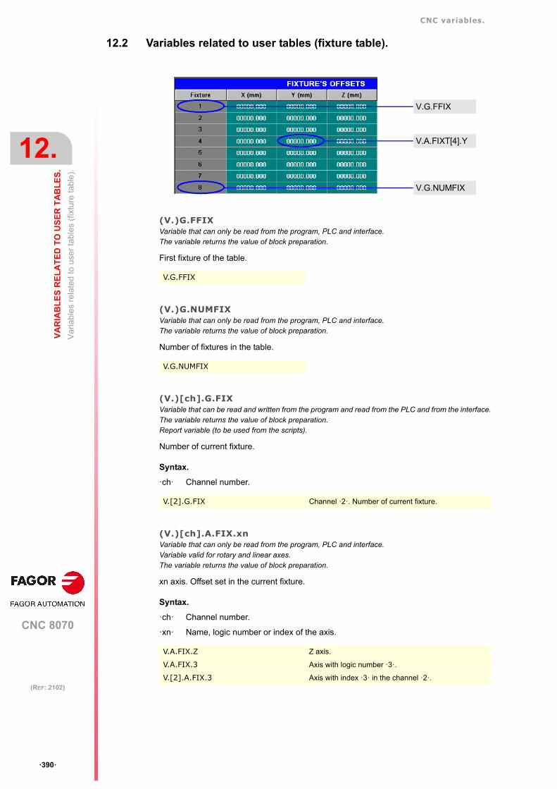
CNC variables.
CNC 8070
12.
VA
RIA
BL
ES
RE
LA
TE
D T
O U
SE
R T
AB
LE
S.
Var
iabl
es r
elat
ed to
use
r ta
bles
(fix
ture
tabl
e).
ꞏ390ꞏ
(REF: 2102)
12.2 Variables related to user tables (fixture table).
(V.)G.FFIXVariable that can only be read from the program, PLC and interface.The variable returns the value of block preparation.
First fixture of the table.
(V.)G.NUMFIXVariable that can only be read from the program, PLC and interface.The variable returns the value of block preparation.
Number of fixtures in the table.
(V.)[ch].G.FIXVariable that can be read and written from the program and read from the PLC and from the interface.The variable returns the value of block preparation.Report variable (to be used from the scripts).
Number of current fixture.
Syntax.
ꞏchꞏ Channel number.
(V.)[ch].A.FIX.xnVariable that can only be read from the program, PLC and interface.Variable valid for rotary and linear axes.The variable returns the value of block preparation.
xn axis. Offset set in the current fixture.
Syntax.
ꞏchꞏ Channel number.
ꞏxnꞏ Name, logic number or index of the axis.
V.G.FFIX
V.G.NUMFIX
V.[2].G.FIX Channel ꞏ2ꞏ. Number of current fixture.
V.A.FIX.Z Z axis.
V.A.FIX.3 Axis with logic number ꞏ3ꞏ.
V.[2].A.FIX.3 Axis with index ꞏ3ꞏ in the channel ꞏ2ꞏ.
V.G.FFIX
V.A.FIXT[4].Y
V.G.NUMFIX

CNC variables.
CNC 8070
VA
RIA
BL
ES
RE
LA
TE
D T
O U
SE
R T
AB
LE
S.
12.
Var
iabl
es r
elat
ed to
use
r ta
bles
(fix
ture
tabl
e).
ꞏ391ꞏ
(REF: 2102)
(V.)[ch].A.FIXT[nb].xnVariable that can be read and written from the program and from the PLC and read from the interface.Variable valid for rotary and linear axes.The variable returns the execution value; reading it interrupts block preparation.Report variable (to be used from the scripts).
xn axis. Offset set in the [nb] fixture.
Syntax.
ꞏchꞏ Channel number.
ꞏnbꞏ Fixture offset number.
ꞏxnꞏ Name, logic number or index of the axis.
V.A.FIXT[1].Z First zero offset. Z axis.
V.A.FIXT[4].3 Fourth zero offset. Axis with logic number ꞏ3ꞏ.
V.[2].A.FIXT[9].3 Ninth zero offset. Axis with index ꞏ3ꞏ in the channel ꞏ2ꞏ.

CNC variables.
CNC 8070
12.
VA
RIA
BL
ES
RE
LA
TE
D T
O U
SE
R T
AB
LE
S.
Var
iabl
es r
elat
ed to
use
r ta
ble
s (a
rithm
etic
par
amet
ers
tab
le).
ꞏ392ꞏ
(REF: 2102)
12.3 Variables related to user tables (arithmetic parameters table).
12.3.1 Local arithmetic parameters.
(V.)[ch].G.LUPACT[nb]Variable that can be read and written via PLC and interface.The variable returns the execution value; reading it interrupts block preparation.Report variable (to be used from the scripts).
Value of local arithmetic parameter [nb] of the current nesting level.
Syntax.
ꞏchꞏ Channel number.
ꞏnbꞏ Parameter number.
(V.)[ch].G.LUP1[nb]··(V.)[ch].G.LUP7[nb]Variable that can be read and written via PLC and interface.The variable returns the execution value; reading it interrupts block preparation.Report variable (to be used from the scripts).
Value of local arithmetic parameter [nb] of nesting level 1 through 7.
Syntax.
ꞏchꞏ Channel number.
ꞏnbꞏ Parameter number.
Remarks.
When reading this variable from the PLC, it truncates the decimal side. If the value of theparameter is 54.9876, when read from the PLC, it will return the value 54.
(V.)[ch].G.LUP1F[nb]··(V.)[ch].G.LUP7F[nb]Variable that can be read and written via PLC and interface.The variable returns the execution value; reading it interrupts block preparation.Report variable (to be used from the scripts).
Value of local arithmetic parameter [nb] of nesting level 1 through 7 (value x10000).
Syntax.
ꞏchꞏ Channel number.
ꞏnbꞏ Parameter number.
[2].G.LUPACT[14] Channel ꞏ2ꞏ. Value of parameter ꞏ14ꞏ.
[2].G.LUP1[14] Channel ꞏ2ꞏ. Value of parameter ꞏ14ꞏ of nesting level ꞏ1ꞏ.
[2].G.LUP7[6] Channel ꞏ2ꞏ. Value of parameter ꞏ6ꞏ of nesting level ꞏ7ꞏ.
Value of the parameter. Reading from the PLC.
P14 = 23.1234 G.LUP1[14] = 23G.LUP1F[14] = 231234
P22 =-12.0987 G.LUP1[22] = -12G.LUP1F[22] = -120987
[2].G.LUP1F[14] Channel ꞏ2ꞏ. Value of parameter ꞏ14ꞏ of nesting level ꞏ1ꞏ.
[2].G.LUP7F[6] Channel ꞏ2ꞏ. Value of parameter ꞏ6ꞏ of nesting level ꞏ7ꞏ.

CNC variables.
CNC 8070
VA
RIA
BL
ES
RE
LA
TE
D T
O U
SE
R T
AB
LE
S.
12.
Var
iabl
es r
elat
ed to
use
r ta
ble
s (a
rithm
etic
par
amet
ers
tab
le).
ꞏ393ꞏ
(REF: 2102)
Remarks.
Reading these variables from the PLC returns the parameter value multiplied by 10000. Ifthe value of the parameter is 54.9876, when read from the PLC, it will return the value 549876.
Value of the parameter. Reading from the PLC.
P14 = 23.1234 G.LUP1[14] = 23G.LUP1F[14] = 231234
P22 =-12.0987 G.LUP1[22] = -12G.LUP1F[22] = -120987

CNC variables.
CNC 8070
12.
VA
RIA
BL
ES
RE
LA
TE
D T
O U
SE
R T
AB
LE
S.
Var
iabl
es r
elat
ed to
use
r ta
ble
s (a
rithm
etic
par
amet
ers
tab
le).
ꞏ394ꞏ
(REF: 2102)
12.3.2 Global arithmetic parameters.
(V.)[ch].G.GUP[nb]Variable that can be read and written via PLC and interface.The variable returns the execution value; reading it interrupts block preparation.Report variable (to be used from the scripts).
Value of the global arithmetic parameter [nb].
Syntax.
ꞏchꞏ Channel number.
ꞏnbꞏ Parameter number.
Remarks.
When reading this variable from the PLC, it truncates the decimal side. If the value of theparameter is 54.9876, when read from the PLC, it will return the value 54.
(V.)[ch].G.GUPF[nb]Variable that can be read and written via PLC and interface.The variable returns the execution value; reading it interrupts block preparation.Report variable (to be used from the scripts).
Value of the global arithmetic parameter [nb] (value x10000).
Syntax.
ꞏchꞏ Channel number.
ꞏnbꞏ Parameter number.
Remarks.
Reading these variables from the PLC returns the parameter value multiplied by 10000. Ifthe value of the parameter is 54.9876, when read from the PLC, it will return the value 549876.
[2].G.GUP[114] Channel ꞏ2ꞏ. Value of parameter ꞏ114ꞏ.
Value of the parameter. Reading the variable.
P114 = 124.4567 G.GUP[114] = 124G.GUPF[114] = 1244567
P200 =-12.0987 G.GUP[200] = -12G.GUPF[200] = -120987
[2].G.GUP[114] Channel ꞏ2ꞏ. Value of parameter ꞏ114ꞏ.
Value of the parameter. Reading the variable.
P114 = 124.4567 G.GUP[114] = 124G.GUPF[114] = 1244567
P200 =-12.0987 G.GUP[200] = -12G.GUPF[200] = -120987

CNC variables.
CNC 8070
VA
RIA
BL
ES
RE
LA
TE
D T
O U
SE
R T
AB
LE
S.
12.
Var
iabl
es r
elat
ed to
use
r ta
ble
s (a
rithm
etic
par
amet
ers
tab
le).
ꞏ395ꞏ
(REF: 2102)
12.3.3 Common arithmetic parameters.
(V.)G.CUP[nb]Variable that can be read and written via PLC and interface.The variable returns the execution value; reading it interrupts block preparation.Report variable (to be used from the scripts).
Value of the common arithmetic parameter [nb].
Syntax.
ꞏnbꞏ Parameter number.
Remarks.
When reading this variable from the PLC, it truncates the decimal side. If the value of theparameter is 54.9876, when read from the PLC, it will return the value 54.
(V.)G.CUPF[nb]Variable that can be read and written via PLC and interface.The variable returns the execution value; reading it interrupts block preparation.Report variable (to be used from the scripts).
Value of the common arithmetic parameter [nb] (value x10000).
Syntax.
ꞏnbꞏ Parameter number.
Remarks.
Reading these variables from the PLC returns the parameter value multiplied by 10000. Ifthe value of the parameter is 54.9876, when read from the PLC, it will return the value 549876.
[2].G.CUP[10014] Channel ꞏ2ꞏ. Value of parameter ꞏ10014ꞏ.
Value of the parameter. Reading the variable.
P10014 = 124.4567 G.CUP[10014] = 124G.CUPF[10014] = 1244567
P10200 =-12.0987 G.CUP[10200] = -12G.CUPF[10200] = -120987
[2].G.CUPF[10014] Channel ꞏ2ꞏ. Value of parameter ꞏ10014ꞏ.
Value of the parameter. Reading the variable.
P10014 = 124.4567 G.CUP[10014] = 124G.CUPF[10014] = 1244567
P10200 =-12.0987 G.CUP[10200] = -12G.CUPF[10200] = -120987

CNC variables.
CNC 8070
12.
VA
RIA
BL
ES
RE
LA
TE
D T
O U
SE
R T
AB
LE
S.
Var
iabl
es r
elat
ed to
use
r ta
ble
s (a
rithm
etic
par
amet
ers
tab
le).
ꞏ396ꞏ
(REF: 2102)

CNC 8070
13
ꞏ397ꞏ
(REF: 2102)
13.VARIABLES ASSOCIATED WITH THE TECHNOLOGICAL TABLES.
13.1 Generic technology tables.
The CNC supports the syntax (V.)TTPIR.varName and (V.TTCUT.varName if there is a tablecalled Piercing or Cutting in the active material file. If not, the CNC will issue an error.
(V.)TT.tableName_varNameVariable that can be read from PLC and interface; written from the program.Units: Parameter units.
Generic mnemonic for the variables of the active technology table. Replace "tableName" withthe name of the table and varName with the name of the parameter.
Remarks.
• The value that the variable returns is the value corresponding to the active set of the table.
• If only the material file is programmed in the instruction #TECHTABLE, the variablesreturn the value of the first group of parameters from the active table.
• If a table and a set is programmed in the instruction #TECHTABLE, the variables returnthe value from the programmed set.
• When the CNC starts up, it assumes the first group of parameters as active, thereforethe variables return the value of this group.
• The values written from the program are not sent to the interface; that is, the table doesnot show the new value. These values are not just written in the kernel. If another groupof parameters or another material file is activated, the written value is lost from theprogram.
(V.)[ch].G.ACTIVEMATERIALVariable to be read via interface.Report variable.Units: Text.
Name of the active material file.
Syntax.
ꞏchꞏ Channel number.
Example.
(V.)[ch].G.TECHTABLEVariable to be read via interface.Report variable.Units: Text.
Technology table and active material group
V.TT.TECHTABLE_GAPDIST
V.[2].G.ACTIVEMATERIAL Channel ꞏ2ꞏ.
#TECHTABLE [N"2_Steel_25", "Adittive"] T3(V.)G.ACTIVEMATERIAL = 2_Steel_25

CNC variables.
CNC 8070
13.
VA
RIA
BL
ES
AS
SO
CIA
TE
D W
ITH
TH
E T
EC
HN
OL
OG
ICA
L
Gen
eric
tech
nolo
gy ta
ble
s.
ꞏ398ꞏ
(REF: 2102)
Syntax.
ꞏchꞏ Channel number.
Example.
V.[2].G.ACTIVEMATERIAL Channel ꞏ2ꞏ.
#TECHTABLE [N"2_Steel_25", "Adittive"] T3(V).G.TECHTABLE = Adittive.3

CNC variables.
CNC 8070
VA
RIA
BL
ES
AS
SO
CIA
TE
D W
ITH
TH
E T
EC
HN
OL
OG
ICA
L
13.
Com
mo
n pa
ram
eter
s.
ꞏ399ꞏ
(REF: 2102)
13.2 Common parameters.
(V.)TT.nameVariable that can only be read from the program, PLC and interface.The variable returns the value of block preparation.
Common parameter defined by the OEM. Replace "name" with the parameter name.
(V.)TT.THICKNESSVariable that can only be read from the program, PLC and interface.The variable returns the value of block preparation.Units: mm or inches.
Sheet metal thickness.
V.TT.THICKNESS
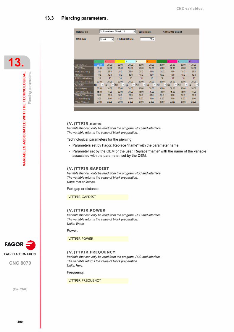
CNC variables.
CNC 8070
13.
VA
RIA
BL
ES
AS
SO
CIA
TE
D W
ITH
TH
E T
EC
HN
OL
OG
ICA
L
Pie
rcin
g pa
ram
eter
s.
ꞏ400ꞏ
(REF: 2102)
13.3 Piercing parameters.
(V.)TTPIR.nameVariable that can only be read from the program, PLC and interface.The variable returns the value of block preparation.
Technological parameters for the piercing.
• Parameters set by Fagor. Replace "name" with the parameter name.
• Parameter set by the OEM or the user. Replace "name" with the name of the variableassociated with the parameter, set by the OEM.
(V.)TTPIR.GAPDISTVariable that can only be read from the program, PLC and interface.The variable returns the value of block preparation.Units: mm or inches.
Part gap or distance.
(V.)TTPIR.POWERVariable that can only be read from the program, PLC and interface.The variable returns the value of block preparation.Units: Watts.
Power.
(V.)TTPIR.FREQUENCYVariable that can only be read from the program, PLC and interface.The variable returns the value of block preparation.Units: Herz.
Frequency.
V.TTPIR.GAPDIST
V.TTPIR.POWER
V.TTPIR.FREQUENCY

CNC variables.
CNC 8070
VA
RIA
BL
ES
AS
SO
CIA
TE
D W
ITH
TH
E T
EC
HN
OL
OG
ICA
L
13.
Pie
rcin
g pa
ram
eter
s.
ꞏ401ꞏ
(REF: 2102)
(V.)TTPIR.DUTYVariable that can only be read from the program, PLC and interface.The variable returns the value of block preparation.Units: Percentage.
Duty cycle.
(V.)TTPIR.PIERCINGTIMEVariable that can only be read from the program, PLC and interface.The variable returns the value of block preparation.Units: Milliseconds.
Piercing duration.
(V.)TTPIR.GASPRESSUREVariable that can only be read from the program, PLC and interface.The variable returns the value of block preparation.Units: Bar or psi.
Gas pressure.
(V.)TTPIR.GASTYPEVariable that can only be read from the program, PLC and interface.The variable returns the value of block preparation.Units: Value listed.
Type of gas.
Values of the variable.
(V.)TTPIR.GASTIMEVariable that can only be read from the program, PLC and interface.The variable returns the value of block preparation.Units: Milliseconds.
Dwell time after activating the gas.
(V.)TTPIR.NOZZLEDIAMVariable that can only be read from the program, PLC and interface.The variable returns the value of block preparation.Units: mm or inches.
Nozzle diameter.
V.TTPIR.DUTY
V.TTPIR.PIERCINGTIME
V.TTPIR.GASPRESSURE
V.TTPIR.GASTYPE
Value. Meaning.
10 N2.
20 O2.
30 Air.
V.TTPIR.GASTIME
V.TTPIR.NOZZLEDIAM

CNC variables.
CNC 8070
13.
VA
RIA
BL
ES
AS
SO
CIA
TE
D W
ITH
TH
E T
EC
HN
OL
OG
ICA
L
Pie
rcin
g pa
ram
eter
s.
ꞏ402ꞏ
(REF: 2102)
(V.)TTPIR.FEEDRATEVariable that can only be read from the program, PLC and interface.The variable returns the value of block preparation.Units: In millimeters/minute or inches/minute.
Work feedrate.
(V.)TTPIR.CUTRADIUSVariable that can only be read from the program, PLC and interface.The variable returns the value of block preparation.Units: mm or inches.
Laser radio.
(V.)TTPIR.FOCALPOSVariable that can only be read from the program, PLC and interface.The variable returns the value of block preparation.Units: mm or inches.
Laser focus position regarding the sheet surface. With a positive value, the focus is abovethe sheet; with a negative value, the focus is under or inside the sheet.
V.TTPIR.FEEDRATE
V.TTPIR.CUTRADIUS
V.TTPIR.FOCALPOS

CNC variables.
CNC 8070
VA
RIA
BL
ES
AS
SO
CIA
TE
D W
ITH
TH
E T
EC
HN
OL
OG
ICA
L
13.
Cut
ting
para
met
ers.
ꞏ403ꞏ
(REF: 2102)
13.4 Cutting parameters.
(V.)TTCUT.nameVariable that can only be read from the program, PLC and interface.The variable returns the value of block preparation.
Technological parameters for the cutting.
• Parameters set by Fagor. Replace "name" with the parameter name.
• Parameter set by the OEM or the user. Replace "name" with the name of the variableassociated with the parameter, set by the OEM.
(V.)TTCUT.GAPDISTVariable that can only be read from the program, PLC and interface.The variable returns the value of block preparation.Units: mm or inches.
Part gap or distance.
(V.)TTCUT.POWERVariable that can only be read from the program, PLC and interface.The variable returns the value of block preparation.Units: Watts.
Power.
(V.)TTCUT.FREQUENCYVariable that can only be read from the program, PLC and interface.The variable returns the value of block preparation.Units: Herz.
Frequency.
V.TTCUT.GAPDIST
V.TTCUT.POWER
V.TTCUT.FREQUENCY
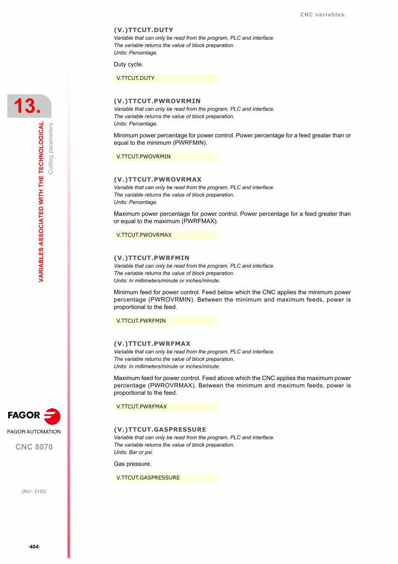
CNC variables.
CNC 8070
13.
VA
RIA
BL
ES
AS
SO
CIA
TE
D W
ITH
TH
E T
EC
HN
OL
OG
ICA
L
Cut
ting
para
met
ers.
ꞏ404ꞏ
(REF: 2102)
(V.)TTCUT.DUTYVariable that can only be read from the program, PLC and interface.The variable returns the value of block preparation.Units: Percentage.
Duty cycle.
(V.)TTCUT.PWROVRMINVariable that can only be read from the program, PLC and interface.The variable returns the value of block preparation.Units: Percentage.
Minimum power percentage for power control. Power percentage for a feed greater than orequal to the minimum (PWRFMIN).
(V.)TTCUT.PWROVRMAXVariable that can only be read from the program, PLC and interface.The variable returns the value of block preparation.Units: Percentage.
Maximum power percentage for power control. Power percentage for a feed greater thanor equal to the maximum (PWRFMAX).
(V.)TTCUT.PWRFMINVariable that can only be read from the program, PLC and interface.The variable returns the value of block preparation.Units: In millimeters/minute or inches/minute.
Minimum feed for power control. Feed below which the CNC applies the minimum powerpercentage (PWROVRMIN). Between the minimum and maximum feeds, power isproportional to the feed.
(V.)TTCUT.PWRFMAXVariable that can only be read from the program, PLC and interface.The variable returns the value of block preparation.Units: In millimeters/minute or inches/minute.
Maximum feed for power control. Feed above which the CNC applies the maximum powerpercentage (PWROVRMAX). Between the minimum and maximum feeds, power isproportional to the feed.
(V.)TTCUT.GASPRESSUREVariable that can only be read from the program, PLC and interface.The variable returns the value of block preparation.Units: Bar or psi.
Gas pressure.
V.TTCUT.DUTY
V.TTCUT.PWOVRMIN
V.TTCUT.PWOVRMAX
V.TTCUT.PWRFMIN
V.TTCUT.PWRFMAX
V.TTCUT.GASPRESSURE
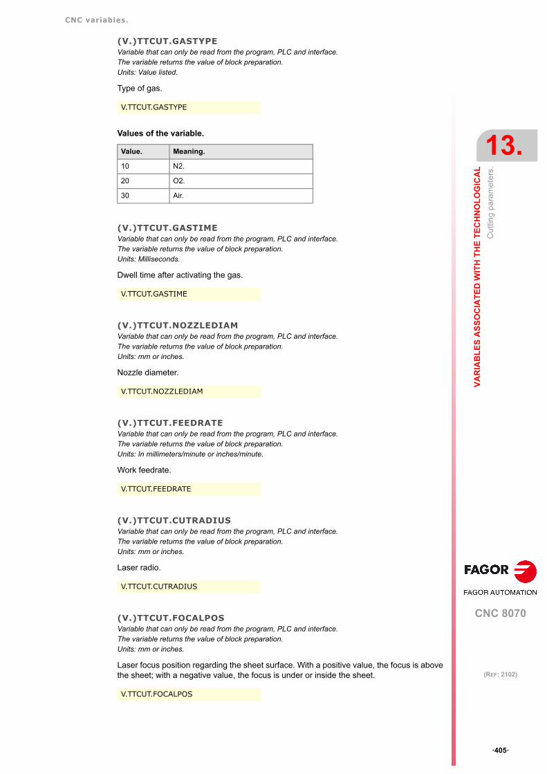
CNC variables.
CNC 8070
VA
RIA
BL
ES
AS
SO
CIA
TE
D W
ITH
TH
E T
EC
HN
OL
OG
ICA
L
13.
Cut
ting
para
met
ers.
ꞏ405ꞏ
(REF: 2102)
(V.)TTCUT.GASTYPEVariable that can only be read from the program, PLC and interface.The variable returns the value of block preparation.Units: Value listed.
Type of gas.
Values of the variable.
(V.)TTCUT.GASTIMEVariable that can only be read from the program, PLC and interface.The variable returns the value of block preparation.Units: Milliseconds.
Dwell time after activating the gas.
(V.)TTCUT.NOZZLEDIAMVariable that can only be read from the program, PLC and interface.The variable returns the value of block preparation.Units: mm or inches.
Nozzle diameter.
(V.)TTCUT.FEEDRATEVariable that can only be read from the program, PLC and interface.The variable returns the value of block preparation.Units: In millimeters/minute or inches/minute.
Work feedrate.
(V.)TTCUT.CUTRADIUSVariable that can only be read from the program, PLC and interface.The variable returns the value of block preparation.Units: mm or inches.
Laser radio.
(V.)TTCUT.FOCALPOSVariable that can only be read from the program, PLC and interface.The variable returns the value of block preparation.Units: mm or inches.
Laser focus position regarding the sheet surface. With a positive value, the focus is abovethe sheet; with a negative value, the focus is under or inside the sheet.
V.TTCUT.GASTYPE
Value. Meaning.
10 N2.
20 O2.
30 Air.
V.TTCUT.GASTIME
V.TTCUT.NOZZLEDIAM
V.TTCUT.FEEDRATE
V.TTCUT.CUTRADIUS
V.TTCUT.FOCALPOS

CNC variables.
CNC 8070
13.
VA
RIA
BL
ES
AS
SO
CIA
TE
D W
ITH
TH
E T
EC
HN
OL
OG
ICA
L
Cut
ting
para
met
ers.
ꞏ406ꞏ
(REF: 2102)

CNC 8070
14
ꞏ407ꞏ
(REF: 2102)
14.VARIABLES RELATED TO THE POSITION OF THE AXES.
There are real and theoretical coordinates corresponding to the tool base and tool tip. Allof them may be referred to Machine Zero or to the current Part Zero.
A theoretical coordinate is the position that the axis must occupy at all times, a real coordinateis the one it actually occupies and the difference between these two is called "following error".
14.1 Programmed coordinates.
(V.)[ch].A.PPOS.xnVariable that can only be read from the program, PLC and interface.Variable valid for rotary and linear axes.The variable returns the value of block preparation.
Channel [ch]. Programmed part coordinates (tool tip).
Syntax.
ꞏchꞏ Channel number.
ꞏxnꞏ Name, logic number or index of the axis.
Remarks.
This variable returns the target coordinate, in part coordinates and referred to the tool tip,in the current reference system; i.e. taking into consideration the coordinate rotation, scalingfactor, active inclined plane, etc.
The values read from a program or from the PLC and the interface will be different when thecoordinate is affected by tool compensation or when machining in round corner mode. Thevalue read by program will be the programmed coordinate whereas the value read from thePLC or interface will be the real (actual) coordinate considering tool radius compensationand corner rounding.
V.A.PPOS.Z Z axis.
V.A.PPOS.3 Axis with logic number ꞏ3ꞏ.
V.[2].A.PPOS.3 Axis with index ꞏ3ꞏ in the channel ꞏ2ꞏ.
Programmed movements. Returned values.
G1 X10 V.A.PPOS.X = 10
#SCALE [2]G1 X10
Scaling factor of ꞏ2ꞏ.V.A.PPOS.X = 20
G73 Q90G1 X10
Coordinate system rotation.V.A.PPOS.Y = 20 The Y axis is the one that moves

CNC variables.
CNC 8070
14.
VA
RIA
BL
ES
RE
LA
TE
D T
O T
HE
PO
SIT
ION
OF
TH
E A
XE
S.
Pro
gram
med
coo
rdin
ates
.
ꞏ408ꞏ
(REF: 2102)
(V.)[ch].G.PLPPOS1Variable that can only be read from the program, PLC and interface.Variable valid for rotary and linear axes.The variable returns the value of block preparation.
Channel [ch]. Coordinate programmed in the first axis of the channel (tool tip).
Syntax.
ꞏchꞏ Channel number.
(V.)[ch].G.PLPPOS2Variable that can only be read from the program, PLC and interface.Variable valid for rotary and linear axes.The variable returns the value of block preparation.
Channel [ch]. Coordinate programmed in the second axis of the channel (tool tip).
Syntax.
ꞏchꞏ Channel number.
(V.)[ch].G.PLPPOS3Variable that can only be read from the program, PLC and interface.Variable valid for rotary and linear axes.The variable returns the value of block preparation.
Channel [ch]. Coordinate programmed in the third axis of the channel (tool tip).
Syntax.
ꞏchꞏ Channel number.
V.[2].G.PLPPOS1 Channel ꞏ2ꞏ.
V.[2].G.PLPPOS2 Channel ꞏ2ꞏ.
V.[2].G.PLPPOS3 Channel ꞏ2ꞏ.

CNC variables.
CNC 8070
VA
RIA
BL
ES
RE
LA
TE
D T
O T
HE
PO
SIT
ION
OF
TH
E A
XE
S.
14.
Po
sitio
n in
pa
rt c
oord
inat
es.
ꞏ409ꞏ
(REF: 2102)
14.2 Position in part coordinates.
(V.)[ch].A.APOS.xnVariable that can only be read from the program, PLC and interface.Variable valid for rotary and linear axes.The variable returns the execution value; reading it interrupts block preparation.
Channel [ch]. Real part coordinates of the tool base.
Syntax.
ꞏchꞏ Channel number.
ꞏxnꞏ Name, logic number or index of the axis.
(V.)[ch].A.ATPOS.xnVariable that can only be read from the program, PLC and interface.Variable valid for rotary and linear axes.The variable returns the execution value; reading it interrupts block preparation.
Channel [ch]. Theoretical part coordinates of the tool base.
Syntax.
ꞏchꞏ Channel number.
ꞏxnꞏ Name, logic number or index of the axis.
(V.)[ch].A.ATIPPOS.xnVariable that can only be read from the program, PLC and interface.Variable valid for rotary and linear axes.The variable returns the execution value; reading it interrupts block preparation.
Channel [ch]. Real part coordinates of the tool tip.
Syntax.
ꞏchꞏ Channel number.
ꞏxnꞏ Name, logic number or index of the axis.
(V.)[ch].A.ATIPTPOS.xnVariable that can only be read from the program, PLC and interface.Variable valid for rotary and linear axes.The variable returns the execution value; reading it interrupts block preparation.
Channel [ch]. Theoretical part coordinates of the tool tip.
Syntax.
ꞏchꞏ Channel number.
V.A.APOS.Z Z axis.
V.A.APOS.3 Axis with logic number ꞏ3ꞏ.
V.[2].A.APOS.3 Axis with index ꞏ3ꞏ in the channel ꞏ2ꞏ.
V.A.ATPOS.Z Z axis.
V.A.ATPOS.3 Axis with logic number ꞏ3ꞏ.
V.[2].A.ATPOS.3 Axis with index ꞏ3ꞏ in the channel ꞏ2ꞏ.
V.A.ATIPPOS.Z Z axis.
V.A.ATIPPOS.3 Axis with logic number ꞏ3ꞏ.
V.[2].A.ATIPPOS.3 Axis with index ꞏ3ꞏ in the channel ꞏ2ꞏ.

CNC variables.
CNC 8070
14.
VA
RIA
BL
ES
RE
LA
TE
D T
O T
HE
PO
SIT
ION
OF
TH
E A
XE
S.
Po
sitio
n in
pa
rt c
oord
inat
es.
ꞏ410ꞏ
(REF: 2102)
ꞏxnꞏ Name, logic number or index of the axis.
V.A.ATIPTPOS.Z Z axis.
V.A.ATIPTPOS.3 Axis with logic number ꞏ3ꞏ.
V.[2].A.ATIPTPOS.3 Axis with index ꞏ3ꞏ in the channel ꞏ2ꞏ.

CNC variables.
CNC 8070
VA
RIA
BL
ES
RE
LA
TE
D T
O T
HE
PO
SIT
ION
OF
TH
E A
XE
S.
14.
Po
sitio
n in
mac
hine
coo
rdin
ates
.
ꞏ411ꞏ
(REF: 2102)
14.3 Position in machine coordinates.
(V.)[ch].A.POS.xnVariable that can only be read from the program, PLC and interface.Variable valid for rotary and linear axes.The variable returns the execution value; reading it interrupts block preparation.
Channel [ch]. Real machine coordinates of the tool base.
Syntax.
ꞏchꞏ Channel number.
ꞏxnꞏ Name, logic number or index of the axis.
(V.)[ch].A.TPOS.xnVariable that can only be read from the program, PLC and interface.Variable valid for rotary and linear axes.The variable returns the execution value; reading it interrupts block preparation.
Channel [ch]. Theoretical machine coordinates of the tool base.
Syntax.
ꞏchꞏ Channel number.
ꞏxnꞏ Name, logic number or index of the axis.
(V.)[ch].A.TIPPOS.xnVariable that can only be read from the program, PLC and interface.Variable valid for rotary and linear axes.The variable returns the execution value; reading it interrupts block preparation.
Channel [ch]. Real machine coordinates of the tool tip.
Syntax.
ꞏchꞏ Channel number.
ꞏxnꞏ Name, logic number or index of the axis.
(V.)[ch].A.TIPTPOS.xnVariable that can only be read from the program, PLC and interface.Variable valid for rotary and linear axes.The variable returns the execution value; reading it interrupts block preparation.
Channel [ch]. Theoretical machine coordinates of the tool tip.
Syntax.
ꞏchꞏ Channel number.
V.A.POS.Z Z axis.
V.A.POS.3 Axis with logic number ꞏ3ꞏ.
V.[2].A.POS.3 Axis with index ꞏ3ꞏ in the channel ꞏ2ꞏ.
V.A.TPOS.Z Z axis.
V.A.TPOS.3 Axis with logic number ꞏ3ꞏ.
V.[2].A.TPOS.3 Axis with index ꞏ3ꞏ in the channel ꞏ2ꞏ.
V.A.TIPPOS.Z Z axis.
V.A.TIPPOS.3 Axis with logic number ꞏ3ꞏ.
V.[2].A.TIPPOS.3 Axis with index ꞏ3ꞏ in the channel ꞏ2ꞏ.

CNC variables.
CNC 8070
14.
VA
RIA
BL
ES
RE
LA
TE
D T
O T
HE
PO
SIT
ION
OF
TH
E A
XE
S.
Po
sitio
n in
mac
hine
coo
rdin
ates
.
ꞏ412ꞏ
(REF: 2102)
ꞏxnꞏ Name, logic number or index of the axis.
V.A.TIPTPOS.Z Z axis.
V.A.TIPTPOS.3 Axis with logic number ꞏ3ꞏ.
V.[2].A.TIPTPOS.3 Axis with index ꞏ3ꞏ in the channel ꞏ2ꞏ.

CNC variables.
CNC 8070
VA
RIA
BL
ES
RE
LA
TE
D T
O T
HE
PO
SIT
ION
OF
TH
E A
XE
S.
14.
Pos
ition
rea
d in
the
inte
rna
l fee
dbac
k (m
otor
feed
back
).
ꞏ413ꞏ
(REF: 2102)
14.4 Position read in the internal feedback (motor feedback).
(V.)[ch].A.POSMOTOR.xnVariable that can only be read from the program, PLC and interface.Variable valid for rotary and linear axes.The variable returns the execution value; reading it interrupts block preparation.
Channel [ch]. Value of the internal feedback (motor feedback).
When the combined feedback is active (parameter FBMIXTIME), the variable returns thevalue of the internal feedback (motor feedback). If there is no feedback combination, thevalue of the variable coincides with (V.)[ch].A.POS.xn.
Syntax.
ꞏchꞏ Channel number.
ꞏxnꞏ Name, logic number or index of the axis.
V.A.POSMOTOR.Z Z axis.
V.A.POSMOTOR.3 Axis with logic number ꞏ3ꞏ.
V.[2].A.POSMOTOR.3 Axis with index ꞏ3ꞏ in the channel ꞏ2ꞏ.

CNC variables.
CNC 8070
14.
VA
RIA
BL
ES
RE
LA
TE
D T
O T
HE
PO
SIT
ION
OF
TH
E A
XE
S.
Fol
low
ing
erro
r o
f the
axi
s.
ꞏ414ꞏ
(REF: 2102)
14.5 Following error of the axis.
(V.)[ch].A.FLWE.xnVariable that can only be read from the program, PLC and interface.Variable valid for rotary and linear axes.The variable returns the execution value; reading it interrupts block preparation.
Channel [ch]. Following error, lag (difference between the theoretical position value and theactual, real, position value of the axis).
If there is no feedback combination, the CNC reads the actual (real) position from either theinternal or the external feedback (parameter FBACKSRC). If feedback combination is active(parameter FBMIXTIME), the CNC calculates the following error (lag) using the combinedfeedback.
Syntax.
ꞏchꞏ Channel number.
ꞏxnꞏ Name, logic number or index of the axis.
(V.)[ch].A.FLWACT.xnVariable that can only be read from the program, PLC and interface.Variable valid for rotary and linear axes.The variable returns the execution value; reading it interrupts block preparation.
Channel [ch]. Following error (lag) with respect to the external feedback (direct feedback).
When the combined feedback is active (parameter FBMIXTIME), the variable returns thefollowing error (axis lag) with respect to the external feedback (direct feedback). If there isno feedback combination, the variable returns the following error (lag) with respect to theactive feedback (parameter FBACKSRC), same as the variable "(V.)[ch].A.FLWE.xn".
Syntax.
ꞏchꞏ Channel number.
ꞏxnꞏ Name, logic number or index of the axis.
(V.)[ch].A.FLWEST.xnVariable that can only be read from the program, PLC and interface.Variable valid for rotary and linear axes.The variable returns the execution value; reading it interrupts block preparation.
Channel [ch]. Linear estimate of the following error (lag).
Syntax.
ꞏchꞏ Channel number.
V.A.FLWE.Z Z axis.
V.A.FLWE.3 Axis with logic number ꞏ3ꞏ.
V.[2].A.FLWE.3 Axis with index ꞏ3ꞏ in the channel ꞏ2ꞏ.
Active feedback. V.A.FLWE.xn V.A.FLWACT.xn
Internal Following error (lag) with respect to the internal feedback (motorfeedback).
External Following error (lag) with respect to the external feedback (directfeedback).
Feedback combination. Following error (lag) with respect tothe combined feedback.
Following error (lag) with respect tothe external feedback.
V.A.FLWACT.Z Z axis.
V.A.FLWACT.3 Axis with logic number ꞏ3ꞏ.
V.[2].A.FLWACT.3 Axis with index ꞏ3ꞏ in the channel ꞏ2ꞏ.

CNC variables.
CNC 8070
VA
RIA
BL
ES
RE
LA
TE
D T
O T
HE
PO
SIT
ION
OF
TH
E A
XE
S.
14.
Fol
low
ing
erro
r o
f the
axi
s.
ꞏ415ꞏ
(REF: 2102)
ꞏxnꞏ Name, logic number or index of the axis.
V.A.FLWE.Z Z axis.
V.A.FLWE.3 Axis with logic number ꞏ3ꞏ.
V.[2].A.FLWE.3 Axis with index ꞏ3ꞏ in the channel ꞏ2ꞏ.

CNC variables.
CNC 8070
14.
VA
RIA
BL
ES
RE
LA
TE
D T
O T
HE
PO
SIT
ION
OF
TH
E A
XE
S.
Dis
tanc
e le
ft (t
o g
o) f
or t
he a
xis
to re
ach
the
pro
gram
med
coo
rdin
ate.
ꞏ416ꞏ
(REF: 2102)
14.6 Distance left (to go) for the axis to reach the programmedcoordinate.
(V.)[ch].A.TOGO.xnVariable that can only be read from the PLC and interface.Variable valid for rotary and linear axes.
Channel [ch]. Distance left (to go) for the axis to reach the programmed coordinate.
Syntax.
ꞏchꞏ Channel number.
ꞏxnꞏ Name, logic number or index of the axis.
V.A.TOGO.Z Z axis.
V.A.TOGO.3 Axis with logic number ꞏ3ꞏ.
V.[2].A.TOGO.3 Axis with index ꞏ3ꞏ in the channel ꞏ2ꞏ.

CNC 8070
15
ꞏ417ꞏ
(REF: 2102)
15.VARIABLES RELATED TO SPINDLE POSITION.
The following are used when the spindle is working in closed loop, it behaves like an axis.A theoretical coordinate is the position that the spindle must occupy at all times, a realcoordinate is the one it actually occupies and the difference between these two is called"following error".
15.1 Spindle position.
(V.)[ch].A.PPOS.sn(V.)[ch].SP.PPOS.snVariable that can only be read from the program, PLC and interface.The variable returns the value of block preparation.
Channel [ch]. Programmed spindle position.
Syntax.
ꞏchꞏ Channel number.
ꞏsnꞏ Name, logic number or index of the spindle.
(V.)[ch].A.POS.sn(V.)[ch].SP.POS.snVariable that can only be read from the program, PLC and interface.The variable returns the execution value; reading it interrupts block preparation.
Channel [ch]. Real spindle position.
Syntax.
ꞏchꞏ Channel number.
ꞏsnꞏ Name, logic number or index of the spindle.
V.A.PPOS.S Spindle S.
V.SP.PPOS.S Spindle S.
V.SP.PPOS Master spindle.
V.A.PPOS.5 Spindle with logic number ꞏ5ꞏ.
V.SP.PPOS.2 Spindle with index ꞏ2ꞏ in the system.
V.[2].SP.PPOS.1 Spindle with index ꞏ1ꞏ in the channel ꞏ2ꞏ.
V.A.POS.S Spindle S.
V.SP.POS.S Spindle S.
V.SP.POS Master spindle.
V.A.POS.5 Spindle with logic number ꞏ5ꞏ.
V.SP.POS.2 Spindle with index ꞏ2ꞏ in the system.
V.[2].SP.POS.1 Spindle with index ꞏ1ꞏ in the channel ꞏ2ꞏ.
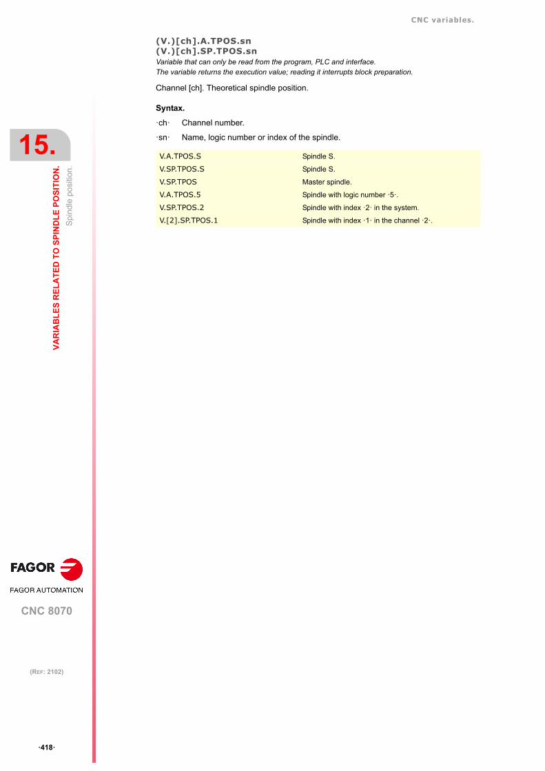
CNC variables.
CNC 8070
15.
VA
RIA
BL
ES
RE
LA
TE
D T
O S
PIN
DL
E P
OS
ITIO
N.
Spi
ndle
po
sitio
n.
ꞏ418ꞏ
(REF: 2102)
(V.)[ch].A.TPOS.sn(V.)[ch].SP.TPOS.snVariable that can only be read from the program, PLC and interface.The variable returns the execution value; reading it interrupts block preparation.
Channel [ch]. Theoretical spindle position.
Syntax.
ꞏchꞏ Channel number.
ꞏsnꞏ Name, logic number or index of the spindle.
V.A.TPOS.S Spindle S.
V.SP.TPOS.S Spindle S.
V.SP.TPOS Master spindle.
V.A.TPOS.5 Spindle with logic number ꞏ5ꞏ.
V.SP.TPOS.2 Spindle with index ꞏ2ꞏ in the system.
V.[2].SP.TPOS.1 Spindle with index ꞏ1ꞏ in the channel ꞏ2ꞏ.

CNC variables.
CNC 8070
VA
RIA
BL
ES
RE
LA
TE
D T
O S
PIN
DL
E P
OS
ITIO
N.
15.
Sp
indl
e fo
llow
ing
erro
r.
ꞏ419ꞏ
(REF: 2102)
15.2 Spindle following error.
(V.)[ch].A.FLWE.sn(V.)[ch].SP.FLWE.snVariable that can only be read from the program, PLC and interface.The variable returns the execution value; reading it interrupts block preparation.
Channel [ch]. Spindle following error.
Syntax.
ꞏchꞏ Channel number.
ꞏsnꞏ Name, logic number or index of the spindle.
(V.)[ch].A.FLWEST.sn(V.)[ch].SP.FLWEST.snVariable that can only be read from the program, PLC and interface.The variable returns the execution value; reading it interrupts block preparation.
Channel [ch]. Linear estimate of the spindle following error (lag).
Syntax.
ꞏchꞏ Channel number.
ꞏsnꞏ Name, logic number or index of the spindle.
V.A.FLWE.S Spindle S.
V.SP.FLWE.S Spindle S.
V.SP.FLWE Master spindle.
V.A.FLWE.5 Spindle with logic number ꞏ5ꞏ.
V.SP.FLWE.2 Spindle with index ꞏ2ꞏ in the system.
V.[2].SP.FLWE.1 Spindle with index ꞏ1ꞏ in the channel ꞏ2ꞏ.
V.A.FLWEST.S Spindle S.
V.SP.FLWEST.S Spindle S.
V.SP.FLWEST.S Master spindle.
V.A.FLWEST.5 Spindle with logic number ꞏ5ꞏ.
V.SP.FLWEST.2 Spindle with index ꞏ2ꞏ in the system.
V.[2].SP.FLWEST.1 Spindle with index ꞏ1ꞏ in the channel ꞏ2ꞏ.

CNC variables.
CNC 8070
15.
VA
RIA
BL
ES
RE
LA
TE
D T
O S
PIN
DL
E P
OS
ITIO
N.
Sp
indl
e fo
llow
ing
erro
r.
ꞏ420ꞏ
(REF: 2102)

CNC 8070
16
ꞏ421ꞏ
(REF: 2102)
16.FEEDRATE RELATED VARIABLES.
16.1 Feedrate active in the channel.
(V.)[ch].G.FREALVariable that can only be read from the program, PLC and interface.The variable returns the execution value; reading it interrupts block preparation.
Channel [ch]. Real filtered feedrate on the tool path.
Syntax.
ꞏchꞏ Channel number.
Remarks.
This variable takes into account the accelerations and decelerations of the machine. Whenthe axes are stopped, it returns a value of ꞏ0ꞏ and when moving it returns the valuecorresponding to the feedrate in mm (inches) per minute. On laser cutting machines, it isrecommended to use this variable so the laser power is proportional to the feedrate.
Use the oscilloscope to compare the real and theoretical feedrates along the path and detectadjustment problems when both are different at specific points. Also, using variablesV.G.LINEN and V.G.BLKN, it is possible to associate these feedrate changes with theprogram blocks or lines where they occur.
(V.)[ch].G.FREALPRVariable that can only be read from the program, PLC and interface.The variable returns the execution value; reading it interrupts block preparation.
Channel [ch]. Actual (real) CNC feedrate in G95.
Syntax.
ꞏchꞏ Channel number.
Remarks.
This variable takes into account the accelerations and decelerations of the machine. Whenthe axes are stopped, it returns a value of ꞏ0ꞏ and when moving it returns the valuecorresponding to the feedrate in mm (inches) per turn.
(V.)[ch].G.PATHFEEDVariable that can only be read from the program, PLC and interface.The variable returns the execution value; reading it interrupts block preparation.
Channel [ch]. Theoretical feedrate on the tool path.
Syntax.
ꞏchꞏ Channel number.
V.[2].G.FREAL Channel ꞏ2ꞏ.
V.[2].G.FREALPR Channel ꞏ2ꞏ.
V.[2].G.PATHFEED Channel ꞏ2ꞏ.

CNC variables.
CNC 8070
16.
FE
ED
RA
TE
RE
LA
TE
D V
AR
IAB
LE
S.
Fee
drat
e ac
tive
in th
e ch
ann
el.
ꞏ422ꞏ
(REF: 2102)
Remarks.
Use the oscilloscope to compare the real and theoretical feedrates along the path and detectadjustment problems when both are different at specific points. Also, using variablesV.G.LINEN and V.G.BLKN, it is possible to associate these feedrate changes with theprogram blocks or lines where they occur.
(V.)[ch].G.ACTFEEDVariable that can only be read from the program, PLC and interface.The variable returns the execution value; reading it interrupts block preparation.
Channel [ch]. Real feedrate on the tool path.
Syntax.
ꞏchꞏ Channel number.
Remarks.
This variable takes into account the accelerations and decelerations of the machine. Whenthe axes are stopped, it returns a value of ꞏ0ꞏ and when moving it returns the valuecorresponding to the feedrate type G94/G95. On laser cutting machines, it is recommendedto use this variable so the laser power is proportional to the feedrate.
Use the oscilloscope to compare the real and theoretical feedrates along the path and detectadjustment problems when both are different at specific points. Also, using variablesV.G.LINEN and V.G.BLKN, it is possible to associate these feedrate changes with theprogram blocks or lines where they occur.
(V.)[ch].PLC.G00FEEDVariable that can be read and written from the PLC and read from the program and from the interface.The variable returns the execution value; reading it interrupts block preparation.
Channel [ch]. Maximum feedrate permitted in the channel.
This variable may be used to limit any time, in real time, the maximum feedrate in the channelfor any type of movement (G00, G01, etc). The CNC assumes the change immediately andstays active until the variable takes a value of ꞏ0ꞏ restoring the limit set by machine parameter.
Syntax.
ꞏchꞏ Channel number.
Remarks.
Regardless of the value assigned to this variable, the feedrate will never exceed the limitsset by parameters G00FEED and MAXFEED.
V.[2].G.ACTFEED Channel ꞏ2ꞏ.
V.[2].PLC.G00FEED Channel ꞏ2ꞏ.
Variable. Machine parameters. Feedrate active in the channel.
(V.)[ch].PLC.G00FEED G00FEED MAXFEED G00 G01, G02, ꞏꞏꞏ
3000 10000 5000 3000 3000
7000 10000 5000 7000 5000
12000 10000 5000 10000 5000

CNC variables.
CNC 8070
FE
ED
RA
TE
RE
LA
TE
D V
AR
IAB
LE
S.
16.
Fee
drat
e ac
tive
in th
e bl
ock.
ꞏ423ꞏ
(REF: 2102)
16.2 Feedrate active in the block.
(V.)[ch].G.IPOFEEDVariable that can only be read from the program, PLC and interface.The variable returns the execution value; reading it interrupts block preparation.
Channel [ch]. Feedrate active in the block.
Syntax.
ꞏchꞏ Channel number.
V.[2].G.IPOFEED Channel ꞏ2ꞏ.

CNC variables.
CNC 8070
16.
FE
ED
RA
TE
RE
LA
TE
D V
AR
IAB
LE
S.
Pro
gra
mm
ing
the
feed
rate
in G
94.
ꞏ424ꞏ
(REF: 2102)
16.3 Programming the feedrate in G94.
(V.)[ch].G.FEEDVariable that can only be read from the program, PLC and interface.The variable returns the execution value; reading it interrupts block preparation.
Channel [ch]. Feedrate active in G94.
Syntax.
ꞏchꞏ Channel number.
Remarks.
The feedrate in G94 may be set by program or by PLC; the one set by PLC has the highestpriority.
(V.)[ch].PLC.FVariable that can be read and written from the PLC and read from the program and from the interface.The variable returns the execution value; reading it interrupts block preparation.
Channel [ch]. Feedrate by PLC in G94.
The feedrate programmed by PLC prevails over the one programmed by program or MDI.To cancel the feedrate by PLC, set the variable to ꞏ0ꞏ; the CNC applies the feedrate activeby program.
Syntax.
ꞏchꞏ Channel number.
(V.)[ch].G.PRGFVariable that can only be read from the program, PLC and interface.The variable returns the value of block preparation.
Channel [ch]. Feedrate by program in G94.
Being G94 active, programming a new feedrate in MDI mode updates the value of thisvariable.
Syntax.
ꞏchꞏ Channel number.
V.[2].G.FEED Channel ꞏ2ꞏ.
Feedrates set. (V.)[ch].PLC.F (V.)[ch].G.PRGF (V.)[ch].G.FEED
By program; F2000.By PLC; none.
0 2000 2000
By program; F2000.By PLC; F4000.
4000 2000 4000
By program; F2000.By PLC; F500.
500 2000 500
By program; F2000.By PLC; none.By MDI; F3000.
0 3000 3000
By program; F2000.By PLC; F6000.By MDI; F3000.
6000 3000 6000
By program; F2000.By PLC; F500.By MDI; F3000.
500 3000 500
V.[2].PLC.F Channel ꞏ2ꞏ.
V.[2].G.PRGF Channel ꞏ2ꞏ.

CNC variables.
CNC 8070
FE
ED
RA
TE
RE
LA
TE
D V
AR
IAB
LE
S.
16.
Pro
gra
mm
ing
the
feed
rate
in G
95.
ꞏ425ꞏ
(REF: 2102)
16.4 Programming the feedrate in G95.
(V.)[ch].G.FPREVVariable that can only be read from the program, PLC and interface.The variable returns the execution value; reading it interrupts block preparation.
Channel [ch]. Feedrate active in G95.
Syntax.
ꞏchꞏ Channel number.
Remarks.
The feedrate in G95 may be set by program or by PLC; the one set by PLC has the highestpriority.
(V.)[ch].PLC.FPRVariable that can be read and written from the PLC and read from the program and from the interface.The variable returns the execution value; reading it interrupts block preparation.
Channel [ch]. Feedrate by PLC in G95.
The feedrate programmed by PLC prevails over the one programmed by program or MDI.To cancel the feedrate by PLC, set the variable to ꞏ0ꞏ; the CNC applies the feedrate activeby program.
Syntax.
ꞏchꞏ Channel number.
(V.)[ch].G.PRGFPRVariable that can only be read from the program, PLC and interface.The variable returns the value of block preparation.
Channel [ch]. Feedrate by program in G95.
Being G95 active, programming a new feedrate in MDI mode updates the value of thisvariable.
Syntax.
ꞏchꞏ Channel number.
V.[2].G.FPREV Channel ꞏ2ꞏ.
Feedrates set. (V.)[ch].PLC.FPR (V.)[ch].G.PRGFPR (V.)[ch].G.FPREV
By program; F0.5.By PLC; none.
0 0.5 0.5
By program; F0.5.By PLC; F0.7.
0.7 0.5 0.7
By program; F0.5.By PLC; F0.12.
0.12 0.5 0.12
By program; F0.5.By PLC; none.By MDI; F1.8.
0 1.8 1.8
By program; F0.5.By PLC; F2.5.By MDI; F1.8.
2.5 1.8 2.5
By program; F0.5.By PLC; F0.7.By MDI; F1.8.
0.7 1.8 0.7
V.[2].PLC.FPR Channel ꞏ2ꞏ.
V.[2].G.PRGFPR Channel ꞏ2ꞏ.

CNC variables.
CNC 8070
16.
FE
ED
RA
TE
RE
LA
TE
D V
AR
IAB
LE
S.
Pro
gram
min
g th
e m
achi
nin
g ti
me.
ꞏ426ꞏ
(REF: 2102)
16.5 Programming the machining time.
(V.)[ch].G.FTIMEVariable that can only be read from the program, PLC and interface.The variable returns the value of block preparation.
Channel [ch]. Machining time in G93 (in seconds).
Syntax.
ꞏchꞏ Channel number.
V.[2].G.FTIME Channel ꞏ2ꞏ.

CNC variables.
CNC 8070
FE
ED
RA
TE
RE
LA
TE
D V
AR
IAB
LE
S.
16.
Pe
rcen
tage
of f
eed
rate
(fe
edra
te o
verr
ide)
.
ꞏ427ꞏ
(REF: 2102)
16.6 Percentage of feedrate (feedrate override).
(V.)[ch].G.FROVariable that can only be read from the program, PLC and interface.The variable returns the execution value; reading it interrupts block preparation.Report variable (to be used from the scripts).
Channel [ch]. Active feedrate (feed override) percentage.
Syntax.
ꞏchꞏ Channel number.
Remarks.
The Feedrate override percentage may be set by program, by PLC or with the selector switch;the one set by program has the highest priority and the one selected with the switch thelowest.
(V.)[ch].G.PRGFROVariable that can be read and written from the program and read from the PLC and from the interface.The variable returns the value of block preparation.
Channel [ch]. Feedrate (feed override) percentage defined by the program.
This variable makes it possible to set a feedrate percentage from the program; to cancel it,define the variable with a value of 0 (zero).
Syntax.
ꞏchꞏ Channel number.
Remarks.
• The percentage set by program has higher priority than the one set by PLC or by theswitch.
• The percentage set by program inhibits DMC, but it does not deactivate it; if thepercentage set by program is canceled, DMC takes back control over the feedratepercentage.
V.[2].G.FRO Channel ꞏ2ꞏ.
(V.)[ch].G.PRGFRO (V.)[ch].PLC.FRO (V.)[ch].G.CNCFRO (V.)[ch].G.FRO
0 0 70 % 70 %
0 40 % 70 % 40 %
85 % 40 % 70 % 85 %
20 % 90 % 70 % 20 %
20 % 0 70 % 20 %
V.[2].G.PRGFRO Channel ꞏ2ꞏ.

CNC variables.
CNC 8070
16.
FE
ED
RA
TE
RE
LA
TE
D V
AR
IAB
LE
S.
Pe
rcen
tage
of f
eed
rate
(fe
edra
te o
verr
ide)
.
ꞏ428ꞏ
(REF: 2102)
(V.)[ch].PLC.FROVariable that can be read and written from the PLC and read from the program and from the interface.The variable returns the execution value; reading it interrupts block preparation.
Channel [ch]. Feedrate (feed override) percentage defined by the PLC.
This variable makes it possible to set a feedrate percentage from the PLC; to cancel it, definethe variable with a value of 0 (zero). To set a 0 % value set by PLC, set the variable to -1.
Syntax.
ꞏchꞏ Channel number.
Remarks.
• The percentage set by PLC has higher priority than the one set by the switch, but lowerpriority than the one set by program..
• The percentage set by PLC inhibits DMC, but does not deactivate it; if the percentageset by PLC is canceled, DMC takes back control over the feedrate percentage.
(V.)[ch].G.CNCFROVariable that can be read and written (asynchronous writing) from the interface and read from theprogram and from the PLC.The variable returns the execution value; reading it interrupts block preparation.
Channel [ch]. Feedrate percentage (feed override) selected on the switch of the operatorpanel.
Syntax.
ꞏchꞏ Channel number.
Remarks.
• The percentage set by the switch of the operator panel has lower priority than the oneset by PLC or by program.
• When DMC is active, the percentage set by DMC affects the percentage set from theswitch.
V.[2].PLC.FRO Channel ꞏ2ꞏ.
V.[2].G.CNCFRO Channel ꞏ2ꞏ.
Override % OverrideDMC % OverrideJOG % 100
-----------------------------------------------------------------------------------------------------=

CNC variables.
CNC 8070
FE
ED
RA
TE
RE
LA
TE
D V
AR
IAB
LE
S.
16.
Pe
rce
ntag
e of
feed
rate
in G
00.
ꞏ429ꞏ
(REF: 2102)
16.7 Percentage of feedrate in G00.
(V.)[ch].PLC.G00FROVariable that can be read and written from the PLC and read from the program and from the interface.The variable returns the execution value; reading it interrupts block preparation.
Channel [ch]. Feedrate (feed override) percentage defined by the PLC for a G00.
This variable makes it possible to set a feedrate percentage from the PLC for movementsin G00; to cancel it, define the variable with a value of 0 (zero). To set a 0 % value set byPLC, set the variable to -1.
Syntax.
ꞏchꞏ Channel number.
V.[2].PLC.G00FRO Channel ꞏ2ꞏ.

CNC variables.
CNC 8070
16.
FE
ED
RA
TE
RE
LA
TE
D V
AR
IAB
LE
S.
Pe
rce
ntag
e of
feed
rate
in G
00.
ꞏ430ꞏ
(REF: 2102)
CNC 8070
17
ꞏ431ꞏ
(REF: 2102)
17.VARIABLES ASSOCIATED WITH ACCELERATION AND JERK ON THE TOOL PATH.
17.1 Acceleration on the tool path.
(V.)[ch].G.MAXACCELVariable that can be read and written via program, PLC and interface.The variable returns the execution value; reading it interrupts block preparation.
Channel [ch]. Modify the maximum acceleration allowed on the machining path.
The maximum acceleration allowed on the machining path is set by parameter MAXACCELand this variable may be used to change this value temporarily at a particular time and inreal time. The CNC assumes the change immediately and stays active until M30 or resetis executed, in which case the CNC restores the value set by the machine parameter. If thevariable takes the value of ꞏ0ꞏ, the CNC does not apply any acceleration limit on the tool path,not even the one set by machine parameter.
The CNC always respects the dynamics of the axes involved in the path; i.e. regardless ofthe maximum acceleration allowed on the path, the movement will respect the accelerationset for each axis.
Syntax.
ꞏchꞏ Channel number.
17.2 Jerk on the tool path.
(V.)[ch].G.MAXJERKVariable that can be read and written via program, PLC and interface.The variable returns the execution value; reading it interrupts block preparation.
Channel [ch]. Modify the maximum jerk on the machining path.
The maximum jerk allowed on the machining path is set by parameter MAXJERK and thisvariable may be used to change this value temporarily at a particular time and in real time.The CNC assumes the change immediately and stays active until M30 or reset is executed,in which case the CNC restores the value set by the machine parameter. If the variable takesthe value of ꞏ0ꞏ, the CNC does not apply any jerk limit on the tool path, not even the one setby machine parameter.
The CNC always respects the dynamics of the axes involved in the path; i.e. regardless ofthe maximum jerk allowed on the path, the movement will respect the jerk set for each axis.
Syntax.
ꞏchꞏ Channel number.
V.[2].G.MAXACCEL Channel ꞏ2ꞏ.
V.[2].G.MAXJERK Channel ꞏ2ꞏ.

CNC variables.
CNC 8070
17.
VA
RIA
BL
ES
AS
SO
CIA
TE
D W
ITH
AC
CE
LE
RA
TIO
N A
ND
JE
RK
Jerk
on
the
too
l pat
h.
ꞏ432ꞏ
(REF: 2102)

CNC 8070
18
ꞏ433ꞏ
(REF: 2102)
18.VARIABLES RELATED TO MANAGING THE HSC MODE.
18.1 Variables related to block preparation.
(V.)[ch].G.PERFRATEVariable that can only be read from the program, PLC and interface.The variable returns the execution value; reading it interrupts block preparation.
Percentage of blocks managed by the CNC in block preparation, with respect to the bestpossible to reach the maximum feedrate in each section.
Syntax.
ꞏchꞏ Channel number.
Remarks.
This variable can return a value close to 100; if the percentage of blocks is lower than 100%,the HSC might be losing room to increase the feedrate, respecting the available room tobrake. To know if this is the case, it will be necessary to analyze the V.G.DROPRATE variablebecause the reason the feedrate is not increasing might be geometrical and not due to thenumber of blocks available.
(V.)[ch].G.DROPRATEVariable that can only be read from the program, PLC and interface.The variable returns the execution value; reading it interrupts block preparation.
Percentage of reduction of the maximum feedrate possible.
Feedrate reduction may be due to an improper supply of blocks or because a feedrate lowerthan possible has been programmed.
Syntax.
ꞏchꞏ Channel number.
Remarks.
This variable can return a value close to 100; if the value is lower than 100%, the CNC mayincrease the feedrate if it has more blocks. To know whether the CNC can supply more blocksor not, it will be necessary to analyze the V.G.PERFRATE variable.
If both variables have a value lower than 100, parameter PREPFREQ may be increased toincrease the supply of blocks as long as the system has enough time; in other words, thepercentage of cycle time used by the CNC is not too close to the total cycle time (about 50%).This information may be checked in the V.G.NCTIMERATE variable.
V.[2].G.PERFRATE Channel ꞏ2ꞏ.
V.[2].G.DROPRATE Channel ꞏ2ꞏ.
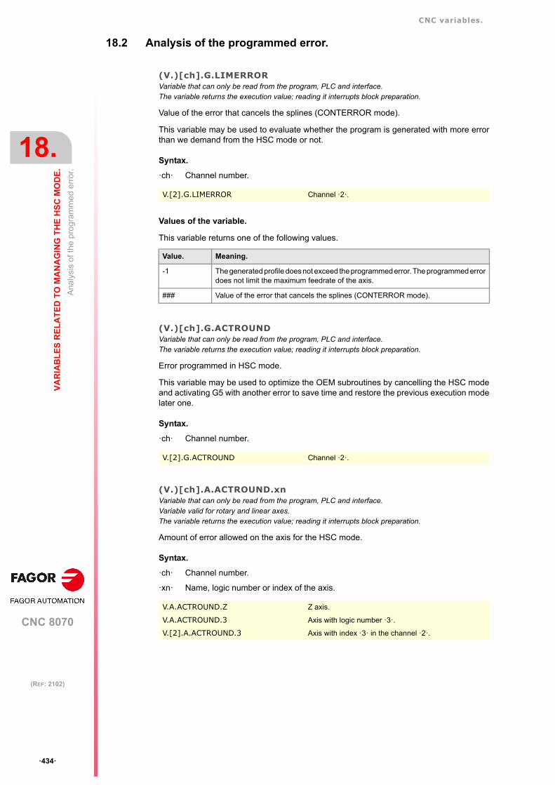
CNC variables.
CNC 8070
18.
VA
RIA
BL
ES
RE
LA
TE
D T
O M
AN
AG
ING
TH
E H
SC
MO
DE
.
An
alys
is o
f the
pro
gram
med
err
or.
ꞏ434ꞏ
(REF: 2102)
18.2 Analysis of the programmed error.
(V.)[ch].G.LIMERRORVariable that can only be read from the program, PLC and interface.The variable returns the execution value; reading it interrupts block preparation.
Value of the error that cancels the splines (CONTERROR mode).
This variable may be used to evaluate whether the program is generated with more errorthan we demand from the HSC mode or not.
Syntax.
ꞏchꞏ Channel number.
Values of the variable.
This variable returns one of the following values.
(V.)[ch].G.ACTROUNDVariable that can only be read from the program, PLC and interface.The variable returns the execution value; reading it interrupts block preparation.
Error programmed in HSC mode.
This variable may be used to optimize the OEM subroutines by cancelling the HSC modeand activating G5 with another error to save time and restore the previous execution modelater one.
Syntax.
ꞏchꞏ Channel number.
(V.)[ch].A.ACTROUND.xnVariable that can only be read from the program, PLC and interface.Variable valid for rotary and linear axes.The variable returns the execution value; reading it interrupts block preparation.
Amount of error allowed on the axis for the HSC mode.
Syntax.
ꞏchꞏ Channel number.
ꞏxnꞏ Name, logic number or index of the axis.
V.[2].G.LIMERROR Channel ꞏ2ꞏ.
Value. Meaning.
-1 The generated profile does not exceed the programmed error. The programmed errordoes not limit the maximum feedrate of the axis.
### Value of the error that cancels the splines (CONTERROR mode).
V.[2].G.ACTROUND Channel ꞏ2ꞏ.
V.A.ACTROUND.Z Z axis.
V.A.ACTROUND.3 Axis with logic number ꞏ3ꞏ.
V.[2].A.ACTROUND.3 Axis with index ꞏ3ꞏ in the channel ꞏ2ꞏ.

CNC variables.
CNC 8070
VA
RIA
BL
ES
RE
LA
TE
D T
O M
AN
AG
ING
TH
E H
SC
MO
DE
.
18.
Fe
edra
te li
mita
tion
at th
e bl
ock
bei
ng e
xecu
ted.
ꞏ435ꞏ
(REF: 2102)
18.3 Feedrate limitation at the block being executed.
(V.)[ch].G.AXLIMFVariable that can only be read from the program, PLC and interface.The variable returns the execution value; reading it interrupts block preparation.
Logic number of the axis that limits the feedrate at the block being executed.
Together with the V.G.PARLIMF variable, it may be used to evaluate the behavior of themachining operation in a particular section where the feedrate decreases too much or isirregular.
Syntax.
ꞏchꞏ Channel number.
(V.)[ch].G.PARLIMFVariable that can only be read from the program, PLC and interface.The variable returns the execution value; reading it interrupts block preparation.
Cause that limits the feedrate at the block being executed.
Syntax.
ꞏchꞏ Channel number.
Values of the variable.
This variable returns one of the following values.
V.[2].G.AXLIMF Channel ꞏ2ꞏ.
V.[2].G.PARLIMF Channel ꞏ2ꞏ.
Value. Meaning.
1 Maximum feedrate of the axis.
2 Acceleration due to curvature (parameter CURVACC).
3 Jerk due to curvature (parameter CURVJERK).
6 Error committed by the spline.
7 Insufficient memory due to very small blocks and/or buffer full.
10 Maximum axis feedrate in transformations.
11 Maximum axis acceleration in transformations.
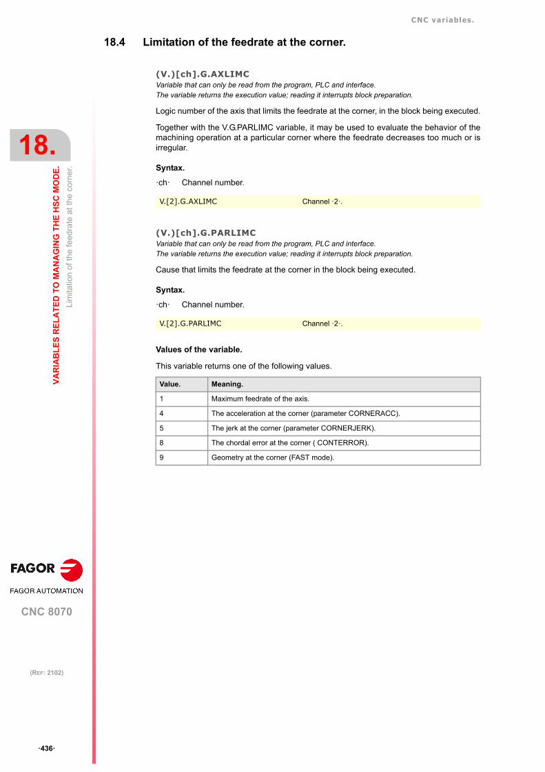
CNC variables.
CNC 8070
18.
VA
RIA
BL
ES
RE
LA
TE
D T
O M
AN
AG
ING
TH
E H
SC
MO
DE
.
Lim
itatio
n of
the
feed
rate
at t
he
corn
er.
ꞏ436ꞏ
(REF: 2102)
18.4 Limitation of the feedrate at the corner.
(V.)[ch].G.AXLIMCVariable that can only be read from the program, PLC and interface.The variable returns the execution value; reading it interrupts block preparation.
Logic number of the axis that limits the feedrate at the corner, in the block being executed.
Together with the V.G.PARLIMC variable, it may be used to evaluate the behavior of themachining operation at a particular corner where the feedrate decreases too much or isirregular.
Syntax.
ꞏchꞏ Channel number.
(V.)[ch].G.PARLIMCVariable that can only be read from the program, PLC and interface.The variable returns the execution value; reading it interrupts block preparation.
Cause that limits the feedrate at the corner in the block being executed.
Syntax.
ꞏchꞏ Channel number.
Values of the variable.
This variable returns one of the following values.
V.[2].G.AXLIMC Channel ꞏ2ꞏ.
V.[2].G.PARLIMC Channel ꞏ2ꞏ.
Value. Meaning.
1 Maximum feedrate of the axis.
4 The acceleration at the corner (parameter CORNERACC).
5 The jerk at the corner (parameter CORNERJERK).
8 The chordal error at the corner ( CONTERROR).
9 Geometry at the corner (FAST mode).

CNC variables.
CNC 8070
VA
RIA
BL
ES
RE
LA
TE
D T
O M
AN
AG
ING
TH
E H
SC
MO
DE
.
18.
Mod
ify th
e dy
nam
ics
of a
ll th
e ax
es
of th
e ch
ann
el.
ꞏ437ꞏ
(REF: 2102)
18.5 Modify the dynamics of all the axes of the channel.
(V.)[ch].G.DYNOVRVariable that can be read and written via program, PLC and interface.The variable returns the execution value; reading it interrupts block preparation.
Percentage applicable to all the dynamics variables of all the axes of the channel.
This variable may be used to make changes in real time to the machining dynamics (ignoringlook-ahead blocks). The dynamics can also be changed from the interface using the dynamicoverride-bar ([CTRL][H]).
Syntax.
ꞏchꞏ Channel number.
Remarks.
The upper and lower limits (range) for varying the value depends on machine parametersMINDYNOVR and MAXDYNOVR. If both parameters are set at 100%, the CNC will notdisplay the slider and it will not be possible to change the machining dynamics in real time.
V.[2].G.DYNOVR Channel ꞏ2ꞏ.

CNC variables.
CNC 8070
18.
VA
RIA
BL
ES
RE
LA
TE
D T
O M
AN
AG
ING
TH
E H
SC
MO
DE
.
Mod
ify th
e dy
nam
ics
of a
ll th
e ax
es
of th
e ch
ann
el.
ꞏ438ꞏ
(REF: 2102)

CNC 8070
19
ꞏ439ꞏ
(REF: 2102)
19.VARIABLES RELATED TO SPINDLE SPEED.
19.1 Programming the speed.
(V.)[ch].A.SREAL.sn(V.)[ch].SP.SREAL.snVariable that can only be read from the program, PLC and interface.The variable returns the execution value; reading it interrupts block preparation.
Channel [ch]. Real spindle speed.
Syntax.
ꞏchꞏ Channel number.
ꞏsnꞏ Name, logic number or index of the spindle.
Remarks.
This variable takes into account the accelerations and decelerations of the machine. Itreturns a value of ꞏ0ꞏ when the spindle is stopped, it returns the value in rpm when the spindleis in G96/G97 and in degrees/minute when the spindle is in M19.
V.A.SREAL.S Spindle S.
V.SP.SREAL.S Spindle S.
V.SP.SREAL Master spindle.
V.A.SREAL.5 Spindle with logic number ꞏ5ꞏ.
V.SP.SREAL.2 Spindle with index ꞏ2ꞏ in the system.
V.[2].SP.SREAL.1 Spindle with index ꞏ1ꞏ in the channel ꞏ2ꞏ.

CNC variables.
CNC 8070
19.
VA
RIA
BL
ES
RE
LA
TE
D T
O S
PIN
DL
E S
PE
ED
.
Spi
ndl
e s
peed
in G
97.
ꞏ440ꞏ
(REF: 2102)
19.2 Spindle speed in G97.
(V.)[ch].A.SPEED.sn(V.)[ch].SP.SPEED.snVariable that can only be read from the program, PLC and interface.The variable returns the execution value; reading it interrupts block preparation.
Channel [ch]. Active spindle speed in G97.
Syntax.
ꞏchꞏ Channel number.
ꞏsnꞏ Name, logic number or index of the spindle.
Remarks.
The speed may be set by program or by PLC; the one set by PLC has the highest priority.
(V.)[ch].PLC.S.snVariable that can be read and written from the PLC and read from the program and from the interface.The variable returns the execution value; reading it interrupts block preparation.
Channel [ch]. Speed active by PLC for G97.
The speed programmed by PLC prevails over the one programmed by program or MDI. Tocancel the speed by PLC, set the variable to ꞏ0ꞏ; the CNC applies the speed active byprogram.
Syntax.
ꞏchꞏ Channel number.
ꞏsnꞏ Name, logic number or index of the spindle.
V.A.SPEED.S Spindle S.
V.SP.SPEED.S Spindle S.
V.SP.SPEED Master spindle.
V.A.SPEED.5 Spindle with logic number ꞏ5ꞏ.
V.SP.SPEED.2 Spindle with index ꞏ2ꞏ in the system.
V.[2].SP.SPEED.1 Spindle with index ꞏ1ꞏ in the channel ꞏ2ꞏ.
Speed set. V.PLC.S.sn V.A.PRGS.sn V.A.SPEED.sn
By program; S5000.By PLC; none.
0 5000 5000
By program; S5000.By PLC; S9000.
9000 5000 9000
By program; S5000.By PLC; S3000.
3000 5000 3000
By program; S5000.By PLC; none.By MDI; S8000.
0 8000 8000
By program; S5000.By PLC; S9000.By MDI; S8000.
9000 8000 9000
By program; S5000.By PLC; S3000.By MDI; S8000.
3000 8000 3000
V.PLC.S.S2 Spindle S2.
V.PLC.S.5 Spindle with logic number ꞏ5ꞏ.
V.[2].PLC.S.1 Spindle with index ꞏ1ꞏ in the channel ꞏ2ꞏ.

CNC variables.
CNC 8070
VA
RIA
BL
ES
RE
LA
TE
D T
O S
PIN
DL
E S
PE
ED
.
19.
Spi
ndl
e s
peed
in G
97.
ꞏ441ꞏ
(REF: 2102)
(V.)[ch].A.PRGS.sn(V.)[ch].SP.PRGS.snVariable that can only be read from the program, PLC and interface.The variable returns the value of block preparation.
Channel [ch]. Speed active by program for G97.
Being G97 active, programming a new speed in MDI mode updates the value of this variable.
Syntax.
ꞏchꞏ Channel number.
ꞏsnꞏ Name, logic number or index of the spindle.
V.A.PRGS.S Spindle S.
V.SP.PRGS.S Spindle S.
V.SP.PRGS Master spindle.
V.A.PRGS.5 Spindle with logic number ꞏ5ꞏ.
V.SP.PRGS.2 Spindle with index ꞏ2ꞏ in the system.
V.[2].SP.PRGS.1 Spindle with index ꞏ1ꞏ in the channel ꞏ2ꞏ.

CNC variables.
CNC 8070
19.
VA
RIA
BL
ES
RE
LA
TE
D T
O S
PIN
DL
E S
PE
ED
.
Sp
ind
le s
pee
d in
G96
(C
SS
).
ꞏ442ꞏ
(REF: 2102)
19.3 Spindle speed in G96 (CSS).
(V.)[ch].A.CSS.sn(V.)[ch].SP.CSS.snVariable that can only be read from the program, PLC and interface.The variable returns the execution value; reading it interrupts block preparation.
Channel [ch]. Active spindle speed in G96.
Syntax.
ꞏchꞏ Channel number.
ꞏsnꞏ Name, logic number or index of the spindle.
Remarks.
The speed may be set by program or by PLC; the one set by PLC has the highest priority.
(V.)[ch].PLC.CSS.snVariable that can be read and written from the PLC and read from the program and from the interface.The variable returns the execution value; reading it interrupts block preparation.
Channel [ch]. Speed active by PLC for G96.
The speed programmed by PLC prevails over the one programmed by program or MDI. Tocancel the speed by PLC, set the variable to ꞏ0ꞏ; the CNC applies the speed active byprogram.
Syntax.
ꞏchꞏ Channel number.
ꞏsnꞏ Name, logic number or index of the spindle.
V.A.CSS.S Spindle S.
V.SP.CSS.S Spindle S.
V.SP.CSS Master spindle.
V.A.CSS.5 Spindle with logic number ꞏ5ꞏ.
V.SP.CSS.2 Spindle with index ꞏ2ꞏ in the system.
V.[2].SP.CSS.1 Spindle with index ꞏ1ꞏ in the channel ꞏ2ꞏ.
Speed set. V.PLC.CSS.sn V.A.PRGCSS.sn V.A.CSS.sn
By program; S150.By PLC; none.
0 150 150
By program; S150.By PLC; S250.
250 150 250
By program; S150.By PLC; S100.
100 150 100
By program; S150.By PLC; none.By MDI; S300.
0 300 300
By program; S150.By PLC; S250.By MDI; S200.
250 200 250
By program; S150.By PLC; S100.By MDI; S200.
100 200 100
V.PLC.CSS.S2 Spindle S2.
V.PLC.CSS.5 Spindle with logic number ꞏ5ꞏ.
V.[2].PLC.CSS.1 Spindle with index ꞏ1ꞏ in the channel ꞏ2ꞏ.

CNC variables.
CNC 8070
VA
RIA
BL
ES
RE
LA
TE
D T
O S
PIN
DL
E S
PE
ED
.
19.
Sp
ind
le s
pee
d in
G96
(C
SS
).
ꞏ443ꞏ
(REF: 2102)
(V.)[ch].A.PRGCSS.sn(V.)[ch].SP.PRGCSS.snVariable that can only be read from the program, PLC and interface.The variable returns the value of block preparation.
Channel [ch]. Speed active by program for G96.
Being G96 active, programming a new speed in MDI mode updates the value of this variable.
Syntax.
ꞏchꞏ Channel number.
ꞏsnꞏ Name, logic number or index of the spindle.
V.A.PRGCSS.S Spindle S.
V.SP.PRGCSS.S Spindle S.
V.SP.PRGCSS Master spindle.
V.A.PRGCSS.5 Spindle with logic number ꞏ5ꞏ.
V.SP.PRGCSS.2 Spindle with index ꞏ2ꞏ in the system.
V.[2].SP.PRGCSS.1 Spindle with index ꞏ1ꞏ in the channel ꞏ2ꞏ.

CNC variables.
CNC 8070
19.
VA
RIA
BL
ES
RE
LA
TE
D T
O S
PIN
DL
E S
PE
ED
.
Spi
ndle
spe
ed
in M
19.
ꞏ444ꞏ
(REF: 2102)
19.4 Spindle speed in M19.
(V.)[ch].A.SPOS.sn(V.)[ch].SP.SPOS.snVariable that can only be read from the program, PLC and interface.The variable returns the execution value; reading it interrupts block preparation.
Channel [ch]. Active spindle speed in M19 .
Syntax.
ꞏchꞏ Channel number.
ꞏsnꞏ Name, logic number or index of the spindle.
Remarks.
The speed may be set by program or by PLC; the one set by PLC has the highest priority.
(V.)[ch].PLC.SPOS.snVariable that can be read and written from the PLC and read from the program and from the interface.The variable returns the execution value; reading it interrupts block preparation.
Channel [ch]. Speed active by PLC for M19.
The speed programmed by PLC prevails over the one programmed by program or MDI. Tocancel the speed by PLC, set the variable to ꞏ0ꞏ; the CNC applies the speed active byprogram.
Syntax.
ꞏchꞏ Channel number.
ꞏsnꞏ Name, logic number or index of the spindle.
V.A.SPOS.S Spindle S.
V.SP.SPOS.S Spindle S.
V.SP.SPOS Master spindle.
V.A.SPOS.5 Spindle with logic number ꞏ5ꞏ.
V.SP.SPOS.2 Spindle with index ꞏ2ꞏ in the system.
V.[2].SP.SPOS.1 Spindle with index ꞏ1ꞏ in the channel ꞏ2ꞏ.
Speed set. V.PLC.SPOS.sn V.A.PRGSPOS.sn V.A.SPOS.sn
By program; S.POS=180.By PLC; none.
0 180 180
By program; S.POS=180.By PLC; S.POS=250.
250 180 250
By program; S.POS=180.By PLC; S.POS=90.
90 180 90
By program; S.POS=180.By PLC; none.By MDI; S.POS=200.
0 200 200
By program; S.POS=180.By PLC; S.POS=250.By MDI; S.POS=200.
250 200 250
By program; S.POS=180.By PLC; S.POS=100.By MDI; S.POS=200.
100 200 100
V.PLC.SPOS.S2 Spindle S2.
V.PLC.SPOS.5 Spindle with logic number ꞏ5ꞏ.
V.[2].PLC.SPOS.1 Spindle with index ꞏ1ꞏ in the channel ꞏ2ꞏ.

CNC variables.
CNC 8070
VA
RIA
BL
ES
RE
LA
TE
D T
O S
PIN
DL
E S
PE
ED
.
19.
Spi
ndle
spe
ed
in M
19.
ꞏ445ꞏ
(REF: 2102)
(V.)[ch].A.PRGSPOS.sn(V.)[ch].SP.PRGSPOS.snVariable that can only be read from the program, PLC and interface.The variable returns the value of block preparation.
Channel [ch]. Speed active by program for M19.
Syntax.
ꞏchꞏ Channel number.
ꞏsnꞏ Name, logic number or index of the spindle.
V.A.PRGSPOS.S Spindle S.
V.SP.PRGSPOS.S Spindle S.
V.SP.PRGSPOS Master spindle.
V.A.PRGSPOS.5 Spindle with logic number ꞏ5ꞏ.
V.SP.PRGSPOS.2 Spindle with index ꞏ2ꞏ in the system.
V.[2].SP.PRGSPOS.1 Spindle with index ꞏ1ꞏ in the channel ꞏ2ꞏ.

CNC variables.
CNC 8070
19.
VA
RIA
BL
ES
RE
LA
TE
D T
O S
PIN
DL
E S
PE
ED
.
Spe
ed li
mit.
ꞏ446ꞏ
(REF: 2102)
19.5 Speed limit.
(V.)[ch].A.SLIMIT.sn(V.)[ch].SP.SLIMIT.snVariable that can only be read from the program, PLC and interface.The variable returns the execution value; reading it interrupts block preparation.
Channel [ch]. Active spindle speed limit.
Syntax.
ꞏchꞏ Channel number.
ꞏsnꞏ Name, logic number or index of the spindle.
Remarks.
The maximum speed may be set by program or by PLC; the one set by PLC has the highestpriority.
(V.)[ch].PLC.SL.snVariable that can be read and written from the PLC and read from the program and from the interface.The variable returns the execution value; reading it interrupts block preparation.
Channel [ch]. Spindle speed limit active by PLC.
The speed programmed by PLC prevails over the one programmed by program or MDI. Tocancel the speed by PLC, set the variable to ꞏ0ꞏ; the CNC applies the speed active byprogram.
Syntax.
ꞏchꞏ Channel number.
ꞏsnꞏ Name, logic number or index of the spindle.
(V.)[ch].A.PRGSL.sn(V.)[ch].SP.PRGSL.snVariable that can only be read from the program, PLC and interface.The variable returns the value of block preparation.
Channel [ch]. Spindle speed limit active by program.
Syntax.
ꞏchꞏ Channel number.
ꞏsnꞏ Name, logic number or index of the spindle.
V.A.SLIMIT.S Spindle S.
V.SP.SLIMIT.S Spindle S.
V.SP.SLIMIT Master spindle.
V.A.SLIMIT.5 Spindle with logic number ꞏ5ꞏ.
V.SP.SLIMIT.2 Spindle with index ꞏ2ꞏ in the system.
V.[2].SP.SLIMIT.1 Spindle with index ꞏ1ꞏ in the channel ꞏ2ꞏ.
V.PLC.SL.S2 Spindle S2.
V.PLC.SL.5 Spindle with logic number ꞏ5ꞏ.
V.[2].PLC.SL.1 Spindle with index ꞏ1ꞏ in the channel ꞏ2ꞏ.
V.A.PRGSL.S Spindle S.
V.SP.PRGSL.S Spindle S.
V.SP.PRGSL Master spindle.
V.A.PRGSL.5 Spindle with logic number ꞏ5ꞏ.
V.SP.PRGSL.2 Spindle with index ꞏ2ꞏ in the system.
V.[2].SP.PRGSL.1 Spindle with index ꞏ1ꞏ in the channel ꞏ2ꞏ.
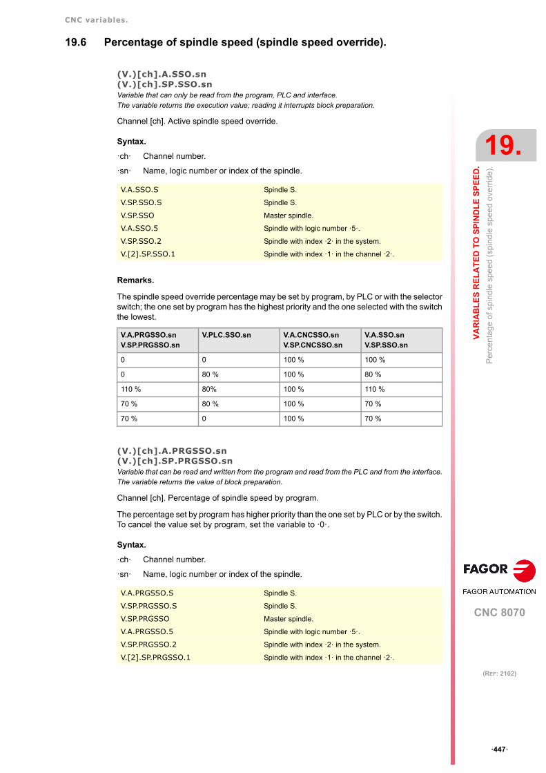
CNC variables.
CNC 8070
VA
RIA
BL
ES
RE
LA
TE
D T
O S
PIN
DL
E S
PE
ED
.
19.
Per
cent
age
of s
pin
dle
spe
ed
(spi
ndle
sp
eed
ove
rrid
e).
ꞏ447ꞏ
(REF: 2102)
19.6 Percentage of spindle speed (spindle speed override).
(V.)[ch].A.SSO.sn(V.)[ch].SP.SSO.snVariable that can only be read from the program, PLC and interface.The variable returns the execution value; reading it interrupts block preparation.
Channel [ch]. Active spindle speed override.
Syntax.
ꞏchꞏ Channel number.
ꞏsnꞏ Name, logic number or index of the spindle.
Remarks.
The spindle speed override percentage may be set by program, by PLC or with the selectorswitch; the one set by program has the highest priority and the one selected with the switchthe lowest.
(V.)[ch].A.PRGSSO.sn(V.)[ch].SP.PRGSSO.snVariable that can be read and written from the program and read from the PLC and from the interface.The variable returns the value of block preparation.
Channel [ch]. Percentage of spindle speed by program.
The percentage set by program has higher priority than the one set by PLC or by the switch.To cancel the value set by program, set the variable to ꞏ0ꞏ.
Syntax.
ꞏchꞏ Channel number.
ꞏsnꞏ Name, logic number or index of the spindle.
V.A.SSO.S Spindle S.
V.SP.SSO.S Spindle S.
V.SP.SSO Master spindle.
V.A.SSO.5 Spindle with logic number ꞏ5ꞏ.
V.SP.SSO.2 Spindle with index ꞏ2ꞏ in the system.
V.[2].SP.SSO.1 Spindle with index ꞏ1ꞏ in the channel ꞏ2ꞏ.
V.A.PRGSSO.snV.SP.PRGSSO.sn
V.PLC.SSO.sn V.A.CNCSSO.snV.SP.CNCSSO.sn
V.A.SSO.snV.SP.SSO.sn
0 0 100 % 100 %
0 80 % 100 % 80 %
110 % 80% 100 % 110 %
70 % 80 % 100 % 70 %
70 % 0 100 % 70 %
V.A.PRGSSO.S Spindle S.
V.SP.PRGSSO.S Spindle S.
V.SP.PRGSSO Master spindle.
V.A.PRGSSO.5 Spindle with logic number ꞏ5ꞏ.
V.SP.PRGSSO.2 Spindle with index ꞏ2ꞏ in the system.
V.[2].SP.PRGSSO.1 Spindle with index ꞏ1ꞏ in the channel ꞏ2ꞏ.

CNC variables.
CNC 8070
19.
VA
RIA
BL
ES
RE
LA
TE
D T
O S
PIN
DL
E S
PE
ED
.
Per
cent
age
of s
pin
dle
spe
ed
(spi
ndle
sp
eed
ove
rrid
e).
ꞏ448ꞏ
(REF: 2102)
(V.)[ch].PLC.SSO.snVariable that can be read and written from the PLC and read from the program and from the interface.The variable returns the execution value; reading it interrupts block preparation.
Channel [ch]. Percentage of spindle speed by PLC.
The percentage set by PLC has higher priority than the one set by the switch, but lower prioritythan the one set by program.. To cancel the value set by PLC, set the variable to ꞏ0ꞏ.
Syntax.
ꞏchꞏ Channel number.
ꞏsnꞏ Name, logic number or index of the spindle.
(V.)[ch].A.CNCSSO.sn(V.)[ch].SP.CNCSSO.snVariable that can be read and written (asynchronous writing) from the interface and read from theprogram and from the PLC.The variable returns the execution value; reading it interrupts block preparation.
Channel [ch]. Spindle speed percentage at the switch of the operator panel.
The percentage set by the switch of the operator panel has lower priority than the one setby PLC or by program.
Syntax.
ꞏchꞏ Channel number.
ꞏsnꞏ Name, logic number or index of the spindle.
V.PLC.SSO.S2 Spindle S2.
V.PLC.SSO.5 Spindle with logic number ꞏ5ꞏ.
V.[2].PLC.SSO.1 Spindle with index ꞏ1ꞏ in the channel ꞏ2ꞏ.
V.A.CNCSSO.S Spindle S.
V.SP.CNCSSO.S Spindle S.
V.SP.CNCSSO Master spindle.
V.A.CNCSSO.5 Spindle with logic number ꞏ5ꞏ.
V.SP.CNCSSO.2 Spindle with index ꞏ2ꞏ in the system.
V.[2].SP.CNCSSO.1 Spindle with index ꞏ1ꞏ in the channel ꞏ2ꞏ.

CNC 8070
20
ꞏ449ꞏ
(REF: 2102)
20.VARIABLES ASSOCIATED WITH TOOL MAGAZINE AND TOOLS.
20.1 Variables associated with the tool manager.
(V.)[ch].TM.MZSTATUSVariable that can be read from the PLC and from the interface.
Tool manager status.
Syntax.
ꞏchꞏ Channel number.
Values of the variable.
This variable returns one of the following values.
(V.)[ch].TM.MZRUNVariable that can be read from the PLC and from the interface.
Tool manager running.
Syntax.
ꞏchꞏ Channel number.
Values of the variable.
This variable returns one of the following values.
[2].TM.MZSTATUS Channel ꞏ2ꞏ.
Value. Meaning.
0 Normal.
1 Tool manager error.
2 Error at the tool manager; waiting to complete the maneuverin progress.
4 Tool manager emergency.
[2].TM.MZRUN Channel ꞏ2ꞏ.
Value. Meaning.
0 There is no maneuver in progress.
1 There is a maneuver in progress.

CNC variables.
CNC 8070
20.
VA
RIA
BL
ES
AS
SO
CIA
TE
D W
ITH
TO
OL
MA
GA
ZIN
E A
ND
Va
riabl
es a
ssoc
iate
d w
ith th
e to
ol m
ana
ger.
ꞏ450ꞏ
(REF: 2102)
(V.)[ch].TM.MZWAITVariable that can only be read from the program, PLC and interface.The variable returns the execution value; reading it interrupts block preparation.
Tool manager processing a maneuver.
Syntax.
ꞏchꞏ Channel number.
Remarks.
From software version V2.01 on, there is no need to use this variable in the subroutineassociated with M06. The subroutine itself waits for the manager's maneuvers to finish andit does not interrupt block preparation.
Values of the variable.
This variable returns one of the following values.
(V.)[ch].TM.MZMODEVariable that can be read and written from the program and interface and read from the PLC.The variable returns the execution value; reading and writing it interrupt block preparation.
Operating mode of the tool manager.
This variable may be used to set the magazine in load or unload mode.
Syntax.
ꞏchꞏ Channel number.
Values of the variable.
This variable returns one of the following values.
V.[2].TM.MZWAIT Channel ꞏ2ꞏ.
Value. Meaning.
0 No need to wait.
1 It has to wait.
V.[2].TM.MZMODE Channel ꞏ2ꞏ.
Value. Meaning.
0 Regular work mode.
1 Magazine in load mode.
2 Magazine in unload mode.

CNC variables.
CNC 8070
VA
RIA
BL
ES
AS
SO
CIA
TE
D W
ITH
TO
OL
MA
GA
ZIN
E A
ND
20.
Va
riabl
es r
ela
ted
to m
ana
ging
the
tool
mag
azi
ne a
nd
the
too
lch
ange
r ar
m.
ꞏ451ꞏ
(REF: 2102)
20.2 Variables related to managing the tool magazine and the toolchanger arm.
20.2.1 Relationship between the tool magazine and the channel.
(V.)[ch].TM.ACTUALMZVariable that can only be read from the program, PLC and interface.The variable returns the execution value; reading it interrupts block preparation.
Tool Magazine being used by the [ch] channel.
Syntax.
ꞏchꞏ Channel number.
(V.)TM.MZACTUALCH[mz]Variable that can only be read from the program, PLC and interface.The variable returns the execution value; reading it interrupts block preparation.
Channel that is using tool magazine [mz].
Syntax.
ꞏmzꞏ Type of tool magazine.
V.[2].TM.ACTUALMZ Channel ꞏ2ꞏ.
V.TM.MZACTUALCH[2] Magazine ꞏ2ꞏ.

CNC variables.
CNC 8070
20.
VA
RIA
BL
ES
AS
SO
CIA
TE
D W
ITH
TO
OL
MA
GA
ZIN
E A
ND
Va
riabl
es r
ela
ted
to m
ana
ging
the
tool
mag
azi
ne a
nd
the
too
lch
ange
r ar
m.
ꞏ452ꞏ
(REF: 2102)
20.2.2 Tool location in the magazine.
(V.)TM.T[mz][pos]Variable that can only be read from the program, PLC and interface.The variable returns the execution value; reading it interrupts block preparation.
Tool in the [pos] position of the [mz] magazine.
Syntax.
ꞏmzꞏ Type of tool magazine.
ꞏposꞏ Tool position in the magazine.
Remarks.
If the variable is missing the offset number, the variable will then refer to the first one. Thisvariable returns 0 if the tool is not in the magazine.
(V.)TM.P[mz][tl]Variable that can only be read from the program, PLC and interface.The variable returns the execution value; reading it interrupts block preparation.
Position of the [t] tool in the [mz] magazine.
Syntax.
ꞏmzꞏ Type of tool magazine.
ꞏtlꞏ Tool number.
Remarks.
If the variable is missing the offset number, the variable will then refer to the first one.
20.2.3 Tool location in the tool changer arm.
(V.)TM.TOOLCH1[mz]Variable that can be read and written via program, PLC(asynchronous writing) and interface.The variable returns the execution value; reading it interrupts block preparation.
Tool in the first claw of the magazine arm [mz].
Syntax.
ꞏmzꞏ Type of tool magazine.
(V.)TM.TOOLCH2[mz]Variable that can be read and written via program, PLC(asynchronous writing) and interface.The variable returns the execution value; reading it interrupts block preparation.
Tool in the second claw of the magazine arm [mz].
Syntax.
ꞏmzꞏ Type of tool magazine.
V.TM.T[2][15] Magazine ꞏ2ꞏ. Position ꞏ15ꞏ.
V.TM.P[2][15] Magazine ꞏ2ꞏ. Position ꞏ15ꞏ.
V.TM.TOOLCH1[2] Magazine ꞏ2ꞏ.
V.TM.TOOLCH2[2] Magazine ꞏ2ꞏ.

CNC variables.
CNC 8070
VA
RIA
BL
ES
AS
SO
CIA
TE
D W
ITH
TO
OL
MA
GA
ZIN
E A
ND
20.
Va
riabl
es r
ela
ted
to th
e ac
tive
tool
and
to th
e ne
xt o
ne.
ꞏ453ꞏ
(REF: 2102)
20.3 Variables related to the active tool and to the next one.
Variables related to the active tool are always read synchronously. The writing of thesevariables is always asynchronous, be it for the active tool or not.
20.3.1 Tool and active offset.
(V.)[ch].TM.TOOLVariable that can only be read from the program, PLC and interface.The variable returns the execution value; reading it interrupts block preparation.
Number of the active tool.
Syntax.
ꞏchꞏ Channel number.
(V.)[ch].TM.TODVariable that can only be read from the program, PLC and interface.The variable returns the execution value; reading it interrupts block preparation.
Number of the active tool offset.
Syntax.
ꞏchꞏ Channel number.
V.[2].TM.TOOL Channel ꞏ2ꞏ. Active tool.
V.[2].TM.TOD Channel ꞏ2ꞏ. Active tool offset.

CNC variables.
CNC 8070
20.
VA
RIA
BL
ES
AS
SO
CIA
TE
D W
ITH
TO
OL
MA
GA
ZIN
E A
ND
Va
riabl
es r
ela
ted
to th
e ac
tive
tool
and
to th
e ne
xt o
ne.
ꞏ454ꞏ
(REF: 2102)
20.3.2 Next tool and tool offset.
(V.)[ch].TM.NXTOOLVariable that can only be read from the program, PLC and interface.The variable returns the execution value; reading it interrupts block preparation.
Number of the next tool.
The "next tool" is the one already selected but waiting to be activated by executing an M06.
Syntax.
ꞏchꞏ Channel number.
Remarks.
Although the variable has writing permission, the value of 0 (zero) cannot be written.
(V.)[ch].TM.NXTODVariable that can only be read from the program, PLC and interface.The variable returns the execution value; reading it interrupts block preparation.
Number of the next tool offset.
Syntax.
ꞏchꞏ Channel number.
20.3.3 Status of the active tool.
(V.)[ch].TM.TSTATUSVariable that can only be read from the program, PLC and interface.The variable returns the execution value; reading it interrupts block preparation.
Active tool. Tool status.
Syntax.
ꞏchꞏ Channel number.
Values of the variable.
This variable returns one of the following values.
V.[2].TM.NXTOOL Channel ꞏ2ꞏ. Next tool.
V.[2].TM.NXTOD Channel ꞏ2ꞏ. Next tool offset.
V.[2].TM.TSTATUS Channel ꞏ2ꞏ. Active tool.
Value. Meaning.
0 Tool available.
1 Tool available.
2 Tool worn out.

CNC variables.
CNC 8070
VA
RIA
BL
ES
AS
SO
CIA
TE
D W
ITH
TO
OL
MA
GA
ZIN
E A
ND
20.
Va
riabl
es r
ela
ted
to th
e ac
tive
tool
and
to th
e ne
xt o
ne.
ꞏ455ꞏ
(REF: 2102)
20.3.4 Family of the active tool.
(V.)[ch].TM.TLFFVariable that can only be read from the program, PLC and interface.The variable returns the execution value; reading it interrupts block preparation.
Active tool. Family code.
Syntax.
ꞏchꞏ Channel number.
V.[2].TM.TLFF Channel ꞏ2ꞏ.

CNC variables.
CNC 8070
20.
VA
RIA
BL
ES
AS
SO
CIA
TE
D W
ITH
TO
OL
MA
GA
ZIN
E A
ND
Va
riabl
es r
ela
ted
to th
e ac
tive
tool
and
to th
e ne
xt o
ne.
ꞏ456ꞏ
(REF: 2102)
20.3.5 Active tool monitoring.
(V.)[ch].TM.TOMON[ofd]Variable that can only be read from the program, PLC and interface.The variable returns the execution value; reading it interrupts block preparation.
[odf] offset of the active tool. Type of tool life monitoring.
Syntax.
[odf] Tool offset; if missing, the active tool offset.
ꞏchꞏ Channel number.
Values of the variable.
This variable returns one of the following values.
(V.)[ch].TM.TLFN[ofd]Variable that can only be read from the program, PLC and interface.The variable returns the execution value; reading it interrupts block preparation.
[odf] offset of the active tool. Nominal life.
Syntax.
[odf] Tool offset; if missing, the active tool offset.
ꞏchꞏ Channel number.
(V.)[ch].TM.TLFR[ofd]Variable that can only be read from the program, PLC and interface.The variable returns the execution value; reading it interrupts block preparation.
[odf] offset of the active tool. Real (actual) life.
Syntax.
[odf] Tool offset; if missing, the active tool offset.
ꞏchꞏ Channel number.
(V.)[ch].TM.REMLIFEVariable that can be read from the PLC and from the interface.
Active tool. Remaining life.
Syntax.
ꞏchꞏ Channel number.
V.[2].TM.TOMON Channel ꞏ2ꞏ. Active tool offset.
V.[2].TM.TOMON[3] Channel ꞏ2ꞏ. Tool offset ꞏ3ꞏ.
Value. Meaning.
0 Without tool life monitoring.
1 Tool life monitoring; machining time.
2 Tool life monitoring; number of operations.
V.[2].TM.TLFN Channel ꞏ2ꞏ. Active tool offset.
V.[2].TM.TLFN[3] Channel ꞏ2ꞏ. Tool offset ꞏ3ꞏ.
V.[2].TM.TLFR Channel ꞏ2ꞏ. Active tool offset.
V.[2].TM.TLFR[3] Channel ꞏ2ꞏ. Tool offset ꞏ3ꞏ.
[2].TM.REMLIFE Channel ꞏ2ꞏ.

CNC variables.
CNC 8070
VA
RIA
BL
ES
AS
SO
CIA
TE
D W
ITH
TO
OL
MA
GA
ZIN
E A
ND
20.
Va
riabl
es r
ela
ted
to th
e ac
tive
tool
and
to th
e ne
xt o
ne.
ꞏ457ꞏ
(REF: 2102)
20.3.6 "CUSTOM" data of the active tool.
(V.)[ch].TM.TOTP1(V.)[ch].TM.TOTP2(V.)[ch].TM.TOTP3(V.)[ch].TM.TOTP4Variable that can be read and written via program, PLC(asynchronous writing) and interface.The variable returns the execution value; reading it interrupts block preparation.
Active tool. Custom parameters.
Syntax.
ꞏchꞏ Channel number.
V.[2].TM.TOTP1 Channel ꞏ2ꞏ. Custom parameter ꞏ1ꞏ.
V.[2].TM.TOTP2 Channel ꞏ2ꞏ. Custom parameter ꞏ2ꞏ.
V.[2].TM.TOTP3 Channel ꞏ2ꞏ. Custom parameter ꞏ3ꞏ.
V.[2].TM.TOTP4 Channel ꞏ2ꞏ. Custom parameter ꞏ4ꞏ.

CNC variables.
CNC 8070
20.
VA
RIA
BL
ES
AS
SO
CIA
TE
D W
ITH
TO
OL
MA
GA
ZIN
E A
ND
Va
riabl
es r
ela
ted
to th
e ac
tive
tool
and
to th
e ne
xt o
ne.
ꞏ458ꞏ
(REF: 2102)
20.3.7 Tool geometry.
(V.)[ch].TM.NUMOFDVariable that can only be read from the program, PLC and interface.The variable returns the execution value; reading it interrupts block preparation.
Active tool. Number of tool offsets.
Syntax.
ꞏchꞏ Channel number.
(V.)[ch].TM.TOOLTYP[ofd](V.)[ch].TM.DTYPE[ofd]Variable that can be read and written via program, PLC(asynchronous writing) and interface.The variable returns the execution value; reading it interrupts block preparation.
Active tool. Code of the tool offset type.
Syntax.
ꞏchꞏ Channel number.
ꞏofdꞏ Tool offset; if missing, the active tool offset.
Values of the variable.
This variable returns one of the following values.
(V.)[ch].TM.DSUBTYPE[ofd]Variable that can be read and written via program, PLC(asynchronous writing) and interface.The variable returns the execution value; reading it interrupts block preparation.
Active tool. Code of the tool offset subtype.
Syntax.
ꞏchꞏ Channel number.
[odf] Tool offset; if missing, the active tool offset.
V.[2].TM.NUMOFD Channel ꞏ2ꞏ.
V.[2].TM.DTYPE Channel ꞏ2ꞏ. Active tool offset.
V.[2].TM.TOOLTYP Channel ꞏ2ꞏ. Active tool offset.
V.[2].TM.DTYPE[3] Channel ꞏ2ꞏ. Tool offset ꞏ3ꞏ.
V.[2].TM.TOOLTYP[3] Channel ꞏ2ꞏ. Tool offset ꞏ3ꞏ.
Value. Meaning.
1 Milling tool..
2 Drilling tool.
3 Surface milling tool.
4 Reaming tool.
5 Boring tool.
6 Threading tool.
7 Grooving or cut-off tool.
8 Turning tool.
9 Other.
10 Measuring probe.
V.[2].TM.DSUBTYPE Channel ꞏ2ꞏ. Active tool offset.
V.[2].TM.DSUBTYPE[3] Channel ꞏ2ꞏ. Tool offset ꞏ3ꞏ.

CNC variables.
CNC 8070
VA
RIA
BL
ES
AS
SO
CIA
TE
D W
ITH
TO
OL
MA
GA
ZIN
E A
ND
20.
Va
riabl
es r
ela
ted
to th
e ac
tive
tool
and
to th
e ne
xt o
ne.
ꞏ459ꞏ
(REF: 2102)
Values of the variable.
This variable returns one of the following values.
(V.)[ch].TM.TURNCONFIG[ofd]Variable that can be read and written via program, PLC(asynchronous writing) and interface.The variable returns the execution value; reading it interrupts block preparation.
[odf] offset of the active tool. Axis orientation.
Only for turning tools. The orientation of the axes is determined by the type of lathe (horizontalor vertical), the position of the turret and the spindle position (on the right or on the left).
Syntax.
ꞏchꞏ Channel number.
[odf] Tool offset; if missing, the active tool offset.
Value. Meaning.
0 Without type
1 Flat endmill.
2 Ball endmill.
3 Toric endmill.
4 Tap.
5 Thread cutter.
6 Disk endmill.
7 Drill bit.
8 Surface milling endmill.
9 Reamer.
10 Boring tool.
11 Diamond shaped cutter for turning.
12 Square cutter for turning, grooving or cut-off.
13 Round cutter for turning.
14 Measuring probe (milling machine).
15 Measuring probe (lathe).
1 2 3 4 5 6 7
8 9 10 11 12 13 14/15
V.[2].TM.TURNCONFIG Channel ꞏ2ꞏ. Active tool offset.
V.[2].TM.TURNCONFIG[3] Channel ꞏ2ꞏ. Tool offset ꞏ3ꞏ.

CNC variables.
CNC 8070
20.
VA
RIA
BL
ES
AS
SO
CIA
TE
D W
ITH
TO
OL
MA
GA
ZIN
E A
ND
Va
riabl
es r
ela
ted
to th
e ac
tive
tool
and
to th
e ne
xt o
ne.
ꞏ460ꞏ
(REF: 2102)
Values of the variable.
This variable returns one of the following values.
(V.)[ch].TM.LOCODE[ofd]Variable that can be read and written via program, PLC(asynchronous writing) and interface.The variable returns the execution value; reading it interrupts block preparation.
[odf] offset of the active tool. Location code (shape) or tool calibration point.
Only for turning tools. The location code indicates which is the calibrated tool tip and,therefore, the point controlled by the CNC to apply radius compensation. The location codedepends on the orientation of the machine axes.
Syntax.
ꞏchꞏ Channel number.
[odf] Tool offset; if missing, the active tool offset.
Values of the variable.
This variable returns one of the following values.
Value. Axis orientation. Value. Axis orientation.
0 4
1 5
2 6
3 7
V.[2].TM.LOCODE Channel ꞏ2ꞏ. Active tool offset.
V.[2].TM.LOCODE[3] Channel ꞏ2ꞏ. Tool offset ꞏ3ꞏ.
Value.
0
1
2
3
4
5
6

CNC variables.
CNC 8070
VA
RIA
BL
ES
AS
SO
CIA
TE
D W
ITH
TO
OL
MA
GA
ZIN
E A
ND
20.
Va
riabl
es r
ela
ted
to th
e ac
tive
tool
and
to th
e ne
xt o
ne.
ꞏ461ꞏ
(REF: 2102)
(V.)[ch].TM.FIXORI[ofd]Variable that can be read and written via program, PLC(asynchronous writing) and interface.The variable returns the execution value; reading it interrupts block preparation.
[odf] offset of the active tool. Tool-holder orientation.
Syntax.
ꞏchꞏ Channel number.
[odf] Tool offset; if missing, the active tool offset.
Values of the variable.
This variable returns one of the following values.
(V.)[ch].TM.SPDLTURDIR[ofd]Variable that can be read and written via program, PLC(asynchronous writing) and interface.The variable returns the execution value; reading it interrupts block preparation.
[odf] offset of the active tool. Spindle turning direction.
Syntax.
ꞏchꞏ Channel number.
[odf] Tool offset; if missing, the active tool offset.
Values of the variable.
This variable returns one of the following values.
(V.)[ch].TM.TOR[ofd]Variable that can be read and written via program, PLC(asynchronous writing) and interface.The variable returns the execution value; reading it interrupts block preparation.
[odf] offset of the active tool. Radius.
7
8
9
V.[2].TM.FIXORI Channel ꞏ2ꞏ. Active tool offset.
V.[2].TM.FIXORI[3] Channel ꞏ2ꞏ. Tool offset ꞏ3ꞏ.
Value. Meaning.
0 Face axis.
1 Longitudinal axis.
V.[2].TM.SPDLTURDIR Channel ꞏ2ꞏ. Active tool offset.
V.[2].TM.SPDLTURDIR[3] Channel ꞏ2ꞏ. Tool offset ꞏ3ꞏ.
Value. Meaning.
0 Undefined direction.
1 Right-hand machining direction.
2 Left-hand machining direction.
Value.

CNC variables.
CNC 8070
20.
VA
RIA
BL
ES
AS
SO
CIA
TE
D W
ITH
TO
OL
MA
GA
ZIN
E A
ND
Va
riabl
es r
ela
ted
to th
e ac
tive
tool
and
to th
e ne
xt o
ne.
ꞏ462ꞏ
(REF: 2102)
This variable is not valid for turning tools.
Syntax.
ꞏchꞏ Channel number.
[odf] Tool offset; if missing, the active tool offset.
(V.)[ch].TM.TOI[ofd]Variable that can be read and written via program, PLC(asynchronous writing) and interface.The variable returns the execution value; reading it interrupts block preparation.
[odf] offset of the active tool. Radius wear.
This variable is not valid for turning tools.
Syntax.
ꞏchꞏ Channel number.
[odf] Tool offset; if missing, the active tool offset.
(V.)[ch].TM.TOL[ofd]Variable that can be read and written via program, PLC(asynchronous writing) and interface.The variable returns the execution value; reading it interrupts block preparation.
[odf] offset of the active tool. Length.
This variable is not valid for turning tools.
Syntax.
ꞏchꞏ Channel number.
[odf] Tool offset; if missing, the active tool offset.
(V.)[ch].TM.TOK[ofd]Variable that can be read and written via program, PLC(asynchronous writing) and interface.The variable returns the execution value; reading it interrupts block preparation.
[odf] offset of the active tool. Length wear.
This variable is not valid for turning tools.
Syntax.
ꞏchꞏ Channel number.
[odf] Tool offset; if missing, the active tool offset.
(V.)[ch].TM.TOAN[ofd]Variable that can be read and written via program, PLC(asynchronous writing) and interface.The variable returns the execution value; reading it interrupts block preparation.
[odf] offset of the active tool. Penetration angle.
Syntax.
ꞏchꞏ Channel number.
V.[2].TM.TOR Channel ꞏ2ꞏ. Active tool offset.
V.[2].TM.TOR[3] Channel ꞏ2ꞏ. Tool offset ꞏ3ꞏ.
V.[2].TM.TOI Channel ꞏ2ꞏ. Active tool offset.
V.[2].TM.TOI[3] Channel ꞏ2ꞏ. Tool offset ꞏ3ꞏ.
V.[2].TM.TOL Channel ꞏ2ꞏ. Active tool offset.
V.[2].TM.TOL[3] Channel ꞏ2ꞏ. Tool offset ꞏ3ꞏ.
V.[2].TM.TOK Channel ꞏ2ꞏ. Active tool offset.
V.[2].TM.TOK[3] Channel ꞏ2ꞏ. Tool offset ꞏ3ꞏ.

CNC variables.
CNC 8070
VA
RIA
BL
ES
AS
SO
CIA
TE
D W
ITH
TO
OL
MA
GA
ZIN
E A
ND
20.
Va
riabl
es r
ela
ted
to th
e ac
tive
tool
and
to th
e ne
xt o
ne.
ꞏ463ꞏ
(REF: 2102)
[odf] Tool offset; if missing, the active tool offset.
(V.)[ch].TM.TOTIPR[ofd]Variable that can be read and written via program, PLC(asynchronous writing) and interface.The variable returns the execution value; reading it interrupts block preparation.
[odf] offset of the active tool. Tip radius.
Syntax.
ꞏchꞏ Channel number.
[odf] Tool offset; if missing, the active tool offset.
(V.)[ch].TM.TOWTIPR[ofd]Variable that can be read and written via program, PLC(asynchronous writing) and interface.The variable returns the execution value; reading it interrupts block preparation.
[odf] offset of the active tool. Tool tip radius wear.
Syntax.
ꞏchꞏ Channel number.
[odf] Tool offset; if missing, the active tool offset.
(V.)[ch].TM.TOCUTL[ofd]Variable that can be read and written via program, PLC(asynchronous writing) and interface.The variable returns the execution value; reading it interrupts block preparation.
[odf] offset of the active tool. Cutting length.
Syntax.
ꞏchꞏ Channel number.
[odf] Tool offset; if missing, the active tool offset.
(V.)[ch].TM.NCUTTERS[offset]Variable that can be read and written via program, PLC(asynchronous writing) and interface.The variable returns the execution value; reading it interrupts block preparation.Units: Teeth.
[Offset] of the active tool. Number of teeth.
Syntax.
ꞏoffsetꞏTool offset; if missing, the active tool offset.
ꞏchꞏ Channel number.
V.[2].TM.TOAN Channel ꞏ2ꞏ. Active tool offset.
V.[2].TM.TOAN[3] Channel ꞏ2ꞏ. Tool offset ꞏ3ꞏ.
V.[2].TM.TOTIPR Channel ꞏ2ꞏ. Active tool offset.
V.[2].TM.TOTIPR[3] Channel ꞏ2ꞏ. Tool offset ꞏ3ꞏ.
V.[2].TM.TOWTIPR Channel ꞏ2ꞏ. Active tool offset.
V.[2].TM.TOWTIPR[3] Channel ꞏ2ꞏ. Tool offset ꞏ3ꞏ.
V.[2].TM.TOCUTL Channel ꞏ2ꞏ. Active tool offset.
V.[2].TM.TOCUTL[3] Channel ꞏ2ꞏ. Tool offset ꞏ3ꞏ.
V.[2].TM.NCUTTERS[3] Channel ꞏ2ꞏ. ꞏ3ꞏ offset of the active tool.
V.[2].TM.NCUTTERS Channel ꞏ2ꞏ. Active offset of the active tool.

CNC variables.
CNC 8070
20.
VA
RIA
BL
ES
AS
SO
CIA
TE
D W
ITH
TO
OL
MA
GA
ZIN
E A
ND
Va
riabl
es r
ela
ted
to th
e ac
tive
tool
and
to th
e ne
xt o
ne.
ꞏ464ꞏ
(REF: 2102)
(V.)[ch].TM.NOSEA[ofd]Variable that can be read and written via program, PLC(asynchronous writing) and interface.The variable returns the execution value; reading it interrupts block preparation.
[odf] offset of the active tool. Cutter angle.
Syntax.
ꞏchꞏ Channel number.
[odf] Tool offset; if missing, the active tool offset.
(V.)[ch].TM.NOSEW[ofd]Variable that can be read and written via program, PLC(asynchronous writing) and interface.The variable returns the execution value; reading it interrupts block preparation.
[odf] offset of the active tool. Cutter width.
Syntax.
ꞏchꞏ Channel number.
[odf] Tool offset; if missing, the active tool offset.
(V.)[ch].TM.CUTA[ofd]Variable that can be read and written via program, PLC(asynchronous writing) and interface.The variable returns the execution value; reading it interrupts block preparation.
[odf] offset of the active tool. Cutting angle of the cutter.
Syntax.
ꞏchꞏ Channel number.
[odf] Tool offset; if missing, the active tool offset.
(V.)[ch].TM.TOFL[ofd].xnVariable that can be read and written via program, PLC(asynchronous writing) and interface.Variable valid for rotary and linear axes.The variable returns the execution value; reading it interrupts block preparation.
[odf] offset of the active tool. Tool length offset on the xn axis.
The offsets are used to define the tool dimensions in each axis. The dimensions of the turningtools are defined using these offsets; either these offsets or tool length and radius may beused for the dimensions of the rest of the tools.
On tools that are not just for turning, e.g. endmills and drill bits, the offsets may also be usedto define the tool position when using a tool holder or an intermediate tool. In this case, thetool dimensions are defined with the radius and the length.
Syntax.
ꞏchꞏ Channel number.
ꞏofdꞏ Tool offset.
V.[2].TM.NOSEA Channel ꞏ2ꞏ. Active tool offset.
V.[2].TM.NOSEA[3] Channel ꞏ2ꞏ. Tool offset ꞏ3ꞏ.
V.[2].TM.NOSEW Channel ꞏ2ꞏ. Active tool offset.
V.[2].TM.NOSEW[3] Channel ꞏ2ꞏ. Tool offset ꞏ3ꞏ.
V.[2].TM.CUTA Channel ꞏ2ꞏ. Active tool offset.
V.[2].TM.CUTA[3] Channel ꞏ2ꞏ. Tool offset ꞏ3ꞏ.

CNC variables.
CNC 8070
VA
RIA
BL
ES
AS
SO
CIA
TE
D W
ITH
TO
OL
MA
GA
ZIN
E A
ND
20.
Va
riabl
es r
ela
ted
to th
e ac
tive
tool
and
to th
e ne
xt o
ne.
ꞏ465ꞏ
(REF: 2102)
ꞏxnꞏ Name, logic number or index of the axis.
(V.)[ch].TM.TOFLW[ofd].xnVariable that can be read and written via program, PLC(asynchronous writing) and interface.Variable valid for rotary and linear axes.The variable returns the execution value; reading it interrupts block preparation.
[odf] offset of the active tool. Tool length offset wear on the xn axis.
Syntax.
ꞏchꞏ Channel number.
ꞏofdꞏ Tool offset.
ꞏxnꞏ Name, logic number or index of the axis.
Remarks.
The value of these variables depends on the active units (radius or diameter). In order forthese variables to return the value in diameter, these units must be enabled by machineparameter and function G151 must be active.
(V.)[ch].TM.TOFL1(V.)[ch].TM.TOFL2(V.)[ch].TM.TOFL3Variable that can be read and written via program, PLC(asynchronous writing) and interface.Variable valid for rotary and linear axes.The variable returns the execution value; reading it interrupts block preparation.
Active offset of the active tool. Tool length offset on the first axes of the channel.
On turning tools, it is used to define the tool length in each axis. On milling tools, it is usedto define the tool position when using a tool holder or an intermediate tooling.
Syntax.
ꞏchꞏ Channel number.
(V.)[ch].TM.TOFLW1(V.)[ch].TM.TOFLW2(V.)[ch].TM.TOFLW3Variable that can be read and written via program, PLC(asynchronous writing) and interface.Variable valid for rotary and linear axes.The variable returns the execution value; reading it interrupts block preparation.
Active offset of the active tool. Tool length offset wear on the first axes of the channel.
V.TM.TOFL[3].Z Tool offset ꞏ3ꞏ. Z axis.
V.TM.TOFL[3].4 Tool offset ꞏ3ꞏ. Axis with logic number ꞏ4ꞏ.
V.[2].TM.TOFL[3].1 Tool offset ꞏ3ꞏ. Axis with index ꞏ1ꞏ in the channel ꞏ2ꞏ.
V.TM.TOFLW[3].Z Tool offset ꞏ3ꞏ. Z axis.
V.TM.TOFLW[3].4 Tool offset ꞏ3ꞏ. Axis with logic number ꞏ4ꞏ.
V.[2].TM.TOFLW[3].1 Tool offset ꞏ3ꞏ. Axis with index ꞏ1ꞏ in the channel ꞏ2ꞏ.
V.[2].TM.TOFL1 Channel ꞏ2ꞏ. First axis of the channel.
V.[2].TM.TOFL2 Channel ꞏ2ꞏ. Second axis of the channel.
V.[2].TM.TOFL3 Channel ꞏ2ꞏ. Third axis of the channel.

CNC variables.
CNC 8070
20.
VA
RIA
BL
ES
AS
SO
CIA
TE
D W
ITH
TO
OL
MA
GA
ZIN
E A
ND
Va
riabl
es r
ela
ted
to th
e ac
tive
tool
and
to th
e ne
xt o
ne.
ꞏ466ꞏ
(REF: 2102)
Syntax.
ꞏchꞏ Channel number.
Remarks.
The value of these variables depends on the active units (radius or diameter). In order forthese variables to return the value in diameter, these units must be enabled by machineparameter and function G151 must be active.
V.[2].TM.TOFLW1 Channel ꞏ2ꞏ. First axis of the channel.
V.[2].TM.TOFLW2 Channel ꞏ2ꞏ. Second axis of the channel.
V.[2].TM.TOFLW3 Channel ꞏ2ꞏ. Third axis of the channel.

CNC variables.
CNC 8070
VA
RIA
BL
ES
AS
SO
CIA
TE
D W
ITH
TO
OL
MA
GA
ZIN
E A
ND
20.
Va
riabl
es r
ela
ted
to th
e ac
tive
tool
and
to th
e ne
xt o
ne.
ꞏ467ꞏ
(REF: 2102)
20.3.8 Cancel the preset turning direction of the tool.
(V.)G.SPDLTURDIRVariable that can be read and written from the program and read from the PLC (asynchronous) and fromthe interface.The variable returns the execution value; reading it interrupts block preparation.
Modify the preset turning direction for the active tool.
The preset turning speed of the active tool may be temporarily canceled from the part-program. This is done by setting this variable to ꞏ0ꞏ. The variable does not modify the tooltable. When changing a tool, this variable will take the corresponding value according to whathas been set in the tool table.
Values of the variable.
This variable returns one of the following values.
Value. Meaning.
0 Without preset turning direction.
1 Turning direction M03.
2 Turning direction M04.

CNC variables.
CNC 8070
20.
VA
RIA
BL
ES
AS
SO
CIA
TE
D W
ITH
TO
OL
MA
GA
ZIN
E A
ND
Var
iabl
es a
ssoc
iate
d w
ith a
ny to
ol.
ꞏ468ꞏ
(REF: 2102)
20.4 Variables associated with any tool.
The variables referred to a tool other than the active one are for synchronous reading if thetool is in the magazine and for asynchronous reading if otherwise. The writing of thesevariables is always asynchronous, be it for the active tool or not.
20.4.1 Tool status.
(V.)TM.TSTATUST[tl]Variable that can be read from the PLC and from the interface.
Tool [tl]. Tool status.
Syntax.
ꞏtlꞏ Tool number.
Values of the variable.
This variable returns one of the following values.
20.4.2 Family of the tool.
(V.)TM.TLFFT[tl]Variable that can be read and written via program, PLC(asynchronous writing) and interface.The variable returns the execution value; reading it interrupts block preparation.
Tool [tl]. Family code.
Syntax.
ꞏtlꞏ Tool number.
Value. Meaning.
0 Tool available.
1 Tool available.
2 Tool worn out.
V.TM.TLFFT[23] Tool ꞏ23ꞏ.

CNC variables.
CNC 8070
VA
RIA
BL
ES
AS
SO
CIA
TE
D W
ITH
TO
OL
MA
GA
ZIN
E A
ND
20.
Var
iabl
es a
ssoc
iate
d w
ith a
ny to
ol.
ꞏ469ꞏ
(REF: 2102)
20.4.3 Tool monitoring.
(V.)TM.TOMONT[tl][ofd]Variable that can be read and written via program, PLC(asynchronous writing) and interface.The variable returns the execution value; reading it interrupts block preparation.
[odf] offset of the [tl] tool. Type of tool life monitoring.
Syntax.
ꞏtlꞏ Tool number.
ꞏofdꞏ Tool offset.
Values of the variable.
This variable returns one of the following values.
(V.)TM.TLFNT[tl][ofd]Variable that can be read and written via program, PLC(asynchronous writing) and interface.The variable returns the execution value; reading it interrupts block preparation.
[odf] offset of the [tl] tool. Nominal life.
Syntax.
ꞏtlꞏ Tool number.
ꞏofdꞏ Tool offset.
(V.)TM.TLFRT[tl][ofd]Variable that can be read and written via program, PLC(asynchronous writing) and interface.The variable returns the execution value; reading it interrupts block preparation.
[odf] offset of the [tl] tool. Real (actual) life.
Syntax.
ꞏtlꞏ Tool number.
ꞏofdꞏ Tool offset.
V.TM.TOMONT[23][3] Tool ꞏ23ꞏ. Tool offset ꞏ3ꞏ.
Value. Meaning.
0 Without tool life monitoring.
1 Tool life monitoring; machining time.
2 Tool life monitoring; number of operations.
V.TM.TLFNT[23][3] Tool ꞏ23ꞏ. Tool offset ꞏ3ꞏ.
V.TM.TLFRT[23][3] Tool ꞏ23ꞏ. Tool offset ꞏ3ꞏ.

CNC variables.
CNC 8070
20.
VA
RIA
BL
ES
AS
SO
CIA
TE
D W
ITH
TO
OL
MA
GA
ZIN
E A
ND
Var
iabl
es a
ssoc
iate
d w
ith a
ny to
ol.
ꞏ470ꞏ
(REF: 2102)
20.4.4 "CUSTOM" data of the tool.
(V.)TM.TOTP1T[tl](V.)TM.TOTP2T[tl](V.)TM.TOTP3T[tl](V.)TM.TOTP4T[tl]Variable that can be read and written via program, PLC(asynchronous writing) and interface.The variable returns the execution value; reading it interrupts block preparation.
Tool [tl]. Custom parameters.
Syntax.
ꞏtlꞏ Tool number.
V.TM.TOTP1T[23] Tool ꞏ23ꞏ. Custom parameter ꞏ1ꞏ.
V.TM.TOTP2T[23] Tool ꞏ23ꞏ. Custom parameter ꞏ2ꞏ.
V.TM.TOTP3T[23] Tool ꞏ23ꞏ. Custom parameter ꞏ3ꞏ.
V.TM.TOTP4T[23] Tool ꞏ23ꞏ. Custom parameter ꞏ4ꞏ.

CNC variables.
CNC 8070
VA
RIA
BL
ES
AS
SO
CIA
TE
D W
ITH
TO
OL
MA
GA
ZIN
E A
ND
20.
Var
iabl
es a
ssoc
iate
d w
ith a
ny to
ol.
ꞏ471ꞏ
(REF: 2102)
20.4.5 Tool geometry.
(V.)TM.NUMOFDT[tl]Variable that can be read and written via program, PLC(asynchronous writing) and interface.The variable returns the execution value; reading it interrupts block preparation.
Tool [tl]. Number of tool offsets.
Syntax.
ꞏtlꞏ Tool number.
(V.)TM.TOOLTYPT[tl][ofd](V.)TM.DTYPET[tl][ofd]Variable that can be read and written via program, PLC(asynchronous writing) and interface.The variable returns the execution value; reading it interrupts block preparation.
[odf] offset of the [tl] tool. Code of the tool offset type.
Syntax.
ꞏtlꞏ Tool number.
[odf] Tool offset; if missing, the active tool offset.
Values of the variable.
This variable returns one of the following values.
(V.)TM.DSUBTYPET[tl][ofd]Variable that can be read and written via program, PLC(asynchronous writing) and interface.The variable returns the execution value; reading it interrupts block preparation.
[odf] offset of the [tl] tool. Code of the tool offset subtype.
Syntax.
ꞏtlꞏ Tool number.
[odf] Tool offset; if missing, the active tool offset.
V.TM.NUMOFDT[23] Tool ꞏ23ꞏ.
V.TM.DTYPET[23] Tool ꞏ23ꞏ. Active tool offset.
V.TM.DTYPET[23][3] Tool ꞏ23ꞏ. Tool offset ꞏ3ꞏ.
Value. Meaning.
1 Milling tool..
2 Drilling tool.
3 Surface milling tool.
4 Reaming tool.
5 Boring tool.
6 Threading tool.
7 Grooving or cut-off tool.
8 Turning tool.
9 Other.
10 Measuring probe.
V.TM.DSUBTYPET[23] Tool ꞏ23ꞏ. Active tool offset.
V.TM.DSUBTYPET[23][3] Tool ꞏ23ꞏ. Tool offset ꞏ3ꞏ.

CNC variables.
CNC 8070
20.
VA
RIA
BL
ES
AS
SO
CIA
TE
D W
ITH
TO
OL
MA
GA
ZIN
E A
ND
Var
iabl
es a
ssoc
iate
d w
ith a
ny to
ol.
ꞏ472ꞏ
(REF: 2102)
Values of the variable.
This variable returns one of the following values.
(V.)TM.TURNCONFIGT[tl][ofd]Variable that can be read and written via program, PLC(asynchronous writing) and interface.The variable returns the execution value; reading it interrupts block preparation.
[odf] offset of the [tl] tool. Axis orientation.
Only for turning tools. The orientation of the axes is determined by the type of lathe (horizontalor vertical), the position of the turret and the spindle position (on the right or on the left).
Syntax.
ꞏtlꞏ Tool number.
[odf] Tool offset; if missing, the active tool offset.
Value. Meaning.
0 Without type
1 Flat endmill.
2 Ball endmill.
3 Toric endmill.
4 Tap.
5 Thread cutter.
6 Disk endmill.
7 Drill bit.
8 Surface milling endmill.
9 Reamer.
10 Boring tool.
11 Diamond shaped cutter for turning.
12 Square cutter for turning, grooving or cut-off.
13 Round cutter for turning.
14 Measuring probe (milling machine).
15 Measuring probe (lathe).
1 2 3 4 5 6 7
8 9 10 11 12 13 14/15
V.TM.TURNCONFIGT[23] Tool ꞏ23ꞏ. Active tool offset.
V.TM.TURNCONFIGT[23][3] Tool ꞏ23ꞏ. Tool offset ꞏ3ꞏ.

CNC variables.
CNC 8070
VA
RIA
BL
ES
AS
SO
CIA
TE
D W
ITH
TO
OL
MA
GA
ZIN
E A
ND
20.
Var
iabl
es a
ssoc
iate
d w
ith a
ny to
ol.
ꞏ473ꞏ
(REF: 2102)
Values of the variable.
This variable returns one of the following values.
(V.)TM.LOCODET[tl][ofd]Variable that can be read and written via program, PLC(asynchronous writing) and interface.The variable returns the execution value; reading it interrupts block preparation.
[odf] offset of the [tl] tool. Location code (shape) or tool calibration point.
Only for turning tools. The location code indicates which is the calibrated tool tip and,therefore, the point controlled by the CNC to apply radius compensation. The location codedepends on the orientation of the machine axes.
Syntax.
ꞏtlꞏ Tool number.
[odf] Tool offset; if missing, the active tool offset.
Values of the variable.
This variable returns one of the following values.
Value. Axis orientation. Value. Axis orientation.
0 4
1 5
2 6
3 7
V.TM.LOCODET[23] Tool ꞏ23ꞏ. Active tool offset.
V.TM.LOCODET[23][3] Tool ꞏ23ꞏ. Tool offset ꞏ3ꞏ.
Value.
0
1
2
3
4
5
6

CNC variables.
CNC 8070
20.
VA
RIA
BL
ES
AS
SO
CIA
TE
D W
ITH
TO
OL
MA
GA
ZIN
E A
ND
Var
iabl
es a
ssoc
iate
d w
ith a
ny to
ol.
ꞏ474ꞏ
(REF: 2102)
(V.)TM.FIXORIT[tl][ofd]Variable that can be read and written via program, PLC(asynchronous writing) and interface.The variable returns the execution value; reading it interrupts block preparation.
[odf] offset of the [tl] tool. Tool-holder orientation.
Syntax.
ꞏtlꞏ Tool number.
[odf] Tool offset; if missing, the active tool offset.
Values of the variable.
This variable returns one of the following values.
(V.)TM.SPDLTURDIRT[tl][ofd]Variable that can be read and written via program, PLC(asynchronous writing) and interface.The variable returns the execution value; reading it interrupts block preparation.
[odf] offset of the [tl] tool. Spindle turning direction.
Syntax.
ꞏtlꞏ Tool number.
[odf] Tool offset; if missing, the active tool offset.
Values of the variable.
This variable returns one of the following values.
7
8
9
V.TM.FIXORIT[23] Tool ꞏ23ꞏ. Active tool offset.
V.TM.FIXORIT[23][3] Tool ꞏ23ꞏ. Tool offset ꞏ3ꞏ.
Value. Meaning.
0 Face axis.
1 Longitudinal axis.
V.TM.SPDLTURDIRT[23] Tool ꞏ23ꞏ. Active tool offset.
V.TM.SPDLTURDIRT[23][3] Tool ꞏ23ꞏ. Tool offset ꞏ3ꞏ.
Value. Meaning.
0 Undefined direction.
1 Right-hand machining direction.
2 Left-hand machining direction.
Value.

CNC variables.
CNC 8070
VA
RIA
BL
ES
AS
SO
CIA
TE
D W
ITH
TO
OL
MA
GA
ZIN
E A
ND
20.
Var
iabl
es a
ssoc
iate
d w
ith a
ny to
ol.
ꞏ475ꞏ
(REF: 2102)
(V.)TM.TORT[tl][ofd]Variable that can be read and written via program, PLC(asynchronous writing) and interface.The variable returns the execution value; reading it interrupts block preparation.
[odf] offset of the [tl] tool. Radius.
This variable is not valid for turning tools.
Syntax.
ꞏtlꞏ Tool number.
[odf] Tool offset; if missing, the active tool offset.
(V.)TM.TOIT[tl][ofd]Variable that can be read and written via program, PLC(asynchronous writing) and interface.The variable returns the execution value; reading it interrupts block preparation.
[odf] offset of the [tl] tool. Radius wear.
This variable is not valid for turning tools.
Syntax.
ꞏtlꞏ Tool number.
[odf] Tool offset; if missing, the active tool offset.
(V.)TM.TOLT[tl][ofd]Variable that can be read and written via program, PLC(asynchronous writing) and interface.The variable returns the execution value; reading it interrupts block preparation.
[odf] offset of the [tl] tool. Length.
This variable is not valid for turning tools.
Syntax.
ꞏtlꞏ Tool number.
[odf] Tool offset; if missing, the active tool offset.
(V.)TM.TOKT[tl][ofd]Variable that can be read and written via program, PLC(asynchronous writing) and interface.The variable returns the execution value; reading it interrupts block preparation.
[odf] offset of the [tl] tool. Length wear.
This variable is not valid for turning tools.
Syntax.
ꞏtlꞏ Tool number.
[odf] Tool offset; if missing, the active tool offset.
V.TM.TORT[23] Tool ꞏ23ꞏ. Active tool offset.
V.TM.TORT[23][3] Tool ꞏ23ꞏ. Tool offset ꞏ3ꞏ.
V.TM.TOIT[23] Tool ꞏ23ꞏ. Active tool offset.
V.TM.TOIT[23][3] Tool ꞏ23ꞏ. Tool offset ꞏ3ꞏ.
V.TM.TOLT[23] Tool ꞏ23ꞏ. Active tool offset.
V.TM.TOLT[23][3] Tool ꞏ23ꞏ. Tool offset ꞏ3ꞏ.
V.TM.TOKT[23] Tool ꞏ23ꞏ. Active tool offset.
V.TM.TOKT[23][3] Tool ꞏ23ꞏ. Tool offset ꞏ3ꞏ.

CNC variables.
CNC 8070
20.
VA
RIA
BL
ES
AS
SO
CIA
TE
D W
ITH
TO
OL
MA
GA
ZIN
E A
ND
Var
iabl
es a
ssoc
iate
d w
ith a
ny to
ol.
ꞏ476ꞏ
(REF: 2102)
(V.)TM.TOANT[tl][ofd]Variable that can be read and written via program, PLC(asynchronous writing) and interface.The variable returns the execution value; reading it interrupts block preparation.
[odf] offset of the [tl] tool. Penetration angle.
Syntax.
ꞏtlꞏ Tool number.
[odf] Tool offset; if missing, the active tool offset.
(V.)TM.TOTIPRT[tl][ofd]Variable that can be read and written via program, PLC(asynchronous writing) and interface.The variable returns the execution value; reading it interrupts block preparation.
[odf] offset of the [tl] tool. Tip radius.
Syntax.
ꞏtlꞏ Tool number.
[odf] Tool offset; if missing, the active tool offset.
(V.)TM.TOWTIPRT[tl][ofd]Variable that can be read and written via program, PLC(asynchronous writing) and interface.The variable returns the execution value; reading it interrupts block preparation.
[odf] offset of the [tl] tool. Tool tip radius wear.
Syntax.
ꞏtlꞏ Tool number.
[odf] Tool offset; if missing, the active tool offset.
(V.)TM.TOCUTLT[tl][ofd]Variable that can be read and written via program, PLC(asynchronous writing) and interface.The variable returns the execution value; reading it interrupts block preparation.
[odf] offset of the [tl] tool. Cutting length.
Syntax.
ꞏtlꞏ Tool number.
[odf] Tool offset; if missing, the active tool offset.
V.TM.TOANT[23] Tool ꞏ23ꞏ. Active tool offset.
V.TM.TOANT[23][3] Tool ꞏ23ꞏ. Tool offset ꞏ3ꞏ.
V.TM.TOTIPRT[23] Tool ꞏ23ꞏ. Active tool offset.
V.TM.TOTIPRT[23][3] Tool ꞏ23ꞏ. Tool offset ꞏ3ꞏ.
V.TM.TOWTIPRT[23] Tool ꞏ23ꞏ. Active tool offset.
V.TM.TOWTIPRT[23][3] Tool ꞏ23ꞏ. Tool offset ꞏ3ꞏ.
V.TM.TOCUTLT[23] Tool ꞏ23ꞏ. Active tool offset.
V.TM.TOCUTLT[23][3] Tool ꞏ23ꞏ. Tool offset ꞏ3ꞏ.

CNC variables.
CNC 8070
VA
RIA
BL
ES
AS
SO
CIA
TE
D W
ITH
TO
OL
MA
GA
ZIN
E A
ND
20.
Var
iabl
es a
ssoc
iate
d w
ith a
ny to
ol.
ꞏ477ꞏ
(REF: 2102)
(V.)TM.NOSEAT[tl][ofd]Variable that can be read and written via program, PLC(asynchronous writing) and interface.The variable returns the execution value; reading it interrupts block preparation.
[odf] offset of the [tl] tool. Cutter angle.
Syntax.
ꞏtlꞏ Tool number.
[odf] Tool offset; if missing, the active tool offset.
(V.)TM.NOSEWT[tl][ofd]Variable that can be read and written via program, PLC(asynchronous writing) and interface.The variable returns the execution value; reading it interrupts block preparation.
[odf] offset of the [tl] tool. Cutter width.
Syntax.
ꞏtlꞏ Tool number.
[odf] Tool offset; if missing, the active tool offset.
(V.)TM.CUTAT[tl][ofd]Variable that can be read and written via program, PLC(asynchronous writing) and interface.The variable returns the execution value; reading it interrupts block preparation.
[odf] offset of the [tl] tool. Cutting angle of the cutter.
Syntax.
ꞏtlꞏ Tool number.
[odf] Tool offset; if missing, the active tool offset.
(V.)TM.TOFLT[tl][ofd].xnVariable that can be read and written via program, PLC(asynchronous writing) and interface.Variable valid for rotary and linear axes.The variable returns the execution value; reading it interrupts block preparation.
[odf] offset of the [tl] tool. Tool length offset on the xn axis.
On turning tools, it is used to define the tool length in each axis. On milling tools, it is usedto define the tool position when using a tool holder or an intermediate tooling.
Syntax.
ꞏofdꞏ Tool offset.
ꞏxnꞏ Name or logic number of the axis.
(V.)TM.TOFLWT[tl][ofd].xnVariable that can be read and written via program, PLC(asynchronous writing) and interface.Variable valid for rotary and linear axes.The variable returns the execution value; reading it interrupts block preparation.
[odf] offset of the [tl] tool. Tool length offset wear on the xn axis.
V.TM.NOSEAT[23] Tool ꞏ23ꞏ. Active tool offset.
V.TM.NOSEAT[23][3] Tool ꞏ23ꞏ. Tool offset ꞏ3ꞏ.
V.TM.NOSEWT[23] Tool ꞏ23ꞏ. Active tool offset.
V.TM.NOSEWT[23][3] Tool ꞏ23ꞏ. Tool offset ꞏ3ꞏ.
V.TM.CUTAT[23] Tool ꞏ23ꞏ. Active tool offset.
V.TM.CUTAT[23][3] Tool ꞏ23ꞏ. Tool offset ꞏ3ꞏ.
V.TM.TOFL[23].Z Tool ꞏ23ꞏ. Z axis.
V.TM.TOFL[23][3].4 Tool ꞏ23ꞏ. Axis with logic number ꞏ4ꞏ.

CNC variables.
CNC 8070
20.
VA
RIA
BL
ES
AS
SO
CIA
TE
D W
ITH
TO
OL
MA
GA
ZIN
E A
ND
Var
iabl
es a
ssoc
iate
d w
ith a
ny to
ol.
ꞏ478ꞏ
(REF: 2102)
Syntax.
ꞏofdꞏ Tool offset.
ꞏxnꞏ Name or logic number of the axis.
Remarks.
The value of these variables depends on the active units (radius or diameter). In order forthese variables to return the value in diameter, these units must be enabled by machineparameter and function G151 must be active.
(V.)TM.NCUTTERST[tool][offset]Variable that can be read and written via program, PLC(asynchronous writing) and interface.The variable returns the execution value; reading it interrupts block preparation.Units: Teeth.
[Offset] of the [tool]. Number of teeth.
Syntax.
ꞏtoolꞏ Tool number.
ꞏoffsetꞏTool offset; if missing, the active tool offset.
V.TM.TOFLWT[23].Z Tool ꞏ23ꞏ. Z axis.
V.TM.TOFLWT[23][3].4 Tool ꞏ23ꞏ. Axis with logic number ꞏ4ꞏ.
V.TM.NCUTTERST[23][3] Offset ꞏ3ꞏ of tool 23.
V.TM.NCUTTERST[23] Tool ꞏ23. Active tool offset.

CNC variables.
CNC 8070
VA
RIA
BL
ES
AS
SO
CIA
TE
D W
ITH
TO
OL
MA
GA
ZIN
E A
ND
20.
Var
iabl
es a
ssoc
iate
d w
ith t
he
too
l bei
ng
prep
are
d.
ꞏ479ꞏ
(REF: 2102)
20.5 Variables associated with the tool being prepared.
The CNC reads several blocks ahead of the one being executed in order to calculate inadvance the path to follow.
As can be seen in the following example, the block being prepared is calculated with the toolT6; whereas the tool T1 is the one currently selected.
There are specific variables for consulting and/or modifying the values being used in thepreparation. These variables can only be accessed from the program and are evaluatedduring block preparation. Writing these variables does not modify the tool table; the newvalue is only used during block preparation.
20.5.1 Tool and active offset.
(V.)[ch].G.TOOLVariable that can be read from the program.The variable returns the value of block preparation.
Number of the tool being prepared.
Syntax.
ꞏchꞏ Channel number.
(V.)[ch].G.TODVariable that can be read from the program.The variable returns the value of block preparation.
Number of tool offset being prepared.
Syntax.
ꞏchꞏ Channel number.
G1 X100 F200 T1 M6 (Block in execution)
Y200
G1 X20 F300 T6 M6
X30 Y60 (Block being prepared)
V.[2].G.TOOL Channel ꞏ2ꞏ.
V.[2].G.TOD Channel ꞏ2ꞏ.

CNC variables.
CNC 8070
20.
VA
RIA
BL
ES
AS
SO
CIA
TE
D W
ITH
TO
OL
MA
GA
ZIN
E A
ND
Var
iabl
es a
ssoc
iate
d w
ith t
he
too
l bei
ng
prep
are
d.
ꞏ480ꞏ
(REF: 2102)
20.5.2 Next tool and tool offset.
(V.)[ch].G.NXTOOLVariable that can be read from the program.The variable returns the value of block preparation.
Number of the next tool being prepared.
Syntax.
ꞏchꞏ Channel number.
(V.)[ch].G.NXTODVariable that can be read from the program.The variable returns the value of block preparation.
Number of the next tool offset being prepared.
Syntax.
ꞏchꞏ Channel number.
20.5.3 Tool status.
(V.)[ch].G.TSTATUSVariable that can be read from the program.The variable returns the value of block preparation.
Tool being prepared. Tool status.
Syntax.
ꞏchꞏ Channel number.
Values of the variable.
This variable returns one of the following values.
V.[2].G.NXTOOL Channel ꞏ2ꞏ.
V.[2].G.NXTOD Channel ꞏ2ꞏ.
V.[2].G.TSTATUS Channel ꞏ2ꞏ.
Value. Meaning.
0 Tool available.
1 Tool available.
2 Tool worn out.

CNC variables.
CNC 8070
VA
RIA
BL
ES
AS
SO
CIA
TE
D W
ITH
TO
OL
MA
GA
ZIN
E A
ND
20.
Var
iabl
es a
ssoc
iate
d w
ith t
he
too
l bei
ng
prep
are
d.
ꞏ481ꞏ
(REF: 2102)
20.5.4 Family of the tool.
(V.)[ch].G.TLFFVariable that can be read from the program.The variable returns the execution value; reading it interrupts block preparation.
Tool being prepared. Family code.
Syntax.
ꞏchꞏ Channel number.
20.5.5 "CUSTOM" data of the tool.
(V.)[ch].G.TOTP1(V.)[ch].G.TOTP2(V.)[ch].G.TOTP3(V.)[ch].G.TOTP4Variable that can be read and written from the program.The variable returns the value of block preparation.
Tool being prepared. Custom parameters.
Syntax.
ꞏchꞏ Channel number.
V.[2].G.TLFF Channel ꞏ2ꞏ.
V.[2].G.TOTP1 Channel ꞏ2ꞏ. Custom parameter ꞏ1ꞏ.
V.[2].G.TOTP2 Channel ꞏ2ꞏ. Custom parameter ꞏ2ꞏ.
V.[2].G.TOTP3 Channel ꞏ2ꞏ. Custom parameter ꞏ3ꞏ.
V.[2].G.TOTP4 Channel ꞏ2ꞏ. Custom parameter ꞏ4ꞏ.

CNC variables.
CNC 8070
20.
VA
RIA
BL
ES
AS
SO
CIA
TE
D W
ITH
TO
OL
MA
GA
ZIN
E A
ND
Var
iabl
es a
ssoc
iate
d w
ith t
he
too
l bei
ng
prep
are
d.
ꞏ482ꞏ
(REF: 2102)
20.5.6 Tool monitoring.
(V.)[ch].G.TOMONVariable that can be read and written from the program.The variable returns the value of block preparation.
Tool offset being prepared. Type of tool life monitoring.
Syntax.
ꞏchꞏ Channel number.
Values of the variable.
This variable returns one of the following values.
(V.)[ch].G.TLFNVariable that can be read from the program.The variable returns the value of block preparation.
Tool offset being prepared. Nominal life.
Syntax.
ꞏchꞏ Channel number.
(V.)[ch].G.TLFRVariable that can be read from the program.The variable returns the value of block preparation.
Tool offset being prepared. Real (actual) life.
Syntax.
ꞏchꞏ Channel number.
(V.)[ch].G.REMLIFEVariable that can be read and written from the program.The variable returns the value of block preparation.
Tool offset being prepared. Remaining life.
Syntax.
ꞏchꞏ Channel number.
V.[2].G.TOMON Channel ꞏ2ꞏ.
Value. Meaning.
0 Without tool life monitoring.
1 Tool life monitoring; machining time.
2 Tool life monitoring; number of operations.
V.[2].G.TLFN Channel ꞏ2ꞏ.
V.[2].G.TLFR Channel ꞏ2ꞏ.
V.[2].G.REMLIFE Channel ꞏ2ꞏ.

CNC variables.
CNC 8070
VA
RIA
BL
ES
AS
SO
CIA
TE
D W
ITH
TO
OL
MA
GA
ZIN
E A
ND
20.
Var
iabl
es a
ssoc
iate
d w
ith t
he
too
l bei
ng
prep
are
d.
ꞏ483ꞏ
(REF: 2102)
20.5.7 Tool geometry.
(V.)[ch].G.TOOLTYPVariable that can be read from the program.The variable returns the value of block preparation.
Tool being prepared. Code of the tool offset type.
Syntax.
ꞏchꞏ Channel number.
Values of the variable.
This variable returns one of the following values.
(V.)[ch].G.DSUBTYPEVariable that can be read from the program.The variable returns the value of block preparation.
Tool being prepared. Code of the tool offset subtype.
Syntax.
ꞏchꞏ Channel number.
Values of the variable.
This variable returns one of the following values.
V.[2].G.TOOLTYP Channel ꞏ2ꞏ.
Value. Meaning.
1 Milling tool..
2 Drilling tool.
3 Surface milling tool.
4 Reaming tool.
5 Boring tool.
6 Threading tool.
7 Grooving or cut-off tool.
8 Turning tool.
9 Other.
10 Measuring probe.
V.[2].G.DSUBTYPE Channel ꞏ2ꞏ.
Value. Meaning.
0 Without type
1 Flat endmill.
2 Ball endmill.
3 Toric endmill.
4 Tap.
5 Thread cutter.
6 Disk endmill.
7 Drill bit.
8 Surface milling endmill.
9 Reamer.
10 Boring tool.

CNC variables.
CNC 8070
20.
VA
RIA
BL
ES
AS
SO
CIA
TE
D W
ITH
TO
OL
MA
GA
ZIN
E A
ND
Var
iabl
es a
ssoc
iate
d w
ith t
he
too
l bei
ng
prep
are
d.
ꞏ484ꞏ
(REF: 2102)
(V.)[ch].G.LOCODEVariable that can be read from the program.The variable returns the value of block preparation.
Tool being prepared. Location code (shape) or tool calibration point.
Only for turning tools. The location code indicates which is the calibrated tool tip and,therefore, the point controlled by the CNC to apply radius compensation. The location codedepends on the orientation of the machine axes.
Syntax.
ꞏchꞏ Channel number.
Values of the variable.
This variable returns one of the following values.
11 Diamond shaped cutter for turning.
12 Square cutter for turning, grooving or cut-off.
13 Round cutter for turning.
14 Measuring probe (milling machine).
15 Measuring probe (lathe).
1 2 3 4 5 6 7
8 9 10 11 12 13 14/15
V.[2].G.LOCODE Channel ꞏ2ꞏ.
Value.
0
1
2
3
4
5
6
Value. Meaning.

CNC variables.
CNC 8070
VA
RIA
BL
ES
AS
SO
CIA
TE
D W
ITH
TO
OL
MA
GA
ZIN
E A
ND
20.
Var
iabl
es a
ssoc
iate
d w
ith t
he
too
l bei
ng
prep
are
d.
ꞏ485ꞏ
(REF: 2102)
(V.)[ch].G.FIXORIVariable that can be read and written via program, PLC(asynchronous writing) and interface.The variable returns the execution value; reading it interrupts block preparation.
Tool being prepared. Tool-holder orientation.
Syntax.
ꞏchꞏ Channel number.
Values of the variable.
This variable returns one of the following values.
(V.)[ch].G.TORVariable that can be read and written from the program.The variable returns the value of block preparation.
Tool being prepared. Radius.
This variable is not valid for turning tools.
Syntax.
ꞏchꞏ Channel number.
(V.)[ch].G.TOIVariable that can be read and written from the program.The variable returns the value of block preparation.
Tool being prepared. Radius wear.
This variable is not valid for turning tools.
Syntax.
ꞏchꞏ Channel number.
(V.)[ch].G.TOLVariable that can be read and written from the program.The variable returns the value of block preparation.
Tool being prepared. Length.
7
8
9
V.[2].G.FIXORI Channel ꞏ2ꞏ.
Value. Meaning.
0 Face axis.
1 Longitudinal axis.
V.[2].G.TOR Channel ꞏ2ꞏ.
V.[2].G.TOI Channel ꞏ2ꞏ.
Value.

CNC variables.
CNC 8070
20.
VA
RIA
BL
ES
AS
SO
CIA
TE
D W
ITH
TO
OL
MA
GA
ZIN
E A
ND
Var
iabl
es a
ssoc
iate
d w
ith t
he
too
l bei
ng
prep
are
d.
ꞏ486ꞏ
(REF: 2102)
This variable is not valid for turning tools.
Syntax.
ꞏchꞏ Channel number.
(V.)[ch].G.TOKVariable that can be read and written from the program.The variable returns the value of block preparation.
Tool being prepared. Length wear.
This variable is not valid for turning tools.
Syntax.
ꞏchꞏ Channel number.
(V.)[ch].G.TOANVariable that can be read and written from the program.The variable returns the value of block preparation.
Tool being prepared. Penetration angle.
Syntax.
ꞏchꞏ Channel number.
(V.)[ch].G.TOTIPRVariable that can be read and written from the program.The variable returns the value of block preparation.
Tool being prepared. Tip radius.
Syntax.
ꞏchꞏ Channel number.
(V.)[ch].G.TOWTIPRVariable that can be read and written from the program.The variable returns the value of block preparation.
Tool being prepared. Tool tip radius wear.
Syntax.
ꞏchꞏ Channel number.
(V.)[ch].G.TOCUTLVariable that can be read and written from the program.The variable returns the value of block preparation.
Tool being prepared. Cutting length.
Syntax.
ꞏchꞏ Channel number.
V.[2].G.TOL Channel ꞏ2ꞏ.
V.[2].G.TOK Channel ꞏ2ꞏ.
V.[2].G.TOAN Channel ꞏ2ꞏ.
V.[2].G.TOTIPR Channel ꞏ2ꞏ.
V.[2].G.TOWTIPR Channel ꞏ2ꞏ.
V.[2].G.TOCUTL Channel ꞏ2ꞏ.

CNC variables.
CNC 8070
VA
RIA
BL
ES
AS
SO
CIA
TE
D W
ITH
TO
OL
MA
GA
ZIN
E A
ND
20.
Var
iabl
es a
ssoc
iate
d w
ith t
he
too
l bei
ng
prep
are
d.
ꞏ487ꞏ
(REF: 2102)
(V.)[ch].G.NOSEAVariable that can be read and written from the program.The variable returns the value of block preparation.
Tool being prepared. Cutter angle.
Syntax.
ꞏchꞏ Channel number.
(V.)[ch].G.NOSEWVariable that can be read and written from the program.The variable returns the value of block preparation.
Tool being prepared. Cutter width.
Syntax.
ꞏchꞏ Channel number.
(V.)[ch].G.CUTAVariable that can be read and written from the program.The variable returns the value of block preparation.
Tool being prepared. Cutting angle of the cutter.
Syntax.
ꞏchꞏ Channel number.
(V.)[ch].A.TOFL.xnVariable that can be read and written from the program.Variable valid for rotary and linear axes.The variable returns the value of block preparation.
Tool being prepared. Tool length offset on the xn axis.
On turning tools, it is used to define the tool length in each axis. On milling tools, it is usedto define the tool position when using a tool holder or an intermediate tooling.
Syntax.
ꞏchꞏ Channel number.
ꞏxnꞏ Name, logic number or index of the axis.
(V.)[ch].A.TOFLW.xnVariable that can be read and written from the program.Variable valid for rotary and linear axes.The variable returns the value of block preparation.
Tool being prepared. Tool length offset wear on the xn axis.
Syntax.
ꞏchꞏ Channel number.
V.[2].G.NOSEA Channel ꞏ2ꞏ.
V.[2].G.NOSEW Channel ꞏ2ꞏ.
V.[2].G.CUTA Channel ꞏ2ꞏ.
V.A.TOFL.Z Z axis.
V.A.TOFL.4 Axis with logic number ꞏ4ꞏ.
V.[2].A.TOFL.1 Axis with index ꞏ1ꞏ in the channel ꞏ2ꞏ.

CNC variables.
CNC 8070
20.
VA
RIA
BL
ES
AS
SO
CIA
TE
D W
ITH
TO
OL
MA
GA
ZIN
E A
ND
Var
iabl
es a
ssoc
iate
d w
ith t
he
too
l bei
ng
prep
are
d.
ꞏ488ꞏ
(REF: 2102)
ꞏxnꞏ Name, logic number or index of the axis.
(V.)[ch].G.TOFL1(V.)[ch].G.TOFL2(V.)[ch].G.TOFL3Variable that can be read and written from the program.Variable valid for rotary and linear axes.The variable returns the value of block preparation.
Tool being prepared. Tool length offset on the first axes of the channel.
On turning tools, it is used to define the tool length in each axis. On milling tools, it is usedto define the tool position when using a tool holder or an intermediate tooling.
Syntax.
ꞏchꞏ Channel number.
(V.)[ch].G.TOFLW1(V.)[ch].G.TOFLW2(V.)[ch].G.TOFLW3Variable that can be read and written from the program.Variable valid for rotary and linear axes.The variable returns the value of block preparation.
Tool being prepared. Tool length offset wear on the first axes of the channel.
Syntax.
ꞏchꞏ Channel number.
(V.)[ch].G.NCUTTERSVariable that can be read and written from the program and read from the PLC and from the interface.The variable returns the value of block preparation.Units: Teeth.
Tool being prepared. Number of teeth.
Syntax.
ꞏchꞏ Channel number.
V.A.TOFLW.Z Z axis.
V.A.TOFLW.4 Axis with logic number ꞏ4ꞏ.
V.[2].A.TOFLW.1 Axis with index ꞏ1ꞏ in the channel ꞏ2ꞏ.
V.[2].G.TOFL1 Channel ꞏ2ꞏ. First axis of the channel.
V.[2].G.TOFL2 Channel ꞏ2ꞏ. Second axis of the channel.
V.[2].G.TOFL3 Channel ꞏ2ꞏ. Third axis of the channel.
V.[2].G.TOFLW1 Channel ꞏ2ꞏ. First axis of the channel.
V.[2].G.TOFLW2 Channel ꞏ2ꞏ. Second axis of the channel.
V.[2].G.TOFLW3 Channel ꞏ2ꞏ. Third axis of the channel.
V.[2].G.NCUTTERS Channel ꞏ2ꞏ. Tool being prepared.

CNC 8070
21
ꞏ489ꞏ
(REF: 2102)
21.VARIABLES RELATED TO JOG MODE.
21.1 Movement allowed in jog mode.
(V.)[ch].G.INTMANVariable that can only be read from the program, PLC and interface.The variable returns the execution value; reading it interrupts block preparation.
Movements in jog mode are allowed.
Syntax.
ꞏchꞏ Channel number.
Remarks.
Jog movements are allowed when the jog mode or the TEACH-IN mode is active, during toolinspection and when functions G200 and G201 are active.
V.[2].G.INTMAN Channel ꞏ2ꞏ.

CNC variables.
CNC 8070
21.
VA
RIA
BL
ES
RE
LA
TE
D T
O J
OG
MO
DE
.
Typ
e of
mo
vem
ent a
ctiv
e in
the
chan
nel
.
ꞏ490ꞏ
(REF: 2102)
21.2 Type of movement active in the channel.
(V.)G.MANMODEVariable that can only be read from the program, PLC and interface.The variable returns the execution value; reading it interrupts block preparation.Report variable (to be used from the scripts).
Type of movement active for all the axes.
Values of the variable.
This variable returns one of the following values.
Remarks.
The type of movement may be set by the switch of the operator panel or by PLC; the oneset by PLC has the highest priority.
(V.)G.CNCMANMODEVariable that can be read and written from the interface and read from the program and from the PLC.The variable returns the execution value; reading it interrupts block preparation.Report variable (to be used from the scripts).
Type of movement selected at the switch for all the axes.
The value set by the switch of the operator panel has lower priority than the one set by PLC.
Values of the variable.
This variable returns one of the following values.
(V.)PLC.MANMODEVariable that can be read and written from the PLC and read from the program and from the interface.The variable returns the execution value; reading it interrupts block preparation.Report variable (to be used from the scripts).
Type of movement selected by PLC for all the axes.
The value selected by PLC prevails over the one selected on the operator panel. To cancelthe feedrate set by PLC, set the variable to ꞏ0ꞏ.
V.G.MANMODE
Value. Meaning.
1 Handwheel mode.
2 Continuous jog mode.
3 Incremental jog mode.
V.G.CNCMANMODE
Value. Meaning.
1 Handwheel mode.
2 Continuous jog mode.
3 Incremental jog mode.
V.PLC.MANMODE

CNC variables.
CNC 8070
VA
RIA
BL
ES
RE
LA
TE
D T
O J
OG
MO
DE
.
21.
Typ
e of
mo
vem
ent a
ctiv
e in
the
chan
nel
.
ꞏ491ꞏ
(REF: 2102)
Values of the variable.
This variable returns one of the following values.
Value. Meaning.
0 Nothing has been selected by PLC.
1 Handwheel mode.
2 Continuous jog mode.
3 Incremental jog mode.

CNC variables.
CNC 8070
21.
VA
RIA
BL
ES
RE
LA
TE
D T
O J
OG
MO
DE
.
Typ
e of
mo
vem
ent a
ctiv
e o
n an
axi
s.
ꞏ492ꞏ
(REF: 2102)
21.3 Type of movement active on an axis.
(V.)[ch].A.MANMODE.xnVariable that can only be read from the program, PLC and interface.Variable valid for rotary and linear axes.The variable returns the execution value; reading it interrupts block preparation.Report variable (to be used from the scripts).
Type of movement active for all the ꞏxnꞏ axis.
Syntax.
ꞏchꞏ Channel number.
ꞏxnꞏ Name, logic number or index of the axis.
Values of the variable.
This variable returns one of the following values.
Remarks.
The type of movement may be set by the switch of the operator panel or by PLC; the oneset by PLC has the highest priority.
(V.)[ch].A.CNCMMODE.xnVariable that can be read and written from the interface and read from the program and from the PLC.Variable valid for rotary and linear axes.The variable returns the execution value; reading it interrupts block preparation.Report variable (to be used from the scripts).
Type of movement selected at the switch for the ꞏxnꞏ axis.
The value set by the switch of the operator panel has lower priority than the one set by PLC.
Syntax.
ꞏchꞏ Channel number.
ꞏxnꞏ Name, logic number or index of the axis.
Values of the variable.
This variable returns one of the following values.
V.A.MANMODE.Z Z axis.
V.A.MANMODE.4 Axis with logic number ꞏ4ꞏ.
V.[2].A.MANMODE.1 Axis with index ꞏ1ꞏ in the channel ꞏ2ꞏ.
Value. Meaning.
1 Handwheel mode.
2 Continuous jog mode.
3 Incremental jog mode.
4 Handwheel mode without selected axis. The handwheelmode has been selected but the axis to be moved has notbeen selected.
V.A.CNCMMODE.Z Z axis.
V.A.CNCMMODE.4 Axis with logic number ꞏ4ꞏ.
V.[2].A.CNCMMODE.1 Axis with index ꞏ1ꞏ in the channel ꞏ2ꞏ.
Value. Meaning.
1 Handwheel mode.
2 Continuous jog mode.
3 Incremental jog mode.

CNC variables.
CNC 8070
VA
RIA
BL
ES
RE
LA
TE
D T
O J
OG
MO
DE
.
21.
Typ
e of
mo
vem
ent a
ctiv
e o
n an
axi
s.
ꞏ493ꞏ
(REF: 2102)
(V.)[ch].A.PLCMMODE.xnVariable that can be read and written from the PLC and read from the program and from the interface.Variable valid for rotary and linear axes.The variable returns the execution value; reading it interrupts block preparation.Report variable (to be used from the scripts).
Type of movement selected by PLC for the ꞏxnꞏ axis.
The value selected by PLC prevails over the one selected on the operator panel. To cancelthe feedrate set by PLC, set the variable to ꞏ0ꞏ.
Syntax.
ꞏchꞏ Channel number.
ꞏxnꞏ Name, logic number or index of the axis.
Values of the variable.
This variable returns one of the following values.
Remarks.
If an axis has been set in handwheel mode from the PLC, it can only be deactivated fromthe PLC; a reset does not deactivate it.
V.A.PLCMMODE.Z Z axis.
V.A.PLCMMODE.4 Axis with logic number ꞏ4ꞏ.
V.[2].A.PLCMMODE.1 Axis with index ꞏ1ꞏ in the channel ꞏ2ꞏ.
Value. Meaning.
0 Nothing has been selected by PLC.
1 Handwheel mode.
2 Continuous jog mode.
3 Incremental jog mode.
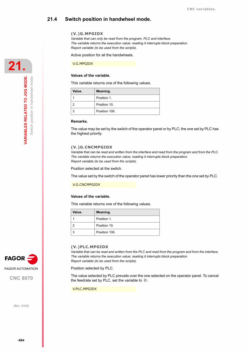
CNC variables.
CNC 8070
21.
VA
RIA
BL
ES
RE
LA
TE
D T
O J
OG
MO
DE
.
Sw
itch
pos
ition
in h
and
whe
el m
ode
.
ꞏ494ꞏ
(REF: 2102)
21.4 Switch position in handwheel mode.
(V.)G.MPGIDXVariable that can only be read from the program, PLC and interface.The variable returns the execution value; reading it interrupts block preparation.Report variable (to be used from the scripts).
Active position for all the handwheels.
Values of the variable.
This variable returns one of the following values.
Remarks.
The value may be set by the switch of the operator panel or by PLC; the one set by PLC hasthe highest priority.
(V.)G.CNCMPGIDXVariable that can be read and written from the interface and read from the program and from the PLC.The variable returns the execution value; reading it interrupts block preparation.Report variable (to be used from the scripts).
Position selected at the switch.
The value set by the switch of the operator panel has lower priority than the one set by PLC.
Values of the variable.
This variable returns one of the following values.
(V.)PLC.MPGIDXVariable that can be read and written from the PLC and read from the program and from the interface.The variable returns the execution value; reading it interrupts block preparation.Report variable (to be used from the scripts).
Position selected by PLC.
The value selected by PLC prevails over the one selected on the operator panel. To cancelthe feedrate set by PLC, set the variable to ꞏ0ꞏ.
V.G.MPGIDX
Value. Meaning.
1 Position 1.
2 Position 10.
3 Position 100.
V.G.CNCMPGIDX
Value. Meaning.
1 Position 1.
2 Position 10.
3 Position 100.
V.PLC.MPGIDX

CNC variables.
CNC 8070
VA
RIA
BL
ES
RE
LA
TE
D T
O J
OG
MO
DE
.
21.
Sw
itch
pos
ition
in h
and
whe
el m
ode
.
ꞏ495ꞏ
(REF: 2102)
Values of the variable.
This variable returns one of the following values.
Value. Meaning.
1 Position 1.
2 Position 10.
3 Position 100.

CNC variables.
CNC 8070
21.
VA
RIA
BL
ES
RE
LA
TE
D T
O J
OG
MO
DE
.
Sw
itch
pos
ition
in in
crem
enta
l jo
g m
ode
.
ꞏ496ꞏ
(REF: 2102)
21.5 Switch position in incremental jog mode.
(V.)G.INCJOGIDXVariable that can only be read from the program, PLC and interface.The variable returns the execution value; reading it interrupts block preparation.Report variable (to be used from the scripts).
Active position for all the axes.
Values of the variable.
This variable returns one of the following values.
Remarks.
The value may be set by the switch of the operator panel or by PLC; the one set by PLC hasthe highest priority.
(V.)G.CNCINCJOGIDXVariable that can be read and written from the interface and read from the program and from the PLC.The variable returns the execution value; reading it interrupts block preparation.Report variable (to be used from the scripts).
Position selected by the switch.
The value set by the switch of the operator panel has lower priority than the one set by PLC.
Values of the variable.
This variable returns one of the following values.
(V.)PLC.INCJOGIDXVariable that can be read and written from the PLC and read from the program and from the interface.The variable returns the execution value; reading it interrupts block preparation.Report variable (to be used from the scripts).
Position selected by PLC.
The value selected by PLC prevails over the one selected on the operator panel. To cancelthe feedrate set by PLC, set the variable to ꞏ0ꞏ.
V.G.INCJOGIDX
Value. Meaning.
1 Position 1.
2 Position 10.
3 Position 100.
4 Position 1000.
5 Position 10000.
V.G.CNCINCJOGIDX
Value. Meaning.
1 Position 1.
2 Position 10.
3 Position 100.
4 Position 1000.
5 Position 10000.
V.PLC.INCJOGIDX

CNC variables.
CNC 8070
VA
RIA
BL
ES
RE
LA
TE
D T
O J
OG
MO
DE
.
21.
Sw
itch
pos
ition
in in
crem
enta
l jo
g m
ode
.
ꞏ497ꞏ
(REF: 2102)
Values of the variable.
This variable returns one of the following values.
Value. Meaning.
1 Position 1.
2 Position 10.
3 Position 100.
4 Position 1000.
5 Position 10000.

CNC variables.
CNC 8070
21.
VA
RIA
BL
ES
RE
LA
TE
D T
O J
OG
MO
DE
.
JOG
feed
rate
s.
ꞏ498ꞏ
(REF: 2102)
21.6 JOG feedrates.
(V.)[ch].G.FMANVariable that can be read and written from the program and interface and read from the PLC.The variable returns the execution value; reading it interrupts block preparation.
Jogging feedrate in G94.
Syntax.
ꞏchꞏ Channel number.
Remarks.
This variable also updates its value when setting a new feedrate ("F" field on the screen forjog mode) or MDI/MDA mode and function G94 is active.
(V.)[ch].G.MANFPRVariable that can be read and written from the program and interface and read from the PLC.The variable returns the execution value; reading it interrupts block preparation.
Jogging feedrate in G95.
Syntax.
ꞏchꞏ Channel number.
Remarks.
This variable also updates its value when setting a new feedrate ("F" field on the screen forjog mode) or MDI/MDA mode and function G95 is active.
V.[2].G.FMAN Channel ꞏ2ꞏ.
V.[2].G.MANFPR Channel ꞏ2ꞏ.

CNC 8070
22
ꞏ499ꞏ
(REF: 2102)
22.VARIABLES RELATED TO THE PROGRAMMED FUNCTIONS.
22.1 Movement of axes and spindles.
(V.)[ch].A.INPOS.xn(V.)[ch].A.INPOS.sn(V.)[ch].SP.INPOS.snVariable that can only be read from the program, PLC and interface.Variable valid for rotary and linear axes as well as for spindles.The variable returns the execution value; reading it interrupts block preparation.Report variable (to be used from the scripts).
Axis or spindle in position.
Syntax.
ꞏchꞏ Channel number.
ꞏxnꞏ Name, logic number or index of the axis.
ꞏsnꞏ Name, logic number or index of the spindle.
(V.)[ch].A.DIST.xn(V.)[ch].A.DIST.sn(V.)[ch].SP.DIST.snVariable that can be read and written via program, PLC and interface.Variable valid for rotary and linear axes as well as for spindles.The variable returns the execution value; reading it interrupts block preparation.
Distance traveled by the axis or spindle.
Syntax.
ꞏchꞏ Channel number.
ꞏxnꞏ Name, logic number or index of the axis.
ꞏsnꞏ Name, logic number or index of the spindle.
V.A.INPOS.Z Z axis.
V.A.INPOS.S Spindle S.
V.SP.INPOS.S Spindle S.
V.SP.INPOS Master spindle.
V.A.INPOS.4 Axis or spindle with logic number ꞏ4ꞏ.
V.[2].A.INPOS.1 Axis with index ꞏ1ꞏ in the channel ꞏ2ꞏ.
V.SP.INPOS.2 Spindle with index ꞏ2ꞏ in the system.
V.[2].SP.INPOS.1 Spindle with index ꞏ1ꞏ in the channel ꞏ2ꞏ.
V.A.DIST.Z Z axis.
V.A.DIST.S Spindle S.
V.SP.DIST.S Spindle S.
V.SP.DIST Master spindle.
V.A.DIST.4 Axis or spindle with logic number ꞏ4ꞏ.
V.[2].A.DIST.1 Axis with index ꞏ1ꞏ in the channel ꞏ2ꞏ.
V.SP.DIST.2 Spindle with index ꞏ2ꞏ in the system.
V.[2].SP.DIST.1 Spindle with index ꞏ1ꞏ in the channel ꞏ2ꞏ.

CNC variables.
CNC 8070
22.
VA
RIA
BL
ES
RE
LA
TE
D T
O T
HE
PR
OG
RA
MM
ED
FU
NC
TIO
NS
.
Mo
vem
ent o
f axe
s an
d sp
ind
les.
ꞏ500ꞏ
(REF: 2102)
(V.)[ch].A.ACCUDIST.xn(V.)[ch].A.ACCUDIST.sn(V.)[ch].SP.ACCUDIST.snVariable that can be read and written via program, PLC and interface.Variable valid for rotary and linear axes as well as for spindles.The variable returns the execution value; reading it interrupts block preparation.
Distance traveled by the axis or spindle since the last coordinate latching. This variable isinitialized to ꞏ0ꞏ when a latching event takes place. To add a position offset to this variableat the latch point, just add it from the PLC in a later cycle. This variable may be initializedin a sampling period and keep counting from the initialized value on.
• A particular example of how to use it could be the treatment of a rotary axis as an infiniteaxis making it possible to increase the feedback count of the axis indefinitely (withoutlimits) regardless of the value of the module.
For example, for a rotary axis that moves an endless conveyor belt on where the partis. The infinite axis treatment allows synchronizing the coordinate of the conveyor beltwith an external event and, this way, count the moving distance of the part beyond thevalue of the module of the rotary axis that moves the belt.
• Another example of how to use it would be the possibility of synchronizing a "physical"or "real" slave axis with the variable A.ACCUDIST.xn of a "virtual" master axis. The PLCcan refresh/write in every cycle the contents of the variable A.ACCUDIST.xn of the virtualaxis with any data combination, the sum of the paths of several real axes with theircorresponding coefficients, etc. Since it is a virtual axis, not physical, writing from the PLCis not altered in every cycle with the accumulated movement (travel) of that axis.
This possibility offers great flexibility to the CNC because it allows synchronizing a slaveaxis not only with a single master axis, but also with a path or a combination of severalmaster axes.
The CNC can use this variable, that can write at any time, to follow up on an axis with asynchronization movement (#FOLLOW ON, #TFOLLOW ON) or a position-cam(#CAM ON, #TCAM ON). The way to use it is programming the master axis with the prefixACCU.
The following table shows, for each case, what the slave axis synchronizes with, whetherwith the real position, the theoretical position or the variable A.ACCUDIST.xn of the masterprogrammed in each instruction.
Syntax.
ꞏchꞏ Channel number.
ꞏxnꞏ Name, logic number or index of the axis.
ꞏsnꞏ Name, logic number or index of the spindle.
#FOLLOW ON [ACCUX, Y, N1, D1]#TFOLLOW ON [ACCUX, Y, N1, D1]#CAM ON [1, ACCUX, Y, 30, 0, 100, 100]#TCAM ON [1, ACCUX, Y, 30, 0, 100, 100]
In these examples, the Y axis follows up on the X axis with the variable V.A.ACCUDIST.X.
Instruction. Synchronization.
#FOLLOW ON [X, Y, N1, D1] Real position.
#FOLLOW ON [ACCUX, Y, N1, D1] Variable A.ACCUDIST.xn
#TFOLLOW ON [X, Y, N1, D1] Theoretical position.
#TFOLLOW ON [ACCUX, Y, N1, D1] Variable A.ACCUDIST.xn
#CAM ON [1, X, Y, 30, 0, 100, 100] Real position.
#CAM ON [1, ACCUX, Y, 30, 0, 100, 100] Variable A.ACCUDIST.xn
#TCAM ON [1, X, Y, 30, 0, 100, 100] Theoretical position.
#TCAM ON [1, ACCUX, Y, 30, 0, 100, 100] Variable A.ACCUDIST.xn
V.A.ACCUDIST.Z Z axis.
V.A.ACCUDIST.S Spindle S.
V.SP.ACCUDIST.S Spindle S.
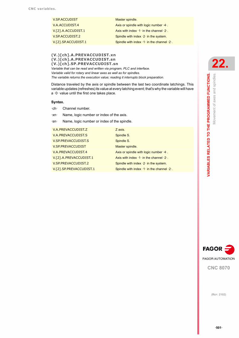
CNC variables.
CNC 8070
VA
RIA
BL
ES
RE
LA
TE
D T
O T
HE
PR
OG
RA
MM
ED
FU
NC
TIO
NS
.
22.
Mo
vem
ent o
f axe
s an
d sp
ind
les.
ꞏ501ꞏ
(REF: 2102)
(V.)[ch].A.PREVACCUDIST.xn(V.)[ch].A.PREVACCUDIST.sn(V.)[ch].SP.PREVACCUDIST.snVariable that can be read and written via program, PLC and interface.Variable valid for rotary and linear axes as well as for spindles.The variable returns the execution value; reading it interrupts block preparation.
Distance traveled by the axis or spindle between the last two coordinate latchings. Thisvariable updates (refreshes) its value at every latching event; that's why the variable will havea ꞏ0ꞏ value until the first one takes place.
Syntax.
ꞏchꞏ Channel number.
ꞏxnꞏ Name, logic number or index of the axis.
ꞏsnꞏ Name, logic number or index of the spindle.
V.SP.ACCUDIST Master spindle.
V.A.ACCUDIST.4 Axis or spindle with logic number ꞏ4ꞏ.
V.[2].A.ACCUDIST.1 Axis with index ꞏ1ꞏ in the channel ꞏ2ꞏ.
V.SP.ACCUDIST.2 Spindle with index ꞏ2ꞏ in the system.
V.[2].SP.ACCUDIST.1 Spindle with index ꞏ1ꞏ in the channel ꞏ2ꞏ.
V.A.PREVACCUDIST.Z Z axis.
V.A.PREVACCUDIST.S Spindle S.
V.SP.PREVACCUDIST.S Spindle S.
V.SP.PREVACCUDIST Master spindle.
V.A.PREVACCUDIST.4 Axis or spindle with logic number ꞏ4ꞏ.
V.[2].A.PREVACCUDIST.1 Axis with index ꞏ1ꞏ in the channel ꞏ2ꞏ.
V.SP.PREVACCUDIST.2 Spindle with index ꞏ2ꞏ in the system.
V.[2].SP.PREVACCUDIST.1 Spindle with index ꞏ1ꞏ in the channel ꞏ2ꞏ.

CNC variables.
CNC 8070
22.
VA
RIA
BL
ES
RE
LA
TE
D T
O T
HE
PR
OG
RA
MM
ED
FU
NC
TIO
NS
.
Wor
k p
lane
and
axe
s.
ꞏ502ꞏ
(REF: 2102)
22.2 Work plane and axes.
(V.)[ch].G.PLANEVariable that can only be read from the program, PLC and interface.The variable returns the value of block preparation.
Axes making up the work plane.
Syntax.
ꞏchꞏ Channel number.
Values of the variable.
(V.)[ch].G.LONGAXVariable that can only be read from the program, PLC and interface.The variable returns the value of block preparation.
Longitudinal axis.
Syntax.
ꞏchꞏ Channel number.
Values of the variable.
V.[2].G.PLANE Channel ꞏ2ꞏ.
X=10 X1=11 X2=12 X3=13 X4=14 ... X9=19
Y=20 Y1=21 Y2=22 Y3=23 Y4=24 ... Y9=29
Z=30 Z1=31 Z2=32 Z3=33 Z4=34 ... Z9=39
U=40 U1=41 U2=42 U3=43 U4=44 ... U9=49
V=50 V1=51 V2=52 V3=53 V4=54 ... V9=59
W=60 W1=61 W2=62 W3=63 W4=64 ... W9=69
A=70 A1=71 A2=72 A3=73 A4=74 ... A9=79
B=80 B1=81 B2=82 B3=83 B4=84 ... B9=89
C=90 C1=91 C2=92 C3=93 C4=94 ... C9=99
Main axes. Main plane. Reading the variable.
X-Y-Z G17 (XY) V.[1].G.PLANE = 1020V.[1].G.LONGAX = 30V.[1].G.TOOLDIR = 2
X-Y-Z G18 (ZX) V.[1].G.PLANE = 3010V.[1].G.LONGAX = 20V.[1].G.TOOLDIR = 2
X-V1-Z3 G17 (X-V1)#TOOL AX [V1-]
V.[1].G.PLANE = 1051V.[1].G.LONGAX = 33V.[1].G.TOOLDIR = 1
V.[2].G.LONGAX Channel ꞏ2ꞏ.
X=10 X1=11 X2=12 X3=13 X4=14 ... X9=19
Y=20 Y1=21 Y2=22 Y3=23 Y4=24 ... Y9=29
Z=30 Z1=31 Z2=32 Z3=33 Z4=34 ... Z9=39
U=40 U1=41 U2=42 U3=43 U4=44 ... U9=49
V=50 V1=51 V2=52 V3=53 V4=54 ... V9=59
W=60 W1=61 W2=62 W3=63 W4=64 ... W9=69
A=70 A1=71 A2=72 A3=73 A4=74 ... A9=79
B=80 B1=81 B2=82 B3=83 B4=84 ... B9=89
C=90 C1=91 C2=92 C3=93 C4=94 ... C9=99

CNC variables.
CNC 8070
VA
RIA
BL
ES
RE
LA
TE
D T
O T
HE
PR
OG
RA
MM
ED
FU
NC
TIO
NS
.
22.
Wor
k p
lane
and
axe
s.
ꞏ503ꞏ
(REF: 2102)
(V.)[ch].G.TOOLDIRVariable that can only be read from the program, PLC and interface.The variable returns the value of block preparation.
Tool orientation.
Syntax.
ꞏchꞏ Channel number.
Values of the variable.
This variable returns one of the following values.
(V.)[ch].G.PLAXNAME1(V.)[ch].G.PLAXNAME2(V.)[ch].G.PLAXNAME3Variable to be read via interface.
Name the main axes of the channel.
Syntax.
ꞏchꞏ Channel number.
V.[2].G.TOOLDIR Channel ꞏ2ꞏ.
Value. Meaning.
1 The tool is positioned in the positive direction of the axis.
2 The tool is positioned in the negative direction of the axis.
[2].G.PLAXNAME1 Channel ꞏ2ꞏ. Abscissa axis.
[2].G.PLAXNAME2 Channel ꞏ2ꞏ. Ordinate axis.
[2].G.PLAXNAME3 Channel ꞏ2ꞏ. Third main axis.

CNC variables.
CNC 8070
22.
VA
RIA
BL
ES
RE
LA
TE
D T
O T
HE
PR
OG
RA
MM
ED
FU
NC
TIO
NS
.
Wor
k p
lane
and
axe
s.
ꞏ504ꞏ
(REF: 2102)
(V.)[ch].G.PLANELONGVariable to be read via interface.
Index of the tool in the axis channel.
Syntax.
ꞏchꞏ Channel number.
Remarks.
In this variable, the index in the channel of the first axis will be ꞏ0ꞏ, that of the second axiswill be ꞏ1ꞏ and so on.
[2].G.PLANELONG Channel ꞏ2ꞏ.

CNC variables.
CNC 8070
VA
RIA
BL
ES
RE
LA
TE
D T
O T
HE
PR
OG
RA
MM
ED
FU
NC
TIO
NS
.
22.
"G"
and
"M
" fu
nctio
ns.
ꞏ505ꞏ
(REF: 2102)
22.3 "G" and "M" functions.
22.3.1 Status of the functions "G" and "M".
(V.)[ch].G.GS[nb]Variable that can only be read from the program, PLC and interface.The variable returns the value of block preparation.Report variable (to be used from the scripts).
Status of the requested "G" function.
Syntax.
ꞏchꞏ Channel number.
ꞏnbꞏ Function number.
Values of the variable.
Each function has a bit that indicates whether the relevant function is active (=1) or not (=0).
(V.)[ch].G.MS[nb]Variable that can only be read from the program, PLC and interface.The variable returns the value of block preparation.Report variable (to be used from the scripts).
Status of the requested "M" function.
Syntax.
ꞏchꞏ Channel number.
ꞏnbꞏ Function number.
Values of the variable.
Each function has a bit that indicates whether the relevant function is active (=1) or not (=0).
(V.)[ch].G.HGS1··(V.)[ch].G.HGS10Variable that can only be read from the program, PLC and interface.The variable returns the value of block preparation.
Status of the requested "G" (32 bit) functions.
Syntax.
ꞏchꞏ Channel number.
Remarks.
Every variable corresponds to a range of 32 G functions and returns a 32-bit value; 1 bit perfunction. Each bit indicates whether the function is active (bit = 1) or not (bit = 0). The leastsignificant bit corresponds to the lowest function of the range.
V.[2].G.GS[3] Channel ꞏ2ꞏ. Function G3.
V.[2].G.MS[5] Channel ꞏ2ꞏ. M5 function.
V.[2].G.HGS1 Channel ꞏ2ꞏ.
Variable. G function range.
(V.)[ch].G.HGS1 G0 - G31. Bit 0 corresponds to G0.
(V.)[ch].G.HGS2 G32 - G63 Bit 0 corresponds to function G32.
(V.)[ch].G.HGS3 G64 - G95 Bit 0 corresponds to function G64.

CNC variables.
CNC 8070
22.
VA
RIA
BL
ES
RE
LA
TE
D T
O T
HE
PR
OG
RA
MM
ED
FU
NC
TIO
NS
.
"G"
and
"M
" fu
nctio
ns.
ꞏ506ꞏ
(REF: 2102)
(V.)[ch].G.HGS4 G96 - G127 Bit 0 corresponds to function G96.
(V.)[ch].G.HGS5 G128 - G159 Bit 0 corresponds to function G128.
(V.)[ch].G.HGS6 G160- G191 Bit 0 corresponds to function G160.
(V.)[ch].G.HGS7 G192 - G223 Bit 0 corresponds to function G192.
(V.)[ch].G.HGS8 G224 - G255 Bit 0 corresponds to function G224.
(V.)[ch].G.HGS9 G256 - G287 Bit 0 corresponds to function G256.
(V.)[ch].G.HGS10 G288 - G319 Bit 0 corresponds to function G288.
To check the status of function G08 from the part-program.
$IF [V.[1].G.HGS1 & [2**8]] == 2**8
To check the status of function G101 from the part-program.
$IF [V.[1].G.HGS4 & [2**5]] == 2**5
To check the status of function G08 from the PLC.
DFU B0KEYBD1 = CNCRD(G.HGS1, R100, M100)B8R100 = ···
To check the status of function G101 from the PLC.
DFU B0KEYBD1 = CNCRD(G.HGS4, R101, M100)B5R101 = ···
Variable. G function range.

CNC variables.
CNC 8070
VA
RIA
BL
ES
RE
LA
TE
D T
O T
HE
PR
OG
RA
MM
ED
FU
NC
TIO
NS
.
22.
"G"
and
"M
" fu
nctio
ns.
ꞏ507ꞏ
(REF: 2102)
22.3.2 Functions "G" and "M" to be displayed in the history.
(V.)[ch].G.HGSVariable to be read via interface.Report variable (to be used from the scripts).
"G" functions to be displayed in the history.
Remarks.
This variable returns a binary value. Each function has a bit that indicates whether therelevant variable will be displayed (=1) or not (=0). Bit 0, the least significant bit, correspondsto G0, bit 1 to G1 and so on.
(V.)[ch].G.HMSVariable to be read via interface.Report variable (to be used from the scripts).
"M" functions of the master spindle to be displayed in the history.
Values of the variable.
This variable returns a hexadecimal value with the following meaning. Each bit representsan M function and indicates whether that function must be displayed (bit=1) or not (bit=0).
(V.)[ch].G.HMS1(V.)[ch].G.HMS2(V.)[ch].G.HMS3(V.)[ch].G.HMS4Variable to be read via interface.Report variable (to be used from the scripts).
"M" functions of spindle 1 through 4 to be displayed in the history.
[2].G.HGS Channel ꞏ2ꞏ.
[2].G.HMS Channel ꞏ2ꞏ. Master spindle.
Value. Meaning.
$1 M0
$2 M1
$4 M2
$8 M3
$10 M4
$20 M5
$40 M6
$80 M8
$100 M19
$200 M30
$800 M41
$1000 M42
$2000 M43
$4000 M44
[2].G.HMS2 Channel ꞏ2ꞏ. Spindle ꞏ2ꞏ.

CNC variables.
CNC 8070
22.
VA
RIA
BL
ES
RE
LA
TE
D T
O T
HE
PR
OG
RA
MM
ED
FU
NC
TIO
NS
.
"G"
and
"M
" fu
nctio
ns.
ꞏ508ꞏ
(REF: 2102)
Values of the variable.
This variable returns a hexadecimal value with the following meaning. Each bit representsan M function and indicates whether that function must be displayed (bit=1) or not (bit=0).
Value. Meaning.
$1 M0
$2 M1
$4 M2
$8 M3
$10 M4
$20 M5
$40 M6
$80 M8
$100 M19
$200 M30
$800 M41
$1000 M42
$2000 M43
$4000 M44

CNC variables.
CNC 8070
VA
RIA
BL
ES
RE
LA
TE
D T
O T
HE
PR
OG
RA
MM
ED
FU
NC
TIO
NS
.
22.
"G"
and
"M
" fu
nctio
ns.
ꞏ509ꞏ
(REF: 2102)
22.3.3 Subroutine associated with M3, M4, M5, M19 and M41-M44.
(V.)[ch].G.SUBMSPDLVariable that can be read from the program.The variable returns the value of block preparation.
System spindles involved in the subroutine associated with M3, M4, M5, M19 and M41-M44.
The variables only have meaning inside the subroutine associated with the M functions ofthe spindle; i.e. in the block where the M function is programmed and, therefore, there is acall to the subroutine. Outside these subroutines, the value of the variable will be 0.
Syntax.
ꞏchꞏ Channel number.
Remarks.
The variable returns a 4-bit value where each bit represents one spindle; the least significantbit corresponds to spindle 1. Each bit indicates whether the spindle is selected (bit = 1) ornot (bit = 0).
V.[2].G.SUBMSPDL Channel ꞏ2ꞏ.
Value. Meaning.
0 0000 No spindle.
1 0001 Spindle 1.
2 0010 Spindle 2.
3 0011 Spindles 1 and 2.
4 0100 Spindle 3.
5 0101 Spindles 1 and 3.
6 0110 Spindles 2 and 3.
7 0111 Spindles 1, 2 and 3.
8 1000 Spindle 4.
9 1001 Spindles 1 and 4.
10 1010 Spindles 2 and 4.
11 1011 Spindles 1, 2 and 4.
12 1100 Spindles 3 and 4.
13 1101 Spindles 1, 3 and 4.
14 1110 Spindles 2, 3 and 4.
15 1111 Spindles 1, 2, 3 and 4.

CNC variables.
CNC 8070
22.
VA
RIA
BL
ES
RE
LA
TE
D T
O T
HE
PR
OG
RA
MM
ED
FU
NC
TIO
NS
.
Can
ned
cycl
es.
ꞏ510ꞏ
(REF: 2102)
22.4 Canned cycles.
(V.)[ch].G.CYCLETYPEONVariable that can only be read from the program, PLC and interface.The variable returns the value of block preparation.
Type of canned cycle active
Syntax.
ꞏchꞏ Channel number.
Values of the variable.
This variable returns one of the following values.
(V.)[ch].G.ACTIVECYCLEVariable that can only be read from the program, PLC and interface.The variable returns the value of block preparation.
Active canned cycle.
Syntax.
ꞏchꞏ Channel number.
Values of the variable.
This variable returns one of the following values.
• Milling cycles: ISO cycles (1 - 99).
V.[2].G.CYCLETYPEON Channel ꞏ2ꞏ.
Value. Meaning.
0 Milling cycles.
1 Turning cycles.
V.[2].G.ACTIVECYCLE Channel ꞏ2ꞏ.
Value / Meaning. Value / Meaning.
0 No active cycle. 41 #PROBE 1
1 G81 42 #PROBE 2
2 G82 43 #PROBE 3
3 G83 44 #PROBE 4
4 G84 45 #PROBE 5
5 G85 46 #PROBE 6
6 G86 47 #PROBE 7
7 G87 48 #PROBE 8
8 G88 49 #PROBE 9
11 G210 50 #PROBE 10
12 G211 51 #PROBE 11
13 G212 52 #PROBE 12
21 G66 61 G8078
31 G160 62 G8079
32 G161 63 G8724
33 G162 64 G8728
34 G163 65 G8734

CNC variables.
CNC 8070
VA
RIA
BL
ES
RE
LA
TE
D T
O T
HE
PR
OG
RA
MM
ED
FU
NC
TIO
NS
.
22.
Can
ned
cycl
es.
ꞏ511ꞏ
(REF: 2102)
• Milling cycles: Cycle editor (100 - 199).
• Turning cycles: ISO cycles (1000 - 1099).
• Turning cycles: Cycle editor (1100 - 1199).
35 G164 66 G8738
36 G165 67 G8753
68 G8778
Value / Meaning. Value / Meaning.
101 Center punching. 131 Free profile milling.
102 Drilling. 132 Point-to-point profile milling.
103 Deep hole drilling. 133 Surface milling.
104 Bore milling. 134 Slot milling.
105 Tapping. 141 Simple positioning.
106 Thread milling. 142 Positioning and M funcions.
107 Reaming. 151 Tool calibration.
108 Boring. 152 Probe calibration.
109 Boring with spindle orientation. 153 Tabletop probe calibration.
121 Simple rectangular pocket. 154 Surfacing measuring.
122 Rectangular pocket with rounding. 155 Outside corner measuring.
123 Circular pocket. 156 Inside corner measuring.
124 Pre-emptied circular pocket. 157 Angle measurement on the abscissaaxis.
125 2D profile pocket. 158 Outs ide co rner and ang lemeasurement.
126 3D profile pockets with islands. 159 Hole measuring.
127 Rectangular boss. 160 Circular boss measuring.
128 Circular boss. 161 Rectangular or circular part/pocketcentering.
Value / Meaning. Value / Meaning.
1001 G81 1012 G68
1002 G82 1013 G69
1003 G83 1021 G160
1004 G84 1022 G161
1005 G85 1023 G162
1006 G86 1024 G163
1007 G87 1031 #PROBE 1
1008 G88 1032 #PROBE 2
1009 G89 1033 #PROBE 3
1011 G66 1034 #PROBE 4
Value / Meaning. Value / Meaning.
1101 Simple turning. 1152 Drilling.
1102 Turning with vertex rounding. 1153 Tapping.
1103 Simple facing. 1161 Multiple center-punching.
1104 Facing with vertex rounding. 1162 Multiple drilling.
Value / Meaning. Value / Meaning.

CNC variables.
CNC 8070
22.
VA
RIA
BL
ES
RE
LA
TE
D T
O T
HE
PR
OG
RA
MM
ED
FU
NC
TIO
NS
.
Can
ned
cycl
es.
ꞏ512ꞏ
(REF: 2102)
1105 Corner chamfering 1. 1163 Multiple tapping.
1106 Corner chamfering 2. 1164 Multiple reaming.
1107 Chamfer between points. 1165 Multiple boring.
1108 Vertex rounding. 1166 Multiple bore milling.
1109 Rounding between points. 1167 Multiple thread milling.
1121 Longitudinal threading. 1168 Multiple slot milling.
1122 Taper threading. 1171 Simple positioning.
1123 Face threading. 1172 Positioning with M functions.
1124 Thread repair. 1181 Rectangular pocket in the ZC/YZplane.
1125 Multi-entry (start) threading 1182 Rectangular pocket in the XC/XYplane.
1131 Simple longitudinal grooving. 1183 Circular pocket in the ZC/YZ plane.
1132 Simple face grooving. 1184 Circular pocket in the XC/XY plane.
1133 Inclined (angled) longitudinal grooving. 1185 Circular pre-emptied pocket in theZC/YZ plane.
1134 Inclined face grooving. 1186 Circular pre-emptied pocket in theXC/XY plane.
1135 Cut-off. 1187 2D profile pocket in the ZC/YZ plane.
1141 Point-to-point turning. 1188 2D profile pocket in the XC/XY plane.
1142 Profile turning. 1191 Tool calibration.
1143 Profile in the ZC/YZ plane. 1192 Tabletop probe calibration.
1144 Profile in the XC/XY plane. 1193 Part measurement along the ordinateaxis.
1151 Center punching. 1194 Part measurement along the abscissaaxis.
Value / Meaning. Value / Meaning.

CNC variables.
CNC 8070
VA
RIA
BL
ES
RE
LA
TE
D T
O T
HE
PR
OG
RA
MM
ED
FU
NC
TIO
NS
.
22.
Can
ned
cycl
e ca
llin
g pa
ram
eter
s.
ꞏ513ꞏ
(REF: 2102)
22.5 Canned cycle calling parameters.
(V.)C.A··ZVariable that can be read and written from the program.The variable returns the value of block preparation.
Value of the ISO canned cycle calling parameter.
Syntax.
ꞏAꞏꞏZꞏ Call parameter.
Remarks.
(V.)C.nameVariable that can be read and written from the program.The variable returns the value of block preparation.
Value of the parameters that call upon the canned cycles of the editor.
Syntax.
ꞏnameꞏCall parameter.
(V.)C.CALLP_A··ZVariable that can be read from the program.The variable returns the value of block preparation.
Parameter programmed in the call to a canned cycle.
Syntax.
ꞏAꞏꞏZꞏ Call parameter.
Values of the variable.
This variable returns one of the following values.
Remarks.
(V.)C.P_A··ZVariable that can be read and written from the program.The variable returns the value of block preparation.
Value of the positioning cycle calling parameter.
V.C.F "F" parameter.
Calling a canned cycle. Reading the variable.
G90 G81 Z0 I-15 V.C.Z = 0V.C.Z = -15
V.C.MROUGHING Parameter MROUGHING.
V.C.CALLP_F "F" parameter.
Value. Meaning.
0 It has not been programmed.
1 It has been programmed.
Calling a canned cycle. Reading the variable.
G90 G81 Z0 I-15 V.C.CALLP_Z = 1V.C.CALLP_I = 1V.C.CALLP_K = 0
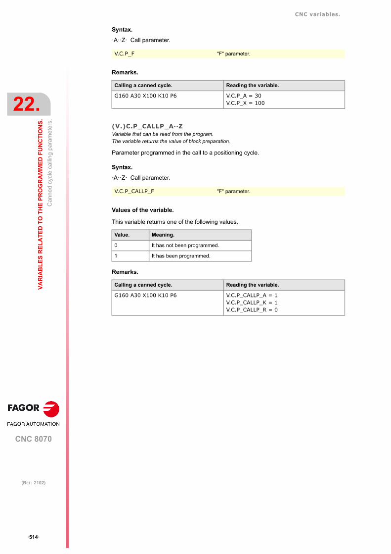
CNC variables.
CNC 8070
22.
VA
RIA
BL
ES
RE
LA
TE
D T
O T
HE
PR
OG
RA
MM
ED
FU
NC
TIO
NS
.
Can
ned
cycl
e ca
llin
g pa
ram
eter
s.
ꞏ514ꞏ
(REF: 2102)
Syntax.
ꞏAꞏꞏZꞏ Call parameter.
Remarks.
(V.)C.P_CALLP_A··ZVariable that can be read from the program.The variable returns the value of block preparation.
Parameter programmed in the call to a positioning cycle.
Syntax.
ꞏAꞏꞏZꞏ Call parameter.
Values of the variable.
This variable returns one of the following values.
Remarks.
V.C.P_F "F" parameter.
Calling a canned cycle. Reading the variable.
G160 A30 X100 K10 P6 V.C.P_A = 30V.C.P_X = 100
V.C.P_CALLP_F "F" parameter.
Value. Meaning.
0 It has not been programmed.
1 It has been programmed.
Calling a canned cycle. Reading the variable.
G160 A30 X100 K10 P6 V.C.P_CALLP_A = 1V.C.P_CALLP_K = 1V.C.P_CALLP_R = 0

CNC variables.
CNC 8070
VA
RIA
BL
ES
RE
LA
TE
D T
O T
HE
PR
OG
RA
MM
ED
FU
NC
TIO
NS
.
22.
Su
brou
tine
calli
ng
para
met
ers.
ꞏ515ꞏ
(REF: 2102)
22.6 Subroutine calling parameters.
(V.)C.PCALLP_A···(V.)C.PCALLP_ZVariable that can be read from the program.The variable returns the value of block preparation.Units: Value listed.
Parameter programmed in the call for a subroutine or in instructions #CUTTING and#PIERCING. This variable is valid for OEM subroutines (G180-G189 and G380-G399) andfor subroutines called upon using #PCALL or #MCALL.
Syntax.
Values of the variable.
Remarks.
(V.)G.CALLPVariable that can be read from the program.The variable returns the value of block preparation.Units: - .
Local parameters programmed in the call for a subroutine or in #CUTTING and #PIERCINGinstructions.
Syntax.
Values of the variable.
The variable returns a value coded in bits, in which each bit represents a parameter; the bitwith the lowest weight (bit 0) corresponds to parameter P0, bit 1, to parameter P1, and soon. Each bit indicates whether the parameter is programmed (bit=1) or not (bit=0).
V.C.PCALLP_A Parameter "A".
V.C.PCALLP_F "F" parameter.
Value. Meaning.
0 It has not been programmed.
1 It has been programmed.
Call to a subroutine. Reading the variable.
#PCALL sub.nc A12.56 D3 V.C.PCALLP_A = 1V.C.PCALLP_D = 1
G180 A12 B34.5667 V.C.PCALLP_A = 1V.C.PCALLP_B = 1
#CUTTING [T3] V.C.PCALLP_T = 1
V.G.CALLP
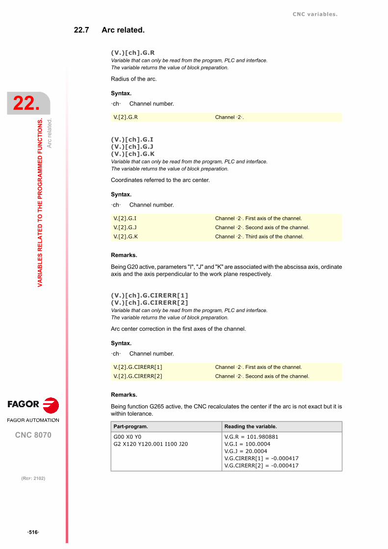
CNC variables.
CNC 8070
22.
VA
RIA
BL
ES
RE
LA
TE
D T
O T
HE
PR
OG
RA
MM
ED
FU
NC
TIO
NS
.
Arc
rel
ated
.
ꞏ516ꞏ
(REF: 2102)
22.7 Arc related.
(V.)[ch].G.RVariable that can only be read from the program, PLC and interface.The variable returns the value of block preparation.
Radius of the arc.
Syntax.
ꞏchꞏ Channel number.
(V.)[ch].G.I(V.)[ch].G.J(V.)[ch].G.KVariable that can only be read from the program, PLC and interface.The variable returns the value of block preparation.
Coordinates referred to the arc center.
Syntax.
ꞏchꞏ Channel number.
Remarks.
Being G20 active, parameters "I", "J" and "K" are associated with the abscissa axis, ordinateaxis and the axis perpendicular to the work plane respectively.
(V.)[ch].G.CIRERR[1](V.)[ch].G.CIRERR[2]Variable that can only be read from the program, PLC and interface.The variable returns the value of block preparation.
Arc center correction in the first axes of the channel.
Syntax.
ꞏchꞏ Channel number.
Remarks.
Being function G265 active, the CNC recalculates the center if the arc is not exact but it iswithin tolerance.
V.[2].G.R Channel ꞏ2ꞏ.
V.[2].G.I Channel ꞏ2ꞏ. First axis of the channel.
V.[2].G.J Channel ꞏ2ꞏ. Second axis of the channel.
V.[2].G.K Channel ꞏ2ꞏ. Third axis of the channel.
V.[2].G.CIRERR[1] Channel ꞏ2ꞏ. First axis of the channel.
V.[2].G.CIRERR[2] Channel ꞏ2ꞏ. Second axis of the channel.
Part-program. Reading the variable.
G00 X0 Y0G2 X120 Y120.001 I100 J20
V.G.R = 101.980881V.G.I = 100.0004V.G.J = 20.0004V.G.CIRERR[1] = -0.000417V.G.CIRERR[2] = -0.000417

CNC variables.
CNC 8070
VA
RIA
BL
ES
RE
LA
TE
D T
O T
HE
PR
OG
RA
MM
ED
FU
NC
TIO
NS
.
22.
Arc
rel
ated
.
ꞏ517ꞏ
(REF: 2102)
Being function G264 active, if the arc is not exact, but it is within tolerances, the CNCexecutes an arc with the radius calculated from the starting point. The CNC maintains theposition of the center.
Part-program. Reading the variable.
G00 X0 Y0G2 X120 Y120.001 I100 J20
V.G.R = 101.981371V.G.I = 100V.G.J = 20V.G.CIRERR[1] = 0V.G.CIRERR[2] = 0

CNC variables.
CNC 8070
22.
VA
RIA
BL
ES
RE
LA
TE
D T
O T
HE
PR
OG
RA
MM
ED
FU
NC
TIO
NS
.
Pol
ar o
rigin
.
ꞏ518ꞏ
(REF: 2102)
22.8 Polar origin.
(V.)[ch].G.PORGFVariable that can only be read from the program, PLC and interface.The variable returns the value of block preparation.
Position of the polar origin referred to part zero (abscissa).
Syntax.
ꞏchꞏ Channel number.
(V.)[ch].G.PORGSVariable that can only be read from the program, PLC and interface.The variable returns the value of block preparation.
Position of the polar origin referred to part zero (ordinate).
Syntax.
ꞏchꞏ Channel number.
V.[2].G.PORGF Channel ꞏ2ꞏ.
V.[2].G.PORGS Channel ꞏ2ꞏ.

CNC variables.
CNC 8070
VA
RIA
BL
ES
RE
LA
TE
D T
O T
HE
PR
OG
RA
MM
ED
FU
NC
TIO
NS
.
22.
Geo
met
ric a
ssis
tanc
e. M
irro
r im
age
.
ꞏ519ꞏ
(REF: 2102)
22.9 Geometric assistance. Mirror image.
(V.)[ch].G.MIRRORVariable that can only be read from the program, PLC and interface.The variable returns the value of block preparation.
Active mirror images.
Syntax.
ꞏchꞏ Channel number.
Remarks.
This variable returns the result in the least significant bits, one per axis (1= active and 0=notactive). The least significant bit is for the first axis, the next one for the second axis and so on.
(V.)[ch].G.MIRROR1(V.)[ch].G.MIRROR2(V.)[ch].G.MIRROR3Variable that can be read from the program.The variable returns the value of block preparation.
Mirror image active on the first axes of the channel.
Syntax.
ꞏchꞏ Channel number.
22.10 Geometric assistance. Scaling factor.
(V.)[ch].G.SCALEVariable that can only be read from the program, PLC and interface.The variable returns the value of block preparation.
It indicates the active general scaling factor.
Syntax.
ꞏchꞏ Channel number.
V.[2].G.MIRROR Channel ꞏ2ꞏ.
V.[2].G.MIRROR1 Channel ꞏ2ꞏ. First axis of the channel.
V.[2].G.MIRROR2 Channel ꞏ2ꞏ. Second axis of the channel.
V.[2].G.MIRROR3 Channel ꞏ2ꞏ. Third axis of the channel.
V.[2].G.SCALE Channel ꞏ2ꞏ.

CNC variables.
CNC 8070
22.
VA
RIA
BL
ES
RE
LA
TE
D T
O T
HE
PR
OG
RA
MM
ED
FU
NC
TIO
NS
.
Geo
met
ric a
ssis
tanc
e. C
oor
din
ate
syst
em r
ota
tion.
ꞏ520ꞏ
(REF: 2102)
22.11 Geometric assistance. Coordinate system rotation.
(V.)[ch].G.ROTPFVariable that can only be read from the program, PLC and interface.The variable returns the value of block preparation.
Position of the rotation center referred to part zero (abscissa).
Syntax.
ꞏchꞏ Channel number.
(V.)[ch].G.ROTPSVariable that can only be read from the program, PLC and interface.The variable returns the value of block preparation.
Position of the rotation center referred to part zero (ordinate).
Syntax.
ꞏchꞏ Channel number.
(V.)[ch].G.ORGROTVariable that can only be read from the program, PLC and interface.The variable returns the value of block preparation.
Rotation angle of the coordinate system.
Syntax.
ꞏchꞏ Channel number.
V.[2].G.ROTPF Channel ꞏ2ꞏ.
V.[2].G.ROTPS Channel ꞏ2ꞏ.
V.[2].G.ORGROT Channel ꞏ2ꞏ.

CNC variables.
CNC 8070
VA
RIA
BL
ES
RE
LA
TE
D T
O T
HE
PR
OG
RA
MM
ED
FU
NC
TIO
NS
.
22.
Blo
ck r
epe
titio
n.
ꞏ521ꞏ
(REF: 2102)
22.12 Block repetition.
(V.)[ch].G.PENDRPTVariable that can only be read from the program, PLC and interface.The variable returns the value of block preparation.
Number of pending repetitions with #RPT.
Syntax.
ꞏchꞏ Channel number.
Remarks.
This variable indicates the number of repetitions left to execute. In the first execution, its valueis the programmed number of repetitions minus one and in the last one, its value is zero.
(V.)[ch].G.PENDNRVariable that can only be read from the program, PLC and interface.The variable returns the value of block preparation.
Number of pending repetitions with NR.
Syntax.
ꞏchꞏ Channel number.
Remarks.
This variable indicates the number of repetitions left to execute. In the first execution, its valueis the programmed number of repetitions minus one and in the last one, its value is zero.
22.13 Axis slaving.
(V.)[ch].G.LINKACTIVEVariable that can only be read from the program, PLC and interface.The variable returns the value of block preparation.
Axis slaving (coupling) status.
Syntax.
ꞏchꞏ Channel number.
V.[2].G.PENDRPT Channel ꞏ2ꞏ.
V.[2].G.PENDNR Channel ꞏ2ꞏ.
V.[2].G.LINKACTIVE Channel ꞏ2ꞏ.

CNC variables.
CNC 8070
22.
VA
RIA
BL
ES
RE
LA
TE
D T
O T
HE
PR
OG
RA
MM
ED
FU
NC
TIO
NS
.
HS
C fu
nct
ion.
ꞏ522ꞏ
(REF: 2102)
22.14 HSC function.
(V.)[ch].G.HSCVariable that can be read from the program.The variable returns the value of block preparation.
HSC function active.
Syntax.
ꞏchꞏ Channel number.
22.15 Active probe.
(V.)[ch].G.ACTIVPROBEVariable that can only be read from the program, PLC and interface.The variable returns the value of block preparation.
Number of the active probe.
Syntax.
ꞏchꞏ Channel number.
V.[2].G.HSC Channel ꞏ2ꞏ.
V.[2].G.ACTIVPROBE Channel ꞏ2ꞏ.

CNC variables.
CNC 8070
VA
RIA
BL
ES
RE
LA
TE
D T
O T
HE
PR
OG
RA
MM
ED
FU
NC
TIO
NS
.
22.
Sta
tus
of th
e lo
cal p
robe
s.
ꞏ523ꞏ
(REF: 2102)
22.16 Status of the local probes.
(V.)G.PRBST(V.)G.PRBST1Variable that can only be read from the program, PLC and interface.The variable returns the execution value; reading it interrupts block preparation.
Status of probe ꞏ1ꞏ.
Values of the variable.
This variable returns one of the following values.
(V.)G.PRBST2Variable that can only be read from the program, PLC and interface.The variable returns the execution value; reading it interrupts block preparation.
Status of probe ꞏ2ꞏ.
Values of the variable.
This variable returns one of the following values.
V.G.PRBST
V.G.PRBST1
Value. Meaning.
0 The probe is not making contact or has not been initialized.
1 The probe is making contact.
V.G.PRBST2
Value. Meaning.
0 The probe is not making contact or has not been initialized.
1 The probe is making contact.

CNC variables.
CNC 8070
22.
VA
RIA
BL
ES
RE
LA
TE
D T
O T
HE
PR
OG
RA
MM
ED
FU
NC
TIO
NS
.
Pro
bing
(G
100
/G1
01/G
102
).
ꞏ524ꞏ
(REF: 2102)
22.17 Probing (G100/G101/G102).
(V.)[ch].G.MEASOKVariable that can be read and written from the program and read from the PLC and from the interface.The variable returns the value of block preparation.
Probing completed properly.
Syntax.
ꞏchꞏ Channel number.
Values of the variable.
This variable returns one of the following values.
Remarks.
The value of this variable can be deleted from the part-program to assist the testing of theprobe using subroutines. Although a value of 0 has been set for the part-program, the readingfrom the PLC or interface will still display a value of 1.
(V.)[ch].A.MEASOK.xnVariable that can only be read from the program, PLC and interface.Variable valid for rotary and linear axes as well as for spindles.The variable returns the execution value; reading it interrupts block preparation.
Probing done on the axis.
Syntax.
ꞏchꞏ Channel number.
ꞏxnꞏ Name, logic number or index of the axis.
ꞏsnꞏ Name, logic number or index of the spindle.
Values of the variable.
This variable returns one of the following values.
V.[2].G.MEASOK Channel ꞏ2ꞏ.
Value. Meaning.
0 No. The probe has reached the programmed coordinate.
1 Yes. The probe has made contact (G100) or stopped making contact (G103).
V.A.MEASOK.Z Z axis.
V.A.MEASOK.S Spindle S.
V.SP.MEASOK.S Spindle S.
V.SP.MEASOK Master spindle.
V.A.MEASOK.4 Axis or spindle with logic number ꞏ4ꞏ.
V.[2].A.MEASOK.1 Axis with index ꞏ1ꞏ in the channel ꞏ2ꞏ.
V.SP.MEASOK.2 Spindle with index ꞏ2ꞏ in the system.
V.[2].SP.MEASOK.1 Spindle with index ꞏ1ꞏ in the channel ꞏ2ꞏ.
Value. Meaning.
0 No.
1 Yes.

CNC variables.
CNC 8070
VA
RIA
BL
ES
RE
LA
TE
D T
O T
HE
PR
OG
RA
MM
ED
FU
NC
TIO
NS
.
22.
Pro
bing
(G
100
/G1
01/G
102
).
ꞏ525ꞏ
(REF: 2102)
(V.)[ch].G.PLMEASOK1(V.)[ch].G.PLMEASOK2(V.)[ch].G.PLMEASOK3Variable that can be read from the program.The variable returns the execution value; reading it interrupts block preparation.
Probing on the plane axes completed.
Syntax.
ꞏchꞏ Channel number.
Values of the variable.
This variable returns one of the following values.
(V.)[ch].A.MEAS.xnVariable that can only be read from the program, PLC and interface.Variable valid for rotary and linear axes as well as for spindles.The variable returns the execution value; reading it interrupts block preparation.
Measured value. Machine coordinates of the tool base.
Syntax.
ꞏchꞏ Channel number.
ꞏxnꞏ Name, logic number or index of the axis.
ꞏsnꞏ Name, logic number or index of the spindle.
Remarks.
(V.)[ch].A.ATIPMEAS.xnVariable that can be read from the program.Variable valid for rotary and linear axes as well as for spindles.The variable returns the execution value; reading it interrupts block preparation.
Measured value. Part coordinates of the tool tip.
Syntax.
ꞏchꞏ Channel number.
V.[2].G.PLMEASOK1 Channel ꞏ2ꞏ. First axis of the plane.
V.[2].G.PLMEASOK2 Channel ꞏ2ꞏ. Second axis of the plane.
V.[2].G.PLMEASOK3 Channel ꞏ2ꞏ. Third axis of the plane.
Value. Meaning.
0 No.
1 Yes.
V.A.MEAS.Z Z axis.
V.A.MEAS.S Spindle S.
V.SP.MEAS.S Spindle S.
V.SP.MEAS Master spindle.
V.A.MEAS.4 Axis or spindle with logic number ꞏ4ꞏ.
V.[2].A.MEAS.1 Axis with index ꞏ1ꞏ in the channel ꞏ2ꞏ.
V.SP.MEAS.2 Spindle with index ꞏ2ꞏ in the system.
V.[2].SP.MEAS.1 Spindle with index ꞏ1ꞏ in the channel ꞏ2ꞏ.
Part-program. Reading the variable.
G00 X0 Y0G100 X100 F100
V.A.MEAS.X = 95V.A.MEASOF.X = -5V.A.MEASOK.X = 1

CNC variables.
CNC 8070
22.
VA
RIA
BL
ES
RE
LA
TE
D T
O T
HE
PR
OG
RA
MM
ED
FU
NC
TIO
NS
.
Pro
bing
(G
100
/G1
01/G
102
).
ꞏ526ꞏ
(REF: 2102)
ꞏxnꞏ Name, logic number or index of the axis.
ꞏsnꞏ Name, logic number or index of the spindle.
(V.)[ch].G.PLMEAS1(V.)[ch].G.PLMEAS2(V.)[ch].G.PLMEAS3Variable that can be read from the program.The variable returns the value of block preparation.
Value measured on the first axes of the channel. Part coordinates of the tool tip.
Syntax.
ꞏchꞏ Channel number.
(V.)[ch].G.PLMEAS4Variable that can be read from the program.The variable returns the value of block preparation.
Value measured at the master spindle of the channel. Part coordinates of the tool tip.
Syntax.
ꞏchꞏ Channel number.
(V.)[ch].A.MEASOF.xnVariable that can only be read from the program, PLC and interface.Variable valid for rotary and linear axes as well as for spindles.The variable returns the execution value; reading it interrupts block preparation.
Difference with respect to programmed point.
Syntax.
ꞏchꞏ Channel number.
ꞏxnꞏ Name, logic number or index of the axis.
ꞏsnꞏ Name, logic number or index of the spindle.
V.A.ATIPMEAS.Z Z axis.
V.A.ATIPMEAS.S Spindle S.
V.SP.ATIPMEAS.S Spindle S.
V.SP.ATIPMEAS Master spindle.
V.A.ATIPMEAS.4 Axis or spindle with logic number ꞏ4ꞏ.
V.[2].A.ATIPMEAS.1 Axis with index ꞏ1ꞏ in the channel ꞏ2ꞏ.
V.SP.ATIPMEAS.2 Spindle with index ꞏ2ꞏ in the system.
V.[2].SP.ATIPMEAS.1 Spindle with index ꞏ1ꞏ in the channel ꞏ2ꞏ.
V.[2].G.PLMEAS1 Channel ꞏ2ꞏ. First axis of the channel.
V.[2].G.PLMEAS2 Channel ꞏ2ꞏ. Second axis of the channel.
V.[2].G.PLMEAS3 Channel ꞏ2ꞏ. Third axis of the channel.
V.[2].G.PLMEAS4 Channel ꞏ2ꞏ. Master spindle of the channel.
V.A.MEASOF.Z Z axis.
V.A.MEASOF.S Spindle S.
V.SP.MEASOF.S Spindle S.
V.SP.MEASOF Master spindle.
V.A.MEASOF.4 Axis or spindle with logic number ꞏ4ꞏ.
V.[2].A.MEASOF.1 Axis with index ꞏ1ꞏ in the channel ꞏ2ꞏ.
V.SP.MEASOF.2 Spindle with index ꞏ2ꞏ in the system.
V.[2].SP.MEASOF.1 Spindle with index ꞏ1ꞏ in the channel ꞏ2ꞏ.

CNC variables.
CNC 8070
VA
RIA
BL
ES
RE
LA
TE
D T
O T
HE
PR
OG
RA
MM
ED
FU
NC
TIO
NS
.
22.
Pro
bing
(G
100
/G1
01/G
102
).
ꞏ527ꞏ
(REF: 2102)
(V.)[ch].A.MEASIN.xnVariable that can only be read from the program, PLC and interface.Variable valid for rotary and linear axes as well as for spindles.The variable returns the execution value; reading it interrupts block preparation.
Coordinate that includes a measurement offset.
Syntax.
ꞏchꞏ Channel number.
ꞏxnꞏ Name, logic number or index of the axis.
ꞏsnꞏ Name, logic number or index of the spindle.
Remarks.
The CNC only refreshes this variable when probing with G101.
V.A.MEASIN.Z Z axis.
V.A.MEASIN.S Spindle S.
V.SP.MEASIN.S Spindle S.
V.SP.MEASIN Master spindle.
V.A.MEASIN.4 Axis or spindle with logic number ꞏ4ꞏ.
V.[2].A.MEASIN.1 Axis with index ꞏ1ꞏ in the channel ꞏ2ꞏ.
V.SP.MEASIN.2 Spindle with index ꞏ2ꞏ in the system.
V.[2].SP.MEASIN.1 Spindle with index ꞏ1ꞏ in the channel ꞏ2ꞏ.

CNC variables.
CNC 8070
22.
VA
RIA
BL
ES
RE
LA
TE
D T
O T
HE
PR
OG
RA
MM
ED
FU
NC
TIO
NS
.
Man
ual
inte
rven
tion.
ꞏ528ꞏ
(REF: 2102)
22.18 Manual intervention.
(V.)[ch].A.MANOF.xnVariable that can only be read from the program, PLC and interface.Variable valid for rotary and linear axes.The variable returns the execution value; reading it interrupts block preparation.
Distance moved in jog mode or tool inspection.
Syntax.
ꞏchꞏ Channel number.
ꞏxnꞏ Name, logic number or index of the axis.
(V.)[ch].A.ADDMANOF.xnVariable that can only be read from the program, PLC and interface.Variable valid for rotary and linear axes.The variable returns the execution value; reading it interrupts block preparation.
Distance moved with G200 or G201.
Syntax.
ꞏchꞏ Channel number.
ꞏxnꞏ Name, logic number or index of the axis.
Remarks.
The value of this variable is maintained during the execution of the program even whencanceling manual intervention.
V.A.MANOF.Z Z axis.
V.A.MANOF.4 Axis with logic number ꞏ4ꞏ.
V.[2].A.MANOF.1 Axis with index ꞏ1ꞏ in the channel ꞏ2ꞏ.
V.A.ADDMANOF.Z Z axis.
V.A.ADDMANOF.4 Axis with logic number ꞏ4ꞏ.
V.[2].A.ADDMANOF.1 Axis with index ꞏ1ꞏ in the channel ꞏ2ꞏ.

CNC variables.
CNC 8070
VA
RIA
BL
ES
RE
LA
TE
D T
O T
HE
PR
OG
RA
MM
ED
FU
NC
TIO
NS
.
22.
Sta
tus
of th
e an
gula
r tr
ans
form
atio
n.
ꞏ529ꞏ
(REF: 2102)
22.19 Status of the angular transformation.
(V.)[ch].G.ANGAXSTVariable that can only be read from the program, PLC and interface.The variable returns the value of block preparation.
Overall status of the angular transformation of the channel.
Syntax.
ꞏchꞏ Channel number.
Values of the variable.
This variable returns one of the following values.
(V.)G.ANGIDST[nb]Variable that can only be read from the program, PLC and interface.The variable returns the value of block preparation.
Status of the angular transformation [nb] of the machine parameters.
Syntax.
ꞏnbꞏ Number of the angular transformation in the order defined in the machine parameters.
Values of the variable.
This variable returns one of the following values.
V.[2].G.ANGAXST Channel ꞏ2ꞏ.
Value. Meaning.
0 Off.
1 On.
2 Frozen (suspended).
V.G.ANGIDST[1] Angular transformation ꞏ1ꞏ.
Value. Meaning.
0 Off.
1 On.
2 Frozen (suspended).

CNC variables.
CNC 8070
22.
VA
RIA
BL
ES
RE
LA
TE
D T
O T
HE
PR
OG
RA
MM
ED
FU
NC
TIO
NS
.
Tan
gen
tial c
ontr
ol s
tatu
s.
ꞏ530ꞏ
(REF: 2102)
22.20 Tangential control status.
(V.)[ch].G.TGCTRLSTVariable that can only be read from the program, PLC and interface.The variable returns the value of block preparation.
Status of tangential control in the channel.
Syntax.
ꞏchꞏ Channel number.
Values of the variable.
This variable returns one of the following values.
(V.)[ch].A.TGCTRLST.xnVariable that can only be read from the program, PLC and interface.Variable valid for rotary and linear axes.The variable returns the value of block preparation.
Status of tangential control in the axis.
Syntax.
ꞏchꞏ Channel number.
ꞏxnꞏ Name, logic number or index of the axis.
Values of the variable.
This variable returns one of the following values.
(V.)[ch].A.TANGAN.xnVariable that can only be read from the program, PLC and interface.Variable valid for rotary and linear axes.The variable returns the execution value; reading it interrupts block preparation.
Angle programmed on the axis.
Syntax.
ꞏchꞏ Channel number.
ꞏxnꞏ Name, logic number or index of the axis.
V.[2].G.TGCTRLST Channel ꞏ2ꞏ.
Value. Meaning.
0 Off.
1 On.
2 Frozen (suspended).
V.A.TGCTRLST.Z Z axis.
V.A.TGCTRLST.4 Axis with logic number ꞏ4ꞏ.
V.[2].A.TGCTRLST.1 Axis with index ꞏ1ꞏ in the channel ꞏ2ꞏ.
Value. Meaning.
0 Off.
1 On.
2 Frozen (suspended).
V.A.TANGAN.Z Z axis.
V.A.TANGAN.4 Axis with logic number ꞏ4ꞏ.
V.[2].A.TANGAN.1 Axis with index ꞏ1ꞏ in the channel ꞏ2ꞏ.

CNC variables.
CNC 8070
VA
RIA
BL
ES
RE
LA
TE
D T
O T
HE
PR
OG
RA
MM
ED
FU
NC
TIO
NS
.
22.
Tan
gen
tial c
ontr
ol s
tatu
s.
ꞏ531ꞏ
(REF: 2102)
(V.)[ch].G.TANGFEEDVariable that can only be read from the program, PLC and interface.The variable returns the execution value; reading it interrupts block preparation.
Positioning feedrate for tangential control.
Syntax.
ꞏchꞏ Channel number.
V.[2].G.TANGFEED Channel ꞏ2ꞏ.

CNC variables.
CNC 8070
22.
VA
RIA
BL
ES
RE
LA
TE
D T
O T
HE
PR
OG
RA
MM
ED
FU
NC
TIO
NS
.
Syn
chro
niz
atio
n of
cha
nnel
s.
ꞏ532ꞏ
(REF: 2102)
22.21 Synchronization of channels.
(V.)[ch].G.MEETST[mk]Variable that can only be read from the program, PLC and interface.The variable returns the execution value; reading it interrupts block preparation.
Status of the MEET type mark [mk] in the [ch] channel.
Syntax.
ꞏchꞏ Channel number.
ꞏmkꞏ Number of the synchronization mark.
(V.)[ch].G.WAITST[mk]Variable that can only be read from the program, PLC and interface.The variable returns the execution value; reading it interrupts block preparation.
Status of the WAIT type mark [mk] in the [ch] channel.
Syntax.
ꞏchꞏ Channel number.
ꞏmkꞏ Number of the synchronization mark.
(V.)[ch].G.MEETCH[nch]Variable that can only be read from the program, PLC and interface.The variable returns the execution value; reading it interrupts block preparation.
MEET type mark originated in channel [nch] and expected by channel [ch].
Syntax.
ꞏchꞏ Channel number.
ꞏnchꞏ Channel that originates the synchronization mark.
(V.)[ch].G.WAITCH[nch]Variable that can only be read from the program, PLC and interface.The variable returns the execution value; reading it interrupts block preparation.
WAIT type mark originated in channel [nch] and expected by channel [ch].
Syntax.
ꞏchꞏ Channel number.
ꞏnchꞏ Channel that originates the synchronization mark.
V.[2].G.MEETST[4] Channel ꞏ2ꞏ. Mark ꞏ4ꞏ.
V.[2].G.WAITST[4] Channel ꞏ2ꞏ. Mark ꞏ4ꞏ.
V.[2].G.MEETCH[4] Channel ꞏ2ꞏ. Channel ꞏ4ꞏ.
V.[2].G.WAITCH[4] Channel ꞏ2ꞏ. Channel ꞏ4ꞏ.

CNC variables.
CNC 8070
VA
RIA
BL
ES
RE
LA
TE
D T
O T
HE
PR
OG
RA
MM
ED
FU
NC
TIO
NS
.
22.
Fee
d-F
orw
ard
and
AC
-Fo
rwar
d.
ꞏ533ꞏ
(REF: 2102)
22.22 Feed-Forward and AC-Forward.
(V.)[ch].A.FFGAIN.xn(V.)[ch].A.FFGAIN.sn(V.)[ch].SP.FFGAIN.snVariable that can only be read from the program, PLC and interface.Variable valid for rotary and linear axes as well as for spindles.The variable returns the execution value; reading it interrupts block preparation.
Active percentage of feed-forward.
Syntax.
ꞏchꞏ Channel number.
ꞏxnꞏ Name, logic number or index of the axis.
ꞏsnꞏ Name, logic number or index of the spindle.
Remarks.
The reading from the PLC will be given in tenths (x10); i.e. if the parameter value is ꞏ10ꞏ,the PLC reading will return a value of ꞏ100ꞏ.
(V.)[ch].A.ACFGAIN.xn(V.)[ch].A.ACFGAIN.sn(V.)[ch].SP.ACFGAIN.snVariable that can only be read from the program, PLC and interface.Variable valid for rotary and linear axes as well as for spindles.The variable returns the execution value; reading it interrupts block preparation.
Active percentage of AC-forward.
Syntax.
ꞏchꞏ Channel number.
ꞏxnꞏ Name, logic number or index of the axis.
ꞏsnꞏ Name, logic number or index of the spindle.
Remarks.
The reading from the PLC will be given in tenths (x10); i.e. if the parameter value is ꞏ10ꞏ,the PLC reading will return a value of ꞏ100ꞏ.
V.A.FFGAIN.Z Z axis.
V.A.FFGAIN.S Spindle S.
V.SP.FFGAIN.S Spindle S.
V.SP.FFGAIN Master spindle.
V.A.FFGAIN.4 Axis or spindle with logic number ꞏ4ꞏ.
V.[2].A.FFGAIN.1 Axis with index ꞏ1ꞏ in the channel ꞏ2ꞏ.
V.SP.FFGAIN.2 Spindle with index ꞏ2ꞏ in the system.
V.[2].SP.FFGAIN.1 Spindle with index ꞏ1ꞏ in the channel ꞏ2ꞏ.
V.A.ACFGAIN.Z Z axis.
V.A.ACFGAIN.S Spindle S.
V.SP.ACFGAIN.S Spindle S.
V.SP.ACFGAIN Master spindle.
V.A.ACFGAIN.4 Axis or spindle with logic number ꞏ4ꞏ.
V.[2].A.ACFGAIN.1 Axis with index ꞏ1ꞏ in the channel ꞏ2ꞏ.
V.SP.ACFGAIN.2 Spindle with index ꞏ2ꞏ in the system.
V.[2].SP.ACFGAIN.1 Spindle with index ꞏ1ꞏ in the channel ꞏ2ꞏ.

CNC variables.
CNC 8070
22.
VA
RIA
BL
ES
RE
LA
TE
D T
O T
HE
PR
OG
RA
MM
ED
FU
NC
TIO
NS
.
Fee
d-F
orw
ard
and
AC
-Fo
rwar
d.
ꞏ534ꞏ
(REF: 2102)
(V.)[ch].A.ACTFFW.xn(V.)[ch].A.ACTFFW.sn(V.)[ch].SP.ACTFFW.snVariable that can only be read from the program, PLC and interface.Variable valid for rotary and linear axes as well as for spindles.The variable returns the execution value; reading it interrupts block preparation.
Instant feed-forward.
Syntax.
ꞏchꞏ Channel number.
ꞏxnꞏ Name, logic number or index of the axis.
ꞏsnꞏ Name, logic number or index of the spindle.
(V.)[ch].A.ACTACF.xn(V.)[ch].A.ACTACF.sn(V.)[ch].SP.ACTACF.snVariable that can only be read from the program, PLC and interface.Variable valid for rotary and linear axes as well as for spindles.The variable returns the execution value; reading it interrupts block preparation.
Instant AC-forward.
Syntax.
ꞏchꞏ Channel number.
ꞏxnꞏ Name, logic number or index of the axis.
ꞏsnꞏ Name, logic number or index of the spindle.
V.A.ACTFFW.Z Z axis.
V.A.ACTFFW.S Spindle S.
V.SP.ACTFFW.S Spindle S.
V.SP.ACTFFW Master spindle.
V.A.ACTFFW.4 Axis or spindle with logic number ꞏ4ꞏ.
V.[2].A.ACTFFW.1 Axis with index ꞏ1ꞏ in the channel ꞏ2ꞏ.
V.SP.ACTFFW.2 Spindle with index ꞏ2ꞏ in the system.
V.[2].SP.ACTFFW.1 Spindle with index ꞏ1ꞏ in the channel ꞏ2ꞏ.
V.A.ACTACF.Z Z axis.
V.A.ACTACF.S Spindle S.
V.SP.ACTACF.S Spindle S.
V.SP.ACTACF Master spindle.
V.A.ACTACF.4 Axis or spindle with logic number ꞏ4ꞏ.
V.[2].A.ACTACF.1 Axis with index ꞏ1ꞏ in the channel ꞏ2ꞏ.
V.SP.ACTACF.2 Spindle with index ꞏ2ꞏ in the system.
V.[2].SP.ACTACF.1 Spindle with index ꞏ1ꞏ in the channel ꞏ2ꞏ.

CNC variables.
CNC 8070
VA
RIA
BL
ES
RE
LA
TE
D T
O T
HE
PR
OG
RA
MM
ED
FU
NC
TIO
NS
.
22.
Err
ors
and
war
ning
s.
ꞏ535ꞏ
(REF: 2102)
22.23 Errors and warnings.
(V.)[ch].G.CNCERRVariable that can only be read from the program, PLC and interface.The variable returns the value of block preparation.
Number of the error with highest priority in the indicated channel.
Syntax.
ꞏchꞏ Channel number.
Remarks.
This variable is initialized with a reset. If several channels are in the same group, the resetof a channel means resetting all of them, thus initializing the variables of all the channelsof the group.
If several channels are in the same group, an error in a channel causes the same error inall of them; in this case, this variable will have the same value for all the channels of the group.
(V.)[ch].G.CNCWARNINGVariable that can only be read from the program, PLC and interface.The variable returns the execution value; reading it interrupts block preparation.
Number of warning displayed in the indicated channel.
Syntax.
ꞏchꞏ Channel number.
Remarks.
This variable is initialized with a reset. If several channels are in the same group, the resetof a channel means resetting all of them, thus initializing the variables of all the channelsof the group.
If there are several warnings, the value of the variable is updated as they are eliminated.When the last warning is eliminated, this variable is initialized to zero.
V.[2].G.CNCERR Channel ꞏ2ꞏ.
V.[2].G.CNCWARNING Channel ꞏ2ꞏ.

CNC variables.
CNC 8070
22.
VA
RIA
BL
ES
RE
LA
TE
D T
O T
HE
PR
OG
RA
MM
ED
FU
NC
TIO
NS
.
Rep
osi
tioni
ng
of a
xes
and
spin
dle
s.
ꞏ536ꞏ
(REF: 2102)
22.24 Repositioning of axes and spindles.
(V.)[ch].G.ENDREPVariable that can be read and written via program, PLC and interface.The variable returns the execution value; reading it interrupts block preparation.
All the axes are repositioned.
Syntax.
ꞏchꞏ Channel number.
(V.)[ch].G.SPDLREP[sn]Variable that can be read and written via program, PLC and interface.The variable returns the execution value; reading it interrupts block preparation.
M function to be used to reposition the spindle after a tool inspection.
Syntax.
ꞏchꞏ Channel number.
ꞏsnꞏ Name, logic number or index of the spindle.
(V.)[ch].G.ENDREPINIVariable that can only be read from the program, PLC and interface.The variable returns the execution value; reading it interrupts block preparation.
Repositioning of axes and spindle at the starting point completed.
Syntax.
ꞏchꞏ Channel number.
(V.)[ch].G.ENDREPINTVariable that can only be read from the program, PLC and interface.The variable returns the execution value; reading it interrupts block preparation.
Repositioning of axes and spindle at the interruption point completed.
Syntax.
ꞏchꞏ Channel number.
V.[2].G.ENDREP Channel ꞏ2ꞏ.
V.[2].G.SPDLREP[S] Channel ꞏ2ꞏ. Spindle S.
V.[2].G.ENDREPINI Channel ꞏ2ꞏ.
V.[2].G.ENDREPINT Channel ꞏ2ꞏ.
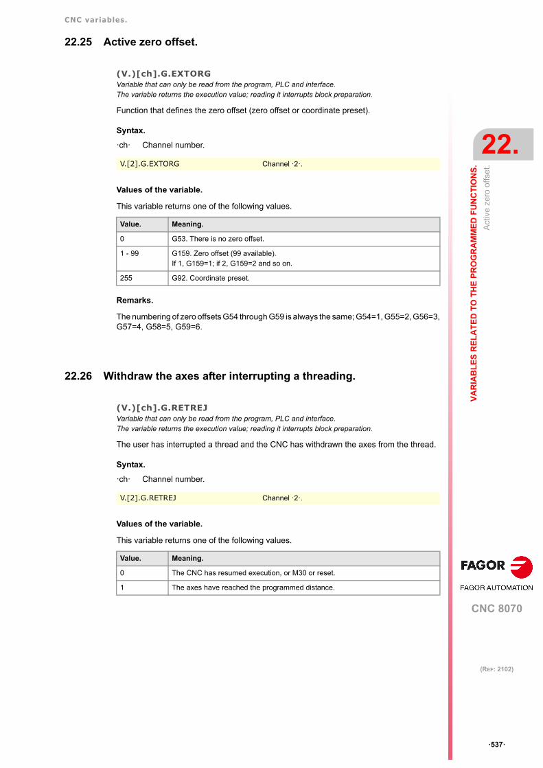
CNC variables.
CNC 8070
VA
RIA
BL
ES
RE
LA
TE
D T
O T
HE
PR
OG
RA
MM
ED
FU
NC
TIO
NS
.
22.
Act
ive
zero
offs
et.
ꞏ537ꞏ
(REF: 2102)
22.25 Active zero offset.
(V.)[ch].G.EXTORGVariable that can only be read from the program, PLC and interface.The variable returns the execution value; reading it interrupts block preparation.
Function that defines the zero offset (zero offset or coordinate preset).
Syntax.
ꞏchꞏ Channel number.
Values of the variable.
This variable returns one of the following values.
Remarks.
The numbering of zero offsets G54 through G59 is always the same; G54=1, G55=2, G56=3,G57=4, G58=5, G59=6.
22.26 Withdraw the axes after interrupting a threading.
(V.)[ch].G.RETREJVariable that can only be read from the program, PLC and interface.The variable returns the execution value; reading it interrupts block preparation.
The user has interrupted a thread and the CNC has withdrawn the axes from the thread.
Syntax.
ꞏchꞏ Channel number.
Values of the variable.
This variable returns one of the following values.
V.[2].G.EXTORG Channel ꞏ2ꞏ.
Value. Meaning.
0 G53. There is no zero offset.
1 - 99 G159. Zero offset (99 available).If 1, G159=1; if 2, G159=2 and so on.
255 G92. Coordinate preset.
V.[2].G.RETREJ Channel ꞏ2ꞏ.
Value. Meaning.
0 The CNC has resumed execution, or M30 or reset.
1 The axes have reached the programmed distance.

CNC variables.
CNC 8070
22.
VA
RIA
BL
ES
RE
LA
TE
D T
O T
HE
PR
OG
RA
MM
ED
FU
NC
TIO
NS
.
Mon
itorin
g th
e pr
ecis
ion
of r
igid
tapp
ing.
ꞏ538ꞏ
(REF: 2102)
22.27 Monitoring the precision of rigid tapping.
(V.)[ch].G.RIGIERVariable that can only be read from the program, PLC and interface.The variable returns the execution value; when read from the program, it interrupts block preparation.
Offset in millimeters or inches between the projection of the following error of the spindle ontothe longitudinal axis and the following error of the longitudinal axis. This variable can bedisplayed on the oscilloscope.
Syntax.
ꞏchꞏ Channel number.
Remarks.
To make the tapping smoother and easier on the tool, the value of this variable must be asclose to zero as possible. That will require retouching the following errors of the longitudinalaxis and of the spindle. Since the adjustment of the spindle in a closed loop is usually morecomplicated than adjusting an axis, it is recommended to first adjust the spindle as best aspossible and then adjust the following error of the longitudinal axis.
V.[2].G.RIGIER

CNC variables.
CNC 8070
VA
RIA
BL
ES
RE
LA
TE
D T
O T
HE
PR
OG
RA
MM
ED
FU
NC
TIO
NS
.
22.
Wor
k zo
nes.
ꞏ539ꞏ
(REF: 2102)
22.28 Work zones.
22.28.1 Safety distance of the limits of the work zones.
(V.)[ch].A.ZONELIMITTOL.xnVariable that can be read and written from the program and PLC.The variable returns the value of block preparation.
Channel [ch]. Safety distance of the limits of the work zones.
Safety distance applied by the CNC to the axis with respect to the limit of the work zone. Whena work zone is active, the CNC stops the axes when one of them reaches the safety distance.The safety distance is defined per axis and each axis will have the same safety distance forall the zones.. On CNC power-up, this variable assumes the value of parameterZONELIMITTOL.
Syntax.
ꞏchꞏ Channel number.
ꞏxnꞏ Name, logic number or index of the axis.
(V.)[ch].G.ZONEWARN[k]Variable that can only be read from the program, PLC and interface.The variable returns the execution value; reading it interrupts block preparation.
Channel [ch]. Some axis has reached the limit of work zone [k].
Syntax.
ꞏchꞏ Channel number.
ꞏkꞏ Zone number.
V.A.ZONELIMITTOL.Z Z axis.
V.A.ZONELIMITTOL.4 Axis with logic number ꞏ4ꞏ.
V.[2].A.ZONELIMITTOL.1 Axis with index ꞏ1ꞏ in the channel ꞏ2ꞏ.
V.[2].G.ZONEWARN[1] Channel ꞏ2ꞏ. Zone 1.
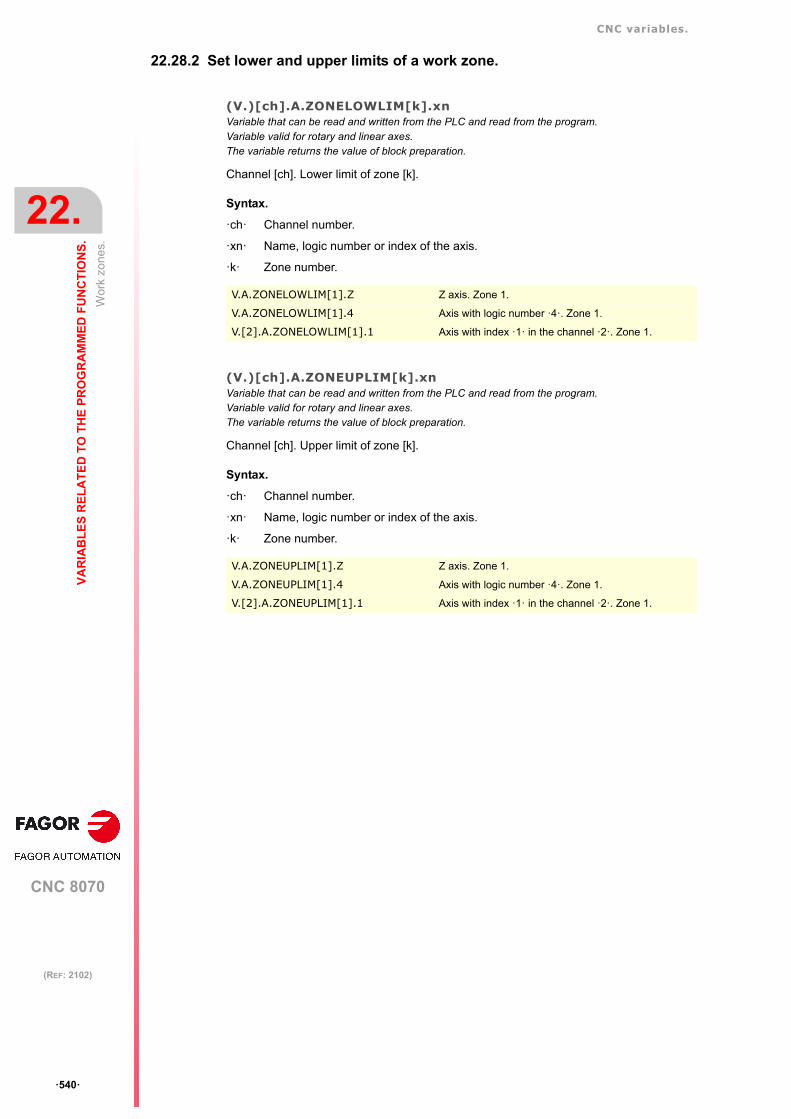
CNC variables.
CNC 8070
22.
VA
RIA
BL
ES
RE
LA
TE
D T
O T
HE
PR
OG
RA
MM
ED
FU
NC
TIO
NS
.
Wor
k zo
nes.
ꞏ540ꞏ
(REF: 2102)
22.28.2 Set lower and upper limits of a work zone.
(V.)[ch].A.ZONELOWLIM[k].xnVariable that can be read and written from the PLC and read from the program.Variable valid for rotary and linear axes.The variable returns the value of block preparation.
Channel [ch]. Lower limit of zone [k].
Syntax.
ꞏchꞏ Channel number.
ꞏxnꞏ Name, logic number or index of the axis.
ꞏkꞏ Zone number.
(V.)[ch].A.ZONEUPLIM[k].xnVariable that can be read and written from the PLC and read from the program.Variable valid for rotary and linear axes.The variable returns the value of block preparation.
Channel [ch]. Upper limit of zone [k].
Syntax.
ꞏchꞏ Channel number.
ꞏxnꞏ Name, logic number or index of the axis.
ꞏkꞏ Zone number.
V.A.ZONELOWLIM[1].Z Z axis. Zone 1.
V.A.ZONELOWLIM[1].4 Axis with logic number ꞏ4ꞏ. Zone 1.
V.[2].A.ZONELOWLIM[1].1 Axis with index ꞏ1ꞏ in the channel ꞏ2ꞏ. Zone 1.
V.A.ZONEUPLIM[1].Z Z axis. Zone 1.
V.A.ZONEUPLIM[1].4 Axis with logic number ꞏ4ꞏ. Zone 1.
V.[2].A.ZONEUPLIM[1].1 Axis with index ꞏ1ꞏ in the channel ꞏ2ꞏ. Zone 1.

CNC variables.
CNC 8070
VA
RIA
BL
ES
RE
LA
TE
D T
O T
HE
PR
OG
RA
MM
ED
FU
NC
TIO
NS
.
22.
Wor
k zo
nes.
ꞏ541ꞏ
(REF: 2102)
22.28.3 Set circular limits of the work zone.
(V.)[ch].G.ZONECIRAX1[k] Variable that can be read and written from the PLC and read from the program.The variable returns the value of block preparation.
Channel [ch]. Logic axis corresponding to the first coordinate of the center of zone [k].
Syntax.
ꞏchꞏ Channel number.
ꞏkꞏ Zone number.
(V.)[ch].G.ZONECIRAX2[k] Variable that can be read and written from the PLC and read from the program.The variable returns the value of block preparation.
Channel [ch]. Logic axis corresponding to the second coordinate of the center of zone [k].
Syntax.
ꞏchꞏ Channel number.
ꞏkꞏ Zone number.
(V.)[ch].G.ZONECIR1[k]Variable that can be read and written from the PLC and read from the program.The variable returns the value of block preparation.
Channel [ch]. Center coordinate of zone [k] along the first axis that defines the circular zone.
Syntax.
ꞏchꞏ Channel number.
ꞏkꞏ Zone number.
(V.)[ch].G.ZONECIR2[k]Variable that can be read and written from the PLC and read from the program.The variable returns the value of block preparation.
Channel [ch]. Center coordinate of zone [k] along the second axis that defines the circularzone.
Syntax.
ꞏchꞏ Channel number.
ꞏkꞏ Zone number.
V.[2].G.ZONECIRAX1[1] Channel ꞏ2ꞏ. Zone 1.
V.[2].G.ZONECIRAX2[1] Channel ꞏ2ꞏ. Zone 1.
V.[2].G.ZONECIR1[1] Channel ꞏ2ꞏ. Zone 1.
V.[2].G.ZONECIR2[1] Channel ꞏ2ꞏ. Zone 1.

CNC variables.
CNC 8070
22.
VA
RIA
BL
ES
RE
LA
TE
D T
O T
HE
PR
OG
RA
MM
ED
FU
NC
TIO
NS
.
Wor
k zo
nes.
ꞏ542ꞏ
(REF: 2102)
(V.)[ch].G.ZONER[k]Variable that can be read and written from the PLC and read from the program.The variable returns the value of block preparation.
Channel [ch]. Radius of zone [k] (circular zone).
Syntax.
ꞏchꞏ Channel number.
ꞏkꞏ Zone number.
V.[2].G.ZONER[1] Channel ꞏ2ꞏ. Zone 1.

CNC variables.
CNC 8070
VA
RIA
BL
ES
RE
LA
TE
D T
O T
HE
PR
OG
RA
MM
ED
FU
NC
TIO
NS
.
22.
Wor
k zo
nes.
ꞏ543ꞏ
(REF: 2102)
22.28.4 Monitoring of a work zone.
(V.)[ch].G.ZONETOOLWATCH[k]Variable that can be read and written from the PLC and read from the program.The variable returns the value of block preparation.
Channel [ch]. Monitor the tool tip or tool base in work zone [k].
Syntax.
ꞏchꞏ Channel number.
ꞏkꞏ Zone number.
Values of the variable.
This variable returns one of the following values.
22.28.5 Enable and disable the work zones.
(V.)[ch].G.ZONEST[k]Variable that can be read and written from the PLC and read from the program.The variable returns the value of block preparation.
Channel [ch]. Status of work zone [K].
Syntax.
ꞏchꞏ Channel number.
ꞏkꞏ Zone number.
Values of the variable.
This variable returns one of the following values.
V.[2].G.ZONETOOLWATCH[1] Channel ꞏ2ꞏ. Zone 1.
Value. Meaning.
0 Monitor the tool tip.
1 Monitor the tool base.
2 Monitor the tool tip and the tool base.
V.[2].G.ZONEST[1] Channel ꞏ2ꞏ. Zone 1.
Value. Meaning.
0 Disabled zone.
1 Work zone enabled as no-entry.
2 Work zone enabled as no-exit.

CNC variables.
CNC 8070
22.
VA
RIA
BL
ES
RE
LA
TE
D T
O T
HE
PR
OG
RA
MM
ED
FU
NC
TIO
NS
.
DM
C fu
nctio
n..
ꞏ544ꞏ
(REF: 2102)
22.29 DMC function..
22.29.1 Commands of the #DMC ON statement.
(V.)[ch].G.DMCPWRSPVariable that can only be read from the program, PLC and interface.The variable returns the value of block preparation.Units: Percentage.
Target power, defined as a percentage of the rated power of the spindle. Value programmedin the PWRSP command of the #DMC ON instruction.
Syntax.
ꞏchꞏ Channel number.
(V.)[ch].G.DMCOVRMINVariable that can only be read from the program, PLC and interface.The variable returns the value of block preparation.Units: Percentage.
Minimum feedrate (feed override) percentage allowed for DMC. Value programmed in theOVRMIN command of the #DMC ON instruction.
Syntax.
ꞏchꞏ Channel number.
(V.)[ch].G.DMCOVRMAX Variable that can only be read from the program, PLC and interface.The variable returns the value of block preparation.Units: Percentage.
Maximum feedrate (feed override) percentage allowed for DMC. Value programmed in theOVRMAX command of the #DMC ON instruction.
Syntax.
ꞏchꞏ Channel number.
(V.)[ch].G.DMCFZMINVariable that can only be read from the program, PLC and interface.The variable returns the value of block preparation.Units: Millimeters/tooth or inches/tooth.
Minimum feedrate per tooth permitted during DMC. Value programmed in the FZMINcommand of the #DMC ON instruction.
Syntax.
ꞏchꞏ Channel number.
V.[2].G.DMCPWRSP Channel ꞏ2ꞏ.
V.[2].G.DMCOVRMIN Channel ꞏ2ꞏ.
V.[2].G.DMCOVRMAX Channel ꞏ2ꞏ.
V.[2].G.DMCFZMIN Channel ꞏ2ꞏ.

CNC variables.
CNC 8070
VA
RIA
BL
ES
RE
LA
TE
D T
O T
HE
PR
OG
RA
MM
ED
FU
NC
TIO
NS
.
22.
DM
C fu
nctio
n..
ꞏ545ꞏ
(REF: 2102)
(V.)[ch].G.DMCFZMAXVariable that can only be read from the program, PLC and interface.The variable returns the value of block preparation.Units: Millimeters/tooth or inches/tooth.
Maximum feedrate per tooth permitted during DMC. Value programmed in the FZMAXcommand of the #DMC ON instruction.
Syntax.
ꞏchꞏ Channel number.
V.[2].G.DMCFZMAX Channel ꞏ2ꞏ.

CNC variables.
CNC 8070
22.
VA
RIA
BL
ES
RE
LA
TE
D T
O T
HE
PR
OG
RA
MM
ED
FU
NC
TIO
NS
.
DM
C fu
nctio
n..
ꞏ546ꞏ
(REF: 2102)
22.29.2 Status and response from DMC.
(V.)[ch].G.DMCONVariable that can only be read from the program, PLC and interface.The variable returns the execution value, without interrupting the block preparation.Units: -.
DMC status. This variable takes into account whether the CNC has activated DMC by meansof the instruction #DMC ON, the status of the DMCON mark of the PLC and incompatibleoperations.
Syntax.
ꞏchꞏ Channel number.
(V.)[ch].G.LEARNEDPWRSPVariable that can only be read from the program, PLC and interface.Variable that may be modified from the environment of the oscilloscope.The variable returns the execution value; reading it interrupts block preparation.Units: Percentage.
Target power for the spindle, calculated by DMC in the learning phase (percentage of ratedpower). This variable does not include the no-load power.
Syntax.
ꞏchꞏ Channel number.
(V.)[ch].G.DMCACTPWRVariable that can only be read from the program, PLC and interface.Variable that may be modified from the environment of the oscilloscope.The variable returns the execution value; reading it interrupts block preparation.Units: Percentage.
Active power on the spindle, measured by DMC (percentage of the rated power).
Syntax.
ꞏchꞏ Channel number.
Remarks.
This variable can be used to monitor DMC from the oscilloscope, with both a digital or analogspindle.
(V.)[ch].G.DMCOVRVariable that can only be read from the program, PLC and interface.Variable that may be modified from the environment of the oscilloscope.The variable returns the execution value; reading it interrupts block preparation.Units: Percentage.
Feedrate percentage (feed override) calculated by DMC.
Syntax.
ꞏchꞏ Channel number.
V.[2].G.DMCON Channel ꞏ2ꞏ.
V.[2].G.LEARNEDPWRSP Channel ꞏ2ꞏ.
V.[2].G.DMCACTPWR Channel ꞏ2ꞏ.
V.[2].G.DMCOVR Channel ꞏ2ꞏ.

CNC variables.
CNC 8070
VA
RIA
BL
ES
RE
LA
TE
D T
O T
HE
PR
OG
RA
MM
ED
FU
NC
TIO
NS
.
22.
DM
C fu
nctio
n..
ꞏ547ꞏ
(REF: 2102)
(V.)[ch].G.DMCFZVariable that can only be read from the program, PLC and interface.The variable returns the execution value; reading it interrupts block preparation.Units: Millimeters/tooth or inches/tooth.
Feedrate per tooth, calculated by DMC.
Syntax.
ꞏchꞏ Channel number.
(V.)[ch].G.DMCNOLOADPWRVariable that can only be read from the program, PLC and interface.The variable returns the execution value; reading it interrupts block preparation.Units: Kilowatts.
Spindle power without a load, measured by DMC.
Syntax.
ꞏchꞏ Channel number.
(V.)[ch].G.DMCSAVEDTIMEVariable that can only be read from the program, PLC and interface.The variable returns the execution value; reading it interrupts block preparation.Units: Seconds.
Time saved by the DMC action.
Syntax.
ꞏchꞏ Channel number.
V.[2].G.DMCFZ Channel ꞏ2ꞏ.
V.[2].G.DMCNOLOADPWR Channel ꞏ2ꞏ.
V.[2].G.DMCSAVEDTIME Channel ꞏ2ꞏ.

CNC variables.
CNC 8070
22.
VA
RIA
BL
ES
RE
LA
TE
D T
O T
HE
PR
OG
RA
MM
ED
FU
NC
TIO
NS
.
FC
AS
(F
ago
r C
olli
sion
Avo
ida
nce
Sys
tem
).
ꞏ548ꞏ
(REF: 2102)
22.30 FCAS (Fagor Collision Avoidance System).
(V.)[ch].G.COLLISIONPERFVariable that can only be read from the program, PLC and interface.The variable returns the execution value; reading it interrupts block preparation.Report variable (to be used from the scripts).
Collision control status.
Syntax.
ꞏchꞏ Channel number.
Values of the variable.
V.[2].G.COLLISIONPERF Channel ꞏ2ꞏ.
Value. Meaning.
0 Deactivated FCAS option.
1 Activated FCAS option.
2 FCAS does not work in optimal conditions due to cpuoverload.
3 The axes are close to the collision zone.

CNC variables.
CNC 8070
VA
RIA
BL
ES
RE
LA
TE
D T
O T
HE
PR
OG
RA
MM
ED
FU
NC
TIO
NS
.
22.
Err
or c
ode
for
#OP
EN
, #W
RIT
E o
r #C
LOS
E s
tate
men
ts.
ꞏ549ꞏ
(REF: 2102)
22.31 Error code for #OPEN, #WRITE or #CLOSE statements.
V.[ch].G.FILEERRNOVariable that can only be read from the program and interface.The variable returns the execution value; reading it interrupts block preparation.
Result of the last operation carried out on the channel by the #OPEN, #WRITE or #CLOSEinstructions. The variable returns a 0 if the operation is successful or an error code. Thevariable always saves the value, regardless of the MUTED command programmed in#OPEN.
Syntax.
Values of the variable.
V.G.FILEERRNO
Value. Meaning.
0 Operation succeded.
1 Operation not permitted.
2 No such file or directory.
3 No such process.
4 Interrupted system call.
5 Input/output error.
6 No such device or address.
7 Argument list too long.
8 Exec format error.
9 Bad file descriptor.
10 No child processes.
11 Resource temporarily unavailable.
11 Resource temporarily unavailable.
12 Cannot allocate memory.
13 Permission denied.
14 Bad address.
15 Block device required.
16 Device or resource busy.
17 File exists.
18 Invalid cross-device link.
19 No such device.
20 Not a directory.
21 Is a directory.
22 Invalid argument.
23 Too many open files in system.
24 Too many open files.
25 Inappropriate ioctl for device.
26 Text file busy.
27 File too large.
28 No space left on device.
29 Illegal seek.
30 Read-only file system.
31 Too many links.
32 Broken pipe.

CNC variables.
CNC 8070
22.
VA
RIA
BL
ES
RE
LA
TE
D T
O T
HE
PR
OG
RA
MM
ED
FU
NC
TIO
NS
.
Err
or c
ode
for
#OP
EN
, #W
RIT
E o
r #C
LOS
E s
tate
men
ts.
ꞏ550ꞏ
(REF: 2102)
33 Numerical argument out of domain.
34 Numerical result out of range.
35 Resource deadlock avoided.
35 Resource deadlock avoided.
36 File name too long.
37 No locks available.
38 Function not implemented.
39 Directory not empty.
40 Too many levels of symbolic links.
42 No message of desired type.
43 Identifier removed.
44 Channel number out of range.
45 Level 2 not synchronized.
46 Level 3 halted.
47 Level 3 reset.
48 Link number out of range.
49 Protocol driver not attached.
50 No CSI structure available.
51 Level 2 halted.
52 Invalid exchange.
53 Invalid request descriptor.
54 Exchange full.
55 No anode.
56 Invalid request code.
57 Invalid slot.
59 Bad font file format.
60 Device not a stream.
61 No data available.
62 Timer expired.
63 Out of streams resources.
64 Machine is not on the network.
65 Package not installed.
66 Object is remote.
67 Link has been severed.
68 Advertise error.
69 Srmount error.
70 Communication error on send.
71 Protocol error.
72 Multihop attempted.
73 RFS specific error.
74 Bad message.
75 Value too large for defined data type.
76 Name not unique on network.
77 File descriptor in bad state.
78 Remote address changed.
79 Can not access a needed shared library.
Value. Meaning.

CNC variables.
CNC 8070
VA
RIA
BL
ES
RE
LA
TE
D T
O T
HE
PR
OG
RA
MM
ED
FU
NC
TIO
NS
.
22.
Err
or c
ode
for
#OP
EN
, #W
RIT
E o
r #C
LOS
E s
tate
men
ts.
ꞏ551ꞏ
(REF: 2102)
80 Accessing a corrupted shared library.
81 .lib section in a.out corrupted.
82 Attempting to link in too many shared libraries.
83 Cannot exec a shared library directly.
84 Invalid or incomplete multibyte or wide character.
85 Interrupted system call should be restarted.
86 Streams pipe error.
87 Too many users.
88 Socket operation on non-socket.
89 Destination address required.
90 Message too long.
91 Protocol wrong type for socket.
92 Protocol not available.
93 Protocol not supported.
94 Socket type not supported.
95 Operation not supported.
95 Operation not supported.
96 Protocol family not supported.
97 Address family not supported by protocol.
98 Address already in use.
99 Cannot assign requested address.
100 Network is down.
101 Network is unreachable.
102 Network dropped connection on reset.
103 Software caused connection abort.
104 Connection reset by peer.
105 No buffer space available.
106 Transport endpoint is already connected.
107 Transport endpoint is not connected.
108 Cannot send after transport endpoint shutdown.
109 Too many references: cannot splice.
110 Connection timed out.
111 Connection refused.
112 Host is down.
113 No route to host.
114 Operation already in progress.
115 Operation now in progress.
116 Stale file handle.
117 Structure needs cleaning.
118 Not a XENIX named type file.
119 No XENIX semaphores available.
120 Is a named type file.
121 Remote I/O error.
122 Disk quota exceeded.
123 No medium found.
124 Wrong medium type.
Value. Meaning.
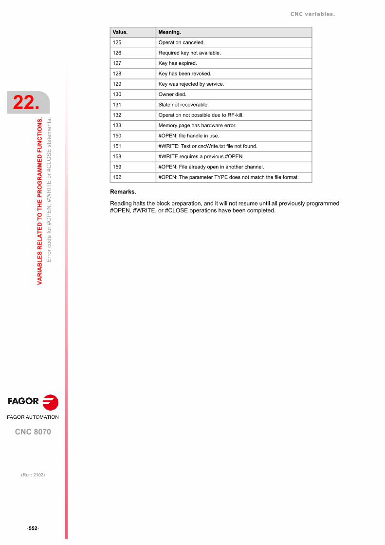
CNC variables.
CNC 8070
22.
VA
RIA
BL
ES
RE
LA
TE
D T
O T
HE
PR
OG
RA
MM
ED
FU
NC
TIO
NS
.
Err
or c
ode
for
#OP
EN
, #W
RIT
E o
r #C
LOS
E s
tate
men
ts.
ꞏ552ꞏ
(REF: 2102)
Remarks.
Reading halts the block preparation, and it will not resume until all previously programmed#OPEN, #WRITE, or #CLOSE operations have been completed.
125 Operation canceled.
126 Required key not available.
127 Key has expired.
128 Key has been revoked.
129 Key was rejected by service.
130 Owner died.
131 State not recoverable.
132 Operation not possible due to RF-kill.
133 Memory page has hardware error.
150 #OPEN: file handle in use.
151 #WRITE: Text or cncWrite.txt file not found.
158 #WRITE requires a previous #OPEN.
159 #OPEN: File already open in another channel.
162 #OPEN: The parameter TYPE does not match the file format.
Value. Meaning.

CNC variables.
CNC 8070
VA
RIA
BL
ES
RE
LA
TE
D T
O T
HE
PR
OG
RA
MM
ED
FU
NC
TIO
NS
.
22.
Fro
m th
e pa
rt-p
rogr
am (
#MS
GV
AR
) ch
ange
the
HM
I var
iab
les.
ꞏ553ꞏ
(REF: 2102)
22.32 From the part-program (#MSGVAR) change the HMI variables.
(V.)G.CNCMSG[num]Variable to be read via interface.Report variable (to be used from the scripts).
Variable to be included in the interface that contains text that can be modified from the part-program using the #MSGVAR instruction.
Syntax.
ꞏnumꞏ variable number (from 1 to 50).
G.CNCMSG[3] Third variable.

CNC variables.
CNC 8070
22.
VA
RIA
BL
ES
RE
LA
TE
D T
O T
HE
PR
OG
RA
MM
ED
FU
NC
TIO
NS
.
Fro
m th
e pa
rt-p
rogr
am (
#MS
GV
AR
) ch
ange
the
HM
I var
iab
les.
ꞏ554ꞏ
(REF: 2102)

CNC 8070
23
ꞏ555ꞏ
(REF: 2102)
23.VARIABLES RELATED TO THE ELECTRONIC CAM.
23.1 Electronic cam.
(V.)G.CAMST[cam]Variable that can only be read from the program, PLC and interface.The variable returns the execution value; reading it interrupts block preparation.
Cam status.
Use this variable in the PLC program to condition the cam operations to the right status andconsequently prevent execution errors. The operations of the cam from the part-programstay in execution, without issuing an error message, waiting for the right cam status.
Syntax.
ꞏcamꞏ Cam number.
Values of the variable.
This variable returns one of the following values.
V.G.CAMST[2] Cam ꞏ2ꞏ.
Value. Meaning.
0 CAM_NULLThe cam does not exist. The cam is not defined in the machine parameters and thereis no file cam available, the CNC or the PLC have not selected it (SELECT) or theyhave deselected it (DESELECT).
• This state only allows loading one file cam from the CNC or PLC.• This status does not allow activating the cam, either from the CNC or from the
PLC.
1 CAM_LOADINGThe CNC or the PLC is loading the file that defines the cam.
• This state only allows activating the cam from the CNC, where the CNC willremain in execution until the cam reaches the CAM_READY state. The camcannot be activated from the PLC.
2 CAM_READYCam ready. The CNC has validated the cam defined in the machine parameters oris done loading the cam from a file.
• This state allows any cam operation, either from the CNC or from the PLC.
3 CAM_STARTThe cam is activated, but it has not entered the range of the master axis yet. In thissituation, if the CNC or the PLC cancels the cam, the cam will not reach theCAM_READY state as long as it does not go into and out of the range of the masteraxis at least once.
• This state allows canceling the cam, either from the CNC or from the PLC.• This state allows deselecting the cam, but only from the CNC.

CNC variables.
CNC 8070
23.
VA
RIA
BL
ES
RE
LA
TE
D T
O T
HE
EL
EC
TR
ON
IC C
AM
.
Ele
ctro
nic
cam
.
ꞏ556ꞏ
(REF: 2102)
Remarks.
To switch from CAM_READY to CAM_NULL, just deselect the file cam and make sure thatthe cam is not in the machine parameters. If the dam is defined in the machine parameters,it maintains the CAM_READY state, but the cam data will be defined in the machineparameters.
• To select a file cam, the cam status (state) must be either CAM_NULL or CAM_READY.
• To select a file cam from the PLC, preventing execution errors, the cam status (state)must be CAM_READY. If the cam is activated from the CNC, the channel will remain inexecution until the cam reaches the CAM_READY state.
• To deselect a file cam from the PLC, preventing execution errors, the cam status (state)must be CAM_READY. If the cam is deselected from the CNC, the channel will remainin execution until the cam reaches the CAM_READY state.
(V.)G.CAM[cam][index]Variable that can be read and written via program, PLC and interface.The variable returns the execution value; reading it interrupts block preparation.
Factor to be applied to the range of the slave axis when activating the cam.
Syntax.
ꞏcamꞏ Cam number (between 1 and 16).
ꞏindexꞏPoint of the cam. For the cams defined in the machine parameters, a value between1 and 1024. For the file cams, the line number.
4 CAM_RUNNING_OUTSIDEThe cam is active and in execution out of the range of the master axis. In this state,the cam has been inside the range of the master axis at least once. If the CNC orthe PLC cancel the cam, the cam will go into CAM_READY state.
• This state allows canceling the cam, either from the CNC or from the PLC.• This state allows deselecting the cam, but only from the CNC.
5 CAM_RUNNING_INSIDEThe cam is active and in execution inside the range of the master axis. If the CNCor the PLC cancel the cam, the cam will go into CAM_FINISH state.
• This state allows canceling the cam, either from the CNC or from the PLC.• This state allows deselecting the cam, but only from the CNC.
6 CAM_FINISHThe CNC or the PLC has canceled the cam, but it keeps executing until the cam goesout of the range of the master axis. This situation occurs when the CNC or the PLCcancel a cam that was in CAM_RUNNING_INSIDE state; if they cancel a cam thatwas in CAM_RUNNING_OUTSIDE state, the cam reaches the CAM_READY state.
• This state only allows deselecting the cam, but only from the CNC.
V.G.CAM[2][123] Cam ꞏ2ꞏ. Point or line of file ꞏ123ꞏ
Value. Meaning.

CNC 8070
24
ꞏ557ꞏ
(REF: 2102)
24.VARIABLES RELATED TO THE INDEPENDENT AXES.
24.1 Independent interpolator.
(V.)[ch].A.INDPOS.xn(V.)[ch].A.INDPOS.sn(V.)[ch].SP.INDPOS.snVariable that can only be read from the program, PLC and interface.Variable valid for rotary and linear axes as well as for spindles.The variable returns the execution value; reading it interrupts block preparation.
Theoretical coordinate of the independent interpolator.
Syntax.
ꞏchꞏ Channel number.
ꞏxnꞏ Name, logic number or index of the axis.
ꞏsnꞏ Name, logic number or index of the spindle.
24.2 Independent axis in execution.
(V.)[ch].G.IBUSYVariable that can only be read from the program, PLC and interface.The variable returns the execution value; reading it interrupts block preparation.Report variable (to be used from the scripts).
An independent axis is in execution.
Syntax.
ꞏchꞏ Channel number.
V.A.INDPOS.Z Z axis.
V.A.INDPOS.S Spindle S.
V.SP.INDPOS.S Spindle S.
V.SP.INDPOS Master spindle.
V.A.INDPOS.4 Axis or spindle with logic number ꞏ4ꞏ.
V.[2].A.INDPOS.1 Axis with index ꞏ1ꞏ in the channel ꞏ2ꞏ.
V.SP.INDPOS.2 Spindle with index ꞏ2ꞏ in the system.
V.[2].SP.INDPOS.1 Spindle with index ꞏ1ꞏ in the channel ꞏ2ꞏ.
V.[2].G.IBUSY Channel ꞏ2ꞏ.

CNC variables.
CNC 8070
24.
VA
RIA
BL
ES
RE
LA
TE
D T
O T
HE
IND
EP
EN
DE
NT
AX
ES
.
Pe
rcen
tage
of f
eed
rate
(fe
edra
te o
verr
ide)
.
ꞏ558ꞏ
(REF: 2102)
24.3 Percentage of feedrate (feedrate override).
(V.)[ch].A.FRO.xnVariable that can be read and written via program, PLC and interface.Variable valid for rotary and linear axes.The variable returns the execution value; reading it interrupts block preparation.Report variable (to be used from the scripts).
Channel [ch]. Feedrate percentage active on the axis.
Syntax.
ꞏchꞏ Channel number.
ꞏxnꞏ Name, logic number or index in the channel of the axis.
V.A.FRO.Z Z axis.
V.A.FRO.4 Axis with logic number ꞏ4ꞏ.
V.[2].A.FRO.1 Axis with index ꞏ1ꞏ in the channel ꞏ2ꞏ.

CNC variables.
CNC 8070
VA
RIA
BL
ES
RE
LA
TE
D T
O T
HE
IND
EP
EN
DE
NT
AX
ES
.
24.
Pos
ition
ing
mov
e.
ꞏ559ꞏ
(REF: 2102)
24.4 Positioning move.
(V.)[ch].A.IPPOS.xnVariable that can only be read from the program, PLC and interface.Variable valid for rotary and linear axes.The variable returns the execution value; reading it interrupts block preparation.
Coordinate programmed for the independent axis.
Syntax.
ꞏchꞏ Channel number.
ꞏxnꞏ Name, logic number or index in the channel of the axis.
(V.)[ch].A.ITPOS.xnVariable that can only be read from the program, PLC and interface.Variable valid for rotary and linear axes.The variable returns the execution value; reading it interrupts block preparation.
Theoretical coordinate of the independent axis.
Syntax.
ꞏchꞏ Channel number.
ꞏxnꞏ Name, logic number or index in the channel of the axis.
(V.)[ch].A.IPRGF.xnVariable that can only be read from the program, PLC and interface.Variable valid for rotary and linear axes.The variable returns the execution value; reading it interrupts block preparation.
Feedrate programmed in the independent axis.
Syntax.
ꞏchꞏ Channel number.
ꞏxnꞏ Name, logic number or index in the channel of the axis.
(V.)[ch].A.IORG.xnVariable that can be read and written via program, PLC and interface.Variable valid for rotary and linear axes.The variable returns the execution value; reading it interrupts block preparation.
Offset for the independent axis.
Syntax.
ꞏchꞏ Channel number.
V.A.IPPOS.Z Z axis.
V.A.IPPOS.4 Axis with logic number ꞏ4ꞏ.
V.[2].A.IPPOS.1 Axis with index ꞏ1ꞏ in the channel ꞏ2ꞏ.
V.A.ITPOS.Z Z axis.
V.A.ITPOS.4 Axis with logic number ꞏ4ꞏ.
V.[2].A.ITPOS.1 Axis with index ꞏ1ꞏ in the channel ꞏ2ꞏ.
V.A.IPRGF.Z Z axis.
V.A.IPRGF.4 Axis with logic number ꞏ4ꞏ.
V.[2].A.IPRGF.1 Axis with index ꞏ1ꞏ in the channel ꞏ2ꞏ.

CNC variables.
CNC 8070
24.
VA
RIA
BL
ES
RE
LA
TE
D T
O T
HE
IND
EP
EN
DE
NT
AX
ES
.
Pos
ition
ing
mov
e.
ꞏ560ꞏ
(REF: 2102)
ꞏxnꞏ Name, logic number or index in the channel of the axis.
V.A.IORG.Z Z axis.
V.A.IORG.4 Axis with logic number ꞏ4ꞏ.
V.[2].A.IORG.1 Axis with index ꞏ1ꞏ in the channel ꞏ2ꞏ.

CNC variables.
CNC 8070
VA
RIA
BL
ES
RE
LA
TE
D T
O T
HE
IND
EP
EN
DE
NT
AX
ES
.
24.
Syn
chro
niza
tion
mov
emen
t.
ꞏ561ꞏ
(REF: 2102)
24.5 Synchronization movement.
(V.)[ch].A.SYNCTOUT.xn(V.)[ch].A.SYNCTOUT.sn(V.)[ch].SP.SYNCTOUT.snVariable that can be read and written via program, PLC and interface.Variable valid for rotary and linear axes as well as for spindles.The variable returns the execution value; reading it interrupts block preparation.
Maximum time to establish synchronism.
Syntax.
ꞏchꞏ Channel number.
ꞏxnꞏ Name, logic number or index of the axis.
ꞏsnꞏ Name, logic number or index of the spindle.
(V.)[ch].A.SYNCVEL.xn(V.)[ch].A.SYNCVEL.sn(V.)[ch].A.SYNCVEL.snVariable that can be read and written via program, PLC and interface.Variable valid for rotary and linear axes as well as for spindles.The variable returns the execution value; reading it interrupts block preparation.
Synchronization speed.
Syntax.
ꞏchꞏ Channel number.
ꞏxnꞏ Name, logic number or index of the axis.
ꞏsnꞏ Name, logic number or index of the spindle.
(V.)[ch].A.SYNCPOSW.xn(V.)[ch].A.SYNCPOSW.sn(V.)[ch].SP.SYNCPOSW.snVariable that can be read and written via program, PLC and interface.Variable valid for rotary and linear axes as well as for spindles.The variable returns the execution value; reading it interrupts block preparation.
Maximum position difference to start correcting it.
Syntax.
ꞏchꞏ Channel number.
V.A.SYNCTOUT.Z Z axis.
V.A.SYNCTOUT.S Spindle S.
V.SP.SYNCTOUT.S Spindle S.
V.SP.SYNCTOUT Master spindle.
V.A.SYNCTOUT.4 Axis or spindle with logic number ꞏ4ꞏ.
V.[2].A.SYNCTOUT.1 Axis with index ꞏ1ꞏ in the channel ꞏ2ꞏ.
V.SP.SYNCTOUT.2 Spindle with index ꞏ2ꞏ in the system.
V.[2].SP.SYNCTOUT.1 Spindle with index ꞏ1ꞏ in the channel ꞏ2ꞏ.
V.A.SYNCVEL.Z Z axis.
V.A.SYNCVEL.S Spindle S.
V.SP.SYNCVEL.S Spindle S.
V.SP.SYNCVEL Master spindle.
V.A.SYNCVEL.4 Axis or spindle with logic number ꞏ4ꞏ.
V.[2].A.SYNCVEL.1 Axis with index ꞏ1ꞏ in the channel ꞏ2ꞏ.
V.SP.SYNCVEL.2 Spindle with index ꞏ2ꞏ in the system.
V.[2].SP.SYNCVEL.1 Spindle with index ꞏ1ꞏ in the channel ꞏ2ꞏ.

CNC variables.
CNC 8070
24.
VA
RIA
BL
ES
RE
LA
TE
D T
O T
HE
IND
EP
EN
DE
NT
AX
ES
.
Syn
chro
niza
tion
mov
emen
t.
ꞏ562ꞏ
(REF: 2102)
ꞏxnꞏ Name, logic number or index of the axis.
ꞏsnꞏ Name, logic number or index of the spindle.
(V.)[ch].A.SYNCVELW.xn(V.)[ch].A.SYNCVELW.sn(V.)[ch].A.SYNCVELW.snVariable that can be read and written via program, PLC and interface.Variable valid for rotary and linear axes as well as for spindles.The variable returns the execution value; reading it interrupts block preparation.
Maximum velocity difference to start correcting it.
Syntax.
ꞏchꞏ Channel number.
ꞏxnꞏ Name, logic number or index of the axis.
ꞏsnꞏ Name, logic number or index of the spindle.
(V.)[ch].A.SYNCPOSOFF.xn(V.)[ch].A.SYNCPOSOFF.sn(V.)[ch].SP.SYNCPOSOFF.snVariable that can be read and written via program, PLC and interface.Variable valid for rotary and linear axes as well as for spindles.The variable returns the execution value; reading it interrupts block preparation.
Position offset for synchronization.
Syntax.
ꞏchꞏ Channel number.
ꞏxnꞏ Name, logic number or index of the axis.
ꞏsnꞏ Name, logic number or index of the spindle.
V.A.SYNCPOSW.Z Z axis.
V.A.SYNCPOSW.S Spindle S.
V.SP.SYNCPOSW.S Spindle S.
V.SP.SYNCPOSW Master spindle.
V.A.SYNCPOSW.4 Axis or spindle with logic number ꞏ4ꞏ.
V.[2].A.SYNCPOSW.1 Axis with index ꞏ1ꞏ in the channel ꞏ2ꞏ.
V.SP.SYNCPOSW.2 Spindle with index ꞏ2ꞏ in the system.
V.[2].SP.SYNCPOSW.1 Spindle with index ꞏ1ꞏ in the channel ꞏ2ꞏ.
V.A.SYNCVELW.Z Z axis.
V.A.SYNCVELW.S Spindle S.
V.SP.SYNCVELW.S Spindle S.
V.SP.SYNCVELW Master spindle.
V.A.SYNCVELW.4 Axis or spindle with logic number ꞏ4ꞏ.
V.[2].A.SYNCVELW.1 Axis with index ꞏ1ꞏ in the channel ꞏ2ꞏ.
V.SP.SYNCVELW.2 Spindle with index ꞏ2ꞏ in the system.
V.[2].SP.SYNCVELW.1 Spindle with index ꞏ1ꞏ in the channel ꞏ2ꞏ.
V.A.SYNCPOSOFF.Z Z axis.
V.A.SYNCPOSOFF.S Spindle S.
V.SP.SYNCPOSOFF.S Spindle S.
V.SP.SYNCPOSOFF Master spindle.
V.A.SYNCPOSOFF.4 Axis or spindle with logic number ꞏ4ꞏ.
V.[2].A.SYNCPOSOFF.1 Axis with index ꞏ1ꞏ in the channel ꞏ2ꞏ.
V.SP.SYNCPOSOFF.2 Spindle with index ꞏ2ꞏ in the system.
V.[2].SP.SYNCPOSOFF.1 Spindle with index ꞏ1ꞏ in the channel ꞏ2ꞏ.

CNC variables.
CNC 8070
VA
RIA
BL
ES
RE
LA
TE
D T
O T
HE
IND
EP
EN
DE
NT
AX
ES
.
24.
Syn
chro
niza
tion
mov
emen
t.
ꞏ563ꞏ
(REF: 2102)
(V.)[ch].A.SYNCVELOFF.xn(V.)[ch].A.SYNCVELOFF.sn(V.)[ch].SP.SYNCVELOFF.snVariable that can be read and written via program, PLC and interface.Variable valid for rotary and linear axes as well as for spindles.The variable returns the execution value; reading it interrupts block preparation.
Velocity offset for synchronization.
Syntax.
ꞏchꞏ Channel number.
ꞏxnꞏ Name, logic number or index of the axis.
ꞏsnꞏ Name, logic number or index of the spindle.
(V.)[ch].A.GEARADJ.xn(V.)[ch].A.GEARADJ.sn(V.)[ch].SP.GEARADJ.snVariable that can be read and written via program, PLC and interface.Variable valid for rotary and linear axes.The variable returns the execution value; reading it interrupts block preparation.
Fine adjustment of the gear ratio during synchronization.
Syntax.
ꞏchꞏ Channel number.
ꞏxnꞏ Name, logic number or index of the axis.
ꞏsnꞏ Name, logic number or index of the spindle.
Remarks.
The reading from the PLC will be given in hundredths (x100); i.e. if the parameter value isꞏ10ꞏ, the PLC reading will return a value of ꞏ1000ꞏ.
(V.)[ch].A.SYNCERR.xn(V.)[ch].A.SYNCERR.sn(V.)[ch].SP.SYNCERR.snVariable that can be read and written via program, PLC and interface.Variable valid for rotary and linear axes as well as for spindles.The variable returns the execution value; reading it interrupts block preparation.
Synchronization error.
V.A.SYNCVELOFF.Z Z axis.
V.A.SYNCVELOFF.S Spindle S.
V.SP.SYNCVELOFF.S Spindle S.
V.SP.SYNCVELOFF Master spindle.
V.A.SYNCVELOFF.4 Axis or spindle with logic number ꞏ4ꞏ.
V.[2].A.SYNCVELOFF.1 Axis with index ꞏ1ꞏ in the channel ꞏ2ꞏ.
V.SP.SYNCVELOFF.2 Spindle with index ꞏ2ꞏ in the system.
V.[2].SP.SYNCVELOFF.1 Spindle with index ꞏ1ꞏ in the channel ꞏ2ꞏ.
V.A.GEARADJ.Z Z axis.
V.A.GEARADJ.S Spindle S.
V.SP.GEARADJ.S Spindle S.
V.SP.GEARADJ Master spindle.
V.A.GEARADJ.4 Axis or spindle with logic number ꞏ4ꞏ.
V.[2].A.GEARADJ.1 Axis with index ꞏ1ꞏ in the channel ꞏ2ꞏ.
V.SP.GEARADJ.2 Spindle with index ꞏ2ꞏ in the system.
V.[2].SP.GEARADJ.1 Spindle with index ꞏ1ꞏ in the channel ꞏ2ꞏ.

CNC variables.
CNC 8070
24.
VA
RIA
BL
ES
RE
LA
TE
D T
O T
HE
IND
EP
EN
DE
NT
AX
ES
.
Syn
chro
niza
tion
mov
emen
t.
ꞏ564ꞏ
(REF: 2102)
Syntax.
ꞏchꞏ Channel number.
ꞏxnꞏ Name, logic number or index of the axis.
ꞏsnꞏ Name, logic number or index of the spindle.
V.A.SYNCERR.Z Z axis.
V.A.SYNCERR.S Spindle S.
V.SP.SYNCERR.S Spindle S.
V.SP.SYNCERR Master spindle.
V.A.SYNCERR.4 Axis or spindle with logic number ꞏ4ꞏ.
V.[2].A.SYNCERR.1 Axis with index ꞏ1ꞏ in the channel ꞏ2ꞏ.
V.SP.SYNCERR.2 Spindle with index ꞏ2ꞏ in the system.
V.[2].SP.SYNCERR.1 Spindle with index ꞏ1ꞏ in the channel ꞏ2ꞏ.

CNC variables.
CNC 8070
VA
RIA
BL
ES
RE
LA
TE
D T
O T
HE
IND
EP
EN
DE
NT
AX
ES
.
24.
Coo
rdin
ate
latc
hing
with
the
help
of a
pro
be o
r a
dig
ital i
npu
t.
ꞏ565ꞏ
(REF: 2102)
24.6 Coordinate latching with the help of a probe or a digital input.
(V.)[ch].A.LATCH1.xnVariable that can only be read from the program, PLC and interface.Variable valid for rotary and linear axes.The variable returns the execution value; reading it interrupts block preparation.
Machine coordinate obtained from latching probe 1 on the ꞏxnꞏ axis.
Syntax.
ꞏchꞏ Channel number.
ꞏxnꞏ Name, logic number or index of the axis.
(V.)[ch].A.LATCH2.xnVariable that can only be read from the program, PLC and interface.Variable valid for rotary and linear axes.The variable returns the execution value; reading it interrupts block preparation.
Machine coordinate obtained from latching probe 2 on the ꞏxnꞏ axis.
Syntax.
ꞏchꞏ Channel number.
ꞏxnꞏ Name, logic number or index of the axis.
V.A.LATCH1.Z Z axis.
V.A.LATCH1.4 Axis with logic number ꞏ4ꞏ.
V.[2].A.LATCH1.1 Axis with index ꞏ1ꞏ in the channel ꞏ2ꞏ.
V.A.LATCH2.Z Z axis.
V.A.LATCH2.4 Axis with logic number ꞏ4ꞏ.
V.[2].A.LATCH2.1 Axis with index ꞏ1ꞏ in the channel ꞏ2ꞏ.

CNC variables.
CNC 8070
24.
VA
RIA
BL
ES
RE
LA
TE
D T
O T
HE
IND
EP
EN
DE
NT
AX
ES
.
Coo
rdin
ate
latc
hing
with
the
help
of a
pro
be o
r a
dig
ital i
npu
t.
ꞏ566ꞏ
(REF: 2102)

CNC 8070
25
ꞏ567ꞏ
(REF: 2102)
25.VARIABLES ASSOCIATED WITH THE VIRTUAL TOOL AXIS.
25.1 Virtual tool axis.
(V.)[ch].G.VIRTAXISVariable that can only be read from the program, PLC and interface.The variable returns the value of block preparation.
Channel [ch]. Logic number of the virtual tool axis.
Syntax.
ꞏchꞏ Channel number.
(V.)[ch].G.VIRTAXSTVariable that can only be read from the program, PLC and interface.The variable returns the value of block preparation.
Channel [ch]. Status of the virtual tool axis: activated/deactivated.
Syntax.
ꞏchꞏ Channel number.
Values of the variable.
This variable returns one of the following values.
(V.)[ch].A.VIRTAXOF.xnVariable that can only be read from the program, PLC and interface.Variable valid for linear axes.The variable returns the execution value; reading it interrupts block preparation.
Distance traveled by the axis, due to the movement of the virtual tool axis.
Syntax.
ꞏchꞏ Channel number.
ꞏxnꞏ Name, logic number or index of the axis.
V.[2].G.VIRTAXIS Channel ꞏ2ꞏ.
V.[2].G.VIRTAXST Channel ꞏ2ꞏ.
Value. Meaning.
0 Virtual tool axis deactivated.
1 Virtual tool axis activated.
V.A.VIRTAXOF.Z Z axis.
V.A.VIRTAXOF.4 Axis or spindle with logic number ꞏ4ꞏ.
V.[2].A.VIRTAXOF.1 Axis with index ꞏ1ꞏ in the channel ꞏ2ꞏ.

CNC variables.
CNC 8070
25.
VA
RIA
BL
ES
AS
SO
CIA
TE
D W
ITH
TH
E V
IRT
UA
L T
OO
L A
XIS
.
Vir
tual
tool
axi
s.
ꞏ568ꞏ
(REF: 2102)

CNC 8070
26
ꞏ569ꞏ
(REF: 2102)
26.VARIABLES RELATED TO THE KINEMATICS.
26.1 Selection of the kinematics.
(V.)[ch].G.KINIDVariable that can only be read from the program, PLC and interface.The variable returns the value of block preparation.
Number of the active kinematics.
If no kinematics is active, the variable will return a ꞏ0ꞏ value.
Syntax.
ꞏchꞏ Channel number.
(V.)G.KINIDMODEVariable that can only be read from the program, PLC and interface.The reading of the variable from the program interrupts block preparation.
Value of the TIP command of the active kinematics.
Syntax.
Values of the variable.
V.[2].G.KINID Channel ꞏ2ꞏ.
V.G.KINIDMODE
Value. Meaning.
0 TIP=0.
1 TIP=1.

CNC variables.
CNC 8070
26.
VA
RIA
BL
ES
RE
LA
TE
D T
O T
HE
KIN
EM
AT
ICS
.
Var
iab
les
rela
ted
to th
e ac
tive
kine
mat
ics.
ꞏ570ꞏ
(REF: 2102)
26.2 Variables related to the active kinematics.
(V.)[ch].G.KINTYPEVariable that can only be read from the program, PLC and interface.The variable returns the value of block preparation.
Type of the active kinematics.
Syntax.
ꞏchꞏ Channel number.
Values of the variable.
This variable returns one of the following values.
V.[2].G.KINTYPE Channel ꞏ2ꞏ.
Value. Meaning.
1 Orthogonal or spherical spindle head YX.
2 Orthogonal or spherical spindle head ZX.
3 Orthogonal or spherical spindle head XY.
4 Orthogonal or spherical spindle head ZY.
5 Swivel (angular) spindle XZ.
6 Swivel (angular) spindle YZ.
7 Swivel (angular) spindle ZX.
8 Swivel (angular) spindle ZY.
9 Rotary table AB.
10 Rotary table AC.
11 Rotary table BA.
12 Rotary table BC.
13 Spindle - table AB.
14 Spindle - table AC.
15 Spindle - table BA.
16 Spindle - table BC.
17 Orthogonal spindle with three rotary axes ABA.
18 Orthogonal spindle with three rotary axes ACA.
19 Orthogonal spindle with three rotary axes ACB.
20 Orthogonal spindle with three rotary axes BAB.
21 Orthogonal spindle with three rotary axes BCA.
22 Orthogonal spindle with three rotary axes BCB.
23 Orthogonal spindle with three rotary axes CAB.
24 Orthogonal spindle with three rotary axes CBA.
41 C axis. Machining on the face of the part when ALIGNC = YES.
42 C axis. Machining on the face of the part when ALIGNC = NO.
43 "C" axis. Machining of the turning side of the part.
50 Vectorial definition of spindle kinematics.
51 Vectorial definition of table kinematics.
52 Vectorial definition of spindle-table kinematics.
100 ꞏꞏ 105 OEM Kinematics.

CNC variables.
CNC 8070
VA
RIA
BL
ES
RE
LA
TE
D T
O T
HE
KIN
EM
AT
ICS
.
26.
Var
iab
les
rela
ted
to th
e ac
tive
kine
mat
ics.
ꞏ571ꞏ
(REF: 2102)
(V.)[ch].G.NKINAXVariable that can only be read from the program, PLC and interface.The variable returns the value of block preparation.
Number of axes of the active kinematics.
Syntax.
ꞏchꞏ Channel number.
(V.)[ch].G.KINMANVariable that can only be read from the program, PLC and interface.The variable returns the value of block preparation.
Manual rotary axes of the kinematics.
Syntax.
ꞏchꞏ Channel number.
Values of the variable.
This variable returns one of the following values.
(V.)G.OFTDATAkin[nb]Variable that can be read and written from the program and read from the PLC and from the interface.The variable returns the value of block preparation.
Kinematics [kin]. Offset of parameter TDATA [nb].
Syntax.
ꞏkinꞏ Number of the kinematics.
ꞏnbꞏ Parameter number.
V.[2].G.NKINAX Channel ꞏ2ꞏ.
V.[2].G.KINMAN Channel ꞏ2ꞏ.
Value. Meaning.
0 All rotary axes are servo controlled.
1 Rotary axis 1 manual.
2 Rotary axis 2 manual.
3 Rotary axes 1 and 2 manual.
4 Rotary axis 3 manual.
5 Rotary axes 1 and 3 manual.
6 Rotary axes 2 and 3 manual.
7 Rotary axes 1, 2 and 3 manual.
8 Rotary axis 4 manual.
9 Rotary axes 1 and 4 manual.
10 Rotary axes 2 and 4 manual.
11 Rotary axes 1, 2 and 4 manual.
12 Rotary axes 3 and 4 manual.
13 Rotary axes 1, 3 and 4 manual.
14 Rotary axes 2, 3 and 4 manual.
15 All rotary axes are manual.
V.G.OFTDATA2[13] Kinematics ꞏ2ꞏ. Offset of parameter TDATA13.

CNC variables.
CNC 8070
26.
VA
RIA
BL
ES
RE
LA
TE
D T
O T
HE
KIN
EM
AT
ICS
.
Var
iab
les
rela
ted
to th
e ac
tive
kine
mat
ics.
ꞏ572ꞏ
(REF: 2102)
(V.)G.OFTDATAFkin[nb]Variable that can be read and written from the program and read from the PLC and from the interface.The variable returns the value of block preparation.
Kinematics [kin]. Offset of parameter TDATA [nb] (value x10000).
Syntax.
ꞏkinꞏ Number of the kinematics.
ꞏnbꞏ Parameter number.
(V.)G.OFTDATA_Ikin[nb]Variable that can be read and written from the program and read from the PLC and from the interface.The variable returns the value of block preparation.
Kinematics [kin]. Offset of parameter TDATA_I [nb].
Syntax.
ꞏkinꞏ Number of the kinematics.
ꞏnbꞏ Parameter number.
V.G.OFTDATAF2[13] Kinematics ꞏ2ꞏ. Parameter TDATA13.
V.G.OFTDATA_I2[13] Kinematics ꞏ2ꞏ. Offset of parameter TDATA_I13.

CNC variables.
CNC 8070
VA
RIA
BL
ES
RE
LA
TE
D T
O T
HE
KIN
EM
AT
ICS
.
26.
Pos
ition
of t
he
rota
ry a
xes
of t
he
kine
mat
ics.
ꞏ573ꞏ
(REF: 2102)
26.3 Position of the rotary axes of the kinematics.
(V.)[ch].G.POSROTF(V.)[ch].G.POSROTS(V.)[ch].G.POSROTT(V.)[ch].G.POSROTOVariable that can be read and written via program, PLC and interface.The variable returns the value of block preparation.
Current position of the rotary axes of the kinematics.
Syntax.
ꞏchꞏ Channel number.
(V.)[ch].G.TOOLORIF1(V.)[ch].G.TOOLORIS1(V.)[ch].G.TOOLORIT1(V.)[ch].G.TOOLORIO1Variable that can only be read from the program, PLC and interface.The variable returns the value of block preparation.
Position to be occupied by the rotary axes of the kinematics (solution 1) in order to positionthe tool perpendicular to the inclined plane. Position in machine coordinates.
Syntax.
ꞏchꞏ Channel number.
Remarks.
These variables that indicate the position the rotary axes of the kinematics must occupy inorder for the tool to be perpendicular to the define inclined plane. These variables are veryuseful when the spindle is not fully motorized (mono-rotary or manual spindles). The CNCupdates these variables every time a new plane is selected, using the instruction #CS or#ACS.
On angular (swivel) spindle heads, there are 2 possible solutions when calculating this targetposition. These variables indicate the solution that involves the shortest movement of themain rotary axis with respect to the zero position.
(V.)[ch].G.TOOLORIF2(V.)[ch].G.TOOLORIS2(V.)[ch].G.TOOLORIT2(V.)[ch].G.TOOLORIO2Variable that can only be read from the program, PLC and interface.The variable returns the value of block preparation.
Position to be occupied by the rotary axes of the kinematics (solution 2) in order to positionthe tool perpendicular to the inclined plane. Position in machine coordinates.
V.[2].G.POSROTF Current position of the first rotary axis of the kinematics.
V.[2].G.POSROTS Current position of the second rotary axis of the kinematics.
V.[2].G.POSROTT Current position of the third rotary axis of the kinematics.
V.[2].G.POSROTO Current position of the fourth rotary axis of the kinematics.
V.[2].G.TOOLORIF1 Target position for the first rotary axis of the kinematics.
V.[2].G.TOOLORIS1 Target position for the second rotary axis of the kinematics.
V.[2].G.TOOLORIT1 Target position for the third rotary axis of the kinematics.
V.[2].G.TOOLORIO1 Target position for the fourth rotary axis of the kinematics.

CNC variables.
CNC 8070
26.
VA
RIA
BL
ES
RE
LA
TE
D T
O T
HE
KIN
EM
AT
ICS
.
Pos
ition
of t
he
rota
ry a
xes
of t
he
kine
mat
ics.
ꞏ574ꞏ
(REF: 2102)
Syntax.
ꞏchꞏ Channel number.
Remarks.
These variables that indicate the position the rotary axes of the kinematics must occupy inorder for the tool to be perpendicular to the define inclined plane. These variables are veryuseful when the spindle is not fully motorized (mono-rotary or manual spindles). The CNCupdates these variables every time a new plane is selected, using the instruction #CS or#ACS.
On angular (swivel) spindle heads, there are 2 possible solutions when calculating this targetposition. These variables indicate the solution that involves the longest movement of themain rotary axis with respect to the zero position.
(V.)[ch].G.TORISOL2Variable that can only be read from the program, PLC and interface.The variable returns the value of block preparation.
Solution 2 is selected in instruction #CS or #ACS.
Syntax.
ꞏchꞏ Channel number.
V.[2].G.TOOLORIF2 Target position for the first rotary axis of the kinematics.
V.[2].G.TOOLORIS2 Target position for the second rotary axis of the kinematics.
V.[2].G.TOOLORIT2 Target position for the third rotary axis of the kinematics.
V.[2].G.TOOLORIO2 Target position for the fourth rotary axis of the kinematics.
V.[2].G.TORISOL2 Channel ꞏ2ꞏ.

CNC variables.
CNC 8070
VA
RIA
BL
ES
RE
LA
TE
D T
O T
HE
KIN
EM
AT
ICS
.
26.
Se
lect
ing
the
posi
tioni
ng r
otar
y ax
es
in ty
pe-5
2 ki
nem
atic
s.
ꞏ575ꞏ
(REF: 2102)
26.4 Selecting the positioning rotary axes in type-52 kinematics.
(V.)[ch].G.SELECTORIVariable that can only be read from the program, PLC and interface.The variable returns the execution value; reading it interrupts block preparation.
Rotary axes selected for positioning the tool (instruction #SELECT ORI)
Syntax.
ꞏchꞏ Channel number.
Values of the variable.
This variable returns one of the following values.
V.[2].G.SELECTORI Channel ꞏ2ꞏ.
Value. Meaning.
1 First and second axis of the spindle.
2 First axis of the spindle and first axis of the table.
3 First axis of the spindle and second axis of the table.
4 Second axis of the spindle and first axis of the table.
5 Second axis of the spindle and second axis of the table.
6 First and second axis of the table.

CNC variables.
CNC 8070
26.
VA
RIA
BL
ES
RE
LA
TE
D T
O T
HE
KIN
EM
AT
ICS
.
Wor
kin
g w
ith R
TC
P in
spi
ndle
+ta
ble
kine
mat
ics.
ꞏ576ꞏ
(REF: 2102)
26.5 Working with RTCP in spindle+table kinematics.
(V.)G.RTCPMODEVariable that can only be read from the program, PLC and interface.The reading of the variable from the program interrupts block preparation.
RTCP mode active (CLEAR, HEAD, TABLE, COROT).
Syntax.
Values of the variable.
Coding of the variable using bits:
Remarks:
The information of the variable may be decoded as follows.
• V.P.RTCPHEAD = INT[V.G.RTCPMODE/1] & 3
Values: 0=OFF, 1=ST, 2=DYN or not programmed.
• V.P.RTCPTABLE = INT[V.G.RTCPMODE/4] & 3
Values: 0=OFF, 1=ST, 2=DYN or not programmed.
• V.P.RTCPROT = INT[V.G.RTCPMODE/16] & 3
Values: 0=FIX, 1=ROT, 2= Not programmed.
V.G.RTCPMODE
RTCP mode. Bit 5 Bit 4 Bit 3 Bit 2 Bit 1 Bit 0
HEAD OFF - - - - 0 0
ST - - - - 0 1
DYN (or not programmed). - - - - 1 0
TABLE OFF - - 0 0 - -
ST - - 0 1 - -
DYN (or not programmed). - - 1 0 - -
COROT FIX (or 0). 0 0 - - - -
ROT (or 1). 0 1 - - - -
Not programmed. 1 0 - - - -

CNC 8070
27
ꞏ577ꞏ
(REF: 2102)
27.VARIABLES RELATED TO THE COORDINATE TRANSFORMATION.
27.1 Inclined planes.
(V.)[ch].G.CSVariable that can only be read from the program, PLC and interface.The variable returns the value of block preparation.Report variable (to be used from the scripts).
Number of CS nestings.
Syntax.
ꞏchꞏ Channel number.
(V.)[ch].G.ACSVariable that can only be read from the program, PLC and interface.The variable returns the value of block preparation.Report variable (to be used from the scripts).
Number of ACS nestings.
Syntax.
ꞏchꞏ Channel number.
V.[2].G.CS Channel ꞏ2ꞏ.
V.[2].G.ACS Channel ꞏ2ꞏ.

CNC variables.
CNC 8070
27.
VA
RIA
BL
ES
RE
LA
TE
D T
O T
HE
CO
OR
DIN
AT
E
Act
ive
tool
leng
th c
ompe
nsa
tion.
ꞏ578ꞏ
(REF: 2102)
27.2 Active tool length compensation.
(V.)[ch].G.TOOLCOMPVariable that can only be read from the program, PLC and interface.The variable returns the value of block preparation.
Longitudinal compensation function active.
Syntax.
ꞏchꞏ Channel number.
Values of the variable.
This variable returns one of the following values.
V.[2].G.TOOLCOMP Channel ꞏ2ꞏ.
Value. Meaning.
1 RTCP.
2 TLC.
3 None.

CNC variables.
CNC 8070
VA
RIA
BL
ES
RE
LA
TE
D T
O T
HE
CO
OR
DIN
AT
E
27.
Var
iabl
es
rela
ted
to th
e C
SR
OT
op
tion.
ꞏ579ꞏ
(REF: 2102)
27.3 Variables related to the CSROT option.
(V.)[ch].G.CSROTSTVariable that can only be read from the program, PLC and interface.The variable returns the value of block preparation.
Status of the #CSROT function.
Syntax.
ꞏchꞏ Channel number.
Values of the variable.
(V.)[ch].G.CSROTF1[1](V.)[ch].G.CSROTS1[1](V.)[ch].G.CSROTT1[1](V.)[ch].G.CSROTO1[1]Variable that can only be read from the program, PLC and interface.The variable returns the execution value; reading it interrupts block preparation.
Position (machine coordinates) calculated for the rotary axis of the kinematics at thebeginning of the block, for solution 1 of the #CSROT mode.
Syntax.
ꞏchꞏ Channel number.
(V.)[ch].G.CSROTF1[2](V.)[ch].G.CSROTS1[2](V.)[ch].G.CSROTT1[2](V.)[ch].G.CSROTO1[2]Variable that can only be read from the program, PLC and interface.The variable returns the execution value; reading it interrupts block preparation.
Position (machine coordinates) calculated for the rotary axis of the kinematics at the end ofthe block, for solution 1 of the #CSROT mode.
Syntax.
ꞏchꞏ Channel number.
V.[2].G.CSROTST Channel ꞏ2ꞏ.
Value. Meaning.
0 Off.
1 On.
V.[2].G.CSROTF1[1] Target position for the first rotary axis of the kinematics.
V.[2].G.CSROTS1[1] Target position for the second rotary axis of the kinematics.
V.[2].G.CSROTT1[1] Target position for the third rotary axis of the kinematics.
V.[2].G.CSROTO1[1] Target position for the fourth rotary axis of the kinematics.
V.[2].G.CSROTF1[2] Target position for the first rotary axis of the kinematics.
V.[2].G.CSROTS1[2] Target position for the second rotary axis of the kinematics.
V.[2].G.CSROTT1[2] Target position for the third rotary axis of the kinematics.
V.[2].G.CSROTO1[2] Target position for the fourth rotary axis of the kinematics.

CNC variables.
CNC 8070
27.
VA
RIA
BL
ES
RE
LA
TE
D T
O T
HE
CO
OR
DIN
AT
E
Var
iabl
es
rela
ted
to th
e C
SR
OT
op
tion.
ꞏ580ꞏ
(REF: 2102)
(V.)[ch].G.CSROTF2[1](V.)[ch].G.CSROTS2[1](V.)[ch].G.CSROTT2[1](V.)[ch].G.CSROTO2[1]Variable that can only be read from the program, PLC and interface.The variable returns the execution value; reading it interrupts block preparation.
Position (machine coordinates) calculated for the rotary axis of the kinematics at thebeginning of the block, for solution 2 of the #CSROT mode.
Syntax.
ꞏchꞏ Channel number.
(V.)[ch].G.CSROTF2[2](V.)[ch].G.CSROTS2[2](V.)[ch].G.CSROTT2[2](V.)[ch].G.CSROTO2[2]Variable that can only be read from the program, PLC and interface.The variable returns the execution value; reading it interrupts block preparation.
Position (machine coordinates) calculated for the rotary axis of the kinematics at the end ofthe block, for solution 2 of the #CSROT mode.
Syntax.
ꞏchꞏ Channel number.
(V.)[ch].G.CSROTF[1](V.)[ch].G.CSROTS[1](V.)[ch].G.CSROTT[1](V.)[ch].G.CSROTO[1]Variable that can be read and written via program, PLC and interface.The variable returns the execution value; reading it interrupts block preparation.
Position (machine coordinates) to be occupied by the rotary axis of the kinematics at thebeginning of the block, for the #CSROT mode.
Syntax.
ꞏchꞏ Channel number.
V.[2].G.CSROTF2[1] Target position for the first rotary axis of the kinematics.
V.[2].G.CSROTS2[1] Target position for the second rotary axis of the kinematics.
V.[2].G.CSROTT2[1] Target position for the third rotary axis of the kinematics.
V.[2].G.CSROTO2[1] Target position for the fourth rotary axis of the kinematics.
V.[2].G.CSROTF2[2] Target position for the first rotary axis of the kinematics.
V.[2].G.CSROTS2[2] Target position for the second rotary axis of the kinematics.
V.[2].G.CSROTT2[2] Target position for the third rotary axis of the kinematics.
V.[2].G.CSROTO2[2] Target position for the fourth rotary axis of the kinematics.
V.[2].G.CSROTF[1] Target position for the first rotary axis of the kinematics.
V.[2].G.CSROTS[1] Target position for the second rotary axis of the kinematics.
V.[2].G.CSROTT[1] Target position for the third rotary axis of the kinematics.
V.[2].G.CSROTO[1] Target position for the fourth rotary axis of the kinematics.

CNC variables.
CNC 8070
VA
RIA
BL
ES
RE
LA
TE
D T
O T
HE
CO
OR
DIN
AT
E
27.
Var
iabl
es
rela
ted
to th
e C
SR
OT
op
tion.
ꞏ581ꞏ
(REF: 2102)
(V.)[ch].G.CSROTF[2](V.)[ch].G.CSROTS[2](V.)[ch].G.CSROTT[2](V.)[ch].G.CSROTO[2]Variable that can be read and written via program, PLC and interface.The variable returns the execution value; reading it interrupts block preparation.
Position (machine coordinates) to be occupied by the rotary axis of the kinematics at the endof the block, for the #CSROT mode.
Syntax.
ꞏchꞏ Channel number.
V.[2].G.CSROTF[2] Target position for the first rotary axis of the kinematics.
V.[2].G.CSROTS[2] Target position for the second rotary axis of the kinematics.
V.[2].G.CSROTT[2] Target position for the third rotary axis of the kinematics.
V.[2].G.CSROTO[2] Target position for the fourth rotary axis of the kinematics.

CNC variables.
CNC 8070
27.
VA
RIA
BL
ES
RE
LA
TE
D T
O T
HE
CO
OR
DIN
AT
E
Va
riabl
es r
ela
ted
to th
e K
INO
RG
op
tion.
ꞏ582ꞏ
(REF: 2102)
27.4 Variables related to the KINORG option.
(V.)[ch].G.KINORG1(V.)[ch].G.KINORG2(V.)[ch].G.KINORG3Variable that can only be read from the program, PLC and interface.The variable returns the execution value; reading it interrupts block preparation.
Position of the part zero transformed by the instruction #KINORG, considering the tableposition, on the first three axes of the channel.
Syntax.
ꞏchꞏ Channel number.
27.5 Die resulting from the inclined plane.
(V.)[ch].G.CSMAT1··(V.)[ch].G.CSMAT9Variable that can only be read from the program, PLC and interface.The variable returns the value of block preparation.
Die resulting from the inclined plane. These variables correspond to the transformationmatrix from theoretical reference system to the real reference system.
Syntax.
ꞏchꞏ Channel number.
(V.)[ch].G.CSMAT10(V.)[ch].G.CSMAT11(V.)[ch].G.CSMAT12Variable that can only be read from the program, PLC and interface.The variable returns the value of block preparation.
Offset of the current coordinate system referred to machine zero on the first axes. Thesevariables correspond to the transformation matrix from theoretical reference system to thereal reference system.
Syntax.
ꞏchꞏ Channel number.
V.[2].G.KINORG1 Part zero position on the first axis of the channel.
V.[2].G.KINORG2 Part zero position on the second axis of the channel.
V.[2].G.KINORG3 Part zero position on the third axis of the channel.
V.[2].G.CSMAT1 Channel ꞏ2ꞏ. Element row 1 column 1.
V.[2].G.CSMAT2 Channel ꞏ2ꞏ. Element row 1 column 2.
V.[2].G.CSMAT3 Channel ꞏ2ꞏ. Element row 1 column 3.
V.[2].G.CSMAT4 Channel ꞏ2ꞏ. Element row 2 column 1.
V.[2].G.CSMAT5 Channel ꞏ2ꞏ. Element row 2 column 2.
V.[2].G.CSMAT6 Channel ꞏ2ꞏ. Element row 2 column 3.
V.[2].G.CSMAT7 Channel ꞏ2ꞏ. Element row 3 column 1.
V.[2].G.CSMAT8 Channel ꞏ2ꞏ. Element row 3 column 2.
V.[2].G.CSMAT9 Channel ꞏ2ꞏ. Element row 3 column 3.
V.[2].G.CSMAT10 Channel ꞏ2ꞏ. Offset on the first axis.
V.[2].G.CSMAT11 Channel ꞏ2ꞏ. Offset on the second axis.
V.[2].G.CSMAT12 Channel ꞏ2ꞏ. Offset on the third axis.

CNC 8070
28
ꞏ583ꞏ
(REF: 2102)
28.VARIABLES DEFINED BY THE USER.
28.1 User variables.
28.1.1 User variables for the program and local subroutines.
(V.)P.var_nameRead-write variable via the program; readable variable from the interface.The variable returns the execution value; reading it interrupts block preparation.
User variables for the program and local subroutines.
Syntax.
ꞏvar_nameꞏ Name of the variable.
Remarks.
These variables maintain their value in local and global subroutines called upon from theprogram. The variables are deleted after executing M30 or a reset.
28.1.2 User variables for the CNC session.
(V.)S.var_nameRead-write variable via the program; readable variable from the interface.The variable returns the execution value; reading it interrupts block preparation.
User variables for the CNC session.
Syntax.
ꞏvar_nameꞏ Name of the variable.
Remarks.
These variables maintain their value between programs and after a reset. Variables aredeleted when the CNC is turned off and they can also be deleted from the part-program usingthe #DELETE instruction.
V.P.myvar Variable with the name of "myvar".
V.S.myvar Variable with the name of "myvar".
#DELETE V.S.myvar1 V.S.myvar2

CNC variables.
CNC 8070
28.
VA
RIA
BL
ES
DE
FIN
ED
BY
TH
E U
SE
R.
Arr
ay u
ser
varia
ble
s.
ꞏ584ꞏ
(REF: 2102)
28.2 Array user variables.
28.2.1 User variables for the program and local subroutines.
(V.)P.var_name[nb]Read-write variable via the program; readable variable from the interface.The variable returns the execution value; reading it interrupts block preparation.
User variables for the program and local subroutines. The first time the variable is defined,the parameter ꞏnbꞏ indicates the number of elements in the array. For any subsequent timesthe variable is used, the parameter ꞏnbꞏ indicates the element number.
Syntax.
ꞏvar_nameꞏ Name of the variable.
ꞏnbꞏ Number of array elements (first time) or element number within the array (subsequenttimes).
Remarks.
These variables maintain their value in local and global subroutines called upon from theprogram. The variables are deleted after executing M30 or a reset.
28.2.2 User variables for the CNC session.
(V.)S.var_name[nb]Read-write variable via the program; readable variable from the interfaceThe variable returns the execution value; reading it interrupts block preparation.
User variables for the CNC session. The first time the variable is defined, the parameter ꞏnbꞏindicates the number of elements in the array. For any subsequent times the variable is used,the parameter ꞏnbꞏ indicates the element number.
Syntax.
ꞏvar_nameꞏ Name of the variable.
ꞏnbꞏ Number of array elements (first time) or element number within the array (subsequenttimes).
Remarks.
These variables maintain their value between programs and after a reset. Variables aredeleted when the CNC is turned off and they can also be deleted from the part-program usingthe #DELETE instruction.
V.P.myvar[4] Define the variable (first time it is used).• Variable with the name of "myvar".• Four-element array variable.
V.P.myvar[4]=100 Once the variable is defined.• Variable with the name of "myvar".• Assign the value 100 to the fourth element of the array.
V.P.myvar[4] Define the variable (first time it is used).• Variable with the name of "myvar".• Four-element array variable.
V.P.myvar[4]=100 Once the variable is defined.• Variable with the name of "myvar".• Assign the value 100 to the fourth element of the array.
#DELETE V.S.myvar1 V.S.myvar2

CNC 8070
29
ꞏ585ꞏ
(REF: 2102)
29.GENERAL VARIABLES OF THE CNC.
29.1 CNC model.
(V.)G.CNCMODEL Variable that can only be read from the program, PLC and interface.The variable returns the value of block preparation.
CNC model.
Values of the variable.
V.G.CNCMODEL
Value. Meaning.
0 8070 M
1 8070 T
2 8070 GP
3 8070 MC
4 8065 M
5 8065 T
6 8065 TT
7 8070 BL
8 8065 M_POWER
9 8065 T_POWER
10 8060 M
11 8060 T

CNC variables.
CNC 8070
29.
GE
NE
RA
L V
AR
IAB
LE
S O
F T
HE
CN
C.
Ha
rdw
are
type
.
ꞏ586ꞏ
(REF: 2102)
29.2 Hardware type.
(V.)G.HARDTYPEVariable that can only be read from the program, PLC and interface.The variable returns the value of block preparation.
Hardware type.
Values of the variable.
This variable returns one of the following values.
29.3 Software version.
(V.)G.VERSIONVariable that can only be read from the program, PLC and interface.The variable returns the value of block preparation.
CNC version and release number.
Values of the variable.
This variable returns a decimal value; to understand the meaning of the variables, resourceto their hexadecimal format. The high portion of this variable contains the software versionand its low portion the release.
(V.)G.SUBVERSIONVariable that can only be read from the program, PLC and interface.The variable returns the value of block preparation.
CNC sub-version number (decimal value).
V.G.HARDTYPE
Value. Meaning.
0 Simulator.
1 DDS System. ComPCI platform (PCI or PC104).
2 DDS System. XTX platform.
3 DDS System. QA platform.
4 DDS System. QA6 platform.Quercus System. XTX platform.
5 DDS System. Q7-A platform.Quercus System. Q7-A platform.
V.G.VERSION
V.G.VERSION Hexadecimal value. Meaning.
778 $30A Version 3.10Software version: $300Software release: $0A
V.G.SUBVERSION

CNC variables.
CNC 8070
GE
NE
RA
L V
AR
IAB
LE
S O
F T
HE
CN
C.
29.
Iden
tifyi
ng th
e in
sta
llatio
n fo
lder
.
ꞏ587ꞏ
(REF: 2102)
29.4 Identifying the installation folder.
(V.)G.FOLDERIDVariable that can be read from the PLC and from the interface.
CNC installation folder.
Syntax.
Values of the variable.
29.5 Identification of the language selected in the CNC.
(V.)G.LANGUAGEIDVariable that can be read from the PLC and from the interface.
Language selected at the HMI.
Syntax.
Values of the variable.
G.FOLDERID
Value. Meaning.
0 Non-standard folder.
1 c:\CNC8070
2 c:\FagorCNC
G.LANGUAGEID
Value. Meaning.
0 Unidentified language.
1 Spanish.
2 English.
3 French.
4 German.
5 Italian.
6 Portuguese.
7 Basque.
8 Chinese.
9 Czech.
10 Russian.
11 Korean
12 Dutch.
13 Polish.

CNC variables.
CNC 8070
29.
GE
NE
RA
L V
AR
IAB
LE
S O
F T
HE
CN
C.
Em
erge
ncy
rela
y.
ꞏ588ꞏ
(REF: 2102)
29.6 Emergency relay.
(V.)G.ERELAYSTVariable that can only be read from the program, PLC (asynchronous) and interface.The variable returns the execution value; reading it interrupts block preparation.
Status of the emergency relay.
Values of the variable.
This variable returns one of the following values.
29.7 Date, time and amount of time of turned on.
(V.)G.DATEVariable that can only be read from the program, PLC and interface.The variable returns the execution value; reading it interrupts block preparation.
Date in year-month-day format.
Values of the variable.
If the date is "April 25th 1999", the returned value will be 990425.
Remarks.
This variable updates its value every hour.
(V.)G.TIMEVariable that can only be read from the program, PLC (asynchronous) and interface.The variable returns the execution value; reading it interrupts block preparation.
Time in hours-minutes-seconds format.
Values of the variable.
If the time is "18hr 22min 34s", the returned value will be 182234.
(V.)G.CLOCKVariable that can only be read from the program, PLC and interface.The variable returns the execution value; reading it interrupts block preparation.
Seconds since the CNC was turned on.
V.G.ERELAYST
Value. Meaning.
0 Open relay.
1 Closed relay.
V.G.DATE
V.G.TIME
V.G.CLOCK

CNC variables.
CNC 8070
GE
NE
RA
L V
AR
IAB
LE
S O
F T
HE
CN
C.
29.
Info
rmat
ion
abo
ut t
he
chan
nel
s.
ꞏ589ꞏ
(REF: 2102)
29.8 Information about the channels.
(V.)G.CNCHANNELVariable that can only be read from the program, PLC and interface.The variable returns the value of block preparation.
Channel which executes the instruction containing the variable.
(V.)G.FOCUSCHANNELVariable that can be read and written from the PLC and from the interface and read from the program.The variable returns the execution value; reading it interrupts block preparation.Report variable (to be used from the scripts).
Channel with active focus.
29.9 Key simulation.
(V.)G.KEYVariable that can be read and written from the PLC and read from the program and from the interface.The variable returns the execution value; reading it interrupts block preparation.
Code of the last key accepted by the CNC.
Remarks.
To read the last key that has been accepted by the CNC or simulate the keyboard from thePLC by writing in it the code of the desired key.
V.G.CNCHANNEL
V.G.FOCUSCHANNEL
V.G.KEY

CNC variables.
CNC 8070
29.
GE
NE
RA
L V
AR
IAB
LE
S O
F T
HE
CN
C.
Key
sim
ulat
ion.
ꞏ590ꞏ
(REF: 2102)

CNC 8070
30
ꞏ591ꞏ
(REF: 2102)
30.VARIABLES RELATED TO CNC STATUS.
30.1 CNC status.
(V.)[ch].G.STATUSVariable that can only be read from the program, PLC and interface.The variable returns the execution value; reading it interrupts block preparation.Report variable (to be used from the scripts).
CNC status (brief).
Syntax.
ꞏchꞏ Channel number.
Values of the variable.
This variable returns a decimal value; to understand the meaning of the variables, resourceto their hexadecimal format. The list of codes is the following.
(V.)[ch].G.FULLSTATUSVariable that can only be read from the program, PLC and interface.The variable returns the execution value; reading it interrupts block preparation.Report variable (to be used from the scripts).
CNC status (detailed).
Syntax.
ꞏchꞏ Channel number.
Values of the variable.
This variable returns a decimal value; to understand the meaning of the variables, resourceto their hexadecimal format. The high portion of this variable contains the information of theSTATUS variable and its low portion provides the substate of the CNC; FULLSATUS =(STATUS)(substate). Thus, if the variable returns a value of 514, it means the following.
V.[2].G.STATUS Channel ꞏ2ꞏ.
Decimal. Hexadecimal. Meaning.
0 $0 Not Ready
1 $1 Ready.
2 $2 In execution.
4 $4 Interrupted.
8 $8 In error.
V.[2].G.FULLSTATUS Channel ꞏ2ꞏ.
Decimal. Hexadecimal. Status. Substate.
514 $0202 $0200In execution.
$02In MDI.

CNC variables.
CNC 8070
30.
VA
RIA
BL
ES
RE
LA
TE
D T
O C
NC
ST
AT
US
.
CN
C s
tatu
s.
ꞏ592ꞏ
(REF: 2102)
The list of codes for the low portion of FULLSTATUS is: In reset state, the low portion ofFULLSTATUS is $0, in jog mode is $1, in simulation mode is $D and so on.
Example of some values of the FULLSTATUS variable.
Decimal. Hexadecimal. Meaning.
0 $0 In reset
1 $1 In manuanl (jog) mode
2 $2 In MDI mode
3 $3 In program
4 $4 Stopped by an M0
5 $5 Stopped with CYCLE STOP
6 $6 Stopped in Single block mode
9 $9 Syntax checks.
10 $A Block search (without moving the axes)
11 $B Block search finished. In stand by
12 $C Execution time estimate.
13 $D In simulation.
Decimal. Hexadecimal. Status. Substate.
521 $209 $200In execution.
$09Syntax checks.
522 $20A $200In execution.
$0ABlock search.
524 $20C $200In execution.
$0CExecution time estimate.
525 $20D $200In execution.
$0DIn simulation.
515 $203 $200In execution.
$03In program.

CNC variables.
CNC 8070
VA
RIA
BL
ES
RE
LA
TE
D T
O C
NC
ST
AT
US
.
30.
Sel
ecte
d ax
es.
ꞏ593ꞏ
(REF: 2102)
30.2 Selected axes.
(V.)G.SELECTEDAXISVariable that can only be read from the program, PLC and interface.The variable returns the execution value; reading it interrupts block preparation.
Axes selected for home search, repositioning, coordinate preset or movement to acoordinate.
Values of the variable.
The variable returns a 32-bit value where each bit represents one axis; the least significantbit corresponds to the axis with the lowest logic number. Each bit indicates whether the axisis selected (bit = 1) or not (bit = 0).
V.G.SELECTEDAXIS

CNC variables.
CNC 8070
30.
VA
RIA
BL
ES
RE
LA
TE
D T
O C
NC
ST
AT
US
.
Det
aile
d C
NC
sta
tus
in jo
g m
ode
.
ꞏ594ꞏ
(REF: 2102)
30.3 Detailed CNC status in jog mode.
(V.)[ch].G.CNCMANSTATUSVariable that can only be read from the program, PLC and interface.The variable returns the execution value; reading it interrupts block preparation.Report variable (to be used from the scripts).
Detailed CNC status in jog mode.
Syntax.
ꞏchꞏ Channel number.
Values of the variable.
This variable returns a hexadecimal value with the following meaning.
V.[2].G.CNCMANSTATUS Channel ꞏ2ꞏ.
Value. Meaning.
$1 Manual (jog) mode.
$2 Jog or handwheel movements.
$4 Manual tool calibration.
$8 Part centering (mill model).
$10 Home search with subroutine. The variable takes this value when pressing the [ZERO] key and maintains it untilthe CNC returns to the READY state after the home search.
$20 Home search on an axis.The variable takes this value when pressing the [ZERO] key with an axis selectedand maintains it until the CNC returns to the READY state after the home search.
$40 "T" field selected. The variable removes the bit when the CNC returns to the READY state after pressing[START].
$80 "F" field selected.The variable removes the bit when the CNC returns to the READY state after pressing[START].
$100 "S" field selected.The variable removes the bit when the CNC returns to the READY state after pressing[START].
$200 Axis ready for coordinate preset or for movement to a coordinate. Axis selected andcoordinate set, waiting for [ENTER] or [START].
$400 Conversational mode. "D" field selected.
$1000 Conversational mode. Program selected.
$2000 Conversational mode. Cycle selected.
$4000 Conversational mode. Cycle editor mode.
$8000 Conversational mode. "Execute Cycle" softkey pressed.
$10000000 MDI/MDA mode.
$20000000 CNCEX.
$40000000 CNC in conversational mode.

CNC variables.
CNC 8070
VA
RIA
BL
ES
RE
LA
TE
D T
O C
NC
ST
AT
US
.
30.
Det
aile
d C
NC
sta
tus
in jo
g m
ode
.
ꞏ595ꞏ
(REF: 2102)
Example of some values of the variable.
CNC status. Variables.
Tool calibration screen is active. V.G.CNCMANSTATUS = $5
An axis has been selected for home search, but[START] has not been pressed.
V.G.CNCMANSTATUS = $21V.G.STATUS = $1 (READY)
A home search is in progress on an axis. V.G.CNCMANSTATUS = $21V.G.STATUS = $2 (IN EXECUTION)
Home search on an axis has been interrupted. V.G.CNCMANSTATUS = $21V.G.STATUS = $4 (INTERRUPTED)
The CNC is executing a block in MDI/MDA from jogmode.
V.G.CNCMANSTATUS=$10000001V.G.STATUS = $2 (IN EXECUTION)
The execution of a block in MDI/MDA from jog mode hasbeen interrupted.
V.G.CNCMANSTATUS=$10000001V.G.STATUS = $4 (INTERRUPTED)

CNC variables.
CNC 8070
30.
VA
RIA
BL
ES
RE
LA
TE
D T
O C
NC
ST
AT
US
.
Det
aile
d C
NC
sta
tus
in a
utom
atic
mo
de.
ꞏ596ꞏ
(REF: 2102)
30.4 Detailed CNC status in automatic mode.
(V.)[ch].G.CNCAUTSTATUSVariable that can only be read from the program, PLC and interface.The variable returns the execution value; reading it interrupts block preparation.Report variable (to be used from the scripts).
Detailed CNC status in automatic mode.
Syntax.
ꞏchꞏ Channel number.
Values of the variable.
This variable returns a hexadecimal value with the following meaning.
V.[2].G.CNCAUTSTATUS Channel ꞏ2ꞏ.
Value. Meaning.
$1 Automatic mode or MDI/MDA mode over the automatic mode.
$2 First block selected.
$4 Stop condition selected.
$8 The option to execute the blocks of the program independently (EXBLK softkey) isactive.
$10 Block search is selected.
$20 The M H F S function display is selected (during block search or tool inspection).
$40 The M H F S function selection is active (during tool inspection).
$80 Tool inspection is selected.
$100 The "cancel and resume" option is active.
$200 Axis repositioning is selected (during block search or tool inspection).
$400 An axis has been selected for repositioning.
$800 The CNC is executing an interruption subroutine.
$1000 Simulated execution is active. Theoretical travel.
$2000 Simulated execution is active. G functions.
$4000 Simulated execution is active. GMST functions.
$8000 Simulated execution is active. Main plane.
$10000 Simulated execution is active. Rapid.
$20000 Simulated execution is active. Rapid S=0.
$40000 The cycle editor is executing a cycle.
$80000 The cycle editor is simulating a cycle.
$100000 Withdrawal from the thread (since [STOP] until [START] to resume).
$10000000 MDI/MDA mode active over the automatic mode.
$20000000 The PLC is executing a CNCEX command.

CNC variables.
CNC 8070
VA
RIA
BL
ES
RE
LA
TE
D T
O C
NC
ST
AT
US
.
30.
Det
aile
d C
NC
sta
tus
in a
utom
atic
mo
de.
ꞏ597ꞏ
(REF: 2102)
Example of some values of the variable.
CNC status. Variables.
There is a program in execution. V.G.CNCAUTSTATUS = $1 V.G.STATUS = $2 (IN EXECUTION)
The execution has been interrupted and tool inspectionis active.
V.G.CNCAUTSTATUS = $81 V.G.STATUS = $4 (INTERRUPTED)
Tool inspection is active and there is a jog movement. V.G.CNCAUTSTATUS = $81V.G.CNCMANSTATUS = $2 V.G.STATUS = $2 (IN EXECUTION)
Tool inspection is active and an axis has been selectedfor repositioning.
V.G.CNCAUTSTATUS = $681 V.G.STATUS = $4 (INTERRUPTED)
The CNC is executing a block in MDI/MDA fromautomatic mode.
V.G.CNCAUTSTATUS = $10000001V.G.STATUS = $2 (IN EXECUTION)
The execution of a block in MDI/MDA from automaticmode has been interrupted.
V.G.CNCAUTSTATUS=$10000001V.G.STATUS = $4 (INTERRUPTED)

CNC variables.
CNC 8070
30.
VA
RIA
BL
ES
RE
LA
TE
D T
O C
NC
ST
AT
US
.
Det
aile
d C
NC
sta
tus
in a
utom
atic
mo
de.
ꞏ598ꞏ
(REF: 2102)

CNC 8070
31
ꞏ599ꞏ
(REF: 2102)
31.VARIABLES ASSOCIATED WITH THE PART-PROGRAM BEING EXECUTED.
31.1 Part-program information.
(V.)[ch].G.FILENAMEVariable to be read via interface.Report variable (to be used from the scripts).
Name of the program in execution.
Syntax.
ꞏchꞏ Channel number.
(V.)[ch].G.PRGPATHVariable to be read via interface.Report variable (to be used from the scripts).
Path of the program in execution.
Syntax.
ꞏchꞏ Channel number.
(V.)[ch].G.CURSORLINEVariable that can only be read from the program, PLC and interface.The variable returns the value of block preparation.
Number of the line of the program where the cursor is.
Syntax.
ꞏchꞏ Channel number.
(V.)[ch].G.FILEOFFSETVariable that can only be read from the program, PLC and interface.The variable returns the value of block preparation.
Number of characters up to the line being executed or prepared.
Syntax.
ꞏchꞏ Channel number.
Remarks.
The variable returns the value of execution or preparation as follows. Reading the variablefrom the PLC or from the interface returns the value of the program being executed; readingit from the part-program or MDI returns the program being prepared.
[2].G.FILENAME Channel ꞏ2ꞏ.
[2].G.PRGPATH Channel ꞏ2ꞏ.
V.[2].G.CURSORLINE Channel ꞏ2ꞏ.
V.[2].G.FILEOFFSET Channel ꞏ2ꞏ.

CNC variables.
CNC 8070
31.
VA
RIA
BL
ES
AS
SO
CIA
TE
D W
ITH
TH
E P
AR
T-P
RO
GR
AM
BE
ING
Pa
rt-p
rog
ram
info
rma
tion.
ꞏ600ꞏ
(REF: 2102)
(V.)[ch].G.BLKNVariable that can only be read from the program, PLC and interface.The variable returns the value of block preparation.
Last block executed (number).
If no label has been executed, the variable will return a -1 value.
Syntax.
ꞏchꞏ Channel number.
(V.)[ch].G.LINENVariable that can only be read from the program, PLC and interface.The variable returns the value of block preparation.
Number of program blocks executed or prepared.
Syntax.
ꞏchꞏ Channel number.
Remarks.
The variable returns the value of execution or preparation as follows. Reading the variablefrom the PLC or from the interface returns the number of blocks executed; reading it fromthe part-program or MDI returns the number of blocks prepared.
V.[2].G.BLKN Channel ꞏ2ꞏ.
V.[2].G.LINEN Channel ꞏ2ꞏ.

CNC variables.
CNC 8070
VA
RIA
BL
ES
AS
SO
CIA
TE
D W
ITH
TH
E P
AR
T-P
RO
GR
AM
BE
ING
31.
Info
rmat
ion
on
prog
ram
exe
cutio
n.
ꞏ601ꞏ
(REF: 2102)
31.2 Information on program execution.
(V.)[ch].G.FIRSTVariable that can be read and written from the interface and read from the program and from the PLC.The variable returns the execution value; reading it interrupts block preparation.
First time a program is executed.
Syntax.
ꞏchꞏ Channel number.
Values of the variable.
This variable returns one of the following values.
Remarks.
First time execution means every time a new program is selected. This variable is initializedwhen changing the program being executed in the channel, even with the #EXEC instruction.
When the instruction #EXEC is involved in a program, the variable behaves as follows:
1 The variable is initialized when selecting and executing the program.
2 When executing the #EXEC instruction, the variable is re-initialized because the programin execution has changed.
3 If then, this program is executed again, the program in execution changes again and thevariable is updated.
(V.)[ch].G.PARTCVariable that can be read and written via program, PLC and interface.The variable returns the execution value; reading it interrupts block preparation.Report variable (to be used from the scripts).
Parts counter.
Syntax.
ꞏchꞏ Channel number.
Remarks.
This variable is initialized when changing the program being executed and it increments itsvalue every time an M02 or M30 is executed. This variable is initialized when changing theprogram being executed in the channel, even with the #EXEC instruction.
When the instruction #EXEC is involved in a program, the variable behaves as follows:
1 The variable is initialized when selecting and executing the program.
2 When executing the #EXEC instruction, the variable is re-initialized because the programin execution has changed.
3 If then, this program is executed again, the program in execution changes again and thevariable is updated.
In this case, to keep track of how many times the program has been executed, it isrecommended to use an arithmetic parameter at the end of the program like a counter.
V.[2].G.FIRST Channel ꞏ2ꞏ.
Value. Meaning.
0 No.
1 Yes.
V.[2].G.PARTC Channel ꞏ2ꞏ.

CNC variables.
CNC 8070
31.
VA
RIA
BL
ES
AS
SO
CIA
TE
D W
ITH
TH
E P
AR
T-P
RO
GR
AM
BE
ING
Info
rmat
ion
on
prog
ram
exe
cutio
n.
ꞏ602ꞏ
(REF: 2102)
(V.)[ch].G.CYTIMEVariable that can only be read from the program, PLC and interface.The variable returns the execution value; reading it interrupts block preparation.
Part-program execution time (in hundredths of a second).
Syntax.
ꞏchꞏ Channel number.
Remarks.
This variable is set to 0 at every new execution even of the same program. It does notmeasure the time that execution has been stopped.
V.[2].G.CYTIME Channel ꞏ2ꞏ.

CNC variables.
CNC 8070
VA
RIA
BL
ES
AS
SO
CIA
TE
D W
ITH
TH
E P
AR
T-P
RO
GR
AM
BE
ING
31.
Exe
cutin
g o
ptio
ns; s
ingl
e b
lock
, ra
pid,
etc
..
ꞏ603ꞏ
(REF: 2102)
31.3 Executing options; single block, rapid, etc..
(V.)[ch].G.SBOUTVariable that can only be read from the program, PLC and interface.The variable returns the execution value; reading it interrupts block preparation.Report variable (to be used from the scripts).
"Single block" function activated.
Syntax.
ꞏchꞏ Channel number.
Remarks.
The single block function may be activated or canceled from the keyboard or from the PLC(SBLOCK mark). To activate it, just set one of them high (=1), but to cancel it both must below (=0).
(V.)[ch].G.SBLOCKVariable that can be read and written from the interface and read from the program and from the PLC.The variable returns the execution value; reading it interrupts block preparation.
"Single block" function requested via keyboard.
Syntax.
ꞏchꞏ Channel number.
(V.)[ch].G.BLKSKIPVariable that can be read and written from the interface and read from the program and from the PLC.The variable returns the execution value; reading it interrupts block preparation.
Block skip function ( \ ) activated.
Syntax.
ꞏchꞏ Channel number.
Remarks.
The "block skip" function is selected from the PLC using the BLKSKIP1 mark.
(V.)[ch].G.M01STOPVariable that can be read and written from the interface and read from the program and from the PLC.The variable returns the execution value; reading it interrupts block preparation.
Conditional stop function (M01) activated.
Syntax.
ꞏchꞏ Channel number.
Remarks.
The "conditional stop" function is activated from the PLC using the M01STOP mark.
V.[2].G.SBOUT Channel ꞏ2ꞏ.
V.[2].G.SBLOCK Channel ꞏ2ꞏ.
V.[2].G.BLKSKIP Channel ꞏ2ꞏ.
V.[2].G.M01STOP Channel ꞏ2ꞏ.

CNC variables.
CNC 8070
31.
VA
RIA
BL
ES
AS
SO
CIA
TE
D W
ITH
TH
E P
AR
T-P
RO
GR
AM
BE
ING
Exe
cutin
g o
ptio
ns; s
ingl
e b
lock
, ra
pid,
etc
..
ꞏ604ꞏ
(REF: 2102)
(V.)[ch].G.RAPIDVariable that can be read and written from the interface and read from the program and from the PLC.The variable returns the execution value; reading it interrupts block preparation.Report variable (to be used from the scripts).
"Rapid traverse" function activated.
Remarks.
The "rapid traverse" function is selected from the PLC using the MANRAPID mark.
V.[2].G.RAPID Canal ꞏ2ꞏ.

CNC 8070
32
ꞏ605ꞏ
(REF: 2102)
32.INTERFACE RELATED VARIABLES.
32.1 Status of the power-up and power-down process.
(V.)E.CNCLOGSTVariable to be read via interface.Report variable (to be used from the scripts).
Status of the CNC during the power-up and power-down process.
Values of the variable.
32.2 Status of the temporary user license.
(V.)E.CNCDISSTATVariable that can be read from the interface.
License status with regard to the operating terms.
Values of the variable.
E.CNCLOGST
Value. Meaning.
1 CNC starting up.
2 CNC running.
3 CNC powering-down.
E.CNCDISSTAT
Value. Meaning.
0 The operating terms have not deactivated the temporaryuser license. Program execution is available.
Not equal to 0 The operating terms have deactivated the temporary userlicense. The program execution is not available.

CNC variables.
CNC 8070
32.
INT
ER
FA
CE
RE
LA
TE
D V
AR
IAB
LE
S.
Inte
rfac
e.
ꞏ606ꞏ
(REF: 2102)
32.3 Interface.
(V.)[ch].E.PROGSELECTVariable that can be read and written via program, PLC and interface.Report variable (to be used from the scripts).
Name of the program selected in automatic.
This variable can only be written with the value of ꞏ0ꞏ to eliminate the program selected inautomatic mode. When simulating the program, writing this variable has no effect.
Syntax.
ꞏchꞏ Channel number.
(V.)E.COMPONENTNAMEVariable to be read via interface.Report variable (to be used from the scripts).
Component name.
(V.)[ch].E.MMCMODEVariable to be read via interface.Report variable (to be used from the scripts).
Mode that the interface is in.
Syntax.
ꞏchꞏ Channel number.
Values of the variable.
(V.)E.NERRORSVariable to be read via interface.Report variable (to be used from the scripts).
Number of errors at the CNC.
(V.)E.ERRORPRIVariable to be read via interface.Report variable (to be used from the scripts).
Error priority.
[2].E.PROGSELECT Channel ꞏ2ꞏ.
E.COMPONENTNAME
[2].E.MMCMODE Channel ꞏ2ꞏ.
Value. Meaning.
0 Automatic mode.
1 Manual (jog) mode.
2 MDI/MDA mode.
E.NERRORS
E.ERRORPRI

CNC variables.
CNC 8070
INT
ER
FA
CE
RE
LA
TE
D V
AR
IAB
LE
S.
32.
Inte
rfac
e.
ꞏ607ꞏ
(REF: 2102)
(V.)[ch].E.MANUALMODEVariable to be read via interface.Report variable (to be used from the scripts).
Exclusive jog mode active.
Syntax.
ꞏchꞏ Channel number.
(V.)E.CALCRESULVariable to be read via interface.Report variable (to be used from the scripts).
Result of the calculator.
(V.)E.NUMJOGPANELSVariable to be read via interface.
Number of jog panels.
(V.)E.HELPDATAVariable that can be read and written from the interface.Report variable (to be used from the scripts).
Mark of the help file corresponding to the help page.
(V.)[ch].E.CNCMSGVariable to be read via interface.Report variable (to be used from the scripts).
Text of the message programmed in the #MSG instruction.
Syntax.
ꞏchꞏ Channel number.
(V.)[ch].E.PATHSELECTVariable to be read via interface.Report variable (to be used from the scripts).
Path of the program selected in automatic.
Syntax.
ꞏchꞏ Channel number.
(V.)[ch].E.CMPNTNUMBERVariable to be read via interface.Report variable (to be used from the scripts).
Component where the channel is.
[2].E.MANUALMODE Channel ꞏ2ꞏ.
E.CALCRESULT
E.NUMJOGPANELS
E.HELPDATA
[2].E.CNCMSG Channel ꞏ2ꞏ.
[2].E.PATHSELECT Channel ꞏ2ꞏ.

CNC variables.
CNC 8070
32.
INT
ER
FA
CE
RE
LA
TE
D V
AR
IAB
LE
S.
Inte
rfac
e.
ꞏ608ꞏ
(REF: 2102)
Syntax.
ꞏchꞏ Channel number.
(V.)[ch].E.PAGENUMBERVariable to be read via interface.Report variable (to be used from the scripts).
Page where the channel is.
Syntax.
ꞏchꞏ Channel number.
(V.)[ch].E.GRAPHTYPEVariable to be read via interface.Report variable (to be used from the scripts).
Graphics configuration selected in parameter GRAPHTYPE.
Syntax.
ꞏchꞏ Channel number.
[2].E.CMPNTNUMBER Channel ꞏ2ꞏ.
[2].E.PAGENUMBER Channel ꞏ2ꞏ.
[2].E.GRAPHTYPE Channel ꞏ2ꞏ.

CNC variables.
CNC 8070
INT
ER
FA
CE
RE
LA
TE
D V
AR
IAB
LE
S.
32.
Use
r lo
g.
ꞏ609ꞏ
(REF: 2102)
32.4 User log.
(V.)E.USERLOGVariable that can be read and written from the program and from the PLC and read from the interface.The variable returns the value of block preparation.
Reading and writing events in the user log. Reading of the variable indicates the id of thelast occurring user event. The writing of the variable adds a line to the user log and definesthe user event. User events are defined in the cncUserLog.txt file.
Remarks.
Events defined by Fagor; its meaning should not be changed.
Example.
V.E.USERLOG = 25
• The variable adds id 25 to the userLog1.txt file.
• The variable writes the text associated with id=25 in the userEvent.txt file.
V.E.USERLOG
Event ID. Description.
1 Pressing a user key or jog key on the operator panel.
2 Pressing a key on the operator panel; spindle keys, [START], [STOP], [ZERO],[SBLOCK], [RESET], override switch, feedrate mode switch.
3 Pressing a key on the operator panel; spindle override.
4 Going to manual mode.
5 Going to automatic mode.
6 Executing an MDI block.
7 Exiting MDI mode.
8 Starting a program in automatic mode.
9 CNC Reset.
10 Machine parameter validation.
11 Entering tool inspection mode.
12 Repositioning axes in tool inspection mode.
13 Exiting tool inspection mode.
14 CNC shut down.
15 Turning the CNC on.
16 Sending messages (#MSG).
17 Executing an interruption subroutine.
18 Activating material file.

CNC variables.
CNC 8070
32.
INT
ER
FA
CE
RE
LA
TE
D V
AR
IAB
LE
S.
Use
r lo
g.
ꞏ610ꞏ
(REF: 2102)

CNC variables.
CNC 8070
ꞏ611ꞏ
User notes:
(REF: 2102)

CNC variables.
CNC 8070
ꞏ612ꞏ
User notes:
(REF: 2102)
CNC variables.
CNC 8070
ꞏ613ꞏ
User notes:
(REF: 2102)

Fagor Automation S. Coop.Bº San Andrés, 19 - Apdo. 144E-20500 Arrasate-Mondragón, SpainTel: +34 943 719 200
+34 943 039 800Fax: +34 943 791 712E-mail: [email protected]