LECS 4x4 CNC Table - Torchmate
38
LECS 4x4 CNC Table Assembly guide March 1, 2016 Copyright 2016 Lincoln Electric Cutting Systems
-
Upload
khangminh22 -
Category
Documents
-
view
2 -
download
0
Transcript of LECS 4x4 CNC Table - Torchmate

LECS 4x4 CNC Table
Assembly guide
March 1, 2016
Copyright 2016
Lincoln Electric Cutting Systems
ii Torchmate 4x4
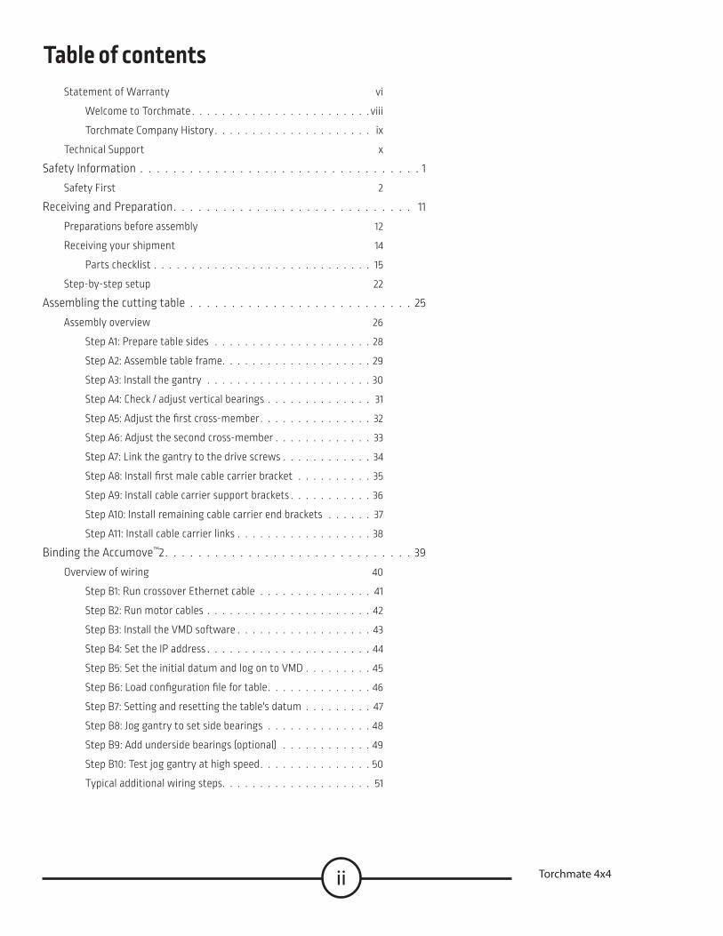
Statement of Warranty vi
Welcome to Torchmate viii
Torchmate Company History ix
Technical Support x
Safety Information 1
Safety First 2
Receiving and Preparation 11
Preparations before assembly 12
Receiving your shipment 14
Parts checklist 15
Step-by-step setup 22
Assembling the cutting table 25
Assembly overview 26
Step A1: Prepare table sides 28
Step A2: Assemble table frame 29
Step A3: Install the gantry 30
Step A4: Check / adjust vertical bearings 31
Step A5: Adjust the first cross-member 32
Step A6: Adjust the second cross-member 33
Step A7: Link the gantry to the drive screws 34
Step A8: Install first male cable carrier bracket 35
Step A9: Install cable carrier support brackets 36
Step A10: Install remaining cable carrier end brackets 37
Step A11: Install cable carrier links 38
Binding the Accumove™2 39
Overview of wiring 40
Step B1: Run crossover Ethernet cable 41
Step B2: Run motor cables 42
Step B3: Install the VMD software 43
Step B4: Set the IP address 44
Step B5: Set the initial datum and log on to VMD 45
Step B6: Load configuration file for table 46
Step B7: Setting and resetting the table's datum 47
Step B8: Jog gantry to set side bearings 48
Step B9: Add underside bearings (optional) 49
Step B10: Test jog gantry at high speed 50
Typical additional wiring steps 51
Table of contents

iiiAssembly Guide
Table of contentsCoupling the water table (optional) 53
Assemble the (optional) 4X4 water table 54
Step C1: Assemble the two end panels 56
Step C2: Add a leveling foot to each leg 57
Step C3: Attach legs to panels for first corner 58
Step C4: Extend the sides with legs and side panels 59
Step C5: Complete the second and third corners 60
Step C6: Complete the fourth corner 61
Step C7: Insert cross members into frame 62
Step C8: Seal the 2x2 and 2x4 water pans together 63
Step C9: Add and seal the 4x4 water pan 64
Step C10: Install the drain valve and pan 65
Step C11: Add the material support slats 66
Step C12: Secure cutting table to water table 67
Deploying the Plasma Cutter 69Cutting tools for Growth Series™ tables 70
Features of the Accumove2 AVHC 72
Step D1: Attach the tool mounting bracket to the tool mounting pate 74
Step D2: Mount the AVHC lifter 76
Step D3: Prepare the plasma cutter 78
Step D4: Place the VFC unit 80
Step D5: Connect the VFC unit 82
Step D6a: Wiring for Lincoln Electric plasma cutters 84
Step D6b: Wiring for non-Lincoln Electric plasma cutters 86
Maintenance and Parts 89Growth Series care and maintenance 90
Recommended 4X4 spare / replacement parts 92
Upgrade parts for the Growth Series 4X4 93

iv Torchmate 4x4
If Buyer is not satisfied with the performance of the Goods within 30 days from the date the Goods were shipped from the Seller, Buyer may return the Goods in the original carton(s) for a full refund less Shipping, Handling, Damages and Freight Charges All sales become final after this 30 day period Buyer should determine the satisfactory performance of the Goods by using the software, and inspecting and bench running the motors and/or accessory items Any items to be returned for full refund must be in new, unused (except for bench testing), and saleable condition at the sole determination of the Seller Items that, in the Seller’s judgment, have been used or modified in any way, or kits that have been partially or fully completed will be subject to a restocking fee to be determined by the Seller A return merchandise authorization number (RMA) must be obtained by the customer prior to any return Shipments of returned items not marked with a valid RMA will be refused Electronics and motors are warranted by their manufacturer to the original purchaser for 12 months from the date of Torchmate, Inc ’s sale invoice Mechanical components are standard industrial parts and are not warranted except by their respective manufacturers If any of the warranted items are found by Seller to be defective, such Goods will, at Seller’s option, be replaced or repaired at Seller’s cost No defective goods are to be returned without written authorization of seller The sole purpose of the stipulated exclusive remedy shall be to provide the Buyer with free repair and replacement of defective Goods in the manner provided herein This exclusive remedy shall not be deemed to have failed of its essential purpose so long as the Seller is willing and able to repair or replace defective Goods in the prescribed manner The foregoing warranty is in lieu of all other warranties, express or implied, including those of merchantability or fitness for any purpose not expressly set forth herein No affirmation of Seller, by words or action, other than as set forth in this Section shall constitute a warranty Seller’s warranty does not apply to any Goods which have been subjected to misuse, mishandling, misapplication, neglect (including but not limited to improper maintenance), accident, improper installation, modification (including by not limited to use of unauthorized parts or attachments), or adjustment or repair performed by anyone other than Seller or one of Seller’s authorized agents When returning products to Seller packaging must be adequate or all warranty is null and void Buyer will pay for the cost of Shipping to and from the Seller for all warranty repairs Any claim by Buyer with reference to the Goods sold hereunder shall be deemed waived by the Buyer unless submitted in writing to seller within the earlier of (i) thirty (30) days following the date Buyer discovered or by reasonable inspection should have discovered, any claimed breach of foregoing warranty, or (ii) 12 months following the date of shipment Any cause of action for breach of the foregoing warranty shall be brought within one year from the date the alleged breach was discovered or should have been discovered, whichever occurs first
Statement of warranty
30 Day guarantee
Warranty
vAssembly Guide
Seller’s liability (whether under the theories of breach of contract or warranty, negligence, or strict liability) for its Goods shall be limited to repairing or replacing Goods found by Seller to be defective, or at Seller’s option, to refunding the purchase price of such Goods or parts thereof In no event shall seller be liable for consequential damages arising out of or in connection with this agreement, including without limitation, breach of any obligation imposed on seller hereunder Consequential damages shall include without limitation, loss of use, income or profit, or loss sustained as the result of injury (including death) to any person, or loss of or damage to property (including without limitation property handled or processed by the use of the goods) Buyer shall indemnify seller against all liability, cost or expense which may be sustained by seller on account of any such loss, damage, or injury Upon buyer’s receipt of shipment, Buyer shall immediately inspect the Goods Unless Buyer provides Seller with written notice of any claim for shortage, overcharge, or damage of Goods within ten (10) days from invoice date, such Goods shall be deemed finally inspected, checked and accepted by Buyer and no allowances shall be made thereafter In absence of shipping and packaging instructions, Seller shall use its own discretion in the choice of carrier and method of packing Seller shall not be responsible for insuring shipments unless specifically requested by Buyer and any insurance or special packaging so requested shall be at Buyer’s expense and valuation Title to any Goods sold and risk of loss of such Goods passes to Buyer upon delivery by Seller to carrier and any claims for losses or damages shall be made by Buyer directly with carrier A In addition to the rights and remedies conferred upon Seller by law, Seller shall not
be required to proceed with the performance of any order or contract if the Buyer is in default in the performance of any order or contract with Seller, and in case of doubt as to Buyer’s financial responsibility, shipments under this order may be suspended
B No delay or omission by Seller in exercising any right or remedy provided for herein shall constitute a waiver of such right or remedy and shall not be constituted as a bar to or a waiver of any such right or remedy on any future occasion
C The sale of Goods shall be governed by the laws of the State of Maryland Seller agrees to comply with all applicable laws of the United States
The invalidity or unenforceability of any one or more phrases, sentences, or sections shall not affect the validity or enforceability of the remaining portions of this Agreement
Limitation of liability
Disclaimer of consequential damages
Acceptance and transporta-tion
Title and risk of loss
General conditions
Severability
1Assembly Guide
Safety First
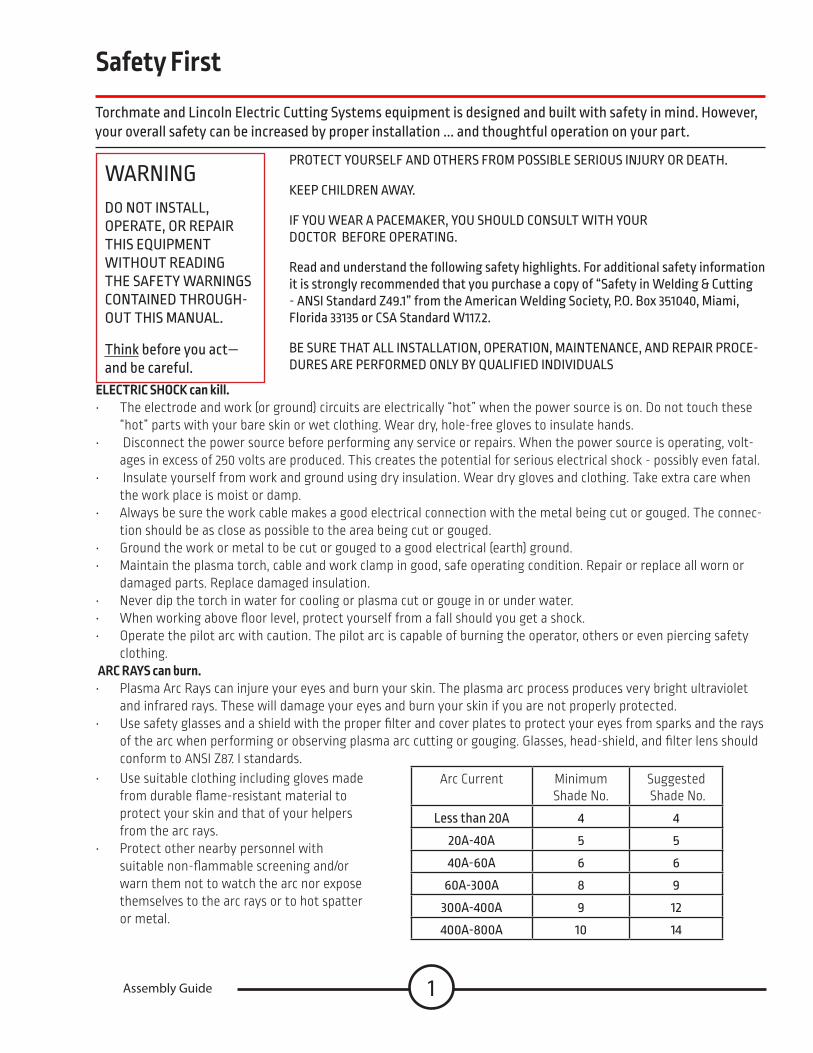
Torchmate and Lincoln Electric Cutting Systems equipment is designed and built with safety in mind However, your overall safety can be increased by proper installation and thoughtful operation on your part
WARNINGDO NOT INSTALL, OPERATE, OR REPAIR THIS EQUIPMENT WITHOUT READING THE SAFETY WARNINGS CONTAINED THROUGH-OUT THIS MANUAL
Think before you act— and be careful
PROTECT YOURSELF AND OTHERS FROM POSSIBLE SERIOUS INJURY OR DEATH
KEEP CHILDREN AWAY
IF YOU WEAR A PACEMAKER, YOU SHOULD CONSULT WITH YOUR DOCTOR BEFORE OPERATING
Read and understand the following safety highlights For additional safety information it is strongly recommended that you purchase a copy of “Safety in Welding & Cutting - ANSI Standard Z49 1” from the American Welding Society, P O Box 351040, Miami, Florida 33135 or CSA Standard W117 2
BE SURE THAT ALL INSTALLATION, OPERATION, MAINTENANCE, AND REPAIR PROCE-DURES ARE PERFORMED ONLY BY QUALIFIED INDIVIDUALS
ELECTRIC SHOCK can kill. • The electrode and work (or ground) circuits are electrically “hot” when the power source is on Do not touch these
“hot” parts with your bare skin or wet clothing Wear dry, hole-free gloves to insulate hands • Disconnect the power source before performing any service or repairs When the power source is operating, volt-
ages in excess of 250 volts are produced This creates the potential for serious electrical shock - possibly even fatal • Insulate yourself from work and ground using dry insulation Wear dry gloves and clothing Take extra care when
the work place is moist or damp • Always be sure the work cable makes a good electrical connection with the metal being cut or gouged The connec-
tion should be as close as possible to the area being cut or gouged • Ground the work or metal to be cut or gouged to a good electrical (earth) ground • Maintain the plasma torch, cable and work clamp in good, safe operating condition Repair or replace all worn or
damaged parts Replace damaged insulation • Never dip the torch in water for cooling or plasma cut or gouge in or under water • When working above floor level, protect yourself from a fall should you get a shock • Operate the pilot arc with caution The pilot arc is capable of burning the operator, others or even piercing safety
clothing ARC RAYS can burn.• Plasma Arc Rays can injure your eyes and burn your skin The plasma arc process produces very bright ultraviolet
and infrared rays These will damage your eyes and burn your skin if you are not properly protected • Use safety glasses and a shield with the proper filter and cover plates to protect your eyes from sparks and the rays
of the arc when performing or observing plasma arc cutting or gouging Glasses, head-shield, and filter lens should conform to ANSI Z87 I standards
Arc Current Minimum Shade No
Suggested Shade No
Less than 20A 4 4
20A-40A 5 5
40A-60A 6 6
60A-300A 8 9
300A-400A 9 12
400A-800A 10 14
• Use suitable clothing including gloves made from durable flame-resistant material to protect your skin and that of your helpers from the arc rays
• Protect other nearby personnel with suitable non-flammable screening and/or warn them not to watch the arc nor expose themselves to the arc rays or to hot spatter or metal

2 Torchmate 4x4
FUMES AND GASES can be dangerous.• Plasma cutting or gouging may produce fumes and gases hazardous to health Avoid breathing these fumes and
gases When cutting or gouging, keep your head out of the fumes Use enough ventilation and/or exhaust at the arc to keep fumes and gases away from the breathing zone
• Use an air-supplied respirator if ventilation is not adequate to remove all fumes and gases • When plasma cutting or gouging on lead or cadmium plated steel and other metals or coatings which produce
highly toxic fumes, keep exposure as low as possible and within applicable OSHA PEL and ACGIH TLV limits using local exhaust or mechanical ventilation In confined spaces or in some circumstances, outdoors, a respirator may be required
• Additional precautions are also required when cutting (zinc) galvanized steel or materials containing or coated with any of the following:
Antimony Beryllium Cobalt Manganese Selenium
Arsenic Cadmium Copper Mercury Silver
Barium Chromium Lead Nickel Vanadium
• The operation of plasma cutting or gouging fume control equipment is affected by various factors including proper use and positioning of the equipment, maintenance of the equipment, and the specific procedure and application involved Worker exposure levels should be checked upon installation and periodically thereafter to be certain levels are within applicable OSHA PEL and ACGIH TLV limits For information on how to test for fumes and gases in your work place, refer to publications section of this manual
• Do not use plasma cutting or gouging equipment in locations near chlorinated hydrocarbon vapors coming from degreasing, cleaning or spraying operations The heat and rays of the arc can react with solvent vapors to form phosgene, a highly toxic gas, and other irritating products Remove all sources of these vapors
• Gases used for plasma cutting and gouging can displace air and cause injury or death Always use enough ventila-tion, especially in confined areas, to insure breathing air is safe
• Read and understand the manufacturer’s instructions for this equipment and follow your employer’s safety practic-es
• This product, when used for cutting, produces fumes or gases which contain chemicals known to the State of Cali-fornia to cause birth defects
• Some dust created by routing, sawing, grinding, drilling, and other construction activities contains chemicals known to cause cancer, birth defects or other reproductive harm Avoid prolonged contact with this dust Wear protective clothing and wash exposed areas with soap and water Allowing dust to get into your mouth, eyes, or lay on the skin may promote absorption of harmful chemicals Some examples of these chemicals are:
Lead from lead-based paint Crystalline silica from bricks and cement and other masonry products Arsenic and chromium from chemically-treated lumber (CCA) Your risk from these exposures varies, depending on how often you do this type of work To reduce your exposure to these chemicals: work in a well ventilated area, and work with approved safety equipment, such as those dust masks that are specially designed to filter out microscopic particles

3Assembly Guide
Cutting flame and sparks can cause FIRE OR EXPLOSION. • Fire and explosion can be caused by hot slag, sparks, oxygen fueled cutting flame, or the plasma arc • Have a fire extinguisher readily available Provide a fire watch when working in an area where fire hazards may
exist • When not cutting or gouging, make certain no part of the electrode circuit is touching the work or ground Acciden-
tal contact can cause overheating and create a fire hazard • Be sure there are no combustible or flammable materials in the workplace Any material that cannot be removed
must be protected • Sparks and hot materials from cutting or gouging can easily go through small cracks and openings to adjacent
areas • Avoid cutting or gouging near hydraulic lines • Do not cut or gouge tanks, drums or containers until the proper steps have been taken to insure that such proce-
dures will not cause flammable or toxic vapors from substances inside They can cause an explosion even though they have been “cleaned ” For information purchase “Recommended Safe Practices for the Preparation for Welding and Cutting of Containers and Piping That Have Held Hazardous Substances”, AWS F4 1 from the American Welding Society (see address above)
• Vent hollow castings or containers before heating, cutting or gouging They may explode • Do not add fuel to engine driven equipment near an area where plasma cutting or gouging is being done • Connect the work cable to the work as close to the cutting or gouging area as practical Work cables connected to
the building framework or other locations away from the cutting or gouging area increase the possibility of the cur-rent passing through lifting chains, crane cables or other alternate circuits This can create fire hazards or overheat lifting chains or cables until they fail
• Hydrogen gas may be formed and trapped under aluminum work pieces when they are cut underwater or while using a water table DO NOT cut aluminum alloys underwater or on a water table unless the hydrogen gas can be eliminated or dissipated Trapped hydrogen gas that is ignited will cause an explosion
• Read and follow NFPA 51B “ Standard for Prevention During Welding, Cutting and Other Hot Work”, available from NFPA, 1 Batterymarch Park,PO box 9101, Quincy, Ma 022690-9101
CYLINDER may EXPLODE if damaged • Use only compressed gas cylinders containing the correct gas for the process used and properly operating regu-
lators designed for the gas and pressure used All hoses, fittings, etc should be suitable for the application and maintained in good condition
• Always keep cylinders in an upright position securely chained to an undercarriage or fixed support • Cylinders should be located: • Away from areas where they may be struck or subjected to physical damage • A safe
distance from plasma cutting or gouging, arc welding operations and any other source of heat, sparks, or flame • Never allow any part of the electrode, torch or any other electrically “hot” parts to touch a cylinder • Keep your head and face away from the cylinder valve outlet when opening the cylinder valve • Valve protection caps should always be in place and hand tight except when the cylinder is in use or connected for
use • Read and follow the instructions on compressed gas cylinders, associated equipment, and CGA publication P-l, “Pre-
cautions for Safe Handling of Compressed Gases in Cylinders,”available from the Compressed Gas Association 1235 Jefferson Davis Highway, Arlington, VA 22202
FOR ELECTRICALLY powered equipment. • Turn off input power using the disconnect switch at the fuse box before working on the equipment • Install equipment in accordance with the U S National Electrical Code, all local codes and the manufacturer’s rec-
ommendations • Ground the equipment in accordance with the U S National Electrical Code and the manufacturer’s recommenda-
tions

4 Torchmate 4x4
PLASMA ARC can injure. • Keep your body away from nozzle and plasma arc • Operate the pilot arc with caution The pilot arc is capable of burning the operator, others or even piercing safety
clothing ELECTRIC AND MAGNETIC FIELDS may be dangerous • Electric current flowing through any conductor causes localized Electric and Magnetic Fields (EMF) Cutting or
gouging current creates EMF fields around torch cables and cutting machines • EMF fields may interfere with some pacemakers, so operators having a pacemaker should consult their physician
before cutting or gouging • Exposure to EMF fields during cutting or gouging may have other health effects which are now not known • All operators should use the following procedures in order to minimize exposure to EMF fields from the cutting or
gouging circuit:• Route the torch and work cables together - Secure them with tape when possible • Never coil the torch cable around your body • Do not place your body between the torch and work cables If the torch cable is on your right side, the work cable
should also be on your right side • Connect the work cable to the workpiece as close as possible to the area being cut or gouged • Do not work next to cutting power source
For Lincoln Electric Cutting Systems Technical Support Please call 775-673-2200 Monday-Friday 7:00-4:00 PST.

5Assembly Guide
Parts checklist
The parts included in your LECS 4x4 CNC Cutting System shipment are listed here in the order you will assem-ble them To make it easier to complete the assembly of your cutting system, lay out the received parts in this order as you check them against this list
Cutting Table Parts
Qty Part Description Part Number Step1
GS 4' Side Set, Assembled (1 set = left and right),
TMS-180-1000-05 1
2 Aluminum cross-member - 4’ wide GS
TMS-180-0002-09 2
1 GS 4' Gantry, Assembled TMS-180-1000-03 3
2 Set of cable carrier end brackets TMS-105-0002-20 8 & 10
1 Set of cable carrier brackets TMS-180-0002-07 9
10 Screw, FSCS, 10-32 x 7⁄8" TMS-410-0111-14 10
73 Mini Cable Carrier Links TMS-105-0002-19 11
1 Compact CNC Controller Accumove 2 BK1250-200000 12
1 Crossover Ethernet cable TMS-103-5000-07
1 24V 6 67A DC power supply, Accu-move2
TMS-400-0003-02
1 AC power cable TMS-402-0069-01
4 Cable, motor, XLR / Molex, 25 ft TMS-402-0010-01 13
1 USB flash drive: Driver software and owners manuals
TMS-100-1000-01 14
4 99R6 Ball bearings TMS-432-0010-01 17

6 Torchmate 4x4
Water Table Parts
Qty Part Description Part Number Step2 GS water table side 31” TMS-180-0001-05 1-wt
2 GS water table side 33 75” TMS-180-0001-07 1-wt
2 GS water table side 25” TMS-180-0001-09 1-wt
2 GS water table side 22” TMS-180-0001-08
4 GS water table leg—corner leg TMS-180-0001-28 2-wt
4 GS water table leg—side leg TMS-180-0001-29 2-wt
1 GS water table leg-center leg TMS-180-0001-30 2-wt
9 3⁄8"-16 stud, leveling foot TMS-448-0001-01 2-wt
1 GS water table cross member—30 (medium)
TMS-180-0005-01 7-wt
1 GS water table cross member—24 75 (short)
TMS-180-0005-02 7-wt
1 GS water table cross member—57 625 (long)
TMS-180-0005-03 7-wt
1 GS WATER PAN A - 4 X 4 WITH DRAIN FITTING
TMS-180-0001-64 8-wt
1 GS water pan B - 4 x 4 TMS-180-0001-73 8-wt
1 Growth Series Silicone Sealant, tube TMS-180-1001-01 8-wt & 9-wt
1 TFP-AR small table 3⁄4 plumbing (water release valve)
TMS-459-0010-01 10-wt
N.A. 28 Slats—271⁄2" X (3" to 4") X 3⁄16" Customer supplied (you will cut these)
11-wt

7Assembly Guide
Parts checklist (continued)
Hardware Pack Table Kit TMS-180-0151-01
5 TMS-414-0201-18 Jam Nut, nylock, 3/8-165 TMS410-0218-16 Screw BSCS 3/8-16 x 1 0 hex drive5 TMS-410-0017-20 Screw SCS 5/25 x 3/4 hex drive5 TMS-410-0318-08 Screw BSCS 3/8-16x 1/2 hex drive18 TMS-413-0406-18 Flat Washer 3/814 TMS-414-3101-16 T-nut 5/16-1818 TMS-410-5016-10 Screw Flanged 5/16-18 x 5/85 TMS-432-0010-01 99R6 Ball Bearing9 TMS410-0511-08 Screw BSCS #10-32 x 1/2 hex drive16 TMS-414-0201-11 Nut Nylock #10-32 x 1/2 16 TMS-413-0001-10 Flat Washer #109 TMS-410-0111-14 Screw FSCS #10-32 x 7/8 hex drive5 TMS-410-0016-12 Screw SCS 5/16-18 x 3/4 hex drive12 TMS-410-0216-16 Screw BSCS 5/16-18 x 1 hex drive7 TMS-413-0001-16 Flat Washer 5/167 TMS-414-0701-16 Nut Nylock 5/16-185 TMS-429-0011-01 Screw SCS M6 x 1 0 x 25MM10 TMS-410-0208-16 #8-32 x 3/8 button socket cap8 TMS-414-0201-10 #8-32 nut nylock
5 TMS-410-0218-16 Screw BSCS 3/8-16 x 1 o hex drive38 TMS-412-1116-08 Screw Serrated hex cap26 TMS-410-0511-08 Screw BSCS #10-32 X1/2 hex drive5 TMS-413-0001-18 Flat Washer 3/826 TMS-414-0201-11 Nut Nylock #10-3238 TMS-414-0701-16 Nut Nylock Flange 5/16-1851 TMS-410-5016-10 Screw BSCS Flanged 5/16-18 x 5/8
Hardware Pack Water Table Kit TMS-180-0152-01

8 Torchmate 4x4
Additional required equip-ment and tools
Qty Part Description Part Number Step1 3⁄8" wrench (separate
purchase) 9, 10, 1-wt,
2-wt
1 1⁄2" wrench (separate purchase)
3-wt, 4-wt, 5-wt, 6-wt, 8-wt, 9-wt
1 9⁄16" wrench (separate purchase)
17
1 5⁄32" hex key (separate purchase)
12-wt
1 3⁄16" hex key (separate purchase)
1, 3-wt, 4-wt, 5-wt, 6-wt, 8-wt, 9-wt
1 7⁄32" hex key (separate purchase)
7, 17
1 1⁄8" hex key (separate purchase)
9, 10, 1-wt
1 Laptop or PC with Microsoft Win-dows 8, Windows 7, Vista, or XP
(separate purchase)
12, 14, & 15
1 Battery power for computer (Uninterruptible power supply or UPS) —with surge protection (recommended)
(separate recommended
purchase)
12, 14, & 15
1 PTFE thread-sealing tape (separate purchase)
10-wt
Toll Free: 1-866-571-1066
International: 775-673-2200
Fax: 775-673-2206
Email: support@torchmate com
Live Chat Torchmate com
Web Community
Fabricationforum com

9Assembly Guide
Assemble the cutting table
In the following steps, you will assemble the LECS 4x4 CNC Cutting System table It precisely controls the motion of the torch or other tools Fourteen steps are required If you purchased the water table, you will find the instructions for assembling the water table and mounting the cutting table on it following this section
Basic assembly steps • The cutting table is assembled in a series of easy steps
• Step 1: Prepare the table sides
• Step 2: Assemble the table frame
• Step 3: Install the gantry
• Step 4: Check / adjust vertical bearings
• Step 5: Adjust the first cross-member
• Step 6: Adjust the second cross-member
• Step 7: Link the gantry to the drive screws
• Step 8: Install first male cable carrier bracket
• Step 9: Install cable carrier support brackets
• Step 10: Install remaining cable carrier end brackets
• Step 11: Install cable carrier links
• Step 12: Run the USB cable
• Step 13: Run motor cables
• Step 14: Install Driver software
• Step 15: Load Driver configuration
• Step 16: Jog gantry to set side bearings
• Step 17: Add underside roller bearings
• Step 18-: Test-jog gantry at high speed
• Depending on the tools purchased, there will be additional tool-mounting and configuration steps
Please Note: your LECS 4x4 water table is no longer supplied with Torchmate branded side panels Some images in this manual may not represent your product Lincoln Electric Cutting Systems reserves the right to make chang-es to the production of products

10 Torchmate 4x4
Weight of the completed CNC
cutting table with optional water table
175 lbs80 kg
Weight of completed CNC cutting table
• The completed CNC cutting table is sturdy and heavy-duty, so that it can precisely and accurately move the torch, support your material, and support the weight of the water in the water table reservoir
• After being removed from the crate, the combined weight is 450 lbs (204 kg), before adding water
• Whether full or empty of water, don’t drag the cutting table when moving it to a new location
• Avoid damage to the CNC cutting table / water table and avoid getting it out of square by not dragging it
• Don’t try to move the cutting table without help When you must re-position the CNC cutting table / water table or move it to a new location, drain all the water and use the proper equipment to carefully lift it
450 lbs 204 kg

11Assembly Guide
Step 1: Prepare table sides
The sides of your LECS 4x4 CNC Cutting System are pre-assembled with a drive-screw, motor, and steel rails The cross-members are extruded aluminum channels which are held to the sides with T-nuts Here you will prepare sides by adding the T-nuts In the next step you will add the cross-members
Qty Part Description Part #1
GS 4' side set, assembled, (L / R set)
TMS-180-1000-05
12
5⁄16"
5⁄8" Screw, BSCS 5⁄16"–18 X 5⁄8" (T-bolt)
TMS-410-0216-14
12 T-nut, 5⁄16"–18, steel, black-plat-ed
TMS-414-3101-16
Required parts / components
Instructions
Illustration
• On each end of each pre-assembled side, insert three 5⁄16"–18 X 5⁄8" button head screws through the holes from the outside
• Fasten a 5⁄16"–18 T-nut to each screw
• Leave the nuts loose on the screws
• The T-nuts should be positioned so that the flanges (raised portions) face away from the screws
• Do not fully tighten the screws

12 Torchmate 4x4
Qty Part Description Part #2 1515 lite aluminum extrusion
cross-member 59 25TMS-511-1515-02
2 Assembled table side components
From Step 1
Step 2: Assemble table frame
The LECS 4x4 CNC Cutting System table uses extruded aluminum cross-members attached to the sides with T-nuts Here you will create the initial linking of the sides with the cross-members The final adjustment for squareness is completed at a later step
Required parts / components
Instructions
Illustration
• Perform this assembly on a flat, level surface
• Slide the cross-members onto the T-nuts on the pre-assembled sides There are channels in the extruded aluminum cross members for the T-nuts to slide into
• When the T-nuts are tightened, they will hold table securely
• The T-nuts will be adjusted and fully tightened later, so for now, tighten them only lightly
• Attach both cross members to one side, then slide the other side on and lightly tighten

13Assembly Guide
Step 3: Install the gantry
Like the sides of the LECS 4x4 CNC Cutting System table, the full gantry is pre-assembled with a drive-screw, motor, and steel rail It also has a multi-bearing cassette and a tool-mounting plate In this step, you will set the gantry on the side rails
Qty Part Description Part #1 Assembled gantry TMS-180-1000-03
1 Assembled side components
From Step 2
Required parts / components
Instructions
Illustration
• Loosen the inner and outer bearings so that they can be moved outward to give clearance for the rail
• Set the gantry onto the sides over the rails Make sure the vertical bearings are taking the weight of the gantry and that it is free to move
• Ensure that the gantry’s tool-mounting plate faces away from the motors on the end of the two sides

14 Torchmate 4x4
Step 4: Check / adjust vertical bearings
The smooth motion of the LECS 4x4 CNC Cutting System gantry is managed by the four vertical bearings that carry the gantry’s weight In this step you check the gantry’s clearance above the side rails and adjust its height, if necessary, by moving the vertical bearings
Illustration
Instructions
Qty Part Description Part #1 Assembled cutting table From Step 3
Required parts / components
• Measure the front and back clearances between each gantry end and the rails (four total measurements)
• A clearance of approximately 1⁄8" is desired
• Hint: The thickness of a new penny and a new dime (0 114 in ) or two new pennies (0 122 in ) is a good beginning clearance
• Loosen and adjust each vertical bearing, as necessary, to achieve an equal clearance of approximately 1⁄8" at each location
• Tighten the vertical bearings fully
• Note: the vertical bearings may require further adjustment in a later step
Measure here to get the clearance
Loosen this bolt to adjust the bearing height

15Assembly Guide
Step 5: Adjust the first cross-member
With the gantry positioned on your LECS 4x4 CNC Cutting System table, you can now begin to adjust the table’s squareness and begin to tighten the cross-members Squaring is essential for smooth and accurate gantry operation
Qty Part Description Part #1 Assembled cutting table From Step 4
Required parts / components
Instructions
Illustration
• Slide the gantry to one end of the table, until it reaches the stops
• On each side rail, rotate the drive screw to move the aluminum brackets Align the bracket holes horizontally with the gantry holes
• If there is a gap between the bracket and the gantry, slide the sides outward in the cross-member channel until the gantry and bracket just touch with no pressure
• If there is tightness between the bracket and the gantry, slide the sides inward in the cross-member channel until the gantry and bracket just touch with no pressure
• Tighten one of the T-bolts on each end of the adjusted cross-member
With the gantry at its stop and the bracket holes aligned with the gantry holes, check between the gantry and bracket for a gap or for tightness They should just touch on both sides, with no pressure
If tight, slide inward
If a gap, slide outward When adjusted, tighten one
T-bolt at each end of the cross member

16 Torchmate 4x4
Step 6: Adjust the second cross-member
With the gantry secured to your LECS 4x4 CNC Cutting System table, you can now adjust the table’s squareness and securely tighten the cross-members When squared, the gantry will operate smoothly and accurately
Qty Part Description Part #1 Assembled cutting table From Step 5
1 Tape measure (From your tool-box)
Required parts / components
Instructions
Illustration
First, measure here—outside of rail to outside of rail
Second, measure here--outside of rail to outside of rail Adjust this end’s rail spacing to make both measure-ments equal
• Measure the distance between the outside edges of the rails at the gantry end
• Measure the distance between the outside edges of the rails at the other (non-gantry) end
• Adjust side rails in the cross-members at the other (non-gantry) end to make both measurements the same
• Re-check the measurements, and make diagonal (corner to corner) measurements to ensure the table is square
• Tighten all T-bolts on both cross-members

17Assembly Guide
Step 7: Link the gantry to the drive screws
Your LECS 4x4 CNC Cutting System achieves accuracy and precision in cutting complex shapes because it uses anti-backlash nuts, which minimize backlash (play) on its drive screws Here you will attach the gantry to the side rail drive screw brackets
Qty Part Description Part #1 Squared cutting table From Step 6
4 1⁄2"
3⁄8"
Screw, BSCS, 3⁄8"–16 X 1⁄2" TMS-410-0318-08
Required parts / components
Instructions
Illustration
• Check that you can bolt the gantry to the aluminum bracket without applying vertical force
• If the holes do not align vertically, adjust the gantry clearance by re-positioning the vertical bearings
• The bearings should support the entire weight of the gantry, leaving the drive screw free to rotate without any binding
• Attach the gantry to the aluminum anti-backlash drive screw brackets on both sides of the table using button head screws
• Fully tighten the screws to secure the gantry to the table
• Note: With the gantry linked to the drive screws, only move the gantry using software jogging or programmed motor control Don’t try to move the gantry by hand

18 Torchmate 4x4
Step 8: Install first male cable carrier bracket
The LECS 4x4 CNC Cutting System includes a "cable carrier" cable management system, which consists of: 1) a number of links that can be opened to insert the cables and 2) a male / female pair of end bracket links at the ends that attach to the table components Here we will attach the first of the end brackets
• The cable carrier tray is pre-installed on the gantry
• Remove the nuts and washers from the bolts holding the tray at the motor end of the gantry
• Position the male cable carrier end bracket (the maile half of the set) over the tray mounting holes and replace the bolts, washers, and nuts
• Tighten securely
Required parts / components
Instructions
Qty Part Description Part #1 Set of cable carrier end brackets
(only the male bracket is used in this step)
TMS-105-0002-20
1 Cutting table with linked gantry From Step 7
Remove the nuts and washers from the bolts,
add the male bracket, and replace the nuts and wash-
ers on the bolts

19Assembly Guide
Step 9: Install cable carrier support brackets
The LECS 4x4 includes a cable carrier system that uses two lengths to manage cables along the rail and along the gantry A tray supports the carrier along the gantry and support brackets, mounted in this step, support the carrier along the rails, at the end of the gantry, and on the tool mounting plate
• Use the screws, washers, and nuts (except at the end of the gantry, where you use the threaded holes instead of nuts and washers) to attach the cable carrier support brackets to the rails (x3), the gantry end (x1), and the tool mounting plate(x1)
Required parts / components
Instructions
Qty Part Description Part #1 Set of cable carrier brackets
Note: All Brackets are BlackTMS-180-0002-07
8 Screw, BSCS, 10-32 x 1⁄2" TMS-410-0511-08
2 Screw, BSCS, #8-32 X 3/8 TMS-410-0208-16
6 Washer, flat, #10, steel, zinc-plated TMS-413-0001-10
8 Nut, Nylock, 10-32, steel, zinc-plated TMS-414-0201-11
1 Cutting table with cable carrier end bracket on tray
From Step 8
Mount: (1) the large cable carrier on the tool mounting plate, (2) the red bracket on the gantry end's threaded holes, and (3)the small bracket with holes nearest the motor along the rail (4) Mount the remaining two support brackets along the rail
Shown from below
Note: This bracket is now black
20 Torchmate 4x4
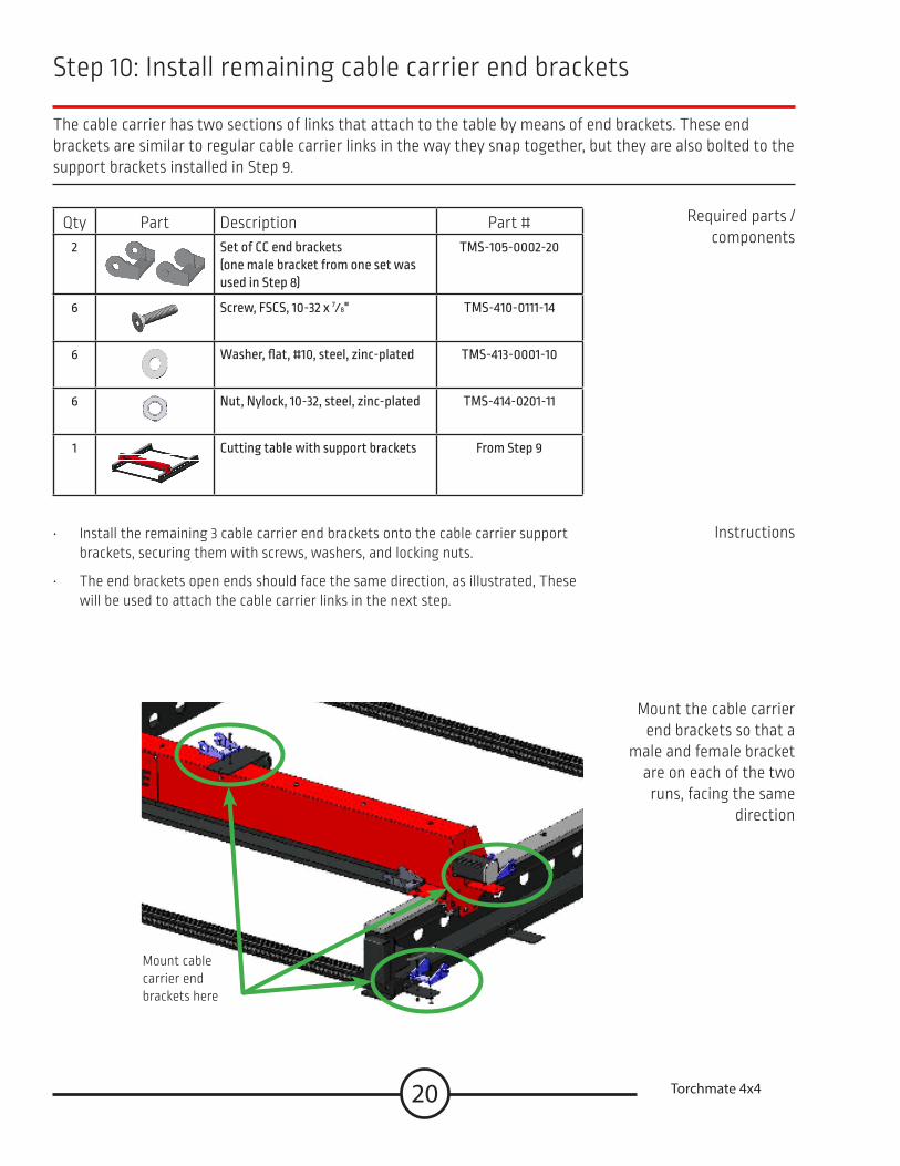
Step 10: Install remaining cable carrier end brackets
The cable carrier has two sections of links that attach to the table by means of end brackets These end brackets are similar to regular cable carrier links in the way they snap together, but they are also bolted to the support brackets installed in Step 9
• Install the remaining 3 cable carrier end brackets onto the cable carrier support brackets, securing them with screws, washers, and locking nuts
• The end brackets open ends should face the same direction, as illustrated, These will be used to attach the cable carrier links in the next step
Required parts / components
Instructions
Qty Part Description Part #2 Set of CC end brackets
(one male bracket from one set was used in Step 8)
TMS-105-0002-20
6 Screw, FSCS, 10-32 x 7⁄8" TMS-410-0111-14
6 Washer, flat, #10, steel, zinc-plated TMS-413-0001-10
6 Nut, Nylock, 10-32, steel, zinc-plated TMS-414-0201-11
1 Cutting table with support brackets From Step 9
Mount the cable carrier end brackets so that a
male and female bracket are on each of the two
runs, facing the same direction
Mount cable carrier end brackets here

21Assembly Guide
Step 11: Install cable carrier links
The LECS 4x4 cutting table includes two sections of snap-together links They similarly snap to the end brack-ets installed in Steps 8 and 10 The lines can be popped open with a screwdriver (from either side) so that the motor-control and other cables can be put inside the carrier We recommend the plasma torch cable be tied to the side
• The cable carrier links snap together You may find it easier to open the links, set the cables inside, and close the links before attaching the chain to the table
• Snap a 38 link chain to the side, resting it on the support brackets
• Snap a 35 link chain to the gantry, resting it on the tray
• Keep the motor (and other signal) cables as far away from the torch cable as possible Tying the torch cable to the outside of the carriers is advised Tie-zips are not included
Required parts / components
Instructions
Qty Part Description Part #73 Mini cable carrier links (10 84 feet) TMS-105-0002-19
1 Cutting table with CC end brackets From Step 10
The links lie as a chain along the gantry tray and along the rail brackets
Snap the links open to set the cables, then snap the links to the end brackets
Electromagnetic interfer-ence (EMI) is reduced by separating the power and control cables Tying the torch lead to the outside of the carrier links helps

22 Torchmate 4x4
Assemble the 4x4 water table
In the following steps, you will assemble the water table The water table supports the CNC cutting table, sup-ports the workpiece being cut, and safely eliminates nearly all of the sparks, dust, and smoke during cutting Nine steps are required to complete the water table assembly
Assembly steps • The 4x4 water table is assembled in a series of easy steps:
• Step 1-wt: Add a leveling foot to each leg
• Step 2-wt: Attach legs to each end panel
• Step 3-wt: Connect the side legs and side panels
• Step 4-wt: Insert cross-member into frame
• Step 5-wt: Seal the water pans and the edge
• Step 6-wt: Install the drain valve and pan
• Step 7-wt: Add the material support slats • (Note: these slats are components you will cut to fit from local material,
and are not included in your shipment )
• Step 8-wt: Secure cutting table to water table
Required space • The completed water table is fairly compact and can easily be assembled for use in a small space It’s dimensions are: 62" X 61 72" X 30 31"
• When planning for the table’s location, consider access to power for the plasma cutter (208V or 230V / 1 or 3 phase / 50 or 60 Hz), power for the computer and CNC controller (120 V), access to compressed air (and/or recommended gas), and how to obtain (and drain) the water

23Assembly Guide
Qty Part Description Part #4 GS water table leg - corner leg TMS-180-0001-28
4 GS water table leg - side leg TMS-180-0001-29
1 GS water table leg - center leg TMS-180-0001-30
9 3⁄8”–16 stud leveling foot TMS-448-0001-01
Step 1-wt: Add a leveling foot to each leg
The second step in water table assembly is to attach a leveling foot to each of the nine legs The leveling feet are used to level the table when the floor is uneven Each leg will be adjusted individually before filing the table with water
Required parts / components
Instructions
Illustration
• On each corner leg, side leg, and center leg attach one 3⁄8” leveling foot into the threaded bottom base plate
• The leveling feet will be adjusted once the table is fully assembled and in position
24 Torchmate 4x4
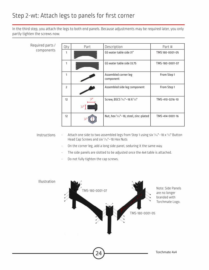
Step 2-wt: Attach legs to panels for first corner
In the third step, you attach the legs to both end panels Because adjustments may be required later, you only partly tighten the screws now
Required parts / components
Instructions
Illustration
Qty Part Description Part #1 GS water table side 31” TMS 180-0001-05
1 GS water table side 33 75 TMS-180-0001-07
1 Assembled corner leg component
From Step 1
2 Assembled side leg component From Step 1
12
5⁄16"
5⁄8" Screw, BSCS 5⁄16"–18 X 5⁄8" TMS-410-0216-10
125⁄16"
Nut, hex 5⁄16"–18, steel, zinc-plated TMS-414-0001-16
• Attach one side to two assembled legs from Step 1 using six 5⁄16"–18 x 5⁄8" Button Head Cap Screws and six 5⁄16"–18 Hex Nuts
• On the corner leg, add a long side panel, seduring it the same way
• The side panels are slotted to be adjusted once the 4x4 table is attached
• Do not fully tighten the cap screws
TMS-180-0001-05
TMS-180-0001-07Note: Side Panels are no longer branded with Torchmate Logo
25Assembly Guide
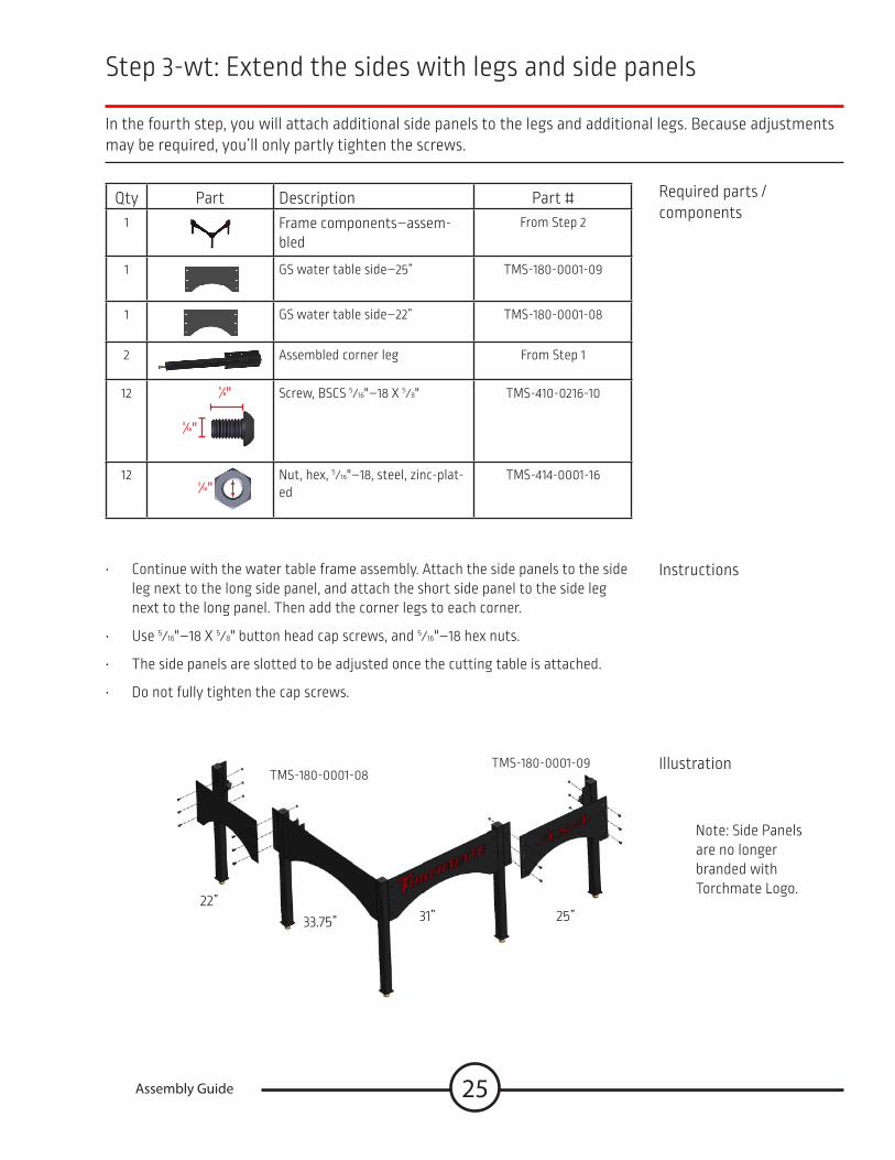
Step 3-wt: Extend the sides with legs and side panels
In the fourth step, you will attach additional side panels to the legs and additional legs Because adjustments may be required, you’ll only partly tighten the screws
Required parts / components
Instructions
Illustration
Qty Part Description Part #1 Frame components–assem-
bledFrom Step 2
1 GS water table side–25” TMS-180-0001-09
1 GS water table side–22” TMS-180-0001-08
2 Assembled corner leg From Step 1
12
5⁄16"
5⁄8" Screw, BSCS 5⁄16"–18 X 5⁄8" TMS-410-0216-10
12
5⁄16"Nut, hex, 5⁄16"–18, steel, zinc-plat-ed
TMS-414-0001-16
• Continue with the water table frame assembly Attach the side panels to the side leg next to the long side panel, and attach the short side panel to the side leg next to the long panel Then add the corner legs to each corner
• Use 5⁄16"–18 X 5⁄8" button head cap screws, and 5⁄16"–18 hex nuts
• The side panels are slotted to be adjusted once the cutting table is attached
• Do not fully tighten the cap screws
TMS-180-0001-09TMS-180-0001-08
Note: Side Panels are no longer branded with Torchmate Logo
25”31”33 75”22”

26 Torchmate 4x4
Step 4-wt: Complete the second and third corners
The 4x4 Growth Series water table frame, which holds the water pan, material support slats, and the cutting table, is built in multiple pieces so that during “growth” to the larger sized water tables, the existing compo-nents can continue to be used The fifth step seals and attaches additional panels and legs to the frame
Required parts / components
Instructions
Illustration
Qty Part Description Part #
1 Frame components–assembled From Step 3
1 Assembled cutout panel–31” TMS-180-0001-05
1 GS water table side - 33 75” TMS-180-0001-07
2 Side leg assemblies From Step 1
125⁄16"
5⁄8" Screw, BSCS, 5⁄16"–18 X 5⁄8" TMS-410-0216-10
125⁄16"
Nut, hex, 5⁄16"–18, steel, zinc-plat-ed
TMS-414-0001-16
• Continue with the water table frame assembly Attach the long side panels to the corner leg next to the short side panel, and attach the long side panel to the corner leg next to the short panels Then add the two remaining side legs
• Use 5⁄16"–18 X 5⁄8" button head cap screws, and 5⁄16"–18 hex nuts
• The side panels are slotted to be adjusted once the cutting table is attached
• Do not fully tighten the cap screws

27Assembly Guide
Step 5-wt: Complete the fourth corner
In step six, you complete the assembly of the table frame At this point, the cap screws attaching the side panels to the legs should not be fully tightened, but should be tight enough to provide the table with strength to hold the water pan and material slats The frame will be squared and tightened after the water pan and cutting table are in place
Required parts / components
Instructions
Illustration
Qty Part Description Part #
1 Frame components–assem-bled
From Step 4
1 Assembled cutout panel–25” TMS-180-0001-09
1 GS water table side–22” TMS-180-0001-08
1 Assembled corner leg From Step 1
125⁄16"
5⁄8" Screw, BSCS, 5⁄16"–18 X 5⁄8" TMS-410-0216-10
125⁄16"
Nut, hex, 5⁄16"–18, steel, zinc-plated
TMS-414-0001-16
• Complete the water table frame assembly Attach the short cutout side panels to the corner leg next to the short uncut side panel, and attach the long uncut side panel to the corner leg next to the short cutout panels Then add the two remaining side legs
• Use 5⁄16"–18 X 5⁄8" button head cap screws, and 5⁄16"–18 hex nuts
• The side panels are slotted to be adjusted once the cutting table is attached Do not fully tighten the cap screws
TMS-180-0001-09 TMS-180-0001-08

28 Torchmate 4x4
Step 6-wt: Insert cross members into frame
The 4x4 water table provides a heavy-duty support system for both the water in the water pan, and also the material being cut The tables side and center legs have support channels to hold the cross members that, in turn, will hold the water pan Step 5-wt places those cross members in the frame and locates the center leg
Required parts / components
Instructions
Illustration
Qty Part Description Part #1 Assembled water table outer
frameFrom Step 5-wt
1 Center leg with foot From Step 1-wt
1 GS water table cross member 57 625
TMS-180-0005-03
1 GS water table cross member 30
TMS-180-0005-01
1 GS water table cross member 24 75
TMS-180-0005-02
• Place the center leg so that the long cross member runs through its channel from side legs to the other
• Locate the other two cross members between the remaining side legs and the center leg
• No fasteners are required

29Assembly Guide
Step 7-wt: Add and seal the 4x4 water pan
The 4x4 water pan bed, which holds the water, is built in multiple pieces to reduce shipping costs In this step you will join the two halves of the water pan into a single unit
Required parts / components
Instructions
Illustration
Qty Part Description Part #
1 GS water pan 4x4 TMS-180-0001-64
GS water pan 4x4 TMS-180-0001-73
22 Screw, BSCS, 5⁄16"–18 X 5⁄8" TMS-412-1116-08
225⁄16"
Nut, hex , 5⁄16"–18, steel, zinc-plated
TMS-414-0701-16
1 GS silicone sealant, tube TMS-180-1001-01
• Apply a generous, continuous, double-bead of silicone sealant to the mating surfaces of the water pans Avoid gaps in the sealant, which may cause leakage
• Attach the water pans together with screws and nuts Don't tighten so much as to squeeze out all the sealant
• Trim off the excess sealant after it has thoroughly set
30 Torchmate 4x4
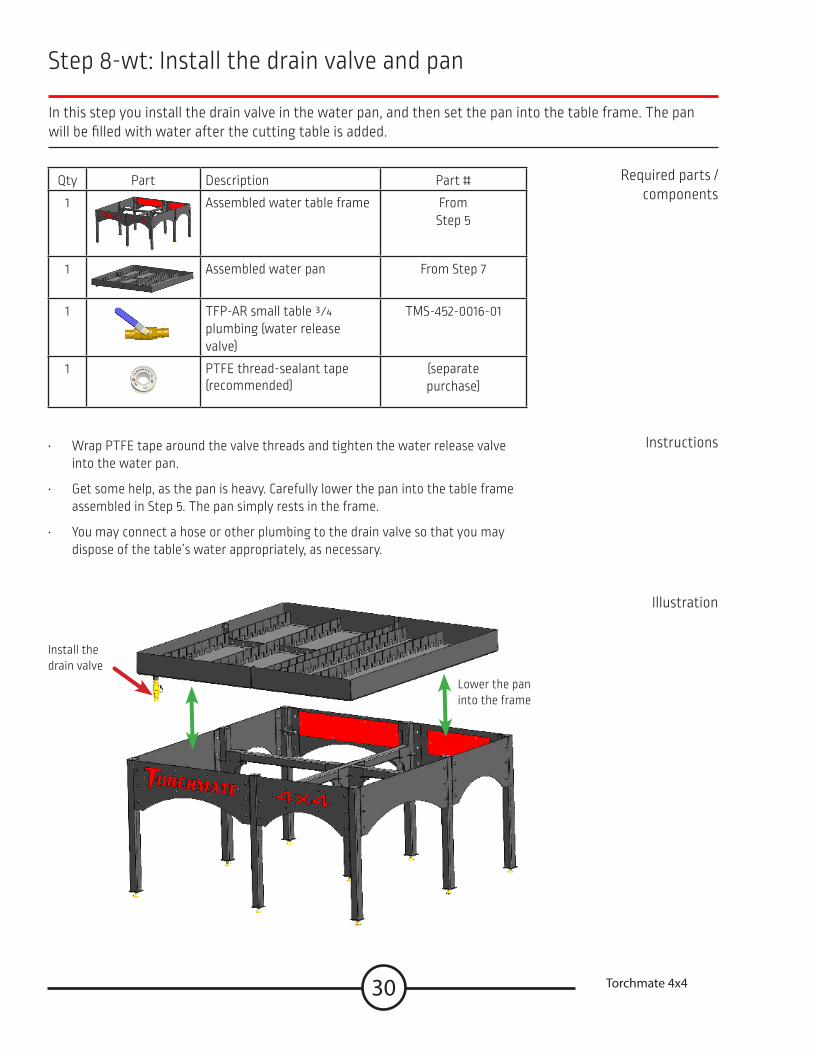
Step 8-wt: Install the drain valve and pan
In this step you install the drain valve in the water pan, and then set the pan into the table frame The pan will be filled with water after the cutting table is added
Required parts / components
Instructions
Illustration
Qty Part Description Part #
1 Assembled water table frame From Step 5
1 Assembled water pan From Step 7
1 TFP-AR small table 3⁄4 plumbing (water release valve)
TMS-452-0016-01
1 PTFE thread-sealant tape (recommended)
(separate purchase)
• Wrap PTFE tape around the valve threads and tighten the water release valve into the water pan
• Get some help, as the pan is heavy Carefully lower the pan into the table frame assembled in Step 5 The pan simply rests in the frame
• You may connect a hose or other plumbing to the drain valve so that you may dispose of the table’s water appropriately, as necessary
Install the drain valve
Lower the pan into the frame

31Assembly Guide
Step 9-wt: Add the material support slats
The 4x4 water table provides a heavy-duty support system for the material being cut using slats that you supply (and replace from time to time) from local material Placed on edge, with a slight curvature, the slats develop the strength required to provide durable, long lasting service Sparks, debris, and smoke from the cutting process are minimized because of the open access to the water surface between the slats
Required parts / components
Instructions
Illustration
Qty Part Description Part #
1 Assembled water table with pan
From Step 8
38 Material support slats 271⁄2" x (3 to 4)" x 3⁄16"
(obtain slats locally—not
supplied)
• Cut 38 support slats from 3⁄16" thickness material (This material is not supplied with your water table ) Make them between 3" and 4" at 27 1/2" long
• Insert the slats into the slat support brackets in the pans The offset in the brackets creates a curve in the slats, which increases their strength and weight-bearing capacity.
• 3"to 4" high slats may be used A 4" high slat will place the material at the top of the water table A lower slat height allows greater control over water contact with the cut material
• Over time, the cutting processes will consume the slats and you will replace them This is normal
The material to be cut will rest directly on the slats
32 Torchmate 4x4
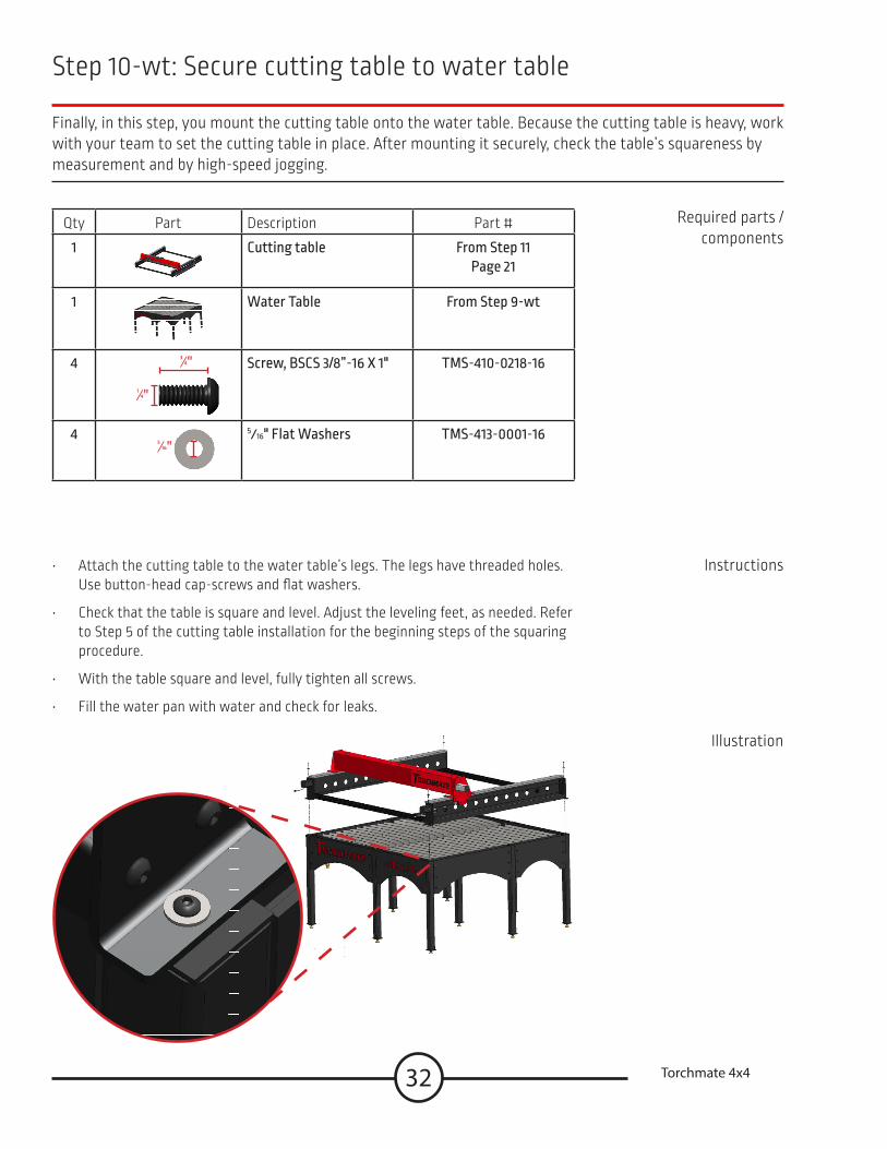
Step 10-wt: Secure cutting table to water table
Finally, in this step, you mount the cutting table onto the water table Because the cutting table is heavy, work with your team to set the cutting table in place After mounting it securely, check the table’s squareness by measurement and by high-speed jogging
Qty Part Description Part #
1 Cutting table From Step 11Page 21
1 Water Table From Step 9-wt
4
1⁄4"
3⁄4" Screw, BSCS 3/8”-16 X 1" TMS-410-0218-16
45⁄16"
5⁄16" Flat Washers TMS-413-0001-16
Required parts / components
Instructions
Illustration
• Attach the cutting table to the water table’s legs The legs have threaded holes Use button-head cap-screws and flat washers
• Check that the table is square and level Adjust the leveling feet, as needed Refer to Step 5 of the cutting table installation for the beginning steps of the squaring procedure
• With the table square and level, fully tighten all screws
• Fill the water pan with water and check for leaks

33Assembly Guide
Toll Free: 1-866-571-1066
International: 775-673-2200
Fax: 775-673-2206
Email: support@torchmate com
When making the connections and setting up the table if a question or concern arises or a part seems to be missing, please contact Torchmate technical support
Technical support will also help you with operating the CNC system, and troubleshooting problems
Torchmate technical support is available Monday through Friday from 6 AM to 4 PM (06:00 to 16:00), Pacific Time Zone
Call, fax, or email
Technical Support
Call us for Consumables, or visit our web store
www TorchmateStore com