MACHINE SAFETY - Fagor Automation
30
Ref.1605 MACHINE SAFETY
-
Upload
khangminh22 -
Category
Documents
-
view
1 -
download
0
Transcript of MACHINE SAFETY - Fagor Automation
Ref.1605
MACHINE SAFETY

This product uses the following source code, subject to the terms of the GPL li-cense. The applications busybox V0.60.2; dosfstools V2.9; linux-ftpd V0.17;ppp V2.4.0; utelnet V0.1.1. The librarygrx V2.4.4. The linux kernel V2.4.4. Thelinux boot ppcboot V1.1.3. If you would like to have a CD copy of this sourcecode sent to you, send 10 Euros to Fagor Automation for shipping and han-dling.
All rights reserved. No part of this documentation may be transmitted, tran-scribed, stored in a backup device or translated into another language withoutFagor Automation’s consent. Unauthorized copying or distributing of this soft-ware is prohibited.
The information described in this manual may be subject to changes due totechnical modifications. Fagor Automation reserves the right to change the con-tents of this manual without prior notice.
All the trade marks appearing in the manual belong to the corresponding own-ers. The use of these marks by third parties for their own purpose could violatethe rights of the owners.
It is possible that CNC can execute more functions than those described in itsassociated documentation; however, Fagor Automation does not guarantee thevalidity of those applications. Therefore, except under the express permissionfrom Fagor Automation, any CNC application that is not described in the docu-mentation must be considered as "impossible". In any case, Fagor Automationshall not be held responsible for any personal injuries or physical damagecaused or suffered by the CNC if it is used in any way other than as explainedin the related documentation.
The content of this manual and its validity for the product described here hasbeen verified. Even so, involuntary errors are possible, hence no absolutematch is guaranteed. However, the contents of this document are regularlychecked and updated implementing the necessary corrections in a later edition.We appreciate your suggestions for improvement.
The examples described in this manual are for learning purposes. Before usingthem in industrial applications, they must be properly adapted making sure thatthe safety regulations are fully met.
Machine safety
·3·
Ref.1605
MACHINESAFETY
I N D E X
CHAPTER 1 INTRODUCTION 5
CHAPTER 2 OPERATING MODES, RISK ANALYSES, SAFETY FUNCTIONS COMPONENTS 7
2.1 Operating modes.............................................................................................. 92.1.1 EN 12417. Machining centres....................................................................... 92.1.2 ISO 23125. Turning machines ...................................................................... 92.2 Safety Functions Components and its PLr ..................................................... 112.2.1 ISO 23125. Machine tools - Safety - Turning machines ............................. 112.2.2 EN 12417. Machine tools - Safety - Machining centres .............................. 112.2.3 PLr calculation for machines different to those preferred in ISO 23125
or EN 1241712............................................................................................ 12
CHAPTER 3 REGULATIONS ·STANDARDS· TO COMPLY WITH ... 13
3.1 Legal regulations in the European Community .............................................. 133.1.1 Directives and CE Mark .............................................................................. 133.1.2 Harmonized Standards ............................................................................... 133.2 EN ISO 13849-1 ............................................................................................. 14
CHAPTER 4 SAFETY FUNCTION OF FAGOR AXD/SPD SERVO DRIVES 15
CHAPTER 5 FAGOR SAFETY SOLUTIONS 17
5.1 Safety Functions. Emergency Stop and Operation with Open Guards (SLS) 175.1.1 Emergency Stop ......................................................................................... 185.1.2 Operation with Open Guards (SLS) ............................................................ 185.2 Safety system architecture for working with FAGOR ..................................... 195.2.1 AXD/SPD servo drives................................................................................ 205.2.2 ACSD servo drives...................................................................................... 215.2.3 Analog servo drives .................................................................................... 225.2.4 Multi-Axis Box ............................................................................................. 235.3 Technical data ................................................................................................ 245.3.1 Safety functions .......................................................................................... 245.3.2 Fix components of the FAGOR application................................................. 255.3.3 Components that can be chosen by Machine Builder................................. 26

·4·
Machine safety
MACHINESAFETY
Ref.1605
This page intentionally left blank

1
· 5 ·
Ref.1605
MACHINESAFETY
INTRODUCTION
The working environment of machine operators offers potential risks for their physical integrity.
To carry out certain operations, users (with different levels of authorization) need to access certainpotentially dangerous areas of the machine. Machine manufacturers install doors to prevent ac-cess to dangerous areas, but some users need to work with open doors sometimes. Under thoseopen-door conditions, certain protection devices must be used (Enable device for moving axesand spindle, E-stop button, etc.) to prevent users' personal injury.
The machine must be built so it adapts to their function allowing for adjustment and maintenancework without any risks to the operators when carrying these tasks under the conditions foreseenby the manufacturer.
The purpose of these measurements is to eliminate any chances for accidents during the foreseenmachine running period, including mounting and dismantling stages where the risk of an accidentis higher due to the abnormal situation at the time.
In order to help set the measurements mentioned earlier, various directives and regulations havebeen created describing the minimum requirements to meet in order to ensure the safest work en-vironment possible.
Machine manufacturers have to build their machines so they meet the essential safety require-ments of the Machine Directive. Manufacturers must have to consider safety integration during thedesign process. In practice, this means that the designer must evaluate the risks for the operatorsalready in the developing stage of the machine.
This document shows the solutions that FAGOR offers to make it easier to comply with those reg-ulations and make the operator's work environment safer. Although the main goal is personnelsafety, FAGOR has developed a number of functionalities that make it possible for these safe workconditions not to affect productivity significantly while protecting the machine and the work piecesbeing made.
DANGER.Information only for the evaluation of the performance level of the machines.The reproduction or redistribution of the following data is not permitted.
WARNING. The information described in this document may be subject to changes due to technicalevolution of FAGOR products or due to modifications on the requirements of the Euro-pean Directives or Regulations.
· 6 ·
Machine safety
1.
INT
RO
DU
CT
ION
MACHINESAFETY
Ref.1605
This page intentionally left blank
2
· 7 ·
Ref.1605
MACHINESAFETY
OPERATING MODES, RISK ANALYSES, SAFETY FUNCTIONS COMPONENTS
The machine shall be designed and constructed so that the principles of ISO 13849-1 are fully tak-en into account.
ISO 23125 and EN 12417 define Operating Modes, Risk Analyses, Safety Functions and PLr forpreferred types of these machines. Usually the actual machine deviates from these types and riskanalisys should be done for these parts.
Safety Functions Components and their PLr are the inputs for the next design step.
Machines fully covered by ISO 23125 or EN 12417
These standards provides the following information for preferred types of machines:
• Determination of the limits.
• Hazard identification.
ISO 23125 or EN 12417 give a list of hazards and hazardous situations.
The risk assessment assumes foreseeable access from all directions, as well as unexpect-ed start-up. It takes into account various conditions (e.g. commissioning, set-up, produc-tion, maintenance, repair and decommissioning) during the life of the machine.
The assessment includes an analysis of the effect of failure in the control system.
• Risk estimation.
• Risk evaluation.
• Safety requirements and/or measures to eliminate or reduce these risks.
Machine shall be designed and safeguarded in accordance with the specific requirementsand/or protective measures listed.
Specific requirements resulting from failure of the control circuit hazards.
In general the safety function shall initiate a Safe Stop 1 (IEC 618000-5-2) also called cat-egory 1 stop in IEC 60204-1 and shall preclude unexpected start-up.
Safety function specification, included required PL.
In this machines the maximum resulted PL d.
· 8 ·
Machine safety
2.
OP
ER
AT
ING
MO
DE
S, R
ISK
AN
AL
YS
ES
, SA
FE
TY
FU
NC
TIO
NS
MACHINESAFETY
Ref.1605
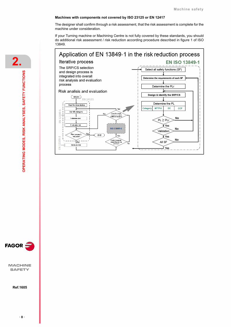
Machines with components not covered by ISO 23125 or EN 12417
The designer shall confirm through a risk assessment, that the risk assessment is complete for themachine under consideration.
If your Turning machine or Machining Centre is not fully covered by these standards, you shoulddo additional risk assessment / risk reduction according procedure described in figure 1 of ISO13849.
Machine safety
OP
ER
AT
ING
MO
DE
S, R
ISK
AN
AL
YS
ES
, SA
FE
TY
FU
NC
TIO
NS
2.
· 9 ·
Op
erat
ing
mod
es
Ref.1605
MACHINESAFETY
2.1 Operating modes
Operating modes of ISO 23125 and EN 12417.
2.1.1 EN 12417. Machining centres
Each user type will have authorization for the modes he's been properly trained for. Access will re-quire a password. Usually a key is used.
• Safe operating mode 1
Mode comprising any of the operations to be carried out when producing parts (CNC automaticmode). Being in this mode, means that any operation must be carried out with the doorsclosed. No element of the machine must move (axes, spindles, etc.) if the doors are open.
• Safe operating mode 2
Setup mode, used by the user to carry out operations such as manual tool calibration, part zerosearch, etc. while the doors are open. Only authorized personnel can work in this mode. Thispossibility is usually enabled through a password. There must also be a push-button on themachine to enable certain specific functions.
Thus, this operating mode will allow the movements of some elements of the machine but withthe following restrictions:
The maximum feed rate of the axes will be 2 m/min.
The spindle will have to stop in 2 revolutions.
No axes can be interpolated; i.e. only one axis can move at a time.
The spindle can only be started if the enable button is pressed.
The spindle will only turn while the enable button stays pressed.
Block execution will only be possible if the start and enable buttons are kept pressed.
There must be a redundant control (using two channels) to ensure that the speed of theaxes and the spindle is the right one and to comply with the limitations set for this mode.
• Safe operating mode 3
Manual intervention mode. Only for qualified users. Similar to previous mode 2, except:
The maximum feed rate of the axes will be 5 m/min.
The spindle will have to stop in 5 revolutions.
Axes can be interpolated; i.e. several axes can move simultaneously.
2.1.2 ISO 23125. Turning machines
The main operating modes are:
• Safe operating mode 0 - Manual
These requirements are also relevant for other machine groups when working in Mode 0 Au-tomatic.
• Safe operating mode 1 - Automatic
With similar philosophy as for milling; i.e. only changing the part to be machined will be allowedwhile the doors are open. On a lathe, the part is attached to the spindle, it is possible to actupon the claws and the tailstock and the spindle may be turned at limited rpm to check that thepart is properly secured same as during setup.
Main characteristics:
Spindle speed is limited to 50 rpm on small lathes.
The axes cannot be moved.
While the door is closed, it must be verified that the spindle speed does not exceed themaximum value.
· 10 ·
Machine safety
2.
OP
ER
AT
ING
MO
DE
S, R
ISK
AN
AL
YS
ES
, SA
FE
TY
FU
NC
TIO
NS
Op
erat
ing
mod
es
MACHINESAFETY
Ref.1605
• Safe operating mode 2 - Setup
This mode is mandatory for group 3, that means that Safe Limited Speed safety function tomonitor movements with open door is mandatory.
This mode is almost identical to that of the milling machine.
Axis feedrate is limited to 2 m/min.
The speed of the main spindle (the one turning the part) is limited to 50 rpm.
The speed of the spindle for the live tool is also limited to 50 rpm.
If the turret is indexed (without an axis moving it), it may be moved in incremental mode bypressing the Enable button and pressing a safe key (hold to run) at the same time.
If the turret has a controlled axis, the feedrate is limited to 50 rpm (with a limit of 1.3 m/s)and it will move like an axis.
Machine safety
OP
ER
AT
ING
MO
DE
S, R
ISK
AN
AL
YS
ES
, SA
FE
TY
FU
NC
TIO
NS
2.
· 11 ·
Saf
ety
Fu
nctio
ns C
ompo
nen
ts a
nd it
s P
Lr
Ref.1605
MACHINESAFETY
2.2 Safety Functions Components and its PLr
Although these two standards talk about “Safety Function”, they are actually “Safety FunctionsComponents” used to build real “Safety Functions” like those described in section "5.1 SafetyFunctions. Emergency Stop and Operation with Open Guards (SLS)" on page 17.
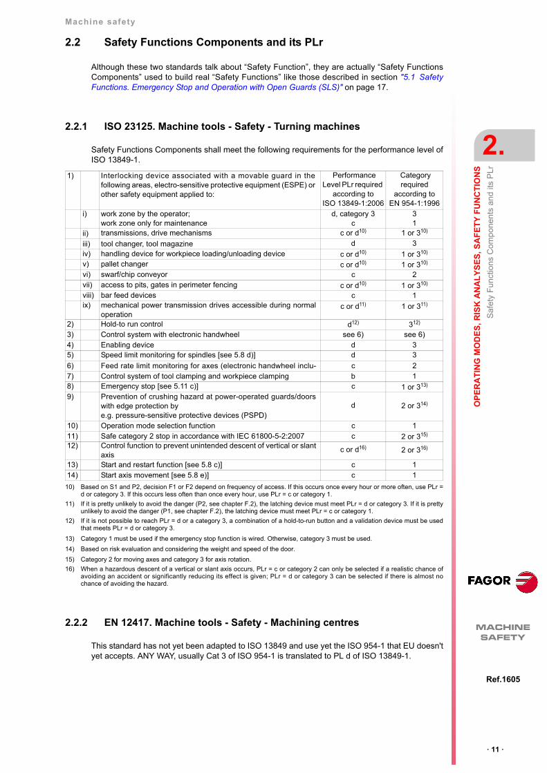
2.2.1 ISO 23125. Machine tools - Safety - Turning machines
Safety Functions Components shall meet the following requirements for the performance level ofISO 13849-1.
2.2.2 EN 12417. Machine tools - Safety - Machining centres
This standard has not yet been adapted to ISO 13849 and use yet the ISO 954-1 that EU doesn'tyet accepts. ANY WAY, usually Cat 3 of ISO 954-1 is translated to PL d of ISO 13849-1.
1) Interlocking device associated with a movable guard in thefollowing areas, electro-sensitive protective equipment (ESPE) orother safety equipment applied to:
Performance Level PLr required
according toISO 13849-1:2006
Category required
according to EN 954-1:1996
i) work zone by the operator;work zone only for maintenance
d, category 3c
31
ii) transmissions, drive mechanisms c or d10) 1 or 310)
iii) tool changer, tool magazine d 3iv) handling device for workpiece loading/unloading device c or d10) 1 or 310)
v) pallet changer c or d10) 1 or 310)
vi) swarf/chip conveyor c 2vii) access to pits, gates in perimeter fencing c or d10) 1 or 310)
viii) bar feed devices c 1ix) mechanical power transmission drives accessible during normal
operationc or d11) 1 or 311)
2) Hold-to run control d12) 312)
3) Control system with electronic handwheel see 6) see 6)4) Enabling device d 35) Speed limit monitoring for spindles [see 5.8 d)] d 3
6) Feed rate limit monitoring for axes (electronic handwheel inclu- c 27) Control system of tool clamping and workpiece clamping b 18) Emergency stop [see 5.11 c)] c 1 or 313)
9) Prevention of crushing hazard at power-operated guards/doorswith edge protection by e.g. pressure-sensitive protective devices (PSPD)
d 2 or 314)
10) Operation mode selection function c 111) Safe category 2 stop in accordance with IEC 61800-5-2:2007 c 2 or 315)
12) Control function to prevent unintended descent of vertical or slantaxis
c or d16) 2 or 316)
13) Start and restart function [see 5.8 c)] c 114) Start axis movement [see 5.8 e)] c 1
10) Based on S1 and P2, decision F1 or F2 depend on frequency of access. If this occurs once every hour or more often, use PLr =d or category 3. If this occurs less often than once every hour, use PLr = c or category 1.
11) If it is pretty unlikely to avoid the danger (P2, see chapter F.2), the latching device must meet PLr = d or category 3. If it is prettyunlikely to avoid the danger (P1, see chapter F.2), the latching device must meet PLr = c or category 1.
12) If it is not possible to reach PLr = d or a category 3, a combination of a hold-to-run button and a validation device must be usedthat meets PLr = d or category 3.
13) Category 1 must be used if the emergency stop function is wired. Otherwise, category 3 must be used.
14) Based on risk evaluation and considering the weight and speed of the door.
15) Category 2 for moving axes and category 3 for axis rotation.
16) When a hazardous descent of a vertical or slant axis occurs, PLr = c or category 2 can only be selected if a realistic chance ofavoiding an accident or significantly reducing its effect is given; PLr = d or category 3 can be selected if there is almost nochance of avoiding the hazard.
· 12 ·
Machine safety
2.
OP
ER
AT
ING
MO
DE
S, R
ISK
AN
AL
YS
ES
, SA
FE
TY
FU
NC
TIO
NS
Saf
ety
Fu
nctio
ns C
ompo
nen
ts a
nd it
s P
Lr
MACHINESAFETY
Ref.1605
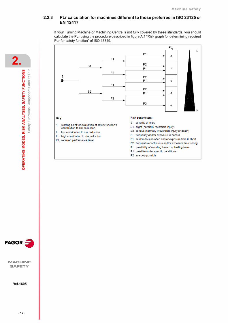
2.2.3 PLr calculation for machines different to those preferred in ISO 23125 orEN 12417
If your Turning Machine or Machining Centre is not fully covered by these standards, you shouldcalculate the PLr using the procedure described in figure A.1 “Risk graph for determining requiredPLr for safety function” of ISO 13849.
3
· 13 ·
Ref.1605
MACHINESAFETY
REGULATIONS (STANDARDS) TO COMPLY WITH ...
3.1 Legal regulations in the European Community
3.1.1 Directives and CE Mark
At list these EC Directives are mandatory for machines:
• Directive 2006/95/EC on Low Voltage.
• Directive 2006/42/EC on Machinery.
• Directive 2004/108/EC on Electromagnetic Compatibility.
Machinery Directive
The essential health and safety requirements should be satisfied as defined in annex A.
Machinery manufactured in conformity with a harmonised standard shall be presumed to complywith the essential health and safety requirements covered by such a harmonised standard.
Manufacturers retain full responsibility for certifying the conformity of their machinery to the provi-sions of this Directive. Nevertheless, for certain types of machinery having a higher risk factor, astricter certification procedure is desirable, usually this is not the case for the Machining Centersshown in EN 12417 or for the Turning Machines shown in ISO 23125.
3.1.2 Harmonized Standards
Machinery manufactured in conformity with a harmonised standard shall be presumed to complywith the essential health and safety requirements covered by such a harmonised standard.
The main harmonized standards used in this document are:
• EN 12417 Machine tools – Safety – Machining centres.
• ISO 23125 Machine tools – Safety – Turning machines.
• ISO 13849 Safety of Machinery – Safety – related parts of control systems.
Part 1: General principles for design
Part 2: Validation
In the FAGOR Declaration of Conformity, see “man_dds_hard.pdf” and/or “man_acsd_so.pdf”,there is the list of harmonized standards that FAGOR drives fulfil for the three directives. The aremuch more harmonized standard for several components and subject of the whole machine but theyare outside FAGOR components.
· 14 ·
Machine safety
3.
RE
GU
LA
TIO
NS
(S
TA
ND
AR
DS
) T
O C
OM
PL
Y W
ITH
...
EN
ISO
13
849
-1
MACHINESAFETY
Ref.1605
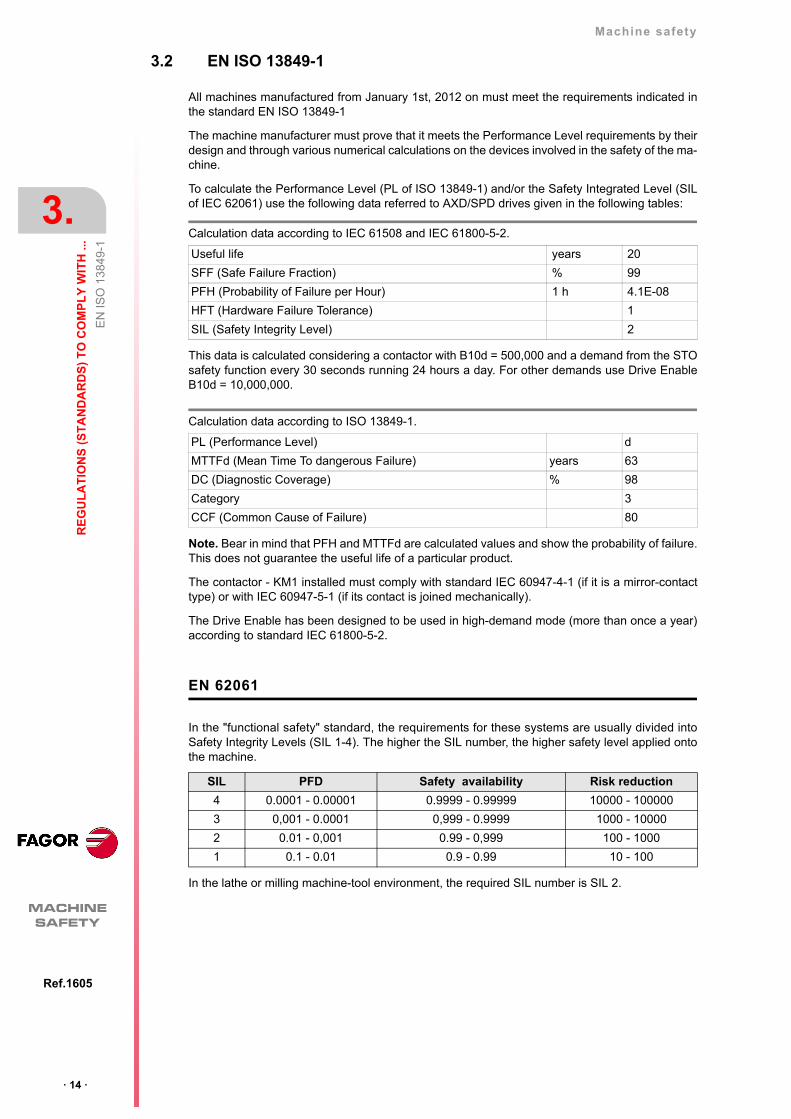
3.2 EN ISO 13849-1
All machines manufactured from January 1st, 2012 on must meet the requirements indicated inthe standard EN ISO 13849-1
The machine manufacturer must prove that it meets the Performance Level requirements by theirdesign and through various numerical calculations on the devices involved in the safety of the ma-chine.
To calculate the Performance Level (PL of ISO 13849-1) and/or the Safety Integrated Level (SILof IEC 62061) use the following data referred to AXD/SPD drives given in the following tables:
This data is calculated considering a contactor with B10d = 500,000 and a demand from the STOsafety function every 30 seconds running 24 hours a day. For other demands use Drive EnableB10d = 10,000,000.
Note. Bear in mind that PFH and MTTFd are calculated values and show the probability of failure.This does not guarantee the useful life of a particular product.
The contactor - KM1 installed must comply with standard IEC 60947-4-1 (if it is a mirror-contacttype) or with IEC 60947-5-1 (if its contact is joined mechanically).
The Drive Enable has been designed to be used in high-demand mode (more than once a year)according to standard IEC 61800-5-2.
EN 62061
In the "functional safety" standard, the requirements for these systems are usually divided intoSafety Integrity Levels (SIL 1-4). The higher the SIL number, the higher safety level applied ontothe machine.
In the lathe or milling machine-tool environment, the required SIL number is SIL 2.
Calculation data according to IEC 61508 and IEC 61800-5-2.
Useful life years 20
SFF (Safe Failure Fraction) % 99
PFH (Probability of Failure per Hour) 1 h 4.1E-08
HFT (Hardware Failure Tolerance) 1
SIL (Safety Integrity Level) 2
Calculation data according to ISO 13849-1.
PL (Performance Level) d
MTTFd (Mean Time To dangerous Failure) years 63
DC (Diagnostic Coverage) % 98
Category 3
CCF (Common Cause of Failure) 80
SIL PFD Safety availability Risk reduction
4 0.0001 - 0.00001 0.9999 - 0.99999 10000 - 100000
3 0,001 - 0.0001 0,999 - 0.9999 1000 - 10000
2 0.01 - 0,001 0.99 - 0,999 100 - 1000
1 0.1 - 0.01 0.9 - 0.99 10 - 100

4
· 15 ·
Ref.1506
MACHINESAFETY
SAFETY FUNCTION OF FAGOR AXD/SPD SERVO DRIVES
FAGOR AXD/SPD drives are certified by TÜV.
Information related to the certificates and declarations of conformity is available in the manualsand in your local Fagor branch office.
The FAGOR AXD/SPD servo drive family holds the certificate that ensures that it meets the re-quirements for:
• Safety Integrity Level (SIL) 2 in compliance with the standard IEC 61800-5-2
• Performance Level (PL) d in compliance with the standard IEC ISO 13849-1
· 16 ·
Machine safety
4.
SA
FE
TY
FU
NC
TIO
N O
F F
AG
OR
AX
D/S
PD
SE
RV
O D
RIV
ES
MACHINESAFETY
Ref.1506
This page intentionally left blank
5
· 17 ·
Ref.1605
MACHINESAFETY
FAGOR SAFETY SOLUTIONS
Depending on the characteristics of the machine and the operations to be carried out, a special de-sign of the electrical cabinet may be required to implement the necessary safety functions. Thisdesign, together with the PLC management and the safety controller (Pilz, DINA,...) make it pos-sible to reach the necessary safety level SIL or PL.
FAGOR offers two servo drive systems designed to provide the best solution in terms of price andfeatures for low-power and high-power machines. This document shows examples of connectiondiagrams to work in those operating modes.
5.1 Safety Functions. Emergency Stop and Operation with Open Guards (SLS)
From the Operating Modes and Safety Function Components defined in ISO 23125 and EN 12417FAGOR has designed these two Safety Function: Emergency Stop and Operation with OpenGuards (SLS) Safety Function, implementing:
• designing architecture.
• designing schematic.
• designing safety software in Safety Controller with SLS.
• calculating and validating MTTFd, DCavg and CCF using “SISTEMA” tool.
· 18 ·
Machine safety
5.
FA
GO
R S
AF
ET
Y S
OL
UT
ION
S
Sa
fety
Fun
ctio
ns. E
mer
gen
cy S
top
and
Op
erat
ion
with
Op
en G
uard
s(S
LS)
MACHINESAFETY
Ref.1605
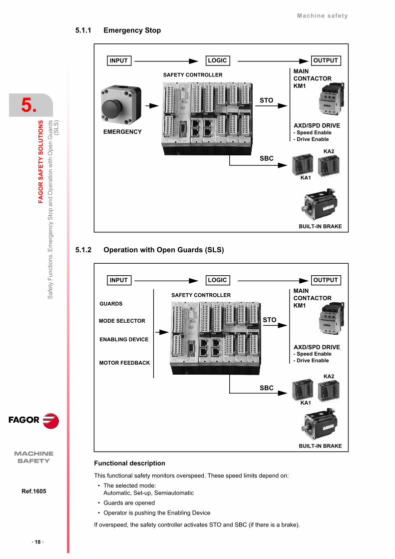
5.1.1 Emergency Stop
5.1.2 Operation with Open Guards (SLS)
Functional description
This functional safety monitors overspeed. These speed limits depend on:
• The selected mode: Automatic, Set-up, Semiautomatic
• Guards are opened
• Operator is pushing the Enabling Device
If overspeed, the safety controller activates STO and SBC (if there is a brake).
INPUT LOGIC OUTPUT
SAFETY CONTROLLER
EMERGENCY
STO
MAINCONTACTORKM1
KA1
KA2
BUILT-IN BRAKE
- Speed Enable- Drive Enable
AXD/SPD DRIVE
SBC
INPUT LOGIC OUTPUT
SAFETY CONTROLLER
GUARDS
STO
MAINCONTACTORKM1
KA1
KA2
BUILT-IN BRAKE
- Speed Enable- Drive Enable
AXD/SPD DRIVE
SBC
MODE SELECTOR
ENABLING DEVICE
MOTOR FEEDBACK

Machine safety
FA
GO
R S
AF
ET
Y S
OL
UT
ION
S
5.
· 19 ·
Saf
ety
sys
tem
arc
hite
ctur
e fo
r w
orki
ng w
ith F
AG
OR
Ref.1605
MACHINESAFETY
5.2 Safety system architecture for working with FAGOR
If the operator needs to work with the doors open, additional measures must be taken to ensurehis safety. In these modes, there can be moving elements on the machine that the user can accessand, therefore, it is necessary to implement the Safety Limited Speed SLS function to ensure thatthe movements do not exceed the speed limits indicated by the standards.
· 20 ·
Machine safety
5.
FA
GO
R S
AF
ET
Y S
OL
UT
ION
S
Saf
ety
sys
tem
arc
hite
ctur
e fo
r w
orki
ng w
ith F
AG
OR
MACHINESAFETY
Ref.1605
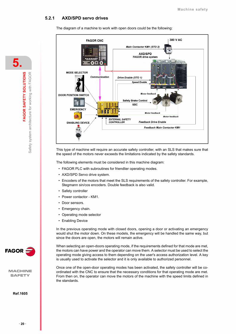
5.2.1 AXD/SPD servo drives
The diagram of a machine to work with open doors could be the following:
This type of machine will require an accurate safety controller, with an SLS that makes sure thatthe speed of the motors never exceeds the limitations indicated by the safety standards.
The following elements must be considered in this machine diagram:
• FAGOR PLC with subroutines for friendlier operating modes.
• AXD/SPD Servo drive system.
• Encoders of the motors that meet the SLS requirements of the safety controller. For example,Stegmann sin/cos encoders. Double feedback is also valid.
• Safety controller
• Power contactor - KM1.
• Door sensors.
• Emergency chain.
• Operating mode selector
• Enabling Device
In the previous operating mode with closed doors, opening a door or activating an emergencywould shut the motor down. On these models, the emergency will be handled the same way, butsince the doors are open, the motors will remain active.
When selecting an open-doors operating mode, if the requirements defined for that mode are met,the motors can have power and the operator can move them. A selector must be used to select theoperating mode giving access to them depending on the user's access authorization level. A keyis usually used to activate the selector and it is only available to authorized personnel.
Once one of the open-door operating modes has been activated, the safety controller will be co-ordinated with the CNC to ensure that the necessary conditions for that operating mode are met.From then on, the operator can move the motors of the machine with the speed limits defined inthe standards.
Machine safety
FA
GO
R S
AF
ET
Y S
OL
UT
ION
S
5.
· 21 ·
Saf
ety
sys
tem
arc
hite
ctur
e fo
r w
orki
ng w
ith F
AG
OR
Ref.1605
MACHINESAFETY
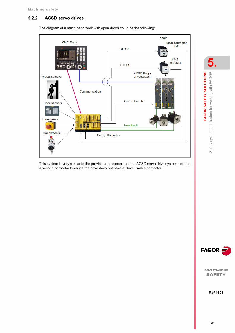
5.2.2 ACSD servo drives
The diagram of a machine to work with open doors could be the following:
This system is very similar to the previous one except that the ACSD servo drive system requiresa second contactor because the drive does not have a Drive Enable contactor.
· 22 ·
Machine safety
5.
FA
GO
R S
AF
ET
Y S
OL
UT
ION
S
Saf
ety
sys
tem
arc
hite
ctur
e fo
r w
orki
ng w
ith F
AG
OR
MACHINESAFETY
Ref.1605
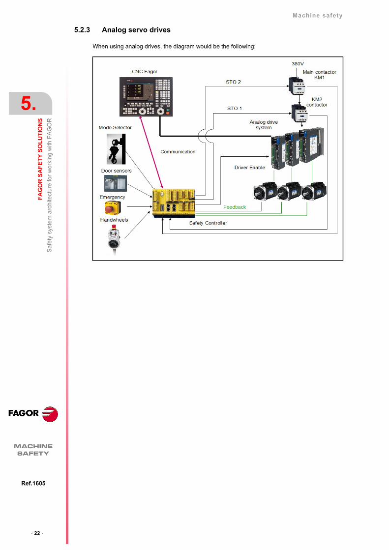
5.2.3 Analog servo drives
When using analog drives, the diagram would be the following:
Machine safety
FA
GO
R S
AF
ET
Y S
OL
UT
ION
S
5.
· 23 ·
Saf
ety
sys
tem
arc
hite
ctur
e fo
r w
orki
ng w
ith F
AG
OR
Ref.1605
MACHINESAFETY
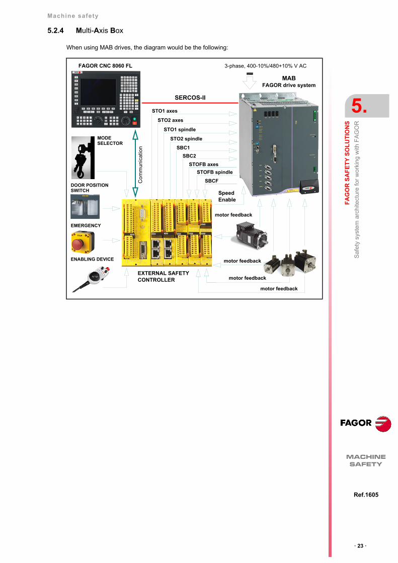
5.2.4 Multi-Axis Box
When using MAB drives, the diagram would be the following:
FAGOR CNC 8060 FL 3-phase, 400-10%/480+10% V AC
MODESELECTOR
DOOR POSITION SWITCH
EMERGENCY
ENABLING DEVICE
MAB FAGOR drive system
Com
mun
icat
ion
EXTERNAL SAFETY CONTROLLER
STO1 axes
STO2 axes
STO1 spindle
STO2 spindle
SBC1
SBC2
SBCF
STOFB axes
SERCOS-II
motor feedback
motor feedback
motor feedback
motor feedback
SpeedEnable
STOFB spindle

· 24 ·
Machine safety
5.
FA
GO
R S
AF
ET
Y S
OL
UT
ION
S
Tec
hnic
al d
ata
MACHINESAFETY
Ref.1605
5.3 Technical data
5.3.1 Safety functions
Emergency Stop
Operation with Open Guards (SLS)
PL required PL PFH
C D 1.14 E-7
PL required PL PFH
D D 2.00 E-007
DANGER.Safety related part of control system should be design according to chapter 9 of·man_dds_hard.pdf· Ref.1601. In a particular design should fulfil ISO 13849-1:2010.
Machine safety
FA
GO
R S
AF
ET
Y S
OL
UT
ION
S
5.
· 25 ·
Tec
hnic
al d
ata
Ref.1605
MACHINESAFETY
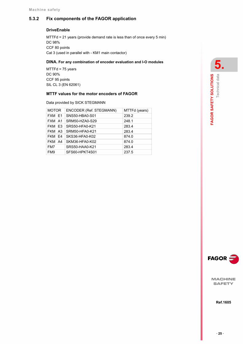
5.3.2 Fix components of the FAGOR application
DriveEnable
DINA. For any combination of encoder evaluation and I-O modules
MTTF values for the motor encoders of FAGOR
Data provided by SICK STEGMANN
MTTFd = 21 years (provide demand rate is less than of once every 5 min)
DC 98%
CCF 80 points
Cat 3 (used in parallel with - KM1 main contactor)
MTTFd = 75 years
DC 90%
CCF 95 points
SIL CL 3 (EN 62061)
MOTOR ENCODER (Ref. STEGMANN) MTTFd (years)
FXM E1 SNS50-HBA0-S01 239.2
FXM A1 SRM50-HZA0-S29 248.1
FKM E3 SRS50-HFA0-K21 283.4FKM A3 SRM50-HFA0-K21 283.4FKM E4 SKS36-HFA0-K02 874.0
FKM A4 SKM36-HFA0-K02 874.0
FM7 SRS50-HAA0-K21 283.4
FM9 SFS60-HPKT4S01 237.5
· 26 ·
Machine safety
5.
FA
GO
R S
AF
ET
Y S
OL
UT
ION
S
Tec
hnic
al d
ata
MACHINESAFETY
Ref.1605
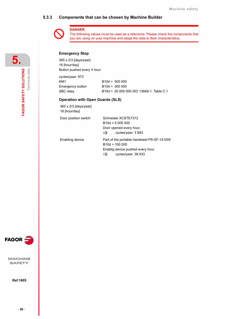
5.3.3 Components that can be chosen by Machine Builder
Emergency Stop
Operation with Open Guards (SLS)
DANGER.The following values must be used as a reference. Please check the components thatyou are using on your machine and adapt the data to their characteristics.
365 x 2/3 [days/year]
16 [hour/day]
Button pushed every 4 hour
cycles/year: 973
KM1 B10d = 500 000
Emergency button B10d = 300 000
SBC relay B10d = 20 000 000 ISO 13849-1. Table C.1
365 x 2/3 [days/year]
18 [hour/day]
Door position switch Schneider XCSTE7312
B10d = 5 000 000
Door opened every hour,
cycles/year: 3 893
Enabling device Part of the portable handweel PS-SF-141005
B10d = 100 000
Enablig device pushed every hour,
cycles/year: 38 933

Machine safety
5.
· 27 ·
Ref.1605
MACHINESAFETY
· 28 ·
Machine safety
5.
MACHINESAFETY
Ref.1605


Fagor Automation S. Coop.
Bº San Andrés, 19 - Apdo. 144E-20500 Arrasate-Mondragón, SpainTel: +34 943 719 200
+34 943 039 800Fax: +34 943 791 712E-mail: [email protected]
FAGOR AUTOMATION