NC-10/20 S for shears - Fagor Automation
60
INSTALLATION MANUAL FAGOR NC-10/20 S FOR SHEARS Manual version: 0302
-
Upload
khangminh22 -
Category
Documents
-
view
0 -
download
0
Transcript of NC-10/20 S for shears - Fagor Automation

INSTALLATION MANUAL
FAGOR NC-10/20 SFOR SHEARS
Manual version: 0302

Page: 2 - Installation Manual - NC-10/20S
INDEXDeclaration of conformity ................................................................................... 4Safety conditions ............................................................................................... 5Warranty terms ................................................................................................... 7Material returning terms ...................................................................................... 8Description of the various models ....................................................................... 8Machine definition. Most relevant parameters ...................................................... 9
1. Unit description .............................................................................. 101.1 Front panel (See operation manual) .................................................... 101.2 Rear panel ........................................................................................ 101.3 General technical characteristics..........................................................11
2. Connections and characteristics .................................................... 112.1 Power and machine connection...........................................................112.2 connection of the feedback systems ................................................... 122.3 Input/Output characteristics (X2) ....................................................... 132.3.1 Precautions for the electrical installation ............................................. 132.4 Input/output Connection (X2). ........................................................... 142.4.1 Input description. .............................................................................. 152.4.2 Output description ............................................................................ 162.4.3 Input / Output connection.................................................................. 172.4.3.1 Electrical interface ............................................................................. 182.4.4 Shear. Time diagram .......................................................................... 192.4.5 Press brake. Time diagram. PAR65(7) = 1. ......................................... 212.5 Machine reference (home) search....................................................... 222.5.1 Axes with home switches (PAR14.1=0).............................................. 222.5.2 Axis without home switch.................................................................. 232.5.3 Precautions when home searching ...................................................... 24
3. Installation Parameters .................................................................. 253.1 Parameter setting ............................................................................... 26

NC-10/20S - Installation Manual - Page: 3
Warning:Before starting up the DRO, carefully read the instructions ofChapter 2 in the Installation Manual.
The DRO must not be powered-on until verifying that themachine complies with the "89/392/CEE" Directive.
Last page of this manual ............................................................................... 44
4 Setup ............................................................................................... 374.1 Test mode .........................................................................................374.1.1 Direct access to the parameters ..........................................................394.2 Axis setting........................................................................................404.2.1 Open loop without analog voltage output.
P46(3)=0, P46(5)=0 ...........................................................................404.2.2 Open loop with analog voltage output.
PAR46(3)=1, PAR46(5)=0 .................................................................414.2.3 Closed loop. PAR 46(3)=1, PAR46(5)=1 ............................................41
Appendix ........................................................................................................ 43Error codes ......................................................................................................43Maintenance......................................................................................................44
Page: 4 - Installation Manual - NC-10/20S
DECLARATION OF CONFORMITY
Manufacturer: Fagor Automation, S. Coop.
Barrio de San Andrés s/n, C.P. 20500, Mondragón -Guipúzcoa(ESPAÑA)
We hereby declare, under our responsibility that the product:
NC Fagor NC-10/20 S1
meets the following directives:
SAFETY:
EN 60204-1 Machine safety. Electrical equipment of the machines.
ELECTROMAGNETIC COMPATIBILITY:
EN 50081-2Emission
EN 55011 Radiated. Class A, Group 1.EN 55011 Conducted. Class A, Group 1.
EN 50082-2 Immunity
EN 61000-4-2 Electrostatic Discharges.EN 61000-4-4 Bursts and fast transients.EN 61000-4-5 Power surgesEN 61000-4-11 Voltage fluctuations and Outages.ENV 50140 Radiofrequency Radiated Electromagnetic Fields.ENV 50141 Conducted disturbance induced by radio frequency
fields.
As instructed by the European Community Directives on Low Voltage:73/23/EEC, on Machine Safety 89/392/EEC and 89/336/EEC on Electro-magnetic Compatibility.
In Mondragón, on February 1st, 2002

NC-10/20S - Installation Manual - Page: 5
SAFETY CONDITIONS
Read the following safety measures in order to prevent damage to personnel,to this product and to those products connected to it.
Fagor Automation shall not be held responsible for any physical or materialdamage derived from the violation of these basic safety regulations.
Do not open this unitOnly personnel authorized by Fagor Automation may open thisunit.
Do not handle the connectors with the unit connected to ACpower.Before handling the connectors (mains, feedback, etc.) make surethat the unit is not connected to AC power.
Use proper Mains AC power cablesTo avoid risks, use only the Mains AC cables recommended for this unit.
Avoid electrical overloadsIn order to avoid electrical discharges and fire hazards, do not apply electricalvoltage outside the range indicated in chapter 2 of this manual
Ground connectionIn order to avoid electrical discharges, connect the ground terminals of all themodules to the main ground terminal. Before connecting the inputs and outputsof this unit, make sure that all the grounding connections are properly made.
Before powering the unit up, make sure that it is connected to groundIn order to avoid electrical discharges, make sure that all the groundingconnections are properly made.
Ambient conditionsRespect the temperature and humidity ranges specified on the chapter abouttechnical characteristics in this manual (1.3).
Do not work in explosive environmentsIn order to avoid risks, damage, do not work in explosive environments.

Page: 6 - Installation Manual - NC-10/20S
Working environmentThis unit is ready to be used in Industrial Environments complying with thedirectives and regulations effective in the European Community
Install the unit in the right placeIt is recommended, whenever possible, to instal the DRO so its power switchof the back panel is at a distance between 0.7 m (27.5 inches) and 1.7 m (5.6ft) off the floor and away from direct sunlight, hot air, coolants, chemicalproducts, blows as well as from relays, or high electromagnetic fields (about0.5m or 20 inches) that could damage it.
This unit complies with the European directives on electromagnetic compatibility.Nevertheless, it is recommended to keep it away from sources of electromagneticdisturbance such as.- Powerful loads connected to the same AC power line as this equipment.- Nearby portable transmitters (Radio-telephones, Ham radio transmitters).- Nearby radio / TC transmitters.- Nearby arc welding machines.- Nearby High Voltage power lines.- Disturbance generating elements of the machine.- Etc.
Safety symbols
Symbols which may appear on the manual
WARNING. symbolIt has an associated text indicating those actions or operations may hurtpeople or damage products.
Symbols that may be carried on the product
WARNING. symbolIt has an associated text indicating those actions or operations may hurtpeople or damage products.
"ELECTRICAL SHOCK" symbolIt indicates that point may be under electrical voltage
"GROUND PROTECTION" symbolIt indicates that point must be connected to the main ground point ofthe machine as protection for people and units.
NC-10/20S - Installation Manual - Page: 7
WARRANTY TERMS
WARRANTY
All products manufactured or marketed by Fagor Automation has a warrantyperiod of 12 months from the day they are shipped out of our warehouses.
The mentioned warranty covers repair material and labor costs, at FAGORfacilities, incurred in the repair of the products.
Within the warranty period, Fagor will repair or replace the products verifiedas being defective.
FAGOR is committed to repairing or replacing its products from the timewhen the first such product was launched up to 8 years after such producthas disappeared from the product catalog.
It is entirely up to FAGOR to determine whether a repair is to be consideredunder warranty.
EXCLUDING CLAUSES
The repair will take place at our facilities. Therefore, all shipping expenses aswell as travelling expenses incurred by technical personnel are NOT underwarranty even when the unit is under warranty.
This warranty will be applied so long as the equipment has been installedaccording to the instructions, it has not been mistreated or damaged by acci-dent or negligence and has been manipulated by personnel authorized byFAGOR.
If once the service call or repair has been completed, the cause of the failure isnot to be blamed the FAGOR product, the customer must cover all generatedexpenses according to current fees.
No other implicit or explicit warranty is covered and FAGOR AUTOMA-TION shall not be held responsible, under any circumstances, of the damagewhich could be originated.
SERVICE CONTRACTS
Service and Maintenance Contracts are available for the customer within thewarranty period as well as outside of it.

Page: 8 - Installation Manual - NC-10/20S
MATERIAL RETURNING TERMS
When returning the DRO, pack it in its original package and with its originalpackaging material. If not available, pack it as follows:
1.- Get a cardboard box whose three inside dimensions are at least 15 cm (6 inches)larger than those of the unit. The cardboard being used to make the box musthave a resistance of 170 Kg (375 lb.).
2.- When sending it to a Fagor Automation office for repair, attach a label indicatingthe owner of the unit, person to contact, type of unit, serial number, symptomand a brief description of the problem.
3.- Wrap the unit in a polyethylene roll or similar material to protect it.
4.- Pad the unit inside the cardboard box with poly-utherane foam on all sides.
5.- Seal the cardboard box with packing tape or industrial staples.
DESCRIPTION OF THE VARIOUS MODELSThis manual mentions different machine models depending on the number ofaxes controlled. All the models have a parts counter whose display is shared withthat of the Y axis position.
SIMPLE PROGRAMMABLE
NC 10S1 NC 10S2 1 axis
NC 20S1 NC 20S2 2 axes
The Y axis may be set (PAR65.3 = 1) to only attend to the three fixed positionsdetected by the limit switches at the 24V INPUTS.
This manual refers to them as NC 20 S1/2*.

NC-10/20S - Installation Manual - Page: 9
MACHINE DEFINITION. MOST RELEVANT PARAMETERS
1.- PAR65(5)=0, PAR64(3)=1 Cut-off / Shear
Independent electrovalves to activate clamp / holders and shearingmechanism.
Sequential operation:
- Clamp.
- Option backstop retraction.
Cut-off / shear.
- Release the foot switch and return.
2.- PAR65(5) = 1 Conventional shear
Single electrovalve.
- Simultaneous action upon sheet holders and shear with optional backstopretraction.
- Release the foot switch and return.
Options:
a) Interrupt the cut. PAR65(4)
If = 1, abort when lifting the foot switch.
If = 0, interrupt / resume the cut with the foot switch.
b) Timed end of cut (PAR32)
c) Auxiliary "Y" axis. "NC-20" model
Blade gap in swinging shear.
Inclination by swinging the position of the cylinders.
Controls 3 fixed positions without encoder [PAR65(3)].
d) Programmable models: NC-10/20 S2
Repetitive shearing sequences or with STOP when finishing the batches.
3.- PAR64(1) Conventional press brake
MANUAL and CICLE modes.
X, Y axes positioning, ram-down permission and confirmation with manometricpressure gage.
Modifiable bending time.
Command to return the ram to the top dead point.

Page: 10 - Installation Manual - NC-10/20S
1. UNIT DESCRIPTION
This NC is specifically designed to be installed on 1 and 2-axis shears. It allowsmoving the axes in JOG mode or to a preset position. Through its digitaloutputs, it can also control auxiliary mechanisms such as sheet holders,pressure valves and shear up and down movements and it has a parts counter.
1.1 FRONT PANEL (SEE OPERATION MANUAL)
1.2 REAR PANELDimensions of the Built-in model (in mm):
On the back of the unit, the following items may be found:
1.- Power switch.
2.- Three-prong power connector for AC and ground connection.
3.- M6 mm terminal for general machine ground connection.
X1, X2.- SUB-D type 37 pin female connector to connect the digital inputs andoutputs as well as the analog outputs.
X3.- SUB-D HD type 15-pin female connector for X axis feedback device.
X4.- SUB-D HD type 15-pin female connector for Y axis feedback device.
WARNING Do not handle the connectors while the unit is under power.
Before handling the connectors (mains, feedback, etc.) makesure that the unit is not under power.
It is NOT enough to turn the display off by using the OFF
ON key
at the keyboard.
105
142
133
300
284272
X1 X2
X3 X4
85
1
2
3

NC-10/20S - Installation Manual - Page: 11
1.3 GENERAL TECHNICAL CHARACTERISTICS
Universal Power Supply between 100V AC and 240V AC ±10% at a mainsfrequency between 45 Hz and 400Hz, between 120Vdc and 300Vdc
Mains frequency of 0 Hz (DC) and from 45 Hz to 400 Hz.
Power outages of up to 20 milliseconds.
10-year memory backup of installation parameter even when the unit is off.
The operating temperature inside the DRO enclosure must be between 5º C and45º C (41ºF and 113ºF).
The storage temperature inside the DRO enclosure must be -25º C and +70º C(-13º F and 158º F).
Maximum relative humidity: 95% non condensing at 45ºC (113ºF).
Front Panel Sealing: IP54 (DIN 40050), Rear panel: IP4X (DIN40050) exceptfor built-in models in which case is: IP20.
2. CONNECTIONS AND CHARACTERISTICS
2.1 POWER AND MACHINE CONNECTION
This NC can be connected to an AC voltage anywhere between 100V AC and264 V AC ±10% at a frequency between 45 Hz and 400 Hz. Between 120Vdcand 300Vdc without having to select it depending on the country where they areinstalled thanks to their universal power supply.
Always mount it vertically so its keyboard is within operator's reach and its digitsare easily visible (at operator's eye level).
Do not connect or disconnect this NC connectors while it is under power.
Connect all metallic parts to a common point on the machine tool and it to thegeneral ground point. Use cables of enough gage (no thinner than 8 mm2).
Page: 12 - Installation Manual - NC-10/20S
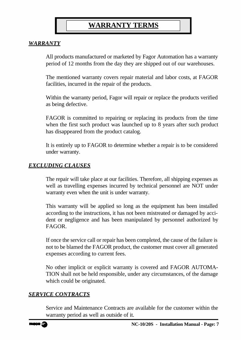
2.2 CONNECTION OF THE FEEDBACK SYSTEMS
The feedback systems (scales or encoders) are connected via SUB-D HD type15-pin female connectors: X3 and X4.
Characteristics of feedback inputs: X3 and X4:
- +5V input consumption: 250 mA
- Admits square-wave signal (TTL). (A, B, Io)
- Maximum frequency: 250 KHz,minimum separation between flanks: 950 nsec.
- Phase shift 90º ±20º, hysteresis 0.25 V, Vmax 7V,maximum input current: 3 mA.
- High threshold (logic state 1) 2.4V < VIH
< 5V
- Low threshold (logic state 0) 0.0V < VIL
< 0.8V
* For double-ended (differential) feedback
1
Pin Signal Function
1 A
Feedback signals2 /A *
3 B
4 /B *
5 Io Reference signal
6 /Io *
7 AlarmFeedback alarm
8 /Alarm *
9 +5V Power for feedback
10 Not connected Not being used at this time
11 0V Power for feedback
12 Not connected Not being used at this time
13 Not connected Not being used at this time
14 Not connected Not being used at this time
15 Chassis Shield

NC-10/20S - Installation Manual - Page: 13
2.3 INPUT/OUTPUT CHARACTERISTICS (X2)
A 37-pin female connector is used.Signal characteristics of connector "X2":The supply voltage is at +24V (±25%), thus the thresholdbetween a "0" and a "1" will be about +6V.Characteristics of the inputs at 24V :- Maximum load current: 100mA- Minimum DC voltage: 18V- Maximum DC voltage: 30VThe main characteristics of the digital outputs are:(optocoupled with solid state relay with a normally opencontact)- Maximum AC or DC voltage: 48V- Maximum load current: 150 mA- Maximum internal resistance: 24Ohm- Maximum peak current: 500mA for 100ms
at 25ºC- Through current when open: ≤ 1µA- Leak current: 200nA (Vload=100V)- Galvanic isolation voltage: 1500V for 1 minute- Activation time: ≤ 3ms- Deactivation time: ≤ 3ms
Main characteristics of the analog outputs
Voltage range: ±10V Resolution: 4.88mVMaximum current: 10mA Offset: ±30mVImpedance: 120 Ohm referred to GND
2.3.1 PRECAUTIONS FOR THE ELECTRICAL INSTALLATION
· Use shielded extension cables for the encoders and analog signal cables.
Install the shielded cables far from mains transformers.
· Separate the power cables from the signal cables in different cable hoses.
· Protect the outputs connected to relays, contactors and electrovalves:
RC if supplied with 110Vac - 220 Vac
Anti-parallelel diode if supplied with 24Vdc
· Ground the following elements with a cable having a section between 1.5 mmand 2 mm:
External screw on the rear of the unit.
Connector X2, Pin 17 - Chassis
Pin 19 - Analog 0V
Pin 2 and 20 - 0V of the the 24Vdc.

Page: 14 - Installation Manual - NC-10/20S
2.4 INPUT/OUTPUT CONNECTION (X2).
Pin I/O NC-10S1 model NC-20S1 model1 Chassis Chassis
2 I 0V External 0V External3 I 24V External 24V External
4 O 24V User 24V User
5 O X Enable X Enable
6 O 1 = X fast, 0 = X slow 1 = X fast, 0 = X slow7 O X direction X direction
8 I * Position-1 detector
9 O Pressure valve Pressure valve
10 O Activate sheet holder Activate sheet holder11 I X limit + (Io X) X limit + (Io X)
12 I X- limit X- limit
13 I Shear up Shear up
14 I Sheet contact15 I Pressure gage
16 I * Position-3 detector
17 I Chassis Chassis
18 O X analog output X analog voltage19 O 0V Analog. 0V Analog.
20 I 0V External 0V External
21 I 24V Externos 24V Externos
22 O 24V User 24V User23 I Emergency Emergency
24 O Y enable
25 O Y speed (* angle -)26 O Y direction (* angle +)
27 O Shear down Shear down
28 O Shear up Shear up
29 O In position In position30 I Y+ limit (Io Y)
31 I Y- limit
32 I Shear down Shear down
33 I34 I Free Y axis
35 I Foot switch Foot switch
36 I * Position-2 detector
37 O Y analog voltage

NC-10/20S - Installation Manual - Page: 15
2.4.1 INPUT DESCRIPTION.
Section 2.4.3 shows the electrical diagrams for the indicated models. Theparameters mentioned there are described in chapter 3 of this manual.
The inputs are active high at 24V (PAR21 and PAR22 = 1....1).
When PAR65.3 = 1, the Y axis (knife inclination) only admits 3 positionsdetected with limit switches recognized at the following inputs:
POS 1, I8: Minimum inclination angle.
POS 2, I36: Medium inclination angle.
POS 3, I16: Maximum inclination angle.
PIN FUNCTION DESCRIPTION
In MANUAL mode, they limit the movement in the corresponding direction
In HOME SEARCH mode, they act as home switches in the positive direction
Disables the axes
Disables the outputs
Displays error 7
34 Y axis disable. It maintains the displayed position
8, 16,
36
Y axis position detectors.
NC-20 S1/S2* modelThey confirm the fixed positions of the inclination of the shear
35 Foot switch connection
13 Shear-up switchConfirms that the shear is at the top position. Make sure that E13 = 1 in order to move the
axes and home search sequence
32 Shear-down switch Causes the shear to return to the top position
23 EXTERNAL EMERGENCY
Hardware travel limits11, 12,
30, 31
Page: 16 - Installation Manual - NC-10/20S
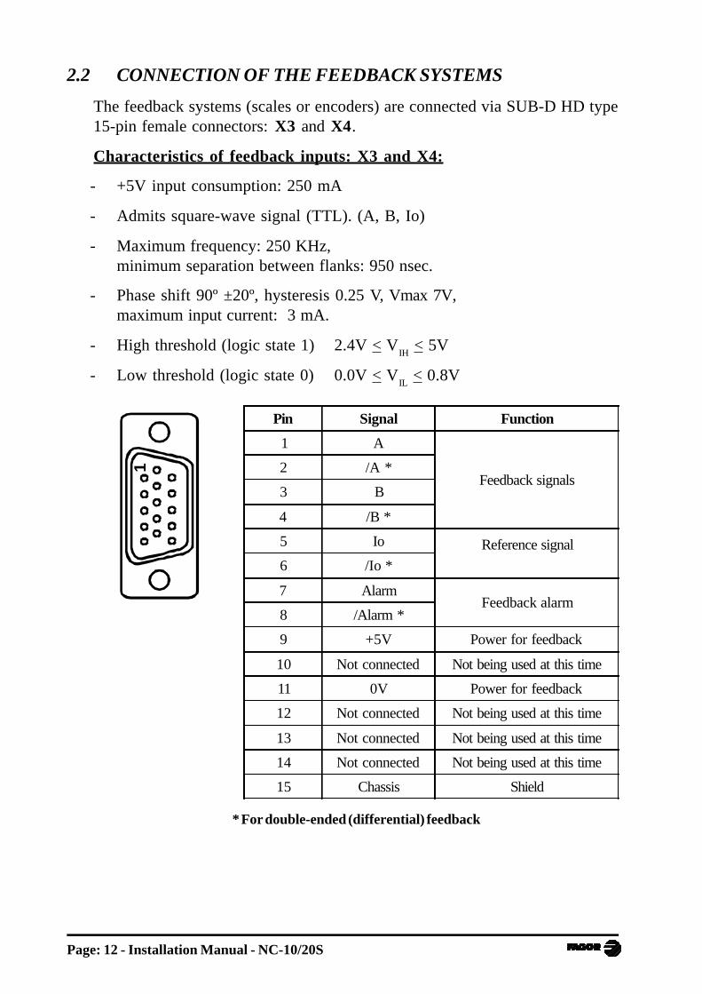
2.4.2 OUTPUT DESCRIPTION
If any of the outputs is going to be connected to some highly inductive device,a "1N4000" type diode must be installed in antiparallel.
The drives are enabled with auxiliary relays (section 4.2).
When PAR65.3 = 1 (Section 2.4.1)O26 is activated if the requested position se higher.O25 is activated if the requested position is lower.O25 and O26 also activate O9, pressure valve.
PIN FUNCTION DESCRIPTION
5, 6, 7, 24,
25, 26
Axis enable
FAST/SLOW
DIRECTION PAR46
Enabling of drives and frequency inverters for open loop control.
9 Pressure valve Simultaneous with O27 OR O28 OR O10 (*OR O25 OR O26)
10 Activate sheet holder Simultaneous with E35 - Foot switch
18, 37 Analog voltage outputs To control drives in closed or open loop
27 Shear down Delay with respect to S10 - PAR31
End of cut command by:
· Lift foot switch
· Down time concluded PAR32
· End of travel, I32
Axes in position (PAR65.5 = 1 does not inhibit if X axis
retraction has been selected when activating the sheet holders.
It is released when X reaches the end position.
Shear up28
INPOS section 2.4.429

NC-10/20S - Installation Manual - Page: 17
2.4.3 INPUT / OUTPUT CONNECTION
* I14 and I15 are exclusive for the SIMPLE PRESS BRAKEmodel (PAR64.1=1). Shear down controlled by resources external to thisNC. (See section 2.4.5)
M
En
cod
er
MO
TO
RC
ON
TR
OL
213202 4 22
18
27
NC
- 20
S
AN
AL
OG
XG
ND
A
SHEAR DOWN
24V USER
X E
NA
BL
EX
SP
EE
D
X D
IRE
CT
ION
M
En
cod
er
Y A
NA
LO
GG
ND
A
Y E
NA
BL
E
83
52
31
43
3
765
19
37
26
25
24
31
30
12
11 X+ LIMIT
X- LIMIT
10
13
32
29
19
36
28
34
9
Inte
rfac
e
15
16
X2
X3
X4
SHEAR UP
EMERGENCY
RELEASE "Y"
FOOT SWITCH
POS 1
POS 2
ON
LY
NC
-20S
1/2*
PO
S 1
, 2,
3
* V
AL
VE
MO
TO
RC
ON
TR
OL 24
VE
XT
ER
NA
L
NC
-20S
1
Y S
PE
ED
Y D
IRE
CT
ION
Y+ LIMIT
Y- LIMIT
POS 3
NC-20S1/2*
SH
EA
R D
OW
N
HO
LD
ER
IN P
OS
ITIO
NS
HE
AR
UP
PR
ES
SU
RE
VA
LV
E
* PRESSURE GAGE
SHEET CONTACT

Page: 18 - Installation Manual - NC-10/20S
27 10 28 35
R1 R2 R4 R5
FOOT SWITCH
R5
R1 (# R2)
R4
R2
110 Vac
SHEAR DOWN SHEET HOLDERS PRESSURE VALVE
O O O I O9
R6
R4
R6
2.4.3.1 ELECTRICAL INTERFACE
# On machines with a single electro-valve, use output O10 (relay R2) as thegoverning signal, set PAR65.5 = 1, PAR65.4 = 1 and PAR31 = 0.
A delay may be set between the beginning of the cut, O10 and the retractionof the X axis using PAR30 = 0.1 to 0.5 sec.
· The electrovalve that activates the lowering of the shear is conditioned bya safety chain, some of them redundant. The cut is only allowed with O27and the foot switch actuated.
· S10, activate sheet holders, is present in the whole cutting sequence.
It is released during the return of the shear.
· On machines with programmable knife inclination, the lowering of the shearforces a movement of the Y axis encoder (Jumper O29 and I34 to release theY axis).
If PAR65.2 = 1, the hardware travel limits are ignored.
· PAR65.4 defines the response of the foot switch in the sensitive or normalmode.

NC-10/20S - Installation Manual - Page: 19
2.4.4 SHEAR. TIME DIAGRAMWITHOUT RETRACTING THE X AXIS when activating the sheet holders
SHEARUP
SHEARDOWN
I13
I32
I35FOOT SWITCH
t1 - PAR31
INPOS O29
SHEET HOLDER O10
DOWN O27
CUT DONEUP
S28
t2 - PAR32
LIF
TF
OO
T S
WT
ICH
TIM
EC
ON
CL
UD
ED
SH
EA
R A
T
EN
D O
F T
RA
VE
L
WITH X AXIS RETRACT
IN POS O29
t3 - PAR30
DOWN O27
X RETURN
0 1 3 4 5 6 78 92
I35
PRESSUREVALVE
O9= O27 or O28 or O10 *OR O25 OR O26
t2 PAR65.5 = 1t2 PAR65.5 = 0
PAR65.5 = 1

Page: 20 - Installation Manual - NC-10/20S
WITHOUT RETRACTING THE "X" AXIS when activating the sheetholders
O29 INPOS
It is activated on power-up or once both axes are IN POSITION and
O10 SHEET HOLDERIt is activated at the same as the foot switch, "1".It is deactivated when the shear reaches its top position, "5", "6" or "4".
O27 SHEAR DOWNIt is activated with a delay t1 = PAR31 with respect to I35, "2".It is deactivated:"4" If the foot switch is lifted."5" If the time t2 - PAR32 has elapsed and the foot switch is lifted."6" If the shear reaches its travel limit switch and the foot switch is lifted.
O28 SHEAR UPIt is activated in the opposite way of O27:"4". If the foot switch is lifted before ending the cut."5 and 6". Once the cut is done, the shear stays at rest in the lower position.The foot switch must be lifted in order to force the return movement.It is deactivated when the shear is at the top position (I13), "8".
O9 PRESSURE VALVESimultaneous with O27 or O28 or S10 and alsoSimultaneous with O25 or O26 on model NC-20S1/S2*
WITH "X" RETRACT when activating the sheet holdersO29 It is activated on power-up or when the axes are in position and when
pressing .
It is deactivated with the delay t3 ome the sheet holders are actuated(PAR30) and it stays at "0" while the X axis retracts if PAR65(5) = 0.
With PAR65(5) = 1, it is not reset in the forced retraction stage prior tothe cut. It is reset in the next move.
O27 It is activated in "1" or "3" depending on the setting of PAR65.5.
The emergency input cancels all the outputs.
On power-up, it activates O29 and if the shear is not at the top position,it forces O28 and O9 until that position is restored activating I13.
At the NC-20S1/S2 (*) model, one of the 3 fixed positions of the Y axis mustbe selected in order to enable the shear controlling outputs.
If during the shearing process or while the machine is turned off, there has beena deviation of the knife angle and when returning to the top rest position, it doesnot restore contact with the selected microswitch, an inclination is forcedtowards the increasing angle until the corresponding microswitch is detected.

NC-10/20S - Installation Manual - Page: 21
2.4.5 PRESS BRAKE. TIME DIAGRAM. PAR64(1) = 1..
Common mode MANUAL or EXECUTION
0 - Axes in position.
O29 is activated to enable the BEND foot switch through the electricalmaneuver.
1 - Sheet metal contact detector, I14.
Begin X retraction if has been selected. O29 is reset.
2 - Pressure reached - I15.
Begin timing (PAR32, direct access parameter).
3 - Output to force the RAM RETURN.
It will have priority over the BEND command, assured by manoeuver.
4 - The ram reaches the top dead point acknowledge with I13.
Begin next positioning move.
5 - Once the ram has reached the top dead point, detected with I13, and the Xposition has been recovered, it begins the next positioning move.
0 - New INPOS position.
IN_POS O29
1 2 3 0
PAR32
SHEET CONTACT I14
0 4 5
X Retract
PRESSUREGAGE, I15
RETURNRAM, O28
TOP DEADPOINT, I13

Page: 22 - Installation Manual - NC-10/20S
2.5 MACHINE REFERENCE (HOME) SEARCH
In this mode, the initial values are preset in a fixed reference position.If PAR14.4 = 1 on any axis, home search is mandatory on that axis every timethe machine is turned on.
This unit starts in mode and suggests homing the X and Y axes directly
with . To quit this mode without homing, press F and key in the
access/exit code: 719200If PAR14.4 = 0, home search is only required on machine setup. At the beginning,the software limits PAR12 and PAR13 should be opened to their maximumvalues to prevent this NC from forcing uncontrolled movements in order toposition the axes within these travel limits.
Should this happen by mistake, the movement may be stopped by pressing .
Being PAR14.1 = 1 (Floating home search), if while in this state you press
F [719200] , the affected axis will show the value: PAR12 + PAR26 as
initial value. When pressing the relevant key , , it will suggest the PAR10
value by default with an option to select any other as described in later chapters.
Exit by pressing
2.5.1 AXES WITH HOME SWITCHES (PAR14.1=0)
Press F to access the mode. It only responds with I13 = 1.
· Select the or axis. The unit will display the text "START".
· Press .
The Axis moves in the positive direction, backwards, in rapid until reaching thepositive travel limit switch causing a stop (PAR34).
Once the switch is pressed, it returns at slow speed until the reference mark (I0)of the rotary encoder is detected. At that point, this unit displays the value setat PAR10 (that will correspond to the real value from the cut line to the supportside of the X axis) or the gap of knife on the "Y" axis.
On cut-off type material removing machines, the cut line corresponds with theinside of the blade whose thickness e = tool.
If a value has been assigned to the tool variable, it will display the real value ofthe cut-off format (PAR10-Tool). See section 4.2.4 of the operating manual.
NC-10/20S - Installation Manual - Page: 23
2.5.2 AXIS WITHOUT HOME SWITCH
Press F , select the axis and enter the password 719200 to access the
mode.
By default, it indicates the value that matches the one set in PAR10.
· Measure the distance between the support sides of the punch and die andpreset that value (Yref).
· A wrong value too different from the real one may cause uncontrolledmovements of the axis.
· Press . It displays the selected coordinate
· Exit pressing F . The led turns off.
If on power-up, you wish to quit the home search mode without actually homing,
press F and key in the password (719200).

Page: 24 - Installation Manual - NC-10/20S
2.5.3 PRECAUTIONS WHEN HOME SEARCHING
The software limits set by PAR12 and PAR13 will indicate the real values referredto machine zero and they will correspond to the + and - limits slightly short ofthe positions of the travel limit switches or hard stops.
As a precaution, make sure that the ram is in the upper area (I13 = 1) to makethe home search sequence possible.
If the machine has home switches (PAR14.1 = 0), the contact point of the micro-switch with the cam should not be too close to the position of the first referencemark (I0) of the encoder. The + limit switch is also the reference input that isdeactivated when reversing the movement direction. A certain margin should bekept in order to reach a stable slow feedrate before receiving the reference mark(I0) also overshooting the amount of backlash set at PAR16. Standard clampsallow some rotation of the encoder body to make this adjustment easily.
Once the home search is finished, the axis moves towards X- until it reaches thesoftware travel limit (always less than the hardware limit set by the X+ homeswitch) until reaching the position = PAR13 - PAR26.
On open-loop controls, the I0 signal sends a stop command; but there is noassurance that the axis will be held at that position. There is a slight overshootingeven when selecting a slow home search speed.
Selecting the reference value for PAR10 takes three steps:
1- Set PAR10 with any value and execute a home search for a first roughapproach.
Calculate the "ε" difference: ε = PAR10 - final position reached (+ value)
2- The final value for PAR10 will be:
"The requested real distance" + ε.
3- Set the software travel limits PAR12 and PAR13 referred to PAR10.
NC-10/20S - Installation Manual - Page: 25
3. INSTALLATION PARAMETERS
These NC's have a number of installation parameters to configure it for a morecustomized operation.
The format for these parameters depends on whether they are general orparticular for each axis.
. If it affects the axes, press the corresponding axis key to modify it.
. If it is a general parameter, the X display will show its current value.
There are several kinds of parameters depending on how to set them:
· Binary values (1/0) are displayed in an 8-digit row identified as 1 through 8from right to left.
Their state changes by pressing their associated number key 1 to 8 .
· With decimal values, select the axis and key in the value.
· Options, the value is selected by pressing -+ which will show the various
options in a rollover way.

Page: 26 - Installation Manual - NC-10/20S
3.1 PARAMETER SETTING
Press and hold for at least 2 seconds, when the displays start blinking,
press OFF
ON .
Key in the access code: 060496 to access the general parameters.
Once on the menu, to access a particular parameter, press:
[Parameter number]
It shows the parameter number:
· If it is a general type, only at the 1st display.
· If it is axis related, at both displays.
Press to go to the next parameter and to go to the previous one.
To change a value:
· Press or to select the axis.
It starts blinking.
· Modify the value.
· Selecting the key of the other axis or , it saves the value of the value
of the previous axis.
· Validate by pressing
· Pressing will quit the parameter editing mode.
· If while changing the value of a parameter, is pressed, the unit will
ignore the new value and will assume the previous one.
· Certain parameters may be accessed directly:
( [parameter number] ): PAR32, PAR37.
NC-10/20S - Installation Manual - Page: 27
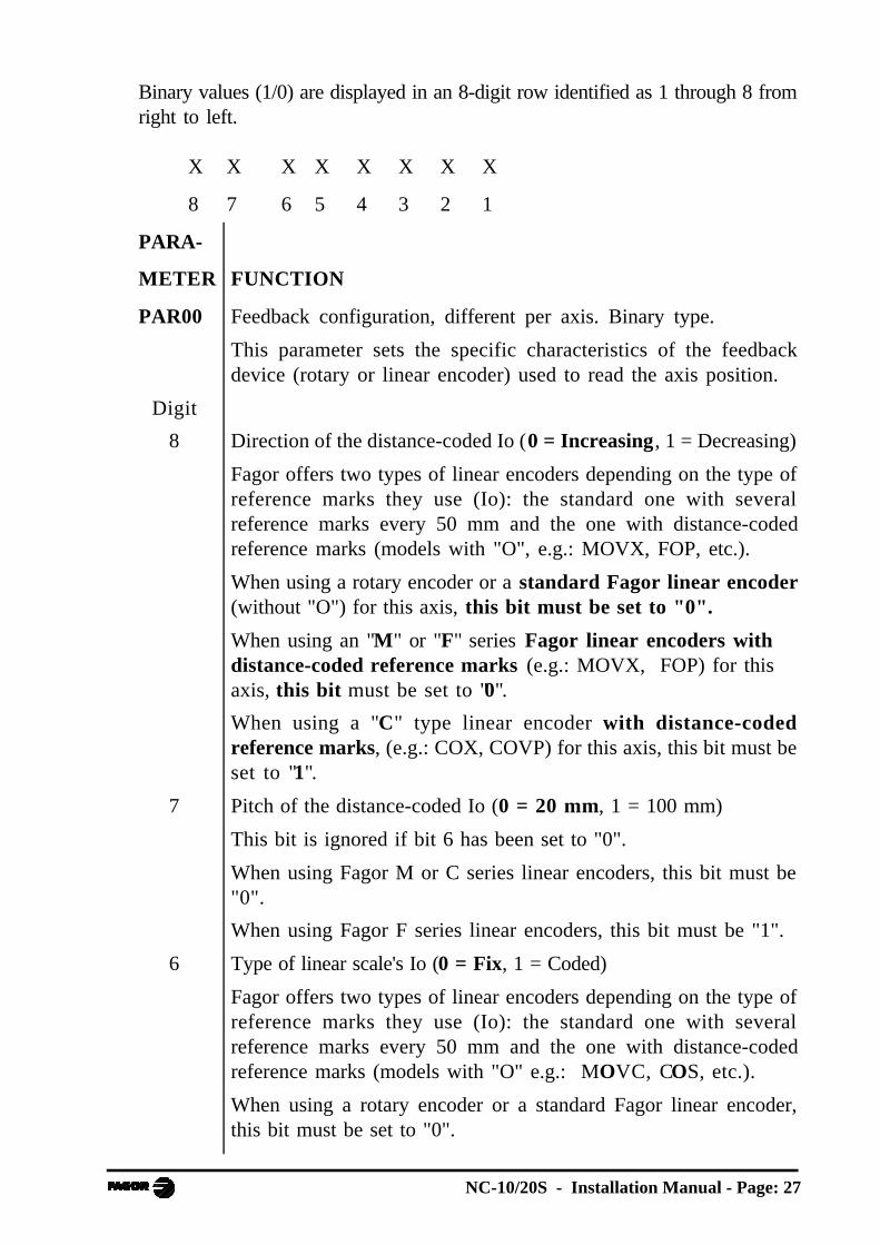
Binary values (1/0) are displayed in an 8-digit row identified as 1 through 8 fromright to left.
X X X X X X X X
8 7 6 5 4 3 2 1
PARA-
METER FUNCTION
PAR00 Feedback configuration, different per axis. Binary type.
This parameter sets the specific characteristics of the feedbackdevice (rotary or linear encoder) used to read the axis position.
Digit
8 Direction of the distance-coded Io (0 = Increasing, 1 = Decreasing)
Fagor offers two types of linear encoders depending on the type ofreference marks they use (Io): the standard one with severalreference marks every 50 mm and the one with distance-codedreference marks (models with "O", e.g.: MOVX, FOP, etc.).
When using a rotary encoder or a standard Fagor linear encoder(without "O") for this axis, this bit must be set to "0".
When using an "M" or "F" series Fagor linear encoders withdistance-coded reference marks (e.g.: MOVX, FOP) for thisaxis, this bit must be set to "0".
When using a "C" type linear encoder with distance-codedreference marks, (e.g.: COX, COVP) for this axis, this bit must beset to "1".
7 Pitch of the distance-coded Io (0 = 20 mm, 1 = 100 mm)
This bit is ignored if bit 6 has been set to "0".
When using Fagor M or C series linear encoders, this bit must be"0".
When using Fagor F series linear encoders, this bit must be "1".
6 Type of linear scale's Io (0 = Fix, 1 = Coded)
Fagor offers two types of linear encoders depending on the type ofreference marks they use (Io): the standard one with severalreference marks every 50 mm and the one with distance-codedreference marks (models with "O" e.g.: MOVC, COS, etc.).
When using a rotary encoder or a standard Fagor linear encoder,this bit must be set to "0".

Page: 28 - Installation Manual - NC-10/20S
5 Axis units: 0 = mm, 1 = inches
These units refer to the feedback and not to the display which may
be changed with the key..
4 Not being used at this time. It must be set to "0"
3 Not being used at this time. It must be set to "0"
2 Type of feedback signals (0 = TTL)
This bit must be set to "0". A value of "1" will be ignored.
1 Counting direction (0 = normal, 1 = reverse)
Regulation for shears:
X axis retracts in the positive direction.knife gap movement "Y" in the positive direction.
If an axis count increases or decreases in the opposite direction to theone desired, change the value of this digit. It conditions the setting ofthe sign bit PAR46(2) and the sign of the analog voltage.
PAR01 Feedback resolution, independent for each axis,
Possible values: from 0.0001 mm to 1 mm.
From 0.000001 to 0.03937 inchfactory setting: 0.0050 (mm).
PAR02 TTL multiplying factor (subdivision). Independent for each axis.
Options: x4, x2, x1 and x0.5.
The selection of these values rotates by pressing
For linear encoders, choose "x4".
When using an encoder, the resolution is calculated as follows:
Resolution (PAR01) = Leadscrew pitch (mm/turn)N x F x i
Where:N = Number of encoder lines (pulses / turn).F = PAR02, is the chosen multiplying factor .i = Gear ratio.

NC-10/20S - Installation Manual - Page: 29
PAR03 External multiplying factor (EX E type) when using linearencoders with distance-coded reference marks and TTL feedbacksignals. Independent for each axis.
Options: 1, 5, 10, 20, 25, 50. Factory setting: 1
These values are selected by pressing
For example:
For standard Fagor linear encoders with squarewave signals (without"O" or "P") e.g.: MX, CT, CX, etc. it must be set to "1".
For Fagor linear encoders with squarewave signals and distance-coded reference marks (models with "O"), eg.: MOX, COX, etc.it must be set to "5".
For Fagor linear encoders with squarewave signals and distance-coded reference marks (models with "O") and 0.5 µm resolution,eg.: MOY, COY, etc. it must be set to "10".
PAR05 Resolution correction factor. Range: 0 to 9,999
Example 1:
"X" axis gear reduction:
· Leadscrew pitch: 5 mm · Gear ratio, i = 3
· Encoder 100 pulses / turn · PAR2 = 1
Resolution = 5 = 0.016666....100 x 3
Select:
PAR1 = 0.0166 mm/pulse
PAR5 = 166 = 0.996166.6666
Page: 30 - Installation Manual - NC-10/20S
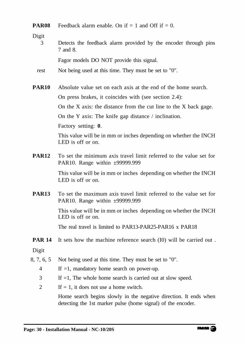
PAR08 Feedback alarm enable. On if = 1 and Off if = 0.
Digit3 Detects the feedback alarm provided by the encoder through pins
7 and 8.
Fagor models DO NOT provide this signal.
rest Not being used at this time. They must be set to "0".
PAR10 Absolute value set on each axis at the end of the home search.
On press brakes, it coincides with (see section 2.4):
On the X axis: the distance from the cut line to the X back gage.
On the Y axis: The knife gap distance / inclination.
Factory setting: 0.
This value will be in mm or inches depending on whether the INCHLED is off or on.
PAR12 To set the minimum axis travel limit referred to the value set forPAR10. Range within ±99999.999
This value will be in mm or inches depending on whether the INCHLED is off or on.
PAR13 To set the maximum axis travel limit referred to the value set forPAR10. Range within ±99999.999
This value will be in mm or inches depending on whether the INCHLED is off or on.
The real travel is limited to PAR13-PAR25-PAR16 x PAR18
PAR 14 It sets how the machine reference search (I0) will be carried out .
Digit
8, 7, 6, 5 Not being used at this time. They must be set to "0".
4 If =1, mandatory home search on power-up.
3 If =1, The whole home search is carried out at slow speed.
2 If = 1, it does not use a home switch.
Home search begins slowly in the negative direction. It ends whendetecting the 1st marker pulse (home signal) of the encoder.
NC-10/20S - Installation Manual - Page: 31
1 If = 0, The selected axis moves in rapid in the positive direction up tothome switch and returns at slow speed until detecting the home pulse.
If = 1, the home position is floating.
When pressing F , it requests the password (719200) to access
to the selection of the "X" or "Y" axis.
PAR 16 It sets the value of the leadscrew backlash to compensate for.
To compensate for the backlash, it must be set it for unidirectionalapproach (PAR17 = 2).
Range: ±99999.999
It is obtained empirically with a simple back-and-forth movementusing a dial indicator.
PAR 17 It sets how the leadscrew backlash compensation will be applied
with unidirectional approach. Rotate with -+
0 = There is no unidirectional approach.
It forces to "0" any value selected in PAR16.
1 = It will be applied after moving in the negative direction (reserved).
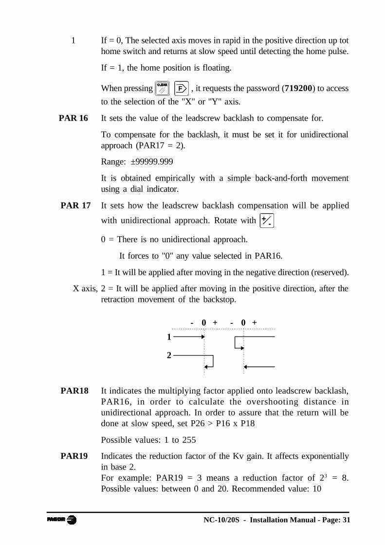
X axis, 2 = It will be applied after moving in the positive direction, after theretraction movement of the backstop.
+0- +0-
2
1
PAR18 It indicates the multiplying factor applied onto leadscrew backlash,PAR16, in order to calculate the overshooting distance inunidirectional approach. In order to assure that the return will bedone at slow speed, set P26 > P16 x P18
Possible values: 1 to 255
PAR19 Indicates the reduction factor of the Kv gain. It affects exponentiallyin base 2.For example: PAR19 = 3 means a reduction factor of 23 = 8.Possible values: between 0 and 20. Recommended value: 10

Page: 32 - Installation Manual - NC-10/20S
PAR21 Indicates the active level of the first 8 inputs.By default, they are set to "1" meaning that they are activated with 24V.
Digit Pin8 337 146 32 Shear down5 13 Shear up4 31 Y axis negative travel limit3 12 X axis negative travel limit2 30 Y axis positive travel limit
1 11 X axis positive travel limit
PAR22 Indicates the active level of the next 7 inputs.
By default, they are set to "1" meaning that they are activated with 24V.Digit Pin
8 Not being used at this time. It must be set to "0".7 23 Emergency.6 8 Knife position 1.5 36 Knife position 2.4 35 Foot switch.3 16 Knife position 3.2 34 Disable the "Y" axis.1 15
PAR23 Indicates the active level of the first 8 outputs.By default, they are set to "1" meaning that when activated, theyprovide 24V.
Digit Pin8 9 Pressure valve.7 27 Shear down6 26 "Y" axis moving direction (* Increase knife angle)5 7 "X" axis moving direction (* Decrease knife angle)4 25 "Y" axis fast movement3 6 "X" axis fast movement2 24 "Y" axis enable1 5 "X" axis enable
PAR24 Indicates the active level of the next 3 outputs.By default, they are set to "1".
Digit Pin8-4 Not being used at this time.3 29 In position.2 10 Activate sheet holders1 28 Shear up.

NC-10/20S - Installation Manual - Page: 33
PAR25 In-position zone.
It is the distance before and behind the point where the axis isconsidered to have reached its target position.
(See the following time diagram)
Possible values: From 0.0001mm to 99999.999 mm(From 0.000005" to 3937").
Recommended value: between 0.02 mm and 0.05 mm
PAR26 Indicates the braking distance (slowdown point)
By default, this unit sets P26=P27 if P26<P27
(See the following time diagram)
Possible values: From 0.0001mm to 99999.999 mm(From 0.000005" to 3937").
Recommended value: between 1 and 5 mm.
PAR27 Indicates the stopping distance (stop offset).It does not admit PAR27 = 0.
(See time diagram below)
Possible values: From 0.0001mm to 99999.999 mm(From 0.000005" to 3937").
Recommended value: between > 0 mm and 0.5 mm
The description of Par27 continues on the next page.
PAR27 and PAR47 must be coordinated in order to ensure that theknown final position is within the in-position zone (PAR25).See chapter 4.
Par27
Par26
Enable
Speed
DirectionFast
Slow
Par25

Page: 34 - Installation Manual - NC-10/20S
PAR30 Delay between output O10 (activate sheet holders) and the retractionof the X axis. Range 0 to 9.9 seconds.
PAR31 Delay between I35 (foot switch) and output O27 (shear down).Range: 0 to 9.9 seconds.
Set to "0" if PAR65.5 = 1
PAR32 It may be accessed directly ( 3 2 )
Time for the shear to come down. Range: 0 to 9.9 seconds.
PAR34 Delay when reversing the homing direction in order to make itsmoother. Range: 0 to 9.9 seconds.
PAR37 Incremental distance for X axis retraction in the positive direction ifthe option of "cutting with a previous X axis retraction" has beendefined. Range: 0 mm to 99999.999 mm (0" to 3937").
We recommend: PAR37 < PAR26
It may be accessed directly: ( 3 7EDIT )
PAR39 Analog voltage centering. Back-and-forth movement for balancingthe sign of the analog voltages.
Measure the analog voltages of this unit in both directions in any ofthe ranges (fast or slow). Calculate the difference and divide by 2.
Try different values of multiples of 5 mV to obtain the best balance.
For example: 6.135 and -6.120 => (0.015 difference)/2 = 0.007Round it off to the closest value: 0.005 or 0.010
PAR40 Proportional gain Kv of the position loop in the positive direction ifPAR46(5) = 1. Axis controlled in closed loop.(See section 4.2). Possible values: Between 0 and 255.
PAR46 Axis control.
Digit8, 7, 6 Not being used at this time. They must be set to "0".
5 If =1, axis controlled in closed loop (the enable is maintained withinthe in-position zone
If =0, "Axis controlled in open loop". The enable is canceled whenreaching the in-position zone. It is restored if the axis gets outof position.
4 Not being used at this time. It must be set to "0".3 Use analog voltage for feedrate.
NC-10/20S - Installation Manual - Page: 35
2 Sign of the positive movement. Change it if the axis does not get inposition.
When installing INVERTERS, using the direction output (O7, O26) itmay happen that the feedback direction does not match the propermoving direction. This is solved by swapping the A and B encodersignals, pins 1 and 3 or the turning direction of the motor.
1 If =1, Bipolar voltage for DC/AC drive.
If =0, Unipolar for inverters governed with an analog voltage
PAR47 Analog voltage for slow axis feedrate in the positive direction.
Value range: Between 0 and 10V.
PAR49 Analog voltage for fast axis feedrate in both directions.
Value range: Between 0 and 10V.
PAR51 Special configurations.Digit8 to 2 Not being used at this time. They must be set to "0".
1 Program memory locking.
If = 0, unlocked. If = 1, locked.
PAR64 Press brake / cut-off mode selection.Digit
8 to 4 Not being used at this time. They must be set to zero.
3 If = 1, it is set in CUT-OFF mode.
Free access to the tool
key to indicate the thickness of the knife.
See section 4.2.4 of the operation manual.
2 Reserved. It must be set to zero.
1 If = 1, it is set as SIMPLE PRESS BRAKE. The bending sequence isconfirmed with the signal from the pressure gage at I15, the dwellPAR32 and ram withdrawal O28. See section 2.4.5.
Page: 36 - Installation Manual - NC-10/20S
PAR65 Special configurations.Digit
8 Not being used at this time. They must be set to "0".
7 If = 0, The X return is enabled only when the shear reaches the topposition.
If = 1, the shear goes up and the X backstop returns at the same time.(The cut is not allowed with the foot switch in sensitive mode,PAR65.4=0).
6 Display a position once the "in-position" zone has been reached.
If = 1, theoretical position. If = 0, real position.
5 If =1, when forcing the backstop retraction before the cut, the DOWNoutput (O27) is kept enabled during the movement towards X+without forcing the backstop to reach the end position to allow the cut.
If =0, it is activated only if the X retraction is completed.
See section 2.4.4
4 If =1, operation in normal mode.
Releasing the foot switch aborts the cutting sequence, the sheet holdersare released and the shear is forced to return.
If =0, sensitive mode.
Releasing and activating the foot switch causes an up and downmovement of the shear without releasing the sheet holders.
3 If =1, the Y axis position is detected with 3 microswitches thatrecognize one of the 3 selectable fixed positions.
Outputs O25 and O26 are enabled to govern the 3-position valve thatcontrols the inclination of the knife.
2 If = 1, ignore Y axis hardware travel limits in the shearing stage.
It may be used when the lowering of the shear drags the feedback andmechanism of the Y axis out of its travel limits.
1 If = 1, on power-up, it assumes X axis retraction when the activatingthe sheet holders. See PAR37.
NC-10/20S - Installation Manual - Page: 37
4 SETUP
4.1 TEST MODE
A special mode has been created in order to access the inputs and outputs aswell as running several tests.
Be particularly careful in this mode because neither software nor hardwaretravel limits are monitored.
While the unit is turned off, Press and hold the 7 3 keys and turn it on.
This accesses the general TEST mode.
Pressing or scrolls through the following test options. Wait for a few
seconds to confirm the requested option before going on to the next one.
1. LED
All displays and LED's are lit.
2. TASTE - Keyboard test.
One or two segments of displays 1 through 5 respond to each key press.
3. COUNT - Feedback reading.
It shows the feedback reading (count) accumulated on each axis.
When accessed, it selects the 1st axis - X
Pressing selects the 2nd axis - Y..
4. I0s. Testing of the encoder I0's
The 2nd line shows 0's and 1's indicating the level of the encoder I0's forthe X and Y axis from right to left.
Moving the axis slowly by hand, the I0 will be detected with a shortblinking.
5. PULSES. Testing the number of encoder pulses/turn
The 1st line displays "PULSES 1" and when selecting the axis, it
displays "PULSES 2".
Moving the axis by hand far enough to detect the I0 signal twice, the 2ndline will show the number of pulses per turn x PAR01 x PAR02.
6. ALARM
If a feedback alarm is activated (pin 7 of X3, X4) it will be reflected in thesecond display row.
Page: 38 - Installation Manual - NC-10/20S
7. SPEED - Feedrate.
When accessed, it selects the "X" axis.
Press to toggle the axis selection.
Moving the encoder, the 2nd display shows the maximum feedrate reached(in m/min).
8. E2PROM - Internal memory test
It responds with a "1" if there are no errors.
9. INPUT- Testing inputsSection 3.1, PAR21 through PAR24 describes the relationship between thedisplay digit and the number of the connector pin to be tested.
· The 1st line shows 0's and 1's indicating the status of inputs I1 throughI8 from right to left.
· The 2nd line shows the status of inputs I9 through I15.
10. OUTPUT- Forcing outputsDigital outputs
· The 1st line shows with "0" and "1" the status of the outputs associatedwith digits 1 through 8 from right to left (see PAR23).
The outputs are activated or reset by pressing their associated keys:
1 through 8
· The 2nd line shows the status of the other three outputs (see PAR24).They can neither be activated nor reset.
· Pressing 9 activates all 11 outputs sequentially one after another..
· Pressing 0inch
resets all of them.

NC-10/20S - Installation Manual - Page: 39
11. OUT ANA
It is possible to force a value at the analog outputs.
1 , 2 select the "X" or the "Y" axis respectively.
-+ offers positive values and then negative values that increase
every time this key is pressed.
or [value] presets that particular analog voltage value.
or 0inch
resets it.
12.DATE
The first row shows the software version and the 2nd one its validation date,day, month and year.
13.CHECKSUM - (memory test)
4.1.1 DIRECT ACCESS TO THE PARAMETERS
In order to get better acquainted with the operation of this unit without havingto connect the 24V input, there is a special way to access the installationparameters on power-up:
· Turn the unit on while pressing 7 5 at the same time until PAR00 of the
parameter table is directly accessed.
· Press 2 2 to go to PAR22.
· If parameter PAR22(7) displays "0", press 7 to force a "1". This cancels
the external emergency even when the emergency input I23 is not connected.
· To access the modes described in the operating manual, the shear must be at thetop position with input I13 activated.
To simulate this state:
Press 2 1 and 5 to force a "0" and recognize I13 that is
not connected.
· Exit to the main menu by pressing .
Safety regulations dictate to connect the emergency input with a "1" level at24V.
The emergency button interrupts the connection causing the machine to stop.
Page: 40 - Installation Manual - NC-10/20S
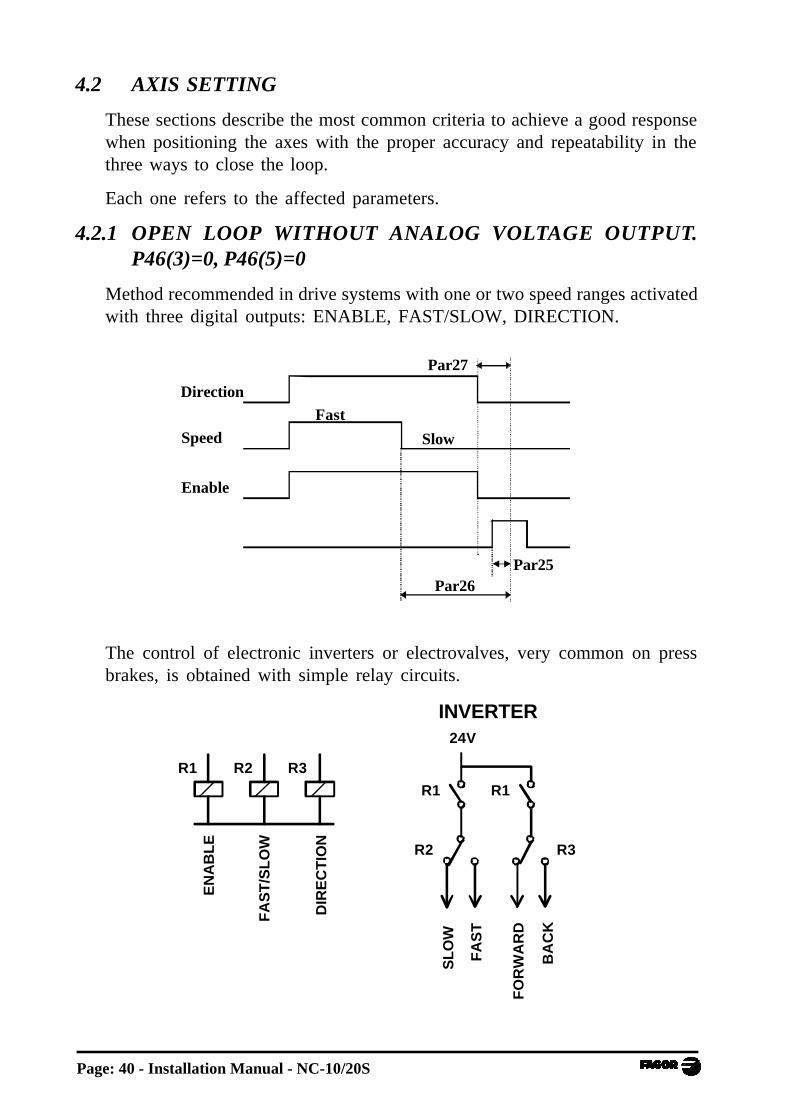
4.2 AXIS SETTING
These sections describe the most common criteria to achieve a good responsewhen positioning the axes with the proper accuracy and repeatability in thethree ways to close the loop.
Each one refers to the affected parameters.
4.2.1 OPEN LOOP WITHOUT ANALOG VOLTAGE OUTPUT.P46(3)=0, P46(5)=0
Method recommended in drive systems with one or two speed ranges activatedwith three digital outputs: ENABLE, FAST/SLOW, DIRECTION.
The control of electronic inverters or electrovalves, very common on pressbrakes, is obtained with simple relay circuits.
R1 R2 R3
EN
AB
LE
FA
ST
/SL
OW
DIR
EC
TIO
N
24V
R1
R3R2
SL
OW
FA
ST
FO
RW
AR
D
BA
CK
INVERTER
R1
Par27
Par26
Enable
Speed
DirectionFast
Slow
Par25

NC-10/20S - Installation Manual - Page: 41
Kv - PAR40
PAR49
Analog voltage
PAR47
PAR25
PAR27
PAR26
Position
4.2.2 OPEN LOOP WITH ANALOG VOLTAGE OUTPUT.PAR46(3)=1, PAR46(5)=0
Method recommended in low range drive systems: unipolar drive[PAR45(1)=0], proportional valves, etc.
PAR27 sets the distance before the end point where the analog voltage iscanceled. On drive systems with good braking response, the drive may be keptactive delaying the releasing of the enable relay. Just connect a capacitor inparallel with the relay. Forcing PAR27 with small values may result in asudden braking and a later release when the axis reaches the end point.
If the axis is forced to get out of the in-position zone, the enable signal and theanalog voltage for the slow speed are activated to restore the programmedcoordinate.
4.2.3 CLOSED LOOP. PAR 46(3)=1, PAR46(5)=1
Method especially developed for AC/DC drives or servo-valves.
The fast approach movements are carried out in open loop with the analogvoltage set in PAR49. PAR26 sets the anticipation distance for the slow speed(PAR47) and it positions in closed loop. The braking response depends on thevalue set for Kv (PAR40 and PAR19) being more sudden at greater Kv gainvalues.
P26
P25P27
Analog VoltagePAR49
PAR47

Page: 42 - Installation Manual - NC-10/20S
The minimum analog voltage PAR44, PAR45 is adjusted to reach the thresholdvoltage of proportional valves.
Especially involved parameters:
PAR40-PAR19 Adjustment of the dampening degree when switchingfrom slow to STOP.
PAR27 Prior distance to force a "0" analog voltage.
The analog voltage may be analyzed at the oscilloscope.
Best positioning is achieved by minimizing the time the minimum voltagePAR45 is on. This voltage corresponds to the sudden lowering from the valueof PAR48 to that of PAR45.
The resources of the TEST mode, section 4.1(11), are very useful to simplifythe adjustment of the axes.
If an axis does not stay stable in the rest position, adjust the offset to cancel the driftcaused by the drive.
Too large Kv gain values make the system unstable.
Low Kv gain values do not provide proper positioning accuracy and repeatability.
Recommendations, most significant parameters:
1- Adjust the drive offset to "0".
2- PAR47 = PAR48 = 0.05 / 0.1
Decrease the slow speed as much as possible.
3- PAR25 = 0.01.
Position tolerance decreased as much as possible.
4- PAR26 = 2/10 mm
Enough range to access the position window at slow speed.
5- PAR27 = 0.01
6- PARP19 = 7/8, PAR40 = 100/200
Maximum proportional gain while maintaining stability.
NC-10/20S - Installation Manual - Page: 43
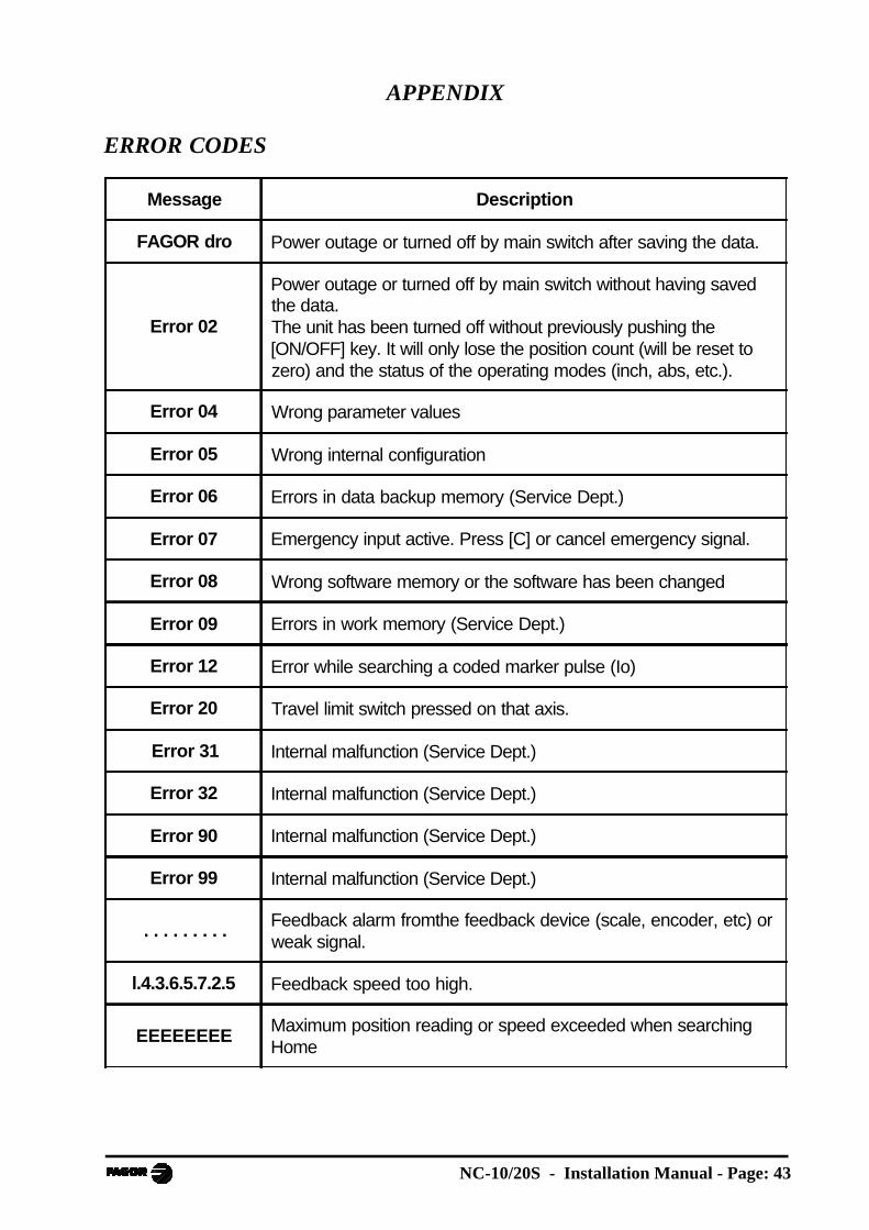
APPENDIX
ERROR CODES
Message Description
FAGOR dro Power outage or turned off by main switch after saving the data.
Error 02
Power outage or turned off by main switch without having savedthe data.The unit has been turned off without previously pushing the[ON/OFF] key. It will only lose the position count (will be reset tozero) and the status of the operating modes (inch, abs, etc.).
Error 04 Wrong parameter values
Error 05 Wrong internal configuration
Error 06 Errors in data backup memory (Service Dept.)
Error 07 Emergency input active. Press [C] or cancel emergency signal.
Error 08 Wrong software memory or the software has been changed
Error 09 Errors in work memory (Service Dept.)
Error 12 Error while searching a coded marker pulse (Io)
Error 20 Travel limit switch pressed on that axis.
Error 31 Internal malfunction (Service Dept.)
Error 32 Internal malfunction (Service Dept.)
Error 90 Internal malfunction (Service Dept.)
Error 99 Internal malfunction (Service Dept.)
. . . . . . . . .Feedback alarm fromthe feedback device (scale, encoder, etc) orweak signal.
l.4.3.6.5.7.2.5 Feedback speed too high.
EEEEEEEEMaximum position reading or speed exceeded when searchingHome

Page: 44 - Installation Manual - NC-10/20S
If any message other than the first two from the table were to come up, the equipmentshould be switched off and on again until one of the first two are seen.
After pressing to access the counting mode, check the parameters.
If any of the errors shown as (Service Department) are often repeated, ask FagorAutomation’s Customer Services Department about this.
The feedback alarm error will appear if the bit of the corresponding alarm activatingparameter for the axis has been set to "1" PAR08(1) = 1.
In either case, to clear the display, press .
If the axis value is flashing, this means that one of the travel limits established bymachine parameter has been exceeded. This error will be displayed if the alarmactivation parameter for the axis PAR08(2) = 1. All outputs are deactivated
If the NC does not come on or goes out while running, check that the voltage andground outlets are as they should be. If an axis does not count, disconnect thefeedback connectors one by one. If the NC comes on, it indicates a fault in thefeedback device. If the fault persists get in touch with Fagor Automation’s CustomerServices Department about it.
MAINTENANCE
Cleaning:
An accumulation of dirt in the equipment can act as a screen preventing properdissipation of the heat generated by the internal electronic circuits with the consequentdanger of overheating and NC fault.
Accumulated dirt can also, in some cases, provide a conductive path for electricity whichcould give rise to faults in the internal circuits of the equipment, especially in highhumidity conditions.
To clean the equipment nonabrasive dish-washing detergents are recommended (inliquid, never powder form) or 75% isotropic alcohol with a clean cloth. DO NOT USEaggressive solvents, (benzol, acetones, etc.) which could damage the materials theequipment is made with.
Do not use high pressure compressed air to clean the item as this could give rise to anaccumulation of charges which in turn lead to electrostatic discharges.
The plastics used in the front panel of the NC stand up to:
1. Grease and mineral oils.2. Alkalis and bleaches.3. Dissolved Detergents.4. Alcohol
Avoid the effect of solvents such as ChlorohyNCcarbons, Benzol, Esters and Ethersbecause these could damage the plastics with which the front of the equipment is made.
Preventive Inspection
If the NC does not come on press the rear switch for starting, make sure it is properlyconnected and being supplied with the proper mains voltage.

OPERATING MANUAL
Manual version 0302
FAGOR NC-10/20 SFOR SHEARS

Page: 2 - Operating Manual - NC-10/20S
INDEXIntroduction....................................................................................................... 3Description of the various models ....................................................................... 3
1. Unit description ................................................................................ 41.1 Front panel ......................................................................................... 4
2. Turning the unit on / off .................................................................... 6
3. Positioning of the axes ...................................................................... 73.1 Safety ................................................................................................. 73.2 Jogging with the keyboard ................................................................... 83.2.1 Movement to a preset position............................................................. 83.2.2 Movement to a fixed position (NC-20 S1/2*) ....................................... 8
4. Enabling shear movement ................................................................ 94.1 Safety ................................................................................................. 94.2 Options, Access modes ...................................................................... 94.2.1 Parts counter ...................................................................................... 94.2.2 "X" axis retracts when actuating the sheet holders. ................................ 94.2.3 Selecting the shear-down time ............................................................ 104.2.4. Cutting thickness compensation on the X axis .................................... 10
5. Machine reference (home) search.................................................. 105.1 Sequence for axes with mandatory home search on power-up ............. 105.2 Sequence for axes without mandatory home search .............................11
6 Programming. Only for NC 10/20 S2 models ................................ 116.1 Program editing..................................................................................116.2 Deleting a program ............................................................................ 13
7 Execution. Only for NC 10/S0 S2 models ...................................... 13
Appendix ........................................................................................................ 14Error codes ..................................................................................................... 14Maintenance..................................................................................................... 15
Last page of this manual ............................................................................... 15
NC-10/20S - Operating Manual - Page: 3
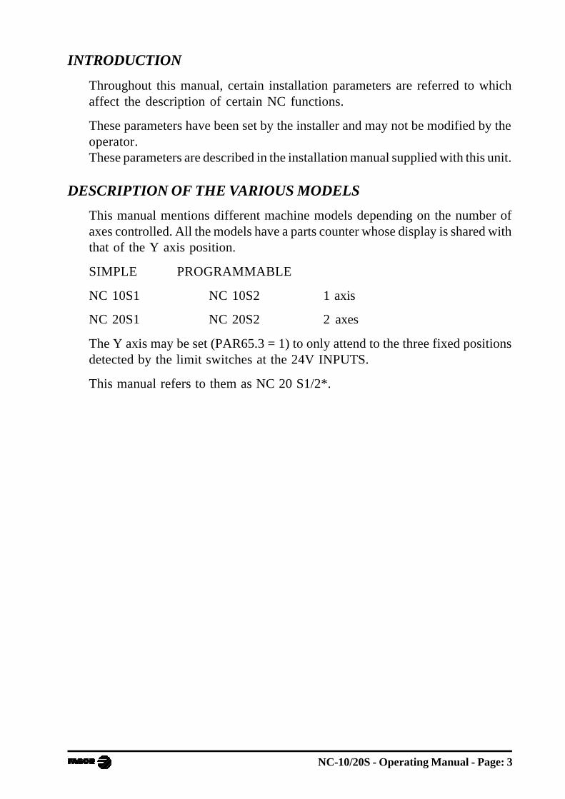
INTRODUCTION
Throughout this manual, certain installation parameters are referred to whichaffect the description of certain NC functions.
These parameters have been set by the installer and may not be modified by theoperator.These parameters are described in the installation manual supplied with this unit.
DESCRIPTION OF THE VARIOUS MODELS
This manual mentions different machine models depending on the number ofaxes controlled. All the models have a parts counter whose display is shared withthat of the Y axis position.
SIMPLE PROGRAMMABLE
NC 10S1 NC 10S2 1 axis
NC 20S1 NC 20S2 2 axes
The Y axis may be set (PAR65.3 = 1) to only attend to the three fixed positionsdetected by the limit switches at the 24V INPUTS.
This manual refers to them as NC 20 S1/2*.

Page: 4 - Operating Manual - NC-10/20S
1. UNIT DESCRIPTION
This NC is specifically designed to be installed on shears. It allows positioningthe horizontal axis "X" and the knife gap /inclination "Y". It can also activateother mechanisms that cause the cutting sequence:
· Shear control by setting the shear-down time.· Control of the elements that hold the sheet down.· Optional X axis back gage when activating the sheet holders.
It also has a parts counter.
1.1 FRONT PANEL
LED description:
INCH- Inch mode selection. To access it or quit it, press 0inch
Machine reference search mode.
It is accessed by pressing or
Press to exit this mode.
EXEC - Execution mode.
SEL - Axis selected.
DIS - Y axis disabled.
CNT- Parts counter.
X axis retraction before the cut.
FSTARTSTOP

NC-10/20S - Operating Manual - Page: 5
Keypad description:
Axis selection.
OFF
ON Turns the display off while reading the position of the axes.
This key should be pressed before turning the unit off with power switchon the rear of the unit.
Validate an operation.
Cancel or abort an operation already started.
Jog the axes in both directions.
5 Jog the axes in rapid.
7EDIT Select the EDITOR mode.
8EXEC Select the EXECUTION mode.
Execute and interrupt, respectively, a positioning move.
987
4 5 6
321
-+ 0
inch
EXECEDIT
tool
Data entry.
-+ Change the sign of the value being entered and to eliminate the last digit
of the X and Y axes.
0inch
Toggle between metric and inch display.
F Auxiliary key to access special functions.

Page: 6 - Operating Manual - NC-10/20S
2. TURNING THE UNIT ON / OFF
Turning the unit ON
The unit is turned on by actuating on the power switch of the rear panel
This NC runs a self-test and its 1st and 2nd displays show "Fagor cnc". Press
and if there is an error, the displays will show the error number if otherwise.
See the appendix at the end of this manual.
Turning the unit OFF
If you press OFF
ON key the NC turns off the displays while maintaining the power
supply to the feedback systems and goes on reading the position of the axes atall times. This is not the case when the equipment is turned off by means of theswitch on the rear panel.
To reset the displays, just press this key again as long as that the NC is gettingvoltage (plugged in and with the switch on the rear panel on).
Precautions:
- Before powering the NC down with the switch on the rear panel or disconnecting
it from mains, it is a good idea to press the OFF
ON key in order to store the current
position of the axes permanently.
- If the unit is powered down with its rear panel switch or there is a power outage
without previously having pressed OFF
ON , the NC will keep the last position of
the axes for at least 30 minutes.
- The unit will display ERROR 2 when powered back up if the position readingwas lost when turned off while the axes were moving or after the accidentalbackup period has expired without having saved the current position.
NC-10/20S - Operating Manual - Page: 7
Imposed safetyOn power-up, once the emergency input is enabled, if the shear is in anintermediate position, it is forced to return to the top position.The NC-20S1/S2* model must have one of the 3 fixed positions of the Y axisselected to enable the shear controlling outputs.If during the shearing process or while the machine is turned off, there has beena deviation of the knife angle and when returning to the top rest position, it doesnot restore contact with the selected microswitch, an inclination is forcedtowards the increasing angle until the corresponding microswitch is detected.
3. POSITIONING OF THE AXES
3.1 SAFETY
· The axes may only be moved if the shear is at the top position.· Software travel limits set by PAR12 and PAR13 may not be overrun.
· If for any anomalous reason, the travel limits are activated, this NC issuesERROR 20.
In MANUAL mode, it inhibits the feed, but it allows movements in the oppositedirection to return to the work zone.
In EXECUTION mode, it aborts it and goes into MANUAL mode.
The return movements of the X+ and Y+ axes may be defined with unidirectionalapproach to compensate for mechanical backlash (PAR16, PAR17).

Page: 8 - Operating Manual - NC-10/20S
3.2 JOGGING WITH THE KEYBOARD
· While the shear is up, select the axis by pressing or
· F to access the JOG mode.
· Press or and the axis will start moving slowly in either direction. Too
move fast, hold down the 5 key at the same time.
· To stop the movement: 1st release 5 and then release the slow movement.
Otherwise, it will keep moving until the value set by PAR26 is reached.
· or F to exit.
Model NC 20 S1/S2(*)· With the shear up, select the Y axis.
· Press F to access the JOG mode.
· Pressing activates the control valve towards the increasing inclination
limited by the top angle microswitch.
· Pressing activates the control valve towards the decreasing inclination
limited by the bottom angle microswitch.
3.2.1 MOVEMENT TO A PRESET POSITION
· Select the axis by pressing or
· Indicate a position value. The selected display starts blinking.
· Press . The axis will move to the indicated position.
To stop this movement before reaching its destination, press .
To resume the movement again, repeat this procedure by selecting the sameposition again.
· to exit.
3.2.2 MOVEMENT TO A FIXED POSITION (NC-20 S1/2*). Select the Y axis.. Indicate one of the 3 fixed positions 1, 2 or 3.
. Press to reach the requested position.
. or aborts the movement already in progress.
. It resumes selecting 1, 2 or 3 again and pressing .
. During the movement of the Y axis, cutting is inhibited.

NC-10/20S - Operating Manual - Page: 9
4. ENABLING SHEAR MOVEMENT
Once the axes are in position, press . To activate the cutting enable and
enable the footswitch, the "SEL" led of the selected axis must be off.4.1 SAFETY
The travel of the shear may be set freely up to the bottom limit switch orcontrolled with a timer (section 4.2.3).In normal operating mode, releasing the foot switch aborts the cutting sequence.The sheet holders are released and the shear returns to the top position.PAR65.4 = 0 sets the sensitive mode.Releasing and pressing the foot switch before completing the cut, forces anintermittent up and down movement of the shear without releasing the sheetholders.Once the cut is completed, the shear is kept at rest in the lower position.The foot switch must be released to force the return movement.
4.2 OPTIONS, ACCESS MODES4.2.1 PARTS COUNTER
Press F
The "Y" axis display shows the accumulated number of parts.The counter increases in one unit when the cutting sequence is completed:Actuate the foot switch and shear down and up.
To show the "Y" position again, press F
The parts counter stays active.
To reset the accumulated count, press
When turning the unit off, the parts counter is deactivated.On NC-10S1/2 and NC-20S1/2* models, the counter is always active.
4.2.2 "X" AXIS RETRACTS WHEN ACTUATING THE SHEETHOLDERS.
Press F to activate and F to deactivate.
It displays the corresponding text "ON" or "OFF" for a second and it is indicated
with the led.
If PAR65.1 = 1, it assumes the "ON" option on power-up.If PAR65.1 = 0, it assumes the "OFF" option on power-up.It the starting position is in the actual travel limit, the cut will not be allowed if
has been selected.
The retraction distance may be changed by pressing 3 7EDIT selecting
a value (usually < 2 mm) and confirming by pressing .

Page: 10 - Operating Manual - NC-10/20S
4.2.3 SELECTING THE SHEAR-DOWN TIME
· Press 3 2 to access machine parameter PAR32.
· Select a value up to 9.9 seconds and confirm it with
· Select "0" to ignore the timer.
4.2.4. CUTTING THICKNESS COMPENSATION ON THE X AXIS
This feature is only useful on material removing cut-off machines.
In the initial mode, press tool
The 1er display shows the text: "tool".
Indicate the thickness of the blade and press .
The real position of the X axis will be affected and it will correspond with:"Programmed X value + blade thickness" .
5. MACHINE REFERENCE (HOME) SEARCH
If machine parameter PAR14.4 = 1, the home search is mandatory on one orboth axes on power-up. Whenever any axis has been moved while the NC wasturned off, the axis that has been moved must be homed.
Parameter PAR14.1 distinguishes the sequence depending on whether homeswitches or used or not.
5.1 SEQUENCE FOR AXES WITH MANDATORY HOME SEARCHON POWER-UP
On power-up, pressing activates the mode.
a. If the axis has a home switch, this unit displays the word: "START".
If it is the Y axis, make sure that the shear is at the top position touchingthe home switch.
Press to force the automatic search, 1st "X", then "Y".
b. If the axis does not use home switches, it will indicate a value thatcorresponds with the value of PAR10.
Measure the distance from the cutting line, o inside of the blade, to the "X"backstop or the gap /misalignment of the blade if it is the Y axis and presetthat value.

NC-10/20S - Operating Manual - Page: 11
A wrong value too different from the real one, that could force a position beyondthe software limits, may cause uncontrolled movements of the axis.
Press . It displays the selected coordinate
Exit pressing F . The led turns off.
If on power-up, you wish to quit the home search mode without actually
homing, press F and key in the password (719200).
5.2 SEQUENCE FOR AXES WITHOUT MANDATORY HOMESEARCH
Press F to access the mode.
Press or to select:
· If the axis has a home switch, the display shows the word "START".
Press .
· If the axis does not have a home switch, it requests the password , 719200Use the method described in section 5.1.b.
6 PROGRAMMING. ONLY FOR NC 10/20 S2 MODELS
Storage capacity for 10 programs of up to 10 blocks.
The memory may be locked with PAR51.1 = 1 to prevent the programs frombeing edited, modified or deleted.
6.1 PROGRAM EDITING
This mode may be used to edit, modify or add blocks at the end of a program.
It is not possible to insert intermediate blocks or delete single blocks.
Each block takes 2 screens: 1st- axis position and 2nd- repetitions(999 maximum).
A blinking display indicates that it is waiting for a value to be loaded and will not
be validated until it is confirmed with . Pressing before restores
the previous data ignoring the one just edited.
Page: 12 - Operating Manual - NC-10/20S
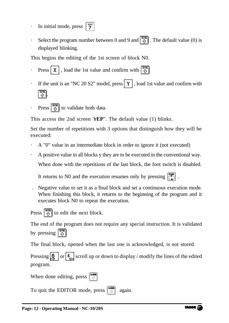
· In initial mode, press 7EDIT
· Select the program number between 0 and 9 and . The default value (0) is
displayed blinking.
This begins the editing of the 1st screen of block N0.
· Press , load the 1st value and confirm with
· If the unit is an "NC 20 S2" model, press , load 1st value and confirm with
.
· Press to validate both data.
This access the 2nd screen "rEP". The default value (1) blinks.
Set the number of repetitions with 3 options that distinguish how they will beexecuted:
· A "0" value in an intermediate block in order to ignore it (not executed)
· A positive value in all blocks y they are to be executed in the conventional way.
When done with the repetitions of the last block, the foot switch is disabled.
It returns to N0 and the execution resumes only by pressing .
. Negative value to set it as a final block and set a continuous execution mode.When finishing this block, it returns to the beginning of the program and itexecutes block N0 to repeat the execution.
Press to edit the next block.
The end of the program does not require any special instruction. It is validated
by pressing
The final block, opened when the last one is acknowledged, is not stored.
Pressing or scroll up or down to display / modify the lines of the edited
program.
When done editing, press
To quit the EDITOR mode, press again.
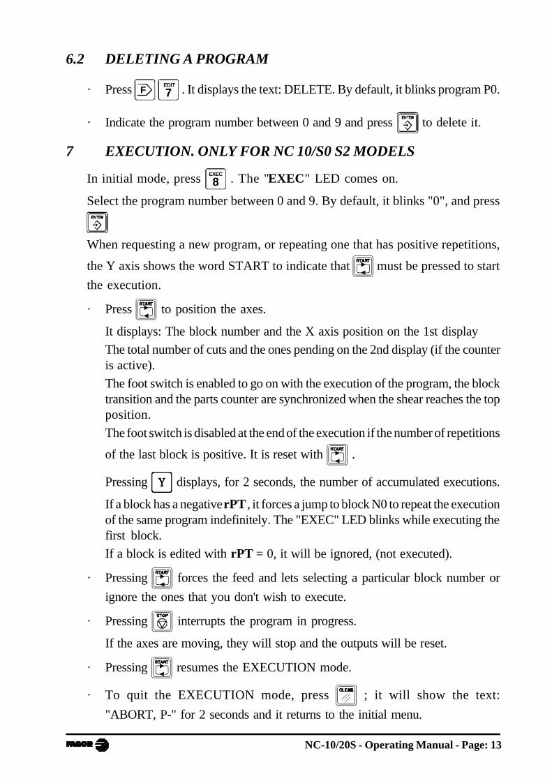
NC-10/20S - Operating Manual - Page: 13
6.2 DELETING A PROGRAM
· Press F 7EDIT . It displays the text: DELETE. By default, it blinks program P0.
· Indicate the program number between 0 and 9 and press to delete it.
7 EXECUTION. ONLY FOR NC 10/S0 S2 MODELS
In initial mode, press 8EXEC . The "EXEC" LED comes on.
Select the program number between 0 and 9. By default, it blinks "0", and press
When requesting a new program, or repeating one that has positive repetitions,
the Y axis shows the word START to indicate that must be pressed to start
the execution.
· Press to position the axes.
It displays: The block number and the X axis position on the 1st display
The total number of cuts and the ones pending on the 2nd display (if the counteris active).
The foot switch is enabled to go on with the execution of the program, the blocktransition and the parts counter are synchronized when the shear reaches the topposition.
The foot switch is disabled at the end of the execution if the number of repetitions
of the last block is positive. It is reset with .
Pressing displays, for 2 seconds, the number of accumulated executions.
If a block has a negative rPT , it forces a jump to block N0 to repeat the executionof the same program indefinitely. The "EXEC" LED blinks while executing thefirst block.
If a block is edited with rPT = 0, it will be ignored, (not executed).
· Pressing forces the feed and lets selecting a particular block number or
ignore the ones that you don't wish to execute.
· Pressing interrupts the program in progress.
If the axes are moving, they will stop and the outputs will be reset.
· Pressing resumes the EXECUTION mode.
· To quit the EXECUTION mode, press ; it will show the text:
"ABORT, P-" for 2 seconds and it returns to the initial menu.
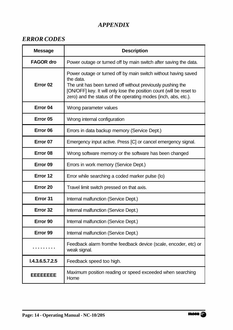
Page: 14 - Operating Manual - NC-10/20S
Message Description
FAGOR dro Power outage or turned off by main switch after saving the data.
Error 02
Power outage or turned off by main switch without having savedthe data.The unit has been turned off without previously pushing the[ON/OFF] key. It will only lose the position count (will be reset tozero) and the status of the operating modes (inch, abs, etc.).
Error 04 Wrong parameter values
Error 05 Wrong internal configuration
Error 06 Errors in data backup memory (Service Dept.)
Error 07 Emergency input active. Press [C] or cancel emergency signal.
Error 08 Wrong software memory or the software has been changed
Error 09 Errors in work memory (Service Dept.)
Error 12 Error while searching a coded marker pulse (Io)
Error 20 Travel limit switch pressed on that axis.
Error 31 Internal malfunction (Service Dept.)
Error 32 Internal malfunction (Service Dept.)
Error 90 Internal malfunction (Service Dept.)
Error 99 Internal malfunction (Service Dept.)
. . . . . . . . .Feedback alarm fromthe feedback device (scale, encoder, etc) orweak signal.
l.4.3.6.5.7.2.5 Feedback speed too high.
EEEEEEEEMaximum position reading or speed exceeded when searchingHome
APPENDIX
ERROR CODES
NC-10/20S - Operating Manual - Page: 15
If any message other than the first two from the table were to come up, the equipmentshould be switched off and on again until one of the first two are seen.
After pressing to access the counting mode, check the parameters.
If any of the errors shown as (Service Department) are often repeated, ask FagorAutomation’s Customer Services Department about this.
The feedback alarm error will appear if the bit of the corresponding alarm activatingparameter for the axis has been set to "1" PAR08(1) = 1 .
In either case, to clear the display, press .
If the axis value is flashing, this means that one of the travel limits established bymachine parameter has been exceeded. This error will be displayed if the alarmactivation parameter for the axis PAR08(2) = 1. All outputs are deactivated
If the NC does not come on or goes out while running, check that the voltage and groundoutlets are as they should be. If an axis does not count, disconnect the feedbackconnectors one by one. If the NC comes on, it indicates a fault in the feedback device.If the fault persists get in touch with Fagor Automation’s Customer Services Departmentabout it.
MAINTENANCE
Cleaning:
An accumulation of dirt in the equipment can act as a screen preventing proper dissipationof the heat generated by the internal electronic circuits with the consequent danger ofoverheating and NC fault.
Accumulated dirt can also, in some cases, provide a conductive path for electricity whichcould give rise to faults in the internal circuits of the equipment, especially in highhumidity conditions.
To clean the equipment nonabrasive dish-washing detergents are recommended (in liquid,never powder form) or 75% isotropic alcohol with a clean cloth. DO NOT USE aggressivesolvents, (benzol, acetones, etc.) which could damage the materials the equipment is madewith.
Do not use high pressure compressed air to clean the item as this could give rise to anaccumulation of charges which in turn lead to electrostatic discharges.
The plastics used in the front panel of the NC stand up to:
1. Grease and mineral oils.2. Alkalis and bleaches.3. Dissolved Detergents.4. Alcohol
Avoid the effect of solvents such as Chlorohydrocarbons, Benzol, Esters and Ethersbecause these could damage the plastics with which the front of the equipment is made.
Preventive Inspection
If the NC does not come on press the rear switch for starting, make sure it is properlyconnected and being supplied with the proper mains voltage.
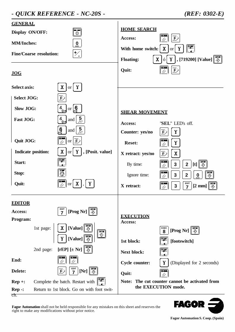
GENERAL
Display ON/OFF:
MM/Inches: 0inch
Fine/Coarse resolution: -+
JOG
Select axis: or
Select JOG: F
Slow JOG: or
Fast JOG: and 5
and 5
Quit JOG: or F
Indicate position: or , [Posit. value]
Start:
Stop:
Quit: or ,
EDITOR
Access: 7EDIT
[Prog Nr]
Program:
1st page: [Value]
[Value]
2nd page: [rEP] [± Nr]
End:
Delete: F 7EDIT
[Nr]
Rep +: Complete the batch. Restart with
Rep -: Return to 1st block. Go on with foot swit-ch.
HOME SEARCH
Access: F
With home switch: or
Floating: ó , [719200] [Value]
Quit: F
SHEAR MOVEMENT
Access: "SEL" LED's off.
Counter: yes/no F
Reset:
X retract: yes/no F
By time: 3 2 [t]
Ignore time: 3 2 0inch
X retract: 3 7EDIT
[2 mm]
EXECUTIONAccess:
8EXEC
[Prog Nr]
1st block: [footswitch]
Next block:
Cycle counter: (Displayed for 2 seconds)
Quit:
Note: The cut counter cannot be activated fromthe EXECUTION mode.
- QUICK REFERENCE - NC-20S - (REF: 0302-E)
Fagor Automation S. Coop. (Spain)
Fagor Automation shall not be held responsible for any mistakes on this sheet and reserves theright to make any modifications without prior notice.