
NC円テーブルシリーズ NC ROTARY TABLE SERIES - kitagawa
148
NC ROTARY TABLE NC 円テーブルシリーズ NC ROTARY TABLE SERIES
-
Upload
khangminh22 -
Category
Documents
-
view
0 -
download
0
Transcript of NC円テーブルシリーズ NC ROTARY TABLE SERIES - kitagawa

NC ROTARY TABLE
NC円テーブルシリーズNC ROTARYTABLE SERIES
CA
TA
LO
GU
EN
C円
テー
ブル
シリ
ーズ
N
C R
OT
AR
Y T
AB
LE
SE
RIE
S
Global Network
・仕様・外観は改良のため、予告なく変更することがあります。 ・カタログと実際の商品の色とは印刷の関係で多少異なる場合もあります。・カタログ記載内容/令和 3 年 10 月・本カタログ記載の商品は「外国為替及び外国貿易法」の「輸出貿易管理令」及び「外国為替令」の規制対象貨物です。
同法に基づき、経済産業省大臣による輸出許可が必要となる場合がございます。日本国外へ持ち出される場合は、あらかじめ当社にご相談ください。
CNO.2R-51/Printed in Japan 3,000
東 京 営 業 課仙台支店駐在名古屋営業課大 阪 営 業 課広 島 営 業 課九州支店駐在海 外 営 業 課
埼玉県さいたま市北区吉野町1-405-1 宮城県仙台市若林区大和町4-15-13愛知県名古屋市中川区上高畑2-62大阪府大阪市住之江区北加賀屋3-2-9広島県府中市元町77-1福岡県福岡市博多区板付7-6-39広島県府中市元町77-1
Tel.(048)667-3469Tel.(022)232-6732(代)Tel.(052)363-0371(代)Tel.(06)6685-9065(代)Tel.(0847)40-0541Tel.(092)501-2102(代)Tel.(0847)40-0526
Fax.(048)663-4678Fax.(022)232-6739Fax.(052)362-0690Fax.(06)6684-2025Fax.(0847)46-1721Fax.(092)501-2103Fax.(0847)45-8911
〒331-9634〒984-0042〒454-0873〒559-0011〒726-8610〒812-0888〒726-8610
本 社 広島県府中市元町77-1 Tel.(0847)40-0561 Fax.(0847)45-8911〒726-8610
日本語対応可能Japanese speaker available
77-1 Motomachi,Fuchu-shi,Hiroshima,726-8610,JapanHEAD OFFICE Tel. +81 847-40-0561 Fax. +81 847-45-8911
・Specifications and outside appearance are subject to change without notice due to ongoing research and development. ・The color of the actual product may be different from the catalogue's due to printing matters.・Catalogue contents as of 2021.10・The products herein are controlled under Japanese Foreign Exchange and Foreign Trade Control Act. In the event of importing and/or exporting the products, you are obliged to consult KITAGAWA as well as your government for the related regulation prior to any transaction.
https://www.kiw.co.jphttps://www.kitagawa.comhttps://www.kitagawa.com.cn Kitagawa Corporation
キタガワ グローバル ハンド カンパニーKitagawa Global hand Company株式会社 北川鉄工所
Tel. +1 847-310-8787 Fax. +1 847-310-9484
Tel. +44 1725-514000 Fax. +44 1725-514001
Tel. +49 2102-123-78-00 Fax. +49 2102-123-78-69
Tel. +48 607-39-8855
Tel. +420 603 856 122
Tel. +40 727-770-329
Tel. +36 30-510-3550
Tel. +91 80-2976-5200 Fax. +91 80-2976-5205
Tel. +66 2-712-7479 Fax. +66 2-712-7481
Tel. +86 21-6295-5772 Fax. +86 21-6295-5792
Tel. +86 20-2885-5276
Tel. +886 2-2393-1221 Fax. +886 2-2395-1231
Tel. +82 2-2026-2222 Fax. +82 2-2026-2113
Tel. +61 3-9561-6155 Fax. +61 3-9561-6705
KITAGAWA - NORTHTECH INC.
KITAGAWA EUROPE LTD.
KITAGAWA EUROPE GmbH
KITAGAWA EUROPE GmbH Poland Office
KITAGAWA EUROPE GmbH Czech Office
KITAGAWA EUROPE GmbH Romania Office
KITAGAWA EUROPE GmbH Hungary Office
KITAGAWA INDIA PVT LTD.
KITAGAWA (THAILAND) CO.,LTD. Bangkok Branch
Kitagawa Corporation (Shanghai)
Kitagawa Corporation (Shanghai) Guangzhou Office
DEAMARK LIMITED
KITAGAWA KOREA AGENT CO.,LTD.
DIMAC TOOLING PTY.LTD.
301 E. Commerce Dr,Schaumburg,IL. 60173 USA
Unit 1 The Headlands,Downton,Salisbury,Wiltshire SP5 3JJ,United Kingdom
Borsigstrasse 3,40880,Ratingen Germany
44-240 Zory,ul. Niepodleglosci 3 Poland
Purkynova 125,612 00 Brno,Czech Republic
Strada Heliului 15,Bucharest 1,013991,Romania
Dery T.u.5,H-9024 Gyor,Hungary
Plot No.42,2nd Phase Jigani Industrial Area,Jigani,Bangalore – 560105,Karnataka,India
9th FL,Home Place Office Building,283/43 Sukhumvit 55Rd. (Thonglor 13),Klongton-Nua,Wattana,Bangkok 10110,Thailand
Room308 3F Building B. Far East International Plaza,No.317 Xian Xia Road,Chang Ning,Shanghai,200051,China
B07,25/F,West Tower,Yangcheng International Trading Centre,No.122,East Tiyu Road,Tianhe District,Guangzhou,China
No. 6,Lane 5,Lin Sen North Road,Taipei,Taiwan
803 Ho,B-Dong,Woolim Lion's Valley,371-28 Gasan-Dong,Gumcheon-Gu,Seoul,Korea
69-71 Williams Rd,Dandenong South,Victoria,3175 Australia
https://www.kitagawa-usa.com
https://www.kitagawa.global/en
https://www.kitagawa.global/de
https://www.kitagawa.global/pl
https://www.kitagawa.global/cz
https://www.kitagawa.global/ro
https://www.kitagawa.global/hu
https://www.kitagawa.global/in
https://www.kitagawa.com.cn
http://www.deamark.com.tw
http://www.kitagawa.co.kr
https://www.dimac.com.au
America Contact
Europe Contact
Asia Contact
Oceania Contact

21
高クランプトルクと高精度、高剛性。確かな技術が生み出すKITAGAWAのNC円テーブル。
耐摩耗性に優れたウォームホイール材質
マルチディスククランプ
北川特製クロスロ-ラベアリング
ウォ-ムシャフト
ウォ-ムホイ-ル
スピンドル
本体
テ-ブル
主軸を支えるのは、大径クロスローラベアリング。クロスローラベアリングは、従来のベアリングと比較して構造的に高い剛性を得られる。また、薄型コンパクト設計も可能に。クロスローラベアリングを採用して30年以上となる経験から、最適な予圧を設定することにより、安定した高い精度、剛性を実現。
北川特製クロスローラベアリングテーブル外径に近い(大径)最適な予圧を設定クロスローラベアリング
1箇所で対応2つのベアリングが2箇所必要となる
転がり軸受の組合せ
従来設計
コンパクト設計
クロスローラベアリング
●ハイドロ高クランプトルク(T・Xシリーズ)
●マルチディスククランプ方式 (MKシリーズ、MRシリーズ、CKシリーズ)
エアハイドロブースタを内蔵することにより、コンパクトボディながら、従来の油圧クランプに相当する高クランプを実現。(右赤丸部)
マルチディスクブレーキ方式を採用し、多面で摩擦させることにより、エア供給のみで油圧クランプに相当する高クランプトルクを実現。また、大径ピストンの採用により、効率の良いクランプ機能も実現。
ピストン 回転ディスク固定ディスク
エアによりピストンが移動
クランプ時アンクランプ時
摩擦面①
摩擦面④
摩擦面③
摩擦面②
多面摩擦
最大設計
高クランプトルクを発生させるクランプ機構の採用
複リードウォーム理想的な歯当たりと、最適なバックラッシ調整が可能。スピンドル一体歯切りと相まって、高い割出精度を実現。
高歯、大径ウォームホイールを採用することにより、歯にかかる面圧を低く抑え、加工負荷の低減、精度維持、耐摩耗に優れた機能を実現。
大径ウォームシャフト大径ウォームホイール
1.3倍
バックラッシを小さくする方向
歯幅大 歯幅小
高歯大径従来品
ウォームシャフト
ウォームホイール
良好な歯当たりを実現
高歯ウォーム、しかも強度と剛性を重視した大径設計
NC円テーブルの特長
素材基地中に硬い金属間化合物を含む特殊合金を採用することにより、従来に比べ、耐摩耗性が大幅に向上。

●ハイドロ高クランプトルク(T・Xシリーズ)
●マルチディスククランプ方式 (MKシリーズ、MRシリーズ、CKシリーズ)
エアハイドロブースタを内蔵することにより、コンパクトボディながら、従来の油圧クランプに相当する高クランプを実現。(右赤丸部)
マルチディスクブレーキ方式を採用し、多面で摩擦させることにより、エア供給のみで油圧クランプに相当する高クランプトルクを実現。また、大径ピストンの採用により、効率の良いクランプ機能も実現。
ピストン 回転ディスク固定ディスク
エアによよりピストンがが移動
クランプ時アンクランプ時
摩擦面①
摩擦面④
摩擦面③
摩擦面②
多面摩擦
最大設計
高クランプトルクを発生させるクランプ機構の採用
複リードウォーム理想的な歯当たりと、最適なバックラッシ調整が可能。スピンドル一体歯切りと相まって、高い割出精度を実現。
高歯、大径ウォームホイールを採用することにより、歯にかかる面圧を低く抑え、加工負荷の低減、精度維持、耐摩耗に優れた機能を実現。
大径ウォームシャフト大径ウォームホイール
1.3倍
バックラッシを小さくする方向
歯幅大 歯幅小
高歯大径従来品
ウォームシャフト
ウォームホイール
良好な歯当たりを実現現現現現現現現現現現現現現現現現現現現現現現現現
高歯ウォーム、しかも強度と剛性を重視した大径設計

Special material to eliminate worm wheel wear
Multi-disc clamping
KITAGAWAoriginal cross roller bearing
Worm shaft
Worm wheel
Spindle
Body
Face Plate
KITAGAWA original cross roller bearing supports the main spindle. Construction of the original bearing has high rigidity compared with conven-tional types, and the original bearing allows the body design to be compact. With over 30 years experience using the original bearing the best pressurization is set meaning high accuracy and high rigidity.
Original Kitagawa cross roller bearing
Rolling bearing combination
Conventional design
Compact design
OriginalCross roller bearing
Larger originalcross roller bearingSet the best pressurization
Two differentroller-bearings are used
KITAGAWAoriginal cross roller bearing
NC ROTARY TABLE FEATURESHigh clamping torque, high accuracyand high rigidityKITAGAWA NC Rotary tables featureproven technology
Kitagawa's special material contains hard inter-metallic compounds to give improved wearcharacteristics over conventional models.

●Air-hydro high clamping system. (T・X series)
●Multi-disc clamping system. (MK series, MR series, CK series)
Powerful clamping torque can be achieved within a compactdesign using integrated air-hydraulic booster.
Multi-disc clamping system with multi-friction surfaces enables increased clamping torque whencompared to conventional air clamped models.
PistonSpinning discStationary disc
Piston moved bypneumatic power
ClampingUnclamping
Frictional area ①
Frictional area ④
Frictional area ③Frictional area ②
Multi-area friction
Wide piston
High clamping torque mechanism
Double-lead worm shaft
Large diameter worm wheel and high gear teeth reduces the pressure on the teeth surfaces.This achieves high accuracy with reduced processing load and wear.
Double-lead worm shaft creates ideal contact between the worm shaft and worm wheel.This allows for simple backlash adjustment and high indexing accuracy. Worm shaft
Worm wheel
1.3times
Backlash reducedDirection Wide
tooth widthNarrowtooth width
High teeth,large diameterConventional model
Worm shaft
Worm whee
Ideal contact on tooth
Large diameter gear with high teeth offering increased strength

P.7
P.9
P.11
P.19
P.21
P.23
P.27
P.31
P.35
P.37
P.41
P.45
P.49
P.53
P.57
P.61
P.67
P.69
P.73
P.75
P.77
P.79
P.81
P.82
高性能NC円テーブル -サイドモータ・立横兼用-High Performance NC Rotary Table-Side motor mounted, Vertical or Horizontal Usage-TMX seriesTMX160・TMX200・TMX250 THX160・THX200
高性能NC円テーブル -サイドモータ・立横兼用-High Performance NC Rotary Table-Side motor mounted, Vertical or Horizontal Usage-TR seriesTRX320・TR400・TR500・TR630 TLX250・TLX320・TL400
二連NC傾斜円テーブルTwo-Spindle NC Tilting Rotary TableTW2180ワイヤカット放電加工機専用NC円テーブルExclusive NC Rotary Table for Wire Cutting Electric Discharge MachineDM100・DME100高速割出NC円テーブルQuick Indexing NC Rotary TableRK201省メンテナンスNC傾斜円テーブルLow maintenance NC Rotary TableRKT180高速NC円テーブルHigh Speed NC Rotary TableRS100NC円テーブルNC Rotary TableTC100
NC円テーブルNC Rotary TableMR seriesMR120・MR160・MR200・MR250・MR320
NC傾斜円テーブルNC Tilting Rotary TableTT150NC傾斜円テーブルNC Tilting Rotary TableTT182・TW182
NC傾斜円テーブルNC Tilting Rotary TableTT200NC傾斜円テーブルNC Tilting Rotary TableTT251/TW251・TT321/TW321
立形・横形M/C用NC円テーブルNC Rotary Table for Vertical or Horizontal M/CMRT200
高性能NC円テーブル -バックモータHigh Performance NC Rotary Table - Back side mounted motor -TBX seriesTBX160・TBX200・TBX250・TBX320
高性能NC円テーブル -アップモータHigh Performance NC Rotary Table - Top-motor -TU seriesTUX200・TUX250・TUX320・TU400
NC多連円テーブルMulti-Spindle NC Rotary TableTM seriesTM2100・TM3100・TM2160・TM3160 TH2100・TH3100・TH2160・TH3160
コンパクトNC傾斜円テーブルCompact Type NC Tilting Rotary TableTT101・TW120低床NC傾斜円テーブルLow Centre Line NC Tilting Rotary TableTT140
大貫通穴NC円テーブルMega Thru-Hole NC Rotary TableTP seriesTP430・TP530
高クランプトルクNC円テーブルHigh Clamping Torque NC Rotary TableGT seriesGT200・GT250・GT320
高速回転NC円テーブルHigh Speed NC Rotary TableMX160
INDEX [掲載商品][Product description]ストロング&コンパクトNC円テーブルStrong & Compact NC Rotary tableMK seriesMK200・MK250
超コンパクトNC円テーブルUltra Compact NC Rotary tableCK(R) seriesCK160・CKR160・CK200・CKR200

P.83
P.111
P.115
P.117
P.118
P119
P.120
P.121
P.122
P.123
P.124
P.125
P.126
P.127
P.127
P.129
P.130
P.131
P.133
P.135
P.141
P.143
P.83P.85P.86P.87P.88P.89P.90P.91P.92P.93
チャック組合せ表Chuck Combinations
NC円テーブルとサーボモータの組合せCombinations of NC Rotary Table and Servomotor
スケ-ル付高精度仕様High-Precision Table with Scale
NC傾斜円テーブル・ワーク積載可能領域NC Tilting rotary table・Work loadable area
精度規格Accuracy specification
用語解説Glossary
ご注意Cautions
DATA 取付寸法詳細Detailed mounting sizes
DATA 取付寸法詳細Detailed mounting sizes
DATA 取付寸法詳細Detailed mounting sizes
DATA 取付寸法詳細Detailed mounting sizes
テールストックTail stock手動・手動(多軸): 空圧/油圧・空圧/油圧(多軸)Manual・Manual(Multi-Spindles):Air/Hydraulic・Air/Hydraulic(Multi-Spindles)
テールスピンドルTail SpindleTSR(C)・MSR(C) seriesロータリジョイントRotary JointRJエアハイドロブースタAir Hydraulic BoosterAB seriesAB10T・AB25T・AB50T
ワークグリッパWork GripperAS series
スクロールチャックScroll ChuckSC・JN series
円テーブル用コントローラ
Quinte seriesQTC100/QTC100CS・QTC200/QTC200CS・QTC300
NC Rotary Table controller
Quinte seriesQTC100/QTC100CS・QTC200/QTC200CS・QTC300
P.97
高精度大貫通穴径中空パワーチャックHigh Precision, Ultra-large Through-hole, High-speed Power ChuckBR series短寸中実回転油圧シリンダCompact Style Hydraulic Cylinder with Closed CentreM series
中実パワーチャックClosed Centre Power ChuckN series短寸中実回転油圧シリンダCompact Style Hydraulic Cylinder with Closed CentreM series
ロータリチャックRotary ChuckNRC series
DATA 取付寸法詳細Detailed mounting sizes
P.94DATA 制御詳細
●コントローラ特長●概観・寸法●仕様●オプション●前面パネル機能説明●液晶画面表示例●プログラム例●接続内容●相互接続図●機械接続図
P.95●手動操作ペンダント
P.109●Manual Operation Pendant
P.97P.99P.100P.101P.102P.103P.104P.105P.106P.107
P.108DATA Control Detail
●Features of controller●Outside view / Dimensions●Specification●OPTION●Front surface●LCD EXAMPLES●PROGRAM EXAMPLES●Connection●Mutual Connection diagram●Machine Connection Diagram(Example)

キタガワのコンパクトNC円テーブルがパワフルで更に使いやすく!High-performance and easy-to use model.
ストロング&コンパクトNC円テーブルStrong & compact NC Rotary Table
●性能向上、強力クランプトルク Performance improved, Powerful clamping torque●取付性向上、コンパクトな実効厚みと改善された切粉掃け Improved mounting, Reduced effective thickness and improved chip flow●用途に合わせて選べるロータリジョイント Wide selection of rotary joints*CE対応品 CE correspondence
MK200
MK
MK series MK200・MK250
■仕様 Specifi cations型 式 MK200 MK250
右勝手Right-handed type ○ ○左勝手 Left-handed type ○ ○テーブル直径 Table dia(mm) φ135 φ155テーブル基準穴径 Centre hole dia(mm) φ65H7 φ70H7スピンドル穴径 Through hole dia(mm) φ70 φ70センタハイト Centre height(mm) 140 180クランプ方式 Clamping method 空圧 Pneumatic 空圧 Pneumaticクランプトルク(空圧 0.5MPa時)Clamping torque (at pneumatic 0.5MPa)(N.m) 570 1000
モータ軸換算イナーシャ Motor axis reduced inertia(kg.m2) 0.000095 0.00041サーボモータ(FANUC仕様の場合)Servomotor (for FANUC specifi cation) αiF4/5000-B αiF4/5000-B減速比 Total reduction ratio 1/90 1/90最高回転速度 Max. rotation speed(min-1) 33.3 33.3許容ワークイナーシャAllowable work inertia(kg.m2) 1.00 1.95割出精度 Indexing accuracy(sec) 20 20再現精度 Repeatability(sec) 4 4製品質量 Mass of product(kg) 60 95手動テールストック(オプション・P111参照)Manual tail stock MR200RN MR250RN
テールスピンドル(オプション・P115参照)Tail spindle (as an option.P115 reference) Note)5 MSRC140/MSR142A MSR181A
内蔵ロータリジョイント(オプション・P117参照)Rotary joint
油圧/空圧6ポート+マルチパーパスホールHydraulic/Pneumatic 6-port + multi-purpose hole
油圧/空圧6ポート+マルチパーパスホールHydraulic/Pneumatic 6-port + multi-purpose hole
許容積載質量Allowable mass of workpiece
横置き(kg)Horizontal installation 200 250
立置き(kg)Vertical installation 100 125
許容荷重(テーブルクランプ時)Allowable load(When clamped to table)
F(kN) 17 21
F×L(N・m) 1100 1600
F×L(N・m) 570 1000
許容切削トルクAllowable cutting torque
T(N・m) 270 480
注)1.圧力確認用スイッチはNCテーブルのTC・DM・LRを除く全シリーズに内蔵しています。2.テーブルクランプ用ソレノイドバルブは内蔵しています。3.NCテーブルと工作機械との間のケーブル及びホースは付属しておりません。4.ロータリジョイントはジグ側固定となります。5.取付ピッチが機械によって異なる為、P115のテールスピンドル寸法図にてピッチを参照下さい。6.製品質量は弊社M信号仕様時の質量です。
Note) 1. The switch for pressure checking is incorporated to all series except TC / DM/ LR series. 2. The solenoid valve for the table clamp is incorporated. 3. Neither cable nor hose is fi tted between NC rotary table and machine tool. 4. Rotary joint is fi xed to jig side. 5 Because a mounting pitch varies with the machines, refer to the pitch of the tail spindle size drawing on P115, 6. Each product mass is determined by a Kitagawa M signal spec.

テーブル貫通穴Thru-Hole Diameter
クランプ器具Clamping Device
14h7 5
260
140
120
8-M10
※モータケース部寸法 Motor case depth
14h7
22°30′45°
φ100
454
118 336
264 184
2 ※153
φ135
9.5 10
15 15
◆155 108◆テーブル高さ Table Height
※モータケース部寸法 Motor case depth
Rc1/4クランプ用エア供給口(裏面) Clamping air supply port(on back side)
6-M6
テーブル上面 Table surface
φ65H7
φ66
φ71
φ70H8
155
10 35
15 φ80
六角ボルトHex boltM12×40
22
28.5
8.6
15
15
(15)
テーブル貫通穴Thru-Hole Diameter
クランプ器具Clamping Device
8-M12
504
Rc1/4クランプ用エア供給口(裏面)Clamping air supply port(on back side)
306 198
518h7
180
142
φ130
150 354
322
22°30′45°
14h7
3 ※161
◆164 107
10
21 21
φ155
10
※モータケース部寸法 Motor case depth
◆テーブル高さ Table Height
6-M8
テーブル上面Table surface
φ70H8
φ70H7
φ71
2114.5
164
φ85
六角ボルトHex boltM16×55
16
(18)
2111
28.5
30
17.5
テーブル貫通穴Thru-Hole Diameter
クランプ器具Clamping Device
260
140
120
14h7 5
8-M10
Rc1/4クランプ用エア供給口 Clamping air supply port
φ100
14h7
22°30′45°
408
118 290
264 144
2 ※153
◆155
9.5 10
15 15
φ135
◆テーブル高さ Table Height
※モータケース部寸法 Motor case depth
6-M6
テーブル上面Table surface
φ65H7
φ66
φ71
φ70H8
155
10 35
15 φ80
六角ボルトHex boltM12×40
22
28.5
8.6
15
15
(15)
13.8
テーブル貫通穴Thru-Hole Diameter
クランプ器具Clamping Device
455
150 305
22°30′45°
14h7φ13
0322
180
142
18h7 5
8-M12
Rc1/4クランプ用エア供給口 Clamping air supply port
306 149
3 ※161
◆164
10 10
φ155
21 21
◆テーブル高さ Table Height
※モータケース部寸法 Motor case depth
φ70H8
φ70H7
φ71
2114.5
164
6-M8
テーブル上面Table surface
φ85
16
(18)
2111
28.5
30
六角ボルトHex boltM16×55
17.5
MK250R(L)
MK200R(L)
MK250R(L)
MK200R(L)
機種Type
デザイン番号Design No.
デザイン番号Design No.
クランプ方式 Clamping method空圧のみ Only Pneumatic クランプ方式 Clamping method
空圧のみ Only Pneumatic
モータ種類 Motor type
左右勝手 Right/Left handR:右勝手 Right-handed typeL:左勝手 Left-handed type
左右勝手 Right/Left handR:右勝手 Right-handed typeL:左勝手 Left-handed type
テーブルサイズTable Size200・250
機種Type
テーブルサイズTable Size200・250 Quinte仕様
Quinte specification
MK A ***L200 MK A V **R200
MK
付加軸仕様 additional axis specifications M信号仕様 M signal specifications
■寸法図 Dimensions【additional axis specifications】
■寸法図【M信号仕様】Dimensions【M signal specifications】

胴厚(テーブル高さ)世界トップクラスの薄さ これまでにない省スペース設計Ultra compact body Smallest-footprint NC Rotary Table
超コンパクトNC円テーブルUltra Compact NC Rotary table
CK
CK(R) series
CK160R
●胴厚(テーブル高さ)世界トップクラスの薄さで ゆりかご仕様に最適Suitable for using with trunnion jig
●ブロックレス構造ロータリジョイント※1Block-less rotary joint ※1
●省スペース機に最適Suitable for small-footprint machines
*CE対応品 CE correspondence
※1 CKR160/CKR200の場合 ※2 全ポート油圧/空圧対応可能。クーラントは使用出来ません。※1 CKR160/CKR200 : All ports are available for both pneumatic and hydraulic, not available for Coolant.
CK160・CKR160CK200・CKR200
■仕様 Specifi cations■仕様Specifications型 式 Model CK160 CKR160 CK200 CKR200
右勝手Right-handed type ○ ○ ○ ○左勝手 Left-handed type ○ ○ ○ ○テーブル直径 Table dia(mm) φ114 φ114 φ130 φ130テーブル基準穴径 Centre hole dia(mm) φ65H7 φ65H7 φ65H7 φ65H7テーブル貫通穴径 Through hole dia(mm) φ65 - φ65 -センタハイト Centre height(mm) 140 140 150 150クランプ方式 Clamping method 空圧 Pneumatic 空圧 Pneumatic 空圧 Pneumatic 空圧 Pneumaticクランプトルク(空圧 0.5MPa時)Clamping torque (at pneumatic 0.5MPa)(N.m) 340 340 400 400
モータ軸換算イナーシャ Motor axis reduced inertia(kg.m2) 0.00009 0.00009 0.00017 0.00017サーボモータ(FANUC仕様の場合)Servomotor (for FANUC specifi cation) αiF 2/5000-B αiF 2/5000-B αiF 2/5000-B αiF 2/5000-B減速比 Total reduction ratio 1/72 1/72 1/120 1/120
テーブル最高回転速度Max. rotation speed
FANUC仕様(min-1/モータ3000min-1時)FANUC specifi cation(min-1/at motor 3000min-1) 41.6 41.6 25 25
M信号仕様(min-1/モータ3000min-1時)M signal specifi cation(min-1/at motor 3000min-1) 41.6 41.6 25 25
許容ワークイナーシャAllowable work inertia(kg.m2) 0.51 0.51 1.00 1.00割出精度 Indexing accuracy(sec) 20 20 20 20再現精度 Repeatability(sec) 4 4 4 4製品質量 Mass of product(kg) 40 41 47 49テールスピンドル(オプション・P115参照)注)5 Tail spindle (as an option.P115 reference) Note)5
MSRC140/TSRC140MSR142A/TSR142A
MSRC140/TSRC140MSR142A/TSR142A
MSRC150TSRC150
MSRC150TSRC150
ロータリジョイント(最高使用圧力 7MPa) Rotary joint (Maximum operating pressure 7Mpa) -
※2油圧/空圧7ポートHydrauric/Pneumatic 7-port
-※2
油圧/空圧8ポートHydrauric/Pneumatic 8-port
許容積載質量Allowable mass of workpiece
横置き(kg)Horizontal installation 160
立置き(kg)Vertical installation 80
許容荷重(テーブルクランプ時)Allowable load(When clamped to table)
F(kN) 10
F×L(N.m) 600
F×L(N.m) 340 400
許容切削トルクAllowable cutting torque
T(N.m) 220
注)1.圧力確認用スイッチはNCテーブルのTC・DM・LRを除く全シリーズに内蔵しています。2.テーブルクランプ用ソレノイドバルブは内蔵しています。3.NCテーブルと工作機械との間のケーブル及びホースは付属しておりません。4.ロータリジョイントはジグ側固定となります。5.取付ピッチが機械によって異なる為、P115のテールスピンドル寸法図にてピッチを参照下さい。6.製品質量は弊社M信号仕様時の質量です。
Note) 1. The switch for pressure checking is incorporated to all series except TC / DM/ LR series. 2. The solenoid valve for the table clamp is incorporated. 3. Neither cable nor hose is fi tted between NC rotary table and machine tool. 4. Rotary joint is fi xed to jig side. 5 Because a mounting pitch varies with the machines, refer to the pitch of the tail spindle size drawing on P115, 6. Each product mass is determined by a Kitagawa M signal spec.

デザイン番号Design No.モータ種類 Motor type
左右勝手 Right/Left handR:右勝手 Right-handed typeL:左勝手 Left-handed type
機種 TypeCK:ロータリジョイントなし without Rotary JointCKR:ロータリジョイント付 with Rotary Joint
左右勝手 Right/Left handR:右勝手 Right-handed typeL:左勝手 Left-handed type
機種 TypeCK:ロータリジョイントなし without Rotary JointCKR:ロータリジョイント付 with Rotary Joint
テーブルサイズTable Size160・200
デザイン番号Design No.
テーブルサイズTable Size160・200 Quinte仕様
Quinte specification
CK
CK 160 R * ** CK 160 R V **
98.5
9.5 10
φ82
φ66 H8
φ65 H7
φ65.5
24.5
28.5
228.6
15
12.5M12×40
108
99◇ 9
φ114
715 1528 10
465(418)
110 355(308)
245 172(125)140
105
245
14h75
6-M8
φ84
60
※
φ130
108 2
110◇
236 211(149)
14h7
5
150
115
265
※
8-M8
45。
φ115
1515
3307
120 387(313)
507(433)
φ65H7
φ130
φ66H8
φ82
φ65.5
219.524.5
109.5
1
28.5
228.6
15
12.5M12×40
CK160
CKR160
CK200
CKR200
φ65H7
φ22
φ7.2
1.4
5 60 。30。
60。
17
φ521.8
98.5
φ65.5
A
B
C
E
D
FG
3-M6
φ7.2
1.4
5
R16
45。
22.5。
45。
φ52
109.5
φ65.5
A
H
G
FE
D
C
B
4-M6
φ65H7
■寸法図 Dimensions
【without Rotary Joint】
【ロータリジョイントなし】【without Rotary Joint】
【ロータリジョイント付き】【with Rotary Joint】
【ロータリジョイント付き】【with Rotary Joint】
◇テーブル高さ ※モータケース部寸法 ◇Table Height ※Motor case depth
◇テーブル高さ ※モータケース部寸法 ◇Table Height ※Motor case depth
ロータリジョイントジグ取付面詳細The detail of rotary joint jigmounting face.
ロータリジョイントジグ取付面詳細The detail of rotary joint jigmounting face.
※外観寸法は、上記のロータリジョイントなしと同じです。 ※Outline dimensions are the same as the above, without rotary joint
※外観寸法は、上記のロータリジョイントなしと同じです。 ※Outline dimensions are the same as the above, without rotary joint
5キリ
5キリ
テーブル上面Table surface
テーブル上面Table surface
OリングO ring
Oリング O ring(6ヶ所)6 portions
Oリング O ring(8ヶ所)8 portions
φ5
φ5
Pneumaticport forclamp
六角ボルトHex bolt
六角ボルト Hex bolt
※上記外観寸法はFANUC仕様です。他社モータ仕様の場合、寸法が異なることがあります。※( )内の数値は、北川製コントローラ「Quinte」仕様の寸法となります。
※The above outline dimensions are shown with FANUC motor specifications.Those dimensions may vary from motor to motor that is mounted.※The number in ( ) shows the dimension for Kitagawa own controller「Quinte」spec.
Rc1/4クランプ用エア供給口
Rc1/4クランプ用エア供給口
付加軸仕様 additional axis specifications M信号仕様 M signal specifications
テーブル貫通穴Through Hole Diameter
クランプ器具Clamping Parts
クランプ器具Clamping Parts
テーブル貫通穴Through Hole Diameter
Pneumaticport forclamp

コンパクトNC円テーブルの決定版 スタンダードタイプIndustry standard compact rotary table
NC円テーブルNC Rotary Table
MR
MR series MR120・MR160・MR200
使用事例 Sample Application
MR160
MR160R(北川専用コントローラ付)(With Kitagawa own controller)
MR160L(オプション ロータリジョイント内蔵)(Rotary Joint built in as option)
▲トラニオンジグ(P115参照)で、より多彩な加工を実現しますVarious trunnion systems available. (See P115).
▲KITAGAWAだからできるチャックと合わせたご提案ワークホールディングも合わせてご相談くださいOnly Kitagawa can offer this combination of NC Rotary Table and chuck
▲T溝付きのテーブルも提供しますTable with T-slot can also be offered.
●クラス最小コンパクト設計Minimum size in its class
●空圧クランプ仕様 Pneumatic spec●トリプルディスククランプ方式による強力空圧クランプトルクPowerful pneumatic clamping torque by triple disk Clamping system
●高速回転 High speed rotation●高精度 High accuracy●ロータリジョイント搭載可能Rotary Joint built in as option
●小型M/Cに最適Ideal for compact machining centres
*CE対応品 CE correspondence

デザイン番号Design No.
デザイン番号Design No.
クランプ方式 Clamping method空圧のみ Only Pneumatic クランプ方式 Clamping method
空圧のみ Only Pneumatic
モータ種類 Motor type
左右勝手 Right/Left handR:右勝手 Right-handed typeL:左勝手 Left-handed type
左右勝手 Right/Left handR:右勝手 Right-handed typeL:左勝手 Left-handed type
機種Type
テーブルサイズTable Size120・160・200
機種Type
テーブルサイズTable Size120・160・200 Quinte仕様
Quinte specification
MR
MR 160 L A * ** MR 160 R A V **M信号仕様 M signal specifications付加軸仕様 additional axis specifications
■仕様 Specifi cations型 式 Model MR120 MR160 MR200
右勝手 Right-handed type ○ ○ ○左勝手 Left-handed type ○ ○ ○テーブル直径 Table dia(mm) φ128 φ165 φ202テーブル基準穴径 Centre hole dia(mm) φ50H7 φ50H7 φ65H7テーブル貫通穴径 Through hole dia(mm) φ32 φ40 φ45センタハイト Centre height(mm) 120 140 140クランプ方式 Clamping method 空圧 Pneumatic 空圧 Pneumatic 空圧 Pneumaticクランプトルク(空圧 0.5MPa時)Clamping torque (at pneumatic 0.5MPa)(N.m) 150 310 350
モータ軸換算イナーシャ Motor axis reduced inertia(kg.m2) 0.00004 0.00008 0.00017サーボモータ(FANUC仕様の場合) Servomotor (for FANUC specifi cation) αiF 2/5000-B αiF 2/5000-B αiF 4/5000-B減速比 Total reduction ratio 1/60 1/72 1/90
テーブル最高回転速度Max. rotation speed
FANUC仕様(min-1/モータ3000min-1時)FANUC specifi cation(min-1/at motor 3000min-1) 50 41.6 33.3
M信号仕様(min-1/モータ3000min-1時)M signal specifi cation(min-1/at motor 3000min-1) 50 41.6 33.3
許容ワークイナーシャ Allowable work inertia(kg.m2) 0.22 0.51 1.00割出精度 Indexing accuracy(sec) 20 20 20再現精度 Repeatability(sec) 4 4 4製品質量 Mass of product(kg) 33 41 61手動テールストック(オプション・P111参照) Manual tail stock (as an option.P111 reference) MR120RN MR160RN MR200RN
テールスピンドル(オプション・P115参照)注)5 Tail spindle (as an option.P115 reference) Note)5 TSR121A MSR142A/TSR142A MSR142A/TSR142A
ロータリジョイント(オプション・P117参照) Rotary joint (as an option.P117 reference)
RJ32-12Q04油圧/空圧3ポート
Hydrauric/Pneumatic 3-port
RJ40H16Q油圧/空圧4ポート
Hydrauric/Pneumatic 4-port
RJ40H20Q02油圧/空圧4ポート
Hydrauric/Pneumatic 4-port
許容積載質量Allowable mass of workpiece
横置き(kg)Horizontal installation 120 160 200
立置き(kg)Vertical installation 60 80 100
許容荷重(テーブルクランプ時)Allowable load(When clamped to table)
F(kN) 8 10 17
F×L(N.m) 350 600 1100
F×L(N.m) 150 310 350
許容切削トルクAllowable cutting torque
T(N.m) 180 220 270
注)1.圧力確認用スイッチはNCテーブルのTC・DM・LRを除く全シリーズに内蔵しています。 2.テーブルクランプ用ソレノイドバルブは内蔵しています。 3.NCテーブルと工作機械との間のケーブル及びホースは付属しておりません。 4.ロータリジョイントのテーブル面ジグ側ポート部はMR120、200は円テーブル側固定、MR160はジグ側固定となります。 5.取付ピッチが機械によって異なる為、P115のテールスピンドル寸法図にてピッチを参照下さい。 6.製品質量は弊社M信号仕様時の質量です。
Note) 1. The switch for pressure checking is incorporated to all series except TC/DM/LR of NC tables. 2. The solenoid valve for the table clamp is incorporated. 3. Neither cable nor hose is fi tted between NC rotary table and machine tool. 4. In the port part on the table surface jig side of a rotary joint, MR120 or 200 is fi xed to the rotary table side and MR160 to jig side. 5. Because a mounting pitch varies with the machines, refer to the pitch of the table spindle size drawing on P115. 6. Each product mass is determined by a Kitagawa M signal spec.

φ170φ170
45。
60。
30。
909。 4
5。
45。
30 。15551 。
18h7
256
14h7
457
110
140
6-M10
16 1621
263
46
1091735
φ202
φ
10
168
10 217.55
250
345112
16
30
28.5
11 16
M16×50
φφ46
φ53φφ65H77
φφ φ55φφ
2035172
3 M53-M5
6-M6
φ45H8
3-M5
24
46
10h7
6
6-M830°
45°5445
45°5
990°°00
3330°00
60°
60°
225
205
85120
387
30285
208179
5 14h7
1051365
φ128
2121
131910
φ5
32.5
φ50H7
6-M5
φ32H8
φ4144
135.5
20
13
M12×45
22
28.5
13.8
8.6
φ113φ11
10
φ145
10
142201
45°
45°
30°
90°
30°
60°
45°15°1
14h7
2121
238
140
98
18h7
6-M10
212.5
48.531292
404
7.55
1071455
φ165
28.5
3011
28
φ50H7
20
1446-M6
φ5
40.
φ40H8
φ50
MR120R(L)
MR160R(L)
MR200R(L)
MR series MR120・MR160・MR200
M16×55
■寸法図【付加軸仕様】Dimensions【additional axis specifications】
六角ボルトHex bolt
テーブル上面Table surface
標準ロータリジョイント取付時In mounting the standard rotary joint
Pneumatic port for clamp(on back side)
Rc1/4クランプ用空圧供給口
(裏面にあります)
六角ボルトHex bolt
テーブル上面Table surface
標準ロータリジョイント取付時In mounting the standard rotary joint
Pneumatic port for clamp(on back side)
Rc1/4クランプ用空圧供給口
(裏面にあります)
Pneumatic port for clamp(on back side)
Rc1/4クランプ用空圧供給口
(裏面にあります)
六角ボルト Hex bolt
テーブル上面Table surface
標準ロータリジョイント取付時In mounting the standard rotary joint
※上記外観寸法はFANUC仕様です。他社モータ仕様の場合、寸法が異なることがあります。Rは右勝手仕様、Lは左勝手仕様です。※The above dimensions are the same as FANUC specifications. Those dimensions may vary from motor to motor that is mounted. R is a right hand spec. and L is a left hand spec.
テーブル貫通穴Through Hole Diameter
クランプ器具Clamping Parts
クランプ器具Clamping Parts
テーブル貫通穴Through Hole Diameter
クランプ器具Clamping Parts
MR
テーブル貫通穴Through Hole Diameter

48.55
337
24592
21
5 145
φ165
21
1010
142
6-M10
φ145φ14
14h777
134201
18h71
55
238
140
98
45゚5455
90゚9090
30゚
60゚
60゚ 30゚
45゚
4555
6-M6
φ50φφφ40H8
φ
14420028
φ50H7
φφφ400.5
16
30
1128.5
3-M5
24
4613615
316
23185
137179
2121φ128
10 9131
φφ5
32.
20
14
55
φ113φ11
6-M8
10h7
205
85120 45゚5
90゚99
30゚33
60゚
60゚ 30゚45゚
45
φ50H7
φ
6-M5
φ32H8
φ φ41φ
135.5
M12×45
22
28.5
13.8
18
8.668
16
46
373
261112
5 173
21
168
101021φ202
φ
6-M10
5 18h7
115256
14h7
φ170
φ170
30 。
454。
45。。
909。303
。60。
60。
250
140
110
φ646
φ53φφ65H77
φ
φ55φ
20203535172
3-M5
6-M6
φ45H8
16111
30
28.5
16
13
MR120R(L)
MR160R(L)
MR200R(L)
■寸法図【M信号仕様】Dimensions【M signal specifications】
M16×55
*モータの仕様により外形寸法が変わる可能性があります。*The dimensions may vary from motor to motor that is mounted.
六角ボルトHex bolt
テーブル上面Table surface
標準ロータリジョイント取付時In mounting the standard rotary joint
Rc1/4クランプ用エア供給口Pneumatic port for clamp
六角ボルトHex bolt
M16×50
六角ボルトHex bolt
テーブル上面Table surface
標準ロータリジョイント取付時In mounting the standard rotary joint
Rc1/4クランプ用エア供給口Pneumatic port for clamp
テーブル上面Table surface
標準ロータリジョイント取付時In mounting the standard rotary joint
Rc1/4クランプ用エア供給口Pneumatic port for clamp
※Rは右勝手仕様、Lは左勝手仕様です。※R is a right hand spec. and L is a left hand spec.
テーブル貫通穴Through Hole Diameter
クランプ器具Clamping Parts
クランプ器具Clamping Parts
クランプ器具Clamping Parts
MR
テーブル貫通穴Through Hole Diameter
テーブル貫通穴Through Hole Diameter

使用事例 Sample Application
MR250
コンパクトNC円テーブルの決定版 スタンダードタイプIndustry standard compact rotary table
NC円テーブルNC Rotary Table
MR series MR250・MR320
●クラス最小コンパクト設計Compact design
●空圧クランプ仕様 Pneumatic spec●トリプルディスククランプ方式による強力空圧 クランプトルクPowerful pneumatic clamping torque by triple disk clamping system
●高速回転 High speed rotation●高精度 High accuracy●ロータリジョイント搭載可能Rotary Joint built in as option
●小型M/Cに最適Ideal for compact machining centres
*CE対応品 CE correspondence
MR250R(L)V(北川専用コントローラ付)(With Kitagawa own controller)
▲トラニオン仕様で、多面加工や多数個同時加工ができコストダウンに一役買いますSpecialist trunnion systems allow for multi surface or simultaneous machining.
MR

付加軸仕様 additional axis specifications M信号仕様 M signal specifications
デザイン番号Design No.
デザイン番号Design No.
クランプ方式 Clamping method空圧のみ Only Pneumatic クランプ方式 Clamping method
空圧のみ Only Pneumatic
モータ種類 Motor type
左右勝手 Right/Left handR:右勝手 Right-handed typeL:左勝手 Left-handed type
R:右勝手 Right-handed typeL:左勝手 Left-handed type
機種Type
テーブルサイズTable Size250・320
機種Type
テーブルサイズTable Size250・320 Quinte仕様
Quinte specification
MR 250 L A * ** MR 250 R A V **
MR
■仕様 Specifi cations型 式 Model MR250 MR320
右勝手Right-handed type ○ ○左勝手Left-handed type ○ ○テーブル直径 Table dia(mm) φ250 φ320テーブル基準穴径 Centre hole dia(mm) φ100H7 φ130H7テーブル貫通穴径 Through hole dia(mm) φ70 φ105センタハイト Centre height(mm) 180 225クランプ方式 Clamping method 空圧 Pneumatic 空圧 Pneumaticクランプトルク(空圧 0.5MPa時)Clamping torque (at pneumatic 0.5MPa)(N.m) 600 1200
モータ軸換算イナーシャ Motor axis reduced inertia(kg.m2) 0.00031 0.00031サーボモータ(FANUC仕様の場合) Servomotor (for FANUC specifi cation) αiF 4/5000-B αiF 8/3000-B減速比 Total reduction ratio 1/90 1/120
テーブル最高回転速度Max. rotation speed
FANUC仕様(min-1/モータ3000min-1時)FANUC specifi cation(min-1/at motor 3000min-1) 33.3 25
M信号仕様(min-1)M signal specifi cation 33.3 (3000min-1) 16.6 (2000min-1)
許容ワークイナーシャAllowable work inertia(kg.m2) 1.95 4.49割出精度 Indexing accuracy(sec) 20 20再現精度 Repeatability(sec) 4 4製品質量Mass of product(kg) 85 135手動テールストック(オプション・P111参照) Manual tail stock (as an optionk .P111 reference) MR250RN MR320RN
テールスピンドル(オプション・P115参照)注)5 Tail spindle (as an option.P115 reference) Note)5 MSR181A/TSR181A TSR181A45
ロータリジョイント(オプション・P117参照) Rotary joint (as an option.P117 reference)
RJ70H25Q02油圧/空圧6ポート
Hydrauric/Pneumatic 6-port
RJ70H32Q01油圧/空圧6ポート
Hydrauric/Pneumatic 6-port
許容積載質量Allowable mass of workpiece
横置き(kg)Horizontal installation 250 350
立置き(kg)Vertical installation 125 180
許容荷重(テーブルクランプ時)
Allowable load(When clamped to table)
F(kN) 21 25
F×L(N.m) 1600 2400
F×L(N.m) 600 1200
許容切削トルクAllowable cutting torque
T(N.m) 480 800
注)1.圧力確認用スイッチはNCテーブルのTC・DM・LRを除く全シリーズに内蔵しています。 2.テーブルクランプ用ソレノイドバルブは内蔵しています。 3.NCテーブルと工作機械との間のケーブル及びホースは付属しておりません。 4.ロータリジョイントのテーブル面ジグ側ポート部はMR250、320は円テーブル側固定となります。 5.取付ピッチが機械によって異なる為、P115のテールスピンドル寸法図にてピッチを参照下さい。 6.製品質量は弊社M信号仕様時の質量です。
Note) 1. The switch for pressure checking is incorporated to all series except TC/DM/LR of NC tables. 2. The solenoid valve for the table clamp is incorporated. 3. Neither cable nor hose is fi tted between NC rotary table and machine tool. 4. In the port part on the table surface jig side of a rotary joint, MR120 or 320 is fi xed to the rotary table side. 5. Because a mounting pitch varies with the machines, refer to the pitch of the table spindle size drawing on P115. 6. Each product mass is determined by a Kitagawa M signal spec.

六角ボルトHex bolt
テーブル上面Table surface
Pneumatic port for clamp(on back side)
Rc1/4 クランプ用空圧供給口(裏面にあります)
MR series MR250・MR320
3-M6
φ86
φ71
6-M8
179
37 20
φ100H7
φ83φ70H8
28.5 30
24 48
St.17
1130.5
45
78.5
7.55
349128
1081805
φ250
305
477
125
180
14h7
φ208
6-M12
175
1021 10
21
0
45°
60°
30°
90°9
45°545°
4
30°15°
281
18h7
45
30 28.5
1145
2417
34
φ106
φ130H77
3-M6 6-M10
209
20
φ116
105H8
φφ122
68
1012105
30
200
101030φ320
6-M12
8343
240320
18h7
560
400160
14h7
φ282
30°
45°
445°
90°
30°
60°
60°
385
225
160
MR250R(L)
MR320R(L)
■寸法図【付加軸仕様】Dimensions【additional axis specifications】
M16×65In mounting the standard rotary joint標準ロータリジョイント取付時
六角ボルトHex boltテーブル上面
Table surface
Pneumatic port for clamp(on back side)
Rc1/4 クランプ用空圧供給口(裏面にあります)
In mounting the standard rotary joint標準ロータリジョイント取付時
M16×75
※上記外観寸法はFANUC仕様です。他社モータ仕様の場合、寸法が異なることがあります。Rは右勝手仕様、Lは左勝手仕様です。※The above dimensions are the same as FANUC specifications.Those dimensions may vary from motor to motor that is mounted. R is a right hand spec. and L is a left hand spec.
テーブル貫通穴Through Hole Diameter
クランプ器具Clamping Parts
テーブル貫通穴Through Hole Diameter
クランプ器具Clamping Parts
MR

六角ボルトHex bolt
六角ボルトHex bolt
テーブル上面Table surface
テーブル上面Table surface
454
30 28.5
1145
241734
3-M6 6-M10
209
20
105H8
φ106
φφ130H7
φ116
φ122
68
10 10 30
200
5 210
30φ320
305128
433
6-M12
5
149281
18h7
14h7305
180
125
φ208
30。
60。
60。 30 。
90 。
454。
454。
3-M6
6-M83737 2020
φ86φ
71φφ
φ100H7
φ φφφφφ83φ70H8
φφ
78.5
175
1010 21
21
5 180
φ250
28.5
30
24 48
St.17
1130.5
45
179
465
305160
145320
14h7
6-M12
385
160
225
185
30 。
45。
45。
90 。
30。
60。
60。
φ282φ28
MR250R(L)
MR320R(L)
M16×75
■寸法図【M信号仕様】Dimensions【M signal specifications】
*モータの仕様により外形寸法が変わる可能性があります。*The dimensions may vary from motor to motor that is mounted.
In mounting the standard rotary joint標準ロータリジョイント取付時
In mounting the standard rotary joint標準ロータリジョイント取付時
M16×65
Pneumatic port for clampRc1/4 クランプ用空圧供給口
Pneumatic port for clampRc1/4 クランプ用空圧供給口
※Rは右勝手仕様、Lは左勝手仕様です。※R is a right hand spec. and L is a left hand spec.
テーブル貫通穴Through Hole Diameter
クランプ器具Clamping Parts
テーブル貫通穴Through Hole Diameter
クランプ器具Clamping Parts
MR

TOPモータ仕様 Y軸フルストロークを実現Top mounted motor position allowsoptimal stroke for Y-axis
立形・横形M/C用NC円テーブルNC Rotary Table for Vertical or Horizontal M/C
MRT
MRT200
MRT200
●機械干渉を解消Less interference
●ハイコストパフォーマンスHigh cost-performance
●空圧クランプ仕様コンパクト商品Compact design with pneumatic clamping system
*CE対応品 CE correspondence
■仕様 Specifi cations型 式 Model MRT200
テーブル直径 Table dia(mm) φ202テーブル基準穴径 Centre hole dia(mm) φ65H7テーブル貫通穴径 Through hole dia(mm) φ45センタハイト Centre height(mm) 140クランプ方式 Clamping method 空圧 Pneumaticクランプトルク(空圧 0.5MPa時)Clamping torque (at pneumatic 0.5MPa)(N.m) 350
モータ軸換算イナーシャMotor axis reduced inertia(kg.m2) 0.00017サーボモータ(FANUC仕様の場合) Servomotor (for FANUC specifi cation) αiF 4/5000-B減速比 Total reduction ratio 1/90
テーブル最高回転速度Max. rotation speed
FANUC仕様(min-1/モータ3000min-1時)FANUC specifi cation(min-1/at motor 3000min-1) 33.3
M信号仕様(min-1/モータ3000min-1時)M signal specifi cation(min-1/at motor 3000min-1) 33.3
許容ワークイナーシャAllowable work inertia(kg.m2) 1.00(2.00)注7 Note7
割出精度 Indexing accuracy(sec) 20再現精度 Repeatability(sec) 4製品質量 Mass of product(kg) 70手動テールストック(オプション・P111参照) Manual tail stock (as an option.P111 reference) MR200RN
テールスピンドル(オプション・P115参照)注)5 Tail spindle (as an option.P115 reference) Note)5 MSR142A/TSR142A
ロータリジョイント(オプション・P117参照) Rotary joint (as an option.P117 reference)
RJ40H20Q02油圧/空圧4ポート
Hydrauric/Pneumatic 4-port
許容積載質量Allowable mass of workpiece
横置き(kg)Horizontal installation -
立置き(kg)Vertical installation 100
許容荷重(テーブルクランプ時)
Allowable load(When clamped to table)
F(kN) 17
F×L(N.m) 1100
F×L(N.m) 350
許容切削トルクAllowable cutting torque
T(N.m) 270
注)1.圧力確認用スイッチはNCテーブルのTC・DM・LRを除く全シリーズに内蔵しています。 2.テーブルクランプ用ソレノイドバルブは内蔵しています。 3.NCテーブルと工作機械との間のケーブル及びホースは付属しておりません。 4.ロータリジョイントのテーブル面ジグ側ポート部は円テーブル側固定となります。 5.取付ピッチが機械によって異なる為、P115のテールスピンドル寸法図にてピッチを参照下さい。 6.製品質量は弊社M信号仕様時の質量です。 7.( )内はTS、TSRを使用した場合の値です。
Note) 1. The switch for pressure checking is incorporated to all series except TC/DM/LR of NC tables. 2. The solenoid valve for the table clamp is incorporated. 3. Neither cable nor hose is fi tted between NC rotary table and machine tool. 4. In the port part on the table surface jig side of a rotary joint is fi xed to the rotary table side. 5. Because a mounting pitch varies with the machines, refer to the pitch of the table spindle size drawing on P115. 6. Each product mass is determined by a Kitagawa M signal spec. 7. The value in ( ) is for using TS and TSR.

デザイン番号Design No.
クランプ方式 Clamping method空圧のみ Only Pneumatic
モータ種類 Motor type
機種Type
テーブルサイズTable Size200
機種Type
テーブルサイズTable Size200
Quinte仕様Quinte specification
【付加軸仕様】【additional axis specifications】
【M信号仕様】【M signal specifications】
*モータの仕様により外形寸法が変わる可能性があります。*The dimensions may vary from motor to motor that is mounted.
テーブル上面Table surface
テーブル上面Table surface
六角ボルトHex bolt
In mounting the standardrotary joint
Pneumatic portfor clamp(on back side)
標準ロータリジョイント取付時
六角ボルトHex bolt
MRT
MRT A *** Aデザイン番号Design No.
クランプ方式 Clamping method空圧のみ Only Pneumatic
V **200 MRT 200
φ45H8
6-M6
φ55
M12×40
28.5
16
8.6
22
35
3-M5
17220
φ65H7
φ53
φ46
Rc1/4クランプ用エア供給口(裏面にあります)
In mounting the standardrotary joint(option)
Pneumatic portfor clamp(on back side)
標準ロータリジョイント取付時(オプション)
Rc1/4クランプ用エア供給口(裏面にあります)
14h7
14h7110 140 30
110 170280
5
140
325
465
45°
60°
30°
90°
45°45°
30°15°φ170
φ202
5173116
16 21
1621
10 1016846
6-M10
35
φ45H8
6-M6
3-M5
17220
φ55
φ65H7
φ53
φ46
M12×40
28.5
16
8.6
22
14h7
14h7110 140 30
5
45°
60°
30°
90°
45°45°
30°15°φ170
φ202
16 21
1621
10 1016846
110 170280517358
140
280
420
6-M10
MRT200
MRT200
■寸法図 Dimensions
付加軸仕様 additional axis specifications M信号仕様 M signal specifications
テーブル貫通穴Through Hole Diameter
クランプ器具Clamping Parts
※上記外観寸法はFANUC仕様です。他社モータ仕様の場合、寸法が異なることがあります。※The above dimensions are the same as FANUC spec. Those dimensions may vary from motor to motor that is mounted.
テーブル貫通穴Through Hole Diameter
クランプ器具Clamping Parts

高速回転 ! 割出し時間 39%短縮(当社比)生産性向上→コスト削減を実現するニュースペックMax. Rotation Speed increased to 75min-1Reduced Cycle Time and Improved Productivity
高速回転NC円テーブルHigh Speed NC Rotary Table
MX
MX160
MX160
●回転スピードUPRotating speed increased
●割出し時間当社比39%短縮(北川専用コントローラ時)Indexing time reduced by 39% (With KITAGAWA own controller)
●MRシリーズと取付け互換性ありMounting dimensions equivalent to MR Series
*CE対応品 CE correspondence
■仕様 Specifi cations型 式 Model MX160
右勝手Right-handed type ×左勝手 Left-handed type ○テーブル直径 Table dia(mm) φ165テーブル基準穴径 Centre hole dia(mm) φ50H7テーブル貫通穴径 Through hole dia(mm) φ40センタハイト Centre height(mm) 140クランプ方式 Clamping method 空圧 Pneumaticクランプトルク(空圧 0.5MPa時)Clamping torque (at pneumatic 0.5MPa)(N.m) 310
モータ軸換算イナーシャMotor axis reduced inertia(kg.m2) 0.00023サーボモータ(SANYO仕様の場合) Servomotor (for SANYO specifi cation) R2AA08075FXPGPM6減速比 Total reduction ratio 1/40
テーブル最高回転速度Max. rotation speed
SANYO仕様(min-1/モータ3000min-1時)SANYO specifi cation(min-1/at motor 3000min-1) 75
M信号仕様(min-1/モータ3000min-1時)M signal specifi cation(min-1/at motor 3000min-1) 75
許容ワークイナーシャ Allowable work inertia(kg.m2) 0.25割出精度 Indexing accuracy(sec) 40再現精度 Repeatability(sec) 8製品質量Mass of product(kg) 43手動テールストック(オプション・P111参照) Manual tail stock (as an optionk .P111 reference) MR160RN
テールスピンドル(オプション・P115参照)注)5 Tail spindle (as an option.P115 reference) Note)5 MSR142A/TSR142A
ロータリジョイント(オプション・P117参照) Rotary joint (as an option.P117 reference)
RJ40H16P01油圧/空圧4ポート
Hydrauric/Pneumatic 4-port
許容積載質量Allowable mass of workpiece
横置き(kg)Horizontal installation 80
立置き(kg)Vertical installation 40
許容荷重(テーブルクランプ時)
Allowable load(When clamped to table)
F(kN) 10
F×L(N.m) 600
F×L(N.m) 310
許容切削トルクAllowable cutting torque
T(N.m) 350
注)1.圧力確認用スイッチはNCテーブルのTC・DM・LRを除く全シリーズに内蔵しています。 2.テーブルクランプ用ソレノイドバルブは内蔵しています。 3.NCテーブルと工作機械との間のケーブル及びホースは付属しておりません。 4.ロータリジョイントのテーブル面ジグ側ポート部はジグ側固定となります。 5.取付ピッチが機械によって異なる為、P115のテールスピンドル寸法図にてピッチを参照下さい。 6.製品質量は弊社M信号仕様時の質量です。
Note) 1. The switch for pressure checking is incorporated to all series except TC/DM/LR of NC tables. 2. The solenoid valve for the table clamp is incorporated. 3. Neither cable nor hose is fi tted between NC rotary table and machine tool. 4. The ports of Rotary Joint at the table surface is fi xed on to the jig. 5. Because a mounting pitch varies with the machines, refer to the pitch of the table spindle size drawing on P115. 6. Each product mass is determined by a Kitagawa M signal spec.

機種Type
デザイン番号Design No.
クランプ方式 Clamping method空圧のみ Only Pneumatic クランプ方式 Clamping method
空圧のみ Only Pneumatic
モータ種類 Motor type
左勝手 Left-handed type左勝手 Left-handed type
テーブルサイズTable Size160
機種Type
デザイン番号Design No.
テーブルサイズTable Size160
【付加軸仕様】【additional axis specifications】
【M信号仕様】【M signal specifications】
*モータの仕様により外形寸法が変わる可能性があります。*The dimensions may vary from motor to motor that is mounted.
MX
MX A ***L
Quinte仕様Quinte specification
160 MX A V **L160
φ165
φφ165
φ
48.5 5150 58 255 102
33
φ50H7
φ
20
φ50φ
149
0.5
φ40φφ40H8
φ
10 21
142
21 10
210.5
8.5
15。30 。
4544。。
45444444。
909。303
。60。
45。
415
238
98140
14h7
5
201
18h7
φφ145φ145φ
6-M6
48.5
107 150 5400
298 102
33
φ50H7
φ
20
φ50φ
149
0.5
φ40φφ40H8
φ
6-M6
10 21
142
21 10
210.5
8.5
15。30 。
454。。
45444444。
909。303
。60。
45。
238
98140
14h7
5
201
18h7
φφ145φ145φ
6-M10
6-M10
11 16
28.5
30
11 16
28.5
30
M16×55
M16×55
MX160L
MX160L
■寸法図 Dimensions
※上記外観寸法は山洋仕様です。他社モータ仕様の場合、寸法が異なることがあります。※The above dimensions are the same as SANYO specifications. In case of other maker motor specifications, dimensions may differ in length.
In mounting the standard rotary joint標準ロータリジョイント取付時
In mounting the standard rotary joint標準ロータリジョイント取付時
六角ボルトHex bolt
テーブル上面Table surface
六角ボルトHex bolt
テーブル上面Table surface
Pneumatic port for clamp(on back side)
Rc1/4クランプ用空圧供給口(裏面にあります)
Pneumatic port for clamp
Rc1/4クランプ用空圧供給口
付加軸仕様 additional axis specifications M信号仕様 M signal specifications
テーブル貫通穴Through Hole Diameter
クランプ器具Clamping Parts
テーブル貫通穴Through Hole Diameter
クランプ器具Clamping Parts

最強クランプトルクで重切削に最適!NC Rotary Table suitablefor heavy cutting
高クランプトルクNC円テーブルHigh Clamping Torque NC Rotary Table
GT
GT series
GT320
GT200
特長 Features
■高クランプトルク High Clamping Torque最大限まで大きくしたピストンと新クランプ方式により、最強のクランプトルクを実現。加工歪みを低減します。Increased clamping torque is achieved by increased piston area and new clamping mechanism.
Rigid Body Design allows heavy cutting.Improved Brake Piston design reduces distortion.
High clamping Torque allows increased machining speed. Improved clamping speed reduces cycle time.
最大限のピストンPiston desinged at a maximum
新クランプ方式(日本特許PAT5216471取得)New Clamping Mechanism (PAT5216471)
モーメント荷重低減Moment loading reduced
最適クランプ方式Best Clamping最適設計
Perfect design
■高剛性 High rigidity
■高スピード High speed
最適設計による高剛性ボデー。構造やクランプ方式など剛性保持を向上。重切削に最適です。
高クランプトルクにより切削速度向上、切削回数削減を実現。クランプ動作時間も短縮。タクトタイムを短縮します。
GT200・GT250・GT320
*CE対応品 CE correspondence

機種Type
機種Type
デザイン番号Design No.
デザイン番号 Design No.
モータ種類 Motor type
左右勝手 Right/Left handR:右勝手 Right-handed typeL:左勝手 Left-handed type
左右勝手 Right/Left handR:右勝手 Right-handed typeL:左勝手 Left-handed type
テーブルサイズTable Size200・250・320
テーブルサイズTable Size200・250・320
Quinte仕様Quinte specification
GT
GT L ***A200 GT L V **A200
クランプ方式 Clamping method空圧のみ Only Pneumatic
クランプ方式 Clamping method空圧のみ Only Pneumatic
付加軸仕様 additional axis specifications M信号仕様 M signal specifications
■仕様 Specifi cations型 式 Model GT200 GT250 GT320
右勝手 Right-handed type ○ ○ ○左勝手 Left-handed type ○ ○ ○テーブル直径 Table dia(mm) φ200 φ250 φ320テーブル基準穴径 Centre hole dia(mm) φ65H7 φ100H7 φ130H7テーブル貫通穴径 Through hole dia(mm) φ45 φ70 φ105センタハイト Centre height(mm) 140 180 225クランプ方式 Clamping method 空圧 Pneumatic 空圧 Pneumatic 空圧 Pneumaticクランプトルク(空圧 0.5MPa時)Clamping torque (at pneumatic 0.5MPa)(N.m) 820 1600 2800
モータ軸換算イナーシャMotor axis reduced inertia(kg.m2) 0.00023 0.00036 0.00039サーボモータ(FANUC仕様の場合)Servomotor (for FANUC specifi cation) αiF 4/5000-B αiF 4/5000-B αiF 8/3000-B減速比 Total reduction ratio 1/72 1/90 1/120
テーブル最高回転速度Max. rotation speed
FANUC仕様(min-1/モータ3000min-1時)FANUC specifi cation(min-1/at motor 3000min-1) 41.6 33.3 25
M信号仕様M signal specifi cation(min-1)
41.6(at motor 3000min-1)
33.3(at motor 3000min-1)
16.6(at motor 2000min-1)
許容ワークイナーシャAllowable work inertia(kg.m2) 1.00 1.95 4.49割出精度 Indexing accuracy(sec) 20 20 20再現精度 Repeatability(sec) 4 4 4製品質量 Mass of product(kg) 64 87 145手動テールストック(オプション・P111参照) Manual tail stock (as an option.P111 reference) MR200RN MR250RN MR320RN
テールスピンドル(オプション・P115参照)注)5 Tail spindle (as an option.P115 reference) Note)5 MSR142A/TSR142A MSR181A/TSR181A TSR181A45
ロータリジョイント(オプション・P117参照)Rotary joint (as an option.P117 reference)
RJ40H20J01油圧/空圧4ポート
Hydrauric/Pneumatic 4-port
RJ70H25J01油圧/空圧6ポート
Hydrauric/Pneumatic 6-port
RJ70H32J01油圧/空圧6ポート
Hydrauric/Pneumatic 6-port
許容積載質量Allowable mass of workpiece
横置き(kg)Horizontal installation 200 250 350
立置き(kg)Vertical installation 100 125 180
許容荷重(テーブルクランプ時)
Allowable load(When clamped to table)
F(kN) 17 21 26
F×L(N.m) 1100 1600 2500
F×L(N.m) 820 1600 2800
許容切削トルクAllowable cutting torque
T(N.m) 310 480 800
注)1.圧力確認用スイッチはNCテーブルのTC・DM・LRを除く全シリーズに内蔵しています。 2.テーブルクランプ用ソレノイドバルブは内蔵しています。 3.NCテーブルと工作機械との間のケーブル及びホースは付属しておりません。 4.ロータリジョイントのテーブル面ジグ側ポート部は円テーブル側固定となります。 5.取付ピッチが機械によって異なる為、P115のテールスピンドル寸法図にてピッチを参照下さい。 6.製品質量は弊社M信号仕様時の質量です。
Note) 1. The switch for pressure checking is incorporated to all series except TC/DM/LR of NC tables. 2. The solenoid valve for the table clamp is incorporated. 3. Neither cable nor hose is fi tted between NC rotary table and machine tool. 4. In the port part on the table surface jig side of a rotary joint is fi xed to the rotary table side. 5. Because a mounting pitch varies with the machines, refer to the pitch of the table spindle size drawing on P115. 6. Each product mass is determined by a Kitagawa M signal spec.

GT
GT series GT200・GT250・GT320
GT250R(L)
GT320R(L)
15。30。
30 。60。
60。
30。
30 。60。
45。
14h7
215 21
8-M10
440
105
250 190
335
178
177
173
101
40
5
18h7 10 10
110
140
250
φ200
M16x65
6-M6
32 2045
24 48
30
3-M5
φ53φ65H7
φ55
28.5
30.5
11
15。30。
30 。60。
60。
30。
30 。60。
45。
14h7
21 21
8-M12
463
125
275 188
338
185
184
180
107
66.5
5
18h7 9 9
125
180
305
φ250
M16x65
6-M8
32 2045
24 48
30
3-M6
φ86
φ71
φ100H7
φ83
28.5
30.5
11
φ70H8
5
15。30。
30 。60。
60。
30。
30 。60。
45。
14h7
30 30
8-M12
556
160
330 226
396
210
209
200
102
57.5
5
18h7 10 10
160
225
385
φ320
M16x75
6-M106 M10
34 2045
17 24
30
3-M6
φ116
φ106
φ130H7
φ122
28.5
4511
φ105H8
5
φ170
φ208
φ282
■寸法図【付加軸仕様】Dimensions【additional axis specifications】
※上記外観寸法はFANUC仕様です。他社モータ仕様の場合、寸法が異なることがあります。Rは右勝手仕様、Lは左勝手仕様です。※The above dimensions are the same as FANUC specifications.Those dimensions may vary from motor to motor that is mounted. R is a right hand spec. and L is a left hand spec.
六角ボルトHex bolt
テーブル上面ブTable surface
Pneumatic port for clamp(on back side)
Rc1/4 クランプ用空圧供給口(裏面にあります)
In mounting the standard rotary joint標準ロータリジョイント取付時
六角ボルトHex bolt
テーブル上面ブル上面テTable surface
Pneumatic port for clamp(on back side)
Rc1/4 クランプ用空圧供給口(裏面にあります)
In mounting the standard rotary joint標準ロータリジョイント取付時
六角ボルトHex bolt
テーブル上面Table surface
Pneumatic port for clamp(on back side)
Rc1/4 クランプ用空圧供給口(裏面にあります)
In mounting the standard rotary joint標準ロータリジョイント取付時
φ46 φ45H8
テーブル貫通穴Through Hole Diameter
クランプ器具Clamping Parts
テーブル貫通穴Through Hole Diameter
クランプ器具Clamping Parts
テーブル貫通穴Through Hole Diameter
クランプ器具Clamping Parts
St.17
St.17

GT
GT320R(L)
GT200R(L)
GT250R(L)
8-M10
18h7
140
110
250
173
21
φ170
14h7
259105
364
215
250 114
5 178
φ200
10 10
M16x65
6-M6
3-M5
45
114824
30
φ46
φ65H7
φ45H8
φ55
2032
177
φ53
30.5
28.5
15。30。
30 。
60。
30。
30 。60。
45。
40
60。
420
125 262
180
125
305
15。30。
30 。60。
60。
30。
30 。60。
45。
18h7
275 112
14h7φ2
08
5
φ250
180
9 921 21
18558-M12
184
32 20
φ86
φ100H7
φ83
φ70H8
6-M8
φ71
M16x65
45
114824
3030.5
28.5
3-M666.5
3-M6
6-M10
17 24
30
45
4511
φ105H8
20
209
φ130H7
φ106
34
28.5
φ122
φ116
M16x75
8-M12 160
385
225
160
φ282
18h75
14h7
10
200330
φ320
5 210
30 3010
15。30。
30 。60。
60。
30。
30 。 60。
45。
57.5
480
320
150
※Rは右勝手仕様、Lは左勝手仕様です。※R is a right hand spec. and L is a left hand spec.
六角ボルトHex bolt
六角ボルトHex bolt
六角ボルトHex bolt
テーブル上面ブTable surface
テーブル上面テTable surface
テーブル上面Table surface
Pneumatic port for clampRc1/4 クランプ用空圧供給口
Pneumatic port for clampRc1/4 クランプ用空圧供給口
Pneumatic port for clampRc1/4 クランプ用空圧供給口
In mounting the standard rotary joint標準ロータリジョイント取付時
In mounting the standard rotary joint標準ロータリジョイント取付時
In mounting the standard rotary joint標準ロータリジョイント取付時
■寸法図【M信号仕様】Dimensions【M signal specifications】
*モータの仕様により外形寸法が変わる可能性があります。*The dimensions may vary from motor to motor that is mounted.
テーブル貫通穴Through Hole Diameter
クランプ器具Clamping Parts
テーブル貫通穴Through Hole Diameter
クランプ器具Clamping Parts
テーブル貫通穴Through Hole Diameter
クランプ器具Clamping Parts
St.17
St.17

高剛性で重切削にぴったり 高性能タイプHigh performance range with high rigidity for heavy cutting
高性能NC円テーブル -サイドモータ・立横兼用-High Performance NC Rotary Table -Side motor mounted, Vertical or Horizontal Usage-
TMX
TMX series
使用事例 Sample Application
TMX160
TMX160・TMX200・TMX250THX160・THX200
●高剛性により強力切削が可能High rigidity for heavy cutting
●高精度 High accuracy●エアハイドロブースタ内蔵により、空圧でも油圧クランプに 匹敵する高クランプトルクIntegrated air-hydraulic booster provides high clamping torque (comparable to hydraulic) from a standard air supply
●空油圧クランプ方式又は油圧クランプ仕様が選択可能air-hydraulic booster or direct hydraulic clamping options available
●ロータリジョイント搭載可能Rotary joint options available
●立置き、横置きが可能Can be used vertically and horizontally
●付加軸仕様時スケール付高精度仕様可能Rotary scale can be fitted to further increase accuracyat additional axis specifications
*CE対応品 CE correspondence
▲テールストック(P107,109参照)と合わせて、長尺物の加工も可能ですCombine with tail stocks on P107 and 109 to suit machining of long work pieces.
▲KITAGAWAだからできるチャックと合わせたご提案 ワークホールディングも合わせてご相談くださいOnly Kitagawa can offer this combination of NC Rotary Table and chuck

機種 Type
デザイン番号Design No.
クランプ方式 Clamping methodB:空油圧(内蔵エアハイドロブースタ)Air-Hydraulic(integrated air hydraulic booster)H:油圧 Hydraulic
モータ種類 Motor type
右勝手 Right-handed type:TMX左勝手 Left-handed type:THX
右勝手 Right-handed type:TMX左勝手 Left-handed type:THX
テーブルサイズTable SizeTMX:160・200・250THX:160・200
機種 Type
デザイン番号Design No.
クランプ方式 Clamping methodB:空油圧(内蔵エアハイドロブースタ)Air-Hydraulic(integrated air hydraulic booster)H:油圧 Hydraulic
テーブルサイズTable SizeTMX:160・200・250THX:160・200
TMX
TMX B *** TMX 160 B V **160
Quinte仕様Quinte specification
付加軸仕様 additional axis specifications M信号仕様 M signal specifications
■仕様 Specifi cations型 式 Model TMX160 TMX200 TMX250
右勝手 Right-handed type ○ ○ ○左勝手 Left-handed type ○ ○ ×テーブル直径 Table dia(mm) φ165 φ200 φ250テーブル基準穴径 Centre hole dia(mm) φ50H7 φ75H7 φ105H7テーブル貫通穴径 Through hole dia(mm) φ40 φ52 φ78センタハイト Centre height(mm) 120 140 180
クランプ方式 Clamping method 空油圧/油圧Air-Hydraulic/Hydraulic
空油圧/油圧Air-Hydraulic/Hydraulic
空油圧/油圧Air-Hydraulic/Hydraulic
クランプトルク(空圧 0.5MPa時/油圧 3.5MPa時)Clamping torque (at pneumatic 0.5MPa/hydraulic 3.5MPa)(N.m) 450 600 1100
モータ軸換算イナーシャ Motor axis reduced inertia(kg.m2) 0.00012 0.00032 0.00056サーボモータ(FANUC仕様の場合) Servomotor (for FANUC specifi cation) αiF 2/5000-B αiF 4/5000-B αiF 4/5000-B減速比 Total reduction ratio 1/72 1/90 1/90
テーブル最高回転速度Max. rotation speed
FANUC仕様(min-1/モータ3000min-1時)FANUC specifi cation(min-1/at motor 3000min-1) 41.6 33.3 33.3
M信号仕様(min-1/モータ3000min-1時)M signal specifi cation(min-1/at motor 3000min-1) 41.6 33.3 33.3
許容ワークイナーシャAllowable work inertia(kg.m2) 0.51 1.00 1.95割出精度 Indexing accuracy(sec) 20 20 20再現精度 Repeatability(sec) 4 4 4製品質量 Mass of product(kg) 56 71 101手動テールストック(オプション・P111参照) Manual tail stock (as an option.P111 reference) TS160RN TS200RN TS250RN
テールスピンドル(オプション・P115参照)注)5 Tail spindle (as an option.P115 reference) Note)5 TSR121A MSR142A/TSR142A MSR181A/TSR181A
ロータリジョイント(オプション・P117参照)Rotary joint (as an option.P117 reference)
RJ40H16D01油圧/空圧4ポート
Hydrauric/Pneumatic 4-port
RJ40H20D03油圧/空圧4ポート
Hydrauric/Pneumatic 4-port
RJ70H25D05油圧/空圧6ポート
Hydrauric/Pneumatic 6-port
許容積載質量Allowable mass of workpiece
横置き(kg)Horizontal installation 160 200 250
立置き(kg)Vertical installation 80 100 125
許容荷重(テーブルクランプ時)
Allowable load(When clamped to table)
F(kN) 10 17 21
F×L(N.m) 600 1100 1600
F×L(N.m) 450 600 1100
許容切削トルクAllowable cutting torque
T(N.m) 240 310 730
注)1.圧力確認用スイッチはNCテーブルのTC・DM・LRを除く全シリーズに内蔵しています。 2.空油圧クランプ仕様の場合は、テーブルクランプ用ソレノイドバルブは内蔵しています。 3.油圧クランプ仕様は、ソレノイドバルブを内蔵していません。従って、お客様にてご準備下さい。 4.NCテーブルと工作機械との間のケーブル及びホースは付属しておりません。 5.ロータリジョイントのテーブル面ジグ側ポート部はTMX200、250は円テーブル側固定、TMX160はジグ側固定となります。 6.取付ピッチが機械によって異なる為、P115のテールスピンドル寸法図にてピッチを参照下さい。 7.製品質量は弊社M信号仕様時の質量です。
Note) 1. The switch for pressure checking is incorporated to all series except TC/DM/LR of NC tables. 2. In case of air-hydro. clamp specifi cation, the solenoid valve for table clamp is incorporated. 3. Solenoid valve is not incorporated in case of hydraulic clamp spec. Consequently, customer shall prepare it. 4. Neither cable nor hose is fi tted between NC rotary table and machine tool... 5. In the port side on a table surface jig side of a rotary joint, TMX200 or 250 is fi xed to the rotary table side, and TMX160 to jig side. 6. Because a mounting pitch varies with the machines, refer to the pitch of the table spindle size drawing on P115. 7. Each product mass is determined by a Kitagawa M signal spec.

TMX
TMX series THX160・THX200TMX160・TMX200・TMX250
TMX160(THX)
TMX200(THX)
TMX250
30
28.5
112316
30
30
21
911
121
32
φ50φφ40H8
φ50H7
φ
14420
6-M6
48
20
100145
14010 1020
φ165
245
246
6
18h7
112
120
431
225206102104
232
5
15°5
3-M10
φ145
φφ14
3030
11231628.5
30
121911
21
φ622φ
37 206-M6
3-M6
φ52H8
φ62
175
φ75H7
φ
47
20
106176
171
1010
φ200
20
282
280
13
15°
φ170φ170
18h7125115
2432404
3-M10
487
5
260120
140
11
30
28.5
45
40
2414
911
21
121
φ92φ
6-M8
φ78H8
20
3-M6
39209209
φ91φ
φ105H7
φ
69210 107
25
2051325
φ250
φ
317
13
152
180
240296415614018h7
φ208φ208
15°3-M12
332
8324
43
540
5
■寸法図【付加軸仕様】Dimensions【additional axis specifications】
M16×60
M16×70
(油圧仕様時)(at hydraulic spec.)
(油圧仕様時)(at hydraulic spec.)
(油圧仕様時)(at hydraulic spec.)
Rc3/8クランプ用油圧供給口Hydraulic port for clamp
Pneumatic port for clamp(on back side)
Rc1/4 クランプ用空圧供給口(裏面にあります)
(エアハイドロブースタ仕様時)(at spec. of air-hydraulic booster)
六角ボルトHex bolt
六角ボルトHex bolt
六角ボルトHex bolt
テーブル上面Table surface
テーブル上面Table surface
In mounting the standard rotary joint標準ロータリジョイント取付時
In mounting the standard rotary joint標準ロータリジョイント取付時
テーブル上面Table surface
In mounting the standard rotary joint標準ロータリジョイント取付時
Rc3/8クランプ用油圧供給口Hydraulic port for clamp
Pneumatic port for clamp(on back side)
Rc1/4 クランプ用空圧供給口(裏面にあります)
(エアハイドロブースタ仕様時)(at spec. of air-hydraulic booster)
Rc3/8クランプ用油圧供給口Hydraulic port for clamp
Pneumatic port for clamp(on back side)
Rc1/4 クランプ用空圧供給口(裏面にあります)
(エアハイドロブースタ仕様時)(at spec. of air-hydraulic booster)
※上記外観寸法はFANUC仕様です。他社モータ仕様の場合、寸法が異なることがあります。TMXは右勝手仕様、THXは左勝手仕様です。※The above dimensions are the same as FANUC specifications.Those dimensions may vary from motor to motor that is mounted. TMX is a right hand spec. and THX is a left hand spec.
テーブルT溝Table T-slot Grooves
クランプ器具Clamping Parts
テーブルT溝Table T-slot Grooves
クランプ器具Clamping Parts
テーブルT溝Table T-slot Grooves
クランプ器具Clamping Parts
テーブル貫通穴Through Hole Diameter
テーブル貫通穴Through Hole Diameter
テーブル貫通穴Through Hole Diameter

TMX
TMX250
TMX160(THX)
TMX200(THX)
M16×60
3-M10
30
112316
28.5
30
30
12
911
21
6-M6
φ50
20
φ40H8
φφ50H7
14432
48
140
20 10 20
145
φ165
10
240
6
18h7
φφ145
57.5345
139206
102104
3-M10
112
120
232
5
15°
30
112316
30
28.5
3012
911
2120
φ52H8
φ62
37
φφ62
175
φφ75H7 3-M6
6-M6
47
20
171
101020φ200
176
13
399 57.5
4 240 155
120
140
φ170
15°
5 18h7
125115
260
φ105H7
φ91
209
φ208
15。
6-M8
3-M12
152
180
140 156
18h7
332
1325
210
39
3-M6
φ92
φ78H8
20
205
28
305
69
φ250
1542964
2513
57454
14 24
40
45
28.5 30
11
M16×70
12
21
119
M16×60(油圧仕様時)(at hydraulic spec.)
Rc3/8クランプ用油圧供給口Hydraulic port for clamp
Rc1/4 クランプ用空圧供給口Pneumatic port for clamp
Rc1/4 クランプ用空圧供給口Pneumatic port for clamp
Rc1/4 クランプ用空圧供給口Pneumatic port for clamp
(エアハイドロブースタ仕様時)(at spec. of air-hydraulic booster)
(油圧仕様時)(at hydraulic spec.)
Rc3/8クランプ用油圧供給口Hydraulic port for clamp
(油圧仕様時)(at hydraulic spec.)
Rc3/8クランプ用油圧供給口Hydraulic port for clamp
(エアハイドロブースタ仕様時)(at spec. of air-hydraulic booster)
(エアハイドロブースタ仕様時)(at spec. of air-hydraulic booster)
※TMXは右勝手仕様、THXは左勝手仕様です。※TMX is a right hand spec. and THX is a left hand spec.
六角ボルトHex boltテーブル上面
Table surface
六角ボルトHex bolt
六角ボルトHex bolt
テーブル上面Table surface
テーブル上面Table surface
In mounting the standard rotary joint標準ロータリジョイント取付時
In mounting the standard rotary joint標準ロータリジョイント取付時
In mounting the standard rotary joint標準ロータリジョイント取付時
テーブルT溝Table T-slot Grooves
クランプ器具Clamping Parts
テーブルT溝Table T-slot Grooves
クランプ器具Clamping Parts
テーブルT溝Table T-slot Grooves
クランプ器具Clamping Parts
■寸法図【M信号仕様】Dimensions【M signal specifications】
*モータの仕様により外形寸法が変わる可能性があります。*The dimensions may vary from motor to motor that is mounted.
テーブル貫通穴Through Hole Diameter
テーブル貫通穴Through Hole Diameter
テーブル貫通穴Through Hole Diameter

TR
大型ワーク加工にぴったり 高性能タイプHigh performance range for machining large work pieces
高性能NC円テーブル -サイドモータ・立横兼用-High Performance NC Rotary Table -Side motor mounted, Vertical or Horizontal Usage-
TR series TRX320・TR400・TR500・TR630TLX250・TLX320・TL400
TRX H ***320 TRX 320
TR H 2400 *** TR H V400 **
使用事例 Sample Application
TRX320
▲トラニオン仕様で、多面加工や多数個同時加工ができコストダウンに一役買います。Reduce cost by multifaceted processing and multi-processing simultaneously at the trunnion specification.
▲立置き・横置き、左・右勝手加工領域に合わせて、自由に選べますCan be used vertically and horizontally. Left and right hand versions available to suit machining area.
●高剛性により強力切削が可能High rigidity for heavy cutting
●空油圧クランプ方式又は油圧クランプ仕様を選択可能 Air-hydraulic booster or direct hydraulic clamping options available●高精度 High accuracy●エアハイドロブースタ内蔵により、空圧でも油圧クランプに 匹敵する高クランプトルク(TRX,TLX時)Hydraulic clamping torque obtained by pneumatic pressurevia air hydraulic booster.(TRX,TLX)
●ロータリジョイント搭載可能Rotary joint options available
●立置き、横置きが可能Vertically and horizontally installed type
●大貫通穴 Large through hole●モータ垂直取付 Vertical mounted motor●付加軸仕様時スケール付高精度仕様可能Rotary scale can be fitted to further increase accuracy at additional axis specifications
*CE対応品 CE correspondence
機種 Type右勝手 Right-handed type:TRX左勝手 Left-handed type:TLX
デザイン番号Design No.
クランプ方式 Clamping methodB:空油圧(内蔵エアハイドロブースタ)Air-Hydraulic(integrated air hydraulic booster)H:油圧 Hydraulic
モータ種類 Motor type
テーブルサイズTable SizeTRX:320TLX:250・320
機種 Type右勝手 Right-handed type:TR左勝手 Left-handed type:TL
デザイン番号Design No.
クランプ方式 Clamping methodB:空油圧(外部エアハイドロブースタ)Air-Hydraulic(external air hydraulic booster)H:油圧 Hydraulic
クランプ方式 Clamping methodB:空油圧(外部エアハイドロブースタ)Air-Hydraulic(external air hydraulic booster)H:油圧 Hydraulic
モータ種類 Motor type
テーブルサイズTable SizeTR:400・500・630TL:400
機種 Type右勝手 Right-handed type:TR左勝手 Left-handed type:TL
デザイン番号Design No.
テーブルサイズTable SizeTR:400・500・630TL:400
機種 Type右勝手 Right-handed type:TRX左勝手 Left-handed type:TLX
H V **デザイン番号Design No.
クランプ方式 Clamping methodB:空油圧(内蔵エアハイドロブースタ)Air-Hydraulic(integrated air hydraulic booster)H:油圧 Hydraulic
テーブルサイズTable SizeTRX:320TLX:250・320
Quinte仕様Quinte specification
Quinte仕様Quinte specification
ギヤ比Gear Ratio2:1/180
付加軸仕様 additional axis specifications M信号仕様 M signal specifications

TR
■仕様 Specifi cations型 式 Model TLX250 TRX320(TLX) TR400 TR500 TR630
右勝手 Right-handed type × ○ ○ ○ ○左勝手 Left-handed type ○ ○ ○ ○ ×テーブル直径 Table dia(mm) φ250 φ320 φ400 φ500 φ630テーブル基準穴径 Centre hole dia(mm) φ105H7 φ135H7 φ180H7 φ200H7 φ280H7テーブル貫通穴径 Through hole dia(mm) φ78 φ110 φ150 φ170 φ250センタハイト Centre height(mm) 180 225 255 310 400
クランプ方式 Clamping method 空油圧/油圧Air-Hydraulic/Hydraulic
空油圧/油圧Air-Hydraulic/Hydraulic
空油圧/油圧Air-Hydraulic/Hydraulic
空油圧/油圧Air-Hydraulic/Hydraulic
空油圧/油圧Air-Hydraulic/Hydraulic
クランプトルク(空圧 TRX・TLX 0.5MPa、TR・TL 0.45MPa時/油圧 3.5MPa時)Clamping torque (Pneumatic TRX.TLX 0.5MPa、TR.TL 0.45MPa/Hydraulic 3.5MPa)(N.m)
1100 2600 2500 3200 4000
モータ軸換算イナーシャMotor axis reduced inertia(kg.m2) 0.00073 0.00085 0.0028 0.0028 0.0064サーボモータ(FANUC仕様の場合)Servomotor (for FANUC specifi cation) αiF 4/5000-B αiF 8/3000-B αiF 12/4000-B αiF 12/4000-B αiF 22/3000-B減速比(M信号時減速比)Total reduction ratio(Decel. Ratio in M signal) 1/90 1/120(1/180) 1/180 1/180 1/180
テーブル最高回転速度Max. rotation speed
FANUC仕様FANUC specifi cation(min-1)
33.3(at motor 3000min-1)
25(at motor 3000min-1)
11.1(at motor 2000min-1)
11.1(at motor 2000min-1)
11.1(at motor 2000min-1)
M信号仕様M signal specifi cation(min-1)
33.3(at motor 3000min-1)
16.6(at motor 3000min-1)
11.1(at motor 2000min-1)
11.1(at motor 2000min-1)
8.3(at motor 1500min-1)
許容ワークイナーシャAllowable work inertia(kg.m2) 1.95 4.48 10.00 18.73 49.62割出精度 Indexing accuracy(sec) 20 20 20 20 20再現精度 Repeatability(sec) 4 4 4 4 4製品質量Mass of product(kg) 142 181 350 550 900手動テールストック(オプション・P111参照)Manual tail stock (as an optionk .P111 reference) TS250RN TS320RN TS400RN TS500RN TS630RN
テールスピンドル(オプション・P115参照)注)6Tail spindle (as an option.P115 reference) Note)6
MSR181ATSR181A TSR181A45 受注生産
Order production受注生産
Order production受注生産
Order production
ロータリジョイント(オプション・P117参照)Rotary joint (as an option.P117 reference)
RJ70H25D05油圧/空圧6ポートHydrauric/Pneumatic 6-port
RJ70H32K02油圧/空圧6ポートHydrauric/Pneumatic 6-port
受注生産Order production
受注生産Order production
受注生産Order production
許容積載質量Allowable mass of workpiece
横置き(kg)Horizontal installation 250 350 500 600 1000
立置き(kg)Vertical installation 125 180 250 300 400
許容荷重(テーブルクランプ時)
Allowable load(When clamped to table)
F(kN) 21 26 32 50 70
F×L(N.m) 1600 2500 5000 8000 10000
F×L(N.m) 1100 2600 2500 3200 4000
許容切削トルクAllowable cutting torque
T(N.m) 730 1000 1700 2600 5000
注)1.圧力確認用スイッチはNCテーブルのTC・DM・LRを除く全シリーズに内蔵しています。 2.空油圧クランプ仕様の場合は、テーブルクランプ用ソレノイドバルブは内蔵しています。 3.油圧クランプ仕様は、ソレノイドバルブを内蔵していません。従って、お客様にてご準備下さい。 4.NCテーブルと工作機械との間のケーブル及びホースは付属しておりません。5.ロータリジョイントのテーブル面ジグ側ポート部はTRX320は円テーブル側固定となります。 6.取付ピッチが機械によって異なる為、P115のテールスピンドル寸法図にてピッチを参照下さい。7.400サイズ以上のロータリジョイント及びテールスピンドルは別途ご相談下さい。 8.製品質量は弊社M信号仕様時の質量です。
Note) 1. The switch for pressure checking is incorporated to all series except TC/DM/LR of NC tables. 2. In case of air-hyd. clamp specifi cation, the solenoid valve for table clamp is incorporated. 3. Solenoid valve is not incorporated in case of hydraulic clamp method. Consequently, customer shall prepare it. 4. Neither cable nor hose is fi tted between NC rotary table and machine tool... 5. In the port part on the table surface jig side of a rotary joint, TRX320 is fi xed to the rotary table side, 6. Because a mounting pitch varies with the machines, refer to the pitch of the table spindle size drawing on P115. 7. Contact to Kitagawa about rotary joint and tail spindle of 400-size or more. 8. Each product mass is determined by a Kitagawa M signal spec.

TR
TR series TLX250・TLX320・TL400TRX320・TR400・TR500・TR630
TLX250
TRX320(TLX)
TR400(TL)
TR500
TR630
45
40
14 24 11
30
28.5521
121
11199
6-M8
φ105H7
φ9222
φ91
3-M63-
209
20 39
φφ8.5
78
1061 210
φ250
φ25
205
131 133
3323152
180
18h77 5
160.5149
309.5263
581
55
15°3-M1269
φ208
φφ
φ78H8 M16×70
11
28.5
10
φ110H8
30 13 301318h7 5
45.5
14 24
45
45
30
M16×75
14
25
13
224
3-M6 8-M8
φ124
φ
225 939
φ320
φ
221
12
612350.5 253
175.5 175
405
225
180
135
φ121
φ
227
20
φ180H7
φ7
0φ150
φ150H8
φφ170
φ
6-M1250 14 23
50
454
28.5
11
30
M16×80
30
18
18122205 225
18h7
430 323
762
220
255475
19
φ400
13 13245
250 107
35
35
5
475
232
20
φ200H7
φ
0φ170
φ170H8
φ190
φ
6-M12
28.5
14 23
50
45
111
30
M16×8044
30
18
1812
260 29318h7
5535 308870
280
310590
84
φ500
φ
250 1071
35 13 13245
355
590
6011
28.5 30
60M16×90
2619
φ280H7
φ250H8
φφ276
2020
279
6-M12
φ250
2
7575
181230
18
360
400760
752 211
972
18h75 77
φ630
13 13
325
40 40
330 106
340345
640
45454 2020010
φ11φ
■寸法図【付加軸仕様】Dimensions【additional axis specifications】
※上記外観寸法はFANUC仕様です。他社モータ仕様の場合、寸法が異なることがあります。TR・TRXは右勝手仕様、TL・TLXは左勝手仕様です。※The above dimensions are the same as FANUC specifications.Those dimensions may vary from motor to motor that is mounted. TR・TRX is a right hand spec. and TL・TLX is a left hand spec.
テーブル貫通穴Through Hole Diameter
テーブルT溝Table T-slot Grooves
クランプ器具Clamping Parts
テーブルT溝Table T-slot Grooves
クランプ器具Clamping Parts
テーブルT溝Table T-slot Grooves
クランプ器具Clamping Parts
テーブルT溝Table T-slot Grooves
クランプ器具Clamping Parts
テーブルT溝Table T-slot Grooves
クランプ器具Clamping Parts
六角ボルトHex boltテーブル上面
Table surface
六角ボルトHex boltテーブル上面
Table surface
六角ボルトHex boltテーブル上面
Table surface
(油圧仕様時)(at hydraulic spec.)
Rc3/8クランプ用油圧供給口Hydraulic port for clamp
(油圧仕様時)(at hydraulic spec.)
Rc3/8クランプ用油圧供給口Hydraulic port for clamp
(油圧仕様時)(at hydraulic spec.)
Rc3/8クランプ用油圧供給口Hydraulic port for clamp
Rc3/8 クランプ用油圧供給口(裏面にあります)(油圧仕様時)
六角ボルトHex bolt
六角ボルトHex bolt
テーブル上面Table surface
テーブル上面Table surface
標準ロータリジョイント取付時In mounting the standard rotary joint
標準ロータリジョイント取付時In mounting the standard rotary joint
Rc1/4 クランプ用空圧供給口(裏面にあります)(エアハイドロブースタ仕様時)
Pneumatic port for clamp(on back side)(at spec. of air-hydraulic booster)
Rc1/4 クランプ用空圧供給口(裏面にあります)(エアハイドロブースタ仕様時)Pneumatic port for clamp(on back side)(at spec. of air-hydraulic booster)
Hydraulic port for clamp(on back side)(at hydraulic spec.)
Rc3/8 クランプ用油圧供給口(裏面にあります)(油圧仕様時)Hydraulic port for clamp(on back side)(at hydraulic spec.)
テーブル貫通穴Through Hole Diameter
テーブル貫通穴Through Hole Diameter
テーブル貫通穴Through Hole Diameter
テーブル貫通穴Through Hole Diameter

TR
TRX320(TLX)
TLX250
TR400(TL)
TR500
M16×70 45
40
14 24 11
30
28.5212
121
119
6-M8
φ105H7
φφ92φφφ91φ
φ78H8
φ
3-M63
209
20 39
8.5
φ78φ
φ250
φ25
20513 13
332
152
180
18h7 5
160.5149
66
309.5220539
21069
15°
(22)
3-M12
φ20888
14 24
45
45
28.5
11
30
14
25
13110
φ135H7
φφ φ110H8
45 20224
3-M6MMM
10φ11φ
8-M8
φ124
φ
φ320
30 13 3013221
122
175.5 175
18h7 5
405
225
180
624350.5
225 45.5
208 57.5
(22)
φ121
φφ
475220
255
5
483
φ400
13
811
35
13
250
35 245
57315430
22520518h7 30
18
1812
14 23
50
4511
30
28.5
227
20
φ180H7 φ150
φ150H8
φ170
6-M1250
M16×80
280
310590
18h75
598
φ500
250
13 13
245
919553 300 57
81
3535
293260
30
18
1812
14 23
50
45
28.5
11
30
50232
20
φ200H7
φ170
φ170H8
φ190
6-M12M16×80
※TR・TRXは右勝手仕様、TL・TLXは左勝手仕様です。※TR・TRX is a right hand spec. and TL・TLX is a left hand spec.※630サイズのM信号仕様は別途ご相談下さい。※Contact to Kitagawa on TR630 with Kitagawa own controller. Kitagawa about M signal spec. of 630-size.
テーブルT溝Table T-slot Grooves
テーブルT溝Table T-slot Grooves
クランプ器具Clamping Parts
クランプ器具Clamping Parts
テーブルT溝Table T-slot Grooves
クランプ器具Clamping Parts
テーブルT溝Table T-slot Grooves
クランプ器具Clamping Parts
(油圧仕様時)(at hydraulic spec.)
Rc3/8 クランプ用油圧供給口Hydraulic port for clamp
(油圧仕様時)(at hydraulic spec.)
Rc3/8 クランプ用油圧供給口Hydraulic port for clamp
(油圧仕様時)(at hydraulic spec.)
Rc3/8 クランプ用油圧供給口Hydraulic port for clamp
(油圧仕様時)(at hydraulic spec.)
Rc3/8 クランプ用油圧供給口Hydraulic port for clamp
六角ボルトHex bolt
六角ボルトHex bolt
六角ボルトHex bolt
六角ボルトHex bolt
標準ロータリジョイント取付時In mounting the standard rotary joint
標準ロータリジョイント取付時In mounting the standard rotary joint
Rc1/4 クランプ用空圧供給口Pneumatic port for clamp(エアハイドロブースタ仕様時)(at spec. of air-hydraulic booster)
Rc1/4 クランプ用空圧供給口Pneumatic port for clamp(エアハイドロブースタ仕様時)(at spec. of air-hydraulic booster)
テーブル上面Table surface
テーブル上面Table surface
テーブル上面Table surface
テーブル上面Table surface
■寸法図【M信号仕様】Dimensions【M signal specifications】
*モータの仕様により外形寸法が変わる可能性があります。*The dimensions may vary from motor to motor that is mounted.
テーブル貫通穴Through Hole Diameter
テーブル貫通穴Through Hole Diameter
テーブル貫通穴Through Hole Diameter
テーブル貫通穴Through Hole Diameter

大物ワークの加工に最適Suitable for machining large workpieces
大貫通穴NC円テーブルMega Thru-Hole NC Rotary Table
●油井管関係の部品加工をはじめ、大物ワーク等に適した設計Suitable for machining large workpieces such as oil pipes
●高剛性で高精度加工High accuracy heavy duty machining
●軽量化&コンパクト設計Low weight and compact design
*CE対応品 CE correspondence TP530
TP
TP series
■仕様 Specifi cations型 式 Model TP430 TP530
右勝手Right-handed type ○ ○左勝手 Left-handed type 受注生産 Order production 受注生産 Order productionテーブル直径 Table dia(mm) φ430 φ530テーブル基準穴径 Centre hole dia(mm) φ300H7 φ400H7テーブル貫通穴径 Through hole dia(mm) φ275 φ345センタハイト Centre height(mm) 280 310クランプ方式 Clamping method 空油圧 Air-Hydraulic/油圧 Hydraulic 空油圧 Air-Hydraulic/油圧 Hydraulicクランプトルク(空圧 0.45MPa時/油圧 3.5MPa時)Clamping torque (at pneumatic 0.45MPa/hydraulic3.5MPa)(N.m) 4000 6100
モータ軸換算イナーシャMotor axis reduced inertia(kg.m2) 0.0025 0.0025サーボモータ(FANUC仕様の場合)Servomotor (for FANUC specifi cation) αiF12/3000-B αiF12/4000-B
減速比Total reduction ratio
付加軸 additional axis specifi cations 1/120 1/180M信号 M signal 1/120 1/180
テーブル最高回転速度Max. rotation speed
FANUC仕様(min-1/モータ2000min-1時)FANUC specifi cation(min-1/at motor 2000min-1) 16.6 11.1
M信号仕様M signal specifi cation(min-1) 16.6 (at motor 2000min-1) 8.33 (at motor 1500min-1)
許容ワークイナーシャAllowable work inertia(kg.m2) 5.78 12.29割出精度 Indexing accuracy(sec) 20 20再現精度 Repeatability(sec) 4 4製品質量Mass of product(kg) 276 350手動テールストック(オプション・P111参照) Manual tail stock (as an option.P111 reference) - TS500RN
テールスピンドル(オプション)Tail spindle (Option) 受注生産 Order production 受注生産 Order productionロータリジョイント(オプション) Rotary joint(Option) 受注生産 Order production 受注生産 Order production
許容積載質量Allowable mass of workpiece
立置き(kg)Vertical installation 250 350
許容荷重(テーブルクランプ時)
Allowable load(When clamped to table)
F(kN) 32 50
F×L(N.m) 4500 8000
F×L(N.m) 4000 6100
許容切削トルクAllowable cutting torque
T(N.m) 1895 2600
注)1.圧力確認用スイッチはNCテーブルのTC・DM・LRを除く全シリーズに内蔵しています。 2.空油圧クランプ仕様の場合は、テーブルクランプ用ソレノイドバルブは内蔵しています。 3.油圧クランプ仕様は、ソレノイドバルブを内蔵していません。従って、お客様にてご準備下さい。 4.NCテーブルと工作機械との間のケーブル及びホースは付属しておりません。 5.ロータリジョイント及びテールスピンドルは別途ご相談下さい。 6.製品質量は弊社M信号仕様時の質量です。
Note) 1. The switch for pressure checking is incorporated to all series except TC/DM/LR of NC rotary tables. 2. In case of air-hyd. Clamp specifi cation, the solenoid valve for table clamp is incorporated. 3. Solenoid valve is not incorporated in case of hydraulic clamp method. Consequently, customer shall prepare it. 4. Neither cable nor hose is fi tted between NC rotary table and machine tool. 5. Contact to Kitagawa about rotary joint and tail spindle. 6. Each product mass is determined by Kitagawa M signal spec.

機種Type
デザイン番号Design No.
デザイン番号Design No.
モータ種類 Motor type
左右勝手 Right/Left handR:右勝手 Right-handed typeL:左勝手 Left-handed type
左右勝手 Right/Left handR:右勝手 Right-handed typeL:左勝手 Left-handed type
テーブルサイズTable Size430・530
機種Type
テーブルサイズTable Size430・530 Quinte仕様
Quinte specification
■寸法図 Dimensions
【付加軸仕様】【additional axis specifications】
TP430
TP430
TP530
TP530
TP ****R430 TP H V **R430
TP
付加軸仕様 additional axis specifications M信号仕様 M signal specifications
【M信号仕様】【M signal specifications】
*モータの仕様により外形寸法が変わる可能性があります。*The dimensions may vary from motor to motor that is mounted.
【付加軸仕様】【additional axis specifications】
【M信号仕様】【M signal specifications】
*モータの仕様により外形寸法が変わる可能性があります。*The dimensions may vary from motor to motor that is mounted.
六角ボルトHex bolt
テーブル上面Table surface
(油圧仕様時)(at hydraulic spec. )
Rc3/8 クランプ用油圧供給口Hydraulic port for clamp
510255255
403
256570848
28528518h75
595
310
285
99
1313 3535
250
φ530
245
φ380
φ355
232
φ400H7
φ346
φ345H8
2020202012-M812-M6
1218
18
30
M16×80
30 28.5
4500
502416
テーブルT溝Table T-slot Grooves
クランプ器具Clamping Parts
六角ボルトHex bolt
テーブル上面Table surface
(油圧仕様時)(at hydraulic spec. )
Rc3/8 クランプ用油圧供給口Hydraulic port for clamp420
600210210
378
235480734
24024018h7
14h7
5
525
280
245
99
1313 3535
2505
φ430
φφφ400
245
φ285
233
φ300H7
φ φ276
φ φ275H8
2020585812-M6
6-M16
11
M16×80
3028.5
450
502416
クランプ器具Clamping Parts
600
六角ボルトHex bolt
テーブル上面Table surface
(油圧仕様時)(at hydraulic spec. )
Rc3/8 クランプ用油圧供給口Hydraulic port for clamp420
210210
378
198480697
240240
18h7
14h7
5
525
280
245
40
1313 3535
2505
φ430
φφ400
245
φ285
233
φ300H7
φ276
φ φ275H8
2020585812-M6
6-M16
11
M16×80
3028.5
450
502416
クランプ器具Clamping Parts
六角ボルトHex bolt
テーブル上面Table surface
(油圧仕様時)(at hydraulic spec. )
Rc3/8 クランプ用油圧供給口Hydraulic port for clamp
510255255
403
256570848
28528518h75
595
310
285
40
1313 3535
250
φ530
245
φ380
φ355
232
φ400H7
φ346
φ345H8
2020202012-M812-M6
1218
18
30
M16×80
30 28.5
4500
502416
テーブルT溝Table T-slot Grooves
クランプ器具Clamping Parts
1111
テーブル貫通穴Through Hole Diameter
テーブル貫通穴Through Hole Diameter
テーブル貫通穴Through Hole Diameter
テーブル貫通穴Through Hole Diameter
クランプ方式 Clamping methodB:空油圧(外部エアハイドロブースタ)Air-Hydraulic(external air hydraulic booster)H:油圧 Hydraulic
クランプ方式 Clamping methodB:空油圧(外部エアハイドロブースタ)Air-Hydraulic(external air hydraulic booster)H:油圧 Hydraulic

M/C内部干渉の心配無用 高性能タイプHigh performance range with back mounted motor toreduce interference with machining area
高性能NC円テーブル -バックモータHigh Performance NC Rotary Table -Back side mounted motor
TBX320
TBX
TBX series TBX160・TBX200TBX250・TBX320
使用事例 Sample Application
▲省スペースなバックモータで、狭い所でもゆりかご仕様が可能ですSpace saving design reduces footprint size.
●高剛性により強力切削が可能High rigidity for heavy cutting
●高精度High accuracy
●モータ後方取付により門型M/Cとの干渉を防ぐ 省スペース対応Back side mounted motor type to reduce interference with machining areaSpace saving
●エアハイドロブースタ内蔵により、空圧でも油圧クラ ンプに匹敵する高クランプトルクIntegrated air-hydraulic booster provides high clamping torque (comparable to hydraulic) from a standard air supply
●空油圧クランプ方式又は油圧クランプ仕様が選択可能Air-hydraulic booster or direct hydraulic clamping options available
*CE対応品 CE correspondence

TBX B *** TBX 160 B V **160機種Type
テーブルサイズTable Size160・200・250320
デザイン番号Design No.モータ種類 Motor type
機種Type
テーブルサイズTable Size160・200・250320
デザイン番号Design No.
クランプ方式 Clamping methodB:空油圧(内蔵エアハイドロブースタ)
Air-Hydraulic(integrated air hydraulic booster)H:油圧 Hydraulic
Quinte仕様Quinte specification
TBX
付加軸仕様 additional axis specifications M信号仕様 M signal specifications
クランプ方式 Clamping methodB:空油圧(内蔵エアハイドロブースタ)
Air-Hydraulic(integrated air hydraulic booster)H:油圧 Hydraulic
■仕様 Specifi cations型 式 Model TBX160 TBX200 TBX250 TBX320
テーブル直径 Table dia(mm) φ165 φ200 φ250 φ320テーブル基準穴径 Centre hole dia(mm) φ50H7 φ75H7 φ105H7 φ135H7テーブル貫通穴径 Through hole dia(mm) φ40 φ52 φ78 φ110センタハイト Centre height(mm) 120 140 180 225
クランプ方式 Clamping method 空油圧/油圧Air-Hydraulic/Hydraulic
空油圧/油圧Air-Hydraulic/Hydraulic
空油圧/油圧Air-Hydraulic/Hydraulic
空油圧/油圧Air-Hydraulic/Hydraulic
クランプトルク(空圧 0.5MPa時/油圧 3.5MPa時)Clamping torque (at pneumatic 0.5MPa/hydraulic 3.5MPa)(N.m) 450 600 1100 2600
モータ軸換算イナーシャMotor axis reduced inertia(kg.m2) 0.00032 0.00087 0.00112 0.00147サーボモータ(FANUC仕様の場合) Servomotor (for FANUC specifi cation) αiF 2/5000-B αiF 4/5000-B αiF 4/5000-B αiF 8/3000-B減速比(M信号時減速比)Total reduction ratio(Decel. Ratio in M signal) 1/72 1/90 1/90 1/120(1/180)
テーブル最高回転速度Max. rotation speed
FANUC仕様(min-1/モータ3000min-1時)FANUC specifi cation(min-1/at motor 3000min-1) 41.6 33.3 33.3 25
M信号仕様(min-1/モータ3000min-1時)M signal specifi cation(min-1/at motor 3000min-1) 41.6 33.3 33.3 16.6
許容ワークイナーシャAllowable work inertia(kg.m2)0.26(0.52)注7 Note7 0.50(1.00)注7 Note7 0.98(1.96)注7 Note7 2.24(4.48)注7 Note7
割出精度 Indexing accuracy(sec) 20 20 20 20再現精度 Repeatability(sec) 4 4 4 4製品質量 Mass of product(kg) 66 74 135 220手動テールストック(オプション・P111参照) Manual tail stock (as an option.P111 reference) TS160RN TS200RN TS250RN TS320RN
テールスピンドル(オプション・P115参照)注)5 Tail spindle (as an option.P115 reference) Note)5 TSR121A MSR142A
TSR142AMSR181ATSR181A TSR181A45
許容積載質量Allowable mass of workpiece
横置き(kg)Horizontal installation - - - -
立置き(kg)Vertical installation 80 100 125 180
許容荷重(テーブルクランプ時)
Allowable load(When clamped to table)
F(kN) 10 17 21 26
F×L(N.m) 600 1100 1600 2500
F×L(N.m) 450 600 1100 2600
許容切削トルクAllowable cutting torque
T(N.m) 240 310 730 1000
注)1.圧力確認用スイッチはNCテーブルのTC・DM・LRを除く全シリーズに内蔵しています。 2.空油圧クランプ仕様の場合は、テーブルクランプ用ソレノイドバルブは内蔵しています。 3.NCテーブルと工作機械との間のケーブル及びホースは付属しておりません。 4.油圧クランプ仕様は、ソレノイドバルブを内蔵していません。従って、お客様にてご準備下さい。 5.取付ピッチが機械によって異なる為、P115のテールスピンドル寸法図にてピッチを参照下さい。 6.製品質量は弊社M信号仕様時の質量です。 7.( )内はTS、TSRを使用した場合の値です。
Note) 1. The switch for pressure checking is incorporated to all series except TC/DM/LR of NC tables. 2. In case of air + hyd. clamp specifi cation, the solenoid valve for table clamp is incorporated. 3. Neither cable nor hose is fi tted between NC rotary table and machine tool. 4. Solenoid valve is not incorporated in case of hydraulic clamp method. Consequently, customer shall prepare it. 5. Because a mounting pitch varies with the machines, refer to the pitch of the table spindle size drawing on P115. 6. Each product mass is determined by a Kitagawa M signal spec. 7. The value in ( ) is for using TS and TSR.

TBX
TBX series TBX160・TBX200・TBX250・TBX320TBX160
TBX200
TBX250
TBX320
M16×50
3030
45
45
11
3773
18112
28.5
121
119921
6-M620
144
φ50H7
φ φ40H8
φ φ500
φ40φ
5 298 101404
φ165
200 101 10
145
5 140
20
32
34
298124 174
120
112
15°
1
φ14555555
104 102
206 72
18h715
265
262
3-M10
45
30
45
M16×50
11
37
1812
28.5
21
119
121
φ200
52φ5φ φ52H8
φ
15°5
123 193316
140
120
18h71115 122237 717
1010117155176
20 35
366 314 116466
φ1700φφφ170000
377 20
175
φ75H7
φφ φ62φ
293
20
296
φ62φ
3-M6
3-M10 5
6-M6
M16×50
30
45
45
11
3773
188121
28.55
121
111921
6-M8
78φ7φφ
φ105H7
209399 20
φφφ91φ78H8
φ7φφ
φφ92
3-M6
131111 133333205
330
5
152
180
φ208
φ288
φ20
φφ220088
55
18h71
173 232405
15°1111 °1151535
140 156
367
296 767655
210
25525φ250
366 377 116529
2
3-M12222
45
14
28.5
M16×7545
11
30
242
1310
141
25
110
φ1φφ
0
225
180
405
183 251434
408
18h71175 175350 76
φ320
300 131 1335 220
225
300 655
43 413 100556
φ135H7
φφ
φ110H8
φφφφφ124
455 20224
φφ121
3-M6
55
8-M8
■寸法図【付加軸仕様】Dimensions【additional axis specifications】
※上記外観寸法はFANUC仕様です。他社モータ仕様の場合、寸法が異なることがあります。※The above dimensions are the same as FANUC spec. Those dimensions may vary from motor to motor that is mounted.
テーブル貫通穴Through Hole Diameter
テーブルT溝Table T-slot Grooves
クランプ器具Clamping Parts
テーブルT溝Table T-slot Grooves
クランプ器具Clamping Parts
テーブルT溝Table T-slot Grooves
クランプ器具Clamping Parts
テーブルT溝Table T-slot Grooves
クランプ器具Clamping Parts
六角ボルトHex bolt
六角ボルトHex bolt
テーブル上面Table surface
Pneumatic port for clamp(on back side)
Rc1/4 クランプ用空圧供給口(裏面にあります)
(エアハイドロブースタ仕様時)(at spec. of air-hydraulicbooster)
(油圧仕様時)(at hydraulic spec.)
Rc3/8 クランプ用油圧供給口(裏面にあります)Hydraulic port for clamp(on back side)
(油圧仕様時)(at hydraulic spec.)
Rc3/8 クランプ用油圧供給口(裏面にあります)Hydraulic port for clamp(on back side)
(油圧仕様時)(at hydraulic spec.)
Rc3/8 クランプ用油圧供給口(裏面にあります)Hydraulic port for clamp(on back side)
Pneumatic port for clamp(on back side)
Rc1/4 クランプ用空圧供給口(裏面にあります)
(エアハイドロブースタ仕様時)(at spec. of air-hydraulic booster)
Pneumatic port for clamp(on back side)
Rc1/4 クランプ用空圧供給口(裏面にあります)
(エアハイドロブースタ仕様時)(at spec. of air-hydraulic booster)
(油圧仕様時)(at hydraulic spec.)
Rc3/8 クランプ用油圧供給口(裏面にあります)Hydraulic port for clamp(on back side)Pneumatic port for clamp(on back side)
Rc1/4 クランプ用空圧供給口(裏面にあります)
(エアハイドロブースタ仕様時)(at spec. of air-hydraulic booster)
六角ボルトHex boltテーブル上面
Table surface
六角ボルトHex bolt
テーブル上面Table surface
テーブル貫通穴Through Hole Diameter
テーブル貫通穴Through Hole Diameter
テーブル貫通穴Through Hole Diameter

TBX
TBX160
TBX200
TBX250
TBX320
12118
45
30
45
M16×50
11
37
28.5
21
11199
12
15°
1°
φ1700
5
3-M10
52φ5
6-M6
123 193316
120
140293
18h71115 122237 71
φ200
φ20
36 314 58408
5 171176
10 10 20 35
37 20175
φ75H7
φ
φ62φφφ2
φφ52H8
296
φ62φ
3-M6
M16×5045
30
11
37 45
20151
28.5
119
12
21
13 135
332
380
6-M86
209
210
φφ208
180 15°
1
36 37742
18h71 255φ250
φ
455
25
55
148 232
140 156296 76
5 205
39 20
φ78H8
φφφ911φφ
φ105H7
φ
78φ7φ152
3-M10
φ92φ2
3-M6
45
14
28.5
M16×75 45
11
30
24
131
14
25 10
5
10φ1
8-M8
405
225
180
434
408
18h71175 175
350 76
131 135 220
225
300 65
φ320
30
413498
φ135H7
φ
φ110H8
φφφ124
45 20224
183 251
φφφ121
3-M6
3-M10 5
6-M6
φ50H7
φ40H8
φ50
145
φ165
φ145
15。
18h7
104 102 5 140
20 34
265
120
112
262
32
144
φ40.5
5 298 42
20
345
10
112 174
286
206 72
1020
12
119
21
30
1812
45
11
4537
28.5
M16×50
六角ボルトHex bolt
テーブル上面Table surface テーブルT溝
Table T-slot Grooves
クランプ器具Clamping Parts
テーブルT溝Table T-slot Grooves
クランプ器具Clamping Parts
Pneumatic port for clamp(on back side)
Rc1/4 クランプ用空圧供給口(裏面にあります)
(エアハイドロブースタ仕様時)(at spec. of air-hydraulicbooster)
Pneumatic port for clamp(on back side)
Rc1/4 クランプ用空圧供給口(裏面にあります)
(エアハイドロブースタ仕様時)(at spec. of air-hydraulic booster)
Pneumatic port for clampt(on back side)
Rc1/4 クランプ用空圧供給口(裏面にあります)
(エアハイドロブースタ仕様時)(at spec. of air-hydraulic booster)
(油圧仕様時)(at hydraulic spec.)
Rc3/8 クランプ用油圧供給口(裏面にあります)Hydraulic port for clamp(on back side)
(油圧仕様時)(at hydraulic spec.)
Rc3/8 クランプ用油圧供給口(裏面にあります)Hydraulic port for clamp(on back side)
(油圧仕様時)(at hydraulic spec.)
Rc3/8 クランプ用油圧供給口(裏面にあります)Hydraulic port for clamp(on back side)
Pneumatic port for clamp(on back side)
Rc1/4 クランプ用空圧供給口(裏面にあります)
(エアハイドロブースタ仕様時)(at spec. of air-hydraulic booster)
(油圧仕様時)(at hydraulic spec.)
Rc3/8 クランプ用油圧供給口(裏面にあります)Hydraulic port for clamp(on back side)
六角ボルトHex boltテーブル上面
Table surface
テーブルT溝Table T-slot Grooves
クランプ器具Clamping Parts
六角ボルトHex boltテーブル上面
Table surface
テーブルT溝Table T-slot Grooves クランプ器具
Clamping Parts
六角ボルトHex boltテーブル上面
Table surface
■寸法図【M信号仕様】Dimensions【M signal specifications】
*モータの仕様により外形寸法が変わる可能性があります。*The dimensions may vary from motor to motor that is mounted.
テーブル貫通穴Through Hole Diameter
テーブル貫通穴Through Hole Diameter
テーブル貫通穴Through Hole Diameter
テーブル貫通穴Through Hole Diameter
43 42

横形M/Cでの5軸加工にぴったり 高性能タイプHigh performance range suitable for 5th axis machiningon horizontal machining centres
高性能NC円テーブル -アップモータ-High Performance NC Rotary Table - Top-motor -
TU
TU series
TUX200
高剛性で加工時間短縮 Machining time shortened by high rigidity
●高剛性 High rigidity高クランプトルクかつ北川特製クロスローラベアリングの採用により、高剛性を実現。加工の切削送りスピード等切削条件のアップが可能。
●大きな貫通穴 Large through hole円テーブルの中心貫通穴が大きい為、大径、長尺パイプ等の加工に適しています。
TUX200・TUX250・TUX320・TU400
●高剛性により強力切削が可能High rigidity for heavy cutting
●高精度 High accuracy●横形マシニング5軸加工用に最適 加工エリアを広げるモータ上面取付Suitable for horizontal 5th axis machiningTop mounted motor position widen the cutting area
●エアハイドロブースタ内蔵により、空圧でも油圧クラ ンプに匹敵する高クランプトルク(TUX時)Integrated air-hydraulic booster provides high clamping torque (comparable to hydraulic) from a standard air supply
●ロータリジョイント搭載可能Rotary Joint built in as option
*CE対応品 CE correspondence
Original Kitagawa cross roller bearing provides high rigidity and allows for high cutting speeds.
Suitable for machining long work pieces.
機種Type
デザイン番号Design No.モータ種類 Motor type
テーブルサイズTable Size200・250・320
機種Type
テーブルサイズTable Size200・250・320 Quinte仕様
Quinte specification
TUX B ***200
TU H 4400 ***
TUX 200 B V **
クランプ方式 Clamping methodB:空油圧(内蔵エアハイドロブースタ)Air-Hydraulic(iintegrated air hydraulic booster)H:油圧 Hydraulic
機種Type
デザイン番号Design No.モータ種類 Motor type
テーブルサイズTable Size400
デザイン番号Design No.
クランプ方式 Clamping methodB:空油圧(内蔵エアハイドロブースタ)Air-Hydraulic(iintegrated air hydraulic booster)H:油圧 Hydraulic
クランプ方式 Clamping methodB:空油圧(外部エアハイドロブースタ)Air-Hydraulic(External air hydraulic booster)H:油圧 Hydraulic
減速比Total reduction
ratio4:1/90
付加軸仕様 additional axis specifications M信号仕様 M signal specifications

TU
■仕様 Specifi cations型 式 Model TUX200 TUX250 TUX320 TU400
テーブル直径 Table dia(mm) φ200 φ250 φ320 φ400テーブル基準穴径 Centre hole dia(mm) φ75H7 φ105H7 φ135H7 φ180H7テーブル貫通穴径 Through hole dia(mm) φ52 φ78 φ110 φ154センタハイト Centre height(mm) 140 180 225 255
クランプ方式 Clamping method 空油圧/油圧Air-Hydraulic/Hydraulic
空油圧/油圧Air-Hydraulic/Hydraulic
空油圧/油圧Air-Hydraulic/Hydraulic
空油圧/油圧Air-Hydraulic/Hydraulic
クランプトルク(空圧 0.45MPa時/油圧 3.5MPa時)Clamping torque (In pneumatic 0.45MPa/hydraulic 3.5MPa)(N.m) 600 1100 2600 2500
モータ軸換算イナーシャMotor axis reduced inertia(kg.m2) 0.00055 0.00068 0.001 0.00634サーボモータ(FANUC仕様の場合)Servomotor (for FANUC specifi cation) αiF 4/5000-B αiF 4/5000-B αiF 8/3000-B αiF 12/4000-B減速比(M信号時減速比)Total reduction ratio(Decel. Ratio in M signal) 1/90 1/90 1/120 1/90
テーブル最高回転速度Max. rotation speed
FANUC仕様FANUC specifi cation(min-1)
33.3(at motor 3000min-1)
33.3(at motor 3000min-1)
25(at motor 3000min-1)
22.2(at motor 2000min-1)
M信号仕様M signal specifi cation(min-1)
33.3(at motor 3000min-1)
33.3(at motor 3000min-1)
25(at motor 3000min-1)
22.2(at motor 2000min-1)
許容ワークイナーシャAllowable work inertia(kg.m2) 0.50(1.00)注10 Note10
0.98(1.96)注10 Note10
2.24(4.48)注10 Note10
5.00(10.00)注10 Note10
割出精度 Indexing accuracy(sec) 20 20 20 20再現精度 Repeatability(sec) 4 4 4 4製品質量 Mass of product(kg) 87 142 200 350手動テールストック(オプション・P111参照)Manual tail stock (as an option.P111 reference) TS200RN TS250RN TS320RN TS400RN
テールスピンドル(オプション・P115参照)注)6Tail spindle (as an option.P115 reference) Note)6
MSR142ATSR142A
MSR181ATSR181A TSR181A45 受注対応
Order productionロータリジョイント(オプション・P117参照)Rotary joint (as an option.P117 reference)
油圧/空圧4ポートHydrauric/Pneumatic 4-port
油圧/空圧6ポートHydrauric/Pneumatic 6-port
油圧/空圧6ポートHydrauric/Pneumatic 6-port
受注対応Order production
許容積載質量Allowable mass of workpiece
横置き(kg)Horizontal installation - - - -
立置き(kg)Vertical installation 100 125 180 250
許容荷重(テーブルクランプ時)
Allowable load(When clamped to table)
F(kN) 17 21 26 32
F×L(N.m) 1100 1600 2500 5000
F×L(N.m) 600 1100 2600 2500
許容切削トルクAllowable cutting torque
T(N.m) 310 730 1000 1700
注)1.圧力確認用スイッチはNCテーブルのTC・DM・LRを除く全シリーズに内蔵しています。2.空油圧クランプ仕様の場合は、テーブルクランプ用ソレノイドバルブは内蔵しています。3.油圧クランプ仕様は、ソレノイドバルブを内蔵していません。従って、お客様にてご準備下さい。4.NCテーブルと工作機械との間のケーブル及びホースは付属しておりません。5.ロータリジョイントのテーブル面ジグ側ポート部はTUX200、250、320は円テーブル側固定となります。6.取付ピッチが機械によって異なる為、P115のテールスピンドル寸法図にてピッチを参照下さい。7.400サイズ以上のロータリジョイント及びテールスピンドルは別途ご相談下さい。8.製品質量は弊社M信号仕様時の質量です。9.TU400のM信号仕様は別途ご相談下さい。10.( )内はTS、TSRを使用した場合の値です。
Note) 1. The switch for pressure checking is incorporated to all series except TC/DM/LR of NC tables. 2. In case of air-hydraulic pressure clamp specifi cation, the solenoid valve for table clamp is incorporated. 3. Solenoid valve(s) is (are) not incorporated in case of hydraulic clamp method. Consequently, customer shall prepare it. 4. Neither cable nor hose is fi tted between NC rotary table and machine tool... 5. In the port part on the table surface jig side of a rotary joint, each TUX200, 250 or 320 is fi xed to the rotary table side. 6. Because a mounting pitch varies with the machines, refer to the pitch of the table spindle size drawing on P115. 7. Contact to Kitagawa about rotary joint and tail spindle of 400-size or more. 8. Each product mass is determined by a Kitagawa M signal spec. 9.Contact to Kitagawa about M signal spec. of 400-size. 10. The value in ( ) is for using TS and TSR.

TU
TU series TUX200・TUX250・TUX320・TU400TUX200
TUX250
TUX320
TU400
11921
12130
30
15 233
28.5 30
111
6-M6M
φ62φ
3-M6
φ52H8
φ
3720
52.5
φ5φφφ62φ φ75H7
φφφ
175
4884
387116 265 66
170 6
95
20φ200
10 10020
176
φφφ1700000
366 2575125 132
310141169
15°
1
430 290
140
18h755
3-M10
■寸法図【付加軸仕様】Dimensions【additional axis specifications】
※上記外観寸法はFANUC仕様です。他社モータ仕様の場合、寸法が異なることがあります。※The above dimensions are the same as FANUC spec. Those dimensions may vary from motor to motor that is mounted.
M16×60
六角ボルトHex bolt
テーブル上面Table surface
テーブル貫通穴Through Hole Diameter
テーブルT溝Table T-slot Grooves
クランプ器具Clamping Parts
In mounting the standard rotary joint標準ロータリジョイント取付時
Pneumatic port for clamp(on back side)
Rc1/4 クランプ用空圧供給口(裏面にあります)
(エアハイドロブースタ仕様時)(at spec. of air-hydraulic booster)
(油圧仕様時)(at hydraulic spec.)
Rc3/8クランプ用油圧供給口(裏面にあります)Hydraulic port for clamp(on back side)
11921
121455
111
30
28.5
40
2414
φ92φφ78H8
φφφ
20
φφφ8.5
78
39209
φ91
φ105H7
φφφ
6-M8M
3-M6
4041199119 280 55
φ250
φ75
69
83 210
205 5
25
13 13 25 34142 1371
606 279φ208
φ208
15°115
3288 240 7117 88
551 371
180
18h73-M12
M16×70
六角ボルトHex bolt
テーブル上面Table surface
クランプ器具Clamping Parts
In mounting the standard rotary joint標準ロータリジョイント取付時 Pneumatic port for clamp
(on back side)
Rc1/4 クランプ用空圧供給口(裏面にあります)
(エアハイドロブースタ仕様時)(at spec. of air-hydraulic booster)
Rc3/8クランプ用油圧供給口(油圧仕様時)Hydraulic port for clamp(at hydraulic spec.)
テーブル貫通穴Through Hole Diameter
テーブルT溝Table T-slot Grooves
11
28.5 30
24214
45
45 141
131025
φφ10.5
11
φ121
φ
22420 45
φ135H7
φφφ7
φ
φ110H8
φ124
φ
8-M8 3-M6
45.5 225
1313 3030
86
221 4
422118 300 4
φ320
φ
622397
225
213182.5395.5
167 50
465
100
12 350 38175 175
18h75
M16×75
六角ボルトHex bolt
テーブル上面Table surface
クランプ器具Clamping Parts
In mounting the standardrotary joint
標準ロータリジョイント取付時
Pneumatic port for clamp(on back side)
Rc1/4 クランプ用空圧供給口(裏面にあります)
(エアハイドロブースタ仕様時)(at spec. of air-hydraulic booster)
Rc3/8クランプ用油圧供給口(油圧仕様時)Hydraulic port for clamp(at hydraulic spec.)
テーブル貫通穴Through Hole Diameter
テーブルT溝Table T-slot Grooves
1812
18
30
11
30
28.5
455
50
24217
6-M12 6-M6
φφ54.5
15
φ166
φφφ170
φφφφφ180H7
50202272 7
53501111166471
105
55245250
13131
35
35φ400
φ
451
12 205 230 44
213 234447
665
30
702447
255
5 18h7
M16×80
六角ボルトHex bolt
テーブル上面Table surface
クランプ器具Clamping Parts
(油圧仕様時)(at hydraulic spec.)
Rc3/8クランプ用油圧供給口(裏面にあります)Hydraulic port for clamp(on back side)
テーブル貫通穴Through Hole Diameter
テーブルT溝Table T-slot Grooves
φφ154H88

TU
TUX200
TUX250
TUX320
175
φ75H7
φ62
φ52.5
20 37
φ52H8
3-M6
φ62
6-M6
176
170
1010 5
430
3-M10
φ170
290
140
18h7
125 132
2020
φ200
30
6
48 25744
141169
310
620058
264
15。
12
219
1111
30
30
28.5
2316
30
M16×60
3-M6
6-M8
φ105H7
φ91
209
39
φ78.5
20
φ78H8
φ92
18h7
142 136.5
12 278.5
180
312
492
13 13
205 5
210
20
25 25φ250
φ208
15。
3-M12
69
145153
298
522558
28812
21 911
14 24
40
45
28.5 30
11
M16×70
100
449
16
225
340
565
5
350 38
175 175
18h7
20
φ320
3013 13
4221
225
30
8-M8
φ124
φ110H8
φ135H7
4520
224
1245.5
3-M6
φ121
424157
302
213182
395
φ110.5
45
45
14 24
3028.5
11
25
14
1013
M16x75
Pneumatic port for clamp(on back side)
Rc1/4 クランプ用空圧供給口(裏面にあります)
(エアハイドロブースタ仕様時)(at spec. of air-hydraulic booster)
Pneumatic port for clamp(on back side)
Rc1/4 クランプ用空圧供給口(裏面にあります)
(エアハイドロブースタ仕様時)(at spec. of air-hydraulic booster)
Pneumatic port for clamp(on back side)
Rc1/4 クランプ用空圧供給口(裏面にあります)
(エアハイドロブースタ仕様時)(at spec. of air-hydraulic booster)
(油圧仕様時)(at hydraulic spec.)
Rc3/8クランプ用油圧供給口(裏面にあります)Hydraulic port for clamp(on back side)
六角ボルトHex bolt
六角ボルトHex bolt
六角ボルトHex bolt
テーブル上面Table surface
テーブル上面Table surface
テーブル上面Table surface
クランプ器具Clamping Parts
クランプ器具Clamping Parts
クランプ器具Clamping Parts
In mounting the standard rotary joint標準ロータリジョイント取付時
In mounting the standard rotary joint標準ロータリジョイント取付時
(油圧仕様時)(at hydraulic spec.)
Rc3/8クランプ用油圧供給口Hydraulic port for clamp
In mounting the standard rotary joint標準ロータリジョイント取付時
(油圧仕様時)(at hydraulic spec.)
Rc3/8クランプ用油圧供給口Hydraulic port for clamp
■寸法図【M信号仕様】Dimensions【M signal specifications】
*モータの仕様により外形寸法が変わる可能性があります。*The dimensions may vary from motor to motor that is mounted.
テーブル貫通穴Through Hole Diameter
テーブルT溝Table T-slot Grooves
テーブル貫通穴Through Hole Diameter
テーブルT溝Table T-slot Grooves
テーブル貫通穴Through Hole Diameter
テーブルT溝Table T-slot Grooves

1度の段取りで複数加工 高生産性多軸タイプMultiple spindle range for multiple work piece machiningReduces set up time and increases productivity
多軸NC円テーブルMultiple Spindle NC Rotary Table
TM
TM series
●ボデー一体型のコンパクト設計Mono-block body & compact design
●高速回転でタッピングマシンにも最適Ideal for tapping machines with high speed rotation
●作業時間の短縮化に貢献Working time reduced
●多数個取マルチスピンドルモデルMultiple spindle for simultaneous work piece machining
*CE対応品 CE correspondence
▲KITAGAWAだからできるチャックと合わせたご提案 ワークホールディングも合わせてご相談くださいWork holding device combining NC Rotary Table and Chuck.
TM2100・TM3100・TM2160・TM3160TH2100・TH3100・TH2160・TH3160
使用事例 Sample Application
TM3100
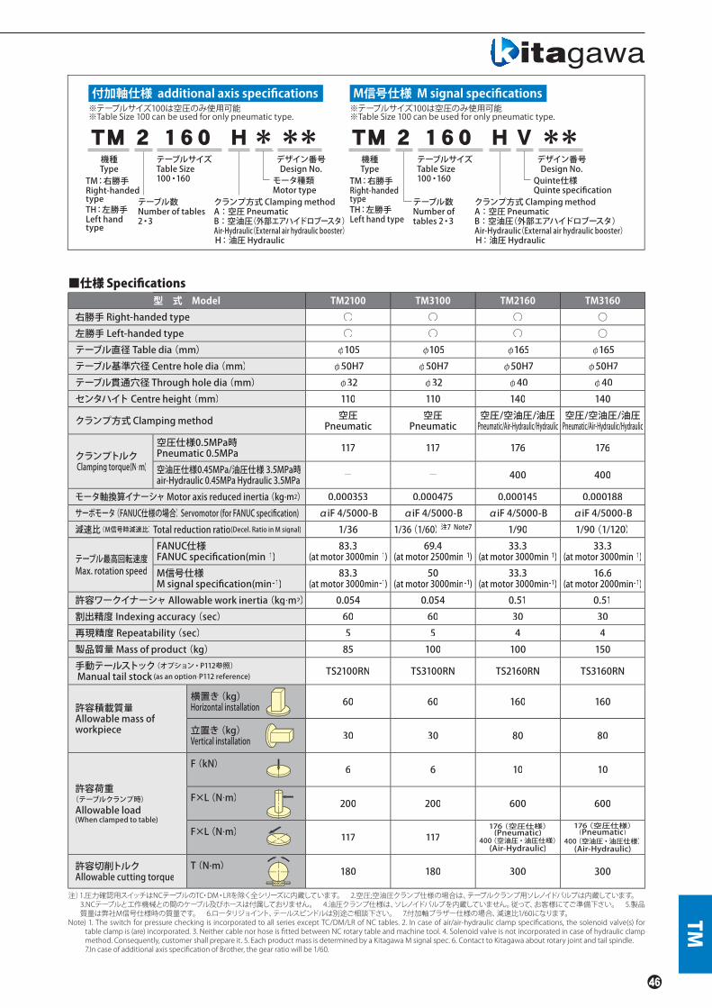
機種Type
TM:右勝手Right-handedtypeTH:左勝手Left handtype
デザイン番号Design No.モータ種類Motor type
テーブルサイズTable Size100・160 Quinte仕様
Quinte specification
TM
クランプ方式 Clamping methodA:空圧 PneumaticB:空油圧(外部エアハイドロブースタ)Air-Hydraulic(External air hydraulic booster)H:油圧 Hydraulic
M信号仕様※テーブルサイズ100は空圧のみ使用可能※Table Size 100 can be used for only pneumatic type.
※テーブルサイズ100は空圧のみ使用可能※Table Size 100 can be used for only pneumatic type.
テーブル数Number of tables2・3
機種Type
TM:右勝手Right-handedtypeTH:左勝手Left hand type
デザイン番号Design No.
テーブルサイズTable Size100・160
クランプ方式 Clamping methodA:空圧 PneumaticB:空油圧(外部エアハイドロブースタ)Air-Hydraulic(External air hydraulic booster)H:油圧 Hydraulic
テーブル数Number oftables 2・3
付加軸仕様 additional axis specifications M信号仕様 M signal specifications
*** **
■仕様 Specifi cations型 式 Model TM2100 TM3100 TM2160 TM3160
右勝手 Right-handed type ○ ○ ○ ○左勝手 Left-handed type ○ ○ ○ ○テーブル直径 Table dia(mm) φ105 φ105 φ165 φ165テーブル基準穴径 Centre hole dia(mm) φ50H7 φ50H7 φ50H7 φ50H7テーブル貫通穴径 Through hole dia(mm) φ32 φ32 φ40 φ40センタハイト Centre height(mm) 110 110 140 140
クランプ方式 Clamping method 空圧Pneumatic
空圧Pneumatic
空圧/空油圧/油圧Pneumatic/Air-Hydraulic/Hydraulic
空圧/空油圧/油圧Pneumatic/Air-Hydraulic/Hydraulic
クランプトルク Clamping torque(N.m)
空圧仕様0.5MPa時Pneumatic 0.5MPa 117 117 176 176
空油圧仕様0.45MPa/油圧仕様 3.5MPa時air-Hydraulic 0.45MPa Hydraulic 3.5MPa - - 400 400
モータ軸換算イナーシャMotor axis reduced inertia(kg.m2) 0.000353 0.000475 0.000145 0.000188サーボモータ(FANUC仕様の場合)Servomotor (for FANUC specifi cation) αiF 4/5000-B αiF 4/5000-B αiF 4/5000-B αiF 4/5000-B減速比(M信号時減速比)Total reduction ratio(Decel. Ratio in M signal) 1/36 1/36(1/60)注7 Note7 1/90 1/90(1/120)
テーブル最高回転速度Max. rotation speed
FANUC仕様FANUC specifi cation(min-1)
83.3(at motor 3000min-1)
69.4(at motor 2500min-1)
33.3(at motor 3000min-1)
33.3(at motor 3000min-1)
M信号仕様M signal specifi cation(min-1)
83.3(at motor 3000min-1)
50(at motor 3000min-1)
33.3(at motor 3000min-1)
16.6(at motor 2000min-1)
許容ワークイナーシャAllowable work inertia(kg.m2) 0.054 0.054 0.51 0.51割出精度 Indexing accuracy(sec) 60 60 30 30再現精度 Repeatability(sec) 5 5 4 4製品質量 Mass of product(kg) 85 100 100 150手動テールストック(オプション・P112参照)Manual tail stock (as an optionk .P112 reference) TS2100RN TS3100RN TS2160RN TS3160RN
許容積載質量Allowable mass of workpiece
横置き(kg)Horizontal installation 60 60 160 160
立置き(kg)Vertical installation 30 30 80 80
許容荷重(テーブルクランプ時)Allowable load(When clamped to table)
F(kN) 6 6 10 10
F×L(N.m) 200 200 600 600
F×L(N.m) 117 117176(空圧仕様)(Pneumatic)
400(空油圧・油圧仕様)(Air-Hydraulic)
176(空圧仕様)(Pneumatic)
400(空油圧・油圧仕様)(Air-Hydraulic)
許容切削トルクAllowable cutting torque
T(N.m) 180 180 300 300
注)1.圧力確認用スイッチはNCテーブルのTC・DM・LRを除く全シリーズに内蔵しています。 2.空圧;空油圧クランプ仕様の場合は、テーブルクランプ用ソレノイドバルブは内蔵しています。 3.NCテーブルと工作機械との間のケーブル及びホースは付属しておりません。 4.油圧クランプ仕様は、ソレノイドバルブを内蔵していません。従って、お客様にてご準備下さい。 5.製品質量は弊社M信号仕様時の質量です。 6.ロータリジョイント、テールスピンドルは別途ご相談下さい。 7.付加軸ブラザー仕様の場合、減速比1/60になります。
Note) 1. The switch for pressure checking is incorporated to all series except TC/DM/LR of NC tables. 2. In case of air/air-hydraulic clamp specifi cations, the solenoid valve(s) for table clamp is (are) incorporated. 3. Neither cable nor hose is fi tted between NC rotary table and machine tool. 4. Solenoid valve is not incorporated in case of hydraulic clamp method. Consequently, customer shall prepare it. 5. Each product mass is determined by a Kitagawa M signal spec. 6. Contact to Kitagawa about rotary joint and tail spindle.7.In case of additional axis specifi cation of Brother, the gear ratio will be 1/60.

TM
TM series TH2100・TH3100・TH2160・TH3160TM2100・TM3100・TM2160・TM3160
TM2100(TH)
TM2160(TH)
TM3100(TH)
TM3160(TH)
6-M6
20
φ40H8H8 φ500φ0
149
32
φ50H7
12
21 911
M16×65
45
30
28.5
30.5
11
St.17
24 48
284
18
6.5 401 218
100.5200100.5
18h715
140
112
252
47.5
φ145
φφ145
φ15°1
625.5
418.5207
φ165
φ
8
286
135151
150
70 70
2121
1
2×3-M10
■寸法図【付加軸仕様】Dimensions【additional axis specifications】
テーブルT溝Table T-slot Grooves
クランプ器具Clamping Parts
※上記外観寸法はFANUC仕様です。他社モータ仕様の場合、寸法が異なることがあります。TMは右勝手仕様、THは左勝手仕様です。※The above dimensions are the same as FANUC specifications.Those dimensions may vary from motor to motor that is mounted. TM is a right hand spec. and TH is a left hand spec.
六角ボルトHex bolt
テーブル上面Table surface
Rc1/8 クランプ用空圧供給口Pneumatic port for clampRc1/4 プラグ付きクランプ用油圧供給口Hydraulic port for clamp with plug(裏面にあります)(on back side)
497
356.5
260
151 109140.5
222269
120 70
150
149
25 1314.6
1
70
10 10
74.574.5
6
2×3-M8
φ82.55
18 h7
5
2×3-M8
19 21 21
304
110
100
210
30。30。
φ105
φ32
φ50H7
45
30
28.5
30.5
11
St.17
24 48
M16×65
六角ボルトHex bolt
テーブル上面Table surface
Pneumatic port for clamp(on back side)
Rc1/8クランプ用空圧供給口(裏面にあります)
φ93
617
416.5
267
156 111200.5
222389
120 120 70
150
149
25 1314.6
1
70
10
6
10
74.574.5
6
3×3-M8
φ82.55
18h75
3×3-M8
19 21 21
304
110
100
210
30。30。
φ105
φ32
φ50H7
45
30
28.5
30.5
11St.17
24 48
M16×65
六角ボルトHex bolt
テーブル上面Table surface
Pneumatic port for clamp(on back side)
Rc1/8クランプ用空圧供給口(裏面にあります)
φ93
833.5
526.5 286
6-M6
151 135
307
226601
200 200 70
15032 20
149
1
70
8
100.5 100.5
6.5
φ145
18h75
3×3-M10
18 21 21
284
140112
47.5
252
15。
φ165
φ50
φ40H8
φ50H7 45
30
21
12
28.5
30.5
11
St.17
24 48
M16×65
119
クランプ器具Clamping Parts
六角ボルトHex bolt
テーブル上面Table surface
Pneumatic port for clampHydraulic port for clamp with plug(on back side)
Rc1/8 クランプ用空圧供給口Rc1/4プラグ付きクランプ用油圧供給口(裏面にあります)
テーブル貫通穴Through Hole Diameter
テーブル貫通穴Through Hole Diameter
テーブル貫通穴Through Hole Diameter
テーブルT溝Table T-slot Grooves
クランプ器具Clamping Parts
テーブル貫通穴Through Hole Diameter
クランプ器具Clamping Parts

TM
■寸法図【M信号仕様】Dimensions【M signal specifications】
*モータの仕様により外形寸法が変わる可能性があります。*The dimensions may vary from motor to motor that is mounted.
TM2100(TH)
TM2160(TH)
TM3100(TH)
TM3160(TH)
φ82.55
18 h75
φ105
10140150
10 10 212×3-M8
7070
21
110
100
210
30。30。
479338.5140.5
2042696
74.512074.5
2×3-M8
φ93 φ50H7
14.5
149
φ32
40 45
30
28.5
30.5
11
St.17
24 48
M16×65φ165
151
150 1
2121 8
70 70
φ145
15。2×3-M10
18h75
6.5 401 225
20222
10
207 425.5632.5
140
112
252
47.5
100.5200100.5
6-M6
20
φ40H8 φ50
149
32
φ50H7
12
21 911
M16×65
45
30 28.5
St.17
24 48
3×3-M8
3×3-M8
φ93φ82.55
φ105
21
10 10
140 10
18h75
150
70 70
110
100
210
30。30。
21
403200603
2083896
74.512012074.5
φ50H7
14.6
149
φ32
40 45
30
28.5
30.5
1124 48
M16×65St.17
18h75
15。
φ145
3×3-M10307 525.5
832.5
20222
1047.5
112
140252
70 70
21
100.5200200100.5
2256016.5
φ165
151
150 1
218
21
119
126-M6
φ50H7
φ40H8
φ5032 20
149 28
28
M16×65
45
30.5
10
St.17
24 48
クランプ器具Clamping Parts
クランプ器具Clamping Parts
クランプ器具Clamping Parts
クランプ器具Clamping Parts
※TMは右勝手仕様、THは左勝手仕様です。※TM is a right hand spec. and TH is a left hand spec.
六角ボルトHex boltテーブル上面
Table surface
Pneumatic port for clamp(on back side)
Rc1/8 クランプ用空圧供給口(裏面にあります)
六角ボルトHex bolt
テーブル上面Table surface
Rc1/8 クランプ用空圧供給口Pneumatic port for clampRc1/4 プラグ付き クランプ用油圧供給口Hydraulic port for clamp with plug(裏面にあります)(on back side)
六角ボルトHex bolt
テーブル上面Table surface
Pneumatic port for clamp (on back side)
Rc1/8 クランプ用空圧供給口(裏面にあります)
Rc1/8 クランプ用空圧供給口Pneumatic port for clampRc1/4 プラグ付き クランプ用油圧供給口Hydraulic port for clamp with plug(裏面にあります)(on back side)
六角ボルトHex bolt
テーブル上面Table surface
テーブル貫通穴Through Hole Diameter
テーブル貫通穴Through Hole Diameter
テーブル貫通穴Through Hole Diameter
テーブル貫通穴Through Hole Diameter
テーブルT溝Table T-slot Grooves
テーブルT溝Table T-slot Grooves
30.5

小物ワークの高度な加工に5軸加工対応傾斜タイプCompact tilting range to suit 5 axis machining on small work pieces
コンパクトNC傾斜円テーブルCompact Type NC Tilting Rotary Table
TT
TT101.TW120
▲KITAGAWAだからできるチャックと合わせた提案 ワークホールディングも合わせてご相談くださいOnly Kitagawa can offer this combination of NC Rotary Table and chuck
▲テールストック(P111、113参照)と合わせて、長尺物の加工も可能ですCombine with tail stock on P111、113 to suit machining of long work pieces.
使用事例 Sample Application
TT101
※TWは傾斜ストレートタイプです。※TW is Straight tilting table
●クラス最小コンパクト設計Minimum size in its class
●軽量 Light weight●高剛性 High rigidity●高速回転 High speed rotation●ロータリジョイント搭載可能Rotary Joint built in as option
●シリンダ取付可能Cylinder mountable
●空圧クランプ仕様Pneumatic clamping specification
●小型M/Cに最適Ideal design for compact machining centres
*CE対応品 CE correspondence
※2軸共付加軸の仕様では、輸出貿易管理令の別表第1の6項の(8)に 該当する商品となりますので、海外に輸出される場合は、経済産業省の許可が必要です。※In specification with the foreign trade control ordinance, permission of the ministry of economy, trade and industry is required when exporting twin axis products overseas.

機種Type
デザイン番号Design No.傾斜軸モータ種類Tilting axis motor type
回転軸モータ種類Rotary axis motor type
テーブルサイズTable SizeTT:101TW:120
デザイン番号Design No.
テーブルサイズTable SizeTT:101TW:120
TT:標準タイプ STD typeTW:傾斜ストレートタイプ
Tilting straight type (120 サイズのみ)(only 120 size)
機種TypeTT:標準タイプ STD typeTW:傾斜ストレートタイプ
Tilting straight type(120 サイズのみ)(only 120 size)
TT
クランプ方式 Clamping method空圧のみ Only Pneumatic
クランプ方式 Clamping method空圧のみ Only Pneumatic
TT A *101 *** TT A V101 **
Quinte仕様Quinte specification
付加軸仕様 additional axis specifications M信号仕様 M signal specifications
■仕様 Specifi cations型 式 Model TT101 TW120
傾斜範囲 Tilting angle range -20。~+120。 -20。~+110。
テーブル直径Table dia(mm) φ110 φ125テーブル基準穴径 Centre hole dia(mm) φ50H7 φ60H7テーブル貫通穴径 Through hole dia(mm) φ32 φ32垂直時センタハイトCentre height(mm) 140 150クランプ方式 Clamping method 空圧 Pneumatic 空圧 Pneumatic
クランプトルク(空圧 0.5MPa時)Clamping torque(N.m)(In pneumatic 0.5MPa)(N.m)
回転軸Rotating axis 180 120傾斜軸 Tilting axis 300 200
モータ軸換算イナーシャMotor axis reduced inertia(kg・m2)
回転軸Rotating axis 0.000082 0.000072傾斜軸 Tilting axis 0.000081 0.000034
サーボモータ(FANUC 仕様の場合)Servomotor (for FANUC specifi cation) 回転軸Rotating axis αiF 1/5000-B傾斜軸 Tilting axis αiF 2/5000-B αiF 2/5000-B
減速比 Total reduction ratio回転軸Rotating axis 1/72 1/90傾斜軸 Tilting axis 1/120 1/180
テーブル最高回転速度Max. rotation speed
FANUC 仕様FANUC specifi cation
回転軸(min-1/モータ3000min-1時)Rotating axis(min-1/at motor 3000min-1) 41.6 33.3傾斜軸(min-1/モータ3000min-1時)Tilting axis(min-1/at motor 3000min-1) 25 16.6
M信号仕様M signal specifi cation
回転軸(min-1/モータ3000min-1時)Rotating axis(min-1/at motor 3000min-1) 41.6 33.3傾斜軸(min-1/モータ3000min-1時)Tilting axis(min-1/at motor 3000min-1) 25 16.6
許容ワークイナーシャ(kg.m2) Allowable work inertia(kg.m2) 0.05 0.06
割出精度 Indexing accuracy(sec)回転軸Rotating axis 30 30傾斜軸 Tilting axis 60 60
再現精度Repeatability(sec) 4 4製品質量 Mass of product(kg) 73 105
ロータリジョイント(オプション・P117参照)Rotary joint (Option.P117 reference)
RJ32-10T05油圧/空圧3ポート
Hydraulic/Pneumatic 3-port
RJ32-12T08油圧/空圧3ポート
Hydraulic/Pneumatic 3-port
許容積載質量Allowable mass of workpiece
水平時(kg)at horizontal 35 35
傾斜時(kg)at tilted 20 20
許容荷重(テーブルクランプ時)Allowable load(When clamped to table)
F(kN) 4 4
F×L(N.m) 300 200
F×L(N.m) 180 120
許容切削トルクAllowable cutting torque
T(N.m) 160 190
傾斜可搬モーメントMoment of tilting weight capacity
W×L(kgf . f m) 7 10
注)1.圧力確認用スイッチはNCテーブルのTC・DM・LRを除く全シリーズに内蔵しています。 2.テーブルクランプ用ソレノイドバルブは内蔵しています。 3.NCテーブルと工作機械との間のケーブル及びホースは付属しておりません。 4.製品質量は弊社M信号仕様時の質量です。 5.ロータリジョイントは別途ご相談下さい。
Note) 1. The switch for pressure checking is incorporated to all series except TC/DM/LR of NC tables. 2. The solenoid valve for the table clamp is incorporated. 3. Neither cable nor hose is fi tted between NC rotary table and machine tool. 4. Each product mass is determined by a Kitagawa M signal spec. 5. Contact to Kitagawa about rotary joint.

Rc1/8クランプ用空圧供給口Pneumatic port for clamp
44712 175 260
130 123 7
399102 297
180 207
90 9014h75
227
2
227
140
45
42
φ110
77 77
212
φ933-M8
87175
122
122 138
116.5
テーブル上面Table surface
1513
15
φ50H7
φ32H8
六角ボルトHex boltM12×40
22
28.5
45
1219
8.614
21
3325
テーブル貫通穴Through Hole Diameter
クランプ器具Clamping Parts
10 10
226 229
455
Rc1/8クランプ用空圧供給口
Pneumatic port for clamp
3-M8
Rc1/8クランプ用空圧供給口
Pneumatic port for clamp
174
112
φ93
733
451 282
14h7
116 145 190 152 123 7
253
150
70
87 82
φ125
113
220
122
4
13
113 342
ネジ深10thread depth 10
6-M5
テーブル上面Table surface
六角ボルトHex boltM12×50φ60H7
φ50
41634
1
125
φ41
φ32H7
8.621
22
20 40
28.5
28
35St.13
クランプ器具Clamping Parts
テーブル貫通穴Through Hole Diameter
TW120
TT TT101.TW120TT101
TW120
■寸法図【付加軸仕様】Dimensions【additional axis specifications】
※上記外観寸法はFANUC仕様です。他社モータ仕様の場合、寸法が異なることがあります。※The above dimensions are the same as FANUC specifications.Those dimensions may vary from motor to motor that is mounted.

TT
TT101
TW120
14h75φ110
227
90 90180 179
42φ933-M8
269102
371400
21317512
83130
2227
7777
14045
87175
49
111 49
212
116.5
1513
15
φ50H7
φ32H8
2114
12
45
2533
22
28.5
M12×40
φ93
253
4
113 1131010
355226 129
152190
666
3M-8
4253
33φ1258287
112174
13253
12234216042
11319052
14h75
φ60H7φ50
41634
1125
φ41φ32H8
8.621
28
20 40
28.5
35
22
M12×50
6-M5
六角ボルト Hex bolt
六角ボルト Hex bolt
テーブル上面Table surface
テーブル上面Table surface
Clamping air supply portRc1/8 クランプ用空圧供給口
Pneumatic port for clamp
Rc1/8クランプ用空圧供給口 Pneumatic port for clamp
Rc1/8クランプ用空圧供給口
ネジ深10thread depth10
テーブル貫通穴Through Hole Diameter
クランプ器具Clamping Parts
クランプ器具Clamping Parts
■寸法図【M信号仕様】Dimensions【M signal specifications】
*モータの仕様により外形寸法が変わる可能性があります。*The dimensions may vary from motor to motor that is mounted.
テーブル貫通穴Through Hole Diameter
198.6
St.13

Z軸が有利に使える5軸加工対応傾斜タイプTilting type to suit 5 axis machining with decreasedinput on the Z axis
低床NC傾斜円テーブルLow centre line tilting NC Rotary Table
TT
TT140
●ロータリジョイント完全内蔵(オプション)でシンプルで確実なジグ配管を実現 Simplified pipework with complete built-in ratary joint (option)
広い加工エリア Wide Machining Area
ロータリジョイント完全内蔵(オプション) Complete built-in rotary joint (option)
TT140
●傾斜軸割出し220° Tilting axis index 220°
●積載ワーク最大径φ200mm Max. dia. φ200mm of loadable work
●加工エリアが広く、傾斜軸割出220°(±110°)Wide machining area and tilting axis index 220°(±110°)
●コンパクト、高速で小型M/Cに最適Compact and high speed Ideal for use on small machining centres
●クラス最高レベルの高クランプトルクHighest clamping torque in its class
●ロータリジョイント完全内蔵(オプション)で シンプルで確実なジグ配管Built in rotary joint (option) allows simple and secure jig piping
●テーブル面と傾斜軸中心が同じ高さTable surface on tilt axis centre line
●空圧クランプ仕様Pneumatic clamping mechanism
*CE対応品 CE correspondence
PHOTPHOTHOTHOHOTHOTOTOOTHOTOOOOOTHOTHOTHOTOOOOOTTTTPHOTHOTHOOOOTHOTHOOTOOOTHOTHOOHOTOTHOHOOOOOTOTTHOHOHOTOOTOTHOOOTHOOOTHOHOOOTHOHOOOTOTPPHOHOHOTOHOOOTHOOTOTHOOHOOOTHOOTOTHOOOTOOOO:TTO:TTO:TTO:TTOOOOOOOOOOOOOOOOOOOOOOOOOOOOOO 11181818818181
※2軸共付加軸の仕様では、輸出貿易管理令の別表第1の6項の(8)に 該当する商品となりますので、海外に輸出される場合は、経済産業省の許可が必要です。※In specification with the foreign trade control ordinance, permission of the ministry of economy, trade and industry is required when exporting twin axis products overseas.
配管不要SimplifiedPipework
配管不要SimplifiedPipework

機種Type
デザイン番号Design No.
モータ種類 Motor type
オプション仕様 Option spec.R:ロータリジョイント Rotary joint-:オプション無し Non- option
テーブルサイズTable Size140
機種Type
デザイン番号Design No.
オプション仕様 Option spec.R:ロータリジョイント Rotary joint-:オプション無し Non- option
テーブルサイズTable Size140
TT
クランプ方式 Clamping method空圧のみ Only Pneumatic
140 V RA **TT140 * RA
Quinte仕様 Quinte specificationクランプ方式 Clamping method空圧のみ Only Pneumatic
**TT付加軸仕様 additional axis specifications M信号仕様 M signal specifications
■仕様 Specifi cations型 式 Model TT140
傾斜範囲 Tilting angle range -110。~+110。
テーブル直径Table dia(mm) φ140テーブル基準穴径 Centre hole dia(mm) φ60H7テーブル貫通穴径 Through hole dia(mm) φ32垂直時センタハイトCentre height(mm) 200クランプ方式 Clamping method 空圧 Pneumatic
クランプトルク(空圧 0.5MPa時)Clamping torque (at pneumatic 0.5MPa)(N.m)
回転軸Rotating axis 280傾斜軸 Tilting axis 500
モータ軸換算イナーシャMotor axis reduced inertia(kg.m2)
回転軸Rotating axis 0.000269傾斜軸 Tilting axis 0.000288
サーボモータ(FANUC 仕様の場合)Servomotor (for FANUC specifi cation) αiF 2/5000-B
減速比 Total reduction ratio回転軸Rotating axis 1/72傾斜軸 Tilting axis 1/180
テーブル最高回転速度Max. rotation speed
FANUC 仕様FANUC specifi cation
回転軸(min-1/モータ3000min-1時) Rotating axis(min-1/at motor 3000min-1) 41.6傾斜軸(min-1/モータ3000min-1時)Tilting axis(min-1/at motor 3000min-1) 16.6
M信号仕様M signal specifi cation
回転軸(min-1/モータ3000min-1時) Rotating axis(min-1/at motor 3000min-1) 41.6傾斜軸(min-1/モータ3000min-1時)Tilting axis(min-1/at motor 3000min-1) 16.6
許容ワークイナーシャAllowable work inertia(kg.m2) 0.12
割出精度 Indexing accuracy(sec)回転軸Rotating axis 30傾斜軸 Tilting axis 60
再現精度Repeatability(sec) 4製品質量 Mass of product(kg) 158
内蔵ロータリジョイント(オプション・P117参照)Buit-in rotary joint (Option.P117 reference)
RJ32TT140油圧/空圧4ポート
Hydraulic/Pneumatic 4-port
許容積載質量Allowable mass of workpiece
水平時(kg)at horizontal 50
傾斜時(kg)at tilted 30
許容荷重(テーブルクランプ時)Allowable load(When clamped to table)
F(kN) 4
F×L(N.m) 500
F×L(N.m) 280
許容切削トルクAllowable cutting torque
T(N.m) 190
傾斜可搬モーメントMoment of tilting weight capacity
W×L(kgf . f m) 11
注)1.圧力確認用スイッチはNCテーブルのTC・DM・LRを除く全シリーズに内蔵しています。 2.テーブルクランプ用ソレノイドバルブは内蔵しています。 3.NCテーブルと工作機械との間のケーブル及びホースは付属しておりません。 4.製品質量は弊社M信号仕様時の質量です。
Note) 1. The switch for pressure checking is incorporated to all series except TC/DM/LR of NC tables. 2. The solenoid valve for the table clamp is incorporated. 3. Neither cable nor hose is fi tted between NC rotary table and machine tool. 4. Each product mass is determined by a Kitagawa M signal spec.

TT140TT
TT140
2.5φ32φ
φ60H7φ
14.5
135
φ41φ
223434
φ50φφ40φ
M66-M
M54-M
φ32H8φ28.5
114824
30.5 45
30
φφ 1400
103 103
1010
21
φ113
φ104.7
φφφ
224 210
434
84
200303
585
458 127
255 20318h7
5
30.5
145
127.5
25 255
280
303
27
297
3-M8
9-M10
139
112
230
122
114
315
122
551
1313
20°
341
R170
58
■寸法図【付加軸仕様】Dimensions【additional axis specifications】
傾斜半径
Tilting radius
M16×65
六角ボルトHex bolt
テーブル上面Table surface
Pneumatic port for clamp
Rc1/4クランプ用空圧供給口
Pneumatic port for clamp
Rc1/4クランプ用空圧供給口
Option Rotary Joint
オプションロータリジョイント
※上記外観寸法はFANUC仕様です。他社モータ仕様の場合、寸法が異なることがあります。※The above dimensions are the same as FANUC specifications.Those dimensions may vary from motor to motor that is mounted.
クランプ器具Clamping Parts
テーブル貫通穴Through Hole Diameter
St.17

TT
TT140
φ140
103 103
21
φ113
φ104.7
84
200303
585
18h75
30.5
145
127.5
25 255
280
303
3-M8
9-M10
131
3
20。
27
297
434
21022458
1010
341
127458
203255
112
230
64
114
315
64
493
139
φ32.5
φ60H7
14.5135
φ41
2234
φ50φ40
6-M6
4-M5
φ32H8
Option Rotary Joint
オプションロータリジョイント
※上記外観寸法はFANUC仕様です。他社モータ仕様の場合、寸法が異なることがあります。※The above dimensions are the same as FANUC specifications.Those dimensions may vary from motor to motor that is mounted.
テーブル上面Table surface
Hydraulic port for clamp
Rc1/4クランプ用空圧供給口
Hydraulic port for clamp
Rc1/4クランプ用空圧供給口
テーブル貫通穴Through Hole Diameter
クランプ器具Clamping Parts
■寸法図【M信号仕様】Dimensions【M signal specifications】
*モータの仕様により外形寸法が変わる可能性があります。*The dimensions may vary from motor to motor that is mounted.
R170
傾斜半径
Tilting radius
30.5
30
28.5
114824
45
M16×65
六角ボルトHex bolt
St.17

主軸剛性&クランプトルク大幅アップ !しかも全高を抑えたコンパクト設計により機械側ハイコラム量を低減High stiffness and High clamp torque of main spindle !Compact designed body with minimized total height keeps less high-column of machine.
NC傾斜円テーブルTilting NC Rotary Table
TT150
TT150
●ロータリジョイント完全内蔵(オプション)で シンプルで確実なジグ配管を実現 Simplified pipework with complete built-in ratary joint (option)
使用事例Sample Application
ロータリジョイント完全内蔵(オプション) Complete built-in rotary joint (option)
TT
●30番小型マシニングセンタに搭載可能(*搭載機械によりハイコラム仕様が必要な場合があります)Suitable for No.30 machining centers(*High-column specification may be required to suit a variety of machine models.)
●高クランプトルクHigh clamping torque
●ロータリージョイント内蔵対応 ※オプションComplete built-in rotary joint (option)
*CE対応品 CE correspondence
※2軸共付加軸の仕様では、輸出貿易管理令の別表第1の6項の(8)に 該当する商品となりますので、海外に輸出される場合は、経済産業省の許可が必要です。※In specification with the foreign trade control ordinance, permission of the ministry of economy, trade and industry is required when exporting twin axis products overseas.
▲KITAGAWAだからできるチャックと合わせた提案 ワークホールディングも合わせてご相談くださいOnly Kitagawa can offer this combination of NC Rotary Table and chuck
Old mOld md mmO mododel
配管不要SimplifiedPipework
配管不要SimplifiedPipework

TT
機種Type
デザイン番号Design No.
モータ種類 Motor type
オプション仕様 Option spec.R:ロータリジョイント Rotary joint-:オプション無し Non- option
テーブルサイズTable Size150
機種Type
デザイン番号Design No.
オプション仕様 Option spec.R:ロータリジョイント Rotary joint-:オプション無し Non- option
テーブルサイズTable Size150
クランプ方式 Clamping method空圧のみ Only Pneumatic
150 V RA **TT150 * RA
Quinte仕様 Quinte specificationクランプ方式 Clamping method空圧のみ Only Pneumatic
**TT付加軸仕様 additional axis specifications M信号仕様 M signal specifications
■仕様 Specifi cations型 式 Model TT150
傾斜角度Tilting angle range -20。~+110。
テーブル直径Table dia(mm) φ150テーブル基準穴径 Centre hole dia(mm) φ60H7テーブル貫通穴径 Through hole dia(mm) φ40垂直時センタハイトCentre height(mm) 150クランプ方式 Clamping method 空圧 Pneumatic
クランプトルク(空圧 0.5MPa時)Clamping torque(at pneumatic 0.5MPa)(N.m)
回転軸Rotating axis 350傾斜軸 Tilting axis 550
モータ軸換算イナーシャMotor axis reduced inertia(kg.m2)
回転軸Rotating axis 0.000242傾斜軸 Tilting axis 0.000132
サーボモータ(FANUC 仕様の場合)Servomotor (for FANUC specifi cation) αiF 2/5000-B
減速比 Total reduction ratio回転軸Rotating axis 1/72傾斜軸 Tilting axis 1/180
テーブル最高回転速度Max. rotation speed
FANUC 仕様for FANUC specifi cation
回転軸(min-1/モータ3000min-1時) Rotating axis(min-1/at motor 3000min-1) 41.6傾斜軸(min-1/モータ3000min-1時)Tilting axis(min-1/at motor 3000min-1) 16.6
M信号仕様for M signal specifi cation
回転軸(min-1/モータ3000min-1時) Rotating axis(min-1/at motor 3000min-1) 41.6傾斜軸(min-1/モータ3000min-1時)Tilting axis(min-1/at motor 3000min-1) 16.6
許容ワークイナーシャAllowable work inertia(kg.m2) 0.14
割出精度 Indexing accuracy(sec)回転軸Rotating axis 30傾斜軸 Tilting axis 60
再現精度Repeatability(sec) 4製品質量 Mass of product(kg) 141
内蔵ロータリジョイント(オプション・P117参照)Buit-in rotary joint (as an option.P117 reference)
RJ40FTT150油圧/空圧4ポート+空圧専用1ポート
Hydraulic/Pneumatic 4-port + Exclusive Pneumatic 1-port of air
許容積載質量Allowable mass of workpiece
水平時(kg)at horizontal 50
傾斜時(kg)at tilted 30
許容荷重(テーブルクランプ時)Allowable load(When clamped to table)
F(kN) 4
F×L(N.m) 550
F×L(N.m) 350
許容切削トルクAllowable cutting torque
T(N.m) 190
傾斜可搬モーメントMoment of tilting weight capacity
W×L(kgf . f m) 11
注)1.圧力確認用スイッチはNCテーブルのTC・DM・LRを除く全シリーズに内蔵しています。 2.テーブルクランプ用ソレノイドバルブは内蔵しています。 3.NCテーブルと工作機械との間のケーブル及びホースは付属しておりません。 4.製品質量は弊社M信号仕様時の質量です。
Note) 1. The switch for pressure checking is incorporated to all series except TC/DM/LR of NC tables. 2. The solenoid valve for the table clamp is incorporated. 3. Neither cable nor hose is fi tted between NC rotary table and machine tool. 4. Each product mass is determined by a Kitagawa M signal spec.

TT150TT
TT150
105
268
117.5 58
14058
84
120120
203
φ60H7
1523132
φ50
φ40.5
φ40H814.5 6-M5
3-M5
φ104.7
φ93
φ113
9-M103-M8
3-M8
107.5 118114.5
φ150
14.5
270
15070
14h7204 138
8 241 342
591
3270
78144
48
24 241
265 443
120 120240 203
3269
5
141.5
30
31
2117
8.6
28.5
22
■寸法図【付加軸仕様】Dimensions【additional axis specifications】
※上記外観寸法はFANUC仕様です。他社モータ仕様の場合、寸法が異なることがあります。※The above dimensions are the same as FANUC specifications.Those dimensions may vary from motor to motor that is mounted.
Pneumatic port for clamp
Rc1/4クランプ用空圧供給口
Option Rotary Joint
オプションロータリジョイント
テーブル貫通穴Through Hole Diameter
テーブル面Detailed table hole
クランプ器具Clamping Parts
21
M12×55
六角ボルトHex bolt
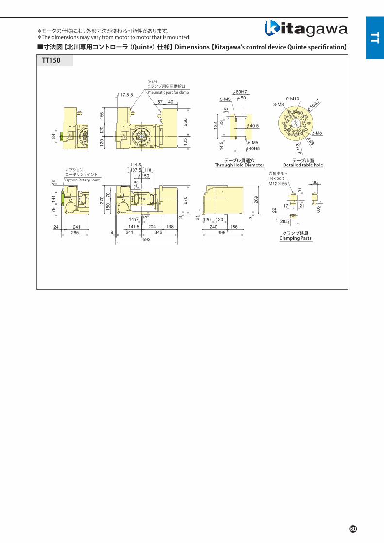
TT
TT150
105
268
107.5 118114.5
φ150
14.5
270
15070
14h7
204 1389 241 342
592
3270
78144
48
24 241265
84
120 120
240
3269
156396
120120
156
117.5 51
14057
141.5
5
30
31
2117
8.6
28.5
22
φ60H7
1523132
φ50
φ40.5
φ40H814.5 6-M5
3-M5
φ104.7
φ93
φ113
9-M103-M8
3-M8
Pneumatic port for clamp
Rc1/4クランプ用空圧供給口
Option Rotary Joint
オプションロータリジョイント
テーブル貫通穴Through Hole Diameter
テーブル面Detailed table hole
クランプ器具Clamping Parts
■寸法図【北川専用コントローラ(Quinte)仕様】Dimensions【Kitagawa’s control device Quinte specification】
*モータの仕様により外形寸法が変わる可能性があります。*The dimensions may vary from motor to motor that is mounted.
21
M12×55
六角ボルトHex bolt
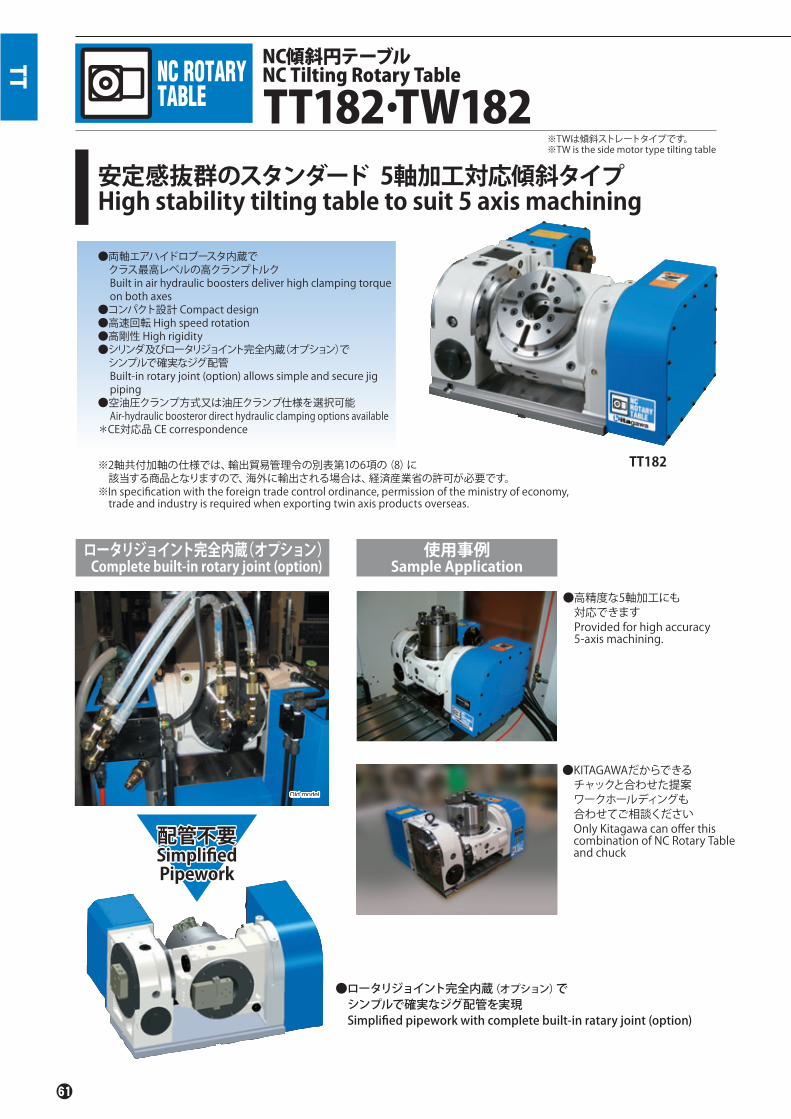
安定感抜群のスタンダード 5軸加工対応傾斜タイプHigh stability tilting table to suit 5 axis machining
NC傾斜円テーブルNC Tilting Rotary Table
TT182.TW182※TWは傾斜ストレートタイプです。※TW is the side motor type tilting table
Old modelOOldld mmoodedeel
TT182
TT
●ロータリジョイント完全内蔵(オプション)で シンプルで確実なジグ配管を実現 Simplified pipework with complete built-in ratary joint (option)
使用事例Sample Application
ロータリジョイント完全内蔵(オプション) Complete built-in rotary joint (option)
●高精度な5軸加工にも 対応できますProvided for high accuracy 5-axis machining.
●KITAGAWAだからできる チャックと合わせた提案 ワークホールディングも 合わせてご相談くださいOnly Kitagawa can offer thiscombination of NC Rotary Tableand chuck
※2軸共付加軸の仕様では、輸出貿易管理令の別表第1の6項の(8)に 該当する商品となりますので、海外に輸出される場合は、経済産業省の許可が必要です。※In specification with the foreign trade control ordinance, permission of the ministry of economy, trade and industry is required when exporting twin axis products overseas.
●両軸エアハイドロブースタ内蔵で クラス最高レベルの高クランプトルクBuilt in air hydraulic boosters deliver high clamping torque on both axes
●コンパクト設計 Compact design●高速回転 High speed rotation●高剛性 High rigidity●シリンダ及びロータリジョイント完全内蔵(オプション)で シンプルで確実なジグ配管Built-in rotary joint (option) allows simple and secure jig piping
●空油圧クランプ方式又は油圧クランプ仕様を選択可能Air-hydraulic boosteror direct hydraulic clamping options available
*CE対応品 CE correspondence
配管不要SimplifiedPipework
配管不要SimplifiedPipework

Quinte仕様 Quinte specification
TT B* 182 B V R **TT182 R **
TT
機種TypeTT:標準タイプSTD typeTW:標準ストレートタイプTilting straight type
機種TypeTT:標準タイプSTD typeTW:傾斜ストレートタイプTilting straight type
デザイン番号Design No.モータ種類
Motor type
テーブルサイズTable Size182
デザイン番号Design No.
テーブルサイズTable Size182
クランプ方式 Clamping methodB:空油圧(内蔵エアハイドロブースタ)Air-Hydraulic(integrated air hydraulic booster)H:油圧 Hydraulic
オプション仕様 Option spec.R:ロータリジョイント Rotary jointC:外部シリンダ Outer cylinder-:オプション無し Non- option
オプション仕様 Option spec.R:ロータリジョイント Rotary jointC:外部シリンダ Outer cylinder-:オプション無し Non- option
クランプ方式 Clamping methodB:空油圧(内蔵エアハイドロブースタ)Air-Hydraulic(integrated air hydraulic booster)H:油圧 Hydraulic
付加軸仕様 additional axis specifications M信号仕様 M signal specifications
■仕様 Specifi cations型 式 Model TT182/TW182
傾斜角度Tilting angle range -35。~+110。
テーブル直径Table dia(mm) φ180テーブル基準穴径 Centre hole dia(mm) φ65H7テーブル貫通穴径 Through hole dia(mm) φ40垂直時センタハイトCentre height(mm) 180クランプ方式 Clamping method 空油圧/油圧Air-Hydraulic/Hydraulic
クランプトルク(空圧 0.5MPa/油圧3.5MPa時)Clamping torque(at pneumatic 0.5MPa/hydraulic 3.5MPa)(N.m)
回転軸Rotating axis 450傾斜軸 Tilting axis 800
モータ軸換算イナーシャMotor axis reduced inertia(kg.m2)
回転軸Rotating axis 0.000242傾斜軸 Tilting axis 0.000135
サーボモータ(FANUC 仕様の場合)Servomotor (for FANUC specifi cation) αiF 2/5000-B
減速比 Total reduction ratio回転軸Rotating axis 1/90傾斜軸 Tilting axis 1/180
テーブル最高回転速度Max. rotation speed
FANUC 仕様for FANUC specifi cation
回転軸(min-1/モータ3000min-1時)Rotating axis(min-1/at motor 3000min-1) 33.3傾斜軸(min-1/モータ3000min-1時)Tilting axis(min-1/at motor 3000min-1) 16.6
M信号仕様for M signal specifi cation
回転軸(min-1/モータ3000min-1時)Rotating axis(min-1/at motor 3000min-1) 33.3傾斜軸(min-1/モータ3000min-1時)Tilting axis(min-1/at motor 3000min-1) 16.6
許容ワークイナーシャAllowable work inertia(kg.m2) 0.25
割出精度 Indexing accuracy(sec)回転軸Rotating axis 20傾斜軸 Tilting axis 60
再現精度Repeatability(sec) 4製品質量 Mass of product TT/TW(kg) 163/178
内蔵ロータリジョイント(オプション・P117参照)Buit-in rotary joint (Option.P117 reference)
RJ40FTT182油圧/空圧4ポート+空圧専用1ポート
Hydraulic/Pneumatic 4-port + Exclusive Pneumatic 1-port of air空圧外部シリンダ(オプション・P65、66参照)Pneumatic outer cylinder(Option.P65、66 reference) NY1312T18B油圧外部シリンダ(オプション・P65、66参照)Hydraulic outer cylinder(Option.P65、66 reference) NY0912T18A
許容積載質量Allowable mass of workpiece
水平時(kg)at horizontal 60
傾斜時(kg)at tilted 40
許容荷重(テーブルクランプ時)Allowable load(When clamped to table)
F(kN) 5
F×L(N.m) 800
F×L(N.m) 450
許容切削トルクAllowable cutting torque
T(N.m) 250
傾斜可搬モーメントMoment of tilting weight capacity
W×L(kgf . f m) 12
注)1.圧力確認用スイッチはNCテーブルのTC・DM・LRを除く全シリーズに内蔵しています。 2.空油圧クランプ仕様の場合は、テーブルクランプ用ソレノイドバルブは内蔵しています。 3.油圧クランプ仕様は、ソレノイドバルブを内蔵していません。従って、お客様にてご準備下さい。 4.NCテーブルと工作機械との間のケーブル及びホースは付属しておりません。5.製品質量は弊社M信号仕様時の質量です。
Note) 1. The switch for pressure checking is incorporated to all series except TC/DM/LR of NC tables. 2. In case of air + hyd. clamp specifi cation, the solenoid valve for table clamp is incorporated. 3. In a hyd. clamp spec., the solenoid valve is not incorporated. Consequently, customer shall prepare it. 4. Neither cable nor hose is fi tted between NC rotary table and machine tool. 5. Each product mass is determined by a Kitagawa M signal spec.

オプションロータリジョイント
OptionRotary Joint
4
280
115 115230 246
361128489
285
18070
285
196 131
864
105
230
131
150
φ145
14.5
φ180120110
117
112
213
4
102 198 237 327
Rc1/4クランプ用油圧供給口Hydraulic port for clamp
(油圧仕様時)(at hydraulic spec.)
Rc1/4クランプ用空圧供給口Pneumatic port for clamp
(エアブースタ仕様時)(at spec. of air booster)
3-M10
21 18h75
φ523-M6
六角ボルトHex bolt
M16×65
3028.5114824
30.5 45
φ40
St.17
37
6-M6
テーブル上面Table surface
φ50
φ65H7
φ40H8
20160
12
119
21
テーブルT溝Table T-slot Grooves
クランプ器具Clamping Parts
テーブル貫通穴Through Hole Diameter
TT TT182.TW182
TW182
TT182
119
21
φ52φ
-M6340φ4φ
37
-M66
φ50φ
φ65H7φ
φ40H8φ
20160
285
18070
196 13118h75
φφ180110 120
14.5
4285
115 115230 285
528
128 400
284
150 131
131
230
105
φ145
φ145
φφφφ
15°51
9610215627
261
577
115185
215
4
117
32723713
23724
3-M10
■寸法図【付加軸仕様】Dimensions【additional axis specifications】
OptionRotary Joint
オプションロータリジョイント
(油圧仕様時)(at hydraulic spec.)
Rc1/4クランプ用油圧供給口Hydraulic port for clamp
Rc1/4 クランプ用空圧供給口Pneumatic port for clamp(エアハイドロブースタ仕様時)(at spec. of air-hydraulic booster)
テーブル上面Table surface
テーブル貫通穴Through Hole Diameter
テーブルT溝Table T-slot Grooves
クランプ器具Clamping Parts
21
30.5
28.5
114824
45
30
M16×65
六角ボルトHex bolt
St.17

TT
TW182
TT182
φ 180
110 120
117
14.5
285
18070
115
185
215
φ145
105
230
4285
5 18h7196 13132723713
577
115 115
15。
23724261
102156
2796
3-M10
528
400128285230
284
4
150 57
57
6-M6
3-M6
φ50
φ65H7
φ40H8
3720160
φ52
φ40
12
119
21
3-M10
4
115 115
285
18070
285
196 131
15。
φ145
14.5
φ180120110
117
112
213
4
105
230
32723719843
805
415
128 287
230 172
18h75
57
φ523-M6
φ40
37
6-M6
φ50
φ65H7
φ40H8
20160
12
119
21
(油圧仕様時)(at hydraulic spec.)
Rc1/4クランプ用油圧供給口Hydraulic port for clamp
(油圧仕様時)(at hydraulic spec.)
Rc1/4クランプ用油圧供給口Hydraulic port for clamp
テーブル上面Table surface
テーブル上面Table surface
OptionRotary Joint
オプションロータリジョイント
OptionRotary Joint
オプションロータリジョイント
Rc1/4 クランプ用空圧供給口Pneumatic port for clamp(エアハイドロブースタ仕様時)(at spec. of air-hydraulic booster)
Rc1/4クランプ用空圧供給口Pneumatic port for clamp(エアハイドロブースタ仕様時)(at spec. of air-hydraulic booster)
テーブルT溝Table T-slot Grooves
テーブル貫通穴Through Hole Diameter
テーブルT溝Table T-slot Grooves
■寸法図【M信号仕様】Dimensions【M signal specifications】
*モータの仕様により外形寸法が変わる可能性があります。*The dimensions may vary from motor to motor that is mounted.
テーブル貫通穴Through Hole Diameter
21
21
28.5
114824
30.5 45
クランプ器具Clamping Parts
クランプ器具Clamping Parts
30.5
28.5
114824
45
30
M16×65
六角ボルトHex bolt
St.17
M16×65
六角ボルトHex bolt
St.17

TT TT182.TW182
12
119
21
MAX.96
M16×2
R168
5
φ65H7φφ40.5φ
MIN.84
φ90φφ120φ
37
25
200
305
200
70
18h7
5
φ 180110 120
14.5
1
24
305
115 115230 285
528
128 400
304
150 131
131
230
105
φ145
φ145
15°1
115
185
215
24
117
96
13119623724
327261
588
122156
27 ←A←
3-M10
←A←←
12
119
21
MAX.96
M16×2
R164
MIN.84
φ65H7φφ40.5φ
25
φ157φ 27
37
φ192φ
9
200
305
200
70
18h7
5
φφ 180
110 120
14.5
24
305
115 115
230 285
528
128 400
304
150 131
131
230
105
φ14555
3-M10
15°1
115
185
215
24
117
96
122156
27 ←A←
←A←←
588
327261
13119623724
■寸法図【付加軸仕様】Dimensions【additional axis specifications】
【TT182 空圧外部シリンダ仕様】【Pneumatic outer cylinder spec.】
TT182 【油圧外部シリンダ仕様】【Hydraulic outer cylinder spec.】
※ 1.上記外観寸法はFANUC仕様です。他社モータ仕様の場合、寸法が異なることがあります。2.外部シリンダ取付仕様はセンタハイトが180から200に変わります。※ 1.The above dimensions are the same as FANUC spec. Those dimensions may vary from motor to motor that is mounted. 2. In outer cylinder mounting spec., centre height varies to 200 from 180.
テーブルT溝Table T-slot Grooves
断面A-ACross section A-A
クランプ器具Clamping Parts
テーブル上面Table surface
Rc1/4供給ポート(外部シリンダ用)Supply port(for outer cyl.)
傾斜軸中心Tilting axis centre
テーブルT溝Table T-slot Grooves
断面A-ACross section A-A
クランプ器具Clamping Parts
テーブル上面Table surface
Rc1/4供給ポート(外部シリンダ用)Supply port(for outer cyl.)
傾斜軸中心Tilting axis centre
21
21
28.5
114824
30.5
45
30
六角ボルトHex bolt
St.17
114824
30.5
45
30
六角ボルトHex bolt
St.17
■空圧外部シリンダ仕様 Pneumatic outer cylinder spec.シリンダCylinder
ポート数Number of ports
シリンダ内径inner dia. of cyl.
(mm)
ピストンストロークPiston stroke
(mm)
ピストン推力 Piston thrust(kN) 許容最大空圧力Max. allowable air pressure
(MPa)
質量Mass(kg)
空圧力 Air pressure 0.5MPa 空圧力 Air pressure 1.0MPa押 Push 引 Pull 押 Push 引 Pull
NY1312T18B 空圧3ポートAir: 3-port 135 12 4.9 4.7 9.8 9.4 1.0 9.0
■油圧外部シリンダ仕様 Hydraulic outer cylinder spec.シリンダCylinder
ポート数Number of ports
シリンダ内径inner dia. of cyl.
(mm)
ピストンストロークPiston stroke
(mm)
ピストン推力 Piston thrust(kN) 許容最大油圧力Max. allowable hyd. pressure
(MPa)
質量Mass(kg)
油圧力 Hydraulic pressure 3.5MPa押 Push 引 Pull
NY0912T18A 油圧2ポート+空圧1ポートHyd.: 2-port+Air: 1-porty 90 12 18.2 17.1 3.5 7.7

TT
12
119
21
MAX.96
M16×2
R164
MIN.84
φ65H7φφ40.5φ
25
φ157φ 27
37
φ192φ
9
200
3-M10
24
115 115230 246
361128
489
305
200
70
5
305
18h7
864
105
230
131
15°1
φ14555
14.5
φ 180
120110
117
112
213
24
102 198 237 327
131196
←A
←A←←
12
119
21
MAX 96
M16×2
R168
5
φ65H7
φ40.5
MIN 84
φ90φφ120φ
37
25
200
3-M10
24
115 115230 246
361128489
305
200
70
5
305
18h7
864
105
230
131
15°1
φ14555
14.5
φ 180
120110
117
112
213
24
←A←
←A←←
1311963277237198102
■寸法図【付加軸仕様】Dimensions【additional axis specifications】
TW182 【油圧外部シリンダ仕様】【Hydraulic outer cylinder spec.】
TW182 【空圧外部シリンダ仕様】【Pneumatic outer cylinder spec.】
※ 1.上記外観寸法はFANUC仕様です。他社モータ仕様の場合、寸法が異なることがあります。 2.外部シリンダ取付仕様はセンタハイトが180から200に変わります。※ 1.The above dimensions are the same as FANUC spec. Those dimensions may vary from motor to motor that is mounted. 2. In outer cylinder mounting spec., centre height varies to 200 from 180.
テーブルT溝Table T-slot Grooves
断面A-ACross section A-A
クランプ器具Clamping Parts
テーブル上面Table surface
Rc1/4供給ポート(外部シリンダ用)Supply port(for outer cyl.)
傾斜軸中心Tilting axis centre
テーブルT溝Table T-slot Grooves
断面A-ACross section A-A
クランプ器具Clamping Parts
テーブル上面Table surface
Rc1/4供給ポート(外部シリンダ用)Supply port(for outer cyl.)
傾斜軸中心Tilting axis centre
2121
114824
30.5
45
30
六角ボルトHex bolt
St.17
114824
30.5
45
30
六角ボルトHex bolt
St.17

強力クランプトルク且つコンパクト北川傾斜シリーズのフラッグシップモデルHigh clamping torque and Compact designFlagship model of Kitagawa tilting rotary table
NC傾斜円テーブルTilting NC Rotary Table
TT200
※2軸共付加軸の仕様では、輸出貿易管理令の 別表第1の6項の(8)に該当する商品となりますので、 海外に輸出される場合は、経済産業省の許可が必要です。※In specification with the foreign trade control ordinance, permission of the ministry of economy, trade and industry is required when exporting twin axis products overseas.
●エアハイドロブースタとダブルディスククランプ方式を採用、 クラス最高のクランプトルクHigh clamping torque in its class by air-hydro and double disk clamp system
●30番小型マシニングセンタ(200mmハイコラム)の搭載に最適、 ストローク制限もないSuitable for No.30 machining centers (200mm high column) without stroke limitation
●オプションでロータリジョイント(油圧4P/空圧1P)内蔵可能Built-in rotary joint (hydraulic 4P/ pneumatic 1P) available as option
*CE対応品 CE correspondence
TT
■仕様 Specifi cations型 式 Model TT200
傾斜角度Tilting angle range -35。~+110。
テーブル直径Table dia(mm) φ200テーブル基準穴径 Centre hole dia(mm) φ65H7テーブル貫通穴径 Through hole dia(mm) φ40垂直時センタハイトCentre height(mm) 180クランプ方式 Clamping method 空油圧/油圧Air-Hydraulic/Hydraulicクランプトルク(空圧 0.5MPa時)Clamping torque(at pneumatic 0.5MPa)(N.m)
回転軸Rotating axis 600傾斜軸 Tilting axis 1200
モータ軸換算イナーシャMotor axis reduced inertia(kg.m2)
回転軸Rotating axis 0.000225傾斜軸 Tilting axis 0.000125
サーボモータ(FANUC 仕様の場合)Servomotor (for FANUC specifi cation) αiF 2/5000-B
減速比 Total reduction ratio回転軸Rotating axis 1/90傾斜軸 Tilting axis 1/180
テーブル最高回転速度Max. rotation speed
FANUC 仕様for FANUC specifi cation
回転軸(min-1/モータ3000min-1時) Rotating axis(min-1/at motor 3000min-1) 33.3傾斜軸(min-1/モータ3000min-1時)Tilting axis(min-1/at motor 3000min-1) 16.6
M信号仕様for M signal specifi cation
回転軸(min-1/モータ3000min-1時) Rotating axis(min-1/at motor 3000min-1) 33.3傾斜軸(min-1/モータ3000min-1時)Tilting axis(min-1/at motor 3000min-1) 16.6
許容ワークイナーシャAllowable work inertia(kg.m2) 0.3
割出精度 Indexing accuracy(sec)回転軸Rotating axis 20傾斜軸 Tilting axis 60
再現精度 Repeatability(sec) 4製品質量 Mass of product(kg) 170
内蔵ロータリジョイント(オプション・P117参照)Buit-in rotary joint (Option.P117 reference)
RJ40FTT200油圧/空圧4ポート+空圧専用1ポート
Hydraulic/Pneumatic 4-port + Exclusive Pneumatic 1-port
許容積載質量Allowable mass of workpiece
水平時(kg)at horizontal 60
傾斜時(kg)at tilted 40
許容荷重(テーブルクランプ時)Allowable load(When clamped to table)
F(kN) 5
F×L(N.m) 1200
F×L(N.m) 600
許容切削トルクAllowable cutting torque
T(N.m) 250
傾斜可搬モーメントMoment of tilting weight capacity
W×L(kgf . f m) 12
注)1.圧力確認用スイッチはNCテーブルのTC・DM・LRを除く全シリーズに内蔵しています。 2.空油圧クランプ仕様の場合は、テーブルクランプ用ソレノイドバルブは内蔵しています。 3.油圧クランプ仕様は、ソレノイドバルブを内蔵していません。従って、お客様にてご準備下さい。 4.NCテーブルと工作機械との間のケーブル及びホースは付属しておりません。5.製品質量は弊社M信号仕様時の質量です。
Note) 1. The switch for pressure checking is incorporated to all series except TC/DM/LR of NC tables. 2. In case of air + hyd. clamp specifi cation, the solenoid valve for table clamp is incorporated. 3. In a hyd. clamp spec., the solenoid valve is not incorporated. Consequently, customer shall prepare it. 4. Neither cable nor hose is fi tted between NC rotary table and machine tool... 5. Each product mass is determined by a Kitagawa M signal spec.

【付加軸仕様】【additional axis specifications】
テーブル上面Table surface
(油圧仕様時)(at hydraulic spec.)
Rc1/4クランプ用油圧供給口Hydraulic port for clamp
(油圧仕様時)(at hydraulic spec.)
Rc1/4 クランプ用油圧供給口Hydraulic port for clamp
テーブル上面Table surface
TT200
TT B* 200 B R **TT200 R ** V
TT200
105
230
57
150 57
96
118.5
185
215
φ145
15。
3-M10 8-M10φ170
φ40.5
φ40H8
φ50
20
160
37
3-M6
φ52
φ65H7
6-M6
28
20 40
35
28.5
228.6
284
4
128 400
528
285
45 14h7
122205
32723716
580
21
289
102
156
31
27 237
264 230 285
115 115
180
70
φ200
117
111.5 120
10.5
3-M10
284
4115 115230 285
128 400528
285
18h7122205
32723716580
180
70289
10.5
5
φ200120111.5
117
105
230
57
118.5
185
215
150 57
8-M10
φ145
23727264
102
156
3196
φ170
15。
6-M6
3-M6
φ50
φ40H8
φ40.5
φ52
φ65H7
20
160
37
45
30.5
4824
30
28.5
11
■寸法図 Dimensions
機種Type
デザイン番号Design No.モータ種類
Motor type
テーブルサイズTable Size200
クランプ方式 Clamping methodB:空油圧(内蔵エアハイドロブースタ)Air-Hydraulic(integrated air hydraulic booster)H:油圧 Hydraulic
オプション仕様 Option spec.R:ロータリジョイント Rotary jointC:外部シリンダ external cylinder-:オプション無し Non- option
機種Type
デザイン番号Design No.
テーブルサイズTable Size200
クランプ方式 Clamping methodB:空油圧(内蔵エアハイドロブースタ)Air-Hydraulic(integrated air hydraulic booster)H:油圧 Hydraulic
オプション仕様 Option spec.R:ロータリジョイント Rotary jointC:外部シリンダ external cylinder-:オプション無し Non- option
Quinte仕様Quintespecification
※上記外観寸法はFANUC仕様です。他社モータ仕様の場合、寸法が異なることがあります。※Those dimensions may vary from motor to motor that is mounted.
TT
オプションOptionロータリジョイントRotary Joint
オプションOptionロータリジョイントRotary Joint
(エアハイドロブースタ仕様時)(at spec. of air-hydraulic booster)
Rc1/4クランプ用空圧供給口 Pneumatic port for clamp
(エアハイドロブースタ仕様時)(at spec. of air-hydraulic booster)
Rc1/4クランプ用空圧供給口 Pneumatic port for clamp
付加軸仕様 additional axis specifications M信号仕様 M signal specifications
【M信号仕様】【M signal specifications】
*モータの仕様により外形寸法が変わる可能性があります。*The dimensions may vary from motor to motor that is mounted.
テーブル貫通穴Through Hole Diameter
クランプ器具Clamping Parts
クランプ器具Clamping Parts
テーブル貫通穴Through Hole Diameter
M16×65
六角ボルトHex bolt
St.13
六角ボルトHex bolt
St.13

大型ワークや重切削に5軸加工対応傾斜タイプHigh rigidity tilting tables to suit 5 axis machining centerson large work pieces with heavy cutting
NC傾斜円テーブルTilting NC Rotary Table
TT251/TW251・TT321/TW321
▲大型ワークの複雑な加工も、NC傾斜円テーブルで対応できますAllows the complex machining of large work pieces.
※TWは傾斜ストレートタイプです。※TW is Straight tilting table
TT251
TW
使用事例 Sample ApplicationTT
●クラス最小コンパクト設計Minimum size in its class
●高剛性により強力切削が可能High rigidity for heavy cutting
●高精度 High accuracy●ロータリジョイント搭載可能Rotary Joint built in as option
●シリンダ取付可能Cylinder mountable
●空油圧クランプ方式又は油圧クランプ仕様を選択可能Air-hyd. booster or direct hydraulic clamping options available
●外部エアハイドロブースタ(オプション)により 空圧でも油圧クランプに匹敵する高クランプIntegrated air-hydraulic booster (option) provides high clamping torque (comparable to hydraulic) from a standard air supply
*CE対応品 CE correspondence
※2軸共付加軸の仕様では、輸出貿易管理令の 別表第1の6項の(8)に該当する商品となりますので、 海外に輸出される場合は、経済産業省の許可が必要です。※In specification with the foreign trade control ordinance, permission of the ministry of economy, trade and industry is required when exporting twin axis products overseas.

機種Type
テーブルサイズTable Size251・321
TT B *251 *** TT H V251 **
TT
TT:標準タイプSTD typeTW:傾斜ストレートタイプTilting straight type
機種TypeTT:標準タイプSTD typeTW:傾斜ストレートタイプTilting straight type
デザイン番号Design No.
テーブルサイズTable Size251・321
デザイン番号Design No.
傾斜軸モータ種類Tilting axis motor type
回転軸モータ種類Rotary axis motor type
クランプ方式 Clamping methodB:外部エアハイドロブースタExternal air hydraulic boosterH:油圧 Hydraulic
クランプ方式 Clamping methodB:外部エアハイドロブースタExternal air hydraulic booster(external air hydraulic booster)H:油圧 Hydraulic
Quinte仕様Quinte specification
付加軸仕様 additional axis specifications M信号仕様 M signal specifications
■仕様 Specifi cations型 式 Model TT251/TW251 TT321/TW321
傾斜角度Tilting angle range -35。~+110。 -35。~+110。
テーブル直径Table dia(mm) φ250 φ320テーブル基準穴径 Centre hole dia(mm) φ100H7 φ135H7テーブル貫通穴径 Through hole dia(mm) φ70 φ110垂直時センタハイトCentre height(mm) 225 255
クランプ方式 Clamping method 空油圧/油圧Air-Hydraulic/Hydraulic
空油圧/油圧Air-Hydraulic/Hydraulic
クランプトルク(空圧 0.45MPa / 油圧 3.5MPa時)Clamping torque(at pneumatic 0.45MPa/hydraulic 3.5MPa)(N.m)
回転軸Rotating axis 900 2600傾斜軸 Tilting axis 1200 2600
モータ軸換算イナーシャMotor axis reduced inertia(kg.m2)
回転軸Rotating axis 0.00070 0.00083傾斜軸 Tilting axis 0.00054 0.00046
サーボモータ(FANUC 仕様の場合)Servomotor (for FANUC specifi cation) αiF 4/5000-B αiF 8/3000-B
減速比Total reduction ratio
FANUC仕様時for FANUC specifi cation
回転軸Rotating axis 1/90 1/120傾斜軸 Tilting axis 1/180 1/360
M信号仕様時for M signal specifi cation
回転軸Rotating axis 1/90 1/180傾斜軸 Tilting axis 1/180 1/360
テーブル最高回転速度Max. rotation speed
FANUC仕様時for FANUC specifi cation
回転軸(min-1/モータ3000min-1時) Rotating axis(min-1/at motor 3000min-1) 33.3 25傾斜軸(min-1/モータ3000min-1時)Tilting axis(min-1/at motor 3000min-1) 16.6 8.3
M信号仕様時for M signal specifi cation
回転軸(min-1/モータ3000min-1時) Rotating axis(min-1/at motor 3000min-1) 33.3 16.6傾斜軸(min-1/モータ3000min-1時)Tilting axis(min-1/at motor 3000min-1) 16.6 8.3
許容ワークイナーシャAllowable work inertia(kg.m2) 0.78 1.92
割出精度 Indexing accuracy(sec)回転軸Rotating axis 20 20傾斜軸 Tilting axis 45 45
再現精度Repeatability(sec) 4 4製品質量 TT/TW Mass of product(kg) 260/270 350/360
ロータリジョイント(オプション・P117参照)Rotary joint (Option.P117 reference)
RJ70H25T02油圧/空圧6ポート
Hydraulic/Pneumatic 6-port
RJ70H32T06油圧/空圧6ポート
Hydraulic/Pneumatic 6-port
許容積載質量Allowable mass of workpiece
水平時(kg)at horizontal 100 150
傾斜時(kg)at tilted 60 100
許容荷重(テーブルクランプ時)Allowable load(When clamped to table)
F(kN) 12 16
F×L(N.m) 1200 2600
F×L(N.m) 900 2600
許容切削トルクAllowable cutting torque
T(N.m) 600 1000
傾斜可搬モーメントMoment of tilting weight capacity
W×L(kgf . f m) 26 75
注)1.圧力確認用スイッチはNCテーブルのTC・DM・LRを除く全シリーズに内蔵しています。 2.油圧クランプ仕様は、テーブルクランプ用ソレノイドバルブを内蔵していません。お客様にてご準備下さい。 3.NCテーブルと工作機械との間のケーブル及びホースは付属しておりません。 4.製品質量は弊社M信号仕様時の質量です。
Note) 1. The switch for pressure checking is incorporated to all series except TC/DM/LR of NC tables. 2. In case of hydraulic clamp specifi cation, the solenoid valve for the table clamp not incorporated. Consequently, customer shall prepare it. 3. Neither cable nor hose is fi tted between NC rotary table and machine tool. 4. Each product mass is determined by a Kitagawa M signal spec.
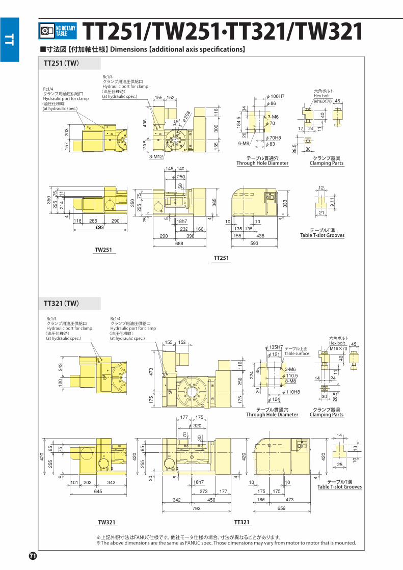
TT TT251/TW251.TT321/TW321
12
119
21
M16×70 45
4011
28.5 30
2417
φ86
-M63-70φ7
6-M8
φ100H7φ
φ70H8φφ83φ
34184.5
20
421411
22575
350
693
203
157
18h7
525
232 166398290
688
4365
350
φφ 250
145 140
10 10
4
155 438135135
593
50
155
300
116
139.5
1438
155 152
15°φ208
118 285 290693693693
333
22575
3-M12
TW251TT251
28.5
M16×7045
4011
30
2414110.5φφ
φ124φφ
45224
3-M63
8-M88
φ121φφφ135H77φ
20 φ110H8
14
25
1013
342202101
645
4
255
95 75
420
120
243
18h7
5
177273
792
450342
30 4
420
420
255
95
177 175
φφ 320
4
10 10
175 175
186 473
420
175
250
116
175
473
155 152
659
30
70
TW321 TT321
TT251(TW)
TT321(TW)
■寸法図【付加軸仕様】Dimensions【additional axis specifications】
テーブル貫通穴Through Hole Diameter
テーブルT溝Table T-slot Grooves
クランプ器具Clamping Parts
テーブルT溝Table T-slot Grooves
クランプ器具Clamping Parts
※上記外観寸法はFANUC仕様です。他社モータ仕様の場合、寸法が異なることがあります。※The above dimensions are the same as FANUC spec. Those dimensions may vary from motor to motor that is mounted.
六角ボルトHex bolt
六角ボルトHex bolt
Rc1/4クランプ用油圧供給口Hydraulic port for clamp(油圧仕様時) (at hydraulic spec.)
Rc1/4クランプ用油圧供給口Hydraulic port for clamp(油圧仕様時) (at hydraulic spec.)
Rc1/4クランプ用油圧供給口Hydraulic port for clamp(油圧仕様時) (at hydraulic spec.)
Rc1/4クランプ用油圧供給口Hydraulic port for clamp(油圧仕様時) (at hydraulic spec.)
テーブル上面Table surface
テーブル貫通穴Through Hole Diameter

TT
TT321(TW)
243
254
25595 75
420
155 57
175
380
757415342142273
18h7
420
4
420
25595
177 175φ320
70 30
566186 380175 175
1010342202
585
175200
57
3041
5
14
25 1013
φ110.5
φ124
45224
3-M6
8-M8
φ121
φ135H7
20 φ110H8
28.5
M16×70 45
4511
30
2417
φ208
139.5
382 15。
290255
545
421475
225350
50
3-M12
57131
203
155 57
140200
574
365
φ250140145
75225350
5
128232
18h7
360290
650
25 4333
1010
135135
155 387
542
φ86
3-6Mφ70
6-M8
φ100H7
φ70H8φ83
34184.5
20
28.5
M16×70 45
4011
30
2417
TT251
TT321TW321
TW251
テーブル貫通穴Through Hole Diameter
クランプ器具Clamping Parts
テーブルT溝Table T-slot Grooves
クランプ器具Clamping Parts
六角ボルトHex bolt
六角ボルトHex bolt
Rc1/4クランプ用油圧供給口Hydraulic port for clamp(油圧仕様時) (at hydraulic spec.)
Rc1/4 クランプ用油圧供給口Hydraulic port for clamp(油圧仕様時) (at hydraulic spec.)
Rc1/4クランプ用油圧供給口Hydraulic port for clamp(油圧仕様時) (at hydraulic spec.)
Rc1/4クランプ用油圧供給口Hydraulic port for clamp(油圧仕様時) (at hydraulic spec.)
テーブル上面7Table surface
テーブル上面Table surface
■寸法図【M信号仕様】Dimensions【M signal specifications】
*モータの仕様により外形寸法が変わる可能性があります。*The dimensions may vary from motor to motor that is mounted.
テーブル貫通穴Through Hole Diameter

高生産性2軸傾斜タイプHigh performance twin spindle tilting table
二連傾斜NC円テーブルTwo-Spindle NC Tilting Rotary Table
TW
TW2180
TW2180
●小型M/Cに取付可能Mountable to a compact M/C
●クラス最小総横幅999mmSmallest width in its class 999mm
●ロータリジョイント完全内蔵(オプション)で シンプルで確実な治具配管Built-in rotary joint (option) allows simple and secure jig piping
●高クランプトルクHigh clamping torque
*CE対応品 CE correspondence
※2軸共付加軸の仕様では、輸出貿易管理令の 別表第1の6項の(8)に該当する商品となりますので、 海外に輸出される場合は、経済産業省の許可が必要です。※In the specifcations of both two additional axes, since this product is applied to (8) of item 6 of a separate list No.1 of the Foreign Trade Control Ordinance, when exporting it overseas, the permission of the Ministry of Economy, Trade and Industry is required.
■仕様 Specifi cations型 式 Model TW2180
傾斜角度Tilting angle range -110。~+110。
テーブル直径Table dia(mm) φ180テーブル基準穴径 Centre hole dia(mm) φ65H7テーブル貫通穴径 Through hole dia(mm) φ40軸間距離Distance between axes(mm) 250テーブル面垂直時センタハイト Centre height at right angle on table face(mm) 200
クランプ方式 Clamping method回転軸Rotating axis 空圧 Pneumatic傾斜軸 Tilting axis 空油圧Air-Hydraulic
クランプトルク(空圧 0.5MPa時)Clamping torque(at pneumatic 0.5MPa)(N.m)
回転軸Rotating axis 400傾斜軸 Tilting axis 800
モータ軸換算イナーシャMotor axis reduced inertia(kg.m2)
回転軸Rotating axis 0.000383傾斜軸 Tilting axis 0.00035
サーボモータ(FANUC 仕様の場合)Servomotor (for FANUC specifi cation) αiF 2/5000-B
減速比 Total reduction ratio回転軸Rotating axis 1/90傾斜軸 Tilting axis 1/180
テーブル最高回転速度Max. rotation speed
FANUC 仕様FANUC specifi cation
回転軸(min-1/モータ3000min-1時) Rotating axis(min-1/at motor 3000min-1) 33.3傾斜軸(min-1/モータ3000min-1時)Tilting axis(min-1/at motor 3000min-1) 16.6
M信号仕様M signal specifi cation
回転軸(min-1/モータ3000min-1時) Rotating axis(min-1/at motor 3000min-1) 33.3傾斜軸(min-1/モータ3000min-1時)Tilting axis(min-1/at motor 3000min-1) 16.6
許容ワークイナーシャAllowable work inertia(kg.m2) 0.12
割出精度 Indexing accuracy(sec)回転軸Rotating axis 30傾斜軸 Tilting axis 60
再現精度 Repeatability(sec) 4製品質量 Mass of product(kg) 247
内蔵ロータリジョイント(オプション)Buit-in rotary joint (as an option)
RJ40TW2180回転1軸あたり 油圧/空圧2ポート+空圧専用3ポートRotation per axis Hydraulic/Pneumatic 2-port + Exclusive Pneumatic 3-port
許容積載質量Allowable mass of workpiece
水平時(kg)at horizontal 回転1軸あたりRotation per axis 30
傾斜時(kg)at tilted 回転1軸あたりRotation per axis 30
許容荷重(テーブルクランプ時)Allowable load(When clamped to table)
F(kN) 回転1軸あたりRotation per axis 5
F×L(N.m) 回転1軸あたりRotation per axis 800
F×L(N.m) 回転1軸あたりRotation per axis 400
許容切削トルクAllowable cutting torque
T(N.m) 回転1軸あたりRotation per axis 250
傾斜可搬モーメントMoment of tilting weight capacity
W×L(kgf . f m) 6
注)1.圧力確認用スイッチはNCテーブルのTC・DM・LRを除く全シリーズに内蔵しています。2.テーブルクランプ用ソレノイドバルブは内蔵しています。3.NCテーブルと工作機械との間のケーブル及びホースは付属しておりません。4.製品質量は弊社M信号仕様時の質量です。5.付加軸仕様の場合供給口の位置と型式が変更になる場合があります。別途ご相談下さい。
Note) 1. The switch for pressure checking is incorporated to all series except TC/DM/LR of NC tables. 2. Solenoid valve(s) is (are) incorporated. 3. Neither cable nor hose is fi tted between NC rotary table and machine tool. 4. Each product mass is determined by a Kitagawa M signal spec. 5. In case of additional axis spec., the position and type of supply port may be changed. Contact to Kitagawa on it separately.

機種Type
デザイン番号Design No.
オプション仕様Option spec.
テーブルサイズTable Size
R:ロータリジョイント Rotary Joint-:オプション無し Non- option
モ-タ種類(両軸同メーカ)、コントロ-ラ種類Motor type (Double axes; same maker)Controller typeV:Quinte仕様 Quinte specificationテーブル数
Number of tables2
【付加軸仕様】 【additional axis specifications】
【M信号仕様】【ロータリジョイント付】【M signal specifications】【with Rotary Joint】
TW
クランプ方式 Clamping methodB:傾斜軸 空油圧のみ Tilting axis Air-Hydraulic回転軸 空圧のみ Rotating axis Only Pneumatic
TW 180 F *2 RB
TW2180
TW2180
TW2180
■寸法図 Dimensions
オプション:ロータリジョイント供給口Option:Supply port for rotary joint
オプション:ロータリジョイント供給口Option:Supply port for rotary joint
※上記外観寸法はFANUC仕様です。他社モータ仕様の場合、寸法が異なることがあります。クランプ器具につては別途ご相談下さい。※Those dimensions may vary from motor to motor that is mounted. Confer with Kitagawa about clamping devices.
【M信号仕様】【M signal specifications】
*モータの仕様により外形寸法が変わる可能性があります。*The dimensions may vary from motor to motor that is mounted.
六角ボルト Hex bolt
Rc1/4クランプ用空圧供給口Pneumatic port for clamp
φ65H7
φ40.5φ52
160
2720 φ40H8
φ506-M6
3-M6
φ180125 250 125
φ180
305
999
φ120 φ120
100
100
5 18h711511587
65
260 125 125 203139 713 147
182
129
235 235
15°
14h7
540
200
2×3-M10φ135
202 288490
58
230
581057
400
77125
115
58375
30 28.5
35.5
1511
M16×55
21
クランプ器具Clamping Parts
テーブル貫通穴Thru-Hole Diameter
テーブル上面Table surface
六角ボルトHex bolt
Rc1/4クランプ用空圧供給口Pneumatic port for clamp
φ65H7
φ40.5φ52
16027
20 φ40H8φ506-M6
3-M6
φ180125 250 125
φ180
305
999
φ120 φ120
100
100
5 18h711511587
65
260 125 125 203139 713 147
182
129
235 235
15°
540
200
2×3-M10φ135
202 287489
239
48112202
166
30 28.5
35.5
1511
M16×55
21
クランプ器具Clamping Parts
テーブル貫通穴Thru-Hole Diameter
テーブル上面Table surface

水中でも信頼のパフォーマンスを ワイヤカット放電加工機専用タイプExclusive table for Wire Cutting Electric DischargeM/C Reliable Performance for use in water
ワイヤカット放電加工機専用NC円テーブルExclusive NC Rotary Table for Wire Cutting Electric Discharge Machinery
DM
DM100.DME100
▲防錆・防水対策は万全 水中でも安心して使用できます
Rust and waterproof for safe use in water.
※DME100はエンコーダタイプです。※DME100:with Encoder type
DM100
注)・クランプ機能搭載仕様はありません。・記載フルクローズド仕様はファナック社製アブソリュートの αiCZセンサA860-2164-T411です。・DM100の製品質量は弊社M信号仕様時の質量です。・DME100の製品質量はFANUC仕様時の質量です。・DME100は付加軸仕様のみです。M信号仕様には対応しておりません。・( )内はTS、TSRを使用した場合の値です。(Note)・There is no clamping method. The described fully-closed spec. Is with Fanuc absolute αiCZ sensor A860-2164-T411.・Product mass of DM100 is determined by M signal spec.・Product mass of DME100 is determined by a FANUC spec.・DME100 is available only for additional axis spec, not for M signal spec.・The value in ( ) is for using TS and TSR.
使用事例 Sample Application
●軽量・コンパクト Light weight・Compact●オールステンレス製ボデーと特殊シールにより防錆性・防水性は万全
Stainless Steel construction and special seals prevent rust and ensure waterproofing●φ40mmの貫通穴で長物ワークにも対応可能(DM100)
Large through hole for long work pieces(DM100)●高精度、高機能 High accuracy and function●立置き専用 Special purpose vertical use●日本特許(PAT.4354773)取得 Patented in Japan (No. 4354773)*CE対応品 CE correspondence
■仕様 Specifi cations■仕様S ifi ti型 式 Model DM100 DME100
テーブル直径 Table dia(mm) φ100 φ100テーブル基準穴径 Centre hole dia(mm) φ45H7 φ45H7テーブル貫通穴径 Through hole dia(mm) φ40 φ26/φ36センタハイト Centre height(mm) 65 65モータ軸換算イナーシャMotor axis reduced inertia(kg.m2) 0.000054 0.000054サーボモータ(FANUC仕様の場合) Servomotor (for FANUC specifi cation) βM0.5/4000-B/βiS0.5/6000-B βM0.5/4000-B/βiS0.5/6000-B減速比 Total reduction ratio 1/120 1/120
テーブル最高回転速度Max. rotation speed
FANUC仕様(min-1/モータ360min-1時)FANUC specifi cation(min-1/at motor 360min-1) 3.0 3.0
M信号仕様(min-1/モータ360min-1時)M signal specifi cation(min-1/at motor 360min-1) 3.0 -
テーブル最低回転速度 Min. rotation speed
FANUC仕様(min-1/モータ0.33min-1時)FANUC specifi cation(min-1/at motor 0.33min-1) 0.00275 0.00275
M信号仕様(min-1/モータ3.6min-1時)M signal specifi cation(min-1/at motor 3.6min-1) 0.03 -
許容ワークイナーシャAllowable work inertia(kg.m2) 0.025(0.05)注 Note 0.025(0.05)注 Note
割出精度 Indexing accuracy(sec) 30 16再現精度 Repeatability(sec) 5 4製品質量Mass of product(kg) 20 25手動テールストック(オプション)Manual tail stock(option) DM100RN01 DM100RN01
許容積載質量Allowable mass of workpiece
立置き(kg)Vertical installation 20 20
最大加工電流 Max. Machine current(A) 20以下 20 or less 20以下 20 or less
保護等級 Protection grade IP68(水没0.5m)但し、配管開放部除くIP68(submerged 0.5m)However, piping opening part is excluded.
IP68(水没0.5m)但し、配管開放部除くIP68(submerged 0.5m)However, piping opening part is excluded.

機種Type
デザイン番号Design No.
DM:標準タイプ StandardDME:エンコーダタイプ with Encoder type
モータ種類 Motor type
テーブルサイズTable Size100
【付加軸仕様】【Additional axis specifications.】
スクロールチャック SC-4D 寸法図※Dimension of scroll chuck SC-4D
手動テールストック DM100RN01寸法図※Dimension of manual tail stock DM100RN01
【付加軸仕様】【M信号仕様】【Additional axis specifications.】【M signal specifications】*モータの仕様により外形寸法が変わる可能性があります。*The dimensions may vary from motor to motor that is mounted.
テーブル上面 Table surface
Tapped Hole 10
Tapped Hole 10
Tabl
e di
amet
erTa
ble di
amet
er
DM
44.1(N・m) 12(kN) 100(min-1)
3.1(kg) 0.004(kg・m2) φ3~φ95 φ29~φ84
DM100
DME100
DM 100 R * **機種Type
デザイン番号Design No.
Quinte仕様Quinte specification
R:右勝手のみOnly Right-handed type
R:右勝手のみOnly Right-handed type
テーブルサイズTable Size100
DM 100 R V **
φ32
11.4
24.1
124
180
160
M8
10140
MAX 153110149
124
70
149 φ8
9665
2X8-M6
22.5゚5 45゚554444444
φ6161φφφφ61φ
φ84φ4444484
22.5゚ 45゚
φ61
3742741001741009010
φ84
8112
632
8565 1010
90 90
63
39.5
70
56 32.5
2.518.5129
150
130
φ100
φ36
φ26
15φ45H7
7872
120
φ40
15
φ45H7
216
58
300
112
32
40
50.5
2151001151009010
φ61φ6161φφ61φ6161 130
120
9918.5
2.5
63
315
10
φ84φ8448φ84φφ8φ8484
22.5゚22.5゚2222.2.5゚
45゚45゚5454545゚5゚
9090
1085
65
φ100
3-M8
φ93
φ95
11 24.5 33.5
18
4.5
30゚30゚
30゚30゚
φ9
3-M816
φ110
φ80H6
φ24
8
58
1442
■仕様 Specifications
外径把握 Outside gripping 内径把握 Inside gripping
許容最高回転速度Max. allowable speed
許容最大ハンドルトルクMax. allowable handle torque
最大静的把握力Max. static gripping force
質量Mass
慣性モーメントMoment of inertia
把握径 Gripping diameter(mm)
■寸法図 Dimensions
ネジ深10
テーブ
ル直
径
2X8-M6
センタ前後後進用ハンドルHandle for centre advance/return
センタクランプレバーCentre clamp lever
クランプ器具Clamping device 超硬チップ径
Carbide tip dia.
超硬センタCarbide centre
テーブ
ル直
径
ネジ深10
※上記外観寸法はFANUC仕様です。他社モータ仕様の場合、寸法が異なることがあります。※The above dimensions are the same as FANUC spec. Those dimensions may vary from motor to motor that is mounted.
※上記外観寸法はFANUC仕様です。他社モータ仕様の場合、寸法が異なることがあります。※The above dimensions are the same as FANUC spec. Those dimensions may vary from motor to motor that is mounted.
※本体・カバー・ピニオンに 防錆処理を施しています。※Rustproof casing, cover and pinion. ※防水・防錆仕様。水中でも長物ワークをしっかり支えます。
※Rust proof and waterproof. Long work pieces can be supported securely.
製品質量 Product mass 11kg
付加軸仕様 additional axis specifications M信号仕様 M signal specifications
テーブル貫通穴Through Hole Diameter
86

高速割出NC円テーブルQuick Indexing NC Rotary Table
RK
RK201
RK201LA
ローラギヤ・カム機構90°割出 0.31sec(モータトルク保持時)
●高速割出 Quick Indexing ●バックラッシゼロ Non Backlash ●省メンテナンス Low maintenance*CE対応品 CE correspondence
(ブレーキ付き)(Clamping mechanism is available)
Roller gear & cam mechanism90。Indexing time: 0.31sec.(Servo-on-holding)
■仕様 Specifi cations型 式 Model RK201
右勝手Right-handed type ○左勝手 Left-handed type ○テーブル直径 Table dia(mm) φ134テーブル基準穴径 Centre hole dia(mm) φ80テーブル貫通穴径 Through hole dia(mm) φ70センタハイト Centre height(mm) 150クランプ方式 Clamping method 空圧 Pneumaticクランプトルク(空圧 0.5MPa時)Clamping torque(at pneumatic 0.5MPa)(N.m) 注2)Note2) 340
瞬時最大保持トルク Max. instantaneous holding torque(N.m) 注1)Note1) (240)連続保持トルク Max. continuous holding torque(N.m) 注1)Note1) (108)モータ軸換算イナーシャMotor axis reduced inertia(kg.m2) 0.000507サーボモータ(FANUCの場合) Servomotor (for FANUC specifi cation) 注5)Note5) αis8/4000減速比 Total reduction ratio 付加軸 4th axis/M信号 M signal 1/20
テーブル最高回転速度Max. rotation speed
FANUC仕様(min-1/モータ2000min-1時)FANUC specifi cation(min-1/at motor 2000min-1) 100
M信号仕様(min-1/モータ2000min-1時)M signal specifi cation(min-1/at motor 2000min-1) 100
許容ワークイナーシャAllowable work inertia(kg.m2) 0.6割出精度 Indexing accuracy(sec) 20再現精度Repeatability(sec) 4製品質量 Mass of product(kg) 68手動テールストック(オプション)Manual tail stock (as an option) TS160RN**テールスピンドル(オプション)Tail spindle (as an option) TSRC150/TSRC150ロータリジョイント Rotary joint RJ70Y20Z03 油圧/空圧8ポートHydrauric/Pneumatic 8-port
許容積載質量Allowable mass of workpiece
横置き(kg)Horizontal installation 120
立置き(kg)Vertical installation 60
許容荷重Allowable load
F(kN) 11
F×L(N.m) 950
F×L(N.m) 注1)Note1)108(モータトルク保持時) (Servo-on-holding)
340(テーブルクランプ時) (Clamping mechanism)
許容切削トルクAllowable cutting torque
T(N.m) 573
注)1.瞬時最大保持トルク、連続保持トルク及び許容荷重FXL(N・m)は弊社M信号コントローラ仕様の値で付加軸の場合、モータ毎に値は異なります。 2.RK200でタクトタイムを短縮する場合には機械式ブレーキ未使用のモータトルク保持が有効です。その時クランプトルクは連続保持トルクになります。3.RK200の機械式ブレーキを使用しない場合、停止中はモータトルクで保持ください。 4.RK200の機械式ブレーキを使用しない場合、電源オフ時及びサーボアラーム時には停止位置を保持しません。起動時及び再起動時にテーブルが回転する場合があります。 5.ファナック株式会社製ロボドリル搭載時にはモータはαiF8/3000-Bになり、仕様が変わります。6.圧力確認スイッチはNCテーブルのTC・DM・LRを除く全シリーズに内蔵しています。
Note 1.The holding torque limits and allowable load (N.m) above are with Kitagawa’ s control device Quinte. In case of with additional axis spec. the limits very per motor used. 2.To shorten the cycle time using RK200LA, not using the clamping mechanism is recommended. For this case, clamping torque changes to the number at the continuous holding torque. 3.There isno mechanical brake for RK200L. Please hold the position by the motor torque when the rotating axis is stopping. 4.RK200L cannot hold the position when the power is turned off or the servo alarm is occurred. There is a possibility that the rotating axis revolve when the power is turned on or restart. 5.When installing RK200 on Fanuc Robodrill, motor isαiF8/3000-B and specifi cations are diff erent. 6.All rotary tables (except TC, DM and LR) have pressure switches.

159.5
75.5
φ70+0.5 0
φ80+0.06
+0.02
12
φ70
テーブル上面Table surface
21
172 235
150
110
260
5
φ100
110363473
18h710250
22.5°
45°
8-M8250223
260
1010 161621
12160◇
※モータケース部寸法◇テーブル高さ※the length of the motor case◇the height of the table
φ134g6
Rc1/4クランプ用空圧供給口(裏面にあります)Pneumatic port for clamp(On the back side)
153※57
1611
16
30
28.5
(14)
六角ボルトHex boltM16×50
テーブル貫通穴Through Hole Diameter
クランプ器具Clamping Parts
159.5
75.5
φ70+0.5 0
φ80+0.06
+0.02
12
260
235
5 18h7
150
110
8-M8
285275
10
172
10
φ134g6
22°5
45°
φ100
160◇ 12
10
φ70
テーブル上面Table surface
16 211621
155※57250188
110328438
1611
16
30
28.5
(14)
六角ボルトHex boltM16×50
※モータケース部寸法◇テーブル高さ※the length of the motor case◇the height of the table
Rc1/4クランプ用空圧供給口(裏面にあります)Pneumatic port for clamp(On the back side)
テーブル貫通穴Through Hole Diameter
クランプ器具Clamping Parts
RK
デザイン番号Design No.
デザイン番号Design No.
クランプ方式 Clamping method空圧のみ Only Pneumatic クランプ方式 Clamping method
空圧のみ Only Pneumatic
モータ種類 Motor type
左右勝手 Right/Left handR:右勝手 Right-handed typeL:左勝手 Left-handed type
R:右勝手 Right-handed typeL:左勝手 Left-handed type
機種Type
テーブルサイズTable Size201
機種Type
テーブルサイズTable Size201 Quinte仕様
Quinte specification
RK 201 L A * ** RK 201 L A V **M信号仕様 M signal specifications付加軸仕様 additional axis specifications
RK201
■寸法図 Dimensions
【付加軸仕様】【additional axis specifications】
RK201 【M信号仕様】【M signal specifications】

省メンテナンスNC傾斜円テーブルLow maintenance NC tilting Rotary Table
※2軸共付加軸の仕様では、輸出貿易管理令の別表第1の6項の(8)に該当する商品となりますので、海外に輸出される場合は、経済産業省の許可が必要です。※In specification with the foreign trade control ordinance, permission of the ministry of economy, trade and industry is required when exporting twin axis products overseas.
RKT
RKT180
RKT R* **180 RKT V R180 **
注意)RKT180は空圧仕様のみNote) Only pneumatic spec.
available for RKT180.
RKT180
自動車加工ラインに最適 ローラギヤカム機構Optimum solution for the automotive industryRoller Gear and Cam mechanism●省スペース機に最適 Optimum solution for No.30 compact machining centre●完全内蔵ロータリジョイント対応(油圧/空圧5ポート・空圧1ポート)Complete built-in Rotary Joint available ( Hyd. 5 ports・Pneumatic 1 port)●省メンテナンスの実現 Low maintenance achieved.*CE対応品 CE correspondence
機種Type
デザイン番号 Design No. デザイン番号 Design No.オプション仕様 Option spec.R:ロータリジョイント Rotary JointC:外部シリンダ external cylinder-:オプション無し Non- option
オプション仕様 Option spec.R:ロータリジョイント Rotary JointC:外部シリンダ external cylinder-:オプション無し Non- option
モータ種類 Motor type
テーブルサイズTable Size180
機種Type
テーブルサイズTable Size180
Quinte仕様 Quinte specification
付加軸仕様 additional axis specifications M信号仕様 M signal specifications
■仕様 Specifi cations型 式 Model RKT180
傾斜角度 Tilting angle range -35。~+110。
テーブル直径 Table dia(mm) φ95テーブル基準穴径Centre hole dia(mm) φ50H7テーブル貫通穴径Through hole dia(mm) φ50垂直時センタハイト Centre height(mm) 170クランプ方式 Clamping method 空圧 Pneumaticクランプトルク(空圧 0.5MPa時)Clamping torque(at pneumatic 0.5MPa)(N.m)
回転軸 Rotating axis 350傾斜軸 Tilting axis 550
モータ軸換算イナーシャMotor axis reduced inertia(kg.m2)
回転軸 Rotating axis 0.000239傾斜軸 Tilting axis 0.000425
サーボモータ(FANUC 仕様の場合) Servomotor (for FANUC specifi cation) αisF2/5000-B
減速比 Total reduction ratio 回転軸 Rotating axis 1/72傾斜軸 Tilting axis 1/120
テーブル最高回転速度Max. rotation speed
FANUC 仕様FANUC specifi cation
回転軸(min-1/モータ3000min-1時) Rotating axis(min-1/at motor 3000min-1) 41.6傾斜軸(min-1/モータ3000min-1時)Tilting axis(min-1/at motor 3000min-1) 25
M信号仕様M signal specifi cation
回転軸(min-1/モータ3000min-1時) Rotating axis(min-1/at motor 3000min-1) 41.6傾斜軸(min-1/モータ3000min-1時)Tilting axis(min-1/at motor 3000min-1) 25
許容ワークイナーシャAllowable work inertia(kg.m2) 0.25
割出精度 Indexing accuracy(sec)回転軸 Rotating axis 20傾斜軸 Tilting axis 20
再現精度 Repeatability(sec) 回転軸 Rotating axis 8傾斜軸 Tilting axis 4
製品質量 Mass of product(kg) 193
内蔵ロータリジョイント(オプション・P117参照)Built-in rotary joint (Option.P117 reference)
RJ50RKT180油圧/空圧5ポート+空圧専用1ポート
Hydraulic/Pneumatic 5-port + Exclusive Pneumatic 1-porty
許容積載質量Allowable mass of workpiece
水平時(kg)at horizontal 60
傾斜時(kg)at tilted 40
許容荷重(テーブルクランプ時)Allowable load(When clamped to table)
F(kN) 7.8
F×L(N.m) 550
F×L(N.m) 350
許容切削トルクAllowable cutting torque
T(N.m) 262
傾斜可搬モーメントMoment of tilting weight capacity
W×L(kgf . f m) 36
注)1. 圧力確認用スイッチはNCテーブルのTC・DM・LRを除く全シリーズに内蔵しています。2. テーブルクランプ用ソレノイドバルブは内蔵しています。3. NCテーブルと工作機械との間のケーブル及びホースは付属しておりません。4. 製品質量は弊社M信号仕様時の質量です。
Note) 1. The switch for pressure checking is incorporated to all series except TC/DM/LR of NC tables. 2. The solenoid valve for the table clamp is incorporated.3. Neither cable nor hose is fi tted between NC rotary table and machine tool. 4. Each product mass is determined by a Kitagawa M signal spec.

RKT180
RKT180
■寸法図 Dimensions 【付加軸仕様】【additional axis specifications】
■寸法図 Dimensions
※上記外観寸法はFANUC仕様です。他社モータ仕様の場合、寸法が異なることがあります。クランプ器具につては別途ご相談下さい。※Those dimensions may vary from motor to motor that is mounted. Confer with Kitagawa about clamping devices.
RKT
【M信号仕様】【M signal specifications】
*モータの仕様により外形寸法が変わる可能性があります。*The dimensions may vary from motor to motor that is mounted.
テーブル上面
Rc1/4 クランプ用空圧供給口Pneumatic port for clampRc1/4 クランプ用空圧供給口Pneumatic port for clamp
131135
8-M6
8-M6
φφφ84
130
130
210
1987
135 164
123
633 545
503 130 130 415
279 224 230115 115
300
14
129φ955
275
275
45
17065
21
φ95h7φ84φ
φ50H7φ
φ50
φ 151
156.5
15
60.5
3
28.5
4020
35
2228
8.6
Table surface
テーブル貫通穴Through Hole Diameter
クランプ器具Clamping Parts
15
テーブル上面
Rc1/4 クランプ用空圧供給口Pneumatic port for clampRc1/4 クランプ用空圧供給口Pneumaticport for clamp
135
8-M6
8-M6
φφφ84
130
130
230
57
210
1787
135 164
123
619 525
503 116 130 395
279 224 230115 115
280
14
129φ955
275
275
45
17065
21
φ95h7φφ84φ
φ50H7φ
φ50
φφ 15
156.5
60.5
3 Table surface
クランプ器具Clamping Parts
テーブル貫通穴Through Hole Diameter
六角ボルトHex boltM12×50
28.5
4020
35
2228
8.6
六角ボルトHex boltM12×50
St.13
St.13

高速NC円テーブルHigh Speed NC Rotary Table
※Rは右勝手仕様、Lは左勝手仕様です。※The notation "R" means right-handed type ; "L" means left-handed type.
注)本モデルはM信号仕様のみです。付加軸には対応しておりません。Note) This model is for only M signal spec., and it is not provided for additional axis specifications.
RS
RS100小型ワークを最速加工 高速回転タイプHigh Speed Table for MachiningSmall Work Pieces
RS100 RS100
60
30
6
200
82
40
F(kN)
F×L(N・m)
F×L(N・m)
T(N・m)
RS100R(L)
RS100
1337
17113
3-M83-M8
18565250
70110180
30。30。
φ82.55
φ93
14h7
5
131 119
2121
6 6
138
φ105
140
22
28.5
218.6
13
φ32
φ50H7
40
139 M12×45
右勝手 Right-handed type
左勝手 Left-handed type
テーブル直径 Table dia(mm)
テーブル基準穴径 Centre hole dia(mm)
テーブル貫通穴径 Through hole dia(mm)
センタハイト Centre height(mm)
クランプ方式 Clamping method
クランプトルク Clamping torque(N・m)(空圧 0.5MPa 時)(at pneumatic 0.5MPa)
減速比 Total reduction ratio
テーブル最高回転速度 Max. rotation speed(min-1 /モータ 3000min-1 時)(min-1/at motor 3000min-1)
許容ワークイナーシャ Allowable work inertia(kg・m2)
割出精度 Indexing accuracy(sec)
再現精度 Repeatability(sec)
製品質量 Mass of product(kg)
手動テールストック Manual tail stock(オプション・P111、113 参照)(as an option・P111、113 reference)
型 式 Model
■北川専用コントローラ仕様 Kitagawa own controller
○○φ105φ50H7φ32110
空圧 Pneumatic
80
1/36
83.3
0.054501023
RS100RN
型 式 Model
許容積載質量Allowable mass ofworkpiece
横置き(kg)Horizontalinstallation
許容切削トルクAllowable cutting torque
許容荷重(テーブルクランプ時)Allowable load(When clamped to table)
立置き(kg)Verticalinstallation
■寸法図 Dimensions
六角ボルトHex bolt
テーブル上面Table surface
Rc1/8クランプ用空圧供給口(裏面より)Pneumatic port for clamp(on surface)
●専用コントローラ付 With exclusive controller●簡易モデル Simple design●軽量・コンパクト Light weight/compact●最高回転数83.3min-1 Max. speed 83.3min-1
*CE対応品 CE correspondence
【M信号仕様】【M signal specifications】
*モータの仕様により外形寸法が変わる可能性があります。*The dimensions may vary from motor to motor that is mounted.
テーブル貫通穴Through hole diameter
クランプ器具Clamping Parts

【付加軸仕様】【additional axis specifications】
※最高回転速度は、モータ回転数が3000min-1 時を示しています。※Max. rotation speed is subject to 3000 min-1 of a motor.
六角ボルトHex bolt
六角ボルトHex bolt
NC円テーブルNC Rotary Table
TC100
TC
5Cコレットマニュアル仕様5C Collet Manual specification
TC100
TCM100
30 601/364.8φ30.3110TC100
TC100 0.054 83.3 5 2445
TC100
2073117
6 6175 38.5213.5
21
φ30.3
10。
21
100
41120
514h767 61
18271
3668
110214
φ68
16144
116
262515
2 3/16-10 UNS
Std 5C
A
22
28.5
8.6
21
M12×45
φ68
16145
2 3/16-10 UNS
Std 5C
φ30.3
21 21
175 38.5213.5
66
2073117
10。
428
182711756167
14h7
110
6836
214
5
A
22
28.5
8.6
21
M12×45
■寸法図 Dimensions
最高回転速度(min-1)Max. rotation speed
立置きVertical
横置きHorizontal
許容積載質量(kg)Allowable mass of workpiece減速比
Total reduction ratioコレット引張力(kN)Collet Thrust force
スピンドル中心穴径(mm)Spindle hole
センタハイト(mm)Centre height
スピンドル形状Spindle
型 式Model
製品質量(kg)Mass of product
再現精度(sec)Repeatability
割出精度(sec)Indexing accuracy
許容ワークイナーシャ(kg・m2)Allowable work inertia
型 式Model
■TC100仕様 Specifications
5Cコレットチャック対応5C Collet chuck adaptation
【M信号仕様】【M signal specifications】
*モータの仕様により外形寸法が変わる可能性があります。*The dimensions may vary from motor to motor that is mounted.
矢視:AView:A
矢視:AView:A
クランプ器具Clamping Parts
クランプ器具Clamping Parts

Quinte
【主な特長】
■カラー液晶採用により多彩な表現が可能高精細なカラー液晶を採用することで、多彩な表現を可能としました。例えば、現在座標に加え、実行中のプログラムやモータ情報などを一つの画面で表示しました。
■簡単プログラム入力対話式の画面でのプログラム編集で、入力ミスを防止します。
■割り出し時間の短縮EtherCAT採用で高速通信を可能に。割出し時間の短縮を実現しました。
■MMC対応でプログラム管理が容易にプログラムやパラメータの送受信が市販のMMC(マルチメディアカード)から行え、管理が容易になりました。
円テーブル用コントローラseries

Quinte
■操作感が異なる2種類のパネルソフトな操作、素早い操作にも追従するタッチパネル型。しっかりしたクリック感で押した安心感が得られるクリックエンボスパネル型(CS)。
■ユーザの使用環境や用途に合わせたモータ選択モータのバリエーションも多く、加工条件にあったモータを選択することができます。
■拡張I/Oを使用することでさらに多様な使い方オプションにて拡張I/Oを使用することで、マシニングからのプログラム選択・加工原点出力・M信号出力などが行え、さらに多彩な使い方が可能となります。
■手動パルス発生器対応 全機種で手動パルス発生器がオプション対応可能。
■リモートコントロール機能対応機械とのシリアル通信によるリモートコントロール機能がオプション対応可能。動作確認済みCNCメーカー、および機械メーカーFANUC㈱、三菱電機㈱、オークマ㈱、ヤマザキマザック㈱、ブラザー工業㈱
■CEおよびKC準拠欧州規格であるEMC指令に準拠した製品となっております。さらに韓国KCマークの取得も行っています。
■バッテリレスアブソリュートエンコーダ対応【カスタム対応】バッテリレスアブソリュートエンコーダ採用によりバッテリ不要※1、またQuinteと円テーブルのケーブルを外したあとの再接続後でも座標ずれはありません。
※1 Quinteのバッテリはシステムに使用します。ただし消費電力が微量のため電池交換は不要です。
【使用可能モータ一覧】1軸仕様
QTC100/QTC100CS
○
○
○
○
○
-
-
-
Quinte
型 式
200W
400W
750W
1000W
1200W
1800W
2000W
3500W
2軸仕様
QTC200/QTC200CS
○
○
○
○
○
-
-
-
高トルク仕様
QTC300
-
-
-
-
-
○
○
○
適合モータ

Quinte
290
320
190
Max 20mm
400
320
190
Max 20mm
400
400
270
Max 20mm
■ QTC100 / QTC100CS
※概観図はQTC100です。※QTC100、QTC100CSの 概観寸法は同一です。
※概観図はQTC200です。※QTC200、QTC200CSの 概観寸法は同一です。
■ QTC200 / QTC200CS
■ QTC300
概観・寸法
series

Quinte
Quinte シリーズ 仕様
Quinte項目
1軸仕様 2軸仕様 高トルク仕様
QTC100 / QTC100CS QTC200 / QTC200CS QTC300
制御軸数 1軸 2軸 1軸
サーボモータ仕様 アブソリュート検出器付きACサーボモータ
設定単位 0.001°/0.0001°(パラメータにより切替え):0.001°
制御単位 0.0001°
最大設定角度 9999回転+360°及び±999.999°
等分割出数 0~9999分割(扇形分割可)
プログラム容量 最大プログラム数999、1プログラムにつき最大2000ブロック(プログラム容量により変化します)
指令方式 アブソリュート/インクリメンタル方式(G90/G91にて選択可能)
原点復帰 機械原点復帰及び加工原点復帰(オプションにて外部入力による指令可能)
手動送り 早送り・低速送り・ステップ送り
非常停止非常停止ボタン、又は外部インタロック入力による強制サーボ停止+全停止
非常停止ボタン押下時には外部出力(2つ)あり
一時停止 キー入力、外部SP入力による円テーブル一時停止
送り速度オーバライド 1 ~ 200 % 迄設定可能(刻み量は1~100%迄変更可能)
準備機能(Gコード)ドウェル、リード切削、バッファ機能(位置偏差チェック機能有)、クランプ有無、連動スタート、連続スタート、機械原点復帰、加工原点復帰、アブソリュート/インクリメンタル、加工原点座標系設定
サブプログラム機能 M98指令にて使用可能。
一方向位置決め 回転方向が異なっても一定方向からの位置決めが可能です。
ソフトウェアリミット 機械原点からのソフトウェアリミットが設定でき、ジグやワークの取付けにより機械との干渉を防ぎます
オーバトラベル機能 円テーブルの回転動作範囲をハードリミット入力で制御できます。
バックラッシ補正 円テーブルのバックラッシ補正が設定できます。
リモートコントロール機能 機械のプログラムデータを転送し、転送プログラムを起動することで円テーブルが動作します。
オートノッチフィルタ機能 ノッチフィルタの検出、設定を4段まで自動で行ない機械振動を抑制します。
アラーム機能 エラー検出時、自動的にアラーム番号、アラームメッセージを表示します。また100件まで履歴を残せます。
角度表示 機械座標、加工座標、残移動量、総合座標
コメント表示機能 プログラムデータのファイル、プログラムにコメントが付加でき、画面表示できます。
入力電源 単相/三相 AC200-230V±10% 50/60Hz(標準三相)
アンプ容量(A) 30 30×2 100
寸法(mm) 320(W)×190(H)×290(D) 320(W)×190(H)×400(D) 400(W)×270(H)×400(D)
質量(kg)本体のみ 10.0 13.0 19.0
使用環境
使用温度:0 ~ 45℃ 保管温度(輸送温度):-10℃ ~ 60℃使用湿度:20~80% RH以下(結露や凍結が発生しないこと)耐振動:0.5G以下 耐衝撃:1G以下雰囲気:汚染度3まで(但し、水、油が直接かからないこと)
表示部 TFTカラー液晶 480×272ドット
標準外部入出力信号(入力)スタート、ストップ、外部非常停止1、外部非常停止2、外部インタロック(出力)ブロック完了、非常停止出力信号1、非常停止出力信号2、アラーム出力信号(B接点)
選択式入出力信号(オプション)
(入力:6点) 外部加工原点復帰要求1、外部加工原点復帰要求2、外部機械原点復帰要求1、外部機械原点復帰要求2、外部プログラム選択1~5、外部プログラムセット、外部自動運転仕様、外部リセット、オーバートラベル、M完了信号1~6
(出力:6点) 加工原点復帰完了1、加工原点復帰完了2、機械原点復帰完了1、機械原点復帰完了2、加工原点位置1、加工原点位置2、機械原点位置1、機械原点位置2、アラーム出力信号(A接点)、AUTOモード選択中、外部プログラム選択完了、外部プログラム番号出力1~6、M信号出力1~6
※上記信号からパラメータ割付により使用できます。
MMCスロット メモリーカードにてプログラム、パラメータ等の入出力ができます。

Quinte
series
■手動パルス発生器(ホルダーつき)テーブルを0.1°、0.01°、0.001°単位で手動操作ができ、ジグなどの調整が容易に行えます。2軸仕様は軸切替えにより1つの手動パルス発生器で対応できます。
■手動パルス発生器内部ケーブル【HC1-IC-Q】手動パルス発生器の使用には、Quinte盤内用の中継ケーブルが必要です。HC1-IC-Qには、ダストキャップ、取付け用ネジ(4本)が付属されます。
■拡張I/Oケーブル(5m)標準配線からの変更で、外部プログラム選択やM信号出力などの拡張機能を使用することが可能になります。※使用可能な信号についてはQuinteシリーズ仕様の「選択式入出力信号」をご確認ください。※ケーブル長は変更できます。
■リモートコントロール機能用ケーブル(5m)○RS232Cケーブル【RSCB0909/RSCB0925】
リモートコントロール機能を使用するためには、RS232Cケーブル(機械間用)が必要です。RSCB0925は9-25ピン、RSCB0909は9-9ピンです。機械側のRS232Cポートの形状に併せてご選択ください。※ケーブル長は2m/3m/5mから選択できます。
○リモート中継ケーブル【RC2-IC-Q】リモートコントロール機能を使用するためには、Quinte盤内用の中継ケーブルが必要です。RC2-IC-Qには、ダストキャップ、取付け用ネジ(4本)が付属されます。
Quinte シリーズ オプション
【RSCB0909】 【RSCB0925】

Quinte
Quinte 前面パネル機能説明
①非常停止ボタン 動作中のテーブルを非常停止します。
②電源スイッチ コントローラの電源ON/OFFを行います。
③カラー液晶ディスプレイ ステータス・座標など様々な表示を行います。
④APPボックス バッテリとMMCのスロットが格納されています。
⑤自動運転キーパネルからプログラムのスタートおよびストップを
行います。
⑥RESETキー プログラムやアラームのリセットを行います。
⑦カーソル移動キー/手動軸送りキーカーソルの移動や、マニュアルモード時はジョグ運
転を行うキーです。
⑧確定キー/手動早送りキー選択した事柄を確定するキーです。またマニュアル
モード時は手動軸送りキーからスライドすることで
手動早送りを行います。
⑨確定キー 選択した事柄を確定するキーです。
⑩ページ切替えキー ページを切替えるキーです。
⑪メニューキー メニューウィンドウを表示します。
⑫戻るキー 1つ前の画面に戻ります。
⑬送りオーバライド変更モードキー オーバライドを変更する場合に使用します。
⑭数字キー 数字を入力するキーです。
⑮削除キー 入力した数値を1文字削除します。
①非常停止ボタン
②電源スイッチ
④APPボックス
③カラー液晶ディスプレイ
⑩ページ切替えキー
⑪メニューキー
⑤自動運転キー
⑥RESETキー
⑦カーソル移動キー 手動軸送りキー
⑧確定キー 手動早送りキー
⑬送りオーバライド 変更モードキー
⑨確定キー
⑫戻るキー
⑭数字キー⑮削除キー
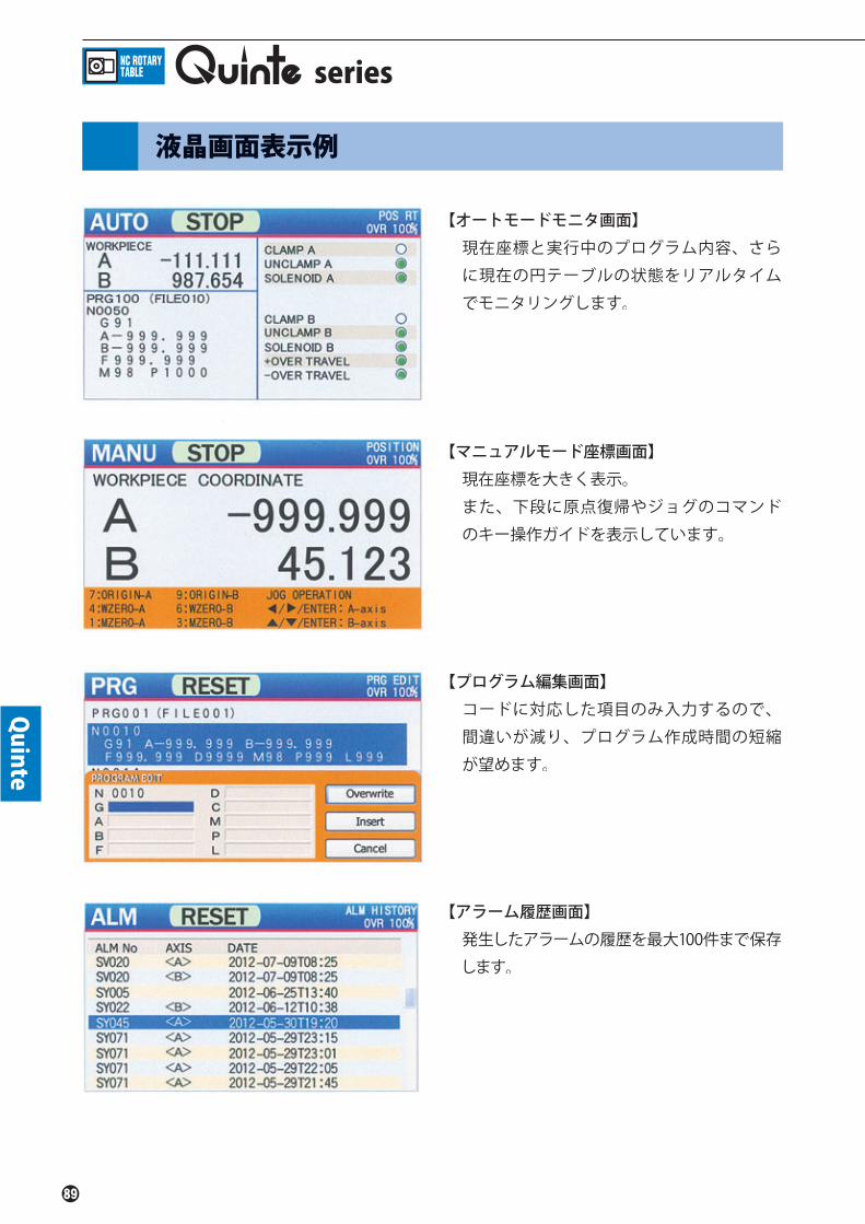
Quinte
series
【オートモードモニタ画面】現在座標と実行中のプログラム内容、さら
に現在の円テーブルの状態をリアルタイム
でモニタリングします。
【マニュアルモード座標画面】現在座標を大きく表示。
また、下段に原点復帰やジョグのコマンド
のキー操作ガイドを表示しています。
【プログラム編集画面】コードに対応した項目のみ入力するので、
間違いが減り、プログラム作成時間の短縮
が望めます。
【アラーム履歴画面】発生したアラームの履歴を最大100件まで保存
します。
液晶画面表示例

Quinte
45°
90°
90°90°
90°90°
30°
90°
120°
45°
75°
N0000 A 45.000 F0
N0001 A90.000 M30
N0000 A360.000 F0 M30D4
N0000 A 30.000 F0
A 75.000A 45.000A120.000A 90.000
N0004
N0001
N0003N0002
M30F5.000
90°
30°
30°
40°
40°
110°
270° 90°
PRG001N0000
N0001
PRG002N0000N0001
PRG003N0000N0001
A90.000
G90
G91A40.000
G91A40.000
F0
A270.000
A30.000M99
A30.000M99
M98
M98
P002
P003
L1
L1
45°
45°180°
45°
225°
N0000 G90
N0001 A225.000
N0002
F0A45.000
G91 A45.000
早送り割出し角度
プログラムエンド
分割対象角度 分割数
送り速度
サブプロ指令
サブプロ遷移先
サブプロ繰返し回数
サブプロエンド
アブソ指令
インクリ指令
割出し位置
割出し角度
割出し位置
早送りで45°回転90°回転しプログラム完了(N0000 へ戻る)
早送りにて360°を4分割(90°毎)で回転し、4回動作後プログラム完了(N0000 へ戻る)
早送りで30°回転90°回転120°回転45°回転送り速度 5.00min-1で 75°回転しプログラム完了(N0000 へ戻る)
プログラム番号1早送りで 90°回転しPRG002へジャンプ
アブソリュートにて270°の位置に早送りで回転しPRG003へジャンプ
プログラム番号2インクリメンタル指令にて30°回転40°回転し、サブプログラム指令元へ戻る
プログラム番号3インクリメンタル指令にて30°回転40°回転し、サブプログラム指令元へ戻る
アブソリュートにて45°の位置に早送りで回転225°の位置に回転インクリメンタルにて45°回転
■ 角度割出
■ 等分割
■ 不等分割
■ サブプログラム
■ アブソリュート / インクリメンタル
プログラム例

Quinte
アースについてはD種(第3種)接続して下さい。また、漏電ブレーカーを使用される際には、モータ高周波による誤作動を防止する為に感度電流30mA以上、動作時間が0.1秒以上、または高周波対策を行ったものをご使用下さい。
QTC100/QTC100CSQTC200/QTC200CS
QTC300
10A15A20A
■ 電源供給 コントローラの電源の供給が必要です。お客様にて専用の遮断器をご準備下さい。遮断器の容量は次の通りです。
型 式 遮断器容量
電源ケーブル(CB4Qケーブル)
■ 外部連動用接続
エアコンビネーションAC25C-02CG-A(SMC)
ドレンキャッチAMG150C-02BC(SMC)
■ エア供給エア源 カプラ カプラ
円テーブル取付側
エアホース
円テーブルのクランプにはエアの供給が必要です。お客様にて下記のものをご準備ください。
※エア機器は、オートドレン付きとする。
・ エアコンビネーション・ ドレン排出装置・ エアホース 又は エアチューブ(難燃性)・ 接続用カプラ
■ エア回路図
要注意要注意
許容最大空圧力 0.7MPa但し、MX160、GTシリーズ、TMXシリーズ、TRシリーズ(TRX、TLX)、TBXシリーズ、TUシリーズ(TUX)、TT182、TT200は0.6MPaTT251、TT321は0.45Mpa)
エア4点ユニット(オートドレン付)AC25C-02CG-A(SMC)
ドレンキャッチ(オートドレン付)AMG150C-02BC(SMC)
円テーブル用ケーブル(CB1Qケーブル)
電源ケーブル(CB4Qケーブル)
連動ケーブル(CB3Qケーブル)
エア源エアホース
部分はお客様にてご準備下さい。
部分は弊社でも取扱っております。
series
接続内容
円テーブルが外部機械と連動するためには、外部機械からのM信号による制御が必要です。外部機械側には、M信号出力、M信号完了入力等の接続箇所(端子台)を準備していただく必要がありますので、機械メーカー様に配線されていることをご確認ください。また配線されていない場合には、機械メーカー様に施工していただくようご依頼ください。

Quinte
0V
0V
0V
+24V
+24V
+24V
+24V
01
02
03
04
05
06
07
08
09
10
11
12
13
14
15
01
02
03
04
05
06
07
08
09
10
11
12
13
14
15
相互接続図
出力信号の電源は、相手機械側から供給ください。出力に接続している外部負荷には、サージ対策を行ってください。
使用電圧 DC24V
入力信号は無電圧接点を使用してください。
※1 オプション拡張I/Oケーブルにて使用可能になります。
ブロック完了
ブロック完了コモン
アラームB接点出力
汎用出力1(※1)
汎用出力2(※1)
汎用出力3(※1)
汎用出力4(※1)
汎用出力5(※1)
汎用出力6(※1)
出力コモン
出力コモン(※1)
非常停止出力1
非常停止出力2コモン
ストップ
入力コモン(※1)
非常停止入力1
非常停止入力1コモン
非常停止入力2
非常停止入力2コモン
入力コモン
汎用入力6(※1)
汎用入力5(※1)
汎用入力4(※1)
汎用入力3(※1)
汎用入力2(※1)
汎用入力1(※1)
外部インタロック
スタート
非常停止出力2
非常停止出力1コモン
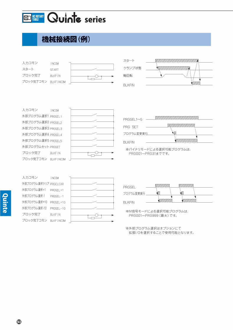
Quinte
series
入力コモン
スタート
ブロック完了
ブロック完了コモン
入力コモン
入力コモン
外部プログラム選択1
外部プログラム選択2
外部プログラム選択3
外部プログラム選択4
外部プログラム選択5
外部プログラムセット
ブロック完了
ブロック完了コモン
ブロック完了コモン
外部プログラム選択クリア
外部プログラム選択+1
外部プログラム選択-1
外部プログラム選択+10
外部プログラム選択-10
ブロック完了
スタート
クランプ状態
軸回転
PRGSEL1~5
PRGSEL
プログラム変更実行
プログラム変更実行
PRG SET
BLKFIN
BLKFIN
BLKFIN
※バイナリモードによる選択可能プログラムは、 PRG001~PRG31までです。
※M信号モードによる選択可能プログラムは、 PRG001~PRG999(最大)です。
※外部プログラム選択はオプションにて 拡張I/Oを選択することで使用可能となります。

Quinte
■ 制御フローチャート
■ NC円テーブル制御方式
北川NC円テーブル制御は、原則的にクランプ時サーボOFFを推奨します。
付加軸Z軸
Y軸X軸
M信号
セミ/フルクローズドループ
付加軸方式 M信号方式
【特 徴】◆機械側NC軸ではなく、別置きコントローラで制御される軸です。◆付加軸対応ができない機械でも、M信号があれば搭載可能です。◆他の機械への載せ換えが容易です。
【特 徴】◆機械側NC軸として制御されます。◆機械軸であるX,Y,Z軸との補間切削が可能です。◆プログラムを機械側で一括管理が行えます。
DATA 制御詳細
Yes
Yes
Yes
Yes
位置決め開始
サーボON指令
アンクランプ指令
クランプ確認PS OFF?
アンクランプ確認PS ON?
インポジション確認OK?
250msec 遅延 注1 注1
円テーブル移動指令
250msec遅延
クランプ指令
アンクランプ確認PS OFF?
クランプ確認PS ON?
位置決め完了
250msec 遅延
サーボOFF
注1
No
No
No
No
No
Yes
注1)遅延時間については、北川推奨値です。パラメーター、仕様等により異なる場合があります。

片手で持ちやすいスタイルを実現円テーブルの動きを間近で見ながら操作が可能!
円テーブル用コントローラQuinteシリーズ対応
手動操作ペンダント
■MOP オプション
■寸法図
【主な特長】■円テーブルの動きを間近で見ながら操作が可能 片手で持ちやすいハンディタイプにより稼動範囲を拡大。 ケーブルの軽量化も図り、見たい場所に接近しやすく、操作が可能です。■有機ELディスプレイ採用 高コントラスト比で文字自体が発光し、暗い場所や機械内でも高い視認性を実現します。■滑らかなタッチ操作キーシステム 操作部に可動部がない滑らかな操作性と、機能別のキーレイアウトを実現しました。■耐水、防塵性の確保 保護等級IP54対応により耐水・防塵性を確保しました。■強力マグネットで簡単設置 裏面の強力マグネットにより、垂直な面でも仮置き可能、不意な脱落の心配もありません。■Quinteに追加取り付け可能 Quinte内部に専用ケーブルの取り付けと、QuinteのF/Wバージョンアップを行うことで MOPに対応できます。
●MOP内部ケーブル 【MOP-IC】 MOPを使用する際には、Quinte盤内用の中継ケーブルが必要です。 MOP-ICには、取付け用ネジ(4本)が付属されます。
●MOPダミーコネクタ 【MOP-DCN】 MOPの未接続時に非常停止回路を短絡するコネクタです。 MOP を複数のQuinteに共用使用する場合、MOPを接続しない Quinteには必要となります。 MOPダミーコネクタを使用しないと非常停止の解除は行えません。
51
83
121
220
■仕様●表示仕様
表示デバイス
表示方式
表示分解能
●操作仕様
方式
イネーブルスイッチ
ブザー
●環境仕様
使用温度範囲
使用湿度範囲
●構造仕様
ケーブル長
保護構造
質量(約)
有機ELディスプレイ
キャラクタ表示
20文字×4行
静電容量スイッチ 相互容量方式
2ポジション
周波数:3520Hz 音圧:0~75dB(10段階)
0~45℃
20~80%RH以下(結露しないこと)
3m
IP54(ケーブルコネクタ部除く)
450g(ケーブルを除く)
Quinte

手動操作ペンダント機能説明
①非常停止スイッチ 動作中の円テーブルを非常停止させます。②有機ELディスプレイ 座標系、座標値、操作状態などを表示します。③有効/無効選択スイッチ MOPの操作の有効/無効を選択することで、 意図しない誤操作を防ぎます。④リセットスイッチ アラームなどのリセットを行ないます。⑤画面切替えスイッチ座標画面とアラーム画面を切替えます。⑥座標選択スイッチ 機械座標と加工座標を選択します。⑦軸選択スイッチQTC200シリーズでMOPを使用する際に、操作する軸(A軸/B軸)を選択します。
⑧原点復帰スイッチ原点復帰の動作を実施します。※1
⑨原点設定スイッチ原点を設定します。※1
⑩イネーブルスイッチJOG、原点復帰など動作を伴う操作、または意図しない変更が危険を招く恐れのある原点設定操作に対し、操作を許可するためのスイッチです。※2
⑪JOG送りスイッチ円テーブルのJOG運転を実施します。回転速度は3段階の切替えができます。また、リセットスイッチとJOG送りスイッチを同時操作することでスイッチ操作時のブザー音量の調整ができます。
⑫手動パルス発生器倍率選択スイッチ手動パルス発生器のパルス倍率を選択します。⑬手動パルス発生器円テーブルを回転させるためのパルスを発生します。
※1 ⑥、⑦で選択した軸と座標系が対象となります。※2 キーの右側に黄色●の印があるキーと同時操作します。
①非常停止スイッチ②有機ELディスプレイ
〈座標画面〉
〈アラーム画面〉
③有効/無効選択スイッチ
④リセットスイッチ
⑩イネーブルスイッチ
⑦軸選択 スイッチ
⑨原点設定 スイッチ
⑪JOG送りスイッチ⑤画面切替えスイッチ
⑥座標選択 スイッチ
⑧原点復帰 スイッチ
⑫手動パルス発生器 倍率選択スイッチ
⑬手動パルス発生器
Quinte

Quinte
【Features】
■Color LCD enables to show various information As well as current position, the high resolution color LCD can show the running program, motor information and more.
■Easy to input a program In editing program, interactive display screen prevents easy mistakes.
■Reduce indexing time Adopting EtherCAT enables high speed communication and shortens the time of indexing.
■Easy to manage programs Innput/output programs and parameters can be managed by MMC (Multi Media Card) that is on the market.
NC Rotary Table controllerseries

Quinte
■Two types of panels with different operational feelingTouch panel type that follows up soft operation and quick operation.Click emboss panel type (CS) that offers a sense of security with a firm click feeling.
■Select motors in accordance to a use or environmentThere are many variations of motors, and a motor suitable for a particular machining condition can be selected.
■To use extension I/O enables a variety of usageTo use extension I/O option enables to select programs and to output WZRN position and M signal from machines.
■Manual pulse generator is available Manual pulse generator is available to all models as option.
■Compatible with a remote control functionRemote control function by serial communication with machine is available as an option.Operation confirmed CNC manufacturer and machine manufacturer.FANUC CORPORATION, Mitsubishi Electric Corporation, Okuma Corporation, Yamazaki Mazak Corporation, BROTHER INDUSTRIES, LTD.
■Conforming to CE and KC standard As well as EMC Directive, all models conform to KC mark.
■Compatible with absolute encoder【Custom support】Batteries are unnecessary with the adoption of a battery-less absolute encoder※1. Coordinates never deviate even with reconnection after removal of cables for Quinte and the rotary table.
※1 Quinte battery is used for the system. However, since power consumption is very small, battery replacement is unnecessary.
【Selectable motor list】Single Axis
QTC100/QTC100CS
○
○
○
○
○
-
-
-
Quinte
Model
200W
400W
750W
1000W
1200W
1800W
2000W
3500W
Double Axis
QTC200/QTC200CS
○
○
○
○
○
-
-
-
Powered
QTC300
-
-
-
-
-
○
○
○
Matchingmotor

Quinte
290
320
190
Max 20mm
400
320
190
Max 20mm
400
400
270
Max 20mm
■ QTC100 / QTC100CS
■ QTC200 / QTC200CS
■ QTC300
Outside view / Dimensions
series
※External view is QTC100.※External dimensions of the QTC100 and QTC100CS are the same.
※External view is QTC200.※External dimensions of the QTC200 and QTC200CS are the same.

Quinte
Quinte Specification
QuinteItem
Single Axis Double Axis Powered
QTC100 / QTC100CS QTC200 / QTC200CS QTC300
Controlled axes 1 axis 2 axes 1 axis
Servo Motor AC servo motor with absolute detector
Setting Unit 0.001°/0.0001°(Can be changed by parameters):0.001°
Controlled unit 0.0001°
Max. setting angle 9999 rotation +360°±999.999°
Equal partition 0~9999 partition(divisible to sector)
Program capacity Max.program No. 999, Max.2000 blocks per program (depending on program capacity)
Command method Absolute / incremental methods(selectable G90/G91)
Zero position return Machine zero return and Workpiece zero return(commandable by external input)
Manual feed Rapid traverse, slow speed feed, step feed
EM StopEmergency stop button or forced servo stop by the external interlock input+master stop
Two pairs of EM stop wires output signal available
Halt Halt of rotary table by key input or external SP input
Feedrate override Settable to 1-200% (Can be notched to 1-100%)
Preparatory function (G code)Dwell, Lead Cutting, Buff er function, Clamp presence, Deviation check function, Interlock start, continuous start, Machine zero return, Workpiece zero return, Repeating function, Loop jump function, Absolute/Incremental, Fin signal control command
Sub-program function Enable at M98 command
Uni-directional approach Even if rotary direction is changed, positioning from uni-direction is available
Software limit function Software limit can be set from machine zero position to prevent interference with the machine by mounting jigs or workpiece.
Over travel stop function The hard limit mode can control the rotary range of rotary table
Backlash compensation The backlash compensation of rotary table can be set.
Remote control function The rotary table is operated by transferring program data for the machine and starting the transferred program.
Auto notch fi lter function Notch fi lter is automatically detected and can be set up to four stages to suppress machine vibration.
Alarm function In case of Error detected, alarm No. and alarm message are automatically displayed. 100 Alarms history log are displayed
Angle display Machine coordinate, Work coordinate, Relative coordinate Remained shift, Overall coordinate
Comment display function Comments can be added to program data fi les and programs, and can be displayed on the screen.
Input power Single / 3 phases AC200-230V±10% 50/60Hz(Std. 3 phases)
Power requirement(A) 30 30×2 100
Dimensions(mm) 320(W)×190(H)×290(D) 320(W)×190(H)×400(D) 400(W)×270(H)×400(D)
Mass of product(kg) 10.0 13.0 19.0
Environment
Use temperature:0 ~ 45℃ Store temperature:-10℃ ~ 60℃Use humidity:20~80% Rh or less(dew condensation, freezing not to be found)Vibration proof:0.5G or less Shock resistant:1G or lessAmbient atmosphere:to pollution level 3(However, do not wet directly with water or oil)
Display TFT color liquid crystal 480x272 dot
External I/O signal (Input) Start, Stop, External EMG Stop1, External EMG Stop2(Output)Block completed, EMG Stop output signal1, EMG Stop output signal2, Alarm output signal(B-contact)
Multiple choice I/O signal(Option)
(Input:6)Ext Workpiece zero return request 1, Ext Workpiece zero return request 2, Ext Machine zero return request 1, Ext Machine zero return request 2, Ext Program select 1-5, Ext Program set,Ext Auto operation function,Ext reset, Over travel, M Fin signal 1-6
(Output:6) Workpiece zero return completed 1, Workpiece zero return completed 2, Machine zero return completed 1,Machine zero return completed 2, Workpiece zero return position confi rmation 1, Workpiece zero return position confi rmation 2, Machine zero return position confi rmation 1, Machine zero return position confi rmation 2, Alarm signal output(A-contact), AUTO mode selected, External program select completed, External program No. output1-6, M signal output1-6
※Can be used from the above signals by parameter layout.
MMC Slot Programs and parameters can be uploaded or downloaded by memory card

Quinte
series
■Manual Pulse Generator (Holder attached)This pulse generator can operate the table at 0.1°,0.01°and 0.001°,and it adjusts jig easily.The QTC200 series can support with one hand-operated pulse generator by an axis select.
■Manual pulse generator internal cable【HC1-IC-Q】A relay cable for the inside of the Quinte panel is necessary for use of the manual pulse generator. A dust cap and 4 installation screws are included with the HC1-IC-Q.
■Extended I/O cable(5m)With the Expansion I/O cable, extended functions like External program selection, M signal output and more are enabled.※For the enable signals, refer to multiple choice I/O signal on the Quinte Specification page.※Cable length can be changed.
■Remote control function cable(5m)○RS232C Cable【RSCB0909/RSCB0925】In order to use the remote control function, a RS232C Cable (for use between machines) is required.RSCB0925 is 9-25 pin, and RSCB0909 is 9-9 pin.Please select according to the shape of the RS232C port on the machine side.※Cable length can be selected from 2m/3m/5m.
○Remote relay cable【RC2-IC-Q】In order to use the remote control function, a relay cable for inside the Quinte panel is required. A dust cap and 4 installation screws are included with the RC2-IC-Q.
Quinte Series OPTION
【RSCB0909】 【RSCB0925】

Quinte
①Emergency stop buttonStop the table during operation in an emergency.
②Power switch Turn ON/OFF controller power.
③Color LCD screen Display current position, programs, parameters
and more.
④APP box Battery and MMC slot are in the APP box.
⑤Auto operation key The key to start and stop the program.
⑥Reset key Reset programs and alarms.
⑦Line feed key/Manual axis feed keyThe key is for cursor movement and for jog feed
operation in manual mode.
⑧Confirm (ENTER) key/Manual rapid forward keyDetermine and confirm things that have been
selected and perform a Manual rapid forward by
sliding from the manual axis feed key in the
manual mode.
⑨Confirm (ENTER)keyDetermine and confirm input for each part,
popup etc., in various ways.
⑩Page change key The key to change the page.
⑪Menu key Display menu window.
⑫Return key Return to the previous screen
⑬Feed override change mode key Adjust the feed speed.
⑭Date input key Input program and data.
⑮Delete keyDelete one letter of numerical values input such
as program or parameter.
①Emergency stop button
②Power switch
④APP box
③Color LCD screen
⑩Page change key
⑪Menu key
⑤Auto operation key
⑥Reset key
⑦Line feed key Manual axis feed key
⑧Confirm (ENTER) key Manual rapid forward key
⑬Feed override change mode key
⑨Confirm (ENTER) key
⑫Return key
⑭Date input key⑮Delete key

Quinte
series
【Screen for Auto mode】Moni to r ing the p resent coo rd inate
(machining coordinate), programming and
condition of the Rotary table in real-time.
【Present coordinate screen at manual mode】Enlarged to show present coordinate
At the bottom of the screen, the wizard for
o r ig in re turn and Jog operat ion are
displayed.
【Program edit screen】Reducing the mistakes and shortening the
programing time are expected through
inserting the section corresponding to the
code
【Alarm history screen】This screen displays history of the past 100
alarms.
LCD EXAMPLES

Quinte
45°
90°
90°90°
90°90°
30°
90°
120°
45°
75°
N0000 A 45.000 F0
N0001 A90.000 M30
N0000 A360.000 F0 M30D4
N0000 A 30.000 F0
A 75.000A 45.000A120.000A 90.000
N0004
N0001
N0003N0002
M30F5.000
90°
30°
30°
40°
40°
110°
270° 90°
PRG001N0000
N0001
PRG002N0000N0001
PRG003N0000N0001
A90.000
G90
G91A40.000
G91A40.000
F0
A270.000
A30.000M99
A30.000M99
M98
M98
P002
P003
L1
L1
45°
45°180°
45°
225°
N0000 G90
N0001 A225.000
N0002
F0A45.000
G91 A45.000
Rapid traverseIndex angle
Jump destination
Partition angle Divided partition
Feed rate
Subprogramcommand
Subprogramjump destination
Subprogram repeating times
Subprogram end
ABS command
INC command
Index position
Partition angle
Index position
Rotates 45°at rapid traverse andreturns to N0000 after rotating 90°
Rotates with circle of 360°dividedinto 4-partition (every 90) at rapidtraverse and returns to N0000 afteroperating 4 times.
Rotates 45°at rapid traverse, 90°,120°,45°and 75°at federate5.000min-1 before returning to N0000.
Program No.1Rotates 90°at rapid traverse andjumps to PRG002Rotates 270°at rapid traverse underabsolute mode and jumps to PRG003
Program No.2Rotates 30°under incremental modeRotates 40°and returns to originalsubprogram command point
Program No.3Rotates 30°under incremental modeRotates 40°and returns to originalsubprogram command point
Rotates 45°at rapid traverseunder absolute mode, Rotates 225°.Rotates 45°under incremental mode.
■ ANGLE INDEX
■ EQUIPARTITION
■ UNEQUAL PARTITION
■ SUBPROGRAM
■ ABSOLUTE / INCREMENTAL
PROGRAM EXAMPLES

Quinte
Connect an earth wire of Class D (Class No. 3). Moreover, when the earth leakage breaker is used, it is recommended to use the breaker for which sensitivity current is 100mA or more, an operation time is 0.1 second or more, or a high frequency measure is taken in order to prevent the motor from the malfunction caused by a motor's high frequency.
QTC100/QTC100CSQTC200/QTC200CS
QTC300
10A15A20A
■ Power Supply Supply power to controller.Customer shall prepare exclusive circuit breaker.Specifications of circuit breaker are as follows:
Type Capacity
Power cables(CB4Q cables)
■ Connection for external interlock
AIR COMBINATIONAC25C-02CG-A(SMC)
DRAIN CATCHERAMG150C-02BC(SMC)
■ Air Supply Air Supply Coupler Coupler
Mounting sideof rotary table
Air hose
The rotary table is clamped by air.Therefore, please prepare the following components.
※Air-Unit should have the specification with Auto drain port
・ Air combination・ Drain unit・Air hoses or air tubes (incombustibility)・Couplers for connection
■ Air Diagram
NOTICENOTICE
MX160, GT series, TMX series(TRX、TLX), TBX series,TU series(TUX), TT182 and TT200are 0.6MPa.TT251 and TT321 are 0.45Mpa.
Four-piece air unit (with auto drain) AC25C-02CG-A(SMC)
Drain catch (with auto drain)AMG150C-02BC(SMC)
Cable for rotary table (CB1Q cable)
Power cable(CB4Q cable)
Interlock cable(CB3Q cable)
Air sourceAir hose
Customer shall prepare.
KITAGAWA can offer.
series
Connection
When the rotary table is interlocked with the external equipment, it is need to be controlled with M signals from the external equipment.The external equipment must be equipped with the connection (terminal board) for M signal OUTPUT, M signal completed INPUT etc., by machine maker.

Quinte
0V
0V
0V
+24V
+24V
+24V
+24V
01
02
03
04
05
06
07
08
09
10
11
12
13
14
15
01
02
03
04
05
06
07
08
09
10
11
12
13
14
15
Mutual Connection diagram
The power for output signal mus t b e supp l i e d f rom t h e machine.Provide a surge protection on the external load connected to the output.
DC24V DC24V
Use no-voltage contacts for input signals.
※1 It will be enable to use byusing expansion I/O cable.
Block completed
Block completed common
Alarm output at B-contact
(※1) General-purpose output 1
(※1) General-purpose output 2
(※1) General-purpose output 3
(※1) General-purpose output 4
(※1) General-purpose output 5
(※1) General-purpose output 6
Output common
(※1) Output common
Emergency stop output
Emergency stop output 2 common
Stop
(※1) Input common
Emergency stop input 1
Emergency stop input 1 common
Emergency stop input 2
Emergency stop input 2 common
Input common
(※1) General-purpose input 6
(※1) General-purpose input 5
(※1) General-purpose input 4
(※1) General-purpose input 3
(※1) General-purpose input 2
(※1) General-purpose input 1
External interlock
Start
Emergency stop output common 2
Emergency stop output 1 common

Quinte
series
Input common
Start
Block completed
Block completed common
Input common
Input common
External program selection 1
External program selection 2
External program selection 3
External program selection 4
External program selection 5
External program set
Block completed
Block completed common
Block completed common
(※1) General-purpose output 3
(※1) General-purpose output 4
(※1) General-purpose output 5
(※1) General-purpose output 6
Output common
(※1) Output common
Machine Connection Diagram(Example)
Start
Clamped
Table rotating
PRGSEL1~5
PRGSEL
Program changed execution
Program changed execution
PRG SET
BLKFIN
BLKFIN
BLKFIN
※The program available on binary mode are PRG001 through PRG31. PRGSEL PRGSEL
※The channels available on M-signal mode are PRG001 through PRG999.
※For external program selection, extension I/O option is required.

Quinte
■ Control Flow-Chart
■ Methods for Controlling NC Rotary Table
It is in principle recommended for Kitagawa's NC rotary table control to turn the servo OFFwhile clamping.
Additional axisZ-axis
Y-axisX-axis
M-Signal
Semi-/Full-Closed Loop
Additional-Axis Method M-Signal Method
【Feature】◆NC Rotary Table is controlled by a separate controller, and not as the NC Axis of the machine.◆NC Rotary Table can be fitted with machine with no compatibility
for an additional axis, as long as M-signal is available.◆NC Rotary Table can easily be transferred to another machine.
【Feature】◆NC Rotary Table is controlled as the NC Axis of the machine.◆Interpolation machining is possible with X- , Y- and Z-axis of the machine.◆Program can be controlled on the machine.
DATA Control Detail
Yes
Yes
Yes
Yes
Positioning started
Servo ON command
Unclamp command
Clamp confirmedPS OFF?
Unclamp confirmedPS ON?
In position confirmedOK?
250msec delay Note1 Note1
Command to move the rotary table
250msec delay
Clamp command
Unclamp confirmedPS OFF?
Clamp confirmedPS ON?
Positioning Commpleted
250msec delay
Servo OFF
Note1
No
No
No
No
No
Yes
Note1)The delay timing here is a recommended value. It may differ with different parameters or specifications.

Easy holding style with one hand.Enables to operateNC rotary table with watching its movement closer
For Kitagawa own controller Quinte series
Manual Operation Pendant
■Option
■Dimensions
【Features】■Enables to operate NC rotary table with watching its movement closer Easy holding style with one hand expands operating range Light weight cable allows high-accessibility to fixtures■OEL display The light-emitting character with a high contrast ratio achieves high visibility even in a dark place or machine.■Smooth touch operating key switchs Achieve smooth operability without moving part in the operation part and key layout by function.■Water and dust resistance Ensure water and dust resistance by the protection grade IP54.■Easy installation by a strong magnet Able to be temporarily placed on vertical surface without sudden fall off.■Able to be additionally installed to Quinte MOP is available with Quinte by installing a dedicated cable to Quinte and updating the F / W of Quinte.
●MOP internal cable【MOP-IC】 When using MOP, a relay cable to the inside Quinte panel must be prepared. 4 screws are supplied with MOP-IC for installation.
●MOP Dummy Connector【MOP-DCN】 Connector for short-circuiting an emergency stop circuit when not connected to MOP. In case using one MOP to plural Quinte units, MOP-DCN is needed for Quinte which is not connected to MOP. MOP-DCN is needed to cancel the emergency stop.
51
83
121
220
■Specifications●Display specifications
Display device
Display type
Display resolution
●Operating specifications
Operating type
Enable switch
Buzzer
●Environmental specifications
Operating temperature range
Operating humidity range
●Structure specifications
Cable length
Protection structure
Mass
OEL display
Character display
20 characters × 4 lines
Capacitance switch, mutual capacitance type
2 positions
Frequency:3520Hz Sound pressure:0~75dB(10 steps)
0~45℃
Less than 20~80%RH(no condensation)
3m
IP54(Except cable connector part)
450g(Except cable)
Quinte

Manual operation pendant features
①Emergency stop switch Emargency stop for NC rotary table in operation.②OEL display Display coordinate system, coordinate data and operation state.③Operation Enable / Disable selector switchPrevent unintended erroneous operations by selectingthe Enable / Disable of the MOP operation.④Reset switch Reset the alarm.⑤Display selection switchSwitch the coordinate screen and alarm screen.⑥Coordinate switch Switch machine coordinate and work coordinate.⑦Axis switchIn case using MOP for QTC200 series, switch axis operating (axis A/B)
⑧Origin return switchReturn to original position. ※1
⑨Origin setting switchSet the origiin. ※1
⑩Enable switchThis switch will allow the operation such as JOG, returning to zero position, and origin setting which unintended changes might lead to dangerous. ※2
⑪Jog-feeding switchJOG operation of the NC rotary table.Select 3 levels of the rotating speed.While operating reset switch and jog-feeding switch at the same time, the buzzer volume can be adjusted.⑫Manual pulse generator scale selection switchSelect the pulse magnification.⑬Manual Pulse GeneratorGenerate pluse for operating NC rotary table.
※1 This switch is for the axis and coordinate systems which selected at ⑥ and ⑦.※2 Simultaneously operated with keys which have the yellow ● marks on the right side.
①Emergency stop switch②OEL display
〈Coordinate screen〉
〈Alarm screen〉
③Operation Enable / Disable selector switch
④Reset switch
⑩Enable switch
⑦Axis switch
⑨Origin setting switch
⑪Jog-feeding switch⑤Display selection switch
⑥Coordinate switch
⑧Origin return switch
⑫Manual pulse generator scale selection switch
⑬Manual Pulse Generator
Quinte

TS
85.0
85.5
85.5
103.0
103.0
111.0
111.0
156.0
156.0
187.0
jbaUTSRQPNMLKJ
8
9
10
12
16
20
24
67
80
100
150
160
180
170
190
230
275
325
380
480
22.0
22.0
28.5
28.5
28.5
28.5
28.5
28.5
28.5
28.5
M12
M12
M16
M16
M16
M16
M16
M16
M16
M16
28.5
28.5
30.0
30.0
30.0
30.0
30.0
30.0
30.0
30.0
47.0
47.0
58.0
54.5
59.5
59.5
59.5
69.5
69.5
94.5
8.6
8.6
11.0
11.0
11.0
11.0
11.0
11.0
11.0
11.0
MT-2
MT-2
MT-2
MT-3
MT-3
MT-3
MT-3
MT-4
MT-4
MT-5
φ35
φ35
φ35
φ45
φ45
φ45
φ45
φ65
φ65
φ80
φ18.0
φ18.0
φ18.0
φ24.1
φ24.1
φ24.1
φ24.1
φ31.6
φ31.6
φ44.7
20
20
25
25
25
25
25
25
25
25
15
15
19
19
19
19
19
19
19
19
20.0
20.0
24.5
22.0
24.5
24.5
24.5
28.5
28.5
32.5
5
5
5
5
5
5
5
5
5
5
φ80
φ80
φ80
φ100
φ100
φ100
φ100
φ140
φ140
φ160
14h7
14h7
18h7
18h7
18h7
18h7
18h7
18h7
18h7
18h7
135.0
135.5
145.5
160.0
163.0
176.0
186.0
261.0
261.0
317.0
100
100
120
110
120
130
150
210
210
260
134.0
144.0
164.0
149.5
169.5
209.5
254.5
305.0
360.0
455.0
110
120
140
120
140
180
225
255
310
400
26
26
31
15
20
20
20
17
17
15
20
20
25
20
25
25
25
35
35
40
40
30
30
50
50
50
50
70
70
80
36.0
36.0
36.0
44.0
44.0
44.0
44.0
52.4
52.4
70.0
5
5
5
5
5
5
5
3
3
5
130
130
140
220
230
230
230
320
320
330
195
185
185
286
286
286
286
401
401
461
hgfedcHGFEMax.DCBA
RS100RN
MR120RN
MR160RN
TS160RN
MR200RN TS200RN
MR250RN TS250RN
MR320RN TS320RN
TS400RN
TS500RN
TS630RN
Kipp
Kipp
潤滑油供給口LUBRICATION PORT
K
j
L
Qf
A EDC
cd
h
B
N
UT
S
JH
e
gg
F
G
P
M
RR
b
潤滑油供給口
油供給
LUBRICATION PORT
LTIO K
j L
dc
UT
N
Q
RRJH
b
G
F
SB
EDCA
g
f
e
PM
h
φ8
φ8
φ8
φ10
φ10
φ10
φ10
φ14
φ14
φ18
テールストックTail stock
■手動テールストック寸法 Dimensions of manual tail stock
■寸法図 Dimensions
RS100/MR120/MR160用寸法図 RS100/MR120/MR160 Dimensions
MR/TS型用寸法図 MR/TS Dimensions
製品質量(kg)Mass ofproduct
手動Manual
●着脱式超硬センタ Removable carbide centre●ハンドルの反対勝手が容易に可能 Clamp handle can be installed on left or right side●ノッチ式ハンドル(RS100、MR120、MR160シリーズのみ) Notch type clamp handle(only for RS160, MR120, MR160 series)
長尺物をしっかり支えるSupports long work pieces securely
超硬センタ(着脱式)aCarbide tip (Detachable) a
超硬チップ径Dia. Of carbide tipt
潤滑油供給口Lubrication port
ハンドル反対勝手使用時In case of the handle attachedon the other side
クランプ器具Clamping parts
センタ取外し用ネジScrew to remove centre
ハンドルHandle
センタクランプレバーCentre clamping lever
超硬センタ(着脱式)aCarbide tip (Detachable) a
超硬チップ径Dia. Of carbide tipt
潤滑油供給口Lubrication port
ハンドル反対勝手使用時In case of the handle attachedon the other side
クランプ器具Clamping parts
センタ取外し用ネジScrew to remove centre
ハンドルHandle
センタクランプレバーCentre clamping lever
Model型式
Dimensions寸法
取付ボルト取付部groove for Mounting bolt
取付ボルト取付部groove for Mounting bolt

TS
baUTSRQPNMLKJ
17
20
32
39
fedcHGFDCBA
TS2100RN
TS2160RN
TS3100RN
TS3160RN
EDCCA
L
S F
eG
RQ
MUT
4824
30.5
21
45
30
28.5
St.17
11
M16×65
fK
b
P
N
B
c
d JH
L
EDCA
RQQ
M
UT
S F
eG
b
B
d JH
4824
30.5
21
45
30
28.5
St.17
11Kf
NP
c
M16×65
89
89
89
89
10
10
10
10
150
180
150
180
180
210
180
210
φ8
φ8
φ8
φ8
MT-2
MT-2
MT-2
MT-2
φ35
φ35
φ35
φ35
φ18
φ18
φ18
φ18
25
25
25
25
33
33
33
33
120
200
120
200
5
5
5
5
φ80
φ80
φ80
φ80
18h7
18h7
18h7
18h7
249
329
369
529
186
266
306
466
138
168
138
168
110
140
110
140
31
31
31
31
21
21
21
21
40
40
40
40
36
36
36
36
5
5
5
5
155
155
155
155
195
195
195
195
■多軸用テールストック寸法 Multi Spindles Dimensions
■寸法図 Dimensions
TS2100/TS2160用寸法図 TS2100/TS2160 Dimensions
TS3100/TS3160用寸法図 TS3100/TS3160 Dimensions
テールストックTail stock 手動(多軸)
Manual(Multi spindles)
●着脱式超硬センタ Removable carbide centre●ハンドルの反対勝手が容易に可能 Clamp handle can be installed on left or right side●ノッチ式ハンドル Notch type clamp handle
長尺物をしっかり支えるSupports long work pieces securely
六角ボルトHex bolt超硬センタ(着脱式)a
Carbide tip (Detachable) a超硬チップ径Dia. Of carbide tips
2-潤滑油供給口2-Lubrication ports
センタ取外し用ネジScrew to remove centreセンタ前後進用ハンドルHandle
センタクランプレバーCentre clamping levers※センタクランプレバーを引いて回すと 角度位置が変更できます。※When pulling and turning thecentre clampinglever, an angle position can be changed.
※センタクランプレバーを引いて回すと 角度位置が変更できます。※When pulling and turning thecentre clampinglever, an angle position can be changed.
六角ボルトHex bolt
超硬センタ(着脱式)aCarbide tip (Detachable) a
超硬チップ径Dia. Of carbide tips
3-潤滑油供給口3-Lubrication portsセンタ取外し用ネジ
Screw to remove centreセンタ前後進用ハンドルHandle
センタクランプレバーCentre clamping levers
クランプ器具Clamping Parts
クランプ器具Clamping Parts
EMax.
製品質量(kg)Mass ofproduct
Model型式
Dimensions寸法

TS
φ35
φ35
φ35
φ45
φ45
φ45
φ45
φ65
φ65
φ8
φ8
φ8
φ10
φ10
φ10
φ10
φ14
φ14
φ18.0
φ18.0
φ18.0
φ24.1
φ24.1
φ24.1
φ24.1
φ31.6
φ31.6
10
11
12
16
20
24
28
71
84
256
236
236
323
323
323
323
458
458
22.0
22.0
28.5
28.5
28.5
28.5
28.5
28.5
28.5
M12
M12
M16
M16
M16
M16
M16
M16
M16
MT-2
MT-2
MT-2
MT-3
MT-3
MT-3
MT-3
MT-4
MT-4
28.5
28.5
30.0
30.0
30.0
30.0
30.0
30.0
30.0
47.0
47.0
58.0
54.5
59.5
59.5
59.5
69.5
69.5
8.6
8.6
11.0
11.0
11.0
11.0
11.0
11.0
11.0
60.0
77.0
57.0
58.0
78.0
118.0
160.0
186.0
241.0
150
160
180
165
185
225
270
323
378
20
20
25
25
25
25
25
25
25
20.0
20.0
24.5
22.5
24.5
24.5
24.5
28.5
28.5
15
15
19
19
19
19
19
19
19
120
120
120
130
130
130
130
165
165
5
5
5
5
5
5
5
5
5
14h7
14h7
18h7
18h7
18h7
18h7
18h7
18h7
18h7
100
100
120
123
126
131
-
-
-
110
120
140
120
140
180
225
255
310
-
-
-
110
120
130
150
210
210
21.5
21.5
26.5
11.0
16.0
16.0
16.0
17.0
17.0
20
20
25
20
25
25
25
35
35
40
30
30
50
50
50
50
70
70
134.0
144.0
164.0
149.5
169.5
209.5
254.5
305.0
360.0
36.0
36.0
36.0
44.0
44.0
44.0
44.0
52.4
52.4
2.0
2.0
2.0
2.5
2.5
2.5
2.5
3.0
3.0
130
130
140
220
230
230
230
320
320
RS100AN
MR120A(H)N
MR160A(H)N
TS160A(H)N
MR200A(H)N TS200A(H)N
MR250A(H)N TS250A(H)N
MR320A(H)N TS320A(H)N
TS400HN
TS500HN
FMax.D E G H J K L M N P Q R S T U V W X Y a b d e fCBA
0.98
0.98
1.55
1.55
1.55
1.55
-
-
-
1.71
1.71
2.80
2.80
2.80
2.80
5.50
5.50
M
N
WV
H
G
J E
Y
T U K LP
R
Q
LUBRICATION PORT
TI潤滑油供給口
油供
abb
f
d
e
S
FA C D
FA
R
Q
DC
f
d
eba
P
N
B
VW
H
UU
TT
S
EJ
G
M
L
Y
■空圧・油圧テールストック寸法・仕様表 Dimensions
■寸法図 Dimensions
RS100/MR120/MR160用寸法図 RS100/MR120/MR160 Dimensions
MR/TS型用寸法図 MR/TS Dimensions
※センタ推力は、空圧力0.5MPa 油圧3.5MPa 投入時の値です。※The centre thrust force values shown are at 0.5 MPa for pneumatic force, or 3.5 MPa for hydraulic force.
テールストックTail stock
空圧・油圧 受注対応品Pneumatic/HydraulicParts corresponding toorder received
●位置確認付シリンダ採用 Stroke confirmation on cylinder●着脱式超硬センタ Removable carbide centre●センタ交換が容易なクイル式 Easily exchangeable quil-type centre●位置確認近接スイッチ付 Equipped with a proximity switch for position confirmation
長尺物をしっかり支えるSupports long work pieces securely
取付ボルト取付部Groove for Mounting bolt
取付ボルト取付部Groove for Mounting bolt
Rc1/4前進用空圧供給口Air supply port for forwardingRc1/8前進用油圧供給口Hyd. supply port for forwarding
Rc1/4前進用空圧/油圧供給口Air/Hyd. supply port for forwarding
y pp yy p
Rc1/4後進用空圧/油圧供給口Air/Hyd. supply portfor retracting
y ppy
Rc1/4後退用空圧供給口Air supply port for retractingRc1/8後退用油圧供給口Hyd. supply port for retracting
クランプ器具Clamping parts
超硬チップ径Dia. Of carbide tipt
超硬チップ径Dia. Of carbide tipt
配線取付用ブラケットBracket for wiring
油圧シリンダ/空圧シリンダ(リードスイッチ3個付,コード長5m)(但し,RS100HNは3m)Hyd./Air cylinder(3 pcs. Lead switch with 5m long cord)(※RS100HN, 3m)
油圧シリンダ/空圧シリンダ(リードスイッチ3個付,コード長5m)Hyd./Air cylinder(3 pcs. Lead switch with 5m long cord)
ジグ付属品グJig Accessories
ジグ付属品Jig Accessories
超硬センタ(着脱式)XCarbide tip(Detachable) X
クランプ器具Clamping parts
超硬センタ(着脱式)XCarbide tip(Detachable) X
潤滑油供給口Lubrication ports
配線取付用ブラケットBracket for wiring
潤滑油供給口Lubrication ports
製品質量(kg)Mass ofproduct
センタ推力[空圧](kN)Centre trust[Pneu]
センタ推力[油圧](kN)Centre trust[Hyd.]
Model型式
Dimensions寸法

TS
362258
21
33120
33φ35φφ25
26.52
62 60 93 3030
48244
30.5
45
30
28.5
St.17
11
M16×65
10
h71815
110
155
60
138
φ18φ
150
φ8
MAX 403662256
26.5
255 21
4824
30.5
45
30
28.5
St.1711
33200
33φ35
h7181
27 133 133 27
10
5
100 100
168
φ18
600 600
155
600600
180
80
φφ8
140
M16×65
150
60
5 h718
26.5
155
MAX 403632258
4824
30.5
45
30
28.5
St.17
11
M16×6533120
120
33φ35φφ18φ2125
29 153 153 30
10 1100138
φ8φ
■多軸用空圧・油圧テールストック仕様表 Multi Spindles Dimensions
■寸法図 Dimensions
TS2100用寸法図TS2100 Dimensions
TS2160用寸法図TS2160 Dimensions
TS3100用寸法図TS3100 Dimensions
TS2100AN
TS2160A(H)N
TS3100A
0.98
0.98
0.98
-
1.71
-
22
25
32
空圧・油圧(多軸)受注対応品Pneumatic/Hydraulic(Multi spindles)Parts corresponding to order received
テールストックTail stock
●位置確認付シリンダ採用 Stroke confirmation on cylinder●着脱式超硬センタ Removable carbide centre●センタ交換が容易なクイル式 Easily exchangeable quil-type centre●位置確認近接スイッチ付 Equipped with a proximity switch for position confirmation
長尺物をしっかり支えるSupports long work pieces securely
クランプ器具Clamping Parts
クランプ器具Clamping Parts
クランプ器具Clamping Parts
超硬チップ径Dia. Of carbide tipt
超硬チップ径Dia. Of carbide tipt
超硬チップ径Dia. Of carbide tipt
配線取付用ブラケットBracket for wiring
配線取付用ブラケットBracket for wiring
配線取付用ブラケットBracket for wiring
ジグ付属品ググJig Accessories
ジグ付属品Jig Accessories
ジグ付属品Jig Accessories
超硬センタMT-2(着脱式)Carbide tips MT-2 (Detachable)
超硬センタMT-2(着脱式)Carbide tips MT-2 (Detachable)
超硬センタMT-2(着脱式)Carbide tips MT-2 (Detachable)
六角ボルトHex bolt
六角ボルトHex bolt
六角ボルトHex bolt
空圧シリンダ(リードスイッチ3個付,コード長5m)Air cylinder(3 pcs. Lead switch with 5m long cord)
2-Rc1/4前進用空圧供給口Air supply port for forwarding
2-Rc1/4後退用空圧供給口Air supply port for retracting
2-Rc1/4 前進用空圧供給口Air supply port for forwarding2-Rc1/8 前進用油圧供給口Hyd. supply port for forwarding
2-Rc1/4 後退用空圧供給口Air supply port for retracting2-Rc1/8 後退用油圧供給口Hyd. supply port for retracting
2-潤滑油供給口2-Lubrication ports
2-潤滑油供給口2-Lubrication ports
3-潤滑油供給口3-Lubrication ports
油圧シリンダ/空圧シリンダ(リードスイッチ3個付,コード長5m)Hyd./Air cylinder(3 pcs. Lead switch with 5m long cord)
空圧シリンダ(リードスイッチ3個付,コード長5m)Air cylinder(3 pcs. Lead switch with 5m long cord)
2-Rc1/4前進用空圧供給口Air supply port for forwarding
2-Rc1/4後退用空圧供給口Air supply port for retracting
センタ推力[空圧](kN)Centre trust[Pneu]
センタ推力[油圧](kN)Centre trust[Hyd.]
製品質量(kg)
Mass of productModel型式
Dimensions寸法

TSR
TSR142A■仕様表【クランプ機構有り仕様】 Specifications【clamping mechanism specification】
注)クランプ・アンクランプ確認用の圧力スイッチ、ソレノイドバルブは内蔵していませんので、外部で行う必要があります。Note)Neither Pressure Switch, for clamp and unclamp, nor Solenoid Valve are attached.
長尺物の割出加工に トラニオン仕様にSupport for index machining of largework and trunnion assemblies
テールスピンドルTail Spindle
TSR(C)・MSR(C) series
●クランプ機構有り仕様(ディスククランプ採用)Clamping mechanism spec.(Heavy duty tailspindle with Disk clamping)
●クランプ機構無し仕様Non clamping mechanism spec.
●ユリカゴジグの支えに最適Suitable for supporting many types of jig
φ40φ40φ40φ40φ70
120140140150180
310400450400600
1819.52120.547
RJ40H12W04 / 4ポートRJ40H14W09 / 4ポートRJ40F14W02 / 4ポートRJ40H14W09 / 4ポートRJ40H18W05 / 4ポート
--600-1000
TSR121A
TSRC140/MSRC140
TSR142A(H)/MSR142A
TSRC150/MSRC150
TSR181A(H)/MSR181A
貫通穴径(mm)Spindle hole
センタハイト(mm)Centre height型式 Model クランプトルク Clamping torque(N・m)
空圧 Pneumatic pressure0.5MPa 油圧 Hydraulic pressure3.5MPa製品質量(Kg)Mass of product
ロータリジョイント(オプション)Rotary joint(as an option)
◀トラニオン仕様で、多面加工や多数個 同時加工ができ コストダウンに一役 買います。 Specialist trunnion systems allow for multi surface or simultaneous machining.
使用事例 Sample Application
トラニオンジグ(ユリカゴ) Trunnion jig plate (cradle)参考資料 Reference
NC円テーブルとテールスピンドルをプレートで連結し、多数個取の多面加工が可能なユニット。Plate assembly to connect NC rotary table and tail spindle thus allowing greater variety of work pieces to be machined.
※受注生産。 トラニオン仕様をご検討の際は、当社営業担当へお問い合わせください。 Order Production. In case of considering trunnion systems, please contact our sales representative.
オフセットタイプ Offset Tyoe
センタータイプ Centre Type
ジグプレートJig plate
NC円テーブルNC rotary table
ベースプレートBase plate
テールスピンドルTail spindle

Rc1/4クランプ用エア供給口Pneumatic port for clamp
25
4-M12
6-M6
φ50
9010 15
φ119
φ216
120
9070 5 5
190120
φ100
20
23018h7
4-M16×45
12-M8
φ40H7
φφ40H8
4015
200130
テーブル貫通穴Through Hole Diameter
Rc1/4クランプ用空圧供給口Pneumatic port for clamp
20.5
6-M6
φ50φ
7910 9.5
φ115
140
245
79
66 25
φ75
25
40 40 5013 8.5
15
230
210
200130
55 50 55
148
14h7
4-M12×50
4-M12
8-M8
8-M6
φ50H7
φ40H8
φ
25 5 18h7
φφ7577
210150
25
280
8-M8
4-M16×50
15
404
11
4013
200250
130 4-M12
φ50φ
φ50H7
φφ40H8
φ
7910 9.5
266
79
150
255
φ115
Rc1/4クランプ用空圧供給口Pneumatic port for clamp
テーブル貫通穴Through Hole Diameter
Rc3/8クランプ用油圧供給口Hydraulic port for clamp
25
6-M6
φ80φφ
φ70H7
φ70H8 128
10 24
788128
180308
φ190
φ
5 18h7
φ160
φ140
φ140
253150
25
280
6-M12
6-M12
4-M16×50 5817.5
5815
250194
4-M12
Rc1/4 クランプ用空圧供給口Pneumatic port for clampM8(油圧クランプ用エア抜き)M8(Air discharge at hyd. clamping)
テーブル貫通穴Through Hole Diameter
Rc1/4 クランプ用空圧供給口Pneumatic port for clampM8(油圧クランプ用エア抜き)M8(Air discharge at hyd. clamping)
25
13404
174-M12 130
4-M16X50
φ50
140
4015
φ80φ80
18h7
28096.5
70 6.5
246
φ130
φ
25
250200
5
210
130
φ40H8
φ φ50H7
1096.5
19
φφ110
6-M6
6-M10
6-M10
Rc3/8クランプ用油圧供給口Hydraulic port for clamp
テーブル貫通穴Through Hole Diameter
A
TSR
TSR121A
TSRC140/MSRC140
TSR142A(H)/MSR142A
TSR181A(H)/MSR181A
TSRC150/MSRC150
■寸法図【クランプ機構有り仕様】 Dimensions【clamping mechanism specification】
※注)旧型式 TSR180A(H)とは、仕様および寸法を変更しています。(次ページ参照)※The specifications and dimensions are different from previous model TSR180A (H).( Please refer to next page )
A
A
A
矢視 AVIEW A
矢視 AVIEW A
矢視 AVIEW A
A
矢視 AVIEW A
矢視 AVIEW A

RJ
■プルスタッド仕様について Pull-stud typeプルスタッド付きテーパシャンクを使用しジグやワークを位置決め、固定するシステム構成としてもNCテーブルを提供可能ですので別途ご相談下さい。Pull studs can be used to position and fix jigs or work pieces easily.For more information, contact Kitagawa.
■油圧ポンプユニットについて Hydraulic pump unit〔仕様〕・使用圧力:3.4MPa・圧力調整範囲:1.5~6.9MPa・電源・動力源:AC3φ 200/220V 50/60Hz〔specifications〕・Service pressure:3.4MPa(35kgf/cm2)・Adjustable pressure range:1.5~6.9MPa(15~70kgf/cm2)・Power source:AC3φ 200/220V 50/60Hz
HUP 07 3 - D **機種Type
連番Serial number
タンク容量Tank capacity07:710:10
ブロック数Number ofblocks
ソレノイド電圧Solenoid VoltageD:DCA:AC
プルスタッド付きテーパシャンクTaper shankwith pull stud.
ロータリジョイントRotary Joint
RJ●内蔵型ロータリジョイントはブロックの飛び出しが抑えられます Built in rotary joint reduces supply block projection●外付型ロータリジョイントはポート数が内蔵型に比べ多く取れます External rotary joint allows many ports●テーブルに取付けたジグに空圧・油圧を供給 Provides pneumatic or hydraulic pressure from the rear of the rotary table to a fixture
外付型ロータリジョイントExternal rotary joint
内蔵型ロータリジョイントBuilt-in rotary joint
■適用機種と仕様 Applicable machine type and the specifi cations
型式Model
サイズSize
最大ポート数 Maximum number of ports 定格投入圧力 Rated input pressure(MPa)
内蔵型Built-in type
外付型External type
油圧 Hydraulic 空圧Pneumatic内蔵型
Built-in type外付型External type
200
4 4 7 25
0.7
4(+1) - 7 -6 6 25 256+1 - 7 -
250
4 4 7 254(+1) - 7 -6 6 25 256+1 - 7 -
MR
120 3 4 3 7160 4(+1) 6
7
200 4(+1) 6250 6 8320 6 8
MRT 200 4(+1) 6
GT200 4(+1) 6250 6 8320 6 8
TMX160 4(+1) 6200 4(+1) 6250 6 8
TUX200 4(+1) 6250 6 8320 6 8
TRX 320 6 10
TT/TW
101 3 - 3120 3 -140 4 -
7
150 4(+1) -182 4(+1) -200 4(+1) -251 6 -320 6 -
RK 200 8 -RKT 180 5(+1) -
(+1)ポートは空圧専用です注1) MKシリーズの6+1の+1ポートはφ12.5のマ
ルチパーパスホールです。空油圧、クーラント、ワーク着座確認センサーのケーブル敷設等にお使いいただけます。お引き合いの際に営業担当に用途をお伝えください。
注2) RSM100、TC、DM、TBX160へは取付出来ません。TBX200サイズ以上及び400サイズ以上のテーブルは別途ご相談下さい。ロータリジョイントは空圧・油圧専用ですので、クーラント等は使用出来ません。隣接するポートで使用流体が異なる場合は、微量のリークを生じることがあります。着座確認等でリークが問題となる場合は、あらかじめ当社にご相談ください。
(+1)port is exclusive for pneumatic pressure.Note 1) +1 port of MK series 6+1 is the φ12.5
multi-purpose hole. Please utilize it as pneumatic or hydraulic port, coolant, cable duct for work seating detection sensor, etc. Please tell the sales representative of the purpose of the multi-purpose hole when making inquiries.
Note 2)Not f i t ted for RSM100, TC, DM, or TBX160.For tables of TBX 200 size or more and 400 size or more, confer with Kitagawa separately.R o t a r y j o i n t i s s p e c i f i c a l l y f o r pneumatic/hydraulic drives, therefore it cannot be used with coolant, etc. In case of using dif ferent f luids in ad jacent por t s , a l eakage can beoccurred.Please consult us in advance when a leak is a problem in the seatingconfirmation, etc.

AB
104
5.5
10 131 23
164
878
OIL
5
OIL
OIL
136
8
CB12
A
8
102
8
AB10T
AB25T/50T
■ 寸法図 Dimensions
※ソレノイドは付属していません。仕様に応じて別途手配となりますのでご相談下さい。※Solenoid is not included. Consult to arranged solenoid appropriate to each specification.
注)オイルキャップとオイルゲージは、NC円テーブルの取付状態によって変更出来ます。Note)Oil cap and oil gauge can be changed by mounting status of NC rotary table.
(ソレノイドバルブ)(Solenoid valve)
オイルゲージOil Gauge
M8
4-M5取付ボルトMounting bolts
●外部取付型エアハイドロブースタ External mounted Air-Hydraulic Booster●空圧を油圧に変換 A unit changing pneumatic pressure to hydraulic pressure●エア源だけで大きなクランプトルクを得られます High clamping force is produced using a standard air supply
エアハイドロブースタAir-Hydraulic Booster
AB series AB10T・AB25T・AB50T
アイボルトEye bolt
オイルキャップOil cup
オイルキャップOil cup
Rc1/4油圧吐出口Hyd. pressuredischarge port
サイレンサSilencer
矢視 AView A
矢視 AView A
Rc1/4クランプ用空圧供給口Clamping air supply port(エアハイドロブースタ仕様時)(at spec. of air-hyd. booster)
(ソレノイドバルブ)(Solenoid valve)
オイルゲージOil Gauge
4-M5取付ボルトMounting bolts
オイルキャップOil cup
オイルキャップOil cup
Rc1/4油圧吐出口Hyd. pressuredischarge port
サイレンサSilencer
Rc1/4クランプ用空圧供給口Clamping air supply port(エアハイドロブースタ仕様時)(at spec. of air-hyd. booster)
OIL
A
A
■仕様表 Specifi cationsSpecifi cations仕様
型式Model
使用空圧力(MPa)PneumaticPressure
増圧比Multiplication
ratio
増幅油圧力(理論値)(MPa)Hydraulic pressure
(theoretically boosted)推奨油
Recommended oil製品質量
Mass of product適用機器
Applicable unit
AB10T 0.4~0.5 1:7.5 3~3.75 タービン油Turbin oil♯32
約 Approx. 3 kg -AB25T 0.4~0.45 1:8 3.2~3.6 約 Approx. 5 kg TT 251,321AB50T 約 Approx. 6 kg TR/TU 400、500、630
■寸法表 Dimensions (単位 Unit : mm)寸法Specifi cations
型式Model A B C
AB25T 168 138 18
AB50T 251 169 70

CHUCK
φD
K L
J
F
H
GφCφA
B
E
φP
MN
W H
FG
■寸法表 Dimensions
■寸法図 Dimensions
※SC-N、JN-Nは、CE対応品。※SC-N, JN-N : CE correspondence.
スクロールチャックScroll Chuck
SC.JN seriesワークホールディングもKITAGAWAでOnly Kitagawa can offer a complete NC RotaryTable and workholding solution
ソフトジョーSoft JawSC-F 型
SC-F type
SC-3-106SC-4-105SC-5-107JN06-101JN07-101JN09-101JN10-101JN12-101SC-14-103SC-16-113
-SC-4F-112SC-5F-113JN06T102JN07T102JN09T102JN10T102JN12T102
--
-SC-4N-
JN06TNJN07TNJN09TNJN10TNJN12TN
--
A B D E F G J K L M N P① ② ③
C(H6)
WMax.
WMin.
85110130165190232273310355405
4558606575848696110120
1624324555708596100110
3.54.54.55566778
35425066788898113132146
11141620.522.526.526.530.53540
78810111212141515
1724.522.52427.529.531.531.53843.5
2833.537.54147.554.554.564.57276.5
121113.617171918.518.52727
3-M63-M83-M83-M103-M103-M123-M123-M126-M146-M14
7193113145170208248282328375
15182027313337445258
-18203942505456--
-18-3942505456--
6080100130155190230260300345
1.52.53.5-------
-7-12-14.5-------
H① ② ③
(単位 Unit : mm)
SC-3-106SC-4-105SC-5-107JN06-101
-JN07-101
-JN09-101
-JN10-101
-JN12-101
-SC-14-103SC-16-113
91215
31
31
37
46
55
40.545
1.53.14.4
8.4
12.2
21.2
28
41
5474
0.0010.0040.009
0.030
0.060
0.160
0.253
0.588
0.9501.725
2~703~953~1103~1603~1604~1804~1805~2205~2205~2605~26010~30010~30025~31525~360
24~6429~8433~10048~15055~15056~17062~17062~21070~21070~25080~25086~29090~290107~290113~340
29.444.163.7
88.3
107.9
147.0
176.5
206.0
225.6245.0
-SC-4F-112SC-5F-113
-JN06T102
-JN07T102
-JN09T102
-JN10T102
-JN12T102
--
-SC-4N--
JN06TN-
JN07TN-
JN09TN-
JN10TN-
JN12TN--
③
■仕様表 Specifications ※把握径/把握範囲は標準のハードジョーを使用した場合。 ※Gripping dia./gripping range is with standard hard jaws.
外径 Outer diaφ(mm)把握範囲 Gripping range
内径 Inner diaφ(mm)ハンドルトルク(N.m)Handle torque
最大静的把握力(kN)Max.Gripping Force
慣性モーメント(kg.m2)Moment of intertia
質量(標準ソフトジョー付)(kg)Net Weight with Soft top jaw
Note) 1. ①SC type and JN type, each one set of mono internal jaws and mono external jaws are attached as standard with. Soft jaws cannot be used.
2. ②SC-F type, each one set of internal jaws, external jaws and soft jaws are attached as standard.3. When the soft jaws are used for SC-F type, use the chuck of lower specification.4. JN-T(N) type, each one set of two piece hard jaws and two piece soft jaws are attached as standard.5. ③SC-N type and JN-N type are chucks applying to CE certificate.6. Gripping range is limited depending on the NC rotary table to mount.7. Gripping dia./gripping range of the JN-T type and JN-TN type with soft jaws are the same as with hard jaws.
注)1.①のSC型、JN型は、硬爪の内爪と外爪各1セットが標準付属です。ソフトジョーは使えません。2.②のSC-F型は、一体型硬爪の内爪と外爪および一体型ソフトジョー各1セットが標準付属です。
3.SC-F型でソフトジョーを御使用になる場合は、仕様を下げてお使い下さい。4.JN,T(N)は分割型内外兼用硬爪および分割型ソフトジョー各1セットが標準付属です。5.③のSC-N,JN-Nは、CE対応品となりハンドルのみ違います。6.取り付けるNC円テーブルにより、把握範囲に制限を受けることがあります。7.JN-TとJN-TNでソフトジョーを使用した場合の把握径/把握範囲は、ハードジョーを使用した場合と同じです。

CHUCK
RS
MR
GT
100
120
160
200
250
320
200
250
320
160
200
250
320
400
500
630
140
136
145
173
180
210
178
185
210
145
176
210
225
250
250
330
15-17-1419-2020-2121-20212525-20-2121-20212525--2020-152121-20---2523--20-2736
4558586065606575657565758486968486966575657584869684869665756575846575848684869611086961109611096120
151818202720273127312731333744333744273127313337443337442731273133273133373337445237445244524458
-181820392039423942394250545650545639423942505456505456394239425039425054505456-5456-56-56-
-1818-39-39423942394250545650545639423942505456505456394239425039425054505456-5456-56-56-
50
50
50
65
100
130
65
100
130
50
75
105
135
180
200
280
30252634344040414656465671859012085984656465671859012085984041526665565671951109898100869810096150100260
1624243245324555455545557085967085964555455570859670859645554555704555708570859610085961009610096110
85110110130165130165190165190165190232273310232273310165190165190232273310232273310165190165190232165190232273232273310355273310355310355310405
105-135-165165-190193-235236-273310320320-193-235236-273310320320--190193-230236236-273--320355314--352-416422
32
32.5
40.5
46
71
106
46
71
106
40
52
78
110.5
150
170.5
250
SC-3-106SC-4-105SC-4-105SC-5-107JN06-101SC-5-107JN06-101JN07-101JN06-101JN07-101JN06-101JN07-101JN09-101JN10-101JN12-101JN09-101JN10-101JN12-101JN06-101JN07-101JN06-101JN07-101JN09-101JN10-101JN12-101JN09-101JN10-101JN12-101JN06-101JN07-101JN06-101JN07-101JN09-101JN06-101JN07-101JN09-101JN10-101JN09-101JN10-101JN12-101SC-14-103JN10-101JN12-101SC-14-103JN12-101SC-14-103JN12-101SC-16-113
JN07-101JN06-101JN10-101JN09-101JN07-101
JN07T102JN06T102JN10T102JN09T102JN07T102
JN07TNJN06TNJN10TNJN09TNJN07TN
155155164164164
1515202020
7565868475
3127373331
4239545042
4239545042
6565707070
5555616161
5545857055
190165273232190
190165273232190
7171717171
-SC-4F-112SC-4F-112SC-5F-113JN06T102SC-5F-113JN06T102JN07T102JN06T102JN07T102JN06T102JN07T102JN09T102JN10T102JN12T102JN09T102JN10T102JN12T102JN06T102JN07T102JN06T102JN07T102JN09T102JN10T102JN12T102JN09T102JN10T102JN12T102JN06T102JN07T102JN06T102JN07T102JN09T102JN06T102JN07T102JN09T102JN10T102JN09T102JN10T102JN12T102
-JN10T102JN12T102
-JN12T102
-JN12T102
-
-SC-4NSC-4N
-JN06TN
-JN06TNJN07TNJN06TNJN07TNJN06TNJN07TNJN09TNJN10TNJN12TNJN09TNJN10TNJN12TNJN06TNJN07TNJN06TNJN07TNJN09TNJN10TNJN12TNJN09TNJN10TNJN12TNJN06TNJN07TNJN06TNJN07TNJN09TNJN06TNJN07TNJN09TNJN10TNJN09TNJN10TNJN12TN
-JN10TNJN12TN
-JN12TN
-JN12TN
-
DA B C φE φF φG φH φJ φK
② ③② ③
■スクロールチャック取付寸法図 Scroll chuck fitting dimensional drawing
注)上記組合せ以外についてはご相談下さい。 Note) Consult our company about an order except the above combination.
■スクロールチャック取付寸法表 Scroll chuck fitting dimensions
φKφ φEφ φFφ φGφ
A B C D
φHφ φJφ
チャック Chuckバックプレート Back plate
円テーブル型式Rotary Table Model
(単位 Unit : mm)
TMXTHXTRXTLXTBXTUX
TRTLTPTU
MK250
200

WORK GRIPPER
A148203248300
AS04AS06AS08AS10
B110165210254
C20H725H736H750H7
D-203043
E F15151516
G27364246
H557295110
J23313540
K130185230280
L P-556885
Q-182530
R S33333333
T34608095
U14202530
VMMax. MMin. NMax. NMin.9095106110
9111113
9.759.2514.7516
6.754.758.758.5
437090110
M 8M10M10M12
AS04 5.25.26.36.3
7.521 33 48
0.70.70.70.7
0.0140.0780.1800.315
SJ04B1SJ06B1SJ08B1SJ10A1
110165210254
10233050
AS06AS08AS10
T
EG
φB
φC
φA
φD
F
H
J
φK
4-L
MNU
P
Q
R
S
R
30°
30°
15°
45°
6-V
2-φ10H7
15°(AS06・08)10°(AS10)
2-Rc1/8
30°
10.5
Specifications ジョーストローク(直径で)Jaw stroke (in dia.)
質量(kg)Mass of product
最高使用空圧力(MPa)Max. pneumaticservice pressure
適用ソフトジョーApplicable soft jaws
把握径Gripping Dia
最大Max. 最小 Min.
慣性モーメント(kg・m2)Moment of intertia
把握力[空圧 0.6MPa ](kN)Gripping force
[pneumatic 0.6MPa ]仕様型式 Model
型式 Model寸法 Dimensions
■仕様 Specifications
■寸法図 Dimensions
φ15 グリース穴(AS04)φ15 Grease port (AS04)
φ15 グリース穴(AS06・08・10)φ15 Grease port(AS06・08・10)
6-M8 深さ15(AS06・08)6-M8 depth15(AS06・08)6-M10 深さ18(AS10)6-M10 depth18(AS10)
ジョー開閉用供給口Supply port for jawopen/close
■寸法表 Dimensions
ワークグリッパWork Gripper
AS seriesワークホールディングもKITAGAWAでOnly Kitagawa can offer a complete NC RotaryTable and workholding solution●エアシリンダを内蔵した薄型・軽量設計 Small and lightweight design, with inbuilt air cylinder●エア配管だけで取付け簡単 Easy mounting by air piping●バーワークやエアブローに最適の中空構造 Hollow structure optimal for bar work-piece and air blow●当社パワーチャックとのソフトジョー共用可能 Standard Soft Jaw for Power Chuck is used●ロックバルブユニット使用により、配管を外して加工可能 Lock valve unit ensures constant and regular gripping force in all machining conditions*CE対応品 CE correspondence
(単位 Unit : mm)
(単位 Unit : mm)
7.31627.742.5
25.544.55366
22.941.949.8562.85

WORK GRIPPER
VH201-02
MK
MR
GT
TMXTHXTRXTLXTBXTUX
200
250
120
160
200
250
320200
250
320
160
200
250
320
AS06AS06AS08AS04AS06AS04AS06AS06AS06AS08AS10AS06AS06AS08AS10AS04AS06AS06AS06AS08AS10
363645273627363636424636364246273636364246
9595106909590959595106110959510611090959595106110
212121202020202025252520252525202020252525
155164164
136
145
173
180
210178
185
210
145
176
210
220
344545
46
47
46
78.5
6940
66.5
57.5
48
47
69
45.5
341361378319333329343370414.5431.5460369407.5424.5448.5330344374435452446.5
203203248148203165203203230250320203230250320148203203250250300
203203248148200148203203203248300203203248300148203203203248300
165165210110165110165165165210254165165210254110165165165210254
A B C D E F φG φH φJ
FE D C B A
φJ
φH
φG
A B
P
R
■ワークグリッパ取付寸法表 Work gripper fitting dimensions
■オプション OptionワークグリッパWork Gripper
ロータリジョイントRotary Joint
VH201-02
エア手動切換弁Manual air switching valve
オートドレン付エアルブリケータユニットAir lubricator unit with auto drain function
最高使用エア圧力Maximum pneumaticservice pressureMAX 0.7MPa
エア手動切換弁Manual air switching valve
オートドレン付エアルブリケータユニットAir lubricator unit with auto drain function
最高使用エア圧力Maximum pneumaticservice pressureMAX 0.7MPa
要注意 Caution
お客様にて手配願います。CUSTMER’S PREPARATION
エア手動切換弁(受注対応)Manual air switching valve (made to order)
■ワークグリッパ取付寸法 Work gripper fitting dimensions
閉Close
開Open
1MPa 90゜Rc/1//4//
注)上記組合せ以外についてはご相談下さい。 Note) Consult our company about an order except the above combination.
チャックChuckバックプレート
Back plate
ロータリジョイントRotary Joint
円テーブル型式Rotary Table Model
チャック型式 Chuck Model
最大許容圧力操 作 角 度接 続 口 径
Maximum allowable pressureOperating degreeConnecting bore size
(単位 Unit : mm)

CHUCK CYLINDER
28
39
47
27
38
45
1.2
1.2
1.2
8.2
10.2
10.3
0.016
0.028
0.029
M1120HC21D
M1221HC21D
M1330HC21D
3-RC1/4
M...HC
M6×1ネジ深12マワリドメ用M6×1depth12for anti rotation
取付ボルト用For mountingbolt
■寸法図 Dimensions
質量(kg)Mass of product
慣性モーメント(kg・m2)Moment of intertia
ドレン量 (ℓ/min)Total leakage
ピストン推力 Piston thrust force押側 Pushing(kN) 引側 Pulling(kN)
■仕様 Specifications
■寸法表 Dimensions
高精度大貫通穴径中空パワーチャックHigh Precision, Ultra-large Through-hole, High-speed Power Chuck
BR series
短寸中実回転油圧シリンダCompact Style Hydraulic Cylinder with Closed Centre
M series
ジョー成形直後の把握精度0.01mm T.I.R.以下。※Gripping accuracy of 0.01mm T.I.R. or less immediately after jaw forming.※
*CE対応品 *CE correspondence
*CE対応品 CE correspondence
M-HCタイプ(ポート無し)M-HC type(No port)
前進 Forward
型式 Model
Specifications仕様
BR06
BR08
BR10
BR12
170
210
254
315
81
91
100
108
140
170
220
300
3-M10
3-M12
3-M16
3-M20
53
66
81
106
-1
-1.5
-10.5
-15
12
16
19
23
M60×2
M75×2
M90×2
M115×2
0
0
0
0
17.5
20
25
28
11
14.5
8.5
8
104.8
133.4
171.4
235
53
66
81
106
170
210
254
315
16
22
31
44
5.5
7.4
8.8
10.6
12
16
19
23
BR06
BR08
BR10
BR12
A B J
20
30
45
50
K
66
81
97
124
L
89.7
111.6
150
166.7
M NGC GD E F
■仕様 Specifications
max.max.Hmax.
Hmin.(H6) min.
■寸法表 Dimensions ※ドロ-ナットのねじは未加工です。※Blank draw nut equipped.
寸法Dimensions型式
Model
BR06
BR08
BR10
BR12
33.3
41.8
49.6
63.5
31
35
40
50
5
5
5
6
M6×11
M6×11
M8×15
M10×16
116
150
190
260
90°
45°
75°
75°
2
2
2
2.8
12
14
16
21
16
17
22
29
20
25
30
30
21.25
23.75
32.25
45.75
9.25
11.75
11.25
12.75
36.05
45.5
54
68.8
72
95
110
111
33.2
39.2
43.2
52
U V XWS S T T Y Z A1 A2P Q R max. min. max. min.寸法
Dimensions型式Model
型式Model
仕様Specifications
貫通穴径
mmThru-Hole
把握径 Gripping rangemm
Max. Min.
ジョーストローク(直径)
mmJaw Stroke(diameter)
プランジャストローク
mmPlunger Stroke
23(2345)
35(3569)
49(4997)
60(6118)
許容最大入力
kN(kgf)Max. Draw Bar Pull Force
6000
5000
4500
3500
許容最高回転速度
min-1Max. Speed
※把握径/把握範囲は標準のソフトジョーを使用した場合。※Gripping dia./ Gripping range is with standard jaws.
BR06
BR08
BR10
BR12
型式Model
仕様Specifications
58.5( 5965)
90( 9177)
123(12543)
156(15907)
最大静的把握力
kN(kgf)Max. Gripping Force
22.5(2294)
36(3671)
44(4487)
53(5404)
最高回転時の動的把握力
kN(kgf)Dynamic gripping force at max. speed
12.8
22.2
35.8
57.0
質量
kgNet Weight
0.052
0.14
0.32
0.80
慣性モーメント
kg・m2
Moment of inertia
SJ06B1
SJ08B1
SJ10B1
SJ12N1
標準ソフトジョーMatching Soft top jaw
■寸法図 Dimensions
セレーションピッチ 1.5Serration pitch 1.5
φAφC
φF
Y
B
P
Q
φD
E
G J
φL
TSR
φA1
3-Z(径×深さ)(Dia.×Depth)
φM
X
H
max.N
(min.φK)
φL
φM
φC
YH
U
V
A2(裏側)
W
A2(Back side)
BR06、08、12
BR10
お客様の制御装置に合わせて、寸法図を参考にご用意願います。The proximity switch is optional. Determine the appropriate type according to the controller type and dimension drawing.
M1120HC21D
M1221HC21D
M1330HC21D
M1120HC21D
M1221HC21D
M1330HC21D
KD E F H J
145
168
168
128
145
150
42
44
51
30
32
36
22
22
26
M20
M20
M24
30
30
35
15
15
15
L
135
138
144
M
125
128
134
C(h7)
G(H8)
R TSQMax.
QMin.
PMax.
PMin. U
14
14
18
60
60
60
40
39
30
72
75
79
52
54
49
26
27
37
159.2
182.2
182.2
M8
M10
M10
14
17
17
N
型式 Model Dimensions
寸法
Dimensions寸法型式 Model
(単位 Unit : mm)
注)1. ピストン推力:最高使用油圧力M1120HC 3.5MPa、M1221HC 4.0MPa、 M1330HC 4.0MPa 2. ドレン量は油圧力3.0MPa、油温50℃の時 3. 近接スイッチ:Model BES M12MI-PSC20B-BV02(バルーフ㈱製)DC24V 200mA PNP 4. ドレンホースの背圧は、10kPa以下になるように配管して下さい。 ドレンホースが不要な外部ドレン無しタイプのシリンダについては別途ご相談ください。 5. NCテーブル以外で使用の際は弊社チャック、シリンダカタログにて 必ず仕様を確認してください。
Note)1. Piston thrust force:maximum hydraulic service pressure of 3.5MPa on M1120HC,4.0MPa on M1221HC, and 4.0MPa on M1330HC.2. Leakage : Pressure 3.0MPa and oil temperature 50℃.3. Proximity switch : Model BES M12MI-PSC20B-BV02(manufactured by Balluff) DC24V 200mA PNP4. Route the pipe so that the back pressure into the drain hose will be 10 kPa or less.When the cylinder without external drain is required, contact with KITAGAWA. 5. When using on devices other than a NC table, be sure of the specificationsdescribed on Kitagawa's catalogues for chucks and cylinders.

CHUCK CYLINDER
φM
φJ
φK
C B AH
E DFG
■BRシリーズパワーチャック、Mシリーズシリンダ取付寸法表 Fitting dimensions for power chuck BR series, cylinder M series
■BRシリーズパワーチャック、 Mシリーズシリンダ取付寸法図
■Fitting dimension drawing for power chuck BR series, cylinder M series
注)上記組合せ以外についてはご相談ください。 Note) Consult our company about an order except the above combination.
チャックChuck
バックプレートBack plate
シリンダCylinder
アダプタAdapter
(単位 Unit : mm)
MK
MR
GT
T*X
200200250250160200250320200250320160200200250250250320
BR06BR08BR06BR08BR06BR06BR06BR10BR06BR08BR10BR06BR06BR08BR06BR08BR10BR10
333933393333334333394333333933394343
8191819181818110081811008181918191100100
201525202121191920202016221722222225
155155164164145173180210178185210145176176210210210225
4418172727172026262827262617172120
157160158161154154154155154158148154159157159157163163
135138135138135135135144135138144135135138135138144144
450464479492461489484547492519549456497506522536547569
170170170170165170170254170210254140170170170210254254
170210170210170190230304194232306170170210183210254260
536653665353538153668153536653668181
2.853.662.853.662.852.852.853.822.853.663.822.852.853.662.853.663.823.82
M1120HC21DM1221HC21DM1120HC21DM1221HC21DM1120HC21DM1120HC21DM1120HC21DM1330HC21DM1120HC21DM1221HC21DM1330HC21DM1120HC21DM1120HC21DM1221HC21DM1120HC21DM1221HC21DM1330HC21DM1330HC21D
A B C D E F G H φJ φK φM円テーブル型式Rotary Table Model
チャック型式Chuck Model
シリンダ型式cylinder Model
許容油圧力(MPa)Pressure

CHUCK CYLINDER
S P
L
(P)
(L)
(N04,N05)
T
F
U
K
(N04,N05)
B
WQR
φC φH
φA
φZ
NOM
X
30°
45°
15°15°
15°
N-05
N-06
N-08
N-10
N-12
A B H J K LC(H6) F
-
21
25
34
34
3-M8
6-M10
6-M12
6-M16
6-M16
14
14
20
18
18
M
19
20
25
30
30
135
165
210
254
304
55
74
85
89
106
80
140
170
220
220
30.4
37.8
46.3
51.1
61
7
5
5
5
6
100
104.8
133.4
171.4
171.4
PMin.
PMax.
NMax.
27.2
33.55
41.9
46.7
55.75
NMin.
TS U V W YX
-6
81.5
106
133
133
OMax.11.25
13.75
22.25
30.75
48.75
OMin.6.75
7.75
11.75
11.25
12.75
9
101.5
127
158
163
35
36
36
36
36
Q
23
31
35
40
50
R
10
12
14
16
18
29
35
42
46
54
-
M6×10
M6×12
M8×15
M8×15
Z
-
116
150
190
190
62
72
95
110
129
3
4
5
5
5
M12×1.75
M16×2.0
M20×2.5
M20×2.5
M20×2.5
28
34
38
45
50
N-05
N-06
N-08
N-10
N-12
N-05
N-06
N-08
N-10
N-12
135
165
210
254
304
16
19
23
24
26
6.4
8.5
8.8
8.8
10.5
15
20
21
25
30
6.2
13
25
37
57.3
0.015
0.045
0.138
0.300
0.725
HB05C1
HB06B1
HB08A1
HB10A1
HB12B1
SJ 05B1
SJ 06B1
SJ 08B1
SJ 10B1
SB 12A1
8.2
18
25
29
41
25.2
52.5
75
108
156
N-05
N-06
N-08
N-10
N-12
■寸法図 Dimensions
※線は標準ソフトジョーを用いた場合のものです。※With standard blank soft top jaw.
注1)N-21, 24の場合 : 0°注2)N-21, 24の場合 : 60°Note1)N-21, 24 : 0°Note2)N-21, 24: 60°
N-04,N-18:1.5N-21,N-24:3
Y
注2 Note2
注1 Note1
■仕様 Specifications
■寸法表 Dimensions
把握径Gripping Dia
ジョーストローク(直径)
Jaw stroke(diameter)
プランジャストロークPlungerStroke
最大 Max. 最小 Min.
許容最大入力Max.Draw BarPull Force(kN)
最大静的把握力Max.GrippingForce(kN)
中実パワーチャックClosed Centre Power Chuck
N series
短寸中実回転油圧シリンダCompact Style Hydraulic Cylinder with Closed Centre
M series
ワークホールディングもKITAGAWAでOnly Kitagawa can offer a complete NC Rotary Table and workholding solution
*CE対応品 CE correspondence
質量(標準ソフトジョー付)(kg)
Net Weight withSoft top jaw
適合ハードジョーMatchingHardtop jaw
標準ソフトジョーMatchingSoft top jaw
慣性モーメント(kg・m2)Moment ofintertia
型式 Model
型式 Model
型式 Model
Specifications仕様
型式 Model
Specifications仕様
※N-05の取付 120°ピッチー3本 ※Fitting of N-05 at 120°pitch-3(径×深さ)(SizeXDepth)
セレーションピッチSerration Pitch
(単位 Unit : mm)
(単位 Unit : mm)
Dimensions寸法
Dimensions寸法
28
39
47
27
38
45
1.2
1.2
1.2
8.2
10.2
10.3
0.016
0.028
0.029
M1120HC21D
M1221HC21D
M1330HC21D
3-RC1/4
M...HC
M6×1ネジ深12マワリドメ用M6×1depth12for anti rotation
取付ボルト用For mountingbolt
■寸法図 Dimensions
質量(kg)Mass of product
慣性モーメント(kg・m2)Moment of intertia
ドレン量 (ℓ/min)Total leakage
ピストン推力 Piston thrust force押側 Pushing(kN) 引側 Pulling(kN)
注)1. ピストン推力:最高使用油圧力M1120HC 3.5MPa、M1221HC 4.0MPa、 M1330HC 4.0MPa 2. ドレン量は油圧力3.0MPa、油温50℃の時 3. 近接スイッチ:Model BES M12MI-PSC20B-BV02(バルーフ㈱製)DC24V 200mA PNP 4. ドレンホースの背圧は、10kPa以下になるように配管して下さい。 ドレンホースが不要な外部ドレン無しタイプのシリンダについては別途ご相談ください。 5. NCテーブル以外で使用の際は弊社チャック、シリンダカタログにて 必ず仕様を確認してください。
Note)1. Piston thrust force:maximum hydraulic service pressure of 3.5MPa on M1120HC,4.0MPa on M1221HC, and 4.0MPa on M1330HC.2. Leakage : Pressure 3.0MPa and oil temperature 50℃.3. Proximity switch : Model BES M12MI-PSC20B-BV02(manufactured by Balluff) DC24V 200mA PNP4. Route the pipe so that the back pressure into the drain hose will be 10 kPa or less.When the cylinder without external drain is required, contact with KITAGAWA. 5. When using on devices other than a NC table, be sure of the specificationsdescribed on Kitagawa's catalogues for chucks and cylinders.
■仕様 Specifications
■寸法表 Dimensions*CE対応品 CE correspondence
M-HCタイプ(ポート無し)M-HC type(No port)
前進 Forward
型式 Model
Specifications仕様
お客様の制御装置に合わせて、寸法図を参考にご用意願います。The proximity switch is optional. Determine the appropriate type according to the controller type and dimension drawing.
M1120HC21D
M1221HC21D
M1330HC21D
M1120HC21D
M1221HC21D
M1330HC21D
KD E F H J
145
168
168
128
145
150
42
44
51
30
32
36
22
22
26
M20
M20
M24
30
30
35
15
15
15
L
135
138
144
M
125
128
134
C(h7)
G(H8)
R TSQMax.
QMin.
PMax.
PMin. U
14
14
18
60
60
60
40
39
30
72
75
79
52
54
49
26
27
37
159.2
182.2
182.2
M8
M10
M10
14
17
17
N
型式 Model Dimensions
寸法
Dimensions寸法型式 Model
(単位 Unit : mm)

CHUCK CYLINDER
MK
MR
GT
T*X
200250
160
200250320200250320
160
200
250
320
N-06N-06N-05N-06N-06N-06N-10N-06N-06N-10N-05N-06N-06N-08N-06N-08N-10N-10N-12
(単位 Unit : mm)
35352935353546353546293535423542464654
747455747474897474895574748574858989106
20202121211919211919211622172222221925
155164
145
173180210178185210
145
176
210
225
418
27
271720271720
27
26261717212034
157158
154
154154155154154155
154
159157159157151151151
135135
135
135135144135135144
135
135138135138144144144
445469431456484479539489484539431451492503517533539550581
165165135165165165254165165254135140165170165210254254304
165165165165193230304193230304140165165210183210254308304
2.332.331.052.332.332.332.582.332.332.581.052.332.332.632.332.632.582.583.64
M1120HC21DM1120HC21D
M1120HC21D
M1120HC21DM1120HC21DM1330HC21DM1120HC21DM1120HC21DM1330HC21D
M1120HC21D
M1120HC21DM1221HC21DM1120HC21DM1221HC21DM1330HC21D
M1330HC21D
A B C D E F G H φJ φK
F E D C B AH
φK
φJ
G
■Nシリーズパワーチャック、Mシリーズシリンダ 取付寸法表 N series power chuck, M series cylinder mounting dimensional list
■Nシリーズパワーチャック、 Mシリーズシリンダ 取付寸法図
■N series power chuck, M series cylinder mounting dimensional
注)上記組合せ以外についてはご相談ください。 Note) Consult our company about an order except the above combination.
円テーブル型式Rotary Table Model
チャック型式Chuck Model
シリンダ型式cylinder Model
許容油圧力(MPa)Pressure

CHUCK
9.89.89.8
9.8
50
3023
10
254
210165
110
SJ10A1
SJ08B1
SJ06B1
SJ04B115
15
15
15
100
72
60
53
10
22
27.7
42.5
0.7
0.7
0.7
0.7
2.5
7
10.8
16
5.2
5.2
6.3
6.3NRC10
NRC08
NRC06
NRC04
B
235235280170170170235170235235280315170235235280315170235170235235280305
H J
363642272727362736364246273636424627362736364246
X
202021151818201820202122182020212218202020202122
Y Z
NRC06NRC06NRC08NRC04NRC04NRC04NRC06NRC04NRC06NRC06NRC08NRC10NRC04NRC06NRC06NRC08NRC10NRC04NRC06NRC04NRC06NRC06NRC08NRC10
MK
RS
MR
GT
T*X
200
250
100120
160
200
250
320
200
250
320
160
200
250
320
155164164140136
145
173
180
210
178
185
210
145
176
210
225
10410411793939310493104104117120931041041171209310493104104117120
Z
Y X H J
φB
A B C GFE H J K L Mmax.
Nmax.
Mmin.
Nmin. S TRQPD(H7)
NRC04
NRC06
NRC08
NRC10
157
220.5
266
303
170
235
280
305
80
110
110
140
55
72
95
110
M6
M8
M8
M10
93
104
117
120
6
7
8
8
100
155
200
235
-
20
30
43
27
36
42
46
14
15
17
21
28
37
46
50
23
31
35
40
14
20
25
30
33
39
41.5
41.5
25.5
44.5
53
66
6.75
4.75
8.75
8.5
22.9
41.9
49.85
62.85
9.75
9.25
14.75
19
113
170.5
216
253
■仕様表 Specificationsツメ1個の把握力空圧力 0.6MPaGripping force perJaw kN Air pressure
at 0.6MPa
製品質量(kg)(標準ソフトジョー付)Mass of Product (kg)
(With Standard Soft Jaw)
回転トルク(N・m)Rotary torque
許容最高回転速度(min-1)
Max. rotation最小 Min.最大 Max.
把握径Gripping Dia.(mm)
適用ソフトジョーMatchingsoft top jaw
最高使用空圧力(MPa)Max. airpressure
■寸法表 Dimensions
■ロータリチャック取付寸法表 Rotary Chuck Fitting Dimensions
315324344275274283305311333340360398316338345365398283305486336370390413
注)1.上記寸法は、まわり止めの無い寸法です。まわり止め取付位置等は別途ご相談下さい。2.クランプ器具位置によってはチャックと干渉する場合が有りますので別途ご相談ください。3.横置き仕様(チャック表面が上向き)で取付ける場合には別途ご相談ください。4.上記組合せ以外についてはご相談ください。
Note:Consult our company in following cases.1. Anti-rotation bracket mounting position required.2. NRC chuck interferes with Clamping Device.3. When the chuck is mounted on holizontal position,Chuck face is upward, please consult with Kitagawa.4. Another combination.
ロータリチャックRotary Chuck
●専用エアチャック Exclusive air-operated chuck●シリンダ内蔵でバックモータタイプにも取付られます Integrated pneumatic cylinder Can easily be fitted to TBX range of tables
NRC seriesワークホールディングもKITAGAWAでOnly Kitagawa can offer a complete NC Rotary Table and workholding solution
RP
BA
T
φF
E
φC
KL
QP
NM
RJH
KφB
φA
φG
φG
φD
30゚
4-M8
6-S 2-Rc1/4
■寸法図 Dimensions
(2-Rc1/8:NRC04 のみ)(2-Rc1/8 : only for NRC04)
(閉)(CLOSE)
(開)(OPEN)
注)ハンドバルブはエキゾーストセンタタイプを使用のこと P128を参照下さい。Note)Exhaust centre Solenoid Valve to be used. See page P128.
セレーションピッチ 1.5Serration Pitch 1.5
円テーブル型式Rotary Table Model
チャック型式Chuck Model
バックプレートBack plate
NC円テーブルNC Rotary Table
型式 Model
型式 Model
Dimensions寸法
Specifications仕様
プランジャストローク(mm)PlungerStroke
ジョーストローク(直径で)(mm)Jaw stroke(in Dia.)
(単位 Unit : mm)
(単位 Unit : mm)

NPT/1 8
5-NPT/3 8
CHUCK
SOL 1
SOL 2
EXH 1
EXH 2
E2SE1
C1 C2
AVF-3-FL
(TMX250 に NRC08 を装着)(NRC08 is installed on TMX250)
切換弁は必ず3位置4方向エキゾーストセンタ形を使用してください。ジョー開又は閉の動きをさせる時は切換弁にて切換えますが、ジョーの動きが止まりましたら切換
弁を中央位置へ戻してください。切換弁を操作するとジョーは直ちに作動し工作物をクランプしますが、シリンダ内圧が安定するまで把握力は発生していません。チャック表面のキャップスクリューを外して付属の圧力計を取付け、内圧が安定するまでの時間を確認ください。圧力が安定した後、切換弁を中立位置へ戻し、エア供給を止めた後にチャック(NC円テーブル)を回転させてください。(圧力計は時間を確認した後は直ちに取外しておくこと)チャック(NC円テーブル)の回転が完全に止まった後に切換弁を操作してアンクランプの動きをさ
せてください。ジョーの動きが止まりましたら切換弁を中立位置へ戻してください。すなわち、チャック(NC円テーブル)を回す時は工作物を把握している、していないにかかわらず切換弁を中立位置としてください。The specified solenoid must have 4 positions and 3 directions with a centre exhaust. After the solenoid valve has been switched and the chuck jaws opened or closed the solenoid valve must return to the centre, neutral position. Jaw movement occurs immediately after the solenoid is switched however, it will take a short amount of time before full gripping force is achieved. The amount of time required can be checked by fitting a pressure gauge to the chuck surface. For normal operation the pressure gauge can be removed and the required amount of time set as a dwell in the machine program. The solenoid valve must always be returned to the neutral position when the part has been gripped or removed. The NC Rotary Table should only be indexed when the solenoid valve is in the neutral position.
要注意最高使用空圧力Max. 0.7MPaNOTICE
Max. Permissibleair pressMax. 0.7MPa
ソレノイドバルブSolenoid valve ロータリチャック
Rotary Chuck
ロータリチャックRotary Chuck
サイレンサSilencer
A(開 OPEN)
B(閉 CLOSE)
お客様にて手配願います。CUSTMER’S PREPARATION
お客様にて手配願います。CUSTMER’S PREPARATION
オートドレン付エアルブリケータユニットAIR LUBRICATOR UNITwith AUTO DRAIN FILTER
■AVF-3-FL 型エア手動切換弁(受注対応) Manual air switching valve AVF-3-FL (Order Production)
軽量小型でプッシュボタン操作となっており、旋盤にシンプルな配管設計ができるよう考慮しております。本バルブは、エキゾーストセンタタイプでNRC型専用に設計されています。Light weight compact push button valve designed exclusively to simplify pipe layoutfor NRC chuck operation.
注) RC接続口径にする場合お客様にて変換プラグをご用意下さい。Note) An adaptor plug is required to have Rc connecting bore.
UCL(赤 red)CL(黒 black)
ロータリジョイントRotary Joint
エア手動切換弁Manual airswitching valve
開 OPEN
閉 CLOSE
取付穴Mounting hole
PEポート PE port
ロータリチャックの配管と操作方法 Piping and operation details for NRC chuck
エア回路図 AIR DIAGRAM
エア回路図 AIR DIAGRAM使用圧力
耐圧力
押ボタン操作力
接続口径
Service pressure
Withstanding pressure
Push button controlling force
Connecting bore size
0~1MPa
1.5MPa
4kg
NPT3/8
要注意最高使用エア圧力Max. 0.7MPaNOTICEE
Max. Permissiblesair presssMax. 0.7MPaM
オートドレン付エアルブリケータユニット
AIR LUBRICATOR UNITwith AUTO DRAIN FILTER

DATA
チャック組合せ表Chuck Combinations
TT101にSC-4-105を装着TT101 fitted with SC-4-105■推奨組合せ仕様 Recommended Combinations
Chuuck type チャック種類型式 Model
スクロールチャックScroll chuck
パワーチャックPower chuck
ワークグリッパWork gripper
ロータリチャックRotary chuck
RSM100SC-4-105SC-4F-112SC-4N
AS04 NRC04
TM2100TM3100
SC-4-105SC-4F-112SC-4N
MR120 SC-5-107SC-5F-113 AS04 NRC04
CK160JN06-101JN06T102JN06TN
NRC06
CKR160 AS06MR160MX160TMX160TM2160TM3160
JN06-101JN06T102JN06TN
N-06B-206 AS06 NRC06
RK200JN07-101JN07T102JN07TN
AS06 NRC06
CK200JN07-101JN07T102JN07TN
NRC06
CKR200 AS06
MK200JN07-101JN07T102JN07TN
N-06B-206BR06
AS06 NRC06
MR200GT200TMX200TUX200
JN07-101JN07T102JN07TN
N-06B-206 AS06 NRC06
MK250JN09-101JN09T102JN09TN
N-10B-210BR10
AS08 NRC06NRC08
MR250GT250TMX250TUX250
JN09-101JN09T102JN09TN
N-10B-210 AS08 NRC06
NRC08
MR320GT320TRX320TUX320
JN12-101JN12T102JN12TN
N-12 AS10 NRC10
TR400TU400 SC-14-103 N-15TR500TU500 SC-14-103 N-15TR630 SC-16-113 N-18
TBX160JN06-101JN06T102JN06TN
NRC06
TBX200JN07-101JN07T102JN07TN
NRC06
TBX250JN09-101JN09T102JN09TN
NRC06NRC08
TBX320 JN12-101JN12T102 NRC10
TT101TW120TT140TT150RKT180
SC-4-105SC-4F-112SC-4N
AS04 NRC04
TT182TW182TT200
JN06-101JN06T102JN06TN
AS04 NRC06
TT251TW251
JN09-101JN09T102JN09TN
AS08 NRC06
TT321TW321
JN12-101JN12T102JN12TN
AS10 NRC10
注)1.上記の組合せ例は一部です。P119~P128も参照下さい。記載にないチャックの選定についてはご相談下さい。2.パワーチャック取付の際はNC円テーブルを立置き仕様でご使用下さい。Note 1)Please refer to P119~P128. Please ask about other combinations Note 2)Position the rotary table upright when mounting a power chuck

DATA
NC円テーブルとサーボモータの組合せCombinations of NC Rotary Table and Servo motor
Motor maker モータメーカ型式 Model FANUC AC 三 菱 AC
Mitsubishi AC安 川 ACYaskawa AC
オークマ ACOkuma AC
山 洋 ACSanyo AC SIEMENS AC
MR120 αiF 2/5000-B HF75SHG75S
SGMAH-08A4A6SSGMAS-08A2A6S BL-ME24M R2AA08075FXPHV 1FK7040-2AK71
MR160 αiF 2/5000-B HF75THG75T
SGMAH-08A4A6SSGMAS-08A2A6S BL-ME24M R2AA08075FXPHV 1FK7040-2AK71
CK160CK200 αiF 2/5000-B HF75S
HG75SSGMAH-08A4A6SSGMAS-08A2A6S BL-ME24M R2AA08075FXPHV -
MX160 - - SGMAH-08A4A6SSGMAS-08A2A6S - R2AA08075FXPHV -
RK201 注 Note4)αiS 8/4000-B
HG154HF154
SGMSV-30A3A2SSGMSV-09A3A2SSGMSV-13A3A2S
BL-MT80M R2AA13120BXP4PM -
MK200 αiF 4/5000-B HF104THG104T
SGMAH-08A4A6SSGMAH-05A2A3SSGMAH-08A2A6S
BL-MT40M R2AAB8100HXPHV 1FK7042-2AF71
MR200MRT200GT200
αiF 4/5000-B HF104THG104T
SGMAH-08A4A6SSGMAH-05A2A3SSGMAH-08A2A6S
BL-MT40M R2AA08075FXPHVR2AAB8100HXPHV 1FK7042-2AF71
MK250 αiF 4/5000-B HF104THG104T
SGMAH-15A4A6SSGMAH-09A2A3S BL-MT40M R2AAB8100HXPHV 1FK7042-2AF71
MR250GT250 αiF 4/5000-B HF104T
HG104TSGMPH-15A4A6SSGMGH-09A2A3S BL-MT40M R2AAB8100HXPHV 1FK7042-2AF71
MR320GT320 αiF 8/3000-B HF104T
HG104TSGMPH-15A4A6SSGMGH-09A2A3S BL-MT80M - 1FK7063-2AF71
TMX160TBX160 αiF 2/5000-B HF75T
HG75TSGMAH-08A4A6SSGMAS-08A2A6S BL-MT40M R2AA08075FXPHV -
TMX200TBX200TUX200
αiF 4/5000-B HF104THG104T
SGMAH-08A4A6SSGMGH-05A2A3SSGMAS-08A2A6S
BL-MT80M R2AA08075FXPHV 1FK7060-2AF71
TMX250TBX250TUX250
αiF 4/5000-B HF104THG104T
SGMPH-15A4A6SSGMGH-09A2A3S BL-MT80M - 1FK7060-2AF71
TRX320TBX320TUX320
αiF 8/3000-B HF104THG104T
SGMPH-15A4A6SSGMGH-09A2A3S BL-MT80M - 1FK7063-2AF71
TM2100TM3100TM2160TM3160
αiF 4/5000-B HF104THG104T
SGMAH-08A4A6SSGMGH-05A2A3SSGMAS-08A2A6S
- R2AAB8100HXPHV -
TT101
回転軸Rotary Axis αiF 1/5000-B HF75S
HG75SSGMAS-04A2A6SSGMPH-04A4A6S BL-ME24M R2AA08075FXPHV 1FK7032-2AK71
傾斜軸Tilt Axis αiF 2/5000-B HF75S
HG75SSGMAS-08A2A6SSGMAH-08A4A6S BL-ME24M R2AA08075FXPHV 1FK7034-2AK71
TW120TT140TT150
αiF 2/5000-B HF75THG75T
SGMAH-08A4A6SSGMAS-08A2A6S BL-ME24M R2AA08075FXPHV -
TT182TW182TT200RKT180
αiF 2/5000-B HF75THG75T
SGMAH-08A4A6SSGMAS-08A2A6S BL-ME24M R2AA08075FXPHV 1FK7040-2AK71
TW251 αiF 4/5000-B HF104THG104T
SGMPH-15A4A6SSGMGH-09A2A3S BL-MT40M - 1FK7060-2AF71
TW321 αiF 8/3000-B HF104THG104T
SGMPH-15A4A6SSGMGH-09A2A3S BL-MT80M - -
TW2180 αiF 2/5000-BαiS 4/5000-B
HF75THG75T
SGMAS-08A2A6SSGMAH-08A4A6S BL-ME24M R2AA08075FXPHV -
TR400TR500TP430TP530
αiF 12/4000-B HF204SHG204S SGMGH-20A2A2S BL-MT100M - 1FK7083-2AF71
LR401TR630 αiF 22/3000-B HF354S
HG354S SGMGH-30A2A2S - -
DM100 βiS 0.5/6000 HG-KR23JK SGMAS-02A2A6S - - -DME100 βiS 0.5/6000 HF-KP43JW04-S6 - - - -
TC100 αiF 1/5000-B HG75S SGMPH-04A4A6SSGMAS-04A2A6S BL-ME24M R2AA08040FXPGPM
1FK7032-2AK711FK7034-2AK711FK7040-2AK71
注)1.使用するモータによって、最高回転数等の仕様及び外観寸法が異なります。2.■■■部(色付)に記載している各NC円テ-ブルは、サーボモータのシャフトがストレートタイプ(キー溝なし)のものが取付けの標準となっています。3.上記の組合せ表に記載されていないモータのご指定についてはご相談下さい。4.ファナック株式会社製ロボドリル搭載時にはモーターはαiF 8/3000-Bになり、仕様が変わります。
Note) 1.Some motor types have diff erence in specifi cations such as the maximum rotation and the outline dimensions. 2.■■■ for the NC rotary tables listed on blue-shadedcolumns, standard fi tting is with a servo motor with a straight shaft (without a keyway). 3.In case of the motor is not indicated in the above combination table, contactwith KITAGAWA. 4.When installing RK200 on Fanuc Robodrill, motor isαiF8/3000-B and specifi cations are diff erent.

DATA
市販のロータリスケールをNC円テーブルへ取付けることにより、フルクローズドループ制御への対応が可能となります。テーブルの回転角度を直接検出することで、より高精度な割出が行えます。Full closed loop control becomes possible by mounting a commercial rotary scale to the NC rotary table. Highly precise indexing becomes possible by detecting the rotary angle of the table directly.
スケ-ル付高精度仕様High-Precision Table with Scale
付加軸仕様でのロータリスケ-ル取付で割出精度を高精度にHigh indexing accuracy by mounting rotary scale at additional axis spec.
■取付可(○)不可(×)一覧表 Fitted (○) Not Fitted (×) List
NC円テーブル型式 NC table modelロータリエンコーダ(ハイデンハイン)Rotary encoder (Heidenhain)
MPスケール(三菱重工業)MP scale(MHI)
MR120、160、200、250、320 CK160、200 RK200 × ×
GT200、250、320 ○ ○
TMX160、200、250 ○ ○
THX160、200 ○ ○
TBX160、200、250、320 × ×
TUX200、250、320 TU400 ○ ○
TLX250、320 ○ ○
TRX320 ○ ○
TR400、500、630 TP530 ○ ○
TT101、150回転軸 Rotary axis × ×
傾斜軸 Tilting axis ※ ※
TT200回転軸 Rotary axis × ×
傾斜軸 Tilting axis ○ ○
TT140、182、251、321回転軸 Rotary axis ○ ※
傾斜軸 Tilting axis ○ ○
TW120回転軸 Rotary axis ○ ×
傾斜軸 Tilting axis × ×
TW182回転軸 Rotary axis ○ ○
傾斜軸 Tilting axis × ×
TW251、321回転軸 Rotary axis ○ ○
傾斜軸 Tilting axis × ×
TW2180、RKT180回転軸 Rotary axis × ×
傾斜軸 Tilting axis × ×
注)1.精度についてはお問い合わせください。 2.※印部の取付可否についてはお問い合わせください。3.ロ-タリスケ-ルを取付けることによって寸法、仕様が変わることがありますのでお問い合わせください。 4.北川コントローラ付きの場合は取付できません。
Note)1. Inquire for accuracy details. 2. Consalt our company about the mounting of ※column.3. Fitting a rotary scale may aff ect dimensions and specifi cations. Please consult for the details. 4. Not fi tted for ones with Kitagawa controller.

DATA
■ハイデンハイン製ロータリエンコーダ仕様テーブル構成 Table configuration with Heidenhain rotary encoder
円テーブル Rotary table MC
円テーブル Rotary table MC
ロータリエンコーダRotary encoder
インターフェイスユニットInterface unit
サーボアンプServo amplifier
サーボモータServomotorテーブル
Table
ロータリエンコーダ Rotary encoder
インターフェースユニット Interface unit
推奨測定ピッチ Recommended measuring pitch
位置値 Position value
RON785
IBV102
0.0001°
-
RON886
IBV102
0.00005°
-
RCN8390F
-
0.0001°
27bit ABS
RCN8590F
-
0.00005°
27bit ABS
注)1.RCN8390FとRCN8590Fは、ファナック殿シリアルインターフェース対応品です。その他のNC対応についてはご相談ください。
2.上記推奨測定ピッチはハイデンハイン殿カタログ値を表記しています。3.上記ロータリエンコーダ以外の取付についてはご相談ください。
Note)1.RCN8390F and RCN8590F are compatible to FANUC serial interface.Consult for compatibilities with other NC devices.
2.The above recommended measuring pitches are of Heidenhain catalogue values.3.Consult for fitting other than the above mentioned Rotary encoder.
■三菱重工業製MPスケール仕様テーブル構成 Table configuration with MHI MP scale
MPスケール MP scale
推奨分解能 Recommended resolution
A/D変換器 A/D converter
MPI 736B
0.0001°
ADB-20J10
MPI 1272B
0.00005°
注)1.A/D変換器をADB-20J60とすることによりシリアルインターフェース対応が可能です。2.上記推奨分解能は三菱重工業殿カタログ値を表記しています。3.MPRシリーズ仕様時にはプリアンプが必要となります。4.MPRシリーズ仕様で標準プリアンプ以外を使用する場合はご相談ください。5.上記MPスケール以外の取付についてはご相談ください。
Note)1.Using the A/D converter ADB-20J60 allows accommodation for serial interface.2. The above recommended resolutions are of MHI catalogue values.3. A pre-amplifier is required for MPR series.4. Consult when using non-standard preamplifier for MPR series.5. Consult for fitting other than the above mentioned MP scales.
サーボアンプServo amplifier
A/D変換機A/D converter
MPスケールMP scale
サーボモータServomotorテーブル
Table

DATA
NC傾斜円テーブル・ワーク積載可能領域NC Tilting rotary table・Work loadable area
TT101
TW120
TT150
TT182TW182
+90 ~゚+120゜-20 ~゚ 0゜0(゚水平)~+90(゚垂直)0。(Horizontal)~ 90
。(Vertical)
+90 ~゚+110゜-20 ~゚ 0゜0(゚水平)~+90(゚垂直)0。(Horizontal)~ 90
。(Vertical)
60゚φ140
40
φ110
φ260
φ146
55
φ140
φ164
φ290
φ240
φ164
6045
φ125
40゚
150
φ150
+90 ~゚+110゜-20 ~゚ 0゜0(゚水平)~+90(゚垂直)0。(Horizontal)~ 90
。(Vertical)
φ220φ
φ206φ
18
φ290φ
φ220φ
φ206φ
18 58
φ200φ
φ150
70
150
40。
40。
+90 ~゚+110゜-35 ~゚ 0゜0(゚水平)~+90(゚垂直)0。(Horizontal)~ 90
。(Vertical)
φ200
φ180φ
φ230φ
φ310φ
φ350φ
60
φ210φ
15
50
40°
φ200φ
170
TT140
90 ~゚ 110゜-110 ~゚ 0゜0(゚水平)~ 90(゚垂直)
0。(Horizontal)~ 90
。(Vertical)
40゚
φ200
295
295φ200
40゚
120
130
φ140φ200φ210φ225φ327φ390
45 70
ワーク積載可能領域 Work loadable area型式 Model

DATATT251TW251
RKT180
+90 ~゚+110゜-35 ~゚ 0゜0(゚水平)~+90(゚垂直)0。(Horizontal)~ 90
。(Vertical)
φ250
55
φ325φ
φ250φφ275φ
140
φ250φ
40゚
+90 ~゚+110゜-35 ~゚ 0゜0(゚水平)~+90(゚垂直)0。(Horizontal)~ 90
。(Vertical)
φ95φ236φ248φ260
289
テーブル上面Table surface
φ95φ236φ248φ268φ330
9 28 50 φ180
40°
170
+90 ~゚+110゜-35 ~゚ 0゜0(゚水平)~+90(゚垂直)0。(Horizontal)~ 90
。(Vertical)
φφ200
φφ350
45
60
φφ200φφ210φφ240
400
φφ200
170
TT321TW321
90 ~゚ 110゜-35 ~゚ 0゜0(゚水平)~ 90(゚垂直)
0。(Horizontal)~ 90
。(Vertical)
φ340 φ280
40゚
260
φ340
φ320
110
φ500
ワーク積載可能領域 Work loadable area型式 Model

DATA
精度規格■MK・MR・MX・GT シリーズ(単位:mm)
番号 検査事項 許容値
1 テーブル基準穴の振れ 0.010
2 テーブル上面の真直度(中高不可) 全長について 0.020
3 テーブル上面と横置き用取付基準面との平行度 150mmについて 0.020
4 テーブル上面と立置き用取付基準面との直角度 全長について 0.020
5 テーブル上面の振れ 0.020
6 回転軸と立置き用取付基準面のガイドブロックとの平行度 150mmについて 0.020
7 回転軸と立置き用取付基準面のガイドブロック中心線の片寄り 0.030
■ CKシリーズ(単位:mm)
番号 検査事項 許容値
1 テーブル基準穴の振れ 0.010
2 テーブル上面と横置き用取付基準面との平行度 150mmについて 0.020
3 テーブル上面と立置き用取付基準面との直角度 150mmについて 0.020
4 テーブル上面の振れ 0.020
5 回転軸と立置き用取付基準面のガイドブロックとの平行度 150mmについて 0.020
6 回転軸と立置き用取付基準面のガイドブロック中心線の片寄り 0.030
■ RKシリーズ(単位:mm)
番号 検査事項 許容値
1 テーブル基準穴の振れ 0.010
2 テーブル上面の振れ 0.020
3 テーブル上面と横置き用取付基準面との平行度 0.020
4 テーブル上面と立置き用取付基準面との直角度 200mmについて 0.020
5 回転軸と立置き用取付基準面のガイドブロックとの平行度 200mmについて 0.020
6 回転軸と立置き用取付基準面のガイドブロック中心線の片寄り 0.030

DATA
■ TT・RKT シリーズ(単位:mm)
番号 検査事項 許容値
1 テーブル基準穴の振れ 0.010
2 テーブル上面の振れ 0.015
3 テーブル上面の真直度(中高不可) 全長について 0.010
4 テーブル上面とベース下面の平行度(傾斜軸方向) 全長について 0.020
5 傾斜軸中心線とベース下面との平行度 全長について 0.020
6 テーブル上面とガイドブロックとの直角度 全長について 0.020
7 回転軸とガイドブロックとの平行度 300mmについて 0.020
■ TMX・TR・TP シリーズ(単位:mm)
番号 検査事項 許容値
1 テーブル基準穴の振れ 0.010
2 テーブル上面の真直度(中高不可) 300mmについて 0.010
3 テーブル上面と横置き用取付基準面との平行度 300mmについて 0.020
4 テーブル上面と立置き用取付基準面との直角度 300mmについて 0.020
5 テーブル上面の振れ 0.010
6 回転軸と立置き用取付基準面のガイドブロックとの平行度 300mmについて 0.020
7 回転軸と立置き用取付基準面のガイドブロック中心線の片寄り 0.020
■ RS100(単位:mm)
番号 検査事項 許容値
1 テーブル基準穴の振れ 0.010
2 テーブル上面の振れ 0.020
3 テーブル上面と横置き用取付基準面との平行度 150mmについて 0.020
4 回転中心と立置き用取付基準面との平行度 150mmについて 0.020
5 回転軸と立置き用取付基準面のガイドブロックとの平行度 150mmについて 0.020

DATA
精度規格■多軸 TMシリーズ(単位:mm)
番号 検査事項 許容値
1 テーブル基準穴の振れ 0.010
2 テーブル上面の振れ 0.010
3 回転中心と立置き用取付基準面との平行度 0.020
4 回転軸と立置き用取付基準面のガイドブロックとの平行度 150mmについて 0.020
5 センタハイトの相互差 0.020
6 テーブル上面の出入りの平均高さの相互差 0.030
7 テーブル上面の真直度(中高不可) 0.010
8 テーブル上面と横置き用取付基準面との平行度 0.010
9 横置き用取付基準面からテーブル上面までの平均高さの相互差 0.020
10 横置き用取付基準面のガイドブロックに対する中心穴位置の相互差 0.020
■ TW2180(単位:mm)
番号 検査事項 許容値
1 テーブル基準穴の振れ 0.010
2 テーブル上面の振れ 0.015
3 テーブル上面の真直度(中高不可) 全長について 0.010
4 テーブル上面とベース下面の平行度(傾斜軸方向) 全長について 0.020
5 傾斜軸中心線とベース下面との平行度 全長について 0.020
6 回転軸とガイドブロックとの直角度 全長について 0.020
7 テーブル上面とガイドブロックとの平行度 全長について 0.020
8 センタハイトの相互差 0.020
9 ベース底からテーブル上面までの平均高さの相互差 0.020
10 テーブル上面の出入りの平均高さの相互差 0.020
11 主軸中心間距離 250mmについて 0.020
12 テーブルの基準(溝)の位相差 0.020

Accuracy specification
DATA
■MK・MR・MX・GT series(Unit:mm)
No. Inspection Item Allowance
1 Concentricity of Center Hole 0.010
2 Flatness of Table Face (Center Slightly Lower) 0.020 at Dia
3Parallelism between Table Face and Reference plane for Horizontal installation
0.020 at 150
4Perpendicularity between Table Face and Reference plane for Vertical installation
0.020 at Dia
5 Run-out of Table Face 0.020
6Parallelism between Rotary axis and Reference plane for Vertical installation of Guide Blocks
0.020 at 150
7 Deviation between Rotary axis and of Guide Blocks central axis 0.030
■ CK series(Unit:mm)
No. Inspection Item Allowance
1 Concentricity of Center Hole 0.010
2Parallelism between Table Face and Reference plane for Horizontal installation
0.020 at 150
3Perpendicularity between Table Face and Reference plane for Vertical installation
0.020 at 150
4 Run-out of Table Face 0.020
5Parallelism between Rotary axis and Reference plane for Vertical installation of Guide Blocks
0.020 at 150
6 Deviation between Rotary axis and of Guide Blocks central axis 0.030
■ RK series(Unit:mm)
No. Inspection Item Allowance
1 Concentricity of Center Hole 0.010
2 Run-out of Table Face 0.020
3Parallelism between Table Face and Reference plane for Horizontal installation
0.020
4Perpendicularity between Table Face and Reference plane for Vertical installation
0.020 at 200
5Parallelism between Rotary axis and Reference plane for Vertical installation of Guide Blocks
0.020 at 200
6 Deviation between Rotary axis and of Guide Blocks central axis 0.030

Accuracy specification
DATA
■ TT・RKT series(Unit:mm)
No. Inspection Item Allowance
1 Concentricity of Center Hole 0.010
2 Run-out of Table Face 0.015
3 Flatness of Table Face (Center Slightly Lower) 0.010 at Dia
4 Parallellism between Table Face and Base(Tilting Axis Direction) 0.020 at Dia
5 Parallelism between Center of Tilting Axis and Base (Tilted at 90°and 0°) 0.020 at Dia
6 Perpendicularity between Table Face and Guide Blocks 0.020 at Dia
7 Parallelism between Rotary axis and Guide Blocks 0.020 at 300
■ TMX・TR・TP series(Unit:mm)
No. Inspection Item Allowance
1 Concentricity of Center Hole 0.010
2 Flatness of Table Face (Center Slightly Lower) 0.010 at 300
3Parallelism between Table Face and Reference plane for Horizontal installation
0.020 at 300
4Perpendicularity between Table Face and Reference plane for Vertical installation
0.020 at 300
5 Run-out of Table Face 0.010
6Parallelism between Rotary axis and Reference plane for Vertical installation of Guide Blocks
0.020 at 300
7 Deviation between Rotary axis and of Guide Blocks central axis 0.020
■ RS100(Unit:mm)
No. Inspection Item Allowance
1 Concentricity of Center Hole 0.010
2 Run-out of Table Face 0.020
3Parallelism between Table Face and Reference plane for Horizontal installation
0.020 at 150
4Parallelism between Center of Rotation and Reference plane for Vertical installation
0.020 at 150
5Parallelism between Rotary axis and Reference plane for Vertical installation of Guide Blocks
0.020 at 150

DATA
■Multiple spindle TM series(Unit:mm)
No. Inspection Item Allowance
1 Concentricity of Center Hole 0.010
2 Run-out of Table Face 0.010
3Parallelism between Center of Rotation and Reference plane for Vertical installation
0.020
4Parallelism between Rotary axis and Reference plane for Vertical installation of Guide Blocks
0.020 at 150
5 Diff erence of Center Hight 0.020
6 Diff erence between Guide Blocks and each Table Surface 0.030
7 Flatness of Table Face(Center Slightly Lower) 0.010
8Parallelism between Table Face and Reference plane for Horizontal installation
0.010
9Diff erence of height between each Table Face and Reference plane forHorizontal installation
0.020
10Diff erence between each SpindleCenter and Reference plane for Horizontal installation of Guide Blocks
0.020
■ TW2180(Unit:mm)
No. Inspection Item Allowance
1 Concentricity of Center Hole 0.010
2 Run-out of Table Face 0.015
3 Flatness of Table Face (Center Slightly Lower) 0.010 at Dia
4 Parallellism between Table Face and Base(Tilting Axis Direction) 0.020 at Dia
5 Parallelism between Center of Tilting Axis and Base (Tilted at 90° and 0° ) 0.020 at Dia
6 Perpendicularity between Rotary axis and Guide Blocks 0.020 at Dia
7 Parallelism between Table Face and Guide Blocks 0.020 at Dia
8 Diff erence of Center Height 0.020
9 Diff erence of height between each Table Face and Base 0.020
10 Diff erence between Guide Blocks and each Table Surface 0.020
11 Distance of Center between Each Spindle 0.020 at 250
12 Diff erence between each Datum Groove and Table 0.020

JA
J
JA
JA
a
Lb
JA
A
A
A
A
A
A
A A
A
L
L
[kg]
[kgm2] [kgm2]
[kgm2]
[kg]
[kgm2]
[kg]
JA[kgm2]
[kgm2]
用語解説 Glossary北川製品を正しくご理解いただくために、カタログ記載の用語についてご説明いたします。Explanation of terms used to describe Kitagawa products.
工作機械のテーブル面を基準にNCテーブルのテーブル面を垂直に設置した状態を立置き、水平に設置した状態を横置きとなります。A vertical NC table is installed with the table surface perpendicular to the table surface of the machine tool, where as a horizontal one is installed flat with the NC table surface parallel to the machine tool table.
立置き・横置き Vertical installation・Horizontal installation
立置きに設置した状態で、NCテーブルのテーブル面に対向してみた場合、外観でモータケースが右側に設置されている状態を右勝手、左側に設置されている状態を左勝手となります。Facing to the table surface of the NC table installed upright, if the motor case is seen on the right hand side, it is “right-handed;” and if on the left hand side, it is “left-handed.”
右勝手・左勝手 Right-handed type・Left-handed type
基準点0°からテーブル1回転の回転角度と測定値との差を求め、その最大値と最小値の絶対値の和となります。The angle of difference between the 0 position after one complete 360°turn of the table. Indexing accuracy is a sum of the max and min values.
割出精度 Indexing accuracy
基準点0°位置に対して正回転方向で数回位置きめ割出動作を行った最大差となります。The maximum difference between several measurements after indexing in clockwise direction from the datum point 0°.
再現精度 Repeatability
テーブル面径の円柱鋼鉄製と仮定した工作物でテーブル面上搭載できる最大質量となります。It is the maximum mass allowed on the table surface where the work is assumed to be a cylindrical castiron body of a diameter equal to the table surface.
許容積載質量 Allowable mass of workpiece
外部からテーブルに回転トルクを与えた時のクランプ機構による保持力を示します。条件としてウォームによるセルフロックは含まず、供給圧力はカタログ値になります。Breaking force of clamping mechanism when rotational torque is applied externally to the table. As the condition, the catalog value is used for the supply pressure and does not include self-locking by the worm gear.
クランプトルク Clamping torque
慣性モーメントの計算式 Formulas to determine moment of inertia
0
+
-
割出精度Indexingaccuracy
テーブル1回転=360°One complete turn of the table=360°
負の最大値Maximum in positive valueIndexing accuracy
正の最大値Maximum in positive value角度
Angle
INFORMATIONr
a
Lb
JA
丸棒の外径[m]Major diameter of the round-bar丸棒の長さ[m]Length of the round-bar密度[kg/m3]Density丸棒の質量[kg]Mass of the round-bar慣性モーメント[kgm2] Moment of inertia
D:
L:
ρ:
M:
JA:
辺の長さ[m]Side length辺の長さ[m]Side length辺の長さ[m]Side length密度[kg/m3]Density回転半径[m]Turning radius慣性モーメント[kgm2] Moment of inertia
a:
b:
L:
ρ:
r:
JA:
辺の長さ[m]Side length辺の長さ[m]Side length辺の長さ[m]Side length密度[kg/m3]Density慣性モーメント[kgm2] Moment of inertia
鉄鋳鉄アルミ銅黄銅
IronCast ironAluminumCopperBrass
7.85×10³kg/m3
7.35×10³kg/m3
2.7×10³kg/m3
8.94×10³kg/m3
8.5×10³kg/m3
各種材料の密度(ρ)Densities of various materials Dynamic velocity
a:
b:
L:
ρ:
JA:
丸棒の外径[m]Major diameter of the round-bar丸棒の長さ[m]Length of the round-bar回転半径[m]Turning radius密度[kg/m3]Density丸棒の質量[kg]Mass of the round-bar丸棒の中心A回りの慣性モーメント[kgm2]Moment of inertia of theround-bar at the centre A慣性モーメント[kgm2] Moment of inertia
D:
L:
r:
ρ:
M:
JA:
J:
円筒の外径[m]Outer diameter of the cylinder円筒の内径[m]Bore diameter of the cylinder丸棒の長さ[m]Length of the round-bar密度[kg/m3]Density円筒の質量[kg]Mass of the cylinder慣性モーメント[kgm2] Moment of inertia
D:
d:
L:
ρ:
M:
JA:

INFORMATION
テーブル面に掛かる荷重の許容値で以下に分類されます。(軸荷重):テーブル面に対して垂直に掛かる荷重(円周荷重):テーブルの円周方向に掛けられる荷重でクランプトルク値と一致します。(モーメント荷重):テーブル面に対し平行方向に掛かる荷重Load allowable onto the table surface; categorized by the following:(Axial load): load exerted perpendicularly onto the table surface.(Circumferential load): load exerted onto the outer edge of the table surface in the parallel direction; agrees with the clamping torque.(Moment load): Load exerted onto the table surface in parallel direction.
許容荷重(軸荷重、円周荷重、モーメント荷重)Allowable load (axial load, circumferential load, moment load)
NC円テーブルを回転させながら加工するリード切削時に掛かる荷重の許容値で、テーブル回転速度1min-1 でのウォームホイールの耐負荷トルク値となります。Load allowed during lead cutting with the NC rotary table turning; it is the load-resistant torque of the worm wheel when the table is rotating at a speed of 1 min-1.
許容切削トルクAllowable cutting torque
ディスクプレートを3枚内蔵し4面での摩擦構造にすることによってエア供給のみで、油圧クランプ相当するクランプトルクを発生させる構造Pneumatic mechanism used to generate high clamping torque equivalent to that of hydraulic clamping. Three disk plates cause frictions on four surfaces.
トリプルディスクブレーキ方式Triple disk brake system
空圧力を増力し油圧に変換する機構をNCテーブルに内蔵することで油圧クランプ方式と同等のクランプトルクが発生できます。Amplifies pneumatic pressure to produce equivalent hydraulic pressure when built in a NC table it generates a clamping torque equivalent to that by direct hydraulic clamping.
エアハイドロブースタAir hydro booster
テーブル面上へ取り付ける物体(ジグ・ワーク等)が停止しているか一定の速度で回転しているときに、速度の変化に抵抗しようとする尺度。Load exerted in the circumferential direction; degrees with the clamping torque.
ワークイナーシャWork inertia
NC円テーブルに積載可能な最大ワークイナーシャThe maximum work inertia allowed on the NC rotary table.
許容ワークイナーシャAllowable work inertia
クランプ用エアを利用してモータケース内にエアを噴出し電気機器保護の為、結露防止します。Air injected into the motor case to prevent condensation, and thus to protect electric devices.
エアパージAir purge
万が一、劣化によりシール性が低下しボデーに内圧が上昇した場合外部に圧力を逃がし、誤動作の防止やモータの保護を行います。Discharges pressure build up inside the rotary table body as a result of deteriorated seals, thus avoiding damage to the break and motor.
リリーフバルブRelief valve
NC円テーブルとテールスピンドルをプレートで連結し、多数個取の多面加工が可能なユニットPlate assembly to connect NC rotary table and tail spindle thus allowing greater variety of work pieces to be machined.
トラニオンジグ(ユリカゴ)Trunnion jig plate (cradle)
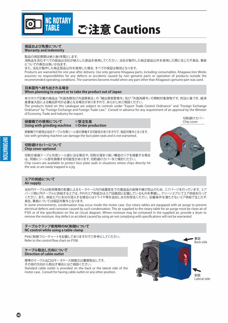
ご注意 Cautions
製品の保証期間は納入後1年間とします。消耗品を含むすべての部品は当社が納入した部品を使用してください。当社が製作した純正部品以外を使用した際に生じた不具合、事故についての責任は負いかねます。また、当社が製作した純正部品以外を使用した場合、すべての保証は無効となります。Products are warranted for one year after delivery. Use only genuine Kitagawa parts, including consumables. Kitagawa Iron Works assumes no responsibilities for any defects or accidents caused by non genuine parts or operation of products outside the recommended operating conditions. The warranties become invalid when any part other than Kitagawa's genuine part was used.
保証および免責についてWarranty and indemnity
INFORMATION
本カタログ記載の商品は「外国為替及び外国貿易法」の「輸出貿易管理令」及び「外国為替令」の規制対象貨物です。同法に基づき、経済産業省大臣による輸出許可が必要となる場合がありますので、あらかじめご相談ください。The products listed on this catalogue are subject to controls under “Export Trade Control Ordinance” and “Foreign Exchange Ordinance” by “Foreign Exchange and Foreign Trade Law.” Consult in advance for any requirement of an approval by the Minister of Economy, Trade and Industry for export.
日本国外へ持ち出される場合When planning to export or to take the product out of Japan
研磨機での使用は当社テーブル外周シール部が損傷する可能性がありますので、保証対象外となります。Use with grinding machine can damage the face plate seals and is not warranted.
研磨機での使用についてUsing with grinding machine
※受注生産※Order production
切粉が直接テーブル外周シール部に当る場合や、切粉が溜まり易い構造のジグを搭載する場合は、同様にシール部を損傷する可能性があります。切粉避けカバーをご検討ください。Chip covers are available to protect face plate seals in situations where chips directly hit the seal, or are easily trapped in a jig.
切粉避けカバーについてChip cover optional
当社円テーブルは使用環境の影響によるモータケース内の結露発生での電装品の故障や錆び防止のため、エアパージを行っています。エアパージ用に円テーブルに供給するエアは、P91のエア供給又はエア回路図に記載しているものを準備し、クリーンエアにてエア供給を行ってください。また、供給エアに水分が混入する場合にはドライヤ等を追加し水分を除去ください。記載条件を満たさないエア供給で生じた不具合、事故については保証対象外となります。In some environments, condensation may occur inside the motor case. Our rotary tables are equipped with air purge to prevent electrical defects and corrosion caused by such condensation. The air supplied to the rotary table for air purge must be clean air of P105 or of the specification on the air circuit diagram. Where moisture may be contained in the supplied air, provide a dryer to remove the moisture. Any defect or accident caused by using air not complying with specifications will not be warranted.
エアの供給についてAir supply
P94に制御フローチャートを記載してありますのでご参考にしてください。Refer to the control flow chart on P108.
テーブルクランプ使用時のNC制御についてNC control while using a table clamp
標準のケーブル出口はモータケース側面又は裏面取出しです。その他の方向から取出す場合にはご相談ください。Standard cable outlet is provided on the back or the lateral side of the motor case. Consult for having cable outlet on any other position.
ケーブル取出し方向についてDirection of cable outlet
切粉避けカバーChip cover
裏面Back side
側面Lateral side

MEMO

MEMO

145
MEMO

NC ROTARY TABLE
NC円テーブルシリーズNC ROTARYTABLE SERIES
CA
TA
LO
GU
EN
C円
テー
ブル
シリ
ーズ
N
C R
OT
AR
Y T
AB
LE
SE
RIE
S
Global Network
・仕様・外観は改良のため、予告なく変更することがあります。 ・カタログと実際の商品の色とは印刷の関係で多少異なる場合もあります。・カタログ記載内容/令和 3 年 10 月・本カタログ記載の商品は「外国為替及び外国貿易法」の「輸出貿易管理令」及び「外国為替令」の規制対象貨物です。
同法に基づき、経済産業省大臣による輸出許可が必要となる場合がございます。日本国外へ持ち出される場合は、あらかじめ当社にご相談ください。
CNO.2R-51/Printed in Japan 3,000
東 京 営 業 課仙台支店駐在名古屋営業課大 阪 営 業 課広 島 営 業 課九州支店駐在海 外 営 業 課
埼玉県さいたま市北区吉野町1-405-1 宮城県仙台市若林区大和町4-15-13愛知県名古屋市中川区上高畑2-62大阪府大阪市住之江区北加賀屋3-2-9広島県府中市元町77-1福岡県福岡市博多区板付7-6-39広島県府中市元町77-1
Tel.(048)667-3469Tel.(022)232-6732(代)Tel.(052)363-0371(代)Tel.(06)6685-9065(代)Tel.(0847)40-0541Tel.(092)501-2102(代)Tel.(0847)40-0526
Fax.(048)663-4678Fax.(022)232-6739Fax.(052)362-0690Fax.(06)6684-2025Fax.(0847)46-1721Fax.(092)501-2103Fax.(0847)45-8911
〒331-9634〒984-0042〒454-0873〒559-0011〒726-8610〒812-0888〒726-8610
本 社 広島県府中市元町77-1 Tel.(0847)40-0561 Fax.(0847)45-8911〒726-8610
日本語対応可能Japanese speaker available
77-1 Motomachi,Fuchu-shi,Hiroshima,726-8610,JapanHEAD OFFICE Tel. +81 847-40-0561 Fax. +81 847-45-8911
・Specifications and outside appearance are subject to change without notice due to ongoing research and development. ・The color of the actual product may be different from the catalogue's due to printing matters.・Catalogue contents as of 2021.10・The products herein are controlled under Japanese Foreign Exchange and Foreign Trade Control Act. In the event of importing and/or exporting the products, you are obliged to consult KITAGAWA as well as your government for the related regulation prior to any transaction.
https://www.kiw.co.jphttps://www.kitagawa.comhttps://www.kitagawa.com.cn Kitagawa Corporation
キタガワ グローバル ハンド カンパニーKitagawa Global hand Company株式会社 北川鉄工所
Tel. +1 847-310-8787 Fax. +1 847-310-9484
Tel. +44 1725-514000 Fax. +44 1725-514001
Tel. +49 2102-123-78-00 Fax. +49 2102-123-78-69
Tel. +48 607-39-8855
Tel. +420 603 856 122
Tel. +40 727-770-329
Tel. +36 30-510-3550
Tel. +91 80-2976-5200 Fax. +91 80-2976-5205
Tel. +66 2-712-7479 Fax. +66 2-712-7481
Tel. +86 21-6295-5772 Fax. +86 21-6295-5792
Tel. +86 20-2885-5276
Tel. +886 2-2393-1221 Fax. +886 2-2395-1231
Tel. +82 2-2026-2222 Fax. +82 2-2026-2113
Tel. +61 3-9561-6155 Fax. +61 3-9561-6705
KITAGAWA - NORTHTECH INC.
KITAGAWA EUROPE LTD.
KITAGAWA EUROPE GmbH
KITAGAWA EUROPE GmbH Poland Office
KITAGAWA EUROPE GmbH Czech Office
KITAGAWA EUROPE GmbH Romania Office
KITAGAWA EUROPE GmbH Hungary Office
KITAGAWA INDIA PVT LTD.
KITAGAWA (THAILAND) CO.,LTD. Bangkok Branch
Kitagawa Corporation (Shanghai)
Kitagawa Corporation (Shanghai) Guangzhou Office
DEAMARK LIMITED
KITAGAWA KOREA AGENT CO.,LTD.
DIMAC TOOLING PTY.LTD.
301 E. Commerce Dr,Schaumburg,IL. 60173 USA
Unit 1 The Headlands,Downton,Salisbury,Wiltshire SP5 3JJ,United Kingdom
Borsigstrasse 3,40880,Ratingen Germany
44-240 Zory,ul. Niepodleglosci 3 Poland
Purkynova 125,612 00 Brno,Czech Republic
Strada Heliului 15,Bucharest 1,013991,Romania
Dery T.u.5,H-9024 Gyor,Hungary
Plot No.42,2nd Phase Jigani Industrial Area,Jigani,Bangalore – 560105,Karnataka,India
9th FL,Home Place Office Building,283/43 Sukhumvit 55Rd. (Thonglor 13),Klongton-Nua,Wattana,Bangkok 10110,Thailand
Room308 3F Building B. Far East International Plaza,No.317 Xian Xia Road,Chang Ning,Shanghai,200051,China
B07,25/F,West Tower,Yangcheng International Trading Centre,No.122,East Tiyu Road,Tianhe District,Guangzhou,China
No. 6,Lane 5,Lin Sen North Road,Taipei,Taiwan
803 Ho,B-Dong,Woolim Lion's Valley,371-28 Gasan-Dong,Gumcheon-Gu,Seoul,Korea
69-71 Williams Rd,Dandenong South,Victoria,3175 Australia
https://www.kitagawa-usa.com
https://www.kitagawa.global/en
https://www.kitagawa.global/de
https://www.kitagawa.global/pl
https://www.kitagawa.global/cz
https://www.kitagawa.global/ro
https://www.kitagawa.global/hu
https://www.kitagawa.global/in
https://www.kitagawa.com.cn
http://www.deamark.com.tw
http://www.kitagawa.co.kr
https://www.dimac.com.au
America Contact
Europe Contact
Asia Contact
Oceania Contact