Automation Components
126
Automation Components Technical Catalogue ABB
-
Upload
khangminh22 -
Category
Documents
-
view
0 -
download
0
Transcript of Automation Components

Automation ComponentsTechnical Catalogue
ABB
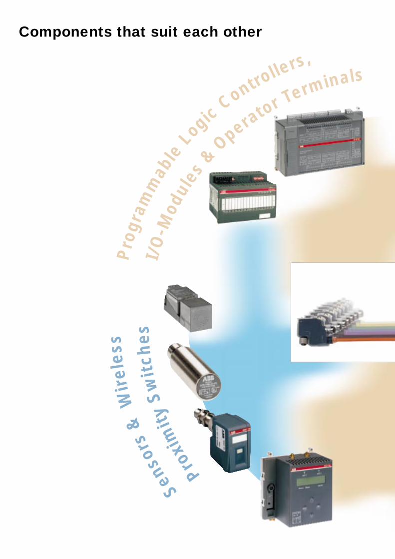
Components that suit each other
Proxi
mit
yS
wit
che
s
Senso
rs&
Wir
ele
ss
I/O
-Mod
ules
&
Operator Terminals
Pro
gram
mab
leLogic
Controllers,
CommunicativeSw
itchingan
dA
uto
matio
nC
omponents
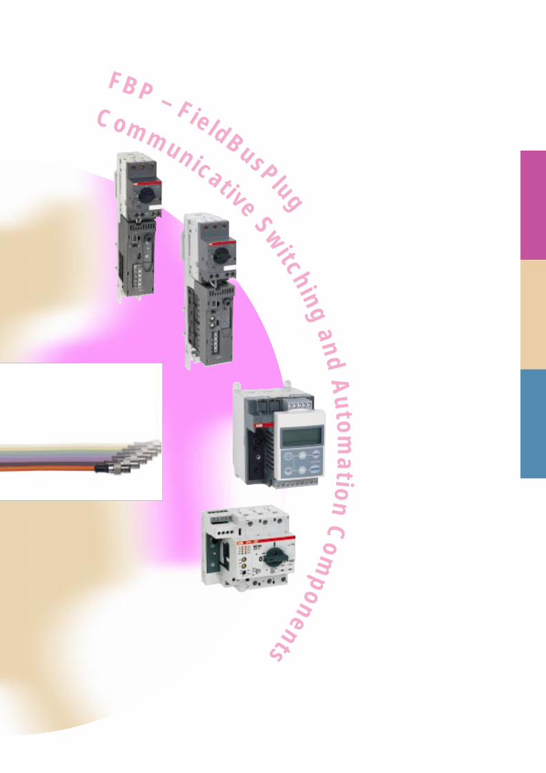
FBP – FieldBusPlug
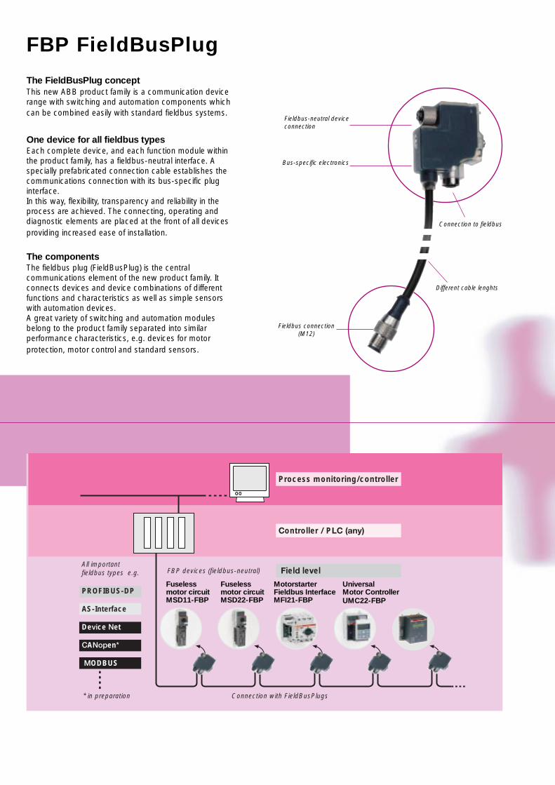
Process monitoring/controller
Controller / PLCL(any)y)
FFielddlevvelFBP devices (fieldbus-neutral)
Connection with FieldBusPlugs* in preparation
All important fieldbus tyypes, e.g..:
PROFIBUS-DP
AS-Interface
DevviceNNet
CANopen**
MMODBUS*
Fuselessmotor circuitMSD22-FBP
MotorstarterFieldbus InterfaceMFI21-FBP
UniversalMotor ControllerUMC22-FBP
FBP FieldBusPlug
The FieldBusPlug conceptThis new ABB product family is a communication devicerange with switching and automation components whichcan be combined easily with standard fieldbus systems.
One device for all fieldbus typesEach complete device, and each function module withinthe product family, has a fieldbus-neutral interface. Aspecially prefabricated connection cable establishes thecommunications connection with its bus-specific pluginterface.In this way, flexibility, transparency and reliability in theprocess are achieved. The connecting, operating anddiagnostic elements are placed at the front of all devicesproviding increased ease of installation.
The componentsThe fieldbus plug (FieldBusPlug) is the centralcommunications element of the new product family. Itconnects devices and device combinations of differentfunctions and characteristics as well as simple sensorswith automation devices.A great variety of switching and automation modulesbelong to the product family separated into similarperformance characteristics, e.g. devices for motorprotection, motor control and standard sensors.
Fuselessmotor circuitMSD11-FBP
Bus-specific electronics
Fieldbus-neutral deviceconnection
Fieldbus connection(M12)
Connection to fieldbus
Different cable lenghts
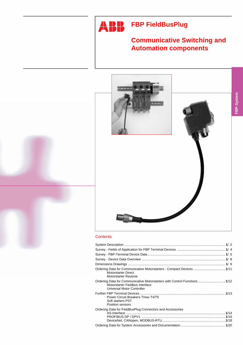
FBP FieldBusPlug
Communicative Switching andAutomation components
Contents
System Description ............................................................................................................... 1/ 2
Survey - Fields of Application for FBP Terminal Devices ..................................................... 1/ 4
Survey - FBP-Terminal Device Data ..................................................................................... 1/ 5
Survey - Device Data Overview ............................................................................................ 1/ 8
Dimensions Drawings ........................................................................................................... 1/ 9
Ordering Data for Communicative Motorstarters - Compact Devices ...................................1/11Motorstarter DirectMotorstarter Reverse
Ordering Data for Communicative Motorstarters with Control Functions ..............................1/12Motorstarter Fieldbus InterfaceUniversal Motor Controller
Further FBP Terminal Devices .............................................................................................. 1/13Power Circuit Breakers Tmax T4/T5Soft starters PSTPosition sensors
Ordering Data for FieldBusPlug Connectors and AccessoriesAS-Interface ............................................................................................................. 1/14PROFIBUS DP / DPV1 ............................................................................................1/16DeviceNet, CANopen, MODBUS-RTU .....................................................................1/18
Ordering Data for System Accessories and Documentation .................................................1/20
FBP
-Sys
tem
1/22CDC003005C0201
FBP FieldBusPlugSystem Description - General Information
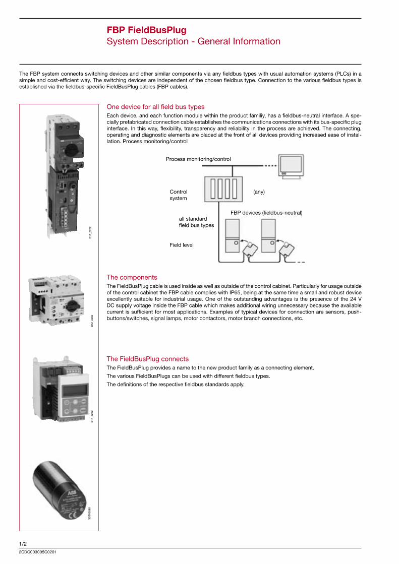
The FBP system connects switching devices and other similar components via any fieldbus types with usual automation systems (PLCs) in a simple and cost-efficient way. The switching devices are independent of the chosen fieldbus type. Connection to the various fieldbus types is established via the fieldbus-specific FieldBusPlug cables (FBP cables).
One device for all field bus types Each device, and each function module within the product familiy, has a fieldbus-neutral interface. A spe-cially prefabricated connection cable establishes the communications connections with its bus-specific plug interface. In this way, flexibility, transparency and reliability in the process are achieved. The connecting, operating and diagnostic elements are placed at the front of all devices providing increased ease of instal-lation. Process monitoring/control
The components The FieldBusPlug cable is used inside as well as outside of the control cabinet. Particularly for usage outside of the control cabinet the FBP cable complies with IP65, being at the same time a small and robust device excellently suitable for industrial usage. One of the outstanding advantages is the presence of the 24 V DC supply voltage inside the FBP cable which makes additional wiring unnecessary because the available current is sufficient for most applications. Examples of typical devices for connection are sensors, push-buttons/switches, signal lamps, motor contactors, motor branch connections, etc.
The FieldBusPlug connects The FieldBusPlug provides a name to the new product family as a connecting element.
The various FieldBusPlugs can be used with different fieldbus types.
The definitions of the respective fieldbus standards apply.
B11
_328
2B
12_3
282
B14
_328
2S
ST0
5595
Process monitoring/control
Control system
(any)
FBP devices (fieldbus-neutral)all standardfield bus types
Field level
1/3
FBP
-Sys
tem
2CDC003005C0201
FBP FieldBusPlugSystem Description - General Information
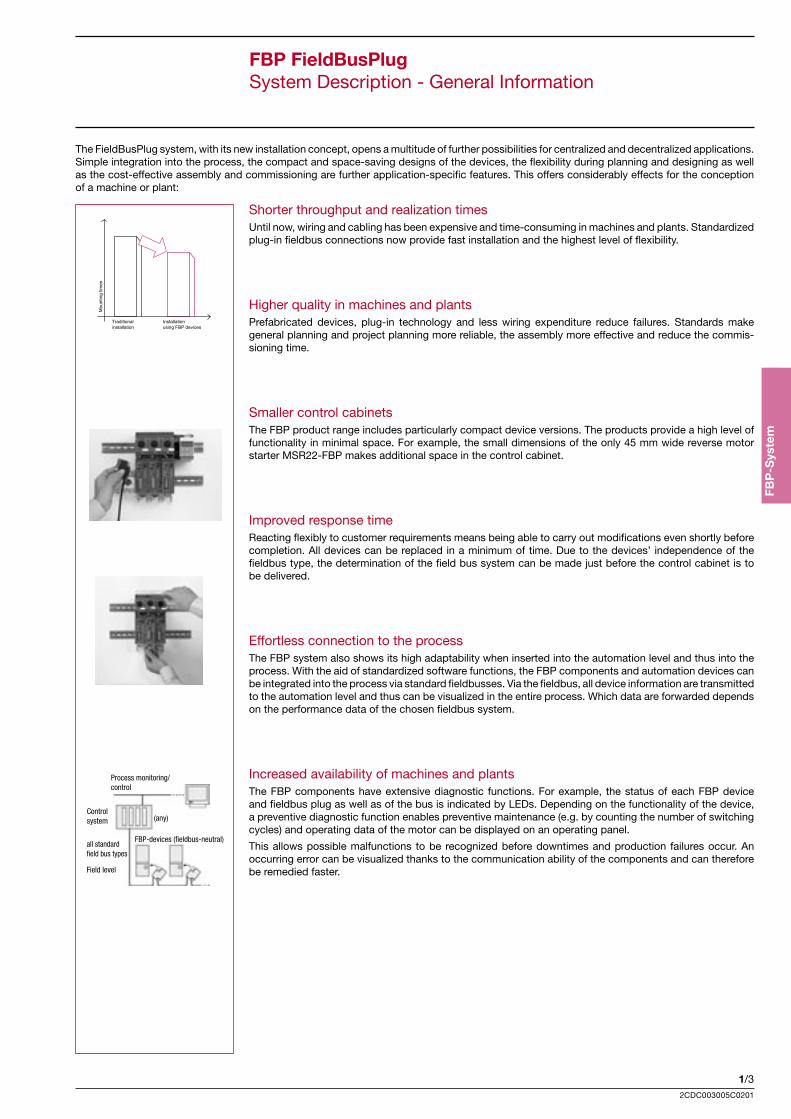
The FieldBusPlug system, with its new installation concept, opens a multitude of further possibilities for centralized and decentralized applications. Simple integration into the process, the compact and space-saving designs of the devices, the flexibility during planning and designing as well as the cost-effective assembly and commissioning are further application-specific features. This offers considerably effects for the conception of a machine or plant:
Shorter throughput and realization times Until now, wiring and cabling has been expensive and time-consuming in machines and plants. Standardized plug-in fieldbus connections now provide fast installation and the highest level of flexibility.
Higher quality in machines and plants Prefabricated devices, plug-in technology and less wiring expenditure reduce failures. Standards make general planning and project planning more reliable, the assembly more effective and reduce the commis-sioning time.
Smaller control cabinets The FBP product range includes particularly compact device versions. The products provide a high level of functionality in minimal space. For example, the small dimensions of the only 45 mm wide reverse motor starter MSR22-FBP makes additional space in the control cabinet.
Improved response time Reacting flexibly to customer requirements means being able to carry out modifications even shortly before completion. All devices can be replaced in a minimum of time. Due to the devices’ independence of the fieldbus type, the determination of the field bus system can be made just before the control cabinet is to be delivered.
Effortless connection to the process The FBP system also shows its high adaptability when inserted into the automation level and thus into the process. With the aid of standardized software functions, the FBP components and automation devices can be integrated into the process via standard fieldbusses. Via the fieldbus, all device information are transmitted to the automation level and thus can be visualized in the entire process. Which data are forwarded depends on the performance data of the chosen fieldbus system.
Increased availability of machines and plants The FBP components have extensive diagnostic functions. For example, the status of each FBP device and fieldbus plug as well as of the bus is indicated by LEDs. Depending on the functionality of the device, a preventive diagnostic function enables preventive maintenance (e.g. by counting the number of switching cycles) and operating data of the motor can be displayed on an operating panel.
This allows possible malfunctions to be recognized before downtimes and production failures occur. An occurring error can be visualized thanks to the communication ability of the components and can therefore be remedied faster.
Process monitoring/control
Controlsystem (any)
FBP-devices (fieldbus-neutral)all standard field bus types
Field level
1/42CDC003005C0201
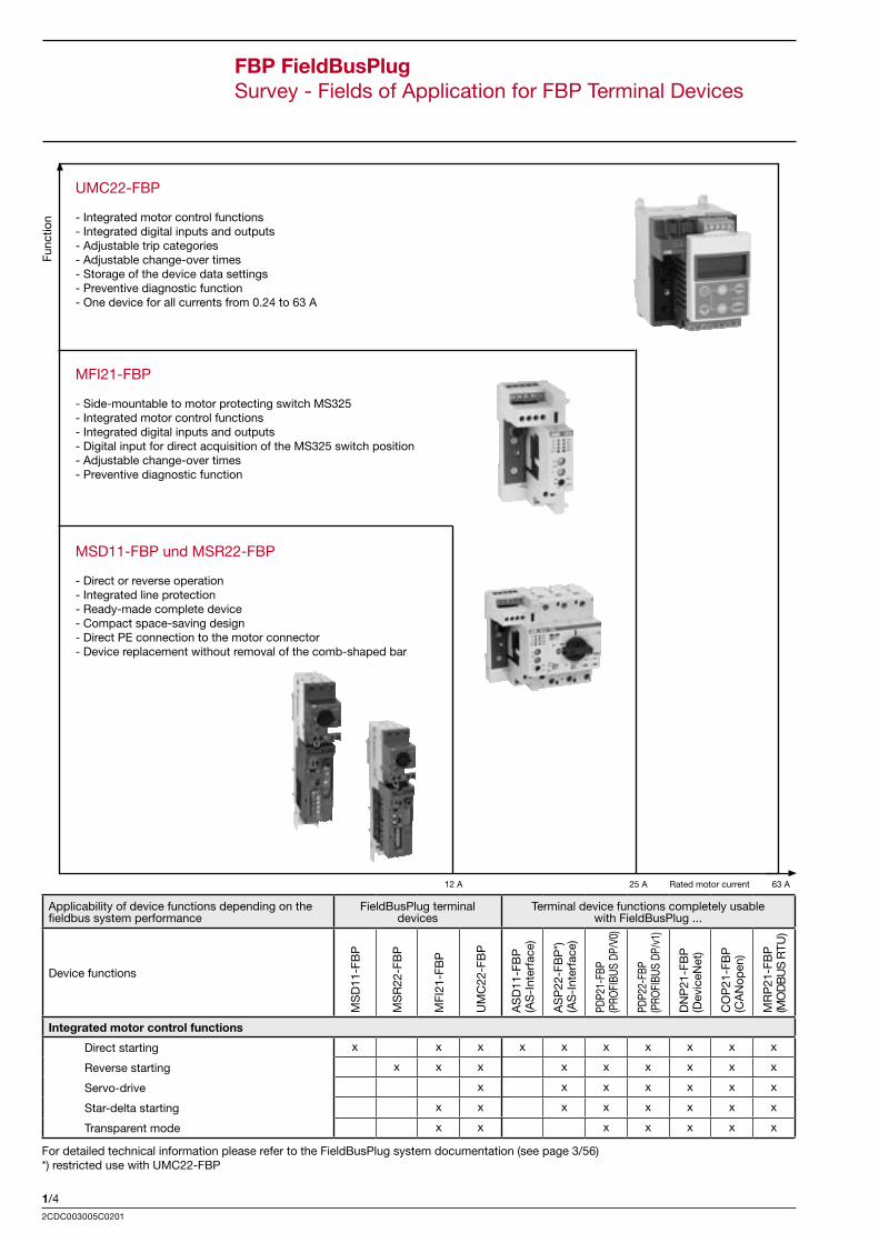
FBP FieldBusPlugSurvey - Fields of Application for FBP Terminal Devices
Func
tion
12 A 25 A Rated motor current 63 A
UMC22-FBP
- Integrated motor control functions- Integrated digital inputs and outputs- Adjustable trip categories- Adjustable change-over times- Storage of the device data settings- Preventive diagnostic function- One device for all currents from 0.24 to 63 A
MFI21-FBP
- Side-mountable to motor protecting switch MS325- Integrated motor control functions- Integrated digital inputs and outputs- Digital input for direct acquisition of the MS325 switch position- Adjustable change-over times- Preventive diagnostic function
MSD11-FBP und MSR22-FBP
- Direct or reverse operation- Integrated line protection- Ready-made complete device- Compact space-saving design- Direct PE connection to the motor connector- Device replacement without removal of the comb-shaped bar
Applicability of device functions depending on the fieldbus system performance
FieldBusPlug terminal devices
Terminal device functions completely usable with FieldBusPlug ...
Device functions
MS
D11
-FB
P
MS
R22
-FB
P
MFI
21-F
BP
UM
C22
-FB
P
AS
D11
-FB
P
(AS
-Int
erfa
ce)
AS
P22
-FB
P*)
(A
S-I
nter
face
)
PDP2
1-FB
P (P
ROFI
BUS
DP/V
0)
PDP2
2-FB
P (P
ROFI
BUS
DP/v
1)
DN
P21
-FB
P
(Dev
iceN
et)
CO
P21
-FB
P
(CA
Nop
en)
MR
P21
-FB
P
(MO
DB
US
RTU
)
Integrated motor control functions
Direct starting x x x x x x x x x x
Reverse starting x x x x x x x x x
Servo-drive x x x x x x x
Star-delta starting x x x x x x x x
Transparent mode x x x x x x x
For detailed technical information please refer to the FieldBusPlug system documentation (see page 3/56) *) restricted use with UMC22-FBP
1/5
FBP
-Sys
tem
2CDC003005C0201
FBP FieldBusPlugSurvey - FBP Terminal Device Data
Motor starter Reverse MSR22-FBP
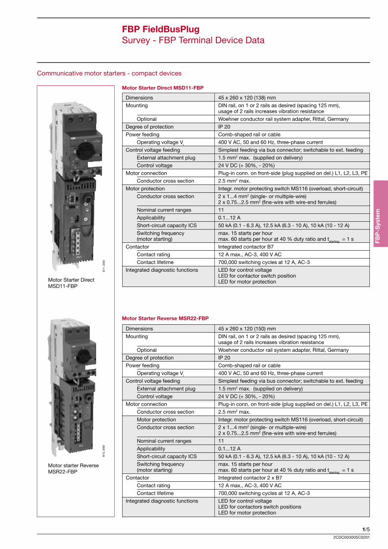
Communicative motor starters - compact devices
Dimensions 45 x 260 x 120 (138) mm
Mounting DIN rail, on 1 or 2 rails as desired (spacing 125 mm), usage of 2 rails increases vibration resistance
Optional Woehner conductor rail system adapter, Rittal, Germany
Degree of protection IP 20
Power feeding Comb-shaped rail or cable
Operating voltage Vi 400 V AC, 50 and 60 Hz, three-phase current
Control voltage feeding Simplest feeding via bus connector; switchable to ext. feeding
External attachment plug 1.5 mm2 max. (supplied on delivery)
Control voltage 24 V DC (+ 30%, - 20%)
Motor connection Plug-in conn. on front-side (plug supplied on del.) L1, L2, L3, PE
Conductor cross section 2.5 mm2 max.
Motor protection Integr. motor protecting switch MS116 (overload, short-circuit)
Conductor cross section 2 x 1...4 mm2 (single- or multiple-wire) 2 x 0.75...2.5 mm2 (fine-wire with wire-end ferrules)
Nominal current ranges 11
Applicability 0.1...12 A
Short-circuit capacity ICS 50 kA (0.1 - 6.3 A), 12.5 kA (6.3 - 10 A), 10 kA (10 - 12 A)
Switching frequency max. 15 starts per hour (motor starting) max. 60 starts per hour at 40 % duty ratio and tstarting = 1 s
Contactor Integrated contactor B7
Contact rating 12 A max., AC-3, 400 V AC
Contact lifetime 700,000 switching cycles at 12 A, AC-3
Integrated diagnostic functions LED for control voltage LED for contactor switch position LED for motor protection
B13
_328
2B
11_3
282
Motor Starter Direct MSD11-FBP
Motor Starter DirectMSD11-FBP
Motor Starter Reverse MSR22-FBP
Dimensions 45 x 260 x 120 (150) mm
Mounting DIN rail, on 1 or 2 rails as desired (spacing 125 mm), usage of 2 rails increases vibration resistance
Optional Woehner conductor rail system adapter, Rittal, Germany
Degree of protection IP 20
Power feeding Comb-shaped rail or cable
Operating voltage Vi 400 V AC, 50 and 60 Hz, three-phase current
Control voltage feeding Simplest feeding via bus connector; switchable to ext. feeding
External attachment plug 1.5 mm2 max. (supplied on delivery)
Control voltage 24 V DC (+ 30%, - 20%)
Motor connection Plug-in conn. on front-side (plug supplied on del.) L1, L2, L3, PE
Conductor cross section 2.5 mm2 max.
Motor protection Integr. motor protecting switch MS116 (overload, short-circuit)
Conductor cross section 2 x 1...4 mm2 (single- or multiple-wire) 2 x 0.75...2.5 mm2 (fine-wire with wire-end ferrules)
Nominal current ranges 11
Applicability 0.1...12 A
Short-circuit capacity ICS 50 kA (0.1 - 6.3 A), 12.5 kA (6.3 - 10 A), 10 kA (10 - 12 A)
Switching frequency max. 15 starts per hour (motor starting) max. 60 starts per hour at 40 % duty ratio and tstarting = 1 s
Contactor Integrated contactor 2 x B7
Contact rating 12 A max., AC-3, 400 V AC
Contact lifetime 700,000 switching cycles at 12 A, AC-3
Integrated diagnostic functions LED for control voltage LED for contactors switch positions LED for motor protection
1/62CDC003005C0201
FBP FieldBusPlugSurvey - FBP Terminal Device Data
Communicative motor starters with control functions
Motor Starter Fieldbus Interface MFI21-FBPB
12_3
282
Motor Starter FieldbusInterface MFI21-FBP
Note:
MS325 is not supplied on delivery (see chapter 4 - Motor Protecting Switches)
Dimensions 36 (90) x 90 x 70 mm
Mounting DIN rail
Mechanical coupling to motor protecting switch MS 325
Degree of protection IP 20
Power feeding see MS 325
Control voltage feeding simplest feeding via bus connector; switchable to ext. feeding
Connection max. 1.5 mm2
Control voltage 24 V DC (+ 30%, - 20%)
Motor connection see MS 325
Conductor cross section terminals max. 1 x 2.5 mm2 or max. 2 x 1.5 mm2
Integrated inputs 3 digital inputs 24 V DC 1 digital input, mechanically coupled with MS325 switch position
Integrated outputs 3 relay outputs with common supply
Voltage switching capacity 24 V AC/DC ... 250 V AC/DC
Current switching cap. per relay 240 V AC (AC 15) max. 1.5 A 120 V AC (AC 15) max. 3 A 250 V DC (DC 13) max. 0.11 A 24 V DC (DC 13) max. 1 A
Load current via common Imax = 3 A (thermal limit)
Relay contact lifetime > 5 x 10⁶ switching cycles - mechanical lifetime > 1 x 10⁶ switching cycles - at 230 V AC, 0.5 A
Protective circuits with for direct current free-wheeling diodes, inductive loads for alternating current varistors / VDRs
Integrated control functions Direct starting, reverse starting, star-delta starting, transparent mode (not for AS-Interface)
Diagnosis at the device LED - Internal supply voltage LED - Device error LED - Status of the digital inputs and outputs
Contactor switching cycles count and data transmission to the automation device (not for AS-Interface)
1/7
FBP
-Sys
tem
2CDC003005C0201
FBP FieldBusPlugSurvey - FBP Terminal Device Data
Universal Motor Controller UMC22-FBP
Communicative motor starters with control functions
B14
_328
2
Dimensions 70 x 105 x 87,5 (110) mm
Mounting On DIN rail or with screws (4 screws M4)
Degree of protection IP 20
Power feeding Bar-type current transf. max. 25 mm2 (max. diameter. = 11 mm)
Operating voltage Ue 690 V AC, 50 and 60 Hz, 3-phase AC
Nominal motor current 0.24 ... 63 A with protective current transformers up to 850 A
Short-circuit protection By fuse on mains side
Control voltage feeding Simplest feeding via bus connector; switchable to ext. feeding
Connection max. 1.5 mm2
Control voltage 24 V DC (+30%, -20%)
Conductor cross section terminals max. 1 x 2.5 mm2 or max. 2 x 1.5 mm2
Integrated inputs 6 digital inputs 24 V DC
Integrated outputs 3 relay outputs with common supply
Voltage switching capacity 24 V AC/DC ... 250 V AC/DC
Current switching cap. per relay 240 V AC (AC 15) max. 1.5 A 120 V AC (AC 15) max. 3 A 250 V DC (DC 13) max. 0.11 A 24 V DC (DC 13) max. 1 A
Load current via common Imax = 4 A (thermal limit)
Relay contact lifetime > 5 x 10⁶ switching cycles - mechanical lifetime > 1 x 10⁶ switching cycles - at 230 V AC, 0.5 A
Protective circuits with For direct current free-wheeling diodes, inductive loads For alternating current varistors / VDRs
Integrated control functions Direct starting, reverse starting, star-delta-starting, servo-drive, transparent mode (not for AS-Interface) Stand alone operation (operation also without bus connection)
Integrated motor protection functions Adjustm. of starting and change-over times via operat. panel Error acknowledgement via operating panel or bus Selectable disabling of outputs on error (PLC or bus) Overload monitoring / phase failure detection Detection of blocking motors Integrated storage of parameters and motor data
Integrated diagnostic functions LED for control voltage LED for "motor running" LED for "device ready for operation" LED for state indication of digital inputs and outputs
Contactor switching cycles count and data transmission to automation device (not for AS-Interface)
Optional operating panel For adjustment and visualization of motor and device data as well as of bus parameters
1/82CDC003005C0201
FBP FieldBusPlugSurvey - Device Data Overview
FieldBusPlug terminal devices FieldBusPlug bus connectors
FieldBusPlug terminal devices
Full usability of terminal device functions with FieldBusPlug ...
Remarks
Functions and technical data
MS
D11
-FB
P
MS
R22
-FB
P
MFI
21-F
BP
UM
C22
-FB
P
AS
D11
-FB
P
AS
P22
-FB
P
PD
P21
-FB
P
PD
P22
-FB
P
DN
P21
-FB
P
CO
P22
-FB
P
MR
P21
-FB
P For detailed technical information please
refer to the FieldBusPlug system documentation
Integrated diagnostic functions
LED supply voltage x x x x x x x green
LED ready to operation x green
LED switch pos. contactor(s) x x yellow
LED switch pos. motor protection x yellow
LED bus failure x D / B x x red
LED function failure x x x x x red
LED motor running x yellow
LED for states of digital I/Os x x yellow
Bus info contactors x x x x x x x x Information to PLC
Bus info contactors x x x Information to PLC
Bus info motor protection x x x Information to PLC
Bus info motor current x x x x Information to PLC
Parameter settings
Change-over time via potentiometer x fixed basic time 50 ms
Change-over time via operat. panel x fixed basic time 50 ms
Change-over time via PLC program x x x x fixed basic time 50 ms
Motor current x x x x x x x at the motor protecting switch
Motor current, trip category x x x optional operating panel
Motor current, trip category x x x PLC program
Mounting
Mounting on DIN rail x x x x 35 mm DIN rail
Mounting on 2 DIN rails x x increased vibration resistance
Mounting by screws x 4 Screws M4
Connections and conductor cross sections
Connecting terminals x x x x 1 x 2.5 bzw. 2 x 1.5 mm2 max.
PE tapping directly on DIN rail x x to motor cennecting plug
Bus connection via FBP conn. x x x x x x x x
Bushing-type transformer x 25 mm2 max. (diameter 11 mm)
Ambient conditions
Degree of protection IP20 IP20 IP65
Storage temp. - 40 ... + 80°C x x x x x x x x
Operating temp. 0 ... + 55°C x x x x x x x x
Approvals
CE, UL, CSA, GL, BV, LRS x x x x x x x x partly in preparation
ATEX x
1/9
FBP
-Sys
tem
2CDC003005C0201
FBP FieldBusPlugDimensioned Drawings
Motor Starter Direct MSD11-FBP
Communicative motor starters with control functions
Motor Starter Reverse MSR22-FBP
Motor Starter Fieldbus Interface MFI21-FBP
90120130138
3535
125
220
260
MS 116
0
I
45
125
52.5
82.5
102120142150
3535
125
220
260
MS 116
0
I
45
125
52.5
82.5
35 45
44
5.5
6270
MS 325
0I
MFI21
012ERR.
OU
TPU
T012
SUP.
INPU
T
x10
x1
Addr.
260s120s50ms60s
1s10s
2
4 6 8 PE
ñ 5 7 9
3
L 1
3690
90
56.5
90
87.570
97.5
105
ca. 4
0
103110
11
20 20
15
MS
D-0
4
MS
r-04
Mfi-
-07a
Um
c-04
Universal Motor Controller UMC22-FBP
Communicative motor starters - compact devices Diameter in mm
1/102CDC003005C0201
48.5
52.5
ca. 5
017
FBP FieldBusPlugDimensioned Drawings
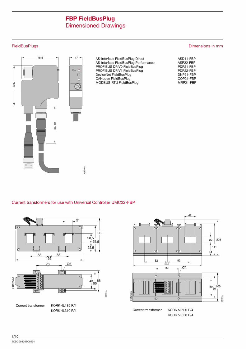
FieldBusPlugs Dimensions in mm
AS-Interface FieldBusPlug Direct ASD11-FBPAS-Interface FieldBusPlug Performance ASP22-FBPPROFIBUS DP/V0 FieldBusPlug PDP21-FBPPROFIBUS DP/V1 FieldBusPlug PDP22-FBPDeviceNet FieldBusPlug DNP21-FBPCANopen FieldBusPlug COP21-FBPMODBUS-RTU FieldBusPlug MRP21-FBP
AS
IFB
P04
Current transformers for use with Universal Controller UMC22-FBP
S01
257A
S01
258A
Current transformer KORK 4L185 R/4
KORK 4L310 R/4 Current transformer KORK 5L500 R/4
KORK 5L850 R/4
VL 2223 3025
58 5819276
21
98
75,522,5
28,5
435566
O6
S012
57A
(Only with KORC 4_R/4 types)
VL 2223 3041
82 8224582
42
203
11144
22
6080100
O7
S012
58A
(Only with KORC 5_R/4 types)
1/11
FBP
-Sys
tem
2CDC003005C0201
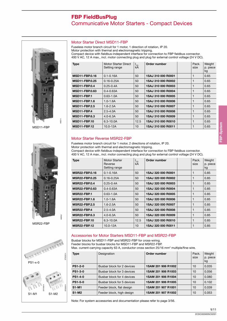
FBP FieldBusPlugCommunicative Motor Starters - Compact Devices
MSD11-FBP
MSR22-FBP
PS1-x-0
S1-M1 S1-M2
Motor Starter Direct MSD11-FBPFuseless motor branch circuit for 1 motor, 1 direction of rotation, IP 20.Motor protection with thermal and electromagnetic tripping.Compact device with fieldbus-independent interface for connection to FBP fieldbus connector.400 V AC, 12 A max., incl. motor connecting plug and plug for external control voltage (24 V DC).
Type Motor Starter Direct ICS Order number Pack. Weight Setting range kA size p. piece kg
MSD11-FBP.0.16 0.1-0.16A 50 1SAJ 310 000 R0001 1 0.65
MSD11-FBP.0.25 0.16-0.25A 50 1SAJ 310 000 R0002 1 0.65
MSD11-FBP.0.4 0.25-0.4A 50 1SAJ 310 000 R0003 1 0.65
MSD11-FBP.0.63 0.4-0.63A 50 1SAJ 310 000 R0004 1 0.65
MSD11-FBP.1 0.63-1.0A 50 1SAJ 310 000 R0005 1 0.65
MSD11-FBP.1.6 1.0-1.6A 50 1SAJ 310 000 R0006 1 0.65
MSD11-FBP.2.5 1.6-2.5A 50 1SAJ 310 000 R0007 1 0.65
MSD11-FBP.4 2.5-4.0A 50 1SAJ 310 000 R0008 1 0.65
MSD11-FBP.6.3 4.0-6.3A 50 1SAJ 310 000 R0009 1 0.65
MSD11-FBP.10 6.3-10.0A 12.5 1SAJ 310 000 R0010 1 0.65
MSD11-FBP.12 10.0-12A 10 1SAJ 310 000 R0011 1 0.65
Motor Starter Reverse MSR22-FBPFuseless motor branch circuit for 1 motor, 2 directions of rotation, IP 20.Motor protection with thermal and electromagnetic tripping.Compact device with fieldbus-independent interface for connection to FBP fieldbus connector.400 V AC, 12 A max., incl. motor connecting plug and plug for external control voltage (24 V DC).
Type Motor Starter ICS Order number Pack. Weight Reverse kA size p. piece Setting range kg
MSR22-FBP.0.16 0.1-0.16A 50 1SAJ 320 000 R0001 1 0.85
MSR22-FBP.0.25 0.16-0.25A 50 1SAJ 320 000 R0002 1 0.85
MSR22-FBP.0.4 0.25-0.4A 50 1SAJ 320 000 R0003 1 0.85
MSR22-FBP.0.63 0.4-0.63A 50 1SAJ 320 000 R0004 1 0.85
MSR22-FBP.1 0.63-1.0A 50 1SAJ 320 000 R0005 1 0.85
MSR22-FBP.1.6 1.0-1.6A 50 1SAJ 320 000 R0006 1 0.85
MSR22-FBP.2.5 1.6-2.5A 50 1SAJ 320 000 R0007 1 0.85
MSR22-FBP.4 2.5-4.0A 50 1SAJ 320 000 R0008 1 0.85
MSR22-FBP.6.3 4.0-6.3A 50 1SAJ 320 000 R0009 1 0.85
MSR22-FBP.10 6.3-10.0A 12.5 1SAJ 320 000 R0010 1 0.85
MSR22-FBP.12 10.0-12A 10 1SAJ 320 000 R0011 1 0.85
Accessories for Motor Starters MSD11-FBP and MSR22-FBPBusbar blocks for MSD11-FBP and MSR22-FBP for cross-wiring.Feeder blocks for busbar blocks for MSD11-FBP and MSR22-FBP.Max. current-carrying capacity 63 A, conductor cross section 25/16 mm2 multiple/fine-wire.
Type Designation Order number Pack. Weight size p. piece kg
PS1-2-0 Busbar block for 2 devices 1SAM 201 906 R1002 10 0.035
PS1-3-0 Busbar block for 3 devices 1SAM 201 906 R1003 10 0.056
PS1-4-0 Busbar block for 4 devices 1SAM 201 906 R1004 10 0.080
PS1-5-0 Busbar block for 5 devices 1SAM 201 906 R1005 10 0.102
S1-M1 Feeder block, flat design 1SAM 201 907 R1001 10 0.039
S1-M2 Feeder block, high design 1SAM 201 907 R1002 10 0.053
Note: For system accessories and documentation please refer to page 3/56.
MS
D11
MS
R22
ST0
2201
4
ST0
1901
4
ST0
2001
4
1/122CDC003005C0201
Accesories for operating panel ACS100-PANExtension cable 3 m and door mounting set IP65 (front side) for ACS100-PAN operating panel
Type Designation Usage with Order number Pack. Weight size p.piece kg
ACS100-CAB.300 Extension cable ACS100-PAN 1SAJ 510 002 R0001 1 0.40 3m with door mounting set
ACS100-CAB.070 Extension cable ACS100-PAN 1SAJ 510 003 R0001 1 0.40 3m with front mounting set
Accessories for Universal Motor Controller UMC22-FBPOperating, diagnostics and parameter setting panel for Universal Motor Controller UMC22-FBP.Setting of motor and bus parameters.
Type Designation Usage with Order number Pack. Weight size p. piece kg
ACS100-PAN Operating panel UMC22-FBP 1SAJ 510 001 R0001 1 0.04
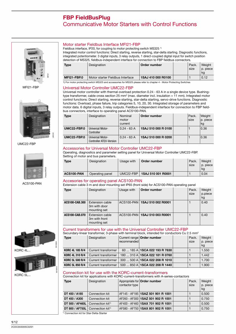
Universal Motor Controller UMC22-FBPUniversal motor controller with thermal overload protection 0.24 - 63 A in a single device type. Bushing-type transformer, cable cross section 25 mm2 (max. diameter incl. insulation = 11 mm). Integrated motor control functions: Direct starting, reverse starting, star-delta starting, servo-drive functions. Diagnostic functions: Overload, phase failure, trip categories 5, 10, 20, 30. Integrated storage of parameters and motor data. 6 digital inputs, 3 relay outputs. Fieldbus-independent interface for connection to FBP field-bus connectors, interface to operating panel ACS100-PAN.
Type Designation Nominal Order number Pack. Weight motor size p. piece current kg
UMC22-FBP.0 Universal Motor- 0.24 - 63 A 1SAJ 510 000 R 0100 1 0.36 Controller
UMC22-FBP.0 Universal Motor- 0.24 - 63 A 1SAJ 510 000 R 0200 1 0.36 Controller ATEX-Version
Motor starter Fieldbus Interface MFI21-FBPFieldbus interface, IP20, for coupling to motor protecting switch MS325 1)
Integrated motor control functions: Direct starting, reverse starting, star-delta starting. Diagnostic functions, integrated potentiometer. 3 digital inputs, 3 relay outputs, 1 direct-coupled digital input for switch position detection of MS325, fieldbus-independent interface for connection to FBP fieldbus connectors.
Type Designation Order number Pack. Weight size p. piece kg
MFI21-FBP.0 Motor starter Fieldbus Interface 1SAJ 410 000 R0100 1 0.121) For motor protecting switch MS325 and accessories for MS325 please refer to chapter 4 - Motor Protecting Switches
FBP FieldBusPlugCommunicative Motor Starters with Control Functions
MFI
21
UMC22-FBP
UM
C22
ACS100-PAN
Dis
pla
yUM
C22
MFI21-FBP
Type Designation Appropriate for Order number Pack. Weight contactor type size p. piece kg
DT 450 / A185 Connection kit AF145 - AF185 1SAZ 501 901 R 1001 1 0.500
DT 450 / A300 Connection kit AF260 - AF300 1SAZ 501 902 R 1001 1 0.750
DT 500 / AF460L Connection kit1) AF400 - AF460 1SAX 701 902 R 1001 1 0.500
DT 800 / AF750L Connection kit1) AF580 - AF750 1SAX 801 902 R 1001 1 0.750
Connection kit for use with the KORC-current-transformersConnection kit for applications with KORC-current-transformers with A-series-contactors
1) Connection kit for Star-Delta-Starter
KORC 4L...
KORC 5L...
S01
260A
S01
261A
Current transformers for use with the Universal Controller UMC22-FBPSecundary-linear transformer, 3-phase with terminal block, intended for conductors Cu 2.5 mm2
Type Designation Current range Order number Pack. Weight recommanded size p. piece kg
KORC 4L 185 R/4 Current transformer 60 ... 185 A 1SCA 022 193 R 7830 1 1.550
KORC 4L 310 R/4 Current transformer 180 ... 310 A 1SCA 022 181 R 0760 1 1.442
KORC 5L 500 R/4 Current transformer 300 ... 500 A 1SCA 022 208 R 1010 1 1.700
KORC 5L 850 R/4 Current transformer 500 ... 850 A 1SCA 022 208 R 1440 1 1.900
1/13
FBP
-Sys
tem
2CDC003005C0201
FBP FieldBusPlugFurther FBP Terminal Devices
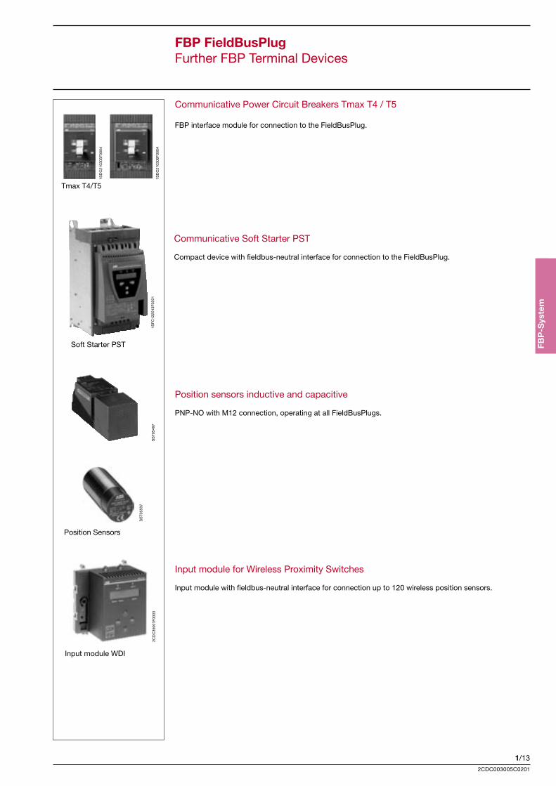
Communicative Power Circuit Breakers Tmax T4 / T5
FBP interface module for connection to the FieldBusPlug.
Tmax T4/T5
Communicative Soft Starter PST
Compact device with fieldbus-neutral interface for connection to the FieldBusPlug.
Position sensors inductive and capacitive
PNP-NO with M12 connection, operating at all FieldBusPlugs.
1SD
C21
0306
F000
4
1SD
C21
0305
F000
4
1SFC
1320
13F0
201
Soft Starter PST
SS
T054
97
Position Sensors
SS
T055
97
Input module for Wireless Proximity Switches
Input module with fieldbus-neutral interface for connection up to 120 wireless position sensors.
2CD
C35
001F
0003
Input module WDI
1/142CDC003005C0201
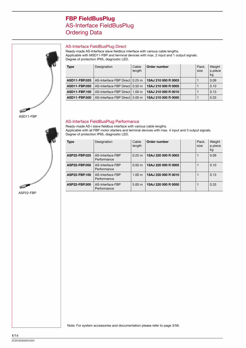
AS-Interface FieldBusPlug DirectReady-made AS-Interface slave fieldbus interface with various cable lengths.Applicable with MSD11-FBP and terminal devices with max. 2 input and 1 output signals.Degree of protection IP65, diagnostic LED.
Type Designation Cable Order number Pack. Weight length size p.piece kg
ASD11-FBP.025 AS-Interface FBP Direct 0.25 m 1SAJ 210 000 R 0003 1 0.09
ASD11-FBP.050 AS-Interface FBP Direct 0.50 m 1SAJ 210 000 R 0005 1 0.10
ASD11-FBP.100 AS-Interface FBP Direct 1.00 m 1SAJ 210 000 R 0010 1 0.13
ASD11-FBP.500 AS-Interface FBP Direct 5.00 m 1SAJ 210 000 R 0050 1 0.33
FBP FieldBusPlugAS-Interface FieldBusPlugOrdering Data
ASD11-FBP
Note: For system accessories and documentation please refer to page 3/56.
ASP22-FBP
AS-Interface FieldBusPlug PerformanceReady-made AS-i slave fieldbus interface with various cable lengths.Applicable with all FBP motor starters and terminal devices with max. 4 input and 3 output signals.Degree of protection IP65, diagnostic LED.
Type Designation Cable Order number Pack. Weight length size p.piece kg
ASP22-FBP.025 AS-Interface FBP 0.25 m 1SAJ 220 000 R 0003 1 0.09 Performance
ASP22-FBP.050 AS-Interface FBP 0.50 m 1SAJ 220 000 R 0005 1 0.10 Performance
ASP22-FBP.100 AS-Interface FBP 1.00 m 1SAJ 220 000 R 0010 1 0.13 Performance
ASP22-FBP.500 AS-Interface FBP 5.00 m 1SAJ 220 000 R 0050 1 0.33 Performance
1/15
FBP
-Sys
tem
2CDC003005C0201
FBP FieldBusPlugAS-Interface AccessoriesOrdering Data
Accessories for the AS-Interface Bus Connection
AS-Interface round cables for bus junctionsReady-made bus cable with M12 connector and open cable end.Applicable for bus junctions such as e.g. AS-Interface couplers or devices with integrated AS-Interfacecommunication.
Type AS-Interface Cable Order number Pack. Weight round cable length size p. piece for bus junctions kg
ASF11-FBP.030 Round cable with 0.30 m 1SAJ 922 002 R 0003 1 0.03 female connector
ASM11-FBP.030 Round cable with 0.30 m 1SAJ 922 003 R 0003 1 0.03 male connector
AS-Interface round cables for bus extensionsReady-made AS-Interface bus cable, round cable with M12 female and male connectors(ASX11-FBP.xxx), AS-Interface bus cable, round cable on coil (ASC11-FBP.999).
Type AS-Interface Cable Order number Pack. Weight extension cables length size p. piece kg
ASX11-FBP.100 Ready-made 1.00 m 1SAJ 922 001 R 0010 1 0.08
ASX11-FBP.300 Ready-made 3.00 m 1SAJ 922 001 R 0030 1 0.18
ASX11-FBP.500 Ready-made 5.00 m 1SAJ 922 001 R 0050 1 0.28
ASC11-FBP.999 Coil 100 m 1SAJ 922 004 R 1000 1 5.20
AS-Interface accessories for the bus extension
Type AS-Interface Order number Pack. Weight cable connectors size p. unit kg
ASM11-FBP.0 Male AS-Interface round c. conn. 1SAJ 922 005 R 0001 5 0.15
ASF11-FBP.0 Female AS-Interf. round c. conn. 1SAJ 922 006 R 0001 5 0.15
AST11-FBP.0 Flat cable branch circuit 1SAJ 922 007 R 0001 1 0.11 with M12 socket (junction to round cable)
AS-Interface addressing unit, miscellaneous accessories
Type Designation Order number Pack. Weight size p. unit kg
ASA21-FBP.0 Adressing unit incl. 1SAJ 922 010 R 0001 1 0.56 plug-in power supply unit
Note: For system accessories and documentation please refer to page 3/56 .
ASX11-FBP
AST11-FBP.0
ASF11-FBP.030
ASM11-FBP.0 ASF11-FBP.0
ASM11-FBP.030
ST0
4901
ST0
5901
ST0
5101
ST0
5501
ST0
5701
ST0
5601
1/162CDC003005C0201
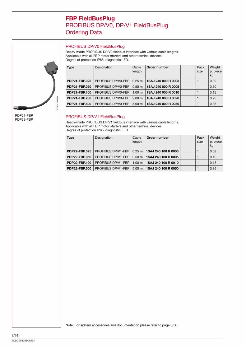
FBP FieldBusPlugPROFIBUS DP/V0, DP/V1 FieldBusPlugOrdering Data
PDP21-FBPPDP22-FBP
Note: For system accessories and documentation please refer to page 3/56.
PROFIBUS DP/V1 FieldBusPlugReady-made PROFIBUS DP/V1 fieldbus interface with various cable lengths.Applicable with all FBP motor starters and other terminal devices.Degree of protection IP65, diagnostic LED.
2CD
C34
1046
F003
PROFIBUS DP/V0 FieldBusPlugReady-made PROFIBUS DP/V0 fieldbus interface with various cable lengths.Applicable with all FBP motor starters and other terminal devices.Degree of protection IP65, diagnostic LED.
Type Designation Cable Order number Pack. Weight length size p. piece kg
PDP21-FBP.025 PROFIBUS DP/V0-FBP 0.25 m 1SAJ 240 000 R 0003 1 0.09
PDP21-FBP.050 PROFIBUS DP/V0-FBP 0.50 m 1SAJ 240 000 R 0005 1 0.10
PDP21-FBP.100 PROFIBUS DP/V0-FBP 1.00 m 1SAJ 240 000 R 0010 1 0.13
PDP21-FBP.200 PROFIBUS DP/V0-FBP 2.00 m 1SAJ 240 000 R 0020 1 0.20
PDP21-FBP.500 PROFIBUS DP/V0-FBP 5.00 m 1SAJ 240 000 R 0050 1 0.36
Type Designation Cable Order number Pack. Weight length size p. piece kg
PDP22-FBP.025 PROFIBUS DP/V1-FBP 0.25 m 1SAJ 240 100 R 0003 1 0.09
PDP22-FBP.050 PROFIBUS DP/V1-FBP 0.50 m 1SAJ 240 100 R 0005 1 0.10
PDP22-FBP.100 PROFIBUS DP/V1-FBP 1.00 m 1SAJ 240 100 R 0010 1 0.13
PDP22-FBP.500 PROFIBUS DP/V1-FBP 5.00 m 1SAJ 240 100 R 0050 1 0.36
1/17
FBP
-Sys
tem
2CDC003005C0201
PDX11-FBP
2CD
C34
1047
F003
PDR11-FBP.150
2CD
C34
1053
F003
2CD
C34
1034
F003
PDF11-FBP.050
PDM11-FBP.050
2CD
C34
1048
F003
2CD
C34
1049
F003
PDF11-FBP.0
PDM11-FBP.0
2CD
C34
1050
F003
2CD
C34
1051
F003
PDV11-FBP.0PDV12-FBP.0
2CD
C34
1006
F000
42C
DC
3410
07F0
004
PDA11-FBP.050
PDA12-FBP.050
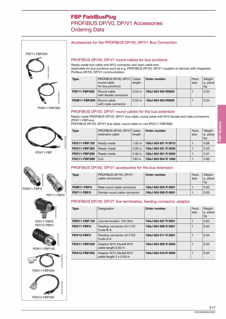
FBP FieldBusPlugPROFIBUS DP/V0, DP/V1 AccessoriesOrdering Data
Accessories for the PROFIBUS DP/V0, DP/V1 Bus Connection
PROFIBUS DP/V0, DP/V1 round cables for bus junctionsReady-made bus cable with M12 connector and open cable end.Applicable for bus junctions such as e.g. PROFIBUS DP/V0, DP/V1 couplers or devices with integratedProfibus DP/V0, DP/V1 communication.
Type PROFIBUS DP/V0, DP/V1 Cable Order number Pack. Weight round cable length size p. piece for bus junctions kg
PDF11-FBP.050 Round cable 0.50 m 1SAJ 924 002 R0005 1 0.04 with female connector
PDM11-FBP.050 Round cable 0.50 m 1SAJ 924 003 R0005 1 0.04 with male connector
PROFIBUS DP/V0, DP/V1 round cables for the bus extensionReady-made PROFIBUS DP/V0, DP/V1 bus cable, round cable with M12 female and male connectors(PDX11-FBP.xxx).PROFIBUS DP/V0, DP/V1 bus cable, round cable on coil (PDC11-FBP.999).
Type PROFIBUS DP/V0, DP/V1 Cable Order number Pack. Weight extension cable length size p. piece kg
PDX11-FBP.100 Ready-made 1.00 m 1SAJ 924 001 R 0010 1 0.08
PDX11-FBP.300 Ready-made 3.00 m 1SAJ 924 001 R 0030 1 0.20
PDX11-FBP.500 Ready-made 5.00 m 1SAJ 924 001 R 0050 1 0.31
PDC11-FBP.999 Coil 100 m 1SAJ 924 004 R 1000 1 5.60
PROFIBUS DP/V0, DP/V1 accessories for the bus extension
Type PROFIBUS DP/V0. DP/V1 Order number Pack. Weight cable connectors size p. piece kg
PDM11-FBP.0 Male round cable connector 1SAJ 924 005 R 0001 1 0.03
PDF11-FBP.0 Female round cable connector 1SAJ 924 006 R 0001 1 0.03
PROFIBUS DP/V0, DP/V1 line termination, feeding connector, adaptor
Type Designation Order number Pack. Weight size p. piece kg
PDR11-FBP.150 Line termination 150 Ohm 1SAJ 924 007 R 0001 1 0.03
PDV11-FBP.0 Feeding connector 24 V DC 1SAJ 924 008 R 0001 1 0.04 Code B-A
PDV12-FBP.0 Feeding connector 24 V DC 1SAJ 924 011 R 0001 1 0.04 Code A-A
PDA11-FBP.050 Adaptor M12-Dsub9-M12 1SAJ 924 009 R 0005 1 0.04 cable length 0.50 m
PDA12-FBP.050 Adaptor M12-Dsub9-M12 1SAJ 924 010 R 0005 1 0.04 cable length 2 x 0.50 m

1/182CDC003005C0201
FBP FieldBusPlugDeviceNet, CANopen and MODBUS-RTU FieldBusPlugsOrdering Data
DNP21-FBPCOP21-FBPMRP21-FBP
DeviceNet FieldBusPlugReady-made DeviceNet fieldbus interface with various cable lengths. Applicable with all FBP motor star-ters and other terminal devices. Degree of protection IP65, diagnostic LED.
Type Designation Cable Order number Pack. Weight length size p. piece kg
DNP21-FBP.025 DeviceNet-FBP 0.25 m 1SAJ 230 000 R0003 1 0.09
DNP21-FBP.050 DeviceNet-FBP 0.50 m 1SAJ 230 000 R0005 1 0.10
DNP21-FBP.100 DeviceNet-FBP 1.00 m 1SAJ 230 000 R0010 1 0.13
DNP21-FBP.500 DeviceNet-FBP 5.00 m 1SAJ 230 000 R0050 1 0.36
CANopen FieldBusPlug*Ready-made CANopen fieldbus interface with various cable lengths. Applicable with all FBP motor star-ters and other terminal devices. Degree of protection IP65, diagnostic LED.
Type Designation Cable Order number Pack. Weight length size p. piece kg
COP21-FBP.025 CANopen-FBP 0.25 m 1SAJ 230 100 R0003 1 0.09
COP21-FBP.050 CANopen-FBP 0.50 m 1SAJ 230 100 R0005 1 0.10
COP21-FBP.100 CANopen-FBP 1.00 m 1SAJ 230 100 R0010 1 0.13
COP21-FBP.500 CANopen-FBP 5.00 m 1SAJ 230 100 R0050 1 0.36
* not yet available
MODBUS-RTU FieldBusPlugReady-made MODBUS-RTU fieldbus interface with various cable lengths. Applicable with all FBP motor starters and other terminal devices. Degree of protection IP65, diagnostic LED.
Type Designation Cable Order number Pack. Weight length size p. piece kg
MRP21-FBP.025 MODBUS-RTU-FBP 0.25 m 1SAJ 250 000 R0003 1 0.09
MRP21-FBP.050 MODBUS-RTU-FBP 0.50 m 1SAJ 250 000 R0005 1 0.10
MRP21-FBP.100 MODBUS-RTU-FBP 1.00 m 1SAJ 250 000 R0010 1 0.13
MRP21-FBP.500 MODBUS-RTU-FBP 5.00 m 1SAJ 250 000 R0050 1 0.36
B10
_328
2_R
ET
1/19
FBP
-Sys
tem
2CDC003005C0201
DeviceNet, CANopen, MODBUS-RTU Accessories for the bus extension
Type DeviceNet, CANopen, Order number Pack. Weight MODBUS-RTU cable connectors size p. piece kg
DNM11-FBP.0 Round cable male plug 1SAJ 923 005 R 0001 5 0.15
DNF11-FBP.0 Rund cable female plug 1SAJ 923 006 R 0001 5 0.15
FBP FieldBusPlugDeviceNet, CANopen, MODBUS-RTU AccessoriesOrdering Data
DeviceNet, CANopen, MODBUS-RTU termination resistor and other accessories
Type DeviceNet, CANopen, Order number Pack. Weight MODBUS-RTU bus accessories size p. piece kg
DNR11-FBP.120 Terminating resistor 120 Ohm 1SAJ 923 007 R 0001 1 0.02
Note: For system accessories and documentation please refer to page 3/56.
Accessories for the DeviceNet, CANopen, MODBUS-RTU bus connectionDeviceNet, CANopen, MODBUS-RTU round cables for bus junctionsReady-made bus cable with an M12 plug and an open cable end.Applicable with bus junctions such as DeviceNet, CANopen, MODBUS-RTU couplers or devices with an integrated DeviceNet, CANopen, MODBUS-RTU communication.
Type DeviceNet, CANopen Cable Order number Pack. Weight MODBUS-RTU round length size p. piece cables for bus junctions kg
DNF11-FBP.050 Round cable 0.50 m 1SAJ 923 002 R 0005 1 0.04 with male plug
DNM11-FBP.050 Round cable 0.50 m 1SAJ 923 003 R 0005 1 0.04 with female plug
DeviceNet, CANopen, MODBUS-RTU round cables for the bus extensionReady-made DeviceNet, CANopen, MODBUS-RTU bus cable, round cable with M12 male and female plugs (DNX11-FBP.xxx). DeviceNet, CANopen, MODBUS-RTU bus cable, round cable as a coil (MRC11-FBP.999).
Type DeviceNet, CANopen, Cable Order number Pack. Weight MODBUS-RTU length size p. piece extension cables kg
DNX11-FBP.100 Ready-made 1.00 m 1SAJ 923 001 R 0010 1 0.08
DNX11-FBP.300 Ready-made 3.00 m 1SAJ 923 001 R 0030 1 0.20
DNX11-FBP.500 Ready-made 5.00 m 1SAJ 923 001 R 0050 1 0.31
DNC11-FBP.999 Coil (Drop cable) 100.00 m 1SAJ 923 004 R 1000 1 5.60
DNF11-FBP.050
DNR11-FBP.050
ST0
5301
ST0
5201
DNX11-FBP
ST0
4801
DNM11-FBP.0
ST0
5701
DNF11-FBP.0
ST0
5401
DNR11-FBP.120
ST0
5501
1/202CDC003005C0201
FieldBusPlug accessories for installation inside control cabinet drawer systemsFixing bracket for passive plug for installation of FBP terminal devices in drawer systems.FBP passive cable for installation of FBP terminal devices in drawer systems.
Type Designation Length Order number Pack. Weight size p. piece kg
CDP11-FBP.0 Passive plug fixing 1SAJ 929 100 R 0001 50 0.50 bracket for drawer systems.
CDP12-FBP.100 Passive cable for 1.00 m 1SAJ 929 120 R 0001 1 0.20 drawer systems (outside)
CDP13-FBP.100 Passive cable for 1.00 m 1SAJ 929 110 R 0001 1 0.31 drawer systems (inside)
FBP addressing set for PROFIBUS DP/V0, DP/V1, DeviceNet, CANopen, MODBUS-RTUFor setting the FieldBusPlug connector address (PROFIBUS DP and DeviceNet). Consisting of software package for notebook, level converter incl. battery and cable to notebook.
Type Designation Order number Pack. Weight size p. unit kg
CAS21-FBP.0 Adressing set for 1SAJ 929 003 R0001 1 0.40 PROFIBUS DP/V0, DP/V1, DeviceNet, CANopen, MODBUS-RTU
FBP FieldBusPlugSystem Accessories and DocumentationOrdering Data
FieldBusPlug power supply unitSupply voltage 90...260 V AC, 47...63 Hz.Adjustable output voltage 23...28 V DC, 5 A.
Type Designation Order number Pack. Weight size p. unit kg
CP-24/5.0 Netzteil 24 V / 5 A 1SVR 423 416 R0100 1 0.58
FieldBusPlug system documentationComplete system documentation for planning and project planning.Technical data, software, examples, FAQs.
Type Designation Language Order number Pack. Weight size p. piece kg
FieldBusPlug CD-ROM Version German 2CDC 190 008 E 0401 1 0.01 documentation English
FieldBusPlug addressing labelsFor addressing the FieldBusPlug connectors.
Type Designation Order number Pack. Weight size p. unit kg
CAL11-FBP.0 400 Adressing labels for FBPs 1SAJ 929 005 R0001 1 0.15

1/21
FBP
-Sys
tem
2CDC003005C0201
Notes
ControlIT Automation Devices
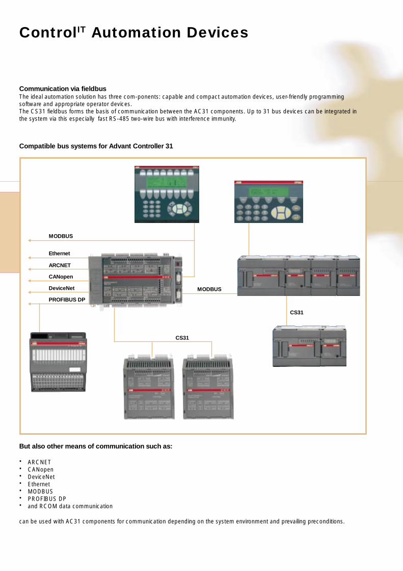
Communication via fieldbusThe ideal automation solution has three com-ponents: capable and compact automation devices, user-friendly programmingsoftware and appropriate operator devices.The CS31 fieldbus forms the basis of communication between the AC31 components. Up to 31 bus devices can be integrated inthe system via this especially fast RS-485 two-wire bus with interference immunity.
MODBUSF
F
F
F
F
F
Ethernet
ARCNET
CANopen
DeviceNet
PROFIBUS DP
MODBUS
CS31
CS31
But also other means of communication such as:
• ARCNET• CANopen• DeviceNet• Ethernet• MODBUS• PROFIBUS DP• and RCOM data communication
can be used with AC31 components for communication depending on the system environment and prevailing preconditions.
Compatible bus systems for Advant Controller 31
Control IT
Automation DevicesProgrammable Controllers,I/O-Modules &Operator Terminals
PLC
etc
.
Contents
Control IT Automation Devices
Overview Automation devices ............................................................................................ 2/ 2• Control IT AC31 PLC family• The communication protocols• Safety-related controllers AC31-S – Safety First• Programming package 907AC1131
Overview logic module AC010 ........................................................................................... 2/ 7
System data AC31 ............................................................................................................. 2/ 9
Overview Central Units AC31 ............................................................................................ 2/ 12
Overview I/O-modules AC31 series 40..50, series 90 and S500 ....................................... 2/ 14
Dimensions drawings central units, I/O-modules and communication-modules ................ 2/ 16
Ordering data small PLC – AC31 series 40..50 ................................................................. 2/ 18• Central units• I/O-modules• Communication module MODBUS• Accessories
Ordering data compact PLC – AC31 series 90 and Slot-PLC .......................................... 2/ 21• Central Units• I/O-modules• Communication modules• Accessories
Ordering data programming package 907AC1131 ............................................................ 2/ 23
Ordering data safety PLC – AC31-S .................................................................................. 2/ 24
Ordering data repeater for CS31 fieldbus .......................................................................... 2/ 25
Ordering data I/O-modules for PROFIBUS DP – S500 ..................................................... 2/ 27
Operator Terminals
Overview ............................................................................................................................ 2/ 31
Ordering data operator terminals with text display ............................................................. 2/ 34
Ordering data operator terminals with graphic display ....................................................... 2/ 34
Ordering data operator terminals with touch screens ........................................................ 2/ 34
Ordering data accessories ................................................................................................. 2/ 35
2/2
2CDC003005C0201
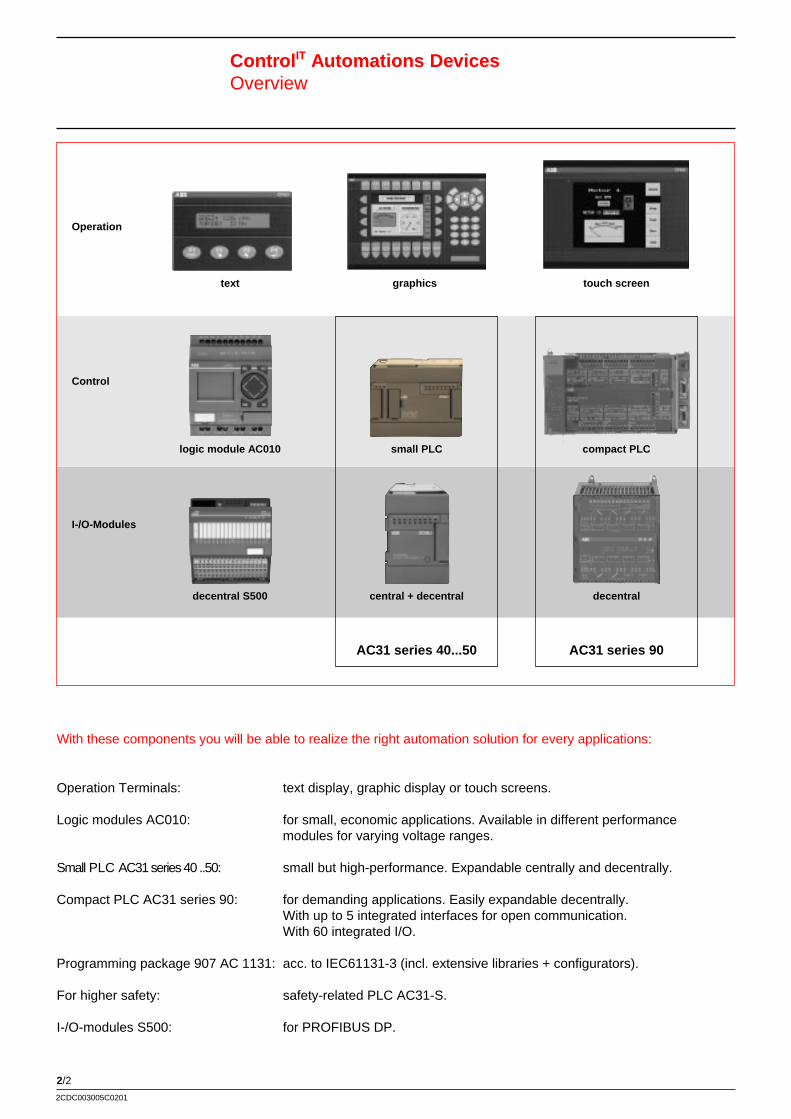
Control IT Automations DevicesOverview
Operation
Control
I-/O-Modules
text graphics touch screen
logic module AC010
decentral S500
small PLC
central + decentral
AC31 series 40...50
compact PLC
decentral
AC31 series 90
With these components you will be able to realize the right automation solution for every applications:
Operation Terminals: text display, graphic display or touch screens.
Logic modules AC010: for small, economic applications. Available in different performancemodules for varying voltage ranges.
Small PLC AC31 series 40 ..50: small but high-performance. Expandable centrally and decentrally.
Compact PLC AC31 series 90: for demanding applications. Easily expandable decentrally.With up to 5 integrated interfaces for open communication.With 60 integrated I/O.
Programming package 907 AC 1131: acc. to IEC61131-3 (incl. extensive libraries + configurators).
For higher safety: safety-related PLC AC31-S.
I-/O-modules S500: for PROFIBUS DP.
2/3
PLC
etc
.
2CDC003005C0201
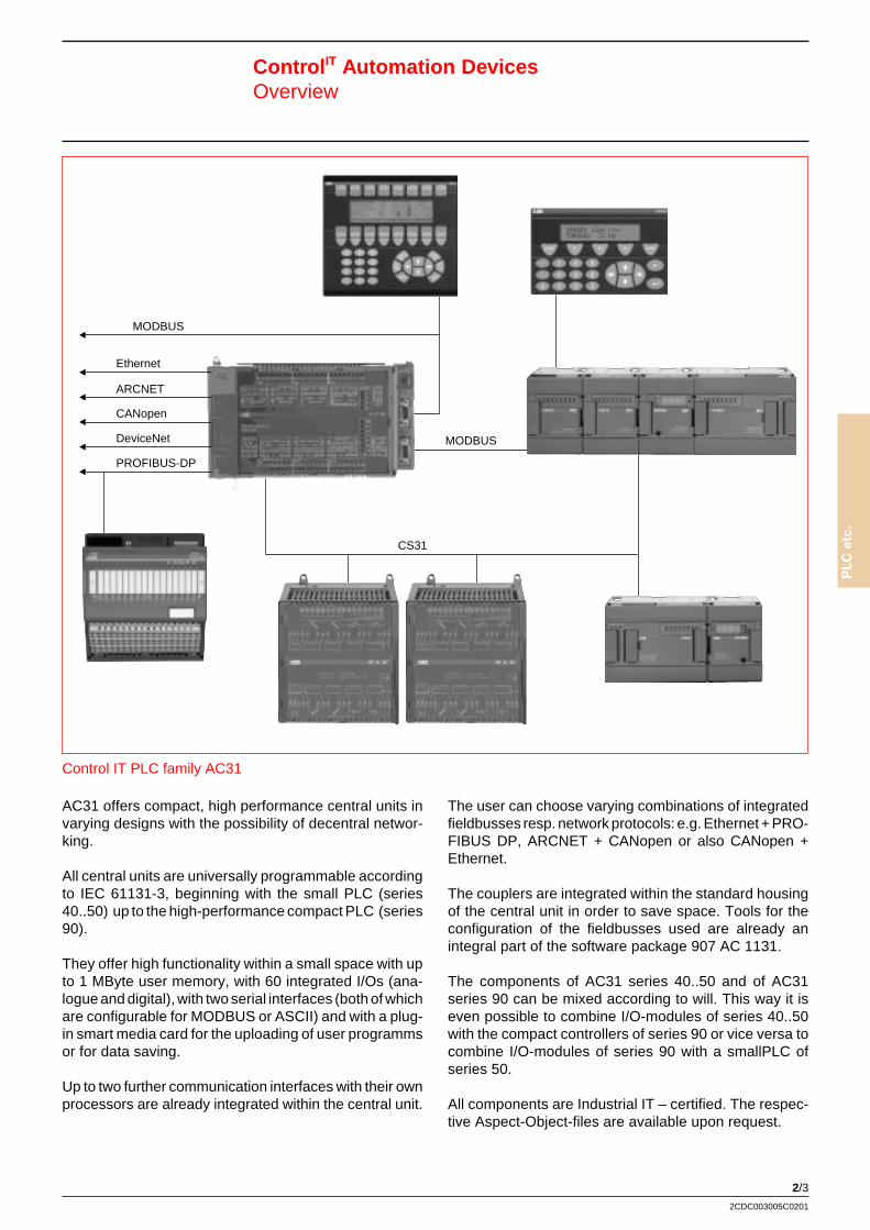
Control IT Automation DevicesOverview
MODBUSF
F
F
F
F
F
Ethernet
ARCNET
CANopen
DeviceNet
PROFIBUS-DP
MODBUS
CS31
Control IT PLC family AC31
AC31 offers compact, high performance central units invarying designs with the possibility of decentral networ-king.
All central units are universally programmable accordingto IEC 61131-3, beginning with the small PLC (series40..50) up to the high-performance compact PLC (series90).
They offer high functionality within a small space with upto 1 MByte user memory, with 60 integrated I/Os (ana-logue and digital), with two serial interfaces (both of whichare configurable for MODBUS or ASCII) and with a plug-in smart media card for the uploading of user programmsor for data saving.
Up to two further communication interfaces with their ownprocessors are already integrated within the central unit.
The user can choose varying combinations of integratedfieldbusses resp. network protocols: e.g. Ethernet + PRO-FIBUS DP, ARCNET + CANopen or also CANopen +Ethernet.
The couplers are integrated within the standard housingof the central unit in order to save space. Tools for theconfiguration of the fieldbusses used are already anintegral part of the software package 907 AC 1131.
The components of AC31 series 40..50 and of AC31series 90 can be mixed according to will. This way it iseven possible to combine I/O-modules of series 40..50with the compact controllers of series 90 or vice versa tocombine I/O-modules of series 90 with a smallPLC ofseries 50.
All components are Industrial IT – certified. The respec-tive Aspect-Object-files are available upon request.
2/4
2CDC003005C0201
Control IT Automation DevicesOverview
The communication protocols – an overview
Communication Descriptionprocessor/module
MODBUS Due to its high dissemination, this protocol offers connectivity for controllers of diffe-rent origin, to operating panels and PC operating stations. The MODBUS interface(s)is integrated in the CPU. A further MODBUS coupler with 2 additional interfaces canbe attached.Max. number of particpants with RS 485: 32. Max distance with RS 485: 1.2 km.Possibility for connecting a user-to-user modems. Network design: Point-to-point andmultipoint-line.
Ethernet Supports sending and receiving data via TCP/IP and/or UDP/IP. Further applicationlayers can be implemented by download. It is even possible to run TCP/IP, UDP/IPand application layers simultaneously. The protocols: IP, TCP, UDP, ARP, RP,BOOTP, DHCP are supported as standard. A communication with third-party-sys-tems is possible using either MODBUS/TCP or customer specific applications layers.Transfer rate 10 / 100 Mbit/s.
CANopen Standardised layer-7-protocol on the basis of Controller Area Network (CAN) and ofthe CAN application layer (CAL). The access method is based on the master-slave-principal. It allows for the combined operation of several busmasters as well as thesynchronized data transmission to multiple subscribers and up to 2.048 different com-munication objects. Baud rate of up to 1 Mbit/s.Protocols: event-triggerd, cyclical, acyclical, on demand.
PROFIBUS DP Allows for the master-and-slave communication in the field.Connection to automation systems of third-party manufacturers as well as intelligentpreprocessors like drives, control panels and sensors.Max. lenght of the net (RS 485): 1200 m at 9.6 kBit/s. 32 stations per net max(master and slave). 126 with repeater. Transfer rate 9,6 kBit/s up to 12 MBit/s.
ARCNET is the basis for an economical and fast integration of AC31 progammable controllers.Also suited for the process visualisation or for connection of other systems.Data transfer rate of 2.5 MBit/s. Collision free data transfer due to token bus withautomated login and logoff of participants. Automated reconfiguration of the netwhen a station activates or deactivates.Up to 255 masters on the same net.Overall net lenght 300 m, up to 6 km with repeaters . All net forms e. g. net, star.
RCOM is a communication protocol designed for the remote data transmisson. It is suitedfor transmissions using a user-to-user or dial-up connection.Standard modems establish the connection between stations.
DeviceNet For fast data exchange on the field level. For coupling of decentral field deviceslike I/O, drives and valves.
CS31 Bus for the easy connection of CPUs and I/O devices . The CS31 system bus isa RS 485-2-wire bus, designed for a fast and interference resistant data transfer. Upto 31 I/O-devices.Max. lenght: 500 m resp. 2000 m with repeater. With repeaters you can also achievebus redundancy. Transfer rate: 187.5 KBaud.
AC31 Safety-Fieldbus For the certified transmission of safety signals between safety-related controllers andthe safety-related I/O devices (AC31-S only). Mixing of safety-related signals andoperation signals
2/5
PLC
etc
.
2CDC003005C0201
Control IT Automation DevicesOverview
07KT51 07KT94-S 07KT95 07KT96 07KT97 07KT98 07SL97
MODBUS x x x x x x x
Ethernet x x
CANopen x x
PROFIBUS DP x x x
ARCNET x x x x
DFÜ RCOM x x x x x
DeviceNet x x x
CS31 system bus x x x x x x x
AC31 Safety Fieldbus x
Safety PLC AC31-S - Safety First
Nowadays, machine and plant manufacturers are con-fronted by ever more extensive and ever more stringentsafety conditions, in line with the demand that the safetyof machines and systems must be implemented optimallyand in line with the “state of the art” for protection of man,machine and the environment. The safety-related auto-mation system AC31-S allows small, distributed controlunits to be designed and standardised. They operateautonomously at a local level where the safety function isrequired. The relevant, related inputs and outputs areinstalled in the field where the signal is detected or output.They are connected to their central unit via the AC31Safety Fieldbus. This helps, once again, to save oncables. These control units can be networked flexibly andcan exchange data among each other or with a higher-level system.
Economical
The Advant Controller 31-S requires no redundantcentral unit for safety functions, so this system is lowcostboth as regards hardware and as regards engineering.The I/O units at a local level already feature an internal 2-channel structure and monitor themselves, includingpassive error and fault detection.
One set of hardware for all functions
The hardware of the Advant Controller 31-S supportsthe safety functions and operating functions simultane-ously. At the AC31 safety field bus safety-related I/Omodules and standard I/Os can be mixed.
The safety-related functions are programmed with thehelp of certified function blocks.
The controller is certified for requirement class 4 andsafety categorie 3.
2/6
2CDC003005C0201
Control IT Automation DevicesOverview
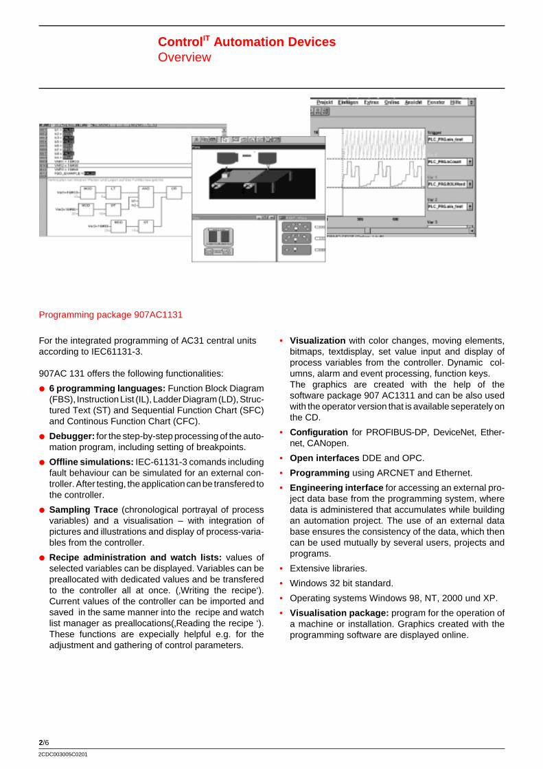
For the integrated programming of AC31 central unitsaccording to IEC61131-3.
907AC 131 offers the following functionalities:
P 6 programming languages: Function Block Diagram(FBS), Instruction List (IL), Ladder Diagram (LD), Struc-tured Text (ST) and Sequential Function Chart (SFC)and Continous Function Chart (CFC).
P Debugger: for the step-by-step processing of the auto-mation program, including setting of breakpoints.
P Offline simulations: IEC-61131-3 comands includingfault behaviour can be simulated for an external con-troller. After testing, the application can be transfered tothe controller.
P Sampling Trace (chronological portrayal of processvariables) and a visualisation – with integration ofpictures and illustrations and display of process-varia-bles from the controller.
P Recipe administration and watch lists: values ofselected variables can be displayed. Variables can bepreallocated with dedicated values and be transferedto the controller all at once. (‚Writing the recipe‘).Current values of the controller can be imported andsaved in the same manner into the recipe and watchlist manager as preallocations(‚Reading the recipe ‘).These functions are expecially helpful e.g. for theadjustment and gathering of control parameters.
• Visualization with color changes, moving elements,bitmaps, textdisplay, set value input and display ofprocess variables from the controller. Dynamic col-umns, alarm and event processing, function keys.The graphics are created with the help of thesoftware package 907 AC1311 and can be also usedwith the operator version that is available seperately onthe CD.
• Configuration for PROFIBUS-DP, DeviceNet, Ether-net, CANopen.
• Open interfaces DDE and OPC.
• Programming using ARCNET and Ethernet.
• Engineering interface for accessing an external pro-ject data base from the programming system, wheredata is administered that accumulates while buildingan automation project. The use of an external database ensures the consistency of the data, which thencan be used mutually by several users, projects andprograms.
• Extensive libraries.
• Windows 32 bit standard.
• Operating systems Windows 98, NT, 2000 und XP.
• Visualisation package: program for the operation ofa machine or installation. Graphics created with theprogramming software are displayed online.
Programming package 907AC1131
2/7
PLC
etc
.
2CDC003005C0201
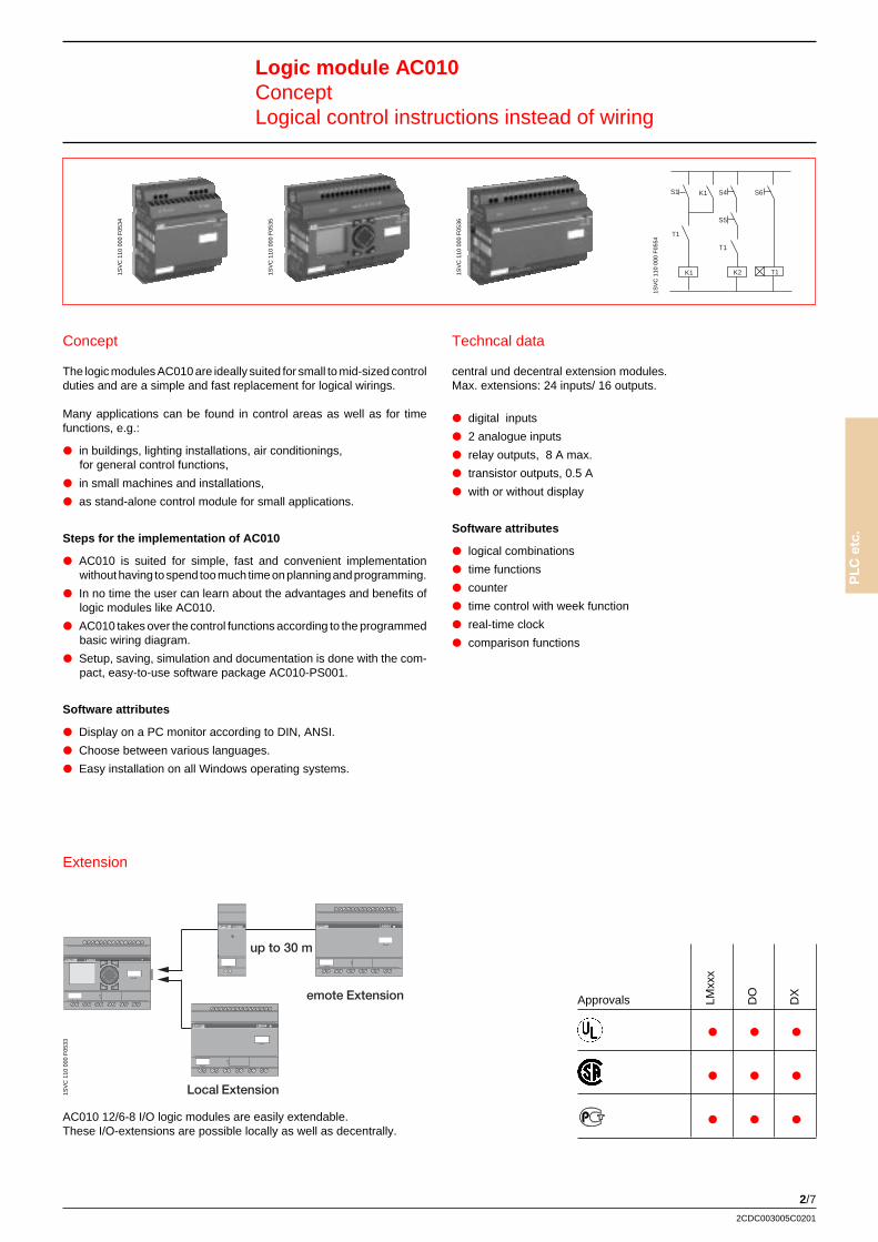
Logic module AC010ConceptLogical control instructions instead of wiring
Concept
The logic modules AC010 are ideally suited for small to mid-sized controlduties and are a simple and fast replacement for logical wirings.
Many applications can be found in control areas as well as for timefunctions, e.g.:
P in buildings, lighting installations, air conditionings,for general control functions,
P in small machines and installations,
P as stand-alone control module for small applications.
Steps for the implementation of AC010
P AC010 is suited for simple, fast and convenient implementationwithout having to spend too much time on planning and programming.
P In no time the user can learn about the advantages and benefits oflogic modules like AC010.
P AC010 takes over the control functions according to the programmedbasic wiring diagram.
P Setup, saving, simulation and documentation is done with the com-pact, easy-to-use software package AC010-PS001.
Software attributes
P Display on a PC monitor according to DIN, ANSI.
P Choose between various languages.
P Easy installation on all Windows operating systems.
Extension
AC010 12/6-8 I/O logic modules are easily extendable.These I/O-extensions are possible locally as well as decentrally.
Techncal data
central und decentral extension modules.Max. extensions: 24 inputs/ 16 outputs.
P digital inputs
P 2 analogue inputs
P relay outputs, 8 A max.
P transistor outputs, 0.5 A
P with or without display
Software attributes
P logical combinations
P time functions
P counter
P time control with week function
P real-time clock
P comparison functions
Approvals
P P P
P P P
P P P
LMxx
x
DO
DX
1SV
C 1
10 0
00 F
0533
1SV
C 1
10 0
00 F
0534
1SV
C 1
10 0
00 F
0535
1SV
C 1
10 0
00 F
0536
S1 K1 S4
S5
K1 K2 T1
T1
T1
S6
1SV
C 1
10 0
00 F
0554
up to 30 m
Local Extension
Remote Extension
2/8
2CDC003005C0201
Logic module AC010Applications and BenefitsProduct overview
Applications
Industrial
K machine building
K compressor control
K gas- / airdryer
K packaging machines
K transport systems
K etc.
Building technology
K control of lights and doors
K fans
K air conditioning systems
Power engineering
K generators
K solar- and wind technology
K water supply
K sewage technology
K etc.
Oil, gas and water
K pump control
K tank- und level control
K etc.
Costsaving benefits
K Control programms, logical functions, time modules,relay in one device
K Saves time and costs in the planning and adaption of the project
K Fast and economical solution for logic control and wiring
K Fast and easy handling
K Very little investment of time necessary for getting to know AC010
applications
K Extendable up to 40 I/Os
K Display for text informationen, parameters,wiring and status
K Memory card for saving the program or for saving times andfunctions
K Password protection
K Compact and convenient software for programmingand documentation
Product overview
Type
LM021-12RDC x 8 4R 8 A x – –
LM022-C12RDC x 8 4R 8 A x x –
LM023-C12RDC12V x 8 4R 8 A x x –
LM024-CX12RDC x 8 4R 8 A – x –
LM025-C12TDC x 8 4T 0.5 A x x –
LM026-CX12TDC x 8 4T 0.5 A – x –
LM041-CE18RDC x 12 6R 8 A x x x x x x x x
LM042-CXE18RDC x 12 6R 8 A – x x x x x x
LM043-CE20TDC x 12 8T 0.5 A x x x x x x x x
LM044-CXE20TDC x 12 8T 0.5 A – x x x x x x
LM001-12RAC x 8 4R 8 A x – –
LM002-C12RAC x 8 4R 8 A x x –
LM003-CX12RAC x 8 4R 8 A – x –
LM011-CE18RAC x 12 6R 8 A x x x x x x x x
LM012-CXE18RAC x 12 6R 8 A x x x x x x x x
Sup
ply
115/
230
V A
C
Sup
ply
24 V
DC
Sup
ply
12 V
DC
Inpu
ts
Out
puts
:R
= R
elay
, T =
Tra
nsis
tor
Con
tinuo
us c
urre
nt O
utpu
ts
LC D
ispl
ay, k
ey p
ad
Tex
t dis
play
Wee
k fu
nctio
n tim
e co
ntro
l
Ext
enda
ble
with
mod
ules
in fo
llow
ing
colu
mns
DO
001-
EX
02R
(on
ly lo
kally
)
DX
001-
EX
18R
AC
DX
011-
EX
18R
DC
DX
021-
EX
20T
DC
2/9
PLC
etc
.
2CDC003005C0201
Control IT Automation DevicesSystem data
System data AC31 series 40..50
Operation and environmental conditions
Environmental conditions
• Temperature:
Operation: horizontal 0 °C to + 55 °Cvertikal 0 °C to + 40 °C
Storage – 40 °C to + 75 °C
Transport – 25 °C to + 75 °C
• Humidity: DIN 40040 class F without bedewing
Anual average < 75%
up to 30 day of the year 95%
occasional 85%
• Air pressure: DIN 40050
Operation > 800 hPa (< 2000 m)
Storage > 600 hPa (< 3500 m)
Mechanical data
• Protection class IP 20
• Housing UL V2
• Vibration resistance CEI68-2-8 Test Fc
• Shock resistance CEI68-2-27 Test Ea
Tolerances for line voltage
• 24 V DC 9.2 to 30 V (– 20%, + 25%)
• 120 V AC (50 / 60 Hz) 97.75 to 126.5 V (– 18.5%, + 5.5%)
• 230 V AC (50 / 60 Hz) 195.5 to 253 V (– 15%, + 10%)
2/10
2CDC003005C0201
Control IT Automation DevicesSystem data
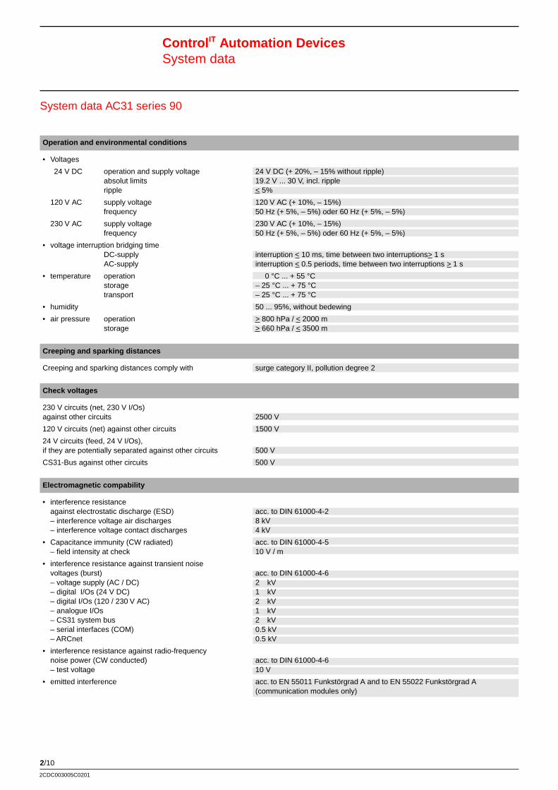
System data AC31 series 90
Operation and environmental conditions
• Voltages
24 V DC operation and supply voltage 24 V DC (+ 20%, – 15% without ripple)absolut limits 19.2 V ... 30 V, incl. rippleripple < 5%
120 V AC supply voltage 120 V AC (+ 10%, – 15%)frequency 50 Hz (+ 5%, – 5%) oder 60 Hz (+ 5%, – 5%)
230 V AC supply voltage 230 V AC (+ 10%, – 15%)frequency 50 Hz (+ 5%, – 5%) oder 60 Hz (+ 5%, – 5%)
• voltage interruption bridging timeDC-supply interruption < 10 ms, time between two interruptions> 1 sAC-supply interruption < 0.5 periods, time between two interruptions > 1 s
• temperature operation 0 °C ... + 55 °Cstorage – 25 °C ... + 75 °Ctransport – 25 °C ... + 75 °C
• humidity 50 ... 95%, without bedewing
• air pressure operation > 800 hPa / < 2000 mstorage > 660 hPa / < 3500 m
Creeping and sparking distances
Creeping and sparking distances comply with surge category II, pollution degree 2
Check voltages
230 V circuits (net, 230 V I/Os)against other circuits 2500 V
120 V circuits (net) against other circuits 1500 V
24 V circuits (feed, 24 V I/Os),if they are potentially separated against other circuits 500 V
CS31-Bus against other circuits 500 V
Electromagnetic compability
• interference resistanceagainst electrostatic discharge (ESD) acc. to DIN 61000-4-2– interference voltage air discharges 8 kV– interference voltage contact discharges 4 kV
• Capacitance immunity (CW radiated) acc. to DIN 61000-4-5– field intensity at check 10 V / m
• interference resistance against transient noisevoltages (burst) acc. to DIN 61000-4-6– voltage supply (AC / DC) 2 kV– digital I/Os (24 V DC) 1 kV– digital I/Os (120 / 230 V AC) 2 kV– analogue I/Os 1 kV– CS31 system bus 2 kV– serial interfaces (COM) 0.5 kV– ARCnet 0.5 kV
• interference resistance against radio-frequencynoise power (CW conducted) acc. to DIN 61000-4-6– test voltage 10 V
• emitted interference acc. to EN 55011 Funkstörgrad A and to EN 55022 Funkstörgrad A(communication modules only)
2/11
PLC
etc
.
2CDC003005C0201
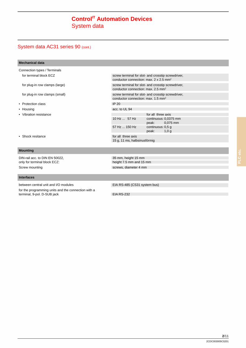
System data AC31 series 90 (cont.)
Mechanical data
Connection types / Terminals
for terminal block ECZ screw terminal for slot- and crosstip screwdriver,conductor connection: max. 2 x 2.5 mm2
for plug-in row clamps (large) screw terminal for slot- and crosstip screwdriver,conductor connection: max. 2.5 mm2
for plug-in row clamps (small) screw terminal for slot- and crosstip screwdriver,conductor connection: max. 1.5 mm2
• Protection class IP 20
• Housing acc. to UL 94
• Vibration resistance for all three axis10 Hz ... 57 Hz continuous: 0,0375 mm
peak: 0,075 mm57 Hz ... 150 Hz continuous: 0,5 g
peak: 1,0 g
• Shock resitance for all three axis15 g, 11 ms, halbsinusförmig
Mounting
DIN-rail acc. to DIN EN 50022, 35 mm, height 15 mmonly for terminal block ECZ: height 7.5 mm and 15 mm
Screw mounting screws, diameter 4 mm
Interfaces
between central unit and I/O modules EIA RS-485 (CS31 system bus)
for the programming units and the connection with aterminal, 9-pol. D-SUB jack EIA RS-232
Control IT Automation DevicesSystem data
2/12
2CDC003005C0201
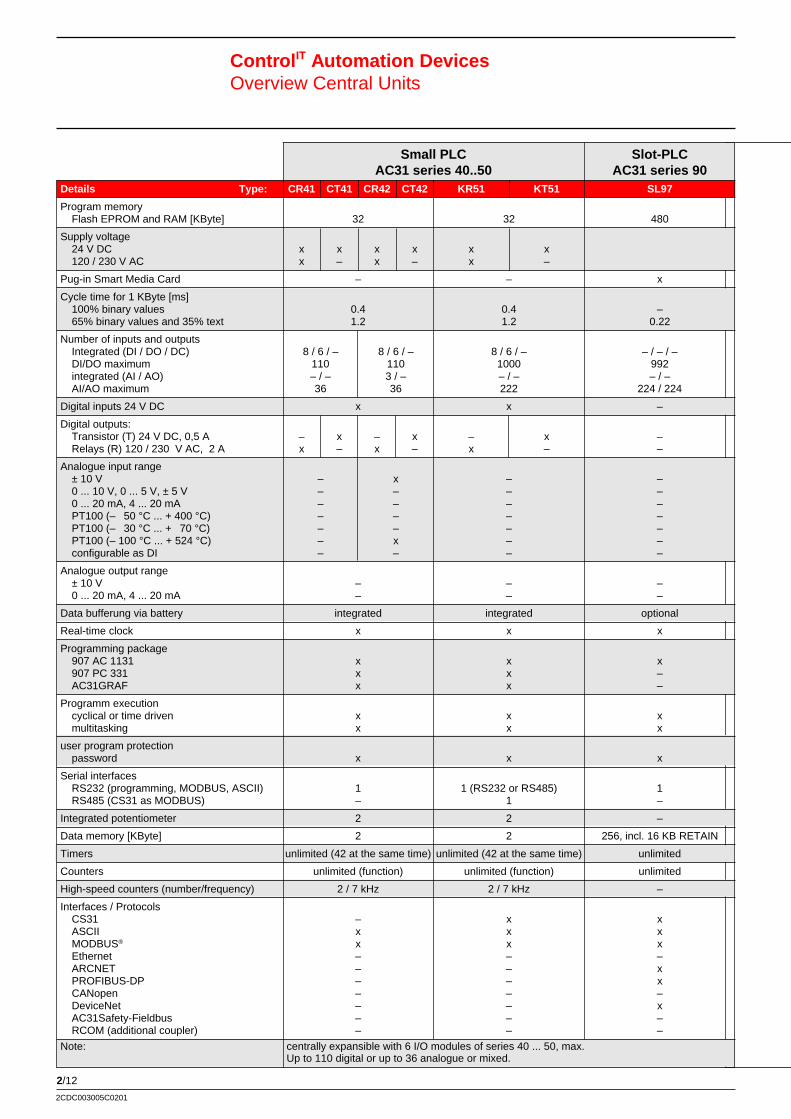
Control IT Automation DevicesOverview Central Units
Small PLC Slot-PLCAC31 series 40..50 AC31 series 90
Details Type: CR41 CT41 CR42 CT42 KR51 KT51 SL97
Program memoryFlash EPROM and RAM [KByte] 32 32 480
Supply voltage24 V DC x x x x x x120 / 230 V AC x – x – x –
Pug-in Smart Media Card – – x
Cycle time for 1 KByte [ms]100% binary values 0.4 0.4 –65% binary values and 35% text 1.2 1.2 0.22
Number of inputs and outputsIntegrated (DI / DO / DC) 8 / 6 / – 8 / 6 / – 8 / 6 / – – / – / –DI/DO maximum 110 110 1000 992integrated (AI / AO) – / – 3 / – – / – – / –AI/AO maximum 36 36 222 224 / 224
Digital inputs 24 V DC x x –
Digital outputs:Transistor (T) 24 V DC, 0,5 A – x – x – x –Relays (R) 120 / 230 V AC, 2 A x – x – x – –
Analogue input range± 10 V – x – –0 ... 10 V, 0 ... 5 V, ± 5 V – – – –0 ... 20 mA, 4 ... 20 mA – – – –PT100 (– 50 °C ... + 400 °C) – – – –PT100 (– 30 °C ... + 70 °C) – – – –PT100 (– 100 °C ... + 524 °C) – x – –configurable as DI – – – –
Analogue output range± 10 V – – –0 ... 20 mA, 4 ... 20 mA – – –
Data bufferung via battery integrated integrated optional
Real-time clock x x x
Programming package907 AC 1131 x x x907 PC 331 x x –AC31GRAF x x –
Programm executioncyclical or time driven x x xmultitasking x x x
user program protectionpassword x x x
Serial interfacesRS232 (programming, MODBUS, ASCII) 1 1 (RS232 or RS485) 1RS485 (CS31 as MODBUS) – 1 –
Integrated potentiometer 2 2 –
Data memory [KByte] 2 2 256, incl. 16 KB RETAIN
Timers unlimited (42 at the same time) unlimited (42 at the same time) unlimited
Counters unlimited (function) unlimited (function) unlimited
High-speed counters (number/frequency) 2 / 7 kHz 2 / 7 kHz –
Interfaces / ProtocolsCS31 – x xASCII x x xMODBUS® x x xEthernet – – –ARCNET – – xPROFIBUS-DP – – xCANopen – – –DeviceNet – – xAC31Safety-Fieldbus – – –RCOM (additional coupler) – – –
Note: centrally expansible with 6 I/O modules of series 40 ... 50, max.Up to 110 digital or up to 36 analogue or mixed.
2/13
PLC
etc
.
2CDC003005C0201
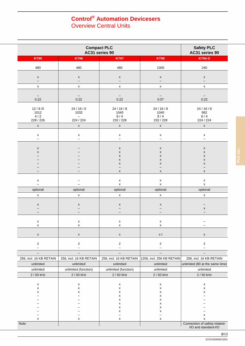
Control IT Automation DevicesersOverview Central Units
Compact PLC S afety PLCAC31 series 90 AC31 series 90
KT95 KT96 KT97 KT98 KT94-S
480 480 480 1000 240
x x x x x– – – – –
x x x x x
– – – – –0.22 0.22 0.22 0.07 0.22
12 / 8 /0 24 / 16 / 0 24 / 16 / 8 24 / 16 / 8 24 / 16 / 81012 1032 1040 1040 9924 / 2 – 8 / 4 8 / 4 8 / 4
228 / 226 224 / 224 232 / 228 232 / 228 224 / 224
x x x x x
x x x x x– – – – –
x – x x xx – x x x– – x x x– – x x x– – x x x– – – – –– – x x x
x – x x x– – x x x
optional optional optional optional optional
x x x x x
x x x x –– – – – x– – – – –
x x x x –x x x x –
x x x x t x
2 2 2 2 2– – – – –
– – – – –
256, incl. 16 KB RETAIN 256, incl. 16 KB RETAIN 256, incl. 16 KB RETAIN 1256, incl. 256 KB RETAIN 256, incl. 16 KB RETAIN
unlimited unlimited unlimited unlimited unlimited (80 at the same time)
unlimited unlimited (function) unlimited (function) unlimited unlimited
2 / 50 kHz 2 / 50 kHz 2 / 50 kHz 2 / 50 kHz 2 / 50 kHz
x x x x xx x x x xx x x x x– – x x –– – x x –– – x x –– – x x –– – x x –– – – – xx x x x x
Note: Connection of safety-related-I/O and standard-I/O
2/14
2CDC003005C0201
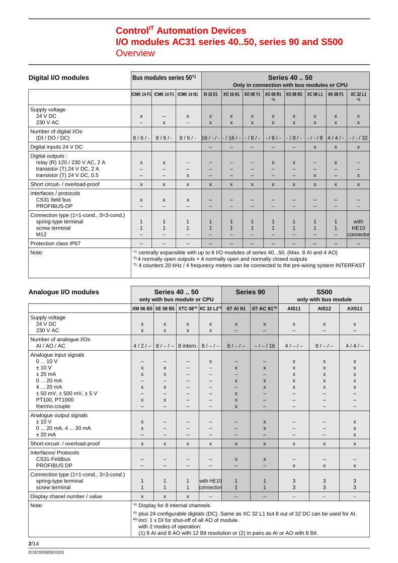
Control IT Automation DevicesI/O modules AC31 series 40..50, series 90 and S500Overview
Digital I/O modules Bus modules series 50 *1) Series 40 .. 50Only in connection with bus modules or CPU
ICMK 14 F1 ICMK 14 F1 ICMK 14 N1 XI 16 E1 XO 16 N1 XO 08 Y1 XO 08 R1 XO 08 R2 XC 08 L1 XK 08 F1 XC 32 L1*2) *3)
Supply voltage24 V DC x – x x x x x x x x x230 V AC – x – x x x x x x x x
Number of digital I/Os(DI / DO / DC) 8 / 6 / - 8 / 6 / - 8 / 6 / - 16 / - / - - / 16 / - - / 8 / - - / 8 / - - / 8 / - - / - / 8 4 / 4 / - - / - / 32
Digital inputs 24 V DC – – – – – x x x
Digital outputs :relay (R) 120 / 230 V AC, 2 A x x – – – – x x – x –transistor (T) 24 V DC, 2 A – – – – – – – – – – –transistor (T) 24 V DC, 0.5 – – x – – – – – x – x
Short circuit- / overload-proof x x x x x x x x x x x
Interfaces / protocolsCS31 field bus x x x – – – – – – – –PROFIBUS-DP – – – – – – – – – – –
Connection type (1=1-cond., 3=3-cond.)spring-type terminal 1 1 1 1 1 1 1 1 1 1 withscrew terminal 1 1 1 1 1 1 1 1 1 1 HE10M12 – – – – – – – – – – connector
Protection class IP67 – – – – – – – – – – –
Note: *1) centrally expansible with up to 6 I/O modules of series 40...50. (Max. 8 AI and 4 AO)*2) 4 normally open outputs + 4 normally open and normally closed outputs*3) 4 counters 20 kHz / 4 frequnecy meters can be connected to the pre-wiring system INTERFAST
Analogue I/O modules Series 40 .. 50 Series 90 S500only with bus module or CPU only with bus module
XM 06 B5 XE 08 B5 XTC 08*4) XC 32 L2*5) 07 AI 91 07 AC 91 *6) AI511 AI512 AX511
Supply voltage24 V DC x x x x x x x x x230 V AC x x x x – – – – –
Number of analogue I/OsAI / AO / AC 4 / 2 / – 8 / – / – 8 intern. 8 / – / – 8 / – / – – / – / 16 4 / – / – 8 / – / – 4 / 4 / –
Analogue input signals0 ... 10 V – – – x – – x x x± 10 V x x – – x x x x x± 20 mA x x – – – – x x x0 ... 20 mA – – – – x x x x x4 ... 20 mA x x – – – x x x x± 50 mV, ± 500 mV, ± 5 V – – – – x – – – –PT100, PT1000 x x – – x – – – –thermo-couple – – – – x – – – –
Analogue output signals± 10 V x – – – – x – – x0 ... 20 mA, 4 ... 20 mA x – – – – x – – x± 20 mA – – – – – – – – x
Short-circuit- / overload-proof x x x x x x x x x
Interfaces/ ProtocolsCS31-Feldbus – – – – x x – – –PROFIBUS DP – – – – – – x x x
Connection type (1=1-cond., 3=3-cond.)spring-type terminal 1 1 1 with HE10 1 1 3 3 3screw terminal 1 1 1 connection 1 1 3 3 3
Display chanel number / value x x x – – – – – –
Note: *4) Display for 8 internal channels*5) plus 24 configurable digitals (DC). Same as XC 32 L1 but 8 out of 32 DC can be used for AI.*6) incl. 1 x DI for shut-off of all AO of module.
with 2 modes of operation:(1) 8 AI and 8 AO with 12 Bit resolution or (2) in pairs as AI or AO with 8 Bit.
2/15
PLC
etc
.
2CDC003005C0201
Control IT Automation DevicesI/O modules AC31 series 40..50, series 90 and S500Overview
Series 90 Bus modules S500 *6) S500only in connection with bus module
07 DI 92 07DI93-I 07DO93-I 07DK93-I 07 DC 91 07 DC 92 07 TC90 / DX501-DP DX502-DP DX511 DI511 DO511TC91 *5)
x x x x x x x x x x x x– – – – – – – – – – – –
– / – / 32 16 / – / – – / 8 / – 8 / 4 / – 16 / 8 / 8 – / – / 32 32 / 32 / – 8 / 8 / – 8 / 8 / – 8 / 8 / – 16 / – / – – / 16 / –
x x – x x x – x x x x –
– – – – – – – – – – – –– – x x – – – – – – – –x – – – x x – x x x – x
x x x x x x – x x x x –
x x x x x x x – – – – –– – – – – – – x x – – –
– – – – – – – 3 3 3 3 31 – – – 1 1 – 3 3 3 3 3– x x x – – – – – – – –
– x x x – – – – – – – –*5) Special key pad for the connection of operating panels with up to *6) Centrally expansible with up to 7 I/O modules of series S500,
32 buttons / switches and 32 LEDs at the CS31 field bus. up to four of which can be analogue. Additionalextension box available (digital or analogue channels in1-conductor technology)
Safety-related I/O modules 07 DI 90-S 07 DO 90-S 07 AI 90-SSupply voltage
24 V DC x x x
Number of safety-related digital I/Os(DI / DO ) 8 / – / – – / 8 / – – / – / –
Number of safety-related analogue I/Os(AI / AO) – / – – / – 4 / –
Digital inputs 24 V DC x – –
Digital outputs:transistor (T) 24 V DC, 0.5 A – x –
Analogue outputs:4 ... 20 mA – – x
Short circuit- / overload-proof x x x
Interfaces / protocolsAC31 Safety field bus x x x
Connection type (1=1-cond., 3=3-cond.)screw terminal 1 1 1
Protection class IP67 – – –
Fault detection:short circuit x x xoverload – x –breakd in cicuits x – xforbidden signal level x – xarea over-, underrun – – xpassive error x x xinternal error x x x
Internal 2-channel structures x x x
Requirement class 4 (DIN19250) x x x
Category 3 (EN954-1) x x X
Note: only in connection with saftey-related CPU KT94-S
2/16
2CDC003005C0201
Control IT Automation DevicesCentral units, Communication couplersDimension Drawings
Central Units series 40..50 and bus module
07CR41/42, 07CT41/42, 07KR51, 07KT51and ICMK 14 F1N1
120
93
C03
33D
8435 m
m E
N 5
0022
C03
32D
W x H x D[mm] 120 x 93 x 84
W x H x D[inches] 4.72 x 3.66 x 3.31
Mounting 35 mm – DIN railacc. to DIN EN 50 022or screw mounting
Central Units series 90
07KT94, 07KT94-S, 07KT96, 07KT97 and 07KT98
W x H x D[mm] 240 x 140 x 85
W x H x D[inches] 9,45 x 5,51 x 3,35
Mounting 35 mm – DIN railacc. to DIN EN 50 022or screw mounting
85
35 m
m E
N 5
0022
C03
18D
Communication modules series 90
07KP90, 07KP93
W x H x D[mm] 120 x 140 x 85
W x H x D[inches] 4,72 x 5,51 x 3,35
Mounting 35 mm – DIN railacc. to DIN EN 50 022or screw mounting
2/17
PLC
etc
.
2CDC003005C0201
Control IT Automation DevicesI/O modulesDimension Drawings
I/O modules and communication modules series 40..50 Approvals
XI16E1, XO16N1, XO08R1, XO08Y1, XC08L1, XK08F1,XM06B5, XE06B5, 07KP53
W x H x D[mm] 65 x 93 x 84,5
W x H x D[inches] 2,56 x 3,66 x 3,33
Mounting 35 mm – DIN railacc. to DIN EN 50 022or screw mounting
65
93
C03
10D
I/O modules series 90
07DI92, 07DC91/92, 07AI91, 07AC91,07DO90-2, 07DI90-S, AI90-S
W x H x D[mm] 120 x 140 x 85
W x H x D[inches] 4,72 x 5,51 x 3,35
Mounting 35 mm – DIN railacc. to DIN EN 50 022or screw mounting
I/O module S500 for PROFIBUS-DP
W x H x D[mm] 102 x 65,3 x 79
W x H x D[inches] 4,02 x 2,57 x 3,11
Mounting 35 mm – DIN railacc. to DIN EN 50 022or screw mounting
Germanischer Lloyd
Lloyds Register of Shipping
Germanischer Lloyd
UL CSA
Lloyds Register of Shipping
Det Norske Veritas
TÜV, BGforAC 31-s
Büro Veritas
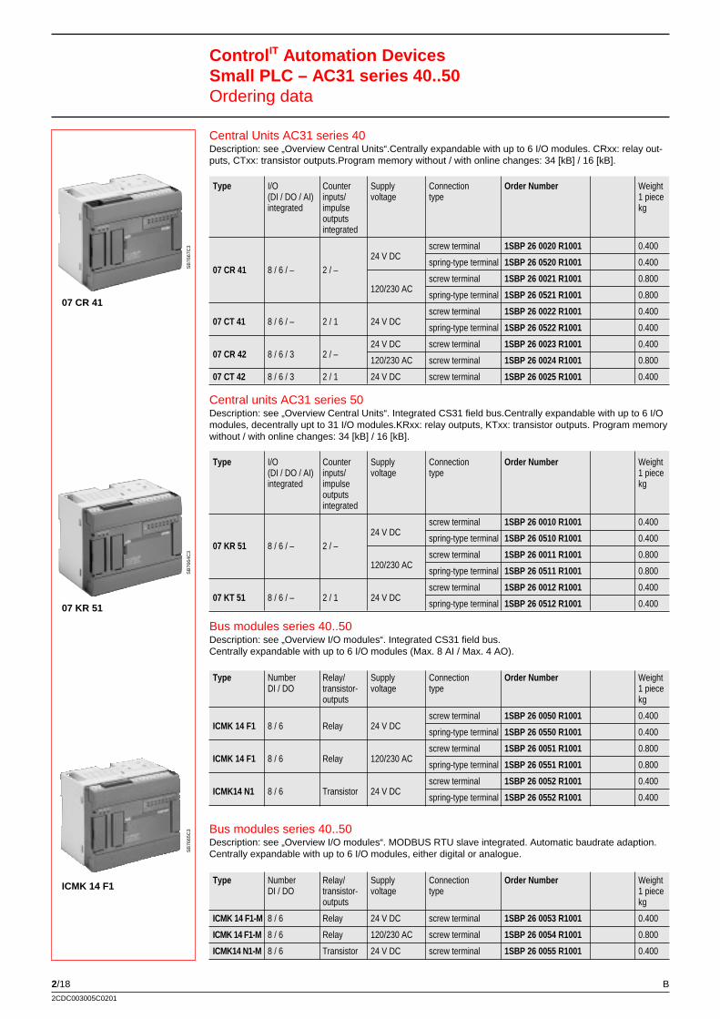
2/182CDC003005C0201
Central Units AC31 series 40Description: see „Overview Central Units“.Centrally expandable with up to 6 I/O modules. CRxx: relay out-puts, CTxx: transistor outputs.Program memory without / with online changes: 34 [kB] / 16 [kB].
Type I/O Counter Supply Connection Order Number Weight(DI / DO / AI) inputs/ voltage type 1 pieceintegrated impulse kg
outputsintegrated
07 CR 41 8 / 6 / – 2 / –24 V DC
screw terminal 1SBP 26 0020 R1001 0.400
spring-type terminal 1SBP 26 0520 R1001 0.400
120/230 ACscrew terminal 1SBP 26 0021 R1001 0.800
spring-type terminal 1SBP 26 0521 R1001 0.800
07 CT 41 8 / 6 / – 2 / 1 24 V DCscrew terminal 1SBP 26 0022 R1001 0.400
spring-type terminal 1SBP 26 0522 R1001 0.400
07 CR 42 8 / 6 / 3 2 / –24 V DC screw terminal 1SBP 26 0023 R1001 0.400
120/230 AC screw terminal 1SBP 26 0024 R1001 0.800
07 CT 42 8 / 6 / 3 2 / 1 24 V DC screw terminal 1SBP 26 0025 R1001 0.400
Control IT Automation DevicesSmall PLC – AC31 series 40..50Ordering data
07 CR 41
SB
7667
C3
07 KR 51
SB
7664
C3
ICMK 14 F1
SB
7665
C3
Central units AC31 series 50Description: see „Overview Central Units“. Integrated CS31 field bus.Centrally expandable with up to 6 I/Omodules, decentrally upt to 31 I/O modules.KRxx: relay outputs, KTxx: transistor outputs. Program memorywithout / with online changes: 34 [kB] / 16 [kB].
Type I/O Counter Supply Connection Order Number Weight(DI / DO / AI) inputs/ voltage type 1 pieceintegrated impulse kg
outputsintegrated
07 KR 51 8 / 6 / – 2 / –24 V DC
screw terminal 1SBP 26 0010 R1001 0.400
spring-type terminal 1SBP 26 0510 R1001 0.400
120/230 ACscrew terminal 1SBP 26 0011 R1001 0.800
spring-type terminal 1SBP 26 0511 R1001 0.800
07 KT 51 8 / 6 / – 2 / 1 24 V DCscrew terminal 1SBP 26 0012 R1001 0.400
spring-type terminal 1SBP 26 0512 R1001 0.400
Bus modules series 40..50Description: see „Overview I/O modules“. Integrated CS31 field bus.Centrally expandable with up to 6 I/O modules (Max. 8 AI / Max. 4 AO).
Type Number Relay/ Supply Connection Order Number WeightDI / DO transistor- voltage type 1 piece
outputs kg
ICMK 14 F1 8 / 6 Relay 24 V DCscrew terminal 1SBP 26 0050 R1001 0.400
spring-type terminal 1SBP 26 0550 R1001 0.400
ICMK 14 F1 8 / 6 Relay 120/230 ACscrew terminal 1SBP 26 0051 R1001 0.800
spring-type terminal 1SBP 26 0551 R1001 0.800
ICMK14 N1 8 / 6 Transistor 24 V DCscrew terminal 1SBP 26 0052 R1001 0.400
spring-type terminal 1SBP 26 0552 R1001 0.400
B
Bus modules series 40..50Description: see „Overview I/O modules“. MODBUS RTU slave integrated. Automatic baudrate adaption.Centrally expandable with up to 6 I/O modules, either digital or analogue.
Type Number Relay/ Supply Connection Order Number WeightDI / DO transistor- voltage type 1 piece
outputs kg
ICMK 14 F1-M 8 / 6 Relay 24 V DC screw terminal 1SBP 26 0053 R1001 0.400
ICMK 14 F1-M 8 / 6 Relay 120/230 AC screw terminal 1SBP 26 0054 R1001 0.800
ICMK14 N1-M 8 / 6 Transistor 24 V DC screw terminal 1SBP 26 0055 R1001 0.400
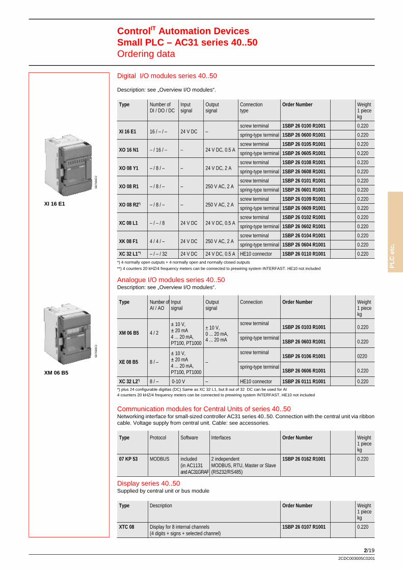
2/19
PLC
etc
.
2CDC003005C0201
Digital I/O modules series 40..50
Description: see „Overview I/O modules“.
Type Number of Input Output Connection Order Number WeightDI / DO / DC signal signal type 1 piece
kg
XI 16 E1 16 / – / – 24 V DC –screw terminal 1SBP 26 0100 R1001 0.220
spring-type terminal 1SBP 26 0600 R1001 0.220
XO 16 N1 – / 16 / – – 24 V DC, 0.5 Ascrew terminal 1SBP 26 0105 R1001 0.220
spring-type terminal 1SBP 26 0605 R1001 0.220
XO 08 Y1 – / 8 / – – 24 V DC, 2 Ascrew terminal 1SBP 26 0108 R1001 0.220
spring-type terminal 1SBP 26 0608 R1001 0.220
XO 08 R1 – / 8 / – – 250 V AC, 2 Ascrew terminal 1SBP 26 0101 R1001 0.220
spring-type terminal 1SBP 26 0601 R1001 0.220
XO 08 R2*) – / 8 / – – 250 V AC, 2 Ascrew terminal 1SBP 26 0109 R1001 0.220
spring-type terminal 1SBP 26 0609 R1001 0.220
XC 08 L1 – / – / 8 24 V DC 24 V DC, 0.5 Ascrew terminal 1SBP 26 0102 R1001 0.220
spring-type terminal 1SBP 26 0602 R1001 0.220
XK 08 F1 4 / 4 / – 24 V DC 250 V AC, 2 Ascrew terminal 1SBP 26 0104 R1001 0.220
spring-type terminal 1SBP 26 0604 R1001 0.220
XC 32 L1**) – / – / 32 24 V DC 24 V DC, 0.5 A HE10 connector 1SBP 26 0110 R1001 0.220
*) 4 normally open outputs + 4 normally open and normally closed outputs
**) 4 counters 20 kHZ/4 frequency meters can be connected to prewiring system INTERFAST. HE10 not included
Control IT Automation DevicesSmall PLC – AC31 series 40..50Ordering data
XI 16 E1
SB
7666
C2
XM 06 B5
SB
7668
C2
Analogue I/O modules series 40..50Description: see „Overview I/O modules“.
Type Number of Input Output Connection Order Number WeightAI / AO signal signal 1 piece
kg
XM 06 B5 4 / 2
± 10 V,+ 10 V,
screw terminal1SBP 26 0103 R1001 0.220± 20 mA
0 ... 20 mA,4 ... 20 mA, 4 ... 20 mA spring-type terminal1SBP 26 0603 R1001 0.220PT100, PT1000
XE 08 B5 8 / –
± 10 V,
–
screw terminal1SBP 26 0106 R1001 0220± 20 mA
4 ... 20 mA, spring-type terminal1SBP 26 0606 R1001 0.220PT100, PT1000
XC 32 L2*) 8 / – 0-10 V – HE10 connector 1SBP 26 0111 R1001 0.220*) plus 24 configurable digitlas (DC) Same as XC 32 L1, but 8 out of 32 DC can be used for AI4 counters 20 kHZ/4 frequency meters can be connected to prewiring system INTERFAST. HE10 not included
Communication modules for Central Units of series 40..50Networking interface for small-sized controller AC31 series 40..50. Connection with the central unit via ribboncable. Voltage supply from central unit. Cable: see accessories.
Type Protocol Software Interfaces Order Number Weight1 piecekg
07 KP 53 MODBUS included 2 independent 1SBP 26 0162 R1001 0.220(in AC1131 MODBUS, RTU, Master or Slaveand AC31GRAF (RS232/RS485)
Display series 40..50Supplied by central unit or bus module
Type Description Order Number Weight1 piecekg
XTC 08 Display for 8 internal channels 1SBP 26 0107 R1001 0.220(4 digits + signs + selected channel)
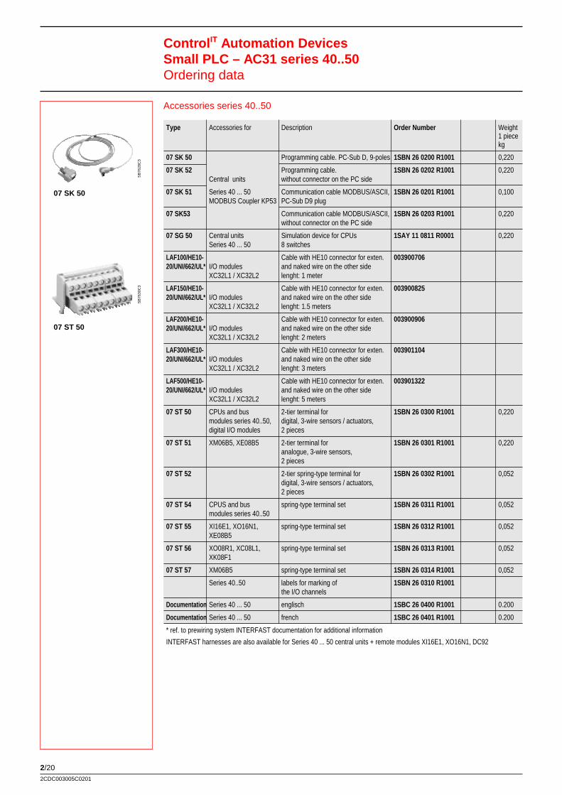
2/202CDC003005C0201
Accessories series 40..50
Type Accessories for Description Order Number Weight1 piecekg
07 SK 50 Programming cable. PC-Sub D, 9-poles 1SBN 26 0200 R1001 0,220
07 SK 52 Programming cable. 1SBN 26 0202 R1001 0,220Central units without connector on the PC side
07 SK 51 Series 40 ... 50 Communication cable MODBUS/ASCII, 1SBN 26 0201 R1001 0,100MODBUS Coupler KP53 PC-Sub D9 plug
07 SK53 Communication cable MODBUS/ASCII, 1SBN 26 0203 R1001 0,220without connector on the PC side
07 SG 50 Central units Simulation device for CPUs 1SAY 11 0811 R0001 0,220Series 40 ... 50 8 switches
LAF100/HE10- Cable with HE10 connector for exten. 00390070620/UNI/662/UL* I/O modules and naked wire on the other side
XC32L1 / XC32L2 lenght: 1 meter
LAF150/HE10- Cable with HE10 connector for exten. 00390082520/UNI/662/UL* I/O modules and naked wire on the other side
XC32L1 / XC32L2 lenght: 1.5 meters
LAF200/HE10- Cable with HE10 connector for exten. 00390090620/UNI/662/UL* I/O modules and naked wire on the other side
XC32L1 / XC32L2 lenght: 2 meters
LAF300/HE10- Cable with HE10 connector for exten. 00390110420/UNI/662/UL* I/O modules and naked wire on the other side
XC32L1 / XC32L2 lenght: 3 meters
LAF500/HE10- Cable with HE10 connector for exten. 00390132220/UNI/662/UL* I/O modules and naked wire on the other side
XC32L1 / XC32L2 lenght: 5 meters
07 ST 50 CPUs and bus 2-tier terminal for 1SBN 26 0300 R1001 0,220modules series 40..50, digital, 3-wire sensors / actuators,digital I/O modules 2 pieces
07 ST 51 XM06B5, XE08B5 2-tier terminal for 1SBN 26 0301 R1001 0,220analogue, 3-wire sensors,2 pieces
07 ST 52 2-tier spring-type terminal for 1SBN 26 0302 R1001 0,052digital, 3-wire sensors / actuators,2 pieces
07 ST 54 CPUS and bus spring-type terminal set 1SBN 26 0311 R1001 0,052modules series 40..50
07 ST 55 XI16E1, XO16N1, spring-type terminal set 1SBN 26 0312 R1001 0,052XE08B5
07 ST 56 XO08R1, XC08L1, spring-type terminal set 1SBN 26 0313 R1001 0,052XK08F1
07 ST 57 XM06B5 spring-type terminal set 1SBN 26 0314 R1001 0,052
Series 40..50 labels for marking of 1SBN 26 0310 R1001the I/O channels
Documentation Series 40 ... 50 englisch 1SBC 26 0400 R1001 0.200
Documentation Series 40 ... 50 french 1SBC 26 0401 R1001 0.200
* ref. to prewiring system INTERFAST documentation for additional information
INTERFAST harnesses are also available for Series 40 ... 50 central units + remote modules XI16E1, XO16N1, DC92
Control IT Automation DevicesSmall PLC – AC31 series 40..50Ordering data
SB
7628
C3
07 SK 50
SB
7630
C3
07 ST 50
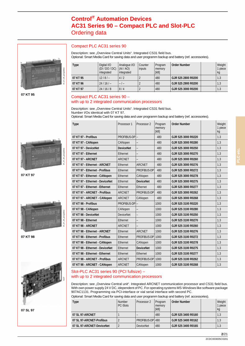
2/21
PLC
etc
.
2CDC003005C0201
Compact PLC AC31 series 90 –with up to 2 integrated communication processors
Description: see „Overview Central Units“. Integrated CS31 field bus.Number I/Os identical with 07 KT 97.Optional: Smart Media Card for saving data and user programm backup and battery (ref. accessories).
Type Processor 1 Processor 2 Program Order Number Weightmemory 1 piece[kB] kg
07 KT 97 - Profibus PROFIBUS-DP – 480 GJR 525 3000 R0220 1.3
07 KT 97 - CANopen CANopen – 480 GJR 525 3000 R0280 1.3
07 KT 97 - DeviceNet DeviceNet – 480 GJR 525 3000 R0250 1.3
07 KT 97 - Ethernet Ethernet – 480 GJR 525 3000 R0270 1.3
07 KT 97 - ARCNET ARCNET – 480 GJR 525 3000 R0260 1.3
07 KT 97 - Ethernet - ARCNET Ethernet ARCNET 480 GJR 525 3000 R0276 1.3
07 KT 97 - Ethernet - Profibus Ethernet PROFIBUS-DP 480 GJR 525 3000 R0272 1.3
07 KT 97 - Ethernet - CANopen Ethernet CANopen 480 GJR 525 3000 R0278 1.3
07 KT 97 - Ethernet - DeviceNet Ethernet DeviceNet 480 GJR 525 3000 R0275 1.3
07 KT 97 - Ethernet - Ethernet Ethernet Ethernet 480 GJR 525 3000 R0277 1.3
07 KT 97 - ARCNET - Profibus ARCNET PROFIBUS-DP 480 GJR 525 3000 R0262 1.3
07 KT 97 - ARCNET - CANopen ARCNET CANopen 480 GJR 525 3000 R0268 1.3
07 KT 98 - Profibus PROFIBUS-DP – 1000 GJR 525 3100 R0220 1.3
07 KT 98 - CANopen CANopen – 1000 GJR 525 3100 R0280 1.3
07 KT 98 - DeviceNet DeviceNet – 1000 GJR 525 3100 R0250 1.3
07 KT 98 - Ethernet Ethernet – 1000 GJR 525 3100 R0270 1.3
07 KT 98 - ARCNET ARCNET – 1000 GJR 525 3100 R0260 1.3
07 KT 98 - Ethernet - ARCNET Ethernet ARCNET 1000 GJR 525 3100 R0276 1.3
07 KT 98 - Ethernet - Profibus Ethernet PROFIBUS-DP 1000 GJR 525 3100 R0272 1.3
07 KT 98 - Ethernet - CANopen Ethernet CANopen 1000 GJR 525 3100 R0278 1.3
07 KT 98 - Ethernet - DeviceNet Ethernet DeviceNet 1000 GJR 525 3100 R0275 1.3
07 KT 98 - Ethernet - Ethernet Ethernet Ethernet 1000 GJR 525 3100 R0277 1.3
07 KT 98 - ARCNET - Profibus ARCNET PROFIBUS-DP 1000 GJR 525 3100 R0262 1.3
07 KT 98 - ARCNET - CANopen ARCNET CANopen 1000 GJR 525 3100 R0268 1.3
Control IT Automation DevicesAC31 Series 90 – Compact PLC and Slot-PLCOrdering data
07 KT 95
07_K
T_9
4_pe
rspe
ktiv
e
07 KT 97
07_K
T_9
4_pe
rspe
ktiv
e
07 KT 98
07 SL 97
SL9
7
Compact PLC AC31 series 90
Description: see „Overview Central Units“. Integrated CS31 field bus.Optional: Smart Media Card for saving data and user programm backup and battery (ref. accessories).
Type Digital I/O Analogue I/O Counter Program Order Number Weight(DI / DO / DC) (AI / AO) inputs memory 1 pieceintegrated integrated [kB] kg
07 KT 95 12 / 8 / – 4 / 2 2 480 GJR 525 2800 R0200 1.3
07 KT 96 24 / 16 / – – / – 2 480 GJR 525 2900 R0200 1.3
07 KT 97 24 / 16 / 8 8 / 4 2 480 GJR 525 3000 R0200 1.3
Slot-PLC AC31 series 90 (PCI fullsize) –with up to 2 integrated communication processors
Description: see „Overview Central unit“. Integrated ARCNET communication processor and CS31 field bus.With own power supply 24 V DC, idependent of PC. For operating systems MS-Windows like software package907AC1131. Programming via PCI-interface or vial serial interface with second PC.Optional: Smart Media Card for saving data and user programm backup and battery (ref. accessories).
Type Number Processor 2 Program Order Number WeightPC-Slots memory 1 piece
[kB] kg
07 SL 97-ARCNET 1 – 480 GJR 525 3400 R0160 1.3
07 SL 97-ARCNET-Profibus 2 PROFIBUS-DP 480 GJR 525 3400 R0162 1.3
07 SL 97-ARCNET-DeviceNet 2 DeviceNet 480 GJR 525 3400 R0165 1.3
07_K
T_9
4_pe
rspe
ktiv
e
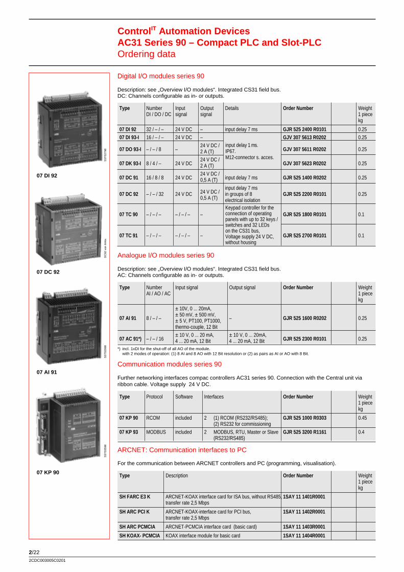
2/222CDC003005C0201
ARCNET: Communication interfaces to PC
For the communication between ARCNET controllers and PC (programming, visualisation).
Type Description Order Number Weight1 piecekg
SH FARC E3 K ARCNET-KOAX interface card for ISA bus, without RS485, 1SAY 11 1401R0001transfer rate 2,5 Mbps
SH ARC PCI K ARCNET-KOAX-interface card for PCI bus, 1SAY 11 1402R0001transfer rate 2,5 Mbps
SH ARC PCMCIA ARCNET-PCMCIA interface card (basic card) 1SAY 11 1403R0001
SH KOAX- PCMCIA KOAX interface module for basic card 1SAY 11 1404R0001
Digital I/O modules series 90
Description: see „Overview I/O modules“. Integrated CS31 field bus.DC: Channels configurable as in- or outputs.
Type Number Input Output Details Order Number WeightDI / DO / DC signal signal 1 piece
kg
07 DI 92 32 / – / – 24 V DC – input delay 7 ms GJR 525 2400 R0101 0.25
07 DI 93-I 16 / – / – 24 V DC – GJV 307 5613 R0202 0.25
07 DO 93-I – / – / 8 –24 V DC /
GJV 307 5611 R0202 0.252 A (T)
07 DK 93-I 8 / 4 / – 24 V DC24 V DC /
GJV 307 5623 R0202 0.252 A (T)
07 DC 91 16 / 8 / 8 24 V DC24 V DC /
input delay 7 ms GJR 525 1400 R0202 0.250,5 A (T)
24 V DC /input delay 7 ms
07 DC 92 – / – / 32 24 V DC0,5 A (T)
in groups of 8 GJR 525 2200 R0101 0.25electrical isolation
07 TC 90 – / – / – – / – / – – GJR 525 1800 R0101 0.1
07 TC 91 – / – / – – / – / – – GJR 525 2700 R0101 0.1
Control IT Automation DevicesAC31 Series 90 – Compact PLC and Slot-PLCOrdering data
07 DI 92
SS
T02
798
07 DC 92
07 AI 91
SS
T02
998
07 KP 90
SS
T03
598
Keypad controller for theconnection of operatingpanels with up to 32 keys /switches and 32 LEDson the CS31 bus,Voltage supply 24 V DC,without housing
input delay 1 ms.IP67.M12-connector s. acces.
Analogue I/O modules series 90
Description: see „Overview I/O modules“. Integrated CS31 field bus.AC: Channels configurable as in- or outputs.
Type Number Input signal Output signal Order Number WeightAI / AO / AC 1 piece
kg
07 AI 91 8 / – / –
± 10V, 0 ... 20mA,
– GJR 525 1600 R0202 0.25± 50 mV, ± 500 mV,± 5 V, PT100, PT1000,thermo-couple, 12 Bit
07 AC 91*) – / – / 16± 10 V, 0 ... 20 mA, ± 10 V, 0 ... 20mA,
GJR 525 2300 R0101 0.254 ... 20 mA, 12 Bit 4 ... 20 mA, 12 Bit*) incl. 1xDI for the shut-off of all AO of the module.
with 2 modes of operation: (1) 8 AI and 8 AO with 12 Bit resolution or (2) as pairs as AI or AO with 8 Bit.
Communication modules series 90
Further networking interfaces compac controllers AC31 series 90. Connection with the Central unit viaribbon cable. Voltage supply 24 V DC.
Type Protocol Software Interfaces Order Number Weight1 piecekg
07 KP 90 RCOM included 2 (1) RCOM (RS232/RS485); GJR 525 1000 R0303 0.45(2) RS232 for commissioning
07 KP 93 MODBUS included 2 MODBUS, RTU, Master or Slave GJR 525 3200 R1161 0.4(RS232/RS485)
DC
92 v
on li
mks
2/23
PLC
etc
.
2CDC003005C0201
Accessories series 90Type Accessory for Description Order Number Weight
1 piecekg
07 SK 90 CPUs AC31 series 90Programming cablel incl. adapter
GJR 525 0200 R0001
(KT94-S, KT95-KT98)25/9-poles. Cable lenght 5 m
07 SK 92 System cable for modem GJR 525 0400 R0001
CPUs 07KT94-SSmart Media Card
07 MC 90and 07KT94
for saving data and backup of GJR 525 2600 R0102user program, 2 MB
CPUs Smart Media Card07 MC 90 07KT95 / 96 / 97 / 98 for saving data and backup of GJR 525 2600 R0201
and 07SL97 user program, 8 MB
07 LE 90 Lithium battery for data buffering GJR 525 0700 R0001
German CPUs AC31 series 90Manual for AC31 (as in
1SAC 133 947 R0101(07KT94-S, 07KT95,
software package 907 AC 1131)
07KT98, 07SL97)Complete hard- und software-
English description. Includes CD-ROM 1SAC 133 947 R0201with documentation.
Plug 5 poles, M12 straight.– Connection for basic I/Os GJV 307 5617 R0001
with FE connectionDigital IP67 Plug 5 poles. M12 bent.
– I/O modules DI93-I, AConnection for basic I/Os GJV 307 5618 R0001DO93-I, DK93-I with FE connection
–Plug 4 poles.
GJV 307 5624 R0001M12 straight for double connection.
– RCOM coupler 07KP90For commissioning interface
GJV 307 3915 R0001Adapter for programming cable 07SK90
– AC31-S: 07KP94-Sinterface cable incl. adapter for KT94-S
GJR 525 0300 R0001with operating panel (passive mode)
07 SK 93Programmiing cable
GJR 525 3500 R000107SL97 Slot CPU
MIN DIN 8/PC-SUB D
07 SK 94Communication cable
GJR 525 3600 R0001MIN DIN 8/-
Programming package 907AC1131 (acc. to IEC61131-3)For small PLC AC 31 series 40...50 (functionalities adjusted), compact PLC AC31 series 90 and Slot-PLC07 SL 97. Operating system: Windows 98 / NT / 2000 / XP.Description: see „Overview Software Package“.
Programming cable: see accessories.
Integrated: 6 programming languages, sampling trace, debugging, offline simulation,trace recording (mulitchannel) recipe management, visualisation,field bus configurators, online visualisation package and more.
Delivery includes: software, libraries and documentation on CD-ROM, update service.
Type Language Manual Description Order Number Weight
907 AC 1131 German Programming package version 5.0 GJP 520 6900 R0102
907 AC 1131 English Programming package version 5.0 GJP 520 7000 R0102
Control IT Automation DevicesAccessories Series 90, Software Package 907AC1131Ordering data
Programming package AC31GRAF (based on IEC61131-3)For small PLC AC 31 series 40...50. Operating system: Windows 98 / NT / 2000.Description: see „Overview Software Package“.
Programming cable: see accessories.
Integrated: 4 programming languages,debugging, visualisation, and much more.Can be used with previous PLC Central units type 30 series and 07KT91 ... KT94
Delivery includes: software, libraries and documentation on CD-ROM.
Type Language Manual Description Order Number Weight
AC31GRAF English Programming package 1SBS 260 250 R0101
AC31GRAF French Programming package 1SBS 260 251 R0101
AC31GRAF Italian Programming package 1SBS 260 252 R0101
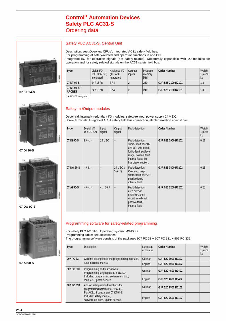
2/242CDC003005C0201
Safety In-/Output modules
Decentral, internally redundant I/O modules, safety-related, power supply 24 V DC.Screw terminals. Integrated AC31 safety field bus connection, electric isolation against bus.
Type Digital I/O Input Output Fault detection Order Number WeightDI / DO / AI signal signal 1 piece
kg
07 DI 90-S 8 / – / – 24 V DC – Fault detection: GJR 525 0900 R0202 0.25short circuit after 0Vand UP, wire break,forbidden input levelrange, passive fault,internal faults likebus disconnection.
07 DO 90-S – / 8 / – – 24 V DC / Fault detection: GJR 525 0800 R0202 0.255 A (T) Overload, resp.
short circuit after ZP,passive fault,internal fault.
07 AI 90-S – / – / 4 4 ... 20 A – Fault detection: GJR 525 1200 R0202 0.25area over orunderrun, shortcircuit, wire break,passive fault,internal fault.
Safety PLC AC31-S, Central Unit
Description: see „Overview CPUs“. Integrated AC31 safety field bus.For programming of safety-related and operation functions in one CPU.Integrated I/O for operation signals (not safety-related). Decentrally expansible with I/O modules foroperation and for safety related signals on the AC31 safety field bus.
Type Digital I/O Analogue I/O Counter Program Order Number Weight(DI / DO / DC) (AI / AO) inputs memory 1 pieceintegrated integrated [kB] kg
07 KT 94-S 24 / 16 / 8 8 / 4 2 240 GJR 525 2100 R2101 1.3
07 KT 94-S *)
24 / 16 / 8 8 / 4 2 240 GJR 525 2100 R2161 1.3ARCNET*) ARCNET integrated
Control IT Automation DevicesSafety PLC AC31-SOrdering data
07 KT 94-S
SS
T02
598
07 DI 90-S
SS
T03
098
07 DO 90-S
SS
T03
198
07 AI 90-S
07A
I90-
S
Programming software for safety-related programming
For safety PLC AC 31-S. Operating system: MS-DOS.Programming cable: see accessories.The programming software consists of the packages 907 PC 33 + 907 PC 331 + 907 PC 339.
Type Description Language Order Number Weightof manual 1 piece
kg
907 PC 33 General description of the programming interface. German GJP 520 3900 R0302Also includes: manual English GJP 520 4000 R0302
907 PC 331 Programming and test software. German GJP 520 4500 R0402Programming languages: IL, FBD, LD.Includes: programming software on disc,
English GJP 520 4600 R0402manuals, update service.
907 PC 339 Add-on safety-related functions for German GJP 520 7500 R0102programming software 907 PC 331.For AC31-S central unit 07 KT94-S.Includes: safety manual, English GJP 520 7600 R0102software on discs, update service.
2/25
PLC
etc
.
2CDC003005C0201
Control IT Automation DevicesBus RepeaterOrdering data
Bus repeater for CS31 field bus
Type Supply Description Ordering Number Weightvoltage 1 piece
kg
NCB 24 V DC Repeater for CS31 bus FPR 347 1200 R1002 0.34max. length 2000 m (3 repeaters)
NCBR 24 V DC Repeater for CS31 bus for redundant, FPR 347 1300 R1002 0.34ring or star shaped bus configuration
s
Bus repeater for RS485 MODBUS RTU network
Type Supply Description Ordering Number Weightvoltage 1 piece
kg
NCBR-M 24 V DC Repeater for MODBUS communiction. For 1SBP 260 161 R1001 0.34redundant, ring or star shaped bus configuration
2/262CDC003005C0201
S500 - decentral In-/Output modulesfor PROFIBUS DP
The PROFIBUS DP I/O modules S500 consist of a pluggable electronics block and the respective terminal block.The bus connection is achieved via a bus module. Up to 7 extension modules can be connected to the bus module(via ribbon cable).Applicable with controllers with a PROFIBUS DP connection.
M pluggable electronics blockR bus modules PROFIBUS DPR I/O moduless
Ribbon cable for connecting of (further)I/O modules
M terminal blockR for bus modulesR for digital I/O modulesR for analogue I/O modules
pluggable potential bar
R with screw terminalsR with spring-type terminals
M Bus modules:
pluggable extension boxesand pluggable bus-cable terminals
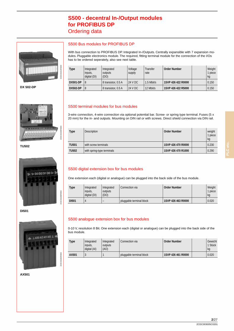
2/27
PLC
etc
.
2CDC003005C0201
S500 analogue extension box for bus modules
0-10 V, resolution 8 Bit. One extension each (digital or analogue) can be plugged into the back side of thebus module.
Type Integrated Integrated Connection via Order Number Gewichtinputs, outputs 1 Stückdigital (AI) (AO) kg
AX501 3 1 pluggable terminal block 1SVP 426 461 R0000 0.020
S500 Bus modules for PROFIBUS DP
With bus connection to PROFIBUS DP. Integrated In-/Outputs. Centrally expansible with 7 expansion mo-dules. Pluggable electronics module. The required, fitting terminal module for the connection of the I/Oshas to be ordered seperately, also see next table.
Type Integrated Integrated Voltage Transfer Order Number Weightinputs, outputs supply rate 1 piecedigital (DI) (DO) kg
DX501-DP 8 8 transistor, 0.5 A 24 V DC 1.5 Mbit/s 1SVP 426 422 R0000 0.150
DX502-DP 8 8 transistor, 0.5 A 24 V DC 12 Mbit/s 1SVP 426 422 R5000 0.150
S500 - decentral In-/Output modulesfor PROFIBUS DPOrdering data
DX 502-DP
2CD
C33
1014
F00
03
TU502
2CD
C33
1025
F00
03
DI501
2CD
C33
1009
F00
03
AX501
2CD
C33
1003
F00
03
S500 terminal modules for bus modules
3-wire connection, 4-wire connection via optional potential bar. Screw- or spring type terminal. Fuses (5 x20 mm) for the in- and outputs. Mounting on DIN rail or with screws. Direct shield connection via DIN rail.
Type Description Order Number weight1 piecekg
TU501 with screw terminals 1SVP 426 470 R0000 0.230
TU502 with spring-type terminals 1SVP 426 470 R1000 0.290
S500 digital extension box for bus modules
One extension each (digital or analogue) can be plugged into the back side of the bus module.
Type Integrated Integrated Connection via Order Number Weightinputs, outputs 1 piecedigital (DI) (DO) kg
DI501 4 – pluggable terminal block 1SVP 426 463 R0000 0.020
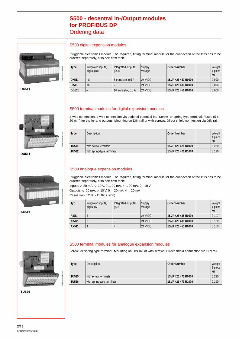
2/282CDC003005C0201
S500 analogue expansion modules
Pluggable electronics module. The required, fitting terminal module for the connection of the I/Os has to beordered seperately, also see next table..
Inputs: w 20 mA, w 10 V, 0 ... 20 mA, 4 ... 20 mA, 0 - 10 V
Outputs: w 20 mA, w 10 V, 0 ... 20 mA, 4 ... 20 mA
Resolution: 12 Bit (11 Bit + sign)
Typ Integrated inputs, Integrated outputss Supply Order Number Weightdigital (AI) (AO) voltage 1 piece
kg
AI511 4 – 24 V DC 1SVP 426 435 R0000 0.110
AI512 8 – 24 V DC 1SVP 426 436 R0000 0.150
AX511 4 4 24 V DC 1SVP 426 455 R0000 0.150
S500 terminal modules for digital expansion modules
3-wire connection, 4-wire connection via optional potential bar. Screw- or spring type terminal. Fuses (5 x20 mm) for the in- and outputs. Mounting on DIN rail or with screws. Direct shield connection via DIN rail.
Type Description Order Number Weight1 piecekg
TU511 with screw terminals 1SVP 426 471 R0000 0.230
TU512 with spring-type terminals 1SVP 426 471 R1000 0.190
S500 digital expansion modules
Pluggable electronics module. The required, fitting terminal module for the connection of the I/Os has to beordered seperately, also see next table..
Type Integrated inputs, Integrated outputs Supply Order Number Weightdigital (DI) (DO) voltage 1 piece
kg
DX511 8 8 transistor, 0.5 A 24 V DC 1SVP 426 450 R0000 0.090
DI511 16 – 24 V DC 1SVP 426 430 R0000 0.090
DO511 – 16 transistor, 0.5 A 24 V DC 1SVP 426 451 R0000 0.900
S500 - decentral In-/Output modulesfor PROFIBUS DPOrdering data
DX511
2CD
C33
1015
F00
03
DU511
2CD
C33
1027
F00
03
AX511
2CD
C33
1004
F00
03
TU526
2CD
C33
1031
F00
03
S500 terminal modules for analogue expansion modules
Screw- or spring type terminal. Mounting on DIN rail or with screws. Direct shield connection via DIN rail.
Type Description Order Number Weight1 piecekg
TU525 with screw terminals 1SVP 426 473 R0000 0.230
TU526 with spring-type terminals 1SVP 426 473 R1000 0.190
2/29
PLC
etc
.
2CDC003005C0201
Accessories for S500
Type Description Order Number Weight1 piecekg
TA501 Potential bar with screw terminal (for 4-wire connection) 1SVP 426 480 R0000 0.020
TA502 Potential bar with spring-type terminal (for 4-wire connection) 1SVP 426 480 R1000 0.020
TA503 Cable shield for bus connection, 2 pieces 1SVP 426 481 R0000 0.010
TA504 Marking stripes, 10 pieces 1SVP 426 482 R1000 0.100
TA505 Fuse 5 x 20 mm 8 A, 10 pieces 1SVP 426 483 R0000 0.050
Configuration data GSD PROFIBUS DP (Disc) 1SVP 426 401 R5000 0.010
User manual German 2CDC 124 002 M0101
User manual English 2CDC 124 002 M0201
User manual French 2CDC 124 002 M0301
S500 - decentral In-/Output modulesfor PROFIBUS DPOrdering data
TA501
2CD
C33
1016
F00
03
TA502
2CD
C33
1017
F00
03
TA503
2CD
C33
1018
F00
03

2/302CDC003005C0201
Notes
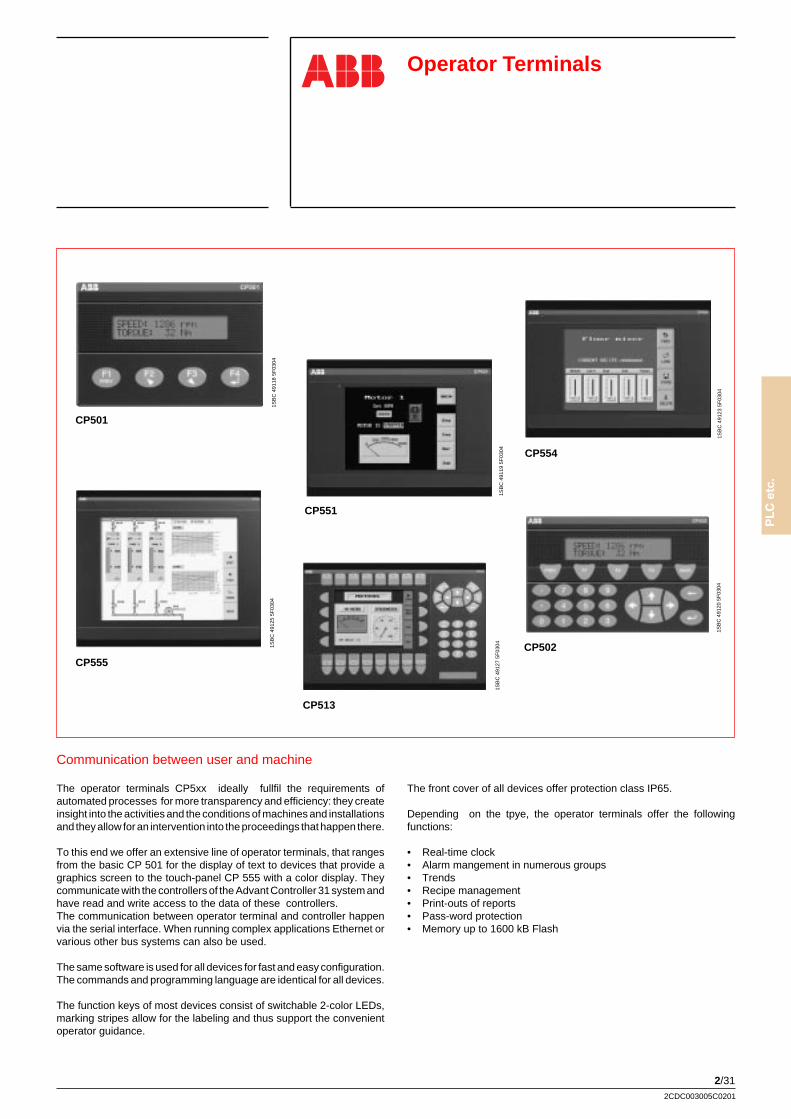
2/31
PLC
etc
.
2CDC003005C0201
Operator Terminals
Communication between user and machine
The operator terminals CP5xx ideally fullfil the requirements ofautomated processes for more transparency and efficiency: they createinsight into the activities and the conditions of machines and installationsand they allow for an intervention into the proceedings that happen there.
To this end we offer an extensive line of operator terminals, that rangesfrom the basic CP 501 for the display of text to devices that provide agraphics screen to the touch-panel CP 555 with a color display. Theycommunicate with the controllers of the Advant Controller 31 system andhave read and write access to the data of these controllers.The communication between operator terminal and controller happenvia the serial interface. When running complex applications Ethernet orvarious other bus systems can also be used.
The same software is used for all devices for fast and easy configuration.The commands and programming language are identical for all devices.
The function keys of most devices consist of switchable 2-color LEDs,marking stripes allow for the labeling and thus support the convenientoperator guidance.
The front cover of all devices offer protection class IP65.
Depending on the tpye, the operator terminals offer the followingfunctions:
• Real-time clock• Alarm mangement in numerous groups• Trends• Recipe management• Print-outs of reports• Pass-word protection• Memory up to 1600 kB Flash
CP501
1SB
C 4
9118
5F
0304
CP513
1SB
C 4
9127
5F
0304
CP555
1SB
C 4
9125
5F
0304
CP5511S
BC
491
19 5
F03
04
CP502
1SB
C 4
9120
5F
0304
CP554
1SB
C 4
9123
5F
0304
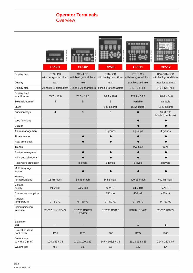
2/322CDC003005C0201
Operator TerminalsOverview
Display type STN-LCD STN-LCD STN-LCD STN-LCD B/W-STN-LCDwith background illum. with background illum. with background illum. with background illum. with background illum.
Display text text text graphics und text graphics and text
Display size 2 lines x 16 characters 2 lines x 20 characters 4 lines x 20 characters 240 x 64 Pixel 240 x 128 Pixel
Display areaW x H (mm) 55.7 x 11.0 73.5 x 11.5 70.4 x 20.8 127.2 x 33.9 120.0 x 64.0
Text height (mm) 5 5 5 variable variable
LEDs 5 (2 colors) 16 (2 colors) 16 (2 colors)
Function keys 4 3 5 8 16 (8 withlabels to write on)
Web functions P P
Buzzer P P
Alarm management 1 groups 4 groups 4 groups
Time channel P P P P
Real-time clock P P P P
Trends real time trend
Recipe managment P P P P
Print-outs of reports P P P P
Pass-word protection 8 levels 8 levels 8 levels 8 levels
Multi languagesupport P P P P
Memoryfor applications 16 kB Flash 64 kB Flash 64 kB Flash 400 kB Flash 400 kB Flash
Voltagesupply 24 V DC 24 V DC 24 V DC 24 V DC 24 V DC
Current consumption 150 mA 450 mA 450 mA
Ambienttemperature 0 – 50 °C 0 – 50 °C 0 – 50 °C 0 – 50 °C 0 – 50 °C
Communicationinterface RS232 oder RS422 RS232, RS422/ RS232, RS422 RS232, RS422 RS232, RS422
RS485
Extensionslot – – – 1 1
Protection classfront cover IP65 IP65 IP65 IP65 IP65
DimensionsW x H x D (mm) 104 x 69 x 38 142 x 100 x 29 147 x 163,5 x 38 211 x 198 x 69 214 x 232 x 87
Weight (kg) 0.2 0.5 0.7 1.5 1.4
CP501 CP502 CP503 CP511 CP5121S
BC
491
18 5
F03
04
1SB
C 4
9120
5F
0304
1SB
C 4
9122
5F
0304
1SB
C 4
9124
5F
0304
1SB
C 4
9126
5F
0304
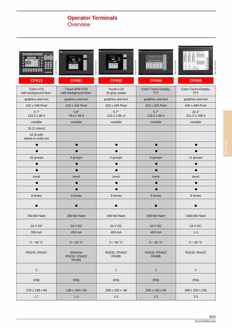
2/33
PLC
etc
.
2CDC003005C0201
Operator TerminalsOverview
Color-LCD Touch-B/W-STN Touch-LCD Color-Touch-Display, Color-Touch-Display,with background illum. with background illum. 16 gray scales TFT TFT
graphics and text graphics and text graphics and text graphics and text graphics and text
320 x 240 Pixel 320 x 240 Pixel 320 x 240 Pixel 320 x 240 Pixel 640 x 480 Pixel
5.7" 3.8" 5.7" 5.7" 10.4"115.2 x 86.4 78.0 x 58.5 115.2 x 86.,4 115.2 x 86.4 211.2 x 158.4
variable variable variable variable variable
16 (2 colors)
16 (8 withlabels to write on)
P P P P P
P P P P P
16 groups 4 groups 5 groups 5 groups 11 groups
P P P P P
P P P P P
trend trend trend trend trend
P P P P P
P P P P P
8 levels 8 levels 8 levels 8 levels 8 levels
P P P P P
400 kB Flash 400 kB Flash 400 kB Flash 400 kB Flash 1600 kB Flash
24 V DC 24 V DC 24 V DC 24 V DC 24 V DC
550 mA 450 mA 400 mA 450 mA 1 A
0 – 50 °C 0 – 50 °C 0 – 50 °C 0 – 50 °C 0 – 50 °C
RS232, RS422 Ethernet RS232, RS422/ RS232, RS422/ RS232, RS422RS232, RS422/ RS485 RS485
RS485
2 1 1 2
IP65 IP65 IP65 IP65 IP65
276 x 198 x 89 138 x 100 x 30 200 x 150 x 69 200 x 150 x 69 290 x 250 x 105
1.7 1.4 1.5 1.5 3.3
CP513 CP551 CP552 CP554 CP555
1SB
C 4
9127
5F
0304
1SB
C 4
9119
5F
0304
1SB
C 4
9121
5F
0304
1SB
C 4
9123
5F
0304
1SB
C 4
9125
5F
0304
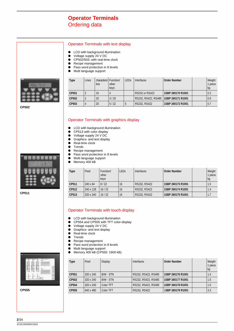
2/342CDC003005C0201
Operator Terminals with touch-display
P LCD with background illuminationP CP554 and CP555 with TFT color-displayP Voltage supply 24 V DCP Graphics- and text displayP Real-time clockP TrendsP Recipe managementP Pass word protection in 8 levelsP Multi language supportP Memory 400 kB (CP555: 1600 kB)
Type Pixel Display Interfaces Order Number Weight1 piecekg
CP551 320 x 240 B/W - STN RS232, RS422, RS485 1SBP 260176 R1001 1.4
CP552 320 x 240 B/W - STN RS232, RS422, RS485 1SBP 260177 R1001 1.5
CP554 320 x 240 Color TFT RS232, RS422, RS485 1SBP 260178 R1001 1.5
CP555 640 x 480 Color TFT RS232, RS422 1SBP 260179 R1001 3.3
Operator Terminals with graphics display
P LCD with background illuminationP CP513 with color displayP Voltage supply 24 V DCP Graphics- and text displayP Real-time clockP TrendsP Recipe managementP Pass word protection in 8 levelsP Multi language supportP Memory 400 kB
Type Pixel Function/ LEDs Interfaces Order Number Weightother 1 piecekeys kg
CP511 240 x 64 8 / 22 16 RS232, RS422 1SBP 260173 R1001 1.5
CP512 240 x 128 16 / 22 16 RS232, RS422 1SBP 260174 R1001 1.4
CP513 320 x 240 16 / 22 16 RS232, RS422 1SBP 260175 R1001 1.7
Operator Terminals with text display
P LCD with background illuminationP Voltage supply 24 V DCP CP502/503: with real-time clockP Recipe managementP Pass word protection in 8 levelsP Multi language support
Type Lines characters/ Function/ LEDs Interfaces Order Number Weightline other 1 piece
keys kg
CP501 2 16 4 RS232 or RS422 1SBP 260170 R1001 0.2
CP502 2 20 3 / 20 RS232, RS422, RS485 1SBP 260171 R1001 0.5
CP503 4 20 5 / 22 5 RS232, RS422 1SBP 260172 R1001 0.7
Operator TerminalsOrdering data
CP502
CP511
CP555
2/35
PLC
etc
.
2CDC003005C0201
Accessories
Type Description Ordering Number Weight1 piecekg
CK516 Add-on keyboard 1SBP 260180 R1001
IFCPBDP Communication interface PROFIBUS DP 1SBN 260320 R1001
IFCETTP Communication interface Ethernet 1SBN 260322 R1001
IFC-PI Printer interface 1SBN 260325 R1001
IFC-MC Interface for Smart Media Card 1SBN 260324 R1001(memory card not included)
PCMCIA 4MB Smart Media Card 4 MB 1SBN 260326 R1001
PCMCIA 8MB Smart Media Card 8 MB 1SBN 260327 R1001
Protection sheet CP551 Protection sheet for display CP551 (5 pcs.) 1SBN 260330 R1001
Protection sheet CP552 Protection sheet for display CP552 (5 pcs.) 1SBN 260328 R1001
Protection sheet CP554 Protection sheet for display CP554 (5 pcs.) 1SBN 260331 R1001
Protection sheet CP555 Protection sheet for display CP555 (5 pcs.) 1SBN 260329 R1001
Programming software for operator terminals CP5xx
For all operator terminals CP5xx, delivery on CD-ROM.Includes documentation for all operator terminals CP5xx.
Type Description Ordering Number Weight1 piecekg
CPsoft Software, documentation on CD 1SBS 260283 R0101
Communications cable
Type Controller Ordering Number Weight1 piecekg
CAB45 series 40 / 50 MiniDin 1SBN 260213 R1001
CAB90 series 90 1SBN 260214 R1001
CAB8 RS422/RS485 converter 1SBN 260212 R1001
Programming cable
Type Interface Ordering Number Weight1 piecekg
CAB5 RS232 1SBN 260210 R1001
CAB6 RS232/RS422 converter 1SBN 260211 R1001
Operator TerminalsOrdering data
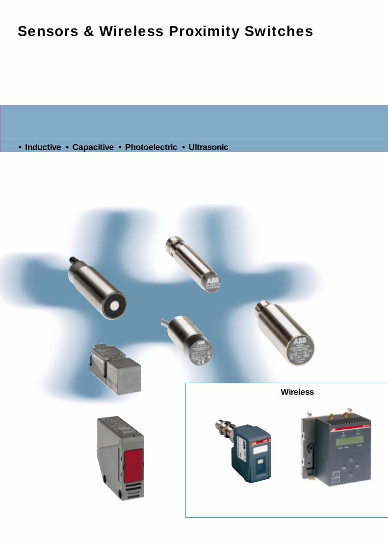
Sensors & Wireless Proximity Switches
• Inductive • Capacitive • Photoelectric • Ultrasonic
Wireless

Sensors &Wireless Proximity Switches
Sen
sors
Contents
Wireless proximity switches
Description ........................................................................................................................ 3/ 2Type key ........................................................................................................................... 3/ 2Ordering data .................................................................................................................... 3/ 3Technical data sensorheads WSIF..., WSIN... .................................................................. 3/ 4Technical data communication module ............................................................................ 3/ 6Technical data input module ............................................................................................ 3/ 7Technical data current supply .......................................................................................... 3/ 8Technical data antennas .................................................................................................. 3/ 9Technical data primary loops ........................................................................................... 3/ 10
Position sensors
Ordering data .................................................................................................................... 3/ 13Type key ........................................................................................................................... 3/ 18
Technical data and dimension drawings of
Inductive sensors- small, cylindrical ....................................................................................................... 3/ 19- with thread M8 ... M30 .............................................................................................. 3/ 20- Block- and square housing ...................................................................................... 3/ 40- Analogue sensor ...................................................................................................... 3/ 47
Capacitive sensors ......................................................................................................... 3/ 48
Photoelectric sensors- Through Beam Photoelectric Sensors ...................................................................... 3/ 49- Retroreflective Sensors ............................................................................................ 3/ 51
- Diffuse Reflective Sensors ....................................................................................... 3/ 56
Ultrasonic sensors .......................................................................................................... 3/ 63
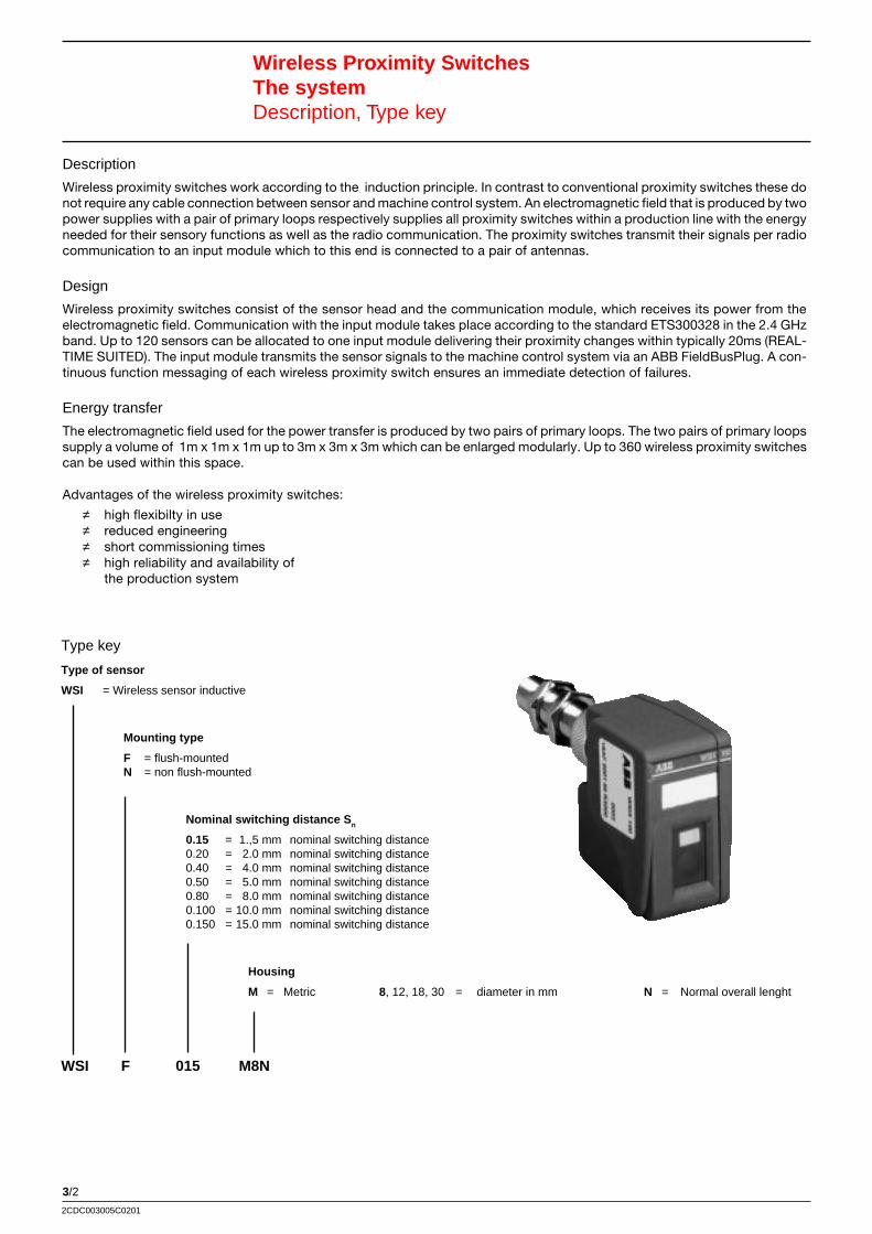
3/2
2CDC003005C0201
Wireless Proximity SwitchesThe systemDescription, Type key
Description
Wireless proximity switches work according to the induction principle. In contrast to conventional proximity switches these donot require any cable connection between sensor and machine control system. An electromagnetic field that is produced by twopower supplies with a pair of primary loops respectively supplies all proximity switches within a production line with the energyneeded for their sensory functions as well as the radio communication. The proximity switches transmit their signals per radiocommunication to an input module which to this end is connected to a pair of antennas.
Design
Wireless proximity switches consist of the sensor head and the communication module, which receives its power from theelectromagnetic field. Communication with the input module takes place according to the standard ETS300328 in the 2.4 GHzband. Up to 120 sensors can be allocated to one input module delivering their proximity changes within typically 20ms (REAL-TIME SUITED). The input module transmits the sensor signals to the machine control system via an ABB FieldBusPlug. A con-tinuous function messaging of each wireless proximity switch ensures an immediate detection of failures.
Energy transfer
The electromagnetic field used for the power transfer is produced by two pairs of primary loops. The two pairs of primary loopssupply a volume of 1m x 1m x 1m up to 3m x 3m x 3m which can be enlarged modularly. Up to 360 wireless proximity switchescan be used within this space.
Advantages of the wireless proximity switches:
≠ high flexibilty in use≠ reduced engineering≠ short commissioning times≠ high reliability and availability of
the production system
Type key
Type of sensor
WSI = Wireless sensor inductive
Mounting type
F = flush-mountedN = non flush-mounted
Nominal switching distance S n
0.15 = 1.,5 mm nominal switching distance0.20 = 2.0 mm nominal switching distance0.40 = 4.0 mm nominal switching distance0.50 = 5.0 mm nominal switching distance0.80 = 8.0 mm nominal switching distance0.100 = 10.0 mm nominal switching distance0.150 = 15.0 mm nominal switching distance
Housing
M = Metric 8, 12, 18, 30 = diameter in mm N = Normal overall lenght
WSI F 015 M8N
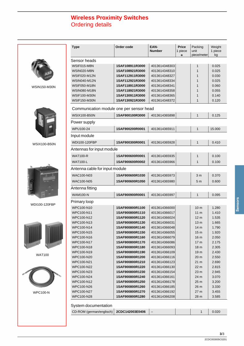
3/3
Sen
sors
2CDC003005C0201
Wireless Proximity SwitchesOrdering details
Type Order code EAN- Price Packing WeightNumber 1 piece unit 1 piece
e piece/meter kg
Sensor headsWSIF015-M8N 1SAF108911R3000 4013614348303 1 0.025
WSIN020-M8N 1SAF108921R3000 4013614348310 1 0.025
WSIF020-M12N 1SAF112911R3000 4013614348327 1 0.030
WSIN040-M12N 1SAF112921R3000 4013614348334 1 0.025
WSIF050-M18N 1SAF118911R3000 4013614348341 1 0.060
WSIN080-M18N 1SAF118921R3000 4013614348358 1 0.055
WSIF100-M30N 1SAF130911R3000 4013614348365 1 0.140
WSIF150-M30N 1SAF130921R3000 4013614348372 1 0.120
Communication module one per sensor head
WSIX100-B50N 1SAF900100R3000 4013614365898 1 0.125
Power supply
WPU100-24 1SAF900200R0001 4013614365911 1 15.000
Input module
WDI100-120FBP 1SAF900300R0001 4013614365928 1 0.410
Antennas for input module
WAT100-R 1SAF900600R0001 4013614365935 1 0.100
WAT100-L 1SAF900600R0002 4013614365966 1 0.100
Antenna cable for input module
WAC100-N03 1SAF900600R1030 4013614365973 3 m 0.370
WAC100-N05 1SAF900600R1050 4013614365980 5 m 0.600
Antenna fitting
WAM100-N 1SAF900900R0001 4013614365997 1 0.095
Primary loopWPC100-N10 1SAF900800R1100 4013614366000 10 m 1.280
WPC100-N11 1SAF900800R1110 4013614366017 11 m 1.410
WPC100-N12 1SAF900800R1120 4013614366024 12 m 1.535
WPC100-N13 1SAF900800R1130 4013614366031 13 m 1.665
WPC100-N14 1SAF900800R1140 4013614366048 14 m 1.790
WPC100-N15 1SAF900800R1150 4013614366055 15 m 1.920
WPC100-N16 1SAF900800R1160 4013614366079 16 m 2.050
WPC100-N17 1SAF900800R1170 4013614366086 17 m 2.175
WPC100-N18 1SAF900800R1180 4013614366093 18 m 2.305
WPC100-N19 1SAF900800R1190 4013614366109 19 m 2.430
WPC100-N20 1SAF900800R1200 4013614366116 20 m 2.550
WPC100-N21 1SAF900800R1210 4013614366123 21 m 2.690
WPC100-N22 1SAF900800R1220 4013614366130 22 m 2.815
WPC100-N23 1SAF900800R1230 4013614366154 23 m 2.945
WPC100-N24 1SAF900800R1240 4013614366161 24 m 3.070
WPC100-N12 1SAF900800R1250 4013614366178 25 m 3.200
WPC100-N26 1SAF900800R1260 4013614366185 26 m 3.330
WPC100-N27 1SAF900800R1270 4013614366192 27 m 3.455
WPC100-N28 1SAF900800R1280 4013614366208 28 m 3.585
System documentationCD-ROM (german/englisch) 2CDC142003E0406 – 1 0.020
WSIN150-M30N
WSIX100-B50N
WDI100-120FBP
WPC100-N
WAT100
3/4
2CDC003005C0201
Wireless proximity switchesTechnical data sensor heads WSIF..., WSIN...
Sensor heads
Switching distance S n, mounting 1,5 mm flush-mounted 2 mm non 2 mm flush-mounted 4 mm nonflush-mounted flush-mounted
Type M8x1 flush-mounted M8x1 non flush-mounted M12x1 flush-mounted M12x1 non flush-mounted
Identification WSIF015-M8N WSIN020-M8N WSIF020-M12N WSIN040-M12N
Switching distance [mm] 0 ... 1.21 0 ... 1.62 0 ... 1.62 0 ... 3.24
Reduction factor rV2A 0.75 0.75 0.75 0.8
rAL 0.4 0.4 0.3 0.45
rCu 0.4 0.4 0.25 0.4
Nominal signal transfer rate 1/s 5 (signal changes per second, typically 20ms)
Hystereses H [%] ≤ 10 ≤ 10 ≤ 10 ≤ 10
Reproducibility [%] ≤ 10 ≤ 10 ≤ 10 ≤ 10
Temperature drift [%] ± 10 ± 10 ± 10 ± 10
Short circuit protection no, because usage only in connection with the communication module.
Reverse polarity protection no, because usage only in connection with the communication module.
Indication see communication module
Operating temperature range [°C] -25 ... +70
Storage temperature range [°C] -40 ... +70
Permissible shockand vibration loading shock b ≤ 30g, T ≤ 11ms
Protection class acc. to IEC 60529 IP67
In compliance with EN 60 947-5-2
Connection M12 connector for one communication module
Housing material Nickel plated brass
Sensing face PBT (Crastin)
Starting torquerecommended/maximum [Nm] 3/5 3/5 10/15 10/15
Drawing number 120025 120026 117740 118943
M8x1
4
4
M12x1
3050
6
13
60
M12x1
4
17
60
4
M12x1
5
17
120025 120026 117740 118943
M8x1
4
3050
6
M12x1
13
3/5
Sen
sors
2CDC003005C0201
M18x1
4
50
60
M12x1
36
60
504
10
M12x1
M18x1
24
Wireless proximity switchesTechnical data sensor heads WSIF..., WSIN...
120027 120029 120030 120031
M30x1,5
5
5060
M12x1
36
60
M18x1
4
M12x1
50
24
Sensor heads
Switching distance S n, mounting 5 mm flush-mounted 8 mm non 10 mm flush-mounted 15 mm nonflush-mounted flush-mounted
Type M18x1 flush-mounted M18x1 non flush-mounted M30x1.5 flush-mounted M30x1.5 non flush-mounted
Identification WSIF050-M18N WSIN080-M18N WSIF100-M30N WSIN150-M30N
Switching distance [mm] 0 ... 4.05 0 ... 6.5 0 ... 8.1 0 ... 12.15
Reduction factor rV2A 0.75 0.75 0.75 0.7
rAL 0.35 0.45 0.45 0.45
rCu 0.3 0.4 0.25 0.35
Nominal signal transfer rate 1/s 5 (signal changes per second, typically 20ms)
Hystereses H [%] ≤ 10 ≤ 10 ≤ 10 ≤ 10
Reproducibility [%] ≤ 10 ≤ 10 ≤ 10 ≤ 10
Temperature drift [%] ± 10 ± 10 ± 10 ± 10
Short circuit protection no, because usage only in connection with the communication module.
Reverse polarity protection no, because usage only in connection with the communication module.
Indication see communication module
Operating temperature range [°C] -25 ... +70
Storage temperature range [°C] -40 ... +70
Permissible shockand vibration loading shock b ≤ 30g, T ≤ 11ms
Protection class acc. to IEC 60529 IP67
In compliance with EN 60 947-5-2
Connection M12 connector for one communication module
Housing material Nickel plated brass
Sensing face PBT (Crastin)
Starting torquerecommended/maximum [Nm] 30/50 30/50 30/100 30/100
Drawing number 120027 120029 120030 120031
3/6
2CDC003005C0201
Wireless proximity switchesTechnical data communication module
Short description
The communication module is attached to one of the eight heads of an inductive sensor as if it were a conventional sensor plug. The commu-nication module for all sensor head variations is identical.The communication module receives its energy for the sensor functions and radio communication with the input module from an electromagneticfield.
Type WSIX100-B50N
Nominal signal transfer rate 1/s 5 (signal changes per second)
Latency (99,9%) 20 ms (max. 34 ms) until the signal is available on the fieldbus
Switch status LED, yellow
Operating status LED, green
Operation 1 foil push-button
Operating temperatur range -25 ... +55 °C
Storage temperatur range -40 ... +70 °C
Permissable shockand vibration loading shock b < 30g, T < 11 ms
Protection class in acc. with IEC 60529 IP67
In compliance with EN 60 947-5-2
Connection Connector M12 with connecting nut for sensor headsfor wireless proximity switches
Housing material Bergamit A700 (PA6.6 not fortified)
Power consumption < 6 mW
Frequency of the power transfer 120 kHz
Frequency band 2,4 GHz ISM band in accordance with ETSI standard ETS 300 328
Maximum number of communicationmodules in one machine cell(3x3x3 m3) 360
Maximum transfer rate 10 m/s
Error rate 10 -9
Range for communication 5 m
Frequency change Frequency hopping method
Address storage Adresses cannot be lost
3/7
Sen
sors
2CDC003005C0201
Wireless proximity switchesTechnical data input module
Short description
One input module transmits the information of up to 120 wireless position sensors to the machine control. The sensor signals reach the inputmodule via two antennas and are then transfered to the machine control system via a FieldBusPlug.
Communication takes place in the 2.4 GHz band according to the standard ETS 300 328. A frequency hopping process with varying frequencysequences is used for reliable data transfer.
Every 500 ms the input module expects a status report of all its assigned sensors . This way the input module monitors the correct functioning of thesensors.
Additionally, the input module is equipped with functions for the configuration and diagnosis of wireless position sensors.
Type WDI100-120FBP
Number of inputs 120 digital inputs for wireless position sensors120 valid-status signals for wireless position sensors
Frequency band (communication) 2.4 GHz ISM band in acc. with ETSI standard ETS 300 328
Frequency-/antenna change Frequency hopping method with varying frequency sequencesAlternation between emitting- and receiving antenna
Error rate (per input) 10 -9
Latency (99,9 %) 20 ms (max. 34 ms) until the signal is available on the fieldbus
Range (of antenna) 5 m
Maximum number of inputmodules per machine cell 3
Operating display - LCD-Display, double-spaced with 16 characters each- 4 foil push-buttons
Electrical connection - 2 coaxial connectors: antenna cable- 1 connector: interface to ABB-FieldBusPlug- 1 set of screw terminals: 24 VDC supply
Protection class in acc. with IEC 60529 IP20
Supply voltage 24 V DC (+20%,-15%)
Operating temperature range 0 ... +50°C
Storage temperature range -25 ... +70°C
Permissible humidity for operation +50 ... +95 %, without bedewing
Dimensions (h x w x d) 140 mm x 120 mm x 85 mm
Mounting - DIN-rail in acc. with DIN EN 50022- Mounting holes for screws up to 4 mm diameter
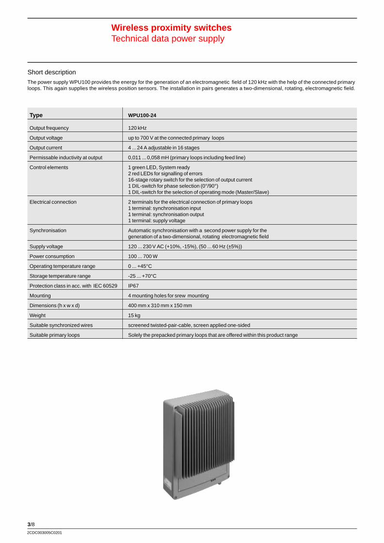
3/8
2CDC003005C0201
Kurzbeschreibung:
Typ
Wireless proximity switchesTechnical data power supply
Short description
The power supply WPU100 provides the energy for the generation of an electromagnetic field of 120 kHz with the help of the connected primaryloops. This again supplies the wireless position sensors. The installation in pairs generates a two-dimensional, rotating, electromagnetic field.
Type WPU100-24
Output frequency 120 kHz
Output voltage up to 700 V at the connected primary loops
Output current 4 ... 24 A adjustable in 16 stages
Permissable inductivity at output 0,011 ... 0,058 mH (primary loops including feed line)
Control elements 1 green LED, System ready2 red LEDs for signalling of errors16-stage rotary switch for the selection of output current1 DIL-switch for phase selection (0°/90°)1 DIL-switch for the selection of operating mode (Master/Slave)
Electrical connection 2 terminals for the electrical connection of primary loops1 terminal: synchronisation input1 terminal: synchronisation output1 terminal: supply voltage
Synchronisation Automatic synchronisation with a second power supply for thegeneration of a two-dimensional, rotating electromagnetic field
Supply voltage 120 ... 230 V AC (+10%, -15%), (50 ... 60 Hz (±5%))
Power consumption 100 ... 700 W
Operating temperature range 0 ... +45°C
Storage temperature range -25 ... +70°C
Protection class in acc. with IEC 60529 IP67
Mounting 4 mounting holes for srew mounting
Dimensions (h x w x d) 400 mm x 310 mm x 150 mm
Weight 15 kg
Suitable synchronized wires screened twisted-pair-cable, screen applied one-sided
Suitable primary loops Solely the prepacked primary loops that are offered within this product range
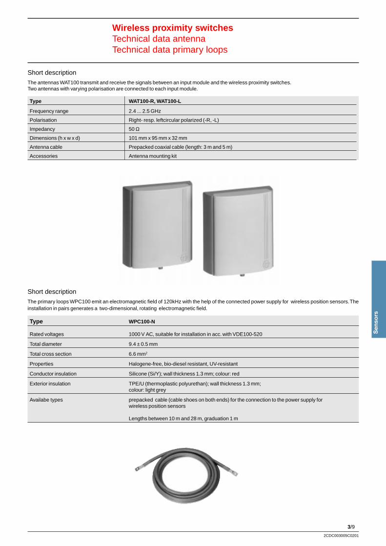
3/9
Sen
sors
2CDC003005C0201
Wireless proximity switchesTechnical data antennaTechnical data primary loops
Short description
The antennas WAT100 transmit and receive the signals between an input module and the wireless proximity switches.Two antennas with varying polarisation are connected to each input module.
Type WAT100-R, WAT100-L
Frequency range 2.4 ... 2.5 GHz
Polarisation Right- resp. leftcircular polarized (-R, -L)
Impedancy 50 Ω
Dimensions (h x w x d) 101 mm x 95 mm x 32 mm
Antenna cable Prepacked coaxial cable (length: 3 m and 5 m)
Accessories Antenna mounting kit
Short description
The primary loops WPC100 emit an electromagnetic field of 120kHz with the help of the connected power supply for wireless position sensors. Theinstallation in pairs generates a two-dimensional, rotating electromagnetic field.
Type WPC100-N
Rated voltages 1000 V AC, suitable for installation in acc. with VDE100-520
Total diameter 9.4 ± 0.5 mm
Total cross section 6.6 mm2
Properties Halogene-free, bio-diesel resistant, UV-resistant
Conductor insulation Silicone (Si/Y); wall thickness 1.3 mm; colour: red
Exterior insulation TPE/U (thermoplastic polyurethan); wall thickness 1.3 mm;colour: light grey
Availabe types prepacked cable (cable shoes on both ends) for the connection to the power supply forwireless position sensors
Lengths between 10 m and 28 m, graduation 1 m
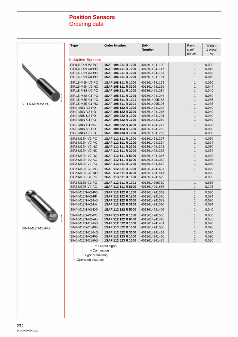
3/10
2CDC003005C0201
Type Order Number EAN- Pack. WeightNumber size/ 1 piece
pieces kg
Position SensorsOrdering data
SIN4-M12N-C1-PO
SS
T 0
64 9
7
SIF1,5-M8N-V2-PO
SS
T 0
61 9
7Inductive Sensors
Output signalConnection
Type of housingOperating distance
SIF0,8-Z4N-V2-PO 1SAF 104 211 R 1000 4013614241130 1 0.020SIF0,8-Z4N-C8-PO 1SAF 104 411 R 1000 4013614241147 1 0.010SIF1,5-Z6N-U2-PO 1SAF 106 211 R 1000 4013614241154 1 0.030SIF1,5-Z6N-C8-PO 1SAF 106 411 R 1000 4013614241161 1 0.010
SIF1,5-M8N-V2-PO 1SAF 108 111 R 1000 4013614241178 1 0.050SIF1,5-M8N-V2-NO 1SAF 108 111 R 3000 4013614241185 1 0.044SIF1,5-M8S-U2-PO 1SAF 109 211 R 1000 4013614241284 1 0.040
SIF1,5-M8S-C1-PO 1SAF 108 511 R 1000 4013614241246 1 0.030SIF1,5-M8E-C1-PO 1SAF 108 511 R 1001 4013614295188 1 0.035SIF1,5-M8E-C1-NO 1SAF 108 511 R 3001 4013614295195 1 0.035SIN2-M8N-V2-PO 1SAF 108 122 R 1000 4013614241208 1 0.040SIN2-M8N-V2-NO 1SAF 108 122 R 3000 4013614241215 1 0.040SIN2-M8S-U2-PO 1SAF 109 222 R 1000 4013614241291 1 0.040SIN2-M8N-C1-PO 1SAF 108 522 R 1000 4013614241260 1 0.030
SIN2-M8N-C1-NO 1SAF 108 522 R 3000 4013614241277 1 0.030SIN3-M8N-V2-PO 1SAF 108 123 R 1000 4013614241222 1 0.050SIN3-M8N-C8-PO 1SAF 108 423 R 1000 4013614241239 1 0.030
SIF2-M12N-V2-PO 1SAF 112 111 R 1000 4013614241307 1 0.030SIF2-M12N-V2-PK 1SAF 112 111 R 1200 4013614241314 1 0.074SIF2-M12N-V2-NO 1SAF 112 111 R 3000 4013614241321 1 0.030SIF2-M12N-V2-NK 1SAF 112 111 R 3200 4013614241338 1 0.074
SIF2-M12N-V2-DO 1SAF 112 111 R 5000 4013614241345 1 0.040SIF2-M12N-V2-AO 1SAF 112 111 R 6000 4013614241352 1 0.085SIF2-M12S-V2-PO 1SAF 113 211 R 1000 4013614241512 1 0.030
SIF2-M12N-C1-PO 1SAF 112 511 R 1000 4013614241437 1 0.020SIF2-M12N-C1-NO 1SAF 112 511 R 3000 4013614241444 1 0.020SIF2-M12S-C1-PO 1SAF 113 511 R 1000 4013614241529 1 0.020
SIF2-M12E-C1-PO 1SAF 112 511 R 1001 4013614296710 1 0.065SIF2-M12E-V2-AC 1SAF 112 111 R 6100 4013614291685 1 0.125
SIN4-M12N-V2-PO 1SAF 112 122 R 1000 4013614241369 1 0.030SIN4-M12N-V2-PK 1SAF 112 122 R 1200 4013614241376 1 0.074SIN4-M12N-V2-NO 1SAF 112 122 R 3000 4013614241383 1 0.030SIN4-M12N-V2-NK 1SAF 112 122 R 3200 4013614241390 1 0.074
SIN4-M12N-V2-DO 1SAF 112 122 R 5000 4013614241406 1 0.040
SIN4-M12S-V2-PO 1SAF 113 122 R 1000 4013614241505 1 0.030SIN4-M12N-V2-AO 1SAF 112 122 R 6000 4013614241413 1 0.085SIN4-M12N-C1-PO 1SAF 112 522 R 1000 4013614241451 1 0.020SIN4-M12S-C1-PO 1SAF 113 522 R 1000 4013614241536 1 0.020
SIN4-M12N-C1-NO 1SAF 112 522 R 3000 4013614241468 1 0.020SIN6-M12N-V2-PO 1SAF 112 123 R 1000 4013614241420 1 0.090SIN6-M12N-C1-PO 1SAF 112 523 R 1000 4013614241475 1 0.020
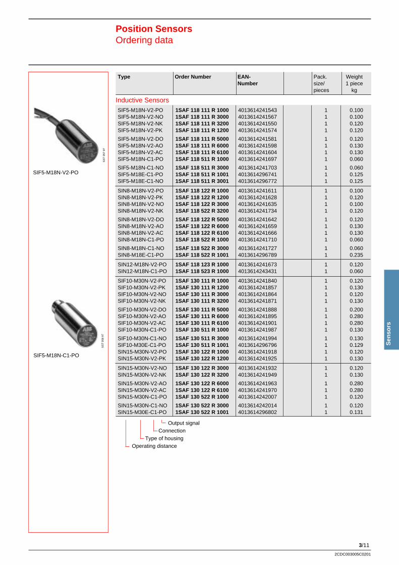
3/11
2CDC003005C0201
Sen
sors
Type Order Number EAN- Pack. WeightNumber size/ 1 piece
pieces kg
Position SensorsOrdering data
SIF5-M18N-V2-PO
SS
T 0
57 9
7S
ST
058
97
SIF5-M18N-C1-PO
Inductive Sensors
Output signalConnection
Type of housingOperating distance
SIF5-M18N-V2-PO 1SAF 118 111 R 1000 4013614241543 1 0.100SIF5-M18N-V2-NO 1SAF 118 111 R 3000 4013614241567 1 0.100SIF5-M18N-V2-NK 1SAF 118 111 R 3200 4013614241550 1 0.120SIF5-M18N-V2-PK 1SAF 118 111 R 1200 4013614241574 1 0.120
SIF5-M18N-V2-DO 1SAF 118 111 R 5000 4013614241581 1 0.120SIF5-M18N-V2-AO 1SAF 118 111 R 6000 4013614241598 1 0.130SIF5-M18N-V2-AC 1SAF 118 111 R 6100 4013614241604 1 0.130SIF5-M18N-C1-PO 1SAF 118 511 R 1000 4013614241697 1 0.060
SIF5-M18N-C1-NO 1SAF 118 511 R 3000 4013614241703 1 0.060SIF5-M18E-C1-PO 1SAF 118 511 R 1001 4013614296741 1 0.125SIF5-M18E-C1-NO 1SAF 118 511 R 3001 4013614296772 1 0.125
SIN8-M18N-V2-PO 1SAF 118 122 R 1000 4013614241611 1 0.100SIN8-M18N-V2-PK 1SAF 118 122 R 1200 4013614241628 1 0.120SIN8-M18N-V2-NO 1SAF 118 122 R 3000 4013614241635 1 0.100SIN8-M18N-V2-NK 1SAF 118 522 R 3200 4013614241734 1 0.120
SIN8-M18N-V2-DO 1SAF 118 122 R 5000 4013614241642 1 0.120SIN8-M18N-V2-AO 1SAF 118 122 R 6000 4013614241659 1 0.130SIN8-M18N-V2-AC 1SAF 118 122 R 6100 4013614241666 1 0.130SIN8-M18N-C1-PO 1SAF 118 522 R 1000 4013614241710 1 0.060
SIN8-M18N-C1-NO 1SAF 118 522 R 3000 4013614241727 1 0.060SIN8-M18E-C1-PO 1SAF 118 522 R 1001 4013614296789 1 0.235
SIN12-M18N-V2-PO 1SAF 118 123 R 1000 4013614241673 1 0.120SIN12-M18N-C1-PO 1SAF 118 523 R 1000 4013614243431 1 0.060
SIF10-M30N-V2-PO 1SAF 130 111 R 1000 4013614241840 1 0.120SIF10-M30N-V2-PK 1SAF 130 111 R 1200 4013614241857 1 0.130SIF10-M30N-V2-NO 1SAF 130 111 R 3000 4013614241864 1 0.120SIF10-M30N-V2-NK 1SAF 130 111 R 3200 4013614241871 1 0.130
SIF10-M30N-V2-DO 1SAF 130 111 R 5000 4013614241888 1 0.200SIF10-M30N-V2-AO 1SAF 130 111 R 6000 4013614241895 1 0.280SIF10-M30N-V2-AC 1SAF 130 111 R 6100 4013614241901 1 0.280SIF10-M30N-C1-PO 1SAF 130 511 R 1000 4013614241987 1 0.130
SIF10-M30N-C1-NO 1SAF 130 511 R 3000 4013614241994 1 0.130SIF10-M30E-C1-PO 1SAF 130 511 R 1001 4013614296796 1 0.129SIN15-M30N-V2-PO 1SAF 130 122 R 1000 4013614241918 1 0.120SIN15-M30N-V2-PK 1SAF 130 122 R 1200 4013614241925 1 0.130
SIN15-M30N-V2-NO 1SAF 130 122 R 3000 4013614241932 1 0.120SIN15-M30N-V2-NK 1SAF 130 122 R 3200 4013614241949 1 0.130
SIN15-M30N-V2-AO 1SAF 130 122 R 6000 4013614241963 1 0.280SIN15-M30N-V2-AC 1SAF 130 122 R 6100 4013614241970 1 0.280SIN15-M30N-C1-PO 1SAF 130 522 R 1000 4013614242007 1 0.120
SIN15-M30N-C1-NO 1SAF 130 522 R 3000 4013614242014 1 0.120SIN15-M30E-C1-PO 1SAF 130 522 R 1001 4013614296802 1 0.131
3/12
2CDC003005C0201
SIF2-B28N-V0,1-PO 1SAF 123 111 R 1000 4013614241796 1 0.010SIF2-B28N-V0,1-N0 1SAF 123 111 R 3000 4013614241819 1 0.010SIF6-B45N-U2-PO 1SAF 125 111 R 1000 4013614241833 1 0.100
SIF15-Q40N-T-PO 1SAF 144 811 R 1000 4013614242113 1 0.280SIF15-Q40N-T-PK 1SAF 144 811 R 1200 4013614242120 1 0.280SIF15-Q40N-T-NO 1SAF 144 811 R 3000 4013614242137 1 0.280SIF15-Q40N-C1-PO 1SAF 144 511 R 1000 4013614242090 1 0.280
SIF20-Q40N-T-PO 1SAF 144 822 R 1000 4013614242151 1 0.280SIN20-Q40N-T-AK 1SAF 144 822 R 6200 4013614242205 1 0.280SIN30-Q40N-T-PO 1SAF 144 823 R 1000 4013614242212 1 0.280
SIN30-Q40N-T-PK 1SAF 144 823 R 1200 4013614242229 1 0.280SIN30-Q40N-T-AK 1SAF 144 823 R 6200 4013614242250 1 0.280SIF20-Q40S-C1-PO 1SAF 145 812 R 1000 4013614244902 1 0.140
SIF20-Q40T-C1-PO 1SAF 146 812 R 1000 4013614244919 1 0.140SIF20-Q40T-C1-PK 1SAF 146 812 R 1200 4013614244926 1 0.140SIN30-Q40S-C1-PO 1SAF 145 823 R 1000 4013614244933 1 0.140SIN30-Q40T-C1-PK 1SAF 146 823 R 1200 4013614244940 1 0.140
SIF40-Q80N-T-PK 1SAF 148 811 R 1200 4013614242328 1 0.460SIN50-Q80N-T-PO 1SAF 148 822 R 1000 4013614242335 1 0.415SIN50-Q80N-T-PK 1SAF 148 822 R 1200 4013614242342 1 0.415
SIF5-M18N-V2-M 1SAF 118 112 R 8000 4013614268830 1 0.170
Type Order Number EAN- Pack. WeightNumber size/ 1 piece
pieces kg
Inductive Sensors
Capacitive Sensors
Type Order Number EAN- Pack. WeightNumber size/ 1 piece
pieces kg
SCF10-M30N-V2-PO 1SAF 230 111 R 1000 4013614242359 1 0.280SCF10-M30N-C1-PO 1SAF 230 511 R 1000 4013614242373 1 0.148SCF10-M30N-V2-AO 1SAF 230 111 R 6000 4013614242366 1 0.270SCF10-M30N-V2-PK 1SAF 230 111 R 1200 4013614290923 1 0.240
SCF10-M30N-C1-PK 1SAF 230 511 R 1200 4013614290916 1 0.140
Output signalConnection
Type of housingOperating distance
Output signal Connection
Type of housingOperating distance
Position SensorsOrdering data
SIF15-Q40N-T-PO
SS
T 0
54 9
7
SCF10-M30N-V2-AO
SS
T 0
55 9
7
3/13
2CDC003005C0201
Sen
sors
Type Order Number EAN- Pack. WeightNumber size/ 1 piece
pieces kg
Photoelectric Sensors
Position SensorsOrdering data
SUD500-M30N-C1-M
SOD500-B45N-C1-PKS
SOT 20M - B75N-T-KK 1SAF 320 750 R 1100 4013614269677 1 0.190SOR 1500 - M18N-C1-PO 1SAF 318 542 R 1001 4013614268793 1 0.100SOR 4000 - M18N-C1-PO 1SAF 318 542 R 1002 4013614366833 1 0.110SOD 200 - M18N-C1-PO 1SAF 318 553 R 1000 4013614242441 1 0.070
SOR 2000 - B26N-U2-PO 1SAF 323 242 R 1000 4013614242458 1 0.070SOD 400 - B26N-U2-PO 1SAF 323 253 R 1000 4013614242465 1 0.100SOR 5000 - B75N-T-POS 1SAF 328 842 R 1000 4013614242564 1 0.200SOR 5000 - B75N-T-KK 1SAF 328 842 R 1100 4013614269660 1 0.110
SOD 500 - B45N-C1-PKS 1SAF 325 553 R 1210 4013614295263 1 0.060SOD 500 - B45N-C1-NKS 1SAF 325 553 R 3210 4013614295270 1 0.060SOR 6000 - B45N-C1-PKS 1SAF 325 545 R 1210 4013614295287 1 0.060SOR 6000 - B45N-C1-NKS 1SAF 325 545 R 3210 4013614295294 1 0.060
SOT 15M - B45N- C1-PKS 1SAF 325 586 R 1210 4013614295300 1 0.120SOT 15M - B45N- C1-NKS 1SAF 325 586 R 3210 4013614295317 1 0.120SORG 2000- B45N- C1-PKS 1SAF 325 543 R 1210 4013614295324 1 0.060SORG 2000- B45N- C1-NKS 1SAF 325 543 R 3210 4013614295331 1 0.060SOD 800 - B75N-T-POS 1SAF 328 853 R 1000 4013614242571 1 0.200SOD 2000- B75N-T-KK 1SAF 328 853 R 1100 4013614269653 1 0.110
Ultrasonic Sensors
Output signal Connection
Type of housingOperating distance
Type Order Number EAN- Pack. WeightNumber size/ 1 piece
pieces kg
Type Order Number EAN- Pack. WeightNumber size/ 1 piece
pieces kg
SOLX- B50N-C8-PKS 1SAF 325 160 R 1000 4013614242533 1 0.120SOLD 50- B50N-PVM6 1SAF 325 152 R 0001 4013614242526 1 0.020SOLD15- B50N-PVM3 1SAF 325 151 R 0001 4013614242519 1 0.020
SOLT150- B50N-PVM4 1SAF 325 163 R 0001 4013614242540 1 0.011SOLT150- B50N-PVM3 1SAF 325 163 R 0002 4013614242557 1 0.011
Photoelectric Sensors with Waveguides
Output signal Connection
Type of housingOperating distance
SUD 500-M30N-C1-POS 1SAF 430 651 R 1002 4013614243738 1 0.200SUD2000-M30N-C1-POS 1SAF 430 653 R 1002 4013614339820 1 0.200SUD4000-M30N-C1-POS 1SAF 430 654 R 1002 4013614339844 1 0.210SUD6000-M30N-C1-POS 1SAF 430 655 R 1002 4013614339868 1 0.400
SUD 500-M30N-C1-NOS 1SAF 430 651 R 3002 4013614339806 1 0.200SUD2000-M30N-C1-NOS 1SAF 430 653 R 3002 4013614339837 1 0.200SUD4000-M30N-C1-NOS 1SAF 430 654 R 3002 4013614339851 1 0.210SUD6000-M30N-C1-NOS 1SAF 430 655 R 3002 4013614339875 1 0.400
SUD 500-M30N-C1-M 1SAF 430 551 R 8002 4013614366895 1 0.220SUD2000-M30N-C1-M 1SAF 430 553 R 8002 4013614366901 1 0.220SUD4000-M30N-C1-M 1SAF 430 554 R 8002 4013614366918 1 0.300SUD6000-M30N-C1-M 1SAF 430 555 R 8002 4013614366925 1 0.400
3/14
2CDC003005C0201
Position SensorsOrdering dataType Code
Type Order Number EAN- Pack. WeightNumber size/ 1 piece
pieces kg
Accessories
SZP2>PROG 1SAF 912 030 R 7000 4013614269684 1 0.020SZC1>4POL-0 1SAF 912 020 R 4000 4013614243745 1 0.050SZC1/4POL-0 1SAF 912 010 R 4000 4013614243752 1 0.050SZC1>U5-3POL-LED0 1SAF 912 225 R 3100 4013614243769 1 0.200
SZC8>U5-3POL-LED0 1SAF 908 225 R 3100 4013614243776 1 0.200SZC1>V5-4POL-0 1SAF 912 125 R 4000 4013614243790 1 0.200SZC1/V5-4POL-0 1SAF 912 115 R 4000 4013614243806 1 0.200
MB5-Kit 1SAF 950 988 R 9403 4013614286490 1 0.100ST-1 1SAF 950 988 R 9401 4013614286513 1 0.141RFL-1 1SAF 950 988 R 9402 4013614286506 1 0.120OPUS-Software 1SAF 950 988 R 9404 4013614317323 1 0.020MH04-Mounting tool 1SAF 950 988 R 9405 4013614339752 1 0.282
MB-5 Kit
SZP2>PROG
RFL-1
ST-1
OPUS-Software
Type CodeInductive / Capacitive / Photoelectric and Ultrasonic Sensors
Type of Sensor
SI = InductiveSC = CapacitiveSO = PhotoelectricSU = UltrasonicSOL = Light guide
Installation method Sensing range
F = flush mounting (inductive and capacitive) in mmN = non-flush mounting (inductive and capacitiv)R = RetroreflectiveD = Diffuse reflective (photoelectric and ultrasonic)T = Through beam (photoelectric)
Housing
Z = cylindrical 4, 6 = diameter (mm) N = normal type lenghtM = Thread 8, 12, 18, 30 = diameter (mm) S = short type lenghtQ = block with square front 30, 40, 80 = diagonal (mm) T = short type lenghtB = block 26, 40, 45, 75 = corner distance (mm) E = stainless steel
Connections
V2 = PVC, 2m cableU2 = PUR, 2m KableC1 = M12 connector with 3-5 pinsC3 = M12 connector, ACC8 = M8 connector with 3 pinsT = Terminal connection
Output signals
PO = 24 VDC, 3-wire PNP, NOPC = 24 VDC, 3-wire PNP, NCPK = 24 VDC, 4-wire PNP, NO/NC combinationNO = 24 VDC, 3-wire NPN, NONK = 24 VDC, 4-wire NPN, NO/NC combination
DO = 24 VDC, 2-wire , NO
AO = 230 VAC, 2-wire , NO
AC = 230 VAC, 2-wire , NC
AK = 230 VAC, 4-wire , NO/NC combination.
KK = 12 ... 240 VDC / 24 ... 240 VAC, 4-wire PNP, Relais output
M = analogue signal
SI F2 M12N V2 PO
3/15
2CDC003005C0201
Sen
sors
Operating distance S n, mounting 0.8 mm flush 0.8 mm flush 1.5 mm flush 1.5 mm flush
PNP NO SIF0,8-Z4N-V2-PO SIF0,8-Z4N-C8-PO SIF1,5-Z6N-U2-PO SIF1,5-Z6N-C8-PO
NC
Antivalent
NPN NO
Antivalent
DC 2-wire NO
AC NO
NC
Antivalent
Switching distance [mm] 0 ... 0.648 0 ... 0.648 0 ... 1.215 0 ... 1.215
Reduction factor rV2A 0.85 0.85 0.7 0.7
rAL 0,45 0.45 0.25 0.25
rCu 0.4 0.4 0.2 0.2
Operating voltage [V] 10 ... 30 10 ... 30 10 ... 60 10 ... 60
Operating current [mA] 200 200 100 100
Switching frequency [Hz] 3000 3000 500 500
Idle current / residual current [mA] 10 / - 10 / - 15 / - 15 / -
Line voltage drop [V] 2 22 3 3
Short circuit protection clocking clocking clocking clocking
Inverse polarity protection yes yes yes yes
Indication output signal LED yellow LED yellow LED yellow -
voltage - - - -
Operating temperature range [°C] -25 ... 70 -25 ... 70 -25 ... 70 -25 ... 70
In compliance with EN60947-5-2 EN60947-5-2 EN60947-5-2 EN60947-5-2
Protection class acc. to IEC 60529 IP67 IP67 IP67 IP67
Connection type 2 m, PVC-cable Connector M8 2 m, PUR-cable Connector M8
Conductor diameter 0.14 mm2 - 0.14 mm2 -
Housing material stainless steel stainless steel stainless steel stainless steel
Front face PBT (Crastin) PBT (Crastin) PBT (Crastin) PBT (Crastin)
Drawing No. LS008002 LS000001 FZ015003 FZ015004
Inductive Sensors, small, cylindrical
Position SensorsTechnial Data, Dimension Drawings
3 / BU
4 / BK
1 / BNL+
L-
Output PO
Output signals Dimensions in mm
Ø 4
18
25
LED
LS00
8002
Ø 6,5
LED
M8x1
Ø 4
18 1938
LS00
0001
Ø 6,5
LED
26
40
FZ
1500
3
ø 6,5
50
M8x1
FZ
1500
4
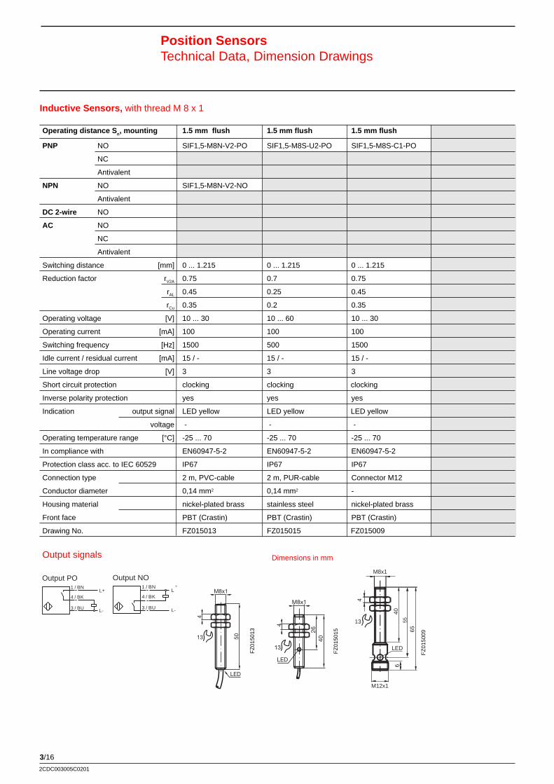
3/16
2CDC003005C0201
3 / BU
4 / BK
1 / BNL+
L-
Output PO
M8x1
4
50
LED
13
M8x1
4
2640
13
LED
FZ
0150
13
FZ
0150
15
1 / BNL+
L-
4 / BK
3 / BU
Output NO
Position SensorsTechnical Data, Dimension Drawings
Inductive Sensors, with thread M 8 x 1
FZ
0150
09
Operating distance S n, mounting 1.5 mm flush 1.5 mm flush 1.5 mm flush
PNP NO SIF1,5-M8N-V2-PO SIF1,5-M8S-U2-PO SIF1,5-M8S-C1-PO
NC
Antivalent
NPN NO SIF1,5-M8N-V2-NO
Antivalent
DC 2-wire NO
AC NO
NC
Antivalent
Switching distance [mm] 0 ... 1.215 0 ... 1.215 0 ... 1.215
Reduction factor rV2A 0.75 0.7 0.75
rAL 0.45 0.25 0.45
rCu 0.35 0.2 0.35
Operating voltage [V] 10 ... 30 10 ... 60 10 ... 30
Operating current [mA] 100 100 100
Switching frequency [Hz] 1500 500 1500
Idle current / residual current [mA] 15 / - 15 / - 15 / -
Line voltage drop [V] 3 3 3
Short circuit protection clocking clocking clocking
Inverse polarity protection yes yes yes
Indication output signal LED yellow LED yellow LED yellow
voltage - - -
Operating temperature range [°C] -25 ... 70 -25 ... 70 -25 ... 70
In compliance with EN60947-5-2 EN60947-5-2 EN60947-5-2
Protection class acc. to IEC 60529 IP67 IP67 IP67
Connection type 2 m, PVC-cable 2 m, PUR-cable Connector M12
Conductor diameter 0,14 mm2 0,14 mm2 -
Housing material nickel-plated brass stainless steel nickel-plated brass
Front face PBT (Crastin) PBT (Crastin) PBT (Crastin)
Drawing No. FZ015013 FZ015015 FZ015009
M8x1
4
13
40
65
LED
M12x1
655
Dimensions in mmOutput signals
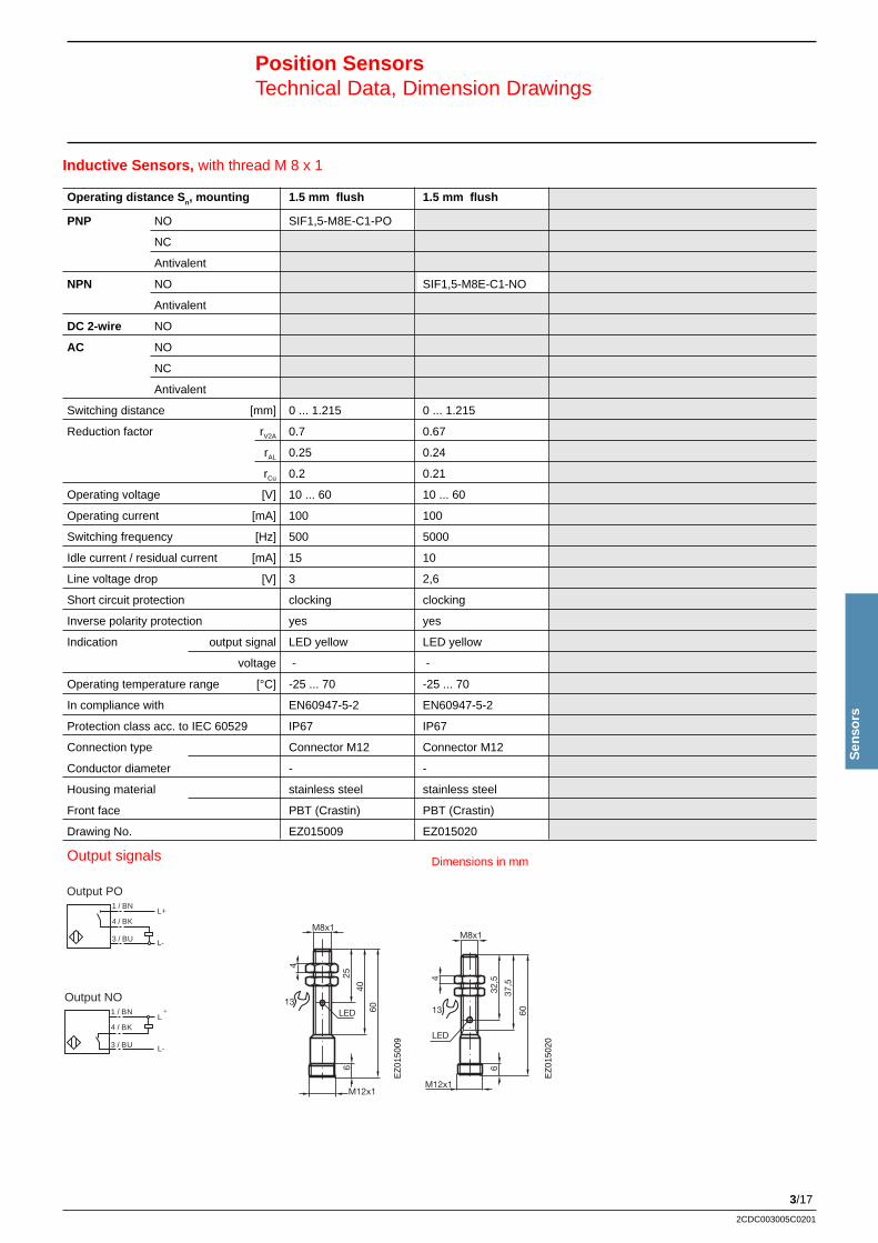
3/17
2CDC003005C0201
Sen
sors
3 / BU
4 / BK
1 / BNL+
L-
Output PO
1 / BNL+
L-
4 / BK
3 / BU
Output NO
Position SensorsTechnical Data, Dimension Drawings
Inductive Sensors, with thread M 8 x 1
Operating distance S n, mounting 1.5 mm flush 1.5 mm flush
PNP NO SIF1,5-M8E-C1-PO
NC
Antivalent
NPN NO SIF1,5-M8E-C1-NO
Antivalent
DC 2-wire NO
AC NO
NC
Antivalent
Switching distance [mm] 0 ... 1.215 0 ... 1.215
Reduction factor rV2A 0.7 0.67
rAL 0.25 0.24
rCu 0.2 0.21
Operating voltage [V] 10 ... 60 10 ... 60
Operating current [mA] 100 100
Switching frequency [Hz] 500 5000
Idle current / residual current [mA] 15 10
Line voltage drop [V] 3 2,6
Short circuit protection clocking clocking
Inverse polarity protection yes yes
Indication output signal LED yellow LED yellow
voltage - -
Operating temperature range [°C] -25 ... 70 -25 ... 70
In compliance with EN60947-5-2 EN60947-5-2
Protection class acc. to IEC 60529 IP67 IP67
Connection type Connector M12 Connector M12
Conductor diameter - -
Housing material stainless steel stainless steel
Front face PBT (Crastin) PBT (Crastin)
Drawing No. EZ015009 EZ015020
Dimensions in mm
M8x1
4
25
4060
6
M12x1
13LED
M8x1
4
32,5
37,5
M12x1
60
6
13
LED
Output signals
EZ
0150
09
EZ
0150
20
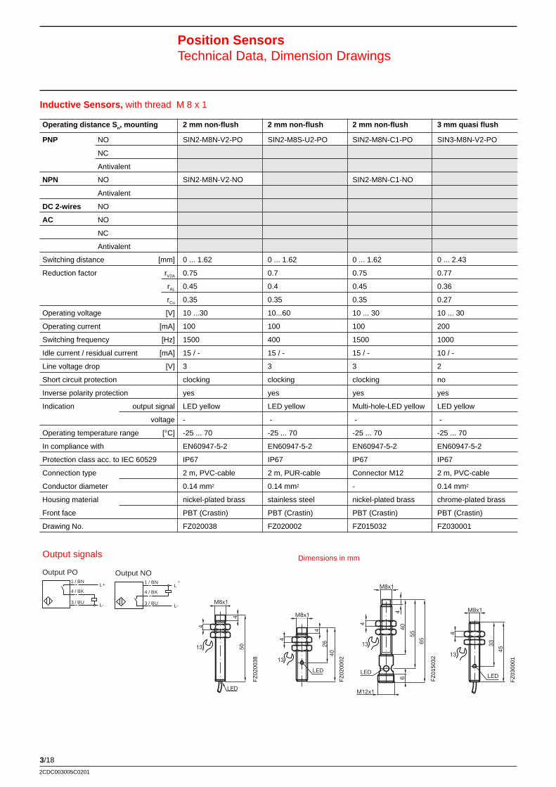
3/18
2CDC003005C0201
Inductive Sensors, with thread M 8 x 1
Position SensorsTechnical Data, Dimension Drawings
M8x1
4
450
LED
13
M8x1
4
426
40
13
LED
M8x1
4
440
55
6
M12x1
6513
LEDLED
M8x1
4
33
45
13
FZ
0200
38
FZ
0200
02
FZ
0150
32
FZ
0300
01
Operating distance S n, mounting 2 mm non-flush 2 mm non-flush 2 mm non-flush 3 mm quasi flush
PNP NO SIN2-M8N-V2-PO SIN2-M8S-U2-PO SIN2-M8N-C1-PO SIN3-M8N-V2-PO
NC
Antivalent
NPN NO SIN2-M8N-V2-NO SIN2-M8N-C1-NO
Antivalent
DC 2-wires NO
AC NO
NC
Antivalent
Switching distance [mm] 0 ... 1.62 0 ... 1.62 0 ... 1.62 0 ... 2.43
Reduction factor rV2A 0.75 0.7 0.75 0.77
rAL 0.45 0.4 0.45 0.36
rCu 0.35 0.35 0.35 0.27
Operating voltage [V] 10 ...30 10...60 10 ... 30 10 ... 30
Operating current [mA] 100 100 100 200
Switching frequency [Hz] 1500 400 1500 1000
Idle current / residual current [mA] 15 / - 15 / - 15 / - 10 / -
Line voltage drop [V] 3 3 3 2
Short circuit protection clocking clocking clocking no
Inverse polarity protection yes yes yes yes
Indication output signal LED yellow LED yellow Multi-hole-LED yellow LED yellow
voltage - - - -
Operating temperature range [°C] -25 ... 70 -25 ... 70 -25 ... 70 -25 ... 70
In compliance with EN60947-5-2 EN60947-5-2 EN60947-5-2 EN60947-5-2
Protection class acc. to IEC 60529 IP67 IP67 IP67 IP67
Connection type 2 m, PVC-cable 2 m, PUR-cable Connector M12 2 m, PVC-cable
Conductor diameter 0.14 mm2 0.14 mm2 - 0.14 mm2
Housing material nickel-plated brass stainless steel nickel-plated brass chrome-plated brass
Front face PBT (Crastin) PBT (Crastin) PBT (Crastin) PBT (Crastin)
Drawing No. FZ020038 FZ020002 FZ015032 FZ030001
1 / BNL+
L-
4 / BK
3 / BU
Output NO
3 / BU
4 / BK
1 / BNL+
L-
Output PO
Dimensions in mmOutput signals
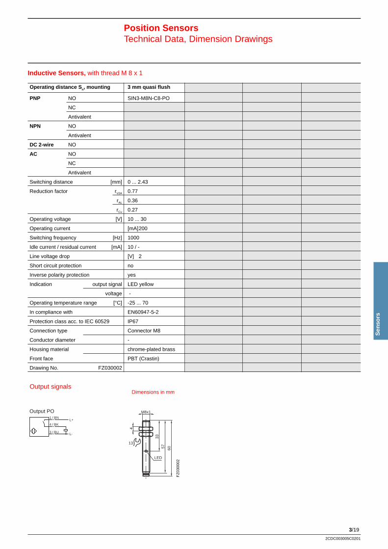
3/19
2CDC003005C0201
Sen
sors
Inductive Sensors, with thread M 8 x 1
Position SensorsTechnical Data, Dimension Drawings
LED
M8x1
4
33
57 60
13
FZ
0300
02
Operating distance S n, mounting 3 mm quasi flush
PNP NO SIN3-M8N-C8-PO
NC
Antivalent
NPN NO
Antivalent
DC 2-wire NO
AC NO
NC
Antivalent
Switching distance [mm] 0 ... 2.43
Reduction factor rV2A 0.77
rAL 0.36
rCu 0.27
Operating voltage [V] 10 ... 30
Operating current [mA]200
Switching frequency [Hz] 1000
Idle current / residual current [mA] 10 / -
Line voltage drop [V] 2
Short circuit protection no
Inverse polarity protection yes
Indication output signal LED yellow
voltage -
Operating temperature range [°C] -25 ... 70
In compliance with EN60947-5-2
Protection class acc. to IEC 60529 IP67
Connection type Connector M8
Conductor diameter -
Housing material chrome-plated brass
Front face PBT (Crastin)
Drawing No. FZ030002
3 / BU
4 / BK
1 / BNL+
L-
Output PO
Dimensions in mmOutput signals
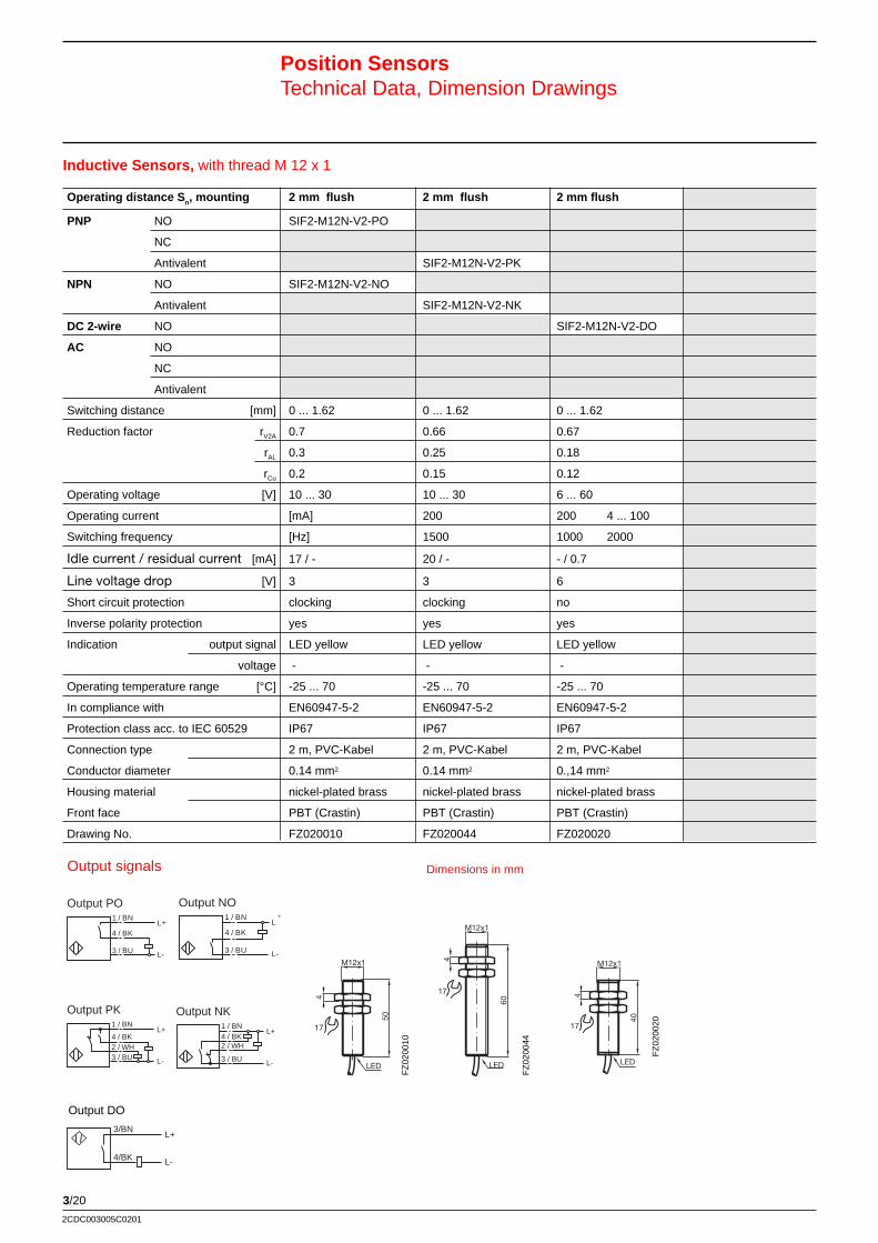
3/20
2CDC003005C0201
M12x1
4
60
LED
17
Inductive Sensors, with thread M 12 x 1
Position SensorsTechnical Data, Dimension Drawings
FZ
0200
10
50
M12x1
4
LED
17
Operating distance S n, mounting 2 mm flush 2 mm flush 2 mm flush
PNP NO SIF2-M12N-V2-PO
NC
Antivalent SIF2-M12N-V2-PK
NPN NO SIF2-M12N-V2-NO
Antivalent SIF2-M12N-V2-NK
DC 2-wire NO SIF2-M12N-V2-DO
AC NO
NC
Antivalent
Switching distance [mm] 0 ... 1.62 0 ... 1.62 0 ... 1.62
Reduction factor rV2A 0.7 0.66 0.67
rAL 0.3 0.25 0.18
rCu 0.2 0.15 0.12
Operating voltage [V] 10 ... 30 10 ... 30 6 ... 60
Operating current [mA] 200 200 4 ... 100
Switching frequency [Hz] 1500 1000 2000
Idle current / residual current [mA] 17 / - 20 / - - / 0.7
Line voltage drop [V] 3 3 6
Short circuit protection clocking clocking no
Inverse polarity protection yes yes yes
Indication output signal LED yellow LED yellow LED yellow
voltage - - -
Operating temperature range [°C] -25 ... 70 -25 ... 70 -25 ... 70
In compliance with EN60947-5-2 EN60947-5-2 EN60947-5-2
Protection class acc. to IEC 60529 IP67 IP67 IP67
Connection type 2 m, PVC-Kabel 2 m, PVC-Kabel 2 m, PVC-Kabel
Conductor diameter 0.14 mm2 0.14 mm2 0.,14 mm2
Housing material nickel-plated brass nickel-plated brass nickel-plated brass
Front face PBT (Crastin) PBT (Crastin) PBT (Crastin)
Drawing No. FZ020010 FZ020044 FZ020020
M12x1
4
40
LED
17
FZ
0200
20
Dimensions in mm
FZ
0200
44
3 / BU
4 / BK
1 / BNL+
L-
Output PO
L+1 / BN
L-
4 / BK2 / WH3 / BU
Output PK1 / BN
L+
L-
4 / BK2 / WH
3 / BU
Output NK
1 / BNL+
L-
4 / BK
3 / BU
Output NO
Output DO
L-
L+3/BN
4/BK
Output signals
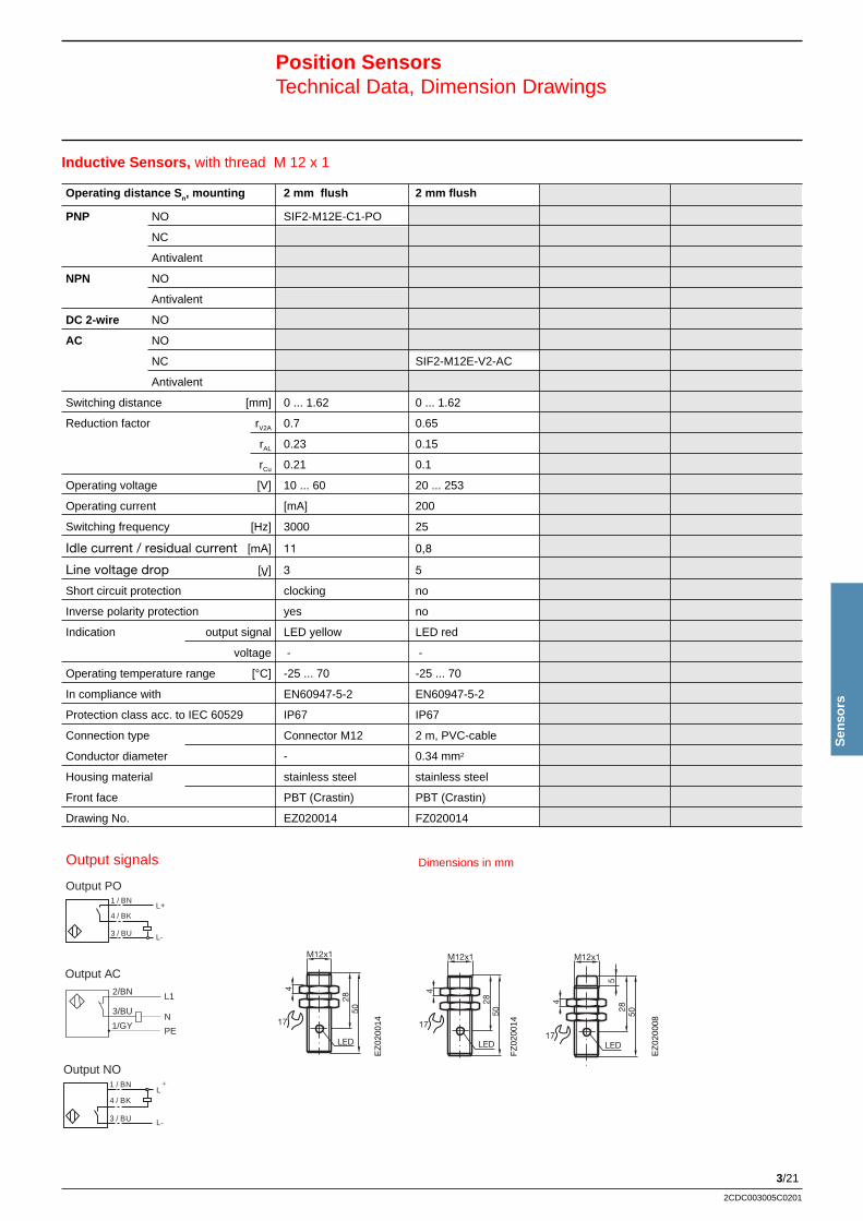
3/21
2CDC003005C0201
Sen
sors
2/BN
3/BU N
L1
PE1/GY
2/BN
3/BUN
L1
1/GYPE
Output AO
Output AC
Inductive Sensors, with thread M 12 x 1
Position SensorsTechnical Data, Dimension Drawings
1 / BNL+
L-
4 / BK
3 / BU
Output NO
3 / BU
4 / BK
1 / BNL+
L-
Output PO
Operating distance S n, mounting 2 mm flush 2 mm flush
PNP NO SIF2-M12E-C1-PO
NC
Antivalent
NPN NO
Antivalent
DC 2-wire NO
AC NO
NC SIF2-M12E-V2-AC
Antivalent
Switching distance [mm] 0 ... 1.62 0 ... 1.62
Reduction factor rV2A 0.7 0.65
rAL 0.23 0.15
rCu 0.21 0.1
Operating voltage [V] 10 ... 60 20 ... 253
Operating current [mA] 200
Switching frequency [Hz] 3000 25
Idle current / residual current [mA] 11 0,8
Line voltage drop [V] 3 5
Short circuit protection clocking no
Inverse polarity protection yes no
Indication output signal LED yellow LED red
voltage - -
Operating temperature range [°C] -25 ... 70 -25 ... 70
In compliance with EN60947-5-2 EN60947-5-2
Protection class acc. to IEC 60529 IP67 IP67
Connection type Connector M12 2 m, PVC-cable
Conductor diameter - 0.34 mm2
Housing material stainless steel stainless steel
Front face PBT (Crastin) PBT (Crastin)
Drawing No. EZ020014 FZ020014
Dimensions in mm
M12x1
4
2850
17
LED
M12x1
4
2850
17
LED
M12x1
4
2850
17LED
5
Output signals
EZ
0200
14
FZ
0200
14
EZ
0200
08
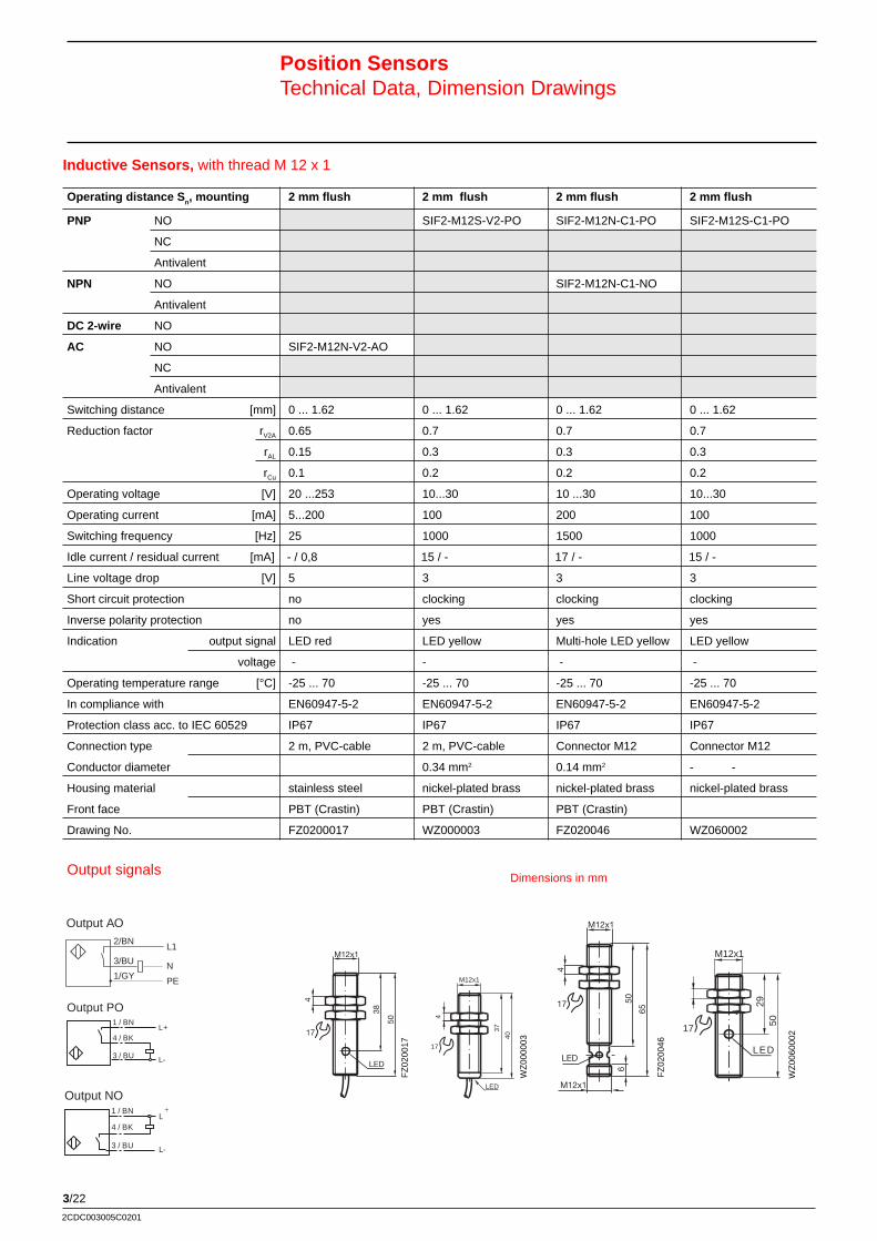
3/22
2CDC003005C0201
FZ
0200
17
4
38
50
M12x1
17
LED
Inductive Sensors, with thread M 12 x 1
Position SensorsTechnical Data, Dimension Drawings
M12x1
4
50
M12x1
65
6
17
LED
WZ
0000
03
FZ
0200
46
M12x1
LED
17
4
37
40
5029
M12x1
4
17
LED
WZ
0060
002
Operating distance S n, mounting 2 mm flush 2 mm flush 2 mm flush 2 mm flush
PNP NO SIF2-M12S-V2-PO SIF2-M12N-C1-PO SIF2-M12S-C1-PO
NC
Antivalent
NPN NO SIF2-M12N-C1-NO
Antivalent
DC 2-wire NO
AC NO SIF2-M12N-V2-AO
NC
Antivalent
Switching distance [mm] 0 ... 1.62 0 ... 1.62 0 ... 1.62 0 ... 1.62
Reduction factor rV2A 0.65 0.7 0.7 0.7
rAL 0.15 0.3 0.3 0.3
rCu 0.1 0.2 0.2 0.2
Operating voltage [V] 20 ...253 10...30 10 ...30 10...30
Operating current [mA] 5...200 100 200 100
Switching frequency [Hz] 25 1000 1500 1000
Idle current / residual current [mA] - / 0,8 15 / - 17 / - 15 / -
Line voltage drop [V] 5 3 3 3
Short circuit protection no clocking clocking clocking
Inverse polarity protection no yes yes yes
Indication output signal LED red LED yellow Multi-hole LED yellow LED yellow
voltage - - - -
Operating temperature range [°C] -25 ... 70 -25 ... 70 -25 ... 70 -25 ... 70
In compliance with EN60947-5-2 EN60947-5-2 EN60947-5-2 EN60947-5-2
Protection class acc. to IEC 60529 IP67 IP67 IP67 IP67
Connection type 2 m, PVC-cable 2 m, PVC-cable Connector M12 Connector M12
Conductor diameter 0.34 mm2 0.14 mm2 - -
Housing material stainless steel nickel-plated brass nickel-plated brass nickel-plated brass
Front face PBT (Crastin) PBT (Crastin) PBT (Crastin)
Drawing No. FZ0200017 WZ000003 FZ020046 WZ060002
Dimensions in mm
2/BN
3/BU N
L1
PE1/GY
2/BN
3/BUN
L1
1/GYPE
Output AO
Output AC
Output signals
1 / BNL+
L-
4 / BK
3 / BU
Output NO
3 / BU
4 / BK
1 / BNL+
L-
Output PO
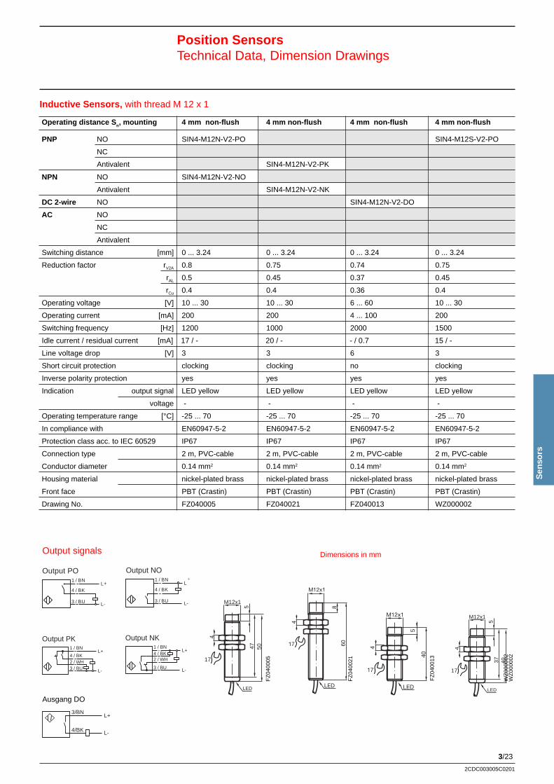
3/23
2CDC003005C0201
Sen
sors
Inductive Sensors, with thread M 12 x 1
Position SensorsTechnical Data, Dimension Drawings
3 / BU
4 / BK
1 / BNL+
L-
Output PO1 / BN
L+
L-
4 / BK
3 / BU
Output NO
L+1 / BN
L-
4 / BK2 / WH3 / BU
Output PK1 / BN
L+
L-
4 / BK2 / WH
3 / BU
Output NK
FZ
0400
05
M12x1
547 50
4
LED
17
60
M12x1
8
4
LED
17
40
M12x1
4
LED
17
5
FZ
0400
21
FZ
0400
13
WZ
0000
02
M12x1
537 40
4
LED
17
Operating distance S n, mounting 4 mm non-flush 4 mm non-flush 4 mm non-flush 4 mm non-flush
PNP NO SIN4-M12N-V2-PO SIN4-M12S-V2-PO
NC
Antivalent SIN4-M12N-V2-PK
NPN NO SIN4-M12N-V2-NO
Antivalent SIN4-M12N-V2-NK
DC 2-wire NO SIN4-M12N-V2-DO
AC NO
NC
Antivalent
Switching distance [mm] 0 ... 3.24 0 ... 3.24 0 ... 3.24 0 ... 3.24
Reduction factor rV2A 0.8 0.75 0.74 0.75
rAL 0.5 0.45 0.37 0.45
rCu 0.4 0.4 0.36 0.4
Operating voltage [V] 10 ... 30 10 ... 30 6 ... 60 10 ... 30
Operating current [mA] 200 200 4 ... 100 200
Switching frequency [Hz] 1200 1000 2000 1500
Idle current / residual current [mA] 17 / - 20 / - - / 0.7 15 / -
Line voltage drop [V] 3 3 6 3
Short circuit protection clocking clocking no clocking
Inverse polarity protection yes yes yes yes
Indication output signal LED yellow LED yellow LED yellow LED yellow
voltage - - - -
Operating temperature range [°C] -25 ... 70 -25 ... 70 -25 ... 70 -25 ... 70
In compliance with EN60947-5-2 EN60947-5-2 EN60947-5-2 EN60947-5-2
Protection class acc. to IEC 60529 IP67 IP67 IP67 IP67
Connection type 2 m, PVC-cable 2 m, PVC-cable 2 m, PVC-cable 2 m, PVC-cable
Conductor diameter 0.14 mm2 0.14 mm2 0.14 mm2 0.14 mm2
Housing material nickel-plated brass nickel-plated brass nickel-plated brass nickel-plated brass
Front face PBT (Crastin) PBT (Crastin) PBT (Crastin) PBT (Crastin)
Drawing No. FZ040005 FZ040021 FZ040013 WZ000002
Dimensions in mmOutput signals
Ausgang DO
L-
L+3/BN
4/BK
WZ
0000
02
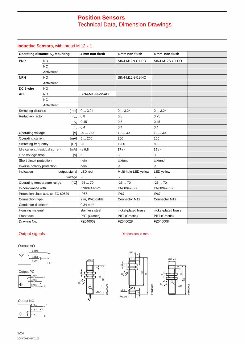
3/24
2CDC003005C0201
Position SensorsTechnical Data, Dimension Drawings
Inductive Sensors, with thread M 12 x 1
LED
M12x1
538
50
4
17
M12x1
4
5
50
65
M12x1
LED
6
17
FZ
0400
09
FZ
0400
28
M12 x 1
5
4
17LED
2850
FZ
0400
08
Operating distance S n, mounting 4 mm non-flush 4 mm non-flush 4 mm non-flush
PNP NO SIN4-M12N-C1-PO SIN4-M12S-C1-PO
NC
Antivalent
NPN NO SIN4-M12N-C1-NO
Antivalent
DC 2-wire NO
AC NO SIN4-M12N-V2-AO
NC
Antivalent
Switching distance [mm] 0 ... 3.24 0 ... 3.24 0 ... 3.24
Reduction factor rV2A 0.8 0.8 0.75
rAL 0.45 0.5 0,45
rCu 0.4 0.4 0.4
Operating voltage [V] 20 ... 253 10 ... 30 10 ... 30
Operating current [mA] 5 ... 200 200 100
Switching frequency [Hz] 25 1200 800
Idle current / residual current [mA] - / 0,8 17 / - 15 / -
Line voltage drop [V] 5 3 3
Short circuit protection nein taktend taktend
Inverse polarity protection nein ja ja
Indication output signal LED red Multi-hole LED yellow LED yellow
voltage - - -
Operating temperature range [°C] -25 ... 70 -25 ... 70 -25 ... 70
In compliance with EN60947-5-2 EN60947-5-2 EN60947-5-2
Protection class acc. to IEC 60529 IP67 IP67 IP67
Connection type 2 m, PVC-cable Connector M12 Connector M12
Conductor diameter 0.34 mm2 - -
Housing material stainless steel nickel-plated brass nickel-plated brass
Front face PBT (Crastin) PBT (Crastin) PBT (Crastin)
Drawing No. FZ040009 FZ040028 FZ040008
Dimensions in mm
2/BN
3/BU N
L1
PE1/GY
Output AO
Output signals
1 / BNL+
L-
4 / BK
3 / BU
Output NO
3 / BU
4 / BK
1 / BNL+
L-
Output PO
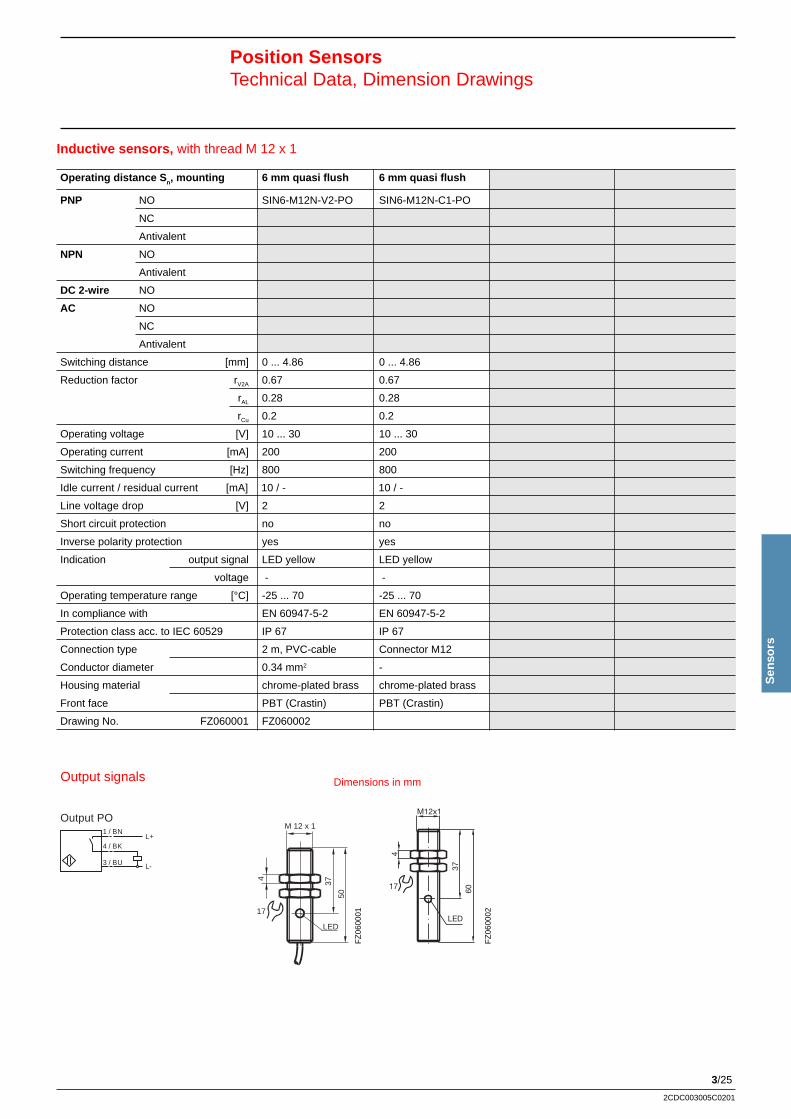
3/25
Sen
sors
2CDC003005C0201
Inductive sensors, with thread M 12 x 1
Position SensorsTechnical Data, Dimension Drawings
3 / BU
4 / BK
1 / BNL+
L-
Output PO
37
60
M12x1
LED
17
4
FZ
0600
02
LED
M 12 x 1
4
17
37
50
FZ
0600
01
Operating distance S n, mounting 6 mm quasi flush 6 mm quasi flush
PNP NO SIN6-M12N-V2-PO SIN6-M12N-C1-PO
NC
Antivalent
NPN NO
Antivalent
DC 2-wire NO
AC NO
NC
Antivalent
Switching distance [mm] 0 ... 4.86 0 ... 4.86
Reduction factor rV2A 0.67 0.67
rAL 0.28 0.28
rCu 0.2 0.2
Operating voltage [V] 10 ... 30 10 ... 30
Operating current [mA] 200 200
Switching frequency [Hz] 800 800
Idle current / residual current [mA] 10 / - 10 / -
Line voltage drop [V] 2 2
Short circuit protection no no
Inverse polarity protection yes yes
Indication output signal LED yellow LED yellow
voltage - -
Operating temperature range [°C] -25 ... 70 -25 ... 70
In compliance with EN 60947-5-2 EN 60947-5-2
Protection class acc. to IEC 60529 IP 67 IP 67
Connection type 2 m, PVC-cable Connector M12
Conductor diameter 0.34 mm2 -
Housing material chrome-plated brass chrome-plated brass
Front face PBT (Crastin) PBT (Crastin)
Drawing No. FZ060001 FZ060002
Dimensions in mmOutput signals
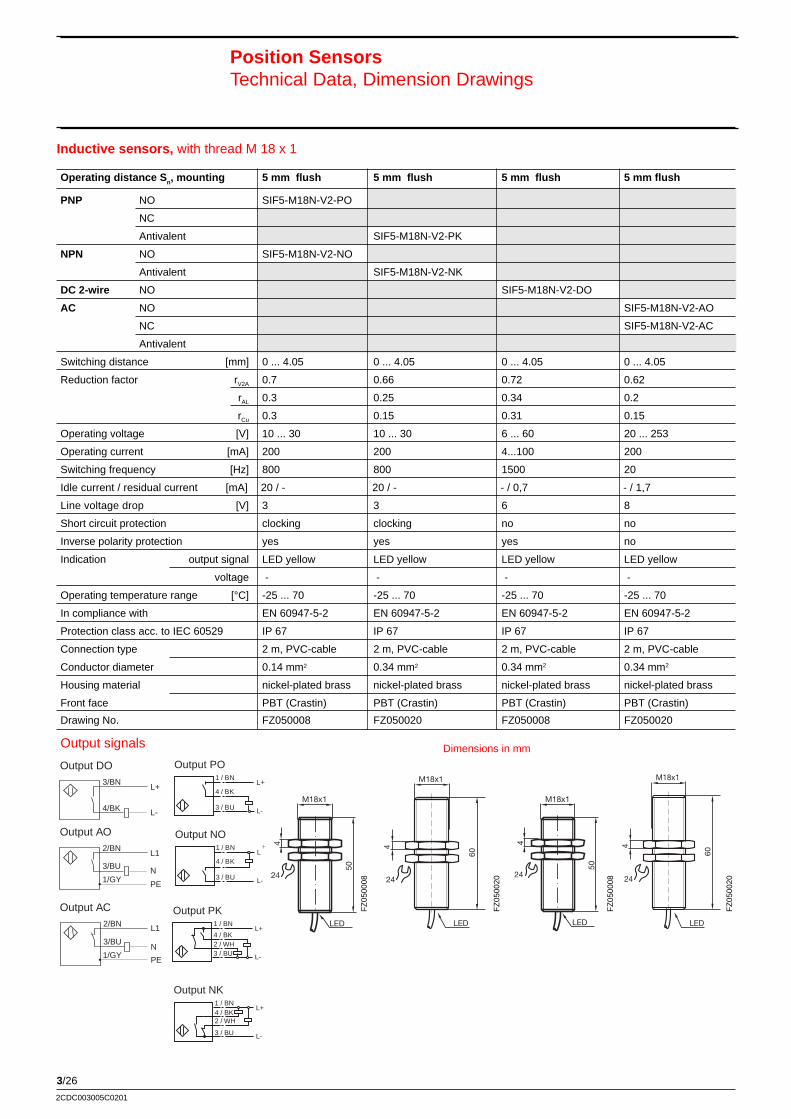
3/26
2CDC003005C0201
Inductive sensors, with thread M 18 x 1
Position SensorsTechnical Data, Dimension Drawings
M18x1
4
LED
50
24
60
M18x1
4
LED
24
M18x1
4
LED
50
24
60
M18x1
4
LED
24
FZ
0500
08
FZ
0500
20
FZ
0500
08
FZ
0500
20
Operating distance S n, mounting 5 mm flush 5 mm flush 5 mm flush 5 mm flush
PNP NO SIF5-M18N-V2-PO
NC
Antivalent SIF5-M18N-V2-PK
NPN NO SIF5-M18N-V2-NO
Antivalent SIF5-M18N-V2-NK
DC 2-wire NO SIF5-M18N-V2-DO
AC NO SIF5-M18N-V2-AO
NC SIF5-M18N-V2-AC
Antivalent
Switching distance [mm] 0 ... 4.05 0 ... 4.05 0 ... 4.05 0 ... 4.05
Reduction factor rV2A 0.7 0.66 0.72 0.62
rAL 0.3 0.25 0.34 0.2
rCu 0.3 0.15 0.31 0.15
Operating voltage [V] 10 ... 30 10 ... 30 6 ... 60 20 ... 253
Operating current [mA] 200 200 4...100 200
Switching frequency [Hz] 800 800 1500 20
Idle current / residual current [mA] 20 / - 20 / - - / 0,7 - / 1,7
Line voltage drop [V] 3 3 6 8
Short circuit protection clocking clocking no no
Inverse polarity protection yes yes yes no
Indication output signal LED yellow LED yellow LED yellow LED yellow
voltage - - - -
Operating temperature range [°C] -25 ... 70 -25 ... 70 -25 ... 70 -25 ... 70
In compliance with EN 60947-5-2 EN 60947-5-2 EN 60947-5-2 EN 60947-5-2
Protection class acc. to IEC 60529 IP 67 IP 67 IP 67 IP 67
Connection type 2 m, PVC-cable 2 m, PVC-cable 2 m, PVC-cable 2 m, PVC-cable
Conductor diameter 0.14 mm2 0.34 mm2 0.34 mm2 0.34 mm2
Housing material nickel-plated brass nickel-plated brass nickel-plated brass nickel-plated brass
Front face PBT (Crastin) PBT (Crastin) PBT (Crastin) PBT (Crastin)
Drawing No. FZ050008 FZ050020 FZ050008 FZ050020
Dimensions in mmOutput signals
3 / BU
4 / BK
1 / BNL+
L-
Output PO
1 / BNL+
L-
4 / BK
3 / BU
Output NO
L+1 / BN
L-
4 / BK2 / WH3 / BU
Output PK
1 / BNL+
L-
4 / BK2 / WH
3 / BU
Output NK
Output DO
2/BN
3/BU N
L1
L-
L+3/BN
4/BK
PE1/GY
2/BN
3/BUN
L1
1/GYPE
Output AO
Output AC
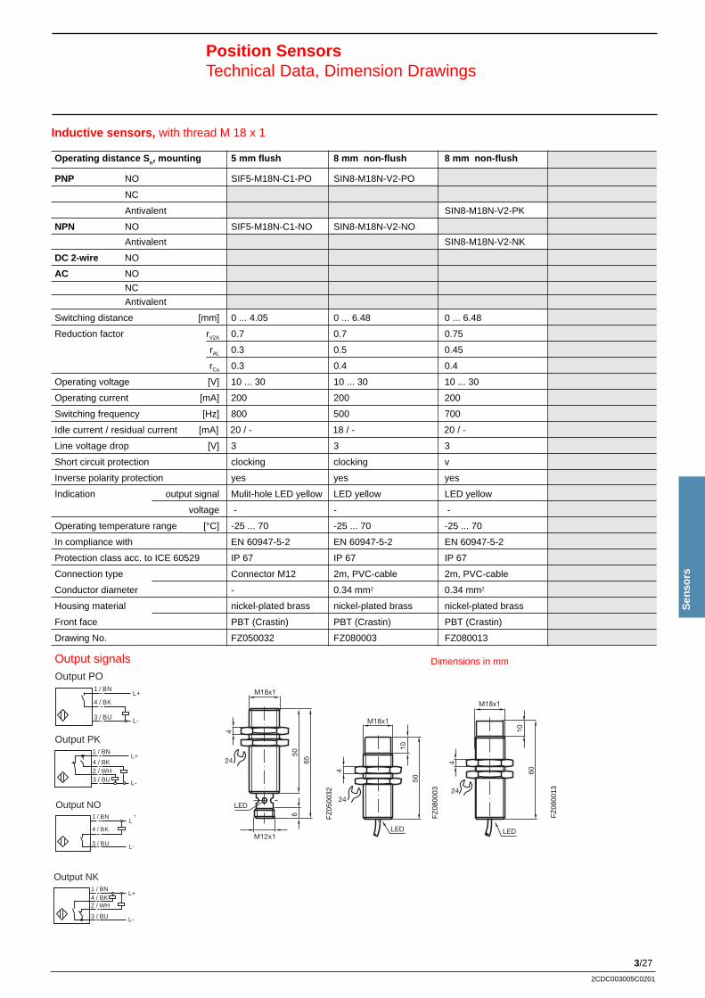
3/27
Sen
sors
2CDC003005C0201
60
M18x1
10
4
LED
24
Inductive sensors, with thread M 18 x 1
Position SensorsTechnical Data, Dimension Drawings
3 / BU
4 / BK
1 / BNL+
L-
Output PO
1 / BNL+
L-
4 / BK
3 / BU
Output NO
L+1 / BN
L-
4 / BK2 / WH3 / BU
Output PK
1 / BNL+
L-
4 / BK2 / WH
3 / BU
Output NK
Operating distance S n, mounting 5 mm flush 8 mm non-flush 8 mm non-flush
PNP NO SIF5-M18N-C1-PO SIN8-M18N-V2-PO
NC
Antivalent SIN8-M18N-V2-PK
NPN NO SIF5-M18N-C1-NO SIN8-M18N-V2-NO
Antivalent SIN8-M18N-V2-NK
DC 2-wire NO
AC NO
NC
Antivalent
Switching distance [mm] 0 ... 4.05 0 ... 6.48 0 ... 6.48
Reduction factor rV2A 0.7 0.7 0.75
rAL 0.3 0.5 0.45
rCu 0.3 0.4 0.4
Operating voltage [V] 10 ... 30 10 ... 30 10 ... 30
Operating current [mA] 200 200 200
Switching frequency [Hz] 800 500 700
Idle current / residual current [mA] 20 / - 18 / - 20 / -
Line voltage drop [V] 3 3 3
Short circuit protection clocking clocking v
Inverse polarity protection yes yes yes
Indication output signal Mulit-hole LED yellow LED yellow LED yellow
voltage - - -
Operating temperature range [°C] -25 ... 70 -25 ... 70 -25 ... 70
In compliance with EN 60947-5-2 EN 60947-5-2 EN 60947-5-2
Protection class acc. to ICE 60529 IP 67 IP 67 IP 67
Connection type Connector M12 2m, PVC-cable 2m, PVC-cable
Conductor diameter - 0.34 mm2 0.34 mm2
Housing material nickel-plated brass nickel-plated brass nickel-plated brass
Front face PBT (Crastin) PBT (Crastin) PBT (Crastin)
Drawing No. FZ050032 FZ080003 FZ080013
Dimensions in mm
M18x1
4
M12x1
LED
650
6524
M18x1
10
4
50
LED
24
FZ
0800
03
FZ
0500
32
Output signals
FZ
0800
13
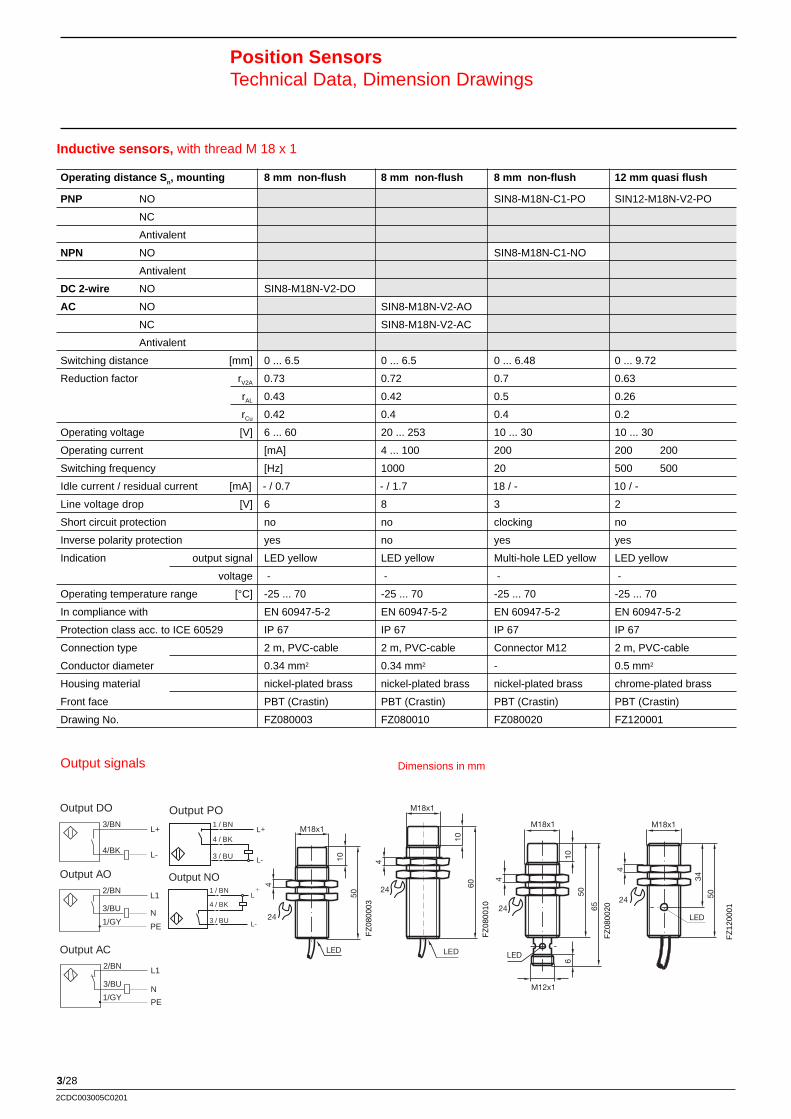
3/28
2CDC003005C0201
Inductive sensors, with thread M 18 x 1
Position SensorsTechnical Data, Dimension Drawings
M18x1
10
4
50
LED
24
60
M18x1
10
4
LEDs
24
LED LED
4
M18x1
10
50
65
M12x1
6
24
FZ
0800
03
FZ
0800
10
FZ
0800
20
FZ
1200
01
Operating distance S n, mounting 8 mm non-flush 8 mm non-flush 8 mm non-flush 12 mm quasi flush
PNP NO SIN8-M18N-C1-PO SIN12-M18N-V2-PO
NC
Antivalent
NPN NO SIN8-M18N-C1-NO
Antivalent
DC 2-wire NO SIN8-M18N-V2-DO
AC NO SIN8-M18N-V2-AO
NC SIN8-M18N-V2-AC
Antivalent
Switching distance [mm] 0 ... 6.5 0 ... 6.5 0 ... 6.48 0 ... 9.72
Reduction factor rV2A 0.73 0.72 0.7 0.63
rAL 0.43 0.42 0.5 0.26
rCu 0.42 0.4 0.4 0.2
Operating voltage [V] 6 ... 60 20 ... 253 10 ... 30 10 ... 30
Operating current [mA] 4 ... 100 200 200 200
Switching frequency [Hz] 1000 20 500 500
Idle current / residual current [mA] - / 0.7 - / 1.7 18 / - 10 / -
Line voltage drop [V] 6 8 3 2
Short circuit protection no no clocking no
Inverse polarity protection yes no yes yes
Indication output signal LED yellow LED yellow Multi-hole LED yellow LED yellow
voltage - - - -
Operating temperature range [°C] -25 ... 70 -25 ... 70 -25 ... 70 -25 ... 70
In compliance with EN 60947-5-2 EN 60947-5-2 EN 60947-5-2 EN 60947-5-2
Protection class acc. to ICE 60529 IP 67 IP 67 IP 67 IP 67
Connection type 2 m, PVC-cable 2 m, PVC-cable Connector M12 2 m, PVC-cable
Conductor diameter 0.34 mm2 0.34 mm2 - 0.5 mm2
Housing material nickel-plated brass nickel-plated brass nickel-plated brass chrome-plated brass
Front face PBT (Crastin) PBT (Crastin) PBT (Crastin) PBT (Crastin)
Drawing No. FZ080003 FZ080010 FZ080020 FZ12000150
M18x1
4
34
24
LED
Dimensions in mmOutput signals
3 / BU
4 / BK
1 / BNL+
L-
Output PO
1 / BNL+
L-
4 / BK
3 / BU
Output NO
Output DO
2/BN
3/BU N
L1
L-
L+3/BN
4/BK
PE1/GY
2/BN
3/BUN
L1
1/GYPE
Output AO
Output AC
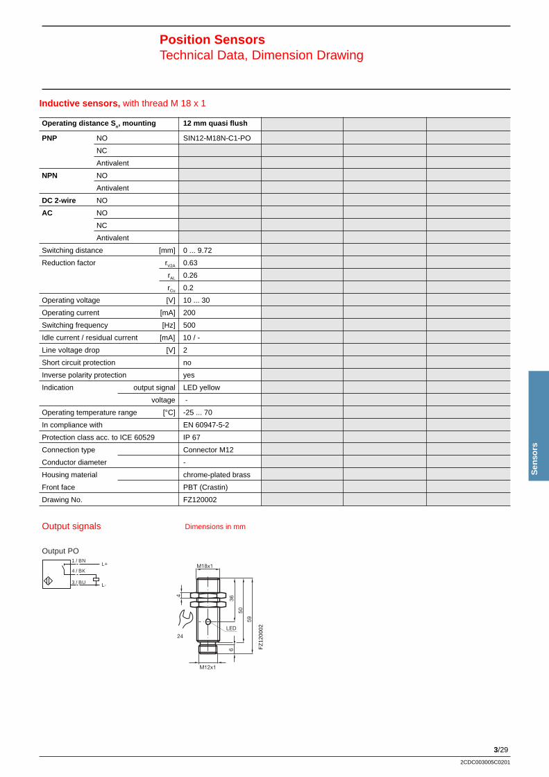
3/29
Sen
sors
2CDC003005C0201
Inductive sensors, with thread M 18 x 1
Position SensorsTechnical Data, Dimension Drawing
3 / BU
4 / BK
1 / BNL+
L-
Output PO
24
4
LED
M18x1
36
50
59
M12x1
6 FZ
1200
02
Operating distance S n, mounting 12 mm quasi flush
PNP NO SIN12-M18N-C1-PO
NC
Antivalent
NPN NO
Antivalent
DC 2-wire NO
AC NO
NC
Antivalent
Switching distance [mm] 0 ... 9.72
Reduction factor rV2A 0.63
rAL 0.26
rCu 0.2
Operating voltage [V] 10 ... 30
Operating current [mA] 200
Switching frequency [Hz] 500
Idle current / residual current [mA] 10 / -
Line voltage drop [V] 2
Short circuit protection no
Inverse polarity protection yes
Indication output signal LED yellow
voltage -
Operating temperature range [°C] -25 ... 70
In compliance with EN 60947-5-2
Protection class acc. to ICE 60529 IP 67
Connection type Connector M12
Conductor diameter -
Housing material chrome-plated brass
Front face PBT (Crastin)
Drawing No. FZ120002
Dimensions in mmOutput signals
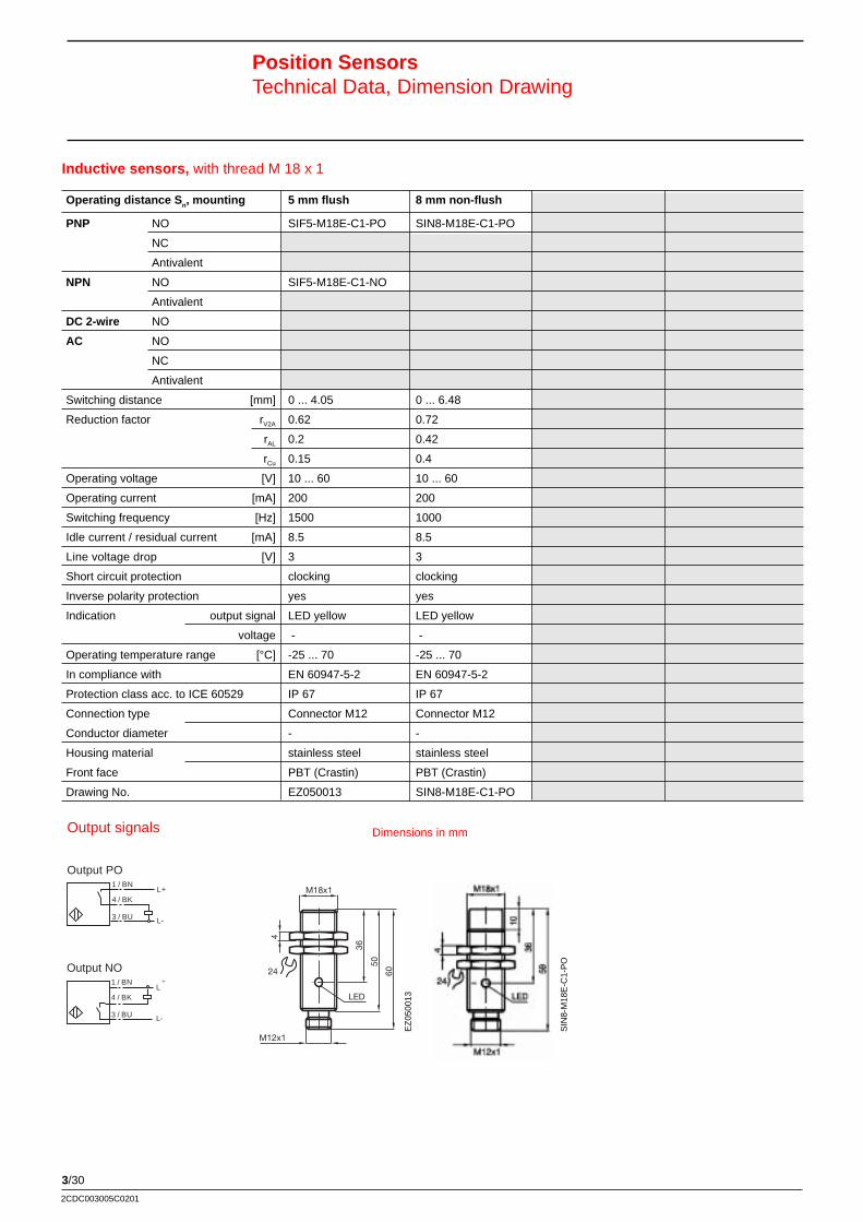
3/30
2CDC003005C0201
Inductive sensors, with thread M 18 x 1
Operating distance S n, mounting 5 mm flush 8 mm non-flush
PNP NO SIF5-M18E-C1-PO SIN8-M18E-C1-PO
NC
Antivalent
NPN NO SIF5-M18E-C1-NO
Antivalent
DC 2-wire NO
AC NO
NC
Antivalent
Switching distance [mm] 0 ... 4.05 0 ... 6.48
Reduction factor rV2A 0.62 0.72
rAL 0.2 0.42
rCu 0.15 0.4
Operating voltage [V] 10 ... 60 10 ... 60
Operating current [mA] 200 200
Switching frequency [Hz] 1500 1000
Idle current / residual current [mA] 8.5 8.5
Line voltage drop [V] 3 3
Short circuit protection clocking clocking
Inverse polarity protection yes yes
Indication output signal LED yellow LED yellow
voltage - -
Operating temperature range [°C] -25 ... 70 -25 ... 70
In compliance with EN 60947-5-2 EN 60947-5-2
Protection class acc. to ICE 60529 IP 67 IP 67
Connection type Connector M12 Connector M12
Conductor diameter - -
Housing material stainless steel stainless steel
Front face PBT (Crastin) PBT (Crastin)
Drawing No. EZ050013 SIN8-M18E-C1-PO
Position SensorsTechnical Data, Dimension Drawing
Dimensions in mm
4
36
50
60
M12x1
LED
M18x1
24
Output signals
3 / BU
4 / BK
1 / BNL+
L-
Output PO
1 / BNL+
L-
4 / BK
3 / BU
Output NO
EZ
0500
13
SIN
8-M
18E
-C1-
PO
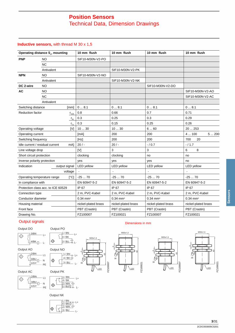
3/31
Sen
sors
2CDC003005C0201
Inductive sensors, with thread M 30 x 1,5
Position SensorsTechnical Data, Dimension Drawings
FZ
1000
07
M30x1,5
5
50
LED
36
M30x1,5
5
60
36
LED
M30x1,5
5
50
LED
36
M30x1,5
5
60
36
LED
FZ
1000
21
FZ
1000
07
FZ
1000
21
Operating distance S n, mounting 10 mm flush 10 mm flush 10 mm flush 10 mm flush
PNP NO SIF10-M30N-V2-PO
NC
Antivalent SIF10-M30N-V2-PK
NPN NO SIF10-M30N-V2-NO
Antivalent SIF10-M30N-V2-NK
DC 2-wire NO SIF10-M30N-V2-DO
AC NO SIF10-M30N-V2-AO
NC SIF10-M30N-V2-AC
Antivalent
Switching distance [mm] 0 ... 8.1 0 ... 8.1 0 ... 8.1 0 ... 8.1
Reduction factor rV2A 0.8 0.66 0.7 0.71
rAL 0.3 0.25 0.3 0.29
rCu 0.3 0.15 0.25 0.26
Operating voltage [V] 10 ... 30 10 ... 30 6 ... 60 20 ... 253
Operating current [mA] 200 200 4 ... 100 5 ... 200
Switching frequency [Hz] 200 200 700 20
Idle current / residual current mA] 20 / - 20 / - - / 0.7 - / 1.7
Line voltage drop [V] 3 3 6 8
Short circuit protection clocking clocking no no
Inverse polarity protection yes yes yes no
Indication output signal LED yellow LED yellow LED yellow LED yellow
voltage - - - -
Operating temperature range [°C] -25 ... 70 -25 ... 70 -25 ... 70 -25 ... 70
In compliance with EN 60947-5-2 EN 60947-5-2 EN 60947-5-2 EN 60947-5-2
Protection class acc. to ICE 60529 IP 67 IP 67 IP 67 IP 67
Connection type 2 m, PVC-Kabel 2 m, PVC-Kabel 2 m, PVC-Kabel 2 m, PVC-Kabel
Conductor diameter 0.34 mm2 0.34 mm2 0.34 mm2 0.34 mm2
Housing material nickel-plated brass nickel-plated brass nickel-plated brass nickel-plated brass
Front face PBT (Crastin) PBT (Crastin) PBT (Crastin) PBT (Crastin)
Drawing No. FZ100007 FZ100021 FZ100007 FZ100021
Dimensions in mmOutput signals
Output DO
2/BN
3/BU N
L1
L-
L+3/BN
4/BK
PE1/GY
2/BN
3/BUN
L1
1/GYPE
Output AO
Output AC
3 / BU
4 / BK
1 / BN L+
L-
Output PO
Output NO
3 / BU
4 / BK
1 / BN +
L-
L
L+1 / BN
L-
4 / BK2 / WH3 / BU
Output PK
1 / BNL+
L-
4 / BK2 / WH3 / BU
Output NK
3/32
2CDC003005C0201
Inductive sensors, with thread M 30 x 1,5
Position SensorsTechnical Data, Dimension Drawings
36
LED
M30x1,5
5
50
65
M12x1
6
M30x1,5
5
18
50
LED36
FZ
1500
03
M30x1,5
18
605
LED(s)
36
FZ
1500
14
FZ
1000
35
Operating distance S n, mounting 10 mm flush 15 mm non-flush 15 mm non-flush
PNP NO SIF10-M30N-C1-PO SIN15-M30N-V2-PO
NC
Antivalent SIN15-M30N-V2-PK
NPN NO SIF10-M30N-C1-NO SIN15-M30N-V2-NO
Antivalent SIN15-M30N-V2-NK
DC 2-wire NOAC NO
NC
AntivalentSwitching distance [mm] 0 ... 8.1 0 ... 12.15 0 ... 12.15
Reduction factor rV2A 0.8 0.8 0.75
rAL 0.3 0.5 0.45
rCu 0.3 0.4 0.4
Operating voltage [V] 10 ... 30 10 ... 30 10 ... 30
Operating current [mA] 200 200 200
Switching frequency [Hz] 200 200 200
Idle current / residual current [mA] 20 / - 15 / - 20 / -
Line voltage drop [V] 3 3 3
Short circuit protection clocking clocking clocking
Inverse polarity protection yes yes yes
Indication output signal Multi hole LED yellow LED yellow LED yellow
voltage - - -
Operating temperature range [°C] -25 ... 70 -25 ... 70 -25 ... 70
In compliance with EN 60947-5-2 EN 60947-5-2 EN 60947-5-2
Protection class acc. to ICE 60529 IP 67 IP 67 IP 67
Connection type Connector M12 2m, PVC-cable 2m, PVC-cable
Conductor diameter - 0.34 mm2 0.34 mm2
Housing material nickel-plated brass nickel-plated brass nickel-plated brass
Front face PBT (Crastin) PBT (Crastin) PBT (Crastin)
Drawing No. FZ100035 FZ150003 FZ150014
Dimensions in mmOutput signals
3 / BU
4 / BK
1 / BN L+
L-
Output PO
Output NO
3 / BU
4 / BK
1 / BN +
L-
L
L+1 / BN
L-
4 / BK2 / WH3 / BU
Output PK
1 / BNL+
L-
4 / BK2 / WH3 / BU
Output NK
3/33
Sen
sors
2CDC003005C0201
Inductive sensors, with thread M 30 x 1,5
Position SensorsTechnical Data, Dimension Drawings
M30x1,5
18
605
LED(s)
36
M30x1,5
M12x1
6
5
1850
65
LED
36
FZ
1500
14
FZ
1500
27
Operating distance S n, mounting 15 mm non-flush 15 mm non-flush
PNP NO SIN15-M30N-C1-PO
NC
Antivalent
NPN NO SIN15-M30N-C1-NO
Antivalent
DC 2-wire NO
AC NO SIN15-M30N-V2-AO
NC SIN15-M30N-V2-AC
Antivalent
Switching distance [mm] 0 ... 12.2 0 ... 12.15
Reduction factor rV2A 0.82 0.8
rAL 0.43 0.5
rCu 0.41 0.4
Operating voltage [V] 20 ... 253 10 ... 30
Operating current [mA] 5 ... 200 200
Switching frequency [Hz] 20 200
Idle current / residual current [mA] - / 1.7 20 / -
Line voltage drop [V] 8 3
Short circuit protection no clocking
Inverse polarity protection no yes
Indication output signal LED yellow Multi-hole LED yellow
voltage - -
Operating temperature range [°C] 25 ... 70 -25 ... 70
In compliance with EN 60947-5-2 EN 60947-5-2
Protection class acc. to ICE 60529 IP 67 IP 67
Connection type 2 m, PVC-cable Connector M12
Conductor diameter 0.34 mm2 -
Housing material nickel-plated brass nickel-plated brass
Front face PBT (Crastin) PBT (Crastin)
Drawing No. FZ 150014 FZ 150027
Dimensions in mmOutput signals
2/BN
3/BU N
L1
PE1/GY
2/BN
3/BUN
L1
1/GYPE
Output AO
Output AC
3 / BU
4 / BK
1 / BN L+
L-
Output PO
Output NO
3 / BU
4 / BK
1 / BN +
L-
L
3/34
2CDC003005C0201
Inductive sensors, with thread M 30 x 1,5
Position SensorsTechnical Data, Dimension Drawings
Operating distance S n, mounting 15 mm flush 15 mm non-flush
PNP NO SIF10-M30E-C1-PO SIN15-M30E-C1-PO
NC
Antivalent
NPN NO
Antivalent
DC 2-wire NO
AC NO
NC
Antivalent
Switching distance [mm] 0 ... 8.1 0 ... 12.15
Reduction factor rV2A 0.72 0.71
rAL 0.34 0.4
rCu 0.32 0.38
Operating voltage [V] 10 ... 60 10 ... 60
Operating current [mA] 200 200
Switching frequency [Hz] 650 500
Idle current / residual current [mA] 9 12
Line voltage drop [V] 2,8 2,8
Short circuit protection clocking clocking
Inverse polarity protection yes yes
Indication output signal LED yellow LED yellow
voltage - -
Operating temperature range [°C] -25 ... 70 -25 ... 70
In compliance with EN 60947-5-2 EN 60947-5-2
Protection class acc. to ICE 60529 IP 67 IP 67
Connection type Connector M12 Connector M12
Conductor diameter - -
Housing material stainless steel stainless steel
Front face PBT (Crastin) PBT (Crastin)
Drawing No. SIF10-M30E-C1-PO SIN15-M30E-C1-PO
Dimensions in mmOutput signals
3 / BU
4 / BK
1 / BNL+
L-
Output PO
SIF
10-M
30E
-C1P
O
SIN
15-M
30E
-C1P
O

3/35
Sen
sors
2CDC003005C0201
Inductive sensors, Block- and square housings
Position SensorsTechnical Data, Dimension Drawings
Operating distance S n, mounting 2 mm flush 6 mm flush
PNP NO SIF2-B28N-V0,1-PO SIF6-B45N-U2-PO
NC
Antivalent
NPN NO SIF2-B28N-V0,1-NO
Antivalent
DC 2-wire NO
AC NO
NC
Antivalent
Switching distance [mm] 0 ... 1.62 0 ... 4.8
Reduction factor rV2A 0.7 0.7
rAL 0.35 0.22
rCu 0.2 0.2
Operating voltage [V] 10 ... 30 10 ... 60
Operating current [mA] 100 200
Switching frequency [Hz] 1000 500
Idle current / residual current [mA] 15 / - 20 / _
Line voltage drop [V] 3 3
Short circuit protection clocking clocking
Inverse polarity protection yes yes
Indication output signal LED yellow LED yellow
voltage - -
Operating temperature range [°C] -25 ... 70 -25 ... 70
In compliance with EN 60947-5-2 EN 60947-5-2
Protection class acc. to ICE 60529 IP 67 IP 67
Connection type 0.1 m, PVC-cable 2 m, PUR-cable
Conductor diameter 0.14 mm2 0.34 mm2
Housing material PBT (Crastin) PBT (Crastin)
Front face PBT (Crastin) PBT (Crastin)
Drawing No. FQ030001 FF00001
Dimensions in mm
30
18
5LED
4524,5
9,5
3,5
128 FF
0000
1
9,2
19,6
22,2
27,8
3
10,3
16
LED
FQ
0300
01
Output signals
3 / BU
4 / BK
1 / BNL+
L-
Output PO
3/36
2CDC003005C0201
Inductive sensors, Block- and square housings
Position SensorsTechnical Data, Dimension Drawings
11
11858
40,5
Pg13,5
60
40
LED(s)
5,5
30
46,5
(*)
(*) Cable inlet acc. to new standard henceforth in M20
CV
1500
02
Operating distance S n, mounting 15 mm flush 15 mm flush 20 mm flush 20 mm non-flush
PNP NO SIF15-Q40N-T-PO SIF15-Q40N-C1-PO SIF20-Q40N-T-PO
NC
Antivalent SIF15-Q40N-T-PK
NPN NO SIF15-Q40N-T-NO
Antivalent
DC 2-wire NO
AC NO
NC
Antivalent SIN20-Q40N-T-AK
Switching distance [mm] 0 ... 12.15 0 ... 12,15 0 ... 16,2 0 ... 16.2
Reduction factor rV2A 0.75 0.75 0.8 0.8
rAL 0.3 0.3 0.3 0.35
rCu 0.25 0.25 0.3 0.35
Operating voltage [V] 10 ... 60 20 ... 253 10 ... 60 20 ...2 53
Operating current [mA] 200 8 ... 500 200 8 ... 500
Switching frequency [Hz] 150 20 150 20
Idle current / residual current [mA] 10 / - - / 1.95 10 / - - / 1.95
Line voltage drop [V] 2.8 12 2.8 12
Short circuit protection clocking no clocking no
Inverse polarity protection yes no yes no
Indication output signal LED yellow LED yellow LED yellow LED yellow
voltage - - - -
Operating temperature range [°C] -25 ... 70 -25 ... 70 -25 ... 70 -25 ... 70
In compliance with EN 60947-5-2 EN 60947-5-2 EN 60947-5-2 EN 60947-5-2
Protection class acc. to ICE 60529 IP 68 IP 68 IP 68 IP 68
Connection type terminal connection Connector M12 terminal connection terminal connection
Conductor diameter up to 2,5 mm2 up to 2,5 mm2 up to 2,5 mm2 up to 2,5 mm2
Housing material PBT (Crastin) PBT (Crastin) PBT (Crastin) PBT (Crastin)
Front face PBT (Crastin) PBT (Crastin) PBT (Crastin) PBT (Crastin)
Drawing No. CV150002 CV150002 CV150002 CV150002
Dimensions in mmOutput signals
3 / BU
4 / BK
1 / BN L+
L-
Output PO
Output NO
3 / BU
4 / BK
1 / BN +
L-
L
1
4
3
2
L1
N
L1N
Output AK
3 / BU
4 / BK
1 / BN L+
L-
Output PO
L+1 / BN
L-
4 / BK2 / WH3 / BU
Output PK
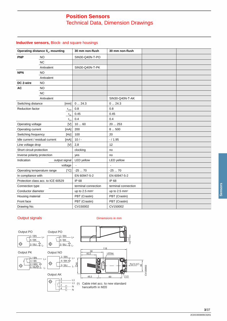
3/37
Sen
sors
2CDC003005C0201
Inductive sensors, Block- and square housings
Position SensorsTechnical Data, Dimension Drawings
11
11858
40,5
Pg13,5
60
40
LED(s)
5,5
30
46,5
(*)
(*) Cable inlet acc. to new standard henceforth in M20
CV
1500
02
Operating distance S n, mounting 30 mm non-flush 30 mm non-flush
PNP NO SIN30-Q40N-T-PO
NC
Antivalent SIN30-Q40N-T-PK
NPN NO
Antivalent
DC 2-wire NO
AC NO
NC
Antivalent SIN30-Q40N-T-AK
Switching distance [mm] 0 ... 24.3 0 ... 24.3
Reduction factor rV2A 0.8 0.8
rAL 0.45 0.45
rCu 0.4 0.4
Operating voltage [V] 10 ... 60 20 ... 253
Operating current [mA] 200 8 ... 500
Switching frequency [Hz] 100 20
Idle current / residual current [mA] 10 / - - / 1.95
Line voltage drop [V] 2,8 12
Short circuit protection clocking no
Inverse polarity protection yes no
Indication output signal LED yellow LED yellow
voltage - -
Operating temperature range [°C] -25 ... 70 -25 ... 70
In compliance with EN 60947-5-2 EN 60947-5-2
Protection class acc. to ICE 60529 IP 68 IP 68
Connection type terminal connection terminal connection
Conductor diameter up to 2.5 mm2 up to 2.5 mm2
Housing material PBT (Crastin) PBT (Crastin)
Front face PBT (Crastin) PBT (Crastin)
Drawing No. CV150002 CV150002
Dimensions in mmOutput signals
3 / BU
4 / BK
1 / BN L+
L-
Output PO
L+1 / BN
L-
4 / BK2 / WH3 / BU
Output PK
3 / BU
4 / BK
1 / BN L+
L-
Output PO
Output NO
3 / BU
4 / BK
1 / BN +
L-
L
1
4
3
2
L1
N
L1N
Output AK
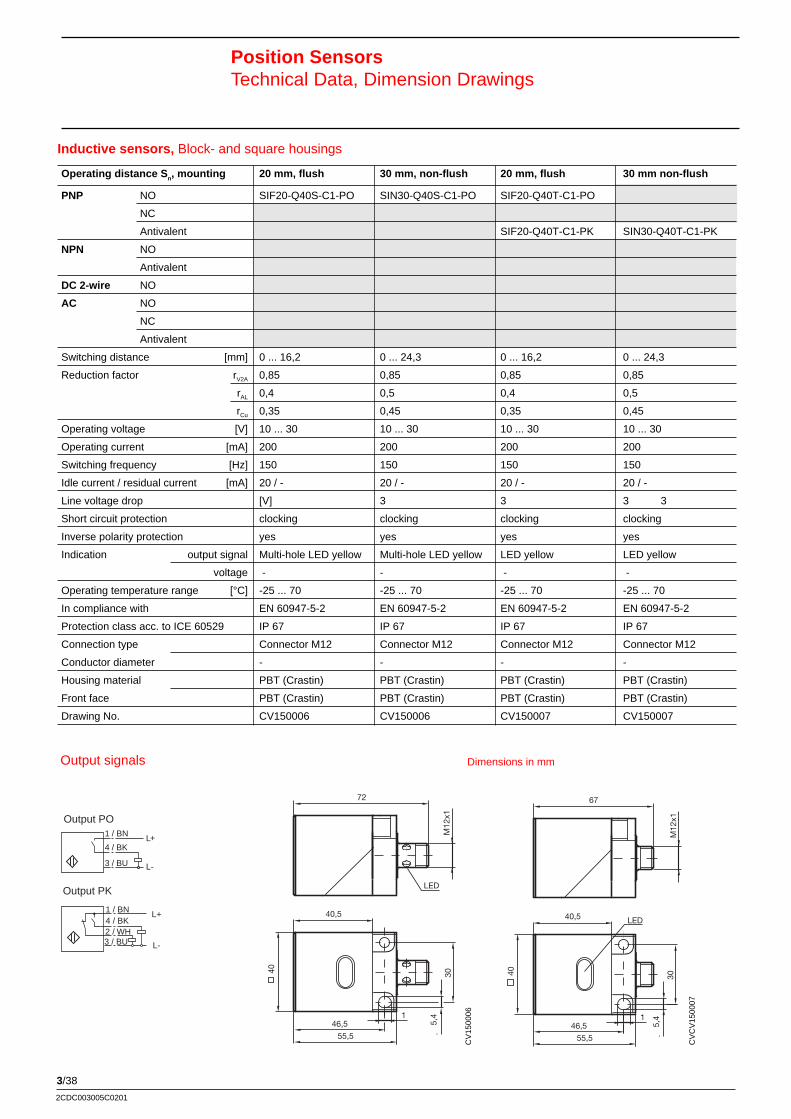
3/38
2CDC003005C0201
Inductive sensors, Block- and square housings
Position SensorsTechnical Data, Dimension Drawings
CV
1500
06
72
40,5
40 30
Ø 5
,4
LED
M12
x1
46,5
55,5
1
55,5
1
67
40,5
40 30
Ø 5
,4
LED
M12
x1
46,5
CV
CV
1500
07
Operating distance S n, mounting 20 mm, flush 30 mm, non-flush 20 mm, flush 30 mm non-flush
PNP NO SIF20-Q40S-C1-PO SIN30-Q40S-C1-PO SIF20-Q40T-C1-PO
NC
Antivalent SIF20-Q40T-C1-PK SIN30-Q40T-C1-PK
NPN NO
Antivalent
DC 2-wire NO
AC NO
NC
Antivalent
Switching distance [mm] 0 ... 16,2 0 ... 24,3 0 ... 16,2 0 ... 24,3
Reduction factor rV2A 0,85 0,85 0,85 0,85
rAL 0,4 0,5 0,4 0,5
rCu 0,35 0,45 0,35 0,45
Operating voltage [V] 10 ... 30 10 ... 30 10 ... 30 10 ... 30
Operating current [mA] 200 200 200 200
Switching frequency [Hz] 150 150 150 150
Idle current / residual current [mA] 20 / - 20 / - 20 / - 20 / -
Line voltage drop [V] 3 3 3 3
Short circuit protection clocking clocking clocking clocking
Inverse polarity protection yes yes yes yes
Indication output signal Multi-hole LED yellow Multi-hole LED yellow LED yellow LED yellow
voltage - - - -
Operating temperature range [°C] -25 ... 70 -25 ... 70 -25 ... 70 -25 ... 70
In compliance with EN 60947-5-2 EN 60947-5-2 EN 60947-5-2 EN 60947-5-2
Protection class acc. to ICE 60529 IP 67 IP 67 IP 67 IP 67
Connection type Connector M12 Connector M12 Connector M12 Connector M12
Conductor diameter - - - -
Housing material PBT (Crastin) PBT (Crastin) PBT (Crastin) PBT (Crastin)
Front face PBT (Crastin) PBT (Crastin) PBT (Crastin) PBT (Crastin)
Drawing No. CV150006 CV150006 CV150007 CV150007
Dimensions in mmOutput signals
3 / BU
4 / BK
1 / BN L+
L-
Output PO
L+1 / BN
L-
4 / BK2 / WH3 / BU
Output PK
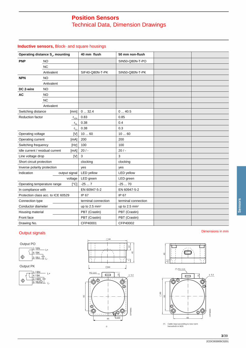
3/39
Sen
sors
2CDC003005C0201
Inductive sensors, Block- and square housings
Position SensorsTechnical Data, Dimension Drawings
Operating distance S n, mounting 40 mm flush 50 mm non-flush
PNP NO SIN50-Q80N-T-PO
NC
Antivalent SIF40-Q80N-T-PK SIN50-Q80N-T-PK
NPN NO
Antivalent
DC 2-wire NO
AC NO
NC
Antivalent
Switching distance [mm] 0 ... 32.4 0 ... 40.5
Reduction factor rV2A 0.83 0.85
rAL 0.38 0.4
rCu 0.38 0.3
Operating voltage [V] 10 ... 60 10 ... 60
Operating current [mA] 200 200
Switching frequency [Hz] 100 100
Idle current / residual current [mA] 20 / - 20 / -
Line voltage drop [V] 3 3
Short circuit protection clocking clocking
Inverse polarity protection yes yes
Indication output signal LED yellow LED yellow
voltage LED green LED green
Operating temperature range [°C] -25 ... 7 -25 ... 70
In compliance with EN 60947-5-2 EN 60947-5-2
Protection class acc. to ICE 60529 IP 67 IP 67
Connection type terminal connection terminal connection
Conductor diameter up to 2.5 mm2 up to 2.5 mm2
Housing material PBT (Crastin) PBT (Crastin)
Front face PBT (Crastin) PBT (Crastin)
Drawing No. CFP40001 CFP40002
Dimensions in mmOutput signals
3 / BU
4 / BK
1 / BN L+
L-
Output PO
L+1 / BN
L-
4 / BK2 / WH3 / BU
Output PK
LED
14
40
7
80
w 84
11
65
65
PG 13,5ÿ 5,3
(*)
(*) Cable input according to new norm henceforth in M2 0
40
w 8
0
11
65
65
PG 13,5
7
ÿ 5,3
(*) Cable input according to new norm henceforth in M20
(*)
CF
P40
001
CF
P40
002
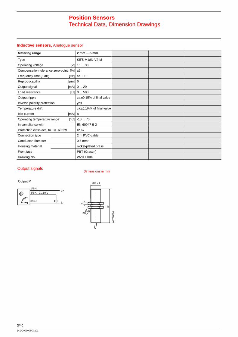
3/40
2CDC003005C0201
Inductive sensors, Analogue sensor
Position SensorsTechnical Data, Dimension Drawings
Metering range 2 mm ... 5 mm
Type SIF5-M18N-V2-M
Operating voltage [V] 15 ... 30
Compensation tolerance zero-point [%] ±2
Frequency limit (3 dB) [Hz] ca. 110
Reproducability [µm] 6
Output signal [mA] 0 ... 20
Load resistance [Ω] 0 ... 500
Output ripple ca.±0,15% of final value
Inverse polarity protection yes
Temperature drift ca.±0,1%/K of final value
Idle current [mA] 8
Operating temperature range [°C] -10 ... 70
In compliance with EN 60947-5-2
Protection class acc. to ICE 60529 IP 67
Connection type 2 m PVC-cable
Conductor diameter 0.5 mm2
Housing material nickel-plated brass
Front face PBT (Crastin)
Drawing No. WZ000004
M18 x 1
4
24
60
WZ
0000
04
L+1/BN
3/BU L-
4/BK 0...10 V
Output M
Dimensions in mmOutput signals
3/41
Sen
sors
2CDC003005C0201
3 / BN L1
N4 / BU
Output AO
Capacitive sensors, with thread M 30 x 1,5
Position SensorsTechnical Data, Dimension Drawings
Operating distance S n, mounting 10 mm flush 10 mm flush 10 mm flush
PNP NO SCF10-M30N-V2-PO SCF10-M30N-C1-PO
NC
Antivalent SCF10-M30N-V2-PK SCF10-M30N-C1-PK
NPN NO
Antivalent
DC 2-Draht NO
AC NO SCF10-M30N-V2-AO
NC
Antivalent
Switching distance [mm] 1 ... 10 1 ... 10 1 ... 10
Reduction factor rV2A - - -
rAL - - -
rCu - - -
Operating voltage [V] 10 ... 60 10 ... 60 20 ... 253
Operating current [mA] 200 200 200
Switching frequency [Hz] 10 10 10
Idle current / residual current [mA] 20 / 0.5 20 / 0.5 - / 1.5
Line voltage drop [V] 2,8 2,8 8
Short circuit protection clocking clocking no
Inverse polarity protection yes yes yes
Indication output signal LED yellow LED yellow LED yellow
voltage - - -
Operating temperature range [°C] -25 ... 70 -25 ... 70 -25 ... 70
In compliance with EN 60947-5-2 EN 60947-5-2 EN 60947-5-2
Protection class acc. to ICE 60529 IP 67 IP 67 IP 67
Connection type 2 m, PVC-cable Connector 2 m, PVC-cable
Conductor diameter 0.75 mm2 - 0.75 mm2
Housing material stainless steel stainless steel stainless steel
Front face PBT (Crastin) PBT (Crastin) PBT (Crastin)
Drawing No. LS100018 LS100019 LS100018
LED
M 30x1,5
18
80
Poti
5
36
78
LED
M 30x1,5
18
80
Poti
5
36
78
Dimensions in mm
L+1 / BN
L-
4 / BK2 / WH3 / BU
Output PK
M 30x1,5
18
80
93
LED
M 12x1
Poti
5
36
78
Output signals
LS10
0018
LS10
0019
LS10
0018
3 / BU
4 / BK
1 / BNL+
L-
Output PO
3/42
2CDC003005C0201
Position SensorsTechnical Data, Dimension Drawing
Photoelectric sensors: Through Beam sensors
Device identification SOT20M-B75N-T-KK
Sensing range 20 000 mmOutput DC, PNP
Operating dataPolarized noReference value through beam photoelectric receiverRange setting with potentiometerSwitching frequency (1:1) / response time 25 Hz / ≤ 20 msReadiness delay ≤ 50 msRange hyteresis -Detectable object: opaque
Operating mode Light ON/dark ON, selectableLED yellow only receiver: Output statusLED red rec.: stability control output, send.: net onType of light IR-light 940 mmExternal light limit
daylight / halogen light ≤ 10 000 Lux / ≤ 7 500 Lux
Operating temperature range -25°C ... +55°CStorage temperature range -40°C ... +55°C
Electrical dataOperating voltage 12 ... 240 VDC, ±10%
24 ... 240 VAC, ±10%; 50 ... 60 HzIdle current −Output NC/NO
Rated operational current relay: ≤ 240 VAC, ≤ 30 VDC, ≤ 3 ALine voltage drop -
Stability control output -Rated operational current -
Short-ciucuit and overload protection noInverse polarity protection no
Mechanical dataProtection class acc. to EN 60529 IP 66Optical system PMMA lenses, pole filterPermissible shock- shock b ≤ 30 g, T ≤ 11 msand vibration resistance vibrations f ≤ 55 Hz, a ≤ 1mmConnection type Terminal compartment, cable Ø 10 mmWeight emitter: 90 g, receiver: 100 gIn compliance with EN 60 947-5-2Drawing No. CO000008
LED yellow
LED red
Sender +Receiver
LED yellow onlyon receiver
Cable-connect ion Pg 9
Dimensions in mm
S E
Objekt
2
L+1
L-
Sender
1234
AC/DC
Relais
ReceiverOutput KK
Output signals
CO
0000
08
3/43
Sen
sors
2CDC003005C0201
Position SensorsTechnical Data, Dimension Drawings
Photoelectric sensors: Through Beam sensors
Device identification SOT15M-B45N-C1-PKS SOT15M-B45N-C1-NKS
Sensing range 2000 mm ... 15 000 mm 2000 mm ... 15 000 mmOutput DC, PNP DC, NPN
Operating dataPolarized no noReference value receiver receiverRange setting with +/- keys with +/- keysSwitching frequency (1:1) / response time max. 1 kHz / ≤ 3 ms max. 1 kHz / ≤ 3 msReadiness delay < 400 ms, with switch-on standardisation < 400 ms, with switch-on standardisationRange hyteresis - -Detectable object: opaque, reflective opaque, reflectiveLED red stability control output flashing 2 Hz, stability control output flashing 2 Hz,
fault indication in teach-in mode 1,5 s fault indication in teach-in mode 1,5 sLED yellow switching condition switching conditionLED green operating status, in teach-in mode flashing operating status, in teach-in mode flashingType of light visible red light 660 mm visible red light 660 mmExternal light limit
daylight / halogen light ≤ 10 000 Lux / ≤ 7 500 Lux ≤ 10 000 Lux / ≤ 7 500 Lux
Operating temperature range -25 °C ... +55 °C -25 °C ... +55 °CStorage temperature range -40 °C ... +55 °C -40 °C ... +55 °C
Electrical dataOperating voltage 10 VDC ... 30 VDC ±10% 10 VDC ... 30 VDC ±10%Idle current ca. 25 mA per device ca. 25 mA per deviceRated operational current 200 mA per device 200 mA per deviceLine voltage drop ≤ 2,5 V ≤ 2,5 VInput voltage for control / test: < 2 V off / > 7 V on for control / test: < 2 V off / > 7 V onShort-ciucuit and overload protection yes yesInverse polarity protection yes yes
Mechanical dataProtection class acc. to EN 60529 > IP 67, materials approved for use in food > IP 67, materials approved for use in food
production productionOptical system PMMA lenses PMMA lensesPermissible shock- shock b ≤ 30 g, T ≤ 11 ms shock b ≤ 30 ≤, T ≤ 11 msand vibration resistance vibrations f ≤ 55 Hz, a ≤ 1mm vibrations f ≤ 55 Hz, a ≤ 1mmConnection type Connector M12 x 1, 5 - pole, Connector M12 x 1, 5 - pole,
90 ° pivoting 90 ° pivotingWeight 60 g per device 60 g per deviceIn compliance with EN 60 947-5-2 EN 60 947-5-2Housing material PBT (Crastin), plug and dovetail AlSi PBT (Crastin), plug and dovetail AlSi
Center optical axisreceiver / sender
5-pol. connector(M12x1)
Keypad only at receiver(sensitivity adjustment, TEACH IN)
3,2 26
,5
3,2
90˚
LED
504
18
50
18
4
4
45
4
M12x1
Receiver
Sender
PKS
NKS
+1/BN
-
4/BK
2/WS3/BU
5/GR
+1/BN
4/BK2/WS
3/BU5/GR
-
+1/BN
-3/BU
5/GR
T
T
T
S E
Objekt
Dimensions in mmOutput signals
3/44
2CDC003005C0201
1 / BNL+
L-
4 / BK
3 / BU
Output POIncidence of light –> Output low
1 / BN
4 / BK
3 / BUL+
L-
Output PO Incidence of light –> Output high
LED
50
Thickness
Potentiometer4
M18x1
35,5
M12x1
7079
24
LS00
0011
Position SensorsTechnical Data, Maßbild
Photoelectric sensors: Retroreflective sensors
Device identification SOR1500-M18N-C1-PO SOR4000-M18N-C1-PO
Sensing range 1 500 mm 4 000 mmOutput DC, PNP DC, PNP
Operating dataPolarized yes yesReference value Retroreflector 50mm x 50mm Retroreflector 50mm x 50mmRange setting with potentiometer with potentiometerSwitching frequency (1:1) / response time 300 Hz / ≤ 1,5 ms ≤ 500 HzReadiness delay ≤ 50 ms ≤ 25 msRange hyteresis - -Detectable object: opaque, reflective opaque, reflective
Mode of operation Light ON/dark ON, selectable by wiring Light ON/dark ON, selectable electronicallysssLED yellow switching condition switching conditionLED red - -Type of light red light 660 nm red light 660 nmExternal light limit
daylight / halogen light ≤ 10 000 Lux / ≤ 3 000 Lux ≤ 10 000 Lux / ≤ 3 000 Lux
Operating temperature range -25°C ... +55°C -25°C ... +55°CStorage temperature range -40°C ... +70°C -40°C ... +70°C
Electrical dataOperating voltage 10 VDC ... 30 VDC, ripple 10%ss 10 VDC ... 30 VDCIdle current ≤ 20 mA ≤ 25 mAOutput NC/NO NC/NO
Rated operational current 100 mA 100 mALine voltage drop ≤ 2,5 V ≤ 2,5 V
Stability control output - -Rated operational current - -
Short-ciucuit and overload protection yes yesInverse polarity protection yes yes
Mechanical dataProtection class acc. to EN 60529 IP 67 IP 67Optical system PMMA lenses, pole filter PMMA lenses, pole filterPermissible shock- shock b ≤ 30 g, T ≤ 11 ms shock b ≤ 30 g, T ≤ 11 msand vibration resistance vibrations f ≤ 55 Hz, a ≤ 1mm vibrations f ≤ 55 Hz, a ≤ 1mmConnection type Connector M12 Connector M12
Housing material nickel-plated brass nickel-plated brassWeight 45 g 45 gIn compliance with EN 60 947-5-2 EN 60 947-5-2Drawing No. CO000001A CO000001B
Objekt
Dimensions in mmOutput signals
LED
51
T
hickness
Potentiometer4
M18x1
35,5
M12x1
6070
44
24
CO
0000
01B
CO
0000
01A
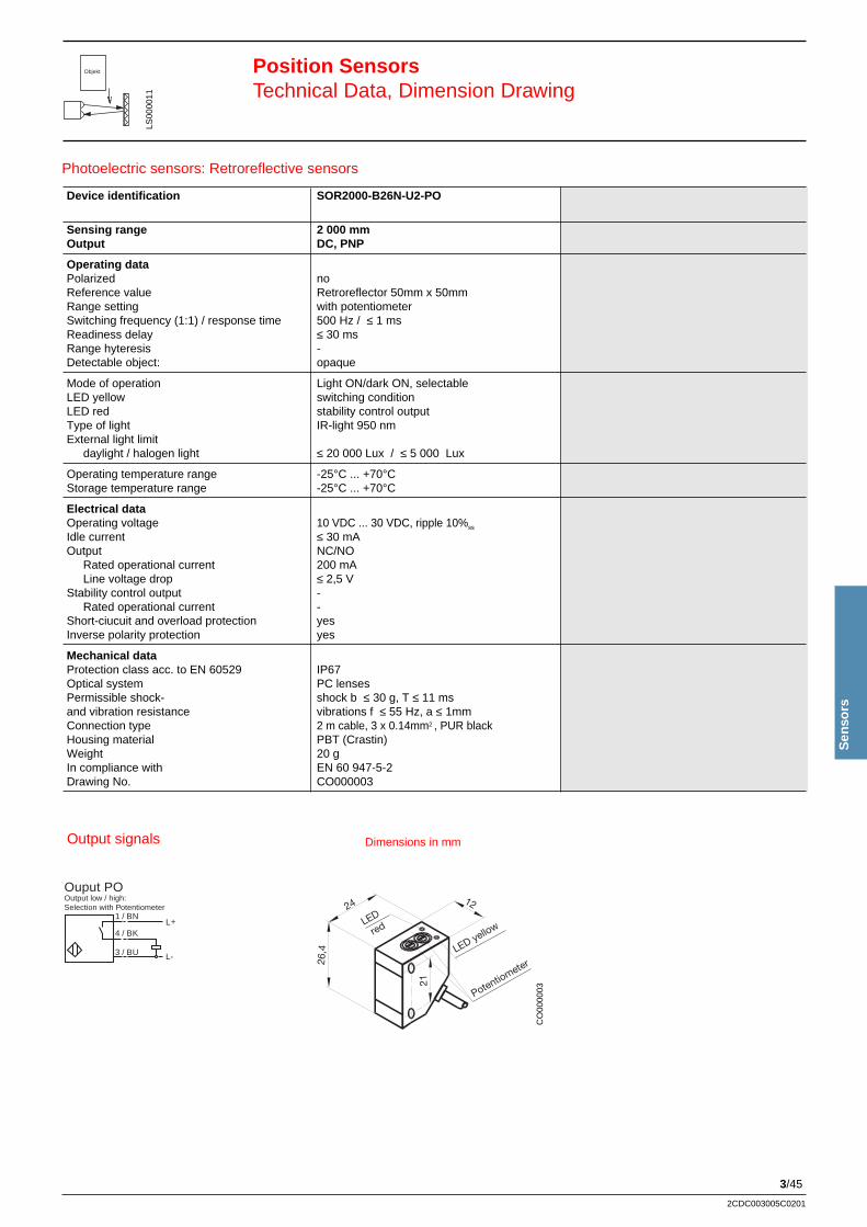
3/45
Sen
sors
2CDC003005C0201
24
26,4
21
12
LED
red
PotentiometerLED yellow
Position SensorsTechnical Data, Dimension Drawing
1 / BNL+
L-
4 / BK
3 / BU
Ouput POOutput low / high:Selection with Potentiometer
Device identification SOR2000-B26N-U2-PO
Sensing range 2 000 mmOutput DC, PNP
Operating dataPolarized noReference value Retroreflector 50mm x 50mmRange setting with potentiometerSwitching frequency (1:1) / response time 500 Hz / ≤ 1 msReadiness delay ≤ 30 msRange hyteresis -Detectable object: opaque
Mode of operation Light ON/dark ON, selectableLED yellow switching conditionLED red stability control outputType of light IR-light 950 nmExternal light limit
daylight / halogen light ≤ 20 000 Lux / ≤ 5 000 Lux
Operating temperature range -25°C ... +70°CStorage temperature range -25°C ... +70°C
Electrical dataOperating voltage 10 VDC ... 30 VDC, ripple 10%ss
Idle current ≤ 30 mAOutput NC/NO
Rated operational current 200 mALine voltage drop ≤ 2,5 V
Stability control output -Rated operational current -
Short-ciucuit and overload protection yesInverse polarity protection yes
Mechanical dataProtection class acc. to EN 60529 IP67Optical system PC lensesPermissible shock- shock b ≤ 30 g, T ≤ 11 msand vibration resistance vibrations f ≤ 55 Hz, a ≤ 1mmConnection type 2 m cable, 3 x 0.14mm2 , PUR blackHousing material PBT (Crastin)Weight 20 gIn compliance with EN 60 947-5-2Drawing No. CO000003
Photoelectric sensors: Retroreflective sensors
LS00
0011
Objekt
Dimensions in mmOutput signals
CO
0000
03
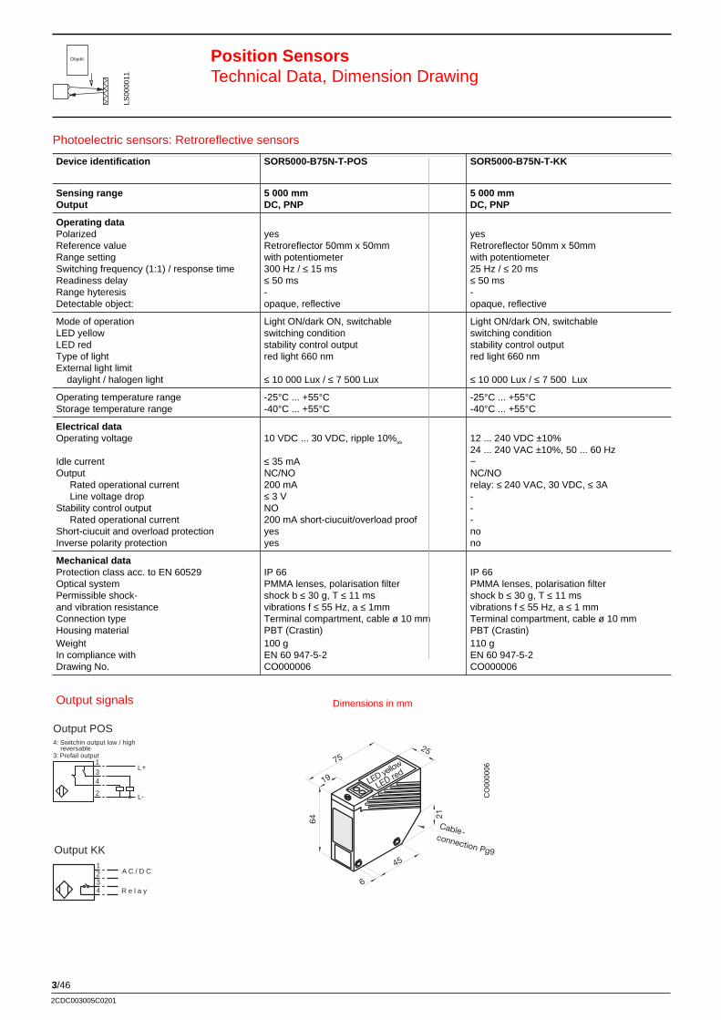
3/46
2CDC003005C0201
Device identification SOR5000-B75N-T-POS SOR5000-B75N-T-KK
Sensing range 5 000 mm 5 000 mmOutput DC, PNP DC, PNP
Operating dataPolarized yes yesReference value Retroreflector 50mm x 50mm Retroreflector 50mm x 50mmRange setting with potentiometer with potentiometerSwitching frequency (1:1) / response time 300 Hz / ≤ 15 ms 25 Hz / ≤ 20 msReadiness delay ≤ 50 ms ≤ 50 msRange hyteresis - -Detectable object: opaque, reflective opaque, reflective
Mode of operation Light ON/dark ON, switchable Light ON/dark ON, switchableLED yellow switching condition switching conditionLED red stability control output stability control outputType of light red light 660 nm red light 660 nmExternal light limit daylight / halogen light ≤ 10 000 Lux / ≤ 7 500 Lux ≤ 10 000 Lux / ≤ 7 500 Lux
Operating temperature range -25°C ... +55°C -25°C ... +55°CStorage temperature range -40°C ... +55°C -40°C ... +55°C
Electrical dataOperating voltage 10 VDC ... 30 VDC, ripple 10%ss 12 ... 240 VDC ±10%
24 ... 240 VAC ±10%, 50 ... 60 HzIdle current ≤ 35 mA −Output NC/NO NC/NO
Rated operational current 200 mA relay: ≤ 240 VAC, 30 VDC, ≤ 3ALine voltage drop ≤ 3 V -
Stability control output NO -Rated operational current 200 mA short-ciucuit/overload proof -
Short-ciucuit and overload protection yes noInverse polarity protection yes no
Mechanical dataProtection class acc. to EN 60529 IP 66 IP 66Optical system PMMA lenses, polarisation filter PMMA lenses, polarisation filterPermissible shock- shock b ≤ 30 g, T ≤ 11 ms shock b ≤ 30 g, T ≤ 11 msand vibration resistance vibrations f ≤ 55 Hz, a ≤ 1mm vibrations f ≤ 55 Hz, a ≤ 1 mmConnection type Terminal compartment, cable ø 10 mm Terminal compartment, cable ø 10 mmHousing material PBT (Crastin) PBT (Crastin)Weight 100 g 110 gIn compliance with EN 60 947-5-2 EN 60 947-5-2Drawing No. CO000006 CO000006
Position SensorsTechnical Data, Dimension Drawing
LS00
0011
1L+
L-
3
2
Output POS4: Switchin output low / high
reversable3: Prefail output
4
Photoelectric sensors: Retroreflective sensors
Objekt
1234
A C / D C
R e l a y
Output KK
Dimensions in mm
Cable-connection Pg9
75
19
64
21
25
45
LED red
6
LED yellow
Output signals
CO
0000
06
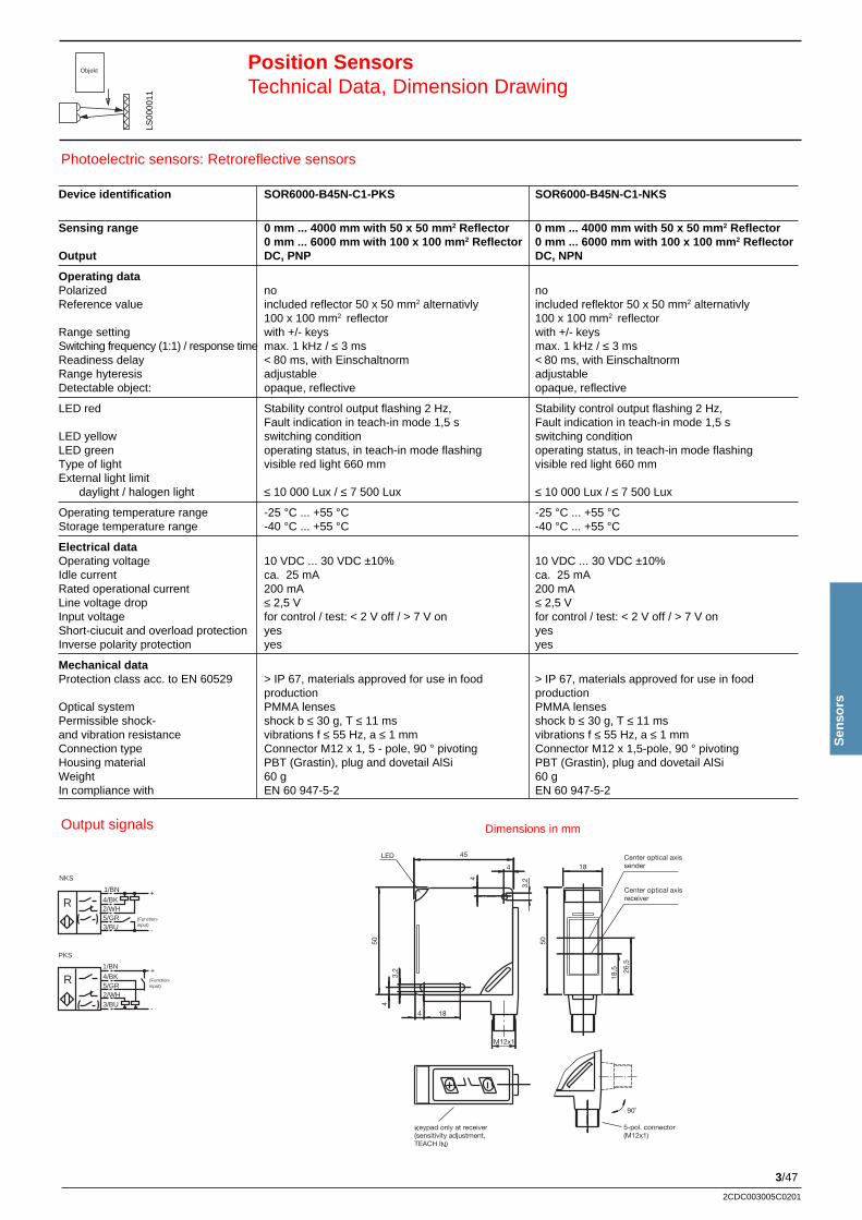
3/47
Sen
sors
2CDC003005C0201
Position SensorsTechnical Data, Dimension Drawing
Device identification SOR6000-B45N-C1-PKS SOR6000-B45N-C1-NKS
Sensing range 0 mm ... 4000 mm with 50 x 50 mm 2 Reflector 0 mm ... 4000 mm with 50 x 50 mm 2 Reflector0 mm ... 6000 mm with 100 x 100 mm 2 Reflector 0 mm ... 6000 mm with 100 x 100 mm 2 Reflector
Output DC, PNP DC, NPN
Operating dataPolarized no noReference value included reflector 50 x 50 mm2 alternativly included reflektor 50 x 50 mm2 alternativly
100 x 100 mm2 reflector 100 x 100 mm2 reflectorRange setting with +/- keys with +/- keysSwitching frequency (1:1) / response time max. 1 kHz / ≤ 3 ms max. 1 kHz / ≤ 3 msReadiness delay < 80 ms, with Einschaltnorm < 80 ms, with EinschaltnormRange hyteresis adjustable adjustableDetectable object: opaque, reflective opaque, reflective
LED red Stability control output flashing 2 Hz, Stability control output flashing 2 Hz,Fault indication in teach-in mode 1,5 s Fault indication in teach-in mode 1,5 s
LED yellow switching condition switching conditionLED green operating status, in teach-in mode flashing operating status, in teach-in mode flashingType of light visible red light 660 mm visible red light 660 mmExternal light limit
daylight / halogen light ≤ 10 000 Lux / ≤ 7 500 Lux ≤ 10 000 Lux / ≤ 7 500 Lux
Operating temperature range -25 °C ... +55 °C -25 °C ... +55 °CStorage temperature range -40 °C ... +55 °C -40 °C ... +55 °C
Electrical dataOperating voltage 10 VDC ... 30 VDC ±10% 10 VDC ... 30 VDC ±10%Idle current ca. 25 mA ca. 25 mARated operational current 200 mA 200 mALine voltage drop ≤ 2,5 V ≤ 2,5 VInput voltage for control / test: < 2 V off / > 7 V on for control / test: < 2 V off / > 7 V onShort-ciucuit and overload protection yes yesInverse polarity protection yes yes
Mechanical dataProtection class acc. to EN 60529 > IP 67, materials approved for use in food > IP 67, materials approved for use in food
production productionOptical system PMMA lenses PMMA lensesPermissible shock- shock b ≤ 30 g, T ≤ 11 ms shock b ≤ 30 g, T ≤ 11 msand vibration resistance vibrations f ≤ 55 Hz, a ≤ 1 mm vibrations f ≤ 55 Hz, a ≤ 1 mmConnection type Connector M12 x 1, 5 - pole, 90 ° pivoting Connector M12 x 1,5-pole, 90 ° pivotingHousing material PBT (Grastin), plug and dovetail AlSi PBT (Grastin), plug and dovetail AlSiWeight 60 g 60 gIn compliance with EN 60 947-5-2 EN 60 947-5-2
Photoelectric sensors: Retroreflective sensors
Objekt
LS00
0011
LED Center optical axissender
5-pol. connector(M12x1)
Keypad only at receiver (sensitivity adjustment,TEACH IN)
Center optical axisreceiver
504
3,2
18
50
26,5
18
3,24
4
45
4
18,5
M12x1
90˚
(Function-input)
(Function-input)
PKS
NKS
+1/BN
-
4/BK
2/WH3/BU
5/GR
+1/BN
4/BK2/WH
3/BU5/GR
-
R
R
Dimensions in mmOutput signals
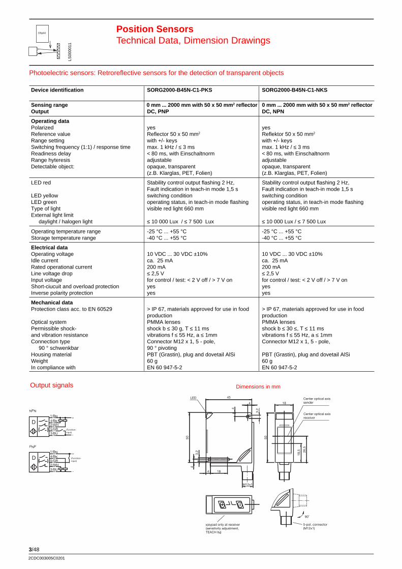
3/48
2CDC003005C0201
Position SensorsTechnical Data, Dimension Drawings
Photoelectric sensors: Retroreflective sensors for the detection of transparent objects
Device identification SORG2000-B45N-C1-PKS SORG2000-B45N-C1-NKS
Sensing range 0 mm ... 2000 mm with 50 x 50 mm 2 reflector 0 mm ... 2000 mm with 50 x 50 mm 2 reflectorOutput DC, PNP DC, NPN
Operating dataPolarized yes yesReference value Reflector 50 x 50 mm2 Reflektor 50 x 50 mm2
Range setting with +/- keys with +/- keysSwitching frequency (1:1) / response time max. 1 kHz / ≤ 3 ms max. 1 kHz / ≤ 3 msReadiness delay < 80 ms, with Einschaltnorm < 80 ms, with EinschaltnormRange hyteresis adjustable adjustableDetectable object: opaque, transparent opaque, transparent
(z.B. Klarglas, PET, Folien) (z.B. Klarglas, PET, Folien)
LED red Stability control output flashing 2 Hz, Stability control output flashing 2 Hz,Fault indication in teach-in mode 1,5 s Fault indication in teach-in mode 1,5 s
LED yellow switching condition switching conditionLED green operating status, in teach-in mode flashing operating status, in teach-in mode flashingType of light visible red light 660 mm visible red light 660 mmExternal light limit
daylight / halogen light ≤ 10 000 Lux / ≤ 7 500 Lux ≤ 10 000 Lux / ≤ 7 500 Lux
Operating temperature range -25 °C ... +55 °C -25 °C ... +55 °CStorage temperature range -40 °C ... +55 °C -40 °C ... +55 °C
Electrical dataOperating voltage 10 VDC ... 30 VDC ±10% 10 VDC ... 30 VDC ±10%Idle current ca. 25 mA ca. 25 mARated operational current 200 mA 200 mALine voltage drop ≤ 2,5 V ≤ 2,5 VInput voltage for control / test: < 2 V off / > 7 V on for control / test: < 2 V off / > 7 V onShort-ciucuit and overload protection yes yesInverse polarity protection yes yes
Mechanical dataProtection class acc. to EN 60529 > IP 67, materials approved for use in food > IP 67, materials approved for use in food
production productionOptical system PMMA lenses PMMA lensesPermissible shock- shock b ≤ 30 g, T ≤ 11 ms shock b ≤ 30 ≤, T ≤ 11 msand vibration resistance vibrations f ≤ 55 Hz, a ≤ 1mm vibrations f ≤ 55 Hz, a ≤ 1mmConnection type Connector M12 x 1, 5 - pole, Connector M12 x 1, 5 - pole,
90 ° schwenkbar 90 ° pivotingHousing material PBT (Grastin), plug and dovetail AlSi PBT (Grastin), plug and dovetail AlSiWeight 60 g 60 gIn compliance with EN 60 947-5-2 EN 60 947-5-2
LED Center optical axissender
5-pol. connector(M12x1)
Keypad only at receiver (sensitivity adjustment,TEACH IN)
Center optical axisreceiver
504
3,2
18
50
26,5
18
3,24
4
45
4
18,5
M12x1
90˚
(Function-input)
(Function-input)
PNP
NPN
+1/BN
-
4/BK
2/WH3/BU
5/GR
+1/BN
4/BK2/WH
3/BU5/GR
-
D
D
Objekt
LS00
0011
Dimensions in mmOutput signals
3/49
Sen
sors
2CDC003005C0201
Position SensorsTechnical Data, Dimension Drawings
24
26,4
21
12
LED
red
PotentiometerLED yellowLED
51
T
hickness
Potentiometer4
M18x1
35,5
M12x1
6070
44
24
1 / BNL+
L-
4 / BK
3 / BU
Ouput POOutput low / high:Selection with Potentiometer
1 / BN
4 / BK
3 / BUL+
L-
Output PO Incidence of light –> Output high
1 / BNL+
L-
4 / BK
3 / BU
Output POIncidence of light –> Output low
LS00
0012
Device identification SOD200-M18N-C1-PO SOD400-B26N-U2-PO
Sensing range 200 mm 400 mmOutput DC, PNP DC, PNP
Operating dataPolarized no noReference value white 200mm x 200mm white 100mm x 100mmRange setting with potentiometer with potentiometerSwitching frequency (1:1) / response time 300 Hz / ≤ 1,5 ms 500 Hz / ≤ 1 msReadiness delay ≤ 50 ms ≤ 30 msRange hyteresis ≤ 15 % ≤ 15 %Detectable object: opaque opaque, transparent
Mode of operation Light ON/dark ON, selectable by wiring Light ON/dark ON, switchableLED yellow switching condition switching conditionLED red - stability control outputType of light IR-light 940 nm IR-light 950 nmExternal light limit
daylight / halogen light ≤ 10 000 Lux / ≤ 3 000 Lux ≤ 20 000 Lux / ≤ 5 000 Lux
Operating temperature range -25°C ... +55°C -25°C ... +70°CStorage temperature range -40°C ... +70°C -25°C ... +70°C
Electrical dataOperating voltage 10 VDC ... 30 VDC, ripple 10%ss 10 VDC ... 30 VDC, ripple 10%ss
Idle current ≤ 20 mA ≤ 30 mAOutput NC / NO NC/NO
Rated operational current 100 mA 200 mALine voltage drop ≤ 2,5 V ≤ 2,5 V
Stability control output - -Rated operational current - -
Short-ciucuit and overload protection yes yesInverse polarity protection yes yes
Mechanical dataProtection class acc. to EN 60529 IP 67 IP 67Optical system PC lenses PC lensesPermissible shock- shock b ≤ 30 g, T ≤ 11 ms shock b ≤ 30 g, T ≤ 11 msand vibration resistance vibrations f ≤ 55 Hz, a ≤ 1 mm vibrations f ≤ 55 Hz, a ≤ 1 mmConnection type Connector M12 2m cable PUR black, 3 x 0.14 mm2
Housing material nickel-plated brass PBT (Crastin)Weight 45 g 20 gIn compliance with EN 60 947-5-2 EN 60 947-5-2Drawing No. CO000001 CO000003
Photoelectric sensors: Diffuse Reflective sensors
Objekt
Dimensions in mmOutput signals
CO
0000
01
CO
0000
03
3/50
2CDC003005C0201
Position SensorsTechnical Data, Dimension Drawings
Cable-connection Pg9
75
19
64
21
25
45
LED red
6
LED yellow
LS00
0012
Photoelectric sensors: Diffuse Reflective sensors
Device identification SOD800-B75N-T-POS
Sensing range 800 mmOutput DC, PNP
Operating dataPolarized noReference value white 100mm x 100mmRange setting with potentiometerSwitching frequency (1:1) / response time 300 Hz / ≤ 15 msReadiness delay ≤ 50 msRange hyteresis ≤ 15 %Detectable object: opaque, transparent
Mode of operation Light ON/dark ON, switchableLED yellow switching conditionLED red stability control outputType of light IR-light 940 nmExternal light limit
daylight / halogen light ≤ 10 000 Lux / ≤ 7 500 Lux
Operating temperature range -25°C ... +70°CStorage temperature range -40°C ... +80°C
Electrical dataOperating voltage 10 VDC ... 30 VDC, ripple 10%ss
Idle current ≤ 25 mAOutput NC/NO
Rated operational current 200 mA short cicuit/overload proofLine voltage drop ≤ 3 V
Stability control output NORated operational current 10 mA
Short-ciucuit and overload protection yesInverse polarity protection yes
Mechanical dataProtection class acc. to EN 60529 IP 66Optical system PMMA lensesPermissible shock- shock b ≤ 30 g, T ≤ 11 msand vibration resistance vibrations f ≤ 55 Hz, a ≤ 1mmConnection type Terminal compartment, cable ø 10 mm
Housing material PBT (Crastin)Weight 100 gIn compliance with EN 60 947-5-2Drawing No. CO000006
Objekt
Dimensions in mmOutput signals
CO
0000
06
1L+
L-
3
2
Output POS4: Switchin output low / high
reversable3: Prefail output
4
3/51
Sen
sors
2CDC003005C0201
Position SensorsTechnical Data, Dimension Drawing
Photoelectric sensors: Diffuse Reflective sensors
Objekt
1234
AC/DC
Relay
Output KK
Device identification SOD2000-B75N-T-KK
Sensing range 2000 mmOutput DC, PNP
Operating dataPolarized noReference value white 200mm x 200mmRange setting with potentiometerSwitching frequency (1:1) / response time 300 Hz / ≤ 1,5 msReadiness delay ≤ 50 msRange hyteresis ≤ 15 %Detectable object: opaque, transparent
Mode of operation Light ON/dark ON, switchableLED yellow switching conditionLED red stability control outputType of light IR-light 940 mmExternal light limit
daylight / halogen light ≤ 10 000 Lux / ≤ 7 500 Lux
Operating temperature range -25°C ... +55°CStorage temperature range -40°C ... +55°C
Electrical dataOperating voltage 12 ...240 VDC. ±10%
24 ... 240 VAC, ±10%; 50 ... 60 HzIdle current −Output NC/NO
Rated operational current relay: ≤ 240 VAC, ≤ 30 VDC, ≤ 3 ALine voltage drop -
Stability control output -Rated operational current -
Short-ciucuit and overload protection noInverse polarity protection no
Mechanical dataProtection class acc. to EN 60529 IP 66Optical system PMMA lensesPermissible shock- shock b ≤ 30 g, T ≤ 11 msand vibration resistance vibrations f ≤ 55 Hz, a ≤ 1mmConnection type Terminal compartment, cable ø 10 mm
Weight 110 gIn compliance with EN 60 947-5-2Drawing No. CO000007
LS00
0012
Dimensions in mm
LED yellow
LED red
Cableconnection P
Output signals
CO
0000
07
3/52
2CDC003005C0201
Position SensorsTechnical Data, Dimension Drawings
Device identification SOD500-B45N-C1-PKS SOD500-B45N-C1-NKS
Sensing rangeOutput DC, PNP DC, NPNOperating dataPolarized no noReference value standard white 100 x 100 mm2 standard white 100 x 100 mm2
Range setting with +/- keys with +/- keysSwitching frequency (1:1) / response time max. 1 kHz / ≤ 3 ms max. 1 kHz / ≤ 3 msReadiness delay < 80 ms, with activation standard < 80 ms, with activation standardRange hyteresis adjustable adjustableDetectable object: opaque opaque
LED ret stability control output flashing2 Hz, stability control output flashing 2 Hz,Fault indication in learning mode 1,5 s Fault indication in learning mode 1,5 s
LED yellow switching condition switching conditionLED green Operation indication, flashing in teach-in mode Operation indication, flashing in teach-in modeType of light visible red light 660 mm visible red light 660 mmExternal light limitdaylight / halogen light ≤ 10 000 Lux / ≤ 7 500 Lux ≤ 10 000 Lux / ≤ 7 500 Lux
Operating temperature range -25 °C ... +55 °C -25 °C ... +55 °CStorage temperature range -40 °C ... +55 °C -40 °C ... +55 °C
Electrical dataOperating voltage 10 VDC ... 30 VDC ±10% 10 VDC ... 30 VDC ±10%Idle current ca. 25 mA ca. 25 mARated operational current 200 mA 200 mALine voltage drop ≤ 2,5 V ≤ 2,5 VInput voltage for control/ test: < 2 V off / > 7 V on for control/ test: < 2 V off / > 7 V onShort-ciucuit and overload predection yes yesInverse polarity predection yes yes
Mechanical dataProtection class acc. to EN 60529 > IP 67, materials approved for use in food > IP 67, materials approved for use in food
production productionOptical system PMMA lenses PMMA lensesPermissible shock- shock b ≤ 30 g, T ≤ 11 ms shock b ≤ 30 g, T ≤ 11 msand vibration resistance vibrationsf ≤ 55 Hz, a ≤ 1 mm vibrationsf f ≤ 55 Hz, a ≤ 1 mmConnection Connector M12 x 1. 5 - pole, 90 ° pivoting Connector M12 x 1.5-pole, 90 ° pivotingHousing material PBT (Grastin), plug and dovetail AlSi PBT (Grastin), plug and dovetail AlSiWeight 60 g 60 gIn compliance with EN 60 947-5-2 EN 60 947-5-2
Photoelectric sensors: Diffuse Reflective sensors
Objekt
LED Center optical axissender
5-pol. connector(M12x1)
Keypad only at receiver (sensitivity adjustment,TEACH IN)
Center optical axisreceiver
504
3,2
18
50
26,5
18
3,24
4
45
4
18,5
M12x1
90˚
(Function-input)
(Function-input)
PKS
NKS
+1/BN
-
4/BK
2/WH3/BU
5/GR
+1/BN
4/BK2/WH
3/BU5/GR
-
R
R
Dimensions in mmOutput signalss
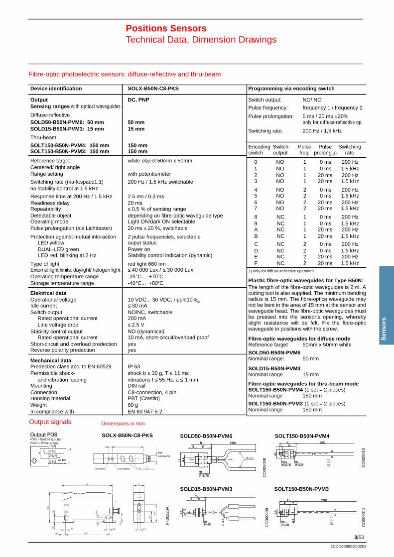
3/53
Sen
sors
2CDC003005C0201
Positions SensorsTechnical Data, Dimension Drawings
Fibre-optic photoelectric sensors: diffuse-reflective and thru-beam
F40
0220
A
CO
0000
08C
O00
0009
CO
0000
10C
O00
0011
SOLD50-B50N-PVM6 SOLT150-B50N-PVM4
SOLD15-B50N-PVM3 SOLT150-B50N-PVM3
Programming via encoding switch
Switch output: NO/ NC
Pulse frequency: frequency 1 / frequency 2
Pulse prolongation: 0 ms / 20 ms ±20%only for diffuse-reflective op.
Switching rate: 200 Hz / 1,5 kHz
Encoding Switch Pulse Pulse Switchingswitch output freq. prolong.1) rate
0 NO 1 0 ms 200 Hz1 NO 1 0 ms 1.5 kHz2 NO 1 20 ms 200 Hz3 NO 1 20 ms 1.5 kHz
4 NO 2 0 ms 200 Hz5 NO 2 0 ms 1.5 kHz6 NO 2 20 ms 200 Hz7 NO 2 20 ms 1.5 kHz
8 NC 1 0 ms 200 Hz9 NC 1 0 ms 1.5 kHzA NC 1 20 ms 200 HzB NC 1 20 ms 1.5 kHz
C NC 2 0 ms 200 HzD NC 2 0 ms 1.5 kHzE NC 2 20 ms 200 HzF NC 2 20 ms 1.5 kHz
1) only for diffuse-reflective operation
Plastic fibre-optic waveguides for Type B50N:The length of the fibre-optic waveguides is 2 m. Acutting tool is also supplied. The minimum bendingradius is 15 mm. The fibre-optice waveguide maynot be bent in the area of 15 mm at the sensor andwaveguide head. The fibre-optic waveguides mustbe pressed into the sensor's opening, wherebyslight resistance will be felt. Fix the fibre-opticwaveguide in positions with the screw.
Fibre-optic waveguides for diffuse modeReference target 50mm x 50mm white
SOLD50-B50N-PVM6Nominal range: 50 mm
SOLD15-B50N-PVM3Nominal range 15 mm
Fibre-optic waveguides for thru-beam modeSOLT150-B50N-PVM4 (1 set = 2 pieces)Nominal range 150 mm
SOLT150-B50N-PVM3 (1 set = 2 pieces)Nominal range 150 mm
Device identification SOLX-B50N-C8-PKS
Output DC, PNPSensing ranges with optical waveguides
Diffuse-reflectiveSOLD50-B50N-PVM6: 50 mm 50 mmSOLD15-B50N-PVM3: 15 mm 15 mm
Thru-beam
SOLT150-B50N-PVM4: 150 mm 150 mmSOLT150-B50N-PVM3: 150 mm 150 mm
Reference target white object 50mm x 50mmCentered/ right angleRange setting with potentiometer
Switching rate (mark:space1:1) 200 Hz / 1.5 kHz switchableno stability control at 1,5 kHz
Response time at 200 Hz / 1.5 kHz 2.5 ms / 0.3 msReadiness delay 20 msRepeatability ≤ 0,5 % of sensing rangeDetectable object depending on fibre-optic waveguide typeOperating mode Light ON/dark ON selectablePulse prolongation (als Lichttaster) 20 ms ± 20 %, switchable
Protection against mutual interaction 2 pulse frequencies, selectable LED yellow ouput status DUAL-LED green Power on LED red, blinking at 2 Hz Stability control indication (dynamic)
Type of light red light 660 nmExternal light limits: daylight/ halogen light ≤ 40 000 Lux / ≤ 30 000 LuxOperating temperature range -25°C.... +70°CStorage temperature range -40°C... +80°C
Elektrical dataOperational voltage 10 VDC... 30 VDC, ripple10%ss
Idle current ≤ 30 mASwitch output NO/NC, switchable
Rated operational current 200 mALine voltage drop ≤ 2.5 V
Stability control output NO (dynamical)Rated operational current 10 mA, short-circuit/overload proof
Short-circuit and overload predection yesReverse polarity predection yes
Mechanical dataPredection class acc. to EN 60529 IP 63Permissible shock- shock b ≤ 30 g, T ≤ 11 ms
and vibration loading vibrations f ≤ 55 Hz, a ≤ 1 mmMounting DIN railConnection C8-connection, 4 pinHousing material PBT (Crastin)Weight 80 gIn compliance with EN 60 947-5-2
Ø 2,2
Output POS4/BK = Switching output2/WH = Prefail output
Ø 2
,2Ø
2,2
SOLX-B50N-C8-PKS
Dimensions in mmOutput signals
59
35,5
3,5
51,75
3,3
6,15
3,5
3,3
2,2
12,9
12
20,9
4,25
3,15
LED yellow LED red/green Sensitivity/TEACH-IN
374
M8 x 1
++ --
M8connector
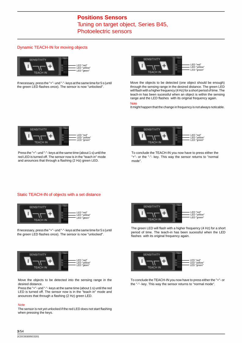
3/54
2CDC003005C0201
Positions SensorsTuning on target object, Series B45,Photoelectric sensors
If necessary, press the "+"- und "-"- keys at the same time for 5 s (untilthe green LED flashes once). The sensor is now "unlocked".
Press the "+"- und "-"- keys at the same time (about 1 s) until thered LED is turned off. The sensor now is in the "teach in" modeand anounces that through a flashing (2 Hz) green LED.
Move the objects to be detected (one object should be enough)through the sensing range in the desired distance. The green LEDwill flash with a higher frequency (4 Hz) for a short period of time. Theteach-in has been sucessful when an object is within the sensingrange and the LED flashes with its original frequency again.
NoteIt might happen that the change in frequency is not always noticable.
To conclude the TEACH-IN you now have to press either the"+"- or the "-"- key. This way the sensor returns to "normalmode".
Dynamic TEACH-IN for moving objects
LED "red"LED "yellow"LED "green"
LED "red"LED "yellow"LED "green"
LED "red"LED "yellow"LED "green"
LED "red"LED "yellow"LED "green"
If necessary, press the "+"- und "-"- keys at the same time for 5 s (untilthe green LED flashes once). The sensor is now "unlocked".
Move the objects to be detected into the sensing range in thedesired distance.Press the "+"- und "-"- keys at the same time (about 1 s) until the redLED is turned off. The sensor now is in the "teach in" mode andanounces that through a flashing (2 Hz) green LED.
NoteThe sensor is not yet unlocked if the red LED does not start flashingwhen pressing the keys.
To conclude the TEACH-IN you now have to press either the "+"- orthe "-"- key. This way the sensor returns to "normal mode".
Static TEACH-IN of objects with a set distance
LED "red"LED "yellow"LED "green"
LED "red"LED "yellow"LED "green"
LED "red"LED "yellow"LED "green"
LED "red"LED "yellow"LED "green"
The green LED will flash with a higher frequency (4 Hz) for a shortperiod of time. The teach-in has been sucessful when the LEDflashes with its original frequency again.
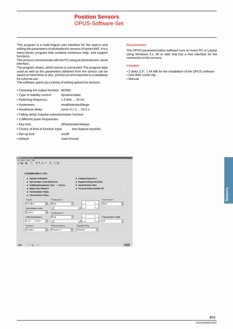
3/55
Sen
sors
2CDC003005C0201
Position SensorsOPUS-Software-Set
This program is a multi-lingual user interface for the read-in andediting the parameters of photoelectric sensors of series B45. It is amenu-driven program that contains numerous help- and supportfunctions.The sensors communicate with the PC using an photoelectric-serialinterface.The program shows, which sensor is connected. The program dataused as well as the parameters obtained from the sensor can besaved on hard drive or disc, printed out and exported to a databasefor external use.The software opens up a variety of setting options for sensors:
• Choosing the output function: NO/NC
• Type of stability control: dynamic/static
• Switching frequency: 1.5 kHz ... 20 Hz
• Hystereses: small/standard/large
• Readiness delay: none/ 0.1 s ... 25.5 s
• Falling delay/ impulse extension/wiper function
• 3 different pulse frequencies
• Key-lock: off/automatic/always
• Choice of kind of function input: test-/logical-input/div.
• Set-up lock: on/off
• Default read-in/reset
Requirements:
The OPUS parameterization software runs on every PC or Laptopusing Windows 3.x, 95 or later that has a free interface for theconnection to the sensors.
Included:
• 2 disks 3,5”, 1.44 MB for the installation of the OPUS software• One B45 combi clip• Manual
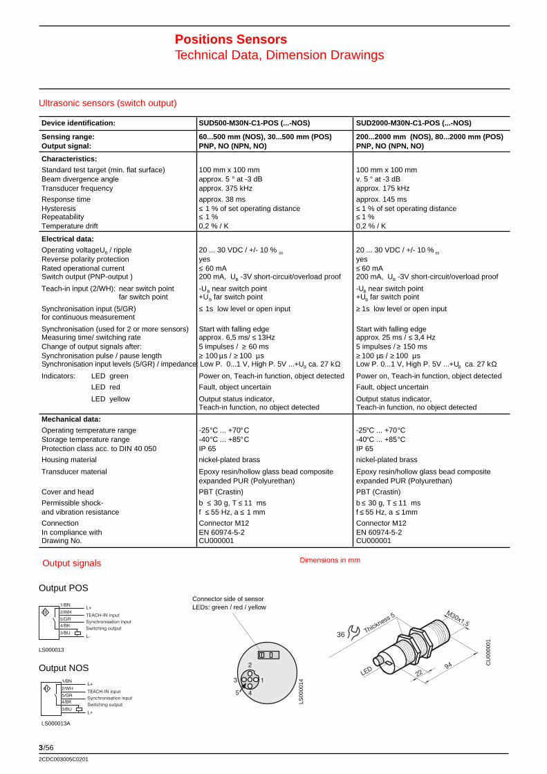
3/56
2CDC003005C0201
Device identification: SUD500-M30N-C1-POS (...-NOS) SUD2000-M30N-C1-POS (...-NOS)
Sensing range: 60...500 mm (NOS), 30...500 mm (POS) 200...2000 mm (NOS), 80...2000 mm (POS)Output signal: PNP, NO (NPN, NO) PNP, NO (NPN, NO)
Characteristics:
Standard test target (min. flat surface) 100 mm x 100 mm 100 mm x 100 mmBeam divergence angle approx. 5 ° at -3 dB v. 5 ° at -3 dBTransducer frequency approx. 375 kHz approx. 175 kHz
Response time approx. 38 ms approx. 145 msHysteresis ≤ 1 % of set operating distance ≤ 1 % of set operating distanceRepeatability ≤ 1 % ≤ 1 %Temperature drift 0,2 % / K 0,2 % / K
Electrical data:
Operating voltageUB / ripple 20 ... 30 VDC / +/- 10 % ss 20 ... 30 VDC / +/- 10 % ss
Reverse polarity protection yes yesRated operational current ≤ 60 mA ≤ 60 mASwitch output (PNP-output ) 200 mA, UB -3V short-circuit/overload proof 200 mA, UB -3V short-circuit/overload proof
Teach-in input (2/WH): near switch point -UB near switch point -UB near switch pointfar switch point +UB far switch point +UB far switch point
Synchronisation input (5/GR) ≤ 1s low level or open input ≥ 1s low level or open inputfor continuous measurement
Synchronisation (used for 2 or more sensors) Start with falling edge Start with falling edgeMeasuring time/ switching rate approx. 6,5 ms/ ≤ 13Hz approx. 25 ms / ≤ 3,4 HzChange of output signals after: 5 impulses / ≥ 60 ms 5 impulses / ≥ 150 msSynchronisation pulse / pause length ≥ 100 µs / ≥ 100 µs ≥ 100 µs / ≥ 100 µsSynchronisation input levels (5/GR) / impedance: Low P. 0...1 V, High P. 5V ...+UB ca. 27 kΩ Low P. 0...1 V, High P. 5V ...+UB ca. 27 kΩIndicators: LED green Power on, Teach-in function, object detected Power on, Teach-in function, object detected
LED red Fault, object uncertain Fault, object uncertain
LED yellow Output status indicator, Output status indicator,Teach-in function, no object detected Teach-in function, no object detected
Mechanical data:
Operating temperature range -25°C ... +70°C -25°C ... +70°CStorage temperature range -40°C ... +85°C -40°C ... +85°CProtection class acc. to DIN 40 050 IP 65 IP 65
Housing material nickel-plated brass nickel-plated brass
Transducer material Epoxy resin/hollow glass bead composite Epoxy resin/hollow glass bead compositeexpanded PUR (Polyurethan) expanded PUR (Polyurethan)
Cover and head PBT (Crastin) PBT (Crastin)
Permissible shock- b ≤ 30 g, T ≤ 11 ms b ≤ 30 g, T ≤ 11 msand vibration resistance f ≤ 55 Hz, a ≤ 1 mm f ≤ 55 Hz, a ≤ 1mm
Connection Connector M12 Connector M12In compliance with EN 60974-5-2 EN 60974-5-2Drawing No. CU000001 CU000001
Ultrasonic sensors (switch output)
Positions SensorsTechnical Data, Dimension Drawings
M30x1,5
LED 94
22
Thickness 5
36
CU
0000
01
LS000013
LS00
0014
Connector side of sensorLEDs: green / red / yellow
TEACH-IN inputSynchronisation inputSwitching output
Output POS
Dimensions in mmOutput signals
TEACH-IN inputSynchronisation inputSwitching output
Output NOS
LS000013A
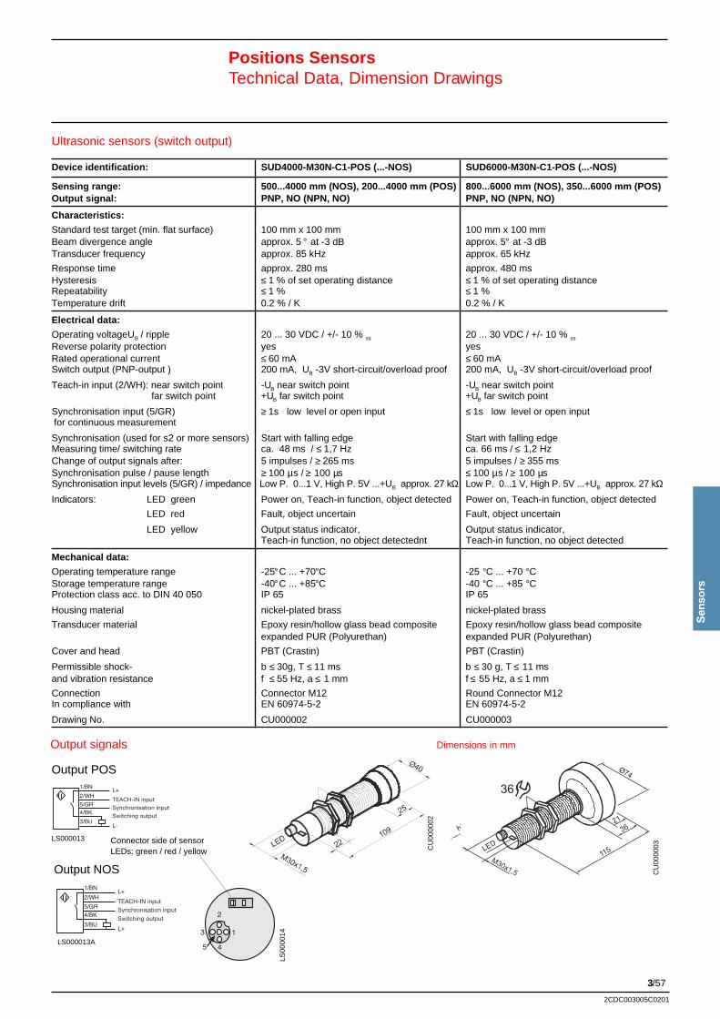
3/57
Sen
sors
2CDC003005C0201
Device identification: SUD4000-M30N-C1-POS (...-NOS) SUD6000-M30N-C1-POS (...-NOS)
Sensing range: 500...4000 mm (NOS), 200...4000 mm (POS) 800...6000 mm (NOS), 350...6000 mm (POS)Output signal: PNP, NO (NPN, NO) PNP, NO (NPN, NO)
Characteristics:
Standard test target (min. flat surface) 100 mm x 100 mm 100 mm x 100 mmBeam divergence angle approx. 5 ° at -3 dB approx. 5° at -3 dBTransducer frequency approx. 85 kHz approx. 65 kHz
Response time approx. 280 ms approx. 480 msHysteresis ≤ 1 % of set operating distance ≤ 1 % of set operating distanceRepeatability ≤ 1 % ≤ 1 %Temperature drift 0.2 % / K 0.2 % / K
Electrical data:
Operating voltageUB / ripple 20 ... 30 VDC / +/- 10 % ss 20 ... 30 VDC / +/- 10 % ss
Reverse polarity protection yes yesRated operational current ≤ 60 mA ≤ 60 mASwitch output (PNP-output ) 200 mA, UB -3V short-circuit/overload proof 200 mA, UB -3V short-circuit/overload proof
Teach-in input (2/WH): near switch point -UB near switch point -UB near switch pointfar switch point +UB far switch point +UB far switch point
Synchronisation input (5/GR) ≥ 1s low level or open input ≤ 1s low level or open inputfor continuous measurement
Synchronisation (used for s2 or more sensors) Start with falling edge Start with falling edgeMeasuring time/ switching rate ca. 48 ms / ≤ 1,7 Hz ca. 66 ms / ≤ 1,2 HzChange of output signals after: 5 impulses / ≥ 265 ms 5 impulses / ≥ 355 msSynchronisation pulse / pause length ≥ 100 µs / ≥ 100 µs ≤ 100 µs / ≥ 100 µsSynchronisation input levels (5/GR) / impedance Low P. 0...1 V, High P. 5V ...+UB approx. 27 kΩ Low P. 0...1 V, High P. 5V ...+UB approx. 27 kΩIndicators: LED green Power on, Teach-in function, object detected Power on, Teach-in function, object detected
LED red Fault, object uncertain Fault, object uncertain
LED yellow Output status indicator, Output status indicator,Teach-in function, no object detectednt Teach-in function, no object detected
Mechanical data:
Operating temperature range -25°C ... +70°C -25 °C ... +70 °CStorage temperature range -40°C ... +85°C -40 °C ... +85 °CProtection class acc. to DIN 40 050 IP 65 IP 65
Housing material nickel-plated brass nickel-plated brass
Transducer material Epoxy resin/hollow glass bead composite Epoxy resin/hollow glass bead compositeexpanded PUR (Polyurethan) expanded PUR (Polyurethan)
Cover and head PBT (Crastin) PBT (Crastin)
Permissible shock- b ≤ 30g, T ≤ 11 ms b ≤ 30 g, T ≤ 11 msand vibration resistance f ≤ 55 Hz, a ≤ 1 mm f ≤ 55 Hz, a ≤ 1 mm
Connection Connector M12 Round Connector M12In compliance with EN 60974-5-2 EN 60974-5-2
Drawing No. CU000002 CU000003
Ultrasonic sensors (switch output)
Positions SensorsTechnical Data, Dimension Drawings
CU
0000
02
LS000013
CU
0000
03
36TEACH-IN inputSynchronisation inputSwitching output
Output POS
LS00
0014
Dimensions in mmOutput signals
Connector side of sensorLEDs: green / red / yellow
TEACH-IN inputSynchronisation inputSwitching output
Output NOS
LS000013A
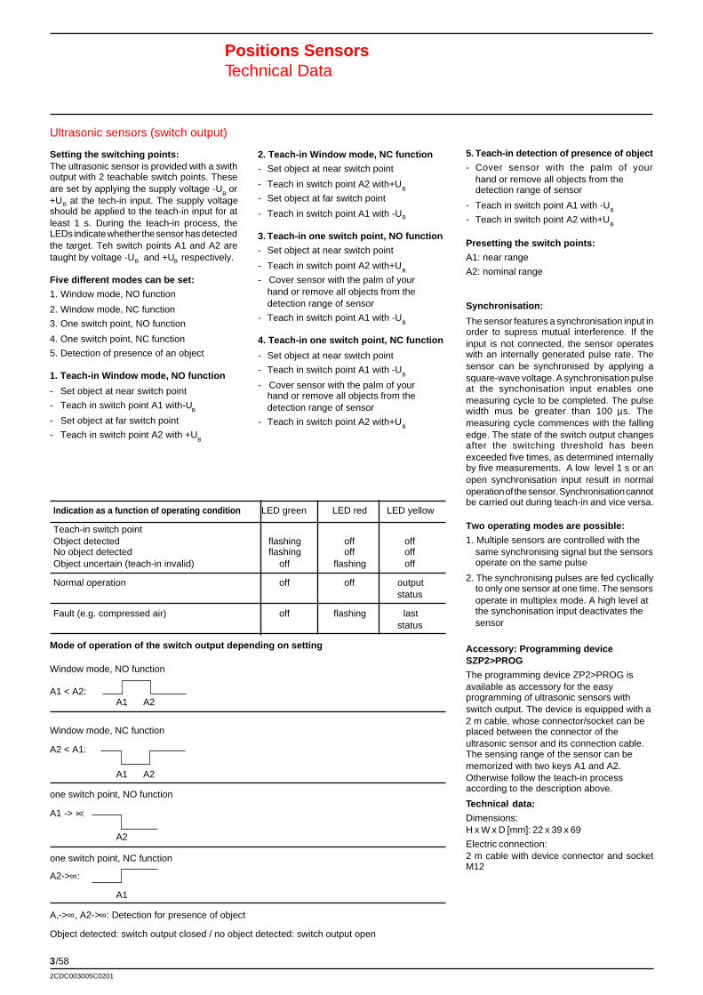
3/58
2CDC003005C0201
Ultrasonic sensors (switch output)
Positions SensorsTechnical Data
Setting the switching points:The ultrasonic sensor is provided with a swithoutput with 2 teachable switch points. Theseare set by applying the supply voltage -U
B or
+UB at the tech-in input. The supply voltageshould be applied to the teach-in input for atleast 1 s. During the teach-in process, theLEDs indicate whether the sensor has detectedthe target. Teh switch points A1 and A2 aretaught by voltage -UB and +UB respectively.
Five different modes can be set:
1. Window mode, NO function
2. Window mode, NC function
3. One switch point, NO function
4. One switch point, NC function
5. Detection of presence of an object
1. Teach-in Window mode, NO function
- Set object at near switch point
- Teach in switch point A1 with-UB
- Set object at far switch point
- Teach in switch point A2 with +UB
2. Teach-in Window mode, NC function
- Set object at near switch point
- Teach in switch point A2 with+UB
- Set object at far switch point
- Teach in switch point A1 with -UB
3. Teach-in one switch point, NO function
- Set object at near switch point
- Teach in switch point A2 with+UB
- Cover sensor with the palm of yourhand or remove all objects from thedetection range of sensor
- Teach in switch point A1 with -UB
4. Teach-in one switch point, NC function
- Set object at near switch point
- Teach in switch point A1 with -UB
- Cover sensor with the palm of yourhand or remove all objects from thedetection range of sensor
- Teach in switch point A2 with+UB
5. Teach-in detection of presence of object
- Cover sensor with the palm of yourhand or remove all objects from thedetection range of sensor
- Teach in switch point A1 with -UB
- Teach in switch point A2 with+UB
Presetting the switch points:
A1: near range
A2: nominal range
Synchronisation:
The sensor features a synchronisation input inorder to supress mutual interference. If theinput is not connected, the sensor operateswith an internally generated pulse rate. Thesensor can be synchronised by applying asquare-wave voltage. A synchronisation pulseat the synchonisation input enables onemeasuring cycle to be completed. The pulsewidth mus be greater than 100 µs. Themeasuring cycle commences with the fallingedge. The state of the switch output changesafter the switching threshold has beenexceeded five times, as determined internallyby five measurements. A low level 1 s or anopen synchronisation input result in normaloperation of the sensor. Synchronisation cannotbe carried out during teach-in and vice versa.
Two operating modes are possible:
1. Multiple sensors are controlled with thesame synchronising signal but the sensorsoperate on the same pulse
2. The synchronising pulses are fed cyclicallyto only one sensor at one time. The sensorsoperate in multiplex mode. A high level atthe synchonisation input deactivates thesensor
Accessory: Programming deviceSZP2>PROG
The programming device ZP2>PROG isavailable as accessory for the easyprogramming of ultrasonic sensors withswitch output. The device is equipped with a2 m cable, whose connector/socket can beplaced between the connector of theultrasonic sensor and its connection cable.The sensing range of the sensor can bememorized with two keys A1 and A2.Otherwise follow the teach-in processaccording to the description above.
Technical data:
Dimensions:H x W x D [mm]: 22 x 39 x 69
Electric connection:2 m cable with device connector and socketM12
Indication as a function of operating condition LED green LED red LED yellow
Teach-in switch pointObject detected flashing off offNo object detected flashing off offObject uncertain (teach-in invalid) off flashing off
Normal operation off off outputstatus
Fault (e.g. compressed air) off flashing laststatus
Mode of operation of the switch output depending on setting
Window mode, NO function
A1 < A2:A1 A2
Window mode, NC function
A2 < A1:
A1 A2
one switch point, NO function
A1 -> ∞:
A2
one switch point, NC function
A2->∞:
A1
A,->∞, A2->∞: Detection for presence of object
Object detected: switch output closed / no object detected: switch output open
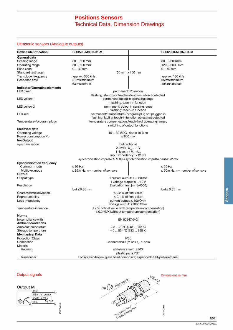
3/59
Sen
sors
2CDC003005C0201
Thickness 5
36
Temperature-/
Programming Pin
Ultrasonic sensors (Analogue outputs)
Positions SensorsTechnical Data, Dimension Drawings
CU
0000
04
Output M
LS00
0015
Dimensions in mmOutput signals
Device identification: SUD500-M30N-C1-M SUD2000-M30N-C1-M
General dataSensing range 30 ... 500 mm 80 ... 2000 mmOperating range 50 ... 500 mm 120 ... 2000 mmBlind zone 0 ... 30 mm 0 ... 80 mmStandard test target 100 mm x 100 mmTransducer frequency approx. 380 kHz approx. 180 kHzResponse time 21 ms minimum 65 ms minimum
63 ms default 195 ms defaultIndicator/Operating elementsLED green permanent: Power on
flashing: standbyor teach-in function: object detectedLED yellow 1 permanent: object in operating range
flashing: teach-in functionLED yellow 2 permanent: object in sensing range
flashing: teach-in functionLED red permanent: temperature-/program plug not plugged in
flashing: fault or teach-in function object not detectedTemperature-/program plugs temperature compensation, teach-in of operating range ,
switching of output functionsElectrical dataOperating voltage 10 ... 30 V DC , ripple 10 %ssPower consumption Po ≤ 900 mwIn-/Outputsynchronisation bidirectional
0-level: -UB...+1 V
1 -level: +4 V...+UB
input impedancy: > 12 KΩsynchronisation impulse: ≥ 100 µs synchronisation impulse pause: ≥2 ms
Synchronisation frequency Common mode ≤ 95 Hz ≤ 30 Hz Multiplex mode ≤ 95/n Hz, n = number of sensors ≤ 30/n Hz, n = number of sensorsOutputOutput type 1 current output: 4 ... 20 mA
1 voltage output: 0 ... 10 VResolution Evaluation limit [mm]/4000,
but ≤ 0.05 mm but ≤ 0.35 mmCharacteristic deviation ≤ 0,2 % of final valueReproducability ≤ 0,1 % of final valueLoad impedancy current output: ≤ 500 Ohm
voltage output: ≥1000 OhmTemperature influence ≤ 2 % of final value (with temperature compensation)
≤ 0.2 %/K (without temperature compensation)NormsIn compliance with EN 60947-5-2Ambient conditionsAmbient temperature -25 ... 70 °C (248 ... 343 K)Storage temperature -40 ... 85 -°C (233 ... 358 K)Mechanical DataProtection Class IP65Connection ConnectorVl 5 (M12 x 1), 5-poleMaterial Housing stainless steel 1.4303
plastic parts PBT Transducer Epoxy resin/hollow glass bead composite; expanded PUR (polyurethane)
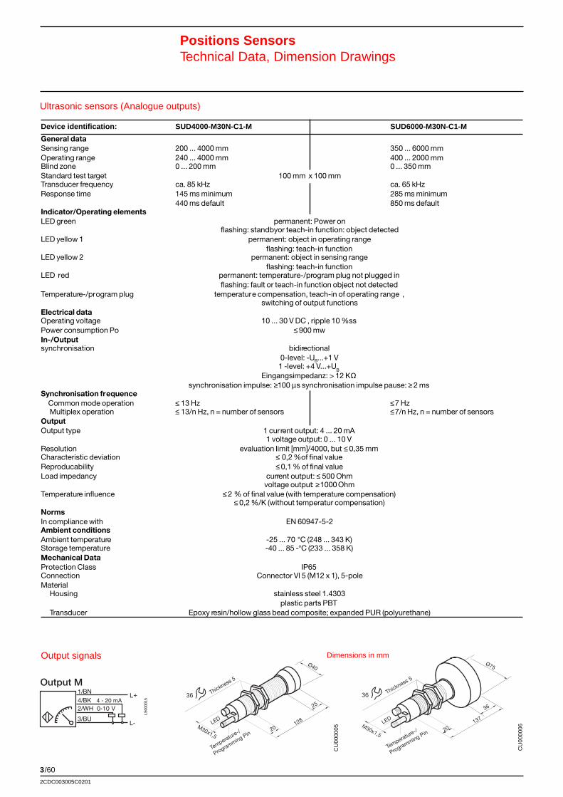
3/60
2CDC003005C0201
Ultrasonic sensors (Analogue outputs)
Positions SensorsTechnical Data, Dimension Drawings
LED
20M30x1,5
128
25
Ø40
Thickness 5
36
Temperature-/
Programming Pin
CU
0000
05
Output M
LS00
0015
Dimensions in mmOutput signals
Device identification: SUD4000-M30N-C1-M SUD6000-M30N-C1-M
General dataSensing range 200 ... 4000 mm 350 ... 6000 mmOperating range 240 ... 4000 mm 400 ... 2000 mmBlind zone 0 ... 200 mm 0 ... 350 mmStandard test target 100 mm x 100 mmTransducer frequency ca. 85 kHz ca. 65 kHzResponse time 145 ms minimum 285 ms minimum
440 ms default 850 ms defaultIndicator/Operating elementsLED green permanent: Power on
flashing: standbyor teach-in function: object detectedLED yellow 1 permanent: object in operating range
flashing: teach-in functionLED yellow 2 permanent: object in sensing range
flashing: teach-in functionLED red permanent: temperature-/program plug not plugged in
flashing: fault or teach-in function object not detectedTemperature-/program plug temperature compensation, teach-in of operating range ,
switching of output functionsElectrical dataOperating voltage 10 ... 30 V DC , ripple 10 %ssPower consumption Po ≤ 900 mwIn-/Outputsynchronisation bidirectional
0-level: -UB...+1 V1 -level: +4 V...+U
B
Eingangsimpedanz: > 12 KΩsynchronisation impulse: ≥100 µs synchronisation impulse pause: ≥ 2 ms
Synchronisation frequence Common mode operation ≤ 13 Hz ≤ 7 Hz Multiplex operation ≤ 13/n Hz, n = number of sensors ≤ 7/n Hz, n = number of sensorsOutputOutput type 1 current output: 4 ... 20 mA
1 voltage output: 0 ... 10 VResolution evaluation limit [mm]/4000, but ≤ 0,35 mmCharacteristic deviation ≤ 0,2 %of final valueReproducability ≤ 0,1 % of final valueLoad impedancy current output: ≤ 500 Ohm
voltage output: ≥1000 OhmTemperature influence ≤ 2 % of final value (with temperature compensation)
≤ 0,2 %/K (without temperatur compensation)NormsIn compliance with EN 60947-5-2Ambient conditionsAmbient temperature -25 ... 70 °C (248 ... 343 K)Storage temperature -40 ... 85 -°C (233 ... 358 K)Mechanical DataProtection Class IP65Connection Connector Vl 5 (M12 x 1), 5-poleMaterial Housing stainless steel 1.4303
plastic parts PBT Transducer Epoxy resin/hollow glass bead composite; expanded PUR (polyurethane)
Thickness 5
36
Temperature-/
Programming Pin
CU
0000
06
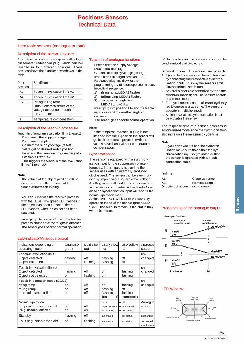
3/61
Sen
sors
2CDC003005C0201
Ultrasonic sensors (analogue output)
Positions SensorsTechnical Data
Description of the sensor funktionsThis ultrasonic senosr is equipped with a four-pin temerature/teach-in plug, which can beiinserted in four different positions. Thesepositions have the significances shown in thetable
Plug Significanceposition
A1 Teach-in evaluation limit A1
A2 Teach-in evaluation limit A2
E2/E3 Rising/falling rampOutput characteristics of thevoltage output go throughthe zero point
T Temperature compensation
Description of the teach-in procedureTeach-in of program evaluation limit 1 resp. 2
Disconnect the supply voltageDisconnect the plugConnect the supply voltage (reset)Set target on desired switch positionInsert and then remove program plug intoPosition A1 resp. A2This triggers the teach-in of the evaluationlimits A1 resp. A2
NoteThe values of the object position will bememorized with the removal of thetemperature/teach-in plug.
You can supervise the teach-in processwith the LEDs. The green LED flashes ifthe object has been detected, the redLED flashes, when no object has beendetected.
Insert plug into position T to end the teach-inprozess and to save the taught-in distance.The sensor goes back to normal operation.
Teach-in of analogue functionsDisconnect the supply voltageDisconnect the plugConnect the supply voltage (reset)Insert teach-in plug in position E2/E3Repeated plug-ins allow for theprogramming of 3 different operation modesin cyclical sequence:1) rising ramp, LED A2 flashes2) falling ramp, LED A1 flashes3) zero point straight line
LED A1 and A2 flashInsert plug into position T to end the teach-in process and to save the taught-indistance.The sensor goes back to normal operation.
NoteIf the temperature/teach-in plug is notinserted into the T-position the sensor willgo back to normal operation (with thevalues saved last) without temperaturecompensation.
SynchronisationThe sensor is equipped with a synchron-isation input for the suppression of inter-ferences. If this input is not on-line thesensor uses with an internally producedclock-speed. The sensor can be synchron-ised by impressing a square wave voltage.A falling range will lead to the emission of asingle ultrasonic impulse. A low level ≈1s oran open synchonisation input will lead to thenormal operation mode.A high-level ≈1 s will lead to the stand-byoperation mode of the sensor (green LED“ON”). The outputs remain in the status theywhere in before.
While teaching-in the sensors can not besynchronised and vice versa.
Different modes of operation are possible:1. 2 (or up to 5) sensors can be synchronized
by connecting their respective synchron-isation inputs. This way the sensors emitultrasonic impulses in turn.
2. Several sensors are controlled by the samesynchronisation signal. The sensors operatein common mode
3. The synchronisations impulses are cyclicallyfed to one sensor at a time. The sensorsoperate in multiplex mode.
4. A high-level at the synchronisation inputdeactivates the sensor
The response time of a sensor increases insynchronised mode since the synchronisationalso increases the measuring cycle time.
NoteIf you don’t want to use the synchron-isation make sure that either the syn-chronisation input is grounded or thatthe sensor is operated with a 4-poleconnection cable.
Default
A1: Close-up rangeA2: Nominal rangeDirection of action: rising ramp
LED-indicator/Analogue output
Indications depending on Dual LED Dual LED LED yellow LED yellow Analogueoperating mode green red A1 A2 output
Teach-in evaluation limit 1 un-Object detected flashing off flashing off changedObject not detected off flashing flashing off
Teach-in evaluation limit 2 un-Object detected flashing off off flashing changedObject not detected off flashing off flashing
Teach-in operation mode (E2/E3) un-rising ramp on off off flashing changedfalling ramp on off flashing offzero-point straight-line on off flashing flashing
(common mode) (common mode)
Normal operation on, if on, if Analoguetemperature compensated on off object in eval- object in eval- valuePlug disconn./shorted off on uation range uation range
Standby flashing off last status last status unchanged
Fault (e.g. compressed air) off flashing last status last status unchanged
or fault value
Progamming of the analogue output
LED-Window
LEDyellow
Dual-LEDgreen/red
LEDyellow
E2
"Power on" / Fault
Evaluation limit 1
E3
Evaluation limit 2A2A1
Analogue functions
near limit ofevaluation range
far limit ofevaluation range
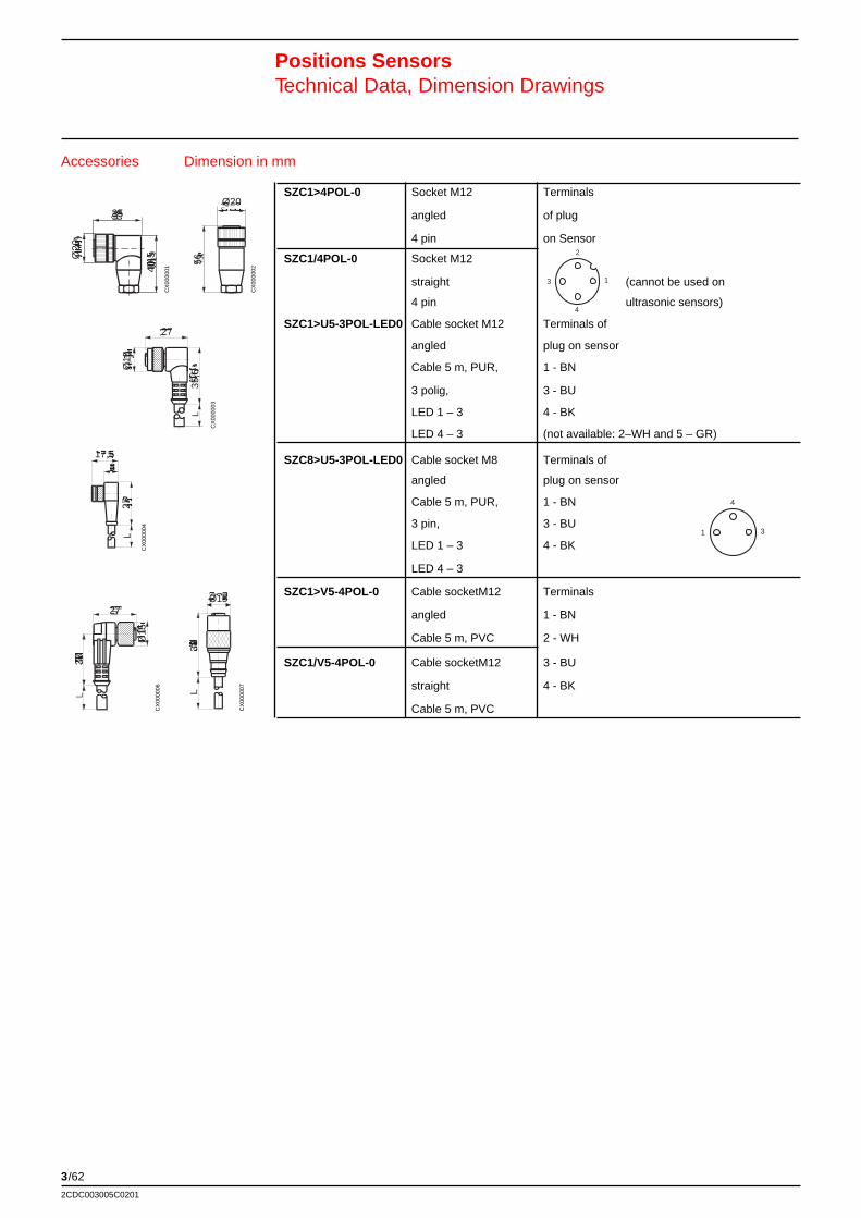
3/62
2CDC003005C0201
SZC1>4POL-0 Socket M12 Terminals
angled of plug
4 pin on Sensor
SZC1/4POL-0 Socket M12
straight (cannot be used on
4 pin ultrasonic sensors)
SZC1>U5-3POL-LED0 Cable socket M12 Terminals of
angled plug on sensor
Cable 5 m, PUR, 1 - BN
3 polig, 3 - BU
LED 1 – 3 4 - BK
LED 4 – 3 (not available: 2–WH and 5 – GR)
SZC8>U5-3POL-LED0 Cable socket M8 Terminals of
angled plug on sensor
Cable 5 m, PUR, 1 - BN
3 pin, 3 - BU
LED 1 – 3 4 - BK
LED 4 – 3
SZC1>V5-4POL-0 Cable socketM12 Terminals
angled 1 - BN
Cable 5 m, PVC 2 - WH
SZC1/V5-4POL-0 Cable socketM12 3 - BU
straight 4 - BK
Cable 5 m, PVC
27
Ø15
33
Accessories Dimension in mm
Positions SensorsTechnical Data, Dimension Drawings
CX
0000
01
CX
0000
02
CX
0000
03
CX
0000
04
CX
0000
06
CX
0000
07
2
13
4
4
31
35
Ø20
40,5
17,58
27
Ø15
38L
Ø2056
27
Ø15
35,5

3/63
Sen
sors
2CDC003005C0201
Notes

abb
Bro
chur
e N
o. 2
CD
C 0
0300
5 C
0201
Prin
ted
in th
e Fe
dera
l Rep
ublic
of G
erm
any
(0
1.05
· 3
· GV
D)
sub
ject
to m
odifi
catio
n
ABB STOTZ-KONTAKT GmbHP. O. Box 10 16 8069006 HeidelbergGermanyTelephone:++49 62 21 / 701-0Telefax: ++49 62 21 / 701-729http://www.abb.de/stotz-kontaktEmail: [email protected]
ABB Global Contact Directory
The ABB Contact Directory (http://www.abb.com/contacts/)helps you find local contacts for ABB products in yourcountry. Please select the relevant product group from thedropdown menu to the right or from the page.