ICSA/ICSPA - IAI Automation
41
LINEAR AXES SYSTEM LINEAR AXIS ISA/ISPA ICSA/ICSPA www.intelligentactuator.de GB
-
Upload
khangminh22 -
Category
Documents
-
view
1 -
download
0
Transcript of ICSA/ICSPA - IAI Automation

LINEAR AXES SYSTEM
LINEAR AXIS ISA/ISPAICSA/ICSPA
w w w . i n t e l l i g e n t a c t u a t o r . d e
GB

Y-Axis Z -Axis
CompactActuator
width90mm
MediumActuator
width120mm
LargeActuator
width150mm
SuperLargeActuator
width198mm
X-AxisStandard Type Mid-Support Type
Single-Axis Robots
ISA-SXMISPA-SXM
P15
(Not available)
P18, P19
P25, P26 P29, P30
P27, P28
P35, P36 P37, P38
P31, P32 P33, P34
P20 P21, P22 P23, P24
P16 P17
ISA-MXMISPA-MXM
ISA-LXMISPA-LXM
ISA-WXMISPA-WXM
ISA-WXMXISPA-WXMX
ISA-LXMXISPA-LXMX
ISA-LXUWXISPA-LXUWX
ISA-LYMISPA-LYM
ISA-LZMISPA-LZM
ISA-MXMXISPA-MXMX
ISA-MYMISPA-MYM
ISA-MZMISPA-MZM
ISA-SYMISPA-SYM
ISA-SZMISPA-SZM
High-precision positioning systems with a linear positioning repeatability of 0.01 to 0.02 mm
V I S U A L I N D E X
(Not available) (Not available)
1 ISPA/ICSPA Catalog

ISPA/ICSPA Catalog 2
Cartesian Robots
The Y-axis slider moves horizontally.
ICSA2-BICSPA2-B
The entire Y-axis moves horizontally.
ICSA2-SICSPA2-S
Y-Axis Base Mount Y-Axis Slider MountP67~86
The Z-axis slider is mounted to the Y-axis positioned on itsside. The entire Z-axis moves vertically.
ICSA2-YICSPA2-Y
Z-Axis Slider Mount
P115~124
The Z-axis is positioned vertically and mounted to theX-axis. The Z-axis slider moves vertically.
ICSA2-ZICSPA2-Z
Z-Axis Base Mount
P99~114
A support axis is added in parallel with the X-axis and theY-axis base is mounted to the sliders on the two axes. TheY-axis slider moves horizontally.
ICSA2-GICSPA2-G
Gantry
P125~128
P87~98
Transfer/positioning systems combining single-axis robotsinto a two to three orthogonal axes configuration.
Overall Contents 2
INDEX
Contents
Features
Specification Table
System Configurations
Points to Note
Explanation of ModelSpecification Items
Explanation of Options
Technical Data IS(P)A
Technical Information
4
5
7
8
9
11
13
15
39
Single-Axis Robot Series
Contents
Features
Product Types
Two-Axes ConfigurationUnit Selection Table
Points to Note
Explanation of ModelSpecification Items
Installation Method
Technical Data ICS(P)A2
42
43
45
47
59
61
63
67
Cartesian Robot Series
Contents 226
Controllers
PointThe ISA/ICSA is a standard actuator with a positioning repeatability of 0.02 mm. The ISPA/ICSPA is a high-precision actuator with a positioning repeatability of 0.01 mm.
Three-Axes ConfigurationUnit Selection Table 49
System Configuration 65
Technical Data ICS(P)A3 129
E-CON 227
S-CON 255S-SEL 265
X-SEL-KE/KET 234X-SEL-P/Q 251
Sin
gle-A
xis Ro
bo
tsC
artesian R
ob
ots
Co
ntro
llers
ICSA3-BB ICSPA3-BB
ICSA3-BS ICSPA3-BS
Z-Axis Base Mount Z-Axis Slider MountP129~170 P171~200
ICSA3-GB ICSPA3-GB
ICSA3-GS ICSPA3-GS
Gantry Z-Axis Base Mount Gantry Z-Axis Slider MountP201~212 P213~224
The Z-axis isbase mountedto the Y slider.The Z slidermoves vertically.The Y-axis slidermoves horizontally.
The Z-axis slider ismounted to theY-axis slider.The body of theZ-axis movesvertically.The Y-axis slidermoves horizontally.
The Z-axis basemounted to theY-axis, Z slidermoves vertically.The Y-axis slidermoves horizontally.
The Z-axis slideris mounted to theY-axis slider andmoves vertically.The Y-axis slidermoves horizontally.

Q u a l i t y a n d I n n o v a t i o n
Single-Axis RobotsISAISPA
C o n t e n t s
Contents 4
Features 5
Specification Table 7
System Configurations 8
Points to Note 9
Explanation of Model Specification Items 11
Explanation of Options 133 ISPA/ICSPA Catalog
ISA/ISPA Single-Axis Robots

Single-Axis Robot Series Contents
ISA (ISPA)-SXM
ISA(ISPA)-SYM
ISA(ISPA)-SZM
ISA(ISPA)-MXM-100
ISA(ISPA)-MXM-200
ISA(ISPA)-MXMX
ISA(ISPA)-MYM-100
ISA(ISPA)-MYM-200
ISA(ISPA)-MZM-100
ISA(ISPA)-MZM-200
ISA(ISPA)-LXM-200
ISA(ISPA)-LXM-400
ISA(ISPA)-LXMX-200
ISA(ISPA)-LXMX-400
ISA(ISPA)-LXUWX-200
ISA(ISPA)-LXUWX-400
ISA(ISPA)-LYM-200
ISA(ISPA)-LYM-400
ISA(ISPA)-LZM-200
ISA(ISPA)-LZM-400
ISA(ISPA)-WXM-600
ISA(ISPA)-WXM-750
ISA(ISPA)-WXMX-600
ISA(ISPA)-WXMX-750
X-Axis
Y-Axis
Z-Axis (Vertical)
X-Axis
Mid-Support Type (Long-Stroke)
Y-Axis
Z-Axis (Vertical)
X-Axis
Mid-Support Type (Long-Stroke)
Y-Axis
Z-Axis (Vertical)
X-Axis
Mid-Support Type (Long-Stroke)
15
16
17
18
19
20
21
22
23
24
25
26
27
28
29
30
31
32
33
34
35
36
37
38
ISPA/ICSPA Catalog 4
ISA/ISPA Single-Axis Robots
CompactActuator width
90mm
MediumActuator width
120mm
LargeActuator width
150mm
SuperLarge
Actuator width198mm
Single-A
xisRobots
Cartesian
Robots
Contro
llers

5 ISPA/ICSPA Catalog
ISA/ISPA Single-Axis Robots
Single-Axis Robot ISA/ISPA Series Features
Higher Maximum Acceleration/Deceleration of 1 G (9800 mm/sec2)
The ISA/ISPA is a high-precision positioning system comprised of a base, linear guides, ball screw and ACservo motor. It achieves cost savings, because its design is more comprehensive and adjustment is mucheasier than when individual components are purchased and assembled.
Both the ISA and ISPA achieve a maximum acceleration/
deceleration of 1 G, which was heretofore possible only with
the ISP Series.
• A dedicated cover prevents intrusion of smallparts and other foreign objects from above.
• To install the actuator, open the cover andaffix with bolts from above.
Y-Axis Type (SYM, MYM, LYM, etc.)
Z-Axis Type (SZM, MZM, LZM, etc.)
• A cover shape is adopted to prevent intrusion ofsmall parts and other foreign objects fromabove when the actuator is installed on its side.
• The actuator comes standard with a slider anti-dropbrake by assuming use in a vertical application.
• The mounting holes provided in the back of the base(actuator-mounting surface) are different from themounting holes of the X-axis type.(A load can be attached easily to the base surface when the actuator is moved vertically.)
Z-Axis
Y-Axis
X-Axis
1
Achieving Higher Rigidity with Smaller Size via Base-Integrated Guide StructureThe thickness of the actuator has been reduced by
embedding the guide rails in the base. The base also
employs a hollow box structure for improved rigidity.
3
Dedicated X/Y/Z-AxesDedicated axes are available to choose from according to your specific need.2
* When accelerating to 2000 mm/sec, a robot operating at an acceleration of1 G achieves the target speed approx. 0.5 second faster than a robotoperating at an acceleration of 0.3 G (as shown in the graph at right).
Acceleration/deceleration indicates the rate of change of speed. 1 G is equivalent to 9800mm/sec2, or the ability to accelerate (or decelerate) 9800 mm/sec per second.
X-Axis Type (SXM, MXM, LXM, etc.)

MotorCoupling
Ball screw
ISPA/ICSPA Catalog 6
X-SEL S-SEL E-CON/S-CON
Program Operation Program/Positioner Operation Positioner/Pulse-train operation
Sin
gle-A
xisR
ob
ots
Cartesian
Ro
bo
tsC
on
trollers

7 ISPA/ICSPA Catalog
ISA/ISPA Single-Axis Robots
Single-Axis Robot Series Specification Table
3
6
14
3
6
14
6
14
5
9
19
6
9
19
-
-
5
9
19
6
9
19
9
19
19
P15
P16
P17
P18
P19
P20
P21
P22
P23
P24
P25
P26
P27
P28
P29
P30
P31
P32
P33
P34
P35
P36
P37
P38
Stroke (mm), maximum speed (mm/sec) (Note 1)Load capacity (Note 2) Motor
capacityLead
Model PageHorizontal
(kg) (W)
60
60
60
100
200
200
100
200
100
200
200
400
200
400
200
400
200
400
100
400
600
750
600
750
(mm)
Vertical
800
400
200
800
400
200
400
200
1000 1000 795 645 540
480 380 310 255
220 175 145 120
1500 1190 965 810
1000 795 645 540
480 380 310 255
500
250
1500
1000
500
1000 795 645 5401000
480 380 310 255500
220 175 145 120250
1500 1190 965 8101500
1000 795 645 5401000
480 380 310 255500
220 175 145 120250
480 380 310 255500
480 380 310 255500
1000 830 690 585 5001000
470 385 320 270 235500
1660 1380 1170 1000
830 690 585 500
1000 830 690 585 5001000
1000 830 690 585 5001000
470 385 320 270 235500
470 385 320 270 235500
470 385 320 270 235500
1670 1390 1170 1000 865
835 695 585 500 430
835 695 585 500 430
415 345 290 250 215
1670 1390 1170 1000 865
2000 1660 1380 1170 10002000
(Note 1) The figure in the elongated circle indicates the maximum speed for each stroke. (Note 2) The load capacity is based on actuator operation at the rated acceleration (refer to page 9).
ISA(ISPA)-SXM- -60-16-
ISA(ISPA)-SXM- -60-8-
ISA(ISPA)-SXM- -60-4-
ISA(ISPA)-SYM- -60-16-
ISA(ISPA)-SYM- -60-8-
ISA(ISPA)-SYM- -60-4-
ISA(ISPA)-SZM- -60-8- -B
ISA(ISPA)-SZM- -60-4- -B
ISA(ISPA)-MXM- -100-20-
ISA(ISPA)-MXM- -100-10-
ISA(ISPA)-MXM- -100-5-
ISA(ISPA)-MXM- -200-30-
ISA(ISPA)-MXM- -200-20-
ISA(ISPA)-MXM- -200-10-
ISA(ISPA)-MXMX- -200-30-
ISA(ISPA)-MXMX- -200-20-
ISA(ISPA)-MYM- -100-20-
ISA(ISPA)-MYM- -100-10-
ISA(ISPA)-MYM- -100-5-
ISA(ISPA)-MYM- -200-30-
ISA(ISPA)-MYM- -200-20-
ISA(ISPA)-MYM- -200-10-
ISA(ISPA)-MZM- -100-10- -B
ISA(ISPA)-MZM- -100-5- -B
ISA(ISPA)-MZM- -200-10- -B
12
25
50
12
25
50
-
-
20
40
80
25
40
80
25
40
20
40
80
25
40
80
-
-
-
16
8
4
16
8
4
8
4
20
10
5
30
20
10
30
20
20
10
5
30
20
10
10
5
10
1500
ISA(ISPA)-LXM- -200-20-
ISA(ISPA)-LXM- -200-10-
ISA(ISPA)-LXM- -400-40-
ISA(ISPA)-LXM- -400-20-
ISA(ISPA)-LXMX- -200-20-
ISA(ISPA)-LXMX- -400-40-
ISA(ISPA)-LXMX- -400-20-
ISA(ISPA)-LXUWX- -200-20-
ISA(ISPA)-LXUWX- -400-40-
ISA(ISPA)-LXUWX- -400-20-
ISA(ISPA)-LYM- -200-20-
ISA(ISPA)-LYM- -200-10-
ISA(ISPA)-LYM- -400-40-
ISA(ISPA)-LYM- -400-20-
ISA(ISPA)-LZM- -200-10- -B
ISA(ISPA)-LZM- -400-10-
ISA(ISPA)-WXM--600-40-
ISA(ISPA)-WXM--600-20-
ISA(ISPA)-WXM--600-10-
ISA(ISPA)-WXM--750-50-
ISA(ISPA)-WXM--750-25-
ISA(ISPA)-WXMX--600-40-
ISA(ISPA)-WXMX--600-20-
ISA(ISPA)-WXMX--750-50-
ISA(ISPA)-WXMX--750-25-
40
80
40
80
40
40
80
40
40
80
40
80
40
80
-
-
60
120
150
60
120
60
120
60
120
9
19
9
19
-
-
-
-
-
-
9
19
9
19
19
39
14
29
60
14
29
-
-
-
-
20
10
40
20
20
40
20
20
40
20
20
10
40
20
10
10
40
20
10
50
25
40
20
50
25
ISAISPA
(kg)
1425
1000 950
1200 1050 900 825 750
800 700 600 550 500
675
450
100 200 300 400 500 600 700 800 900 1000 1100 1200 1300 1400 1500 1600 1700 1800 1900 2000 2100 2200 2300 2400 2500
950 830 740 650 590 540 490 440 410 370 340
1480 1300 1180 1080 980 880 820 740 680
740 650 590 540 490 440 410 370 340
740 650 590 540 490 440 410 370 340
740 650 590 540 490 440 410 370 340
1480 1300 1180 1080 980 880 820 740 680
1000
1900 16602000
950 8301000
950 8301000
1900 16602000
950 8301000
17251965 1530 1365 1225 1110 1005 915 840 770 710 6552000
860980 765 680 610 555 500 455 420 385 355 325
720 660 605 555 515
1000
1250
2000
1000
1000
500
2000
2000
1000
1440 1320
1200 1075
12101930 1740 1580 1115 10352000
965 870 790

ISPA/ICSPA Catalog 8
ISA/ISPA Single-Axis Robots
Single-Axis Robot Series System Configurations
Actuator
Actuator
Motor CableEncoder CableLimit Switch Cable
Option
Option
Teaching Pendant
IA-T-X/XD/XA(-J)
PC Software
IA-101-X-MW(-J)IA-101-X-USBMW
Teaching Pendant
SEL-T/TD-J
PC Software
IA-101-X-MW-JIA-101-X-USB
Teaching Pendant
CON-T
PC Software
RCM-101-MWRCM-101-USB
Controller
Controller
X-SEL S-SEL E-CON/S-CON(P234) (P227/255)(P265)
(P245) (P273) (P232/263)
ISA/ISPA(P15~38)
Sin
gle-A
xisR
ob
ots
Cartesian
Ro
bo
tsC
on
trollers

9 ISPA/ICSPA Catalog
ISA/ISPA Single-Axis Robots
Single-Axis Robot Series Points to Note
Speed "Speed" refers to the specified speed at which the actuator slider will move.The slider accelerates from a stationary state, and once the specified speed is reached it willmaintain that speed until the specified position (immediately before the target position), whereit will begin decelerating to stop at the target position.
Notes on Catalog Specifications
< Caution > The maximum speed of the ISA/ISPA Series will remain the same even when the load placed on the slider is changed. The time needed to reach the specified speed will vary according to the acceleration (deceleration). If the travel distance is short, the specified speed may not be reached. With a long-stroke axis, the maximum speed will drop to avoid reaching a dangerous speed.
(If you are using a 600 or longer stroke, check the maximum speed for the applicable stroke in the corresponding dimensional drawing.) When calculating the travel time, consider acceleration, deceleration and stabilization periods in addition to the travel time
at the specified speed. (Refer to pages 39 and 40 for the method to calculate travel time.) Speed can be set in increments of 1 mm/sec in a program.
Acceleration/Deceleration
"Acceleration" refers to the rate of change of speed when the speed rises from zero (stationarystate) to the specified speed."Deceleration" refers to the rate of change of speed when the specified speed drops to zero(stationary state).
PositioningRepeatability
"Positioning repeatability" refers to the positioning accuracy of repeated movements to a pre-stored position.This is not the same as "absolute positioning accuracy," so exercise caution.
Duty IAI recommends that our actuators be used at a duty of 50% or less as a guideline in view of the relationship of service life and accuracy.
< Caution > Increasing the acceleration (deceleration) will shorten the duration the actuator accelerates (decelerates) and decrease the
travel time. However, doing so will also cause rapid acceleration (deceleration), resulting in increased shock. The rated acceleration is 0.3 G (or 0.15 G if the lead is 4 or 5 mm).
(The load capacity is set based on the rated acceleration.) If the ISA/ISPA Series is operated at an acceleration (deceleration) exceeding the rated acceleration, the load capacity will drop.
(Refer to page 40 for details.) Acceleration can be set in increments of 0.01 G in a program.
Positioning repeatabilityAccuracy variation of the stop positionwhen positioning is performedrepeatedly to the same point.
Absolute positioning accuracyDifference between the coordinate valueand the measured value when positioningis performed to a given positioning pointspecified by coordinates.
Duty (%) = Motion timeMotion time + Inactivity
x 100

ISA/ISPA Single-Axis Robots
ISPA/ICSPA Catalog 10
Single-Axis Robot Series Points to Note
Notes on Catalog Specifications
Home The home is set on the motor side for the standard specification, or on the counter-motor sidefor the reversed-home specification.
• The incremental actuator always requires homing every time the power is reconnected.• During homing the slider will move to the mechanical end before reversing, so be careful to prevent contact
with surrounding parts.• To change the home direction, the controller parameters must be changed.
Allowable LoadMoments (Ma, Mb, Mc)
Each allowable load moment is calculated by assuming the service life of the guide as 10,000km. Applying a moment exceeding the specified value will reduce the life of the guide, soexercise caution.
Directions of load moment for slider type
Actuator Accuracy The accuracy of the ISA/ISPA-Series actuators is specified below.The side and bottom faces of the actuator base provide reference surfaces for slider travel.Use them to adjust parallelism when installing the actuator.
and load-mounting surface (top face)±0.05 mm/m or less
Parallelism when mounted on frame (when the actuatoris mounted to a flat surface *1)±0.05 mm/m or less
Condition: The above values are applicable at 20°C. *1 Flatness: 0.05 mm or less
Overhung LoadLength (L)
"Overhung load length" refers to a referenceoffset at which the actuator can operatesmoothly when a load, bracket, etc., is installedat a position offset from the actuator/slidercenter.When each model is used with an overhung loadexceeding the allowable length, vibration orstabilization delay may result. Therefore, besure to keep the overhung load length within theallowable value.
Sin
gle-A
xisR
ob
ots
Cartesian
Ro
bo
tsC
on
trollers

ISA/ISPA Single-Axis Robots
11 ISPA/ICSPA Catalog
Explanation of Model Specification Items
Applicablecontroller
AQ
B
C
CL
L
LL
LLM
LM
NM
RT
S
EU
T1
T2
N
S
M
X
Encoder type
48
16
ISA
ISPAAI
48
51020
102030
510
10
2030
1020
2040
10
10
20
2040
102040
2550
2040
2550
100 ~
600
100 ~
1000
800 ~
2000
100 ~
1200
1000 ~
2500
100 ~
1300
900 ~
2500
900 ~
2500
SXMSYM
SZM
MXMMYM
MZM
MXMX
LXMLYM
LZM
LXMX
LXUWX
WXM
WXMX
2040
20
Series Motor output Lead Stroke Cable length Options
(7)(3)(1) (4) (5) (6) (8) (9)
60
_
_
100_
200_
100
200
200
200
400
200
400
200
400
600
750
600
750
400
200
_
_
_
_
_
_
_
_
_
_
_
_
_
_
_
_
_
_
_
_
_
_
_
_
_
_
_
_
_
_
_
_
_
_
_
_
_
_
_
_
_
_
_
_
_
_
_
_
_
_
_
_
_
_
_
_
_
_
_
_
_
_
_
_
_
_
_
_
_
_
_
_
_
_
_
_
_
_
_
_
_
_
_
_
_
_
_
_
_
_
_
_
_
_
_
_
_
_
_
_
_
_
_
_
_
_
_
_
_
_
Type
(2)
Refer to the right page for the explanation of each model specification item.The selection range for each item will vary depending on the actuator type. For details, refer to the page corresponding toeach actuator type.

ISA/ISPA Single-Axis Robots
ISPA/ICSPA Catalog12
(1) Series
Indicate the name of each series.
(3) Encoder type
Indicate whether the encoder installed in the actuator is an "absolute type" or "incremental type."
A: Absolute type Since the current slider position will be retained after the power is turned off, homing is not required when the actuator is powered up.
I: Incremental type Since the slider position data are cleared when the power is turned off, homing must be performed every time the actuator is powered up.
(4) Motor output
Indicate the output of the motor installed in the actuator in watts.
(6) Stroke
Indicate the actuator stroke (range of operation) in millimeters.
(8) Cable length
Indicate the length of the motor/encoder cable connecting the actuator and the controller.N : No cableS : 3mM : 5mX : Use this field when a length other than 3 m and 5 m is specified.(Example X08 : 8m)* The standard cable is a robot cable.
(9) Options
Indicate a desired option(s) to be equipped on the actuator. Refer to pages 13 and 14 for the explanation of each option.* When selecting multiple options, specify them in alphabetical order (e.g., AQ-B-L-NM).
AQ : [AQ seal] A unit that supplies lubricant to the sliding sections of the ball screw and guide.B : [Brake] A brake for preventing the slider from falling in a vertical application when the power or servo is turned off.C : [Creep sensor] A sensor for increasing the homing speed and thereby decreasing the homing time.CL : [Creep sensor on opposite side] The creep sensor is normally installed on the right side as viewed from the motor.
Select this option if you want to install the sensor on the left side.L : [Home limit switch] A limit switch for completing homing by reversing the slider using a sensor, not by the normal contact
method, during homing.LL : [Home limit switch on opposite side] Similarly to the creep sensor on opposite side option, select this option if you want to
install the limit switch on the opposite side.LM : [Master-axis designation] Specify this option for the axis to be used as the master in synchronized operation.
LLM : [Master-axis limit switch on opposite side] Select this option if you want to install the limit switch on the opposite side of themaster axis used in synchronized operation.
NM : [Reverse-homing specification] Normally the home is set on the motor side. Select this option to specify the home on the counter-motor side.
RT : [Guide with ball-retaining mechanism] A mechanism for reducing noise while extending the service life of the guide by inserting a spacer (retention device) between guide balls.
EU : [Metal cablejoint connector] Select this option for a motor/encoder cable with metal cable plugs (see page 15). Without this option plastic plugs are default. By this option cable lengths to 5 m are without surcharge, too.
S : [Slave-axis designation] Specify this option for the axis to be used as the slave in synchronized operation (limit switch is notrequired).
(5) Lead
Indicate the ball screw lead."Lead" refers to the distance the slider will move when theball screw rotates by one revolution.The larger the lead, the faster the maximum speed becomes.
(2) Type
Indicate the classification by size (S, M, L or W), shape (X,Y or Z), etc.
(7) Applicable controller
Indicate the type of controller that can be used with theactuator.T1: X-SEL-KE/KT, E-CONT2: X-SEL-P/Q, S-SEL, S-CON
Single-A
xisRobots
Cartesian
Robots
Contro
llers
ISA/ISPA Single-Axis Robots
13 ISPA/ICSPA Catalog
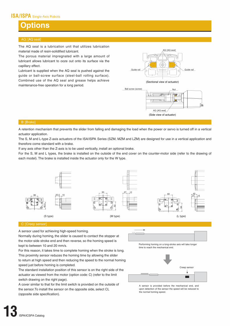
AQ: [AQ seal]
The AQ seal is a lubrication unit that utilizes lubricationmaterial made of resin-solidified lubricant.The porous material impregnated with a large amount oflubricant allows lubricant to ooze out onto its surface via thecapillary effect.Lubricant is supplied when the AQ seal is pushed against theguide or ball-screw surface (steel-ball rolling surface).Combined use of the AQ seal and grease helps achievemaintenance-free operation for a long period.
B: [Brake]
A retention mechanism that prevents the slider from falling and damaging the load when the power or servo is turned off in a verticalactuator application.The S, M and L-type Z-axis actuators of the ISA/ISPA Series (SZM, MZM and LZM) are designed for use in a vertical application andtherefore come standard with a brake.If any axis other than the Z-axis is to be used vertically, install an optional brake.For the S, M and L types, the brake is installed on the outside of the end cover on the counter-motor side (refer to the drawing ofeach model). The brake is installed inside the actuator only for the W type.
C: [Creep sensor]
A sensor used for achieving high-speed homing.Normally during homing, the slider is caused to contact the stopper at the motor-side stroke end and then reverse, so the homing speed is kept to between 10 and 20 mm/s.For this reason, it takes time to complete homing when the stroke is long. This proximity sensor reduces the homing time by allowing the slider to return at high speed and then reducing the speed to the normal homing speed just before homing is completed.The standard installation position of this sensor is on the right side of the actuator as viewed from the motor (option code: C) (refer to the limit switch drawing on the right page).A cover similar to that for the limit switch is provided on the outside of the sensor.To install the sensor on the opposite side, select CL (opposite side specification).
AQ: [AQ seal]
Guide rail Guide rail
AQ: [AQ seal]
Ball screw (screw)
(Sectional view of actuator)
Nut
(Side view of actuator)
Options
(S type) (M type) (L type)
ISPA/ICSPA Catalog14
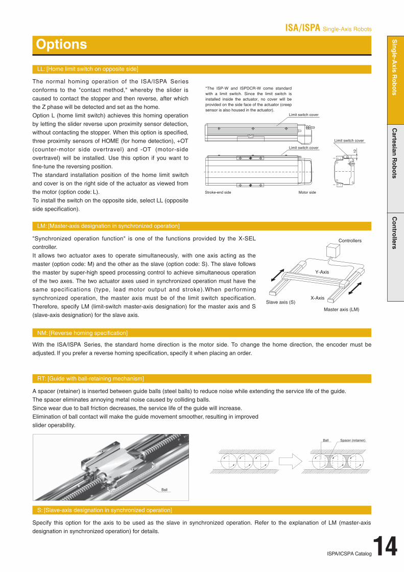
LL: [Home limit switch on opposite side]
The normal homing operation of the ISA/ISPA Seriesconforms to the "contact method," whereby the slider iscaused to contact the stopper and then reverse, after whichthe Z phase will be detected and set as the home.Option L (home limit switch) achieves this homing operationby letting the slider reverse upon proximity sensor detection,without contacting the stopper. When this option is specified,three proximity sensors of HOME (for home detection), +OT(counter-motor side overtravel) and -OT (motor-sideovertravel) will be installed. Use this option if you want tofine-tune the reversing position.The standard installation position of the home limit switchand cover is on the right side of the actuator as viewed fromthe motor (option code: L).To install the switch on the opposite side, select LL (oppositeside specification).
LM: [Master-axis designation in synchronized operation]
"Synchronized operation function" is one of the functions provided by the X-SELcontroller.It allows two actuator axes to operate simultaneously, with one axis acting as themaster (option code: M) and the other as the slave (option code: S). The slave followsthe master by super-high speed processing control to achieve simultaneous operationof the two axes. The two actuator axes used in synchronized operation must have thesame specifications (type, lead motor output and stroke).When performingsynchronized operation, the master axis must be of the limit switch specification.Therefore, specify LM (limit-switch master-axis designation) for the master axis and S(slave-axis designation) for the slave axis.
NM: [Reverse homing specification]
With the ISA/ISPA Series, the standard home direction is the motor side. To change the home direction, the encoder must beadjusted. If you prefer a reverse homing specification, specify it when placing an order.
RT: [Guide with ball-retaining mechanism]
A spacer (retainer) is inserted between guide balls (steel balls) to reduce noise while extending the service life of the guide.The spacer eliminates annoying metal noise caused by colliding balls.Since wear due to ball friction decreases, the service life of the guide will increase.Elimination of ball contact will make the guide movement smoother, resulting in improved slider operability.
S: [Slave-axis designation in synchronized operation]
Specify this option for the axis to be used as the slave in synchronized operation. Refer to the explanation of LM (master-axisdesignation in synchronized operation) for details.
Options
* This option cannot be used
ISA/ISPA Single-Axis Robots
Single-A
xisRobots
Cartesian
Robots
Contro
llers

ISA/ISPA Single-Axis Robots
15 ISPA/ICSPA Catalog
* Note that changing the home direction will require the actuator to bereturned to IAI for adjustment.
Applicable Controller Specifications
Models/Specifications
Options
Dimensions
Common Specifications * Refer to page 10 for the details of common specification items.
* Refer to page 11 for the details of model specification items.
Dimensions, Weight and Maximum Speed by Stroke
ISA-SXMISPA-SXM
Type Compact X-axis (90-mm wide) Stroke 100~600mm Load capacity 50kg (horizontal)/14kg (vertical)
Model specification items
Single-Axis Robot: Compact X-Axis Type, Actuator Width 90mm, 60W,Straight Shape
Single-Axis Robot: Compact X-Axis Type, Actuator Width 90mm, 60W, Straight Shape
High-Precision Specification
ISA[ISPA] – SXM – A – 60 – 16 – 600 – T1 – S – BOptionsCable lengthApplicable controllerStrokeLeadMotor outputEncoder typeTypeSeries
Model Encoder type
Absolute
Incremental
Motor output
(W)
60
Lead(mm)
16
8
4
16
8
4
Stroke (mm)In increments of
50mm(Note 1)
Speed(mm/s)
100 ~ 600
1 ~ 800
1 ~ 400
1 ~ 200
1 ~ 800
1 ~ 400
1 ~ 200
Rated thrust(N)
63.7
127.4
254.8
63.7
127.4
254.8
* In the above model names, indicates the stroke, the cable length and the applicable options. *1.0G=9800mm/sec 2
Load capacity (Note 2)
Horizontal (kg)
Ratedacceleration
Maximumacceleration
12
25
50
12
25
50
3.5
12
30
3.5
12
30
Vertical (kg)
Ratedacceleration
Maximumacceleration
3
6
14
3
6
14
Acceleration (Note 2)
Horizontal (G)
Rated Maximum
0.3
0.3
0.15
0.3
0.3
0.15
1.0
0.6
0.5
1.0
0.6
0.5
Vertical (G)
Rated Maximum
0.3
0.3
0.15
0.3
0.3
0.15
0.7
0.5
0.3
0.7
0.5
0.3
2
5
12
2
5
12
Name
AQ seal
Brake
Creep sensor
Creep sensor on opposite side
Home limit switch
Home limit switch on opposite side
AQ
B
C
CL
L
LL
P13
P13
P13
P13
P14
P14
Code Page Name
Master-axis designation
Master-axis designation (sensor on opposite side)
Reverse homing specification
Guide with ball-retaining mechanism
Slave-axis designation
LM
LLM
NM
RT
S
P14
P14
P14
P14
P14
Code Page Positioning repeatability (Note 3)
Drive system (Note 4)
Backlash (Note 5)
Guide
Allowable load moment
Overhung load length
Base
Cable length (Note 6)
±0.02mm [±0.01mm]
Ball screw ø12mm, rolled C10 [equivalent to rolled C5]
0.05mm or less [0.02mm or less]
Integrated with base
Ma: 28.4N • m M b: 40.2N • m M c: 65.7N • m
Ma direction: 450mm or less, Mb/Mc directions: 450mm or less
Material: Aluminum with white alumite treatment
N: No cable, S: 3m, M: 5m, X : Length specification
Stroke 100 (150) 200
800400200
(250) 300ABCDEF
Weight (kg)Lead 16Lead 8Lead 4
344.52511000
1514
2.8
394.53011500
2014
3.1
444.53512000
2514
3.4
494.54012501
1016
3.7
544.54513001
1516
4.0
Maximumspeed
(mm/s)
(350) 400 (450) 500 (550) 600594.55013501
2016
4.3
644.55514001
2516
4.6
694.5601450
2101
84.9
744.56515002
1518
5.2
794.57015502
2018
5.5
844.57516002
2518
5.8
* Refer to page 9 for other points to note.
(Note 1) The strokes that are set in increments of 50 mm are semi-standard settings.
(Note 2) Refer to page 40 for the relationship of acceleration and load capacity.
(Notes 3, 4, 5) The figures in brackets apply to the ISPA Series. Other specification values apply to both the ISA and ISPA Series.
(Note 6) The maximum cable length is 30 m. Specify the desired length in meters (e.g., X08 = 8 m).
Applicablecontroller
Maximum numberof controlled axes
Compatibleencoder type
Programoperation
Positioneroperation
Pulse-traincontrol
Supplyvoltage
X-SEL(-P/Q) 4(6) axes Absolute/incremental AC100/230VAC100/230VAC100/230V
ISA [ISPA] -SXM-A-60-16- -T1(2)--
ISA [ISPA] -SXM-A-60-8- -T1(2)--
ISA [ISPA] -SXM-A-60-4- -T1(2)--
ISA [ISPA] -SXM-I-60-16- -T1(2)--
ISA [ISPA] -SXM-I-60-8- -T1(2)--
ISA [ISPA] -SXM-I-60-4- -T1(2)--
Cable joint connector *1(plastic plugs are default)
Cable joint connectorof metal: option EU
Metal cable joint connector EU
S-/E-CON / - / S-SEL
1 axis2 axes
Absolute/incremental
Absolute/incremental

ISA/ISPA Single-Axis Robots
ISPA/ICSPA Catalog16
Models/Specifications
Options Common Specifications
Dimensions
* Note that changing the home direction will require the actuator to bereturned to IAI foradjustment.
* Refer to page 10 for the details of common specification items.
ISA-SYMISPA-SYM
Type Compact Y-axis (90-mm wide) Stroke 100~600mm Load capacity 50kg (horizontal)/14kg (vertical)
* Refer to page 11 for the details of model specification items.
■ Dimensions, Weight and Maximum Speed by Stroke
High-Precision Specification
Single-Axis Robot: Compact Y-Axis Type, Actuator Width 90mm, 60W,Straight Shape
Single-Axis Robot: Compact Y-Axis Type, Actuator Width 90mm, 60W, Straight Shape
■ Model specification items
ISA[ISPA] - SYM - A - 60 - 16 - 600 - T1 - S - BOptionsCable lengthApplicable controllerStrokeLeadMotor outputEncoder typeTypeSeries
Model Encoder type
Absolute
Incremental
Motoroutput
(W)
60
Lead(mm)
16
8
4
16
8
4
Stroke (mm)In increments of
50mm(Note 1)
Speed(mm/s)
100 ~ 600
1 ~ 800
1 ~ 400
1 ~ 200
1 ~ 800
1 ~ 400
1 ~ 200
Rated thrust(N)
63.7
127.4
254.8
63.7
127.4
254.8
* In the above model names, indicates the stroke, the cable length and the applicable options. *1.0G=9800mm/sec 2
Load capacity (Note 2)
Horizontal (kg)Rated
accelerationMaximumacceleration
12
25
50
12
25
50
3.5
12
30
3.5
12
30
Vertical (kg)Rated
accelerationMaximumacceleration
3
6
14
3
6
14
Acceleration (Note 2)
Horizontal (G)
Rated Maximum
0.3
0.3
0.15
0.3
0.3
0.15
1.0
0.6
0.5
1.0
0.6
0.5
Vertical (G)
Rated Maximum
0.3
0.3
0.15
0.3
0.3
0.15
0.7
0.5
0.3
0.7
0.5
0.3
2
5
12
2
5
12
Name
AQ seal
Brake
Creep sensor
Creep sensor on opposite side
Home limit switch
Home limit switch on opposite side
AQ
B
C
CL
L
LL
➔ P13
➔ P13
➔ P13
➔ P13
➔ P14
➔ P14
Code Page Name
Master-axis designation
Master-axis designation (sensor on opposite side)
Reverse homing specification
Guide with ball-retaining mechanism
Slave-axis designation
LM
LLM
NM
RT
S
➔ P14
➔ P14
➔ P14
➔ P14
➔ P14
Code Page Positioning repeatability (Note 3)
Drive system (Note 4)
Backlash (Note 5)
Guide
Allowable load moment
Overhung load length
Base
Cable length (Note 6)
�0.02mm [�0.01mm]
Ball screw ø12mm, rolled C10 [equivalent to rolled C5]
0.05mm or less [0.02mm or less]
Integrated with base
Ma: 28.4Nm M b: 40.2Nm M c: 32.8Nm
Ma direction: 450mm or less, Mb/Mc directions: 450mm or less
Material: Aluminum with white alumite treatment
N: No cable, S: 3m, M: 5m, X : Length specification
Stroke 100 (150) 200
800400200
(250) 300ABCDEF
Weight (kg)Lead 16Lead 8Lead 4
344.5251100618Ð
2.8
394.53011502110903.2
444.53512007110903.5
494.540125012110903.9
544.545130017110904.2
Maximumspeed
(mm/s)
(350) 400 (450) 500 (550) 600594.550135022110904.6
644.555140027110904.9
694.560145032110905.3
744.565150037110905.6
794.570155042110906.0
844.575160047110906.3
* Refer to page 9 for other points to note.
(Note 1) The strokes that are set in increments of 50 mm are semi-standard settings.
(Note 2) Refer to page 40 for the relationship of acceleration and load capacity.
(Notes 3, 4, 5) The figures in brackets apply to the ISPA Series. Other specification values apply to both the ISA and ISPA Series.
(Note 6) The maximum cable length is 30 m. Specify the desired length in meters (e.g., X08 = 8 m).
Applicable Controller SpecificationsApplicablecontroller
Maximum numberof controlled axes
Compatibleencoder type
Programoperation
Positioneroperation
Pulse-traincontrol
Supplyvoltage
X-SEL(-P/Q) 4(6) axes Absolute/incremental ● ▲▲ AC100/230VAC100/230VAC100/230V
ISA [ISPA] -SYM-A-60-16- -T1(2)--
ISA [ISPA] -SYM-I-60-4- -T1(2)--
ISA [ISPA] -SYM-A-60-8- -T1(2)--
ISA [ISPA] -SYM-A-60-4- -T1(2)--
ISA [ISPA] -SYM-I-60-16- -T1(2)--
ISA [ISPA] -SYM-I-60-8- -T1(2)--
Metal cable joint connector EU P15
S-/E-CON / - / S-SEL
1 axis2 axes
Absolute/incremental
Absolute/incremental
Single-A
xisRobots
Cartesian
Robots
Contro
llers

17 ISPA/ICSPA Catalog
ISA/ISPA Single-Axis Robots
Models/Specifications
Dimensions
* Note that changing the home direction will require the actuator to bereturned to IAI for adjustment.
ISA-SZMISPA-SZM
Type Compact vertical axis (90-mm wide) Stroke 100~600mm Vertical application only (with standard brake) 14kg
* Refer to page 11 for the details of model specification items.
*The SZM type comes standard with a brake, so use a controller of brake specification.
Options Common Specifications
* The SZM type comes standard with a brake (B).
* Refer to page 10 for the details of common specification items.
Stroke 100 (150) 200
400200
(250) 300ABCD
Weight (kg)
Lead 8Lead 4
370251100113.0
420301150613.4
4703512001113.7
5204012501614.1
5704513002114.4
Maximumspeed
(mm/s)
(350) 400 (450) 500 (550) 6006205013502614.8
6705514003115.1
7206014503615.5
7706515004115.8
8207015504616.2
8707516005116.5
Dimensions, Weight and Maximum Speed by Stroke
Model Encoder type
Absolute
Incremental
Motor output
(W)
60
Lead(mm)
8
4
8
4
Stroke (mm)In increments of
50mm(Note 1)
Speed(mm/s)
100 ~ 600
1 ~ 400
1 ~ 200
1 ~ 400
1 ~ 200
Rated thrust(N)
127.4
254.8
127.4
254.8
* In the above model names, indicates the stroke, the cable length and the applicable options.
Load capacity (Note 2)
Ratedacceleration
Maximumacceleration
Ratedacceleration
Maximumacceleration
Horizontal (kg)
Vertical
application
only
Vertical (kg)
6
14
6
14
5
12
5
12
Acceleration (Note 2)
Rated Maximum Rated Maximum
Horizontal (G)
Vertical
application
only
Vertical (G)
0.3
0.15
0.3
0.15
0.5
0.3
0.5
0.3
*1.0G=9800mm/sec2
High-Precision Specification
Single-Axis Robot: Compact Vertical-Axis Type, Actuator Width 90mm, 60W,Straight Shape
Single-Axis Robot: Compact Vertical-AxisType, Actuator Width 90mm, 60W, Straight Shape
Model specification items
ISA[ISPA] - SZM - A - 60 - 16 - 600 - T1 - S - B - LOptionsCable lengthApplicable controllerStrokeLeadMotor outputEncoder typeTypeSeries
Name
AQ seal
Brake
Creep sensor
Creep sensor on opposite side
Home limit switch
Home limit switch on opposite side
AQ
B
C
CL
L
LL
P13
P13
P13
P13
P14
P14
Code Page Name
Master-axis designation
Master-axis designation (sensor on opposite side)
Reverse homing specification
Guide with ball-retaining mechanism
Slave-axis designation
LM
LLM
NM
RT
S
P14
P14
P14
P14
P14
Code Page Positioning repeatability (Note 3)
Drive system (Note 4)
Backlash (Note 5)
Guide
Allowable load moment
Brake
Base
Cable length (Note 6)
±0.02mm [±0.01mm]
Ball screw ø12mm, rolled C10 [equivalent to rolled C5]
0.05mm or less [0.02mm or less]
Integrated with base
Ma: 28.4Nm M b: 40.2Nm M c: 33.3Nm
Comes standard with a dry, single-plate, non-excitation type electromagnetic brake.
Material: Aluminum with white alumite treatment
N: No cable, S: 3m, M: 5m, X : Length specification
Applicable Controller SpecificationsApplicablecontroller
Maximum numberof controlled axes
Compatibleencoder type
Programoperation
Positioneroperation
Pulse-traincontrol
Supplyvoltage
X-SEL(-P/Q) 4(6) axes Absolute/incremental AC100/230VAC100/230VAC100/230V
* Refer to page 9 for other points to note.
(Note 1) The strokes that are set in increments of 50 mm are semi-standard settings.
(Note 2) Refer to page 40 for the relationship of acceleration and load capacity.
(Notes 3, 4, 5) The figures in brackets apply to the ISPA Series. Other specification values apply to both the ISA and ISPA Series.
(Note 6) The maximum cable length is 30 m. Specify the desired length in meters (e.g., X08 = 8 m).
ISA [ISPA] -SZM-A-60-8- -T1(2)--B-
ISA [ISPA] -SZM-I-60-4- -T1(2)--B-
ISA [ISPA] -SZM-A-60-4- -T1(2)--B-
ISA [ISPA] -SZM-I-60-8- -T1(2)--B-
Metal cable joint connector EU P15
S-/E-CON / - / S-SEL
1 axis2 axes
Absolute/incremental
Absolute/incremental

■ Model specification items
ISA[ISPA] - MXM - A - 100 - 20 - 1000 - T1 - S - BOptionsCable lengthApplicable controllerStrokeLeadMotor outputEncoder typeTypeSeries
ISA-MXM-100 Single-Axis Robot: Medium X-Axis Long Slider Type, ActuatorWidth 120mm, 100W, Straight Shape
ISPA-MXM-100Type Stroke 100 ~ 1000mm Load capacity 80kg (horizontal)/19kg (vertical)
* Refer to page 11 for the details of model specification items.
Applicable Controller Specifications
Models/Specifications
Options Common Specifications
Dimensions
* Note that changing the home direction will require the actuator to bereturned to IAI foradjustment.
* Refer to page 10 for the details of common specification items.
Positioning repeatability (Note 4)
Drive system (Note 5)
Backlash (Note 6)
Guide
Allowable load moment
Overhung load length
Base
Cable length (Note 7)
±0.02mm [±0.01mm]
Ball screw ø16mm, rolled C10 [equivalent to rolled C5]
0.05mm or less [0.02mm or less]
Integrated with base
Ma: 69.6Nm M b: 99.0Nm M c: 161.7Nm
Ma direction: 600mm or less, Mb/Mc directions: 600mm or less
Material: Aluminum with white alumite treatment
N: No cable, S: 3m, M: 5m, X : Length specification
ISA/ISPA Single-Axis Robots
ISPA/ICSPA Catalog18
Stroke 100 (150) 200 (250)
1000500250
300 (350)ABCDEF
Weight (kg)Lead 20Lead 10Lead 5
393.53041000
2044
6.2
443.53541500
2544
6.7
493.54042001
1046
7.2
543.54542501
1546
7.7
593.55043001
2046
8.3
643.5554350
1254
68.8
Maximumspeed
(mm/s)
400 (450) 500 (550)
693.56044002
1048
9.3
743.56544502
1548
9.8
793.57045002
2048
10.4
843.57545502
2548
10.9
600 (650) (750)700 800
893.58046003
10410
11.4
943.58546503
15410
11.9
1043.5954750
325410
13.0
993.5904700
320410
12.5
1093.510048004
10412
13.5
(850) 900 (950) 1000
1143.510548504
15412
14.0
1193.511049004
20412
14.6
1243.511549504
25412
15.1
1293.512041000
510414
15.6
■ Dimensions, Weight and Maximum Speed by Stroke
540255120
645310145
795380175
1000480220
Model Encoder type
Absolute
Incremental
Motoroutput
(W)
100
Lead(mm)
20
10
5
20
10
5
Stroke (mm)In increments of
50mm(Note 1)
Speed(Note 2)(mm/s)
100 ~ 1000
1 ~ 1000
1 ~ 500
1 ~ 250
1 ~ 1000
1 ~ 500
1 ~ 250
Rated thrust(N)
84.3
169.5
340.1
84.3
169.5
340.1
Acceleration (Note 3)
Horizontal (G)
Rated Maximum Rated Maximum
0.3
0.3
0.15
0.3
0.3
0.15
1.0
0.6
0.5
1.0
0.6
0.5
0.3
0.3
0.15
0.3
0.3
0.15
0.8
0.5
0.3
0.8
0.5
0.3
Vertical (G)
Load capacity (Note 3)
Horizontal (kg)Rated
accelerationMaximumacceleration
Ratedacceleration
Maximumacceleration
20
40
80
20
40
80
6
20
45
6
20
45
3.5
9
19
3.5
9
19
2
7
15
2
7
15
Vertical (kg)
* In the above model names, indicates the stroke, the cable length and the applicable options. *1.0G=9800mm/sec2
High-Precision SpecificationMedium X-axis (120-mm wide)
long slider type
Single-Axis Robot: Medium X-Axis Long Slider Type, ActuatorWidth 120mm, 100W, Straight Shape
Name
AQ seal
Brake
Creep sensor
Creep sensor on opposite side
Home limit switch
Home limit switch on opposite side
AQ
B
C
CL
L
LL
➔ P13
➔ P13
➔ P13
➔ P13
➔ P14
➔ P14
Code Page Name
Master-axis designation
Master-axis designation (sensor on opposite side)
Reverse homing specification
Guide with ball-retaining mechanism
Slave-axis designation
LM
LLM
NM
RT
S
➔ P14
➔ P14
➔ P14
➔ P14
➔ P14
Code Page
Applicablecontroller
Maximum numberof controlled axes
Compatibleencoder type
Programoperation
Positioneroperation
Pulse-traincontrol
Supplyvoltage
X-SEL(-P/Q) 4(6) axes Absolute/incremental ● ▲▲ AC100/230VAC100/230VAC100/230V * Refer to page 9 for other points to note.
(Note 1) The strokes that are set in increments of 50 mm are semi-standard settings.(Note 2) A longer stroke will result in a lower maximum speed to prevent the ball
screw from reaching a dangerous speed. (Refer to the above table for the maximum speed at a given stroke.)
(Note 3) Refer to page 40 for the relationship of acceleration and load capacity.(Notes 4, 5, 6) The figures in brackets apply to the ISPA Series.
Other specification values apply to both the ISA and ISPA Series.(Note 7) The maximum cable length is 30 m. Specify the desired length in meters (e.g., X08 = 8 m).
ISA [ISPA] -MXM-A-100-20- -T1(2)--
ISA [ISPA] -MXM-A-100-10- -T1(2)--
ISA [ISPA] -MXM-A-100-5- -T1(2)--
ISA [ISPA] -MXM-I-100-5- -T1(2)--
ISA [ISPA] -MXM-I-100-20- -T1(2)--
ISA [ISPA] -MXM-I-100-10- -T1(2)--
Metal cable joint connector EU P15
S-/E-CON / - / S-SEL
1 axis2 axes
Absolute/incremental
Absolute/incremental
Single-A
xisRobots
Cartesian
Robots
Contro
llers
19 ISPA/ICSPA Catalog
Model specification items
ISA[ISPA] - MXM - A - 200 - 30 - 1000 - T1 - S - BOptionsCable lengthApplicable controllerStrokeLeadMotor outputEncoder typeTypeSeries
ISA/ISPA Single-Axis Robots
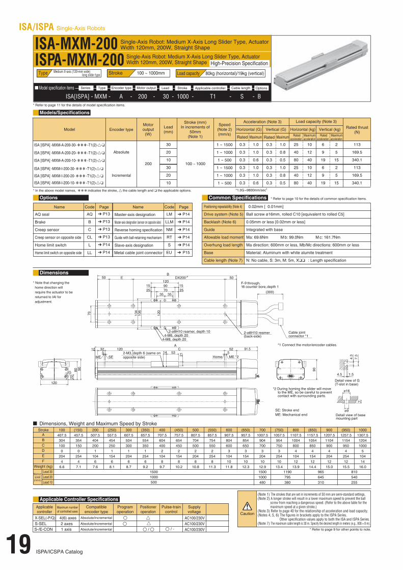
ISA-MXM-200 Single-Axis Robot: Medium X-Axis Long Slider Type, ActuatorWidth 120mm, 200W, Straight Shape
ISPA-MXM-200Type Stroke 100 ~ 1000mm Load capacity 80kg (horizontal)/19kg (vertical)
* Refer to page 11 for the details of model specification items.
Applicable Controller Specifications
Models/Specifications
Options
Dimensions
Common Specifications
* Note that changing the home direction will require the actuator to bereturned to IAI for adjustment.
* Refer to page 10 for the details of common specification items.
Stroke 100 (150) 200 (250)
15001000500
300 (350)ABCDEF
Weight (kg)Lead 30Lead 20Lead 10
407.53041000
2044
6.6
457.53541500
2544
7.1
507.54042001
1046
7.6
557.54542501
1546
8.1
607.55043001
2046
8.7
657.5554350
1254
69.2
Maximumspeed
(mm/s)
400 (450) 500 (550)707.56044002
1048
9.7
757.56544502
1548
10.2
807.57045002
2048
10.8
857.57545502
2548
11.3
600 (650) (750)700 800907.58046003
10410
11.8
957.58546503
15410
12.3
1057.59547503
25410
13.4
1007.5904700
320410
12.9
1107.510048004
10412
13.9
(850) 900 (950) 10001157.510548504
15412
14.4
1207.511049004
20412
15.0
1257.511549504
25412
15.5
1307.512041000
510414
16.0
Dimensions, Weight and Maximum Speed by Stroke
810540255
965645310
1190795380
15001000480
Model Encoder type
Absolute
Incremental
Motor output
(W)
200
Lead(mm)
30
20
10
30
20
10
Stroke (mm)In increments of
50mm(Note 1)
Speed(Note 2)(mm/s)
100 ~ 1000
1 ~ 1500
1 ~ 1000
1 ~ 500
1 ~ 1500
1 ~ 1000
1 ~ 500
Rated thrust(N)
113
169.5
340.1
113
169.5
340.1
Acceleration (Note 3)
Horizontal (G)
Rated Maximum Rated Maximum
0.3
0.3
0.3
0.3
0.3
0.3
1.0
1.0
0.6
1.0
1.0
0.6
0.3
0.3
0.3
0.3
0.3
0.3
1.0
0.8
0.5
1.0
0.8
0.5
Vertical (G)
Load capacity (Note 3)
Horizontal (kg)Rated
accelerationMaximumacceleration
Ratedacceleration
Maximumacceleration
25
40
80
25
40
80
10
12
40
10
12
40
6
9
19
6
9
19
2
5
15
2
5
15
Vertical (kg)
* In the above model names, indicates the stroke, the cable length and the applicable options. *1.0G=9800mm/sec2
High-Precision SpecificationSingle-Axis Robot: Medium X-Axis Long Slider Type, ActuatorWidth 120mm, 200W, Straight Shape
Medium X-axis (120-mm wide) long slider type
Name
AQ seal
Brake
Creep sensor
Creep sensor on opposite side
Home limit switch
Home limit switch on opposite side
AQ
B
C
CL
L
LL
P13
P13
P13
P13
P14
P14
Code Page Name
Master-axis designation
Master-axis designation (sensor on opposite side)
Reverse homing specification
Guide with ball-retaining mechanism
Slave-axis designation
LM
LLM
NM
RT
S
P14
P14
P14
P14
P14
Code Page Positioning repeatability (Note 4)
Drive system (Note 5)
Backlash (Note 6)
Guide
Allowable load moment
Overhung load length
Base
Cable length (Note 7)
0.02mm [ 0.01mm]
Ball screw ø16mm, rolled C10 [equivalent to rolled C5]
0.05mm or less [0.02mm or less]
Integrated with base
Ma: 69.6Nm M b: 99.0Nm M c: 161.7Nm
Ma direction: 600mm or less, Mb/Mc directions: 600mm or less
Material: Aluminum with white alumite treatment
N: No cable, S: 3m, M: 5m, X : Length specification
Applicablecontroller
Maximum numberof controlled axes
Compatibleencoder type
Programoperation
Positioneroperation
Pulse-traincontrol
Supplyvoltage
X-SEL(-P/Q) 4(6) axes Absolute/incremental AC100/230VAC100/230VAC100/230V * Refer to page 9 for other points to note.
(Note 1) The strokes that are set in increments of 50 mm are semi-standard settings.(Note 2) A longer stroke will result in a lower maximum speed to prevent the ball
screw from reaching a dangerous speed. (Refer to the above table for the maximum speed at a given stroke.)
(Note 3) Refer to page 40 for the relationship of acceleration and load capacity.(Notes 4, 5, 6) The figures in brackets apply to the ISPA Series.
Other specification values apply to both the ISA and ISPA Series.(Note 7) The maximum cable length is 30 m. Specify the desired length in meters (e.g., X08 = 8 m).
ISA [ISPA] -MXM-A-200-30- -T1(2)--
ISA [ISPA] -MXM-A-200-20- -T1(2)--
ISA [ISPA] -MXM-I-200-10- -T1(2)--
ISA [ISPA] -MXM-I-200-30- -T1(2)--
ISA [ISPA] -MXM-A-200-10- -T1(2)--
ISA [ISPA] -MXM-I-200-20- -T1(2)--
Metal cable joint connector EU P15
S-/E-CON / - / S-SEL
1 axis2 axes
Absolute/incremental
Absolute/incremental

Model specification items
ISA[ISPA] - MXMX - A - 200 - 30 - 2000 - T1 - S - NMOptionsCable lengthApplicable controllerStrokeLeadMotor outputEncoder typeTypeSeries
ISA/ISPA Single-Axis Robots
ISPA/ICSPA Catalog20
Dimensions
* Note that changing the home direction will require the actuator to bereturned to IAI for adjustment.
* Due to its structure themid-support type cannot be positioned horizontallyon its side or vertically.
Models/Specifications
ISA-MXMX Single-Axis Robot: Medium X-Axis Mid-Support Type, Actuator Width120mm, 200W, Straight Shape
ISPA-MXMXStroke 800 ~ 2000mm Load capacity 40kg (horizontal)
* Refer to page 11 for the details of model specification items.
Type
Stroke 800 900 1000 1100
15001000
1200 1300ABCDEFGH
Weight (kg)Lead 30Lead 20
1203.5110080000
200010
15.0
1303.5120090000
200010
16.1
1403.5130010002000
200012
17.1
1503.514001100250
0250
012
18.2
1603.5150012003000
300012
19.2
1703.5160013003500
350012
20.3Maximumspeed
(mm/s)
1400 1500 1600 17001803.5170014004000
400012
21.31425950
1903.518001500450
0450
012
22.41200800
2003.5190016005000
500012
23.41050700
2103.5200017005500
550012
24.5900600
18002203.52100180020040020040016
25.5825550
19002303.52200190020045020045016
26.6750500
20002403.52300200020050020050016
27.6675450
Dimensions, Weight and Maximum Speed by Stroke
Options Common Specifications * Refer to page 10 for the details of common specification items.
Model Encoder type
Absolute
Incremental
Motor output
(W)
200
Lead(mm)
30
20
30
20
Stroke (mm)In increments of
10mm
Speed(Note 1)(mm/s)
800 ~ 2000
1 ~ 1500
1 ~ 1000
1 ~ 1500
1 ~ 1000
Rated thrust(N)
113
169.5
113
169.5
* In the above model names, indicates the stroke, the cable length and the applicable options.
Acceleration (Note 2)
Horizontal (G)
0.3
0.3
0.3
0.3
Vertical (G)
Rated RatedMaximum Maximum
Horizontal
application
only
Load capacity (Note 2)
Horizontal (kg)
25
40
25
40
Vertical (kg)Rated
accelerationRated
accelerationMaximumacceleration
Maximumacceleration
Horizontal
application
only
*1.0G=9800mm/sec2
High-Precision SpecificationSingle-Axis Robot: Medium X-Axis Mid-Support Type, ActuatorWidth 120mm, 200W, Straight Shape
Medium X-axis (120-mm wide) mid-support type
Name
AQ seal
Brake
Creep sensor
Creep sensor on opposite side
Home limit switch
Home limit switch on opposite side
AQ
B
C
CL
L
LL
P13
P13
P13
P13
P14
P14
Code Page Name
Master-axis designation
Master-axis designation (sensor on opposite side)
Reverse homing specification
Guide with ball-retaining mechanism
Slave-axis designation
LM
LLM
NM
RT
S
P14
P14
P14
P14
P14
Code Page Positioning repeatability (Note 3)
Drive system (Note 4)
Backlash (Note 5)
Guide
Allowable load moment
Overhung load length
Base
Cable length (Note 6)
±0.02mm [±0.01mm]
Ball screw ø16mm, rolled C10 [equivalent to rolled C5]
0.05mm or less [0.02mm or less]
Integrated with base
Ma: 69.6Nm M b: 99.0Nm M c: 161.7Nm
Ma direction: 600mm or less, Mb/Mc directions: 600mm or less
Material: Aluminum with white alumite treatment
N: No cable, S: 3m, M: 5m, X : Length specification
Applicable Controller Specifications
Applicablecontroller
Maximum numberof controlled axes
Compatibleencoder type
Programoperation
Positioneroperation
Pulse-traincontrol
Supplyvoltage
X-SEL(-P/Q) 4(6) axes Absolute/incremental AC100/230VAC100/230VAC100/230V * Refer to page 9 for other points to note.
(Note 1) The strokes that are set in increments of 50 mm are semi-standard settings.
(Note 2) Refer to page 40 for the relationship of acceleration and load capacity.
(Notes 3, 4, 5) The figures in brackets apply to the ISPA Series. Other specification values apply to both the ISA and ISPA Series.
(Note 6) The maximum cable length is 30 m. Specify the desired length in meters (e.g., X08 = 8 m).
ISA [ISPA] -MXMX-A-200-30- -T1(2)--
ISA [ISPA] -MXMX-A-200-20- -T1(2)--
ISA [ISPA] -MXMX-I-200-20- -T1(2)--
ISA [ISPA] -MXMX-I-200-30- -T1(2)--
Metal cable joint connector EU P15
S-/E-CON / - / S-SEL
1 axis2 axes
Absolute/incremental
Absolute/incremental
Sin
gle-A
xisR
ob
ots
Cartesian
Ro
bo
tsC
on
trollers

21 ISPA/ICSPA Catalog
Model specification items
ISA[ISPA] - MYM - A - 100 - 20 - 1000 - T1 - S - NMOptionsCable lengthApplicable controllerStrokeLeadMotor outputEncoder typeTypeSeries
ISA/ISPA Single-Axis Robots
Models/Specifications
Options
Dimensions
Common Specifications
* Note that changing the home direction will require the actuator to bereturned to IAI for adjustment.
* Refer to page 10 for the details of common specification items.
ISA-MYM-100 Single-Axis Robot: Medium Y-Axis Long Slider Type, ActuatorWidth 120mm, 100W, Straight Shape
ISPA-MYM-100Type Stroke 100 ~ 1000mm Load capacity 80kg (horizontal)/19kg (vertical)
* Refer to page 11 for the details of model specification items.
Stroke 100 (150) 200 (250)
1000500250
300 (350)ABCDEF
Weight (kg)Lead 20Lead 10Lead 5
393.5304100Ð
120106.3
443.5354150ÐÐ8
6.8
493.540420054120107.3
543.5454250104120107.8
593.5504300154120108.3
643.5554350204120108.8
Maximumspeed
(mm/s)
400 (450) 500 (550)693.5604400254120109.3
743.5654450304120109.9
793.570450035412010
10.4
843.575455040412010
10.9
600 (650) (750)700 800893.580460045412010
11.4
943.585465050412010
11.9
1043.595475060412010
12.9
993.590470055412010
12.4
1093.5100480065412010
13.4
(850) 900 (950) 10001143.5105485070412010
13.9
1193.5110490075412010
14.4
1243.5115495080412010
14.9
1293.51204100085412010
15.4
Dimensions, Weight and Maximum Speed by Stroke
540255120
645310145
795380175
1000480220
Model Encoder type
Absolute
Incremental
Motor output
(W)
100
Lead(mm)
20
10
5
20
10
5
Stroke (mm)In increments of
50mm(Note 1)
Speed(Note 2)(mm/s)
100 ~ 1000
1 ~ 1000
1 ~ 500
1 ~ 250
1 ~ 1000
1 ~ 500
1 ~ 250
Rated thrust(N)
84.3
169.5
340.1
84.3
169.5
340.1
Acceleration (Note 3)
Horizontal (G)
0.3
0.3
0.15
0.3
0.3
0.15
1.0
0.6
0.5
1.0
0.6
0.5
Vertical (G)
0.3
0.3
0.15
0.3
0.3
0.15
0.8
0.5
0.3
0.8
0.5
0.3
Load capacity (Note 3)
Horizontal (kg)
20
40
80
20
40
80
6
20
45
6
20
45
Vertical (kg)
Rated Maximum Rated Maximum Ratedacceleration
Ratedacceleration
Maximumacceleration
Maximumacceleration
3.5
9
19
3.5
9
19
2
7
15
2
7
15
* In the above model names, indicates the stroke, the cable length and the applicable options. *1.0G=9800mm/sec2
High-Precision SpecificationSingle-Axis Robot: Medium Y-Axis Long Slider Type, ActuatorWidth 120mm, 100W, Straight Shape
Medium Y-axis (120-mm wide) long slider type
Name
AQ seal
Brake
Creep sensor
Creep sensor on opposite side
Home limit switch
Home limit switch on opposite side
AQ
B
C
CL
L
LL
P13
P13
P13
P13
P14
P14
Code Page Name
Master-axis designation
Master-axis designation (sensor on opposite side)
Reverse homing specification
Guide with ball-retaining mechanism
Slave-axis designation
LM
LLM
NM
RT
S
P14
P14
P14
P14
P14
Code Page Positioning repeatability (Note 4)
Drive system (Note 5)
Backlash (Note 6)
Guide
Allowable load moment
Overhung load length
Base
Cable length (Note 7)
0.02mm [ 0.01mm]
Ball screw ø16mm, rolled C10 [equivalent to rolled C5]
0.05mm or less [0.02mm or less]
Integrated with base
Ma: 69.6N m M b: 99.0N m M c: 81.3N m
Ma direction: 600mm or less, Mb/Mc directions: 600mm or less
Material: Aluminum with white alumite treatment
N: No cable, S: 3m, M: 5m, X : Length specification
Applicable Controller SpecificationsApplicablecontroller
Maximum numberof controlled axes
Compatibleencoder type
Programoperation
Positioneroperation
Pulse-traincontrol
Supplyvoltage
X-SEL(-P/Q) 4(6) axes Absolute/incremental AC100/230VAC100/230VAC100/230V * Refer to page 9 for other points to note.
(Note 1) The strokes that are set in increments of 50 mm are semi-standard settings.(Note 2) A longer stroke will result in a lower maximum speed to prevent the ball
screw from reaching a dangerous speed. (Refer to the above table for the maximum speed at a given stroke.)
(Note 3) Refer to page 40 for the relationship of acceleration and load capacity.(Notes 4, 5, 6) The figures in brackets apply to the ISPA Series.
Other specification values apply to both the ISA and ISPA Series.(Note 7) The maximum cable length is 30 m. Specify the desired length in meters (e.g., X08 = 8 m).
ISA [ISPA] -MYM-A-100-20- -T1(2)--
ISA [ISPA] -MYM-I-100-5- -T1(2)--
ISA [ISPA] -MYM-A-100-10- -T1(2)--
ISA [ISPA] -MYM-A-100-5- -T1(2)--
ISA [ISPA] -MYM-I-100-20- -T1(2)--
ISA [ISPA] -MYM-I-100-10- -T1(2)--
Metal cable joint connector EU P15
S-/E-CON / - / S-SEL
1 axis2 axes
Absolute/incremental
Absolute/incremental

■ Model specification items
ISA[ISPA] - MYM - A - 200 - 30 - 1000 - T1 - S - NMOptionsCable lengthApplicable controllerStrokeLeadMotor outputEncoder typeTypeSeries
ISA/ISPA Single-Axis Robots
ISPA/ICSPA Catalog 22
Models/Specifications
Options
Dimensions
Common Specifications
* Note that changing the home direction will require the actuator to bereturned to IAI for adjustment.
* Refer to page 10 for the details of common specification items.
ISA-MYM-200 Single-Axis Robot: Medium Y-Axis Long Slider Type, ActuatorWidth 120mm, 200W, Straight Shape
ISPA-MYM-200Type Stroke 100 ~ 1000mm Load capacity 80kg (horizontal)/19kg (vertical)
* Refer to page 11 for the details of model specification items.
Stroke 100 (150) 200 (250)
15001000500
300 (350)ABCDEF
Weight (kg)Lead 30Lead 20Lead 10
407.5304100Ð
120106.8
457.5354150ÐÐ8
7.3
507.540420054120107.8
557.5454250104120108.3
607.5504300154120108.8
657.5554350204120109.3
Maximumspeed
(mm/s)
400 (450) 500 (550)707.5604400254120109.8
757.565445030412010
10.4
807.570450035412010
10.9
857.575455040412010
11.4
600 (650) (750)700 800907.580460045412010
11.9
957.585465050412010
12.4
1057.595475060412010
13.4
1007.590470055412010
12.9
1107.5100480065412010
13.9
(850) 900 (950) 10001157.5105485070412010
14.4
1207.5110490075412010
14.9
1257.5115495080412010
15.4
1307.51204100085412010
15.9
■ Dimensions, Weight and Maximum Speed by Stroke
810540255
965645310
1190795380
15001000480
Model Encoder type
Absolute
Incremental
Motoroutput
(W)
200
Lead(mm)
30
20
10
30
20
10
Stroke (mm)In increments of
50mm(Note 1)
Speed(Note 2)(mm/s)
100 ~ 1000
1 ~ 1500
1 ~ 1000
1 ~ 500
1 ~ 1500
1 ~ 1000
1 ~ 500
Rated thrust(N)
113
169.5
340.1
113
169.5
340.1
Acceleration (Note 3)
0.3
0.3
0.3
0.3
0.3
0.3
1.0
1.0
0.6
1.0
1.0
0.6
0.3
0.3
0.3
0.3
0.3
0.3
1.0
0.8
0.5
1.0
0.8
0.5
Load capacity (Note 3)
25
40
80
25
40
80
10
12
40
10
12
40
6
9
19
6
9
19
2
5
15
2
5
15
* In the above model names, indicates the stroke, the cable length and the applicable options. *1.0G=9800mm/sec2
Horizontal (G) Vertical (G) Horizontal (kg) Vertical (kg)
Rated Maximum Rated Maximum Ratedacceleration
Ratedacceleration
Maximumacceleration
Maximumacceleration
High-Precision SpecificationSingle-Axis Robot: Medium Y-Axis Long Slider Type, ActuatorWidth 120mm, 200W, Straight Shape
Medium Y-axis (120-mm wide) long slider type
Name
AQ seal
Brake
Creep sensor
Creep sensor on opposite side
Home limit switch
Home limit switch on opposite side
AQ
B
C
CL
L
LL
➔ P13
➔ P13
➔ P13
➔ P13
➔ P14
➔ P14
Code Page Name
Master-axis designation
Master-axis designation (sensor on opposite side)
Reverse homing specification
Guide with ball-retaining mechanism
Slave-axis designation
LM
LLM
NM
RT
S
➔ P14
➔ P14
➔ P14
➔ P14
➔ P14
Code Page Positioning repeatability (Note 4)
Drive system (Note 5)
Backlash (Note 6)
Guide
Allowable load moment
Overhung load length
Base
Cable length (Note 7)
±0.02mm [±0.01mm]
Ball screw ø16mm, rolled C10 [equivalent to rolled C5]
0.05mm or less [0.02mm or less]
Integrated with base
Ma: 69.6Nm M b: 99.0Nm M c: 81.3Nm
Ma direction: 600mm or less, Mb/Mc directions: 600mm or less
Material: Aluminum with white alumite treatment
N: No cable, S: 3m, M: 5m, X : Length specification
Applicable Controller SpecificationsApplicablecontroller
Maximum numberof controlled axes
Compatibleencoder type
Programoperation
Positioneroperation
Pulse-traincontrol
Supplyvoltage
X-SEL(-P/Q) 4(6) axes Absolute/incremental ● ▲▲ AC100/230VAC100/230VAC100/230V * Refer to page 9 for other points to note.
(Note 1) The strokes that are set in increments of 50 mm are semi-standard settings.(Note 2) A longer stroke will result in a lower maximum speed to prevent the ball
screw from reaching a dangerous speed. (Refer to the above table for the maximum speed at a given stroke.)
(Note 3) Refer to page 40 for the relationship of acceleration and load capacity.(Notes 4, 5, 6) The figures in brackets apply to the ISPA Series.
Other specification values apply to both the ISA and ISPA Series.(Note 7) The maximum cable length is 30 m. Specify the desired length in meters (e.g., X08 = 8 m).
ISA [ISPA] -MYM-A- 200-30- -T1(2)--
ISA [ISPA] -MYM-A- 200-20- -T1(2)--
ISA [ISPA] -MYM-A- 200-10- -T1(2)--
ISA [ISPA] -MYM-I- 200-30- -T1(2)--
ISA [ISPA] -MYM-I- 200-20- -T1(2)--
ISA [ISPA] -MYM-I- 200-10- -T1(2)--
Metal cable joint connector EU P15
S-/E-CON / - / S-SEL
1 axis2 axes
Absolute/incremental
Absolute/incremental
Single-A
xisRobots
Cartesian
Robots
Contro
llers

23 ISPA/ICSPA Catalog
Model specification items
ISA[ISPA] - MZM - A - 100 - 10 - 1000 - T1 - S - B - LOptionsCable lengthApplicable controllerStrokeLeadMotor outputEncoder typeTypeSeries
ISA/ISPA Single-Axis Robots
Options
Dimensions
* Note that changing the home direction will require the actuator to bereturned to IAI for adjustment.
* The MZM type comes standard with a brake (B).
Vertical application only (with standard brake) 19kg
ISA-MZM-100 Single-Axis Robot: Medium Vertical-Axis Long Slider Type, Actuator Width 120mm, 100W, Straight Shape
ISPA-MZM-100Type Stroke 100 ~ 1000mm
* Refer to page 11 for the details of model specification items.
Models/Specifications
* The MZM type comes standard with a brake, so usea controller of brake specification.
Stroke 100 (150) 200 (250) 300ABCD
Weight (kg)Lead 10Lead 5
420.5304100647.1
470.53541501147.6
520.54042001648.1
570.54542502148.6
620.55043002649.1
(350) 400 (450) 500670.55543503149.6
720.560440036410.1
770.565445041410.7
820.570450046411.2
(550)870.575455051411.7
600920.580460056412.2
500250
700 800
13.2480220
14.2380175
900
15.2310145
1000
16.2255120
Use the base of the MXM type for 700 and longer strokes.Refer to the drawing on page 18 for the mountingdimensions.
Dimensions, Weight and Maximum Speed by Stroke
Maximumspeed
(mm/s)
Model Encoder type
Absolute
Incremental
Motor output
(W)
100
Lead(mm)
10
5
10
5
Stroke (mm)In increments of
50mm(Note 1)
Speed(Note 2)(mm/s)
100 ~ 1000
1 ~ 500
1 ~ 250
1 ~ 500
1 ~ 250
Rated thrust(N)
169.5
340.1
169.5
340.1
* In the above model names, indicates the stroke, the cable length and the applicable options.
0.3
0.15
0.3
0.15
Acceleration (Note 3)
Horizontal (kg)
Vertical
application
only
Vertical (kg)
Rated RatedMaximum Maximum
0.5
0.3
0.5
0.3
9
19
9
19
Load capacity (Note 3)
Horizontal (kg)
Vertical
application
only
Vertical (kg)Rated
accelerationRated
accelerationMaximumacceleration
Maximumacceleration
7
15
7
15
*1.0G=9800mm/sec2
High-Precision SpecificationSingle-Axis Robot: Medium Vertical-Axis Long Slider Type, ActuatorWidth 120mm, 100W, Straight Shape
Medium vertical-axis (120-mm wide) long slider type
Name
AQ seal
Brake
Creep sensor
Creep sensor on opposite side
Home limit switch
Home limit switch on opposite side
AQ
B
C
CL
L
LL
P13
P13
P13
P13
P14
P14
Code Page Name
Master-axis designation
Master-axis designation (sensor on opposite side)
Reverse homing specification
Guide with ball-retaining mechanism
Slave-axis designation
LM
LLM
NM
RT
S
P14
P14
P14
P14
P14
Code Page
Common Specifications * Refer to page 10 for the details of common specification items.
Positioning repeatability (Note 4)
Drive system (Note 5)
Backlash (Note 6)
Guide
Allowable load moment
Brake
Base
Cable length (Note 7)
±0.02mm [±0.01mm]
Ball screw ø16mm, rolled C10 [equivalent to rolled C5]
0.05mm or less [0.02mm or less]
Integrated with base
Ma: 69.6Nm M b: 99.0Nm M c: 81.3Nm
Comes standard with a dry, single-plate, non-excitation type electromagnetic brake.
Material: Aluminum with white alumite treatment
N: No cable, S: 3m, M: 5m, X : Length specification
Applicable Controller SpecificationsApplicablecontroller
Maximum numberof controlled axes
Compatibleencoder type
Programoperation
Positioneroperation
Pulse-traincontrol
Supplyvoltage
X-SEL(-P/Q) 4(6) axes Absolute/incremental AC100/230VAC100/230VAC100/230V
* Refer to page 9 for other points to note.
(Note 1) The strokes that are set in increments of 50 mm are semi-standard settings.(Note 2) A longer stroke will result in a lower maximum speed to prevent the ball
screw from reaching a dangerous speed. (Refer to the above table for the maximum speed at a given stroke.)
(Note 3) Refer to page 40 for the relationship of acceleration and load capacity.(Notes 4, 5, 6) The figures in brackets apply to the ISPA Series.
Other specification values apply to both the ISA and ISPA Series.(Note 7) The maximum cable length is 30 m. Specify the desired length in meters (e.g., X08 = 8 m).
ISA [ISPA] -MZM-A-100-10- -T1(2)--B-
ISA [ISPA] -MZM-A-100-5- -T1(2)--B-
ISA [ISPA] -MZM-I-100-10- -T1(2)--B-
ISA [ISPA] -MZM-I-100-5- -T1(2)--B-
Metal cable joint connector EU P15
S-/E-CON / - / S-SEL
1 axis2 axes
Absolute/incremental
Absolute/incremental

Model specification items
ISA[ISPA] - MZM - A - 200 - 10 - 1000 - T1 - S - B - LOptionsCable lengthApplicable controllerStrokeLeadMotor outputEncoder typeTypeSeries
ISA/ISPA Single-Axis Robots
ISPA/ICSPA Catalog 24
Dimensions
* Note that changing the home direction will require the actuator to bereturned to IAI for adjustment.
Vertical application only (with standard brake) 19kg
ISA-MZM-200 Single-Axis Robot: Medium Vertical-Axis Long Slider Type,Actuator Width 120mm, 200W, Straight Shape
ISPA-MZM-200Type Stroke 100 ~ 1000mm
* Refer to page 11 for the details of model specification items.
Models/Specifications
* The MZM type comes standard with a brake, so usea controller of brake specification.
Options
* The MZM type comes standard with a brake (B).
Stroke 100 (150) 200 (250) 300ABCD
Weight (kg)Maximum speed (mm/s)
434.5304100647.1
484.53541501147.6
534.54042001648.1
584.54542502148.6
634.55043002649.1
(350) 400 (450) 500684.55543503149.6
734.560440036410.1
784.565445041410.7
834.570450046411.2
(550)884.575455051411.7
600934.580460056412.2
500
700 800
13.2480
14.2380
900
15.2310
1000
16.2255
Use the base of the MXM type for 700 and longer strokes.Refer to the drawing on page 19 for the mountingdimensions.
Dimensions, Weight and Maximum Speed by Stroke
Model Encoder type
Absolute
Incremental
Motor output
(W)
200
Lead(mm)
10
Rated thrust(N)
340.1
340.1
Stroke (mm)In increments of
50mm(Note 1)
Speed(Note 2)(mm/s)
100 ~ 10001 ~ 500
1 ~ 500
* In the above model names, indicates the stroke, the cable length and the applicable options. *1.0G=9800mm/sec2
Acceleration (Note 3)
Horizontal (G)
Verticalapplication
only
Vertical (G)
Rated Rated
0.3
0.3
Maximum Maximum
0.5
0.5
Load capacity (Note 3)
Horizontal (kg)
Verticalapplication
only
Vertical (kg)
Ratedacceleration
Ratedacceleration
19
19
Maximumacceleration
Maximumacceleration
15
15
High-Precision SpecificationSingle-Axis Robot: Medium Vertical-Axis Long Slider Type, Actuator Width 120mm, 200W, Straight Shape
Medium vertical-axis (120-mm wide) long slider type
Name
AQ seal
Brake
Creep sensor
Creep sensor on opposite side
Home limit switch
Home limit switch on opposite side
AQ
B
C
CL
L
LL
P13
P13
P13
P13
P14
P14
Code Page Name
Master-axis designation
Master-axis designation (sensor on opposite side)
Reverse homing specification
Guide with ball-retaining mechanism
Slave-axis designation
LM
LLM
NM
RT
S
P14
P14
P14
P14
P14
Code Page
Common Specifications * Refer to page 10 for the details of common specification items.
Positioning repeatability (Note 4)
Drive system (Note 5)
Backlash (Note 6)
Guide
Allowable load moment
Brake
Base
Cable length (Note 7)
±0.02mm [±0.01mm]
Ball screw ø16mm, rolled C10 [equivalent to rolled C5]
0.05mm or less [0.02mm or less]
Integrated with base
Ma: 69.6Nm M b: 99.0Nm M c: 81.3Nm
Comes standard with a dry, single-plate, non-excitation type electromagnetic brake.
Material: Aluminum with white alumite treatment
N: No cable, S: 3m, M: 5m, X : Length specification
Applicable Controller SpecificationsApplicablecontroller
Maximum numberof controlled axes
Compatibleencoder type
Programoperation
Positioneroperation
Pulse-traincontrol
Supplyvoltage
X-SEL(-P/Q) 4(6) axes Absolute/incremental AC100/230VAC100/230VAC100/230V
* Refer to page 9 for other points to note.
(Note 1) The strokes that are set in increments of 50 mm are semi-standard settings.(Note 2) A longer stroke will result in a lower maximum speed to prevent the ball
screw from reaching a dangerous speed. (Refer to the above table for the maximum speed at a given stroke.)
(Note 3) Refer to page 40 for the relationship of acceleration and load capacity.(Notes 4, 5, 6) The figures in brackets apply to the ISPA Series.
Other specification values apply to both the ISA and ISPA Series.(Note 7) The maximum cable length is 30 m. Specify the desired length in meters (e.g., X08 = 8 m).
ISA [ISPA] -MZM-A-200-10- -T1(2)--B-
ISA [ISPA] -MZM-I-200-10- -T1(2)--B-
Metal cable joint connector EU P15
S-/E-CON / - / S-SEL
1 axis2 axes
Absolute/incremental
Absolute/incremental
Sin
gle-A
xisR
ob
ots
Cartesian
Ro
bo
tsC
on
trollers

25 ISPA/ICSPA Catalog
Model specification items
ISA[ISPA] - LXM - A - 200 - 10 - 1200 - T1 - S - BOptionsCable lengthApplicable controllerStrokeLeadMotor outputEncoder typeTypeSeries
ISA/ISPA Single-Axis Robots
Options
Dimensions* Note that changing the home direction
will require the actuator to be returned to IAI for adjustment.
ISA-LXM-200 Single-Axis Robot: Large X-Axis Long Slider Type, ActuatorWidth 150mm, 200W, Straight Shape
ISPA-LXM-200Type Stroke 100 ~ 1200mm Load capacity 80kg (horizontal)/19kg (vertical)
* Refer to page 11 for the details of model specification items.
Models/Specifications
Stroke 100 (150) 200 (250) 300 (350)ABCDEF
Weight (kg)Lead 20Lead 10
4533381000
2384
11.0
5033881500
2884
11.8
5534382001
1386
12.5
6034882501
1886
13.3
6535383001
2386
14.0
7035883501
2886
14.8Maximumspeed
(mm/s)
400 (450) 500 (550)7536384002
1388
15.5
8036884502
1888
16.3
8537385002
2388
17.0
9037885502
2888
17.8
6009538386003
13810
18.5
(650)1003888650
318810
19.31000500
7001053938700
323810
20.0
(750)1103988750
328810
20.8
80011531038800
413812
21.5
(850)120310888504
18812
22.3
900 (950) 1000 (1050) 1100 (1150)125311389004
23812
23.0
130311889504
28812
23.8
135312381000
513814
24.5
140312881050
518814
25.3
145313381100
523814
26.0
150313881150
528814
26.8
1200155314381200
613816
27.5
Dimensions, Weight and Maximum Speed by Stroke
585270
690320
830385
1000470
500235
Model Encoder type
Absolute
Incremental
Motor output
(W)
200
Lead(mm)
20
10
20
10
Stroke (mm)In increments of
50mm(Note 1)
Speed(Note 2)(mm/s)
100 ~ 1200
1 ~ 1000
1 ~ 500
1 ~ 1000
1 ~ 500
Rated thrust(N)
170.5
340.1
170.5
340.1
* In the above model names, indicates the stroke, the cable length and the applicable options.
Acceleration (Note 3)
Horizontal (G)
0.3
0.3
0.3
0.3
Vertical (G)
Rated Rated
0.3
0.3
0.3
0.3
1.0
0.6
1.0
0.6
Maximum Maximum
0.8
0.5
0.8
0.5
Load capacity (Note 3)
Horizontal (kg)
40
80
40
80
Vertical (kg)
Ratedacceleration
Ratedacceleration
9
19
9
19
12
40
12
40
Maximumacceleration
Maximumacceleration
4
14
4
14
*1.0G=9800mm/sec2
High-Precision SpecificationSingle-Axis Robot: Large X-Axis Long Slider Type, ActuatorWidth 150mm, 200W, Straight Shape
Large X-axis (150-mm wide) long slider type
Name
AQ seal
Brake
Creep sensor
Creep sensor on opposite side
Home limit switch
Home limit switch on opposite side
AQ
B
C
CL
L
LL
P13
P13
P13
P13
P14
P14
Code Page Name
Master-axis designation
Master-axis designation (sensor on opposite side)
Reverse homing specification
Guide with ball-retaining mechanism
Slave-axis designation
LM
LLM
NM
RT
S
P14
P14
P14
P14
P14
Code Page
Common Specifications * Refer to page 10 for the details of common specification items.
Positioning repeatability (Note 4)
Drive system (Note 5)
Backlash (Note 6)
Guide
Allowable load moment
Overhung load length
Base
Cable length (Note 7)
0.02mm [ 0.01mm]
Ball screw ø20mm, rolled C10 [equivalent to rolled C5]
0.05mm or less [0.02mm or less]
Integrated with base
Ma: 104.9Nm M b: 149.9Nm M c: 248.9Nm
Ma direction: 750mm or less, Mb/Mc directions: 750mm or less
Material: Aluminum with white alumite treatment
N: No cable, S: 3m, M: 5m, X : Length specification
Applicable Controller SpecificationsApplicablecontroller
Maximum numberof controlled axes
Compatibleencoder type
Programoperation
Positioneroperation
Pulse-traincontrol
Supplyvoltage
X-SEL(-P/Q) 4(6) axes Absolute/incremental AC100/230VAC100/230VAC100/230V * Refer to page 9 for other points to note.
(Note 1) The strokes that are set in increments of 50 mm are semi-standard settings.(Note 2) A longer stroke will result in a lower maximum speed to prevent the ball
screw from reaching a dangerous speed. (Refer to the above table for the maximum speed at a given stroke.)
(Note 3) Refer to page 40 for the relationship of acceleration and load capacity.(Notes 4, 5, 6) The figures in brackets apply to the ISPA Series.
Other specification values apply to both the ISA and ISPA Series.(Note 7) The maximum cable length is 30 m. Specify the desired length in meters (e.g., X08 = 8 m).
ISA [ISPA] -LXM-A-200-20- -T1(2)--
ISA [ISPA] -LXM-A-200-10- -T1(2)--
ISA [ISPA] -LXM-I-200-10- -T1(2)--
ISA [ISPA] -LXM-I-200-20- -T1(2)--
Metal cable joint connector EU P15
S-/E-CON / - / S-SEL
1 axis2 axes
Absolute/incremental
Absolute/incremental
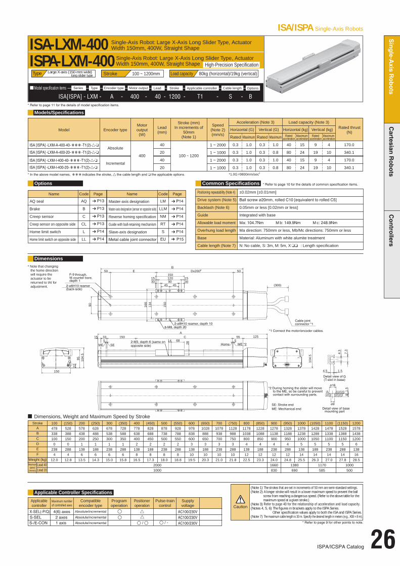
■ Model specification items
ISA[ISPA] - LXM - A - 400 - 40 - 1200 - T1 - S - BOptionsCable lengthApplicable controllerStrokeLeadMotor outputEncoder typeTypeSeries
G
134
150
Dx200P
1501512015
EB
166
5533 C150
90
30 90 3045 45
81.
5
4.5 1.5
4.3
7.3
5050
5512515
A
150
2295 10
4.5
14
28
68
104.
5
SEME
ISA/ISPA Single-Axis Robots
ISPA/ICSPA Catalog 26
Models/Specifications
Dimensions* Note that changing
the home directionwill require the actuator to be returned to IAI foradjustment.
ISA-LXM-400 Single-Axis Robot: Large X-Axis Long Slider Type, ActuatorWidth 150mm, 400W, Straight Shape
ISPA-LXM-400Stroke 100 ~ 1200mm Load capacity 80kg (horizontal)/19kg (vertical)
* Refer to page 11 for the details of model specification items.
Type
Stroke 100 (150) 200 (250) 300 (350)ABCDEF
Weight (kg)Lead 40Lead 20
4783381000
2384
12.0
5283881500
2884
12.8
5784382001
1386
13.5
6284882501
1886
14.3
6785383001
2386
15.0
7285883501
2886
15.8Maximumspeed
(mm/s)
400 (450) 500 (550)7786384002
1388
16.5
8286884502
1888
17.3
8787385002
2388
18.0
9287885502
2888
18.8
600978838600
313810
19.5
(650)1028888650
318810
20.320001000
7001078938700
323810
21.0
(750)11289887503
28810
21.8
800117810388004
13812
22.5
(850)122810888504
18812
23.3
900 (950) 1000 (1050) 1100 (1150)127811389004
23812
24.0
132811889504
28812
24.8
137812381000
513814
25.5
142812881050
518814
26.3
147813381100
523814
27.0
152813881150
528814
27.8
1200157814381200
613816
28.5
■ Dimensions, Weight and Maximum Speed by Stroke
1660830
1380690
1170585
1000500
Model Encoder type
Absolute
Incremental
Motoroutput
(W)
400
Lead(mm)
40
20
40
20
Stroke (mm)In increments of
50mm(Note 1)
Speed(Note 2)(mm/s)
100 ~ 1200
1 ~ 2000
1 ~ 1000
1 ~ 2000
1 ~ 1000
Rated thrust(N)
170.0
340.1
170.0
340.1
* In the above model names, indicates the stroke, the cable length and the applicable options.
Acceleration (Note 3)
Horizontal (G)
0.3
0.3
0.3
0.3
Vertical (G)
Rated Rated
0.3
0.3
0.3
0.3
1.0
1.0
1.0
1.0
Maximum Maximum
1.0
0.8
1.0
0.8
Load capacity (Note 3)
Horizontal (kg)
40
80
40
80
Vertical (kg)Rated
accelerationRated
acceleration
9
19
9
19
15
24
15
24
Maximumacceleration
Maximumacceleration
4
10
4
10
*1.0G=9800mm/sec2
High-Precision SpecificationSingle-Axis Robot: Large X-Axis Long Slider Type, ActuatorWidth 150mm, 400W, Straight Shape
Large X-axis (150-mm wide) long slider type
Options
Name
AQ seal
Brake
Creep sensor
Creep sensor on opposite side
Home limit switch
Home limit switch on opposite side
AQ
B
C
CL
L
LL
➔ P13
➔ P13
➔ P13
➔ P13
➔ P14
➔ P14
Code Page Name
Master-axis designation
Master-axis designation (sensor on opposite side)
Reverse homing specification
Guide with ball-retaining mechanism
Slave-axis designation
LM
LLM
NM
RT
S
➔ P14
➔ P14
➔ P14
➔ P14
➔ P14
Code Page
Common Specifications * Refer to page 10 for the details of common specification items.
Positioning repeatability (Note 4)
Drive system (Note 5)
Backlash (Note 6)
Guide
Allowable load moment
Overhung load length
Base
Cable length (Note 7)
±0.02mm [±0.01mm]
Ball screw ø20mm, rolled C10 [equivalent to rolled C5]
0.05mm or less [0.02mm or less]
Integrated with base
Ma: 104.7Nm M b: 149.9Nm M c: 248.9Nm
Ma direction: 750mm or less, Mb/Mc directions: 750mm or less
Material: Aluminum with white alumite treatment
N: No cable, S: 3m, M: 5m, X : Length specification
Applicable Controller Specifications
Applicablecontroller
Maximum numberof controlled axes
Compatibleencoder type
Programoperation
Positioneroperation
Pulse-traincontrol
Supplyvoltage
X-SEL(-P/Q) 4(6) axes Absolute/incremental ● ▲▲ AC100/230VAC100/230VAC100/230V * Refer to page 9 for other points to note.
(Note 1) The strokes that are set in increments of 50 mm are semi-standard settings.(Note 2) A longer stroke will result in a lower maximum speed to prevent the ball
screw from reaching a dangerous speed. (Refer to the above table for the maximum speed at a given stroke.)
(Note 3) Refer to page 40 for the relationship of acceleration and load capacity.(Notes 4, 5, 6) The figures in brackets apply to the ISPA Series.
Other specification values apply to both the ISA and ISPA Series.(Note 7) The maximum cable length is 30 m. Specify the desired length in meters (e.g., X08 = 8 m).
ISA [ISPA] -LXM-A-400-40- -T1(2)--
ISA [ISPA] -LXM-I-400-20- -T1(2)--
ISA [ISPA] -LXM-A-400-20- -T1(2)--
ISA [ISPA] -LXM-I-400-40- -T1(2)--
Metal cable joint connector EU P15
S-/E-CON / - / S-SEL
1 axis2 axes
Absolute/incremental
Absolute/incremental
Single-A
xisRobots
Cartesian
Robots
Contro
llers

27 ISPA/ICSPA Catalog
Model specification items
ISA[ISPA] - LXMX - A - 200 - 20 - 2500 - T1 - S - NMOptionsCable lengthApplicable controllerStrokeLeadMotor outputEncoder typeTypeSeries
ISA/ISPA Single-Axis Robots
ISA-LXMX-200 Single-Axis Robot: Large X-Axis Mid-Support Type, ActuatorWidth 150mm, 200W, Straight Shape
ISPA-LXMX-200
* Refer to page 11 for the details of model specification items.
Models/Specifications
Dimensions
* Note that changing the home direction will require the actuator to bereturned to IAI for adjustment.
* Due to its structure themid-support type cannot be positioned horizontallyon its side or vertically.
Stroke 1000 ~ 2500mm Load capacity 40kg (horizontal)Type
Stroke 1000 1100 1200 1300
1000
1400 1500ABCDEFGHJK
Weight (kg)Maximum speed (mm/s)
14651350101422500
2250012
27.5
15651450111427500
2750012
29.0
16651550121432500
3250012
30.5
17651650131437500
3750012
32.0
18651750141442500
4250012
33.5
19651850151447500
4750012
35.0950
1600 1700206519501614525
00
52500
1236.5830
21652050171457500
5750012
38.0740
1800 1900 2000 2100 2200 23002265215018142004250
200425016
39.5650
236522501914200475
0200475
016
41.0590
2465235020142005250
200525016
42.5540
2565245021142005750
200575016
44.0490
26652550221420020042520020042520
45.5440
27652650231420020047520020047520
47.0410
2400 250028652750241420020052520020052520
48.5370
29652850251420020057520020057520
50.0340
Dimensions, Weight and Maximum Speed by Stroke
Model Encoder type
Absolute
Incremental
Motor output
(W)
200
Lead(mm)
20
20
Stroke (mm)In increments of
100mm
Speed(Note 1)(mm/s)
1000 ~ 25001 ~ 1000
1 ~ 1000
Rated thrust(N)
170.5
170.5
Acceleration (Note 2)
Horizontal (G)
0.3
0.3
Vertical (G)
Rated Rated
Horizontalapplication
only
Maximum Maximum
Load capacity (Note 2)
Horizontal (kg)
40
40
Vertical (kg)
Ratedacceleration
Ratedacceleration
Horizontalapplication
only
Maximumacceleration
Maximumacceleration
* In the above model names, indicates the stroke, the cable length and the applicable options. *1.0G=9800mm/sec2
High-Precision SpecificationSingle-Axis Robot: Large X-Axis Mid-Support Type, ActuatorWidth 150mm, 200W, Straight Shape
Large X-axis (150-mm wide) mid-support type
Options
Name
AQ seal
Brake
Creep sensor
Creep sensor on opposite side
Home limit switch
Home limit switch on opposite side
AQ
B
C
CL
L
LL
P13
P13
P13
P13
P14
P14
Code Page Name
Master-axis designation
Master-axis designation (sensor on opposite side)
Reverse homing specification
Guide with ball-retaining mechanism
Slave-axis designation
LM
LLM
NM
RT
S
P14
P14
P14
P14
P14
Code Page
Common Specifications * Refer to page 10 for the details of common specification items.
Positioning repeatability (Note 3)
Drive system (Note 4)
Backlash (Note 5)
Guide
Allowable load moment
Overhung load length
Base
Cable length (Note 6)
0.02mm [ 0.01mm]
Ball screw ø20mm, rolled C10 [equivalent to rolled C5]
0.05mm or less [0.02mm or less]
Integrated with base
Ma: 104.9Nm M b: 149.9Nm M c: 248.9Nm
Ma direction: 750mm or less, Mb/Mc directions: 750mm or less
Material: Aluminum with white alumite treatment
N: No cable, S: 3m, M: 5m, X : Length specification
Applicable Controller Specifications
Applicablecontroller
Maximum numberof controlled axes
Compatibleencoder type
Programoperation
Positioneroperation
Pulse-traincontrol
Supplyvoltage
X-SEL(-P/Q) 4(6) axes Absolute/incremental AC100/230VAC100/230VAC100/230V * Refer to page 9 for other points to note.
(Note 1) The strokes that are set in increments of 50 mm are semi-standard settings.
(Note 2) Refer to page 40 for the relationship of acceleration and load capacity.
(Notes 3, 4, 5) The figures in brackets apply to the ISPA Series. Other specification values apply to both the ISA and ISPA Series.
(Note 6) The maximum cable length is 30 m. Specify the desired length in meters (e.g., X08 = 8 m).
ISA [ISPA] -LXMX-A-200-20- -T1(2)--
ISA [ISPA] -LXMX-I-200-20- -T1(2)--
Metal cable joint connector EU P15
S-/E-CON / - / S-SEL
1 axis2 axes
Absolute/incremental
Absolute/incremental

■ Model specification items
ISA[ISPA] - LXMX - A - 400 - 40 - 2500 - T1 - S - NMOptionsCable lengthApplicable controllerStrokeLeadMotor outputEncoder typeTypeSeries
ISA/ISPA Single-Axis Robots
ISPA/ICSPA Catalog 28
Models/Specifications
Dimensions
* Note that changing the home direction will require the actuator to bereturned to IAI foradjustment.
* Due to its structure themid-support type cannot be positioned horizontallyon its side or vertically.
ISA-LXMX-400 Single-Axis Robot: Large X-Axis Mid-Support Type, ActuatorWidth 150mm, 400W, Straight Shape
ISPA-LXMX-400Stroke 1000 ~ 2500mm Load capacity 80kg (horizontal)
* Refer to page 11 for the details of model specification items.
Type
Stroke 1000 1100 1200 1300
20001000
1400 1500ABCDEFGHJK
Weight (kg)Lead 40Lead 20
14901350101422500
2250012
28.5
15901450111427500
2750012
30.0
16901550121432500
3250012
31.5
17901650131437500
3750012
33.0
18901750141442500
4250012
34.5
19901850151447500
4750012
36.01900950
1600 170020901950161452500
5250012
37.51660830
21902050171457500
5750012
39.01480740
1800 1900 2000 2100 2200 23002290215018142004250
200425016
40.51300650
2390225019142004750
200475016
42.01180590
2490235020142005250
200525016
43.51080540
2590245021142005750
200575016
45.0980490
26902550221420020042520020042520
46.5880440
27902650231420020047520020047520
48.0820410
2400 250028902750241420020052520020052520
49.5740370
29902850251420020057520020057520
51.0680340
Maximumspeed
(mm/s)
■ Dimensions, Weight and Maximum Speed by Stroke
Model Encoder type
Absolute
Incremental
Motoroutput
(W)
400
Lead(mm)
40
20
40
20
Stroke (mm)In increments of
100mm
Speed(Note 1)(mm/s)
1000 ~ 2500
1 ~ 2000
1 ~ 1000
1 ~ 2000
1 ~ 1000
Rated thrust(N)
170.0
340.1
170.0
340.1
* In the above model names, indicates the stroke, the cable length and the applicable options.
Acceleration (Note 2)
Horizontal (G)
0.3
0.3
0.3
0.3
Vertical (G)
Rated Rated
Horizontalapplication
only
Horizontalapplication
only
Maximum Maximum
*1.0G=9800mm/sec2
Load capacity (Note 2)
Horizontal (kg)
40
80
40
80
Vertical (kg)Rated
accelerationRated
accelerationMaximum
accelerationMaximum
acceleration
High-Precision SpecificationSingle-Axis Robot: Large X-Axis Mid-Support Type, ActuatorWidth 150mm, 400W, Straight Shape
Large X-axis (150-mm wide) mid-support type
Options
Name
AQ seal
Brake
Creep sensor
Creep sensor on opposite side
Home limit switch
Home limit switch on opposite side
AQ
B
C
CL
L
LL
➔ P13
➔ P13
➔ P13
➔ P13
➔ P14
➔ P14
Code Page Name
Master-axis designation
Master-axis designation (sensor on opposite side)
Reverse homing specification
Guide with ball-retaining mechanism
Slave-axis designation
LM
LLM
NM
RT
S
➔ P14
➔ P14
➔ P14
➔ P14
➔ P14
Code Page
Common Specifications * Refer to page 10 for the details of common specification items.
Positioning repeatability (Note 3)
Drive system (Note 4)
Backlash (Note 5)
Guide
Allowable load moment
Overhung load length
Base
Cable length (Note 6)
±0.02mm [±0.01mm]
Ball screw ø20mm, rolled C10 [equivalent to rolled C5]
0.05mm or less [0.02mm or less]
Integrated with base
Ma: 104.9Nm M b: 149.9Nm M c: 248.9Nm
Ma direction: 750mm or less, Mb/Mc directions: 750mm or less
Material: Aluminum with white alumite treatment
N: No cable, S: 3m, M: 5m, X : Length specification
Applicable Controller Specifications
Applicablecontroller
Maximum numberof controlled axes
Compatibleencoder type
Programoperation
Positioneroperation
Pulse-traincontrol
Supplyvoltage
X-SEL(-P/Q) 4(6) axes Absolute/incremental ● ▲▲ AC100/230VAC100/230VAC100/230V * Refer to page 9 for other points to note.
(Note 1) The strokes that are set in increments of 50 mm are semi-standard settings.
(Note 2) Refer to page 40 for the relationship of acceleration and load capacity.
(Notes 3, 4, 5) The figures in brackets apply to the ISPA Series. Other specification values apply to both the ISA and ISPA Series.
(Note 6) The maximum cable length is 30 m. Specify the desired length in meters (e.g., X08 = 8 m).
ISA [ISPA] -LXMX-A-400-40- -T1(2)--
ISA [ISPA] -LXMX-I-400-20- -T1(2)--
ISA [ISPA] -LXMX-A-400-20- -T1(2)--
ISA [ISPA] -LXMX-I-400-40- -T1(2)--
Metal cable joint connector EU P15
S-/E-CON / - / S-SEL
1 axis2 axes
Absolute/incremental
Absolute/incremental
Single-A
xisRobots
Cartesian
Robots
Contro
llers

29 ISPA/ICSPA Catalog
Model specification items
ISA[ISPA] - LXUMX - A - 200 - 20 - 2500 - T1 - S - NMOptionsCable lengthApplicable controllerStrokeLeadMotor outputEncoder typeTypeSeries
ISA/ISPA Single-Axis Robots
ISA-LXUWX-200ISPA-LXUWX-200
* Refer to page 11 for the details of model specification items.
Models/Specifications
Dimensions
* Note that changing the home direction will require the actuator to bereturned to IAI for adjustment.
Stroke 1000 ~ 2500mm Load capacity 40kg (horizontal)Type
Stroke 1000 1100 1200 1300
1000
1400 1500ABCDEFGHJK
Weight (kg)Maximum speed (mm/s)
15651450101427500
2750012
29.0
16651550111432500
3250012
30.5
17651650121437500
3750012
32.0
18651750131442500
4250012
33.5
19651850141447500
4750012
35.0
20651950151452500
5250012
36.5950
1600 1700216520501614575
00
57500
1238.0830
2265215017142004250
200425016
39.5740
1800 1900 2000 2100 2200 23002365225018142004750
200475016
41.0650
246523501914200525
0200525
016
42.5590
2565245020142005750
200575016
44.0540
26652550211420020042520020042520
45.5490
27652650221420020047520020047520
47.0440
28652750231420020052520020052520
48.5410
2400 250029652850241420020057520020057520
50.0370
30652950251420020062520020062520
51.5340
Dimensions, Weight and Maximum Speed by Stroke
Model Encoder type
Absolute
Incremental
Motor output
(W)
200
Lead(mm)
20
20
Stroke (mm)In increments of
100mm
Speed(Note 1)(mm/s)
1000 ~ 25001 ~ 1000
1 ~ 1000
Rated thrust(N)
170.5
170.5
Acceleration (Note 2)
Horizontal (G)
0.3
0.3
Vertical (G)
Rated Rated
Horizontalapplication
only
Maximum Maximum
Load capacity (Note 2)
Horizontal (kg)
40
40
Vertical (kg)
Ratedacceleration
Ratedacceleration
Horizontalapplication
only
Maximumacceleration
Maximumacceleration
* In the above model names, indicates the stroke, the cable length and the applicable options. *1.0G=9800mm/sec2
High-Precision Specification
Single-Axis Robot: Large X-Axis Mid-Support, Double SliderType, Actuator Width 150mm, 200W, Straight Shape
Single-Axis Robot: Large X-Axis Mid-Support, Double Slider Type, ActuatorWidth 150mm, 200W, Straight Shape
Large X-axis (150-mm wide)mid-support, double slider type
Options
Name
AQ seal
Brake
Creep sensor
Creep sensor on opposite side
Home limit switch
Home limit switch on opposite side
AQ
B
C
CL
L
LL
P13
P13
P13
P13
P14
P14
Code Page Name
Master-axis designation
Master-axis designation (sensor on opposite side)
Reverse homing specification
Guide with ball-retaining mechanism
Slave-axis designation
LM
LLM
NM
RT
S
P14
P14
P14
P14
P14
Code Page
Common Specifications * Refer to page 10 for the details of common specification items.
Positioning repeatability (Note 3)
Drive system (Note 4)
Backlash (Note 5)
Guide
Allowable load moment
Overhung load length
Base
Cable length (Note 6)
0.02mm [ 0.01mm]
Ball screw ø20mm, rolled C10 [equivalent to rolled C5]
0.05mm or less [0.02mm or less]
Integrated with base
Ma: 179.3N m M b: 254.8N m M c: 247.0N m
Ma direction: 1250mm or less, Mb/Mc directions: 1250mm or less
Material: Aluminum with white alumite treatment
N: No cable, S: 3m, M: 5m, X : Length specification
Applicable Controller Specifications
Applicablecontroller
Maximum numberof controlled axes
Compatibleencoder type
Programoperation
Positioneroperation
Pulse-traincontrol
Supplyvoltage
X-SEL(-P/Q) 4(6) axes Absolute/incremental AC100/230VAC100/230VAC100/230V * Refer to page 9 for other points to note.
(Note 1) The strokes that are set in increments of 50 mm are semi-standard settings.
(Note 2) Refer to page 40 for the relationship of acceleration and load capacity.
(Notes 3, 4, 5) The figures in brackets apply to the ISPA Series. Other specification values apply to both the ISA and ISPA Series.
(Note 6) The maximum cable length is 30 m. Specify the desired length in meters (e.g., X08 = 8 m).
* Due to its structure themid-support type cannot be positioned horizontallyon its side or vertically.
ISA [ISPA] -LXUWX-A-200-20- -T1(2)--
ISA [ISPA] -LXUWX-I-200-20- -T1(2)--
Metal cable joint connector EU P15
S-/E-CON / - / S-SEL
1 axis2 axes
Absolute/incremental
Absolute/incremental

■ Model specification items
ISA[ISPA] - LXUWX - A - 400 - 40 - 2500 - T1 S - NMOptionsCable lengthApplicable controllerStrokeLeadMotor outputEncoder typeTypeSeries
ISA/ISPA Single-Axis Robots
ISPA/ICSPA Catalog 30
Models/Specifications
Dimensions* Note that changing the home direction will require the actuator to bereturned to IAI for adjustment.
ISA-LXUWX-400 Single-Axis Robot: Large X-Axis Mid-Support, DoubleSlider Type, Actuator Width 150mm, 400W, Straight Shape
ISPA-LXUWX-400Stroke 1000 ~ 2500mm Load capacity 80kg (horizontal)
* Refer to page 11 for the details of model specification items.
Type
Stroke 1000 1100 1200 1300
20001000
1400 1500ABCDEFGHJK
Weight (kg)Lead 40Lead 20
15901450101427500
2750012
30.0
16901550111432500
3250012
31.5
17901650121437500
3750012
33.0
18901750131442500
4250012
34.5
19901850141447500
4750012
36.0
20901950151452500
5250012
37.51900950
1600 170021902050161457500
5750012
39.01660830
2290215017142004250
200425016
40.51480740
1800 1900 2000 2100 2200 23002390225018142004750
200475016
42.01300650
2490235019142005250
200525016
43.51180590
2590245020142005750
200575016
45.01080540
26902550211420020042520020042520
46.5980490
27902650221420020047520020047520
48.0880440
28902750231420020052520020052520
49.5820410
2400 250029902850241420020057520020057520
51.0740370
30902950251420020062520020062520
52.5680340
Maximumspeed
(mm/s)
■ Dimensions, Weight and Maximum Speed by Stroke
Model Encoder type
Absolute
Incremental
Motoroutput
(W)
400
Lead(mm)
40
20
40
20
Stroke (mm)In increments of
100mm
Speed(Note 1)(mm/s)
1000 ~ 2500
1 ~ 2000
1 ~ 1000
1 ~ 2000
1 ~ 1000
Rated thrust(N)
170.0
340.1
170.0
340.1
* In the above model names, indicates the stroke, the cable length and the applicable options.
Acceleration (Note 2)
Horizontal (G)
0.3
0.3
0.3
0.3
Vertical (G)
Rated Rated
Horizontalapplication
only
Maximum Maximum
Load capacity (Note 2)
Horizontal (kg)
40
80
40
80
Vertical (kg)
Ratedacceleration
Ratedacceleration
Horizontalapplication
only
Maximumacceleration
Maximumacceleration
*1.0G=9800mm/sec2
High-Precision SpecificationSingle-Axis Robot: Large X-Axis Mid-Support, Double Slider Type, ActuatorWidth 150mm, 400W, Straight Shape
Large X-axis (150-mm wide) mid-support, double slider type
Options
Name
AQ seal
Brake
Creep sensor
Creep sensor on opposite side
Home limit switch
Home limit switch on opposite side
AQ
B
C
CL
L
LL
➔ P13
➔ P13
➔ P13
➔ P13
➔ P14
➔ P14
Code Page Name
Master-axis designation
Master-axis designation (sensor on opposite side)
Reverse homing specification
Guide with ball-retaining mechanism
Slave-axis designation
LM
LLM
NM
RT
S
➔ P14
➔ P14
➔ P14
➔ P14
➔ P14
Code Page
Common Specifications * Refer to page 10 for the details of common specification items.
Positioning repeatability (Note 3)
Drive system (Note 4)
Backlash (Note 5)
Guide
Allowable load moment
Overhung load length
Base
Cable length (Note 6)
±0.02mm [±0.01mm]
Ball screw ø20mm, rolled C10 [equivalent to rolled C5]
0.05mm or less [0.02mm or less]
Integrated with base
Ma: 179.3Nm M b: 254.8Nm M c: 247.0Nm
Ma direction: 1250mm or less, Mb/Mc directions: 1250mm or less
Material: Aluminum with white alumite treatment
N: No cable, S: 3m, M: 5m, X : Length specification
Applicable Controller Specifications
Applicablecontroller
Maximum numberof controlled axes
Compatibleencoder type
Programoperation
Positioneroperation
Pulse-traincontrol
Supplyvoltage
X-SEL(-P/Q) 4(6) axes Absolute/incremental ● ▲▲ AC100/230VAC100/230VAC100/230V * Refer to page 9 for other points to note.
(Note 1) The strokes that are set in increments of 50 mm are semi-standard settings.
(Note 2) Refer to page 40 for the relationship of acceleration and load capacity.
(Notes 3, 4, 5) The figures in brackets apply to the ISPA Series. Other specification values apply to both the ISA and ISPA Series.
(Note 6) The maximum cable length is 30 m. Specify the desired length in meters (e.g., X08 = 8 m).
* Due to its structure themid-support type cannot be positioned horizontallyon its side or vertically.
ISA [ISPA] -LXUWX-A-400-40- -T1(2)--
ISA [ISPA] -LXUWX-I-400-20- -T1(2)--
ISA [ISPA] -LXUWX-A-400-20- -T1(2)--
ISA [ISPA] -LXUWX-I-400-40- -T1(2)--
Metal cable joint connector EU P15
S-/E-CON / - / S-SEL
1 axis2 axes
Absolute/incremental
Absolute/incremental
Single-A
xisRobots
Cartesian
Robots
Contro
llers

31 ISPA/ICSPA Catalog
Model specification items
ISA[ISPA] - LYM - A - 200 - 20 - 1200 Ð T1 - S - NMOptionsCable lengthApplicable controllerStrokeLeadMotor outputEncoder typeTypeSeries
ISA/ISPA Single-Axis Robots
Models/Specifications
Dimensions
* Note that changing the home direction will require the actuator to bereturned to IAI for adjustment.
ISA-LYM-200 Single-Axis Robot: Large Y-Axis Long Slider Type, ActuatorWidth 150mm, 200W, Straight Shape
ISPA-LYM-200Stroke 100 ~ 1200mm Load capacity 80kg (horizontal)/19kg (vertical)
* Refer to page 11 for the details of model specification items.
Type
Stroke 100 (150) 200 (250) 300 (350)ABCD
Weight (kg)Lead 20Lead 10
4533381000
11.0
5033881500
11.8
5534382001
12.5
6034882501
12.3
6535383001
14.1
7035883501
14.9Maximumspeed
(mm/s)
400 (450) 500 (550)7536384002
15.7
8036884502
16.5
8537385002
17.3
9037885502
18.1
6009538386003
18.8
(650)1003888650
319.6
1000500
7001053938700
320.4
(750)1103988750
321.2
80011531038800
422.01000470
(850)120310888504
22.8
900 (950) 1000 (1050) 1100 (1150)125311389004
23.5
130311889504
24.3
135312381000
525.1
140312881050
525.9
145313381100
526.7
150313881150
527.5
1200155314381200
628.2
Dimensions, Weight and Maximum Speed by Stroke
830385
690320
585270
500235
Model Encoder type
Absolute
Incremental
Motor output
(W)
200
Lead(mm)
20
10
20
10
Stroke (mm)In increments of
50mm(Note 1)
Speed(Note 2)(mm/s)
100 ~ 1200
1 ~ 1000
1 ~ 500
1 ~ 1000
1 ~ 500
Rated thrust(N)
170.5
340.1
170.5
340.1
* In the above model names, indicates the stroke, the cable length and the applicable options.
Acceleration (Note 3)
Horizontal (G)
0.3
0.3
0.3
0.3
1.0
0.6
1.0
0.6
0.3
0.3
0.3
0.3
0.8
0.5
0.8
0.5
Vertical (G)
Rated RatedMaximum Maximum
Load capacity (Note 3)
Horizontal (kg)
40
80
40
80
12
40
12
40
9
19
9
19
4
14
4
14
Vertical (kg)
Ratedacceleration
Ratedacceleration
Maximumacceleration
Maximumacceleration
* 1.0G=9800mm/sec2
High-Precision SpecificationSingle-Axis Robot: Large Y-Axis Long Slider Type, ActuatorWidth 150mm, 200W, Straight Shape
Large Y-axis (150-mm wide) long slider type
Options
Name
AQ seal
Brake
Creep sensor
Creep sensor on opposite side
Home limit switch
Home limit switch on opposite side
AQ
B
C
CL
L
LL
P13
P13
P13
P13
P14
P14
Code Page Name
Master-axis designation
Master-axis designation (sensor on opposite side)
Reverse homing specification
Guide with ball-retaining mechanism
Slave-axis designation
LM
LLM
NM
RT
S
P14
P14
P14
P14
P14
Code Page
Common Specifications * Refer to page 10 for the details of common specification items.
Positioning repeatability (Note 4)
Drive system (Note 5)
Backlash (Note 6)
Guide
Allowable load moment
Overhung load length
Base
Cable length (Note 7)
0.02mm [ 0.01mm]
Ball screw ø20mm, rolled C10 [equivalent to rolled C5]
0.05mm or less [0.02mm or less]
Integrated with base
Ma: 104.9Nm M b: 149.9Nm M c: 124.5Nm
Ma direction: 750mm or less, Mb/Mc directions: 750mm or less
Material: Aluminum with white alumite treatment
N: No cable, S: 3m, M: 5m, X : Length specification
Applicable Controller SpecificationsApplicablecontroller
Maximum numberof controlled axes
Compatibleencoder type
Programoperation
Positioneroperation
Pulse-traincontrol
Supplyvoltage
X-SEL(-P/Q) 4(6) axes Absolute/incremental AC100/230VAC100/230VAC100/230V * Refer to page 9 for other points to note.
(Note 1) The strokes that are set in increments of 50 mm are semi-standard settings.(Note 2) A longer stroke will result in a lower maximum speed to prevent the ball
screw from reaching a dangerous speed. (Refer to the above table for the maximum speed at a given stroke.)
(Note 3) Refer to page 40 for the relationship of acceleration and load capacity.(Notes 4, 5, 6) The figures in brackets apply to the ISPA Series.
Other specification values apply to both the ISA and ISPA Series.(Note 7) The maximum cable length is 30 m. Specify the desired length in meters (e.g., X08 = 8 m).
ISA [ISPA] -LYM-A-200-20- -T1(2)--
ISA [ISPA] -LYM-I-200-20- -T1(2)--
ISA [ISPA] -LYM-A-200-10- -T1(2)--
ISA [ISPA] -LYM-I-200-10- -T1(2)--
Metal cable joint connector EU P15
S-/E-CON / - / S-SEL
1 axis2 axes
Absolute/incremental
Absolute/incremental

■ Model specification items
ISA[ISPA] - LYM - A - 400 - 40 - 1200 - T1 - S - NMOptionsCable lengthApplicable controllerStrokeLeadMotor outputEncoder typeTypeSeries
ISA/ISPA Single-Axis Robots
ISPA/ICSPA Catalog 32
ISA-LYM-400 Single-Axis Robot: Large Y-Axis Long Slider Type, ActuatorWidth 150mm, 400W, Straight Shape
ISPA-LYM-400
* Refer to page 11 for the details of model specification items.
Models/Specifications
Dimensions
* Note that changing the home direction will require the actuator to bereturned to IAI foradjustment.
Stroke 100 ~ 1200mm Load capacity 80kg (horizontal)/19kg (vertical)Type
Stroke 100 (150) 200 (250) 300 (350)ABCD
Weight (kg)Lead 40Lead 20
4783381000
12.0
5283881500
12.8
5784382001
13.5
6284882501
14.3
6785383001
15.1
7285883501
15.9Maximumspeed
(mm/s)
400 (450) 500 (550)7786384002
16.7
8286884502
17.5
8787385002
18.3
9287885502
19.1
600978838600
319.8
(650)1028888650
320.6
20001000
7001078938700
321.4
(750)11289887503
22.2
800117810388004
23.0
(850)122810888504
23.8
900 (950) 1000 (1050) 1100 (1150)127811389004
24.51660830
132811889504
23.3
137812381000
526.1
142812881050
526.9
147813381100
527.7
152813881150
528.5
1200157814381200
629.2
■ Dimensions, Weight and Maximum Speed by Stroke
1380690
1170585
1000500
Model Encoder type
Absolute
Incremental
Motoroutput
(W)
400
Lead(mm)
40
20
40
20
Stroke (mm)In increments of
50mm(Note 1)
Speed(Note 2)(mm/s)
100 ~ 1200
1 ~ 2000
1 ~ 1000
1 ~ 2000
1 ~ 1000
Rated thrust(N)
170.0
340.1
170.0
340.1
* In the above model names, indicates the stroke, the cable length and the applicable options.
Acceleration (Note 3)
Horizontal (G)
0.3
0.3
0.3
0.3
Vertical (G)
Rated Rated
0.3
0.3
0.3
0.3
1.0
1.0
1.0
1.0
Maximum Maximum
1.0
0.8
1.0
0.8
Load capacity (Note 3)
Horizontal (kg)
40
80
40
80
Vertical (kg)
Ratedacceleration
Ratedacceleration
9
19
9
19
15
24
15
24
Maximumacceleration
Maximumacceleration
4
10
4
10
*1.0 G=9800mm/sec2
High-Precision SpecificationSingle-Axis Robot: Large Y-Axis Long Slider Type, ActuatorWidth 150mm, 400W, Straight Shape
Large Y-axis (150-mm wide) long slider type
Options
Name
AQ seal
Brake
Creep sensor
Creep sensor on opposite side
Home limit switch
Home limit switch on opposite side
AQ
B
C
CL
L
LL
➔ P13
➔ P13
➔ P13
➔ P13
➔ P14
➔ P14
Code Page Name
Master-axis designation
Master-axis designation (sensor on opposite side)
Reverse homing specification
Guide with ball-retaining mechanism
Slave-axis designation
LM
LLM
NM
RT
S
➔ P14
➔ P14
➔ P14
➔ P14
➔ P14
Code Page
Common Specifications * Refer to page 10 for the details of common specification items.
Positioning repeatability (Note 4)
Drive system (Note 5)
Backlash (Note 6)
Guide
Allowable load moment
Overhung load length
Base
Cable length (Note 7)
±0.02mm [±0.01mm]
Ball screw ø20mm, rolled C10 [equivalent to rolled C5]
0.05mm or less [0.02mm or less]
Integrated with base
Ma: 104.9Nm M b: 149.9Nm M c: 124.5Nm
Ma direction: 750mm or less, Mb/Mc directions: 750mm or less
Material: Aluminum with white alumite treatment
N: No cable, S: 3m, M: 5m, X : Length specification
Applicable Controller SpecificationsApplicablecontroller
Maximum numberof controlled axes
Compatibleencoder type
Programoperation
Positioneroperation
Pulse-traincontrol
Supplyvoltage
X-SEL(-P/Q) 4(6) axes Absolute/incremental ● ▲▲ AC100/230VAC100/230VAC100/230V * Refer to page 9 for other points to note.
(Note 1) The strokes that are set in increments of 50 mm are semi-standard settings.(Note 2) A longer stroke will result in a lower maximum speed to prevent the ball
screw from reaching a dangerous speed. (Refer to the above table for the maximum speed at a given stroke.)
(Note 3) Refer to page 40 for the relationship of acceleration and load capacity.(Notes 4, 5, 6) The figures in brackets apply to the ISPA Series.
Other specification values apply to both the ISA and ISPA Series.(Note 7) The maximum cable length is 30 m. Specify the desired length in meters (e.g., X08 = 8 m).
ISA [ISPA] -LYM-A-400-40- -T1(2)--
ISA [ISPA] -LYM-I-400-20- -T1(2)--
ISA [ISPA] -LYM-A-400-20- -T1(2)--
ISA [ISPA] -LYM-I-400-40- -T1(2)--
Metal cable joint connector EU P15
S-/E-CON / - / S-SEL
1 axis2 axes
Absolute/incremental
Absolute/incremental
Single-A
xisRobots
Cartesian
Robots
Contro
llers

33 ISPA/ICSPA Catalog
Model specification items
ISA[ISPA] - LZM - I - 200 - 10 - 1200 - T1 - S - B - LOptionsCable lengthApplicable controllerStrokeLeadMotor outputEncoder typeTypeSeries
ISA/ISPA Single-Axis Robots
ISA-LZM-200 Single-Axis Robot: Large Vertical-Axis Long Slider Type,Actuator Width 150mm, 200W, Straight Shape
ISPA-LZM-200
* Refer to page 11 for the details of model specification items.
Models/Specifications
Dimensions
* Note that changing the home direction will require the actuator to bereturned to IAI for adjustment.
Options
Stroke 100 ~ 1200mmType Vertical application only (with standard brake) 19kg
Stroke (150) 200
500
(250) 300ABCD
Weight (kg)Maximum speed (mm/s)
53038815014813.2
58043820019813.9
63048825024814.7
68053830029815.5
10048033810098
12.4
(350) 400 (450) 50073058835034816.3
78063840039817.1
83068845044817.9
88073850049818.7
(550)93078855054819.5
60098083860059820.2
700
21.8500
Use the base of the LXM type for 700 and longer strokes.Refer to the drawing on page 23 for the mounting dimensions.
800
23.4470
24.9385
900
26.5320
1000
28.1270
1100 1200
29.6235
Dimensions, Weight and Maximum Speed by Stroke
Model Encoder type
Absolute
Incremental
Motor output
(W)
200
Lead(mm)
10
10
Stroke (mm)In increments of
50mm(Note 1)
Speed(Note 2)(mm/s)
100 ~ 12001 ~ 500
1 ~ 500
Rated thrust(N)
340.1
340.1
Acceleration (Note 3)
Horizontal (G)
0.3
0.3
0.5
0.5
Vertical (G)
Rated Rated
Verticalapplication
only
Maximum Maximum
Load capacity (Note 3)
Horizontal (kg)
19
19
14
14
Vertical (kg)
Ratedacceleration
Ratedacceleration
Verticalapplication
only
Maximumacceleration
Maximumacceleration
* In the above model names, indicates the stroke, the cable length and the applicable options. *1.0G=9800mm/sec2
High-Precision SpecificationSingle-Axis Robot: Large Vertical-Axis Long Slider Type, ActuatorWidth 150mm, 200W, Straight Shape
Large vertical-axis (150-mm wide)long slider type
* The MZM type comes standard with a brake (B).
Name
AQ seal
Brake
Creep sensor
Creep sensor on opposite side
Home limit switch
Home limit switch on opposite side
AQ
B
C
CL
L
LL
P13
P13
P13
P13
P14
P14
Code Page Name
Master-axis designation
Master-axis designation (sensor on opposite side)
Reverse homing specification
Guide with ball-retaining mechanism
Slave-axis designation
LM
LLM
NM
RT
S
P14
P14
P14
P14
P14
Code Page
Common Specifications * Refer to page 10 for the details of common specification items.
Positioning repeatability (Note 4)
Drive system (Note 5)
Backlash (Note 6)
Guide
Allowable load moment
Brake
Base
Cable length (Note 7)
±0.02mm [±0.01mm]
Ball screw ø16mm, rolled C10 [equivalent to rolled C5]
0.05mm or less [0.02mm or less]
Integrated with base
Ma: 104.9Nm M b: 149.9Nm M c: 124.5Nm
Comes standard with a dry, single-plate, non-excitation type electromagnetic brake.
Material: Aluminum with white alumite treatment
N: No cable, S: 3m, M: 5m, X : Length specification
* The LZM type comes standard with a brake, so usea controller of brake specification.
Applicable Controller SpecificationsApplicablecontroller
Maximum numberof controlled axes
Compatibleencoder type
Programoperation
Positioneroperation
Pulse-traincontrol
Supplyvoltage
X-SEL(-P/Q) 4(6) axes Absolute/incremental AC100/230VAC100/230VAC100/230V * Refer to page 9 for other points to note.
(Note 1) The strokes that are set in increments of 50 mm are semi-standard settings.(Note 2) A longer stroke will result in a lower maximum speed to prevent the ball
screw from reaching a dangerous speed. (Refer to the above table for the maximum speed at a given stroke.)
(Note 3) Refer to page 40 for the relationship of acceleration and load capacity.(Notes 4, 5, 6) The figures in brackets apply to the ISPA Series.
Other specification values apply to both the ISA and ISPA Series.(Note 7) The maximum cable length is 30 m. Specify the desired length in meters (e.g., X08 = 8 m).
ISA [ISPA] -LZM-A-200-10- -T1(2)--B-
ISA [ISPA] -LZM-I-200-10- -T1(2)--B-
Metal cable joint connector EU P15
S-/E-CON / - / S-SEL
1 axis2 axes
Absolute/incremental
Absolute/incremental

Model specification items
ISA[ISPA] - LZM - I - 400 - 10 - 1200 - T1 - S - B - LOptionsCable lengthApplicable controllerStrokeLeadMotor outputEncoder typeTypeSeries
ISA/ISPA Single-Axis Robots
ISPA/ICSPA Catalog 34
ISA-LZM-400 Single-Axis Robot: Large Vertical-Axis Long Slider Type, Actuator Width 150mm, 400W, Straight Shape
ISPA-LZM-400
* Refer to page 11 for the details of model specification items.
Models/Specifications
Dimensions
* Note that changing the home direction will require the actuator to bereturned to IAI for adjustment.
Stroke 100 ~ 1200mmType Vertical application only (with standard brake) 39kg
Stroke (150) 200
500
(250) 300
ABCD
Weight (kg)Maximum speed (mm/s)
55538815014813.2
60543820019813.9
65548825024814.7
70553830029815.5
10050533810098
12.4
(350) 400 (450) 50075558835034816.3
80563840039817.1
85568845044817.9
90573850049818.7
(550)95578855054819.5
600100583860059820.2
700
21.8500
Use the base of the LXM type for 700 and longer strokes.Refer to the drawing on page 26 for the mounting dimensions.
800
23.4470
24.9385
900
26.5320
1000
28.1270
1100 1200
29.6235
Dimensions, Weight and Maximum Speed by Stroke
Model Encoder type
Absolute
Incremental
Motor output
(W)
400
Lead(mm)
10
10
Stroke (mm)In increments of
50mm(Note 1)
Speed(Note 2)(mm/s)
100 ~ 12001 ~ 500
1 ~ 500
Rated thrust(N)
680.2
680.2
Acceleration (Note 3)
Horizontal (G)
0.3
0.3
0.5
0.5
Vertical (G)
Rated Rated
Verticalapplication
only
Maximum Maximum
Load capacity (Note 3)
Horizontal (kg)
39
39
28
28
Vertical (kg)
Ratedacceleration
Ratedacceleration
Verticalapplication
only
Maximumacceleration
Maximumacceleration
* In the above model names, indicates the stroke, the cable length and the applicable options. *1.0G=9800mm/sec2
High-Precision SpecificationSingle-Axis Robot: Large Vertical-Axis Long Slider Type, ActuatorWidth 150mm, 400W, Straight Shape
Large vertical-axis (150-mm wide)long slider type
Options
* The MZM type comes standard with a brake (B).
Name
AQ seal
Brake
Creep sensor
Creep sensor on opposite side
Home limit switch
Home limit switch on opposite side
AQ
B
C
CL
L
LL
P13
P13
P13
P13
P14
P14
Code Page Name
Master-axis designation
Master-axis designation (sensor on opposite side)
Reverse homing specification
Guide with ball-retaining mechanism
Slave-axis designation
LM
LLM
NM
RT
S
P14
P14
P14
P14
P14
Code Page
Common Specifications * Refer to page 10 for the details of common specification items.
Positioning repeatability (Note 4)
Drive system (Note 5)
Backlash (Note 6)
Guide
Allowable load moment
Brake
Base
Cable length (Note 7)
±0.02mm [±0.01mm]
Ball screw ø20mm, rolled C10 [equivalent to rolled C5]
0.05mm or less [0.02mm or less]
Integrated with base
Ma: 104.9Nm M b: 149.9Nm M c: 124.5Nm
Comes standard with a dry, single-plate, non-excitation type electromagnetic brake.
Material: Aluminum with white alumite treatment
N: No cable, S: 3m, M: 5m, X : Length specification
* The LZM type comes standard with a brake, so usea controller of brake specification.
Applicable Controller SpecificationsApplicablecontroller
Maximum numberof controlled axes
Compatibleencoder type
Programoperation
Positioneroperation
Pulse-traincontrol
Supplyvoltage
X-SEL(-P/Q) 4(6) axes Absolute/incremental AC100/230VAC100/230VAC100/230V * Refer to page 9 for other points to note.
(Note 1) The strokes that are set in increments of 50 mm are semi-standard settings.(Note 2) A longer stroke will result in a lower maximum speed to prevent the ball
screw from reaching a dangerous speed. (Refer to the above table for the maximum speed at a given stroke.)
(Note 3) Refer to page 40 for the relationship of acceleration and load capacity.(Notes 4, 5, 6) The figures in brackets apply to the ISPA Series.
Other specification values apply to both the ISA and ISPA Series.(Note 7) The maximum cable length is 30 m. Specify the desired length in meters (e.g., X08 = 8 m).
ISA [ISPA] -LZM-A-400-10- -T1(2)--B-
ISA [ISPA] -LZM-I-400-10- -T1(2)--B-
Metal cable joint connector EU P15
S-/E-CON / - / S-SEL
1 axis2 axes
Absolute/incremental
Absolute/incremental
Sin
gle-A
xisR
ob
ots
Cartesian
Ro
bo
tsC
on
trollers

ISA/ISPA Single-Axis Robots
35 ISPA/ICSPA Catalog
Caution
ISA-WXM-600ISPA-WXM-600
Single-Axis Robot: Super Large X-Axis Long Slider Type, Actuator Width 198mm, 600W, Straight Shape
Single-Axis Robot: Super Large X-Axis Long Slider Type, Actuator Width 198mm, 600W, Straight Shape, High-Precision Specification
Type Super large X-axis (198-mm wide)Long slider type Stroke 100~1300mm Load capacity 150kg (horizontal)/60kg (vertical)
WXM I 600 40 1300 T1 S C(Example) ISAModel specification items Cable length OptionsApplicable controllerStrokeLeadMotor outputEncoder typeTypeSeries
- - - - - - - - L-
(Note 1) When the stroke increases, the maximum speed drops in order to prevent the ball screw from reaching a dangerous speed. (Refer to the above table for the maximum speed at each stroke.)
(Note 2) Refer to page 40 for the relationship of acceleration and load capacity.
(Note 3) The maximum cable length is 30 m. Specify a desired length in meters. (Example: X08 = 8 m)
Models/Specifications
Options
Dimensions
Common Specifications
Applicable Controller Specifications
Model Encoder Type Lead(mm)
Motor output(W)
Stroke100mm increments
(mm)
Speed(Note 1)(mm/s)
Load capacity (Note2)
Horizontal (kg) Vertical (kg) Rated thrust(N)
Absolute
Incremental
255
510
1020
ISA [ISPA]-WXM- -600-40- - - -L-
ISA [ISPA]-WXM- -600-20- - - -L-
ISA [ISPA]-WXM- -600-10- - - -L-
*In the above model names, indicates the encoder type, the stroke, the applicable controller, the cable length, and the applicable options.
* The WXM type comes standard with home limit switch (code: L).
* The specifications of the ISPA are shown in [ ].
* 1.0G=9800mm/sec2
* Refer to page 11 for the details of model specification items.
600
40
20
10
100 ~ 1300
1 ~ 2000
1 ~ 1000
1 ~ 500
60
120
150
18
36
75
14
29
60
5
Maximumacceleration
Maximumacceleration
Ratedacceleration
Ratedacceleration
15
40
Acceleration (Note 2)
Horizontal (G) Vertical (G)
0.3
0.3
0.3
1.0
1.0
0.6
0.2
0.2
0.2
1.0
Maximum MaximumRated Rated
0.8
0.5
AQ
B
C
L
AQ seal
Brake
Creep sensor
Home limit switch
P13
P13
P13
P14
PageBall screw ø20mm, equivalent to rolled C10 [equivalent to C5]0.05mm or less [0.02mm or less]Integrated with base
Ma/Mb/Mc directions: 900mm or less
T1: XSEL-KE/KT, E-Con, P-Driver, T2: XSEL-P/QMaterial: Aluminum with white alumite treatment
N: No cable, S: 3m, M: 5m, X : Length specification0~40°C, 85% RH (non-condensing)
Drive systemPositioning repeatability
BacklashGuideAllowable load momentOverhang load lengthBaseApplicable controllerCable length (Note 3)Ambient operating temperature/humidity
Applicablecontroller
Maximumnumber of
controlled axesCompatible
encoder typeOperatingmethod
Supplyvoltage
X-SEL(-P/Q)
S-SEL
S-/E-CON
* The WXM type comes standard with home limit switch, so use it with a controller of the limit switch specification.
4(6) axes
2 axes
1 axis
Absolute/incremental
Programor
PositionerPositioner
(S-CON: also pulse train)
AC100/230V
AC230V
AC230V
CodeName
LM
NM
S
Master-axis designation
Reversed home specification
Slave-axis designation
P14
P14
P14
PageCodeName 0.02mm [0.01mm]
Ma: 139.2Nm, Mb: 199.9Nm, Mc: 391Nm20.0–081
310135
160 II
(7)SEME
(7)
031
2-M5, depth 10Same on the opposite side
m-ø9K
2-ø8H7 reamer2-ø8H7 reamer
41
2-ø8H7 reamer, depth 10 8-M8, depth 30ME * 2Home
Ensure 100 or more
164196
9090
NX200
L(Stroke+440)
30 120 3010 160 10
60 235
335
41 Stroke
50 65 02
5.811
081
180 219–2 (300)
198A
05021
PP
(ø9)
¿18
8
Detail of base mounting hole
Detail view of A
10
4R2
7H8
4R
Detail view of P
7151
3.46
3.7
1.5 4.5
6Referencesurface
Cable joint connector*1
*1 Connect the motor cable and encoder cable here. SE: Stroke endME: Mechanical end
*2 During home return, the slider will move to the ME, so be careful to prevent contact with surrounding parts.
*3 The cable outlet direction can be changed to right or left at the customer s site.
* 3
* 3
* Those equipped with an optional brake have the same external dimensions, but the weight increases by 0.5 kg.
Stroke 100 200 300 400 500 600 700 800 900 1000LIKNm
Weight (kg)
Lead 40
Lead 20
Lead 10
54070
245-4
18.1
2000
1000
500
640170145
16
20.1
740270245
16
22.1
840370145
28
24.1
940470245
28
26.1
1040570145
310
28.0
1140670245
310
30.0
1240770145
412
32.0
1340870245
412
34.0
1670
835
415
1440970145
514
35.9
1390
695
345
110015401070245
514
37.9
1170
585
290
120016401170145
616
39.9
1000
500
250
130017401270245
616
41.9
865
430
215
Dimensions, Weight and Maximum Speed by Stroke
* To change the home direction, the actuator must be returned to IAI for adjustment.
Maximum speed(mm/s)
* Varies dependingon the stroke.
Metal cable joint connector EU P15

ISA/ISPA Single-Axis Robots
ISPA/ICSPA Catalog 36Caution
Single-Axis Robot: Super Large X-Axis Long Slider Type, Actuator Width 198mm, 750W, Straight Shape
Single-Axis Robot: Super Large X-Axis Long Slider Type, Actuator Width 198mm, 750W, Straight Shape, High-Precision Specification
Type Super large X-axis (198-mm wide)Long slider type Stroke 100~1300mm Load capacity 120kg (horizontal)/29kg (vertical)
WXM I 750 50 1300 T1 S C(Example) ISAModel specification items Cable length OptionsApplicable controllerStrokeLeadMotor outputEncoder typeTypeSeries
- - - - - - - - L-
(Note 1) When the stroke increases, the maximum speed drops in order to prevent the ball screw from reaching a dangerous speed. (Refer to the above table for the maximum speed at each stroke.)
(Note 2) Refer to page 40 for the relationship of acceleration and load capacity.
(Note 3) The maximum cable length is 30 m. Specify a desired length in meters. (Example: X08 = 8 m)
Models/Specifications
Options
Dimensions
Common Specifications
Applicable Controller Specifications
Model Encoder Type Lead(mm)
Motor output(W)
Stroke100mm increments
(mm)
Speed(Note 1)(mm/s)
Load capacity (Note2)
Horizontal (kg) Vertical (kg) Rated thrust(N)
Absolute
Incremental
255
510
ISA [ISPA]-WXM- -750-50- - - -L-
ISA [ISPA]-WXM- -750-25- - - -L-
*In the above model names, indicates the encoder type, the stroke, the applicable controller, the cable length, and the applicable options.
* The WXM type comes standard with home limit switch (code: L).
* The specifications of the ISPA are shown in [ ].
* 1.0G=9800mm/sec2
* Refer to page 11 for the details of model specification items.
75050
25100 ~ 1300
1 ~ 2000
1 ~ 1250
60
120
18
36
14
29
5
Maximumacceleration
Maximumacceleration
Ratedacceleration
Ratedacceleration
15
Acceleration (Note 2)
Horizontal (G) Vertical (G)
0.3
0.3
1.0
1.0
0.2
0.2
1.0
Maximum MaximumRated Rated
0.8
AQ
B
C
L
AQ seal
Brake
Creep sensor
Home limit switch
P13
P13
P13
P13
PageBall screw ø20mm, equivalent to rolled C10 [equivalent to C5]0.05mm or less [0.02mm or less]Integrated with base
Ma/Mb/Mc directions: 900mm or less
T1: XSEL-KE/KT, E-Con, P-Driver, T2: XSEL-P/QMaterial: Aluminum with white alumite treatment
N: No cable, S: 3m, M: 5m, X : Length specification0~40°C, 85% RH (non-condensing)
Drive systemPositioning repeatability
BacklashGuideAllowable load momentOverhang load lengthBaseApplicable controllerCable length (Note 3)Ambient operating temperature/humidity
Applicablecontroller
Maximumnumber of
controlled axesCompatible
encoder typeOperatingmethod
Supplyvoltage
X-SEL(-P/Q)
* The WXM type comes standard with home limit switch, so use it with a controller of the limit switch specification.
4(6) axes
AC230V
AC230V
CodeName
LM
NM
S
Master-axis designation
Reversed home specification
Slave-axis designation
P14
P14
P14
PageCodeName
ISA-WXM-750ISPA-WXM-750
±0.02mm [±0.01mm]
Ma: 139.2N • m, Mb: 199.9N • m, Mc: 391N • m
Detail of base mounting hole
Detail view of A
Detail view of P
Referencesurface
Cable joint connector*1
*1 Connect the motor cable and encoder cable here. SE: Stroke endME: Mechanical end
*2 During home return, the slider will move to the ME, so be careful to prevent contact with surrounding parts.
*3 The cable outlet direction can be changed to right or left at the customer’s site.
* Those equipped with an optional brake have the same external dimensions, but the weight increases by 0.5 kg.
Dimensions, Weight and Maximum Speed by Stroke
* To change the home direction, the actuator must be returned to IAI for adjustment.
081±
20 .0
330135
160 II
(7)SEME
(7)
031
2-M5, depth 10Same on the opposite side
m-ø9K
2-ø8H7 reamer2-ø8H7 reamer
41
2-ø8H7 reamer, depth 10 8-M8, depth 30ME* 2Home
Ensure 100 or more
164196
9090
NX200
L(Stroke+460)
30 120 3010 160 10
60 255
355
41 Stroke
50 65 02
5.811
081
180 239±2 (300)
198
05021
PP
(ø9)
ø18
8
10
4R2
7H8
4R
7151
3.46
3.7
1.5 4.5
6
A
* 3
* 3
Stroke 100 200 300 400 500 600 700 800 900 1000LIKNm
Weight (kg)
Lead 40
Lead 25
56070
245-4
20.9
2000
1250
660170145
16
22.9
760270245
16
24.9
860370145
28
26.9
960470245
28
28.9
1060570145
310
30.8
1160670245
310
32.8
1260770145
412
34.8
1360870245
412
36.8
1460970145
514
38.7
2000
1090
110015601070245
514
40.7
1840
920
120016601170145
616
42.7
1570
785
130017601270245
616
44.7
1360
680
Maximum speed (mm/s)* Varies depending
on the stroke.
S-SEL
S-/E-CON
2 axes
1 axis
Absolute/incremental
Programor
PositionerPositioner
(S-CON: also pulse train)
AC100/230V
Metal cable joint connector EU P15
Single-A
xisRobots
Cartesian
Robots
Contro
llers

ISA/ISPA Single-Axis Robots
37 ISPA/ICSPA Catalog
Caution
ISA-WXMX-600ISPA-WXMX-600
Single-Axis Robot: Super Large X-axis Mid-support Type, Actuator Width 198mm, 600W, Straight Shape
Single-Axis Robot: Super Large X-axis Mid-support Type, Actuator Width 198mm, 600W, Straight Shape, High-Precision Specification
Type Super large X-axis (198-mm wide)Mid-support type Stroke 900~2500mm Load capacity 120kg (horizontal)
WXMX I 600 40 2500 T1 S C(Example) ISAModel specification items Cable length OptionsApplicable controllerStrokeLeadMotor outputEncoder typeTypeSeries
- - - - - - - - L-
(Note 1) When the stroke increases, the maximum speed drops in order to prevent the ball screw from reaching a dangerous speed. (Refer to the above table for the maximum speed at each stroke.)
(Note 2) Refer to page 40 for the relationship of acceleration and load capacity.
(Note 3) The maximum cable length is 30 m. Specify a desired length in meters. (Example: X08 = 8 m)
Models/Specifications
Options
Dimensions
Common Specifications
Applicable Controller Specifications
Model Encoder Type Lead(mm)
Motor output(W)
Stroke100mm increments
(mm)
Speed(Note 1)(mm/s)
Load capacity (Note2)
Horizontal (kg) Vertical (kg) Rated thrust(N)
AbsoluteIncremental
255
510
ISA [ISPA]-WXMX- -600-40- - - -L-
ISA [ISPA]-WXMX- -600-20- - - -L-
*In the above model names, indicates the encoder type, the stroke, the applicable controller, the cable length, and the applicable options.
* The WXMX type comes standard with home limit switch (code: L).
* The specifications of the ISPA are shown in [ ].
* 1.0G=9800mm/sec2
* Refer to page 11 for the details of model specification items.
60040
20900 ~ 2500
1 ~ 2000
1 ~ 1250
60
120
Maximumacceleration
Maximumacceleration
Ratedacceleration
Ratedacceleration
Acceleration (Note 2)
Horizontal (G) Vertical (G)
0.3
0.3Horizontal only Horizontal only
Maximum MaximumRated Rated
AQ
B
C
L
AQ seal
Brake
Creep sensor
Home limit switch
P13
P13
P13
P14
PageBall screw ø20mm, equivalent to rolled C10 [equivalent to C5]0.05mm or less [0.02mm or less]Integrated with base
Ma/Mb/Mc directions: 900mm or less
T1: XSEL-KE/KT, E-Con, P-Driver, T2: XSEL-P/QMaterial: Aluminum with white alumite treatment
N: No cable, S: 3m, M: 5m, X : Length specification0~40°C, 85% RH (non-condensing)
Drive systemPositioning repeatability
BacklashGuideAllowable load momentOverhang load lengthBaseApplicable controllerCable length (Note 3)Ambient operating temperature/humidity
Applicablecontroller
Maximumnumber of
controlled axesCompatible
encoder typeOperatingmethod
Supplyvoltage
X-SEL(-P/Q)
* The WXMX type comes standard with home limit switch, so use it with a controller of the limit switch specification.
4(6) axes
AC230V
AC230V
CodeName
LM
NM
S
Master-axis designation
Reversed home specification
Slave-axis designation
P14
P14
P14
PageCodeName ±0.02mm [±0.01mm]
Ma: 139.2N • m, Mb: 199.9N • m, Mc: 391N • m
Detail of base mounting hole
Detail view of A
Detail view of P
Cable joint connector*1
*1 Connect the motor cable and encoder cable here. SE: Stroke endME: Mechanical end
*2 During home return, the slider will move to the ME, so be careful to prevent contact with surrounding parts.
*3 The cable outlet direction can be changed to right or left at the customer’s site.
* Those equipped with an optional brake have the same external dimensions, but the weight increases by 0.5 kg.
Dimensions, Weight and Maximum Speed by Stroke
* To change the home direction, the actuator must be returned to IAI for adjustment.
* Due to their structure, the mid-support type cannot be positioned horizontally on their side, or in the vertical direction.
081±
20 .0
330I185 I
2-ø8H7 reamer2-ø8H7 reamer210
(15) (15)
031
2-M5, depth 10Same on the opposite side
m-ø9K
2-ø8H7 reamer, depth 10 8-M8, depth 30
Ensure 100 or more
164196
9090
NX200
L(Stroke+666)
30 120 3010 160 10
110 255
355
167 Stroke
50 65 02
5.811
081
180 319±2 (300)
198
05021
PP
(ø9)
ø188
41
SEME
ME * 2Home
10
4R 2
7H8
4R
A
7151
3.46
3.7
1.5 4.5
6
* 3
* 3
21661626201
820
50.5
1725
860
22661726301
820
52.5
1530
765
23661826201
922
54.5
1365
680
24661926301
922
56.5
1225
610
256620262011024
58.4
1110
555
266621263011024
60.4
1005
500
276622262011126
62.4
915
455
286623263011126
64.4
840
420
296624262011228
66.3
770
385
306625263011228
68.3
710
355
316626262011330
70.3
655
325
Stroke 900LIKNm
15661026201
514
38.6
100016661126301
514
40.6
110017661226201
616
42.6
120018661326301
616
44.6
130019661426201
718
46.6
140020661526301
718
48.5
1965
980
1500 1600 1700 1800 1900 2000 2100 2200 2300 2400 2500
2000
1000
Weight (kg)
Lead 40
Lead 20
Maximum speed (mm/s)* Varies depending
on the stroke.
Referencesurface
S-SEL
S-/E-CON
2 axes
1 axis
Absolute/incremental
Programor
PositionerPositioner
(S-CON: also pulse train)
AC100/230V
Metal cable joint connector EU P15

ISA/ISPA Single-Axis Robots
ISPA/ICSPA Catalog 38Caution
60
120
0.3
0.3Horizontal only Horizontal only
ISA-WXMX-750ISPA-WXMX-750
Single-Axis Robot: Super Large X-axis Mid-support Type, Actuator Width 198mm, 750W, Straight Shape
Single-Axis Robot: Super Large X-axis Mid-support Type, Actuator Width 198mm, 750W, Straight Shape, High-Precision Specification
Type Super large X-axis (198-mm wide)Mid-support type Stroke 900~2500mm Load capacity 120kg (horizontal)
WXMX I 750 50 2500 T1 S C(Example) ISAModel specification items Cable length OptionsApplicable controllerStrokeLeadMotor outputEncoder typeTypeSeries
- - - - - - - - L-
(Note 1) When the stroke increases, the maximum speed drops in order to prevent the ball screw from reaching a dangerous speed. (Refer to the above table for the maximum speed at each stroke.)
(Note 2) Refer to page 40 for the relationship of acceleration and load capacity.
(Note 3) The maximum cable length is 30 m. Specify a desired length in meters. (Example: X08 = 8 m)
Models/Specifications
Options
Dimensions
Common Specifications
Applicable Controller Specifications
Model Encoder Type Lead(mm)
Motor output(W)
Stroke100mm increments
(mm)
Speed(Note 1)(mm/s)
Load capacity (Note2)
Horizontal (kg) Vertical (kg) Rated thrust(N)
Absolute
Incremental
255
510
ISA [ISPA]-WXMX- -750-50- - - -L-
ISA [ISPA]-WXMX- -750-25- - - -L-
*In the above model names, indicates the encoder type, the stroke, the applicable controller, the cable length, and the applicable options.
* The WXMX type comes standard with home limit switch (code: L).
* The specifications of the ISPA are shown in [ ].
* 1.0G=9800mm/sec2
* Refer to page 11 for the details of model specification items.
75050
25900 ~ 2000
1 ~ 2000
1 ~ 1250
Maximumacceleration
Maximumacceleration
Ratedacceleration
Ratedacceleration
Acceleration (Note 2)
Horizontal (G) Vertical (G)
Maximum MaximumRated Rated
AQ
B
C
L
AQ seal
Brake
Creep sensor
Home limit switch
P13
P13
P13
P13
PageBall screw ø20mm, equivalent to rolled C10 [equivalent to C5]0.05mm or less [0.02mm or less]Integrated with base
Ma/Mb/Mc directions: 900mm or less
T1: XSEL-KE/KT, E-Con, P-Driver, T2: XSEL-P/QMaterial: Aluminum with white alumite treatment
N: No cable, S: 3m, M: 5m, X : Length specification0~40°C, 85% RH (non-condensing)
Drive systemPositioning repeatability
BacklashGuideAllowable load momentOverhang load lengthBaseApplicable controllerCable length (Note 3)Ambient operating temperature/humidity
Applicablecontroller
Maximumnumber of
controlled axesCompatible
encoder typeOperatingmethod
Supplyvoltage
X-SEL(-P/Q)
* The WXMX type comes standard with home limit switch, so use it with a controller of the limit switch specification.
4(6) axes
AC230V
AC230V
CodeName
LM
NM
S
Master-axis designation
Reversed home specification
Slave-axis designation
P14
P14
P14
PageCodeName ±0.02mm [±0.01mm]
Ma: 139.2N • m, Mb: 199.9N • m, Mc: 391N • m
081±
20 .0
330I185 I
2-ø8H7 reamer2-ø8H7 reamer210
(15) (15)
031
2-M5, depth 10Same on the opposite side
m-ø9K
2-ø8H7 reamer, depth 10 8-M8, depth 30
Ensure 100 or more
164196
9090
NX200
L(Stroke+666)
30 120 3010 160 10
110 255
355
167 Stroke
50 65 02
5.811
081
180 319±2 (300)
198
05021
PP
(ø9)
ø188
41SEME
ME * 2Home
10
4R 2
7H8
4R
A
7151
3.46
3.7
1.5 4.5
6
* 3
* 3
21661626201
820
53.3
22661726301
820
55.3
1200
23661826201
922
57.3
1075
24661926301
922
59.3
1930
965
256620262011024
61.2
1740
870
266621263011024
63.2
1580
790
276622262011126
65.2
1440
720
286623263011126
67.2
1320
660
296624262011228
69.1
1210
605
306625263011228
71.1
1115
555
316626262011330
73.1
1035
515
Stroke 900LIKNm
15661026201
514
41.4
100016661126301
514
43.4
110017661226201
616
45.4
120018661326301
616
47.4
130019661426201
718
49.4
140020661526301
718
51.3
1500 1600 1700 1800 1900 2000 2100 2200 2300 2400 2500
1250
2000
Weight (kg)
Lead 50
Lead 25
Maximum speed (mm/s)* Varies depending
on the stroke.
Dimensions, Weight and Maximum Speed by Stroke
Detail of base mounting hole
Detail view of A
Detail view of P
Cable joint connector*1
*1 Connect the motor cable and encoder cable here. SE: Stroke endME: Mechanical end
*2 During home return, the slider will move to the ME, so be careful to prevent contact with surrounding parts.
*3 The cable outlet direction can be changed to right or left at the customer’s site.
* Those equipped with an optional brake have the same external dimensions, but the weight increases by 0.5 kg.* To change the home direction,
the actuator must be returned to IAI for adjustment.
* Due to their structure, the mid-support type cannot be positioned horizontally on their side, or in the vertical direction.
Referencesurface
S-SEL
S-/E-CON
2 axes
1 axis
Absolute/incremental
Programor
PositionerPositioner
(S-CON: also pulse train)
AC100/230V
Metal cable joint connector EU P15
Single-A
xisRobots
Cartesian
Robots
Contro
llers
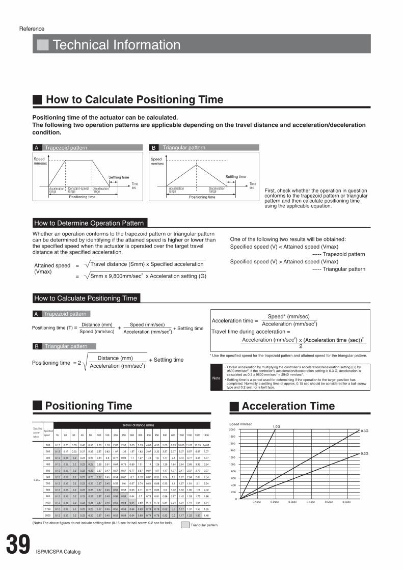
Reference
39 ISPA/ICSPA Catalog

Reference
ISPA/ICSPA Catalog40
Single-A
xisRobots
Cartesian
Robots
Contro
llers