System Automation for z/OS : Defining Automation Policy - IBM
462
System Automation for z/OS Version 4.Release 1 Defining Automation Policy IBM SC34-2717-01
-
Upload
khangminh22 -
Category
Documents
-
view
1 -
download
0
Transcript of System Automation for z/OS : Defining Automation Policy - IBM

System Automation for z/OSVersion 4.Release 1
Defining Automation Policy
IBM
SC34-2717-01

Note
Before using this information and the product it supports, read the information in Appendix D,“Notices,” on page 387.
Edition Notes
This edition applies to IBM® System Automation for z/OS (Program Number 5698-SA4) Version 4 Release 1, an IBMlicensed program, and to all subsequent releases and modifications until otherwise indicated in new editions.
This edition replaces SC34-2717-00.© Copyright International Business Machines Corporation 1996, 2017.US Government Users Restricted Rights – Use, duplication or disclosure restricted by GSA ADP Schedule Contract withIBM Corp.

Contents
Figures................................................................................................................. ix
Tables.................................................................................................................xxi
Accessibility..................................................................................................... xxiiiUsing assistive technologies................................................................................................................... xxiiiKeyboard navigation of the user interface.............................................................................................. xxiii
About this publication........................................................................................ xxvWho Should Use This Publication.............................................................................................................xxvNotes on Terminology...............................................................................................................................xxvWhere to Find More Information..............................................................................................................xxv
The System Automation for z/OS Library........................................................................................... xxvRelated Product Information............................................................................................................. xxvi
Summary of Changes for SC34-2717-01................................................................................................xxviNew Information................................................................................................................................ xxviChanged Information........................................................................................................................ xxviiDeleted Information..........................................................................................................................xxvii
Chapter 1. Introducing the Customization Dialog....................................................1How to Define Automation Policy: An Outline.............................................................................................1Entry Type Introduction............................................................................................................................... 2
Policy Objects and Policy Items.............................................................................................................4Considerations for Automation....................................................................................................................6Assigning System Automation Symbols (AOCCLONE)................................................................................ 7
Using System Symbols and System Automation Symbols....................................................................8Nested Classes...........................................................................................................................................11
Class Hierarchy.....................................................................................................................................12Inheritance and Defaulting.................................................................................................................. 12
Chapter 2. Using the Customization Dialog........................................................... 15How to Start the Customization Dialog..................................................................................................... 15Getting Help............................................................................................................................................... 17How to Navigate in the Customization Dialog........................................................................................... 17
How to Use an Entry Type as a Fast Path.............................................................................................18How to Use a Policy Item as a Fast Path............................................................................................. 18Concurrent User Access.......................................................................................................................19How to Cancel Input on a Panel...........................................................................................................19
How to Create New Policy Objects............................................................................................................ 19How to Rename a Policy Object.................................................................................................................20How to Delete Policy Objects.................................................................................................................... 21
How to Delete a Single Policy Object...................................................................................................21How to Delete Several Policy Objects in One Go (Bulk Deletion)....................................................... 22
How to Browse a Policy Item.....................................................................................................................23How to Find Data in a Policy Item............................................................................................................. 23How to View Long Input Fields in Full Length........................................................................................... 25Common Policy Items................................................................................................................................26
DESCRIPTION Policy Item................................................................................................................... 26COPY Policy Item..................................................................................................................................26
iii

WHERE USED Policy Item.................................................................................................................... 28Select ................................................................................................................................................... 30
Chapter 3. Scenarios on How to Use the Customization Dialog.............................. 33How to Work with Resources.....................................................................................................................33
A Grouping Scenario.............................................................................................................................33Grouping the Resources.......................................................................................................................35
How to Use Schedules (Service Periods).................................................................................................. 54Schedule Override................................................................................................................................ 54Early Start............................................................................................................................................. 55
How to Use Triggers and Events................................................................................................................55Scenario Environment and Behavior....................................................................................................55A Possible Solution...............................................................................................................................55
How to Use User E-T Pairs......................................................................................................................... 61Step 1: Specifying User Data in the Customization Dialog..................................................................61Step 2: Access the User Data...............................................................................................................62
How to Implement Message Processing with User-Defined Data........................................................... 63Step 1: Specify the User-Defined Data................................................................................................ 63Step 2: Specify the Commands............................................................................................................64Step 3: Update the NetView Automation Table...................................................................................64Step 4: Write the REXX Script.............................................................................................................. 66
How to Work with Externally Stopped and Started Resources................................................................ 67Configuring a resource that is externally started................................................................................ 67External Startup Sequence.................................................................................................................. 68Configuring a Resource that is Externally Stopped............................................................................. 68
FORCEDOWN - Configuring a Resource to be Automatically Shutdown.................................................. 69Working with MONITOR Resources...........................................................................................................69
Passive and Active Monitors................................................................................................................ 69Monitor Status...................................................................................................................................... 70
Chapter 4. Entry Type Reference.......................................................................... 71Defining Automation for OPC Components...............................................................................................72Enterprise Entry Type................................................................................................................................ 73
Policy Items for an Enterprise..............................................................................................................73SEND COMMAND OPERS Policy Item.................................................................................................. 74INGSEND PARMS Policy Item.............................................................................................................. 75PROCOPS FOCAL POINTS Policy Item.................................................................................................76USER MSG CLASSES Policy Item......................................................................................................... 76SYMBOL DESCRIPTION Policy Item.................................................................................................... 77
Group Entry Type....................................................................................................................................... 78Creating a New Group.......................................................................................................................... 78Policy Items for Standard Groups........................................................................................................79Policy Items for Sysplex Groups.......................................................................................................... 80GROUP INFO Policy Item..................................................................................................................... 81SYSPLEX Policy Item............................................................................................................................ 82LOCAL PAGE DATA SET Policy Item..................................................................................................... 83JOB DEFINITIONS Policy Item............................................................................................................ 84JOB/ASID DEFINITIONS Policy Item.................................................................................................. 84COMMAND DEFINITIONS Policy Item.................................................................................................85COMMAND FLOODING Policy Item......................................................................................................87RESOURCE DEFINITIONS Policy Item................................................................................................ 87RECOVERY OPTIONS Policy Item........................................................................................................ 88
SubGroup Entry Type.................................................................................................................................89Creating a New SubGroup.................................................................................................................... 89Policy Items for SubGroups................................................................................................................. 90
System Entry Type..................................................................................................................................... 91Creating a New System........................................................................................................................ 91
iv

Policy Items for Systems......................................................................................................................92SYSTEM INFO Policy Item....................................................................................................................95AUTOMATION SYMBOLS Policy Item.................................................................................................. 96AUTOMATION CONSOLE Policy Item.................................................................................................. 97PROCESSOR Policy Item...................................................................................................................... 98TARGET SYSTEM INFO Policy Item......................................................................................................99IPL INFO Policy Item..........................................................................................................................100
ApplicationGroup Entry Type.................................................................................................................. 102Creating a New ApplicationGroup..................................................................................................... 102Policy Items for ApplicationGroups...................................................................................................105APPLGROUP INFO Policy Item.......................................................................................................... 107APPLICATIONS Policy Item............................................................................................................... 109TRIGGER Policy Item......................................................................................................................... 110SERVICE PERIOD Policy Item............................................................................................................110RELATIONSHIPS Policy Item.............................................................................................................110RESOURCES Policy Item.................................................................................................................... 115GENERATED RESOURCES Policy Item.............................................................................................. 122MEMBER OF Policy Item.................................................................................................................... 122
Application Entry Type.............................................................................................................................123Creating a New Application................................................................................................................123Policy Items for Applications.............................................................................................................127UPWARD CLASS Policy Item..............................................................................................................130DOWNWARD CLASS/INST Policy Item..............................................................................................131APPLICATION INFO Policy Item........................................................................................................132AUTOMATION FLAGS Policy Item..................................................................................................... 140APPLICATION SYMBOLS Policy Item................................................................................................ 142TRIGGER Policy Item......................................................................................................................... 143SERVICE PERIOD Policy Item............................................................................................................143RELATIONSHIPS Policy Item.............................................................................................................143MESSAGES/USER DATA Policy Item.................................................................................................. 144STARTUP Policy Item......................................................................................................................... 160SHUTDOWN Policy Item.................................................................................................................... 163THRESHOLDS Policy Item..................................................................................................................169MINOR RESOURCES Policy Item....................................................................................................... 170SYSTEM ASSOCIATION Policy Item.................................................................................................. 172GENERATED RESOURCES Policy Item.............................................................................................. 172MEMBER OF Policy Item for Applications......................................................................................... 173Policy Items for JES2 Subsystems.................................................................................................... 173Policy Items for JES3 Subsystems.................................................................................................... 177Policy Items for CICS Subsystems.................................................................................................... 178Policy Items for DB2 Subsystems..................................................................................................... 180Policy Items for IMS Subsystems......................................................................................................181Policy Items for OPC Subsystems..................................................................................................... 182Policy Items for USS Subsystems......................................................................................................183
Events Entry Type.................................................................................................................................... 186Creating a New Event......................................................................................................................... 186Policy Items for Events...................................................................................................................... 187CONDITION Policy Item.................................................................................................................... 187
Service Periods Entry Type......................................................................................................................188Policy Items for Service Periods........................................................................................................ 188SERVICE WINDOW Policy Item......................................................................................................... 189
Triggers Entry Type.................................................................................................................................. 191Policy Items for Triggers.................................................................................................................... 191CONDITION Policy Item.................................................................................................................... 191
Processor Entry Type...............................................................................................................................193Creating a New Processor..................................................................................................................193Policy Items for Mainframe Processors.............................................................................................195Policy Items for PSM Processors....................................................................................................... 201
v

Monitor Resource Entry Type.................................................................................................................. 204Policy Items for Monitor Resources...................................................................................................205MONITOR INFO Policy Item.............................................................................................................. 206MESSAGES/USER DATA Policy Item.................................................................................................. 208HEALTHSTATE Policy Item.................................................................................................................213TRIGGER Policy Item......................................................................................................................... 214
zEnterprise Ensembles Entry Type......................................................................................................... 214Creating a New zEnterprise Ensemble.............................................................................................. 214Policy Items for zEnterprise Ensembles........................................................................................... 215ENSEMBLE INFO Policy Item.............................................................................................................215
Pacing Gates Entry Type..........................................................................................................................217Policy Items for Pacing Gates............................................................................................................217PACING GATE INFO Policy item.........................................................................................................217
OPC System Detail Entry Type................................................................................................................ 218OPCAO ENVIRON Policy Item............................................................................................................218
OPC Controller Details Entry Type.......................................................................................................... 219OPCA PCS Policy Item........................................................................................................................219
OPC Special Resources Entry Type......................................................................................................... 220SPECIAL RESOURCE Policy Item.......................................................................................................221
OPC Workstation Domains Entry Type.................................................................................................... 221Code Processing for OPC Workstation Domains.....................................................................................222Messages Entry Type............................................................................................................................... 223
Messages Policy Items.......................................................................................................................223MESSAGE AUTOMATION Policy Item................................................................................................ 224MPF DEFINITIONS Policy Item......................................................................................................... 226AT/MRT INSERTS Policy Item............................................................................................................ 227BUILD CONTROL Policy Item.............................................................................................................228
Timers Entry Type....................................................................................................................................229TIMERS Policy Item........................................................................................................................... 229
Tape Attendance Entry Type................................................................................................................... 232ATTEND TIME Policy Item................................................................................................................. 233
MVS Component Entry Type....................................................................................................................234Policy Items for MVS Component......................................................................................................234PREDEFINED MESSAGES Policy Item............................................................................................... 235MESSAGES/USER DATA Policy Item.................................................................................................. 237MINOR RESOURCES Policy Item....................................................................................................... 238
MVSCOMP Defaults Entry Type............................................................................................................... 238Policy Items for MVSCOMP Defaults................................................................................................. 238
System Defaults Entry Type.................................................................................................................... 239Policy Items for System Defaults...................................................................................................... 239AUTOMATION OPTIONS Policy Item.................................................................................................240
Application Defaults Entry Type..............................................................................................................241Policy Items for Application Defaults................................................................................................ 241
Automation Operators Entry Type...........................................................................................................242Policy Items for Automation Operators.............................................................................................242
Notify Operators Entry Type....................................................................................................................245Policy Items for Notify Operators...................................................................................................... 245NOTIFY OPERATORS Policy Item...................................................................................................... 246
Network Entry Type................................................................................................................................. 249Policy Items for Network................................................................................................................... 250SDF FOCALPOINT Policy Item........................................................................................................... 250FULL SESSIONS Policy Item.............................................................................................................. 251GATEWAY Policy Item........................................................................................................................ 252OMEGAMON Policy Item....................................................................................................................253AUTHENTICATION Policy Item..........................................................................................................255SOAP SERVER Policy Item................................................................................................................. 255
Sysplex Defaults Entry Type....................................................................................................................258Policy Items for Sysplex Defaults...................................................................................................... 258
vi

RESOURCE INFO Policy Item.............................................................................................................258Resident CLISTs Entry Type.................................................................................................................... 259
Policy Items for Resident CLISTs.......................................................................................................259Status Display Entry Type........................................................................................................................260
Policy Items for Status Display..........................................................................................................260SDF DETAILS Policy Item...................................................................................................................260
Remote Domains Entry Type................................................................................................................... 262Policy Items for Remote Domains..................................................................................................... 262DOMAIN INFO Policy Item.................................................................................................................263REFERENCES Policy Item.................................................................................................................. 263
Resource References Entry Type............................................................................................................ 263Policy Items for Resource References.............................................................................................. 264
User E-T Pairs Entry Type........................................................................................................................ 265Policy Items for User E-T Pairs.......................................................................................................... 265E-T DATA Policy Item......................................................................................................................... 266
Chapter 5. Policy Database Maintenance............................................................ 269Policy Database Selection List................................................................................................................ 269Creating a New Policy Database..............................................................................................................270
Using SA z/OS Sample Policies.......................................................................................................... 273Specifying Options for Policy Databases................................................................................................ 274
Logging Policy Database Modifications............................................................................................. 276
Chapter 6. Creating Reports about Policy Databases...........................................279
Chapter 7. Building and Distributing Configuration Files..................................... 287How to Define Data Sets for Build Processing........................................................................................ 287Building the Configuration Files.............................................................................................................. 287
Configuration Files Build Options...................................................................................................... 288Distributing the Configuration Files................................................................................................... 292Generating a Job for Batch Build.......................................................................................................293
Chapter 8. Automation Table, Message Revision Table, and MPFLSTxx member... 295The NetView Automation Table...............................................................................................................295The NetView Message Revision Table.....................................................................................................295Enabling AT Updates................................................................................................................................296Setting AT/MRT Scope............................................................................................................................. 296MPFLSTxx member.................................................................................................................................. 296System and Application Specific Overrides............................................................................................ 297The INGMSGSA Automation Table..........................................................................................................298Predefined SA z/OS Messages................................................................................................................ 298
The +SA_PREDEFINED_MSGS MVS Component Entry.....................................................................298Modifying Predefined Messages........................................................................................................ 299How to Apply Service Updates...........................................................................................................299
Chapter 9. Data Management............................................................................. 305Start Panel for Data Management........................................................................................................... 305Importing Policy Database Data............................................................................................................. 305
Batch Import with Data Modification................................................................................................ 308Importing Sample Add-On Policies.........................................................................................................309Making Updates with Text Files...............................................................................................................311
Supported Policies............................................................................................................................. 312Updating Policy Objects Using Text Files.......................................................................................... 313Creating New Policy Objects Using Text Files................................................................................... 318Deleting Policy Objects Using Text Files............................................................................................320
Generating a Job for Batch Update.........................................................................................................321
vii

Chapter 10. Conversion Function........................................................................323Moved and Restructured Data.................................................................................................................323
Converting from SA z/OS 3.5............................................................................................................. 323Converting from SA z/OS 3.4............................................................................................................. 323
Initial Policy Database Conversion..........................................................................................................324Selective Policy Database Conversion...............................................................................................324Generating a Job for Batch Conversion............................................................................................. 324Write Data to File using a Batch Job..................................................................................................324
Appendix A. Concurrent Customization by Multiple Users................................... 325Concurrent User Access Capabilities...................................................................................................... 325
Concurrent User Access within the Customization Dialog................................................................325Policy Definitions Usage.....................................................................................................................325Policy Database Selection..................................................................................................................326Entry Type Selection.......................................................................................................................... 326Entry Name Selection........................................................................................................................ 326Changing Links................................................................................................................................... 326
Appendix B. More about Using the Customization Dialog.....................................327Changing Your Customization Dialog Environment................................................................................ 327
Enabling and Disabling AT / MRT Syntax Checking........................................................................... 328Extending Policy Definitions.............................................................................................................. 329Defining Data Sets for Batch Processing........................................................................................... 332Defining ISPF Temporary Data Sets for Batch Build......................................................................... 334
User-written Functions............................................................................................................................334Alternate and Tertiary Configuration Support.........................................................................................335
How to Define Alternate and Tertiary Configurations for Systems................................................... 336How to Build Alternate and Tertiary Configurations......................................................................... 336Restrictions........................................................................................................................................ 336
Appendix C. Add-on policies.............................................................................. 339*BASE....................................................................................................................................................... 340*CICS........................................................................................................................................................346*DB2.........................................................................................................................................................348*E2E......................................................................................................................................................... 351*GDPS.......................................................................................................................................................354*IBMCOMP............................................................................................................................................... 356*IMS......................................................................................................................................................... 364*ITM......................................................................................................................................................... 368*IWS......................................................................................................................................................... 374*PROCOPS................................................................................................................................................376*SAPSRV...................................................................................................................................................380*TBSM...................................................................................................................................................... 385
Appendix D. Notices...........................................................................................387Trademarks.............................................................................................................................................. 388Terms and conditions for product documentation................................................................................. 388
Glossary............................................................................................................ 391
Index................................................................................................................ 423
viii

Figures
1. Entry Type Selection Panel............................................................................................................................5
2. Entry Name Selection Panel for Groups....................................................................................................... 5
3. Policy Selection Panel for Sysplex Groups................................................................................................... 6
4. Nested Class Links...................................................................................................................................... 12
5. Inheritance from Classes and Defaulting................................................................................................... 13
6. Customization Dialog Primary Menu...........................................................................................................16
7. Define New Entry Panel for an Application.................................................................................................20
8. Sample Generic Define New Entry Panel....................................................................................................20
9. Entry Name Selection Panel: Rename Action.............................................................................................21
10. Entry Name Rename Pop-up Panel.......................................................................................................... 21
11. Delete Confirmation Panel for a Single Policy Object.............................................................................. 22
12. Confirmation Panel for Bulk Deletion with WHERE USED Links.............................................................. 22
13. Sample Description Policy Item Panel..................................................................................................... 26
14. Hierarchy of Entry Types...........................................................................................................................29
15. Policy Selection Panel...............................................................................................................................30
16. Applications for ApplicationGroup Panel for System Application Groups.............................................. 30
17. Application Groups....................................................................................................................................34
18. Grouping of Applications into Nested ApplicationGroups....................................................................... 35
19. Scenario: Current Configuration with Sysplex Application Group CICSAOR...........................................40
20. Scenario: Current Configuration with Applications CICS1AR1, CPSMCMAS, CPSMWUI........................41
21. Scenario: Resources for the CICSAOR Sysplex Application Group......................................................... 41
22. Scenario: Current Configuration with Application Group DB2.................................................................42
23. Scenario: Current Configuration with Applications Linked to DB2.......................................................... 43
ix

24. Scenario: Select System Panel for DB2 Application group......................................................................43
25. Scenario: Select Resources Panel for DB2 Application Group................................................................ 44
26. Scenario: Grouping Resources..................................................................................................................45
27. Scenario: Resources for the CICS Sysplex Application Group.................................................................45
28. Scenario: Current Configuration with Applications Linked to DB2.......................................................... 45
29. Scenario: Select Resources Panel for Application Group NET................................................................ 46
30. Scenario: Select Resources Panel for DWHAPG with valid APG Resources............................................47
31. Scenario: Select Resources Panel for DWHAPG2.................................................................................... 48
32. Scenario: Select Resources Panel for DWHAPG2 after Selection........................................................... 49
33. Scenario: Select Resources Panel for DWHAPG3.................................................................................... 49
34. Scenario: Select Resources Panel for DWHAPG with Valid APG Resources........................................... 50
35. Scenario: Setting Preferences with the Select Resources Panel for DWHAPG....................................... 50
36. Scenario: Select Resources Panel for DWHAPG with Converted Preferences........................................51
37. Scenario: Define New Entry Input Panel for WBSRVAPG.........................................................................53
38. Scenario: Final Select Resources Panel for WBSRVAPG..........................................................................54
39. Policy Objects in the Solution................................................................................................................... 56
40. Generated Resources in the Solution.......................................................................................................57
41. UET Entry-Type Selection Panel............................................................................................................... 62
42. UET Keyword-Data Specification Panel....................................................................................................62
43. Scenario: Using the Message Processing Panel....................................................................................... 63
44. Scenario: User Data Processing Panel......................................................................................................64
45. Scenario: Command Processing Panel.....................................................................................................64
46. Scenario: Message Processing Panel for AT Entry................................................................................... 65
47. Scenario: Message Automation Overview Panel Default Values............................................................. 65
48. Scenario: Editor with User Values for Automation Table Entry............................................................... 65
x

49. Scenario: Message Automation Overview with User Values....................................................................66
50. Entry Type Selection Panel....................................................................................................................... 71
51. Entry Type Selections for Product Automation Panel..............................................................................72
52. Policy Selection Panel for Enterprises......................................................................................................73
53. Operator Profile for Sending Commands Panel....................................................................................... 74
54. INGSEND Command Parms Panel............................................................................................................75
55. Processor Operations Focal Point Information Panel..............................................................................76
56. User Message Classes Panel.................................................................................................................... 77
57. System Automation Symbols (AOCCLONEx) Description Panel.............................................................. 77
58. Define New Entry Panel for a Sysplex Group........................................................................................... 78
59. Policy Selection Panel for Standard Groups.............................................................................................79
60. Policy Selection Panel for Sysplex Groups............................................................................................... 80
61. Group Information Panel for Standard Groups........................................................................................ 81
62. Sysplex Policy Definition Panel for Sysplex Groups.................................................................................82
63. Local Page Data Set Recovery Panel........................................................................................................ 83
64. Local Page Data Set Recovery Job Definition Panel.................................................................................84
65. Long Running ENQ Job/ASID Definitions Panel....................................................................................... 85
66. "Hung" Command Definitions Panel.........................................................................................................86
67. Command Flooding Definition Panel........................................................................................................ 87
68. Long Running ENQ Resource Definition Panel......................................................................................... 87
69. Recovery Options Panel............................................................................................................................ 88
70. Define New Entry Panel for a Subgroup................................................................................................... 90
71. Policy Selection Panel for Subgroups.......................................................................................................90
72. Define New Entry Panel for a System....................................................................................................... 91
73. Policy Selection Panel for Systems...........................................................................................................93
xi

74. System Information Panel........................................................................................................................ 95
75. Automation Symbols Panel.......................................................................................................................97
76. Environment Definition: CONSOLE (Route Codes) Panel.........................................................................98
77. Select Target Hardware for System Panel................................................................................................99
78. Target System Information Panel............................................................................................................. 99
79. MVS Target System IPL Information Panel............................................................................................ 101
80. VM Target System IPL Information Panel.............................................................................................. 102
81. Define New Entry Panel for a Sysplex Application Group......................................................................103
82. Policy Selection Panel for System Application Groups..........................................................................106
83. Application Group Information Panel.................................................................................................... 107
84. Applications for ApplicationGroup Panel for System Application Groups............................................ 109
85. Trigger for ApplicationGroup Panel........................................................................................................ 110
86. Service Period for ApplicationGroup Panel for System Application Groups......................................... 110
87. Relationship Selection List Panel........................................................................................................... 111
88. Define Relationship Panel.......................................................................................................................112
89. Example of Strong Chaining....................................................................................................................115
90. Select Resources for ApplicationGroup Panel....................................................................................... 116
91. Generated Resources Panel................................................................................................................... 122
92. Member of Panel for ApplicationGroups................................................................................................ 122
93. Define New Entry Panel for Applications............................................................................................... 123
94. Policy Selection Panel for Applications..................................................................................................127
95. Upward Link to Class Panel.................................................................................................................... 130
96. Downward Link to Classes or Instances Panel...................................................................................... 131
97. Application Information Panel............................................................................................................... 133
98. Flag Automation Specification Panel..................................................................................................... 141
xii

99. Application Symbols Panel..................................................................................................................... 142
100. Trigger for Application Panel................................................................................................................ 143
101. Service Period for Application Panel....................................................................................................143
102. Relationship Selection List Panel......................................................................................................... 144
103. Message Processing Panel................................................................................................................... 144
104. Command Processing Panel for Applications...................................................................................... 147
105. Reply Processing Panel for Applications..............................................................................................148
106. Code Processing Panel......................................................................................................................... 149
107. User Data Processing Panel for Applications.......................................................................................152
108. Message Automation Overview Panel..................................................................................................153
109. Automation Table entry Conditions Panel........................................................................................... 154
110. AT Status Specification Panel...............................................................................................................155
111. Editor Panel to Specify an AT Override................................................................................................ 156
112. Message Revision Table Conditions Panel........................................................................................... 157
113. Editor Panel to Specify an MRT Override............................................................................................. 158
114. MPF Specification Panel....................................................................................................................... 158
115. AT/MRT/MPF Ignore Specification Panel............................................................................................. 159
116. Using the STARTUP Policy Item........................................................................................................... 160
117. Subsystem Startup Processing Panel.................................................................................................. 161
118. Command Processing Panel for Startup Commands...........................................................................162
119. Subsystem Shutdown Processing Panel.............................................................................................. 163
120. Command Processing Panel for SHUTINIT or SHUTFINAL.................................................................165
121. Command Processing Panel for SHUTNORM, SHUTIMMED, or SHUTFORCE.....................................166
122. Reply Processing Panel for SHUTINIT................................................................................................. 167
123. Reply Processing Panel for SHUTNORM, SHUTIMMED and SHUTFORCE.......................................... 168
xiii

124. Thresholds Definition Panel................................................................................................................. 169
125. Minor Resource Definitions Panel........................................................................................................ 170
126. System Association Panel.................................................................................................................... 172
127. Generated Resources Panel................................................................................................................. 172
128. Member of Panel for Applications........................................................................................................173
129. Policy Selection Panel for JES2 Subsystems....................................................................................... 173
130. SPOOLFULL Specification Panel for JES2............................................................................................ 174
131. SPOOLFULL Processing Panel for JES2............................................................................................... 175
132. SPOOLSHORT Specification Panel....................................................................................................... 176
133. SPOOLSHORT Commands Processing Panel for JES2........................................................................ 176
134. JES2 DRAIN Specification Panel..........................................................................................................177
135. Policy Selection Panel for JES3 Subsystems....................................................................................... 177
136. JES3 SPOOLFULL Processing Panel.....................................................................................................178
137. JES3 SPOOLSHORT Processing Panel................................................................................................. 178
138. Policy Selection Panel for CICS Subsystems....................................................................................... 179
139. CICS Control Specifications Panel....................................................................................................... 179
140. Policy Selection Panel for DB2 Subsystems........................................................................................ 180
141. DB2 Control Entries Panel.................................................................................................................... 180
142. Policy Selection Panel for IMS Subsystems.........................................................................................181
143. IMS Control Region Specifications Panel for Subcategory CTL...........................................................182
144. Policy Selection Panel for OPC Subsystems........................................................................................ 182
145. OPC control specifications Panel......................................................................................................... 183
146. Policy Selection Panel for USS Subsystems.........................................................................................184
147. USS Control Specification Panel for Application Classes.................................................................... 184
148. USS Control Specification Panel for Application Instances................................................................ 184
xiv

149. Entry Name Selection Panel for Events............................................................................................... 186
150. Define New Event Panel....................................................................................................................... 187
151. Policy Selection Panel for Events......................................................................................................... 187
152. Unset Condition Panel for Events.........................................................................................................188
153. Policy Selection Panel for Service Periods...........................................................................................189
154. Service Windows Panel for Service Periods.........................................................................................189
155. Policy Selection Panel for Triggers.......................................................................................................191
156. Trigger Conditions Panel.......................................................................................................................192
157. STARTUP Condition for Trigger Panel...................................................................................................192
158. Defining a New SA z/OS Processor Entry............................................................................................. 193
159. Policy Selection Panel for Processor....................................................................................................196
160. Processor Information Panel................................................................................................................197
161. LPAR Definitions Panel......................................................................................................................... 201
162. Policy Selection Panel for PSM Processors..........................................................................................202
163. ProcOps Service Machine Information Panel...................................................................................... 202
164. GUEST Definitions Panel.......................................................................................................................204
165. Policy Selection for Monitor Resource................................................................................................. 205
166. Monitor Resource Information Panel................................................................................................... 206
167. Message Processing Panel with OMEGAMON Exception.................................................................... 209
168. Message Automation Overview Panel..................................................................................................209
169. AT Status Specification Panel...............................................................................................................210
170. CMD Processing Panel for Monitor Resources.....................................................................................210
171. Code Processing Panel......................................................................................................................... 211
172. User Defined Data Panel.......................................................................................................................211
173. Monitor Resource CMD Processing Panel - Pass Processing.............................................................. 212
xv

174. User Defined Data Panel.......................................................................................................................212
175. Command Processing Panel for the HEALTHSTATE Policy Item......................................................... 213
176. Trigger for Monitor Resource Panel......................................................................................................214
177. Defining a New zEnterprise Ensemble Panel.......................................................................................214
178. zEnterprise Ensemble Policy Items Panel........................................................................................... 215
179. zEnterprise Ensemble Information Panel............................................................................................ 216
180. Policy Selection Panel for Pacing Gates...............................................................................................217
181. Pacing Gate Information Panel............................................................................................................ 217
182. Policy Selection Panel for OPC System Detail..................................................................................... 218
183. OPC System Details Panel.................................................................................................................... 218
184. Policy Selection Panel for OPC Controller Details............................................................................... 219
185. OPC Controller Details Panel................................................................................................................220
186. Policy Selection Panel for OPC Special Resources.............................................................................. 221
187. OPC Special Resource Definitions Panel..............................................................................................221
188. Policy Selection Panel for OPC Workstation Domain...........................................................................222
189. Code Processing Panel for OPC Workstation Domain IDs...................................................................222
190. Messages Entry Type Policy Selection Panel.......................................................................................223
191. Message Definitions Panel................................................................................................................... 224
192. Entries linked to Message Panel.......................................................................................................... 225
193. Message Automation Overview Panel..................................................................................................225
194. MPFLSTxx Member Definitions Panel...................................................................................................226
195. User Insert Definition........................................................................................................................... 227
196. Define Build Control Parameter........................................................................................................... 228
197. Policy Selection Panel for Timers.........................................................................................................229
198. Timer Definitions Panel........................................................................................................................ 229
xvi

199. Timer Definitions Panel 2..................................................................................................................... 230
200. Policy Selection Panel for Tape Attendance........................................................................................ 233
201. Environment Definition: TAPES Panel.................................................................................................. 233
202. Panel for MVS Component Selection................................................................................................... 234
203. Policy Selection Panel for MVS Components....................................................................................... 235
204. Component Selection Panel for MVS Components..............................................................................236
205. Message Processing Panel for MVS Components................................................................................237
206. Policy Selection Panel for MVSCOMP Defaults.................................................................................... 238
207. Policy Selection Panel for System Defaults......................................................................................... 239
208. System Automation Options Panel...................................................................................................... 240
209. Policy Selection Panel for Application Defaults...................................................................................242
210. Policy Selection Panel for Automation Operators............................................................................... 243
211. Automation Operator Definition Panel.................................................................................................243
212. Automation Operator Definitions Panel............................................................................................... 244
213. Policy Selection Panel for Notify Operators.........................................................................................246
214. Operator Notification Panel..................................................................................................................246
215. Notify Operator Message Classes Panel.............................................................................................. 247
216. Policy Selection Panel for Network...................................................................................................... 250
217. SDF Focal Point Definition panel.......................................................................................................... 251
218. Fullscreen TAF Application Definition Panel........................................................................................252
219. GATEWAY Definitions Panel................................................................................................................. 252
220. OMEGAMON Sessions Definitions Panel..............................................................................................253
221. OMEGAMON Session Attributes Panel.................................................................................................254
222. Authentication Definitions Panel..........................................................................................................255
223. SOAP Server Definitions Panel............................................................................................................. 256
xvii

224. SOAP-Server Attributes Panel..............................................................................................................256
225. Policy Selection Panel for Sysplex Defaults.........................................................................................258
226. Sysplex Resource Information Defaults Panel.................................................................................... 258
227. Policy Selection Panel for Resident CLISTs......................................................................................... 259
228. Policy Selection Panel for Status Display.............................................................................................260
229. Status Display Facility Details Panel.................................................................................................... 261
230. Policy Selection Panel for Remote Domains........................................................................................262
231. Domain Information Panel................................................................................................................... 263
232. References Panel.................................................................................................................................. 263
233. Policy Selection Panel for REF..............................................................................................................264
234. Remote Resource Panel....................................................................................................................... 265
235. Policy Selection Panel for User E-T Pairs............................................................................................. 266
236. UET Entry-Type Selection Panel...........................................................................................................266
237. UET Keyword-Data Specification Panel............................................................................................... 267
238. Policy Database Selection Panel.......................................................................................................... 269
239. Policy Database Selection Panel.......................................................................................................... 271
240. Create a New Policy Database Panel................................................................................................... 271
241. New Policy Database Data Set Information Panel...............................................................................272
242. Options for Policy Database Panel....................................................................................................... 275
243. Example of an Activity Log....................................................................................................................277
244. SA z/OS Report Selection Menu........................................................................................................... 279
245. Policy Data Base Report Parameters Panel......................................................................................... 279
246. Example of Report Output Format FLAT.............................................................................................. 282
247. List of Generated Resources................................................................................................................ 283
248. Unreferenced Member Report..............................................................................................................284
xviii

249. Example Status Messages Report (Excerpt)........................................................................................284
250. Example Symbols Report (Excerpt)..................................................................................................... 285
251. Configuration Build Panel..................................................................................................................... 288
252. Message and Logging Functions Panel................................................................................................ 292
253. SA z/OS Automation Configuration...................................................................................................... 293
254. APAR Apply Options panel................................................................................................................... 300
255. Data Management Menu Panel............................................................................................................ 305
256. Policy Data Base Import Panel.............................................................................................................306
257. Entry Name Selection Panel for Import Policy Data............................................................................307
258. Selected Entry Names For Import Panel............................................................................................. 307
259. Modify Data Pop-Up Window............................................................................................................... 308
260. Import Add-On Policies Panel..............................................................................................................309
261. Entries of Selected Add-on Policies Panel...........................................................................................310
262. SA z/OS Customization Dialog Settings Menu..................................................................................... 327
263. Automation Table Override Checking.................................................................................................. 328
264. Sample of Edit Policy Selections Panel................................................................................................ 329
265. Define Policy Selection Panel...............................................................................................................330
266. SA z/OS Data Set Customization Details Panel....................................................................................333
267. ISPF Temporary Data Sets Preallocation for Batch Panel...................................................................334
268. Send Automation Configuration Data Sets Panel................................................................................ 335
xix

xx

Tables
1. System Automation for z/OS library.......................................................................................................... xxv
2. System Symbols and System Automation Symbols.....................................................................................8
3. System Symbols.......................................................................................................................................... 10
4. System Automation Symbols......................................................................................................................11
5. Entry Details for Applications in the Scenario............................................................................................ 38
6. Preference Value Scenarios...................................................................................................................... 119
7. SA z/OS Message Classes......................................................................................................................... 248
8. Policy Selection Filter Attributes.............................................................................................................. 331
xxi

xxii

Accessibility
Accessibility features help users with physical disabilities, such as restricted mobility or limited vision, touse software products successfully. System Automation for z/OS supports several user interfaces.Product functionality and accessibility features vary according to the interface.
The major accessibility features in this product enable users in the following ways:
• Use assistive technologies such as screen reader software and digital speech synthesizer, to hear whatis displayed on screen. Consult the product documentation of the assistive technology for details onusing those technologies with this product and screen magnifier software
• Operate specific or equivalent features using only the keyboard• Magnify what is displayed on screen.
The product documentation includes the following features to aid accessibility:
• All documentation is available to both HTML and convertible PDF formats to give the maximumopportunity for users to apply screen-reader software
• All images in the documentation are provided with alternative text so that users with vision impairmentscan understand the contents of the images.
Using assistive technologiesAssistive technology products, such as screen readers, function with the user interfaces found in z/OS®.Consult the assistive technology documentation for specific information when using such products toaccess z/OS interfaces.
Keyboard navigation of the user interfaceUsers can access z/OS user interfaces using TSO/E or ISPF. Refer to z/OS TSO/E Primer, z/OS TSO/E User'sGuide, and z/OS ISPF User's Guide Vol 1 for information about accessing TSO/E and ISPF interfaces. Theseguides describe how to use TSO/E and ISPF, including the use of keyboard shortcuts or function keys (PFkeys). Each guide includes the default settings for the PF keys and explains how to modify their functions.
© Copyright IBM Corp. 1996, 2017 xxiii

xxiv System Automation for z/OS : Defining Automation Policy

About this publication
This publication describes System Automation for z/OS (SA z/OS). This product plays a key role insupplying high-end automation solutions whereas Tivoli® Systems (Tivoli Management Environment,Tivoli) delivers integrated cross-platform management functions. This publication contains informationabout how to enable SA z/OS automation.
Who Should Use This PublicationThis publication is primarily intended for automation administrators who are responsible for defining andmaintaining the automation policy.
Notes on Terminology
MVSReferences in this book to MVS™ refer either to the MVS/ESA product or to the MVS element of z/OS.
OPCReferences in this book to OPC refer to IBM Workload Scheduler (IWS) that is formally called TivoliWorkload Scheduler (TWS).
Resources, Applications, and SubsystemsThese three terms are used in the SA z/OS library to designate automated entities. The correct term to beused depends on the context. See "Understanding Terms" in IBM System Automation for z/OS Operator'sCommands for the definition of these terms.
Where to Find More Information
The System Automation for z/OS LibraryTable 1 on page xxv shows the information units in the System Automation for z/OS library. Thesemanuals can be downloaded from IBM Documentation.
Table 1. System Automation for z/OS library
Title Form Number Description
Get Started Guide SC27-9532 This book is intended for SA z/OS beginners. Itcontains the information about early planning,configuring the product, making it secure,customizing your automation environment, andthe basic operational tasks that you perform on adaily basis.
Planning and Installation SC34-2716 Describes SA z/OS new capabilities and how toplan, install, configure, and migrate SA z/OS.
Customizing and Programming SC34-2715 Describes how to adapt the standard installation,add new applications to automation, write yourown automation procedures, and add newmessages for automated applications.
© Copyright IBM Corp. 1996, 2017 xxv

Table 1. System Automation for z/OS library (continued)
Title Form Number Description
Defining Automation Policy SC34-2717 Describes how to define and maintain theautomation policy.
User's Guide SC34-2718 Describes SA z/OS functions and how to useSA z/OS to monitor and control systems.
Messages and Codes SC34-2719 Describes the problem determination informationof SA z/OS, including messages, return codes,reason codes, and status codes.
Operator's Commands SC34-2720 Describes the operator commands available withSA z/OS, including their purpose, format, andspecifics of how to use them.
Programmer's Reference SC34-2748 Describes the programming interfaces of SA z/OSand the definitions for the status display facility(SDF).
End-to-End Automation SC34-2750 Describes the end-to-end automation adapter forz/OS and how it enables end-to-end automationand how it connects to Service Management UniteAutomation.
Service Management UniteAutomation Installation andConfiguration Guide
SC27-8747 Describes how to plan, install, set up, configure,and troubleshoot Service Management UniteAutomation.
Product AutomationProgrammer's Reference andOperator's Guide
SC34-2714 Describes how to customize and operate productautomation components (CICS, Db2, and IMSautomation) with SA z/OS to provide a simple andconsistent way to monitor and control all of theCICS, Db2, and IMS regions, both local andremote, within your organization.
TWS Automation Programmer'sand Operator's Reference Guide
SC34-2749 Describes how to customize and operate TWSAutomation.
Related Product InformationFor information that supports System Automation for z/OS, visit the z/OS library in IBM Documentation(https://www.ibm.com/docs/en/zos).
Summary of Changes for SC34-2717-01This document contains information previously presented in System Automation for z/OS V3R5.0 DefiningAutomation Policy, SC34-2717-00.
The following sections provide details of significant or major changes in this edition.
New InformationThe following information is new in this edition:
Support for end-to-end automation
• With the help of the new entry types DMN (Remote Domains) and REF (Resource References), you areable to define references to resources running in domains outside the SAplex.
xxvi About this publication

• New value E2E in 'Inform List' to control whether or not the resource is shown on the End-to-Enddomain view. Note that this is currently only for future use.
Inform List is available for:
– Applications (APL)– Applications Groups (APG)– Monitor Resources (MTR)– Resource References (REF)– System Defaults (SDF)– MVSCOMP Defaults (MDF)– Sysplex Defaults (XDF)
• New IBM-supplied category E2EAGT to indicate that the application represents the end-to-end agent.
Support for IMS-MQ and CICS-MQ connection monitoring
• IMS-MQ connection monitoring defined in *IMS add-on policy• CICS-MQ connection monitoring defined in *CICS add-on policy
Changed InformationThe following information has been changed in this edition:
• With the definition of the 'Connection Scope' in the PROCESSOR INFO policy, it is possible to groupprocessors to a logically composite. With this definition you may restrict the established and monitoredconnections.
• List and delete unused members in the build output dataset directly from the 'Build Parameters' panel.See “Configuration Files Build Options” on page 288.
• *BASE add-on policy is restructured.
– z/OS Healthchecker definitions moved from *IBMCOMP add-on policy– SDSF and SDFSAUX included– New component for VIPA included
• *ITM add-on policy is restructured.• *TWS add-on policy is renamed to *IWS.• The pictures of SA z/OS Best Practice policies have been moved from the USS directory to Add-on
policies.
Deleted InformationThe following information has been deleted:
• SA z/OS Graphical Interface (NMC)• *USS add-on policy (integrated in *BASE)• *NMC add-on policy• *WEBSPHERE add-on policy (integrated in *IBMCOMP)• Component IO-Operations removed from *IBMCOMP add-on policy
You may notice changes in the style and structure of some content in this document—for example,headings that use uppercase for the first letter of initial words only, and procedures that have a differentlook and format. The changes are ongoing improvements to the consistency and retrievability ofinformation in our documents.
This document contains terminology, maintenance, and editorial changes.
About this publication xxvii

xxviii System Automation for z/OS : Defining Automation Policy

Chapter 1. Introducing the Customization Dialog
Before you can use SA z/OS to automate, monitor, and control the resources in your enterprise, you mustdefine your enterprise's automation policy. You use the SA z/OS customization dialog to provideinformation for SA z/OS, such as:
• Which resources (such as systems or applications) you want to automate, monitor and control• How resources are to be associated (that is, grouped) with each other for automation• The dependencies between resources and groups of resources• What sort of automation, such as automatic startup or shutdown, is to be applied to these resources
and how• The conditions that automated actions should occur under, and what actions should be performed• When automation is to be active, and how it handles certain tasks and events during system operation
The customization dialog leads the SA z/OS policy administrator through the process of defining resourcesand automation for the enterprise. SA z/OS automatically extracts the required information from this todisplay resources graphically.
Before you begin to use the customization dialog to define your enterprise automation policy, you need todetermine how you want SA z/OS to work within your enterprise. This is part of the process of planning touse SA z/OS. There are many considerations for planning to use SA z/OS that you should be aware of. Formore information, see the planning instructions given in IBM System Automation for z/OS Planning andInstallation.
Note: Do not use the customization dialogs on a Kanji terminal because they will not work. If you haveyour terminal defined as a 3278KN terminal, you can circumvent the Kanji restriction by going into ISPFoption 0.1 (panel ID ISPOPT1) and redefining the TERMINAL TYPE to 3278.
How to Define Automation Policy: An OutlineAutomation policy is needed if you want to use system operations or processor operations automationfunctions.
ProcedureThe process of defining automation policy comprises the following steps:1. At the configuration focal point where you have the customization dialog installed, create the
information in the policy database using the ISPF input panels of the customization dialog.2. Use the BUILD function of the customization dialog to produce the required output, that is, the
configuration files: automation control file (ACF), automation manager configuration file (AMC),NetView automation table (AT), the message revision table (MRT), and the MPFLSTxx file.
3. Distribute the generated output to each system in the SA z/OS enterprise where SA z/OS systemoperations functions are to run. In general, this is all of the z/OS systems in the SA z/OS enterprise. Ina sysplex, the data set name of the automation control file must be the same on all systems in thesysplex. However, it is highly recommended that you use a shared data set in a sysplex, and if possible,to use a shared data set for the whole enterprise.
ResultsSee Chapter 7, “Building and Distributing Configuration Files,” on page 287 and Figure 253 on page 293for more information on building and distributing the generated configuration files.
How to Define Automation Policy: An Outline
© Copyright IBM Corp. 1996, 2017 1

Entry Type IntroductionAll resources in your enterprise, such as systems or applications, or other objects that you use toautomate your enterprise data processing, such as components of your z/OS operating system, are calledentry types.
A complete list of SA z/OS entry types is given on the Entry Type Selection panel (see Figure 1 on page5), which is the first panel you see after you have decided which enterprise or policy database you aregoing to work with.
For each entry type you can invoke a series of panels to create, modify, or delete entries of a certain entrytype. A single instance of a particular entry type is called a policy object. These entries are referred to bytheir entry name.
When you select an object via its name, you get a list of policy items specific for the entry type that you areworking with. For example, the Timers entry type may consist of several named sets of timer definitions,each containing a number of timers. These named sets are selected and linked to a particular system asrequired. Each set can be linked to an arbitrary number of systems and any number of sets can be linkedto any particular system.
The letters and numbers in the following list indicate the entry type index on the Entry Type Selectionpanel. You can use either numbers or letters to select the appropriate entry type. The alphanumeric indexis used on other panels of the customization dialog to identify a certain entry type.
Detailed information and scenarios on how to automate the resources (applications and applicationgroups) and make them available on certain systems is given in Chapter 3, “Scenarios on How to Use theCustomization Dialog,” on page 33.
1/ENT Enterprise
An Enterprise is the top level of your SA z/OS structure. It comprises enterprise wide data for thecomplete policy database.
2/GRP GroupA group is the largest subdivision of an SA z/OS enterprise. An SA z/OS enterprise may have severalgroups, each consisting of systems or subgroups, or both.
A sysplex group can be used to represent a logical sysplex (systems within the same XCF group ID,also named SAplex). A standard group can be used to represent a physical sysplex (systems indifferent XCF group IDs). The definition of groups is a prerequisite for sysplex-wide automation.
3/SBG SubgroupLike groups, subgroups are collections of systems. You define a subgroup by selecting the membersystems and assigning a name to the subgroup. Subgroups can be collected into groups. They offer afiner level of structuring groups.
4/SYS SystemA system is an image of an operating system running on a host processor monitored by SA z/OS. Thesystem may be MVS, VM, VSE, LINUX, or CF (coupling facility). A system definition includes forexample:
• Links to other objects associated with the system, for example, links to application groups• Application defaults• System defaults• System automation symbols
5/APG ApplicationGroupAn application group is a set of applications that you assign a name to. You can define two types ofapplication groups: System Application Groups and Sysplex Application Groups. You assign SystemApplication Groups to one or more systems and Sysplex Application Groups to one or more SAplexes(GRP of type sysplex).
Entry Type Introduction
2 System Automation for z/OS : Defining Automation Policy

6/APL ApplicationAn application is a z/OS subsystem or job that runs on a system in the SA z/OS enterprise. SA z/OSmonitors applications through the messages they issue to the system, MVS commands, and SA z/OS-provided services. An application can belong to more than one application group. An applicationdefinition includes:
• Subsystem name and the name of the procedure that runs the job• Warning and alert thresholds• Start and Stop specifications• Individual automation flags
7/EVT EventsEvents are used for external dependencies where they represent a process that the automationcannot handle. For example, an operator needs to manually edit a file before the application cancontinue. SA z/OS remembers which events are SET (have occurred) and can be told when to forgetthem (by defining an UNSET condition).
8/SVP Service PeriodsDefine the availability of applications. A service period is a set of time intervals (service windows)during which a resource (APL, APG, or MTR) should be active or inactive.
9/TRG TriggersIn combination with events, triggers are used to control the starting and stopping of resources (APL,APG, or MTR).
10/PRO ProcessorA processor is the physical or physically-partitioned hardware that a system runs on. A "logical"processor, called the ProcOps Service Machine (PSM) monitors VM guest systems.
All processors of the IBM mainframe family are supported, which includes all IBM z10, IBM eServer™
zSeries, IBM S/390®, and IBM z196.
11/MTR Monitor ResourceThe Monitor Resource entry type enables you to monitor the performance and health of anapplication. That is, a separate status informs you about the application's health. This health statuscan be used by the automation manager to make decisions and, if necessary, trigger automation forthe subject application.
12/ENS zEnterprise® EnsemblesThe zEnterprise Ensembles entry type (ENS) enables you to use zEnterprise z/BX Compute power.
13/PAC Pacing GatesThe Pacing Gates entry type enables you to create a limit for the number of applications that may startand stop in parallel on the same system.
20/PRD Product AutomationWith this entry type, you can define automation policy for IBM Workload Scheduler.
21/MSG MessagesThis entry type displays a list of all the messages that are defined in the policy database together withthe messages from the MVC entry, +SA_PREDEFINED_MSGS. It also provides all additionalspecifications for the generation of automation table ( AT), message revision table (MRT) and theMPFLSTxx member.
30/TMR TimersAutomation timer definitions. This object is used to schedule automation tasks which are periodic, orwhich must run at a particular time.
32/TPA Tape AttendanceSpecifies the time during which tape drives are either attended or unattended. This entry type alsoallows you to specify whether you want to monitor tape mounts on this system. If you do want tomonitor tape mounts, you must enter warning and alert thresholds (in minutes and seconds)indicating how long a wait is allowed in mounting a tape before the response is consideredunsatisfactory.
Entry Type Introduction
Chapter 1. Introducing the Customization Dialog 3

33/MVC MVS ComponentThis entry type allows you to apply automation to various z/OS data sets, resources and facilities.
34/MDF MVSCOMP DefaultsSets defaults for z/OS component (entry type MVS Component) automation.
35/SDF System DefaultsThis entry type allows you to set various defaults that are used throughout the system. The values sethere may be overridden by other entry types, such as Application, Application Defaults, or MVSCOMPDefaults, or by setting appropriate values in individual applications or MVS Component objects.
36/ADF Application DefaultsThis entry type specifies default values for automation flags and error threshold settings. Thesevalues are used as the default for any Application object on the system that the Application Defaultsset is attached to.
37/AOP Automation OperatorsThis entry type maps automation functions to automation operators. Automation operators areautomated operator tasks, or autotasks, that can respond to operating system, application, andnetwork messages without requiring a human operator. Sets of automation operators can be linked toa system. Each automation operator takes actions similar to those of a human operator, such asmonitoring the system and handling and coordinating recovery and shutdown operations.
Automation operators are assigned specific messages to act on.
38/NFY Notify OperatorsDefines NetView operators who receive notification messages.
39/NTW NetworkContains definitions for Gateway, SDF focal points, OMEGAMON sessions, TAF sessions,authentication, and SOAP servers.
40/XDF Sysplex DefaultsThis entry type specifies default values for sysplex application groups.
41/RES Resident CLISTsAutomation CLISTs (that is, REXX scripts) that must be preloaded to improve performance.
42/SCR Status DisplayDefines NetView Status Display facility (SDF) settings.
50/DMN Remote DomainsThis entry type defines a remote domain (for example a z/OS sysplex) where resources are runningwhich are in the scope of end-to-end automation.
51/REF Resource ReferencesThis entry type defines a reference to a resource running on a remote domain (for example a z/OSsysplex).
99/UET User E-T PairsUser-defined entry/type data for the automation control file. Used for user-defined extensions toautomation policy.
Policy Objects and Policy ItemsA policy object is represented by an entry name for a particular entry type, for example, an application ortimer.
Each policy object has a number of policy items associated with it. To define your policy, you enter datafor the policy items of each policy object in the SA z/OS enterprise. For example, if you choose option 2 onthe Entry Type Selection panel (Figure 1 on page 5) to specify Group policy, Figure 2 on page 5 isdisplayed.
Entry Type Introduction
4 System Automation for z/OS : Defining Automation Policy

MENU HELP ------------------------------------------------------------------------------ AOFGETYP Entry Type Selection Option ===>
Enter number or entry type or use "BR <entry type>" for browse 1 ENT Enterprise 30 TMR Timers 2 GRP Groups 32 TPA Tape Attendance 3 SBG SubGroups 33 MVC MVC Components 4 SYS Systems 34 MDF MVSCOMP Defaults 5 APG ApplicationGroups 34 SDF System Defaults 6 APL Applications 36 ADF Application Defaults 7 EVT Events 37 AOP Automation Operators 8 SVP Service Periods 38 NFY Notify Operators 9 TRG Triggers 39 NTW Networks 10 PRO Processors 40 XDF Sysplex Defaults 11 MTR Monitor Resources 41 RES Resident CLISTs 12 ENS zEnterprise Ensembles 42 SCR Status Display 13 PAC Pacing Gates 50 DMN Remote Domains 51 REF Resource References 20 PRD Product Automation 99 UET User E-T Pairs 21 MSG Messages
Figure 1. Entry Type Selection Panel
A label for each panel (for example, AOFGETYP, AOFGENAM) is shown to the left of the panel title. This isthe panel ID. You can toggle its display by entering the command PANELID at the command line.
Figure 2 on page 5 shows the Group policy objects SYSPLEX1 and SYSPLEX2.
COMMANDS ACTIONS VIEW HELP ------------------------------------------------------------------------------ AOFGENAM Entry Name Selection Row 1 of 2 Command ===> SCROLL===> PAGE Entry Type : Group PolicyDB Name : USER_PDB Enterprise Name : USER_ENTERPRISE Action Entry Name C Short Description S SYSPLEX1 Sysplex with SYSTEM1, SYSTEM2, SYSTEM3 SYS1SYS2 Sysplex with SYS1 and SYS2
Figure 2. Entry Name Selection Panel for Groups
If you select a group, the Policy Selection panel for this group is displayed, as shown in Figure 3 on page6. This panel gives you a list of the policy items for a group. You can enter S (for SELECT) in the Actionfield next to any policy item to display the associated policy input panel. Figure 3 on page 6 shows thePolicy Selection panel for groups, listing the policy items for the selected policy object SYSPLEX1.
Entry Type Introduction
Chapter 1. Introducing the Customization Dialog 5

ACTIONS HELP ------------------------------------------------------------------------------ AOFGEPOL Policy Selection Row 1 of 19 Command ===> SCROLL===> PAGE Entry Type : Group PolicyDB Name : USER_PDB Entry Name : SYSPLEX1 Enterprise Name : USER_ENTERPRISE Action Policy Name Policy Description DESCRIPTION Enter description GROUP INFO Define group information SUBGROUPS Select subgroups for group SYSTEMS Select systems for group -------------------- -----SYSPLEX SPECIFIC POLICY----------------- SYSPLEX Define sysplex policy APPLICATION GROUPS Select application groups for sysplex SYSPLEX DEFAULTS Select sysplex resource defaults for group -------------------- -----LOCAL PAGE DATA SET POLICY-------------- LOCAL PAGE DATA SET Define local page data set recovery JOB DEFINITIONS Define handling of jobs -------------------- -----LONG RUNNING ENQUEUE POLICY------------- JOB/ASID DEFINITIONS Define handling of long running jobs and ASID COMMAND DEFINITIONS Define "hung" commands COMMAND FLOODING Define check intervals for command flooding RESOURCE DEFINITIONS Define long running enqueue resources RECOVERY OPTIONS Define dump and miscellaneous options -------------------- --------------------------------------------- COPY Copy data from an existing entry
Figure 3. Policy Selection Panel for Sysplex Groups
Considerations for AutomationWhile information for monitoring of resources is defined at the enterprise level, automation of resourcesand applications is defined at the system level. Each system in an SA z/OS enterprise uses SA z/OSroutines to automate operator functions for its own applications and z/OS components.
The programs that automate these functions are called SA z/OS automation procedures. SA z/OSautomation procedures invoke common routines and generic routines that are provided by SA z/OS. Youcan customize your automation by writing your own automation procedures that can also invoke theroutines that are provided by SA z/OS.
SA z/OS provides automation procedures that are internally invoked according to the NetView automationtable and that manage, for example, the following:
• TCP/IP• HTTP Server• Job Entry Subsystem/2 (JES2)• Job Entry Subsystem/3 (JES3)• Time Sharing Option/Extensions (TSO/E)• APPC• ASCH• Resource Measurement Facility (RMF)• Virtual Telecommunication Access Method (VTAM®)• NetView• Transient jobs• USS processes• Non-z/OS resources• Any other applications
SA z/OS manages and integrates with:
Considerations for Automation
6 System Automation for z/OS : Defining Automation Policy

• CICS®
• IMS• DB2®
• IBM Workload Scheduler• SAP• Websphere• TBSM• GDPS® and others.
SA z/OS provides automation procedures that enable recovery of the following z/OS components and datasets:
• SYSLOG data sets• LOGREC data sets• System Management Facility (SMF) data sets• Write-to-operator (WTO) buffers• JES spools• z/OS dump data sets• Action Message Retention Facility (AMRF) buffers• Sysplex resources, for example, coupling facility
With SA z/OS you can also define policies for the automated startup and shutdown of processors and forthe automated IPL and shutdown of operating systems.
The above lists represent applications and z/OS components that SA z/OS provides automation for, butyou are not limited to these. You can extend automation by adding new applications, and you can createyour own automation procedures.
The SA z/OS policy administrator uses the customization dialog to set the way that enterprise resourcesare to be handled by SA z/OS when predefined conditions are met. In addition to invoking providedautomation procedures, SA z/OS can be used to trigger user-written automation procedures.
Note: In order to avoid problems with automation procedures and customization dialogs, do not use thefollowing terms for entry names or application subsystem names: RC, RETURN, or SIGL.
Assigning System Automation Symbols (AOCCLONE)You can assign up to 36 system automation symbols to each system (for example, &AOCCLONE., ~,&AOCCLONE1. through &AOCCLONE9., and &AOCCLONEA. through &AOCCLONEZ.). When you use asystem automation symbol in a job name, each system can run with a unique job name while theapplication or subsystem shares a single automation policy across systems.
The substitution can occur anywhere within the job name. Any of the 36 available system automationsymbols can be used. You may specify more than one system automation symbol.
Note: Be careful when cloning applications that are controlled by the Automatic Restart Manager. In mostcases, the applications should be defined to Automatic Restart Manager as restart-in-place only. If youallow cross-system restarts for cloned applications, they may be restarted more than once on the samesystem.
The usage of system automation symbols is not limited to job names. In addition to qualifying the jobname, you can use system automation symbols for substitution anywhere within a defined literal, such asa shutdown command. The value of system automation symbols is also available for your automationthrough the NetView AOFAOCCLONE common global variables (1 to 9, and A to Z). The AOFAOCCLONEand each AOFAOCCLONEn variable contains the value of the corresponding AOCCLONE variable.
Assigning System Automation Symbols (AOCCLONE)
Chapter 1. Introducing the Customization Dialog 7

Using System Symbols and System Automation SymbolsYou can specify system symbols as well as system automation symbols (AOCCLONE variables) in thefields in the customization dialog that are given in Table 2 on page 8.
Table 2. System Symbols and System Automation Symbols
Entry Type Policy Item Field Name
APG MESSAGES/USER DATA Message ID
MESSAGES/USER DATA (type CMD) Command text 1 3
MESSAGES/USER DATA (type CODE) Code1/2/3Value Returned1
MESSAGES/USER DATA (type REPLY) Reply text1
MESSAGES/USER DATA (type USER) Data 1 3
Assigning System Automation Symbols (AOCCLONE)
8 System Automation for z/OS : Defining Automation Policy

Table 2. System Symbols and System Automation Symbols (continued)
Entry Type Policy Item Field Name
APL APPLICATION INFO ARM element nameCommand prefixJCL procedure nameJob nameStartup parameter1
WLM resource name
APPLICATION SYMBOLS SYMBOL1–SYMBOL91
DB2 CONTROL DB2 Active Log Dataset NameDB2 Subsystem ID
IMS CONTROL IMS Control Region NameIMS Subsystem ID
JES2/JES3 SPOOLFULL CMDS Command text1
JES2/JES3 SPOOLSHORT CMDS Command text1
JES2 DRAIN CMDS Force drain linesForce drain VTAM interfaceForce drain spool offloadersForce drain printersForce drain readersForce drain punches
MESSAGES/USER DATA Message ID
MESSAGES/USER DATA (type CMD) Command text1 3
MESSAGES/USER DATA (type CODE) Code1/2/3Value Returned1
MESSAGES/USER DATA (type REPLY) Reply text1
MESSAGES/USER DATA (type USER) Data1 3
MINOR RESOURCES Minor resource names2
OPC CONTROL OPC Subsystem ID
STARTUP Command text1 3Startup parameter1
SHUTDOWN Command text1 3Reply text1
USS CONTROL Command/Path1
File Name1
Filter1
Monitoring Command1
User ID
ENS ENSEMBLE INFO TCPIP stack
GRP SYSPLEX Temporary Data Set HLQ
Assigning System Automation Symbols (AOCCLONE)
Chapter 1. Introducing the Customization Dialog 9

Table 2. System Symbols and System Automation Symbols (continued)
Entry Type Policy Item Field Name
MVC MESSAGES/USER DATA Message ID
MESSAGES/USER DATA (type CMD) Command text1 3
MESSAGES/USER DATA (type CODE) Code1/2/3Value Returned1
MESSAGES/USER DATA (type REPLY) Reply text1
MESSAGES/USER DATA (type USER) Data 1 3
MINOR RESOURCES Minor resource names2
MTR MESSAGES/USER DATA Message ID
MESSAGES/USER DATA (type CMD) Command text1 3
MESSAGES/USER DATA (type CODE) Code1/2/3Value Returned1
MESSAGES/USER DATA (type REPLY) Reply text1
MESSAGES/USER DATA (type USER) Data1 3
MONITOR INFO Activate command1
Deactivate command1
Monitor command1
Monitored Object1
HEALTHSTATE Command text1
NTW SOAP SERVER Host name1
IP stackUser ID1
Password1
Absolute path1
SYS AUTOMATION CONSOLE Console Name
SYSTEM INFO UNIX Installation Path1
TMR TIMERS Command text1
UET E-T DATA Data1 3
1. If you are using system automation symbols in fields that are not automatically translated touppercase, these variables must be entered in uppercase.
2. The ending period of a system automation symbol for minor resource names must be followed by atleast one character, for example, DAT&AOCCLONE2.A
3. The tilde (~) symbol is not substituted when used in the Command Text and Data fields. You must use&AOCCLONE. system automation symbol instead in order to achieve the equivalent substitution.
Table 3 on page 10 lists the fields in the customization dialog where you can only specify systemsymbols.
Table 3. System Symbols
Field Name Policy Name
Primary Operator Policy OPERATORS of entry type AOP
Assigning System Automation Symbols (AOCCLONE)
10 System Automation for z/OS : Defining Automation Policy

Table 3. System Symbols (continued)
Field Name Policy Name
Backup Operator Policy OPERATORS of entry type AOP
NetView Operators Policy OPERATORS of entry type AOP
Console Name Policy OPERATORS of entry type AOP
Table 4 on page 11 lists the field in the customization dialog where you can only specify systemautomation symbols (AOCCLONE variables).
Table 4. System Automation Symbols
Field Name Policy Name
Supporting Resource Name Policy RELATIONSHIPS of entry type APL, APG and MTR
Nested ClassesNested class support allows you to link one application class to another, thus enabling the specification ofa class hierarchy. Links from a class can be made in two directions:
• Downward to multiple classes or instances, where the policy that is defined in the upper-level class isinherited by the classes or instances
• Upward to a single class, so that the lower-level application inherits the policy that is defined in theupper-level class
These classes can carry data on various levels, be nested, and an application can inherit data from a classchain. This can be particularly useful for policy databases with lots of applications of the same category,for example, large IMS installations with lots of IMS subsystems. You might define a top-level class withbasic definitions for all IMS applications, and nested classes with more specific definitions for the variousIMS subcategories, so that applications can inherit policy values from the top-level class and specificnested classes.
Class policies are inherited down to the instance level where any changes to the policy on that leveloverride the inherited policy. Inherited policy data is displayed in a different color that you can change inthe customization dialog Settings Menu (see “Changing Your Customization Dialog Environment” on page327). Inherited data is displayed for linked instances for the following policies:
• “APPLICATION INFO Policy Item” on page 132• “AUTOMATION FLAGS Policy Item” on page 140• “APPLICATION SYMBOLS Policy Item” on page 142• “RELATIONSHIPS Policy Item” on page 110• “MESSAGES/USER DATA Policy Item” on page 237• “STARTUP Policy Item” on page 160• “SHUTDOWN Policy Item” on page 163• “THRESHOLDS Policy Item” on page 169• “MINOR RESOURCES Policy Item” on page 238• “DB2 CONTROL Policy Item” on page 180• “IMS CONTROL Policy Item” on page 182• “USS CONTROL Policy Item” on page 184• “JES2 SPOOLFULL CNTL Policy Item” on page 174• “JES2 SPOOLFULL CMDS Policy Item” on page 175• “JES2 SPOOLSHORT CNTL Policy Item” on page 175
Nested Classes
Chapter 1. Introducing the Customization Dialog 11

• “JES2 SPOOLSHORT CMDS Policy Item” on page 176• “JES2 DRAIN CMDS Policy Item” on page 176• “JES3 SPOOLFULL CMDS Policy Item” on page 178• “JES3 SPOOLSHORT CMDS Policy Item” on page 178
Note that you can overwrite inherited data for an instance with the same value for the following policyitems:
• APPLICATION INFO• THRESHOLDS• DB2 CONTROL• IMS CONTROL• USS CONTROL
Example:
If an application instance is linked to a class with a job type of TRANSIENT and you change theTransient Rerun value, you also need to specify the Job Type TRANSIENT on the instance even thoughit has already been inherited from the class.
Class HierarchyClasses can be linked to each other and to instances according to the following rules:
• An application class can have one or more downward links to other classes or instances• There can be only one upward link from an application class to any particular class• There is no limit for the number of supported class levels
Figure 4 on page 12 shows example links that are allowed or forbidden between classes and instances.
Figure 4. Nested Class Links
Inheritance and DefaultingFigure 5 on page 13 shows how inheritance from application classes relates to defaulting from thedefaults policy items.
Nested Classes
12 System Automation for z/OS : Defining Automation Policy

Figure 5. Inheritance from Classes and Defaulting
The data that is defined in Defaults policies and for application classes is handled differently. If class datais modified and built, a configuration refresh updates the applications that are linked to the modifiedclasses. However, if defaults are modified and built, a configuration refresh updates only the globalvariables for the modified entries but not for the affected objects, for example, applications.
Class/Instance Link ConsiderationsYou should be aware of the following when making links between classes and instances:
• Only applications with either the same category or no category specification can be in a link chain• Category-specific policies are only available if the category is specified explicitly rather than inherited
For example, the IMS CONTROL policy item is available for an application of category IMS. It is notavailable, however, for an application that does not have a category specification but is linked to a class ofcategory IMS.
Thus, if an application without a category is linked to a class with a category specification, you should beaware that you can only specify category-specific data for the class, but it will be inherited by theinstance.
Furthermore, if you need to specify category-specific data at the application level, you must specify thecategory for the application.
Nested Classes
Chapter 1. Introducing the Customization Dialog 13

Nested Classes
14 System Automation for z/OS : Defining Automation Policy

Chapter 2. Using the Customization Dialog
The SA z/OS customization dialog runs under Interactive System Productivity Facility (ISPF) DialogManager, which operates under Time Sharing Option/Extended (TSO/E). For information on installing thecustomization dialog and sample policy databases on the focal point system, see IBM System Automationfor z/OS Planning and Installation.
The customization dialog provides panels to create and work with SA z/OS automation policy definitions.The task of defining and building automation policy is performed on the SA z/OS configuration focal pointsystem from where it is distributed to the systems and sysplexes that you want to automate (see alsoFigure 253 on page 293).
The combined definition of all the resources is called an enterprise definition or also an automationconfiguration. SA z/OS enterprise definition data entered in the customization dialog is stored in an z/OSdata set called a policy database. You can define more than one enterprise, each with its own policydatabase, or you can store the automation policy of an enterprise in more than one policy database,however, the policy for all systems of a sysplex must be in the same policy database.
Your first step in defining automation policy will be to create a new policy database, using one of thesample databases as a model. SA z/OS provides sample policy databases containing sample enterprisedefinitions. These are described in “Using SA z/OS Sample Policies” on page 273.
To do this, you should create an empty policy database using the *EMPTY sample database, and then usethe IMPORT function to import policy definitions from either the other sample databases that are suppliedwith SA z/OS, or from your own policy databases. For more details about importing policy databases, see“Importing Policy Database Data” on page 305. You should note that this is now the preferred method forcreating new policy databases.
You can create many different SA z/OS enterprise definitions. However, SA z/OS uses only one enterprisedefinition at a time. Each SA z/OS enterprise definition is stored in a different policy database. Thecustomization dialog enables you to edit, copy, delete, and build SA z/OS enterprise definitions after youcreate them.
You select entry types from the list shown on the Entry Type Selection panel (Figure 1 on page 5) andcertain objects from these entry types to specify the way enterprise resources are to be handled bySA z/OS when predefined conditions are met. You can link automation policies to individual systems asrequired to meet your automation needs.
How to Start the Customization Dialog
ProcedureTo start the customization dialog:1. Log on to TSO/E using a logon procedure that makes the customization dialog available to you. See
"Allocate Libraries for the Dialogs" in IBM System Automation for z/OS Planning and Installation forinstructions on how to create an appropriate logon procedure.
2. Select the customization dialog from the ISPF menu that it has been installed on. SA z/OS displays theCustomization Dialog Primary Menu as shown in Figure 6 on page 16.
How to Start the Customization Dialog
© Copyright IBM Corp. 1996, 2017 15

MENU OPTIONS HELP ------------------------------------------------------------------------------ AOFGPRM System Automation for z/OS 4.1 Customization Dialog Option ===> 0 Settings User parameters
BR Browse Browse the Policy Database 1 Edit Edit the Policy Database 2 Build Build functions for Policy Database 3 Report Generate reports from Policy Database 4 Policies Maintain Policy Database list 5 Data Management Import policies into a Policy Database U User User-defined selections X Exit Terminate Customization Dialog To switch to another Policy Database, specify the Policy Database name in the following field, or specify a ? to get a selection list. Current Policy Database . . . USER_PDB Licensed Materials - Property of IBM © Copyright IBM Corp. 1990, 2014
Figure 6. Customization Dialog Primary Menu
What to do nextTo start the customization dialog for a policy database of your choice, you can:
• Type the name of your desired policy database into the Current Policy Data Base field (if not filled infrom a previous invocation) and enter option 1 (you can also enter Edit) at the Option line. This leadsyou directly to the Entry Type Selection panel shown in Figure 1 on page 5.
• Type ? in the Current Policy Data Base field and press Enter to get a list of available policy databases inthe Policy Database Selection panel as shown in Figure 239 on page 271. Select the desired policydatabase from this panel. (You can also reach the Policy Database Selection panel by entering option 4,or Policies, at the Option line.)
If no policy databases are displayed on the Policy Database Selection panel when you start thecustomization dialog, you must either create a policy database (see “Creating a New Policy Database” onpage 270) or add an existing policy database to the list.
If other users want to view the policy database that you have just created, they must add it to their policydatabase list on the Policy Database Selection panel using the ADD command.
You can also select the following options:
0 SettingsThis option displays the Customization Dialog Settings Menu, see “Changing Your CustomizationDialog Environment” on page 327.
BR BrowseThis option displays the Entry Type Selection panel shown in Figure 1 on page 5 from where youadvance to the data panels via entry type and entry name selections. With these selections, all datapanels can be invoked but no data in the policy database can be modified. See “How to Browse aPolicy Item” on page 23.
1 EditThis option displays Figure 1 on page 5.
2 BuildThis option displays the Build Functions Menu, see Chapter 7, “Building and Distributing ConfigurationFiles,” on page 287.
3 ReportThis option displays the Report Selection Menu, see Chapter 6, “Creating Reports about PolicyDatabases,” on page 279.
How to Start the Customization Dialog
16 System Automation for z/OS : Defining Automation Policy

4 PoliciesThis option displays the Policy Database Selection panel with the list of existing policy databases, see“Creating a New Policy Database” on page 270.
5 Data ManagementThis option displays the Data Management Menu panel, see “Start Panel for Data Management” onpage 305.
U UserThis option invokes the User-written Functions Selection Menu. This menu allows you to addinstallation-specific functions to the customization dialog. For more information see “User-writtenFunctions” on page 334.
X ExitUse this option to exit the customization dialog
Getting HelpOnline help is available for the customization dialog. You can display online help by entering the HELPcommand (or press the PF key associated with the HELP command) while on a particular dialog panel.
When selecting HELP from the action bar, the pull-down lists the following selections:Automation Help
This help provides online information about important functions of the customization dialog. Itcombines the help panels of the functional panels within the customization dialog. This combinationallows you to view the help panels sequentially, or you can choose selected topics from lists that aredisplayed on many of the help pages.
Changes for this ReleaseThis panel provides a list of the changes and enhancements that have been added to thecustomization dialog for different releases.
How to Navigate in the Customization DialogMany characteristics of the customization dialog are ISPF facilities.
See ISPF User's Guide for details. You need to know the following characteristics of the customizationdialog:
• For panels that display a list that you are required to select one or more entries from and specify anaction against that entry, you can:
– Enter "action entry name" on the command line, for example, EDIT entry name– Enter the action in the Action column next to the appropriate entry, for example, enter EDIT in the
Action column next to entry name.– Select the entry by entering S or SELECT in the Action column next to the entry. Move the cursor to
the ACTIONS menu bar entry, press Enter, and enter the number corresponding to the action youwant to take. For example, place an S in the Action column next to "entry name" and select 1 (EDIT)from the Action menu.
The action most likely to be used on a certain panel is always the first action listed in the ACTIONSpull-down menu. When you enter S or SELECT in the Action column and press Enter, this defaultaction is used. For example, entering S under Action for "MY_ENTERPRISE" in the Policy DatabaseSelection panel opens the MY_ENTERPRISE database.
Some panels display a list that you can select only one entry from. If you attempt to select more thanone entry from such a list, only one selection is accepted. If one entry is already selected and you selectanother one, this new selection becomes active and the previous selection is removed.
From a list of policy items, you can select multiple items. Then they are processed sequentially. Pressingthe END (PF3) key takes you to the next selected item to be processed without returning to theselection panel.
Getting Help
Chapter 2. Using the Customization Dialog 17

• The COMMANDS pull-down menu lists all commands that can be entered at the command line.• The ACTIONS pull-down menu lists all actions that can be entered in the Action column for panels
displaying entry lists.• The VIEW pull-down menu lists the different levels of detail that can be displayed for the entries in an
entry list. For example, in many entry lists you can display just the entry name and short description, oryou can also display a detailed description for each entry.
Sample panels shown in this documentation may look different on your system depending on theselected view.
• On data entry panels, the END (PF3) key verifies input, saves the data, and exits the current panel.• Pressing the Enter key verifies input and redisplays the current panel.• In certain cases a long message is displayed in a pop-up window on the panel. If this pop-up window
covers required input areas you can move it. For more information, see the section Movable Pop-Ups inz/OS ISPF Dialog Developer's Guide and Reference.
How to Use an Entry Type as a Fast PathIf the policy database that you want to work with is already displayed in the Current Policy Data Basefield of the Customization Dialog Primary Menu, you can use the entry type abbreviation as a fast path atthe Option line:
• You can directly type the code for the entry type that you want to work with. For example, to reach theEntry Name Selection panel for Applications, enter:
APL
• If you want to start with defining a new application group, for example, enter:
APG; NEW application group_name
• If you want to reach a certain entry type and you already know the name of the object that you want toedit, you can enter a fast path from every panel within the customization dialog. For example, to reachthe APPC application, enter:
=APL; S APPC
To reach the application group CICS_APG, enter:
=APG; S CICS_APG
To reach the Entry Name Selection panel for Applications, enter:
=APL
How to Use a Policy Item as a Fast PathThe Entry Name Selection panel has a special feature that allows you to jump directly to a particularpolicy item for an entry (skipping the Policy Selection panel for that entry).
If you enter an abbreviation for a policy item in the Action column of an entry, SA z/OS immediately takesyou to the policy item that best matches what you have typed. For example, if you are in entry type APL,entering I takes you to the Application Information policy item, and entering LC takes you to the LinkInstance to Class policy item.
There are no predefined abbreviations for policy items; SA z/OS finds the best match for any input, forexample, the beginning of policies or of words, and significant letters. This also ensures that abbreviationswork for user-defined policy items.
Note the following special cases:
How to Navigate in the Customization Dialog
18 System Automation for z/OS : Defining Automation Policy

• Characters reserved for actions will not be matched with policy items. For example, S is reserved foraction "select". Thus it will not be matched with policy items (such as "SERVICE PERIOD").
• If there is no best match, you will be taken to the Policy Selection panel, with an error message.
Concurrent User AccessBecause you may have separate administrators for different areas (for example, JES or VTAM) who shouldbe able to do their updates independently, the customization dialog allows concurrent update within thepolicy database.
See also Appendix A, “Concurrent Customization by Multiple Users,” on page 325 for further information.
How to Cancel Input on a PanelTo cancel your input on the current panel, type CANCEL or C at the Command prompt. CANCEL can beused to discard data entered on the panel, whether you have pressed the Enter key.
However, once the message
POLICY SAVED
is displayed when leaving a panel, the data entered has been saved and cannot be canceled. To deleteinput after this message is displayed, you must go back to that panel and type over existing values.
How to Create New Policy ObjectsThe process of creating a new policy object is the same for all types of policy objects, as follows:
Procedure1. From the Entry Type Selection panel, you select the desired policy object's entry type. For example, if
you want to create a new Application object, enter option 6 or APL at the command line.2. SA z/OS displays the Entry Name Selection panel for the selected entry type. You can either select
action NEW from the COMMANDS pull-down or enter the command new entry_type_name at thepanel's command line. The entry type name is optional for this command.
3. SA z/OS displays Define New Entry panel (an example for defining a new Application is shown in Figure7 on page 20) for the selected entry type, where you now specify the required information. SeeChapter 4, “Entry Type Reference,” on page 71 for more information about how to create new policyobjects.
How to Create New Policy Objects
Chapter 2. Using the Customization Dialog 19

COMMANDS HELP ------------------------------------------------------------------------------ AOFGDYN3 Define New Entry Command ===> Define new entry of type Application Entry Name . . . . . . . Subsystem Name . . . . . Object Type . . . . . . INSTANCE (CLASS INSTANCE) Category . . . . . . . . (IBM-defined, user-defined or blank, see help) Subcategory . . . . . . (IBM-defined, user-defined or blank, see help) Job Type . . . . . . . . (MVS NONMVS TRANSIENT) Job Name . . . . . . . . Transient Rerun . . . . (YES NO) Scheduling Subsystem . . (MSTR, JES Subsystem) JCL Procedure Name . . . Short description . . . Long description 1 . . . Long description 2 . . . Long description 3 . . . Long description 4 . . . Long description 5 . . .
Figure 7. Define New Entry Panel for an Application4. If you specify an entry name and press Enter, the subsystem name and job name are defaulted to the
entry name, if possible. This is also true for all other entry types where the entry name can be used asa default for further qualifications.
What to do nextThroughout Chapter 4, “Entry Type Reference,” on page 71, if there is no extra information given aboutcreating a particular policy object, it is created using a generic panel, as shown in Figure 8 on page 20.
COMMANDS HELP ------------------------------------------------------------------------------ AOFGDYN2 Define New Entry Command ===> Define new entry of type Timers Entry Name . . . . . . . Short description . . . Long description 1 . . . Long description 2 . . . Long description 3 . . . Long description 4 . . . Long description 5 . . .
Figure 8. Sample Generic Define New Entry Panel
For more details about the description fields, see “DESCRIPTION Policy Item” on page 26.
How to Rename a Policy ObjectThe process of renaming an existing policy object is the same for all types of policy object. From the EntryName Selection panel, type r or rename in the Action field in front of the entry you want to rename, asshown in Figure 9 on page 21.
How to Rename a Policy Object
20 System Automation for z/OS : Defining Automation Policy

COMMANDS ACTIONS VIEW HELP ------------------------------------------------------------------------------ AOFGENAM Entry Name Selection Row 1 of 5 Command ===> SCROLL===> PAGE Entry Type : Application PolicyDB Name : USER_PDB Enterprise Name : USER_ENTERPRISE Action Entry Name C Short Description APPC APPC/MVS automation policy r ASCH ASCH automation policy CICS_SA_PPI_RCV CICS SA PPI Receiver CICSK1H CICS TS V1.3 FOC1 with TCP/IP CICSK1H_PPI CICSK1H PPI Receiver
Figure 9. Entry Name Selection Panel: Rename Action
The sample screen shows a list of applications with command r in the action field of entry name ASCH.Pressing the Enter key will display a rename pop-up panel where you can enter the new entry name, asshown in Figure 10 on page 21.
┌────────────────────────────────────────────────────────┐│ AOFGPREN Entry Rename ││ ││ Description : ASCH automation policy ││ Old Name : ASCH ││ ││ New Name . . ││ ││ Press ENTER to rename member. ││ Press CANCEL to cancel rename. │└────────────────────────────────────────────────────────┘
Figure 10. Entry Name Rename Pop-up Panel
Pressing Enter will start the renaming process; if the name you entered already exists or is invalid you willbe required to enter a different name. After completion, the newly sorted Entry Name Selection panel willbe displayed with the renamed entry as the top row. If there are multiple rename requests, the lastrenamed entry is shown as the top row.
You can leave the rename pop-up panel using END or CANCEL without renaming the policy object.
The Enterprise Name can be modified on the Options panel for the policy database. You get this panel byselecting OPTIONS on the Policy Database Selection panel, edit the policy database and then simplyovertype the name, see “Specifying Options for Policy Databases” on page 274.
How to Delete Policy ObjectsThere are two ways to delete policy objects; you can:
• Delete a single policy object• Delete any number of policy objects in one go (bulk deletion)
Note that if a class is selected for deletion and there are objects linked to it that inherit data, theconfirmation panel is displayed. If a class is deleted that has only upward links, no confirmation panel isshown. These links are removed without further notification because there is no object left that losesdata.
How to Delete a Single Policy ObjectTo delete a single policy object use action d against the policy object that you want to delete.
This displays a confirmation panel; the example shown in Figure 11 on page 22 lists any links that existto the policy object.
How to Delete Policy Objects
Chapter 2. Using the Customization Dialog 21

COMMANDS HELP ------------------------------------------------------------------------------ AOFGMS05 Confirm Delete Row 1 of 1 Command ===> Name : APL_OBJ Short description : Press ENTER to confirm delete of this entry. Press CANCEL or END to cancel delete. The following links exist in the WHERE USED policy: Name Type Short Description APL_OBJ APL
Figure 11. Delete Confirmation Panel for a Single Policy Object
If the policy object to be deleted has any policy objects selected in its WHERE USED policy item (asreported in the confirmation panel), deleting it will automatically remove it from the corresponding policyitems in those other policy objects (see Figure 14 on page 29 for the corresponding policy items).
Links between APL policy objects of object type CLASS and object type INSTANCE are treatedanalogously.
If a class is selected for deletion and there are objects linked to it that inherit data, a confirmation panel isdisplayed. However, if a class is deleted that has only upward links, a confirmation panel is not displayed.These upward links are removed without further notification because there are no objects left that losethe data.
How to Delete Several Policy Objects in One Go (Bulk Deletion)To delete several policy objects in one go, type d in the action column against each of the policy objectsthat you want to delete and press Enter.
This displays the confirmation panel shown in Figure 12 on page 22. Note that only policy objects of thesame entry type can be deleted in one go.
COMMANDS HELP ------------------------------------------------------------------------------ AOFGMM05 Confirm Delete Row 1 of 1 Command ===> Name : APL_OBJ Short description : Show confirmation for . . . . ALL (ALL LINKED NONE) Press ENTER to confirm delete of this entry. Press CANCEL or END to cancel delete. The following links exist in the WHERE USED policy: Name Type Short Description APL_OBJ APL
Figure 12. Confirmation Panel for Bulk Deletion with WHERE USED Links
You can use the Show confirmation for field to set how confirmation of the bulk deletion is handled:ALL
Only the policy object that is named on the confirmation panel will be deleted. The confirmation panelwill then be redisplayed with the name and links of the next policy object that you marked with d.
This will continue until you change the value in the Show confirmation for field or all the policyobjects that you marked with d have been deleted.
How to Delete Policy Objects
22 System Automation for z/OS : Defining Automation Policy

LINKEDThe policy object that is named on the confirmation panel will be deleted. SA z/OS then processes therest of the policy objects that you marked with d in the following way:
• Any policy object that is not involved in links will be deleted without further confirmation.• As soon as a policy object with links is encountered the confirmation panel is redisplayed with that
policy object name and links on it.
NONEAll the policy objects that you marked with d will be deleted at once, without further confirmation.
Note that when a policy object with links is deleted, the links are treated exactly as in “How to Delete aSingle Policy Object” on page 21.
How to Browse a Policy ItemTo read a Policy Database without the risk of changing something by accident, the data can be browsed,using selection BROWSE.
A selection BROWSE exists for a complete Policy Database, for an entry type or for a single entry name.
• Complete PDB: If a complete Policy Database is selected with BROWSE, then within the PDB all datapanels can be accessed and all data fields are displayed with their current values. But it is ensured thatno modifications are written to the PDB if they occur by accident.
• Entry Type: On the Entry Type Selection panel, an entry type can be selected with BROWSE, forexample, BROWSE APL. Then all selected entries are opened for browse only which means all panelscan be accessed, but it is ensured that nothing is changed inadvertently.
• Single policy object: If neither the Policy Database nor the entry type is selected with BROWSE, then itis possible to select a single entry on the Entry Type Selection panel with BROWSE. Then no changes arepossible for this entry.
When a policy object is browsed the data panels are displayed in the same way as for Edit. For entry typeAPL this has the advantage that you can still see which are inherited data just by color because not allcolors are the same. When a data panel is invoked the message Policy in Browse model is displayed as areminder, and likewise a message is displayed when a data panel is left.
If a user with READ access to a PDB data set tries to open the PDB for Edit, this is automatically switchedto an open with Browse.
How to Find Data in a Policy ItemYou can use the FIND/RFIND command for the following policy items:
• AUTOMATION FLAGS of entry types APL, ADF, SDF, and MDF (on EXIT and DISABLE TIME panel)• MINOR RESOURCES of entry types APL and MVC• MESSAGES/USER DATA of entry types APL, APG, MTR, and MVC• STARTUP of entry types APL• SHUTDOWN of entry types APL• HEALTHSTATE of entry type MTR• OPCA DOMAINID of entry type ODM• E-T DATA of entry type UET
The FIND command is used to find and display the next occurrence of a character string in the data that isbeing edited. You can abbreviate it to F.
How to Find Data in a Policy Item
Chapter 2. Using the Customization Dialog 23

For every FIND command, you must specify the string of characters that is to be located. In most cases,you simply enter FIND, or its abbreviation F, followed by the character string. For example, to find thecharacter string demo, enter the following:
find demo
The cursor is placed at the beginning of the string. Automatic scrolling is performed, if necessary, to bringthe string into view. You can use left or right scrolling (by default, the PF10 and PF11 keys) to bring otherfields into view.
For the following two fields the length of the input area can be modified, so it can occur that the content isnot displayed in full length. In this case only the data that is visible is searched through:
• The Message ID column on the Message Processing panel for entry types APL, APG, MTR, and MVC• The Keyword column on the UET Keyword-Data Specification panel
You should therefore consider expanding the column width so that all data is visible before performing asearch.
You can limit the columns that are searched through by the FIND command by specifying a column nameor a non-ambiguous abbreviation for it. The string is found if it is completely contained within thedesignated column. For example, to find the character string demo in the Data column on the UETKeyword-Data Specification panel, enter:
find demo data
To use the same string that was used in the previous FIND command, you can replace it with a *(asterisk). For example, to find the character string demo again in the Data column, enter:
find * data
If you want to find data strings that contain spaces or special characters, you can enclose the string inquotation marks. For example, to find the expression A = B, enter:
find 'a = b'
Normally the FIND command searches for the next occurrence of the specified character string, startingat the top of the displayed page or at the cursor position (if the cursor is within the data portion of thedisplay). You can control the scope of the search by entering the optional parameter ALL. For example, toperform a search for all of the occurrences of the character string demo, starting at the beginning of thefirst line of data and continuing to the bottom, enter:
find demo all
If the string is found one or more times, the cursor is placed at the beginning of the first occurrence andthe string is highlighted. You can use the RESET command to remove the highlighting.
A message is displayed indicating the number of times that the string was found. If you press the RFINDPF key (the default is PF5 or PF17), the second occurrence is found, then the third, and so forth until thebottom of the data is reached.
If the string is not found within the data, a message is displayed indicating that the characters cannot befound.
The RFIND (repeat find) command can be used to repeat the last FIND command that was entered.Because this command is sensitive to the current position of the cursor, it is normally entered via a PF key.By pressing the RFIND PF key repeatedly, you can find successive occurrences of the specified characterstring. After the first occurrence of a character string has been found using the FIND command, the RFINDkey will find the next occurrence. After the last occurrence of a character string has been found, you canuse the RFIND key to continue the search, wrapping around from the bottom line to the top line of thedata.
If you enter the optional ALL parameter or a column name as part of the FIND command, you can specifythem in any order. Although normally not required, you can avoid ambiguity with the optional parameters
How to Find Data in a Policy Item
24 System Automation for z/OS : Defining Automation Policy

by using quotation marks or apostrophes to enclose the character string that is to be found. For example,the following command is ambiguous:
find all k
It could mean either scan for the string all in the Keyword column, or scan for all occurrences of thestring k. In such cases the message Put string in quotes is displayed. You should reenter thecommand with the search string in quotation marks.
If the FIND command cannot be interpreted, the message Parameter not recognized is displayed.Reenter the command with appropriate parameters.
If you exit a panel, the search string is not retained, so you need to enter a new FIND command if youreturn to the panel.
How to View Long Input Fields in Full LengthThere are policies which show data in a tabular form and have input fields which are longer than thestandard screen width of 80 characters.
A typical example is the 'Command Processing' panel in the MESSAGES/USER DATA policy forApplications (see Figure 104 on page 147). Any number of commands can be defined with each commandspecification in one line. The command input field has a length of 159 characters, so to see it in full lengthit is necessary to scroll to the right.
However when editing long commands scrolling right and left may be cumbersome and a separate panelwith all input fields of one data line on one screen can be invoked with S (select) or E (edit) linecommands. Here is an example for one line of the 'Command Processing' panel in the MESSAGES/USERDATA policy:
Command Processing : line 1 Command ===> Scroll ===> CSR_
This panel displays the complete input fields of a single data line.
Pass/Selection . . . . . AutoFn/* . . . . . . . . Command Text . . . . . . INGUSS JOBNAME=&SUBSJOB,/bin/tcsh -c '&SUBSSYMBOL2/sapctrl_em SAP &SUBSSYMBOL5&SUBSSYMBOL8 0 ERS START >& &SUBSSYMBOL2/start_&SUBSSYMBOL6_ERS.&SYSNAME..log'
This is available for all policies with "long" input fields:
• MESSAGES/USER DATA for entry types APL, APG, MTR, and MVC• STARTUP for entry type APL• SHUTDOWN for entry type APL• HEALTHSTATE for entry type MTR• E-T DATA for entry type UET• OPCA DOMAINID for entry type ODM.
Furthermore, these policies have a Cmd column which allows you to insert, delete and move lines.
You can use the following line commands in the Cmd field to manipulate the entries on this panel:Inn
Insert one or nn, if you specify a number, new lines after the selected lineRnn
Repeat the selected line one or nn times if you specify a numberDnn
Delete the selected line, and the following nn lines if you specify a number
Command and User Data Policies
Chapter 2. Using the Customization Dialog 25

MnnMove the selected line and the following nn lines if you specify a number
AMove lines after the selected line
BMove lines before the selected line.
For these policies, you can use the FIND/RFIND command on this panel to locate data. See “How to FindData in a Policy Item” on page 23 for more details.
Common Policy ItemsThe following policy items are found on many policy definitions:
• DESCRIPTION• COPY• WHERE USED
DESCRIPTION Policy ItemFigure 13 on page 26 shows an example of a Description policy item panel (in this case for the SYSTEMentry type)
COMMANDS HELP ------------------------------------------------------------------------------ AOFGXDSC Description Command ===> Entry Type : System PolicyDB Name : USER_PDB Entry Name : SYS1 Enterprise Name : USER_ENTERPRISE Enter or update the entry description: Short Description. . . . Focal Point system Long Description 1 . . . Long Description 2 . . . Long Description 3 . . . Long Description 4 . . . Long Description 5 . . .
Figure 13. Sample Description Policy Item Panel
Both types of description (short and long) can be displayed in the customization dialog, depending on theVIEW option that you choose.Short Description
This is optional and can be up to forty characters in length. The short description is shown at severalplaces, for example in DISPSTAT and INGLIST.
Long DescriptionThis is optional and can consist of up to five lines of up to fifty characters in length. The extendeddescription is part of the DISPINFO display for applications.
COPY Policy ItemWhen creating a new policy object, you can use the COPY policy item to copy policy information from anexisting object to the created object.
This function displays a list of all the other entries of the same entry type in the SA z/OS enterprise thatare eligible to be used as the source of the copy function.
Command and User Data Policies
26 System Automation for z/OS : Defining Automation Policy

Copy ProcessThe following outlines the process of using an object's COPY policy item when creating a new object.
Procedure1. Select an entry type from the Entry Type Selection panel. The Entry Name Selection panel is displayed.2. Enter new (N) at the command line to create a new object. SA z/OS displays the Define New Entry
panel for the policy object that you want create.3. Enter information for the new object as prompted by its Define New Entry panel. Exit the panel (using
the PF3 key or END command).4. The Policy Selection panel for the new object is displayed. Select its COPY policy item.5. A panel listing all the objects that are currently defined with the same entry type is displayed. Select
the policy object that you want to copy policy information from.Take note of the following:
• Groups of type SYSPLEX can only be copied from groups of type SYSPLEX, and groups of typeSTANDARD can only be copied of type STANDARD (see “Creating a New Group” on page 78).
• For entry type SYS, copying is only possible for those entries that have the same operating system.• For entry type APL, copying is only possible for those entries that have the same category.• Sysplex Application Groups can only be copied from Sysplex Application Groups, and System
Application Groups can only be copied from System Application Groups (see “ApplicationGroupEntry Type” on page 102).
6. When the copy is complete, you return to the Policy Selection panel for the new object. A Copycomplete message in the top right corner shows the copy was successful.If you copy groups, processors, or zEnterprise ensembles, you may receive the message Partialcopy complete, which means that it has not been possible to copy all entries. The help functiongives details about the data that was not copied.
7. Complete the new definition by performing any necessary modifications to the information that hasbeen copied.
Information that Is CopiedThe following indicates what information is or is not copied by the COPY policy item:
1. All source object data is copied to the target object for all entry types with two exceptions:
• Any data that has to be entered during the creation process on the associated Define New Entrypanel for the target object is not copied from the source object.
• The short and extended description on the Define New Entry panel is copied from the source objectwhenever this is not already specified for the target object.
2. All the links to other objects that are lower down in the hierarchy of objects are copied from the sourceto the target. For example, if you copy an application group with linked applications, the links of thesource application group are copied to the target application group.
3. None of the links to other objects that are higher up in the hierarchy of objects are copied from thesource to the target. For example, if you copy an application that is linked to an application group, thecopied target application is not linked to that application group.
4. If you copy a class or instance with "upward" links (that is, links to a class), these links are copied.However, if you copy a class that has "downward" links, they are not copied.
5. Links to members of sysplex groups (that is, links to subgroups, systems, or Sysplex ApplicationGroups) are not copied. This is to avoid conflicts such as having the same system defined in more thanone sysplex.
6. Links from systems to processors are not copied to avoid conflicts such as having the same systemdefined for more than one processor.
Command and User Data Policies
Chapter 2. Using the Customization Dialog 27

7. Resource links of application groups are not copied.
WHERE USED Policy ItemThe WHERE USED policy item is effectively a container for references to existing policy objects. Thecontainer may be empty. To put a reference to a policy object in the container, select that policy objectfrom within WHERE USED.
SA z/OS automatically ensures that each reference in WHERE USED is matched by a reverse reference inan appropriate policy item of the other policy object (details further on in this section). Thus, WHEREUSED actually contains one direction of mutual references. These mutual references are called "WHEREUSED links" or "links", for short.
What Policy Objects Can Be Linked?Whether it is possible to have a link between two policy objects depends on their entry types.
The entry types that SA z/OS supports are arranged in the hierarchy as shown in Figure 14 on page 29.The figure shows the various counterparts of WHERE USED. By following the arrows backwards, you cantell what information you will find in WHERE USED. That is, the entry type where a given policy object maybe used.
Key to figure: Gray boxes in Figure 14 on page 29 represent entry types, and arrows represent policyitems. When an arrow is attached to a white box inside a gray box (rather than to the gray box itself), thepolicy item that the arrow represents is only present on policy objects with the specific property named inthe white box. An arrow named z from an entry type named X to an entry type named Y means:
• Every policy object in entry type X has a policy item named z. This policy item contains zero, one or morereferences to policy objects in entry type Y.
• Conversely, every policy object in entry type Y has the WHERE USED policy item. Any references in itsWHERE USED policy item are to policy objects in entry type X.
With a few exceptions, the name of an arrow matches the name of the entry type that it points to (that is:the one that is lower in the hierarchy).
Command and User Data Policies
28 System Automation for z/OS : Defining Automation Policy

Figure 14. Hierarchy of Entry Types
How to Create, View or Remove LinksBecause links are mutual references, there are two alternative approaches to create, view or removethem.
Bottom-Up Approach
Procedure1. In the lower policy object (regarding the hierarchy in Figure 14 on page 29), open the WHERE USED
policy item.
This displays a list of all the policy objects where the current one may be used. Those that have astatus of SELECTED are the ones where the current one is actually used at present.
2. To create a link, apply action "s" to the policy object in question.3. To remove a link, apply action "m" to the policy object in question.
Command and User Data Policies
Chapter 2. Using the Customization Dialog 29

Top-Down Approach
Procedure1. In the upper object (regarding the hierarchy in Figure 14 on page 29), open the policy item that takes
you to the intended lower type, as shown in Figure 14 on page 29.
This displays a list of all the policy objects that the current one may use. Those that have a status ofSELECTED are the ones that the current one does actually use at present.
2. To create a link, apply action "s" to the policy object in question.3. To remove a link, apply action "m" to the policy object in question.
Select ...For almost every entry type there are policies to link 'child' entry types
These link panels are just the reverse of the WHERE USED policies of the child entry types. Here is anexample for Application Groups with the policies to link Applications (APL) , Trigger (TRG) and ServicePeriods (SVP).
ACTIONS HELP ------------------------------------------------------------------------------ Policy Selection Row 1 to 13 of 14 Command ===> SCROLL===> PAGE Entry Type : ApplicationGroup PolicyDB Name : USER_PDB Entry Name : BASE_APPL Enterprise Name : USER_ ENTERPRISE Action Policy Name Policy Description ... ... APPLICATIONS Select applications for system APG TRIGGER Select trigger SERVICE PERIOD Select service period ...
Figure 15. Policy Selection Panel
When you select one of these policy items, a list of entry names is shown as in Figure 16 on page 30.
COMMANDS ACTIONS VIEW HELP ------------------------------------------------------------------------------ AOFGXC4E Applications for ApplicationGroup Row 1 to 13 of 106 Command ===> SCROLL===> PAGE Entry Type : ApplicationGroup PolicyDB Name : USER_PDB Entry Name : NET Enterprise Name : USER_ENTERPRISE Action Status Application SELECTED CICSAR1 CPSMCMAS CPSMWUI CICS1FOR CICSMAIN CICS1TOR DB21IRLM DB21MSTR DWH SELECTED TCPIP SELECTED VTAM WBSRV
Figure 16. Applications for ApplicationGroup Panel for System Application Groups
Entries which are already linked are shown with Status 'SELECTED'.
With action SELECT or ADD (or abbreviations S and A) the entries can be selected while with actionREMOVE (or M) any selection can be reverted. It is also possible to make a single selection without
Selecting policy items
30 System Automation for z/OS : Defining Automation Policy

scrolling via the command by entering the command SELECT or REMOVE with an entry name asparameter.
Usually multiple entries can be selected, but there are a few policies where only one linked entry isallowed, for example, the policy SERVICE PERIOD. For those policies always the last selection is taken.That means if an entry is already selected, and then another selection via the Action column is specified,then the indication 'SELECTED' for the already selected entry is removed automatically. And if multipleselections are specified in the Action column then the bottom selection is used.
Initially the displayed list is sorted alphabetically, but you can use the SORT command to get all selectedentries to the top. The SORT command has the column name as parameter, so in the example above thecommand 'SORT STATUS' would move all selected applications to the top of the screen. The column canbe abbreviated, so 'SORT S' would also move all selected names to the top, while 'SORT A' would showthe applications again sorted alphabetically by name.
The SORT command is also available on the WHERE USED panels. On some of those panels, entries fromdifferent types are shown, for example, WHERE USED for Trigger shows Applications andApplicationGroups. On these panels the command 'SORT T' would show the names sorted by Type and foreach type sorted by name.
Selecting policy items
Chapter 2. Using the Customization Dialog 31

Selecting policy items
32 System Automation for z/OS : Defining Automation Policy

Chapter 3. Scenarios on How to Use theCustomization Dialog
This information provides a series of scenarios on how to use the customization dialog to implement theappropriate automation policy:
This section discusses the following scenarios:
• “How to Work with Resources” on page 33• “How to Use Schedules (Service Periods)” on page 54• “How to Use Triggers and Events” on page 55• “How to Use User E-T Pairs” on page 61• “How to Implement Message Processing with User-Defined Data” on page 63• “How to Work with Externally Stopped and Started Resources” on page 67• “FORCEDOWN - Configuring a Resource to be Automatically Shutdown” on page 69• “Working with MONITOR Resources” on page 69
How to Work with ResourcesThis section contains a scenario on how to group resources for applications in a complex configuration.
A Grouping ScenarioThe following scenario shows how grouping is performed on the conceptual level.
For information on how to enter such a grouping policy into the customization dialog, see “Grouping theResources” on page 35.
Grouping applications and nesting application groups is a process that can be logically divided intomultiple steps:
• “Step 1: Identify Resources” on page 33• “Step 2: Group the Resources” on page 34• “Step 3: Nest the Groups” on page 34• “Step 4: Match Resources to Systems” on page 35
Note: Applications and application groups are also referred to with the general term resources.
Step 1: Identify ResourcesImagine a scenario with two application groups that represent a data warehouse and a Web server:
• The data warehouse requires the following resources:
– VTAM– TCP/IP– DB2 (consisting of components DB21MSTR, DB21IRLM)– CICS (consisting of components CICSMAIN, CICS1AR1, CPSMCMAS, CPSMWUI, CICS1TOR,
CICS1FOR)– DWH
• The Web server requires the following resources:
– VTAM– TCP/IP
© Copyright IBM Corp. 1996, 2017 33

– DB2 (consisting of components DB21MSTR, DB21IRLM, DB21DIST, DB21DBM1)– WBSRV
Step 2: Group the ResourcesSome of the required resources that were identified in the previous step are candidates for aggregation:
• Resources that are made of multiple components. In our example, these are:
– CICS1AR1, CPSMCMAS, and CPSMWUI, which could be aggregated into a group called CICSAOR, sothat they can be automated as a unit.
– The group CICS, which will contain resources CICSMAIN, CICS1TOR, CICS1FOR and the aggregatedCICSAOR group.
– The group DB2, which will contain resources DB21MSTR, DB21IRLM, DB21DIST, and DB21DBM1.• Resources that are used by multiple exploiters. In our example, these are:
– VTAM and TCP/IP, which are used by the data warehouse and the Web server. We will aggregate theminto a group called NET.
– DB21MSTR, DB21IRLM, DB21DIST, and DB21DBM1, which are used by the data warehouse and theWeb server. We will aggregate them into a group called DB2.
• Finally we implement the data warehouse as the group DWHAPG and the Web server as the groupWBSRVAPG to allow nesting the other groups into them as required later (see “Step 3: Nest the Groups”on page 34).
Figure 17 on page 34 shows a possible aggregation of all components into groups.
Figure 17. Application Groups
In Figure 17 on page 34, oval labels represent application groups and rectangular labels representapplications. For example, application group CICS contains applications CICSMAIN, CICS1TOR,CICS1FOR and the nested application group CICSAOR.
Step 3: Nest the GroupsFigure 18 on page 35 shows how the application groups are nested in this environment. From anoperator's point of view, a start request against WBSRVAPG should start all imbedded components in a
34 System Automation for z/OS : Defining Automation Policy

reasonable order. The same is true for requests against all other groups such as, for example, NET andDB2.
Figure 18. Grouping of Applications into Nested ApplicationGroups
Step 4: Match Resources to SystemsSystem administrators must next decide what systems and sysplexes these groups and applicationsshould run on. Assume that in our scenario we have an environment of three z/OS systems SYSTEM1,SYSTEM2, SYSTEM3 that are members in sysplex SYSPLEX1.
In our example, a possible decision could be:
• The Web server group WBSRVAPG should run on SYSTEM1.• The data warehouse group DWHAPG should run on SYSTEM2 and (if SYSTEM2 is not available) on
SYSTEM3.• The DB2 group, containing applications DB21MSTR, DB21IRLM, DB21DIST, and DB21DBM1, should run
on SYSTEM2 and on SYSTEM3.• The NET group, containing applications VTAM AND TCPIP, should run in the entire sysplex.• The CICS group, containing applications CICSMAIN, CICS1FOR, CICS1TOR and the application group
CICSAOR should run on SYSTEM2 and on SYSTEM3.
See “How to Work with Resources” on page 33 for detailed information on how to implement thisscenario using the customization dialog.
Grouping the ResourcesThe complete process of grouping resources is divided into three steps:
• “Step 1: Creating the Policy Objects that Make Up the Sysplex” on page 35• “Step 2: Creating the Applications” on page 38• “Step 3: Creating the Application Groups” on page 39
Step 1: Creating the Policy Objects that Make Up the SysplexYou start on the Entry Type Selection panel. It is assumed that the policy database is empty.
Creating a sysplex consists of:
• Creating the systems• Creating the sysplex group• Linking the systems to the sysplex group
Step 1: Creating the Policy Objects that Make Up the Sysplex
Chapter 3. Scenarios on How to Use the Customization Dialog 35

Step 1a: Creating the SystemsIn this substep, you create the systems SYSTEM1, SYSTEM2 and SYSTEM3.
Before you beginYou may want to read the information in “Creating a New System” on page 91 to see some samplecustomization dialog panels before you continue this scenario.
Procedure1. On the Entry Type Selection panel enter option 4 or SYS to get to the Entry Name Selection panel for
systems, which currently displays an empty list.2. Enter NEW SYSTEM1 at the command line.
The Define New Entry panel for systems is displayed. The Entry name field is already filled withSYSTEM1. The default operating system is MVS.
3. Press Enter to have the Image/System name field default to the same as the Entry name field. Thisalso enters default values in the Heartbeat Interval and Missing Heartbeat Dealy fields. Press PF3.The Policy Selection panel for systems is displayed, showing a message indicating that the system hasbeen created.
Background:
• The Image/System name is part of the resource names that have a system scope. This name usuallyconsists of three parts:
– An 11-character identifier– The entry type that it was derived from– The System that it runs on (that is, the Image/System name that is specified for the system)
• For sysplex-wide resources (for example, Sysplex Application Groups), the system identifier isomitted.
• Resources of type APL, APG, or MTR are automatically generated when applications, applicationgroups, or monitor resources are linked to systems. Resources of other types are generateddynamically when the system operations configuration files are built.
• Within the customization dialog, resources of type APL, APG, or MTR can be viewed and they can belinked via special policy items.
4. Press PF3 or enter END to return to the Entry Name Selection panel showing SYSTEM1 in the list.5. Repeat the previous steps to create SYSTEM2 and SYSTEM3. Now you have three systems in the list on
the Entry Name Selection panel. Press PF3 to return to the Entry Type Selection panel.
Step 1b: Creating the Sysplex
Before you beginYou may want to read the information in “Creating a New Group” on page 78 to see some samplecustomization dialog panels before you continue with the scenario.
Procedure1. On the Entry Type Selection panel, enter option 2 or GRP to go to the Entry Name Selection panel for
groups, which displays an empty list.2. Enter NEW SYSPLEX1 at the command line.
The Define New Entry panel for groups is displayed; the Entry name field is already filled withSYSPLEX1.
3. The Group Type field defaults to SYSPLEX which is correct here because you want to create a sysplexgroup. Press PF3 to exit this panel.
Step 1: Creating the Policy Objects that Make Up theSysplex
36 System Automation for z/OS : Defining Automation Policy

The Policy Selection panel for Groups is displayed, showing a message that the group has beencreated.
4. Consider specifying default definitions for all your sysplex resources (that is, Sysplex ApplicationGroups) using the Sysplex Defaults (XDF) and linking it to your sysplex group, as follows:a) Return to the Entry Type Selection panel and select the Sysplex Defaults entry type by entering XDF
or 40. This displays the Entry Name Selection panel for Sysplex Defaults.b) To create a new entry called, for example, XDF1, enter new xdf1 at the command line.
This displays the Define New Entry panel with XDF1 in the Entry name field. Press PF3 to exit thispanel. The Policy Selection panel for Sysplex Defaults is displayed, showing a message that theentry has been created.
c) Select the RESOURCE INFO policy item to display the Sysplex Resource Information Defaults paneland specify the needed data. Press PF3 to save the changes and return to the Policy Selectionpanel.
d) Select the WHERE USED policy item to display the Where Used panel. Select the SYSPLEX1 sysplexby typing an S in the Action column and pressing Enter. Press PF3 to save the changes and return tothe Policy Selection panel.
5. On the Policy Selection panel for the SYSPLEX Group entry type (which you can reach via the EntryType Selection panel), select the SYSTEMS policy item. The Systems for Group panel is displayedshowing the three systems defined in “Step 1a: Creating the Systems” on page 36.
6. Select all three systems with an S and press PF3 until you return to the Entry Type Selection panel.Now your environment contains a sysplex with three z/OS systems.
Ways to Link Systems to a Sysplex
A sysplex for SA z/OS consists of z/OS systems within an XCF group with the same group ID. In thecustomization dialog such a sysplex must be built by creating a sysplex group and linking its systems.
This happens either bottom-up (from a system to a group, with the system's WHERE USED policy item) ortop-down (from a group to a system, with the group's SYSTEM policy item).
For the bottom-up approach you must go into the SYS entry type, select all systems you want in theSysplex, select each system's WHERE USED policy item where you get a list of sysplex groups andsubgroups that you can link the system to.
You can also link groups with systems indirectly. This happens if you create SubGroup objects (SBG entrytype) and link these subgroups bottom-up to groups and top-down to systems.
Sysplex groups usually consist of several systems, but systems can only be linked to one sysplex group(either directly or indirectly).
The following figure shows how you can create a sysplex:
1 SYSTEM1 and SYSTEM2 are linked directly to sysplex SYSPLEX1.
2 SYSTEM3 and SYSTEM4 are linked to subgroup SUBGRP2 and this subgroup is linked to SYSPLEX1.
Step 1: Creating the Policy Objects that Make Up the Sysplex
Chapter 3. Scenarios on How to Use the Customization Dialog 37

Step 2: Creating the ApplicationsIn this step, you create all required application subsystems.
Before you beginYou may want to read the information in “Creating a New Application” on page 123 to see some samplepanels of the customization dialog before you continue with the scenario.
Procedure1. On the Entry Type Selection panel enter option 6 or APL to get to the Entry Name Selection panel for
applications, which is displayed with an empty list.2. Enter NEW VTAM at the command line.
The Define New Entry panel for applications is displayed and the Entry name field is already filled withVTAM.
3. Press Enter to have the Subsystem Name and Job Name fields filled with their default value. Thesefields are mandatory.Both of them default to the application's Entry name (see Subsystem Name and Job Name in“Creating a New Application” on page 123 for more information on this defaulting mechanism). So, inthis case, they default to VTAM.
The Subsystem Name is used as the first part of the application's resource name. It is recommendedto use the same name for the application entry name and subsystem name for better identification ofapplications and resources that will be derived from applications.
4. Press PF3 to leave this panel. The Policy Selection panel is displayed, showing a message that theapplication has been created.
5. On the Policy Selection panel for applications press PF3 again to return to the Entry Name Selectionpanel. It now shows VTAM in the list.
6. Repeat the previous steps for the rest of the applications using the values from Table 5 on page 38.
Table 5. Entry Details for Applications in the Scenario
Entry Name Application Category Subcategory
WBSRV (Web Server) blank –
DWH (Data Warehouse) blank –
CICSMAIN CICS TOR
CICS1TOR CICS TOR
CICS1FOR CICS FOR
CICS1AR1 CICS AOR
CPSMCMAS CICS CPSM
CPSMWUI CICS WUI
DB21MSTR DB2 MSTR
DB21IRLM DB2 IRLM
DB21DIST DB2 DIST
DB21DBM1 DB2 DBM1
TCPIP blank –
Now all subsystems (applications) are defined to your environment.
Step 2: Creating the Applications
38 System Automation for z/OS : Defining Automation Policy

Step 3: Creating the Application GroupsIn this step, you create all the required application groups and define the behavior of their members.
According to the example from “A Grouping Scenario” on page 33, the groups should run on the followingsystems:
• WBSRVAPG should run on SYSTEM1.• DWHAPG should run on SYSTEM2 and alternatively on SYSTEM3.• DB2 should run on SYSTEM2 and SYSTEM3.• NET should run in the entire sysplex.• CICS should run on SYSTEM2 and on SYSTEM3.
The application group type (SYSTEM or SYSPLEX) sets the boundaries for the automation of theapplication group and its members.
• Sysplex Application Groups can be located on multiple systems in one or more sysplexes.• System Application Groups are located on single systems.
Use Sysplex Application Groups for DWHAPG, NET, and CICS. System Application Groups will be used forWBSRVAPG and DB2.
Step 3a: Create Sysplex Application Group CICSAORYou start with the creation of the sysplex application group CICSAOR because CICSAOR contains onlyapplications that have already been defined (CICS1AR1, CPSMCMAS, CPSMWUI).
Before you beginYou may want to read the information in “Creating a New ApplicationGroup” on page 102 to see somesample customization dialog panels before you continue this scenario.
Procedure1. On the Entry Type Selection panel enter option 5 or APG. The Entry Name Selection panel is
displayed with an empty list.2. On the Entry Name Selection panel enter NEW CICSAOR at the command line. The Define New Entry
panel for application groups is displayed. The Entry name field has already been filled with CICSAOR.3. Check that the Application Group Type field contains SYSPLEX and the Nature field contains BASIC.
Application groups can have one of three natures, depending on how many components must beavailable:
BASICIn a BASIC application group all of its components must be available before the group isconsidered to be available.
MOVEIn a MOVE application group exactly one of its components must be available before the group isconsidered to be available. In MOVE groups you can specify alternative components to start iftheir primary component fail to start.
SERVERIn a SERVER application group any number of components can be specified that must beavailable before the group is considered to be available. In SERVER groups you can specify whatshould happen if their components fail to start.
The nature of an application group can be changed later on. However be careful with such a change,because the role of the application group will change too (and definitions made for a MOVE group, forexample, may not be appropriate for a SERVER group).
In this scenario, the application group consists of three applications (CICS1AR1, CPSMCMAS, andCPSMWUI) that should all be available. You should therefore make it a BASIC Group.
Step 3: Creating the Application Groups
Chapter 3. Scenarios on How to Use the Customization Dialog 39

4. Type CICSAOR in the Automation Name field.
The Automation Name is used as the first part of this application group resource name. It isrecommended that you use the same name as the application group Entry name and AutomationName for better identification of application groups and resources that will be derived from them.
Note: If you do not specify an Automation Name, no resource is generated for the application group.Nevertheless, the application resources for all applications that are linked to this application groupare created and become available for automation.
5. Press PF3 to exit the panel. The Policy Selection panel for Groups is displayed showing a messagethat the application group has been created.
6. On the Policy Selection panel select the WHERE USED policy item. The Where Used panel is displayedwith sysplex group SYSPLEX1.
7. Select the sysplex group and press PF3. You briefly see the Command Progress Display pop-upwindow, showing that the resource has been created, before it disappears automatically.
You can see the generated resources in the GENERATED RESOURCES policy item of the applicationgroup. Return to the Policy Selection panel for CICSAOR.
Background:
• A Sysplex Application Group resource is created automatically if there is an Automation Name forthe application group, and there is a link to a sysplex group.
• Only one resource is created (rather than one resource per system) and the resource name doesnot have a system identifier.
CICSAOR has an Automation Name; therefore a resource for this application group is generated.
The current configuration with application group CICSAOR is shown in Figure 19 on page 40.
Figure 19. Scenario: Current Configuration with Sysplex Application Group CICSAOR8. On the Policy Selection panel for CICSAOR select the APPLICATIONS policy item. This displays the
Applications for ApplicationGroup panel with all of the applications.9. Select CICS1AR1, CPSMCMAS, and CPSMWUI and press PF3 (END) to return to the Policy Selection
panel for CICSAOR.
Application resources are generated when applications are linked to systems. This is the case forCICS1AR1, CPSMCMAS, and CPSMWUI, which are now linked to systems SYSTEM1, SYSTEM2, andSYSTEM3 via sysplex application group CICSAOR.
So for each application three resources are generated and linked to the application group resource:one application resource for each linked system.
Again, you see the Command Progress Display pop-up window telling you that the resources arebeing created. For example, for CICS1AR1, the following resources are generated:
CICS1AR1/APL/SYSTEM1CICS1AR1/APL/SYSTEM2CICS1AR1/APL/SYSTEM3
Note: These application resources are deleted if one of the following happens:
• The application is deleted.• The application group CICSAOR is deleted.
Step 3: Creating the Application Groups
40 System Automation for z/OS : Defining Automation Policy

• Other parts of the link chain APL-APG-GRP-SYS are deleted or delinked (that is, if SYSPLEX1 or anyof the systems SYSTEM1, SYSTEM2, or SYSTEM3, or the links between them are deleted).
The current links are shown in Figure 20 on page 41.
Figure 20. Scenario: Current Configuration with Applications CICS1AR1, CPSMCMAS, CPSMWUI10. On the Policy Selection panel for CICSAOR select the RESOURCES policy item. This displays the
Select Resources panel with 9 application resources selected, as shown in Figure 21 on page 41.
COMMANDS ACTIONS HELP ------------------------------------------------------------------------------ AOFGARS3 Select Resources Row 1 to 9 of 9 Command ===> SCROLL===> CSR Entry Type : ApplicationGroup Entry Name : CICSAOR Sysplex : SYSPLEX1 Number of selected Resources . . : 9 Show all Resources . . . . . . . . NO YES NO Show only Resources with String. . Action Status Resource Name Entry Name SELECTED CICS1AR1/APL/SYSTEM1 CICS1AR1 SELECTED CICS1AR1/APL/SYSTEM2 CICS1AR1 SELECTED CICS1AR1/APL/SYSTEM3 CICS1AR1 SELECTED CPSMCMAS/APL/SYSTEM1 CPSMCMAS SELECTED CPSMCMAS/APL/SYSTEM2 CPSMCMAS SELECTED CPSMCMAS/APL/SYSTEM3 CPSMCMAS SELECTED CPSMWUI/APL/SYSTEM1 CPSMWUI SELECTED CPSMWUI/APL/SYSTEM2 CPSMWUI SELECTED CPSMWUI/APL/SYSTEM3 CPSMWUI
Figure 21. Scenario: Resources for the CICSAOR Sysplex Application Group11. On the Select Resources panel for CICSAOR, deselect the three resources on SYSTEM1, because
CICS should not run on SYSTEM1. Type an M (the action code for REMOVE) in the Action column infront of each resource that you want to remove from the group.When you press Enter, the Number of selected Resources field is now 6.
12. Press PF3 (END) to return to the Policy Selection panel for CICSAOR.13. Select the APPLGROUP INFO policy item to display the Application Group Information panel for
CICSAOR.14. Press PF8 to scroll to the bottom of the input field section and change the Automatically link
Application-Resources field to NO.You need to do this because the application group definitions are now complete. Furthermodifications within the sysplex should not affect the completed resource selections on the SelectResources panel.
Background:
• You should set this input field to NO if the definition of an application group resource (with its linkedapplications, its nature and its behavior and so on) is complete. This prevents any possible changesin the automation policy, such as changed system links or application links, from having aninfluence on this application group resource.
Step 3: Creating the Application Groups
Chapter 3. Scenarios on How to Use the Customization Dialog 41

• If this field is set to YES, the application group resource will be changed if system links orapplication links occur. That is, the number of generated application resources or linked applicationresources, and possibly the behavior of the application group resource will change. For example, ifyou link another system to SYSPLEX1, this produces three more resources in the CICSAORapplication group, one for each linked application.
• Later on, you will specify preference values for application resources, where automaticallygenerated resources with their default preferences could adversely affect your completedapplication group definition.
15. Press PF3 until you return to the Entry Name Selection panel.The CICSAOR application group is now complete. If a start request is issued against CICSAOR, startrequests for CICS1AR1, CPSMCMAS, and CPSMWUI are also automatically issued on SYSTEM2 andSYSTEM3.
Step 3b: Create System Application Group DB2The DB2 application group runs on two specific systems, so you define it as a system application group.
Procedure1. Enter NEW DB2 at the command line on the Entry Name Selection panel for application groups. This
displays the Define New Entry panel for application groups and the Entry name field already filledwith DB2.
2. Enter the required values on this panel:a) In this scenario DB2 runs permanently on only two of the three systems of SYSPLEX1 (SYSTEM2
and SYSTEM3), so type SYSTEM in the Application Group Type field.b) You want DB2 be started with all of its components but without specific backup considerations, so
leave the Nature field as BASIC.c) To generate resources you need an automation name, so type DB2 in the Automation Name field.
Press PF3. The Policy Selection panel is displayed indicating that the application group has beencreated.
A resource is not created for the APG at this point because the application group is not yet linked toany systems.
3. Select the WHERE USED policy item. This displays the Where Used panel with the three systems thatyou created in “Step 1a: Creating the Systems” on page 36.
4. DB2 should only run on SYSTEM2 and SYSTEM3. Select SYSTEM2 and SYSTEM3 and press PF3 (END).You will see the Command Progress Display pop-up window telling you that the following tworesources have been created:
DB2/APG/SYSTEM2DB2/APG/SYSTEM3
Background: A System Application Group resource is automatically generated if there is anAutomation Name for the application group and a link to a system. One resource is generated foreach linked system.
The current configuration is shown in Figure 22 on page 42.
Figure 22. Scenario: Current Configuration with Application Group DB2
Step 3: Creating the Application Groups
42 System Automation for z/OS : Defining Automation Policy

5. On the Policy Selection panel for DB2, select the APPLICATIONS policy item to link the requiredapplications. This displays the Applications for ApplicationGroup panel with all 12 applications.
6. Select DB21MSTR, DB21IRLM, DB21DIST, and DB21DBM1, and press PF3 (END) to return to thePolicy Selection panel.
Now DB21MSTR, DB21IRLM, DB21DIST, and DB21DBM1 are linked to two systems via theapplication group DB2. For the application group, the field Automatically link Application-Resources into APG is set to YES, which is the default.
One resource is generated for each system link of each application. The Command Progress Displaypop-up window indicates that the following resources are generated:
DB21IRLM/APL/SYSTEM2DB21IRLM/APL/SYSTEM3DB21DBM1/APL/SYSTEM2DB21DBM1/APL/SYSTEM3DB21DIST/APL/SYSTEM2DB21DIST/APL/SYSTEM3DB21MSTR/APL/SYSTEM2DB21MSTR/APL/SYSTEM3
The current configuration is shown in Figure 23 on page 43.
Figure 23. Scenario: Current Configuration with Applications Linked to DB27. On the Policy Selection panel for application group DB2, select the RESOURCES policy item.
This displays the Select System panel, showing the number of resources that have been selected foreach of the two systems. You can compare the resulting panel on your system with Figure 24 on page43.
COMMANDS ACTIONS HELP ------------------------------------------------------------------------------ AOFGARS1 Select System Row 1 to 2 of 2 Command ===> SCROLL===> PAGE Entry Type : ApplicationGroup PolicyDB Name : USER_PDB Entry Name : DB2 Enterprise Name : USER_ENTERPRISE Action System Selected Resources SYSTEM2 4 SYSTEM3 4
Figure 24. Scenario: Select System Panel for DB2 Application group8. A System Application Group can be linked to several systems. This generates application resources
for those systems. So to work with the resource links, you first have to specify which system you wantto get the resources for. This is done on the Select System panel by selecting one of the systems. Onthe Select System panel, select either SYSTEM2 or SYSTEM3 and press Enter.This displays the Select Resources panel with, for example, the two APL Resources for SYSTEM2. Youcan compare the resulting panel on your system with Figure 25 on page 44.
Step 3: Creating the Application Groups
Chapter 3. Scenarios on How to Use the Customization Dialog 43

COMMANDS ACTIONS HELP ------------------------------------------------------------------------------ AOFGARS3 Select Resources Row 1 to 2 of 2 Command ===> SCROLL===> PAGE Entry Type : ApplicationGroup Entry Name : DB2 System : SYSTEM2 Number of selected Resources : 4 Show all Resources . . . . . . . . NO YES NO Show only Resources with String. . Action Status Resource Name Entry Name SELECTED DB21DBM1/APL/SYSTEM2 DB21DBM1 SELECTED DB21DIST/APL/SYSTEM2 DB2DIST SELECTED DB21IRLM/APL/SYSTEM2 DB21IRLM SELECTED DB21MSTR/APL/SYSTEM2 DB21MSTR
Figure 25. Scenario: Select Resources Panel for DB2 Application Group
Both applications should be started, so no change is required on this panel.9. On the Select Resources panel, press PF3 (END) or CANCEL. This returns you to the Select System
panel, where you can also view the Select Resources panel for the APL resources in SYSTEM3 tocheck the created links for SYSTEM3.
10. Press PF3 (END) twice to return to the Policy Selection panel for the DB2 application group.11. Select the APPLGROUP INFO policy item to display the Application Group Information panel. Press
PF8 to scroll down the input field section and change the Automatically link Application-Resourcesinto APG field to NO.The DB2 application group is now complete.
12. Press PF3 to return to the Entry Name Selection panel for application groups.13. The application group DB2 is now complete. If a start request is issued against DB2 on SYSTEM2,
start requests to the application resources DB21MSTR, DB21IRLM, DB21DIST, and DB21DBM1 arealso automatically issued for SYSTEM2. A start request against application group DB2 on SYSTEM3does the same for SYSTEM3.
Step 3c: Create System Application Group CICS
About this taskYou create the CICS application group with a nature of BASIC and with links to three applications(CICSMAIN, CICS1TOR, CICS1FOR) that you defined in “Step 2: Creating the Applications” on page 38.
Procedure1. To create a System Application Group called CICS, repeat steps “2” on page 42–“8” on page 43 of
“Step 3b: Create System Application Group DB2” on page 42 accordingly. In the equivalent of step “8”on page 43, select the applications CICSMAIN, CICS1TOR, and CICS1FOR on the Applications forApplicationGroup panel.
2. On the Policy Selection panel for application group CICS, select the RESOURCES policy item.The Select System panel is displayed as shown in Figure 26 on page 45.
Step 3: Creating the Application Groups
44 System Automation for z/OS : Defining Automation Policy

COMMANDS ACTIONS HELP ------------------------------------------------------------------------------ AOFGARS1 Select System Row 1 to 2 of 2 Command ===> SCROLL===> PAGE Entry Type : ApplicationGroup PolicyDB Name : USER_PDB Entry Name : CICS Enterprise Name : USER_ENTERPRISE Action System Selected Resources SYSTEM2 3 SYSTEM3 3
Figure 26. Scenario: Grouping Resources3. Select SYSTEM2. A panel is displayed similar to the one shown in Figure 27 on page 45.
COMMANDS ACTIONS HELP ------------------------------------------------------------------------------ AOFGARS3 Select Resources Row 1 to 3 of 3 Command ===> SCROLL===> PAGE Entry Type : ApplicationGroup Entry Name : CICS System : SYSTEM2 Number of selected Resources : 3 Show all Resources . . . . . . . . NO YES NO Show only Resources with String. . Action Status Resource Name Entry Name SELECTED CICS1FOR/APL/SYSTEM2 CICS1FOR SELECTED CICSMAIN/APL/SYSTEM2 CICSMAIN SELECTED CICS1TOR/APL/SYSTEM2 CICS1TOR
Figure 27. Scenario: Resources for the CICS Sysplex Application Group
Check the created links for SYSTEM3 too. The selected links should be the same.4. Press PF3 to return to the Policy Selection panel and select the APPLGROUP INFO policy item. Once
again, change the Automatically link Application-Resources field to NO.5. Press PF3 to return to the Entry Name Selection panel for application groups.
ResultsThe CICS application group is now complete. If a start request is issued against CICS, start requests arealso issued for the application resources CICS1FOR, CICSMAIN, and CICS1TOR (on SYSTEM2 andSYSTEM3).
The current configuration is shown in Figure 28 on page 45.
Figure 28. Scenario: Current Configuration with Applications Linked to DB2
Step 3: Creating the Application Groups
Chapter 3. Scenarios on How to Use the Customization Dialog 45

Step 3d: Create Sysplex Application Group NETThe creation of Sysplex Application Group NET follows the previous examples, therefore, no detaileddescription of the required steps is contained here.
The Sysplex Application Group NET should run in the entire SYSPLEX1, and the applications VTAM andTCP/IP should be linked to it.
After your definitions are complete, the Select Resources panel for the NET application group should looklike Figure 29 on page 46.
COMMANDS ACTIONS HELP ------------------------------------------------------------------------------ AOFGARS3 Select Resources Row 1 to 6 of 6 Command ===> SCROLL===> PAGE Entry Type : ApplicationGroup Entry Name : NET Sysplex : SYSPLEX1 Number of selected Resources : 6 Show all Resources . . . . . . . . NO YES NO Show only Resources with String. . Action Status Resource Name Entry Name SELECTED TCPIP/APL/SYSTEM1 TCPIP SELECTED TCPIP/APL/SYSTEM2 TCPIP SELECTED TCPIP/APL/SYSTEM3 TCPIP SELECTED VTAM/APL/SYSTEM1 VTAM SELECTED VTAM/APL/SYSTEM2 VTAM SELECTED VTAM/APL/SYSTEM3 VTAM
Figure 29. Scenario: Select Resources Panel for Application Group NET
Step 3e: Create MOVE Group DWHAPG
About this taskThe Data Warehouse Group DWHAPG should run on one system (SYSTEM2) and, if something goes wrongon SYSTEM2, on SYSTEM3. This application group is created with the nature MOVE.
Background: For an application group of nature BASIC all components are equivalent and all of themneed to be available before the application group is considered to be available.
In contrast, an application group of nature MOVE is designed for backup solutions. A MOVE Group canhave many components, but exactly one is expected to be active. All other components are for backuponly. Thus MOVE Groups usually contain members of one kind (where one application can replace theothers).
The applications needed for the DWHAPG application group are available, but additional preparation isneeded.
Procedure1. From the Entry Type Selection panel, enter option 5 or APG. The Entry Name Selection panel is
displayed with four application groups: CICS, CICSAOR, DB2, and NET.2. Enter NEW DWHAPG at the command line. The Define New Entry panel is displayed with the Name
field already filled with DWHAPG.3. Enter the required values on this panel:
a) The application group DWHAPG should run alternatively on two of the three systems, so leave theApplication Group Type field as SYSPLEX.
b) You want to start the components of DWHAPG exactly once, but with backups. Change Nature toMOVE.
c) To generate resources you need an automation name, so type DWHAPG in the Automation Namefield.
Step 3: Creating the Application Groups
46 System Automation for z/OS : Defining Automation Policy

4. Press PF3 to exit the panel. The Policy Selection panel for Groups is displayed showing a messagethat the application group has been created.
5. Select the WHERE USED policy item to display the Where Used panel with sysplex group SYSPLEX1.6. Select the sysplex group and press PF3. The Command Progress Display panel informs you that theDWHAPG/APG resource has been created.
7. Select the RESOURCES policy item.The Select Resources panel shows an empty list of resources. The reason is that you did not link anyapplications to the application group and so no application resources were generated.
Note that the Availability Target is 1 (exactly 1 resource is expected to be up in a MOVE Group). Youcannot change this value.
8. Change the Show all Resources field to YES and press Enter.
The Select Resources panel is displayed, as shown in Figure 30 on page 47, with all valid applicationgroup resources:
• Sysplex Application Group resources in the same sysplex: CICSAOR/APG and NET/APG• System Application Group resources on one of the systems in the sysplex: CICS/APG/SYSTEM2,
CICS/APG/SYSTEM3, DB2/APG/SYSTEM2, and DB2/APG/SYSTEM3
COMMANDS ACTIONS HELP ------------------------------------------------------------------------------ AOFGARS5 Select Resources Row 1 of 6 Command ===> SCROLL===> PAGE Entry Type : ApplicationGroup Entry Name : DWHAPG Sysplex : SYSPLEX1 Number of selected Resources : 0 Availability Target : 1 (Move Application Group) Show all Resources . . . . . . . YES (YES NO) Show only Resources with String. Action Preference Resource Name Entry Name CICS/APG/SYSTEM2 CICS CICS/APG/SYSTEM3 CICS CICSAOR/APG CICSAOR DB2/APG/SYSTEM2 DB2 DB2/APG/SYSTEM3 DB2 NET/APG NET
Figure 30. Scenario: Select Resources Panel for DWHAPG with valid APG Resources
However, this is not yet what you want. The purpose of your group is to start all of these componentsand the DWH application on either SYSTEM2 or SYSTEM3.
You need to define two additional application groups with the same contents, one for SYSTEM2 andone for SYSTEM3. Their names will be DWHAPG2 and DWHAPG3. DWHAPG will have these two APGsas members and start them alternatively.
You must define these groups as System Application Groups because they must contain the SystemApplication Group CICS on SYSTEM2 and SYSTEM3.
9. Press PF3 until you return to the Entry Name Selection panel and enter NEW DWHAPG2 at thecommand line (you could also use the fast path =APG;NEW DWHAPG2).The Define New Entry panel is displayed, with DWHAPG2 already in the Name field.
10. Enter the required values on this panel:a) DWHAPG2 should run on a single system, so change the Type to SYSTEM.b) Because you want to start all of the components of DWHAPG2, the Nature must be BASIC.c) To generate resources you need an automation name, so type DWHAPG2 in the Automation Name
field.d) Press PF3 to exit the panel.
Step 3: Creating the Application Groups
Chapter 3. Scenarios on How to Use the Customization Dialog 47

11. On the Policy Selection panel select the WHERE USED policy item, and then select SYSTEM2 sysplexgroup on the Where Used panel.
12. Press PF3 to exit the panel. The Command Progress Display panel is displayed, showing that theresource DWHAPG2/APG/SYSTEM2 has been generated.
13. Select the APPLICATIONS policy item. From the displayed list, select the application DWH. Press PF3to exit the panel. The application resource DWH/APL/SYSTEM2 is generated and linked to theapplication group resource DWHAPG2.
14. Select the RESOURCES policy item. The Select Resources panel with the APL Resource DWH/APL/SYSTEM2 is displayed. Select this APL Resource, if it is not already selected.
15. Change the Show all Resources field to YES and press Enter.
As a result, two application group resources are displayed together with the one application resource,as shown in Figure 31 on page 48.
COMMANDS ACTIONS HELP ------------------------------------------------------------------------------ AOFGARS3 Select Resources Row 1 to 3 of 3 Command ===> SCROLL===> PAGE Entry Type : ApplicationGroup Entry Name : DWHAPG2 System : SYSTEM2 Number of selected Resources : 1 Show all Resources . . . . . . . . YES YES NO Show only Resources with String. . Action Status Resource Name Entry Name CICS/APG/SYSTEM2 CICS DB2/APG/SYSTEM2 DB2 SELECTED DWH/APL/SYSTEM2 DWH
Figure 31. Scenario: Select Resources Panel for DWHAPG216. You want to use DWHAPG2 to start the application groups CICS and DB2 on SYSTEM2. Select CICS on
SYSTEM2 (the resource CICS/APG/SYSTEM2), DB2 on SYSTEM2 (the resource DB2/APG/SYSTEM2)and DWH on SYSTEM2 (the resource DWH/APL/SYSTEM2).
Note: The application group CICS is now linked to DWHAPG2. However, when you are using theresource selection panel for CICS, be careful not to link DWHAPG2 to CICS, because this would resultin a loop.
17. The Select Resources panel with one application resource and two application group resourcesselected should now be as shown in Figure 32 on page 49.
Step 3: Creating the Application Groups
48 System Automation for z/OS : Defining Automation Policy

COMMANDS ACTIONS HELP ------------------------------------------------------------------------------ AOFGARS3 Select Resources Row 1 to 3 of 3 Command ===> SCROLL===> PAGE Entry Type : ApplicationGroup Entry Name : DWHAPG2 System : SYSTEM2 Number of selected Resources : 3 Show all Resources . . . . . . . . YES YES NO Show only Resources with String. . Action Status Resource Name Entry Name SELECTED CICS/APG/SYSTEM2 CICS SELECTED DB2/APG/SYSTEM2 DB2 SELECTED DWH/APL/SYSTEM2 DWH
Figure 32. Scenario: Select Resources Panel for DWHAPG2 after Selection18. Press PF3 until you return to the Entry Name Selection panel.19. Now create the DWHAPG3 system application group in the same way as for the DWHAPG2
application group, as described in steps “9” on page 47 through “12” on page 48, and link it tosystem SYSTEM3.
20. You want the same application members for the DWHAPG3 system application group as you alreadydefined for DWHAPG2, but with their focus on SYSTEM3.You can do this by copying DWHAPG2. Select the COPY policy item and then select DWHAPG2 in theSelect Entry for Copy panel. The Command Progress Display pop-up window shows the resourcebeing created.
After the copy process you are at the Policy Selection panel for DWHAPG3.21. Select the RESOURCES policy item and link the resources that you need for SYSTEM3. The result
should look like the panel shown in Figure 33 on page 49.
COMMANDS ACTIONS HELP ------------------------------------------------------------------------------ AOFGARS5 Select Resources Row 1 to 3 of 3 Command ===> SCROLL===> PAGE Entry Type : ApplicationGroup Entry Name : DWHAPG3 System : SYSTEM3 Number of selected Resources : 3 Show all Resources . . . . . . . . NO YES NO Show only Resources with String. . Action Status Resource Name Entry Name SELECTED CICS/APG/SYSTEM3 CICS SELECTED DB2/APG/SYSTEM3 DB2 SELECTED DWH/APL/SYSTEM3 DWH
Figure 33. Scenario: Select Resources Panel for DWHAPG3
Press PF3 until you return to the Entry Name Selection panel.22. Now you have all the components for the DWHAPG move group. Select DWHAPG on the Entry Name
Selection panel, and then select the RESOURCES policy item (alternatively, you can enter res in theAction field for DWHAPG).
23. The Select Resources panel for DWHAPG is displayed. Change the Show all Resources field to YESand press Enter.The Select Resources panel with eight APG resources is displayed, as shown in Figure 34 on page50.
Step 3: Creating the Application Groups
Chapter 3. Scenarios on How to Use the Customization Dialog 49

COMMANDS ACTIONS HELP ------------------------------------------------------------------------------ AOFGARS5 Select Resources Row 1 to 8 of 8 Command ===> SCROLL===> PAGE Entry Type : ApplicationGroup Entry Name : DWHAPG Sysplex : SYSPLEX1 Number of selected Resources : 0 Availability Target : 1 (Move Application Group) Show all Resources . . . . . . . YES (YES NO) Show only Resources with String. Action Preference Resource Name Entry Name CICS/APG/SYSTEM2 CICS CICS/APG/SYSTEM3 CICS CICSAOR/APG CICS DB2/APG/SYSTEM2 DB2 DB2/APG/SYSTEM3 DB2 DWHAPG2/APG/SYSTEM2 DWHAPG2 DWHAPG3/APG/SYSTEM3 DWHAPG3 NET/APG NET
Figure 34. Scenario: Select Resources Panel for DWHAPG with Valid APG Resources24. To set the preferences, define:
a. The DWHAPG2 group on SYSTEM2 (DWHAPG2/APG/SYSTEM2) as primary by typing p in its Actionfield
b. The DWHAPG3 group on SYSTEM3 (DWHAPG3/APG/SYSTEM3) as secondary by typing 500 in itsPreference field
This is shown in Figure 35 on page 50.
COMMANDS ACTIONS HELP ------------------------------------------------------------------------------ AOFGARS5 Select Resources Row 1 to 8 of 8 Command ===> SCROLL===> PAGE Entry Type : ApplicationGroup Entry Name : DWHAPG Sysplex : SYSPLEX1 Number of selected Resources : 0 Availability Target : 1 (Move Application Group) Show all Resources . . . . . . . YES (YES NO) Show only Resources with String. Action Preference Resource Name Entry Name CICS/APG/SYSTEM2 CICS CICS/APG/SYSTEM3 CICS CICSAOR/APG CICSAOR DB2/APG/SYSTEM2 DB2 DB2/APG/SYSTEM3 DB2 p DWHAPG2/APG/SYSTEM2 DWHAPG2 500 DWHAPG3/APG/SYSTEM3 DWHAPG3 NET/APG NET
Figure 35. Scenario: Setting Preferences with the Select Resources Panel for DWHAPG
Press Enter. Figure 36 on page 51 shows the Select Resources panel after pressing Enter, with the Paction converted to the corresponding value of 700.
Step 3: Creating the Application Groups
50 System Automation for z/OS : Defining Automation Policy

COMMANDS ACTIONS HELP ------------------------------------------------------------------------------ AOFGARS5 Select Resources Row 1 to 8 of 8 Command ===> SCROLL===> PAGE Entry Type : ApplicationGroup Entry Name : DWHAPG Sysplex : SYSPLEX1 Number of selected Resources : 2 Availability Target : 1 (Move Application Group) Show all Resources . . . . . . . YES (YES NO) Show only Resources with String. Action Preference Resource Name Entry Name CICS/APG/SYSTEM2 CICS CICS/APG/SYSTEM3 CICS CICSAOR/APG CICSAOR DB2/APG/SYSTEM2 DB2 DB2/APG/SYSTEM3 DB2 700 DWHAPG2/APG/SYSTEM2 DWHAPG2 500 DWHAPG3/APG/SYSTEM3 DWHAPG3 NET/APG NET
Figure 36. Scenario: Select Resources Panel for DWHAPG with Converted Preferences
You can either set preferences directly in the Preference column or use the Action column:
• (P)RIMARY sets a primary preference of 700.• SECON(D)ARY sets a secondary preference of 400.
Press PF3 to return to the Policy Selection panel for DWHAPG. A pop-up window indicated that thepreference values have been saved.
25. Select the APPLGROUP INFO policy item and change the Automatically link Application-Resourcesfield to NO.
26. Press PF3 to return to the Entry Name Selection panel for application groups.
ResultsApplication group DWHAPG is now complete. If a start request is issued against DWHAPG, its primaryresource DWHAPG2 is started. If DWHAPG2 fails, a start vote is issued against DWHAPG3.
Background: Using Preferences to Define Specific Roles:
• The Resources panel for MOVE groups looks slightly different to the panel for BASIC groups. It has anadditional field (Availability Target) that cannot be modified, and the second column in the scrollablepart of the panel is called Preferences. Preferences are used to define specific roles for the resourcesthat are linked to a group.
• You want DWHAPG2 on SYSTEM2 to be started and, if this fails, you want to start DWHAPG3 onSYSTEM3. To define this, start with preference values 700 for DWHAPG2 and 500 for DWHAPG3. Theyhave the following meaning:700
The resource is started when the group is started. The resource is not stopped unless a very highpreference (greater than 950) alternative becomes available. (Use for the resource that normallyruns).
500The resource is started when the higher preference alternative becomes unavailable. It continuesrunning when normal preference alternatives (that is, with a value of 700) become available again. Itstops at the next (scheduled) outage. (Use for a backup resource).
• For more details about preference values, see “RESOURCES Policy Item” on page 115.• The SECON(D)ARY command sets a preference of 400, which has the following meaning:
Step 3: Creating the Application Groups
Chapter 3. Scenarios on How to Use the Customization Dialog 51

400Resource is started when the higher preference alternative becomes unavailable. The difference topreference 500 is that the resource is stopped when the normal Preference (700) alternativebecomes available again.
Step 3f: Create Sysplex Application Group WBSRVAPG
About this taskIn this step you create the Sysplex Application Group WBSRVAPG as a SERVER group.
Background:
• SERVER groups are created when only a certain number of linked resources need to be available toconsider the application group as being available.
• A SERVER group with an Availability Target of 1 and appropriate preference values can behave like aMOVE group.
• A SERVER group with an Availability Target of *ALL and all the preferences of its members set to 700acts like a BASIC group.
The Web server group WBSRVAPG should run only on SYSTEM1. The WBSRV application and the NETapplication group are essential parts that must be up, but the DB2 application group is not necessarilyneeded.
Procedure1. Enter NEW WBSRVAPG at the command line. The Define New Entry panel is displayed with the Entry
name field already as WBSRVAPG.2. Enter the required values on this panel:
a. The WBSRVAPG application group runs mainly on SYSTEM1. However, WBSRVAPG will have somemembers that run on other systems in the sysplex, so leave the Application Group Type field asSYSPLEX.
b. WBSRVAPG should start with all of its components, but it is acceptable if DB2 cannot be started. Sochange the Nature of the WBSRVAPG group to SERVER.
c. Change the default preference in the Default Preference field to 444. This is the initial value for allresources that will be linked automatically.
d. For resource generation you need an automation name; so enter WBSRVAPG in the AutomationName field.
The input in the Define New Entry panel should now look similar to Figure 37 on page 53.
Step 3: Creating the Application Groups
52 System Automation for z/OS : Defining Automation Policy

COMMANDS HELP ------------------------------------------------------------------------------ AOFGDYN3 Define New Entry Command ===> More: + Define new entry of type ApplicationGroup Entry Name . . . . . . . WBSRVAPG Type . . . . . . . . . . SYSPLEX (SYSTEM SYSPLEX) Nature . . . . . . . . . SERVER (BASIC MOVE SERVER) Default Preference . . . 444 (0 to 3200, *DEF) Automation Name . . . . WBSRVAPG Automatically link . . . YES (for Application-Resources) Behavior . . . . . . . . ACTIVE (ACTIVE PASSIVE) Prepare Move . . . . . . (YES NO) Move Mode . . . . . . . (PARALLEL SERIAL) Short description . . . Long description 1 . . . Long description 2 . . . Long description 3 . . . Long description 4 . . . Long description 5 . . .
Figure 37. Scenario: Define New Entry Input Panel for WBSRVAPG3. Press PF3 to create WBSRVAPG. The Policy Selection panel for WBSRVAPG is displayed with a
message indicating that the application group has been created.4. On the Policy Selection panel select the WHERE USED policy item. The Where Used panel is displayed
with sysplex group SYSPLEX1.5. Select the sysplex group and press PF3. The Command Progress Display pop-up window shows that
the resource WBSRVAPG/APG has been created.6. Select the APPLICATIONS policy item and select the application WBSRV. Press PF3 to return to the
Policy Selection panel for WBSRVAPG.You will be notified that the following resources have been generated:
WBSRV/APL/SYSTEM1WBSRV/APL/SYSTEM2WBSRV/APL/SYSTEM3
7. Select the RESOURCES policy item of WBSRVAPG to get to the Select Resources panel for WBSRVAPG.
You can see that the preference for the linked resources is the value that you entered when youcreated the WBSRVAPG application group.
You can use the Preference field to fine-tune the automatic linking of application resources to anapplication group.
a. Change the Show all Resources field to YES and press Enter to see the complete list of selectableresources.
b. Now you need to change the preferences so that the WBSRVAPG application group is started onSYSTEM1 with WBSRV and NET as mandatory components and DB2 as optional. To achieve this:
i) Set the Availability Target to 2.ii) Enter 1000 in the Preference field for the mandatory components (WBSRV/APL/SYSTEM1 and
NET/APG).iii) Enter m in the Action field for WBSRV/APL/SYSTEM2 and WBSRV/APL/SYSTEM3 to deselect
them.iv) Enter a value between 501 and 999 in the Preference field for DB2/APG/SYSTEM2 and
DB2/APG/SYSTEM3.
When the application group is started, all selected members with at least Preference 600 will also bestarted, but members with Preference 1000 are mandatory.
If you change the Show all Resources field to NO, your definitions should look like Figure 38 on page54.
Step 3: Creating the Application Groups
Chapter 3. Scenarios on How to Use the Customization Dialog 53

COMMANDS ACTIONS HELP ------------------------------------------------------------------------------ AOFGARS2 Select Resources Row 1 to 4 of 4 Command ===> SCROLL===> PAGE Entry Type : ApplicationGroup Entry Name : WBSRVAPG Sysplex : SYSPLEX1 Number of selected Resources : 4 Availability Target. . . . . . . 2 (-3 to 4 , *ALL) Satisfactory Target. . . . . . . (Level at which group is available) Show all Resources . . . . . . . NO (YES NO) Show only Resources with String. Action Preference Resource Name Entry Name 700 DB2/APG/SYSTEM2 DB2 700 DB2/APG/SYSTEM3 DB2 1000 NET/APG NET 1000 WBSRV/APL/SYSTEM1 WBSRV
Figure 38. Scenario: Final Select Resources Panel for WBSRVAPG8. Press PF3, select the APPLGROUP INFO policy item in the Policy Selection panel and change the
Automatically link Application-Resources into APG field to NO on the Application Group Informationpanel.
ResultsThe WBSRVAPG application group is complete. If a start request is issued against WBSRVAPG, bothWBSRV and NET must be successfully started for WBSRVAPG to be available.
How to Use Schedules (Service Periods)You can extend the scenario described in “A Grouping Scenario” on page 33 using service periods thatautomatically control the startup and shutdown of resources. Service periods can be linked to APLs,APGs, and MTRs.
You will extend the scenario so that:
• The data warehouse application is available from 9a.m. to 10p.m.• The Web server is available from 4a.m. through 11p.m.
Three service periods are needed:
• SWBSRV linked to the WBSRVAPG (Web server) application group• SDWH linked to the DWHAPG (data warehouse) application group• SDB2DWN linked to the DB2 application group
The SDB2DWN service period should be for the resource to be down 24 hours a day, seven days a week.This will serve to shut down DB2 and CICS when they are not needed to support an application (WBSRV orDWH or anything else that is dependent upon them).
Schedule OverrideThe Web server needs to be available until midnight. So the operator just needs to override the SWBSRVservice period (changing 11 p.m. to 12 a.m.). An appropriate action would be the only one required toreverse the override.
If you do not want to use service periods, you could just issue a high priority request for WBSRVAPG to beavailable sometime before 11 p.m.. To remove this request at midnight, you could either use INGREQcommand with the expiration time parameter, which will automatically remove the request. Or, at 12 a.m.,you could use the INGVOTE command to remove this request.
How to Use Schedules (Service Periods)
54 System Automation for z/OS : Defining Automation Policy

Early StartAt 3 a.m. the Web server application needs to be started.
The operator simply creates an override for SWBSRV that says to start the Web server at 3 a.m. and keepit up until 11 p.m.. Everything will then happen automatically. This can be done several hours (or evendays) in advance.
If the operator does not want to use service periods to achieve this, he or she just needs to issue a startcommand against the WBSRVAPG application group and all the required resources will be made available(and kept available) until the operator removes their request (if this is after 4 a.m., the resources will notbe stopped because the desired status of the resource will not change. The requested AVAILABLE fromthe operator will be replaced with a requested AVAILABLE from the schedule).
How to Use Triggers and EventsThis section describes a scenario on how to define automatic starts and stops that are based either onfixed time intervals (service periods) or on special conditions (events).
This scenario is based on the environment that you created in “How to Work with Resources” on page 33and describes:
• What environment you need and when it should be available, see “Scenario Environment and Behavior”on page 55
• What policy objects and links you need and why you need them, see “A Possible Solution” on page 55• How to enter these in the customization dialog (“Implementing the Solution” on page 58)
Note that, like service periods, triggers can be linked to APLs, APGs, and MTRs
Scenario Environment and BehaviorAssume that you are in the environment that you created in “How to Work with Resources” on page 33and that you want to set up the following CICS applications:
• One terminal-owning region (TOR) on system SYSTEM3• One application-owning region (AOR) on SYSPLEX1 to support this TOR
They should meet these requirements:
1. Between 7a.m. and 6p.m. on weekdays, and 8a.m. and 2p.m. on Saturdays:
a. The TOR should be available.b. The AOR should be available on one of the systems in SYSPLEX1.
2. Before any of the CICS applications are started, certain related data sets need to be backed up.3. A TOR does not make sense without an AOR, so you need relationships that ensure that:
a. The TOR should not be started until the AOR is available on one of the systems.b. If the AOR has to be shut down (for example, in an emergency) so that it is no longer available on
any of the systems in the sysplex, the TOR must be shut down first.
It does not matter which system the AOR is available on and it need not be the same system throughoutthe specified periods. Thus it is enough to start the AOR on one of the systems and switch to anothersystem when the AOR cannot or does not continue to run on its current system.
A Possible SolutionFigure 39 on page 56 shows the policy objects and connections that you need to define in thecustomization dialog.
How to Use Triggers and Events
Chapter 3. Scenarios on How to Use the Customization Dialog 55

Figure 39. Policy Objects in the Solution
Note: Some of the policy objects that you need here were already created in “How to Work withResources” on page 33. So you can start from that existing policy database. If you do, you will have moreentries and links in your policy database than are present in Figure 39 on page 56, but the additional oneswill not affect the solution of the current task.
Figure 40 on page 57 shows the resources that will be generated from your policy objects.
How to Use Triggers and Events
56 System Automation for z/OS : Defining Automation Policy

Figure 40. Generated Resources in the Solution
The AOR can run on different systems in the sysplex. This means you create one policy object of type APLto represent the AOR, but SA z/OS generates three resources from this policy object (one resource persystem in the sysplex).
You can use the application CICS1AR1 as the AOR, and CICS1TOR for the TOR. You defined both of thesein “How to Work with Resources” on page 33.
Resources will only be generated from a policy object if it is linked to a system or sysplex. For entry typeAPL, the customization dialog does not allow you to create a direct link. What you need to do is link boththe application and the system or sysplex to the same application group. In the plan shown in Figure 39on page 56, this is done as follows:
• Application group AOR_MOVE provides indirect linking between application CICS1AR1 and sysplexSYSPLEX1
• Application group TOR_GRP provides indirect linking between application CICS1TOR and systemSYSTEM3.
To have the CICS applications available when required, you need to define a service period (a policyobject of type SVP). This is CICS_SVP in Figure 39 on page 56. There are two ways that you can use theservice period:
1. Link the service period to both application groups AOR_MOVE and TOR_GRP.2. Put AOR_MOVE and TOR_GRP together in another application group and link the service period to it.
The plan in Figure 39 on page 56 uses the second method. The application group that groups AOR_MOVEand TOR_GRP is CICS_APL.
To back up the data sets, you need to define an event (a policy object of type EVT) and combine it with atrigger (a policy object of type TRG). In Figure 39 on page 56 the event is BCKUPFIN and the trigger isCHCKBCKP.
To start and stop the resources in the correct order, you need to define a HASPARENT relationship with asuitable supporting resource. This is an additional move group (policy object of type APG and natureMOVE), which is AOR_MOVE in Figure 39 on page 56.
How to Use Triggers and Events
Chapter 3. Scenarios on How to Use the Customization Dialog 57

Implementing the Solution
Procedure1. On the Customization Dialog Primary Menu panel, open the policy database that you created in the
scenario described in “How to Work with Resources” on page 33.2. Create a new application group called AOR_MOVE with these values:
• Application Group Type: SYSPLEX• Nature: MOVE• Automation Name: AOR_MOVE
3. Use the WHERE USED policy item to link the application group AOR_MOVE to SYSPLEX1.
SA z/OS generates the APG resource: AOR_MOVE/APG4. Link application CICS1AR1 to application group AOR_MOVE.
SA z/OS generates the following APL resources:
CICS1AR1/APL/SYSTEM1CICS1AR1/APL/SYSTEM2CICS1AR1/APL/SYSTEM3
5. In application group AOR_MOVE, select policy item RESOURCES and set the following preferences forthe new APL resources:
• 900 for CICS1AR1/APL/SYSTEM1, so that starting AOR_MOVE/APG starts CICS1AR1/APL/SYSTEM1• 600 for CICS1AR1/APL/SYSTEM2, so that it starts if CICS1AR1/APL/SYSTEM1 fails• 500 for CICS1AR1/APL/SYSTEM3, so that it starts if CICS1AR1/APL/SYSTEM2 also fails
6. Create a new application group called TOR_GRP with these values:
• Application Group Type: SYSTEM• Nature: BASIC• Automation Name: TOR_GRP
7. Use the WHERE USED policy item to link the application group TOR_GRP to system SYSTEM3.
SA z/OS generates the APG resource: TOR_GRP/APG/SYSTEM38. Link application CICS1TOR to application group TOR_GRP. SA z/OS generates the APL resource:CICS1TOR/APL/SYSTEM3
9. Define a HASPARENT relationship between CICS1TOR/APL/SYSTEM3 as the child (dependentresource) and AOR_MOVE/APG as the parent (supporting resource) as follows:a) For application CICS1TOR, select policy item RELATIONSHIPS.b) On the Relationship Selection List panel, enter new hasparent at the command line.c) On the Define Relationship panel, enter resource AOR_MOVE/APG in the Supporting Resource
field.10. Create a new application group called CICS_APL with these values:
• Application Group Type: SYSPLEX• Nature: BASIC• Automation Name: CICS_APL
11. Use the WHERE USED policy item to link application group CICS_APL to group SYSPLEX1.SA z/OS generates the APG resource: CICS_APL/APG
12. Make TOR_GRP/APG/SYSTEM3 and AOR_MOVE/APG members of CICS_APL/APG as follows:a) In application group CICS_APL, select policy item RESOURCES.b) Overtype NO in the Show all Resources field with YES and press Enter.
How to Use Triggers and Events
58 System Automation for z/OS : Defining Automation Policy

This displays the resources that have been generated so far.c) Use action s to select the following resources:
• AOR_MOVE/APG• TOR_GRP/APG/SYSTEM3
13. Create a new event called BCKUPFIN.
This event is set whenever the backup process that is required is completed.
Note: SA z/OS can automatically set this event by trapping message IEF404I from the backupprocess. Use the INGEVENT command to set events.
14. Select policy item CONDITION and, on the Unset Condition panel that appears, enter the option thatsuits your needs in the Unset Condition field, for example UP.
Background:
• The condition for unsetting an event will be checked on the observed status. There are elevenpossible values for the observed status: six that indicate availability and five that indicateunavailability (see "Observed Status" in IBM System Automation for z/OS User's Guide for details).Among those values that indicate availability, there is one named STARTING. The "UP" condition,for example, means: the observed status has a value that indicates availability, but is not the valueSTARTING.
• The observed status belongs to generated resources, not to policy objects. In other words: a policyobject does not have an observed status. Only the resources that are generated from the policyobject have an observed status. So there is an observed status for each of the boxes in Figure 40 onpage 57, but not for the boxes in Figure 39 on page 56.
• As a result of all this, the condition for unsetting an event only has an effect when the event isrelated to a generated resource because only then is there an observed status that the conditioncan be checked on.
• The only way that an event can be related to generated resources is via a trigger, as follows: whenthe event is linked to a trigger and the trigger is linked to an APL, APG, or MTR policy object, theevent will be indirectly related to every resource that is generated from that APL, APG, or MTRpolicy object.
• The key to understanding the effect of the unset condition is that SA z/OS maintains a separateevent value for each generated resource that an event is indirectly related to. So an event may beset for one generated resource, but unset for another at the same time.
• The effect of UP, for example, is that the event will be unset for a particular generated resource assoon as the observed status of that particular generated resource is given a value that indicatesavailability, but is different from the value STARTING.
15. Create a new trigger called CHCKBCKP, then enter trigger details as follows to make the trigger checkbackup completion before startups:a) On the Policy Selection panel for the new trigger, select policy item CONDITION.b) On the Trigger Conditions panel, select condition STARTUP 1.c) On the STARTUP Condition for Trigger panel that follows, use action s to change the status of
event BCKUPFIN to SELECTED.16. Link trigger CHCKBCKP to application CICS1AR1 as follows:
a. Select policy item WHERE USED for trigger CHCKBCKP.b. On the Where Used panel, select the application CICS1AR1.
As a result of linking trigger CHCKBCKP to both application CICS1AR1 and event BCKUPFIN, SA z/OSmaintains a separate BCKUPFIN value for each of the three resources that were generated fromapplication CICS1AR1 (that is, CICS1AR1/APL/SYSTEM1, CICS1AR1/APL/SYSTEM2, andCICS1AR1/APL/SYSTEM3).When you use INGEVENT to set the event, you can supply the name of oneof these resources so that the event is only set for that particular resource, but remains unset for theothers. If you do not supply a resource parameter with INGEVENT, the event will be set for all three
How to Use Triggers and Events
Chapter 3. Scenarios on How to Use the Customization Dialog 59

resources. They will, however, still be independent of each other, so they might be unset at differenttimes.
17. Create a service period called CICS_SVP, then enter schedule details as follows:
a. On the Policy Selection panel for the new service period, select policy item SERVICE WINDOW.b. On the Service Windows panel, scroll down to SATURDAY and WEEKDAY and fill in the following
values:
Saturday U 08:00 14:00 D
Weekday U 07:00 18:00 D
18. Link service period CICS_SVP to application group CICS_APL as follows:a) For service period CICS_SVP, select policy item WHERE USED.b) On the Where Used panel, select the application group CICS_APL.
How the Solution WorksThe key to understanding how this works is the distinction in SA z/OS between starting a resource andsetting a resource's desired status to AVAILABLE (see "Desired Status" in IBM System Automation for z/OSUser's Guide for more information on the concept of desired status).
A desired status of AVAILABLE is a prerequisite for starting a resource, but it may not be enough. Furtherstartup prerequisites may be attached to individual resources, for example, conditions that are implicit ina HASPARENT relationship.
You also need to be aware of what it means to start a resource. For an APL resource, this is obvious: itmeans that a start order is sent to the appropriate automation agent. For an APG resource, however, itmeans something different: the start request is propagated to some or all (depending on the APGresource's nature) of its member resources. Provided that the propagated start request wins over anyother request that might be simultaneously sent to the same member resource, its desired status is set toAVAILABLE.
The resources in our scenario and the special prerequisites attached to them can be seen in Figure 40 onpage 57. This is what happens:
1. Whenever the time of day enters the time window defined for availability in service period CICS_SVP,SA z/OS generates a start request to resource CICS_APL/APG.
2. If this start request wins over any concurrent requests to CICS_APL/APG from elsewhere, SA z/OSsets the desired status of CICS_APL/APG to AVAILABLE.
3. Resource CICS_APL/APG has no further start prerequisites attached to it, so it is started immediately.4. CICS_APL/APG has a nature of BASIC, so starting CICS_APL/APG means that the start request is
propagated to every resource that is a member of it. In this scenario, these are AOR_MOVE/APG andTOR_GRP/APG.
5. If the start request that is propagated to AOR_MOVE/APG and TOR_GRP/APG wins, SA z/OS sets thedesired status of both application groups to AVAILABLE.
6. Neither AOR_MOVE/APG nor TOR_GRP/APG has any further start prerequisites attached to it, so theyare started immediately.
7. Starting TOR_GRP/APG means that the start request is propagated to its only member,CICS1TOR/APL/SYSTEM3.
8. If the start request that is propagated to CICS1TOR/APL/SYSTEM3 wins, SA z/OS sets its desiredstatus to AVAILABLE.
9. Because of the HASPARENT relationship that is attached to CICS1TOR/APL/SYSTEM3, a desiredstatus of AVAILABLE is not yet enough to start CICS1TOR/APL/SYSTEM3. So nothing happens as longas its supporting resource, AOR_MOVE/APG, has not started up.
How to Use Triggers and Events
60 System Automation for z/OS : Defining Automation Policy

10. AOR_MOVE/APG is a move group, so starting AOR_MOVE/APG means that the start request is onlypropagated to one of its member resources. This is the one with the highest preference (referred to asits primary member). In this scenario, it is CICS1AR1/APL/SYSTEM1.
11. If the start request that is propagated to CICS1AR1/APL/SYSTEM1 wins, SA z/OS sets its desiredstatus to AVAILABLE.
12. Because of the trigger, a desired status of AVAILABLE is not yet enough to start CICS1AR1/APL/SYSTEM1. So nothing happens before its backup event is set. As soon as the event is set for resourceCICS1AR1/APL/SYSTEM1, it starts up.
13. Starting CICS1AR1/APL/SYSTEM1 means that the automation manager sends a start order forCICS1AR1/APL/SYSTEM1 to the automation agent on SYSTEM1.
14. When CICS1AR1/APL/SYSTEM1 is fully up and running, the automation agent on SYSTEM1 reportsthe fact to the automation manager, which sets the observed status of CICS1AR1/APL/SYSTEM1 to anobserved status value that indicates availability, but is different from STARTING.
15. The new observed status passes up from CICS1AR1/APL/SYSTEM1 to AOR_MOVE/APG. SoAOR_MOVE/APG, too, now has an observed status value that indicates availability, but is differentfrom STARTING.
16. This supplies the second startup prerequisite for CICS1TOR/APL/SYSTEM3 that is implicit in itsHASPARENT relationship, so CICS1TOR/APL/SYSTEM3 is now started, too.
17. Starting CICS1TOR/APL/SYSTEM3 means that the automation manager sends a start order forCICS1TOR/APL/SYSTEM3 to the automation agent on SYSTEM3.
18. When CICS1TOR/APL/SYSTEM3 is fully up and running, the automation agent on SYSTEM3 report thefact to the automation manager, which sets the observed status of CICS1TOR/APL/SYSTEM3 to anobserved status value that indicates availability, but is different from STARTING.
19. For the reasons given in step “14” on page 59 and step “16” on page 59, the observed status ofCICS1TOR/APL/SYSTEM3 is checked to determine when the BCKUPFIN event for CICS1TOR/APL/SYSTEM3 will be unset.
How to Use User E-T PairsThis section describes how user-specified data that does not fit into one of the standard entry types (forexample, APL, APG, or SYS) can be entered into a policy database and retrieved later on by theautomation.
In this example, the data for a job card is modified.
Step 1: Specifying User Data in the Customization DialogSelect entry type User E-T Pairs (99) from the Entry Type Selection panel.
In this example, assume that an entry JOBCARDS for a set of jobcards has already been created. Selectthis entry.
If you select the E-T DATA policy item from the Policy Selection panel for the JOBCARDS User E-T Pairs,the UET Entry-Type Selection panel similar to Figure 41 on page 62 is displayed.
How to Use User E-T Pairs
Chapter 3. Scenarios on How to Use the Customization Dialog 61

COMMANDS ACTIONS VIEW HELP ------------------------------------------------------------------------------ AOFGUET UET Entry-Type Selection Row 8 of 13 Command ===> SCROLL===> PAGE Entry Type : User E-T Pairs PolicyDB Name : USER_PDB Entry Name : JOBCARDS Enterprise Name : USER_ENTERPRISE Action Entry Name Type s JOBCARD DEFAULTS JOBCARD ICKDSF JOBCARD IDCAMS JOBCARD IMSFUND JOBCARD SENDMAIL
Figure 41. UET Entry-Type Selection Panel
Enter S for Select in the Action column for the User E-T Pairs pair that you want to process. In thisexample, you want to process the JOBCARD of type DEFAULTS. SA z/OS displays the UET Keyword-DataSpecification panel, where you can enter the keywords and user data for each Entry-Type pair data, asshown in Figure 42 on page 62. For more details about this panel, see “E-T DATA Policy Item” on page266.
A keyword is an identifier for the data that follows it. The set of keyword/data pairs may be null, and eachkeyword does not have to be unique; that is, each keyword may have multiple sets of data assigned to it.
COMMANDS HELP ------------------------------------------------------------------------------ AOFGDYNU UET Keyword-Data Specification Line 00000001 Col 001 075 Command ===> Scroll ===> PAGE Entry: JOBCARD Type: DEFAULTS Mixed case . . . NO (YES NO) Keyword length. . . 20 (1-64) Cmd Keyword Data JOBNAME HAIAOC3* CLASS A MSGCLASS N MSGLEVEL (1,1) REGION 4096K
Figure 42. UET Keyword-Data Specification Panel
Step 2: Access the User DataIn a NetView session, you can use the command DISPACF to retrieve the data from the automationcontrol file.
You can also retrieve the data using ACFFQRY from within a REXX script as shown in the followingexample:
Get_keyword: /* name of a subroutine in the REXX ecec */ Arg keyword . len = Length(keyword) /* get the data within a pipe */ 'PIPE NetView ACFFQRY JOBCARD DEFAULTS | STEM ALL_DATA.', '| SEPARATE | LOCATE 1.'||len' /'||keyword||'/', '| STEM KEY.' If all_data.0 < 1 Then Call Terminal_Error 'PIPE 1 Failed' If all_data.1 <> 'ACFFQRY:0' Then Return If key.0 = 0 Then Say 'No Match for 'keyword Else Do i = 1 to key.0 Say 'Match! 'key.i End
Return
This method returns the following data in the pipe:
How to Use User E-T Pairs
62 System Automation for z/OS : Defining Automation Policy

| IPSNOACFFQRY:0JOBCARD DEFAULTSJOBNAME=HAIAOC3*CLASS=AMSGCLASS=NMSGLEVEL=(1,1)REGION=4096K
After this processing, the data is available in the key. stem variable and you can use it for furtherprocessing.
How to Implement Message Processing with User-Defined DataThis section describes how user-defined data is used to automatically execute commands if anapplication issues a certain message.
Consider the following scenario:
• The HSM application issues the ARC0909E message that indicates the utilization percentage of thejournal data set. You want to automate recovery of the HSM journal data set if it is more than 97% full.You therefore want SA z/OS to automatically issue two commands to HSM that will perform therecovery:
– HOLD ALL: To stop all further activities for HSM.– BACKVOL CDS: To create a backup of the full journal data set and allocate a new one.
To implement this scenario, perform the steps described in the following sections.
Step 1: Specify the User-Defined DataSelect the application that you want to automate the recovery for and then select its MESSAGES/USERDATA policy item.
This leads you to the Message Processing panel where you enter the message ID ARC0909E as shown inFigure 43 on page 63.
COMMANDS HELP ------------------------------------------------------------------------------ AOFGDYNM Message Processing Line 00000001 Col 001 075 Command ===> Scroll ===> PAGE Entry Type : Application PolicyDB Name : USER_PDB Entry Name : HSM Enterprise Name : USER_ENTERPRISE
Line Commands: S/C (Cmd), R (Rep), K (Cod), U (Usr), A,M (AT, MRT, MPF) I, D (insert or delete lines), CN (Class Name) Message ID field length. . 16 (1 - 32) Cmd Message ID Description C R K U A M F ARC0909E HSM journal data set utilization
Figure 43. Scenario: Using the Message Processing Panel
To specify your data, type U or USR in the Action column of the Message Processing panel shown in Figure43 on page 63. Pressing Enter leads to the User Data Processing panel where you specify your input asshown in Figure 44 on page 64.
How to Implement Message Processing with User-Defined Data
Chapter 3. Scenarios on How to Use the Customization Dialog 63

COMMANDS HELP ------------------------------------------------------------------------------ AOFGDYN8 User Data Processing : ARC0909E Line 00000001 Col 001 075 Command ===> Scroll ===> PAGE Mixed case . . . NO (YES NO) Keyword length. . . 20 (1-64) Cmd Keyword Data LIMIT 97%
Figure 44. Scenario: User Data Processing Panel
In the REXX script that you will write in “Step 4: Write the REXX Script” on page 66, you will compare thepercentage value returned from the ARC0909E message with the value specified here, and, if it exceedsyour specified value, you will cause SA z/OS to issue the commands specified in “Step 3: Update theNetView Automation Table” on page 64. If you later decide to start recovery if 95% usage is exceeded,you need not edit your REXX script, but only your customization dialog input and then rebuild your systemoperations configuration files.
Press PF3 to store your input and return to the Message Processing panel.
Step 2: Specify the CommandsOn the Message Processing panel (Figure 43 on page 63) enter C or CMD in the Cmd column for messageARC0909E. This leads to the Command Processing panel where you specify your input as shown in Figure45 on page 64.
COMMANDS HELP ------------------------------------------------------------------------------ AOFGDYNC Command Processing : ARC0909E Line 00000001 Col 001 075 Command ===> Scroll ===> PAGE
Mixed case . . . NO (YES NO) Cmd Ps/Select AutoFn/* Command Text MVS F &SUBSJOB, HOLD ALL MVS F &SUBSJOB, BACKVOL CDS
Figure 45. Scenario: Command Processing Panel
Step 3: Update the NetView Automation TableYou need to specify a NetView automation table (AT) entry to trigger a REXX script called YOUR_CLIST,which you will create in “Step 4: Write the REXX Script” on page 66.
You can specify the AT entry with the Automation Processing panel to override the predefined AT entry. Todo this, enter A or AT in the Action column for message ARC0909E in the Message Processing panel, asshown in Figure 46 on page 65.
How to Implement Message Processing with User-Defined Data
64 System Automation for z/OS : Defining Automation Policy

COMMANDS HELP ------------------------------------------------------------------------------ AOFGDYNM Message Processing Line 00000001 Col 001 075 Command ===> Scroll ===> PAGE Entry Type : Application PolicyDB Name : USER_PDB Entry Name : HSM Enterprise Name : USER_ENTERPRISE
Line Commands: S/C (Cmd), R (Rep), K (Cod), U (Usr), A,M (AT, MRT, MPF) I, D (insert or delete lines), CN (Class Name) Message ID field length. . 16 (1 - 32) Cmd Message ID Description C R K U A M F a ARC0909E HSM journal data set utilization 2 1
Figure 46. Scenario: Message Processing Panel for AT Entry
This leads to the Message Automation Overview panel, as shown in Figure 47 on page 65. This showsthe default values for the message.
AOFGMADV Message Automation Overview Command ===> AC AT condition MS MRT action selection MF MPFLSTxx specifications AS AT status MO MRT override IG Ignore for AT, MRT, MPF AO AT override Message ID : ARC0909E Generated AT entry : IF MSGID = 'ARC0909E' THEN EXEC(CMD('ISSUEACT') ROUTE(ONE %AOFOPGSSOPER%)); Generated MRT entry : UPON ( OTHERMSG ) SELECT WHEN (WORD 1 RIGHT 7 = 'ARC0909E') REVISE('CR' COLOR) Generated MPF entry : ARC0909E
Figure 47. Scenario: Message Automation Overview Panel Default Values
You need to change the action so enter AO at the command line to open the AT entry in an editor andupdate the entry, as shown in Figure 48 on page 65.
File Edit Edit_Settings Menu Utilities Compilers Test Help ------------------------------------------------------------------------------- ISREDDE2 OPER1.USER.PDB(OPER0001) - 01.00 Columns 00001 00072 Command ===> Scroll ===> PAGE ****** ***************************** Top of Data ****************************** 000001 IF MSGID = 'ARC0909E' THEN 000002 EXEC(CMD('YOUR_CLIST') ROUTE(ONE *));
Figure 48. Scenario: Editor with User Values for Automation Table Entry
Saving the entry and pressing PF3 returns you to the Message Automation Overview panel, where you cansee that the entry has been updated with your override, as shown in Figure 49 on page 66
How to Implement Message Processing with User-Defined Data
Chapter 3. Scenarios on How to Use the Customization Dialog 65

COMMANDS HELP ------------------------------------------------------------------------------ AOFGMADV Message Automation Overview Command ===> Scroll ===> PAGE AC AT condition MS MRT action selection MF MPFLSTxx specifications AS AT status MO MRT override IG Ignore for AT, MRT, MPF AO AT override Message ID : ARC0909E Generated AT entry : IF MSGID = 'ARC0909E' THEN EXEC(CMD('YOUR_CLIST') ROUTE(ONE *));
Figure 49. Scenario: Message Automation Overview with User Values
Alternatively, you can manually specify this automation table entry either in INGMSGU1 (which is empty,but already included in INGMSG01), or in your own automation table, which then needs to be specified inthe SYSTEM INFO policy for entry type SYS. This entry should be as follows:
IF MSGID = 'ARC0909E'THEN EXEC(CMD('YOUR_CLIST') ROUTE(ONE *));
Step 4: Write the REXX ScriptThe value specified on the User Data Processing panel (Figure 44 on page 64) is accessed in the PIPEstatement using the ACFFQRY command and stored in the variable limit ( 1 ).
To issue the commands specified on the Command Processing panel (Figure 45 on page 64), the ACFCMDcommand is used ( 2 ).
/* REXX */
/* debugging … */…..
lrc = 0
/* Get the message from the safe */"GETMLINE txt 1"
svmsgid = msgid()svjobname = jobname()Parse Var txt . type . ' IS ABOUT ' usage '% ' .
/* This sample recovers just type JRNL */If type \= 'JRNL' Then Exit 0
/* Check the RECOVERY automation flag */"AOCQRY "svjobname"."svmsgid" RECOVERY"lrc = rc
Select /* Automation allowed */ When lrc = 0 Then Do /* Get TGlobal variable from AOCQRY */ "GLOBALV GETT SUBSAPPL"
/* Get the user-data from the ACF */ "PIPE (STAGESEP | NAME GETUDATA)" , "NETV ACFFQRY "subsappl","svmsgid , 1 "| SEPARATE" , "| LOCATE 1.6 /LIMIT=/" , "| EDIT 7.2 1" , "| VAR limit"
/* If no limit was defined use default */ If symbol('limit') = 'LIT' Then limit = '95'
/* Check if limit is exeeded. If so, issue commands */ If usage >= limit Then Do "ACFCMD MSGTYP="svmsgid 2 lrc = rc
How to Implement Message Processing with User-Defined Data
66 System Automation for z/OS : Defining Automation Policy

/* Error occured ? */ If lrc \= 0 Then Do … End End /* Automation not allowed */ When lrc < 3 Then Do … End /* Resource not known to SA */ When lrc = 3 Then Nop /* Error occured */ Otherwise Do … EndEnd
Exit lrc
How to Work with Externally Stopped and Started ResourcesThere are times when you start one address space, it will start one or more additional address spaces as apart of its initialization sequence. There are times when stopping one address space will cause it to stop anumber of additional address spaces as a part of its shutdown sequence. These are examples of addressspaces being externally started or stopped.
Address spaces that abend as a result of you stopping another address space are not considered to beexternally stopped by that address space and should be defined using the normal dependencyrelationships so that automation can gracefully stop them before the address space that they depend onis stopped.
Configuring a resource that is externally startedThere are two extra things you need to set up for an externally started address space:
1. You need to tell the automation that it is externally started. This is done by changing the ExternallyStarted setting in the "APPLICATION INFO policy item" from NEVER to either INITIAL or ALWAYS.
2. You need to tell the automation the address space that initiates its external start. This is done byadding a StartsMe condition to a relationship going from the externally started resource to theresource representing the address space that initiates the external start.
• The relationship does not have to have any particular sequence number.• This can be an existing HasParent or HasPassiveParent relationship or you may need to create a new
Externally relationship.
System Automation does not currently support applications that are externally started by something otherthan another application that is under SA's control. Resources initially started out of COMMNDxx shouldnot be defined as being externally started. SA will see that they are active when it starts after the IPL andwill set their initial status to UP.
The difference between the INITIAL and ALWAYS actions comes into play if the externally startedresource abends. Some applications will capture the failure and restart the failed address space withoutautomation having to do anything. This is the ALWAYS setting and under these circumstances automationwill simply monitor the recovery of the failed resource.
However, if the application will only start the externally started resource as a part of their initializationsequence, but takes no further responsibility for monitoring and operating it, you need to use the INITIALsetting. This permits System Automation to restart the application if it fails, but the application thatexternally started it keeps running. INITIAL in this case means if it is being started at the same time asthe application responsible for externally starting it. In the case that both the externally started addressspace and the parent address space fail at the same time, automation will not restart the externallystarted address space, but will expect it to be restarted by the address space that externally starts itwhen that address space is restarted.
How to Work with Externally Stopped and Started Resources
Chapter 3. Scenarios on How to Use the Customization Dialog 67

If an address space is ALWAYS externally started, there is no point in specifying any start commands for it,as automation will never issue them. The start commands for a resource with External Start INITIALspecified should be those needed to start it assuming that the address space that normally externallystarts it is up and running.
External Startup SequenceWhen automation wants to start a resource that is about to be externally started, it sends an order downto the automation agent that tells it to expect the external start to occur. To send this order:
• The automation manager must recognize that the application is ready to be started – desired state,observed state, automation flag, triggers, and so on, must be set accordingly.
• The application responsible for externally starting it must be up (only for External Start ALWAYS) or bestarting itself.
The 'external start expected' order is sent in place of the 'application start' order that the AM wouldusually send to the agent.
If an application starts without the agent having received such an order, the agent treats it as anunexpected external startup. The startup will be tracked as normal but, when it is complete, automationmay shut it down again if its desired state doesn't indicate that it should be up.
When it receives the order, the automation agent activates the startup monitor for the address space – ifthe resource isn't Active within its Start Delay, it'll be set to INACTIVE; if it is Active but not UP withintwice its Start Delay, it'll be set to STARTED2.
In addition, automation will issue status change and POSTSTART commands.
The automation manager expects an externally started resource to be started if the resource that starts ithas a desired status of available and is SoftDown, Starting, or Problem (mapping to agent statuses DOWN,AUTODOWN, RESTART, INACTIVE, STARTING, ACTIVE, or STARTED2). Its start dependency must also besatisfied.
• In the unlikely event that the responsible resource is not in the correct state, but the externally startedapplication's start dependencies are satisfied, and the application has External Start INITIAL specified,the automation will instruct the agent to perform an automated start of the application.
• If it has External Start ALWAYS specified, the automation can do nothing other than wait for theresource that externally starts it to sort itself out.
Configuring a Resource that is Externally StoppedSometimes you will get an address space that, when you tell it to shut down, tells the address spaces thatdepend on it to close down as well. In System Automation terms, the dependent address spaces areexternally stopped by the supporting address space.
To define an externally stopped address space, you need to set up three things:
1. You need to tell the automation that the address space is externally stopped by changing the ExternalStop setting on the "APPLICATION INFO policy" from NEVER to ALWAYS or FINAL.
2. You need to tell automation the address space that initiates the external stop by specifying a /StopsMecondition on the HasParent or HasPassiveParent link from the dependent resource to the supportingresource. If you don't have one of those relationships, you need to add an Externally/StopsMerelationship from the dependent resource to the supporting resource.
3. You need to ensure you have an /AndStoppable condition on any stop or prestop dependencyrelationships from the supporting resource to the dependent resource. This has the effect of addingthe dependent resources stop dependencies to the supporting resource and removing the requirementthat the dependent resource be shut down itself. This is automatically handled if you just haveHasParent/StopsMe or HasPassiveParent/StopsMe relationships. Relationships where you have to addit manually are MakeUnavailable and PrepareUnavailable.
How to Work with Externally Stopped and StartedResources
68 System Automation for z/OS : Defining Automation Policy

If the application can tolerate having the dependent resource shutdown while the application is running,you can use External Stop FINAL. This tells automation that it should only expect the resource to beexternally stopped if the supporting resource is also being shut down. If it is not included in the shutdown,then automation may use the specified set of shutdown commands to stop the dependent resource whilethe supporting resource is still running. If the application cannot tolerate this, then you should useExternal Stop ALWAYS, which means that automation will be unable to stop just the dependent resource.
There are some special behaviors for resources with External Stop FINAL: If the supporting resourceabends, SA will expect the dependent resources to stop or abend as well. If they fail to do so by the timethe supporting resource leaves the machine, SA will use the stop commands it has to bring the dependentresources down. This is to clean up for the eventual restart of the supporting resource.
During a shutdown, System Automation expects the dependent resources to enter AUTOTERM before thesupporting resource leaves the machine. If this does not happen, it will assume the external shutdown bythe supporting resource has failed and use its shutdown commands to stop the resource.
FORCEDOWN - Configuring a Resource to be AutomaticallyShutdown
You can configure automation so that under certain circumstances, it will shut down a resource. This isdone by creating ForceDown relationships from the resource to be stopped to the resource that willtrigger the shutdown. The condition on the ForceDown relationship defines the circumstances when theshutdown is triggered. For example, ForceDown/WhenAssumedDownOrStopping will activate the forcedshutdown if the target resource abends, is shut down, or is being shut down.
The shutdown request is injected at FORCE priority and overrides ANY operator request – including aFORCE start. This stop request is propagated normally over the dependency relationships and can end upaffecting a large number of resources. It does not override any of the normal shutdown processing, so theresources involved will be shut down in an orderly sequence.
The ForceDown relationship does not contribute to a resource's stop or start dependencies. If you wantautomation to ensure that the resource is shut down before the one it has a ForceDown relationship to,you need to add an explicit automation sequence relationship, such as HasParent or MakeUnavailable/WhenAssumedDown between the two resources.
Once the forced shutdown is complete, the injected request will be removed. However, the resource willnot be allowed to restart until the circumstances that triggered the forcedown have been resolved. So, ifthe forcedown was triggered by a WhenAssumedDown condition, the resources that were stopped as aresult of it would not be allowed to restart until the resource that triggered the shutdown was in, at least,a Starting state.
The above is applicable when the resources have a start dependency with the resource that triggered theshutdown. If there is no start dependency, then the dependent resources will be able to restartimmediately.
Working with MONITOR ResourcesMTR resources are designed to let you introduce the status of resources that can be monitored but notautomated into System Automation. Their monitoring is achieved through their health status. TheObserved and Desired states of the MTR resource refer to the state of the monitor, not the entity that it ismonitoring. Thus the monitor resources can be started and stopped by automation along with theresources that they are monitoring.
Passive and Active MonitorsPassive monitors are simply set up so that various messages get caught in the automation table and drivea monitor routine to change their health status. The initial health status of a passive monitor is Unknown,until the first passive monitor event is captured.
FORCEDOWN - Configuring a Resource to be Automatically Shutdown
Chapter 3. Scenarios on How to Use the Customization Dialog 69

Active monitors require a monitoring routine to be written for them. They have a monitoring cycle timedefined and every time this cycle comes around they drive the monitoring routine and interpret its resultto derive their new health status. While there is more overhead involved in driving an active monitor, theycan be used to monitor complex situations and to check that an application is actually working rather thanmerely running on the machine.
Monitor StatusMonitors have the normal Desired and Observed statuses, which refer to the statuses of the monitor itself,not the entity being monitored. When an Active Monitor is Available, it means that the monitor is being runon a regular basis. The result of the monitoring is fed back through the MTR resource's Health Status.
The only Health Status that SA will react to is Fatal, to which its reaction is to shut down the resource andnot allow it to be restarted for 15 minutes. This is to ensure that a Move or Server group will move an APLthat got a Fatal Health Status away from the system that it failed on. Note that refers to the APL, not MTR.MTRs are linked to the APL they monitor via a HasMonitoring relationship. This relationship propagatesstart and stop requests from the APL to the MTR. It also propagates Health Status from the MTR back tothe APL. If an APL is linked to multiple MTRs, its Health Status will be the worst Health Status of all of thelinked MTRs.
If you don't want an MTR to trigger such drastic action, it should, at worst, only return a Health Status ofCritical.
If you want to use the state of an MTR in a dependency relationship (or to trigger a ForceDown), you needto specify relationship conditions that inspect its Health Status rather than its Observed and DesiredStatus. For Example, MakeAvailable/WhenHealthNormal (doesn't start the resource until the monitor hasreturned at least one 'normal' result) or ForceDown/WhenHealthNotNormal (which means, if the monitorreturns a Minor, Warning, Critical or Fatal Health Status, stop this resource).
Working with MONITOR Resources
70 System Automation for z/OS : Defining Automation Policy

Chapter 4. Entry Type Reference
This information describes how to define SA z/OS entry types. They are described in the followingsections in the order they appear on the Entry Type Selection panel shown in Figure 50 on page 71.
MENU HELP ------------------------------------------------------------------------------ AOFGETYP Entry Type Selection Option ===>
Enter number or entry type or use "BR <entry type>" for browse 1 ENT Enterprise 30 TMR Timers 2 GRP Groups 32 TPA Tape Attendance 3 SBG SubGroups 33 MVC MVC Components 4 SYS Systems 34 MDF MVSCOMP Defaults 5 APG ApplicationGroups 34 SDF System Defaults 6 APL Applications 36 ADF Application Defaults 7 EVT Events 37 AOP Automation Operators 8 SVP Service Periods 38 NFY Notify Operators 9 TRG Triggers 39 NTW Networks 10 PRO Processors 40 XDF Sysplex Defaults 11 MTR Monitor Resources 41 RES Resident CLISTs 12 ENS zEnterprise Ensembles 42 SCR Status Display 13 PAC Pacing Gates 50 DMN Remote Domains 51 REF Resource References 20 PRD Product Automation 99 UET User E-T Pairs 21 MSG Messages
Figure 50. Entry Type Selection Panel
This information discusses the following entry types:
• “Enterprise Entry Type” on page 73• “Group Entry Type” on page 78• “SubGroup Entry Type” on page 89• “System Entry Type” on page 91• “ApplicationGroup Entry Type” on page 102• “Application Entry Type” on page 123• “Events Entry Type” on page 186• “Service Periods Entry Type” on page 188• “Triggers Entry Type” on page 191• “Processor Entry Type” on page 193• “Monitor Resource Entry Type” on page 204• “zEnterprise Ensembles Entry Type” on page 214• “Pacing Gates Entry Type” on page 217• “Messages Entry Type” on page 223• “Timers Entry Type” on page 229• “Tape Attendance Entry Type” on page 232• “MVS Component Entry Type” on page 234• “MVSCOMP Defaults Entry Type” on page 238• “System Defaults Entry Type” on page 239• “Application Defaults Entry Type” on page 241
© Copyright IBM Corp. 1996, 2017 71

• “Automation Operators Entry Type” on page 242• “Notify Operators Entry Type” on page 245• “Network Entry Type” on page 249• “Sysplex Defaults Entry Type” on page 258• “Resident CLISTs Entry Type” on page 259• “Status Display Entry Type” on page 260• “Remote Domains Entry Type” on page 262• “Resource References Entry Type” on page 263• “User E-T Pairs Entry Type” on page 265• Product Automation (PRD) from the Entry Type Selection panel with the following Entry Types:
– “OPC System Detail Entry Type” on page 218– “OPC Controller Details Entry Type” on page 219– “OPC Special Resources Entry Type” on page 220– “OPC Workstation Domains Entry Type” on page 221
Selecting Product Automation (PRD) from the Entry Type Selection panel will bring you to the Entry typeselections for Product Automation panel shown in Figure 51 on page 72 where you can select theproduct that you want to define automation policy for. You can select from the following product(s):
• OPC, see “Defining Automation for OPC Components” on page 72.
MENU HELP ------------------------------------------------------------------------------ AOFGEPOM Entry type selection for Product Automation Option ===>
Enter number or entry type or use "BR <entry type>" for browse IBM Workload Scheduler components 30 OEN OPC System Details 31 OCS Controller Details 32 OSR Special Resources 33 ODM Workstation DomainID
Figure 51. Entry Type Selections for Product Automation Panel
Defining Automation for OPC ComponentsFor OPC components, the following entry types are available:
(OEN) OPC System detailsWith this option, you can define certain system wide defaults. Selecting this entry type brings you tothe Entry Name Selection panel for OPC system details where you can create or edit system defaults.You can link an OPC system detail to one or more System policy objects, however, you can link onlyone OPC system detail to a System. This is described in more detail in “OPC System Detail Entry Type”on page 218.
(OCS) Controller detailsWith this option, you can link the OPC controller subsystem name with the NetView domain where it islocated. Selecting this entry type will bring you to the Entry Name Selection panel for OPC controllerdetails where you can create or edit controller details. You can link an OPC controller detail to one ormore System policy objects, however, you can link only one OPC controller detail to a System. This isdescribed in more detail in “OPC Controller Details Entry Type” on page 219.
72 System Automation for z/OS : Defining Automation Policy

(OSR) Special resourcesUse this option to define special resources that are to be set for a OPC controller. This is described inmore detail in “OPC Special Resources Entry Type” on page 220.
(ODM) Workstation domainsUse this option to relate a OPC automatic workstation to a NetView domain ID. This is described inmore detail in “OPC Workstation Domains Entry Type” on page 221.
Enterprise Entry TypeYou can define one enterprise for each policy database.
An enterprise definition includes:
• Enterprise description• Operator profile and command parameters for INGSEND• Processor operations focal point information
Policy Items for an EnterpriseFigure 52 on page 73 shows the policy items that are displayed when Enterprise is selected from theEntry Type Selection panel.
ACTIONS HELP ------------------------------------------------------------------------------ AOFGEPOL Policy Selection Row 1 to 9 of 9 Command ===> SCROLL===> PAGE Entry Type : Enterprise PolicyDB Name : USER_PDB Entry Name : MY_NEW_ENTERPRISE Enterprise Name : USER_ENTERPRISE Action Policy Name Policy Description DESCRIPTION Enter description SEND COMMAND OPERS Define Operator Profile for sending commands INGSEND PARMS Define INGSEND Command Parms PROCOPS FOCAL POINTS Define processor operations focal point info USER MSG CLASSES Define User Message Classes SYMBOL DESCRIPTION Enter system automation symbol description DOCUMENTATION Overall Policy Database documentation ******************************* Bottom of data ********************************
Figure 52. Policy Selection Panel for Enterprises
The policy items for Enterprises are:
SEND COMMAND OPERSThis policy item allows you to define default RMTCMD autotasks for target domains, so that operatorsdo not have to remember which target operator ID to use for a particular domain. This gives you moreflexibility than the RMTCMD default of taking the task ID of the issuing operator.
These definitions are also used for cross domain command routing to systems that are outside thelocal sysplex. This is valid for all operator commands supporting the TARGET parameter.
For more information, see “SEND COMMAND OPERS Policy Item” on page 74.
INGSEND PARMSThis policy item allows you to define default parameters for the INGSEND command.
For more information see “INGSEND PARMS Policy Item” on page 75.
PROCOPS FOCAL POINTSThis policy item allows you to define focal point domain IDs. For more information, see “PROCOPSFOCAL POINTS Policy Item” on page 76.
Policy Items for an Enterprise
Chapter 4. Entry Type Reference 73

USER MSG CLASSESThis policy item allows you to define your own message classes. Message classes that are definedhere can be assigned to operators by using policy NOTIFY OPERATORS of the entry type NFY. Formore information, see “USER MSG CLASSES Policy Item” on page 76.
SYMBOL DESCRIPTIONThis policy item allows you to enter system automation symbol descriptions. For more information,see “SYMBOL DESCRIPTION Policy Item” on page 77.
DOCUMENTATIONThis policy item allows you to enter or update any text with the ISPF editor. You can use it to:
• Enter overall policy database descriptions• View documentation that is shipped together with predefined SA z/OS sample add-on policies
The policy database is locked for updates by other users while you are editing data in this policy item.
SEND COMMAND OPERS Policy ItemFigure 53 on page 74 shows the panel that is displayed when the SEND COMMAND OPERS policy item isselected.
COMMANDS HELP ------------------------------------------------------------------------------ AOFGOPR Operator Profile for sending commands Row 1 to 12 of 20 Command ===> SCROLL===> PAGE Entry Type : Enterprise PolicyDB Name : USER_PDB Entry Name : USER_ENTERPRISE Enterprise Name : USER_ENTERPRISE ORIGIN ORIGIN ORIGIN TARGET TARGET TARGET NETID DOMAIN OPER NETID DOMAIN OPER * IPSFO JACKY * IPSFM USERID1 * IPSFP JACKY * IPSFM USERID2
Figure 53. Operator Profile for Sending Commands Panel
This policy item allows you to define default RMTCMD autotasks for target domains, so that operators donot have to remember which target operator ID to use for a particular domain. This gives you moreflexibility than the RMTCMD default of taking the task ID of the issuing operator.
These definitions are also used for cross domain command routing to systems that are outside the localsysplex. This is valid for all operator commands supporting the TARGET parameter.
This policy item is intended to help you migrate your cross domain command routing to RMTCMD byallowing you to use any naming scheme for RMTCMD autotasks. By default, RMTCMD uses the operator IDof the invoking task to determine the RMTCMD autotask to issue a command to. Use the Operator Profilefor Sending Commands panel to define an association between an origin operator and a target RMTCMDautotask. The INGSEND command uses predefined RMTCMD associations to resolve the OPER keyword(target operator ID to execute the routed command), if it has not been specified on an invocation. IfINGSEND does not find an RMTCMD association for the invoking operator to the target domain in theautomation control file, the RMTCMD default will be used to resolve the target operator ID. For moreinformation on INGSEND, see IBM System Automation for z/OS Operator's Commands. For moreinformation on RMTCMD, see Tivoli NetView for z/OS Command Reference Volume 1.
SEND COMMAND OPERS Policy Item for Enterprises
74 System Automation for z/OS : Defining Automation Policy

The definitions you enter here apply to all systems in the enterprise. They are included in the automationcontrol file built for each system. At runtime, INGSEND on each origin domain will use only theinformation intended for that particular origin Netid.Domain.
On the Operator Profile for Sending Commands panel (Figure 53 on page 74), the following fields aredefined for both origin and target:
NETIDThe Network ID is optional. The maximum length is eight characters. The first character must bealphanumeric. The rest must be either alphanumeric or national characters.
DOMAINThe NetView Domain ID is optional. The maximum length is five characters. The first character mustbe alphanumeric. The rest must be either alphanumeric or national characters.
OPERThe Origin Operator ID is required. The maximum length is eight characters.
The Target Operator ID is optional. If entered, it must be eight characters or less. If the field is leftblank, it will resolve to the ORIGIN OPER value. This is the NetView default.
The operator ID you define here should have matching OPERATOR statements in the relevant DSIOPFfor each origin and target domain.
Note: For TARGET OPER, PPT or target domain concatenated with PPT is not allowed.
A wildcard character, *, can be used for NETID and DOMAIN.
INGSEND PARMS Policy ItemIf you select policy item INGSEND PARMS from the Policy Selection panel for enterprises, a panel similarto Figure 54 on page 75 is shown.
COMMANDS HELP ------------------------------------------------------------------------------ AOFGSND INGSEND Command Parms Row 1 to 12 of 20 Command ===> SCROLL===> PAGE Entry Type : Enterprise PolicyDB Name : USER_PDB Entry Name : USER_ENTERPRISE Enterprise Name : USER_ENTERPRISE TARGET TARGET NETID DOMAIN CORRWAIT
Figure 54. INGSEND Command Parms Panel
The System Operations INGSEND command is used to route commands across domains. It exploits theNetView® RMTCMD command.
RMTCMD-based INGSEND invocations can involve usage of the NetView PIPE command. BecauseRMTCMD produces asynchronous command output, it is necessary to use the CORRWAIT Pipe stage totrap the asynchronous messages. You can customize the CORRWAIT time that INGSEND uses per targetdomain.
INGSEND PARMS Policy Item for Enterprises
Chapter 4. Entry Type Reference 75

TARGET NETIDThe Target Network ID is optional and, if entered, must be eight characters or less. The first charactermust be alphanumeric. The rest must be either alphanumeric or national characters. If left blank, itdefaults to the wildcard value of '*'.
TARGET DOMAINThe Target Domain is optional and, if entered, must be five characters or less. The first character mustbe alphanumeric. The rest must be either alphanumeric or national characters. If left blank, it defaultsto the wildcard value of '*'.
Wildcard value of '*' is allowed.
CORRWAITThe corrwait value is optional. This value is used by INGSEND for the NetView PIPE CORRWAIT stage.If left blank, it defaults to 10 seconds.
PROCOPS FOCAL POINTS Policy ItemA panel, as shown in Figure 55 on page 76, is displayed if you select policy item PROCOPS FOCALPOINTS from the Policy Selection panel for enterprises.
COMMANDS HELP ------------------------------------------------------------------------------ ISQDPD02 Processor Operations Focal Point Information Command ===> Entry Type : Enterprise PolicyDB Name : USER_PDB Entry Name : USER_ENTERPRISE Enterprise Name : USER_ENTERPRISE Primary focal point name . . . Backup focal point name . . .
Figure 55. Processor Operations Focal Point Information Panel
The panel contains the following fields:
Primary/Backup focal point nameEnter the domain name of the primary and backup NetView that is hosting processor operations. Thecustomization dialog does not verify your entry.
This name is shown in the processor operations ISQXDST status display command.
USER MSG CLASSES Policy ItemA panel, as shown in Figure 56 on page 77, is displayed if you select policy item USER MSG CLASSES onthe Policy Selection panel for enterprises.
PROCOPS FOCAL POINTS Policy Item forEnterprises
76 System Automation for z/OS : Defining Automation Policy

COMMANDS HELP ------------------------------------------------------------------------------ AOFPIEM0 User Message Classes Row 1 to 10 of 20 Command ===> SCROLL===> PAGE Entry Type : Enterprise PolicyDB Name : USER_PDB Entry Name : USER_ENTERPRISE Enterprise Name : USER_ENTERPRISE Define message classes by entering the class and its description. Do not use any of the pre-defined SA z/OS message classes. Message Description Class
Figure 56. User Message Classes Panel
This panel defines the user message classes available for assignment to notify operators via policyNOTIFY OPERATORS of entry type NFY.
Message classes can consist of one numeric, two numerics, one alpha plus one numeric, or one numericplus one alpha. You can define you own message classes, except those reserved by IBM. For a list ofreserved messages classes, see online help by pressing PF1.
No duplicate message classes are allowed. Message classes used within any Notify Operators cannot bedeleted.
SYMBOL DESCRIPTION Policy ItemIf you select policy item SYMBOL DESCRIPTION from the Policy Selection panel for enterprises, a panelsimilar to Figure 57 on page 77 is shown.
COMMANDS HELP ------------------------------------------------------------------------------ AOFGSYMD System Automation Symbols (AOCCLONEx) Description Command ===> Entry Type : Enterprise PolicyDB Name : USER_PDB Entry Name : USER_ENTERPRISE Enterprise Name : USER_ENTERPRISE More: + General Use of AOCCLONE . . . . Used for VTAM startlist suffix AOCCLONE1. . . . AOCCLONE2. . . . AOCCLONE3. . . . AOCCLONE4. . . . AOCCLONE5. . . . AOCCLONE6. . . . AOCCLONE7. . . . AOCCLONE8. . . . AOCCLONE9. . . . AOCCLONEA. . . . AOCCLONEB. . . . AOCCLONEC. . . .
Figure 57. System Automation Symbols (AOCCLONEx) Description Panel
This panel allows you to enter the description of the general use of each system automation symbol.AOCCLONEx
This allows you to describe the general use of each system automation symbol. This description isshown in the AUTOMATION SYMBOLS policy of all systems (entry type SYS) in the policy database.
SYMBOL DESCRIPTION Policy Item for Enterprises
Chapter 4. Entry Type Reference 77

Group Entry TypeA group is the largest subdivision of an SA z/OS enterprise. It is a set of systems or subgroups, or both,that you want to associate with one another for purposes of automation and monitoring or that you wantto use with the SA z/OS processor operations functions.
An SA z/OS enterprise may have many groups, each consisting of one or more systems and subgroups.You define a group by assigning a name to it and by selecting the member systems and subgroups.
The status of a group depends on the status of the systems or applications that it is comprised of. Youspecify the number of systems or applications of a group that must be in an unsatisfactory state to causeSA z/OS to change the color of a group in the graphic display.
Creating a New GroupHow to create new policy objects in general, is described in “How to Create New Policy Objects” on page19.
Groups can be defined as either standard groups or sysplex groups. A standard group contains anycombination of systems and subgroups. A sysplex group contains only systems or subgroups that belongto the same XCF group. For a sysplex group, there are additional policy items to describe certain sysplex-specific resources. A sysplex group may also have Sysplex Application Groups connected to it. SysplexApplication Groups are groups of applications that can be located on more than one system in thesysplex. A group must be defined as either a sysplex group or a standard group when it is created. Figure58 on page 78 is an example of the Define New Entry panel for groups.
A system may belong to many standard groups, but can belong to only one sysplex group.
COMMANDS HELP ------------------------------------------------------------------------------ AOFGDYN2 Define New Entry Command ===> Define new entry of type Group Entry name . . . . . . . SYSPLEX_1 Group Type . . . . . . . SYSPLEX (STANDARD SYSPLEX) ProcOps Commands . . . . NO (YES NO) Short description . . . Long description 1 . . . Long description 2 . . . Long description 3 . . . Long description 4 . . . Long description 5 . . .
Figure 58. Define New Entry Panel for a Sysplex Group
The unique fields are:Entry name
This is the name of the entry as used by the SA z/OS dialogs. Each group must be assigned a unique,non-blank name. The name must start with an alphabetic character. The name must be unique amongthe names of all zEnterprise ensembles, groups, subgroups, systems (including both the entry namesand the system/image names), and processors (including both the entry names and processoroperations Target HW names) in the current policy database.
Note: The entry name of a group with group type SYSPLEX represents the SAplex name and can beused in the TARGET parameter of the SA z/OS commands. If the specified name is longer than 8characters, a truncation of the name may occur on certain SA z/OS full screen command panels.
If the name is to be used in the Status Display Facility (SDF), it must not be longer than 16 characters.
Creating a New Group
78 System Automation for z/OS : Defining Automation Policy

Group typeUse this field to specify the type of group you want to create. You can create either a Sysplex group ifthe group is to be associated with a sysplex, or a Standard group. Each type of group has specificpolicy items and restrictions associated with it. The value you enter here cannot be changed after thegroup is created.
The available values are:SYSPLEX
If the Group is being used to represent a logical sysplex (a group of systems within the same XCFgroup ID).
STANDARDFor all other Groups, for example, to represent a physical sysplex (a group of systems withindifferent XCF group IDs, such as a GDPS site).
ProcOps CommandsIndicates whether processor operations commands issued against this group are to be accepted forprocessing. The default is NO. See IBM System Automation for z/OS Operator's Commands forinformation about the processor operations commands.
Note: If you specify YES, a processor operations command directed to that group will affect allsystems in that group, even if those systems are associated with a subgroup of the group and thatsubgroup is not enabled for processor operations commands.
Policy Items for Standard GroupsFigure 59 on page 79 shows the policy items that are displayed for a standard group.
ACTIONS HELP ------------------------------------------------------------------------------ AOFGEPOL Policy Selection Row 1 of 6 Command ===> SCROLL===> PAGE Entry Type : Group PolicyDB Name : USER_PDB Entry Name : STANDARD_GROUP Enterprise Name : USER_ENTERPRISE Action Policy Name Policy Description DESCRIPTION Enter description GROUP INFO Define group information SUBGROUPS Select subgroups for group SYSTEMS Select systems for group -------------------- --------------------------------------------- COPY Copy data from an existing entry
Figure 59. Policy Selection Panel for Standard Groups
The unique policy items for groups are:GROUP INFO
This displays the type of group that was specified when the group was created. This can be eitherstandard or sysplex. It also displays and allows you to update the current value of the processoroperations commands indicator.
For more information, see “GROUP INFO Policy Item” on page 81.
SUBGROUPSThis policy item displays a list of all Subgroups indicating which subgroups are selected for this group.
For more information, see “SubGroup Entry Type” on page 89.
SYSTEMSThis policy item displays a list of all Systems, indicating which systems are selected for this group.
For more information, see “System Entry Type” on page 91.
Policy Items for Standard Groups
Chapter 4. Entry Type Reference 79

Policy Items for Sysplex GroupsYou define a sysplex group when creating a new group object by specifying sysplex in the Group Typefield of the Define New Entry panel.
There are certain restrictions for sysplex groups:
• A system can be linked to only one sysplex group. The same system can be linked to other standardgroups. This applies if the system is linked directly to the system group, or indirectly through asubgroup.
• A subgroup may be linked to only one sysplex group.
Figure 60 on page 80 is an example of the Policy Selection panel for Sysplex groups.
ACTIONS HELP ------------------------------------------------------------------------------ AOFGEPOL Policy Selection Row 1 to 20 of 20 Command ===> SCROLL===> PAGE Entry Type : Group PolicyDB Name : USER_PDB Entry Name : SYSPLEX_GROUP_01 Enterprise Name : USER_ENTERPRISE Action Policy Name Policy Description DESCRIPTION Enter description GROUP INFO Define group information SUBGROUPS Select subgroups for group SYSTEMS Select systems for group -------------------- -----SYSPLEX SPECIFIC POLICY----------------- SYSPLEX Define sysplex policy APPLICATION GROUPS Select application groups for sysplex SYSPLEX DEFAULTS Select sysplex resource defaults for group DOMAINS Select domains for group -------------------- -----LOCAL PAGE DATA SET POLICY-------------- LOCAL PAGE DATA SET Define local page data set recovery JOB DEFINITIONS Define handling of jobs -------------------- -----LONG RUNNING ENQUEUE POLICY------------- JOB/ASID DEFINITIONS Define handling of long running jobs and ASID COMMAND DEFINITIONS Define "hung" commands COMMAND FLOODING Define check intervals for command flooding RESOURCE DEFINITIONS Define long running enqueue resources RECOVERY OPTIONS Define dump and miscellaneous options -------------------- --------------------------------------------- COPY Copy data from an existing entry
Figure 60. Policy Selection Panel for Sysplex Groups
The policy items for sysplex groups are the same as those for standard groups with the followingadditions:
SYSPLEXThis policy item allows you to describe certain resources associated with the sysplex. For moreinformation, see “SYSPLEX Policy Item” on page 82.
APPLICATION GROUPSThis policy item displays a list of all Sysplex Application Groups, indicating which application groupsare selected for this sysplex. For more information, see “ApplicationGroup Entry Type” on page 102.
SYSPLEX DEFAULTSThis policy item displays a list of all Sysplex Defaults, indicating which sysplex defaults are selectedfor this sysplex. For more information, see “Sysplex Defaults Entry Type” on page 258.
DOMAINSThis policy item displays a list of all Remote Domains, indicating which remote domains are selectedfor this sysplex. For more information, see “Remote Domains Entry Type” on page 262.
LOCAL PAGE DATA SETWith this policy item you can predefine local page data sets that are used in recovery situations toprevent auxiliary storage shortage outages. For more information, see “LOCAL PAGE DATA SET PolicyItem” on page 83.
Policy Items for Sysplex Groups
80 System Automation for z/OS : Defining Automation Policy

JOB DEFINITIONSWith this policy item you can define the jobs that can or cannot be canceled (KEEP/CANCEL), in casethe job is responsible for the shortage condition. For more information, see “JOB DEFINITIONS PolicyItem” on page 84.
JOB/ASID DEFINITIONSWith this policy item you can define the jobs and address space IDs that can or cannot be canceled.You can specify KEEP if the job must not be canceled, DUMP to dump the job after the wait time hasexpired, or NODUMP to suppress the dump before the job is canceled.
For more information, see “JOB/ASID DEFINITIONS Policy Item” on page 84.
COMMAND DEFINITIONSWith this policy item you can define which commands you want to monitor and define a maximumtime that a command can be blocked by a job or another command before recovery action takesplace.
You can also specify an action (KEEP, DUMP or NODUMP) to be taken against this command if it isfound to be blocking other commands from executing.
For more information, see “COMMAND DEFINITIONS Policy Item” on page 85.
COMMAND FLOODINGWith this policy item you can define individually the interval time for snapshot processing for eachcommand class. When message IEE806A triggers the recovery, the first snapshot is taken after theinterval has expired.
For more information, see “COMMAND FLOODING Policy Item” on page 87.
RESOURCE DEFINITIONSWith this policy item you can define DUMP and other miscellaneous recovery options, including themessage delay time for message ING920I (issued when option KEEP is specified), and IEADMCxxsymbols.
For more information, see “RESOURCE DEFINITIONS Policy Item” on page 87.
RECOVERY OPTIONSWith this policy item you can define DUMP and other miscellaneous recovery options includingmessage delay time for message ING920I (issued when option KEEP is specified), and IEADMCxxsymbols.
For more information, see “RECOVERY OPTIONS Policy Item” on page 88.
GROUP INFO Policy ItemA panel, as shown in Figure 61 on page 81, is displayed if you select policy item GROUP INFO on thePolicy Selection panel for groups.
COMMANDS HELP ------------------------------------------------------------------------------ AOFGGPA0 Group Information Command ===> Entry Type : Group PolicyDB Name : USER_PDB Entry Name : STANDARD_GROUP Enterprise Name : USER_ENTERPRISE The following field was specified when the Group was defined and cannot be modified: Group Type : STANDARD ProcOps Commands . . . . NO (YES NO)
Figure 61. Group Information Panel for Standard Groups
This panel displays the following information:
GROUP INFO Policy Item for Groups
Chapter 4. Entry Type Reference 81

Group TypeThis field cannot be changed; it shows the value SYSPLEX or STANDARD as it was specified when thisgroup was created. For more details, see Group Type in “Creating a New Group” on page 78.
ProcOps CommandsFor more details, see ProcOps Commands in “Creating a New Group” on page 78.
SYSPLEX Policy ItemA panel, as shown in Figure 62 on page 82, is displayed if you select policy item SYSPLEX on the PolicySelection panel for sysplexes.
COMMANDS HELP ------------------------------------------------------------------------------ AOFGGPB0 Sysplex Policy Definition Command ===> Entry Type : Group PolicyDB Name : USER_PDB Entry Name : SYSPLEX_GROUP_01 Enterprise Name : USER_ENTERPRISE Sysplex Name. . . . . . . . . . . . . Temporary Data Set HLQ. . . . . . . . Data set HLQ (max. 17 chars) Started Task Job Name . . . . . . . . Couple Data Set HLQ . . . . . . . . . CDS type Alternate volumes Sysplex ARM CFRM LOGR SFM
Figure 62. Sysplex Policy Definition Panel for Sysplex Groups
The fields on the Sysplex Policy Definition panel are as follows:
Sysplex NameDefines the name of the sysplex.
Temporary Data Set HLQDefines the high level qualifier to be used to assemble a data set name for allocating temporary datasets needed by programs running as started tasks. The qualifier can consist of up to 17 charactersaccording to the z/OS data set naming rules (hlq1.hlq2.hlq3). Specify the name without quotes.
If nothing specified, the first qualifier of the automation status file (AOFSTAT) is used.
Started Task Job NameDefines the job name to be used for programs running as started tasks. The name can consist of up to8 characters according to the z/OS job naming rules.
Couple Data Set HLQSpecify the high level qualifier to be used for the allocation of alternate couple data sets (CDS). Thequalifier can consist of up to three parts according to the z/OS data set naming rules. When allocatingan alternate CDS, this qualifier is appended with the type (for example, SYSPLEX) and Svvvvvv, wherevvvvvv is the volume name from the list of Alternate Volumes.
CDS type Alternate volumesSpecify the types of couple data sets to be used, and the monitoring to be done.
The types of supported couple data sets are:
SYSPLEX Policy Item
82 System Automation for z/OS : Defining Automation Policy

SysplexContains the policy and status for basic sysplex functions and points to the other couple data sets.
ARMContains the policy for automatic restart management.
CFRMContains the policy for coupling facility resource management.
LOGRContains an inventory for the sysplex logger function.
SFMContains the policy for sysplex failure management.
In the Alternate volumes column you can enter up to 8 volume names for allocating alternate coupledata sets for types Sysplex, ARM, CFRM, LOGR and SFM. The names must be in accordance with thez/OS volume naming rules. When allocating alternate couple data sets, the allocation starts at the firstspecified volume and continues in the specified order.
LOCAL PAGE DATA SET Policy ItemWith the automation of local page data sets, SA z/OS prevents auxiliary storage shortage outages, bydynamically allocating spare local page data sets when needed.
When you select the LOCAL PAGE DATA SET policy item the Local Page Data Set Recovery panel isdisplayed, as shown in Figure 63 on page 83.
COMMANDS HELP ------------------------------------------------------------------------------ AOFGLCLP Local Page Data Set Recovery Row 1 to 6 of 20 Command ===> SCROLL===> PAGE Entry Type : Group PolicyDB Name : USER_PDB Entry Name : SYSPLEX_GROUP_01 Enterprise Name : USER_ENTERPRISE Page Data Set HLQ . . . . . SPARE.PAGE Data set HLQ (max. 23 chars) Number of Cylinders . . . . 400 100-999 Page Data Set Volumes . . SP1Z61 SP1Z62 SP1Z63 Spare Page Data Sets SPARE.PAGE.&SYSPLEX..LOCAL.DS1 SPARE.PAGE.&SYSPLEX..LOCAL.DS2
Figure 63. Local Page Data Set Recovery Panel
Fill in the following fields:
Page Data Set HLQDefines a high level qualifier that is used to assemble a data set name for creating and allocating apage data. The qualifier can consist of up to 23 characters and must follow the naming conventions ofMVS data sets (hlq.hlq2.hlq3). The high level qualifier must point to the master catalog and must notbe SMS managed.
Number of CylindersDefines the maximum number of cylinders (100 to 999) used for the dynamic allocation of a localpage data set. The default value is 400. Note that on a 3390 DASD, 100 cylinders is adequate to 70MB and the formatting process takes approximately 20 seconds for this amount of space.
LOCAL PAGE DATA SET Policy Item for Groups
Chapter 4. Entry Type Reference 83

Page Data Set VolumesDefines a list of volume IDs which are eligible when the automation is creating and allocating a newpage data set. The volumes must be shared by all systems in the sysplex. You can specify a list of 8volume IDs, separated by commas or blanks.
Spare Page Data SetsDefines the pre-formatted spare page data set to be used in the recovery situation. Specify the nameswithout quotes. You can include system symbols and system automation symbols (see “AssigningSystem Automation Symbols (AOCCLONE)” on page 7). The data sets must be allocated on a volumeshared by all systems in the sysplex and must be catalogued in the master catalog. In case thesystems in the sysplex do not share the master catalog, the page data set must be re-catalogued oneach system except the one which created the data set using the following IDCAMS statement:
DEF PAGESPACE(NAME(lpdsn) VOLUME(volume) RECATALOG)
JOB DEFINITIONS Policy ItemYou can use the JOB DEFINITIONS policy item to customize the automation to cancel or keep jobs thatare blocking a resource.
When you select the JOB DEFINITIONS policy item the Local Page Data Set Recovery Job Definition panelis displayed, as shown in Figure 64 on page 84.
COMMANDS HELP ------------------------------------------------------------------------------ AOFGLCLJ Page Data Set Recovery Job Definition Row 1 to 8 of 20 Command ===> SCROLL===> PAGE Entry Type : Group PolicyDB Name : USER_PDB Entry Name : SYSPLEX_GROUP_01 Enterprise Name : USER_ENTERPRISE Define the jobs which can or cannot be cancelled (KEEP/CANCEL) in case the job is one of those jobs responsible for the shortage condition. A default specification with Job Name=* must exist. Job Name Handling (KEEP/CANCEL)
Figure 64. Local Page Data Set Recovery Job Definition Panel
Fill in the following fields:
Job NameDefines the jobs that can or cannot be canceled if they are one of the jobs that are responsible for theshortage condition.
HandlingSpecify KEEP if the job cannot be canceled. Otherwise specify CANCEL. You can also specify awildcard character (*). You must define a default with Job Name=* and either KEEP if all jobs notexplicitly defined cannot be canceled, or CANCEL if all jobs can be canceled.
JOB/ASID DEFINITIONS Policy ItemEntries specified in the JOB/ASID DEFINITIONS policy item apply to long-running ENQ, hung-commandand command-flooding recovery.
Specify the names of Jobs or ASIDs that require special treatment (KEEP, DUMP or NODUMP) when a TCBin the Job or ASID is found to be causing a long-running ENQ lockout, a hung-command situation orcommand flooding.
JOB DEFINITIONS Policy Item for Groups
84 System Automation for z/OS : Defining Automation Policy

When you select the JOB/ASID DEFINITIONS policy item the Long Running ENQ Job/ASID Definitionspanel is displayed, as shown in Figure 64 on page 84.
COMMANDS HELP ------------------------------------------------------------------------------ AOFGENQJ Long Running ENQ Job/ASID Definitions Row 1 to 7 of 20 Command ===> SCROLL===> PAGE Define the jobs and address space IDs which can or cannot be cancelled with or without dump (KEEP/NODUMP/DUMP) or their dump IDs in case the job/ASID is one of those responsible for the long running ENQ. A default specification with Job Name/ASID=* must exist. Job Name/ Action ASID (KEEP/NODUMP/DUMP/dumpids) * KEEP SCOT NODUMP SCOT1 NODUMP
Figure 65. Long Running ENQ Job/ASID Definitions Panel
Fill in the following fields:
Job Name/ASIDDefines the jobs and address space IDs that can or cannot be canceled if they are responsible for along running ENQ or hung command.
ActionSpecify:
• KEEP if the job or ASID cannot be canceled. Message ING920I is issued at user-defined intervals aslong as the ENQ or hung command situation persists (see Message Delay field) in “RECOVERYOPTIONS Policy Item” on page 88.
• NODUMP if the job or ASID can be canceled without a dump.• DUMP if the job or ASID can be canceled with a dump. DUMP options are specified with the
RECOVERY OPTIONS policy item (see “RECOVERY OPTIONS Policy Item” on page 88).
You can specify a trailing wildcard (*).
For long-running ENQ recovery you must define a default entry with Job name/ASID=* together with theaction that will be appropriate for all jobs and ASIDs that are not explicitly defined. For hung-commandrecovery this default entry is ignored.
COMMAND DEFINITIONS Policy ItemWith this policy item you can define which commands you want to monitor and define a maximum timethat a command can be blocked by a job or another command before recovery action takes place.
You can also define an action (KEEP, DUMP or NODUMP) to be taken against this command if it is found tobe blocking other commands from executing.
When you select the COMMAND DEFINITIONS policy item the "Hung" Command Definition panel isdisplayed, as shown in Figure 66 on page 86.
COMMAND DEFINITIONS Policy Item for Groups
Chapter 4. Entry Type Reference 85

COMMANDS HELP ------------------------------------------------------------------------------ AOFGENQC "Hung" Command Definition Row 1 to 6 of 20 Command ===> SCROLL===> PAGE Entry Type : Group PolicyDB Name : USER_PDB Entry Name : SYSPLEX_GROUP_01 Enterprise Name : USER_ENTERPRISE
Define the commands and its parameter(s) together with the elapsed execution time (30-999 sec) after that a command is treated as a "hung" command and the action (KEEP/DUMP/NODUMP) to be taken on the blocker of the command. If resources are excluded a default specification with Command=* and Command Parameter(s)=* must exist. Command Command Parameter(s) Time/EXCL Action (30-999 s) * * 30 KEEP D M=CHP(02) 30 NODUMP D TRACE 60 NODUMP D M=CHP(01) EXCL
Figure 66. "Hung" Command Definitions Panel
Fill in the following fields:
CommandSpecify the name of a z/OS system command that you want to check whether it is a long-runningcommand (for example, the z/OS command SET).
Note: The MODIFY command (F) cannot be processed by hung-command recovery because it doesnot enqueue on any system resource. There is no need to automate the MODIFY command.
Command Parameter(s)Specify the parameter (or parameters) of a z/OS command that is to be checked whether it is a longrunning command (for example, PROG as the parameter of the z/OS command SET).
Time/EXCLDefines the execution time that elapses before a command is treated as a long-running command.Valid value is 30-999 seconds.
If the command should be excluded from long-running command checking, specify EXCL.
ActionDefines the action to be taken (KEEP, DUMP or NODUMP) when the specified command blocks othercommands from executing.
The action specified here will be overridden by the action that is specified in the JOB/ASIDDEFINITIONS policy item for the job or ASID that issued the blocking command (often *MASTER* orCONSOLE).
For example, if a TSO user named FRED issued a D TRACE command that hung and blocked othercommands from executing, and there is a Hung Command Definition of DISPLAY TRACE,30,NODUMPthen, after 30 seconds the following would happen for different Job/ASID Definitions:
Job/ASID Definition Result
FRED,KEEP FRED's D TRACE command would not be canceled but messageING920I would be issued because specific Job/ASID definitions takeprecedence over COMMAND DEFINITIONs.
– The D TRACE command would be canceled without a dump.
*,KEEP The D TRACE command would be canceled without a dump becauseCOMMAND DEFINITIONs take precedence over default Job/ASIDdefinitions.
COMMAND DEFINITIONS Policy Item for Groups
86 System Automation for z/OS : Defining Automation Policy

COMMAND FLOODING Policy ItemYou can define individually the interval time for snapshot processing for each command class. Whenmessage IEE806A triggers the recovery, the first snapshot is taken after the interval has expired.
When you select the COMMAND FLOODING policy item the Command Flooding Definition panel isdisplayed, as shown in Figure 67 on page 87.
COMMANDS HELP ------------------------------------------------------------------------------ AOFGENQF Command Flooding Definition Command ===> SCROLL===> PAGE
Entry Type : Group PolicyDB Name : USER_PDB Entry Name : SYSPLEX_GROUP_01 Enterprise Name : USER_ENTERPRISE
Define the snapshot time (1-60 sec) after that the commands in this class are evaluated for command flooding.
Command class M1 . . . M2 . . . M3 . . . C1 . . . C2 . . . C3 . . .
Figure 67. Command Flooding Definition Panel
Fill in the following field with the snapshot time for each command class:
Snapshot timeDefines the time the recovery routine should wait before it takes the next snapshot of the commandsthat are being executed or waiting in the command class. The time should be long enough to allow atask that issues a set of commands to finish before the first snapshot is taken. Valid value is 1-60seconds. A default value of 3 seconds is used if nothing is specified.
RESOURCE DEFINITIONS Policy ItemYou can specify which resources you want to monitor and define a value for the maximum time that a jobcan lock a resource while other jobs are waiting for the resource. If the amount of time is exceeded, therecovery takes place.
When you select the RESOURCE DEFINITIONS policy item the Long Running ENQ Resource Definitionpanel is displayed, as shown in Figure 68 on page 87.
COMMANDS HELP ------------------------------------------------------------------------------ AOFGENQR Long Running ENQ Resource Definition Row 1 to 7 of 20 Command ===> SCROLL===> PAGE Entry Type : Group PolicyDB Name : USER_PDB Entry Name : SYSPLEX_GROUP_01 Enterprise Name : USER_ENTERPRISE Define the major and minor resource names together with the elapsed execution time (30-999 sec) after that an ENQ is treated as a long running ENQ. If resources are excluded a default specification with Major Resource/Minor Resources=* must exist. Major Minor Time/EXCL Resource Resource (30-999 s) _________ ________________________________________________ ____ _________ ________________________________________________ ____ _________ ________________________________________________ ____ _________ ________________________________________________ ____ _________ ________________________________________________ ____ _________ ________________________________________________ ____ _________ ________________________________________________ ____ _________ ________________________________________________ ____
Figure 68. Long Running ENQ Resource Definition Panel
COMMAND FLOODING Policy Item for Groups
Chapter 4. Entry Type Reference 87

Fill in the following fields:
Major ResourceDefines the major resource name of the resource to be checked for long-running enqueues.
Minor ResourceDefines the minor resource name of the resource to be checked for long-running enqueues.
Time/EXCLDefines the execution time that elapses before an enqueue is treated as a long-running ENQ. A validvalue is 30-999 seconds. If the resource should be excluded from long-running enqueue checking,specify EXCL.
RECOVERY OPTIONS Policy ItemIf you want to automate long-running ENQs, "hung" commands, or command flooding, you can specifydump options, a title for each dump being taken, and job names or address space IDs of the jobs that arekept or canceled.
Note that the dump options do not apply to command flooding because the recovery routine of the jobbeing canceled can suppress the dump.
With this policy item you can define DUMP and other miscellaneous recovery options including messagedelay time for message ING920I (issued when option KEEP is specified), and IEADMCxx symbols.
When you select the RECOVERY OPTIONS policy item the Recovery Options panel is displayed, as shownin Figure 69 on page 88.
COMMANDS HELP ------------------------------------------------------------------------------ AOFGENQS Long Running ENQ Recovery Options Row 1 to 3 of 20 Command ===> SCROLL===> PAGE Entry Type : Group PolicyDB Name : USER_PDB Entry Name : SYSPL1 Enterprise Name : USER_ENTERPRISE Message Delay . . 1 Time between notification messages (1-60 minutes) Dump Options . . . Dump Title . . . . Define the IEADMCxx symbols together with their substitution value for selective jobs or address space IDs. Job Name/ Symbol and Value ASID (&symbol.='value')
Figure 69. Recovery Options Panel
Fill in the following fields:
Message DelayDefines the number of minutes that automation waits before it reissues the message indicating that ajob or a command is still blocking other jobs or commands but that the blocker must not be canceled.
Leaving the field blank results in a delay of 15 minutes.
Dump OptionsDefines the DUMP option that is used for the SDATA parameter on the dump command. The followingoptions are allowed:
• ALLNUC• LPA• NOSUM
RECOVERY OPTIONS Policy Item for Groups
88 System Automation for z/OS : Defining Automation Policy

• SERVERS• TRT• COUPLE• LSQA• NUC• SQA• WLM• CSA• NOPSA• PSA• SUM• XESDATA• GRSQ• NOSQA• RGN• SWA
These options apply only to the jobs or address space IDs that are defined with DUMP in the list at thebottom of the panel.
Dump TitleDefines the title of each dump being taken with the default dump options.
Job Name/ASIDDefines the jobs and address space IDs together with their symbols and substitution value for usewith the dump command parmlib members IEADMCxx.
Specification of a trailing wildcard (*) is allowed.
Symbol and ValueDefines the symbol names and their substitution value in the format &symbol='value'.
Valid characters for the symbol are A – Z, 0 – 9, @, # and $. The value must be enclosed in singlequotes and its length must not be longer than the symbol name.
SubGroup Entry TypeA subgroup is an intermediary grouping of the systems within a group. You define a subgroup by selectingthe member systems and assigning a name to the subgroup. You do not have to define subgroups, but itmay be useful to do so for a large enterprise.
For example, a sysplex defined as a group may have subgroups consisting of systems running on one ormore S/390 microprocessors within the sysplex so they can be managed separately from systems runningon the other CPC types. Another option is to form subgroups based on system type, for example, all VMsystems in one subgroup.
A system in a sysplex can belong to more than one subgroup within the sysplex group.
Creating a New SubGroupHow to create new policy objects in general, is described in “How to Create New Policy Objects” on page19.
Figure 70 on page 90 is an example of the Define New Entry panel for subgroups.
Creating a New SubGroup
Chapter 4. Entry Type Reference 89

COMMANDS HELP ------------------------------------------------------------------------------ AOFGDYN2 Define New Entry Command ===> Define new entry of type SubGroup Entry Name . . . . . . . ProcOps Commands . . . . NO (YES NO) Short description . . . Long description 1 . . . Long description 2 . . . Long description 3 . . . Long description 4 . . . Long description 5 . . .
Figure 70. Define New Entry Panel for a Subgroup
The unique field on this panel is:ProcOps Commands
Indicates whether processor operations commands issued against this subgroup are to be acceptedfor processing. The default is NO.
Note: If a group with which this subgroup is associated is enabled for processor operationscommands, a processor operations command directed to that group will affect all systems in thegroup even if this subgroup is not enabled for processor operations commands.
Policy Items for SubGroupsFigure 71 on page 90 shows the policy items that are displayed when a subgroup is selected from theEntry Name Selection panel.
ACTIONS HELP ------------------------------------------------------------------------------ AOFGEPOL Policy Selection Row 1 of 6 Command ===> SCROLL===> PAGE Entry Type : SubGroup PolicyDB Name : USER_PDB Entry Name : TARGET_SUBGROUP Enterprise Name : USER_ENTERPRISE
Action Policy Name Policy Description DESCRIPTION Enter description SUBGROUP INFO Display subgroup information SYSTEMS Select systems for subgroup -------------------- --------------------------------------------- WHERE USED List groups linked to this entry COPY Copy data from an existing entry
Figure 71. Policy Selection Panel for Subgroups
The unique policy items for subgroups are:SUBGROUP INFO
When you select this policy item, information about subgroups is displayed for verification andupdating.
SYSTEMSWhen you select this policy item, a list of all systems in the SA z/OS enterprise is displayed, indicatingthose systems that are related to this subgroup. You can add systems to the subgroup, or removesystems from the subgroup.
Policy Items for SubGroups
90 System Automation for z/OS : Defining Automation Policy

System Entry TypeA system is any host system in the SA z/OS enterprise. The operating systems can be either MVS or non-MVS. For system operations, the system must be MVS.
For processor operations functions, the system can be MVS, VM, VSE, LINUX, or CF (coupling facility). Asystem definition includes:
• The operating system type• Processor operations information• Details about which IBM automation products are operating on the system• Member application groups• NetView and z/OS-related information• Automation policy for the system (optional)
The information you supply here will determine what automation policy set objects are included in yoursystem and how your system is automated.
Creating a New SystemHow to create new policy objects in general, is described in “How to Create New Policy Objects” on page19.
Figure 72 on page 91 shows the panel that is displayed when you create a new system from the EntryName Selection panel for systems.
COMMANDS HELP ------------------------------------------------------------------------------ AOFGDYN3 Define New Entry Command ===> Define new entry of type System Entry name . . . . . . . SYS1 Operating system . . . . MVS (MVS VM VSE LINUX CF ZAPP KVMIBM)) Image/System name . . . SYS1 Short description . . . Long description 1 . . . Long description 2 . . . Long description 3 . . . Long description 4 . . . Long description 5 . . .
Figure 72. Define New Entry Panel for a System
The fields that can be filled in are:
Entry nameThis required name gives a unique name to the system that you are defining.
Valid characters are any alphanumeric character or any of the at sign (@), number sign (#), dollar sign($), question mark (?), or underscore (_), with the first character being alphanumeric, or @, #, or $.
The entry name must be unique among the names of all zEnterprise ensembles, groups, subgroups,systems (including both the entry names and the system/image names) and processors (includingboth the entry names and the ProCops Target HW names) in the current policy database with theexception that the image/system name may match the entry name.
Operating systemDefines the operating system to be run on the system. Valid values are MVS, VM, VSE, LINUX, CF,ZAPP, or KVMIBM.
Creating a New System
Chapter 4. Entry Type Reference 91

CF indicates the coupling facility control code for the coupling facility in a Parallel Sysplex.
LINUX identifies a Linux® on z Systems® distribution, and ZAPP identifies a z System appliance.
KVMIBM indicates that KVM for z System distribution runs in a IBM z partition in LINUX mode.
This field is required and its default value is MVS.
Image/System nameIdentifies the system. For MVS systems, this value must match the system name (SYSNAME) asspecified in the IEASYSxx member of SYS1.PARMLIB.
Valid characters are any alphanumeric character or any of @, #, or $. The name may start with anumeric character except for systems of type CF.
This name must be unique among the names of all zEnterprise ensembles, groups, subgroups,systems (including both the entry names and the system/image names) and processors (includingboth the entry names and the ProCops Target HW names) in the current policy database with theexception that the image/system name may match the entry name.
Note:
• To define a system for an alternate or tertiary configuration, it must be marked with a trailing plussign "+" or minus sign "-", respectively. This trailing character will be removed when the automationfiles are built and is only valid for operating system type MVS.
• If you are going to enable automation for IXC102A/IXC402D the Image/System name must not startwith a numeric character. For more information about XC102A/IXC402D automation, see"Automating IXC102A and IXC402D Messages" in IBM System Automation for z/OS Customizing andProgramming.
Policy Items for SystemsFigure 73 on page 93 shows the z/OS policy items that are displayed when an MVS system is selectedfrom the Entry Name Selection panel.
Several of the policy items available from this panel allow you to select and manage the links between thesystem and a variety of entry types. The panels associated with these policy items are all very similar andstraightforward to use and are not covered in this section.
Policy Items for Systems
92 System Automation for z/OS : Defining Automation Policy

ACTIONS HELP ------------------------------------------------------------------------------ AOFGEPOL Policy Selection Row 1 to 29 of 29 Command ===> SCROLL===> PAGE Entry Type : System PolicyDB Name : USER_PDB Entry Name : SYS1 Enterprise Name : USER_ENTERPRISE Action Policy Name Policy Description DESCRIPTION Enter description SYSTEM INFO Enter and display system information AUTOMATION SYMBOLS Define system automation symbols (AOCCLONEx) AUTOMATION CONSOLE Enter MVS route codes for notifications APPLICATION GROUPS Select applicationgroups for system MONITOR RESOURCES Select monitor resources for system AUTOMATION TIMERS Select timers for system USER E-T PAIRS Select user entry-type pairs for system RESIDENT CLISTS Select resident clists for system TAPE ATTENDANCE Select tape attendance for system APPLICATION DEFAULTS Select application defaults for system SYSTEM DEFAULTS Select system defaults for system MVSCOMP DEFAULTS Select MVS Component Defaults for system MVS COMPONENT Select MVS Components for system NETWORK Select network for system AUTOMATION OPERATORS Select automation operators for system STATUS DISPLAY Select screen status definitions NOTIFY OPERATORS Select notify operators OPC SYSTEM DETAILS Select OPC system details for system CONTROLLER DETAILS Select OPC controller details for system WORKSTATION DOMAINS Select OPC Workstation domains for system -------------------- -----PROCESSOR OPERATIONS SPECIFIC POLICY---- PROCESSOR Select processor or partition TARGET SYSTEM INFO Basics, time zones, and interested operators IPL INFO Define IPL information -------------------- --------------------------------------------- WHERE USED List groups/subgroups linked to this entry COPY Copy data from existing entry
Figure 73. Policy Selection Panel for Systems
The policy items for systems are:
SYSTEM INFOThis displays and allows you to update the following:
• The operating system type for this system definition.• The heartbeat interval and the missing heartbeat delay times.• Details required for interacting with NetView. This information is required only if you are using
enterprise monitoring.• Details of your operating environment.
See “SYSTEM INFO Policy Item” on page 95 for more information.AUTOMATION SYMBOLS
You can enter or update SA z/OS symbols that can be set to various system-specific values. These canthen be substituted into several values, such as MVS automatic restart management element names,MVS workload manager resource names, job names, user specified commands and others. See“AUTOMATION SYMBOLS Policy Item” on page 96 for more information.
AUTOMATION CONSOLEThe automation console definitions are used when SA z/OS notification messages are to be sent aswrite-to-operator (WTO) messages to the MVS consoles. This policy item defines the route codes andMCSFLAGS necessary for this process. WTO messages are sent to the Automation Console when noneof the notification operators defined in the NOTIFY OPERATORS policy item are logged on or whenSYSOP is defined as a notification operator.
For more information on this policy item see “AUTOMATION CONSOLE Policy Item” on page 97.
APPLICATION GROUPSWhen you select this policy item, a list of all System Application Groups that are linked to this systemis displayed. You can add application groups to or remove them from the system.
Policy Items for Systems
Chapter 4. Entry Type Reference 93

MONITOR RESOURCESThis policy item allows you to manage links to Monitor Resource entries. See “Monitor Resource EntryType” on page 204 for more information.
AUTOMATION TIMERSThis policy item displays a list of defined Automation Timer sets and allows you to choose which setsare to be associated with this system object. See “Timers Entry Type” on page 229 for moreinformation.
USER E-T PAIRSThis policy item displays a list of defined User E-T Pairs sets and allows you to choose which sets areto be associated with this system object. See “User E-T Pairs Entry Type” on page 265 for moreinformation.
RESIDENT CLISTSThis policy item displays a list of defined Resident CLIST sets and allows you to choose which sets areto be associated with this system object. See “Resident CLISTs Entry Type” on page 259 for moreinformation.
TAPE ATTENDANCEThis policy item displays a list of defined Tape Attendance sets and allows you to choose which setsare to be associated with this system object. See “Tape Attendance Entry Type” on page 232 for moreinformation.
APPLICATION DEFAULTSThis policy item displays a list of defined Application Defaults sets and allows you to choose a set tobe associated with this system object. If an application belongs to an application class, the classinheritance takes precedence. See “Application Defaults Entry Type” on page 241 for moreinformation.
SYSTEM DEFAULTSThis policy item displays a list of defined System Defaults sets and allows you to choose a set to beassociated with this system object. If an application belongs to an application class, the classinheritance takes precedence. See “System Defaults Entry Type” on page 239 for more information.
MVSCOMP DEFAULTSThis policy item displays a list of defined MVSCOMP Defaults sets and allows you to choose a set to beassociated with this system object. See “MVSCOMP Defaults Entry Type” on page 238 for moreinformation.
MVS COMPONENTThis policy item displays a list of defined MVS Component sets and allows you to choose which setsare to be associated with this system object. See “MVS Component Entry Type” on page 234 for moreinformation.
NETWORKThis policy item displays a list of defined Network sets and allows you to choose which sets are to beassociated with this system object. See “Network Entry Type” on page 249 for more information.
AUTOMATION OPERATORSThis policy item displays a list of defined Automation Operator sets and allows you to choose whichsets are to be associated with this system object. See “Automation Operators Entry Type” on page242 for more information.
STATUS DISPLAYThis policy item displays a list Status Display Facility (SDF) Status Definition sets and allows you tochoose which sets are to be associated with this system object. See “Status Display Entry Type” onpage 260 for more information.
NOTIFY OPERATORSThis policy item displays a list of defined notification operator sets who receive SA z/OS notificationmessages. See “Notify Operators Entry Type” on page 245 for more information.
Policy Items for Systems
94 System Automation for z/OS : Defining Automation Policy

OPC SYSTEM DETAILSThis policy item allows you to manage links to OPC System Details. Only one entry should be linked toa system, otherwise multiple entries will be built with SA z/OS only loading the last one that isprocessed. See “OPC System Detail Entry Type” on page 218 for more information.
CONTROLLER DETAILSThis policy item allows you to manage links to OPC Controller Details. Only one entry should be linkedto a system, otherwise multiple entries will be built with SA z/OS only loading the last one that isprocessed. See “OPC Controller Details Entry Type” on page 219 for more information.
WORKSTATION DOMAINSThis policy item allows you to manage links to workstation domain IDs. Only one entry should belinked to a system, otherwise multiple entries will be built with SA z/OS only loading the last one thatis processed. See “OPC Workstation Domains Entry Type” on page 221 for more information.
PROCESSORSelection of this policy item displays a panel that lists all processors and partitions defined in theenterprise. You can select one processor or partition that the system should run on. See “PROCESSORPolicy Item” on page 98 for more information.
TARGET SYSTEM INFOThis policy item displays basic information about the target system, for example, time zones,operators receiving messages from the system and operator consoles. See “TARGET SYSTEM INFOPolicy Item” on page 99 for more information.
IPL INFOWith this policy item you can define IPL information for the MVS or VM target system. See “IPL INFOPolicy Item” on page 100 for more information.
SYSTEM INFO Policy ItemThe panel shown in Figure 74 on page 95 is displayed when you select policy item SYSTEM INFO on thePolicy Selection panel for Systems (Figure 73 on page 93).
COMMANDS HELP ------------------------------------------------------------------------------ AOFGSPD0 System Information Command ===> Entry Type : System PolicyDB Name : USER_PDB Entry Name : SYSTEM_01 Enterprise Name : USER_ENTERPRISE More: + Operating system . . . : MVS Image/System name. . . . FOC1 The following specifications are for MVS systems only. Primary JES. . . . . . . JES2 Primary JES2/JES3 subsystem name System Monitor Time. . . 00:59 Time between monitor cycles (hh:mm or NONE) Gateway Monitor Time . . 00:15 Time between monitor cycles (hh:mm or NONE) Automation Table(s). . . INGMSG01 NetView automation table members SDF Root Name. . . . . . Root of system's SDF tree Exit name(s) . . . . . . Environment setup user exit names USS automation path. . . /usr/lpp/ing/ussauto/lib System Automation UNIX installation SA NetView Domain. . . . NetView domain ID of SA z/OS Network NetView Domain . NetView domain ID of network automation
Figure 74. System Information Panel
You can enter the following information:
SYSTEM INFO Policy Item for Systems
Chapter 4. Entry Type Reference 95

Operating systemOperating system shows the operating system that has been specified when creating this systementry. It cannot be changed.
Image/System nameIdentifies the system. See Image/System Name in “Creating a New System” on page 91 for moredetails.
Primary JESThe name of the primary Job Entry Subsystem as specified for a JES2 or JES3 subsystem. The namedsubsystem is the default scheduling subsystem.
System Monitor TimeThe time between system monitoring cycles. The default is every 59 minutes. Monitoring may besuspended by specifying NONE.
Gateway Monitor TimeThe time between gateway monitoring cycles. The default is 15 minutes. Monitoring may besuspended by specifying NONE.
Automation Table(s)You may specify multiple NetView automation tables that are loaded and used for messageautomation. The automation tables are activated in the sequence as specified. The sequence of theautomation tables is not changed during a configuration refresh (INGAMS REFRESH).
The default is INGMSG01.
Note: If one or more user-defined automation tables are specified, only those will automatically beloaded during initialization. Therefore make sure that SA z/OS-supplied automation tables (forexample, INGMSG01 or INGMSGGP) are included in the list if those should also be loaded.
SDF Root NameDefines the name used by SDF for the system name. This is the root component that is used duringinitialization. If nothing is entered, the default is the Image/System name.
Exit name(s)An installation exit or exits invoked to perform additional environment setup. This item is optional. See"SA z/OS User Exits" in IBM System Automation for z/OS Customizing and Programming for moreinformation.
USS automation pathDefines the path where the SA z/OS USS automation programs (for example, INGCCMD) are installed.The SA z/OS installation default is /usr/lpp/ing/ussauto/lib.
SA NetView DomainThis field is optional. It allows you to enter the domain ID of the NetView on the local system whereSA z/OS runs. The field may be used for customer-specific and documentation purposes.
In case this system is used as an SDF focal point and is located in the sysplex but not in the SAplexand no gateway definitions have been specified between the target system and this focal point system(see entry type NTW), this field is required. Otherwise, the SDF connection may not work as expected.
Network NetView DomainThis field is optional. It allows you to enter the domain ID of the NetView on the local system wherethe network automation runs. The field may be used for customer-specific and documentationpurposes.
AUTOMATION SYMBOLS Policy ItemThe panel shown in Figure 75 on page 97 is displayed when you select policy item AUTOMATIONSYMBOLS from the Policy Selection panel for Systems (Figure 73 on page 93).
AUTOMATION SYMBOLS Policy Item
96 System Automation for z/OS : Defining Automation Policy

COMMANDS HELP ------------------------------------------------------------------------------ AOFGSSYM System Automation Symbols (AOCCLONEx) Command ===> Entry Type : System PolicyDB Name : USER_PDB Entry Name : SYS1 Enterprise Name : USER_ENTERPRISE More: + AOCCLONE . . . . 01 General Use: Used for VTAM startlist suffix Description . . SYS1 has VTAM startlist 01 AOCCLONE1. . . . General Use: Description 1 . AOCCLONE2. . . . General Use: Description 2 . AOCCLONE3. . . . General Use: Description 3 . AOCCLONE4. . . . General Use:
Figure 75. Automation Symbols Panel
This panel allows you to enter or update system automation symbols that can be set to various system-specific values. These can then be substituted into several values, such as MVS automatic restartmanagement element names, MVS workload manager resource names, job names, user-specifiedcommands and others.
To specify that AOCCLONE value x is to be substituted, enter &AOCCLONEx. at the appropriate point inthe field. You must specify both the leading ampersand (&) and the trailing period (.).
You may, additionally, specify the tilde (~) to get the 0th (unnumbered) AOCCLONE value substituted. Formore details see “Using System Symbols and System Automation Symbols” on page 8.
This panel has the following fields:General Use
This shows the description of the general use of the system automation symbol. It is defined in theSYMBOL DESCRIPTION policy item of the enterprise definitions (entry type ENT), see “SYMBOLDESCRIPTION Policy Item” on page 77.
AOCCLONExThis allows you to specify the value of the system automation symbol (&AOCCLONEx variable).
Valid characters are A–Z, a–z, 0–9, @ (X'7C'), # (X'7B'), $ (X'5B'), ? (X'6F'), _ (X'6D'), ! (X'5A'), and ¢(X'4A'). The entered data is not automatically translated to upper case.
DescriptionThis allows you to specify a specific description of the automation symbol for this system only.
AUTOMATION CONSOLE Policy ItemThe panel shown in Figure 76 on page 98 is displayed when you select policy item AUTOMATIONCONSOLE from the Policy Selection panel for Systems (Figure 73 on page 93).
AUTOMATION CONSOLE Policy Item
Chapter 4. Entry Type Reference 97

COMMANDS HELP ------------------------------------------------------------------------------ AOFPIEC0 Automation Console Command ===> Entry Type : System PolicyDB Name : USER_PDB Entry Name : SYS1 Enterprise Name : USER_ENTERPRISE Console Name. . . . . . Select the route codes: Select the MCSFLAGS: A Code Definition A Flag Definition More: + All Display ALL messages 1 Master console action 1 Send msg conditionally to console 2 Master console information (REG0) 3 Tape pool 2 Send msg unconditionally (QREG0) 4 Direct access pool 3 Immediate command response (RESP) 5 Tape library 4 Reply to WTOR (REPLY) 6 Disk library 5 Broadcast to all active consoles 7 Unit record pool (BRDCST) 8 Teleprocessing control 6 Queue for hard copy only (HDRCPY) 9 System security 7 Do not append time to the message 10 System error, maintenance (NOTIME) 11 Programmer information 8 No hard copy if issued from 12 Emulators supervisor state (NOCPY) 13 User 14 User 15 User 16 User
Figure 76. Environment Definition: CONSOLE (Route Codes) Panel
In order to define an automation console, you need to specify:
Console NameThis parameter defines the 1-8 alphanumeric console name specified in the CONSOLnn member ofthe z/OS PARMLIB.
Route CodesThe appropriate z/OS route codes can be selected from this panel. These route codes define whichkind of messages the automation console is to receive. Each notification message has already beendefined as one of these kinds of WTOs. The console can also be defined to receive all of thenotification messages regardless of how they have been defined. The last four codes on the panel arereserved for user-defined codes.
The default routing code is 1 (only messages that appear as Master Console Action WTOs aredisplayed on the console). Further information on the route codes can be found in the MVS SystemMessages books.
MCSFLAGSSelect the appropriate MVS MCSFLAG from the list. These codes are used to provide additionalinformation for the WTO messages (for example, if flag 7 is set, the time is not included with theWTO).
If flag 1 or 2 is set, the console name is required and the messages are queued to the specifiedconsole.
Further information on the MCSFLAG codes can be found in Tivoli NetView for z/OS Customization:Using REXX and the NetView Command List Language
PROCESSOR Policy ItemThe panel shown in Figure 77 on page 99 is displayed when you select policy item PROCESSOR on thePolicy Selection panel for Systems (Figure 73 on page 93).
PROCESSOR Policy Item
98 System Automation for z/OS : Defining Automation Policy

COMMANDS ACTIONS HELP ------------------------------------------------------------------------------ AOFGXWLU Select Target Hardware for System Row 1 to 11 of 11 Command ===> SCROLL===> PAGE Entry Type : System PolicyDB Name : USER_PDB Entry Name : SYS1 Enterprise Name : USER_ENTERPRISE Action Status Processor CPC Name LPAR Name PROSITE1 CPC1 SYK1 PROSITE1 CPC1 SYS3 PROSITE2 CPC2 SYK2 SELECTED PROSITE2 CPC2 SYS1 PROSITE2 CPC2 SYS2 VCPC VCPC MVSTEST1 ******************************* Bottom of data ********************************
Figure 77. Select Target Hardware for System Panel
This panel allows you to link a system to the target hardware. It displays a list of:
• All processors together with their LPARs• All processors in basic mode
The panel displays the following information:Processor
The processor entry name.CPC Name
The CPC Name/NAU as specified on the Processor Information panel. This field may be blank if datafor the Processor Information policy has not yet been specified.
LPAR NameThe name of the logical partition as specified on the LPAR Definitions panel. This field is empty forbasic processors.
TARGET SYSTEM INFO Policy ItemThe panel shown in Figure 78 on page 99 is displayed when you select the TARGET SYSTEM INFO policyitem on the Policy Selection panel for Systems (Figure 73 on page 93).
COMMANDS HELP ------------------------------------------------------------------------------ AOFGPOTS Target System Basic Characteristics Command ===> Entry Type : System PolicyDB Name : USER_PDB Entry Name : SYS1 Enterprise Name : USER_ENTERPRISE Enter basic information: Initialize target system. . . YES (YES, NO, BYPASS) Load Profile Name . . . . . . (Activate Load Profile) Enter target system time zones: Target time same as host . . YES (YES or blank) Target time earlier . . . . . (1 to 23, or blank) Target time later . . . . . . (1 to 23, or blank) Enter operators who are to receive messages from console: System Console . . . . . . . SYSOP1 SYSOP2 SYSOP3 Operator Console . . . . . . SYSOP4
Figure 78. Target System Information Panel
Fill in the following fields:
TARGET SYSTEM INFO Policy Item
Chapter 4. Entry Type Reference 99

Initialize target systemEnter YES to indicate that communication to the target system is automatically initialized whenSA z/OS processor operations starts.
Enter NO if the target system communication should not be established when processor operationsstarts and the target status should be set to UNKNOWN. In this status the target systemcommunication will be automatically initialized as soon as another target system that is running onthe same LPAR mode hardware is initialized.
Enter BYPASS to set the target system status to CLOSED and to prevent automatic initializationcommunication to the target system when processor operations starts.
Note: If you choose to initialize the target system automatically, be aware that when you startSA z/OS, the ISQSTART command may be completed before the target system is initialized.
Load Profile NameEnter the load profile name defined at the support element. The name you choose must correspondwith the load profile defined at the support element. Leave this field blank to take the default definedat the support element. The profile name can contain only the characters A to Z and 0 to 9.
Target time same as hostIf the target system is in the same time zone as the focal-point system, type YES or Y. If not, leave thisfield blank. For systems that run as guest systems under VM this field must be set to YES.
Target time earlierEnter the number of hours that the target system is earlier than the focal point system. (A targetsystem in Los Angeles is three hours earlier than a focal-point system in New York.)
Target time laterEnter the number of hours that the target system is later than the focal point system. (A target systemin New York is three hours later than a focal point system in Los Angeles.)
System ConsoleEnter the user IDs of the operators you want to receive system console messages. The operatorslisted receive messages only from the system console. You can enter any valid NetView user ID. Thisfield is optional.
Operator ConsoleEnter the user IDs of the operators you want to receive operator console messages. You can enter anyvalid NetView user ID. This field is optional.
Notes:
1. For OCF-based systems using only console integration, the operating system messages are forwardedto the system console interested operator list.
2. Operators not on these lists do not see messages from these consoles unless their user IDs are addedusing the ISQXMON command when SA z/OS is running.
IPL INFO Policy ItemThe panels that you can use to define your target system IPL information depend on the operating systemthat you are running.
MVS Target System IPL InformationThe panel shown in Figure 79 on page 101 is displayed when you select the IPL INFO policy item on thePolicy Selection panel for Systems (Figure 73 on page 93) for MVS.
IPL INFO Policy Item for Systems
100 System Automation for z/OS : Defining Automation Policy

COMMANDS HELP ------------------------------------------------------------------------------ AOFGPOMI MVS Target System IPL Information Command ===> SCROLL===> PAGE Entry Type : System PolicyDB Name : USER_PDB Entry Name : SYS1 Enterprise Name : USER_ENTERPRISE Enter responses to the following messages for the target system. IEA101A specify system parameters _____________________________________________________________________________
IEA347A specify master catalog parameter _____________________________________________________________________________
IEA213A or IEA214A DUPLICATE VOLUME ____ ____ ____ ____ ____ ____ ____ ____ ____ ____ ____ ____
____ ____ ____ ____ ____ ____ ____ ____ ____ ____ ____ ____
Provide default response when neither device is specified . . . YES
Figure 79. MVS Target System IPL Information Panel
Use this panel to define responses that are used during the MVS or z/OS target IPL process.
During the start process, the target system requests information from the operator. By providing theresponses at this panel, the operator enables SA z/OS to respond to these messages. Target systemsusing VSE, LINUX, or CF do not request information from the operator during startup.
IEA101A specify system parametersEnter the desired response to the IEA101A message. All IEA101A message responses begin with thecharacters R 0. You do not have to begin your response with these characters, they are provided bySA z/OS automation. Quotation marks are not necessary. The customization dialog does not verifyyour entry.
IEA347A specify master catalog parameterEnter the desired response to the IEA347A message. The customization dialog does not verify yourentry.
IEA213A/IEA214A DUPLICATE VOLUMESpecify the device addresses to be kept online if duplicate DASD volumes exist on a z/OS system atIPL time. You have 24 entries to specify real or generic DASD device addresses. Example for a genericdevice address: 012*. This indicates that all addresses from 0120 to 012F must remain online.
This entry works in conjunction with the automatic response selection.
Provide default response when neither device is specified. Specify YES or NO to indicate whether adefault response is required if neither or both of the devices in the IEA213A/IEA214A message matchthose identified as required devices. For IEA214A messages, the current IPL (SYSRES) device isconsidered as being implicitly defined. If YES is selected, an automated response will always beprovided. For a SYSRES device, the device shown in the message is dismounted. Otherwise thefollowing applies:
• If neither device is in the reply list, the first device is demounted.• If only one device is in the reply list, the remaining device is demounted.• If both devices are in the reply list, the first device in the list as scanned from left to right remains
mounted and the other device is demounted.• If both devices are in the reply list due to the same generic device mask in the list as scanned from
left to right, the second device is demounted.
A selection of NO will result in a response allowing the IPL to continue only if one and only one deviceis identified as being required. Otherwise, message ISQ1203 will be issued and the IPL process willbe suspended. In such a case, the operator needs to react to system message ISQ1203.
IPL INFO Policy Item for Systems
Chapter 4. Entry Type Reference 101

A selection of NO and a generic device address of **** will always stop the IPL process if a duplicatevolume is detected.
Notes:
1. For valid responses, see z/OS MVS Messages Vol 6 (GOS-IEA).2. Responses to IEA101A, IEA347A, IEA213A and IEA214A can be changed without generating and
loading new configuration files by the use of the host ISQXOPT command before IPLing the targetsystem. However, these changes are not saved if SA z/OS processor is stopped or restarted.
3. All message responses begin with the characters R 0. You do not have to begin your response withthese characters; SA z/OS automation provides them. Quotation marks are also not necessary.
VM Target System IPL InformationTo define the response to the VM IPL START message, use the panel shown in Figure 80 on page 102.During the start process, the target system requests information from the operator. By providing theresponses at this panel, the operator enables SA z/OS to respond to these messages.
COMMANDS HELP -------------------------------------------------------------------------------AOFGPOVI VM Target System IPL Information Command ===> __________________________________________________________________ Entry Type : System PolicyDB Name : USER_PDB Entry Name : VM1 Enterprise Name : USER_ENTERPRISE Enter message for the target system. VM IPL START message response
Figure 80. VM Target System IPL Information Panel
VM IPL START message responseEnter the desired response to the VM IPL START message. The customization dialog does not verifyyour entry.
Note: The VM IPL START message response field can be changed without generating and loading newconfiguration files. You can do this by issuing the host ISQXOPT command before you IPL the targetsystem. However, these changes are not saved if processor operations or SA z/OS is stopped or restarted.
ApplicationGroup Entry TypeAn application group is a set of applications that you assign a name to.
There are two types of ApplicationGroups:
1. System Application Groups: application groups that are associated with particular systems.2. Sysplex Application Groups: application groups that are associated with sysplexes.
A Sysplex Application Group is a special type of application group that is associated with one or moresysplexes. Sysplex Application Groups are used to monitor and automate applications and applicationgroups that can run on multiple systems in a sysplex. Using Sysplex Application Groups means you do notneed to connect the application group to each system of the sysplex. Instead, all applications of thisSysplex Application Group are known on all systems of the sysplex. You can then monitor the group at thesysplex level, rather than at system level.
Creating a New ApplicationGroupHow to create new policy objects in general, is described in “How to Create New Policy Objects” on page19.
Figure 81 on page 103 shows the panel that is displayed when you create a new application group withthe New command from the Entry Name Selection panel for application groups.
Creating a New ApplicationGroup
102 System Automation for z/OS : Defining Automation Policy

COMMANDS HELP ------------------------------------------------------------------------------ AOFGDYN3 Define New Entry Command ===> Define new entry of type ApplicationGroup Entry Name . . . . . . . Type . . . . . . . . . . SYSPLEX (SYSTEM SYSPLEX) Nature . . . . . . . . . BASIC (BASIC MOVE SERVER) Default Preference . . . *DEF (0 to 3200, *DEF) Automation Name . . . . Automatically link . . . YES (for Application-Resources) Behavior . . . . . . . . ACTIVE (ACTIVE PASSIVE) Prepare Move . . . . . . (YES NO) Move Mode . . . . . . . (PARALLEL SERIAL) Short description . . . Long description 1 . . . Long description 2 . . . Long description 3 . . . Long description 4 . . . Long description 5 . . .
Figure 81. Define New Entry Panel for a Sysplex Application Group
The unique fields are:
Entry NameThis is the name of the application group. It must be unique within the policy database. Valid namesmay contain up to twenty alphanumeric characters.
Application Group TypeThis indicates whether the Application Group will be used for Systems or for a Sysplex. This attributesets the boundaries for the selection of Resource members of the Application Group, and should beset as follows:SYSPLEX
Use this type if the Application Group is being used to define sets of Applications and Resourcesthat may be on multiple systems within a sysplex or sysplexes.
SYSTEMUse this type if the Application Group is being used to define sets of Applications and Resourcesthat be on single systems.
Application Group Types cannot be changed after this panel has been left.Nature
In this field you can define the availability behavior of application groups and applications. You canspecify one of the following attributes:BASIC
The group is available when all of its resource members are available.MOVE
The group is available when one of its resource members is available.
All members should be instances of the same application.
To avoid the following conflict, you should not define an application to be a member in two MOVEgroups: Assume that resource RES1 is a member in two MOVE groups. One of the MOVE groupsstarts a member that is not shared by the other MOVE group. This implies that RES1 should bedown for this MOVE group, because only one member should be available. The second MOVEgroup now starts the shared member RES1. This causes the first MOVE group to run with twoapplications. The move group will ensure that only one member of the group will be active at anypoint in time.
SERVERThis is like a move group. Additionally, you need to define an availability target that determineshow many of its members should be available to define the server group as being available, as
Creating a New ApplicationGroup
Chapter 4. Entry Type Reference 103

well as a satisfactory target that specifies the number of members in the group that must be activebefore the automation manager treats the group as being in a satisfactory state.
All members should be instances of the same application.
If you do no make a specification, the default is BASIC.
Depending on your selection in the Nature field, the process of entering resources into a group isdifferent, as described in “How to Work with Resources” on page 33. This section also providesexamples of how to use the different natures appropriately.
Default PreferenceThis field specifies what preference should be used for application resources when automaticallylinking applications to ApplicationGroups (note that the Automatically link field below must be set toYES for automatic linking and that preference values are only used for SERVER and MOVEApplicationGroups). The *DEF preference corresponds to default preference 700. This is the defaultfor this field. For information about preference values and their meanings, see “RESOURCES PolicyItem” on page 115 and Using Preferences to Define Specific Roles. For more details about how anoperator can override preference values, see "Controlling Application Move with Preference Values" inIBM System Automation for z/OS User's Guide.
Automation Name
If you want to automate and monitor the current application group an automation name is required. Ifpossible, the specified entry name is used as a default and automatically inserted into the field butcan be removed again.
At the time an application group is created, it is not yet known which systems you want to link it to. Soyou need to use its WHERE USED policy item to connect it to the systems you want. Suppose youcreated a System Application Group called SYST_APG and linked it to systems SYSTEM1 (with thesame MVS SYSNAME) and SYSTEM2 (with the same MVS SYSNAME). After pressing the END key,SA z/OS generates the following resources:
SYST_APG/APG/SYSTEM1SYST_APG/APG/SYSTEM2
If you do not provide an automation name, an ACF fragment is not built for the APG and thus the APGis not included in the ACF main include member (ACFZxxx). If you change the automation name of anAPG to or from blank (that is, no name is specified), you need to rebuild the main include member toreflect this change.
Automatically linkThis entry field specifies whether applications that will later be linked to the current ApplicationGroupshould also be automatically linked as resources. This field should be changed to NO if no moreresources should automatically be added if the group is linked to another system or sysplex.Otherwise the automation behavior might not be as expected for complex group definitions (that is,groups with manually adapted preference values or availability targets other than *ALL).
Note: This field is only relevant for application groups that have a specified automation name. If noautomation name is specified the value cannot be set to NO. In this case the resources are alwayslinked and cannot be handled individually.
BehaviorWith this field you can define whether requests to the application group should be propagated to thegroup members or not. With this option you can avoid having a resource unintentionally stopped if it isrequired for some other process outside the group.ACTIVE
Propagates requests to all members of the application group according to the nature of theapplication group, for example, a start request to a BASIC group is propagated to all members, asa BASIC group is considered to be available when all members are available. A start request to aMOVE group is forwarded to the member with the highest preference, as a MOVE group isconsidered to be available when exactly one member is available.
Creating a New ApplicationGroup
104 System Automation for z/OS : Defining Automation Policy

ACTIVE is the default.
PASSIVEDoes not propagate the requests to the group members. This enables monitoring and disables theautomation of the application group.
Prepare MoveSpecifies whether the downtime during the move or switch of a resource should be kept as short aspossible.
For an application group of nature MOVE this means that the group member that is currently runningwill not be stopped until the replacement member is ready to be started, for example, all parents areavailable.
For an application group of nature SERVER this means that a group member will not be stopped untilthe replacement member that has just started is available.
To have the highest possible availability, it is recommended that you set this value to YES unless theapplication cannot support this.
If you leave this the field blank the value can be inherited from the system or sysplex defaultsdefinition. If nothing is specified or inherited the default value is YES.
Note: This field is only relevant for application groups with a nature of MOVE or SERVER.
Move ModeSpecifies how a move is made from an old member to a new one:PARALLEL
The new member is started at the same time as the old member is being stopped. This is thedefault.
SERIALThe new member is started after the old member has been stopped completely.
Note: This field is only relevant for groups of type MOVE. For groups of any other type it is forced toblank.
Policy Items for ApplicationGroupsAs described in “Creating a New ApplicationGroup” on page 102, there are two types of applicationgroups:
• System Application Groups• Sysplex Application Groups
Figure 82 on page 106 shows the policy items that are displayed when a System Application Group isselected from the Entry Name Selection panel.
Policy Items for ApplicationGroups
Chapter 4. Entry Type Reference 105

ACTIONS HELP ------------------------------------------------------------------------------ AOFGEPOL Policy Selection Row 1 to 14 of 14 Command ===> SCROLL===> PAGE Entry Type : ApplicationGroup PolicyDB Name : USER_PDB Entry Name : APPL_GROUP_NAME Enterprise Name : USER_ENTERPRISE Action Policy Name Policy Description DESCRIPTION Enter description APPLGROUP INFO Define applicationgroup information APPLICATIONS Select applications for sysplex APG TRIGGER Select trigger SERVICE PERIOD Select service period RELATIONSHIPS Define relationships MESSAGES/USER DATA Define messages and user data -------------------- -----RESOURCES------------------------------- RESOURCES Select resources and set preferences GENERATED RESOURCES List resources generated for this entry MEMBER OF List resources where this entry is a member -------------------- --------------------------------------------- WHERE USED List sysplex groups linked to this entry COPY Copy data from existing entry
Figure 82. Policy Selection Panel for System Application Groups
The unique policy items for application groups are:
APPLGROUP INFOThis policy item displays information about the Application Group, as specified when creating theapplication group. The panel is very similar to the one used for creating the application group. Youmay update indicated values in this panel. See “APPLGROUP INFO Policy Item” on page 107 for moreinformation.
APPLICATIONSWhen you select this policy item, a list of all applications in the SA z/OS enterprise is displayed,indicating which, if any, are associated with this application group. You can add applications to theapplication group or remove applications from the application group. If the current application grouphas a resource name, the appropriate APL resources are generated. According to the applicationgroup settings, the application resources (APL resources) are linked as members into the applicationgroup resource (APG resource). See “APPLICATIONS Policy Item” on page 109 for more informationon this policy item.
TRIGGEREach application group may be linked to one trigger. With this policy item, you can use the Trigger forApplicationGroup panel to link the application group to a trigger so that all of its applications will bestarted or stopped depending on the defined trigger conditions.
SERVICE PERIODWith this policy item, you can use the Service Period for ApplicationGroup panel to link a serviceperiod to the application group. Its resources are then automatically started up or shut down in thetime frame specified by the service period.
RELATIONSHIPSThis policy item has the same functionality for entry types Application, ApplicationGroup, and MonitorResource. For each application, application group, or monitor resource you may specify severalrelationships. They will be used to automate the startup or stopping of those applications, applicationgroups, and monitor resources. If you select this policy item, in the Relationship Selection List panel,you can view existing relationships or define new relationships for the current application, applicationgroup, or monitor resource.
You define relationships between dependent resources and supporting resources. In thecustomization dialog you define relationships always from the point of view of the dependentresource. So the resource that you have currently selected will become the dependent resource, whenyou define a new relationship.
Policy Items for ApplicationGroups
106 System Automation for z/OS : Defining Automation Policy

See “RELATIONSHIPS Policy Item” on page 110 for more information on viewing existing or definingnew dependency relationships.
MESSAGES/USER DATAThis policy item has the same functionality as for applications and MVS components. It allows you tospecify automated actions, such as the issuing of a command or reply, to be taken in response to amessage. However, because application groups do not produce 'real' messages, this policy behavesdifferently. Currently only the special message ID, INGALERT, together with the command definitionsassigned to it are honored by SA z/OS.
How to proceed in specifying this policy item is described in “MESSAGES/USER DATA Policy Item” onpage 237, where the policy is described for applications.
RESOURCESThis policy item allows you to select resources for current ApplicationGroup and set their preferencesor name.
The panels displayed look different depending on the nature of the current application group. SeeChapter 3, “Scenarios on How to Use the Customization Dialog,” on page 33 and “RESOURCES PolicyItem” on page 115 for information on how to work with these different panels.
GENERATED RESOURCESThis policy item displays a list of all resources that have been generated for the current applicationgroup and for the applications that are linked to this application group. See “GENERATED RESOURCESPolicy Item” on page 122 for a description of the Generated Resources panel.
MEMBER OFAs resources derived from application groups can be members of other APG resources, this policyitem lets you see those resources that the current application group resource is a member of. See theMember of panel in “MEMBER OF Policy Item” on page 122 for more details.
APPLGROUP INFO Policy ItemA panel like Figure 83 on page 107 is displayed if you select policy item APPLGROUP INFO from the PolicySelection Panel for Application Groups.
COMMANDS HELP ------------------------------------------------------------------------------ AOFGAPA0 Application Group Information Command ===> Entry Type : ApplicationGroup PolicyDB Name : USER_PDB Entry Name : APPL_GROUP_NAME Enterprise Name : USER_ENTERPRISE The following field was specified when the Application Group was defined and cannot be modified: Application Group Type : SYSPLEX Nature . . . . . . . . . . BASIC (BASIC MOVE SERVER) Default Preference . . . . *DEF (0 to 3200, *DEF) Automation Name . . . . . Behavior . . . . . . . . . ACTIVE (ACTIVE PASSIVE) Desired Available. . . . . (ALWAYS ONDEMAND ASIS) Monitor for IPL complete . (YES NO)
Prepare Move . . . . . . . (YES NO) Move Mode. . . . . . . . . (PARALLEL SERIAL) Status Determination . . . (CSONLY) Inform List. . . . . . . . (SDF EIF E2E IOM ITM SMF TTT USR NONE) Owner. . . . . . . . . . . Info Link. . . . . . . . . Automatically link Application-Resources into APG . . . . . . . . YES (YES NO)
Figure 83. Application Group Information Panel
You can update the following values that are shown in the lower part of the panel:
APPLGROUP INFO Policy Item for ApplicationGroups
Chapter 4. Entry Type Reference 107

NatureSee Nature in “Creating a New ApplicationGroup” on page 102 for more details.
Default PreferenceSee Default Preference in “Creating a New ApplicationGroup” on page 102 for more details.
Automation NameSee Automation Name in “Creating a New ApplicationGroup” on page 102 for more details.
BehaviorSee Behavior in “Creating a New ApplicationGroup” on page 102 for more details.
Desired AvailableLets you specify the default desired status of the resource. The desired state of each resource is eitherAvailable or Unavailable, which is the goal that automation tries to achieve.
You can specify the following values:
ALWAYSThe desired state of the resource is set to Available, unless it is dependent on a resource that hasa Desired Available setting of ONDEMAND. In this case the resource behaves as if it had a DesiredAvailable setting of ONDEMAND itself.
This is the same behavior as in earlier releases of SA z/OS.
ONDEMANDIf there is demand for the resource to be available, its desired status is set to Available, otherwiseits desired status is set to Unavailable.
Demand arises either from propagated MakeAvailable votes or implicitly through membership of anon-passive basic application group (APG) that has a desired status of Available. Demand doesnot arise from dependent resources with a Desired Available setting of ALWAYS.
A MakeAvailable vote that is propagated to the resource overrides any demand considerations.
An active ONDEMAND member of a move or server group is always sent a vote that sets its desiredstatus, thus overriding any demand considerations.
ASISThe desired status is always set to the observed status. The resource remains in the status that itcurrently has and no action is taken by SA z/OS at any time, as long as there is no request placedfor or propagated to the resource.
If you leave the field blank the value can be inherited from the system or sysplex defaults definition. Ifnothing is specified or inherited the default value is ALWAYS.
Monitor for IPL completeSpecifies whether the application group has to be in an AVAILABLE status before IPL is considered tobe completed.YES
indicates that it has to be in an AVAILABLE statusNO
indicates that this is not the case.If nothing is specified, the default value is NO.
Prepare MoveSee Prepare Move in “Creating a New ApplicationGroup” on page 102 for more details.
Move ModeSee Move Mode in “Creating a New ApplicationGroup” on page 102 for more details.
Status DeterminationSpecifies how the compound status of the application is going to be determined:CSONLY
The worst compound status of any of the group members is used to define the compound statusof the application group.
APPLGROUP INFO Policy Item forApplicationGroups
108 System Automation for z/OS : Defining Automation Policy

Leave this field blank if the application group's compound status should be determined from severalstatuses, like observed status, desired status, automation status, startability status and others.
Inform ListThis field allows you to specify:
• Where the application is registered to• Where all status changes are propagated to• Whether SMF records are written
Valid receivers are SDF, EIF, E2E, IOM, ITM, SMF, TTT and USR. You can specify more than onereceiver. The list of values can be blank or comma separated. Neither system automation symbols(AOCCLONEs) nor system symbols are allowed.
If you leave the field blank, the value from the system defaults (SDF) or sysplex defaults (XDF) will beused if specified there.
Specify NONE to prevent the default being used from the system defaults definition (for applicationgroups of type SYSTEM, see “System Defaults Entry Type” on page 239) or the sysplex defaultsdefinition (for application groups of type SYSPLEX, see “Sysplex Defaults Entry Type” on page 258).
If nothing is specified, no status changes are propagated. If E2E is specified, the application group willbe shown on the e2e domain view. This applies only to application groups that are directly attached toa system or sysplex. For others, the specification will be ignored.
OwnerSpecifies who the operator should contact if there is an error.
Info LinkThis field can be used to specify a location (for example, a URL) where additional information aboutthe application can be found.
Automatically link Application-ResourcesSpecifies whether linked applications should also be automatically linked as resources. See alsoAutomatically link in “Creating a New ApplicationGroup” on page 102.
APPLICATIONS Policy ItemIf you select an application group policy item APPLICATIONS, you reach the Applications forApplicationGroup panel.
Figure 84 on page 109 shows an example.
COMMANDS ACTIONS VIEW HELP ------------------------------------------------------------------------------ AOFGXC4E Applications for ApplicationGroup Row 1 to 13 of 106 Command ===> SCROLL===> PAGE Entry Type : ApplicationGroup PolicyDB Name : USER_PDB Entry Name : NET Enterprise Name : USER_ENTERPRISE Action Status Application SELECTED CICSAR1 CPSMCMAS CPSMWUI CICS1FOR CICSMAIN CICS1TOR DB21IRLM DB21MSTR DWH SELECTED TCPIP SELECTED VTAM WBSRV
Figure 84. Applications for ApplicationGroup Panel for System Application Groups
Here you can add or remove applications from an application group. If you add an application to anapplication group that is already linked to a system, SA z/OS will generate a resource for this application.
APPLICATIONS Policy Item for ApplicationGroups
Chapter 4. Entry Type Reference 109

If you previously set the option Automatically link Application-Resources to YES when creating theapplication group, SA z/OS will also add the new resource into this application group. Otherwise, yousimply have an independent application resource that you can start, stop, or automate as required.
TRIGGER Policy ItemIf you select the TRIGGER policy item of an application group, you reach the Trigger for ApplicationGrouppanel if triggers have been defined for the application group.
Figure 85 on page 110 shows an example. Use the panel to add triggers to or remove them from anapplication group. For more details about triggers, see the section "Event and Trigger Support" in IBMSystem Automation for z/OS User's Guide.
COMMANDS ACTIONS VIEW HELP ------------------------------------------------------------------------------ AOFGXC4E Trigger for ApplicationGroup Row 1 to 4 of 4 Command ===> SCROLL===> PAGE Entry Type : ApplicationGroup PolicyDB Name : USER_PDB Entry Name : APPL_GROUP_NAME Enterprise Name : USER_ENTERPRISE Action Status Trigger CICSK34 CICSK42 TRIGGER1 XRFTRIG
Figure 85. Trigger for ApplicationGroup Panel
SERVICE PERIOD Policy ItemIf you select the SERVICE PERIOD policy item of an application group, you reach the Service Period forApplicationGroup panel if service periods have been defined for the application group.
Figure 86 on page 110 shows an example. Use the panel to add service periods to or remove them froman application group.
COMMANDS ACTIONS VIEW HELP ------------------------------------------------------------------------------ AOFGXC4E Service Period for ApplicationGroup Row 1 to 6 of 6 Command ===> SCROLL===> PAGE Entry Type : ApplicationGroup PolicyDB Name : USER_PDB Entry Name : APPL_GROUP_NAME Enterprise Name : USER_ENTERPRISE Action Status Service Period SELECTED CICSK42 IMS711C4 IMS712CX IMS722CX IM631C4 SERVP1
Figure 86. Service Period for ApplicationGroup Panel for System Application Groups
RELATIONSHIPS Policy ItemThe Relationship Selection List panel (Figure 87 on page 111) is displayed if you select policy itemRELATIONSHIPS from the Policy Selection panel for applications. It shows information about existingrelationships and allows you to define new relationships.
The ACTION pull-down choice offers actions to edit and delete selected relationships. The Deletecommand immediately deletes the relationship. The Edit command leads to the Define Relationship panel(as shown in Figure 87 on page 111).
TRIGGER Policy Item for ApplicationGroups
110 System Automation for z/OS : Defining Automation Policy

COMMANDS ACTIONS VIEW HELP ------------------------------------------------------------------------------ AOFGXREL Relationship Selection List Command ===> Entry Type : Application PolicyDB Name : USER_PDB Entry Name : APPL1 Enterprise Name : USER_ENTERPRISE External Startup . . . . . (INITIAL ALWAYS NEVER blank) External Shutdown. . . . . (FINAL ALWAYS NEVER blank) Action # Type Supporting Resource Auto Chain 1 HASPARENT VTAM/APL/= MAKEAVAILABLE S/APG/= ACTIVE WEAK
Figure 87. Relationship Selection List Panel
This panel displays information about existing relationships. In all of the relationships for the currentresource, this resource is the dependent resource. The columns have the same meaning as described in“Defining Relationships” on page 111.
If the application is linked to a class, the External Startup and External Shutdown fields in thesubheader area show inherited data individually, however the relationships are inherited only as a whole ifno relationships are defined for the child object.
You can find out which class a value has been inherited from by typing the command classname (or itsabbreviation cn) on the command line, moving the cursor to the field of interest and pressing Enter.
If the application has inherited relationships from a class, only these are displayed in a different color. Ifyou change one of these relationships, all the inherited relationships become specific to that particularclass or instance (and thus change color to reflect this).
Entering the NEW command from this panel to define new relationships takes you to the DefineRelationship panel described in “Defining Relationships” on page 111.
The External Startup and External Shutdown fields are the ones from “APPLICATION INFO Policy Item”on page 132 (see Startup Parameters and External Shutdown for details).
Defining RelationshipsYou define relationships between dependent resources and supporting resources. In the customizationdialog you always define relationships from the point of view of the dependent resource. So the resourcethat you are currently editing becomes the dependent resource for the relationship dependency that isbeing defined.
If you select this policy item, the Define Relationship panel is displayed, as shown in Figure 88 on page112. You specify the name of the supporting resource in the Supporting Resource field.
RELATIONSHIPS Policy Item for Applications
Chapter 4. Entry Type Reference 111

COMMANDS HELP ------------------------------------------------------------------------------ AOFGXRE0 Define Relationship Command ===> Entry Type : ApplicationGroup PolicyDB Name : USER_PDB Entry Name : APPL_GROUP_NAME Enterprise Name : USER_ENTERPRISE More: + Automation Name : APPL_GRP_01 Description. . . . . Relationship Type. . HASPARENT MAKEAVAILABLE MAKEUNAVAILABLE PREPAVAILABLE PREPUNAVAILABLE HASPARENT HASPASSIVEPARENT HASMONITOR PEEROF FORCEDOWN EXTERNALLY Supporting Resource. VTAM/APG/= Resource Name Sequence Number. . . 1 Sequence Number (1-99,blank) Automation . . . . . ACTIVE PASSIVE Chaining . . . . . . STRONG WEAK Condition . . . . . Satisfy condition (? for list of possible values)
Figure 88. Define Relationship Panel
This panel shows either the automation name (Autoname) for ApplicationGroups, or the subsystem name(Subsystem) for Applications.
This panel contains the following fields:Description
You can enter text up to 40 characters describe the relationship. It is stored only in the policydatabase and is not created in the automation configuration files.
Relationship Type
Define the relationship between the application group, referred to as the dependent resource, with anyother resource, referred to as the supporting resource. The supporting resource can be an application,application group, monitor resources, or resource references.
Relationships and conditions are only observed by automation if the requested goal of the resourcesthat are involved allow them. Dependencies are only checked if they are of importance to the existingdesired goal.
Enter one of the following values:MAKEAVAILABLE
The dependent resource cannot be started until the specified Condition has been fulfilled for thesupporting resource. For example, if you specify WhenAvailable as the relationship condition,SA z/OS starts the dependent resource as soon as the supporting resource itself is available, if norequest or goal contradicts this.
If a goal is not explicitly specified, the default goal is to make the resource available.
MAKEUNAVAILABLEThe dependent resource cannot be stopped until the specified Condition has been fulfilled for thesupporting resource.
PREPAVAILABLEIf the desired goal of the resource is MAKEAVAILABLE, the PRESTART commands for thedependent resource are issued as soon as the specified Condition has been satisfied for thesupporting resource.
PREPUNAVAILABLEIf the desired goal of the resource is MAKEAUNVAILABLE, the SHUTINIT commands for thedependent resource are issued as soon as the specified Condition has been satisfied for thesupporting resource.
RELATIONSHIPS Policy Item for Applications
112 System Automation for z/OS : Defining Automation Policy

FORCEDOWNThis forces a shutdown of the dependent resource if the supporting resource has reached itsspecified satisfactory condition.
EXTERNALLYAt certain times the supporting resource performs various automated actions for the dependentresource. These actions are specified through the relationship condition (see Condition). Forexample, with this selection you specify that an external resource is responsible for starting orstopping the current (dependent) resource.
HASMONITORUse this for relationships that define connections between application or application groupresources and monitor resources.
HASPARENTWith this selection you specify that the current application or application group has a parent. Theparent is the supporting resource that you specify in the Supporting Resource field (seeSupporting Resource).
The dependent resource cannot be started until the supporting resource is available.
The supporting resource cannot be stopped before the dependent resource is unavailable.
At certain times the supporting resource performs various automated actions for the dependentresource. These actions are specified through the relationship condition (see Condition). Forexample, if you specify StartsMe as the relationship condition, the supporting resource starts thedependent resource whenever the supporting resource is started.
A request to start the dependent resource results in issuing a start request against the supportingresource if the supporting resource is down.
HASPASSIVEPARENTThe only difference between the HasPassiveParent and HasParent relationship is that a request tostart the dependent resource does not result in the issuing of a start request against thesupporting resource if the supporting resource is down. A start request must be issued against thesupporting resource before the start request for the dependent resource is processed.
PEEROFThe PEEROF relationship means that any MakeAvailable votes that arrive at the supportingresource are propagated to the dependent resource.
Any MakeUnavailable votes that arrive at the supporting resource are not propagated to thedependent resource unless SCOPE=ALL has been specified.
Supporting ResourceHere you enter the name of the resource that the dependent resource has the previously definedrelationship with. This name consists of two or three parts, separated by slashes, where the last partshows the system name. You can use the equal sign (=) which then stands for the local system of thedependent resource. The syntax for valid formats is similar to the syntax for generated resources:
APG-AutomationName/APG (for sysplex APG)APG-AutomationName/APG/MVSSysname (for system APG)APG-AutomationName/APG/= (for system APG)SubSystemName/APL/MVSSysname (for APL) SubSystemName/APL/= (for APL) MonitorName/MTR/MVSSysname (for MTR) MonitorName/MTR/= (for MTR)
If the supporting resource is an APL resource, an MTR resource, or a system APG resource, onesystem automation symbol (&AOCCLONE., ~ or &AOCCLONEx. with x=1 through 9, A through Z) can bespecified in the name. System symbols cannot be specified.
For MVSSysname, the special notation with a trailing plus sign for an alternate system and the specialnotation with a trailing minus sign for a tertiary system are allowed.
RELATIONSHIPS Policy Item for Applications
Chapter 4. Entry Type Reference 113

Sequence NumberThis number is used when the ACF is built. Each relationship that has a number assigned to it is put inthe ACF PARENT=(...) field. The first subsystem name in the list where the subsystem is defined in thecurrent sysplex is used for AOCQRY. The position in the list is given by this number. Relationships withthe same number are sorted within their sequence number. Valid values are 1 - 99 and blank.
Specifying this number is only valid for APL resources with a local system specification, that is,subsysname/APL/=. The number is forced to blank for relationships where the supporting resourceis an APG , an MTR or an APL without a local system specification.
AutomationDefines the processing of SA z/OS to satisfy the specified relationship as follows:ACTIVE
Specifies that SA z/OS attempts to bring the resource to the desired condition to satisfy thedependency. This is the default for MAKEAVAILABLE and MAKEUNAVAILABLE.
PASSIVESpecifies that SA z/OS waits until the resource is in the desired condition to satisfy thedependency. That is, the request to bring the resource into the desired condition needs to comefrom outside, such as an operator command.
This field is forced to blank for the following relationships:
• HASMONITOR• HASPARENT• HASPASSIVEPARENT• EXTERNALLY• FORCEDOWN• PEEROF
It is forced to PASSIVE for the following conditions:
• WhenGroupHasNotFailed• WhenHardDown• Any WhenObserved... condition.
ChainingDefines whether the status of the supporting resource or attached subtree is to be considered:STRONG
SA z/OS considers the status of the attached subtree.WEAK
SA z/OS considers only the status of the supporting resource (this is the default forMAKEAVAILABLE and MAKEUNAVAILABLE).
This field is forced to blank for the following relationships:
• HASMONITOR• HASPARENT• HASPASSIVEPARENT• EXTERNALLY• FORCEDOWN• PEEROF
It is forced to WEAK for PREPAVAILABLE and MAKEAVAILABLE relationships with aWhenGroupHasNotFailed condition.
Strong chaining causes SA z/OS to check all the relationships of the resources along the attachedsubtree. Weak chaining simply requires that the action is allowed on the dependent resource.
RELATIONSHIPS Policy Item for Applications
114 System Automation for z/OS : Defining Automation Policy
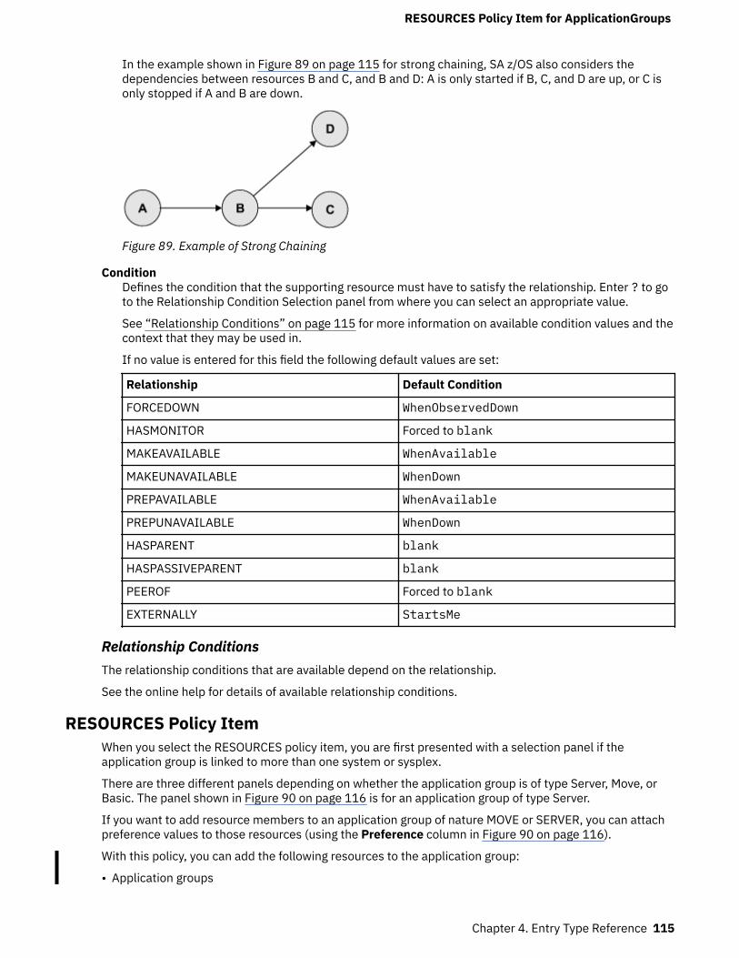
In the example shown in Figure 89 on page 115 for strong chaining, SA z/OS also considers thedependencies between resources B and C, and B and D: A is only started if B, C, and D are up, or C isonly stopped if A and B are down.
Figure 89. Example of Strong Chaining
ConditionDefines the condition that the supporting resource must have to satisfy the relationship. Enter ? to goto the Relationship Condition Selection panel from where you can select an appropriate value.
See “Relationship Conditions” on page 115 for more information on available condition values and thecontext that they may be used in.
If no value is entered for this field the following default values are set:
Relationship Default Condition
FORCEDOWN WhenObservedDown
HASMONITOR Forced to blank
MAKEAVAILABLE WhenAvailable
MAKEUNAVAILABLE WhenDown
PREPAVAILABLE WhenAvailable
PREPUNAVAILABLE WhenDown
HASPARENT blank
HASPASSIVEPARENT blank
PEEROF Forced to blank
EXTERNALLY StartsMe
Relationship ConditionsThe relationship conditions that are available depend on the relationship.
See the online help for details of available relationship conditions.
RESOURCES Policy ItemWhen you select the RESOURCES policy item, you are first presented with a selection panel if theapplication group is linked to more than one system or sysplex.
There are three different panels depending on whether the application group is of type Server, Move, orBasic. The panel shown in Figure 90 on page 116 is for an application group of type Server.
If you want to add resource members to an application group of nature MOVE or SERVER, you can attachpreference values to those resources (using the Preference column in Figure 90 on page 116).
With this policy, you can add the following resources to the application group:
• Application groups
RESOURCES Policy Item for ApplicationGroups
Chapter 4. Entry Type Reference 115

• Applications• Monitor resources• Resource references
To get a list of all selectable resources, set 'Show all Resources' to YES.
COMMANDS ACTIONS HELP ------------------------------------------------------------------------------ AOFGARS2 Select Resources Row 1 to 4 of 4 Command ===> SCROLL===> PAGE Entry Type : ApplicationGroup Entry Name : SYSPLEX_APPLGROUP Sysplex : SYSPLEX_GROUP_01 Number of selected Resources : 4 Availability Target. . . . . . . *ALL (-3 to 4 , *ALL) Satisfactory Target. . . . . . . *ALL (Level at which group is available) Show all Resources . . . . . . . NO YES NO Show only Resources with String. Action Preference Resource Name Entry Name 700 SYSPLEX_JOB/APL/FOCB SYSPLEX_JOB 700 SYSPLEX_JOB/APL/FOC1 SYSPLEX_JOB 700 SYSPLEX_JOB/APL/TGT1 SYSPLEX_JOB 700 SYSPLEX_JOB/APL/TGT2 SYSPLEX_JOB
Figure 90. Select Resources for ApplicationGroup Panel
This panel has the following fields (unless stated, the fields apply to all application group types):Number of selected Resources
This shows the current number of selected Resources.Availability Target
This Availability Target is different depending on the type of application group:Server
Valid values for server application groups are:*ALL
This means that all selected resources must be available before the current application group-derived resource is considered as available.
numberThis (positive) number is the number of selected resources that must be available before thecurrent application group-derived resource is considered as available. This number must beless than or equal to the value in the Number of selected Resources field.
If you enter a value that is greater than e value in the Number of selected Resources field, itis changed to the maximum allowed when you leave the panel.
-numberThis (negative) number is the number of selected resources less than the total that must beavailable before the current application group-derived Resource is considered as available.This number must be less than the value in the Number of selected Resources field.
If the value entered is less than or equal to the minimum value that is allowed, it will bechanged to the minimum when you leave the panel.
MoveThe Availability Target is always 1. This field cannot be modified for move application groups.
BasicThe Availability Target is not applicable and is not displayed for basic application groups.
RESOURCES Policy Item for ApplicationGroups
116 System Automation for z/OS : Defining Automation Policy

Satisfactory TargetThe Satisfactory Target is only applicable to server application groups. It specifies the number ofmembers in the group that must be active before the automation manager treats the group as being ina satisfactory state.
Valid values for server application groups are the same as for the Availability Target.
The Satisfactory Target may be less than, or equal to the Availability Target, but cannot be higher.
If the Satisfactory Target is of type -number then it is treated relative to the adjusted AvailabilityTarget.
Show all ResourcesThis can be:YES
Shows all selectable resources of type APL, APG, and REF.NO
Only shows selected resources.Show only Resources with String
If you enter a string in this field, only matching resources are listed. Wildcards are not supported.Action
The following actions are valid from the ACTIONS menu and Action prompt:
Action Result
(P)RIMARY Sets the preference value to 700.
SECON(D)ARY Sets the preference value to 400.
(A)DD Sets the preference value to 700.
RE(M)OVE Removes the preference value.
(S)ELECT Sets the preference value to 700.
PreferenceA resource becomes SELECTED when a positive number is entered to this field. The preference valuesays what "role" the selected resource has. The maximum valid value is 3200. Any value greater than3200 will be changed to that valid maximum.
The following roles are related to the preference values given:>2600
The resource always selected regardless of its state. Use this value if the APL or APG resourcemust run.
≥2000The resource always selected unless the observed status of the resource is SYSGONE orHARDDOWN. It is only selected when no other viable member exists. A viable member is aresource that can be started and that is allowed to be started. In principle, the observed status isone of the following: SoftDown, Starting, Degraded, Available or WasAvailable.
1000The resource always started, other resources stopped. (Use if you really want the APL or APGresource to run).
700The resource is selected for startup after an IPL and after recovery situations. Members withpreference 300 will be stopped in favour of this group. It is not stopped unless a very highpreference alternative becomes available. This value is the default. Use it in a MOVE group for aresource that normally runs.
RESOURCES Policy Item for ApplicationGroups
Chapter 4. Entry Type Reference 117

600Used as a threshold. A resource with a preference of 600 and lower will not be selected at groupstartup.
500This resource is not selected for startup after IPL but it is started as a backup after failure andcontinues running even though normal preference (700) alternatives become available. It isstopped at the next (scheduled) outage. Use this value in a MOVE group for the backup resource.
400This resource is not selected for startup after IPL but it is started as a backup after failure. Thedifference to preference 500 is that the resource is stopped when normal preference (700)alternatives become available again.
300Like 200, but a move to an alternate backup (Preference 500) would only occur at a (scheduled)outage.
200Resource started as backup, stopped as soon as better alternative (Preference 450 and greater)becomes available. (Use where you can have a backup, but you don't really want one).
1This means that the member will always be deselected and will always have a MakeUnavailablevote propagated to it. This can be useful if you want complete manual control of the moveprocess.
0This means that the member is a passive member and will never get a vote propagated to it by thegroup. If a member has its preference changed so it becomes passive, any votes that have beenpropagated to it from the group will be withdrawn.
Note: SA z/OS offers the possibility to consider the workload in its decision making via resource awareapplication move. This only takes place if the applications in a system or sysplex have the sameeffective preference values. It also does not affect any preference values that you have defined foryour resources. For more details, see "Resource Aware Application Move" in IBM System Automationfor z/OS User's Guide.
Preferences other than those listed are accepted. You can find more information on the meaning ofpreferences in "Controlling Application Move with Preference Values" in IBM System Automation forz/OS User's Guide.
The effective preference of each group member is calculated to determine which group members getpicked to be activated by the group. The primary inputs into this are the base preference (as specifiedthrough the customization dialogs) and the preference adjustment (specified indirectly through theINGGROUP interface). These are added together to produce the resource's adjusted preference (thisis the same as the preference value you actually enter the INGGROUP panels).
The following modifiers are then applied to the resource's adjusted preference if it is >1.
Bonus Reason
25 The member is currently selected and has an adjusted preference ≤1000.
175 The member is currently selected and has an adjusted preference >1000.
220 The member has an observed status of Starting, Stopping or Degraded and thesystem is not being stopped.
225 The member has an observed status of Available and the system is not being stopped.
–400 The member has an adjusted preference >1500 and either the system is beingstopped or the system has already been stopped and the member thus has observedstatus of SysGone.
RESOURCES Policy Item for ApplicationGroups
118 System Automation for z/OS : Defining Automation Policy

The working value for the preference may then be set to an absolute value if any of the followingconditions are satisfied:
Value Condition
3600 • The member has an adjusted preference of 0 (indicating a passive member) and ithas an observed status of Starting, Degraded, Available, or WasAvailable.
• The member at startup is of a Move group. This preference is assigned temporarilyand makes sure that no other member is selected.
100 The member has a working preference between 2–2599 and requires a resource onan Avoided system.
1 The member has:
• An adjusted preference of 0 (indicating a passive member) and its observed statusis none of Starting, Degraded, Available or WasAvailable.
• A working preference of 2000–2599, there is a viable alternative resource and themember either has an observed status of HardDown or SysGone or the system thatit is on is being stopped.
• A working preference <2000 and has observed status of HardDown or SysGone.• A working preference <2600 and has observed status of StandBy, Unknown or
Problem.• A working preference <2600, has observed status of Stopping or SoftDown and its
automation flag is turned off.• A working preference <2600 and requires a member on an excluded system.
After all of these adjustments have been made, this produces the member's effective preference.Normally a Move or Server group will pick the members with the highest effective preferences to beavailable, however there are three special rules to take into consideration:
1. A member with an effective preference of 1 may never be picked. SA z/OS sends aMakeUnavailable vote.
2. A member with an effective preference <600 may only be picked if the group is in recovery mode(that is, it is recovering from a failure).
3. A member requiring a resource on an excluded system must be sent a MakeUnavailable vote, evenif it has been picked. This can occur with resources that have adjusted preferences >2600.
Various scenarios are described in Table 6 on page 119.
Table 6. Preference Value Scenarios
Scenario Description
Absolute manual control Member to be activated gets preference 3200, all others getpreference 1.
The member with the 3200 preference will be selected. All otherswill always have a MakeUnavailable vote propagated to them.
This does not change even if the system with the selectedmember leaves the sysplex.
A shutdown of the primary system will not initiate a move of theapplication, as the 400 point penalty is not sufficient to drop itspreference below 2600.
RESOURCES Policy Item for ApplicationGroups
Chapter 4. Entry Type Reference 119

Table 6. Preference Value Scenarios (continued)
Scenario Description
Move only after system failure Primary member defined preference 2800, backups preference500.
As long as the primary is not SYSGONE it will be selected. If theprimary is SYSGONE, its preference drops to 2575 (2800 – 400 + 175), allowing an alternative viable member to be selected.
The backups will only be viable if the resource was previouslyactive because of the groups recovery mode.
A shutdown of the primary system will not initiate a move of theapplication. Although the primary systems preference will bebelow 2600, there will be no viable alternatives as the backupsmay only be used if the group is in recovery mode.
Move only if system down orstopping
Primary member defined preference 2800, backups preference700.
As long as the primary member is not SYSGONE and its system isnot being stopped it will be selected. If the primary member isSYSGONE or its system is being stopped, its preference drops to2575 (2800 – 400 + 175), allowing an alternative viable resourceto be selected.
The backups are always viable.
A shutdown of the primary system will initiate a move of theapplication during the shutdown.
Sticky move only after systemdown or stopping
Primary member defined preference 2801, backups preference2800.
As long as the primary member is not SYSGONE and its system isnot being stopped, it will be selected. If the primary becomesSYSGONE or its system is being stopped, its preference drops to2576 (2801 – 400 + 175), allowing one of the backups to beselected. The sticky bonus raises its preference to 2975(2800 + 175), meaning that even when the primary returns theselected backup system will remain selected.
It will only be deselected if it goes to SYSGONE or its system isbeing stopped, in which case the primary will be re-selected if it isavailable otherwise another backup would be picked.
A shutdown of the primary system will initiate a move of theapplication during the shutdown.
Move only after system orapplication failure
Primary member defined with preference 2400, backupspreference 500.
As long as the primary member does not fail to SYSGONE orHARDDOWN it remains selected. If it gets to HARDDOWN orSYSGONE without failing, there are no viable alternatives, so it willnot be moved. If it does fail, its preference is between 2600 and2000 and the backups are viable, so one of them can be picked.
The backups are only viable if the group is in recovery mode (thatis, the member was active when the failure occurred).
RESOURCES Policy Item for ApplicationGroups
120 System Automation for z/OS : Defining Automation Policy

Table 6. Preference Value Scenarios (continued)
Scenario Description
Move only if system down, beingstopped or application failure
Primary member defined with preference 2400, backupspreference 700.
As long as the primary member is not SYSGONE or HARDDOWNand its system is not being stopped it remains selected. If it isHARDDOWN or SYSGONE or its system is being stopped itspreference is between 2600 and 2000, so a viable alternative canbe selected.
A shutdown of the primary system will initiate a move of theapplication, as it will have lost its 225 point bonus for beingavailable and have incurred a 400 point penalty, bringing itspreference down to well below 2600, allowing the selection of analternative resource if there is a viable one.
Sticky move if system down orbeing stopped, move afterapplication failure
Primary member defined with preference 2401, backupspreference 2400.
As long as the primary is not SYSGONE or HARDDOWN and itssystem is not being stopped it remains selected. If it is SYSGONEor HARDDOWN or its system is being stopped its preference isbetween 2000–2600, so a viable alternative may be chosen.
The sticky bonus raises the preference of the selected member to2575 (2400 + 175), so it will remain selected until it gets to astate of SYSGONE or HARDDOWN or its system is being stopped,at which point another viable alternative will be selected, with theprimary member having preference.
The individual shutdown of the active member will not trigger amove.
A shutdown of the primary system will result in a move of theapplication. It will have a 400 point penalty, dropping itspreference to between 2600 and 2000, permitting the selection ofa viable alternative.
Sticky move group, unlessmember stopped
Primary member defined with preference 701, backupspreference 700.
As long as the primary member is startable, it remains selected. Ifit becomes non-startable, another member is selected and thatremains selected as long as it is startable.
Individually stopping the active member will trigger a move. If themembers were defined with preferences >1500, the bonus wouldbe 175 points rather than 25 points.
Sticky move group, until toldotherwise
Primary member defined with preference 3200, backups withpreference 1600.
With base preferences of 3200, you get it picking a member whenthe sysplex is IPLd and retaining that one until an operator usesINGGROUP to make it pick another one.
Beware of timing problems as the first system with a member toregister will probably get it.
RESOURCES Policy Item for ApplicationGroups
Chapter 4. Entry Type Reference 121

GENERATED RESOURCES Policy ItemThe Generated Resources panel appears if you select the GENERATED RESOURCES policy item from thePolicy Selection panel for ApplicationGroups. This panel shows all resources that are generated bySA z/OS for the application group itself and all the resources for the applications that are members of thisapplication group.
This panel is for information only. No actions are allowed.
COMMANDS HELP ------------------------------------------------------------------------------ AOFGXRSG Generated Resources Row 1 to 8 of 8 Command ===> SCROLL===> PAGE Entry Type : ApplicationGroup PolicyDB Name : USER_PDB Entry Name : NET Enterprise Name : USER_ENTERPRISE Resource Name Generated by link to Resources for THIS entry: NET/APG/SYSTEM1 SYSTEM1 NET/APG/SYSTEM2 SYSTEM2 Resources for APPLICATIONS (generated by links to this entry): TCPIP/APL/SYSTEM1 NET TCPIP/APL/SYSTEM2 NET VTAM/APL/SYSTEM1 NET VTAM/APL/SYSTEM2 NET
Figure 91. Generated Resources Panel
This panel displays the following information:
Resources for THIS entryShows the resources generated for the application group. The display is different for applicationgroups of type SYSPLEX or SYSTEM: No system information is shown for Sysplex Application Groups,as several systems can be part of the sysplex.
Resources for APPLICATIONS (generated by links to this entry)Shows the resources generated for applications that are linked to the application group.
MEMBER OF Policy ItemThe Member of panel appears if you select the MEMBER OF policy item from the Policy Selection panel forapplication groups.
COMMANDS HELP ------------------------------------------------------------------------------ AOFGXMOF Member of Command ===> SCROLL===> PAGE Entry Type : ApplicationGroup PolicyDB Name : USER_PDB Entry Name : APPL_GROUP_NAME Enterprise Name : USER_ENTERPRISE Own Resource... ...is a member of Preference Nature NET/APG/SYSTEM1 WBSRVAPG/APG 700 MOVE/SERVER NET/APG/SYSTEM2 WBSRVAPG/APG 700 MOVE/SERVER
Figure 92. Member of Panel for ApplicationGroups
This panel lists all resources, where this ApplicationGroup is a member "resource-wise", that is, it lists allrelations from resources that have been derived from the current ApplicationGroup to other resources.This panel is for information only. No data can be changed.
A Member of relation can be added or removed in the RESOURCES policy item of the entry that is given inthe ...is a member of column (that is, in the RESOURCES policy of the APG Entry Name that the "memberof" resource was derived from).
GENERATED RESOURCES Policy Item forApplicationGroups
122 System Automation for z/OS : Defining Automation Policy

If the owning APG resource (given ...is a member of) is of nature SERVER or MOVE, the Preferencecolumn shows the preference value that was set for the current resource in the RESOURCES policy item ofthe owning resource. If the owning resource's nature is BASIC, the Preference column shows"SELECTED". For more details about available preference values see “Creating a New ApplicationGroup”on page 102.
In the example in Figure 92 on page 122, the resource NET/APG/SYSTEM1 is a member of resourceWBSRVAPG/APG.
Application Entry TypeAn application is a z/OS subsystem, started task, application, batch job, or non-MVS resource that runs ona system in the SA z/OS enterprise. SA z/OS monitors applications through the messages they issue to theoperator. The term application is also used to refer to a subsystem or process on an SNMP-capablemachine.
Note that SA z/OS does not provide automation for applications on non-MVS systems.
An application cannot be linked to a system directly. It must be defined as part of an application group,and it may belong to more than one application group. If a system is assigned multiple application groupscontaining the same application, SA z/OS ensures that the application is defined only once in theautomation control file.
Creating a New ApplicationHow to create new policy objects in general is described in “How to Create New Policy Objects” on page19.
Figure 93 on page 123 shows the panel that is displayed when you create a new application from theEntry Name Selection panel for applications.
COMMANDS HELP ------------------------------------------------------------------------------ AOFGDYN3 Define New Entry Command ===> Define new entry of type Application Entry name . . . . . . . Subsystem Name . . . . . Object Type . . . . . . INSTANCE (CLASS INSTANCE) Category . . . . . . . . (IBM-defined, user-defined or blank, see help) Subcategory . . . . . . (IBM-defined, user-defined or blank, see help) Job Type . . . . . . . . (MVS NONMVS TRANSIENT) Job Name . . . . . . . . Transient Rerun . . . . (YES NO) Scheduling Subsystem . . (MSTR, JES Subsystem) JCL Procedure Name . . . Short description . . . Long description 1 . . . Long description 2 . . . Long description 3 . . . Long description 4 . . . Long description 5 . . .
Figure 93. Define New Entry Panel for Applications
When you define a new application, you provide the following information:Entry Name
This field is required. It assigns a unique twenty-character name to the application you are defining. Itis often convenient to use the same name for both the subsystem name and the application name. Insome cases, however, it may be useful to have multiple applications with the same subsystem name.
Creating a New Application
Chapter 4. Entry Type Reference 123

This enables you to have a standard "tree" of subsystems but to assign the right characteristics of anapplication to a specific system. The first character of the application name must not be numeric.
Subsystem NameThe subsystem name is required. It defaults to the application's entry name if the entry namecomplies with the restrictions for subsystem names (see below). Press Enter to have the defaultdisplayed in the field.
The subsystem name provides a unique, eleven-character name for the Application that you aredefining. This name is used by SA z/OS automation. You can have multiple application instances withthe same subsystem name, however, you should take care to ensure that only one of them is linked toany given system. The subsystem name of an application class must be unique across the wholepolicy database, that is, it cannot be the same as the subsystem name of any other applicationinstance or class.
Note that the subsystem name of an existing application can be modified by overtyping theSubsystem Name field in the Application Information policy panel.
The restrictions on the subsystem name are:
• The length is limited to eleven characters.• Valid characters are any alphanumeric character or any of @, #, $, ? or _ (underscore), with the first
character being alphanumeric or one of @, #, $ or ?.• See the online help for a list of values that are reserved for SA z/OS and cannot be used.
For applications of category IMAGE, the same value is required for the subsystem and the job name.Therefore the subsystem name must comply with the restrictions for job names (see Job Name).
Object TypeCLASS
If the entry represents common policy that is to be inherited by one or more other applicationentries that are defined as INSTANCEs, select this object type. CLASSes are used only forinheriting; they do not represent actual applications that are managed by SA z/OS.
INSTANCEIf the entry represents an application that is to be managed by SA z/OS, select this object type. Ifyou link an INSTANCE to a CLASS you can omit policy items from the INSTANCE, which permitsthat policy data can be inherited from the specified CLASS.
Use of the CLASS object type allows you to define a common policy for multiple applications. This isadvisable if these applications share common characteristics and functions. It decreases effortduring:
• Initial definition• Administrative changes (using the customization dialog)• Runtime changes (using the SA z/OS automation engine)
An application instance can be linked to a class using the UPWARD CLASS policy item. If a policy itemis not specified for the instance, it is inherited from the class. Conversely, a policy item that isspecified for an instance overrides any class specification.
Flag definitions for classes or defaults cannot be merged with specific resource definitions. Forexample, specifying a RESTART flag with an exit at class level and a RESTART flag with a NOAUTOperiod at resource level will not result in a resource definition with both. The presence of anydefinition at resource level takes precedence over those at class and default level. Likewise a classdefinition takes precedence over a default. The definitions for a specific flag type are not merged.
The inheritance of policy items from an application class occurs during SA z/OS initialization. If anapplication policy item is not specified in either the application instance or the class, defaults are usedfrom the application defaults, system defaults, and environment setup objects. Some policy items arerequired to be specified for an application instance. Except for job name, these same items need to bespecified for an application class, but note they will never be inherited.
Creating a New Application
124 System Automation for z/OS : Defining Automation Policy

CategoryIdentifies IBM-defined or user-defined applications. For IBM-defined applications, specify one of thefollowing: CICS, DB2, IMAGE, IMS, INFOSPHERE, ITM, JES2, JES3, LIFELINE, MQ, OPC, USS or TCPIP.
Specifying one of those categories may cause additional policy options, specific to the automation ofthose applications, to be displayed on the Policy Selection panel. These additional policy options arenot displayed if the category is inherited from an application class.
Once specified, IBM-defined categories cannot be changed anymore. User-defined categories can beany alphanumeric text string and can be changed later at any time.
SubcategorySpecifies any IBM-defined or user-defined subcategory of the application for which a category wasspecified. An IBM-defined subcategory specifies the region type for CICS, DB2, and IMS, thesubcategory for ITM, the component for LIFELINE, or the controller type for OPC.
The following IBM-defined values may be specified:
• CICS: AOR TOR FOR DOR QOR CMAS WUI• DB2: MSTR SPAS IRLM DBM1 DIST WLMS ADMT• IMS: CTL TP DBRC DLS FP BMP FDR• ITM: KAHAGENT TEMS• LIFELINE: ADVISOR AGENT• OPC: CONTROLLER TRACKER SERVER DATASERVER
For applications of category IMAGE, INFOSPHERE, JES2, JES3, MQ, TCPIP or USS there are no IBM-defined subcategories available.
For user-defined subcategories, any alphanumeric text string can be specified.
Job TypeThis can be one of:MVS
This is the standard MVS job type that SA z/OS normally handles. It is typically monitored usingthe ASCB checker. This job type can be specified explicitly with JOBTYPE=MVS for an application,however, it is the assumed default if the Job Type entry is omitted from the definition of theapplication.
NONMVSThis is a type of resource that may be started by SA z/OS but which cannot be monitored using anASCB check or the MVS D A method.
If the AOFATMON routine cannot be used to monitor this type of resource, either a user-providedapplication monitor routine is required or the message automation table must be correctly set upto maintain the job status accurately. This status is the only way of monitoring this class of job.NONMVS jobs must have STARTUP and SHUTDOWN commands defined.
TRANSIENTThis is a type of job that may be started by SA z/OS but terminates without the intervention ofSA z/OS. It is a short running job that will generally, but not necessarily, terminate before SA z/OSdoes. It can be monitored using an ASCB check.
As far as monitoring is concerned, a TRANSIENT job is treated as a z/OS job, but it has specialproperties: transient jobs must START and END before their dependent applications are started.
You can specify shutdown passes for transient jobs if there is a possibility that they may need to beshut down by SA z/OS. These passes are optional.
Job NameThe job name is required. It defaults to the subsystem name if this complies with the restrictions onjob names. Press Enter to have the default displayed in the field. For applications of category IMAGE,the job name is forced to the subsystem name. Thus, for applications of category IMAGE, thesubsystem name must comply with the restrictions on job names.
Creating a New Application
Chapter 4. Entry Type Reference 125

The job name gives a unique name to the application to be run. There is a one-to-one mappingbetween the MVS job name and the subsystem name. SA z/OS automation interprets messages fromMVS by taking the MVS job name and mapping it to the subsystem name.
You can have multiple applications with the same job name but you must ensure that only one of themis linked to a particular system. Duplicates are ignored by the BUILD function.
The restrictions on the job name are:
• It can be up to eight alphanumeric and national characters, including @, #, and $, after cloneresolution, provided the first character is not numeric.
• If the job type is NONMVS, you can also use _ and ?.• You can include system symbols and system automation symbols.• The special value *MASTER* is allowed for applications without a category. If the object type is
CLASS, a job name is not allowed.
For details about creating the start command, see JCL Procedure Name.
Transient RerunThis field specifies whether a TRANSIENT application may be rerun within the lifetime of z/OS. TheTransient Rerun option involves the concept of a one-shot transient job.YES
This indicates that the job will be rerun as appropriate. SETSTATE can be used to set it to RESTARTstatus, and it can be part of a shutdown request with the RESTART option set to YES.
NOThis indicates that the job will only be run once in the lifecycle of a particular z/OS. A value of NOaffects the processing of the SETSTATE command. NO is the default value for transient jobs.
Note:
• On an initial automation policy load, such as at IPL, a one-shot transient will run, terminate and goto ENDED status. If a SETSTATE or INGREQ with restart is attempted it will be rejected because aone-shot transient is only allowed to run once in the lifecycle of a particular z/OS.
• A one-shot job remains in an ENDED state across a SA z/OS recycle.• There are some situations when even one-shot transient jobs will be rerun:
– If the automation status file is deleted and NetView is recycled, a one-shot transient job will berestarted.
– If a job is deleted from the automation policy, status information for that job is deleted during arefresh of the policy. If a later refresh is used to redefine the application to automation, theapplication status is set to DOWN. This may also result in the restart of a one-shot transient job.
Scheduling SubsystemThis is optional. It is the name of the subsystem that is to schedule this application, as follows:MSTR
The application is scheduled directly by the master scheduler subsystem.other
The application is scheduled by another scheduling subsystem. The value entered is the name ofthat subsystem. The subsystem that is specified must be defined as category JES2 or JES3.
If you leave this field blank, it indicates that the application is scheduled by the primary JES.
For applications of category IMAGE the value is forced to blank.
JCL Procedure NameThe JCL Procedure Name is optional. It specifies the name of the JCL procedure that is used to createthis instance of the application. If specified, the default start command for the application is:
MVS S procname,JOBNAME=jobname
Creating a New Application
126 System Automation for z/OS : Defining Automation Policy

Where procname is the JCL Procedure Name and jobname is the Job Name. If you do not specify a JCLprocedure name, the default start command is:
MVS S jobname
You can include system symbols and system automation symbols (see “Assigning System AutomationSymbols (AOCCLONE)” on page 7).
For applications of category IMAGE the value is forced to blank.
Policy Items for ApplicationsFigure 94 on page 127 shows the policy items that are displayed when an Application is selected from theEntry Name Selection panel.
Some of the policy items may be set for all application automation on a certain system via the applicationor system defaults. For example, Thresholds can be set to a default value for all applications. If thedefinition of an application has no value specified for Thresholds, the value specified in the ApplicationDefaults is used. If no value is specified in the Application Defaults any value specified in System Defaultsis used. See also “Application Defaults Entry Type” on page 241 and “System Defaults Entry Type” onpage 239.
ACTIONS HELP ------------------------------------------------------------------------------ AOFGEPOL Policy Selection Row 1 to 20 of 20 Command ===> SCROLL===> PAGE Entry Type : Application PolicyDB Name : USER_PDB Entry Name : APPL1 Enterprise Name : USER_ENTERPRISE Action Policy Name Policy Description DESCRIPTION Enter description UPWARD CLASS Select a class to inherit data from APPLICATION INFO Define application information AUTOMATION FLAGS Define application automation flags APPLICATION SYMBOLS Define application symbols TRIGGER Select trigger SERVICE PERIOD Select service period PACING GATE Select pacing gate RELATIONSHIPS Define relationships MESSAGES/USER DATA Define application messages and user data STARTUP Define startup procedures SHUTDOWN Define shutdown procedures THRESHOLDS Define error thresholds MINOR RESOURCES Define application minor flags and thresholds SYSTEM ASSOCIATION Define primary and secondary associations -------------------- -----RESOURCES------------------------------- GENERATED RESOURCES List resources generated for this entry MEMBER OF List resources where this entry is a member -------------------- --------------------------------------------- WHERE USED List application groups linked to this entry COPY Copy data from an existing entry
Figure 94. Policy Selection Panel for Applications
The unique policy items for Applications are:
UPWARD CLASSThis field is displayed if the application was defined as an INSTANCE or CLASS (see “Creating a NewApplication” on page 123). It lists all entries that have been defined as resource classes and allowsyou to select one class that this application should be linked to so that it inherits the policy values ofthat class or class chain.
See “UPWARD CLASS Policy Item” on page 130 for more information.
DOWNWARD CLASS/INSTThis policy item is displayed if the application was defined as a CLASS (see “Creating a NewApplication” on page 123) and it lists all class or instance entries. You can add or remove classes orinstances linked to this class.
Policy Items for Applications
Chapter 4. Entry Type Reference 127

See “DOWNWARD CLASS/INST Policy Item” on page 131 for more information.
APPLICATION INFOThis policy item displays the Application Information panel that shows the policy for the currentapplication as entered when it was created. It is also used to define the application to SA z/OSautomation. You can edit part of the policy information on this panel. The fields that contain policyinformation that you must not modify are read-only. To change read-only information, you must deleteand recreate the application.
See “APPLICATION INFO Policy Item” on page 132 for more information.
AUTOMATION FLAGSAutomation flags allow you to enable and disable automation. You can disable automation for specifictime periods or turn it off entirely. You can also enable or disable automation for specific automationphases, such as Initstart, Start, Recovery, Shutdown, and Restart, and for responses to specificmessages and status changes within these phases.
Determine whether the automation flags currently set for your system at the system wide defaults andapplication levels are appropriate for this application. If they are not, define one or more applicationautomation flags in either the application instance or class policy object.
For more information, see “AUTOMATION FLAGS Policy Item” on page 140 and the section"Automation Flags" in IBM System Automation for z/OS User's Guide.
APPLICATION SYMBOLSApplication symbols allow you to enter or update application symbols that can be set to variousapplication-specific values. These can then be substituted using the runtime variables SUBSSYMBOL1through SUBSSYMBOL9. Those variables can be used in a similar fashion to runtime variables likeSUBSSPARM, SUBSSCHEDSS, SUBSJOB, etc.
For more information, see “APPLICATION SYMBOLS Policy Item” on page 142.
TRIGGEREach application may be linked to one trigger. This policy item allows you to link the currentapplication to a trigger. Only one trigger can be selected.
Triggers are used to control the starting and stopping of applications in a single system or a ParallelSysplex. They determine the behavior of the requested action. For an application to be started, itsdesired status must be AVAILABLE and its startup trigger must be satisfied.
For an application to be stopped, its desired status must be UNAVAILABLE and its shutdown triggermust be satisfied.
For more information on how to use triggers, see “TRIGGER Policy Item” on page 214 and the section"Event and Trigger Support" in IBM System Automation for z/OS User's Guide.
SERVICE PERIODService periods allow users to schedule the availability of applications, application groups, or monitorresources. With this policy item you can link a service period to the application so that it isautomatically started up or shut down in the time frame specified with the service period.
For more information, see “SERVICE PERIOD Policy Item” on page 143.
PACING GATEEach application may be linked to one pacing gate. Pacing gates are used to define a number ofapplications that may be started or stopped in parallel on one system. You can select a defined pacinggate from this panel or confirm its status. Only one pacing gate may be selected.
For more information, see “PACING GATE INFO Policy item” on page 217.
RELATIONSHIPSRelationships are used to define dependencies between resources that are used to perform in acontrolled way startup or shutdown actions of dependent and supporting applications, applicationgroups, monitor resources, and resource references.
Policy Items for Applications
128 System Automation for z/OS : Defining Automation Policy

This policy item has the same functionality for entry types Application, ApplicationGroup, MonitorResource, and Resource Reference. For each application, application group, monitor resource, orresource reference, you may specify several relationships. If you select this policy item, in theupcoming Relationship Selection List panel, you can view existing or define new relationships for thecurrent application, application group, monitor resources, or resource references.
You define relationships between dependent resources and supporting resources. In thecustomization dialog you define relationships always from the point of view of the dependentresource. So the resource that you have currently selected will become the dependent resource, whenyou define a new relationship.
See “RELATIONSHIPS Policy Item” on page 110 for more information on viewing or definingdependency relationships.
MESSAGES/USER DATAThis policy item allows you to specify automated actions, such as the issuing of a command or reply,to be taken in response to a message issued by the application.
You can also specify some of the application statuses as messages to trigger the command of yourchoice.
How to proceed in specifying this policy item is described in “MESSAGES/USER DATA Policy Item” onpage 144.
STARTUPThis policy item allows you to add, remove or modify startup procedures for the current application.
See “STARTUP Policy Item” on page 160 for more information how to specify the startup automationpolicy.
SHUTDOWN
You must specify NORMAL shutdown commands for any application that you want to automate withSA z/OS. You may also specify INIT, IMMED, FORCE, and FINAL shutdown commands.
Specifying shutdown commands or replies for the application allows the automation to performapplication shutdowns. You can specify different shutdown commands or replies to be issued for thedifferent types of shutdown situations.
How to achieve this is described in “SHUTDOWN Policy Item” on page 163.
THRESHOLDSError threshold definitions for an application define how many abend errors can occur before amessage is logged or restart processing is stopped. If no error thresholds are set here, the applicationuses the thresholds that are defined in the Application Defaults entry type.
Determine whether existing default threshold values are appropriate for this application. If they arenot appropriate, create a unique threshold entry for the application.
For more information on thresholds, see the section "How SA z/OS Uses Error Thresholds" in IBMSystem Automation for z/OS User's Guide and “THRESHOLDS Policy Item” on page 169.
MINOR RESOURCESThis policy item allows you to define flags and thresholds for minor resources for the application.Minor resources are any resources specified to be subsidiary to this application, for example,messages and statuses.
The main purposes in defining minor resources are to let you:
• Trigger automation for minor resources• Override the automation settings of major resources for a single minor resource, or a select number
of minor resources
See the description of the MINOR RESOURCES policy item in “MVS Component Entry Type” on page234 for information on how to manage minor resources and “MINOR RESOURCES Policy Item” onpage 238.
Policy Items for Applications
Chapter 4. Entry Type Reference 129

The automation flags that are associated with minor resources are sometimes called extendedautomation flags. See "Automation Agent Flags and Minor Resource Flags" in IBM System Automationfor z/OS User's Guide for information about them.
See also the section "Thresholds for Minor Resources" in IBM System Automation for z/OS User'sGuide.
SYSTEM ASSOCIATIONThis policy item allows you to define primary and secondary systems for the application. Primary andsecondary categorizations help SA z/OS determine whether an application should be started bySA z/OS when SA z/OS is initialized on a system. These categories allow SA z/OS to performautomation, such as monitoring or shut down, on applications that can be moved by an external agent.
For a detailed description on how to define system categories with this option see “SYSTEMASSOCIATION Policy Item” on page 172.
GENERATED RESOURCESThis policy item lists all resources that were generated for the current application. Applicationresources are generated when a link between an application and a system occurs. Applications cannever be linked directly to systems. This link happens indirectly by linking an application to anapplication group (either in an application WHERE USED policy item or in an application groupAPPLICATIONS policy item.)
The GENERATED RESOURCES panel is displayed, which looks similar to the one shown in Figure 127on page 172, except that the section, Resources for THIS entry, showing the application groupresource is missing.
MEMBER OFThis policy item lets you see the APG Resources that the current application is a member of.
See “MEMBER OF Policy Item” on page 122 for more details.
UPWARD CLASS Policy ItemIf you select the UPWARD CLASS policy item from the Policy Selection panel for Applications, the UpwardLink to Class panel is displayed, as shown in Figure 95 on page 130.
COMMANDS ACTIONS VIEW HELP ------------------------------------------------------------------------------ AOFGXI2C Upward Link to Class Row 1 to 13 of 23 Command ===> SCROLL===> PAGE Entry Type : Application PolicyDB Name : USER_PDB Entry Name : AM Enterprise Name : USER_ENTERPRISE Action Status Entry Name Category Upward Class Link SELECTED C_AM C_AMK C_APPL C_CICS_GENERIC CICS C_CICS_NV_PPI C_CICS_GENERIC C_CICS_PPI C_CICS_GENERIC C_CICS_SHAREDSERVERS C_CICS_TG C_CICS_XACTIONSERVER CICS C_DB2_DEPENDENTS C_DB2_MSTR DB2 C_GEO C_IMS_APPLICATIONS IMS
Figure 95. Upward Link to Class Panel
This panel allows you to manage the upward link from an application class or instance to a class of thesame category. This link allows the instances or classes to inherit any policy data that has been defined inthe selected class or other classes further up in the class chain.
• Use the Action field to manage the link by entering:
UPWARD CLASS Policy Item for Applications
130 System Automation for z/OS : Defining Automation Policy

– Add (A) or Select (S) to link the class or instance to this class– Remove (M) to unlink the class or instance from this class
• The Status column indicates whether this class or instance has been linked up to the class in the list.• The Category column indicates what category the class in the list was defined as.• The Upward Class Link column indicates the class, if any, that the entry in the list is currently upwardly
linked to.
To avoid circular links, a check is made to ensure that the class you select is not already linked in thedownward tree of the current class.
See “Nested Classes” on page 11 for more details about nested class support.
DOWNWARD CLASS/INST Policy ItemIf you select the DOWNWARD CLASS/INST policy item from the Policy Selection panel for Applications,the Downward Link to Classes or Instances panel is displayed, as shown in Figure 96 on page 131.
COMMANDS ACTIONS VIEW HELP ------------------------------------------------------------------------------ AOFGXC2I Downward Link to Classes or Instances Row 1 to 13 of 125 Command ===> SCROLL===> PAGE Entry Type : Application PolicyDB Name : USER_PDB Entry Name : C_AM Enterprise Name : USER_ENTERPRISE Action Status Entry Name C Category Upward Class Link SELECTED AM C_AM SELECTED AM2 C_AM APPC ASCH C_APPL BLSJPRMI C_APPL * C_CICS_NV_PPI * C_CICS_PPI * C_CICS_SHAREDSERVERS * C_CICS_TG * C_CICS_XACTIONSERVER * CICS C_DB2_DEPENDENTS * C_DB2_MSTR * DB2
Figure 96. Downward Link to Classes or Instances Panel
This panel allows you to manage the downward links from an application class to classes or instances ofthe same category. These links allow the instances or classes to inherit any policy data that has beendefined in this class or other classes further up in the class chain.
• Use the Action field to manage the links by entering:
– Add (A) or Select (S) to link the class or instance to this class– Remove (M) to unlink the class or instance from this class
• The Status column indicates whether the entry in the list has been linked down to by this class.• The C column indicates with an asterisk (*) that the entry is a class because this may not be obvious
from the entry name.• The Category column indicates what application category the entry was defined as. Note that an
application class that you are working with can only be linked to entries of the same category as itself.• The Upward Class Link column indicates the class, if any, that the entry in the list is currently upwardly
linked to. If you select such an entry, you would change its class chain, so be careful not to break itsdata inheritance
To avoid circular links, a check is made to ensure that the class you select is not already linked in theupward tree of the current class.
DOWNWARD CLASS/INST Policy Item for Applications
Chapter 4. Entry Type Reference 131
Both link panels show the category because class-instance links are only allowed if there is no categorymismatch in the class hierarchy, that is, either the specified categories must be the same or no category isspecified.
To avoid category mismatches, the categories of the link partner or the inherited categories are checked.A link is invalid if the resulting class chain includes category specifications that do not match (for example,a class or instance of category IMS and another class or instance of category CICS). Thus, if both linkpartners (the current entry and the linked class or instance) have a category specified it is checked thatthey are identical. If either link partner has no category specified, the class hierarchy that leads to thisentry is scanned to check whether an inherited category may cause a mismatch. If this is the case, adetailed link error message that includes the names of the conflicting entries is displayed.
See “Nested Classes” on page 11 for more details about nested class support.
APPLICATION INFO Policy ItemIf you select the APPLICATION INFO policy item from the Policy Selection panel for Applications, theApplication Information panel is displayed, as shown in Figure 97 on page 133.
APPLICATION INFO Policy Item for Applications
132 System Automation for z/OS : Defining Automation Policy

COMMANDS HELP ------------------------------------------------------------------------------ AOFGDYNA Application Information Command ===> Entry Type : Application PolicyDB Name : USER_PDB Entry Name : APPL1 Enterprise Name : USER_ENTERPRISE More: + Category . . . . . . . . . (IBM-defined, user-defined or blank, see help) Subcategory . . . . . . . (IBM-defined, user-defined or blank, see help) Subsystem Name . . . . . . APPL1 Job Type . . . . . . . . . (MVS NONMVS TRANSIENT) Job Name . . . . . . . . . APPL1 Transient Rerun. . . . . . (YES NO) Scheduling Subsystem . . . (MSTR, JES Subsystem) JCL Procedure Name . . . . Job Log Monitor Interval . (mm:ss NONE) Captured Messages Limit. . (0 to 999) Desired Available. . . . . (ALWAYS ONDEMAND ASIS) Restart after IPL. . . . . (START NOSTART NONE) Monitor for IPL complete . (YES NO)
Start Delay. . . . . . . (time for "UP" status checks, hh:mm:ss) Start Cycles . . . . . . . (start timeout checks, 0 to 99) UP Status Delay . . . . . (time to delay "UP" status, hh:mm:ss) Restart Option . . . . . . (ALWAYS ABENDONLY NEVER) External Startup . . . . . (INITIAL ALWAYS NEVER) Skip ACTIVE status . . . . (YES NO) Startup Parameters . . . . External Shutdown. . . . . (FINAL ALWAYS NEVER blank) Shutdown Pass Interval . . (hh:mm:ss) Cleanup Delay . . . . . . (hh:mm:ss) Command Prefix . . . . . . Message Prefix . . . . . . Sysname . . . . . . . . . (System name) Monitor Routine. . . . . . (name NONE) Monitor Interval . . . . . (hh:mm NONE) Inform List . . . . . . . (SDF EIF E2E IOM ITM SMF TTT USR NONE) ARM Element Name . . . . . WLM Resource Name 1 . . . WLM Resource Name 2 . . . WLM Resource Name 3 . . . Owner. . . . . . . . . . . Info Link. . . . . . . . . Runtokens. . . . . . . .
Figure 97. Application Information Panel
Any policy values that have been inherited from linked classes are displayed in a different color. You canfind out which class a value has been inherited from by typing the command classname (or itsabbreviation cn) on the command line, moving the cursor to the field of interest and pressing Enter. Youcan override any inherited values by overtyping them. If you override any values for a class, they areindividually applied to the current application and change color to turquoise to indicate this.
This panel displays the following information:Category
Identifies IBM-defined or user-defined applications. See Category in “Creating a New Application” onpage 123.
SubcategorySpecifies any IBM-defined or user-defined subcategory of the application for which a category wasspecified. See Subcategory in “Creating a New Application” on page 123.
APPLICATION INFO Policy Item for Applications
Chapter 4. Entry Type Reference 133

Subsystem NameThis gives a unique, eleven-character name to the application that you are defining. This name is usedby SA z/OS automation. You can have multiple application instances with the same subsystem name,however, only one of them can be linked to a system. The subsystem name of an application classmust be unique across the whole policy database, that is, it cannot be the same as the subsystemname of any other application instance or class.
You can change the subsystem name by overwriting the existing name. If the application instance islinked, the name is checked to be unique across all subsystem names in the policy database. If youwant to change the subsystem name to a name that already exists, you first need to unlink theapplication instance from all application groups.
If no subsystem name is specified, the default is the value of the Entry name (if this name is not longerthan 8 characters for applications of category IMAGE, and not longer than 11 characters for all othercategories).
For applications of category IMAGE the subsystem name can only be an 8-character name.
Certain values are reserved for SA z/OS and cannot be used. See the online help for a complete list.
Job TypeSee Job Type in “Creating a New Application” on page 123 for more details.
Job NameSee Job Name in “Creating a New Application” on page 123 for more details.
Transient RerunSee Transient Rerun in “Creating a New Application” on page 123 for more details.
Scheduling SubsystemSee Scheduling Subsystem in “Creating a New Application” on page 123 for more details.
JCL Procedure NameSee JCL Procedure Name in “Creating a New Application” on page 123 for more details.
Job Log Monitor IntervalSpecifies how frequently the Job Log should be monitored. The frequency must be specified usingformat mm:ss. The allowed minimum is 1 second (00:01), maximum is 60 minutes (60:00). If the fieldis left blank the value can be inherited from a class definition. If monitoring is not required, specifyNONE, to prevent inheritance.
If nothing is specified or inherited no monitoring will be done. If scheduling subsystem is MSTR, thespecification is ignored.
Captured Messages LimitSpecifies the maximum number of captured messages that will be saved for the SA z/OS commandDISPINFO.
If the field is left blank the value can be inherited from a class, the application defaults (ADF), or thesystem's default definition (SDF). If neither of these are specified a default value of 0 is used.
Desired AvailableLets you specify the default desired status of the resource. The desired state of each resource is eitherAvailable or Unavailable, which is the goal that automation tries to achieve.
You can specify the following values:ALWAYS
The resource's desired status is set to Available, unless it is dependent on a resource that has aDesired Available setting of ONDEMAND. In this case the resource behaves as if it had a DesiredAvailable setting of ONDEMAND itself.
ONDEMANDIf there is demand for the resource to be available, its desired status is set to Available, otherwiseits desired status is set to Unavailable.
APPLICATION INFO Policy Item for Applications
134 System Automation for z/OS : Defining Automation Policy

Demand arises either from propagated MakeAvailable votes or implicitly through membership of anon-passive basic application group (APG) that has a desired status of Available. Demand doesnot arise from dependent resources with a Desired Available setting of ALWAYS.
A MakeAvailable vote that is propagated to the resource overrides any demand considerations.
An active ONDEMAND member of a move or server group is always sent a vote that sets its desiredstatus, thus overriding any demand considerations.
ASISThe desired status is always set to the observed status. The resource remains in the status that itcurrently has and no action is taken by SA z/OS at any time, as long as there is no request placedfor or propagated to the resource.
If you leave the field blank the value can be inherited from a class or the system defaults definition.
If nothing is specified or inherited the default value is ALWAYS.
Restart after IPLSpecifies how SA z/OS determines the initial status of the application on the first occasion thatSA z/OS is started after a z/OS IPL or an automation status file reallocation.
Reallocating the automation status file has the same effect as a z/OS IPL because SA z/OS stores thelast IPL date and time in the automation status file. When the automation status file is deleted,SA z/OS assumes that the next startup is the first startup following a z/OS IPL.
You can specify four values for Restart after IPL:
STARTThe application is always startable when the start dependency is fulfilled. The application status isset to DOWN during initialization. It is recommended that you specify START for criticalapplications such as JES, VTAM, and TSO. Replying NOSTART to message AOF603D (specifyinitialization options) overrides this setting.
NOSTARTThis enforces a STOP request with priority FORCE to be injected during SA z/OS initialization. Thisresults in a desired status of UNAVAILABLE and an observed status of SOFTDOWN, whichproduces a compound status of SATISFACTORY. If the observed status before IPL wasHARDDOWN this status remains in HARDDOWN, which produces a compound status of PROBLEM.
NONEThis value is the same as leaving the field blank, except that if the application is an instance, itdoes not inherit the value from its related application class.
If you leave this field blank, it indicates that the application is startable, depending on its status. If thestatus is STOPPED, BROKEN or CTLDOWN, it is not changed and the application is not started. Anytransient status (for example, BREAKING) is changed to the corresponding final status (for example,BROKEN). Any other status is changed to DOWN during initialization and, if the INITSTART flag is setto YES, the application is started when all its relationships are fulfilled.
Note: If the field is left blank then the DISPINFO panel AOFKINFO will display the value of MAYBE forfield Restart after IPL.
Monitor for IPL completeSpecifies whether the application has to be in an AVAILABLE status before IPL is considered to becompleted.YES
indicates that it has to be in an AVAILABLE status.NO
indicates that this is not the case.If the field is left blank the value can be inherited from a class definition. If nothing specified norinherited the default is NO.
APPLICATION INFO Policy Item for Applications
Chapter 4. Entry Type Reference 135

Start DelaySpecifies an interval which begins when a start command for the application is issued by SA z/OS.After the expiration of this interval, a check occurs to determine whether the application recorded astatus of STARTED and/or ACTIVE depending on the MVS active/inactive state at that time. MessageAOF 571I is issued.
If nothing is specified the default supplied by the automation agent is used, which is 2 minutes.
Start CyclesSpecifies the number of times to cycle the start timeout period before posting the subsystem as aproblem which means the application is given a STARTED2 or INACTIVE status.
If nothing is specified the default value is 1.
UP Status DelaySpecifies an interval which begins when the UP message is received and ACTIVMSG UP=MSG istriggered. The application will not be set to an UP status before the specified time has expired. If thefield is left blank the value can be inherited from a class definition.
If nothing is specified or inherited the default value is 00:00:00 which means that there is no delaybetween receiving the UP message and setting the application to an UP status.
Restart OptionSpecifies the circumstances that the application should be restarted under. The options are:ALWAYS
The application is restarted if it was terminated without using the INGREQ command. Note that, ifthe advanced automation option AOFRESTARTALWAYS is set to 0, the application restartthresholds are checked. The application is restarted only if it has not exceeded the criticalthreshold. By default the application is restarted every time it is stopped outside the control ofSA z/OS.
ABENDONLYThe application is eligible for restart only if it abnormally ends. The application is restarted only ifits critical error threshold has not been exceeded.
NEVERThe application is never eligible for restart by SA z/OS.
You can use this option to force a specific application state. For example, if an application is definedwith the restart option set to ALWAYS and an operator tries to shut down the application without usingthe INGREQ command, the application will be restarted when it has completed its shutdown. TheAOFRESTARTALWAYS advanced automation option can be used to modify this behavior.
External StartupSpecifies whether the application is started externally or via a specified startup procedure.INITIAL
The application will only initially be started externally.ALWAYS
The application will always be started externally.NEVER
The application will never be started externally.
If you leave this field blank, the value can be inherited from a class definition.
For applications of category IMAGE where the monitor routine is INGMTSYS the value is forced toALWAYS.
If nothing is specified or inherited the default supplied by the automation agent is used, which isNEVER.
Skip ACTIVE statusSpecifies whether the application has a specific indication for the UP status.
APPLICATION INFO Policy Item for Applications
136 System Automation for z/OS : Defining Automation Policy

YESSets the status to UP for standard applications if message IEF403I is trapped. For transientapplications the status is changed from ACTIVE to RUNNING.
For USS applications with a job type of NONMVS it also sets the status to UP if the USS processexists.
NO or blankIt does not automatically set the status.
Startup ParametersSpecifies the desired subsystem startup parameters. These values are added to the MVS STARTcommand for the subsystem. For example, suppose the desired start command for VTAM is:
S VTAM,,,(LIST=00)
If this command is to be submitted from SA z/OS, the Startup Parameters field should contain:
,,,(LIST=00)
Whatever you enter in this field is appended directly to the MVS START command for the subsystem,therefore, the commas preceding (LIST=00) are necessary.
You can include system symbols and system automation symbols. See “Assigning System AutomationSymbols (AOCCLONE)” on page 7 for details on using system automation symbols.
You may also include runtime variables, such as SUBSAPPL, SUBSJOB, SUBSPROC, SUBSSHUTDLYand others. For a complete list of runtime variables, see table "AOCQRY Subsystem Task GlobalVariables" in IBM System Automaton for z/OS Programmers Reference.
External ShutdownSpecifies whether the application is stopped externally or via a specified shutdown procedure.FINAL
The application will be stopped externally if the external supporting resource (parent) is also beingstopped.
Restriction: A parent is only considered being stopped if any existing PREPUNAVAILABLErelationships are fulfilled and the SHUTINIT commands have been run.
ALWAYSThe application will always be stopped externally.
NEVERThe application will never be stopped externally.
If you this field is left blank, the value can be inherited from a class definition. For applications ofcategory IMAGE where the monitor routine is INGMTSYS, the value is forced to ALWAYS.
If nothing is specified or inherited, the default supplied by the automation agent is used, which isNEVER.
Shutdown Pass IntervalUsed to tell SA z/OS how long to wait for attempts to shutdown the subsystem. These attempts aredefined in the SHUTDOWN policy. If the field is left blank, the value can be inherited from a class orthe application defaults definition.
If nothing is specified or inherited, the default supplied by the automation agent is used, which is 2minutes.
Cleanup DelayUsed to specify an interval which begins when the final termination message (TERMMSG FINAL=YES)for the subsystem is processed. The purpose of this delay is to allow for additional processingperformed by or on behalf of the subsystem to the message being issued. If the field is left blank thevalue can be inherited from a class or the application defaults definition.
APPLICATION INFO Policy Item for Applications
Chapter 4. Entry Type Reference 137

If nothing is specified or inherited the default supplied by the automation agent is used, which is 12seconds.
The delay time takes effect only if the Monitor Routine field is specified with NONE.
Command PrefixThis is the console prefix character for the application. Many applications, such as JES2, JES3, andNetView support the use of a command prefix character which identifies a command as belonging tothat application. If such support is available for this application, enter the corresponding commandcharacter.
Any command that would normally be issued at a z/OS console should be prefixed with MVS. NetViewcommands to control NetView automation do not require the MVS prefix.
You can include system symbols and system automation symbols, see “Assigning System AutomationSymbols (AOCCLONE)” on page 7.
The single quotation character ( ' ) is reserved for SA z/OS and should not be used.
Message PrefixSpecifies one or more prefixes of messages to ensure that they are processed on the work operatordedicated to this application. This overrules the "assign by jobname" established by SA z/OS. So formost applications this field can be blank. It is recommended to make a specification only if:
• There is no jobname associated to the message (in the control block called WQE).• The message prefix is unique for this application.
For more details, see the description of the automation flow in "Adding a Message to Automation" ofIBM System Automation for z/OS Customizing and Programming.
SysnameThe system name for the subsystem. This is only required for JES subsystems where the Sysname forthe subsystem is not the same as the MVS Sysname. If Sysname is not specified, it will default to thename specified in the SYSTEM INFO policy item of the System entry type.
Monitor RoutineThe name of the application monitor routine that is used to monitor the application's status.
The following specifications are valid:INGPJMON
Monitors status via ASCB checking.INGPSMON
Monitors status via IEFSSI service.INGVMON
Monitors status of a VOST via LIST STATUS=VOST.AOFADMON
Monitors status via MVS DA commands.AOFATMON
Monitors status of a task in the NetView environment.AOFUXMON
Routine used to monitor USS applications.AOFAPMON
Routine used to monitor a PPI receiver.AOFCPSM
Dedicated routine used to monitor SA z/OS Proc-Ops.INGMTSYS
Dedicated routine used to monitor IMAGE applications for BCPii usage.INGROMON
Dedicated routine used to monitor OMVS which should not be used for any other application.
APPLICATION INFO Policy Item for Applications
138 System Automation for z/OS : Defining Automation Policy

INGDBMONMonitors status via ASCB checking plus additional check whether application is registered to SSI(MVS D OPDATA command). Especially to be used for DB2 applications.
INGDVMONDedicated routine used to monitor a Dynamic Virtual IP address (DVIPA) application.
ISQMTSYSDedicated routine used to monitor SA z/OS Proc-Ops target system resources.
NONENo monitor routine is to be used.
usernameA monitor routine that is defined and created by the user.
If a user-defined routine is not found by automation, the SA z/OS routine INGPJMON is used exceptfor applications of category IMAGE, when INGMTSYS is the default. For non-MVS applications, makesure that either a user-defined monitoring routine or NONE is specified.
Monitor IntervalThis is the amount of time between application subsystem monitoring cycles. If you specify NONE, nomonitoring takes place.
This will also prevent inheritance.
Note: If the monitor routine is NONE, any value specified here is not honored. It is forced to NONE.
Inform ListThis field allows you to specify:
• Where the application is registered to• Where all status changes are propagated to• Whether SMF records are written
Valid receivers are SDF, EIF, E2E, IOM, ITM, SMF, TTT and USR. You can specify more than onereceiver. The list of values can be blank or comma separated. Neither system automation symbols(AOCCLONEs) nor system symbols are allowed.
If the field is left blank the value is obtained from the systems default definition (see “System DefaultsEntry Type” on page 239).
Specify NONE to prevent the default from the systems default definition. This prevents inheritancefrom the system's default definitions (SDF).
If nothing is specified or inherited, no status changes are propagated. If E2E is specified, theapplication will be shown on the e2e domain view. T his applies only to applications that are membersof an application group without an automation name specified. For others, the specification will beignored.
ARM Element NameAn application defined to MVS Automatic Restart Manager must have an element name that is uniquewithin each sysplex where the application runs. Each element name consists of up to 16alphanumeric and national characters including @,#,$ and _ (underscore) after clone resolution,provided the first character is not numeric. Clone resolution occurs at automation control file load.
You can include system symbols and system automation symbols. For more details, see “AssigningSystem Automation Symbols (AOCCLONE)” on page 7.
The element name can be:Constant
The element name is the same, regardless of which system the application is running on. This isrequired for applications that are restartable on multiple systems in the sysplex. An applicationwith a constant Automatic Restart Manager element name may at the same time have a cloned jobname.
APPLICATION INFO Policy Item for Applications
Chapter 4. Entry Type Reference 139

An application with a cloned job name and a constant Automatic Restart Manager element namecan be started on only one system within a sysplex.
For applications of category IMAGE the value is forced to blank.
ClonedThe application has a different element name on each system. The element name is derived fromsome attribute that is unique to the system that the application runs on. Applications with clonedelement names must be defined to MVS Automatic Restart Manager in such a way that MVS willonly attempt to restart them on the same system and not move them to other systems in thesysplex.
Applications with cloned element names may have constant job names. This can be useful if youwant to have the same application running on multiple systems with Automatic Restart Managerrecovery enabled.
For example, you have a USERPROC that runs on all your systems and you want Automatic RestartManager recovery for it. Automatic restart management requires that USERPROC have a differentelement name on each system. Defining USERPROC to SA z/OS with a constant job name, but witha cloned element name (and perhaps some parameters to define the element name) allows you todefine a single SA z/OS application with a different element name on each system.
WLM Resource Name 1–3These are the names of the WLM Resources that are associated with the application.
The same WLM resource name can be used for multiple applications. If any of these applications arein the UP or ENDED automation status, the WLM resource status is set to ON. When all theapplications that are associated with the same WLM resource name are in any other status, theresource is set to OFF.
You can include system symbols and system automation symbols, see “Assigning System AutomationSymbols (AOCCLONE)” on page 7.
You can specify up to three different WLM resource names, but only one per field.
No WLM resource names are accepted for applications of category IMAGE.
All three WLM resource names are inherited together. Thus if you specify one for an instance andanother for a class, this is not inherited.
OwnerThis specifies information for the operator about who to contact in case of error.
Info LinkThis field can be used to specify a location (for example, a URL) where additional information aboutthe application can be found.
RuntokensThis field can be used to specify one or more blank delimited tokens (each up to 20 characters long)to define a runmode qualification for the application.
AUTOMATION FLAGS Policy ItemThe Flag Automation Specification panel (Figure 98 on page 141) is displayed if you select policy itemAUTOMATION FLAGS from the Policy Selection panel for applications. For more details about automationflags, see the section "SA z/OS Automation Flags" in IBM System Automation for z/OS User's Guide.
AUTOMATION FLAGS Policy Item for Applications
140 System Automation for z/OS : Defining Automation Policy

COMMANDS ACTIONS HELP ------------------------------------------------------------------------------- AOFGFAS1 Automation Flag Specification Command ===> Entry Type : Application PolicyDB Name : USER_PDB Entry Name : APPL1 Enterprise Name : USER_ENTERPRISE Resource: APPL1 Line Commands: Exi (Exits), Dis (Disable Times), CN (Class Name) Level of automation: YES, NO, LOG, EXITS Cmd Flag Auto Exits DisableTimes Automation (A) Inistart (I) Start (S) Recovery (R) EXITS 1 1 Terminate (T) Restart (RS) NO
Figure 98. Flag Automation Specification Panel
This panel allows you to specify:
• whether automation should not occur in certain states• whether automated operator functions will operate in log assist mode• whether user-provided exit routines are to be called to determine whether automation is to continue• whether automation should be disabled during certain time intervals
There are six types of automation flags supported by SA z/OS:Automation
Is the global automation flag that must be YES for the remaining flags to be used. If it is NO, there isno automation for the resource.
RecoveryIndicates whether recovery of the resource (actions on messages that are neither for the initializationnor the ending of the resource) is allowed.
StartIndicates whether the start command and actions or responses to initialization for the resource areallowed.
TerminateIndicates whether the shutdown command and actions on or responses to ending messages areallowed.
InitStartIndicates whether a resource can be started when its state is DOWN (that is, it controls initial startingof the resource).
RestartIndicates whether the restarting of a resource that abnormally ended or was automatically shut downis allowed.
For each flag you may specify:Cmd
Select one of the following values:EXI(E)
permits specification of automation flag exit names and descriptions.DIS(D)
permits specification of automation disable times.
AUTOMATION FLAGS Policy Item for Applications
Chapter 4. Entry Type Reference 141

CNthe name of the class where data are inherited from (Application Entry Type only).
AutoUse this field to control what particular automated responses are allowed:YES
Automation is active.NO
Automation is not active.LOG
LOG assist mode is active. Actions that should be taken under the chosen type of automation donot occur, but messages describing what would have happened are written to the NetView log.
EXITSOne or more user-provided exit routines have been defined.
The Exits and DisableTimes fields display the number of exit routines and disable time intervals whichhave been specified for the particular automation flag. If the data is defined on a linked class then thenumbers are shown in the color of the inherited data.
For all flags, if EXITS is specified as a value, the defined exits are called to determine if automation isactive.
APPLICATION SYMBOLS Policy ItemIf you select the APPLICATION SYMBOLS policy item from the Policy Selection panel for Applications, theApplication Symbols panel is displayed, as shown in Figure 99 on page 142.
COMMANDS HELP ------------------------------------------------------------------------------ AOFGDYNA Application Symbols Line 00000001 Command ===> Scroll ===> PAGE Entry Type : Application PolicyDB Name : USER_PDB Entry Name : APPL1 Enterprise Name : USER_ENTERPRISE SYMBOL1 . . . . Description 1 . SYMBOL2 . . . . Description 2 . SYMBOL3 . . . . Description 3 . SYMBOL4 . . . . Description 4 . SYMBOL5 . . . . Description 5 . SYMBOL6 . . . . Description 6 . SYMBOL7 . . . . Description 7 .
Figure 99. Application Symbols Panel
This panel allows you to enter or update application symbols that can be set to various application-specific values. These can then be substituted using the runtime variables SUBSSYMBOL1 throughSUBSSYMBOL9. Those variables can be used in a similar fashion to runtime variables like SUBSSPARM,SUBSSCHEDSS, SUBSJOB, etc.
To specify that SUBSSYMBOL value x is to be substituted, enter &SUBSSYMBOLx at the appropriate pointin the field. You must specify only the leading ampersand (&).
SYMBOLxAllows you to specify the value of the application symbol. You can enter any character but you shouldavoid using any SA z/OS reserved runtime variables, such as &SUBSJOB or others. The entered data isnot automatically translated to upper case.
APPLICATION SYMBOLS Policy Item forApplications
142 System Automation for z/OS : Defining Automation Policy

DescriptionAllows you to specify a description of the application symbol.
TRIGGER Policy ItemThe Trigger for Application panel (Figure 100 on page 143) is displayed if you select policy item TRIGGERfrom the Policy Selection panel for applications. For more details about triggers, see the section "Eventand Trigger Support" in IBM System Automation for z/OS User's Guide.
COMMANDS ACTIONS VIEW HELP ------------------------------------------------------------------------------ AOFGXC4E Trigger for Application Row 1 of 4 Command ===> SCROLL===> PAGE Entry Type : Application PolicyDB Name : USER_PDB Entry Name : APPL1 Enterprise Name : USER_ENTERPRISE Action Status Trigger CICSK34 CICSK42 TRIGGER1 XRFTRIG
Figure 100. Trigger for Application Panel
This panel allows you to add triggers to or remove them from an application.
SERVICE PERIOD Policy ItemIf you select an application's SERVICE PERIOD policy item, you reach the Service Period for Applicationpanel. Figure 101 on page 143 shows an example.
COMMANDS ACTIONS VIEW HELP ------------------------------------------------------------------------------ AOFGXC4E Service Period for Application Row 1 of 6 Command ===> SCROLL===> PAGE Entry Type : Application PolicyDB Name : USER_PDB Entry Name : APPL1 Enterprise Name : USER_ENTERPRISE Action Status Service Period SELECTED CICSK42 IMS711C4 IMS712CX IMS722CX IM631C4 SERVP1
Figure 101. Service Period for Application Panel
This panel allows you to add service periods to or remove them from an application.
RELATIONSHIPS Policy ItemThe Relationship Selection List panel (Figure 102 on page 144) is displayed if you select policy itemRELATIONSHIPS from the Policy Selection panel for applications. It shows information about existingrelationships and allows you to define new relationships.
The ACTION pull-down choice offers actions to edit and delete selected relationships. The Deletecommand immediately deletes the relationship. The Edit command leads to the Define Relationship panel(as shown in Figure 102 on page 144).
TRIGGER Policy Item for Applications
Chapter 4. Entry Type Reference 143

COMMANDS ACTIONS VIEW HELP ------------------------------------------------------------------------------ AOFGXREL Relationship Selection List Command ===> Entry Type : Application PolicyDB Name : USER_PDB Entry Name : APPL1 Enterprise Name : USER_ENTERPRISE External Startup . . . . . (INITIAL ALWAYS NEVER blank) External Shutdown. . . . . (FINAL ALWAYS NEVER blank) Action # Type Supporting Resource Auto Chain 1 HASPARENT VTAM/APL/= MAKEAVAILABLE S/APG/= ACTIVE WEAK
Figure 102. Relationship Selection List Panel
This panel displays information about existing relationships. In all of the relationships for the currentresource, this resource is the dependent resource. The columns have the same meaning as described in“Defining Relationships” on page 111.
If the application is linked to a class, the External Startup and External Shutdown fields in thesubheader area show inherited data individually, however the relationships are inherited only as a whole ifno relationships are defined for the child object.
You can find out which class a value has been inherited from by typing the command classname (or itsabbreviation cn) on the command line, moving the cursor to the field of interest and pressing Enter.
If the application has inherited relationships from a class, only these are displayed in a different color. Ifyou change one of these relationships, all the inherited relationships become specific to that particularclass or instance (and thus change color to reflect this).
Entering the NEW command from this panel to define new relationships takes you to the DefineRelationship panel described in “Defining Relationships” on page 111.
The External Startup and External Shutdown fields are the ones from “APPLICATION INFO Policy Item”on page 132 (see Startup Parameters and External Shutdown for details).
MESSAGES/USER DATA Policy ItemIf you select policy item MESSAGES/USER DATA from the Policy Selection panel for Applications (“PolicyItems for Applications” on page 127), the Message Processing panel shown in Figure 103 on page 144 isdisplayed.
COMMANDS HELP ------------------------------------------------------------------------------ AOFGDYNM Message Processing Line 00000001 Col 001 075 Command ===> Scroll ===> PAGE Entry Type : Application PolicyDB Name : USER_PDB Entry Name : DB21MSTR Enterprise Name : USER_ENTERPRISE
Line Commands: S/C (Cmd), R (Rep), K (Cod), U (Usr), A,M (AT, MRT, MPF) I, D (insert or delete lines), CN (Class Name) Message ID field length. . 16 (1 - 32) Cmd Message ID Description C R K U A M F CAPMSGS Severity definition for Captured Msgs. 1 P P P DATABASE Specifications for DATABASE 3 P P P DSNB250E Start tablespaces 1 DSNP007I Data set extend failed 1 5 * DSNT500I Resource unavailable 1 5 *
Figure 103. Message Processing Panel
On the Message Processing panel you specify how SA z/OS should react if the application issues thespecified message. If the application is linked to a class, the panel shows both instance and class datasorted alphabetically, with the inherited data shown in a different color. For more details see “Nested
RELATIONSHIPS Policy Item for Applications
144 System Automation for z/OS : Defining Automation Policy

Class Details” on page 159. You can find out which class a value has been inherited from by typing thecommand classname (or its abbreviation cn) on the command line, moving the cursor to the field ofinterest and pressing Enter.
Use the CANCEL command (abbreviated to C) to exit the panel without saving any changes to the data.
You can define message responses for each message ID. By default, the first 16 characters of themessage ID is shown. The length of the description that is displayed depends on your screen width (for a24x80 screen, it is 40 characters).
You can change the length of the message ID field with the Message ID field length field. Note that thisvalue is saved across sessions. If you increase the message ID field length, you can view any informationon the right of the panel that is no longer displayed by scrolling right with the PF11 key.
You can enter different line commands in the Cmd column. Depending on what you type here, SA z/OSdisplays a follow-on panel where you further specify SA z/OS automated reaction to the message. Notethat the message ID must not end with an asterisk and cannot have any commas in it.
Generally, SA z/OS requires an entry in the NetView automation table that specifies which routine SA z/OSshould use to process your specified action. SA z/OS is able automatically to build the NetView AT entriesfor all CMD, REP, and AT actions as well as for certain USR and COD actions.
Information about how to manage the NetView automation table is given in IBM System Automation forz/OS Customizing and Programming.
The following line commands are available:CMD
To issue commands as a response to a message, see “Command Processing” on page 146.REP
To issue replies, see “Reply Processing” on page 148.COD
To check for certain codes within a message. For different sets of code values, you can define acorresponding value that is returned to the calling REXX script that checks for a matching codedefinition. See “Code Processing” on page 149.
USRYou can specify your own data that is needed when SA z/OS runs user-specified actions if the currentmessage requires more specific automation than provided by the generic routines (see “User DataProcessing” on page 152).
Using the ACFFQRY common routine from within a REXX exec, you can retrieve the keywords enteredinto this panel and process them as needed. Syntax rules for specifying user data are available in theonline help. For information on how to use ACFFQRY in a REXX exec, see ACFFQRY in IBM SystemAutomation for z/OS Programmer's Reference.
A or M (short for AT, MRT, MPF)Use the associated panels to customize the AT, MRT, and MPF entry that is built for the message ID.See “Message Automation Definitions” on page 152.
Columns C, R, K, and U display the number of commands, replies, codes, and user definitions for theparticular message.
Columns A, M, and F indicate whether there are any specifications that are related to entries for theNetView automation table, message revision table or MPFLSTxx member as follows:*
User data has been defined for the message ID. The * is always turquoise because the data cannot beassociated with a class because there may be other instances with entries for the same message ID.
PThere is a predefined entry for this message ID, shown in the color for inherited data.
blankIf none of the above.
RELATIONSHIPS Policy Item for ApplicationGroups
Chapter 4. Entry Type Reference 145

You can enter the LOCATE (abbreviated to L) command to position to a specific message ID.
You can enter FIND (abbreviated to F) at the command line on the Message Processing panel to searchthe displayed data for a specific string, for example, f abc. All occurrences of the string are highlightedand the cursor is positioned at the start of the first one. You can use the RESET command to remove thehighlighting.
Note that only the data that is visible is searched through in the Message ID column. You should thereforeconsider expanding the column width so that the complete message ID is visible before performing asearch.
You can use the RFIND function key (PF5) to move to the next occurrence of the string. If you enter theRFIND command at the command line it repeats the last find.
For more details, see “How to Find Data in a Policy Item” on page 23.
Working with Message IDsIf you add a new message ID that already exists elsewhere in the policy database and it has AT or MRTdata specifications, pressing Enter causes the AT or MRT data indicators to appear in the correspondingcolumns.
Furthermore, if you do not specify a message description for a message that already exists in policydatabase, the description is filled in from either a user-specification or a predefined entry in+SA_PREDEFINED_MSGS.
If you change a message ID, not only are the commands, replies, etc. kept, but also any AT or MRT data. Ifyou change the message ID to one that already exists, there may be a conflict. For example, if message IDABC123 is changed to DEF456:
• If ABC123 has AT data, but DEF456 does not, the AT data from ABC123 is copied to DEF456.• If ABC123 does not have any AT data, but DEF456 does, the AT data from DEF456 are kept.• If ABC123 and DEF456 both have AT data that differs, the message ID change is not possible and the
message Conflicting AT data is issued.
You should also bear in mind that if the message ABC123 has also been defined for another application, itkeeps any AT or MRT data that has already been defined.
If you delete a message ID that has been specified in the MESSAGES/USER DATA policy item of just oneapplication or MVS component, this deletes all related data. The message ID no longer exists in the policydatabase, and is no longer displayed in MESSAGE AUTOMATION policy item of entry type ENT, and any ATor MRT specifications are removed from the policy database.
If you delete a message ID that has been specified in the MESSAGES/USER DATA policy item for multipleobjects, and AT or MRT data exists, this does not delete the AT or MRT data. Any AT or MRT data is deletedonly if the message is deleted from the last remaining object in the policy database, or the object itself isdeleted.
Command ProcessingSA z/OS displays the Command Processing panel (Figure 104 on page 147) if you enter the action codeCMD in the Cmd column on the Message Processing panel.
Command Processing for Applications
146 System Automation for z/OS : Defining Automation Policy

COMMANDS HELP ------------------------------------------------------------------------------ AOFGDYNC Message: HSAM1390E Line 00000001 Col 001 075 Command ===> Scroll ===> PAGE
Mixed case . . . NO (YES NO) Cmd Ps/Select AutoFn/* Command Text
Figure 104. Command Processing Panel for Applications
Use this panel to enter commands that are executed when the application issues the specified message.If you specify one of the automation commands that are provided by SA z/OS (see IBM System Automationfor z/OS Operator's Commands), they should be queued using the NetView CMD LOW command. Thisensures that task global variables that are in use by the calling automation procedure are not changed bythe calling command.
For a list of runtime variables that can be substituted into each command prior to execution, see ACFCMDin IBM System Automation for z/OS Programmer's Reference.
For a full description of using line commands, refer to Line Commands on Message Processing Panels in“How to View Long Input Fields in Full Length” on page 25.
The value that you enter in the Ps/Select field defines when the command or reply should be issued, asfollows:
Mixed caseSpecify whether the value entered in the Command Text field remains unchanged (YES) or istranslated to upper case characters automatically (NO).
Ps/SelectEnter a number from 1 through 99 or an asterisk (*) in this field to specify a pass value. During theautomation control file build, this value is prefixed with PASS to create the selection criterion for thecommand and reply entry.
For more information about pass processing see the description of the PASSES parameter for theISSUEACT generic routine in IBM System Automation for z/OS Programmer's Reference.
An expression other than a pass value is considered a selection value and is not altered during thebuild process. A selection value can be a blank or any name that does not begin with a number orcontain imbedded blanks, commas, quotes, or parentheses.
Note: For commands issued by SA z/OS during startup or shutdown, an attempt is made to issue onlythe commands that are relevant to the particular start or stop type. SA z/OS looks for commanddefinitions with a selection field that matches the start or stop type. Commands that are definedwithout a selection value are issued or selected for each start or stop type. Where appropriate, theAAO AOFSTATUSCMDSEL is taken into consideration.
AutoFn/*Enter the name of the automated function that the command is to run under. The AT entry that isgenerated does not reflect the automated function that you enter, however the execution of thecommand is routed internally to the automated function that you specify. If you leave the field blank,the function defaults to the one currently running the command list. SA z/OS automated functions aremapped to NetView automation operators.
Entering * enables return-code checking for the specified command. This means that processingcontinues if the command returns a return code of 0. In all other cases processing is stopped
Command Processing for Applications
Chapter 4. Entry Type Reference 147

immediately. If you are running in LOG assist mode, return code checking has no effect because thecommands are not executed.
Command TextEnter the command or command list to be issued. You must preface a system command with MVS.
Pass or selection values can be repeated for several text entries. Each set of entries with the same pass orselection value forms a command group.
To process this message, an entry in the NetView automation table is generated that uses the ISSUEACTgeneric routine. For more details, see ISSUEACT in IBM System Automation for z/OS Programmer'sReference.
Note: If a command is added to a message and this message has an existing AT override that is NOT usingthe ISSUEACT generic routine, then the ISSUEACT generic routine is not added to the AT overrideautomatically. You have to manually add it to the AT override. For example, here is an AT override of CICSmessage DFHAC2236:
IF (GROUP:INGCICS) MSGID = 'DFHAC2236' & ATF('ING$QRY APPL') ¬= '' THEN EXEC(CMD('EVEERTRN') ROUTE(ONE %AOFOPGSSOPER%));
To add a command to this message, you need to update the AT override manually as follows:
IF (GROUP:INGCICS) MSGID = 'DFHAC2236' & ATF('ING$QRY APPL') ¬= '' THEN EXEC(CMD('EVEERTRN') ROUTE(ONE %AOFOPGSSOPER%)) EXEC(CMD('ISSUEACT') ROUTE(ONE %AOFOPGSSOPER%));
Reply ProcessingSA z/OS displays the Reply Processing panel if you enter the action code REP in the Cmd column on theMessage Processing panel.
COMMANDS HELP ------------------------------------------------------------------------------ AOFGDYN9 Message: ARC0055A Line 00000001 Col 001 075 Command ===> Scroll ===> PAGE Cmd Ps/Select Ct Reply Text
Figure 105. Reply Processing Panel for Applications
Use this panel to enter the replies that are to be issued when this resource issues the specified message.For a list of runtime variables that can be substituted into each reply prior to execution, see ACFREP inIBM System Automation for z/OS Programmer's Reference.
You can use line commands in the Cmd field to manipulate the entries on this panel as described in LineCommands on Message Processing Panels in “How to View Long Input Fields in Full Length” on page 25.
The use of the Ps/Select field is similar to that described in The Ps/Select Field in “Command Processing”on page 146. Pass or selection values can be repeated for several text entries. Each set of entries with thesame pass or selection forms a reply group.
Reply Processing for Applications
148 System Automation for z/OS : Defining Automation Policy

To process this message an entry in the NetView automation table is generated that uses the ISSUEACTgeneric routine. For more details, see ISSUEACT in IBM System Automation for z/OS Programmer'sReference.
Additionally, there are the following fields:
CtThis is the Retry Count field. Enter a number in the range 1–99 in this field to define the number ofretry attempts that are made before the common routine decides that a reply cannot be issued. Aretry occurs when the outstanding reply number is not available. For the first retry there is a onesecond time delay and for all further retries there is a two second time delay. The default retry countis 0.
Reply TextCode the actual reply to the message in this field. Enter it in the same format as you would do from anMVS console (without the R and the reply number). To specify a null reply, type NULL in this field.
Code ProcessingSA z/OS displays the panel shown in Figure 106 on page 149 if you enter the action code COD (K) in theCmd column on the Message Processing panel.
AOFGDYN9 Message: WTORS Line 00000001 Col 001 075 Command ===> Scroll ===> PAGE Cmd Code 1 Code 2 Code 3 Value Returned
Figure 106. Code Processing Panel
Use this panel to specify a series of code definitions. Each code definition consists of up to three codevalues and an associated Value Returned.
The code definitions can be used by automation procedures to check, if a set of up to three given valuesmatches with one of the code definitions in the automation policy. The values to be checked may beextracted variable values from an automated message or any other retrieved values, for which a matchingcode definition is searched. The associated Value Returned of the matching code definition can be usedto decide about the further processing in the automation procedure.
Code definitions are used by SA z/OS, for example, to determine the severity of received WTORs. Furtheron, when processing termination messages of resources, SA z/OS uses code definitions to decide whatstatus to place the resource in. In your own automation routine, you can use the common routineCDEMATCH to compare a set of given values with a series of code definitions in the automation policy andto gather the Value Returned from the matching code definition. For more details about common routineCDEMATCH, see IBM System Automation for z/OS Programmer's Reference.
You can use line commands in the Cmd field to manipulate the entries on this panel as described in LineCommands on Message Processing Panels in “How to View Long Input Fields in Full Length” on page 25.
The fields on this panel are used by the CDEMATCH routine.
Code 1, 2, 3Patterns in these fields are compared with a set of up to three given values that are provided by anautomation procedure. If one of the defined sets of code patterns matches, the content of thecorresponding Value Returned field is returned to the automation procedure and no furthercomparison is made.
Code Processing for Applications
Chapter 4. Entry Type Reference 149
If no match is found at all a null string is returned.
If the pattern is a single token, string comparison is performed. Such a pattern can contain wildcardcharacters in any position and combination. An asterisk (*) matches a string of arbitrary length and apercent sign (%) matches a single character.
Preceding the asterisk or percent sign with a backslash (\) prevents these characters from beingconsidered as wildcard characters.
A pattern can also consist of two tokens. In this case, the first token is a string or numeric comparisonoperator and the second is the value to be compared to (wildcard characters are not supported).
The following string comparison operators are supported:$EQ
equal to$NE
not equal to$GT
greater than$GE
greater than or equal to$LT
less than$LE
less than or equal toString comparison is done by character and in binary format after all the values have been translatedto uppercase. For strings with different lengths, the shorter string is padded with blank characters atthe end of the string to make it the same length as the longer string. Strings that consist of wholenumbers with or without leading zeros are not considered as equal.
The following numeric comparison operators are supported:@EQ
equal to@NE
not equal to@GT
greater than@GE
greater than or equal to@LT
less than@LE
less than or equal toWhole numbers up to an absolute value of 231–1 are accepted.
For numeric comparison, whole numbers with or without leading zeros are considered as equal.
Value ReturnedIf all the specified values in the code fields match the passed values from the automation procedure,the value in this field is returned to the automation procedure to be used for decision making.
The special value *IGNORE* prevents any operation by the command ISSUEACT.
Code match checking is used by SA z/OS in the following situations:
• Processing of messages with ISSUEACT to trigger appropriate commands or replies.
Code Processing for Applications
150 System Automation for z/OS : Defining Automation Policy

• Processing of messages or OMEGAMON® exceptions with INGMON to update the status of amonitoring resource or to issue appropriate commands or replies.
• Processing of termination messages with TERMMSG to determine which status to place theresource in.
• Processing of WTORs with OUTREP to assign a severity.• Capturing of messages with AOFCPMSG to assign a severity.• Sending events with INGALERT to event notification targets such as IOM, EIF, TTT, or USR.• Processing of CICS or IMS transaction abend recovery using message ID ABCODETRAN.• Processing of IMS BMP region abends using message ID ABCODEPROG.• Processing of WTO buffer shortage recovery. For details see IBM System Automation for z/OS
Customizing and Programming.
Example 1
Code 1 Code 2 Code 3 Value Returned * IMSTCTL WARNING * IMS%CTL CRITICAL
When checking two values for a match with the code definitions of this example, the first code definitionmatches with the given values, if the second value is IMSTCTL. In this case, WARNING is returned as thevalue.
If the second given value consists of IMS and CTL with any single character other than T between, amatch with the second code definition occurs and CRITICAL is returned as the value.
Consider the following examples:
Values checked Value returned Reason
DFS2013 and IMSTCTL WARNING These values match the first code definition
DFS2013 and IMS1CTL CRITICAL These values match the second code definition
DFS2013 and IMS10CTL null string These code values do not match any of the codedefinitions
Example 2
Code 1 Code 2 Code 3 Value Returned * TEST* * WARNING * * @GT 8 CRITICAL * * * WARNING
When checking three values for a match the code definitions of this example, the three values match thefirst code definition, if the second value begins with the string TEST.
Three given values match the second code definition, if the second value does not begin with string TESTand the third value is a whole number greater than 8.
For example, the three values IEF451I, TESTJOB1 and 4 match the first code definition and WARNING isreturned as value.
When checking with the three values IEF451I, IMS1CTL and 12, value CRITICAL is returned from thematching second code definition.
When checking with the values IEF451I, IMS1CTL and 4, value WARNING is returned from the matchinglast code definition.
More information about this panel is given in the online help.
Code Processing for Applications
Chapter 4. Entry Type Reference 151

User Data ProcessingSA z/OS displays the User Data Processing panel, as shown in Figure 107 on page 152, if you entered theaction code USR in the Cmd column on the Message Processing panel.
COMMANDS HELP ------------------------------------------------------------------------------ AOFGDYN8 Message: ARC0909E Line 00000001 Col 001 075 Command ===> Scroll ===> PAGE Mixed case . . . NO (YES NO) Keyword length. . . 20 (1-64) Cmd Keyword Data LIMIT 97%
Figure 107. User Data Processing Panel for Applications
This panel allows you to manage the list of keyword-data pairs.
You can use this panel to let SA z/OS perform user specified actions in case the current message requiresmore specific automation than provided by the generic routines. Using the ACFFQRY common routinefrom within a REXX exec, you can retrieve the keywords entered into this panel and process them asneeded. Syntax rules for how to specify user data is available in the online help. For information on how touse ACFFQRY in a REXX exec, see ACFFQRY in IBM System Automation for z/OS Programmer's Reference.
The following fields are available:Mixed case
Specify whether the value entered in the Data field remains unchanged (YES) or is translated to uppercase characters automatically (NO).
Keyword lengthFor better readability only the first 20 characters of the Keyword value and the first 55 characters ofthe Data value is shown. Enter a value in this field to change how much of each field is visible.
KeywordA value is required and should represent the keyword that will be assigned to the user data.
DataA value is required and can contain any characters. There are, however, rules regarding how the datavalue must be delimited if it contains any special characters. For more information about these rules,see the online help.
You can use line commands in the Cmd field to manipulate the entries on this panel as described in LineCommands on Message Processing Panels in “How to View Long Input Fields in Full Length” on page 25.
Message Automation DefinitionsSA z/OS supports the automatic generation of NetView automation tables (AT), the message revision table(MRT), and MPF list member MPFLSTxx.
You enable the automatic generation of these members using the AT/MRT scope field specified in theBUILD CONTROL policy (see “BUILD CONTROL Policy Item” on page 228, and Chapter 8, “AutomationTable, Message Revision Table, and MPFLSTxx member,” on page 295).
If you do not enable the automatic generation of the AT, MRT, and MPFLSTxx you do not need to specifyanything on the panels that are described in this section. If you do enable automatic generation, you canuse the Message Automation Overview panel to view what SA z/OS will generate for a particular message
User Data Processing for Applications
152 System Automation for z/OS : Defining Automation Policy

in the AT, MRT, and MPFLSTxx. If the entry is not appropriate, you can use the options on the panel tomodify it as described in this section.
If you enter AT in the Cmd field for a message ID, the Message Automation Overview panel is displayed,as shown in Figure 108 on page 153.
AOFGMADV Message Automation Overview Command ===> AC AT condition MS MRT action selection MF MPFLSTxx specifications AS AT status MO MRT override IG Ignore for AT, MRT, MPF AO AT override Message ID : HASP050 AT Override : IF MSGID = . 'HASP050' & TEXT = . 'TGS'. THEN EXEC(CMD('AOFRSD01')ROUTE(ONE %AOFOPJESOPER%)); Generated MRT entry : UPON ( OTHERMSG ) SELECT WHEN (WORD 1 RIGHT 7 = 'HASP050') REVISE('CR' COLOR) Generated MPF entry : HASP050
Figure 108. Message Automation Overview Panel
This panel allows you to:
• View the AT, MRT, and MPF entry that SA z/OS will automatically generate for the message ID• Modify predefined AT entries for a given Entry Name and Message ID• Modify the default AT and MRT entries via the selections on the detail panels or enter your ownspecification on the override panels
• Modify the default MPF entry.
You can use the options listed at the top of the panel to display further panels, as follows:AC
A panel to specify conditions for the AT entry, see “Specifying AT Entry Conditions” on page 154AS
A panel to select the SA z/OS status that is used to generate the AT action, see “Selecting a Status forthe AT Entry” on page 155
AOA panel to specify the AT override, see “Specifying an AT Override” on page 155
MSA panel to specify what action is taken with the MRT entry that is generated, see “Specifying an Actionfor an MRT Entry” on page 156
MOA panel to specify an MRT override, see “Specifying an MRT Override” on page 157
MFA panel to specify an MPFLSTxx entry, see “Specifying an MPFLSTxx entry” on page 158.
IGA panel to specify whether an entry is ignored for the AT, MRT, and MPF processing, see “Specifyingthat an Entry Is Not Built” on page 159.
The scrollable preview area shows the AT, MRT, and MPF entries that would be generated based on thecurrent specifications. If, for example, you modify the AT conditions on a subsequent panel and return,the AT preview is updated to reflect the new specifications.
If a generated AT entry is based on an SA z/OS definition (that is, it is defined in the MVC entry+SA_PREDEFINED_MSGS), it is shown in the color that has been selected for class data.
Message Automation Definitions for Applications
Chapter 4. Entry Type Reference 153

Specifying AT Entry ConditionsEnter the line command AC on the Message Automation Overview panel to display the Automation Tableentry Conditions panel, as shown in Figure 109 on page 154.
COMMANDS HELP ------------------------------------------------------------------------------ AOFGMATC Automation Table entry Conditions Command ===> Scroll ===> PAGE View or change specifications for message: IEF451I Ignore for AT . . . . . . . . . (YES NO) Message placement . . . . . . . (TOP BOTTOM) Check for message ID . . . . . (YES NO) Ignore message ID characters. . (LEADING TRAILING BOTH) Additional condition . . . . . Generated AT entry : * The variable SVJOB is set by the BEGIN statement for IEF4 IF MSGID = 'IEF451I' & ATF('ING$QRY APPL,,JOB='VALUE(SVJOB)) ^= '' & TEXT = . '- ENDED BY CC' CCODE . THEN EXEC(CMD('TERMMSG JOBNAME=' SVJOB ',CODE1=' SVJOB ',CODE2=' CCODE) ROUTE(ONE %AOFOPGSSOPER%));
Figure 109. Automation Table entry Conditions Panel
The fields on this panel are:
Ignore for ATAllows you to exclude this message from the generated AT.
Message placementAllows you to specify whether the generated AT entry should be placed at the beginning or end of theAT. In both cases the generated AT entry is not placed in a BEGIN-END block. If you set Check formessage ID to YES or blank, the default placement is in a BEGIN-END block, and if you set it to NOthe default placement is BOTTOM.
Check for message IDAllows you to exclude the check IF MSGID = '...' from the AT condition. This may be necessary iffor example you specify the complete condition in the Additional condition field. If checking formessage is excluded, the AT entry is not placed in a BEGIN-END block.
Ignore message ID charactersAllows you to use only a portion of a message ID when checking for the message ID. Enter one of thefollowing to control which parts of the message ID are ignored:LEADING
The beginning of the message ID is ignored, that is, the suffix is used.TRAILING
The end of the message ID is ignored, that is, the prefix is used.BOTH
Both the beginning and the end of the message ID are ignored, that is, the string must appearsomewhere within the message ID.
This behavior is achieved by adding a leading or trailing period to the AT condition, as shown in thepreview in the lower half of the panel
Additional conditionAllows you to specify any text that is added to the AT condition. This field allows mixed case. A syntaxcheck for this field can be turned on via field AT / MRT syntax check in Settings, selection "3Message". For more details, see “Enabling and Disabling AT / MRT Syntax Checking” on page 328.
Pressing Enter updates the preview that is shown in the lower half of the panel.
Message Automation Definitions for Applications
154 System Automation for z/OS : Defining Automation Policy

If a preview is not generated, an explanation is displayed in the preview area, for example, No AT entrywill be generated because there is no Command, Reply, or Status defined.
Press PF3 to save your changes or enter the CANCEL (C) command to discard them and then return to theMessage Automation Overview panel.
Selecting a Status for the AT EntryEnter the line command AS on the Message Automation Overview panel to display the AT StatusSpecification panel, as shown in Figure 110 on page 155.
COMMANDS HELP ------------------------------------------------------------------------------ AOFGMAT1 AT Status Specification Command ===> View or change specifications for message: IKT007I Application / MVC Component status Monitor health status ACTIVE Starting NORMAL Resource shows good results UP Available WARNING Resource shows degradation HALTED Degraded MINOR More severe than WARNING Terminating Received STOP command CRITICAL More severe than MINOR Terminated Terminated normally FATAL More severe than CRITICAL ABENDING Going to end abnormally UNKNOWN Health status not available Abended Ended abnormally Check Evaluate health status BREAKING Non-recoverable abending Monitor status BROKEN Non-recoverable abend FAILED Monitor failed BROKEN Monitor finally failed Capture specification S Capture Capture Message DOM . . . IKT008I
Figure 110. AT Status Specification Panel
You can display and modify the following status selections:
• one selection for Application / MVC Component status• one selection for Monitor health status or Monitor status• a capture message specification
Note that the commands which are generated into the AT entry based on the status selection (forexample, ACTIVMSG or TERMMSG) capture the message anyway. So it is recommended to avoidexcessive capture message selections and use it only if:
• there is no other status selection• a different message should be deleted and thus the DOM option is required.
For messages that are defined for a monitor resource only but have an application status and a monitorstatus specification, the AT entry is generated both for the application status and the monitor status.
If you select a monitor status for a message but then remove the message from the MESSAGES/USERDATA policy item of the monitor resource, the monitor status is ignored for the AT build. The monitorstatus selection is however still shown on this panel until you remove it.
Press PF3 to save your changes or enter the CANCEL (C) command to discard them and then return to theMessage Automation Overview panel.
Specifying an AT OverrideEnter the line command AO on the Message Automation Overview panel to display the ISPF editor whereyou can specify an AT override, as shown in Figure 111 on page 156.
Message Automation Definitions for Applications
Chapter 4. Entry Type Reference 155

ISREDDE2 OPER1.USER.PDB(OPER0001) - 01.00 Columns 00001 00072 Command ===> Scroll ===> CSR ****** ***************************** Top of Data ****************************** 000001 IF 000002 MSGID = 'IEF451I' & ATF('ING$QRY APPL,,JOB='VALUE(SVJOB)) ^= '' 000003 & TEXT = . '- ENDED BY CC' CCODE . 000004 THEN 000005 EXEC(CMD('TERMMSG JOBNAME=' SVJOB ',CODE1=' SVJOB ',CODE2=' CCODE) 000006 ROUTE(ONE %AOFOPGSSOPER%)); 000007 000008 000009 000010 000011 000012 000013 000014 000015
Figure 111. Editor Panel to Specify an AT Override
If you have defined an AT action or condition, or both, and then invoke the override panel, the AT entrypreview is shown on the override editor screen. You can use this as a model for your own AT definition.You can use system symbols and SA z/OS symbols in your specification.
Use the END command (PF3 key) to leave the editor panel and save any changes as an AT override.
Use the CANCEL command to leave the editor panel and discard any changes that you have made.
Notes:
1. You can only define one override per message ID and thus this override applies to all applicationswhere the message has been specified. If you define a command against a message ID that alreadyhas an override you must ensure that the command is honored via the override.
2. If an AT override is specified when a specific AT action or condition already existed, then this AT actionor condition is removed.
Syntax check of an AT or MRT OverrideOn leaving the override panel, a syntax check is attempted. This check is not performed in the TSO/ISPFenvironment, but by NetView which must be available on the same system. The prerequisites aredescribed in detail in “Enabling and Disabling AT / MRT Syntax Checking” on page 328. If no syntax erroris detected, a message is issued indicating a successful check. If syntax errors are found, the errormessages are displayed on a pop-up panel which allows:
• to return to the override EDIT panel to fix the error, or• to confirm that the error message is accepted (for example, an unresolved variable) and the override
EDIT panel is left.
If the syntax check is not run because the prerequisites are not met or there is a communication errorwith NetView then an error message is issued.
The syntax check is not run if the override panel is left with CANCEL.
The syntax check can be disabled, for example, if the Customization Dialog is running on a system withoutNetView. There is an option on the 'Message and Logging Functions' panel in '0 Settings', selection '3Message'.
Specifying an Action for an MRT EntryEnter the line command MS on the Message Automation Overview panel to display the Message RevisionTable Conditions panel, as shown in Figure 112 on page 157.
Message Automation Definitions for Applications
156 System Automation for z/OS : Defining Automation Policy

COMMANDS HELP ------------------------------------------------------------------------------ AOFGMRT1 Message Revision Table Conditions Command ===> View or change specifications for message: IKT007I Ignore for MRT . . . . . . (YES NO) Delete completely . . . . (YES NO) Automate . . . . . . . . . (YES NO) Suppress from console . . (YES NO) Suppress from system log . (YES NO) Translate to upper case . (YES NO) Append text . . . . . . Color . . . . . . . . . . (BLUE RED PINK YELLOW GREEN WHITE TURQ) Highlighting . . . . . . . (UNDERLINED BLINKING REVERSEVIDEO) Intensity . . . . . . . . (YES NO)
Figure 112. Message Revision Table Conditions Panel
The fields on this panel are:Ignore for MRT
Allows you to exclude this message from the generated MRT.Delete completely
Allows you to delete the message completely so that it is not run through any automation processing.Automate
Allows you to ensure that the message is run through the automation processing. This specification isonly needed if the message is not exposed to automation by default or via MPF specification.
Suppress from consoleAllows you to run the message through the automation table, but not show it at the console.
Suppress from system logAllows you to run the message through the automation table, but not write it to the syslog.
Translate to upper caseAllows you to translate the entire message to upper case.
Append textAllows you to provide a text portion which is appended at the end of the message text.
ColorAllows you to set the color attribute of the message.
HighlightingAllows you to set the highlighting attribute of the message.
IntensityAllows you to set the intensity attribute of the message.
If you select Delete completely, no other selection is valid.
Any MRT specifications that you make are independent of any AT entry data for the message. Thus if youmake a definition for the MRT but not for the AT, any predefined data for AT entry is still in effect.
Specifying an MRT OverrideEnter the line command MO on the Message Automation Overview panel to display the ISPF editor whereyou can specify a NetView message revision table entry override, as shown in Figure 113 on page 158.
Message Automation Definitions for Applications
Chapter 4. Entry Type Reference 157

ISREDDE2 OPER1.USER.PDB(OPER0001) - 01.00 Columns 00001 00072 Command ===> Scroll ===> CSR ****** ***************************** Top of Data ******************************000001 UPON ( MSGID = 'IEF451I' ) 000002 REVISE('Y' AUTOMATE) 000003 REVISE('CR HR' COLOR) 000004 000005 000006 000007 000008 000009 000010 000011 000012 000013 000014 000015
Figure 113. Editor Panel to Specify an MRT Override
Use the END command (PF3 key) to leave the editor panel and save any changes as an MRT override. Usethe CANCEL command to leave the editor panel and discard any changes that you have made.
Specifying an MPFLSTxx entryEnter the line command MF on the Message Automation Overview panel to display the MPF Specificationpanel, as shown in Figure 114 on page 158.
COMMANDS HELP ------------------------------------------------------------------------------ AOFGMPF1 MPF Specification Command ===> View or change specifications for message: GEO MPF default specification from policy MPF DEFINITIONS: .DEFAULT,SUP(YES),RETAIN(I,CE),AUTO(YES) Ignore for MPF member . . (YES NO) Alternate message ID . . . GEO* Message parameters . . . .
Figure 114. MPF Specification Panel
On the top of the screen the default specification for the MPF member is shown if it is specified in thepolicy MPF DEFINITIONS of entry type MSG. If no default specification is found, a corresponding text isshown.
The fields on this panel are:Ignore for MPF Member
Allows you to exclude this message from the generated MPFLSTxx member.Alternate message ID
Allows you to specify a variant of the message ID which is put into the MPFLSTxx member if themessage ID is not appropriate.
Message parametersAllows you to specify specific parameters for this message ID if the defaults are not appropriate.
Message Automation Definitions for Applications
158 System Automation for z/OS : Defining Automation Policy

Specifying that an Entry Is Not BuiltEnter the line command IG on the Message Automation Overview panel to display the AT/MRT/MPF IgnoreSpecification panel, as shown in Figure 115 on page 159.
COMMANDS HELP ------------------------------------------------------------------------------ AOFGMSGS AT/MRT/MPF Ignore Specification Command ===> View or change specifications for message: SYSTEM_SHUTDOWN Ignore No AT entry; no MRT entry; no MPFLSTxx entry
Figure 115. AT/MRT/MPF Ignore Specification Panel
This panel allows you to specify that an entry is not built for the AT, MRT, and Message Processing Facility(MPF) member MPFLSTxx. There is only one input field:
IgnoreThis selection allows you to specify that an entry is not built for AT, MRT, or Message ProcessingFacility (MPF). It has the same effect as selecting "Ignore for..." on the three panels for the AT, MRT,and MPF definitions. This specification is recommended for user data which are not messages andshould not be automated.
Nested Class DetailsCMD (Command), REP (Reply), COD (Code), and USR (User Data) policies are inherited per message ID.
Thus if a message ID has a command definition for an instance and the same message ID is defined for aclass with reply data, the command and reply data are not merged on the instance, and the classdefinitions are not inherited at all.
AT and MRT specifications provide instructions for the generation of the NetView automation table andmessage revision table entry. This data exists only once in the policy database and is not tied to aparticular application, monitor resource or MVS Component. It is used to create one AT entry or one MRTentry. Thus the inheritance rules do not apply.
ExamplesConsider the following examples that demonstrate how policy values are inherited and AT entries arebuilt:No overrides
A class has a command and a linked instance has a reply defined for the message ID, ABC123.
Result: The following AT entry is built:
IF MSGID = 'ABC123' THEN EXEC(CMD('ISSUEACT ')ROUTE(ONE %AOFOPGSSOPER%));
However, the command is not executed because it is not inherited by the instance and so is not loadedduring automation agent initialization.
Two applications and an overrideOne application has a command defined for a message ID, another application has a reply defined forthe same message ID, and an override is defined for the message ID.
Result: One AT entry is generated for the override. This override should deal with any commands orreplies that should be executed
Nested Classes for Applications
Chapter 4. Entry Type Reference 159

Panel InteractionThe Message Processing panel shows message IDs that are defined for the current application and anydata that has been inherited from linked classes. Inherited message IDs are displayed in a different color.
AT and MRT specifications are always indicated by a asterisk * for either an instance or a class. If the AT orMRT specifications are for predefined messages, these are indicated with a P in the color that is used forclasses.
If a linked class and the current application have definitions for the same message ID, only the definitionfor the current application is displayed.
Consider the following examples that illustrate inheritance from class message IDs that are modified, andhow the panel display reflects this:Modifying commands for an inherited message ID
Consider an inherited message ID with command and reply definitions and a status definition. If youmodify a command definition, this becomes a definition for the current application along with thereply data, however the status data is not affected.
Specifying AT data for an inherited message IDAgain, consider an inherited message ID with command and reply definitions and an AT definition. Ifyou modify the AT data, the message ID does not become a definition for the current application. Thedisplay shows the message ID with the counts for Cmd and Rep in the color for inherited data and the* indicator for AT (the A column) in turquoise.
Command and reply for a class and instanceConsider a class definition that has a command defined for message ID, and a linked instance that hasa reply defined for the same message ID, and there is also a Status definition, for example BROKEN.
One AT entry is generated using TERMMSG, the reply from the instance is executed, but the commandfrom the class is not inherited (and thus not executed). The following line is displayed all in turquoise:
Cmd Message ID Description C R K U A M F ABC123 Descriptive text 1 *
STARTUP Policy ItemThe STARTUP policy item is used to specify the scheduling subsystem, JCL procedure name (which arealso available on the APPLICATION INFO policy item), the startup parameters and all the commandsnecessary to start a subsystem.
These commands are issued when SA z/OS is going to start the subsystem.
You can use the STARTUP policy item to define several command sequences that are executed if anapplication requires certain start types that depend upon particular circumstances, such as a cold start,warm start or recovery start. You can use the INGREQ command to specify which command sequenceshould be taken.
You can also use this facility for performance improvements. Consider the example in Figure 116 on page160 if application A depends on application B, and B in turn depends on C, and A also has aPREPAVAILABLE relation to C, after C is started, you can have SA z/OS issue a sequence of prestartcommands to A while the supporting resource B is starting.
Figure 116. Using the STARTUP Policy Item
If you select the STARTUP policy item from the Policy Selection panel for Applications (Figure 94 on page127), you come to the Subsystem Startup Processing panel shown in Figure 117 on page 161.
STARTUP Policy Item for Applications
160 System Automation for z/OS : Defining Automation Policy

COMMANDS HELP ------------------------------------------------------------------------------ AOFGASTT Subsystem Startup Processing Command ===> Entry Type : Application PolicyDB Name : USER_PDB Entry Name : APPL1 Enterprise Name : USER_ENTERPRISE Scheduling Subsystem. . MSTR (MSTR, JES Subsystem) JCL Procedure Name. . . Startup Parameters. . . Line Commands: S (Cmd), C (Cmd) Cmd Phase Description Cmd PRESTART Executed before startup is initiated STARTUP Executed to initiate the startup POSTSTART Executed after startup has completed REFRESHSTART Executed after recycle or INGAMS REFRESH ANYSTART Executed after POSTSTART and REFRESHSTART
Figure 117. Subsystem Startup Processing Panel
For each application, you can specify a list of commands (startup procedures) that are used:
• Before the application is started• To start the application• After the application has started
All specified commands are processed during the different startup phases of the application. TheSTARTUP policy item is used to specify all the necessary commands.
The advantage of this is that you can have SA z/OS perform certain actions for the preparation of anapplication. For example, before starting CICS, you can have the VTAM major node activated.
The fields in the subheader area can be inherited individually from a linked class and if they have beeninherited, they are shown in a different color. Any commands that have been inherited for the prestart,start or poststart phases are also shown in this color in the Cmd column. You can find out which class avalue has been inherited from by typing the command classname (or its abbreviation cn) on thecommand line, moving the cursor to the field of interest and pressing Enter.
Command definitions are inherited per start phase. For example, if a PRESTART command is defined forthe instance and both PRESTART and STARTUP commands have been defined for the class, the instanceinherits the STARTUP commands from the class.
You can fill in the following fields:
Scheduling SubsystemThis optional field specifies the name of the subsystem that is to schedule the current application. SeeScheduling Subsystem in “Creating a New Application” on page 123 for more details.
JCL Procedure NameSpecifies the name of the JCL procedure that is used to create this instance of the application. SeeJCL Procedure Name in “Creating a New Application” on page 123 for more details.
Startup ParametersSpecifies the desired subsystem startup parameters. See Startup Parameters in “APPLICATION INFOPolicy Item” on page 132 for more details.
Specifying Startup CommandsYou can specify commands by entering S or C in the Cmd field for the following startup phases:
STARTUP Policy Item for Applications
Chapter 4. Entry Type Reference 161

PRESTARTCommands entered for this type are issued before the application is started. You can use these toperform preparation work, for example, having SA z/OS issue VTAM commands to activate additionalconnections.
If a PrepAvailable relationship is defined for the resource, the PRESTART commands are executedwhen the PrepAvailable condition is satisfied, or as soon as the start request becomes a winning one.Therefore, if the PRESTART commands rely on another resource running, you should define aPrepAvailable relationship.
STARTUPYou should enter only one command that is issued to start the application.
If you select this option, you need to specify the complete startup command, otherwise, no automaticstartup command is generated from the policy specified in the APPLICATION INFO policy item (in theJob Name and JCL Procedure Name entry fields).
POSTSTARTCommands entered for this type are issued immediately after the UP message has been received.
REFRESHSTARTCommands entered under this phase are issued after a recycle of SA z/OS or after an INGAMSREFRESH which caused data changes in the subsystem. They are issued whether the subsystem hasbeen started by SA z/OS or not.
ANYSTARTCommands entered under this phase are issued after the POSTSTART and after the REFRESHSTARTcommands.
The Cmd column displays the number of commands that have been entered for a particular startup entry.
For each of these phases (PRESTART, STARTUP, POSTSTART, REFRESHSTART and ANYSTART) a CommandProcessing panel for that phase is displayed (as shown in Figure 118 on page 162 for the POSTSTART),where you can enter the startup commands that are specific to the current application.
COMMANDS HELP ------------------------------------------------------------------------------ AOFGDYNC Command Processing : POSTSTART Line 00000001 Col 001 075 Command ===> Scroll ===> PAGE
Mixed case . . . NO (YES NO) Cmd Type AutoFn/* Command Text WARM NETOPER VARY NET,ACT,ID=APL&SUBSJOB WARM JESOPER MVS $SI U0-U5
Figure 118. Command Processing Panel for Startup Commands
The entries on this panel can be inherited from a class, in which case they are displayed in a differentcolor. Because all of the commands are inherited together, if you edit one of them they all change color toindicate that they are now particular to that instance.
You can find out which class a value has been inherited from by typing the command classname (or itsabbreviation cn) on the command line.
You can use line commands in the Cmd field to manipulate the entries on this panel as described in LineCommands on Message Processing Panels in “How to View Long Input Fields in Full Length” on page 25.
Use the following fields to enter the commands that are particular to this start phase:
STARTUP Policy Item for Applications
162 System Automation for z/OS : Defining Automation Policy

Mixed caseSpecify whether the value entered in the Data field remains unchanged (YES) or is translated to uppercase characters automatically (NO).
TypeEnter the condition (for example, COLD) that the command should be executed for. NORM is apredefined type of SA z/OS.
Leaving this field blank means that the command is executed for any condition.
AutoFn/*
See AutoFn/* in “Command Processing” on page 146 for a detailed description.
Command TextEnter the command or command list that is to be issued. You must preface a system command withMVS.
SHUTDOWN Policy ItemIf you select the SHUTDOWN policy item from the Policy Selection panel for Applications, the SubsystemShutdown Processing panel is displayed, as shown in Figure 119 on page 163.
COMMANDS HELP ------------------------------------------------------------------------------ Subsystem Shutdown Processing Command ===> Entry Type : Application PolicyDB Name : USER_PDB Entry Name : CANSM2RC Enterprise Name : USER_ENTERPRISE Shutdown Pass Interval. . (hh:mm:ss) Line Commands: S/C (Cmd), R (Rep) Cmd Phase Description Cmd Rep INIT Executed when shutdown is initiated NORM Executed when normal shutdown is invoked 2 IMMED Executed when immediate shutdown is invoked 2 FORCE Executed when force shutdown is invoked 1 FINAL Executed after final termination message
Figure 119. Subsystem Shutdown Processing Panel
The SHUTDOWN policy is used to specify the shutdown pass interval (which is also available on policyAPPLICATION INFO) and all the commands necessary to shutdown a subsystem and follow-on activities.
Any commands or replies that have been inherited from linked classes for the different shutdown phasesare shown in a different color in the Cmd and Rep columns.
You should bear in mind the following inheritance behavior for shutdown definitions:
• Shutdown specifications are inherited per phase. For example, if you define a SHUTINIT command foran instance that has been linked to a class that has both SHUTINIT and SHUTNORM commands definedfor it, the instance inherits only the SHUTNORM commands from the class.
• Command and reply definitions for each phase are inherited together. For example, if you define acommand for the SHUTFORCE phase for an instance that is linked to a class that has a reply defined forSHUTFORCE, nothing is inherited by that instance.
• If you modify any inherited data, that definition becomes one for the current application. For example, ifcommand and reply definitions are inherited for a phase and you then modify the commands, both the
SHUTDOWN Policy Item for Applications
Chapter 4. Entry Type Reference 163

reply and command definitions become data for the current application. This is also the case if aninstance inherits only command definitions for a phase and you then define a reply for that phase.
You can find out which class a value has been inherited from by typing the command classname (or itsabbreviation cn) on the command line, moving the cursor to the field of interest and pressing Enter.
Because shutdown procedures may involve replies to outstanding messages as well as commands, theCmd field is used to indicate whether a command or reply is to be specified for a particular shutdownphase. If you enter either CMD or REP, you go to another panel where the actual commands and repliescan be defined.
Shutdown Pass IntervalSpecifies how long SA z/OS waits for attempts to shutdown the subsystem. These attempts aredefined in the following shutdown phases.
If the field is left blank the value can be inherited from a class or the application defaults definition. Ifnothing specified nor inherited the automation agent supplied default is 2 minutes.
Similar to the startup processing of applications described in the previous section, the followingcommands or replies can be chosen from this panel:
INITCommands and replies that you enter for this phase are issued when the shutdown process is initiated(that is, before the subsystem is brought down). Possible entries could be commands to send outwarning messages to users or quiescing activities.
If you specified a PREPUNAVAILABLE relationship, the commands listed under INIT will be executedif the condition is satisfied.
Initial shutdown commands do any necessary processing for an application when shutdown begins,for example:
• You can use initial shutdown commands to issue a warning to any logged-on users that theapplication is shutting down.
• For the JES2 subsystem, you may wish to stop users on JES2 NJE lines from starting newtransmissions or sessions.
Note: You should not use the initial shutdown commands to actually shut down the applicationbecause unpredictable results may occur.
NORMIf the NORM option is selected for the INGREQ STOP command, all the commands and replies that areentered for this phase are issued. These entries should be the commands and replies that perform anormal shutdown of the subsystem.
IMMEDThe commands and replies specified here are run if the IMMED option for INGREQ STOP is selected.These entries bring the subsystem down immediately.
FORCEThe entries specified here are run if the FORCE option for INGREQ STOP is selected. The commandsand replies would be the typical ones a user would enter to force a subsystem off the system withoutany delay.
FINALThe commands specified here are run after the final termination message has been received. Notethat shutdown reply processing is not allowed for FINAL phases, that is, you can only specifycommands for this shutdown phase.
The Cmd and Rep columns display the number of commands or replies that have been entered orinherited from a linked class for a particular shutdown entry.
You can use the multiple pass feature to issue one or more groups of shutdown commands or replies forall shutdown types except initial shutdown. Commands or replies with 1 in their corresponding pass fieldsare the entries that are issued during the first attempt at shutting down the subsystem. If, after a
SHUTDOWN Policy Item for Applications
164 System Automation for z/OS : Defining Automation Policy

specified amount of time (entered in the Shutdown Pass Interval field on this panel) the subsystem isstill not down, another attempt (or pass) is made. The next pass runs all entries that have 2 in their passfield. This continues until the subsystem is down. Each pass may consist of zero or more commands andzero or one reply. Note that issuing multiple replies on a single pass is not advisable. Either codesecondary replies on subsequent passes or chain them through the automation table and ISSUEREP.
All commands for a given pass are processed before any replies for that pass are processed. After eachset of commands and replies is issued, SA z/OS waits for the amount of time defined in the ShutdownPass Interval field on this panel. After that time, if a call to the application monitor routine shows that theapplication has not shut down, the commands or reply, or both, defined for the next pass are issued. If acall to the application monitor routine shows that the application has shut down, any subsequentshutdown passes are not processed. If the final termination message is not received within the timespecified in AOFSHUTDELAY, SA z/OS assumes that the application is down.
If SA z/OS processes all the shutdown passes defined for an application and the application monitorroutine still shows the application as active, a warning is sent to the operator and the application status isset to STUCK.
The next panel that is displayed depends on the type of shutdown processing that you specify in the Cmdfield for the shutdown phases on the Subsystem Shutdown Processing panel:
• Specify command processing for all shutdown types by entering CMD, C or S.• Specify reply processing for all shutdown types except FINAL by entering REP or R.
How to proceed is described in the following sections:
• “Shutdown Command Processing for INIT or FINAL” on page 165• “Shutdown Command Processing for NORM, IMMED, or FORCE” on page 166• “Shutdown Reply Processing for INIT” on page 167• “Shutdown Reply Processing for NORM, IMMED, or FORCE” on page 168
Shutdown Command Processing for INIT or FINALTo define shutdown commands for INIT or FINAL phases, you enter S or C in the Cmd field on theSubsystem Shutdown Processing panel for those phases. This displays a Command Processing panel, asshown in Figure 120 on page 165.
COMMANDS HELP ------------------------------------------------------------------------------ AOFGDYNC Command Processing : SHUTINIT Line 00000001 Col 001 075 Command ===> Scroll ===> PAGE Mixed case . . . NO (YES NO)
Cmd Type AutoFn/* Command Text MVS SEND 'VTAM COMING DOWN SHORTLY'
Figure 120. Command Processing Panel for SHUTINIT or SHUTFINAL
You can use line commands in the Cmd field to manipulate the entries on this panel as described in“Specifying Startup Commands” on page 161.
Use the following fields to enter the commands that are particular to the specified shutdown phase:
SHUTDOWN Policy Item for Applications
Chapter 4. Entry Type Reference 165

Mixed caseSpecify whether the value entered in the Data field remains unchanged (YES) or is translated to uppercase characters automatically (NO).
TypeEnter the condition that the command should be executed for. The following values (for thecorresponding shutdown phases) are allowed:
Condition Shutdown phase
NORM SHUTNORM
IMMED SHUTIMMED
FORCE SHUTFORCE
Leaving this field blank means that the command is executed for any condition.AutoFn/*
See AutoFn/* in “Command Processing” on page 146 for a detailed description.
Command TextEnter the command or command list that is to be issued. You must preface a system command withMVS.
Notes:
1. You cannot issue multiple passes of initial shutdown commands.2. Do not invoke MDFYSHUT.
The entries on this panel can be inherited from a class, in which case they are displayed in a differentcolor. Because all of the commands are inherited together, if you edit one of them they all change color toindicate that they are now particular to that instance.
You can find out which class a value has been inherited from by typing the command classname (or itsabbreviation cn) on the command line.
Shutdown Command Processing for NORM, IMMED, or FORCETo define shutdown commands for NORM, IMMED, or FORCE phases, you enter S or C in the Cmd field onthe Subsystem Shutdown Processing panel for those phases. This displays a Command Processing panel,as shown in Figure 121 on page 166.
COMMANDS HELP ------------------------------------------------------------------------------ AOFGDYNC Command Processing : SHUTNORM Line 00000001 Col 001 075 Command ===> Scroll ===> PAGE
Mixed case . . . NO (YES NO) Cmd Ps AutoFn/* Command Text 1 MVS Z NET,QUICK 2 MVS Z NET,CANCEL
Figure 121. Command Processing Panel for SHUTNORM, SHUTIMMED, or SHUTFORCE
You can use line commands in the Cmd field to manipulate the entries on this panel as described in“Specifying Startup Commands” on page 161.
Use the following fields to enter the commands that are particular for the specified shutdown phase:
SHUTDOWN Policy Item for Applications
166 System Automation for z/OS : Defining Automation Policy

Mixed caseSpecify whether the value entered in the Data field remains unchanged (YES) or is translated to uppercase characters automatically (NO).
Ps (Pass)You can enter any number between 1 and 99 in this field. Commands or replies with 1 in theircorresponding Pass field are the entries that are issued during the first attempt at shutting down thesubsystem.
If after a specified amount of time (entered in the Shut Delay field on the Subsystem Definition panel)the subsystem is still not down, another attempt (or pass) is made. The next pass runs all entries thathave 2 in their Pass field. This continues until the subsystem is down. If you do not specify a pass for acommand, it is issued on every pass.
For example, Figure 121 on page 166 defines the normal shutdown commands that are issued for theVTAM subsystem. This example defines two passes of shutdown commands. On the first pass, thecommand MVS Z NET,QUICK is issued. On the second pass, the command MVS Z NET,CANCEL isissued.
In another example, MVS P TSO could be a command for pass 1 and MVS C TSO could be thecommand for pass 2 (which means that if purging TSO fails, it is canceled).
AutoFn/*
See AutoFn/* in “Command Processing” on page 146 for a detailed description.
Command TextEnter the command or command list to be issued. You must preface any system command with MVS.
If you want to use MDFYSHUT to change the shutdown pass processing, you should specify it as acommand on one of the passes.
The entries on this panel can be inherited from a class, in which case they are displayed in a differentcolor. Because all of the commands are inherited together, if you edit one of them they all change color toindicate that they are now particular to that instance.
You can find out which class a value has been inherited from by typing the command classname (or itsabbreviation cn) on the command line.
Shutdown Reply Processing for INITYou enter R in the Cmd field for the INIT phase on the Subsystem Shutdown Processing panel to defineshutdown replies for that phase. This displays a Reply Processing panel, as shown in Figure 122 on page167.
COMMANDS HELP ------------------------------------------------------------------------------ AOFGDYN9 Reply Processing : SHUTINIT Line 00000001 Col 001 075 Command ===> Scroll ===> PAGE Cmd Type Ct Reply Text NORM GO
Figure 122. Reply Processing Panel for SHUTINIT
You can use line commands in the Cmd field to manipulate the entries on this panel as described in“Specifying Startup Commands” on page 161.
SHUTDOWN Policy Item for Applications
Chapter 4. Entry Type Reference 167

Use the following fields to enter the replies that are particular to the specified shutdown phase:Type
Enter the condition that the command should be executed for. The following values (for thecorresponding shutdown phases) are allowed:
Condition Shutdown Phase
NORM SHUTNORM
IMMED SHUTIMMED
FORCE SHUTFORCE
Ct (Retry Count)Enter a number in the range 1 to 99 in this field to define the number of retry attempts that are madebefore the common routine decides that a reply cannot be issued. A retry occurs when theoutstanding reply number is not available. For the first retry there is a one-second delay, and for allfurther retries there is a two-second delay. The default retry count is 0.
Reply TextEnter the reply that is to be issued when the selected shutdown phase is invoked for this subsystem.For a null reply enter NULL as the reply.
The entries on this panel can be inherited from a class, in which case they are displayed in a differentcolor. Because all of the commands are inherited together, if you edit one of them they all change color toindicate that they are now particular to that instance.
You can find out which class a value has been inherited from by typing the command classname (or itsabbreviation cn) on the command line.
Shutdown Reply Processing for NORM, IMMED, or FORCETo define shutdown replies for NORM, IMMED, or FORCE phases, you enter R in the Cmd field on theSubsystem Shutdown Processing panel for those phases. This displays a Reply Processing panel, asshown in Figure 123 on page 168.
COMMANDS HELP ------------------------------------------------------------------------------ AOFGDYN9 Reply Processing : SHUTNORM Line 00000001 Col 001 075 Command ===> Scroll ===> PAGE Cmd Ps Ct Reply Text 1 9 SHUT 3 9 I TA 4 9 I TER ACQ 5 9 END
Figure 123. Reply Processing Panel for SHUTNORM, SHUTIMMED and SHUTFORCE
You can use line commands in the Cmd field to manipulate the entries on this panel as described in“Specifying Startup Commands” on page 161.
Use the following fields to enter the replies that are particular to the specified shutdown phase:Ps (Pass)
Enter a number between 1 and 99 in this field. Commands or replies with 1 in their correspondingPass field are the entries that are issued during the first attempt at shutting down the subsystem.
If, after a specified amount of time (entered in the Shut Delay field on the Subsystem Definitionpanel) the subsystem is still not down, another attempt (or pass) is tried. The next pass runs all
SHUTDOWN Policy Item for Applications
168 System Automation for z/OS : Defining Automation Policy

entries that have 2 in their Pass field. This continues until the subsystem is down. A pass number isrequired for each shutdown reply.
For example, MVS P TSO could be a command for pass 1 and MVS C TSO could be the command forpass 2 (which means that if purging TSO fails, it is canceled).
Ct (Retry Count)Enter a number in the range 1 through 99 in this field to define the number of retry attempts that aremade before the common routine decides that a reply cannot be issued. A retry occurs when theoutstanding reply number is not available. For the first retry there is a one-second delay, and for allfurther retries there is a two-second delay. The default retry count is 0.
Reply TextEnter the reply to be issued when the selected shutdown phase is invoked for this subsystem. For anull reply enter NULL as the reply.
The entries on this panel can be inherited from a class, in which case they are displayed in a differentcolor. Because all of the commands are inherited together, if you edit one of them they all change color toindicate that they are now particular to that instance.
You can find out which class a value has been inherited from by typing the command classname (or itsabbreviation cn) on the command line.
THRESHOLDS Policy ItemThe Thresholds Definition panel is displayed if you select policy item THRESHOLDS on the PolicySelection panel for applications, as shown in Figure 124 on page 169.
COMMANDS HELP ------------------------------------------------------------------------------ AOFGDYNA Thresholds Definition Line 00000001 Command ===> Scroll ===> CSR Entry Type : Application PolicyDB Name : USER_PDB Entry Name : APPL1 Enterprise Name : USER_ENTERPRISE Resource : APPL1 Critical Number . . . . 5 (1 to 50) Critical Interval . . . 00:10:00 (hh:mm:ss or hhmmss, 00:00:01 to 24:00:00) Frequent Number . . . . 3 (1 to 50) Frequent Interval . . . 01:00:00 (hh:mm:ss or hhmmss, 00:00:01 to 24:00:00) Infrequent Number . . . 3 (1 to 50) Infrequent Interval . . 12:00:00 (hh:mm:ss or hhmmss, 00:00:01 to 24:00:00)
Figure 124. Thresholds Definition Panel
The information provided in the THRESHOLDS dialogs is used to determine when an operator should benotified of an error situation. An attempt at recovering an error (such as an abend of a subsystem) ishandled by automation, but an operator may want to know if this error is occurring often.
Thresholds can be set that let the operator know if certain errors are occurring infrequently, frequently orhave reached a critical stage where the recovery process should be ended (to avoid endless loops). This isdone by specifying how many times an error must happen in a certain time period for each error situation.
The entries on this panel can be inherited from a class, in which case they are displayed in a differentcolor. Because all of the thresholds are inherited together, if you edit one of them, all of the thresholdschange color to indicate that they are now particular to that instance because they are no longer inherited.
You can find out which class a value has been inherited from by typing the command classname (or itsabbreviation cn) on the command line.
You can define three different threshold levels:
InfrequentIssues a warning message and restart processing is done.
THRESHOLDS Policy Item for Applications
Chapter 4. Entry Type Reference 169

FrequentIssues a warning message, but restart processing is still done.
CriticalSets the resource to a status of BROKEN, stops the restart automation and issues a message.
You can enter data in the following fields:
NumberThis field is used to define the number of occurrences of an error that creates the particular errorlevel. The range of allowable numbers is 1 to 50.
IntervalThe number of errors entered in the Number field must occur in a certain time period in order tocreate a specific error level. You specify this time period in the Interval field. You can specify it in theform HH:MM:SS or HHMMSS. Valid values are 00:00:01 to 24:00:00.
The values entered in the Number and Interval fields should be such that the threshold levels arereached in a logical manner (a critical threshold should not be reached before a frequent threshold).
Not all three threshold levels need be specified, for example, if an application needs only a specificationfor the critical number and interval, you can leave the frequent and infrequent fields empty.
For more information on setting thresholds, see the section "How SA z/OS Uses Error Thresholds" in IBMSystem Automation for z/OS User's Guide.
MINOR RESOURCES Policy ItemThe Minor Resource Definitions panel, as shown in Figure 125 on page 170, is displayed if you select theMINOR RESOURCES policy item on the Policy Selection panel for applications.
The "Minor Resource" panel shows all minor resources which have been defined for the current object. Itallows the user to key in particular minor resources to specify specific thresholds or automation flagsettings. For applications, also the inherited minor resources are displayed in a different color.
COMMANDS HELP ------------------------------------------------------------------------------ AOFGMRES Minor Resource Definitions Row 1 to 9 of 20 Command ===> SCROLL===> PAGE Entry Type : Application PolicyDB Name : USER_PDB Entry Name : APPL1 Enterprise Name : USER_ENTERPRISE Line Commands: F (Flg), S (Thr), T (Thr), CN (Class Name) I, D (insert or delete lines) - Automation Flags - Cmd Minor Resource Name Thres A I S R T RS
Figure 125. Minor Resource Definitions Panel
The following fields can be entered on the "Minor Resource" panel:
CmdOne of the following values can be placed in this field: FLG, THR, F, S, T, I, or D.FLG (F)
allows to enter automation flag definitions for minor resources.
MINOR RESOURCES Policy Item for Applications
170 System Automation for z/OS : Defining Automation Policy

THR (T, S)allows to enter threshold definitions for minor resources.
Iallows to insert one or more lines into the data.I
causes one line to be inserted.I3
causes 3 lines (or any number of lines) to be inserted.D
allows to delete one or more minor resources except inherited data lines which cannot be deleted.D
identifies a single minor resource that is to be deleted.D5
identifies the first 5 minor resources (or any number of minor resources) to be deleted.CN
The CN command is available for entry type Applications.It displays the class name for the column where the cursor is positioned. If the cursor is in the"Cmd" column and data are inherited from one class, only then that class name is shown. If dataare inherited from multiple classes, then the name of the "lowest-level" class is shown.
Minor resource nameThe minor resource name for which specific automation is required. The following rules apply to theminor resource names:
• The name cannot contain any of the following characters: comma, single quotation mark, doublequotation mark, left or right parenthesis, equal sign or a blank.
• The name cannot start or end with a period.• The name cannot contain consecutive periods.• The length concatenated with the "major name" cannot exceed 32 characters. The "major name" is
the subsystem name for APL processing or MVSESA for MVS Component processing
For MVS Component processing, special minor resource names might be used:
MVSDUMPcorresponds to system messages saying that an SVC dump has been taken (IEA611I andIEA911E).
SMFDUMP
corresponds to system messages saying that the smfdump data set is full or has been switched(IEE362A, IEE362I, IEE391A and IEE392I).
LOGRECcorresponds to system messages saying that the logrec data set is full or nearly full (IFB040I,IFB060E, IFB080E, IFB081I and IFC001I).
SYSLOGcorresponds to system messages saying that the syslog has been queued (IEE043I).
LOGcorresponds to system messages saying that the syslog has become inactive (IEE037D -followedby IEE043I, IEE533E or IEE769E- and IEE041I).
The defined automation flags and thresholds for these minor resources together with definedcommands to messages of the same name are used by automation routines, which are provided by SAz/OS for recovery actions as described in chapter "Automation Solutions" in System Automation forz/OS Customizing and Programming.
The Thres and the - Automation Flags - fields show an asterisk if there are user data. If the data isdefined on a linked class, then the asterisk is shown in the color of inherited data.
MINOR RESOURCES Policy Item for Applications
Chapter 4. Entry Type Reference 171

For entry types MVS Components and MVSCOMP Defaults, only the automation flags Automation (A)and Recovery (R) may show an asterisk because the other flags are not supported.
The COMMANDS choices on the action bar show the valid commands and their abbreviations, if available.
SYSTEM ASSOCIATION Policy ItemThe System Association panel, as shown in Figure 126 on page 172, is displayed if you select the SYSTEMASSOCIATION policy item on the Policy Selection panel for applications. Note that the specifieddefinitions are not used for automation by SA z/OS. They are for customer-specific purposes only.
COMMANDS ACTIONS VIEW HELP ------------------------------------------------------------------------------ AOFGLPD0 System Association Row 1 to 3 of 3 Command ===> SCROLL===> PAGE Entry Type : Application PolicyDB Name : USER_PDB Entry Name : APPL1 Enterprise Name : USER_ENTERPRISE Action Association System PRIMARY SYSTEM1 PRIMARY SYSTEM2 PRIMARY SYSTEM3
Figure 126. System Association Panel
Using MOVED and FALLBACK StatusSA z/OS provides two automation statuses, MOVED and FALLBACK, to handle applications that normallyrun on one system (the primary) but which can run on an alternative system (the secondary) if the primaryis unavailable.
SA z/OS does not provide any logic to actually perform a fallback from a primary to a secondary system. Ifyou want cross-system fallback, you must provide the coordinating logic yourself.
If you want the application moved automatically you will have to write your own code or define a MOVE-group.
GENERATED RESOURCES Policy ItemThe Generated Resources panel appears if you select the GENERATED RESOURCES policy item from thePolicy Selection panel for Applications.
See Figure 127 on page 172. This panel shows all resources that are generated by SA z/OS for theapplication. This panel is for information only. No actions are allowed.
Application resources are generated when a link between an application and a system occurs.Applications can never be linked directly to systems. This link happens indirectly by linking an applicationto an application group (either in an application's WHERE USED policy item or in an application group'sAPPLICATIONS policy item.)
COMMANDS HELP ------------------------------------------------------------------------------ AOFGXRSG Generated Resources Row 1 of 2 Command ===> SCROLL===> PAGE Entry Type : Application PolicyDB Name : USER_PDB Entry Name : NET Enterprise Name : USER_ENTERPRISE Resource Name Generated by link to NET/APL/SYSTEM1 SYSTEM1 NET/APL/SYSTEM2 SYSTEM2
Figure 127. Generated Resources Panel
SYSTEM ASSOCIATION Policy Item for Applications
172 System Automation for z/OS : Defining Automation Policy

This panel displays the following information:
Resource NameShows the resources that have generated for the application.
Generated by link toThis says who the owner of a resource is. In this case; owners are application groups because thecurrent entry is an APL.
A link to the owner creates the resource, unlinking from the owner (or deletion of the owner) deletesthe resource.
MEMBER OF Policy Item for ApplicationsThe Member of panel is displayed if you select policy item MEMBER OF on the Policy Selection panel forapplications.
COMMANDS HELP------------------------------------------------------------------------------AOFGXMOF Member of Row 1 of 2 Command ===> SCROLL===> PAGE
Entry Type : Application PolicyDB Name : USER_PDB Entry Name : AOR1 Enterprise Name : USER_ENTERPRISE
Own Resource... ...is a member of Preference Nature AOR1/APL/SYS1 AOR_G/APG 700 MOVE/SERVER AOR1/APL/SYS2 AOR_G/APG 700 MOVE/SERVER
Figure 128. Member of Panel for Applications
This panel lists all Resources where this Application is a member "resource-wise", that is, it lists allrelations from resources that have been derived from the current Application to other resources. Thispanel is for information only. No data can be changed.
Use the RESOURCES policy of an APG to add or remove it to the list in the ...is a member of column (thatis in the RESOURCES policy of the APG Entry Name that the member of Resource was derived from).
In this example, this panel is invoked for application AOR1, which is a member of a Sysplex ApplicationGroup. In such a case, you will see all the resources that are generated for the sysplex.
Policy Items for JES2 SubsystemsFigure 129 on page 173 is an example of a Policy Selection panel for a JES2 subsystem.
ACTIONS HELP ------------------------------------------------------------------------------ AOFGEPOL Policy Selection Row 14 to 26 of 26 Command ===> SCROLL===> PAGE Entry Type : Application PolicyDB Name : USER_PDB Entry Name : JES2 Enterprise Name : USER_ENTERPRISE Action Policy Name Policy Description … -------------------- -----JES2 SPECIFIC POLICY-------------------- JES2 SPOOLFULL CNTL Define JES2 spool full procedures JES2 SPOOLFULL CMDS Define JES2 spool full commands JES2 SPOOLSHORT CNTL Define JES2 spool short procedures JES2 SPOOLSHORT CMDS Define JES2 spool short commands JES2 DRAIN CMDS Define JES2 drain commands -------------------- --------------------------------------------- …
Figure 129. Policy Selection Panel for JES2 Subsystems
See “Policy Items for Applications” on page 127 for descriptions of most policy items on this panel. Theadditional policy items are:
MEMBER OF Policy Item for Applications
Chapter 4. Entry Type Reference 173

JES2 SPOOLFULL CNTLProvides for recovery from a JES spool full condition. Figure 130 on page 174 shows the recoveryparameters that can be specified for JES2 when this policy item is selected.
JES2 SPOOLFULL CMDSProvides for the specification of recovery commands for JES spool full condition. See JES2SPOOLFULL CMDS Policy Item on page “JES2 SPOOLFULL CMDS Policy Item” on page 175.
JES2 SPOOLSHORT CNTLProvides for recovery from JES spool shortage condition. The recovery parameters available for JES2spool shortage recovery are the same as for spool full recovery. See “JES2 SPOOLSHORT CNTL PolicyItem” on page 175.
JES2 SPOOLSHORT CMDSProvides for the specification of recovery commands for JES spool short condition. See “JES2SPOOLSHORT CMDS Policy Item” on page 176.
JES2 DRAIN CMDSAllows you to specify which JES resources are to be drained and how they are to be drained in theevent that a JES2 shutdown fails. See “JES2 DRAIN CMDS Policy Item” on page 176.
JES2 SPOOLFULL CNTL Policy ItemIf you select policy item SPOOLFULL CNTL for a JES2 subsystem, SA z/OS displays the SPOOLFULLSpecification panel.
COMMANDS HELP ------------------------------------------------------------------------------ AOFGDYNA JES2 SPOOLFULL Specification Command ===> Entry Type : Application PolicyDB Name : USER_PDB Entry Name : JES2 Enterprise Name : USER_ENTERPRISE Spool Full Retry Time . . . . 00:02:00 (hh:mm:ss) Spool Full Buffer . . . . . . 5 (0 to 50) Spool Full Reset Time . . . . (hh:mm:ss) Enter priority of systems for spool recovery:Spool Full Recovery SMFID 1 . . SYS1Spool Full Recovery SMFID 2 . . SYS2Spool Full Recovery SMFID 3 . . SYS3Spool Full Recovery SMFID 4 . . Spool Full Recovery SMFID 5 . . Spool Full Recovery SMFID 6 . . Spool Full Recovery SMFID 7 . . Spool Full Recovery SMFID 8 . . Spool Full Recovery SMFID 9 . . Spool Full Recovery SMFID 10 . . Spool Full Recovery SMFID 11 . . Spool Full Recovery SMFID 12 . . Spool Full Recovery SMFID 13 . . Spool Full Recovery SMFID 14 . . Spool Full Recovery SMFID 15 . . Spool Full Recovery SMFID 16 . . Spool Full Recovery SMFID 17 . . Spool Full Recovery SMFID 18 . .
Figure 130. SPOOLFULL Specification Panel for JES2
The following parameters can be entered:
Retry TimeThe time entered in this field defines the time between attempts at spool recovery. If the first set ofrecovery commands has been issued and the spool is not recovered after this amount of time, thesecond set of defined commands is issued. Time range 00:00:00 to 23:59:59. The default is 5minutes.
SPOOLFULL CNTL Policy Item for JES2 Subsystems
174 System Automation for z/OS : Defining Automation Policy

BufferThe percentage amount of spool that is to be recovered under the threshold (TGWARN forSPOOLSHORT, 100% for SPOOLFULL). The value must be positive and less than 75% of the thresholdvalue. If invalid or not specified a default of 5 is used. For example, if TGWARN is set to 80 and Bufferis set to 10, SPOOLSHORT recovery will continue until spool utilization is less than 70%.
Reset timeThis is the amount of time that must elapse after the spool has been driven below the recovery targetbefore the spool incident is considered to be closed. If the spool exceeds the trigger threshold againbefore this interval is up, the recovery will begin again with the next pass, rather than restarting frompass 1.
The default is 15 minutes.
SMFIDAn ordered list of system IDs belonging to the JES2 subsystems sharing the JES spool in a MASdefinition. During the recovery the JES2 command D MEMBER,STATUS=ACTIVE,NAME is issued andthe first machine in the list that is active on the display response is assumed to be responsible forhandling the recovery.
Note:
• You must keep the SMFID lists for JES subsystems sharing the spool space in synchronization.• If SA z/OS cannot find an active machine in the SMFID list, it will assume responsibility for the
recovery itself. This can lead to multiple machines issuing recovery commands if your lists areincomplete.
JES2 SPOOLFULL CMDS Policy ItemIf you select policy item SPOOLFULL CMDS you can specify recovery commands for JES spool full to beissued on each attempt at recovery. Figure 131 on page 175 shows the SPOOLFULL Processing panelwhere you can enter commands to be issued during SPOOLFULL processing.
COMMANDS HELP ------------------------------------------------------------------------------ AOFGDYNC Command Processing : SPOOLFULL Line 00000001 Col 001 075 Command ===> Scroll ===> CSR
Mixed case . . . NO (YES NO) Cmd Ps AutoFn/* Command Text 1 MVS $D JOBQ,SPOOL=10 1 MVS $O JOBQ,ALL,CANCEL,DA>2
Figure 131. SPOOLFULL Processing Panel for JES2
Commands are issued by passes, so a command to be issued on every pass should be specified withoutpass specification. Two substitution variables (EHKVAR1 and EHKVAR2) are available. EHKVAR1 containsthe current spool utilization, and EHKVAR2 contains the recovery target.
JES2 SPOOLSHORT CNTL Policy ItemIf you select policy item SPOOLSHORT CNTL for a JES2 subsystem, SA z/OS displays the SPOOLSHORTSpecification panel, as shown in Figure 132 on page 176.
SPOOLFULL CMDS Policy Item for JES2 Subsystems
Chapter 4. Entry Type Reference 175

COMMANDS HELP ------------------------------------------------------------------------------ AOFGDYNA JES2 SPOOLSHORT Specification Line 00000001 Command ===> SCROLL ===> CSR Entry Type : Application PolicyDB Name : USER_PDB Entry Name : JES2 Enterprise Name : USER_ENTERPRISE Spool Full Retry Time . . . . 00:02:00 (hh:mm:ss) Spool Full Buffer . . . . . . 5 (0 to 50) Spool Full Reset Time . . . . (hh:mm:ss) Enter priority of systems for spool recovery:Spool Full Recovery SMFID 1 . . SYS1Spool Full Recovery SMFID 2 . . SYS2Spool Full Recovery SMFID 3 . . SYS3Spool Full Recovery SMFID 4 . . Spool Full Recovery SMFID 5 . . Spool Full Recovery SMFID 6 . . Spool Full Recovery SMFID 7 . . Spool Full Recovery SMFID 8 . . Spool Full Recovery SMFID 9 . . Spool Full Recovery SMFID 10 . . Spool Full Recovery SMFID 11 . . Spool Full Recovery SMFID 12 . . Spool Full Recovery SMFID 13 . . Spool Full Recovery SMFID 14 . . Spool Full Recovery SMFID 15 . . Spool Full Recovery SMFID 16 . . Spool Full Recovery SMFID 17 . . Spool Full Recovery SMFID 18 . .
Figure 132. SPOOLSHORT Specification Panel
The parameters that can be entered on this panel are similar to those described in “JES2 SPOOLFULLCNTL Policy Item” on page 174, and the SPOOLSHORT Specification panel is similar to the SPOOLFULLSpecification panel.
JES2 SPOOLSHORT CMDS Policy ItemIf you select policy item SPOOLSHORT CMDS you can specify recovery commands for JES spool shortageto be issued on each attempt at recovery. Figure 133 on page 176 shows the SPOOLSHORT Processingpanel where you can enter commands to be issued during SPOOLSHORT processing.
COMMANDS HELP ------------------------------------------------------------------------------ AOFGDYNC Command Processing : SPOOLSHORT Line 00000001 Col 001 075 Command ===> Scroll ===> CSR
Mixed case . . . NO (YES NO) Cmd Ps AutoFn/* Command Text 1 MVS $D JOBQ,SPOOL=(%>3)
Figure 133. SPOOLSHORT Commands Processing Panel for JES2
JES2 DRAIN CMDS Policy ItemIf you select the DRAIN CMDS policy item for a JES2 subsystem, SA z/OS displays the JES2 DRAINSpecification panel, as shown in Figure 134 on page 177.
SPOOLSHORT CMDS Policy Item for JES2 systems
176 System Automation for z/OS : Defining Automation Policy

COMMANDS HELP ------------------------------------------------------------------------------ AOFGDYNA JES2 DRAIN Specification Command ===> Entry Type : Application PolicyDB Name : USER_PDB Entry Name : JES2 Enterprise Name : USER_ENTERPRISE
Enter YES or NO for initial drain to bring down JES2 facilities: Drain lines . . . . . . . . . YES (YES NO) Drain VTAM interface . . . . . YES (YES NO) Drain spool offloaders . . . . NO (YES NO) Drain printers . . . . . . . . YES (YES NO) Drain readers . . . . . . . . YES (YES NO) Drain punches . . . . . . . . YES (YES NO) Enter NO or a command for force drain if normal drain fails: Force drain lines . . . . . . $E (NO, Command) Force drain VTAM interface . . $E (NO, Command) Force drain spool offloaders . NO (NO, Command) Force drain printers . . . . . $1 (NO, Command) Force drain readers . . . . . $C (NO, Command) Force drain punches . . . . . $E (NO, Command)
Figure 134. JES2 DRAIN Specification Panel
This panel is used to identify which JES resources are to be drained and how they are to be drained if aJES shutdown is unsuccessful:Initial drain
Choose the resources that are to be stopped with a JES $P command. An initial drain occurs eitherbecause of a JES shutdown or an operator issued DRAINJES. YES indicates that a stop commandshould be issued for the resource while a NO (the default) does not drain the resource type.
Force drainDefine the drain command to be entered for each resource if JES has not successfully shut down.Possible JES commands could be Restart ($E), Cancel ($C) or any other appropriate command. If NOis entered (the default), this resource type does not have any commands issued for it.
Policy Items for JES3 SubsystemsFigure 135 on page 177 shows a Policy Selection panel for a JES3 subsystem.
ACTIONS HELP ------------------------------------------------------------------------------ AOFGEPOL Policy Selection Row 14 to 24 of 24 Command ===> SCROLL===> PAGE Entry Type : Application PolicyDB Name : USER_PDB Entry Name : JES3 Enterprise Name : USER_ENTERPRISE Action Policy Name Policy Description … -------------------- -----JES3 SPECIFIC POLICY-------------------- JES3 SPOOLFULL CMDS Define JES3 spool full commands JES3 SPOOLSHORT CMDS Define JES3 spool short commands -------------------- --------------------------------------------- …
Figure 135. Policy Selection Panel for JES3 Subsystems
See “Policy Items for Applications” on page 127 for descriptions of most policy items on this panel. Theadditional policy items are:
JES2 DRAIN Policy Item for JES2 Subsystems
Chapter 4. Entry Type Reference 177

JES3 SPOOLFULL CMDSAllows you to specify recovery from JES spool full condition. For more information see “JES3SPOOLFULL CMDS Policy Item” on page 178.
JES3 SPOOLSHORT CMDSAllows you to specify recovery from JES spool short condition. For more information see “JES3SPOOLSHORT CMDS Policy Item” on page 178.
JES3 SPOOLFULL CMDS Policy ItemIf you select policy item SPOOLFULL CMDS for a JES3 subsystem, SA z/OS displays the SPOOLFULLProcessing panel, as shown in Figure 136 on page 178.
COMMANDS HELP ------------------------------------------------------------------------------ AOFGDYNC Command Processing : SPOOLFULL Line 00000001 Col 001 075 Command ===> Scroll ===> PAGE
Mixed case . . . NO (YES NO) Cmd Ps AutoFn/* Command Text
Figure 136. JES3 SPOOLFULL Processing Panel
Commands are issued by passes, so a command that is to be issued on every pass should be specifiedwith an asterisk * in the Pass field. Two substitution variables are available: EHKVAR1 contains thecurrent spool utilization and EHKVAR2 contains the recovery target.
JES3 SPOOLSHORT CMDS Policy ItemIf you select policy item SPOOLSHORT CMDS for a JES3 subsystem, SA z/OS displays the SPOOLSHORTProcessing panel, as shown in Figure 137 on page 178.
COMMANDS HELP ------------------------------------------------------------------------------ AOFGDYNC Command Processing : SPOOLSHORT Line 00000001 Col 001 075 Command ===> Scroll ===> PAGE
Mixed case . . . NO (YES NO) Cmd Ps AutoFn/* Command Text 1 JESOPER MVS &SUBSCMDPFXF U,Q=HOLD,AGE=30D, N=ALL, C 2 JESOPER MVS &SUBSCMDPFXF U,Q=HOLD,AGE=10D, N=ALL, C 3 JESOPER MVS &SUBSCMDPFXF U,Q=HOLD,AGE=3D, N=ALL, C 10 JESOPER MVS &SUBSCMDPFXF U,Q=HOLD,AGE=1D, N=ALL, C
Figure 137. JES3 SPOOLSHORT Processing Panel
Commands are issued by passes, so a command to be issued on every pass should be specified with anasterisk * in the Pass field. Two substitution variables are available: EHKVAR1 contains the current spoolutilization and EHKVAR2 contains the recovery target.
Policy Items for CICS SubsystemsFigure 138 on page 179 shows the Policy Selection panel for applications of category CICS (see theCategory entry field in Figure 93 on page 123). This Policy Selection panel contains additional policyitems.
SPOOLFULL CMDS Policy Item for JES3 Subsystems
178 System Automation for z/OS : Defining Automation Policy

ACTIONS HELP ------------------------------------------------------------------------------ AOFGEPOL Policy Selection Row 19 to 23 of 23 Command ===> SCROLL===> PAGE Entry Type : Application PolicyDB Name : USER_PDB Entry Name : CICS Enterprise Name : USER_ENTERPRISE Action Policy Name Policy Description -------------------- -----CICS SPECIFIC POLICY-------------------- CICS CONTROL Define CICS subsystem specific data -------------------- --------------------------------------------- …
Figure 138. Policy Selection Panel for CICS Subsystems
The CICS specific policy items are:
CICS CONTROLWith this policy item you can define the extended subsystem information required for CICSAutomation. For more information, see “CICS CONTROL Policy Item” on page 179.
CICS CONTROL Policy ItemWith this policy item you can define the extended subsystem information required for CICS Automation,as shown in Figure 139 on page 179.
COMMANDS HELP ------------------------------------------------------------------------------ AOFGDYNA CICS control specifications Line 00000001 Command ===> Scroll ===> CSR Entry Type : Application PolicyDB Name : USER_PDB Entry Name : CPSMCMAS Enterprise Name : USER_ENTERPRISE Subsystem : CPSMCMAS Subcategory: CMAS inherited from class C_CICS_CMAS ApplID . . . . . . . . . . .
Figure 139. CICS Control Specifications Panel
SubcategoryThis parameter shows the subcategory and can be any value. It can be entered in the Subcategoryfield of the APPLICATION INFO policy item of the application instance or application class. The valueshown is either for the application instance or the application class that the application is linked to.
ApplIDThe following settings are available:APPLID
If XRF=NO is coded on the SIT for this CICS subsystem, use this keyword to specify the VTAMapplication identifier, provided that the name of the VTAM APPL statement and the ACBNAMEspecified in it are the same.
VTAM-APPL-name VTAM-ACBNAMEIf XRF=NO is coded on the SIT for this CICS, but the name of the VTAM APPL statement isdifferent from ACBNAME specified in it, code them both in this entry. The VTAM ACBNAME definedmust be the same as that used by the CICS application.
generic-applid specific-applidIf XRF=YES is coded on the SIT for this CICS subsystem, generic-applid is the name given to boththe active and alternate subsystem and specific-applid is the specific name for this subsystem.The specific-applid defined must be the same as that used by the CICS application.
The extended CICS subsystem automation that you define here is also described in the CICSCNTL sectionin IBM System Automation for z/OS Product Automation Programmer's Reference and Operator's Guide.
Policy Items for CICS Subsystems
Chapter 4. Entry Type Reference 179

Policy Items for DB2 SubsystemsFigure 140 on page 180 shows the Policy Selection panel for applications that have been created withcategory DB2 (see the Category field in Figure 93 on page 123).
ACTIONS HELP ------------------------------------------------------------------------------ AOFGEPOL Policy Selection Row 17 of 21 Command ===> SCROLL===> PAGE Entry Type : Application PolicyDB Name : USER_PDB Entry Name : DB2 Enterprise Name : USER_ENTERPRISE Action Policy Name Policy Description -------------------- -----DB2 SPECIFIC POLICY--------------------- DB2 CONTROL Define DB2 subsystem specific data -------------------- --------------------------------------------- …
Figure 140. Policy Selection Panel for DB2 Subsystems
The DB2 specific policy items are:
DB2 CONTROLWith this policy item you can specify additional data for a DB2 subsystem of subcategory MSTR. Formore information see “DB2 CONTROL Policy Item” on page 180.
DB2 CONTROL Policy ItemIf you select DB2 CONTROL policy item from the Policy Section panel for DB2 subsystems, and you havespecified the subcategory MSTR, Figure 141 on page 180 is displayed where you describe the DB2 masteraddress space:
COMMANDS HELP ------------------------------------------------------------------------------ AOFGDYNA DB2 Control Entries Line 00000001 Command ===> Scroll ===> PAGE Entry Type : Application PolicyDB Name : USER_PDB Entry Name : DB2_MSTR Enterprise Name : USER_ENTERPRISE Subsystem : DB2_MSTR Subcategory: MSTR defined in policy APPLICATION INFO Subsystem ID . . . . . . . DB21 Active Log Dataset . . . . DSN1.DB21.LOGCOPY1 Log Full Threshold . . . . (0 to 99 percent) Process iteration delays: STOP Tablespace Delay . . (00:00:00 to 23:59:59) Active Log Alert . . . . . (00:00:00 to 23:59:59) Log Alert Threshold . . . (0 to 99) Log Offload Interval . . . (00:00:00 to 23:59:59)
Figure 141. DB2 Control Entries Panel
On this panel, either all the fields are inherited from linked classes all together and displayed in a differentcolor, or none of them are.
You can find out which class a value has been inherited from by typing the command classname (or itsabbreviation cn) on the command line.
You can override any inherited values by overtyping them. If you override any values for a class, all theinherited values become specific to that particular class or instance (and thus change color to reflect this).
DB2 CONTROL Policy Item for DB2 Subsystems
180 System Automation for z/OS : Defining Automation Policy

SubcategoryThis parameter shows the subcategory and is always MSTR. It can be entered in the Subcategoryfield of the APPLICATION INFO policy item of the application instance or application class. The valueshown is either for the application instance or the application class that the application is linked to.
Subsystem IDThis entry should correspond to the DB2 subsystem ID as defined in the system PARMLIB.
You can include system symbols and system automation symbols. See “Assigning System AutomationSymbols (AOCCLONE)” on page 7.
Active Log DatasetThe name of the active log data set to check against before the command to message DSNJ002I isissued. This value is compared with the data set name in the message text. The specified value isimplicitly appended with a wildcard character. You can include system symbols and systemautomation symbols.
Log Full ThresholdHow full that the active log data set is allowed to be before the command corresponding to theDSNJ110E message is issued. The default value is 90%.
STOP Tablespace DelayThis is the delay between STOP tablespace request cycles. Up to 3 cycles are performed to ensurethat the tablespace is shut down. 2 minutes (00:02:00) is the default.
Active Log AlertThis is the amount of time after which the DSNJ111E alert is reset. The default value is 5 minutes(00:05:00).
Log Alert ThresholdThis is the number of DSNJ111E alerts to allow for before issuing any associated commands. 5 alertsis the default.
If 0 is specified, the specified command is issued on the first occurrence of the DSNJ111E message.
Log Offload IntervalThis is the amount of time to allow between DSNJ115I messages before issuing an alert plus anyassociated commands for the DSNJ115I message entry. 30 minutes is the default.
Policy Items for IMS SubsystemsFigure 142 on page 181 shows the Policy Selection panel for applications that have been created withcategory IMS (see the Category entry field in Figure 93 on page 123). This Policy Selection panel containsadditional policy items for an IMS subsystem.
Some of these policy items are only applicable to an IMS subsystem defined as an instance. If asubsystem CLASS of category IMS is selected, only the additional policy item IMS CONTROL is available.
ACTIONS HELP ------------------------------------------------------------------------------ AOFGEPOL Policy Selection Row 18 to 23 of 23 Command ===> SCROLL===> PAGE Entry Type : Application PolicyDB Name : USER_PDB Entry Name : IMS Enterprise Name : USER_ENTERPRISE Action Policy Name Policy Description -------------------- -----IMS SPECIFIC POLICY--------------------- IMS CONTROL Define IMS subsystem specific data -------------------- --------------------------------------------- …
Figure 142. Policy Selection Panel for IMS Subsystems
DB2 CONTROL Policy Item for DB2 Subsystems
Chapter 4. Entry Type Reference 181

IMS CONTROLUse this policy item to define additional IMS information for an IMS subsystem of subcategory CTL.This policy item is only defined for an IMS control region. For more information see “IMS CONTROLPolicy Item” on page 182.
IMS CONTROL Policy ItemIf you select the IMS CONTROL policy item from the Policy Selection panel for IMS subsystems, and youhave specified the subcategory CTL, Figure 143 on page 182 is displayed where you describe the IMS/DCcontrol region.
COMMANDS HELP ------------------------------------------------------------------------------ AOFGDYNA IMS Control Region specifications Line 00000001 Command ===> Scroll ===> PAGE Entry Type : Application PolicyDB Name : USER_PDB Entry Name : IMSCTL Enterprise Name : USER_ENTERPRISE Subsystem : IMSCTL Subcategory: CTL defined in policy APPLICATION INFO Subsystem ID . . . . . . IMSplex name . . . . . .
Figure 143. IMS Control Region Specifications Panel for Subcategory CTL
The fields that you enter or update have the following meaning:
SubcategoryThis parameter shows the subcategory and is always CTL. It can be entered on the APPLICATIONINFO policy item of the application, or the application class in the Subcategory field. The value shownis either the one specified for the application or the application class that the application is linked to.
Subsystem IDSpecifies the subsystem ID (IMSID) specified in the IMS control region parameters or SYSGEN. Youcan include system symbols and system automation symbols, see “Assigning System AutomationSymbols (AOCCLONE)” on page 7.
IMSplex nameSpecifies the IMSplex name that is defined in the z/OS PROCLIB members. You must not specify anIMSplex name if you do not have the Common Service Layer (CSL) infrastructure in place.
Policy Items for OPC SubsystemsFigure 144 on page 182 shows the Policy Selection panel for applications that have been created withcategory OPC (see the Category entry field in Figure 93 on page 123). This Policy Selection panel containsadditional policy items for an OPC subsystem.
These policy items are only applicable to an OPC subsystem defined as an instance. If a subsystem CLASSof category OPC is selected, no additional policy items are available.
ACTIONS HELP------------------------------------------------------------------------------AOFGEPOL Policy Selection Row 17 of 21Command ===> SCROLL===> PAGE
Entry Type : Application PolicyDB Name : USER_PDB Entry Name : OPC Enterprise Name : USER_ENTERPRISE
Action Policy Name Policy Description ------------------- -----OPC SPECIFIC POLICY--------------------- OPC CONTROL Define OPC Control entries -------------------- --------------------------------------------- …
Figure 144. Policy Selection Panel for OPC Subsystems
IMS CONTROL Policy Item for IMS Subsystems
182 System Automation for z/OS : Defining Automation Policy

The OPC specific policy item is:
OPC CONTROLUse this policy item to specify OPC extensions to subsystem definitions. For more information, see“OPC CONTROL Policy Item” on page 183.
OPC CONTROL Policy ItemIf you select the OPC CONTROL policy item on the Policy Selection panel for OPC subsystems, SA z/OSdisplays the panel in Figure 145 on page 183 where you can describe additional information for OPCsubsystems.
COMMANDS HELP ------------------------------------------------------------------------------ AOFGDYNA OPC control specifications Line 00000001 Command ===> Scroll ===> CSR Entry Type : Application PolicyDB Name : USER_PDB Entry Name : OPCCTRL Enterprise Name : USER_ENTERPRISE Subsystem : OPCCTRL Subcategory: CONTROLLER defined in policy APPLICATION INFO Subsystem ID . . . . . . Controller ID . . . . . (Tracker only) Controller LU Name . . . (Tracker only)
Figure 145. OPC control specifications Panel
SubcategoryThis parameter shows the subcategory and can be any value. It can be entered in the Subcategoryfield of the APPLICATION INFO policy item for the application itself or application class that thisapplication is linked to.
Subsystem IDEnter the OPC subsystem ID.
Controller IDEnter the OPC subsystem ID of the controller that is controlling this tracker. This field is only used fortracker definitions. It allows for the specification of a remote controller. If the controller is not in thesame sysplex as the tracker, specify this field.
Remote controllers with the hot standby function are not supported.
Controller LU NameEnter the Logical Unit name of the controller that is controlling this tracker. This field is only used fortracker definitions. It allows for the specification of a remote controller. If the controller is not in thesame sysplex as the tracker, specify this field.
You do not need to specify the Controller ID and Controller LU Name fields if the controller is in a remotesysplex or system that can be controlled by SA z/OS with the TARGET= parameter of the commands.
Policy Items for USS SubsystemsFigure 146 on page 184 shows the Policy Selection panel for applications that have been created withcategory USS (see Category) in “Creating a New Application” on page 123.
USS Applications must be defined with a HASPARENT relationship to JES.
By using the USS CONTROL policy item you can define UNIX System Services-specific data.
OPC CONTROL Policy Item
Chapter 4. Entry Type Reference 183

ACTIONS HELP ------------------------------------------------------------------------------ AOFGEPOL Policy Selection Row 17 of 21 Command ===> SCROLL===> PAGE Entry Type : Application PolicyDB Name : USER_PDB Entry Name : USSTEST Enterprise Name : USER_ENTERPRISE Action Policy Name Policy Description -------------------- -----USS SPECIFIC POLICY--------------------- USS CONTROL Define USS specific data -------------------- --------------------------------------------- …
Figure 146. Policy Selection Panel for USS Subsystems
USS CONTROL Policy ItemIf you select the USS CONTROL policy item on the Policy Selection panel for USS subsystems, SA z/OSdisplays the panel shown in Figure 147 on page 184 and Figure 148 on page 184 where you can enteradditional information for UNIX subsystems.
COMMANDS HELP ------------------------------------------------------------------------------ AOFGDYNA USS Control Specification Line 00000001 Command ===> Scroll ===> CSR Entry Type : Application PolicyDB Name : USER_PDB Entry Name : C_USS_APPL Enterprise Name : USER_ENTERPRISE User ID . . . . . . . . OMVSKERN Monitoring Command . . . Further definitions have to be done for the instance objects. ******************************* Bottom of data ********************************
Figure 147. USS Control Specification Panel for Application Classes
COMMANDS HELP ------------------------------------------------------------------------------ AOFGDYNA USS Control Specification Line 00000001 Command ===> Scroll ===> CSR Entry Type : Application PolicyDB Name : USER_PDB Entry Name : SSHD Enterprise Name : USER_ENTERPRISE User ID . . . . . . . . OMVSKERN Monitoring Command . . . Specify either a USS Process, a USS File or a USS Port: Process Command/Path . . /usr/sbin/sshd with Filter . . . . . . USSFILT File Name . . . . . . . IP Stack . . . . . . . . Port Number . . . . . .
Figure 148. USS Control Specification Panel for Application Instances
USS CONTROL Policy Item for USS Subsystems
184 System Automation for z/OS : Defining Automation Policy

If either of the values for the User ID or Monitoring Command has been inherited from linked classes,they are displayed in a different color. You can find out which class a value has been inherited from bytyping the command classname (or its abbreviation cn) on the command line, moving the cursor to thefield of interest and pressing Enter. You can override any inherited values by overtyping them. If youoverride either of the values that have been inherited, they are individually applied to the currentapplication and change color to turquoise to indicate this.
For class objects, only User ID and Monitoring Command may be specified.
For instance objects, additionally either Process, File, or Port monitoring must be specified.
User IDEnter the UNIX user ID that this resource belongs to.
Monitoring CommandEnter the UNIX System Services monitoring command that is used to get the status of the resource.This command must be a valid program in the zFS. If the field is left blank, the SA z/OS suppliedstandard monitoring routine is used. The return codes must be one of the following:0
The resource is available.4
The resource is starting.8
The resource is unavailable.12
An error occurred.If the first character is a '/', the specified command is considered to be an absolute path. Otherwisethe monitoring routine must be in the same directory as the SA z/OS routines.For USS Process monitoring specify either one or both of the following fields:
Process Command/PathEnter the path of the command that is running, as shown by the UNIX command ps -e.
Sample output of UNIX ps -e command:
PID ... CMD 16 ... /usr/sbin/inetd 50331665 ... /bin/sh 50331666 ... /usr/sbin/sshd 83886161 ... /SYSTEM/local/WebSphere/V6R1/AP/AppServer/java/bin/java50331736 ... /local/WebSphere/V6R1/AP/AppServer/java/bin/java
FilterEnter additional filter criteria to uniquely identify the USS process. This field is optional and can onlybe specified if a Process Command/Path specification is available.
As shown in the sample output for the Process Command/Path field, the command/pathspecification, especially for Java™ processes, is not unique. You can use the UNIX command ps -efto obtain the complete definitions.
Sample output of UNIX ps -ef command:
PID ... CMD 83886161 ... java -Djava.util.logging.configureByServer=true50331736 ... java -Dcom.ibm.eez.adapter.debug=true
Specify -Djava.util.logging.configureByServer=true as the filter to identify the first Javaprocess listed above.
IP StackEnter the TCP/IP jobname to indicate the corresponding IP stack. Complete this field only if yoursystem is configured for multiple IP stacks. If nothing is specified, the first active TCP/IP job is used.You may include system symbols and system automation symbols.
USS CONTROL Policy Item for USS Subsystems
Chapter 4. Entry Type Reference 185

Port NumberEnter the TCP port number that this resource is supposed to listen to on the local host.
For USS File monitoring specify the following field:File Name
Enter the path of a file in the zFS. If the file exists and the user ID that you specified is the owner ofthe file the resource is available, otherwise the resource is not available.
For USS Port monitoring specify either one or both of the following fields:IP Stack
Enter the TCP/IP jobname to indicate the corresponding IP stack. Complete this field only if yoursystem is configured for multiple IP stacks. If nothing is specified, the first active TCP/IP job is used.You may include system symbols and system automation symbols.
Port NumberEnter the TCP port number that this resource is supposed to listen to on the local host.
Events Entry TypeEvents basically are used for external dependencies where they represent a process that the automationcannot handle. For example, an operator needs to manually edit a file before the application can bestarted. SA z/OS remembers which events are SET (have occurred) and can be told when to forget them(by defining an UNSET condition).
Creating a New EventTo begin defining a new event, access the Events entry type by entering 7 or EVT for events on the EntryType Selection panel (Figure 1 on page 5).
This displays a panel similar to the one shown in Figure 149 on page 186. This panel may show a list ofexisting events.
COMMANDS ACTIONS VIEW HELP ------------------------------------------------------------------------------ AOFGENAM Entry Name Selection Row 1 of 3 Command ===> new SCROLL===> PAGE
Entry Type : Event PolicyDB Name : USER_PDB Enterprise Name : USER_ENTERPRISE
Action Entry Name C Short Description EVENT1 Startup event, backup completed EVENT2A Startup event, AOR1 is ready EVENT2B Startup event, AOR2 is ready
Figure 149. Entry Name Selection Panel for Events
Enter the command new at the command line. A panel similar to the one shown in Figure 150 on page 187is displayed. Specify the event name, the UNSET condition, and a description.
USS CONTROL Policy Item for USS Subsystems
186 System Automation for z/OS : Defining Automation Policy

COMMANDS HELP ------------------------------------------------------------------------------ AOFGDYN2 Define New Entry Command ===> Define new entry of type Event Entry Name . . . . . . . EVENT1 Unset Condition . . . . NONE (DOWN NONE START UP) Short description . . . Backup successfully completed Long description 1 . . . Long description 2 . . . Long description 3 . . . Long description 4 . . . Long description 5 . . .
Figure 150. Define New Event Panel
The unset condition is preset to NONE. You can change this input field if desired. For more information onthe unset condition, see “CONDITION Policy Item” on page 187.
Policy Items for EventsFigure 151 on page 187 shows the policy items that are displayed when an event is selected from theEntry Name Selection panel for events.
ACTIONS HELP ------------------------------------------------------------------------------ AOFGEPOL Policy Selection Row 1 of 5 Command ===> new SCROLL===> PAGE
Entry Type : Event PolicyDB Name : USER_PDB Entry Name : EVENT3 Enterprise Name : USER_ENTERPRISE
Action Policy Name Policy Description DESCRIPTION Enter description S CONDITION Define the unset condition -------------------- --------------------------------------------- WHERE USED List triggers linked to this entry COPY Copy data from an existing entry
Figure 151. Policy Selection Panel for Events
The unique policy item for Events is:
CONDITIONWith this policy item you can specify when SA z/OS should unset (forget) a previously set event. See“CONDITION Policy Item” on page 187.
On the WHERE USED panel for Events, only action "remove" is available. Action "select" is not possiblebecause an Event cannot just be linked to a Trigger, instead it needs to be specified for a single Triggercondition.
CONDITION Policy ItemSelecting the CONDITION policy item will bring up a panel as shown in Figure 152 on page 188 where youcan define the unset condition of the current event.
Policy Items for Events
Chapter 4. Entry Type Reference 187

COMMANDS HELP ------------------------------------------------------------------------------ AOFGAPEV Unset Condition Command ===> ________________________________________________________________
Entry Type : Event PolicyDB Name : USER_PDB Entry Name : EVENT3 Enterprise Name : USER_ENTERPRISE
Verify the following condition
Unset condition . . . NONE DOWN NONE START UP
Figure 152. Unset Condition Panel for Events
The unset condition determines when an event for an application is reset to not occurred (that is, unset).You can enter the following values:
NONEOnce set, the event will never be unset.
STARTOnce set, the event will be unset if the application is already in the respective state or if the observedstatus of the application turns into STARTING.
UPOnce set, the event will be unset if the application is already in the respective state or if the observedstatus of the application turns into one of the following:
• AVAILABLE• DEGRADED
DOWNOnce set, the event will be unset if the application is already in the respective state or if the observedstatus of the application turns into one of the following:
• SOFTDOWN• HARDDOWN• SYSGONE• STANDBY
Service Periods Entry TypeService periods define the availability of resources. A service period is a set of time intervals (servicewindows) during which a resource should be active or inactive.
Policy Items for Service PeriodsFigure 153 on page 189 shows the policy items that are displayed when an existing Service Periods entryis selected from the Entry Name Selection panel.
CONDITION Policy Item for Events
188 System Automation for z/OS : Defining Automation Policy

ACTIONS HELP ------------------------------------------------------------------------------ AOFGEPOL Policy Selection Row 1 to 5 of 5 Command ===> SCROLL===> PAGE Entry Type : Service Period PolicyDB Name : USER_PDB Entry Name : SERVP1 Enterprise Name : USER_ENTERPRISE Action Policy Name Policy Description DESCRIPTION Enter description SERVICE WINDOW Define service windows -------------------- --------------------------------------------- WHERE USED List APLs, APGs, MTRs linked to this entry COPY Copy from existing entry
Figure 153. Policy Selection Panel for Service Periods
The unique policy item for Service Periods is:
SERVICE WINDOWWith this policy item you define the time frame (or frames) when an application, application group ormonitor resource should be available or unavailable. You need to link a service period with a definedservice window to Applications, Application Groups, or Monitor Resources.
SERVICE WINDOW Policy ItemSelecting the SERVICE WINDOW policy item displays a panel as shown in Figure 154 on page 189 whereyou can define the time duration of the service period.
COMMANDS HELP ------------------------------------------------------------------------------ AOFGAPSP Service Windows Command ===> Entry Type : Service Period PolicyDB Name : USER_PDB Entry Name : SERVP1 Enterprise Name : USER_ENTERPRISE Note: Review help panel for complete description of data entry fields. Valid times are 00:00-24:00, valid priorities (P) are L and H. P From To From To From To From To From To Monday U _ 00:00 24:00 _____ _____ _____ _____ _____ _____ _____ _____ D _ _____ _____ _____ _____ _____ _____ _____ _____ _____ _____ Tuesday U _ 00:00 24:00 _____ _____ _____ _____ _____ _____ _____ _____ D _ _____ _____ _____ _____ _____ _____ _____ _____ _____ _____ Wednesday U _ _____ _____ _____ _____ _____ _____ _____ _____ _____ _____ D _ _____ _____ _____ _____ _____ _____ _____ _____ _____ _____ Thursday U _ _____ _____ _____ _____ _____ _____ _____ _____ _____ _____ D _ _____ _____ _____ _____ _____ _____ _____ _____ _____ _____ Friday U _ _____ _____ _____ _____ _____ _____ _____ _____ _____ _____ D _ _____ _____ _____ _____ _____ _____ _____ _____ _____ _____ Saturday U _ 08:00 14:00 _____ _____ _____ _____ _____ _____ _____ _____ D _ _____ _____ _____ _____ _____ _____ _____ _____ _____ _____ Sunday U _ _____ _____ _____ _____ _____ _____ _____ _____ _____ _____ D _ _____ _____ _____ _____ _____ _____ _____ _____ _____ _____ Weekday U _ 07:00 18:00 _____ _____ _____ _____ _____ _____ _____ _____ D _ _____ _____ _____ _____ _____ _____ _____ _____ _____ _____ Weekend U _ _____ _____ _____ _____ _____ _____ _____ _____ _____ _____ D _ _____ _____ _____ _____ _____ _____ _____ _____ _____ _____ Daily U _ _____ _____ _____ _____ _____ _____ _____ _____ _____ _____ D _ _____ _____ _____ _____ _____ _____ _____ _____ _____ _____
Figure 154. Service Windows Panel for Service Periods
SERVICE WINDOW Policy Item for Service Periods
Chapter 4. Entry Type Reference 189

A service period is a schedule of times (referred to as service windows) when a resource is expected to beactive or inactive. Times that you enter into a line preceded by the letter U will be used as From/To timesfor the periods when the resource should be available (UP). A line preceded by the letter D will containFrom/To times for DOWN periods. Start and Stop times are specified in 24 hour notation, 00:00-24:00,and in any order. For example, to keep an application continuously available from Monday throughTuesday around the clock, specify the times as shown:
P From To From To From To From To From To Monday U _ 00:00 24:00 _____ _____ _____ _____ _____ _____ _____ _____ D _ _____ _____ _____ _____ _____ _____ _____ _____ _____ _____ Tuesday U _ 00:00 24:00 _____ _____ _____ _____ _____ _____ _____ _____ D _ _____ _____ _____ _____ _____ _____ _____ _____ _____ _____
The schedule is defined by specifying one or more (up to five) service windows for:
• Each day of the week: Monday through Sunday• Weekday days: the weekday schedule (Monday through Friday)• Weekend days: the weekend schedule (Saturday and Sunday)• Daily: all seven days; the daily schedule
For the time between the specified intervals, the automation manager decides what to do with theresources.
For each UP and DOWN schedule, you can specify a priority in the P column:
LFor low priority. Orders resulting from a service period with low priority can be overruled by anoperator's INGREQ command. This is the default.
HFor high priority. H schedules override L schedules and low priority operator requests.
This priority is checked in case two goals conflict. The hierarchy of requests and priorities is implementedas follows:
Request from Wins over request from
Service period high Service period low, INGREQ low
INGREQ low Service period low
INGREQ high Service period high, service period low, INGREQlow
Note: There are other methods of generating requests within SA z/OS. For a complete description of thesemethods and the implemented hierarchy of their priorities, see "Desired status requests/goals" in IBMSystem Automation for z/OS User's Guide.
When defining a service period keep in mind that the startup time is the time at which SA z/OS is to beginstartup processing. It is not the time at which the resource will be available. The time until availabilitydepends on how long the startup of an application or an application group takes.
According to the goal driven concept, a vote to start a resource is generated from a service period that youenter into an in a UP service window. A vote to stop a resource is generated from each service period thatyou enter into a DOWN service window. These votes have to compete with other votes that have beenprobably issued (for example, due to operator request). At the end of the service period, these votes areremoved from SA z/OS. An end of an UP service window does not mean implicitly the start of a DOWNservice window.
For more information about the hierarchy of service windows or the syntax of FROM and TO times, see theonline help for the product.
If you later change a service period that is already active, and the service period is activated again, thismay lead to conflicts and mismatches with overrides that have been made previously. So if you want to
SERVICE WINDOW Policy Item for Service Periods
190 System Automation for z/OS : Defining Automation Policy

change a service period, check your existing NetView overrides that use this service period beforehand, sothat no override is outside the new service period (see also the INGSCHED command, described in IBMSystem Automation for z/OS Operator's Commands).
Triggers Entry TypeIn combination with events, triggers are used to control the starting and stopping of resources beyondwhat is done with specified goals. You use events and triggers if external conditions must be fulfilled(such as a tape mount, for example).
Policy Items for TriggersFigure 155 on page 191 shows the policy items that are displayed when a trigger is selected from theEntry Name Selection panel.
ACTIONS HELP ------------------------------------------------------------------------------ AOFGEPOL Policy Selection Row 1 to 5 of 5 Command ===> SCROLL===> PAGE
Entry Type : Trigger PolicyDB Name : USER_PDB Entry Name : TRIGGER1 Enterprise Name : USER_ENTERPRISE
Action Policy Name Policy Description DESCRIPTION Enter description CONDITION Define the Trigger condition -------------------- --------------------------------------------- WHERE USED List APLs, APGs, MTRs linked to this entry COPY Copy data from an existing entry
Figure 155. Policy Selection Panel for Triggers
The unique policy item for a trigger is:
CONDITIONThis policy item allows you to define the startup and shutdown conditions for this trigger. You need tolink the trigger with its defined conditions to Applications, Application Groups, or Monitor Resources.
CONDITION Policy ItemWith the CONDITION policy item you can:
1. Define up to ten startup conditions for the application that you want to connect to the trigger ( 1 ), see“Defining STARTUP and SHUTDOWN Conditions for a Trigger” on page 192.
2. Define up to ten shutdown conditions for the application that you want to connect to the trigger ( 2 ),see “Defining STARTUP and SHUTDOWN Conditions for a Trigger” on page 192.
CONDITION Policy Item for Triggers
Chapter 4. Entry Type Reference 191

COMMANDS ACTIONS VIEW HELP ------------------------------------------------------------------------------ AOFGAPT0 Trigger Conditions Row 1 of 20 Command ===> SCROLL===> PAGE
Entry Type : Trigger PolicyDB Name : USER_PDB Entry Name : TRIGGER1 Enterprise Name : USER_ENTERPRISE
Action Condition Names ___________ STARTUP 1 EVENT1 EVENT2 1 ___________ STARTUP 2 ___________ STARTUP 3 ___________ STARTUP 4 ___________ STARTUP 5 ___________ STARTUP 6 ___________ STARTUP 7 ___________ STARTUP 8 ___________ STARTUP 9 ___________ STARTUP 10 ___________ SHUTDOWN 1 EVENT3 2 ___________ SHUTDOWN 2 ___________ SHUTDOWN 3 ___________ SHUTDOWN 4 ___________ SHUTDOWN 5 ___________ SHUTDOWN 6 ___________ SHUTDOWN 7 ___________ SHUTDOWN 8 ___________ SHUTDOWN 9 ___________ SHUTDOWN 10
Figure 156. Trigger Conditions Panel
Initially the Trigger Condition panel shows only the list of STARTUP and SHUTDOWN conditions. TheEvents in the Names column are shown after the Condition has been selected and the Events have beenadded according to the following rules:
• A maximum number of 20 condition names (service period and events) can be selected for eachcondition.
• The overall number of different events in a trigger is limited to 28.• An event can be specified either in STARTUP conditions or in SHUTDOWN conditions of a particular
trigger, however, not in both types of conditions simultaneously.
Defining STARTUP and SHUTDOWN Conditions for a TriggerIf you enter S in front of a STARTUP condition on the panel shown in Figure 156 on page 192 ( 1 ), SA z/OSdisplays another panel similar to Figure 157 on page 192.
COMMANDS ACTIONS VIEW HELP ------------------------------------------------------------------------------ AOFGAPT1 STARTUP Condition for Trigger Row 1 of 2 Command ===> SCROLL===> PAGE
Entry Type : Trigger PolicyDB Name : USER_PDB Entry Name : TRIGGER1 Enterprise Name : USER_ENTERPRISE
Description. . . .
Action Status Event Short Description SELECTED EVENT1 Startup event, backup completed SELECTED EVENT2 Startup event, AOR1 is ready EVENT2B Startup event, AOR2 is ready EVENT3 Shutdown event in case of emergency
Figure 157. STARTUP Condition for Trigger Panel
Figure 157 on page 192 displays a list of events where you can select one or more events that shouldtrigger the startup of an application. Entering S in the Action field selects an event and sets its status toSELECTED. All selected events are added to the startup condition that is currently selected.
Additionally you can enter a description for the startup condition.
CONDITION Policy Item for Triggers
192 System Automation for z/OS : Defining Automation Policy

If you enter S in front of a SHUTDOWN condition on the panel shown in Figure 156 on page 192 ( 2 ),SA z/OS displays another panel similar to Figure 157 on page 192. The title of the panel is SHUTDOWNCondition for Trigger and the panel contains a list of events that you can add to or remove from thecurrently selected shutdown condition.
Processor Entry TypeUse the Processor Entry Type to define and control your processor hardware in the sysplex.
Creating a New ProcessorHow to create new policy objects in general is described in “How to Create New Policy Objects” on page19.
Figure 158 on page 193 shows the panel for defining a new Processor policy object.
COMMANDS HELP ----------------------------------------------------------------------------- Define New Entry Command ===> More: + Define new entry of type Processor Entry name . . . . . . . Processor Type . . . . . Mainframe (Mainframe PSM) Mode . . . . . . . . . . LPAR (LPAR ESA) Connection Protocol . . (INTERNAL SNMP TCPIP HTTP) HW Resource Name . . . . Network Name . . . . . . The following specifications depend on the Connection Protocol: Auth Token . . . . . . . (for INTERNAL/TCPIP) Community Name . . . . . (for SNMP) ProcOps Target HW Name . (for SNMP) TCP/IP Address or Hostname . . . (for TCPIP/SNMP) Alternate Address or Hostname . (for SNMP)
Short description . . . Long description 1 . . . Long description 2 . . . Long description 3 . . . Long description 4 . . . Long description 5 . . .
Figure 158. Defining a New SA z/OS Processor Entry
NameThe processor name must have 1 to 8 alphanumeric characters and must begin with an alphabeticcharacter, #, $, or @. The name must be different from the names of all groups, subgroups, systems(including the processor operations names), and processors defined in the current policy database.
Processor TypeSpecifies the processor machine type of the target hardware. Select a name from the list shown tospecify the processor type.
Use the generic type name Mainframe to specify the IBM System z Mainframes supported in SA z/OS.
The actual processor type is determined at SA z/OS processor operations runtime when a targetsystem associated with the target hardware is initialized. The default is Mainframe.
CONDITION Policy Item for Triggers
Chapter 4. Entry Type Reference 193

Use the type PSM to specify a ProcOps Service Machine on VM as virtual hardware for VM guestsystems. For more details about the PSM, see IBM System Automation for z/OS Customizing andProgramming.
ModeSpecifies the operating mode of the processor hardware as defined in the Reset Profile that is used forhardware activation. For zSeries, 390-CMOS in logical partition mode, and PSM processors specifyLPAR. Note that for processors of type PSM, the mode is forced to LPAR.
Connection ProtocolIndicates the protocol used for communication with the processor:INTERNAL
Connection via the operating system (BCPII).SNMP
Connection through TCP/IP network or BCPii redirection.HTTP
Connection via HTTP and enables management of zEnterprise BladeCenter Extension (zBX)resources attached to the processor using the Unified Resource Manager Web Services API. Donot specify HTTP if the Processor is not a member of an Ensemble defined in the policy or ifProcOps is not intended to manage any zBX resources attached to the processor. Specify HTTP ifthe zBX resources attached to the CPC should be discovered during initialization of the Ensembleconnection to manage them later using extended ProcOps commands.
TCPIPConnection through TCP/IP. It is the only valid connection protocol for processors of type PSM.
You can also specify multiple values:
INTERNAL SNMPINTERNAL HTTPINTERNAL SNMP HTTPSNMP HTTP
If INTERNAL and SNMP are specified and both connections are active, the "ISQCCMDtarget_system_name" form for LPAR Management can no longer be used; instead the form "ISQCCMDtarget_hardware_name.LPAR_name" must be used. For more information, see the description of theISQCCMD in IBM System Automation for z/OS Operator's Commands.
HW Resource NameSpecifies the network addressable unit name (NAU) of the local support element attached to the CPCfor processors of type Mainframe. On the HMC/SE this name is shown as the second part of the SNAaddress when viewing the CPC's network information details. The SNA address is needed to identifyuniquely the processor in a CPC LAN. In addition, the CPC name is part of the internally built securityresource name for SAF checking purposes.
For processors of type PSM this definition is only used as the security resource name for SAF checkingpurposes.
Network NameSpecifies the name of the SNA network in which the support element resides for processors of typeMainframe. On the HMC/SE this name shown as the first part of the SNA address when viewing theCPC's network information details. The SNA address is needed to identify uniquely the processor in aCPC LAN. In addition, the network name is part of the internally built security resource name for SAFchecking purposes.
For processors of type PSM this definition is only used as the security Network Name for SAF checkingpurposes.
The following specification is for INTERNAL and TCPIP processors:
CONDITION Policy Item for Triggers
194 System Automation for z/OS : Defining Automation Policy

Auth TokenSpecifies an acronym for the community name setting made in the support element for processors oftype Mainframe and connection protocol INTERNAL. The setting is used to validate the connection.For processors of type PSM it is the authorization token for TCPIP connections. (TCPIP is the onlypossible connection protocol for ProcOps Service Machine.)
The following specifications are for SNMP processors:
Community NameSpecifies the community name of the support element. It is defined at the support element, and isused to validate the connection. It is only used for SNMP Version 2.
Note: If you want to use SNMP Version 3 specify NONE. Be aware that for SNMP Version 3 additionaldefinitions have to be done in policy PROCESSOR INFO.
ProcOps Target HW NameSpecifies the name that the Processor Operations feature of SA z/OS knows the processor by. Forprocessors with only SNMP specified as connection protocol, this name is defaulted to the processor'sentry name. If you specify multiple connection protocols this field is required and must be differentfrom the processor's entry name.
The name must be unique among the names of zEnterprise ensembles, groups, subgroups, systems(including both the entry names and system/image names) and processors (including both the entrynames and the Processor Operations Target HW names) in the current policy database.
The following specifications are for SNMP and TCPIP processors:
TCP/IP Address or Hostname - Alternate Address or Hostname
Specifies the TCP/IP address or symbolic hostname for communication with the target hardware, forthese communication protocols, the ProcOps Service Machine.
At least one address is required for SNMP and TCPIP connections.
For SNMP connections both addresses might be specified. The first address is used for the supportelement first adapter address and the alternate is used for the second adapter address or HMC. Ifboth are specified, the support element first adapter address has preference and the second adapteraddress can be used to recover from adapter failures.
Use the ProcOps focal command point ISQIPSWT to perform the switch from the first to the secondadapter address. Depending on the Support Element version, a second adapter with an alternate maynot be supported.
A HMC address alone may be considered if multiple processors should be controlled via one singleconnection.
The following specification is for SNMP processor connections only:
ISQET32 for BCPii redirection
A hostname value of ISQET32 causes to use the BCPii connection to the target hardware SupportElement, bypassing the IP network. BCPii redirection always targets the SE, even if specified for anHMC. Note that these redirected BCPii connections are part of the ProcOps SNMP protocolimplementation.
Policy Items for Mainframe ProcessorsFigure 159 on page 196 shows the Policy Selection panel for processors.
CONDITION Policy Item for Triggers
Chapter 4. Entry Type Reference 195

ACTIONS HELP ------------------------------------------------------------------------------ AOFGEPOL Policy Selection Command ===> SCROLL===> PAGE Entry Type : Processor PolicyDB Name : USER_PDB Entry Name : PROC1 Enterprise Name : USER_ENTERPRISE Action Policy Name Policy Description DESCRIPTION Enter description PROCESSOR INFO Enter and display processor information LPARS AND SYSTEMS Define LPARs and select systems -------------------- --------------------------------------------- WHERE USED List ensemble linked to this entry COPY Copy data from an existing entry
Figure 159. Policy Selection Panel for Processor
The unique policy items for the Processor entry type are:
PROCESSOR INFOUsing this policy, you can specify the processor type and mode, the connection protocol and networkinformation. See “PROCESSOR INFO Policy Item” on page 196.
LPARS AND SYSTEMSThis policy is displayed for processors with mode LPAR. See “LPARS AND SYSTEMS Policy Item” onpage 200.
SYSTEMSThis policy is displayed for processors with mode ESA. Use this policy to select a system.
PROCESSOR INFO Policy ItemA panel similar to Figure 160 on page 197 is displayed if you select the PROCESSOR INFO policy itemfrom the Policy Selection panel for Processors.
PROCESSOR INFO Policy Item for MainframeProcessors
196 System Automation for z/OS : Defining Automation Policy

COMMANDS HELP ------------------------------------------------------------------------------ Processor Information Top of data Command ===> More: + Entry Type : Processor PolicyDB Name : USER_PDB Entry Name : PROC1 Enterprise Name : USER_ENTERPRISE Processor Type : Mainframe Processor Mode : LPAR Connection Protocol . . . . . . . INTERNAL SNMP (INTERNAL SNMP HTTP) HW Resource Name . . . . . . . . Network Name . . . . . . . . . . NET Site/Location Name . . . . . . . SITE1 LPAR Scope . . . . . . . . . . . ALL (ALL DEFONLY) The following specifications are for INTERNAL processors only: Auth Token. . . . . . . . . . . . PUBLIC Connection Monitor Interval . . . 05:00 (mm:ss NONE) The following specifications are for SNMP processors only: Community Name . . . . . . . . . COMM ProcOps Target HW Name . . . . . THW1 SNMPv3 . . . . . . . . . . . . . (YES NO) SNMPv3 User Name . . . . . . . . SNMPv3 Password . . . . . . . . . IP Stack . . . . . . . . . . . . Activation Reset Profile . . . . DEFAULT Path Poll Option . . . . . . . . (CPC CONN) Path Poll Frequency . . . . . . . 0 (0 to 99 minutes) Path Poll Retries . . . . . . . . 0 (0 to 99) Command Retries . . . . . . . . . 10 (0 to 99) Command Retry Wait Time . . . . . 1 (0 to 99 seconds) At least one address must be specified: TCP/IP Address or Hostname or ISQET32 for BCPii redirection . . . Alternate Address or Hostname or ISQET32 for BCPii redirection . .
Figure 160. Processor Information Panel
The fields at the top of this panel show the following information that was defined when the processorwas created:
Processor TypeThe processor machine type of the target hardware.
Processor ModeThe operating mode of the processor hardware as defined in the Reset Profile used for hardwareactivation.
Connection ProtocolIndicates the protocol used for communication with the processor:INTERNAL
Connection via the operating system (BCPII).SNMP
Connection through TCP/IP network or BCPii redirection.HTTP
Connection via HTTP and enables management of zEnterprise BladeCenter Extension (zBX)resources attached to the processor using the Unified Resource Manager Web Services API. Do
PROCESSOR INFO Policy Item for Mainframe Processors
Chapter 4. Entry Type Reference 197

not specify HTTP if the Processor is not a member of an Ensemble defined in the policy or ifProcOps is not intended to manage any zBX resources attached to the processor. Specify HTTP ifthe zBX resources attached to the CPC should be discovered during initialization of the Ensembleconnection to manage them later using extended ProcOps commands.
You can also specify multiple values:
INTERNAL SNMPINTERNAL HTTPINTERNAL SNMP HTTPSNMP HTTP
If INTERNAL and SNMP are specified and both connections are active, the "ISQCCMDtarget_system_name" form for LPAR Management can no longer be used; instead the form "ISQCCMDtarget_hardware_name.LPAR_name" must be used. For more information, see the description ofISQCCMD in IBM System Automation for z/OS Operator's Commands.
On the Processor Information panel you can specify the following definitions so that the automationknows where the system is located to send the commands to the appropriate support element.
HW Resource NameSpecifies the network addressable unit name (NAU) of the local support element attached to the CPCfor processors. On the HMC/SE this name is shown as the second part of the SNA address whenviewing the CPC's network information details. The SNA address is needed to identify uniquely theprocessor in a CPC LAN. In addition, the CPC name is part of the internally built security resourcename for SAF checking purposes.
CPC Name / NAUIndicates the network addressable unit of the support element within the network. This field isrequired for all connections that are supported.
Network NameSpecifies the name of the SNA network in which the support element resides. On the HMC/SE thisname shown as the first part of the SNA address when viewing the CPC's network information details.The SNA address is needed to identify uniquely the processor in a CPC LAN. In addition, the networkname is part of the internally built security resource name for SAF checking purposes.
For SNMP connections, the central processor complex name of the support element consists of theNetwork Name and CPC Name.
Site/Location NameSpecify a descriptive name for the processor's location.
LPAR ScopeDefines which partitions are discovered for the SNMP/INTERNAL sessions.ALL
indicates that all detectable partitions on the CPC are discovered.DEFONLY
indicates that only the partitions defined in the policy LPARS AND SYSTEMS are discovered andused.
If nothing specified the default value is ALL.
The following specification is for INTERNAL processors:
Auth TokenThe authorization token of the support element. It is defined at the support element, and is used tovalidate command authorization.
Connection Monitor IntervalIndicates how frequently the support element INTERNAL connection status should be monitored.Frequency must be specified using format mm:ss. The allowed minimum is 1 minute (01:00), themaximum is 99 minutes (99:00). If nothing is specified the default value is 5 minutes (05:00). Tosuspend monitoring specify NONE.
PROCESSOR INFO Policy Item for MainframeProcessors
198 System Automation for z/OS : Defining Automation Policy

Note: At runtime this connection monitor will not monitor the INTERNAL connections of processorsspecified in the GDPS GEOPLEX DOMAIN and/or GEOPLEX OPTIONS definitions. These connectionsare exclusively monitored by the GDPS HMC monitor function.
The following specifications are for SNMP processors:Community Name
For SNMP Version 2 connections, this field indicates the community name of the support element.Both the community name and authorization token are defined at the support element, and are usedto validate command authorization. This field is required.
For SNMP Version 3 connections, this field should be set to NONE.
ProcOps Target HW NameThe name that Processor Operations knows the processor by. For processors with only SNMPspecified as connection protocol, this name is defaulted to the processor's entry name. If you specifymultiple connection protocols this field is required and must be different from the processor's entryname.
The name must be unique among the names of zEnterprise ensembles, groups, subgroups, systems(including both the entry names and system/image names) and processors (including both the entrynames and the Processor Operations Target HW names) in the current policy database.
SNMPv3Indicates whether SNMP Version 3 protocol can be used to communicate with the HMC or SE.SNMPv3 provides enhanced security via password based authentication or encryption.
If YES is specified, also the SNMPv3 User Name and the Password as defined on the HMC/SE for theSNMP APIs must be provided.
If nothing specified the default value is NO.
SNMPv3 User NameIdentifies the name of the SNMPv3 user to access to the console application on the HMC or SE. Itmust be defined on the HMC/SE. The minimum length is 8 characters.
SNMPv3 PasswordIdentifies the password for the SNMPv3 user identified by the User Name field. The predefined valueSAFPW may be used to allow SA z/OS to maintain the password of the user ID. In this case theProcOps Target HW Name value is used to set up the SAF resource identifier in the VSAM filerepresenting the password data set.
Be aware of this when changing, adding or deleting processor entries. The minimum length (if notSAFPW) is 8 characters. For more information, see "Security and Authorization" in IBM SystemAutomation for z/OS Planning and Installation.
IP StackThe name of the IP stack to be used. If not defined, the default IP stack is used. You may includesystem symbols and system automation symbols.
Activation Reset ProfileIndicates the reset profile name to use when activating the target hardware. This profile name mustmatch with the reset profile name defined at the target hardware support element. This field isoptional. The reset profile name specified here will be used by Processor Operations commoncommand processing if the CNAME keyword is omitted from the ACTIVATE or LOAD command, anduse of a reset profile is appropriate.
If you do not specify a reset profile name, and the CNAME keyword is not used on the LOAD orACTIVATE command, Processor Operations omits the CNAME parameter from the command that issent to the support element. In this case, the support element uses its default reset profile.
Path Poll OptionsDefines how the connection polling result is handled:
PROCESSOR INFO Policy Item for Mainframe Processors
Chapter 4. Entry Type Reference 199

CPCIf the connection polling is positive, a CPCDATA request is executed to validate the consoleapplication.
CONNRegardless of the polling result, an ISQXCON status request is issued, returning the availableconnection details.If nothing is specified the default value is CPC.
Path Poll FrequencyEnter how often (in minutes) SA z/OS processor operations should poll the support element for status.Valid values are 0 to 99 minutes. Specify 0 to deactivate polling.
Path Poll RetriesEnter the number of attempts to retry path polling that should occur before processor operationsnotifies the operator that the connection failed. Valid values are 0 to 99 retries.
Command RetriesThe number of retry steps for calling the hardware interface. If nothing is specified the default value is10.
Command Retry Wait TimeThe wait time between the retry steps for calling the hardware interface. If nothing is specified thedefault value is 1 second.
TCP/IP Address or Hostname or ISQET32 for BCPii redirection - Alternate Address or Hostname orISQET32 for BCPii redirection
Specifies the TCP/IP Address or symbolic hostname for communication with the target hardware.
At least one address is required for SNMP connections. If you specify two addresses, the supportelement first adapter address has preference and the second adapter address can be used to recoverfrom adapter failures. Use the Processor Operations ISQIPSWT focal point command to perform theswitch from the first to the second adapter address. Depending on the Support Element version, asecond adapter with an alternate address may not be supported.
You can choose to use an HMC address if multiple processors should be controlled via one singleconnection.
The following specification is for SNMP processor connections only:
ISQET32 for BCPii redirection
A hostname value of ISQET32 causes to use the BCPii connection to the target hardware SupportElement, bypassing the IP network. BCPii redirection always targets the SE, even if specified for anHMC. Note that these redirected BCPii connections are part of the ProcOps SNMP protocolimplementation.
LPARS AND SYSTEMS Policy ItemIf you have created a Processor policy object with LPAR mode, the policy item LPARS AND SYSTEMS isavailable, and has the LPAR Definitions panel shown in Figure 161 on page 201 associated with it.
LPARS AND SYSTEMS Policy Item for MainframeProcessors
200 System Automation for z/OS : Defining Automation Policy

COMMANDS ACTIONS HELP ------------------------------------------------------------------------------ AOFGXC4P LPAR Definitions Row 1 to 13 of 20 Command ===> SCROLL===> PAGE Entry Type : Processor PolicyDB Name : USER_PDB Entry Name : PROC1 Enterprise Name : USER_ENTERPRISE Action LPAR Name Target Mode Target System Name LPAR1 SSC SYSZAPP1 LPAR2 LINUX SYSKVM1 LPAR3 LINUX SYSLNX1 LPAR4 ESA SYSMVS1 LPAR5 ESA
Figure 161. LPAR Definitions Panel
You can specify the following:
ActionAction allows you to remove LPAR definitions and to invoke the system selection panel:
• DELETE (D) deletes the current LPAR definition. Confirmation on a separate panel is not required.• SYSTEM (S) displays a selection list of all defined systems allowing a system to link to the current
LPAR.
LPAR NameSpecifies the name of the logical partition. Duplicate LPAR names without Target System Name arewiped out when the panel is left. However, it is possible to link different systems to one LPAR, soduplicate LPAR names are accepted when they have links to different systems. Linking one system tomultiple LPARs is not accepted.
Target ModeSpecifies the mode of the system that is supposed to run in this LPAR.
Valid LPAR Target Modes are 370, ESA, CF, LINUX, and SSC.
Valid VM GUEST Target Modes are 370, ESA, and LINUX.
The Target Mode LINUX is used for hardware that supports LPARs for Linux only, where a reducedinstruction set is provided and therefore cannot run MVS or VM. For a Linux system, specify LINUX ifthe processor hardware is configured in 'LINUX Only' mode, otherwise specify ESA.
The Target Mode SSC is used for LPARs that run as a Secure Service Container (SSC).
For compatibility reasons, the specification of former zACI (z Appliance Container Infrastructure)mode is still allowed.
Target System NameYou can specify a system entry name, which establishes a "link" of this system to the partition. Anyname is allowed here, it is not required that the system entry has already been defined. During build,such an undefined system is treated as not specified. If the system is already defined as SYS entry, itis checked that it is a valid selection according to the rules described in the following section for entrytype SYS. Otherwise, an error message is displayed.
Policy Items for PSM ProcessorsFigure 162 on page 202 shows the Policy Selection panel for PSM processors.
LPARS AND SYSTEMS Policy Item for Mainframe Processors
Chapter 4. Entry Type Reference 201

ACTIONS HELP ------------------------------------------------------------------------------ AOFGEPOL Policy Selection Entry created Command ===> SCROLL===> PAGE Entry Type : Processor PolicyDB Name : USER_PDB Entry Name : PSMPROC1 Enterprise Name : USER_ENTERPRISE Action Policy Name Policy Description DESCRIPTION Enter description PSM INFORMATION Enter and display PSM processor information GUESTS AND SYSTEMS Define VM guests and select systems -------------------- --------------------------------------------- COPY Copy data from an existing entry
Figure 162. Policy Selection Panel for PSM Processors
The unique policy items for the Processor entry type are:
PSM INFORMATIONUsing this policy, you can specify the processor type and mode, and network information. See “PSMINFORMATION Policy Item” on page 202.
GUESTS AND SYSTEMSThis policy allows you to define VM guests and select systems. For more details, see “GUESTS ANDSYSTEMS Policy Item” on page 203.
PSM INFORMATION Policy ItemA panel similar to Figure 163 on page 202 is displayed if you select the PSM INFORMATION policy itemfrom the Policy Selection panel for PSM Processors.
COMMANDS HELP ------------------------------------------------------------------------------ AOFGCPD1 ProcOps Service Machine Information Command ===> Entry Type : Processor PolicyDB Name : USER_PDB Entry Name : PSMPROC1 Enterprise Name : USER_ENTERPRISE Processor Type : PSM Processor Mode : LPAR Connection Protocol : TCPIP HW Resource Name . . . . . . . Network Name . . . . . . . . . Site/Location Name. . . . . . . Auth Token. . . . . . . . . . . IP Stack . . . . . . . . . . . VM Host Target System Name . . Service Machine Name . . . . . Enforce IPv4 for Hostname . . . (YES NO) Message Server Port . . . . . . (0 - 65535) Command Server Port . . . . . . (0 - 65535) Path Poll Frequency . . . . . . (0 to 99 minutes) Path Poll Retries . . . . . . . (0 to 99) TCP/IP Address or Hostname . .
Figure 163. ProcOps Service Machine Information Panel
The ProcOps Service Machine Information panel shows the Processor Type, Processor Mode andConnection Protocol that were defined when the processor was created. For ProcOps Service Machinesthe Processor Mode is always LPAR and the Connection Protocol is always TCPIP.
On this panel you can update the following:
HW Resource NameThis field is used only as the security resource name for SAF checking purposes.
Network NameThis field is only used as the security network name for SAF checking purposes.
PSM INFORMATION Policy Item for PSM Processors
202 System Automation for z/OS : Defining Automation Policy

Site/Location NameSpecify a descriptive name for the processor's location.
Auth TokenThe authorization token for TCPIP connections (TCPIP is the only possible connection protocol forProcOps Service Machines). This field is required.
IP StackIP Stack is the jobname of the TCPIP to indicate the corresponding IP stack. Specify this field only ifyour system is configured for multiple IP stacks. If nothing is specified the first active TCPIP is used.
You may include system symbols and system automation symbols.
VM Host Target System NameThe name of the VM host system if it is also defined in ProcOps. This field is optional. The number ofPSMs per hosting VM system is restricted to 12.
The host command ISQXPSM can only be used to operate the PSM via the VM host if this informationis provided.
Service Machine NameThe name of the PSM as it is known to the VM host system.
The host command ISQXPSM can only be used to operate the PSM via the VM host if this informationis provided.
Enforce IPv4 for HostnameYou should set this to YES to indicate that the connection to the PSM will use IPv4 in an IPv6-enabledenvironment. In IPv4-only environments the value is ignored.
This specification is used only if the TCP/IP address is used for the communication and not thesymbolic hostname.
If nothing is specified the default value is NO.
Message Server PortThe port that the ProcOps Service Machine Message Server uses for communication with the ProcOpsreceiver task. If nothing is specified, the default value is 2001.
Command Server PortThe port that the ProcOps Service Machine Command Server uses for communication with theProcOps send program. If nothing is specified, the default value is 2002.
Path Poll FrequencyHow frequently the support element should be queried for status. The frequency must be specified inwhole minutes in the range 0–99. A frequency of 0 means that polling is deactivated.
Path Poll RetriesThe number of times that the status query should be retried before notifying the operator. If nothing isspecified the default value is 0.
TCP/IP Address or HostnameThe TCP/IP address or symbolic host name for communication with the ProcOps Service Machine.
GUESTS AND SYSTEMS Policy ItemIf you have created a Processor policy object of type PSM, the GUESTS AND SYSTEMS policy item isavailable, and has the GUEST Definitions panel shown in Figure 164 on page 204 associated with it.
GUESTS AND SYSTEMS Policy Item for PSM Processors
Chapter 4. Entry Type Reference 203

COMMANDS ACTIONS HELP ------------------------------------------------------------------------------ AOFGXC4P GUEST Definitions Row 1 to 13 of 20 Command ===> SCROLL===> PAGE Entry Type : Processor PolicyDB Name : USER_PDB Entry Name : PRLPR01 Enterprise Name : USER_ENTERPRISE Action GUEST Name Target Mode Target System Name LINUX1 LINUX LINUX1 LINUX2 LINUX LINUX2
Figure 164. GUEST Definitions Panel
This panel allows you to define VM GUESTs and to link systems to them. Within ProcOps, VM guestsystems are treated like LPARs.
ActionAction allows you to remove VM GUEST definitions and to invoke the system selection panel:
• DELETE (D) deletes the current VM GUEST definition. Confirmation on a separate panel is notrequired.
• SYSTEM (S) displays a selection list of all defined systems allowing a system to link to the currentVM GUEST
GUEST NameSpecifies the name of the VM GUEST. Duplicate VM GUEST names without Target System Name arewiped out when the panel is left. However, it is possible to link different systems to one VM GUEST, soduplicate VM GUEST names are accepted when they have links to different systems. Linking onesystem to multiple VM GUESTs is not accepted.
Target ModeSpecifies the mode of the system that is supposed to run on this VM GUEST. The Target Mode LINUX isused for hardware that supports VM GUESTs for Linux only, where a reduced instruction set isprovided and therefore cannot run MVS or VM.
For a Linux system specify LINUX if the processor hardware is configured in 'LINUX Only' mode,otherwise specify ESA. Valid VM GUEST Target Modes are 370, ESA, and LINUX.
Target System NameYou can specify the name of the system that runs on this VM GUEST. Any name is allowed here; it isnot required that the system entry has already been defined. During build, such an undefined systemis treated as not specified.
If the system is already defined as a SYS entry, it is checked that it is a valid selection according to therules described in the following section for entry type SYS. Otherwise, an error message is displayed.
The number of guest systems per PSM is restricted to 60. When a new guest system is defined, thenumber of guests that have already been defined for the associated PSM is checked. If there are already60 defined, any further guest definition is rejected.
Monitor Resource Entry TypeThe Monitor Resource (MTR) entry type allows you to obtain the health state of an object in two differentways:
• Actively, by polling, that is, executing a monitoring command periodically
GUESTS AND SYSTEMS Policy Item for PSMProcessors
204 System Automation for z/OS : Defining Automation Policy

• Passively, by processing events
Monitor resources are connected to application resources (APLs) or application group resources (APGs).The health status of the monitored object is propagated to the APLs or APGs and results in a health statusthere.
Selecting Monitor Resources (MTR) from the Entry Type Selection panel brings you to the Entry NameSelection panel that lists your current monitor resources, if you have any. From this panel you can eithercreate new monitor resources, or select an entry and action for one of the existing entries.
Policy Items for Monitor ResourcesFigure 165 on page 205 shows the policy items that are displayed when an existing Monitor Resourcesentry is selected from the Entry Name Selection panel.
ACTIONS HELP ------------------------------------------------------------------------------ AOFGEPOL Policy Selection Row 1 of 9 Command ===> SCROLL===> PAGE Entry Type : Monitor Resource PolicyDB Name : USER_PDB Entry Name : MONITOR1 Enterprise Name : USER_ENTERPRISE Action Policy Name Policy Description DESCRIPTION Enter description MONITOR INFO Define monitor information RELATIONSHIPS Define relationships MESSAGES/USER DATA Define monitor messages and user data HEALTHSTATE Define commands for healthstate processing TRIGGER Select trigger SERVICE PERIOD Select service period -------------------- --------------------------------------------- WHERE USED List systems linked to this entry COPY Copy data from an existing entry
Figure 165. Policy Selection for Monitor Resource
The unique policy items for the Monitor Resource entry type are:MONITOR INFO
This policy item allows you to make definitions for the monitor resource. See “MONITOR INFO PolicyItem” on page 206 for more details.
RELATIONSHIPSThis policy item has the same functionality for entry types Application, ApplicationGroup, MonitorResource, and Resource Reference. For each application, application group, monitor resource, orresource reference, you may specify several relationships. They will be used to automate the startupor stopping of those applications, application groups, monitor resources, and resource references. Ifyou select this policy item, in the Relationship Selection List panel, you can view existing relationshipsor define new relationships for the current application, application group, or monitor resource.
You define relationships between dependent resources and supporting resources. In thecustomization dialog you define relationships always from the point of view of the dependentresource. So the resource that you have currently selected will become the dependent resource, whenyou define a new relationship.
See “RELATIONSHIPS Policy Item” on page 110 for more information on viewing existing or definingnew dependency relationships.
MESSAGES/USER DATAThis policy item allows you to define actions to be taken in response to particular events. Normally,these events are message IDs, but they can also be OMEGAMON exceptions. See “MESSAGES/USERDATA Policy Item” on page 237 for details.
HEALTHSTATEThis policy item allows you to define the processing that takes place when the monitor resourcedetects a change of the health state of the monitored resource. See “HEALTHSTATE Policy Item” on
GUESTS AND SYSTEMS Policy Item for PSM Processors
Chapter 4. Entry Type Reference 205

page 213 and the section "Event and Trigger Support" in IBM System Automation for z/OS User's Guidefor more details.
TRIGGERThis policy item allows you to manage the link from the current Monitor Resource entry to the Triggerentry. Each Monitor Resource entry may be linked to one Trigger entry. See “TRIGGER Policy Item” onpage 214 and the section "Event and Trigger Support" in IBM System Automation for z/OS User's Guidefor more details.
SERVICE PERIODThis policy item allows you to link a service period to the monitor resource. Its resources are thenautomatically started up or shut down in the time frame specified by the service period.
MONITOR INFO Policy ItemIf you select the MONITOR INFO policy item from the Policy Selection panel for monitor resources, theMonitor Resource Information panel is displayed, as shown in Figure 166 on page 206.
COMMANDS HELP ------------------------------------------------------------------------------ AOFGMTR Monitor Resource Information Command ===> More: + Entry Type : Monitor Resource PolicyDB Name : USER_PDB Entry Name : CI2XREP Enterprise Name : USER_ENTERPRISE Monitored Object . . . . . JES2MON Monitored Jobname. . . . . Activate command. . . Deactivate command. . Monitor command . . . INGMTRAP NAME=OMSY4MVS XTYPE=XREP Monitoring Interval. . . . 00:05 (hh:mm or blank) Captured Messages Limit. . 12 (0 to 999, or blank) Desired Available. . . . . (ALWAYS ONDEMAND ASIS) Monitor for IPL complete . (YES NO) Inform List . . . . . . . (SDF EIF E2E IOM ITM SMF TTT USR NONE) Owner. . . . . . . . . . . Sysprog Info Link. . . . . . . . . Runtokens. . . . . . . . .
Figure 166. Monitor Resource Information Panel
To create a new Monitor Resource entry, provide the following information:Monitored Object
This is the name of the real object that is being monitored by this monitor resource. It is used to locatethe monitor resource that is affected by a real monitor event.
For example, the following values can be used:
OLDS if the monitored object is the IMS Online Log Data SetRECON if the monitored object is the IMS Recovery Control Data Set
For more details, see the section "Health Monitoring" in the chapter "Monitoring Applications" in IBMSystem Automation for z/OS Customizing and Programming.
You can include system symbols and system automation symbols. See “Assigning System AutomationSymbols (AOCCLONE)” on page 7 for more details.
MONITOR INFO Policy Item
206 System Automation for z/OS : Defining Automation Policy

Monitored JobnameThis can be used to specify the name of the job that this monitor resource accepts events from. Thisensures that only events that are issued from a specific job trigger automation actions for this monitorresource.
For example, if the monitor routine should only react for the IMS Online Log Data Set of a specific IMS,specify the job name here.
You can include system symbols and system automation symbols. See “Assigning System AutomationSymbols (AOCCLONE)” on page 7 for more details.
Activate CommandThis can be any NetView command. It is executed when the monitor resource is started.
You can include system symbols and system automation symbols but they must be entered inuppercase letters (for example, &AOCCLONE1.). See “Assigning System Automation Symbols(AOCCLONE)” on page 7 for details on using system automation symbols.
Deactivate CommandThis can be any NetView command. It is executed when the monitor resource is stopped.
You can include system symbols and system automation symbols but they must be entered inuppercase letters (for example, &AOCCLONE1.). See “Assigning System Automation Symbols(AOCCLONE)” on page 7 for details on using system automation symbols.
Monitor CommandThis can be any NetView command. If a command and an interval is specified, the command will beexecuted periodically while the monitor is active.
If a command is specified and no interval is specified, the command will be executed once during thestartup phase.
If no command is specified the monitor is a passive monitor. In this case, the health status must beset via the INGMON command (see INGMON in IBM System Automation for z/OS Programmer'sReference for more details).
You can include system symbols and system automation symbols but they must be entered inuppercase letters (for example &AOCCLONE1). See “Assigning System Automation Symbols(AOCCLONE)” on page 7 for more details.
Monitoring IntervalSpecifies an interval time for periodic execution of the monitor command. If you leave the field blank,no periodic monitoring is performed. If you specify an interval, you must also specify a monitorcommand.
Captured Messages LimitSpecifies the maximum number of history messages that will be saved for the SA z/OS DISPMTRcommand. If the field is left blank the value can be inherited from the system defaults definition. If itis also not specified there, a default value of 0 will be used.
Desired AvailableLets you specify the default desired status of the resource. The desired state of each resource is eitherAvailable or Unavailable, which is the goal that automation tries to achieve.
You can specify the following values:
ALWAYSThe desired state of the resource is set to Available, unless it is dependent on a resource that hasa Desired Available setting of ONDEMAND. In this case the resource behaves as if it had a DesiredAvailable setting of ONDEMAND itself.
This is the same behavior as in earlier releases of SA z/OS.
ONDEMANDIf there is demand for the resource to be available, its desired status is set to Available, otherwiseits desired status is set to Unavailable.
MONITOR INFO Policy Item
Chapter 4. Entry Type Reference 207

Demand arises either from propagated MakeAvailable votes or implicitly through membership of anon-passive basic application group (APG) that has a desired status of Available. Demand doesnot arise from dependent resources with a Desired Available setting of ALWAYS.
A MakeAvailable vote that is propagated to the resource overrides any demand considerations.
An active ONDEMAND member of a move or server group is always sent a vote that sets its desiredstatus, thus overriding any demand considerations.
ASISThe desired status is always set to the observed status. The resource remains in the status that itcurrently has and no action is taken by SA z/OS at any time, as long as there is no request placedfor or propagated to the resource.
If you leave the field blank the value can be inherited from the system defaults definition. Refer to“System Defaults Entry Type” on page 239 for further details.
If nothing is specified or inherited the default value is ALWAYS.
Monitor for IPL completeSpecifies whether the monitor resource has to be in an AVAILABLE status before IPL is considered tobe completed.YES
indicates that it has to be in an AVAILABLE status.NO
indicates this is not the case.
If nothing is specified, the default value is NO.
Inform ListThis field allows you to specify:
• Where the application is registered to• Where all status changes are propagated to
Valid receivers are SDF, EIF, E2E, IOM, ITM, SMF, TTT and USR. You can specify more than onereceiver. The list of values can be blank or comma separated.
If the field is left blank the value is inherited from the systems default definition (see “System DefaultsEntry Type” on page 239).
If the resource should not be registered at all, specify NONE. This will prevent inheritance from thesystems default definitions.
If E2E is specified, the monitor resource will be shown on the e2e domain view.
OwnerSpecifies information for the operator about who to contact in case of error.
Info LinkThis field can be used to specify a location (for example, a URL) where additional information aboutthe application can be found.
RuntokensThis field is used to specify one or more blank delimited tokens (each up to 20 characters long) todefine the runmode, for which the monitor resources qualifies.
There is no verification process to confirm whether the specified runtokens are in use by a specificrunmode.
MESSAGES/USER DATA Policy ItemIn entry type MTR, the MESSAGES/USER DATA policy item allows you to specify OMEGAMON exceptionsand messages in the Message ID field, as shown in Figure 167 on page 209. Note that the ‘+’ sign and theimbedded blank must be specified to distinguish the exception from regular messages.
MESSAGES/USER DATA Policy Item for MonitorResources
208 System Automation for z/OS : Defining Automation Policy

COMMANDS HELP ------------------------------------------------------------------------------ AOFGDYNM Message Processing Line 00000001 Col 001 075 Command ===> Scroll ===> PAGE Entry Type : Monitor Resource PolicyDB Name : USER_PDB Entry Name : ON_MON Enterprise Name : USER_ENTERPRISE
Line Commands: S/C (Cmd), R (Rep), K (Cod), U (Usr), A,M (AT, MRT, MPF) I, D (insert or delete lines), CN (Class Name) Message ID field length. . 16 (1 - 32) Cmd Message ID Description C R K U A M F A + XCHN
Figure 167. Message Processing Panel with OMEGAMON Exception
With an OMEGAMON exception in the Message ID field, you can use the line command Cmd to specifycommands, Cod for codes, Usr for user data, and A for health states. This results in a default automationtable entry that is processed whenever message ING080I is issued on behalf of the subject monitor andexception. If the defaults provided by the customization dialog do not meet your installation’s needs, youcan select an override action to modify the AT entry.
You can use the FIND command on the Message Processing panel to search the displayed data for aspecific string. For more details, see “How to Find Data in a Policy Item” on page 23.
On the Command Processing panel (accessed via the Cmd line command), you can specify a set of one ormore commands to react to the exception represented by ING080I
You can also define generic key/value pairs (USER DATA) that are available to the called command.SA z/OS provides a predefined key, DISABLETIME, which you can use to determine the time thatprocessing for this particular exception will be disabled. The commands that are specified will be issued,but will only be re-issued if the exception still exists after the time specified with DISABLETIME. This isuseful if the recovery for an exception takes a while and no subsequent parallel recovery actions shouldbe taken while the initial recovery is still running.
The A line command allows you to select the health state of the monitor whenever this exception tripsand message ING080I is issued. When A is specified, a panel similar to Figure 168 on page 209 isdisplayed.
COMMANDS HELP ------------------------------------------------------------------------------ AOFGMADV Message Automation Overview Command ===> Scroll ===> PAGE AC AT condition MS MRT action selection MF MPFLSTxx specifications AS AT status MO MRT override IG Ignore for AT, MRT, MPF AO AT override Message ID : + XCHN No AT entry will be generated because there is no Command, Reply, or Status defined No MRT entry will be generated because there are no specifications for this message
Figure 168. Message Automation Overview Panel
Enter AS on this panel to display the AT Status Specification panel, as shown in Figure 169 on page 210.Select the WARNING monitor status.
MESSAGES/USER DATA Policy Item for Monitor Resources
Chapter 4. Entry Type Reference 209

COMMANDS HELP ------------------------------------------------------------------------------ AOFGMAT1 AT Status Specification Command ===>
View or change specifications for message: + XCHN Application / MVC Component status Monitor health status ACTIVE Starting NORMAL Resource shows good results UP Available WARNING Resource shows degradation HALTED Degraded MINOR More severe than WARNING Terminating Received STOP command CRITICAL More severe than MINOR Terminated Terminated normally FATAL More severe than CRITICAL ABENDING Going to end abnormally UNKNOWN Health status not available Abended Ended abnormally Check Evaluate health status BREAKING Non-recoverable abending Monitor status BROKEN Non-recoverable abend FAILED Monitor failed BROKEN Monitor finally failed Capture specification S Capture Capture Message DOM . . . IKT008I
Figure 169. AT Status Specification Panel
Pressing PF3 returns you to Message Automation Overview panel, where you can now see that the ATentry that will be generated for the + XCHN message is:
Generated AT entry:IF TOKEN(5) = 'XCHN' THEN EXEC(CMD('INGMON 'MTRNM',STATUS=WARNING') ROUTE(ONE %AOFOPGSSOPER%));
The MTRNM variable is available for all exceptions that cause an ING080I message to be created.
The following series of panels shows a sample specification with different sets of commands based onattributes contained within the exception message.
As an example, the XCHN exception is used. A code entry is specified to return the value CONFIGwhenever channel path 26 is found to be not available. The appropriate reaction is to issue the commandMYCMD to fix it. In addition, and for all other channels that are not available, the administrator should benotified. Figure 170 on page 210 shows the input for the Cmd line command.
COMMANDS HELP ------------------------------------------------------------------------------ AOFGDYNC Command Processing : + XCHN Line 00000001 Col 001 075 Command ===> Scroll ===> PAGE
Mixed case . . . NO (YES NO) Cmd Ps/Select AutoFn/* Command Text CONFIG MYCMD MYALERT ADMIN
Figure 170. CMD Processing Panel for Monitor Resources
Figure 170 on page 210 shows two commands, one with a selection CONFIG and another without aselection value. To execute the command in the CONFIG selection, a code entry must be defined thatresults in the value CONFIG. No special action is required to execute the commands in the other selectionbecause they will always be issued.
MESSAGES/USER DATA Policy Item for MonitorResources
210 System Automation for z/OS : Defining Automation Policy

With action COD on the Message Processing panel of Figure 167 on page 209, a table of codes can bespecified that will be evaluated by INGMON to select the commands to issue based on the actual settingof one or more codes. Figure 171 on page 211 shows an example where the value CONFIG is returnedwhenever code1 has a value of 26. In this case, it is channel path 26 because the XCHN exception is beingprocessed.
A row is matched whenever the conjunction of code1, code2, and code3 evaluates to true. Otherwise, thenext row is evaluated for a match. If no match is found, the value returned will be ALWAYS.
COMMANDS HELP ------------------------------------------------------------------------------ AOFGDYN9 Code Processing : + XCHN Line 00000001 Col 001 075 Command ===> Scroll ===> PAGE Cmd Code 1 Code 2 Code 3 Value Returned 26 * CONFIG
Figure 171. Code Processing Panel
With action USR on the Message Processing panel of Figure 167 on page 209, a key/value pair can bespecified that denotes the administrator to be notified, as shown in Figure 172 on page 211. (There mustbe a REXX exec that performs this function.)
COMMANDS HELP ------------------------------------------------------------------------------ AOFGDYNC User Data Processing : + XCHN Line 00000001 Col 001 075 Command ===> Scroll ===> PAGE Mixed case . . . NO (YES NO) Keyword length. . . 20 (1-64) Cmd Keyword Data ADMIN [email protected]
Figure 172. User Defined Data Panel
You can also use the Command Processing panel to set up Pass Processing to make multiple attempts torecover from or resolve the exception. PASS counts from 1 to 99 and is incremented for each instance ofthe message or exception, unless recovery is disabled. In the example in Figure 173 on page 212, whenthe number of outstanding replies exceeds the OMEGAMON threshold:
• The first time, issue MYCMD and pass parameter 'ORANGE'• The second time, do nothing• The third time, issue MYCMD and pass parameter 'RED'
Note that a blank pass means that the command is always executed.
MESSAGES/USER DATA Policy Item for Monitor Resources
Chapter 4. Entry Type Reference 211

COMMANDS HELP ------------------------------------------------------------------------------ AOFGDYNC Message: + XREP Line 00000001 Col 001 075 Command ===> Scroll ===> PAGE
Mixed case . . . NO (YES NO) Cmd Ps/Select AutoFn/* Command Text 1 MYCMD 'ORANGE' 3 MYCMD 'RED'
Figure 173. Monitor Resource CMD Processing Panel - Pass Processing
The USR action can also be used to disable further processing within INGMON using the DISABLETIMEkeyword, as in Figure 174 on page 212. The data value is the time, which can be specified in the normalNetView format: hh:mm:ss, mm:ss, :ss, or mm..
A DISABLETIME of 0 means that the message processing for this particular combination of monitor andexception is disabled forever. If message processing should be enabled again or prematurely, an INGMONCLEARING request must be issued. It is best issued from within the command that handles theresolution.
COMMANDS HELP ------------------------------------------------------------------------------ AOFGDYN8 Message: + XCHN Line 00000001 Col 001 075 Command ===> Scroll ===> PAGE Mixed case . . . NO (YES NO) Keyword length. . . 20 (1-64) Cmd Keyword Data DISABLETIME 15:00
Figure 174. User Defined Data Panel
Action OVR on the Message Processing panel of Figure 167 on page 209 needs to be used to manuallyrefine the NetView AT-entry in order to exploit the code entry. SA z/OS generates a default condition andaction statement that can be modified by the installation. In the example, the condition statement wouldbe modified to set a variable named MISSCHAN:
IF TOKEN(2)=’MONITORS/MTR/SYS1’ & TOKEN(5)=’XCHN’ & TOKEN(10)=MISSCHAN
The action statement would be modified to say:
EXEC(CMD ‘INGMON MONITORS/MTR/SYS1 CODE1=’MISSCHAN)
OVR can also be used to add the NetView THRESHOLD condition item to the condition statementsuggested by SA z/OS. The THRESHOLD condition item counts the number of occurrences within a giventime interval and returns a value of true (1) only if the count is equal to or higher than the specifiedthreshold.
MESSAGES/USER DATA Policy Item for MonitorResources
212 System Automation for z/OS : Defining Automation Policy

HEALTHSTATE Policy ItemIf you select the HEALTHSTATE policy item from the Policy Selection panel for monitor resources, theCommand Processing panel is displayed, as shown in Figure 175 on page 213.
COMMANDS HELP ------------------------------------------------------------------------------ AOFGDYNC Command Processing : HEALTH_RECOVERY Line 00000001 Col 001 075 Command ===> Scroll ===> PAGE Mixed case . . . NO (YES NO) Cmd State AutoFn/* Command Text
Figure 175. Command Processing Panel for the HEALTHSTATE Policy Item
You can use this panel to enter commands to be executed when the monitor resource detects a change inthe healthstate of the monitored resource.
The following fields are available:Mixed case
Specify whether the value entered in the Data field remains unchanged (YES) or is translated to uppercase characters automatically (NO).
StateDefines the health state that the monitored resource must change to in order to initiate the specifiedcommands. Valid values are :
• NORMAL• WARNING• MINOR• CRITICAL• FATAL• blank
Leaving this field blank means that the specified commands will be executed in any health statechange.
AutoFn/*See AutoFn/* in “Command Processing” on page 146 for a detailed description.
Command TextEnter the command or command list to be issued. You must preface a system command with MVS.
You can use line commands in the Cmd field to manipulate the entries on this panel as described in LineCommands on Message Processing Panels in “How to View Long Input Fields in Full Length” on page 25.
You can use the FIND command on the Command Processing panel to search the displayed data for aspecific string. For more details, see “How to Find Data in a Policy Item” on page 23.
A healthstate can be specified on the call to ACFCMD, which will issue the corresponding command orCommand Group defined in the CMD entry.
HEALTHSTATE Policy Item for Monitor Resources
Chapter 4. Entry Type Reference 213

A healthstate of blank can be specified to ensure that the corresponding command is issued regardless ofthe SEL= parameter included on the ACFCMD call. Thus, for any given healthstate processing, the blankentries will be issued in addition to the entries coded for that particular healthstate.
TRIGGER Policy ItemThe Trigger for Monitor Resource panel Figure 176 on page 214 is displayed if you select policy itemTRIGGER from the Policy Selection panel for monitor resources. For more details about triggers, see thesection "Event and Trigger Support" in IBM System Automation for z/OS User's Guide.
COMMANDS ACTIONS VIEW HELP ------------------------------------------------------------------------------ AOFGXC4E Trigger for Monitor Resource Row 1 to 1 of 4 Command ===> SCROLL===> PAGE Entry Type : Monitor Resource PolicyDB Name : USER_PDB Entry Name : JES3MON Enterprise Name : USER_ENTERPRISE Action Status Trigger CICSK34 CICSK42 SELECTED TRIGGER1 XRFTRIG
Figure 176. Trigger for Monitor Resource Panel
This panel allows you to manage the link (only one is allowed) between the current Monitor Resourceentry and a Trigger entry.
zEnterprise Ensembles Entry TypeUse the zEnterprise Ensembles (ENS) Entry Type to define and control your groups of processing powerfor the zEnterprise zBX compute systems in your enterprise.
Creating a New zEnterprise EnsembleHow to create new policy objects in general is described in “How to Create New Policy Objects” on page19.
Figure 177 on page 214 shows the panel for defining a new zEnterprise Ensemble policy object.
COMMANDS HELP -----------------------------------------------------------------------------—-------— Define New Entry Command ===> Define new entry of type zEnterprise Ensemble Entry name . . . . . . . Ensemble Name . . . . . TCP/IP Address or Hostname of primary HMC . User ID . . . . . . . . Password . . . . . . . . Short Description . . . Long Description 1 . . . Long Description 2 . . . Long Description 3 . . .
Figure 177. Defining a New zEnterprise Ensemble Panel
TRIGGER Policy Item for Monitor Resources
214 System Automation for z/OS : Defining Automation Policy

Entry NameSpecifies the name for the Entry Type in the SA z/OS Customization Dialogs. Each ensemble must beassigned a unique, non-blank name. The name must start with an alphabetic character. It must beunique among the names of all zEnterprise ensembles, groups, subgroups, systems (including boththe entry names and the ProcOps Target HW names) in the current Policy Database.
Ensemble NameSpecifies the 16 character ensemble name as defined on the ensemble HMC. Any character is valid.
TCP/IP Address or Hostname of Primary HMCSpecifies the TCP/IP address or symbolic hostname of the primary ensemble HMC where thezManager Web Service API is hosted.
User IDSpecifies the name of the HMC user to be associated with the new HMC session. It must be defined onthe HMC. It is used to logon and to initialize the connection to the HMC. The minimum length is 4characters.
PasswordSpecifies the password used to authenticate the HMC user identified by the User ID field. It isrequired. The predefined value SAFPW may be used to allow SA z/OS to maintain the password of theuser ID. In this case, the Ensembles entry type is used to set up the SAF resource identifier in theVSAM file representing the SA z/OS password data set. Be aware of this when changing, adding ordeleting ensemble entries. For more information, refer to the appendix "Security and Authorization" inIBM System Automation for z/OS Planning and Installation. The minimum length is 4 characters.
Policy Items for zEnterprise EnsemblesFigure 178 on page 215 shows Policy Selection panel for zEnterprise Ensembles.
ACTIONS HELP ------------------------------------------------------------------------------ Policy Selection Row 1 to 5 of 5 Command ===> SCROLL===> PAGE Entry Type : zEnterprise Ensemble PolicyDB Name : USER_PDB Entry Name : NEWZGRP Enterprise Name : USER_ENTERPRISE Action Policy Name Policy Description DESCRIPTION Enter description ENSEMBLE INFO Enter and display ensemble information PROCESSORS Select processors -------------------- --------------------------------------------- COPY Copy data from existing entry
Figure 178. zEnterprise Ensemble Policy Items Panel
The unique policy items for the zEnterprise Ensemble Entry Type are:ENSEMBLE INFO
Using this policy, you can specify and display zEnterprise ensemble information. See “ENSEMBLEINFO Policy Item” on page 215.
PROCESSORSThis Policy Item allows you to manage links to Processor entries. See “Processor Entry Type” on page193 for further information.
ENSEMBLE INFO Policy ItemThe panel shown in Figure 179 on page 216 is displayed when you select Policy Item ENSEMBLE INFO onthe Policy Item Selection panel for zEnterprise Ensembles.
zEnterprise Ensembles Entry Type
Chapter 4. Entry Type Reference 215

COMMANDS HELP ------------------------------------------------------------------------------ zEnterprise Ensemble Information Command ===> More: + Entry Type : zEnterprise Ensemble PolicyDB Name : USER_PDB Entry Name : NEWZGRP Enterprise Name : USER_ENTERPRISE Ensemble Name . . . . . . . . ensemble01 TCP/IP Address or Hostname of primary HMC 123.456.789.000 TCP/IP Address or Hostname of alternate HMC User ID.. . . . . . . . . . . OPER1 Password. . . . . . . . . . . (Password or SAFPW) ABCDEF IP Stack. . . . . . . . . . . Connection Logon. . . . . . . (YES NO BYPASS) Path Poll Frequency . . . . . (0 to 359 minutes) Path Poll Retries . . . . . . (0 to 99) Command Retries . . . . . . . (0 to 99) Command Retry Wait Time . . . (0 to 600 seconds)
Figure 179. zEnterprise Ensemble Information Panel
IP StackSpecifies the jobname of the TCPIP (stack) to indicate the corresponding IP stack. Specify this fieldonly if your system is configured for multiple IP stacks. If nothing is specified the first active TCPIP(stack) is used. You may include system symbols and system automation symbols.
Connection LogonDefines how the Ensemble Connection is handled when processor operations is started.YES
If set to YES, an automatic logon with the specified user ID and password is completed, and aconnection initialization is attempted, when processor operations is started. Polling will retry untilthe status is ACTIVE.
NOIf set to NO, no logon is done and the connection is not established when processor operations isstarted. The status is set to UNKNOWN/DORMANT. In this status polling will try to logon andinitialize the connection.
BYPASSIf set to BYPASS, the connection status is set to CLOSED and polling will ignore the connection.
Path Poll FrequencyDefines how frequently the ensemble HMC should be queried for status. It must be specified in wholeminutes. Valid values are 0 to 359 minutes. If nothing is specified, the default value is 0 which meansthat polling is deactivated.
Path Poll RetriesDefines the number of query retries before notifying the operator that the connection could not beestablished. Valid values are 0 to 99 retries. If nothing is specified, the default value is 0, which meansno retry is attempted.
Command RetriesDefines the number of retry steps for calling the hardware interface. Valid values are 0 to 99 retries. Ifnothing is specified the default value is 10.
Command Retry Wait TimeDefines the wait time in whole seconds between the retry steps for calling the hardware interface.Valid values are 1 to 600 seconds. If nothing is specified the default value is 1 second.
zEnterprise Ensembles Entry Type
216 System Automation for z/OS : Defining Automation Policy

Pacing Gates Entry TypePacing Gates control the flow of application activity for a system. The Pacing Gate entry type specifies thenumber of applications which are allowed to be started or stopped concurrently by SA z/OS during systemstartup or shutdown.
Only one Pacing Gate may be selected for any application.
Policy Items for Pacing GatesFigure 180 on page 217 displays the policy items that are shown when a Pacing Gate is selected from theEntry Name Selection panel.
ACTIONS HELP --------------------------------------------------------------------------------- Policy Selection Row 1 to 5 of 5 Command ===> SCROLL===> PAGE Entry Type : Pacing Gate PolicyDB Name : USER_PDB Entry Name : PACING_GATE_NAME Enterprise Name : USER_ENTERPRISE Action Policy Name Policy Description DESCRIPTION Enter description PACING GATE INFO Enter and display pacing gate information -------------------- --------------------------------------------- WHERE USED List applications linked to this entry COPY Copy data from an existing entry
Figure 180. Policy Selection Panel for Pacing Gates
The unique policy item for Pacing Gates is:PACING GATE INFO
Using this policy, you can specify and display Pacing Gate information. See “PACING GATE INFO Policyitem” on page 217.
PACING GATE INFO Policy itemSelecting the PACING GATE INFO policy item displays Figure 181 on page 217.
COMMANDS HELP --------------------------------------------------------------------------------- Pacing Gate Information Command ===> Entry Type : Pacing Gate PolicyDB Name : USER_PDB Entry Name : PACING_GATE_NAME Enterprise Name : USER_ENTERPRISE Start Concurrency Limit . . 14 (0-9999 or NOLIMIT) Stop Concurrency Limit . . 9 (0-9999 or NOLIMIT)
Figure 181. Pacing Gate Information Panel
A Pacing Gate consists of the following:Start Concurrency Limit
Specifies the number of applications which are allowed to start concurrently by SA z/OS during systemstartup. If an unlimited number of applications is allowed, specify NOLIMIT which is also the defaultvalue. Alternatively exactly one system automation symbol may be specified.
Pacing Gates Entry Type
Chapter 4. Entry Type Reference 217

Stop Concurrency LimitSpecifies the number of applications which are allowed to be stopped concurrently by SA z/OS duringsystem shutdown. If an unlimited number of applications is allowed, specify NOLIMIT which is alsothe default value. Alternatively exactly one system automation symbol may be specified.
OPC System Detail Entry TypeFigure 182 on page 218 shows the policy items that are displayed when you select an OPC system detailfrom the related Entry Name Selection panel or if you want to create a new OPC system detail.
ACTIONS HELP ------------------------------------------------------------------------------ AOFGEPOL Policy Selection Row 1 to 5 of 5 Command ===> SCROLL===> PAGE
Entry Type : OPC System details PolicyDB Name : USER_PDB Entry Name : OPC_SYS_DET1 Enterprise Name : USER_ENTERPRISE
Action Policy Name Policy Description DESCRIPTION Enter description OPCAO ENVIRON Define OPCAO environ entries -------------------- --------------------------------------------- WHERE USED List Systems linked to this entry COPY Copy data from an existing entry
Figure 182. Policy Selection Panel for OPC System Detail
The unique policy item for OPC system details is:
OPCAO ENVIRONThis policy item checks the status on START and STOP requests. If you select this policy item, SA z/OSdisplays the OPC System details panel, which is described in more detail in “OPCAO ENVIRON PolicyItem” on page 218.
OPCAO ENVIRON Policy ItemThe OPCAO ENVIRON policy item checks the status on START and STOP requests. If you select this policyitem from the Policy Selection panel for OPC System Details, SA z/OS displays the panel shown in Figure183 on page 218.
COMMANDS HELP-----------------------------------------------------------------------------AOFPOEN OPC System detailsCommand ===> Entry Type : OPC System details PolicyDB Name : USER_PDB Entry Name : OPC_SYS_DET1 Enterprise Name : USER_ENTERPRISE
Status check on requests. . YES (YES/NO)Operation reset delay . . . NEVER (hh:mm/NEVER)Batch Interface Server. . . EVJCMDRV (PPI Receiver Name)
Figure 183. OPC System Details Panel
The following fields can be filled in:
Status checkThis entry controls the checking of subsystem status on OPC Automation START, STOP, and RECYCLErequests. If this is not coded, OPC Automation enforces the rule that START operations are ended inerror if the subsystem is already UP, and likewise for STOP operations if the subsystem is down. CodeREQUEST=NO if you want to have OPC Automation proceed as normal in this case. The default value isYES.
Operation reset delayThis specifies how long the NetView interface to OPC may be unavailable before OPC Automation willnot reset operations that ended in error while it was down.
OPCAO ENVIRON Policy Item
218 System Automation for z/OS : Defining Automation Policy

The NetView interface consists of both the NetView SA z/OS OPC Automation address space and itsassociated NetView SSI address space, over which requests flow from OPC to OPC Automation. Whenthe interface is down, OPC Automation sets any operations destined for a NetView workstation to anerror status with an error code of UNTV. If you do not code a value, no operations are reset when theinterface becomes available again.
The default value is NEVER.
Batch Interface ServerThis specifies the PPI name of the server that accepts commands from batch jobs and executes themon NetView. The default value is EVJCMDRV.
For more information see IBM System Automation for z/OS TWS Automation Programmer's Reference andOperator's Guide.
OPC Controller Details Entry TypeFigure 184 on page 219 shows the policy items that are displayed when you create a new OPC controllerdetail or when you select an existing OPC controller detail from the related Entry Name Selection panel.
Note that if multiple controllers are running on the same system they must share the same ControllerDetails (OCS) definitions. If more than one OCS policy object is linked to the same system, the last is used.
ACTIONS HELP ------------------------------------------------------------------------------ AOFGEPOL Policy Selection Command ===> SCROLL===> PAGE
Entry Type : Controller details PolicyDB Name : USER_PDB Entry Name : OPC_OCS_1 Enterprise Name : USER_ENTERPRISE
Action Policy Name Policy Description DESCRIPTION Enter description OPCA PCS Define OPCA PCS entries SPECIAL RESOURCES Select Special Resources for this controller -------------------- --------------------------------------------- WHERE USED List Systems linked to this entry COPY Copy data from an existing entry
Figure 184. Policy Selection Panel for OPC Controller Details
The unique policy items for OPC controller details are:
OPCA PCSWith this policy item you either specify the NetView domain that the OPC controller resides on orspecify that the local sysplex is to be searched for the active controller when required. You must alsospecify the subsystem name for the OPC controller. For more information, see “OPCA PCS PolicyItem” on page 219.
SPECIAL RESOURCESUse this policy item to select one or more special resources as defined with the (OSR) SpecialResources entry type for the current controller. These selected special resources for OPC are used onthe systems that the current controller details entry is linked to. (You can view the systems that thisentry is linked to, and link or unlink this entry to systems using the WHERE USED policy item).
OPCA PCS Policy ItemThe panel shown in Figure 185 on page 220 appears if you select the OPCA PCS policy item from thePolicy Selection panel for OPC controller details.
OPCA PCS Policy Item for OPC Controller Details
Chapter 4. Entry Type Reference 219

COMMANDS HELP ------------------------------------------------------------------------------ AOFPOCS OPC Controller details Command ===>
Entry Type : Controller details PolicyDB Name : USER_PDB Entry Name : OPC_OCS_1 Enterprise Name : USER_ENTERPRISE
OPC PCS entry name: OPC_OCS_1
Enter or update the following table names:
Netview domain name. . . SYSPLEX OPC controller subsystem X OPC Special resources NO (YES NO ALL)
Figure 185. OPC Controller Details Panel
The OPCA PCS automation definition defines the NetView domain that the OPC Controller resides on andspecifies the MVS subsystem name for the OPC Controller system.
Fill in the following fields:
NetView domain nameSpecify the parameter as either a NetView domain ID (up to five characters) or the keyword SYSPLEX.If a domain ID is specified, it indicates that the OPC Controller always runs on the specified domain.The keyword SYSPLEX indicates that the OPC Controller may be run on any one of the systems in thelocal sysplex.
OPC controller subsystemThe MVS subsystem name of the OPC Controller as defined in the IEFSSNxx member.
When defining the OPC Controller as a separate application, the subsystem name and job name mustbe this OPC controller subsystem name.
OPC Special resourcesThe following entries are valid:YES
The OPC special resources will be set for any SA z/OS-monitored subsystem that is specified inthe OPC special resource definitions panel (see Figure 187 on page 221). Ensure that OPC SpecialResources are defined if using this option.
If YES is specified, but no OPC Special Resources are defined, then it is processed as NO duringconfiguration file build.
NONo Special Resources will be set. This is the default.
ALLSpecial Resources will be set for all SA z/OS Monitored subsystems. No Special Resource entriesare required.
OPC Special Resources Entry TypeFigure 186 on page 221 shows the policy items that are displayed when you select an OPC specialresource from the related Entry Name Selection panel.
OPCA PCS Policy Item for OPC Controller Details
220 System Automation for z/OS : Defining Automation Policy

ACTIONS HELP ------------------------------------------------------------------------------ AOFGEPOL Policy Selection Command ===> SCROLL===> PAGE
Entry Type : Special resources PolicyDB Name : USER_PDB Entry Name : OPC_RES1 Enterprise Name : USER_ENTERPRISE
Action Policy Name Policy Description DESCRIPTION Enter description SPECIAL RESOURCE Define OPC special resources -------------------- --------------------------------------------- WHERE USED List Controllers linked to this entry COPY Copy data from an existing entry******************************* Bottom of data *******************************
Figure 186. Policy Selection Panel for OPC Special Resources
The unique policy item for an OPC special resource is:
SPECIAL RESOURCEWith this policy item you can specify resources as special resources for OPC. SA z/OS will display theOPC special resource definitions panel. For a detailed description of this panel, see “SPECIALRESOURCE Policy Item” on page 221.
SPECIAL RESOURCE Policy ItemWith this policy item SA z/OS is able to globally control the creation and setting of OPC Special resourcesbased on the status of SA z/OS monitored subsystems. This allows OPC to resolve job schedulingdependencies based on the status of SA z/OS automated resources. A group or groups of specialresources can be linked to a controller definition defined with option 31 (see “Defining Automation forOPC Components” on page 72).
COMMANDS HELP ------------------------------------------------------------------------------ AOFPOSD OPC special resource definitions Row 1 to 12 of 20 Command ===> SCROLL===> PAGE
Entry Type : Special resources PolicyDB Name : USER_PDB Entry Name : OPC_RES1 Enterprise Name : USER_ENTERPRISE
Enter the Special Resource names or wild cards that are to be used.
DB2/APG/* ASCH/APL/S* CICS/APG/SYSTEM2 APPL1/APL/SYSTEM1
Figure 187. OPC Special Resource Definitions Panel
Fill in your special resource names with up to 24 characters. You can enter wildcard characters andpatterns.
OPC Workstation Domains Entry TypeFigure 188 on page 222 shows the policy items that are displayed when you select an OPC workstationdomain from the related Entry Name Selection panel.
SPECIAL RESOURCE Policy Item
Chapter 4. Entry Type Reference 221

ACTIONS HELP ------------------------------------------------------------------------------ AOFGEPOL Policy Selection Command ===> SCROLL===> PAGE
Entry Type : Workstation domainID PolicyDB Name : USER_PDB Entry Name : OPC_WST_DOM1 Enterprise Name : USER_ENTERPRISE
Action Policy Name Policy Description DESCRIPTION Enter description OPCA DOMAINID Define the OPCA Domainid entries -------------------- --------------------------------------------- WHERE USED List Systems linked to this entry COPY Copy data from an existing entry
Figure 188. Policy Selection Panel for OPC Workstation Domain
The unique policy item for an OPC workstation domain is:
OPCA DOMAINIDIf you select this policy item, it leads to the Code Processing panel where you specify how SA z/OSshould react if OPC issues the specified message.
For a detailed description of this panel and how to define code processing policy with it, see “CodeProcessing for OPC Workstation Domains” on page 222.
For more information you should also see OPCA DOMAINID in IBM System Automation for z/OS TWSAutomation Programmer's Reference and Operator's Guide.
Code Processing for OPC Workstation DomainsYou can use this policy item to define the system or sysplex that SA z/OS routes the request that isassociated with the message to.
See Figure 189 on page 222.
Use the entry in the Code 1 field , NVxx, to specify a NetView automatic general workstation with aNetView domain index of xx. This is resolved in the Controller NetView into the target NetView systemthrough the definitions in the Value Returned field. These can be:
• The NetView domain ID• The name of a remote sysplex. SA z/OS determines one of the systems in the remote sysplex that has a
Gateway connection with the local system. This system is then used to route the command to.
A sysplex name should only be used for commands that operate sysplex-wide.• SYSPLEX. All SA z/OS systems in the local sysplex are queried for the status of the application that is
associated with the job name of the request.• *LOCAL. The request is processed on the same system that the OPC controller runs on.
COMMANDS HELP ------------------------------------------------------------------------------ AOFGDYN9 Code Processing : DOMAINID Line 00000001 Col 001 075 Command ===> Scroll ===> PAGE Cmd Code 1 Code 2 Code 3 Value Returned NV01 SYSPLEX
Figure 189. Code Processing Panel for OPC Workstation Domain IDs
Code Processing for OPC Workstation Domains
222 System Automation for z/OS : Defining Automation Policy

You can use the FIND command on the Code Processing panel to search the displayed data for a specificstring. For more details, see “How to Find Data in a Policy Item” on page 23.
You can use line commands to manipulate the entries. You can also use operators in your code definitionsto make comparisons with the values that are provided by the automation procedure. For more details seethe online help.
Messages Entry TypeThe Messages entry type shows a list of all messages defined in the policy database together with themessages from MVC entry '+SA_PREDEFINED_MSGS'. This list offers alternative access to the messagesdefinitions with the advantage that it is not necessary to know the entry defined for the message.
This policy is the main location for all AT, MRT, and MPF related changes.
Messages Policy ItemsFigure 190 on page 223 shows the Policy Items that are displayed when Messages is selected from theentry type Selection panel.
ACTIONS HELP ------------------------------------------------------------------------------ Policy Selection Row 1 to 4 of 4 Command ===> SCROLL===> PAGE Entry Type : Messages PolicyDB Name : USER_PDB Entry Name : USER_ENTERPRISE Enterprise Name : USER_ ENTERPRISE Action Policy Name Policy Description MESSAGE AUTOMATION Define message specific AT, MRT, MPF data MPF DEFINITIONS Define MPFLSTxx suffix, header, and trailer AT/MRT INSERTS Specify user inserts for AT and MRT BUILD CONTROL Define AT, MRT, MPF build control parameters
Figure 190. Messages Entry Type Policy Selection Panel
The Policy Items for Messages are:
MESSAGE AUTOMATIONThis policy shows a list of all messages defined in the Policy Database together with the messagesfrom special MVC entry "+SA_PREDEFINED_MSGS" which contains the predefined messages that areused for AT, MRT, and MPF generation. See “MESSAGE AUTOMATION Policy Item” on page 224 forfurther information.
MPF DEFINITIONSThis policy allows you to enter or update specifications for MPF header and trailer lines which will beincluded in the MPFLSTxx member during MPF build. See “MPF DEFINITIONS Policy Item” on page226 for further information.
AT/MRT INSERTSThis policy allows user specifications for the NetView automation table (AT) and message revisiontable (MRT). During the configuration file build they are inserted into each generated AT and MRT. See“AT/MRT INSERTS Policy Item” on page 227 for further information.
BUILD CONTROLThis policy contains some basic settings for the generated AT, MRT, and MPF such as the scope of ATand MRT or whether a default entry in the message revision table is generated for all messages. See“BUILD CONTROL Policy Item” on page 228 for further information.
Code Processing for OPC Workstation Domains
Chapter 4. Entry Type Reference 223

MESSAGE AUTOMATION Policy ItemThis policy item shows a panel similar to Figure 191 on page 224 with all messages in the policy databasetogether with the short descriptions, some status data and a line command area. The list is sortedalphabetically by message.
COMMANDS ACTIONS HELP ------------------------------------------------------------------------------ AOFGMSLT Message Definitions Row 277 to 297 of 1,116 Command ===> SCROLL===> CSR PolicyDB Name : USER_PDB Enterprise Name : USER_ENTERPRISE Make a selection ( S ) or use shortcuts ( WHU AC AS AO MS MO MF IG ). Cmd Message ID Description AT M F DFS629I IMS Abend Codes O DFS810A Specifications for DFS810A DFS989I DBCTL Restart commands DFS994I IMS CTL region is UP CA DOWN Subsystem Status I I I DSI001I NetView message suppression O DSI107I NetView received stop command CA DSI112I NetView is available A DSI122I NetView received stop command CA DSI135I NetView terminated normally A DSI166I NetView task is available O
Figure 191. Message Definitions Panel
This policy shows a list of all the messages that are defined in the policy database together with themessages from the special MVC entry, +SA_PREDEFINED_MSGS, which contains predefined messagesthat are used for the NetView automation table (AT), message revision table (MRT), and MPFLSTxxmember build.
The messages are sorted alphabetically and shown together with their short description and status data.The AT, MRT, and MPF status columns show whether there are specifications for the Netview automationtable, message revision table, and MPFLSTxx member build:I
Ignore or Suppress is specified for this message.C
An AT condition is specified for this message.A
A definition for this message causes a specific AT or MRT action. For the AT this is a status selection,for the MRT this is a selection resulting in a REVISE statement.
OAn AT or MRT override is specified for this message.
This panel allows you to select one entry from the list displayed or manage its message definitions withthe following command codes:WHU
Shows a list of the Applications, MVS Components, and Monitors where the current message isdefined.
If you enter the WHU command for a message ID, this displays the Entries linked to Message panel. Itshows you all the entries of type APL, MTR, and MVC where the message has been defined, as shownin Figure 192 on page 225.
MESSAGE AUTOMATION Policy Item for Messages
224 System Automation for z/OS : Defining Automation Policy

COMMANDS HELP ------------------------------------------------------------------------------ AOFGMSL1 Entries linked to Message Row 1 to 7 of 7 Command ===> SCROLL===> PAGE Message ID : CAPMSGS Entry name Short Description Type +SA_PREDEFINED_MSGS Messages predefined by SA for AT build MVC C_CICS Class for CICS APL C_DB2_MSTR DB2 Class - DB2 Master APL C_IMS_CONTROL Class for IMS Control regions APL C_IMS_SUBORDINATES Class for IMS Subordinate Regions APL E2EADPT E2E Automation Adapter APL IMSCQS IMS Common Queue Server APL
Figure 192. Entries linked to Message Panel
ACAllows you to define the AT entry conditions for the message.
ASAllows you to define the status specifications for the message action.
AOAllows you to specify your own AT entry.
MSAllows you to define the specifications that are used to generate the NetView message revision table.
MOAllows you to define your own MRT entry.
MFAllows you to define the specifications that are used to generate the MPFLSTxx member.
IGAllows you to exclude the message from AT, MRT, and MPF.
You can use the LOCATE (L) command to locate an entry in the list.
Line command (S) leads to the Message Automation Overview panel for that entry, as shown in Figure 193on page 225.
AOFGMADV Message Automation Overview Command ===> AC AT condition MS MRT action selection MF MPFLSTxx specifications AS AT status MO MRT override IG Ignore for AT, MRT, MPF AO AT override Message ID : HASP050 AT Override : IF MSGID = . 'HASP050' & TEXT = . 'TGS'. THEN EXEC(CMD('AOFRSD01') ROUTE(ONE %AOFOPJESOPER%)); Generated MRT entry : UPON ( OTHERMSG ) SELECT WHEN (WORD 1 RIGHT 7 = 'HASP050') REVISE('CR' COLOR) Generated MPF entry : HASP050
Figure 193. Message Automation Overview Panel
The scrollable preview area shows the AT, MRT, and MPF entries that would be generated based on thecurrent specifications. If, for example, you modify the AT conditions on a subsequent panel and return,the AT preview is updated to reflect the new specifications.
MESSAGE AUTOMATION Policy Item for Messages
Chapter 4. Entry Type Reference 225

If a generated AT entry is based on an SA z/OS definition (that is, it is defined in the MVC entry+SA_PREDEFINED_MSGS), it is shown in the color that has been selected for class data.
Note that if a message is only predefined by SA z/OS (that is, it is only provided in MVC entry+SA_PREDEFINED_MSGS), but not specified for any application or MVS component in the policydatabase, you cannot modify it.
For more details about message automation definitions, see “Message Automation Definitions” on page152.
For more details about the NetView automation table and message revision table see IBM NetView forz/OS Automation Guide.
MPF DEFINITIONS Policy ItemIf you select policy item MPF DEFINITIONS from the Policy Selection panel for messages, a panel similarto Figure 194 on page 226 is shown.
COMMANDS HELP ------------------------------------------------------------------------------ AOFGMPF MPFLSTxx Member Definitions Command ===> PolicyDB Name : USER_PDB Entry Type : USER_ENTERPRISE MPF Member Name Suffix . . SA MPF Header Lines . . . . . .DEFAULT,SUP(YES),RETAIN(I,CE),AUTO(YES) MPF Trailer Lines . . . . .NO_ENTRY,SUP(NO),RETAIN(I,CE),AUTO(NO)
Figure 194. MPFLSTxx Member Definitions Panel
This panel allows you to specify the MPFLSTxx member suffix and enter or update definitions that will beincluded in the MPFLSTxx member during configuration file build.
The message processing facility (MPF) is a z/OS table that screens all messages that are sent to the z/OSconsole. The MPF compares these messages with a user-defined list of messages on which to automate,suppress from the z/OS console display, or both, and marks messages to automate or suppress.
MPF Member Name SuffixAllows you to specify the MPFLSTxx member name suffix which must be two alphanumericcharacters. The default suffix is SA.
MPF Header LinesSpecify up to 5 MPF statements that will be included at the top of the MPFLSTxx member, forexample:
.NO_ENTRY,SUP(NO),RETAIN(I,CE),AUTO(NO)
or
.DEFAULT,SUP(YES),RETAIN(I,CE),AUTO(YES)
You can specify comment lines by including /* as the first 2 characters.MPF Trailer Lines
Specify up to 3 MPF statements that will be included at the bottom of the MPFLSTxx member.
MPF DEFINITIONS Policy Item for Enterprises
226 System Automation for z/OS : Defining Automation Policy

Changes in MPF header and trailer lines result in a complete rebuild of AT, MRT, and MPF.
AT/MRT INSERTS Policy ItemIf you select Policy Item AT/MRT INSERTS from the Policy Selection panel for messages, the followingpanel is shown:
COMMANDS HELP ----------------------------------------------------------------------------------------- User Insert Definition Command ===> PolicyDB Name : USER_PDB Enterprise Name : USER_ENTERPRISE Line Command: S (Select) Cmd Description Insert AT Definitions at the end of each BEGIN - END block * MRT Definitions at the top of the UPON (OTHERMSG) MRT Definitions at the bottom of the UPON (OTHERMSG)
Figure 195. User Insert Definition
User Inserts can be specified for the NetView automation table (AT) and the message revision table(MRT). The configuration file build adds these inserts into each generated AT and MRT.
The panel offers the following three choices which can be selected with the line command S:AT Definitions at the end of each BEGIN - END block
The AT generated by SA z/OS puts all messages into BEGIN - END blocks based on the first threecharacters of the message ID. The AT statements specified here are inserted at the end of each suchBEGIN- END block.
MRT Definitions at the top of the UPON (OTHERMSG)Within NetView, there can be only one MRT with only one UPON(OTHERMSG). And SA z/OS needs togenerate this UPON (OTHERMSG) with specifications for certain message IDs. The MRT statementsspecified here are inserted at the top of the UPON (OTHERMSG) above the statements generated bySA z/OS.
MRT Definitions at the bottom of the UPON (OTHERMSG)The MRT statements specified here are inserted at the bottom of the UPON (OTHERMSG) below thestatements generated by SA z/OS.
Note: If a message matches an UPON (OTHERMSG) statement, subsequent SELECT statements in thatUPON group are not bypassed. If you want them bypassed, you need to code an EXIT statement.
Column Insert shows an asterisk if there are user specifications.
To specify such an insert, the ISPF EDIT panel is displayed. Any specification is added to the AT and theMRT as it is entered, without any further formatting.
A syntax check can be enabled or disabled through the field AT/MRT Syntax Check on the Settings panelfor Messages, option 0.3. For the AT syntax check %INCLUDE AOFMSGSY is inserted as the first line sothat the synonyms of SA z/OS do not cause error messages. Beyond that, no other variable resolutiontakes place. For the MRT syntax check, UPON(OTHERMSG) is inserted as the first line.
MPF DEFINITIONS Policy Item for Enterprises
Chapter 4. Entry Type Reference 227

BUILD CONTROL Policy ItemIf you select Policy Item BUILD CONTROL from the Policy Selection panel for messages, the followingpanel is shown.
COMMANDS HELP ------------------------------------------------------------------------------ Define Build Control Parameter Command ===> PolicyDB Name : USER_PDB Enterprise Name : USER_ENTERPRISE AT/MRT scope . . . . . . . . SYSTEM (NONE ENTERPRISE SYSPLEX SYSTEM) Generate MPFLSTxx member . . YES (YES NO)
MRT default AUTOMATE . . . . YES (YES NO) Route all WTORs to AT . . . NO (YES NO)
Figure 196. Define Build Control Parameter
This panel allows you to specify some basic settings for the generated AT, MRT, and MPF:AT/MRT Scope
Defines whether automation tables (ATs), message revision tables (MRT), and the MPFLSTxx membershould be generated automatically by the configuration file build and what the scope should be. Fordetails, see “Setting AT/MRT Scope” on page 296.
Generate MPFLSTxx memberDefines whether the MPF list member is created during the configuration file build. Note that AT/MRTScope = NONE takes precedence over this field which means that no MPFLSTxx is built even if YES isspecified.
MRT Default AUTOMATEDefines whether a default MRT entry is generated.
• YES means that an MRT entry is generated for a message if:
– an AT entry is created (independent from AT/MRT Scope)– there is no further user specification for an MRT entry.
Furthermore MRT entries are generated for all messages in the special automation table INGMSGSAshipped by SA z/OS.
• NO means that no MRT entry as described above is generated.
The generated MRT entry looks like the following:
UPON ( MSGID = '.........' ) REVISE('Y' AUTOMATE)
Route all WTORs to ATDefines whether a special MRT entry is generated to ensure that all WTORs which are not defined inthe PDB are passed to automation.
The entry is put into the SELECT which System Automation generates within the UPON(OTHERMSG)as the last WHEN-condition.
The generated MRT entry looks like the following:
WHEN (WQE SUBSTR 345.1 ^= '00'X) REVISE('Y' AUTOMATE)
MPF DEFINITIONS Policy Item for Enterprises
228 System Automation for z/OS : Defining Automation Policy

Timers Entry TypeThe Timers entry type allows you to define sets of timers that run commands or automation procedures atscheduled times.
Figure 197 on page 229 shows the policy items that are displayed when a new Timers entry is defined orwhen an existing Timers entry is selected from the Entry Name Selection panel.
ACTIONS HELP ------------------------------------------------------------------------------ AOFGEPOL Policy Selection Command ===> SCROLL===> PAGE Entry Type : Timers PolicyDB Name : USER_PDB Entry Name : TIMER_NAME Enterprise Name : USER_ENTERPRISE Action Policy Name Policy Description DESCRIPTION Enter description TIMERS Define timers for automation -------------------- --------------------------------------------- WHERE USED List Systems linked to this entry COPY Copy data from an existing entry
Figure 197. Policy Selection Panel for Timers
The unique policy item for Timers is:
TIMERSYou define a timer in the Timer specification panel. For more details see “TIMERS Policy Item” onpage 229.
TIMERS Policy ItemSA z/OS displays the following panel if you select the TIMERS policy item from the Policy Selection panelfor Timers.
COMMANDS ACTIONS HELP ------------------------------------------------------------------------------ AOFPITI0 Timer Definitions Row 1 to 2 of 20 Command ===> SCROLL===> PAGE Entry Type : Timers PolicyDB Name : USER_PDB Entry Name : TIMER1 Enterprise Name : USER_ENTERPRISE Enter information for commands to be executed at scheduled times. Action Timer Id Execution Time Task Clock Catchup Command text S1BKUP1 AFTER 10 days and 01:10:00 SYSOPER LOCAL NO S1BKUP1 DAILY
Figure 198. Timer Definitions Panel
You should note that, at runtime, the commands that you define here are converted to the NetViewCHRON format.
A timer definition consists of:
Timer IDWhen a user timer is defined with the SAVE-option outside the control of SA z/OS, it is recommendedthat a unique timer ID is specified to avoid duplicate timers being created at automation control file(ACF) reload.
TIMERS Policy Item for Timers
Chapter 4. Entry Type Reference 229

The uniqueness of the timer ID applies to the system that uses this entry and all other timer entriesthat are used by the same system.
TaskSpecify the automated function or NetView task name where the command should run. You can alsospecify a NetView operator group by using a plus sign (+) as the first character (for example,+OPERGRP). Such an operator group is defined using an ASSIGN statement in NetView CNMSTYLEmember or through an ASSIGN command. To run under the primary programmed task (PPT), specifyPPT. Be aware that not all commands can run under PPT.
Restriction: If the task in the timer definition is changed, the timers existing under the old task cannotbe purged during an INGAMS REFRESH processing. The changed timers are added as new ones andthe old timers remain in effect until manually purged.
ClockSpecifies whether the command is to run on a Greenwich Mean Time schedule or the local systemtime. You can enter either GMT or LOCAL.
CatchupSpecify whether a saved timer should be caught up (that is, it should still be run) after a systemoutage.
This parameter is ignored for timers which are scheduled at regular intervals with specification EVERY.
Command textThe actual timer-driven command or automation procedure that SA z/OS issues or calls.
The Execution Time field cannot be filled in from this panel, but it shows the time at which the timer hasbeen scheduled. This is the result of completing the Timer Definition panel (selected with an S in theAction column).
Use the S command code to define when the timer executes. This leads to the second Timer Definitionspanel, as shown in Figure 199 on page 230.
COMMANDS HELP ------------------------------------------------------------------------------ AOFPITI1 Timer Definitions Command ===> Entry Type : Timers PolicyDB Name : USER_PDB Entry Name : TIMER1 Enterprise Name : USER_ENTERPRISE Timer Id : S1BKUP1 Specify one timer definition and optional CHRON parameters. Time, elapsed time and interval time may be hh:mm:ss, hh:mm or mm. Number of Days . . After 10 days (1-365) and 01:10:00 (elapsed time). Every days (1-365) and (elapsed time). Day of Week. . . . On (Mon-Sun) at (time). Every (Mon-Sun) at (time). Every Weekday at (time). Every Weekend at (time). Every Day at (time). Date . . . . . . . On (mm/dd/yy) at (time). Time Only. . . . . At (time). After (elapsed time). Every (elapsed time) from to (time). Notify . . . . . . Remark . . . . . . CHRON parameter. . RECOVERY=AUTOLOGN
Figure 199. Timer Definitions Panel 2
You can use only one of the available options to define a timer, and additionally any valid NetView CHRONtimer parameters. Note that entering the colons is optional for all the time fields (that is, you can enter, forexample, 011000, which is then converted to 01:10:00).
The time and elapsed time can be entered as:
TIMERS Policy Item for Timers
230 System Automation for z/OS : Defining Automation Policy

1. Hours, minutes and seconds2. Hours and minutes3. Minutes only (hours then defaults to 00)
Valid values are 00-23 (hours) and 00-59 (minutes and seconds). Specifying 24:00:00 is also valid forelapsed time.
Additionally, you can specify Xs for the time to indicate that the command should run at the nextincrement of time, for example, XX:00:00. This causes the command to run at the beginning of the nexthour.
You can define timers in the various sections of the panel, based on the time interval, as follows:
Time interval When the timer should expire
Number of Days, based on theelapsed time.
AfterAfter a certain number of days and specified time interval.
EveryPeriodically, after a specified number of days and specified timeinterval.
Day of Week, based on the dayof the week.
OnOnly once at a certain time within the next seven days.
EveryOnce a week at a certain time.
Every WeekdayAt the same time every weekday (Monday through Friday).
Every WeekendAt the same time every weekend (Saturday or Sunday).
Every DayAt the same time every day.
Date, if the timer is to expire on aparticular day.
OnOn a particular day. Only future dates are allowed.
Time Only, based on a specifiedtime.
AtAt a certain time within the next 24 hours.
AfterA certain period of time after the timer has been set.
EveryAt regular intervals. Optionally you may specify a time frame(using the from and end fields) where the timer expires at theregular interval.
NotifyThe Notify parameter specifies a BNH549I message will be sent as notification when certain eventsoccur in the processing of the CHRON command. It supports four event types: IGNORE, PURGE,REMOVE and RUN. For each event type specify a list of operator IDs on group names. You may specifymore than one event, for example, IGNORE=(OPER1 OPER2) PURGE=(OPER3).
RemarkThe Remark parameter can be any string specifying informational data.
CHRON parameterThe CHRON parameter can be any combination of NetView CHRON timer parameters, like RECOVERY,INTERNAL, CALENDAR, and so on. The following parameters must not be specified as those areautomatically created from the definitions that you make on this panel and the preceding panel: AT,
TIMERS Policy Item for Timers
Chapter 4. Entry Type Reference 231

AFTER, EVERY, SAVE/NOSAVE, GMT/LOCAL, ROUTE, ID, COMMAND. If the 'Notify' and/or 'Remark'fields are used also the following parameters must not be specified: NOTIFY, REM.
For more details about the NetView CHRON commands that SA z/OS generates during initialization, seethe online help.
Tape Attendance Entry TypeThis entry type allows you to specify whether you want to monitor tape mounts on this system.
If you do want to monitor tape mounts, you must enter warning and alert thresholds (in minutes andseconds) indicating how long a wait is allowed in mounting a tape before the response is consideredunsatisfactory.
You can customize SA z/OS to respond to the IEF238D message while tape drives are attended byoperators. This can be achieved by specifying an entry with code definitions for the IEF238D message inthe MESSAGES/USER DATA policy item of the MVS Component entry type.
The codes that are passed when checking for a code match with this entry are one of the following,depending on which of these terms is included in the IEF238D message:
• The job name as the first parameter, and either DEVICE or WAIT as the second parameter• The job name as the first parameter, and DEVICE and WAIT as the second and third parameters
Therefore the coded entries should be entered as follows:CODE1
This should contain a pattern match for the job name that needs the response to the IEF238Dmessage.
CODE2This should contain DEVICE or WAIT or an asterisk (*) to allow for both terms.
CODE3This should contain WAIT (if CODE2=DEVICE), an asterisk (*), or can be left blank.
Value ReturnedThis should contain a selection name that has a reply defined for the IEF238D message, depending onthe results of the code matching process.
SA z/OS provides a NetView automation table entry that extracts the values from the message that are tobe checked for a code match and passes them as CODEx parameters to the ISSUEACT generic routine.ISSUEACT searches for a matching code definition and issues a reply, depending on the Value Returned ofthe matching code definition. For further information about message automation, see "Adding a Messageto Automation" in IBM System Automation for z/OS Customizing and Programming. For more details on theformat of the IEF238D message, see the system message documentation for your particular operatingsystem level and release.
This entry type also allows you to set a schedule for unattended tape drives. If a job requests a tapemount at a time defined as unattended, the job will be canceled. Figure 200 on page 233 shows the policyitems that are displayed when a new Tape Attendance entry is defined or when an existing TapeAttendance entry is selected from the Entry Name Selection panel.
TIMERS Policy Item for Timers
232 System Automation for z/OS : Defining Automation Policy

ACTIONS HELP ------------------------------------------------------------------------------ AOFGEPOL Policy Selection Command ===> SCROLL===> PAGE
Entry Type : Tape Attendance PolicyDB Name : USER_PDB Entry Name : TAPE_ATTEND_NAME Enterprise Name : USER_ENTERPRISE
Action Policy Name Policy Description DESCRIPTION Enter description ATTEND TIME Define tape drive attend time -------------------- --------------------------------------------- WHERE USED List Systems linked to this entry COPY Copy data from an existing entry
Figure 200. Policy Selection Panel for Tape Attendance
The unique policy item for Tape Attendance is:
ATTEND TIMEThis policy item allows you to specify when tapes are attended and whether you want to monitor tapemounts on this system. If you do want to monitor tape mounts, you must enter warning and alertthresholds (in minutes and seconds) indicating the maximum tape mount delay that is allowed beforethe response is considered unsatisfactory. See “ATTEND TIME Policy Item” on page 233 for moredetails.
ATTEND TIME Policy ItemFigure 201 on page 233 shows the Environment Definition: TAPES panel.
COMMANDS HELP ------------------------------------------------------------------------------ AOFPIETA Environment Definition: TAPES Row 1 to 5 of 21 Command ===> SCROLL===> PAGE Entry Type : Tape Attendance PolicyDB Name : USER_PDB Entry Name : TAPE_ATTENDANCE Enterprise Name : USER_ENTERPRISE Indicate if tapes are attended and if tape mount monitoring via SDF should be done. If YES, specify the warning and alert delay times in format MM:SS. Tapes Attended. . . . YES YES NO Monitor Tape Mounts. . . YES YES NO Warning Delay Time. . 01:00 Alert Delay Time . . . . 02:00 ------------------------ Unattended Times ------------------------- Day Begin End Begin End Begin End Begin End * 18:00 23:59 00:00 07:00 07:00 23:00
Figure 201. Environment Definition: TAPES Panel
Fill in the following fields:
Tapes AttendedSpecify YES if the tape drives are attended always except those entered in the UnattendedSpecifications table. The default value is YES.
Specify NO if the tape drives are always unattended. It means that the system has no tape drivesattached to it; or the tape drives are used temporarily, such as for testing.
Monitor Tape MountsSpecify YES to activate the monitoring of tape mounts. YES is valid only if Tapes Attended is also YES.The default value is NO.
ATTEND TIME Policy Item for Tape Attendance
Chapter 4. Entry Type Reference 233

Warning DelayThe delay period, in minutes and seconds, after which the tape mount icon changes to the warningcolor of white if the tape mount has not been completed.
Alert DelayThe delay period, in minutes and seconds, between the time that the warning delay is reached and thetime that the tape mount icon changes to the alert color of red, if the tape mount has not beencompleted.
If tapes are attended, enter days and times (24-hour clock) when unattended.These fields are used to enter days and times when tape drives are unattended. A "*" character can beused in the Day field to specify all days of the week.
MVS Component Entry TypeThis entry type allows you to apply automation to various z/OS data sets, resources and facilities, whichare referred to as MVS components.
You can set error thresholds and automation flags for the following MVS components:
• MVSDUMP (SYS1.DUMP00–xx)• SMFDUMP (SYS1.MANx)• LOGREC (SYS1.LOGREC)• SYSLOG (SYS1.SYSLOG.INDX)
In addition, you can customize the recovery procedure that is used for a WTOBUF overflow and automateresponses to messages that are issued for MVS components.
Figure 202 on page 234 is displayed when you select MVS Component from the Entry Type Selectionmenu.
COMMANDS ACTIONS VIEW HELP ------------------------------------------------------------------------------ AOFGENAM Entry Name Selection Row 1 to 2 of 2 Command ===> SCROLL===> PAGE Entry Type : MVS Component PolicyDB Name : USER_PDB Enterprise Name : USER_ENTERPRISE Action Entry Name Short Description +SA_PREDEFINED_MSGS Messages predefined by SA for AT build MVS_COMPONENTS MVS Components used in all systems
Figure 202. Panel for MVS Component Selection
On top of the list there is a special entry +SA_PREDEFINED_MSGS, followed by the user defined entries.This special entry is described in detail in “Predefined SA z/OS Messages” on page 298 of Chapter 8,“Automation Table, Message Revision Table, and MPFLSTxx member,” on page 295.
Policy Items for MVS ComponentFigure 203 on page 235 shows the policy items that are displayed when a new MVS Component entry isselected or when an existing MVS Component entry other than the special entry +SA_PREDEFINED_MSGSis selected from the Entry Name Selection panel.
ATTEND TIME Policy Item for Tape Attendance
234 System Automation for z/OS : Defining Automation Policy

ACTIONS HELP ------------------------------------------------------------------------------ AOFGEPOL Policy Selection Entry created Command ===> SCROLL===> PAGE Entry Type : MVS Component PolicyDB Name : USER_PDB Entry Name : MVS_COMPONENTS Enterprise Name : USER_ENTERPRISE Action Policy Name Policy Description DESCRIPTION Enter description PREDEFINED MESSAGES Select SA predefined messages for AT build MESSAGES/USER DATA Define MVS messages and user data MINOR RESOURCES Define MVSESA minor flags and thresholds -------------------- --------------------------------------------- WHERE USED List systems linked to this entry COPY Copy data from an existing entry
Figure 203. Policy Selection Panel for MVS Components
The unique policy items for MVS Component entry types are:
PREDEFINED MESSAGESThis policy item allows you to specify a display level for the MESSAGES/USER DATA policy and offers acomponent selection for the messages in the MVS component +SA_PREDEFINED_MSGS. For moreinformation see “PREDEFINED MESSAGES Policy Item” on page 235.
MESSAGES/USER DATAThis policy item allows you to specify automated actions, such as the issuing of a command or reply,to be taken in response to a message issued by the application. You may specify commands if theapplication issues messages because something went wrong with the MVSDUMP, SMFDUMP, SYSLOG,or LOGREC data sets. For more information see “MESSAGES/USER DATA Policy Item” on page 237.
MINOR RESOURCESThis policy item allows you to define flags and thresholds for minor resources for the system. Minorresources are any resources, such as messages or statuses, that are specified to be subsidiary to themajor resource MVSESA.
Minor resources take, by default, the automation settings of their major resources. The main purposesin defining minor resources are to:
• Enable automation for minor resources• Override the automation settings of major resources for a single minor resource, or a group of minor
resources
For information on this policy item see “MINOR RESOURCES Policy Item” on page 238. See alsosections "Automation Flags and Minor Resource Flags" and "Thresholds for Minor Resources" in IBMSystem Automation for z/OS User's Guide.
PREDEFINED MESSAGES Policy ItemThis policy is ONLY available for a user defined MVS Component Entry, not for the entry named+SA_PREDEFINED_MSGS.
If you select the PREDEFINED MESSAGES policy item from the Policy Selection panel for MVSComponents (Figure 203 on page 235), the Component Selection panel is displayed, as shown in Figure204 on page 236.
PREDEFINED MESSAGES Policy Item
Chapter 4. Entry Type Reference 235

COMMANDS ACTIONS HELP ------------------------------------------------------------------------------ Component Selection Row 1 to 11 of 37 Command ===> Taylor amount of messages displayed on the MESSAGES/USER DATA policy: Display level . . . 0 (0 - display only messages defined for this entry) (1 - add SA predefined messages) Deselect components for which SA predefined messages should not be used: Act S Component Description Message prefixes S zFS Unix File System for zSeries (IOE) S APPC Advanced Program to Program Communication (ASB ATB) S BMC BMC multiple Software Products (BMC BBM) S CA CA multiple Software Products (CAS ESF PXM) S CICS CICS transaction server (CTG DFH BBM) S DB2 DB2 database server for z/OS (DSN) S DFHSM Hierarchical Storage Manager (ARC) S DFRMM Removable Media Manager (EDG) S GDPS GDPS and z/OS Hyperswap Services (GEO IOS) S GMFHS NetView Graphical Monitor Facility Host Subsystem (DUI) S InfoSphere DB2 and IMS Queue Replication (ASN CAC) S IMS IMS database and supporting framework (DFS CQS CSL DSNM) S IWS IBM Workload Scheduler (EQQ) S JES2 Job Entry Subsystem 2 (HASP) S JES3 Job Entry Subsystem 3 (IAT) S Lifeline Multi-Site Workload Lifeline (AQS) S LDAP Lightweight Directory Access Protocol (GLD) S MIM CA MultiSystem Integrity Manager (MIM) S MQ z/OS WebSphere MQSeries (CSQ) S NFS z/OS Network File System (GFS) S OMEGAMON z/OS Omegamon Perform. Monitors (CND CSA EC ETE KM KN KO OMV) S OMVS/USS z/OS Unix System Services (Open MVS) (BPX) S OSA/SF zSeries Open Systems Adapter Support Facility (IOA) S QFETCH Unicenter CA-QuickFetch (QFS) S RACF Resource Access Control Facility (IRR) S RMF Resource Measurement Facility (ERB) S RODM NetView Resource Object Data Manager (EKG) S RRS Resource Recovery Services (ASA) S SDSF System Display and Search Facility (ISF) S SLS SUN Microsystem Tape System Host Software Component (SLS) S TBSM Tivoli Business Service Manager (GTM) S TPX CA Terminal Productivity Executive (VTAM appl) (TPX) S TSM Tivoli Storage Manager (ANR) S VPS LRS VTAM Printer Support (VPS) S VTAM z/OS Communication Server (IST) S WebServer z/OS HTTP Server (IMW) S WebSphere z/OS WebSphere components (BBO)
Figure 204. Component Selection Panel for MVS Components
This policy item allows you to specify how many messages are displayed in the MESSAGES/USER DATApolicy item of this MVC entry, and to control the number of predefined messages that are used for the ATbuild.
Display levelSpecifies whether the messages that have AT specifications predefined by SA z/OS are displayed inthe MESSAGES/USER DATA policy of this MVC entry.0
Displays only messages defined for this entry. This is the default.1
Displays the messages that are defined for this entry together with the messages predefined bySA z/OS. For better readability, the predefined messages are displayed in the same color as theinherited data in application policies.
Note that this option only controls the messages that are displayed in the MESSAGES/USER DATApolicy. It has no effect on the AT build.
The predefined messages can only be shown if the special MVC entry ,+SA_PREDEFINED_MSGS, islinked to the same systems that the current MVC entry is linked to.
PREDEFINED MESSAGES Policy Item
236 System Automation for z/OS : Defining Automation Policy

Deselect componentsShows a list of those MVS components that predefined messages exist for.
You can select or deselect individual components. Initially all components are selected. If youdeselect a component, it is not displayed in the MESSAGES/USER DATA policy item and it is notincluded in the AT build for the systems that this MVC entry is linked to.
Note that some of the predefined messages do not belong to any of the listed components. Thesemessages that do not have a component relation are always displayed in the policy and used for theAT build. With a display level of 0, deselecting a component has no effect on the messages that aredisplayed in the MESSAGES/USER DATA policy item, but it does affect the AT build.
You can select or remove single components with the line commands SELECT or REMOVE, or allcomponents with the primary commands SELECT ALL or REMOVE ALL.
The columns in the selection list show the following:S
shows if a component is selected or notComponent
shows the component nameDescription
shows a short description of the componentMessage prefixes
the prefixes of the related messages in the special MVC entry "+SA_PREDEFINED_MSGS".
MESSAGES/USER DATA Policy ItemIf you select policy item MESSAGES/USER DATA from the Policy Selection panel for MVS Components(Figure 203 on page 235), the Message Processing panel is displayed, as shown in Figure 205 on page237.
COMMANDS HELP ------------------------------------------------------------------------------ AOFGDYNM Message Processing Line 00000001 Col 001 075 Command ===> Scroll ===> PAGE Entry Type : MVS Component PolicyDB Name : USER_PDB Entry Name : MVS_COMPONENTS Enterprise Name : USER_ENTERPRISE Line Commands: S/C (Cmd), R (Rep), K (Cod), U (Usr), A,M (AT, MRT, MPF) I, D (insert or delete lines) Message ID field length. . 16 (1 - 32) Cmd Message ID Description C R K U A M F IEA793A No dump datasets available 1 IEC613A Unable to position a tape 1 IEE767A Buffer shortage on system log 1 IEE768I Buffer on system log relieved 1 IEE824E Catch WTORs after console failure 1 IEF238D Cannot complete device allocation 4 * IEF450I Job abended 8 P LOGREC LOGREC commands 3 P P P
Figure 205. Message Processing Panel for MVS Components
On this panel, you can define how SA z/OS reacts to an issued message. Message processing providedhere is the same as provided for Applications. For more information, see “MESSAGES/USER DATA PolicyItem” on page 144 and IBM System Automation for z/OS Customizing and Programming.
MESSAGES/USER DATA Policy Item
Chapter 4. Entry Type Reference 237

MINOR RESOURCES Policy ItemThe Minor Resource Definitions panel is displayed if you select the MINOR RESOURCES policy item in thePolicy Selection panel for the MVS Component entry type.
Refer to “MINOR RESOURCES Policy Item” on page 170 for Applications. Only two flags are supported:(A)utomation and (R)ecovery.
You can use special minor resource names for MVS Component processing, such as:
• MVSDUMP for system messages that report that an SVC dump has been made (IEA611E and IEA911E)• SMFDUMP for system messages that report that the smfdump data set is full or has been switched
(IEE362A, IEE362I, IEE391A, and IEE392I)• LOGREC for system messages that report that the logrec data set is full or nearly full (IFB040I,
IFB060E, IFB080E, IFB081I, and IFC001I)• SYSLOG for system messages that report that the syslog has been queued (IEE043I)• LOG for system messages that report that the syslog has become inactive (IEE037D—followed by
IEE043I, IEE533E or IEE769E—and IEE041I).
MVSCOMP Defaults Entry TypeMVSCOMP Defaults allow you to set default values for MVS Component sets.
Policy Items for MVSCOMP DefaultsFigure 206 on page 238 shows the policy items that are displayed when a new MVSCOMP Defaults entryis defined or when existing MVSCOMP Defaults entry is selected from the Entry Name Selection panel.
ACTIONS HELP ------------------------------------------------------------------------------ AOFGEPOL Policy Selection Row 1 of 7 Command ===> SCROLL===> PAGE Entry Type : MVSCOMP Defaults PolicyDB Name : USER_PDB Entry Name : MVSCOMP_DFLTS_NAME Enterprise Name : USER_ENTERPRISE Action Policy Name Policy Description DESCRIPTION Enter description MVSESA INFO Define MVS component information defaults AUTOMATION FLAGS Define MVS component automation flags default THRESHOLDS Define MVS component thresholds defaults -------------------- --------------------------------------------- WHERE USED List systems linked to this entry COPY Copy data from an existing entry
Figure 206. Policy Selection Panel for MVSCOMP Defaults
The unique policy items for MVSCOMP Defaults are:
MVSESA INFOThis option allows you to specify a captured messages limit as the maximum number of messagesthat will be captured for each MVSESA resource while SA z/OS is running. These messages will showup in the SA z/OS command DISPSYS. If the field is left blank the value can be inherited from thesystem defaults definition. If neither of them is specified, a default value of 0 is used.
You can use the Inform List field to specify where each MVSESA resource is registered to and who allstatus changes are propagated to. Valid values are SDF, EIF, E2E, IOM, ITM, TTT and USR. You canspecify one or more values. If the field is left blank the value can be inherited from the systemsdefault definition. If the resource should not be registered at all, specify NONE. This will preventinheritance from systems default definitions. If nothing is specified, no status changes arepropagated. If E2E is specified, the resources will be shown on the e2e domain view. This applies onlyto resources that are directly attached to a system or sysplex. For others, the specification will beignored.
MINOR RESOURCES Policy Item
238 System Automation for z/OS : Defining Automation Policy

AUTOMATION FLAGSThis option allows you to specify automation settings that will be used as defaults for MVSComponents. The settings specified here will be used if you do not provide specific automationsettings for MVS Components. See the section "SA z/OS Automation Flags" in IBM System Automationfor z/OS User's Guide for more information about setting automation flags.
THRESHOLDSThis policy item is used to set default error thresholds for MVS Components. The settings specifiedhere will be used if you do not provide specific thresholds for MVS components. See the section "HowSA z/OS Uses Error Thresholds" in IBM System Automation for z/OS User's Guide for more informationabout error thresholds.
More than one MVSCOMP Default may be attached to a system, but it is recommended that you attachonly one to avoid data being overwritten during SA z/OS initialization or an INGAMS REFRESH.
System Defaults Entry TypeThis entry type allows you to set various defaults that are used throughout the system.
The values set here may be overridden by other objects, such as application class, application defaults, orMVSCOMP defaults, or by setting appropriate values in individual application or MVS component objects.
Policy Items for System DefaultsFigure 207 on page 239 shows the policy items that are displayed when a new System Defaults entry isdefined or when an existing System Defaults entry is selected from the Entry Name Selection panel.
ACTIONS HELP ------------------------------------------------------------------------------ AOFGEPOL Policy Selection Row 1 of 7 Command ===> SCROLL===> PAGE Entry Type : System Defaults PolicyDB Name : USER_PDB Entry Name : SYSTEM_DEFAULTS Enterprise Name : USER_ENTERPRISE Action Policy Name Policy Description DESCRIPTION Enter description AUTOMATION OPTIONS Define system automation options AUTOMATION FLAGS Define system automation flag defaults THRESHOLDS Define system thresholds defaults -------------------- --------------------------------------------- WHERE USED List systems linked to this entry COPY Copy data from an existing entry
Figure 207. Policy Selection Panel for System Defaults
The unique policy items for System Defaults entry type are:AUTOMATION OPTIONS
This policy item is used to set system-wide options. See “AUTOMATION OPTIONS Policy Item” onpage 240 for more information.
AUTOMATION FLAGSThis policy item allows you to specify automation settings that are used as defaults for the system.The settings specified here are used if you do not provide specific automation settings for those entrytypes that allow automation. See the section "SA z/OS Automation Flags" in IBM System Automationfor z/OS User's Guide for more information on setting automation flags.
THRESHOLDSThis policy item is used to set system-wide error thresholds. The settings specified here are used ifyou do not provide object-specific threshold settings. See the section "How SA z/OS Uses ErrorThresholds" in IBM System Automation for z/OS User's Guide for more information on error thresholds.
More than one set of System Defaults may be attached to a system, but it is recommended that you attachonly one to avoid data being overwritten during SA z/OS initialization or an INGAMS REFRESH.
MVSCOMP Defaults Entry Type
Chapter 4. Entry Type Reference 239

AUTOMATION OPTIONS Policy ItemThe System Automation Options panel, as shown in Figure 208 on page 240, is displayed if you select theAUTOMATION OPTIONS policy item on the Policy Selection panel for the System Defaults entry type.
COMMANDS HELP ------------------------------------------------------------------------------ AOFGSDFO System Automation Options Command ===> Entry Type : System Defaults PolicyDB Name : USER_PDB Entry Name : SYSTEM_DEFAULTS Enterprise Name : USER_ENTERPRISE Captured Messages Limit. . . (0 to 999) Exceptional Messages Limit . (0 to 1020) Desired Available. . . . . . (ALWAYS ONDEMAND ASIS) Prepare Move . . . . . . . . (YES NO) Move Mode. . . . . . . . . . (PARALLEL SERIAL) Inform List. . . . . . . . . (SDF EIF E2E IOM ITM SMF TTT USR) IPL Complete Time Limit. . . (00:00:00 to 24:00:00) IPL Complete Status. . . . . (AVAILABLE SOFTDOWN STANDBY or SATISFACTORY)
Figure 208. System Automation Options Panel
The following parameters can be specified for system-wide defaults. If the corresponding entry is notspecified for individual resources, this value will prevail.
Captured Messages LimitThis specifies the maximum number of messages that will be captured for each resource whileSA z/OS is running. These messages will show up in the DISPSYS, DISPINFO, or DISPMTR commandoutput, or the SA z/OS Graphic Interface.
Exceptional Messages LimitThis defines the maximum number of exceptional messages (that is, those with a severity ofUNUSUAL, IMPORTANT, or CRITICAL) that are captured for the entire system while SA z/OS isrunning.
These messages are displayed with the SA z/OS INGMSGS command and in SDF and TEP.
If you do not specify a value, the default is 300. The maximum is 1020.
Desired AvailableLets you specify the default desired status of the resource. The desired state of each resource is eitherAvailable or Unavailable, which is the goal that automation tries to achieve.
You can specify the following values:
ALWAYSThe desired state of the resource is set to Available, unless it is dependent on a resource that hasa Desired Available setting of ONDEMAND. In this case the resource behaves as if it had a DesiredAvailable setting of ONDEMAND itself.
This is the same behavior as in earlier releases of SA z/OS.
ONDEMANDIf there is demand for the resource to be available, its desired status is set to Available, otherwiseits desired status is set to Unavailable.
Demand arises either from propagated MakeAvailable votes or implicitly through membership of anon-passive basic application group (APG) that has a desired status of Available. Demand doesnot arise from dependent resources with a Desired Available setting of ALWAYS.
A MakeAvailable vote that is propagated to the resource overrides any demand considerations.
AUTOMATION OPTIONS Policy Item
240 System Automation for z/OS : Defining Automation Policy

An active ONDEMAND member of a move or server group is always sent a vote that sets its desiredstatus, thus overriding any demand considerations.
ASISThe desired status is always set to the observed status. The resource remains in the status that itcurrently has and no action is taken by SA z/OS at any time, as long as there is no request placedfor or propagated to the resource.
If nothing is specified or inherited the default value is ALWAYS.Prepare Move
Specifies whether the downtime during the move or switch of a resource should be kept as short aspossible. For more details see Prepare Move in “Creating a New ApplicationGroup” on page 102.
Move ModeSpecifies how a move is made from an old member to a new one. For more details see Move Mode in“Creating a New ApplicationGroup” on page 102.
Inform ListThis field allows you to specify:
• Where the application is registered to• Where all status changes are propagated to• Whether SMF records are written
Valid values are SDF, EIF, E2E, IOM, ITM, SMF, TTT and USR. You can specify more than one value. Thelist of values can be blank or comma separated.
If nothing is specified, no status changes are propagated. If E2E is specified, the resources will beshown on the e2e domain view. This applies only to resources that are directly attached to a system orsysplex. For others, the specification will be ignored.
IPL Complete Time LimitSpecifies the maximum time before the IPL can be considered as completed. If all required resourceshave reached an AVAILABLE status within this timeframe, a message will be issued to indicate thatthe IPL completed successfully.
If this is not the case a message indicating that the IPL did not complete successfully is issued.
If 00:00:00 is specified all resources must already have reached an AVAILABLE status before theinitialization of SA z/OS has started to get the successful message.
If nothing is specified, there are no resource status checks.
IPL Complete StatusDefines a list of observed statuses the resources may have to consider the IPL to be completed. Validvalues are AVAILABLE, STANDBY and SOFTDOWN. One or more values are allowed to be specified.Instead of a list of observed statuses the compound status SATISFACTORY may be specified.
Note: If nothing is specified the default value is AVAILABLE.
Application Defaults Entry TypeThe Application Defaults entry type specifies default values for automation flags and error thresholdsettings.
These values will be used as the default for any Application object on the system that the ApplicationDefaults set is attached to. If the application belongs to an application class with automation flags or errorthresholds specified, the class policy takes precedence over the defaults.
Policy Items for Application DefaultsFigure 209 on page 242 shows the policy items that are displayed when a new Application Defaults entryis defined or when an existing Application Defaults entry is selected from the Entry Name Selection panel.
Application Defaults Entry Type
Chapter 4. Entry Type Reference 241

ACTIONS HELP------------------------------------------------------------------------------AOFGEPOL Policy Selection Row 1 of 7Command ===> SCROLL===> PAGE
Entry Type : Application Defaults PolicyDB Name : USER_PDB Entry Name : APPL_DEFAULTS_NAME Enterprise Name : USER_ENTERPRISE
Action Policy Name Policy Description DESCRIPTION Enter description APPLICATION INFO Define application information defaults AUTOMATION FLAGS Define application automation flag defaults THRESHOLDS Define application thresholds defaults -------------------- --------------------------------------------- WHERE USED List Systems linked to this entry COPY Copy data from an existing entry
Figure 209. Policy Selection Panel for Application Defaults
The unique policy items for Application Defaults policy are:
APPLICATION INFO
This policy item allows you to set various defaults for applications that you define to the system. Thevalues entered in the Application Information Defaults panel are used as default values forApplication objects that are attached to this system and do not have this information specified. Formore details about these parameters, see “Application Entry Type” on page 123.
AUTOMATION FLAGSThis policy item allows you to specify automation flag settings that are used as defaults for allapplications on the system. The settings specified here are used if you do not provide application-specific automation settings. See the section "SA z/OS Automation Flags" in IBM System Automationfor z/OS User's Guide for more information on setting automation flags.
THRESHOLDSThis policy item allows you to specify threshold settings that are used as defaults for all applicationson the system. The settings specified here override system default settings and are used if you do notprovide application-specific threshold settings. See the section "How SA z/OS Uses Error Thresholds"in IBM System Automation for z/OS User's Guide for more information on setting thresholds.
More than one set of Application Defaults may be attached to a system, but it is recommended that youattach only one to avoid data being overwritten during SA z/OS initialization or an INGAMS REFRESH.
Automation Operators Entry TypeAutomation operators are automated operator tasks, that can respond to messages from the operatingsystem, applications, and network without requiring a human operator.
Sets of automation operators can be linked to a system. Each automation operator task takes actionssimilar to those of a human operator, such as monitoring the system and handling and coordinatingrecovery and shutdown operations.
Automation operators are assigned specific messages to act on. During automated operations, themessages are routed to the appropriate operator using the NetView ASSIGN command.
Policy Items for Automation OperatorsFigure 210 on page 243 shows the policy items that are displayed when a new Automation Operatorspolicy object is created or Automation Operators is selected from the Entry Type Selection panel.
Automation Operators Entry Type
242 System Automation for z/OS : Defining Automation Policy

ACTIONS HELP ------------------------------------------------------------------------------ AOFGEPOL Policy Selection Command ===> SCROLL===> PAGE
Entry Type : Automation Operators PolicyDB Name : USER_PDB Entry Name : AUTO_OPERATORS_NAME Enterprise Name : USER_ENTERPRISE
Action Policy Name Policy Description DESCRIPTION Enter description OPERATORS Define automation operators -------------------- --------------------------------------------- WHERE USED List Systems linked to this entry COPY Copy data from an existing entry
Figure 210. Policy Selection Panel for Automation Operators
The unique policy item for Automation Operators is:
OPERATORSThis policy item allows you to specify Automation operators. Refer to the section "AutomationOperators" in Chapter 2 - Concepts of IBM System Automation for z/OS User's Guide.
OPERATORS Policy ItemFigure 211 on page 243 show the Automation Operator panel that you can use to select operators,specify specific messages and link it to console names and NetView operator IDs.
COMMANDS HELP ------------------------------------------------------------------------------ Automation Operator Definitions Line 00000001 Col 001 075 Command ===> Scroll ===> PAGE Entry Type : Automation Operators PolicyDB Name : USER_PDB Entry Name : BASE_AUTOOPS Enterprise Name : USER_ENTERPRISE Line Commands: S (Select), M (Move), B (Before), A (After), R (Repeat) I (Insert lines), D (Delete lines) Cmd AutoFunc Primary Operator Backup Operator Messages for this Operator INITOPR1 AUTINIT1 INITOPR2 AUTINIT2 ALRTOPER AUTALERT BASEOPER AUTBASE GSSOPER AUTGSS JESOPER AUTJES LOGOPER AUTLOG * MONOPER AUTMON MSGOPER AUTMSG AOF* MVSCONS AUTCON NETOPER AUTNET1 AUTNET2 PPIOPER AOFARCAT
Figure 211. Automation Operator Definition Panel
For each Automation Function specification an Automation Operator name is required. This is the name ofthe corresponding task in NetView. Two automation operator task names can be specified. Primary is thename of NetView operator and is required while Backup is optional and can be used to define a secondaryoperator.
The field Messages for this Operator can be used to specify which messages are handled by the definedautomation operators. Please note that specifications in this field change the recommended automationprocessing and should be used only as an exception.
The order of the automation operators in the list is irrelevant for the execution. NetView ensures that themessages are assigned correctly with the most specific first, followed by the more general. You can usethe following action codes:
Automation Operators Entry Type
Chapter 4. Entry Type Reference 243

(M) MOVE, (B) BEFORE, (A) AFTERto change the order of the automated functions in the list
(R) REPEAT, (I) INSERTto define new automated functions
(D) DELETEto remove automated functions
(S) SELECTto display another panel with all fields of that automated function's specification. Figure 212 on page244 provides an example.
This panel supports scrolling left / right (PF10 and PF11) to access all fields of an automated functionspecification. For example to get a field left adjusted on the screen you can place the cursor at thebeginning of the field and then scroll right. Furthermore you can use the Select (S) line command todisplay all fields of one line in full length on one screen without the need to scroll right.
COMMANDS HELP ------------------------------------------------------------------------------ Automation Operator Definitions Processing : line 7 Command ===> Scroll ===> PAGE This panel displays the complete input fields of a single data line. Automated Function . . . . . MSGOPER Primary Operator . . . . . . AUTMSG Backup Operator . . . . . . Messages for this Operator . AOF* MVS Console Name . . . . . . NetView Operator 1 . . . . . NetView Operator 2 . . . . . NetView Operator 3 . . . . . NetView Operator 4 . . . . . NetView Operator 5 . . . . . NetView Operator 6 . . . . .
Figure 212. Automation Operator Definitions Panel
The fields are:
Primary Operator / Backup OperatorEach Primary / Backup Operator relates to a specific NetView operator ID. Each message is assignedto a list of operators. This list includes the primary NetView ID, the secondary NetView ID (ifspecified), the primary NetView ID for SYSOPER, and the primary NetView ID for BASEOPER. Themessage is processed on the first operator in the list that is logged on when the message is received.If none of the operators are logged on, it will be processed on the task that started the systemNetView Subsystem Interface Router task (SIR task), if it was started by a NetView task. In theNetView default initialization sequence, AUTO1 starts the SIR task. If the SIR task was not started byan autotask (that is, it has INIT=Y coded in DSIDMN) or the task that started it is no longer active, themessage will not be automated. Similar lists of autotasks are defined in AOFMSGSY and are used toroute commands to tasks from the NetView automation table.
If a group is specified (the ID starts with a "+"), all the IDs that are assigned to the group are insertedinto the list at that point.
Automation Operators Entry Type
244 System Automation for z/OS : Defining Automation Policy

You may also use SYSCLONE variables and the &DOMAIN. variable for the automation operators andNetView operators specification.
Messages for this OperatorDefines messages which are handled by the defined automation operators. Multiple message IDs canbe entered, separated by commas or blanks. You can specify:
• A single message, such as IEE115I• A group of messages, by specifying a message prefix and an asterisk (*), such as AOF* or $HASP*• All messages, not otherwise assigned, by specifying an asterisk (*) only
The following automated functions should not have messages assigned to them on the AutomationOperator Definition panel:
• BASEOPER• GATOPER• MVSCONSi (where i is blank, A-Z, or 0-9)• SHUTOPER• AOFWRKxx• GSSOPER
For these automation operators, you should only specify the automated function name in theAutomated Function field, and leave the Messages for this Operator field blank.
For more details, see the SA z/OS online help.
MVS Console NameThis is a 1-8 alphanumeric field as defined in the CONSOLnn member of the MVS PARMLIB. Thesystem console name *MASTER*, *ANY* or *INTERN* can also be used. Otherwise, the first characterof the name must be alphabetic. If console name is specified, the autotask is considered as anattended task. It will be applied to the Primary Automation Operator only.
The name may include any system symbol (for example, &DOMAIN. ). System automation symbols(&AOCCLONEx.) are not allowed.
NetView OperatorsDefines NetView IDs to receive copies of the messages assigned to the automation operator. The IDmust be logged on to receive the message and either the primary or backup operator must also belogged on. Operator "groups" can be defined by specifying a "+" as the first character.
Notify Operators Entry TypeThe Notify Operators entry type allows you to define notification messages for certain operators.
Policy Items for Notify OperatorsFigure 213 on page 246 shows the policy items that are displayed when a Notify Operator entry isselected from the Entry Name Selection panel.
Automation Operators Entry Type
Chapter 4. Entry Type Reference 245

ACTIONS HELP ------------------------------------------------------------------------------ AOFGEPOL Policy Selection Row 1 to 5 of 5 Command ===> SCROLL===> PAGE Entry Type : Notify Operators PolicyDB Name : USER_PDB Entry Name : NOTIFY_OPERATORS Enterprise Name : USER_ENTERPRISE Action Policy Name Policy Description DESCRIPTION Enter description NOTIFY OPERATORS Define forward messages to operators -------------------- --------------------------------------------- WHERE USED List systems linked to this entry COPY Copy data from an existing entry
Figure 213. Policy Selection Panel for Notify Operators
The unique policy item for Notify Operators is:
NOTIFY OPERATORSNotification operators are human NetView operators who receive SA z/OS notification messages,which are messages about events SA z/OS detects or actions it takes. These notification messages arerouted to one or more logged-on human operators, using the message forwarding path you set up inthe Network policy object. The messages can optionally be held until the operator clears them. See“NOTIFY OPERATORS Policy Item” on page 246.
NOTIFY OPERATORS Policy ItemFigure 214 on page 246 shows the Operator Notification panel that you can use to select notificationoperators or define new notification operators that you want to be notified about selected messageclasses from applications on a system.
COMMANDS HELP ------------------------------------------------------------------------------ Operator Notification Row 1 to 9 of 21 Command ===> SCROLL===> PAGE Entry Type : Notify Operators PolicyDB Name : USER_PDB Entry Name : NOTIFY_OPERATORS Enterprise Name : USER_ENTERPRISE Line Commands: S (Select), D (Delete) Cmd Operator Operator Notify --- Message Type --- ID Description (Yes/No) I E D W A SYSOP MVS CONSOLE NO S S S S NETPRM1 Operating primary YES S S S NETBKP1 Operating backup YES S S S SAMPLE2 Simon Sample YES S S S S S JOHNDOE SysProg primary NO S S S S
Figure 214. Operator Notification Panel
The fields on this panel are:Cmd
The line commands S (Select) and D (Delete) can be used to select an operator ID for message classassignment or to delete an operator ID specification.
NOTIFY OPERATORS Policy Item for NotifyOperators
246 System Automation for z/OS : Defining Automation Policy

Operator IDThis is the name of the operator that is to receive notification messages and should be defined in theNetView DSIOPF member of the NetView DSIPARM data set.
Operator DescriptionThis field can be used for a description of the operator (optional).
NotifyThis field specifies whether notification messages are to be received by this operator. This is used toturn on and off receiving notification messages temporarily. The default is YES.
Message TypeThis field specifies which type of messages are held on the operator's screen. Select the type(s) byplacing an S in the correct column:
• I - Informational messages• E - Eventual Action messages• D - Immediate Decision messages• W - System Wait messages• A - Immediate Action messages
If you selected an operator ID on the previous panel, the Notify Operator Message Classes panel isdisplayed to set or change the message class assignment for this operator.
COMMANDS HELP ------------------------------------------------------------------------------ Notify Operator Message Classes Row 1 to 10 of 25 Command ===> SCROLL===> PAGE Entry Type : Notify Operators PolicyDB Name : USER_PDB Entry Name : NOTIFY_OPERATORS Enterprise Name : USER_ENTERPRISE OperatorID : SYSOP Description : MVS CONSOLE Cmd Status Class Description SELECTED 0 Errors SELECTED 1 Debug 40 All agent automation messages 41 No longer used 42 No longer used 43 Information SELECTED 44 Action 45 Status SELECTED 46 User intervention SELECTED 50 Critical threshold exceeded 51 Frequent threshold exceeded 52 Infrequent threshold exceeded 55 No longer used SELECTED 60 IMS automation messages 80 All manager automation messages SELECTED 81 Intervention required 82 Automation denied 83 Impacted 84 Awaiting automation 85 In automation 86 Degraded, target resources 87 Degraded, all resources 88 Satisfactory, target resources 89 Satisfactory, all resources 90 SA infrastructure, environment SELECTED 06 User message class 1 U5 User message class 2
Figure 215. Notify Operator Message Classes Panel
How to define messages for a message class and where to store them, is described in IBM SystemAutomation for z/OS Customizing and Programming.
NOTIFY OPERATORS Policy Item for Notify Operators
Chapter 4. Entry Type Reference 247

Use this panel to assign certain message classes to a particular operator. You can select message classesfrom the list of SA z/OS predefined classes or from user messages classes at the end of the list. The usermessage classes can be defined in policy USER MSG CLASSES of entry type ENT, see “USER MSGCLASSES Policy Item” on page 76.
To add or remove selections, use the following line commands:S
Select a message classM
Remove a message class
Each SA z/OS message can have one or more message classes associated with it. Similarly, eachnotification operator can have one or more message classes assigned. When messages are processedduring automated or manual operations, the class of each message is compared to the classes defined foreach notification operator. If a match occurs, the notification operator receives the message.
Table 7 on page 248 shows the message classes defined by SA z/OS. Message classes from 80 to 90 arerelevant for monitoring the automation manager.
Table 7. SA z/OS Message Classes
Message Class Description Message Class Number
General Message Classes
Errors 0
Debug 1
Automation Agent-Related Message Classes
All automation agent messages 40
No longer used 41
No longer used 42
Information 43
Action 44
Status 45
User intervention 46
Critical threshold setting exceeded 50
Frequent threshold setting exceeded 51
Infrequent threshold exceeded 52
No longer used 55
IMS Automation Messages 60
Automation Manager-Related Message Classes
All automation manager messages 80
Intervention required 81
Automation denied 82
Impacted 83
Awaiting Automation 84
In Automation 85
NOTIFY OPERATORS Policy Item for NotifyOperators
248 System Automation for z/OS : Defining Automation Policy

Table 7. SA z/OS Message Classes (continued)
Message Class Description Message Class Number
Degraded — Target resources 86
Degraded — All resources 87
Satisfactory — Target resources 88
Satisfactory — All resources 89
SA z/OS Infrastructure/Environment 90
For example, any operator defined with a notification operator class of all SA z/OS messages (classnumber 40 and 80) receives all SA z/OS messages. Operators responsible for system operations shouldreceive all SA z/OS messages or a subset of those messages. As another example, you may want to haveyour lead operator receive all debug messages.
SA z/OS uses the general and console automation message classes only. The SA z/OS customizationdialog supports the message classes used by SA z/OS only.
SA z/OS uses notification messages to update the status display facility (SDF).
Network Entry TypeWhen multiple z/OS systems are interconnected and require consolidated operations at one focal pointsystem, you can use focal point services to monitor and control the systems.
These services allow an operator to view the status of multiple systems from a single system acting as afocal point and to send messages, commands, and responses from a focal point system to other systems.The Network entry type allows you to:
• Define paths for sending messages, commands, or responses from one system to another.• Define primary and backup focal point systems.• Define user Terminal Access Facility (TAF) fullscreen sessions and specify whether each of these should
be initiated automatically when the operator logs on to the SA z/OS NetView Interface. If a TAF sessionis not defined to start automatically, you can initialize it using the OPER dialog.
• Define gateway sessions connecting systems.
A gateway session uses autotasks both inbound to and outbound from a system to send data betweensystems.
Communication with the focal point system is performed using the NetView RMTCMD command or XCF.XCF is used when commands are sent to systems within the same sysplex (that is, with the same XCFgroup ID or PLEX ID). Otherwise, RMTCMD is used. In both cases, you can see the responses on youroperator task.
• Define OMEGAMON sessions.
OMEGAMON sessions can be used to retrieve exception information or general performance andavailability data for health monitoring and proactive automation.
• Manage access keys to the NetView password data set, where passwords can be stored that are neededwhen OMEGAMON sessions have to be established.
• Define Simple Object Access Protocol (SOAP) servers and their attributes to be able to communicatewith IBM Tivoli Monitoring (ITM).
The chapter "Automating Networks" in IBM System Automation for z/OS Customizing and Programmingprovides more information on the defining automation networks.
NOTIFY OPERATORS Policy Item for Notify Operators
Chapter 4. Entry Type Reference 249

Policy Items for NetworkFigure 216 on page 250 shows the policy items that are displayed when a new Network policy object isdefined or when an existing Network object is selected from the Entry Name Selection panel.
ACTIONS HELP ------------------------------------------------------------------------------ AOFGEPOL Policy Selection Row 1 to 10 of 10 Command ===> SCROLL===> PAGE Entry Type : Network PolicyDB Name : USER_PDB Entry Name : BASE_NETWORK Enterprise Name : USER_ENTERPRISE Action Policy Name Policy Description DESCRIPTION Enter description SDF FOCALPOINT Define Status Display Facility focal point FULL SESSIONS Define TAF sessions (Applications) GATEWAY Define gateways OMEGAMON SESSIONS Define OMEGAMON sessions AUTHENTICATION Define authentication information (INGPW) SOAP SERVER Define ITM SOAP-Servers -------------------- --------------------------------------------- WHERE USED List systems linked to this entry COPY Copy data from an existing entry
Figure 216. Policy Selection Panel for Network
The unique policy items for Network are:
SDF FOCALPOINTThis policy item is used to define the domain that is to receive the notification messages to beforwarded from the current domain. See “SDF FOCALPOINT Policy Item” on page 250 for moredetails.
FULL SESSIONSWith this policy item you can define applications that TAF fullscreen sessions can be established to.See “FULL SESSIONS Policy Item” on page 251 for more details.
GATEWAYEach domain that is to receive commands, replies, or notification messages must have a gatewaydefined for it. Communication with the focal point system is performed via XCF (within the samesysplex) or the NetView RMTCMD command. See “GATEWAY Policy Item” on page 252 for moredetails.
OMEGAMON SESSIONSThis policy item is used to define the attributes used to establish and run a communication sessionwith OMEGAMON based on the NetView Terminal Access Facility (TAF). See “OMEGAMON PolicyItem” on page 253 for more details.
AUTHENTICATIONThis policy item is used to define access keys for particular OMEGAMON application IDs in order to letSA z/OS retain passwords in the SA z/OS password data set. See “AUTHENTICATION Policy Item” onpage 255 for more details.
SOAP SERVERThis policy item is used to define SOAP servers and their attributes. See “SOAP SERVER Policy Item”on page 255 for more details.
SDF FOCALPOINT Policy ItemIf you select the SDF FOCALPOINT policy item from the Network Policy Selection panel, the SDF FocalPoint Definition panel is displayed.
SDF FOCALPOINT Policy Item for Networks
250 System Automation for z/OS : Defining Automation Policy

COMMANDS HELP ------------------------------------------------------------------------------ AOFPINE2 SDF Focal Point Definition Command ===> Entry Type : Network PolicyDB Name : USER_PDB Entry Name : BASE_NETWORK Enterprise Name : USER_ENTERPRISE Enter the Netview domains for notification forwarding to the Status Display Facility (SDF). Primary Domain. . . ING01 Domain ID of the primary focal point Backup Domain . . . &DOMAIN. Domain ID of the backup focal point
Parallel Update . . NO (YES NO, default NO)
Figure 217. SDF Focal Point Definition panel
You can use the SDF Focal Point Definition dialog to define the domains that will receive the notificationmessages forwarded from the current domain.Primary Domain
This is the domain that serves as the primary focal point for the Status Display Facility (SDF) ofSA z/OS.
The name consists of up to five alphanumeric characters or can be &DOMAIN..
If nothing is specified, the default value is &DOMAIN..
Backup DomainThis is the domain that serves as the backup focal point for the SDF of SA z/OS. It's used if the primarydomain is not active.
The name consists of up to five alphanumeric characters or can be &DOMAIN..
If nothing is specified, the default value is &DOMAIN..
Parallel Update (APAR OA55386)This field specifies whether (Yes or No) all updates should run in parallel on the primary and backupdomains.
If nothing is specified, the default value is NO.
If you want to enable SDF Parallel Update, pay attention to any user REXX routine that uses theAOFCFP common global variable. The AOFCFP value will change to the domain IDs of both the primaryand backup focal points after SDF Parallel Update is enabled.
FULL SESSIONS Policy ItemIf you select the FULL SESSIONS policy item from the Network Policy Selection panel, the panel shown inFigure 218 on page 252 is displayed.
FULL SESSIONS Policy Item for Networks
Chapter 4. Entry Type Reference 251

COMMANDS HELP ------------------------------------------------------------------------------ AOFPINE3 Fullscreen TAF Application Definition Row 1 to 10 of 20 Command ===> SCROLL===> PAGE Entry Type : Network PolicyDB Name : USER_PDB Entry Name : ALL_SYSTEMS_NETWORK Enterprise Name : USER_ENTERPRISE Enter the applications with which SA z/OS operators can establish TAF sessions automatically using the operator interface. Session Name Application ID System
Figure 218. Fullscreen TAF Application Definition Panel
With this option you can define applications that TAF fullscreen sessions can be established to. Thefollowing fields can be specified:Session Name
This field acts as a description of the application that is displayed on the interface panel.Application ID
The application name as specified in VTAMLST.System
The name of the system that the application runs on. This field also acts as a description field that isdisplayed on the interface panel.
GATEWAY Policy ItemIf you select the GATEWAY policy item from the Network Policy Selection panel, the panel shown in Figure219 on page 252 is displayed.
COMMANDS HELP ------------------------------------------------------------------------------ AOFPINE4 GATEWAY Definitions Row 1 to 11 of 24 Command ===> SCROLL===> PAGE Entry Type : Network PolicyDB Name : USER_PDB Entry Name : ALL_SYSTEMS_NETWORK Enterprise Name : USER_ENTERPRISE Specify each NetView domain that commands or responses are forwarded to. Domain Description DOMFB Gateway to backup focal point DOMF1 Gateway to main focal point DOMT1 Gateway to target 1 DOMT2 Gateway to target 2
Figure 219. GATEWAY Definitions Panel
Each domain that is to receive commands, replies or notification messages must have a gateway definedfor it. This includes the domain name for the outbound gateway autotask. To define the gateway, providethe following information:
GATEWAY Policy Item for Networks
252 System Automation for z/OS : Defining Automation Policy

DomainThe name of all the domains that should receive anything forwarded from the current domain.
DescriptionThe description of the domain that is to be communicated with through the gateway.
For more details, see the section "Automating Networks" in IBM System Automation for z/OS Customizingand Programming.
OMEGAMON Policy ItemIf you select the OMEGAMON policy item from the Network Policy Selection panel, the panel shown inFigure 220 on page 253 is displayed.
COMMANDS ACTIONS HELP ------------------------------------------------------------------------------ AOFGOSON OMEGAMON Sessions Definitions Row 1 to 10 of 20 Command ===> SCROLL===> PAGE Entry Type : Network PolicyDB Name : USER_PDB Entry Name : ALL_SYSTEMS_NETWORK Enterprise Name : USER_ENTERPRISE Enter the OMEGAMON session name and select it to define the attributes. Action Session Name Description SESS1 Session to OMEGAMON IMS SESS2 Session to OMEGAMON CICS
Figure 220. OMEGAMON Sessions Definitions Panel
This panel allows you to create, select or delete OMEGAMON sessions.Action
Can be used to select (S) a session for further processing or delete (D) a session.Session Name
A unique, eight character name for the session that you are defining. Any alphabetic, numeric, #, @and $ character can be used. The first character must be alphabetic.
DescriptionThis is optional arbitrary text that describes the purpose of this session.
Selecting a session from the OMEGAMON Session Definitions panel leads to the OMEGAMON SessionAttributes panel, as shown in Figure 221 on page 254.
OMEGAMON Policy Item for Networks
Chapter 4. Entry Type Reference 253

COMMANDS HELP ------------------------------------------------------------------------------ AOFGOSOA OMEGAMON Session Attributes Command ===> Entry Type : Network PolicyDB Name : USER_PDB Entry Name : ALL_SYSTEMS_NETWORK Enterprise Name : USER_ENTERPRISE Session Name : SESS1 VTAM Applid. . . OMIMS1 Name of OMEGAMON VTAM application VTAM Logmode . . Logmode for session setup TAF SRCLU. . . . Name of TAF source LU or blank Type . . . . . . OMIIIMS (OMIICICS OMIIDB2 OMIIIMS OMIIMVS) User ID. . . . . SAIMS User ID to log on to OMEGAMON Password . . . . SAFPW Password of the logon user or SAFPW Timeout. . . . . Time to wait for OMEGAMON response (1-999 sec) Session Data . .
Figure 221. OMEGAMON Session Attributes Panel
This panel allows you to define OMEGAMON sessions together with their attributes.VTAM Applid
This is the name of the OMEGAMON VTAM application as defined by the installation duringcustomization of the OMEGAMON product. The name is 1 to 8 characters long and may containsystem and automation symbols.
VTAM LogmodeThis is the logon mode name designating the device properties for the session setup to theOMEGAMON application. Because the NetView command BGNSESS is used with the ATTACH option, itmust be compatible with a 24x80, non-queryable screen. If you do not specify the logmode, thedefault BIND image table as defined to VTAM is used.
TAF SRCLUThis is the name of the source LU that is assigned to this session by the installation. Specify this field ifthe default names that are created and assigned to a TAF session by NetView do not conform withyour network naming conventions. If you leave the field blank, NetView assigns a name.
You can include system symbols and system automation symbols (see “Assigning System AutomationSymbols (AOCCLONE)” on page 7).
TypeThis is the type of OMEGAMON monitor that a session is established with. Valid types are OMIICICS,OMIIDB2, OMIIIMS, and OMIIMVS; they represent the OMEGAMON classic monitor for CICS, Db2,IMS, and MVS, respectively.
User IDThis is the ID of the user that logs on to OMEGAMON when a session is established. To establish sucha session, the user ID must be authorized to log on to OMEGAMON either within OMEGAMON itself orusing a SAF-product.
To issue OMEGAMON commands, the user ID must also be authorized to issue commands that areprotected by OMEGAMON internal command security or by the security profiles that are managed by aSAF product. For more details about user authorization, see "Security and Authorization" in IBMSystem Automation for z/OS Planning and Installation.
The user ID has a maximum length of 8 characters and may contain system and automation symbols.It can be omitted if no OMEGAMON product level security is required.
PasswordThe password of the user who logs on to OMEGAMON. The password has a maximum length of 8characters and must be specified if a user ID was specified.
The predefined keyword SAFPW may be used to allow SA z/OS to retain the password in the SA z/OSpassword data set for the user ID. See also “AUTHENTICATION Policy Item” on page 255.
OMEGAMON Policy Item for Networks
254 System Automation for z/OS : Defining Automation Policy

TimeoutThis is the maximum time in seconds that SA z/OS waits for a response from OMEGAMON. If thespecified timeout expires, the user is logged off and the session is terminated.
Any value between 1 and 999 seconds can be specified. The default value is derived from the settingof the WAITTIME variable (default: 29 seconds) that can be set in CNMSTYLE.
Session DataThis is an optional 60-character field of data that is passed unchanged to OMEGAMON during logon.The data field must be used to specify the job name of a particular CICS region or the name of aparticular Db2 subsystem that should be monitored by automation, for example:CICS=PRDAOR1
where PRDAOR1 is the job name of the CICS regionDB2=SGG4
where SGG4 denotes the Db2 subsystem
AUTHENTICATION Policy ItemIf you select the AUTHENTICATION policy item from the Network Policy Selection panel, the panel shownin Figure 222 on page 255 is displayed.
COMMANDS HELP ------------------------------------------------------------------------------ AOFGSAF Authentication Definitions (INGPW) Row 1 to 8 of 21 Command ===> SCROLL===> PAGE Entry Type : Network PolicyDB Name : USER_PDB Entry Name : ALL_SYSTEMS_NETWORK Enterprise Name : USER_ENTERPRISE Owner Share OMOP SESS1 SESS2
Figure 222. Authentication Definitions Panel
When SAFPW is specified as the password for a given OMEGAMON session, SA z/OS retrieves the actualpassword from the SA z/OS password data set using the user ID that is specified for this session and theowner that is specified in this policy item. For more details about the use of the SA z/OS password dataset, see the security chapter in IBM System Automation for z/OS Planning and Installation.Owner
Custom value of up to 5 characters that is used by SA z/OS to look up the password in the SA z/OSpassword data set when an OMEGAMON session with any of the VTAM application IDs listed underShare is established.
ShareThis is the list of VTAM application IDs representing OMEGAMON monitors that passwords are kept forin the SA z/OS password data set under the same owner. The application IDs may be delimited byblank or comma.
SOAP SERVER Policy ItemIf you select the SOAP SERVER policy item from the Network Policy Selection panel, the panel shown inFigure 223 on page 256 is displayed.
AUTHENTICATION Policy Item for Networks
Chapter 4. Entry Type Reference 255

COMMANDS ACTIONS HELP ------------------------------------------------------------------------------ AOFGSOAS SOAP-Server Definitions Row 1 to 10 of 20 Command ===> SCROLL===> PAGE Entry Type : Network PolicyDB Name : USER_PDB Entry Name : ALL_SYSTEMS_NETWORK Enterprise Name : USER_ENTERPRISE Enter the SOAP-Server name and select it to define the attributes. Action Server Name Description
Figure 223. SOAP Server Definitions Panel
Use this panel to manage your IBM Tivoli Monitoring (ITM) SOAP-Server definitions.Action
Use this field to select (S) a server for further processing or to delete (D) a server.Server Name
Enter a unique 8-character name for the server. Any alphabetic, numeric, #, @ and $ character can beused. The first character must be alphabetic.
DescriptionEnter descriptive text for the server.
Selecting a server leads to the SOAP-Server Attributes panel, as shown in Figure 224 on page 256.
COMMANDS HELP ------------------------------------------------------------------------------ AOFGSOAA SOAP-Server Attributes Command ===> Entry Type : Network PolicyDB Name : USER_PDB Entry Name : ALL_SYSTEMS_NETWORK Enterprise Name : USER_ENTERPRISE Server Name : KEYATEMS Host name. . . . . Symbolic host name or IP-address of the SOAP-Server IP stack . . . . . Port number. . . . 1920 Port number of the SOAP-Server (1-65535) Protocol . . . . . HTTP Protocol used for SOAP requests (HTTP or HTTPS) User ID. . . . . . User ID to log on to SOAP-Server Password . . . . . Password of the logon user or SAFPW Absolute path. . . ///cms/soap Absolute path of the SOAP-Server on that host
Figure 224. SOAP-Server Attributes Panel
Use this panel to define the SOAP-Server and its attributes. The following fields can be specified:Host name
This is the required address of the host where the SOAP-Server is running. It can be a symbolic hostname (which consists of alphanumeric characters and dots) or an IP address. Both IPv4 and IPv6address formats are allowed.
SOAP SERVER Policy Item for Networks
256 System Automation for z/OS : Defining Automation Policy

An IPv4 address consists of 4 decimal qualifiers, each in the range 0–255, separated by a period.System symbols and system automation symbols are not supported in IPv4 format.
An IPv6 address consists of 8 hexadecimal qualifiers, each in the range 0–FFFF, separated by a colon.You can include system symbols and system automation symbols but you must enter them inuppercase (for example, &AOCCLONE1.). See the note for details on using system automationsymbols.
IP stackThis field defines the TCP/IP jobname that indicates the corresponding IP stack. Specify this field onlyif your system is configured for multiple IP stacks. If nothing is specified, the first active TCP/IP isused.
You can include system symbols and system automation symbols. See the note for details on usingsystem automation symbols.
Port numberThis is the port number that the SOAP-Server is listening to. The default for the ITM SOAP-Server is1920.
ProtocolThis field defines how data is exchanged between SA z/OS and the SOAP-Server. SOAP-requests canbe issued using the HyperText Transfer Protocol (HTTP) or via HTTPS secured through Secure SocketLayer or Transaction Level Security protocols. The default protocol is HTTP.
User IDThis defines the user who logs on to the SOAP-Server. The user ID is needed to control access to theSOAP-Server. It can be omitted if security is not implemented for the server.
You can include system symbols and system automation symbols but you must enter them inuppercase (for example, &AOCCLONE1.). See the note for details on using system automationsymbols.
PasswordThis defines the password of the logon user. It is required if a user ID is specified. The predefinedvalue SAFPW can be used to allow SA z/OS to maintain the password of the generic user ID.
You can include system symbols and system automation symbols but you must enter them inuppercase (for example, &AOCCLONE1.). See the note for details on using system automationsymbols.
Note: For authentication, User ID and Password are used as defined.
Absolute pathThis is the absolute path that, together with the host name and the port number, form the completeaddress of the SOAP-Server. The default path that is used for ITM SOAP-Server is ///cms/soap. Ifthere is no path, specify a forward slash ('/') to denote the root directory as the SOAP-Server path.
You can include system symbols and system automation symbols but you must enter them inuppercase (for example, &AOCCLONE1.). See the note for details on using system automationsymbols.
Note: Using system automation symbols (&AOCCLONEx.)
On the AUTOMATION SYMBOLS policy of the system, you are able to define a number of different valuesfor each system. These values can be substituted into Host name, IP stack, User ID, Password, andAbsolute path.
To specify that AOCCLONE value x is to be substituted, enter &AOCCLONEx. at the appropriate point in thename. You must specify both the leading ampersand (&) and the trailing period (.).
Additionally, you can specify the tilde (~) to get the 0th (unnumbered) AOCCLONE value substituted. The0th (unnumbered) AOCCLONE value preserves compatibility with prior releases where only one value wassupported and was just named &AOCCLONE. When additional values were supported, they were namedstarting with &AOCCLONE1.
SOAP SERVER Policy Item for Networks
Chapter 4. Entry Type Reference 257

On the command line, you can enter the following commands:
• CANCEL (C) - Exits the panel without saving any changes.• ENTER - Validates the data entered and refreshes the screen.• END - Saves the changes made and exits the panel.
Sysplex Defaults Entry TypeThe Sysplex Defaults entry type allows you to define sysplex resource information defaults.
Policy Items for Sysplex DefaultsFigure 225 on page 258 shows the Entry Selection panel to define sysplex resource information defaults.
ACTIONS HELP ------------------------------------------------------------------------------ AOFGEPOL Policy Selection Row 1 to 5 of 5 Command ===> SCROLL===> PAGE Entry Type : Sysplex Defaults PolicyDB Name : USER_PDB Entry Name : SYSDEF1 Enterprise Name : USER_ENTERPRISE Action Policy Name Policy Description DESCRIPTION Enter description RESOURCE INFO Define sysplex resource information defaults -------------------- --------------------------------------------- WHERE USED List sysplex groups linked to this entry COPY Copy data from an existing entry
Figure 225. Policy Selection Panel for Sysplex Defaults
The unique policy item for the Sysplex Defaults entry type is:RESOURCE INFO
Use this policy to specify where sysplex resources are registered to and how the desired status of theresource is determined in the absence of any propagated DesiredStatus votes on the resource. See“RESOURCE INFO Policy Item” on page 258.
RESOURCE INFO Policy ItemFigure 226 on page 258 shows the Sysplex Resource Information Defaults panel that you can use todefine where sysplex resources are registered.
COMMANDS HELP ------------------------------------------------------------------------------ AOFGXDFI Sysplex Resource Information Defaults Command ===> Entry Type : Sysplex Defaults PolicyDB Name : USER_PDB Entry Name : SYSDEF1 Enterprise Name : USER_ENTERPRISE Desired Available. . . . . (ALWAYS ONDEMAND ASIS) Prepare Move . . . . . . . (YES NO) Move Mode. . . . . . . . . (PARALLEL SERIAL) Inform List . . . . . . . (SDF EIF E2E IOM ITM SMF TTT USR)
Figure 226. Sysplex Resource Information Defaults Panel
Fill in the following fields:Desired Available
Lets you specify the default desired status of the resource. The desired state of each resource is eitherAvailable or Unavailable, which is the goal that automation tries to achieve.
For further details, refer to “APPLGROUP INFO Policy Item” on page 107.
RESOURCE INFO Policy Item
258 System Automation for z/OS : Defining Automation Policy

Prepare MoveSpecifies whether the downtime during the move or switch of a resource should be kept as short aspossible. For more details see Prepare Move.
Move ModeSpecifies how a move is made from an old member to a new one. For more details see Move Mode.
Inform ListThis field allows you to specify:
• Where the application is registered to• Where all status changes are propagated to• Whether SMF records are written
Valid receivers are SDF, EIF, E2E, IOM, ITM, SMF, TTT and USR. You can specify more than onereceiver. The list of values can be blank or comma separated.
If nothing is specified, no status changes are propagated. If E2E is specified, the resources will beshown on the e2e domain view. This applies only to resources that are directly attached to a system orsysplex. For others, the specification will be ignored.
Resident CLISTs Entry TypeBecause NetView automatically loads frequently used REXX scripts (CLISTs) into storage, you do not needto define your own resident REXX scripts. However, if you want to do this, you can define resident CLISTSthat will then be automatically loaded during SA z/OS initialization.
A resident CLIST is a REXX script that is loaded into and kept in NetView storage for the first and allsubsequent calls.
Resident CLISTs can improve performance by removing the overhead required to access REXX script thatare stored on a direct access storage device (DASD) each time the REXX script is called. Resident CLISTsare automatically loaded into main storage during initialization of the automation environment usingNetView's PIPE INSTORE command.
If a new automation control file is loaded after SA z/OS is up and initialized, and that automation controlfile contains fewer automation procedures in the resident portion than the original automation control fileloaded at initialization, even if the procedures are not specified in the new file, they will not be droppedfrom storage. For example, if the original automation control file contained procedures A, B and C to beloaded resident, and the new automation control file contains procedures A, B, and D to be loadedresident, procedure D will be loaded but procedure C will not be dropped.
Policy Items for Resident CLISTsFigure 227 on page 259 shows the policy items that are displayed when a new Resident CLISTs entry isdefined or when an existing Resident CLISTs entry is selected from the Entry Name Selection panel.
ACTIONS HELP ------------------------------------------------------------------------------ AOFGEPOL Policy Selection Row 1 to 5 of 5 Command ===> SCROLL===> PAGE Entry Type : Resident CLISTs PolicyDB Name : USER_PDB Entry Name : AOF_BASIC Enterprise Name : USER_ENTERPRISE Action Policy Name Policy Description DESCRIPTION Enter description CLISTS Define command lists to load to main storage -------------------- --------------------------------------------- WHERE USED List systems linked to this entry COPY Copy data from an existing entry
Figure 227. Policy Selection Panel for Resident CLISTs
The unique policy item for Resident CLISTs sets is:
Resident CLISTs Entry Type
Chapter 4. Entry Type Reference 259

CLISTSThis option allows you to enter the names of the REXX scripts (CLISTs) that you want to be maderesident during initialization of SA z/OS.
Status Display Entry TypeThe status display facility (SDF) provides a display of automated systems and resources using assignedstatus colors. An operator monitors the status of automated systems and resources by viewing the SDFmain panel.
Typically, for example, an application shown in green on an SDF status panel indicates the application isup, while red indicates the application is stopped or in a problem state. Operators can use the SDF tomonitor the system and decide which actions to take when problems occur. This section describes theentries used to define the SDF in the customization dialog. You only need to change these entries if youuse values other than the SA z/OS-provided defaults. The entries specified here define statuses and thepriorities assigned to those statuses. These entries are used by SA z/OS common routines to gather datafor requests to add status descriptors to status components. Additional parameters manage existingstatus descriptors and eliminate redundancy.
If no definitions exist the SA z/OS defaults are in effect. For more details, see IBM System Automation forz/OS User's Guide
Policy Items for Status DisplayFigure 228 on page 260 shows the policy items that are displayed when a new Status Display policyobject is defined or when an existing Status Display object is selected from the Entry Name Selectionpanel.
ACTIONS HELP ------------------------------------------------------------------------------ AOFGEPOL Policy Selection Row 1 to 5 of 5 Command ===> SCROLL===> PAGE Entry Type : Status Display PolicyDB Name : USER_PDB Entry Name : STATUS_DETAILS_NAME Enterprise Name : USER_ENTERPRISE Action Policy Name Policy Description DESCRIPTION Enter description SDF DETAILS Enter status display facility details -------------------- --------------------------------------------- WHERE USED List systems linked to this entry COPY Copy data from an existing entry
Figure 228. Policy Selection Panel for Status Display
The unique policy item for Status Display is:
SDF DETAILSYou can use this policy item to define colors and highlights associated with each status.
See “SDF DETAILS Policy Item” on page 260 for more information about this policy item.
SDF DETAILS Policy ItemA panel similar to Figure 229 on page 261 is displayed if you select the SDF DETAILS policy item from thePolicy Selection panel for Status Display.
These entries are show as an example but are not required in the definition. Please refer to the table of"Default Subsystem Status Colors and Priorities" in IBM System Automation for z/OS Programmer'sReference for a list of SDF default settings.
SDF DETAILS Policy Item for Status Display
260 System Automation for z/OS : Defining Automation Policy

COMMANDS HELP ------------------------------------------------------------------------------ AOFGSCR Status Display Facility Details Row 1 to 2 of 64 Command ===> SCROLL===> PAGE Entry Type : Status Display PolicyDB Name : USER_PDB Entry Name : STATUS_DEFINITIONS Enterprise Name : USER_ENTERPRISE Status Priority Highlight Color Clear Srv Req(noadd) STARTED2 230 BLINK PINK (Y,RV*) STUCK 240 UNDERSCORE PINK (Y,RV*)
Figure 229. Status Display Facility Details Panel
The fields are:
StatusAny required name. The name must start with an alphabetic or numeric character or one of '@, #, or $.All other characters must be alphabetic, numeric, or one of @, #, $, ?, _, !, or . This value can be up to8 characters long. It is recommended that you use the SA z/OS default statuses.
PriorityThe priority number assigned to a particular status type. PRIORITY must be a valid number in therange specified in the AOFINIT member. Normally, priority determines the color displayed for a status.This is the recommended method. If the priority is not defined, the default is 99999999.
HighlightThe type of highlighting used for a particular status type. If this field is not specified, or HL=P isspecified, highlighting is determined by the panel definition.
ColorThe color used for a particular status type. This is the color override entry. Use this parameter tooverride the priority and color relationship that is defined in the AOFINIT member. Although the colorof the status descriptor is changed, the priority is still determined by the order that the statusdescriptor is chained in.
There is no default color associated with an SA z/OS status. Any color specifications defined using thisparameter override the color defined for the range that the priority is in.
ClearThe CLEAR parameter helps manage redundant status descriptors. With SA z/OS, the reference valueon a status descriptor is usually the status component name. This option is only available for statusesdefined in the automation control file and accessed by SA z/OS common routines described in IBMSystem Automation for z/OS Programmer's Reference. The following values are allowed:Y
Deletes any existing status descriptor for this status component with the same reference value asthe status descriptor being added. This verifies that, for any given status component, there is onlyone status descriptor reflecting the true status.
(Y,RV*)Performs the same function as CLEAR=Y, and also deletes status descriptors with referencevalues prefixed with the same reference value (followed by anything else). For example, if theexisting status descriptor for RMF has a reference value of RMF1, and the status descriptor beingadded has a reference value of RMF, the RMF1 status descriptor is deleted before the new RMFstatus descriptor is added.
(Y,RV)Performs the same function as CLEAR=(Y,RV*) but the reference value must be the same (not awildcard).
(Y,RV*,DA)Performs the same function as CLEAR=(Y,RV*), and also deletes all status descriptors with similardata in the data field. (The data field is defined with the DATA keyword on the SDF request thatadds the status descriptor to a chain of status descriptors.)
SDF DETAILS Policy Item for Status Display
Chapter 4. Entry Type Reference 261

(Y,RV2*,CO)Performs the same function as CLEAR=(Y,RV*) with the following differences:
• The color of the existing status descriptor must be the same as that specified in the color entrybefore it is deleted.
• Status descriptors that have reference values prefixed with the new reference value followed bythe number 2 are deleted, provided that the color matches the status descriptor that is beingadded.
NIndicates that redundant status descriptors are not deleted.
SrvDetermines the format of the reference value that is generated for this entry.Y
Generates Status_component/Status.N or blank
Generates Status_component.Req (noadd)
Specifies whether the component with this status is to be added to the SDF chain:blank
The entry is to be added. This is the default value.NOADD
The entry is not to be added.
Note: Combining NOADD with Clear=Y causes a component to be removed from the SDF displaywhen this status is reached.
Remote Domains Entry TypeThis entry type defines a remote domain (for example a z/OS sysplex) where resources are running whichare in the scope of end-to-end automation.
Policy Items for Remote DomainsFigure 230 on page 262 shows the policy items that are displayed when a Remote Domain entry isselected from the Entry Name Selection panel.
ACTIONS HELP ------------------------------------------------------------------------------ AOFGEPOL Policy Selection Row 1 to 6 of 6 Command ===> SCROLL===> CSR Entry Type : Remote Domain PolicyDB Name : USER_PDB Entry Name : DOMAIN01 Enterprise Name : USER_ENTERPRISE Action Policy Name Policy Description DESCRIPTION Enter description DOMAIN INFO Define domain information REFERENCES Select references to remote resources -------------------- --------------------------------------------- WHERE USED List sysplex group linked to this entry COPY Copy data from an existing entry
Figure 230. Policy Selection Panel for Remote Domains
The unique policy items for Remote Domains are:
DOMAIN INFOYou can use this policy item to define a remote domain (for example a z/OS sysplex) where resourcesare located which are in the scope for end-to-end automation.
SDF DETAILS Policy Item for Status Display
262 System Automation for z/OS : Defining Automation Policy

See “DOMAIN INFO Policy Item” on page 263 for more information about this policy item.
REFERENCESYou can use this policy item to select resource references which represent resources that are locatedon a remote domain.
See “REFERENCES Policy Item” on page 263 for more information about this policy item.
DOMAIN INFO Policy ItemFigure 231 on page 263 shows the Domain Information panel that you can use to define the name of aremote domain.
COMMANDS HELP ------------------------------------------------------------------------------ AOFGDMN Domain Information Command ===> Entry Type : Remote Domain PolicyDB Name : USER_PDB Entry Name : DOMAIN01 Enterprise Name : USER_ENTERPRISE Domain Name . . . . . . IBMPLEX INGXSG01
Figure 231. Domain Information Panel
The following information is displayed:Domain Name
Specifies the name of the remote domain.
This name must match the name in the E2E adapter configuration. For SA z/OS subplexes, the defaultis plexname INGXSGid, where "plexname" is the name of the physical sysplex and "id" is the XCFgroup ID which might be blank.
REFERENCES Policy ItemThis policy item displays a list of Resource References (REF) and allows you to select or de-select themfrom this domain according to your needs.
COMMANDS HELP ------------------------------------------------------------------------------ Command ===> SCROLL===> SCR Entry Type : Remote Domain PolicyDB Name : USER_PDB Entry Name : DOMAIN01 Enterprise Name : USER_ENTERPRISE Action Status Resource Reference SELECTED REF11 SELECTED REF12 SELECTED REF13 REF21 REF22 REF23
Figure 232. References Panel
Resource References Entry TypeThis entry type defines a reference to a resource running on a remote domain (for example a z/OSsysplex).
DOMAIN INFO Policy Item
Chapter 4. Entry Type Reference 263

Policy Items for Resource ReferencesA resource reference refers to a remote resource, that is, a resource defined on a remote domain that isdifferent from the domain, where the resource reference itself is defined.
Figure 233 on page 264 shows the policy items that are displayed when a new REF policy object isdefined or when an existing REF object is selected from the Entry Name Selection panel.
ACTIONS HELP ------------------------------------------------------------------------------ AOFGEPOL Policy Selection Row 1 to 6 of 6 Command ===> SCROLL===> CSR Entry Type : Resource Reference PolicyDB Name : USER_PDB Entry Name : REF11 Enterprise Name : USER_ENTERPRISE Action Policy Name Policy Description DESCRIPTION Enter description REMOTE RESOURCE Define remote resource RELATIONSHIPS Define relationships -------------------- --------------------------------------------- WHERE USED List domains linked to this entry COPY Copy data from an existing entry
Figure 233. Policy Selection Panel for REF
The unique policy items for Resource References are:
REMOTE RESOURCEYou can use this policy item to define the remote resource, which is the 'real' name of the resource onthe remote domain (for example a z/OS sysplex).
See “REMOTE RESOURCE Policy Item” on page 264 for more information about this policy item.
RELATIONSHIPSThis policy item has the same functionality for entry types Application, ApplicationGroup, MonitorResource, and Resource Reference. For each application, application group, monitor resource, orresource reference you may specify several relationships. They will be used to automate the startupor stopping of those applications, application groups, monitor resources, and resource references. Ifyou select this policy item in the Relationship Selection List panel, you can view existing relationshipsor define new relationships for the current application, application group, monitor resource, or aresource reference.
You define relationships between dependent resources and supporting resources. In thecustomization dialog you define relationships always from the point of view of the dependentresource. So the resource that you have currently selected will become the dependent resource, whenyou define a new relationship.
See “RELATIONSHIPS Policy Item” on page 110 for more information to view existing or define newdependency relationships.
REMOTE RESOURCE Policy ItemFigure 234 on page 265 shows the Remote Resource panel that you can use to define the 'real' name ofthe resource that is located on a remote domain.
REMOTE RESOURCE Policy Item
264 System Automation for z/OS : Defining Automation Policy

COMMANDS HELP ------------------------------------------------------------------------------ AOFGREF Remote Resource Command ===> Entry Type : Resource Reference PolicyDB Name : USER_PDB Entry Name : REFHTTPSYS4 Enterprise Name : USER_ENTERPRISE Informlist . . . . . . . ___ (E2E) Owner . . . . . . . . . ____________________________________________________ Info Link . . . . . . . ____________________________________________________ Specify the remote resource: Name . . . . . . . . . . HTTPSRV Type . . . . . . . . . . APL System . . . . . . . . . SYS4
Figure 234. Remote Resource Panel
The following information is displayed:Inform List
It can be used to indicate that the resource reference will be shown on the e2e domain view. SpecifyE2E to indicate this.
OwnerIt specifies information for the operator whom to contact in case of error.
Info LinkIt can be used to specify an URL (for example) where additional information about the resourcereference can be found.
NameIt is the name of the remote resource. This is typically the subsystem name of an application (APL),the automation name of an application group (APG), the name of a monitor resource (MTR), or thename of a resource reference (REF).
TypeIt is the type of the remote resource. This is typically APL for an application, APG for an applicationgroup, MTR for a monitor resource, or REF for a resource reference.
SystemIt is the name of the system where the remote resource is running. Leave this field blank if the remoteresource is a sysplex wide group.
Don't use system symbols or system automation symbols in any of the fields.
User E-T Pairs Entry TypeThis entry type allows you to create your own entry-type pairs and associated keywords in the sameformat as those used by SA z/OS.
You can use User E-T Pairs to store data for your own automation procedures in the automation controlfile. User E-T Pairs are provided for situations where there is no suitable, predefined SA z/OS entry type.Using the automation control file to store policy-specific information helps keep your automationprocedures generic.
Policy Items for User E-T PairsFigure 235 on page 266 shows the policy items that are displayed when a new User E-T Pairs policyobject is defined or when an existing User E-T Pairs object is selected from the Entry Name Selectionpanel.
REMOTE RESOURCE Policy Item
Chapter 4. Entry Type Reference 265

ACTIONS HELP ------------------------------------------------------------------------------ AOFGEPOL Policy Selection Row 1 to 5 of 5 Command ===> SCROLL===> PAGE
Entry Type : User E-T Pairs PolicyDB Name : USER_PDB Entry Name : USER_ET_NAME Enterprise Name : USER_ENTERPRISE
Action Policy Name Policy Description DESCRIPTION Enter description E-T DATA Define User Entry-Type pairs -------------------- --------------------------------------------- WHERE USED Lists Systems linked to this entry COPY Copy data from an existing entry
Figure 235. Policy Selection Panel for User E-T Pairs
The unique policy item for User E-T Pairs is:
E-T DATAThis policy item enables you to specify entry-type pairs for the set. You can also enter a descriptionfor each pair. See “E-T DATA Policy Item” on page 266 for more information on this policy item.
E-T DATA Policy ItemFigure 236 on page 266 shows the UET Entry-Type Selection panel.
COMMANDS ACTIONS VIEW HELP ------------------------------------------------------------------------------ AOFGUET UET Entry-Type Selection Row 20 from 40 Command ===> SCROLL===> PAGE
Entry Type : User E-T Pairs PolicyDB Name : USER_PDB Entry Name : JOBCARDS Enterprise Name : USER_ENTERPRISE
Action Entry Name Type JOBCARD DEFAULTS
Figure 236. UET Entry-Type Selection Panel
The Entry Name and Type fields define a unique set of key-data pairs. In general, the Entry Name fieldcan contain any name except subsystem names that already exist in the policy database. The Type fieldcan be used to identify groups of information for the entry name. You can define wildcards and types byappending the asterisk (*) character to the type value.
The following actions are possible:S(ELECT)
To select the entry-type pair for further processing. Another panel, similar to Figure 237 on page 267,is displayed where the keyword-data pairs can be entered.
E(DIT)To select the entry-type pair to change the value of any of entry, type, short and long description.
D(ELETE)To delete the complete entry-type pair with all associated keyword-data pairs.
The following VIEWs are possible:
• Entry-type pairs only• Entry-type pairs with their short description• Entry-type pairs with their long description
When you enter an E (for Edit) in the Action column, another panel, similar to Figure 237 on page 267, isdisplayed where you can enter the keywords and user data for each Entry-Type pair.
A keyword is an identifier for the data that follows it. The set of keyword/data pairs may be null, and akeyword does not have to be unique; that is, each keyword may have multiple sets of data assigned to it.
E-T DATA Policy Item for User E-T Pairs
266 System Automation for z/OS : Defining Automation Policy

The following rules apply to the user data:
• Data containing the special characters ()'," or imbedded spaces must be enclosed in delimiters. Validdelimiters are single quotation marks, double quotation marks, or parentheses.
• Any imbedded single quotation marks will be automatically doubled by the processing logic of the UETKeyword-Data Specification panel. For example, ABC'DEF'GHI will be changed to ABC"DEF"GHI
• Imbedded single quotation marks must appear in pairs.
COMMANDS HELP ------------------------------------------------------------------------------ AOFGDYNU UET Keyword-Data Specification Command ===> Scroll ===> PAGE Entry: JOBCARD Type: DEFAULTS Mixed case . . . NO (YES NO) Keyword length. . . 20 (1-64) Cmd Keyword Data JOBNAME HAIAOC3* CLASS A MSGCLASS N MSGLEVEL (1,1) REGION 4096K
Figure 237. UET Keyword-Data Specification Panel
The UET Keyword-Data Specification panel allows you to manage the list of keyword-data pairs for oneentry-type pair of one User E-T pair entry.
You can define multiple keyword-data pairs for each entry-type pair. By default, the first 20 characters ofthe keyword value is shown. The length of the data value that is displayed depends on your screen width(for a 24x80 screen, it is 55 characters).
From this panel you can:
• Specify whether the value entered in the Data field remains unchanged (Mixed case=YES) or isautomatically translated to uppercase characters (Mixed case=NO)
• Change the length of the field that the keyword value is displayed in using the Keyword length field
If necessary, use F11 to scroll to the right to view more of the data field.
For a description of further commands on this panel, see “How to View Long Input Fields in Full Length”on page 25 .
From within a REXX exec, you can retrieve the data entered in the UET Keyword-Data Specification panelsusing the ACFFQRY command. An example is provided in “How to Use User E-T Pairs” on page 61
More than one set of User E-T Pairs may be attached to a system, but it is recommended that you attachonly one to avoid data being overwritten during initialization of SA z/OS.
E-T DATA Policy Item for User E-T Pairs
Chapter 4. Entry Type Reference 267

E-T DATA Policy Item for User E-T Pairs
268 System Automation for z/OS : Defining Automation Policy

Chapter 5. Policy Database Maintenance
Option 4 (Policies) of the Customization Dialog Primary Menu panel allows you to maintain the list of yourpolicy databases and to access various panels for selected policy databases.
Policy Database Selection ListIf you have already created one or more policy databases, they are listed in the Policy Database Selectionpanel.
See shown in Figure 238 on page 269.
MENU COMMANDS ACTIONS VIEW HELP ------------------------------------------------------------------------------ AOFGPDB Policy Data Base Selection Row 1 to 2 of 2 Command ===> SCROLL===> PAGE Action PolicyDB Name Enterprise Name/Data Set Name USER_PDB USER_ENTERPRISE 'USER.DOCU.PDB' RESOURCE_PDB MY_ENTERPRISE 'USER.RESOURCE.PDB'
Figure 238. Policy Database Selection Panel
Databases created with the NEW command automatically appear in your policy database list. You can addother databases if you know the name of their data set and have the appropriate authority to updatethem. You can only work with one policy database from your list at a time.
To select a policy database:
1. Move the cursor to the line containing the database you want to use.2. Enter s in the Action column on that line.
The selected policy database is opened, and the Entry Type Selection panel for that database isdisplayed. At this point you are ready to start defining your enterprise.
The commands and actions available from the Policy Database Selection panel are:
(B) BROWSEThis option lets you access the policy data for that database. All data can be displayed, but no updatescan be saved. The Entry Type Selection panel is displayed. See Figure 1 on page 5.
(E) EDITThis option lets you access the policy data for that database. The Entry Type Selection panel isdisplayed. With this option, you can edit the contents of policy database . See Figure 1 on page 5.
(N) NEWThis option lets you create a new policy database as described in “Creating a New Policy Database” onpage 270. The Create a New Policy Database panel is displayed. See “Creating a New PolicyDatabase” on page 270 for more details.
(O) OPTIONSThis option lets you change the data set names of your policy database for the build, report, and logoutput. You can also start and stop the logging of user activity and change the Enterprise name. Formore information, see “Specifying Options for Policy Databases” on page 274.
(D) DELETEThis option lets you delete the policy database data set, and all references to the policy database.SA z/OS will display a panel asking you to confirm your request.
© Copyright IBM Corp. 1996, 2017 269

SA z/OS does not provide any extended security to prevent you from deleting policy database datasets. This must be provided by a System Authorization Facility (SAF) product such as RACF®.
(A) ADDThis option lets you add a policy database to the displayed list. You enter a policy database name, anenterprise name and the name of a policy database data set that already exists.
(M) REMOVEThis option lets you remove the policy database details from the displayed list. The data set itself isnot affected.
(B) BUILDThis option displays the Build Functions Menu. You can build various configuration files. This functionis explained in Chapter 7, “Building and Distributing Configuration Files,” on page 287.
(G) MANAGEThis option will take you to the Data Management Menu panel shown in Figure 255 on page 305,which allows you to import policies into a policy database of the current release of SA z/OS.
You can find more information about this option in Chapter 9, “Data Management,” on page 305.
(R) REPORTThis option displays the Report Selection Menu for the selected policy database. You can create areport of all automation data in the policy database. The report offers options to report either the fullautomation policy, or to select a specific entry type and name to be reported.
You can either create an unformatted file to be viewed in a TSO session, or an HTML file to be viewedby an Internet Browser.
The following reports can be created:
• A report for all objects in the policy database, that will not be used for building the systemoperations configuration files (unlinked entries and relationships).
• A report for all automatically generated resources, which are the resources of type APL, APG, MTR,and REF.
• A report of all members in the system operations build output data set, that are not referenced bythe actual configuration.
• A status message report.
For more information, see Chapter 6, “Creating Reports about Policy Databases,” on page 279.
(V) VIEWThis option toggles between two views. The summary view displays the policy database name andenterprise name for each policy database on one line. The extended view displays a second line foreach policy database, giving the data set name.
(L) LOCATEEntering LOCATE lets you position yourself within the displayed list. If the entry is identical, theselected entry is the first in the list. If the entry is not identical, the next higher (alphabetically) entryis the second in the list. This is the same as the ISPF LOCATE function.
Creating a New Policy DatabaseA policy database is a partitioned data set (PDS) that contains policy data in its members.
ProcedureTo create a new policy database, follow these steps:1. Select option 4 (Policies) on the Customization Dialog Primary Menu.
This takes you to the Policy Database Selection panel, shown in Figure 239 on page 271, which lists allpolicy databases that are currently available.
You can toggle the display of the data set and enterprise name in the VIEW pull-down menu.
Creating a New Policy Database
270 System Automation for z/OS : Defining Automation Policy

MENU COMMANDS ACTIONS VIEW HELP ------------------------------------------------------------------------------ AOFGPDB Policy Data Base Selection Row 1 to 2 of 2 Command ===> SCROLL===> PAGE Action PolicyDB Name Enterprise Name/Data Set Name USER_PDB USER_ENTERPRISE 'USER.DOCU.PDB' RESOURCE_PDB MY_ENTERPRISE 'USER.RESOURCE.PDB'
Figure 239. Policy Database Selection Panel2. Enter N or NEW on the command line.
This takes you to the Create a New Policy Database panel, shown in Figure 240 on page 271.
COMMANDS ACTIONS HELP ------------------------------------------------------------------------------ AOFGPDBN Create a New Policy Database Row 1 to 8 of 15 Command ===> To define a new Policy Database, specify the following information: Policy Database Name . . Enterprise Name. . . . . Data Set Name. . . . . . Model Policy Database. . *EMPTY Policy Database name or "?" for list of names Add-on policies to be added to a standard SA model policy database: Action Status Add-on Policy Customizable *BASE YES *CICS *DB2 *E2E YES *GDPS *IBMCOMP YES *IMS *ITM YES
Figure 240. Create a New Policy Database Panel3. Fill in the fields on this panel:
• The PolicyDB Name field is mandatory. Enter the name of the new policy database; this can be up totwenty characters in length.
• The Enterprise Name field is mandatory. This can be up to twenty characters in length. You can usethe same value as in the PolicyDB Name field.
• The Data Set Name field is mandatory. This can be any valid z/OS data set name. Standard rules forquoted and unquoted data set names apply.
If you enter the name of an existing data set, a warning is issued. If you enter a name that has notbeen given to an existing data set, a new data set will be created. The policy database that you arecreating will be stored in that new data set.
• The Model PolicyDB name field is mandatory. This must be an existing policy database name. Thenew policy database that you are creating will contain a copy of the model policy database.
You can use either of the SA z/OS sample policy database *EMPTY or a database that is currently inyour list of policy databases.
If you do not want your new policy database to contain data that is copied from an existing policydatabase, use *EMPTY in this field.
If you want to see what model databases are available, type "?" in this field and press Enter. This willdisplay the Select Model Policy Database panel that you can select a database from.
• The sample Add-on Policies that are shipped with SA z/OS contain definitions that fully complementthose in *BASE.
Creating a New Policy Database
Chapter 5. Policy Database Maintenance 271

Selecting one or more of the sample add-on policies from the list on the panel is optional. If you domake a selection, the new policy database that you are creating will contain a copy of each add-onthat you have selected. If an add-on policy is marked as customizable, this means that it containscomponents that can be separately selected (for example, *IBMCOMP contains definitions for z/OSHealth Checker, the Automation Command Receiver, the Automation RDS Archiver and others).
If a user PDB is selected (that is, one without a ‘*’ as the first character), no add-on PDBs can beselected.
4. Press Enter to submit your input. This takes you to the New Policy Database Data Set Informationpanel, shown in Figure 241 on page 272.
COMMANDS HELP ------------------------------------------------------------------------------ AOFGPDBO New Policy Database Dataset Information Command ===> New Policy Data Base : TEST Attributes to be used for allocation of the new data set: Managed storage. . . . . NO YES NO Management class . . . . Blank for default management class * Storage class. . . . . . Blank for default storage class * Volume serial. . . . . Blank for authorized default volume Data class . . . . . . . Blank for default data class * Space units. . . . . . CYLINDERS CYLS TRKS BLKS KB MB Primary quantity . . . 1 1 to 999 - In above units Secondary quantity . . 1 0 to 999 - In above units Directory blocks . . . 50 1 to 999 or blank - Required for PDS Record format. . . . : FB Record length. . . . : 80 Block size . . . . . . 32720 Data Set Name type . . PDS LIBRARY PDS * Device Type. . . . . . SYSDA * Used only if Managed storage = YES Press ENTER to start creation of new PolicyDB.
Figure 241. New Policy Database Data Set Information Panel5. The fields that you must enter data in are listed below. For fields that are not explicitly explained, see
the appropriate z/OS literature.Managed Storage
This indicates whether the data set should be allocated on managed storage. If this field is set toYES, the fields marked with an * are used to allocate the data set. If NO is specified then thesefields may be specified but are not used.
Management classThis specifies the management class that should be used to obtain the data management relatedinformation for the allocation of the data set.
Storage classThis specifies the storage class that should be used to obtain the storage related information forthe allocation of the data set. The following data, related to storage class, can be specified if youare not using managed storage or you have not specified a storage class or if you wish to overridethe default storage class values.
Volume serialThe volume that the database is to be stored on. If this field is left blank, it defaults to your localsystem default.
Data classThis specifies the data class that should be used to obtain the data related information for theallocation of the data set. The following data, related to data class, can be specified if you are notusing managed storage or you have not specified a data class or if you wish to override the defaultdata class values:Space Units
Valid allocation units for the data set are:
Creating a New Policy Database
272 System Automation for z/OS : Defining Automation Policy

• CYLINDERS• TRACKS• BLOCKS• MEGABYTES• KILOBYTES
Primary quantityThis specifies the primary space allocation in space units. Specify a value according to the sizeof your enterprise.
Secondary quantityThis specifies the secondary space allocation in space units. Specify a value according to thesize of your enterprise.
Directory blocksNumber of blocks to allocate for the directory. This field is only used when allocating a PDS.Specify a value according to the size of your enterprise.
Record formatThis is FB and cannot be changed.
Record lengthThis is 80 and cannot be changed.
Block sizeThis defines the block size for the data set. It must be a multiple of 80. The default is 32720.
Data Set Name typeThis indicates whether the data set is to be allocated as a partitioned data set (PDS) orpartitioned data set extended (LIBRARY).
Device TypeThe type of storage device. This field defaults to SYSDA.
Note: Many installations regularly delete data sets that are created on SYSDA volumes. If youwant to create a permanent policy database you should not create it on a SYSDA volume.
6. Press Enter to submit your input.This creates the new policy database. SA z/OS displays a Command Progress Display panel. Whendatabase creation is finished, the Entry Type Selection panel is displayed for the new database.
Using SA z/OS Sample PoliciesSA z/OS provides sample enterprise organizations implemented as SA z/OS policies. The sample policiesthat are shipped with SA z/OS are installed when the SA z/OS customization dialog is installed.
To see what sample policies there are, navigate to the Create a New Policy Database panel as described in“Creating a New Policy Database” on page 270. The asterisk character (*) at the start of a policy name onthat panel indicates that it is a sample.
You can never modify the sample policies themselves. You can only modify copies of the samples. Tocreate a copy of a sample policy, follow the steps in “Creating a New Policy Database” on page 270 andselect the sample that you want to copy in step “3” on page 271.
For information on how to import a sample policy into an existing policy database, see “Importing SampleAdd-On Policies” on page 309.
There are two kinds of sample policies: basic and add-on.
The basic policy is:
*EMPTYThis sample is simply an empty policy database.
The add-on policies are:
Creating a New Policy Database
Chapter 5. Policy Database Maintenance 273

• *BASE• *CICS• *DB2• *E2E• *GDPS• *IBMCOMP• *IMS• *ITM• *IWS• *PROCOPS• *SAPSRV• *TBSM
The *BASE add-on policy simplifies the exploitation of basic system automation using SA z/OS. Thisallows users to startup and shutdown a basic z/OS computing environment within a sysplex.
The *BASE policy contains the main z/OS, networking and security components that are required in mostclient shops:
1. z/OS Link List Look-Aside2. z/OS Base components3. z/OS Base applications4. Networking components5. Security components6. SA z/OS components
The computing environment consists of three systems running within a sysplex. This environment isconsidered to be an appropriate base for high availability solutions, delivered as add-on model policies.Depending on your needs, these models can easily be tailored to less or more than three systems, just byunlinking or removing, or adding or linking systems.
A single system needs to be defined as a sysplex with only one system.
For information on what is in the sample add-on policies, use the view (v) action on the Create a NewPolicy Database panel (shown in Figure 240 on page 271).
Diagrams of the add-on policies are also provided as PDF files, located in Add-on policies. For moreinformation about the installation settings, refer to the chapter "SMP/E Installation" in IBM SystemAutomation for z/OS Planning and Installation.
Specifying Options for Policy DatabasesSpecifying (O) Options on the Policy Database Selection panel for a policy database leads to the Optionsfor Policy Database panel.
See Figure 242 on page 275.
Specifying Settings for Policy Databases
274 System Automation for z/OS : Defining Automation Policy

COMMANDS HELP ------------------------------------------------------------------------------ AOFGPDBE Options for Policy Data Base USER_PDB Command ===> Enterprise and data set names: Enterprise Name . . . . . . USER_ENTERPRISE PolicyDB data set name. . . 'USER.PDB' Build output data set . . . 'USER.SOCNTL' Report output data set. . . 'USER.PDB.REP' Report output file system . /u/oper/ Data set names for update via file: Output file name . . . . . Input file name . . . . . . PolicyDB activity log options: Write log entries . . . . . ON (ON OFF) Log data set name 1 . . . . 'USER.PDB.LOG1' Log data set name 2 . . . . 'USER.PDB.LOG2'
Figure 242. Options for Policy Database Panel
The first set of fields on this panel allows you to specify Enterprise and data set names, as follows:Enterprise Name
This allows you to re-specify the enterprise name. If this policy database has also been added to thePolicy Data Base Selection list of other users they need to REMOVE or ADD the policy database to getthe new name.
PolicyDB data set nameThis allows you to re-specify the enterprise data set name.
Build output data setThis allows you to specify where you want the configuration files that are created by the SystemOperations build to be stored.
Report output data setThis allows you to specify where you want the output, created by the REPORT function, to be stored. Itis not recommended that you store the output as a member of the policy database itself due to recordlength problems.
If you leave the field empty, SA z/OS allocates a data set with a default name (the policy databasedata set name extended with .REP as the low-level qualifier) and a default size.
If you do specify a data set name, SA z/OS allocates a data set with that name and a default size.
If you preallocate a data set and specify the name here, SA z/OS uses that data set. For the completepolicy database report, it is recommended that you use format VB and a record length of 1000 toavoid truncations.
For other reports, a record length of 132 is usually sufficient (see Figure 244 on page 279 for a list ofother reports that are available).
Report output file systemThis allows you to specify the UNIX system where the report output should be stored. No upper casetranslation is performed. If a directory is specified that does not exist, it is created.
Output file nameThis specifies where you want the output created by the file update function to be stored. It needs tobe a sequential file. You can leave the output file name field empty. If you do, SA z/OS will allocate adata set with a default name (policy database data set name extended with a low level qualifierof .UPD) and a default size. If you specify a sequential file name that has not been preallocated,SA z/OS will allocate a data set with that name and a default size. If you preallocate a sequential fileand specify the name here, SA z/OS will use that file. It is recommended to use format VB and arecord length of 255 to avoid truncations.
Specifying Settings for Policy Databases
Chapter 5. Policy Database Maintenance 275

Input file nameThis specifies where you want the input created by the file update function to be stored, or the inputfor the policy database update to be read from. It needs to be a sequential file.
The second set of fields allows you to set PolicyDB activity log options for this policy database. See“Logging Policy Database Modifications” on page 276 for more details.
Logging Policy Database ModificationsWith SA z/OS you can write a log entry whenever a modification has been made for a specific PolicyDatabase by using the policy database activity log option on the Options for Policy Data Base panel (seeFigure 242 on page 275). Fill in the following fields:Write log entries
Turns logging ON or OFF for this Policy Database. The default value is OFF.Log data set name
This allows you to specify two data sets for the activity log. Whenever a data set runs out of space orcannot be accessed for some reason, the dialog switches automatically to the alternate data set andcontinues writing the log records there.
The alternate log data set is cleared and exit routine INGEX09 is called to allow user-specific actions,such as backing up the data set.
If you leave this field blank, SA z/OS allocates data sets with a default name (the policy database dataset name extended with .LOG1 or .LOG2 as low level qualifier) and a default size.
If you specify a data set name, SA z/OS allocates a data set with this name and a default size.
If you preallocate a data set and specify the name here, SA z/OS uses this data set.
It is recommended that you use format VB and a record length of 400 to avoid truncations.
If the Options for Policy Data Base panel is invoked and the specified policy database data set cannotbe accessed, the log option fields are initially empty.
Whenever the policy database data set name is changed, the current log options are read from thepolicy database and displayed on the panel.
The following information is logged:
• Editing a policy item (for example, changing an automation flag or a command)• Changing a link, which includes:
– Entry type links, for example, a link between an application and an application group– Links of instances and classes– Resource links
• Adding events to a trigger• Invoking the DATA MANAGEMENT functions (these commands change the policy database content)• Invoking control file build (it writes build statistics into the policy database)• Creating and deleting objects• Copying objects• Errors (as long as a policy database is open)• Renaming objects
The following information is not logged:
• Option changes (using selection 0 Settings)• Data set name changes (OPTIONS)• REPORT function invocations• VIEW functions (for example, view build report)
Specifying Settings for Policy Databases
276 System Automation for z/OS : Defining Automation Policy

• Initial conversion of the policy database (when invoked the first time with SA z/OS)• Invocation of batch functions, for example, batch build
A log entry includes the user ID, timestamp, and the policy item that was changed, or the command nameand parameters if available. An example of an activity log is shown in Figure 243 on page 277.
2012/04/30 16:50:35 OPER1 : Log Data Set Created2012/04/30 16:51:01 OPER1 : PDB activity logging turned on2012/04/30 17:05:39 OPER1 : MVC MVS_COMPONENTS WHEREUSED2012/04/30 17:05:50 OPER1 : delinked from SYS AOC12012/04/30 17:05:51 OPER1 : linked to SYS AOC22012/04/30 08:40:45 OPER1 : APL APPL1 EDIT2012/04/30 08:41:17 OPER1 : policy UPWARD CLASS2012/04/30 08:41:36 OPER1 : linked to CLASS APPL_CLS012012/04/30 08:41:45 OPER1 : APL APPL1 MSG2012/04/30 08:41:46 OPER1 : policy MESSAGES/USER DATA2012/04/30 08:41:52 OPER1 : modified ANR0991I TSM has ended2012/04/30 08:41:53 OPER1 : added Application Status: TERMINATED2012/04/30 08:42:16 OPER1 : APL APPL2 EDIT2012/04/30 08:42:26 OPER1 : policy APPLICATION INFO2012/04/30 08:42:27 OPER1 : modified Start Delay old: 00:10:002012/04/30 08:42:27 OPER1 : new: 00:15:002012/04/30 08:42:51 OPER1 : ADF APPL_DEFAULTS EDIT2012/04/30 08:43:18 OPER1 : policy THRESHOLDS2012/04/30 08:43:30 OPER1 : deleted Infrequent Number : 22012/04/30 08:45:13 OPER1 : deleted Infrequent Interval : 24:00:002012/04/30 08:45:26 OPER1 : APL APPL3 NEW2012/04/30 08:45:26 OPER1 : policy COPY 2012/04/30 08:45:48 OPER1 : copied from APL APPL12012/04/30 08:45:48 OPER1 : policy WHERE USED 2012/04/30 08:45:49 OPER1 : linked to APG BASE_APPL2012/04/30 08:45:50 OPER1 : APL TEST004 DELETE2012/04/30 08:46:05 OPER1 : * * BUILD2012/04/30 08:46:05 OPER1 : options: 1 USER.SOCNTL ONLINE MODIFIED NORMAL2012/04/30 08:47:18 OPER1 : terminated: return code 0
Figure 243. Example of an Activity Log
Log settings are stored together with the Policy Database data. If a user adds an existing Policy Databaseto their Policy Database Selection list, the existing options including the activity logs options are kept. Forexample, user USER1 turns logging on for a PDB and provides specific log data sets, and USER 2 adds thisPDB to his selection list. Then for USER2 the options from USER1 are used, and activities from USER2 arelogged into the log data sets provided by USER1.
Specifying Settings for Policy Databases
Chapter 5. Policy Database Maintenance 277

Specifying Settings for Policy Databases
278 System Automation for z/OS : Defining Automation Policy

Chapter 6. Creating Reports about Policy Databases
If you select option 3 Report of the Customization Dialog Primary Menu shown in “How to Start theCustomization Dialog” on page 15, the panel shown in Figure 244 on page 279 is displayed, where youcan create reports about various SA z/OS objects.
MENU HELP ------------------------------------------------------------------------------ AOFGREPK Report Selection Menu Option ===> 1 Report Create Policy Database Report 2 Unlinked Create List of entries not linked in Policy Database 3 ViewUnlinked View List of unlinked entries 4 Resources Create List of generated Resources 5 ViewResources View List of generated Resources 6 MemberList Create List of unused members in configuration data set 7 ViewMemberList View List of unused members 8 StatusMsgs Create Status Messages Report 9 ViewStatusMsgs View Status Messages Report A Symbols Create List of Symbols (AOCCLONEx) in Policy Database B ViewSymbols View List of Symbols
Figure 244. SA z/OS Report Selection Menu
1 ReportUse this option to create a report that includes all the automation data of the selected policydatabase. SA z/OS displays the Policy Data Base Report Parameters panel, as shown in Figure 245 onpage 279, where you can choose to create either the full automation policy report, or to create areport about a specific entry type and name. You can also run this function in batch mode.
OPTIONS HELP ------------------------------------------------------------------------------ AOFGRPTP Policy Data Base Report Parameters Option ===> 1 Create report for a complete enterprise 2 Create report for entry type or entry name Entry Type. . . . . . . . . . (*, ?, or type) Entry Name. . . . . . . . . . * (*, ?, or name) Report options: Data set type . . . . . PDS (PDS FS) PDS name . . . . . . . USER.PDB.REP File system directory . /u/oper/ Member / file name . . HTMLREP4 Mode . . . . . . . . . ONLINE (ONLINE BATCH) Format . . . . . . . . HTML (FLAT HTML) HTML file split . . . . 1 (1 to 99 or *) Job statement information: (used for BATCH report) //AOFRPT JOB //* //*
Figure 245. Policy Data Base Report Parameters Panel
Use the Report options section of the panel to specify how the report is created and saved.Data set type
Specify the output type for the report:
Creating Reports about Policy Databases
© Copyright IBM Corp. 1996, 2017 279

PDSThe report is stored as a partitioned data set.
FSThe report is written to a UNIX file system (zFS).
The default is PDS.PDS name
If the data set type is PDS, this field can remain empty. A default data set name is assumed and adefault allocation is performed. Any user input is translated to upper case.
File system directoryIf the data set type is FS, you need to enter the file system directory. There is no default. Nouppercase translation is performed. If you specify a directory that does not exist, it is created.
Member / file nameSpecify the member or file name for the report. The default is $RPTHTML or $RPTFLAT. Any namethat you specify is saved across sessions.
For a PDS it must be a valid TSO member name. When it is downloaded to a PC, you must add thefile extension .html. Note also that the file name for FS is case-sensitive.
If you choose to split an HTML file that is targeted to a PDS, the last 1 or 2 characters of the filename are replaced with a serial number. This is 1–n if you specify a single figure split value, or 01–nn for a 2-digit value. Thus, $RPTHTML becomes either $RPTHTM1–$RPTHTMn or $RPTHT01–$RPTHTnn.
If split files are directed to an FS director, the running number is appended to the specifiedmember name, and a .html suffix is added as the files are written.
If a member with the specified or generated split-file name already exists, you are asked toconfirm the report generation before it is overwritten.
ModeSpecify whether the report should be created in the foreground (ONLINE) or background (BATCH).The default is ONLINE.
FormatSpecify the format of the report:
• FLAT creates a plain text file to be viewed in a TSO session.• HTML creates an HTML file that you can view with your Internet browser. This version of the
report creates hyperlinks for all entry names and resource names that take you to the start ofthe data for the selected entry or resource. These links also work if the HTML report has beensplit into several files. Note however that a hyperlink is not created if the application orapplication group name is not unique (for example, there are identical subsystem names fordifferent applications) or it does not exist in the policy database.
The default is FLAT.HTML file split
If you have large policy databases that produce large reports you may find that your Internetbrowser has difficulties handling a single large file. You can use this field to have the HTML reportsplit into several smaller files, as follows:1
One file is generated. This is the default.nn (>1)
The report is split into nn files that are all roughly the same size. The files are split betweenpolicy entries.
*The report output is split with a default size of 10.000 lines per file.
The Command Progress Display panel informs you about the progress of report generation.
Creating Reports about Policy Databases
280 System Automation for z/OS : Defining Automation Policy

You can run a job for batch report creation. The SINGSAMP sample library contains a sample job inmember INGEBRPT. The output data set or file system must exist before you run this job.
The example in Figure 246 on page 282 shows a small part of the data listed in the report outputformat FLAT for the application JES2.
Creating Reports about Policy Databases
Chapter 6. Creating Reports about Policy Databases 281

⋮⋮========================================JES2=============Applications==============================Short description : JES2 policy definition Subsystem Name : JES2 Category : JES2Job Name : JES2 Last changed by : HUT Inherit from Class : C_JES2 Command Prefix : $
========== JES2 Drain Specifications ==========Drain lines : YESDrain VTAM interface : YES Drain spool offloaders : NODrain printers : YESDrain readers : YESDrain punches : YESForce drain lines : $EForce drain VTAM interface : $E Force drain spool offloaders : NO Force drain printers : $I Force drain readers : $CForce drain punches : $E ========== Messages and User Data ========== | Message ID | Description | --------------------------------------------------------------| $HASP095 | JES2 Catastrophic ABEND | Error |--------------------------------------------------------------
| Code 1 | Code 2 | Code 3 | Value Returned | ------------------------------------------------- ::::
| SHUTIMMED | Executed when immediate shutdown is invoked |-------------------------------------------------------
| Ps | Command Text | ------------------------------- | 1 | MVS &SUBSCMDPFXP&SUBSJOB | | 2 | MVS &SUBSCMDPFXP&SUBSJOB,ABEND |
| SHUTFORCE | Executed when force shutdown is invoked |-----------------------------------------------------
| Ps | Command Text | ------------------------------- | 1 | MVS &SUBSCMDPFXP&SUBSJOB,ABEND | | SHUTFINAL | Executed after final termination message | ------------------------------------------------------
| AutoFn/* | Command Text -------------------------------------- | JESOPER | MVS F BPXOINIT,SHUTDOWN=FILESYS ⋮⋮
Figure 246. Example of Report Output Format FLAT
2 UnlinkedUse this option to create a report of all entries within the current policy database that would beignored during BUILD processing. This includes all:
Creating Reports about Policy Databases
282 System Automation for z/OS : Defining Automation Policy

• Objects in the policy database that are not linked to a system or sysplex• Relationships that are not used during a build
3 ViewUnlinkedUse this option to view the report of all unreferenced objects created by option 2 Unlinked.
4 ResourcesUse this option to create a list of all generated resources. In the Command Progress Display you willsee in which member of the current policy database data set the generated list has been stored.
5 ViewResourcesUse this option to view a list that is generated with option 4 Resources for each existing system.
Monitor resources (MTR) for system: AOC1 CICS1CON1/MTR/AOC1 CICS1CON1 CICS1CON2/MTR/AOC1 CICS1CON2 JES2MON/MTR/A0C1 JES2MON Application resources (APL) for system: AOC1 AM/APL/AOC1 AM via APG: AM_X APPL1/APL/AOC1 APPL1 via APG: BASE_APPL APPL2/APL/AOC1 APPL2 via APG: BASE_APPL APPL3/APL/AOC1 APPL3 via APG: BASE_APPL DB23LITE/APL/AOC1 DB23LITE via APG: DB23_LITE_X
Figure 247. List of Generated Resources
6 MemberListUse this option to create a report of all members in the system operations build output data set thatare not referenced by the actual configuration anchored in the ACF map member AOFACFMP. Thishelps to identify members that can be deleted when you perform a data set cleanup. The report isdivided in two sections:
1. The first section lists all unreferenced members that have been identified as valid configurationfiles, together with some additional information such as entry name, or build time.
2. The second section lists all other unreferenced members, where either no build statistics could befound, or which have not been identified as valid configuration files.
Report members created by the customization dialog itself such as build report member $BLDRPT arenot included in the report. To run this report, a successful build is required. Otherwise the control filefragments may be damaged and incomplete, and the content of the report is unpredictable.
7 ViewMemberListUse this option to read the report of all unreferenced members that was created by option 6MemberList.
Creating Reports about Policy Databases
Chapter 6. Creating Reports about Policy Databases 283

*************************************************************************Members with build statistics ************************************************************************ Member | Entry Name | Build Date/Time | UserId | | YY/MM/DD HH:MM | ---------+----------—----------+-------------------+---------------------ACFZ99V | TEST1 | 03/10/17 14:19 | OPER1 HSAZ996 | LNXTEST1 | 03/10/17 13:21 | OPER1 Z934AAPL | ES#DDC57 | 03/10/17 13:06 | OPER1 Z935AAPL | ES#DDC56 | 03/10/17 13:06 | OPER1 Z943AAPL | INETD | 03/10/17 13:06 | OPER1 Z95YAAPL | TSO | 03/10/17 13:07 | OPER1 Z95ZAAPL | VTAM | 03/10/17 13:07 | OPER1 Z952AAPL | TCPIP | 03/10/17 13:06 | OPER1
Figure 248. Unreferenced Member Report
8 StatusMsgsSelect this option to create a Status Messages Report. This includes status messages that arepredefined by SA z/OS as well as user-defined status messages. The report shows the message ID,message description, and resource status indicated by this message and, if it is defined in the policydatabase, the entry name and the entry type that the message has been defined for. An example ofthe start of the Status Messages Report is shown in Figure 249 on page 284.
Pressing Enter returns you to the Report Selection panel, where you can view the report by selectingoption 9 ViewStatusMsgs.
9 ViewStatusMsgsSelect this option to view the Status Message Report that was created by using option 8. An exampleof the start of the Status Messages Report is shown in Figure 249 on page 284.
In the report, user-defined messages are listed with their associated entry name and entry type,whereas those messages listed without these columns are predefined SA z/OS messages.
Message ID |Status |Description |Entry Name | Typ -----------+------------+-----------------------------+--------------------+---------------ANR0990I |ACTIVE |TSM is coming up |+SA_PREDEFINED_MSGS | MVCANR0991I |TERMINATED |TSM has ended |+SA_PREDEFINED_MSGS | MVCANR0993I |UP |TSM is available |+SA_PREDEFINED_MSGS | MVCARC0002I |TERMINATED |DFHSM has terminated |+SA_PREDEFINED_MSGS | MVCARC0008I |UP |DFHSM is available |+SA_PREDEFINED_MSGS | MVCARC0016I |TERMINATED |DFHSM is stopping |+SA_PREDEFINED_MSGS | MVCARC0026E |HALTED |DFHSM is degraded |+SA_PREDEFINED_MSGS | MVCASA2011I |UP |RRS is available |+SA_PREDEFINED_MSGS | MVCASA2013I |ABENDING |RRS is abending |+SA_PREDEFINED_MSGS | MVCCQS0008W |CAPTURE |CRITICAL message captured |IMSCQS | APLCQS0009W |CAPTURE |CRITICAL message captured |IMSCQ | APLCQS0020I |UP |CQS up message |+SA_PREDEFINED_MSGS | MVCTEST001I |UP |Test application has started | APPL1 | APLTEST002I |TERMINATED |Test application has ended | APPL1 | APL
Figure 249. Example Status Messages Report (Excerpt)
A SymbolsThis option allows you to create a report with information about all the system automation symbols(AOCCLONEx) in the policy database.
The report file is written to the report output data set (default name is the policy database data setname with .REP as the low level qualifier). The member name is RTPSYM.
The report includes:
• The Symbolname and Description, as defined in the Enterprise (ENT) SYMBOL DEFINITION policy
Creating Reports about Policy Databases
284 System Automation for z/OS : Defining Automation Policy

• For each Symbolname it shows the System name, Value and Specific Description as defined in theSystem (SYS) AUTOMATION SYMBOLS policy for each System entry where either the Value orSpecific Description have been defined for that Symbolname
B ViewSymbolsSelect this option to view the Symbols Report that was created by using option A. An example of thestart of the Symbols Report is shown in Figure 250 on page 285.
* -------- Symbolname ----------- |General Description System |Value |Description * -------- AOCCLONE ------------ | SYS1 |2 |for use by AddOn PDB Entries * -------- AOCCLONE1 ------------ |VTAM subarea AOC1 |16 |VTAM subarea AOC2 |17 |
Figure 250. Example Symbols Report (Excerpt)
You can create the special reports like unlinked, resources, symbols, and so forth with a batch job. TheSINGSAMP sample library contains a sample job in member INGEBRP2.
Creating Reports about Policy Databases
Chapter 6. Creating Reports about Policy Databases 285

Creating Reports about Policy Databases
286 System Automation for z/OS : Defining Automation Policy

Chapter 7. Building and Distributing ConfigurationFiles
After you have completed the SA z/OS customization process, you can build the configuration files thatare needed for automation.
How to Define Data Sets for Build ProcessingTo use the batch options of the build facility for automation control files, you must first specify the namesof the data sets required for the batch processing. These names form the DD name concatenations to beincluded in the JCL of the batch processing job.
The data set names are saved in an ISPF table in the partitioned data set that is referenced by theAOFTABL DD name, for example, ING.CUSTOM.AOFTABL (allocated during installation of SA z/OS).
On the Customization Dialog Primary Menu panel, select the Settings option. This displays theCustomization Dialog Settings Menu (see Figure 262 on page 327). On this panel, choose option 11,DSNAMES. The Data Set Customization Details panel is displayed (see Figure 266 on page 333).
For more information, see “Defining Data Sets for Batch Processing” on page 332.
Building the Configuration FilesThe configuration build is performed with the customization dialog and the configuration files aredistributed from there to the locations where needed. You must use the customization dialog to create theconfiguration files.
Do not edit any of the configuration files manually.
Building the configuration files causes enterprise automation data for SA z/OS to be built. This dataconsists of:
• The automation control file (ACF) for the automation agent• The automation manager configuration file (AMC file)• The NetView automation table (AT)• The message revision table (MRT)• The MPFLSTxx member
To build a new enterprise automation configuration you invoke the BUILD process, as follows:
• On the Customization Dialog Primary Menu enter option 2 or B.• From the Policy Database Selection panel, enter the action code B in the Action column of the policy
database that you want to invoke the BUILD process for.
A Command Progress Display panel shows the progress of the build. If errors are encountered during thebuild process, the Command Progress Display displays a message. The automation configuration files areplaced in the data sets that you defined in the Output Data Set field on the Configuration Build panel.
Every new build generates an automation configuration map AOFACFMP that contains:
• For each system, one ACFxnnn system include member that is used by the automation agents• For each sysplex, one HSAxnnn sysplex include member that describes the automation managerconfiguration
The ACF, AMC, AT, MRT, and MPF build is always invoked together. This is because the configuration dataalways needs to be synchronized so that the automation agents and the automation manager operate onthe same data.
How to Define Data Sets for Build Processing
© Copyright IBM Corp. 1996, 2017 287

Configuration Files Build OptionsThe Configuration Build panel allows you to specify the information required to build the configurationfiles that are required for automation.
See Figure 251 on page 288.
The very first build after installing a new release must be a full build to produce a complete set ofconfiguration files. Furthermore, if a policy database is new, or the build output data set is empty, a fullbuild is required. This means you need to issue a build with option 1 and Type = ALL. For all subsequentbuilds, option 1 and Type = MODIFIED can be used. Options 2 and 3 build only part of the configurationand are for special situations only.
MENU HELP ------------------------------------------------------------------------------ AOFGBLDP Configuration Build Option ===> 1 Build a complete enterprise 2 Build sysplex group or stand alone system Sysplex / System name. . (*, ?, or name) 3 Build entry type or entry name Entry Type. . . . . . . . SYS (*, ?, or type) Entry Name. . . . . . . . * (*, ?, or name) 4 View build report 5 Delete unused build output members Build options: Output Data Set . . . . MULTISYS.SOCNTL Mode. . . . . . . . . . ONLINE (ONLINE BATCH) Type. . . . . . . . . . MODIFIED (MODIFIED ALL) Configuration . . . . . NORMAL (NORMAL ALTERNATE TERTIARY) Job statement information: (used for BATCH build) //AOFRPT JOB //* //*
Figure 251. Configuration Build Panel
You can enter one of the following build processes:
1 Build a complete enterpriseBuilds all automation configuration files for a complete enterprise.
For the usual configuration file build without special needs it is recommended to use this optiontogether with Type = ALL or Type = MODIFIED.
2 Build sysplex group or stand alone systemAllows the selection of a single sysplex group or a standalone system.
This build option performs a complete build of all objects linked to the selected sysplex or standalonesystem. For a large policy database, this option helps to reduce build time for small changes.
While this option only updates a single system or sysplex, deleted standalone systems and sysplexesstill remain in the configuration files. For example, a deleted sysplex or standalone system is notremoved from the ACF map AOFACFMP. So, you may wish to consider issuing a build with option 1whenever a large number of parts have been deleted, to clean up unnecessary entries from theconfiguration files.
3 Build entry type or entry nameAllows you to specify an entry type and name to be rebuilt. Only the ACF fragments for that entry willbe updated.
If for example, a timer object is modified and linked to another system, a build of this object withoption 3 would only build that fragment and update the timestamp in the system include member, butnot build the link changes for the system.
The same is true if an object is renamed. A build with option 3 of the new name would not add thisnew object to the system include member. Instead a build with option 2 is required.
Building the Configuration Files
288 System Automation for z/OS : Defining Automation Policy

For entry type System, this has the consequence that a selective build is rejected if there is also a linkchange pending.
However, if this option is used with entries of type Events, Triggers, Service Periods, Application,ApplicationGroup, System, or Group, a check is made as to whether data that affect the automationmanager has been changed.
For certain entry types (for example, Service Periods, Events, Triggers) this option cannot be usedbecause they do not have data included that needs to be built into an ACF fragment. In this case,building only the ACF fragment for the requested entry would mean that your previously generatedAMC files would no longer be compatible with your current ACF files. To avoid this, a complete build(using build type MOD) will automatically be invoked. Before the build actually starts a confirmationpanel is displayed explaining this situation, and allowing you to defer the build.
You will see the same behavior with automation tables if this option is used with entries of type APL orMVC. A check is made as to whether data has been changed that affect the NetView automation table.If so, a confirmation panel is displayed allowing you to defer or to start a complete build (using buildoption MOD).
If you enter a '?' in this field, SA z/OS displays a list of either entry types or a list of available entrynames for the selected entry type, or both.
4 View build reportAllows you to view the build report available on the build output data set. It contains all messagesfrom the In-progress panel of the last build.
5 Delete unused build output membersAllows you to delete members in the build output data set, that are not referenced by the actualconfiguration. Identified as unused are:
• Members identified as valid configuration files without a reference.• Members with either no build statistics or which have not been identified, as valid configurationfiles.
When invoked, all unreferenced members are unlisted and the deletion has to be confirmed.
In the Build options section, you can enter values for the following fields:
Output Data SetUse this field to specify where you want to store the build output. The data set must be an existingpartitioned data set.
If the data set is not empty, but already contains a control file, the policy database name and theconfiguration name within the data set are compared with those of the requested build. If they do notmatch, and Type = MODIFIED is selected, a message is issued and the build is not started. If they donot match, and Type = ALL is selected, a warning panel is displayed which allows you to either startthe build or cancel it.
ModeUse this field to specify how to process the BUILD request:ONLINE
Indicates that the BUILD should run in the foreground.BATCH
Indicates that the BUILD should run in the background.
The default value is ONLINE (if this field is set to blank).
TypeUse this field to specify which entries are to be processed.MODIFIED
Indicates that only those entries that have been changed since the last BUILD request should beprocessed.
Building the Configuration Files
Chapter 7. Building and Distributing Configuration Files 289

Depending on the type of change, the affected objects are identified, and only the necessary partsof the configuration file are rebuilt.
For example:
• If a new timer is linked to one system, only the system include member for that system is rebuilt.For all other system include members only the header timestamps are updated, and the build ofthe AMC file, AT, MRT, and MPFLSTxx member is skipped, because timer data does not go to theautomation manager configuration file, AT, MRT, or MPFLSTxx member.
• If a new application is linked to a Sysplex Application Group, the build determines whichsystems are linked to that sysplex, and the include members for those systems are rebuiltautomatically, together with the AMC, AT, MRT, and MPFLSTxx member for that sysplex.
• If the AT/MRT Scope is changed, only the AT, MRT, and MPFLSTxx member are built.
ALLIndicates that all entries are to be processed unconditionally, even if there has been no change tothose entries since the last BUILD request.
If a build type of ALL is selected together with build option 2, only the configuration files thatbelong to the selected sysplex or standalone system are rebuilt.
The default value is MODIFIED (if this field is set to blank).
ConfigurationThis field allows you to select between alternative configurations:NORMAL
indicates that only those entries linked to the systems of the NORMAL configuration are processedby the current build.
ALTERNATEindicates that only those entries linked to the systems of the ALTERNATE configuration areprocessed by the current build. These systems must have been marked with a "+" in their MVSsystem name.
TERTIARYIndicates that only those entries linked to the systems of the TERTIARY configuration areprocessed by the current build. These systems must have been marked with a suffix of "-" in theirMVS system name.
NORMAL, ALTERNATE, and TERTIARY configurations must be built into different data sets. The defaultvalue is NORMAL (if this field is set to blanks).
In the Job statement information section you must enter a valid JOB statement for the batch job, if youspecified that the BUILD request should run in BATCH mode.
The information that you specify here is saved in your ISPF profile data set and is used as the initial valuesthe next time you issue the BUILD command.
BUILD Error MessagesThe messages in the pop-up panel showing the command progress indicate error and warning situations.In most cases, it should not be necessary to check the build output member for unusual entries or errorindications. Furthermore, the message log can be viewed from the panel where the build has been issued.
There are build errors that may stop the build, for example, resources in a loop, and other messages thatare tolerated, for example, duplicate MVS job names linked to the same system. Build errors that causetermination are shown with the label ERROR in the message prefix section, while tolerated errors areshown with the label WARNING in the message prefix section.
If an error is shown, no usable set of configuration files was created. It is necessary to correct the causeof the problem and run the build again.
If a warning is shown, the configuration files can be used for automation. However it is recommended thatyou fix the problem and run the build again.
Building the Configuration Files
290 System Automation for z/OS : Defining Automation Policy

A possible cause for a warning during ACF fragment build may be that there are policy database objectswith missing or conflicting definitions, that are not critical for automation, for example, an applicationdefault entry (type ADF) without any definitions. In this case, the build function continues, but issues awarning message. This message is displayed whenever a full enterprise build is issued, and does notrequire that the application be linked to a system.
There is a summary message at the end of the AT build report, and specific messages that show, forexample, the object name somewhere within the build progress messages. The specific message reads:
.......WARNING. System MIGR_TEST includes the following entries with ..........cont. an unsatisfactory build status in main member ACFZ995: ............... -- SYSTEM_DEFAULTS (NUL)
The summary message at the bottom of the build message log reads:
.......WARNING. Missing or conflicting definitions found for entry ..........cont. types: SDF. The entry names are listed in the build ..........cont. report.
Possible causes for a warning during system main include member build are:
• Applications with duplicate MVS job names linked to the same system. The processing is the same asfor duplicate subsystems.
• If missing or conflicting definitions are detected, which are not critical for automation, a warningmessage is shown and the entry name is listed together with the status NUL. There are only a fewsituations where this can occur, for example, an application default entry (type ADF) without anydefinitions.
• If an object is linked and has been previously built, however it does not exist in the build output dataset, a warning message is shown and the entry name is listed together with the status DEL. The buildfunction continues, but the object is not included in the control files.
Note that such a warning message may cause a rebuild of the objects in error and the linked systems andsysplexes. So, a build of type MOD may rebuild more systems and sysplexes than you would expect due tothe actual changes.
Possible causes for a warning during automation manager configuration file build are:
• The AMC logic member could not be found. The build function searches in the sample PDB data set forthe current logic member. If this data set is not allocated, or contains no logic member, it could beadded to the Configuration Files by the user.
• A trigger is linked to the current sysplex, but no conditions have been specified. The trigger will not beadded to the automation manager configuration file.
• One or more application groups are linked to the current sysplex without an automation name beingspecified. The build function continues, but no resources will be created for these application groups.
• One or more supporting application resources are not linked to the system. The relationships are notadded to the automation manager configuration file.
You can tailor the level of detail of the warning messages. When you invoke the 0 Settings option,selecting 3 MESSAGE allows the message level to be set, as shown in Figure 252 on page 292.
Building the Configuration Files
Chapter 7. Building and Distributing Configuration Files 291

COMMANDS HELP ------------------------------------------------------------------------------ AOFGCMSG Message and Logging Functions Command ===> The message level is used to control the number of messages that are produced on the "Command Progress Display" panel (AOFGZIPS): Message level . . . . . . . 0 0 - Minimum One message per major processing section 1 - Intermediate One message per primary entry type being processed 2 - Maximum Additional messages for other than primary entry ...
Figure 252. Message and Logging Functions Panel
With level 1 (the default), in the above situation just one summary message is displayed per managerconfiguration, whilst level 2 displays all details of the definitions causing the problem.
You can also specify whether SA z/OS should check for Processor Operations-related messages duringconfiguration build and write them to the build report $BLDRPT. The default value is OFF. If you useprocessor operations you should set this option to ON.
Independent of the message logging switch, error messages are always written to the ISPF LOG. Youcannot turn this off.
If the AOFPROF user profile for batch build is not allocated, the default message level is 2 to write allpossible messages to the batch report and the ISPF LOG.
Distributing the Configuration FilesThe SA z/OS configuration files consists of the following components:
• The automation manager configuration file (AMC) of the automation manager• The automation control file (ACF) of the automation agent• The NetView automation table (AT)• The NetView message revision table (MRT)• The MPFLSTxx member
SA z/OS runs on a sysplex basis, that is, the same configuration files must be available to all of theautomation agents and automation managers in the sysplex.
It is recommended that you perform the build into a fixed partitioned data set, which allows a build with atype of MOD. Do not use this data set for the automation agents and automation managers. Instead youshould copy it into a configuration file GDG. This helps to avoid token mismatches due to changes in theconfiguration data set, for example, a new build into the data set that is used by the automation agent andautomation manager. Additionally, there are always backup versions of the configuration file available sothat the configuration can fall back to a previous generation if there is a problem.
An automation agent needs to run on every system that is automated by SA z/OS and at least oneautomation manager needs to run per sysplex and one per standalone system. Automation managers canmanage systems sysplex-wide. Figure 253 on page 293 shows a sample automation configuration andpresents the build process.
The MPFLSTxx member must be copied to a z/OS parmlib data set.
Building the Configuration Files
292 System Automation for z/OS : Defining Automation Policy

Figure 253. SA z/OS Automation Configuration
Figure 253 on page 293 shows a sample enterprise consisting of one sysplex Sysplex1 and onestandalone system SYS5. The sysplex consists of four systems SYS1, SYS2, SYS3, SYS4 and has a primaryand a secondary automation manager (PAM and SAM). The sysplex shares a copy of the systemoperations configuration files and the standalone system has its own copy of the same files.
The sysplex in this example has one primary and optionally one secondary automation manager and oneautomation agent on each system. The standalone system must have one automation manager (AM) andone automation agent.
You could share one common automation configuration file in your enterprise, or you can copy theautomation configuration file to where it is needed as shown in our scenario.
The automation manager AMC file and the automation agent ACF files must match. Therefore theautomation manager and an automation agent exchange a token to verify that the automationconfiguration matches. You can share one common data set containing all automation managerconfiguration file and all automation control files within a sysplex.
Notes:
1. The automation configuration files must be distributed to each system in the SA z/OS enterprise whereSA z/OS system operations functions are to run. In general, this is all of the z/OS systems in theSA z/OS enterprise. In a sysplex, the data set name of the automation configuration file must be equalon all systems in the sysplex.
2. However, it is highly recommended that you use a shared data set in a sysplex, and it is preferable thatyou use a shared data set for the whole enterprise.
Generating a Job for Batch BuildYou can run a job for batch build that performs the same processing as the BUILD function of thecustomization dialog.
The SINGSAMP sample library contains a sample job for this task in the member INGEBBLD. Beforesubmitting this job, you need to edit the jobcard appropriately as described in the sample itself.
The build can only run if the output data set exists and is allocated. If the data sets are not SMS-managed,allocating the data set within the same job step does not work because the cataloging is done by z/OS atend of the job (or job step). Therefore the allocation and cataloging of the build output data set must bedone in a separate job (or job step) prior to the build job (or job step).
The batch build produces the following return codes:0
Successful.
Building the Configuration Files
Chapter 7. Building and Distributing Configuration Files 293

4Build complete, however, some warning messages are issued. Also issued if user exit INGEX02 endedwith a RC > 0.
8User exit INGEX01 ended with RC > 0. Build processing not started. No configuration files built.
16Build not started. The policy database is from a previous version of SA z/OS. The policy database mustbe converted first before a batch build will be successful.
20Severe error: build terminated without usable configuration.
SA z/OS provides user exits at invocation and termination of the build function. For more details, see"User Exits for BUILD Processing" in IBM System Automation for z/OS Customizing and Programming.
Building the Configuration Files
294 System Automation for z/OS : Defining Automation Policy

Chapter 8. Automation Table, Message RevisionTable, and MPFLSTxx member
This information explains how SA z/OS uses the NetView automation table (AT) and the message revisiontable (MRT), to process messages. And it describes how you can use the customization dialog to maintainyour AT and MRT entries as well as the MPFLSTxx member.
The NetView Automation TableThe NetView automation table (AT) enables you to respond automatically to messages.
It contains statements that define actions that NetView takes when it receives specific messages. Forexample, you can issue a response in the form of a command, command list, or command processor. Youcan also set attributes and processing options. For example, you can suppress, log, or route messages.
You can specify any number of actions for SA z/OS to take when an incoming message matches yourconditions. Actions can be commands, command lists, and command processors. For simple responses, asingle command might be sufficient, such as a NetView command, a VTAM command, or a system orsubsystem command. For more complex responses, you can write command lists or commandprocessors. The AT specifies the task that the action is performed under, enabling you to run automationprocedures under an autotask.
Actions also include setting message-processing options. For any particular message, you can usemessage-processing options to specify such things as:
• Suppressing the message (and which operator it should be displayed for)• Triggering the execution of a command• Setting the status of a resource• Setting the health state of a monitor resource• Running user-specific processing, such as performing alerting by creating a trouble ticket• Taking a recovery action in case of a failure
For an introduction to NetView and NetView automation tables, see IBM Tivoli NetView for z/OSAutomation Guide and IBM Tivoli NetView for z/OS User's Guide.
The NetView Message Revision TableThe message revision table (MRT) enables user-defined modification of attributes such as color, routecode, descriptor code, display and syslog settings, and text of original z/OS messages (rather than copies).
You can make decisions about the message based on its message ID, job name, and many otherproperties. For example, you can take the following actions:
• Revise messages before they are presented to the system log, console or automation• Treat a message differently depending on its source• Suppress messages entirely• Automate only
The message revision table can override actions taken by the z/OS message processing facility (MPF) andcan generally replace the MPF. It can also remain active even while NetView is not, but the subsysteminterface (SSI) address space is required. However, loading or querying the MRT, or gathering statistics,depends on the functional NetView address space being active.
For more details, see IBM Tivoli NetView for z/OS Automation Guide.
© Copyright IBM Corp. 1996, 2017 295

Enabling AT UpdatesYou use the AOFSMARTMAT advanced automation option (AAO) in your CNMSTGEN stylesheet toconfigure how the SA z/OS automation agent performs refreshes of your ATs.
If AOFSMARTMAT is set to 0, the SA z/OS automation agent is disabled from refreshing ATs and the MRTand any changes that you make to your AT and MRT entries with the customization dialog are not loadedby the automation agent. You therefore need to set AOFSMARTMAT to 2 or 3 to enable the changes thatyou make to your AT or MRT entries to be propagated to your SA z/OS systems. Note that the defaultsetting for AOFSMARTMAT is 2.
For more details, see the description of AOFSMARTMAT in the table "Global Variables to Enable AdvancedAutomation (CGLOBALS)" in IBM System Automation for z/OS Customizing and Programming.
Setting AT/MRT ScopeThe field AT/MRT Scope in “BUILD CONTROL Policy Item” on page 228 allows you to define the scope ofthe NetView automation table and message revision table that are created by the configuration file build.Valid definitions are:
NONENo NetView automation table, no message revision table, and no MPFLSTxx member is built.
ENTERPRISEOne NetView automation table and one message revision table are built for the entire policy database.
SYSPLEXOne NetView automation table and one message revision table are built per Sysplex Group.
One NetView automation table and one message revision table are built for each system that is notlinked to a sysplex group.
SYSTEMOne NetView automation table and one message revision table are built per system (default).
For all values except NONE one MPFLSTxx member is built according to the rules described in the nextchapter.
If the AT/MRT scope is changed to any value except NONE, the tables are rebuilt at the next configurationfile build.
MPFLSTxx memberThe Message Processing Facility (MPF) list member MPFLSTxx contains information that the messageprocessing facility uses to control message suppression, message retention and message processing, orto set attributes like highlighting or the color of the appearance of messages on certain devices.
The customization dialog build creates such a member with a list of all messages that are included in theautomation table which is built in the same step. The message entries for the MPF member are generatedaccording to the following rules:
• For applications of type JES2, all defined command prefixes are read from the Policy Database. If thereare none then $ is used as the default. Then all messages of that application starting with HASP arecombined with all command prefixes (of that application) and the resulting messages are added to theMPF member.
• Messages starting with HASP and not defined for an application JES2, for example, HASP messagesdefined in +SA_PREDEFINED or defined for an MTR, are all combined with all JES2 command prefixes inthe Policy Database, and the resulting messages are added to the MPF member.
• Messages with specification:
Ignore message ID character = LEADING
or
296 System Automation for z/OS : Defining Automation Policy

Ignore message ID character = BOTH
are added to the MPF member as they have been specified on panel Message Processing (AOFGDYNM)except HASP messages, which are also added, but according to the rules described above.
• Messages with specification
Ignore message ID character = TRAILING
are added to MPF with an asterisk(*) appended.• Messages which are longer than 10 characters are added with the first 9 characters followed by an
asterisk (*).• Messages with only MRT specifications which are not put into any AT are also not put into the MPF
member.• If there is a specification in MPFLSTxx specifications then that is used as it is specified without any
formatting during MPF member build.
System and Application Specific OverridesWithin an override, you can use the keywords *BEGINAPL and *ENDAPL to mark a section for selectedapplications only. Usually this would be a class, but the specification of instances is also supported. Eachmarked sequence is contained only in the AT where an instance is linked.
Likewise you use the keywords *BEGINMVC and *ENDMVC to mark a section for selected MVCcomponents only. Furthermore you can use the keywords *BEGINSYS and *ENDSYS to mark a section forselected systems only. Each marked system is contained only in the AT of the corresponding system.
The keywords are accepted in upper case and mixed case. The Begin keywords allow the specification ofone or more entry names, separated by blanks or commas. A Begin keyword without a entry name isignored and the current selection (if any) remains in effect. If you need to specify more entry names thanfit onto one line, use a continuation line by adding another line with the Begin keyword. The namespecifications in multiple consecutive lines with Begin keywords are evaluated together.
There is no syntax check for the specified names and it is not verified whether the names exist asapplication or system entries in the policy database. If a Begin keyword is specified with a name that doesnot exist in the policy database, then that portion of the override is excluded from all ATs being built.
The End keywords indicate the end of the current selection and have the following properties:
• The End keyword cannot be qualified with specific entry names. Any text that follows the End keywordon the same line is ignored.
• An End keyword that does not have a matching Begin keyword is ignored.• If there is no matching end for a Begin keyword, the current selection remains in effect until either the
override ends or another specification of the same Begin keyword is found.
Whenever a *BEGINAPL is found, a full system evaluation is run replacing any selections from a previous*BEGINAPL. The same is true for *BEGINMVC and *BEGINSYS. However, a *BEGINSYS specificationremains in effect if a *BEGINAPL or *BEGINMVC specification is found, and vice versa.
If the variable "&*JOBNAME." is used in an override it is resolved for all jobnames across all classes forwhich the message is specified. This can be limited to a subset of classes or instances with the keyword*BEGINAPL. If no linked instances can be found then the variable "&JOBNAME." is resolved with aplaceholder/period(.).
It is recommended to use these keywords as little as possible because the evaluation may increase thebuild time depending on the specified names (for example, with a lot of instances) and to avoidconvoluted overrides. Especially it is recommended to avoid combinations of *BEGINSYS with *BEGINAPLor *BEGINMVC within one override.
If an application, MVS component, or system is deleted, a scan for the corresponding *BEGINAPL,*BEGINMVC, or *BEGINSYS keyword is run across all message overrides. If the deleted entry name is
Chapter 8. Automation Table, Message Revision Table, and MPFLSTxx member 297

found within a list of names then it is removed from the list. If there is a Begin keyword where only thedeleted name is specified then the complete section of the override is deleted.
If an application, MVS component or system is renamed, a scan for the corresponding *BEGINAPL,*BEGINMVC, or *BEGINSYS keyword is run across all message overrides. Wherever the name is found it isreplaced with the new name.
If data are imported into a target policy database, and there is a message with an override among theimported data while the same message exists already in the target policy database with an override, then*BEGINAPL or *BEGINMVC keywords are inserted with the corresponding entry names.
If application or MVS component data are copied, and a message with an override is contained in thecopied data, then a check is done to determine whether the "copy-from" application is specified in a*BEGINxxx keyword within the copied override. If this is the case then the "copy-to" application name isadded to that *BEGINxxx keyword.
The INGMSGSA Automation TableSA z/OS provides an automation table, called INGMSGSA, that contains all the statements that arerequired for SA z/OS to work properly.
You must not modify the INGMSGSA automation table. If you need your own automation for messagesthat are processed in INGMSGSA, you can achieve that by using a separate AT that runs parallel withINGMSGSA. SA z/OS does not stop any message in INGMSGSA and prevent its processing in other ATs.
INGMSGSA is loaded unconditionally as the first AT ahead of any other ATs that you declare in thecustomization dialog. It must not be specified in the customization dialog.
Predefined SA z/OS MessagesMessages that are predefined by SA z/OS are provided in:
• A NetView automation table called INGMSGSA• An MVS component (MVC) entry called +SA_PREDEFINED_MSGS
The +SA_PREDEFINED_MSGS MVS Component EntryThe +SA_PREDEFINED_MSGS MVS component entry contains all the messages that are predefined bySA z/OS except the essential messages that are already provided in the INGMSGSA automation table.
It is copied into a new policy database when it is created or copied into an existing policy database duringconversion from a downlevel release.
The +SA_PREDEFINED_MSGS MVS component entry allows you view all that SA z/OS would automaticallygenerate AT entries for. It thus also allows you to check a particular AT entry that is predefined by SA z/OSto verify that it is appropriate for your environment.
You cannot modify, delete or rename the +SA_PREDEFINED_MSGS MVS component entry. It is updatedvia an automatic APAR application process (see “How to Apply Service Updates” on page 299). You can,however, view the contents of the entry by selecting it from the list of MVS components.
Policy ItemsThe +SA_PREDEFINED_MSGS MVS component entry has the following policy items:DESCRIPTION
The non-editable description that explains that the entry contains predefined messages for SA z/OS.MESSAGES/USER DATA
This displays all the predefined SA z/OS messages. You cannot edit the entries in this policy item.WHERE USED
This allows you to link the entry to systems, as for other MVC entries.
298 System Automation for z/OS : Defining Automation Policy

Modifying Predefined MessagesThere are different ways that you can modify predefined messages:
• Unlinking systems from the +SA_PREDEFINED_MSGS MVS component entry with its WHERE USEDpolicy item. The predefined messages are then not used for the AT of that system.
• Deselecting components in a user-defined MVC entry through the PREDEFINED MESSAGES policy item.The MVC entry must be linked to those systems where the deselection should take effect. Note that ifmultiple MVC entries are linked to a system, all components that are selected in at least one of the MVCmembers are added to the AT build. That is, only those components that are deselected in all linkedMVC members are excluded from the AT build.
• Overwriting individual messages through the MESSAGES/USER DATA policy item of an MVC entry. Howyou do this depends on the display level that is set in the PREDEFINED MESSAGES policy item:
– If it is set to 1, all predefined messages that have not been deselected are shown in the MESSAGES/USER DATA policy item. They have the same color as inherited messages for applications.
If you now add a command or just modify the description of a message, it becomes a messagespecification for the current MVC entry. You can now modify the AT or MRT specification, or both,according to your own needs. This new specification superimposes the predefined SA z/OS data.
– If it is set to 0, you can enter a predefined message ID in an empty row in the list. The existence ofpredefined data for an AT or MRT specification is indicated with a P in the corresponding column. Youcan now modify this predefined data.
• Overwriting individual messages through the MESSAGES/USER DATA policy item of an APL entry. Aswith predefined messages of an MVC entry, if the display level in the PREDEFINED MESSAGES policyitem is set to 0, you can simply add the message ID and modify the predefined AT or MRT dataaccording to your needs.
AT/MRT specifications are processed by NetView per system. And the system specific AT contains theentries for the messages from all instances linked to that system. So if a message is issued by multipleapplications, an AT specification is not required once per application, but only once per AT. That is why anAT specification in SA z/OS applies to the message wherever it is defined across all applications.
If you specify an override for a message with a predefined AT entry then the user override completelyreplaces the predefined specification. This is indicated in the AT preview section of the correspondingpanels where only the AT entry based on the user specifications is shown. The AT is generated as is shownin the preview section, only the user override is used within the AT.
If you want to run with a predefined AT entry on most of your systems, but need a specific override for oneapplication only, then it is recommended you specify the message ID for that single application togetherwith a unique suffix and add that specific override there. This results in different message IDs and so thespecific user override will not replace the predefined AT entry.
Note that AT and MRT specifications are independent of each other, so, for example, you can definechanges for the MRT entry without affecting a predefined AT entry for the message.
How to Apply Service UpdatesWhenever maintenance updates that affect the generation of NetView automation tables via SA z/OS areavailable, the AT/MRT APAR Apply Options panel is displayed.
An example is shown in Figure 254 on page 300.
Chapter 8. Automation Table, Message Revision Table, and MPFLSTxx member 299

AT/MRT APAR Apply Options Option ===> _________________________________________________________________ Select one of the following options and press ENTER to continue. 1 Apply Copy message data from APAR(s) to the Policy Database 2 Show Show differences between APAR(s) and Policy Database 3 Skip Defer APAR processing until next edit of the Policy Database The following new APARs affecting AT and/or MRT build are available: OA12345
Figure 254. APAR Apply Options panel
Choose one of the following options by entering its number:1 Apply
Copies the changes from the shipped tables in SINGITBL into the +SA_PREDEFINED_MSGS MVCentry. Processing continues with the option that you specified before this panel was displayed (forexample, displaying the Entry Type Selection panel or Report Selection Menu). The message APARapplied successfully is shown on the next panel.
The changes that were made by applying the APAR are in effect for the next configuration file buildand no further action is required. This option is recommended if you have not made any usermodifications for the AT build.
This option also creates a detailed report about the differences and writes it to an output data set (see“Service Updates Report” on page 300). The report member name is SRVyyddd where yy is the yearand ddd is the day, for example, SRV09327.
2 ShowCreates a detailed report as for option 1 (see “Service Updates Report” on page 300).
No data is copied to the +SA_PREDEFINED_MSGS MVC entry.
3 SkipDoes not copy any data and continues with the option that you specified before this panel wasdisplayed. The message APAR apply deferred is shown on the next panel. The APAR ApplyOptions panel is displayed again when you next edit a policy database. This option is recommended ifyou want to check the changes before they are applied to the policy database.
The END, RETURN, and CANCEL commands have the same effect as this option.
Note: The APAR application process is sufficient only if you use a NetView automation table that isgenerated by SA z/OS. If you maintain your own AT manually you need to make the necessary changesyourself.
The panel shows the APAR that caused the panel to be displayed. It is possible that multiple APARs areshown if more than one APAR with AT-related changes has been installed, or a policy database has notbeen edited for a long time and several APARs with AT changes have been installed in the meantime.
Service Updates ReportThe service updates report provides details of:
• New messages together with the generated AT entry.• Deleted messages together with the generated AT entry.• Messages that have a modified AT entry. It includes the old and new generated AT entry.
Furthermore for all messages the user-defined AT entry is shown, if it exists in the policy database. Thefollowing shows an example of the report.
*********************************************************************************
300 System Automation for z/OS : Defining Automation Policy

* Function Service Updates for AT build * Policy Database name USER_PDB * Policy Database data set name 'OPER1.USER.PDB' * Version SA 4.1 * * UserId OPER1 * Creation Date Monday, 13 Mar 2017 * Creation Time 16:12 * ******************************************************************************** ********************************************************************************* * This report includes the following APAR(s). For details see the * APAR description(s): * ********************************************************************************OA11111 OA22222 OA33333 ********************************************************************************* * New message(s) * ******************************************************************************** SLS0451I - SLS No matching HOSTid New predefined Automation Table entry : IF MSGID = . 'SLS0451I' THEN EXEC(CMD('TERMMSG FINAL=NO,BREAK=YES') ROUTE(ONE %AOFOPGSSOPER%));
User defined Automation Table entry :
Chapter 8. Automation Table, Message Revision Table, and MPFLSTxx member 301

NONE SLS0452I - SLS Attach failed for module New predefined Automation Table entry : IF MSGID = . 'SLS0452I' THEN EXEC(CMD('TERMMSG FINAL=NO,BREAK=YES') ROUTE(ONE %AOFOPGSSOPER%));
User defined Automation Table entry :
NONE ********************************************************************************* * Deleted message(s) * ******************************************************************************** OMV999I - VPS Subsystem request failure Old predefined Automation Table entry : IF MSGID = 'OMV999I' THEN EXEC(CMD('TERMMSG FINAL=YES')ROUTE(ONE * AUTGSS AUTSYS AUTBASE AUTINIT1));
User defined Automation Table entry :
NONE OMV999I - OMII component has ended Old predefined Automation Table entry : IF MSGID = 'OMV999I' THEN EXEC(CMD('TERMMSG FINAL=YES')ROUTE(ONE * AUTGSS AUTSYS AUTBASE AUTINIT1));
User defined Automation Table entry :
NONE *****************************************************************************
302 System Automation for z/OS : Defining Automation Policy

**** * Modified message(s) * ******************************************************************************** HSAL1108I - Refresh of the takeover file completed Old predefined Automation Table entry : IF MSGID = 'HSAL1108I' THEN EXEC(CMD('ACTIVMSG UP=YES') ROUTE(ONE %AOFOPGSSOPER%)); New predefined Automation Table entry : IF MSGID = 'HSAL1108I' & ATF('ING$QRY STAT') = 'HALTED' THEN EXEC(CMD('ACTIVMSG UP=YES') ROUTE(ONE %AOFOPGSSOPER%)); User defined Automation Table entry : IF MSGID = 'HSAL1108I' THEN EXEC(CMD('USEREXEC PARM1,PARM2') ROUTE(ONE %AOFOPGSSOPER%)); IEF238D - Allocation error Old predefined Automation Table entry : IF MSGID = 'IEF238D' & JOBNAME = SVJOB & ACQUIRE('PAD /''/ /CODE2=/ 1 W 6.1 STRIP N /,CODE3=/ N SKIPTO /,/ SKIPTO /''/ 2.4 N') = CODES THEN EXEC(CMD('ISSUEACT CODE1=' SVJOB ',' CODES ',SYSTEMMSG=YES') ROUTE(ONE %AOFOPGSSOPER%)); New predefined Automation Table entry : IF MSGID = 'IEF238D' & JOBNAME = SVJOB & ACQUIRE('PAD /''/ /CODE2=/ 1 W 6.1 STRIP N /,CODE3=/ N SKIPTO /,/ 3.6 STRIP N') = CODES THEN EXEC(CMD('ISSUEACT CODE1=' SVJOB ',' CODES ',SYSTEMMSG=YES') ROUTE(ONE %AOFOPGSSOPER%)); User defined Automation Table entry : NONE
Chapter 8. Automation Table, Message Revision Table, and MPFLSTxx member 303

304 System Automation for z/OS : Defining Automation Policy

Chapter 9. Data Management
This chapter provides information about SA z/OS functions for:
• Importing selected entries from another policy database• Importing sample add-on policies• Making bulk policy updates via flat files
Start Panel for Data ManagementOption5 (Data Management) on the Customization Dialog Primary Menu takes you to the DataManagement Menu panel, shown in Figure 255 on page 305.
MENU HELP ------------------------------------------------------------------------------ AOFGIMP0 Data Management Menu Option ===> 1 Import from PDB Import from another Policy Database 2 Import from Add-on Import from predefined add-on policies 3 Update via File Write selected data to file or read data from file
Figure 255. Data Management Menu Panel
Your options on this panel are:
1 Import from PDBThis option enables you to select entries in a policy database and add them to the current policydatabase. See “Importing Policy Database Data” on page 305 for details.
2 Import from Add-onThis option enables you to select sample add-on policies and add all or part of their entries to thecurrent policy database. See “Importing Sample Add-On Policies” on page 309 for details.
3 Update via FileThis option enables you to export the policy database data of a selected entry type to a flat file. Afteryou have modified this data or added new entries, the flat file can be read in again. All the modified ornewly added entries will be updated in the policy database or added to it without any further panelinteraction. See “Making Updates with Text Files” on page 311 for details.
Importing Policy Database DataSelecting option 1 (Import from PDB) on the Data Management Menu panel leads to the panel shown inFigure 256 on page 306.
Start Panel for Data Management
© Copyright IBM Corp. 1996, 2017 305

MENU HELP ------------------------------------------------------------------------------ AOFGIMPP Import entries from a Policy Database Option ===> Current Policy Database : BASE Enterprise Name : BASE 1 Import Policy Data Source Policy Database. . . . IMPORT_DATABASE (? or name) Entry type . . . . . . . . . APL (? or type) Import linked entries . . . . NO (YES or NO) (applies to ENS, GRP, SYS, APG, APL, TRG and DMN only) 2 View import report
Figure 256. Policy Data Base Import Panel
This panel enables you to select entries in a policy database and add them to your current one, and viewthe import report for the target policy database. It has the following options:1 Import Policy Data
This option allows you to define the following:
• An existing policy database that data will be imported from.
Entering a question mark (?) in this field and pressing Enter displays the Policy Database Selectionpanel where you can select one of the existing policy databases.
• The particular entry type that selected entries will be imported for.
Entering a question mark (?) in this field and pressing Enter displays the Entry Type Selection panelwhere you can select one of the existing entry types.
• Whether you want to import entries that are linked to the entry type that you selected in the Entrytype field.
The following rules determine which linked entries are also imported, depending on the entry typethat is imported:GRP
Linked entry types SBG or SYS are also imported. For sysplex groups, any linked APG entry typeof type SYSPLEX is imported.
The links between resources where the group is involved are imported.
SYSAll entry types that are linked to the selected systems are imported along with the resourcesthat belong to those systems and the links between the resources in the systems.
APGLinked entry types APL, SVP, or TRG are also imported.
APLIf the application has an object type of CLASS, its instances and their service periods andtriggers are imported.
If the application has an object type of INSTANCE, the class application that it is linked to and itsservice periods and triggers are imported.
TRGThe entries of entry type EVT that are selected in its startup or shutdown conditions areimported along with it.
DMNLinked entry types REF are also imported.
Importing entry type ENT (Enterprise) and MSG (Messages) is not supported.
Importing Policy Database Data
306 System Automation for z/OS : Defining Automation Policy

2 View import reportThis allows you to view the import report that is available in the target policy database. It invokes theISPF VIEW function. If there is no import report, an empty screen is displayed.
The information that you specify here is saved in your ISPF profile data set and used as the initial valuesthe next time you issue the import function.
Selecting 1 Import Policy Data on this panel takes you to a list of existing entries for the specified type(see Figure 257 on page 307 for an example).
COMMANDS ACTIONS HELP ------------------------------------------------------------------------------ AOFGIMPS Entry Name Selection Row 24 to 32 of 32 Command ===> SCROLL===> CSR
Action Status Entry Name Short Description SELECTED RRS Resource Recovery Services SYSVAPPL Automation Application SYSVIPLC IPL Data Gatherer SYSVSSI Automation Subsystem Interface TCPIP TCP/IP TSO Time Sharing Option s VLF Virtual Lookaside Facility VTAM Virtual Telecommunication Access Method ZFS z/OS File System
Figure 257. Entry Name Selection Panel for Import Policy Data
Here you can select entries that you want to:
• Copy to your current policy database• Get a modified copy of for your current policy database
Making selections and pressing Enter takes you to the panel shown in Figure 258 on page 307.
OPTIONS ACTIONS HELP ------------------------------------------------------------------------------ AOFGIMP3 Selected Entry Names for Import Row 1 to 3 of 3 Option ===> SCROLL===> CSR 1 Modify data 2 Check data 3 Run Import 4 View report Action Entry Name Type C D Short Description C APPL APL * Y Class for general APL definitions RRS APL Y Resource Recovery Services VLF APL Y Virtual Lookaside Facility
Figure 258. Selected Entry Names For Import Panel
The panel displays the entries that you selected with Entry Name, Entry Type and Short Description. Foran application class, column C contains a *. If there is already an entry with the same name and type inthe current policy database, it is marked as duplicate with a Y in column D.
This panel allows you to modify the selected entries before you import them. You can:
• Rename entries in the list by:
– Overtyping their names– Entering RENAME (R) in the Action field
• Overtype an entry's Short Description field (this only affects non-duplicate entries).• Remove entries from the list by:
– Blanking their names
Importing Policy Database Data
Chapter 9. Data Management 307

– Entering REMOVE (M) in the Action field• Locate an entry by entering LOCATE (L) at the command line.• Modify data using character string replacement by entering 1 or MODIFY (M) at the command line. This
opens a Modify data pop-up window, as shown in Figure 259 on page 308.
┌────────────────────────────────────────────────────────┐│ AOFGPMOD Modify data ││ ││ ││ Old string. . . . . ││ ││ New string. . . . . ││ ││ Press ENTER to modify import data. ││ Press CANCEL to cancel modify. ││ │└────────────────────────────────────────────────────────┘
Figure 259. Modify Data Pop-Up Window
Type data in the Old string and New string fields.
Replacement happens in a predefined set of fields in the import data. This set of fields supports thecloning of complete systems, for example, IMS, CICS, or SAP solutions.
You can update all relevant fields at once with a single modify action. This only works if the naming of asolution was done systematically (for example, consistently using an IMS subsystem ID of IMS1).
The modification for certain fields is case-sensitive. For a complete list of modifiable fields (includingwhether data modification is case-sensitive) see the online help.
Note: No checks are made to prevent &AOCCLONE variables that are used in fields being modified.• Check the data that is to be imported by entering 2 or CHECK (K) at the command line.
This executes an integrity check of the data and links to be imported so that there are no conflicts withdefinitions in the current policy database. Error messages for any conflicting data properties that aredetected are listed in the import report. An import is not carried out.
• Start the import process by entering 3 or RUN (R) at the command line.
This executes the same data integrity check as with option 2 and, if no conflicts are found, imports thedata into the current policy database.
• View the import report by entering 4 or VIEW (V) at the command line.
This allows you to view the most recent import or data check report that is available in the current policydatabase. It invokes the ISPF VIEW function. If there is no import report, an empty screen is displayed.
• Return to the Entry Name Selection panel by pressing the END or PF3 key.• Go to the Data Management panel by entering CANCEL (C) at the command line.
Batch Import with Data ModificationSA z/OS provides a batch interface that can be invoked from a separate JCL.
The SINGSAMP sample library contains a sample job for this task in the member INGEBIMP. Beforesubmitting this job, you need to edit the jobcard appropriately as described in the sample itself.
The batch job needs the following input parameters:
• Target policy database name• Target policy database data set name• Source policy database name• Source policy database data set name• Entry name (to be imported)
Importing Policy Database Data
308 System Automation for z/OS : Defining Automation Policy

• Entry type (to be imported)• Whether entries linked to the selected entries as well as the links themselves should be imported• List of strings to be modified, separated by blanks• List of replacement strings, which must have as many words as the list of strings to be modified
The batch import produces the following return codes:0
Successful.8
Import did not run due to incomplete or conflicting specifications20
Severe error: no data imported.
Importing Sample Add-On PoliciesSA z/OS comes with a number of sample add-on policies that you can import into an existing policydatabase to speed up database development.Importing add-on policies into a policy database means adding a copy of the sample to that policydatabase. The add-on policies themselves are not modified.
ProcedureTo import sample add-on policies:1. Specify the target policy database that you want to import the sample into in the Current Policy Data
Base field of the Customization Dialog Primary Menu and select option 5 Data Management.2. On the Data Management Menu panel, select option 2 Import from Add-on.
This takes you to the Import Add-On Policies panel, shown in Figure 260 on page 309, which displaysa list of the add-on sample policies that SA z/OS provides.
ACTIONS HELP ------------------------------------------------------------------------------ AOFGPIMA Import Add-on Policies Row 1 of 15 Command ===> 1 Import selected add-on policies 2 View import report Current Policy Database: USER_PDB Add-on policies to be added to the current policy database: Action Status Add-on Policy Customizable SELECTED *BASE YES *CICS *DB2 *E2E YES *GDPS *IBMCOMP YES *IMS *ITM YES *IWS *PROCOPS *SAPSRV *TBSM
Figure 260. Import Add-On Policies Panel
YES in the Customizable column indicates that a policy has several components. If you enter C in theAction field for a customizable add-on policy, this displays the Select Add-on Policy Componentspanel. From the list of the components you can select or deselect the components that you want toinclude in the import.
Importing Sample Add-On Policies
Chapter 9. Data Management 309

3. Select the add-on samples that you want to import and invoke option 1 Import selected add-onpolicies.This performs a check of the selected policies (a pop-up window shows the progress of the checks). Apanel similar to Figure 261 on page 310 is then displayed.
COMMANDS ACTIONS HELP ------------------------------------------------------------------------------ AOFGIMP3 Entries of selected Add-on Policies Row 1 to 14 of 28 Command ===> SCROLL===> PAGE 1 Modify data 2 Check data 3 Run Import 4 View report Action Entry Name Type C D Short Description SYSPLEX1 GRP Placeholder. Original in *BASE SYS1 SYS Placeholder. Original defined in *BASE SYS2 SYS Placeholder. Original defined in *BASE SYS3 SYS Placeholder. Original defined in *BASE CICS_ APG Y All CICS Components. CICS_SHARED APG CICS Shared Servers for CF Structures CICS1 APG Y CICS Instance #1 (System Server APG) CICS1_X APG Y CICS Instance #1 (Sysplex Move APG) CICS1TG APG CICS Transaction Gateway APG CPSM APG Y CICSPlex SM C_CICS APL * Y Class for CICS C_CICS_CMAS APL * Y Class for CICS CPSMCMAS C_CICS_SHAREDSERVERS APL * Class for CICS Shared Servers C_CICS_TG APL * Class for CICS Transaction Gateway C_CICS_WUI APL * Y Class for CICS CPSMWUI C_CICS_XACTIONSERVER APL * Y Class for CICS Transaction Server CICSDT APL CICS Shared Data Tables CF Support CICSNC APL CICS Shared Named Counter CF Support CICSTS APL CICS Shared Temp. Storage CF Support CICS1AR1 APL Y CICS1 Application Owning Region #1
Figure 261. Entries of Selected Add-on Policies Panel4. This panel allows you to modify the selected entries before you import them. If the entry is a class,
column C is set to "*".
If there is already an entry with the same name and type in the current policy database, it is marked asa duplicate (column D is set to Y).
You can:
• Rename entries in the list by:
– Overtyping their names– Entering RENAME (R) in the Action field
• Overtype an entry's Short Description field (this only effects non-duplicate entries).• Remove entries from the list by:
– Blanking their names– Entering REMOVE (M) in the Action field
• Locate an entry by entering LOCATE (L) on the command line.• Modify data using character string replacement by entering 1 or MODIFY (M) at the command line.
See the online help for details of which entry types and fields you can use character stringreplacement with.
Note that the modify action is supported only for a single selected add-on policy, rather than severalsimultaneously.
A Modify data pop-up window opens, similar to Figure 259 on page 308. For details about using thiswindow, see Modifying Data in “Importing Policy Database Data” on page 305.
• Check the data that is to be imported by entering 2 or CHECK (K) at the command line.
Importing Sample Add-On Policies
310 System Automation for z/OS : Defining Automation Policy
This executes an integrity check of the data and links to be imported so that there are no conflictswith definitions in the current policy database. Error messages for any conflicting data propertiesthat are detected are listed in the import report. An import is not carried out.
• Start the import process by entering 3 or RUN (R) at the command line.
This executes the same data integrity check as with option 2 and, if no conflicts are found, importsthe data into the current policy database.
• View the import report by entering 4 or VIEW (V) at the command line.
This allows you to view the most recent import or data check report that is available in the currentpolicy database. It invokes the ISPF VIEW function. If there is no import report, an empty screen isdisplayed.
• Return to the Import Add-On Policies panel by pressing the END or PF3 key.• Go to the Data Management panel by entering CANCEL (C) at the command line.
What to do nextWarning - Consistent Naming: Importing an add-on policy includes importing all relationships and linksbetween policy objects in that database. You therefore need to make sure that naming is consistentacross your current policy database and the sample that you want to add if you start from one of thefollowing:
• A copy of the *BASE sample policy database, but you modify it before importing an add-on policy• A policy database that you have created yourself on the basis of the *EMPTY sample policy database
This is so that relationships and links can be resolved during the import operation. When there arerelationships or links that cannot be resolved, an "unresolved link" message is displayed in the progressindication panel.
Making Updates with Text FilesYou can carry out bulk updates of policy objects using a flat text file. You can select one or more policyobjects and their associated policy items and have their data written to a text file.
You can then edit the text file to update the policies and then import the updated file into your policydatabase.
This update method can be quicker than using the customization dialog if you want to update severalentries, but you must take care that the syntax is correct.
Currently, only policy objects of type APG, APL, MTR, MVC, PRO, and UET are supported, as well as certainpolicies of entry types GRP and SYS.
Note that the file update facility does not allow concurrent user access.
For example, to update APL policy objects via a text file, follow these steps:
1. Edit the text file:
Use option 5 (Edit output file) on the Policy Data Base Update Selection panel to edit the data setwhere you put your text policy data.
2. Check syntax (optional):
Although a syntax check is performed when you import a text file, you can use option 2 (Performsyntax check) to check whether the syntax of the file data complies with the data in the policydatabase before you import the file. This can save you time because it allows you to check the syntaxwithout invoking the complete import process.
3. Import the updated text file:
On the Data Management Menu panel, make sure that the Input File Name field specifies the data setwith your updated policy data. If you do not provide a name in this field, SA z/OS will put in the name ofthe data set previously used for output.
Making Updates with Text Files
Chapter 9. Data Management 311

Type 3 on the option line and press Enter.
Further update processing is controlled by the Mode setting:ONLINE
This is the default value. It indicates that the update should run in the foreground. It displays acommand progress display. Processing is as follows:
a. A syntax check of the whole text file is performed. Only when the syntax check has finishedsuccessfully does the actual policy database update take place.
b. If there is a timestamp in the text file and it is more recent than the last modification of entriesin the policy database, the policy database is modified.
Otherwise a confirmation panel with the names of the most recently modified entries isdisplayed, where you can either confirm or cancel the update processing.
Messages from the update are written to a report data set that can be viewed with option 4 in thePolicy Database Update Selection panel.
The data set with the text policy data is not affected by the import. In particular it is not deleted.
BATCHThis indicates that the update should run in the background. Processing is as follows:
a. A batch job is started, executing the policy database update as soon as it obtains exclusiveaccess to the database. This requires you to specify valid JOB statement information in thepanel.
b. A syntax check of the whole text file is performed. Only when the syntax check has finishedsuccessfully, does the actual policy database update take place.
c. If there is a timestamp in the text file and it is more recent than the last modification of entriesthe policy database, the policy database is modified.
Otherwise the update process ends with messages in the report data set giving the reasons forending without updating the policy database.
The settings in the Mode field and Job statement information are saved in your ISPF profile dataset and are used as the initial values the next time you issue the UPDATE command.
Hint: If you run the policy update via batch overnight, it is recommended to check the syntax first,to ensure the overnight update does not fail due to syntax errors.
Supported PoliciesApart from the policies that are available for applications, the following policies are supported for otherentry types:Groups
• DESCRIPTION• SYSPLEX
– Sysplex Name– Sysplex Timer Monitoring– Number Monitored Sysplex Timer– Temporary Data Set HLQ– Started Task Job Name
Systems
• DESCRIPTION• SYSTEM INFO (Read-only)
Operating System (Read-only)
Making Updates with Text Files
312 System Automation for z/OS : Defining Automation Policy

Image/System name (Read-only)• AUTOMATION SYMBOLS• WHERE USED
Application Groups
DESCRIPTIONAPPLGROUP INFORELATIONSHIPSMESSAGES/USER DATAWHERE USED
Processors
DESCRIPTIONPROCESSOR INFOPSM INFORMATIONLPARS AND SYSTEMS
Monitor Resources
DESCRIPTIONMONITOR INFORELATIONSHIPSMESSAGES/USER DATAHEALTHSTATEWHERE USED
MVS Components
DESCRIPTIONMESSAGES/USER DATAMINOR RESOURCESWHERE USED
User E-T Pairs
DESCRIPTIONE-T DATAWHERE USED
Updating Policy Objects Using Text FilesEach policy object in the text file is represented by the following structure:
UPD <Entry Type> - <Entry Name> <Policy Item> ( field|block|policy replacement ) <Field> : <Value> <Field> : <Value> ... <Policy Item> ( field|block|policy replacement ) <Field> : <Value> <Field> : <Value> ... ...
The actual values for the Entry Type, Entry Name, Policy Item, and Field variables depend on theselections that you made when the file was created and what data is in your policy database, for example:
UPD APL - AM RELATIONSHIPS ( policy replacement ) Relationship Type : MAKEUNAVAILABLE Supporting Resource : AM2/APL/= Description : Prevents takeover at system shutdown Sequence Number :
Making Updates with Text Files
Chapter 9. Data Management 313

Automation : PASSIVE Chaining : WEAK Condition : WhenDown * MESSAGES/USER DATA no data available WHERE_USED APG : AM_X
The <Policy Item> lines must be indented by 1 or 2 characters, and the <Field> lines must be indented by3 or more characters.
Do not modify the <Policy Item> or <Field> segments because the syntax of the file will be invalid and thefile will fail syntax checking.
If the file does fail the syntax check, you can view the update report and fix any errors that are reportedbefore trying the update again.
The text after each policy item indicates which type of data replacement is possible:
• Field replacement: the data that you specify in the text file replaces only the corresponding data in thepolicy database.
• Block replacement: the row and all data that is nested underneath it is treated as one block of data, andeach such block replaces the corresponding data in the policy database.
• Policy replacement: the policy definition in the text file replaces the whole policy definition in the policydatabase.
Field ReplacementWith field replacement the specified data in the file replaces only the corresponding data in the policydatabase.
A blank value for a field in the file discards a value that may be in the policy database or resets it to adefault in the same way as for the input field on the panel. The data in any other fields that belong to apolicy but are not specified in the text file remains unchanged.
Block ReplacementWith block replacement a data row marked with a dash indicates a data block that consists of that row andall data that is nested underneath it. Each such block replaces the corresponding data in the policydatabase.
Other blocks for the same policy item remain unchanged. A data block where you have edited all thefields to blank would delete all the corresponding data from the policy database. For example, thefollowing would delete the reply definitions from a message:
Action - REPLY Pass/Selection : Retry Count : Reply Text :
You can also specify just the block header line to delete all the data in that block. Thus, the equivalent forprevious example would be:
Action - REPLY
You can also delete data by specifying:
Message ID : ABC123I
or
Minor Resource Name : aMinResName
If no related detail lines follow, then all related details are deleted. In this case, all actions for messageABC123I as well as the message description will be deleted, but the message ID will not be deleted.Correspondingly, all definitions made for a minor resource will be deleted, but the minor resource itselfwill not be deleted.
Making Updates with Text Files
314 System Automation for z/OS : Defining Automation Policy

Example 1: Create or Delete Messages for application TSO in a Policy DatabaseAll of these changes are made in one file.
1. The data in the text file is initially:
UPD APL - TSO MESSAGES/USER DATA ( block replacement ) Message ID : IKT001D Description : Active users during TCAS start Action - REPLY Pass/Selection : Retry Count : Reply Text : U
Change Message ID IKT001D to TEBULK and add some REPLY data. This will result in a new messagedefinition in the Policy Database:
UPD APL - TSO MESSAGES/USER DATA ( block replacement ) Message ID : TEBULK Description : Active users during TCAS start Action - REPLY Pass/Selection : Retry Count : Reply Text : U Pass/Selection : * Retry Count : 1 Reply Text : dump
2. Create a new Message ID TEST for the application TSO:
UPD APL - TSO MESSAGES/USER DATA ( block replacement )... Message ID : TEST Description : test bulk Action - code Code 1 : 9999 Code 2 : Code 3 : Value Returned : TERM
3. Delete description and all actions of Message ID 'ABC123' for application TSO:
UPD APL - TSO MESSAGES/USER DATA ( block replacement)... Message ID : ABC123
Example 2: Change or Insert SHUTDOWN for the application class C_IWS in a PolicyDatabase1. Delete pass 4 for PHASE NORM, change the pass from 2 to 4 for PHASE IMMED, and insert a reply for
PHASE INIT:
UPD APL - C_IWS SHUTDOWN ( block replacement ) Phase : NORM Action - CMD Pass : 1 Automated Function/'*' : Command Text : MVS P &SUBSJOB Pass : 4 Automated Function/'*' : Command Text : MVS C &SUBSJOB Phase : IMMED Action - CMD Pass : 1 Automated Function/'*' : Command Text : MVS P &SUBSJOB Pass : 4 Automated Function/'*' : Command Text : MVS C &SUBSJOB
Making Updates with Text Files
Chapter 9. Data Management 315

Phase : FORCE Action - CMD Pass : 1 Automated Function/'*' : Command Text : MVS C &SUBSJOB Phase : INIT Action - REPLY Reply Text : TEST BULKUPDATE
Policy ReplacementWith policy replacement the data in the text file replaces the whole policy item definition in the policydatabase.
For example:
• An application has two relationships defined for it in the policy database and one relationship in the textfile. After the file update has been completed the application has only the one relationship from the textfile.
• An application has some USS data defined in the policy database, while all USS fields in the text file forthe application are blank. After the file update has been completed the application no longer has anyUSS data.
Empty lines are allowed anywhere in the file. They are ignored when the file update is performed.Comment lines are also allowed anywhere in the file. They have an asterisk in the first column and areskipped during file import.
If a field is specified several times, the last definition wins, even if it is an empty field. The followingsequence in the APPLICATION INFO policy would remove any Owner data from the policy database forthe corresponding application:
Owner : OPERATOR Owner :
Example: Create, Change or Delete Policy Relationships for applications in a PolicyDatabaseAll of these changes are made in one file.
1. The data in the text file is initially:
UPD APL - JES2 RELATIONSHIPS ( policy replacement ) Relationship Type : HASMONITOR Supporting Resource : JES2MON/MTR/= Description : Relationship to JES2 Monitor Sequence Number : Automation : Chaining : Condition : * Relationship Type : PREPUNAVAILABLE Supporting Resource : VTAM/APL/= Description : Delay DRAINJES until VTAM is down Sequence Number : Automation : PASSIVE Chaining : WEAK Condition : WhenDown
Change the second relationship for JES2:
UPD APL - JES2 RELATIONSHIPS ( policy replacement ) Relationship Type : HASMONITOR Supporting Resource : JES2MON/MTR/= Description : Relationship to JES2 Monitor Sequence Number : Automation : Chaining : Condition :
Making Updates with Text Files
316 System Automation for z/OS : Defining Automation Policy

* Relationship Type : PREPAVAILABLE Supporting Resource : VTAM/APL/= Description : Edit the description for test Sequence Number : 1 Automation : PASSIVE Chaining : WEAK Condition : WhenDown
2. Add a new relationship to JES3. The data in the text file is initially:
UPD APL - JES3 * RELATIONSHIPS no data available
Edit the file as follows:
...UPD APL - JES3 RELATIONSHIPS ( policy replacement ) Relationship Type : HASMONITOR Supporting Resource : JES3MON/MTR/= Description : Relationship to JES3 Monitor Sequence Number : Automation : Chaining : Condition :
3. Delete the second relationship from TCPIP (blank all fields or delete all lines for the secondrelationship). The data in the text file is initially:
UPD APL - TCPIP RELATIONSHIPS ( policy replacement ) Relationship Type : HASPARENT Supporting Resource : RESOLVER/APL/= Description : TCPIP requires RESOLVER for addr xlation Sequence Number : Automation : Chaining : Condition : * Relationship Type : HASPARENT Supporting Resource : VTAM/APL/= Description : TCPIP is dependent on VTAM Sequence Number : Automation : Chaining : Condition :
Edit the file, for example, as follows:
...UPD APL - TCPIP RELATIONSHIPS ( policy replacement ) Relationship Type : HASPARENT Supporting Resource : RESOLVER/APL/= Description : TCPIP requires RESOLVER for addr xlation Sequence Number : Automation : Chaining : Condition : * Relationship Type : Supporting Resource : Description : Sequence Number : Automation : Chaining : Condition :
Making Updates with Text Files
Chapter 9. Data Management 317

Creating New Policy Objects Using Text FilesTo create new policy objects, insert sections that have the following structure:
NEW <Entry Type> : <new entry name> COPY : <name of existing entry to copy data from>WHERE_USED <parent entry type> : <name of existing entry to link to>LINK_TO_CLASS : <name of existing APL class entry to link to>
You can create new policy objects for any entry type except for types ENT (Enterprise), DMN (RemoteDomains), REF (Resource References), and MSG (Messages).
The 'Policy Database Update Selection' panel provides an option to create templates for generating newentries (NEW template) in the policy or respectively deleting existing entries (DEL template) from thepolicy.
These sections can be inserted anywhere in the text file, with the following conditions:
• Policy object sections are not broken apart by other ones.• The keywords (NEW, COPY, WHERE_USED, and LINK_TO_CLASS) must begin in column 1. Any <Policy
Item> lines must begin in column 2 or 3. All other data must be indented.
The keywords LINK_TO_CLASS (for entry type APL only), COPY, and WHERE_USED are optional. If they arespecified, they can appear in any order.
The NEW keyword allows additional specifications, for example, subsystem name, in the same notation asfor the update function. All the fields that are available on the NEW panel for the entry type that you arecreating are also valid here. Ensure that the field names are consistent with the NEW panel used in theCustomization Dialogs.
The COPY keyword works in the same way as the COPY policy in the customization dialog panels. Thismeans that the same limitations apply with respect to category, subcategory, or class/instancecompatibilities.
For each keyword, the specification of only one value is allowed. To link an application to severalapplication groups, the WHERE_USED keyword may appear as many times as you require.
The WHERE_USED keyword may need an optional parameter, <parent entry type>, for entries that mightbe linked to several parent types, for example, Service Periods to Applications, Application Groups orMonitor Resources.
If the parent entry type is omitted, the following defaults are assumed:
• For SYS the default is GRP• For SVP the default is APL• For TRG the default is APL
The parent entry type for Application Groups defaults according to the Application Group's type. If thetype is SYSPLEX the default link parent entry type is Group, otherwise it is System.
If either of the COPY or LINK_TO_CLASS keywords is specified several times, the last one is used (the lastspecification overwrites any previous one) even if it is blank.
The following example shows a more elaborate definition:
NEW APL : $IMS711_MSG_REGION5 Subsystem Name : IMS711M5 Category : IMS Job Name : IMS711M5 Short description : IMS V7 - IMS711 Message region on SYS1 LINK_TO_CLASS : CLASS_IMS_TPWHERE_USED APG : IMS711_CONTROLWHERE_USED APG : APPLGR_MAINTCOPY : IMS713M0
Making Updates with Text Files
318 System Automation for z/OS : Defining Automation Policy

Note: You should take care with the order of your definitions. It is possible that a class link that you setwith a LINK_TO_CLASS definition is overwritten by a class link that is inherited by a COPY command that isexecuted after the LINK_TO_CLASS definition.
The instructions to create new entries and the data to modify existing fields are both run from a flat file.As a consequence they can be combined so that the following would be possible:
NEW APL : IMS721RCCOPY : IMS713RCWHERE_USED : IMS721_CONTROLLINK_TO_CLASS: CLASS_IMS_DBRC
UPD APL : IMS721RC DESCRIPTION Short description : IMS V7 - IMS721 DBRC region on SYS2 RELATIONSHIPS Relationship Type : HASPARENT Supporting Resource : IMS721C4/APL/= Description : Sequence Number : 1 Automation : Chaining : Condition :
If the keyword NEW or UPD is specified more than once with the same application name, only the lastspecification is processed. All previous are ignored. If a specification is ignored, all data rows are skippedup to the next occurrence of NEW or UPD keyword. If a NEW or UPD keyword is skipped, an informationalmessage is issued.
Here are some examples for the NEW keyword with all additional specifications for the following entrytypes:
• APL• APG• MTR• UET
These are the most common entry types that you are likely to want to create new policy objects for via fileupdates.
ApplicationThe following is an example for a new IMS Application Class entry, APLNEW, with data copied from anexisting application, OTHERAPL, and linked to another class, IMSCLASS1:
NEW APL : APLNEW Subsystem Name : APLNEW Object Type : CLASS Category : IMS Subcategory : CTL Job Type : Job Name : Transient Rerun : Scheduling Subsystem : JCL Procedure Name : Short Description : New IMS application Long Description 1 : Long Description 2 : Long Description 3 : Long Description 4 : Long Description 5 : COPY : OTHERAPLLINK_TO_CLASS : IMSCLASS1
Application GroupThe following is an example for a new system Application Group entry, APGNEW, with data copied from anexisting application group, OTHERAPG, and linked to an existing system, SYSTEM1:
Making Updates with Text Files
Chapter 9. Data Management 319

NEW APG : APGNEW Type : SYSTEM Nature : BASIC Default Preference : *DEF Automation Name : APGAUTO Automatically link : YES Behavior : ACTIVE Move Mode : Prepare Move : YES Short Description : New Application Group of type System Long Description 1 : Long Description 2 : Long Description 3 : Long Description 4 : Long Description 5 : COPY : OTHERAPGWHERE_USED SYS : SYSTEM1
Monitor ResourceThe following is an example for a new Monitor Resource entry, MTRNEW:
NEW MTR : MTRNEW Monitored object : OBJECT1 Monitored jobname : JOB1 Short Description : New Monitor Resource Long Description 1 : Long Description 2 : Long Description 3 : Long Description 4 : Long Description 5 :
User Entry-Type PairThe following is an example for a new User E-T Pair entry, UETNEW:
NEW UET : UETNEW Short Description : New User E-T Pair. Long Description 1 : For this entry type only Long Description 2 : the description lines can be specified Long Description 3 : in combination with the file update Long Description 4 : keyword 'NEW'. Long Description 5 :
Deleting Policy Objects Using Text FilesYou can delete policy objects for any entry type except for type ENT (Enterprise), DMN (Remote Domains),REF (Resource References), and MSG (Messages).
The DEL keyword has the following syntax:
DEL <Entry Type> : <existing entry name>
The keyword can appear anywhere in the file with the following restrictions:
• the keyword DEL must begin in column 1,• the keyword does not break other sequences, for example, a new entry consisting of NEW and related
COPY, WHERE_USED keywords,• no detail specifications are needed in subsequent lines (unlike, for example, NEW or UPD).
For each specification of DEL, only one entry name is allowed. To delete multiple entries, a single DELspecification is required for each entry.
If there are multiple DEL specifications for the same entry type/name this is not handled as an error. Theentry is deleted and WARNING messages are issued additionally for each duplicate specification toindicate there may be an error.
Making Updates with Text Files
320 System Automation for z/OS : Defining Automation Policy

An entry can only be deleted via the DEL keyword if it is not referenced anywhere else in the file. Forexample, an application can only be deleted via file if it is not modified via UPD or created via NEW in thesame file. If there is a need to delete an entry and recreate it, then the corresponding specifications haveto be split into two files that need to be run one after the other.
Generating a Job for Batch UpdateYou can run a job for batch update that performs the same processing as the UPDATE function of thecustomization dialog.
The SINGSAMP sample library contains a sample job for this task in member INGEBFLT. Beforesubmitting this job, you need to edit the jobcard appropriately as described in the sample itself.
The batch update produces the following return codes:0
Successful4
Syntax errors or timestamp conflicts were detected; the update was terminated. See the job log orreport file for details.
8The update text file could not be read or the report data set could not be reallocated. The update wasterminated.
>8Severe error; update terminated. See the job log for details.
Making Updates with Text Files
Chapter 9. Data Management 321

Making Updates with Text Files
322 System Automation for z/OS : Defining Automation Policy

Chapter 10. Conversion Function
This chapter provides information on what you should be aware of before using the new release ofSA z/OS. In detail, the following topics are discussed:
• “Moved and Restructured Data” on page 323• “Initial Policy Database Conversion” on page 324
The conversion function creates a report called $RPTCNV as a member in the data set of the policydatabase. All messages are logged.
Moved and Restructured Data
Converting from SA z/OS 3.5The following changes apply when converting from SA z/OS 3.5:
• All data used only for the SA z/OS Graphical Interface (NMC) is deleted from entry types SYS and GRP.• Value NMC in inform list is deleted in entry types APL, APG, MTR, SDF, MDF and XDF.• Existing data in all entry types is converted to new internal structure.
Converting from SA z/OS 3.4The following changes apply when converting from SA z/OS 3.4:
• All data of CCN and CVP entry types are deleted• The existing policy items JES2 SPOOLFULL and JES2 SPOOLSHORT are both split into two items: JES2
SPOOLFULL CNTL, JES2 SPOOLFULL CMDS, JES2 SPOOLSHORT CNTL, and JES2 SPOOLSHORT CMDSrespectively
• Certain data in entry type APL, policy item CICS Control is deleted: Keypoint, Reload Transaction,CICSPlex/SM CMAS region
• Certain data in entry type APL, policy item DB2 Control is deleted: Shutdown Indoubt, ConnectionMonitor Delay, Terminate Thread Delay, Terminate Thread Cycles
• Certain data in entry type APL, policy item IMS Control is deleted: DBCTL control region• All definitions with Entry Name THRESHOLDS in entry type UET, policy item E-T are deleted• Processors with only NVC specified as a protocol are deleted• Processors with NVC and INTERNAL specified as a protocol get all NVC protocol related data deleted• Existing data in entry type AOP is converted to the new internal structure• Existing data in entry type NFY is converted to the new internal structure• Existing data in pseudo message IDs ACORESTART and INGTIMER in entry type APL are converted to
policy item STARTUP• Field AT/MRT scope is added from the Policy Database Options panel to entry type MSG, policy item
BUILD CONTROL• Within Message Automation definitions of entry type APL, MVC, and MSG, all Ignore / Suppressspecifications are converted into the new Ignore and MPF specification fields:
– IGNORE for a message is converted to YES for all three new fields Ignore for AT, Ignore for MRT, andIgnore for MPF
– SUPPRESS for a message is converted to YES for Ignore for AT and Ignore for MRT, and furthermorewithin the MPF specifications the new field MPF message parameter gets the value"SUP(YES),AUTO(NO)".
Moved and Restructured Data
© Copyright IBM Corp. 1996, 2017 323

Initial Policy Database ConversionThe first time that a policy database is opened with the customization dialog, conversion to the currentlayout is done automatically.
There are special conversion options available by selecting 0 Settings in the Customization DialogPrimary Menu, and then 4 Convert in the Customization Dialog Settings Menu. This displays the PDBConvert Option panel. This panel is used to specify the options for the PDB Conversion. These options aresaved in your ISPF profile pool and remain in effect until set again
On this panel, SA z/OS allows you to request the generation of an automation name for application groupsduring the very first conversion of a policy database. If an application group has an automation name,SA z/OS can generate resources from such entries.
Selective Policy Database ConversionAfter your entries have been migrated to the policy database, the conversion is done to convert the olddata which might have been migrated to the policy database to the new format.
The migration functions automatically start the conversion function.
Generating a Job for Batch ConversionYou can run a job for batch conversion that performs the same processing as the conversion function ofthe customization dialog.
The SINGSAMP sample library contains a sample job for this task in member INGEBCON. Beforesubmitting this job, you need to edit the jobcard appropriately as described in the sample itself.
Write Data to File using a Batch JobYou can customize and run sample job INGEBFXT, found in SINGSAMP, to write selected Entry Types fromthe policy database into a flat file in batch. Refer to the documentation within sample job INGEBFXT forfurther instructions.
The batch job produces the following return codes:0
SuccessfulOther
Error. Refer to the job control output for further information.
Initial Policy Database Conversion
324 System Automation for z/OS : Defining Automation Policy

Appendix A. Concurrent Customization by MultipleUsers
The customization dialog supports concurrent access of multiple users. The following subsectionsdescribe the consequences for users that want to work simultaneously on entry types within one policydatabase.
Concurrent User Access CapabilitiesIf a policy database is selected for processing (using the SELECT or EDIT command), access to that policydatabase for other users is possible, that is, multiple editing of a policy database is supported.
Performing commands other than BROWSE, EDIT or SELECT against a policy database while another useris editing an entry may not work. This limitation depends on the data tables that are needed for theselected action or command, and it is indicated by specific messages. The most common situations aredescribed in the following sections.
Concurrent User Access within the Customization DialogThe customization dialog allows editing within all entry types by several users at the same time.
To prevent simultaneous usage of the same resource, serialization is implemented using the ENQ andDEQ macros with global resources. If an installation runs several systems in a global resource serialization(GRS) complex, but GRS is not installed, you should ensure that the following major names (qname of theENQ and DEQ macros) are propagated:
INGPDBThis name is used by SA z/OS to serialize access within the customization dialog. It is mandatory tohave this major name distributed among all systems where the customization dialog may run.Otherwise different users may overwrite their changes and data may get lost.
SYSDSNThis name is used by SA z/OS to obtain the user ID of a resource holder in case a policy databasecannot be accessed. If this major name is not distributed, messages indicating that a resource cannotbe accessed would not show a user ID.
SPFEDITThis name is used by SA z/OS to obtain the user ID of a resource holder in case an ISPF table, whichholds the data within a policy database, cannot be accessed. If this major name is not distributed,messages indicating that a resource cannot be accessed would not show a user ID.
Policy Definitions UsageIf you want to change your Enterprise Policy Options by selecting option 10 on the Customization DialogSettings Menu panel (see Figure 262 on page 327), while another user works with a policy database, theselection is not possible and an appropriate message is displayed.
On the other hand, if you are accessing the SA z/OS policy items for modification, this will prevent otherusers from accessing any policy item and an appropriate message is displayed.
Concurrent User Access Capabilities
© Copyright IBM Corp. 1996, 2017 325

Policy Database SelectionIf you want to issue a BUILD, DELETE, or REPORT command from the Policy Database Selection panel oruse a DATA MANAGEMENT function while another user has accessed the same policy database, thecommand is rejected and an appropriate message is displayed.
Additionally, if you request access to a policy database via S (Select), (E)Edit, or BR(Browse), while aBUILD, DELETE, DATA MANAGEMENT function, or REPORT is in progress for this policy database, theaccess is rejected and an appropriate message is displayed.
For other commands there are also limitations, if a user has already opened the specific policy database.These limitations depend upon the selected entry types and actions, and are indicated by an appropriatemessage.
Entry Type SelectionIf a policy database is opened successfully (with S (Select) or E(Edit)), the Entry Type Selection panel isdisplayed.
Here a specific Entry Type can be selected, or a BUILD can be requested.
If a BUILD command is issued from this screen, but another user has also opened this policy database towork with applications or any other entry type, the command is rejected and an appropriate message isdisplayed.
Entry Name SelectionOn the Entry Name Selection panel a specific entry (for example, Application) can be selected, and aBUILD can be requested.
If you try a BUILD action, and the policy database has been simultaneously opened by another user, thecommand is rejected and an appropriate message is displayed.
If another user is currently editing the same application in the same policy database, access is allowedonly to view the data, that is, changing the displayed data is not allowed. In this case, however, it ispossible to select that application and view the data. A warning message is displayed on the PolicySelection panel, indicating that no updates will be accepted.
If, nevertheless, the displayed values are changed on the data entry panel for that policy option, thesechanges are not accepted when leaving that panel. If you try to leave the panel with the END command, amessage will remind you that you must leave this panel with CANCEL.
Changing LinksThe WHERE USED panel allows you to manage the links between the current entry and other entries in thepolicy database. The links are "parent-child" with the parent depending on the entry type.
The panel displays a list of all possible entries that may be linked to the current entry, showing entryname and type.
For example, the WHERE USED policy item for Systems allows you to change the links of one system toone or more groups or subgroups.
For example, the WHERE USED policy item for Applications allows you to change the links of oneapplication to one or more application groups.
For example, the WHERE USED policy item for Application Groups allows you to change the links of oneapplication group to one or more systems or sysplexes.
You can only add or remove such links, if no other user is accessing the "parent" entries. If another user iscurrently editing a "parent" entry, a message is displayed indicating that updates are not possible.
Concurrent User Access Capabilities
326 System Automation for z/OS : Defining Automation Policy

Appendix B. More about Using the CustomizationDialog
Use this appendix to find out how to get help when using the customization dialog and how to change thecustomization dialog environment.
Changing Your Customization Dialog EnvironmentYou can invoke the Settings function from the Customization Dialog Primary Menu or from the Menu pull-down of the Policy Database Selection panel.
The first three options in the Customization Dialog Settings Menu panel (see Figure 262 on page 327)allow you to change the customization dialog environment for your user ID. This is a usability functiononly and has no effect on the policy database contents.
MENU HELP ------------------------------------------------------------------------------ AOFGCUST Settings Menu Option ===> The following options apply only to your userid: 1 Alias Define alias for standard commands 2 Display Define display characteristics 3 Message Define message and logging options 4 Convert Define policy database conversion options 5 Color Define color for inherited class values The following options can be made available to all SA z/OS users: 10 Policy Modify SA z/OS policy definitions 11 Dsnames Define SA z/OS data set names 12 Workdsn Define ISPF temporary data sets for batch build 13 JobStep Define JOB and EXEC statement for batch build
Figure 262. SA z/OS Customization Dialog Settings Menu
AliasThis option allows you to change commands and command abbreviations that can be entered on thecommand line or action column in the customization dialog.
DisplayThis option allows you to change the line spacing for lists that appear in the customization dialog.
MessageThis option allows you to specify the level of detail in the messages you receive when you run variouscustomization dialog options or batch jobs, and whether the messages are written to the ISPF log.
Furthermore you can enable additional checking during configuration build for Processor Operationsdefinitions. All messages are shown on the In-progress panel of the build and appear in the buildreport. If the additional checking is disabled, the following information is written to the build report:
Note........ Checking for Processor Operations definitions is suppressed.
These settings are stored in the ISPF application profile. To have them available for batch processing(build or migration), make sure that your ISPF profile data set is allocated to the table library,DDname: AOFTLIB, as described in “Defining Data Sets for Batch Processing” on page 332.
Changing Your Customization Dialog Environment
© Copyright IBM Corp. 1996, 2017 327

ConvertThis option lets you specify whether SA z/OS should create an automation name for anApplicationGroup resource during the very first conversion of a policy database. See “Initial PolicyDatabase Conversion” on page 324 for more information.
ColorThis option allows you to specify the color and reverse video option that is used to display inheritedclass values.
PolicySee “Extending Policy Definitions” on page 329;
DsnamesSee “Defining Data Sets for Batch Processing” on page 332;
WorkdsnSee “Defining ISPF Temporary Data Sets for Batch Build” on page 334;
Enabling and Disabling AT / MRT Syntax CheckingSA z/OS allows you to specify complete NetView automation table entries or message revision tableentries for example by the override panels in the MESSAGES/USER DATA policy or by the AT/MRTINSERTS policy for entry type MSG.
For these specifications a syntax check is performed which, however, requires a special setup becausethe check is not run within the customization dialog itself, but within a NetView address space.
If a syntax check cannot be performed due to communication problems with NetView or because NetViewis not available at all, a warning message is issued. This message is issued whenever the AT or MRTspecification is modified. To avoid this message, the checking can be disabled with the following option onthe 'Message' selection of the 'Settings Menu' in Figure 262 on page 327.
Enable checking of AT and MRT specifications requiring NetView: AT / MRT syntax check. . . YES (YES NO)
Figure 263. Automation Table Override Checking
The installation prerequisites are:
• the REXX function package INGTXFPG available in TSO/E• a NetView running on the local system• the command receiver task CMDRCVR and the automation operators AUTCMD0x must be up and
running in the local NetView.
The details are described in the "Command Receivers" chapter of IBM System Automation for z/OSCustomizing and Programming.
The syntax check consists of the following steps:
• For the AT syntax check, %INCLUDE AOFMSGSY is inserted as first line so that the synonyms of SA z/OSdo not cause error messages. Beyond that, no other variable resolution takes place.
• For the MRT syntax check in policy AT/MRT INSERTS for entry type MSG, the condition UPON(OTHERMSG) is inserted as first line.
• The AT or MRT specification is sent to the local NetView by the command receiver infrastructure.• The AT syntax is checked with the command 'AUTOTBL MEMBER=TEMPAT,TEST'• The MRT syntax is checked with the command 'REVISE MSG MEMBER=TEMPAT,TEST'• Each check is recorded in the netlog with the message 'ING335I Execute remote command on behalf of
JOBID=RTL CLIST=AOFFTADV COMMAND=.....'• The result of the syntax check, which is sent to the console, is caught by the work operator and returned
to TSO
Changing Your Customization Dialog Environment
328 System Automation for z/OS : Defining Automation Policy

• In the customization dialog some superfluous messages like 'DSI412I THE FOLLOWING ERRORSENCOUNTERED IN PROCESSING DSIPARM MEMBER TEMPAT' are dropped and the remaining syntaxerror messages are displayed in a pop-up window.
Extending Policy DefinitionsWith SA z/OS you can extend your policy definitions by creating new policy items or modifying existingones. Any user-defined policy items that you create or modify are now kept separate from the SA z/OSpolicies.
This means that with future releases of SA z/OS you will not have to redefine those policy items that youhave created or modified.
To create new policy items or modify existing ones, you should perform the following steps:
1. Select option 10 Policy from the Customization Dialog Settings Menu (see Figure 262 on page 327). AnEntry Type Selection panel is displayed.
2. Select the entry type that you want to create a new policy item or modify one for. The Edit PolicySelections panel is displayed, listing all current policy items for that entry type, as shown in Figure 264on page 329. Any user-defined policy items are indicated by USR in the Status column.
COMMANDS ACTIONS HELP ------------------------------------------------------------------------------ AOFGCPO1 Edit Policy Selections Row 1 to 14 of 44 Command ===> SCROLL===> PAGE Entry Type : Application Act Stat Policy Name Policy Description SEL DESCRIPTION Enter description SEL UPWARD CLASS Select a class to inherit data from SEL DOWNWARD CLASS/INST Select classes or instances that inherit data USR WAC INFO Define WAC application information SEL APPLICATION INFO Define application information SEL AUTOMATION FLAGS Define application automation flags SEL TRIGGER Select trigger SEL SERVICE PERIOD Select service period SEL RELATIONSHIPS Define relationships SEL MESSAGES/USER DATA Define messages and user data SEL STARTUP Define startup procedures SEL SHUTDOWN Define shutdown procedures SEL THRESHOLDS Define error thresholds SEL MINOR RESOURCE FLAGS Define application sub-component flags
Figure 264. Sample of Edit Policy Selections Panel3. In the Edit Policy Selections panel you can:
• Create a new entry by entering NEW at the command line. The new entry is added to the top of thelist.
• Create a new entry by entering INSERT in the Act column. The new entry is added after the entrywhere INSERT was specified.
• Edit an entry by entering EDIT in the Act column. It is recommended to edit only user-definedentries. The existing SA z/OS policy definitions should not be modified.
• Delete a user-defined entry by entering DELETE in the Act column.• Suppress an SA z/OS entry by entering REMOVE in the Act column.• Activate a deselected entry by entering SELECT in the Act column.• Leave the panel and save all changes by entering the END command.• Discard all changes by entering the CANCEL command.
4. If you choose to insert a new policy item for an entry type, or edit an existing policy item, the DefinePolicy Selection panel is displayed. The example in Figure 265 on page 330 shows how to define policyitem APPLICATION INFO of entry type Application.
Changing Your Customization Dialog Environment
Appendix B. More about Using the Customization Dialog 329

COMMANDS HELP ------------------------------------------------------------------------------ AOFGCPO2 Define Policy Selection Command ===> Entry Type : Application Enter or update the following to define the Policy Definition: Name . . . . . APPLICATION INFO Description. . Define application information Help Action. . PGM(ISPTUTOR) PARM(AOFHLPA0) Edit Action. . CMD(AOFFLCVW DISPL,D0M) ISPF Tables. . User Note. . . . . . . . . . . . . . . Filter attributes . .
Figure 265. Define Policy Selection Panel
If you want to create policy items you must specify an ISPF action for the selection of the new policyitem from the Policy Selection panel. You must then create your own ISPF input panel for the newpolicy item.
Each policy selection consists of information defining:
• How the policy appears on the Policy Selection panel.• How the policy is processed when it is selected.• Under what conditions the policy should be displayed.
This panel has the following fields:Entry Type
Indicates the entry that the policy is being defined for. This field is set based on the entry type youhad previously selected.
Policy NameThis is the name of the policy you are defining. It appears in the first column of the Policy Selectionpanel. This field is required.
DescriptionThis is a short description of the policy. It appears in the second column of the Policy Selectionpanel. This field is required.
Help ActionSpecifies the action to be taken when policy help is requested (by entering HELP in the Actioncolumn on the Policy Selection panel). The action must be a valid ISPF SELECT service. Forexample, to display an ISPF panel enter:
PGM(ISPTUTOR) PARM(panel-name)
The help text should describe the function provided by this policy rather than describing how toenter the data for the policy.
This field is optional; if no action is specified HELP will not be available from the Policy Selectionpanel for this policy.
Edit ActionSpecifies the action to be taken when the policy is selected from the Policy Selection panel. Theaction must be a valid ISPF SELECT Service. This field is required.
ISPF TablesAllows you to specify a list of ISPF tables which are used in this policy. All the table namesspecified here are provided for that policy if invoked in BROWSE mode. This specification isoptional and only needed for BROWSE.
Changing Your Customization Dialog Environment
330 System Automation for z/OS : Defining Automation Policy

User NoteThese fields are not shown on the Policy Selection panel. They can be used for documentationpurposes. These fields are optional.
You can also specify filtering conditions, that is, attributes of the entry being processed from the PolicySelection panel that can be used to determine whether this policy should be displayed. The followingfiltering information can be specified:
Filter attributesThis specifies attributes that an entry must have in order for this policy to be displayed. This fieldcontains multiple words, each word identifying one attribute. All the attributes specified must besatisfied in order for the policy to be displayed. If no attributes are specified then the policy is valid forall entries. The attributes that can be specified are defined by SA z/OS and differ based on the entrytype, as shown in Table 8 on page 331.
Table 8. Policy Selection Filter Attributes
Entry Type Attribute Value
Group Group type (blank)STANDARDSYSPLEX
System Operating System type (blank)CFKVMIBMLINUXMVSVMVSE
ApplicationGroup ApplicationGroup type (blank)SYSPLEXSYSTEM
Application Object type (blank)CLASSINSTANCE
Category (blank)CICSDB2E2EAGTJES2JES3IMAGEIMSINFOSPHERELIFELINEMQOPCTCPIPUSS
Changing Your Customization Dialog Environment
Appendix B. More about Using the Customization Dialog 331

Table 8. Policy Selection Filter Attributes (continued)
Entry Type Attribute Value
Processor Processor type/mode (blank)ESALPARPSM
Others –
The following rules apply to the filtering attributes:
1. If no attributes are specified (indicated by (blank) in Table 8 on page 331), the policy is alwaysdisplayed for all entries.
2. If multiple attributes are specified then all attributes must be satisfied in order for the policy to bedisplayed. For example:JES2 CLASS
This displays the policy for application entries that are classes and are of category JES2.JES2
This displays the policy for application entries that are of category JES2 and either class orinstances.
3. For each ATTRIBUTE, the words listed in the VALUE column are mutually exclusive. If you specifyboth values the policy will never be displayed as both conditions cannot be true at the same time.Here is an example for systems:MVS VM
This is never displayed because a system can be either MVS or VM but not both.4. No validity checking is done on the attribute values. If an invalid value is specified the policy will
never be displayed since the condition cannot be satisfied. Here is an example for systems:STANDARD
This is never displayed because a system cannot be of type STANDARD.
Defining Data Sets for Batch ProcessingUse Option 11 of the Customization Dialog Settings Menu panel to define the batch processing data sets.
To use the batch options of the build or migrate function you must first specify the names of the data setsrequired for the batch processing. These names form the DD name concatenations to be included in theJCL of the batch processing job.
Changing Your Customization Dialog Environment
332 System Automation for z/OS : Defining Automation Policy

COMMANDS HELP ------------------------------------------------------------------------------ AOFGCUSD Data Set Customization Details Row 1 to 16 of 35 Command ===> SCROLL===> PAGE DDname Seq Bas Data set name Volume Unit AOFEXEC 98 YES 'ING.SINGIREX' AOFEXEC 99 YES 'SYS1.ISPF.ISPEXEC' AOFIPDB 99 YES 'ING.SINGIPDB' AOFLLIB 98 YES 'ING.SINGMOD1' AOFLLIB 99 YES 'SYS1.ISPF.ISPLOAD' AOFMLIB 98 YES 'ING.SINGIMSG' AOFMLIB 99 YES 'SYS1.ISPF.ISPMENU' AOFPLIB 98 YES 'ING.SINGIPNL' AOFPLIB 99 YES 'SYS1.ISPF.ISPPENU' AOFSLIB 98 YES 'ING.SINGISKL' AOFSLIB 99 YES 'SYS1.ISPF.ISPSLIB' AOFSTEP 99 YES 'ING.SINGMOD1' AOFTABL 99 YES 'ING.CUSTOM.AOFTABL' AOFTLIB 96 NO 'OPER.ISPF.ISPPROF' AOFTLIB 97 NO 'ING.CUSTOM.AOFTABL' AOFTLIB 98 YES 'ING.SINGITBL' AOFTLIB 99 YES 'SYS1.ISPF.ISPTLIB'
Figure 266. SA z/OS Data Set Customization Details Panel
On the Data Set Customization Details panel, a table is displayed with groups of data definition (DD)names and data set names. You must modify the data set names in accordance with your local namingconventions.
Each column can be modified as follows:
DDnameNo new DD names can be added, but a new entry for an existing DD name can be added at the end ofthe table. It is inserted at the correct position within the table when it is saved. An entry can bedeleted by blanking out the DD name, but if an entry is removed incorrectly the batch functionsbecome inoperative.
SeqThis entry should be a number from 1 through 99. This value positions the entry in the correctconcatenation sequence when the JCL is built. The higher the number, the further down theconcatenation sequence it appears. The values 98 and 99 are reserved.
BaseThe Base column indicates a reserved DD name entry and should not be removed. All entries that arenot reserved (see the Seq column description) must have the value of NO.
Data set nameThis is the fully-qualified data set name, including quotation marks, that is represented by this DDname.
VolumeMay be left blank for catalogued data sets, otherwise enter the label ID of the volume where the dataset is located (as would be coded for an ALLOC JCL entry). SMS may be entered for any data set underspace management.
UnitMust be left blank for catalogued and space managed data sets, otherwise you must enter the unitrelevant to the volume where the data set is located (as would be coded for an ALLOC JCL entry).
AOFIPDB is needed to get access to the automation manager logic file.
For AOFTLIB the following data sets should be additionally allocated to the ISPF table libraries:
• The user's ISPF profile may be added to obtain access to the dialog, messages and logging options. Ifyou omit this, the options that provide the most information are always used. This relates only to thesettings in option 3 Message of the Customization Dialog Settings Menu panel
• The table output data set of the Customization Dialog is needed to get access to the tables with usermodifications, for example, the data set specifications.
Changing Your Customization Dialog Environment
Appendix B. More about Using the Customization Dialog 333

In the example in Figure 266 on page 333, these are:
'OPER.ISPF.ISPPROF''ING.CUSTOM.AOFTABL'
The ISPF load libraries should be allocated to DDname AOFSTEP if they have not been defined in LPA.
To avoid ISPF enqueues with the ISPF input table library name, a temporary data set is always added asthe first data set of the ISPTLIB data set allocation.
Defining ISPF Temporary Data Sets for Batch BuildUse Option 12 in the Customization Dialog Settings Menu panel to define the data sets for the batch build.
SA z/OS displays the ISPF Temporary Data Sets Preallocation for Batch panel (see Figure 267 on page334).
OPTIONS HELP ------------------------------------------------------------------------------ AOFGWKDS ISPF Temporary Data Sets Preallocation for Batch Command ===> More: + Specify ISPF work data sets, used by ISPF for processing file tailoring services during batch build. //ISPWRK1 DD DISP=NEW,UNIT=SYSALLDA,SPACE=(CYL,(5,10)), // DCB=(LRECL=256,RECFM=FB) //ISPWRK2 DD DISP=NEW,UNIT=SYSALLDA,SPACE=(CYL,(5,10)), // DCB=(LRECL=256,RECFM=FB) //ISPWRK3 DD DISP=NEW,UNIT=SYSALLDA,SPACE=(CYL,(5,10)), // DCB=(LRECL=256,RECFM=FB) //ISPWRK4 DD DISP=NEW,UNIT=SYSALLDA,SPACE=(CYL,(5,10)), // DCB=(LRECL=256,RECFM=FB) //ISPCTL1 DD DISP=NEW,UNIT=SYSALLDA,SPACE=(CYL,(5,10)), // DCB=(LRECL=80,RECFM=FB)
Figure 267. ISPF Temporary Data Sets Preallocation for Batch Panel
This panel allows you to add or modify job control data to preallocate temporary ISPF data sets that areused for the batch build. The build function creates the ACF and AMC output files in two steps:
1. All members are created and stored in a temporary file using ISPF file tailoring.2. This file is written to disk creating all the individual members.
To hold the intermediate files, ISPF work and control data sets are used. If the default allocations of ISPFare not sufficient, they can be changed on this panel.
The ISPWRKx ddnames are used by ISPF for file tailoring services. The ISPCTLx ddnames are used byISPF to hold the file tailoring output and to pass it to the subsequent functions that write the members tothe output data set.
User-written FunctionsOption U User on the Customization Dialog Primary Menu displays the User-written Functions SelectionMenu. This menu allows you to add installation-specific functions to the customization dialog.
As an example, one selection has already been provided:
1 - Transmit Transmit build output to a remote node
If you select this option 1, SA z/OS displays the Send Policy Data Base panel (see Figure 268 on page335), where you can distribute policy databases to remote nodes.
To add further selections, edit the panel (member AOFGUSR) and do the following:
User-written Functions
334 System Automation for z/OS : Defining Automation Policy

• Add selection number and description to the panel )BODY section• Add a line to the TRANSLATE instruction in the panel )PROC section, containing the selection number
and the command string which invokes the new function.
The Send Policy Data Base panel allows you to transmit a build output data set to a specified node anduser ID.
MENU HELP ------------------------------------------------------------------------------ AOFGCMDX Send Automation Configuration Data Sets Command ===> To transmit the build output data set to a remote node, specify or revise the following values: Data set name . . . 'OPER1.USER.SOCNTL' Target: User ID or nickname . . . OPER1 Node ID . . SYS1 Transmit command parameters: Command parameters. . . . To issue the transmit command, enter the SEND command ( PF6 ). To exit from this panel without transmitting data, enter the CANCEL or END command.
Figure 268. Send Automation Configuration Data Sets Panel
With the parameter specified on this screen, a TSO TRANSMIT command is created. The transmission isstarted by issuing the SEND command (PF 6).
Data set nameThis entry field is filled with the build output data set name of the current policy database, if that dataset name is available. The name is always fully qualified and follows the TSO data set namingconventions.
User ID or nicknameallows to specify the target user ID or nickname. Input in this field is saved across sessions.
Node IDallows to specify the target node. This field may remain empty, if a nickname has been specified. Inputin this field is saved across sessions.
Command parametersallows to specify parameters for the TRANSMIT command. Any values specified here are appended tothe TRANSMIT command as they have been typed in. Input in this field is saved across sessions.
Alternate and Tertiary Configuration SupportThere might be situations, for example, in disaster recovery or on weekends, when you want to have analternative automation configuration for one or more systems out of your enterprise (policy database). Insome other cases, in addition to an alternative automation, you might need a tertiary configuration so thatthree distinct configurations can be built using the same policy database.
The Customization Dialog allows you to specify an alternate or tertiary configuration by:
• Marking a system as part of an alternate configuration or a tertiary configuration• Allowing a specific build for a normal, alternate, or tertiary configuration• Enforcing the build of a normal, alternate, or tertiary configuration into different output data sets
All other definitions and links remain unchanged, for example, an application group can be linked to anormal system, an alternate system, a tertiary system, or to all of them.
Alternate Configuration Support
Appendix B. More about Using the Customization Dialog 335

How to Define Alternate and Tertiary Configurations for SystemsTo define a system for an alternative configuration, add a "+" sign to the end of the MVS system name inthe Image/System name field, either on the Define New Entry panel or in the SYSTEM INFO policy item.For example, SYS1+, where "+" indicates that SYS1 system belongs to the alternate configuration. Todefine a system for a tertiary configuration, add a "-" sign to the end of the MVS system name.
Furthermore, these "+" and "-" signs can be specified in the supporting resource definition of arelationship, and on the initial migration panel.
When a new system is defined and its processor operations name (in the ProcOps name field) isdefaulted with the MVS system name, any "+" or "-" is removed.
When linking systems to a group or subgroup, the configuration type (normal, alternate, tertiary) is notchecked. For example, if a sysplex is intended for an alternate configuration, you have to ensure that onlysystems for this configuration are linked to that sysplex. The same applies to tertiary configuration.
How to Build Alternate and Tertiary ConfigurationsThe Configuration Build panel (see Figure 251 on page 288) has an option to select either a normal,alternate, or tertiary configuration build. The default is NORMAL. To avoid overwriting an existingconfiguration with wrong data, the build checks the configuration type in the build output data set. If thereis already a configuration of a different type, the build is not started, and a warning message is displayed.If the policy database contains a normal and an alternate configuration, or an additional tertiaryconfiguration, they have to be built into different output data sets.
Furthermore, the policy database name is checked to prevent an automation control file being destroyedby building a configuration into the wrong output data set.
When building an alternate configuration, all "+" signs are removed from the MVS system name. Whenbuilding a tertiary configuration, all "-" signs are removed from the MVS system name. Thus the generatedautomation configuration files can be used for automation simply by switching the data sets.
If a policy database contains two configurations or three configurations, the build picks out the systemsthat are linked to the selected configuration:
• The ACF map AOFACFMP contains only the systems marked for the selected configuration. Systems foralternate configuration are marked by the "+" sign added to the MVS system names, while systems fortertiary configuration are marked by the "-" sign added to the MVS system names.
• System include members (ACFZxxx) are generated only for the systems of the selected configuration.• The AMC file, which is sysplex-oriented, consists of members for each sysplex and stand-alone system.
In each sysplex, it contains only the systems that are marked for the selected configuration, and stand-alone system members are created only for systems of the selected configuration.
• The ATs are generated only for the systems of the selected configuration.• The MPFLSTxx member is built for the messages that belong to the selected configuration.
RestrictionsFor performance reasons, building the complete policy database (option 1), does not check which systemeach object is linked to. Thus the build output data set will contain fragments of each object in the policydatabase, regardless of which configuration they are linked to.
Of course, fragments of the wrong configuration cannot be accessed by automation because they are notincluded via system main include members. However, the build output data sets need to be large enoughto hold all fragments.
Furthermore, with build option 3 (to build an entry type or entry name), it is possible to update eachfragment in a data set, independent of its link to a configuration.
The Unlinked report (see Chapter 6, “Creating Reports about Policy Databases,” on page 279) does notinclude relationships that have been defined across configurations. That means, if a relationship is
Alternate Configuration Support
336 System Automation for z/OS : Defining Automation Policy

defined between a resource in configuration NRM and another resource in configuration ALT, it is notincluded by the build function. However, the Unlinked report does not show it as not used.
It is not possible to define processor operations proxy resources for systems belonging to the alternate ortertiary configuration because the Processor Operations name must be different for all systems. Forexamples on how to use proxy definitions, see "Automating Processor Operations Resources of z/OSTarget Systems Using Proxy Definitions" in IBM System Automation for z/OS Customizing andProgramming.
Alternate Configuration Support
Appendix B. More about Using the Customization Dialog 337

Alternate Configuration Support
338 System Automation for z/OS : Defining Automation Policy

Appendix C. Add-on policiesThis section provides information about add-on policies in IBM Z System Automation.
• “*BASE” on page 340
– JES, ICSF, OMVS, Automation Manager, System Automation Data Store, NetView, SDSF, SDSFAUX,RMF, RACF, TSO, HSM, HZSPROC, TCPIP, VTAM, and others
– Base Communication Services (USS)– Secure Shell Daemon (SSHD)– File Transfer Protocol Daemon (FTPD)– TELNET Server for 3270 (TN3270)– IBM HTTP Server– NFS Server and Client– Dynamic Virtual IP Addressing (DVIPA)
• “*CICS” on page 346• “*DB2” on page 348• “*E2E” on page 351
– E2E Automation Adapter– E2E Automation Agent
• “*GDPS” on page 354• “*IBMCOMP” on page 356
– z/OS Common Information Model– Automation RDS Archiver– Automation Command Receiver– Automation Webservices Adapter– NetView Event/Automation Service– z/OS MultiSite Workload Lifeline– Infosphere Q Replication for DB2– Infosphere Replication for IMS– z/OS Connect V1– z/OS Connect EE– WebSphere Application Server V7– IBM MQ
• “*IMS” on page 364• “*ITM” on page 368
– Automation Monitoring Analytics– OMEGAMON - NetView z/OS– OMEGAMON - z/OS– OMEGAMON - JVM on z/OS– OMEGAMON - IMS– OMEGAMON - CICS– OMEGAMON - DB2 Performance Monitor– OMEGAMON - Mainframe Networks on z/OS
© Copyright IBM Corp. 1996, 2017 339

– OMEGAMON - MQ• “*IWS” on page 374• “*PROCOPS” on page 376• “*SAPSRV” on page 380• “*TBSM” on page 385
*BASE
340 System Automation for z/OS : Defining Automation Policy

Appendix C. Add-on policies 341

342 System Automation for z/OS : Defining Automation Policy

Appendix C. Add-on policies 343

344 System Automation for z/OS : Defining Automation Policy

Appendix C. Add-on policies 345

*CICS
346 System Automation for z/OS : Defining Automation Policy

Appendix C. Add-on policies 347

*DB2
348 System Automation for z/OS : Defining Automation Policy

Appendix C. Add-on policies 349

350 System Automation for z/OS : Defining Automation Policy

*E2E
Appendix C. Add-on policies 351

352 System Automation for z/OS : Defining Automation Policy

Appendix C. Add-on policies 353

*GDPS
354 System Automation for z/OS : Defining Automation Policy
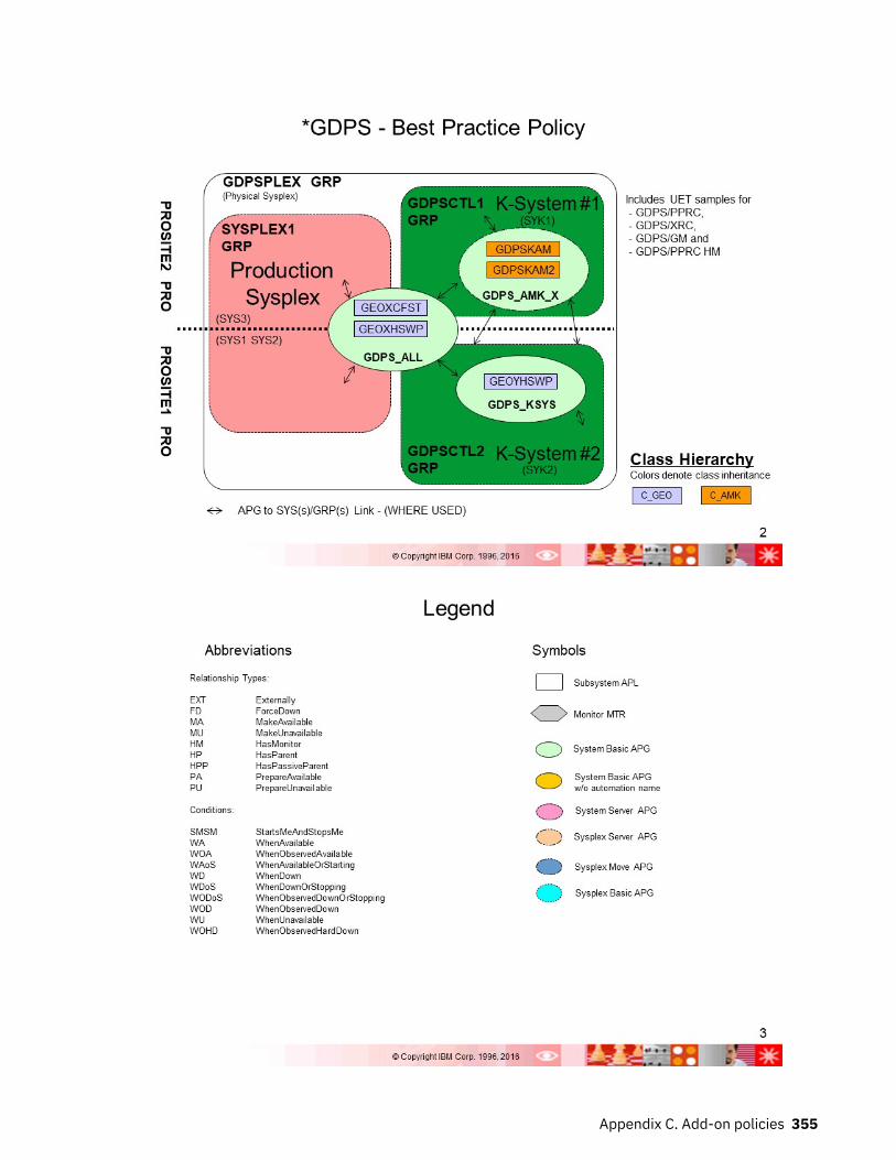
Appendix C. Add-on policies 355

*IBMCOMP
356 System Automation for z/OS : Defining Automation Policy

Appendix C. Add-on policies 357

358 System Automation for z/OS : Defining Automation Policy

Appendix C. Add-on policies 359

360 System Automation for z/OS : Defining Automation Policy

Appendix C. Add-on policies 361

362 System Automation for z/OS : Defining Automation Policy

Appendix C. Add-on policies 363

*IMS
364 System Automation for z/OS : Defining Automation Policy

Appendix C. Add-on policies 365

366 System Automation for z/OS : Defining Automation Policy

Appendix C. Add-on policies 367

*ITM
368 System Automation for z/OS : Defining Automation Policy

Appendix C. Add-on policies 369

370 System Automation for z/OS : Defining Automation Policy

Appendix C. Add-on policies 371

372 System Automation for z/OS : Defining Automation Policy

Appendix C. Add-on policies 373

*IWS
374 System Automation for z/OS : Defining Automation Policy

Appendix C. Add-on policies 375

*PROCOPS
376 System Automation for z/OS : Defining Automation Policy

Appendix C. Add-on policies 377

378 System Automation for z/OS : Defining Automation Policy

Appendix C. Add-on policies 379

*SAPSRV
380 System Automation for z/OS : Defining Automation Policy

Appendix C. Add-on policies 381

382 System Automation for z/OS : Defining Automation Policy

Appendix C. Add-on policies 383

384 System Automation for z/OS : Defining Automation Policy

*TBSM
Appendix C. Add-on policies 385

386 System Automation for z/OS : Defining Automation Policy

Appendix D. Notices
This information was developed for products and services offered in the US. This material might beavailable from IBM in other languages. However, you may be required to own a copy of the product orproduct version in that language in order to access it.
IBM may not offer the products, services, or features discussed in this document in other countries.Consult your local IBM representative for information on the products and services currently available inyour area. Any reference to an IBM product, program, or service is not intended to state or imply that onlythat IBM product, program, or service may be used. Any functionally equivalent product, program, orservice that does not infringe any IBM intellectual property right may be used instead. However, it is theuser's responsibility to evaluate and verify the operation of any non-IBM product, program, or service.
IBM may have patents or pending patent applications covering subject matter described in thisdocument. The furnishing of this document does not grant you any license to these patents. You can sendlicense inquiries, in writing, to:
IBM Director of LicensingIBM CorporationNorth Castle Drive, MD-NC119Armonk, NY 10504-1785US
For license inquiries regarding double-byte character set (DBCS) information, contact the IBM IntellectualProperty Department in your country or send inquiries, in writing, to:
Intellectual Property LicensingLegal and Intellectual Property LawIBM Japan Ltd.19-21, Nihonbashi-Hakozakicho, Chuo-kuTokyo 103-8510, Japan
INTERNATIONAL BUSINESS MACHINES CORPORATION PROVIDES THIS PUBLICATION "AS IS"WITHOUT WARRANTY OF ANY KIND, EITHER EXPRESS OR IMPLIED, INCLUDING, BUT NOT LIMITED TO,THE IMPLIED WARRANTIES OF NON-INFRINGEMENT, MERCHANTABILITY OR FITNESS FOR APARTICULAR PURPOSE. Some jurisdictions do not allow disclaimer of express or implied warranties incertain transactions, therefore, this statement may not apply to you.
This information could include technical inaccuracies or typographical errors. Changes are periodicallymade to the information herein; these changes will be incorporated in new editions of the publication.IBM may make improvements and/or changes in the product(s) and/or the program(s) described in thispublication at any time without notice.
Any references in this information to non-IBM websites are provided for convenience only and do not inany manner serve as an endorsement of those websites. The materials at those websites are not part ofthe materials for this IBM product and use of those websites is at your own risk.
IBM may use or distribute any of the information you provide in any way it believes appropriate withoutincurring any obligation to you.
Licensees of this program who wish to have information about it for the purpose of enabling: (i) theexchange of information between independently created programs and other programs (including thisone) and (ii) the mutual use of the information which has been exchanged, should contact:
IBM Director of LicensingIBM CorporationNorth Castle Drive, MD-NC119Armonk, NY 10504-1785US
© Copyright IBM Corp. 1996, 2017 387

Such information may be available, subject to appropriate terms and conditions, including in some cases,payment of a fee.
The licensed program described in this document and all licensed material available for it are provided byIBM under terms of the IBM Customer Agreement, IBM International Program License Agreement or anyequivalent agreement between us.
The performance data and client examples cited are presented for illustrative purposes only. Actualperformance results may vary depending on specific configurations and operating conditions.
Information concerning non-IBM products was obtained from the suppliers of those products, theirpublished announcements or other publicly available sources. IBM has not tested those products andcannot confirm the accuracy of performance, compatibility or any other claims related to non-IBMproducts. Questions on the capabilities of non-IBM products should be addressed to the suppliers ofthose products.
Statements regarding IBM's future direction or intent are subject to change or withdrawal without notice,and represent goals and objectives only.
All IBM prices shown are IBM's suggested retail prices, are current and are subject to change withoutnotice. Dealer prices may vary.
This information is for planning purposes only. The information herein is subject to change before theproducts described become available.
This information contains examples of data and reports used in daily business operations. To illustratethem as completely as possible, the examples include the names of individuals, companies, brands, andproducts. All of these names are fictitious and any similarity to actual people or business enterprises isentirely coincidental.
COPYRIGHT LICENSE:
This information contains sample application programs in source language, which illustrate programmingtechniques on various operating platforms. You may copy, modify, and distribute these sample programsin any form without payment to IBM, for the purposes of developing, using, marketing or distributingapplication programs conforming to the application programming interface for the operating platform forwhich the sample programs are written. These examples have not been thoroughly tested under allconditions. IBM, therefore, cannot guarantee or imply reliability, serviceability, or function of theseprograms. The sample programs are provided "AS IS", without warranty of any kind. IBM shall not beliable for any damages arising out of your use of the sample programs.
Each copy or any portion of these sample programs or any derivative work must include a copyright notice as follows: © (your company name) (year). Portions of this code are derived from IBM Corp. Sample Programs. © Copyright IBM Corp. _enter the year or years_.
TrademarksIBM, the IBM logo, and ibm.com are trademarks or registered trademarks of International BusinessMachines Corp., registered in many jurisdictions worldwide. Other product and service names might betrademarks of IBM or other companies. A current list of IBM trademarks is available on the web at"Copyright and trademark information" at www.ibm.com/legal/copytrade.shtml.
Terms and conditions for product documentationPermissions for the use of these publications are granted subject to the following terms and conditions.
ApplicabilityThese terms and conditions are in addition to any terms of use for the IBM website.
388 System Automation for z/OS : Defining Automation Policy

Personal useYou may reproduce these publications for your personal, noncommercial use provided that all proprietarynotices are preserved. You may not distribute, display or make derivative work of these publications, orany portion thereof, without the express consent of IBM.
Commercial useYou may reproduce, distribute and display these publications solely within your enterprise provided thatall proprietary notices are preserved. You may not make derivative works of these publications, orreproduce, distribute or display these publications or any portion thereof outside your enterprise, withoutthe express consent of IBM.
RightsExcept as expressly granted in this permission, no other permissions, licenses or rights are granted, eitherexpress or implied, to the publications or any information, data, software or other intellectual propertycontained therein.
IBM reserves the right to withdraw the permissions granted herein whenever, in its discretion, the use ofthe publications is detrimental to its interest or, as determined by IBM, the above instructions are notbeing properly followed.
You may not download, export or re-export this information except in full compliance with all applicablelaws and regulations, including all United States export laws and regulations.
IBM MAKES NO GUARANTEE ABOUT THE CONTENT OF THESE PUBLICATIONS. THE PUBLICATIONS AREPROVIDED "AS-IS" AND WITHOUT WARRANTY OF ANY KIND, EITHER EXPRESSED OR IMPLIED,INCLUDING BUT NOT LIMITED TO IMPLIED WARRANTIES OF MERCHANTABILITY, NON-INFRINGEMENT,AND FITNESS FOR A PARTICULAR PURPOSE.
Appendix D. Notices 389

390 System Automation for z/OS : Defining Automation Policy

Glossary
This glossary includes terms and definitions from:
• The IBM Dictionary of Computing New York: McGraw-Hill, 1994.• The American National Standard Dictionary for Information Systems, ANSI X3.172-1990, copyright
1990 by the American National Standards Institute (ANSI). Copies can be purchased from the AmericanNational Standards Institute, 1430 Broadway, New York, New York 10018. Definitions are identified bythe symbol (A) after the definition.
• The Information Technology Vocabulary developed by Subcommittee 1, Joint Technical Committee 1, ofthe International Organization for Standardization and the International Electrotechnical Commission(ISO/IEC JTC1/SC1). Definitions of published parts of this vocabulary are identified by the symbol (I)after the definition; definitions taken from draft international standards, committee drafts, and workingpapers being developed by ISO/IEC JTC1/SC1 are identified by the symbol (T) after the definition,indicating that final agreement has not yet been reached among the participating National Bodies ofSC1.
The following cross-references are used in this glossary:
Contrast with. This refers to a term that has an opposed or substantively different meaning.Deprecated term for. This indicates that the term should not be used. It refers to a preferred term,which is defined in its proper place in the glossary.See. This refers the reader to multiple-word terms in which this term appears.See also. This refers the reader to terms that have a related, but not synonymous, meaning.Synonym for. This indicates that the term has the same meaning as a preferred term, which is definedin the glossary.Synonymous with. This is a backward reference from a defined term to all other terms that have thesame meaning.
AACF
See automation configuration file.ACF/NCP
Advanced Communications Function for the Network Control Program. See AdvancedCommunications Function and Network Control Program.
ACF/VTAMAdvanced Communications Function for the Virtual Telecommunications Access Method. Synonym forVTAM. See Advanced Communications Function and Virtual Telecommunications Access Method.
active monitoringIn SA z/OSautomation control file, the acquiring of resource status information by soliciting suchinformation at regular, user-defined intervals. See also passive monitoring.
adapterHardware card that enables a device, such as a workstation, to communicate with another device,such as a monitor, a printer, or some other I/O device.
adjacent hostsSystems connected in a peer relationship using adjacent NetView sessions for purposes of monitoringand control.
adjacent NetViewIn SA z/OS, the system defined as the communication path between two SA z/OS systems that do nothave a direct link. An adjacent NetView is used for message forwarding and as a communication linkbetween two SA z/OS systems. For example, the adjacent NetView is used when sending responsesfrom a focal point to a remote system.
© Copyright IBM Corp. 1996, 2017 391

Advanced Communications Function (ACF)A group of IBM licensed programs (principally VTAM, TCAM, NCP, and SSP) that use the concepts ofSystems Network Architecture (SNA), including distribution of function and resource sharing.
advanced program-to-program communication (APPC)A set of inter-program communication services that support cooperative transaction processing in aSystems Network Architecture (SNA) network. APPC is the implementation, on a given system, ofSNA's logical unit type 6.2.
Advanced Workload Analysis Reporter (zAware)IBM analytics appliance running in a z Systems partition, activated in zACI mode. Customers can usethe appliance to monitor the console message streams of other LPARs running in the same System z®
cluster and create trend reports. Exploiting zAware and these trend reports can help to better predictOS outages or performance degradations and initiate proactive clusters.
alertIn SNA, a record sent to a system problem management focal point or to a collection point tocommunicate the existence of an alert condition.In NetView, a high-priority event that warrants immediate attention. A database record is generatedfor certain event types that are defined by user-constructed filters.
alert conditionA problem or impending problem for which some or all of the process of problem determination,diagnosis, and resolution is expected to require action at a control point.
alert thresholdAn application or volume service value that determines the level at which SA z/OS changes theassociated icon in the graphical interface to the alert color. SA z/OS may also issue an alert. Seewarning threshold.
AMCSee Automation Manager Configuration.
American Standard Code for Information Interchange (ASCII)A standard code used for information exchange among data processing systems, data communicationsystems, and associated equipment. ASCII uses a coded character set consisting of 7-bit codedcharacters (8-bit including parity check). The ASCII set consists of control characters and graphiccharacters. See also Extended Binary Coded Decimal Interchange Code.
APFSee authorized program facility.
APISee application programming interface.
APPCSee advanced program-to-program communication.
applicationIn SA z/OS, applications refer to z/OS subsystems, started tasks, or jobs that are automated andmonitored by SA z/OS. On SNMP-capable processors, application can be used to refer to a subsystemor process.
Application entryA construct, created with the customization dialogs, used to represent and contain policy for anapplication.
application groupA named set of applications. An application group is part of an SA z/OS enterprise definition and isused for monitoring purposes.
application programA program written for or by a user that applies to the user's work, such as a program that doesinventory or payroll.A program used to connect and communicate with stations in a network, enabling users to performapplication-oriented activities.
392 System Automation for z/OS : Defining Automation Policy

application programming interface (API)An interface that allows an application program that is written in a high-level language to use specificdata or functions of the operating system or another program.
ApplicationGroup entryA construct, created with the customization dialogs, used to represent and contain policy for anapplication group.
ARMSee automatic restart management.
ASCBAddress space control block.
ASCB statusAn application status derived by SA z/OS running a routine (the ASCB checker) that searches the z/OSaddress space control blocks (ASCBs) for address spaces with a particular job name. The job nameused by the ASCB checker is the job name defined in the customization dialog for the application.
ASCIISee American Standard Code for Information Interchange.
ASFSee automation status file.
authorized program facility (APF)A facility that permits identification of programs that are authorized to use restricted functions.
automated console operations (ACO)The use of an automated procedure to replace or simplify the action that an operator takes from aconsole in response to system or network events.
automated functionSA z/OS automated functions are automation operators, NetView autotasks that are assigned toperform specific automation functions. However, SA z/OS defines its own synonyms, or automatedfunction names, for the NetView autotasks, and these function names are referred to in the samplepolicy databases provided by SA z/OS. For example, the automation operator AUTBASE correspondsto the SA z/OS automated function BASEOPER.
automatic restart management (ARM)A z/OS recovery function that improves the availability of specified subsystems and applications byautomatically restarting them under certain circumstances. Automatic restart management is afunction of the Cross-System Coupling Facility (XCF) component of z/OS.
automatic restart management element nameIn MVS 5.2 or later, z/OS automatic restart management requires the specification of a unique sixteencharacter name for each address space that registers with it. All automatic restart management policyis defined in terms of the element name, including the SA z/OS interface with it.
automationThe automatic initiation of actions in response to detected conditions or events. SA z/OS providesautomation for z/OS applications, z/OS components, and remote systems that run z/OS. SA z/OS alsoprovides tools that can be used to develop additional automation.
automation agentIn SA z/OS, the automation function is split up between the automation manager and the automationagents. The observing, reacting and doing parts are located within the NetView address space, andare known as the automation agents. The automation agents are responsible for:
• Recovery processing• Message processing• Active monitoring: they propagate status changes to the automation manager
automation configuration fileThe SA z/OS customization dialogs must be used to build the automation configuration file. It consistsof:
Glossary 393

• The automation manager configuration file (AMC)• The NetView automation table (AT)• The NetView message revision table (MRT)• The MPFLSTxx member
automation control file (ACF)In SA z/OS, a file that contains system-level automation policy information. There is one masterautomation control file for each NetView system that SA z/OS is installed on. Additional policyinformation and all resource status information is contained in the policy database (PDB). The SA z/OScustomization dialogs must be used to build the automation control files. They must not be editedmanually.
automation flagsIn SA z/OS, the automation policy settings that determine the operator functions that are automatedfor a resource and the times during which automation is active. When SA z/OS is running, automationis controlled by automation flag policy settings and override settings (if any) entered by the operator.Automation flags are set using the customization dialogs.
automation managerIn SA z/OS, the automation function is split up between the automation manager and the automationagents. The coordination, decision making and controlling functions are processed by each sysplex'sautomation manager.
The automation manager contains a model of all of the automated resources within the sysplex. Theautomation agents feed the automation manager with status information and perform the actions thatthe automation manager tells them to.
The automation manager provides sysplex-wide automation.
Automation Manager ConfigurationThe Automation Manager Configuration file (AMC) contains an image of the automated systems in asysplex or of a standalone system. See also automation configuration file.
Automation NetViewIn SA z/OS the NetView that performs routine operator tasks with command procedures or uses otherways of automating system and network management, issuing automatic responses to messages andmanagement services units.
automation operatorNetView automation operators are NetView autotasks that are assigned to perform specificautomation functions. See also automated function. NetView automation operators may receivemessages and process automation procedures. There are no logged-on users associated withautomation operators. Each automation operator is an operating system task and runs concurrentlywith other NetView tasks. An automation operator could be set up to handle JES2 messages thatschedule automation procedures, and an automation statement could route such messages to theautomation operator. Similar to operator station task. SA z/OS message monitor tasks and targetcontrol tasks are automation operators.
automation policyThe policy information governing automation for individual systems. This includes automation forapplications, z/OS subsystems, z/OS data sets, and z/OS components.
automation policy settingsThe automation policy information contained in the automation control file. This information isentered using the customization dialogs. You can display or modify these settings using thecustomization dialogs.
automation procedureA sequence of commands, packaged as a NetView command list or a command processor written in ahigh-level language. An automation procedure performs automation functions and runs underNetView.
394 System Automation for z/OS : Defining Automation Policy

automation routinesIn SA z/OS, a set of self-contained automation routines that can be called from the NetViewautomation table, or from user-written automation procedures.
automation status file (ASF)In SA z/OS, a file containing status information for each automated subsystem, component or dataset. This information is used by SA z/OS automation when taking action or when determining whataction to take. In Release 2 and above of AOC/MVS, status information is also maintained in theoperational information base.
automation table (AT)See NetView automation table.
autotaskA NetView automation task that receives messages and processes automation procedures. There areno logged-on users associated with autotasks. Each autotask is an operating system task and runsconcurrently with other NetView tasks. An autotask could be set up to handle JES2 messages thatschedule automation procedures, and an automation statement could route such messages to theautotasks. Similar to operator station task. SA z/OS message monitor tasks and target control tasksare autotasks. Also called automation operator.
availableIn VTAM programs, pertaining to a logical unit that is active, connected, enabled, and not at its sessionlimit.
BBase Control Program (BCP)
A program that provides essential services for the MVS and z/OS operating systems. The programincludes functions that manage system resources. These functions include input/output, dispatchunits of work, and the z/OS UNIX System Services kernel. See also Multiple Virtual Storage and z/OS.
basic modeA central processor mode that does not use logical partitioning. Contrast with logically partitionedmode.
BCPSee Base Control Program.
BCP Internal InterfaceProcessor function of System z processor families. It allows for communication between basic controlprograms such as z/OS and the processor support element in order to exchange information or toperform processor control functions. Programs using this function can perform hardware operationssuch as ACTIVATE or SYSTEM RESET.
beaconingThe repeated transmission of a frame or messages (beacon) by a console or workstation upondetection of a line break or outage.
bladeA hardware unit that provides application-specific services and components. The consistent size andshape (or form factor) of each blade allows it to fit in a BladeCenter chassis.
BladeCenter chassisA modular chassis that can contain multiple blades, allowing the individual blades to share resourcessuch as management, switch, power, and blower modules.
BookManager®An IBM product that lets users view softcopy documents on their workstations.
Ccentral processor (CP)
The part of the computer that contains the sequencing and processing facilities for instructionexecution, initial program load (IPL), and other machine operations.
Glossary 395
central processor complex (CPC)A physical collection of hardware that consists of central storage, (one or more) central processors,(one or more) timers, and (one or more) channels.
central siteIn a distributed data processing network, the central site is usually defined as the focal point foralerts, application design, and remote system management tasks such as problem management.
channelA path along which signals can be sent; for example, data channel, output channel. See also link.
channel path identifierA system-unique value assigned to each channel path.
channel-attachedAttached directly by I/O channels to a host processor (for example, a channel-attached device).Attached to a controlling unit by cables, rather than by telecommunication lines. Contrast with link-attached. Synonymous with local.
CHPIDIn SA z/OS, channel path ID; the address of a channel.
CHPID portA label that describes the system name, logical partitions, and channel paths.
CISee console integration.
CICS/VSCustomer Information Control System for Virtual Storage. See Customer Information Control System.
CLISTSee command list.
cloneA set of definitions for application instances that are derived from a basic application definition bysubstituting a number of different system-specific values into the basic definition.
clone IDA generic means of handling system-specific values such as the MVS SYSCLONE or the VTAM subareanumber. Clone IDs can be substituted into application definitions and commands to customize a basicapplication definition for the system that it is to be instantiated on.
commandA request for the performance of an operation or the execution of a particular program.
command facilityThe component of NetView that is a base for command processors that can monitor, control,automate, and improve the operation of a network. The successor to NCCF.
command list (CLIST)A list of commands and statements, written in the NetView command list language or the REXXlanguage, designed to perform a specific function for the user. In its simplest form, a command list is alist of commands. More complex command lists incorporate variable substitution and conditionallogic, making the command list more like a conventional program. Command lists are typicallyinterpreted rather than being compiled.In SA z/OS, REXX command lists that can be used for automation procedures.
command procedureIn NetView, either a command list or a command processor.
command processorA module designed to perform a specific function. Command processors, which can be written inassembler or a high-level language (HLL), are issued as commands.
Command Tree/2An OS/2-based program that helps you build commands on an OS/2 window, then routes thecommands to the destination you specify (such as a 3270 session, a file, a command line, or an
396 System Automation for z/OS : Defining Automation Policy

application program). It provides the capability for operators to build commands and route them to aspecified destination.
common commandsThe SA z/OS subset of the CPC operations management commands.
Common User Access (CUA) architectureGuidelines for the dialog between a human and a workstation or terminal.
communication controllerA type of communication control unit whose operations are controlled by one or more programsstored and executed in the unit or by a program executed in a processor to which the controller isconnected. It manages the details of line control and the routing of data through a network.
communication lineDeprecated term for telecommunication line.
connectivity viewIn SA z/OS, a display that uses graphic images for I/O devices and lines to show how they areconnected.
console automationThe process of having NetView facilities provide the console input usually handled by the operator.
console connectionIn SA z/OS, the 3270 or ASCII (serial) connection between a PS/2 computer and a target system.Through this connection, the workstation appears (to the target system) to be a console.
console integration (CI)A hardware facility that if supported by an operating system, allows operating system messages to betransferred through an internal hardware interface for display on a system console. Conversely, itallows operating system commands entered at a system console to be transferred through an internalhardware interface to the operating system for processing.
consolesWorkstations and 3270-type devices that manage your enterprise.
couple data setA data set that is created through the XCF couple data set format utility and, depending on itsdesignated type, is shared by some or all of the z/OS systems in a sysplex. See also sysplex coupledata setand XCF couple data set.
coupling facilityThe hardware element that provides high-speed caching, list processing, and locking functions in asysplex.
CPSee central processor.
CPCSee central processor complex.
CPC operations management commandsA set of commands and responses for controlling the operation of System/390® CPCs.
CPC subsetAll or part of a CPC. It contains the minimum resource to support a single control program.
CPUCentral processing unit. Deprecated term for processor.
cross-system coupling facility (XCF)A component of z/OS that provides functions to support cooperation between authorized programsrunning within a sysplex.
Customer Information Control System (CICS)A general-purpose transactional program that controls online communication between terminal usersand a database for a large number of end users on a real-time basis.
Glossary 397

customization dialogsThe customization dialogs are an ISPF application. They are used to customize the enterprise policy,like, for example, the enterprise resources and the relationships between resources, or theautomation policy for systems in the enterprise. How to use these dialogs is described in IBM SystemAutomation for z/OS Customizing and Programming.
DDataPower® X150z
See IBM Websphere DataPower Integration Appliance X150 for zEnterprise (DataPower X150z).DASD
See direct access storage device.data services task (DST)
The NetView subtask that gathers, records, and manages data in a VSAM file or a network device thatcontains network management information.
data setThe major unit of data storage and retrieval, consisting of a collection of data in one of severalprescribed arrangements and described by control information to which the system has access.
data set membersMembers of partitioned data sets that are individually named elements of a larger file that can beretrieved by name.
DBCSSee double-byte character set.
DCCFSee disabled console communication facility.
DCFSee Document Composition Facility.
DELAY ReportAn RMF report that shows the activity of each job in the system and the hardware and softwareresources that are delaying each job.
deviceA piece of equipment. Devices can be workstations, printers, disk drives, tape units, remote systemsor communications controllers. You can see information about all devices attached to a particularswitch, and control paths and jobs to devices.
DEVR ReportAn RMF report that presents information about the activity of I/O devices that are delaying jobs.
dialogInteractive 3270 panels.
direct access storage device (DASD)A device that allows storage to be directly accessed, such as a disk drive.
disabled console communication facility (DCCF)A z/OS component that provides limited-function console communication during system recoverysituations.
disk operating system (DOS)An operating system for computer systems that use disks and diskettes for auxiliary storage ofprograms and data.Software for a personal computer that controls the processing of programs. For the IBM PersonalComputer, the full name is Personal Computer Disk Operating System (PCDOS).
displayTo present information for viewing, usually on the screen of a workstation or on a hardcopy device.Deprecated term for panel.
398 System Automation for z/OS : Defining Automation Policy

distribution managerThe component of the NetView program that enables the host system to use, send, and delete filesand programs in a network of computers.
Document Composition Facility (DCF)An IBM licensed program used to format input to a printer.
domainAn access method and its application programs, communication controllers, connecting lines,modems, and attached workstations.In SNA, a system services control point (SSCP) and the physical units (PUs), logical units (LUs), links,link stations, and associated resources that the SSCP can control with activation requests anddeactivation requests.
double-byte character set (DBCS)A character set, such as Kanji, in which each character is represented by a 2-byte code.
DP enterpriseData processing enterprise.
DSIPARMThis file is a collection of members for NetView customization.
DSTData Services Task.
EEBCDIC
See Extended Binary Coded Decimal Interchange Code.ECB
See event control block.EMCS
Extended multiple console support. See also multiple console support.ensemble
A collection of one or more zEnterprise nodes (including any attached zBX) that are managed as asingle logical virtualized system by the Unified Resource Manager, through the Hardware ManagementConsole.
ensemble memberA zEnterprise node that has been added to an ensemble.
enterpriseThe composite of all operational entities, functions, and resources that form the total businessconcern and that require an information system.
Enterprise Systems Architecture (ESA)A hardware architecture that reduces the effort required for managing data sets and extendsaddressability for system, subsystem, and application functions.
entriesResources, such as processors, entered on panels.
entry typeResources, such as processors or applications, used for automation and monitoring.
environmentData processing enterprise.
error thresholdAn automation policy setting that specifies when SA z/OS should stop trying to restart or recover anapplication, subsystem or component, or offload a data set.
ESASee Enterprise Systems Architecture.
eventIn NetView, a record indicating irregularities of operation in physical elements of a network.
Glossary 399

An occurrence of significance to a task; for example, the completion of an asynchronous operation,such as an input/output operation.Events are part of a trigger condition, such that if all events of a trigger condition have occurred, astartup or shutdown of an application is performed.
event control block (ECB)A control block used to represent the status of an event.
exception conditionAn occurrence on a system that is a deviation from normal operation. SA z/OS monitoring highlightsexception conditions and allows an SA z/OS enterprise to be managed by exception.
Extended Binary Coded Decimal Interchange Code (EBCDIC)A coded character set of 256 8-bit characters developed for the representation of textual data. Seealso American Standard Code for Information Interchange.
extended recovery facility (XRF)A facility that minimizes the effect of failures in z/OS, VTAM, the host processor, or high availabilityapplications during sessions between high availability applications and designated terminals. Thisfacility provides an alternate subsystem to take over sessions from the failing subsystem.
Ffallback system
See secondary system.field
A collection of bytes within a record that are logically related and are processed as a unit.file manager commands
A set of SA z/OS commands that read data from or write data to the automation control file or theoperational information base. These commands are useful in the development of automation thatuses SA z/OS facilities.
focal pointIn NetView, the focal-point domain is the central host domain. It is the central control point for anymanagement services element containing control of the network management data.
focal point systemA system that can administer, manage, or control one or more target systems. There are a number ofdifferent focal point system associated with IBM automation products.SA z/OS Processor Operations focal point system. This is a NetView system that has SA z/OS hostcode installed. The SA z/OS Processor Operations focal point system receives messages from thesystems and operator consoles of the machines that it controls. It provides full systems andoperations console function for its target systems. It can be used to IPL these systems. Note thatsome restrictions apply to the Hardware Management Console for an S/390 microprocessor cluster.SA z/OS SDF focal point system. The SA z/OS SDF focal point system is an SA z/OS NetView systemthat collects status information from other SA z/OS NetViews within your enterprise.Status focal point system. In NetView, the system to which STATMON, VTAM and NLDM send statusinformation on network resources.Hardware Management Console. Although not listed as a focal point, the Hardware ManagementConsole acts as a focal point for the console functions of an S/390 microprocessor cluster. Unlike allthe other focal points in this definition, the Hardware Management Console runs on a LAN-connectedworkstation,
frameFor a System/390 microprocessor cluster, a frame contains one or two central processor complexes(CPCs), support elements, and AC power distribution.
full-screen modeIn NetView, a form of panel presentation that makes it possible to display the contents of an entireworkstation screen at once. Full-screen mode can be used for fill-in-the-blanks prompting. Contrastwith line mode.
G
400 System Automation for z/OS : Defining Automation Policy

gateway sessionAn NetView-NetView Task session with another system in which the SA z/OS outbound gatewayoperator logs onto the other NetView session without human operator intervention. Each end of agateway session has both an inbound and outbound gateway operator.
generic alertEncoded alert information that uses code points (defined by IBM and possibly customized by users orapplication programs) stored at an alert receiver, such as NetView.
groupA collection of target systems defined through configuration dialogs. An installation might set up agroup to refer to a physical site or an organizational or application entity.
group entryA construct, created with the customization dialogs, used to represent and contain policy for a group.
group entry typeA collection of target systems defined through the customization dialog. An installation might set up agroup to refer to a physical site or an organizational entity. Groups can, for example, be of typeSTANDARD or SYSPLEX.
HHardware Management Console (HMC)
A user interface through which data center personnel configure, control, monitor, and manage Systemz hardware and software resources. The HMC communicates with each central processor complex(CPC) through the Support Element. On an IBM zEnterprise 196 (z196), using the Unified ResourceManager on the HMCs or Support Elements, personnel can also create and manage an ensemble.
Hardware Management Console Application (HWMCA)A direct-manipulation object-oriented graphical user interface that provides a single point of controland single system image for hardware elements. The HWMCA provides grouping support, aggregatedand real-time system status using colors, consolidated hardware messages support, consolidatedoperating system messages support, consolidated service support, and hardware commands targetedat a single system, multiple systems, or a group of systems.
help panelAn online panel that tells you how to use a command or another aspect of a product.
hierarchyIn the NetView program, the resource types, display types, and data types that make up theorganization, or levels, in a network.
high-level language (HLL)A programming language that provides some level of abstraction from assembler language andindependence from a particular type of machine. For the NetView program, the high-level languagesare PL/I and C.
HLLSee high-level language.
host (primary processor)The processor that you enter a command at (also known as the issuing processor).
host systemIn a coupled system or distributed system environment, the system on which the facilities forcentralized automation run. SA z/OS publications refer to target systems or focal-point systemsinstead of hosts.
HWMCASee Hardware Management Console Application.
HypervisorA program that allows multiple instances of operating systems or virtual servers to run simultaneouslyon the same hardware device. A hypervisor can run directly on the hardware, can run within anoperating system, or can be imbedded in platform firmware. Examples of hypervisors include PR/SM,z/VM®, and PowerVM® Enterprise Edition.
Glossary 401

IIBM blade
A customer-acquired, customer-installed select blade to be managed by IBM zEnterprise UnifiedResource Manager. One example of an IBM blade is a POWER7® blade.
IBM Secure Service Container (SSC)IBM Z partitions, activated to run in SSC operating mode, provide the basic infrastructure runtime anddeployment support for firmware or software based appliances, such as zAware or z/VSE® VNA.
IBM Smart Analyzer for DB2 for z/OSAn optimizer that processes certain types of data warehouse queries for DB2 for z/OS.
IBM System z Application Assist Processor (zAAP)A specialized processor that provides a Java execution environment, which enables Java-based webapplications to be integrated with core z/OS business applications and backend database systems.
IBM System z Integrated Information Processor (zIIP)See Integrated Information Processor (IIP).
IBM Websphere DataPower Integration Appliance X150 for zEnterprise (DataPower X150z)A purpose-built appliance that simplifies, helps secure, and optimizes XML and Web servicesprocessing.
IBM Workload Scheduler (IWS)A family of IBM licensed products (formerly known as Tivoli Workload Scheduler or OPC/A) that plan,execute, and track jobs on several platforms and environments.
IBM zEnterprise 196 (z196)The newest generation of System z family of servers built on a new processor chip, with enhancedmemory function and capacity, security, and on demand enhancements to support existing mainframeworkloads and large scale consolidation.
IBM zEnterprise BladeCenter Extension (zBX)A heterogeneous hardware infrastructure that consists of a BladeCenter chassis attached to an IBMzEnterprise 196 (z196). A BladeCenter chassis can contain IBM blades or optimizers.
IBM zEnterprise BladeCenter Extension (zBX) bladeGeneric name for all blade types supported in an IBM zEnterprise BladeCenter Extension (zBX). Thisterm includes IBM blades and optimizers.
IBM zEnterprise System (zEnterprise)A heterogeneous hardware infrastructure that can consist of an IBM zEnterprise 196 (z196) and anattached IBM zEnterprise BladeCenter Extension (zBX) Model 002, managed as a single logicalvirtualized system by the Unified Resource Manager.
IBM zEnterprise Unified Resource ManagerLicensed Internal Code (LIC), also known as firmware, that is part of the Hardware ManagementConsole. The Unified Resource Manager provides energy monitoring and management, goal-orientedpolicy management, increased security, virtual networking, and data management for the physical andlogical resources of a given ensemble.
I/O resource numberCombination of channel path identifier (CHPID), device number, etc. See internal token.
imagesA grouping of processors and I/O devices that you define. You can define a single-image mode thatallows a multiprocessor system to function as one central processor image.
IMSSee Information Management System.
IMS/VSSee Information Management System/Virtual Storage.
inboundIn SA z/OS, messages sent to the focal-point system from the PC or target system.
402 System Automation for z/OS : Defining Automation Policy

inbound gateway operatorThe automation operator that receives incoming messages, commands, and responses from theoutbound gateway operator at the sending system. The inbound gateway operator handlescommunications with other systems using a gateway session.
Information Management System (IMS)Any of several system environments available with a database manager and transaction processingthat are capable of managing complex databases and terminal networks.
Information Management System/Virtual Storage (IMS/VS)A database/data communication (DB/DC) system that can manage complex databases and networks.Synonymous with Information Management System.
initial microprogram loadThe action of loading microprograms into computer storage.
initial program load (IPL)The initialization procedure that causes an operating system to commence operation.The process by which a configuration image is loaded into storage at the beginning of a workday orafter a system malfunction.The process of loading system programs and preparing a system to run jobs.
initialize automationSA z/OS-provided automation that issues the correct z/OS start command for each subsystem whenSA z/OS is initialized. The automation ensures that subsystems are started in the order specified in theautomation control files and that prerequisite applications are functional.
input/output configuration data set (IOCDS)A configuration definition built by the I/O configuration program (IOCP) and stored on disk filesassociated with the processor controller.
input/output support processor (IOSP)The hardware unit that provides I/O support functions for the primary support processor andmaintenance support functions for the processor controller.
Integrated Information Processor (IIP)A specialized processor that provides computing capacity for selected data and transactionprocessing workloads and for selected network encryption workloads.
Interactive System Productivity Facility (ISPF)An IBM licensed program that serves as a full-screen editor and dialog manager. Used for writingapplication programs, it provides a means of generating standard screen panels and interactivedialogs between the application programmer and the terminal user. See also Time Sharing Option.
interested operator listThe list of operators who are to receive messages from a specific target system.
internal tokenA logical token (LTOK); name by which the I/O resource or object is known; stored in IODF.
IOCDSSee input/output configuration data set.
IOSPSee input/output support processor..
IPLSee initial program load.
ISPFSee Interactive System Productivity Facility.
ISPF consoleYou log on to ISPF from this 3270-type console to use the runtime panels for SA z/OS customizationpanels.
issuing hostThe base program that you enter a command for processing with. See primary host.
Glossary 403

JJCL
See job control language.JES
See job entry subsystem.JES2
An MVS subsystem that receives jobs into the system, converts them to internal format, selects themfor execution, processes their output, and purges them from the system. In an installation with morethan one processor, each JES2 processor independently controls its job input, scheduling, and outputprocessing. See also job entry subsystem and JES3
JES3An MVS subsystem that receives jobs into the system, converts them to internal format, selects themfor execution, processes their output, and purges them from the system. In complexes that haveseveral loosely coupled processing units, the JES3 program manages processors so that the globalprocessor exercises centralized control over the local processors and distributes jobs to them using acommon job queue. See also job entry subsystem and JES2.
jobA set of data that completely defines a unit of work for a computer. A job usually includes allnecessary computer programs, linkages, files, and instructions to the operating system.An address space.
job control language (JCL)A problem-oriented language designed to express statements in a job that are used to identify the jobor describe its requirements to an operating system.
job entry subsystem (JES)An IBM licensed program that receives jobs into the system and processes all output data that isproduced by jobs. In SA z/OS publications, JES refers to JES2 or JES3, unless otherwise stated. Seealso JES2 and JES3.
KKanji
An ideographic character set used in Japanese. See also double-byte character set.LLAN
See local area network.line mode
A form of screen presentation in which the information is presented a line at a time in the messagearea of the terminal screen. Contrast with full-screen mode.
linkIn SNA, the combination of the link connection and the link stations joining network nodes; forexample, a System/370 channel and its associated protocols, a serial-by-bit connection under thecontrol of synchronous data link control (SDLC). See synchronous data link control.In SA z/OS, link connection is the physical medium of transmission.
link-attachedDescribes devices that are physically connected by a telecommunication line. Contrast with channel-attached.
Linux on z SystemsUNIX-like open source operating system conceived by Linus Torvalds and developed across theinternet.
localPertaining to a device accessed directly without use of a telecommunication line. Synonymous withchannel-attached.
404 System Automation for z/OS : Defining Automation Policy

local area network (LAN)A network in which a set of devices is connected for communication. They can be connected to alarger network. See also token ring.A network that connects several devices in a limited area (such as a single building or campus) andthat can be connected to a larger network.
logical partition (LP)A subset of the processor hardware that is defined to support an operating system. See also logicallypartitioned mode.
logical token (LTOK)Resource number of an object in the IODF.
logical unit (LU)In SNA, a port through which an end user accesses the SNA network and the functions provided bysystem services control points (SSCPs). An LU can support at least two sessions, one with an SSCPand one with another LU, and may be capable of supporting many sessions with other LUs. See alsophysical unit and system services control point.
logical unit 6.2 (LU 6.2)A type of logical unit that supports general communications between programs in a distributedprocessing environment. LU 6.2 is characterized by:
• A peer relationship between session partners• Efficient use of a session for multiple transactions• A comprehensive end-to-end error processing• A generic application program interface (API) consisting of structured verbs that are mapped to a
product implementation
Synonym for advanced program-to-program communication.logically partitioned (LPAR) mode
A central processor mode that enables an operator to allocate system processor hardware resourcesamong several logical partitions. Contrast with basic mode.
LOGRThe sysplex logger.
LPSee logical partition.
LPARSee logically partitioned mode.
LUSee logical unit.
LU 6.2See logical unit 6.2.
LU 6.2 sessionA session initiated by VTAM on behalf of an LU 6.2 application program, or a session initiated by aremote LU in which the application program specifies that VTAM is to control the session by using theAPPCCMD macro. See logical unit 6.2.
LU-LU sessionIn SNA, a session between two logical units (LUs) in an SNA network. It provides communicationbetween two end users, or between an end user and an LU services component.
MMAT
Deprecated term for NetView automation table.MCA
See Micro Channel architecture.
Glossary 405

MCSSee multiple console support.
memberA specific function (one or more modules or routines) of a multisystem application that is defined toXCF and assigned to a group by the multisystem application. A member resides on one system in thesysplex and can use XCF services to communicate (send and receive data) with other members of thesame group.
message automation table (MAT)Deprecated term for NetView automation table.
message classA number that SA z/OS associates with a message to control routing of the message. Duringautomated operations, the classes associated with each message issued by SA z/OS are compared tothe classes assigned to each notification operator. Any operator with a class matching one of themessage’s classes receives the message.
message forwardingThe SA z/OS process of sending messages generated at an SA z/OS target system to the SA z/OSfocal-point system.
message groupSeveral messages that are displayed together as a unit.
message monitor taskA task that starts and is associated with a number of communications tasks. Message monitor tasksreceive inbound messages from a communications task, determine the originating target system, androute the messages to the appropriate target control tasks.
message processing facility (MPF)A z/OS table that screens all messages sent to the z/OS console. The MPF compares these messageswith a customer-defined list of messages (based on this message list, messages are automatedand/or suppressed from z/OS console display), and marks messages to automate or suppress.Messages are then broadcast on the subsystem interface (SSI).
message suppressionThe ability to restrict the amount of message traffic displayed on the z/OS console.
Micro Channel architectureThe rules that define how subsystems and adapters use the Micro Channel bus in a computer. Thearchitecture defines the services that each subsystem can or must provide.
microprocessorA processor implemented on one or a small number of chips.
migrationInstallation of a new version or release of a program to replace an earlier version or release.
MPMultiprocessor.
MPFSee message processing facility.
MPFLSTxxThe MPFLST member that is built by SA z/OS.
multi-MVS environmentphysical processing system that is capable of operating more than one MVS image. See also MVSimage.
multiple console support (MCS)A feature of MVS that permits selective message routing to multiple consoles.
Multiple Virtual Storage (MVS)An IBM operating system that accesses multiple address spaces in virtual storage. The predecessor ofz/OS.
406 System Automation for z/OS : Defining Automation Policy

multiprocessor (MP)A CPC that can be physically partitioned to form two operating processor complexes.
multisystem applicationAn application program that has various functions distributed across z/OS images in a multisystemenvironment.
multisystem environmentAn environment in which two or more systems reside on one or more processors. Or one or moreprocessors can communicate with programs on the other systems.
MVSSee Multiple Virtual Storage.
MVS imageA single occurrence of the MVS operating system that has the ability to process work. See also multi-MVS environment and single-MVS environment.
MVS/ESAMultiple Virtual Storage/Enterprise Systems Architecture. See z/OS.
MVS/JES2Multiple Virtual Storage/Job Entry System 2. A z/OS subsystem that receives jobs into the system,converts them to an internal format, selects them for execution, processes their output, and purgesthem from the system. In an installation with more than one processor, each JES2 processorindependently controls its job input, scheduling, and output processing.
NNAU
See network addressable unit.See network accessible unit.
NCCFSee Network Communications Control Facility..
NCPSee network control program (general term).See Network Control Program (an IBM licensed program). Its full name is Advanced CommunicationsFunction for the Network Control Program. Synonymous with ACF/NCP.
NCP/token ring interconnectionA function used by ACF/NCP to support token ring-attached SNA devices. NTRI also providestranslation from token ring-attached SNA devices (PUs) to switched (dial-up) devices.
NetViewAn IBM licensed program used to monitor a network, manage it, and diagnose network problems.NetView consists of a command facility that includes a presentation service, command processors,automation based on command lists, and a transaction processing structure on which the sessionmonitor, hardware monitor, and terminal access facility (TAF) network management applications arebuilt.
NetView (NCCF) consoleA 3270-type console for NetView commands and runtime panels for system operations and processoroperations.
NetView automation proceduresA sequence of commands, packaged as a NetView command list or a command processor written in ahigh-level language. An automation procedure performs automation functions and runs under theNetView program.
NetView automation table (AT)A table against which the NetView program compares incoming messages. A match with an entrytriggers the specified response. SA z/OS entries in the NetView automation table trigger an SA z/OSresponse to target system conditions. Formerly known as the message automation table (MAT).
NetView command list languageAn interpretive language unique to NetView that is used to write command lists.
Glossary 407

NetView hardware monitorThe component of NetView that helps identify network problems, such as hardware, software, andmicrocode, from a central control point using interactive display techniques. Formerly called networkproblem determination application.
NetView logThe log that NetView records events relating to NetView and SA z/OS activities in.
NetView message tableSee NetView automation table.
NetView paths via logical unit (LU 6.2)A type of network-accessible port (VTAM connection) that enables end users to gain access to SNAnetwork resources and communicate with each other. LU 6.2 permits communication betweenprocessor operations and the workstation. See logical unit 6.2.
NetView-NetView task (NNT)The task that a cross-domain NetView operator session runs under. Each NetView program must havea NetView-NetView task to establish one NNT session. See also operator station task.
NetView-NetView task sessionA session between two NetView programs that runs under a NetView-NetView task. In SA z/OS,NetView-NetView task sessions are used for communication between focal point and remote systems.
networkAn interconnected group of nodes.In data processing, a user application network. See SNA network.
network accessible unit (NAU)In SNA networking, any device on the network that has a network address, including a logical unit(LU), physical unit (PU), control point (CP), or system services control point (SSCP). It is the origin orthe destination of information transmitted by the path control network. Synonymous with networkaddressable unit.
network addressable unit (NAU)Synonym for network accessible unit.
Network Communications Control Facility (NCCF)The operations control facility for the network. NCCF consists of a presentation service, commandprocessors, automation based on command lists, and a transaction processing structure on which thenetwork management applications NLDM are built. NCCF is a precursor to the NetView commandfacility.
Network Control Program (NCP)An IBM licensed program that provides communication controller support for single-domain,multiple-domain, and interconnected network capability. Its full name is Advanced CommunicationsFunction for the Network Control Program.
network control program (NCP)A program that controls the operation of a communication controller.A program used for requests and responses exchanged between physical units in a network for dataflow control.
Networking NetViewIn SA z/OS the NetView that performs network management functions, such as managing theconfiguration of a network. In SA z/OS it is common to also route alerts to the Networking NetView.
NIPSee nucleus initialization program.
NNTSee NetView-NetView task.
notification messageAn SA z/OS message sent to a human notification operator to provide information about significantautomation actions. Notification messages are defined using the customization dialogs.
408 System Automation for z/OS : Defining Automation Policy

notification operatorA NetView console operator who is authorized to receive SA z/OS notification messages. Authorizationis made through the customization dialogs.
NTRISee NCP/token ring interconnection.
nucleus initialization program (NIP)The program that initializes the resident control program; it allows the operator to request last-minutechanges to certain options specified during system generation.
Oobjective value
An average Workflow or Using value that SA z/OS can calculate for applications from past service data.SA z/OS uses the objective value to calculate warning and alert thresholds when none are explicitlydefined.
OCAIn SA z/OS, operator console A, the active operator console for a target system. Contrast with OCB.
OCBIn SA z/OS, operator console B, the backup operator console for a target system. Contrast with OCA.
OPC/ASee Operations Planning and Control/Advanced.
OPC/ESASee Operations Planning and Control/Enterprise Systems Architecture.
operating system (OS)Software that controls the execution of programs and that may provide services such as resourceallocation, scheduling, input/output control, and data management. Although operating systems arepredominantly software, partial hardware implementations are possible. (T)
operationsThe real-time control of a hardware device or software function.
Operations Planning and Control/Advanced (OPC/A)A set of IBM licensed programs that automate, plan, and control batch workload. OPC/A analyzessystem and workload status and submits jobs accordingly.
Operations Planning and Control/Enterprise Systems Architecture (OPC/ESA)A set of IBM licensed programs that automate, plan, and control batch workload. OPC/ESA analyzessystem and workload status and submits jobs accordingly. The successor to OPC/A.
operatorA person who keeps a system running.A person or program responsible for managing activities controlled by a given piece of software suchas z/OS, the NetView program, or IMS.A person who operates a device.In a language statement, the lexical entity that indicates the action to be performed on operands.
operator consoleA functional unit containing devices that are used for communications between a computer operatorand a computer. (T)A display console used for communication between the operator and the system, used primarily tospecify information concerning application programs and to monitor system operation.In SA z/OS, a console that displays output from and sends input to the operating system (z/OS, LINUX,VM, VSE). Also called operating system console. In the SA z/OS operator commands and configurationdialogs, OC is used to designate a target system operator console.
operator station task (OST)The NetView task that establishes and maintains the online session with the network operator. Thereis one operator station task for each network operator who logs on to the NetView program.
Glossary 409

operator viewA set of group, system, and resource definitions that are associated together for monitoring purposes.An operator view appears as a graphic display in the graphical interface showing the status of thedefined groups, systems, and resources.
OperatorView entryA construct, created with the customization dialogs, used to represent and contain policy for anoperator view.
optimizerA special-purpose hardware component or appliance that can perform a limited set of specificfunctions with optimized performance when compared to a general-purpose processor. Because of itslimited set of functions, an optimizer is an integrated part of a processing environment, rather than astand-alone unit. One example of an optimizer is the IBM Smart Analytics Optimizer for DB2 for z/OS.
OSSee operating system.
OSTSee operator station task.
outboundIn SA z/OS, messages or commands from the focal-point system to the target system.
outbound gateway operatorThe automation operator that establishes connections to other systems. The outbound gatewayoperator handles communications with other systems through a gateway session. The automationoperator sends messages, commands, and responses to the inbound gateway operator at thereceiving system.
Ppage
The portion of a panel that is shown on a display surface at one time.To transfer instructions, data, or both between real storage and external page or auxiliary storage.
panelA formatted display of information that appears on a terminal screen. Panels are full-screen 3270-type displays with a monospaced font, limited color and graphics.By using SA z/OS panels you can see status, type commands on a command line using a keyboard,configure your system, and passthru to other consoles. See also help panel.In computer graphics, a display image that defines the locations and characteristics of display fieldson a display surface. Contrast with screen.
parameterA variable that is given a constant value for a specified application and that may represent anapplication, for example.An item in a menu for which the user specifies a value or for which the system provides a value whenthe menu is interpreted.Data passed to a program or procedure by a user or another program, specifically as an operand in alanguage statement, as an item in a menu, or as a shared data structure.
partitionA fixed-size division of storage.In VSE, a division of the virtual address area that is available for program processing.On an IBM Personal Computer fixed disk, one of four possible storage areas of variable size; one canbe accessed by DOS, and each of the others may be assigned to another operating system.
partitionable CPCA CPC that can be divided into 2 independent CPCs. See also physical partition, single-image mode,MP, and side.
410 System Automation for z/OS : Defining Automation Policy

partitioned data set (PDS)A data set in direct access storage that is divided into partitions, called members, each of which cancontain a program, part of a program, or data.
passive monitoringIn SA z/OS, the receiving of unsolicited messages from z/OS systems and their resources. Thesemessages can prompt updates to resource status displays. See also active monitoring
PCEA processor controller. Also known as the support processor or service processor in some processorfamilies.
PDBSee policy database.
PDSSee partitioned data set.
physical partitionPart of a CPC that operates as a CPC in its own right, with its own copy of the operating system.
physical unit (PU)In SNA, the component that manages and monitors the resources (such as attached links andadjacent link stations) of a node, as requested by a system services control point (SSCP) through anSSCP-PU session. An SSCP activates a session with the physical unit to indirectly manage, through thePU, resources of the node such as attached links.
physically partitioned (PP) configurationA mode of operation that allows a multiprocessor (MP) system to function as two or moreindependent CPCs having separate power, utilities, and maintenance boundaries. Contrast withsingle-image mode.
PLEXID groupPLEXID group or "extended XCF communication group" is a term used in conjunction with a sysplex.The PLEXID group includes System Automation Agents for a subset of a sysplex or for the entiresysplex. It is used to provide XCF communication beyond the SAplex boundaries. For a detaileddescription, refer to "Defining the Extended XCF Communication Group" in IBM System Automation forz/OS Planning and Installation.
POISee program operator interface.
policyThe automation and monitoring specifications for an SA z/OS enterprise. See IBM System Automationfor z/OS Defining Automation Policy.
policy databaseThe automation definitions (automation policy) that the automation administrator specifies using thecustomization dialog is stored in the policy database. Also known as the PDB. See also automationpolicy.
PORSee power-on reset.
portSystem hardware that the I/O devices are attached to.An access point (for example, a logical unit) for data entry or exit.A functional unit of a node that data can enter or leave a data network through.In data communication, that part of a data processor that is dedicated to a single data channel for thepurpose of receiving data from or transmitting data to one or more external, remote devices.
power-on reset (POR)A function that re-initializes all the hardware in a CPC and loads the internal code that enables theCPC to load and run an operating system. See initial microprogram load.
PPSee physical partition.
Glossary 411

PPISee program to program interface.
PPTSee primary POI task.
PR/SMSee Processor Resource/Systems Manager.
primary hostThe base program that you enter a command for processing at.
primary POI task (PPT)The NetView subtask that processes all unsolicited messages received from the VTAM programoperator interface (POI) and delivers them to the controlling operator or to the command processor.The PPT also processes the initial command specified to execute when NetView is initialized andtimer request commands scheduled to execute under the PPT.
primary systemA system is a primary system for an application if the application is normally meant to be runningthere. SA z/OS starts the application on all the primary systems defined for it.
problem determinationThe process of determining the source of a problem; for example, a program component, machinefailure, telecommunication facilities, user or contractor-installed programs or equipment,environment failure such as a power loss, or user error.
processorA device for processing data from programmed instructions. It may be part of another unit.In a computer, the part that interprets and executes instructions. Two typical components of aprocessor are a control unit and an arithmetic logic unit.
processor controllerHardware that provides support and diagnostic functions for the central processors.
processor operationsThe part of SA z/OS that monitors and controls processor (hardware) operations. Processor operationsprovides a connection from a focal-point system to a target system. Through NetView on the focal-point system, processor operations automates operator and system consoles for monitoring andrecovering target systems. Also known as ProcOps.
Processor Resource/Systems Manager (PR/SM)The feature that allows the processor to use several operating system images simultaneously andprovides logical partitioning capability. See also logically partitioned mode.
ProcOpsSee processor operations.
ProcOps Service Machine (PSM)The PSM is a CMS user on a VM host system. It runs a CMS multitasking application that serves as"virtual hardware" for ProcOps. ProOps communicates via the PSM with the VM guest systems that aredefined as target systems within ProcOps.
product automationAutomation integrated into the base of SA z/OS for the products CICS, DB2, IMS, IBM WorkloadScheduler (formerly called features).
program operator interface (POI)A NetView facility for receiving VTAM messages.
program to program interface (PPI)A NetView function that allows user programs to send or receive data buffers from other userprograms and to send alerts to the NetView hardware monitor from system and application programs.
protocolIn SNA, the meanings of, and the sequencing rules for, requests and responses used for managing thenetwork, transferring data, and synchronizing the states of network components.
412 System Automation for z/OS : Defining Automation Policy

proxy resourceA resource defined like an entry type APL representing a processor operations target system.
PSMSee ProcOps Service Machine.
PUSee physical unit.
RRACF
See Resource Access Control Facility.remote system
A system that receives resource status information from an SA z/OS focal-point system. An SA z/OSremote system is defined as part of the same SA z/OS enterprise as the SA z/OS focal-point system towhich it is related.
requesterA workstation from that user can log on to a domain from, that is, to the servers belonging to thedomain, and use network resources. Users can access the shared resources and use the processingcapability of the servers, thus reducing hardware investment.
resourceAny facility of the computing system or operating system required by a job or task, and including mainstorage, input/output devices, the processing unit, data sets, and control or processing programs.In NetView, any hardware or software that provides function to the network.In SA z/OS, any z/OS application, z/OS component, job, device, or target system capable of beingmonitored or automated through SA z/OS.
Resource Access Control Facility (RACF)A program that can provide data security for all your resources. RACF protects data from accidental ordeliberate unauthorized disclosure, modification, or destruction.
resource groupA physically partitionable portion of a processor. Also known as a side.
Resource Measurement Facility (RMF)A feature of z/OS that measures selected areas of system activity and presents the data collected inthe format of printed reports, System Management Facility (SMF) records, or display reports.
restart automationAutomation provided by SA z/OS that monitors subsystems to ensure that they are running. If asubsystem fails, SA z/OS attempts to restart it according to the policy in the automation configurationfile.
Restructured Extended Executor (REXX)A general-purpose, high-level, programming language, particularly suitable for EXEC procedures orprograms for personal computing, used to write command lists.
return codeA code returned from a program used to influence the issuing of subsequent instructions.
REXXSee Restructured Extended Executor.
REXX procedureA command list written with the Restructured Extended Executor (REXX), which is an interpretivelanguage.
RMFSee Resource Measurement Facility.
SSAF
See Security Authorization Facility.
Glossary 413

SA IOMSee System Automation for Integrated Operations Management.
SAplexSAplex or "SA z/OS Subplex" is a term used in conjuction with a sysplex. In fact, a SAplex is a subsetof a sysplex. However, it can also be a sysplex. For a detailed description, refer to "Using SA z/OSSubplexes" in IBM System Automation for z/OS Planning and Installation.
SA z/OSSee System Automation for z/OS.
SA z/OS customization dialogsAn ISPF application through which the SA z/OS policy administrator defines policy for individual z/OSsystems and builds automation control data.
SA z/OS customization focal point systemSee focal point system.
SA z/OS data modelThe set of objects, classes and entity relationships necessary to support the function of SA z/OS andthe NetView automation platform.
SA z/OS enterpriseThe group of systems and resources defined in the customization dialogs under one enterprise name.An SA z/OS enterprise consists of connected z/OS systems running SA z/OS.
SA z/OS focal point systemSee focal point system.
SA z/OS policyThe description of the systems and resources that make up an SA z/OS enterprise, together with theirmonitoring and automation definitions.
SA z/OS policy administratorThe member of the operations staff who is responsible for defining SA z/OS policy.
SA z/OS SDF focal point systemSee focal point system.
SCAIn SA z/OS, system console A, the active system console for a target hardware. Contrast with SCB.
SCBIn SA z/OS, system console B, the backup system console for a target hardware. Contrast with SCA.
screenDeprecated term for panel.
screen handlerIn SA z/OS, software that interprets all data to and from a full-screen image of a target system. Theinterpretation depends on the format of the data on the full-screen image. Every processor andoperating system has its own format for the full-screen image. A screen handler controls one PS/2connection to a target system.
SDFSee status display facility.
SDLCSee synchronous data link control.
SDSFSee System Display and Search Facility.
secondary systemA system is a secondary system for an application if it is defined to automation on that system, but theapplication is not normally meant to be running there. Secondary systems are systems to which anapplication can be moved in the event that one or more of its primary systems are unavailable.SA z/OS does not start the application on its secondary systems.
414 System Automation for z/OS : Defining Automation Policy

Security Authorization Facility (SAF)An MVS interface with which programs can communicate with an external security manager, such asRACF.
serverA server is a workstation that shares resources, which include directories, printers, serial devices, andcomputing powers.
service language command (SLC)The line-oriented command language of processor controllers or service processors.
service periodService periods allow the users to schedule the availability of applications. A service period is a set oftime intervals (service windows), during which an application should be active.
service processor (SVP)The name given to a processor controller on smaller System/370 processors.
service thresholdAn SA z/OS policy setting that determines when to notify the operator of deteriorating service for aresource. See also alert threshold and warning threshold.
sessionIn SNA, a logical connection between two network addressable units (NAUs) that can be activated,tailored to provide various protocols, and deactivated, as requested. Each session is uniquelyidentified in a transmission header by a pair of network addresses identifying the origin anddestination NAUs of any transmissions exchanged during the session.
session monitorThe component of the NetView program that collects and correlates session-related data andprovides online access to this information. The successor to NLDM.
shutdown automationSA z/OS-provided automation that manages the shutdown process for subsystems by issuingshutdown commands and responding to prompts for additional information.
sideA part of a partitionable CPC that can run as a physical partition and is typically referred to as the A-side or the B-side.
Simple Network Management Protocol (SNMP)A set of protocols for monitoring systems and devices in complex networks. Information aboutmanaged devices is defined and stored in a Management Information Base (MIB).
single imageA processor system capable of being physically partitioned that has not been physically partitioned.Single-image systems can be target hardware processors.
single-MVS environmentAn environment that supports one MVS image. See also MVS image.
single-image (SI) modeA mode of operation for a multiprocessor (MP) system that allows it to function as one CPC. Bydefinition, a uniprocessor (UP) operates in single-image mode. Contrast with physically partitioned(PP) configuration.
SLCSee service language command.
SMP/ESee System Modification Program/Extended.
SNASee Systems Network Architecture.
SNA networkIn SNA, the part of a user-application network that conforms to the formats and protocols of systemsnetwork architecture. It enables reliable transfer of data among end users and provides protocols for
Glossary 415

controlling the resources of various network configurations. The SNA network consists of networkaddressable units (NAUs), boundary function components, and the path control network.
SNMPSee Simple Network Management Protocol.
solicited messageAn SA z/OS message that directly responds to a command. Contrast with unsolicited message.
SSCPSee system services control point.
SSISee subsystem interface.
start automationAutomation provided by SA z/OS that manages and completes the startup process for subsystems.During this process, SA z/OS replies to prompts for additional information, ensures that the startupprocess completes within specified time limits, notifies the operator of problems, if necessary, andbrings subsystems to an UP (or ready) state.
startupThe point in time that a subsystem or application is started.
statusThe measure of the condition or availability of the resource.
status display facility (SDF)The system operations part of SA z/OS that displays status of resources such as applications,gateways, and write-to-operator messages (WTORs) on dynamic color-coded panels. SDF showsspool usage problems and resource data from multiple systems.
steady state automationThe routine monitoring, both for presence and performance, of subsystems, applications, volumesand systems. Steady state automation may respond to messages, performance exceptions anddiscrepancies between its model of the system and reality.
structureA construct used by z/OS to map and manage storage on a coupling facility.
subgroupA named set of systems. A subgroup is part of an SA z/OS enterprise definition and is used formonitoring purposes.
SubGroup entryA construct, created with the customization dialogs, used to represent and contain policy for asubgroup.
subplexSee SAplex.
subsystemA secondary or subordinate system, usually capable of operating independent of, or asynchronouslywith, a controlling system.In SA z/OS, an z/OS application or subsystem defined to SA z/OS.
subsystem interface (SSI)The z/OS interface over which all messages sent to the z/OS console are broadcast.
support elementA hardware unit that provides communications, monitoring, and diagnostic functions to a centralprocessor complex (CPC).
support processorAnother name given to a processor controller on smaller System/370 processors. See serviceprocessor.
SVPSee service processor.
416 System Automation for z/OS : Defining Automation Policy

symbolic destination name (SDN)Used locally at the workstation to relate to the VTAM application name.
synchronous data link control (SDLC)A discipline for managing synchronous, code-transparent, serial-by-bit information transfer over a linkconnection. Transmission exchanges may be duplex or half-duplex over switched or nonswitchedlinks. The configuration of the link connection may be point-to-point, multipoint, or loop. SDLCconforms to subsets of the Advanced Data Communication Control Procedures (ADCCP) of theAmerican National Standards Institute and High-Level Data Link Control (HDLC) of the InternationalStandards Organization.
SYSINFO ReportAn RMF report that presents an overview of the system, its workload, and the total number of jobsusing resources or delayed for resources.
SysOpsSee system operations.
sysplexA set of z/OS systems communicating and cooperating with each other through certain multisystemhardware components (coupling devices and timers) and software services (couple data sets).
In a sysplex, z/OS provides the coupling services that handle the messages, data, and status for theparts of a multisystem application that has its workload spread across two or more of the connectedprocessors, sysplex timers, coupling facilities, and couple data sets (which contains policy and statesfor automation).
A Parallel Sysplex® is a sysplex that includes a coupling facility.
sysplex application groupA sysplex application group is a grouping of applications that can run on any system in a sysplex.
sysplex couple data setA couple data set that contains sysplex-wide data about systems, groups, and members that use XCFservices. All z/OS systems in a sysplex must have connectivity to the sysplex couple data set. See alsocouple data set.
Sysplex TimerAn IBM unit that synchronizes the time-of-day (TOD) clocks in multiple processors or processor sides.External Time Reference (ETR) is the z/OS generic name for the IBM Sysplex Timer (9037).
systemIn SA z/OS, system means a focal point system (z/OS) or a target system (MVS, VM, VSE, LINUX, orCF).
System Automation for Integrated Operations ManagementAn outboard automation solution for secure remote access to mainframe/distributed systems. TivoliSystem Automation for Integrated Operations Management, previously Tivoli AF/REMOTE, allowsusers to manage mainframe and distributed systems from any location.The full name for SA IOM.
System Automation for z/OSThe full name for SA z/OS.
system consoleA console, usually having a keyboard and a display screen, that is used by an operator to control andcommunicate with a system.A logical device used for the operation and control of hardware functions (for example, IPL, alter/display, and reconfiguration). The system console can be assigned to any of the physical displaysattached to a processor controller or support processor.In SA z/OS, the hardware system console for processor controllers or service processors ofprocessors connected using SA z/OS. In the SA z/OS operator commands and configuration dialogs,SC is used to designate the system console for a target hardware processor.
Glossary 417

System Display and Search Facility (SDSF)An IBM licensed program that provides information about jobs, queues, and printers running underJES2 on a series of panels. Under SA z/OS you can select SDSF from a pull-down menu to see theresources’ status, view the z/OS system log, see WTOR messages, and see active jobs on the system.
System entryA construct, created with the customization dialogs, used to represent and contain policy for asystem.
System Modification Program/Extended (SMP/E)An IBM licensed program that facilitates the process of installing and servicing an z/OS system.
system operationsThe part of SA z/OS that monitors and controls system operations applications and subsystems suchas NetView, SDSF, JES, RMF, TSO, ACF/VTAM, CICS, IMS, and OPC. Also known as SysOps.
system services control point (SSCP)In SNA, the focal point within an SNA network for managing the configuration, coordinating networkoperator and problem determination requests, and providing directory support and other sessionservices for end users of the network. Multiple SSCPs, cooperating as peers, can divide the networkinto domains of control, with each SSCP having a hierarchical control relationship to the physical unitsand logical units within its domain.
System/390 microprocessor clusterA configuration that consists of central processor complexes (CPCs) and may have one or moreintegrated coupling facilities.
Systems Network Architecture (SNA)The description of the logical structure, formats, protocols, and operational sequences fortransmitting information units through, and controlling the configuration and operation of, networks.
TTAF
See terminal access facility.target
A processor or system monitored and controlled by a focal-point system.target control task
In SA z/OS, target control tasks process commands and send data to target systems and workstationsthrough communications tasks. A target control task (a NetView autotask) is assigned to a targetsystem when the target system is initialized.
target hardwareIn SA z/OS, the physical hardware on which a target system runs. It can be a single-image orphysically partitioned processor. Contrast with target system.
target systemIn a distributed system environment, a system that is monitored and controlled by the focal-pointsystem. Multiple target systems can be controlled by a single focal-point system.In SA z/OS, a computer system attached to the focal-point system for monitoring and control. Thedefinition of a target system includes how remote sessions are established, what hardware is used,and what operating system is used.
taskA basic unit of work to be accomplished by a computer.In the NetView environment, an operator station task (logged-on operator), automation operator(autotask), application task, or user task. A NetView task performs work in the NetView environment.All SA z/OS tasks are NetView tasks. See also message monitor task, and target control task.
telecommunication lineAny physical medium, such as a wire or microwave beam, that is used to transmit data.
418 System Automation for z/OS : Defining Automation Policy

terminal access facility (TAF)A NetView function that allows you to log onto multiple applications either on your system or othersystems. You can define TAF sessions in the SA z/OS customization panels so you don't have to setthem up each time you want to use them.In NetView, a facility that allows a network operator to control a number of subsystems. In a full-screen or operator control session, operators can control any combination of subsystemssimultaneously.
terminal emulationThe capability of a microcomputer or personal computer to operate as if it were a particular type ofterminal linked to a processing unit to access data.
thresholdA value that determines the point at which SA z/OS automation performs a predefined action. Seealert threshold, warning threshold, and error threshold.
time of day (TOD)Typically refers to the time-of-day clock.
Time Sharing Option (TSO)An optional configuration of the operating system that provides conversational time sharing fromremote stations. It is an interactive service on z/OS, MVS/ESA, and MVS/XA.
Time-Sharing Option/Extended (TSO/E)An option of z/OS that provides conversational timesharing from remote terminals. TSO/E allows awide variety of users to perform many different kinds of tasks. It can handle short-runningapplications that use fewer sources as well as long-running applications that require large amounts ofresources.
timersA NetView instruction that issues a command or command processor (list of commands) at a specifiedtime or time interval.
TODTime of day.
token ringA network with a ring topology that passes tokens from one attaching device to another; for example,the IBM Token-Ring Network product.
TPSee transaction program.
transaction programIn the VTAM program, a program that performs services related to the processing of a transaction.One or more transaction programs may operate within a VTAM application program that is using theVTAM application program interface (API). In that situation, the transaction program would requestservices from the applications program using protocols defined by that application program. Theapplication program, in turn, could request services from the VTAM program by issuing the APPCCMDmacro instruction.
transitional automationThe actions involved in starting and stopping subsystems and applications that have been defined toSA z/OS. This can include issuing commands and responding to messages.
translating hostRole played by a host that turns a resource number into a token during a unification process.
triggerTriggers, in combination with events and service periods, are used to control the starting and stoppingof applications in a single system or a parallel sysplex.
TSOSee Time Sharing Option.
Glossary 419

TSO consoleFrom this 3270-type console you are logged onto TSO or ISPF to use the runtime panels for SA z/OScustomization panels.
TSO/ESee Time-Sharing Option/Extended.
TWSSee IBM Workload Scheduler (IWS).
Uunsolicited message
An SA z/OS message that is not a direct response to a command.uniform resource identifier (URI)
A uniform resource identifier is a string of characters used to identify a name of a web resource. Suchidentification enables interaction with representations of the web resource over the internet, usingspecific protocols.
user taskAn application of the NetView program defined in a NetView TASK definition statement.
UsingAn RMF Monitor III definition. Jobs getting service from hardware resources (processors or devices)are using these resources. The use of a resource by an address space can vary from 0% to 100%where 0% indicates no use during a Range period, and 100% indicates that the address space wasfound using the resource in every sample during that period.
Vview
In the NetView Graphic Monitor Facility, a graphical picture of a network or part of a network. A viewconsists of nodes connected by links and may also include text and background lines. A view can bedisplayed, edited, and monitored for status information about network resources.
Virtual ServerA logical construct that appears to comprise processor, memory, and I/O resources conforming to aparticular architecture. A virtual server can support an operating system, associated middleware, andapplications. A hypervisor creates and manages virtual servers.
Virtual Server CollectionA set of virtual servers that supports a workload. This set is not necessarily static. The constituents ofthe collection at any given point are determined by virtual servers involved in supporting the workloadat that time.
virtual Server ImageA package containing metadata that describes the system requirements, virtual storage drives, andany goals and constraints for the virtual machine {for example, isolation and availability). The OpenVirtual Machine Format (OVF) is a Distributed Management Task Force (DMTF) standard that describesa packaging format for virtual server images.
Virtual Server Image CaptureThe ability to store metadata and disk images of an existing virtual server. The metadata describes thevirtual server storage, network needs, goals and constraints. The captured information is stored as avirtual server image that can be referenced and used to create and deploy other similar images.
Virtual Server Image CloneThe ability to create an identical copy (clone) of a virtual server image that can be used to create anew similar virtual server.
Virtual Storage Extended (VSE)A system that consists of a basic operating system (VSE/Advanced Functions), and any IBM suppliedand user-written programs required to meet the data processing needs of a user. VSE and thehardware that it controls form a complete computing system. Its current version is called VSE/ESA.
420 System Automation for z/OS : Defining Automation Policy

Virtual Telecommunications Access Method (VTAM)An IBM licensed program that controls communication and the flow of data in an SNA network. Itprovides single-domain, multiple-domain, and interconnected network capability. Its full name isAdvanced Communications Function for the Virtual Telecommunications Access Method. Synonymouswith ACF/VTAM.
VM Second Level Systems SupportWith this function, Processor Operations is able to control VM second level systems (VM guestsystems) in the same way that it controls systems running on real hardware.
VM/ESAVirtual Machine/Enterprise Systems Architecture. Its current version is called z/VM.
volumeA direct access storage device (DASD) volume or a tape volume that serves a system in an SA z/OSenterprise.
VSESee Virtual Storage Extended.
VTAMSee Virtual Telecommunications Access Method.
Wwarning threshold
An application or volume service value that determines the level at which SA z/OS changes theassociated icon in the graphical interface to the warning color. See alert threshold.
workstationIn SA z/OS workstation means the graphic workstation that an operator uses for day-to-dayoperations.
write-to-operator (WTO)A request to send a message to an operator at the z/OS operator console. This request is made by anapplication and is handled by the WTO processor, which is part of the z/OS supervisor program.
write-to-operator-with-reply (WTOR)A request to send a message to an operator at the z/OS operator console that requires a responsefrom the operator. This request is made by an application and is handled by the WTO processor, whichis part of the z/OS supervisor program.
WTOSee write-to-operator.
WTORSee write-to-operator-with-reply.
WWVThe US National Institute of Standards and Technology (NIST) radio station that provides standardtime information. A second station, known as WWVB, provides standard time information at adifferent frequency.
XXCF
See cross-system coupling facility.XCF couple data set
The name for the sysplex couple data set prior to MVS/ESA System Product Version 5 Release 1. Seealso sysplex couple data set.
XCF groupA set of related members that a multisystem application defines to XCF. A member is a specificfunction, or instance, of the application. A member resides on one system and can communicate withother members of the same group across the sysplex.
XRFSee extended recovery facility.
Glossary 421

Zz/OS
An IBM mainframe operating system that uses 64-bit real storage. See also Base Control Program.z/OS component
A part of z/OS that performs a specific z/OS function. In SA z/OS, component refers to entities that aremanaged by SA z/OS automation.
z/OS subsystemSoftware products that augment the z/OS operating system. JES and TSO/E are examples of z/OSsubsystems. SA z/OS includes automation for some z/OS subsystems.
z/OS systemA z/OS image together with its associated hardware, which collectively are often referred to simply asa system, or z/OS system.
z196See IBM zEnterprise 196 (z196).
zAAPSee IBM System z Application Assist Processor (zAAP).
zBXSee IBM zEnterprise BladeCenter Extension (zBX).
zBX bladeSee IBM zEnterprise BladeCenter Extension (zBX) blade.
zCPCThe physical collection of main storage, central processors, timers, and channels within a zEnterprisemainframe. Although this collection of hardware resources is part of the larger zEnterprise centralprocessor complex, you can apply energy management policies to zCPC that are different from thosethat you apply to any attached IBM zEnterprise BladeCenter Extension (zBX) or blades. See alsocentral processor complex.
zEnterpriseSee IBM zEnterprise System (zEnterprise).
422 System Automation for z/OS : Defining Automation Policy

Index
Special Characters*BASE sample policy 273+SA_PREDEFINED_MSGS MVS Component entry 298
Aaccessibility xxiiiACF 229ACFFQRY 62actions on policy databases 269add-on sample policies
importing 309listed 273
alternate configurationbuilding 336defining 336restrictions 336
alternate configuration support 335alternate data sets, monitoring 82AMC file
distributing 292ANYSTART 161AOCCLONE 7AOCCLONE IDs 7AOFSMARTMAT advanced automation option, to enable ATupdates 296APPLGROUP INFO policy item 107application
scenario, creating 38application class 123Application Defaults entry type 241Application Defaults entry type, short description 2Application entry type
creating 123introduction 123policy items 127
application entry type, short description 2application group
nature 102nature of 39scenario, creating 39Sysplex Application Group 39System Application Group 39
application group entry type, short description 2application group resource name 39APPLICATION GROUPS policy item
for systems 92APPLICATION INFO policy item
for application defaults 241for applications 132
application instance 123application monitor routine 125, 138application move, resource aware 115application resource name 38application resources
automatically linking 39
application resources (continued)generating 39
APPLICATION SYMBOLS policy item 142application type 123ApplicationGroup entry type
creating 102introducing 102policy items 105
APPLICATIONS policy item 109applying service updates 299ASCB chaining
MVS job type 123with application automation 132
assigningclone IDs 7system automation symbols 7
AT 64AT/MRT INSERTS policy item 227AT/MRT syntax checking, disabling 328AT/MRT syntax checking, enabling 328ATTEND TIME policy item 233AUTHENTICATION policy item 255automated function 146, 161, 165, 166Automatic Restart Manager
defining element names 132using clone values for element names 132
automationconsiderations 6table policy definition 95
automation configurationACF 292AMC file 292automation control file 292automation manager configuration file 292introducing 15
AUTOMATION CONSOLE policy item 97automation control file
building 287distributing 292
automation flagssetting application defaults 241
AUTOMATION FLAGS policy itemfor Application Defaults 241for applications 140for MVSCOMP Defaults 238for System Defaults 239
automation manager configuration filebuilding 287distributing 292
automation name 39, 102automation networks
definition 249automation operators 242Automation Operators entry type 242Automation Operators entry type, short description 2AUTOMATION OPTIONS policy item 240automation policy
Index 423

automation policy (continued)defining, outlined 1overview of defining 1
automation procedurefunctions managed by 6introducing 6recovery of components and data sets 6
automation resource name 102AUTOMATION SYMBOLS policy item 96autotask 2availability target 115
BBASIC 102BASIC application group 39batch build
INGEBCON 293job 293return codes 293
batch build processingdefining data sets 332defining ISPF temporary data sets 334
batch conversion 324batch update
INGEBFLT 321job 321return codes 321
behavior of application groupsACTIVE 102PASSIVE 102
BROWSE command 23build
job for batch build 293, 321BUILD
automation control file 287automation manager configuration file 287description 287MPFLSTxx member 287NetView automation table 287Policy Database Selection panel 269system operations configuration files 287
BUILD error messages 290build processing
with BUILD command 288BUILDF command 287bulk deletion
policy objects 22bulk update 311
Ccanceling input 19CDS 82chaining 111changing links
concurrent user access 326CICS CONTROL policy item 178, 179CICS subsystems
policy items 178classes, nested 11cleanup delay policy definition 132CLISTS policy item 259
clone IDsassigning 7
clone values 132CMD processing 146code processing 149COMMAND DEFINITIONS policy item 85COMMAND FLOODING policy item 87command prefix 132command processing 146command routing mechanism 75common routine, introduced 6components
recovery of with automation procedures 6components, SA z/OS enterprise 71concurrent customization by multiple users 325concurrent user access
changing links 326entry name selection 326entry type selection 326introuducing 19policy database selection 326policy definitions 325
conditionrelationship 111shutdown 191startup 191unset condition 187
CONDITION policy itemfor a trigger 191for an event 187
configurationof automation 15
configuration filesdistributing 292
configuration focal point system 15configuration support, alternate 335configuration support, tertiary 335considerations
automation 6console name 97controller details
OPC 219conversion
job for batch conversion 324of initial policy database 324selective policy database conversion 324write data to file using batch job 324
conversion function 323COPY policy item 26copying policy
information that is copied 27process 27
couple data set 82creating
application groups 102application groups, scenario 39applications 123applications, scenario 38events 186groups 78MOVE sysplex application group, scenario 46policy databases 270policy objects 19policy objects using text file updates 318
424 System Automation for z/OS : Defining Automation Policy

creating (continued)policy objects, scenario 35processors 193SERVER sysplex application groups, scenario 52subgroups 89sysplex application groups, scenario 39, 46sysplexes, scenario 36system application groups, scenario 42, 44systems 91systems, scenario 36
critical threshold 169CRM 75customization dialog
canceling input 19changing environment 327features 17help 17invocation 15primary menu 15primary menu, introducing 15starting 15using 15, 17
Ddata
finding in a panel 23management 305moved and restructured 323
data setsdefining for batch processing 332ISPF temporary, defining for batch processing 334monitoring 82recovery of with automation procedures 6
DB2 CONTROL policy item 180DB2 subsystems
policy items 180defining
alternate configuration for systems 336automation policy, outlined 1automation policy, overview 1data sets for batch processing 332ISPF temporary data sets for batch processing 334relationships 111tertiary configuration for systems 336
deletingpolicy object 21policy objects using text file updates 320several policy objects 22single policy object 21
dependent resource 111Description panel 26DESCRIPTION policy item 26desired status, setting 107, 132, 206, 240, 258DesiredStatus vote 107, 132, 206, 240, 258disability xxiiidisabling AT/MRT syntax checking 328DISPACF 62displaying panel ID 4distributing
automation control file 292configuration files 292
DMNentry type 262
DOCUMENTATION policy item 73DOMAIN INFO policy item 263DOWNWARD CLASS/INST policy item 131drain, JES2 173
EE-T DATA policy item 266element name, Automatic Restart Manager
cloned 132constant 132defining 132
enabling AT/MRT syntax checking 328enterprise definition 15, 73Enterprise entry type
policy items 73enterprise entry type, short description 2entry name selection
concurrent user access 326entry type
Application 123Application Defaults 241ApplicationGroup 102Automation Operators 242defined 2DMN 262Enterprise 73Events 186fast path 18Group 78introduction 2Monitor Resource 204MVS Component 234MVSCOMP Defaults 238Network 249Notify Operators 245Processor 193Resident CLISTs 259Service Periods 188short description
application 2Application Defaults 2application group 2Automation Operators 2enterprise 2events 2group 2messages 2monitor resource 2MVS Component 2MVSCOMP Ddefaults 2Network 2Notify Operators 2Pacing Gates 2processor 2product automation 2Resident CLISTs 2service periods 2Status Display 2subgroup 2Sysplex Defaults 2system 2System Defaults 2tape attendance 2
Index 425

entry type (continued)short description (continued)
timers 2triggers 2User E-T Pairs 2zEnterprise Ensembles 2
Status Display 260, 263SubGroup 89Sysplex Application Group 102, 105Sysplex Defaults 258System 91System Application Group 105System Defaults 239Tape Attendance 232Timers 223, 229Triggers 191User E-T Pairs 265zEnterprise Ensemble 214
entry type Pacing Gates 217entry type selection
concurrent user access 326error messages
BUILD 290events
scenario 55Events entry type
creating 186policy items 187
events entry type, short description 2exit names policy definition 95extending policy definitions 329external shutdown 132external startup 132EXTERNALLY relationship 111
FFALLBACK status
support 172using 172
fast pathentry type 18policy item 18
FINAL shutdown 163FIND command 23finding data in a panel 23focal point
name 76focal point NetView domains policy definition 250focal point services 249FORCE shutdown 163FORCEDOWN relationship 111frequent threshold 169FULL SESSIONS policy item 251functions
user-written 334functions managed by automation procedures 6
Ggateway monitor time policy definition 95gateway policy definition 252GATEWAY policy item 252
GENERATED RESOURCES policy item 122, 172generic routine, introduced 6global resource serialization 325Group entry type
creating 78group entry type, short description 2GROUP INFO policy item 81grouping
scenario 33groups
creating 78standard 78sysplex 78
GRS 325GUESTS AND SYSTEMS policy item 203
HHASMONITOR relationship 111HASPARENT relationship 111HASPASSIVEPARENT relationship 111heartbeat
interval 91missing heartbeat delay 91
heartbeat interval 91help information 17
IIEADMCxx SYMBOLS policy item 88IMMED shutdown 163importing
add-on sample policies 309policy database data 305policy database data, batch 308
IMS CONTROL policy item 181, 182IMS subsystems
policy items 181infrequent threshold 169ING.CUSTOM.AOFTABL 287, 332INGEBCON member for batch build 293INGEBFLT member for batch update 321INGEBRPT member, for batch report creation 279INGMSGSA automation table 298INGPDB 325INGSEND PARMS policy item 75inheritance
classes 11initialize target system 99input, canceling 19interested operator list 99invoking the customization dialog 15IPL
MVS target system 100VM target system 102
IPL INFO policy item for systems 100ISPF temporary data sets, defining for batch build 334
JJES2
recovery parameters 174spool recovery
426 System Automation for z/OS : Defining Automation Policy

JES2 (continued)spool recovery (continued)
establishing 173from full condition 173
JES2 DRAIN 173, 176JES2 SPOOLFULL 173, 174JES2 SPOOLSHORT 173, 175JES2 subsystems
policy items 173JES3
recovery parameters 177, 178SPOOL
control 177SPOOLFULL 177SPOOLSHORT 177
JES3 SPOOLFULL 177JES3 SPOOLSHORT 178JES3 subsystems
policy items 177JOB DEFINITIONS policy item 84job name
defined 123job type
description 123MVS 123NONMVS 123policy definition 123TRANSIENT 123
JOB/ASID DEFINITIONS policy item 84
Kkeyboard xxiii
Llabels, system, in overrides 297linking application resources automatically 39linking policy objects 28load profile name 99LOCAL PAGE DATA SET policy item 83LOCATE 269logging function for policy database 276logging policy database modifications 276LPARS AND SYSTEMS policy item 200
Mmaintenance, policy database 269MAKEAVAILABLE relationship 111MAKEUNAVAILABLE relationship 111MANAGE 269MCSFLAGS policy definition 97MEMBER OF policy item
for application groups 122for applications 173
MESSAGE AUTOMATION policy itemfor enterprises 224
message class 246message classes 246message prefix 132message processing
code processing 149
message processing (continued)reply processing 148scenario 63user defined data 152with user-defined data 63
message revision tableintroducing 295
messagespredefined 298predefined, modifying 299response 100, 102
messages entry type, short description 2MESSAGES/USER DATA policy item
for applications 144for monitor resources 208for MVS components 237
minor resources 238MINOR RESOURCES policy item, for applications 170MINOR RESOURCES policy item, for MVS components 238missing heartbeat 91missing heartbeat delay 91modifications to policy database, logging 276MONITOR INFO policy item 206Monitor Resource
entry type 204monitor resource entry type, short description 2monitoring
alternate data sets 82primary data sets 82tape mounts 232
Monitoring, Sysplex Timer 82MOVE 102MOVE application group 39MOVE group
introduced 46moved and restructured data 323MOVED status
using 172MPF DEFINITIONS policy item 226MPFLSTxx member
building 287distributing 292
MVS Component+SA_PREDEFINED_MSGS 298
MVS Component entry typeusing 234
MVS Component entry type, short description 2MVS job 123MVS Target System IPL Information panel 100MVSCOMP Defaults entry type 238MVSCOMP Defaults entry type, short description 2MVSDUMP
MVS Component entry type 234MVSESA INFO policy item
for MVSCOMP Defaults 238
Nnaming restrictions 287nature of application groups
BASIC 39, 102introduced 39MOVE 39, 102SERVER 39, 102
Index 427

nested classesdefaulting 12hierarchy 12inheritance 12inherited 11introduced 11link considerations 13
NetViewnomination before BUILD 1Operators 243RMTCMD command 249
NetView automation tableAOFSMARTMAT advanced automation option 296building 287distributing 292enabling updates 296INGMSGSA 298introduction 295scenario 64
Network entry type 249Network entry type, short description 2NONMVS job 123NORM shutdown 163notification operators 246notify operators entry type 245Notify Operators entry type, short description 2NOTIFY OPERATORS policy item 246
OOMEGAMON sessions policy definition 253OMEGAMON SESSIONS policy item 253OPC automation 72OPC CONTROL policy item 182, 183OPC controller details
policy items 219OPC special resources 72, 220OPC subsystems
policy items 182OPC system details 72, 218OPC workstation domains 72, 221OPCA DOMAINID policy item 221OPCA PCS policy item 219OPCAO ENVIRON policy item 218operator console
interested operator 99output data set 288overrides, application labels 297overrides, system labels 297overview of defining automation policy 1
PPacing Gates entry type 217Pacing Gates entry type, short description 2Pacing Gates policy item 217panel ID, displaying 4PEEROF relationship 111policy
add-on sample 273basic sample 273samples 273
policy database
policy database (continued)adding to index 270available actions 269batch import 308creating 270creating policy objects using text file updates 318data, importing 305data, updating policy text files 313data, updating via file 311initial conversion of 324logging function 276logging modifications 276maintenance 269reports 279reports, batch creation 279reports, job for batch creation 279sending to remote nodes 334sharing 325specifying settings 274updating data, block replacement 314updating data, block replacement examples 314updating data, field replacement 314updating data, policy replacement 316updating data, policy replacement examples 316using existing 269
policy database selectionconcurrent user access 326
policy definitionsconcurrent user access 325
policy definitions, extending 329policy item
APPLICATION GROUPS, for systems 92AT/MRT INSERTS 227AUTOMATION CONSOLE 97AUTOMATION OPTIONS 240AUTOMATION SYMBOLS 96COMMAND DEFINITIONS 85COMMAND FLOODING 87common policy items 26COPY 26create or modify 329defined 2DESCRIPTION 26fast path 18for standard groups 79for sysplex groups 80GROUP INFO 81INGSEND PARMS 75introducing 4IPL INFO, for systems 100JOB DEFINITIONS 84JOB/ASID DEFINITIONS 84LOCAL PAGE DATA SET 83MESSAGE AUTOMATION for enterprises 224MPF DEFINITIONS 226PROCESSOR 98PROCESSOR OPS INFO 76RECOVERY OPTIONS 88RESOURCE DEFINITIONS 87SEND COMMAND OPERS 74SUBGROUP INFO 90SYMBOL DESCRIPTION 77SYSPLEX 82SYSTEM INFO 95
428 System Automation for z/OS : Defining Automation Policy

policy item (continued)SYSTEMS, for SubGroups 90TARGET SYSTEM INFO, for systems 99USER MSG CLASSES 76WHERE USED 28
policy objectbulk deletion 22copying 26copying definitions 26creating 19defined 2deleting 21deleting policy objects using text file updates 320deleting several 22introducing 4renaming 20scenario, creating 35single, deleting 21
policy objectslinking 28
POSTSTART 161predefined SA z/OS messages
introduced 298modifying 299viewing generated AT entry 298
preference valuesdefault 102effective 115overview 115scenarios 115
preferences 46PREPAVAILABLE relationship 111PREPUNAVAILABLE relationship 111PRESTART 161primary data sets, monitoring 82primary JES policy definition 95primary menu
customization dialog 15customization dialog, introducing 15
priority of requests 189Processor entry type
creating 193policy items for mainframe preocessors 195policy items for PSM 201
processor entry type, short description 2PROCESSOR INFO policy item 196PROCESSOR OPS INFO policy item 76PROCESSOR policy item 98product automation entry type, short description 2profile information before BUILD 1PSM 193PSM INFORMATION policy item 202
RRECOVERY OPTIONS policy item 88REFERENCES policy item 263REFRESHSTART 161relationship
condition 111EXTERNALLY 111FORCEDOWN 111HASMONITOR 111HASPARENT 111
relationship (continued)HASPASSIVEPARENT 111MAKEAVAILABLE 111MAKEUNAVAILABLE 111PEEROF 111PREPAVAILABLE 111PREPUNAVAILABLE 111
relationshipsdefining 111types 111
RELATIONSHIPS policy item 110, 143REMOTE RESOURCE policy item 264renaming
policy object 20reply processing 148report
service updates 300REPORT 269reports
about ApplicationGroups 279about Applications 279about generated resources 279
Resident CLISTs entry type 259Resident CLISTs entry type, short description 2resource
background information 36dependent 111scenario 33supporting 111
resource aware application move 115RESOURCE DEFINITIONS policy item 87RESOURCE INFO policy item 258resource name
WLM 132resource states
desired, setting 107, 132, 206, 240, 258resources
scenario 33scenario, grouping 34scenario, matching to systems 35scenario, nesting 34
RESOURCES policy item 115resources, generating 42restart option policy definition 132restrictions, building alternate configuration 336restrictions, building tertiary configuration 336return codes
batch build 293batch update 321
REXX script, message scenario 66RFIND command 23RMTCMD command 249route codes policy definition 97
SSA z/OS enterprise components 71sample policies
*BASE 273add-on 273add-on importing 309basic 273introduction 273
satisfactory target 115
Index 429

scenariocreating application groups 39creating applications 38creating MOVE sysplex application group 46creating policy objects 35creating SERVER sysplex application groups 52creating sysplex application groups 39, 46creating sysplexes 36creating system application groups 42, 44creating systems 36grouping 33grouping resources 34identifying resources 33matching resources to systems 35message processing 63nesting resources 34NetView automation table 64REXX script 66schedule override 54schedules 54service periods 54User E-T Pairs 61using customization dialog 33using triggers and events 55working with resources 33
schedulescenario 54
schedule override scenario 54SDF
automation control file entry 260highlight 260priority policy definition 260root name policy definition 96
SDF DETAILS policy item 260SDF FOCALPOINT policy item 250SEND COMMAND OPERS policy item 74sending policy databases to remote nodes 334Sequence Number
automation control file 111SERVER application group 39SERVER group 52service period
scenario 54SERVICE PERIOD policy item
for application groups 105Service Periods entry type 188service periods entry type, short description 2service updates
applying 299report 300
service window 189SERVICE WINDOW policy item 189settings
policy databases 274settings menu 327Settings option 327shortcut keys xxiiishutdown command processing
INIT or FINAL 165NORM, IMMED or FORCE 166
shutdown condition 191, 192SHUTDOWN condition for a trigger 192shutdown delay policy definition 132SHUTDOWN policy item 163
shutdown processingcommand 165for applications 163reply 167
shutdown reply processingINIT 167NORM, IMMED or FORCE 168
SMFDUMPMVS Component entry type 234
SOAP SERVER policy item 255SPECIAL RESOURCE policy item
OPC 221SPECIAL RESOURCES policy item
for OPC controller details 219SPFEDIT 325SPOOLFULL 173SPOOLFULL (JES3) 177SPOOLSHORT 173SPOOLSHORT(JES3) 177standard group 78standard groups, policy items 79start
restart after IPL 132start timeout policy definition 132
starting the customization dialog 15STARTUP 161startup condition 191STARTUP condition for a trigger 192startup condition list 192startup parameters 132startup phases
POSTSTART 161PRESTART 161STARTUP 161
STARTUP policy item 160Status Display
display facility 260, 263entry type 260, 263
Status Display entry type, short description 2subcategory 123SubGroup entry type
creating 89policy items 90
subgroup entry type, short description 2SUBGROUP INFO policy item 90subgroups
creating 89subsystem
name, defining 123supporting resource 111symbol descriptions 77SYSDSN 325SYSLOG
MVS Component entry type 234SYSNAME naming restrictions 287sysplex
scenario, creating 36ways to create 36
sysplex application groupscenario, creating 39, 46scenario, creating MOVE group 46scenario, creating SERVER group 52
Sysplex Application Groupgenerating Sysplex Application Group resources 39
430 System Automation for z/OS : Defining Automation Policy

Sysplex Application Group entry type 102Sysplex Defaults entry type 258Sysplex Defaults entry type, short description 2sysplex group 78sysplex groups, policy items 80SYSPLEX policy item 82Sysplex Timer Monitoring 82system application group
scenario, creating 42, 44System Application Group 39, 103System Application Groups 105SYSTEM ASSOCIATION policy item 172system automation symbols
assigning 7using 8
system consoleinterested operator 99
System Defaults entry type 239System Defaults entry type, short description 2System entry type
creating 91policy items 92
system entry type, short description 2SYSTEM INFO policy item 95system labels in overrides 297system monitor time policy definition 95system operations configuration files
building 287system symbols
using 8systems
scenario, creating 36SYSTEMS policy item
for processors 195for SubGroups 90
TTAF 249TAF fullscreen sessions policy definition 251Tape Attendance entry type 232tape attendance entry type, short description 2tape mount, monitoring 232tape policy 232target
focal point name 76TARGET SYSTEM INFO
for systems 99target system information
initialize target system 99load profile name 99time zones 99
target system time zones 99task
message monitor 76target control 76
Terminal Access Facility 249tertiary configuration
building 336defining 336restrictions 336
tertiary configuration support 335threshold
critical 169
threshold (continued)frequent 169infrequent 169
THRESHOLDS policy itemfor application defaults 241for MVSCOMP Defaults 238for System Defaults 239
Timers entry type 223, 229timers entry type, short description 2TIMERS policy item 229TRANSIENT job 123trigger
link to an application group 105TRIGGER policy item
for application groups 105, 110for applications 143for monitor resources 214
triggersscenario 55
Triggers entry type 191triggers entry type, short description 2
Uunset condition 187update
job for batch update 321updating
policy database data policy text files 313policy database data via file 311policy database data, block replacement 314policy database data, block replacement examples 314policy database data, field replacement 314policy database data, policy replacement 316policy database data, policy replacement examples 316
UPWARD CLASS policy item 130user defined data processing 152User E-T Pairs
entry type 265scenario 61
User E-T Pairs entry type, short description 2USER MSG CLASSES policy item 76user-written functions 334USS CONTROL policy item 184USS subsystems
policy items 183
VVIEW 269VM Target System IPL Information panel 102vote, DesiredStatus 107, 132, 206, 240, 258VTAMLST 251
WWHERE USED policy item 28WLM resource name 132workstation domains
OPC 221
Index 431

Zz/OS job name defined 123zEnterprise Ensemble Entry Type
entry type 214zEnterprise Ensemble policy item 215zEnterprise Ensembles entry type, short description 2
432 System Automation for z/OS : Defining Automation Policy


IBM®
SC34-2717-01