IBM Nways RouteSwitch Implementation Guide - IBM Documents List
390
IBM IBM Nways RouteSwitch Implementation Guide John Parker, Corky Camin, Jocelyn Cecire, Matthias Enders Milind Gupte, Richard Shaw, Kevin Treweek, , International Technical Support Organization http://www.redbooks.ibm.com SG24-4881-01
-
Upload
khangminh22 -
Category
Documents
-
view
3 -
download
0
Transcript of IBM Nways RouteSwitch Implementation Guide - IBM Documents List

IBML
IBM Nways RouteSwitch Implementation Guide
John Parker, CorkyCamin, Jocelyn Cecire, Matthias EndersMilind Gupte, Richard Shaw, Kevin Treweek, ,
International Technical Support Organization
http://www.redbooks.ibm.com
SG24-4881-01


International Technical Support Organization
IBM Nways RouteSwitch Implementation Guide
September 1998
SG24-4881-01
IBML

Take Note!
Before using this information and the product it supports, be sure to read the general information inAppendix D, “Special Notices” on page 365.
Second Edition (September 1998)
This edition applies to Version 3, Release 2 of Nways RouteSwitch Software Program, Program Number 5697-B70(8274) and 5697-B69 (8273).
Comments may be addressed to:IBM Corporation, International Technical Support OrganizationDept. HZ8 Building 678P.O. Box 12195Research Triangle Park, NC 27709-2195
When you send information to IBM, you grant IBM a non-exclusive right to use or distribute the information in anyway it believes appropriate without incurring any obligation to you.
Copyright International Business Machines Corporation 1997, 1998. All rights reserved.Note to U.S. Government Users — Documentation related to restricted rights — Use, duplication or disclosure issubject to restrictions set forth in GSA ADP Schedule Contract with IBM Corp.

Contents
Preface . . . . . . . . . . . . . . . . . . . . . . . . . . . . . . . . . . . . . . . . . . viiThe Team That Wrote This Redbook . . . . . . . . . . . . . . . . . . . . . . . . . viiComments Welcome . . . . . . . . . . . . . . . . . . . . . . . . . . . . . . . . . vii i
Chapter 1. IBM 8274 and 8277 RouteSwitch - Functional Overview . . . . . . 11.1 1996 Announcement . . . . . . . . . . . . . . . . . . . . . . . . . . . . . . . . 11.2 1998 Announcement . . . . . . . . . . . . . . . . . . . . . . . . . . . . . . . . 11.3 Functional Overview . . . . . . . . . . . . . . . . . . . . . . . . . . . . . . . . 1
1.3.1 The 8274 LAN RouteSwitch . . . . . . . . . . . . . . . . . . . . . . . . . 21.3.2 8274 Description . . . . . . . . . . . . . . . . . . . . . . . . . . . . . . . . 2
1.4 Hardware Components . . . . . . . . . . . . . . . . . . . . . . . . . . . . . . 41.4.1 RouteSwitch Architecture . . . . . . . . . . . . . . . . . . . . . . . . . . 41.4.2 Backplane . . . . . . . . . . . . . . . . . . . . . . . . . . . . . . . . . . . 51.4.3 MPMs . . . . . . . . . . . . . . . . . . . . . . . . . . . . . . . . . . . . . . 61.4.4 Hardware Routing Engine (HRE) . . . . . . . . . . . . . . . . . . . . . . 61.4.5 Frame-to-Cell Switching Module (FCSM) . . . . . . . . . . . . . . . . . 71.4.6 RouteCell Modules . . . . . . . . . . . . . . . . . . . . . . . . . . . . . . 71.4.7 ATM Access Switching Modules . . . . . . . . . . . . . . . . . . . . . . 71.4.8 Switching Modules . . . . . . . . . . . . . . . . . . . . . . . . . . . . . . 7
1.5 Funtional Overview of IBM 8277 RouteSwitch . . . . . . . . . . . . . . . . . 81.5.1 8277 Description . . . . . . . . . . . . . . . . . . . . . . . . . . . . . . . 81.5.2 The 8277 Ethernet RouteSwitch Model 524 . . . . . . . . . . . . . . . . 9
Chapter 2. Basic RouteSwitch Setup . . . . . . . . . . . . . . . . . . . . . . . . 112.1 Nways RouteSwitch Software Program . . . . . . . . . . . . . . . . . . . . . 112.2 Basic Setup and Operation of the RouteSwitch . . . . . . . . . . . . . . . . 12
2.2.1 Getting Started . . . . . . . . . . . . . . . . . . . . . . . . . . . . . . . . . 122.3 Switch Configuration Using Console . . . . . . . . . . . . . . . . . . . . . . 14
2.3.1 Basic Console Setup . . . . . . . . . . . . . . . . . . . . . . . . . . . . . 142.3.2 SNMP Setup . . . . . . . . . . . . . . . . . . . . . . . . . . . . . . . . . . 182.3.3 Listing the Files Loaded in the MPM . . . . . . . . . . . . . . . . . . . . 192.3.4 Copying and Deleting Configuration Files . . . . . . . . . . . . . . . . . 202.3.5 File Names of Switching Modules . . . . . . . . . . . . . . . . . . . . . 21
2.4 Management Processor Module (MPM) . . . . . . . . . . . . . . . . . . . . 222.4.1 Management Processor Module Memory . . . . . . . . . . . . . . . . . 232.4.2 Management Processor Module Redundancy . . . . . . . . . . . . . . 242.4.3 MPM Changeover Procedure . . . . . . . . . . . . . . . . . . . . . . . . 252.4.4 Module Replacement . . . . . . . . . . . . . . . . . . . . . . . . . . . . . 262.4.5 Configuring the Modem Port on the MPM . . . . . . . . . . . . . . . . 28
2.5 Installing Software on the MPM . . . . . . . . . . . . . . . . . . . . . . . . . 302.5.1 Using an FTP Server . . . . . . . . . . . . . . . . . . . . . . . . . . . . . 302.5.2 Using an FTP Client . . . . . . . . . . . . . . . . . . . . . . . . . . . . . . 312.5.3 Using ZMODEM . . . . . . . . . . . . . . . . . . . . . . . . . . . . . . . . 32
Chapter 3. VLAN and Mobile Groups Concepts . . . . . . . . . . . . . . . . . . 373.1 Traditional LAN Design . . . . . . . . . . . . . . . . . . . . . . . . . . . . . . 373.2 VLAN Design . . . . . . . . . . . . . . . . . . . . . . . . . . . . . . . . . . . . 383.3 RouteSwitch Terminology . . . . . . . . . . . . . . . . . . . . . . . . . . . . . 40
3.3.1 RouteTracker Policies . . . . . . . . . . . . . . . . . . . . . . . . . . . . 403.3.2 Port Rules . . . . . . . . . . . . . . . . . . . . . . . . . . . . . . . . . . . 413.3.3 MAC Address Rules . . . . . . . . . . . . . . . . . . . . . . . . . . . . . 42
Copyright IBM Corp. 1997, 1998 iii

3.3.4 Protocol Rules . . . . . . . . . . . . . . . . . . . . . . . . . . . . . . . . . 443.3.5 Network Address Rules . . . . . . . . . . . . . . . . . . . . . . . . . . . 453.3.6 User-Defined Rules . . . . . . . . . . . . . . . . . . . . . . . . . . . . . . 463.3.7 Port Binding Rule . . . . . . . . . . . . . . . . . . . . . . . . . . . . . . . 473.3.8 DHCP Port Rules . . . . . . . . . . . . . . . . . . . . . . . . . . . . . . . 473.3.9 DHCP MAC Address Rules . . . . . . . . . . . . . . . . . . . . . . . . . 473.3.10 Non-Mobile Groups . . . . . . . . . . . . . . . . . . . . . . . . . . . . . 473.3.11 Mobile Groups . . . . . . . . . . . . . . . . . . . . . . . . . . . . . . . . 50
3.4 Ports, MAC Devices and VLAN Timers - Non-Mobile Groups . . . . . . . . 523.5 RouteSwitch Packet Processing for Non-Mobile Groups . . . . . . . . . . . 53
3.5.1 The Switching Process for Non-Mobile Groups . . . . . . . . . . . . . 543.5.2 Frame Flooding for Non-Mobile Groups . . . . . . . . . . . . . . . . . . 543.5.3 VLAN Leakage for Non-Mobile Groups . . . . . . . . . . . . . . . . . . 583.5.4 Optimized Device Switching Ports . . . . . . . . . . . . . . . . . . . . . 59
3.6 RouteSwitch Packet Processing for Mobile Groups . . . . . . . . . . . . . 593.6.1 Broadcast Frames Processing for Mobile Groups . . . . . . . . . . . . 603.6.2 Unicast Frames Processing for Mobile Groups . . . . . . . . . . . . . 63
Chapter 4. Basic VLAN Configuration . . . . . . . . . . . . . . . . . . . . . . . . 674.1 Non-Mobile Group and VLAN Configuration . . . . . . . . . . . . . . . . . . 67
4.1.1 Non-Mobile Group Configuration Using the Console . . . . . . . . . . 674.1.2 VLAN Configuration Using the Console . . . . . . . . . . . . . . . . . . 714.1.3 The Precedence of the Policies . . . . . . . . . . . . . . . . . . . . . . . 80
4.2 Basic Mobile Group Configuration . . . . . . . . . . . . . . . . . . . . . . . . 804.2.1 Mobile Group Configuration Using the Console . . . . . . . . . . . . . 814.2.2 Configuration of the RouteSwitch . . . . . . . . . . . . . . . . . . . . . 81
Chapter 5. Bridging, Routing, Switching and Trunking . . . . . . . . . . . . . . 895.1 Bridging Methods . . . . . . . . . . . . . . . . . . . . . . . . . . . . . . . . . . 89
5.1.1 Transparent Bridging . . . . . . . . . . . . . . . . . . . . . . . . . . . . . 905.1.2 Source Route Bridging . . . . . . . . . . . . . . . . . . . . . . . . . . . . 945.1.3 Translational Bridges . . . . . . . . . . . . . . . . . . . . . . . . . . . . . 955.1.4 Source Route Transparent Bridges . . . . . . . . . . . . . . . . . . . . 96
5.2 The Spanning Tree . . . . . . . . . . . . . . . . . . . . . . . . . . . . . . . . . 965.2.1 The Spanning Tree in Source Route Bridges . . . . . . . . . . . . . . . 965.2.2 The Spanning Tree in Transparent Bridging . . . . . . . . . . . . . . . 975.2.3 The 802.1d Spanning Tree Protocol . . . . . . . . . . . . . . . . . . . . 985.2.4 Transparent Bridges and Network Topology Changes . . . . . . . . 1025.2.5 Setting the Parameters That Control the Spanning Tree . . . . . . . 1035.2.6 Summary of the IEEE 802.1d Spanning Tree Algorithm . . . . . . . . 112
5.3 Configuring Source Route Bridging . . . . . . . . . . . . . . . . . . . . . . 1125.3.1 Virtual Token-Rings . . . . . . . . . . . . . . . . . . . . . . . . . . . . . 1205.3.2 Invalid Configuration . . . . . . . . . . . . . . . . . . . . . . . . . . . . 1215.3.3 Source Route Bridging between RouteSwitches . . . . . . . . . . . . 1225.3.4 Summary of Bridge Types . . . . . . . . . . . . . . . . . . . . . . . . . 123
5.4 VLAN and Group Routing . . . . . . . . . . . . . . . . . . . . . . . . . . . . 1255.4.1 RouteSwitch Handling of Router Ports . . . . . . . . . . . . . . . . . . 130
5.5 Advanced Routing . . . . . . . . . . . . . . . . . . . . . . . . . . . . . . . . 1305.5.1 Advanced Routing Example 1 . . . . . . . . . . . . . . . . . . . . . . . 1315.5.2 Advanced Routing Example 2 . . . . . . . . . . . . . . . . . . . . . . . 140
5.6 Next Hop Resolution Protocol (NHRP) . . . . . . . . . . . . . . . . . . . . 1425.6.1 ELAN Support . . . . . . . . . . . . . . . . . . . . . . . . . . . . . . . . 1445.6.2 NHRP Example 1 . . . . . . . . . . . . . . . . . . . . . . . . . . . . . . 146
5.7 Mixed Media . . . . . . . . . . . . . . . . . . . . . . . . . . . . . . . . . . . 1505.7.1 Any-to-Any Switching . . . . . . . . . . . . . . . . . . . . . . . . . . . . 150
iv IBM Nways RouteSwitch Implementation Guide

5.7.2 Theory of Operation . . . . . . . . . . . . . . . . . . . . . . . . . . . . . 1515.7.3 Default Translation Tables . . . . . . . . . . . . . . . . . . . . . . . . . 163
5.8 Example of Bridging, Routing and Switching . . . . . . . . . . . . . . . . 1655.9 Trunking . . . . . . . . . . . . . . . . . . . . . . . . . . . . . . . . . . . . . . 169
5.9.1 ATM Trunking . . . . . . . . . . . . . . . . . . . . . . . . . . . . . . . . 1705.9.2 Group Multiplexing on FDDI . . . . . . . . . . . . . . . . . . . . . . . . 185
Chapter 6. RouteSwitch ATM LAN Emulation . . . . . . . . . . . . . . . . . . 1896.1 LAN Emulation Benefits . . . . . . . . . . . . . . . . . . . . . . . . . . . . . 1896.2 Emulated LANs (ELANs) . . . . . . . . . . . . . . . . . . . . . . . . . . . . . 1896.3 ATM Addresses . . . . . . . . . . . . . . . . . . . . . . . . . . . . . . . . . . 191
6.3.1 ATM Addresses of LAN Emulation Components . . . . . . . . . . . . 1916.4 Overview of ILMI Functions . . . . . . . . . . . . . . . . . . . . . . . . . . . 192
6.4.1 LAN Emulation Components . . . . . . . . . . . . . . . . . . . . . . . . 1926.4.2 LAN Emulation VC Connections . . . . . . . . . . . . . . . . . . . . . 1956.4.3 LE Service Operation . . . . . . . . . . . . . . . . . . . . . . . . . . . . 1966.4.4 LAN Emulation Summary . . . . . . . . . . . . . . . . . . . . . . . . . 197
6.5 LAN Emulation on the RouteSwitch . . . . . . . . . . . . . . . . . . . . . . 1976.5.1 SAR Option . . . . . . . . . . . . . . . . . . . . . . . . . . . . . . . . . 198
Chapter 7. ATM Cell Switching . . . . . . . . . . . . . . . . . . . . . . . . . . . 2017.1 Cell Switching Modules . . . . . . . . . . . . . . . . . . . . . . . . . . . . . 201
7.1.1 Frame to Cell Switching Module . . . . . . . . . . . . . . . . . . . . . 2017.2 Cell Switching Matrix . . . . . . . . . . . . . . . . . . . . . . . . . . . . . . 2027.3 Traffic Management . . . . . . . . . . . . . . . . . . . . . . . . . . . . . . . 203
7.3.1 Buffer Management . . . . . . . . . . . . . . . . . . . . . . . . . . . . . 2037.3.2 Traffic Contract Parameters . . . . . . . . . . . . . . . . . . . . . . . . 2037.3.3 Class of Service . . . . . . . . . . . . . . . . . . . . . . . . . . . . . . . 204
7.4 Private Network-to-Network Interface (PNNI) . . . . . . . . . . . . . . . . 2057.4.1 Understanding PNNI Networks . . . . . . . . . . . . . . . . . . . . . . 2057.4.2 PNNI Network Initialization . . . . . . . . . . . . . . . . . . . . . . . . 2057.4.3 PNNI Data Path . . . . . . . . . . . . . . . . . . . . . . . . . . . . . . . 2067.4.4 PNNI and IISP . . . . . . . . . . . . . . . . . . . . . . . . . . . . . . . . 2067.4.5 PNNI Implementation in the 8274 . . . . . . . . . . . . . . . . . . . . . 207
Chapter 8. LECS and LES/BUS Functionality . . . . . . . . . . . . . . . . . . . 2138.1 LANE Services Configuration . . . . . . . . . . . . . . . . . . . . . . . . . . 2138.2 LSM Configuration Examples . . . . . . . . . . . . . . . . . . . . . . . . . . 214
8.2.1 Auto-Creating an ATM Environment . . . . . . . . . . . . . . . . . . . 2148.2.2 LSM Example: Routing between ELANs . . . . . . . . . . . . . . . . . 2218.2.3 Example of Redundant LES/BUS . . . . . . . . . . . . . . . . . . . . . 2308.2.4 Example of LES/BUS Redundancy with IP Routing . . . . . . . . . . 247
Chapter 9. Wide Area Networking . . . . . . . . . . . . . . . . . . . . . . . . . 2579.1 Interfaces . . . . . . . . . . . . . . . . . . . . . . . . . . . . . . . . . . . . . 2579.2 Compression . . . . . . . . . . . . . . . . . . . . . . . . . . . . . . . . . . . 2589.3 Virtual Circuits and DLCIs . . . . . . . . . . . . . . . . . . . . . . . . . . . . 2599.4 Congestion Control . . . . . . . . . . . . . . . . . . . . . . . . . . . . . . . . 260
9.4.1 FECN and BECN . . . . . . . . . . . . . . . . . . . . . . . . . . . . . . . 2609.4.2 Comitted Information Rate and Burst Sizes . . . . . . . . . . . . . . 261
9.5 WSM Routing and Interoperablility Examples . . . . . . . . . . . . . . . . 2639.5.1 Back-to-Back Bridging/Routing Using a Frame Relay Group . . . . 2639.5.2 Frame Relay Routing with an IBM 2210 . . . . . . . . . . . . . . . . . 268
Chapter 10. Network Configuration Examples . . . . . . . . . . . . . . . . . . 273
Contents v

10.1 Fast Ethernet Interconnected RouteSwitches . . . . . . . . . . . . . . . . 27310.1.1 Network Topology . . . . . . . . . . . . . . . . . . . . . . . . . . . . . 27310.1.2 RouteSwitch Configuration . . . . . . . . . . . . . . . . . . . . . . . . 274
10.2 RouteSwitch Using Original Port Rule . . . . . . . . . . . . . . . . . . . . 28310.3 RouteSwitch Interconnection Using MSS and 8260 . . . . . . . . . . . . 284
10.3.1 Network Topology . . . . . . . . . . . . . . . . . . . . . . . . . . . . . 28510.3.2 RouteSwitch Configuration . . . . . . . . . . . . . . . . . . . . . . . . 286
10.4 IP Routing at the MSS . . . . . . . . . . . . . . . . . . . . . . . . . . . . . 29110.4.1 Network Topology . . . . . . . . . . . . . . . . . . . . . . . . . . . . . 29110.4.2 RouteSwitch Configuration . . . . . . . . . . . . . . . . . . . . . . . . 292
10.5 IP Routing at the MSS Using Multiple LECs . . . . . . . . . . . . . . . . 30010.5.1 Logical Network Topology . . . . . . . . . . . . . . . . . . . . . . . . 30010.5.2 RouteSwitch Configuration . . . . . . . . . . . . . . . . . . . . . . . . 301
10.6 Configuration Example of the 8274 as an ATM Switch . . . . . . . . . . 30510.7 Configuration of Two 8274s over MSS and Using DHCP Protocol Rule 308
10.7.1 Logical View of the Network . . . . . . . . . . . . . . . . . . . . . . 30810.7.2 RouteSwitch Configuration . . . . . . . . . . . . . . . . . . . . . . . 309
Appendix A. Correcting ARI/FCI Issues . . . . . . . . . . . . . . . . . . . . . . 335A.1 Read Me File from the TRDRVFIX Diskette . . . . . . . . . . . . . . . . . 335
Appendix B. Ether-Types and SAP Listings . . . . . . . . . . . . . . . . . . . . 341B.1 Ether-Type Listing . . . . . . . . . . . . . . . . . . . . . . . . . . . . . . . . 341B.2 SAP Listing . . . . . . . . . . . . . . . . . . . . . . . . . . . . . . . . . . . . 343
Appendix C. Sample GATED Configuration File . . . . . . . . . . . . . . . . . 345
Appendix D. Special Notices . . . . . . . . . . . . . . . . . . . . . . . . . . . . 365
Appendix E. Related Publications . . . . . . . . . . . . . . . . . . . . . . . . . 367E.1 International Technical Support Organization Publications . . . . . . . . 367E.2 Redbooks on CD-ROMs . . . . . . . . . . . . . . . . . . . . . . . . . . . . . 367E.3 Other Publications . . . . . . . . . . . . . . . . . . . . . . . . . . . . . . . . 367
How to Get ITSO Redbooks . . . . . . . . . . . . . . . . . . . . . . . . . . . . . 369How IBM Employees Can Get ITSO Redbooks . . . . . . . . . . . . . . . . . . 369How Customers Can Get ITSO Redbooks . . . . . . . . . . . . . . . . . . . . . 370IBM Redbook Order Form . . . . . . . . . . . . . . . . . . . . . . . . . . . . . . 371
List of Abbreviations . . . . . . . . . . . . . . . . . . . . . . . . . . . . . . . . . 373
Index . . . . . . . . . . . . . . . . . . . . . . . . . . . . . . . . . . . . . . . . . . . 375
ITSO Redbook Evaluation . . . . . . . . . . . . . . . . . . . . . . . . . . . . . . . 377
vi IBM Nways RouteSwitch Implementation Guide

Preface
This redbook describes the features, models and operation of the IBM NwaysRouteSwitch family. This book will help you to understand basic switchingconcepts such as VLANs, ELANs and groups.
Procedures for hardware and software installation, setup and configurationrelated to the 8273 and 8274 are also documented. The primary focus of thisbook is on Ethernet, token-ring and ATM environments.
The unique any-to-any switching capabilities of the RouteSwitch are discussedand explored in several chapters. Particular emphasis is placed on those areasof interoperability that have to do with any-to-any configuration issues.
Several practical examples document the different policies/types of VLANs byproviding detailed configuration scripts. Examples include TCP/IP routing,bridging, and trunking, including ATM ELANs. With minor modifications, thesescripts can be used as models for many customer environments.
Some knowledge of LAN architecture, switching, ATM, and bridging is assumed.
The Team That Wrote This RedbookThis redbook was produced by a team of specialists from around the worldworking at the Systems Management and Networking ITSO Center, Raleigh.
The authors of this redbook were:
John Parker is an Advisory ITSO Specialist in Campus LAN at the SystemsManagement and Networking ITSO Center, Raleigh. He writes extensively andteaches IBM classes worldwide on all areas of Campus LAN. Before joining theITSO, John worked in Availability Services, USA as an I/T Services Specialist.
Corky Camin is an Advisory Networking Strategist at RTP, NC providing directnetwork support for IBM and external customers. He has been in networking for14+ years and LANs for 11+ years. His areas of expertise include bridges,switches, and routers for Ethernet and token-ring networks. He also has abackground in ATM networking.
Jocelyn Cecire is a Senior Networking Systems Specialist in Canada. He has 25years of experience in the telecommunication/networking field. He has workedat IBM for 25 years. His areas of expertise include hubs, bridges, switches aswell as analyzing traces and performing LAN Doctor services. He is also theauthor of 3174INFO, 82XXINFO and the Advanced LAN Problem Determinationcourse. He is a token-ring CNX.
Matthias Enders is a Networking Specialist in Germany. He has seven years ofexperience in the networking field. His areas of expertise include TCP/IP,campus LAN products and LAN protocol analysis as well as multiprotocolnetwork design. He has written extensively on the fifth edition of the redbookTCP/IP Tutorial and Technical Overview.
Copyright IBM Corp. 1997, 1998 vii

Milind Gupte is a Technical Manager - Networking Services in India. He has 11years of experience in networking. His areas of expertise include designing andimplementing campus/building networks as well as WAN. This is his first bookon the topic.
Richard Shaw is a Network Specialist in South Africa. He works extensively inthe pre-sales role, specializing in network design and switching. He presentsextensively. This is his first book on the topic.
Kevin Treweek is an Advisory IT Specialist in South Africa. He has eight years ofexperience in the networking field. He works in the pre-sales environment andhis areas of expertise are Campus and LAN network design. This is his firstbook on the topic.
Thanks to the following people for their invaluable contributions to this project:
Volkert KreukInternational Technical Support Organization, Raleigh Center
Matt DarlingtonIBM, Raleigh
Wes WegnerXylan California
Robert RoohparvarXylan California
Comments WelcomeYour comments are important to us!
We want our redbooks to be as helpful as possible. Please send us yourcomments about this or other redbooks in one of the following ways:
• Fax the evaluation form found in “ITSO Redbook Evaluation” on page 377 tothe fax number shown on the form.
• Use the electronic evaluation form found on the Redbooks Web sites:
For Internet users http://www.redbooks.ibm.com/For IBM Intranet users http://w3.itso.ibm.com/
• Send us a note at the following address:
viii IBM Nways RouteSwitch Implementation Guide

Chapter 1. IBM 8274 and 8277 RouteSwitch - Functional Overview
The 8274 and 8277 RouteSwitch provide connectivity and functionality neverbefore found in an IBM LAN switch. In this chapter we review the RouteSwitchannouncements and general capabilities of these unique LAN switches.
1.1 1996 Announcement
Figure 1. 8274 RouteSwitches Models W93 and W53
The 8274 RouteSwitches and the associated software were originally announcedon September 12th 1996. By announcing these switches, IBM is bringing itsswitched virtual networking concept to the LAN/VLAN as well as the ATM/ELANlevel. The 8274 LAN RouteSwitch provides you with powerful, inexpensive,transparent switching at wire speeds, at the same time providing extensiveVLAN support.
1.2 1998 AnnouncementThe 8277 RouteSwitch can provide drop-in solutions for many requirements intoday′s environment. It provides with the fixed configuration, 10/100Base-Tauto-sensing switched ports and can consolidate a cluster of 24 workstations intoa large network, providing each workstation with its own dedicated port.
1.3 Functional OverviewOutlined in the next three sections are the general characteristics of the IBMNways RouteSwitch. The hardware features and general functions areexplained.
Copyright IBM Corp. 1997, 1998 1

1.3.1 The 8274 LAN RouteSwitchThe following list highlights some of the features and functions available in the8274 RouteSwitch:
• Provides low-cost, high-function LAN and ATM switching
• Improves network availability with hot-swappable modules and powersupplies
• Connects to network segments, file servers, or individual workstations
• Supports Ethernet, token-ring, FDDI, CDDI, Fast Ethernet, frame relay (WAN),and ATM switching to the desktop and the backbone
• Protects your investments and positions you for future expansion with the13.2 Gbps ATM cell switching backplane (Models 513, 913, W53, and W93)
• Uses a flexible, failure-resistant architecture
The 8274 LAN RouteSwitch incorporates a scalable, hot-swappable, modularchassis. The LAN RouteSwitch combines an innovative hardware architecturewith sophisticated features and configuration software. The Nways 8274 LANRouteSwitch is available in three models providing you with the uniquecombination of LAN switching and ATM switching to the desktop and to thebackbone. The IBM 8274 Nways LAN RouteSwitch is for customers who needfunctionality and higher port density.
1.3.2 8274 DescriptionThe IBM 8274 Nways LAN RouteSwitch is a flexible, powerful, highly reliable newswitching platform. It combines an innovative hardware architecture with asophisticated feature set.
IBM 8274 LAN RouteSwitch is uniquely versatile. It supports routing of IP andIPX. It connects to network segments, file servers, or individual workstations. Itsupports any combination of Ethernet, FDDI, CDDI, Fast Ethernet, token-ring, andATM at wire speed with automatic any-to-any translation.
The 8274 LAN RouteSwitch is designed for situations where customers needfunctionality of virtual LANs and a higher port density. The 8274 providescustomers with extensive VLAN support. An MPM or Management ProcessorModule is required in all models of the 8274 RouteSwitch. The originallyannounced MPM II will support environments where packet-only switching isneeded.
The 8274 models 513, 913, W33, W53, and W93 with the 13.2 Gbps ATM cellswitching backplane matrix will include all components required to support theCell Switching Modules (CSM) in addition to all existing framed-based modules.The MPM modules that will support the cell-based ATM switching backplaneinclude the MPM II-16, MPM 1G or the MPM 1GW. The IBM 8274 Models W53and W93 require the MPM 1GW, which will also support the ATM cell switchingfunction. Additionally, if the CSMs are installed in one of these RouteSwitches, aFrame-to-Cell Switching Module (FCSM) will be required. The FCSM is requiredfor the MPM to do call setup for the new ATM switching function.
The 8274 IBM LAN RouteSwitch is the most reliable product in its class. Thereare no active components in the IBM LAN RouteSwitch backplane. Every modulehas its own processing power. You can add redundancy to any criticalcomponent.
2 IBM Nways RouteSwitch Implementation Guide

Some of the reliability and serviceability features include:
• Multiple SPARC RISC processor architecture
• Hot-swappable modules
• Redundant power supplies
• Hot-swappable power supplies
• Dual inputs
• Redundant cooling fans
• Temperature alarm
• Flash memory
• Extensive LED indicators
• Global agency listings for safety and emissions
• Small profile wall mount/standard 19-inch rack mount
1.3.2.1 8274 Model DescriptionsThe 8274 LAN RouteSwitch is available in three models: 300 series, 500 series,and 900 series. The 300 series includes the W33 model. The 500 series includesthe 500, 513 and W53 models. The 900 series includes the 900, 913 and W93models. The 300 series requires MPM module in slot one and would have twoslots available if using frame (LAN) switching. Frame and cell switching are notsupported together in the W33, consequently if the W33 is to be used as an ATMswitch, then an MPM, frame to cell switching module (FCSM) and one cellswitching module (CSM) would be required. The 500 series has four slotsavailable for LAN modules with a Management Processor Module (MPM)installed, while the 900 series has eight available slots with the MPM inserted.Below is a brief description of the 8274 models:
• 8274 Model 513 (discontinued)
− Five slots
− 250 watt AC power supply
− 13.2 Gbps capable, cell-based backplane
− MPM II-16 and MPM 1G only
• 8274 Model 913 (discontinued)
− Nine slots
− 500 watt power supply
− 13.2 Gbps capable, cell-based backplane
− MPM II-16 and MPM 1G only
• 8274 Model W33
− Three slots 1-1/2 inch wide slots
− 150 watt AC power supply
− 13.2 Gbps capable, cell-based backplane
− Requires MPM 1GW
• 8274 Model W53
− Five 1-1/2 inch wide slots
Chapter 1. IBM 8274 and 8277 RouteSwitch - Functional Overview 3

− 250 watt AC power supply
− 13.2 Gbps capable, cell-based backplane
− Requires MPM 1GW
• 8274 Model W93
− Nine 1-1/2 inch wide slots
− 500 watt AC power supply
− 13.2 Gbps capable, cell-based backplane
− Requires MPM 1GW
1.4 Hardware ComponentsThe following sections describe the hardware features that are available for the8274.
1.4.1 RouteSwitch ArchitectureThe RouteSwitch′s architecture is based on a store-and-forward technology.This allows the RouteSwitch to filter out runts, packets that exceed the maximumallowed length, CRC-flawed packets, misaligned packets, etc. Anotheradvantage of store-and-forward is the rate conversion, allowing connectivity tohigh-speed servers and backbones.
Figure 2 on page 5 is a representation of the architecture. Terms included inthe figure are:
• MBUS - Management Bus
• VBUS - Frame path
• CAM - Content Addressable Memory (MAC addresses, VLAN membershipflags)
• MPM - Management Processor Module
• ESM - Ethernet Switching Module
• HSM - High-Speed Switching Module (FDDI, token-ring, ATM, etc.)
• NSM - Network Switch Module (ESM, HSM, etc.)
4 IBM Nways RouteSwitch Implementation Guide

Figure 2. RouteSwitch Architecture
Each switching module, as well as the Management Processor Module havemultiple SPARC RISC processors, supported by an advanced memoryarchitecture. Processor power is added with the addition of each switchingmodule. Switching tasks are distributed over all processors. A sophisticatedoperating system gives the RouteSwitch the ability to rapidly integrate powerfulnew features.
The RouteSwitch architecture uses a resilient switching fabric called the VLANBus (VBUS). The VBUS supports high-performance switching while maintainingseparation between up to 96 groups within any one RouteSwitch and up to 65,000groups in a network. Within each non-mobile group up to 32 VLANs can beconfigured in any one switch.
Management of the switching modules is provided via a separate managementbus, the MBUS. The switching functionality is distributed across both theManagement Processor Module and all of the switching modules, resulting in ascalable, high-capacity capability.
1.4.2 BackplaneIBM 8274 frame bus operates at 640 or 960 Mbps, depending on the MPM usedand the switching modules revision levels. The MPM 1G supports a frame buscapacity of 960 Mbps while MPM and MPM II supports 640 Mbps. Managementof the switching modules is provided via a separate management bus whichoperates at 120 Mbps.
IBM 8274 Models W33, 513, W53, 913 and W93 provide an ATM cell matrix inaddition to the frame and management bus. This ATM cell matrix operates at upto 13.2 Gbps.
Chapter 1. IBM 8274 and 8277 RouteSwitch - Functional Overview 5

1.4.3 MPMsThe following three MPMs were announced on March 11th 1997:
• MPM II-16• MPM-1G• MPM-1GW
The first two, the MPM II-16 and the MPM-1G, can be used in the all modelsexecpt the wide chassis types. The MPM-1GW is supported in the 8274 modelsW33, W53 and W93 wide chassis only. These MPMs include 16 MB of DRAM, 4MB flash memory and connect to the management bus as well as the LAN/framebus. Unlike the prior MPMs, these MPMs are capable of operating the framebus at 960 Mbps versus the original speed of 640 Mbps.
1.4.4 Hardware Routing Engine (HRE)The HRE performs the IP and IPX routing functions previously done in softwareon a separately priced and orderable module for the currently offered and newlyannounced 8274 models. The MPM-1G or the MPM-1GW is a prerequisite of thisHRE feature. This new feature is a hardware add-on daughter card for the MPM.The HRE vastly improves the IP and IPX routing performance of the RouteSwitch.No additional software is required in the RouteSwitch for the HRE. The HRE Plushas the same capacity for routing frames, and also offers HRE redundancy whentwo MPMs are installed in the same RouteSwitch. The HRE and HRE Plus do notrequire any additional software in the MPM. Before installing the HRE somejumpers need to be removed from the MPM.
Refer to Figure 3 for the location of the jumpers. Remove all of the jumpers inlocation E30 to E35 before installing the HRE or the HRE Plus. The HRE Plus alsorequires the installation of two modules in location U37 and U55.
Figure 3. Jumpers and Modules Location on MPM for HRE and HRE Plus
6 IBM Nways RouteSwitch Implementation Guide

1.4.5 Frame-to-Cell Switching Module (FCSM)When an IBM 8274 is used as a hybrid LAN frame and cell switch, or as astand-alone ATM switch the frame-to-cell switching module (FCSM) serves as aninternal linkage between the IBM 8274′s frame and cell bus. By performing thecritical SAR function (segmentation and reassembly), the FCSM convertsbetween LAN frames and cells enabling hybrid frame/cell switch operation in theIBM 8274 without external ATM connections. Additionally, in currentRouteCell-only configurations, this module also performs certain ATMmanagement and control functions.
1.4.6 RouteCell ModulesThe RouteCell modules are a subgroup of 8274 modules that are optimized forATM cell switching and are supported in the following 8274 models only:
• 513, 913• W33, W53, W93
These RouteCell modules only have connections to the 13.2 Gbps cell matrix andare intended to provide the ATM connections when these 8274 models are usedas an ATM switch (ATM-to-ATM). Each of these RouteCell modules occupiesone slot in any of the currently offered 8274 models. RouteCell module requiresFCSM module installed in the 8274
1.4.7 ATM Access Switching ModulesATM access switching modules allow you to connect the IBM 8274 to ATMservers, backbones and switches without having frame-to-cell switching modules(FCSM). These modules are suited for connecting the switch to an ATMbackbone or directly to the ATM server. These ASM modules have connectionto the frame bus on the backplane. The SAR function (segmentation andreassembly) is included in each of the ASM modules.
Through the use of point-to-point bridging one can extend all LAN traffic over theATM backbone. Several IBM 8274s can be connected over one or morebackbones. In such a configuration, one combines the flexibility of the 8274′sany-to-any switching with the power and speed of the ATM backbone without theuse of an ATM backbone switch.
If the IBM 8274 is connected directly to the ATM server using an ASM module,then all non-ATM devices in the LAN can communicate with the high-speed ofthe ATM server through the 8274.
1.4.8 Switching ModulesSwitching modules are available for Ethernet, token-ring, ATM, FDDI, CDDI andWAN interfaces. A variety of connectors, speeds, and signaling options areavailable for each network interface type.
Each switching module port is assigned a dedicated amount of bandwidth. Forexample, a 10 Mbps Ethernet module contains ports that each provide the full 10Mbps of bandwidth. Likewise, an ATM OC-3 module contains ports that eachprovide the full 155 Mbps of bandwidth
Since the IBM 8274 employs a distributed architecture. each switching modulethat is added, increases the processing and memory power of the entire switch.The Management Processor Module (MPM) passes off much of the processing
Chapter 1. IBM 8274 and 8277 RouteSwitch - Functional Overview 7

and memory functions to individual switching modules. Switching modulesperform software filtering, translations between dissimilar network interfaces (forexample, token-ring and Ethernet, Ethernet and ATM, ATM and frame relay), andhardware-based switching.
Each switching module contains at least one RISC processor, RAM for softwarestorage, ASICs for performing hardware-based switching and contentaddressable memory (CAM) for storing the MAC addresses of source devices. AMAC address for a single source device only needs to be stored once in theCAM of the switching module that received the original frame. Each module′sCAM is capable of storing up to 1,024 MAC addresses and one can optionallyadd another CAM chip to boost the total addresses stored by the module to 2,048or 4,096, depending on the module′s requirement and the maximum CAMsupported by the module.
All switching modules provide front panel LEDs that give a quick view of thestatus of the module, ports, connections and traffic. All switching modules maybe hot swapped as long as the same type of module is re-inserted.
1.5 Funtional Overview of IBM 8277 RouteSwitchThe following sections describe the newly announced 8277 RouteSwitch. Detailson its description and a list of features are listed.
1.5.1 8277 DescriptionThe 8277 is equipped with twenty-four 10/100 Base-T Ethernet ports and canconsolidate a cluster of 24 workstations with its own dedicated port. If the higherperformance is needed, the 8277 offers smooth migration from 10 Mbps to 100Mbps without changing the 8277 switch. IBM 8277 Ethernet RouteSwitch is idealfor small-to-mid-size workgroups. It uses advanced hardware architecture toprovide high-speed switching between a fixed number of Ethernet ports, and anuplink for high-speed server and backbone access. It supports a very largenumber of hubs and and segments throughout the network by connectingmultiple 8277s together over 100Base-TX, 100Base-FX or ATM backbone links.As soon as it is connected to the network it automatically learns the locations ofover 1000 devices and starts passing traffic to the network. A hub can beconnected to the 8277 switched port.
The IBM Nways 8277 RouteSwitch Software Program (NRSP) is the maincontrolling software program that is preloaded on the 8277 Ethernet RouteSwitch.The 8277 provides multiple networking protocols between like-to-like entites. Thebase software, NRSP, offers a wide variety of advanced functions, including layerthree switching, IP/IPX routing, Remote Network Monitoring (RMON),policy-based virtual local area networks (VLANs) and LANE client. The NwaysRouteSwitch Advanced Routing Software Program (NRAR), Nways RouteSwitchLANE Software Module (NRLS), and Nways RouteSwitch Next Hop Resolution(NHRP) are optional and offer additional funtions. The base software, NRSP, mustbe in place prior to installing any of these optional programs.
8 IBM Nways RouteSwitch Implementation Guide

1.5.2 The 8277 Ethernet RouteSwitch Model 524The following list highlights some of the features and funtions available in the8277 RouteSwitch:
• 24-port 10/100 auto-sensing full-duplex Ethernet
• Internal IPand IPX routing
• Layer 3 switching
• HRE, GeB capable
• Full range of options for high-speed connections.
• LAN Emulation, Multiprotocol Encapsulation over ATM and Classical IP overATM
Chapter 1. IBM 8274 and 8277 RouteSwitch - Functional Overview 9

10 IBM Nways RouteSwitch Implementation Guide

Chapter 2. Basic RouteSwitch Setup
This chapter describes the Management Processor Module (MPM) and itsrequired software. Its function is to control the RouteSwitches as well as theadditional software used to configure the RouteSwitches and to create andmanage VLANs.
There are three basic software programs that are used to control and managethe RouteSwitch hardware. They are:
• Nways RouteSwitch Software Program
• Nways RouteTracker Manager
• Nways RouteSwitch Network Manager
For powerful enterprise management of an entire network including equipmentfrom different vendors, RouteSwitch Manager applications can be integrated witha variety of enterprise network management platforms. These platforms include:
• HP OpenView for Windows
• HP OpenView for UNIX
• SunSoft SunNet Manager
• IBM NetView for AIX
2.1 Nways RouteSwitch Software ProgramThe operating system capabilities of the RouteSwitches are controlled andmanaged by software. This software is mandatory when ordering an 8274RouteSwitch. The software controls all the hardware in the switch as well asperforming microcode functionality for all the routing, bridging, and setup ofVLAN configurations. These functions include:
• IP routing
• IPX routing
• Frame switching
• Backup management
• IEEE 802.1D Spanning Tree Transparent Bridging
• Source route
• Source route transparent
• Any-to-any switching
• Optimized device switching
• Virtual ring extensions
• ATM cell switching
This RouteSwitch Software Program can be thought of as similar in function tothe software required for products such as the IBM Nways 2210 and its requiredsoftware, the Multiprotocol Routing Services (MRS).
Copyright IBM Corp. 1997, 1998 11

2.2 Basic Setup and Operation of the RouteSwitchThis section outlines the setup and basic operation of the RouteSwitch. Itdiscusses basic console functions and commands. The operation of theRouteSwitch is described in relation to basic network configurations and VirtualLANs (VLAN). Further technical studies and examples of VLAN concepts can befound in Chapter 3, “VLAN and Mobile Groups Concepts” on page 37.
2.2.1 Getting StartedAfter the physical installation of the 8274 the switch is ready to be utilized.Various switching modules could have been installed within the 8274 chassis.
2.2.1.1 Powering on the Switch and Power Diagnostic TestThe 8274 models take up to two power supply modules and have ON/OFFswitches. When two power supplies are installed in an 8274, they act asredundant power sharing sources. During normal operation, the power suppliesshare the load. In the event of failure of one of the power supplies, the othertakes over the load of the failed unit. The takeover does not affect the operationof the RouteSwitch.
After power on, the 8274 and its modules go through a power diagnostic check.This is called the Power-On Self Test (POST) cycle. On the 8274, while thediagnostics are running, the MPM OK2 LED will blink amber. When thediagnostics are completed and the modules are operating correctly, the OK1 LEDon all the modules should be solid green and the OK2 LED should be blinkinggreen. The RouteSwitch will take between two to five minutes to power-updepending of the hardware and software configurations.
The correct condition on the power display LEDs on the front of all models afterpower on is:
• 8274 - PS1 LED - Steady green
• 8274 - PS2 LED - steady green if two modules are installed
2.2.1.2 Basic Operation of the RouteSwitchAfter powering up, without any software configuration entered the 8274RouteSwitch will perform switching (transparent bridging) between ports of thesame type and any-To-any switching between ports of a different type.
At Version 3.2.3 and higher all of the ports are in optimized mode. Uponactivation, the port will not participate in the spanning tree protocol and will startforwarding frames immediatly. If more than one MAC address is detected on aport, then the port will go to bridge mode and participate in the spanning treeprotocol. Prior to V3.2.3, the ports were open in bridge mode, participating in thespanning tree and would take up to 30 seconds before forwarding frames.Optimized ports were a configurable parameter.
In a switch-based network, a broadcast domain or group can be within onephysical switch or it can span across multiple switches. As was the case withlegacy hub-based networks of the past, a broadcast domain within the LANswitching environment is not limited by:
• A single network interface (for example, Ethernet or token-ring)
• Specific geographic location
12 IBM Nways RouteSwitch Implementation Guide

An unconfigured RouteSwitch contains one default group called GROUP #1.Within this group, there is also a default VLAN called VLAN #1. The defaultgroup and VLAN are comprised of all the physical ports of the switch. Allworkstations and servers connected to the switch are initially members of thedefault group and default VLAN before any configuration changes are made tothe switch. When a new switching module is added to the RouteSwitch, theseadditional ports are immediately added to the default group and VLAN.
Figure 4. Basic Operation of RouteSwitch
Any device or workstation that is attached to either Switch A or Switch B willsimply acquire network connectivity automatically on power up. The inter-switchlink whether it is ATM, Fast Ethernet, Ethernet, FDDI or token-ring will provideconnectivity between the two switches with no configuration of the inter-switchport necessary. This operation is sometimes referred to as plug and play. Inessence what is created by linking multiple switches together is one large, flat,switched network. Any port can be switched from one to another.
2.2.1.3 Any-to-Any SwitchingThe RouteSwitch with its innovative chassis design provides the option ofconfiguring different media types. Frames from these media types aretransported across the switch backplane fabric. For example, an Ethernet framecan be transported onto an FDDI ring or a token-ring frame can be transportedonto a Fast Ethernet link. This feature of the RouteSwitch is called any-to-anyswitching.
Workstations and servers connected to the switch communicate by means ofestablished routing protocols but the broadcast domains or groups handled bythe RouteSwitch′s internal router are no longer limited by specific media type.The switch therefore transforms the frame type of one media into a frame type ofanother media in such a way that it is acceptable to the routing protocols.
Any-to-any switching is automatically performed by the RouteSwitch software.
Chapter 2. Basic RouteSwitch Setup 13

This transformation process is discussed in greater detail in 5.7.1, “Any-to-AnySwitching” on page 150.
2.3 Switch Configuration Using ConsoleSeveral basic definitions are necessary to allow access from the graphicalapplications of the RouteSwitch. These basic steps must be defined from theconsole. Once these definitions are in place, then one can use either theconsole or RouteTracker Manager or RouteSwitch Network Manager for furtherconfiguration. Examples of specific configurations for both console mode and thegraphical interfaces are documented in Chapter 7, “ATM Cell Switching” onpage 201.
These basic definitions may include:
• System name
• System contact
• System location
• TCP/IP address
• Community name
2.3.1 Basic Console SetupAccess to the switch management software console can be gained through aserial (RS-232C) female 9 pin (DB-9) port labelled Console on the front panel ofthe MPM. The interface cable that is required should be of the straight throughpin-to-pin variety and conform to the IBM AT serial port specification.
Flow control on the ASCII terminal emulation software must be set to none.
The terminal emulation software on the RouteSwitch will allow you to changeemulation settings. The default factory settings are:
• 9600 baud
• 8 data bits
• No parity
• 1 stop bit
The default user ID is admin and the default password is password.
The user ID of diag and password of switch is also available. It is used to runonline dignostics on the modules installed in the RouteSwitch.
14 IBM Nways RouteSwitch Implementation Guide

The password will not display on the screen. It is recommendedfor security purposes that the password be changed on a regularbasis by the designated network administrator.
With V3.2 up to four users can now log onas admin or diag.
Only the first user will have write privilege.The other user will be able to view only.
The following message will appear when a user does not havewrite privilege:You are logged in as ′ admin′ without the WRITE privilege.The WRITE privilege is currently in use by another user.
Any admin or diag user can see who else is logged on and canpossibly gain write privilege.
The command who is used to see who else is loggedon as admin (or diag if the command is issued from a diag user).
The command write is used to send a message to anotheruser. The session number displayed by the who commandis required. Typing write 0 What is your phone number?will display the message at the console port.
The command kill will grant the admin or diag userthe write privilege. The session number displayed by the whocommand is required. As an example kill 0 will remove thewrite privilege from the admin user on the console port.
� �Welcome to the IBM Corporation LAN RouteSwitch! (Serial # 64999721)login : adminpassword:
********************************************************************
IBM Corporation LAN RouteSwitch - Copyright (c) 1994, 1995, 1996, 1997All rights reserved.
System Name: no_nameCommand Main Menu------------ -----------------------------------------------------File Manage system filesSummary Display summary info for VLANs, bridge, interfaces, etc.VLAN VLAN managementNetworking Configure/view network parameters such as routing, etc.
Interface View or configure the physical interface parametersSecurity Configure system security parametersSystem View/set system-specific parametersServices View/set service parametersSwitch Enter Any to Any Switching MenuHelp Help on specific commandsDiag Display diagnostic level commandsExit/Logout Log out of this session? Display the current menu contents
/ %� �Figure 5. Logging into the RouteSwitch
Chapter 2. Basic RouteSwitch Setup 15

Once logged into the RouteSwitch, basic information may be changed. Typesyscfg at the command line. The following figure shows a y entered on theChange any of the above? line and the entry of the new information.
� �/% syscfg
System Contact : UnsetSystem Name : no_nameSystem Location : UnsetSystem Description : DESCRIPTION NOT SET.Duplicate MAC Aging Timer : 0 (not configured)Change any of the above {Y/N}? (N) : ySystem Contact (Unset) : Jocelyn CecireSystem Name (no_name) : ibm8274aSystem Location (Unset) : LABSystem Description (DESCRIPTION NOT SET.) : RouteSwitch at IBMDuplicate Mac Aging Timer (0) :/%� �
Figure 6. Changing the Basic System Information
The next screen shows the configuration steps for changing the default IPaddress of the switch. First you will see that the modvl command was issued tomodify the default group and default VLAN. The following screen shows thecurrent values.
� �/ % modvl 1 Current values associated with GROUP 1.1 are as follows:
1) GROUP Number - 1:12) Description - Default GROUP (#1)
IP parameters:3) IP enabled - Y4) IP Network Address - 192.168.10.15) IP Subnet Mask - 255.255.255.06) IP Broadcast Address - 192.168.10.2557) Router Description - GROUP #1.0 IP router vport8) RIP Mode - Silent
{Active(a), Inactive(i), Deaf(d), Silent(s)}9) Routing disabled - N
10) NHRP enabled - N 11) Default Framing - Ethernet II
{Ethernet II(e), Ethernet 802.3(8), fddi(f),token-ring(t), source route token-ring(s)}
IPX parameters: 12) IPX enabled - N
(save/quit/cancel):� �
Figure 7. Default RouteSwitch IP Address
Then as Figure 8 on page 17 shows, use option 4 and 5 to change the default IPaddress.
16 IBM Nways RouteSwitch Implementation Guide

� �1) GROUP Number - 1:12) Description - Default GROUP (#1)
IP parameters:3) IP enabled - Y4) IP Network Address - 192.168.10.15) IP Subnet Mask - 255.255.255.06) IP Broadcast Address - 192.168.10.2557) Router Description - GROUP #1.0 IP router vport8) RIP Mode - Silent
{Active(a), Inactive(i), Deaf(d), Silent(s)}9) Routing disabled - N
10) NHRP enabled - N 11) Default Framing - Ethernet II
{Ethernet II(e), Ethernet 802.3(8), fddi(f),token-ring(t), source route token-ring(s)}
IPX parameters: 12) IPX enabled - N
(save/quit/cancel): 4=9.24.105.99New IP address generates new subnet and broadcast addresses.Enter ′ ? ′ to view the changes.: 5=255.255.255.0New mask caused change in broadcast address.
: ?
1) GROUP Number - 1:12) Description - Default GROUP (#1)
IP parameters:3) IP enabled - Y4) IP Network Address - 9.24.105.995) IP Subnet Mask - 255.255.255.06) IP Broadcast Address - 9.24.105.2557) Router Description - GROUP #1.0 IP router vport8) RIP Mode - Silent
{Active(a), Inactive(i), Deaf(d), Silent(s)}9) Routing disabled - N
10) NHRP enabled - N 11) Default Framing - Ethernet II
{Ethernet II(e), Ethernet 802.3(8), fddi(f),token-ring(t), source route token-ring(s)}
IPX parameters: 12) IPX enabled - N
: save� �Figure 8. Changing a RouteSwitch IP Address
Enter save to save the changes. The options of quit and cancel are alsoavailable.
If the RouteSwitch is to be placed on a different IP subnet behind an existingrouter, an IP static route must be defined. This provides the path back from theRouteSwitch through the router to the management station or telnet client.Figure 9 on page 18 shows the commands necessary to implement the staticroute. In the following example any unresolved IP addresses will be forwardedto the 9.24.105.1 gateway.
Chapter 2. Basic RouteSwitch Setup 17

� �/ % aisr
Do you want to see the current route table? (y or n) (y) : y
IP ROUTING TABLE
Group VLANNetwork Mask Gateway Metric Id: Id-----------------------------------------------------------------------9.24.105.0 255.255.255.0 9.24.105.99 1 1:1127.0.0.1 255.255.255.255 127.0.0.1 1 LOOPBACK-----------------------------------------------------------------------
Destination IP address of host or network : 0.0.0.0IP address of next hop : 9.24.105.1Route successfully added� �
Figure 9. Adding an IP Static Route
Once the initial IP address is set up using the console, the RouteSwitch NetworkManager and RouteTracker Manager software can access the switch.
2.3.2 SNMP SetupFigure 10 on page 19 shows the setup necessary to enable SNMP on the 8274.First option 5 is set to enabled and even though option 6 does not appear on thescreen it must be set. Option 6 is to configure the TCP/IP address of the SNMPmanagement station.
Note
If SNMP is going to be used, the default TCP/IP address of group 1 should bechanged to an IP address that complies with your network. The SNMPprocess always uses the TCP/IP address defined for the default group/VLANas its reporting IP address, regardless of whether IP is enabled or not in thedefault VLAN. If IP is disabled in the default group, then the same IP addresscan now be used in a policy-based VLAN for another group.
18 IBM Nways RouteSwitch Implementation Guide

� �/ % snmpcSNMP current configuration:
1) Set Community Name - public 2) Get Community Name - public 3) Trap Community Name - public 4) Broadcast Traps - disabled 5) 0 Unicast Traps - disabled
(save/quit/cancel): 5=enabled
(save/quit/cancel): ?
1) Set Community Name - public 2) Get Community Name - public 3) Trap Community Name - public 4) Broadcast Traps - disabled 5) 0 Unicast Traps - enabled
(save/quit/cancel): 6=192.168.26.188
Enter trap mask words 0:1 (ffffffff:ffffffff):Enter trap mask words 2:3 (ffffffff:ffffffff):Enter destination port (162):NMS state (on):Special Access? (no):
(save/quit/cancel): ?
1) Set Community Name - public 2) Get Community Name - public 3) Trap Community Name - public 4) Broadcast Traps - disabled 5) 1 Unicast Traps - enabled 6) NMS IP address - 192.168.26.188 /162 -- bfffffff:ffffffff
-- ffffffff:ffffffff (on)
(save/quit/cancel): save� �
Figure 10. Enabling SNMP
2.3.3 Listing the Files Loaded in the MPMThe files loaded in the MPM can be listed using the ls command.
Chapter 2. Basic RouteSwitch Setup 19

� �/ % ls
mpm.img 1563137 01/01/70 00:00e12.img 26862 01/01/70 00:00mpm.cmd 18 01/01/70 00:02mpm.cnf 32768 01/01/70 00:00mpm.cfg 1024 01/01/70 00:00mpm.log 18072 06/02/98 14:20oem.res 122 06/02/98 16:02fesm2.img 30948 06/03/98 08:00asm.img 805254 06/03/98 08:01diag.img 157148 06/03/98 08:06dni.img 17936 06/03/98 08:06
998027 bytes free/ %� �
Figure 11. Listing File in the MPM
The file name is case-sensitive. The RouteSwitch only loads files when the filename is in lowercase.
2.3.4 Copying and Deleting Configuration FilesOccasionally, it may be neccessary to alter the configuration settings of theRouteSwitch for the following reasons:
• To reset the RouteSwitch to its factory default settings
• Duplication of files for backup purposes
• Configuration changes implemented on the network
All the configuration settings are saved in two files: mpm.cfg and mpm.cnf.
These files can be erased in order to reset the switch to its factory defaultsettings. The commands to do this are rm mpm.cfg and rm mpm.cnf.
A file can also be duplicated and the duplicate given a new name therebycreating a backup file. The command to do this is cp. An example would be cpmpm.cfg bak.cfg. The result would be two identical files: one with the file namempm.cfg and the other bak.cfg.
The following console screen captures display how the mpm.cfg file haschanged.
20 IBM Nways RouteSwitch Implementation Guide

� �/ % cp mpm.cfg bak.cfg
/flash/mpm.cfg -> /flash/bak.cfg : 100%/ % ls
mpm.img 1563137 01/01/70 00:00e12.img 26862 01/01/70 00:00mpm.cmd 18 01/01/70 00:02mpm.cnf 32768 01/01/70 00:00mpm.cfg 1024 01/01/70 00:00mpm.log 18072 06/02/98 14:20oem.res 122 06/02/98 16:02fesm2.img 30948 06/03/98 08:00asm.img 805254 06/03/98 08:01diag.img 157148 06/03/98 08:06dni.img 17936 06/03/98 08:06bak.cfg 1024 06/03/98 08:40
996795 bytes free. 32768 4/ 1/97 09:12/ %
� �Figure 12. Creating a Backup File
When the cp mpm.cfg bak.cfg is complete, you can see that the file calledbak.cfg is created.
2.3.5 File Names of Switching ModulesFlash memory on the MPM holds the RouteSwitch′s executable images andconfiguration data for each image file of a switching module. When a switchingmodule comes online, the MPM downloads the appropriate image file for thatmodule into the module′s memory. Image files have the extension .img. Theimage files contain executable code for the different modules.
The following table identifies the relevant image file to its hardware switchingmodule.
Table 1 (Page 1 of 2). File Names of Switching Modules
File Name Switching Module Module Type
asm.img ATM ASM-155-Fx,ASM-155-C, ASM-DS3,ASM-E3ASM-DS3,ASM-E3
asmce.img Circuit emulation ASM-CE, CSM-AB-CE
cell. img Cell CSM-155, CSM-622, CSM-A25, FCSM
diag.img Diagnostics MPM
dni.img Diagnostics MPM
ds3e3drv.img DS3 ASM-DS3, ASM-E3, CSM-AB-DS3,CSM-AB-E3CSM-AB-E3
esm.img Ethernet ESM-C-8,ESM-U
e12.img Ethernet ESM-C-12,ESM-T-12, ESM-F-8ESM-F-8
Chapter 2. Basic RouteSwitch Setup 21

Not all image files loaded in flash memory are required. Only those files neededfor the RouteSwitch hardware configuration need to be loaded. Any files that arenot required can be removed by using the rm command. For example, if noFDDI module is installed in the RouteSwitch, then the command rm fsm2.imgcould be used to delete the FDDI image file.
The RouteSwitch will alter flash memory contents for the following reasons:
• When a software command requests a configuration change
• When a remote administrator downloads a new executable image
• When the switch fails, a record of the failure is written to flash memory
Table 1 (Page 2 of 2). File Names of Switching Modules
File Name Switching Module Module Type
fesm2.img Fast Ethernet ESM-100-C, ESM-100-C-FD,ESM-100-Fx-FD, ESM-100C-5,ESM-100CFx-5ESM-100-Fx-FD, ESM-100C5,ESM-100CFx-5
fsm2.img. FDDI FSM-M, FSM-S, FSM-C, FSM-M-C,FSM-SHFSM-MC, FSM-SH
gated.img Advanced routingfunctions
MPM
lsm.img LES/BUSfunctions
MPM
mesm.img Ethernet ESM-C-100-12, ESM-C-16, ESM-C-32,ESM-100FM-8ESM-100FM-8
mpm.cfg Basicconfiguration fi les
MPM
mpm.cnf Networkconfiguration fi les
MPM
mpm.cmd Startup file MPM
mpm.img Base software MPM
oem.res IBM unique file MPM
t1e1drv.img E1/T1 WSM-FT1/E1, ASM-CE, CSM-AB-T1,CSM-AB-E1CSM-AB-T3
tsm.img token-ring TSM-C6,TSM-F6,TSM-CD6
tsm.pga token-ring TSM-F6
wsm.img WAN WSM-S
2.4 Management Processor Module (MPM)The MPM is the core of the distributed management function of the Nways LANRouteSwitch. It provides such systems services as:
• Maintenance of user configuration information
• Downloading of switching module software
22 IBM Nways RouteSwitch Implementation Guide

• Basic bridge management functions
• Basic routing functions
• SNMP management agent
• Access to the software console interface
The MPM contains additional hardware logic to support future routingenhancements to the Nways RouteSwitch and provides clocking for theRouteCell backplane.
2.4.1 Management Processor Module MemoryThe standard memory configuration for the MPM II-16, 1G and 1GW is 4 MB offlash and 16 MB of DRAM. Version 3 of the RouteSwitch requires 4 MB of flashand 16 MB of DRAM.
The flash memory is used to store the configuration and the executable files ofthe RouteSwitch.
The DRAM is used as a working memory to store IP Route entries, PVCs, LEARP cache and also when the Advanced Routing function is loaded.
Of the 4 MB of flash available, only 3.45 MB can be utilized for the system files.Free memory is required to expand the mpm.cfg and to store the dump files (ifone gets created).
The maximum number of files in flash cannot exceed 32. This limit also includesthe dump files.
The maximum memory required by V3.2 and above exceeds 4 MB. It is stillpossible to use V3.2 if all of the required files do not exeed the limit of 3.45 MB.
See Table 1 on page 21 for a list of files that would be required for a particularconfiguration. The releases notes will contain the size of each file.
In some cases, it may be necessary to add more DRAM memory. There arecurrently three options available for the MPM-1G and MPM-1GW: 32/4 MB, 32/8MB and 64/4 MB. The 4/32 and 4/64 will still only have 4 MB flash for systemfiles. The 8/32 option adds an additional 4 MB to the original flash. Some of thesystem files can now be loaded in the new 4 MB SIMM. This extra 4 MB willappear as a subdirectory in the RouteSwitch file system. The mpm.img,mpm.cmd, mpm.cfg and mpm.cnf files must reside in the /flash directory. Theother files can be loaded in either the /flash or the /simm directory. The MPMII-16 is limited to 16 MB of DRAM.
The following scenarios provide basic examples to show when more DRAMmemory is required.
Scenario 1: The customer is planning to use:
• Basic switching technology, installing only the RouteSwitch BaseSoftware (without installing any optional Software modules, suchas advanced routing or cell switching)
• Less than 2,000 PVCs.
• The internal RouteSwitch routing functionality with less than20,000 IP route entries
Chapter 2. Basic RouteSwitch Setup 23

If the customer′s requirements match any combination of the aboveitems, they should purchase an MPM 1G or MPM 1GW, which comessupplied with 16 MB DRAM and 4 MB flash memory as standard.This scenario also applies to customer owned MPM-II-16MB modules.
Scenario 2: The customer is planning to use:
• Any of the optional software modules, in addition to theRouteSwitch Base Software.
• More than 2,000 PVCs
• The internal RouteSwitch routing functionality with up to 45,000 IProute entries
If the customer requires any combination of the above conditions,they should purchase an MPM 1G-32MB or MPM 1GW-32MB, whichcomes supplied with 32 MB DRAM and 4 MB flash memory asstandard. Existing customers can upgrade their existing MPMs to 32MB DRAM.
Scenario 3: The customer is planning to use:
• Basic switching technology, installing only the RouteSwitch BaseSoftware (without installing any optional software modules, suchas advanced routing or cell switching)
• Less than 2,000 PVCs
• The internal RouteSwitch routing functionality with up to 70,000 IProute entries
If the customer requires a minimal configuration with a very highnumber of IP route entries, as defined in the bullet items above, theyshould purchase an MPM 1G-64MB or MPM 1GW-64MB ManagementProcessor Module, which comes supplied with 64 MB DRAM and 4MB flash memory as standard. Existing customers can upgrade theirexisting MPMs to 64 MB DRAM.
Note:
Only IP route entries are referenced in the scenarios above. The reason forthis is that the MPM′s IPX processing capabilities is restricted to about 2,000IPX route entries and 2,000 SAP entries, which can be supported by anyDRAM configuration, including the minimum 16 MB option. Therefore,increasing the size of DRAM has no effect in an IPX routing environment.
2.4.2 Management Processor Module RedundancyTo provide greater reliability and resilience within the 8274, redundant MPMs aresupported. Depending on how they are assigned, they will either be primary orsecondary. If the primary MPM fails, the secondary MPM takes over themanagement functions of the RouteSwitch automatically without any operatorintervention.
If two MPMs are implemented within a single chassis, they must be installed inslots 1 and 2 of the switch. Only one processor can be active at a time. Theroles of the MPMs are the following:
• Primary - This processor is active and processing commands.
• Secondary - This processor is in a standby and monitoring state.
24 IBM Nways RouteSwitch Implementation Guide

It is recommended that for full redundancy, the secondary MPM is at the samesoftware version as the primary MPM and the network configuration on thesecondary is the same as the primary. In this state, the secondary MPM is ableto take over the primary role at any time.
A physical indication of the state of the processors is displayed on the frontpanel of the MPMs. The PRI LED is green on the primary and the SEC LED isgreen on the secondary.
2.4.3 MPM Changeover ProcedureThe secondary MPM continuously monitors the primary MPM. This monitoringserves two purposes:
• To notify the the secondary MPM that the primary is up and processing
• To update the configuration and keep the two MPMs in-sync
If the secondary MPM detects that the primary is no longer operational, it beginstake over as primary instantaneously. When a secondary MPM becomesprimary, it resets all other modules in the chassis and performs a primary MPMinitialization which takes approximately 30 seconds. For a primary/secondaryconfiguration to be in a full redundant state, the relationship between the twoMPMs must meet the conditions shown in the table below:
The current configuration state of the MPM can be viewed from the console bytyping the command slot .
Table 2. MPM Status
MPM State Requirement for State
Redundant Both MPMs are running the same version of softwareand the configurations are in-sync.
Configuration Fallback Both MPMs are running the same version of softwarebut the configurations are different.
Software Fallback The MPMs are running different versions of softwareand their configurations may be the same or different.
None There is only one MPM installed in the chassis.
� �/ % slot
Module-Type Adm-Status HW Board Mfg Firmware-VersionSlot Part-Number Oper-Status Rev Serial # Date Base-MAC-Address---- ----------- ----------- ----- ---------- -------- ----------------- 1* MPM-II Enabled 1.00 64999721 12/17/96 2.3.33
5012013 Operational 00::20::da::75::8e::d0
2 MPM-II Enabled 1.00 64999795 12/21/96 2.3.335012013 Redundant 00::20::da::75::e1::c0
� �Figure 13. Redundant MPM
As can be seen in the preceding screen, slot 1 contains the primary MPM andslot 2 contains the secondary MPM. This screen also displays an indication of
Chapter 2. Basic RouteSwitch Setup 25

the Firmware-Version level of the MPM. This is highlighted in the furthermostright-hand column of the screen console. In this case, it is shown that theversion of firmware that this switch is at is 2.1.3.
Another useful command to display the status of the processors is mpm .
� �/ % mpm
Currently this slot 1 holds the Primary MPM and slot 2 holds theSecondary
� �Figure 14. MPM Slot Allocation
2.4.4 Module ReplacementEven though all modules including the MPM processors are hot-swappable, thatis, they can be removed from the chassis without powering down the hardware,it is recommended that one of the following procedures be followed when eitherreseating or changing a module:
1. Procedure One:
• Initiate the swap command from the console.
• Change the swap state to on.
• Change the swap timeout to the time required to perform swappingfunction. (The default is five minutes.)
• Some additional steps are required when hot swapping an ESM-C-32,M-Ether/12, or the ESM-100F-8, refer to the next procedure.
• Remove or reset the specific module.
• Replace the module.
• Turn swap state to off.
2. Procedure Two
• Initiate the swap command from the console.
• Change the swap state to on.
• Change the swap timeout to the time required to perform swappingfunction. (The default is five minutes.)
• Enter reset x reset where x is the actual slot location of the modulebeing swapped.
• Remove or reset the specific module.
• Replace the module.
• Enter reset x enable where is the the actual slot location of the modulebeing swapped.
• Turn swap state to off.
• After entering the swap command, enter reset x reset where x is thephysical slot location of the module being reset.
26 IBM Nways RouteSwitch Implementation Guide

If the swap state of the system is not on, the system may halt or restart when amodule is replaced. While the swap state is on, a special function calledREFERENCE CHECKING takes place. In this state, performance of theRouteSwitch may decrease. Therefore, it is recommended that the swap stateonly be turned on when you want to swap modules. After completion of theswapping procedure, the swap state should be switched to off. If this is notdone, the system will automatically turn the swap state to off after the specifiedtimeout period expires.
Only modules of the same type can replace modules that have been removed.For example, if an ATM switching module has been removed, it can only bereplaced with a similar ATM module.
Modules can only be hot swapped when the MPM′s OK2 light is in its normalflashing green state. When the module is removed, the OK2 light will flashamber one or two times and then return to normal. On inserting a module, theOK2 light will flash amber again for several seconds and then return to normal.If a module is removed or inserted when the OK2 light is flashing amber, thiscan cause the system to reset.
If after swapping modules the OK2 light continues to flash amber for more than10 seconds, a reset of the switch is needed.
An example of the swap command is in the following figure:
� �/ % swap
Swap is OFF, timeout is 5 minutesusage swap { ON { minutes } | OFF { minutes } }/ % swap onSwap is ON for 5 minutes/ % swap off
Swap time expired without change to chassis THU APR 03 07:08:31 1997.
Swap is OFF, timeout is 5 minutes
� �Figure 15. Initiating the Swap Command
2.4.4.1 Installing a New ModuleA new module might be installed into an operational RouteSwitch for one thefollowing reasons:
• Replacing an existing module with a different media module type, forexample, an ATM module to replace a FDDI module
• A new module is to be installed in a vacant slot of the RouteSwitch chassis
The RouteSwitch must be rebooted after the installation of the new module orthe newly installed module will not be recognized by the MPM and will not work.
If after the reboot the new module is still not operational, the RouteSwitch mustbe powered off and then powered on in order for the MPM to recognize the newhardware configuration.
Chapter 2. Basic RouteSwitch Setup 27

2.4.5 Configuring the Modem Port on the MPMThe modem and console ports can be operated simultaneously.
The two serial ports have a physical component and a logical componentassociated with them.
• Physical console port
− 9 pin D-Shell female connector
− Requires a straight-through cable from a terminal emulator
− Requires a crossover cable from a modem
− Physical modem port
− 9 pin D-Shell male connector
− Requires a crossover cable from a terminal emulator
− Requires a straight-through cable from a modem
The logical definitions can be assigned to either the console port or the modemport. The logical definitions are:
• Console
• Slip
• Auxiliary Console (Version 3.2 and higher)
• Down
By default the physical console port is set to the logical console mode and thephysical modem port is set to the down mode.
The 8274 RouteSwitch will display the messages during the boot process to thelogical console port.
In the auxiliary console mode, the serial port will be available to access theMPM console even if the other serial port is in use.
The procedure to configure the modem port to be in auxiliary console mode isshown in Figure 16 on page 29.
Table 3. Port Configuration Status
Console Port Modem Port
Console Down, SLIP or AuxConsole
Down Console, SLIP
SLIP Console, Down
AuxConsole SLIP, Console
28 IBM Nways RouteSwitch Implementation Guide

� �/ % ser
Port to configure? {(C)onsole,(M)odem} (Console) : mCurrent Modem port configuration:
9600 bps, 8 data bits, None parity, 1 stop bit, running DownSpeed {1200/9600/19200/38400} (9600) :Data size {7/8} bits (8) :Parity {(N)one/(E)ven/(O)dd} (None) :Stop bits {0/1/2} (1) :Mode {(D)own,(C)onsole,(A)uxConsole,(S)LIP} (D) : aSet (and save) these settings? {(S)ave/(Q)uit} (Save) : s
� �Figure 16. Axiliary Console Setup for Modem Port
Additional configuration parameters are required when defining SLIP mode onone of the physical port.
� �/ % ser
Port to configure? {(C)onsole,(M)odem} (Console) : mCurrent Modem port configuration:
9600 bps, 8 data bits, None parity, 1 stop bit, running DownSpeed {1200/9600/19200/38400} (9600) :Data size {7/8} bits (8) :Parity {(N)one/(E)ven/(O)dd} (None) :Stop bits {0/1/2} (1) :Mode {(D)own,(C)onsole,(A)uxConsole,(S)LIP} (A) : s
Current SLIP configuration:
SLIP not running on any ports, do you want to configure it?Yes, No {Y/N} (Y) : y
Configuring SLIP device sl0:Local IP address (0.0.0.0) : 1.2.3.4Remote IP address (0.0.0.0) : 1.2.3.5Set (and save) these settings? {(S)ave/(Q)uit} (Save) : s
/ %� �Figure 17. SLIP Setup for Modem Port
Note:
In order for the new serial port mode to take effect the MPM must berebooted.
When using a modem, it is recommended to configure the modem port for SLIPas this will allow access to the user interface software through a modem SLIPconnection.
Chapter 2. Basic RouteSwitch Setup 29

2.5 Installing Software on the MPMThe Nways RouteSwitch Software Program (NRPS) comes preloaded on theMPM. You do not have to reload unless one of the following conditions occurs:
• Upgrading
• Backing up
• Reloading due to file corruption
There are different transfer methods for loading software onto the MPM. Thetransfer method that is used depends on the hardware configuration and theoperational condition of RouteSwitch. These methods are:
• FTP Server - The RouteSwitch has a built-in FTP server.
• FTP Client - The RouteSwitch can also be an FTP client.
• ZMODEM - Software can be loaded directly through the serial port with anyterminal emulator that supports the ZMODEM protocol.
Existing files should be erased before attempting to load new files in the MPM.Existing files can be removed individually using the command rm and the filename or the complete image can be removed with the command imgcl. Theimgcl command will not remove the mpm.cfg, mpm.cnf and mpm.cmd files.
When loading software, the versions of software on all the modules must be atthe same level. Mixing earlier versions of software with current versions cancause the RouteSwitch to reset or hang.
It is strongly recommended to keep a backup copy of the mpm.cfg, mpm.cnf andmpm.cmd files. This way if an MPM is replaced, the RouteSwitch configurationcan be reloaded quickly.
Note:
The latest level of RouteSwitch software can be found at:http://www.networking.ibm.com/nes/neshome.html
2.5.1 Using an FTP ServerThe RouteSwitch is an FTP server. Software can be loaded to the RouteSwitchusing FTP-compatible software. General instructions in using FTP to transfersoftware to the RouteSwitch are listed below:
• An IP address must be configured in the RouteSwitch. If this has not beendone, refer to Figure 8 on page 17.
• Use your FTP client software just as you would with any FTP server. Whenyou connect to the switch you will be able to see the files contained in theflash directory. It is the only directory in the switch.
• Because of the organization of files in the switch, any time a file is deleted,the flash memory is compacted. Depending on the number of files in theswitch and where they are located in memory, this compaction can takeanywhere from a few seconds to several minutes.
• Before a file can be transferred to the switch, the old file with the samename must first be deleted. When the old file is deleted, compaction takesplace and the transfer can begin. You may not see anything happening for
30 IBM Nways RouteSwitch Implementation Guide

approximately 2 minutes due to the file compaction procedure. Aftercompaction, the file will be transferred.
• The file name of each file must be in lowercase. The RouteSwitch will notload a file name in uppercase or in mixed-case.
2.5.2 Using an FTP ClientFollow the steps below to start the FTP client:
• Log on to the switch and type ftp.
• The system will prompt for a host. The host must be a valid and active FTPserver.
• The system will prompt for a user name. If the username anonymous isused with no password, the message Login failed. will appear immediatelyafter the message 230 User anonymous logged in. The user anonymous islogged in anyway.
• If the system prompts you for a password, enter your password.
• After logging onto the system you will receive the ftp> prompt.
Type a question mark (?) to review the FTP commands. The following screendisplays:
� �ftp> ?Supported commands:ascii binary bye ed deletedir get help hash lsput pwd quit remotehelp userlpwd
ftp>� �Figure 18. FTP Commands
Following is a brief description of each command.
ascii: Set transfer type to ASCII (7-bit).
binary Set transfer type to binary (8-bit).
bye Close gracefully.
cd Change to a new directory on the remote machine.
delete Delete a file on the remote machine.
dir Obtain a long listing on the remote machine.
get Retrieve a file from the remote machine.
hash Print the # for every block of data transferred. This command toggleshash enabling and disabling.
ls Summary listing of the current directory on the remote host.
put Send a file to the remote machine.
pwd Display the current working directory on the remote host.
quit Close gracefully.
remotehelp List the commands that the remote FTP server.
Chapter 2. Basic RouteSwitch Setup 31

user Send new user information.
lpwd Display the current working directory on the local host.
If you lose communications while running FTP, you may receive the followingmessage Waiting for reply (Hit Ctrl C to abort). You may press C t r l + C toabort the FTP or wait until the communication failure is resolved and the FTPtransfer will continue.
2.5.3 Using ZMODEMNormally, it is advisable to use FTP to transfer files to the RouteSwitch. FTP isfaster than using the serial port of the RouteSwitch, but the following situationsmay arise where it is necessary to use ZMODEM:
• No access to an FTP client or server program.
• Image software files on the switch have been deleted or corrupted.
To use ZMODEM, you must have a terminal emulator that supports the ZMODEMprotocol. If a file you are transferring already exists in the switch, it must beremoved before transferring the new file via ZMODEM.
2.5.3.1 Using ZMODEM from the Command LineIf the RouteSwitch is up and working, log onto the switch and type the commandload to start the ZMODEM transfer.
� �/File % load
The Console (DCE) port is currently running at 9600 baudType ′ y′ to start ZMODEM download. ′ q′ to quit (y) : y
Upload directory: /flashZMODEM ready to receive file, please start upload or(send 5 Ctrl X′ s to abort)**B000000023be50� �
Figure 19. ZMODEM Load Command
When the transfer is completed, the file or files that have been loaded can beseen by entering ls to list the transferred files.
2.5.3.2 Using ZMODEM from the Boot-Line PromptIf you encounter the situation where you have deleted some or all of the files inyour switch, it is necessary to load files through the boot line prompt. This loadprocedure is done before the switch has finished the boot process. If there is nosoftware available in the switch, then it cannot boot until the software has beenreloaded. Loading software through the boot prompt should only be done whenthe switch is offline and not during the normal working process. The proceduresfor utilizing ZMODEM through the boot line prompt are:
1. Connect a terminal to the console port. Set the terminal to the last values setin the switch. If the mpm.cfg has been deleted or corrupted, the console portvalues will default to the factory settings.
2. Switch the RouteSwitch on.
32 IBM Nways RouteSwitch Implementation Guide

a. If the software cannot load, the RouteSwitch will stop at the boot prompt.
b. If the software can load, the following message will be displayed.
� �System Boot
Press any key to stop auto-boot...2� �
Figure 20. System Boot
The number 2 shown counts down to 0. To stop the boot, press anykeyboard key before the number counts down to 0.
3. Type ? to view a list of commands available from the boot prompt.
� �:[Boot:]: ?
? - print this list @ - boot (load and go) p - print boot params c - change boot params l - load boot file g adrs - go to adrs d adrs:[,n:] - display memory m adrs - modify memory f adrs, nbytes, value - fill memory t adrs, adrs, nbytes - copy memory e - print fatal exception n netif - print network interface device address L - list ffs files P - Purge system: removes ALL ffs files R file :[files:] - remove ffs file(s) S - save boot configuration V - display bootstrap version $dev(0,procnum)host:/file h=# e=# b=# g=# u=usr :[pw=passwd:] f=#
tn=targetname s=script o=other Boot flags: 0x02 - load local system symbols 0x04 - don′ t autoboot 0x08 - quick autoboot (no countdown) 0x20 - disable login security 0x40 - use bootp to get boot parameters 0x80 - use tftp to get boot image
0x100 - use proxy arp0x1000 - factory reset
available boot devices: sl ffs zm:[Boot:]:� �
Figure 21. Boot Prompt Commands
4. Type c to select a different boot device. The default boot device is the flashmemory in the RouteSwitch. Change the boot device to zm. This will tell thesystem to load files from a ZMODEM connection instead of flash memory.
The default file the RouteSwitch is expected to receive is mpm.img as shownin Figure 22 on page 34. If you are loading more than one file, the file namecan then be changed when changing the boot mode.
Chapter 2. Basic RouteSwitch Setup 33

� �:[Boot:]: c
′ . ′ = clear field; ′ -′ = go to previous field; ^D = quit
Boot device : ffs zmBoot file : /flash/mpm.imgLocal SLIP addr : 0.0.0.0Local SLIP hostname :Remote SLIP addr : 0.0.0.0Remote SLIP hostname :SLIP gateway addr :User :Remote password :Startup script : /flash/mpm.cmdConsole params : 9600,n81cModem params : 9600,n81aBoot flags : 0xbOther : dvip:ibm8274a,9.24.105.99,255.255.255.0,9.24.105.2
:[boot:]:� �Figure 22. Changing the Boot Parameters
Press the Return key to accept all the defaults. Enter a period followed bythe return key to clear the entry from a field.
5. When this is completed, the system will return to the boot prompt. Type inthe @ command to load the boot parameters.
� �:[Boot:]: @
Boot device : zmBoot file : /flash/mpm.imgLocal SLIP addr : 0.0.0.0Remote SLIP addr : 0.0.0.0Startup script : /flash/mpm.cmdConsole params : 9600,n81cModem params : 9600,n81aBoot flags : 0xbOther : dvip:ibm8274a,9.24.105.99,255.255.255.0,9.24.105.2
Attaching network interface lo0... done.Disk load or Boot load {D/B/Q}? -> d
Upload directory: /flashZMODEM ready to receive file, please start upload (or send 5 CTRL-X′ s to
**B000000023be50� �Figure 23. Loading the Boot Parameters
6. At the Disk load or Boot load D/B/Q prompt type in d. This tells the systemto load from disk and accept the ZMODEM transfer.
� �Upload directory: /flashZMODEM ready to receive file, please start upload (or send 5 CTRL-X′ s toabort)**BOIOOOOOO23be5O� �
Figure 24. Loading from Disk
34 IBM Nways RouteSwitch Implementation Guide

7. Activate the ZMODEM transfer through the terminal emulation software.
8. When the transfer is completed, use the L command (case-sensitive) to listthe files that have been loaded.
9. Repeat this procedure for every file that needs to be uploaded.
Chapter 2. Basic RouteSwitch Setup 35

36 IBM Nways RouteSwitch Implementation Guide

Chapter 3. VLAN and Mobile Groups Concepts
This chapter looks briefly at traditional LANs and their evolution to switching. Itexamines the past ways of segmenting a LAN using bridges and routers, andmoves on to the way a switch is capable of achieving this using Virtual LANs(VLANs). It then looks briefly at the policies that the IBM Nways RouteSwitchcan use to set up these VLANs.
3.1 Traditional LAN DesignWhen local area networks were first implemented, they were traditionally verysmall and consisted of a server and a couple of PCs. Due to the fact that earlyPCs had limited processing capacity, and could only sustain limited bursts ofdata on and off the network, the process worked quite well.
LANs have grown at an incredible rate over the last couple of years, and withthis growth has also come more powerful PCs as well as moregraphical-intensive software. Client/server computing is also present andtransferring large files across the network is required.
Figure 25. Example of a Traditional LAN
To enable this growth, the LAN had to be segmented by bridges or routers orboth. Bridges, by their nature, propagate traffic (broadcasts) to all stations. Thisworks well in smaller networks, since broadcasts are normally a very smallpercentage of the total traffic. But in large networks, the number of devicesbecomes large enough that the broadcasts start overloading the network.
Figure 26. Example of a Traditional Bridged Network
Copyright IBM Corp. 1997, 1998 37

Routing, both in file servers and in external units, solved this problem.Broadcasts are stopped at the router and thus user traffic between LANsegments is controlled. Routers do this by analyzing the layer three header ofthe protocol, which allows them to filter broadcasts intelligently; however, it doesadd latency in the network, which occurs in the router. Another disadvantage ofrouters is that the layer three network address assignment is done on a per portbasis. That means if a network station is moved to another building for example,its protocol address has to be changed accordingly.
Figure 27. Example of a LAN That Has Been Segmented Using a Router
So with the incredibly rapid growth in desktop computers in the organizationsand the increased processor power of these PCs, we are being driven to a newera of networking: switching. A switch port also provides dedicated bandwidth tothe segment or device that is attached to it. Thus, a server attached directly to aport on the switch will be on its own collision domain with dedicated bandwidth.
Network managers are also facing new problems. Continuous moving within thecompany results in people changing floors or buildings only to find that they canno longer access their servers. The cost to keep segmenting the LAN is veryhigh in a router-based network, due to the cost of a port for the router. Incomparison, a switch port is inexpensive.
The physical constraints of the segments in a router and bridged environmentlimit the mobility of devices. An example of this is a salesman can′ t just walkinto the office, find a free desk, plug into the network and start working. This isbecause he or she is physically on the wrong segment for the configuration ofhis or her computer. Thus he or she has to have a specific area to work and thisspace is wasted when he or she is not in the office.
With the Virtual LAN concept that switching provides, devices can be plugged inon any segment without a problem, and all resources used, for example fileservers, printers, etc. will be available. This is because the device isautomatically connected to its Virtual LAN by the switch.
3.2 VLAN DesignVirtual LANs are an inherent outgrowth of LAN switching and to fully understandthe reasoning and concepts of Virtual LANs, it is necessary to also look at theneed to use LAN switches.
38 IBM Nways RouteSwitch Implementation Guide

Following on from the topics discussed in 3.1, “Traditional LAN Design” onpage 37, LANs have continued to grow and so has the traffic on them. Witheveryone within an organization using a networked PC, the growth of users, anddemands for network bandwidth to run applications, a switch may be anattractive alternative.
Flat bridged networks have limitations. They flood the network with broadcasts,multicasts and even unicasts so as to learn paths to destination addresses. Inlarger networks, this can have an impact on point-to-point traffic. Therefore, it isimportant to keep broadcast traffic limited in broadcast domains.
A router is a very effective device in controlling broadcasts due to the routingtables and lookups it performs. It also has segmentation of the network on itsports and does not have to flood the entire network when it does broadcast, butrather only the segment(s) involved. The segments are essentially broadcastdomains.
A network based on LAN switches also needs to provide this function ofcontrolling broadcasts on the network, hence the concept of the Virtual LAN.The Virtual LAN is a combination of fast MAC layer switching and broadcastcontrol based on analysis of frames to be forwarded.
Switches achieve high performance levels due to the fact that they ″switch″ dataat layer two (of the OSI Model). This differs from a router that has to do thingssuch as address resolution, adaptation of MAC headers, path determination, etc.which is done in software and thus at layer three of the OSI Model. Today′sswitches function similarly to transparent bridges and thus are typically muchfaster than a router.
The idea of controlling broadcasts is not new. What is new is that physically, thebroadcast domain is not restricted to one area, but can be scattered around thenetwork. This is because in the past, router networks segmented LANs on a perport basis. Now in a switched environment, logical Virtual LANs based on otherpolicies can be built.
VLANs are logical rather than physical collections of devices. In router-basednetworks, users are identified by their physical location in the network. In theold model, the location of users would be in one building or a section of thatbuilding. A Virtual LAN on the other hand need not be constrained to a physicalarea, but may be spread out to selected users in different buildings or evenacross a WAN. Thus VLANs make it possible to build large switched networks inwhich the VLANs control the broadcasts. VLANs don ′ t even have to consist ofonly one single LAN type; there may be Ethernet, token-ring and ATM devices forexample, all members of one VLAN based on a common IP subnet. Thispossibility of having different MAC types within one Virtual LAN allowsconnections of central resources such as file servers, application servers, ormainframes to run at speeds greater than those of the workstations usingswitching rather than routing, which is typically faster.
Chapter 3. VLAN and Mobile Groups Concepts 39

3.3 RouteSwitch TerminologyIn order to make a decision on how the RouteSwitch could fit in yourenvironment and to be able to do the proper configuration, the following newterms have to be understood quite well:
• VLAN and mobile group policies
• Non-mobile groups and VLAN
• Mobile groups
• Ports, MAC devices and VLAN timer
Note: The non-mobile groups in Release 3.2.X and later, are exactly the sameas groups in Release 3.1.X and lower.
3.3.1 RouteTracker PoliciesThe RouteTracker policies are used to define membership criteria that must bemet in order for a device to join a VLAN in a non-mobile group, or to join amobile group.
1. Non-mobile groups
In order to limit flooding of broadcasts within a non-mobile group to thenecessary ports only, policies must be in place. Policies are used to groupdevices with common characteristics dynamically together in order to buildsmaller broadcast domains. Since the assignment to VLANs is based onnetwork-wide policies, devices can be moved within the entire RouteSwitchnetwork without any reconfiguration.
In this section we look at the types of policies and the implications of usingeach. Keep in mind that a port or device is included in a VLAN if it matchesany one VLAN rule. The types of policies that are available for producingVLANs in a RouteSwitch environment are as follows:
• Port rules
• MAC address rules
• Protocol rules
• Network address rules
• User-defined rules
• Binding rules
• DHCP port rules
• DHCP MAC rules
2. Mobile groups
The same RouteTracker policies are used to define membership criteria formobile groups. The policies are defined in VLAN 1 of the mobile group andno other VLANs can be configured in the mobile group. When a policy ismatched, the port and MAC address are moved to the mobile group whosepolicy has been matched. Multiple policies can be defined for a mobilegroup, but only one policy has to be matched in order to be dynamicallyadded to the mobile group.
40 IBM Nways RouteSwitch Implementation Guide

These defining policies are now examined in further detail, in respect tonon-mobile groups.
3.3.2 Port RulesPort-based VLANs are the simplest form of virtual LANs. Being the simplest theyalso offer the most control and security. They are configured by assigningphysical ports to that particular Virtual LAN. Basically this type of VLAN simplygroups ports together. There are some disadvantages using port-based VLANs:
• They offer only limited flexibility when relocating stations from one switch toanother. The proper port assignment always has to be proven at the newlocation prior to connecting a station.
• Port policies can cause problems in a multi-switch environment becausethey are switch-specific and not network-wide.
• In Nways RouteSwitch software Release 2.1 and later, port policies are nolonger used to learn VLAN assignments for traffic received on suchconfigured ports. Thus devices not matching any logical policies stay in thedefault VLAN and are not moved to the port-based VLAN.
Note: To change the port policy so that it works as in Release 2.0 and earlier,add the following line to the mpm.cmd file reg_port_rule=1.
Port policies are, in fact, not useful in the creation of consistent VLANmembership across multiple switches, so why use port policies at all? Portpolicies should be added as a second rule to logical VLANs in these situations:
• If a device does not transmit any traffic during its initialization phase thatmatches an appropriate VLAN (such as some network printers), the port towhich the device is connected never gets assigned to a VLAN, thus otherstations that have already joined a VLAN can not communicate with thatdevice.
• VLANs and their internal virtual router are not activated until at least oneport is assigned to that VLAN. The RouteSwitch as mentioned earlier onlyassigns ports to VLANs if a frame is received at a particular port thatmatches any one VLAN policy. This means, in some network situations, aport policy may be needed to force a VLAN active, thus allowing the internalrouter to be able to participate in routing updates.
• All RouteSwitch ports that are used for backbone connections should beadded to a VLAN by an additional port policy in order to enable traffic fromthat VLAN to flow out onto the backbone.
Chapter 3. VLAN and Mobile Groups Concepts 41

Figure 28. The Usefulness of Port Policies
In Figure 28, initially just the network policy-based VLAN 2 was configured forthe IP network 9.24.104.0 in each of the RouteSwitches. Assume device C is theonly station at switch 2 that could join VLAN 2 and it did not send a frame duringinitialization. As soon as device A communicates with B, their MAC addressesare moved from default VLAN 1 to VLAN 2 and they are deleted from VLAN 1.Their ports also become members of VLAN 2, and the ports 2/1 and 2/2 are nowmembers of VLAN 1 and VLAN 2. Port 3/1 of switch 1 remains in VLAN 1 sinceno traffic was received on this port. On the other hand, port 3/1 of switch 2becomes a member of VLAN 2 in that switch because of the very first ARPbroadcast sent by A, which was flooded to all ports of group 1 including port 3/1If device A now wants to communicate with device C, it sends out an ARPrequest in order to resolve device C ′s MAC address. This broadcast, accordingto the flooding rules discussed in 3.5.2, “Frame Flooding for Non-Mobile Groups”on page 54, stays within VLAN 2 and thus is not forwarded to switch 2 becauseport 3/1 is not a member of VLAN 2. This is the current status of the VLANassignment in Figure 28. To solve this problem, port 3/1 was added to VLAN 2by configuring a port rule as a second rule to each VLAN 2, which forces port 3/1to VLAN 2. Also port 2/1 of switch 2 was added to VLAN 2 in order to force thequiet network printer to that VLAN. Now the ARP request arrives at C and thus,both devices are able to communicate. With this configuration, a network-wideVLAN membership consistency is achieved.
3.3.3 MAC Address RulesA MAC address VLAN is a grouping of MAC addresses that builds a broadcastdomain (VLAN). Configuration is done by assigning MAC addresses to theVLAN.
MAC address Virtual LANs can take a long time to implement; imagineconfiguring a network with 1,000 users and each of these users must be
42 IBM Nways RouteSwitch Implementation Guide

assigned to a VLAN. In addition, MAC addresses are inherently cryptic, makingthem a bit more difficult to configure.
MAC address-based VLANs provide a little more flexibility than port-basedVLANs because VLAN assignment is done by the source MAC address thus astation could be connected to any port of the switch.
MAC address-based VLANs provide a larger degree of control and security ifuniversal adapter addresses are used because by their very nature, they can notbe changed. Thus, a device won′ t be able to join a MAC-based VLAN if its MACaddress is not predefined in the switch.
But MAC-based policies have several disadvantages:
• In a multi-switch environment every MAC address has to be defined in allswitches in order to have a consistent network-wide VLAN membership.
• Every time a new device is added to the network, the new MAC address hasto be added to all switches.
• If a network adapter card fails and has to be replaced, the new address hasto be added to all switches if universal addresses were used, as well asdeleting the old adapter card address, if it is known.
• More effort is needed to gather all addresses and keep track of them.
• Some communication problems may occur in multi-switch networks since theports used to link the switches will not become members of a MAC-basedVLAN unless they are forced by an additional port rule.
Figure 29. MAC Address-Based VLAN Example
In Figure 29, MAC devices A and B and MAC devices C and D will be able tocommunicate respectively. Since universal MAC addresses that are notconfigurable at the devices were used, station A has no chance to become amember of VLAN 3 and thus will not be able to communicate to any station in
Chapter 3. VLAN and Mobile Groups Concepts 43

VLAN 3. Since MAC E is not defined, device E remains in VLAN 1 and getsisolated.
Note: If a hub is connected to a port, all devices connected to this hub will bemembers of a MAC-based VLAN if only one device′s MAC addressmatches a defined MAC rule.
3.3.4 Protocol RulesProtocol-based VLANs provide a convenient way of grouping devices togetherbased on a common layer three protocol. Since traffic is separated by protocol,this can significantly reduce the amount of unnecessary packets an adapter hasto receive and forward to the software for further processing. Later, thesepackets are discarded by the upper layer software because a particular protocolis not active or even installed in that device.
Furthermore, protocol-based VLANs are well-suited to configure consistent VLANassignment of devices in a multi-switch environment.
The protocol policies are a set of given fields within a frame that are common toall traffic designated to participate within a protocol-based Virtual LAN. Becausethe intelligent policies specify a field within the frame, the user does not have tobe concerned with the media from which the frame was received, or the offsetinto the frame. Following is a list of the set of protocol policies the user candefine to govern traffic within a Virtual LAN:
• All IP protocol traffic
• All IPX protocol traffic
• All DECnet protocol traffic (DECnet Phase IV only)
• All AppleTalk traffic
• All traffic of a specific Ether-Type
• All traffic with a specified source and destination SAP header
• All traffic with a specified SNAP type
The SNAP header consists of five bytes. The first three bytes of the SNAPheader is the vendor code, generally the same as the first three bytes of thesource MAC address, although it is sometimes set to zero. Following thevendor code is a two-byte field that typically contains an Ether-Type for theframe. Here is where the backwards compatibility with Ethernet Version II isimplemented.
Please refer to Appendix B, “Ether-Types and SAP Listings” on page 341 forvalid Ether-Type or SAP values or look athttp://www.optimized.com/tech_cmp/index.html for further explanations.
Protocol rules should be used to define VLANs for all protocols that are notcurrently routed by the RouteSwitch in order to isolate broadcasts to theparticipating devices.
44 IBM Nways RouteSwitch Implementation Guide

Figure 30. Protocol-Based VLAN Example
In Figure 30, the VLANs are determined by the protocol that a device is using,therefore all devices using NetBIOS make up one VLAN (in this case VLAN 3),and all devices using IP make up a separate VLAN (in this case VLAN 2).NetBIOS relies heavily on broadcasting. Therefore, two broadcast domainsbased on protocol type were built, thus no unnecessary NetBIOS broadcasts willbe forwarded to IP stations and vice versa.
Note: A port rule to both protocol-based VLANs in both switches was added inorder to force port 3/1 in VLAN 2 and 3.
3.3.5 Network Address RulesNetwork address rules allow the network administrator to build broadcastdomains based on the logical layer three network topology. This is the exactcriteria that network administrators have been using to create broadcastdomains with routers, but with the difference that devices can be moved toanother location without the need of any change. This is the most effective wayto limit unnecessary broadcast flooding within the network. The following list isa set of the network address policies the network administrator can define togovern traffic within a virtual LAN:
• IP network address and IP network mask
• IPX network number and encapsulation type
Chapter 3. VLAN and Mobile Groups Concepts 45

Figure 31. Network Address-Based VLAN Example
The VLAN policy in Figure 31 has been defined to split the devices into twoVLANs. Devices with IP addresses in the 9.24.104.0 subnet are defined to be inVLAN 2, and devices with IP addresses in the subnet 9.24.105.0 are members ofVLAN 3. A subnet mask of 255.255.255.0 is assumed. The advantage of usingnetwork rules is that all ARP requests stay within the appropriate VLAN once theMAC addresses have been learned by the RouteSwitch.
Notes:
1. A port rule to both protocol-based VLANs in both switches was addedin order to force ports 3/1 in VLAN 2 and 3.
2. Do not activate IPX routing on the default VLAN (VLAN 1) if IPXnetwork-based VLANs have been configured. This is because whenthe internal router sends out RIP and SAP broadcasts on VLAN 1, thebroadcasts are flooded out of all ports in the group. Thus all serversreceive the broadcasts and respond to this with a router configurationerror.
3.3.6 User-Defined RulesNetwork managers may also define their own policies for configuring VirtualLANs. User-defined policies provide the definition of VLAN membership on thebasis of a specified pattern at a specified location within a frame. All devicesthat originate frames containing the specified pattern at the specified locationare included in the VLAN. User-defined policies allow the definition of custompolicies for a specific application not covered by the RouteSwitch′s network orprotocol policies. To create a user-defined policy, the following componentsmust be defined:
• An offset, to define the location of the pattern in the frame
• A value, to define the pattern
46 IBM Nways RouteSwitch Implementation Guide

• A mask, to define the bits in the value that should be recognized
3.3.7 Port Binding RuleThis rule allows you to:
1. Bind an IP address to a port and a MAC address.
2. Bind a MAC address to a protocol and a port. The protocols that the MACaddress can be bound to are the same as the protocols in 3.3.4, “ProtocolRules” on page 44.
3.3.8 DHCP Port RulesThis rule is the same as the port rule (see 3.3.2, “Port Rules” on page 41) butapplies only to ports on the switch on which DHCP clients are attached.
Note: For non-mobile groups, the port must be moved to the appropriate groupusing addvp before enabling the DHCP port policy.
3.3.9 DHCP MAC Address RulesThis rule is the same as the MAC address rule in 3.3.3, “MAC Address Rules” onpage 42, but also only applies to MAC addresses of DHCP clients that areattached to the switch.
3.3.10 Non-Mobile GroupsVersion 3.2 introduced new configuration options for the RouteSwitch. Thissection details the original method used for defining groups and VLANs in theRouteSwitch.
1. Non-mobile group
Non-mobile groups make it possible to physically subdivide the network on aper port basis. The RouteSwitch supports network-wide Non-mobile groupidentifiers ranging from 1 to 65,535. One non-mobile group of physical portscan be spread over different RouteSwitches throughout the entire network.Each switch chassis can support up to 32 different non-mobile groups. Eachnon-mobile group is viewed as a separate entity and traffic from onenon-mobile group cannot be forwarded to another non-mobile group withoutthe use of routing. To summarize:
• A non-mobile group is a broadcast domain.
• A non-mobile group is a collection of physical ports.
• Non-mobile groups can span switches.
• Non-mobile groups may not overlap.
• Ports may belong to only one non-mobile group.
• Frames are routed between non-mobile groups.
• Frames are routed between VLANs in the same non-mobile group.
2. RouteTracker VLAN
In prior releases, RouteSwitches supported port-based VLANs only. TheseVLANs were equivalent to today′s non-mobile groups. In order to provide formultiple VLANs in the same physical network, the paradigm of port-basedVirtual LANs was expanded and the VLAN assignment is now based onlogical criteria called policies rather than physical ports. The software
Chapter 3. VLAN and Mobile Groups Concepts 47

component that provides this functionality is called RouteTracker, thuspolicy-based VLANs are RouteTracker VLANs.
Note: In the switch configuration software IBM Nways RouteTracker,policy-based VLANs are called RouteTracker VLANs but at theconsole, the term AutoTracker is used instead of RouteTracker. Bothterms refer to the same function within the RouteSwitch.
In summary a RouteTracker VLAN:
• RouteTracker VLAN is a smaller portion of a non-mobile group′sbroadcast domain.
• Broadcasts as well as frames with unknown destination addresses staywithin a VLAN, provided the broadcast and unknown frames originateinside the Virtual LAN.
• RouteTracker VLAN is a logical association of virtual ports.
• VLANs may overlap, which means that one port or MAC device may bemember of different VLANs.
• VLANs are defined by rules or policies using the RouteTrackercapabilities.
• The assignment of a MAC device to a VLAN(s) is done by a completeanalysis of the first frame a station sends to the RouteSwitch, whilebroadcasts and multicasts are always checked by the MPM.
• Upon this analysis, a station becomes a member of all VLANs that havematching policies.
• Up to 32 policies of each type may be defined per non-mobile group.Since there are five types of policies, there is a maximum of 160 policiesper non-mobile group.
• A VLAN first becomes activated if at least one device or port is assignedto it by the RouteTracker.
• LAN frames matching a rule or a set of rules are logically groupedtogether.
• The rules for all VLANs are contained in the RouteTracker rulesdatabase.
• VLAN numbers must be unique within a non-mobile group.
• Switching occurs within a VLAN.
• Routing occurs between VLANs.
• Only one virtual router port with only one IP and/or IPX network addressmay be assigned to a VLAN.
• There can be up to 32 VLANs within a non-mobile group.
3. Multicast VLAN
Multicast VLANs (MVLANs) provide flooding control of multicast traffic in anetwork. Multicast destination addresses are used by several applications todeliver information from one source to multiple recipients. For example, anapplication is a server distributing CNN Newscasts. The goal of multicastVLANs is to reduce CPU cycles because a defined multicast is onlyprocessed once by the MPM and then delegated to the switch modules. Theother advantage is that the multicasts propagation could be limited topredefined stations, which really need this kind of information. In summary:
48 IBM Nways RouteSwitch Implementation Guide

• MVLANs operate independently of RouteSwitch VLANs.
• Up to 32 MVLANs may be created per non-mobile group.
• MVLANs are defined by a multicast address.
• The members of an MVLAN are specified ports or MAC addresses.
• There is no default MVLAN.
• Routing may not be configured for MVLANs.
4. Default Group and Default VLAN
Since the default group as well as the default VLAN have specialcharacteristics, the following rules apply:
• Initially, the RouteSwitch has a default group (Group #1), with one defaultVLAN (VLAN #1) inside of it and all physical ports are part of thisnon-mobile group and VLAN.
• Whenever a new non-mobile group is created, a default VLAN for thisnon-mobile group is also created.
• The default group is the pool from which ports are selected to becomemembers of other non-mobile groups.
• If RouteSwitches are interconnected, all default groups are bridged bydefault while all additionally created non-mobile groups can be trunkedin order to share one link between RouteSwitches with differentnon-mobile groups. The traffic remains separated between non-mobilegroups even if it flows through one single link.
• A non-mobile group must exist prior to VLAN creation.
• Neither the default group nor the default VLAN may be deleted.
• VLAN #1 is the ″home of the homeless″ which means that any traffic thathas not been tagged as belonging to a policy-based VLAN goes here.
• If the default VLAN is turned off by using the command defvl off, framesfrom devices are automatically dropped when they do not match anyVLAN policy, which means they are isolated from the network.
• If the default VLAN is off, all types of traffic existing in the network shouldbe covered by VLAN policies, otherwise devices may not be able tocommunicate.
• For maximum control of LAN traffic, turn default VLAN off.
• No policies can be added to the default VLAN.
• All physical ports always remain members of the default VLAN, but theycan also become members of other VLANs.
• All MAC devices are initially part of the default VLAN.
• Individual MAC devices are removed from the default VLAN if they matchany one defined policy and moved to a non-default VLAN.
5. Virtual Port
The RouteSwitch assigns at least one virtual port to every physical port forinternal processing. Virtual ports are numbered sequentially within theentire RouteSwitch, thus each virtual port number is unique. Ports for whicha service may be configured, such as FDDI or ATM, may have multiplevirtual ports. Each configured service has its own virtual port. An ATM port,
Chapter 3. VLAN and Mobile Groups Concepts 49

for example, may have three virtual ports if there are three LECs configuredfor it.
By default, the description field of all virtual ports contains the virtual portnumber, which can be displayed by using the via command; however, thiscould be changed to describe the actual configuration. If there are multipledifferent services configured for one port for example, the service should bedescribed here for easier administration in the future. However, these virtualport numbers are not of importance because console commands never referto them; they always relate to group number, module slot, service, instance,and physical port numbers.
Note: There is no virtual port number assigned to the internal virtual routerports.
3.3.11 Mobile GroupsMobile groups allow ports to be dynamically assigned to the group based onRouteTracker policies. Both mobile and non-mobile groups can coexist in thesame network and even the same RouteSwitch, this is shown in Figure 32. OnlyEthernet and token-ring ports can be dynamically assigned to groups.
Figure 32. Coexistence of Mobile and Non-Mobile Groups
In the following list the terms used in the mobile group environment will bedefined. Some of the terms from the non-mobile group environment are thesame, however their function may differ in a mobile group configuration.
1. Mobile groups
The dynamic method of assigning ports to groups is called group mobility,thus the terminology we use is:
50 IBM Nways RouteSwitch Implementation Guide

• Mobile groups - Groups for which group mobility has been enabled.
• Non-mobile groups - Groups for which group mobility is disabled.
Important
By default, the mobile group function is disabled in the RouteSwitch. Thecommand gmcfg is used to enable the mobile group function within aRouteSwitch.
There are no RouteTracker VLANs within the mobile groups. However theRouteTracker policies are defined to the default VLAN within the mobilegroup, and these policies apply to the entire mobile group in which they aredefined. To summarize:
• Physical ports are dynamically assigned to mobile groups.
• Ports can belong to multiple mobile groups.
• Frames are routed between mobile groups.
• Frames are switched within mobile groups.
• Whenever a new mobile group is created, a default VLAN for this mobilegroup is created.
2. RouteTracker Policies
RouteTracker policies are defined in the default VLAN in the mobile group.These policies apply to the entire mobile group and membership is granted ifa policy is matched within the mobile group.
• Mobile groups have to be defined prior to creating RouteTracker policies.
• Policies can also be defined during the configuration on the mobilegroup.
3. Default Group
The following characteristics apply to the default group with regard to mobilegroups.
• Physical ports must belong to the default group so that they can beassigned to mobile groups once a policy has been matched.
• If ports are removed from the default group and assigned to anon-mobile group, they can not be dynamically assigned to a mobilegroup.
4. Dynamic Port Assignment
When a device on a port matches a RouteTracker policy defined in a mobilegroup, the port is dynamically added to that mobile group.
To summarize:
• Each port is initially assigned to the default group.
• RouteTracker examines traffic on the ports to see if policies can bematched.
• If more than one device is coming in on a port, the port can belong tomore than one mobile group.
• Only ports in the default group and other mobile groups are eligible fordynamic port assignment.
Chapter 3. VLAN and Mobile Groups Concepts 51

• Only token-ring and Ethernet ports can be dynamically assigned tomobile groups.
• LANE service ports carrying token-ring or Ethernet traffic can also bedynamically added to a mobile group.
• If the same RouteTracker policy is defined on two separate mobilegroups, a port will be dynamically added to the mobile group with thelowest group number.
• Once a port has been added to a mobile group it will stay in that group,even if the MAC address of the device times out of the RouteTrackerVLAN. This variable can be changed globally per RouteSwitch.
3.4 Ports, MAC Devices and VLAN Timers - Non-Mobile GroupsPorts and MAC addresses are treated differently in the RouteSwitch in order tolimit the broadcasts and unicasts with unknown destination addresses to theVLAN of the source device. This section explains how this is achieved by theRouteSwitch.
Figure 33. Port and MAC Address Handling
Initially all ports and MAC devices belong to the default VLAN 1. As soon as thefirst frame of device A is received at a RouteSwitch port, the frame is flooded outof all ports within the same group and in parallel it is completely analyzed by theMPM. Assuming the frame contents matches the defined policy for VLAN 2, thenfollowing will occur:
• The MAC address of device A is removed from VLAN 1 and moved to VLAN2. Therefore, device A is no longer a member of the default VLAN 1.
• The port to which device A is connected to (port 2/1 in this case) will beadded to VLAN 2 but also remain in VLAN 1 because all ports are alwaysmembers of the default VLAN.
52 IBM Nways RouteSwitch Implementation Guide

• VLAN 2 is activated because port 2/1 is the first port assigned to that VLAN.
If device A sends a subsequent broadcast frame, this frame is only forwarded toports that are in the same circle, just VLAN 2, and not flooded out to the rest ofthe RouteSwitch ports.
Note: If MAC A was assigned to multiple VLANs, the broadcast would beforwarded to all ports that have VLANs in common with MAC A.
The RouteSwitch uses a timeout mechanism to remove inactive devices andports from their logical VLAN(s). All learned MAC addresses and their VLANmembership information is stored in the Content Addressable Memory (CAM).Each switching module maintains its own CAM. Only source MAC addresses offrames that were received at a particular port of a switch module are stored inthat module ′s CAM. There is a timer in place in order to delete outdated MACaddresses and their VLAN membership information. If the switch does notreceive a subsequent frame from a device within a certain amount of time, thedevice′s MAC address and VLAN membership flags are removed from CAM.The CAM timeout for inactive devices varies depending on available CAMstorage and is initially set to the maximum value of 300 seconds. Furtherinformation can be found in 1.4.1, “RouteSwitch Architecture” on page 4.
This means, if device A is inactive for more than five minutes, the RouteSwitchdeletes its MAC address from VLAN 2 and MAC A becomes an unknown deviceagain.
The port timeout is different and initially set to 1200 seconds. Therefore, VLAN 2membership of device A is given for at least 20 minutes based on the portmembership.
Important
If a station is connected to a dedicated port at the RouteSwitch and does notsend a frame out that matches a particular VLAN policy within a time periodof 20 minutes, its MAC address and port assignment is deleted from thatVLAN by the RouteTracker. Thus, this station is no longer available to otherdevices in that VLAN until it sends out a matching frame again.
For example, the above described RouteSwitch behavior may causecommunication problems for network printers that are quiet for more than 20minutes.
Please refer to 3.3.2, “Port Rules” on page 41 for a solution to such problems.
3.5 RouteSwitch Packet Processing for Non-Mobile GroupsThe RouteSwitch switching process combines hardware-based switching withsoftware-based management. The result of this design is that the standardswitching is performed by hardware while the RouteSwitch software provides theopportunity to examine each frame.
Chapter 3. VLAN and Mobile Groups Concepts 53

3.5.1 The Switching Process for Non-Mobile GroupsThe following list describes the steps the MPM and NSMs use in determining theswitching of frames.
1. A frame is received on a network interface.
2. Hardware looks up the source address to ensure that the source has beenlearned and that it is in the correct VLAN.
3. If the source address is unknown (not in CAM), the NSM tags the frameindicating that it is intended for the MPM, and forwards the frame to theVBUS.
4. The MPM examines the entire frame to determine which VLAN(s) the sourceaddress qualifies for membership in and adds the source address to theforwarding table. The MPM then relays information concerning VLANmembership to the NSM via the MBUS.
5. The NSM now adds an entry into its CAM and modifies the filtering databasewith VLAN membership information.
6. Broadcasts and multicasts are always sent to the MPM for a completeanalysis.
7. If the source address is known to belong to another VLAN, the managementsystem is notified and the port is automatically reconfigured to join thecorrect VLAN. (This applies to optimized device switched ports.)
8. Simultaneously, all NSMs copy the frame from the VBUS where it isexamined by the hardware forwarding engine of each module.
9. If the destination address is recognized, the frame wil l be picked up by thedesignated switching module.
10. This NSM will check the filtering database to determine if the destinationdevice belongs to a VLAN that is also associated with the virtual port thatreceived the frame from the source device. If so, the NSM will do anynecessary translations that may be required and forward the frame out thecorrect port; otherwise the frame will be dropped. The NSM also sends asignal claiming the frame and all other NSMs abort.
11. If no module recognizes the destination address, and the source address isknown, the frame is forwarded by all switching modules within commonVLANs with the source address.
12. If no module recognizes the destination address, and the source address isunknown, the frame is forwarded by all switching modules to all ports withinthe same group. RouteSwitches do not flood unrecognized frames tooptimized device switching ports, further conserving the dedicated bandwidthat that port.
3.5.2 Frame Flooding for Non-Mobile GroupsFlooding occurs when a frame received by the RouteSwitch is destined for aMAC station that has never been heard from before. In a typical bridgedenvironment, the frame will be forwarded out all ports. The situation is differentin the RouteSwitch because of the existence of RouteSwitch non-mobile groupsthat lead to segmentation of the network into broadcast domains. Frames aretreated differently under different conditions. A RouteSwitch non-mobile groupconsists of a set of ports which is the maximum set of ports out of which abroadcast frame will be forwarded. The following tables list the criteria forflooding traffic within a RouteSwitch non-mobile group.
54 IBM Nways RouteSwitch Implementation Guide

Please refer to Chapter 7, “ATM Cell Switching” on page 201 for furtherinformation about how these rules are applied in a network.
Table 4. Unicast Processing
MAC Address Known Destination Unknown Destination
Known Source Frame is switched todestination port if sourceand destinationaddresses have at leastone VLAN in common.Frame is not analyzed bythe MPM and noadditional VLANassignment is made.
Frame is forwarded outof all ports that have atleast one VLAN incommon with the sourceMAC address exceptoptimized deviceswitching ports. Frame isnot analyzed by the MPMand no additional VLANassignment is made.
Unknown Source The frame is completelyanalyzed by MPM andVLAN assignment isupdated in the NSM′sCAM. Then the frame isswitched to thedestination port if thesource and destinationaddress have at least oneVLAN in common.
Frame is flooded out allports that are in thesame non-mobile groupas the source port exceptoptimized deviceswitching ports. Theframe is completelyanalyzed by MPM andVLAN assignment isupdated in the NSM′sCAM.
Table 5. Broadcast and Multicast Processing
MAC Address Processing
Known Source Frame is forwarded out of all ports thathave at least one VLAN in common withthe source MAC address. The frame iscompletely analyzed by MPM and VLANassignment is updated in the NSM′sCAM.
Unknown Source Frame is flooded out all ports that are inthe same non-mobile group as thesource port. The frame is completelyanalyzed by MPM and VLAN assignmentis updated in the NSM′s CAM.
3.5.2.1 VLAN Example 1 - Non-Mobile GroupsThe following example provides a better understanding of how VLANs areimplemented for non-mobile groups in the RouteSwitch. Please refer to 3.5,“RouteSwitch Packet Processing for Non-Mobile Groups” on page 53 in order tosee how received frames are actually processed in the RouteSwitch.
Chapter 3. VLAN and Mobile Groups Concepts 55

Figure 34. Physical View of a RouteSwitch Network
Figure 35. Logical View of RouteSwitch VLANs
56 IBM Nways RouteSwitch Implementation Guide

Configuration of the RouteSwitch In Figure 34:
1. A second non-mobile group (group 2) was created and the 10Base-T ports2/3 and 2/6 and the 100Base-TX port 4/4 were assigned respectively.
2. The RouteSwitch automatically created the default VLAN 1 in non-mobilegroup 2.
3. The network policy-based VLAN 2 was created in non-mobile group 2 and theIP subnetwork address of 9.24.104.0 with the subnetwork mask of255.255.255.0 was created.
4. The network policy-based VLAN 2 in group 1 was created and the IPXnetwork number 10 was assigned.
5. A second IP VLAN was created in group 1 in order to group all devices withthe IP subnetwork number of 9.24.105.0 together. The same subnetworkmask as above was used.
6. Finally, the protocol-based VLAN 4 for NetBIOS traffic was created.
7. No further configuration was done.
Details on creating VLANs can be found in Chapter 4, “Basic VLANConfiguration” on page 67.
VLAN Assignment: In Figure 35 on page 56, if every station has sent at leastone frame to the RouteSwitch, all devices will be known by the RouteSwitch andassigned to the appropriate VLAN.
Communication will work as follows:
• Communication between devices in different non-mobile groups isimpossible because non-mobile groups physically separate the network. Ifan external router or the internal virtual router would be connected betweenthese two non-mobile groups, communication would be possible.
• All ports are at least members of the default VLAN 1 and they remain thereeven if the port becomes a member of another VLAN.
• Initially all MAC addresses and ports belong to the particular default VLANs.As a result of the first received frame of each station, the MAC addresseswere moved from VLAN 1 to the appropriate VLAN or VLANs according tothe defined policies. (For example, MAC H is member of VLAN 3 and VLAN4.) The corresponding port is added to the VLAN or VLANs.
• The AppleTalk (MAC K) and NetBIOS (MAC C) devices haven′ t matched anydefined policy; their ports and MAC addresses remain in the default VLAN.
• Devices G and I share a port at the RouteSwitch and use different protocols;port 3/1 becomes a member of both VLANs (VLAN 3 and VLAN 4) and ofcourse still remains in VLAN 1. Thus, all broadcasts of both protocols will beforwarded to the token-ring hub on port 3/1. Device I is only a member ofVLAN 3 and device G is only member of VLAN 4 even though they areconnected to the same switch port 3/1. This shows clearly the differenttreatment of ports and MAC addresses.
• Station H has two network protocols active, thus the station ′s MAC addressis added to both VLANs. Station H is a member of two broadcast domains.
• VLAN membership is independent from the MAC layer protocol. Stations F,H and I are members of the IP network VLAN 9.24.105.0 even if they areconnected at different speeds and MAC layer protocols.
Chapter 3. VLAN and Mobile Groups Concepts 57

• IPX RIPs and SAPs of Novell server D in VLAN 2, group 1 are only forwardedto port 2/1, thus preserving bandwidth at all other ports.
• If MAC I sends an ARP broadcast, this broadcast will be forwarded to portsthat are in the same circle of MAC I, thus VLAN 3 only. In this case, the ARPwill show up at ports 2/8, 3/1, and 4/2 only.
• The VLAN assignment is checked by the RouteSwitch network switchmodule ′s (NSM) hardware on which a frame was received to always ensurea proper VLAN membership. If a device is moved from one port to anotheror even to another switch, its MAC address remains in the same VLAN. Theonly thing that changes is the assigned port number.
• The actual port and MAC address assignments can be checked by thefollowing commands:
− vivl - Displays the VLAN membership of virtual ports
− fwtvl - Displays the VLAN membership of MAC devices
3.5.3 VLAN Leakage for Non-Mobile GroupsSince the assignment of devices to VLANs is done dynamically through learningunknown source addresses, some frames may be forwarded under certaincircumstances to ports that belong to a different VLAN. This is called VLANleakage. VLAN leakage occurs if at least one of the MAC addresses (source ordestination) within a received frame is unknown to the switch (not in CAM). Theframe is then flooded within the non-mobile group according to the rulesdescribed in 3.5.2, “Frame Flooding for Non-Mobile Groups” on page 54, in orderto provide connectivity with unknown devices. This may lead to a device that isonly a member of a NetBIOS VLAN and directly connected to a switch port,receiving IP ARP broadcast frames.
Following are some examples that discuss the problems that may arise becauseof the VLAN leakage.
3.5.3.1 Multiple Novell Servers Using the Same EncapsulationTypeAssume there are two Novell servers connected to a RouteSwitch network. Bothservers have different IPX network numbers configured but they are using thesame encapsulation type. There are two IPX network address-based VLANsconfigured, one for each IPX network configured at the servers. Furthermore anIP network address-based VLAN is configured. As soon as both servers sendout their first RIP frame, the switch assigns them to the appropriate VLAN. Nowall subsequent RIPs and SAPs of both servers stay within their VLANs andeverything is fine.
Assume IP is bound to both servers as a second protocol to do backup withADSM. Now both servers also become members of the common IP VLAN.According to Table 5 on page 55 broadcasts from known sources are forwardedto all ports that have at least one VLAN in common; now both servers receivethe RIPs and SAPs of the other server because of the common IP VLAN. Bothservers will show up routing configuration errors.
In summary:
• If devices that are assigned to different VLANs join an additional commonVLAN, the broadcast domain is expanded to the common VLAN.
58 IBM Nways RouteSwitch Implementation Guide

• The very first frame of all devices is always forwarded to all ports within thenon-mobile group regardless of VLAN membership.
• If an already known MAC address is timed out and removed from CAM, thenext broadcast from such a device is forwarded to all ports within thenon-mobile group regardless of VLAN membership.
• Unicasts are forwarded to all ports within a non-mobile group if source anddestination addresses were timed out and removed from CAM.
3.5.4 Optimized Device Switching PortsWhen the RouteSwitch detects a single device attached to a port, it automaticallyputs that port into optimized device switching mode. In this mode, the port onlyreceives traffic specifically destined for it as well as broadcasts and multicasts.Unicast floods (unknown destinations) and BPDU frames will not be forwarded tothis port, reducing extraneous traffic. The feature is especially valuable whenthe device is a server, in order to maximize its throughput. The RouteSwitchdefault setting is auto optimized for all ports. When the RouteSwitch detects asingle MAC address on the port, the port is automatically placed in optimizedswitching mode. Should the RouteSwitch detect multiple devices attached to aport, the port is automatically placed into transparent bridging mode.
3.6 RouteSwitch Packet Processing for Mobile GroupsThe following list describes the steps the MPM and NSMs use in determining theswitching of frames:
1. A frame is received on a network interface.
2. Hardware looks up the source address to ensure that the source has beenlearned and that it is in the correct mobile group.
3. If the source address is unknown (not in CAM), and the physical port belongsto the Default Group, MPM picks up the frame.
4. The MPM examines the entire frame to to see if policies can be matched anddetermines which mobile group the source address qualifies for membershipin and adds the source address to the forwarding table. The MPM thenrelays information concerning mobile group membership to the NetworkSwitching Module (NSM) via the MBUS.
5. Once the policies are matched, the port and MAC address are moved to themobile group whose policy has been matched. The NSM now adds an entryinto its CAM and modifies the filtering database with mobile groupmembership information.
6. MPM drops the frame after moving the port to the respective group. If thethere are no matching policies to the frame, then the frame is forwarded toall the ports in the default group.
7. If the port is moved to a different mobile group other than default group, thenthe second frame from the source is sent to all the ports in the respectivemobile group.
8. Broadcasts and multicasts are always sent to the MPM for a completeanalysis.
9. Once a port has been added to a mobile group it wil l stay in that group evenif the MAC address of the device times out of the RouteTracker VLAN.
Chapter 3. VLAN and Mobile Groups Concepts 59

10. If the destination address is recognized, the frame will be picked up by thedesignated switching module.
11. This NSM will check the filtering database to determine if the destinationdevice belongs to a mobile group that is also associated with the virtual portthat received the frame from the source device. If so, the NSM will do anynecessary translations that may be required and forward the frame out thecorrect port; otherwise the frame will be dropped. The NSM also sends asignal claiming the frame and all other NSMs abort.
12. If no module recognizes the destination address, and the source address isknown, the frame is forwarded to all ports within a common mobile groupwith the source address.
13. If no module recognizes the destination address, the source address isunknown to be in a particular mobile group (also does not match anypolicies), then the frame is forwarded to all the ports in the default mobilegroup. RouteSwitches do not flood unrecognized frames to optimized deviceswitching ports, further conserving the dedicated bandwidth at that port.
3.6.1 Broadcast Frames Processing for Mobile Groups
Figure 36. Broadcast from the Default Group
Figure 36 illustrates three possible scenarios for a broadcast frame.
1. MAC-A, Port-A
• MAC-A is unknown and the broadcast frame matches the policy for group2.
• Port-A is in the default group.
60 IBM Nways RouteSwitch Implementation Guide

• The first broadcast frame will be forwarded to all ports that are amember of the default group.
• The frame is analyzed by the MPM.
• Port-A will become a member of group 2.
• MAC-A will be added to the address table for group 2.
• Subsequent broadcast frames matching the policy for group 2 will beforwarded to all ports that are members of group 2.
• In this case it does not matter if the default group is enabled or disabled.
2. MAC-B, Port-B
• MAC-B is unknown and the broadcast frame does not match any policy.
• Port-B is in the default group.
• The first broadcast frame will be forwarded to all the ports that are amember of the default group.
• The frame is analyzed by the MPM.
• Port-B will remain a member of the default group.
• MAC-B will be added to the address table for the default group.
• Subsequent broadcast frames will be forwarded to all ports that are amember of the default group.
• With the default group enabled, MAC-B will be able to send unicastframes to any devices that are members of the default group.
• With the default group disabled, broadcast frames will still be forwardedto all ports in the default group. MAC-B will not be added to the defaultgroup ′s address table and unicast frames will not be switched to anyports.
3. MAC-C, Port-C
• MAC-C is known and the broadcast frame matches the policy for group 3.(This is possible if MAC-C has sent an earlier broadcast frame notmatching any policy. See the details for MAC-B).
• Port-C is in the default group.
• The first broadcast frame will be forwarded to all the ports that aremembers of the default group 1.
• The frame is analyzed by the MPM.
• Port-C will remain a member of the default group and also become amember of group 3.
• MAC-C will remain in the address table of the default group and will beadded to the address table of group 3.
• The second (and subsequent) broadcast frames matching the policy forgroup 3 will be forwarded to all ports that are members of group 3. Anyother broadcast frame, not matching any policy will be forwarded to allports that are members of the default group.
Chapter 3. VLAN and Mobile Groups Concepts 61

Figure 37. Broadcasts from a Default Group Matching Several Policies
• MAC-D is unknown and the first broadcast frame matches the policy forgroup 2.
• Port-D is in the default group.
• The first broadcast will be forwarded to all ports that are member of thedefault group.
• The frame is analyzed by the MPM.
• Port-D becomes a member of group 2 and MAC-D is added to the addresstable for group 2.
• MAC-D now sends a broadcast frame that matches the policy for group 3.
• The frame is analyzed by the MPM and dropped. Another broadcast will beneeded to establish communication.
• Port-D remains a member of group 2 and also becomes a member of group3.
• MAC-D remains in the address table for group 2 and also gets added to theaddress table for group 3.
• All subsequent broadcast frames matching the policy for group 2 will beforwarded to all ports that are members of group 2.
• All subsequent broadcast frames matching the policy for group 3 will beforwarded to all ports that are members of group 3.
62 IBM Nways RouteSwitch Implementation Guide

3.6.2 Unicast Frames Processing for Mobile Groups
Figure 38. Unicast Processing When Source and Destination Are Unknown
Figure 38 shows two examples of unicast frame processing using mobile groups.In each case the source and destination MAC address are unknown. The defaultgroup is enabled.
1. The source unicast frame from MAC-A to MAC-B matches the policy forgroup 2.
• The first unicast frame will be forwarded to all ports in the default group.
• MAC-B will respond using the default group.
• The MPM will analyze both the MAC-A and MAC-B frame and move bothports to group 2.
• MAC-A and MAC-B addresses will be added to the address table forgroup 2.
2. The source unicast frame from MAC-C for MAC-D does not match any policy.
• The first unicast frame will be forwarded to all ports in the default group.
• MAC-D will respond using the default group.
• The MPM will analyze both the MAC-C and MAC-D frame. Both Port-Cand Port-D will retain membership in the default group.
• MAC-C and MAC-D addresses will be added to the address table for thedefault group.
Chapter 3. VLAN and Mobile Groups Concepts 63

Figure 39. Unicast Processing When Source and Destination Are Unknown
Figure 39 shows two examples of unicast frame processing using mobile groups.In each case the source and destination MAC address are unknown. The defaultgroup is disabled.
1. The source unicast frame from MAC-A to MAC-B matches the policy forgroup 2.
• The first unicast frame will not be forwarded to any ports that aremember of group 1 (see exception note).
• The MPM will analyze the MAC-A unicast frame.
• Port-A will become a member of group 2.
• MAC-A address will be added to the address table for group 2.
Exception
The first unicast frame from the first device opening a port on theRouteSwitch will be forwarded to all ports in the default group.Subsequent unicast frames from any known or unknown devices on thesame port will not be forwarded to any ports in the default group.
2. The source unicast frame from MAC-C for MAC-D does not match any policy.
• The first unicast frame will not be forwarded to any ports (see exceptionnote).
• The MPM will analyze both the MAC-C and MAC-D frame. Both Port-Cand Port-D will retain membership in the default group.
64 IBM Nways RouteSwitch Implementation Guide

• MAC-C address will not be added to the address table for the defaultgroup.
• MAC-C and MAC-D cannot communicate.
Figure 40. Unicast Frame Processing for a Known Source
Figure 40 shows examples when the source MAC address (MAC-A) is known.The default group is enabled.
1. Unicast frames from MAC-A are matching the policy for group 2.
• Unicast frames for known destinations that are in group 2 will beswitched to ports in group 2 using the address table for each port.
• Unicast frames for the unknown address (MAC-B) or addresses in thedefault group (MAC-C) will not be forwarded to group 1. Connectivitybetween MAC-A and MAC-B or MAC-C is not possible.
2. Unicast frames from MAC-A match a policy for group 3.
• The first unicast frame will be sent to the MPM for processing anddropped. Another unicast will be needed to establish communications.
− Port-A will remain a member of group 2 and become a member ofgroup 3.
− MAC-A address will be in the address table of group 2 and 3.
− A second unicast frame will be required to reach MAC-D.
• Subsequent unicast frames from MAC-A will be switched to devicesaccording to the address table for the ports that are a member of group2 and group 3.
Chapter 3. VLAN and Mobile Groups Concepts 65

3. Unicast frames from MAC-A do not match any policy.
• The first unicast frame will be sent to the MPM for processing anddropped. Another unicast will be needed to establish communications.
• Port-A will retain membership in group 2 and become a member of thedefault group.
• MAC-A address will be added to the address table for the default group.
• For known destination, MAC-C, a second unicast frame will be switcheddirectly to the port.
• For unknown destination, MAC-B, a second unicast frame will beforwarded to all ports in the default group.
• Connectivity between MAC-A and MAC-C or MAC-B is possible.
The following commands will help in finding out what the port′s membershipsare:
• vivl will show which group each port has joined first. There are nodifferences between ports assigned to non-mobile groups and ports assignedmanually or by the RouteTracker to mobile groups.
• vpl and vigl will show ports assigned to a second and third group, and so on.
• fwtvl x (x being a group number) will show the content of the MAC addressestable for each group.
66 IBM Nways RouteSwitch Implementation Guide

Chapter 4. Basic VLAN Configuration
This chapter is separated into two sections. The first shows the configuration ofnon-mobile groups and VLANs using the console configuration method. Thesecond section shows the configuration of mobile groups, as discussed in 3.3,“RouteSwitch Terminology” on page 40.
4.1 Non-Mobile Group and VLAN ConfigurationIn 3.3.10, “Non-Mobile Groups” on page 47 the logical inner workings ofnon-mobile groups is discussed. We now go through the following setups:
• Non-mobile group configuration
• VLAN configuration in non-mobile groups
4.1.1 Non-Mobile Group Configuration Using the ConsoleBefore a VLAN is created, it is important to know the group number it will join. Ifthe VLAN is created for a group other than the default group (group 1), then anew group will need to be created.
Do not create an AutoTracker VLAN in group #1 if mobile groups are to bedefined. Any AutoTracker VLAN defined in group #1 will be disabled when thefirst mobile group is defined and activated.
Figure 41 on page 68 shows the steps required to create a new group.
Copyright IBM Corp. 1997, 1998 67

� �/ % crgp �1�
GROUP Number ( 2) : �2�Description (no quotes) : Group 2 �3�Enable WAN Routing? (n): �4�Enable ATM CIP? (n): �5�Enable IP (y) : n �6�Enable IPX? (y): n �7�
Enable Group Mobility on this Group ? (y/n)(n): �8�This Group will not participate in Group Mobility
Do you wish to configure the interface group for this Virtual LANat this time? (y) y �9�
Initial Vports(Slot/Phys Intf. Range) - For example, first I/O Module(slot 2), second Interface would be 2/2. Specify a range of interfacesand/or a list as in: 2/1-3, 3/3, 3/5, 4/6-8.
Initial Slot/Interface Assignments: 2/2-3 �10�2/2 - This interface is currently assigned to GROUP 1 -
(Default GROUP (#1)).Do you wish to remove it from that GROUP and assign it (withnew configuration values) to this GROUP(y|n|c to Accept defaults) (n)? y �11�
2/3 - This interface is currently assigned to GROUP 1 -(Default GROUP (#1)).Do you wish to remove it from that GROUP and assign it (withnew configuration values) to this GROUP(y|n|c to Accept defaults) (n)? y
� �Figure 41. Creating a Group (1 of 2)
68 IBM Nways RouteSwitch Implementation Guide

� �Modify Ether/12 Vport 2/2 Configuration �12�
1) Vport : 5 2) Description : 3) Bridge Mode : Auto-Switched
31) Switch Timer : 60 4) Flood Limit : 192000 5) Output Format Type : Default(IP-Eth II, IPX-802.3) 6) Ethernet 802.2 Pass Through : Yes 7) Admin, Operational Status : Enabled, inactive 8) Mirrored Port Status : Disabled, available
Command {Item=Value/?/Help/Quit/Redraw/Next/Previous/Save} (Previous) :
Modify Ether/12 Vport 2/3 Configuration �12�
1) Vport : 5 2) Description : 3) Bridge Mode : Auto-Switched
31) Switch Timer : 60 4) Flood Limit : 192000 5) Output Format Type : Default(IP-Eth II, IPX-802.3) 6) Ethernet 802.2 Pass Through : Yes 7) Admin, Operational Status : Enabled, inactive 8) Mirrored Port Status : Disabled, available
Command {Item=Value/?/Help/Quit/Redraw/Next/Previous/Save} (Previous) :
Adding port 2/2 to GROUP 2...Adding port 2/3 to GROUP 2...
You may modify interfaces to this group using the addvp, modvp and rmvpcommands at a later date if you choose./ %� �
Figure 42. Creating a Group (2 of 2)
�1� The command crgp is used to create a group.
�2� The next available group number is assigned or a different group numbercan be entered.
�3� A description for this group, up to 30 characters.
�4� A y answer will enable frame relay RFC 1490 routing through this group.If only bridging or trunking using a frame relay connection is required, thenframe relay RFC 1490 does not need to be enabled.
�5� A y answer will allow any devices on ATM using classic IP tocommunicate through this group. If the answer is y, then only ATM CIP issupported in this group.
�6� Enabling IP allows this group to be connected to the internal router. IPtraffic will be routed to and from this group by the internal virtual router.
�7� Enabling IPX allows this group to be connected to the internal router.IPX traffic will be routed to and from this group by the internal virtual router.
�8�A y answer will enable group mobility for this group. An example of thisis shown in 4.2.1, “Mobile Group Configuration Using the Console” onpage 81.
Chapter 4. Basic VLAN Configuration 69

�9� This option allows for ports to be assigned to the newly created groupimmediately. If n is selected, ports can be added later using the addvpcommand.
�10� The list of ports to be added to the newly created group. The format isslot/port interface. In this case ports 2 and 3 are added to group 2. Ports canbe added later using the addvp command.
�11� The RouteSwitch will ask for a confirmation to move each port to thenew group.
�12� The configuration of each port moved will be reviewed and can bemodified if required.
The new group is now created and ports assignment can be displayed using thevia command as shown in Figure 43.
� �GROUP Interface Attachments For All Interfaces
GROUP: Service/ AdminSlot/Intf Description Instance Protocol Status========== ================================ ============ ============ =======
1.1 :* GROUP #1.0 IP router vport Rtr / 1 IP Enabled1.3 :* Net B IPX router Rtr / 2 IPX Enabled1.2 :* Rtr / 3 IPX Enabled1:2/1 ETH V2 port Brg / 1 Tns Enabled2:2/2 Group 2 Port 2/2 Brg / 1 Tns Enabled2:2/3 Group 2 Port 2/3 Brg / 1 Tns Enabled1:2/4 Virtual port (#4) Brg / 1 Tns Enabled1:2/5 Virtual port (#5) Brg / 1 Tns Enabled1:2/6 Virtual port (#6) Brg / 1 Tns Enabled1:2/7 Virtual port (#7) Brg / 1 Tns Enabled1:2/8 Virtual port (#8) Brg / 1 Tns Enabled1:2/9 Virtual port (#9) Brg / 1 Tns Enabled1:2/10 Virtual port (#10) Brg / 1 Tns Enabled1:2/11 Virtual port (#11) Brg / 1 Tns Enabled1:2/12 Virtual port (#12) Brg / 1 Tns Enabled1:3/1 Virtual port (#15) Lne / 1 Tns Enabled1:3/1 Virtual port (#14) Lne / 2 Tns Enabled1:4/2 Virtual port (#13) Brg / 1 Tns Enabled
/ %� �Figure 43. Port Assignments
In Figure 43, the highlights show port 2/2 and 2/3 as part of group 2, while allother ports are part of the default group.
A group can be removed using the command rmgp.
All ports must be moved to another group before the group can be deleted. Aport must always be assigned to a defined group The command addvp is used tomove ports.
70 IBM Nways RouteSwitch Implementation Guide

4.1.2 VLAN Configuration Using the ConsoleThe following steps are used to build VLANs with different rules (policies) usingthe console interface. Setting up a console interface is described in 2.3.1, “BasicConsole Setup” on page 14.
4.1.2.1 Basic Switch ConfigurationA list of commands to configure VLANs is available in the AutoTrackersubdirectory. To get to the directory, type at on the command line.
The command cratvl as shown in Figure 44 is used to create VLANs.
� �/VLAN/Auto-Tracker % cratvl �1�Enter the VLAN Group id for this VLAN ( 1): 2 �2�Enter the VLAN Id for this VLAN ( 2): �3�Enter the new VLAN′ s description: VLAN#2 �4�Enter the Admin status for this vlan (e)nable/(d)isable (d): e �5�Select rule type: �6� 1. Port Rule 2. MAC Address Rule 3. Protocol Rule 4. Network Address Rule 5. User Defined Rule 6. Binding Rule 7. DHCP PORT Rule 8. DHCP MAC RuleEnter rule type (1):� �
Figure 44. Example of Initial VLAN Configuration Using the Console
�1� The cratvl command will start the process to create a VLAN.
�2� The group where the VLAN will be created. If a group other than thedefault group (group 1) is selected, the group must be defined first. VLANnumbers have to be unique within a group.
�3� The VLAN number can be entered or the next available VLAN can beselected by pressing the Enter key.
�4� A description of the VLAN, up to 30 characters.
�5� This parameter enables or disables the VLAN. A VLAN can be createdand disabled. Once ready to be activated, the VLAN can then be enabled.
�6� The eight rules (policies) for VLAN creation are described starting with4.1.2.2, “Port-Based VLAN.”
Once created, a VLAN can be modified using the modatvl command. Whenusing the modified VLAN command, the group number and VLAN number mustbe specified. modatvl 1:2 indicates that VLAN 2 in group 1 will be modified.
4.1.2.2 Port-Based VLANWhen rule 1 is applied, the defined port(s) will join the VLAN. The VLAN and thevirtual router port will be activated. In Figure 45 on page 72, ports 5, 6, 7 and 9of slot 2 are configured to to join VLAN 2.
Chapter 4. Basic VLAN Configuration 71

Important
When a port rule is defined for a VLAN, only the port joins the VLAN. TheMAC addresses on that port will remain in the default VLAN and will neverjoin a port rule only VLAN. The original port rule for the RouteSwitch wasthat when a port joined a VLAN, all MAC addresses seen on this port wouldalso joined the same VLAN. The original port rule can be enabled on theRouteSwitch by entering the following line in mpm.cmd: reg_port_rule=1.
� �Select rule type: 1. Port Rule 2. MAC Address Rule 3. Protocol Rule 4. Network Address Rule 5. User Defined Rule 6. Binding Rule 7. DHCP PORT Rule 8. DHCP MAC RuleEnter rule type (1): 1 �1�Set Rule Admin Status to [(e)nable/(d)isable] (d): e �2�Enter the list of ports in Slot/Intf/Service/Instance format*colon. 2/5-7 2/9 �3�Configure more rules for this vlan y/n (n): n �4�VLAN 1: 2 created successfullyEnable IP? (y): n �5�Enable IPX? (y): n/ %� �
Figure 45. Example of Port-Based VLAN Configuration Using the Console
�1� The port rule was selected by entering a 1.
�2�The administration status was enabled. It is possible to define a newpolicy on an existing VLAN and leave the new policy disabled until such timeas the policy is required.
�3�A single port or multiple ports can be entered at the same time. For asingle port the format is slot/interface. 2/5 indicates port 5 located on themodule in slot 2. If consecutive ports are entered, then the format is: 2/5-7.In this case, ports 5, 6 and 7 located on the module in slot 2 will be enteredin the port rule. If a service needs to be entered, then the instance alsoneeds to be specified: 3/1 3.
�4�It is possible to define more than one rule for a specific VLAN. The samerule can be defined more than once. In these examples, only one rule wasdefined at a time.
�5� IP and IPX routing were not defined here. See 5.4, “VLAN and GroupRouting” on page 125 for an explanation of the virtual router in theRouteSwitch.
4.1.2.3 MAC-Based VLANRule 2 will act upon defined MAC addresses and only when a defined MACaddress is seen by the MPM will the MAC address join the VLAN. The VLANand the virtual router port will be activated when one MAC address joins theVLAN.
A list of known MAC addresses will not be displayed and thus a knowledge ofthe MAC addresses to be in the VLAN is required.
72 IBM Nways RouteSwitch Implementation Guide

� �Select rule type: 1. Port Rule 2. MAC Address Rule 3. Protocol Rule 4. Network Address Rule 5. User Defined Rule 6. Binding Rule 7. DHCP PORT Rule 8. DHCP MAC RuleEnter rule type (1): 2 �1�Set Rule Admin Status to [(e)nable/(d)isable] (d): e �2�Enter the list of MAC addresses (AABBCC:DDEEFF)in Cannonical format.(Enter save to end): 020056:5B6C01 �3�08005A:BB0C590800F8:CCDD01save �4�Configure more rules for this vlan [y/n] (n): n �5�VLAN 1: 2 created successfullyEnable IP? (y): n �6�Enable IPX? (y): n/ %� �
Figure 46. Example of MAC Address-Based VLAN Configuration Using the Console
�1� The MAC address rule was selected by entering a 2.
�2�The administration status was enabled. It is possible to define a newpolicy on an existing VLAN and leave the new policy disabled until such timeas the policy is required.
�3�A single MAC address or multiple MAC addresses can be entered.
�4�Once all MAC addresses are entered, the save command is used to savethe list.
�5�It is possible to define more than one rule for a specific VLAN. The samerule can be defined more than once. In these examples, only one rule wasdefined at the time.
�6�IP and IPX routing were not defined here. See 5.4, “VLAN and GroupRouting” on page 125 for an explanation of the virtual router in theRouteSwitch.
4.1.2.4 Protocol-Based VLANRule 3 will act on protocol type and the MPM will assign the port and MACaddress by analyzing the protocol in each frame.
Chapter 4. Basic VLAN Configuration 73

� �Select rule type: 1. Port Rule 2. MAC Address Rule 3. Protocol Rule 4. Network Address Rule 5. User Defined Rule 6. Binding Rule 7. DHCP PORT Rule 8. DHCP MAC RuleEnter rule type (1): 3 �1�Set Rule Admin Status to [(e)nable/(d)isable] (d): e �2�Select Protocol: 1. IP 2. IPX 3. DECNET 4. APPLETALK 5. Protocol specified by ether-type (in hex) 6. Protocol specified by DSAP and SSAP (in hex) 7. Protocol specified by SNAP (in hex)Enter protocol type (1): 1 �3�Configure more rules for this VLAN [y/n] (n): n �4�VLAN 1: 2 created successfullyEnable IP? (y): n �5�Enable IPX? (y): n/ %� �
Figure 47. Example of Protocol-Based VLAN Configuration Using the Console
�1� The protocol rule was selected by entering a 3.
�2�The administration status was enabled. It is possible to define a newpolicy on an existing VLAN and leave the new policy disabled until such timeas the policy is required.
�3�There are seven choices to define the protocol rule for the VLAN. Onceselected, options 1, 2, 3 and 4 have no more options. Options 5, 6 and 7have more options in order to define the protocol. The additional options foroptions 5, 6 and 7 are shown in the following figures:
• 5. Protocol specified by Ether-Type (in hex); Figure 48 on page 75.
• 6. Protocol specified by DSAP and SSAP (in hex); Figure 49 on page 75.
• 7. Protocol specified by SNAP (in hex); Figure 50 on page 75.
�4�It is possible to define more than one rule for a specific VLAN. The samerule can be defined more than once. In these examples, only one rule wasdefined at the time.
�5� IP and IPX routing were not defined here. See 5.4, “VLAN and GroupRouting” on page 125 for an explanation of the virtual router in theRouteSwitch.
74 IBM Nways RouteSwitch Implementation Guide

� �Select Protocol:1. IP2. IPX3. DECNET4. APPLETALK 5. Protocol specified by ether-type (in hex) 6. Protocol specified by DSAP and SSAP (in hex) 7. Protocol specified by SNAP (in hex)Enter protocol type (1): 5Enter the Ether-type value in hex: 8137� �
Figure 48. Protocol Rule, Ether-Type
Refer to Appendix B, “Ether-Types and SAP Listings” on page 341 for a list ofvalid Ether-Type values.
� �Select Protocol:1. IP2. IPX3. DECNET4. APPLETALK 5. Protocol specified by ether-type (in hex) 6. Protocol specified by DSAP and SSAP (in hex) 7. Protocol specified by SNAP (in hex)Enter protocol type (1): 6Enter the DSAP value in hex: f0Enter the SSAP value in hex: f0� �
Figure 49. Protocol Rule, DSAP and SSAP
Refer to the end of Appendix B, “Ether-Types and SAP Listings” on page 341 fora list of valid SAP values.
� �Select Protocol:1. IP2. IPX3. DECNET4. APPLETALK 5. Protocol specified by ether-type (in hex) 6. Protocol specified by DSAP and SSAP (in hex) 7. Protocol specified by SNAP (in hex)Enter protocol type (1): 7Enter the SNAP value in hex: 0000008137� �
Figure 50. Protocol Rule, SNAP
Refer to Appendix B, “Ether-Types and SAP Listings” on page 341 for a list ofvalid SNAP values.
4.1.2.5 Network Address-Based VLANA network address rule can be assigned to a VLAN. The option is only valid forIP and IPX protocols.
Chapter 4. Basic VLAN Configuration 75

� �Select rule type: 1. Port Rule 2. MAC Address Rule 3. Protocol Rule 4. Network Address Rule 5. User Defined Rule 6. Binding Rule 7. DHCP PORT Rule 8. DHCP MAC RuleEnter rule type (1): 4 �1�Set Rule Admin Status to [(e)nable/(d)isable] (d): e �2�Select the Network Protocol: 1. IP 2. IPXEnter protocol type: 1 �3�Enter the IP Address: 9.24.105.0 �4�Enter the IP Mask (255.0.0.0): 255.255.255.0 �5�Configure more rules for this VLAN [y/n] (n): n �6�VLAN 1: 2 created successfullyEnable IP? (y): n �7�Enable IPX? (y): n/ %� �
Figure 51. Example of Network-Based VLAN Configuration Using the Console
�1� The network address rule was selected by entering a 4.
�2�The administration status was enabled. It is possible to define a newpolicy on an existing VLAN and leave the new policy disabled until such timeas the policy is required.
�3�IP was selected by entering 1.
�4�The IP network address is specified. In this example, any devices with anetwork address of 9.24.105 will join the VLAN. A single IP address can alsobe defined so that a unique host joins the VLAN.
�5�The subnet mask used on this IP network.
�6�It is possible to define more than one rule for a specific VLAN. The samerule can be defined more than once. In these examples, only one rule wasdefined at the time.
�7�IP and IPX routing were not defined here. See 5.4, “VLAN and GroupRouting” on page 125 for an explanation of the virtual router in theRouteSwitch. This VLAN is IP-based but cannot use the internal virtualrouter to communicate to other VLANs since IP routing was not enabled.
If IPX is selected as the network protocol rule for this VLAN, then a networknumber will have to be entered as well as an encapsulation type. An example ofthis is seen in Figure 52 on page 77.
76 IBM Nways RouteSwitch Implementation Guide

� �Select the Network Protocol: 1. IP 2. IPXEnter protocol type: 2Enter the IPX Network Number: 0001Select the IPX Network Encapsulation 1. Ethernet 2. IEEE 802.2 3. IEEE 802.3 SNAP 4. IPX ProprietaryEnter the IPX Network Encapsulation (1): 1 �1�Configure more rules for this VLAN y/n (n): nVLAN 1: 2 created successfullyEnable IP? (y): nEnable IPX? (y): n/ %� �
Figure 52. Enabling the IPX Router Arm
�1� The encapsulation type used on this VLAN (see 5.7, “ Mixed Media” onpage 150).
The IPX client boots up with no network number because it gets it from thefirst server it finds. Thus, the RouteSwitch will not be able to assign theclient to a VLAN based on a network number alone. When the client sendsout a broadcast, it may get a response from a server on a totally differentVLAN. The RouteSwitch will then assign the client to the incorrect VLAN. Toinsure that the IPX client joins the correct VLAN, encapsulation type is used.This enables the client to join the correct VLAN and attach to the server onthat VLAN. The encapsulation method of the router port attached to thisVLAN must match the encapsulation type selected during VLAN creation.
4.1.2.6 User-Defined Based VLANIf none of the rules 1 to 4 applies, it is possible to define a rule using a specificoffset in the frame.
� �Select rule type: 1. Port Rule 2. MAC Address Rule 3. Protocol Rule 4. Network Address Rule 5. User Defined Rule 6. Binding Rule 7. DHCP PORT Rule 8. DHCP MAC RuleEnter rule type (1): 5 �1�Set Rule Admin Status to [(e)nable/(d)isable] (d): e �2�Enter the Offset into the frame ( < 64 ): 20 �3�Enter the value (as a hex string) of the pattern to match: ffef �4�Enter the mask (as a hex string) for the pattern to match: ffff �5�Configure more rules for this VLAN [y/n] (n): n �6�� �
Figure 53. User-Defined Rule
�1� The user-defined rule was selected by entering a 5.
�2�The administration status was enabled. It is possible to define a newpolicy on an existing VLAN and leave the new policy disabled until such timeas the policy is required.
Chapter 4. Basic VLAN Configuration 77

�3�This is the offset in the frame where the pattern to match is located. Thefirst byte of the MAC header is byte 1 or offset 0. An offset of 20 indicatesthat byte 21 of the frame is where the pattern to match is located.
�4�The pattern of the data to match in hex. The MPM will analyze the frameand if the pattern matches, the port and MAC address where this frameoriginates will join the VLAN. The pattern can be a maximum of 8 bytes.
�5�The mask for the pattern to match. This allows the MPM to ignore somebits within the pattern. For example a mask of FFFF (binary 1111 1111 11111111) indicates that every bit of the pattern has to match for this rule. Amask of FFF7 (binary 1111 1111 1111 0111) indicates that the value of thethird bit of the pattern (0 is the rightmost bit) is ignored. A mask of FFF8(binary 1111 1111 1111 1000) indicates that the value of bit 0, 1 and 2 areignored and the pattern has to match bit 3 to 15.
�6�It is possible to define more than one rule for a specific VLAN. The samerule can be defined more than once. In these examples, only one rule wasdefined at the time.
4.1.2.7 Binding Rule-Based VLANThe binding rule allows you to bind IP addresses, MAC addresses and portstogether.
� �Select rule type: 1. Port Rule 2. MAC Address Rule 3. Protocol Rule 4. Network Address Rule 5. User Defined Rule 6. Binding Rule 7. DHCP PORT Rule 8. DHCP MAC RuleEnter rule type (1): 6 �1�Set Rule Admin Status to [(e)nable/(d)isable] (d): e �2�Please select one of the following bindings:1. Bind IP Address to a Port and a MAC Address.2. Bind MAC Address to a Protocol and a PortEnter the type of binding (1): 1 �3�Enter the port in the form of slot/interface: 2/5 �4�Enter the IP Address: 9.24.105.66 �5�Enter the Canonical MAC address in AABBCC:DDEEFF format:400000:aabbcc �6�
� �Figure 54. Binding Rule
�1� The binding rule was selected by entering a 6.
�2�The administration status was enabled. It is possible to define a newpolicy on an existing VLAN and leave the new policy disabled until such timeas the policy is required.
�3�Binding an IP address to a port and a MAC address was selected byentering a 1.
�4�Enter the port you want to bind the IP address to.
�5�Enter the IP address. No sub-net mask is required.
�6�Entering the MAC address completes the configuration for this VLAN.
78 IBM Nways RouteSwitch Implementation Guide

� �Please select one of the following bindings:1. Bind IP Address to a Port and a MAC Address.2. Bind MAC Address to a Protocol and a PortEnter the type of binding (1): 2 �1�Enter the port in the form of slot/interface: 3/5 �2�Enter the Canonical MAC address in AABBCC:DDEEFF format: 400000:bbccdd �3�Specify the protocol as:1. IP2. IPX3. DECNET4. APPLETALK5. Protocol specified by ether-type (in hex)6. Protocol specified by DSAP and SSAP (in hex)7. Protocol specified by SNAP (in hex)Enter protocol type (1): �4�
� �Figure 55. Binding Rule
�1�Binding the MAC address to a protocol and port was selected by entering2.
�2�Enter the port that the MAC address and protocol are going to be boundto.
�3�Enter the MAC address in canonical format.
�4�The protocols that can be selected are the same as shown in 4.1.2.4,“Protocol-Based VLAN” on page 73.
4.1.2.8 DHCP Port-Based VLANThe DHCP port rule allows the port to join a VLAN if a DHCP frame is seen onthat port. Like the port rule, the MAC address will not join the VLAN and asecond rule should be configured so that the MAC address sending the DHCPframe joins the VLAN.
� �Select rule type: 1. Port Rule 2. MAC Address Rule 3. Protocol Rule 4. Network Address Rule 5. User Defined Rule 6. Binding Rule 7. DHCP PORT Rule 8. DHCP MAC RuleEnter rule type (1): 7 �1�Set Rule Admin Status to ((e)nable/(d)isable) (d): eEnter the list of ports in Slot/Interface format: 3/5 �2�
� �Figure 56. DHCP Port Rule
�1� The DHCP port rule was selected by entering a 7.
�2�The list of ports that are to be added to this rule are defined.
Chapter 4. Basic VLAN Configuration 79

4.1.2.9 DHCP MAC Address-Based VLANThe DHCP MAC address rule allows for a MAC address-based VLAN that willonly allow DHCP clients whose MAC addresses are listed to join.
� �Select rule type: 1. Port Rule 2. MAC Address Rule 3. Protocol Rule 4. Network Address Rule 5. User Defined Rule 6. Binding Rule 7. DHCP PORT Rule 8. DHCP MAC RuleEnter rule type (1): 8 �1�Set Rule Admin Status to ((e)nable/(d)isable) (d): eEnter the list of MAC addresses (AABBCC:DDEEFF) in Cannonical format.(Enter save to end): 400000:ccddee �2�save� �
Figure 57. DHCP MAC Address Rule
�1� The DHCP MAC address rule was selected by entering a 8.
�2�The list of MAC addresses is added to the VLAN definition. To end thislist type save.
4.1.3 The Precedence of the PoliciesWhen multiple policies are defined for a VLAN or mobile group the RouteSwitchwill look at these policies in a specific order.
Note: It is recommended to have only one policy defined for each VLAN ormobile group.
1. MAC address policy
2. Network address policy
3. Protocol or port policy (depending on which one was defined first)
4. User-defined policy
When multiple policies are defined, the RouteSwitch will stop looking at policiesonce the first defined policy has been matched.
The line precedence=0 can be added to the mpm.cmd so that the RouteSwitchwill now look at all of the defined policies and keep making VLAN assignementwith all of the matched defined policies.
4.2 Basic Mobile Group ConfigurationIn 3.3.11, “Mobile Groups” on page 50 mobile groups are discussed in detail.This section shows the configuration steps required to define mobile groups andassociate RouteTracker policies to them.
80 IBM Nways RouteSwitch Implementation Guide

4.2.1 Mobile Group Configuration Using the ConsoleThe configuration and workings of mobile groups vary from the traditionalnon-mobile groups.
There are two steps in creating mobile groups:
• Enable group mobility for the RouteSwitch using the gmcfg command
• Create each group and define the policy(ies) for each using the crgpcommand
This example shows how to configure mobile groups and helps explain thelogic of how they work.
4.2.2 Configuration of the RouteSwitchMobile groups can be created with group mobility disabled. However the mobilegroups defined will not act on any policy. Use the gmcfg command to enablegroup mobility for for the RouteSwitch. Mobile groups are configured using thecrgp command. The group mobility option also needs to be selected whilecreating the group. The following RouteTracker policies were defined for thisexample to determine membership in the mobile group.
• Disable IP from group 1. There can be no VLANs defined in group 1. If thereare any VLANs defined in group 1, they will be disabled once group mobilityis enabled. In this scenario IP was disabled in group 1. See the note in2.3.2, “SNMP Setup” on page 18 when disabling IP in the default group.
• Mobile group 2 is to be configured with the NetBIOS protocol policyconfigured. All the network nodes running NetBIOS will become member ofthis group 2.
• Mobile group 3 is to be configured with the IP network 9.24.105.0 and subnetmask of 255.255.255.0 policy. All the network nodes with IP networkaddresses in that range will become a member group 3.
Figure 58. Logical Configuration of Mobi le Groups
Chapter 4. Basic VLAN Configuration 81

1. The gmcfg command is used to enable group mobility for the RouteSwitch.
� �/ % gmcfgGroup Mobility is Disabled. Enable Group Mobility ? yes/no (no): y �1�move_to_def is set to Disabled. Set to Enable ? yes/no (no): y �2�def_group is set to Enable. Set it to Disable ? yes/no (no): �3�/ %� �
Figure 59. Enabling Group Mobil i ty
• �1�This will enable or disable group mobility for all of the groups in aRouteSwitch.
• �2�mode_to_def will decide if a port in a mobile group will be moved tothe default group once the port is disabled. If move_to_def is disabled,then a port will remain in a mobile group and never rejoin the defaultgroup.
• �3�When the default group is enabled, then communication is possiblewithin the default group. This would apply to devices that are notmatching any policies. If the default group is disabled, only broadcastsand multicasts frames will be allowed in the default group.
2. Disable IP from the default group.
� �/ % modvl 1 Current values associated with GROUP 1.1 are as follows:
1) GROUP Number - 1:12) Description - Default GROUP (#1)
IP parameters:3) IP enabled - Y4) IP Network Address - 9.24.105.995) IP Subnet Mask - 255.255.255.06) IP Broadcast Address - 9.24.105.2557) Router Description - GROUP #1.0 IP router vport8) RIP Mode - Silent
{Active(a), Inactive(i), Deaf(d), Silent(s)}9) Routing disabled - N
10) NHRP enabled - N 11) Default Framing - Ethernet II
{Ethernet II(e), Ethernet 802.3(8), fddi(f),token ring(t), source route token ring(s)}
IPX parameters: 12) IPX enabled - N
(save/quit/cancel): 3=n: ?1) GROUP Number - 1:12) Description - Default GROUP (#1)
IP parameters:3) IP enabled - N
IPX parameters:4) IPX enabled - N
: save� �Figure 60. Disabling IP in the Default Group
3. Create mobile group 2 and assign NetBIOS protocol policy to it. The internalvirtual router port will not be configured.
82 IBM Nways RouteSwitch Implementation Guide

� �/ % crgp
GROUP Number ( 2):Description (no quotes) : Mobile Netbios Group 2Enable WAN Routing? (n):Enable ATM CIP? (n):Enable IP (y) : nEnable IPX? (y): n
Enable Group Mobility on this Group ? y/n(n): yEnable User Authentication for this Group y/n(n):
Do you wish to configure the interface group for this Virtual LANat this time? (y) n
GROUP 2 has been added to the system.You may add interfaces to this group using the addvp command at a later dFor now, the GROUP is inactive until you add interfaces.Configure Auto-Activated LEC service ? y/n(y): nConfigure AutoTracker rules for this group y/n(y): ySelect rule type: 1. Port Rule 2. MAC Address Rule 3. Protocol Rule 4. Network Address Rule 5. User Defined Rule 6. Binding Rule 7. DHCP PORT Rule 8. DHCP MAC RuleEnter rule type (1): 3Set Rule Admin Status to (e)nable/(d)isable (d): eSelect Protocol: 1. IP 2. IPX 3. DECNET 4. APPLETALK 5. Protocol specified by ether-type (in hex) 6. Protocol specified by DSAP and SSAP (in hex) 7. Protocol specified by SNAP (in hex)Enter protocol type (1): 6Enter the DSAP value in hex: f0Enter the SSAP value in hex: f0Configure more rules for this vlan y/n (n): nVLAN 2: 1 created successfully� �
Figure 61. Creating a NetBIOS Mobi le Group
4. Create mobile group 3 and assign IP network 9.24.105.0 policy defined to it.
Chapter 4. Basic VLAN Configuration 83

� �/ % crgp
GROUP Number ( 3) :Description (no quotes) : IP Net 9.24.105.0 Group 3Enable WAN Routing? (n):Enable ATM CIP? (n):Enable IP (y) :
IP Address : 9.24.105.99IP Subnet Mask (0xff000000) : 255.255.255.0IP Broadcast Address (9.24.105.255 ) :Description (30 chars max) :Disable routing? (n) :Enable NHRP? (n) :IP RIP mode {Deaf(d),Silent(s),Active(a),Inactive(i)} (s) :Default framing type {Ethernet II(e),fddi(f),token ring(t),Ethernet 802.3 SNAP(8),source route token ring(s)} (e) :
Enable IPX? (y): nEnable Group Mobility on this Group ? y/n(n): yEnable User Authentication for this Group y/n(n):
Do you wish to configure the interface group for this Virtual LANat this time? (y) y
Initial Vports(Slot/Phys Intf. Range) - For example, first I/O Module(slot 2), second Interface would be 2/2. Specify a range of interfacesand/or a list as in: 2/1-3, 3/3, 3/5, 4/6-8.
Initial Slot/Interface Assignments: 3/123/12 - This interface is currently assigned to GROUP 1 -(Default GROUP (#1)).Do you wish to remove it from that GROUP and assign it (withnew configuration values) to this GROUP y|n|c to Accept defaults (� �
Figure 62 (Part 1 of 2). Creating an IP Network Address Mobi le Group
84 IBM Nways RouteSwitch Implementation Guide

� �Modify Ether/12 Vport 3/12 Configuration
1) Vport : 12 2) Description : 3) Bridge Mode : Auto-Switched
31) Switch Timer : 60 4) Flood Limit : 192000 5) Output Format Type : Default(IP-Eth II, IPX-802.3) 6) Ethernet 802.2 Pass Through : Yes 7) Admin, Operational Status : Enabled, active 8) Mirrored Port Status : Disabled, available
Command {Item=Value/?/Help/Quit/Redraw/Save} (Redraw) : qAdding port 3/12 to GROUP 3...
You may modify interfaces to this group using the addvp, modvp and rmvpcommands at a later date if you choose.Configure Auto-Activated LEC service ? y/n(y): nConfigure AutoTracker rules for this group y/n(y): ySelect rule type: 1. Port Rule 2. MAC Address Rule 3. Protocol Rule 4. Network Address Rule 5. User Defined Rule 6. Binding Rule 7. DHCP PORT Rule 8. DHCP MAC RuleEnter rule type (1) :: 4Set Rule Admin Status to (e)nable/(d)isable (d):: eSelect the Network Protocol:: 1. IP 2. IPXEnter protocol type:: 1Enter the IP Address:: 9.24.105.0Enter the IP Mask (255.0.0.0):: 255.255.255.0Configure more rules for this vlan y/n (n):: nVLAN 3: 1 created successfully/ %� �
Figure 62 (Part 2 of 2). Creating an IP Network Address Mobi le Group
5. The viatrl command is used to view the VLAN configuration.
� �/ % viatrlVLAN VLAN Rule Rule Rule RuleGroup::Id Num Type Status Definition----------------------------------------------------------
2 1 PROTOCOL RULE Enabled Protocol DSAP = 0xF0, SSAP = 0xF03 1 NET ADDR RULE Enabled IP Addr = 9.24.105.0
IP Mask = 255.255.255.0/ %� �
Figure 63. Viewing the Policies for Mobi le Groups
6. The gp command is used to view the groups defined in the RouteSwitch.
Chapter 4. Basic VLAN Configuration 85

� �/ % gpGroup Network Address Proto/ ID Group Description (IP Subnet Mask) Encaps(::VLAN ID) or (IPX Node Addr)===== ============================== =============== ========
1 Default GROUP (#1)2 Mobile Netbios Group 2 192.168.3.1 IP /
(ff.ff.ff.00 ) ETH23 IP Net 9.24.105.0 Group 3 9.24.105.99 IP /
(ff.ff.ff.00 ) ETH2/ %� �
Figure 64. Viewing Mobi le Group Policies
7. The vivl command is used to view the port allocation to the first mobilegroup each port joins.
� �/ % vivl
Virtual Interface VLAN MembershipSlot/Intf/Service/Instance Group Member of VLAN#-------------------------- ----- ---------------2 /1 /Rtr /1 3 12 /1 /Rtr /2 2 13 /1 /Brg /1 1 13 /2 /Brg /1 1 13 /3 /Brg /1 1 13 /4 /Brg /1 1 13 /5 /Brg /1 1 13 /6 /Brg /1 1 13 /7 /Brg /1 1 13 /8 /Brg /1 1 13 /9 /Brg /1 1 13 /10 /Brg /1 2 13 /11 /Brg /1 1 13 /12 /Brg /1 3 14 /1 /Lne /1 1 14 /2 /Lne /1 1 15 /1 /Brg /1 1 15 /2 /Brg /1 1 15 /3 /Brg /1 1 15 /5 /Brg /1 1 15 /6 /Brg /1 1 1/ %� �
Figure 65. Viewing Mobi le Group Allocations
8. The vpl command is used to view additional port allocation to mobile groups.
� �/ % vpl===================================================Group ID Physical Port Virtual Port===================================================Group ID: 2 NULL Port ListGroup ID: 3 NULL Port ListGroup ID: 1 NULL Port List/ %� �
Figure 66. Viewing Additions Mobi le Group Allocation
86 IBM Nways RouteSwitch Implementation Guide

4.2.2.1 Group Membership for the Above ConfigurationFollowing are the different scenarios in which a network node becomes amember of the different mobile groups created in the RouteSwitch. A networknode can be a member of multiple mobile groups at a time. In these examplesonly NetBIOS, TCP/IP and SNA protocols are considered. NetBIOS and TCP/IPprotocols are selected specifically because these protocol policies are definedfor the groups in the above example, whereas SNA is considered as arepresentation of any protocol which is not defined for the group membershippolicy. Hence, if the node uses any protocol other than or in addition o theNetBIOS and/or TCP/IP protocol, then its group membership will be similar tothe network node running SNA protocol in this example
Figure 67 shows the logical configuration of the mobile groups.
Figure 67. Ports in Mobi le Groups
1. Network node �A� becomes a member of mobile group 2 as it is running onlyNetBIOS protocol on it.
2. Network node �B� becomes a member of mobile group 3 as it is running onlyTCP/IP and the IP address of the node is 9.24.105.5.
3. Network node �C� remains a member of default group, that is, group 1, as itis neither running NetBIOS protocol nor is it in the TCP/IP network 9.24.105.0.It is running only SNA protocol for which there is no policy defined to any ofthe mobile groups.
4. Network node �D� is a member of mobile groups 2 and 3 as it is runningNetBIOS protocol as well as its TCP/IP address is 9.24.105.6.
5. Network node �E� becomes a member of group 2 as well as remaining amember of the default group, as it is running the NetBIOS and SNAprotocols.
6. Network node �F� becomes a member of group 3 as well as remaining amember of the default group, as its IP address is 9.24.105.7 and it is runningthe SNA protocol.
Chapter 4. Basic VLAN Configuration 87

7. Network node �G� becomes a member of group 2 and 3, at the same timeremaining a member of the default group, as it is running NetBIOS, SNA andTCP/IP with IP address 9.24.105.8.
8. Network node �H� has been placed in group 2 using the addvp command.Network node �H� then issued a TCP/IP frame that matched the policy forgroup 3.
88 IBM Nways RouteSwitch Implementation Guide

Chapter 5. Bridging, Routing, Switching and Trunking
A RouteSwitch can be compared to a transparent bridge, with the addedfunctionality of IP and IPX routing.
In Chapter 3, “VLAN and Mobile Groups Concepts” on page 37, the concepts ofVLANs and mobile groups were explained, but even in dividing our networks forany reason, there always arises the need for interconnectivity. It is importantthen to fully understand the concepts and workings of bridging and routing, andthus discuss these topics first as well as the topic of the spanning tree.
In the first parts of this chapter, the RouteSwitch is viewed as another bridge inthe network. The concepts of VLAN bridging and VLAN switching are explainedlater in this chapter.
5.1 Bridging MethodsA bridge makes its primary filtering/forwarding decision based on the contents ofthe media-specific header of a LAN frame, that is, the MAC header.
The following types of bridges exist today:
Transparent BridgesThese bridges forward frames based on the destination MAC addressof a LAN frame. The bridge builds a table for each active port basedon the source MAC addresses seen. If the destination address of aframe is known to be on the same LAN as the source address, thenno forwarding will take place. If the destination address is on adifferent port than the source MAC address, then the bridge willforward the frame. If the destination MAC address is unknown, thebridge will forward the frame to all active ports. The IEEE standard802.1d defines the operation of transparent bridges. These bridgesare predominantly used with Ethernet LANs. However, they may beused with other LAN types such as token-ring. A switch is basically amultiport transparent bridge.
Source Routing BridgesThese bridges are used to provide interconnection between token-ringand FDDI LANs. They forward frames based on a routing informationfield (RIF), which is part of the MAC frame header. The RIF defines aroute that a frame will take to get from its source to its destination.The bridge will forward the frame only if the RIF contains the correctring numbers and bridge number. The RIF field also contains theallowable maximum frame size to cross all of the bridges betweenthe source and the destination.
Translational BridgesThese bridges connect LAN segments of different MAC types. Theiroperation has facets usually associated with routers; their operationis more protocol-specific than the previous bridge types. Thetranslational bridge will need to convert frames from one type to theother type. In some cases, such as with the RIF field, translationalbridges will have to store the RIF on behalf of the devices.
Copyright IBM Corp. 1997, 1998 89

Source Route Transparent BridgesThese bridges combine both a source route and a transparent bridge.The decision to forward a frame is based on the presence of a RIF(source route) or absence of a RIF (transparent).
5.1.1 Transparent BridgingAs mentioned earlier, the transparent bridging method is primarily used toconnect Ethernet LANs; however, it is used to interconnect other LANs such astoken-ring. The operation of a transparent bridge is totally transparent to theendstations. The endstations are not aware of the presence of the bridge andview all the interconnected LANs as a single LAN.
There are two key points about transparent bridges:
1. They need a filtering database to decide whether to forward or discard aframe.
2. They allow only one active path between a pair of interconnected LANs. Thisis necessary to prevent frames from looping in the network and isimplemented by the so-called spanning tree algorithm defined in the IEEE802.1d standard.
Once operational, a transparent bridge builds a filtering database by listening toframes exchanged on the LAN and learning the MAC addresses of the stationsattached to any LAN. It does this by recording the source addresses of theframes seen on the LANs connected to each of its ports that is in forwardingstate. This results in the creation of the dynamic part of the filtering database.An aging mechanism ensures the removal of addresses that are not seen for apredetermined period of time. The timeout period is determined by the agingtime parameter, which is a user-definable option.
In general, a transparent bridge applies the following rules to determine if aframe should be forwarded or discarded:
• If the destination address (DA) is associated with the receiving port, then theframe is not forwarded.
• If the DA is associated with a specific port that is in the forwarding state, theframe is forwarded.
• If the DA is not associated with a specific port, the frame is forwarded on allports of the bridge that are in forwarding state.
Note: User-definable filters can be used to affect the forwarding/discarding offrames.
5.1.1.1 Transparent Bridging on Token-RingThere are two issues when using transparent bridging on a token-ring: themaximum frame size that can be sent between source and destination and theaddress recognize indicator/frame copied indicator (ARI/FCI) issues. These twoissues are now looked at in detail.
Maximum Frame Size: Unlike source route bridging, there is no process intransparent bridging to limit the size of a frame through the network. Themaximum frame size that the 8274 can forward is 4472 bytes. Any frames largerthan 4472 bytes will be discarded by the 8274. Each endstation must bemanually configured to limit the maximum size of the frame that can be
90 IBM Nways RouteSwitch Implementation Guide

transmitted. Endstations configured incorrectly will work fine until a request ismade to transfer a large file.
Address Recognize Indicator/Frame Copied Indicator (ARI/FCI): The ARI/FCIindicators are located at the end of every token-ring frame. They are used toindicate to the source if the destination has recognized (ARI=1) the destinationaddress in the frame and if the destination has copied (FCI=1) the framecorrectly.
In 1989 the IEEE 802.5 standards committee set a recommendation on the use ofthe Address Recognized Indicator/Frame Copied Indicator. The newrecommendation is that the setting of the bits should not be used to confirm thereceipt or delivery of frames. The 8274, as other IBM switches, was developedwith the new recommendation. Issues can arise in a network with devicesdrivers that were developed to the old recommendation, or with devices/driversdeveloped since 1989 that do not adhere to the current recommendations of theIEEE 802.5 standards committee.
The 8274 will set the ARI/FCI bits to 1 for every LLC frame that passes by the8274 (default). The console command tpcfg allows the behavior of any of the8274 token-ring ports to be altered so that the 8274 will no longer modify theARI/FCI bits.
� �/ % tpcfg 2/1
ACTIVE STATUS: port mode = Station, ring speed = 16 Mbps
New Ring Speed (16 or 4 Mbps) (current configured speed is 16) :Active Monitor Participation (currently configured No) :Frame-Copied Bit Always Set (currently configured yes): nThe new value is saved into configuration and will beactivated on next Reset command or after reboot.New Frame-Copied Mode is saved in configuration.Immediate Command [Open, Reset, Close, <ret>No action]: resetReset the token-ring port 2/1 may cause disruption to the ring.Are you sure you want to do this ? y/n [n]: y
Enter Slot/Interface [<ret> to exit]:
/ %� �Figure 68. Setting of the Frame-Copied Bit
Note: Duplicate address tests sent from a device inserting to a token-ringsegment rely on the ARI/FCI bits to insure that there is not a duplicate MACaddress on the segment. The 8274 RouteSwitch does not alter the ARI/FCI bitsof MAC frames so the duplicate address test is not affected.
Two issues to be discussed here are soft errors (frame-copied errors) and failureto establish connections along with the loss of connections.
1. The first of the two issues occurs when the 8274 is left at the default value(setting of the ARI/FCI bits to 1). All frames that pass by the 8274 beforegetting to the destination will have the ARI/FCI bits set to 1 by the 8274. Thisincludes frames that do not have to pass through the 8274 to get to thedestination address.
Chapter 5. Bridging, Routing, Switching and Trunking 91

Figure 69. Address Recognized/Frame Copied Indicators
Figure 69 illustrates a ring with two endstations, S and D. The 8274 port islocated between S and D. Endstation S sends a frame to endstation D. Asthe frame passes by the 8274, the 8274 sets the ARI/FCI bits to 1. Drecognize its MAC address in the frame and copies the frame; when Dreaches the end of the frame it notices that the ARI/FCI bits are set to 1.This indicates to D that some other endstation has recognized D′s MACaddress (ARI=1) and copied the frame (FCI=1). D will then start a 2 secondtimer. During that time it will count how many more frames it receives withthe ARI/FCI set to 1. Any other soft errors will also be included in theirrespective counters. When the 2 second timer expires, D will send a frameto the Ring Error Monitor (REM) indicating how many frame-copied error(s)and other soft error(s) it has accumulated. The process will start again whenD detects another soft error. There is no problem when D sends a frame toS since endstation S will set the ARI/FCI to 1. In this case, the 8274 will notbe able to alter the setting of the ARI/FCI bits when the frame goes by itsport.
If the 8274 is configured to not modify the ARI/FCI bits, then no frame copiederrors will be seen by the endstations.
2. The second issue is connection loss and\or the ability to establish aconnection. In most cases, this can be attributed to the device and\or driverneeding the ARI/FCI bits to be set to 1 (pre-1989 standard). This time, thesource and destination are on two different ports of the 8274, and the 8274has been configured to not modify the ARI/FCI bits.
92 IBM Nways RouteSwitch Implementation Guide

Figure 70. Loss of Connection
Endstation S in Figure 70 sends a frame and the 8274 copies the frame to theappropriate port where endstation D is located. The ARI/FCI bits are left to0. S removes the frame and notices that the destination has not recognizedits address (ARI=0) and that the frame was not copied (FCI=0). The sourcewill normally keep resending the frame. In the mean time D receives theframe sent by S and replies. S receives the reply frame from D and mayignore it or proceed to the next frame depending on the drivers/softwareinstalled.
If the 8274 is left at the default value, setting the ARI/FCI bits to 1, then thetransactions between S and D will proceed normally.
Refer to Appendix A, “Correcting ARI/FCI Issues” on page 335 on theprocedures to get drivers that are compliant to the new IEEE′srecommendations.
5.1.1.2 Transparent Bridge Port StatesThe ports on a transparent bridge can be in one of the following five states:
Disabled Not participating in spanning tree protocol, not learning, notforwarding frames.
Blocking Participating in spanning tree protocol, not learning, notforwarding frames.
Listening Participating in spanning tree protocol, not learning, notforwarding frames, in transition from blocking to learning. Thepurpose of this state is to prevent the bridge from building itsfiltering database, based on incorrect station information, beforethe spanning tree becomes stable.
Learning Participating in spanning tree protocol, learning, not forwardingframes. The purpose of this stage is to minimize theunnecessary forwarding of frames by ensuring that the bridgehas built up its filtering database before beginning to forwardframes.
Forwarding Participating in spanning tree protocol, learning and forwardingframes.
Chapter 5. Bridging, Routing, Switching and Trunking 93

Note
All of the above states, except the disabled state, are determined by thespanning tree protocol.
At V3.2.x and later, the RouteSwitch will open its ports in optimized mode. Ifmore than one MAC address is seen on a port, then the RouteSwitch will gothrough the spanning tree algorithm.
When a port joins a mobile group, the port will participate in the spanningtree of the first group that the port joins. The vivl command will show whichgroup the port join first.
5.1.2 Source Route BridgingSource route bridging is the scheme used by IBM token-ring LANs to control theroute a frame will traverse in a multisegment LAN. Source route bridges are theresult of placing the responsibility for navigating through a multisegment LAN onthe endstations. This is in contrast to transparent bridging in which theendstations have no knowledge of the route a frame will travel to reach itsdestination.
In a source route bridging environment, the route through the network isdescribed by the sequence of rings and bridges that the frame should traverse toreach its destination. This information is stored in the routing information field(RIF) of a token-ring frame.
RIF is an optional part of the MAC header of the token-ring frame. The presenceof this optional field in the data frame is indicated by the routing informationindicator (RII) bit, which is the high-order bit (individual/group bit) of the sourceMAC address. If set to 1, it signals the existence of the RIF in the frame.
If present, the RIF contains at least a two-byte routing control field and optionallymay contain up to a maximum of eight (or 14) route designator fields. IEEE′snew recommendation has expanded the route designator to 14. It is notrecommended to exceed the seven hops limit since not all token-ring cards willbe able to understand more than eight route designators.
Each route designator field is two bytes in length and consists of a ring number(12 bits) and a bridge number (4 bits).
The routing control field specifies if the frame is non-broadcast, single-routebroadcast or all-routes broadcast. It also specifies the length of the RIF and thelargest frame size that can be sent over this path. In addition, the direction bit ofthis field indicates whether the route designators are to be interpreted from leftto right or from right to left.
A source route bridge definition will contain a ring number associated with oneside of the bridge, a bridge number and a second ring number associated withthe ring on the other side of the bridge.
The route designators map out the route through a multisegment LAN. Thebridges will examine the RIF and forward the frame if they recognize the two ringnumbers and their bridge number.
94 IBM Nways RouteSwitch Implementation Guide

Figure 71. Source Route Bridge Network
In Figure 71, Bridge 5 will only forward a frame if it sees 001-5-002 in the RIF.Bridge A will have to see 002-A-003 in order to forward a frame.
The broadcast indicators in the routing control field also control the way a bridgetreats the frame. The types of source routed frames are:
Non-Broadcast Also known as routed frames. The frame will travel a specificroute as defined in the RIF.
The term specifically routed frame (SRF) is used by the IEEE todescribe these frames.
All-Routes Broadcast Also known as general broadcast frames. The frame willbe forwarded across the bridge provided certain conditions are met.These conditions are described later in this chapter.
In IEEE terminology, these frames are known as all routes explorers(ARE).
Single-Route Broadcast Also known as limited broadcast frames. The frame willbe forwarded across a spanning tree, reaching every LAN segmentonce.
In IEEE terminology, these frames are known as spanning treeexplorers (STE).
Typically, all-routes broadcast and single-route broadcast frames are used todiscover a route during session setup. Once the route is established,non-broadcast frames are generally used.
5.1.3 Translational BridgesTranslational bridges interconnect two different LAN types using bridgingtechniques common to each network bridged. In an OSI standard-based worldthis would not cause much difficulty, but unfortunately:
• Not all protocols use IEEE 802.2 LLC headers. One prime example isEthernet, which often uses Ethernet V2 frame formats rather than IEEE frameformats.
Chapter 5. Bridging, Routing, Switching and Trunking 95

• Some protocols use layer 2 addresses within some of their data frames.
• Some LAN protocols use source routing fields in their MAC headers(token-ring) and some do not (Ethernet).
Generally, the preferred method of connecting dissimilar LAN types is withrouters. However, in some specific combinations, MAC layer bridges can beused. The IBM 8209/8229 is a good example of a MAC layer bridge that canconnect two dissimilar LAN types. These products interconnect source routetoken-rings to transparent bridged Ethernet networks for a common set ofprotocols. These bridges are known as source route to transparent bridges(SR-TB). One side of the bridge (token-ring) will act as a source route bridgewhile the other side (Ethernet) will act as a transparent bridge.
5.1.4 Source Route Transparent BridgesAn SRT bridge is a bridge that combines both a source route bridge and atransparent bridge. The presence or absence of an RII/RIF will trigger the bridgeto function like a source route bridge or a transparent bridge.
1. If a frame arrives at an SRT bridge port without an RII/RIF in the MACheader, then the SRT bridge will function like a transparent bridge asdescribed in 5.1.1, “Transparent Bridging” on page 90.
2. If a frame arrives at an SRT bridge port with an RII/RIF in the MAC header,then the SRT bridge will function like a source route bridge as described in5.1.2, “Source Route Bridging” on page 94.
5.2 The Spanning TreeThe spanning tree enables transparent bridges to dynamically discover aloop-free network tree and provide a single physical path between any twostations attached to the network. The RouteSwitch has one spanning tree pergroup. The spanning tree can be enabled, disabled or change from the 802.1d tothe IBM spanning tree for each group defined in the RouteSwitch.
Transparent bridges and source route bridges use a different spanning treealgorithm:
• Source route bridges use the IBM spanning tree algorithm.
• Transparent bridges use the 802.1d spanning tree algorithm.
5.2.1 The Spanning Tree in Source Route BridgesIBM source route bridges use the spanning tree algorithm to determine the routethat will be taken by the single-route broadcast frames through a multisegmenttoken-ring LAN.
The spanning tree algorithm used in source route bridges is identical to thespanning tree algorithm used in transparent bridging with the followingexceptions:
1. The Hello BPDU is sent to the bridge functional address X′C0000000100′.
2. The port ID for a source route bridge consists of a ring identifier and bridgenumber while the port ID for a transparent bridge consists of a port priorityand port number.
96 IBM Nways RouteSwitch Implementation Guide

3. The spanning tree in source route bridges is used only by single-routebroadcast frames. This means that bridges that are in blocking state willonly block single-route broadcast frames. They will forward any all-routesbroadcast frames, as well as frames that carry the appropriate routinginformation.
This means that unlike transparent bridges, source route bridges supportactive parallel paths that can be used for load-balancing across bridges aswell as providing a backup path in case of bridge failures.
4. As there is no learning process in source route bridges, they can be in oneof three states:
• Blocking• Listening• Forwarding
5. Source route bridges do not support the topology change notificationprotocol, as it is needed only to update the transparent bridge filteringdatabase.
5.2.2 The Spanning Tree in Transparent BridgingThe spanning tree algorithm enables transparent bridges to dynamicallydiscover a loop-free network (tree) and provide a single physical path betweenany two stations attached to the network (spanning).
The IEEE 802.1d standard defines how the spanning tree will work in atransparent bridging environment.
If there were loops in the network topology, there would be networkconfigurations where:
• Frames endlessly circulate within the network.
• Communication is prevented because a bridge may incorrectly assert that asource and destination address are on the same side of the bridge.
If there is more than one bridge between any two interconnected LANs, thespanning tree algorithm will ensure that only one of them will be included in thespanning tree. This bridge will be in a forwarding state and is the only one thatwill be passing frames between the two interconnected LANs. All the otherbridges that are parallel to the forwarding bridge will be excluded from thespanning tree and will not perform any frame forwarding. These bridges aresaid to be in blocking state.
Note: In the case of multiport bridges, a single bridge may be in forwardingstate on some of its ports while it is in blocking state on the others.
Chapter 5. Bridging, Routing, Switching and Trunking 97

Figure 72. A Network with Spanning Tree
Note: In the following explanation the words bridge and switch areinterchangeable.
The switches in Figure 72 have many connections to various segments. Aswitch works similar to a multiport bridge. The dark line represents physicalconnections that are forwarding and the broken line represents physicalconnections that have been blocked by the spanning tree to insure that there areno loops in the network.
The spanning tree algorithm will always insure that there is a path to the rootswitch. In this example switch 1 became the root switch.
Many configurable parameters will affect which ports will be forwarding andwhich ports will be blocking. See 5.2.5, “Setting the Parameters That Control theSpanning Tree” on page 103 for the various spanning tree parameters.
5.2.3 The 802.1d Spanning Tree ProtocolTo participate in the spanning tree protocol, each bridge will initially assume it isthe root bridge and will transmit a Hello BPDU on each of its ports.
See 5.2.3.1, “Hello BPDU” on page 100 for details about the contents of the HelloBPDU. This message will be sent every Hello time. Hello time is one of thespanning tree configuration parameters that can be specified for each bridgeduring the bridge configuration. This Hello BPDU will have the followingcharacteristics:
1. The source address will be the address of the transmitting bridge. 2. The destination address wil l be X′800143000000′. 3. The source and destination SAPs wil l be X′42′. 4. The Root ID field wil l contain the ID of the transmitting bridge. 5. The Bridge ID field wil l contain the ID of the transmitting bridge.
98 IBM Nways RouteSwitch Implementation Guide

6. The Path Cost field wil l contain 0. 7. It wil l be sent out by the bridge on all its ports.
Each Hello BPDU sent out on a bridge port will be received by all the otherbridges that are connected to the LAN attached to that port.
BPDUs are not broadcast frames. They are sent to bridges, and selectivelyupdated and forwarded to other bridges.
Each bridge uses the information received in the Hello BPDUs to determine theroot bridge, the designated bridges, and the designated ports within eachdesignated bridge. To do this, each bridge will continue transmitting a HelloBPDU on each of its ports until it receives a better Hello BPDU than the one it istransmitting on that port.
The better Hello BPDU will be determined based on the following informationcontained in the Hello BPDU (listed in order of their significance):
1. The lowest root ID 2. The lowest path cost to the bridge 3. The lowest transmitting bridge ID 4. The lowest port ID
As soon as a bridge receives such a Hello BPDU on a port, it will stoptransmitting any further Hello BPDUs on that port and will use the informationreceived in the better Hello BPDU to transmit a new Hello BPDU on all its otherports. The new Hello BPDU will have the following characteristics:
1. The source address will be the address of this bridge. 2. The destination address wil l be X′800143000000′. 3. The source and destination SAP wil l be X′42′. 4. The Root ID field wil l contain the root ID received in the better Hello BPDU. 5. The Bridge ID field wil l contain the ID of this bridge. 6. The Path Cost field wil l be the sum of the path cost received in the better
Hello BPDU plus the path cost defined for the bridge port on which the betterHello BPDU was received.
7. The new Hello BPDU wil l be sent out by the bridge on all its ports except theport on which the better Hello BPDU was received.
This process will be repeated by all the bridges until:
1. There is one bridge (root bridge) remaining that is still transmitting itsoriginal Hello BPDU.
2. One bridge (designated bridge) on each LAN is transmitting the Hello BPDUbased on the Hello BPDU received from the root bridge.
On the designated bridge, the port on which the best Hello BPDU is received isthe root port and all the ports to which the Hello BPDUs are transmitted are thedesignated ports.
Note
There may be some ports on the designated bridge, over which the bridgewill not be transmitting Hello BPDUs due to the fact that the received BPDUson those ports are better than the one this bridge would be able to transmit(but they are not better than the Hello BPDU received on its root port).
Chapter 5. Bridging, Routing, Switching and Trunking 99

Once the root and designated bridges have been elected, the root ports and thedesignated ports will be put in forwarding state and all the other ports will be putin blocking state.
5.2.3.1 Hello BPDUThe format of the Hello BPDU is shown in Table 6.
The meaning of the various fields in the Hello BPDU are as follows:
• Protocol Identifier
Identifies the spanning tree protocol. This field contains 0.
• Protocol Version Identifier
Identifies the version number of the spanning tree protocol used. This fieldcontains 0.
Note: The IEEE 802.1d committee has proposed Version 1 for remotebridges only.
• BPDU Type
Denotes the type of BPDU.
− 0 for a configuration (Hello) BPDU.
− 128 for Topology Change Notification (TCN) BPDU (see 5.2.4,“Transparent Bridges and Network Topology Changes” on page 102).
• Flags
− Topology Change
This is the least significant bit of the Flag field, and if set to 1, denotesthat the receiving bridge should use the forward delay timer rather thanthe aging timer for aging out the entries in the filtering database. See5.2.4.2, “Topology Change Notification” on page 103 for more detailsabout topology change notification.
Table 6. Configuration BPDU
Field Size (bytes)
Protocol Identif ier 2
Protocol Version Identifier 1
BPDU Type 1
Flags 1
Root Identif ier 8
Root Path Cost 4
Bridge Identif ier 8
Port Identif ier 2
Message Age 2
Max Age 2
Hello Time 2
Forward Delay 2
100 IBM Nways RouteSwitch Implementation Guide

− Topology Change Acknowledgment (TCA)
This is the most significant bit of the Flag field and if set to 1, it indicatesthat the bridge no longer needs to send TCN BPDUs. See 5.2.4.2,“Topology Change Notification” on page 103 for more details about TCA.
• Root ID
Specifies the bridge identifier of the root bridge. This field consists of thepriority of the root bridge (2 bytes) and bridge address of the root bridge.Priority is assigned to a bridge during the configuration, and bridge addressis the MAC address of the port with the lowest port identifier.
• Root Path Cost
Total cost from the bridge that transmitted this BPDU to the root bridge.BPDUs transmitted by the root bridge will have 0 in this field.
• Bridge ID
Bridge ID of the bridge transmitting the Hello BPDU. This field consists of 2bytes of the bridge priority followed by the MAC address of the port with thelowest port identifier. The bridge transmitting a Hello BPDU is either the rootor a designated bridge.
• Port Identifier
Port priority (1 byte) plus the port number (1 byte). Port priority is auser-configurable option.
• Message Age
Indicates the approximate age of the BPDU since it originated at the rootbridge.
When a bridge receives a Hello BPDU, it starts a timer that is incrementedevery second. The initial value of this timer is the value contained in theMessage Age field of the received BPDU.
When the designated bridge transmits its own Hello BPDU, it puts the valueof this timer in the Message Age field.
• Max Age
This is the time after which the Hello BPDU stored in the bridge is deleted.Once the Message Age timer has reached this value, the bridge will assumethe root bridge is not active and it will begin to establish itself as the rootbridge.
• Hello Time
Denotes the frequency with which the root bridge should send the HelloBPDUs. This is a user-configurable option.
• Forward Delay Time
Specifies the length of the time that the bridge should stay in each of thelistening and learning states before moving from blocking to forwarding state.As discussed in 5.2.4.1, “Filtering Database Update” on page 102, this timercan also be used for aging out the entries in the filtering database.
Chapter 5. Bridging, Routing, Switching and Trunking 101

5.2.4 Transparent Bridges and Network Topology ChangesBridges using the spanning tree algorithm automatically adjust to changes innetwork topology to ensure that a loop-free network is maintained. A change inthe network topology can occur in the following circumstances:
1. When bridges enter or leave the network 2. When spanning tree parameters change, causing bridge ports to change
state or causing a change in the choice of the root bridge
The result of any of the above changes is that:
1. The spanning tree has to be reconfigured using a Topology ChangeNotification protocol.
2. The filtering database must be updated.
5.2.4.1 Filtering Database UpdateA transparent bridge builds a filtering database for each of its ports by listeningto the frames exchanged on the LAN attached to that port. This databasecontains the addresses of stations attached to that LAN segment and are used toforward/discard frames across the bridge.
When the network topology changes due to the bridge addition, removal orreconfiguration, it is important that the bridges can update their filteringdatabase quickly enough to cope with these changes in a manner that:
1. Ensures that the stations can continue to communicate with each otherthrough the bridges.
2. Ensures the performance of the network is not affected due to the bridgesforwarding the frames incorrectly and flooding the network.
To ensure the above, an aging timer is used by the bridges to delete entrieswithin the filtering database that have not been used recently.
This timer should be able to cope with changes that happen as a result ofstations physically moving from one LAN to another, as well as changeshappening as a result of a bridge addition/removal (spanning treereconfiguration). The latter will normally result in a group of stations logicallymoving from one LAN to another.
In general, to cope with the changes occurring due to the station moves, alonger aging timer is required than the one required to cope with the spanningtree reconfiguration. Therefore, the standard defines two timer values for theaging timer:
1. A longer timer value is to be used in coping with normal changes due tostation additions, removals or timeouts. This is a user-configurableparameter and is referred to as aging time.
2. A shorter timer value is to be used when the bridge is in a state of topologychange (see 5.2.4.2, “Topology Change Notification” on page 103). Theforward delay timer of the root bridge is used for this purpose.
Note: The forward delay timer is specified for each bridge during itsconfiguration, but all the bridges will use the value defined in the currentroot bridge.
102 IBM Nways RouteSwitch Implementation Guide

5.2.4.2 Topology Change NotificationSpanning tree topology change is detected by a bridge whenever:
• A port enters forwarding state• A port leaves forwarding state• A new bridge becomes the root bridge
When a topology change happens, the following actions will be performed:
1. The bridge detecting the change issues a Topology Change Notification(TCN) BPDU. This frame will be sent on the root port to the destinationaddress X′800143000000′.
2. The designated bridge on this port wil l acknowledge this frame by sendingback a Hello BPDU with Topology Change Acknowledgment (TCA) set to 1.
3. The designated bridge wil l issue, on its root port, its own TCN BPDU.
4. This process repeats until a TCN BPDU reaches the root bridge.
5. The root bridge wil l start transmitting a Hello BPDU with the TCN set to 1 fora period equal to the sum of forward delay time and maximum age time.
6. The bridges that receive the Hello BPDU with TCN set to 1, wil l start usingthe shorter aging timer (forward delay) to age out filtering database entries.The forward delay timer will be used as the aging timer until a Hello BPDUwith TCN set to 0 is received.
5.2.5 Setting the Parameters That Control the Spanning TreeTable 7 shows the configurable spanning tree parameters that are defined aspart of the standard for transparent bridging.
The spanning tree configuration parameters for the RouteSwitch can be verifiedby entering the command sts at the console.
Table 7. Spanning Tree Parameters
Parameter Meaning Default
Bridge Max Age Maximum age of receivedBPDU
20 seconds
Bridge Hello Time Time interval betweenconfiguration BPDUs
2 seconds
Bridge Forward Delay Time spent in Listeningstate, time spent inLearning state, shortaging t imer
15 seconds
Bridge Priority Priority portion of bridgeidentif ier
32768
Path Cost Cost for entering this port 1000/LAN_speed (Mbps)
Port Priority Priority portion of portidentif ier
128
Chapter 5. Bridging, Routing, Switching and Trunking 103

� �/ % sts 1
Spanning Tree Parameters for Group 1 (Default GROUP (#1))Spanning Tree Status : ON �1�Bridge Protocol Used : IEEE 802.1D �2�Priority : 32768 (0x8000) �3�Bridge ID : 8000-0020DA:71C2C1 �4�Designated Root : 000F-08005A:910371 �5�Cost to Root Bridge : 100 �6�Root Port : Slot 2 Interface 1 Brg/1 �7�Hold Time : 1 �8�Topology Changes : 1 �9�Last Topology Change : 2 minutes, 8 seconds ago �10�Bridge Aging Timer : 300 �11�
Parameters system uses when �13�Current Parameters �12� attempting to become root
-------------------------------- --------------------------------Max Age 20 secs System Max Age 20 secsForward Delay 15 secs System Forward Delay 15 secsHello Time 2 secs System Hello Time 2 secs� �
Figure 73. IEEE 802.1d Spanning Tree
� � / % sts 1
Spanning Tree Parameters for Group 1 (Default GROUP (#1))Spanning Tree Status : ON �1�Bridge Protocol Used : IBM Spanning Tree �2�Priority : 32768 (0x8000) �3�Bridge ID : 8000-0020DA:71C2C1 �4�Designated Root : 0000-000000:000000 �5�Cost to Root Bridge : 0 �6�Root Port : None �7�Hold Time : 1 �8�Topology Changes : 0 �9�Last Topology Change : 5 seconds ago �10�Bridge Aging Timer : 300 �11�
Parameters system uses when �13�Current Parameters �12� attempting to become root
-------------------------------- --------------------------------Max Age 6 secs System Max Age 6 secsForward Delay 4 secs System Forward Delay 4 secsHello Time 2 secs System Hello Time 2 secs� �
Figure 74. IBM Spanning Tree
Figure 73 shows the output generated by the sts command when theRouteSwitch spanning tree is configured for the 802.1d spanning tree andFigure 74 shows the output when configured for the IBM spanning tree. The 1after the sts command indicates that the bridge for group 1 is being viewed.
�1�Spanning Tree Status: Indicates that the spanning tree is currently active.Care should be taken if the spanning tree is turned off since all ports on theswitch will start forwarding. If the spanning tree needs to be disabled, firstverify that there are no blocked port on the switch. If any ports are blocked,disable them first.
104 IBM Nways RouteSwitch Implementation Guide

�2�Bridge Protocol Used: The spanning tree is using the IEEE 802.1D versionfor transparent bridging. The IBM spanning tree protocol can be selected forsource route bridging.
�3�Priority: The bridge priority is utilized by the spanning tree algorithm todecide which bridge will become the root bridge. The priority can be set byentering a decimal number from 0 to 65,265. Zero being the highest priority.
�4�Bridge ID: This is the current bridge ID of this switch.
�5�Designated Root: This is the bridge ID of the root bridge. In this example,the root bridge is a different switch/bridge than the RouteSwitch.
�6�Cost to the Root Bridge: This is the cost of the path from the RouteSwitchto the root bridge.
�7�Root Port: The port on the RouteSwitch that has a path to the root bridge.
�8�Hold Time: The interval length, in seconds, during which no more thantwo BPDUs can be transmitted.
�9�Topology Change: The total number of topology changes detected by theRouteSwitch since the MPM was last reset or initialized.
�10�Last Topology Change: Indicates the length of time elapsed since thelast topology change.
�11�Bridge Aging Timer: A timeout period in seconds for aging outdynamically learned forwarding information.
�12�Current Parameters: The maximum age, forward delay, and hello timeparameters defined in the root bridge.
�13�Parameters System Uses when Attempting to Become Root: Themaximum age, forward delay, and hello time defined in the RouteSwitch.
Note: The maximum age, forward delay and hello time are global parameters.To avoid confusion, they should be identically set on all bridges. Once thetopology stabilizes, the values used throughout the network are those defined inthe root bridge.
The stc command is used to modify the spanning tree configuration parameters.
� �/ % stc 1
Spanning Tree Parameters for Group 1 (Default GROUP (#1))
Spanning Tree is ON for this Group, set to OFF ? (y/n) : nIEEE spanning Tree for this Group, set to IBM ? (y/n) : nNew Priority (0..65535) (current value is 32768•0x8000‘) :New Bridge Hello Time (1..10 secs) (current value is 2) :New Bridge Max Age (6..40 secs) (current value is 20) :New Bridge Forward Delay (4..30 secs) (current value is 15) :Aging Time (10..1000000 sec) (current value is 300) :Auto-Tracker VLAN Aging Time (10..1000000 sec)(current value is 1200)
/ %� �Figure 75. Spanning Tree Parameter Modifications Using the stc Command
The spanning tree parameters can also be viewed and modified from the IBMRouteSwitch Manager.
Chapter 5. Bridging, Routing, Switching and Trunking 105

Figure 76. Selecting Spanning Tree Parameters from RouteSwitch Manager
Figure 77. Spanning Tree Parameters from the RouteSwitch Manager
106 IBM Nways RouteSwitch Implementation Guide

The aging time can be viewed and modified from the IBM RouteSwitch Manageras seen in Figure 78 on page 107 and Figure 79 on page 107.
Figure 78. Selecting Aging Time Parameters from the RouteSwitch Manager
Figure 79. Aging Time Parameters
The spanning tree configuration parameters for all ports of the RouteSwitch canbe verified by entering the command stps at the console.
� �/ % stps 1
Spanning Tree Port Summary for Group 1 (Default GROUP (#1))
Slot Service Path Desig Des Rt Swt Fw Root BridgIntf Inst Pri State MAC Cost Cost Pt Pt Pt Tx Desig Bridg---- ----------- --- ----- ------ ----- ----- --- --- --- -- ------------4/ 1 Brg/ 1 128 FORWD 6FA8E0 7 100 No Yes No 1 000F-08005A:
8000-0020DA:5/ 1 Brg/ 1 128 BLOCK 76B210 10 100 No No No 0 000F-08005A:
8000-0020DA:� �Figure 80. Port Spanning Tree
Chapter 5. Bridging, Routing, Switching and Trunking 107

Figure 80 shows the output from the stps command. Only active ports aredisplayed.
• Slot/Intf: The slot number/port number.
• Service Inst: The type of service, in this case a bridge, and also indicates ifthere is more than one service defined on a port.
• Pri: The priority of the port (from 0 to 256).
• State: The current state of the port as defined by the spanning treealgorithm. The state values are: disabled, blocking, listening, learning andforwarding.
• MAC: The last three bytes of the MAC address for the port.
• Path Cost: The cost of this port. The spanning tree algorithm will use thisvalue to make a decision on the lowest cost paths to reach the root bridge.The RouteSwitch assigns the path cost based on the formula: 1000/mediaspeed. Port 4/1 is an ATM port with a media speed of 155 Mbps;1000/155=6.45, rounded to 7. Port 5/1 is a 100 Mbps Ethernet port,1000/100=10. Port 4/1 having the lowest cost is forwarding frames whileport 5/1 is blocked.
• Desig Cost: The path cost of the designated port of the segment connected tothis port; this value is always 0 on the root bridge.
• Rt Pt: The root port, if yes, has the lowest cost path to the root bridge; noindicates that another port has the lowest path cost.
• Swt pt: Switch port; if yes, indicates that this port is in optimize switch mode.The RouteSwitch will not transmit BPDU on this port. If a BPDU is receive onthis port, then the RouteSwitch will automatically revert the port back tonormal operation and process BPDU frames.
• FWD Transition: The number of times this port has changed from a learningstate to a forwarding state.
• Root Bridge ID: The bridge identification number of the root bridge.
• Desig Bridge ID: The unique bridge identifier of the designated bridge for thisport.
The spanning tree port parameters can be modified using the stpc command, asshown in Figure 81 on page 109.
108 IBM Nways RouteSwitch Implementation Guide

� �/ % stpc 1
Spanning Tree Port Configuration for Group 1 (Default GROUP (#1))
Port Path Enable tx ManualPriority Cost Spanning Tree FA Mode
Index Slot/Intf/Service/Inst (a) (b) (c) (d) (e)----- ---------------------- -------- ------ ------------- ----- ------
1 3/ 1/ Brg/ 1 128 100 y NA n2 3/ 2/ Brg/ 1 128 100 y NA n3 3/ 3/ Brg/ 1 128 100 y NA n4 3/ 4/ Brg/ 1 128 100 y NA n5 3/ 5/ Brg/ 1 128 100 y NA n6 3/ 6/ Brg/ 1 128 100 y NA n7 4/ 1/ Brg/ 1 128 7 y NA n8 4/ 2/ Brg/ 1 128 7 y NA n9 5/ 1/ Brg/ 1 128 10 y NA n
save|cancel|next|prev :� �Figure 81. Spanning Tree Port Configuration Menu
The parameters for each port can be modified by entering <index><column>=<newparameter> at the command line.
� �/ % stpc 1
Spanning Tree Port Configuration for Group 1 (Default GROUP (#1))
Port Path Enable tx ManualPriority Cost Spanning Tree FA Mode
Index Slot/Intf/Service/Inst (a) (b) (c) (d) (e)----- ---------------------- -------- ------ ------------- ----- ------
1 3/ 1/ Brg/ 1 128 100 y NA n2 3/ 2/ Brg/ 1 128 100 y NA n3 3/ 3/ Brg/ 1 128 100 y NA n4 3/ 4/ Brg/ 1 128 100 y NA n5 3/ 5/ Brg/ 1 128 100 y NA n6 3/ 6/ Brg/ 1 128 100 y NA n7 4/ 1/ Brg/ 1 128 7 y NA n8 4/ 2/ Brg/ 1 128 7 y NA n9 5/ 1/ Brg/ 1 128 10 y NA n
save|cancel|next|prev : 1c=nsave|cancel|next|prev : save All items savedsave|cancel|next|prev : cancel/ %� �
Figure 82. Modifying the Spanning Tree Port Configuration
Typing 1c=n means that:
1. Modify the entry at index 1.
2. Change the parameter for column c; enable the spanning tree.
3. Set the new parameter to no.
The commands save and cancel were entered to save the new parameters andreturn to the prompt of the RouteSwitch console.
Figure 83 on page 110 shows the result of the 1c=n command the next time thecommand stpc is entered.
Chapter 5. Bridging, Routing, Switching and Trunking 109

� �/ % stpc 1
Spanning Tree Port Configuration for Group 1 (Default GROUP (#1))
Port Path Enable tx ManualPriority Cost Spanning Tree FA Mode
Index Slot/Intf/Service/Inst (a) (b) (c) (d) (e)----- ---------------------- -------- ------ ------------- ----- ------
1 3/ 1/ Brg/ 1 128 100 n NA n2 3/ 2/ Brg/ 1 128 100 y NA n3 3/ 3/ Brg/ 1 128 100 y NA n4 3/ 4/ Brg/ 1 128 100 y NA n5 3/ 5/ Brg/ 1 128 100 y NA n6 3/ 6/ Brg/ 1 128 100 y NA n7 4/ 1/ Brg/ 1 128 7 y NA n8 4/ 2/ Brg/ 1 128 7 y NA n9 5/ 1/ Brg/ 1 128 10 y NA n
save|cancel|next|prev :/ %� �
Figure 83. Modified Spanning Tree Port Configuration
The following parameters can be modified in the spanning tree port configurationmenu:
• Port priority (a): The priority of the port. The default is 128. The port priorityhas little effect on the spanning tree algorithm.
• Path cost (b): The contribution of this port to the path cost of paths towardsthe spanning tree root which includes this port. 802.1d-1990 recommendsthat the default value of this parameter be inversely proportional to thespeed of the attached LAN. The RouteSwitch uses the formula 1000/mediaspeed.
• Enable spanning tree (c): To enable or disable the spanning tree on a port.The values are y or n.
• tx FA: Transmit functional address.
The values are:
− NA - Not applicable.
− y - Yes transmit functional address instead of the normal spanning treemulticast address.
− n - (Default) transmit normal spanning tree multicast address.
The spanning tree port configuration can also be viewed and modified with theIBM RouteSwitch Manager.
110 IBM Nways RouteSwitch Implementation Guide

Figure 84. Selecting Port Spanning Tree Parameters
Figure 85. Port Spanning Tree Parameters
Chapter 5. Bridging, Routing, Switching and Trunking 111

Figure 86. Modifying the Port Spanning Tree Parameters
5.2.6 Summary of the IEEE 802.1d Spanning Tree AlgorithmFrom the previous discussion, it is clear that the key parameters governing thetopology of the spanning tree are the bridge priority and the path cost. The portpriority is unlikely to have any effect on the spanning topology.
In most circumstances, adjusting the bridge priority and using the IEEE defaultsfor all other parameters should provide acceptable control over the activetopology. One approach could be to:
1. Choose three values of bridge priority: a low value, a medium value and theIEEE default.
2. Assign the low value to the bridge to be the normal root bridge. This bridgebecomes the center of the network.
3. Assign the medium value to any other bridge that may become the root.This allows for failure of the root bridge.
4. Allow all other bridges in the network to use the IEEE or IBM default.
The result of the spanning tree algorithm for transparent bridges is a loop-freenetwork in which the endstations require no knowledge of the network topologyto be able to communicate with the other stations through one or more bridges.However, another result is a network in which there is no load balancing overbridges and in case of parallel bridges all but one of the bridges will be idle(blocking state).
5.3 Configuring Source Route BridgingBy default, all ports of the RouteSwitch will forward frames using transparentbridging.
In some cases, source route bridging might be needed in a network. Forexample, to have load balancing paths (used commonly with SNA host access),or to preserve ring and bridge numbers for network management purpose.
112 IBM Nways RouteSwitch Implementation Guide

It is possible to define the ports on the token-ring and FDDI modules to be a partof a source route bridge (SR) or source route transparent bridge (SRT).
As mentioned in 5.2, “The Spanning Tree” on page 96, only one type ofspanning tree can be defined for a group. When there is a need to use both the802.1d and the IBM spanning tree for SR or SRT bridging, then the token-ringports will have to be assigned to a new group in order to enable the IBMspanning tree for this new group, leaving the 802.1d spanning tree for theoriginal group.
Important
The RouteSwitch does not store RIF information. Therefore, translationalbridging is not supported. It is possible to enable RIF stripping in theRouteSwitch so that if a frame contains a broadcast RIF with no RIFinformation, the RouteSwitch will remove the RIF frame and forward theframe.
RIF stripping can be enabled on the entire RouteSwitch if the followingconditions are met:
• The RIF is 2 bytes.
• The frame is switched between token-ring and Ethernet.
• The token-ring port is set to SRT.
To enable RIF stripping, add the following line to the mpm.cmd:rifStripping=1
Token-ring frames with an RII/RIF can only be forwarded using the SR or SRTbridging function.
Token-ring frames without an RII/RIF will be translated to other frame typesusing the any-to-any switching function of the RouteSwitch. See 5.7, “ MixedMedia” on page 150, for a further explanation of any-to-any switching.
SR and SRT bridges require a ring number and bridge number.
Chapter 5. Bridging, Routing, Switching and Trunking 113

Figure 87. RouteSwitch As a Source Route Bridge
Figure 87 shows a simple source route bridge network using the 8274 as thebridge. This network will now be defined using the RouteSwitch console. Thetoken-ring module is installed in slot 2 and six ports are assigned to group #2.
� �/ % src 2
Source Routing Parameters for Group 2 (Test GROUP #2)
Slot Type/ Ring Bridge Largest HopCnt Port Block Intf Inst/Srvc Number Number frame In Out Type ARE
---- ------------ ------------ -------- ------- --- --- ---- ---1. 2/ 1 Brg/ 1/ na ************ not configured ***********2. 2/ 2 Brg/ 1/ na ************ not configured ***********3. 2/ 3 Brg/ 1/ na ************ not configured ***********4. 2/ 4 Brg/ 1/ na ************ not configured ***********5. 2/ 5 Brg/ 1/ na ************ not configured ***********6. 2/ 6 Brg/ 1/ na ************ not configured ***********
Enter index of the entry to configure (e.g. 1) <RETURN> to exit :� �Figure 88. Defining Source Route Bridging
Figure 88 shows the output of entering the command src 2. The 2 indicates thatports assigned to group 2 will be modified.
114 IBM Nways RouteSwitch Implementation Guide

� �/ % src 2
Source Routing Parameters for Group 2 (Test GROUP #2)
Slot Type/ Ring Bridge Largest HopCnt Port Block Intf Inst/Srvc Number Number frame In Out Type ARE
---- ------------ ------------ -------- ------- --- --- ---- ---1. 2/ 1 Brg/ 1/ na ************ not configured ***********2. 2/ 2 Brg/ 1/ na ************ not configured ***********3. 2/ 3 Brg/ 1/ na ************ not configured ***********4. 2/ 4 Brg/ 1/ na ************ not configured ***********5. 2/ 5 Brg/ 1/ na ************ not configured ***********6. 2/ 6 Brg/ 1/ na ************ not configured ***********
Enter index of the entry to configure (e.g. 1) <RETURN> to exit : 1Ring Number (1 - 4095, 0 to disable) (-----) : 1 �1�Virtual Ring (y/n) (n) : n �2�Bridge Number (1 - 15, 0 to disable) (---) : 6 �3�Max Outbound Hop Count ( 7) : 7 �4�Max Inbound Hop Count ( 7) : 7 �4�Largest Frame size (4472) : �5�Turn Transparent Bridging ON (y/n) (y) : n �6�Block ARE on non-forward state (y/n) (n) : �7�Save the new configuration? (y/n) (n) : y �8�Enter index of the entry to configure (e.g. 1) <RETURN> to exit :/ %� �
Figure 89. Defining Port 2/1 for Source Route Bridging
The following explains the parameters used in Figure 89.
�1�Ring number 1 defined on port 2/1. If the ring number is entered with noparameters, then the ring number will be converted from decimal tohexadecimal. The format to specify a hexadecimal ring number is 0xrrrwhere rrr is the ring number. For example entering 588 will convert to a ringnumber of 0x24c. Entering 0x588 will provide a ring number of 0x588.
�2�For virtual ring definition, see 5.3.1, “Virtual Token-Rings” on page 120.
�3�Bridge number 6. The bridge number must always be the same within agroup.
�4�The Maximum Outbound and Inbound hop count were left at the default of7.
�5�The maximum frame size was left at the default of 4472.
�6�Port 2/1 is an SR bridge only. Only frames with an RII and the correct RIFwill be forwarded by this port.
�7�All route explorer frames will be sent on this port even if the spanningtree has blocked the port.
�8�The configuration is saved. Entering n or pressing the Return key woulddiscard the configuration just defined.
Chapter 5. Bridging, Routing, Switching and Trunking 115

� �Enter index of the entry to configure (e.g. 1) <RETURN> to exit : 2Ring Number (1 - 4095, 0 to disable) (-----) : 5 �1�Virtual Ring (y/n) (n) : n �2�Bridge Number (1 - 15, 0 to disable) (---) : 6 �3�Max Outbound Hop Count ( 7) : 7 �4�Max Inbound Hop Count ( 7) : 7 �4�Largest Frame size (4472) : �5�Turn Transparent Bridging ON (y/n) (y) : y �6�Block ARE on non-forward state (y/n) (n) : �7�Save the new configuration? (y/n) (n) : y �8�Enter index of the entry to configure (e.g. 1) <RETURN> to exit :/ %� �
Figure 90. Defining Port 2/2 for Source Route Transparent Bridging
The following explains the parameters used in Figure 90.
�1�Ring number 5 defined on port 2/2.
�2�For virtual ring definition, see 5.3.1, “Virtual Token-Rings” on page 120.
�3�Bridge number 6. The bridge number must always be the same within agroup.
�4�The Maximum Outbound and Inbound Hop Counts were left at theirdefaults of 7.
�5�The maximum frame size was left at the default of 4472.
�6�Port 2/2 is an SRT bridge. Frames with an RII and the correct RIF will beforwarded using source route bridging and frames with no RIF will beforwarded using transparent bridging.
�7�All route explorer frames will be sent on this port even if the spanningtree has blocked the port.
�8�The configuration is saved. Typing n or pressing the Return key woulddiscard the configuration just defined.
� �Enter index of the entry to configure (e.g. 1) <RETURN> to exit : 3Ring Number (1 - 4095, 0 to disable) (-----) : 8 �1�Virtual Ring (y/n) (n) : n �2�Bridge Number (1 - 15, 0 to disable) (---) : 6 �3�Max Outbound Hop Count ( 7) : 7 �4�Max Inbound Hop Count ( 7) : 7 �4�Largest Frame size (4472) : 1542�5�Turn Transparent Bridging ON (y/n) (y) : y �6�Block ARE on non-forward state (y/n) (n) : �7�Save the new configuration? (y/n) (n) : y �8�Enter index of the entry to configure (e.g. 1) <RETURN> to exit :/ %� �
Figure 91. Defining Port 2/3 for Source Route Transparent Bridging
The following explains the parameters used in Figure 91.
�1�Ring number 8 defined on port 2/3.
�2�For virtual ring definition, see 5.3.1, “Virtual Token-Rings” on page 120.
�3�Bridge number 6. The bridge number must always be the same within agroup.
116 IBM Nways RouteSwitch Implementation Guide

�4�The Maximum Outbound and Inbound Hop Counts were left at theirdefaults of 7.
�5�The maximum frame size was reduced to 1542.
�6�Port 2/3 is an SRT bridge. Frames with an RII and the correct RIF will beforwarded using source route bridging and frames with no RII/RIF will beforwarded using transparent bridging.
�7�All route explorer frames will be sent on this port even if the spanningtree has blocked the port.
�8�The configuration is saved. Typing n or pressing the Return key woulddiscard the configuration just defined.
The same configuration can be done using the RouteSwitch Manager as shownin Figure 92 through Figure 97 on page 120.
Figure 92. Selecting Source Route Bridging Function
Chapter 5. Bridging, Routing, Switching and Trunking 117

Figure 93. Selecting a Port to Be Configured
Figure 94. Configuring Port 2/1
118 IBM Nways RouteSwitch Implementation Guide

Figure 95. Configuring Port 2/2
Figure 96. Configuring Port 2/3
Chapter 5. Bridging, Routing, Switching and Trunking 119

Figure 97. Viewing New Source Route Bridge Configuration
5.3.1 Virtual Token-RingsThe 8274 RouteSwitch allows one ring number to be assigned to multipletoken-ring ports; this is known as virtual rings. The traffic between the physicalrings will be switched. The traffic going to a different ring number will bebridged by the SRT bridge. When using virtual rings, only an SRT bridge can beconfigured for these ports.
Figure 98. Network with Virtual Rings
Figure 98 shows a network with virtual rings, both 001 rings. When the 8274RouteSwitch sees a frame destined for ring 001, it will switch the frame to port2/1 or 2/3 according to the destination MAC address of the frame.
120 IBM Nways RouteSwitch Implementation Guide

Figure 99. Logical Representation of Virtual Rings
Figure 99 represents the logical view of having virtual rings mixed with physicalrings. Ring 001 logically exists in the 8274 RouteSwitch. Frames to and fromring 005 will use the SRT bridge to exchange frames with ring 001. Once theframes are in ring 001, the 8274 RouteSwitch will switch the frames to theappropriate physical port, 2/1 or 2/3 following the transparent bridging rules.
The users on the ring attached to port 2/1 and 2/3 will appear to be on ring 001.
� �Enter index of the entry to configure (e.g. 1) <RETURN> to exit : 1Ring Number (1 - 4095, 0 to disable) (-----) : 2Virtual Ring (y/n) (n) : yBridge Number (1 - 15, 0 to disable) (---) : 6Max Outbound Hop Count ( 7) : 7Max Inbound Hop Count ( 7) : 7Largest Frame size (4472) :Block ARE on non-forward state (y/n) (n) :Save the new configuration? (y/n) (n) : yEnter index of the entry to configure (e.g. 1) <RETURN> to exit :� �
Figure 100. Defining Port 2/1 for Virtual Ring
Figure 100 shows how to define a virtual ring.
Since only SRT bridging is possible when a selecting virtual ring, the question ontransparent bridging is not asked.
5.3.2 Invalid ConfigurationIt is possible to enter an invalid source route bridge configuration in the 8274RouteSwitch.
Do not:
• Configure more than one bridge number per group.
Chapter 5. Bridging, Routing, Switching and Trunking 121

• Configure two rings with the same ring number in the same group withouthaving virtual rings enabled for these rings.
• Create a loopback to a ring using an external SR or SRT bridge.
5.3.3 Source Route Bridging between RouteSwitchesVirtual rings cannot be extended between two or more RouteSwitches when thebackbone is token-ring. In this case, the 8274 RouteSwitch will act as an SR orSRT bridge.
Figure 101. Source Route Bridging between RouteSwitch
Figure 101 shows two RouteSwitches, each sharing the backbone ring 001. Rings002 on 8274-A and rings 003 on 8274-B must be defined as virtual rings asdescribed in 5.3.1, “Virtual Token-Rings” on page 120.
Notice that the ring numbers are different for each ring or each virtual ringacross the network. The bridge numbers are also different.
When the link between two or more RouteSwitches is an FDDI or ATM link andthe link is a trunk, it is then possible to extend the virtual rings across theRouteSwitches.
Figure 102. Source Route Bridging with Trunking
122 IBM Nways RouteSwitch Implementation Guide

Figure 102 shows that ring 005 on 8274-A and ring 005 on 8274-B are virtualrings. A frame with an RIF for ring 005 will go to both RouteSwitches and thenthe frame will be switched to the appropriate port as per the destination MACaddress of the frame. Virtual ring 003 has three ports associated with it.
Notice that in this case, both RouteSwitche bridge numbers are is the same andwill act as a single source route bridge number 1.
The extension of virtual rings between RouteSwitches are only supported whenusing FDDI or ATM trunking. ATM LEC will not work to extend virtual ringsbetween RouteSwitches.
5.3.4 Summary of Bridge TypesEach token-ring port of the RouteSwitch can be configured with a different bridgetype: TB, SR or SRT. Mixing bridge types within a group may lead to a failure toestablish connections between devices on different ports.
Figure 103 along with Table 8 on page 124 shows what devices are able tocommunicate together in an environment where multiple bridge types are used.
This diagram does not take frame type and protocol type into considerationwhen frames are moved to/from the Ethernet segment.
Figure 103. Bridging within the RouteSwitch
The following was configured:
• One RouteSwitch, one group using bridge 1
• No VLANs configured
• Port 5/1: Ring 001, token-ring, source route bridge only
• Port 5/2: Ring 002, token-ring, source route transparent bridge with virtualring enabled, associated to port 5/4
• Port 5/3: Ring 003, token-ring, source route bridge only
Chapter 5. Bridging, Routing, Switching and Trunking 123

• Port 5/4: Ring 002, token-ring, source route transparent bridge with virtualring enabled, associated to port 5/2
• Port 5/5: Ring 005, token-ring, source route transparent bridge and virtualring disabled
• Port 5/6: Token-ring, transparent bridge (default)
• Port 3/1: Ethernet, transparent bridge
� �/ % srs 2
Source Routing Parameters for Group 1 (Default GROUP (#1))
Slot Type/ Ring Bridge Largest HopCnt Port BlockIntf Inst/Srvc Number Number frame In Out Type ARE---- ------------ ------------ -------- ------- --- --- ---- ---
1. 5/ 1 Brg/ 1/ na 1 (0x001) 1 (0x1) 4472 14 14 SR n2. 5/ 2 Brg/ 1/ na (V) 2 (0x002) 1 (0x1) 4472 14 14 SRT n3. 5/ 3 Brg/ 1/ na 3 (0x003) 1 (0x1) 4472 14 14 SR n4. 5/ 4 Brg/ 1/ na (V) 2 (0x002) 1 (0x1) 4472 14 14 SRT n5. 5/ 5 Brg/ 1/ na 5 (0x005) 1 (0x1) 4472 14 14 SR n6. 5/ 6 Brg/ 1/ na ************ not configured ***********
Enter index of the entry to see details (e.g. 1) <RETURN> to exit :� �Figure 104. Token-Ring Bridging Configuration
The srs command will show the bridge configuration for each token-ring port.
In Figure 104 port 5/6 shows not configured. This means that port 5/6 is atransparent bridge port.
Table 8 shows which devices can communicate together and exchange data.
The following explains the acronyms used in Table 8:
• N/A: Not Available.
• SR: The traffic will flow using the source route bridge function.
• T: The traffic will flow using the transparent bridge function.
• SR-T: The traffic will flow using either the source route bridge function or thetransparent bridge function.
Table 8. Bridging within the RouteSwitch
A B C D E F G
A - SR SR SR SR N/A N/A
B SR - SR T SR-T T T
C SR SR - SR SR N/A N/A
D SR T SR - SR-T T T
E SR SR-T SR SR-T - T T
F N/A T N/A T T - T
G N/A T N/A T T T -
124 IBM Nways RouteSwitch Implementation Guide

Important
The transparent bridge (TB) function in the 8274 will not forward frames thatcontain a RIF (unlike the 8272). This also includes frames sent with abroadcast RIF. RIF stripping can be enabled on the entire RouteSwitch if thefollowing conditions are met:
• The RIF is 2 bytes.
• The frame is switched between token-ring and Ethernet.
• The token-ring port is set to SRT.
To enable RIF stripping, add the following line to the mpm.cmd:rifStripping=1. Some protocols, in their implementation will:
• Always include an RIF broadcast within their broadcast frames.
• Include an RIF broadcast in their frame when replying to a frame with noRIF.
5.4 VLAN and Group RoutingThe RouteSwitch contains an internal virtual router that can route IP and IPXframes between VLAN and/or groups. Please take into consideration theintroduction of mobile groups in 3.3.11, “Mobile Groups” on page 50. Thissection describes the routing between VLANs in non-mobile groups. Routingports can also be defined in mobile groups with the same policies.
Each RouteSwitch can have up to thirty-two active virtual router ports.
The router can forward thirty to forty thousands packets per seconds.
Important
A VLAN or a group can only have one router port assigned to it.
Only one IP and/or IPX network address can be assigned to each router port.
Chapter 5. Bridging, Routing, Switching and Trunking 125

Figure 105. Logical View of the RouteSwitch Virtual Router
In Figure 105, a second group was defined within a RouteSwitch. VLAN 2 wasadded to the default group. VLAN 2 and VLAN 3 were added to group 2.
Virtual router ports are defined when creating (cratvl) or modifying (modvl) aVLAN.
See Chapter 4, “Basic VLAN Configuration” on page 67 for the procedure todefine groups and VLANs.
VLAN 2 of group 2 does not have a connection to the virtual router. Anendstation that is a member of a VLAN that is not linked to the virtual routercannot send or receive any IP or IPX frame from the other VLANs. As anexample, endstation X in Figure 105 cannot send or receive any IP or IPX framesvia the virtual router.
However, an endstation on an isolated VLAN, (VLAN 2, Group 2) which is also amember of another VLAN (VLAN 3 Group 2) that is attached to the virtual router,may be able to communicate to endstations on other VLANs.
126 IBM Nways RouteSwitch Implementation Guide

� �/ % cratvlEnter the VLAN Group id for this VLAN ( 1) :Enter the VLAN Id for this VLAN ( 2) :Enter the new VLAN′ s description: IP based VLANEnter the Admin status for this vlan (e)nable/(d)isable (d): eSelect rule type: 1. Port Rule 2. MAC Address Rule 3. Protocol Rule 4. Network Address Rule 5. User Defined Rule 6. Binding Rule 7. DHCP PORT Rule 8. DHCP MAC RuleEnter rule type (1): 3Set Rule Admin Status to (e)nable/(d)isable (d): eSelect Protocol: 1. IP 2. IPX 3. DECNET 4. APPLETALK 5. Protocol specified by ether-type (in hex) 6. Protocol specified by DSAP and SSAP (in hex) 7. Protocol specified by SNAP (in hex)Enter protocol type (1): 1Configure more rules for this vlan y/n (n): nVLAN 1: 2 created successfully� �
Figure 106. Configuration of an IP Router Port (1 of 2)
Chapter 5. Bridging, Routing, Switching and Trunking 127

� �Enable IP? (y): y �1�
IP Address : 9.24.106.1 �2�IP Subnet Mask (0xff000000) : 255.255.255.0 �3�IP Broadcast Address (9.24.106.255 ) : �4�Description (30 chars max) : Router port for VLAN 2 �5�Disable routing? (n) :Enable NHRP? (n) :IP RIP mode {Deaf(d),
Silent(s),Active(a),Inactive(i)} (s) : a �6�
Default framing type {Ethernet II(e),fddi(f),token-ring(t),Ethernet 802.3(8),source route token-ring(s)} (e) : �7�
Created router port for vlan 1: 2Enable IPX? (y): y �8�
IPX Network : 01234567 �9�Description (30 chars max) : IPX router on VLAN 2 �10�IPX RIP and SAP mode {RIP and SAP active(a),
RIP only active(r),RIP and SAP inactive(i)} (a) : a �11�
Default router framing type for: {Ethernet Media:
Ethernet II(0),Ethernet 802.3 LLC(1),Ethernet 802.3 SNAP(2),Novell Ethernet 802.3 raw(3),
FDDI Media:fddi SNAP(4),source route fddi SNAP(5),fddi LLC(6),source route fddi LLC(7),
Token-Ring Media:token-ring SNAP(8),source route token-ring SNAP(9),token-ring LLC(a),source route token-ring LLC(b)} (0) : 0 �12�
Created router port for vlan 1: 2� �Figure 107. Configuration of an IP Router Port (2 of 2)
Figure 106 on page 127 and Figure 107 show how to define a router port usingthe cratvl command.
�1� Enabling IP will activate the IP protocol on the router port for the VLANjust defined. Entering n will bypass all IP configurations.
�2� The IP address associated with this router port.
�3� The subnet mask of the IP address defined in �2�.
�4� The broadcast address.
�5� A brief description of this router port, up to 30 characters.
�6� The status of the RIP protocol on this router port.
• Deaf: The router port will not listen to RIP updates from the network, butwill transmit RIP updates.
• Silent: The router port will listen to RIP updates, but will not transmit anyRIP updates.
128 IBM Nways RouteSwitch Implementation Guide

• Active: The router port will listen and transmit RIP updates.
• Inactive: The router port will not be listening or transmitting RIP updates.
�7� Select the default frame type for the frames that will be generated by thisrouter port and propagated over this VLAN to the outbound ports. Set theframing type to the encapsulation type that is most prevalent in this VLAN. Ifthis VLAN contains devices using encapsulation types other than thosedefined here, the MPM must translate those frames, which slows downthroughput:
• Ethernet Version II
• FDDI
• Token-ring
• Ethernet 802.3
• Source route token-ring
�8� Enabling IPX will activate the IPX protocol on the router port for the VLANjust defined. Typing n will bypass all IPX configurations.
�9� IPX Network: An IPX network address contains eight hex characters. Ifless than eight characters are entered, the RouteSwitch will prefix your entrywith 0s.
�10� A brief description of this router port, up to 30 characters.
�11� Router Internet Protocol (RIP) or Service Access Protocol (SAP) for thisrouter port can be enabled.
The choices are:
• RIP and SAP active: The router will transmit and receive RIP and SAP.
• RIP only: The router will only transmit and receive RIP.
• RIP and SAP inactive: The IPX router port is active but does notparticipate in the RIP and SAP protocol.
�12� Select the default frame type for the frames that will be generated bythis router port and propagated over this VLAN to the outbound ports. Setthe framing type to the encapsulation type that is most prevalent in thisVLAN. If this VLAN contains devices using encapsulation types other thanthose defined here, the MPM must translate those frames, which slows downthroughput.
Important
The frame type must match the frame type defined in the VLAN policy:network address rule, IPX.
The following IP protocols are supported by the virtual router:
• Routing Information Protocol (RIP)
• Internet Control Message Protocol (ICMP)
• User Datagram Protocol (UDP)
• Simple Network Management Protocol (SNMP)
• Transmission Control Protocol (TCP)
• File Transfer Protocol (FTP)
Chapter 5. Bridging, Routing, Switching and Trunking 129

• TELNET
• Serial Line Internet Protocol (SLIP)
• Rlogin
5.4.1 RouteSwitch Handling of Router PortsRouteTracker functions on the assumption that the data in a frame is associatedwith the source MAC address contained in the frame.
Frames coming from a router port may contain several different IP or IPXnetwork numbers. SAP and RIP sent by the router port will be associated withthe IP and IPX network defined on that router port.
Following this logic, RouteTracker would then assign the MAC address of thevirtual router port to all VLANs that have a policy matching the data in theframes sent by the router.
RouteTracker analyzes the frame further and if one of the following types offrames is seen coming out of a MAC address, then RouteTracker flags this MACaddress as a router port and removes all VLAN assignments for the MACaddress of the virtual router port.
• IP protocol: RIP, OSPF, BGP4, DVRMP and IGRP
• IPX protocol: IPX RIP, SAP
5.5 Advanced RoutingIn Release 3.x of the RouteSwitch software, more routing protocols areintroduced. No additional hardware is required, but a separatly orderablemodule of code called Gated.img must be loaded into the flash.
Gate Daemon (GateD) originated from a UNIX environment. It is developed,maintained, and licensed by Merit Network Inc.′s GateD Consortium and is adynamically loadable program.
GateD supports multiple routing protocols, such as:
• OSPF
• RIP I and II
• EGP
• BGP
• SNMP
The advantages of GateD on the RouteSwitch, allow the integration of OSPF andRIP and RIP II routing. It is also an extensively tested, industry standard routingplatform, and being modular new routing protocols can be added in the future.
For a comprehensive guide on the advanced routing function please see theNways RouteSwitch Advanced Routing User′s Guide, GC30-3965.
For GateD to run on the 8274, it requires both gated.img and gated.conf files inthe 8274 flash at bootup. If gated.conf is not in the flash or does not compile atbootup, the advanced routing function will not be started.
130 IBM Nways RouteSwitch Implementation Guide

Gated.conf (Configuration file) must be written in a text editor and downloadedas ASCII. Changes may be made by editing the file in the 8274′s buffer. To runGateD it requires 16 MB DRAM and 4 MB Flash, it also requires V3.X.X of theRouteSwitch software.
5.5.1 Advanced Routing Example 1In this example an 8274 and an MSS were configured with various IP subnetsand the OSPF protocol was used to exchange routing information. A singlebackbone (0.0.0.0) OSPF area was created for all the routing updates betweenthe 8274 and the MSS, as seen in Figure 108.
Figure 108. Physical View of Autonymous OSPF Area
An Ethernet LEC was set up on the 8274 to join an Ethernet ELAN configured onthe MSS. In Figure 109 on page 132, a service on the ASM port 4/1 wasmodified to join this Ethernet ELAN. If you are running token-ring ELANs, then atoken-ring LEC should be configured instead of an Ethernet LEC.
Chapter 5. Bridging, Routing, Switching and Trunking 131

� �8274/Networking/Gated % mas 4/1 2
Slot 4 Port 1 Service 2 Configuration
1) Description (30 chars max) : LAN Emulation Service 22) LAN Emulated Group : 1
21) LAN type { 802.3 (1),802.5 (2) } : 802.3
22) Change LANE Cfg { NO (1),YES (2) } : NO
3) LECS Address (40-char-hex) :4700790000000000000000000000A03E00000100
4) Admin Status { disable(1),enable(2) } : Enable
6) Connection Type { PVC(1),SVC(2) } : SVC
60) SEL for the ATM address : 02
Enter (option=value/save/cancel) : 22=2
Slot 4 Port 1 Service 2 LANE Configuration Parameters
1) Proxy { NO (1), YES (2) } : YES2) Max Frame Size { 1516 (1), 4544 (2)
9234 (3), 18190 (4) } : 15163) Use translation options{NO (1), YES (2) : Yes
(use Swch menu to set)4) Use Fwd Delay time { NO (1), YES (2) } : NO5) Use LE Cfg Server (LECS){ NO (1), YES (2)}: YES6) Use Default LECS address { NO(1), YES (2)}: YES7) Control Time-out (in seconds) : 108) Max Unknown Frame Count : 109) Max Unknown Frame Time (in seconds) : 110) VCC Time-out Period (in minutes) : 2011) Max Retry Count : 212) Aging Time (in seconds) : 30013) Expectd LE_ARP Resp Time (in seconds) : 114) Flush Time-out (in seconds) : 415) Path Switching Delay (in seconds) : 616) ELAN name (32 chars max) : eth1
Enter (option=value/save/cancel) : save� �Figure 109. Modify the Service on the ASM Port to Join the eth1 ELAN
Viewing the ASM ports in slot 4 and the services configured on the ports isshown in Figure 110 on page 133.
132 IBM Nways RouteSwitch Implementation Guide

� �8274/ % vas
ATM Services
Serv Service ServiceSlot Port Num Description Type==== ==== ==== ============================= =========4 1 1 PTOP Bridging Service 1 PTOP Priv4 1 2 LAN Emulation Service 2 802.3 LEC4 2 1 PTOP Bridging Service 1 PTOP Priv
ATM Services
Serv VC OperSlot Port Num Typ Status SEL Groups Conn VCI′ s/Addresses==== ==== ==== === ======== === =========== =====================4 1 1 PVC Enabled N/A 1 1004 1 2 SVC LANE Op. 02 1 158 159 160 161
1624 2 1 PVC Disabled N/A 1 100
FDDI Services do not exist!
8274/ % vap
ATM Port Table
Conn Tran Media UNI Max VCISlot Port ATM Port Description Type Type Type Typ VCC bits==== ==== ============================== ==== ====== ===== === ==== ====4 1 ATM PORT SVC STS3c Multi Pri 1023 104 2 ATM PORT PVC STS3c Multi Pri 1023 10
Slot Port Loopback Cfg Tx Clk Source==== ==== ============ =============4 1 NoLoop LocalTiming4 2 NoLoop LocalTiming
End System Sig Sig ILMI ILMISlot Port ATM Network Prefix Identifier Ver VCI Enable VCI==== ==== ========================== ============ === ==== ====== ====4 1 39999999999999000099990101 400082740000 3.0 5 True 164 2 N/A N/A N/A N/A N/A N/A
Status-------------------
Slot Port Tx Seg Sz Rx Seg Sz Tx Buff Sz Rx Buff Sz Oper SSCOP ILMI==== ==== ========= ========= ========== ========== ======== ===== ====4 1 8192 8192 4600 4600 Enb(SVC) Up Up4 2 8192 8192 4600 4600 Dis(T/R) Down Down
8274/ %� �Figure 110. Viewing the ASM Ports and Services Defined on Them
Figure 111 on page 134 shows the VLAN configuration on the 8274. We havealso added the ASM port 4/1 service 1 to the VLANs to make sure that it isincluded in each VLAN.
Chapter 5. Bridging, Routing, Switching and Trunking 133
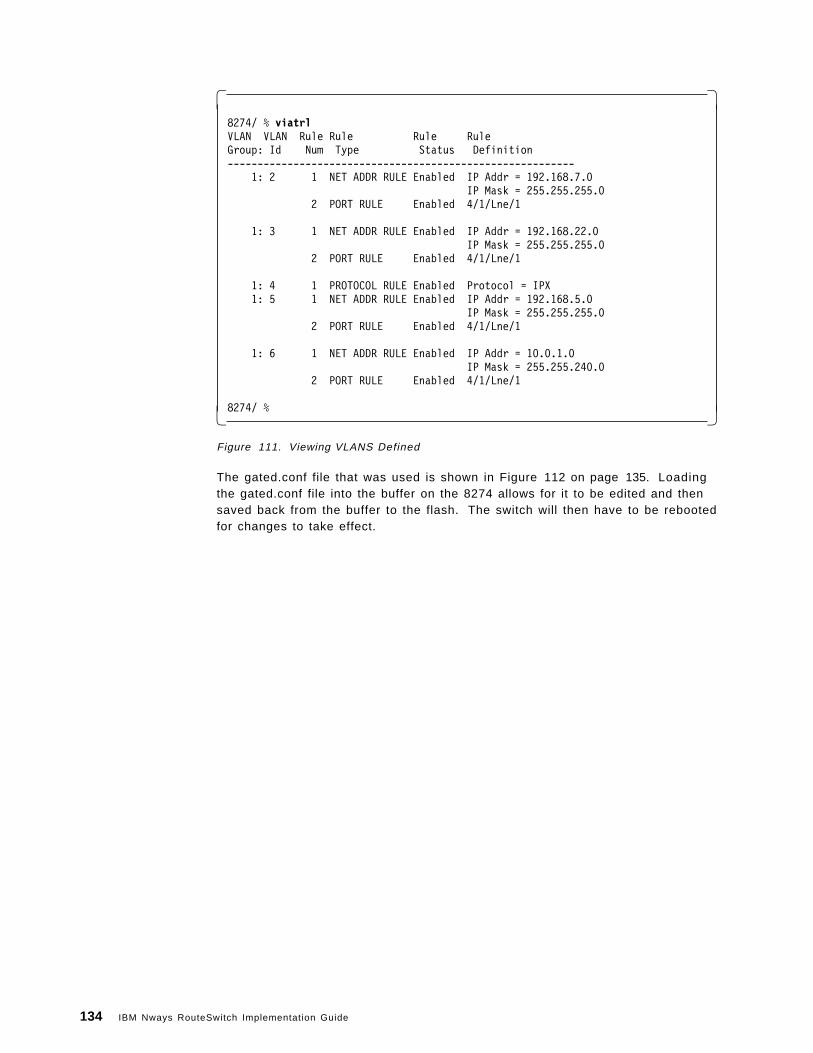
� �8274/ % viatrlVLAN VLAN Rule Rule Rule RuleGroup: Id Num Type Status Definition----------------------------------------------------------
1: 2 1 NET ADDR RULE Enabled IP Addr = 192.168.7.0IP Mask = 255.255.255.0
2 PORT RULE Enabled 4/1/Lne/1
1: 3 1 NET ADDR RULE Enabled IP Addr = 192.168.22.0IP Mask = 255.255.255.0
2 PORT RULE Enabled 4/1/Lne/1
1: 4 1 PROTOCOL RULE Enabled Protocol = IPX1: 5 1 NET ADDR RULE Enabled IP Addr = 192.168.5.0
IP Mask = 255.255.255.02 PORT RULE Enabled 4/1/Lne/1
1: 6 1 NET ADDR RULE Enabled IP Addr = 10.0.1.0IP Mask = 255.255.240.0
2 PORT RULE Enabled 4/1/Lne/1
8274/ %� �Figure 111. Viewing VLANS Defined
The gated.conf file that was used is shown in Figure 112 on page 135. Loadingthe gated.conf file into the buffer on the 8274 allows for it to be edited and thensaved back from the buffer to the flash. The switch will then have to be rebootedfor changes to take effect.
134 IBM Nways RouteSwitch Implementation Guide

� �8274/File % edit8274/File/Edit % ?
Command Edit Menu------------ --------------------------------------------------------ab Append line(s) to the buffercb Clear the bufferdb Delete line from the buffereb Edit a buffer lineib Insert buffer linelb List contents of the buffernb Name file for bufferrb Read file into bufferwb Write buffer to file
Main File Summary VLAN NetworkingInterface Security System Services Help
8274/File/Edit % cb
8274/File/Edit % rb gated.conf
8274/File/Edit % lb00: traceoptions state ;01: routerid 9.24.105.99 ; �1�02: ospf yes { �2�03: backbone { �3�04: authtype none ;05: interface all { �4�06: priority 1 ;07: } ;08: } ;09: } ;10: export proto ospfase { �5�11: proto ospfase {12: all13: metric 1 ; } ;14: proto static {15: all16: metric 1 ; } ;17: proto direct {18: all19: metric 1 ; } ;20: proto rip {21: all22: metric 1 ; } ;23: } ;
Work buffer is unnamed8274/File/Edit % cb� �
Figure 112. Viewing the GateD.conf File
�1�The router ID is used to identify this router in routing tables throughoutthe network. It is advisable to make it unique, and can consist of numericand alphanumeric characters.
�2�This enables the OSPF protocol.
�3�The OSPF area defined is 0.0.0.0 (backbone). Depending on individualrequirement multiple OSPF areas can exist in a single 8274. Furtherconfiguration will be required in order to match the OSPF areas to interfaces.
�4�All interfaces have been included in the backbone area.
Chapter 5. Bridging, Routing, Switching and Trunking 135

�5�In this section of the gated.conf file we specify all the protocols andlearned routes that must be advertised and the interfaces that they will beadvertised on.
In Figure 112 on page 135, the gated.conf file has been indented to make it morelegable. Although using indentation makes the file easier to read it is not arequirement in writing the gated.conf file. Writing the file without indentationwould look something like this:
traceoptions state ;routerid 9.24.105.99 ;ospf yes {backbone {authtype none ;interface all {priority 1 ;} ;} ;} ; . . .
Figure 113 on page 137 shows how the protocols defined in the advancedrouting setup can be viewed.
136 IBM Nways RouteSwitch Implementation Guide

� �8274/ % gatedparameters for gated root command are:
stat GateD status displayroutes Displays GateD internal routing tablereconfig Reloads configuration file
8274/Networking/Gated % gated stat
Gated is running
RIP: not configuredOSPF: enabledICMP Router Discovery: not configured
8274/Networking/Gated % gated routes
***** Gated Routing Table *****Destination Subnet Mask Gateway Metric Tag Pref Protocol=========================================================================9.24.105.0 255.255.255.0 9.24.105.99 0 0 0 Direct10.0.0.0 255.255.240.0 10.0.1.1 0 0 120 Direct127.0.0.0 255.0.0.0 127.0.0.1 0 0 0 Static127.0.0.1 255.255.255.255 127.0.0.1 0 0 0 Direct192.168.5.0 255.255.255.0 192.168.5.200 0 0 0 Direct192.168.7.0 255.255.255.0 192.168.7.200 0 0 0 Direct192.168.20.10 255.255.255.255 192.168.5.10 1 0 10 OSPF192.168.21.10 255.255.255.255 192.168.5.10 1 0 10 OSPF192.168.22.0 255.255.255.0 192.168.22.200 0 0 120 Direct
8274/Networking/Gated % ospf stat***** OSPF Status *****
OSPF running with 1 neighbor(s), Router ID = 9.24.105.99
Hello Packets TX:1865 Hello Packets RX:351Database Description packets TX: 10 Database Description packets RX: 6LSR packets TX: 22 LSR packets RX: 2LSU packets TX: 0 LSU packets RX: 7LSA packets TX: 6 LSA packets RX: 19
8274/Networking/Gated % ospf nl***** Neighbours List *****
Area IP Address Rtr Id Priority State (M/S)=================================================================0.0.0.0 192.168.5.10 192.168.20.10 1 Full (S)
8274/Networking/Gated % ospf al***** Area List *****
ASBDRs = Autonomous System Border RoutersABDRs = Area Border Routes
Area Transit/Stub SPF runs ASBDRs ABDRs LSA count Full neighbors=======================================================================0.0.0.0 Neither 9 1 0 3 18274/Networking/Gated %� �
Figure 113. Viewing OSPF Statistics
The configuration steps that were reguired on the MSS are also shown.Figure 114 on page 138 illustrates the IP addresses for each interface, which arenot automatically added with an OSPF interface.
Chapter 5. Bridging, Routing, Switching and Trunking 137

� �MSS_A *t 6MSS_A Config>p ipInternet protocol user configuration
MSS_A IP config>li add
IP addresses for each interface:intf 0 192.168.20.10 255.255.255.0 Local wire broadcast, fill 1
192.168.21.10 255.255.255.0 Local wire broadcast, fill 1intf 1 192.168.3.10 255.255.255.0 Local wire broadcast, fill 1intf 2 192.168.2.10 255.255.255.0 Local wire broadcast, fill 1 intf 3 IP disabled on this interface intf 4 IP disabled on this interface intf 5 IP disabled on this interface intf 6 IP disabled on this interfaceintf 7 192.168.5.10 255.255.255.0 Local wire broadcast, fill 1intf 8 9.24.104.115 255.255.255.0 Local wire broadcast, fill 1
192.168.4.10 255.255.255.0 Local wire broadcast, fill 1intf 9 192.168.207.10 255.255.255.0 Local wire broadcast, fill 1
MSS_A IP config>exMSS_A Config>p ospfOpen SPF-Based Routing Protocol configuration console
MSS_A OSPF Config>li int
--Interface configuration--IP address Area Cost Rtrns TrnsDly Pri Hello Dead192.168.20.10 0.0.0.0 1 5 1 1 10 40192.168.21.10 0.0.0.0 1 5 1 1 10 40192.168.3.10 0.0.0.0 1 5 1 1 10 40192.168.2.10 0.0.0.0 1 5 1 1 10 40192.168.5.10 0.0.0.0 1 5 1 1 10 40� �
Figure 114. Viewing IP and OSPF Interfaces on the MSS
Figure 115 on page 139 shows how to add an IP interface so that it will run theOSPF protocol. This is confirmed when we list the OSPF interface configurationtable.
138 IBM Nways RouteSwitch Implementation Guide

� �MSS_A *t 6
MSS_A OSPF Config>set intInterface IP address (0.0.0.0)? 192.168.207.10Attaches to area (0.0.0.0)?Retransmission Interval (in seconds) (5)?Transmission Delay (in seconds) (1)?Router Priority (1)?Hello Interval (in seconds) (10)?Dead Router Interval (in seconds) (40)?Type Of Service 0 cost (1)?Authentication Key ()?Retype Auth. Key ()?MSS_A OSPF Config>
MSS_A OSPF Config>li int
--Interface configuration--IP address Area Cost Rtrns TrnsDly Pri Hello Dead192.168.20.10 0.0.0.0 1 5 1 1 10 40192.168.21.10 0.0.0.0 1 5 1 1 10 40192.168.3.10 0.0.0.0 1 5 1 1 10 40192.168.2.10 0.0.0.0 1 5 1 1 10 40192.168.5.10 0.0.0.0 1 5 1 1 10 40192.168.207.10 0.0.0.0 1 5 1 1 10 40
MSS_A OSPF Config>� �Figure 115. Configuring the OSPF Interface
Figure 116 on page 140 shows a dump of OSPF routes that are defined on theMSS and also learned from elsewhere in the network.
Chapter 5. Bridging, Routing, Switching and Trunking 139

� �MSS_A *t 5
CGW Operator Console
MSS_A +MSS_A +p osOpen SPF-Based Routing Protocol consoleMSS_A OSPF>dumpType Dest net Mask Cost Age Next hop(s)
Stat* 0.0.0.0 00000000 1 3525 192.168.20.60Sbnt 9.0.0.0 FF000000 1 1366 None Dir* 9.24.104.0 FFFFFF00 1 1427 TKR/3 SPF 9.24.105.0 FFFFFF00 2 1386 192.168.5.200Sbnt 10.0.0.0 FF000000 1 1366 None SPF 10.0.0.0 FFFFF000 2 1386 192.168.5.200 Dir* 192.168.4.0 FFFFFF00 1 1427 TKR/3 SPF* 192.168.5.0 FFFFFF00 1 1427 Eth/3 SPF 192.168.7.0 FFFFFF00 2 1143 192.168.5.200 Dir* 192.168.20.0 FFFFFF00 1 3496 ATM/0 SPF 192.168.20.10 FFFFFFFF 0 3525 ATM/0 Dir* 192.168.21.0 FFFFFF00 1 3496 ATM/0 SPF 192.168.21.10 FFFFFFFF 0 3525 ATM/0 SPF 192.168.22.0 FFFFFF00 2 1386 192.168.5.200 Dir* 192.168.207.0 FFFFFF00 1 1427 Eth/3Default gateway in use.Type Cost Age Next hopStat 1 3525 192.168.20.60
Routing table size: 768 nets (49152 bytes), 14 nets known� �Figure 116. Viewing the OSPF Routing Table
5.5.2 Advanced Routing Example 2This example shows two RouteSwitches that are connected together in an OSPFautonomous area. There are multiple OSPF areas as well as RIP II running onthe 8274s, as is shown in Figure 117 on page 141. Extracts from the gated.conffiles from both switches are listed to show the required parameters that wereused.
140 IBM Nways RouteSwitch Implementation Guide

Figure 117. Physical View of Autonomous OSPF Area
In Appendix C, “Sample GATED Configuration File” on page 345, a detailedsample gated configuration file lists all the parameters that can be used whenwriting the gated.conf file. In Figure 118, the protocol section in the gated.conffile for switch 1 shows RIP II and OSPF running in the same RouteSwitch.
� �...rip yes {
interface 3/6 version 2 ; �1�} ;ospf yes {
backbone { interface 2/1; �2�} ;
} ;export proto ospfase interface 2/1 { �3�
proto rip interface 3/6 {9.24.105.0 mask 255.255.255.0 ;
} ;} ;export proto rip interface 3/6 { �4�
proto ospfase interface 2/1 ;} ; . . .� �
Figure 118. Extract of gateD.conf File on Switch 1
�1�RIP II is enabled on port 3/6.
�2�OSPF area 0 (backbone) is enabled on port 2/1.
�3�The RIP II routing information that is learned on port 3/6 about the IPsubnet 9.24.105.0 is exported as OSPF routing information on port 2/1.
Chapter 5. Bridging, Routing, Switching and Trunking 141

�4�The OSPF routing information that is learned on port 2/1 is exported inRIP II format on port 3/6.
An extract from the gated.conf file for switch 2 is shown in Figure 119.
� �...rip no ;ospf yes {
backbone { interface 3/4 ; �1�} ;area 1 { interface 4/2 ; �2�} ;
} ; . . .� �
Figure 119. Extract of gateD.conf File on Switch 2
�1�OSPF is enabled on port 3/4 with OSPF area 0.
�2�OSPF is enabled on port 4/2 with OSPF area 1.
5.6 Next Hop Resolution Protocol (NHRP)Next Hop Resolution Protocol (NHRP) is an IETF protocol that can improvenetwork performance by eliminating router hops on Non-Broadcast Multi-Access(NBMA) subnetworks such as ATM. When internetworking protocols such as IPare run over NBMA subnetworks, the routed path through the network caninclude multiple hops across the same subnetwork.
142 IBM Nways RouteSwitch Implementation Guide

Figure 120. Conventional Routing over ATM
As an example, consider the network shown in Figure 120, where the ATMsubnetwork has been partitioned into IP subnets, and ATM is used primarily as ahigh-speed data link technology (that is, a fat pipe) that provides connectivitybetween hosts and routers. Packets from Host x to Host y encounter threerouter hops and traverse the ATM subnetwork four times: (1) Host x to Router 1,(2) Router 1 to Router 2, (3) Router 2 to Router 3, and (4) Router 3 to Host y.NHRP was designed to better utilize the capabilities of the underlying switchedinfrastructure in configurations such as this by enabling the establishment ofshort-cut routes across ATM subnetworks. The short-cut may be directly to thedestination or, if that is not possible, to the egress router nearest to thedestination.
NHRP is a client/server protocol. NHRP clients (NHCs) issue requests to NHRPservers (NHSs), and NHSs either respond to the requests or forward the requestsalong the routed path.
There are also cases where an NHS will respond to NHRP resolution requestswith an ATM address associated with its co-located router. One such case iswhen the NHS is serving as the egress router to destinations that are notresident on the ATM subnetwork. Figure 121 on page 144 provides an examplewhere the destination (IP Host y) is behind a router (Router 4 ) that is connectedto the egress NHS (NHS 3 ) via an FDDI LAN.
Chapter 5. Bridging, Routing, Switching and Trunking 143

Figure 121. Shortcut to an Egress Router
Protocol address-to-ATM address mappings provided in NHRP resolutionresponses include a holding time that indicates how long the mappinginformation may be considered valid. When the holding time expires, theassociated short-cut can no longer be used. Thus, the MSS server′s NHCattempts to refresh mappings, provided that they are still being used, before theholding time expires in order to avoid lapses in short-cut service. NHCs includethe holding time when registering their (protocol and ATM) addresses with anNHS.
Since NHRP resolution requests follow the routed path, NHSs are coupled withrouters, and routers without an NHS can discontinue NHRP reachability. Ingeneral, short-cuts are not possible when there is an intermediate router thatdoes not support NHRP.
5.6.1 ELAN SupportNHRP packets that are to follow the routed path are forwarded over ELANs aswell as Classical IP subnets. While this seems like the natural thing to do, andcertainly is efficient, since existing VCCs are utilized, other implementations mayonly send NHRP packets over VCCs employing RFC 1483 encapsulation. TheNHRP specification is unclear in this regard, specifying that NHRP packets mustfollow the routed path, but referring only to RFC 1483 when defining ATMencapsulations. (The ambiguity arises because the routed path may be over anELAN, but LANE Version 1.0 does not employ RFC 1483 encapsulation.) Inaddition to the superfluous connections, implementations that do not utilize ELAN
144 IBM Nways RouteSwitch Implementation Guide

VCCs may impose the unnecessary configuration burden of requiring users tospecify the ATM addresses to be used when establishing these RFC 1483 VCCs.
Figure 122. One-Hop Routing
One-hop routing with LANE short-cuts is illustrated in Figure 123 on page 146.In this example, both source and destination IP stations reside on legacy LANsbehind ATM-attached LAN switches. MSS Server 1 initiates a short-cut to IPHost y on behalf of IP Host x, and includes the LANE short-cut extensions in theNHRP resolution request. The request is sent to MSS Server 2 over IP Subnet9.1.2, which may be an ELAN or a LIS. MSS Server 2 recognizes that thedestination is accessible via a local ELAN subnet (that is, 9.1.3), and fills in theextensions with the MAC address of IP Host y and the ATM address of the LECrepresenting IP Host y in LAN Switch 2. MSS Server 2 learns the MAC addressof IP Host y through IP ARP procedures, and the associated ATM address isobtained via LE_ARP procedures. When the NHRP resolution reply is returned,MSS Server 1 establishes a short-cut LANE data direct VCC to LEC 2, andsubsequent traffic for IP Host y is transmitted directly over this VCC. Shortcuttraffic destined for other hosts represented by LEC 2, such as IP Host z, will alsobe transmitted over this VCC.
Chapter 5. Bridging, Routing, Switching and Trunking 145

Figure 123. One-Hop Routing with LANE Shortcuts
NHS 2 establishes a short-cut for traffic to IP Host x in a similar manner.However, in this case, the LANE short-cut extensions also include the token-ringrouting information field (RIF) necessary for sending traffic to IP Host x, whichresides behind a downstream source route bridge. Although both hosts resideon legacy LANs, the short-cut routing mechanisms are equivalent forATM-attached hosts with LANE interfaces, such as IP Host w.
The 8274 NHRP support is for IP traffic over ATM only. This allows for directconnections to be established to LAN Emulation clients and to Classical IP (CIP)(RFC 1577) clients.
The 8274 is also only an NHRP client and thus requires an NHRP server in thenetwork in order for NHRP to run. The IBM MSS is used for the NHRP serverfunction.
5.6.2 NHRP Example 1A simple configuration, shown in Figure 124 on page 147, was used to test if the8274 NHRP client would work with the MSS NHRP server, which according to alldocumentation it should. A logical representation of the network is shown inFigure 125 on page 147.
146 IBM Nways RouteSwitch Implementation Guide

Figure 124. Physical View of Network - NHRP Example
Figure 125. Logical View of Network - NHRP Example
5.6.2.1 NHRP Example 1 ConfigurationA token-ring LEC was defined on port 4/1 service number 3, and the defaultEthernet LEC that is defined by factory defaults on all ASM ports was deleted.Viewing the services for the ASM ports in Figure 126 on page 148, shows theresult of this configuration.
Chapter 5. Bridging, Routing, Switching and Trunking 147

� �8274/ >vas
ATM Services
Serv Service ServiceSlot Port Num Description Type==== ==== ==== ============================= =========4 1 2 VCM Service 2 VCM4 1 3 LAN Emulation Service 3 802.5 LEC4 2 1 LAN Emulation Service 1 802.3 LEC4 2 2 VCM Service 2 VCM
ATM Services
Serv VC OperSlot Port Num Typ Status SEL Groups Conn VCI′ s/Addresses==== ==== ==== === ======== === =========== =====================4 1 2 SVC Enabled 02 14 1 3 SVC LANE Op. 03 1 568 569 570 5714 2 1 SVC Initial 01 14 2 2 SVC Disabled 02 1
FDDI Services do not exist!
Mammoth Ethernet Services do not exist!
8274/ >� �Figure 126. Token-Ring LEC Is Configured on Port 4/1 3 to Join tok1
The RouteTracker VLANs that we defined in Group 1 are shown in Figure 127. Itis important to note that although the service that was created on port 4/1 to jointhe token-ring ELAN was service 3 on port 4/1, when adding that port and serviceto VLAN 2 it shows that we have added 4/1/Lne/2. This is because it is thesecond sequential service that is running on port 4/1 and when it is added to theVLAN we can only choose a service that is defined and running on an ASM port.In this case service 3 on port 4/1 was the second sequential service running onASM port 4/1.
� �8274/ >viatrlVLAN VLAN Rule Rule Rule RuleGroup: Id Num Type Status Definition----------------------------------------------------------
1: 2 1 NET ADDR RULE Enabled IP Addr = 192.168.4.0IP Mask = 255.255.255.0
2 PORT RULE Enabled 4/1/Lne/23 PORT RULE Enabled 3/12/Brg/1
1: 3 1 NET ADDR RULE Enabled IP Addr = 192.168.3.0IP Mask = 255.255.255.0
8274/ >� �Figure 127. VLAN Configuration
During RouteTracker VLAN configuration we are prompted to enable IP, it isduring this IP configuration that we are asked if NHRP should be enabled. If yes
148 IBM Nways RouteSwitch Implementation Guide

is selected to enable NHRP, then NHRP is enabled for that VLAN. This is shownin Figure 128 on page 149.
� �Enable IP? (y):
IP Address : 192.168.4.3IP Subnet Mask (0xffffff00) : 255.255.255.0IP Broadcast Address (192.168.4.255 ) :Description (30 chars max) :Disable routing? (n) :Enable NHRP? (n) : yIP RIP mode {Deaf(d),Silent(s),Active(a),Inactive(i)} (s) : aDefault framing type {Ethernet II(e),fddi(f),token ring(t),Ethernet 802.3(8),source route token ring(s)} (e) : t
Created router port for vlan 1: 2Enable IPX? (y): n� �
Figure 128. VLAN Configuration
The Ethernet workstation with IP address 192.168.4.22 on ESM port 3/12 then senta ping to the ATM-attached workstation with IP address 192.168.6.3 and memberof the eth1 ELAN. The statistics shown in Figure 129, Figure 130, and Figure 131on page 150, were then seen.
� �8274/Networking/NHRP >vinvl VLANs with NHRP enabled ======================= gp:vl Router IP @ State Rtr CIP?------- ---------------- -------- ----- ---- 1:3 192.168.3.3 Inactive 252 No 1:2 192.168.4.3 Active 253 No=================================================8274/Networking/NHRP >� �
Figure 129. NHRP Enabled VLANs
� �8274/Networking/NHRP >vinrc
NHRP Resolution Cache Entries ============================= Dest Address NextHop Address State HTime MTU VCM Rtr VCI Type ------------ --------------- ----- ----- ---- --- --- ---- ---------- 192.168.6.3 0.0.0.0 Samp 253 0 0 253 0 unresolved =====================================================================8274/Networking/NHRP >� �
Figure 130. NHRP Cache Entries
Chapter 5. Bridging, Routing, Switching and Trunking 149

� �8274/Networking/NHRP >vinrce
Enter destination address (0.0.0.0) : 192.168.6.3 ================================================= Destination: 192.168.6.3 PrefixLength: 0xFF NextHop: unknown NbmaAddress: unknown VCI: 0 Shortcut Type: unresolved EntryType: 7 (other) EntryState: 4 (Sampling) MTU size: 0 IfIndex: 0 Holding time: 227 VCM port: 0 Router port: 253 Flags: 0x01000000 =================================================
8274/Networking/NHRP >� �Figure 131. NHRP Cache Entry Detail
5.7 Mixed MediaOne way for data to get from one media type to another is via routing. Anotherway is using an SR-TB bridge. The router removes the media-specific headersof a received frame and appends the new media-specific header for the networktype of the destination port. In this process the frame itself is not transmittedfrom one media type to another, only the information within it.
Routing involves heavy computation, requiring table lookups to guide this headerdeletion/creation and additional router-to-router protocols to set up and maintainthese tables.
Routing is not restricted, nor even primarily intended for moving data betweendifferent types of media but instead seeks to break networks down into a numberof smaller networks, each of which is a broadcast domain. Historically, networksbased on different technologies and media naturally form distinct broadcastdomains.
However, the advent of LAN switching is rewriting these rules. Today, theformation of broadcast domains and the allocation of devices to them is drivenby logical requirements such as virtual LANs and LAN switches. They seek tobreak free of topology and network constraints imposed by mere mediadifferences.
5.7.1 Any-to-Any SwitchingBecause the RouteSwitch is a LAN switch that carries frames from multiplemedia types on its backplane fabric, it offers the facility to switch frames fromany media to any other media for example, an Ethernet frame onto a token-ringframe. This feature is referred to as any-to-any switching.
150 IBM Nways RouteSwitch Implementation Guide

Within this new paradigm there is still a place for routing. The installed base ofclients and servers must communicate by established routing protocols, but thebroadcast domains handled by a router are no longer a restraint to a singlemedia type.
To support this paradigm, a LAN switch must ″transform″ a frame of one mediatype into a frame of another media type in such a way that the frame is stillacceptable to the routing protocols.
5.7.1.1 Any-to-Any Switching Is Protocol-SpecificUnfortunately, the requirements for this transformation algorithm are specific tothe various protocols that currently exist.
There is no single, simple algorithm that will allow the frames to be switchedtransparently between media types to the higher level protocols and frameformats.
This leads to a fairly complex set of configuration options and limitations on theapplicability of the any-to-any switching features.
In order to understand why these options and limitations arise and to betterunderstand the configuration options available, it is advisable to understand, asbackground, the theory of operation for any-to-any switching. This material alsomay help to determine the applicability of any-to-any switching for a protocol notdescribed in the reference material.
5.7.2 Theory of OperationEvery frame, of any protocol, on any media type, consists of the following parts:
1. MAC Header: This consists of a source and destination address (MACaddresses) specifying the transmitting station and the intended recipient(s),as well as other media-specific fields for example, Access Control (AC) andField Control (FC) fields in token-ring, FC in FDDI, etc.
2. RIF: Optional field defined by the source routing standard and is only foundon token-ring and FDDI media.
3. Encapsulation: This is defined by the various standards for the media, manyof which reference common standards. For example, on Ethernet media, asdefined by Ethernet II, this is a 16-bit type field. On Ethernet media, asdefined by the IEEE 802.3 committee, this is a length field together with anyencapsulation defined by the IEEE 802.2 logical link control (LLC) committee.On token-ring and FDDI, it is any encapsulation defined by the IEEE 802.2 LLCcommittee.
4. Network Header: This is defined by the organization responsible for theparticular routing protocol whose data is being carried within the frame. Thevalues of fields defined in the encapsulation area allow the recipient toidentify which protocol standard to use to decode the network header part ofthe frame.
5. Data: The payload being carried between the endstations.
In a routing implementation, the first three fields are the ones stripped andrebuilt when the frame is forwarded. These are the three areas that have to bemanipulated.
Chapter 5. Bridging, Routing, Switching and Trunking 151

Each of these areas and their interactions will be examined to see the mediaand protocol dependencies. As these are understood, the reasons whyany-to-any switching requires protocol-specific switch support will becomeapparent.
5.7.2.1 The MAC HeaderThe format and values defined for this area are covered in the media standards,but here we show the choices that are dictated by the upper layer protocol:
• Canonical versus non-canonical
The first requirement of the switch is to transform the bit ordering of theaddress fields. Token-ring and FDDI use the non-canonical format or mostsignificant bit (MSB) first. Ethernet uses the canonical format or leastsignificant bit (LSB) first. Thus when a frame is moved between these mediatypes, the addresses must be bit-swapped.
• Abbreviated addresses
Normally, a MAC address is 48 bits long. FDDI and 802.5 token-ring mediaallows for the use of small 16-bit MAC addresses.
The RouteSwitch only supports a 48-bit MAC address. Abbreviatedaddress-based protocols are not supported.
• Functional addresses and multicasts
The IEEE 802.5 media also have different rules for the formation of multicastaddresses or group addresses. In Ethernet, a single bit defines the addressas a multicast. In 802.5, a single bit also indicates a multicast, but theremaining bits are structured into functional address groups withpre-assigned meanings and functions.
The RouteSwitch does not map multicasts and functional addresses, thusprotocols dependent on these features may not be switchable any-to-any.
5.7.2.2 The RIF FieldThe same source routing standard is supported by FDDI and token-ring so theRIF fields can be switched without problems between these media.
Ethernet does not support source routing, thus token-ring frames with RIF fieldscannot be switched onto the Ethernet media. RIF stripping can be enabled byentering the following command in the mpm.cmd: rifStripping=1. RIF strippingonly works when going to and from token-ring and Ethernet. The token-ringports must be set to SRT and the RIF field must be 2 bytes long.
The alternative is stripping the RIF fields, remembering them for each MACaddress and reinserting them on replies to terminate a source routed connectionand act as a proxy to a transparent device (such as SR-TB on 8209/8229). This isnot well standardized and is difficult to execute and manage. SR-TB bridging isnot supported by the RouteSwitch.
Ethernet frames are allowed onto a token-ring if the token-ring supportstransparent bridging; for example, the port is configured as either transparent(TB) or source route transparent (SRT).
Token-ring frames with an RIF will not be switched to Ethernet when thetoken-ring port is configured for SRT.
152 IBM Nways RouteSwitch Implementation Guide

Token-ring frames without RIF will be switched to Ethernet when the token-ringport is configured for SRT. Also all communication between SR configuredtoken-ring ports and transparent Ethernet ports is barred.
5.7.2.3 EncapsulationEncapsulation is the biggest problem for implementing a transformationalgorithm in support of any-to-any switching. All media types provide a choice ofmore than one encapsulation and not all encapsulations are available on allmedia. Additionally, the methodology of these encapsulations vary from protocolto protocol.
An ideal protocol would dictate a single encapsulation which would be the sameon all media.
Most protocols make use of more than one encapsulation. For example, IP usesEther-Type most of the time on Ethernet and SNAP on FDDI and token-ring. Inthis case, there may be clearly established rules for transforming frames fromone encapsulation to another as media types are traversed.
Some protocols may allow more than one encapsulation even on a single mediatype. Some might use the encapsulation to separate functional parts of theprotocols, for example, routing table updating protocols from user dataforwarding protocols. Others, such as IPX may simply allow the user toarbitrarily choose the encapsulation method.
Some, most notably IPX, may entangle the notion of encapsulation in with thenotion of the network level broadcast domain to create multiple logical networksover a single physical broadcast domain.
Clearly, there is no single algorithmic rule by which the any-to-anytransformation function can switch arbitrary protocols.
There are two choices available to address this situation:
1. The switch must be configurable, per device, per protocol, per media toselect the transformation of encapsulations.
2. The switch performs a single transformation and the user must configure allendstations and routers to use this single choice made by the switch.
The RouteSwitch uses the first approach for IP and IPX as they are the mostdominant protocols in the market. It uses the second approach for all otherprotocols.
Protocols Other Than IP and IPX: On Ethernet media, three encapsulations arepossible:
• Ether-Type
• IEEE 802.2 LLC
• IEEE 802.2 SNAP
Note: SNAP is an instance of an LLC encapsulation defined by the IEEE 802.2committee to support the transformation of Ether-Type Ethernet frames to mediathat do not support that encapsulation.
On token-ring and FDDI, two encapsulations are permitted by the standards:
• IEEE 802.2 LLC
Chapter 5. Bridging, Routing, Switching and Trunking 153

• IEEE 802.2 SNAP
The SNAP Conversion: The intent of the 802.2 committee is that Ether-Typeframes are transformed to SNAP on crossing from Ethernet media to 802 mediaand restored to Ether-Type in the reverse direction.
The RouteSwitch could follow this rule for all protocols including IP; however,this would prevent AppleTalk from inter-working between Ethernet and FDDI.The RouteSwitch explicitly checks for the AppleTalk protocol. If found, the rule isnot applied. In addition, the RouteSwitch checks for the Banyan Vines protocoland translates according to the media type.
As there may be other protocols with this problem, the SNAP to Ether-Typetransformation is configurable for all protocols other than AppleTalk.
Other Conversions: There are no equivalent algorithmic approaches that thetransformation function can adopt for dealing with protocols that requireEther-Type on Ethernet and some form of LLC encapsulation on FDDI and/ortoken-ring. The mapping between Ether-Type values and LLC values is arbitraryrequiring tables indexed by protocol.
The approach followed in the RouteSwitch is therefore to simply pass LLCencoding between Ethernet, FDDI and token-ring with no changes other than toinsert/strip the length field required by IEEE 802.3 on Ethernet. This leavesprotocols that require transformations between Ether-Type and LLCencapsulations as unswitchable unless the clients and servers can be configuredto use SNAP.
Summary of Non-IPX Encapsulation Transformation Rules: Ether-Type/SNAPtransformations are configurable on an all protocols, except for AppleTalk andBanyan Vines. Ether-Type frames going to FDDI or token-ring are translated toSNAP unconditionally.
SNAP frames going to Ethernet are translated to Ether-Type or left as SNAP asper the RouteSwitch configuration, unless the protocol is AppleTalk, in whichcase they are left as SNAP.
LLC frames are passed unchanged in value but with the length field required onEthernet media stripped/inserted.
IPX Encapsulation Transformation Rules: For IPX, the encapsulation problemsdescribed above are compounded by the introduction of a fourth encapsulationon Ethernet media.
Novell introduced a frame format, when the IEEE 802.3 standards committeeproduced its version of Ethernet, which was incompatible with Ethernet.
Novell places its network header and data within a raw IEEE 802.3 Ethernet framewith no intervening IEEE 802.2 LLC header. This is in direct contravention of thestandards but has become a de facto standard encapsulation.
Novell refers to this as Ethernet 802.3. It is also widely known as NovellProprietary, Novell Raw, Raw 802.3, etc. Such frames are identifiable only by thefact that the Novell network header starts with a two-byte field called thechecksum, which is never used and assumes the value 0xFFFF.
154 IBM Nways RouteSwitch Implementation Guide

Therefore, routers, bridges and switches check for this value after an 802.3length field. In effect, Novell has usurped the value 0xFF for the destination andsource SAP addresses (DSAP/SSAP) of an LLC header.
Thus, on Ethernet media, there are four encapsulations for IPX as represented byFigure 132.
• Ether-Type - Value 0x8137
• Novell Proprietary (raw 802.3)
• LLC - SAP value 0XE0
• SNAP - Protocol Identifier 0x0000008137
Figure 132. IPX Frame Types on Ethernet
On token-ring and FDDI, the same LLC and SNAP encapsulations are found ason Ethernet (without the length field).
Fortunately, this leaves an aggregate of only four encapsulations across allmedia with only two being universal (LLC and SNAP).
Unfortunately, the SNAP conversion rule isn′ t applicable and there is noalgorithmic determination for the use of particular encapsulations on any media;it is purely the choice of the network administrator.
Worse, multiple encapsulations can be found on a single media to createmultiple logical networks over a single physical broadcast domain.
The RouteSwitch, therefore, allows configuration of the encapsulationtransformations of IPX frames. Before transmission of a frame occurs, theswitch first determines the current encapsulation of the frame. It then consultsthe configuration information to determine which of the permitted encapsulationsfor the media the frame is to be transmitted on is required. Thus, theadministrator can choose not only a single output option but an option perpossible received encapsulation.
Chapter 5. Bridging, Routing, Switching and Trunking 155

For example, over FDDI media, LLC and SNAP are permissible so theadministrator might configure one of the following:
1. LLC and SNAP encapsulations received from other FDDI, token-ring orEthernet media are translated to SNAP.
2. Ether-Type and proprietary encapsulations from Ethernet are translated toLLC.
Essentially, for each encapsulation, transformation to each of the other threeencapsulations is available, but may simply be left as is. This choice may befurther constrained by the output media type. For example, Ether-Type is not avalid option on FDDI or token-ring.
5.7.2.4 The Network HeaderThere are essentially two requirements for the any-to-any switchingtransformation function to address the network header fields:
1. In every protocol, there is a mechanism for mapping global network-wideaddresses required in the local broadcast domain.
2. Different media have different minimum and maximum frame sizes leading tothe issues of padding insertion/stripping and fragmentation/reassembly ormaximum frame size negotiation protocols at the network level.
Address Mapping: There are almost as many ways to map a global networklevel address to a local subnetwork MAC address as there are routing protocols.These may or may not be affected by any-to-any switching.
Some may construct MAC addresses algorithmically, for example, DECNETmodel. Some may involve table lookups with an additional protocol to build andmaintain these tables, for example, the IP/ARP model. Others may involve someform of building the network address around the MAC address as in the IPXmodel.
In all cases, these mechanisms are susceptible, without good design andforethought, to the problem of canonical versus non-canonical representation ofMAC addresses in the network header area.
Address Mapping in IP - ARP: To map a 32-bit IP network address into the MACaddress of a locally connected station, a router uses the Address ResolutionProtocol (ARP) to build an ARP table. The router broadcasts a requestcontaining the IP address in the body of the frame. The station with that IPaddress responds with its MAC address in the body of an ARP reply frame. Therouter inserts these two addresses in its ARP table and can now use the MACaddress received to transmit any frames addressed to that IP address.
Since a router can have interfaces to Ethernet ports (canonical MAC addresses),FDDI, and token-ring (non-canonical MAC addresses), it is crucial that the routerkeep track of what media type it receives on each port.
If an IP ARP were defined such that all MAC addresses when conveyed in thebody of an ARP frame were in canonical format, switching would be easy. Arouter, when taking an address from the ARP table and using it as thedestination MAC address on an Ethernet port would use the address as is. Ifsending to FDDI or token-ring, it would bit swap the address to non-canonicalformat as required by the media.
156 IBM Nways RouteSwitch Implementation Guide

Given this model of implementation, a station responding with an ARP onEthernet that was switched to FDDI would result in the same representation ofthe MAC address in the ARP table of the router. The router would then use thebit swapped form in the MAC address of subsequent frames to the FDDI ring andthe switch would bit swap these MAC header addresses as it transformed theframe onto Ethernet, resulting in the correct representation to be received by theoriginal station.
Unfortunately, this model has only been defined in IP for Ethernet and FDDI.Token-ring stations place MAC addresses into the body of ARP frames in theirnative, non-canonical format and routers use addresses from the ARP table as iswhen sending to token-ring ports.
To achieve any-to-any switching with IP, it is necessary for the RouteSwitch to besensitive to ARP frames and to bit swap the MAC addresses in the body of theARP when switching a frame between token-ring and FDDI or Ethernet.
Because IP is well designed, the issue of address mapping being confined to theARP protocol, this is sufficient to isolate the problem allowing all subsequent IPframes to be switched any-to-any.
Address Mapping in IPX: A network address in IPX consists of three parts:
1. Network Number: A globally unique identifier of a particular broadcastdomain.
Strictly, because of the formation of logical networks using encapsulations,this is not equivalent to a physical broadcast domain but the distinction canbe put aside for the purposes of this particular discussion.
2. Node Address: The MAC address of a station on that domain.
3. Socket Number: The task (process) within that station which should processthe message.
Just as in IP, routers move a frame along hop by hop on the basis of the networknumber portion of the destination address. To do this, IPX needs the MACaddress of the next hop router. This is obtained from the RIP table which is builtup from the RIP updates sent out by all routers. When a router receives an RIPupdate frame, it uses the source node address in the frame as the MAC addressfor the next hop router.
Although there is not an explicit ARP-like protocol for mapping addresses as inIP, this same function is being achieved by the use of source node addresses inRIP frames.
In IPX, as in IP, the canonical versus non-canonical representation of addressesstill applies. In switching, this needs to be considered for the source nodeaddress in IPX frames.
The node address in IPX Ethernet and FDDI observe a convention of using MACaddresses in the IPX header in canonical format. Therefore no translation takesplaces in the IPX network.node address. For token-ring, the node addresses arenon-canonical, therefore the node address will be translated between canonicaland non-canonical when transversing the RouteSwitch.
The RouteSwitch will not modify any addresses found in the data portion of aSAP frame. If the client and the service are in the same IPX network and acrossa RouteSwitch using different media, the client will use the node address found
Chapter 5. Bridging, Routing, Switching and Trunking 157

in the data portion of the SAP frame. Since that address has not been translatedwhen transversing the RouteSwitch the client will never be able to contact theservice. If the client and the service are on different IPX networks, then theclient uses a RIP frame to contact the service. Novell has an internal IPXnetwork which will cause the client to send a RIP frame. Network printers andother applications do not have an internal IPX network. These will fail if theservice and the client are on different media across a RouteSwitch.
Proprietary Token-Ring IPX Switching: The RouteSwitch therefore offers thefacility to modify IPX frames switching between token-ring and FDDI or Ethernet.
ARP bit swapping for IP is a de facto standard widely implemented in theindustry. This is not the case with IPX. The switch must be able to coexist withbridges that do not support any-to-any switching or applications where thisfeature is not required. Therefore, this feature can be configured on or off.
Frame Size Requirements: The frame size requirements for the different mediacauses two problem areas which have to be addressed by the any-to-anyswitching transformation function.
Ethernet has a minimum frame size requirement. This requires that padding isinserted on frames switched to Ethernet which are below the minimum size andstripped from frames switched from Ethernet.
All media have different maximum frame size requirements. This gives rise tothe problems of fragmenting large frames and/or negotiating maximum framesizes.
Insertion of Frame Padding: Ethernet has a minimum frame size of 64 bytes.For frames smaller than 64 bytes it is a simple task for the RouteSwitch toperform padding.
Stripping such padding from Ethernet frames when switching to FDDI ortoken-ring is not so easy.
In most implementations of IP that have been tested, the presence of padding onFDDI or token-ring frames appears not to cause any problems. However, IPXimplementations are adversely affected by its presence. Therefore, theRouteSwitch takes a conservative approach for all frames, regardless of protocoltype, and strips padding where it can be detected.
Stripping of Padding for all IEEE 802.3 Frames: Ethernet frames in IEEE 802.3format can be stripped of padding because of the presence of the length field.This includes all LLC and hence SNAP encapsulated protocols as well as NovellProprietary format.
No Stripping of Non-IPX Ether-Type Frames: Padding can only be detected forEther-Type encapsulated frames if the protocol is known and the protocol hassome length information that can allow the valid data size to be inferred. This isprotocol-specific and is currently only performed for IPX frames. Therefore, theRouteSwitch does not strip padding from non-IPX Ether-Type encapsulatedframes including IP.
IPX-Specific Stripping: For IPX, the RouteSwitch performs pad stripping for allframe types including Ether-Type. This is possible because all IPX frames havea common header that includes the data length and allows the frame size to be
158 IBM Nways RouteSwitch Implementation Guide

inferred. In fact, for IPX, the length in the IPX header is used to strip padding inall frame encapsulations, including the 802.3-based formats. This is because aswell as padding frames for minimum length, many IPX Ethernet implementationspad frames to an even byte length. This single-byte pad, when performed on802.3-based frames, is included in the 802.3 length field. Thus, the generic802.3-based stripping technique is not sufficient to strip this odd-byte padding.When performing any-to-any switching FDDI implementations of IPX were foundto be tolerant of this extra byte, whereas token-ring implementations would notwork with it present. By adopting the single IPX stripping strategy of using theIPX header length, these problems are avoided, thus the RouteSwitchunconditionally strips all padding from IPX frames.
Also, it does not support odd-byte pad insertion when switching to Ethernet. Thiswas a feature added to overcome limitations of some NIC cards, which is now ofonly historical importance and in fact, NetWare 4.1 servers provide this insertionas a port configuration option.
MTU Handling: Routers address the problem of maximum frame size limitationswith the notion found in many protocols of a maximum transmission unit (MTU)size. Protocols use this notion in two possible ways.
• PDU fragmentation/reassembly
The router is configured with the MTU of each port. If a frame that is toolarge is required to be sent on a port, the protocol data unit (PDU) within theframe is fragmented into many smaller PDUs, each of which isre-encapsulated and sent as a frame that fits within the MTU.
• Connection-oriented end-to-end MTU negotiation
When an endstation enters into a protocol to communicate with anotherstation, the initial PDU exchanges are guaranteed to fit all possible MTUs. Inthe handshaking between endstations to establish the connection, a phase isentered where large frames are sent. If an intervening link has an MTU toosmall for these frames, it will be dropped and the handshaking will time out.The endstations send progressively smaller frames until the handshakingsucceeds and hence, establish the MTU to be used between the two stationsfor the remainder of their connection use.
IP supports the former mechanism and IPX the latter.
IP Fragmentation: The RouteSwitch Ethernet interfaces will use IP fragmentationif they are allowed to (if the don′ t fragment bit is not set). Fragmentation byFDDI and token-ring is not supported, though technically the token-ring couldsend frames larger than those supported by FDDI, and LAN Emulation couldgenerate frames larger than both.
ICMP-Based MTU Discovery: IP uses the don′ t fragment bit to support an MTUdiscovery protocol, which superficially resembles the negotiation of IPX. Thedifference is that when IP stations attempt to discover an MTU size for their use,which doesn′ t require fragmentation by intermediate routers, the protocolexpects a protocol response by the intermediate router that is an ICMP reportingthat a frame was dropped because it couldn′ t be fragmented.
The RouteSwitch transformation function of any-to-any switching does notsupport this ICMP generation but just silently drops IP frames that can′ t befragmented. The IP virtual router in the RouteSwitch does honor this protocoland supports ICMP. It is only the any-to-any switching that doesn ′ t support this
Chapter 5. Bridging, Routing, Switching and Trunking 159

protocol because it is not a router and may not even have an IP address withwhich to respond.
IPX Packet Size Negotiation: For IPX, the requirement of intervening devices issimply to drop frames that are too large to be forwarded. This is what theRouteSwitch does.
Other Protocols: Dropping oversized frames is the approach for all protocolsother than IP. If the protocol in question is modeled like IPX, this will be thecorrect thing to do and will not cause problems. If the protocol is modeled likeIP and expects fragmentation to occur or requires explicit response from theRouteSwitch, then the protocol will not succeed in any-to-any switching.
Banyan Vines: Banyan Vines supports Ethernet, FDDI, and token-ring networks.Each type of network generates a different frame format so the RouteSwitchperforms translations for frames moving from one network type to another. TheBanyan Vines protocol only uses one frame format per network type; no userconfiguration of translations is necessary. This protocol uses Ethernet II frameson Ethernet, SNAP frames on FDDI, and IEEE 802.2 (LLC) frames on token-ring.The RouteSwitch uses these frame formats when translating Banyan Vinesframes.
Note: Checksums for Banyan Vines frames are automatically set to the nullchecksum, 0xFFFF, so that the checksum header does not require recalculation.Receiving stations will ignore this field and assume the sender is not usingchecksums.
5.7.2.5 Implementation DetailsThe previous material has covered the requirements for any-to-any switching interms of what an abstract transformation function needs to do. The followingsections cover the actual implementation of this function on the RouteSwitch.
The any-to-any switching function is done by each module when the frame isreceived from the RouteSwitch backplane.
Forwarding versus Flooding: Such frames will be handled in two ways:
• Forwarded frames - If the frame has a unicast destination address that hasbeen learned on a particular port, the encapsulation translation choices aredriven by options associated with the destination MAC address.
• Flooded/multicast frames - If the frame has a unicast destination addressthat has not been learned on a particular port, or if the destination addressis a multicast address, then the frame has to be transmitted potentially onmany ports. In this case, the encapsulation translation choices are driven byoptions associated with each destination port.
Port-Based Translation Options: The translation options for ports allowconfiguration of IP and IPX protocols on a per encapsulation basis.
MAC Address-Based Translation Options: The translation options for MACsarise from two possible sources:
1. Inheritance from port options during source address learning
When a source MAC address is learned, the translation options of the porton which it is learned are copied into the MAC-based database.
2. Automatic determination by RouteTracker
160 IBM Nways RouteSwitch Implementation Guide

When a frame is processed by RouteTracker as part of determining the VLANto be associated with the MAC, the frames protocol type and encapsulationare also determined. This information is used to update/set the translationoptions in the MAC-based database.
The AutoEncaps Option: Autoencapsulation is a technique employed by theRouteTracker software to learn the protocol and encapsulation type used by asource MAC address and automatically translate frames bound to that MACaddress to the proper encapsulation type.
Normally, all devices attached to a switch port receive frames translatedaccording to the translation options defined on that port. However, somedevices attached to the same port may require a different frame format.
For example, one endstation may support IPX 802.3 frames and anotherendstation may support IPX SNAP frames. The switch port may be configured totranslate incoming IPX 802.3 frames to LLC frames, which would satisfy only oneof the endstations. If autoencapsulation is turned on, then the switch willtranslate frames for the first IPX endstation to IPX 802.3 and for the secondendstation to IPX SNAP. Autoencapsulation operates only on learned unicastframes. It does not work on broadcast, multicast or unlearned unicast frames.For this reason, it is recommended that the autocaps option be on for ports withclient endstations only. The server ports would be sending a high volume ofbroadcast and the server ports should be defined to use the correctencapsulation type for the server.
Which of these options is used is determined by setting the AutoEncaps option.
Native versus Non-Native on Ethernet: For Ethernet, one further distinction ismade. If the frame received from the backplane is an Ethernet media type framefrom another Ethernet switching module in the same chassis, then noencapsulation translations are applied. Such frames are referred to as nativeframes.
If a frame of an Ethernet media type was put onto the backplane by some othertype of switching module, for example, the frame came from an FDDI card via atrunk port, or from the MPM via routing, then encapsulation translations areapplied. Such frames are referred to as non-native frames.
Native versus Non-Native on FDDI and Token-Ring: For FDDI, token-ring, andLAN Emulation on ATM, a native/non-native distinction is not made. Instead, noencapsulation translations are applied by these switching modules to frames thatare of their own media type.
No Translation on Trunk or PTOP Ports: Switching modules that supportencapsulation mechanisms, such as trunking ports on FDDI and token-ring, andpoint-to-point ports on ATM, do not apply translation to frames destined to suchports.
All other aspects of the transformation process are driven by the media type ofthe frame, the media type of the port on which the frame is to be transmitted andthe protocol type determined for the frame. Thus frame padding insertion/stripping, IP fragmentation, IP ARP bit swapping, etc., are all automatic.
Chapter 5. Bridging, Routing, Switching and Trunking 161

The Proprietary Token-Ring IPX Option: The one area that remains configurableis the bit swapping of source addresses for IPX in order to allow token-ring towork with FDDI and Ethernet. This is the equivalent function to IP ARP bitswapping.
This option is configurable and by default is off.
Earlier releases of the RouteSwitch did not provide extensive support forany-to-any switching and only a limited set of options were provided.
In more recent releases, full support is provided and all aspects areconfigurable.
In order to not encumber users upgrading to later releases who do not requirethese new features, much of the previous interface has been preserved allowingconfiguration and management of a subset of the full features. A new interfacehas been provided for the convenience of those users requiring these newfeatures and these two interfaces are able to coexist. The factory defaults for alloptions are chosen such that a later release′s factory defaults are compatiblewith previous releases.
In earlier releases, the user interface is the vi command to observeencapsulation configuration for ports, and the modvp, addvp and crgp commandswhere encapsulation transformation options can be set.
The commands of the latest release′s user interface are found in a new menu,the Switch menu. This menu is covered later in this chapter.
In SNMP, the old interface is the vportEncapsulation item of the vportTable. Thenew interface is the vportSwitchTable and the vportSwitchDefauItTable.
5.7.2.6 The User InterfaceEssentially, the forwarding code is now capable of applying the transformationfunction per:
• Protocol
• Encapsulation
• Port for flooded/mcast traffic
• Protocol
• Encapsulation
• Destination MAC address for forwarded unicast traffic
The old interface provides a small subset of these possible port translationoptions.
The addvp, modvp and crgp Commands: All of these commands include in theirdialog an output format question for ports and a subsidiary IEEE 802.2passthrough option. The options offered are:
• Default
• Ether-Type
• SNAP
• LLC
162 IBM Nways RouteSwitch Implementation Guide

Each of these represents a set of translation options for the IP and IPX protocols.The names chosen for these sets basically represent the translations for IPX withthe translation for IP being implied.
For example, LLC represents a translation set where all IPX encapsulations areconfigured to translate to IEEE 802.2. This is not a valid encapsulation for IPwhich is therefore configured to a default appropriate to the media, Ether-Typefor Ethernet ports and SNAP for FDDI and token-ring ports. The translation of allother protocol types and encapsulations is fixed by the RouteSwitch. Thus,AppleTalk is never translated and Ether-Type/SNAP-based protocols follow the IPoption.
For those options that imply a translation of IEEE 802.2 IPX frames to somethingelse, a subsidiary question is asked, IEEE 802.2 IPX Pass Through(y/n):. An IEEE802.2 passthrough option is provided because Novell 4.1 servers use thisencapsulation by default and it is becoming Novell ′s encapsulation of choice.
The Default Translation Option: The meaning of the default is determinedseparately for each media type and is fully configurable. The factory defaults arechosen so that the latest release is fully compliant with earlier ones. The defaulttranslation option is provided to allow a single point of configuration of all portscapability. When the default option for a media is changed, all ports of thatmedia type whose encapsulation is configured as default will inherit the newtranslation setting. All MAC address-based translation options that wereinherited from those ports, as opposed to those set by RouteTracker, will also beupdated. Ports that have an encapsulation setting other than default will beunaffected.
5.7.3 Default Translation TablesThe following tables detail the default types of translations for the different mediatypes. The factory defaults are chosen so that the latest release is fullycompliant with earlier ones.
Table 9. Ethernet Media - Default Mode
Ethernet Media - Default Mode
No translation is performed on outbound Ethernet frames where the inbound interface is Ethernet.
IP frames of any encapsulation are transmitted as Ethernet II frames.
IPX frames are transmitted as IEEE 802.3 Proprietary as the default setting. The only exception is when LLCpassthrough mode is enabled, then the IEEE 802.2 (LLC) frames are forwarded as is.
No translation is performed on AppleTalk frames, and only AppleTalk Phase II (SNAP format) is supported.
Other than IP and IPX, all other Ethernet II and SNAP encapsulated protocols are sent as Ethernet II frames.
All other IEEE 802.3 with LLC encapsulated protocols are not translated.
Table 10. FDDI Media - Default Mode
FDDI Media - Default Mode
IP of any encapsulation is encapsulated SNAP.
IPX encapsulations are encapsulated SNAP except for IEEE 802.2 which is forwarded as is.
All other Ether-Type and SNAP encapsulated protocols are sent as for IP.
All other LLC encapsulated protocols are forwarded as is.
Chapter 5. Bridging, Routing, Switching and Trunking 163

Table 11. Token-Ring Media - Default Mode
Token-Ring Media - Default Mode
IP of any encapsulation is encapsulated SNAP.
IPX encapsulations are encapsulated SNAP except for IEEE 802.2 which is forwarded as is.
All other Ether-Type and SNAP encapsulated protocols are sent as for IP.
All other LLC encapsulated protocols are forwarded as is.
Table 12. Ethernet Media - Ethernet II Mode
Ethernet Media - Ethernet II Mode
No translation is performed on outbound Ethernet frames where the inbound interface is Ethernet.
IP frames are transmitted as Ethernet II frames.
All IPX frames are transmitted as Ethernet II frames. The only exception is when LLC passthrough mode isenabled, then the IEEE 802.2 (LLC) frames are forwarded as is.
No translation is performed on AppleTalk frames, and only AppleTalk Phase II (SNAP format) is supported.
Other that IP and IPX, all other Ethernet II or SNAP frames are transmitted as Ethernet II frames.
Other IEEE 802.3 with LLC are not translated.
Table 13. Ethernet Media - SNAP Mode
Ethernet Media - SNAP Mode
No translation is performed on outbound Ethernet frames where the inbound interface is Ethernet.
IP frames are transmitted as SNAP frames.
All IPX frames are transmitted as IEEE 802.2 (LLC) frames.
No translation is performed on AppleTalk frames, and only AppleTalk Phase II (SNAP format) is supported.
Other than IP and IPX, all other Ethernet II or SNAP frames are transmitted as Ethernet II frames.
Other IEEE 802.3 with LLC are not translated.
Table 14. FDDI/Token-Ring Media - SNAP Option
FDDI/Token-Ring Media - SNAP Option
No translation is performed on outbound FDDI or token-ring frames where the inbound interface is the samemedia type.
IP frames of any encapsulation type are transmitted as IEEE 802.5 with SNAP frames.
IPX frames received that do not have an IEEE 802.2 encapsulation type, are transmitted as IEEE 802.5 withSNAP.
IPX frames received that are of IEEE 802.2 encapsulation type are transmitted as IEEE 802.5 with SNAP if theLLC passthrough is disabled. If the LLC passthrough is enabled, there frames will not be translated.
No translation is performed on AppleTalk frames, only AppleTalk Phase II is supported.
All other LLC encapsulated protocols are left as is.
164 IBM Nways RouteSwitch Implementation Guide

Table 15. Ethernet Media - LLC Mode
Ethernet Media - LLC Mode
No translation is performed on outbound Ethernet frames where the inbound interface is Ethernet.
IP frames are transmitted as IEEE 802.2 (LLC) frames.
All IPX frames are transmitted as IEEE 802.2 (LLC) frames.
No translation is performed on AppleTalk frames, and only AppleTalk Phase II (SNAP format) is supported.
Other that IP and IPX, all other Ethernet II or SNAP frames are transmitted as Ethernet II frames.
Other IEEE 802.3 with LLC are not translated.
Table 16. FDDI/Token-Ring Media - LLC Mode
FDDI/Token-Ring Media - LLC Mode
IP frames are transmitted as IEEE 802.5 with SNAP frames.
All IPX frames are transmitted as IEEE 802.2 (LLC) frames.
No translation is performed on AppleTalk frames, and only AppleTalk Phase II (SNAP format) is supported.
Other than IP and IPX, all other Ethernet II or SNAP frames are transmitted as IEEE 802.5 with SNAP frames.
No translation is performed on outbound FDDI or token-ring frames where the inbound interface was the samemedia type.
Other IEEE 802.3 with LCC are not translated.
5.8 Example of Bridging, Routing and SwitchingBridging, routing and switching in the RouteSwitch are best summarized usingan example.
The example described in this section has been tested using an 8274RouteSwitch.
Chapter 5. Bridging, Routing, Switching and Trunking 165

Figure 133. Physical View
Figure 133 shows the physical view of the network.
There are four endstations:
• DEV-A and DEV-B are directly connected to the ESM (Ethernet) module of theRouteSwitch. DEV-A is on port 3/1 and DEV-B is on port 3/2.
• DEV-C is attached to token-ring segment 580 via a source route bridge. Port5/1 of the RouteSwitch is attached to token-ring segment 588.
• DEV-D is attached directly to TSM (token-ring) port 5/6.
Ports 5/1 and 5/6 are configured for SRT bridging with virtual ring enabled.The segment number is 588 and the bridge number in group 2 is 1.
166 IBM Nways RouteSwitch Implementation Guide

Figure 134. Logical View
Figure 134 is a logical representation of the physical network shown inFigure 133 on page 166.
• Group 2 is defined, but IP is not enabled in group 2.
• The default VLAN is not modified.
• VLAN 2 is created and assigned a network rule of 9.168.200.0. IP is enabledand the router arm R-B is assigned address 9.168.200.1. The frame type forthe virtual router arm R-B was changed to source route token-ring.
• VLAN 3 is created and assigned a network rule of 9.168.300.0. IP is enabledand the router arm is assigned address 9.168.300.1. The frame type for thevirtual router arm R-A was left at the default: Ethernet V2 frame type for IPprotocol.
As described in Chapter 2, “Basic RouteSwitch Setup” on page 11, the MPM willhave to see an IP frame with the correct IP network in order to assign ports tothe appropriate VLAN.
One of the problems encountered during the testing was that once a MAC isassigned to a VLAN, the RouteSwitch will only forward broadcast to ports thatbelong to the same VLAN as the MAC address that sent the broadcast. Forexample, in Figure 134 if DEV-D had just powered up and had not sent an IPframe yet, then DEV-D would never see an IP ping from DEV-B. The solution isto either send an IP frame from DEV-D so that port 5/6 joins VLAN 2, or forceport 5/6 to join VLAN 2 using a port rule policy.
The following is a summary of the endstations that can communicate togetherusing the network represented by Figure 133 on page 166 and Figure 134.
Chapter 5. Bridging, Routing, Switching and Trunking 167

• DEV-A to DEV-B: The IP traffic will flow through the virtual router. The framewill be converted from Ethernet V2 to source route token-ring by the router.The frame will convert again to Ethernet V2 by module 3 because port 3/2 isleft at a default of Ethernet V2.
• DEV-B to DEV-A: The IP traffic will flow through the virtual router. No frameconversion will take place since the frame type is the same for port 3/1 androuter arm R-A.
• DEV-A to DEV-C: The IP traffic will flow through the virtual router. The framewill convert from Ethernet V2 to source route token-ring by the router. Nofurther frame conversion will take place since router arm R-B and port 5/1have the same frame type.
• DEV-C to DEV-A: The IP traffic will flow through the virtual router. The framewill convert from source route token-ring to Ethernet V2 by the router. Therouter will act as a source route termination and keep the RIF on behalf ofDEV-A.
• DEV-B to DEV-C or DEV-C to DEV-B: No communication possible. The framefrom DEV-C contains an RIF. The RouteSwitch any-to-any switching will notforward a frame with an RIF when the port is Ethernet or token-ring TB.
• DEV-B to DEV-D or DEV-D to DEV-B: Since ports 5/1 and 5/6 are on the samevirtual ring, the frame from DEV-B will be received using the source routebridge configured in the RouteSwitch. The RouteSwitch will then switch theframe to port 5/6. See 5.3.1, “Virtual Token-Rings” on page 120 for anexplanation of virtual rings.
• DEV-C to DEV-D: Port 5/1 and 5/6 are configured to be on the same virualring. Therfore the frame will be switched by the MAC address between theports.
• DEV-C to R-A: It appears that the router port cannot handle a frame with aRIF field. The router however is able to provide RIF route termination fordevices located on the Ethernet side.
Further examples include:
• Port 5/6 was an SR only port: Then no communication would be possiblebetween DEV-C and DEV-D. A token-ring port must be TB or SRT in order tocommunicate with Ethernet ports or token-ring TB ports.
• Port 5/6 was left at the default of transparent bridging: Then communicationwould be possible between DEV-A and DEV-D, DEV-B and DEV-D. However,there will be no communication between DEV-C and DEV-D because of theRIF field in the frames sent by DEV-C.
• Router arm R-B was left at the default of Ethernet V2: Everything would stillwork, except for communication to DEV-C. Port R-B would no longer be able
Table 17. Bridging within the RouteSwitch
DEV-A DEV-B DEV-C DEV-D R-A
DEV-A - YES YES YES YES
DEV-B YES - NO YES YES
DEV-C YES NO - YES NO
DEV-D YES YES YES - YES
168 IBM Nways RouteSwitch Implementation Guide

to handle RIF route termination. Module 5 would convert the frame fromEthernet V2 to token-ring for port 5/6 using any-to-any switching.
5.9 TrunkingVLAN trunking provides the capability to transport multiple VLAN groups throughhigh-speed RouteSwitch to RouteSwitch links. Only ATM, FDDI and WAN linkssupport trunking. The extended VLAN group (one that would span multipleswitches) must be be connected through contiguous VLAN groups or the VLANgroup will be segmented.
Groups can be connected together with their own single connection as inFigure 135. However, this would be a waste of resources. Each connectionbetween extended groups requires its own virtual circuit Trunking provides theability to multiplex VLAN groups across a single virtual connection as seen inFigure 136 on page 170.
Figure 135. Multiple Groups without Trunking
Chapter 5. Bridging, Routing, Switching and Trunking 169

Figure 136. Trunking Al lows Mult ip le Groups to Use a Single Physical Connection
When created between RouteSwitches, trunk ports maintain data separation,keep spanning trees distinct to a VLAN group and allow multiple VLAN groups tospan the trunking media.
When using trunking, the frames are encapsulated within a proprietary frame,implicitly identifying them with their VLAN group number to provide the dataseparation and to prevent interaction with non-trunked stations.
5.9.1 ATM TrunkingAn ATM trunk can be configured as a PVC or an SVC connection.
5.9.1.1 Configuring an ATM Trunk over a PVC ConnectionThe following network example shows how to set up a RouteSwitch with an ATMtrunk over a PVC connection. Two RouteSwitches, ibm8274a and ibm8274b, withan ASM module, were used in this example. The ATM ports of both theRouteSwitches were interconnected for trunking. In both the RouteSwitches anon-mobile group 2 was created with a default VLAN. VLAN 2 was defined ingroup 2. Mobile group 3 was created in both the RouteSwitches with a IPprotocol policy defined to it.
170 IBM Nways RouteSwitch Implementation Guide

Figure 137. Logical View of Using ATM Trunking over PVC
Trunking can only be configured from the console or by using a telnet session.
To create an ATM trunking service, enter the command cas followed by the slotand port on which the service will be created (see Figure 138 through Figure 143on page 174). The same configuration needs to be done on both theRouteSwitches: Switch ibm8274a and ibm8274b. Here it is assumed that theconfiguration of both RouteSwitches is identical. If the configuration of theswitches is not identical, then the correct slot number for the ASM module needsto be considered while doing the configuration.
� �IBM8274A-/>>cas 4/1
Slot 4 Port 1 Service 2 Configuration
1) Description (30 chars max) : PTOP Bridging Service 22) Service type { LAN Emulation (1),
Trunking (4),Classical IP(5),PTOP Bridging(6),VLAN cluster(7) } : PTOP Bridging
10) Encaps Type { Private(1),RFC1483(2) } : Private
3) Connection Type { PVC(1),SVC(2) } : PVC
4) PTOP Group : 15) PTOP connection : none6) Admin Status { disable(1),
enable(2) } : Enable
Enter (option=value/save/cancel) :� �Figure 138. Configuring an ATM Trunk over a PVC Connection (1 of 5)
Chapter 5. Bridging, Routing, Switching and Trunking 171

Define the service on port 4/1 to be trunking by typing 2=4.
� �Enter (option=value/save/cancel) :2=4
Slot 4 Port 1 Service 2 Configuration
1) Description (30 chars max) : Trunking Service 22) Service type { LAN Emulation (1),
Trunking (4),Classical IP(5),PTOP Bridging(6),VLAN cluster(7) } : Trunking
3) Connection Type { PVC(1),SVC(2) } : PVC
4) Trunked Groups : 15) Connection : none6) Admin Status { disable(1),
enable(2) } : Enable� �Figure 139. Configuring an ATM Trunk over a PVC Connection (2 of 5)
Define which group will be multiplexed on this trunk by entering 4=(groupnumber).
In this example group 2 is added to the trunk.
� �Enter (option=value/save/cancel) : 4=2
Slot 4 Port 1 Service 2 Configuration
1) Description (30 chars max) : Trunking Service 22) Service type { LAN Emulation (1),
Trunking (4),Classical IP(5),PTOP Bridging(6),VLAN cluster(7) } : Trunking
3) Connection Type { PVC(1),SVC(2) } : PVC
4) Trunked Groups : 1 25) Connection : none6) Admin Status { disable(1),
enable(2) } : Enable
Enter (option=value/save/cancel) :� �Figure 140. Configuring an ATM Trunk over a PVC Connection (3 of 5)
Similarly group 3 is added to the trunk.
172 IBM Nways RouteSwitch Implementation Guide

� �Enter (option=value/save/cancel) : 4=3
Slot 4 Port 1 Service 2 Configuration
1) Description (30 chars max) : Trunking Service 22) Service type { LAN Emulation (1),
Trunking (4),Classical IP(5),PTOP Bridging(6),VLAN cluster(7) } : Trunking
3) Connection Type { PVC(1),SVC(2) } : PVC
4) Trunked Groups : 1 2 35) Connection : none6) Admin Status { disable(1),
enable(2) } : Enable
Enter (option=value/save/cancel) :� �Figure 141. Configuring an ATM Trunk over a PVC Connection (4 of 5)
Define Connection VCI for this connection by entering 5=(VCI number, whichshould be the same as that configured on the other switch on the trunk).
In this example Connection is configured to VCI as 200.
� �Enter (option=value/save/cancel) : 5=200
Slot 4 Port 1 Service 2 Configuration
1) Description (30 chars max) : Trunking Service 22) Service type { LAN Emulation (1),
Trunking (4),Classical IP(5),PTOP Bridging(6),VLAN cluster(7) } : Trunking
3) Connection Type { PVC(1),SVC(2) } : PVC
4) Trunked Groups : 1 2 35) Connection : 2006) Admin Status { disable(1),
enable(2) } : Enable
Enter (option=value/save/cancel) : saveCreating service, please wait...
Enabling service...IBM8274A-/>>� �
Figure 142. Configuring Connection Parameters (5 of 5)
The command vas displays all the services as shown in Figure 143 on page 174.
Chapter 5. Bridging, Routing, Switching and Trunking 173

� �IBM8274A-/>>vas
ATM Services
Serv Service ServiceSlot Port Num Description Type==== ==== ==== ============================= =========4 1 1 PTOP Bridging Service 1 PTOP Priv4 1 2 Trunking Service 2 Trunking4 2 1 PTOP Bridging Service 1 PTOP Priv
ATM Services
Serv VC OperSlot Port Num Typ Status SEL Groups Conn VCI′ s/Addresses==== ==== ==== === ======== === =========== =====================4 1 1 PVC Disabled N/A 1 1004 1 2 PVC Enabled N/A 1 2 200
34 2 1 PVC Disabled N/A 1 100
More? [<SPACE> for next page, <RETURN> for next line, Quit]
� �Figure 143. Displaying Services
Note: If there are ATM switches between the two RouteSwitches when using anATM PVC connection, the PVC will also need to be configured on the ATMswitches to have RouteSwitch-to-RouteSwitch connectivity.
5.9.1.2 Configuring an ATM Trunk over an SVC ConnectionConfiguration of the two RouteSwitches using an ATM trunk over an SVC can bedone as given in the following example.
174 IBM Nways RouteSwitch Implementation Guide

Figure 144. Logical View of Using ATM Trunking over SVC
Logical view of the network is as shown in Figure 144. Two RouteSwitches,ibm8274a and ibm8274b, were connected using the ATM port of the ASM moduleinstalled in both the RouteSwitches. In both the RouteSwitches, the physical portas well as the service, need to be defined as an SVC. Steps required toconfigure both the RouteSwitches are as follows:
1. Configure the ATM port of the RouteSwitch ibm8274a as an SVC port.
� �ibm8274a-/>>map 4/1
Slot 4 Port 1 Configuration
1) Description (30 chars max) : ATM PORT2) Conn Type { PVC(1), SVC(2) } : PVC3) Max VCCs (1-1023) : 10234) Max VCI bits (1..10) : 105) UNI Type { Pub(1), Priv(2) } : Private6) Tx Segment Size (2048-131072) : 163847) Rx Segment Size (2048-131072) : 163848) Tx Buffer Size (1800-8192) : 46009) Rx Buffer Size (1800-8192) : 460010) Pl Scramble {(False(1),True(2)} : True11) Timing Mode {(Loop(1),Local(2)} : Local12) Loopback Config { NoLoop(1), DiagLoop(2),
LineLoop(3) } : NoLoop13) Phy media { SONET(1),SDH(2)} : SONET
Enter (option=value/save/cancel) :� �Figure 145. Configuring an ATM Port for SVC on ibm8274a (1 of 11)
2. Change connection type to SVC.
Chapter 5. Bridging, Routing, Switching and Trunking 175

� �Enter (option=value/save/cancel) : 2=2
1) Description (30 chars max) : ATM PORT2) Conn Type { PVC(1), SVC(2) } : SVC
30) Sig version { 3.0(1) 3.1(2) } : 3.031) Signaling VCI (0..1023) : 532) ILMI Enable {(False(1),True(2)} : True33) ESI (12 hex-chars) : 0020da6fa8e134) ILMI VCI (0..1023) : 16
3) Max VCCs (1-1023) : 10234) Max VCI bits (1..10) : 105) UNI Type { Pub(1), Priv(2) } : Private6) Tx Segment Size (4096-131072) : 163847) Rx Segment Size (4096-131072) : 163848) Tx Buffer Size (1800-8192) : 46009) Rx Buffer Size (1800-8192) : 460010) Pl Scramble {(False(1),True(2)} : True11) Timing Mode {(Loop(1),Local(2)} : Local12) Loopback Config { NoLoop(1), DiagLoop(2),
LineLoop(3) } : NoLoop13) Phy media { SONET(1),SDH(2)} : SONET
Enter (option=value/save/cancel) :� �Figure 146. Configuring an ATM Port for SVC on ibm8274a (2 of 11)
3. Change ILMI Enable status to False.
� �Enter (option=value/save/cancel) : 32=1
Slot 4 Port 1 Configuration
1) Description (30 chars max) : ATM PORT2) Conn Type { PVC(1), SVC(2) } : SVC
30) Sig version { 3.0(1) 3.1(2) } : 3.031) Signaling VCI (0..1023) : 532) ILMI Enable {(False(1),True(2)} : False33) Net Prefix & ESI (38 hex-chars) : 3911223344556677889900
3) Max VCCs (1-1023) : 10234) Max VCI bits (1..10) : 105) UNI Type : Private6) Tx SAR Buffer Size (2048-131072) : 163847) Rx SAR Buffer Size (2048-131072) : 163848) Tx Frame Buffer Size (1800-16384) : 46009) Rx Frame Buffer Size (1800-16384) : 460010) Pl Scramble {(False(1),True(2)} : True11) Timing Mode {(Loop(1),Local(2)} : Local12) Loopback Config { NoLoop(1), DiagLoop(2),
LineLoop(3) } : NoLoop13) Phy media { SONET(1),SDH(2)} : SONET
Enter (option=value/save/cancel) :� �Figure 147. Configuring an ATM Port for SVC on ibm8274a (3 of 11)
4. Enter appropriate Net Prefix at option 33.
176 IBM Nways RouteSwitch Implementation Guide

� �Enter (option=value/save/cancel):
33=39112233445566778899001101400000082 74a00
Slot 4 Port 1 Configuration
1) Description (30 chars max) : ATM PORT2) Conn Type { PVC(1), SVC(2) } : SVC
30) Sig version { 3.0(1) 3.1(2) } : 3.031) Signaling VCI (0..1023) : 532) ILMI Enable {(False(1),True(2)} : False33) Net Prefix & ESI (38 hex-chars)
: 3911223344556677889900110240000008274a00
3) Max VCCs (1-1023) : 10234) Max VCI bits (1..10) : 105) UNI Type : Private6) Tx SAR Buffer Size (2048-131072) : 163847) Rx SAR Buffer Size (2048-131072) : 163848) Tx Frame Buffer Size (1800-16384) : 46009) Rx Frame Buffer Size (1800-16384) : 460010) Pl Scramble {(False(1),True(2)} : True11) Timing Mode {(Loop(1),Local(2)} : Local12) Loopback Config { NoLoop(1), DiagLoop(2),
LineLoop(3) } : NoLoop13) Phy media { SONET(1),SDH(2)} : SONET
Enter (option=value/save/cancel) :� �Figure 148. Configuring an ATM Port for SVC on ibm8274a (4 of 11)
5. Save the configuration on the ibm8274a RouteSwitch.
� �Enter (option=value/save/cancel) : save
Reset all services on slot 4 port 1 (n)? : yResetting port, please wait...
ibm8274a-/>>� �Figure 149. Configuring an ATM Port for SVC on ibm8274a (5 of 11)
6. Define service on port 4/1 of the RouteSwitch ibm8274a.
Chapter 5. Bridging, Routing, Switching and Trunking 177

� �ibm8274a-/>>cas 4/1
Slot 4 Port 1 Service 2 Configuration
1) Description (30 chars max) : PTOP Bridging Service 22) Service type { LAN Emulation (1),
Trunking (4),Classical IP(5),PTOP Bridging(6),VLAN cluster(7) } : PTOP Bridging
10) Encaps Type { Private(1),RFC1483(2) } : Private
3) Connection Type { PVC(1),SVC(2) } : PVC
4) PTOP Group : 15) PTOP connection : none6) Admin Status { disable(1),
enable(2) } : Enable
Enter (option=value/save/cancel):� �Figure 150. Configuring an ATM Port for SVC on ibm8274a (6 of 11)
7. Configure Service type as Trunking.
� �Enter (option=value/save/cancel): 2=4
Slot 4 Port 1 Service 2 Configuration
1) Description (30 chars max) : Trunking Service 22) Service type { LAN Emulation (1),
Trunking (4),Classical IP(5),PTOP Bridging(6),VLAN cluster(7) } : Trunking
3) Connection Type { PVC(1),SVC(2) } : PVC
4) Trunked Groups : 15) Connection : none6) Admin Status { disable(1),
enable(2) } : Enable
Enter (option=value/save/cancel):� �Figure 151. Configuring an ATM Port for SVC on ibm8274a (7 of 11)
8. Change the connection type from PVC to SVC by typing 3=2.
178 IBM Nways RouteSwitch Implementation Guide

� �Enter (option=value/save/cancel): 3=2
Slot 4 Port 1 Service 2 Configuration
1) Description (30 chars max) : Trunking Service 22) Service type { LAN Emulation (1),
Trunking (4),Classical IP(5),PTOP Bridging(6),VLAN cluster(7) } : Trunking
3) Connection Type { PVC(1),SVC(2) } : SVC
30) SEL for the ATM address : 024) Trunked Groups : 15) Address (40-char-hex) : none6) Admin Status { disable(1),
enable(2) } : Enable
Enter (option=value/save/cancel):� �Figure 152. Configuring an ATM Port for SVC on ibm8274a (8 of 11)
9. Add which group(s) wil l be using this trunking service by typing 4=(groupnumber). In our example group 2 was added. The ATM address of the ATMswitch is also defined.
� �Enter (option=value/save/cancel): 4=2
Enter (option=value/save/cancel) : 5=3911223344556677889900110240000008274b00
Address 3911223344556677889900110240000008274b00′ :doesn′ t exist, this address will be created with default values
Connection Address 3911223344556677889900110240000008274b00 Configuration
1) Description (30 chars max) : Address 1
2) Requested Tx QoS Class { Unspecified(0) } : Unspecified3) Requested TX Best Effort { False (1), True (2) } : True4) Requested Tx Traffic Descriptor { NoCLPNoSCR(2) } : NoCLP NoSCR
20) Peak Cell Rate (cells/sec) for CLP=0+1 : 353208
5) Requested Rx QoS Class { Unspecified(0) } : Unspecified6) Requested RX Best Effort { False (1), True (2) } : True7) Requested Rx Traffic Descriptor { NoCLPNoSCR(2) } : NoCLP NoSCR
30) Peak Cell Rate (cells/sec) for CLP=0+1 : 353208
14) Tx Maximum Frame Size : 452015) Rx Maximum Frame Size : 4520Enter (option=value/save/cancel) :� �
Figure 153. Configuring an ATM Port for SVC on ibm8274a (9 of 11)
10. Save the port configuration.
Chapter 5. Bridging, Routing, Switching and Trunking 179

� �Enter (option=value/save/cancel) : saveCreating address connection, please wait...
Slot 4 Port 1 Service 2 Configuration
1) Description (30 chars max) : Trunking Service 22) Service type { LANE client(1),
Trunking (4),Classical IP(5),PTOP Bridging(6),VLAN cluster(7) } : Trunking
3) Connection Type { PVC(1),SVC(2) } : SVC
30) SEL for the ATM address : 024) Trunked Groups : 1 25) Address (40-char-hex) : 3911223344556677889900110240000008274b006) Admin Status { disable(1),
enable(2) } : Enable
Enter (option=value/save/cancel) :� �Figure 154. Configuring an ATM Port for SVC on ibm8274a (10 of 11)
11. Save the service configuration.
� �Enter (option=value/save/cancel): saveCreating service, please wait...
Enabling service...ibm8274a-/>>� �
Figure 155. Configuring an ATM Port for SVC on ibm8274a (11 of 11)
12. Configure ATM port of the RouteSwitch ibm8274b as an SVC port.
� �ibm8274b-/>>map 4/1
Slot 4 Port 1 Configuration
1) Description (30 chars max) : ATM PORT2) Conn Type { PVC(1), SVC(2) } : PVC3) Max VCCs (1-1023) : 10234) Max VCI bits (1..10) : 105) UNI Type { Pub(1), Priv(2) } : Private6) Tx Segment Size (2048-131072) : 163847) Rx Segment Size (2048-131072) : 163848) Tx Buffer Size (1800-8192) : 46009) Rx Buffer Size (1800-8192) : 460010) Pl Scramble {(False(1),True(2)} : True11) Timing Mode {(Loop(1),Local(2)} : Local12) Loopback Config { NoLoop(1), DiagLoop(2),
LineLoop(3) } : NoLoop13) Phy media { SONET(1),SDH(2)} : SONET
Enter (option=value/save/cancel) :� �Figure 156. Configuring an ATM Port for SVC on ibm8274b (1 of 11)
13. Change connection type to SVC.
180 IBM Nways RouteSwitch Implementation Guide

� �Enter (option=value/save/cancel) : 2=2
1) Description (30 chars max) : ATM PORT2) Conn Type { PVC(1), SVC(2) } : SVC
30) Sig version { 3.0(1) 3.1(2) } : 3.031) Signaling VCI (0..1023) : 532) ILMI Enable {(False(1),True(2)} : True33) ESI (12 hex-chars) : 0020da6fa8e134) ILMI VCI (0..1023) : 16
3) Max VCCs (1-1023) : 10234) Max VCI bits (1..10) : 105) UNI Type { Pub(1), Priv(2) } : Private6) Tx Segment Size (4096-131072) : 163847) Rx Segment Size (4096-131072) : 163848) Tx Buffer Size (1800-8192) : 46009) Rx Buffer Size (1800-8192) : 460010) Pl Scramble {(False(1),True(2)} : True11) Timing Mode {(Loop(1),Local(2)} : Local12) Loopback Config { NoLoop(1), DiagLoop(2),
LineLoop(3) } : NoLoop13) Phy media { SONET(1),SDH(2)} : SONET
Enter (option=value/save/cancel) :� �Figure 157. Configuring an ATM Port for SVC on ibm8274b (2 of 11)
14. Change ILMI Enable status to False.
� �Enter (option=value/save/cancel) : 32=1
Slot 4 Port 1 Configuration
1) Description (30 chars max) : ATM PORT2) Conn Type { PVC(1), SVC(2) } : SVC
30) Sig version { 3.0(1) 3.1(2) } : 3.031) Signaling VCI (0..1023) : 532) ILMI Enable {(False(1),True(2)} : False33) Net Prefix & ESI (38 hex-chars) : 3911223344556677889900
3) Max VCCs (1-1023) : 10234) Max VCI bits (1..10) : 105) UNI Type : Private6) Tx SAR Buffer Size (2048-131072) : 163847) Rx SAR Buffer Size (2048-131072) : 163848) Tx Frame Buffer Size (1800-16384) : 46009) Rx Frame Buffer Size (1800-16384) : 460010) Pl Scramble {(False(1),True(2)} : True11) Timing Mode {(Loop(1),Local(2)} : Local12) Loopback Config { NoLoop(1), DiagLoop(2),
LineLoop(3) } : NoLoop13) Phy media { SONET(1),SDH(2)} : SONET
Enter (option=value/save/cancel) :� �Figure 158. Configuring an ATM Port for SVC on ibm8274b (3 of 11)
15. Enter the appropriate Net Prefix at option 33.
Chapter 5. Bridging, Routing, Switching and Trunking 181

� �Enter (option=value/save/cancel) : 33=3911223344556677889900110240000008274b00
Slot 4 Port 1 Configuration
1) Description (30 chars max) : ATM PORT2) Conn Type { PVC(1), SVC(2) } : SVC
30) Sig version { 3.0(1) 3.1(2) } : 3.031) Signaling VCI (0..1023) : 532) ILMI Enable {(False(1),True(2)} : False33) Net Prefix & ESI (38 hex-chars)
: 3911223344556677889900110240000008274b00
3) Max VCCs (1-1023) : 10234) Max VCI bits (1..10) : 105) UNI Type : Private6) Tx SAR Buffer Size (2048-131072) : 163847) Rx SAR Buffer Size (2048-131072) : 163848) Tx Frame Buffer Size (1800-16384) : 46009) Rx Frame Buffer Size (1800-16384) : 460010) Pl Scramble {(False(1),True(2)} : True11) Timing Mode {(Loop(1),Local(2)} : Local12) Loopback Config { NoLoop(1), DiagLoop(2),
LineLoop(3) } : NoLoop13) Phy media { SONET(1),SDH(2)} : SONET
Enter (option=value/save/cancel) :� �Figure 159. Configuring an ATM Port for SVC on ibm8274b (4 of 11)
16. Save the configuration on the ibm8274b RouteSwitch.
� �Enter (option=value/save/cancel) : save
Reset all services on slot 4 port 1 (n)? : yResetting port, please wait...
ibm8274b-/>>� �Figure 160. Configuring an ATM Port for SVC on ibm8274b (5 of 11)
17. Define the service on port 4/1 of the RouteSwitch ibm8274b.
182 IBM Nways RouteSwitch Implementation Guide

� �ibm8274b-/>>cas 4/1
Slot 4 Port 1 Service 2 Configuration
1) Description (30 chars max) : PTOP Bridging Service 22) Service type { LAN Emulation (1),
Trunking (4),Classical IP(5),PTOP Bridging(6),VLAN cluster(7) } : PTOP Bridging
10) Encaps Type { Private(1),RFC1483(2) } : Private
3) Connection Type { PVC(1),SVC(2) } : PVC
4) PTOP Group : 15) PTOP connection : none6) Admin Status { disable(1),
enable(2) } : Enable
Enter (option=value/save/cancel):� �Figure 161. Configuring an ATM Port for SVC on ibm8274b (6 of 11)
18. Configure Service type as Trunking.
� �Enter (option=value/save/cancel): 2=4
Slot 4 Port 1 Service 2 Configuration
1) Description (30 chars max) : Trunking Service 22) Service type { LAN Emulation (1),
Trunking (4),Classical IP(5),PTOP Bridging(6),VLAN cluster(7) } : Trunking
3) Connection Type { PVC(1),SVC(2) } : PVC
4) Trunked Groups : 15) Connection : none6) Admin Status { disable(1),
enable(2) } : Enable
Enter (option=value/save/cancel):� �Figure 162. Configuring an ATM Port for SVC on ibm8274b (7 of 11)
19. Change the connection type from PVC to SVC by typing 3=2.
Chapter 5. Bridging, Routing, Switching and Trunking 183

� �Enter (option=value/save/cancel): 3=2
Slot 4 Port 1 Service 2 Configuration
1) Description (30 chars max) : Trunking Service 22) Service type { LAN Emulation (1),
Trunking (4),Classical IP(5),PTOP Bridging(6),VLAN cluster(7) } : Trunking
3) Connection Type { PVC(1),SVC(2) } : SVC
30) SEL for the ATM address : 024) Trunked Groups : 15) Address (40-char-hex) : none6) Admin Status { disable(1),
enable(2) } : Enable
Enter (option=value/save/cancel):� �Figure 163. Configuring an ATM Port for SVC on ibm8274b (8 of 11)
20. Add which group(s) will be using this trunking service by typing 4=(groupnumber). In our example group 2 was added. The ATM address of the ATMswitch is also defined.
� �Enter (option=value/save/cancel): 4=2
Enter (option=value/save/cancel) : 5=3911223344556677889900110140000008274a00
Address 3911223344556677889900110140000008274a00′ :doesn′ t exist, this address will be created with default values
Connection Address 3911223344556677889900110140000008274a00 Configuration
1) Description (30 chars max) : Address 1
2) Requested Tx QoS Class { Unspecified(0) } : Unspecified3) Requested TX Best Effort { False (1), True (2) } : True4) Requested Tx Traffic Descriptor { NoCLPNoSCR(2) } : NoCLP NoSCR
20) Peak Cell Rate (cells/sec) for CLP=0+1 : 353208
5) Requested Rx QoS Class { Unspecified(0) } : Unspecified6) Requested RX Best Effort { False (1), True (2) } : True7) Requested Rx Traffic Descriptor { NoCLPNoSCR(2) } : NoCLP NoSCR
30) Peak Cell Rate (cells/sec) for CLP=0+1 : 353208
14) Tx Maximum Frame Size : 452015) Rx Maximum Frame Size : 4520Enter (option=value/save/cancel) :� �
Figure 164. Configuring an ATM Port for SVC on ibm8274b (9 of 11)
21. Save the port configuration.
184 IBM Nways RouteSwitch Implementation Guide

� �Enter (option=value/save/cancel) : saveCreating address connection, please wait...
Slot 4 Port 1 Service 2 Configuration
1) Description (30 chars max) : Trunking Service 22) Service type { LANE client(1),
Trunking (4),Classical IP(5),PTOP Bridging(6),VLAN cluster(7) } : Trunking
3) Connection Type { PVC(1),SVC(2) } : SVC
30) SEL for the ATM address : 024) Trunked Groups : 1 25) Address (40-char-hex) : 3911223344556677889900110140000008274a006) Admin Status { disable(1),
enable(2) } : Enable
Enter (option=value/save/cancel) :� �Figure 165. Configuring an ATM Port for SVC on ibm8274b (10 of 11)
22. Save the service configuration.
� �Enter (option=value/save/cancel): saveCreating service, please wait...
Enabling service...ibm8274b-/>>� �
Figure 166. Configuring an ATM Port for SVC on ibm8274b (11 of 11)
5.9.2 Group Multiplexing on FDDIUsing FDDI, it is possible to multiplex several groups via a single FDDIconnection. Two methods can be used to multiplex groups:
• Trunking
• 802.10
Trunking is the recommended method since it encapsulates rather thantranslates frames. When using trunking, the media type and source routinginformation are retained since the original frame is not modified. The originalframe is appended with a header containing the group information for the nextRouteSwitch. Once the frame comes out of the trunk, the header is analyzedand removed. The original frame is then delivered to the correct group.
802.10 is the method used by Cisco and other vendors for multiplexing trunksover an FDDI backbone. When using 802.10, the frame is first translated, thentagged with a header containing the group information. 802.10 does not supportsource routing.
The commands vi and fwt will display the type of trunk used on FDDI ports. Thetwo types will be displayed as Trk for trunking and T10 for 802.10.
By default, every LAN port of the RouteSwitch has a virtual transparent bridgeport associated with it. The FDDI virtual bridge port cannot be deleted, but canbe moved between groups.
Chapter 5. Bridging, Routing, Switching and Trunking 185

The FDDI virtual bridge port is, by default, attached to the default group (group1).
When defining a group multiplexing service (trunking or 802.10) on an FDDI port,a virtual trunk port will be created on the FDDI physical port.
A physical FDDI port can have up to 31 virtual trunk ports and only one bridgeport.
An FDDI virtual bridge port and an FDDI trunk port cannot coexist within thesame group.
The virtual bridge port will have to be moved to a group that will not be usinggroup multiplexing. If such a group is not available, then one must be created.
Figure 167. Group Mult iplexing on FDDI
Figure 167 shows that groups 2 and 3 are using trunking and the frame taggingwill keep the data separated from other traffic on the physical FDDI port. Group1 is using the virtual bridge, therefore the frame will be translated to an FDDIframe.
The spanning tree is maintained and separated for all three groups. Thespanning tree BPDU frames for the multiplexed groups are encapsulated, taggedwith the group information and sent across the trunk port.
When trunking (not 802.10) is selected, the RouteSwitch sends a trunking hellomessage every 30 seconds. The trunking hello message contains the groupssupported by this trunking service.
When a RouteSwitch receives a trunking hello message, it learns which groupsare supported by the sender of the hello message.
The receiving RouteSwitch will ignore any groups in the trunking hello messagethat are not supported by the trunking service at the receiving RouteSwitch.
802.10 trunking does not use trunking hello messages. The group information iscontained in the translated frame, and that information is used to forward theframe to the appropriate group. If the receiving RouteSwitch does not supportthe group contained in the frame, then the frame is discarded.
186 IBM Nways RouteSwitch Implementation Guide

Table 18. Receiving a Frame on an FDDI Trunk
Trunking 802.10
Learns the source MAC address in the encapsulatedframe and associates it with the source MACaddress of the remote trunk service. The header isstripped and frame forwarded to the RouteSwitchback plane for processing.
Checks the group ID in the header and forwards theframe to the appropriate group after stripping theheader.
The frame will be dropped if the group is not activeon this trunk service.
The frame will be dropped if the group does notexist.
Table 19. Transmitting a Frame on an FDDI Trunk
Trunking 802.10
Known destination MAC address: The frame isencapsulated and forwarded on the appropriatetrunk.
Unknown destination MAC address: The frame isencapsulated and forwarded to all trunk services.
The RouteSwitch first verifies that the source groupcan be multiplexed. The frame is then translated toFDDI, the 802.10 header is added, and the frame isforwarded to the FDDI port.
It is possible to view the MAC addresses learned from the trunking service viathe rts command.
Trunking over ATM is done in almost the same way; the only difference is that avirtual circuit identifier (VCI) has to be defined for each group so that a virtualcircuit is defined in the permanent connection. When configuring the trunking, aconnection name will need to be entered, which is the VCI. This name must bethe same when configuring the trunking on the other switch.
5.9.2.1 FDDI Trunking CommandsThe same commands are used to configure and manage FDDI trunking:
• Type cas followed by the slot and port number of the interface where theservice will be created.
• Select the type of service (1=Trunking, 2=802.10).
• A screen displays the settings selected so far and a description can now beentered. The groups participating in this trunk service will need to beentered.
An example of this is seen in Figure 168 on page 188.
Chapter 5. Bridging, Routing, Switching and Trunking 187

� �/ % cas 7/1Service Type (1=Trunk, 2=802.10) (1) : 1
Slot 7 Station 1 FDDI Trunk Service 1) Description (30 chars max) : 2) Group IDs : none
: 1=FDDI Trunking serviceSlot 7 Station 1 FDDI Trunk Service
1) Description (30 chars max) : FDDI Trunking service 2) Group IDs : none
: 2=2Slot 7 Station 1 FDDI Trunk Service
1) Description (30 chars max) : FDDI Trunking service 2) Group IDs : 2
: saveCreated trunk service for Group 2 on 7/1 (slot/station)
/ %� �Figure 168. Example of the Configuration of Trunking over FDDI
188 IBM Nways RouteSwitch Implementation Guide

Chapter 6. RouteSwitch ATM LAN Emulation
This chapter is intended to introduce the basic concepts of ATM Forum-compliant(FC) LAN Emulation and the implementation on the IBM Nways RouteSwitches.
6.1 LAN Emulation BenefitsToday′s networking applications are running primarily on Ethernet and token-ringnetworks that interface with LAN adapters via standard interfaces such as ODIand NDIS. ATM application programming interfaces (APIs) are underdevelopment, which will allow applications to interface directly with the ATMlayer and take advantage of all of ATM′s advanced features (such as quality ofservice). In the meantime, a service is required that will allow existingapplications written for Ethernet and token-ring networks to take advantage of atleast some of ATM ′s benefits today, such as high-speed switched connectionsand scalability. This service is called LAN Emulation (LANE).
LANE allows applications running on ATM-attached stations, as well astoken-ring and Ethernet stations, to communicate over an ATM network withoutany changes. For directly attached ATM stations (via 25,100 or 155Mbps), a driveris installed at the data link layer which presents a standard token-ring orEthernet interface to the upper layers, while at the same time converting LANframes to ATM cells to present to the ATM network. Endstations that do nothave an ATM interface, but are on token-ring or Ethernet segments, can accessthe ATM network by means of a bridge or switch that has an ATM uplink. Thistype of device is known as a proxy as it does the frame-to-cell conversion, andconnection management, on behalf of its LAN-attached endstations.
6.2 Emulated LANs (ELANs)There is much confusion in the industry over what is meant by the terms ELANand VLAN, as these terms are often used interchangably. To avoid furtherconfusion, these terms are reviewed as they apply in this publication:
VLAN: A VLAN (Virtual LAN) is a logical grouping of hosts, independent ofphysical location in the network, which defines what stations can communicateto each other. A VLAN can be based on different policies, such as protocol ornetwork address. Each endstation joining a VLAN will share a broadcast domainwith other endstations in the same VLAN.
ELAN: The term ELAN (Emulated LAN) is a specific implementation of a VirtualLAN, as it relates to LAN Emulation in ATM networks. An ELAN consists of oneor more LAN Emulation clients (LEC), which share the same LAN EmulationServer and Broadcast and Unknown Server (LES/BUS). Broadcasts by anymember of the ELAN are contained within the boundaries of that ELAN, and,ELAN membership can be assigned based on configurable policies.
The LES, BUS and LECS are collectively known as the LE Service components.The LE clients may obtain the address of their LES/BUS from a LAN EmulationConfiguration Server (LECS), or alternatively, may be pre-configured with theirLES/BUS address. It is preferable to allow the LECS to assign the LES/BUSaddress to the LE client, as the LECS can act as the central administration pointfor the creation of ELANs based on policies. For instance, an ELAN based on an
Copyright IBM Corp. 1997, 1998 189

ELAN_NAME policy, could assign all LE clients with the name ACCOUNTS to oneELAN, and all the LE clients with the name ENGINEERING to another ELAN. ForATM-attached endstations, this would allow the physical re-location of theendstation without requiring reconfiguration of that endstation; that is, anENGINEERING workstation would still belong to the ENGINEERING ELAN,regardless of where it is located.
Figure 169 shows a physical and logical view of a simple LAN Emulation networkconsisting of two ELANs.
Figure 169. Physical and Logical Views of a Simple LAN Emulation Network
The LAN Emulation 1.0 specification does not specify how ELANs should beinterconnected. To enable ELANs to be interconnected, the MSS server hasextensive bridging and routing functions. These bridging and routing functionsare accessed by creating internal LE clients (LECs), which are assigned to theELANs to be bridged or routed. These internal LECs convert the ATM cells totoken-ring or Ethernet frames which are then processed by the MSS ′s internalbridge or router, before being converted back to ATM cells to be forwarded tothe destination ELAN. All members of an ELAN must be of the same type, thatis, Ethernet or token-ring. ELANs of different types can be bridged or routed bythe MSS server.
The MSS also contains the broadcast manager (BCM) function. When the BCMfunction is enabled, it will learn the network address associated to the ATMaddress. If the destination address has been learned, then a broadcast from anendstation will be changed to a unicast and forwarded to the appropriate ATMaddress. If the destination address is unknown to the BCM, then the broadcastis sent to the LES/BUS for processing.
190 IBM Nways RouteSwitch Implementation Guide

A LEC can only belong to a single ELAN; however, an endstation that has morethan one ATM adapter (or an adapter that supports more than one LEC), canhave LECs belonging to different ELANs.
Before going into LAN Emulation in more detail, the basics of ATM addressingand the functions of ILMI will be reviewed as they relate to LAN Emulation.
6.3 ATM AddressesATM uses 20-byte hierarchical addressing. The first 13 bytes of an ATM addressare called the network prefix. End systems obtain the network prefix componentof their addresses from their adjacent ATM switch. The next six bytes of theaddress are called the end system identifier (ESI). The final byte is called theselector. End systems form their addresses by appending their ESI and selectorto the network prefix provided by the ATM switch. The selector is onlysignificant within the end system; it is not used to route calls within the ATMnetwork, but is used within end systems to uniquely identify called/callingparties.
Figure 170. ATM Addresses
The network prefix and ESI components of ATM addresses must register with anATM switch before calls can be placed or received. If the address is not unique(that is, if it duplicates an address already registered with the switch), the switchwill reject the registration. One way to guarantee a unique ATM address is touse the burned-in (universally administered) IEEE MAC address as the ESI.
6.3.1 ATM Addresses of LAN Emulation ComponentsIn general, ATM addresses must be unique among LAN Emulation components.The only exception is a LES and BUS serving the same ELAN may share an ATMaddress. (This is the case on the MSS server.) LAN Emulation components areconfigured for a particular ATM interface. The user may decide to use theburned-in MAC address as the ESI portion of the component ′s ATM address orselect one of the locally administered ESIs defined for the ATM interface.Multiple LE components may share the same ESI if they have unique selectorbytes. By default, the configuration interface assigns each LE component aunique selector byte value for the configured ESI; however, the user mayoverride this assignment and explicitly configure a particular selector byte value.
An ATM interface parameter determines the number of selectors per ESIreserved for explicit assignment. (The remainder are available for dynamicassignment by the ATM interface at run time.) LE components only use theselectors reserved for explicit assignment; by default, 200 of the 256 possibleselectors per ESI are reserved for explicit assignment. Run-time selector
Chapter 6. RouteSwitch ATM LAN Emulation 191

assignment is beneficial when the user does not need to control the assignedselector. (Classical IP clients are an example.)
While ATM addresses must be unique among LE components, LE componentsmay use the same ATM addresses as non-LE components such as Classical IPclients/servers.
6.4 Overview of ILMI FunctionsThe Interim Local Management Interface (ILMI) defines a set of SNMP-basedprocedures used to manage the user-to-network interface (UNI) between an ATMend system and an ATM switch. The following three ILMI functions areparticularly relevant to LAN Emulation:
1. ATM address registration
2. Dynamic determination of UNI version being run on the switch
3. Acquisition of the LECS ATM address(es)
ILMI is the method of choice for locating the LECS. The ILMI MIB at the ATMswitch includes a list of LECS ATM addresses that may be retrieved by the LECs.This is useful having the LECS ATM address(es) configured at the ATM switchesonly, not at LECs. There are fewer switches tha LECs.
6.4.1 LAN Emulation ComponentsThe individual components that make up an ELAN are now reviewed. Anemulated LAN is comprised of the following components:
• One LAN Emulation server (LES)• One broadcast and unknown server (BUS)• One LAN Emulation configuration server (LECS)• LAN Emulation clients (LECs), such as user workstations, bridges, routers,
etc.
Users connect to the ELAN via the LEC, which requests services through the LANEmulation User-to-Network Interface (LUNI). The three components (LES, LECS,and BUS) may be distributed over different physical systems or may be groupedtogether in one system, but logically they are distinct functions. The LANEmulation services may be implemented in ATM intermediate systems (forexample, switches such as the 8260 and 8285) as part of the ATM network, or inone or more ATM end systems, such as the MSS.
As illustrated in Figure 171 on page 193, each LEC has to support a variety ofVCCs across the LUNI for transport of control and data traffic.
6.4.1.1 LAN Emulation Server (LES)The basic function of the LE server is to provide directory and address resolutionservices to the LECs of the emulated LAN. Each emulated LAN must have an LEserver. An LE client registers the LAN address(es) it represents with the LEserver. When an LE client wants to establish a direct connection with adestination LEC, it gets the destination′s MAC address from the higher layerprotocols and has to ask the LE server for the destination′s ATM address. TheLES will either respond directly (if the destination client has registered thataddress) or forward the request to other clients to find the destination.
192 IBM Nways RouteSwitch Implementation Guide

Figure 171. LAN Emulation Components
An emulated token-ring LAN cannot have members that are emulating anEthernet LAN (and vice versa). Thus, an instance of a LES is dedicated to asingle type of LAN emulation. The problems of translational bridging betweendifferent LAN types is not addressed in the ATM Forum ′s LAN Emulation. TheMSS will do translational bridging between Ethernet and token-ring for NetBIOSand SNA protocols.
The LES may be physically internal to the ATM network or provided in anexternal device, but logically it is always an external function that simply usesthe services provided by ATM to do its job.
6.4.1.2 LE Configuration Server (LECS)The LECS assigns the individual LECs to the different ELANs that can exist in theATM network. During initialization, a LEC requests the ATM address of the LESfor the ELAN to which it should be connected. A LEC is not required to requestthis information from the LECS; a LES′s ATM address may be configured(system-defined) in the LEC. In this case a LECS is not required.
Using a LECS to assign LECs to the different ELANs allows for centralconfiguration and administration of multiple ELANs in an ATM network. TheLECS could make its decision to assign a LES, for example, based on a client′sATM or MAC address according to a defined policy, or simply based on asystem-defined database.
To take advantage of an MSS server′s flexibility in creating policy-based ELANs,it is recommended that a LEC be configured to use the LECS to obtain the ATMaddress of their LES, where possible.
Chapter 6. RouteSwitch ATM LAN Emulation 193

6.4.1.3 Broadcast and Unknown Server (BUS)The BUS has two main functions:
• Distribute multicast and broadcast frames to all LECs in the ELAN
• Forward unicast frames to the appropriate destination
The BUS is required because legacy application on Ethernet and token-ringrelies on broadcast to find their partners. Since ATM is a point-to-pointconnection, BUS service is required to be able to resolve the broadcasts on theATM network. To avoid creating a bottleneck at the BUS, the rate at which aLEC can send unicast frames to the BUS is limited.
6.4.1.4 LAN Emulation Client (LEC)Each workstation connecting to the ELAN has to implement the LE layer (alsocalled LE entity), which performs data forwarding and control functions such asaddress resolution, establishment of the various VCCs, etc. The LE layerfunctions could be implemented completely in software, in hardware on aspecialized LAN Emulation ATM adapter, or in a combination of both. Thelayered structure of the LEC is shown in Figure 172.
Figure 172. LAN Emulation Client Functional Layers
The LE layer provides the interface to existing higher-layer protocol support(such as IPX, IEEE 802.2 LLC, NetBIOS, etc.) and emulates the MAC-levelinterface of a real shared-media LAN (802.3/Ethernet or token-ring). This meansthat no changes are needed in existing LAN application software to use ATMservices. The LE layer implements the LUNI interface when communicating withother entities in the emulated LAN.
The primary function of the LE layer is to transfer LAN frames (arriving fromhigher layers) to their destination.
A separate instance of the LE layer is needed in each workstation for eachdifferent LAN or type of LAN to be supported. For example, if both token-ringand Ethernet LAN types are to be emulated within a single station, then two LElayers are required. In fact, they will probably just be different threads within the
194 IBM Nways RouteSwitch Implementation Guide

same copy of the same code but they are logically separate LE layers. SeparateLE layers would also be used if one workstation needed to be part of twodifferent ELANs both emulating the same LAN type (for example, token-ring).Each separate LE layer needs to have a different MAC address and must beattached to its own LE server, but it can share the same physical ATMconnection (adapter).
6.4.2 LAN Emulation VC ConnectionsData transfer in the LE system (consisting of control messages and encapsulatedLAN frames) uses a number of different ATM VCCs as illustrated in Figure 171on page 193.
6.4.2.1 Configuration and Control ConnectionsControl VCCs connect a LEC to the LECS and the LES, but they are never usedfor user data traffic. These connections may be permanent or switched and areestablished when a LEC connects to the ELAN.
Configuration Direct VCC
A bidirectional, point-to-point configuration direct VCC may beestablished between a LEC and the LECS to obtain configurationinformation (for example, the LES′s ATM address).
Control Direct VCC
A bidirectional, point-to-point control direct VCC must be established(and kept active) between each LEC and the LES. This is used for theexchange of control traffic (for example, address resolution) between theLEC and the LES.
Control Distribute VCC
The LES may optionally establish a unidirectional control distribute VCCto distribute control information (for example, query for an unregisteredMAC address) to all LECs connected to the ELAN. This can be apoint-to-point VCC to each LEC. If the ATM supports point-to-multipointconnections, then the LES might instead establish one point-to-multipointVCC to all LECs. (The clients will be added or deleted as leaves on thispoint-to-multipoint tree as they enter or leave the ELAN.)
6.4.2.2 Data ConnectionsData connections are direct VCCs from a LEC to another LEC and to the BUS.They are used to carry user data traffic and never carry control traffic (except fora flush message for cleanup).
Data Direct VCC
For unicast data transfer between end systems, data direct VCCs are setup through ATM signaling as bidirectional, point-to-point connectionsonce the LEC has received the destination′s ATM address from the LES.
The LEC will send its first frame to the LES/BUS. The LES/BUS willresolve the destination LEC′s ATM address and send the destinationaddress to the originating LEC. The originating LEC will now set up adata direct VCC to the destination LEC and send the data on that newlycreated VCC.
Data direct VCCs stay in place until one of the partner LECs decides toend the connection based on installation options defining relevanttimeouts, etc.
Chapter 6. RouteSwitch ATM LAN Emulation 195

Multicast Send VCC
During initialization, a LEC has to establish a bidirectional, point-to-pointmulticast send VCC to the BUS (the BUS′s ATM address is provided tothe LEC by the LES) and must keep this VCC alive while being connectedto the ELAN. This VCC is used by the LEC to send broadcast andmulticast data frames.
Multicast Forward VCC
When a LEC establishes its multicast send VCC to the BUS, the BUSlearns about the new member of the ELAN. The BUS then will initiatesignaling for the unidirectional multicast forward VCC to the LEC. ThisVCC can be either point-to-point or point-to-multipoint (Apoint-to-multipoint VCC is more effective for multicast operations.)
6.4.3 LE Service OperationIn operation, the LAN Emulation service performs the following functions:
Initialization
During initialization, the LEC discovers its own ATM address from theATM switch, which is needed for the client to set up direct VCCs. Itobtains the LES′s ATM address from the LECS and establishes thecontrol VCCs with the LES and the BUS. The BUS address is provided tothe LEC by the LES.
Address Registration
Clients use this function to provide address information to the LES. Aclient must either register all LAN destinations for which it is responsible,or join as a proxy. The LAN destinations may also be unregistered asthe state of the clients changes. A LES can respond to addressresolution requests if LECs register their LAN destinations (MACaddresses, or for source routing IEEE 802.5 LANs only, route descriptors)with the LES.
Address Resolution
This is the method used by an ATM client to associate a LAN destinationwith the ATM address of another client or the BUS. Address resolutionallows clients to set up data direct VCCs to carry cells. This functionincludes mechanisms for learning the ATM address of a target station,mapping the MAC address to an ATM address, storing the mapping in atable, and managing the table.
For the LES, this function provides the means for supporting the use ofdirect VCCs by endstations. This includes a mechanism for mapping theMAC address of an end system to its ATM address, storing theinformation, and providing it to a requesting endstation.
Connection Management
In SVC environments, the LEC, the LES, and the BUS set up connectionsbetween each other using UNI signaling. This function is beyond thescope of this book.
Data Transfer
To transmit a frame, the sending LE layer must do the following:
• Decide on which of its VCCs (to destination LEC or BUS) a frame is tobe transmitted
196 IBM Nways RouteSwitch Implementation Guide

• Encapsulate the frame (AAL-5 is used.)
It must also decide when to establish and release data direct VCCs. Todo this, it may need to access the LES for address resolution purposes.
6.4.3.1 Operation in Real SystemsIn many practical LAN networks, this system is going to work very well. WhileLANs allow any-to-any data transport, typical LAN users connect to very fewservers (such as communication servers, file servers, and print servers) at onetime.
In this situation, the LE architecture described above can be extremely effective.After a short time, workstations will have established VCCs with all of theservers that they usually communicate with. Data transfer is then direct andvery efficient. Timeouts can be set so that the switched VCCs are maintainedduring normal session usage.
Further details and an explanation of ATM Forum LAN Emulation is available inthe ATM Forum Technical Committee′s LAN Emulation Over ATM technicalspecification.
6.4.4 LAN Emulation SummaryLAN Emulation provides a relatively efficient means of transporting existingLAN-based applications across an ATM network, providing them with thebenefits of high-speed switched connections, and scalablility. A LAN Emulationsystem consists of the following basic components:
1. LAN Emulation Clients (LECs), which reside on endstations orproxy-bridges/switches. These provide the interface between traditional LANtraffic based on frames, and the ATM cell-based network.
2. A LAN Emulation Server (LES), which provides ATM-to-MAC addressresolution.
3. A Broadcast and Unknown Server (BUS), which forwards all broadcast trafficto the LE clients.
4. A LAN Emulation Configuration Server (LECS), which assigns LES/BUSaddresses to attaching LE clients. The LECS is optional, but if available,provides a central administration point for the assignment of policy-basedELANs.
6.5 LAN Emulation on the RouteSwitchThe RouteSwitch supports both Ethernet ELANs and token-ring ELANs.
Each ATM port can support up to 16 services. These services could be a mix ofLEC, PTOP bridging, ATM trunking and VLAN cluster.
Because of the conversion to/from Ethernet, the default frame type might causea connectivity problem.
The RouteSwitch without an FCSM is not an ATM switch, but can use theservices of an 8210 (MSS) or an 8260 for example. A RouteSwitch with the FCSMand CSM modules can support LECs attached to it. With Version 3 Release 2 theseparately orderable LSM code can be used to create ELANs that other LECs
Chapter 6. RouteSwitch ATM LAN Emulation 197

could join as well as the frame-based side of the 8274. See Chapter 8, “LECSand LES/BUS Functionality” on page 213 for details on this functionality.
Within the RouteSwitch, a LEC is associated to a group and only one group. ALEC can only be connected to one LES/BUS. A group can have more than oneLEC defined if each LEC is connected to a different LES/BUS. See 10.4, “IPRouting at the MSS” on page 291 on the configuration and utilization LECs withthe RouteSwitch.
An example of how to configure a LEC on a ASM port can be found in 10.3,“RouteSwitch Interconnection Using MSS and 8260” on page 284.
6.5.1 SAR OptionAll ATM switching modules support ATM Forum LAN Emulation 1.0. Two optionsare available on all modules (except for DS-3 modules) to specify SRAM size usefor SAR buffer space. Generally speaking, large LANE environments will requirethe larger SRAM option.
Figure 173 illustrates the variables affected by SRAM size, namely logicalconnections (SVCs/PVCs) and SAR buffer size per connection. Increasing thesize of the SAR buffer commensurately reduces the maximum number ofconnections that can be supported. Determining the maximum required size ofthe SAR buffer for a particular application will indicate the maximum number ofconnections that can be supported. If the 500 KB SAR option cannot support therequired number, it will be necessary to utilize the 2 Mb SAR option. If the 2 Mboption cannot support the required number of connections, it will be necessaryto segment the emulated LAN.
1000| .-------------.| <-------------| Not |------------->
M | | Supported | A | ′ -------------′ X |504 | 248 # |120 120
100| .-------------. o | <--------|Use 2 Mb | f | 56 56 |SAR Option |
| ′ -------------′ C | o | 24 24 n 10| n | 8 8 e |.-------------. c ||Use 500 Kb |<--------------> t ||SAR Option | 4 i |′ -------------′ 2 o 1′ ------------------------------------------------
n 4000 8000 16000 32000 64000 128000s SAR Buffer Size (bytes)/VC
Figure 173. SAR Option Chart
If, for example, 24 VCs are required and the ATM module has a 500 KB buffer,then the maximum memory available for each of these 24 VCs is 16000 bytes. IfEthernet is the only media used, then the SAR for each VC will be able tocontain ten Ethernet frames (16000/1518=10.5). On the other hand, the SAR
198 IBM Nways RouteSwitch Implementation Guide

buffer per VC will increase to 64000 bytes if the 2 MB option is installed on theATM module. This will allow to store 42 Ethernet frames in the SAR of each VC.
The recommended option for SAR values are:
• 8 KB - Ethernet-only connections
• 16 KB - Minimum for token-ring, FDDI and ATM LANE
• 32 KB - Best performance for token-ring, FDDI and ATM LANE
Chapter 6. RouteSwitch ATM LAN Emulation 199

200 IBM Nways RouteSwitch Implementation Guide

Chapter 7. ATM Cell Switching
This chapter describes the 8274 as an ATM switch. As described in the lastchapter most ATM networks utilize LANE or Classical IP. These services can beprovided in an 8210 (MSS) or with the new LSM (LANE Services Module)described in Chapter 8, “LECS and LES/BUS Functionality” on page 213.
7.1 Cell Switching ModulesThe cell switching modules are known as CSMs and are required in order to doATM cell switching.
Each (CSM) supports:
• ATM UNI 3.0/3.1
• NNI (PNNI 1.0 or IISP)
• 4 Input Output Processor (IOP) ASICs
• 1 ATM Fabric ASIC
• All ports support point-to-point and point-to-multipoint connections
• Virtual Path Connections (VPCs)
• Virtual Channel Connections (VCCs)
• Permanent Virtual Circuits (PVCs)
• Switched Virtual Circuits (SVCs)
• 1 OC-3c port supports 4096 connections in hardware
• 1 OC-12c port supports 65536 connections in hardware
7.1.1 Frame to Cell Switching ModuleThe frame-to-cell switching Module (FCSM) provides the internal link betweenthe backplane′s frame bus and cell matrix. The FCSM is required when the 8274is configured with both frame and cell (LAN-to-ATM) switching, or just for ATMcell switching. It is not required for a pure frame switch configuration.
The FCSM does not contain any physical ports, as can be seen in Figure 174 onpage 202, but it does contain an internal backplane port that can be configuredand viewed with the user interface (UI). This internal port is functionally thesame as an ASM port (see 6.5, “LAN Emulation on the RouteSwitch” onpage 197) and is hardwired into the ATM cell matrix. ATM services such as LANEmulation, Classical IP and trunking can be configured on this port.
This internal ATM port is also functionally the same as a CSM port, thus logicallythese seemingly two ports are actually halves of the same virtual port. This isseen in Figure 174 on page 202, where there is one IOP supporting two SARs,one supporting the ASM function, the other the CSM function.
Copyright IBM Corp. 1997, 1998 201

Figure 174. FCSM Conversion between Frame and Cel l Switching
7.2 Cell Switching MatrixThe ATM cell matrix is distributed across the CSM modules with a totalaggregate bandwidth of 13.2 Gbps. As an ATM switch the 8274 can be scaledfrom 2.0 Gbps up to 13.2 Gbps in 1.6 Gbps increments.
Each CSM module that is added to the 8274 provides an additional 1.6 Gbps ofbackplane capacity, due to the design, where each module has processors thatallow for distributed cell switching.
Figure 175 shows the aggregation of bandwidth as modules are added.
Figure 175. CSM Aggregate Bandwidth
202 IBM Nways RouteSwitch Implementation Guide

7.3 Traffic ManagementThere are various methods used to manage traffic in the 8274, all with the goalof preventing congestion. When there is congestion it can cause traffic queuing,degradation of performance and even cell discard.
The following methods are used in the 8274 to manage the traffic and preventcongestion:
• Buffer management
• Traffic contract parameters
• Class of service
• Virtual circuit priority
7.3.1 Buffer ManagementCells that are being switched from input ports to output ports can have collisionswith other cells destined for the same output port. These collisions on the cellfabric create the need for queueing/buffering.
The 8274 uses a dynamic buffering system where the buffers are physicallylocated on the input ports but are controlled by the output ports.
There are 8,192 cells expandable to 32K cell buffers per OC-3c/STM-1 interface,128K cell buffers per OC-12c/STM-4c and 1K cells expandable to 4,096 cellbuffers per ATM25.
These buffers are allocated to the various connections (VCs) based onconnection′s class of service. Each output port can see all traffic that is destinedfor it. This allows for the traffic to be released based on Class of Service andfairness algorithms.
7.3.2 Traffic Contract ParametersThe traffic contract parameters only affect the virtual circuit on which they aredefined. When the congestion levels reach a threshold that can no longer bemanaged by buffers, the Class of Service and user priority variables are used todetermine the traffic that will receive priority on the physical link.
The following methods are used by the 8274 to police, tag, and discard traffic:
1. Cell Loss Priority (CIP)
The cell loss priority is a 1-bit field in the ATM header and is used to indicatethe priority of the cell. It is generally used during times of congestion todiscard cells of a low priority and keep cells of a high priority.
CIP=0 High priority
CIP=1 Low priori ty
Due to traffic contract parameters, congestion can cause the status to bechanged from high priority to low priority.
2. Traffic Contract Descriptors
Each virtual circuit has a defined traffic contract which includes:
• A description of traffic type.
Chapter 7. ATM Cell Switching 203

• A class of service expected on that circuit.
• A descriptor that quantifies the cell rate allowed.
• Traffic descriptors are defined for each direction of the connection.
• These values can differ for each direction.
• Values are specified through software.
The traffic contract descriptors supported are:
• Peak Cell Rate (PCR), which is the maximum number of cells per secondallowed on a virtual circuit, defined for all ATM traffic.
• Sustainable Cell Rate (SCR), which is the maximum average cell rate persecond allowed for traffic. It is always less than PCR, and is notspecified for constant bit rate traffic, as PCR will be equal to SCR.
• Maximum Cell Rate (MBS), is the maximum number of cells that can besent in a burst at the peak cell rate. MBS is not specified for CBR traffic.
3. Traffic Contract Enforcement Methods
The traffic descriptors indicate the cell flow to monitor and the parameters tocheck cell flow against. When traffic violates any of the specifiedparameters, some form of traffic enforcement will take place. Generally,traffic that violates the specified contract will be tagged for discard eligibilityor will be discarded.
The 8274 can do both congestion-based traffic enforcement and standardstatic enforcement. The difference being:
• Congestion-based traffic enforcement only discards cells when there iscongestion. If there is available bandwidth on the connection, then nocells are discarded.
• Static traffic enforcement discards any cell that violates the trafficcontract parameters regardless of the availability of bandwidth.
7.3.3 Class of ServiceThe Classes of Service that the 8274 supports as defined by the ATM Forum are:
• Class 1 - Constant Bit Rate (CBR)
This is the highest priority and guarantees zero cell loss. It is usually usedfor real-time traffic, for example compressed voice or video, as the loss of acell can affect the decompression at the destination.
• Class 2 - Real-Time Variable Bit Rate
For real-time applications (for example, uncompressed voice and video).Losing a cell here will not impact on the application.
• Class 3 - Non-Real-Time Variable Bit Rate
This is used for non-real-time connection-oriented traffic.
• Class 4 - Available Bit Rate and Unspecified Bit Rate
This supports connectionless data protocols, for example, IP.
• Unspecified Class - Unspecified Bit Rate.
Traffic is transmitted on a ″best effort″ basis.
204 IBM Nways RouteSwitch Implementation Guide

7.4 Private Network-to-Network Interface (PNNI)Private Network-to-Network Interface (PNNI) is the ATM routing protocol that isused to implement ATM networks. PNNI determines the path a cell/cells shoulduse to traverse the ATM network so as to meet bandwidth and quality of servicerequirements. PNNI is a hierarchical structure that is built dynamically by ATMswitches once it is enabled.
7.4.1 Understanding PNNI NetworksPNNIs hierarchical structure requires nodes within the network to haveinformation about other nodes and paths within the network. This information isthen used to compute routes through the network.
Terminology used in PNNI networks:
• Peer Group - Made up of nodes with the same network identifier.
• Designated Transit List (DSL) - Route between nodes within a peer group.
• Horizontal Link - Link between two nodes in a single peer group.
• Border Node - Lies at the edge of the peer group and has a physical link toanother border node in a different peer group.
• Exterior Link - A link between border nodes.
Each node can be a member of one or more peer group; nodes within a peergroup share information on paths and other nodes within that peer group.
Figure 176. PNNI Peer Groups
7.4.2 PNNI Network InitializationIn order for connections to be set up between ATM endstations the ATMswitches need to initialize and learn about the network topology.
The process that they follow is:
1. Discover directly attached endstations.
This includes ATM workstations and LAN switches with ATM uplinks. The8274 uses Interim Local Management Interface (ILMI) to discover directlyattached endstations.
2. Discover neighbor nodes.
Chapter 7. ATM Cell Switching 205

All neighboring nodes are discovered within the peer group.
3. Discover topology information.
Each node exchanges topology information about the attached devices that ithas discovered.
4. Computation of topology.
A shortest path first (SPF) algorithm is run at user-defined intervals. Thiscomputes the fastest path through the network.
7.4.3 PNNI Data PathThe following steps explain how a point-to-point connection is established, sothat two endstations can communicate.
1. Call request received by switch.
An ATM endstation requests a call to another endstation. In the case of aSVC this includes Class of Service and VPI/VCI identifiers.
2. Determine called parties.
The ATM switch searches its topology database to determine if thedestination device is reachable. If it is not reachable, the call is terminated.
3. Select path through network.
Now that the destination is determined, a path is selected through thenetwork that will satisfy the Class of Service and bandwidth requirements.
4. Setup message sent.
A setup message is then sent to the next node, this node will process therequest and then pass it on to the following node in the path.
5. Setup message is processed.
At each node the setup message is processed to determine if the requestedbandwidth and class of service can be supported for the duration of the call.This is known as call admission control. If the requirements are met, then aVPI/VCI is set up and bandwidth is allocated for the connection.
6. Call proceeding message is sent.
Once the connection request has been accepted, the node forwards a callpreceding message to the previous node and a setup message to the nextnode in the path.
7. Connect message is sent.
After all nodes in the path have accepted the setup message, the destinationendstation sends a connect message. This message is sent back to theendstation that originated the call. Once this message is received, data canbe sent.
7.4.4 PNNI and IISPWith the current implementation of PNNI on the 8274, there is only support forsingle peer groups using PNNI. If you are implementing a network that requiresmultiple peer groups, you will have to run Interim Inter-Switch SignallingProtocol (IISP) between the peer groups.
IISP is a static ATM routing protocol and routes between peer groups have to beconfigured manually.
206 IBM Nways RouteSwitch Implementation Guide

Note: Because the 8274 supports just one peer group in this release, there isjust one level in the PNNI hierarchy. The default number for this level is99.
7.4.5 PNNI Implementation in the 8274To best illustrate the implementation of PNNI in the 8274 the following example isused:
Figure 177. Example of PNNI between 8260 and 8274
The hardware configuration used for this example was:
1. 8274 with:
• FCSM
• CSM 155 Mb Multimode Fiber (MM) Module
2. 8260 with:
• A-CPSW (ATM Cell Switch)
• 155 Mb Multimode Fiber (MM) Module
The following screens show the setup of the 8260 for PNNI.
Chapter 7. ATM Cell Switching 207

� �8260ATM> set module 13 connected enable �1�Slot 13:Module set
8260ATM> set port 13.1 enable pnni ilmi_vpi_vci:none�2�13.01:Port set
8260ATM> show port 13.1 verbose �3�
Type Mode Status-----------------------------------------------------------------------13.01:PNNI enabled UP �4�
No ILMI �5�NNI Bandwidth : 155000 kbpsRB Bandwidth : unlimitedSignaling vci : 0.5Routing vci : 0.18Administrative weight: 5040VPI.VCI range : 15.1023 (4.10 bits)Connector : SC DUPLEXMedia : multimode fiberPort speed : 155000 kbpsRemote device is active
Frame format : SONET STS-3cScrambling mode : frame and cellClock mode : internal
8260ATM>� �Figure 178. Example of PNNI between 8274 an 8260 - Setup on 8260
�1�Enable the OC-3 module so that the ports can be configured andconnected to the backplane.
�2�Enable the port on the module and also enable PNNI for the port. ILMImust be disabled for PNNI to work and this is disabled in the samecommand.
�3�Display the settings of the port in verbose mode.
�4�This line shows that PNNI is enabled and is currently up and running.
�5�No ILMI: This shows ILMI is disabled.
� �8260ATM> set pnni node_0 atm_address: �1�
Enter ATM address :39.99.99.99.99.99.99.00.00.99.99.01.10.00.00.00.82.60.02.00
To activate issue COMMIT after your last ′ set pnni...′ entry.
8260ATM> save all �2�
8260ATM> commit pnni �3�COMMIT execution will first SAVE pnni configurationupdates then RESET Hub.Are you sure ? (Y/N) Y
8260ATM>� �Figure 179. Example of PNNI between 8274 an 8260 - Setup on 8260
208 IBM Nways RouteSwitch Implementation Guide

�1�The ATM address for the 8260 must also be set. The 13th byte of theaddress must be unique for each switch in the peer group.
�2�Save the settings before resetting the 8260.
�3�Commit PNNI: This command will save the PNNI settings and then resetthe 8260.
That completes the setup for PNNI on the 8260. The following screens show thesetup for PNNI on the 8274.
� �8274/ >pnni �1�8274/Networking/PNNI >?
Command ATM PNNI Menu------------ --------------------------------------------------------Pconfig Enter the PNNI configuration submenuProute Enter the PNNI route management submenuPinfo Enter the PNNI information submenuPstats Enter the PNNI statistics submenuPadmin Enter the PNNI administration submenu
Main File Summary VLAN NetworkingInterface Security System Services Help
8274/Networking/PNNI >pconfig �2�8274/Networking/PNNI/Config >?
Command ATM PNNI Configuration Menu------------ --------------------------------------------------------pgcfg Configure PNNI general parameterspncfg Configure PNNI node-specific operation parametersppcfg Configure PNNI port (interface) operating parameters
Related Menus:Pconfig Proute Pinfo Pstats Padmin
8274/Networking/PNNI/Config >� �Figure 180. Example of PNNI between 8274 an 8260 - Setup on 8274
�1�PNNI menu of commands on the 8274.
�2�The PNNI configuration menu shows three levels for PNNI configuration,these are general, node and port.
No changes need to be made for the general parameters.
Chapter 7. ATM Cell Switching 209

� �8274/Networking/PNNI/Config >pncfg
1) ATM address of this node(hex) : �1�399999999999990000999901010020da7fa46000
2) Node ID (without level and rsvd) : �2�399999999999990000999901010020da7fa46000
3) Local node level :[96:]::Unspecified �3� 4) Admin status (up,down) :[up:]:Unspecified �4� 5) Timer configuration sub-menu
To configure a parameter, type ″item = value″ (as in 3=100)To quit out of configuration, type ″quit″To save the configured info, type ″save″
: save �5�Do you want these parameters to take effect immediately? (y)y
Configuring this PNNI Node′ s basic info... OKDone.
8274/Networking/PNNI/Config >� �Figure 181. Example of PNNI between 8274 an 8260 - Setup on 8274
In the node configuration the following settings are required:
�1�The ATM address for the node is put in here. It must have the same ATMprefix as the address for the 8260 but the 13th byte must be different. TheESI section of the ATM address has the default MAC address assigned to theMPM module in the 8274.
�2�This field must be the same as the node′s ATM address. Do not includenode level or reserved characters, as they are added dynamically .
�3�Node level specifies the level within the PNNI hierarchy where this nodeexists. It can only be set if Admin Status is down.
�4�If set to up, the node will become operationally active and take part inPNNI protocol exchange. If set to down, node will be inactive and not takepart in PNNI protocol exchange.
�5�Settings must be saved before exiting the menu in order for parametersto take effect.
210 IBM Nways RouteSwitch Implementation Guide

� �8274/Networking/PNNI/Config >map 5/7
Slot 5 Port 7 Configuration
1) Description (30 chars max) : CSM PORT2) Atm Address (40 hex-chars) :
00000000000000000000000000000000000000003) Max VPI bits (1..12) : 24) Max VCI bits (1..12) : 105) I/F Type {Pub UNI(1), Pri UNI(2),
PNNI(3), IISP(4)} : PNNI �1�6) Phy Protocol {SONET(1), SDH(2) : SONET7) Signaling Ver {3.0(1), 3.1(2)} : 3.08) ILMI Enable {False(1), True(2)} : Disable �2�
Enter (option=value/save/cancel) : save
Reset all connections on slot 5 port 7 (n)? : yResetting port, please wait...send port change eventsend port change event
8274/Networking/PNNI/Config >� �Figure 182. Example of PNNI between 8274 an 8260 - Setup on 8274
�1�The CSM port must be modified for PNNI.
�2�ILMI must be disabled on the port doing PNNI.
Chapter 7. ATM Cell Switching 211

212 IBM Nways RouteSwitch Implementation Guide

Chapter 8. LECS and LES/BUS Functionality
Version 3.2.x of the Nways RouteSwitch Software Program added support to theRouteSwitch for basic ATM functions. These functions include:
• LECS
• LES
• BUS
These additional functions are a chargeable extension to the Nways RouteSwitchSoftware Program. See Chapter 6, “RouteSwitch ATM LAN Emulation” onpage 189 for a detailed explanation of these ATM functions.
These new functions allow the RouteSwitch to operate in a manner similar to theintegrated functions of the 8260 and 8285. The addition of the LECS takes theRouteSwitch one step further by making it easier to configure clients into aRouteSwitch ATM environment by being able to specify just an ELAN name andnot the entire ATM address of the LES/BUS. Also it makes it possible to providebackup LES/BUS functions on multiple switches or ATM interfaces. These newfunctions are based on IBM ′s 8210 MSS Server.
Additionally this function is able to run on any RouteSwitch in the network, notjust switches that have the ATM cell switching capability. This provides flexibilityin placing and backing up the functions throughout the network. For example, ifyour network presently includes an ATM-capable 8260 running the internalLES/BUS function, these services could be distributed throughout the network byrunning these extensions on a number of RouteSwitches including the backupLES/BUS capability that the 8260 and 8285 do not include.
8.1 LANE Services ConfigurationIn order for the LANE services to be enabled, the lsm.img file must be presenton the RouteSwitch. You can verify that the lsm.img file is loaded on theRouteSwitch by entering the ls command to see if it is listed.
The configuration options are available from the LANE Service Menu. Byentering lsm at the RouteSwitch command line the screen in Figure 183 onpage 214 is displayed.
Copyright IBM Corp. 1997, 1998 213

� �/ % lsm Command LANE Service Menu ------------ -------------------------------------------------------- autolesbus Automatic Configuration of LES/BUS, LECS and/or LECS
database lsmcfg Configuration of LES/BUS, LECS and/or LECS database lslb Show status of a LES/BUS pair vlb Show status of a LES/BUS pair vlbs Show statistics of a LES/BUS pair vlbc Show configuration of a LES/BUS pair vlec List all LE clients per LES/BUS pair vmac List registered MAC address of a given LES/BUS pair vrd List registered route descriptor of a given LES/BUS pair vlecd List detail LE client information by LEC id vlecs Show status of a LECS vlecss Show statistics of a LECS vlecsc Show configuration of a LECS velan List elan(s) configured in the LECS database vpolicy List policy value assigned to an elan in the LECS
database
Main File Summary VLAN NetworkingInterface Security System Services Help
/Interface/LSM %
� �Figure 183. LANE Services Menu
All of the commands available on the LSM menu, as well as the submenus, usethe command syntax of command <slot>/<port>, where the slot is where theASM or FCSM is located and the appropriate port on the blade.
Note
One important consideration in implementing these functions on theRouteSwitch is that the port setup for these services must be changed fromthe default of PVC to SVC since LANE functions are SVC only. This can bechanged using the map command. See Figure 267 on page 287 for anexample of this procedure.
8.2 LSM Configuration ExamplesThe next set of examples begins by very simply creating a single ELANenvironment and then follows up by manually creating additional ELANs andbuilds in redundancy.
8.2.1 Auto-Creating an ATM EnvironmentMost ATM networks contain at least one LECS and a LES/BUS pair. If you havea simple ATM environment and need only the LECS and a single LES/BUS pair(one ELAN), then the autolesbus command may be used. This command willallow you to quickly set up your RouteSwitch to support one ELAN and toconfigure LECS services. Figure 186 on page 216 shows the commandautolesbus entered and the resulting output. This command creates a LECS withan entry for an ELAN to match an ELAN name policy in the LECS database. Inaddition an ELAN with the name default is created.
214 IBM Nways RouteSwitch Implementation Guide

To demonstrate the use of the autolesbus command, a simple network has beencreated using an 8273, 8274 and an 8260. Please see Figure 184 on page 215,which is a physical diagram of the network setup.
Figure 184. Physical View of the Network for Auto-Creating an ATM Environment
Figure 185 shows the logical configuration of the LECS, LES/BUS and LECs.
Figure 185. Logical View of Network for Auto-Creating an ATM Environment
The configuration screens that follow describe the necessary steps that werefollowed in order to make the network functional.
In Figure 186 on page 216, the 8274 is configured with a LES/BUS pair thatcreates an ELAN with the name default and a LECS is also configured. TheELAN is added to the LECS database, and a policy is defined for the ELAN in theLECS database.
Chapter 8. LECS and LES/BUS Functionality 215

In this example all this is done using the autolesbus command where 4/1 is theASM blade in slot four, port one.
� �8274/Interface/LSM > autolesbus 4/1
Creating LSM service ... please wait
LSM service created for slot 4, port 1Creating LECS on slot 4, port 1, please wait...
LECS created on slot 4, port 1
Creating LES/BUS pair for elan ′ default′ on slot 4, port 1, please wait..
LES/BUS pair for elan ′ default′ created on slot 4, port 1
Creating default ELAN ′ default′ for LES/BUS pair on slot 4, port 1,please wait..
default elan default added to the LECS databasedefault policy (ELAN_NAME) added to LECS database for elan ′ default′8274/Interface/LSM >� �
Figure 186. Auto Create the LES/BUS Pair and LECS
In Figure 187 on page 217, the status of the LECS and the LES/BUS pair areshown. This also shows us the ATM addresses that are being used. The ESIwas changed by the map 4/1 command. An example of use of the mapcommand can be seen in 10.3, “RouteSwitch Interconnection Using MSS and8260” on page 284.
216 IBM Nways RouteSwitch Implementation Guide

� �8274/Interface/LSM > vlecs 4/1
LECS status at slot 4, port 1
State: Operating normally (88)Time of last state change: 00.01.11.04Elapsed time since last change: 00.02.44.59
Error Log: No error (0)Local ATM address:
39999999999999000099990101400082740000c1Well-known address:
4700790000000000000000000000a03e00000100
8274/Interface/LSM > vlb 4/1 defaultELAN Name: default
ELAN Type: Ethernet# of Proxy LEC′ s: 1# of Non-Proxy LEC′ s: 0LES ATM Address:
39999999999999000099990101400082740000c2
-Status-LES-BUS State: OPERATIONALMajor Reason LES-BUS was last Down: noneMinor Reason LES-BUS was last Down: noneLES-BUS State last changed at: 00.01.11.08
(System Up Time)LES-LEC Status Table changed at: 00.01.14.54
(System Up Time)BUS-LEC Status Table changed at: 00.01.15.46
(System Up Time)
-Current Configuration-LES-BUS Enabled/Disabled: EnabledELAN Type: (S2) EthernetMax Frame Size: (S3) 1516Control Timeout: (S4) 120Max Frame Age: (S5) 1Redundancy: Disabled
8274/Interface/LSM >� �Figure 187. View Status of LES/BUS and LECS
Figure 188 on page 218, shows the reachable addresses on the 8260. These areATM addresses of LEC devices that are connected to the 8260 ATM switch in ournetwork. Note that on the 8260, blade 13 port 2 shows the ATM address of the8274, along with the well-known address associated with the LECS on the 8274.
Chapter 8. LECS and LES/BUS Functionality 217

� �8260_HUB1> show reachable_address allPort Len Address Active Idx------------------------------------------------------------12.01 96 39.99.99.99.99.99.99.00.00.99.99.03. . . . . . . Y 112.03 152 39.99.99.99.99.99.99.00.00.99.99.01.01.08.00.5A.99.0A.B3 Y
Dyn 013.02 152 39.99.99.99.99.99.99.00.00.99.99.01.01.40.00.82.74.00.00 Y
Dyn 013.02 152 47.00.79.00.00.00.00.00.00.00.00.00.00.00.A0.3E.00.00.01 Y
Dyn 013.03 152 39.99.99.99.99.99.99.00.00.99.99.01.01.40.00.82.73.00.00 Y
Dyn 017.03 152 39.99.99.99.99.99.99.00.00.99.99.01.01.00.04.AC.2C.35.94 Y
8260_HUB1>� �Figure 188. Reachable Addresses on the 8260
Figure 189 on page 219, shows a LAN Emulation service being set up on anASM port in the 8273. The LECS well-known address is used, and the ELANname is added.
218 IBM Nways RouteSwitch Implementation Guide

� �8273/ > mas 3/1 4
Slot 3 Port 1 Service 4 Configuration
1) Description (30 chars max) : LAN Emulation Service 42) LAN Emulated Group : 1
21) LAN type { 802.3 (1),802.5 (2) } : 802.3
22) Change LANE Cfg { NO (1),YES (2) } : NO
3) LECS Address (40-char-hex) :4700790000000000000000000000A03E000001004) Admin Status { disable(1),
enable(2) } : Enable6) Connection Type { PVC(1),
SVC(2) } : SVC60) SEL for the ATM address : 04
Enter (option=value/save/cancel) : 22=2
Slot 3 Port 1 Service 4 LANE Configuration Parameters
1) Proxy { NO (1), YES (2) } : YES2) Max Frame Size { 1516 (1), 4544 (2)
9234 (3), 18190 (4) } : 45443) Use translation options{NO (1), YES (2) : Yes
(use Swch menu to set)4) Use Fwd Delay time { NO (1), YES (2) } : NO5) Use LE Cfg Server (LECS){ NO (1), YES (2)}: YES6) Use Default LECS address { NO(1), YES (2)}: YES7) Control Time-out (in seconds) : 1208) Max Unknown Frame Count : 19) Max Unknown Frame Time (in seconds) : 110) VCC Time-out Period (in minutes) : 2011) Max Retry Count : 112) Aging Time (in seconds) : 30013) Expectd LE_ARP Resp Time (in seconds) : 114) Flush Time-out (in seconds) : 415) Path Switching Delay (in seconds) : 616) ELAN name (32 chars max) : default
Enter (option=value/save/cancel) :� �Figure 189. Modify the Service on the ASM Port in the 8273
A Windows NT workstation is also configured to join the ELAN on the 8274 byconfiguring the LES-BUS address into the driver screen. The configuration of theadapter can be seen in Figure 190 on page 220. It would also have beenpossible to check the Automatic Configuration Mode box and input an EmulatedLAN Name (default in our case).
Chapter 8. LECS and LES/BUS Functionality 219

Figure 190. Configuring the Windows NT Driver
Viewing the status of the default ELAN, as seen in Figure 191 on page 221, wesee that there are two proxy LECs and one non-proxy LEC that have joined thedefault ELAN. The service that was created on the 8273 and on the 8274 are theproxy LECs shown here, and the Windows NT workstation is the non-proxy LEC.
Also in Figure 191 on page 221, a list of all the registered MAC addresses forthe default ELAN are shown.
220 IBM Nways RouteSwitch Implementation Guide

� �8274/Interface/LSM > vlb 4/1 defaultELAN Name: default
ELAN Type: Ethernet# of Proxy LEC′ s: 2# of Non-Proxy LEC′ s: 1LES ATM Address:39999999999999000099990101400082740000c2
-Status-LES-BUS State: OPERATIONALMajor Reason LES-BUS was last Down: noneMinor Reason LES-BUS was last Down: noneLES-BUS State last changed at: 00.01.11.08
(System Up Time)LES-LEC Status Table changed at: 00.13.14.43
(System Up Time)BUS-LEC Status Table changed at: 00.13.14.59
(System Up Time)
-Current Configuration- LES-BUS Enabled/Disabled: Enabled
ELAN Type: (S2) EthernetMax Frame Size: (S3) 1516Control Timeout: (S4) 120Max Frame Age: (S5) 1Redundancy: Disabled
8274/Interface/LSM > vmac 4/1 default
Number of Registered MAC′ s to display: 3
Registered LECMAC Address Registering ATM Address Type ID------------ ---------------------------------------- - ----400082730000 3999999999999900009999010140008273000004 R 0003020000002010 399999999999990000999901010004ac2c359481 R 00020020da6fa8e0 3999999999999900009999010140008274000001 R 0001
8274/Interface/LSM >� �Figure 191. Viewing the Status of Members in the LES/BUS
8.2.2 LSM Example: Routing between ELANsFollowing on from 8.2.1, “Auto-Creating an ATM Environment” on page 214, weconfigured another LES/BUS pair (ELAN) manually and then defined AutoTrackerVLANs, so as to route between the two ELANs.
The physical layout and equipment used was unchanged, as can be seen inFigure 192 on page 222, but with the added complexity of multiple ELANs thediagram differs slightly from Figure 184 on page 215.
Chapter 8. LECS and LES/BUS Functionality 221

Figure 192. Physical View of Network for ELAN Routing
Figure 193 shows the extended VLAN configuration, as well as the new ELAN,which was not configured in Figure 185 on page 215.
Figure 193. Logical View of Network for ELAN Routing
We now look in detail at the configuration screens. In Figure 194 on page 223,we enter the LSM configuration menu and select the option to create a LES/BUS.The settings that need to be defined are:
• ELAN name: We set to tok8274 for the new ELAN.
• ELAN type: Because the ELAN type is token-ring we must set it to 802.5which is option 2.
• Max Data Frame Size. The frame size for token-ring is 4544.
222 IBM Nways RouteSwitch Implementation Guide

� �8274/Interface/LSM > lsmcfg 4/1
LSM configuration for slot 4, port 1
1) Specify Global elan name (currently none specified)2) Create LES/BUS3) Modify LES/BUS4) Delete LES/BUS5) Create LECS6) Modify LECS7) Delete LECS8) Add elan to LECS database9) Delete elan from LECS database10) Add policy to elan in LECS database11) Delete policy from elan in LECS database12) Exit configuration menu
Enter option : 2LES/BUS for Slot 4 Port 1
1) ELAN name (32 chars max) :2) ELAN type { 802.3 (1), 802.5 (2) } : 802.33) Max Data Frame Size { 1516 (1), 4544 (2),
9234 (3), 18190 (4) } : 15164) Control time-out { 10 - 300 seconds } : 1205) Max. Frame age { 1 - 4 seconds } : 16) Enable redundancy { No (1), Yes (2) } : NO7) Admin Status { Disable (1), Enable (2) } : Enable8) LES/BUS Security { Disable (1), Enable (2) }: Disable9) Create default ELAN { No (1), Yes (2) } : No
Enter (option=value/save/cancel) : 1=tok8274Enter (option=value/save/cancel) : 2=2Enter (option=value/save/cancel) : 3=2LES/BUS for Slot 4 Port 1
1) ELAN name (32 chars max) : tok82742) ELAN type { 802.3 (1), 802.5 (2) } : 802.53) Max Data Frame Size { 1516 (1), 4544 (2),
9234 (3), 18190 (4) } : 45444) Control time-out { 10 - 300 seconds } : 1205) Max. Frame age { 1 - 4 seconds } : 16) Enable redundancy { No (1), Yes (2) } : NO7) Admin Status { Disable (1), Enable (2) } : Enable8) LES/BUS Security { Disable (1), Enable (2) }: Disable9) Create default ELAN { No (1), Yes (2) } : No
Enter (option=value/save/cancel) : save
Creating LES/BUS pair for elan ′ tok8274′ on slot 4, port 1, please wait..
LES/BUS pair for elan ′ tok8274′ created on slot 4, port 1� �Figure 194. Create a LES/BUS Pair - Token-Ring ELAN
After creating the ELAN called tok8274, it must be added to the LECS database.In Figure 195 on page 224, the LSM configuration menu and the options thatmust be configured to add the ELAN to the LECS database are shown.
Chapter 8. LECS and LES/BUS Functionality 223

� �LSM configuration for slot 4, port 1
1) Specify Global elan name (currently none specified)2) Create LES/BUS3) Modify LES/BUS4) Delete LES/BUS5) Create LECS6) Modify LECS7) Delete LECS8) Add elan to LECS database9) Delete elan from LECS database10) Add policy to elan in LECS database11) Delete policy from elan in LECS database12) Exit configuration menu
Enter option : 8
1) ELAN name (32 chars max) :2) Elan type {802.3 (1), 802.5 (2) } : 802.33) Max Frame Size { 1516 (1), 4544 (2)
9234 (3), 18190 (4) } : 15164) Primary LES′ s ATM address :
index ATM address----- ----------------------------------------
5) Backup LES { No (1), Yes (2) } : No
Enter (option=value/save/cancel) : 1=tok8274Enter (option=value/save/cancel) : 2=2Enter (option=value/save/cancel) : 3=2
1) ELAN name (32 chars max) : tok82742) Elan type {802.3 (1), 802.5 (2) } : 802.53) Max Frame Size { 1516 (1), 4544 (2)
9234 (3), 18190 (4) } : 45444) Primary LES′ s ATM address :
index ATM address----- ----------------------------------------local 00000000000000000000000000400082740000c3
5) Backup LES { No (1), Yes (2) } : No
Enter (option=value/save/cancel) : save
elan tok8274 added to the LECS database� �Figure 195. Add ELAN to LECS Database
Now that the ELAN is added to the LECS database, we must define policies thatallow entry into the ELAN. In Figure 196 on page 225, from the LSMconfiguration menu we select the option that allows us to add a policy to anELAN in the LECS database.
In this example the ELAN name was used to allow entry into the ELAN. Aftercompleting the configuration, the settings defined are saved automatically whenexiting the menu.
224 IBM Nways RouteSwitch Implementation Guide

� �LSM configuration for slot 4, port 1
1) Specify Global elan name (currently none specified)2) Create LES/BUS3) Modify LES/BUS4) Delete LES/BUS5) Create LECS6) Modify LECS7) Delete LECS8) Add elan to LECS database9) Delete elan from LECS database10) Add policy to elan in LECS database11) Delete policy from elan in LECS database12) Exit configuration menu
Enter option : 10
Enter (elan name) : tok8274
Add policy value to elan ′ tok8274′
1) By Elan name2) By Elan type3) By ATM address prefix4) By MAC address5) By Max. Frame size6) By Route Descriptor7) Exit
Enter option : 1
Enter elan name : tok8274policy added to LECS database for elan ′ tok8274′
Add policy value to elan ′ tok8274′
1) By Elan name2) By Elan type3) By ATM address prefix4) By MAC address5) By Max. Frame size6) By Route Descriptor7) Exit
Enter option : 7� �Figure 196. Add a Policy for the Token-Ring ELAN
Creating a service on the 8274 to join the tok8274 ELAN is required for routingbetween the ELANs. Each service that is created on port 4/1, for both thetoken-ring ELAN and the Ethernet ELAN, will be added to separate AutoTrackerVLANs using the port rule. These AutoTracker VLANs also have networkaddress rules defined, based on IP subnets. Each AutoTraker VLAN is a differentIP subnet, as can be seen in Figure 193 on page 222.
Chapter 8. LECS and LES/BUS Functionality 225

� �8274/Interface/LSM > cas 4/1 4
Slot 4 Port 1 Service 4 Configuration
1) Description (30 chars max) : LAN Emulation Service 42) Service type { LANE client(1),
Trunking (4),Classical IP(5),PTOP Bridging(6), �1�VLAN cluster(7) } : LAN Emulation
21) LAN type { 802.3 (1),802.5 (2) } : 802.5 �2�
22) Change LANE Cfg { NO (1),YES (2) } : NO
3) Connection Type { PVC(1),SVC(2) } : SVC
30) SEL for the ATM address : 044) LAN Emulated Group : 15) LECS Address (40-char-hex) :
4700790000000000000000000000A03E000001006) Admin Status { disable(1),
enable(2) } : Enable
Enter (option=value/save/cancel) : 22=2 �3�
Slot 4 Port 1 Service 4 LANE Configuration Parameters
1) Proxy { NO (1), YES (2) } : YES2) Max Frame Size { 1516 (1), 4544 (2)
9234 (3), 18190 (4) } : 4544 �4�3) Use translation options{NO (1), YES (2) : Yes (use Switch menu to set4) Use Fwd Delay time { NO (1), YES (2) } : NO5) Use LE Cfg Server (LECS){ NO (1), YES (2)}: YES6) Use Default LECS address { NO(1), YES (2)}: YES7) Control Time-out (in seconds) : 108) Max Unknown Frame Count : 109) Max Unknown Frame Time (in seconds) : 110) VCC Time-out Period (in minutes) : 2011) Max Retry Count : 212) Aging Time (in seconds) : 30013) Expectd LE_ARP Resp Time (in seconds) : 114) Flush Time-out (in seconds) : 415) Path Switching Delay (in seconds) : 616) ELAN name (32 chars max) : tok8274 �5�17) Ring Number (1 - 4095) : 018) Bridge Number (1 - 15) : 0
Enter (option=value/save/cancel) : save� �Figure 197. Create a Service on the ASM Port in the 8274
For a full explanation of creating a service please see 10.3, “RouteSwitchInterconnection Using MSS and 8260” on page 284. A summary of creating theservice for this example is shown in Figure 197
�1�Select the LANE service.
�2�The ELAN that the service is going to join is a token-ring ELAN, so weselect 802.5.
�3�We are required to make changes to the LANE configuration.
�4�Set the frame size for token-ring.
226 IBM Nways RouteSwitch Implementation Guide

�5�Enter the ELAN name the service must join.
A summary of the AutoTracker VLANs that are configured is shown inFigure 198.
� �8274/ >viatrlVLAN VLAN Rule Rule Rule RuleGroup: Id Num Type Status Definition----------------------------------------------------------
1: 2 1 PORT RULE Enabled 3/11/Brg/1
2 NET ADDR RULE Enabled IP Addr = 9.24.105.0IP Mask = 255.255.255.0
3 PORT RULE Enabled 4/1/Lne/1
1: 3 1 NET ADDR RULE Enabled IP Addr = 192.168.70.0IP Mask = 255.255.255.0
2 PORT RULE Enabled 4/1/Lne/2
8274/ >� �Figure 198. VLANs Configured on the 8274
Viewing the status of the tok8274 LES/BUS pair in Figure 199 on page 228 showsone proxy LEC and one non-proxy LEC. The proxy LEC is the service that hasbeen configured on the ASM port of the 8274, and the non-proxy LEC is the NTworkstation whose configuration has been changed to join the tok8274 ELAN.
A list of the registered MAC addresses for the tok8274 ELAN is also shown.
Chapter 8. LECS and LES/BUS Functionality 227

� �8274/ >vlb 4/1 tok8274ELAN Name: tok8274
ELAN Type: Token Ring# of Proxy LEC′ s: 1# of Non-Proxy LEC′ s: 1LES ATM Address: 39999999999999000099990101400082740000c3
-Status-LES-BUS State: OPERATIONALMajor Reason LES-BUS was last Down: noneMinor Reason LES-BUS was last Down: noneLES-BUS State last changed at: 01.59.10.94
(System Up Time)LES-LEC Status Table changed at: 02.12.56.23
(System Up Time)BUS-LEC Status Table changed at: 02.12.56.39
(System Up Time)
-Current Configuration- LES-BUS Enabled/Disabled: Enabled
ELAN Type: (S2) Token RingMax Frame Size: (S3) 4544Control Timeout: (S4) 120Max Frame Age: (S5) 1Redundancy: Disabled
8274/ >vmac 4/1 tok8274
Number of Registered MAC′ s to display: 2
Registered LECMAC Address Registering ATM Address Type ID------------ ---------------------------------------- - ----400000000408 399999999999990000999901010004ac2c359481 R 00020020da6fa8e5 3999999999999900009999010140008274000004 R 00018274/ >� �
Figure 199. View Status of LES/BUS - Token-Ring ELAN
Viewing the status of the default LES/BUS pair in Figure 200 on page 229 showstwo proxy LECs. One proxy LEC is the service that has been configured on theASM port of the 8274, and the other proxy LEC is a service that was configuredon an ASM port in the 8273.
A list of the registered MAC addresses for the default ELAN is also shown.
228 IBM Nways RouteSwitch Implementation Guide

� �8274/ >vlb 4/1 defaultELAN Name: default
ELAN Type: Ethernet# of Proxy LEC′ s: 2# of Non-Proxy LEC′ s: 0LES ATM Address: 39999999999999000099990101400082740000c2
-Status-LES-BUS State: OPERATIONALMajor Reason LES-BUS was last Down: noneMinor Reason LES-BUS was last Down: noneLES-BUS State last changed at: 00.01.11.08 (System Up Time)LES-LEC Status Table changed at: 02.05.24.08 (System Up Time)BUS-LEC Status Table changed at: 02.05.24.08 (System Up Time)
-Current Configuration-LES-BUS Enabled/Disabled: EnabledELAN Type: (S2) EthernetMax Frame Size: (S3) 1516Control Timeout: (S4) 120Max Frame Age: (S5) 1Redundancy: Disabled
8274/ >vmac 4/1 default
Number of Registered MAC′ s to display: 2
Registered LECMAC Address Registering ATM Address Type ID------------ ---------------------------------------- - ----400082730000 3999999999999900009999010140008273000004 R 00030020da6fa8e0 3999999999999900009999010140008274000001 R 00018274/ >� �
Figure 200. View Status of LES/BUS - Ethernet ELAN
A view of the IP routing table in Figure 201 shows that the internal virtual routerhas learned the IP subnets that were defined in the AutoTracker VLANs and theirrespective gateways. Routing will now take place between the AutoTrakerVLANs and thus routing can take place between the ELANs.
� �8274/ >ipr
IP ROUTING TABLE
Group VLANNetwork Mask Gateway Metric Id: Id-----------------------------------------------------------------------9.24.105.0 255.255.255.0 9.24.105.99 1 1:2127.0.0.1 255.255.255.255 127.0.0.1 1 LOOPBACK192.168.21.0 255.255.255.0 9.24.105.98 2 1:2192.168.70.0 255.255.255.0 192.168.70.1 1 1:3-----------------------------------------------------------------------
8274/ >� �Figure 201. IP Routing Table on 8274
Chapter 8. LECS and LES/BUS Functionality 229

8.2.3 Example of Redundant LES/BUSThe LSM code of the 8274 supports redundant LES/BUS pairs. In this examplewe show a very simple redundant LES/BUS configuration.
The primary LES/BUS is configured on the MSS and the backup LES/BUS isconfigured on the 8274. Both the 8274 and the MSS have the configuration of theELAN eth1, and the definition of primary and redundant LES/BUS ATM addressesare defined on the devices.
If the primary LES/BUS fails for any reason, the redundant LES/BUS takes over.We also configured a LECS on both the MSS and the 8274. The ATM switch usesthe LECS it finds first. During the test we found that it used the LECS on theMSS. However, when we switched off the power to the MSS the ATM switchused the LECS on the 8274. When the MSS was powered back on, it resumedthe operation of the LES/BUS, but the LECS continued to be done by the 8274.Only when the 8274 was rebooted did the ATM switch use the LECS on the MSS.
A physical representation of the example is shown in Figure 202.
Figure 202. Physical View of the Network
The logical diagram is shown Figure 203 on page 231.
230 IBM Nways RouteSwitch Implementation Guide

Figure 203. Physical View of the Network
The screens that follow show the configuration steps we used. A Qconfig wasdone on the MSS and the following was defined:
• Ethernet ELAN.
• LECS.
• LEC.
• An IP address was added to the LEC of 192.168.5.10.
• No bridging or IPX was configured.
After the Qconfig, the configuring of the LES/BUS redundancy on the MSS wasdone, as seen in Figure 204.
� �*t 6
Config>net 0ATM user configurationATM Config>le-s
LE Services config>les-busLES-BUS config for ELAN ′ eth1′>enable redRedundancy protocol role
(1) Primary LES-BUS(2) Backup LES-BUS
Enter Selection: (1) 1 �1�
ATM address of backup les-bus ()?39.99.99.99.99.99.99.00.00.99.99.01.01.40.00.82.74.00.00.c1 �2�Selection ″Enable Redundancy″ Complete
� �Figure 204. Configuration of Redundant LES/BUS on MSS
�1�The LES/BUS is primary on the MSS.
�2�This is the ATM address on the redundant LES/BUS on the 8274.
Chapter 8. LECS and LES/BUS Functionality 231

The configuration of ELAN eth1 is listed in Figure 205 on page 232. Thisconfiguration was saved and the MSS reloaded.
� �LES-BUS config for ELAN ′ eth1′>list allLES-BUS Detailed ConfigurationName: eth1
LES-BUS Enabled/Disabled: EnabledATM Device number: 0End System Identifier (ESI): 40.00.82.10.00.00Selector Byte: 0x03ELAN Type: (S2) EthernetMax Frame Size: (S3) 1516Control Timeout: (S4) 120Max Frame Age: (S5) 1LECID Range Minimum: 1LECID Range Maximum: 65279Validate Best Effort Peak Cell Rate (PCR): NoControl Distribute VCC Traffic Type: Best Effort VCCControl Distribute VCC PCR in Kbps: 155000Control Direct VCC Max Reserved Bandwidth: 0Multicast Forward VCC Traffic Type: Best Effort VCCMulticast Forward VCC PCR in Kbps: 155000Multicast Send VCC MAX Reserved Bandwidth: 0
-LES-BUS Options-BUS Mode: AdapterSecurity (LECS Validation of Joins): DisabledPartition LE_ARP_REQUEST Forwarding Domain: YesLE_ARP RESPONSE Destination: One clientPartition Unicast Frame Domain: YesRedundancy: EnabledRedundancy Role: Primary LES-BUSATM address of Backup LES-BUS:
39999999999999000099990101400082740000C1ATM address trace filter value:
0000000000000000000000000000000000000000ATM address trace filter mask:
FFFFFFFFFFFFFFFFFFFFFFFFFFFFFFFFFFFFFFFF
Config>writeConfig Save: Using bank A and config number 2Config>*reload� �
Figure 205. Viewing Detailed LES/BUS Configuration on MSS
In Figure 206 on page 233, the active LES/BUSs configured on the MSS areshown.
232 IBM Nways RouteSwitch Implementation Guide

� �*t 6
Config>net 0ATM user configurationATM Config>list Command errorATM Config>le-sLAN Emulation Services user configurationLE Services config>listList of Configured LES-BUS(s)
ELAN Type (E=Ethernet/802.3, T=Token Ring/802.5)| Interface #| | Enabled Max.| | | Frame Redundancy| | | ELAN Name LES ESI Sel Size Role- - - -------------------------- ------------ --- ----- -------T 0 Y tok1 400082100000 x02 4544 (disabled)E 0 Y eth1 400082100000 x03 1516 PrimaryLE Services config>
� �Figure 206. View LES/BUS Active on MSS
Detailed in the following screen captures are the configuration steps on the 8273for configuring a LEC to join the eth1 ELAN
The LAN Emulation service on the 8273 is modified to join the eth1 ELAN. Theseconfiguration steps can be seen in Figure 207 on page 234, and are the same asif the LEC was configured to join any other ELAN.
Chapter 8. LECS and LES/BUS Functionality 233

� �8273/ >mas 3/1 2
Slot 3 Port 1 Service 2 Configuration
1) Description (30 chars max) : LAN Emulation Service 22) LAN Emulated Group : 1
21) LAN type { 802.3 (1),802.5 (2) } : 802.3
22) Change LANE Cfg { NO (1),YES (2) } : NO
3) LECS Address (40-char-hex) :4700790000000000000000000000A03E00000100
4) Admin Status { disable(1),enable(2) } : Enable
6) Connection Type { PVC(1),SVC(2) } : SVC
60) SEL for the ATM address : 02
Enter (option=value/save/cancel) : 22=2
Slot 3 Port 1 Service 2 LANE Configuration Parameters
1) Proxy { NO (1), YES (2) } : YES2) Max Frame Size { 1516 (1), 4544 (2)
9234 (3), 18190 (4) } : 15163) Use translation options{NO (1), YES (2) : Yes
(use Swch menu to set)4) Use Fwd Delay time { NO (1), YES (2) } : NO5) Use LE Cfg Server (LECS){ NO (1), YES (2)}: YES6) Use Default LECS address { NO(1), YES (2)}: YES7) Control Time-out (in seconds) : 1208) Max Unknown Frame Count : 19) Max Unknown Frame Time (in seconds) : 110) VCC Time-out Period (in minutes) : 2011) Max Retry Count : 112) Aging Time (in seconds) : 30013) Expectd LE_ARP Resp Time (in seconds) : 114) Flush Time-out (in seconds) : 415) Path Switching Delay (in seconds) : 616) ELAN name (32 chars max) : eth2
Enter (option=value/save/cancel) : 16=eth1� �Figure 207 (Part 1 of 2). Creating a Service on 8273
234 IBM Nways RouteSwitch Implementation Guide

� �Slot 3 Port 1 Service 2 LANE Configuration Parameters
1) Proxy { NO (1), YES (2) } : YES2) Max Frame Size { 1516 (1), 4544 (2)
9234 (3), 18190 (4) } : 15163) Use translation options{NO (1), YES (2) : Yes
(use Swch menu to set)4) Use Fwd Delay time { NO (1), YES (2) } : NO5) Use LE Cfg Server (LECS){ NO (1), YES (2)}: YES6) Use Default LECS address { NO(1), YES (2)}: YES7) Control Time-out (in seconds) : 1208) Max Unknown Frame Count : 19) Max Unknown Frame Time (in seconds) : 110) VCC Time-out Period (in minutes) : 2011) Max Retry Count : 112) Aging Time (in seconds) : 30013) Expectd LE_ARP Resp Time (in seconds) : 114) Flush Time-out (in seconds) : 415) Path Switching Delay (in seconds) : 616) ELAN name (32 chars max) : eth1
Enter (option=value/save/cancel) : save
Saving new LANE Configuration values
Slot 3 Port 1 Service 2 Configuration
1) Description (30 chars max) : LAN Emulation Service 22) LAN Emulated Group : 1
21) LAN type { 802.3 (1),802.5 (2) } : 802.3
22) Change LANE Cfg { NO (1),YES (2) } : NO
3) LECS Address (40-char-hex) :4700790000000000000000000000A03E00000100
4) Admin Status { disable(1),enable(2) } : Enable
6) Connection Type { PVC(1),SVC(2) } : SVC
60) SEL for the ATM address : 02
Enter (option=value/save/cancel) : saveModifying service, please wait...
Resetting service, please wait...Enabling service...8273/ >� �
Figure 207 (Part 2 of 2). Creating a Service on 8273
Viewing the statistics on the port 3/1 and also the services on the port is shownin Figure 208 on page 236.
Chapter 8. LECS and LES/BUS Functionality 235

� �8273/ >vap
ATM Port Table
Conn Tran Media UNI Max VCISlot Port ATM Port Description Type Type Type Typ VCC bits==== ==== ============================== ==== ====== ===== === ==== ====3 1 ATM PORT SVC STS3c Multi Pri 1023 10
Slot Port Loopback Cfg Tx Clk Source==== ==== ============ =============3 1 NoLoop LocalTiming
End System Sig Sig ILMI ILMISlot Port ATM Network Prefix Identifier Ver VCI Enable VCI==== ==== ========================== ============ === ==== ====== ====3 1 39999999999999000099990101 400082730000 3.0 5 True 16
Status-------------------
Slot Port Tx Seg Sz Rx Seg Sz Tx Buff Sz Rx Buff Sz Oper SSCOP ILMI==== ==== ========= ========= ========== ========== ======== ===== ====3 1 8192 8192 4600 4600 Enabled Up Up
8273/ >vas
ATM Services
Serv Service ServiceSlot Port Num Description Type==== ==== ==== ============================= =========3 1 1 PTOP Bridging Service 1 PTOP Priv3 1 2 LAN Emulation Service 2 LANE
ATM Services
Serv VC OperSlot Port Num Typ Status SEL Groups Conn VCI′ s/Addresses==== ==== ==== === ======== === =========== =====================3 1 1 PVC Enabled N/A 1 1003 1 2 SVC LANE Op. 02 1 39 40 41 42
FDDI Services do not exist!
� �Figure 208. Viewing Services on 8273
The AutoTracker VLAN configuration on the 8273 is shown in Figure 209 onpage 237.
236 IBM Nways RouteSwitch Implementation Guide

� �8273/ >viatrlVLAN VLAN Rule Rule Rule RuleGroup: Id Num Type Status Definition----------------------------------------------------------
1: 2 1 NET ADDR RULE Enabled IP Addr = 192.168.5.0IP Mask = 255.255.255.0
2 PORT RULE Enabled 3/1/Lne/2
8273/ >
� �Figure 209. VLAN Configuration on 8273
The redundant LES/BUS on the 8274 is configured next.
In Figure 210 and Figure 211 on page 238 the LES/BUS is created.
� �8274/Interface/LSM % lsmcfg 4/1Creating LSM service ... please wait
LSM service created for slot 4, port 1
LSM configuration for slot 4, port 1
1) Specify Global elan name (currently none specified)2) Create LES/BUS3) Modify LES/BUS4) Delete LES/BUS5) Create LECS6) Modify LECS7) Delete LECS8) Add elan to LECS database9) Delete elan from LECS database10) Add policy to elan in LECS database11) Delete policy from elan in LECS database12) Exit configuration menu
Enter option : 2 �1�
LES/BUS for Slot 4 Port 1
1) ELAN name (32 chars max) :2) ELAN type { 802.3 (1), 802.5 (2) } : 802.33) Max Data Frame Size { 1516 (1), 4544 (2),
9234 (3), 18190 (4) } : 15164) Control time-out { 10 - 300 seconds } : 1205) Max. Frame age { 1 - 4 seconds } : 16) Enable redundancy { No (1), Yes (2) } : NO7) Admin Status { Disable (1), Enable (2) } : Enable8) LES/BUS Security { Disable (1), Enable (2) }: Disable9) Create default ELAN { No (1), Yes (2) } : No
Enter (option=value/save/cancel) :
� �Figure 210. Configure Redundant LES/BUS on 8274
Chapter 8. LECS and LES/BUS Functionality 237

� �Enter (option=value/save/cancel) : 1=eth1 �2�
Enter (option=value/save/cancel) : 6=2 �3�
Enter (option=value/save/cancel) : 61=2 �4�
Enter (option=value/save/cancel) :62=3999999999999900009999010140008210000003 �5�
Enter (option=value/save/cancel) : 63=1 �6�
LES/BUS for Slot 4 Port 1
1) ELAN name (32 chars max) : eth12) ELAN type { 802.3 (1), 802.5 (2) } : 802.33) Max Data Frame Size { 1516 (1), 4544 (2),
9234 (3), 18190 (4) } : 15164) Control time-out { 10 - 300 seconds } : 1205) Max. Frame age { 1 - 4 seconds } : 16) Enable redundancy { No (1), Yes (2) } : YES
61) Redundancy Role { Pri (1), Sec(2) } : Secondary62) Primary LES′ s ATM addr or addr index :
index ATM address----- ----------------------------------------
1 3999999999999900009999010140008210000003
63) Primary LES local { No (1), Yes (2) } : No7) Admin Status { Disable (1), Enable (2) } : Enable8) LES/BUS Security { Disable (1), Enable (2) }: Disable9) Create default ELAN { No (1), Yes (2) } : No
Enter (option=value/save/cancel) : save
Creating LES/BUS pair for elan ′ eth1′ on slot 4, port 1, please wait...
LES/BUS pair for elan ′ eth1′ created on slot 4, port 1
� �Figure 211. Configuring LES/BUS on 8274
�1�From the LSM configuration menu, select create LES/BUS.
�2�Set the ELAN name to eth1.
�3�Enable LES/BUS redundancy.
�4�Enter the role of the LES/BUS we are configuring on the 8274.
�5�Enter the primary LES/BUS ATM address. In this example the ATMaddress of the ELAN eth1 on the MSS is entered.
�6�Specify whether the primary LES/BUS is local or remote.
Next an LECS was configured on the 8274. This configuration is shown inFigure 212 on page 239.
238 IBM Nways RouteSwitch Implementation Guide

� �LSM configuration for slot 4, port 1
1) Specify Global elan name (currently none specified)2) Create LES/BUS3) Modify LES/BUS4) Delete LES/BUS5) Create LECS6) Modify LECS7) Delete LECS8) Add elan to LECS database9) Delete elan from LECS database10) Add policy to elan in LECS database11) Delete policy from elan in LECS database12) Exit configuration menu
Enter option : 5
Configuration for LECS at Slot 4 Port 1
1) Max Config Direct VCCs to LECS {1 - 128}: 1282) Seconds before VCC declare idle {1 - 43200}: 603) Priority for ELAN name policies {0 - 65535}: 14) Priority for ELAN type policies {0 - 65535}: 0 - not used5) Priority for ATM addr prefix policies {0 - 65535}: 0 - not used6) Priority for MAC address policies {0 - 65535}: 0 - not used7) Priority for Max. Frame Size policies {0 - 65535}: 0 - not used8) Priority for Route Descriptor policies {0 - 65535}: 0 - not used9) Admin Status { Disable (1), Enable (2) } : Enable
Enter (option=value/save/cancel) : saveCreating LECS on slot 4, port 1, please wait...
LECS created on slot 4, port 1
� �Figure 212. Configuring LECS on 8274
After configuring the LECS, the ELAN must now be added to the LECS database.This configuration is listed in Figure 213 on page 240 and Figure 214 onpage 241.
Chapter 8. LECS and LES/BUS Functionality 239

� �LSM configuration for slot 4, port 1
1) Specify Global elan name (currently none specified)2) Create LES/BUS3) Modify LES/BUS4) Delete LES/BUS5) Create LECS6) Modify LECS7) Delete LECS8) Add elan to LECS database9) Delete elan from LECS database10) Add policy to elan in LECS database11) Delete policy from elan in LECS database12) Exit configuration menu
Enter option : 8 �1�
1) ELAN name (32 chars max) :2) Elan type {802.3 (1), 802.5 (2) } : 802.33) Max Frame Size { 1516 (1), 4544 (2)
9234 (3), 18190 (4) } : 15164) Primary LES′ s ATM address :
index ATM address----- ----------------------------------------
5) Backup LES { No (1), Yes (2) } : No
Enter (option=value/save/cancel) :
Enter (option=value/save/cancel) : 1=eth1 �2�
Enter (option=value/save/cancel) : 5=2 �3�
Enter (option=value/save/cancel) :4=3999999999999900009999010140008210000003 �4�
Enter (option=value/save/cancel) :51=39999999999999000099990101400082740000c1 �5�
1) ELAN name (32 chars max) : eth12) Elan type {802.3 (1), 802.5 (2) } : 802.33) Max Frame Size { 1516 (1), 4544 (2)
9234 (3), 18190 (4) } : 15164) Primary LES′ s ATM address :
index ATM address----- ----------------------------------------
1 3999999999999900009999010140008210000003
5) Backup LES { No (1), Yes (2) } : Yes51) Backup LES′ s ATM address :
index ATM address----- ----------------------------------------
2 39999999999999000099990101400082740000c1
Enter (option=value/save/cancel) : save
elan eth1 added to the LECS database
� �Figure 213. Add ELAN to LECS Database
240 IBM Nways RouteSwitch Implementation Guide

�1�Select option 8 from LSM configuration menu to add the ELAN to theLECS database.
�2�Enter the ELAN name.
�3�Specify that there is a backup LES/BUS.
�4�Enter the primary LES/BUS ATM address. The ATM address of theLES/BUS in the MSS is used in this example.
�5�Enter the backup LES/BUS ATM address. In this example the ATMaddress of the backup LES/BUS in the 8274 is used.
The last LSM configuration needed is to add a policy to the LECS database forthe eth1 ELAN. This is shown in Figure 214.
� �LSM configuration for slot 4, port 1
1) Specify Global elan name (currently none specified)2) Create LES/BUS3) Modify LES/BUS4) Delete LES/BUS5) Create LECS6) Modify LECS7) Delete LECS8) Add elan to LECS database9) Delete elan from LECS database10) Add policy to elan in LECS database11) Delete policy from elan in LECS database12) Exit configuration menu
Enter option : 10 �1�
Enter (elan name) : eth1 �2�
Add policy value to elan ′ eth1′
1) By Elan name2) By Elan type3) By ATM address prefix4) By MAC address5) By Max. Frame size6) By Route Descriptor7) Exit
Enter option : 1 �3�
Enter elan name : eth1 �4�policy added to LECS database for elan ′ eth1′
Add policy value to elan ′ eth1′
Enter option : 7 �5�
� �Figure 214. Add ELAN Policy to LECS Database
�1�Select option 10 from the LSM configuration menu to add a policy to theLECS database for an ELAN.
�2�Enter the ELAN you wish to add the policy for. In this example it is eth1.
�3�The policy we selected was ELAN name.
Chapter 8. LECS and LES/BUS Functionality 241

�4�The name for the policy we set to eth1.
�5�Enter 7 to exit the policy menu and save settings.
The LAN emulation service was then modified on the ASM port 4/1, as shown inFigure 215.
� �8274/ % mas 4/1 1
Slot 4 Port 1 Service 1 Configuration
1) Description (30 chars max) : LAN Emulation Service 12) LAN Emulated Group : 1
21) LAN type { 802.3 (1),802.5 (2) } : 802.3
22) Change LANE Cfg { NO (1),YES (2) } : NO
3) LECS Address (40-char-hex) :4700790000000000000000000000A03E00000100
4) Admin Status { disable(1),enable(2) } : Enable
6) Connection Type { PVC(1),SVC(2) } : SVC
60) SEL for the ATM address : 01
Enter (option=value/save/cancel) : 22=2
Slot 4 Port 1 Service 1 LANE Configuration Parameters
1) Proxy { NO (1), YES (2) } : YES2) Max Frame Size { 1516 (1), 4544 (2)
9234 (3), 18190 (4) } : 15163) Use translation options{NO (1), YES (2) : Yes (use Swch menu to set)4) Use Fwd Delay time { NO (1), YES (2) } : NO5) Use LE Cfg Server (LECS){ NO (1), YES (2)}: YES6) Use Default LECS address { NO(1), YES (2)}: YES7) Control Time-out (in seconds) : 108) Max Unknown Frame Count : 109) Max Unknown Frame Time (in seconds) : 110) VCC Time-out Period (in minutes) : 2011) Max Retry Count : 212) Aging Time (in seconds) : 30013) Expectd LE_ARP Resp Time (in seconds) : 114) Flush Time-out (in seconds) : 415) Path Switching Delay (in seconds) : 616) ELAN name (32 chars max) : eth1
Enter (option=value/save/cancel) : 16=eth1
Enter (option=value/save/cancel) : save
Saving new LANE Configuration values
Enter (option=value/save/cancel) : saveModifying service, please wait...
Resetting service, please wait...Enabling service...8274/ %
� �Figure 215. Modifying a Service on the ASM Port of the 8274
242 IBM Nways RouteSwitch Implementation Guide

After rebooting the 8274 the service and the port setings of the ASM ports wereviewed. These are shown in Figure 216 on page 243.
� �/ % vas
ATM Services
Serv Service ServiceSlot Port Num Description Type==== ==== ==== ============================= =========4 1 1 LAN Emulation Service 1 802.3 LEC4 1 2 VCM Service 2 VCM4 1 3 LANE Service Module Service 3 LSM4 2 1 LAN Emulation Service 1 802.3 LEC4 2 2 VCM Service 2 VCM
ATM Services
Serv VC OperSlot Port Num Typ Status SEL Groups Conn VCI′ s/Addresses==== ==== ==== === ======== === =========== =====================4 1 1 SVC LANE Op. 01 1 784 785 786 7874 1 2 SVC Enabled 02 14 1 3 SVC Enabled 03 N/A N/A4 2 1 SVC Initial 01 14 2 2 SVC Disabled 02 1
FDDI Services do not exist!
Mammoth Ethernet Services do not exist!
8274/ %
� �Figure 216. Viewing the Service on the 8274
With the MSS still running the primary LES/BUS, the backup LES/BUS state wasviewed, as shown in Figure 217.
� �/Interface/LSM % lslb 4/1 eth1ELAN Type (E=Ethernet/802.3, T=Token Ring/802.5)|| LES-BUS State (UP=Up, ID=Idle, ND=Net Down, ER=Error/Down,| | **=Other; Work with specific LES-BUS to see actual state)| || | ELAN Name LES ATM Addr-- -- ------------------------------- ----------------------------------------E UP eth1 39999999999999000099990101400082740000c1/Interface/LSM %
� �Figure 217. Redundant LES/BUS Viewed on 8274
In Figure 218 on page 244 the status of the ELAN eth1 is shown.
Chapter 8. LECS and LES/BUS Functionality 243

� �/Interface/LSM % vlec 4/1 eth1
Number of LEC′ s to display: 0 �1�
/Interface/LSM % vlb 4/1 eth1ELAN Name: eth1
ELAN Type: Ethernet# of Proxy LEC′ s: 0 �2�# of Non-Proxy LEC′ s: 0 �3�LES ATM Address: 39999999999999000099990101400082740000c1
-Status-LES-BUS State: OPERATIONAL �4�Redundancy VCC State: ESTABLISHED �5�Major Reason LES-BUS was last Down: noneMinor Reason LES-BUS was last Down: noneLES-BUS State last changed at: 00.08.02.29 (System Up Time)LES-LEC Status Table changed at: 00.00.00.00 (System Up Time)BUS-LEC Status Table changed at: 00.00.00.00 (System Up Time)
-Current Configuration-LES-BUS Enabled/Disabled: EnabledELAN Type: (S2) EthernetMax Frame Size: (S3) 1516Control Timeout: (S4) 120Max Frame Age: (S5) 1Redundancy: Enabled
� �Figure 218. Viewing Status of the ELAN eth1 on the 8274
�1�There are no LECs that have joined the ELAN eth1 of the backup LES/BUSon the 8274 to display, because the MSS is still running and all the LECshave joined the ELAN on the primary LES/BUS.
�2�Shows no proxy LECs have joined the backup ELAN on the 8274, as theMSS is still running.
�3�For the same reason no non-proxy LECs have joined the backup ELAN.
�4�Shows the backup LES/BUS is up and available.
�5�Shows the primary and backup LES/BUSes are communicating.
The power to the MSS was then switched off and the output in Figure 219 onpage 245, Figure 220 on page 245, and Figure 221 on page 246 were observed.
244 IBM Nways RouteSwitch Implementation Guide

� �/Interface/LSM % vlb 4/1 eth1ELAN Name: eth1
ELAN Type: Ethernet# of Proxy LEC′ s: 2 �1�# of Non-Proxy LEC′ s: 1 �2�LES ATM Address: 39999999999999000099990101400082740000c1
-Status-LES-BUS State: OPERATIONAL �3�Redundancy VCC State: IDLE �4�Major Reason LES-BUS was last Down: noneMinor Reason LES-BUS was last Down: noneLES-BUS State last changed at: 00.01.02.71 (System Up Time)LES-LEC Status Table changed at: 00.10.00.53 (System Up Time)BUS-LEC Status Table changed at: 00.10.00.69 (System Up Time)
-Current Configuration-LES-BUS Enabled/Disabled: EnabledELAN Type: (S2) EthernetMax Frame Size: (S3) 1516Control Timeout: (S4) 120Max Frame Age: (S5) 1Redundancy: EnabledRedundancy Role: Backup LES-BUS
/Interface/LSM %
� �Figure 219. Viewing Stats on LES/BUS on 8274 - MSS Off
�1�The proxy LECs now join the backup ELAN. The LECS gives the LEC theATM address of the backup LES/BUS because the primary LES/BUS in theMSS is no longer available.
�2�For the same reason the non-proxy LECs join the backup ELAN.
�3�Shows the LES/BUS is up and running.
�4�Shows no connection can be made to the primary LES/BUS.
Figure 220 shows the LECs that have registered in the backup ELAN in moredetail.
� �/Interface/LSM % vlec 4/1 eth1
Number of LEC′ s to display: 3
LEC-LES and LEC-BUS State (UP=Up, ID=Idle, --. --.**=Other; Show specific LEC to see actual) v v
LEC State #ATM #RegLEC Primary ATM Address Proxy ID LES BUS Adrs MACs---------------------------------------- - ---- -- -- ---- -----3999999999999900009999010140008274000001 Y 0001 UP UP 1 13999999999999900009999010140008273000002 Y 0002 UP UP 1 1399999999999990000999901010004ac2c359481 N 0003 UP UP 1 1
/Interface/LSM %
� �Figure 220. LEC Registration
Chapter 8. LECS and LES/BUS Functionality 245

Viewing the reachable ATM addresses on the 8260 in Figure 221 on page 246shows the LECS well-known address on port 13.2. This is the port to which the8274 is connected. The well-known address was shown before the MSS waspowered off on port 13.1. This is the port the MSS was connected to.
� �8260_HUB1> show reachable_address 13.allPort Len Address Active Idx VPI------------------------------------------------------------------- ------13.02 152 39.99.99.99.99.99.99.00.00.99.99.01.01.40.00.82.74.00.00
Y Dyn 013.02 152 47.00.79.00.00.00.00.00.00.00.00.00.00.00.A0.3E.00.00.01
Y Dyn 013.03 152 39.99.99.99.99.99.99.00.00.99.99.01.01.40.00.82.73.00.00
Y Dyn 08260_HUB1>
� �Figure 221. Reachable Addresses on 8260 after MSS Powered Down
The MSS was then powered back up and in Figure 222, there are no longer anyLECs joining the ELAN on the backup LES/BUS. These LECs are moved to theELAN in the primary LES/BUS on the MSS.
Figure 222 shows the stats on 8274 after powering up MSS again; MSS resumescontrol.
� �/Interface/LSM % vlec 4/1 eth1
Number of LEC′ s to display: 0 �1�
/Interface/LSM % vlb 4/1 eth1ELAN Name: eth1
ELAN Type: Ethernet# of Proxy LEC′ s: 0# of Non-Proxy LEC′ s: 0LES ATM Address: 39999999999999000099990101400082740000c1
-Status-LES-BUS State: OPERATIONALRedundancy VCC State: ESTABLISHED �2�Major Reason LES-BUS was last Down: noneMinor Reason LES-BUS was last Down: noneLES-BUS State last changed at: 00.01.02.71 (System Up Time)LES-LEC Status Table changed at: 00.22.03.43 (System Up Time)BUS-LEC Status Table changed at: 00.22.03.43 (System Up Time)
-Current Configuration-LES-BUS Enabled/Disabled: EnabledELAN Type: (S2) EthernetMax Frame Size: (S3) 1516Control Timeout: (S4) 120Max Frame Age: (S5) 1Redundancy: EnabledRedundancy Role: Backup LES-BUS
/Interface/LSM %� �Figure 222. LES/BUS Stats - MSS Resumes Control
�1�Shows no LECs on the ELAN in backup LES/BUS.
246 IBM Nways RouteSwitch Implementation Guide

�2�Shows the connection between the primary and backup LES/BUSes hasbeen established.
Even though the MSS has resumed control of the LES/BUS, the LECS is stillrunning on the 8274. In Figure 223 the well-known address is still shown on port13.2 on the 8260.
� �8260_HUB1> show reachable_address 13.allPort Len Address Active Idx VPI------------------------------------------------------------------- ------13.01 152 39.99.99.99.99.99.99.00.00.99.99.01.01.00.04.13.47.39.36
Y Dyn 013.01 152 39.99.99.99.99.99.99.00.00.99.99.01.01.40.00.82.10.00.00
Y Dyn 013.02 152 39.99.99.99.99.99.99.00.00.99.99.01.01.40.00.82.74.00.00
Y Dyn 013.02 152 47.00.79.00.00.00.00.00.00.00.00.00.00.00.A0.3E.00.00.01
Y Dyn 013.03 152 39.99.99.99.99.99.99.00.00.99.99.01.01.40.00.82.73.00.00
Y Dyn 08260_HUB1>� �
Figure 223. Reachable Addresses on 8260 after Powering On MSS
8.2.4 Example of LES/BUS Redundancy with IP RoutingIn 8.2.3, “Example of Redundant LES/BUS” on page 230, the 8274 was thebackup LES/BUS for the MSS. In MSS configurations on production networks,however, there are different protocols running. These also need to be taken intoconsideration when configuring the 8274 to back up the MSS.
It is important to note that the MSS is more functional than the 8274 in itsprotocol support. The 8274 only supports the routable protocols IP and IPX forELANs. This means that all other protocols running on the MSS can not besupported by the 8274 when the 8274 is the backup LES/BUS.
In Release 1.1 and later of the MSS code, the same IP address of a gateway canbe configured on both the primary and backup MSS. In the configuration it isspecified that the IP address is primary on the primary MSS and backup on thebackup MSS.
In Release 1.0 of the MSS code, the same IP address for a gateway on theprimary MSS could also be configured on the backup MSS, but there were noparameters that could specify that the IP address was primary or backup. Theway backup IP addresses were configured on the MSS in Release 1.0 is similarto the way we are required to configure it for the 8274.
This example shows the configuration required to back up the LES/BUS of theMSS on the 8274, and also have backup IP gateways so that no IP connectivity islost should the MSS fail.
The configuration follows on from that in 8.2.3, “Example of Redundant LES/BUS”on page 230.
A physical representation of the example is shown in Figure 224 on page 248.
Chapter 8. LECS and LES/BUS Functionality 247

Figure 224. Physical View of the Network
The logical diagram is shown Figure 225.
Figure 225. Physical View of the Network
In Figure 226 on page 249 an IP instance is added to the ELAN eth1 on the MSS.The list of instances is also shown.
248 IBM Nways RouteSwitch Implementation Guide

� �IP config>add address 2New address (0.0.0.0)? 192.168.6.10Address mask (255.255.255.0)?
IP config>list allInterface addressesIP addresses for each interface:
intf 0 192.168.21.10 255.255.255.0 Local wire broadcast, fill 1intf 1 192.168.4.10 255.255.255.0 Local wire broadcast, fill 1intf 2 192.168.5.10 255.255.255.0 Local wire broadcast, fill 1
192.168.6.10 255.255.255.0 Local wire broadcast, fill 1
Routing
ProtocolsBOOTP forwarding: disabledIP Time-to-live: 64Source Routing: enabledEcho Reply: enabledDirected broadcasts: enabledARP subnet routing: disabledARP network routing: disabledPer-packet-multipath: disabledOSPF: enabledBGP: disabledRIP: enabledRIP default origination: disabledPer-interface address flags:
intf 0 192.168.21.10 RIP disabled for this interfaceintf 1 192.168.4.10 Send net, subnet, static and default routes
Received RIP packets are ignored.intf 2 192.168.5.10 Send net, subnet, static and default routes
Received RIP packets are ignored.192.168.6.10 Send net and subnet routes
Receive No Dynamic host routes
Accept RIP updates always for:(NONE)
IP config>exitConfig>writeConfig Save: Using bank A and config number 3*reloadAre you sure you want to reload the gateway? ((yes) or (No)): y
� �Figure 226. Configuring Second IP Instance on MSS
A second group is defined on the 8274 that will be used only for the configurationof VLANs for IP routing. The IP addresses used will be the same as the onesused on the MSS, and a LEC will be defined for group 2 that will only be able tojoin the backup ELAN when the MSS fails. The backup IP addresses will thusonly become active in the network when the MSS fails.
In Figure 227 on page 250 group 2 is created, and the port 4/2 is added to thenew group.
Chapter 8. LECS and LES/BUS Functionality 249

� �/ % crgp
GROUP Number ( 2) :Description (no quotes) : IP backupEnable WAN Routing? (n):Enable ATM CIP? (n):Enable IP (y) : nEnable IPX? (y): n
Enable Group Mobility on this Group ? :[y/n:]: nThis Group will not participate in Group Mobility
Do you wish to configure the interface group for this Virtual LANat this time? (y) y
Initial Vports(Slot/Phys Intf. Range) - For example, first I/O Module(slot 2), second Interface would be 2/2. Specify a range of interfacesand/or a list as in: 2/1-3, 3/3, 3/5, 4/6-8.
Initial Slot/Interface Assignments: 4/2Please use the ′ cas′ command to add ATM services.
You may modify interfaces to this group using the addvp, modvp and rmvpcommands at a later date if you choose./ %
� �Figure 227. Creating a New Group on 8274
We now create a LAN emulation service on ASM port 4/2 to join the backupELAN on the 8274.
250 IBM Nways RouteSwitch Implementation Guide

� �/VLAN % cas 4/2
Slot 4 Port 2 Service 1 Configuration
1) Description (30 chars max) : LAN Emulation Service 12) Service type { LANE client(1),
Trunking (4),Classical IP(5),PTOP Bridging(6),VLAN cluster(7) } : LAN Emulation
21) LAN type { 802.3 (1),802.5 (2) } : 802.3
22) Change LANE Cfg { NO (1),YES (2) } : NO
3) Connection Type { PVC(1),SVC(2) } : SVC
30) SEL for the ATM address : 034) LAN Emulated Group : 2 �1�5) LECS Address (40-char-hex) :
4700790000000000000000000000A03E000001006) Admin Status { disable(1),
enable(2) } : Enable
Enter (option=value/save/cancel) : 22=2 �2�
Enter (option=value/save/cancel) : 5=1 �3�
Slot 4 Port 2 Service 1 LANE Configuration Parameters
1) Proxy { NO (1), YES (2) } : Yes2) Max Frame Size { 1516 (1), 4544 (2)
9234 (3), 18190 (4) } : 15163) Use translation options{NO (1), YES (2) : Yes
(use Swch menu to set)4) Use Fwd Delay time { NO (1), YES (2) } : NO5) Use LE Cfg Server (LECS){ NO (1), YES (2)}: NO6) Use Default LECS address { NO(1), YES (2)}: YES7) Control Time-out (in seconds) : 108) Max Unknown Frame Count : 109) Max Unknown Frame Time (in seconds) : 110) VCC Time-out Period (in minutes) : 2011) Max Retry Count : 212) Aging Time (in seconds) : 30013) Expectd LE_ARP Resp Time (in seconds) : 114) Flush Time-out (in seconds) : 415) Path Switching Delay (in seconds) : 616) ELAN name (32 chars max) :
Enter (option=value/save/cancel) : save �4�
Saving new LANE Configuration values
� �Figure 228 (Part 1 of 2). Creating a Service on the 8274 for Group 2 on ASM Port 4/2
Chapter 8. LECS and LES/BUS Functionality 251

� �Enter (option=value/save/cancel) :
5=39999999999999000099990101400082740000c1 �5�
Would you like to modify parameters (y/n)? (n) : y �6�
Connection Address 39999999999999000099990101400082740000c1Configuration
1) Description (30 chars max) : Address 2
2) Requested Tx QoS Class { Unspecified(0) } : Unspecified3) Requested TX Best Effort { False (1), True (2) } : True4) Requested Tx Traffic Descriptor { NoCLPNoSCR(2) } : NoCLP NoSCR
20) Peak Cell Rate (cells/sec) for CLP=0+1 : 3532085) Requested Rx QoS Class { Unspecified(0) } : Unspecified6) Requested RX Best Effort { False (1), True (2) } : True7) Requested Rx Traffic Descriptor { NoCLPNoSCR(2) } : NoCLP NoSCR
30) Peak Cell Rate (cells/sec) for CLP=0+1 : 353208
14) Tx Maximum Frame Size : 452015) Rx Maximum Frame Size : 4520
Enter (option=value/save/cancel) : save
Slot 4 Port 2 Service 1 Configuration
1) Description (30 chars max) : LAN Emulation Service 12) Service type { LANE client(1),
Trunking (4),Classical IP(5),PTOP Bridging(6),VLAN cluster(7) } : LAN Emulation
21) LAN type { 802.3 (1),802.5 (2) } : 802.3
22) Change LANE Cfg { NO (1),YES (2) } : NO
3) Connection Type { PVC(1),SVC(2) } : SVC
30) SEL for the ATM address : 034) LAN Emulated Group : 25) LES Address (40-char-hex) :
39999999999999000099990101400082740000c16) Admin Status { disable(1),
enable(2) } : Enable
Enter (option=value/save/cancel) : save �7�Creating service, please wait...
Enabling service...
� �Figure 228 (Part 2 of 2). Creating a Service on the 8274 for Group 2 on ASM Port 4/2
�1�This LAN emulation service on port 4/2 is for group 2.
�2�Changes need to be made to the LANE cfg.
�3�This service must not use the LECS. It must use the LES/BUS of thebackup ELAN.
�4�Save the LANE configuration settings.
�5�Enter the backup LES/BUS ATM address the LEC must join.
252 IBM Nways RouteSwitch Implementation Guide

�6�Yes or no can be chosen at the modifcation of the connection address. Ifyes is chosen, just save the parameters without making any changes.
�7�Save the service configuration to create and enable the service.
Figure 229 shows the RouteTracker VLANs that are created on the 8274 in group2.
� �8274/VLAN % viatrlVLAN VLAN Rule Rule Rule RuleGroup: Id Num Type Status Definition----------------------------------------------------------
2: 2 1 NET ADDR RULE Enabled IP Addr = 192.168.5.0IP Mask = 255.255.255.0
2 PORT RULE Enabled 4/2/Lne/1
2: 3 1 NET ADDR RULE Enabled IP Addr = 192.168.6.0IP Mask = 255.255.255.0
2 PORT RULE Enabled 4/2/Lne/1
8274/VLAN %� �Figure 229. 8274 VLANs
In Figure 230 the status of the backup LES/BUS is shown. The MSS is still upand running so no LECs can join this ELAN, including the LANE service on port4/2.
� �/ % lec 4/1 eth1Number of LEC′ s to display: 0/ % vlb 4/1 eth1ELAN Name: eth1
ELAN Type: Ethernet# of Proxy LEC′ s: 0# of Non-Proxy LEC′ s: 0LES ATM Address: 39999999999999000099990101400082740000c1
-Status-LES-BUS State: OPERATIONALRedundancy VCC State: ESTABLISHEDMajor Reason LES-BUS was last Down: noneMinor Reason LES-BUS was last Down: noneLES-BUS State last changed at: 00.00.55.78 (System Up Time)LES-LEC Status Table changed at: 00.00.00.00 (System Up Time)BUS-LEC Status Table changed at: 00.00.00.00 (System Up Time)
-Current Configuration-LES-BUS Enabled/Disabled: EnabledELAN Type: (S2) EthernetMax Frame Size: (S3) 1516Control Timeout: (S4) 120Max Frame Age: (S5) 1Redundancy: EnabledRedundancy Role: Backup LES-BUS
/ % vmac 4/1 eth1
Number of Registered MAC′ s to display: 0� �Figure 230. Viewing Stats - 8274 LES/BUS Backup to MSS
Chapter 8. LECS and LES/BUS Functionality 253

In Figure 231 on page 254 the operational status of service 1 on port 4/2 showsthat it is trying to join the backup ELAN on the 8274. It will not be able to join thebackup LES/BUS until the primary LES/BUS fails.
� �/ % vas
ATM ServicesServ Service Service
Slot Port Num Description Type==== ==== ==== ============================= =========4 1 1 LAN Emulation Service 1 802.3 LEC4 1 1 VCM Service 1 VCM4 1 3 LANE Service Module Service 3 LSM4 2 1 LAN Emulation Service 1 802.3 LEC4 2 2 VCM Service 2 VCM
ATM ServicesServ VC Oper
Slot Port Num Typ Status SEL Groups Conn VCI′ s/Addresses==== ==== ==== === ======== === =========== =====================4 1 1 SVC LANE Op. 01 1 173 174 175 1764 1 1 SVC Enabled 01 14 1 3 SVC Enabled 03 N/A N/A4 2 1 SVC Join 01 24 2 2 SVC Enabled 02 1
� �Figure 231. Viewing a Service on the 8274 with MSS Sti l l Operational
The MSS is now powered off. In Figure 232, service 1 on port 4/2 now joins thebackup ELAN on the 8274. This means that devices in group 1 can use the IPgateway addresses defined in group 2 in the RouteTracker VLANs.
� �/ % vas
ATM ServicesServ Service Service
Slot Port Num Description Type==== ==== ==== ============================= =========4 1 1 LAN Emulation Service 1 802.3 LEC4 1 1 VCM Service 1 VCM4 1 3 LANE Service Module Service 3 LSM4 2 1 LAN Emulation Service 1 802.3 LEC4 2 2 VCM Service 2 VCM
ATM ServicesServ VC Oper
Slot Port Num Typ Status SEL Groups Conn VCI′ s/Addresses==== ==== ==== === ======== === =========== =====================4 1 1 SVC LANE Op. 01 1 237 240 241 2434 1 1 SVC Enabled 01 14 1 3 SVC Enabled 03 N/A N/A4 2 1 SVC LANE Op. 01 2 156 157 158 1594 2 2 SVC Enabled 02 1� �
Figure 232. Viewing a Service on the 8274 with MSS Not Operational
Figure 233 on page 255 shows the ATM network prefix and ESI on each ASMport.
254 IBM Nways RouteSwitch Implementation Guide

� �/ % vap
ATM Port TableConn Tran Media UNI Max VCI
Slot Port ATM Port Description Type Type Type Typ VCC bits==== ==== ============================== ==== ====== ===== === ==== ======== ==== ============================== ==== ====== ===== === ==== ====4 2 ATM PORT SVC STS3c Multi Pri 1023 10
Slot Port Loopback Cfg Tx Clk Source==== ==== ============ =============4 1 NoLoop LocalTiming4 2 NoLoop LocalTiming
End System Sig Sig ILMI ILMISlot Port ATM Network Prefix Identifier Ver VCI Enable VCI==== ==== ========================== ============ === ==== ====== ====4 1 39999999999999000099990101 400082740000 3.0 5 True 164 2 39999999999999000099990101 40008274000b 3.0 5 True 16
Status-------------------
Slot Port Tx Seg Sz Rx Seg Sz Tx Buff Sz Rx Buff Sz Oper SSCOP ILMI==== ==== ========= ========= ========== ========== ======== ===== ====4 1 16384 16384 4600 4600 Enb(SVC) Up Up4 2 16384 16384 4600 4600 Enb(SVC) Up Up� �
Figure 233. Viewing a Port
Viewing the status of the backup ELAN eth1 in Figure 234 on page 256, proxyand non-proxy LECs have joined the backup ELAN. On closer analysis of theLECs we see the ATM addresses shown in Figure 233 for ports 4/1 an 4/2.
Chapter 8. LECS and LES/BUS Functionality 255

� �/ % vlb 4/1 eth1ELAN Name: eth1
ELAN Type: Ethernet# of Proxy LEC′ s: 3# of Non-Proxy LEC′ s: 1LES ATM Address: 39999999999999000099990101400082740000c1
-Status-LES-BUS State: OPERATIONALRedundancy VCC State: IDLEMajor Reason LES-BUS was last Down: noneMinor Reason LES-BUS was last Down: noneLES-BUS State last changed at: 00.00.55.78 (System Up Time)LES-LEC Status Table changed at: 00.27.43.83 (System Up Time)BUS-LEC Status Table changed at: 00.27.44.01 (System Up Time)
-Current Configuration-LES-BUS Enabled/Disabled: EnabledELAN Type: (S2) EthernetMax Frame Size: (S3) 1516Control Timeout: (S4) 120Max Frame Age: (S5) 1Redundancy: EnabledRedundancy Role: Backup LES-BUS
/ % vlec 4/1 eth1
Number of LEC′ s to display: 4
LEC-LES and LEC-BUS State (UP=Up, ID=Idle, --. --.**=Other; Show specific LEC to see actual) v v
LEC State #ATM #RegLEC Primary ATM Address Proxy ID LES BUS Adrs MACs---------------------------------------- - ---- -- -- ---- -----3999999999999900009999010140008273000002 Y 0001 UP UP 1 13999999999999900009999010140008274000b01 Y 0002 UP UP 1 13999999999999900009999010140008274000001 Y 0003 UP UP 1 1399999999999990000999901010004ac2c359481 N 0004 UP UP 1 1
/ % vmac 4/1 eth1
Number of Registered MAC′ s to display: 4
Registered LECMAC Address Registering ATM Address Type ID------------ ---------------------------------------- - ----400082730000 3999999999999900009999010140008273000002 R 0001020000002010 399999999999990000999901010004ac2c359481 R 00040020da6fa8e2 3999999999999900009999010140008274000001 R 00030020da6fa8e3 3999999999999900009999010140008274000b01 R 0002
� �Figure 234. Viewing Stats of LES/BUS on 8274
256 IBM Nways RouteSwitch Implementation Guide

Chapter 9. Wide Area Networking
The WAN switching module (WSM) consists of high-speed high-performanceserial interfaces for connecting switches across a frame relay network. TheWSM functions such as management, data handling, compression, andmulti-protocol encapsulation are compatible with the current frame relaystandards such as RFC 1490 and FRF.9.
Switches with the WSM can also be connected ″back-to-back″ over leased T1/E1lines. Interoperability exists for connecting to routers, including other vendersproducts.
Some of the advantages of using the wide area switching module in your 8274network include:
• Large geographical distances
• VLAN preserved across the WAN
• Trunking across the WAN
• Compatible with any-to-any switching
• Congestion controls
• Extensive statistics
• Self configuration
• Automatic cable detection
• Supports common frame relay standards
9.1 InterfacesTable 20 shows the cable interface specifications and the line speeds that theWSM currently supports.
Table 20. Interface Specifications
Interface Cable Minimum Speed Maximum Speed
RS-232 9600 64 Kbps
RS-449 9600 2 Mbps
RS-530 9600 2 Mbps
V.35 9600 2 Mbps
X.21 (Europe) 9600 2 Mbps
The WSM is designed to require as little configuration as possible. It willautomatically sense the attached cable type installed and map virtual circuits tovirtual ports. When the WSM is installed it is automatically configured to thedefault setings. In default mode the WSM uses the frame relay protocol and forthe serial ports (RS-232) the speed is set to 64 kbps. For other cable types thedefault is 2 Mbps. The configuration menu for the WSM module can be reachedby entering wan on the command line. Figure 235 on page 258 shows the menuused to configure the WSM modules.
Copyright IBM Corp. 1997, 1998 257

� �Command Wide Area Networking Menu--------------------------------------------------------------wpmodify Modify a given WAN portÕs parameterswpdelete Delete a given portÕs parameters, and restore defaultswpview View WAN port parameters for a given slot and portwpstatus View WAN port status of entire chassis, slot,
or individual portfr Enter the Frame Relay submenuppp Enter the PPP submenuisdn Enter the ISDN-specific submenulink Enter the link-specific submenu
Main File Summary VLAN NetworkingInterface Security System Services Help
� �Figure 235. WSM Configuration Screen
9.2 CompressionData compression allows you to get more data through the frame relay pipeline,further enhancing cost benefits. The typical data compression rate on the WSMboard at the hardware level is 4:1. In addition, the compression processor (STAC9705) has its own memory that can store up to 100 virtual circuits (on a 4-portWSM) and 200 virtual circuits on an 8-port WSM without performancedegradation.
In order to use compression on the WSM you must enable compressionnegotiation through software and the bridge/router at the other end of the framerelay virtual circuit must support standard FRF.9 compression. (ARouteSwitch-to-RouteSwitch connection would support compression.) Thecompression negotiation is specified on the frmodify command. Figure 236 onpage 259 shows the modify screen where option 5 would be set to enabled toallow for negotiation.
258 IBM Nways RouteSwitch Implementation Guide

� �Modifying Frame Relay DLCI for Slot 3, Port 1, DLCI 17.1) Administrative State ..................................= U{(U)p, (D)own}2) Committed Information Rate (CIR) in BPS ............... = 0{0 through line speed in BPS}3) Committed Burst Rate(Bc) .............................. = 0{0 through positive number in bits}4) Excess Burst Rate(Be) ................................. = 0{0 through positive number in bits)5) Compression Administrative Status ..................... = Enabled{(E)nabled, (D)isabled}6) Compression PRetry Time ............................... =3{1..10}7) Compression PRetry Count .............................. =10{3..255}To change a value, enter the corresponding number, an ′ = ′ , and the newvalue. For example to set a new DLCI Active/Inactive Traps, use: 5=dWhen complete enter ″save″ to save all changes, or cancel or Ctrl-C tocancel all changes. Enter ? to view the new configuration.
� �Figure 236. Compression Negotiation
Negotiation is necessary because if compressed data is sent to a bridge/routerthat does not support compression, then the remote bridge/router will notrecognize the data and will automatically drop the unrecognizable frames. Ifcompression negotiation is enabled, the WSM will query the frame relay deviceon the other end of the circuit (according to FRF.9 specifications) to see if itsupports compression. If it does, then the WSM compresses all data exceptDLCMI (management) data. If it doesnt, then data on that virtual circuit is sentuncompressed.
Note
Compression is not supported on the 2-port WSM modules.
9.3 Virtual Circuits and DLCIsThe WSM can support up to 256 permanent virtual circuits (PVCs). The WSMdoes not support switched virtual circuits (SVCs). PVCs may either beconfigured or dynamically learned. User-configured PVCs consist ofmanagement, control, and any configured data PVCs. Management VCs areused by the WSM to communicate with the frame relay network. Dynamic PVCsare usually data circuits, which are controlled by the frame relay network andnot configured in advance. A logical frame relay DTE device such as the WSMdoes not create or control dynamic data VCs. It is informed of their statusthrough periodic status updates from the frame relay network. Each virtualcircuit is locally defined by a Data Link Connection Identifier (DLCI). The framerelay network (generally the carrier) assigns the DLCIs and informs the WSMabout them.
The following steps describe the WSM self configuration of virtual circuits.
1. Cable is plugged into WSM.
2. WSM senses cable type and adjusts circuitry.
Chapter 9. Wide Area Networking 259

3. WSM send Status Enquiry message to the frame relay network. Thismessage requests the DLCIs of all virtual circuits and their status(active/inactive).
4. Frame relay network returns a status message the includes the DLCIs for allthe virtual circuits and their status.
5. WMS maps each DLCI (virtual circuit) to a virtual port within the switch. Inthis auto configuration mode all of these virtual ports are assigned to VLAN 1(default VLAN).
Figure 237 shows a graphical representation of this process.
Figure 237. Virtual Circuit to Virtual Port Mapping
9.4 Congestion ControlCongestion control can be defined as a set of mechanisms incorporated to attaincertain network performance objectives, particularly in the peak periods, whileoptimizing or improving the network resource requirements. It aims to minimizethe number of occurrences of user-perceived congestion. Frame relayingnetworks should not allow users to monopolize network resource usage at theexpense of other users. Congestion control includes both congestion avoidanceand congestion recovery mechanisms.
9.4.1 FECN and BECNThe network is able to inform endstations about congestion by using two fields inthe frame address field. For this purpose the forward explicit congestionnotification (FECN) bit and the backward explicit congestion notification (BECN)bit have been reserved. The FECN bit will be set in frames flowing in thedirection in which the network is experiencing congestion. The BECN field willbe set in frames flowing in the opposite direction in which the network isexperiencing congestion. The WSM supports BECN and FECN and can adjusttraffic flow down to the Committed Information Rate (CIR) or below.
260 IBM Nways RouteSwitch Implementation Guide

9.4.2 Comitted Information Rate and Burst SizesCongestion control based on the discarding of frames or the use of FECN/BECNbits and relying on the ″good behavior″ of endstations has therefore beenconsidered inadequate to networks providing a frame relaying service andadditional provisions have been defined.
9.4.2.1 Comitted Information Rate and Burst SizesThe maximum number of bits per seconds that an endstation can transmit intothe network is bounded by the access rate of the user-network interface. Theaccess rate is limited by the line speed of the user-network connection andestablished by subscription.
The maximum committed amount of data which a user may offer to the networkis defined as committed burst size (Bc). Bc is a measurement for the volume ofdata for which the network will guarantee message delivery under normalconditions. It is measured during the committed rate measurement interval (T c).
End stations are allowed to transmit data in excess of the committed burst rate.The excess burst size (Be) has been defined as the allowed amount of data bywhich a user can exceed Bc during the committed measurement rate interval Tc.If spare capacity exists, the network will forward the data to its destination. Thenetwork however is free to mark the data as discard eligible (DE).
The committed information rate (CIR) has been defined as the allowed amount ofdata that the network is committed to transfer under normal conditions. The rateis averaged over a increment of time Tc. The CIR is also referred to as minimumacceptable throughput.
Bc and Be are expressed in bits, Tc in seconds, the access rate and CIR in bitsper second. Bc, Be, Tc and CIR are defined per DLCI. The access rate is validfor the user-network interface. For Bc, Be and CIR incoming and outgoingvalues can be distinguished. If the connection is symmetrical, the values in bothdirections are the same. For permanent virtual circuits, Bc (incoming andoutgoing), Be(incoming and outgoing) and CIR (incoming and outgoing) aredefined at subscription time. They are negotiated for SVCs at call establishmenttime. Tc is calculated as depicted in Table 21.
Table 21. Measurement Interval Calculation
CIR Bc Be Measurement Interval (T c)
> 0 > 0 > 0 Tc = B c/CIR
> 0 > 0 0 Tc = B c/CIR
0 0 > 0 Tc = ( B e/Access Rate)•
Notes:
1. Table depicts the valid parameter configurations. Other configurations are for further study.
2. When the two communicating endstations have different access rates, the network may define a smal ler Tc value.
Individual CIRs on a physical connection are always lower than the access rate;however, the sum of CIRs defined can be larger than the access rate. Anexample could be a network connection with an access rate of 256 kbps onwhich three virtual circuit have been defined two having a CIR of 128 kbps each,one having a CIR of 64 kbps.
Chapter 9. Wide Area Networking 261

Optimal values for the above parameters depend on network implementation,availability of spare network capacity, charging methods, type of user device andperformance required. Only a number of considerations are mentioned andcareful study is required.
Networks may mark frames above Bc with discard eligible (DE) but have plentyof spare capacity to transport the frame, or the reverse, have limited capacityand discard excessive frames immediately. Networks may mark frames aboveBc+ B e with discard eligible (DE), and possibly transport it, or just drop theframes as suggested by ITU-T I.370.
Network manager always try to balance costs and performance and have toexamine the frame relay service provider charging schemes. Networks mayimplement fixed charging dependent on access rate, a scheme dependent onCIR, Bc and Be or more sophisticated schemes for example charging on numberof bits transported and charging progressively for data above B c or Bc+ B e.Depending on the charging scheme employed subscribing to high values of CIR,Bc and Be, may lead to high networking costs. It should be examined if theperformance gain, if any, counterbalances the additional networking expenses.
Many devices have limited control over the volumes of data they send into thenetwork. Assuming flow control mechanisms implemented on top of the layertwo core functions are not inhibiting data transfer, data will be transmitted with aspeed up to the network access rate. If the device has only one DLCI active, orhas (temporarily) data to send for one DLCI only, the data rate on a single DLCImay be equal to the network access rate. If the sum of committed and excessburst size (Bc+ B e) is lower than the access rate times Tc, the network maydecide to discard frames. In this situation it may be advisable to subscribe forall DLCIs to:
Bc+Be = Access rate*Tc
Depending on functions implemented on top of the layer two core functions, lostframes may be quickly detected and recovered from. This may be atime-consuming activity severely impacting performance. In the latter casesubscribing to high values of CIR, Bc and Be is important.
As with compression, these values (Committed Information Rate (CIR),Committed Burst Rate (Bc), and Excess Burst Rate (Be)) can be altered. Thecommand frmodify is used, where the syntax is frmodify< s l o t > / < p o r t > / < D L C I > . Figure 238 on page 263 shows the console screenwhere these parameters can be changed.
262 IBM Nways RouteSwitch Implementation Guide

� �Modifying Frame Relay DLCI for Slot 3, Port 1, DLCI 17.1) Administrative State ..................................= U{(U)p, (D)own}2) Committed Information Rate (CIR) in BPS ............... = 0{0 through line speed in BPS}3) Committed Burst Rate(Bc) .............................. = 0{0 through positive number in bits}4) Excess Burst Rate(Be) ................................. = 0{0 through positive number in bits)5) Compression Administrative Status ..................... = Enabled{(E)nabled, (D)isabled}6) Compression PRetry Time ............................... =3{1..10}7) Compression PRetry Count .............................. =10{3..255}To change a value, enter the corresponding number, an ′ = ′ , and the newvalue. For example to set a new DLCI Active/Inactive Traps, use: 5=dWhen complete enter ″save″ to save all changes, or cancel or Ctrl-C tocancel all changes. Enter ? to view the new configuration.
� �Figure 238. Congestion Control
9.5 WSM Routing and Interoperablility ExamplesThe following examples show the setup and configuration of the RouteSwitchesin a frame relay environment. The examples include back-to-back, with a framerelay group as well as IP routing with another RouteSwitch and an IBM 2210.
9.5.1 Back-to-Back Bridging/Routing Using a Frame Relay GroupThis first example is of a self-configured pair of RouteSwitches. They are set upin a back-to-back configuration. Figure 239 shows the physical connection.
Figure 239. Back-to-Back Self Configuration
Two types of configurations are possible using this method: bridging or routing ofIP. Both methods will be described
First described will be the bridging method. Very little user input has to beentered to configure this environment. As in most bridged environments theTCP/IP subnet remains the same. Both RouteSwitches will be configured usingthe same subnet with different host addresses. Figure 240 on page 264 shows
Chapter 9. Wide Area Networking 263

the configuration necessary to set the TCP/IP addresses. Subnet 10.2.2.x isused. Only switch one is shown.
� �/ % modvl 1 Current values associated with GROUP 1.1 are as follows:
1) GROUP Number - 1:12) Description - Default GROUP (#1)
IP parameters:3) IP enabled - Y4) IP Network Address - 192.168.10.15) IP Subnet Mask - 255.255.255.06) IP Broadcast Address - 192.168.10.2557) Router Description - GROUP #1.0 IP router vport8) RIP Mode - Silent
{Active(a), Inactive(i), Deaf(d), Silent(s)}9) Default Framing - Ethernet II
{Ethernet II(e), Ethernet 802.3(8), fddi(f),token ring(t), source route token ring(s)}
IPX parameters: 10) IPX enabled - N
(save/quit/cancel): 4=10.2.2.1New IP address generates new subnet and broadcast addresses.Enter ′ ? ′ to view the changes.: 5=255.255.255.0New mask caused change in broadcast address.: save
� �Figure 240. Setting the TCP/IP Address
After both switches have been configured with their respective addresses andproperly connected, either back-to-back with DCE/DTE cables or the E1/T1connection the frs (frame relay service) and vas (view a service) commands canbe used to check the status of the connections. Figure 241 on page 265 showsthe output generated from these commands. Note that the swich recognized theDCE cable and has automatically assigned the service to virtual port 16.
264 IBM Nways RouteSwitch Implementation Guide

� �/ % frsFrame Relay Status for the Chassis:
Admin/Oper Intf Speed
Slot/Port Status Type BPS Clocking Inactive========= ======= ======= ======== ======== ========= 6/1 UP/DN V35DCE 2048000 Split 0/0 6/2 UP/DN *NONE* EXT CLK External 0/0 6/3 UP/DN *NONE* EXT CLK External 0/0 6/4 UP/DN *NONE* EXT CLK External 0/0 6/5 UP/DN *NONE* EXT CLK External 0/0 6/6 UP/DN *NONE* EXT CLK External 0/0 6/7 UP/DN *NONE* EXT CLK External 0/0 6/8 UP/DN *NONE* EXT CLK External 0/0
/ % vas
Frame-Relay ServicesSlot Oper Service ServicePort Sta. VCs Groups Number Vport Description Type==== ==== ==== ====== ======= ===== ================= ========6/1 UP 32 1 1 16 Frame-Relay-BridgingBridging� �
Figure 241. Frame Relay Services
The setup for a routed environment is nearly the same. The same physicalsetup is used for the routed environment. The difference in this configuration isthat a second group will be added to the RouteSwitches. In this configurationthe second group will have a different TCP/IP address and all traffic will berouted across the frame relay or back-to-back connection. Effectively the widearea portion becomes a separate subnet. This allows multiple subnets to existon each side of the wide area link. These subnets must, however, have differentaddresses. Again only one switch configration will be shown.
Figure 242 on page 266 shows the new group being created with a differnetTCP/IP address. The crgp command is used to add and assign the address.The IP subnet 10.1.1.x will be used on the wide area link, where switch A will beassigned 10.1.1.1 and switch B 10.1.1.2. IPX was also configured to route acrossthe link using subnet 100.
Chapter 9. Wide Area Networking 265

� �/ % crgp
GROUP Number ( 2) :Description (no quotes) :Enable FR Routing? (n): yEnable IP (y) :
IP Address : 100.1.1.1IP Subnet Mask (0xff000000) : 255.255.255.0IP Broadcast Address (100.1.1.255 ) :Description (30 chars max) :IP RIP mode {Deaf(d),
Silent(s),Active(a),Inactive(i)} (a) :
Enable IPX? (y):IPX Network : 100Description (30 chars max) :IPX RIP and SAP mode {RIP and SAP active(a),
RIP only active(r),RIP and SAP inactive(i)} (a) :
GROUP 2 has been added to the system.� �Figure 242. Creating a Frame Relay Routing Group
Next the frame relay port needs to be altered to join the newly created group,Figure 243 on page 267 shows the command frmod used to alter itsconfiguration.
Note: Option eleven is altered from its default to the new group two.
266 IBM Nways RouteSwitch Implementation Guide

� �/ % frmod 6/1Modify Frame Relay port for Slot: 6, Port: 1.
1) Speed in BPS ................................. = 0{9600, 19200, 56000, 64000, 128000, 256000, 512000, 768000}{1024000, 1544000 2048000}
2) Clocking ..................................... = External{(I)nternal, (E)xternal, (S)plit}
3) DLCMI Type ................................... = ANSI T1.617 Annex D{(L)MI Rev. 1.0, T1.617 Annex (D), Q.933 Annex (A), (N)one }
4) Polling Interval T391/nT1 in seconds ......... = 10{1 through 255 seconds}
5) Full Status Interval N391/nN1 ................ = 6{1 through 10}
6) Error Threshold N392/nN2 ..................... = 3{1 through 10}
7) Monitored Events Counter N393/nN3 ............ = 4{1 through 10}
8) Administrative Status ........................ = UP{(U)p, (D)own}
9) Default Bridging Group ....................... = 1{1-65535}
10) Default Frame-Relay Bridging Mode ............ = Bridge All{Bridge (A)ll, (E)thernet only}
11) Default Routing Group ........................ = 0{1-65535}
12) Default Compression Admin Status ............. = Enabled{(E)nable, (D)isable}
13) Default Compression PRetry Time .............. = 3{1-10}
14) Default Compression PRetry Count ............. = 10{3-255}
15) Description .................................. ={Enter up to 30 characters}
(save/quit/cancel): 11=2: save� �
Figure 243. Altering the Frame Relay Port
Lastly, by viewing the group and the service menu it can be seen that the switchautomatically created the new service in group 2. Figure 244 on page 268shows the newly created group and service.
Chapter 9. Wide Area Networking 267

� �/ % gpGroup NetworkProto/ID Group Description (IP Subnet Mask)Encaps(VLAN ID) or (IPX Node Addr)===== ============================ ============== ========
1 Default GROUP (#1) 10.2.2.1 IP/(ff.ff.ff.00) ETH2
2 New GROUP (#2) 10.1.1.1(ff.ff.ff.00) IP/
1490/ % vas
Frame-Relay ServicesSlot Oper Service ServicePort Sta. VCs Groups Number Vport Description Type==== ==== ==== ====== ======= ===== ======== =================== =======6/1 UP 32 2 2 24 Frame-Relay-Routing Routing� �
Figure 244. Group 2 Description
9.5.2 Frame Relay Routing with an IBM 2210This example shows how the IBM 2210 can interoperate with the 8274′s WSMmodule. In this example the frame relay network once again is used as aseparated subnet. To begin the process the mpm.cfg and mpm.cnf files weredeleted off of the RouteSwitches to set them to the default state. Figure 245shows the physical network connections.
Figure 245. 8274 with an 2210
The first step is to configure the IP address on each switch. Swich A will beassigned 10.2.2.2, switch B 10.2.2.1 and the 2210 will use 10.2.2.3. Figure 246 onpage 269 shows how to assign the IP address to the 8274. In this case noVLANs were configured and the IP address was assigned to the default VLAN.Only switch A′s configuration is shown.
268 IBM Nways RouteSwitch Implementation Guide

� �/ % modvl 1 Current values associated with GROUP 1.1 are as follows:
1) GROUP Number - 1:12) Description - Default GROUP (#1)
IP parameters:3) IP enabled - Y4) IP Network Address - 192.168.10.15) IP Subnet Mask - 255.255.255.06) IP Broadcast Address - 192.168.10.2557) Router Description - GROUP #1.0 IP router vport8) RIP Mode - Silent
{Active(a), Inactive(i), Deaf(d), Silent(s)}9) Default Framing - Ethernet II
{Ethernet II(e), Ethernet 802.3(8), fddi(f),token ring(t), source route token ring(s)}
IPX parameters: 10) IPX enabled - N
(save/quit/cancel): 4=10.2.2.2New IP address generates new subnet and broadcast addresses.Enter ′ ? ′ to view the changes.: 5=255.255.255.0New mask caused change in broadcast address.: save� �
Figure 246. Changing the Default IP Address
Since this configuration will use routing through the frame relay network a newframe relay group must be created in each switch. Refer to Figure 242 onpage 266 for the configuration of the group. Additionally the frame relay portmust be configured into the new group. Figure 243 on page 267 shows thecommands necessary to move the port into the new group.
Once the IP address is set and the ports have been modified, the switch learnsthat the DLCI is associated with its interfaces. This process is described in 9.3,“Virtual Circuits and DLCIs” on page 259. Once this process has beencompleted the the commands frs and vas were entered to view the frame relayconfiguration and status. Figure 247 on page 270 shows the status screen.
Chapter 9. Wide Area Networking 269

� �/ % frsFrame Relay Status for the Chassis:
Admin/ VCsOper Intf Speed Active/
Slot/Port Status Type BPS Clocking Inactive========= ====== ====== ======= ======== ======== ======= 6/1 UP/UP V35DTE EXT CLK External 2/0 6/2 UP/DN *NONE* EXT CLK External 0/0 6/3 UP/DN *NONE* EXT CLK External 0/0 6/4 UP/DN *NONE* EXT CLK External 0/0 6/5 UP/DN *NONE* EXT CLK External 0/0 6/6 UP/DN *NONE* EXT CLK External 0/0 6/7 UP/DN *NONE* EXT CLK External 0/0 6/8 UP/DN *NONE* EXT CLK External 0/0
/ % vas
Frame-Relay ServicesSlot Oper Service ServicePort Sta. VCs Groups Number Vport Description Type==== ==== ==== ====== ======= ===== ================= ======6/1 UP 102 2 1 16 Frame-Relay-Routing Routing6/1 UP 103 2 2 24 Frame-Relay-Routing Routing� �
Figure 247. Frame Relay Status
Figure 248 shows switch C′s configuration.
� �/ % frsFrame Relay Status for the Chassis:
Admin/ VCsOper Intf Speed Activ/
Slot/Port Status Type BPS Clocking Inactive========= ====== ====== ======= ======= ======== 3/1 UP/UP V35DTE EXT CLK External 1/0 3/2 UP/DN *NONE* EXT CLK External 0/0
/ % vas
Frame-Relay ServicesSlot Oper Service ServicePort Sta. VCs Groups Number Vport Description Type==== ==== ==== ====== ======= === ================ =====3/1 UP 102 2 1 16 Frame-Relay-Bridging Routing
� �Figure 248. Frame Relay Status
For simplicity the qconfig command will be used to configure the 2210.
The following parameters were used in the configuration of the 2210 duringqconfig:
• Interface 1 is WAN frame relay.
• Interface 1 cable type is V.35 modem.
• Configure Bridging = No
270 IBM Nways RouteSwitch Implementation Guide

• Configure IPX = No
• Configure IP = Yes
• INT 0 IP= 10.2.2.3 M=255.255.255.0
• INT 1 IP= 100.1.1.4 M=255.255.255.0
Additional parameters must be changed that cannot be altered or set during theqconfig process. In this case the LMI type was set to ansi, the DLCI was addedand the IP address set. Figure 249 shows the commands entered on the 2210 toset these parameters.
� �*t 6Gateway user configurationConfig>net 1Frame Relay user configuration
FR Config>set lmi-type ansiFR Config>add permanent-virtual-circuitCircuit number 16 ? 103Committed Information Rate (CIR) in bps 64000 ?Committed Burst Size (Bc) in bits 64000 ?Excess Burst Size (Be) in bits 0 ?Assign circuit name ?FR Config>add protocol-addressProtocol name or number IP ?IP Address 0.0.0.0 ? 10.2.2.2Circuit number 16 ? 103
FR Config>**restartAre you sure you want to restart the gateway? (Yes or No): y� �
Figure 249. Configuring the 2210 for Frame Relay
The configuration parameters can be verfied by listing the interface as shown inFigure 250 on page 272.
Chapter 9. Wide Area Networking 271

� �FR Config>li all
Frame Relay HDLC ConfigurationEncoding = NRZ IDLE = Flag
Clocking = External Cable type = V.35 DTELine access rate bps = 0 Interface MTU in bytes = 2048Transmit delay = 0
Frame Relay ConfigurationLMI enabled = Yes LMI DLCI = 0
LMI type = ANSI LMI Orphans OK = YesProtocol broadcast = Yes Congestion monitoring = YesEmulate multicast = Yes CIR monitoring = NoPVCs P1 allowed = 64 CIR monitor adjustment = 1Timer T1 seconds = 10 Counter N1 increments = 6LMI N2 error threshold = 3 LMI N3 error threshold window = 4DECnet length field = No MIR % of CIR = 25IR % Increment = 12 IR % Decrement = 25
Maximum PVCs allowable = 64Total PVCs configured = 1
Circuit Circuit Circuit CIR Burst ExcessName Number Type in bps Size Burst
--------------- ------- ------- ------ ----------Unassigned 103 Permanent 64000 64000 0
Frame Relay Protocol Address TranslationsProtocol Type Protocol Address Circuit Number------------- ---------------- ------
IP 102.2.2 103� �Figure 250. Verfying 2210 Setup
272 IBM Nways RouteSwitch Implementation Guide

Chapter 10. Network Configuration Examples
This chapter examines and documents several network scenarios.
The configuration examples in this chapter utilize two IBM Nways RouteSwitchesfor demonstration purposes.
RouteSwitch A is an 8273 with an ATM submodule installed in slot 3 of the switchand a Fast Ethernet submodule installed in slot 4.
RouteSwitch B is a 5-slot chassis 8274 with an ATM module installed in slot 4 ofthe switch and a Fast Ethernet module installed in slot 5.
It is important to note the physical configuration setup of these switches as all ofthe following console screen examples refer to this setup. The relevanthighlighted information in the console screens also makes reference to the setupof these switches.
10.1 Fast Ethernet Interconnected RouteSwitchesThe objective of this example is to create multiple policy-based VLANs withinone group in RouteSwitch A and interlink this switch via a Fast Ethernet link toRouteSwitch B. RouteSwitch B is also configured with multiple policy-basedVLANs within one group. More than one policy-based VLAN rule will be used inthe creation of VLANs in this example.
10.1.1 Network TopologyShown in Figure 251 is the physical view of the network followed by the logicalview in Figure 252 on page 274.
Figure 251. Physical View of Interconnected RouteSwitch Network
Copyright IBM Corp. 1997, 1998 273

Figure 252. Logical View of Interconnected RouteSwitch Network
10.1.2 RouteSwitch ConfigurationIn all configuration examples, RouteSwitch A will be configured first and thenRouteSwitch B.
In Figure 253 on page 275, the default VLAN 1 in RouteSwitch A was modified todisable IP. This was done for the following reasons:
• An internal virtual router arm is not going to be used in this configuration forthe default VLAN.
• Management of the VLANs will not be done via the default VLAN but ratherby the VLANs that will be created.
• To save IP address space since every virtual router port has to have its ownIP subnet.
• The default VLAN should not be used for communication at all.
• Since there are no policies configurable for the default VLAN 1 all broadcastand unicast traffic to unknown destinations would be flooded out of all portswithin the group.
274 IBM Nways RouteSwitch Implementation Guide

� �SwitchA % modvl 1 Current values associated with GROUP 1.1 are as follows:
1) GROUP Number - 1:12) Description - Default GROUP (#1)
IP parameters:3) IP enabled - Y4) IP Network Address - 192.168.10.15) IP Subnet Mask - 255.255.255.06) IP Broadcast Address - 192.168.10.2557) Router Description - GROUP #1.0 IP router vport8) RIP Mode - Silent
{Active(a), Inactive(i), Deaf(d), Silent(s)}9) Routing disabled - N
10) NHRP enabled - N 11) Default Framing - Ethernet II
{Ethernet II(e), Ethernet 802.3(8), fddi(f),token ring(t), source route token ring(s)}
IPX parameters: 12) IPX enabled - N
(save/quit/cancel): 3=n: save� �
Figure 253. Modifying the Default VLAN in RouteSwitch A
IP was disabled by using the command 3=n. This disables IP within the defaultVLAN.
Chapter 10. Network Configuration Examples 275

� �SwitchA % cratvlEnter the VLAN Group id for this VLAN ( 1) :Enter the VLAN Id for this VLAN ( 2) :Enter the new VLAN′ s description: 9.24.104.0Enter the Admin status for this vlan{(e)nable/(d)isable} (d):eSelect rule type: 1. Port Rule 2. MAC Address Rule 3. Protocol Rule 4. Network Address Rule 5. User Defined Rule 6. Binding Rule 7. DHCP PORT Rule 8. DHCP MAC RuleEnter rule type (1): 4Set Rule Admin Status to {(e)nable/(d)isable} (d):eSelect the Network Protocol: 1. IP 2. IPXEnter protocol type: 1Enter the IP Address: 9.24.104.0Enter the IP Mask (255.0.0.0): 255.255.255.0Configure more rules for this VLAN {y/n} (n): ySelect rule type: 1. Port Rule 2. MAC Address Rule 3. Protocol Rule 4. Network Address Rule 5. User Defined Rule 6. Binding Rule 7. DHCP PORT Rule 8. DHCP MAC RuleEnter rule type (1): 1Set Rule Admin Status to {(e)nable/(d)isable} (d): eEnter the list of ports in Slot/Interface format: 2/1Configure more rules for this VLAN {y/n} (n):VLAN 1: 2 created successfullyEnable IP? (y):
IP Address : 9.24.104.1IP Subnet Mask (0xff000000) : 255.255.255.0IP Broadcast Address (9.255.255.255 ) :Description (30 chars max) :IP RIP mode {Deaf(d),
Silent(s),Active(a),Inactive(i)} (s) :
Default framing type {Ethernet II(e),fddi(f),token ring(t),Ethernet 802.3(8),source route token ring(s)} (e) :
Created router port for VLAN 1: 2Enable IPX? (y): n� �
Figure 254. Creating a VLAN on RouteSwitch A
VLAN 2 with the IP address of 9.24.104.0 was created according to the networkaddress rule. The internal router arm for this VLAN was configured with theaddress 9.24.104.1. This will be the default gateway for any devices that willattach to this VLAN.
276 IBM Nways RouteSwitch Implementation Guide

� �SwitchA % cratvlEnter the VLAN Group id for this VLAN ( 1) :Enter the VLAN Id for this VLAN ( 3) :Enter the new VLAN′ s description: 9.24.105.0Enter the Admin status for this vlan{(e)nable/(d)isable} (d):eSelect rule type: 1. Port Rule 2. MAC Address Rule 3. Protocol Rule 4. Network Address Rule 5. User Defined Rule 6. Binding Rule 7. DHCP PORT Rule 8. DHCP MAC RuleEnter rule type (1): 4Set Rule Admin Status to {(e)nable/(d)isable} (d): eSelect the Network Protocol: 1. IP 2. IPXEnter protocol type: 1Enter the IP Address: 9.24.105.0Enter the IP Mask (255.255.255.0):Configure more rules for this VLAN {y/n} (n): ySelect rule type: 1. Port Rule 2. MAC Address Rule 3. Protocol Rule 4. Network Address Rule 5. User Defined Rule 6. Binding Rule 7. DHCP PORT Rule 8. DHCP MAC RuleEnter rule type (1): 1Set Rule Admin Status to {(e)nable/(d)isable} (d): eEnter the list of ports in Slot/Interface format: 4/1Configure more rules for this vlan {y/n} (n):VLAN 1: 3 created successfullyEnable IP? (y):
IP Address : 9.24.105.1IP Subnet Mask (0xffffff00) :IP Broadcast Address (9.24.105.255 ) :Description (30 chars max) :IP RIP mode {Deaf(d),
Silent(s),Active(a),Inactive(i)} (s) : a
Default framing type {Ethernet II(e),fddi(f),token ring(t),Ethernet 802.3(8),source route token ring(s)} (e) :
Created router port for vlan 1: 3Enable IPX? (y): n� �
Figure 255. Configuring the Fast Ethernet Inter-Switch Link on RouteSwitch A
VLAN 3 with the address 9.24.105.0 was created for the Fast Ethernet inter-switchlink. The internal router arm with the address 9.24.105.1 (default gateway) wasassigned to slot 4/2 for the Fast Ethernet inter-switch link of RouteSwitch A.
Configuration for RouteSwitch A is completed.
Chapter 10. Network Configuration Examples 277

� �SwitchB % timeout 30Auto logout time now 30 minutesSwitchB % modvl 1 Current values associated with GROUP 1.1 are as follows:
1) GROUP Number - 1:12) Description - Default GROUP (#1)
IP parameters:3) IP enabled - Y4) IP Network Address - 192.168.10.15) IP Subnet Mask - 255.255.255.06) IP Broadcast Address - 192.168.10.2557) Router Description - GROUP #1.0 IP router vport8) RIP Mode - Silent
{Active(a), Inactive(i), Deaf(d), Silent(s)}9) Routing disabled - N
10) NHRP enabled - N 11) Default Framing - Ethernet II
{Ethernet II(e), Ethernet 802.3(8), fddi(f),token ring(t), source route token ring(s)}
IPX parameters: 12) IPX enabled - N
(save/quit/cancel): 3=n: save� �
Figure 256. Modifying the Default VLAN in RouteSwitch B
The default VLAN was modified to disable IP.
The console timeout was changed to 30 minutes. This allows the operator moretime to work away from the console while configuring VLANs without having theconsole session timing out due to keyboard inactivity.
278 IBM Nways RouteSwitch Implementation Guide

� �SwitchB % cratvlEnter the VLAN Group id for this VLAN ( 1) :Enter the VLAN Id for this VLAN ( 2) :Enter the new VLAN′ s description: 9.24.106.0Enter the Admin status for this vlan{(e)nable/(d)isable} (d):eSelect rule type: 1. Port Rule 2. MAC Address Rule 3. Protocol Rule 4. Network Address Rule 5. User Defined Rule 6. Binding Rule 7. DHCP PORT Rule 8. DHCP MAC RuleEnter rule type (1): 4Set Rule Admin Status to {(e)nable/(d)isable} (d): eSelect the Network Protocol: 1. IP 2. IPXEnter protocol type: 1Enter the IP Address: 9.24.106.0Enter the IP Mask (255.0.0.0): 255.255.255.0Configure more rules for this vlan {y/n} (n): nVLAN 1: 2 created successfullyEnable IP? (y):
IP Address : 9.24.106.1IP Subnet Mask (0xff000000) : 255.255.255.0IP Broadcast Address (9.255.255.255 ) :Description (30 chars max) :IP RIP mode {Deaf(d),
Silent(s),Active(a),Inactive(i)} (s) : a
Default framing type {Ethernet II(e),fddi(f),token ring(t),Ethernet 802.3(8),source route token ring(s)} (e) :
Created router port for vlan 1: 2Enable IPX? (y): n� �
Figure 257. Creating a VLAN on RouteSwitch B
VLAN 2 with the IP address of 9.24.106.0 was created according to the networkaddress rule. This will be the default gateway for any devices attaching to thisVLAN.
Chapter 10. Network Configuration Examples 279

� �SwitchB % modatvl 1:2VLAN 1: 2 is defined as:
1. Description = 9.24.106.02. Admin Status = Enabled3. Rule Definition
Rule Num Rule Type Rule Status1 Net Addr Rule Enabled
Available options:1. Set VLAN Admin Status2. Set VLAN Description3. Add more rules4. Delete a rule5. Set rule Admin Status6. Quit
Option = 3Select rule type: 1. Port Rule 2. MAC Address Rule 3. Protocol Rule 4. Network Address Rule 5. User Defined Rule 6. Binding Rule 7. DHCP PORT Rule 8. DHCP MAC RuleEnter rule type (1): 1Set Rule Admin Status to {(e)nable/(d)isable} (d): eEnter the list of ports in Slot/Interface format: 3/1
1. Description = 9.24.106.02. Admin Status = Enabled3. Rule Definition
Rule Num Rule Type Rule Status1 Net Addr Rule Enabled2 Port Rule Enabled
Available options:1. Set VLAN Admin Status2. Set VLAN Description3. Add more rules4. Delete a rule5. Set rule Admin Status6. Quit
Option = 6� �Figure 258. Modifying a VLAN on RouteSwich B
Figure 258 shows how to add additional VLAN policies to an existing VLAN.VLAN 1:2 was modified because no internal router arm was configured for the9.24.106.0 VLAN in the intial VLAN setup.
280 IBM Nways RouteSwitch Implementation Guide

� �SwitchB % cratvlEnter the VLAN Group id for this VLAN ( 1) :Enter the VLAN Id for this VLAN ( 3) :Enter the new VLAN′ s description: 9.24.105.0Enter the Admin status for this vlan{(e)nable/(d)isable} (d):eSelect rule type: 1. Port Rule 2. MAC Address Rule 3. Protocol Rule 4. Network Address Rule 5. User Defined Rule 6. Binding Rule 7. DHCP PORT Rule 8. DHCP MAC RuleEnter rule type (1): 4Set Rule Admin Status to {(e)nable/(d)isable} (d): eSelect the Network Protocol: 1. IP 2. IPXEnter protocol type: 1Enter the IP Address: 9.24.105.0Enter the IP Mask (255.255.255.0):Configure more rules for this vlan {y/n} (n): ySelect rule type: 1. Port Rule 2. MAC Address Rule 3. Protocol Rule 4. Network Address Rule 5. User Defined Rule 6. Binding Rule 7. DHCP PORT Rule 8. DHCP MAC RuleEnter rule type (1): 1Set Rule Admin Status to {(e)nable/(d)isable} (d): eEnter the list of ports in Slot/Interface format: 5/1Configure more rules for this vlan {y/n} (n):VLAN 1: 3 created successfullyEnable IP? (y):
IP Address : 9.24.105.2IP Subnet Mask (0xffffff00) :IP Broadcast Address (9.24.105.255 ) :Description (30 chars max) :IP RIP mode {Deaf(d),
Silent(s),Active(a),Inactive(i)} (s) : a
Default framing type {Ethernet II(e),fddi(f),token ring(t),Ethernet 802.3(8),source route token ring(s)} (e) :
Created router port for vlan 1: 3Enable IPX? (y): n� �
Figure 259. Creating the Inter-Switch l ink for RouteSwitch B
VLAN 3 with the address 9.24.105.0 was created for the Fast Ethernet inter-switchlink. The address 9.24.105.2 was assigned to slot 5/1 for the Fast Ethernetinter-switch link of RouteSwitch B. The VLAN port rule was used so the link willalways be up and not disconnected due to traffic inactivity across theinter-switch link.
Configuration for RouteSwitch B is completed.
Chapter 10. Network Configuration Examples 281

The following console displays are used to confirm that the configuration of theRouteSwitches is correct. It also shows that the two RouteSwitches arecommunicating with each other.
These console displays are from RouteSwitch B.
� �SwitchB % ipr
IP ROUTING TABLEGroup VLAN
Network Mask Gateway Metric Id: Id-----------------------------------------------------------------------9.24.104.0 255.255.255..0 9.24.105.1 2 1:3
9.24.106.0 255.0.0.0 9.24.106.1 1 1:2 127.0.0.1 255.255.255.255 127.0.0.1 1 L0OPBACK 9.24.105.0 255.255.255.0 9.24.105.2 1 1:3 -----------------------------------------------------------------------� �
Figure 260. Displaying the Dynamic IP Routing Tables
The dynamic IP routing table of RouteSwitch B indicates that it is aware of anexisting network on the remote side of its own Fast Ethernet link. This isindicated by the 9.24.104.0 IP address being listed in the Network column of thetable.
� �SwitchB % vivl
Virtual Interface VLAN MembershipSlot/Intf/Service/Instance Group Member of VLAN#-------------------------- ----- ---------------1 /1 /Rtr /1 1 21 /1 /Rtr /2 1 33 /1 /Brg /1 1 1 23 /2 /Brg /1 1 13 /3 /Brg /1 1 13 /4 /Brg /1 1 13 /5 /Brg /1 1 13 /6 /Brg /1 1 13 /7 /Brg /1 1 13 /8 /Brg /1 1 13 /9 /Brg /1 1 13 /10 /Brg /1 1 13 /11 /Brg /1 1 13 /12 /Brg /1 1 14 /1 /Brg /1 1 14 /2 /Brg /1 1 15 /1 /Brg /1 1 1 3� �
Figure 261. VLAN Membership within RouteSwitch B
This screen shows the VLAN membership of the slots in RouteSwitch B. Slot 5/1can be seen to have become a member of both the inter-switch link VLAN andthe router arm due to the port rule VLAN rule.
282 IBM Nways RouteSwitch Implementation Guide

� �SwitchB % vi
Virtual Interface Summary Information- For All Interfaces
StatusSlot/ Type/ --------------------
Group Intf Inst/Srvc MAC Address Prt Encp Admin Oper Spn Tr Mode===== ==== ============ ============= === ==== ====== ====== ====== =======
1 All Rtr/ 1 0020da:758ed0 IP DFLT Enabld Active N/A N/A1 All Rtr/ 2 0020da:758ed3 IP DFLT Enabld Active N/A N/A1 3/1 Brg/ 1/ na 0020da:73f1b0 Tns DFLT Enabld Inactv Disabl Bridged1 3/2 Brg/ 1/ na 0020da:73f1b1 Tns DFLT Enabld Inactv Disabl Bridged1 3/3 Brg/ 1/ na 0020da:73f1b2 Tns DFLT Enabld Inactv Disabl Bridged1 3/4 Brg/ 1/ na 0020da:73f1b3 Tns DFLT Enabld Inactv Disabl Bridged1 3/5 Brg/ 1/ na 0020da:73f1b4 Tns DFLT Enabld Inactv Disabl Bridged1 3/6 Brg/ 1/ na 0020da:73f1b5 Tns DFLT Enabld Inactv Disabl Bridged1 3/7 Brg/ 1/ na 0020da:73f1b6 Tns DFLT Enabld Inactv Disabl Bridged1 3/8 Brg/ 1/ na 0020da:73f1b7 Tns DFLT Enabld Inactv Disabl Bridged1 3/9 Brg/ 1/ na 0020da:73f1b8 Tns DFLT Enabld Inactv Disabl Bridged1 3/10 Brg/ 1/ na 0020da:73f1b9 Tns DFLT Enabld Inactv Disabl Bridged1 3/11 Brg/ 1/ na 0020da:73f1ba Tns DFLT Enabld Inactv Disabl Bridged1 3/12 Brg/ 1/ na 0020da:73f1bb Tns DFLT Enabld Inactv Disabl Bridged1 4/1 Brg/ 1/ 1 0020da:6fa8e0 Tns DFLT Enabld Inactv Disabl Bridged1 4/2 Brg/ 1/ 1 0020da:6fa8e1 Tns DFLT Enabld Inactv Disabl Bridged1 5/1 Brg/ 1/ na 0020da:76b210 Tns DFLT Enabld Active Fwdng Bridged� �
Figure 262. Viewing Port Status
The Fast Ethernet inter-switch link that is connected to slot 5/1 can be seen in aforwarding state in this table. This is an indication that the Fast Ethernet link isoperational on RouteSwitch B.
� �SwitchB % viatrlVLAN VLAN Rule Rule Rule Rule Group Id Num Type Status Definition ----------------------------------------------------------
1: 2 1 NET ADDR RULE Enabled IP Addr = 9.24.106.0IP Mask = 255.0.0.0
2 PORT RULE Enabled 3/1/Brg/1
1: 3 1 NET ADDR RULE Enabled IP Addr = 9.24.105.0IP Mask = 255.255.255.0
2 PORT RULE Enabled 5/1/Brg/1
/ %Syncing configuration data with secondary 2 .. complete� �
Figure 263. Viewing VLAN Rules on RouteSwitch B
This screen indicates the different VLAN policy rules that are associated with theVLANs.
10.2 RouteSwitch Using Original Port RuleIn this example, a single RouteSwitch is using the original port rule. The originalport rule specifies that once a port is assigned to a VLAN, all of the MACaddresses seen on this port will join the VLAN. This differs from the current portrule where the MAC addresses will not join the VLAN.
Chapter 10. Network Configuration Examples 283

The first step is to edit the mpm.cmd and add the following line: reg_port_rule=1and reboot the RouteSwitch.
In this scenario we have two groups of workstations using a common server.Each workstations should be able to communicate with the server and at thesame time workstations in one group should not be able to communicate withworkstations in the other group.
In this example, the server is connected to port 2/1; workstations in group A areconnected to port 2/2; and workstations in group B are connected to port 2/3
Figure 264. Logical View Using Original Port Rules
The configuration of the VLAN and the definition of the port rules for each VLANdo not change from the description in Chapter 3, “VLAN and Mobile GroupsConcepts” on page 37.
10.3 RouteSwitch Interconnection Using MSS and 8260In this example, the two RouteSwitches are configured to use ATM LANEmulation (LANE). The RouteSwitches will connect via their ATM ports to anIBM Nways 8260 MultiProtocol Switching hub. The 8260 is connected to an IBM8210 MultiProtocol Switching Services (MSS). The MSS is configured with anEmulated LAN (ELAN) and the RouteSwitches will connect to this ELAN.
The VLAN configurations for both the RouteSwitches stay the same as in theprevious examples. The console screen captures in this example show how theRouteSwitches are configured to be LAN Emulation Clients (LECs) attached tothe ELAN on the MSS.
284 IBM Nways RouteSwitch Implementation Guide

10.3.1 Network TopologyShown in Figure 265 is the physical view of the network followed by the logicalview in Figure 266 on page 286.
Figure 265. Physical View of Interconnection via ATM LANE
Chapter 10. Network Configuration Examples 285

Figure 266. Logical View of Interconnection via ATM LANE
10.3.2 RouteSwitch Configuration
286 IBM Nways RouteSwitch Implementation Guide

� �SwitchB % map 4/1
Slot 4 Port 1 Configuration
1) Description (30 chars max) : ATM PORT2) Conn Type { PVC(1), SVC(2) } : PVC3) Max VCCs (1-1023) : 10234) Max VCI bits (1..10) : 105) UNI Type { Pub(1), Priv(2) } : Private6) Tx Segment Size (4096-131072) : 81927) Rx Segment Size (4096-131072) : 81928) Tx Buffer Size (1800-8192) : 46009) Rx Buffer Size (1800-8192) : 460010) Pl Scramble {(False(1),True(2)} : True11) Timing Mode {(Loop(1),Local(2)} : Local12) Loopback Config { NoLoop(1), DiagLoop(2),
LineLoop(3) } : NoLoop13) Phy media { SONET(1),SDH(2)} : SONETEnter (option=value/save/cancel) :2=2
Slot 4 Port 1 Configuration
1) Description (30 chars max) : ATM PORT2) Conn Type { PVC(1), SVC(2) } : SVC
30) Sig version { 3.0(1) 3.1(2) } : 3.031) Signaling VCI (0..1023) : 532) ILMI Enable {(False(1),True(2)} : True33) ESI (12 hex-chars) : 0020da6fa8e034) ILMI VCI (0..1023) : 16
3) Max VCCs (1-1023) : 10234) Max VCI bits (1..10) : 105) UNI Type { Pub(1), Priv(2) } : Private6) Tx Segment Size (4096-131072) : 81927) Rx Segment Size (4096-131072) : 81928) Tx Buffer Size (1800-8192) : 46009) Rx Buffer Size (1800-8192) : 460010) Pl Scramble {(False(1),True(2)} : True11) Timing Mode {(Loop(1),Local(2)} : Local12) Loopback Config { NoLoop(1), DiagLoop(2),
LineLoop(3) } : NoLoop13) Phy media { SONET(1),SDH(2)} : SONETEnter (option=value/save/cancel) : save
Reset all services on slot 4 port 1 (n)? : yResetting port, please wait...� �
Figure 267. Modifying the ATM Port of RouteSwitch B for SVCs
The connection type is changed from PVC to SVC because LAN Emulation(LANE) is based on SVCs. The physical port is configured with SVC to match theservice type, that is LANE.
Chapter 10. Network Configuration Examples 287

� �SwitchB % cas 4/1
Slot 4 Port 1 Service 2 Configuration
1) Description (30 chars max) : PTOP Bridging Service 22) Service type { LAN Emulation (1),
Trunking (4),Classical IP(5),PTOP Bridging(6),VLAN cluster(7) } : PTOP Bridging
10) Encaps Type { Private(1),RFC1483(2) } : Private
3) Connection Type { PVC(1),SVC(2) } : PVC
4) PTOP Group : 15) PTOP connection : none6) Admin Status { disable(1),
enable(2) } : Enable
Enter (option=value/save/cancel) : 2=1
Slot 4 Port 1 Service 2 Configuration
1) Description (30 chars max) :LAN Emulation Service 22) Service type { LAN Emulation (1),
Trunking (4),Classical IP(5),PTOP Bridging(6),VLAN cluster(7) } :LAN Emulation
21) LAN type { 802.3 (1),802.5 (2) } : 802.3
22) Change LANE Cfg { NO (1),YES (2) } : NO
3) Connection Type { PVC(1),SVC(2) } : SVC
30) SEL for the ATM address : 024) LAN Emulated Group : 15) LECS Address (40-char-hex) : 4700790000000000000000000000A03E06) Admin Status { disable(1),
enable(2) } : EnableEnter (option=value/save/cancel) : 22=2� �
Figure 268. Changing the Service Type to LAN Emulation
The service type was changed from PTOP bridging to LAN Emulation. LANE willbe used to attach to the MSS server.
288 IBM Nways RouteSwitch Implementation Guide

� �Enter (option=value/save/cancel) : 22=2
Slot 4 Port 1 Service 2 LANE Configuration Parameters
1) Proxy { NO (1), YES (2) } : YES2) Max Frame Size { 1516 (1), 4544 (2)
9234 (3), 18190 (4) } : 45443) Use translation options{NO (1), YES (2) : Yes4) Use Fwd Delay time { NO (1), YES (2) } : NO5) Use LE Cfg Server (LECS){ NO (1), YES (2)}: YES6) Use Default LECS address { NO(1), YES (2)}: YES7) Control Time-out (in seconds) : 1208) Max Unknown Frame Count : 19) Max Unknown Frame Time (in seconds) : 110) VCC Time-out Period (in minutes) : 2011) Max Retry Count : 112) Aging Time (in seconds) : 30013) Expectd LE_ARP Resp Time (in seconds) : 114) Flush Time-out (in seconds) : 415) Path Switching Delay (in seconds) : 616) ELAN name (32 chars max) :
Enter (option=value/save/cancel) : 16=ETH_ELAN_8210_1Slot 4 Port 1 Service 2 LANE Configuration Parameters
1) Proxy { NO (1), YES (2) } : YES2) Max Frame Size { 1516 (1), 4544 (2)
9234 (3), 18190 (4) } : 45443) Use translation options{NO (1), YES (2) : Yes4) Use Fwd Delay time { NO (1), YES (2) } : NO5) Use LE Cfg Server (LECS){ NO (1), YES (2)}: YES6) Use Default LECS address { NO(1), YES (2)}: YES7) Control Time-out (in seconds) : 1208) Max Unknown Frame Count : 19) Max Unknown Frame Time (in seconds) : 110) VCC Time-out Period (in minutes) : 2011) Max Retry Count : 112) Aging Time (in seconds) : 30013) Expectd LE_ARP Resp Time (in seconds) : 114) Flush Time-out (in seconds) : 415) Path Switching Delay (in seconds) : 616) ELAN name (32 chars max) :ETH_ELAN_8210_1
Enter (option=value/save/cancel) : save
Creating service, please wait...Enabling service...� �
Figure 269. Definition of ELAN Name
The case-sensitive ELAN name on the MSS is specified so that the LANEmulation Client service that was created on RouteSwitch B may join the ELANof the MSS.
A maximum frame size of 4544 bytes is not possible in an Ethernet network.During the ELAN join phase, this value is reduced to the true Ethernet ELANframe size configured at the LES. The value specified here has to be greaterthan the actual maximum frame size of the ELAN to join.
If option 5) is set to no, the ATM address of the LES has to be specified.
Chapter 10. Network Configuration Examples 289

If option 6) is set to no, the ATM address of the LECS has to be specified in theprevious screen. With the above setting, the ATM Forum well-known address forLECS is used to establish a connection to the LECS. Since this address may notbe a valid LECS address, the ATM switch has to map it to a valid LECS addressfor the particular network. This is done by the CP/SW ATM switch.
� �SwitchB % das 4/1 1
ATM Services
Serv Service ServiceSlot Port Num Description Type==== ==== ==== ============================= =========4 1 1 PTOP Bridging Service 1 PTOP Priv4 1 2 LAN Emulation Service 2 LANE
ATM ServicesServ VC Oper
Slot Port Num Typ Status SEL Groups Conn VCI′ s/Addresses==== ==== ==== === ======== === =========== =====================4 1 1 PVC Enabled N/A 1 1004 1 2 SVC LANE Op. 02 1 102 103 104 105
Remove ATM Slot 4 Port 1 Service 1 (n)? :yRemoving ATM Slot 4 Port 1 Service 1, please wait...
ATM Slot 4 Port 1 Service 1 removed� �Figure 270. Deleting an ATM Service from the 4/1 RouteSwitch Port
PTOP bridging is deleted to ensure that the LAN Emulation service is used andnot PTOP.
� �SwitchB % vas
ATM Services
Serv Service ServiceSlot Port Num Description Type==== ==== ==== ============================= =========4 1 2 LAN Emulation Service 2 LANE4 2 1 PTOP Bridging Service 1 PTOP Priv
ATM Services
Serv VC OperSlot Port Num Typ Status SEL Groups Conn VCI′ s/Addresses==== ==== ==== === ======== === =========== =====================4 1 2 SVC LANE Op. 02 1 102 103 104 105
107 1064 2 1 PVC Disabled N/A 1 100� �
Figure 271. Viewing an ATM Service
The SVC-LAN Emulation service is configured and working while the originalPVC PTOP bridging service is no longer operational.
290 IBM Nways RouteSwitch Implementation Guide

� �SwitchB % ipr
IP ROUTING TABLE
Network Mask Gateway Metric Id: Id-----------------------------------------------------------------------9.24.104.0 255.0.0.0 9.24.105.1 2 1:39.24.106.0 255.0.0.0 9.24.106.1 1 1:2127.0.0.1 255.255.255.255 127.0.0.1 1 LOOPBACK9.24.105.0 255.255.255.0 9.24.105.2 1 1:3-----------------------------------------------------------------------� �
Figure 272. Displaying the IP Routing Tables
Displaying the IP routing tables verifies the connection between theRouteSwitches.
10.4 IP Routing at the MSSThe following network example shows how to set up a RouteSwitch in an ATMMSS environment. In contrast to the prior example 10.3, “RouteSwitchInterconnection Using MSS and 8260” on page 284 where the internal virtualrouter of the RouteSwitch was used to do the IP routing, in this example therouting capabilities of the MSS will be used. Note that only a single LECinstance was used to route frames from one VLAN to another. The routingwithin a single ELAN was made possible by the MSS′s capability of supportingmultiple IP addresses per LEC.
10.4.1 Network TopologyShown in Figure 273 is the physical view of the network followed by the logicalview in Figure 274 on page 292.
Figure 273. Physical View of Network Routed at MSS
Chapter 10. Network Configuration Examples 291

Figure 274. Logical View of Network Routed at MSS
10.4.2 RouteSwitch Configuration
� �SwitchA % modvl 1 Current values associated with GROUP 1.1 are as follows:
1) GROUP Number - 1:12) Description - Default GROUP (#1)
IP parameters:3) IP enabled - Y4) IP Network Address - 192.168.10.15) IP Subnet Mask - 255.255.255.06) IP Broadcast Address - 192.168.10.2557) Router Description - GROUP #1.0 IP router vport8) RIP Mode - Silent
{Active(a), Inactive(i), Deaf(d), Silent(s)}9) Routing disabled - N
10) NHRP enabled - N 11) Default Framing - Ethernet II
{Ethernet II(e), Ethernet 802.3(8), fddi(f),token ring(t), source route token ring(s)}
IPX parameters: 12) IPX enabled - N
(save/quit/cancel): 3=n: save� �
Figure 275. Disabling the Virtual Router for the Default VLAN
In Figure 275, the default VLAN 1 in RouteSwitch A was modified to disable IP.This was done for the following reasons:
292 IBM Nways RouteSwitch Implementation Guide

• The internal virtual router arm is not going to be used in this configurationfor the default VLAN.
• Management of the RouteSwitch will not be done via the default VLAN butrather by the VLANs that will be created.
• Since there are no policies configurable for the default VLAN 1, all broadcastand unicast traffic to unknown destinations are flooded out all ports withinthe group.
• Save IP address space since every virtual router port has to have its own IPsubnet.
• The default VLAN should not be used for communication at all.
� �SwitchA % cratvlEnter the VLAN Group id for this VLAN ( 1) :Enter the VLAN Id for this VLAN ( 2) :Enter the new VLAN′ s description: ip_9.24.104.0Enter the Admin status for this vlan [(e)nable/(d)isable] (d): eSelect rule type: 1. Port Rule 2. MAC Address Rule 3. Protocol Rule 4. Network Address Rule 5. User Defined Rule 6. Binding Rule 7. DHCP PORT Rule 8. DHCP MAC RuleEnter rule type (1): 4Set Rule Admin Status to &lrbk.(e)nable/(d)isable&rbk. (d): eSelect the Network Protocol: 1. IP 2. IPXEnter protocol type: 1Enter the IP Address: 9.24.104.0Enter the IP Mask (255.0.0.0): 255.255.255.0Configure more rules for this vlan [y/n] (n):VLAN 1: 2 created successfullyEnable IP? (y):
IP Address : 9.24.104.1IP Subnet Mask (0xff000000) : 255.255.255.0IP Broadcast Address (9.24.104.255 ) :Description (30 chars max) :IP RIP mode {Deaf(d),
Silent(s),Active(a),Inactive(i)} (s) :
Default framing type {Ethernet II(e),fddi(f),token ring(t),Ethernet 802.3(8),source route token ring(s)} (e) :
Created router port for vlan 1: 2Enable IPX? (y): n� �
Figure 276. Creating VLAN 2
In Figure 276, IP was enabled for management purposes only. No internalrouting takes place because this is the only router arm configured.
Chapter 10. Network Configuration Examples 293

� �SwitchA % cratvlEnter the VLAN Group id for this VLAN ( 1) :Enter the VLAN Id for this VLAN ( 3) :Enter the new VLAN′ s description: ip_9.24.105.0Enter the Admin status for this vlan (e)nable/(d)isable (d): eSelect rule type: 1. Port Rule 2. MAC Address Rule 3. Protocol Rule 4. Network Address Rule 5. User Defined Rule 6. Binding Rule 7. DHCP PORT Rule 8. DHCP MAC RuleEnter rule type (1): 4Set Rule Admin Status to [(e)nable/(d)isable] (d): eSelect the Network Protocol: 1. IP 2. IPXEnter protocol type: 1Enter the IP Address: 9.24.105.0Enter the IP Mask (255.0.0.0): 255.255.255.0Configure more rules for this vlan [y/n] (n):VLAN 1: 3 created successfullyEnable IP? (y): nEnable IPX? (y): n� �
Figure 277. Creating VLAN 3
In Figure 277, IP was disabled in order to suppress internal routing within theRouteSwitch.
� �SwitchA % map 3/1
Slot 3 Port 1 Configuration
1) Description (30 chars max) : ATM PORT2) Conn Type { PVC(1), SVC(2) } : PVC3) Max VCCs (1-1023) : 10234) Max VCI bits (1..10) : 105) UNI Type { Pub(1), Priv(2) } : Private6) Tx Segment Size (2048-131072) : 163847) Rx Segment Size (2048-131072) : 163848) Tx Buffer Size (1800-8192) : 46009) Rx Buffer Size (1800-8192) : 460010) Pl Scramble {(False(1),True(2)} : True11) Timing Mode {(Loop(1),Local(2)} : Local12) Loopback Config { NoLoop(1), DiagLoop(2),
LineLoop(3) } : NoLoop13) Phy media { SONET(1),SDH(2)} : SONET
Enter (option=value/save/cancel) : 2=2� �Figure 278. Changing Connection Type to SVC
In Figure 278, the connection type of the ATM port 3/1 was changed to SVC sinceLAN Emulation is based on SVCs. All the other values remained unchanged.
294 IBM Nways RouteSwitch Implementation Guide

� �SwitchA % cas 3/1
Slot 3 Port 1 Service 2 Configuration
1) Description (30 chars max) : PTOP Bridging Service 22) Service type { LAN Emulation (1),
Trunking (4),Classical IP(5),PTOP Bridging(6),VLAN cluster(7) } : PTOP Bridging
10) Encaps Type { Private(1),RFC1483(2) } : Private
3) Connection Type { PVC(1),SVC(2) } : PVC
4) PTOP Group : 15) PTOP connection : none6) Admin Status { disable(1),
enable(2) } : Enable
Enter (option=value/save/cancel) : 2=1� �Figure 279. Creating the LEC Instance
� �Slot 3 Port 1 Service 2 Configuration
1) Description (30 chars max) : LAN Emulation Service 22) Service type { LAN Emulation (1),
Trunking (4),Classical IP(5),PTOP Bridging(6),VLAN cluster(7) } : LAN Emulation
21) LAN type { 802.3 (1),802.5 (2) } : 802.3
22) Change LANE Cfg { NO (1),YES (2) } : NO
3) Connection Type { PVC(1),SVC(2) } : SVC
30) SEL for the ATM address : 024) LAN Emulated Group : 15) LECS Address (40-char-hex) : 4700790000000000000000000000A03E000001006) Admin Status { disable(1),
enable(2) } : Enable
Enter (option=value/save/cancel) : 22=2� �Figure 280. Modifying the LANE Configuration
In Figure 279 and Figure 280, the RouteSwitch automatically creates a servicewith the next available service instance. In this case, instance two is used sinceby default all service ports have a bridging service already configured.
Note: Each LEC service may only be assigned to one group.
Chapter 10. Network Configuration Examples 295

� �Slot 3 Port 1 Service 2 LANE Configuration Parameters
1) Proxy { NO (1), YES (2) } : YES2) Max Frame Size { 1516 (1), 4544 (2)
9234 (3), 18190 (4) } : 15163) Use translation options{NO (1), YES (2) : Yes (use Swch menu to set)4) Use Fwd Delay time { NO (1), YES (2) } : NO5) Use LE Cfg Server (LECS){ NO (1), YES (2)}: YES6) Use Default LECS address { NO(1), YES (2)}: YES7) Control Time-out (in seconds) : 108) Max Unknown Frame Count : 109) Max Unknown Frame Time (in seconds) : 110) VCC Time-out Period (in minutes) : 2011) Max Retry Count : 212) Aging Time (in seconds) : 30013) Expectd LE_ARP Resp Time (in seconds) : 114) Flush Time-out (in seconds) : 415) Path Switching Delay (in seconds) : 616) ELAN name (32 chars max) :
Enter (option=value/save/cancel) : 16=ETH_ELAN_8210_1� �Figure 281. Definition of ELAN Name
In Figure 281, the ELAN name is specified. This name is case-sensitive.
A maximum frame size of 4544 bytes is not possible in an Ethernet network.During the ELAN join phase, this value is reduced to the true Ethernet ELANframe size configured at the LES. The value specified here has to be greaterthan the actual maximum frame size of the ELAN to join.
If option 5) is set to no, the ATM address of the LES has to be specified.
If option 6) is set to no, the ATM address of the LECS has to be specified in theprevious screen. With the above setting, the ATM Forum well-known address forLECS is used to establish a connection to the LECS. Since this address may notbe a valid LECS address, the ATM switch has to map it to a valid LECS addressfor the particular network. This is done by the CP/SW ATM switch.
296 IBM Nways RouteSwitch Implementation Guide

� �SwitchA % das 3/1 1
ATM Services
Serv Service ServiceSlot Port Num Description Type==== ==== ==== ============================= =========3 1 1 PTOP Bridging Service 1 PTOP Priv3 1 2 LAN Emulation Service 2 LANE
ATM Services
Serv VC OperSlot Port Num Typ Status SEL Groups Conn VCI′ s/Addresses==== ==== ==== === ======== === =========== =====================3 1 1 PVC Disabled N/A 1 1003 1 2 SVC Initial 02 1
Remove ATM Slot 3 Port 1 Service 1 (n)? : y
Removing ATM Slot 3 Port 1 Service 1, please wait...
ATM Slot 3 Port 1 Service 1 removed� �Figure 282. Removing the Default Bridging Service
In Figure 282, the default bridging service that uses the VPI/VCI 0/100 and a PVCconnection was removed because there are no other services needed for thisexample.
The operational status of service 2 shows Initial, which means that the LEC hasnot yet joined the ELAN.
Note: The service number is not necessarily equal to the instance number. Inthis case, the LAN Emulation service 2 becomes service instance 1 afterremoving of the bridging service.
Chapter 10. Network Configuration Examples 297

� �SwitchA % modatvl 1:2VLAN 1: 2 is defined as:
1. Description = ip_9.24.104.02. Admin Status = Enabled3. Rule Definition
Rule Num Rule Type Rule Status1 Net Addr Rule Enabled
Available options:1. Set VLAN Admin Status2. Set VLAN Description3. Add more rules4. Delete a rule5. Set rule Admin Status6. Quit
Option = 3Select rule type: 1. Port Rule 2. MAC Address Rule 3. Protocol Rule 4. Network Address Rule 5. User Defined Rule 6. Binding Rule 7. DHCP PORT Rule 8. DHCP MAC RuleEnter rule type (1): 1Set Rule Admin Status to [(e)nable/(d)isable] (d): eEnter the list of ports in Slot/Interface format: 3/1
1. Description = ip_9.24.104.02. Admin Status = Enabled3. Rule Definition
Rule Num Rule Type Rule Status1 Net Addr Rule Enabled2 Port Rule Enabled� �
Figure 283. Adding the LEC Instance to VLAN 2
298 IBM Nways RouteSwitch Implementation Guide

� �SwitchA % modatvl 1:3VLAN 1: 3 is defined as:
1. Description = ip_9.24.105.02. Admin Status = Enabled3. Rule Definition
Rule Num Rule Type Rule Status1 Net Addr Rule Enabled
Available options:1. Set VLAN Admin Status2. Set VLAN Description3. Add more rules4. Delete a rule5. Set rule Admin Status6. Quit
Option = 3Select rule type: 1. Port Rule 2. MAC Address Rule 3. Protocol Rule 4. Network Address Rule 5. User Defined Rule 6. Binding Rule 7. DHCP PORT Rule 8. DHCP MAC RuleEnter rule type (1): 1Set Rule Admin Status to [(e)nable/(d)isable] (d): eEnter the list of ports in Slot/Interface format: 3/1
1. Description = ip_9.24.105.02. Admin Status = Enabled3. Rule Definition
Rule Num Rule Type Rule Status1 Net Addr Rule Enabled2 Port Rule Enabled� �
Figure 284. Adding the LEC Instance to VLAN 3
In Figure 283 on page 298 and Figure 284, the LEC instance is added to bothVLANs with an additional port rule. This prevents the LEC from being timed outand dropped from the VLAN membership if there is no traffic for a certainamount of time. With this additional rule, the LEC is always a member of bothVLANs so that communication problems are avoided. For a further explanation,refer to 3.3.2, “Port Rules” on page 41.
Chapter 10. Network Configuration Examples 299

� �SwitchA % vivl
Virtual Interface VLAN MembershipSlot/Intf/Service/Instance Group Member of VLAN#-------------------------- ----- ---------------1 /1 /Rtr /1 1 22 /1 /Brg /1 1 12 /2 /Brg /1 1 12 /3 /Brg /1 1 12 /4 /Brg /1 1 12 /5 /Brg /1 1 12 /6 /Brg /1 1 12 /7 /Brg /1 1 12 /8 /Brg /1 1 12 /9 /Brg /1 1 12 /10 /Brg /1 1 12 /11 /Brg /1 1 12 /12 /Brg /1 1 13 /1 /Lne /1 1 1 2 34 /2 /Brg /1 1 1SwitchA %� �
Figure 285. Viewing the VLAN Membership of Ports
As shown in Figure 285, there is only one virtual router arm defined andassigned to VLAN 2. Thus no internal routing takes place.
Because of the additional port rules, the virtual LEC instance one is also amember of VLANs two and three even though no frames were sent to theRouteSwitch at this time.
10.5 IP Routing at the MSS Using Multiple LECsThe following network example shows how to set up a RouteSwitch in an ATMMSS environment using separate LECs for each VLAN. Routing is done withinthe MSS.
This example is based on the physical network topology of Figure 273 onpage 291.
10.5.1 Logical Network TopologyShown in Figure 286 on page 301 is the logical view of the network.
300 IBM Nways RouteSwitch Implementation Guide

Figure 286. Logical View of Network with Mult iple ELANs Routed at MSS
10.5.2 RouteSwitch ConfigurationFollow the configuration steps starting in Figure 275 on page 292 untilFigure 283 on page 298 for the basic VLAN and ATM LEC configuration.
� �SwitchA % cas 3/1
Slot 3 Port 1 Service 1 Configuration
1) Description (30 chars max) : PTOP Bridging Service 12) Service type { LAN Emulation (1),
Trunking (4),Classical IP(5),PTOP Bridging(6),VLAN cluster(7) } : PTOP Bridging
10) Encaps Type { Private(1),RFC1483(2) } : Private
3) Connection Type { PVC(1),SVC(2) } : PVC
4) PTOP Group : 15) PTOP connection : none6) Admin Status { disable(1),
enable(2) } : Enable
Enter (option=value/save/cancel) : 2=1� �Figure 287. Creating the LEC Instance
Chapter 10. Network Configuration Examples 301

� �Slot 3 Port 1 Service 1 Configuration
1) Description (30 chars max) : LAN Emulation Service 12) Service type { LAN Emulation (1),
Trunking (4),Classical IP(5),PTOP Bridging(6),VLAN cluster(7) } : LAN Emulation
21) LAN type { 802.3 (1),802.5 (2) } : 802.3
22) Change LANE Cfg { NO (1),YES (2) } : NO
3) Connection Type { PVC(1),SVC(2) } : SVC
30) SEL for the ATM address : 014) LAN Emulated Group : 15) LECS Address (40-char-hex) : 4700790000000000000000000000A03E000001006) Admin Status { disable(1),
enable(2) } : Enable
Enter (option=value/save/cancel) : 22=2� �Figure 288. Modifying the LANE Configuration
In Figure 287 on page 301 and Figure 288, a second LEC instance was created.Note that each LEC instance gets its own ATM selector, which is the 20th byte ofthe ATM address.
Since all defined VLANs reside in group 1, this LEC is also assigned to group 1.
Note: Each LEC service may only be assigned to one group.
� �Slot 3 Port 1 Service 1 LANE Configuration Parameters
1) Proxy { NO (1), YES (2) } : YES2) Max Frame Size { 1516 (1), 4544 (2)
9234 (3), 18190 (4) } : 15163) Use translation options{NO (1), YES (2) : Yes (use Swch menu to set)4) Use Fwd Delay time { NO (1), YES (2) } : NO5) Use LE Cfg Server (LECS){ NO (1), YES (2)}: YES6) Use Default LECS address { NO(1), YES (2)}: YES7) Control Time-out (in seconds) : 108) Max Unknown Frame Count : 109) Max Unknown Frame Time (in seconds) : 110) VCC Time-out Period (in minutes) : 2011) Max Retry Count : 212) Aging Time (in seconds) : 30013) Expectd LE_ARP Resp Time (in seconds) : 114) Flush Time-out (in seconds) : 415) Path Switching Delay (in seconds) : 616) ELAN name (32 chars max) :
Enter (option=value/save/cancel) : 16=ETH_ELAN_8210_2� �Figure 289. Definition of ELAN Name
This second LEC joins the other ELAN, which is ETH_ELAN_8210_2.
Note: Each LEC instance defined to one physical ATM port must join a differentELAN.
302 IBM Nways RouteSwitch Implementation Guide

� �SwitchA % modatvl 1:3VLAN 1: 3 is defined as:
1. Description = ip_9.24.105.02. Admin Status = Enabled3. Rule Definition
Rule Num Rule Type Rule Status1 Net Addr Rule Enabled
Available options:1. Set VLAN Admin Status2. Set VLAN Description3. Add more rules4. Delete a rule5. Set rule Admin Status6. Quit
Option = 3Select rule type: 1. Port Rule 2. MAC Address Rule 3. Protocol Rule 4. Network Address Rule 5. User Defined Rule 6. Binding Rule 7. DHCP PORT Rule 8. DHCP MAC RuleEnter rule type (1): 1Set Rule Admin Status to [(e)nable/(d)isable] (d): eEnter the list of ports in Slot/Interface format: 3/13/1 has the following services configured:Index Service Type/Instance=============================1. Lne/22. Lne/1
Enter the index of the service/instance to add: 11. Description = ip_9.24.105.02. Admin Status = Enabled3. Rule Definition
Rule Num Rule Type Rule Status1 Net Addr Rule Enabled2 Port Rule Enabled� �
Figure 290. Adding the Second LEC Instance to VLAN 3
Since multiple LEC instances are configured for group one, the RouteSwitch asksfor the instance to choose for the VLAN assignment. Instance one is alreadyassigned to VLAN two, thus instance two was chosen.
Chapter 10. Network Configuration Examples 303

� �SwitchA % vivl
Virtual Interface VLAN MembershipSlot/Intf/Service/Instance Group Member of VLAN#-------------------------- ----- ---------------1 /1 /Rtr /1 1 22 /1 /Brg /1 1 12 /2 /Brg /1 1 12 /3 /Brg /1 1 12 /4 /Brg /1 1 12 /5 /Brg /1 1 12 /6 /Brg /1 1 12 /7 /Brg /1 1 12 /8 /Brg /1 1 12 /9 /Brg /1 1 12 /10 /Brg /1 1 12 /11 /Brg /1 1 12 /12 /Brg /1 1 13 /1 /Lne /1 1 1 23 /1 /Lne /2 1 1 34 /2 /Brg /1 1 1SwitchA %� �
Figure 291. Viewing the VLAN Membership of Ports
Figure 291 shows the VLAN membership of both LEC instances. In thisconfiguration, each VLAN has its own LEC and each LEC is connected to adifferent ELAN.
The internal virtual router is only connected to VLAN 2 thus no routing isperformed within the RouteSwitch.
� �SwitchA % vas 3/1
ATM Services
Serv Service ServiceSlot Port Num Description Type==== ==== ==== ============================= =========3 1 1 LAN Emulation Service 1 LANE3 1 2 LAN Emulation Service 2 LANE
ATM Services
Serv VC OperSlot Port Num Typ Status SEL Groups Conn VCI′ s/Addresses==== ==== ==== === ======== === =========== =====================3 1 1 SVC LANE Op. 01 1 225 226 227 228
2293 1 2 SVC LANE Op. 02 1 231 232 233 234
235
SwitchA %� �Figure 292. Verification of LANE Operation
The vas 3/1 command was used to verify the operational status of both LECs. InFigure 292, both LECs have joined the configured ELANs and established theVCCs to the LES/BUS of the MSS.
304 IBM Nways RouteSwitch Implementation Guide

10.6 Configuration Example of the 8274 as an ATM SwitchThe following example shows how the 8274 can be set up as an ATM switch. Inthe previous example 10.3, “RouteSwitch Interconnection Using MSS and 8260”on page 284, an 8260 is used as the ATM switch. In this example we use the8274 as the ATM switch. We do not change the configuration of switch B or theMSS, which is now connected to CSM ports on the 8274.
Note: The MSS is used for LECS and LES/BUS functionality as the 8274 requiresthe code LSM.IMG in order to do LECS and LES/BUS internally. Please seeChapter 8, “LECS and LES/BUS Functionality” on page 213.
The physical view of the network is shown in Figure 265 on page 285.
Figure 293. Physical View of Interconnection via ATM LANE
The configuration on switch B is unchanged from the previous example. Pleasesee 10.3, “RouteSwitch Interconnection Using MSS and 8260” on page 284.
The IBM 8210 MSS configuration is also unchanged, and still has the ELANETH_ELAN_8210_1.
The configuration for switch A is as follows.
The internal port of the FCSM must be set to SVC. The FCSM module is in slot 4of switch A, so the command is map 4/1. The configuration of this virtual port issimilar to the configuration of the ASM port in switch B. The difference is thatafter saving the configuration shown in Figure 294 on page 306, the switchautomatically continues with the configuration of the CSM portion of the virtualport 4/1, as seen in Figure 295 on page 306. No changes have to be made hereand we just save the configuration. Please note that we are using UNI 3.0 in thisexample and thus leave option 7 in Figure 295 on page 306 unchanged.
Chapter 10. Network Configuration Examples 305

� �Switch A / >map 4/1
Slot 4 Port 1 Configuration1) Description (30 chars max) : ATM PORT2) Conn Type { PVC(1), SVC(2) } : SVC
30) Sig version { 3.0(1) 3.1(2) } : 3.031) Signaling VCI (0..1023) : 532) ILMI Enable {(False(1),True(2)} : True33) ESI (12 hex-chars) : 0020da81d5e034) ILMI VCI (0..1023) : 16
3) Max VCCs (1-1023) : 10234) Max VCI bits (1..10) : 105) UNI Type : Private6) Tx SAR Buffer Size (4096-131072) : 163847) Rx SAR Buffer Size (4096-131072) : 163848) Tx Frame Buffer Size (1800-16384) : 46009) Rx Frame Buffer Size (1800-16384) : 460010) Pl Scramble {(False(1),True(2)} : True11) Timing Mode {(Loop(1),Local(2)} : Local12) Loopback Config { NoLoop(1), DiagLoop(2), LineLoop(3) } : NoLoop13) Phy media { SONET(1),SDH(2)} : SONETEnter (option=value/save/cancel) : saveReset all services on slot 4 port 1 (n)? : y� �
Figure 294. Set the Internal Port of FCSM to SVC
� �Slot 4 Port 1 Configuration
1) Description (30 chars max) : CSM PORT2) Atm Address (40 hex-chars) :
00000000000000000000000000000000000000003) Max VPI bits (1..12) : 24) Max VCI bits (1..12) : 105) I/F Type {Pub UNI(1), Pri UNI(2),
PNNI(3), IISP(4)} : Private6) Phy Protocol {SONET(1), SDH(2) : SONET7) Signaling Ver {3.0(1), 3.1(2)} : 3.08) ILMI Enable {False(1), True(2)} : Enable
Enter (option=value/save/cancel) : saveReset all connections on slot 4 port 1 (n)? : yResetting port, please wait...send port change eventsend port change event
Switch A / >� �Figure 295. Configuration of the Internal FCSM Port
We now create a service on the virtual port in the FCSM. This configuration isexactly the same as configuring a service for the ASM port on switch B. Thereason for this is that we are creating a LEC on the SAR in the FCSM virtual portthat is like an ASM port, thus allowing for frame to cell conversion from switchA′s frame switching modules. Please see Figure 174 on page 202 for a fulldescription on the internal FCSM port.
306 IBM Nways RouteSwitch Implementation Guide

� �Switch A / >cas 4/1
Slot 4 Port 1 Service 2 Configuration
1) Description (30 chars max) : LAN Emulation Service 22) Service type { LAN Emulation (1),
Trunking (4),Classical IP(5),PTOP Bridging(6), �1�VLAN cluster(7) } : LAN Emulation
21) LAN type { 802.3 (1),802.5 (2) } : 802.3 �2�
22) Change LANE Cfg { NO (1),YES (2) } : NO
3) Connection Type { PVC(1),SVC(2) } : SVC
30) SEL for the ATM address : 024) LAN Emulated Group : 15) LECS Address (40-char-hex) : �3�
4700790000000000000000000000A03E000001006) Admin Status { disable(1),
enable(2) } : EnableEnter (option=value/save/cancel) :Enter (option=value/save/cancel) : 22=2 �4�
Slot 4 Port 1 Service 2 LANE Configuration Parameters
1) Proxy { NO (1), YES (2) } : YES2) Max Frame Size { 1516 (1), 4544 (2) 9234 (3), 18190 (4) } : 45443) Use translation options{NO (1), YES (2) : Yes (use Swch menu to set4) Use Fwd Delay time { NO (1), YES (2) } : NO5) Use LE Cfg Server (LECS){ NO (1), YES (2)}: YES6) Use Default LECS address { NO(1), YES (2)}: YES7) Control Time-out (in seconds) : 108) Max Unknown Frame Count : 109) Max Unknown Frame Time (in seconds) : 110) VCC Time-out Period (in minutes) : 2011) Max Retry Count : 212) Aging Time (in seconds) : 30013) Expected LE_ARP Resp Time (in seconds) : 114) Flush Time-out (in seconds) : 415) Path Switching Delay (in seconds) : 616) ELAN name (32 chars max) �5� : ETH_ELAN_8210_117) Ring Number (1 - 4095) : 018) Bridge Number (1 - 15) : 0
Enter (option=value/save/cancel) : save �6�� �Figure 296. Configuring a Service on FCSM Virtual Port
�1�Create the service: LAN Emulation.
�2�Select 802.3 because we are configuring a proxy LEC for the EthernetELAN on the MSS.
�3�Enter the LECS address that is configured on the MSS.
�4�Use the option 22=2 to enter the LANE configuration menu.
�5�Set the ELAN name as used in the MSS.
�6�Save the new configuration. This will also exit you from the configurationmenu and enable the service.
Chapter 10. Network Configuration Examples 307

10.7 Configuration of Two 8274s over MSS and Using DHCP Protocol RuleThe following example shows how two 8274s can be interconnected using MSS.The DHCP policy can be applied for the groups so that nodes that are configuredfor DHCP can boot with the IP address allocated by the DHCP server over ATMnetwork.
In this example there are two 8274s: ibm8274a and ibm8274b. Both the 8274s areconnected to the 8260 over two independent ATM ports. RouteSwitch ibm8274ahas groups 2 and 3 in addition to default group. Group 2 has a network IP policydefined with the IP network 192.168.3.0 and net mask 255.255.255.0. Group 3 hastwo policies defined: network IP 192.168.4.0 with netmask 255.255.255.0 andDHCP.
RouteSwitch ibm8274b has only default group. The DHCP server will beconnected to the ibm8274b RouteSwitch. There are two types of nodes in thenetwork: one with the IP address defined and the others with the DHCP clientenabled. These nodes are connected to the ibm8274a. All the nodes with the IPaddress in the 192.168.3.0 range will get connected to group 2 in theRouteSwitch. Nodes with the DHCP client enabled will get connected to group 3and request for the IP address will be forwarded to the DHCP server connectedto the other RouteSwitch ibm8274b through ATM switch. The DHCP server hasthe IP address range 192.168.4.0. Hence, the node remains in the group 3 of theibm8274a as it also matches the second policy for that switch.
On both of the RouteSwitches LEC services are defined over ATM. There aretwo ELANs defined on the ATM switch: ELAN1 and ELAN2. Group 2 of ibm8274ais configured to get connected to the ELAN1, whereas group 3 of ibm8274a anddefault group of ibm8274b are configured to connect to ELAN2. Routing betweenthe two ELANs is configured on the MSS.
10.7.1 Logical View of the Network
308 IBM Nways RouteSwitch Implementation Guide

Figure 297. Logical View of the Network When Using DHCP
10.7.2 RouteSwitch ConfigurationThe following screens show the configuration steps necessary to implement theDHCP configuration.
1. Do the system configuration using the syscfg command.
� �/ % syscfg
System Contact : UnsetSystem Name : no_nameSystem Location : UnsetSystem Description : DESCRIPTION NOT SET.Duplicate MAC Aging Timer : 0 (not configured)Change any of the above {Y/N}? (N) : ySystem Contact (Unset) : John ParkerSystem Name (no_name) : ibm8274aSystem Location (Unset) : LABSystem Description (DESCRIPTION NOT SET.) : RouteSwitchDuplicate Mac Aging Timer (0) :� �
Figure 298. System Configuration of ibm8274a
2. Modify default VLAN configuration of the default group using the modvlcommand.
Chapter 10. Network Configuration Examples 309

� �/ % modvl 1 Current values associated with GROUP 1.1 are as follows:
1) GROUP Number - 1:12) Description - Default GROUP (#1)
IP parameters:3) IP enabled - Y4) IP Network Address - 192.168.10.15) IP Subnet Mask - 255.255.255.06) IP Broadcast Address - 192.168.10.2557) Router Description - GROUP #1.0 IP router vport8) RIP Mode - Silent
{Active(a), Inactive(i), Deaf(d), Silent(s)}9) Routing disabled - N
10) NHRP enabled - N 11) Default Framing - Ethernet II
{Ethernet II(e), Ethernet 802.3(8), fddi(f),token ring(t), source route token ring(s)}
IPX parameters: 12) IPX enabled - N
(save/quit/cancel): 4=9.24.105.99New IP address generates new subnet and broadcast addresses.� �
Figure 299 (Part 1 of 2). Modifying the Default VLAN on ibm8274a
310 IBM Nways RouteSwitch Implementation Guide

� �Enter ′ ? ′ to view the changes.: ?1) GROUP Number - 1:12) Description - Default GROUP (#1)
IP parameters:3) IP enabled - Y4) IP Network Address - 9.24.105.995) IP Subnet Mask - 255.0.0.06) IP Broadcast Address - 9.255.255.2557) Router Description - GROUP #1.0 IP router vport8) RIP Mode - Silent
{Active(a), Inactive(i), Deaf(d), Silent(s)}9) Routing disabled - N
10) NHRP enabled - N 11) Default Framing - Ethernet II
{Ethernet II(e), Ethernet 802.3(8), fddi(f),token ring(t), source route token ring(s)}
IPX parameters: 12) IPX enabled - N
: 5=255.255.255.0New mask caused change in broadcast address.: ?1) GROUP Number - 1:12) Description - Default GROUP (#1)
IP parameters:3) IP enabled - Y4) IP Network Address - 9.24.105.995) IP Subnet Mask - 255.255.255.06) IP Broadcast Address - 9.24.105.2557) Router Description - GROUP #1.0 IP router vport8) RIP Mode - Silent
{Active(a), Inactive(i), Deaf(d), Silent(s)}9) Routing disabled - N
10) NHRP enabled - N 11) Default Framing - Ethernet II
{Ethernet II(e), Ethernet 802.3(8), fddi(f),token ring(t), source route token ring(s)}
IPX parameters: 12) IPX enabled - N
: save� �Figure 299 (Part 2 of 2). Modifying the Default VLAN on ibm8274a
3. Define static route parameters for the router port.
Chapter 10. Network Configuration Examples 311

� �/ % aisrDo you want to see the current route table? (y or n) (y) : y
IP ROUTING TABLE
Group VLANNetwork Mask Gateway Metric Id: Id-----------------------------------------------------------------------9.24.104.0 255.255.255.0 9.24.105.70 2 1:19.24.105.0 255.255.255.0 9.24.105.99 1 1:1127.0.0.1 255.255.255.255 127.0.0.1 1 LOOPBACK-----------------------------------------------------------------------
Destination IP address of host or network : 0.0.0.0IP address of next hop : 9.24.105.1Route successfully added� �
Figure 300. Defining Static Route on ibm8274a
4. Disable IP from the default VLAN of the default group.
� �/ % modvl 1 Current values associated with GROUP 1.1 are as follows:
1) GROUP Number - 1:12) Description - Default GROUP (#1)
IP parameters:3) IP enabled - Y4) IP Network Address - 9.24.105.995) IP Subnet Mask - 255.255.255.06) IP Broadcast Address - 9.24.105.2557) Router Description - GROUP #1.0 IP router vport8) RIP Mode - Silent
{Active(a), Inactive(i), Deaf(d), Silent(s)}9) Routing disabled - N
10) NHRP enabled - N 11) Default Framing - Ethernet II
{Ethernet II(e), Ethernet 802.3(8), fddi(f),token ring(t), source route token ring(s)}
IPX parameters: 12) IPX enabled - N
(save/quit/cancel): 3=n: ?1) GROUP Number - 1:12) Description - Default GROUP (#1)
IP parameters:3) IP enabled - N
IPX parameters:4) IPX enabled - N
: save/ %� �
Figure 301. Disabling IP from the Default VLAN
5. Enable group mobil ity on the switch.
312 IBM Nways RouteSwitch Implementation Guide

� �/ % gmcfgGroup Mobility is Disabled. Enable Group Mobility ? yes/no (no): ymove_to_def is set to Disabled. Set to Enable ? yes/no (no):def_group is set to Enable. Set it to Disable ? yes/no (no):/ %� �
Figure 302. Enabling Group Mobil i ty on ibm8274a
6. Create a new mobile group 2 for the IP network 192.168.3.0.
� �/ % crgp 2
GROUP Number ( 2) :Description (no quotes) : IP Net 192.168.3.0Enable WAN Routing? (n):Enable ATM CIP? (n):Enable IP (y) : nEnable IPX? (y): n
Enable Group Mobility on this Group ? y/n(n): yEnable User Authentication for this Group y/n(n):
Do you wish to configure the interface group for this Virtual LANat this time? (y) n
GROUP 2 has been added to the system.You may add interfaces to this group using the addvp command at a later date.For now, the GROUP is inactive until you add interfaces.Configure Auto-Activated LEC service ? y/n(y): n� �
Figure 303. Creating Group 2 on ibm8274a
7. Add the AutoTracker network policy to the group.
� �Configure AutoTracker rules for this group y/n(y): ySelect rule type: 1. Port Rule 2. MAC Address Rule 3. Protocol Rule 4. Network Address Rule 5. User Defined Rule 6. Binding Rule 7. DHCP PORT Rule 8. DHCP MAC RuleEnter rule type (1): 4Set Rule Admin Status to (e)nable/(d)isable (d): eSelect the Network Protocol: 1. IP 2. IPXEnter protocol type: 1Enter the IP Address: 192.168.3.0Enter the IP Mask (255.255.255.0): 255.255.255.0Configure more rules for this vlan y/n (n):VLAN 2: 1 created successfully/ %� �
Figure 304. Adding AutoTracker Policy to Group 2
8. Create new group 3.
Chapter 10. Network Configuration Examples 313

� �/ % crgp 3
GROUP Number ( 3) :Description (no quotes) : DHCP and IP 192.168.4.0Enable WAN Routing? (n):Enable ATM CIP? (n):Enable IP (y) : nEnable IPX? (y): n
Enable Group Mobility on this Group ? y/n(n): yEnable User Authentication for this Group y/n(n): n
Do you wish to configure the interface group for this Virtual LANat this time? (y) n
GROUP 3 has been added to the system.You may add interfaces to this group using the addvp command at a later date.For now, the GROUP is inactive until you add interfaces.Configure Auto-Activated LEC service ? y/n(y): n� �
Figure 305. Creating Group 3 on ibm8274a
9. Add the AutoTracker DHCP policy to the mobile group 3.
� �Configure AutoTracker rules for this group y/n(y): ySelect rule type: 1. Port Rule 2. MAC Address Rule 3. Protocol Rule 4. Network Address Rule 5. User Defined Rule 6. Binding Rule 7. DHCP PORT Rule 8. DHCP MAC RuleEnter rule type (1): 7Set Rule Admin Status to (e)nable/(d)isable (d): eEnter the list of ports in Slot/Interface format: 3/7-12Configure more rules for this vlan y/n (n): y� �
Figure 306. Adding AutoTracker Policy to Group 3
10. Add another AutoTracker policy, IP network 192.168.4.0 to the mobile group3.
314 IBM Nways RouteSwitch Implementation Guide

� �Configure more rules for this vlan y/n (n): ySelect rule type: 1. Port Rule 2. MAC Address Rule 3. Protocol Rule 4. Network Address Rule 5. User Defined Rule 6. Binding Rule 7. DHCP PORT Rule 8. DHCP MAC RuleEnter rule type (1): 4Set Rule Admin Status to (e)nable/(d)isable (d): eSelect the Network Protocol: 1. IP 2. IPXEnter protocol type: 1Enter the IP Address: 192.168.4.0Enter the IP Mask (255.255.255.0): 255.255.255.0Configure more rules for this vlan y/n (n): nVLAN 3: 1 created successfully/ %� �
Figure 307. Adding Additional AutoTracker Policy to Group 3
11. View a service on the RouteSwitch ibm8274a using the vas command.
� �/ % vas
ATM Services
Serv Service ServiceSlot Port Num Description Type==== ==== ==== ============================= =========4 1 1 PTOP Bridging Service 1 PTOP Priv4 2 1 PTOP Bridging Service 1 PTOP Priv
ATM Services
Serv VC OperSlot Port Num Typ Status SEL Groups Conn VCI′ s/Addresses==== ==== ==== === ======== === =========== =====================4 1 1 PVC Enabled N/A 1 1004 2 1 PVC Disabled N/A 1 100
FDDI Services do not exist!/ %� �
Figure 308. Viewing Services on ibm8274a
12. Modify a port configuration of the switch using the map command.
Chapter 10. Network Configuration Examples 315

� �/ % map 4/1
Slot 4 Port 1 Configuration
1) Description (30 chars max) : ATM PORT2) Conn Type { PVC(1), SVC(2) } : PVC3) Max VCCs (1-1023) : 10234) Max VCI bits (1..10) : 105) UNI Type : Private6) Tx SAR Buffer Size (2048-131072) : 163847) Rx SAR Buffer Size (2048-131072) : 163848) Tx Frame Buffer Size (1800-16384) : 46009) Rx Frame Buffer Size (1800-16384) : 460010) Pl Scramble {(False(1),True(2)} : True11) Timing Mode {(Loop(1),Local(2)} : Local12) Loopback Config { NoLoop(1), DiagLoop(2),
LineLoop(3) } : NoLoop13) Phy media { SONET(1),SDH(2)} : SONET
Enter (option=value/save/cancel) :� �Figure 309. Modifying Port Configuration of ibm8274a
13. Change the port connection type from PVC to SVC.
� �Enter (option=value/save/cancel) : 2=2
Slot 4 Port 1 Configuration
1) Description (30 chars max) : ATM PORT2) Conn Type { PVC(1), SVC(2) } : SVC
30) Sig version { 3.0(1) 3.1(2) } : 3.031) Signaling VCI (0..1023) : 532) ILMI Enable {(False(1),True(2)} : True33) ESI (12 hex-chars) : 40000008274a34) ILMI VCI (0..1023) : 16
3) Max VCCs (1-1023) : 10234) Max VCI bits (1..10) : 105) UNI Type : Private6) Tx SAR Buffer Size (2048-131072) : 163847) Rx SAR Buffer Size (2048-131072) : 163848) Tx Frame Buffer Size (1800-16384) : 46009) Rx Frame Buffer Size (1800-16384) : 460010) Pl Scramble {(False(1),True(2)} : True11) Timing Mode {(Loop(1),Local(2)} : Local12) Loopback Config { NoLoop(1), DiagLoop(2),
LineLoop(3) } : NoLoop13) Phy media { SONET(1),SDH(2)} : SONET
Enter (option=value/save/cancel) :� �Figure 310. Modifying Connection Type
14. Change IMLI Enable to False.
316 IBM Nways RouteSwitch Implementation Guide

� �Enter (option=value/save/cancel) : 32=1
Slot 4 Port 1 Configuration
1) Description (30 chars max) : ATM PORT2) Conn Type { PVC(1), SVC(2) } : SVC
30) Sig version { 3.0(1) 3.1(2) } : 3.031) Signaling VCI (0..1023) : 532) ILMI Enable {(False(1),True(2)} : False33) Net Prefix & ESI (38 hex-chars)
: 000000000000000000000000000020da6fa8e1
3) Max VCCs (1-1023) : 10234) Max VCI bits (1..10) : 105) UNI Type : Private6) Tx SAR Buffer Size (2048-131072) : 163847) Rx SAR Buffer Size (2048-131072) : 163848) Tx Frame Buffer Size (1800-16384) : 46009) Rx Frame Buffer Size (1800-16384) : 460010) Pl Scramble {(False(1),True(2)} : True11) Timing Mode {(Loop(1),Local(2)} : Local12) Loopback Config { NoLoop(1), DiagLoop(2),
LineLoop(3) } : NoLoop13) Phy media { SONET(1),SDH(2)} : SONET
Enter (option=value/save/cancel) :� �Figure 311. Disabling ILMI
15. Configure Net Prefix for the ATM port. It is a 38-hex character uniquenumber for the port. At the end, save the configuration.
Chapter 10. Network Configuration Examples 317

� �Enter (option=value/save/cancel) : 33=3911223344556677889900110140000008274a00
Slot 4 Port 1 Configuration
1) Description (30 chars max) : ATM PORT2) Conn Type { PVC(1), SVC(2) } : SVC
30) Sig version { 3.0(1) 3.1(2) } : 3.031) Signaling VCI (0..1023) : 532) ILMI Enable {(False(1),True(2)} : False33) Net Prefix & ESI (38 hex-chars)
: 3911223344556677889900110140000008274a00
3) Max VCCs (1-1023) : 10234) Max VCI bits (1..10) : 105) UNI Type : Private6) Tx SAR Buffer Size (2048-131072) : 163847) Rx SAR Buffer Size (2048-131072) : 163848) Tx Frame Buffer Size (1800-16384) : 46009) Rx Frame Buffer Size (1800-16384) : 460010) Pl Scramble {(False(1),True(2)} : True11) Timing Mode {(Loop(1),Local(2)} : Local12) Loopback Config { NoLoop(1), DiagLoop(2),
LineLoop(3) } : NoLoop13) Phy media { SONET(1),SDH(2)} : SONET
Enter (option=value/save/cancel) : save
Reset all services on slot 4 port 1 (n)? : yResetting port, please wait.../ %� �
Figure 312. Defining Net Prefix for ibm8274a
16. Create a new service for ELAN1 on port 4/1 using the cas command.
� �/ % cas 4/1
Slot 4 Port 1 Service 2 Configuration
1) Description (30 chars max) : PTOP Bridging Service 22) Service type { LANE client(1),
Trunking (4),Classical IP(5),PTOP Bridging(6),VLAN cluster(7) } : PTOP Bridging
10) Encaps Type { Private(1),RFC1483(2) } : Private
3) Connection Type { PVC(1),SVC(2) } : PVC
4) PTOP Group : 15) PTOP connection : none6) Admin Status { disable(1),
enable(2) } : Enable
Enter (option=value/save/cancel) :� �Figure 313. Creating New Service 2 on ibm8274a
17. Change service type to LANE Client.
318 IBM Nways RouteSwitch Implementation Guide

� �Enter (option=value/save/cancel) : 2=1
Slot 4 Port 1 Service 2 Configuration
1) Description (30 chars max) : LAN Emulation Service 22) Service type { LANE client(1),
Trunking (4),Classical IP(5),PTOP Bridging(6),VLAN cluster(7) } : LAN Emulation
21) LAN type { 802.3 (1),802.5 (2) } : 802.3
22) Change LANE Cfg { NO (1),YES (2) } : NO
3) Connection Type { PVC(1),SVC(2) } : SVC
30) SEL for the ATM address : 024) LAN Emulated Group : 15) LECS Address (40-char-hex) : 4700790000000000000000000000A03E000001006) Admin Status { disable(1),
enable(2) } : Enable
Enter (option=value/save/cancel) :� �Figure 314. Modifying Service Type
18. Change LANE configuration.
� �Enter (option=value/save/cancel) : 22=2
Slot 4 Port 1 Service 2 LANE Configuration Parameters
1) Proxy { NO (1), YES (2) } : YES2) Max Frame Size { 1516 (1), 4544 (2)
9234 (3), 18190 (4) } : 15163) Use translation options{NO (1), YES (2) : Yes (use Swch menu to set)4) Use Fwd Delay time { NO (1), YES (2) } : NO5) Use LE Cfg Server (LECS){ NO (1), YES (2)}: YES6) Use Default LECS address { NO(1), YES (2)}: YES7) Control Time-out (in seconds) : 108) Max Unknown Frame Count : 109) Max Unknown Frame Time (in seconds) : 110) VCC Time-out Period (in minutes) : 2011) Max Retry Count : 212) Aging Time (in seconds) : 30013) Expectd LE_ARP Resp Time (in seconds) : 114) Flush Time-out (in seconds) : 415) Path Switching Delay (in seconds) : 616) ELAN name (32 chars max) :
Enter (option=value/save/cancel) :� �Figure 315. Modifying LANE Configuration
19. Define the ELAN name to which this service will be connected.
Chapter 10. Network Configuration Examples 319

� �Enter (option=value/save/cancel) : 16=ELAN1
Slot 4 Port 1 Service 2 LANE Configuration Parameters
1) Proxy { NO (1), YES (2) } : YES2) Max Frame Size { 1516 (1), 4544 (2)
9234 (3), 18190 (4) } : 15163) Use translation options{NO (1), YES (2) : Yes (use Swch menu to set)4) Use Fwd Delay time { NO (1), YES (2) } : NO5) Use LE Cfg Server (LECS){ NO (1), YES (2)}: YES6) Use Default LECS address { NO(1), YES (2)}: YES7) Control Time-out (in seconds) : 108) Max Unknown Frame Count : 109) Max Unknown Frame Time (in seconds) : 110) VCC Time-out Period (in minutes) : 2011) Max Retry Count : 212) Aging Time (in seconds) : 30013) Expectd LE_ARP Resp Time (in seconds) : 114) Flush Time-out (in seconds) : 415) Path Switching Delay (in seconds) : 616) ELAN name (32 chars max) : ELAN1
Enter (option=value/save/cancel) : save
Saving new LANE Configuration values
Slot 4 Port 1 Service 2 Configuration
1) Description (30 chars max) : LAN Emulation Service 22) Service type { LANE client(1),
Trunking (4),Classical IP(5),PTOP Bridging(6),VLAN cluster(7) } : LAN Emulation
21) LAN type { 802.3 (1),802.5 (2) } : 802.3
22) Change LANE Cfg { NO (1),YES (2) } : NO
3) Connection Type { PVC(1),SVC(2) } : SVC
30) SEL for the ATM address : 024) LAN Emulated Group : 15) LECS Address (40-char-hex) : 4700790000000000000000000000A03E000001006) Admin Status { disable(1),
enable(2) } : Enable
Enter (option=value/save/cancel) :� �Figure 316. Modifying ELAN Name for the Service and Saving the Configuration
20. Define mobile groups that need to be added to this service. Here in thisexample group 2 will be added to the service which gets connected to theELAN1. Define appropriate LECS address in option 5 and save theconfiguration.
320 IBM Nways RouteSwitch Implementation Guide

� �Enter (option=value/save/cancel) : 4=2
Slot 4 Port 1 Service 2 Configuration
1) Description (30 chars max) : LAN Emulation Service 22) Service type { LANE client(1),
Trunking (4),Classical IP(5),PTOP Bridging(6),VLAN cluster(7) } : LAN Emulation
21) LAN type { 802.3 (1),802.5 (2) } : 802.3
22) Change LANE Cfg { NO (1),YES (2) } : NO
3) Connection Type { PVC(1),SVC(2) } : SVC
30) SEL for the ATM address : 024) LAN Emulated Group : 25) LECS Address (40-char-hex) : 4700790000000000000000000000A03E000001006) Admin Status { disable(1),
enable(2) } : Enable
Enter (option=value/save/cancel) : saveCreating service, please wait...
Enabling service.../ %� �
Figure 317. Adding Mobi le Group to the LANE Group
21. Create service 3 on the port 4/1 of the ibm8274a switch.
� �/ % cas 4/1 3
Slot 4 Port 1 Service 3 Configuration
1) Description (30 chars max) : PTOP Bridging Service 32) Service type { LANE client(1),
Trunking (4),Classical IP(5),PTOP Bridging(6),VLAN cluster(7) } : PTOP Bridging
10) Encaps Type { Private(1),RFC1483(2) } : Private
3) Connection Type { PVC(1),SVC(2) } : PVC
4) PTOP Group : 15) PTOP connection : none6) Admin Status { disable(1),
enable(2) } : Enable
Enter (option=value/save/cancel) :� �Figure 318. Creating an Addit ional Service on ibm8274a
22. Change service type to LANE Client.
Chapter 10. Network Configuration Examples 321

� �Enter (option=value/save/cancel) : 2=1
Slot 4 Port 1 Service 3 Configuration
1) Description (30 chars max) : LAN Emulation Service 32) Service type { LANE client(1),
Trunking (4),Classical IP(5),PTOP Bridging(6),VLAN cluster(7) } : LAN Emulation
21) LAN type { 802.3 (1),802.5 (2) } : 802.3
22) Change LANE Cfg { NO (1),YES (2) } : NO
3) Connection Type { PVC(1),SVC(2) } : SVC
30) SEL for the ATM address : 034) LAN Emulated Group : 15) LECS Address (40-char-hex) : 4700790000000000000000000000A03E000001006) Admin Status { disable(1),
enable(2) } : Enable
Enter (option=value/save/cancel) :� �Figure 319. Defining Service Type
23. Change LANE configuration for this service.
� �Enter (option=value/save/cancel) : 22=2
Slot 4 Port 1 Service 3 LANE Configuration Parameters
1) Proxy { NO (1), YES (2) } : YES2) Max Frame Size { 1516 (1), 4544 (2)
9234 (3), 18190 (4) } : 15163) Use translation options{NO (1), YES (2) : Yes (use Swch menu to set)4) Use Fwd Delay time { NO (1), YES (2) } : NO5) Use LE Cfg Server (LECS){ NO (1), YES (2)}: YES6) Use Default LECS address { NO(1), YES (2)}: YES7) Control Time-out (in seconds) : 108) Max Unknown Frame Count : 109) Max Unknown Frame Time (in seconds) : 110) VCC Time-out Period (in minutes) : 2011) Max Retry Count : 212) Aging Time (in seconds) : 30013) Expectd LE_ARP Resp Time (in seconds) : 114) Flush Time-out (in seconds) : 415) Path Switching Delay (in seconds) : 616) ELAN name (32 chars max) :
Enter (option=value/save/cancel) :� �Figure 320. Changing Service Type
24. Define the name of the ELAN to which this service is going to be connected.Here in this example it is the ELAN2.
322 IBM Nways RouteSwitch Implementation Guide

� �Enter (option=value/save/cancel) : 16=ELAN2
Slot 4 Port 1 Service 3 LANE Configuration Parameters
1) Proxy { NO (1), YES (2) } : YES2) Max Frame Size { 1516 (1), 4544 (2)
9234 (3), 18190 (4) } : 15163) Use translation options{NO (1), YES (2) : Yes (use Swch menu to set)4) Use Fwd Delay time { NO (1), YES (2) } : NO5) Use LE Cfg Server (LECS){ NO (1), YES (2)}: YES6) Use Default LECS address { NO(1), YES (2)}: YES7) Control Time-out (in seconds) : 108) Max Unknown Frame Count : 109) Max Unknown Frame Time (in seconds) : 110) VCC Time-out Period (in minutes) : 2011) Max Retry Count : 212) Aging Time (in seconds) : 30013) Expectd LE_ARP Resp Time (in seconds) : 114) Flush Time-out (in seconds) : 415) Path Switching Delay (in seconds) : 616) ELAN name (32 chars max) : ELAN2
Enter (option=value/save/cancel) :� �Figure 321. Defining ELAN Name
25. Save the configuration.
� �Enter (option=value/save/cancel) : save
Saving new LANE Configuration values
Slot 4 Port 1 Service 3 Configuration
1) Description (30 chars max) : LAN Emulation Service 32) Service type { LANE client(1),
Trunking (4),Classical IP(5),PTOP Bridging(6),VLAN cluster(7) } : LAN Emulation
21) LAN type { 802.3 (1),802.5 (2) } : 802.3
22) Change LANE Cfg { NO (1),YES (2) } : NO
3) Connection Type { PVC(1),SVC(2) } : SVC
30) SEL for the ATM address : 034) LAN Emulated Group : 15) LECS Address (40-char-hex) : 4700790000000000000000000000A03E000001006) Admin Status { disable(1),
enable(2) } : Enable
Enter (option=value/save/cancel) :� �Figure 322. Saving the LANE Configuration
26. Add a mobile group to the LAN Emulated Group in option 4. Define theappropriate LECS address in option 5 and save the configuration.
Chapter 10. Network Configuration Examples 323

� �Enter (option=value/save/cancel) : 4=3
Slot 4 Port 1 Service 3 Configuration
1) Description (30 chars max) : LAN Emulation Service 32) Service type { LANE client(1),
Trunking (4),Classical IP(5),PTOP Bridging(6),VLAN cluster(7) } : LAN Emulation
21) LAN type { 802.3 (1),802.5 (2) } : 802.3
22) Change LANE Cfg { NO (1),YES (2) } : NO
3) Connection Type { PVC(1),SVC(2) } : SVC
30) SEL for the ATM address : 034) LAN Emulated Group : 35) LECS Address (40-char-hex) : 4700790000000000000000000000A03E000001006) Admin Status { disable(1),
enable(2) } : Enable
Enter (option=value/save/cancel) : saveCreating service, please wait...
Enabling service.../ %� �
Figure 323. Adding Mobi le Group to the LANE Group and Saving the Configuration
27. View the services using the vas command.
� �/ % vas
ATM Services
Serv Service ServiceSlot Port Num Description Type==== ==== ==== ============================= =========4 1 2 LAN Emulation Service 2 802.3 LEC4 1 1 PTOP Bridging Service 1 PTOP Priv4 1 3 LAN Emulation Service 3 802.3 LEC4 2 1 PTOP Bridging Service 1 PTOP Priv
ATM Services
Serv VC OperSlot Port Num Typ Status SEL Groups Conn VCI′ s/Addresses==== ==== ==== === ======== === =========== =====================4 1 2 SVC Initial 02 24 1 1 PVC Disabled N/A 1 1004 1 3 SVC Initial 03 34 2 1 PVC Disabled N/A 1 100
FDDI Services do not exist!
/ %� �Figure 324. Viewing Services on ibm8274a
324 IBM Nways RouteSwitch Implementation Guide

28. Use the syscfg command to show or alter the configuration of the ibm8274bRouteSwitch.
� �/ % syscfg
System Contact : UnsetSystem Name : no_nameSystem Location : UnsetSystem Description : DESCRIPTION NOT SET.Duplicate MAC Aging Timer : 0 (not configured)Change any of the above {Y/N}? (N) : ySystem Contact (Unset) : John ParkerSystem Name (no_name) : ibm8274bSystem Location (Unset) : LABSystem Description (DESCRIPTION NOT SET.) : RouteSwitchDuplicate Mac Aging Timer (0) :� �
Figure 325. System Configuration of the ibm8274b
29. Modify the default VLAN configuration of the default group using the modvlcommand.
Chapter 10. Network Configuration Examples 325

� �/ % modvl 1 Current values associated with GROUP 1.1 are as follows:
1) GROUP Number - 1:12) Description - Default GROUP (#1)
IP parameters:3) IP enabled - Y4) IP Network Address - 192.168.10.15) IP Subnet Mask - 255.255.255.06) IP Broadcast Address - 192.168.10.2557) Router Description - GROUP #1.0 IP router vport8) RIP Mode - Silent
{Active(a), Inactive(i), Deaf(d), Silent(s)}9) Routing disabled - N
10) NHRP enabled - N 11) Default Framing - Ethernet II
{Ethernet II(e), Ethernet 802.3(8), fddi(f),token ring(t), source route token ring(s)}
IPX parameters: 12) IPX enabled - N
(save/quit/cancel): 4=192.168.4.99New IP address generates new subnet and broadcast addresses.Enter ′ ? ′ to view the changes.: ?1) GROUP Number - 1:12) Description - Default GROUP (#1)
IP parameters:3) IP enabled - Y4) IP Network Address - 192.168.4.995) IP Subnet Mask - 255.255.255.06) IP Broadcast Address - 9.168.4.2557) Router Description - GROUP #1.0 IP router vport8) RIP Mode - Silent
{Active(a), Inactive(i), Deaf(d), Silent(s)}9) Routing disabled - N
10) NHRP enabled - N 11) Default Framing - Ethernet II
{Ethernet II(e), Ethernet 802.3(8), fddi(f),token ring(t), source route token ring(s)}
IPX parameters: 12) IPX enabled - N
: 5=255.255.255.0New mask caused change in broadcast address.� �
Figure 326 (Part 1 of 2). Modifying Default VLAN of ibm8274b
326 IBM Nways RouteSwitch Implementation Guide

� �: ?1) GROUP Number - 1:12) Description - Default GROUP (#1)
IP parameters:3) IP enabled - Y4) IP Network Address - 192.168.4.995) IP Subnet Mask - 255.255.255.06) IP Broadcast Address - 192.168.4.2557) Router Description - GROUP #1.0 IP router vport8) RIP Mode - Silent
{Active(a), Inactive(i), Deaf(d), Silent(s)}9) Routing disabled - N
10) NHRP enabled - N 11) Default Framing - Ethernet II
{Ethernet II(e), Ethernet 802.3(8), fddi(f),token ring(t), source route token ring(s)}
IPX parameters: 12) IPX enabled - N
: save� �Figure 326 (Part 2 of 2). Modifying Default VLAN of ibm8274b
30. Define static route parameters for the router port.
� �/ % aisrDo you want to see the current route table? (y or n) (y) : y
IP ROUTING TABLE
Group VLANNetwork Mask Gateway Metric Id: Id-----------------------------------------------------------------------9.24.104.0 255.255.255.0 9.24.105.70 2 1:1192.168.4.0 255.255.255.0 192.168.4.99 1 1:1127.0.0.1 255.255.255.255 127.0.0.1 1 LOOPBACK-----------------------------------------------------------------------
Destination IP address of host or network : 0.0.0.0IP address of next hop : 9.24.105.1Route successfully added� �
Figure 327. Adding Static Route
31. Modify port parameters of the service port 4/1.
Chapter 10. Network Configuration Examples 327

� �/ % map 4/1
Slot 4 Port 1 Configuration
1) Description (30 chars max) : ATM PORT2) Conn Type { PVC(1), SVC(2) } : PVC3) Max VCCs (1-1023) : 10234) Max VCI bits (1..10) : 105) UNI Type : Private6) Tx SAR Buffer Size (2048-131072) : 163847) Rx SAR Buffer Size (2048-131072) : 163848) Tx Frame Buffer Size (1800-16384) : 46009) Rx Frame Buffer Size (1800-16384) : 460010) Pl Scramble {(False(1),True(2)} : True11) Timing Mode {(Loop(1),Local(2)} : Local12) Loopback Config { NoLoop(1), DiagLoop(2),
LineLoop(3) } : NoLoop13) Phy media { SONET(1),SDH(2)} : SONET
Enter (option=value/save/cancel) :� �Figure 328. Modifying Port Parameters of ibm8274b
32. Change connection type to SVC.
� �Enter (option=value/save/cancel) : 2=2
Slot 4 Port 1 Configuration
1) Description (30 chars max) : ATM PORT2) Conn Type { PVC(1), SVC(2) } : SVC
30) Sig version { 3.0(1) 3.1(2) } : 3.031) Signaling VCI (0..1023) : 532) ILMI Enable {(False(1),True(2)} : True33) ESI (12 hex-chars) : 40000008274a34) ILMI VCI (0..1023) : 16
3) Max VCCs (1-1023) : 10234) Max VCI bits (1..10) : 105) UNI Type : Private6) Tx SAR Buffer Size (2048-131072) : 163847) Rx SAR Buffer Size (2048-131072) : 163848) Tx Frame Buffer Size (1800-16384) : 46009) Rx Frame Buffer Size (1800-16384) : 460010) Pl Scramble {(False(1),True(2)} : True11) Timing Mode {(Loop(1),Local(2)} : Local12) Loopback Config { NoLoop(1), DiagLoop(2),
LineLoop(3) } : NoLoop13) Phy media { SONET(1),SDH(2)} : SONET
Enter (option=value/save/cancel) :� �Figure 329. Modifying Connection Type of the ibm8274b
33. Change ILMI Enable to False.
328 IBM Nways RouteSwitch Implementation Guide

� �Enter (option=value/save/cancel) : 32=1
Slot 4 Port 1 Configuration
1) Description (30 chars max) : ATM PORT2) Conn Type { PVC(1), SVC(2) } : SVC
30) Sig version { 3.0(1) 3.1(2) } : 3.031) Signaling VCI (0..1023) : 532) ILMI Enable {(False(1),True(2)} : False33) Net Prefix & ESI (38 hex-chars)
: 3911223344556677889900110240000008274a
3) Max VCCs (1-1023) : 10234) Max VCI bits (1..10) : 105) UNI Type : Private6) Tx SAR Buffer Size (2048-131072) : 163847) Rx SAR Buffer Size (2048-131072) : 163848) Tx Frame Buffer Size (1800-16384) : 46009) Rx Frame Buffer Size (1800-16384) : 460010) Pl Scramble {(False(1),True(2)} : True11) Timing Mode {(Loop(1),Local(2)} : Local12) Loopback Config { NoLoop(1), DiagLoop(2),
LineLoop(3) } : NoLoop13) Phy media { SONET(1),SDH(2)} : SONET
Enter (option=value/save/cancel) :� �Figure 330. Disabling ILMI
34. Change Net Prefix ATM address for the port and save the configuration.
Chapter 10. Network Configuration Examples 329

� �Enter (option=value/save/cancel) : 33=3911223344556677889900110240000008274b
Slot 4 Port 1 Configuration
1) Description (30 chars max) : ATM PORT2) Conn Type { PVC(1), SVC(2) } : SVC
30) Sig version { 3.0(1) 3.1(2) } : 3.031) Signaling VCI (0..1023) : 532) ILMI Enable {(False(1),True(2)} : False33) Net Prefix & ESI (38 hex-chars)
: 3911223344556677889900110240000008274b
3) Max VCCs (1-1023) : 10234) Max VCI bits (1..10) : 105) UNI Type : Private6) Tx SAR Buffer Size (2048-131072) : 163847) Rx SAR Buffer Size (2048-131072) : 163848) Tx Frame Buffer Size (1800-16384) : 46009) Rx Frame Buffer Size (1800-16384) : 460010) Pl Scramble {(False(1),True(2)} : True11) Timing Mode {(Loop(1),Local(2)} : Local12) Loopback Config { NoLoop(1), DiagLoop(2),
LineLoop(3) } : NoLoop13) Phy media { SONET(1),SDH(2)} : SONET
Enter (option=value/save/cancel) : save
Reset all services on slot 4 port 1 (n)? : yResetting port, please wait.../ %� �
Figure 331. Defining Net Prefix for ibm8274b
35. Create a new service for the RouteSwitch ibm8274b.
� �/ % cas 4/1
Slot 4 Port 1 Service 2 Configuration
1) Description (30 chars max) : PTOP Bridging Service 22) Service type { LANE client(1),
Trunking (4),Classical IP(5),PTOP Bridging(6),VLAN cluster(7) } : PTOP Bridging
10) Encaps Type { Private(1),RFC1483(2) } : Private
3) Connection Type { PVC(1),SVC(2) } : PVC
4) PTOP Group : 15) PTOP connection : none6) Admin Status { disable(1),
enable(2) } : Enable
Enter (option=value/save/cancel) :� �Figure 332. Creating New Service on ibm8274b
36. Change service type to LANE Client.
330 IBM Nways RouteSwitch Implementation Guide

� �Enter (option=value/save/cancel) : 2=1
Slot 4 Port 1 Service 2 Configuration
1) Description (30 chars max) : LAN Emulation Service 22) Service type { LANE client(1),
Trunking (4),Classical IP(5),PTOP Bridging(6),VLAN cluster(7) } : LAN Emulation
21) LAN type { 802.3 (1),802.5 (2) } : 802.3
22) Change LANE Cfg { NO (1),YES (2) } : NO
3) Connection Type { PVC(1),SVC(2) } : SVC
30) SEL for the ATM address : 024) LAN Emulated Group : 15) LECS Address (40-char-hex) : 4700790000000000000000000000A03E000001006) Admin Status { disable(1),
enable(2) } : Enable
Enter (option=value/save/cancel) :� �Figure 333. Changing Service Type
37. Change LANE configuration for the RouteSwitch ibm8274b.
� �Enter (option=value/save/cancel) : 22=2
Slot 4 Port 1 Service 2 LANE Configuration Parameters
1) Proxy { NO (1), YES (2) } : YES2) Max Frame Size { 1516 (1), 4544 (2)
9234 (3), 18190 (4) } : 15163) Use translation options{NO (1), YES (2) : Yes (use Swch menu to set)4) Use Fwd Delay time { NO (1), YES (2) } : NO5) Use LE Cfg Server (LECS){ NO (1), YES (2)}: YES6) Use Default LECS address { NO(1), YES (2)}: YES7) Control Time-out (in seconds) : 108) Max Unknown Frame Count : 109) Max Unknown Frame Time (in seconds) : 110) VCC Time-out Period (in minutes) : 2011) Max Retry Count : 212) Aging Time (in seconds) : 30013) Expectd LE_ARP Resp Time (in seconds) : 114) Flush Time-out (in seconds) : 415) Path Switching Delay (in seconds) : 616) ELAN name (32 chars max) :
Enter (option=value/save/cancel) :� �Figure 334. Modifying LANE Configuration
38. Configure the ELAN name for the service to which this service port will getconnected.
Chapter 10. Network Configuration Examples 331

� �Enter (option=value/save/cancel) : 16=ELAN2
Slot 4 Port 1 Service 2 LANE Configuration Parameters
1) Proxy { NO (1), YES (2) } : YES2) Max Frame Size { 1516 (1), 4544 (2)
9234 (3), 18190 (4) } : 15163) Use translation options{NO (1), YES (2) : Yes (use Swch menu to set)4) Use Fwd Delay time { NO (1), YES (2) } : NO5) Use LE Cfg Server (LECS){ NO (1), YES (2)}: YES6) Use Default LECS address { NO(1), YES (2)}: YES7) Control Time-out (in seconds) : 108) Max Unknown Frame Count : 109) Max Unknown Frame Time (in seconds) : 110) VCC Time-out Period (in minutes) : 2011) Max Retry Count : 212) Aging Time (in seconds) : 30013) Expectd LE_ARP Resp Time (in seconds) : 114) Flush Time-out (in seconds) : 415) Path Switching Delay (in seconds) : 616) ELAN name (32 chars max) : ELAN2
Enter (option=value/save/cancel) :� �Figure 335. Configuring ELAN Name for the Service
39. Save the LANE configuration.
� �Enter (option=value/save/cancel) : save
Saving new LANE Configuration values
Slot 4 Port 1 Service 2 Configuration
1) Description (30 chars max) : LAN Emulation Service 22) Service type { LANE client(1),
Trunking (4),Classical IP(5),PTOP Bridging(6),VLAN cluster(7) } : LAN Emulation
21) LAN type { 802.3 (1),802.5 (2) } : 802.3
22) Change LANE Cfg { NO (1),YES (2) } : NO
3) Connection Type { PVC(1),SVC(2) } : SVC
30) SEL for the ATM address : 024) LAN Emulated Group : 15) LECS Address (40-char-hex) : 4700790000000000000000000000A03E000001006) Admin Status { disable(1),
enable(2) } : Enable
Enter (option=value/save/cancel) :� �Figure 336. Save the LANE Configuration
40. Define the appropriate LECS address in option 5.
41. Save the service configuration.
332 IBM Nways RouteSwitch Implementation Guide

� �Enter (option=value/save/cancel) : saveCreating service, please wait...
Enabling service.../ %� �
Figure 337. Saving the Service Configuration on ibm8274b
Chapter 10. Network Configuration Examples 333

334 IBM Nways RouteSwitch Implementation Guide

Appendix A. Correcting ARI/FCI Issues
The ARI/FCI issues came to light with the advent of the IBM 8272 Token-Ringswitch.
A diskette was created that contained upgrades to various drivers to helpalleviate the ARI/FCI issues.
The current diskette is available at the following Web site:http://www.networking.ibm.com. Follow the link to the 8272 to find the filetrdrvfix.exe.
Currently the URL to the file is:http://www.networking.ibm.com/nes/nesswitc.htm#MISC.
The diskette contains the following files:
• FILE_ID.DIZ
• READ.ME
• LSP138P.EXE
• PRODAID.TXT
• DXMC0MOD.SYS
• DXMCSMOD.SYS
• NETBEUI.OS2
• LANDD.OS2
• LANDD.NIF
• NET.EXE
A.1 Read Me File from the TRDRVFIX Diskette==============================================
Token-Ring Protocol Driver Fixes, Version 1.20
March 25, 1996
==============================================
It has been revealed that some IBM token-ring drivers aresusceptible to a latent condition that appears under certainconfigurations when an 8272 switch is in the client/server path. Theaffected IBM protocol drivers do not handle the ARI/FCI bit(Address Recognized and Frame Copied Indicator) correctly.
The symptoms of this condition are:
1) A client/server application fails to establish a session2) A client/server session can be established but then fails when
file transfer or other normal session activity occurs
Copyright IBM Corp. 1997, 1998 335

3) TCP/IP sessions will log excessive errors but will not dropsession links.
The condition does not occur in all client/server applications.In general, the symptoms will be apparent in different combinationsof applications and network configurations.
Affected Configurations:
The condition is confined to these specific switch configurations:
1) Client or server stations must be on a ring that is directlyattached to a switch port AND
2) There is an intermediate Source Route Bridge in the path
Applications That Are Affected:
The following applications are affected (driver dependent):
1) All DOS client/server applications that reside above thefollowing DOS client device drivers:
JETBEUI Driver DXMJ0MOD.SYS
Native Token-Ring Support driver DXMC0MOD.SYSDXMC1MOD.SYSDXMCSMOD.SYS
DOS LAN Services (DLS) Driver NET.EXE
2) All OS/2 client/server applications utilize the following:
NETBIOS Device Driver NETBEUI.OS2802.2 Device Driver LANDD.OS2
3) All OS/2 and DOS TCP/IP client/server applications thatutilize IBM TCP/IP drivers (false errors only)
Replacement drivers Available:
Replacement drivers are now available for the IBM drivers that areaffected (see below).
Applications that are not affected (regardless of configuration):
The following applications have not shown to be affected to date:
* Novell applications are not affected if they are using Novelldrivers.
* TCP/IP sessions can still be maintained, but false frame errorswill be logged.
* The condition has not been seen in RS/6000s.* 3745 TICs are not affected* The condition has not been observed with 3174 configurations
The following IBM protocol drivers are not affected:
* The new IBM LAN CLIENT drivers are not affected (DOS, Windows,and Windows for Workgroup).
336 IBM Nways RouteSwitch Implementation Guide
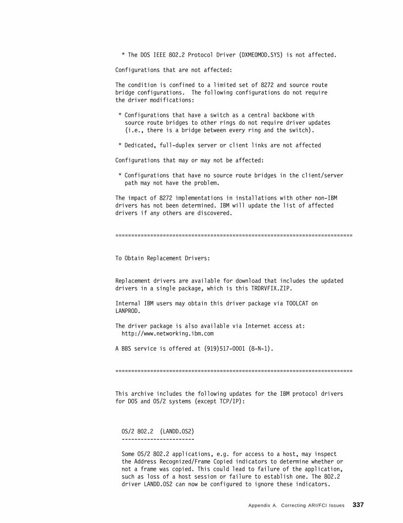
* The DOS IEEE 802.2 Protocol Driver (DXME0MOD.SYS) is not affected.
Configurations that are not affected:
The condition is confined to a limited set of 8272 and source routebridge configurations. The following configurations do not requirethe driver modifications:
* Configurations that have a switch as a central backbone withsource route bridges to other rings do not require driver updates(i.e., there is a bridge between every ring and the switch).
* Dedicated, full-duplex server or client links are not affected
Configurations that may or may not be affected:
* Configurations that have no source route bridges in the client/serverpath may not have the problem.
The impact of 8272 implementations in installations with other non-IBMdrivers has not been determined. IBM will update the list of affecteddrivers if any others are discovered.
===========================================================================
To Obtain Replacement Drivers:
Replacement drivers are available for download that includes the updateddrivers in a single package, which is this TRDRVFIX.ZIP.
Internal IBM users may obtain this driver package via TOOLCAT onLANPROD.
The driver package is also available via Internet access at:http://www.networking.ibm.com
A BBS service is offered at (919)517-0001 (8-N-1).
===========================================================================
This archive includes the following updates for the IBM protocol driversfor DOS and OS/2 systems (except TCP/IP):
OS/2 802.2 (LANDD.OS2)-----------------------
Some OS/2 802.2 applications, e.g. for access to a host, may inspectthe Address Recognized/Frame Copied indicators to determine whether ornot a frame was copied. This could lead to failure of the application,such as loss of a host session or failure to establish one. The 802.2driver LANDD.OS2 can now be configured to ignore these indicators.
Appendix A. Correcting ARI/FCI Issues 337

Copy LANDD.OS2 and LANDD.NIF to the IBMCOM\PROTOCOL or comparableLAPS or MPTS directory (make sure you remove, and not just rename,the old versions of these files in IBMCOM\PROTOCOL). To configurethe driver to ignore the indicators run LAPS or MPTS, select Configure,then Edit the 802.2 driver to set NetFlags to 1000. Alternately, youcan manually add the following line manually to the LANDD_nif sectionof PROTOCOL.INI:
NETFLAGS = 0x1000
The replacement driver can be used with any version of LAPS or MPTSat the level distributed with LAN Server 3.0 or higher. It will beincluded in future LAPS/MPTS CSD packages and in OS2 Warp Server.
Please note: The LANDD.NIF file is in English. Non-English versionsof this file that have been updated with the NETFLAGS parameter arenot yet available. This change will be included in a future CSD ofLAPS/MPTS. If you cannot use the LANDD.NIF included in this packageyou will have to add the NETFLAGS line to PROTOCOL.INI manually, asit will not appear as a configuration option in LAPS/MPTS. Pleasealso be aware that if you later run LAPS/MPTS in the future to makea configuration change, the NETFLAGS line will be removed from theLANDD section of PROTOCOL.INI -- since it is not in the NIF fileLAPS/MPTS believes it is invalid and should be removed.
OS/2 LAN Requester (NETBEUI.OS2)--------------------------------
LAN Requester will enter a polling state when it believes the targetstation is not receiving frames, causing additional network trafficand possibly leading to loss of connection to the server. Simplycopy NETBEUI.OS2 to the IBMCOM\PROTOCOL or comparable LAPS or MPTSdirectory to resolve this. The replacement driver can be used withany version of LAPS or MPTS at the level distributed with LAN Server 3.0or higher. It will be included in future LAPS/MPTS CSD packages and inOS2 Warp Server.
TCP/IP for OS/2---------------
The condition does not cause any traffic or connection failures forTCP/IP for OS/2 but results in an error counter being incorrectlyincremented (reported by NETSTAT -- number of packets dropped).These have been reported in APARs PN77766 for version 2.0 andIC11795 for version 3.0 shipped with OS/2 Warp Connect. A futureCSD for these packages will include a fix not to increment thiscounter for this condition.
DOS LAN Services (NET.EXE)--------------------------
A protocol-layer driver loaded by NET.EXE can experience problemsif the indicators are not set, which can result in loss ofconnection to the server or failure to connect to the server at all.The replacement driver can be used with any level of DLS 4.x.
338 IBM Nways RouteSwitch Implementation Guide

LAN Support Program (Version 1.38P, full release)--------------------------------------------------
The DXMC0MOD.SYS, DXMC1MOD.SYS, and DXMJ0MOD.SYS drivers of LANSupport Program Version 1.38 have been patched to handle thecondition gracefully; other drivers in the package such asDXME0MOD.SYS and DXMT0MOD.SYS are unaffected. If you are usingthe full version of LAN Support Program, use the LOADDSKF.EXEprogram to create the LAN Support Program 1.38P diskette (3.5-inch1.44M formatted) from the diskette image:
LOADDSKF LSP138P.DSK A:
LAN Support Program Custom (DXMC0MOD.SYS, DXMCSMOD.SYS)--------------------------------------------------------This archive also includes replacement driver DXMC0MOD.SYS forLAN Support Custom shipped with some IBM Token-Ring adapterssuch as Auto 16/4 and ISA-16, and DXMCSMOD.SYS for the LAN SupportCustom shipped with the Auto 16/4 Token-Ring Credit Card adapter.
===========================================================================
1/05/96-------
Initial release, version 1.00.
Includes the following updated drivers/products:
DXMC0MOD.SYS 11,648 1-05-96DXMCSMOD.SYS 23,629 1-05-96LSP138P.DSK 615,610 1-05-96NETBEUI.OS2 114,676 1-05-96
1/25/96-------
Version 1.10. Expanded READ.ME to include more background anddetails on the problem. Added the following:
LANDD.NIF 10,603 1-25-96 LANDD.OS2 115,236 1-23-96
NET.EXE 352,999 12-06-95
3/25/96-------
Version 1.20. Fixed a problem in LANDD.NIF that could cause theNETFLAGS settings to be lost on subsequent LAPS/MPTS configuration.
LANDD.NIF 10,602 3-25-96
Appendix A. Correcting ARI/FCI Issues 339

===========================================================================
340 IBM Nways RouteSwitch Implementation Guide

Appendix B. Ether-Types and SAP Listings
The following listings contain all possible Ether-Types and SAP values that maybe used to configure protocol-based VLANs in the RouteSwitch.
The SNAP values are the same as the Ether-type values predeeded by sixzeroes. The SNAP value for Novell NetWare would then be 0000008137.
B.1 Ether-Type ListingValue Description0000-05DC IEEE 802.3 Length Fields0101-01FF Experimental (for development) -- Conflicts with 802.3
Length Fields0200 Xerox PUP -- Conflicts with 802.3 Length Field0201 PUP Address Translation -- Conflicts with 802.3 Length
Fields0600 Xerox XNS IDP0800 DOD IP0801 X.75 Internet0802 NBS Internet0803 ECMA Internet0804 CHAOSnet0805 X.25 Level 30806 ARP (for IP and CHAOS)0807 Xerox XNS Compatibility081C Symbolics Private0888-088A Xyplex0900 Ungermann-Bass network debugger0A00 Xerox 802.3 PUP0A01 Xerox 802.3 PUP Address Translation0A02 Xerox PUP CAL Protocol (unused)0BAD Banyan Systems, Inc.
1000 Berkeley Trailer negotiation1001-100F Berkeley Trailer encapsulation for IP1066 VALIS Systems1600 VALID Systems3C01-3C0D 3Com Corporation3C10-3C14 3Com Corporation4242 PCS Basic Block Protocol5208 BBN Simnet Private
6000 DEC Unassigned6001 DEC MOP Dump/Load Assistance6002 DEC MOP Remote Console6003 DEC DECnet Phase IV6004 DEC LAT6005 DEC DECnet Diagnostic Protocol: DECnet Customer Use6007 DEC DECnet LAVC6008 DEC Amber6009 DEC MUMPS6010-6014 3Com Corporation
7000 Ungermann-Bass download7001 Ungermann-Bass NIU
Copyright IBM Corp. 1997, 1998 341

7002 Ungermann-Bass diagnostic/loopback7007 OS/9 Microware7020-7028 LRT (England)7030 Proteon7034 Cabletron
8003 Cronus VLN8004 Cronus Direct8005 HP Probe protocol8006 Nestar8008 AT&T8010 Excelan8013 SGI diagnostic type (obsolete)8014 SGI network games (obsolete)8015 SGI reserved type (obsolete)8016 SGI ″bounce server″ (obsolete)8019 Apollo802E Tymshare802F Tigan, Inc.8035 Reverse ARP (RARP)8036 Aeonic Systems8038 DEC LANBridge8039 DEC DSM803A DEC Aragon803B DEC VAXELN803C DEC NSMV803D DEC Ethernet CSMA/CD Encryption Protocol803E DEC DNA803F DEC LAN Traffic Monitor8040 DEC NetBIOS8041 DEC MS/DOS8042 DEC Unassigned8044 Planning Research Corporation8046 AT&T8047 AT&T8049 ExperData (France)805B VMTP (Versatile Message Transaction Protocol,
RFC-1045, Stanford)805C Stanford V Kernel production, Version 6.0805D Evans & Sutherland8060 Little Machines8062 Counterpoint Computers8065 University of Massachusetts, Amherst8066 University of Massachusetts, Amherst8067 Veeco Integrated Automation8068 General Dynamics8069 AT&T806A Autophon (Switzerland)806C ComDesign806D Compugraphic Corporation806E-8077 Landmark Graphics Corporation807A Matra (France)807B Dansk Data Elektronic A/S (Denmark)807C Merit Intermodal807D VitaLink Communications807E VitaLink Communications807F VitaLink Communications8080 VitaLink Communications bridge8081 Counterpoint Computers
342 IBM Nways RouteSwitch Implementation Guide
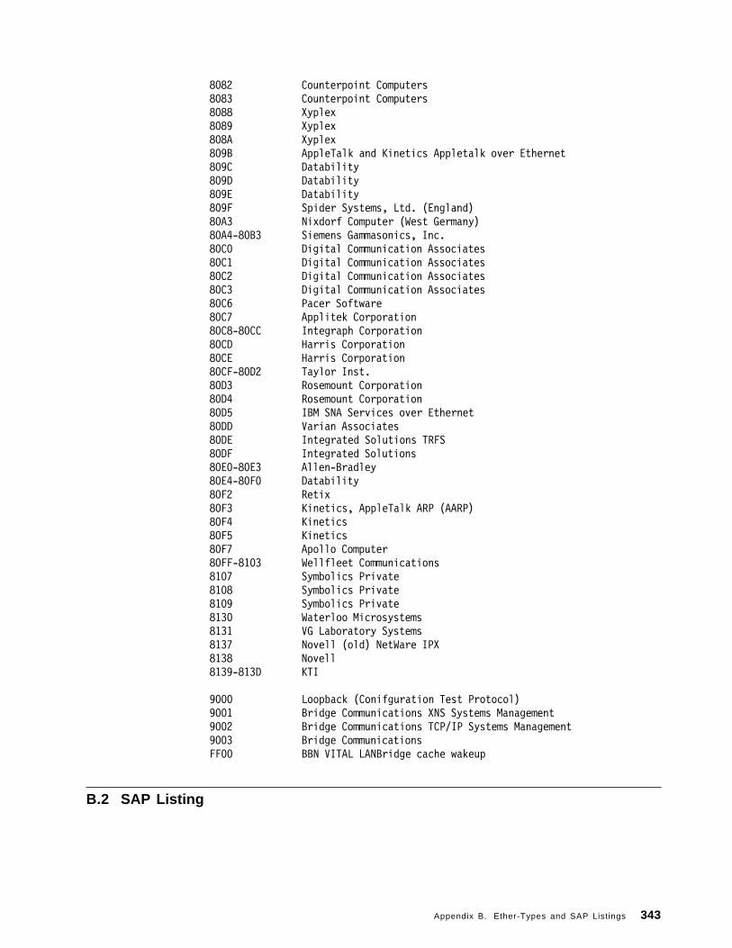
8082 Counterpoint Computers8083 Counterpoint Computers8088 Xyplex8089 Xyplex808A Xyplex809B AppleTalk and Kinetics Appletalk over Ethernet809C Datability809D Datability809E Datability809F Spider Systems, Ltd. (England)80A3 Nixdorf Computer (West Germany)80A4-80B3 Siemens Gammasonics, Inc.80C0 Digital Communication Associates80C1 Digital Communication Associates80C2 Digital Communication Associates80C3 Digital Communication Associates80C6 Pacer Software80C7 Applitek Corporation80C8-80CC Integraph Corporation80CD Harris Corporation80CE Harris Corporation80CF-80D2 Taylor Inst.80D3 Rosemount Corporation80D4 Rosemount Corporation80D5 IBM SNA Services over Ethernet80DD Varian Associates80DE Integrated Solutions TRFS80DF Integrated Solutions80E0-80E3 Allen-Bradley80E4-80F0 Datability80F2 Retix80F3 Kinetics, AppleTalk ARP (AARP)80F4 Kinetics80F5 Kinetics80F7 Apollo Computer80FF-8103 Wellfleet Communications8107 Symbolics Private8108 Symbolics Private8109 Symbolics Private8130 Waterloo Microsystems8131 VG Laboratory Systems8137 Novell (old) NetWare IPX8138 Novell8139-813D KTI
9000 Loopback (Conifguration Test Protocol)9001 Bridge Communications XNS Systems Management9002 Bridge Communications TCP/IP Systems Management9003 Bridge CommunicationsFF00 BBN VITAL LANBridge cache wakeup
B.2 SAP Listing
Appendix B. Ether-Types and SAP Listings 343

Address Assignment00 Null LSAP02 Individual LLC Sublayer Management Function03 Group LLC Sublayer Management Function04 IBM SNA Path Control (individual)05 IBM SNA Path Control (group)06 ARPANET Internet Protocol (IP)08 SNA0C SNA0E PROWAY (IEC955) Network Management & Initialization10 Novell and SDLC Link Servers18 Texas Instruments20 CLNP ISO OSI34 CLNP ISO OSI42 IEEE 802.1 Bridge Spannning Tree Protocol4E EIA RS-511 Manufacturing Message Service7E ISO 8208 (X.25 over IEEE 802.2 Type 2 LLC)80 Xerox Network Systems (XNS)86 Nestar8E PROWAY (IEC 955) Active Station List Maintenance98 ARPANET Address Resolution Protocol (ARP)AA SNAPBC Banyan VINESAA SubNetwork Access Protocl (SNAP)E0 Novell NetWareEC CLNP ISO OSIF0 IBM NetBIOSF4 IBM LAN Management (individual)F5 IBM LAN Management (group)F8 Remote Program LoadFA Ungermann-BassFC IBM Remote Program LoadFE ISO Network Layer ProtocolFF Global LSAP
344 IBM Nways RouteSwitch Implementation Guide

Appendix C. Sample GATED Configuration File
This gated file is a sample taken from an RS/6000. It shows the various settingsthat are available in a UNIX environment. The RouteSwitch architecture andgated function is based on UNIX. This file is not meant to be a full example butexplains some of the functions used in a gated configuration file.
# @(#)61 1.6 src/tcpip/etc/gated.conf, tcpip, tcpip411, GOLD410# 12/6/93 14:23:11## COMPONENT_NAME: TCPIP gated.conf## FUNCTIONS:## ORIGINS: 27## (C) COPYRIGHT International Business Machines Corp. 1985, 1989# All Rights Reserved# Licensed Materials - Property of IBM## US Government Users Restricted Rights - Use, duplication or# disclosure restricted by GSA ADP Schedule Contract with IBM Corp.### gated configuration file################################################################################# How to configure this file for your system:## Statement classes.# There are eight classes of statements. The first two may# be specified in the configuration file in any order.## directives# These statements are immediately acted upon by the# parser. They are used to specify included files and# the directory in which the reside. Unlike other# statements which terminate with a semi-colon (;),# directive statements terminate with a newline# character.# trace# These statements control tracing options.## The six remaining classes must be specified in order:## options# These statements allow specification of some global# options.# interface# These statements specify interface options.# definition# These statements options, the autonomous system and# martian networks.# protocol# These statements enable or disable protocols and set# protocol options.# route
Copyright IBM Corp. 1997, 1998 345

# These statements define static routes.# control# These statements define routes that are imported from# routing peers and routes that are exported to these# peers.## Statements within a class may be listed in any order.################################################################################# 1) Directive Statements# Set optional directive statements.## %directory ″<path_name>″## Sets the current directory to <path_name>. This is the# path that gated uses to look for included files that do# not begin with ″ / ″ .## %include ″filename″## Causes the specified file to be parsed completely before resuming# this file. Nesting up to 10 levels is supported.################################################################################# 2) Trace Statements# Set optional trace statements.## tracefile [″filename″ [replace]]# [size <size> [k]m] files <files>] ;## Specifies the file to contain tracing output. If a filename is# specified, trace information is appended to this file unless ″replace″# specified.# If specified, <size> and <files> cause the trace file to be limited# to <size>, with <files> files kept (including the active file). The# backup file names are created by appending a period and a number to# the trace file name, starting with ″ .0″ . The minimum size that can# be specified is 10k, the minimum number of files that can be specified# is 2. The default is not to rotate log files.## traceoptions <traceoption> [<traceoption> [ ... ]]# [except <traceoption># [<traceoption> [ ... ]]];## Where ″traceoption″ is:## all, general, internal, external, nostamp, kernel, mark, task,# timer, parse, route, kernel, bgp, egp, rip, hello, icmp, snmp,# protocol, or update.################################################################################# 3) Options Statements# options <option_list> ;# Sets gated options:## noinstall Do not change kernel′ s routing table.
346 IBM Nways RouteSwitch Implementation Guide

# Useful for verifying configuration# files.## gendefault# BGP and EGP neighbors should cause the# internal generation of a default route# when up. This route will not be# installed in the kernel′ s routing table,# but may be announced by other protocols.# Announcement is controlled by# referencing the special protocol# ″default″ .## nosend Do not send any packets. This allows# running gated on a live network to test# protocol interactions without actually# participating in the routing protocols.# The packet traces in the gated log can# be examined to verify that gated is# functioning properly. This is most# useful for RIP and HELLO and possibly# the SMUX SNMP interface. This does not# yet apply to BGP packets.## noresolv Do not try to resolv symbolic names into# IP addresses by using the host/network# tables or Domain Name System. This is# intended for systems where a lack of# routing information could cause a DNS# lookup to hang.## syslog Controls the amount of data gated logs# via syslog on systems where setlogmask()# is supported. The log_levels and other# terminology are as defined in the# setlogmask() man page. The default is# equivalent to ″syslog upto info″ .################################################################################# 4) Interface Statements# interfaces {# options [strictifs] [scaninterval <time>] ;# interface <interface_list> <interface_options> ;# define <address> [broadcast <broadaddr>|pointopoint# <lcladdr>] [netmask <netmask>]# [multicast] ;# } ;## options Sets some global options related to interfaces.## Options are:## strictifs Indicates that it is a fatal error to# reference an interface in the# configuration file that is not listed in# a define statement or not present when# gated is started. Without this option a# warning message will be issued and gated
Appendix C. Sample GATED Configuration File 347

# will continue.## scaninterval <time># Specifies how often gated scans the# kernel interface list for changes. The# default is every 15 seconds on most# systems, 60 seconds on systems that pass# interface status changes through the# routing socket (i.e. BSD 4.4). Note# that gated will also scan the interface# list on receipt of a SIGUSR2.## define Defines interfaces that may not be present when# gated is started. Gated considers it an error to# reference a non-existent interface in the config# file. This clause allows specification of that# interface so it can be referenced in the config# file.## Definition keywords are:## broadcast <broad_addr># Defines the interface as broadcast# capable (i.e. Ethernet and Token Ring)# and specifies the broadcast address.## pointopoint <local_addr># Defines the interface as a point to# point interface (i.e. SLIP and PPP) and# specifies the address on the local side.# For this type of interface the# <interface_addr> specifies the address# of the remote host.## An interface not defined as broadcast or# pointopoint is assumed to be non-broadcast# multiaccess (NBMA), such as an X.25 network.## netmask <subnetmask># Specifies the non-standard subnet mask# to be used on this interface. Note that# this currently ignored on pointopoint# interfaces.## multicast Specifies the interface is multicast# capable.## interface Sets interface options on the specified# interfaces. An interface list is ″all″ or a list# of interface names (see warning about interface# names), domain names, or numeric addresses.#### Options are:## preference <pref># Sets the preference for routes to this# interface when it is up, defaults to 0.
348 IBM Nways RouteSwitch Implementation Guide

## down preference <pref># Sets the preference for routes to this# interface when gated believes it to be down# due to lack of received routing information,# defaults to 120.## passive# Prevents gated from changing the preference# of the route to this interface if it is# believed to be down due to lack of received# routing information.## simplex# Defines an interface as unable to hear it′ s# own broadcast packets. Currently defining an# interface as simplex is functionally# equivalent to defining it as passive.## reject# Specifies that the address loopback# interfaces which match these criteria will be# used as the local address when installing# reject routes in the kernel. Should only# used with systems based on BSD 4.3 Tahoe or# earlier which have installed a# reject/blackhole pseudo interface.## blackhole# Specifies that the address loopback# interfaces which match these criteria will be# used as the local address when installing# blackhole routes in the kernel. Should only# used with systems based on BSD 4.3 Tahoe or# earlier which have installed a# reject/blackhole pseudo interface.################################################################################# 5) Definition Statements# autonomoussystem <autonomous system> ;# Sets the autonomous system of this router to be# <autonomous system>. This option is required if# BGP or EGP are in use.## routerid <host> ;# Sets the router identifier for use by the BGP and# OSPF protocols. The default is the address of the# first interface encountered by gated. The address# of a non-POINTOPOINT interface is prefered over# the local address of a POINTOPOINT interface and# an address on a loopback interface that is not the# loopback address (127.0.0.1) is most perfered.## martians {# <martian_list># } ;## Defines a list of martian addresses about which
Appendix C. Sample GATED Configuration File 349

# all routing information is ignored. The# <martian_list> is a semi-colon separated list of# symbolic or numeric hosts with optional masks.# See dest_mask. Also, the allow′ parameter may be# specified to explicitly allow a subset of a range# that was disallowed.################################################################################# 7) Protocol Statements# Enables or disables use of a protocol and controls protocol# options. These may be specified in any order.## For all protocols, ″preference″ controls the choice of# routes learned via this protocol or from this autonomous# system in relation to routes learned from other# protocols/autonomous systems. The default metric used when# propagating routes learned from other protocols is specified# with ″defaultmetric″ which itself defaults to the highest## valid metric for this protocol, for many protocols this# signifies a lack of reachability.## For distance vector IGPs with no explicit connections or# authentication (RIP and HELLO) and redirects (ICMP), the# ″trustedgateways″ clause supplies a list of gateways# providing valid routing information; routing packets from# other gateways are ignored. This defaults to all gateways# on the attached networks.## Routing packets may be sent not only to the remote end of# point-to-point links and the broadcast address of# broadcast-capable interfaces, but also to specific gateways# if they are listed in a ″sourcegateways″ clause and ″yes″ or# ″on″ is specified. If ″nobroadcast″ is specified, routing# updates will be sent only to gateways listed in the# ″sourcegateways″ clause, and not at all to the broadcast# address. Disabling the transmission and reception of# routing packets for a particular protocol may be specified# with the ″interface″ clause. An ″interface″ clause which# disables sending or receiving protocol packets may be# overridden for specific peers using the ″trustedgateways″# and ″sourcegateways″ clauses.## For exterior protocols (BGP, EGP), the autonomous system# advertised to the peer is specified by the global# ″autonomoussystem″ clause unless overridden by the ″asout″# parameter. The incoming autonomous system number is not# verified unless ″peeras″ is specified. Specifying# ″metricout″ fixes the outgoing metric for all routes# propagated to this peer. If the peer does not share a# network, ″interface″ can be used to specify which interface# address to use when communicating with this peer and# ″gateway″ can be used to specify the next hop to use for all# routes learned from this peer. An internal default is# generated when routing information is learned from a peer# unless the ″nogendefault″ parameter is specified.## Any protocol can have a ″traceoptions″ clause, which enables
350 IBM Nways RouteSwitch Implementation Guide

# tracing for a particular protocol, group or peer. The# allowable protocol-specific options are: all, general,# internal, external, route, update, task, timer, protocol, or# kernel.## rip yes|no|on|off [ {# broadcast ;# nobroadcast ;# nocheckzero;# preference <preference> ;# defaultmetric <metric> ;# interface <interface_list> [noripin]# [noripout]# [metricin <metric>] [metricout <metric>]
# [version 1]|[version 2# [multicast|broadcast]];# ...# trustedgateways <gateway_list> ;# sourcegateways <gateway_list> ;# traceoptions <traceoptions> ;# } ] ;## If the rip clause is not specified the default is ″rip# on″ . ″Nobroadcast″ specifies that RIP packets will# only be sent to gateways listed in the ″sourcegateways″# clause, if there are any. If ″yes″ or ″on″ is# specified, RIP will assume ″nobroadcast″ if there is# only one interface and ″broadcast″ if there is more# than one. ″Broadcast″ specifies that RIP packets will# always be generated. ″Nocheckzero″ specifies that RIP# should not make sure that the reserved fields in RIP# packets are zero.## Note that using ″broadcast″ with only one# interface is useful only when propagating static# routes or routes learned from another protocol.# This will cause data packets to travel across the# same network twice, which may be tolerable in# certain configurations.## The default metricout is zero, the default metricin is# the kernel interface metric plus 1 (the default RIP hop# count).## If the version is specified as or defaults to 1, RIP# version 2 packets will never be sent except in response# to a v2 POLL packet. If the version is specified as 2,# RIP version 2 packets will be sent to the RIP multicast# address if possible, or to the broadcast addresss,# unless the method is explicitly specified.## The default metric is 16; the default preference is# 100.## hello yes|no|on|off [ {# broadcast ;# nobroadcast ;# preference <preference> ;
Appendix C. Sample GATED Configuration File 351

# defaultmetric <metric> ;# interface <interface_list> [nohelloin]# [nohelloout]# [metricin <metric>]# [metricout <metric>];# ...# trustedgateways <gateway_list> ;# sourcegateways <gateway_list> ;# traceoptions <traceoptions> ;# } ] ;## If ″yes″ or ″on″ is specified, HELLO will assume# ″nobroadcast″ if there is only one interface and# ″broadcast″ if there is more than one. If the HELLO# clause is not specified the default is ″hello off″ .# ″Broadcast″ specifies that HELLO packets will be# generated. ″Nobroadcast″ specifies that HELLO packets# will only be sent to gateways listed in the# ″sourcegateways″ clause, if there are any.## Note that using ″broadcast″ with only one# interface is useful only when propagating static# routes or routes learned from another protocol.# This will cause data packets to travel across the# same network twice, which may be tolerable in# certain configurations.## The default metricout is zero, the default metricin is# a translation of the kernel interface metric into a# hello metric plus 100 (the default HELLO hop count).## The default metric is 30000; the default preference is# 90.## ospf yes|no|on|off [ {# [ defaults {# preference <preference> ;# cost <cost> ;# tag [<tag> | as [<as_tag>]] ;# type <1|2> ;# } ] ;# [exportlimit <routes> ;]# [exportinterval <time> ;]# [traceoptions <traceoptions> ;]# [monitorauthkey <authkey> ;]# [area <area> {# authtype <0|1|none|simple> ;# stub [cost <cost>];# networks {# network [mask <mask>] ;# } ;# stubhosts {# <host> cost <cost> ;# } ;# interface <interface> [cost <cost>] {# [enable|disable] ;# retransmitinterval <time> ;# transitdelay <time> ;# priority <priority> ;
352 IBM Nways RouteSwitch Implementation Guide

# hellointerval <time> ;# routerdeadinterval <time> ;# authkey <auth_key> ;# } ;# interface <interface> nonbroadcast# [cost|<cost>]{# pollinterval <time> ;# routers {# <gateway> [eligible] ;# ...# } ;# [enable|disable] ;# retransmitinterval <time> ;# transitdelay <time> ;# priority <priority> ;# hellointerval <time> ;# routerdeadinterval <time> ;# authkey <auth_key> ;# } ;# } ; ]# [ backbone {# authtype <0|1|none|simple> ;# networks {# network [mask <mask>] ;# } ;# subhosts {# <host> cost <cost> ;# } ;# interface <interface> [cost <cost>] {# [enable|disable] ;# retransmitinterval <time> ;# transitdelay <time> ;# priority <priority> ;# hellointerval <time> ;# routerdeadinterval <time> ;# authkey <auth_key> ;# } ;# . . .# interface <interface> nonbroadcast# [cost <cost>]{# pollinterval <time> ;# routers {# <gateway> [eligible] ;# ...# } ;# [enable|disable] ;# retransmitinterval <time> ;# transitdelay <time> ;# priority <priority> ;# hellointerval <time> ;# routerdeadinterval <time> ;# authkey <auth_key> ;# } ;# . . .# virtuallink neighborid <host> transitarea <area> {# [enable|disable] ;# retransmitinterval <time> ;# transitdelay <time> ;# priority <priority> ;
Appendix C. Sample GATED Configuration File 353

# hellointerval <time> ;# routerdeadinterval <time> ;# authkey <auth_key> ;# } ;# . . .# } ; ]# } ] ;## interface# An interface is specified with an address, a name,# a wildcard name (name without any number), or# ″all″ . Multiple interface clauses may be# specified with different parameters, the# parameters used are accumlated from the interface# clauses. If a parameter is specified more than# once the instance with the most specific interface# reference is used. The order of precedence is# address, name, wildcard name, ″all″ .## cost A number between 0 and 65535 specifying an OSPF# internal cost.## tag The OSPF tag (an unsigned 31-bit number) to be# placed on all routes exported by gated into OSPF.## as_tag# The OSPF-BGP tag (an unsigned 12-bit number) to be# placed on all routes export by gated into OSPF.# When ″tag as [<as_tag>]″ is used, tag fields are# automatically generated and the as_tag field is# assigned if specified.## metric# A number between 0 and 16777215 specifying an OSPF# external (ASE) cost.## area A dotted quad or a number between 1 and# 4294967295. Area 0 is always referred to as the# ″backbone″ .## auth_key# One to eight decimal digits separated by periods,# a one to eight byte hexadecimal string preceded by# ″0x″ , or a one to eight character string in double# quotes.## priority# A number between 0 and 255 specifying the priority# of becoming the designated router on this# interface.## OSPF inter and intra area are always imported into the# gated routing table with a preference of 10. It would# be a violation of the protocol to do otherwise so it is# not possible to override this. OSPF Autonomous System# External (ASE) routes are imported with a preference of# 150. This default may be changed with the preference# keyword in the defaults section. ASE routes are# imported at a rate of 100 ASEs every 1 second, these
354 IBM Nways RouteSwitch Implementation Guide

# parameters can be tuned with the ″exportlimit″ and# ″exportinterval″ parameters.## Gated routes are exported to OSPF as ASEs with a# default cost of 0 and a type of 1. By default, the tag# is calculated from the AS path of the route being# exported (tag as). These may all be changed in the# defaults section.## OSPF areas may be specified in any order, but the# ″backbone″ area must be specified last.## Reconfiguration (SIGHUP) is currently disabled when# OSPF is enabled. This will hopefully be fixed in a# future release.## egp yes|no|on|off [ {# [preference <preference> ;]# [defaultmetric <metric> ;]# [packetsize <maxpacketsize> ;]# [traceoptions <traceoptions> ;]# [group [peeras <autonomous system>]# [localas <autonomous system>]# [maxup <number>]# [preference <preference>]# {# neighbor <host># [metricout <metric>]# [nogendefault]# [importdefault]# [exportdefault]# [gateway <gateway>]# [lcladdr <local_address>]# [sourcenet <network>]# [minhello <min_hello>]# [minpoll <min_poll>]# [traceoptions <traceoptions>] {# ;# ...# } ;# ...]# } ] ;## ″Packetsize″ specifies the size, in bytes, of the# largest EGP packet that will be accepted or sent. A# ″group″ lists a group of EGP peers in one autonomous# system. ″Maxup″ specifies the maximum number of peers# that will be maintained in the Up state.# ″Importdefault″ and ″exportdefault″ tell gated to# import or export the default route (0.0.0.0) in updates# exchanged with an EGP neighbor. If not specified, the# the default network is ignored when exchanging EGP# updates. ″Sourcenet″ specifies the network to query in# EGP Poll packets, this is normally the shared network.# The minimum EGP hello and poll intervals acceptable may# be specified with the ″minhello″ and ″minpoll″# arguments, respectively. These are both specified as a# time in seconds, minutes:seconds or# hours:minutes:seconds. Any number of ″group″ clauses
Appendix C. Sample GATED Configuration File 355

# may be specified containing any number of ″neighbor″# clauses. Any parameters from the ″neighbor″ clause may# be specified on the ″group″ clause to provide defaults# for the group.## The ″local_address″ is used to set the address the# local address to be used when there is a choice of# interfaces. If not specified it defaults to whichever# interface is shared with the neighbor. If a network is# not shared with the neighbor, ″gateway″ may be used to# specify the next-hop gateway to use when installing# routes learned from this neighbor. In this case the# default interface is the one shared with the specified# gateway.## The default metric is 255; the default preference is# 200.## bgp yes|no|on|off [ {# [preference <preference> ;]# [defaultmetric <metric> ;]# [traceoptions <traceoptions> ;]# [group type external|internal|igp|test peeras <peeras># [metricout <metric>]# [localas <localas>]# [nogendefault]# [gateway <gateway>]# [preference <preference>]# [lcladdr <local_address>]# [holdtime <time>]# [traceoptions <traceoptions>]# [version <version>]# [passive]# [importdefault]# [exportdefault]# [sendbuffer <bufsize>]# [recvbuffer <bufsize>]# [spoolbuffer <bufsize>]# [keepall]# {# [allow { dest_mask ... } ;]# [peer <host># [metricout <metric>]# [localas <localas>]# [nogendefault]# [gateway <gateway>]# [preference <preference>]# [lcladdr <local_address>]# [holdtime <time>]# [traceoptions <traceoptions>]# [version <version>]# [passive]# [importdefault]# [exportdefault]# [sendbuffer <bufsize>]# [recvbuffer <bufsize>]# [spoolbuffer <bufsize>]# [keepall]# ;]
356 IBM Nways RouteSwitch Implementation Guide

# ...# } ;# ....]# } ] ;## BGP peers are assigned to groups based on the type and# peeras, it is not possible to have two groups with the# same type and peeras. Peer specifies the address of# each BGP peer. Group options provide the defaults for# all peers within that group.## ″Peeras″ is the autonomous system expected from a peer.# ″Metricout″ is the default metric to use when sending# to this peer. ″Localas″ specifies the autonomous# system advertised to this peer, the default is that# which has been set globally. ″Nogendefault″ specifies# that this peer should not cause the automatic default# to be generated.## The ″local_address″ specifies the address to be used on# the local end of the TCP connection with the peer. For# ″external″ peers the local address must be on an# interface which is shared with the peer (or for a non-# local peer′ s configured next-hop gateway when the# ″gateway″ option is used to specify this) and a session# with the peer will be opened only when an interface# with the appropriate local address through which the# peer (gateway) address is directly reachable is# operating. For other types of peers a peer session# will be maintained when any interface with the# specified local address is operating. In either case# incoming connections will only be recognized as# matching a configured peer if they are addressed to the# configured local address.## ″Holdtime″ specifies the BGP holdtime to use with this# peer. Traceoptions specify tracing options for this# peer (and are not yet implemented). Version specifies# the version of the BGP protocol to use with this peer.# If not specified, the highest supported version is used# first and version negotiation is attempted. ″Passive″# specifies that active opens to this peer should not be# attempted. ″Importdefault″ and ″exportdefault″ control# whether the default network (0.0.0.0) can be exchanged# with this peer. ″Keepall″ is used to retain routes# learned from a peer that contain one of our autonomous# system numbers in their path.## ″Sendbuffer″ and ″Recvbuffer″ control the amount of# buffering asked of the kernel, the default is to# configure the maximum supported, up to 65535 bytes.# ″Spoolbuffer″ is used to indicate that BGP should# buffer data for peers when the kernel queues are full,# the default is to break the connection. These options# are normally not needed on properly functioning# systems..## If a metric is not specified, the default is not to# send a metric. The default preference is 170, the
Appendix C. Sample GATED Configuration File 357

# default holdtime is 180 and the default version is 3.## redirect yes|no|on|off [ {# preference <preference> ;# interface <interface_list> [noredirects] ;# trustedgateways <gateway_list> ;# traceoptions <traceoptions> ;# } ] ;## Controls whether gated makes routing table changes# based on ICMP redirects when not functioning as a# router. When functioning as a router (i.e. any# interior routing protocols (RIP, HELLO, OSPF) are# participating in routing on any interface, ICMP# redirects are disabled. When ICMP redirects are# disabled, gated must actively remove the effects of# redirects from the kernel as the kernel always# processes ICMP redirects.## The default preference is 30.## snmp yes|no|on|off [ {# preference <preference> ;# traceoptions <traceoptions> ;# port <port> ;# } ] ;## Controls whether gated tries to contact the SMUX SNMP# daemon to register supported variables. The default is# ″on″ . The default preference is 50. The default port# is 199 (SMUX).################################################################################ 8) Route/Static Statements# Static routes are specified with ″static″ clauses.# static {# <dest_mask> gateway <gateway> [<gateway2># [<gateway3> [...]]]# [interface <interface_list>]# [preference <preference>]# [retain] [reject]# [blackhole] [noinstall] ;# ...# <dest_mask> interface <interface> [preference# <preference>] [retain]# [reject] [blackhole]# [noinstall] ;# ...# } ;## Any number of ″static″ statements may be specified,# each containing any number of static route definitions.# The first form defines a static route through one or# more gateways. If multiple gateways are specified,# they are limited by the number of multipath# destinations supported (on Unix this is almost always# one). Only gateways on interfaces that are configured# and up are used.#
358 IBM Nways RouteSwitch Implementation Guide

# The second defines a static interface route which is# used for primitive support of multiple networks on one# interface.## The interface list on the first form restricts static# routes to a specific set of interfaces.## ″Retain″ causes the route to be retained in the kernel# after gated is shut down. ″Reject″ causes all packets# to this route to be rejected. ″Blackhole″ causes all# packets to this route to be silently discarded.# ″Reject″ and ″blackhole″ are not supported by all# systems. ″Noinstall″ is used to prevent this route# from being installed in the kernel## The preference for static routes defaults to 60.################################################################################# 9) Control Statements# Importation of routes from routing protocol peers and# exportation of routes to routing protocol peers are# controlled by ″import″ and ″export″ clauses.## import proto bgp|egp as <autonomous system> restrict ;## import proto bgp|egp as <autonomous system># [preference <preference>] {# <import_list># } ;## import proto bgp aspath <aspath_spec> restrict ;## import proto bgp aspath <aspath_spec># [preference <preference>] {# <import_list># } ;## import proto rip|hello|redirect restrict ;## import proto rip|hello|redirect# [preference <preference>] {# <import_list># } ;## import proto rip|hello|redirect interface# <interface_list> restrict ;## import proto rip|hello|redirect interface <interface_list># [preference <preference>] {# <import_list># } ;## import proto rip|hello|redirect gateway <gateway_list># restrict;## import proto rip|hello|redirect gateway <gateway_list># [preference <preference>] {# <import_list>
Appendix C. Sample GATED Configuration File 359

# } ;## import proto ospfase [tag <ospf_tag>] restrict ;## import proto ospfase [tag <ospf_tag>]# [preference <preference>] [{# <import_list># }] ;## If an OSPF type is specified, only routes of that# type will be considered for import, otherwise# either type will be considered. If an ospf_tag# specification is given, only routes matching that# tag specification will be considered, otherwise# any tag will be considered. An OSPF tag# specification may is a decimal, hexidecimal or# dotted quad number.## If more than one import statement relevant to a# protocol is specified, they are processed most# specific to least specific (i.e. for RIP and# HELLO, gateway, interface and protocol), then in# the order specified in the config file.## import_list# An import_list consists of zero or more# destinations (with optional mask). One of two# parameters may be specified, ″restrict″ to prevent# a set of destinations from being imported or a# specific preference for this set of destinations.## <dest_mask> [[restrict] |# [preference <preference>]] ;### Note that the contents of an import_list are# sorted internally so that entries with the most# specific masks are examined first. The order in# which dest_mask entries are specified does not# matter.## If no import list is specified, all routes will be# accepted. If an import list is specified, the# import list is scanned for a match. If no match# is found, the route is discarded. Rephrased, a# ″all restrict″ entry is assumed in an import list.## export proto bgp|egp as <autonomous system> restrict ;## export proto bgp|egp as <autonomous system># [metric <metric>] {# <export_list># } ;## export proto rip|hello restrict ;## export proto rip|hello [metric <metric>] {# <export_list># } ;
360 IBM Nways RouteSwitch Implementation Guide

## export proto rip|hello interface <interface_list> restrict ;## export proto rip|hello interface <interface_list># [metric <metric>] {# <export_list># } ;## export proto rip|hello gateway <gateway_list> restrict ;## export proto rip|hello gateway <gateway_list># [metric <metric>] {# <export_list># } ;## export proto ospfase [type 1|2]# [tag <ospf_tag>] restrict ;## export proto ospfase [type 1|2]# [tag <ospf_tag>]# [cost <ospf_cost>] {# <export_list># } ;## export_list# The export list specifies exportation based on the# origin of a route to a destination:## proto bgp|egp as <autonomous system># [restrict] | [metric <metric>]# [ {# <announce_list># } ] ;## proto rip|hello|direct|static|default# [restrict] | [metric <metric>]# [ {# <announce_list># } ] ;## proto rip|hello|direct|static|default interface# <interface_list># [restrict] | [metric <metric>]# [ {# <announce_list># } ] ;## proto rip|hello gateway <gateway_list># [restrict] | [metric<metric>]# [ {# <announce_list># } ] ;## proto ospf [restrict] | [metric# <metric>] [ {# <announce_list> ;# } ] ;## proto ospfase [restrict | metric <metric>]]
Appendix C. Sample GATED Configuration File 361

# [ {# <announce_list> ;# } ] ;## proto <proto> aspath <aspath_spec># [restrict] | [metric <metric>]# [ {# <announce_list># } ] ;## proto <proto> tag <tag># [restrict] | [metric <metric>]# [ {# <announce_list># } ] ;## If a tag is specified, only routes with that tag# will be considered, otherwise any tag will be# considered. An OSPF tag on an export statement# may be a decimal, hexidecimal, or ″AS″ to generate# a tag based on the AS path of route being# announced. An OSPF tag on an export list is just# an 31 bit number that is matched against the tag# present (if any) on that route.## If more than one export statement relevant to a# protocol is specified, they are processed most# specific to least specific (i.e. for RIP and# HELLO, gateway, interface and protocol), then in# the order specified in the config file.## By default interface routes are exported to all# protocols. RIP and HELLO also export their own# routes. An export specification with just a# restrict will prevent these defaults from being# exported. Note that it is not possible to change# the metric RIP and HELLO use for their own routes;# any attempt to override it will be silently# ignored.## Any protocol may be specified for import lists# refering to aspaths and tags. AS paths are most# meaningful with BGP and OSPF ASE routes, but are# generated for all routes. Tags are currently only# meaningful for OSPF ASE routes.## announce_list# An announce_list consists of zero or more# destinations (with optional mask). One of two# parameters may be specified, ″restrict″ to prevent# a set of destinations from being exported or a# specific metric for this set of destinations.## <dest_mask> [[restrict] |# [metric <metric>]] ;### Note that the contents of an announce_list are sorted# internally so that entries with the most specific masks
362 IBM Nways RouteSwitch Implementation Guide

# are examined first. The order in which dest_mask# entries are specified does not matter.## If no announce_list is specified, all destinations# are announced. If an announce list is specified,# an ″all restict″ is assumed. Therefore, an empty# announce list is the equivalent of ″all restrict″ .## Note that to announce routes which specify a next# hop of the loopback interface (i.e. static and# internally generated default routes) via RIP or# HELLO it is necessary to specify the metric at# some level in the propagate clause. Just setting# a default metric for RIP or HELLO is not# sufficient.## aspath_spec# An AS path specification is used to match one or# more AS paths.## aspath <regexp> origin [igp]egp]incomplete]any]## where the regexp is a regular expression over the# set of AS numbers as defined in RFC-1164 section 4.2.################################################################################# Sample setups.################################################################################# Simple RIP quiet# This configuration runs RIP in quiet mode, it only listens to# packets, no matter how many interfaces are configured.# It traces all trace output to a file called /var/tmp/rip.quiet.trace.# The tracefile options allow the creation of 4 files to rotate trace# information. Each of these trace files will grow to about 50K bytes# before rotating to the next trace file. The trace files will be called,# /var/tmp/rip.quite.trace, /var/tmp/rip.quite.trace.0,# /var/tmp/rip.quite.trace.1, and /var/tmp/rip.quite.trace.2.## traceoptions all ;## tracefile ″ /var/tmp/rip.quiet.trace″ replace size 50k files 4 ;## rip yes {# nobroadcast ;# } ;################################################################################# Simple RIP supplier# Run as a RIP supplier, do not supply RIP packets to# tr0, and only listen to RIP packets from 192.100.110.1.## rip yes {# broadcast ;# interface tr0 noripout ;# trustedgateways 192.100.110.1 ;
Appendix C. Sample GATED Configuration File 363

# } ;################################################################################# Simple EGP# This host is in autonomous system 283. Verify neighbor# 192.35.82.100 is in autonomous system 145. Do not# generate a default route from EGP information learned.## autonomoussystem 283;## egp yes {# group peeras 145 {# neighbor 192.100.110.100 nogendefault ;# } ;# } ;################################################################################# Simple BGP# This host is in autonomous system 283. Verify peer# 192.100.110.1 is in autonomous system 145.## autonomoussystem 283;## bgp yes {# group type# External peeras 145 {# peer 192.100.110.1 ;# } ;# } ;###############################################################################
364 IBM Nways RouteSwitch Implementation Guide

Appendix D. Special Notices
This publication is intended to help customers, system engineers, servicespecialists and marketing specialists understand VLANs and the IBM NwaysRouteSwitch architecture for planning, installation, and support purposes. Theinformation in this publication is not intended as the specification of anyprogramming interfaces that are provided by Nways RouteSwitches or theassociated software. See the PUBLICATIONS section of the IBM ProgrammingAnnouncement for IBM Nways RouteSwitch for more information about whatpublications are considered to be product documentation.
References in this publication to IBM products, programs or services do notimply that IBM intends to make these available in all countries in which IBMoperates. Any reference to an IBM product, program, or service is not intendedto state or imply that only IBM′s product, program, or service may be used. Anyfunctionally equivalent program that does not infringe any of IBM′s intellectualproperty rights may be used instead of the IBM product, program or service.
Information in this book was developed in conjunction with use of the equipmentspecified, and is limited in application to those specific hardware and softwareproducts and levels.
IBM may have patents or pending patent applications covering subject matter inthis document. The furnishing of this document does not give you any license tothese patents. You can send license inquiries, in writing, to the IBM Director ofLicensing, IBM Corporation, North Castle Drive, Armonk, NY 10504-1785.
Licensees of this program who wish to have information about it for the purposeof enabling: (i) the exchange of information between independently createdprograms and other programs (including this one) and (ii) the mutual use of theinformation which has been exchanged, should contact IBM Corporation, Dept.600A, Mail Drop 1329, Somers, NY 10589 USA.
Such information may be available, subject to appropriate terms and conditions,including in some cases, payment of a fee.
The information contained in this document has not been submitted to anyformal IBM test and is distributed AS IS. The information about non-IBM(″vendor″) products in this manual has been supplied by the vendor and IBMassumes no responsibility for its accuracy or completeness. The use of thisinformation or the implementation of any of these techniques is a customerresponsibility and depends on the customer′s ability to evaluate and integratethem into the customer′s operational environment. While each item may havebeen reviewed by IBM for accuracy in a specific situation, there is no guaranteethat the same or similar results will be obtained elsewhere. Customersattempting to adapt these techniques to their own environments do so at theirown risk.
Any pointers in this publication to external Web sites are provided forconvenience only and do not in any manner serve as an endorsement of theseWeb sites.
Any performance data contained in this document was determined in acontrolled environment, and therefore, the results that may be obtained in other
Copyright IBM Corp. 1997, 1998 365

operating environments may vary significantly. Users of this document shouldverify the applicable data for their specific environment.
Reference to PTF numbers that have not been released through the normaldistribution process does not imply general availability. The purpose ofincluding these reference numbers is to alert IBM customers to specificinformation relative to the implementation of the PTF when it becomes availableto each customer according to the normal IBM PTF distribution process.
The following terms are trademarks of the International Business MachinesCorporation in the United States and/or other countries:
The following terms are trademarks of other companies:
C-bus is a trademark of Corollary, Inc.
Java and HotJava are trademarks of Sun Microsystems, Incorporated.
PC Direct is a trademark of Ziff Communications Company and isused by IBM Corporation under license.
Pentium, MMX, ProShare, LANDesk and ActionMedia are trademarks orregistered trademarks of Intel Corporation in the United States and othercountries.
UNIX is a registered trademark in the United States and othercountries licensed exclusively through X/Open Company Limited.
Microsoft, Windows, and the Windows 95 logo are trademarks orregistered trademarks of Microsoft Corporation.
Other company, product and service names may be trademarks or servicemarks of others.
IBM NwaysNetView AIXAT CurrentOS/2 IBM
366 IBM Nways RouteSwitch Implementation Guide

Appendix E. Related Publications
The publications listed in this section are considered particularly suitable for amore detailed discussion of the topics covered in this redbook.
E.1 International Technical Support Organization PublicationsFor information on ordering these ITSO publications see “How to Get ITSORedbooks” on page 369.
• Understanding and Using the IBM MSS Server, SG24-4915
• IBM 8260 As a Campus ATM Switch, SG24-5003
• Internetworking over ATM: An Introduction, SG24-4699
E.2 Redbooks on CD-ROMsRedbooks are also available on CD-ROMs. Order a subscription and receiveupdates 2-4 times a year at significant savings.
CD-ROM Title SubscriptionNumber
Collection KitNumber
System/390 Redbooks Collection SBOF-7201 SK2T-2177Networking and Systems Management Redbooks Collection SBOF-7370 SK2T-6022Transaction Processing and Data Management Redbook SBOF-7240 SK2T-8038Lotus Redbooks Collection SBOF-6899 SK2T-8039Tivoli Redbooks Collection SBOF-6898 SK2T-8044AS/400 Redbooks Collection SBOF-7270 SK2T-2849RS/6000 Redbooks Collection (HTML, BkMgr) SBOF-7230 SK2T-8040RS/6000 Redbooks Collection (PostScript) SBOF-7205 SK2T-8041RS/6000 Redbooks Collection (PDF Format) SBOF-8700 SK2T-8043Application Development Redbooks Collection SBOF-7290 SK2T-8037
E.3 Other PublicationsThese publications are also relevant as further information sources:
• Nways RouteSwitch User′s Guide, GA27-4166
• Nways RouteSwitch Network Manager Software User′s Guide, GC30-3871
Copyright IBM Corp. 1997, 1998 367

368 IBM Nways RouteSwitch Implementation Guide

How to Get ITSO Redbooks
This section explains how both customers and IBM employees can find out about ITSO redbooks, CD-ROMs,workshops, and residencies. A form for ordering books and CD-ROMs is also provided.
This information was current at the time of publication, but is continually subject to change. The latestinformation may be found at http://www.redbooks.ibm.com/.
How IBM Employees Can Get ITSO Redbooks
Employees may request ITSO deliverables (redbooks, BookManager BOOKs, and CD-ROMs) and information aboutredbooks, workshops, and residencies in the following ways:
• Redbooks Web Site on the World Wide Web
http://w3.itso.ibm.com/
• PUBORDER — to order hardcopies in the United States
• Tools Disks
To get LIST3820s of redbooks, type one of the following commands:
TOOLCAT REDPRINTTOOLS SENDTO EHONE4 TOOLS2 REDPRINT GET SG24xxxx PACKAGETOOLS SENDTO CANVM2 TOOLS REDPRINT GET SG24xxxx PACKAGE (Canadian users only)
To get BookManager BOOKs of redbooks, type the following command:
TOOLCAT REDBOOKS
To get lists of redbooks, type the following command:
TOOLS SENDTO USDIST MKTTOOLS MKTTOOLS GET ITSOCAT TXT
To register for information on workshops, residencies, and redbooks, type the following command:
TOOLS SENDTO WTSCPOK TOOLS ZDISK GET ITSOREGI 1998
• REDBOOKS Category on INEWS
• Online — send orders to: USIB6FPL at IBMMAIL or DKIBMBSH at IBMMAIL
Redpieces
For information so current it is still in the process of being written, look at ″Redpieces″ on the Redbooks WebSite (http://www.redbooks.ibm.com/redpieces.html). Redpieces are redbooks in progress; not all redbooksbecome redpieces, and sometimes just a few chapters will be published this way. The intent is to get theinformation out much quicker than the formal publishing process allows.
Copyright IBM Corp. 1997, 1998 369

How Customers Can Get ITSO Redbooks
Customers may request ITSO deliverables (redbooks, BookManager BOOKs, and CD-ROMs) and information aboutredbooks, workshops, and residencies in the following ways:
• Online Orders — send orders to:
• Telephone Orders
• Mail Orders — send orders to:
• Fax — send orders to:
• 1-800-IBM-4FAX (United States) or USA International Access Code -408-256-5422 (Outside USA) — ask for:
• On the World Wide Web
Redpieces
For information so current it is still in the process of being written, look at ″Redpieces″ on the Redbooks WebSite (http://www.redbooks.ibm.com/redpieces.html). Redpieces are redbooks in progress; not all redbooksbecome redpieces, and sometimes just a few chapters will be published this way. The intent is to get theinformation out much quicker than the formal publishing process allows.
I B M M A I L InternetIn United States: usib6fpl at ibmmail us ib6fp l@ibmmai l .com
In Canada: caibmbkz at ibmmai l lmannix@vnet . ibm.com
Outside North America: dk ibmbsh at ibmmai l bookshop@dk. ibm.com
United States (toll free) 1-800-879-2755
Canada (toll free) 1-800-IBM-4YOU
Outside North America (long distance charges apply)
(+45) 4810-1320 - Danish
(+45) 4810-1420 - Dutch
(+45) 4810-1540 - English
(+45) 4810-1670 - Finnish
(+45) 4810-1220 - French
(+45) 4810-1020 - German
(+45) 4810-1620 - Ital ian
(+45) 4810-1270 - Norwegian
(+45) 4810-1120 - Spanish
(+45) 4810-1170 - Swedish
I B M Publ icat ions
Publications Customer Support
P.O. Box 29570
Raleigh, NC 27626-0570
USA
I B M Publ icat ions
144-4th Avenue, S.W.
Calgary, Alberta T2P 3N5
Canada
IBM Direct Services
Sortemosevej 21
DK-3450 Allerød
Denmark
United States (toll free) 1-800-445-9269
Canada 1-403-267-4455
Outside North America (+45) 48 14 2207 (long distance charge)
Index # 4421 Abstracts of new redbooks
Index # 4422 IBM redbooks
Index # 4420 Redbooks for last six months
Redbooks Web Site ht tp : / /www.redbooks. ibm.com/
IBM Direct Publ icat ions Catalog ht tp : / /www.e l ink . ibml ink . ibm.com/pbl /pb l
370 IBM Nways RouteSwitch Implementation Guide

IBM Redbook Order Form
Please send me the following:
Title Order Number Quantity
First name Last name
Company
Address
City Postal code Country
Telephone number Telefax number VAT number
• Invoice to customer number
• Credit card number
Credit card expiration date Card issued to Signature
We accept American Express, Diners, Eurocard, Master Card, and Visa. Payment by credit card notavailable in all countries. Signature mandatory for credit card payment.
How to Get ITSO Redbooks 371

372 IBM Nways RouteSwitch Implementation Guide

List of Abbreviations
APA all points addressable
ARE all route explorer
ATM asynchronous transfer mode
BCM broadcast manager
BPDU bridge protocol data unit
BUS broadcast and unknownserver
DA destination address
DSAP destination service acesspoint
ELAN emulated LAN
FDDI f iber distributed datainterface
IBM International BusinessMachines Corporation
ILMI interim local managementinterface
IPX internetwork packet exchange
ITSO International TechnicalSupport Organization
LAN local area network
LANE LAN emulation
LEC lan emulation client
LECS lan emulation configurationserver
LED l ight emitting diodes
LES lan emulation server
LLC logical link control
LSB least significant bit
LUNI lAN emulation user tonetwork interface
MAC medium access control
MPM management processormodule
MSB most significant bit
MTU maximum transmission unit
NetBIOS network basic input outputsystem
NIC network interface card
PDU protocol data unit
PROFS professional office system
PTOP point to point
PVC permanent virtual circuit
REM r ing error monitor
RIF routing information field
RII routing information indicator
SA source address
SAP service access point
SNA systems network architecture
SNAP sub-network access protocol
SNMP simple network managementprotocol
SPX sequenced packet exchange
SRB source route bridge
SRF specifically routed frame
SR-TB source route to transparentbridge
SSAP source servcice access pointSTE
spanning tree explorer
SVC switched virtual circuit
TB transparent bridge
TCN topology change notification
UNI user to network interface
VLAN virtual LAN
Copyright IBM Corp. 1997, 1998 373

374 IBM Nways RouteSwitch Implementation Guide

Index
Numerics802.10 185, 186802.1d 110802.3 based formats 1598210 2848260 2848274 LAN RouteSwitch 28274 Model Descriptions 3
Aabbreviations 373acronyms 373Act ive 129Address Registration 196address resolution 194Address Resolution Protocol 156address resolution requests 196addvp command 162all route explorer 95any-to-any switching 13, 150, 157, 159APPLETALK 75, 154ARE 95ARP 156ARP bit swapping 158ATM 273
addresses 191cells 189LAN Emulation 189, 284selector 302trunking 123
autocaps 161AutoEncaps 161AutoTracker 71
Bbackplane 13backup file 21Banyan Vines 154, 160Basic Console Setup 14basic information 16Basic Setup 12bibliography 367binding based VLAN 78binding rules 40bit swap 156blocking 108BPDU 59, 98, 100, 186Bridge Aging Timer 105bridge management 23bridge priority 105, 112bridging 89
Broadcast and Unknown Server 189, 194, 197broadcast domain 12broadcasts 37, 52, 194Burst Sizes 261
committed 261excess 261Measurement Interval 261
BUS 189, 192, 194, 197
CCAM 53canonical 156cas command 171cell switching 7Cell Switching Modules (CSM) 2Checksum field 154checksums 160CIP 69CIR 261collision domain 38community name 14Configuration Fallback 25configuration fi les 20configuration settings 20configuring VLANs 67connection management 189Console 14console port 28Content Addressable Memory 4, 53control direct VCC 195control distribute VCC 195cratvl 71, 128CRC-flawed packets 4crgp command 69, 162
Ddata 151data direct VCC 195data link layer 189Deaf status 128DECNET 75default group 13, 49default VLAN 13, 49, 274DHCP MAC address-based rule 80DHCP MAC rules 40DHCP port based rule 79DHCP port rules 40diagnostic check 12disabled 108discard frames 262DSAP 75dynamic IP routing table 282
Copyright IBM Corp. 1997, 1998 375

EELAN 189, 194, 197, 284ELAN_NAME 190Emulated LAN 189, 284Encapsulation 151, 161Encapsulation Transformation Rules 154encapsulation transformations 155End System Identifier 191Ether-Type 75, 154, 155, 158Ether-Type encapsulated frame 158Ether-Type/SNAP transformations 154Ethernet
802.3 129LANs 90switching module 4Version II 129, 160
Ffactory settings 14Fast Ethernet 273FDDI 129, 158, 159
trunking 123trunking commands 187virtual bridge port 185
filtering database 90Firmware-Version 26flood 52flooded frames 160forwarding 108forwarding state 283fragmentation/reassembly 156frame flooding 54frame path 4frame relay 69frame size requirements 156frame type 13frame-to-cell conversion 189Frame-to-Cell Switching Module (FCSM) 2, 7FTP 30, 129ftp commands 31fwt command 185
Gglobal network-wide addresses 156graphical applications 14group
configuration 67identif iers 47multiplexing on FDDI 185, 186number 50
GROUP can 12
Hhardware forwarding engine 54
hardware routing engine (HRE) 6Hello bridge protocol data unit 100High-Speed Switching Module 4hot-swappable modules 3
IIBM spanning tree protocol 105ICMP 129, 159ICMP-based MTU discovery 159IEEE 802.2 160IEEE 802.2 IPX 163IEEE 802.2 IPX Pass Through 163IEEE 802.3 154, 158IEEE 802.5 196ILMI 192ILMI MIB 192Inactive 129Initial 297instance 50inter-switch link 13Interim Local Management Interface 192IP 75
fragmentation 159subnet 17
IPX 75IPX frame types 155IPX packet size negotiation 160
LLAN Emulation 159, 284, 294
Clients 189, 194, 197, 284Configuration Server 189, 197Server 189, 197summary 197user-to-network interface 192
LANE 284Last Topology Change 105LE Service components 189learning 108LEC 189, 194LECS 189, 192, 193, 284, 290, 296LECS ATM addresses 192LES 189, 192, 197listening 108LLC 155, 158, 160LLC encapsulation 154loading boot parameters 34loading from disk 35LSB 152LUNI 192
MMAC address rules 40MAC header 151MAC-based VLAN 72
376 IBM Nways RouteSwitch Implementation Guide

Management Bus 4, 5Management Processor Module (MPM) 2, 4, 11, 22management station 17maximum frame size 158, 289, 296maximum frame size negotiation 156Maximum Transmission Unit 159MBUS 5minimum frame size 158misaligned packets 4modatvl 71modem port 28module slot 50modvp command 162MPM 2, 14, 22, 52MPM Changeover 25MSB 152MSS server 190MTU 159mult icast 194multicast forward VCC 196multicast frames 160multicast send VCC 196multicast VLANs 48multiplex VLAN 169MultiProtocol Switching hub 284MultiProtocol Switching Services 284
Nnative 161network
address rules 40, 276, 279address-based VLAN 75header 151level address 156number 157policy-based VLAN 57prefix 191switch module 4
next hop resolution 142NHRP 142node address 157non-canonical 156non-IPX Ether-Type encapsulated frames 158non-native 161Novell 154
4.1 163network header 154Proprietary 154, 155, 158Raw 154
Nways RouteSwitch Network Manager 11Nways RouteSwitch Software Program 11Nways RouteTracker Manager 11
Oodd-byte padding 159OK1 LED 12
OK2 27OK2 LED 12Optimized device switching 11, 59
Ppadding 158password 14path cost 108PDU fragmentation/reassembly 159physical port numbers 50policies 47, 49policy-based ELANs 193policy-based VLANs 273port assignment 70port rules 40, 72, 299port t imeout 53port-based translation 160port-based VLANs 47PRI LED 25prior i ty 108protocol data unit (PDU) 159protocol identif ier 155protocol rules 40protocol-based VLAN 73proxy 189PS1 LED 12PTOP 161
RRaw 802.3 154redundancy 25redundant MPMs 24REFERENCE CHECKING 27reset 20RFC 1490 69RIF 94, 151RIP 129RIP update 157Rlogin 130rmgp 70root bridge 112route designator 94router 38RouteSwitch Architecture 4RouteSwitch group 54RouteSwitch Network Manager 18RouteSwitch Software 11RouteTracker Manager 18RouteTracker VLANs 48routing 89
control field 94functions 23information field 94protocols 13
rts command 187runts 4
Index 377

SSAP 129SEC LED 25Selector byte 191serial port specification 14service 50Silent 128SLIP 130SNAP 75, 154, 155SNAP encapsulated protocols 158SNAP frames 160SNMP 129SNMP management 23socket number 157Software Fallback 25software version 25source route bridges 89source route token-ring 129source route transparent bridges 90spanning tree 89, 170, 186
algori thm 90, 112explorer 95parameters 103sett ing parameters 103
SPARC RISC 3, 5specifically routed frame 95SRF 95SSAP 75static route 17STE 95store-and-forward 4stpc 108stps 108subnetwork MAC address 156SVC 196SVCs 294swap state 27swapping 26switching 89system contact 14system location 14system name 14
TTCN BPDU 103TCP 129TCP/IP address 14TELNET 130telnet client 17terminal emulation 14timeout 278token-ring 129, 158Token-Ring IPX Switching 158topology change notification 103transfer methods 30translational bridges 89
transparent bridge 89, 90transparent bridges 89trunk 161trunk ports 170trunking 89, 169, 185
configuration 170hello message 186over ATM 187ports 161
UUDP 129unicast destination address 160unicast floods 59unicasts 52universally administered 191user interface 29user-defined based VLAN 77user-defined rules 40user-to-network interface 192using ZMODEM 32
Vvas command 173VBUS 5VCC 192VCCs 194VCI 187vi command 162, 185via 70virtual circuit identif ier 187Virtual LANs (VLANs) 12, 37virtual port numbers 50virtual r ings 120virtual router 125virtual router port 50virtual transparent bridge port 185VLAN 189
bus 5group number 170groups 169membership 58policies 40policy rules 283t imers 52trunking 169
vportEncapsulation 162vportSwitchDefauItTable 162vportSwitchTable 162vportTable 162
ZZMODEM protocol 32
378 IBM Nways RouteSwitch Implementation Guide

ITSO Redbook Evaluation
IBM Nways RouteSwitch Implementation GuideSG24-4881-01
Your feedback is very important to help us maintain the quality of ITSO redbooks. Please complete thisquestionnaire and return it using one of the following methods:
• Use the online evaluation form found at http://www.redbooks.ibm.com• Fax this form to: USA International Access Code 914 432 8264• Send your comments in an Internet note to [email protected]
Which of the following best describes you?__Customer __Business Partner __Solution Developer __IBM employee__None of the above
Please rate your overall satisfaction with this book using the scale:(1 = very good, 2 = good, 3 = average, 4 = poor, 5 = very poor)
Overall Satisfaction ____________
Please answer the following questions:
Was this redbook published in time for your needs? Yes____ No____
If no, please explain:_____________________________________________________________________________________________________
_____________________________________________________________________________________________________
_____________________________________________________________________________________________________
_____________________________________________________________________________________________________
What other redbooks would you like to see published?_____________________________________________________________________________________________________
_____________________________________________________________________________________________________
_____________________________________________________________________________________________________
Comments/Suggestions: (THANK YOU FOR YOUR FEEDBACK!)_____________________________________________________________________________________________________
_____________________________________________________________________________________________________
_____________________________________________________________________________________________________
_____________________________________________________________________________________________________
_____________________________________________________________________________________________________
Copyright IBM Corp. 1997, 1998 379

SG
24-4
881-
01P
rinte
d in
the
U.S
.A.
IBM Nways RouteSwitch Implementation Guide SG24-4881-01
IBM
L