Fit PDF Report Output to Page in IBM Cognos BI Report Studio
Upload
khangminh22Category
view
12download
0
z/OSVersion 2 Release 3
Cryptographic Services ICSFTrusted Key Entry Workstation User'sGuideSEE RESOURCE LINK FOR THE LATESTCOPY OF THIS BOOK
IBM
SC14-7511-08

Note
Before using this information and the product it supports, read the information in “Notices” on page399.
This edition applies to TKE 9.1 and Version 2 Release 3 of z/OS® (5650-ZOS) and to all subsequent releases andmodifications until otherwise indicated in new editions.
Last updated: 2019-02-26© Copyright International Business Machines Corporation 2000, 2019.US Government Users Restricted Rights – Use, duplication or disclosure restricted by GSA ADP Schedule Contract withIBM Corp.

Contents
List of Figures....................................................................................................... xiList of Tables.......................................................................................................xxi
About this information...................................................................................... xxiiiWho should read this information........................................................................................................... xxiiiHow to use this information.................................................................................................................... xxiiiWhere to find more information.............................................................................................................. xxiv
How to send your comments to IBM.................................................................... xxvIf you have a technical problem............................................................................................................... xxv
Summary of changes......................................................................................... xxviChanges made in z/OS Version 2 Release 3 (V2R3)............................................................................... xxviChanges made in z/OS Version 2 Release 3 (V2R3).............................................................................. xxviiChanges made in z/OS Version 2 Release 2 (V2R2)............................................................................. xxviiiChanges made in z/OS Version 2 Release 1 (V2R1)............................................................................... xxix
Chapter 1. Overview.............................................................................................. 1Trusted Key Entry components................................................................................................................... 1
TKE hardware......................................................................................................................................... 1TKE software...........................................................................................................................................2
Supported host cryptographic adapters......................................................................................................3Host crypto module................................................................................................................................ 3
TKE concepts and mechanisms...................................................................................................................3Integrity.................................................................................................................................................. 4PCI-HSM overview..................................................................................................................................4Authorities.............................................................................................................................................. 5Crypto module OA signature key............................................................................................................7Command signatures............................................................................................................................. 7Key-exchange protocol...........................................................................................................................8Domain controls and domain control points..........................................................................................9Domain modes........................................................................................................................................9
TKE operational considerations...................................................................................................................9Logically partitioned (LPAR) mode considerations..............................................................................10Multiple hosts....................................................................................................................................... 10Multiple TKE workstations................................................................................................................... 10
Defining your security policy..................................................................................................................... 10TKE enablement.........................................................................................................................................11Trusted Key Entry console......................................................................................................................... 11
Trusted Key Entry console navigation..................................................................................................15TKE workstation crypto adapter roles and profiles.................................................................................. 16
Authority checking on the TKE.............................................................................................................16Types of profiles................................................................................................................................... 16Initializing a TKE workstation crypto adapter..................................................................................... 17Roles and profiles definition files.........................................................................................................20System-supplied role access control points (ACPs)............................................................................23
Blue smart cards (00RY790)..................................................................................................................... 37TKE security policy wizards....................................................................................................................... 38
Chapter 2. Using smart cards with TKE.................................................................43Terminology............................................................................................................................................... 43Preparation and planning.......................................................................................................................... 44
iii

Using the IDENTIV smart card reader................................................................................................. 44Using the OmniKey smart card reader.................................................................................................45Using the Gemalto smart card reader..................................................................................................45Things to consider................................................................................................................................ 46Smart card compatibility issues...........................................................................................................46
Zone concepts ...........................................................................................................................................50Authentication and secure communication.........................................................................................51Zone creation .......................................................................................................................................51Multiple zones...................................................................................................................................... 52Enrolling an entity.................................................................................................................................52TKE smart cards................................................................................................................................... 53EP11 smart cards................................................................................................................................. 53Steps to set up a smart card installation............................................................................................. 54
Moving TKE and EP11 smart card data to smart cards in a new zone..................................................... 55Moving data from a TKE smart card in a 1024-bit zone to a blue smart card..........................................55
Chapter 3. TKE upgrade and migration actions..................................................... 57Considerations before upgrading a TKE or copying data from an existing TKE....................................... 57
DVD-RAM is not supported on a TKE 7.2 or later system................................................................... 57Copying files to the TKE 7.0 or TKE 7.1 hard drive..............................................................................57Copying files to a USB flash memory drive while on a TKE 7.0 or TKE 7.1 system............................58Preparing for a new TKE local crypto adapter..................................................................................... 60
Upgrading an existing TKE workstation to TKE 9.1...................................................................................62Moving data from a TKE Version 5.x, 6.0, 7.x, 8.0, or 9.x to a new workstation at TKE 9.1.................... 64
Identifying data to be copied from the source TKE to the target TKE................................................ 64Copying customer data from the source TKE to USB memory in a form that the target TKE can
read..................................................................................................................................................68On the Target TKE, copying data from USB memory onto the TKE’s hard drive.................................69Loading TKE local adapter roles and profiles...................................................................................... 71
Recovery installation................................................................................................................................. 72
Chapter 4. TKE setup and customization.............................................................. 75TKE TCP/IP setup.......................................................................................................................................75TKE host transaction program setup.........................................................................................................76
Cancel the TKE server.......................................................................................................................... 79TKE workstation setup and customization................................................................................................79
The TKE Workstation Setup wizard......................................................................................................80Configuring TCP/IP............................................................................................................................... 83Customize console date and time........................................................................................................85Initializing the TKE workstation crypto adapter.................................................................................. 86TKE workstation crypto adapter post-initialization tasks................................................................... 87
Chapter 5. TKE up and running.............................................................................99Crypto adapter logon: passphrase or smart card..................................................................................... 99
Passphrase and passphrase group logon............................................................................................ 99Smart card and smart card group logon............................................................................................101
Automated crypto module recognition................................................................................................... 104Authenticating host crypto modules.......................................................................................................104Initial authorities..................................................................................................................................... 105Backing up files........................................................................................................................................105
Host file to back up............................................................................................................................ 106
Chapter 6. Main window.................................................................................... 107Working with hosts.................................................................................................................................. 108
Creating a new host............................................................................................................................108Changing host entries........................................................................................................................ 109Deleting host entries.......................................................................................................................... 109
iv

Logging on to a host........................................................................................................................... 109Closing a host..................................................................................................................................... 110
Understanding crypto modules and domain groups.............................................................................. 110Working with crypto modules..................................................................................................................110Working with domain groups...................................................................................................................111
Creating a domain group....................................................................................................................113Changing a domain group.................................................................................................................. 115Viewing a domain group.....................................................................................................................117Checking domain group overlap........................................................................................................ 118Comparing groups.............................................................................................................................. 120TKE functions supporting domain groups......................................................................................... 121
Crypto module groups............................................................................................................................. 121Function menu......................................................................................................................................... 121
Load signature key............................................................................................................................. 121Unload signature key..........................................................................................................................123Display signature key information..................................................................................................... 123Define transport key policy................................................................................................................ 123Exit......................................................................................................................................................124Exit and logoff.....................................................................................................................................124
Utilities menu...........................................................................................................................................125Manage workstation DES keys...........................................................................................................125Manage workstation PKA keys...........................................................................................................126Manage workstation AES keys........................................................................................................... 128Manage smart card contents............................................................................................................. 128Copy smart card contents..................................................................................................................130Copy binary file key part.................................................................................................................... 131Create CCA key parts......................................................................................................................... 132Duplicate TKE and EP11 smart card..................................................................................................133Generate EP11 master key parts.......................................................................................................133TKE customization............................................................................................................................. 133
Chapter 7. Using the Crypto Module Notebook to administer CCA crypto modules135Notebook mode....................................................................................................................................... 135Crypto Module Notebook function menu................................................................................................136Tabular pages...........................................................................................................................................137Crypto Module Notebook General tab.................................................................................................... 137
Intrusion latch ................................................................................................................................... 138Crypto Module Notebook Details tab...................................................................................................... 139Crypto Module Notebook Roles tab........................................................................................................ 141
Dual-signature commands.................................................................................................................141Domain access................................................................................................................................... 141Creating or changing a role................................................................................................................ 142Deleting a role.................................................................................................................................... 143View a role.......................................................................................................................................... 143Using Guided Create Roles................................................................................................................ 143Setup Module Policy...........................................................................................................................145
Crypto Module Notebook Authorities tab............................................................................................... 145Generating authority signature keys................................................................................................. 146Create authority................................................................................................................................. 148Change authority................................................................................................................................ 153Delete authority .................................................................................................................................153Using Guided Create Authorities....................................................................................................... 154Setup Module Policy...........................................................................................................................154
Crypto Module Notebook Domains tab...................................................................................................155Domain General page....................................................................................................................... 155Domain Keys page ............................................................................................................................ 157Operational keys ................................................................................................................................169
v

RSA keys.............................................................................................................................................182Domain Controls pages...................................................................................................................... 186Domain Decimalization Tables page............................................................................................... 189Domain Restricted PINs page............................................................................................................191Domain Certificates page...................................................................................................................192Domain Roles page............................................................................................................................ 193Domain Authorities page................................................................................................................... 194Domain Audit Log page...................................................................................................................... 194
Crypto Module Notebook Co-Sign tab.....................................................................................................195Host crypto module index values............................................................................................................195Placing a domain in PCI-compliant mode...............................................................................................196
Required dual controls.......................................................................................................................196Configuring a domain to be in PCI-compliant mode......................................................................... 196
Chapter 8. Using the Crypto Module Notebook to administer EP11 cryptomodules........................................................................................................ 209Notebook mode....................................................................................................................................... 210Imprint mode...........................................................................................................................................210Crypto Module Notebook Function menu............................................................................................... 211Tabular pages...........................................................................................................................................212Crypto Module Notebook Module General tab....................................................................................... 212
Intrusion latch....................................................................................................................................213Crypto Module Notebook Module Details tab.........................................................................................214Crypto Module Notebook Module Administrators tab............................................................................215
Generate signature key...................................................................................................................... 216Add administrator.............................................................................................................................. 217Remove administrator........................................................................................................................217Setup Module Policy...........................................................................................................................217
Crypto Module Notebook Module Attributes tab....................................................................................217Crypto Module Notebook Domains tab...................................................................................................219
Domain General page.........................................................................................................................220Domain Administrators page............................................................................................................. 221Domain Attributes page..................................................................................................................... 221Domain Keys page..............................................................................................................................223Domain Control Points page ............................................................................................................. 225
Chapter 9. Auditing............................................................................................227TKE Audit Configuration utility................................................................................................................ 227Service Management auditing functions.................................................................................................229
View security logs.............................................................................................................................. 230Audit and log management................................................................................................................231Archive security logs.......................................................................................................................... 235
TKE Security Events Viewer.....................................................................................................................236TKE Audit Record Upload Configuration utility....................................................................................... 238
Starting the TKE Audit Record Upload Configuration utility............................................................. 238Configure TKE for audit data upload..................................................................................................239Uploading audit records.....................................................................................................................240Enabling and disabling automatic audit record upload.................................................................... 240
Chapter 10. Managing keys using TKE and ICSF..................................................243Changing master keys..............................................................................................................................243Adding host crypto modules after ICSF initialization............................................................................. 244Loading operational keys to the CKDS.................................................................................................... 245Installing RSA keys in the PKDS from a data set.................................................................................... 248
Chapter 11. Cryptographic Node Management utility (CNM)................................ 251Crypto adapter logon............................................................................................................................... 251
vi

File menu................................................................................................................................................. 252Crypto Node menu...................................................................................................................................252
TKE crypto adapter clock-calendar .................................................................................................. 252Access Control menu...............................................................................................................................253
Initialize..............................................................................................................................................253Managing profiles............................................................................................................................... 254Managing roles................................................................................................................................... 264Save user roles and profiles...............................................................................................................270Load user roles and profiles...............................................................................................................270Check TKE crypto adapter group profiles..........................................................................................270Load TKEGRPMB role.........................................................................................................................270TKE Workstation Logon Profile Wizard.............................................................................................. 270
Master Key menu..................................................................................................................................... 271Auto Set and Create Random Master Key .........................................................................................272Clear new............................................................................................................................................272Parts — Loading a new master key from clear key parts...................................................................272Smart card parts — generating master key parts to a smart card.................................................... 274Smart card parts — loading master key parts from a smart card..................................................... 276Set — setting the master key value....................................................................................................277Verify — verifying the master key.......................................................................................................277
Key Storage menu....................................................................................................................................279Reenciphering key storage.................................................................................................................279
Smart card menu..................................................................................................................................... 280Change PIN.........................................................................................................................................281Generate TKE crypto adapter logon key............................................................................................282Display smart card details................................................................................................................. 282Manage smart card contents............................................................................................................. 283Copy smart card................................................................................................................................. 285
CNM common errors................................................................................................................................288
Chapter 12. Smart Card Utility Program (SCUP).................................................. 291General information ................................................................................................................................291Starting point for all the TKE policy wizards........................................................................................... 293Gemalto smart card reader considerations............................................................................................ 293File menu functions................................................................................................................................. 294
Display smart card information......................................................................................................... 294Display smart card key identifiers..................................................................................................... 296TKE zone wizard................................................................................................................................. 298TKE Smart Card wizard...................................................................................................................... 298
CA smart card menu functions................................................................................................................299Initialize and personalize a CA smart card........................................................................................ 299Create a backup CA smart card......................................................................................................... 301Change the CA smart card PINs........................................................................................................ 302
TKE smart card menu functions..............................................................................................................302Initialize and enroll a smart card....................................................................................................... 302Personalize a smart card....................................................................................................................303Unblock PIN on a smart card.............................................................................................................304Change PIN of a smart card............................................................................................................... 304Enroll smart card in an alternate zone...............................................................................................304Remove alternate zone from smart card........................................................................................... 304
EP11 smart card menu functions............................................................................................................305Crypto adapter menu functions.............................................................................................................. 305
Enroll a TKE cryptographic adapter in a primary zone......................................................................305View current zone for the crypto adapter..........................................................................................310
Appendix A. Secure key part entry..................................................................... 313Steps for secure key part entry............................................................................................................... 313
vii

Steps for secure key part entry for a TKE smart card....................................................................... 313Steps for secure key part entry for a EP11 smart card..................................................................... 318
Entering a key part on the smart card reader......................................................................................... 320
Appendix B. LPAR considerations.......................................................................323
Appendix C. Trusted Key Entry - workstation crypto adapter initialization........... 325Cryptographic Node Management Batch Initialization.......................................................................... 325CCA CLU (Code Load utility).....................................................................................................................326
CLU processing...................................................................................................................................326Checking coprocessor status.............................................................................................................328Loading coprocessor code................................................................................................................. 328Validating coprocessor code..............................................................................................................329Checking system status..................................................................................................................... 329Resetting coprocessor....................................................................................................................... 329Removing coprocessor CCA code and zeroizing CCA........................................................................330Help menu.......................................................................................................................................... 330
Appendix D. Clear RSA key format......................................................................331
Appendix E. Trusted Key Entry applications and utilities..................................... 333Using USB flash memory drives with TKE applications and utilities......................................................335Begin Zone Remote Enroll Process ........................................................................................................ 335CCA CLU................................................................................................................................................... 335Complete Zone Remote Enroll Process ..................................................................................................335Configure Displayed Hash Size................................................................................................................336Enhanced Password Encryption Policy................................................................................................... 336Configure Printers....................................................................................................................................336Cryptographic Node Management batch initialization........................................................................... 337Cryptographic Node Management utility................................................................................................ 337Edit TKE files............................................................................................................................................ 337Migrate Roles utility................................................................................................................................. 341Smart Card Utility Program......................................................................................................................341TKE Audit Configuration utility................................................................................................................ 342TKE Audit Record Upload Configuration utility....................................................................................... 342TKE File Management utility....................................................................................................................342TKE workstation code information ......................................................................................................... 345Configuration migration...........................................................................................................................345
Migrate Host Crypto Module Public Configuration Data................................................................... 346Configuration migration tasks............................................................................................................347Signature collection........................................................................................................................... 348Window actions.................................................................................................................................. 349Instructions for migrating key material............................................................................................. 351OA proxy............................................................................................................................................. 351Smart card applet level for configuration migration......................................................................... 352
Service Management tasks......................................................................................................................352Analyze console internal code........................................................................................................... 353Archive security logs.......................................................................................................................... 353Authorize internal code changes....................................................................................................... 353Backup critical console data..............................................................................................................353Change console internal code............................................................................................................354Change password .............................................................................................................................. 354Customize scheduled operations...................................................................................................... 355Format media..................................................................................................................................... 359Audit and log management................................................................................................................361Hardware messages...........................................................................................................................361Lock console ......................................................................................................................................363
viii

Manage print screen files...................................................................................................................363Network diagnostic information........................................................................................................ 364Rebuild vital product data..................................................................................................................364Offload virtual RETAIN data to removable media............................................................................. 364Password protect console..................................................................................................................365Save/restore customizable console data.......................................................................................... 365Save upgrade data..............................................................................................................................365Shutdown or restart........................................................................................................................... 366Transmit console service data........................................................................................................... 367Users and tasks.................................................................................................................................. 369View console events...........................................................................................................................370View console information.................................................................................................................. 371View console service history..............................................................................................................372View console tasks performed.......................................................................................................... 374View licenses......................................................................................................................................375View security logs.............................................................................................................................. 376
Appendix F. TKE best practices.......................................................................... 377Checklist for loading a TKE machine - passphrase.................................................................................377Checklist for loading a TKE machine - smart card..................................................................................379
Appendix G. TKE hardware support and migration information........................... 383TKE release and feature codes available by CEC levels......................................................................... 383Smart card readers and smart cards orderable by TKE release............................................................ 383TKE (LIC) upgrade paths..........................................................................................................................385Host cryptographic modules managed by TKE.......................................................................................385
Appendix H. Hardware Security Module (HSM) event log entries that CCAversion 6.0.3 supports................................................................................... 387
Appendix I. Multi-Factor Authentication (MFA) and the TKE................................ 393
Appendix J. Accessibility................................................................................... 395Accessibility features.............................................................................................................................. 395Consult assistive technologies................................................................................................................ 395Keyboard navigation of the user interface.............................................................................................. 395Dotted decimal syntax diagrams.............................................................................................................395
Notices..............................................................................................................399Terms and conditions for product documentation................................................................................. 400IBM Online Privacy Statement................................................................................................................ 401Policy for unsupported hardware............................................................................................................401Minimum supported hardware................................................................................................................402Trademarks.............................................................................................................................................. 402
Index................................................................................................................ 403
ix

x
List of Figures
1. TKE Console - initial panel ......................................................................................................................... 122. TKE Console - pre-login panel ................................................................................................................... 133. Log on with other privileged mode access console user names ...............................................................134. Trusted Key Entry for ADMIN - categorized................................................................................................145. Service Management – No Privileged Mode Access...................................................................................156. Multiple primary zones................................................................................................................................527. Entry example..............................................................................................................................................768. Example of reserving a port........................................................................................................................ 769. Format of AUTHCMD................................................................................................................................... 7610. Assign a user ID to CSFTTKE in FACILITY class.......................................................................................7711. Assign a User ID to CSFTTKE in APPL Class.............................................................................................7712. Assign a user ID to a started task.............................................................................................................7713. Sample startup procedure........................................................................................................................ 7814. Start the TKE server.................................................................................................................................. 7915. Cancel the TKE server............................................................................................................................... 7916. Login with ADMIN user name .................................................................................................................. 8017. The TKE Workstation Setup wizard Welcome window.............................................................................8018. Customize Network Settings - Identification Tab.................................................................................... 8319. Customize Network Settings LAN Adapters Tab...................................................................................... 8320. Local Area Network................................................................................................................................... 8421. Customize Network Settings - Name Services Tab.................................................................................. 8422. Network Diagnostic Information Task...................................................................................................... 8523. Customize Console Date and Time Window.............................................................................................8524. Configure NTP settings............................................................................................................................. 8625. Add Network Time Server.........................................................................................................................8626. Migrate Roles utility ..................................................................................................................................9127. Configure 3270 Emulators........................................................................................................................9528. Add 3270 Emulator Session..................................................................................................................... 9529. Start or Delete a 3270 Emulator Session................................................................................................. 9530. Manage trusted signing certificates..........................................................................................................9631. Import remote certificate......................................................................................................................... 9632. Confirm import.......................................................................................................................................... 9733. Manage trusted signing certificates..........................................................................................................9734. Configure 3270 emulators........................................................................................................................9735. Add 3270 emulator session......................................................................................................................9836. Configure 3270 emulators: Start at console startup............................................................................... 9837. Crypto Adapter logon window with passphrase profiles......................................................................... 9938. Enter passphrase for logon.....................................................................................................................10039. Change logon passphrase.......................................................................................................................100
xi

40. Crypto Adapter group logon window with passphrase profiles.............................................................10041. Enter passphrase for logon.....................................................................................................................10142. Crypto Adapter Group logon window with passphrase profile ready....................................................10143. Crypto Adapter Logon Window with smart card profiles....................................................................... 10244. Insert the smart card.............................................................................................................................. 10245. Enter smart card PIN.............................................................................................................................. 10246. Crypto Adapter Group logon window with smart card profiles............................................................. 10347. Insert the smart card.............................................................................................................................. 10348. Crypto Adapter Group logon window with smart card profile ready.....................................................10349. Authenticate Crypto Module ..................................................................................................................10550. TKE Preferences......................................................................................................................................10751. Create Host............................................................................................................................................. 10852. Host Logon window.................................................................................................................................10953. Main window .......................................................................................................................................... 11154. Main window - working with domain groups......................................................................................... 11255. Create New CCA Domain Group............................................................................................................. 11456. Change CCA Domain Group ................................................................................................................... 11657. View CCA Domain Group ........................................................................................................................11758. Check Domain Group Overlap................................................................................................................ 11859. Duplicate Domains Not Allowed.............................................................................................................11960. Domain Group Overlap Details .............................................................................................................. 11961. Compare Group.......................................................................................................................................12062. Select Authority Signature Key Source...................................................................................................12263. Specify Authority Index.......................................................................................................................... 12264. Load Signature Key................................................................................................................................. 12365. Select Transport Key Policy.................................................................................................................... 12466. TKE Workstation DES Key Storage Window........................................................................................... 12667. TKE Workstation PKA Key Storage Window........................................................................................... 12768. TKE Workstation AES Key Storage window............................................................................................12869. Smart card contents (for TKE smart cards)............................................................................................12970. Smart card contents (for EP11 smart cards)......................................................................................... 12971. Select keys to copy................................................................................................................................. 13172. Copy binary file key part utility............................................................................................................... 13273. Create CCA key parts.............................................................................................................................. 13374. Crypto Module Notebook for CCA - General Page .................................................................................13575. Window to Release Crypto Module........................................................................................................ 13676. Set clock..................................................................................................................................................13877. Dual Validation........................................................................................................................................ 14078. Create New Role page.............................................................................................................................14279. Guided Create Roles page...................................................................................................................... 14480. Authorities Page......................................................................................................................................14681. Completed generate signature key window ..........................................................................................14682. Save authority signature key.................................................................................................................. 147
xii

83. Generate signature key...........................................................................................................................14884. Key saved status message......................................................................................................................14885. Select source of authority signature key................................................................................................14986. Create new authority.............................................................................................................................. 15087. Load Signature Key from binary file........................................................................................................15188. Create New Authority with Role Container............................................................................................ 15289. Change Authority ................................................................................................................................... 15390. Guided Create Authorities page............................................................................................................. 15491. Domain General page - Normal mode....................................................................................................15592. Select mode panel for IMPRINT mode.................................................................................................. 15693. Select mode panel for PCI-COMPLIANT mode......................................................................................15694. Select mode panel for PCI-COMPLIANT mode, key migration allowed................................................15695. Domain in IMPRINT mode......................................................................................................................15796. Domain Keys page...................................................................................................................................15897. Enter number of keys to be generated................................................................................................... 16398. Select source of new AES Master Key part............................................................................................ 16499. Select key part from TKE smart card......................................................................................................164100. Warning message..................................................................................................................................164101. Key part information panel...................................................................................................................165102. Enter Key Value - Blind Key Entry........................................................................................................ 165103. Enter Key Value.....................................................................................................................................166104. Specify Key File ....................................................................................................................................166105. Generate Operational Key - predefined EXPORTER key type............................................................. 170106. Generate Operational Key - USER DEFINED........................................................................................171107. Generate Operational Key panel - AES MAC operational key..............................................................171108. AES MAC Key Attributes panel............................................................................................................. 172109. Key part information - first DES key part............................................................................................. 173110. Key part information - first DES key part PCI-compliant.....................................................................174111. DES key part register information........................................................................................................ 174112. Enter key value - keyboard source for predefined EXPORTER key type............................................. 175113. DES Key part information - add part ................................................................................................... 176114. Complete DES Operational Key Part Register - predefined EXPORTER key type...............................176115. DES Key part register information - predefined EXPORTER key type in Complete state................... 177116. Key Part Information panel for an AES operational key other than DATA...........................................177117. Key Part Register Information panel for an AES operational key other than DATA............................ 178118. View Operational Key Part Register panel - AES CIPHER operational key......................................... 179119. Key Part Register Information panel - AES CIPHER operational key..................................................179120. Clear Operational Key Part Register panel -- AES CIPHER operational key....................................... 180121. Install IMP-PKA Key Part in Key Storage............................................................................................. 181122. Install AES IMPORTER Key Part in Key Storage...................................................................................182123. Generate RSA Key.................................................................................................................................183124. Encipher RSA Key .................................................................................................................................184125. Load RSA Key to PKDS ......................................................................................................................... 185
xiii

126. Load RSA Key to Dataset ..................................................................................................................... 186127. Domain Controls page.......................................................................................................................... 187128. Decimalization tables page.................................................................................................................. 189129. Table entry options............................................................................................................................... 190130. Enter new decimalization table value.................................................................................................. 190131. Domain Restricted PINs page ............................................................................................................. 191132. Domain certificates...............................................................................................................................193133. Domain audit log...................................................................................................................................194134. PCI-HSM smart card wizard................................................................................................................. 197135. PCI-HSM smart card wizard - Welcome screen...................................................................................198136. TKE smart card wizard..........................................................................................................................198137. TKE smart card wizard - Welcome screen........................................................................................... 198138. TKE smart card wizard - Creation screen.............................................................................................199139. Enter imprint mode...............................................................................................................................201140. Select source for signature key for command..................................................................................... 201141. Setup PCI Environment........................................................................................................................ 202142. Setup PCI Environment - Welcome screen..........................................................................................203143. Setup domain-specific roles.................................................................................................................203144. Setup PCI environment........................................................................................................................ 203145. Setup domain specific authorities........................................................................................................204146. Setup domain specific authorities - Summary.....................................................................................204147. Move an imprint mode domain to compliant mode.............................................................................206148. Authority error message.......................................................................................................................206149. Select source........................................................................................................................................ 207150. Enter PCI mode - Co-sign.....................................................................................................................207151. Co-sign pending....................................................................................................................................207152. PCI-compliant mode.............................................................................................................................208153. Crypto Module Notebook for EP11 - Module General page................................................................ 209154. Window to release crypto module....................................................................................................... 211155. Module Administrators page................................................................................................................ 216156. Generate Signature Key........................................................................................................................216157. Module Attributes page........................................................................................................................ 218158. Domain General page........................................................................................................................... 221159. Domain Attributes page........................................................................................................................222160. Domain Keys page................................................................................................................................ 224161. Domain Control Points page.................................................................................................................226162. Default settings for auditing................................................................................................................. 228163. Auditing is off........................................................................................................................................ 228164. Example of expanded auditing points..................................................................................................229165. Set heartbeat interval...........................................................................................................................229166. Viewing the security logs......................................................................................................................230167. Viewing additional details of the security logs.................................................................................... 231168. Audit and Log Management dialog.......................................................................................................232
xiv

169. Audit and Log Management dialog (security log data selected)......................................................... 233170. Security Log...........................................................................................................................................234171. Export Data........................................................................................................................................... 235172. Archiving the security logs................................................................................................................... 236173. TKE Security Events..............................................................................................................................237174. TKE Audit Record Upload Configuration utility.................................................................................... 238175. Specify Host Information dialog...........................................................................................................239176. Other hosts and associated timestamps............................................................................................. 239177. Specify Host Login Information............................................................................................................240178. ICSF primary menu panel.....................................................................................................................246179. Coprocessor Management panel..........................................................................................................246180. Operational Key Load panel................................................................................................................. 247181. Operational Key Load panel................................................................................................................. 247182. Operational Key Load Panel - ENC-ZERO and CV values displayed.................................................... 248183. Operational Key Load Panel - AES -VP displayed................................................................................ 248184. Selecting the TKE option on the ICSF primary menu panel................................................................ 249185. PKA Direct Key Load............................................................................................................................. 249186. CNM main window................................................................................................................................ 251187. CNM main window — Crypto Node Time sub-menu............................................................................252188. Current Coprocessor Clock ..................................................................................................................253189. Sync time with host window.................................................................................................................253190. Profile Management window listing the profiles on the TKE's local crypto adapter.......................... 255191. From the CCA Node Management Utility's Profile Management window, click on the New push
button....................................................................................................................................................... 256192. Select profile type.................................................................................................................................256193. Select profile and click Edit.................................................................................................................. 257194. From the CCA Node Management Utility's Profile Management window, click on the Open push
button....................................................................................................................................................... 257195. Specify file to open dialog.................................................................................................................... 258196. Profile Management window for passphrase profiles......................................................................... 259197. Profile Management window for smart card profiles...........................................................................261198. Profile Management window for group profiles...................................................................................262199. Role Management window listing the roles on the TKE workstation crypto adapter.........................265200. From the CCA Node Management Utility's Role Management window, click on the New push
button....................................................................................................................................................... 266201. Select role and click Edit...................................................................................................................... 266202. From the CCA Node Management Utility's Role Management window, click on the Open push
button....................................................................................................................................................... 267203. Specify file to open dialog.................................................................................................................... 267204. Role Management window modifying role attributes..........................................................................268205. CNM main window — Master Key pull-down menu............................................................................. 271206. Clear New Master Key Register — confirm clearing.............................................................................272207. Clear New Master Key Register — register cleared..............................................................................272208. Load Master Key from Clear Parts........................................................................................................273
xv

209. Load Master Key from Clear Parts — key part randomly generated....................................................273210. Load Master Key from Clear Parts — key part successfully loaded.....................................................274211. Smart Card Master Key Parts panel..................................................................................................... 275212. Smart Card Master Key Parts panel — key part description prompt................................................... 275213. Smart Card Master Key Parts panel — key part generated..................................................................276214. Master Key Part Smart Card panel — loading a Crypto Adapter key part from a smart card............. 277215. Master key part successfully loaded....................................................................................................277216. Master Key Verify sub-menu................................................................................................................ 278217. Master Key Register Verification panel - verification pattern is displayed..........................................278218. Master Key Register VP compare successful....................................................................................... 279219. CNM main window — Key Storage pull-down menu............................................................................279220. Key Storage Management Panel – key labels list................................................................................ 280221. CNM main menu — Smart Card pull-down menu................................................................................ 281222. Change PIN — insert smart card prompt............................................................................................. 281223. Change PIN — enter current PIN prompt.............................................................................................281224. Change PIN — enter new PIN prompt..................................................................................................281225. Generate Crypto Adapter Logon Key — insert smart card................................................................... 282226. Generate Crypto Adapter Logon Key — PIN prompt............................................................................282227. Generate Crypto Adapter Logon Key — User ID prompt......................................................................282228. Generate Crypto Adapter Logon Key — key generated........................................................................282229. Display Smart Card Details — insert smart card prompt..................................................................... 282230. Display Smart Card Details — public information displayed............................................................... 283231. Manage Smart Card contents — contents of smart card are displayed.............................................. 284232. Manage Smart Card contents — confirm delete prompt..................................................................... 284233. Manage Smart Card contents............................................................................................................... 285234. Copy Smart Card — insert first smart card...........................................................................................286235. Copy Smart Card — asked for the TKE or EP11 smart card.................................................................286236. Copy Smart Card — smart card contents are displayed...................................................................... 286237. Copy Smart Card — highlight object to copy and direction..................................................................287238. Copy Smart Card — first smart card PIN prompt................................................................................. 287239. Copy Smart Card — second smart card PIN prompt............................................................................287240. Establishing a secure session between the two smart cards..............................................................287241. Objects are copied to the target smart card........................................................................................ 287242. Copy Smart Card — objects are copied to the target container...........................................................288243. First screen of TKE Smart Card Utility Program (SCUP) with 2 readers..............................................292244. First screen of TKE Smart Card Utility Program (SCUP) with more than 2 readers............................ 293245. Display smart card information............................................................................................................ 295246. Display of smart card key identifiers....................................................................................................297247. First step for initialization and personalization of the CA smart card................................................. 299248. Zone key length window.......................................................................................................................299249. Message if card is not empty................................................................................................................300250. Initialization message for CA smart card.............................................................................................300251. Enter first PIN for CA smart card..........................................................................................................300
xvi

252. Enter second PIN twice for CA smart card...........................................................................................300253. Enter zone description for CA smart card............................................................................................ 300254. Enter card description for CA smart card.............................................................................................301255. Building a CA smart card...................................................................................................................... 301256. Begin creation of backup CA smart card..............................................................................................301257. Initialization of backup CA smart card.................................................................................................301258. Continue creation of backup CA smart card........................................................................................ 301259. Establish secure connection for backup CA smart card......................................................................302260. Building backup CA smart card............................................................................................................ 302261. Select first CA PIN ............................................................................................................................... 302262. Initialize and enroll TKE smart card..................................................................................................... 303263. Initializing TKE smart card................................................................................................................... 303264. Building TKE smart card....................................................................................................................... 303265. Personalizing TKE smart card...............................................................................................................303266. Enroll TKE smart card in alternate zone...............................................................................................304267. View current zone for a TKE cryptographic adapter ........................................................................... 305268. Select local zone...................................................................................................................................306269. Certifying request for local Crypto Adapter enrollment...................................................................... 306270. Message for successful Crypto Adapter enrollment............................................................................306271. View current zone after Crypto Adapter enrollment............................................................................306272. View current zone after crypto adapter enrollment............................................................................ 311273. Choosing secure key part entry from the domains keys panel........................................................... 313274. Enter description panel for secure key part entry............................................................................... 314275. DES USER DEFINED operational key for secure key part entry.......................................................... 314276. AES non-DATA operational key for secure key part entry................................................................... 315277. Secure key part entry — insert TKE smart card into reader.................................................................315278. Secure key part entry — enter key part digits...................................................................................... 315279. Secure key part entry card identification.............................................................................................316280. Secure key part entry — enter key part digits...................................................................................... 316281. Secure key part entry — DES key part information for a master key...................................................317282. Secure key part entry — AES key part information for a master key...................................................317283. Secure key part entry — DES key part information for operational key.............................................. 317284. Secure key part entry — AES DATA operational key............................................................................ 318285. Secure key part entry — AES non-DATA key........................................................................................ 318286. Secure key part entry — message for successful execution................................................................318287. Choosing secure key part entry from the domain keys window..........................................................319288. Secure key part entry card identification.............................................................................................319289. Secure key part entry -- enter key part digits...................................................................................... 320290. Secure key part entry -- key part information window........................................................................320291. An example of TKE host and TKE target LPARs without domain sharing............................................324292. An example of TKE host and TKE target LPARs with domain sharing................................................. 324293. Cryptographic Node Management Batch Initialization task window.................................................. 325294. Cryptographic Node Management Batch Initialization task output window...................................... 326
xvii
295. CLU command check boxes..................................................................................................................326296. CLU View menu..................................................................................................................................... 327297. Output log file....................................................................................................................................... 327298. CLU command history...........................................................................................................................328299. Successful completion of CLU commands...........................................................................................328300. CLU File menu....................................................................................................................................... 329301. Configure Displayed Hash Size task window....................................................................................... 336302. Enhanced Password Encryption Policy window.................................................................................. 336303. Edit TKE Files task window...................................................................................................................338304. Editor - File menu items....................................................................................................................... 339305. Editor - Edit menu items.......................................................................................................................340306. Editor - Style Menu Items.....................................................................................................................341307. TKE File Management Utility task window...........................................................................................343308. TKE File Management - directory options............................................................................................344309. Delete confirmation window................................................................................................................ 344310. Window for inputting a filename.......................................................................................................... 344311. TKE Workstation Code Information window........................................................................................345312. Configuration Migration Tasks panel....................................................................................................347313. Backup Critical Console Data -- select backup destination................................................................ 353314. Backup Critical Console Data -- in progress........................................................................................ 354315. Backup Critical Console Data -- final status........................................................................................ 354316. Customize Scheduled Operations task window.................................................................................. 355317. Customize Scheduled Operations - Add a Scheduled Operation window.......................................... 356318. Customize Scheduled Operations - Set Date and Time window.........................................................356319. Customize Scheduled Operations - Set repetition of operation..........................................................357320. Completion window for Adding Scheduled Operation........................................................................ 357321. Customize Scheduled Operations........................................................................................................ 358322. Details view of scheduled operation.................................................................................................... 359323. New time range window for scheduled operation...............................................................................359324. Format Media dialog............................................................................................................................. 360325. Select Media Device..............................................................................................................................361326. Hardware Messages window................................................................................................................362327. Hardware Messages - details window................................................................................................. 362328. Prompt for password............................................................................................................................ 363329. Prompt to unlock console.....................................................................................................................363330. Virtual RETAIN Data Offload window...................................................................................................364331. Successful offload of data.................................................................................................................... 364332. Virtual RETAIN Data Offload incorrect media error ............................................................................ 365333. Save Upgrade window.......................................................................................................................... 365334. Save upgrade success window.............................................................................................................366335. Shutdown or Restart task window....................................................................................................... 366336. Confirmation window............................................................................................................................367337. Transmit Console Service Data............................................................................................................ 367
xviii

338. Transmit Console Service Data - successful completion.................................................................... 368339. Update problem number for virtual RETAIN file..................................................................................368340. Select the virtual RETAIN files............................................................................................................. 369341. Copying data to selected media...........................................................................................................369342. Users and Tasks window...................................................................................................................... 370343. View Console Events window...............................................................................................................370344. View Console Information window...................................................................................................... 371345. Internal Code Change Details window.................................................................................................372346. View Console Service History window................................................................................................. 373347. Problem summary................................................................................................................................ 373348. Problem Analysis.................................................................................................................................. 374349. View Console Tasks Performed window.............................................................................................. 375350. View Licenses window..........................................................................................................................376
xix

xx

List of Tables
1. CAA code loaded for specific releases of TKE............................................................................................172. Definition files and their corresponding role or profile.............................................................................. 203. System-supplied role definition files for passphrase roles........................................................................214. System-supplied role definition files for smart card roles.........................................................................215. System-supplied profile definition files for passphrase profiles............................................................... 226. ACPs assigned to the SCTKEADM role........................................................................................................247. ACPs assigned to the SCTKEUSR role.........................................................................................................258. ACPs assigned to the TKEGRPMB role........................................................................................................279. ACPs assigned to the DEFAULT role when initialized for use with smart card profiles............................. 2710. ACPs assigned to the TKEADM role.......................................................................................................... 3211. ACPs assigned to the TKEGRPMB role..................................................................................................... 3312. ACPs assigned to the TKEUSER role.........................................................................................................3413. ACPs assigned to the KEYMAN1 role........................................................................................................3514. ACPs assigned to the KEYMAN2 role........................................................................................................3615. ACPs assigned to the DEFAULT role when initialized for use with passphrase profiles..........................3716. Prerequisite TKE wizard: TKE Smart Card Wizard....................................................................................4017. TKE security policy implementation wizards........................................................................................... 4018. Applet version by TKE release.................................................................................................................. 4619. Applet version by TKE release.................................................................................................................. 4820. CA smart card usage................................................................................................................................. 4921. TKE smart card usage............................................................................................................................... 4922. Smart card task checklist .........................................................................................................................5423. TKE feature code changes........................................................................................................................ 6224. TKE Data Directory.................................................................................................................................... 6425. CNM Data Directory (system-supplied files)............................................................................................ 6526. CNM Data Directory (Customer-named files)...........................................................................................6627. Configuration Data Directory.................................................................................................................... 6628. CCA Audit Log Data Directory................................................................................................................... 6729. Summary of data to be copied from the source TKE............................................................................... 6730. TKE management system task checklist .................................................................................................7531. Key types and actions for the supported crypto modules.....................................................................15832. Module index type displayed on the TKE............................................................................................... 19533. Smart cards............................................................................................................................................. 19934. Smart cards and purpose....................................................................................................................... 20435. Smart card migration actions................................................................................................................. 29436. Decimal to Hexadecimal Conversion Table............................................................................................32137. Tasks, applications and utilities accessible by console user name.......................................................33338. Allowable labels when formatting USB flash memory.......................................................................... 36039. TKE release and feature codes available by CEC level.......................................................................... 383
xxi

40. Smart card readers and smart cards orderable by TKE release............................................................38441. Summary of when a TKE workstation can be upgraded........................................................................ 38542. Host cryptographic modules managed by TKE LIC............................................................................... 38643. Hardware Security Module (HSM) event log entries.............................................................................. 387
xxii

About this information
This information introduces Version 9.1 of the Trusted Key Entry (TKE) customized solution for ICSF.
It includes information to support these tasks for the solution:
• Planning• Installing• Administering• Customizing• Using
Who should read this informationThis information is for technical professionals who will be installing, implementing and administeringVersion 9.1 of the Trusted Key Entry product. It is intended for anyone who manages cryptographic keys,usually a security administrator.
To understand this information you should be familiar with z/OS, OS/390®, RACF®, ICSF, VTAM®, andTCP/IP. You should also be familiar with cryptography and cryptographic terminology.
The information provided with ICSF provides the background information you need to managecryptographic keys. For more information, see z/OS Cryptographic Services ICSF Overview and z/OSCryptographic Services ICSF Administrator's Guide.
How to use this informationThe major topics are:
Chapter 1, “Overview,” on page 1, gives a high-level explanation of the TKE workstation, its relationshipto ICSF and the environment it requires for operation.
Chapter 2, “Using smart cards with TKE,” on page 43, gives an explanation of the smart card support forthe TKE workstation.
Chapter 3, “TKE upgrade and migration actions,” on page 57, provides details on migrating fromprevious versions of TKE.
Chapter 4, “TKE setup and customization,” on page 75, provides information about using TCP/IP and thehost files needed by TKE. It also explains how to configure the TKE workstation for TCP/IP and initializethe TKE workstation.
Chapter 5, “TKE up and running,” on page 99, provides preliminary setup and initialization tasks that arenecessary for operation.
Chapter 6, “Main window,” on page 107, explains the beginning window of the TKE program and thefunctions and utilities accessible from it.
Chapter 7, “Using the Crypto Module Notebook to administer CCA crypto modules,” on page 135, explainshow to work with CCA crypto modules. The status of the master keys and key parts are displayed. Thiswindow is where the keys can be generated, loaded and cleared. The domain controls are set here. Thezeroize domain function is accessed from here. RSA handling is described here.
Chapter 8, “Using the Crypto Module Notebook to administer EP11 crypto modules,” on page 209explains how to work with EP11 crypto modules.
Chapter 9, “Auditing,” on page 227, provides information on auditing.
© Copyright IBM Corp. 2000, 2019 xxiii

Chapter 10, “Managing keys using TKE and ICSF,” on page 243, explains how ICSF is used when loadingand importing keys to a host crypto module on IBM® S/390®, IBM System z10, IBM zEnterprise® 196 orIBM zSeries hardware.
Chapter 11, “Cryptographic Node Management utility (CNM),” on page 251, provides information on theCNM utility tasks.
Chapter 12, “Smart Card Utility Program (SCUP),” on page 291, provides information on the SCUP tasks.
Appendix A, “Secure key part entry,” on page 313, provides information on secure entry of a known keypart onto a TKE or EP11 smart card.
Appendix B, “LPAR considerations,” on page 323, discusses host setup considerations for managing hostcrypto modules across multiple logical partitions.
Appendix C, “Trusted Key Entry - workstation crypto adapter initialization,” on page 325, providesinformation on the TKE Workstation Cryptographic Adapter Initialization.
Appendix D, “Clear RSA key format,” on page 331, provides information on the format of RSA-enteredkeys.
Appendix E, “Trusted Key Entry applications and utilities,” on page 333, provides information on TKEconsole applications and utilities and Service Management tasks.
Appendix F, “TKE best practices,” on page 377, provides information on Checklists for Loading a TKEMachine for both passphrase and smart card.
Appendix G, “TKE hardware support and migration information,” on page 383, provides information onTKE release and feature codes available by CEC levels, smart card readers and smart cards orderable byTKE release, TKE (LIC) upgrade paths, and host cryptographic modules managed by TKE.
Appendix H, “Hardware Security Module (HSM) event log entries that CCA version 6.0.3 supports,” onpage 387, provides information on all the possible Hardware Security Module (HSM) event log entries thatCCA version 6.0.3 supports.
Appendix J, “Accessibility,” on page 395, provides information on accessibility features that help a userwho has a physical disability to use software products successfully.
“Notices” on page 399, provides information on notices, programming interface information, andtrademarks.
Where to find more informationThe information in this book is supported by other books in the ICSF library and other system libraries.These books include:
• z/OS Cryptographic Services ICSF Administrator's Guide• z/OS Cryptographic Services ICSF System Programmer's Guide• z/OS Cryptographic Services ICSF Application Programmer's Guide• z/OS Cryptographic Services ICSF Overview• z/OS Cryptographic Services ICSF Messages• Z Service Guide for TKE Workstations, GC28-6980• PR/SM Planning Guide, SB10-7153
xxiv z/OS: Cryptographic Services ICSF Trusted Key Entry Workstation User's Guide

How to send your comments to IBM
We invite you to submit comments about the z/OS product documentation. Your valuable feedback helpsto ensure accurate and high-quality information.
Important: If your comment regards a technical question or problem, see instead “If you have a technicalproblem” on page xxv.
Submit your feedback by using the appropriate method for your type of comment or question:Feedback on z/OS function
If your comment or question is about z/OS itself, submit a request through the IBM RFE Community(www.ibm.com/developerworks/rfe/).
Feedback on IBM Knowledge Center functionIf your comment or question is about the IBM Knowledge Center functionality, for example searchcapabilities or how to arrange the browser view, send a detailed email to IBM Knowledge CenterSupport at [email protected].
Feedback on the z/OS product documentation and contentIf your comment is about the information that is provided in the z/OS product documentation library,send a detailed email to [email protected]. We welcome any feedback that you have, includingcomments on the clarity, accuracy, or completeness of the information.
To help us better process your submission, include the following information:
• Your name, company/university/institution name, and email address• The following deliverable title and order number: z/OS Cryptographic Services ICSF TKE Workstation
User's Guide, SC14-7511-08• The section title of the specific information to which your comment relates• The text of your comment.
When you send comments to IBM, you grant IBM a nonexclusive right to use or distribute the commentsin any way appropriate without incurring any obligation to you.
IBM or any other organizations use the personal information that you supply to contact you only about theissues that you submit.
If you have a technical problemIf you have a technical problem or question, do not use the feedback methods that are provided forsending documentation comments. Instead, take one or more of the following actions:
• Go to the IBM Support Portal (support.ibm.com).• Contact your IBM service representative.• Call IBM technical support.
© Copyright IBM Corp. 2000, 2019 xxv

Summary of changes
This information includes terminology, maintenance, and editorial changes. Technical changes oradditions to the text and illustrations for the current edition are indicated by a vertical line to the left ofthe change.
Changes made in z/OS Version 2 Release 3 (V2R3)This document contains information previously presented in z/OS Cryptographic Services ICSF TKEWorkstation User's Guide, SC14-7511-07.
The most recent updates are listed at the top of each section.
New
• A new smart card part, 00RY790, was shipped with TKE 9.1. In addition to having the part numberprinted on it, the card is blue. The blue smart card supports 521-bit Elliptic Curve (EC) cryptography andhas more memory than the previous TKE smart card. For additional information, see “Blue smart cards(00RY790)” on page 37.
• TKE 9.1 provides six wizards that work together to implement a comprehensive set of security policiesfor managing access to the TKE workstation and managing host crypto modules and their domains. Allof the policies require that something be stored on a smart card. Therefore, the first wizard, TKE SmartCard Wizard, creates all the smart cards the other wizards need. The TKE provides five additionalwizards that setup the minimum recommended security policies for managing administratorsresponsible for specific tasks. For additional information, see “TKE security policy wizards” on page38.
• With TKE 9.1, you have access to a new type of domain group compare. This function performs thesame module-wide comparisons as the Compare Group function. When doing the domain-specificcomparisons, this function only compares domains that have the same index value on all cryptomodules in the group. In other words, domain 0 on crypto module A is compared only with domain 0 onall other crypto modules, domain 1 is compared with all other domain 1's, and so on. This groupcompare only has value if there is more than one module in the group.
• Beginning in TKE 9.1, there is a Duplicate TKE or EP11 Smart Card feature available from the TKEUtilities pull down menu. This utility is used to delete existing content from a target smart card and thencopy data from a source smart card to the target smart card. Once the duplicate feature has determinedyou can copy the contents of a source smart card to a target smart card, there are two types of duplicatefunctions that you can do:Duplicate an entire smart card
The target smart card becomes a complete copy of the source smart card. All the current content ofthe target smart card is deleted and then all the content of the source smart card is copied to thetarget smart card.
Only duplicate master and operational key partsAny signature keys that are on the target smart card stay on the target smart card. Only the currentmaster and operational key parts on the target smart card are deleted and then all of the master andoperational key parts from the source smart cards are copied to the target smart cards.
Note: You can only use the duplicate feature if the target smart card is at the same or newer appletversion as the source smart card and the primary zone of the source smart card matches the primary oralternate zone of the target smart card.
xxvi z/OS: Cryptographic Services ICSF Trusted Key Entry Workstation User's Guide

For additional information, see “Moving TKE and EP11 smart card data to smart cards in a new zone” onpage 55 and “Moving data from a TKE smart card in a 1024-bit zone to a blue smart card” on page55.
Changed
• TKE 9.1 supports the generation of 24-byte DES operational keys parts. There is no change to key loadprocess.
• TKE 9.1 supports new key usage values, which are available in CCA 5.4 and CCA 6.1. You select the keyusage values when the key parts are created.
• Beginning in TKE 9.1, audit records are saved and displayed in human-readable form when retrievedfrom the Download EP11 Audit Data task. You no longer have to run the data through a user createdutility to parse the data.
Deleted
No content was removed from this information.
Changes made in z/OS Version 2 Release 3 (V2R3)This document contains information previously presented in z/OS Cryptographic Services ICSF TKEWorkstation User's Guide, SC14-7511-06.
The most recent updates are listed at the top of each section.
New
• “Using the IDENTIV smart card reader” on page 44 is added.• “Using the Gemalto smart card reader” on page 45 is added.• “Things to consider” on page 46 is added.• “Gemalto smart card reader considerations” on page 293 is added.• TKE 9.0 adds support for dual validation of the crypto module. This can be found on the host crypto
module's details tab.• TKE 9.0 adds support for allowing key material to be copied from smart cards in one TKE zone to smart
cards in another zone through assigning smarts cards to alternate zones.• TKE 9.0 adds the ability to create key parts without opening a host to allow the key administrators to
create key parts while offline or to prepare key parts before a host is defined.• TKE 9.0 adds a TKE Security Event Viewer application that is available for the Privileged Mode Access ID
of AUDITOR. It provides an alternate means of working with the TKE audit log, with save-to-file andprint capabilities, simple text search, and the ability to limit the displayed entries to a specific time anddate range.
• TKE 9.0 provides every TKE with TKE 9.0 a heartbeat audit record. Heartbeat audit records are recordsthat get written if no audit events occur during a specific interval. The heartbeat audit cannot be turnedoff, but its interval can be changed.
• TKE 9.0 adds a step in the TKE Workstation Setup wizard to change the role of a TKE workstation groupprofile MEMBER to TKEGRPMB if it is set to the DEFAULT role.
• The number of commands that are needed to Load, Set, or Clear commands in a Domain Group aresignificantly reduced with TKE 9.0 with CCA version 5.3. Depending on the size of a domain group, users
Summary of changes xxvii

might experience an improvement when they are doing a Load, Set, or Clear operation from inside adomain group.
• TKE 9.0 EP11 smart card applet now supports secure key entries of EP11 master key parts.• TKE 9.0 adds support for the CEX6C crypto module, including support for working with domaincertificates and support for a mode of operation that is designed to be compliant with the Payment CardIndustry (PCI) PIN Transaction Security (PTS) Hardware Security Module (HSM) standard, Version 3.0,dated June 2016 (PCI-compliant mode). PCI-HSM support includes the following features:
– Each domain can exist in either normal mode, imprint mode, or PCI-compliant mode.– The host crypto module clock can be set from TKE.– For each domain in imprint mode or PCI-compliant mode, an audit log on the crypto module is
exposed and active. The audit log can hold a maximum of 512 audit records. These must bedownloaded to file periodically. Most TKE administrative actions to the domain are prevented fromexecuting when the domain audit log on the crypto module is full.
– Each domain in imprint mode or PCI-compliant mode has a set of domain-specific roles andauthorities that are used to administer the domain.
• “Placing a domain in PCI-compliant mode” on page 196 is new.• “TKE Security Events Viewer” on page 236 is new.• Appendix H, “Hardware Security Module (HSM) event log entries that CCA version 6.0.3 supports,” on
page 387 is new.
Changed
• “Gemalto smart card reader considerations” on page 293 is updated.• “TKE hardware” on page 1 is updated.• “Domain modes” on page 9 is updated.• “Smart card readers and smart cards orderable by TKE release” on page 383 is updated.• TKE 9.0 adds the ability for TKE data to be saved to, or restored from, removable media in the same
directory structure they are found on the TKE. Previously, data copied to be removed was placed in thebase directory of the removable media. When you would copy data from one TKE to another, you had toremember which directory each file went into.
• TKE 9.0 adds a usability improvement to the Cryptographic Node Management utility (CNM). Previously,when you created a new profile, the default activation period was one day. With TKE 9.0, the defaultactivation period is one year.
Deleted
No content was removed from this information.
Changes made in z/OS Version 2 Release 2 (V2R2)This document contains information previously presented in z/OS Cryptographic Services ICSF TKEWorkstation User's Guide, SC14-7511-04.
New
• Download EP11 Audit Data was added to “Crypto Module Notebook Function menu” on page 211.• TKE 8.1 adds TKE support for the coordinated change master key function. Previously this function
could be performed only using ICSF panels.
xxviii z/OS: Cryptographic Services ICSF Trusted Key Entry Workstation User's Guide

• TKE 8.1 adds support for domain-only apply. This allows configuration settings from a single sourcedomain to be applied to one or more target domains without changing module-level configurationsettings or non-target domains.
• TKE 8.1 adds several wizard-like features to create roles and authorities, create the smart cards used toimplement a TKE zone, and create the smart cards needed to implement a migration zone.
• TKE 8.1 adds support for HMAC operational keys.• TKE 8.1 supports a new option on domain groups to clear and load operational key registers for all
domains in the group rather than for just the master domain.• TKE 8.1 adds support for access control tracking. Access control tracking identifies what access control
points are referenced as applications run in a domain.• TKE 8.1 supports a new function to copy a key part from a binary file to a smart card.• TKE 8.1 supports new administrative settings to require enhanced password encryption for host
connections and to disable TKE console automatic logon.
Changed
• The ICSF primary menu panel and the Coprocessor Management panel in “Loading operational keys tothe CKDS” on page 245 have been updated.
Deleted
No content was removed from this information.
Changes made in z/OS Version 2 Release 1 (V2R1)This book contains information previously presented in z/OS Cryptographic Services ICSF TKE WorkstationUser's Guide, SA23-2211-08.
New information
• Added the following note to Table 42 on page 386:
Important: A minimum level of ICSF FMID HCR77B0 is required when managing Crypto Express5Scoprocessors. Older releases of ICSF, even in toleration mode, will not return the list of CryptoExpress5S coprocessors to the TKE.
• TKE 8.0 is required for managing the Crypto Express5S coprocessor.
TKE 8.0 support for the Crypto Express5S includes the ability to use the host adapter migration wizardto collect data from old crypto coprocessors and apply the data to the Crypto Express5S.
Important: A minimum level of ICSF FMID HCR77B0 is required when managing Crypto Express5Scoprocessors. Older releases of ICSF, even in toleration mode, will not return the list of CryptoExpress5S coprocessors to the TKE.
• Crypto module groups are no longer supported on TKE. A utility was created to allow you to createDomain Groups from existing Crypto Module group definitions.
• There is a new wizard-like feature that steps you through the process of loading all master keys in onetask. In addition, there is a new feature that allows you to create a set of master key parts for all ofdifferent master key types in one task.
• For passphrase profiles on the TKE local crypto adapter, a user can now change their own passwordduring the sign on process.
Note: The new change password option is not available during a group logon.
Summary of changes xxix

• The Privileged Mode Access ID of ADMIN now has the capability to configure the size of the verificationpatterns displayed for keys and key parts.
• TKE applications now include an indicator in the title when the application has access to the smart cardreaders.
• “Host crypto module index values” on page 195 is new.• Appendix G, “TKE hardware support and migration information,” on page 383 is new.• DVD-RAM is no longer supported on TKE 7.2 or later systems. If you have a DVD-RAM that is formatted
for TKEDATA (TKEDATA DVD-RAM) and you want to use the files from the TKEDATA DVD-RAM on a TKE7.2 or later system, see “DVD-RAM is not supported on a TKE 7.2 or later system” on page 57.
• A new Migration Setup wizard simplifies the migration of customer data. For information, see Chapter 3,“TKE upgrade and migration actions,” on page 57 and “The TKE Workstation Setup wizard” on page80.
• New information is included on using an SSL 3270 emulation session. See “Using an TLS (SSL) 3270emulation session” on page 96.
• A new ACP, "Manage Host List" controls the ability to manage a host list. For information, see “TKE 7.3role migration considerations for customer-defined roles” on page 93.
• A new function to close a host is provided on the TKE main window. For information, see “Closing ahost” on page 110.
• A new function unloads the authority signature key. For information, see “Unload signature key” onpage 123.
• On the Crypto Module Notebook Roles tab, a new option is added to remove all domain access to alldomains on the crypto module. See “Domain access” on page 141.
• A new option on the Domain Keys page of the Crypto Module Notebook, Set, immediate, sets a masterkey. For information, see “Set, immediate” on page 168.
• You can specify up to 20 PIN values whose use is restricted on the new Domain Restricted PINS pageof the Crypto Module Notebook. For information, see “Domain Restricted PINs page” on page 191.
• On the Domain controls page of the Crypto Module Notebook for CCA crypto modules, you can savedomain controls to a file and load them from a file. See “Domain Controls pages” on page 186.
• On the Domain control points page of the Crypto Module Notebook for EP11 crypto modules, you cansave control points to a file and load them from a file. See “Domain Control Points page ” on page 225.
• The Configuration migrations tasks application supports both CCA and EP11 crypto modules. For moreinformation, see “Configuration migration tasks” on page 347.
Changed information
• The section on remote crypto adapter enrollment was rewritten. See “Remote crypto adapterenrollment” on page 306.
• "Multi-signature commands" are now referred to as "dual-signature commands."• "Asymmetric master keys" are now referred to as "RSA master keys".
Deleted information
• The list of single-signature commands was deleted.
xxx z/OS: Cryptographic Services ICSF Trusted Key Entry Workstation User's Guide

Chapter 1. Overview
The ICSF Program Product provides secure, high-speed cryptographic services in the z/OS and OS/390environment. By using cryptographic keys on the Integrated Cryptographic Service Facility (ICSF), you canperform functions such as protecting data, verifying messages, generating and verifying signatures, andmanaging personal identification numbers (PINs). Cryptographic systems use cryptographic keys. Acryptographic key instructs the cryptographic function in its operation. The security of the cryptographicservice and its results depend on safeguarding the cryptographic keys.
Cryptographic systems use a variety of keys that must be securely managed. ICSF uses a hierarchical keymanagement approach and provides one or more master keys to protect all the other keys that are activeon your system.
Trusted Key Entry (TKE) is an optional hardware feature of IBM Z® that provides a management tool for Zhost cryptographic coprocessors. The main features provided by TKE are:
• Compliance-level, hardware-based, master key management for Z host cryptographic coprocessors.
Notes:
– Key material can be kept on smart cards. This provides an additional level of data confidentiality andsecurity. The use of smart card is required to meet some compliance requirements.
– The same key management mechanisms are also available for many types of Common CryptographicArchitecture (CCA) operational keys.
• Highly secure management of the configuration of the Z host cryptographic coprocessors.• Highly secure and speedy method to collect configuration data from one Z host cryptographic
coprocessor and apply the data to another host cryptographic coprocessor. This feature is used for cardcloning in the case of new hardware deployments or recovery situations.
• Grouping support is provided so that multiple Z host cryptographic coprocessors and multiple domainson Z host cryptographic coprocessors can be managed together.
• The TKE provides separation of duties mechanisms to require multiple security officers to performcritical operations.
TKE works together with ICSF:
• The TKE manages Z cryptographic coprocessors through a network-connected Z. The ICSF TKE hosttransaction program must be started.
• Key registers are loaded from the TKE, but keys are set from ICSF. This requires an active Time SharingOption/Extended (TSO/E) session on the TKE workstation or another workstation located nearby. TheICSF panels are used to load operational keys from key part registers, set master keys, and initialize orreencipher the CKDS (Cryptographic Key Data Set), PKDS (Public Key Data Set), and TKDS (PKCS #11Token Data Set). The TSO/E session is also required to disable and enable PKA services so that thePublic Key Algorithm (PKA) master keys can be reset and changed and the PKDS can be initialized,reenciphered, and refreshed.
Trusted Key Entry componentsThe Trusted Key Entry feature is a combination of workstation hardware and software network-connectedto zSeries, System z9, System z10, and zEnterprise hardware and software.
TKE hardware• TKE Workstation.• IBM 4768 Cryptographic adapter.
© Copyright IBM Corp. 2000, 2019 1

The cryptographic adapter, which is the TKE workstation engine and has key storage for DES, AES, andPKA keys, supports a broad range of DES, AES, and public-key cryptographic processes.
Available with a TKE 9.1 workstation is:
• Feature 0900: 10 IBM part number 00RY790 smart cards.• Feature 0891: 2 smart card readers and 20 IBM part number 00RY790 smart cards.
Notes:
1. You can carry your smart card readers from feature code 0885 or 0891 forward. Existing smart cardscan be used on TKE 9.1 with these readers.
2. With Gemalto smart card readers, you must press the green Enter button after you enter the PIN or acharacter during the secure key entry process.
3. IDENTIV smart card readers do not have a display window. When you press on the pad, a tone comesfrom the reader that indicates that the pad was pressed. When the PIN is fully entered, a differentpitched tone plays, signaling that the PIN is complete.
4. To manage EP11 host crypto modules, EP11 smart cards are required. Only IBM part numbers74Y0551 and 00JA710 can be used to create EP11 smart cards.
5. Kobil smart card readers are not supported and not usable with TKE 7.0 or later.6. DataKey smart cards are no longer usable with TKE 7.0 or later.7. Older smart cards must be reinitialized on TKE 7.0 or later to be able to store ECC (APKA) master keys.
Two USB flash memory drives are shipped with TKE:
• Use one USB drive for saving and backing up TKE-related files in the TKE data directories.• Use the other USB drive for backing up critical console data only.
TKE softwareThe following software is preinstalled on the TKE workstation:
• IBM Cryptographic Coprocessor Support Program Release 6.0.• Trusted Key Entry Version 9.1 - FC 0879.
Notes:
1. TKE software should not be changed without instructions from IBM Service.2. TKE 6.0 software, FC 0858, can be installed only on TKE workstations FC 0859, FC 0839, or FC 0840.3. TKE 7.0 software, FC 0860, can be installed only on a TKE 7.0 workstation, FC 0841.4. TKE 7.1 software, FC 0867, can be installed only on a TKE 7.0 workstation, FC 0841.5. TKE 7.2 software, FC 0850, can be installed only on a TKE 7.0 workstation, FC 0841.6. TKE 7.3 software, FC 0872, can be installed only on a TKE 7.0 workstation, FC 0841 or FC 0842.7. TKE 8.0 software, FC 0877, can be installed only on a TKE 8.0 workstation, FC 0847.8. TKE 8.1 software, FC 0878, can be installed only on a TKE 8.0 workstation, FC 0847 or FC 0097.9. TKE 9.0 software, FC 0879, can be installed on a TKE workstation, FC 0842, FC 0847, FC 0097, FC
0098, FC 0849, FC 0080, FC 0081, FC 0085, or FC 0086.
Note:
• When TKE 9.0 is installed on FC 0842 or FC 0847, the workstation feature code becomes 0849.• When TKE 9.0 is installed on FC 0097, the workstation becomes feature code becomes 0080.• When TKE 9.0 is installed on FC 0098, the workstation becomes feature code becomes 0081.
2 z/OS: Cryptographic Services ICSF Trusted Key Entry Workstation User's Guide

Supported host cryptographic adaptersThe host cryptographic adapters supported by TKE 9.1 are:
• Crypto Express2 adapter (CEX2C).• Crypto Express3 adapter (CEX3C).• Crypto Express4 CCA adapter (CEX4C).• Crypto Express4 PKCS #11 adapter (CEX4P).• Crypto Express5S CCA adapter (CEX5C).• Crypto Express5S PKCS #11 adapter (CEX5P).• Crypto Express6S CCA adapter (CEX6C).• Crypto Express6S PKCS #11 adapter (CEX6P).
These host cryptographic adapters:
• Provide a secure processing environment with hardware to provide DES, AES, TDES, RSA, SHA-1, andSHA-256 cryptographic services with secure key management and finance-industry special functionsupport.
• Perform random number generation and modular math functions for RSA and similar public-keycryptographic algorithms.
• Include sensors to protect against attacks that involve probe penetration, power sequencing, radiation,and temperature manipulation.
CEX2C, CEX3C, CEX4C, CEX5C, and CEX6C adapters implement the IBM Common CryptographicArchitecture and are referred to as CCA coprocessors.
CEX4P, CEX5P, and CEX6P adapters implement the IBM Enterprise PKCS #11 architecture and arereferred to as EP11 coprocessors.
Host crypto moduleThe supported host cryptographic card is the host system hardware device performing the cryptographicfunctions, referred to as the host crypto module or, simply, the crypto module.
When a host crypto module is manufactured, a unique 8-byte Crypto-Module ID (CMID) is generated andpermanently stored on the crypto module. The CMID is returned in all reply messages sent from the hostcrypto module to the TKE workstation.
TKE concepts and mechanismsThe TKE program uses the following terms on its window displays:Host
Refers to the name of the currently-defined logical partition or single image.Host crypto module
Performs the cryptographic functions and is identified by the crypto module index.Domain
Holds master keys and may hold operational keys. Host crypto modules may contain up to 85domains (0-84).
AuthorityFor CCA host crypto modules, a person or TKE workstation that is able to issue signed commands tothe host crypto module. All administration of host CCA crypto modules is done by authorities.Authorities do not apply to EP11 host crypto modules.
Overview 3

RolePrivileges assigned to one or more authorities. Roles apply only to CCA host crypto modules and not toEP11 crypto modules.
AdministratorFor EP11 host crypto modules, the owner of a smart card who is able to issue signed commands tothe host crypto module.
IntegrityTKE security consists of separate mechanisms to provide integrity and secrecy. At initialization time,security is built up in stages: first, integrity of the host crypto module, then integrity of the authorities andadministrators. Finally, these integrity mechanisms are used as part of the process to establish secrecy.
The authenticity of the commands issued by an authority or administrator at the TKE workstation to a hostcrypto module is established by means of digitally signing the command. The command is signed by theTKE workstation using the private key of the authority or administrator. It is verified by the host cryptomodule using the public key of the authority or administrator previously loaded into the host cryptomodule.
In the same way, the authenticity of the reply from the host crypto module to the TKE workstation isestablished. The reply is signed by the host crypto module using its private OA signature key and verifiedby the TKE workstation using the public OA signature key of the host crypto module.
In order to eliminate the possibility of an attacker successfully replaying a previously signed command,sequence numbers are included in all signed commands. A command with an invalid sequence number isrejected.
PCI-HSM overviewPCI standards are developed by the PCI (Payment Card Industry) Security Standards Council to ensuresecurity in the payment card industry. The PCI Security Standards Council defines their standards as “aset of security standards designed to ensure that all companies that accept, process, store or transmitcredit card information maintain a secure environment”.
Compliance with the PCI-HSM (PCI Hardware Security Module) standard has a great deal of value forcustomers, particularly those who are in the banking and finance industry. There are two fundamentalreasons that this certification is important to customers.
1. Compliance is increasingly becoming mandatory.2. The requirements in PCI-HSM make your system more secure.
This topic includes:
• “Industry requirements for PCI-HSM compliance” on page 4.• “Improved security through use of PCI-HSM” on page 5.• “PCI-HSM features for IBM Crypto Express” on page 5.
Industry requirements for PCI-HSM compliance
The PCI organization itself has no power to require compliance with its standards. Compliance with PCIstandards is enforced by the payment card brands: Visa, MasterCard, American Express, JCBInternational, and Discover. If you are a bank, acquirer, processor, or other participant in the paymentcard systems, the card brands have the ability to impose requirements on you if you want to process theircards. One set of requirements they have been increasingly enforcing are the PCI standards.
The card brands work with the PCI Security Standards Council to develop the PCI standards. Thestandards that they developed first were the ones they considered most important, particularly the PCIData Security Standard (PCI-DSS). Other standards were added over time, and PCI-HSM is one of thelatest to be developed. In addition, many of the standards have been changed over time to make securityrequirements stronger and to make requirements mandatory that were optional before.
4 z/OS: Cryptographic Services ICSF Trusted Key Entry Workstation User's Guide
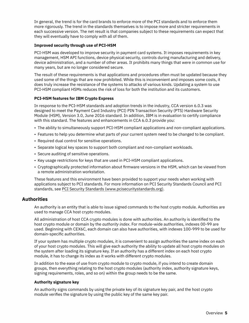
In general, the trend is for the card brands to enforce more of the PCI standards and to enforce themmore rigorously. The trend in the standards themselves is to impose more and stricter requirements ineach successive version. The net result is that companies subject to these requirements can expect thatthey will eventually have to comply with all of them.
Improved security through use of PCI-HSM
PCI-HSM was developed to improve security in payment card systems. It imposes requirements in keymanagement, HSM API functions, device physical security, controls during manufacturing and delivery,device administration, and a number of other areas. It prohibits many things that were in common use formany years, but are no longer considered secure.
The result of these requirements is that applications and procedures often must be updated because theyused some of the things that are now prohibited. While this is inconvenient and imposes some costs, itdoes truly increase the resistance of the systems to attacks of various kinds. Updating a system to usePCI-HSM compliant HSMs reduces the risk of loss for both the institution and its customers.
PCI-HSM features for IBM Crypto Express
In response to the PCI-HSM standards and adoption trends in the industry, CCA version 6.0.3 wasdesigned to meet the Payment Card Industry (PCI) PIN Transaction Security (PTS) Hardware SecurityModule (HSM), Version 3.0, June 2016 standard. In addition, IBM is in evaluation to certify compliancewith this standard. The features and enhancements in CCA 6.0.3 provide you:
• The ability to simultaneously support PCI-HSM compliant applications and non-compliant applications.• Features to help you determine what parts of your current system need to be changed to be compliant.• Required dual control for sensitive operations.• Separate logical key spaces to support both compliant and non-compliant workloads.• Secure auditing of sensitive operations.• Key usage restrictions for keys that are used in PCI-HSM compliant applications.• Cryptographically protected information about firmware versions in the HSM, which can be viewed from
a remote administration workstation.
These features and this environment have been provided to support your needs when working withapplications subject to PCI standards. For more information on PCI Security Standards Council and PCIstandards, see PCI Security Standards (www.pcisecuritystandards.org).
AuthoritiesAn authority is an entity that is able to issue signed commands to the host crypto module. Authorities areused to manage CCA host crypto modules.
All administration of host CCA crypto modules is done with authorities. An authority is identified to thehost crypto module or domain by the authority index. For module-wide authorities, indexes 00-99 areused. Beginning with CEX6C, each domain can also have authorities, with indexes 100-999 to be used fordomain-specific authorities.
If your system has multiple crypto modules, it is convenient to assign authorities the same index on eachof your host crypto modules. This will give each authority the ability to update all host crypto modules onthe system after loading its signature key. If an authority has a different index on each host cryptomodule, it has to change its index as it works with different crypto modules.
In addition to the ease of use from crypto module to crypto module, if you intend to create domaingroups, then everything relating to the host crypto modules (authority index, authority signature keys,signing requirements, roles, and so on) within the group needs to be the same.
Authority signature key
An authority signs commands by using the private key of its signature key pair, and the host cryptomodule verifies the signature by using the public key of the same key pair.
Overview 5

Beginning with the CEX5C, authority signature keys can be either RSA keys or ECC keys. For prior CCAcrypto modules, only RSA authority signature keys are supported. The public exponent of RSA authoritysignature keys is always 65537 and the public key is identified by just the modulus.
Before signing and verifying command signatures, the signature key pair must be generated and thepublic key sent to the host crypto module.
1024-bit, 2048-bit, and 4096-bit RSA authority signature keys can be saved to key storage or binary files.1024-bit and 2048-bit RSA authority signature keys and BP-320 ECC authority signature keys can besaved to smart cards.
Note: For authority indexes in the range 100 to 999, the associated signature key must reside on a smartcard and must be either a 2048-bit RSA key or a 320-bit ECC key.
Authority default signature key
During the crypto module initialization, the public key of a default signature key pair is loaded into thehost crypto module. The private key of the default signature key pair is known to the TKE workstation andused until valid authority signature keys are generated and made known to the host crypto module. Youare able to reload the public key of a default signature key pair to the host crypto module.
For all crypto module types, a default authority with index 0 is created on the crypto module when it ismanufactured or reinitialized. Starting with the CEX6C, a default authority with index 99 is created at thesame time as the default authority with index 0. The default authority for index 0 uses a 1024-bit RSA key.The default authority for index 99 uses a 512-bit Brainpool ECC key. In future crypto modules, the defaultauthority with index 0 will no longer be created and users will need to use the default authority with index99 for initial setup. The default authorities with index 0 and 99 are module-wide authorities.
Also, starting with the CEX6C, a default authority with index 100 is created when a domain enters imprintmode. This default authority is a domain-specific authority and is used to create extra domain-specificauthorities and their associated roles for administering a domain in PCI-compliant mode. The defaultauthority with index 100 also uses a 512-bit Brainpool ECC signature key.
Roles
Each authority has an associated role, which specifies what signed commands the authority can issue orco-sign and what domains the authority can change.
When segments 2 and 3 of a CCA host crypto module are loaded for the first time, or when ownership ofsegments 2 and 3 is surrendered and the segments are reloaded, an initial authority with index 00 iscreated. This authority is assigned the INITADM role, which is created at the same time. The INITADM roleallows the authority to create, change, and delete authorities and roles.
Roles are not supported on EP11 host crypto modules.
Administrators
An administrator is another entity that is able to issue signed commands to a host crypto module.Administrators manage EP11 host crypto modules.
Because EP11 host crypto modules use a different architecture than CCA host crypto modules, theadministration is different. Administrative commands to a EP11 host crypto module can be signed by upto eight administrators. The exact number of signatures required depends on the specific command, thetarget of the command, and the crypto module or domain attributes set by the user.
Administrators are represented in a EP11 host crypto module as an X.509 certificate containing anadministrator name (up to 30 characters) and the public part of an ECC signature key. The signature keypair is stored on a smart card, which must be inserted in a smart card reader for commands to be signed.
The concepts of authority index and signature key index are not used when managing EP11 host cryptomodules. Panels for managing administrators display the administrator name and a 32-byte Subject KeyIdentifier, which is a hash of the public part of the signature key. EP11 host crypto modules identifyadministrators using the Subject Key Identifier. The ability to specify an administrator name is provided asa usability feature. Users are strongly encouraged to assign meaningful, unique names for each
6 z/OS: Cryptographic Services ICSF Trusted Key Entry Workstation User's Guide

administrator signature key created, but this is not required. Both the administrator name and the SubjectKey Identifier are written to audit records when commands are signed.
Administrator signature keys are 320-bit Brainpool ECC keys. Administrator signature keys cannot besaved to key storage or to binary files.
Crypto module OA signature keyHost crypto modules sign replies to the TKE workstation using a special OA signature key.
The type of OA signature key depends on the type of host crypto module:
• For the CEX2C, the OA signature key is a 1024-bit RSA key.• For the CEX3C, CEX4C, and CEX4P, the OA signature key is a 4096-bit RSA key.• For the CEX5C, CEX5P, CEX6C, and CEX6P, the OA signature key is a P521 ECC key.
When a host crypto module is manufactured, a random RSA or ECC key pair, known as the device key, isgenerated. The public part of the key is exported and is incorporated into a device key certificate. Thecertificate is signed by an IBM Class Root key. This certificate validates that the host crypto module wasmanufactured by IBM.
As code is loaded into segments 1, 2, and 3 of the host crypto module, additional keys and certificates aregenerated, forming a certificate chain based on the IBM Class Root key and the crypto module device keycertificate.
The crypto module OA signature key is the final key in this chain. The process of validating the signatureon a reply, and retrieving and validating the certificates in the chain, is known as Outbound Authentication(OA).
When TKE connects to a host, it queries the attached crypto modules. If a new Crypto-Module ID isdiscovered, TKE fetches the OA certificate chain for the crypto module and verifies it ends with acertificate signed by the IBM Class Root key. TKE displays the Crypto-Module ID and asks the user toaccept or reject the crypto module. If the user accepts the crypto module, TKE saves the public part of thecrypto module OA signature key and uses it to validate all future signed replies from the crypto module.
Command signaturesThe number of signatures required on commands to a host crypto module depends on the host cryptomodule type.
Command signatures for CCA host crypto modules
All commands to CCA host crypto modules are signed. Depending on the command and the setup, thecommand is either executed immediately or is pending (waiting to be co-signed by other authoritiesbefore being executed). Commands requiring more than one signature are called dual-signaturecommands.
The following single-signature commands deal with master key management and disabling the hostcrypto module:
• Clear old master key (DES, AES, RSA, or ECC (APKA))• Clear new master key (DES, AES, RSA, or ECC (APKA))• Load/combine new master key parts (DES, AES, RSA, or ECC (APKA))• Set master key (RSA master key only)• Set master key, immediate (DES, AES, RSA, or ECC (APKA))• Disable crypto module
The dual-signature commands always require two signatures. These commands deal with:
• Access Control• Zeroize Domain
Overview 7

• Enable Crypto Module• Domain Controls• Domain Mode Transitions
The single-signature commands for operational keys are:
• Load first key part (DES or AES)• Load additional key part (DES or AES)• Complete key (DES or AES)• Clear operational key register (DES or AES)
Command signatures for EP11 host crypto modules
Commands to EP11 host crypto modules require up to eight signatures. The number of requiredsignatures depends on the specific command, the target of the command, and the crypto module ordomain attributes set by the user.
If the EP11 host crypto module or the target domain is in imprint mode, no command signatures arerequired, but only a limited subset of administrative commands can be executed. (See “Imprint mode” onpage 210 for more information.) Otherwise, the number of required signatures depends on the commandtype and on the signature threshold and revocation signature threshold attributes set by the user for thehost crypto module or target domain.
The following commands to EP11 host crypto modules require a single signature, regardless of how thesignature threshold is set:
• Generate IMPORTER key• Load new master key• Clear new master key• Clear current master key
The following commands require up to eight signatures, depending on how the signature threshold orrevocation signature threshold attributes are set:
• Add administrator• Remove administrator• Commit master key• Set attributes• Enable Crypto Module• Disable Crypto Module
The following commands can be configured to either require a single signature or require the number ofsignatures specified by the signature threshold:
• Set control points• Zeroize domain• Zeroize crypto module
Key-exchange protocolTKE provides a Diffie-Hellman key-exchange protocol that permits an authority to set up a transport keybetween the workstation and the host crypto module. One or more key parts can then be encrypted underthe transport key.
8 z/OS: Cryptographic Services ICSF Trusted Key Entry Workstation User's Guide

Domain controls and domain control pointsDomain controls (CCA host crypto modules) and domain control points (EP11 host crypto modules)enable or restrict the cryptographic capabilities of a particular domain. Your installation should considerthe ramifications of various implementations.
Domain modesBeginning with the CEX6C crypto module, the domains of a crypto module can exist in various modes ordistinct operational states. These modes support setting up a domain for PCI-compliant operation,running PCI-compliant applications, and converting non-compliant key tokens into PCI-compliant keytokens.
There are three main domain modes:Normal mode
The legacy state of a domain. Domains on crypto modules before the CEX6C exist in what is callednormal mode on the CEX6C crypto module. After a domain is zeroized, it reverts to normal mode.Module-wide roles and authorities are used to administer domains in normal mode.
Imprint modeUsed to create the domain-specific roles and authorities that are needed to administer a domain forPCI-compliant operation. When a domain enters imprint mode, a default domain-specific role andauthority with index 100 are created. The default authority uses a default signature key whose privatepart is known to the TKE workstation. The default role and authority can be used to create otherdomain-specific roles and authorities for administering the domain in PCI-compliant mode. Mostother administrative actions are prohibited in imprint mode.
PCI-compliant modeAfter a set of domain-specific roles and authorities is created in imprint mode, the domain can moveto PCI-compliant mode. The transition to PCI-compliant mode deletes the default authority if it stilluses the default signature key. PCI-compliant mode operations that use PCI-compliant key tokens areallowed. In both imprint mode and PCI-compliant mode, only domain-specific roles and authoritiesfor the domain can be used to run administrative commands to the domain.
PCI-compliant mode was designed to meet the security requirements of the Payment Card Industry (PCI)PIN Transaction Security (PTS) Hardware Security Module (HSM) standard, Version 3.0, dated June 2016.IBM is in evaluation to certify compliance with this standard. On future IBM host crypto modules,additional compliance modes may be supported.
Applications that use non-compliant key tokens can run in all domain modes, but applications that usePCI-compliant key tokens can run only in PCI-compliant mode.
To convert non-compliant key tokens to PCI-compliant key tokens, a fourth domain mode is supportedwhich is a sub-mode of PCI-compliant mode. This mode is described as PCI-compliant mode, keymigration allowed on the Domain General page. In this mode, applications that are running on the hostare permitted to re-encipher the secret key in key tokens by using the effective master key for PCI-compliant mode and mark the key token as PCI-compliant. Only key tokens that contain DES operationalkeys can be marked as PCI-compliant. A TKE workstation is required to enable this sub-mode and whilethis mode is active, PCI-compliant key tokens cannot be used by applications.
Note: This sub-mode can be explicitly disabled, or it automatically ends if no non-compliant key tokensare converted to PCI-compliant key tokens in the last 30 minutes. If automatically disabled, in order tosee the mode change on the TKE workstation, the crypto module notebook must be refreshed by usingthe Refresh Notebook option on the function menu.
TKE operational considerationsThe TKE workstation can manage CEX2C, CEX3C, CEX4C, CEX4P, CEX5C, CEX5P, CEX6C, and CEX6Pcrypto modules attached to a Z host.
Overview 9

Logically partitioned (LPAR) mode considerationsWhen you activate a logical partition, you can prepare it for running software products that work withsupported host crypto modules. These supported crypto modules can be shared among several ProcessorResource/Systems Manager (PR/SM) logical partitions, provided unique domains are assigned to eachLPAR.
When you run in LPAR mode, each logical partition can have its own master keys, CKDS, PKDS, and TKDS.
When you activate a logical partition, you prepare it for being a TKE host or a TKE target. For details, referto Appendix B, “LPAR considerations,” on page 323.
Multiple hostsOne TKE workstation can be connected to several hosts. Each host connection will have a uniquetransport key, which is used to protect any key material sent over the connection.
Multiple TKE workstationsSeveral users on different TKE workstations can have sessions with one host simultaneously. Whenever auser attempts to work with a host crypto module, the system checks to determine whether another user isworking with that module. The first user has a reserve on the host crypto module. All other users open thehost crypto module in read-only mode until either:
• The first user releases the host crypto module by closing the notebook.• A user in read-only mode forces the release of the crypto module using the Release Crypto Module
function from within the notebook.
Defining your security policyEach installation should have its own unique policies. These policies should be documented in a securityplan. Security officers should periodically review their corporate security policy and their current keymanagement system.
The security plan might include these areas:
• General
– How many security officers does your organization have?– How often is the master key changed?– Who is authorized to enter master key parts?– Do the key parts you enter from the keyboard need to be masked?– Who has access to the secure computer facility?– What are the policies for working with service representatives?– Will you be using smart card support?
• Workstation Considerations
– Who will use the TKE workstation?– Where will your workstation be located?– Is it only accessible to the security administrators or security officers?– How many workstations will there be?– Will you use group logon?– Who will backup the workstations?– Where will the passwords of the security officers be saved?
• Command Considerations
10 z/OS: Cryptographic Services ICSF Trusted Key Entry Workstation User's Guide

– Which commands require multiple signatures?– Which crypto modules should be grouped together?– How many signatures will be required?– Will this affect the availability of the system?– Which commands require a single signature?– Who will make these decisions?
TKE enablementA support element is a dedicated workstation used for monitoring and operating Z hardware. TKEcommands must be permitted on the Support Element before any commands issued by the TKEworkstation can be executed.
For CCA crypto modules the default setting for TKE Commands is Denied. The setting must be changed toPermitted before the TKE workstation can be used to manage the crypto module.
For EP11 crypto modules, only a TKE workstation can perform certain management functions, so thesetting is always shown as Permitted on the Support Element.
If TKE commands are not permitted on the Support Element, the following Details Error is displayed onthe TKE Workstation when an attempt is made to open the Host ID:
Error Message: Program CSFPCIX InterfaceError Type 2Return Code 12Reason Code 2073
Detail Message "The Crypto Coprocessor has been disabled on the Support Element. It must be enabled on the Support Element before TKE can access it."
An authorized user can permit TKE commands on the Support Element, using the Support ElementConsole Application. For more information, see the help files that are provided with the Support Element.
Note: A global zeroize issued from the Support Element returns the state of TKE Commands to the defaultvalue of Denied for CCA host crypto modules.
Trusted Key Entry consoleThe Trusted Key Entry Console automatically loads on start up with a set of commonly used tasks. Theconsole is shipped with several predefined console user names. Your first logon is with the console username.
Most tasks require an additional logon to the TKE workstation crypto adapter. You log on with your TKEworkstation crypto adapter profile. The profile is defined for your workstation when TKE is configured andcustomized.
At start up, you are logged in with the default user name TKEUSER. The user names determine theapplications and utilities that can be run during the console session. The predefined console user namesare:
• TKEUSER -- default console user name.• ADMIN -- provides access to administrative functions, such as migration utilities, the code load utility,
and the crypto adapter initialization utility.• AUDITOR -- provides access to audit functions, such as the Audit Configuration Utility, the Audit Record
Upload Configuration Utility, and utilities to view and archive security logs.• SERVICE -- provides access to service functions, such as managing the console code level, setting the
date and time, and saving upgrade data.
Overview 11

The ADMIN, AUDITOR, and SERVICE console user names require a password when logging on theconsole. The default TKEUSER console user name may optionally require a password. See “Passwordprotect console” on page 365 for more information.
Appendix E, “Trusted Key Entry applications and utilities,” on page 333 describes the applications andutilities available to each console user name.
After starting the TKE console, the initial Trusted Key Entry Console panel appears.
Figure 1: TKE Console - initial panel
This initial panel provides access to applications and utilities that are available when you are using thedefault TKEUSER console user name.
• Clicking Trusted Key Entry provides access to the main TKE window, the Smart Card Utility Program,the Cryptographic Node Management Utility, and other commonly used applications and utilities.
• Clicking Service Management provides access to service functions, such as locking, shutting down, orrestarting the console.
• Clicking Status Bar displays the current status of the TKE Hardware.
When it is necessary to log on to the TKE console using a different user name, for example, ADMIN,AUDITOR or SERVICE, close this panel by clicking the X in the upper right corner. The Trusted Key EntryConsole pre-login panel appears.
12 z/OS: Cryptographic Services ICSF Trusted Key Entry Workstation User's Guide

Figure 2: TKE Console - pre-login panel
Clicking Launch the Trusted Key Entry Console web application, starts a console session using thedefault TKEUSER console user name. It returns you to the initial panel.
Clicking view the online help opens an IBM help window. You can navigate to the help information for theTKE panels.
Clicking Privileged Mode Access displays a logon panel. You can log on as any of the following privilegedmode access user IDs: AUDITOR, ADMIN, SERVICE.
Figure 3: Log on with other privileged mode access console user names
Overview 13

Fill in the user name field with one of the following:
• ADMIN - the default password is PASSWORD• AUDITOR - the default password is PASSWORD• SERVICE - the default password is SERVMODE
After logging on with the new user name, an initial panel appears. In the upper-right corner, to the left ofthe word Help, the privileged mode access id is displayed. This initial panel provides access toapplications and utilities when you are using a console user name. It is identical to the TKEUSER initialpanel with the same options:
• Clicking Trusted Key Entry provides access to the applications and utilities available with the consoleuser name you used to log on.
• Clicking Service Management provides access to service functions available with the console username you used to log on.
• Clicking Status Bar displays the current status of the TKE Hardware.
Figure 4: Trusted Key Entry for ADMIN - categorized
The Trusted Key Entry console message bar can contain three types of status messages to the left of theword Help:
• Privileged Mode Access ID is displayed if the console user is logged on as a privileged mode accessuser.
• Crypto Adapter Logon ID is displayed when the user of a TKE application is logged on to the CryptoAdapter.
14 z/OS: Cryptographic Services ICSF Trusted Key Entry Workstation User's Guide

• Smart Card Readers Locked By is displayed when a TKE application has a lock on the smart cardreaders.
Guideline: After you log in the first time, change the password with the Change Password task. See“Change password ” on page 354.
Trusted Key Entry console navigationWhen the TKE console initially comes up it consists of a navigation area on the left side and a Welcomepage on the right side. The navigation area contains links to the Trusted Key Entry and ServiceManagement categories. The Welcome page displays a brief description of these categories and a link towhere the TKE Workstation User's Guide can be accessed. When clicking on the Trusted Key Entry andService Management categories, a list of tasks and utilities will be displayed on the right side of your TKEconsole.
There are three presentation options:
• Detail (the way things are shown in the screen shots).• Icon (looks similar to icons on a desktop).• Tile (looks similar to the Icon view).
Each Category can be displayed in two different views, alphabetical and categorized. The categorized viewfor Trusted Key Entry contains the sub categories Applications and Utilities. The alphabetical view allowsa user to display all tasks, uncategorized, in a flat alphabetized list. A user can select either theAlphabetical or Categorized Link at the top of the window to change the view.
Figure 5: Service Management – No Privileged Mode Access
Overview 15

TKE workstation crypto adapter roles and profilesThis information describes how the roles and profiles on the TKE workstation crypto adapter are used tocontrol access to the TKE applications and the cryptographic services on the adapter.
Roles and profiles are placed on a TKE workstation crypto adapter when you:
• Run the TKE Crypto Adapter Initialization application to initialize the adapter for use with smart card orpassphrase profiles. This application loads system-supplied roles and profiles onto the adapter.
• Explicitly load roles and profiles onto the adapter through the Cryptographic Node Management Utility.
Every profile must have a role. Each role contains a list of Access Control Points (ACPs) in its permittedoperations list. The list of permitted operations in a role determines what a profile with the role is allowedto do.
When a user signs onto the TKE workstation crypto adapter, the profile and its associated role become theadapter’s current profile and current role. All the authority checks are done against the current role.
There is always a current role in effect.
• If you are explicitly signed on to TKE, the profile and its role became the current profile and current rolewhen you signed on.
• If you are not explicitly signed on to TKE, there is no current profile. However, there is a default currentrole. This is only valuable if you have also signed onto the TKE in Privileged Access Mode.
Authority checking on the TKEEvery time a TKE application is started, an authority check is done. The following describes the basic teststhat are done:
• Is there a current profile?
– NO: Present a logon screen. Only profiles with roles that have enough authority to start theapplication are presented on the logon screen.
– YES: Does the current role have the necessary ACPs to start the application?
- YES: The application is started.- NO: The user is given the option to log off and be presented with a new logon screen. Only profiles
with roles that have enough authority to start the application are presented on the logon screen.
Every time a cryptographic service on the TKE workstation crypto adapter is attempted, an authoritycheck is done to determine if the current role has the required ACP to perform the cryptographic service.If the role has the ACP, the operations will be done. If not, the operation will not be performed.
Types of profilesA TKE workstation crypto adapter supports 3 types of profiles:
• Passphrase Profiles: A profile that requires the user to provide the correct passphrase during theauthentication process.
• Smart Card Profiles: A profile that requires the user to have the correct crypto adapter logon key on asmart card during the authentication process. In addition, the user must know the PIN number of thesmart card that has the logon key.
• Group Profiles: A profile designed to require a specific number of people to sign on to their individualprofiles before the logon process for the group profile is complete. The following characteristics apply togroup profiles:
– A group profile has a set of 1 to 10 members.– A group member is an individual passphrase or smart card profile that must exist when the group
profile is created.
16 z/OS: Cryptographic Services ICSF Trusted Key Entry Workstation User's Guide

– All the members of a group profile must be the same type, either passphrase or smart card.– A group profile contains an attribute that defines how many people must sign on before the group
logon is complete. The number is a value between 1 and the total number of members of the group.– A group profile has a role. Normally the group’s role is more powerful than the roles given to each
individual group member.
A TKE workstation crypto adapter can contain all types of profile at the same time:
• Passphrase profiles• Smart card profiles• Group profiles with passphrase profile members• Group profiles with smart card profile members
For instructions on creating or changing roles and profiles, refer to Chapter 11, “Cryptographic NodeManagement utility (CNM),” on page 251.
Initializing a TKE workstation crypto adapterThis information describes how to initialize a TKE workstation crypto adapter.
Rule: The user must be logged on to the TKE Workstation console through Privileged Mode Access asADMIN to initialize a TKE workstation crypto adapter.
Initial adapter conditions
Before you can start to use your TKE workstation, the crypto adapter must meet the following conditions:
• It must have the correct CCA level of code.• The Function Control Vector must be loaded.
Initial adapter conditions on new TKE workstations
Every TKE workstation comes with a cryptographic adapter. The following steps should have beenperformed before the adapter was shipped with the TKE workstation:
• The proper level of CCA code was loaded onto the TKE workstation crypto adapter. Specific releases ofCCA are associated with specific releases of TKE.
Table 1: CAA code loaded for specific releases of TKE
TKE Release CCA Release
TKE 5.3 CCA 3.4
TKE 6.0 CCA 3.5
TKE 7.0 CCA 4.1
TKE 7.1 CCA 4.2
TKE 7.2 CCA 4.3
TKE 7.3 CCA 4.4
TKE 8.0 CCA 5.0
TKE 8.1 CCA 5.2
TKE 9.0 CCA 6.0
TKE 9.1 CCA 6.1
• The Function Control Vector (FCV) was loaded onto the TKE workstation crypto adapter.
Notes:
Overview 17

1. During the process of loading the CCA code and the FCV, the card was initialized for use withpassphrase profiles. The system-supplied roles and profiles might still be on the adapter.
2. Beginning in 7.2, every time a TKE application is opened, a check is done to make sure that the TKEworkstation has the correct level of CCA code. If not, a message tells you to reload the CCA codeonto the adapter.
Initial adapter conditions on upgraded TKE workstations
When you upgrade an existing TKE workstation to a new level of TKE, the upgrade process states:
• You must go into the CCA CLU utility and load the new CCA code onto your TKE workstation cryptoadapter. The CLU utility can only be accessed through Privileged Mode Access by a user logged onto theTKE Workstation console as ADMIN.
• You might have to load a new Function Control Vector onto your TKE workstation crypto adapter. TheInstallation Instructions for your upgrade will tell you if this is required.
Verify current crypto adapter settings
You can check the state of the TKE workstation crypto adapter at any time using the following utilities.
• You can determine the CCA level by running the Check Coprocessor Status command from the CCACLU utility. (To access the CCA CLU utility you must log on to the TKE Workstation console throughPrivileged Access Mode as ADMIN.)
• You can determine if the FCV is loaded by pressing the “export control” button on the Crypto Node ->Status screen in the Cryptographic Node Management (CNM) utility.
• You can determine if there are any roles on the adapter by looking at the Access Control –Roles screenin the CNM utility.
• You can determine if there are any roles on the adapter by looking at the Access Control –Profilesscreen in the CNM utility.
System-supplied roles and profiles on TKE workstation crypto adapters:
The TKE provides an initial set of system-supplied roles and profiles based on whether you intend to usepassphrase or smart card profiles. Prior to initializing your TKE workstation crypto adapter, you mustdecide if you want to sign on to the adapter using passphrase profiles, smart card profiles, or both types ofprofiles.
Guideline: Use smart card profiles whenever possible. They provide the highest level of security.
Once you have decided what type of profiles you will use, you need to initialize the TKE workstation cryptoadapter for use with those kinds of profiles. The initialization is done through the TKE Crypto AdapterInitialization application. To start this application you must be logged on as ADMIN through PrivilegedMode Access. When you start this application, you are asked:
Would you like to prepare your cryptographic coprocessor for Smart Card or Pass Phrase use?
Guidelines: Make your choice following these guidelines:
• Select “s”, smart card if you will use smart card profiles exclusively.• Select “p”, pass phrase, if you will use passphrase profiles exclusively.• Select “p”, pass phrase if you will use a combination of pass phrase and smart card profiles.
Initializing for use with smart card profiles
When you initialize a TKE workstation crypto adapter for use with smart card profiles, the followingsystem-supplied roles and profiles will be created:
• System-supplied roles:
18 z/OS: Cryptographic Services ICSF Trusted Key Entry Workstation User's Guide

DEFAULTIntended for use during the migration process or initial setup of the roles and smart card profiles onthe TKE.
SCTKEADMIntended for use with customer-defined smart card profiles. The role is designed to provide theauthority to manage the TKE.
SCTKEUSRIntended for use with customer-defined smart card profiles. The role is designed to provide theauthority to manage host cryptographic modules.
TKEGRPMBIntended for use by members of a group profile. Has the minimum required authority. When loggingon as a group, the role for each member is ignored. Once the group logon completes, the role for thegroup profile controls what operations are allowed.
• System-supplied profiles:None
No system-supplied smart card profiles are provided by the TKE.
Initializing for use with passphrase profiles
When you initialize a TKE workstation crypto adapter for use with passphrase profiles, the followingsystem-supplied roles and profiles will be created:
• System-supplied roles:DEFAULT
Intended for use during the migration process or initial setup of the roles and smart card profiles onthe TKE.
TKEADMIntended for use with system-supplied and customer-defined passphrase profiles. The role isdesigned to provide the authority to manage the TKE.
TKEUSERIntended for use with system-supplied and customer-defined passphrase profiles. The role isdesigned to provide the authority to manage host crypto modules.
KEYMAN1Intended for use with the system-supplied passphrase profile KEYMAN1. The role is designed toprovide users authority to clear the TKE crypto adapter new master key register and load firstmaster key parts.
KEYMAN2Intended for use with the system-supplied passphrase profile KEYMAN2. The role is designed toprovide users authority to load any middle and last master key parts to the TKE crypto adapter newmaster key register, set the master key and reencipher key storage.
TKEGRPMBIntended for use by members of a group profile. Has the minimum required authority. When loggingon as a group, the role for each member is ignored. Once the group logon completes, the role for thegroup profile controls what operations are allowed.
• System-supplied profiles:TKEADM
Intended for a person with the responsibility of initially setting up a TKE, completing migrationtasks, or managing the TKE.
TKEUSERIntended for a person with the responsibility of managing host crypto modules.
KEYMAN1Intended for a person with the responsibility to clear the TKE crypto adapter new master keyregister and load first master key parts.
Overview 19

KEYMAN2Intended for a person with the responsibility to load any middle and last master key parts to the TKEcrypto adapter new master key register, set the master key and reencipher key storage.
Roles and profiles definition filesFiles can be created that contain enough information to create or update roles and profiles on a TKEworkstation crypto adapter. These are called role definition files and profile definition files. Definition filescan be stored on the TKE workstation’s hard drive or on removable media. The files can be used to createor update roles and profiles in the following instances:
• The TKE workstation crypto adapter is initialized.• Migration is being done.• Recovery is being done.
Definition files and their corresponding role or profile might or might not be synchronized. The followingtable shows all of the possible relationships.
Table 2: Definition files and their corresponding role or profile
Role or profile definition fileexists
Corresponding role or profileexists on TKE workstationcrypto adapter
File attributes equal adapter’sattributes
Yes Yes Yes
Yes Yes No
Yes No N/A
No Yes N/A
Role definition files
A role definition file contains enough information to create or replace a role on a TKE workstation cryptoadapter. The file contains the following information:
• Role name.• Comment field.• Required Authentication Strength. Only applies to passphrase profiles with the role.• Valid times a user with the role can use the TKE.• Permitted operations list. The list of capabilities a profile with the role is allowed to use.
All system-supplied roles have corresponding system-supplied role definition files. When you create arole, you can also create a corresponding role definition file for the role.
System-supplied role definition files
The TKE comes with system-supplied role definition files for each of the system-supplied roles that canbe created on a TKE. When a TKE workstation crypto adapter is initialized, the system-supplied roles arecreated from the system-supplied definition files.
Guideline: To preserve the ability to restore system-supplied roles to their default settings, do not updatesystem-supplied role definition files.
Passphrase roles
When a TKE workstation crypto adapter is initialized for use with passphrase profiles, six roles arecreated. The following table shows the names of the system-supplied role definition files that are used tocreate the roles.
20 z/OS: Cryptographic Services ICSF Trusted Key Entry Workstation User's Guide

Table 3: System-supplied role definition files for passphrase roles
TKERelease DEFAULT KEYMAN1 KEYMAN2 TKEADM TKEUSER
TKEGRPMB(non-modifiable)
TKE 5.0 to6.0
default.rol keyman1.rol keyman2.rol tkeadm50.rol tkeuser42.rol N/A
TKE 7.0 default_70.rol
keyman1_70.rol
keyman2_70.rol
tkeadm_70.rol
tkeusr_70.rol N/A
TKE 7.1 default_71.rol
keyman1_71.rol
keyman2_71.rol
tkeadm_71.rol
tkeusr_71.rol N/A
TKE 7.2 default_72.rol
keyman1_72.rol
keyman2_72.rol
tkeadm_72.rol
tkeusr_72.rol N/A
TKE 7.3 default_73.rol
keyman1_73.rol
keyman2_73.rol
tkeadm_73.rol
tkeusr_73.rol N/A
TKE 8.0 default_80.rol
keyman1_80.rol
keyman2_80.rol
tkeadm_80.rol
tkeusr_80.rol N/A
TKE 8.1 default_81.rol
keyman1_81.rol
keyman2_81.rol
tkeadm_81.rol
tkeuser_81.rol
tkegrpmb_81.rol
TKE 9.0 default_90.rol
keyman1_90.rol
keyman2_90.rol
tkeadm_90.rol
tkeusr_90.rol tkegrpmb_90.rol
TKE 9.1 default_91.rol
keyman1_91.rol
keyman2_91.rol
tkeadm_91.rol
tkeusr_91.rol tkegrpmb_91.rol
Note: Beginning in TKE 7.0, release-specific system-supplied role definition files were shipped with theTKE workstation.
Smart card roles
When a TKE workstation crypto adapter is initialized for use with smart card profiles, four roles arecreated. The following table shows the names of the system-supplied role definition files that are used tocreate the roles.
Table 4: System-supplied role definition files for smart card roles
TKE Release DEFAULT SCTKEADM SCTKEUSRTKEGRPMB (non-modifiable)
TKE 5.0 to 6.0 tempdefault.rol sctkeadm50.rol sctkeusr.rol N/A
TKE 7.0 tempdefault_70.rol sctkeadm_70.rol sctkeusr_70.rol N/A
TKE 7.1 tempdefault_71.rol sctkeadm_71.rol sctkeusr_71.rol N/A
TKE 7.2 tempdefault_72.rol sctkeadm_72.rol sctkeusr_72.rol N/A
TKE 7.3 tempdefault_73.rol sctkeadm_73.rol sctkeusr_73.rol N/A
TKE 8.0 tempdefault_80.rol sctkeadm_80.rol sctkeusr_80.rol N/A
TKE 8.1 tempdefault_81.rol sctkeadm_81.rol sctkeusr_81.rol tkegrpmb_81.rol
TKE 9.0 tempdefault_90.rol sctkeadm_90.rol sctkeusr_90.rol tkegrpmb_90.rol
TKE 9.1 tempdefault_91.rol sctkeadm_91.rol sctkeusr_91.rol tkegrpmb_91.rol
Note: Beginning in TKE 7.0, release-specific system-supplied role definition files were shipped with theTKE workstation.
Overview 21

Customer-defined role definition files
You can create your own roles on your TKE’s local crypto adapter. When you create a role, an associateddefinition file is not automatically created. You must explicitly create the definition file.
Guidelines: Follow these guidelines for creating customer-defined roles:
• Create role definition files for your customer-defined roles. These files can be used for recovery ormigration purposes if necessary.
• Use the file naming convention “role_name.rol”.• When you update a role on the TKE’s local crypto adapter, make the same change to the associateddefinition file. Remember, the definition file is not automatically updated when you make a change to arole.
For Instructions on creating or changing role definition files, refer to Chapter 11, “Cryptographic NodeManagement utility (CNM),” on page 251.
Profile definition files
A profile definition file contains enough information to create or replace a profile on a TKE local cryptoadapter. The file contains the following information:
• Profile Name• Comment field• Activation and deactivation dates• Role• For passphrase profiles, the passphrase and passphrase expiration date for the profile.• For smart card profiles, the public modulus of the crypto adapter logon key for the profile.
All system-supplied profiles have a corresponding system-supplied profile definition files. When youcreate your own profiles, they can also create a corresponding profile definition file for the profile.
System-supplied profile definition files
The TKE comes with system-supplied profile definition files for each of the system-supplied profiles thatcan be created on a TKE. When a TKE workstation crypto adapter is initialized, the system-suppliedprofiles are created from the system-supplied definition files. Profiles do not change between releases ofTKE. The definition file names are the same in each release of the TKE.
To preserve the ability to restore system-supplied profiles to their default settings, including the defaultpasswords, do not update system-supplied profile definition files.
Passphrase profiles: When a TKE workstation crypto adapter is initialized for use with Passphrase profiles,four profiles are created using their system-supplied profiles definition files. The following table showsthe profiles and the definition files used to create them:
Table 5: System-supplied profile definition files for passphrase profiles
Profile Definition File
TKEADM tkeadm.pro
TKEUSER tkeuser.pro
KEYMAN1 keyman1.pro
KEYMAN2 keyman2.pro
Smart card profiles: No profiles are created when the TKE workstation crypto adapter is initialized for usewith smart card profiles.
22 z/OS: Cryptographic Services ICSF Trusted Key Entry Workstation User's Guide

Customer-defined profile definition files
You can create your own profiles on your TKE workstation crypto adapter. When you create a profile anassociated definition file is not automatically created. You must explicitly create the definition file.
Guidelines: Follow these guidelines for creating customer-defined profiles:
• Create profile definition files for your customer-defined profiles. These files can be used for recovery ormigration purposes if necessary.
• Use the file naming convention “profile_name.pro”.• When you update a profile on the TKE workstation crypto adapter, make the same change to the
associated definition file. Remember, the definition file is not automatically updated when you make achange to a profile.
For instructions on creating or changing profile definition files, refer to Chapter 11, “Cryptographic NodeManagement utility (CNM),” on page 251.
System-supplied role access control points (ACPs)The primary purpose of any role is to define the capabilities of a user with the role. Each role has a list ofpermitted operations, also called access control points (ACPs), which define the capabilities of the user.
ACP considerations for user-defined roles
There are many cryptographic services the TKE uses during normal operation which the user is not awareof. To use these services, the user’s role must contain the appropriate list of ACPs in its “permittedoperations” list. If you are going to create user-defined roles, it is difficult to know what cryptographicservices will be used by your target users. Therefore, selecting the correct list of ACPs is difficult.
Guideline: If you are going to create roles, use one of the following system-supplied roles as the basis foryour new role.
• TKE workstation crypto adapter initialized for passphrase profile use:
– TKEUSER– TKEADM
• TKE workstation crypto adapter initialized for smart card profile use:
– SCTKEUSR– SCTKEADM
ACPs assigned to system-supplied roles
The following tables show the ACPs that are assigned to each of the system-supplied roles.
Note:
• Beginning in TKE 7.1, the ACP "TKE USER, X'8002’" is no longer used. This ACP was replaced with moregranular access control checking. The new ACPs that are checked are ACPs X'1000' through X'100E'.
• Beginning with TKE 8.0, TKE supports a USB-attached printer. To print files, the X'1010' (print files) ACPmust be enabled. This ACP is not enabled by default in any system-supplied role.
• Beginning with TKE 8.1:
– To copy a key part that is stored in a binary file to a smart card, the X'1011' (Copy binary file key partto smart card) ACP must be enabled.
– To invoke from the TKE workstation an ICSF function that coordinates the setting of one or moremaster keys with the updating of key storage on a host system, the X'1012' (Coordinated changemaster key and KDS) ACP must be enabled.
These ACPs are not enabled by default in any system-supplied role.
The following roles are created when a TKE workstation crypto adapter is initialized for use with smartcard profiles:
Overview 23

• SCTKEADM• SCTKEUSR• TKEGRPMB• DEFAULT
SCTKEADM
Table 6: ACPs assigned to the SCTKEADM role
ACP - Current descriptionNumericvalue
EnabledinreleaseTKE 5.0to TKE5.2
EnabledinreleaseTKE 5.3,TKE 6.0
EnabledinreleaseTKE 7.0
EnabledinreleaseTKE 7.1
EnabledinreleaseTKE 7.2,TKE 7.3
EnabledinreleaseTKE 8.0,TKE 8.1
EnabledinreleaseTKE 9.0,TKE 9.1
***Required*** 0047 Change Own Passphrase X'0047' x x
***Required*** 008E Generate Key X'008E' x x x x x x x
***Required*** 0100 PKA96 Digital Signature Generate X'0100' x x x x x
***Required*** 0103 PKA96 Key Generate X'0103' x x x x x x
***Required*** 0116 Read Public Access-Control Information X'0116' x x x x x x x
***Required*** 011F RSA Decipher Clear Key X'011F x x
***Required*** 012A Encipher Data Using AES X'012A' x x
***Required*** 012B Symmetric Algorithm Decipher - secureAES keys
X'012B' x x x x x
***Required*** 0203 Delete Retained Key X'0203' x x x x x x
***Required*** 027D Permit Regeneration Data X'027D' x x
***Required*** 027E Permit Regeneration Data For RetainedKeys
X'027E' x x x x x
Load First Master Key Part X'0018' x x x x x x x
Combine Master Key Parts X'0019' x x x x x x x
Set Master Key X'001A' x x x x x x x
Compute Verification Pattern X'001D' x x x x x x x
Clear New Master Key Register X'0032' x x x x x x x
Reencipher to Current Master Key X'0090' x x x x x x x
Reencipher to Current Master Key2 X'00F1' x x x
PKA96 Key Token Change X'0102' x x x x x x x
One-Way Hash, SHA-1 X'0107' x x x x x x x
Reset Intrusion Latch X'010F' x x x x x x x
Set Clock X'0110' x x x x x x x
Reinitialize Device X'0111' x x x x x x x
Initialize Access-Control System X'0112' x x x x x x x
Change User Profile Expiration Date X'0113' x x x x x x x
Change User Profile Authentication Data X'0114' x x x x x x x
Reset User Profile Logon-Attempt-Failure Count X'0115' x x x x x x x
Delete User Profile X'0117' x x x x x x x
Delete Role X'0118' x x x x x x x
Load Function-Control Vector X'0119' x x x x x x x
Clear Function-Control Vector X'011A' x x x x x x x
Clear AES New Master Key Register X'0124' x x x
24 z/OS: Cryptographic Services ICSF Trusted Key Entry Workstation User's Guide

Table 6: ACPs assigned to the SCTKEADM role (continued)
ACP - Current descriptionNumericvalue
EnabledinreleaseTKE 5.0to TKE5.2
EnabledinreleaseTKE 5.3,TKE 6.0
EnabledinreleaseTKE 7.0
EnabledinreleaseTKE 7.1
EnabledinreleaseTKE 7.2,TKE 7.3
EnabledinreleaseTKE 8.0,TKE 8.1
EnabledinreleaseTKE 9.0,TKE 9.1
Load First AES Master Key Part X'0125' x x x
Load Middle/Last AES Master Key Parts X'0126' x x x
Set AES Master Key X'0128' x x x
Unrestrict Combine Key Parts X'027A' x x x x x x x
RNX access control point X'02A2' x x x x x x x
Session Key Master X'02A3' x x x x x x x
Session Key Slave X'02A4' x x x x x x x
Import Card Device Certificate X'02A5' x x x x x x
Import CA Public Certificate X'02A6' x x x x x x
Master Key Extended X'02A7' x x x x x x x
Delete Device Retained Key X'02A8' x x x x x x
Export Card Device Certificate X'02A9' x x x x x x
Export CA Public Certificate X'02AA' x x x x x x
Reset Battery Low Indicator X'030B' x x x x x x x
Clear APKA New Master Key Register X'031F' x
Load First APKA Master Key Part X'0320' x
Load Middle/Last APKA Master Key Parts X'0321' x
Set APKA Master Key X'0322' x
Open Begin Zone Remote Enroll Process X'1000' x x x x
Open Complete Zone Remote Enroll Process X'1001' x x x x
Open Cryptographic Node Management Utility X'1002' x x x x
Open Smart Card Utility Program X'1005' x x x x
Open Edit TKE Files X'100D' x x x x
Open TKE File Management Utility X'100E' x x x x
TKE USER X'8002' x x
SCTKEUSR
Table 7: ACPs assigned to the SCTKEUSR role
ACP - Current descriptionNumericvalue
EnabledinreleaseTKE 5.0to TKE6.0
EnabledinreleaseTKE 7.0
EnabledinreleaseTKE 7.1
EnabledinreleaseTKE 7.2
EnabledinreleaseTKE 7.3
EnabledinreleaseTKE 8.0,TKE 8.1,TKE 9.0,TKE 9.1
***Required*** 0047 Change Own Passphrase X'0047' x
***Required*** 008E Generate Key X'008E' x x x x x x
***Required*** 0100 PKA96 Digital Signature Generate X'0100' x x x x x x
***Required*** 0103 PKA96 Key Generate X'0103' x x x x x x
***Required*** 0116 Read Public Access-Control Information X'0116' x x x x x x
***Required*** 011F RSA Decipher Clear Key X'011F' x
Overview 25

Table 7: ACPs assigned to the SCTKEUSR role (continued)
ACP - Current descriptionNumericvalue
EnabledinreleaseTKE 5.0to TKE6.0
EnabledinreleaseTKE 7.0
EnabledinreleaseTKE 7.1
EnabledinreleaseTKE 7.2
EnabledinreleaseTKE 7.3
EnabledinreleaseTKE 8.0,TKE 8.1,TKE 9.0,TKE 9.1
***Required*** 012A Encipher Data Using AES X'012A' x
***Required*** 012B Symmetric Algorithm Decipher - secure AES keys X'012B' x x x x x
***Required*** 0203 Delete Retained Key X'0203' x x x x
***Required*** 027D Permit Regeneration Data X'027D' x
***Required*** 027E Permit Regeneration Data For Retained Keys X'027E' x x x x
Encipher X'000E' x x x x x x
Decipher X'000F' x x x x x x
Reencipher to Master Key X'0012' x x x x x x
Reencipher from Master Key X'0013' x x x x x x
Load First Key Part X'001B' x x x x x x
Combine Key Parts X'001C' x x x x x x
Compute Verification Pattern X'001D' x x x x x x
Compute CMACZERO Verification Pattern for DES X'0023' x (TKE9.0 and9.1 only)
Generate Key Set X'008C' x x x x x x
PKA96 Digital Signature Verify X'0101' x x x x x x
PKA96 Key Import X'0104' x x x x x x
PKA Clone Key Generate X'0204' x x x x x x
PKA Clear Key Generate X'0205' x x x x x x
Load Diffie-Hellman Key mod/gen X'0250' x x x x x x
Combine Diffie-Hellman Key part X'0251' x x x x x x
Clear Diffie-Hellman Key values X'0252' x x x x x x
Unrestrict Combine Key Parts X'027A' x x x x x x
Import First AES Key Part (min of 2) X'0298' x x x
Import Last Required AES Key Part X'029B' x x x
Import Optional AES Key Part X'029C' x x x
Complete AES Key Import X'029D' x x x
Process cleartext ICSF key parts X'02A0' x x x x x x
Process enciphered ICSF key parts X'02A1' x x x x x x
RNX access control point X'02A2' x x x x x x
Session Key Master X'02A3' x x x x x x
Session Key Slave X'02A4' x x x x x x
Export Card Device Certificate X'02A9' x x x x x x
OA Proxy Key Generate X'0344' x x x x x
OA Proxy Signature Return X'0345' x x x x x
Open Migrate Host Crypto Module Public Configuration Data X'1003' x x x x
Open Configuration Migration Tasks X'1004' x x x x
Open Smart Card Utility Program X'1005 x x x x
Open Trusted Key Entry X'1006' x x x x
26 z/OS: Cryptographic Services ICSF Trusted Key Entry Workstation User's Guide

Table 7: ACPs assigned to the SCTKEUSR role (continued)
ACP - Current descriptionNumericvalue
EnabledinreleaseTKE 5.0to TKE6.0
EnabledinreleaseTKE 7.0
EnabledinreleaseTKE 7.1
EnabledinreleaseTKE 7.2
EnabledinreleaseTKE 7.3
EnabledinreleaseTKE 8.0,TKE 8.1,TKE 9.0,TKE 9.1
Create Domain Group X'1007' x x x x
Change Domain Group X'1008' x x x x
Delete Domain Group X'1009' x x x x
Create Crypto Module Group X'100A' x x x x
Change Crypto Module Group X'100B' x x x x
Delete Crypto Module Group X'100C' x x x x
Open Edit TKE Files X'100D' x x x x
Open TKE File Management Utility X'100E' x x x x
Manage Host List X'100F' x x
TKE USER X'8002' x x
TKEGRPMB
Table 8: ACPs assigned to the TKEGRPMB role
ACP - Current description Numeric value
Enabled inrelease TKE8.1, TKE9.0, TKE 9.1
***Required*** 0047 Change Own Passphrase X'0047' x
***Required*** 008E Generate Key X'008E' x
***Required*** 0100 PKA96 Digital Signature Generate X'0100' x
***Required*** 0103 PKA96 Key Generate X'0103' x
***Required*** 0116 Read Public Access-Control Information X'0116' x
***Required*** 011F RSA Decipher Clear Key X'011F x
***Required*** 012A Encipher Data Using AES X'012A' x
***Required*** 012B Symmetric Algorithm Decipher - secure AES keys X'012B' x
***Required*** 0203 Delete Retained Key X'0203' x
***Required*** 027D Permit Regeneration Data X'027D' x
***Required*** 027E Permit Regeneration Data For Retained Keys X'027E' x
DEFAULT
DEFAULT role when initialized for use with smart card profiles
Table 9: ACPs assigned to the DEFAULT role when initialized for use with smart card profiles
ACPNumericvalue
EnabledinreleaseTKE 5.0to TKE6.0
EnabledinreleaseTKE 7.0to TKE7.1
EnabledinreleaseTKE 7.2,TKE 7.3
EnabledinreleaseTKE 8.0,TKE 8.1
EnabledinreleaseTKE 9.0,TKE 9.1
***Required*** 0047 Change Own Passphrase X'0047' x x
***Required*** 008E Generate Key X'008E' x x x x x
Overview 27
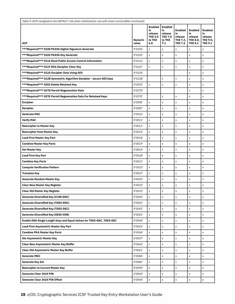
Table 9: ACPs assigned to the DEFAULT role when initialized for use with smart card profiles (continued)
ACPNumericvalue
EnabledinreleaseTKE 5.0to TKE6.0
EnabledinreleaseTKE 7.0to TKE7.1
EnabledinreleaseTKE 7.2,TKE 7.3
EnabledinreleaseTKE 8.0,TKE 8.1
EnabledinreleaseTKE 9.0,TKE 9.1
***Required*** 0100 PKA96 Digital Signature Generate X'0100' x x x x x
***Required*** 0103 PKA96 Key Generate X'0103' x x x x x
***Required*** 0116 Read Public Access-Control Information X'0116' x x x x x
***Required*** 011F RSA Decipher Clear Key X'011F' x x x x x
***Required*** 012A Encipher Data Using AES X'012A' x x
***Required*** 012B Symmetric Algorithm Decipher - secure AES keys X'012B' x x x x
***Required*** 0203 Delete Retained Key X'0203' x x x x x
***Required*** 027D Permit Regeneration Data X'027D' x x
***Required*** 027E Permit Regeneration Data For Retained Keys X'027E' x x x x
Encipher X'000E' x x x x x
Decipher X'000F' x x x x x
Generate MAC X'0010' x x x x x
Verify MAC X'0011' x x x x x
Reencipher to Master Key X'0012' x x x x x
Reencipher from Master Key X'0013' x x x x x
Load First Master Key Part X'0018' x x x x x
Combine Master Key Parts X'0019' x x x x x
Set Master Key X'001A' x x x x x
Load First Key Part X'001B' x x x x x
Combine Key Parts X'001C' x x x x x
Compute Verification Pattern X'001D' x x x x x
Translate Key X'001F' x x x x x
Generate Random Master Key X'0020' x x x x x
Clear New Master Key Register X'0032' x x x x x
Clear Old Master Key Register X'0033' x x x x x
Generate Diversified Key (CLR8-ENC) X'0040' x x x x x
Generate Diversified Key (TDES-ENC) X'0041' x x x x x
Generate Diversified Key (TDES-DEC) X'0042' x x x x x
Generate Diversified Key (SESS-XOR) X'0043' x x x x x
Enable DKG Single Length Keys and Equal Halves for TDES-ENC, TDES-DEC X'0044' x x x x x
Load First Asymmetric Master Key Part X'0053' x x x x x
Combine PKA Master Key Parts X'0054' x x x x x
Set Asymmetric Master Key X'0057' x x x x x
Clear New Asymmetric Master Key Buffer X'0060' x x x x x
Clear Old Asymmetric Master Key Buffer X'0061' x x x x x
Generate MDC X'008A' x x x x x
Generate Key Set X'008C' x x x x x
Reencipher to Current Master Key X'0090' x x x x x
Generate Clear 3624 PIN X'00A0' x x x x x
Generate Clear 3624 PIN Offset X'00A4' x x x x x
28 z/OS: Cryptographic Services ICSF Trusted Key Entry Workstation User's Guide

Table 9: ACPs assigned to the DEFAULT role when initialized for use with smart card profiles (continued)
ACPNumericvalue
EnabledinreleaseTKE 5.0to TKE6.0
EnabledinreleaseTKE 7.0to TKE7.1
EnabledinreleaseTKE 7.2,TKE 7.3
EnabledinreleaseTKE 8.0,TKE 8.1
EnabledinreleaseTKE 9.0,TKE 9.1
Verify Encrypted 3624 PIN X'00AB' x x x x x
Verify Encrypted German Bank Pool PIN X'00AC' x x x x x
Verify Encrypted VISA PVV X'00AD' x x x x x
Verify Encrypted InterBank PIN X'00AE' x x x x x
Format and Encrypt PIN X'00AF' x x x x x
Generate Formatted and Encrypted 3624 PIN X'00B0' x x x x x
Generate Formatted and Encrypted German Bank Pool PIN X'00B1' x x x x x
Generate Formatted and Encrypted InterBank PIN X'00B2' x x x x x
Translate PIN with No Format-Control to No Format-Control X'00B3' x x x x x
Reformat PIN with No Format-Control to No Format-Control X'00B7' x x x x x
Generate Clear VISA PVV Alternate X'00BB' x x x x x
Encipher Under Master Key X'00C3' x x x x x
Lower Export Authority X'00CD' x x x x x
Translate Control Vector X'00D6' x x x x x
Generate Key Set Extended X'00D7' x x x x x
Encipher/Decipher Cryptovariable X'00DA' x x x x x
Replicate Key X'00DB' x x x x x
Generate CVV X'00DF' x x x x x
Verify CVV X'00E0' x x x x x
Unique Key Per Transaction, ANSI X9.24 X'00E1' x x x x x
Reencipher to Current Master Key2 X'00F1' x x x
PKA96 Digital Signature Verify X'0101' x x x x x
PKA96 Key Token Change X'0102' x x x x x
PKA96 Key Import X'0104' x x x x x
Symmetric Key Export PKCS-1.2/OAEP X'0105' x x x x x
Symmetric Key Import PKCS-1.2/OAEP X'0106' x x x x x
One-Way Hash, SHA-1 X'0107' x x x x x
Data Key Import X'0109' x x x x x
Data Key Export X'010A' x x x x x
Compose SET Block X'010B' x x x x x
Decompose SET Block X'010C' x x x x x
PKA92 Symmetric Key Generate X'010D' x x x x x
NL-EPP-5 Symmetric Key Generate X'010E' x x x x x
Reset Intrusion Latch X'010F' x x x x x
Set Clock X'0110' x x x x x
Reinitialize Device X'0111' x x x x x
Initialize Access-Control System X'0112' x x x x x
Change User Profile Expiration Date X'0113' x x x x x
Change User Profile Authentication Data X'0114' x x x x x
Reset User Profile Logon-Attempt-Failure Count X'0115' x x x x x
Overview 29

Table 9: ACPs assigned to the DEFAULT role when initialized for use with smart card profiles (continued)
ACPNumericvalue
EnabledinreleaseTKE 5.0to TKE6.0
EnabledinreleaseTKE 7.0to TKE7.1
EnabledinreleaseTKE 7.2,TKE 7.3
EnabledinreleaseTKE 8.0,TKE 8.1
EnabledinreleaseTKE 9.0,TKE 9.1
Delete User Profile X'0117' x x x x x
Delete Role X'0118' x x x x x
Load Function-Control Vector X'0119' x x x x x
Clear Function-Control Vector X'011A' x x x x x
Force User Logoff X'011B' x x x x x
Set EID X'011C' x x x x x
Initialize Master Key Cloning X'011D' x x x x x
RSA Encipher Clear Key X'011E' x x x x x
Generate Random Asymmetric Master Key X'0120' x x x x x
SET PIN Encrypt with IPINENC X'0121' x x x x x
SET PIN Encrypt with OPINENC X'0122' x x x x x
Clear AES New Master Key Register X'0124' x x x
Load First AES Master Key Part X'0125' x x x
Load Middle/Last AES Master Key Parts X'0126' x x x
Set AES Master Key X'0128' x x x
PKA Register Public Key Hash X'0200' x x x x x
PKA Public Key Register with Cloning X'0201' x x x x x
PKA Public Key Register X'0202' x x x x x
PKA Clone Key Generate X'0204' x x x x x
PKA Clear Key Generate X'0205' x x x x x
Clone-info (share) Obtain 1 X'0211' x x x x x
Clone-info (share) Obtain 2 X'0212' x x x x x
Clone-info (share) Obtain 3 X'0213' x x x x x
Clone-info (share) Obtain 4 X'0214' x x x x x
Clone-info (share) Obtain 5 X'0215' x x x x x
Clone-info (share) Obtain 6 X'0216' x x x x x
Clone-info (share) Obtain 7 X'0217' x x x x x
Clone-info (share) Obtain 8 X'0218' x x x x x
Clone-info (share) Obtain 9 X'0219' x x x x x
Clone-info (share) Obtain 10 X'021A' x x x x x
Clone-info (share) Obtain 11 X'021B' x x x x x
Clone-info (share) Obtain 12 X'021C' x x x x x
Clone-info (share) Obtain 13 X'021D' x x x x x
Clone-info (share) Obtain 14 X'021E' x x x x x
Clone-info (share) Obtain 15 X'021F' x x x x x
Clone-info (share) Install 1 X'0221' x x x x x
Clone-info (share) Install 2 X'0222' x x x x x
Clone-info (share) Install 3 X'0223' x x x x x
Clone-info (share) Install 4 X'0224' x x x x x
Clone-info (share) Install 5 X'0225' x x x x x
30 z/OS: Cryptographic Services ICSF Trusted Key Entry Workstation User's Guide

Table 9: ACPs assigned to the DEFAULT role when initialized for use with smart card profiles (continued)
ACPNumericvalue
EnabledinreleaseTKE 5.0to TKE6.0
EnabledinreleaseTKE 7.0to TKE7.1
EnabledinreleaseTKE 7.2,TKE 7.3
EnabledinreleaseTKE 8.0,TKE 8.1
EnabledinreleaseTKE 9.0,TKE 9.1
Clone-info (share) Install 6 X'0226' x x x x x
Clone-info (share) Install 7 X'0227' x x x x x
Clone-info (share) Install 8 X'0228' x x x x x
Clone-info (share) Install 9 X'0229' x x x x x
Clone-info (share) Install 10 X'022A' x x x x x
Clone-info (share) Install 11 X'022B' x x x x x
Clone-info (share) Install 12 X'022C' x x x x x
Clone-info (share) Install 13 X'022D' x x x x x
Clone-info (share) Install 14 X'022E' x x x x x
Clone-info (share) Install 15 X'022F' x x x x x
List Retained Key X'0230' x x x x x
Generate Clear NL-PIN-1 Offset X'0231' x x x x x
Verify Encrypted NL-PIN-1 X'0232' x x x x x
PKA92 Symmetric Key Import X'0235' x x x x x
PKA92 Symmetric Key Import with PIN keys X'0236' x x x x x
ZERO-PAD Symmetric Key Generate X'023C' x x x x x
ZERO-PAD Symmetric Key Import X'023D' x x x x x
ZERO-PAD Symmetric Key Export X'023E' x x x x x
Symmetric Key Generate PKCS-1.2/OAEP X'023F' x x x x x
Load Diffie-Hellman Key mod/gen X'0250' x x x x x
Combine Diffie-Hellman Key part X'0251' x x x x x
Clear Diffie-Hellman Key values X'0252' x x x x x
Unrestrict Reencipher from Master Key X'0276' x x x x x
Unrestrict Data Key Export X'0277' x x x x x
Add Key Part X'0278' x x x x x
Complete Key Part X'0279' x x x x x
Unrestrict Combine Key Parts X'027A' x x x x x
Unrestrict Reencipher to Master Key X'027B' x x x x x
Unrestrict Data Key Import X'027C' x x x x x
Generate Diversified Key (DALL with DKYGENKY Key Type) X'0290' x x x x x
Generate CSC-5, 4 and 3 Values X'0291' x x x x x
Verify CSC-3 Values X'0292' x x x x x
Verify CSC-4 Values X'0293' x x x x x
Verify CSC-5 Values X'0294' x x x x x
Process cleartext ICSF key parts X'02A0' x x x x x
Process enciphered ICSF key parts X'02A1' x x x x x
RNX access control point X'02A2' x x x x x
Session Key Master X'02A3' x x x x x
Session Key Slave X'02A4' x x x x x
Import Card Device Certificate X'02A5' x x x x x
Overview 31
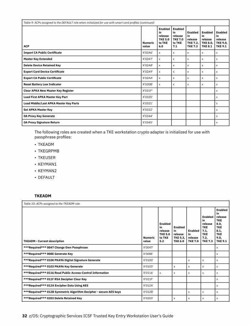
Table 9: ACPs assigned to the DEFAULT role when initialized for use with smart card profiles (continued)
ACPNumericvalue
EnabledinreleaseTKE 5.0to TKE6.0
EnabledinreleaseTKE 7.0to TKE7.1
EnabledinreleaseTKE 7.2,TKE 7.3
EnabledinreleaseTKE 8.0,TKE 8.1
EnabledinreleaseTKE 9.0,TKE 9.1
Import CA Public Certificate X'02A6' x x x x x
Master Key Extended X'02A7' x x x x x
Delete Device Retained Key X'02A8' x x x x x
Export Card Device Certificate X'02A9' x x x x x
Export CA Public Certificate X'02AA' x x x x x
Reset Battery Low Indicator X'030B' x x x x x
Clear APKA New Master Key Register X'031F' x
Load First APKA Master Key Part X'0320' x
Load Middle/Last APKA Master Key Parts X'0321' x
Set APKA Master Key X'0322' x
OA Proxy Key Generate X'0344' x
OA Proxy Signature Return X'0345' x
The following roles are created when a TKE workstation crypto adapter is initialized for use withpassphrase profiles:
• TKEADM• TKEGRPMB• TKEUSER• KEYMAN1• KEYMAN2• DEFAULT
TKEADM
Table 10: ACPs assigned to the TKEADM role
TKEADM - Current descriptionNumericvalue
EnabledinreleaseTKE 5.0to TKE5.2
EnabledinreleaseTKE 5.3,TKE 6.0
EnabledinreleaseTKE 7.0
EnabledinreleaseTKE7.1,TKE7.2,TKE 7.3
EnabledinreleaseTKE8.0,TKE8.1,TKE9.0,TKE 9.1
***Required*** 0047 Change Own Passphrase X'0047' x
***Required*** 008E Generate Key X'008E' x
***Required*** 0100 PKA96 Digital Signature Generate X'0100' x x x
***Required*** 0103 PKA96 Key Generate X'0103' x x x x
***Required*** 0116 Read Public Access-Control Information X'0116' x x x x x
***Required*** 011F RSA Decipher Clear Key X'011F' x
***Required*** 012A Encipher Data Using AES X'012A' x
***Required*** 012B Symmetric Algorithm Decipher - secure AES keys X'012B' x x x
***Required*** 0203 Delete Retained Key X'0203' x x x x
32 z/OS: Cryptographic Services ICSF Trusted Key Entry Workstation User's Guide

Table 10: ACPs assigned to the TKEADM role (continued)
TKEADM - Current descriptionNumericvalue
EnabledinreleaseTKE 5.0to TKE5.2
EnabledinreleaseTKE 5.3,TKE 6.0
EnabledinreleaseTKE 7.0
EnabledinreleaseTKE7.1,TKE7.2,TKE 7.3
EnabledinreleaseTKE8.0,TKE8.1,TKE9.0,TKE 9.1
***Required*** 027D Permit Regeneration Data X'027D' x
***Required*** 027E Permit Regeneration Data For Retained Keys X'027E' x x x
Compute Verification Pattern X'001D' x x x x x
One-Way Hash, SHA-1 X'0107' x x x x x
Reset Intrusion Latch X'010F' x x x x x
Set Clock X'0110' x x x x x
Reinitialize Device X'0111' x x x x x
Initialize Access-Control System X'0112' x x x x x
Change User Profile Expiration Date X'0113' x x x x x
Change User Profile Authentication Data X'0114' x x x x x
Reset User Profile Logon-Attempt-Failure Count X'0115' x x x x x
Delete User Profile X'0117' x x x x x
Delete Role X'0118' x x x x x
Load Function-Control Vector X'0119' x x x x x
Clear Function-Control Vector X'011A' x x x x x
Import Card Device Certificate X'02A5' x x x x
Import CA Public Certificate X'02A6' x x x x
Delete Device Retained Key X'02A8' x x x x
Export Card Device Certificate X'02A9' x x x x
Export CA Public Certificate X'02AA' x x x x
Reset Battery Low Indicator X'030B' x x x x x
Open Begin Zone Remote Enroll Process X'1000' x x
Open Complete Zone Remote Enroll Process X'1001' x x
Open Cryptographic Node Management Utility X'1002' x x
Open Smart Card Utility Program X'1005' x x
Open Edit TKE Files X'100D' x x
Open TKE File Management Utility X'100E' x x
TKE USER X'8002' x x
TKEGRPMB
Table 11: ACPs assigned to the TKEGRPMB role
ACP - Current description Numeric value
Enabled inrelease TKE8.1, TKE9.0, TKE 9.1
***Required*** 0047 Change Own Passphrase X'0047' x
***Required*** 008E Generate Key X'008E' x
***Required*** 0100 PKA96 Digital Signature Generate X'0100' x
Overview 33

Table 11: ACPs assigned to the TKEGRPMB role (continued)
ACP - Current description Numeric value
Enabled inrelease TKE8.1, TKE9.0, TKE 9.1
***Required*** 0103 PKA96 Key Generate X'0103' x
***Required*** 0116 Read Public Access-Control Information X'0116' x
***Required*** 011F RSA Decipher Clear Key X'011F x
***Required*** 012A Encipher Data Using AES X'012A' x
***Required*** 012B Symmetric Algorithm Decipher - secure AES keys X'012B' x
***Required*** 0203 Delete Retained Key X'0203' x
***Required*** 027D Permit Regeneration Data X'027D' x
***Required*** 027E Permit Regeneration Data For Retained Keys X'027E' x
TKEUSER
Table 12: ACPs assigned to the TKEUSER role
TKEUSER - Current descriptionNumericvalue
EnabledinreleaseTKE 5.0to TKE6.0
EnabledinreleaseTKE 7.0
EnabledinreleaseTKE 7.1
EnabledinreleaseTKE 7.2
EnabledinreleaseTKE 7.3
EnabledinreleaseTKE 8.0,TKE 8.1
EnabledinreleaseTKE 9.0,TKE 9.1
***Required*** 0047 Change Own Passphrase X'0047' x x
***Required*** 008E Generate Key X'008E' x x x x x x x
***Required*** 0100 PKA96 Digital Signature Generate X'0100' x x x x x x x
***Required*** 0103 PKA96 Key Generate X'0103' x x x x x x x
***Required*** 0116 Read Public Access-Control Information X'0116' x x x x x x x
***Required*** 011F RSA Decipher Clear Key X'011F' x x
***Required*** 012A Encipher Data Using AES X'012A' x x
***Required*** 012B Symmetric Algorithm Decipher - secureAES keys
X'012B' x x x x x x
***Required*** 0203 Delete Retained Key X'0203' x x x x x
***Required*** 027D Permit Regeneration Data X'027D' x x
***Required*** 027E Permit Regeneration Data For RetainedKeys
X'027E' x x x x x
Encipher X'000E' x x x x x x x
Decipher X'000F' x x x x x x x
Reencipher to Master Key X'0012' x x x x x x x
Reencipher from Master Key X'0013' x x x x x x x
Load First Key Part X'001B' x x x x x x x
Combine Key Parts X'001C' x x x x x x x
Compute Verification Pattern X'001D' x x x x x x x
Computer CMACZERO Verification Pattern for DES X'0023' x
Generate Key Set X'008C' x x x x x x x
PKA96 Digital Signature Verify X'0101' x x x x x x x
PKA96 Key Import X'0104' x x x x x x x
PKA Clone Key Generate X'0204' x x x x x x x
PKA Clear Key Generate X'0205' x x x x x x x
34 z/OS: Cryptographic Services ICSF Trusted Key Entry Workstation User's Guide

Table 12: ACPs assigned to the TKEUSER role (continued)
TKEUSER - Current descriptionNumericvalue
EnabledinreleaseTKE 5.0to TKE6.0
EnabledinreleaseTKE 7.0
EnabledinreleaseTKE 7.1
EnabledinreleaseTKE 7.2
EnabledinreleaseTKE 7.3
EnabledinreleaseTKE 8.0,TKE 8.1
EnabledinreleaseTKE 9.0,TKE 9.1
Load Diffie-Hellman Key mod/gen X'0250' x x x x x x x
Combine Diffie-Hellman Key part X'0251' x x x x x x x
Clear Diffie-Hellman Key values X'0252' x x x x x x x
Unrestrict Combine Key Parts X'027A' x x x x x x x
Import First AES Key Part (min of 2) X'0298' x x x x
Import Last Required AES Key Part X'029B' x x x x
Import Optional AES Key Part X'029C' x x x x
Complete AES Key Import X'029D' x x x x
Process cleartext ICSF key parts X'02A0' x x x x x x x
Process enciphered ICSF key parts X'02A1' x x x x x x x
RNX access control point X'02A2' x x x x x x x
Session Key Master X'02A3' x x x x x x x
Session Key Slave X'02A4' x x x x x x x
Export Card Device Certificate X'02A9' x x x x x x x
OA Proxy Key Generate X'0344' x x x x x x
OA Proxy Signature Return X'0345' x x x x x x
Open Migrate Host Crypto Module Public Configuration Data X'1003' x x x x x
Open Configuration Migration Tasks X'1004' x x x x x
Open Smart Card Utility Program X'1005' x x x x x
Open Trusted Key Entry X'1006' x x x x x
Create Domain Group X'1007' x x x x x
Change Domain Group X'1008' x x x x x
Delete Domain Group X'1009' x x x x x
Create Crypto Module Group X'100A' x x x x x
Change Crypto Module Group X'100B' x x x x x
Delete Crypto Module Group X'100C' x x x x x
Open Edit TKE Files X'100D' x x x x x
Open TKE File Management Utility X'100E' x x x x x
Manage Host List X'100F' x x x
TKE USER X'8002' x x
KEYMAN1
Table 13: ACPs assigned to the KEYMAN1 role
ACP - Current descriptionNumericvalue
EnabledinreleaseTKE 5.0to TKE6.0
EnabledinreleaseTKE 7.0
EnabledinreleaseTKE 7.1
EnabledinreleaseTKE 7.2,TKE 7.3
EnabledinreleaseTKE 8.0,TKE 8.1
EnabledinreleaseTKE 9.0,TKE 9.1
***Required*** 0047 Change Own Passphrase X'0047' x x
***Required*** 008E Generate Key X'008E' x x x x x
Overview 35

Table 13: ACPs assigned to the KEYMAN1 role (continued)
ACP - Current descriptionNumericvalue
EnabledinreleaseTKE 5.0to TKE6.0
EnabledinreleaseTKE 7.0
EnabledinreleaseTKE 7.1
EnabledinreleaseTKE 7.2,TKE 7.3
EnabledinreleaseTKE 8.0,TKE 8.1
EnabledinreleaseTKE 9.0,TKE 9.1
***Required*** 0100 PKA96 Digital Signature Generate X'0100' x x x x x
***Required*** 0103 PKA96 Key Generate X'0103' x x x x x
***Required*** 0116 Read Public Access-Control Information X'0116' x x x x x x
***Required*** 011F RSA Decipher Clear Key X'011F' x x
***Required*** 012A Encipher Data Using AES X'012A' x x
***Required*** 012B Symmetric Algorithm Decipher - secure AES keys X'012B' x x x x x
***Required*** 0203 Delete Retained Key X'0203' x x x x x
***Required*** 027D Permit Regeneration Data X'027D' x x
***Required*** 027E Permit Regeneration Data For Retained Keys X'027E' x x x x x
Load First Master Key Part X'0018' x x x x x x
Compute Verification Pattern X'001D' x x x x x x
Clear New Master Key Register X'0032' x x x x x x
Clear AES New Master Key Register X'0124' x x x
Load First AES Master Key Part X'0125' x x x
Clear APKA New master Key Register X'031F' x
Load First APKA Master Key Part X'0320' x
Open Cryptographic Node Management Utility X'1002' x x x x
KEYMAN2
Table 14: ACPs assigned to the KEYMAN2 role
ACP - Current descriptionNumericvalue
EnabledinreleaseTKE 5.0to TKE6.0
EnabledinreleaseTKE 7.0
EnabledinreleaseTKE 7.1
EnabledinreleaseTKE 7.2,TKE 7.3
EnabledinreleaseTKE 8.0,TKE 8.1
EnabledinreleaseTKE 9.0,TKE 9.1
***Required*** 0047 Change Own Passphrase X'0047' x x
***Required*** 008E Generate Key X'008E' x x x x x x
***Required*** 0100 PKA96 Digital Signature Generate X'0100' x x x x x
***Required*** 0103 PKA96 Key Generate X'0103' x x x x x
***Required*** 0116 Read Public Access-Control Information X'0116' x x x x x x
***Required*** 011F RSA Decipher Clear Key X'011F' x x
***Required*** 012A Encipher Data Using AES X'012A' x x
***Required*** 012B Symmetric Algorithm Decipher - secure AES keys X'012B' x x x x x
***Required*** 0203 Delete Retained Key X'0203' x x x x x
***Required*** 027D Permit Regeneration Data X'027D' x x
***Required*** 027E Permit Regeneration Data For Retained Keys X'027E' x x x x x
Combine Master Key Parts X'0019' x x x x x x
Set Master Key X'001A' x x x x x x
Compute Verification Pattern X'001D' x x x x x x
Reencipher to Current Master Key X'0090' x x x x x x
36 z/OS: Cryptographic Services ICSF Trusted Key Entry Workstation User's Guide

Table 14: ACPs assigned to the KEYMAN2 role (continued)
ACP - Current descriptionNumericvalue
EnabledinreleaseTKE 5.0to TKE6.0
EnabledinreleaseTKE 7.0
EnabledinreleaseTKE 7.1
EnabledinreleaseTKE 7.2,TKE 7.3
EnabledinreleaseTKE 8.0,TKE 8.1
EnabledinreleaseTKE 9.0,TKE 9.1
Reencipher to Current Master Key2 X'00F1' x x x
PKA96 Key Token Change X'0102' x x x x x x
Load Middle/Last AES Master Key Parts X'0126' x x x
Set AES Master Key X'0128' x x x
Load Middle/Last APKA Master Key Parts X'0321' x
Set APKA Master Key X'0322' x
Open Cryptographic Node Management Utility X'1002' x x x x
DEFAULT
DEFAULT role when initialized for use with passphrase profiles
Table 15: ACPs assigned to the DEFAULT role when initialized for use with passphrase profiles
ACP - Current descriptionNumericvalue
EnabledinreleaseTKE 5.0to TKE6.0
EnabledinreleaseTKE 7.0,TKE 7.1,TKE 7.2,TKE 7.3
EnabledinreleaseTKE 8.0,TKE 8.1,TKE 9.0,TKE 9.1
***Required*** 0047 Change Own Passphrase X'0047' x
***Required*** 008E Generate Key X'008E' x
***Required*** 0100 PKA96 Digital Signature Generate X'0100' x x
***Required*** 0103 PKA96 Key Generate X'0103' x x
***Required*** 0116 Read Public Access-Control Information X'0116' x x x
***Required*** 011F RSA Decipher Clear Key X'011F' x
***Required*** 012A Encipher Data Using AES X'012A' x
***Required*** 012B Symmetric Algorithm Decipher - secure AES keys X'012B' x x
***Required*** 0203 Delete Retained Key X'0203' x x
***Required*** 027D Permit Regeneration Data X'027D' x
***Required*** 027E Permit Regeneration Data For Retained Keys X'027E' x x
Compute Verification Pattern X'001D' x x x
Reinitialize Device X'0111' x x x
Export Card Device Certificate X'02A9' x x x
Blue smart cards (00RY790)Smart card part, 00RY790, was shipped with TKE 9.1. In addition to having the part number printed on it,the card is blue. The blue smart card supports 521-bit Elliptic Curve (EC) cryptography and has morestorage than the previous TKE smart card. Because of the stronger encryption and increase in storage, thefollowing important features were added to TKE 9.1:
Overview 37

• With a blue smart card, you can create a TKE zone (defined when you initialize and personalize aCertificate Authority (CA) smart card) or a Migration zone (defined when you initialize and personalize aMigration Certificate Authority (MCA) smart card) with a zone strength of 521-bit EC. All the smart cardsin any type of 521-bit EC zone must also be blue smart cards.
• If your Migration Zone (MCA) strength is 521-bit EC, you can collect and apply data from domains thatare in Imprint or PCI compliant mode. With the older smart cards, it was not possible to collect or applythe settings of domains in these two states.
• When a new Local Adapter Logon key is generated on a blue smart card, the strength is 521-bit EC.• When an Authority Signature Key or Administrator Signature key is generated on a blue smart card, you
can select 521-bit EC as the key strength. You would only select this strength if the host crypto modulethat you will manage also has 521-bit EC support.
• Blue smart cards can hold up to 85 key parts. This is an increase of 35 key parts.
Things to know about the blue smart card:
• TKE 9.1 is the minimum supported release for the blue smart card. You may not use the blue smart cardon any TKE below TKE 9.1.
• IMPORTANT RESTRICTIONS: The blue smart card is configured to run in FIPS mode. Therefore, thesmart card hardware prohibits the generation of any 1024-bit RSA keys. This has the followingsignificant implications:
1. When you initialize a Certificate Authority (CA) smart card using a blue smart cart, the zone strengthmay not be 1024-bit RSA. The zone strength can be set to 2048-bit RSA or 521-bit EC.
2. When you are making a backup CA smart card from an existing CA smart card, you may not use ablue smart card to make a backup of a 1024-bit RSA CA smart card.
3. A blue smart card may not have a 1024-bit RSA alternate zone. This means that you must use aspecial procedure to move (migrate) key material from one 1024-bit RSA zone TKE smart card onto ablue TKE smart card, which must be in a different, stronger zone.
Note: The process for moving data onto a blue smart card is described in “Moving data from a TKEsmart card in a 1024-bit zone to a blue smart card” on page 55.
4. You may not create an Authority Signature Key for managing a Crypto Express 2 host crypto moduleonto a blue smart card. The Crypto Express 2 only supports 1024-bit RSA signature keys.
Note: You can copy an existing 1024-bit RSA Authority Signature Key or 1024-bit RSA local adapterlogon key onto a blue smart card and use these keys.
Recommendations:
– Only continue to use 1024-bit RSA Authority Signature Keys if you are still managing CryptoExpress 2 modules. This is a very weak key strength and it is recommended that you move tostronger keys.
– You should stop using 1024-bit RSA local adapter logon keys. The strength is too weak. If yougenerate a local adapter logon key onto a blue smart card, the strength of the key will be 521-bitEC.
TKE security policy wizardsStrictly defined security policies are important in order to govern who can do the following TKEworkstation activities:Manage the TKE workstation
Activities include setting up access to the TKE workstation and managing your smart cardenvironment.
Manage host crypto modules running in Common Cryptographic Architecture (CCA) modeActivities include setting up access to the module, managing general purpose settings, and master keywrapping management.
38 z/OS: Cryptographic Services ICSF Trusted Key Entry Workstation User's Guide

Manage host crypto modules running in IBM Enterprise PKCS11 (EP11) modeActivities include setting up access to the module, managing general purpose setting, and master keywrapping management.
All of these activities, including signing onto the TKE workstation, are security-relevant administrativeactions and should only be done by a small set of trusted administrators with a high degree ofaccountability.
TKE 9.1 and later provides six TKE security policy wizards that work together to implement acomprehensive set of security policies for managing access to the TKE workstation and managing hostcrypto modules and their domains. All of the TKE security policies require that something be stored on asmart card so use the TKE Smart Card Wizard to create all the smart cards that the other TKE wizardsneed. See the TKE Smart Card Wizard in Table 16 on page 40 for additional information. Five additionalwizards setup the minimum recommended security policies for managing administrators responsible forspecific tasks. See Table 17 on page 40 for additional information.
TKE security policy guidance
Before using the TKE security policy wizards, analyze your environment and decide which of the policiesyou need to implement:Controlling who has access to your TKE workstation
This policy should be on your list because you need to control who has access to your TKEworkstation. See the TKE Workstation Logon Profile Wizard in Table 17 on page 40 for additionalinformation.
Controlling who can manage CCA legacy settingsAnalyze your host cryptographic environment managed from the TKE workstation to determine if thispolicy applies to you. See the Setup Module Policy Wizard in Table 17 on page 40 for additionalinformation.
Controlling who can manage CCA PCI-compliant domain settingsAnalyze your host cryptographic environment managed from the TKE workstation to determine if thispolicy applies to you. See the Setup PCI Environment Wizard in Table 17 on page 40 for additionalinformation.
Controlling who can manage EP11 module-wide settingsAnalyze your host cryptographic environment managed from the TKE workstation to determine if thispolicy applies to you. See the Setup Module Policy Wizard in Table 17 on page 40 for additionalinformation.
Controlling who can manager EP11 domain-specific settingsAnalyze your host cryptographic environment managed from the TKE workstation to determine if thispolicy applies to you. See the Setup Domain Policy Wizard in Table 17 on page 40 for additionalinformation.
TKE security policy wizards
Once you know which set of TKE security policies you need, use the TKE Smart Card Wizard to create thesmart cards you need for the rest of the TKE security policy wizards. Table 16 on page 40 provides asummary of the TKE Smart Card Wizard. Table 17 on page 40 provides a summary of the security policyimplementation wizards.
Note: There is a link to wizard-specific information and guidance provided on the welcome screen of allsix of the wizards.
Overview 39

Table 16: Prerequisite TKE wizard: TKE Smart Card Wizard
Required activity TKE security policywizard name
TKE security policywizard purpose
Where the TKE securitypolicy wizard is found
Manage smart cardenvironment.
TKE Smart Card Wizard To create all the smartcards needed by theother TKE security policywizards. You can alsocreate a new TKE zone,enroll the TKE in a zone,or both.
Smart Card UtilityProgram (SCUP) in theFile pull down menu.
Table 17: TKE security policy implementation wizards
Policy purpose TKE security policywizard name
TKE security policywizard purpose
Where the TKE securitypolicy wizard is found
Control access to theTKE workstation.
TKE Workstation LogonProfile Wizard
To create TKE localcrypto adapter smartcard profiles that controlaccess to the TKEworkstation.
Cryptographic NodeManagement (CNM)Utility in the AccessControl pull downmenu.
Control who can manageCCA legacy settings.
Setup Module PolicyWizard
To create CCA module-wide roles andauthorities to controladministrative accessfor managing module-wide and normal modedomain-specificsettings.
Trusted Key Entry (TKE)application in Open ahost or CCA domaingroup on the module'sGeneral tab.
Control who can manageCCA PCI-compliantdomain settings.
Setup PCI EnvironmentWizard
To create CCA domain-specific roles andauthorities to controladministrative accessfor managing thedomain-specific settingsin IMPRINT and PCI-COMPLIANT domains.
Trusted Key Entry (TKE)application in Open ahost or CCA domaingroup on the domain'sGeneral tab (onlyavailable while inimprint mode).
Control who can manageEP11 module-widesettings.
Setup Module PolicyWizard
To add administrators tothe EP11 module-widelist and take themodules out of imprintmode to controladministrative accessfor managing EP11module-wide settings.
Trusted Key Entry (TKE)application in Open thehost of EP11 domaingroup on the ModuleGeneral tab (onlyavailable while inimprint mode).
40 z/OS: Cryptographic Services ICSF Trusted Key Entry Workstation User's Guide

Table 17: TKE security policy implementation wizards (continued)
Policy purpose TKE security policywizard name
TKE security policywizard purpose
Where the TKE securitypolicy wizard is found
Control who can manageEP11 domain-specificsettings.
Setup Domain PolicyWizard
To add administrators tothe EP11 domain-specific list and take thedomains out of imprintmode to controladministrative accessfor managing EP11domain-specificsettings.
Trusted Key Entry (TKE)application in Open thehost or EP11 domaingroup on DomainGeneral tab (onlyavailable while inimprint mode).
Overview 41

42 z/OS: Cryptographic Services ICSF Trusted Key Entry Workstation User's Guide

Chapter 2. Using smart cards with TKE
Companies aiming for a high level of data confidentiality and integrity are likely to install a hardware-based cryptographic system, such as one provided by the Trusted Key Entry (TKE) workstation. It allowsyou to keep your cryptographic keys secret and protected from unauthorized access. When properlyinstalled and administered, using smart cards with the TKE workstation provides a high level of security.
Smart card support gives the user the ability to keep all key parts, authority and administrator signaturekeys, and crypto adapter logon keys from ever appearing in the clear.
TerminologyThere are several terms you should be familiar with to understand the smart card support.
Certificate authority (CA) smart cardAn entity that establishes a zone using the Smart Card Utility Program (SCUP). Protected by two 6-digit PINs.
CNICryptographic Node Batch Initialization utility. The CNI Editor is a utility within CNM that is used tocreate CNI scripts to automate some of the functions of CNM. CNI scripts can be used for additionalsetup of the TKE workstation crypto adapter.
CNMCryptographic Node Management utility. This utility is a Java™ application that provides a graphicaluser interface to initialize and manage the TKE workstation crypto adapter. See Chapter 11,“Cryptographic Node Management utility (CNM),” on page 251.
EntityA member of a zone. Entities can be a CA smart card, one or more TKE or EP11 smart cards, and oneor more TKE workstation cryptographic adapters.
EP11 smart cardUsed for storing keys and key parts. Can hold a maximum of 50 key parts, a TKE crypto adapter logonkey, and an administrator signature key. Protected by a 6-digit PIN. EP11 smart cards support EP11host crypto modules.
Group logonAllows multiple users to co-sign the logon to the TKE workstation crypto adapter. A group may have aminimum of one member and a maximum of ten members.
Injection authority (IA) smart cardUsed for approving the application of a data to a target host crypto module using the ConfigurationMigration Tasks application's Apply Configuration Data wizard. Protected by a 6-digit PIN.
Key part holder (KPH) smart cardUsed for decrypting a specific piece of the encryption key used to protect the data that is migrated toa host crypto module using the Configuration Migration Tasks application's Apply Configuration Datawizard. Protected by a 6-digit PIN.
Migration certificate authority (MCA) smart cardAn entity that establishes a migration zone using the Configuration Migration Tasks application.Protected by two 6-digit PINs.
PIN promptPIN prompts appear as pop-ups from the application and also on the smart card reader. The smartcard reader expects a PIN to be entered promptly; otherwise a timeout condition occurs.
© Copyright IBM Corp. 2000, 2019 43

SCUPSmart Card Utility Program. Performs maintenance operations, such as the creation/initialization andpersonalization of CA, TKE, and EP11 smart cards and zone enrollment of the TKE workstation cryptoadapter. See Chapter 12, “Smart Card Utility Program (SCUP),” on page 291.
Smart card readerHardware where the PIN protecting the smart card is entered. Also, where the key parts are enteredwith secure key entry. Two, three, or four smart card readers may be attached to the TKE workstation.
TKE smart cardUsed for storing keys and key parts. Can hold a maximum of 50 key parts, a TKE crypto adapter logonkey and a TKE authority key. Protected by a 6-digit PIN. TKE smart cards support CCA host cryptomodules.
ZoneA security concept ensuring that only members of the same zone can exchange key parts. A zone isestablished by a CA smart card. See “Zone creation ” on page 51.
Preparation and planningBefore beginning a smart card implementation, consider these questions:
• How many users will be using smart cards?• Will you be using group logon?• How many members will be in the group?• How many members in the group will be required to sign a logon?• What role will the group have?• What type of roles will users have?• Are there procedures requiring special security considerations?• Which tasks will have dual control?• Who should be involved in security, auditing, and operation procedures in a test environment?• Who should be involved in security, auditing, and operation procedures in a production environment?• How many TKE and EP11 smart cards will you have?• How many backup CA smart cards will you have?• Where will you keep backup CA smart cards?• How many users will have access to the CA smart cards? Who will know the two CA PIN numbers?
Where will the CA smart card and backups be secured?• If you have more than one TKE workstation, will they be in the same zone?
Using the IDENTIV smart card readerTKE 9.0 and later supports IDENTIV smart card readers.
The IDENTIV smart card reader does not have a display window and all the necessary information issignaled by sound from the smart card reader. The IDENTIV smart card reader has:A PIN pad
When you press on the PIN pad, a tone comes from the reader that indicates that the pad waspressed. When the PIN is fully entered, a different pitched tone plays, signaling that the PIN iscomplete. On the PIN pad, TKE supports the numeric buttons (0-9), the red cancel button, the yellowclear button, and the green enter button. The yellow clear button is a backspace button so if you pressthe wrong button, you can clear it by using the yellow button.
Two LED indicators (green and yellow)When the green LED indicator is on, the smart card is present in the reader. If the green LED indicatoris flashing or not on, the smart card is not detected to be in the reader or has timed out.
44 z/OS: Cryptographic Services ICSF Trusted Key Entry Workstation User's Guide
When the yellow LED indicator is flashing, the PIN operation is in progress. If the PIN operation is notin progress, the yellow LED indicator is not on.
Only one smart card application can be opened at a time. If more than one is opened, you get an errormessage that indicates that smart card functions are not available or smart card readers are not available,depending on the application.
The smart card has a gold plated contact. Insert the gold plated contact so that it faces you and pointeddown into the smart card reader.
Using the OmniKey smart card readerThe smart card reader has a PIN pad and a display window. On the PIN pad, TKE supports the numericbuttons (0-9), the red X cancel button, and the yellow <- backspace button.
The display is blank if the reader is not attached. When attached, a USB plug symbol displays. Amicroprocessor chip symbol displays after you insert a smart card.
Only one smart card application may be opened at a time. If more than one is opened, you will get anerror message indicating that smart card functions are not available or smart card readers are notavailable, depending on the application.
The smart card has a gold plated contact. Insert the gold plated contact facing you and pointing down intothe smart card reader.
When prompted to insert a smart card, push the smart card all the way in until a microprocessor chipsymbol displays. If a USB plug symbol displays, you have not inserted the smart card correctly
When prompted for a PIN, enter your PIN using the numeric buttons on the PIN pad. If a PIN is notentered promptly, the PIN prompt will time out and a timeout message will be issued from theapplication. You must restart the task.
The <- is a backspace button; if you press the wrong button, you can backspace using <-.
The other buttons on the PIN pad are not operational.
Using the Gemalto smart card readerTKE 9.0 and later supports Gemalto smart card readers.
Important: Gemalto CT700 readers only work with smart cards that have applets that are loaded fromTKE 8.1 or later. Therefore, you must carry Omnikey Cardman 3821 smart card readers forward to usesmart cards with pre-TKE 8.1 applets on TKE 9.0 and later. See Table 35 on page 294 for the actions thatare required to move to smart cards that work in Gemalto smart card readers.
The smart card reader has a PIN pad, a display window, and some LED indicators. On the PIN pad, TKEsupports the numeric buttons (0-9), the red cancel button, the yellow clear button, and the green Enterbutton.
The display is blank if the reader is not attached. When attached, the display shows 'Insert Card' and thegreen LED flashes. When you insert a smart card, the display goes blank and the green LED goes to a solidcolor.
Only one smart card application can be opened at a time. If more than one is opened, you get an errormessage that indicates that smart card functions are not available or smart card readers are not available,depending on the application.
The smart card has a gold plated contact. Insert the gold plated contact so that it faces you and pointeddown into the smart card reader.
When prompted to insert a smart card, insert the smart card until the green LED light stops flashing. If thedisplay still shows 'Insert Card', the smart card was not inserted correctly.
When prompted for a PIN, enter your PIN by using the numeric buttons on the PIN pad and press Enter. Ifa PIN is not entered promptly, the PIN prompt times out and a timeout message is displayed for theapplication. You must then restart the task.
Using smart cards with TKE 45

The Clear button works like a backspace button. If you press the wrong button when you are entering yourPIN, you can backspace a character or characters by pressing the clear button.
The Cancel button can be used to cancel the task anytime while you are completing a smart cardoperation.
The other buttons on the PIN pad are not operational.
For information on the procedures that must be followed if you want to use smart cards that aresupported by Gemalto smart card readers, see Chapter 3, “TKE upgrade and migration actions,” on page57.
Things to consider• You can carry your HID/OMNIKEY smart card readers from older TKEs forward to your TKE 9.0 and later
systems.• If you use HID/OMNIKEY smart card readers on your TKE 9.0 or later system, any previously initialized
smart cards can be used on TKE 9.0 or later. Any smart card limitations that existed for the smart cardson TKE 8.1 also apply to TKE 9.0 and later.
• Any smart card that is initialized and personalized on TKE 9.0 or later can be used in either the HID/OMNIKEY, Gemalto, or IDENTIV smart card readers.
• TKE 9.0 and later supports a combination of HID/OMNIKEY, Gemalto, and IDENTIV smart card readersat the same time. Gemalto and IDENTIV smart card readers can be used only with smart cards thatwere initialized on TKE 8.1 or later.
• If you experience issues after you unplugged and plugged a combination of smart card readers in, youmight restart the workstation.
Smart card compatibility issuesFeatures added in recent TKE releases (such as support for ECC authority signature keys in TKE 8.0) haverequired changes to the smart card applets. Because of these changes, there are restrictions on whichsmart cards can be used with a particular TKE release.
Applet version
When a new smart card is created, an applet is loaded onto the smart card. This occurs when initializingand personalizing CA or MCA smart cards, when creating a backup CA or MCA smart card, or wheninitializing and enrolling TKE, EP11, IA, or KPH smart cards in a zone. The applet version depends on theTKE release and type of smart card used, as shown in the following tables.
Table 18: Applet version by TKE release
CA smart card TKE smart card EP11 smart card Smart card part
TKE 5.2 or earlier applet version =0.3
applet version =0.3
Not supported Any supported card
TKE 5.3 applet version =0.3
applet version =0.4
Not supported Any supported card
TKE 6.0 applet version =0.4
applet version =0.5
Not supported Any supported card
TKE 7.0 applet version =0.4
applet version =0.6
Not supported Any supported card
TKE 7.1 applet version =0.4
applet version =0.7
Not supported Any supported card
TKE 7.2 applet version =0.4
applet version =0.8
Not supported 45D3398
46 z/OS: Cryptographic Services ICSF Trusted Key Entry Workstation User's Guide

Table 18: Applet version by TKE release (continued)
CA smart card TKE smart card EP11 smart card Smart card part
TKE 7.2 applet version =0.4
applet version =0.8
applet version =0.1
74Y0551
TKE 7.3 applet version =0.4
applet version =0.8
Not supported 45D3398
TKE 7.3 applet version =0.5
applet version =0.9
applet version =0.2
74Y0551
TKE 8.0 applet version =0.4
applet version =0.8
Not supported 45D3398
TKE 8.0 applet version =0.5
applet version =0.10
applet version =0.2
74Y0551
TKE 8.0 applet version =0.5
applet version =0.10
applet version =0.2
00JA710
TKE 8.1 applet version =0.6
applet version =0.11 1
Not supported 45D3398
TKE 8.1 applet version =0.7
applet version =0.12 2
applet version =0.33
74Y0551
TKE 8.1 applet version =0.7
applet version =0.122
applet version =0.33
00JA710
TKE 9.0 applet version =0.6
applet version =0.154
Not supported 45D3398
TKE 9.0 applet version =0.7
applet version =0.165
applet version =0.46
74Y0551
TKE 9.0 applet version =0.7
applet version =0.165
applet version =0.46
00JA710
TKE 9.1 applet version =0.6
applet version =0.17
Not supported 45D3398
TKE 9.1 applet version =0.7
applet version =0.18
applet version =0.5
74Y0551
TKE 9.1 applet version =0.7
applet version =0.18
applet version =0.5
00JA710
TKE 9.1 applet version =0.8
applet version =0.19
applet version =0.6
00RY790
Notes:
1. A PTF available on TKE 8.1 changes the applet version to 0.13. The PTF adds support for an alternatezone when copying smart card contents.
2. A PTF available on TKE 8.1 changes the applet version to 0.14. The PTF adds support for an alternatezone when copying smart card contents.
3. A PTF available on TKE 8.1 changes the applet version to 0.4. The PTF adds support for an alternatezone when copying smart card contents.
4. A PTF available on TKE 9.0 changes the applet version to 0.17. The PTF modifies support for using analternate zone when copying smart card contents.
Using smart cards with TKE 47

5. A PTF available on TKE 9.0 changes the applet version to 0.18. The PTF modifies support for using analternate zone when copying smart card contents.
6. A PTF available on TKE 9.0 changes the applet version to 0.5. The PTF modifies support for using analternate zone when copying smart card contents.
Table 19: Applet version by TKE release
MCA smart card IA smart card KPH smart card Smart card part
TKE 7.0 to TKE 7.2 applet version =0.1
applet version =0.1
applet version =0.1
Any supported card
TKE 7.3 applet version =0.1
applet version =0.1
applet version =0.1
45D3398
TKE 7.3 applet version =0.2
applet version =0.2
applet version =0.2
74Y0551
TKE 8.0 applet version =0.1
Not supported Not supported 45D3398
TKE 8.0 applet version =0.2
applet version =0.3
applet version =0.3
74Y0551
TKE 8.0 applet version =0.2
applet version =0.3
applet version =0.3
00JA710
TKE 8.1, TKE 9.0,and TKE 9.1
applet version =0.3
Not supported Not supported 45D3398
TKE 8.1, TKE 9.0,and TKE 9.1
applet version =0.4
applet version =0.4
applet version =0.4
74Y0551
TKE 8.1, TKE 9.0,and TKE 9.1
applet version =0.4
applet version =0.4
applet version =0.4
00JA710
TKE 9.1 applet version =0.5
applet version =0.5
applet version =0.5
00RY790
In general, smart cards that are created on a particular TKE release cannot be used on TKE workstationsthat are at prior release levels. TKE 5.2 applets are not usable on TKE 7.1 and later because they can onlybe installed on DataKey smart cards, and DataKey smart cards are not supported.
Zone key type and length
TKE uses smart cards and establishes zones for two categories of operations: normal crypto moduleadministration, which includes loading keys and key parts and signing commands to a crypto module, andconfiguration migration. CA, TKE, and EP11 smart cards are created for normal crypto moduleadministration, and MCA, IA, and KPH smart cards are created for configuration migration. Support forconfiguration migration was added in TKE 7.0.
Zone keys establish secure communication between entities in a zone. Entities include smart cards andthe TKE workstation crypto adapter.
Prior to TKE 6.0, zones for normal crypto module administration use 1024-bit RSA keys. Beginning in TKE6.0, customers can select either 1024-bit RSA keys or 2048-bit RSA keys as the zone key type.
When support for configuration migration was added in TKE 7.0, the zone key type for configurationmigration was restricted to 2048-bit RSA keys. Similarly, when support for EP11 crypto modules wasadded in TKE 7.2, a zone key type of 2048-bit RSA keys was required to create an EP11 smart card.
Beginning in TKE 9.1, zones based on P521 ECC keys are supported for both normal crypto moduleadministration and configuration migration. You must use 00RY790 smart cards for this zone type. Thezone key type and size is selected when initializing and personalizing a CA or an MCA smart card.
48 z/OS: Cryptographic Services ICSF Trusted Key Entry Workstation User's Guide

Smart card usage
Table 20 on page 49 indicates in more detail where CA smart cards created in different releases can beused. Usage means employing a CA smart card to create TKE smart cards, creating a backup CA smartcard, or enrolling a TKE workstation cryptographic adapter in the zone. OmniKey smart card readers arerequired to use CA smart cards with a zone key length of 2048-bits.
Table 20: CA smart card usage
Use on TKE 5.2 orearlier Use on TKE 5.3 Use on TKE 6.0
Use on TKE 7.0and later
Created on TKE5.2 or before
Yes Yes Yes No
Created on TKE5.3
No Yes Yes Yes1
Created on TKE6.0, 1024-bit zonekey
No Yes Yes Yes1
Created on TKE6.0, 2048-bit zonekey
No No Yes Yes
Created on TKE7.0 and above
No No No Yes
1 You must use smart cards associated with part number 45D3398 or 74Y0551 in this release of TKE.Datakey smart cards are not supported in TKE 7.0 and above.
Table 21 on page 49 indicates in more detail where TKE smart cards created in different releases can beused. Usage means employing a TKE smart card to store or load key parts or to generate and retain anauthority signature key or a crypto adapter logon key, to copy keys and key parts from one smart card toanother, to log on to the TKE workstation crypto adapter, or to create a profile for the TKE workstationcrypto adapter. The TKE smart card must be enrolled in the zone where it is used, although this is notrequired to use the authority signature key or crypto adapter logon key on the smart card. The authoritysignature key and the crypto adapter logon key are not subject to zone constraints.
Table 21: TKE smart card usage
Use on TKE 5.2 orbefore Use on TKE 5.3 Use on TKE 6.0
Use on TKE 7.0and above
Created on TKE5.2 or before
Yes Yes Yes No
Created on TKE5.3
No Yes Yes Yes2
Created on TKE6.0, 1024-bit zonekey
No Yes1 Yes Yes2
Created on TKE6.0, 2048-bit zonekey
No No Yes Yes
Created on TKE7.0 and above
No No No Yes
1 This smart card could contain:
Using smart cards with TKE 49

• Key parts.• A 1024-bit or 2048-bit authority signature key.• A 1024-bit or 2048-bit cryptographic adapter logon key.
In TKE 5.3, 2048-bit keys are not supported. Only the key parts and 1024-bit keys could be used in TKE5.3.2 You must use smart cards associated with part number 45D3398 or 74Y0551 in this release of TKE.Datakey smart cards are not supported in TKE 7.0 or later.
When creating an EP11 smart card on TKE 8.1, you must use a smart card associated with part numbers74Y0551 or 00JA710.
Datakey card usage
Support for Datakey smart cards was withdrawn in TKE 7.0. You can make a backup of an existing DatakeyCA smart card onto a more current smart card part number or copy key parts from an existing DatakeyTKE smart card onto a more current smart card part number, but you cannot otherwise use Datakey smartcards on TKE 7.0 or later.
Use the Smart Card Utility program to backup an existing Datakey CA smart card. This allows the zone ofthe Datakey CA smart card to continue to be used on TKE 7.0 or later. Use the Backup CA smart cardoption in the CA Smart Card pull-down menu to backup a CA smart card.
Copy key parts from an existing Datakey TKE smart card using the Cryptographic Node ManagementUtility. The target TKE smart card must be in the same zone as the source TKE smart card. This allows keyparts from the Datakey TKE smart card to be used on TKE 7.0 or later. Use the Copy Smart Card option inthe Smart Card pull-down menu to copy keys and key parts from one TKE smart card to another. TheSmart Card pull-down menu is displayed only when smart card readers are enabled under the File pull-down menu.
Zone conceptsSmart card support provides the ability to store key parts and the ability to enter key parts directly byusing the card reader key pad. Key parts can also be transferred between the TKE crypto adapter and thesmart card, or between two smart cards securely. Smart card support for TKE is designed around theconcept of a zone. This is done to ensure the secure transfer of key parts.
These are members of a zone:
• CA smart card• TKE workstation crypto adapter• TKE smart cards• EP11 smart cards
A member of a zone is referred to as an entity. Entities must be in the same zone before they canexchange key information.
The zone ID is checked only when exchanging key parts. Other functions using TKE smart cards (TKEcrypto adapter logon key, TKE authority signature key) do not check the zone ID of the TKE smart cardagainst the zone ID of the TKE workstation crypto adapter. In other words, a TKE smart card from adifferent zone may be used to logon to the TKE workstation crypto adapter in another zone, but the keyparts on the TKE smart card cannot be exchanged in this zone (because the TKE smart card is enrolled inanother zone).
Beginning with TKE 9.0, TKE and EP11 smart cards can be created that support both a primary zone andan alternate zone. The primary zone is established when the TKE or EP11 smart card is initialized andenrolled by using the Smart Card Utility Program. The primary zone cannot be changed. The primary zoneis used when you load key parts from the smart card to a host crypto module and when you generate akey part on the TKE workstation crypto adapter and transfer it to the smart card.
50 z/OS: Cryptographic Services ICSF Trusted Key Entry Workstation User's Guide

An optional alternate zone can also be established by using the Smart Card Utility Program. The alternatezone allows key parts that are saved on smart cards in one primary zone to be copied to smart cards witha different primary zone. Without the alternate zone, these copies would not be possible. Keys and keyparts can be copied from one smart card to another whenever the primary zone on the source smart cardmatches either the primary or the alternate zone on the target smart card. An alternate zone can beremoved when it is no longer needed or changed to a different alternate zone.
Alternate zone support was added to allow you to upgrade from a zone based on a 1024-bit RSA key to azone based on a 2048-bit RSA key and to copy existing keys and key parts from the old smart cards to thenew smart cards. A PTF for TKE 8.1 makes alternate zone support available on that TKE release.
Authentication and secure communicationThe entity authentication and generation of session keys is established through a public key exchangeprocess between entities. Session keys are symmetric keys that are exchanged between entities and areprotected by encryption with a public key that was previously received from the intended recipient.Session keys are used for both encryption and decryption of key parts between entities. In order to have asecure line for communication, the session keys are established between any two entities.
Export of sensitive information (from TKE smart cards or TKE workstation crypto adapters) is only donewhen encrypted under a session key. An entity will only establish a connection with other entities that aremembers of the same zone as itself. This prevents sensitive information from being used outside thezone.
Zone creationA zone is created when you use the Smart Card Utility Program (SCUP) to create a CA smart card. The CAsmart card issues a root certificate for itself and has the ability to issue certificates to other TKE entities. Azone can have only one CA smart card (plus optional backup smart cards). In other words, a zone isdefined by a CA smart card.
CA smart cards
The CA smart card is protected by two six-digit PINs. To ensure dual control, the two PINs should belongto different people. Both PINs must be entered for all functions requiring a CA smart card. A CA smartcard is only used by the SCUP application. If either of the PINs of a CA smart card is entered incorrectly 5times, the CA smart card will be permanently blocked. A CA smart card cannot be unblocked. You will beunable to unblock any blocked TKE smart cards – which means you will be unable to retrieve key partsfrom the blocked TKE smart card; nor will you be able to enroll TKE workstation crypto adapters in thezone.
We strongly recommend that you have backups of the CA smart card available. CA backup smart cards arenecessary in case the original CA smart card is misplaced, destroyed or blocked.
Zone description
When a CA smart card is created, the user is prompted to enter an optional zone description. The zonedescription can be up to twelve characters in length and cannot be changed.
When you enroll an entity (a TKE smart card, EP11 smart card, or a TKE workstation crypto adapter), theentity inherits the zone description from the CA smart card performing the enrollment. Similarly, when youbackup a CA smart card, the zone description will be the same for both cards.
Zone identifier (ID)
When a CA smart card is created, the system will generate an 8-digit zone number, a zone ID. The zone IDhas similar properties to the zone description. The main difference is that the zone ID is created by thesystem. It is derived from the system clock of the workstation that created the CA smart card.
The TKE application uses the zone ID to check if two cards belong to the same zone. The zone ID acts asan 'early warning' that an illegal action is being attempted; if this check fails, the entities themselves willeventually detect and stop the illegal operation.
Using smart cards with TKE 51

Multiple zonesIt may be desirable to use multiple primary zones, especially if you have multiple TKE workstations. Infact, it is recommended that separate zones be created for testing and production systems. This preventskeys from getting intermixed.
Figure 6: Multiple primary zones
Figure 6 on page 52 shows multiple primary zones for a production and test system. The productionsystem has a remote TKE workstation enrolled; the test system does not. There are separate CA smartcards associated with each system.
Enrolling an entityTo enroll an entity into a zone, you need the CA smart card for the zone. Entities that the CA smart cardenrolls are:
• TKE workstation crypto adapters.• TKE smart cards.• EP11 smart cards.
For TKE workstation crypto adapters, there are local and remote enrollments. Your primary TKEworkstations and any local backups use local enrollment. Any offsite TKE workstations that do not havedirect access to the CA use remote enrollment.
During enrollment, the entity receives and stores the root certificate of the CA smart card. The rootcertificate is then used to verify other entities that are enrolled in the same zone.
Additionally, the CA issues a certificate for the entity, enabling the entity to:
• Prove to other entities that it has been enrolled into the zone.• Allow a session key to be encrypted by the public key included in the entity certificate in order to
exchange key parts.
The certificate that was issued to the TKE workstation crypto adapter by the CA is destroyed if youinitialize the adapter.
Cryptographic connections can be established only between entities that share a common zone. The TKEworkstation crypto adapter supports only a primary zone. TKE and EP11 smart cards that are created on
52 z/OS: Cryptographic Services ICSF Trusted Key Entry Workstation User's Guide
TKE 9.0 or later support both a primary zone and an optional alternate zone. The alternate zone on TKEand EP11 smart cards can be used only for copying keys and key parts from one smart card to another.
TKE smart cardsTKE smart cards support CCA host crypto modules. They can hold:
• A maximum of 50 key parts for non-blue smart cards or 85 key parts for blue smart cards:
– ICSF master key parts– ICSF operational key parts– TKE workstation crypto adapter master key parts
• One TKE crypto adapter logon key. TKE crypto adapter logon keys generated on TKE 7.0 and later are2048-bits long. TKE crypto adapter logon keys generated on earlier versions of the TKE workstation maybe 1024-bits long.
• One authority signature key. When generating an authority signature key and saving it to a smart card,you select the key type and size. 1024-bit and 2048-bit RSA keys and BP-320 ECC keys are supported.
After the TKE smart card is initialized, enrolled in a zone, and personalized, it can be used for the storageand exchange of key parts.
A TKE smart card initialized using TKE 7.0 (applet version 0.6 or later) is protected by a 6-digit PIN. Smartcards initialized on earlier versions of TKE are protected by a 4-digit PIN. Enter this PIN when promptedto access the TKE smart card. If the PIN of a TKE smart card is entered incorrectly 3 times, the TKE smartcard will be blocked. It is possible to unblock a TKE smart card using SCUP and a CA smart card in thesame zone. The unblocking process resets the PIN failure counter on the TKE smart card. It does notreset or change the PIN value.
The zone environment is the primary security feature of the TKE smart cards (not the PIN). Even if anattacker gets access to several TKE smart cards containing all key parts for a certain key and manages toget access to the PIN's of those smart cards, there will not be any access to the key parts. The TKE smartcard will only export its key parts to other entities in the same zone and the key parts will always beencrypted during such transfers.
Before a TKE smart card can be used for logging onto a TKE workstation, a TKE crypto adapter logon keymust be generated on the TKE smart card and the TKE administrator must create a user profile for theuser.
During the personalization of a TKE smart card, a PIN and an optional 20 character card description canbe entered. The description can be changed if the TKE smart card is personalized again. The descriptioncan be used to distinguish between TKE smart cards.
EP11 smart cardsEP11 smart cards support EP11 host crypto modules. They can hold:
• A maximum of 50 key parts for non-blue smart cards or 85 key parts for blue smart cards. These can be:
– ICSF P11 master key parts– TKE workstation crypto adapter master key parts
• One TKE crypto adapter logon key. This is a 2048-bit RSA key.• One administrator signature key. This is a 320-bit Brainpool ECC key.
EP11 smart cards are protected by a 6-digit PIN. If you enter the PIN incorrectly three times in a row, thesmart card is blocked and cannot be used. To unblock the smart card, run the Smart Card Utility Programand select the Unblock EP11 smart card option in the EP11 Smart Card menu. You will need a CA smartcard for the zone to do this. Unblocking the smart card does not change the PIN value.
An optional description for an EP11 smart card can be entered when the smart card is personalized, thesame as for TKE smart cards.
Using smart cards with TKE 53
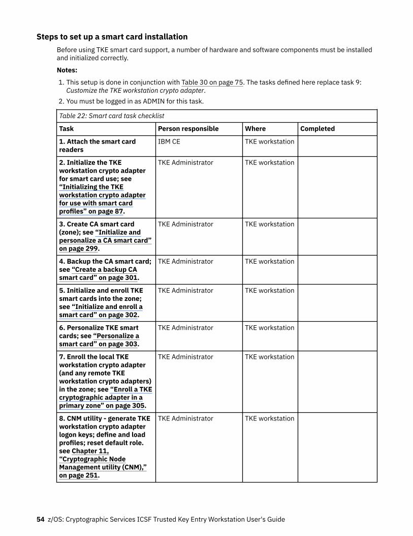
Steps to set up a smart card installationBefore using TKE smart card support, a number of hardware and software components must be installedand initialized correctly.
Notes:
1. This setup is done in conjunction with Table 30 on page 75. The tasks defined here replace task 9:Customize the TKE workstation crypto adapter.
2. You must be logged in as ADMIN for this task.
Table 22: Smart card task checklist
Task Person responsible Where Completed
1. Attach the smart cardreaders
IBM CE TKE workstation
2. Initialize the TKEworkstation crypto adapterfor smart card use; see“Initializing the TKEworkstation crypto adapterfor use with smart cardprofiles” on page 87.
TKE Administrator TKE workstation
3. Create CA smart card(zone); see “Initialize andpersonalize a CA smart card”on page 299.
TKE Administrator TKE workstation
4. Backup the CA smart card;see “Create a backup CAsmart card” on page 301.
TKE Administrator TKE workstation
5. Initialize and enroll TKEsmart cards into the zone;see “Initialize and enroll asmart card” on page 302.
TKE Administrator TKE workstation
6. Personalize TKE smartcards; see “Personalize asmart card” on page 303.
TKE Administrator TKE workstation
7. Enroll the local TKEworkstation crypto adapter(and any remote TKEworkstation crypto adapters)in the zone; see “Enroll a TKEcryptographic adapter in aprimary zone” on page 305.
TKE Administrator TKE workstation
8. CNM utility - generate TKEworkstation crypto adapterlogon keys; define and loadprofiles; reset default role.see Chapter 11,“Cryptographic NodeManagement utility (CNM),”on page 251.
TKE Administrator TKE workstation
54 z/OS: Cryptographic Services ICSF Trusted Key Entry Workstation User's Guide

Moving TKE and EP11 smart card data to smart cards in a new zoneTo move data from a TKE or EP11 smart card onto a corresponding TKE or EP11 smart card in a differentzone, either because you want to move to a stronger zone or because you want to consolidate data frommultiple zones into one zone, do the following:
1. Using the Smart Card Utility Program (SCUP) TKE Smart Card -> Enroll TKE smart card in alternatezone function, enroll all the target smart cards in the alternate zone of the source smart card. Thealternate zone must be the same as the primary zone of the source smart card.
Note: Alternate zones are only supported on smart cards that were initialized and personalized on TKE8.1 or later.
2. Using any of the copy smart card or duplicate smart card content features found in the CryptographicNode Management (CNM) or Trusted Key Entry (TKE) applications, copy the contents from the sourcesmart cards to their corresponding target smart cards.
Note: If the source TKE smart card is in a 1024-bit RSA zone, you must use a special process to movedata onto a blue smart card. See “Moving data from a TKE smart card in a 1024-bit zone to a bluesmart card” on page 55 for additional information.
Moving data from a TKE smart card in a 1024-bit zone to a blue smart cardBecause blue smart cards run in FIPS mode, the blue smart card cannot have primary or alternate zonesthat have 1024-bit RSA strength. Therefore, data cannot be moved directly from a TKE smart card that isenrolled in 1024-bit RSA zone onto a blue TKE smart card. In this case, the following steps must be takento move data from a 1024-bit zone TKE smart card onto a blue smart card:
Note: This process only applies to TKE smart cards. EP11 smart cards were never allowed to be in a1024-bit RSA strength zone.
1. In order to copy data from the source 1024-bit zone TKE smart card to a non-blue intermediate TKEsmart card, you first need to create the intermediate TKE smart card by using the Smart Card UtilityProgram File -> TKE zone wizard function. Do one of the following:
• If the target blue smart card is enrolled in an EC 521-bit zone, use the wizard to create anintermediate 2048-bit RSA strength Certificate Authority (CA) smart card. Once you have the new2048-bit zone CA smart card, use the wizard to create one non-blue intermediate TKE smart card.
• If the target blue smart card is enrolled in a 2048-bit zone, you do not need to create a CA smartcard. Use the wizard, with the existing CA smart card, to create one non-blue intermediate TKE smartcard.
The non-blue intermediate TKE smart card must:
• Not be a blue smart card.• Be enrolled in a 2048-bit zone.• Have the alternate zone equal to the source smart card’s 1024-bit zone primary zone.
2. If necessary, enroll all the target blue smart cards in the alternate zone of the non-blue intermediateTKE smart card. You only need to do this step if the non-blue intermediate and target blue smart cardsare not enrolled in the same zone. Using the Smart Card Utility Program TKE Smart Card -> Enroll TKEsmart card in alternate zone function, enroll all the target blue smart cards in the alternate zone.
3. Using any of the copy smart card or duplicate smart card content features found in the CryptographicNode Management (CNM) or Trusted Key Entry (TKE) applications, copy the contents from the source1024-bit RSA zone TKE smart card to the non-blue intermediate 2048-bit RSA zone TKE smart card.
Note: Repeat this step for each source and target smart card pair.4. Using any of the copy smart card or duplicate smart card content features found in the Cryptographic
Node Management (CNM) or Trusted Key Entry (TKE) applications, copy the contents from the non-blue intermediate TKE smart card to the target blue TKE smart card. The target smart card must have
Using smart cards with TKE 55

the primary zone equal to the non-blue intermediate smart card’s primary zone or have the alternatezone equal to the non-blue intermediate smart card’s primary zone.
Note: Repeat this step for each source and target smart card pair.
56 z/OS: Cryptographic Services ICSF Trusted Key Entry Workstation User's Guide

Chapter 3. TKE upgrade and migration actions
When you upgrade an existing TKE to TKE 9.1 or when you want to copy data from one TKE to another,there are some things to consider:
• When you upgrade a TKE from one version to another, do not install the new TKE licensed internal code(LIC) or replace the TKE local crypto adapter if a new adapter is required. These tasks are done by anIBM Customer Engineer (CE). However, during an upgrade process, there are decisions and actions youneed to take part in. Those actions are discussed in this topic.
• If you purchased a new TKE, this new TKE might be a replacement for an existing TKE or it might be abackup to an existing TKE. In either case, you want to copy data from the existing TKE and place it onthe new TKE. The processes for copying the data on the source TKE and applying the data to the targetTKE are discussed in this topic.
The topic includes:
• “Considerations before upgrading a TKE or copying data from an existing TKE” on page 57• “Upgrading an existing TKE workstation to TKE 9.1” on page 62• “Moving data from a TKE Version 5.x, 6.0, 7.x, 8.0, or 9.x to a new workstation at TKE 9.1” on page 64
Considerations before upgrading a TKE or copying data from an existing TKE• “DVD-RAM is not supported on a TKE 7.2 or later system” on page 57• “Copying files to the TKE 7.0 or TKE 7.1 hard drive” on page 57• “Copying files to a USB flash memory drive while on a TKE 7.0 or TKE 7.1 system” on page 58• “Preparing for a new TKE local crypto adapter” on page 60
DVD-RAM is not supported on a TKE 7.2 or later systemImportant: If you are still using DVD-RAM on a pre-TKE 7.2 system, DVD-RAM is not supported on TKE7.2 or later systems. If you want to continue to use files that are on your DVD-RAM on a TKE 7.2 or later,you must remove the data from the DVD-RAM before your move to the TKE 7.2 or later system.
Beginning with TKE 7.2, you can no longer read files from a DVD-RAM. Therefore, if you have a DVD-RAMthat is formatted for TKEDATA (TKEDATA DVD-RAM) and you want to use the files from the TKEDATA DVD-RAM on a TKE 7.2 or later system, do one of the following procedures:
• Copy the files from the TKEDATA DVD-RAM to the TKE's hard drive before upgrading the TKE to version7.2 or later. For more information, see “Copying files to the TKE 7.0 or TKE 7.1 hard drive” on page 57.
• Copy the files from the TKEDATA DVD-RAM to a USB flash memory drive that is formatted for TKEDATAfrom a TKE 7.0 or TKE 7.1 system. For more information, see “Copying files to a USB flash memory drivewhile on a TKE 7.0 or TKE 7.1 system” on page 58.
Copying files to the TKE 7.0 or TKE 7.1 hard driveBecause DVD-RAM is no longer supported on TKE 7.2 or later systems, perform the following steps if youdo not need to use removable media in the future. To copy any files you have on a TKEDATA DVD-RAM tothe TKE's hard drive on the TKE 7.0 or TKE 7.1 system before upgrading to TKE 7.2 or later:
1. From the Trusted Key Entry Console on your TKE 7.0 or TKE 7.1 system, open the Trusted Key Entrywindow pane.
2. Perform the following setup steps for the source DVD-RAM:
a. Insert the TKEDATA DVD-RAM into the DVD drive.b. Open the TKE Media Manager utility.
© Copyright IBM Corp. 2000, 2019 57

Note: The TKE Media Manager is in the Utilities list on the Trusted Key Entry window pane.c. Select “Activate read only CD/DVD inserted in DVD drive” and press OK.
Note: When complete, the “DVD Drive Status” is “Active (Read Only)”.d. Press Cancel to close the TKE Media Manager.e. Press OK to close the informational warning message. Remember, the DVD drawer will not open
until the DVD drive is deactivated.3. Perform the following steps to copy the files from the DVD-RAM to the TKE 7.0 or TKE 7.1 hard drive:
a. Open the TKE File Management Utility.
Note: The TKE File Management Utility is in the Utilities list on the Trusted Key Entry window.b. On the left side of the File Management Utility window, select the CD/DVD Drive radio button.c. On the right side of the File Management Utility window, select the Local Hard Drive radio button.d. Select the files from the CD/DVD Drive file list and use the “Copy ->” button to copy files from the
CD/DVD Drive to the local hard drive.
Note: In general, store each file from the TKEDATA DVD-RAM into the directory that the fileoriginally came from. General information about the three most common types of files that aresaved on TKEDATA DVD-RAM include:
• Key part files should be stored in the TKE Data Directory.• Profile and role definition files should be stored in the CNM Directory.• Data from either of the host migration wizards should be stored in the Configuration Data
Directory.
Note: After the files are saved on the TKE 7.0 or TKE 7.1 system, the files are included in the datathat is saved and applied when the TKE system is upgraded to TKE 7.2 or later.
4. Perform the following clean-up steps:
a. Close the File Management Utility by selecting either “Exit” or “Exit and logoff” to close the TKEapplication window.
b. Open the TKE Media Manager utility.
Note: The TKE Media Manager is in the Utilities list on the Trusted Key Entry window pane.c. Select “Deactivate media inserted into DVD drive” and press OK. When complete, the “DVD Drive
Status” is “Deactivated”.d. Remove the TKEDATA DVD-RAM from the DVD drive.
Copying files to a USB flash memory drive while on a TKE 7.0 or TKE 7.1 systemBecause DVD-RAM is no longer supported on TKE 7.2 or later systems, perform the following steps if youwant to use removable media on a TKE 7.2 or later system. To copy your TKEDATA DVD-RAM files to aUSB flash memory drive that is formatted for TKEDATA from a TKE 7.0 or TKE 7.1 system:
1. From the Trusted Key Entry Console on your TKE 7.0 or TKE 7.1 system, open the Trusted Key Entrywindow pane.
2. Perform the following setup steps for the source DVD-RAM:
a. Insert the TKEDATA DVD-RAM into the DVD drive.b. Open the TKE Media Manager utility.
Note: The TKE Media Manager is in the Utilities list on the Trusted Key Entry window pane.c. Select “Activate read only CD/DVD inserted in DVD drive” and press OK.
Note: When complete, the “DVD Drive Status” is “Active (Read Only)”.d. Press Cancel to close the TKE Media Manager.
58 z/OS: Cryptographic Services ICSF Trusted Key Entry Workstation User's Guide

e. Press OK to close the informational warning message. Remember, the DVD drawer will not openuntil the DVD drive is deactivated.
3. Perform the following setup steps for the new USB flash memory removable media:
a. Insert the USB flash memory drive into any open USB port on the TKE 7.0 or TKE 7.1 workstationand wait for the “USB Device Status” message to appear.
Note:
• It can take up to 1 minute for the message to appear.• You can press OK to close the “USB Device Status” message or wait for it to close in 10 seconds.
b. Perform the following steps only if you want to format the USB flash memory drive. Proceed to Step“4” on page 59 if you do not want to format the USB flash memory drive.
The USB flash memory drive must be formatted if:
• The drive is not formatted for TKEDATA.• You want to remove any existing data from the USB flash memory drive before you copy your files.
You can use a USB flash memory drive that was formatted for TKEDATA on a TKE 7.2 or latersystem. To format the USB flash memory drive:
1) From the Trusted Key Entry Console on your TKE 7.0 or TKE 7.1 system, open the ServiceManagement window pane.
2) Open the Format Media application.3) Select the “Trusted Key Entry Data” radio button and press the FORMAT button.4) Select the radio button for the USB flash memory drive device you want to format and press OK.5) You might receive the “file system setting” window before the confirm format message. If you
do, take the default setting and press the FORMAT button.6) Press YES to confirm that you want to format the media.7) Press OK to close the completion message.
4. Perform the following steps to copy the files from the TKEDATA DVD-RAM to the USB flash memorydrive:
a. From the Trusted Key Entry Console on your TKE 7.0 or TKE 7.1 system, open the Trusted Key Entrywindow pane.
b. Open the TKE File Management Utility.
Note: The TKE File Management Utility is in the Utilities list on the Trusted Key Entry window.c. On the left side of the File Management Utility window, select the CD/DVD Drive radio button.d. On the right side of the File Management Utility window, select the USB Flash Memory Drive radio
button.e. Select the files from the CD/DVD Drive file list and use the “Copy ->” button to copy files from the
CD/DVD Drive to the USB flash memory drive.
Important: The directory pull-down menu does not apply to the USB flash memory drive. Do notchange the directory or it will also select the Local Hard Drive radio button.
Note: After all the files are stored on the USB flash memory drive:
• The USB flash memory drive can be used as removable media on any TKE 7.0 or later system.• You can remove the USB flash memory drive at any time.
5. Perform the following clean-up steps:
a. Close the File Management Utility by selecting either “Exit” or “Exit and logoff” to close the TKEapplication window.
b. Open the TKE Media Manager utility.
Note: The TKE Media Manager is in the Utilities list on the Trusted Key Entry window pane.
TKE upgrade and migration actions 59

c. Select “Deactivate media inserted into DVD drive” and press OK. When complete, the “DVD DriveStatus” is “Deactivated”.
d. Remove the TKEDATA DVD-RAM from the DVD drive.
Preparing for a new TKE local crypto adapterAll TKEs have a local crypto adapter. After a TKE has been configured according to your TKE securitypolicy, the TKE local crypto adapter will contain user-defined profiles and sometimes user-defined roles.You might want to configure a new TKE local crypto adapter with an existing set of user-defined roles anduser-defined profiles if:
• Your TKE is given a new TKE local crypto adapter as part of an upgrade. For example, an upgrade fromTKE 8.x to TKE 9.0 requires the 4767 TKE crypto adapter to be replaced with the 4768 TKE local cryptoadapter.
• You want to configure a new TKE workstation local crypto adapter with the same user-defined roles anduser-defined profiles found on an existing TKE local crypto adapter.
You might prefer to manually configure the new TKE local crypto adapter, but there are three methods forcreating files with user-defined role and user-defined profile definitions that can be copied and later usedto load the roles and profiles onto a new TKE local crypto adapter. The different methods for creating roleand profile definition files that can be used to load the roles and profiles onto a TKE local crypto adapterare:
• “Method 1: Creating TKESavedRoles.dat and TKESavedProfiles.dat files from CNM” on page 60• “Method 2: Creating TKESavedRoles.dat and TKESavedProfiles.dat files from the TKE Workstation Setup
wizard” on page 60• “Method 3: Creating individual user-defined role and user-defined profile definition files” on page 61
Method 1: Creating TKESavedRoles.dat and TKESavedProfiles.dat files from CNM
Beginning in TKE 8.0, the Crypto Node Management utility provides a feature that allows you to collect allthe user-defined role and user-defined profile definitions in one operation. If any user-defined roles arefound, the definitions are placed in the TKESavedRoles.dat file. If any user-defined profiles are found, thedefinitions are placed in the TKESavedProfiles.dat file. The following steps can be used to create thesefiles:
1. From the Trusted Key Entry Console, select Cryptographic Node Management Utility.2. Select Access Control > Save User Roles and Profiles.
Method 2: Creating TKESavedRoles.dat and TKESavedProfiles.dat files from the TKE WorkstationSetup wizard
Beginning in TKE 7.3, the TKESavedRoles.dat and TKESavedProfiles.dat files can be created by a stepinside the TKE Workstation Setup wizard. In TKE 7.3, only the tasks in the TKE Workstation setup wizardcan use these files. The following steps can be used to create these files:
1. On the source TKE workstation, close all windows except the pre-logon screen. The pre-logon screenhas the title Welcome to the Trusted Key Entry Console.
2. Select Privileged Mode access.3. Enter admin for the user ID.4. Enter the password. The default password for the admin user ID is password.5. From the Trusted Key Entry Console, select Trusted Key Entry.6. Open the TKE Workstation Setup wizard.7. Click Next as many times as necessary to skip to the Save User Roles and Profiles task.8. Select Yes.9. Click Next to perform the save.
• If a file exists, you are asked whether it can be overwritten.
60 z/OS: Cryptographic Services ICSF Trusted Key Entry Workstation User's Guide
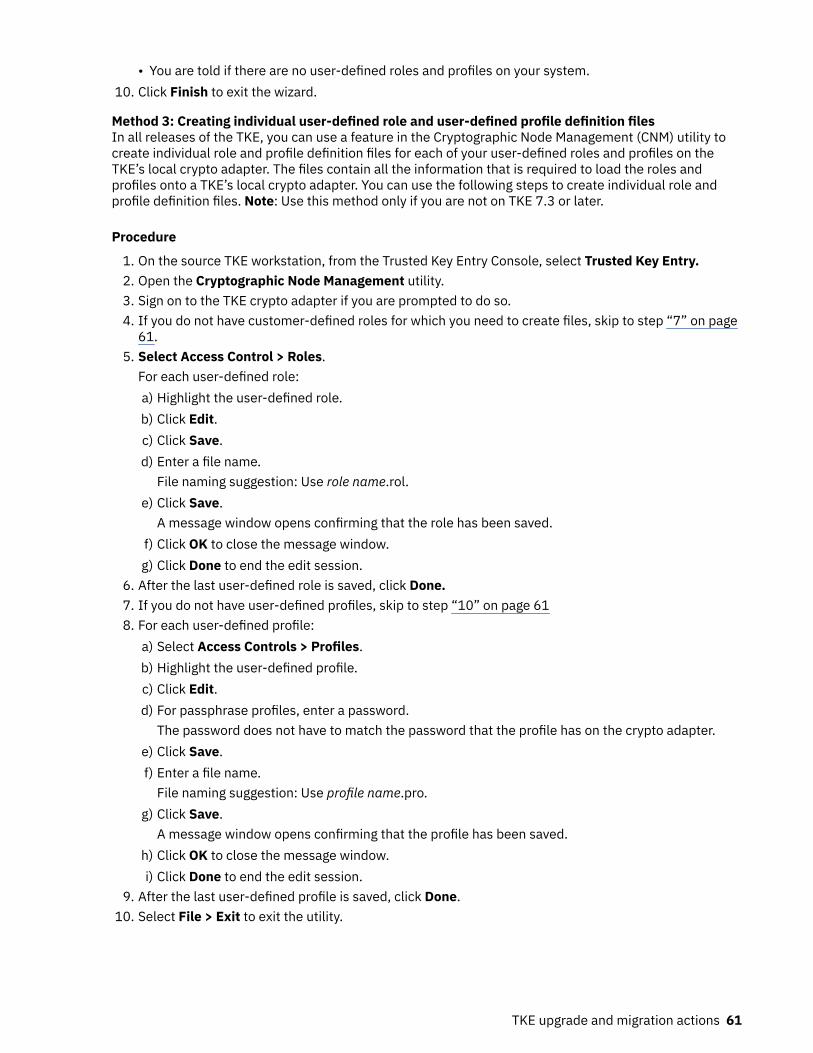
• You are told if there are no user-defined roles and profiles on your system.10. Click Finish to exit the wizard.
Method 3: Creating individual user-defined role and user-defined profile definition filesIn all releases of the TKE, you can use a feature in the Cryptographic Node Management (CNM) utility tocreate individual role and profile definition files for each of your user-defined roles and profiles on theTKE’s local crypto adapter. The files contain all the information that is required to load the roles andprofiles onto a TKE’s local crypto adapter. You can use the following steps to create individual role andprofile definition files. Note: Use this method only if you are not on TKE 7.3 or later.
Procedure
1. On the source TKE workstation, from the Trusted Key Entry Console, select Trusted Key Entry.2. Open the Cryptographic Node Management utility.3. Sign on to the TKE crypto adapter if you are prompted to do so.4. If you do not have customer-defined roles for which you need to create files, skip to step “7” on page
61.5. Select Access Control > Roles.
For each user-defined role:a) Highlight the user-defined role.b) Click Edit.c) Click Save.d) Enter a file name.
File naming suggestion: Use role name.rol.e) Click Save.
A message window opens confirming that the role has been saved.f) Click OK to close the message window.g) Click Done to end the edit session.
6. After the last user-defined role is saved, click Done.7. If you do not have user-defined profiles, skip to step “10” on page 618. For each user-defined profile:
a) Select Access Controls > Profiles.b) Highlight the user-defined profile.c) Click Edit.d) For passphrase profiles, enter a password.
The password does not have to match the password that the profile has on the crypto adapter.e) Click Save.f) Enter a file name.
File naming suggestion: Use profile name.pro.g) Click Save.
A message window opens confirming that the profile has been saved.h) Click OK to close the message window.i) Click Done to end the edit session.
9. After the last user-defined profile is saved, click Done.10. Select File > Exit to exit the utility.
TKE upgrade and migration actions 61

Upgrading an existing TKE workstation to TKE 9.1TKE 7.3 workstations with hardware feature code 0842 and TKE 8.0 or TKE 8.1 workstations withhardware feature code 0847, 0097, and 0098 can be upgraded to TKE 9.1. Upgrading the workstationrequires the purchase of the 4768 workstation crypto adapter.
When you upgrade an existing workstation to TKE 9.1, the TKE licensed internal code (LIC) is updated anda new TKE local crypto adapter is installed in the workstation. Both of these actions are completed by anIBM Customer Engineer (CE). At the end of the process, when the CE runs the TKE Workstation Setupwizard, you need to make the necessary customer-based decisions. The following steps are an overviewof the entire upgrade process:
1. You need to create the TKESavedRoles.dat and TKESavedProfiles.dat files that are used to load yourroles and profiles onto the new 4768 TKE local crypto adapter that the TKE workstation receives. Forinstructions on how to create these files, see “Preparing for a new TKE local crypto adapter” on page60. These files are included in the data that is collected during the save upgrade data.
2. Before the CE starts the firmware upgrade, the CE collects customer data on the workstation by usingthe Save Upgrade Data utility. The data is placed on a USB flash memory drive.
3. The CE powers down the TKE workstation and replaces the 4767 crypto adapter with the 4768 cryptoadapter.
Notes:
• When the 4767 crypto adapter is replaced with the 4768 crypto adapter, the TKE workstation'sfeature code also changes.
Table 23: TKE feature code changes
Starting TKE workstation feature code New TKE workstation feature code
0842 and 0847 0849
0097 0080
0098 0081
• Code is not placed on the new 4768 crypto adapter until the TKE Workstation Setup wizard is run.4. The CE installs the new TKE firmware on the TKE workstation by using the Install/Recovery procedure.5. The CE reapplies the customer data onto the TKE workstation by using the frame roll installation
procedure. The USB flash memory drive with the saved upgrade data is used during this procedure.This step also restores the network settings.
6. The CE runs the TKE Workstation Setup wizard to complete the workstation setup process. The wizardincludes a step for updating the code on the new TKE workstation’s local crypto adapter.
7. During a TKE workstation upgrade, you need to make the following customer configuration decisions.If you are not present when the CE runs the TKE Workstation Setup wizard, you can run the TKEWorkstation Setup wizard on your own. The following are a list of wizard steps that require yourattention:Initialize TKE crypto adapter
The new 4768 TKE local crypto adapter must be initialized. You need to decide whether the TKElocal crypto adapter is to be initialized for use with passphrase or smart card profiles.
Note that initializing the TKE local adapter zeroizes the adapter. Initialize the TKE local cryptoadapter only one time or when you want to return to a known starting point.
Hints:
• If your user-defined TKE local adapter profiles use the system-supplied roles of TKEUSER orTKEADM, you want to initialize your adapter for use with Passphrase profiles.
• If your user-defined TKE local adapter profiles use the system-supplied roles of SCTKEUSR orSCTKADM, you want to initialize your adapter for use with smart card profiles.
62 z/OS: Cryptographic Services ICSF Trusted Key Entry Workstation User's Guide

Enable smart card readersIf you use smart cards, select Yes.
Customize displayed hash sizeIf you are subject to any regulations or policies that require you to limit the length of your displayedkey verification patterns, you can select a reduced display length.
Load user roles and profilesIn the TKE 9.1 upgrade, the TKE workstation received a new TKE local crypto adapter. Your user-defined roles and profiles need to be loaded onto this new adapter. If you created and saved theTKESavedRoles.dat and TKESavedProfiles.dat files, as mentioned in step 1, the wizard finds thefiles and reloads your roles and profiles.
Note: You must set the passphrase for any passphrase profile you load onto the new TKE cryptoadapter.
Add new access control points to your user rolesIf you have any user-defined roles, you might need to add new access control points to the roles.
Check TKE crypto adapter group profilesIn the past, it was recommended that members of a TKE local crypto adapter group profile beassigned the role of DEFAULT. TKE now contains the system-supplied role of TKEGRPMB (TKEgroup member role). The TKEGRPMB role contains only the required ACPs. Checking TKE cryptoadapter group profiles determines whether you have any TKE local adapter group profile memberswith the role of DEFAULT. If you do, the wizard offers you the option to change the member’s roleto TKEGRPMB.
Save user roles and profilesIf you changed any group member profiles, you might want to save your updated user-definedroles and profiles.
Convert crypto module groups to domain groupsIf you have any crypto module groups from a pre-TKE 8.0 system, you can use this utility to creatednew domain groups based on the existing group definition.
Note: You can do this process only when you are willing and able to open the hosts included in thegroup. You might want to do the conversion later.
Enroll TKE crypto adapter in a zoneIf your TKE was enrolled in a zone before the upgrade, you need to enroll your new 4768 TKE localcrypto adapter in your zone. The CA smart card with the zone is required for this operation.
Add migration zoneIf you use the Configuration Migration Tasks application, the list of known MCAs was cleared whenthe new 4768 crypto module was initialized. You need to add your MCAs to your MCA zone list. TheMCA smart card or cards are required for this operation.
Add key part holder certificatesThe upgrade operation saved and restored customer data. The list of known key part holders(KPHs) is restored. You do not need to add you KPH certificates again.
Change enhanced password encryption policyThe TKE always uses the best available method for protecting the host password during a sign-onoperation. When ICSF is at FMID HCR77B0 or later, enhanced password protection is used. Youcan select a policy that only allows a host sign-on attempt if enhanced password protection isused. IBM recommends that you move to the minimum ICSF level of FMID HCR77B0 and that youselect the TKE policy that only allows a sign-on to systems that support enhanced passwordprotection.
Your TKE 9.1 is ready for use when all preceding steps are completed.
TKE upgrade and migration actions 63
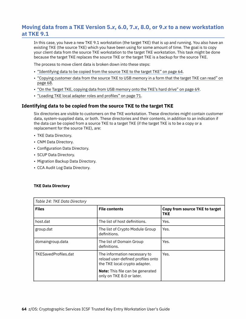
Moving data from a TKE Version 5.x, 6.0, 7.x, 8.0, or 9.x to a new workstationat TKE 9.1
In this case, you have a new TKE 9.1 workstation (the target TKE) that is up and running. You also have anexisting TKE (the source TKE) which you have been using for some amount of time. The goal is to copyyour client data from the source TKE workstation to the target TKE workstation. This task might be donebecause the target TKE replaces the source TKE or the target TKE is a backup for the source TKE.
The process to move client data is broken down into these steps:
• “Identifying data to be copied from the source TKE to the target TKE” on page 64.• “Copying customer data from the source TKE to USB memory in a form that the target TKE can read” on
page 68.• “On the Target TKE, copying data from USB memory onto the TKE’s hard drive” on page 69.• “Loading TKE local adapter roles and profiles” on page 71.
Identifying data to be copied from the source TKE to the target TKESix directories are visible to customers on the TKE workstation. These directories might contain customerdata, system-supplied data, or both. These directories and their contents, in addition to an indication ifthe data can be copied from a source TKE to a target TKE (if the target TKE is to be a copy or areplacement for the source TKE), are:
• TKE Data Directory.• CNM Data Directory.• Configuration Data Directory.• SCUP Data Directory.• Migration Backup Data Directory.• CCA Audit Log Data Directory.
TKE Data Directory
Table 24: TKE Data Directory
Files File contents Copy from source TKE to targetTKE
host.dat The list of host definitions. Yes.
group.dat The list of Crypto Module Groupdefinitions.
Yes.
domaingroup.data The list of Domain Groupdefinitions.
Yes.
TKESavedProfiles.dat The information necessary toreload user-defined profiles ontothe TKE local crypto adapter.
Note: This file can be generatedonly on TKE 8.0 or later.
Yes.
64 z/OS: Cryptographic Services ICSF Trusted Key Entry Workstation User's Guide

Table 24: TKE Data Directory (continued)
Files File contents Copy from source TKE to targetTKE
TKESavedRoles.dat The information necessary toreload user-defined roles ontothe TKE local crypto adapter.
Note: This file can be generatedonly on TKE 8.0 or later.
Yes.
kphcard.dat The list of known Key PartHolders that are used in variousfeatures of the ConfigurationMigration Tasks application.
Yes.
zone.dat The list of known MigrationCertificate Authorities that areused in various features of theConfiguration Migration Tasksapplication.
No. The MCA must be explicitlyadded to the list of known MCAson the target TKE.
customer-named key part file Each file contains one key part. Yes. However, do not moveobsolete part.
customer-named authoritysignature key file
Each file contains one AuthoritySignature Key.
Yes. However, it is recommendedthat you store Signature Keys onsmart cards and not in files.
customer-named miscellaneousfile
Files might contain clientgenerated screen captures, traceinformation, or other items.
Maybe. Copy if you want toarchive or retain the data for anyreason. However, do not moveobsolete data.
CNM Data Directory
Table 25: CNM Data Directory (system-supplied files)
Files File contents Copy from source TKE to targetTKE
adapterinit_xx.cniadapteSCrinit_xx.cni
Where xx is the TKE release used.For example, 71.
Cryptographic Node Initializationfiles.
No.
default_xx.roltempdefault_xx.rolkeyman1_xx.rolkeyman2_xx.rolsctkeadm_xx.rolsctkeusr_xx.roltkeadm_xx.roltkeuser_xx.rol
Where xx is the TKE release used.For example, 71.
Role definition files. No.
TKE upgrade and migration actions 65

Table 25: CNM Data Directory (system-supplied files) (continued)
Files File contents Copy from source TKE to targetTKE
keyman1.prokeyman2.protkeadm.protkeuser.rol
Profile definition files. No.
aesstore.dataesstore.dat.NDXfesstore.datdesstore.dat.NDXpkastore.datkastore.dat.ND
Local Key Store files. No.
Fcv_4tkexx.crt
Where xx is the TKE release used.For example, 80.
Function Control Vector files. No.
Table 26: CNM Data Directory (Customer-named files)
Files File contents Copy from source TKE to targetTKE
customer-named cni file
File name likely ends with .cni.
Cryptographic Node Initializationfiles.
Note: Old method for configuringlocal crypto module. This methodis obsolete and discouraged.
No. Obsolete data.
customer-named role definitionfile
File name likely ends with .rol.
Role definition files. Maybe. Only move ifTKESaveRoles.dat support is notavailable.
customer-named profile definitionfile
File name likely ends with .pro.
Profile definition files. Maybe. Only move ifTKESaveProfiles.dat support isnot available.
Configuration Data Directory
Table 27: Configuration Data Directory
Files File contents Copy from source TKE to targetTKE
customer-named full collect file Collect files from theConfiguration Migration Tasksapplication.
Yes. However, do not moveobsolete files.
66 z/OS: Cryptographic Services ICSF Trusted Key Entry Workstation User's Guide

Table 27: Configuration Data Directory (continued)
Files File contents Copy from source TKE to targetTKE
customer-named public infocollect file
Collect files from the MigrateHost Crypto Module PublicConfiguration Data application.
Yes. However, do not moveobsolete files.
SCUP Data Directory
This directory is empty.
Migration Backup Data Directory
This directory is empty.
CCA Audit Log Data Directory
The CCA Audit Log Data Directory is new with TKE 9.0 and only available when you sign on to the TKEworkstation in Privileged Mode Access with the AUDITOR ID.
Table 28: CCA Audit Log Data Directory
Files File contents Copy from source TKE to targetTKE
customer-named audit log file Archive files of domain-specificaudit logs from a host cryptomodule domain.
Available with CEX6C and later.
Maybe. Move the files if you wantto archive the files on the targetTKE.
Table 29 on page 67 contains a summary of the data that can be copied from the source TKE to thetarget TKE.
Table 29: Summary of data to be copied from the source TKE.
Source directory File name Copy from source TKE to targetTKE
TKE Data Directory host.dat Yes.
group.dat Yes.
domaingroup.data Yes.
TKESavedProfiles.dat Yes.
TKESavedRoles.dat Yes.
kphcard.dat Yes.
customer-named key part files Yes, if current.
customer-named authoritysignature key files
Yes, if current.
customer-named miscellaneousfiles
Yes, if current.
TKE upgrade and migration actions 67

Table 29: Summary of data to be copied from the source TKE. (continued)
Source directory File name Copy from source TKE to targetTKE
CNM Data Directory customer-named role definitionfiles
Yes, if TKESavedRoles.dat is notavailable.
customer-named profile definitionfiles
Yes, if TKESavedProfiles.dat isnot available.
Configuration Data Directory customer-named full informationcollect files
Yes, if current.
customer-named publicinformation collect files
Yes, if current.
CCA Audit Log Data Directory customer-named domain-specificaudit log archive files
Yes, if retaining or backing updata.
Copying customer data from the source TKE to USB memory in a form that the target TKEcan read
When you know what data needs to be copied and moved to the target TKE, select a method for copyingthe data to removable media. The options are:
• “Format USB memory for TKEDATA” on page 68.• “Method 1: Copying data to USB memory by using the Save/Restore Customizable Console Data
application” on page 68.• “Method 2: Manually copy data to USB memory by using the TKE File Management Utility” on page 69.
Format USB memory for TKEDATA
All the methods for copying and moving data require the USB memory to be formatted for TKEDATA. Usethe following procedure to format the removable USB memory:
1. From the Trusted Key Entry Console select Service Management.2. Open the Format Media application.3. Select the Trusted Key Entry Data radio button.4. Click Format.5. Select your USB flash memory device.6. Click OK to start the format process.7. Click Format. Do not change the file system format.8. Click Yes to allow the media to be overwritten.9. Click OK to close the completion message.
Method 1: Copying data to USB memory by using the Save/Restore Customizable Console Dataapplication
This method is only available on TKE 8.1 and later. In this case, all the customer data is saved by using theSave/Restore Customizable Console Data application of the TKE. Use the following procedure to run theapplication:
Note: All the files in the listed directories are copied, including system-supplied files. There are no issueswith moving the system-supplied files.
1. On the source TKE workstation, close all windows except the pre-logon screen. The pre-logon screenhas the title Welcome to the Trusted Key Entry Console.
2. Select Privileged Mode Access.
68 z/OS: Cryptographic Services ICSF Trusted Key Entry Workstation User's Guide

3. Enter admin for the user ID.4. Enter the password. The default password for the admin user ID is password.5. From the Trusted Key Entry Console, select Service Management.6. Open the Save/Restore Customizable Console Data application.7. Select the following:
a. The TKE Data check box.b. The USB flash memory driver radio button.c. (Optional) The User Profile Data check box if you want to copy the password information for
Privileged Access Mode IDs of ADMIN, SERVICE, and AUDITOR.8. Click Save.9. Select your USB flash memory device.
10. Click OK to start the save process.11. Click Yes to save.12. Click OK to close the completion message.13. Click Cancel to close the application.
Method 2: Manually copy data to USB memory by using the TKE File Management Utility
With this method, you explicitly decide which files you copy to USB memory. Use the following procedureto run the TKE file Management Utility:
1. From the Trusted Key Entry Console, select Trusted Key Entry.2. Open the TKE file Management Utility.3. On the right side of the TKE file Management Utility panel, select the USB Flash Memory Drive radio
button.
Note: If the copy is done on TKE 9.0 or later, you can preserve the TKE directory structure on the USBdrive. You select the appropriate subdirectory on the USB flash memory drive.
4. On the left side of the TKE file Management Utility panel, select:
a. The local hard drive radio button.b. The TKE Data Directory.c. Highlight the files to be copied.
5. Press the Copy button that points to the USB Flash Memory side.6. Repeat steps 4 and 5 for any of the following directories if they exist and contain data that you want to
copy onto the target TKE:
a. CNM Data Directory.b. Configuration Data Directory.c. CCA Audit Log Data Directory.
7. Select File > Exit to close the utility.
On the Target TKE, copying data from USB memory onto the TKE’s hard driveWhen your customer data is on USB flash memory, copy the data onto the target TKE. The method that isused to copy the data on the target TKE depends on how the data was placed on the USB flash memorydrive.
• “Method 1: Using the Save/Restore Customizable Console Data application to put your customer dataonto the TKE” on page 70.
• “Method 2: Manually copy data from USB memory by using the TKE File Management Utility” on page70
TKE upgrade and migration actions 69

Method 1: Using the Save/Restore Customizable Console Data application to put your customer dataonto the TKE
This method is only available on TKE 8.1 and later. In this case, your USB flash memory drive contains thefile that is created during the save operation of the Save/Restore Customizable Console Data application.Use the following procedure to run the restore operation on the target TKE:
Notes:
• If a file was saved and exists on the target TKE, the file on the target TKE is overwritten during therestore operation.
• No files are removed from the target TKE by this operation.
1. On the source TKE workstation, close all windows except the pre-logon screen. The pre-logon screenhas the title Welcome to the Trusted Key Entry Console.
2. Select Privileged Mode Access.3. Enter admin for the user ID.4. Enter the password. The default password for the admin user ID is password.5. From the Trusted Key Entry Console, select Service Management.6. Open the Save/Restore Customizable Console Data application.7. Select the following:
a. The TKE Data check box.b. The USB flash memory driver radio button.c. (Optional) The User Profile Data check box if you have this data and want to restore it.
8. Click Restore.9. Select your USB flash memory device.
10. Click OK to start the restore process.11. Click Yes to restore.12. Click OK to close the completion message.13. Click Cancel to close the application.
Important: This method restores the zone.dat file. If zone.data was copied onto the target TKE, you mustopen the Configuration Migration Tasks application, remove all the known migration zones from the list,and explicitly add your migration zones to the list.
Method 2: Manually copy data from USB memory by using the TKE File Management Utility
With this method, you explicitly copy the files onto the target TKE. Use the following procedure to run theTKE file Management Utility:
1. From the Trusted Key Entry Console, select Trusted Key Entry.2. Open the TKE file Management Utility.3. On the left side of the TKE file Management Utility panel, select:
a. The local hard drive radio button.b. The TKE Data Directory.
4. On the right side of the TKE file Management Utility panel, select:
a. The USB Flash Memory Drive radio button.
Note: On TKE 9.0 or later, you need to select the subdirectory that contains your data.b. Highlight the files to be copied to the target directory.
5. Press the Copy button that points to the local hard drive.6. Repeat steps 3, 4, and 5 for any of the files that belong in any of the following directories:
70 z/OS: Cryptographic Services ICSF Trusted Key Entry Workstation User's Guide

a. CNM Data Directory.b. Configuration Data Directory.c. CCA Audit Log Data Directory.
7. Select File > Exit to close the utility.
Loading TKE local adapter roles and profilesIf you chose to save the TKE local crypto adapter user-defined role and user-defined profile definitions, itis time to load the roles and profiles onto the TKE local crypto adapter.
• “Method 1: Loading the roles and profiles from TKESavedRoles.dat and TKESavedProfiles.dat fromCNM” on page 71
• “Method 2: Loading the individual user-defined roles and user-defined profiles for unique definitionfiles” on page 71.
Method 1: Loading the roles and profiles from TKESavedRoles.dat and TKESavedProfiles.dat fromCNM
Note: You can also use the TKESavedRoles.dat and TKESavedProfiles.dat files to reload the roles andprofiles for the TKE Workstation Setup application.
This method is only available on TKE 8.0 or later. In this case, all the role and profile definitions are in filesthat a single Cryptographic Node Management Utility feature can use. The following procedure loads theroles and profiles for you:
1. From the Trusted Key Entry Console, select Trusted Key Entry.2. Open the Cryptographic Node Management Utility.3. Sign on as required.4. Select Access Control > Load User Roles and Profiles.
Note: For any passphrase profiles, you must enter a new passphrase. If a profile exists, you mustdecide whether it is over written.
5. You are asked if you want to delete or keep the TKESaveProfiles.dat and TKESavedRoles.dat files.Select NO to keep the files or YES to delete the files.
6. Select File > Exit to close the utility.
Method 2: Loading the individual user-defined roles and user-defined profiles for unique definitionfilesUsing the Cryptographic Node Management (CNM) utility, you can load the roles and profiles from yourindividual role and profile definition files. The following procedure can be used to load roles and profilesfrom your role and profile definition files.
Procedure
1. On the source TKE workstation, from the Trusted Key Entry Console, select Trusted Key Entry.2. Open the Cryptographic Node Management utility.3. Sign on to the TKE crypto adapter if you are prompted to do so.4. If you do not have customer-defined role definition files, skip to step “7” on page 72.5. Select Access Control > Roles.
For each user-defined role definition file:a) Click Open.b) Highlight the user-defined role definition file.c) Click Open.d) Click Load.e) Click OK to close the message window.
TKE upgrade and migration actions 71

6. After the last user-defined role is saved, click Done.7. If you do not have user-defined profiles for which you need to create files, skip to step “10” on page
728. Select Access Controls > Profiles. For each user-defined profile:
a) Select Open.b) Highlight the user-defined profile definition file.c) Click Open.d) Click Load.e) Click OK to close the message window.
9. After the last user-defined profile is saved, click Done.10. Select File > Exit to exit the utility.
Recovery installationIn general you should not need to install TKE code on your workstation. If you are directed to do so, followthese instructions.
Before you beginYou need to have the TKE installation DVD and a USB flash memory drive.
About this taskThere are four parts to this task:
1. Save the customer data that is on the TKE workstation to the USB flash memory drive.2. Perform the TKE workstation code update.3. Reapply the saved customer data to the TKE workstation using a Frame Roll installation.4. Run the TKE Workstation Setup wizard to complete the workstation setup tasks.
Procedure
Save the customer data on the TKE workstation to a USB flash memory drive.1. Follow the instructions in “Copying customer data from the source TKE to USB memory in a form that
the target TKE can read” on page 68.2. You can install the USB flash memory with the save upgrade data onto your TKE workstation at this
time or wait until step “9.a” on page 73.Perform the TKE workstation code update.
3. Insert the first TKE installation DVD into the DVD drive on the TKE workstation.4. Restart the TKE workstation:
a) Select Service Management.b) Select Shutdown or Restart.c) Select Restart Console.d) Click OK.e) Click Yes on the Confirm Shutdown or Restart window.
It can take over 7 minutes for the restart operation to complete.5. On the Trusted Key Entry: Upgrade / Install Recovery / Frame role window, enter option 2 (Install
Recovery) and click Enter.6. Select option 1 and click Enter to start the Install Recovery process.
It can take over 15 minutes for the TKE code installation to complete. You might receive the messageif the RC is zero, press ENTER to continue. If so, click Enter.
72 z/OS: Cryptographic Services ICSF Trusted Key Entry Workstation User's Guide

Note: Click Enter when you receive the green message, "The operation has completed with RC=0."and then click Enter on the "Part 1 successful" screen.
The DVD drive opens. Replace first TKE installation DVD with the second TKE installation DVD andclose the DVD drive. Click Enter, if necessary, to continue the install process. Click Enter when youreceive the OPERATION SUCCESSFUL message and take out the second TKE installation DVD whenthe DVD drawer opens. Insert first TKE installation DVD again. Close the drawer and click Enter, ifnecessary.
Apply the user data to the TKE workstation using a Frame Roll installation.7. On the Trusted Key Entry: Upgrade / Install Recovery / Frame Roll window, enter option 3 (Frame
Roll) and click Enter.8. Select option 1 and click Enter to start the Frame Roll process.
When the Frame Roll installation is complete, the DVD drive opens and a message window opens withOPERATION SUCCESSFUL at the top.
9. Follow the steps listed in the message window.a) Insert the USB flash memory drive that contains the Save Upgrade data, if it is not already
installed in the workstation.b) Remove the TKE installation DVD from the DVD drive. You can manually close the door to the DVD
drive, or let it close automatically in the next step.c) Click Enter to restart the TKE workstation.
It can take over 10 minutes for the workstation to restart. When restart processing completes, theinstallation is complete and the message "TKE: Trusted Key Entry Console Workplace (Version 7.2)"displays.
Run the TKE Workstation Setup wizard to complete the workstation setup tasks.10. Close all windows except the pre-logon window.
The pre-logon window has the title Welcome to the Trusted Key Entry Console.11. Select Privileged Mode Access.12. Enter admin for the user ID.13. Enter the password.
The default password for the admin user id is password.14. From the Trusted Key Entry Console, select Trusted Key Entry.15. Open the TKE Workstation Setup Wizard16. Click Finish when you are finished.
ResultsYour recovery installation is complete. You have saved the customer data on the TKE workstation,updated the TKE workstation code, reapplied the customer data to the workstation, and completed theworkstation setup.
TKE upgrade and migration actions 73

74 z/OS: Cryptographic Services ICSF Trusted Key Entry Workstation User's Guide

Chapter 4. TKE setup and customization
To use the Trusted Key Entry key management system, several complex tasks must be completed.
Table 30: TKE management system task checklist
Task Responsible Where Completed
1. Configure the host cryptomodules
IBM CE or Client OperationsRepresentative
Support Element
2. Load host crypto moduleconfiguration data, ensure LICcode has been loaded
IBM CE or Client OperationsRepresentative
Support Element
3. If operating in LPAR mode,configure the processor
IBM CE or Client OperationsRepresentative
Support Element
4. Permit each host cryptomodule for TKE commands
IBM CE or Client OperationsRepresentative
Support Element
5. Update TCP/IP profiles forTKE
Client Network orCommunications Serverpersonnel and ICSFAdministrator
Host z/OS System
6. Customize TKE Host Programstarted procs (delivered withICSF)
Client Network orCommunications Serverpersonnel and ICSFAdministrator
Host z/OS System
7. Ensure RACF administrationis complete.
Client SecurityAdministrator
Host z/OS System
8. Start ICSF Client Operations or SystemProgrammer
Host z/OS SystemConsole
9. Customize the TKEworkstation crypto adapter
TKE Administrator TKE workstation
10. TKE ApplicationCustomization
TKE Administrator TKE workstation
For more information on tasks 1 and 2, see Z Service Guide for TKE Workstations.
For more information on tasks 3 and 4, see:
• Z Service Guide for TKE Workstations.• PR/SM Planning Guide.• “TKE enablement” on page 11.• Appendix B, “LPAR considerations,” on page 323.
TKE TCP/IP setupTKE uses TCP/IP for communication between the TKE workstation and the z/OS operating system. Youshould already have TCP/IP installed and configured.
© Copyright IBM Corp. 2000, 2019 75

1. If you do not have a domain name server running, update the Hosts file with your IP address. TKErefers to the host by IP address, not by the host name. If a domain name server (DNS) is running, thenthis update is unnecessary as all hosts will be identified to the DNS.
HOST : 9.117.59.140 :
Figure 7: Entry example2. Update your TCPIP profile to reserve a port for the TKE application.
PORT 50003 TCP CSFTTCP ;ICSF TKE Server
Figure 8: Example of reserving a port
The example allows use of the port by the server named CSFTTCP. The port number must not start incolumn 1. TCP is the port type. CSFTTCP is the name of the started procedure. The 50003 is added tothe port section and can be changed by the installation. The port number here has to be specified onthe workstation when connecting to the host.
Any job with jobname CSFTTCP can connect to this port.
TKE host transaction program setupThe TKE Host Transaction Program (TKE HTP) is the host-based part of Trusted Key Entry. It forms theinterface between the TKE workstation and the host crypto modules.
The TKE HTP (server) needs to be started before a TKE workstation (client) can communicate with thehost crypto modules. The TKE HTP consists of a started procedure (CSFTTCP) which passes some start-up parameters to a REXX clist (CSFTHTP3). The clist then calls a module (CSFTTKE) that does RACFauthorization checking to make sure that no unauthorized clients get to the TKE HTP server.
In order to run the new TKE Host Transaction program, the CSFTTKE module must be added to theauthorized command list in IKJTSOxx on the system where the TKE HTP server will be started.
Perform these steps to install the server:
1. Update the authorized commands list in the TSO/E commands and programs member, IKJTSOxx, inthe SYS1.PARMLIB data set.
AUTHCMD NAMES( /* AUTHORIZED COMMANDS */ + COMMAND1 /* */ + COMMAND2 /* */ + COMMAND3 /* */ + . + . + . + CSFTTKE /* AUTHORIZE TKE */ + . + . + . +
Figure 9: Format of AUTHCMD2. Set up system security
You will associate a RACF profile or group with the TKE Host Transaction Program. The userid or groupassociated with the TKE host transaction program must be authorized to all the APIs in the CSFSERVclass it will use.
76 z/OS: Cryptographic Services ICSF Trusted Key Entry Workstation User's Guide
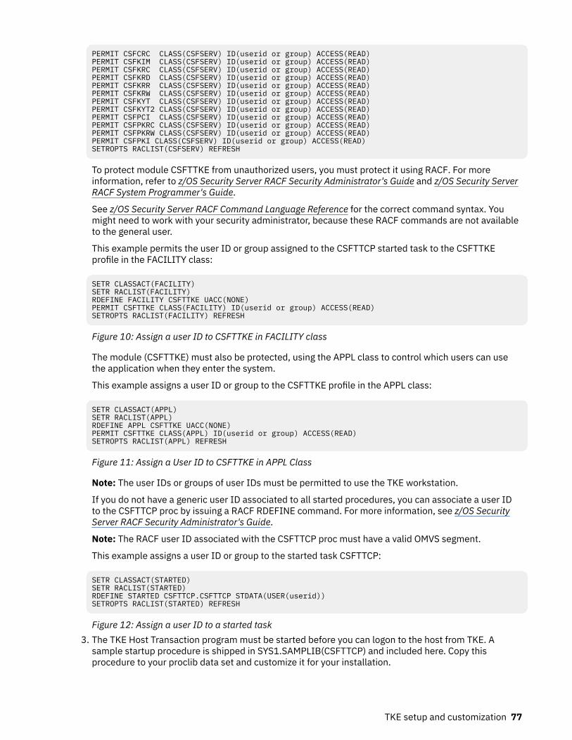
PERMIT CSFCRC CLASS(CSFSERV) ID(userid or group) ACCESS(READ)PERMIT CSFKIM CLASS(CSFSERV) ID(userid or group) ACCESS(READ)PERMIT CSFKRC CLASS(CSFSERV) ID(userid or group) ACCESS(READ)PERMIT CSFKRD CLASS(CSFSERV) ID(userid or group) ACCESS(READ)PERMIT CSFKRR CLASS(CSFSERV) ID(userid or group) ACCESS(READ)PERMIT CSFKRW CLASS(CSFSERV) ID(userid or group) ACCESS(READ)PERMIT CSFKYT CLASS(CSFSERV) ID(userid or group) ACCESS(READ)PERMIT CSFKYT2 CLASS(CSFSERV) ID(userid or group) ACCESS(READ)PERMIT CSFPCI CLASS(CSFSERV) ID(userid or group) ACCESS(READ)PERMIT CSFPKRC CLASS(CSFSERV) ID(userid or group) ACCESS(READ)PERMIT CSFPKRW CLASS(CSFSERV) ID(userid or group) ACCESS(READ)PERMIT CSFPKI CLASS(CSFSERV) ID(userid or group) ACCESS(READ)SETROPTS RACLIST(CSFSERV) REFRESH
To protect module CSFTTKE from unauthorized users, you must protect it using RACF. For moreinformation, refer to z/OS Security Server RACF Security Administrator's Guide and z/OS Security ServerRACF System Programmer's Guide.
See z/OS Security Server RACF Command Language Reference for the correct command syntax. Youmight need to work with your security administrator, because these RACF commands are not availableto the general user.
This example permits the user ID or group assigned to the CSFTTCP started task to the CSFTTKEprofile in the FACILITY class:
SETR CLASSACT(FACILITY)SETR RACLIST(FACILITY)RDEFINE FACILITY CSFTTKE UACC(NONE) PERMIT CSFTTKE CLASS(FACILITY) ID(userid or group) ACCESS(READ)SETROPTS RACLIST(FACILITY) REFRESH
Figure 10: Assign a user ID to CSFTTKE in FACILITY class
The module (CSFTTKE) must also be protected, using the APPL class to control which users can usethe application when they enter the system.
This example assigns a user ID or group to the CSFTTKE profile in the APPL class:
SETR CLASSACT(APPL)SETR RACLIST(APPL)RDEFINE APPL CSFTTKE UACC(NONE)PERMIT CSFTTKE CLASS(APPL) ID(userid or group) ACCESS(READ) SETROPTS RACLIST(APPL) REFRESH
Figure 11: Assign a User ID to CSFTTKE in APPL Class
Note: The user IDs or groups of user IDs must be permitted to use the TKE workstation.
If you do not have a generic user ID associated to all started procedures, you can associate a user IDto the CSFTTCP proc by issuing a RACF RDEFINE command. For more information, see z/OS SecurityServer RACF Security Administrator's Guide.
Note: The RACF user ID associated with the CSFTTCP proc must have a valid OMVS segment.
This example assigns a user ID or group to the started task CSFTTCP:
SETR CLASSACT(STARTED)SETR RACLIST(STARTED)RDEFINE STARTED CSFTTCP.CSFTTCP STDATA(USER(userid))SETROPTS RACLIST(STARTED) REFRESH
Figure 12: Assign a user ID to a started task3. The TKE Host Transaction program must be started before you can logon to the host from TKE. A
sample startup procedure is shipped in SYS1.SAMPLIB(CSFTTCP) and included here. Copy thisprocedure to your proclib data set and customize it for your installation.
TKE setup and customization 77

//CSFTTCP PROC LEVEL=CSF,MEMBER=CSFTHTP3, // CPARM='PORT;1000;SET DISPLAY LEVEL;TRACE ALL' //CLIST EXEC PGM= IKJEFT01, // PARM='EX ''&LEVEL..SCSFCLI0(&MEMBER)'' ''&CPARM'' EXEC' //STEPLIB DD DSN=EZA.SEZALINK,DISP=SHR//SYSABEND DD SYSOUT=*//SYSPRINT DD SYSOUT=* //SYSEXEC DD DSN=&LEVEL..SCSFCLI0,DISP=SHR //SYSPROC DD DSN=&LEVEL..SCSFCLI0,DISP=SHR //SYSTSPRT DD SYSOUT=* //SYSTSIN DD DUMMY //TKEPARMS DD DSN=&LEVEL..SAMPLIB(CSFTPRM),DISP=SHR //*//* customize the DSN to be the TCP/IP data set on your system //*//*SYSTCPD DD DSN=TCPIP.SEZAINST(TCPDATA),DISP=SHR// PEND CSFTTCP //* -----------------------------------------------------------------
Figure 13: Sample startup procedure
TKE startup parameters
Startup parameters may be passed to the TKE Host Transaction Program in a JCL parm field (CPARM)or in a data set referenced in the TKEPARMS DD statement. Parameters specified on the CPARM fieldoverride the parameters in the TKEPARMS data set. A sample TKEPARMS data set is shipped inSYS1.SAMPLIB(CSFTPRM).
These parameters are allowed:
• SET THE TKE DATA SETS;CM data set name
The CM data set will contain the crypto module descriptions, domain descriptions, and authorityinformation for a host. If the data set name does not exist, TKE will automatically create it on thehost the first time you send updates to it. If you do not specify a CM data set name, TKE uses adefault data set name of 'smfid.TKECM'.
Note: A fully qualified data set name may not be specified on the CPARM field. Use the TKEPARMS toset the fully qualified TKECM data set name.
Here are some examples:
– Example 1: SET THE TKE DATA SETS;TKECM
TKE will use data set name 'generic_id.TKECM'. The generic_id is the user ID assigned to theSTARTED class for this proc.
– Example 2: SET THE TKE DATA SETS;'TKEV3.TKECM'
TKE will use data set name 'TKEV3.TKECM'.• SET DISPLAY LEVEL;trace level
This parameter sets the amount of trace information that is written to the job log of the started proc.The valid options are:
– TRANSACTION TRACE - Logs HTP input and output transaction data– TRACE ALL - logs all HTP activities, including all TCP/IP verb return codes and information, input
and output transaction data, and ICSF input and output data– TRACE NON-ZERO - Logs TCP/IP verbs with non-zero return codes only (this is the default if
display level is not specified)• PORT;port number
This parameter defines the TCP/IP application port number that the started proc will use. This portnumber should be reserved in your TCP/IP profile for CSFTTCP to prevent other applications fromusing this port. This port number must be specified at the TKE workstation when defining a host (see“TKE TCP/IP setup” on page 75).
78 z/OS: Cryptographic Services ICSF Trusted Key Entry Workstation User's Guide

If a port number is not specified, a default port of 50003 will be used. However, if port 50003 is notreserved in your TCP/IP profile, another application may use it and the TKE HTP will fail.
For example: PORT;1000
SYSTCPD is optional but, depending on your TCP/IP installation, may be needed.
You may choose between implicit and explicit allocation.
• Implicit - The name of the configuration data set is constructed at run time, based on rulesimplemented in the components of TCP/IP. Once a data set name is constructed, TCP/IP uses thedynamic allocation services of z/OS to allocate the configuration data set.
• Explicit - TCP/IP searches for a specific DD name allocation for some configuration data sets. If youallocated a DD name with a DD statement in the JCL used to start a TCP/IP component, TCP/IP willread its configuration data from that allocation. It will not construct a configuration data set name fordynamic allocation.
4. Start the TKE server from the z/OS system console:
S CSFTTCP
Figure 14: Start the TKE server
Note: If you encounter problems during the start of CSFTTCP, the documented Errortype and ReasonCodes are located within the REXX clist CSFTHTP3.
Cancel the TKE serverTo cancel the TKE server:
S CSFTCTCP
Or
STOP CSFTTCP
Figure 15: Cancel the TKE server
A sample procedure CSFTCTCP is shipped in SYS1.SAMPLIB(CSFTCTCP). You must copy this procedure toyour proclib data set and customize it with the port number reserved for the TKE HTP server. If a portnumber is not specified, it defaults to 50003.
Note: Depending on your system setup, you might have to define the CSFTCTCP task to the RACFSTARTED class:
REDEFINE STARTED CSFTCTCP.CSFTCTCP STDATA(USER(userid))SETROPTS RACLIST(STARTED) REFRESH
TKE workstation setup and customizationThis topic describes several tasks that are necessary preparation for operating your TKE workstation.
The IBM CE installs the TKE cryptographic adapter into your TKE workstation and then powers it up.
Note: When using a KVM switching unit, the TKE windows might appear to be distorted. The TKE shouldbe initialized while it is connected directly to the LCD monitor. After initial boot up on the LCD monitor, theTKE can be connected to the KVM switching unit.
Important: For reliable TKE operation, the customer must ensure an installation area ambienttemperature in the range of 10 degrees Celsius to 40 degrees Celsius, plus or minus 5 degrees Celsius.
TKE setup and customization 79

For TKE storage, the customer must ensure an installation area ambient temperature in the range of 1degree Celsius to 60 degrees Celsius, plus or minus 5 degrees Celsius. In addition, the ambient relativehumidity must not exceed 80 percent.
Most of the workstation setup and customization tasks require you to be signed on to TKE in privilegedmode with the ADMIN user name. When TKE is initially started, you are not signed on to TKE in privilegedmode. The following steps are used to sign on to TKE in privileged mode.
• Close the Trusted Key Entry Console.• From the Welcome to the Trusted Key Entry Console screen select Privileged Mode Access.• From the Trusted Key Entry Console Logon screen enter the user name ADMIN and the passwordPASSWORD.
• Click Logon.
You can determine whether you are signed on to the TKE in privileged mode by looking at the upper-rightcorner of the TKE console. When you are signed on in privileged mode, the ID is listed in the area.
Figure 16: Login with ADMIN user name
The TKE Workstation Setup wizardBeginning in TKE 7.3, the TKE workstation includes the TKE Workstation Setup wizard. This wizard takesyou through the process of performing the final configuration of your TKE workstation. The wizard tests forcritical settings and ensures that the TKE workstation is set up correctly. After the workstation is set up,you can run the wizard at any time to check the TKE workstation or to make changes to it.
Guideline: Use the TKE Workstation Setup wizard to finish your workstation configuration.
Figure 17: The TKE Workstation Setup wizard Welcome window.
Overview of the TKE Workstation Setup wizardThe TKE Workstation Setup wizard takes you through a series of workstation setup tasks. Perform thetasks in the order in which they are presented. Some conditions are required for the TKE workstation to
80 z/OS: Cryptographic Services ICSF Trusted Key Entry Workstation User's Guide

work correctly. The wizard tests for these conditions and takes you through the process of making thenecessary changes.
The wizard tasks fall into five categories:
• Basic Workstation Tasks
These tasks start workstation configuration utilities. The wizard does not attempt to make anyrecommendations for these tasks. It is up to you to decide whether you want to perform these tasks.The following tasks are in this category:
– Customize network settings. (For more information about this task, see “Customize network settings”on page 83, which describes how to perform this task if you do not use the Workstation Setupwizard.)
– Customize date and time. (For more information about this task, see “Customize console date andtime” on page 85, which describes how to perform this task if you do not use the Workstation Setupwizard.)
• Critical tasks
These tasks check for conditions that are required for the TKE workstation to work correctly. If thewizard determines that the TKE workstation is not set up correctly, it issues a message that states thesituation and suggests an action. When you click Next, the wizard performs the action. The followingtasks are in this category:
– Check the TKE crypto adapter code level– Load the function control vector
• Important tasks
These tasks check for conditions that might limit the functionality of the TKE workstation. If the wizardtask determines that the TKE workstation is not set up correctly, it issues a message that states thesituation and suggests an action. When you click Next, the wizard performs the action. The followingtasks are in this category:
– Initialize the TKE crypto adapter.– Load user roles and profiles. For more information about this task, see “Wizard tasks to load and save
customer-defined roles and profiles” on page 82.– Check system-supplied roles.– Check TKE crypto adapter group profiles.– Change enhanced password encryption policy.– Check user roles for required ACPs.– Add new access control points to user roles.– Convert crypto module groups, if present, to domain groups.
• Secure workstation tasks
These tasks change default settings for system-supplied items. The wizard can test for the need toreload the DEFAULT role. You decide whether you want to perform the change password tasks. Thefollowing tasks are in this category:
– Change privileged mode access passwords.– Change system-supplied profile passwords.– Load the system-supplied DEFAULT role.
• Customer preference tasks
These tasks configure optional features of the TKE workstation. You decide whether you want toperform these tasks. The following tasks are in this category:
– Enable smart card readers.– Customize displayed hash size.
TKE setup and customization 81

– Save user roles and profiles. For more information about this task, see “Wizard tasks to load and savecustomer-defined roles and profiles” on page 82.
– Enroll the TKE crypto adapter in a zone.– Add migration zones.– Add key part holder certificates.
Wizard tasks to load and save customer-defined roles and profiles
There are two wizard tasks that deal with customer-defined roles and profiles;
• Save user roles and profiles• Load user roles and profiles
These two tasks work together to simplify the process of backing up, migrating, and loading customer-defined roles and profiles onto a TKE workstation local crypto adapter.
The save user roles and profiles wizard task performs the following tasks:
• It determines whether there are any customer-defined roles or profiles on the TKE workstation’s localcrypto adapter.
• If it finds customer-defined roles or profiles, it creates files that contain information that allows the loaduser roles and profiles wizard task to load the roles and profiles.
Notes:
• Role and profile information is kept in different files.• The files are saved in the TKE Data Directory.• The files can be left on the TKE workstation for recovery purposes, or moved to another TKE workstation
for migration purposes.• The save and load user roles and profiles tasks can also be run from the Access Control menu in the
Cryptographic Node Management utility (CNM).
The load user roles and profiles wizard task performs the following tasks:
• It determines whether either of the files that are created by the save user roles and profiles wizard taskis on the system.
• Depending on which files are found, all the roles, or profiles, or both, are loaded onto the TKEworkstation’s local adapter.
Note: When a passphrase profile is loaded, you must assign a new password to the profile. This passworddoes not have to match the password that the profile had at the time the profile was saved.
Restriction: The load user roles and profiles wizard task requires data from the save user roles andprofiles wizard task. Therefore, you can use the load task only when the roles and profiles come from asystem with a minimum release level of TKE 7.3.
Running the TKE Workstation Setup wizard
The TKE Workstation Setup wizard is supported starting with TKE 7.3. To run the TKE Workstation Setupwizard, follow these steps:
1. Close all windows except the pre-logon screen. The pre-logon screen has the title Welcome to theTrusted Key Entry Console.
2. Select Privileged Mode Access.3. Enter admin for the user ID.4. Enter the password for the admin user ID. The default password for the admin user ID is password.5. From the Trusted Key Entry Console, select Trusted Key Entry.6. Open the TKE Workstation Setup wizard.7. Take all appropriate actions in response to the prompts from the wizard.
82 z/OS: Cryptographic Services ICSF Trusted Key Entry Workstation User's Guide

8. Click Finish when you are done.
Configuring TCP/IPThe TKE Administrator must configure the TKE workstation for TCP/IP. You must be logged on with theADMIN user name for this task. TCP/IP is configured through the Customize Network Settings task.
Customize network settings
In the left frame of the Trusted Key Entry Console, click on Service Management. In the right frame of theTrusted Key Entry Console, click on Customize Network Settings.
The Customize Network Settings window opens. Its Identification tab is displayed.
Figure 18: Customize Network Settings - Identification Tab
By default, the Console name is TKE. It is displayed in the title bar of all the window displays. Enter thedomain name for your network and a brief description for the workstation. If you do not have any furtherupdates to make, click OK. To continue with updates to your network settings, click on the LAN AdaptersTab.
Figure 19: Customize Network Settings LAN Adapters Tab
With the Ethernet LAN adapter highlighted, click on Details.
The LAN Adapter Details window opens.
TKE setup and customization 83

Figure 20: Local Area Network
Specify Local Area Network Information and DHCP Client/IP address information for your network. Pressthe OK push button. If you do not have any further updates to make, click the OK push button on theCustomize Network Settings Window. To continue with updates to your network settings, click on theName Services tab.
Figure 21: Customize Network Settings - Name Services Tab
Select whether DNS is enabled or disabled. Configure the DNS Server Search Order and the Domain SuffixSearch Order for your network. If you do not have any further updates to make, click OK. If Routinginformation is required for your network, click on the Routing tab and configure as appropriate. Whencomplete, click OK to save all updates to your network settings.
Problems associated with networking can be diagnosed with the Network Diagnostic Information task. Toopen this task select Service Management, Network Diagnostic Information.
If you are having problems connecting to a host system, test the TCP/IP connection by pinging theaddress. Enter the host address in the TCP/IP Address to Ping field and click on Ping.
84 z/OS: Cryptographic Services ICSF Trusted Key Entry Workstation User's Guide

Figure 22: Network Diagnostic Information Task
Customize console date and timeTo set the system clock on your workstation, open the Customize Console Date/Time task under ServiceManagement. You must be logged on with the ADMIN user name for this task.
Setting the assigned time for your system manually
If you have selected None as your time source, specify the new time using the same format as shown inthe Time field. For example,
09:35:00 AM
Setting the assigned date for your system
Specify the new date using the same format as shown in the Date field. For example,
September 10, 2005
If you have chosen the None time source, choose a city from the list that has the same time zone as theone you need. Click OK when finished.
Figure 23: Customize Console Date and Time Window
Setting the assigned time for your system - NTP
If you have chosen the Network Time Protocol (NTP) time source option, a list of your available NTPservers will be displayed.
TKE setup and customization 85

Figure 24: Configure NTP settings
To add an NTP server, choose Select Action from the drop down menu and then select Add Serveroption.
The Add Network Time Server dialog opens.
Figure 25: Add Network Time Server
Enter the NTP server host name or IP address, choose an appropriate Authentication Selection, and clickOK.
Initializing the TKE workstation crypto adapterThe TKE workstation crypto adapter only needs to be initialized when:
• This is a first time setup for a TKE workstation.• You want to zeroize the TKE workstation crypto adapter and start over.
The TKE workstation crypto adapter needs to be initialized before it can be used for cryptographicfunctions. You must be logged on with the ADMIN user name for this task.
You need to decide whether to use passphrase or smart card authentication. For simplicity, werecommend that you do not use a mix of authentication methods.
Initialize the TKE workstation crypto adapter using TKE's Crypto Adapter Initialization and CryptographicNode Management Utility.
86 z/OS: Cryptographic Services ICSF Trusted Key Entry Workstation User's Guide

• If you are initializing using passphrase, see “Initializing the TKE workstation crypto adapter for use withpassphrase profiles” on page 87.
• If you are initializing using smart cards, see “Initializing the TKE workstation crypto adapter for use withsmart card profiles” on page 87.
Initializing the TKE workstation crypto adapter for use with passphrase profiles
Guideline: The TKE Workstation Setup wizard has a task that takes you through initializing the cryptoadapter. If you want to initialize the adapter, use the wizard to do the initialization. For more information,see “The TKE Workstation Setup wizard” on page 80.
To initialize the TKE workstation crypto adapter for use with passphrase profiles:
1. Open the Trusted Key Entry window pane of the Trusted Key Entry Console.2. From the Applications list, open the TKE Crypto Adapter Initialization application.
The initialization script will be run inside of a script window. There are several messages you mustreply to as the script runs:
• A warning indicates that the action will delete any existing data on the card, and you are asked if youwant to continue. Select Y if you want to continue.
• A message asks if you want to initialize the adapter for use with passphrase or smart card profiles.Select P for passphrase profiles.
3. After the script has completed, you can review status messages that show what initialization actionswere performed. After you have reviewed the data, press the ENTER key to close the script window.
The TKE workstation crypto adapter is initialized with the roles and profiles required for the passphraseenvironment. The times on the TKE workstation and the crypto adapter are synchronized. The cryptoadapter master keys are set to random values, and DES, PKA, and AES key storages are initialized.
Initializing the TKE workstation crypto adapter for use with smart card profiles
To initialize the TKE workstation crypto adapter for use with smart card profiles:
1. Open the Trusted Key Entry window pane of the Trusted Key Entry Console.2. From the Applications list, open the TKE Crypto Adapter Initialization application.
The initialization script will be run inside of a script window. There are several messages you mustreply to as the script runs:
• A warning indicates that the action will delete any existing data on the card, and you are asked if youwant to continue. Select Y if you want to continue.
• A message asks if you want to initialize the TKE’s adapter for use with passphrase or smart cardprofiles. Select S for smart card profiles.
3. After the script has completed, you can review status messages that show what initialization actionswere performed. After you have reviewed the data, press the ENTER key to close the script window.
The TKE workstation crypto adapter is initialized with the roles required for the smart card environment.The times on the TKE workstation and the crypto adapter are synchronized. The crypto adapter masterkeys are set to random values, and DES, PKA, and AES key storages are initialized.
TKE workstation crypto adapter post-initialization tasksAfter the TKE workstation adapter is initialized, you may need or want to do the following tasks:
• Verify that Function Control Vector (FCV) has been loaded onto the TKE workstation crypto adapter. Theadapter is shipped with the FCV installed. The initialization script does not remove the FCV from theadapter. However, if the FCV was cleared by an administrator or was not properly installed, the TKE willnot function properly. Taking the time to verify the FCV is present is highly recommended and takingcorrective action if it is not installed is mandatory.
TKE setup and customization 87

• Change the passwords for the system-supplied passphrase profiles that were created on the adapter.We strongly recommend you perform this task.
• Load previously created user defined Roles and Profiles from role and profile definition files.• Create new user defined Roles and Profiles.• Load known master keys rather than use the random keys that were generated.• Redefine the DEFAULT role if the TKE workstation crypto adapter was initialized for use with smart cardprofiles. We strongly recommend you perform this task.
• Add new ACPs to existing roles using the Migrate Roles utility.• Enroll the TKE workstation crypto adapter in a zone.• Add migration zones.• Configure 3270 emulators.
Verifying that the function control vector (FCV) has been loaded
Guideline: The TKE Workstation Setup wizard has a task for testing and loading the FCV. Use the wizard totest and update your workstation. For more information, see “The TKE Workstation Setup wizard” on page80.
The TKE workstation crypto adapter function control vector governs what cryptographic services can beused on the adapter. If the FCV is not loaded, you will not have access to any cryptographic function. Youcan use the following steps to verify that the FCV is loaded:
1. Open the Trusted Key Entry window pane of the Trusted Key Entry Console.2. From the Applications list, open the Cryptographic Node Management (CNM) Utility.3. The CNM utility will prompt for a profile. Select TKEADM or equivalent profile.4. From the main CCA Node Management Utility screen, select the Crypto Node –> Status pull-down.5. From the CCA Node Management Utility – CCA Application Status screen, press the Export Control
push button.
The FCV is properly set when:
• The maximum modulus size is 4096.• All values except CDMF are available.
If the maximum modulus size is 0 and all other values are "not available", you must reload the FCV.6. Press the Cancel push button to return to the main CCA Node Management Utility screen.7. Exit and logoff the CNM utility.
Reloading the function control vector
This task is only necessary if you determined the FCV is not currently loaded on the TKE workstationcrypto adapter.
To reload the Function Control Vector:
1. Open the Trusted Key Entry window pane of the Trusted Key Entry Console.2. From the Applications list, open the Cryptographic Node Management (CNM) Utility.3. The CNM utility will prompt for a profile. Select TKEADM or equivalent profile.4. From the main CCA Node Management Utility screen, select Crypto Node –> Authorization –> Load
off the pull-down menu.5. Find the file named fcv_4tke80.crt and highlight it.6. Press the open push button.7. When prompted, press yes to confirm you want to load the FCV.8. An "authorizations have been loaded" message window displays. Press OK to close this window.
Note: If you are unable to load the FCV, contact your service representative.
88 z/OS: Cryptographic Services ICSF Trusted Key Entry Workstation User's Guide

9. Exit and logoff the CNM utility.
Changing the passwords for system-supplied passphrase profiles created on the TKE workstationcrypto adapter
Guideline: The TKE Workstation Setup wizard has a task that tests to see if there are any system-suppliedpassphrase profiles on the TKE workstation’s local adapter. If there are, you can use the task to changetheir passwords. If you decide you are going to change system-supplied profile passwords, use the wizardto change them. For more information, see “The TKE Workstation Setup wizard” on page 80.
When the TKE workstation crypto adapter was initialized for use with passphrase profiles, system-supplied profiles were created with passphrases that match their profile names. The profiles are:
• TKEADM• TKEUSER• KEYMAN1• KEYMAN2
You should change the passwords for all of these profiles. The following steps can be used to change theprofile passwords:
1. Open the Trusted Key Entry window pane of the Trusted Key Entry Console.2. From the Applications list, open the Cryptographic Node Management (CNM) Utility.3. The CNM utility will prompt for a profile. Select TKEADM or equivalent profile.4. From the main CCA Node Management Utility screen, select Access Control –> Profiles off the pull-
down menu.5. Highlight the profile to be changed and press the edit push button.6. Enter the passphrase and confirm passphrase values.7. Press the change passphrase push button to make the change.8. Press OK on the “passphrase changed” message.9. Repeat the process for all the profiles you want to change.
10. When finished, press done to return to the main CCA Node Management Utility screen.11. Exit and logoff the CNM utility.
Loading previously created user-defined roles and profiles from role and profile definition files
Guideline: The TKE Workstation Setup wizard has a task that simplifies the process of loading roles andprofiles onto a TKE workstation’s local adapter. There are limitations. For more information, “Wizard tasksto load and save customer-defined roles and profiles” on page 82.
If you have user-defined role and profile definition files and you want to install the roles and profiles onthe TKE workstation crypto adapter, see the following topics for installation instructions:
• To load roles on the adapter, see “Opening a role definition file” on page 266 and “Making changes to arole or role definition file” on page 268.
• To load profile on the adapter, see “Opening a profile definition file” on page 257 and “Making changesto a profile or profile definition file” on page 258.
For more information about role and profile definition files, see “TKE workstation crypto adapter roles andprofiles” on page 16.
Creating new user-defined roles and profiles
If you want to create new user defined roles and profiles (including group profiles), see “Managing roles”on page 264 and “Managing profiles” on page 254. For more information about role and profile definitionfiles, see “TKE workstation crypto adapter roles and profiles” on page 16.
TKE setup and customization 89

Loading a known master key instead of using the randomly generated key
Note: The TKE Workstation Setup wizard does not have a task for this activity.
When the TKE workstation crypto adapter is initialized, new random master key values are loaded. If youwant to, you can load a new master key value from clear key parts or a smart card. If you want to load aknown master key, see the following sections of this document for installation instructions:
• To load clear key parts, see “Parts — Loading a new master key from clear key parts” on page 272.• To load smart card key parts, see “Smart card parts — loading master key parts from a smart card” on
page 276.
After you load a new master key, you must set the master key and reencipher DES, PKA, or AES keystorage. For more information, see “Reenciphering key storage” on page 279.
Note: If you initialized the TKE workstation crypto adapter for use with passphrase profiles, you must logon to the adapter using the profile of:
• KEYMAN1 or equivalent to clear the new master key register and load the first master key part role.• KEYMAN2 or equivalent to combine master key parts, set the master key, and reencipher key storage.
Redefining the DEFAULT role when the TKE workstation crypto adapter has been initialized for usewith smart card profiles
Guideline: The TKE Workstation Setup wizard has a task for testing and loading the DEFAULT role. Use thewizard to test and update your workstation. For more information, see “The TKE Workstation Setupwizard” on page 80.
The DEFAULT role that is created when a TKE workstation crypto adapter is initialized for use with smartcard profiles is designed to provide enough authority to perform the initial administration of the adapter.Be aware, however, that the DEFAULT role is a powerful role. After the initial administration is done, youshould replace the DEFAULT role with the less powerful DEFAULT role that is created when a TKEworkstation crypto adapter is initialized for use with passphrase profiles. To reload the DEFAULT role,follow instructions in “Opening a role definition file” on page 266 and “Making changes to a role or roledefinition file” on page 268 using the default_81.rol file.
Adding new ACPs to existing roles using the Migrate Roles utility
Guideline: The TKE Workstation Setup wizard has two tasks that are related to this activity. One task testsand updates system-supplied roles. The other task starts the Migrate Roles utility for customer-definedroles. Use the wizard to test and update your workstation. For more information, see “The TKEWorkstation Setup wizard” on page 80.
Sometimes between TKE releases, new Access Control Points (ACPs) are made available to the roles onthe TKE workstation crypto adapter. New ACPs are never automatically added to existing roles during themigration process. For this reason, it might be necessary to add ACPs to existing roles after you upgradeto a new TKE release. Beginning in TKE 7.1, TKE includes the Migrate Roles utility to simplify the processof adding new ACPs to existing roles on the TKE workstation crypto adapter.
Note: In TKE 7.1,15 individual ACPs were added to control access to TKE applications and some functionswithin TKE applications. If you migrated roles from an earlier version of TKE to TKE 7.1 or later, review theinformation in “TKE 7.1 role migration considerations” on page 91.
The Migrate Roles utility is a graphical user interface that allows you to quickly add new ACPs to existingroles. Starting with TKE 7.1, the utility lists the new ACPs that were added in each release. Using a treestructure interface, you can quickly select the ACPs you want to add to your roles. After you make yourselection, you send the command to make the updates.
Notes:
1. After you initialize your TKE workstation crypto adapter, the system-supplied roles have the correctAccess Control Points for the TKE's release level.
2. In TKE 7.1, many ACPs were added to control access to TKE applications. See “TKE 7.1 role migrationconsiderations” on page 91.
90 z/OS: Cryptographic Services ICSF Trusted Key Entry Workstation User's Guide

3. User-defined roles are normally based off of one of the system-supplied roles. It is highlyrecommended you view the new ACPs for the base system-supplied roles to help you determine whatACPs you might want to add to your user-defined roles.
4. The ACPs for all of the system-supplied roles are listed in “System-supplied role access control points(ACPs)” on page 23. The tables show what ACPs are new in any given release.
To start the Migrate Roles utility, you must be signed onto the TKE with the Privileged Mode Access ID ofADMIN.
1. In the left frame of the Trusted Key Entry Console, click Trusted Key Entry.2. In the right frame of the Trusted Key Entry Console, under the Applications list, click Migrate Roles
Utility.
The Migrate Roles utility starts.
Figure 26: Migrate Roles utility
The Migrate Roles utility window has two tabs that provide two different views of the ACPs that can beadded.
• In the Role View, each individual Role has every new ACP listed under it. Check boxes under each roleare provided to activate or deactivate individual ACPs for that role.
• In the Access Control Point View, each individual ACP has every role listed under it. Check boxes undereach ACP are provided to activate or deactivate the ACP for individual roles.
To add new ACPs to existing roles:
1. Click on the Role View or Access Control Point View tab depending on your desired view of the newACPs.
2. Use the check boxes provided to select which ACPs you want to add to which roles.3. Press the Load Roles push button to add the selected ACPs to the selected roles.
When the load operation completes, a message box displays a "Role loaded successfully" message.Press the Close push button on this message box. The process is complete.
TKE 7.1 role migration considerations
Beginning in TKE 7.1, fifteen individual ACPs were added to control access to TKE applications and somefunctions within TKE applications. The new TKE 7.1 ACPs were logically put into three groups. The
TKE setup and customization 91

following list shows the ACP groups and their ACP values. The items are listed in the order they appear inthe Role View of the Migrate Roles utility.
Application Logon ACPs
• 1000: Open Begin Zone Remote Enroll Process• 1001: Open Complete Zone Remote Enroll Process• 1002: Open Cryptographic Node Management Utility• 1003: Open Migrate Host Crypto Module Public Configuration Data• 1004: Open Configuration Migration Tasks• 1005: Open Smart Card Utility Program• 1006: Open Trusted Key Entry• 100D: Open Edit TKE Files• 100E: Open TKE File Management Utility
Crypto Module Group ACPs
• 100A: Create Crypto Module Group• 100B: Change Crypto Module Group• 100C: Delete Crypto Module Group
Domain Group ACPs
• 1007: Create Domain Group• 1008: Change Domain Group• 1009: Delete Domain Group
New ACPs are never automatically added to existing roles on a TKE workstation crypto adapter. You musttake explicit actions to add the new ACPs to existing roles when:
• The role was created on a TKE workstation before the workstation was upgraded to TKE 7.1 or later.• The role was created on TKE 7.1 or later from a role definition file that was created on a pre-TKE 7.1
system.
TKE 7.1 role migration considerations for system-supplied roles
If your system-supplied roles were created before your system was upgraded to TKE 7.1 or later, youneed to add ACPs to your system-supplied roles. To do this, you must determine which system-suppliedroles you have on your TKE workstation. If you initialized your TKE workstation for use with smart cardprofiles, you need to update the following roles:
• SCTKEUSR• SCTKEADM
If you initialized your TKE workstation for use with passphrase profiles, you need to update the followingroles:
• TKEUSER• TKEADM• KEYMAN1• KEYMAN2
When you have determined which roles you need to update, go into the Crypto Node Management utilityand reload the system-supplied roles from the system-supplied role definition files for this release. Forinstructions on loading system-supplied roles from system-supplied role definition files, see “Managingroles” on page 264.
92 z/OS: Cryptographic Services ICSF Trusted Key Entry Workstation User's Guide

TKE 7.1 role migration considerations for customer-defined roles
If your customer-defined roles were created before your system was upgraded to TKE 7.1 or later, or yourroles were created from role definition files that were created on a TKE that was pre-TKE 7.1, you need toadd ACPs to your customer-defined roles. To do this, you must determine which ACPs you want to add toyour customer-defined roles. When you have made your choices, use the Migrate Roles utility (describedin “Adding new ACPs to existing roles using the Migrate Roles utility” on page 90) to manually add theACPs to each of the customer-defined roles.
The TKE has two pairs of general purpose roles; TKEUSER/SCTKEUSR and TKEADM/SCTKEADM. TheTKEUSER and SCTKEUSR roles are designed for users responsible for managing host crypto modules. TheTKEADM or SCTKEADM roles are designed for users responsible for managing the TKE workstation.Customer-defined roles should be modeled off of one of these two pairs of roles. The following lists showwhich new ACPs were added to these general purpose roles. You can use this information to help youdecide which ACPs you need to add to your customer-defined roles.
In the TKEUSER and SCTKEUSR roles, the following ACPs were added:
• Application Logon ACPs
– 1003: Open Migrate Host Crypto Module Public Configuration Data– 1004: Open Configuration Migration Tasks– 1005: Open Smart Card Utility Program– 1006: Open Trusted Key Entry– 100D: Open Edit TKE Files– 100E: Open TKE File Management Utility
• Crypto Module Group ACPs
– 100A: Create Crypto Module Group– 100B: Change Crypto Module Group– 100C: Delete Crypto Module Group
• Domain Group ACPs
– 1007: Create Domain Group– 1008: Change Domain Group– 1009: Delete Domain Group
In the TKEADM and SCTKEADM role:s, the following ACPs were added:
• Application Logon ACPs
– 1000: Open Begin Zone Remote Enroll Process– 1001: Complete Zone Remote Enroll Process– 1002: Open Cryptographic Node Management Utility– 1005: Open Smart Card Utility Program– 100D: Open Edit TKE Files– 100E: Open TKE File Management Utility
TKE 7.3 role migration considerations for customer-defined roles
In TKE 7.3, an ACP was added to control the ability to manage a host entry. The new ACP is:
• 100F: Manage Host List
You must have this ACP to be able to create, delete, or change a host entry. The ACP was added to thesystem-supplied roles TKEUSER and SCTKEUSR. If you have any customer-defined roles that aremodeled after these roles, you might want to add this ACP to them.
TKE setup and customization 93

TKE 8.0 role migration considerations for customer-defined roles
In TKE 8.0, an ACP was added for shipping print support. The new ACP is:
• 1010: Print Files
You must have this ACP to be able to print a file on the TKE workstation. The ACP has not been added toany system-supplied roles for security reasons.
TKE 8.1 role migration considerations for customer-defined roles
Two ACPs were added in TKE 8.1 to control access to new functions in TKE 8.1:
• 1011: Copy binary file key part to smart card.• 1012: Coordinated change master key and KDS.
The first function allows you to copy a key part stored in a binary file to a smart card. The second functionallows you to invoke from the TKE workstation an ICSF function that coordinates the setting of one ormore master keys with the updating of key storage on a host system.
These ACPs have not been added to any system-supplied roles. To use the new functions, you must addthe new ACPs to the TKE roles you plan to use when performing the new functions.
TKE 9.0 role migration considerations for customer-defined roles
One ACP was added in TKE 9.0 to control access to new functions in TKE 9.0:
• Compute CMAC Verification Pattern for DES
Customize the TKE application
Note: The TKE Workstation Setup wizard does not have a task for this activity.
1. Open the TKE application by clicking on Trusted Key Entry and then clicking on Trusted Key Entry 9.0.2. Logon to the TKE workstation crypto adapter. See Workstation Logon: Passphrase or Smart Card on
“Crypto adapter logon: passphrase or smart card” on page 99 for details.3. Click on Preferences on the task bar.4. Enable/Disable the Preferences as appropriate. See “TKE customization” on page 133 for details.
Configure 3270 emulators
Note: The TKE Workstation Setup wizard does not have a task for this activity.
A z/OS session is required on the host for several tasks executed on TKE to complete. If you do not haveaccess to the z/OS system outside of the TKE Workstation, create access to the z/OS system on the TKEby configuring a 3270 emulator session.
To configure a 3270 emulator session, click Service Management and then click Configure 3270Emulators.
The Configure 3270 Emulators window is displayed.
94 z/OS: Cryptographic Services ICSF Trusted Key Entry Workstation User's Guide
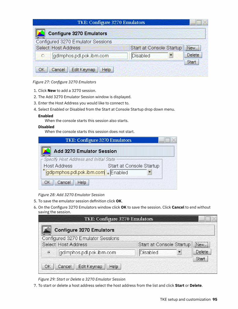
Figure 27: Configure 3270 Emulators
1. Click New to add a 3270 session.2. The Add 3270 Emulator Session window is displayed.3. Enter the Host Address you would like to connect to.4. Select Enabled or Disabled from the Start at Console Startup drop down menu.
EnabledWhen the console starts this session also starts.
DisabledWhen the console starts this session does not start.
Figure 28: Add 3270 Emulator Session5. To save the emulator session definition click OK.6. On the Configure 3270 Emulators window click OK to save the session. Click Cancel to end without
saving the session.
Figure 29: Start or Delete a 3270 Emulator Session7. To start or delete a host address select the host address from the list and click Start or Delete.
TKE setup and customization 95

If you click Edit Keymap, you can edit the keymap in the 3270 emulator session. You can customize thekeyboard functions while in a 3270 session.
Using an TLS (SSL) 3270 emulation session
To use an TLS (SSL) 3270 emulation session, you must perform the following tasks:
1. Configure the TKE workstation to use TLS for 3270 emulation. For instructions, see “Configuring theTKE workstation to use TLS (SSL) for 3270 emulation” on page 96
2. Add a 3270 emulation session. See “Adding a 3270 emulator session” on page 97.
Configuring the TKE workstation to use TLS (SSL) for 3270 emulation
You must import the certificate for the session. Use the following procedure:
1. Sign on to the TKE workstation in Privileged Mode Access with the ADMIN profile.2. From the Trusted Key Entry Console, click Service Management.3. Under Configuration, open the "Certificate Management " application.4. Click Import > From Remote Server.
Figure 30: Manage trusted signing certificates
The following window opens:
Figure 31: Import remote certificate5. Enter the information about the certificate’s location and click OK. For example, specify the host's TLS
IP address and port to get the host certificate that is presented during the TLS handshake. Aconfirmation window opens:
96 z/OS: Cryptographic Services ICSF Trusted Key Entry Workstation User's Guide

Figure 32: Confirm import6. Click Yes to import the certificate. The imported certificate is now in the list of certificates.
Figure 33: Manage trusted signing certificates7. Close the Certificate Management utility.8. Close your Privileged Mode Access session.
Adding a 3270 emulator session
1. From the Trusted Key Entry Console, click Service Management.2. Under Configuration, click Configure 3270 Emulators. The following window opens:
Figure 34: Configure 3270 emulators3. Click New. A window opens in which you can enter the host address and initial state of the emulator
session.4. Specify the host address in the form L:IP address or DNS name:port nmber and click OK. For example:
TKE setup and customization 97

Figure 35: Add 3270 emulator session5. The emulator session is now listed as a configured 3270 emulator session. To initiate a new emulator
session, select it from the list of configured sessions and click Start. In the following example, theemulator session is started every time that the TKE console is started.
Figure 36: Configure 3270 emulators: Start at console startup
98 z/OS: Cryptographic Services ICSF Trusted Key Entry Workstation User's Guide

Chapter 5. TKE up and running
The Trusted Key Entry console displays the applications and utilities available on the TKE workstation.When you open a TKE application or utility, you must sign on with a profile that is on the TKE workstationcrypto adapter. The individual or group profile you choose must have enough authority to do the functionsperformed by the application or utility.
Crypto adapter logon: passphrase or smart cardWhen you start any TKE application, you are presented a list of profiles that are allowed to start theapplication. Depending on how you initialized the TKE workstation crypto adapter and set up the TKEworkstation crypto adapter profiles, you may have passphrase, smart card, or group profiles presentedwhen you open an application. If you open a TKE application and the list of available profiles is empty, thismay mean that you need to initialize your TKE workstation crypto adapter, or create and load profiles. Forinstructions on how to do this, refer to “Initializing the TKE workstation crypto adapter” on page 86.
Passphrase and passphrase group logonFrom the Framework tree on the left panel of the main TKE console screen, click on Trusted key Entry,then click on Trusted Key Entry 9.0.
Depending on how you have initialized your environment, the Crypto Adapter Logon window will bedisplayed with Profile IDs that represent single and/or group passphrase logon.
Figure 37: Crypto Adapter logon window with passphrase profiles
Steps for logging on are:
1. Select the Profile ID that you would like to use to log on to the TKE workstation crypto adapter.2. Select OK
If you selected a single passphrase profile ID
1. The Passphrase Logon window will be displayed.
© Copyright IBM Corp. 2000, 2019 99

Figure 38: Enter passphrase for logon2. Enter the passphrase for this profile ID and select OK.
Note: The passphrase is case sensitive.3. Optionally, the passphrase for the crypto adapter profile ID can be changed by the user by selecting
the Change Passphrase check box before pressing OK to initiate the logon. If the Change Passphrasebox was checked, then the Change Logon Passphrase dialog will be displayed after the user profile hasbeen logged on, but before the selected TKE application is started.
Figure 39: Change logon passphrase
To change the passphrase, enter the current passphrase, the new passphrase and the verify newpassphrase, then select OK.
If you selected a group passphrase profile ID
1. The Crypto Adapter Group Logon window will be displayed. This window displays the number ofmembers required for logon and the profile IDs available for logon.
Figure 40: Crypto Adapter group logon window with passphrase profiles2. Select the member profile ID that you would like to use to log on to the TKE workstation crypto
adapter.3. Select OK
100 z/OS: Cryptographic Services ICSF Trusted Key Entry Workstation User's Guide

The Passphrase Logon window is displayed.4. Enter the passphrase for this profile ID and select OK.
Note: The passphrase is case sensitive.
Figure 41: Enter passphrase for logon5. Information in the Crypto Adapter Group Logon window is updated to reflect that the selected profile
ID is now ready for logon.
Figure 42: Crypto Adapter Group logon window with passphrase profile ready6. Repeat steps 2-4 until the number of group members required for logon is met
Note: If the group logon should fail, the Group members ready for logon is reset to zero and grouplogon must start over.
Once the single or group passphrase logon is successful, the TKE application will be opened for use.
You may use the predefined user profile, TKEUSER, for single passphrase logon or another user profilewith an equivalent role. If you choose to use passphrase group logon, the TKE Administrator must createa passphrase group profile and add the single user passphrase profiles to the group profile. Thepassphrase group profile should be mapped to the TKEUSER role or an equivalent role. The single userprofiles that will be added to the group profile should be mapped to the DEFAULT role. This is done to limitthe services permitted to the single users outside of the group. For details on creating single and grouppassphrase profiles see Chapter 11, “Cryptographic Node Management utility (CNM),” on page 251.
Smart card and smart card group logonDepending on how you have initialized your environment, the Crypto Adapter Logon window will bedisplayed with profile IDs that represent single and/or group smart card logon.
TKE up and running 101

Figure 43: Crypto Adapter Logon Window with smart card profiles
Steps for logging on are:
1. Select the profile ID that you would like to use to log on to the TKE workstation crypto adapter.2. Select OK.
If you selected a single smart card profile ID
1. The Smart Card Logon window will be displayed.2. Insert the smart card that contains the crypto adapter logon key for the selected profile ID and select
OK. Both TKE smart cards and EP11 smart cards can contain a TKE workstation crypto adapter logonkey.
Figure 44: Insert the smart card3. A message box displays, instructing you to "Enter your PIN in the Smart Card Reader". Enter the PIN
for the smart card.
Figure 45: Enter smart card PIN
If you selected a group smart card profile ID
1. The Crypto Adapter Group Logon window will be displayed. This window displays the number ofmembers required for logon and the profile IDs available for logon.
102 z/OS: Cryptographic Services ICSF Trusted Key Entry Workstation User's Guide

Figure 46: Crypto Adapter Group logon window with smart card profiles2. Select the member profile ID that you would like to use to log on to the TKE workstation crypto
adapter.3. Select OK
The Smart card logon window is displayed.4. Insert the smart card that contains the crypto adapter logon key for the selected profile ID and select
OK. Both TKE smart cards and EP11 smart cards can contain a TKE workstation crypto adapter logonkey.
Figure 47: Insert the smart card5. Information in the Crypto Adapter Group Logon window is updated to reflect that the selected profile
ID is now ready for logon.
Figure 48: Crypto Adapter Group logon window with smart card profile ready6. Repeat steps 2-4 until the number of group members required for logon is met
Note: If the group logon should fail, the Group members ready for logon is reset to zero and grouplogon must start over.
TKE up and running 103

Once the single or group smart card logon is successful, the TKE application will be opened for use.
You may use a group smart card profile assigned to the predefined role SCTKEUSR, or another user profileassigned to an equivalent role. If you choose to use single smart card logon, the TKE Administrator mustcreate a single smart card user profile and map it to the SCTKEUSR role or an equivalent role. If a smartcard group profile is used, the TKE Administrator must define single smart card user profiles to be addedto the group. The single user profiles that will be added to the group profile should be mapped to theDEFAULT role. This is done to limit the services permitted to the single users outside of the group. Fordetails on creating single and group smart card profiles see Chapter 11, “Cryptographic NodeManagement utility (CNM),” on page 251.
With either passphrase or smart card logon, if you cancel the logon, the TKE application is not opened.
Automated crypto module recognitionFor each host, the TKE workstation maintains a list of the installed crypto modules. The list contains allthe information required to protect communication between the workstation and the host cryptomodules.
Whenever the user of the workstation connects to a host, TKE queries the host to determine the installedcryptographic hardware. The resulting list is compared to the contents of the crypto module file.
The user is notified if any of the following events occur:
• A new crypto module has been installed.• A crypto module has been removed.• A crypto module has been replaced.• A new OA signature key has been generated for the crypto module. A new OA signature key is generated
when the CCA CLU utility is used to zeroize and un-own segments 2 and 3, then load factory segments 2and 3.
• A crypto module has been moved from one slot to another.
Authenticating host crypto modulesThe TKE workstation uses the Crypto Module ID (CMID) and the public crypto module OA signature key toverify messages returned from a host crypto module.
To verify the CMID, you need to log on to your host TSO/E user ID. From the ICSF main panel, chooseoption 1, Coprocessor Management. This panel will list all the crypto modules available to this host. Verifythe coprocessor index and serial number with the information on the 'Authenticate crypto module'window on TKE.
On the Authenticate crypto module window:
• Press Yes if the coprocessor index and serial number on the host match the index and CMID on thewindow. The CMID value is saved on the TKE workstation for further communication with the hostcrypto module. The crypto module is marked as Authenticated.
• Press No if they do not match. The crypto module is marked as Rejected by user. You will not be able towork with the host crypto module but you are able to authenticate the module again. You select thecrypto module and the CMID/type window is displayed for you to accept or reject the values.
104 z/OS: Cryptographic Services ICSF Trusted Key Entry Workstation User's Guide

Figure 49: Authenticate Crypto Module
The crypto module type for all currently supported host crypto modules is "Crypto Coprocessor". Priorversions of TKE could manage other crypto module types that are no longer supported.
It is not necessary to authenticate the public crypto module OA signature key. The OA signature key isauthenticated by a chain of certificates. The public key of the IBM Class Root certificate is hardcoded intothe TKE workstation. The user is informed of the result of the verification process.
The IBM Customer Engineer (CE) may need to reload code in the host crypto module on the host formaintenance. If the code is reloaded, it may become necessary to reauthenticate the host crypto moduleduring the first communication with it after the code reload. The reauthentication is necessary becausethe OA signature key has been regenerated.
Initial authoritiesCommands from the TKE workstation to a host crypto module are signed. In order to configure a CCA hostcrypto module, an initial authority with a signature key must exist on the crypto module. This initialauthority uses the Default Signature Key.
When a CCA host crypto module is initialized in the factory or by performing certain operations using theCCA CLU Utility, an authority with index 0 and the default signature key is created on the crypto module.
Backing up filesDuring normal TKE operations, users can create and modify files to:
• Store key parts, signature keys, and TKE roles and profiles.• Define host connections and domain groups.• Save host crypto module configuration data that will be applied to other host crypto modules.• Implement key storage used by the TKE workstation.• Save printable information for later reference.
Several directories on the TKE hard drive are used for these files.
Backing up these files on a regular basis is good practice. For information on file backups, see “Backupcritical console data” on page 353. To schedule a one-time backup or repeating backups, see “Customizescheduled operations” on page 355.
TKE up and running 105

Individual files can also be copied to USB flash memory. For more information, see “TKE File Managementutility” on page 342.
Some files of interest in the TKE Data Directory are:
• host.dat -- holds host TCP/IP addresses and port numbers for the TKE Host Transaction program.• domaingroup.dat -- holds domain group definitions.• zone.dat -- holds information on configuration migration zones known to the TKE workstation.• kphcard.dat-- holds information on key part holders used during configuration migration.
Some files of interest in the CNM Data Directory are:
• desstore.dat and desstore.dat.NDX -- implement DES key storage on the TKE workstation.• aesstore.dat and aesstore.dat.NDX -- implement AES key storage on the TKE workstation.• pkastore.dat and pkastore.dat.NDX -- implement PKA Key storage on the TKE workstation.
DES and AES key storage on the TKE workstation can hold EXPORTER keys used to transfer RSA keys to ahost system. PKA key storage on the TKE workstation can hold a single RSA key for signing commands.
Host file to back upThe TKE Host Transaction program running on a z/OS host system uses a host data set to save cryptomodule descriptions, domain descriptions, and authority information, such as name, address, phone, andso on. This information is not critical for managing host crypto modules using TKE, but improves usability.
The default data set name is smfid.TKECM, where smfid is the System Management Facility identifier forthe TKE Host Transaction program. The data set name can also be passed as the SET THE TKE DATA SETSstartup parameter to the TKE Host Transaction program. See “TKE host transaction program setup” onpage 76 for more information.
106 z/OS: Cryptographic Services ICSF Trusted Key Entry Workstation User's Guide

Chapter 6. Main window
The purpose of the TKE application is to allow administrators to manage host cryptographic modules,either individually or through groups. From the main window, you also create host definitions and groupdefinitions.
Note: Many screen captures show smart card options. If Enable Smart Card Readers is not checked, youwill not see the smart card options.
Beginning in TKE 7.1, when you initialize a TKE workstation crypto adapter for use with smart cardprofiles, the Enable Smart Card Readers option is automatically selected.
Figure 50: TKE Preferences
You can update the TKE application preferences by using the Preferences pull-down menu. To display thepop-up menu, click Preferences in the toolbar. Click individual items to enable or disable them. A checkmark indicates that the preference is enabled. For details on each of the preferences, see “TKEcustomization” on page 133.
Note: When the Enable Smart Card Readers preference is enabled or disabled, the updated setting doesnot take effect until you restart the TKE application.
The main window has three containers that are labeled Hosts, Domain Groups, and Crypto Modules. Allcontainers are blank until you create a host.
When you have created one or more hosts, decide whether you are working with single crypto modules orwith domain groups. To work with domain groups, right-click in the Domain Groups container to display a
© Copyright IBM Corp. 2000, 2019 107

menu. the pop-up menu contains options to create, change, delete, open, view, and close domain groupsand an option to check group overlap.
To open a crypto module notebook for a single crypto module, open a host. (Right-click on it and selectthe Open Host option from the pop-up menu, or double-click it with the left mouse button.) After you logon to the host, TKE queries it and displays a list of the attached host crypto modules in the CryptoModules window. To open a crypto module notebook, right-click on one of the host crypto modules andselect Open Crypto Module from the pop-up menu, or double-click it with the left mouse button.
To open a crypto module notebook for a domain group, right-click the group and select the Open Groupoption from the pop-up menu, or double-click it with the left mouse button. You are prompted to log on toall host systems with crypto modules that are part of the group. A list of the crypto modules that are partof the group is displayed in the Crypto Modules container. Right-click in this list and select Open DomainGroup from the pop-up menu, or double-click it with the left mouse button.
Note: Support for crypto module groups is removed beginning with TKE 8.0. If any crypto module groupsare defined on your TKE workstation, a fourth container is displayed in the main window, labeled CryptoModule Groups. Right-clicking in this container causes a menu to be displayed, but the only options are todelete the group or convert the group to a domain group. For more information, see “Crypto modulegroups” on page 121.
Note the message in the lower right that the signature key is not loaded. See “Load signature key” onpage 121.
Working with hostsThe Hosts container of the TKE Main Window lists the host IDs currently defined to the TKE workstation.You can create, change, delete, open, or close host definitions from this container. When you select yourhost (by double-clicking or selecting open), the host logon window opens if you are not yet logged on.When you are logged on, the crypto modules available for that specific host are displayed in the cryptomodule container.
Beginning in TKE 7.3, your TKE workstation profile's role must have the Manage Host List ACP to be ableto create, change, or delete a host list entry.
Creating a new hostThe TKE workstation keeps a host definition for every host it can connect to. Clicking the right mousebutton in the Hosts container causes a pop-up menu to be displayed, allowing you to choose the CreateHost menu item.
Figure 51: Create Host
The host definition contains the following information:
• Host ID — Mandatory free format text used for referencing the host within TKE.• Host description — Free-format text for your own use• Host Name / IP — Address in decimal-dot notation of the host where the TKE Host Transaction Program
server is running. The field can contain a host name or a TCP/IP address in either TCP/IP V4 or TCP/IPV6 format.
108 z/OS: Cryptographic Services ICSF Trusted Key Entry Workstation User's Guide

• Port number — Application port number reserved in your host TCP/IP profile for the TKE HostTransaction Program server. See Chapter 4, “TKE setup and customization,” on page 75.
It is not necessary to define each logical partition to TKE. One partition will have its control domaincontain its own domain as well as any other domain where you want to load keys. This domain must beunique and must have access to all host crypto modules that it is to control.
For additional details on LPAR setup, refer to Appendix B, “LPAR considerations,” on page 323.
Changing host entriesRight-click on the host definition in the hosts container that you want to change. A menu is displayed.Select the Change Host menu item.
You can change the host description, IP address and port number. However, you cannot change the hostID. If you want to change the host ID, you must delete the host definition. You then create a new host ID.
Deleting host entriesTo delete a host definition, right-click on the host you want to delete from the hosts container. A menu isdisplayed. Select the Delete Host menu item. A confirmation message is displayed. Select Yes to confirmthe delete request. Select No to cancel the delete. Multiple hosts can be deleted at the same time byusing ctrl+left-click or shift+left-click to highlight more than one host entry. When more than one hostentry is selected, right-clicking on one of the selected host entries allows the Delete Host option to applyto all of the selected entries.
Logging on to a hostTo log on, left-double-click on the host entry or right-click on the host entry and select Open Host fromthe pop-up menu. If you are working with a domain group, left-double-click on the domain group or right-click on the domain group and select Open Group from the pop-up menu. When you open a domain groupin the TKE main window, you must log on to all hosts that are to be accessed within that group.
Note: Before attempting to use a user ID that has been configured to use Multi-Factor Authentication(MFA), see Appendix I, “Multi-Factor Authentication (MFA) and the TKE,” on page 393.
The Logon window is displayed for the host logon.
Figure 52: Host Logon window
Enter your RACF-defined TSO/E host user ID and password. Your RACF-defined TSO/E host user ID is theuser ID of the TKE administrator.
If z/OS V1R7 or higher is installed, mixed case passwords are supported by RACF. If the Enable MixedCase Passwords check box is enabled on the Log on to Host window, passwords are used as entered andare not automatically folded to uppercase. You must enter your password as it was defined in the RACFdatabase. If your system does not support mixed case passwords and you check the Enable Mixed CasePasswords check box, you must enter your password in uppercase or you get "The password is incorrect"error.
Note: If your TSO/E password has expired, the message The password has expired. Changepassword from TSO is displayed. Change your password and perform the logon again.
Main window 109

Closing a hostTo close a host, in the hosts container right-click the host that you want to close. Then, click Close host.
Close a host when you are done working with the crypto modules in the host. The next time that you openthe host, a logon is required.
Understanding crypto modules and domain groupsThe term host crypto module refers to an IBM cryptographic coprocessor plugged into an IBM hostsystem. Host crypto modules support up to 85 domains, where each domain may be assigned to adifferent logical partition on the host system. Domains include one or more master key registers. Thesesupport key storage for the logical partition.
When you open a host, TKE queries the host system to determine what host crypto modules are attachedand available. These are displayed in the Crypto Modules container of the TKE Main Window. You canopen a crypto module notebook for individual host crypto modules. This allows you to display informationrelated to the crypto module and to issue commands to it. Some commands are module scoped and someare domain scoped.
• A module scoped command applies to the entire crypto module. For example, creating, changing, anddeleting roles and authorities are module scoped commands because there is only one set of roles andauthorities for the entire crypto module. Similarly, the commands to enable and disable the cryptomodule are module scoped commands.
• A domain scoped command applies to a single domain on the crypto module. For example, commandsto load and clear master keys, change the domain controls, and zeroize the domain, are domain scopedcommands.
To make the administration of crypto modules easier, you can create domain groups. A domain groupallows you to use a single crypto module notebook to administer a set of domains or a set of cryptomodules as a single unit. For example, you can use a domain group to load the same master key value in aset of domains (the member domains of the group).
To create a domain group, right-click in the Domain Groups container in the TKE Main Window. Thisdisplays a pop-up menu. Select the Create CCA Group option to create a domain group containing CCAhost crypto modules. Select the Create EP11 Group option to create a domain group containing EP11host crypto modules. You can create domain groups containing either CCA host crypto modules or EP11host crypto modules, but you cannot create a domain group that includes both types of host cryptomodules.
When you create a domain group, you select the domains to be included in the group. You can includedomains from multiple host crypto modules from multiple hosts. You also specify a master domain. Whenyou open a crypto module notebook for a domain group, the domain-level information displayed isinformation for the master domain. The module-level information displayed is for the crypto modulecontaining the master domain.
When you issue a domain-scoped command using a crypto module notebook for a domain group, thecommand is normally sent to every domain in the group. When you issue a module-scoped commandusing a crypto module notebook for a domain group, the command is sent to every crypto module havingat least one domain included in the group.
A special case is commands to load or clear operational key registers in CCA domain groups. When youcreate or change a CCA domain group, you specify whether commands on operational key registersshould be sent to just the master domain or to all domains in the group.
Working with crypto modulesThe crypto module container of the TKE Main Window displays the crypto modules that are available foruse with the host or group you have selected. The container lists the host ID that the crypto module
110 z/OS: Cryptographic Services ICSF Trusted Key Entry Workstation User's Guide

belongs to, the crypto module index, the status of the crypto module and the description of the cryptomodule. You are not able to change any of these fields from this container.
Figure 53 on page 111 illustrates the main window after logging on to a host. Note that in this screencapture, the signature key has not been loaded. To load a signature key, refer to “Load signature key” onpage 121.
Figure 53: Main window
As discussed in “Automated crypto module recognition” on page 104, the Crypto Module container isfilled in automatically once you have logged onto the host or hosts.
If you have selected a host to work with, you will be able to choose the crypto module you would like toopen by highlighting it.
If you have chosen a group, when you highlight a crypto module all of the crypto modules will behighlighted.
To open a crypto module notebook, you can either left-double-click on a crypto module or right-click on acrypto module and select Open Crypto Module from the pop-up menu.
Working with domain groupsYou manage domain groups in the TKE main window. You can add, change, delete or view domain groupdefinitions from this container. You can also check group overlap.
Main window 111

Figure 54: Main window - working with domain groups
The domain group concept allows you to perform operations on a set of crypto module domains as youwould on a single crypto module domain. A domain group can include crypto modules from many hosts.
A domain group can contain domains on one or more crypto modules configured with CCA firmware orelse can contain domains on one or more crypto modules configured with EP11 firmware. A domain groupcannot contain a mixture of CCA-configured and EP11-configured domains.
In general, you work with the domain group as if it is a single domain. For example, you will see only oneNew Master Key register. The values displayed for a domain group are the values of the master domain.You select the master domain when you create the domain group. Also, note that the master cryptomodule of a domain group is the crypto module that contains the master domain.
For most operations, it is important that the crypto modules and domains within a domain group are in thesame state. For example, the crypto modules have identical roles and domains have the same masterkeys. You maintain this by always working on members of the domain group using the domain groupinterface, and not operating on the crypto modules individually.
When TKE performs a domain group operation that is not successful, two new groups are created. Onedomain group contains the successfully updated crypto module domains and one domain group containsthe crypto module domains where the update failed. This allows you to operate on the crypto moduledomains of the failed group until the update is successful. You may then delete the two new domaingroups as you wish.
When you work with a domain group, either left-double-click on one of the domain groups defined in theDomain Groups container or right-click on one of the domain groups defined in the Domain Groupscontainer and select Open Group from the pop-up menu. You are prompted to log on to the hostsassociated with the crypto module members of the domain group.
When you open the crypto modules of a domain group, a crypto module notebook is displayed.
112 z/OS: Cryptographic Services ICSF Trusted Key Entry Workstation User's Guide

When loading operational key parts using a CCA domain group, with TKE 8.1 and later, you have the optionto load them to either the master domain only or to all domains in the group. The desired behavior isselected when the domain group is created or changed.
Creating a domain groupYou can create a domain group containing domains on one or more crypto modules configured with CCAfirmware, or else containing domains on one or more crypto modules configured with EP11 firmware. Adomain group cannot contain a mixture of CCA crypto module domains and EP11 crypto module domains.
To create a new domain group:
1. Right-click the mouse button in the Domain Groups container.
A pop-up menu displays.2. To create a domain group containing domains from CCA crypto modules, select the Create New CCA
Domain Group menu item. To create a domain group containing domains from EP11 crypto modules,select the Create New EP11 Domain Group menu item.
The “Create New Group” window opens.
Note: For CCA domain groups, the supported crypto module types are CEX2C, CEX3C, CEX4C, CEX5C,and CEX6C. For EP11 domain groups, the supported crypto module types are CEX4P, CEX5P, andCEX6P.
Main window 113

Figure 55: Create New CCA Domain Group3. Enter your information in the following fields:
a. Group ID - Name of the domain group (mandatory)b. Description - Optional free text descriptionc. Operational Key Register Option - Beginning with TKE 8.1, you can choose to only update the
operational key register on the master domain (selected by default) or you can choose to updateoperational key registers on all domains in the group.
d. Select the crypto module domains to be in the domain group. In the Host tree structure, select thedomains from each host you want to include in the domain group by selecting the check boxassociated with the domain. You will be prompted to log on to the selected host or hosts if you arenot currently logged on.
Note: Only domains defined as control domains on the crypto module will be available for inclusionin the domain group.
114 z/OS: Cryptographic Services ICSF Trusted Key Entry Workstation User's Guide

e. Select the crypto module domain to be the Master Domain by right-clicking on the domain andselecting Make this the Master Domain. The Master Domain information field of the Create NewGroup window changes to represent the Master Domain information.
f. When finished, press OK.
Notes:
1. Crypto modules at different CCA levels may support different features. For example, ECC (APKA)master keys were introduced with the CEX3C crypto module and restricted PIN support wasintroduced with the CEX4C crypto module. Domain groups can be created using crypto modules atdifferent CCA levels. The notebook for the domain group will reflect the features supported on thecrypto module containing the master domain.
2. If the crypto module containing the master domain has capabilities that other crypto modules in thegroup do not have, what happens during a group operation depends on the specific commandexecuted. Commands to clear and load the AES and ECC (APKA) master keys are ignored on cryptomodules that do not support those master key types. All other commands, such as commands tomanage decimalization tables and restricted PINs, are attempted on all domains in the group and willfail on crypto modules that do not support those operations.
Changing a domain groupTo change a domain group, right-click on the desired domain group in the Domain Groups container in theTKE main window and select the Change Group option.
The Change Group window is displayed.
Main window 115

Figure 56: Change CCA Domain Group
To change the description, edit the Group Description field.
To change the Operational Key Register Option, select the other radio button.
To modify which crypto module domains are in the domain group, check the boxes corresponding to thedomains to be included in the domain group. At least one domain must be checked.
To refresh the list of crypto modules associated with a host, do the following:
1. Highlight the host with the left mouse button.2. Click the right mouse button to display a pop-up selection menu.3. Select Refresh crypto module list.
To select which domain is the master domain, do the following:
1. Highlight a checked domain with the left mouse button.
116 z/OS: Cryptographic Services ICSF Trusted Key Entry Workstation User's Guide

2. Click the right mouse button to display a pop-up selection menu.3. Select Make this the master domain menu item from the pop-up menu.
One domain must be selected as the master domain.
When finished, press OK.
Viewing a domain groupTo view a domain group, either right-click on the desired domain group in the Domain Groups container inthe TKE main window and select the View Group action or open a domain group in the crypto modulecontainer and press the View Group button on the Domain tab.
Figure 57: View CCA Domain Group
The View Group window is opened. The following information is displayed:
• Group ID – The group identifier• Group Description – Optional free text description• Master Domain – The master domain for this domain group. All displayed values for this group are
retrieved from this domain.• Operational Key Register Option - Indicates if domains in the group can have operational key register
updates.• Domain table window – A window containing a table that lists the crypto module domains in the
domain group. There are four columns in the table: Host ID, Crypto Module Index, Domain Index andMaster Domain.
You can copy the domain group information to a file by selecting Copy to file and specifying the file nameand location to be saved. Otherwise, when finished, press Cancel.
Main window 117

Checking domain group overlapTo check if domain groups defined on the TKE workstation contain crypto module domains that are foundin more than one domain group, click with the right mouse button in the “Domain Groups” container in theTKE main window and select the Check Group Overlap action. The Domain Group Overlap window isopened.
Figure 58: Check Domain Group Overlap
This window displays a list of domains that are specified in more than one domain group defined on theTKE workstation. Double clicking with the left mouse button on one of the domains displays an OverlapDetails window that lists the names of the domain groups that contain the selected domain.
118 z/OS: Cryptographic Services ICSF Trusted Key Entry Workstation User's Guide

Figure 59: Duplicate Domains Not Allowed
Figure 60: Domain Group Overlap Details
You can copy the domain group overlap information to a file by selecting Copy to file and specifying thefile name and location to be saved. Otherwise, when finished, press Cancel.
Main window 119

Comparing groupsIn order for operations on a domain group to be successful, all member domains need to be configuredthe same. For example, the status of a master key register needs to be the same in each domain of adomain group in order for an operation on that master key register to have the same result in eachmember domain.
The Group Compare function reads the state of the domains and crypto modules in a domain group andchecks for differences. To run the group compare function, open the domain group, click on the Functionmenu at the top of the domain group notebook, and select Compare Group.
TKE reads and compares the state of all domains and crypto modules in the group. If differences arefound, a Group Compare window is displayed showing the differences.
Note: Beginning in TKE 9.1, you can also run the Compare Group (Same Domain Index) function. Thiscompare highlights differences between domains with the same index. For example, Domain 0 and 1 canhave different settings. However, the compare highlights only the differences between the domains withthe same index, not differences between domain 0 and 1.
Figure 61: Compare Group
The Group Compare window displays the following results:
• Group Name – Name of the group that has been compared• Status – Overall result of the compare operation• Mismatches – A list of properties that do not match.
If you select a property, a list of all crypto modules in the group with the actual values for that propertyis displayed.
120 z/OS: Cryptographic Services ICSF Trusted Key Entry Workstation User's Guide

TKE functions supporting domain groupsThe values displayed in a domain group notebook are those read from the master domain, or from thecrypto module that contains the master domain. In general, updates made in a domain group notebookare made in all member domains or member crypto modules of the group. For CCA domain groups, theoperation 'View operational key part register' is only performed on the master domain.
Nearly all operations that can be performed in a crypto module notebook can also be performed in adomain group notebook. The only exception is for CCA domain groups. When creating or changing a role,users are not allowed to directly manage the domain access ACPs.
Crypto module groupsThe Trusted Key Entry workstation no longer supports crypto module groups. To manage a group of cryptomodules, a domain group can be created instead.
To assist users in converting from crypto module groups to domain groups, TKE provides a utility to createdomain groups from crypto module groups. The utility is invoked as part of the TKE Workstation Setupwizard. From the utility, users select a crypto module group to be converted. The utility displays aproposed domain group for the crypto module group, and users may either accept this definition or makechanges before creating the domain group.
Crypto module groups can also be converted to domain groups from the main TKE application. If at leastone crypto module group is defined on the TKE workstation, the main TKE application displays a CryptoModule Groups container. From this container, you can select a crypto module group and either delete itor convert it to a domain group.
If no crypto module groups are defined on the TKE workstation, a Crypto Module Groups container is notdisplayed in the main TKE application.
Function menuThese selections are available from the Function menu in the TKE main window:
• Load signature key• Unload signature key• Display signature key information• Define transport key policy• Exit• Exit and logoff
Load signature keyThis function is used to load the authority signature key. Authority signature keys are used whenmanaging CCA host crypto modules. The authority signature key is active for all operations until explicitlychanged by clicking on this option again to load a different authority signature key, or until the signaturekey is unloaded.
A message is displayed in the lower-right corner of the TKE main window, indicating what signature key isactive. If no signature key has been loaded, the message SIGNATURE KEY NOT LOADED is displayed. Ifa signature key has been loaded, the message SIGNATURE KEY LOADED is displayed, along with theindex and name associated with the active signature key.
The CEX2C supports only 1024-bit RSA authority signature keys. CEX3C and CEX4C host crypto modulessupport 1024-bit, 2048-bit and 4096-bit RSA authority signature keys. CEX5C and CEX6C host cryptomodules support 1024-bit, 2048-bit, and 4096-bit RSA authority signature keys, and BP-320 EC and521-bit EC authority signature keys.
Main window 121

To create an authority signature key, see “Generating authority signature keys” on page 146.
A Select Source window opens. Select the source of the authority signature key, and click Continue.
Notes:
• In order to see a smart card as one of the authority signature key sources, you must have previouslyselected Enable Smart Card Readers through the TKE main window Preferences menu.
• Starting in TKE 7.2, the TKE supports 2, 3 or 4 smart card readers.
Figure 62: Select Authority Signature Key Source
• If you select Key storage or any Default key as the authority signature key source, the Specifyauthority index window opens. Enter the authority index to be used and click Continue.
Figure 63: Specify Authority Index• If you select Binary file as the authority signature key source, the Load Signature Key window opens.
The authority signature key must have been previously generated and saved to a binary file. Eitherselect a file from the Files list or enter a file name. Additionally, you must enter a password.
122 z/OS: Cryptographic Services ICSF Trusted Key Entry Workstation User's Guide

Figure 64: Load Signature Key
You are then prompted to specify the authority index.• If you select Smart card in reader 1 or Smart card in reader 2, you are prompted to insert your TKE
smart card into the smart card reader. You are then prompted to enter the PIN on the TKE smart cardreader's PIN pad.
You will then be prompted to specify the authority index.
Unload signature keyThis function unloads the authority signature key. Use this function when you are finished using the keyand want to ensure that the key is not used until it is loaded again.
Display signature key informationSelecting Display signature key information displays a panel showing the current signature index, keytype, and the key identifier for the current authority signature key.
Define transport key policyFor CCA host crypto modules, master keys and operational keys are protected by encryption duringtransfer between the TKE workstation crypto adapter and host crypto modules. The transport encryptionkeys (key-encrypting keys) are established by means of a Diffie-Hellman key agreement mechanism. TheSelect Transport Key Policy Window lets you select the policy for the transport key.
For EP11 host crypto modules, master keys are also protected by encryption during transfer between theTKE workstation and host crypto modules, but a different mechanism is used. The policy selected by theSelect Transport Key Policy Window does not apply to EP11 host crypto modules.
For CCA host crypto modules, TKE supports two Diffie-Hellman key agreement protocols: Diffie-Hellman(DH) and Elliptic Curve Diffie-Hellman (ECDH). DH is used when TKE sends key material to a CCA hostcrypto module with a CCA level earlier than 4.2. ECDH is used when the host crypto module has a CCAlevel of 4.2 or greater.
Main window 123
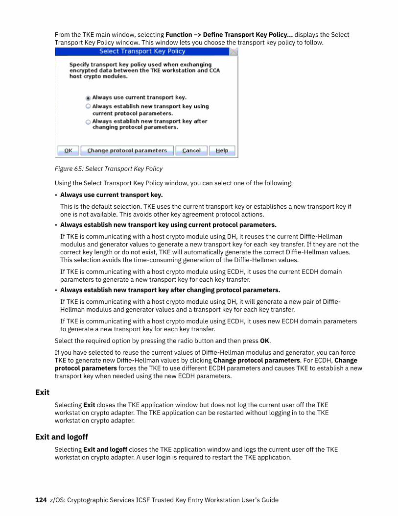
From the TKE main window, selecting Function –> Define Transport Key Policy... displays the SelectTransport Key Policy window. This window lets you choose the transport key policy to follow.
Figure 65: Select Transport Key Policy
Using the Select Transport Key Policy window, you can select one of the following:
• Always use current transport key.
This is the default selection. TKE uses the current transport key or establishes a new transport key ifone is not available. This avoids other key agreement protocol actions.
• Always establish new transport key using current protocol parameters.
If TKE is communicating with a host crypto module using DH, it reuses the current Diffie-Hellmanmodulus and generator values to generate a new transport key for each key transfer. If they are not thecorrect key length or do not exist, TKE will automatically generate the correct Diffie-Hellman values.This selection avoids the time-consuming generation of the Diffie-Hellman values.
If TKE is communicating with a host crypto module using ECDH, it uses the current ECDH domainparameters to generate a new transport key for each key transfer.
• Always establish new transport key after changing protocol parameters.
If TKE is communicating with a host crypto module using DH, it will generate a new pair of Diffie-Hellman modulus and generator values and a transport key for each key transfer.
If TKE is communicating with a host crypto module using ECDH, it uses new ECDH domain parametersto generate a new transport key for each key transfer.
Select the required option by pressing the radio button and then press OK.
If you have selected to reuse the current values of Diffie-Hellman modulus and generator, you can forceTKE to generate new Diffie-Hellman values by clicking Change protocol parameters. For ECDH, Changeprotocol parameters forces the TKE to use different ECDH parameters and causes TKE to establish a newtransport key when needed using the new ECDH parameters.
ExitSelecting Exit closes the TKE application window but does not log the current user off the TKEworkstation crypto adapter. The TKE application can be restarted without logging in to the TKEworkstation crypto adapter.
Exit and logoffSelecting Exit and logoff closes the TKE application window and logs the current user off the TKEworkstation crypto adapter. A user login is required to restart the TKE application.
124 z/OS: Cryptographic Services ICSF Trusted Key Entry Workstation User's Guide

Utilities menuThese selections are available from the Utilities pull-down menu in the TKE main window:
• Copy binary file key part...• Copy smart card contents...• Create CCA key parts...• Duplicate TKE or EP11 smart card...• Generate EP11 master key parts...• Manage smart card contents...• Manage Workstation AES keys...• Manage Workstation DES keys...• Manage Workstation PKA keys...
These utilities are used for managing the keys in TKE workstation DES, PKA, and AES key storage,managing smart card contents, and copying smart card contents.
The following utilities require the use of smart card readers and are grayed out if Enable Smart CardReaders is not selected in the Preferences menu:
• Copy binary file key part...• Copy smart card contents...• Duplicate TKE or EP11 smart card...• Generate EP11 master key parts...• Manage smart card contents...
Manage workstation DES keysTKE workstation DES key storage is used to hold DES IMP-PKA keys that encrypt RSA keys for transfer tohost systems. DES IMP-PKA keys can be loaded into TKE workstation DES key storage using an option onthe Domain Keys page in the crypto module notebook. When DES IMP-PKA keys are loaded into TKE keystorage, the key type is changed from IMP-PKA to EXPORTER.
This option lets you view and delete keys in TKE workstation DES key storage.
Main window 125

Figure 66: TKE Workstation DES Key Storage Window
The TKE Workstation DES Key Storage window displays the following information:
• Key label• Key type
DES IMP-PKA keys written to key storage have the key type EXPORTER. Keys with key type NO_KEY areempty and can be deleted. There might be other key types if the TKE workstation crypto adapter is usedfor purposes other than TKE.
• Key Attributes
Following is a list of some of the key words used by the TKE workstation crypto adapter card for definingthe control vector.
– KEY-PART - The initial key part has been loaded but the last key part has not been loaded.– NO-XPORT - The key cannot be exported. IMP-PKAs used to protect generated RSA keys have this
attribute.– XPORT-OK - The key is exportable. IMP-PKAs used to protect entered RSA keys have this attribute.
• Control vector - The CCA control vector.• Created date and time• Updated date and time
Deleting an entry
When you right-click on an entry, a menu is displayed. The only selection is Delete Key. This allows you topermanently delete a key from key storage.
Manage workstation PKA keysTKE uses the TKE workstation PKA key storage for holding one authority signature key. This can be a1024-bit, 2048-bit, or 4096-bit RSA signature key.
126 z/OS: Cryptographic Services ICSF Trusted Key Entry Workstation User's Guide

Figure 67: TKE Workstation PKA Key Storage Window
The TKE Workstation PKA Key Storage window displays the following information:
• Key label• Key type
The type of key is one of the following:
– RSA-PRIV - A token holding the private and public key part of a PKA key pair. This is the key type foran authority signature key.
– RSA-PUB - A token holding the public part of a PKA key pair.– RSA-OPT - A token holding the private and public part of a PKA key part in optimized form.
• Key Token Type
The type of token is one of the following:
– Internal - The key token is internal and the key value is enciphered under the TKE workstation cryptoadapter master key.
– External - The key token is external and the key value is either enciphered by a key-encrypting key orunenciphered.
– NO_KEY - The key token is empty.• Key Identifier - Identifies the RSA key in PKA key storage. The key identifier is the SHA-256 hash of the
DER-encoded public modulus and public exponent of the RSA key pair.• Created date and time• Updated date and time
Deleting an entry
When you right-click on an entry, a menu is displayed. The only selection is Delete Key. This allows you topermanently delete a key from key storage.
Main window 127

Manage workstation AES keysTKE workstation AES key storage is used to hold AES IMPORTER keys that encrypt RSA keys for transferto host systems. AES IMPORTER keys can be loaded into TKE workstation AES key storage using an optionon the Domain Keys page in the crypto module notebook. When AES IMPORTER keys are loaded into TKEkey storage, the key type is changed from IMPORTER to EXPORTER.
This option lets you view and delete keys in TKE workstation AES key storage.
Figure 68: TKE Workstation AES Key Storage window
The TKE Workstation AES Key Storage window displays the following information:
• Key label• Key type
AES IMPORTER keys written to key storage have the key type EXPORTER. Keys with key type NO_KEYare empty and can be deleted.
• Key attributes
Indicates whether the AES EXPORTER key has default or custom attributes. You can display the specifickey attributes by right-clicking on an entry to display a menu. Select Display key attributes to view theattributes of the selected key.
• Created date and time• Updated date and time
Deleting an entry
When you right-click on an entry, a menu is displayed. Select Delete Key to permanently delete a keyfrom key storage.
Manage smart card contentsThis function allows you to view a list of the keys and key parts stored on the smart card, delete keys andkey parts from the smart card, and, for TKE smart cards, display information about AES EXPORTER,IMPORTER, and CIPHER operational keys stored on the smart card. This function can be used with bothTKE smart cards and EP11 smart cards.
1. At the prompt, insert your smart card into smart card reader 2.
128 z/OS: Cryptographic Services ICSF Trusted Key Entry Workstation User's Guide

2. The utility reads the smart card contents. This may take some time. The card ID is displayed followedby the card description. Verify that this is the smart card you want to work with.
Figure 69: Smart card contents (for TKE smart cards)
Figure 70: Smart card contents (for EP11 smart cards)
The Manage smart card contents window displays the following information for a smart card:Card ID
Identification string for the smart cardZone description
Description of the zone in which the smart card is enrolledCard description
Description of the smart card; entered when the smart card was personalized
Main window 129

Card contentsKey type, Description, Origin, MDC4 or CMAC, SHA1, ENC-Zero, AES-VP or HMAC-VP, ControlVector or Key Attributes (for operational keys only), and Length.
3. To delete multiple keys at once, highlight all the keys you want to delete. By holding down the controlbutton, you can select specific entries on the list with your mouse. By holding down the shift button,you can select a specific range of entries on the list with your mouse.
4. Right-click on either the single entry you would like to delete or one of the highlighted entries whendeleting more than one entry at a time. Then, select Delete from the menu.
5. Right click and select Delete.6. Confirm the delete.7. Enter the 6-digit PIN.
Note: TKE smart cards created before TKE 7.0 use 4-digit PINs.8. You will get a message that the command was executed successfully.9. You can display the key attributes associated with a CIPHER, EXPORTER, or IMPORTER AES
operational key part stored on the smart card. Right-click on the desired key part to display a pop-upmenu. Select the Display key attributes option to display the key attributes.
Copy smart card contentsThis function allows you to copy keys and key parts from one TKE smart card to another TKE smart card,or from one EP11 smart card to another EP11 smart card. You can copy these types of keys:
• Crypto adapter logon key• TKE authority signature key• EP11 administrator signature key• ICSF operational key parts• ICSF master key parts• Crypto adapter master key parts
Notes:
1. The two smart cards must be enrolled in the same zone; otherwise, the copy fails. To display the zoneof a smart card, exit from the TKE application and use either the Cryptographic Node ManagementUtility or the Smart Card Utility Program found in the Trusted Key Entry category's Applications list onthe TKE Workstation Console. See Chapter 11, “Cryptographic Node Management utility (CNM),” onpage 251 or Chapter 12, “Smart Card Utility Program (SCUP),” on page 291.
2. To copy ECC (APKA) master key parts from a source TKE smart card to a target TKE smart card, theapplet version of the target TKE smart card must be 0.6 or greater.
3. To copy an ECC authority signature key from a source TKE smart card to a target TKE smart card, theversion of the target TKE smart card must be 0.10 or greater.
To copy a smart card:
1. Select Copy smart card contents from the Utilities menu.
A message box prompts you to “Insert source TKE or EP11 smart card in smart card reader 1”.2. Insert the source smart card in smart card reader 1 and press OK.
A message box prompts you to insert the target smart card in smart card reader 2. The target smartcard must be the same type (TKE or EP11) as the source card.
3. Insert the target smart card in smart card reader 2 and press OK.
The utility reads the smart card contents, which may take some time. The card ID is displayed,followed by the card description. Verify that these are the smart cards that you want to work with.
The Copy smart card contents window lists the following information for a smart card:
130 z/OS: Cryptographic Services ICSF Trusted Key Entry Workstation User's Guide

Card IDIdentification string for the smart card.
Zone descriptionDescription of the zone in which the smart card is enrolled.
Card descriptionDescription of the smart card, which was entered when the smart card was personalized.
Card contentsKey type, Description, Origin, MDC4 or CMAC, SHA1, ENC-Zero, AES-VP or HMAC-VP, ControlVector or Key Attributes (for operational keys only), and Length.
4. To copy multiple keys at the same time, highlight all the keys that you want to copy. By holding downthe control button on the keyboard, you can select specific entries on the list with your mouse. Byholding down the shift button on the keyboard, you can select a specific range of entries on the listwith your mouse. Left-click on the Copy button or right-click on one of the highlighted entries andselect Copy from the menu. To copy a single key, right-click on the wanted key, and select Copy fromthe menu.
Note: Smart card copy does not overwrite the target smart card. If there is not enough room on thetarget smart card, you get an error message. You can either delete some of the keys on the targetsmart card (see “Manage smart card contents” on page 128) or use a different smart card.
Figure 71: Select keys to copy5. At the prompts, enter the PINs for the smart cards on the smart card reader PIN pads. The keys are
then copied to the target smart card. The target smart card contents panel is refreshed.
Note: You can display the key attributes that are associated with an AES non-DATA operational key partthat is stored on either the source or target TKE smart card. Right-click on the wanted key part to display apop-up menu. Select the Display key attributes option to display the key attributes.
Copy binary file key partThe Copy binary file key part utility allows a TKE application user, with the proper role, to copy a key partfrom a binary file to a smart card for secure storage. The user is then given the opportunity to delete thebinary file.
A user is allowed to use the Copy binary file key part utility if their TKE local adapter profile has a role thatincludes the Copy binary file key part to smart card Access Control Point (ACP 1011). If the role does not
Main window 131

support this level of access or if the smart card readers are not enabled, the utility is visible, but notenabled.
Figure 72: Copy binary file key part utility
Create CCA key partsThe Create CCA key parts utility allows for the creation of CCA key parts outside of a host crypto module.This utility has similar behavior to key part creation inside of a host, but without the ability to load the keyparts onto the host.
132 z/OS: Cryptographic Services ICSF Trusted Key Entry Workstation User's Guide

Figure 73: Create CCA key parts
Duplicate TKE and EP11 smart cardThe Duplicate TKE or EP11 Smart Card feature allows you to delete existing content from a target smartcard and then copy data from a source smart card to the target smart card. Once the duplicate feature hasdetermined you can copy the contents of a source smart card to a target smart card, there are two typesof duplicate functions that you can do:Duplicate an entire smart card
The target smart card becomes a complete copy of the source smart card. All the current content ofthe target smart card is deleted and then all the content of the source smart card is copied to thetarget smart card.
Only duplicate master and operational key partsAny signature keys that are on the target smart card stay on the target smart card. Only the currentmaster and operational key parts on the target smart card are deleted and then all of the master andoperational key parts from the source smart cards are copied to the target smart cards.
Note: You can only use the duplicate feature if the target smart card is at the same or newer appletversion as the source smart card and the primary zone of the source smart card matches the primary oralternate zone of the target smart card.
Generate EP11 master key partsThe Generate EP11 master key parts utility allows for the creation of EP11 key parts outside of a hostcrypto module. You must have smart cards that are enabled and EP11 smart cards that are alreadyinitialized to use this utility. This utility has similar behavior to key part creation inside of a host, butwithout the ability to load the key parts onto the host.
TKE customizationAfter installation of the TKE workstation, the following parameters can be customized by using the TKEPreferences menu.
Main window 133

Blind Key EntryControls whether key values entered at the TKE keyboard are displayed or hidden. With hidden entry,a * character is displayed for each entered hexadecimal character.
Ensure the menu item is checked if you want hidden entry; otherwise uncheck the menu item.
Removable Media OnlyLimits file read and write operations to removable media only.
When unchecked, the TKE data directory on the TKE local hard drive can also be used for file read andwrite operations.
Enable TracingActivates the trace facility in TKE. The output can be used to help debug problems with TKE. Do notcheck this menu item unless a service representative instructs you to do so.
When checked, TKE produces a trace file named trace.txt in the TKE Data Directory. Every timeTKE is restarted, the trace.txt file is overwritten and a new file is created.
Enable Smart Card ReadersEnables the smart card option for TKE.
If the menu item is unchecked, TKE will remove or gray out menu options that require the use of smartcards.
Note: When the TKE workstation crypto adapter is initialized for smart card use, this option isautomatically selected.
134 z/OS: Cryptographic Services ICSF Trusted Key Entry Workstation User's Guide
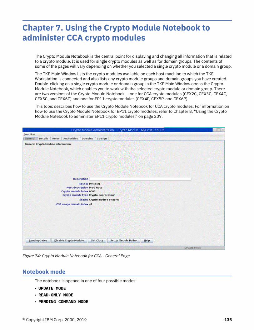
Chapter 7. Using the Crypto Module Notebook toadminister CCA crypto modules
The Crypto Module Notebook is the central point for displaying and changing all information that is relatedto a crypto module. It is used for single crypto modules as well as for domain groups. The contents ofsome of the pages will vary depending on whether you selected a single crypto module or a domain group.
The TKE Main Window lists the crypto modules available on each host machine to which the TKEWorkstation is connected and also lists any crypto module groups and domain groups you have created.Double-clicking on a single crypto module or domain group in the TKE Main Window opens the CryptoModule Notebook, which enables you to work with the selected crypto module or domain group. Thereare two versions of the Crypto Module Notebook — one for CCA crypto modules (CEX2C, CEX3C, CEX4C,CEX5C, and CEX6C) and one for EP11 crypto modules (CEX4P, CEX5P, and CEX6P).
This topic describes how to use the Crypto Module Notebook for CCA crypto modules. For information onhow to use the Crypto Module Notebook for EP11 crypto modules, refer to Chapter 8, “Using the CryptoModule Notebook to administer EP11 crypto modules,” on page 209.
Figure 74: Crypto Module Notebook for CCA - General Page
Notebook modeThe notebook is opened in one of four possible modes:
• UPDATE MODE• READ-ONLY MODE• PENDING COMMAND MODE
© Copyright IBM Corp. 2000, 2019 135

• LOCKED READ-ONLY MODE - group notebooks only
The mode is displayed in the lower-right corner on all of the Crypto Module Notebook pages.
In UPDATE MODE, you are able to display crypto module information and to perform updates to the cryptomodule.
In READ-ONLY MODE, you are able to display crypto module information but not update it.
In PENDING COMMAND MODE, a command is waiting to be co-signed. A multi-signature command issuedby an authority, but not yet executed, is called a pending command. You must perform the co-sign. Youcannot issue other commands in this mode. For information about co-signing a pending command, referto “Crypto Module Notebook Co-Sign tab” on page 195.
In LOCKED READ-ONLY MODE, you are able to display crypto module information for the master moduleand to compare the reduced group of crypto modules. You are not allowed to do updates. TKE was notable to access one or more crypto modules of the group or domain group.
Crypto Module Notebook function menuThe selections under the Function pull-down menu are:
• Refresh Notebook - The content of the notebook is refreshed by reading information from the host. Beaware that performing a refresh may change the mode of the notebook.
• Load Signature Key - For more information, see “Load signature key” on page 121.• Unload Signature key - For more information, see “Unload signature key” on page 123.• Release Crypto Module - A window displays the user ID that currently has this crypto module open.
This selection releases the crypto module from the update lock. This selection is only active if thenotebook is in read-only mode.
Figure 75: Window to Release Crypto Module
You can confirm release of the crypto module by pressing Yes.
Attention: Releasing a crypto module can damage an on-going operation initiated by anotherauthority. Use this option only if you are certain that the crypto module must be released.
• Display Crypto Module Settings - This produces a summary report of how the crypto module isconfigured, which can include what roles and authorities are defined, the master key register status andhash values for each domain, the domain control settings for each domain, and other information. Youare asked to select what information to collect and display.
The information is displayed on a new panel with tabs for each of the selected categories. A Save buttonallows you to save the information in a file, and a Print button allows you to print the information.
In a domain group notebook, the displayed information is for the crypto module containing the masterdomain.
• Display Domain Mode States - This produces a summary report of the states of all the domains on acrypto module or in a domain group. The summary shows the mode of each domain, and for domainsthat are not in normal mode, the number of audit log entries that have not been downloaded to the file.
• Compare Group - This selection is only displayed if working with a domain group. For more information,see “Comparing groups” on page 120.
• Compare Group (Same Domain Index) - This selection is only displayed if working with a domaingroup. For more information, see “Comparing groups” on page 120.
136 z/OS: Cryptographic Services ICSF Trusted Key Entry Workstation User's Guide

• Close - This selection closes the Crypto Module Notebook.
Tabular pagesFor the host cryptographic modules, the tabular pages available are:
• General: see “Crypto Module Notebook General tab” on page 137.• Details: see “Crypto Module Notebook Details tab” on page 139.• Roles: see “Crypto Module Notebook Roles tab” on page 141.• Authorities: see “Crypto Module Notebook Authorities tab” on page 145.• Domains: see “Crypto Module Notebook Domains tab” on page 155.• Co-sign: see “Crypto Module Notebook Co-Sign tab” on page 195.
The notebook opens to the General tab.
Crypto Module Notebook General tabThe contents of the Crypto Module Notebook General tab are:
• Description
An optional free text description that is displayed in the crypto module container at the main window.This description is saved in the crypto module data set specified in the TKE host transaction programstarted procedure on the host. To change the description, edit the field contents and press Sendupdates.
• Host ID• Host Description• Crypto Module Index
Identifies the crypto module type and installed location on the host system. The last two characters canrange from 00 to 63. For more information, see “Host crypto module index values” on page 195.
Together with the crypto module type, the index uniquely identifies the crypto module within a host. Theindex value is 00 through 63.
• Crypto Module Type• Status
A crypto module is either enabled or disabled. When a crypto module is enabled, it is available forprocessing. You can change the status of the module by pressing the Enable Crypto Module / DisableCrypto Module push button. Enable Crypto Module is a dual-signature command and another authoritymay need to co-sign. Disable Crypto Module is a single signature command.
Disabling a crypto module disables all the cryptographic functions for a single crypto module, a group ofcrypto modules, or a domain group. This disables the crypto module for the entire system, not just theLPAR that issued the disable.
• ICSF usage domain index
The usage domain on the crypto module where the TKE host transaction program is running. The usagedomain is also indicated by an asterisk on one of the numbered domain tabs when these are displayedin the notebook.
This field appears only when ICSF FMID HCR77B1 with APAR OA49067, or later, is running in the usagedomain.
If you press the Disable Crypto Module button, a series of windows opens. You are asked if you are surethat you want to disable the module, and are then notified if the command runs successfully. If theauthority signature key has not been loaded, you are asked, through a series of windows, to load an
Using the Crypto Module Notebook to administer CCA crypto modules 137
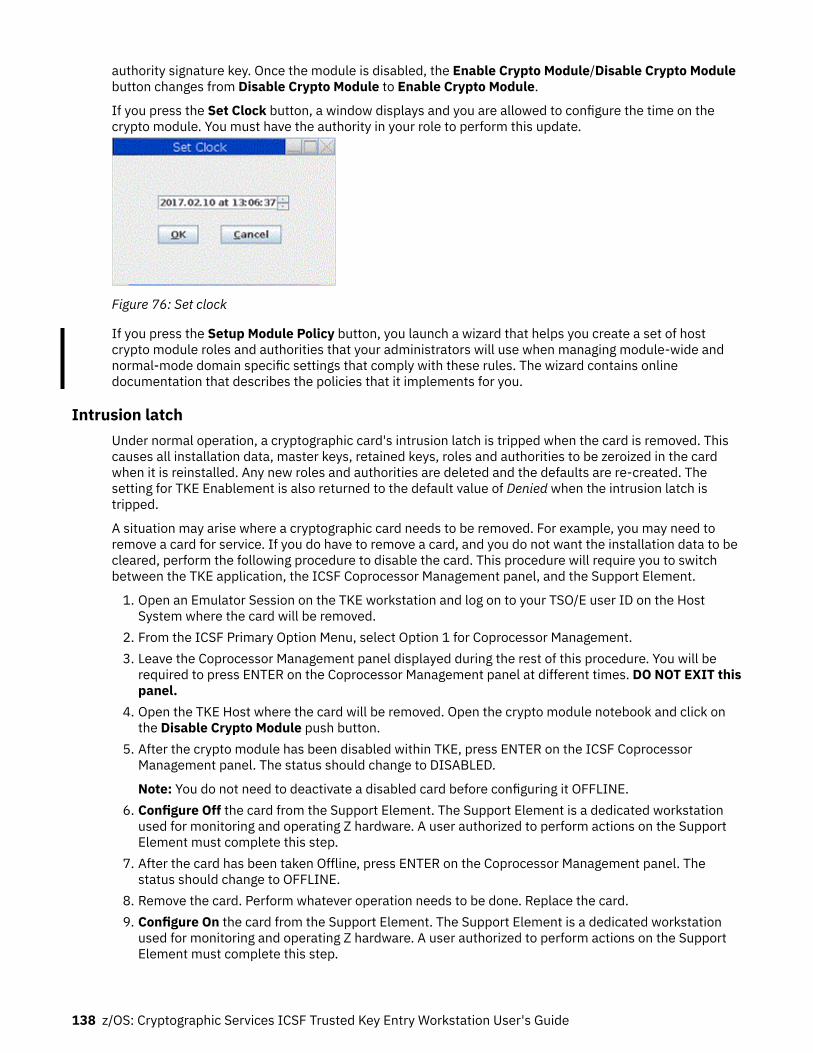
authority signature key. Once the module is disabled, the Enable Crypto Module/Disable Crypto Modulebutton changes from Disable Crypto Module to Enable Crypto Module.
If you press the Set Clock button, a window displays and you are allowed to configure the time on thecrypto module. You must have the authority in your role to perform this update.
Figure 76: Set clock
If you press the Setup Module Policy button, you launch a wizard that helps you create a set of hostcrypto module roles and authorities that your administrators will use when managing module-wide andnormal-mode domain specific settings that comply with these rules. The wizard contains onlinedocumentation that describes the policies that it implements for you.
Intrusion latchUnder normal operation, a cryptographic card's intrusion latch is tripped when the card is removed. Thiscauses all installation data, master keys, retained keys, roles and authorities to be zeroized in the cardwhen it is reinstalled. Any new roles and authorities are deleted and the defaults are re-created. Thesetting for TKE Enablement is also returned to the default value of Denied when the intrusion latch istripped.
A situation may arise where a cryptographic card needs to be removed. For example, you may need toremove a card for service. If you do have to remove a card, and you do not want the installation data to becleared, perform the following procedure to disable the card. This procedure will require you to switchbetween the TKE application, the ICSF Coprocessor Management panel, and the Support Element.
1. Open an Emulator Session on the TKE workstation and log on to your TSO/E user ID on the HostSystem where the card will be removed.
2. From the ICSF Primary Option Menu, select Option 1 for Coprocessor Management.3. Leave the Coprocessor Management panel displayed during the rest of this procedure. You will be
required to press ENTER on the Coprocessor Management panel at different times. DO NOT EXIT thispanel.
4. Open the TKE Host where the card will be removed. Open the crypto module notebook and click onthe Disable Crypto Module push button.
5. After the crypto module has been disabled within TKE, press ENTER on the ICSF CoprocessorManagement panel. The status should change to DISABLED.
Note: You do not need to deactivate a disabled card before configuring it OFFLINE.6. Configure Off the card from the Support Element. The Support Element is a dedicated workstation
used for monitoring and operating Z hardware. A user authorized to perform actions on the SupportElement must complete this step.
7. After the card has been taken Offline, press ENTER on the Coprocessor Management panel. Thestatus should change to OFFLINE.
8. Remove the card. Perform whatever operation needs to be done. Replace the card.9. Configure On the card from the Support Element. The Support Element is a dedicated workstation
used for monitoring and operating Z hardware. A user authorized to perform actions on the SupportElement must complete this step.
138 z/OS: Cryptographic Services ICSF Trusted Key Entry Workstation User's Guide

10. When the initialization process is complete, press ENTER on the Coprocessor Management panel. Thestatus should change to DISABLED.
11. From the TKE Workstation Crypto Module General page, click on the Enable Crypto Module pushbutton.
12. After the card has been enabled from TKE, press ENTER on the Coprocessor Management panel. TheStatus should return to its original state. If the Status was ACTIVE in step 2, when the card is enabledit should return to ACTIVE.
All installation data, master keys, retained keys, roles, and authorities should still be available. The datawas not cleared with the card removal because it was disabled first using the TKE workstation.
Crypto Module Notebook Details tabThe Details tab contains five pages, two for crypto modules and three for crypto module and diagnosticinformation. These five pages are accessible through tabs found on the right side of the Details tabscreen. To view these pages, click on the corresponding tabs. The pages and their contents are:
• Crypto Module: Shows basic information needed to recognize a host crypto module. Differentinformation is displayed, depending on the crypto module type. The following fields may be displayedon this page:
– Crypto Module ID - Unique identifier burned into the crypto module during the manufacturingprocess.
– Public Modulus - For crypto modules with an RSA OA signature key, the modulus of the key. TKE usesthe public key to verify signed replies from the host crypto module.
– Modulus Length - For crypto modules with an RSA OA signature key, the length of the modulus, inbits.
– ECC Public Key - For crypto modules with an ECC OA signature key, the ECC public key.– Key Identifier - The SHA-256 hash over the public part of the OA signature key. For RSA keys, the
hash is over the DER-encoded modulus and public exponent. For ECC keys, the hash is over the ECCpublic key.
– Signature Sequence Number - Each signed reply from the crypto module contains a uniquesequence number; the current value is displayed.
– Hash pattern of transport key - For CEX2C crypto modules, the MDC-4 hash value of the currentDiffie-Hellman generated triple-DES transport key for the crypto module. For later crypto modules,the first 16 bytes of the SHA-256 hash value of the current Diffie-Hellman generated AES transportkey.
• Crypto Services (Function Control Vector Values)
– Base CCA services availability– CDMF availability– 56-bit DES availability– Triple DES availability– 128-bit AES availability– 192-bit AES availability– 256-bit AES availability– SET services– Maximum length of RSA keys used to encipher DES keys– Maximum elliptic curve field size in bits for key management
• Other CM Info - The following crypto module information is displayed:
– CCA Version
Using the Crypto Module Notebook to administer CCA crypto modules 139

– CCA Build Date– DES Hardware Level– RSA Hardware Level– Power-On Self Test Version (0,1,2)– Operating System Name– Operating System Version– Part Number– Engineering Change Level– Miniboot Version (0,1)– Adapter ID– Processor Speed– Flash Memory Size– Dynamic RAM Memory Size– Battery-Backed Memory Size
• Diagnostic Info - The following diagnostic information is displayed:
– Intrusion Latch– Battery State– Error Log Status– Command Information
• Dual Validation - This tab validates that the host crypto co-processor code load has not been tamperedwith. This is done by retrieving the data in two different ways and comparing the results. If the tworesults are identical, then there are no signs of tampering.
Figure 77: Dual Validation
The settings in the Crypto Module Details tab are loaded during crypto module initialization.
140 z/OS: Cryptographic Services ICSF Trusted Key Entry Workstation User's Guide

Crypto Module Notebook Roles tabCCA crypto modules use role-based authority. Each authority has an associated role. This role indicateswhat operations the authority is permitted to execute and what domains on the crypto module theauthority is permitted to change.
With role-based authority, a set of roles can be defined that correspond to different classes ofcoprocessor users. For example, one class of users might be permitted to access only test domains, whileanother class of users might be permitted to access production domains. One class of users might bepermitted to perform only key operations, while another class of users might be permitted only to changedomain controls.
For key operations, further granularity is possible, with separate controls for loading first, middle, and finalkey parts, and for setting, completing, and clearing keys. Permission to execute these operations can beassigned to different roles, implying that multiple users are needed to manage keys. Or, one role canindicate permission to execute them all.
You can create, change, and delete roles from the Roles tab.
INITADM is a pre-defined role available on coprocessors that are shipped with the system, or aftersegments 2 and 3 of the coprocessor are zeroized and unowned (ownership surrendered) and thenreloaded. It is assigned to authority 00. It allows you to create an initial set of roles and authorities on thecrypto module. After you create these initial roles and authorities, you can choose to delete authority 00or to assign a different role to it.
Dual-signature commandsTo complete some commands, two authority signatures are required. For these commands there are twoentries in the Role Access Control Points tree, one indicating issue authority and one indicating co-signauthority. If a role contains both permissions, both signatures are collected automatically when anauthority with that role is used to execute the command. If an authority with a role containing only issueauthority is used to execute the command, the command is held in a pending command buffer until asignature is collected from a second authority whose role contains the co-sign permission.
When working with a single crypto module, use the Co-Sign tab in the notebook to collect the secondsignature for the command. When working with a domain group, a window opens asking you to co-signthe command.
Domain accessWhen you work with a role by using a crypto module notebook, the Role Access Control Points treecontains a Domain Access category that allows you to specify what domains the role gives permission tochange.
When you work with a role by using a domain group notebook, the Role Access Control Points tree doesnot include a Domain Access category. Instead, three Domain Access options are displayed:
• Set all Domain Access control points• Set Domain Access control points from group definition• Clear all Domain Access control points
Selecting the first option causes the role to allow access to all domains on the crypto module, whether ornot the domain is a member of the domain group.
Selecting the second option causes the role to allow access only to those domains on the crypto modulethat are members of the domain group. If the domain group includes domains on more than one cryptomodule, the Domain Access values can be different on different crypto modules. For example, if thedomain group includes domains 0, 1, and 2 on crypto module A and domains 3, 4, and 5 on crypto moduleB, the role on crypto module A has only domains 0, 1, and 2 set in the Domain Access category, and therole on crypto module B has only domains 3, 4, and 5 set.
Using the Crypto Module Notebook to administer CCA crypto modules 141

Selecting the third option causes the role to remove all domain access to all domains on the cryptomodule, whether or not the domain is a member of the domain group. Select this option when the roledoes not have any access control points that require access to domains. A role does not need any domainaccess if it includes only access control points from these categories:
• Crypto Module Enable• Access Control• Configuration Migration
Creating or changing a roleWhen you right-click in the Roles tab container, a menu opens and you can select Create Role, ChangeRole, Delete Role, View Role, or Guided Create Roles.
Figure 78: Create New Role page
If you select Create Role or Change Role from the menu, a window opens displaying the following fieldsand elements:
• Role ID: Enter the Role ID. If you are creating a new role, you must enter a name for that role. If you arechanging a role, you cannot change this field.
• Description : Optional free text description.• Tree structure and check boxes: This pane shows the operations and domains that can be allowed or
restricted by the role. Figure 78 on page 142 shows the list of categories. Each category can beexpanded to show a list of operations or domains. A check mark indicates that the operation or accessto the domain is permitted. The absence of a check mark indicates that the operation or access to thedomain is not permitted.
The Access Control category controls whether an authority can create, change, and delete roles andauthorities.
142 z/OS: Cryptographic Services ICSF Trusted Key Entry Workstation User's Guide

Dual-signature commands have entries for issue and co-sign authority.
Some categories in the Role Access Control Points tree are not shown if the crypto module does notsupport the operations in that category. For example, the ECC (APKA) Master Key category is notdisplayed for crypto modules that do not support ECC (APKA) master keys.
After you complete the fields on the panel and select the operations and domains to be permitted for therole, click Send Updates to create or change the role.
Deleting a roleTo delete a single role, right-click on the wanted role to display a menu. Select Delete Role from themenu. To delete multiple roles at the same time, highlight all the roles that you want to delete. By holdingdown the control button on the keyboard, you can select specific entries on the list with your mouse. Byholding down the shift button on the keyboard, you can select a specific range of entries on the list withyour mouse. Right-click on one of the highlighted entries and select Delete Role from the menu. You areprompted to confirm that you want to delete the previously selected number of roles.
You are not allowed to delete a role if it is assigned to one or more authorities. You are only allowed todelete unused roles.
View a roleTo view a single role, highlight the role and right-click for options. Select View Role. You can examine thesettings of the role, but you cannot change them.
Using Guided Create RolesTo use the Guided Create Roles process, right-click to display the menu. Select Guided Create Roles.
Note: Informational dialogs will appear during the process to help describe each step as it occurs.
Using the Crypto Module Notebook to administer CCA crypto modules 143

Figure 79: Guided Create Roles page
The Guided Create Roles window contains the following elements:Role ID
You have the option to fill in the name of the new role you are creating on the Guided Create Roleswindow.
DescriptionYou have the option to fill in the description of the new role you are creating on the Guided CreateRoles window.
Role ACP sets to includeA set of check boxes that describe commonly used sets of ACP choices for role creation. Multiplecheck boxes can be selected. When more than one check box is selected, the ACPs from all selectedsets will be set ON when the Create New Role panel is brought up later in the Guided Create Rolesprocess. The following check boxes are provided:
• Issuing commands that manage host module roles and authorities.• Co-signing commands that manage host module roles and authorities.• Managing host module domain settings.• Collecting and applying data using the migration wizard.• Managing first master key parts.• Managing middle master key parts.• Managing last master key parts.• Managing first operational key parts.
144 z/OS: Cryptographic Services ICSF Trusted Key Entry Workstation User's Guide
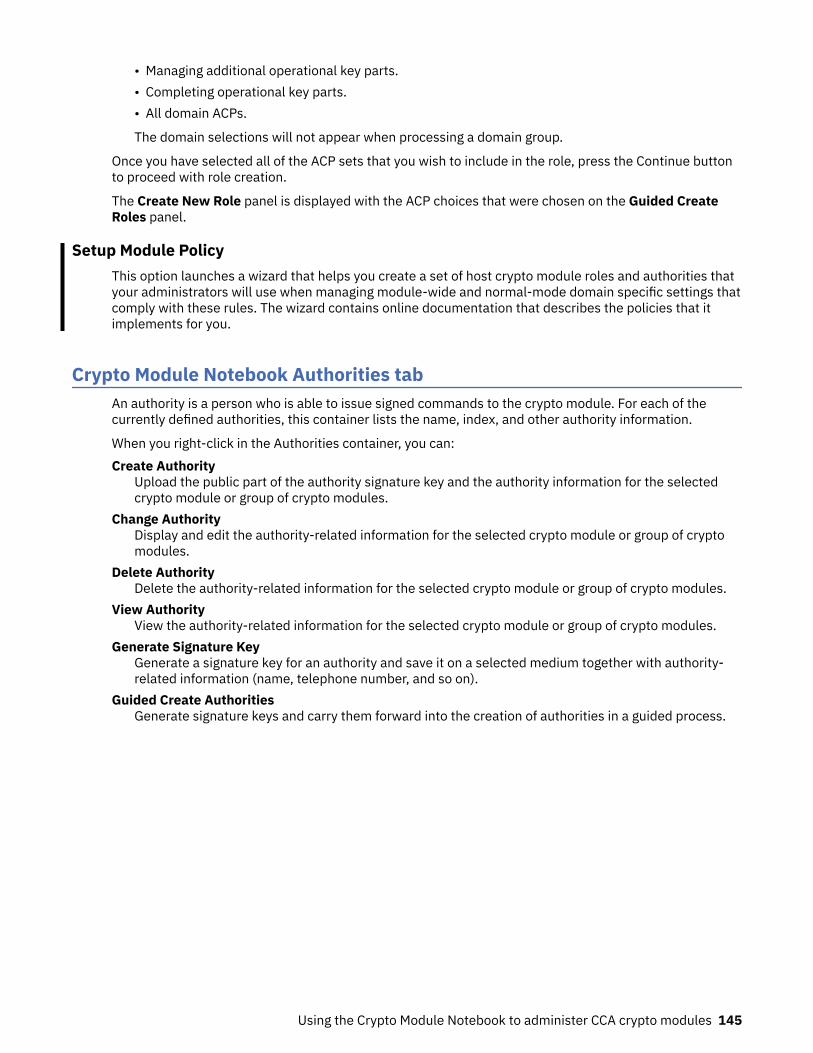
• Managing additional operational key parts.• Completing operational key parts.• All domain ACPs.
The domain selections will not appear when processing a domain group.
Once you have selected all of the ACP sets that you wish to include in the role, press the Continue buttonto proceed with role creation.
The Create New Role panel is displayed with the ACP choices that were chosen on the Guided CreateRoles panel.
Setup Module PolicyThis option launches a wizard that helps you create a set of host crypto module roles and authorities thatyour administrators will use when managing module-wide and normal-mode domain specific settings thatcomply with these rules. The wizard contains online documentation that describes the policies that itimplements for you.
Crypto Module Notebook Authorities tabAn authority is a person who is able to issue signed commands to the crypto module. For each of thecurrently defined authorities, this container lists the name, index, and other authority information.
When you right-click in the Authorities container, you can:Create Authority
Upload the public part of the authority signature key and the authority information for the selectedcrypto module or group of crypto modules.
Change AuthorityDisplay and edit the authority-related information for the selected crypto module or group of cryptomodules.
Delete AuthorityDelete the authority-related information for the selected crypto module or group of crypto modules.
View AuthorityView the authority-related information for the selected crypto module or group of crypto modules.
Generate Signature KeyGenerate a signature key for an authority and save it on a selected medium together with authority-related information (name, telephone number, and so on).
Guided Create AuthoritiesGenerate signature keys and carry them forward into the creation of authorities in a guided process.
Using the Crypto Module Notebook to administer CCA crypto modules 145

Figure 80: Authorities Page
Generating authority signature keysYou generate and save an authority signature key by right-clicking in the Authorities container andselecting the Generate Signature Key action.
The Generate Signature Key window is displayed.
Follow this procedure:
1. Enter Authority index. This is a mandatory field with the index of the authority. Valid range is 00through 99. The authority index is saved with the key and is called the Default Authority index. TheDefault Authority index for a saved authority signature key can be overridden when the authoritysignature key is loaded.
2. Enter information about the authority by using one of the following two common practices:
• Enter Name, Phone, E-mail, Address, and Description to identify the authority to a person. Theseare optional free text fields. The information that you enter here is saved with the key. It is filled inautomatically when the key is selected for creating a new authority. Press Continue.
Figure 81: Completed generate signature key window
146 z/OS: Cryptographic Services ICSF Trusted Key Entry Workstation User's Guide

• Enter a Name that identifies the purpose of the authority. This is the second most common practicebecause associating a card to a person can become hard to maintain, so using the name field as acard identifier might be a better solution for you.
3. Enter Name, Phone, E-mail, Address, and Description to identify the authority. These are optionalfree text fields. The information that you enter here is saved with the key. It will be filled inautomatically when the key is selected for creating a new authority. Press Continue.
4. A Select Target dialog box is displayed that allows you to select the target destination for thegenerated key. Authority signature keys can be saved to a binary file or key storage, or generated andsaved on a TKE smart card. Make your selection and press Continue.
5. Select the length of the authority signature key you want to generate. The length choices varydepending on the signature key target. If the signature key target is a smart card, you can generate1024-bit or 2048-bit RSA or BP-320 ECC authority signature keys. BP-320 ECC authority signaturekeys can only be generated to a TKE smart card with applet version 0.10 or greater. If the signature keytarget is a binary file or key storage, you can generate 1024-bit, 2048-bit, or 4096-bit RSA authoritysignature keys.
6. If the authority signature key is to be saved to a binary file, a password and file name are required toencrypt and save the key file. After you save the authority signature key and information to a binary fileor key storage, you are prompted to save the key again. It is not recommended that you save it again.
Figure 82: Save authority signature key
Attention : Do not remove a USB flash memory drive from the USB port before you complete theoperation that is using the drive, or before you respond to a message related to the operation that isusing the drive. If you do remove a drive before the operation is complete, hardware messages mightbe generated on the TKE workstation.
7. If the key is to be generated and saved on a TKE smart card, a message box displays, prompting youto "Insert TKE smart card in smart card reader 2."
a. Insert the TKE smart card into smart card reader 2. Press OK.
Using the Crypto Module Notebook to administer CCA crypto modules 147

b. When the authority signature key is generated and saved to a TKE smart card, it is protected by thePIN of the TKE smart card. A message box prompts you to “Enter a 6-digit PIN on smart card reader2 PIN pad”. Enter the PIN as prompted.
Note: If the TKE smart card was created on a version of the TKE Workstation before version 7.0, thePIN of the TKE smart card is 4 digits instead of 6 digits.
The authority signature key is generated on the TKE smart card and a successful message isdisplayed.
Figure 83: Generate signature key
When generating and saving an authority signature key on a TKE smart card, you are not given theoption to save it again. You should use the Copy smart card contents utility to save the signaturekey again. See “Copy smart card contents” on page 130.
Each TKE smart card can hold only one authority signature key.8. If the keys are to be saved in Key Storage, only one authority signature key can be stored in PKA key
storage.
Figure 84: Key saved status message
Create authorityThis selection allows you to create an authority at the host and select its authority signature key. Beforeyou can create a new authority, you need to generate an authority signature key (see “Generatingauthority signature keys” on page 146).
To create an authority, click with the right mouse button in the container on the Authorities page. A pop-up menu displays. From this menu, select the Create Authority menu item.
The Select Source window opens, enabling you to specify the authority signature key source. Make yourselection and press the Continue push button.
148 z/OS: Cryptographic Services ICSF Trusted Key Entry Workstation User's Guide

Figure 85: Select source of authority signature key
• If you select Key storage, the key and accompanying information from key storage appears in theCreate New Authority window.
• If you select Smart card in reader 1 or Smart card in reader 2, you are prompted to insert the TKEsmart card into the appropriate reader. Insert the smart card into the reader, and press OK.
Notes:
– Starting in TKE 7.2, you can have 2, 3, or 4 smart card readers. The number of attached smart cardreaders is detected when the main TKE application starts and controls the options that are displayedon the panel. If no attached smart card readers are detected, no smart card reader options aredisplayed.
– BP-320 ECC authority signature keys may be used only on a CEX5C host crypto module.
A message box prompts you to enter the TKE smart card PIN. Enter the PIN as prompted.
After the PIN has been verified, the Create New Authority window opens.
Using the Crypto Module Notebook to administer CCA crypto modules 149

Figure 86: Create new authority• If you select Binary file, the Load Signature Key window is displayed. You are prompted for the
signature key file to load and password before the Create New Authority window appears.
Attention : Do not remove a USB flash memory drive from the USB port before you complete theoperation that is using the drive, or before you respond to a message related to the operation that isusing the drive. If you do remove a drive before the operation is complete, hardware messages might begenerated on the TKE workstation.
150 z/OS: Cryptographic Services ICSF Trusted Key Entry Workstation User's Guide
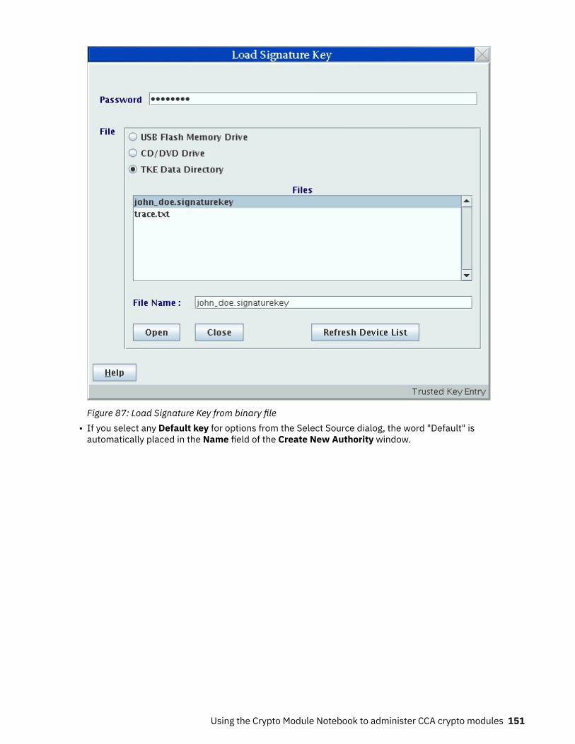
Figure 87: Load Signature Key from binary file• If you select any Default key for options from the Select Source dialog, the word "Default" is
automatically placed in the Name field of the Create New Authority window.
Using the Crypto Module Notebook to administer CCA crypto modules 151

Figure 88: Create New Authority with Role Container
The Create New Authority window is opened with the following authority information that is read fromthe signature key source:Authority index
This is a mandatory field with the index of the authority. Valid range for module-wide authorities is00 through 99.
If the authority signature key is going to be used on several crypto modules, it simplifies matters touse the same authority index for all crypto modules.
NameName of the authority. Optional free text entry field.
PhoneTelephone number of the authority. Optional free text entry field.
E-mailE-mail address for the authority. Optional free text entry field.
AddressAddress of the authority. Optional free text entry field.
DescriptionDescription of the authority. Optional free text entry field.
Signature keyPublic modulus of the authority signature key.
Key LengthLength of the authority signature key.
Key IdentifierIdentifier for the authority signature key that is associated with the authority. The key identifier isthe SHA-256 hash of the DER-encoded public modulus and public exponent of the authoritysignature key.
You can edit all of the entry fields.
152 z/OS: Cryptographic Services ICSF Trusted Key Entry Workstation User's Guide

In the Role container, there is a drop-down list. Select one of the previously defined roles. The authorityis mapped to the access rights of that role. This is available only when creating or changing a cryptomodule authority.
Press Send updates. This is a dual signature command. If you do not have both sign and co-signauthority, another authority is required to co-sign.
The authority information (name, telephone, e-mail, and address) is saved in the crypto module data setspecified in the TKE host transaction program started procedure on the host.
Change authorityThis selection opens the Change Authority window, allowing you to change authority information, changethe role, and replace the authority signature key.
Figure 89: Change Authority
When an authority is selected, you will be able to update the Name, Phone, E-mail, Address andDescription fields. You can change the Role definition by clicking on the pull-down menu and selecting adifferent role. You can change the authority signature key by clicking on Get Signature Key.
Get Signature Key opens a Select Source window and a Load Signature Key window. The contents of theselected key file replace the contents of the Change Authority window except for the index.
Send updates uploads the information displayed at the window to the crypto module. The authorityinformation (name, phone, e-mail and address) is updated in the crypto module dataset specified in theTKE host transaction program started procedure on the host.
Delete authorityThe supported crypto modules operate with a variable number of TKE authorities (TKEAUTxx profiles).TKE allows a user to delete an authority from a crypto module. TKE performs a consistency check of theresulting TKE roles and profiles to ensure that access to the crypto module is not lost when the profile isdeleted.
Using the Crypto Module Notebook to administer CCA crypto modules 153

Using Guided Create AuthoritiesTo use the Guided Create Authorities process, right-click to display the menu. Select Guided CreateAuthorities.
Note: Informational dialogs will appear during the process to help describe each step as it occurs.
Figure 90: Guided Create Authorities page
The Guided Create Authorities window contains the following elements:Authority Index
You have the option to fill in the number of a new authority index on the Guided Create Authoritieswindow.
Actions to PerformYou can select which actions you wish to perform as part of the Guided Create Authorities process.You can select either Generate Signature Key, or Create Authority, or both Generate Signature Key andCreate Authority. It is important to note that you must have generated at least one signature keybefore you can create an authority because the Create Authority process requires a signature key asinput.
Once you have chosen whether to specify an authority index or not and selected Generate Signature Keyor Create Authority or both Generate Signature Key and Create Authority check boxes, press the Continuebutton to proceed with the Guided Create Authorities process. If it was previously selected, theGenerate Signature Key panel will be displayed with the authority index filled in from the Guided CreateAuthorities panel. Once the Generate Signature Key process is completed, the Guided CreateAuthorities process will continue. If Create Authority was previously selected, the Create New Authoritypanel will be displayed with the authority index used in the Generate Signature Key process already filledin.
Setup Module PolicyThis option launches a wizard that helps you create a set of host crypto module roles and authorities thatyour administrators will use when managing module-wide and normal-mode domain specific settings thatcomply with these rules. The wizard contains online documentation that describes the policies that itimplements for you.
154 z/OS: Cryptographic Services ICSF Trusted Key Entry Workstation User's Guide

Crypto Module Notebook Domains tabThe Domains tab allows you to work with the domains on the host crypto module. Master keys andoperational keys can be loading using the Domains tab and domain control values can be changed.
When the Domains tab is selected, numbered tabs are displayed on the right for each domain that isconfigured as a control domain on the host system. Up to 85 domain tabs may be displayed, depending onthe host system type and the crypto module type that are accessed. When ICSF FMID HCR77B1 withAPAR OA49067, or later, runs in the logical partition that services requests from the TKE workstation, theconfigured usage domain will be indicated by an asterisk on one of these tabs.
In the crypto module notebook for a domain group, numbered tabs for individual domains are omitted andthe displayed information is for the master domain. The tab label at the top for a domain group is Domaininstead of Domains.
Domain scoped commands issued using a domain group are normally broadcast to all domains in thegroup. Commands to load and clear operational key registers may optionally be issued to only the masterdomain. The desired behavior is selected when a CCA domain group is created or changed.
Domain General pageThe Domain General page opens when you select a domain. By clicking tabs at the bottom of the page,you can work with the domain keys, domain control points, domain decimalization tables, domainrestricted PINs, and domain certificates. From the Domain General page, you can update the domaindescription, zeroize the domain, change the default key wrapping methods, and change the mode of thedomain.
Figure 91: Domain General page - Normal mode
To change the description, edit the entry field and click Send updates. The description is saved in thecrypto module data set specified in the TKE host transaction program started procedure on the host.
To change the default key wrapping methods that are used for the domain, select the methods forexternal and internal formatted tokens and click Send updates.
Using the Crypto Module Notebook to administer CCA crypto modules 155

If you click Discard changes, any changes that you made on the panel to the domain description or thedefault key wrapping methods are discarded, and the current values are refetched from the cryptomodule.
Zeroize domain
Zeroizing a domain erases its configuration data and clears all cryptographic keys and registers for thecurrent domain.
Selecting Zeroize domain... results in the display of an action (warning) message. By accepting themessage, the domain is zeroized. That is, all registers and keys that are related to this domain are set tozero or set to not valid.
If you are reassigning a domain for another use, it is a good security practice to zeroize that domain beforeproceeding.
When a domain is zeroized, the domain's controls are reset to their initial state.
Note: Unlike the Global Zeroize issued from the Support Element, Zeroize Domain does not affect theenablement of TKE Commands on the supported crypto modules. Refer to “TKE enablement” on page 11.
Changing domain modes
Beginning with the CEX6C crypto module, a domain can exist in various modes or distinct operationalstates. The current domain mode is displayed on the Domain General panel.
The Domain General panel includes a button that allows you to change from one mode to another. For adomain in normal mode, an Enter imprint mode button is displayed. For a domain in one of the othermodes, a Change mode button is displayed. Clicking the button causes a secondary panel to be displayedwith a set of mode transition options.
Figure 92: Select mode panel for IMPRINT mode
Figure 93: Select mode panel for PCI-COMPLIANT mode
Figure 94: Select mode panel for PCI-COMPLIANT mode, key migration allowed
156 z/OS: Cryptographic Services ICSF Trusted Key Entry Workstation User's Guide

For a domain in imprint mode or PCI-compliant mode, extra tabs are displayed at the bottom of the cryptomodule notebook panel that allow you to work with the domain roles, domain authorities, and domainaudit log.
Figure 95: Domain in IMPRINT mode
For more information, see “Domain modes” on page 9.
Domain Keys pageThis page displays the status and hash patterns of the master key registers. It allows you to generate keyparts; load, clear, and set master key registers; and load, view, and clear operational key registers. It alsoallows you to enter key parts on a smart card using secure key entry.
The upper part of the window displays the status and hash patterns of the master key registers. Themaster key registers shown depend on the crypto module type.
Note: ICSF uses the term 'ECC master key register' and CCA uses the term 'APKA master key register' torefer to the same entity. On TKE, this is labeled 'ECC (APKA) master key register'.
If you are using smart cards, the TKE workstation crypto adapter must be enrolled in the same zone as thesmart cards you are using. Otherwise, you cannot generate key parts and save them on the smart card orload key parts from the smart card to a master key register or operational key register.
You can view the zone for smart cards using the Smart Card Utility Program. Insert the smart card in areader and select File and then Display smart card information. You can view the zone for the TKEworkstation crypto adapter and enroll the TKE workstation crypto adapter in a zone using the Smart CardUtility Program using options under the Crypto Adapter pull-down menu.
Using the Crypto Module Notebook to administer CCA crypto modules 157

Figure 96: Domain Keys page
The lower part of the Domain Keys page allows you to work with different key types. Right-click on a keytype in the Key Type container to display a pop-up menu. Table 31 on page 158 describes what menuoptions are available for the different key types.
Table 31: Key types and actions for the supported crypto modules
Key type Pop-up Sub-pop-up Action description
AES masterkey
ECC (APKA)master key
DES masterkey
RSA masterkey
Generate single keypart
Generate one master key part and store it on aTKE smart card or save it to a binary or print file.
Generate multiplekey parts to …
Smart card
Binary file
Print file
Run a wizard-like feature to generate a userspecified number of master key parts and storethem on TKE smart cards or save them to binary orprint files.
Note: You can use the same smart card or switchsmart cards between key part generations.
Generate a set ofmaster key parts
Run a wizard-like feature to generate a set ofmaster key parts (AES, DES, RSA or ECC (APKA)).
158 z/OS: Cryptographic Services ICSF Trusted Key Entry Workstation User's Guide

Table 31: Key types and actions for the supported crypto modules (continued)
Key type Pop-up Sub-pop-up Action description
Load single key part First
Intermediate
Last
Load one key part into the appropriate "new"master key register.
Notes:
1. To load a first part, the "new" master registerstatus must be "empty".
2. To load an intermediate or last part, the "new"master register status must be "part full"(partially full).
Load all key partsfrom
Smart card
Binary file
Print file
Run a wizard-like feature to load an entire "new"master key register. At the beginning of theprocess, you specify the total number of key partsand have the option of clearing the "new" masterkey register.
Note: No new security controls are introduced bythis feature. ALL authority and dual controlrequirements you put in place remain in effect. Ittakes the same number of people to load an entirekey using this procedure as it does loading anentire key one part at a time.
Load all new masterkeys
Run a wizard-like feature to load one or more newmaster key registers -- first, middle (optional), andlast key parts. At the beginning of the process, youhave the option of clearing one or more masterkey registers. Note: No new security controls areintroduced by this feature. ALL authority and dualcontrol requirements you put in place remain ineffect. It takes the same number of people to loadan entire key using this procedure as it doesloading an entire key one part at a time.
Clear New Master KeyRegister
Old Master KeyRegister
Clear the new or old master key register. Thestatus of the register will be "empty" when theoperation is complete.
Using the Crypto Module Notebook to administer CCA crypto modules 159

Table 31: Key types and actions for the supported crypto modules (continued)
Key type Pop-up Sub-pop-up Action description
Set (Option onlyshown on RSAmaster key)
Sets the RSA master key.
Notes:
1. Beginning with ICSF FMID HCR7790, ICSFblocks the use of the Set RSA Master Keycommand from TKE if any online host cryptomodules are found with the September 2011LIC or later (CEX3C or later). The set must bedone from ICSF.
2. The current RSA master key is transferred tothe old RSA master key register.
3. The new RSA master key register is transferredto the current RSA master key register.
4. The new RSA master key register is reset tozeros.
Set, immediate Sets the master key.
Transfers the value in the current master keyregister to the old master key register, transfersthe value in the new master key register to thecurrent master key register, and clears the newmaster key register.
Under normal circumstances, set master keysusing ICSF procedures or services that coordinatesetting the master key with initializing or re-enciphering key storage. This option sets themaster key but does not change the associatedkey storage. If used inappropriately, thiscommand causes the keys in key storage tobecome unusable when accessed by ICSF in thedomain.
Use this option only when key storage does notneed to be initialized or re-enciphered when themaster key is set. For example, this command canbe used to reload previous master key values if ahost crypto module has been inadvertentlyzeroized.
Secure key partentry
Enter known key part value to a TKE smart card;see Appendix A, “Secure key part entry,” on page313.
160 z/OS: Cryptographic Services ICSF Trusted Key Entry Workstation User's Guide

Table 31: Key types and actions for the supported crypto modules (continued)
Key type Pop-up Sub-pop-up Action description
AES masterkey
DES masterkey
Coordinated changemaster keys andCKDS
Run a wizard-like feature to re-encipher thecurrent ICSF cryptographic key data set (CKDS)under the new AES or DES master keys or both,set the AES or DES master keys or both, and makethe re-enciphered CKDS the active in-store CKDSused by ICSF.
Note: This option is displayed only when thefollowing conditions are met:
• The current domain is the usage domain.• The "Coordinated change master key and KDS"
operation is permitted in the role for the usercurrently logged on the TKE crypto adapter.
• The host usage domain is running ICSF FMIDHCR77B1 with APAR OA49067, or later.
ECC (APKA)master key
RSA masterkey
Coordinated changemaster key andPKDS
Run a wizard-like feature to re-encipher thecurrent ICSF public key data set (PKDS) under thenew ECC (APKA) or RSA master keys or both, setthe ECC (APKA) or RSA master keys or both, andmake the re-enciphered PKDS the active in-storePKDS used by ICSF.
Note: This option is displayed only when thefollowing conditions are met:
• The current domain is the usage domain.• The "Coordinated change master key and KDS"
operation is permitted in the role for the usercurrently logged on the TKE crypto adapter.
• The host usage domain is running ICSF FMIDHCR77B1 with APAR OA49067, or later.
DES, AES, orHMACoperationalkeys
Generate single keypart
Generate one key part and store it on a TKE smartcard or save it to a binary or print file.
Generate multiplekey parts to …
Smart card
Binary file
Print file
Run a wizard-like feature to generate a userspecified number of key parts and store them onTKE smart cards or save them to binary or printfiles.
Note: You can use the same smart card or switchsmart cards between key part generations.
Using the Crypto Module Notebook to administer CCA crypto modules 161

Table 31: Key types and actions for the supported crypto modules (continued)
Key type Pop-up Sub-pop-up Action description
Load single key part First
First (minimum of 2parts)
First (minimum of 3parts)
Add part
Complete
Load one key part into a key part register.
Note:
1. When the first key part is loaded, you mustenter a unique key label for the register.
2. The First option can be selected only for DESoperational keys and AES DATA operationalkeys.
3. The First (minimum of 2 parts) and First(minimum of 3 parts) options can be selectedonly for AES operational keys (other than DATA)and HMAC operational keys.
4. After selecting First or First (minimum of 2parts), you must load at least one additionalkey part before completing the register.
5. After selecting First (minimum of 3 parts), youmust load at least two additional key partsbefore completing the register.
Load to Key Storage First
Intermediate
Last
Load a key part to the TKE workstation's DES orAES key storage.
Note: These options can be selected only for DESIMP-PKA operational keys and AES IMPORTERoperational keys.
Load all key partsfrom
Smart card
Binary file
Print file
Run a wizard-like feature to load an entireoperational key register. At the beginning of theprocess, you specify the total number of key partsand have the option of clearing the "new" masterkey register.
Note: No new security controls are introduced bythis feature. ALL authority and dual controlrequirements you put in place remain in effect. Ittakes the same number of people to load an entirekey using this procedure as it does loading anentire key one part at a time.
View View key part register information
Clear Clear (reset) the operational key part register.
Secure key partentry
Enter known key part value to a TKE smart card;see Appendix A, “Secure key part entry,” on page313.
RSA keys Generate single keypart
Generate an RSA key and encrypt it under a DESIMP-PKA key or AES IMPORTER key.
Encipher Encipher an unencrypted RSA key under an IMP-PKA key.
Load to PKDS Load an RSA key to the PKDS active in the logicalpartition where the Host Transaction Program isstarted.
162 z/OS: Cryptographic Services ICSF Trusted Key Entry Workstation User's Guide

Table 31: Key types and actions for the supported crypto modules (continued)
Key type Pop-up Sub-pop-up Action description
Load to dataset Load an RSA key to the host data set
Master keys - AES, ECC (APKA), DES, or RSA
Generate single key part
This generates and saves a random master key part.
When you select this option, you are prompted to enter the following information:
• The target for the master key part. This can be a smart card reader, a binary file, or a print file.• The length of the key part. This is requested only for DES master key parts on CCA 4.3 or later. The
allowed choices are 16 bytes and 24 bytes.• If the target is a binary file or print file, the file name and location are requested. The target file can be in
the TKE Data Directory or on USB memory.• If the target is a binary file or print file, after the key part is generated and saved, you are asked if you
want to save the key part elsewhere.• If the target is a smart card reader, you are prompted to insert the smart card and enter the PIN. You are
prompted to supply a key part description.
Attention : Removing a USB flash memory drive from a USB port while an operation accessing the drive isin progress can cause hardware messages on the TKE workstation. Wait for the operation to completebefore removing the USB flash memory drive.
Generate multiple key parts
If you are going to create more than one key part at a time, use the “generate multiple key part to”feature. When this feature is started, you are asked to provide the total number of key parts you want tocreate. The minimum number of key parts that can be specified is 2.
Figure 97: Enter number of keys to be generated
The feature will walk you through the process of creating the requested number of key parts.
Generate a set of master key parts
To create a set of master key parts of different types, use the 'generate a set of master key parts' feature.The feature helps you through the process of generating the set of master key parts.
Load single key part
This loads a key part into the new master key register. Cascaded options on the pop-up menu selectwhether the First, Intermediate, or Last key part is to be loaded.
The new master key register must be Empty in order to load a First key part. It must be Partially full inorder to load an Intermediate or Last key part. You must load a First and a Last key part, and you can loadany number of Intermediate key parts (zero or more).
After selecting the pop-up menu option, you are asked to select the source of the key part.
Using the Crypto Module Notebook to administer CCA crypto modules 163

Figure 98: Select source of new AES Master Key part
Load from TKE smart card
You are prompted to insert the smart card in the reader. The smart card contents are read, and you areprompted to select a key part. Only key parts for the selected master key type are displayed.
Figure 99: Select key part from TKE smart card
If no matching key parts are found, a warning message is displayed and the load operation terminates.
Figure 100: Warning message
Left-click on a key part to select it, then click on the OK button. You are asked to enter the PIN for thesmart card if it has not been entered already. When the PIN is entered, the key part is read and one ormore hash patterns or verification patterns are displayed. For DES master keys, the ENC-ZERO and MDC-4or CMAC hash patterns are displayed. For RSA master keys, the MDC-4 hash pattern is displayed. For AESand ECC (APKA) master keys, the AES-VP or HMAC-VP is displayed.
164 z/OS: Cryptographic Services ICSF Trusted Key Entry Workstation User's Guide

Figure 101: Key part information panel
Click on the Load key button to load the key part.
Load from keyboard
You can load a key part whose value you type in from the keyboard. The Blind Key Entry option on thePreferences pull-down menu on the main TKE panel controls the appearance and behavior of the panelused to enter the key part using the keyboard.
When the Blind Key Entry option is selected, only asterisks are displayed in the Enter Key Value panel ascharacters are entered using the keyboard. Optional reenter fields are displayed on the right side of thepanel. If these are filled in, the values entered must match the values entered on the left side of the panelin order for the key part to be accepted.
Figure 102: Enter Key Value - Blind Key Entry
When the Blind Key Entry option is not selected, the characters entered using the keyboard are displayedon the Enter Key Value panel and there are no reenter fields.
Using the Crypto Module Notebook to administer CCA crypto modules 165

Figure 103: Enter Key Value
When you have entered the key part, click on the Continue button. A Key Part Information panel isdisplayed showing one or more hash patterns or verification patterns for the key part. Click on the Loadkey button to load the key part.
Before the key part is actually loaded, you are asked if you would like to save the key part. You can savethe key part in one or more binary files or print files.
Load from binary file
You can load a key part saved in a binary file. The binary file can be in the TKE Data Directory or on USBmemory. When you select this option, the Specify Key File window is opened.
Figure 104: Specify Key File
166 z/OS: Cryptographic Services ICSF Trusted Key Entry Workstation User's Guide

Select the file location by clicking on a radio button at the top. The Files container lists the files for thislocation. A radio button for USB flash memory is displayed only when a USB flash memory drive isplugged into a USB port on the TKE workstation.
Left-click on one of the listed files to select the file containing the key part, then click on the Open button.A Key Part Information panel is displayed showing one or more hash patterns or verification patterns forthe key part. Click on the Load key button to load the key part.
Attention : Removing a USB flash memory drive from a USB port while an operation accessing the drive isin progress can cause hardware messages on the TKE workstation. Wait for the operation to completebefore removing the USB flash memory drive.
Note on DES master key lengthStarting with CCA 4.3, a DES master key can be either 16-bytes or 24-bytes long. For earlier CCA versions,the DES master key length is always 16 bytes.
To load 24-byte DES master keys, you must use TKE 7.2 or later and run ICSF FMID HCR77A0 or later onthe host system.
The DES master key length is selected through a domain control setting. The 'DES master key - 24-bytekey' domain control under 'ISPF Services' controls the length of the first DES master key part that can beloaded into the new DES master key register. When the domain control is enabled, only a 24-byte key partcan be loaded. When the domain control is disabled, only a 16-byte key part can be loaded.
The domain control setting only affects loading the first DES master key part. If a first DES master key partis loaded and the domain control setting is changed, the length of additional key parts must match thelength of the first key part, regardless of the domain control setting.
Note on weak keysTwo other domain controls were introduced with CCA 4.3 and ICSF FMID HCR77A0: 'Warn when weakwrap - Master keys' and 'Prohibit weak wrapping - Master keys', both under 'Coprocessor Configuration'.
The first causes a warning to be signaled when loading a last 24-byte DES or RSA master key part, if thefinal key is considered weak. The final key is considered weak if two or more 8-byte pieces of the key areidentical. For example, if A, B, and C represent the 8-byte pieces of the master key, an A-B-C key would beconsidered 'strong', but an A-B-A key would be considered 'weak'.
The second domain control causes an error to be reported instead of a warning for the same scenario.
Load all key parts from
This option allows you to fully load a new master key register without having to open and choose from thepop-up menu for each part. Cascaded options on the pop-up menu allow you to choose the source type(smart cards, binary files, or the keyboard).
You are asked to enter the number of key parts. You can optionally clear the new master key register. Thenyou are led through the process of loading each of the key parts from the selected source type.
When loading key parts from smart cards, you can use different smart cards for each key part, if desired.
For each operation that requires an authority signature, if no authority signature key is loaded or if thecurrent authority is not allowed to perform the operation, you are prompted to load an appropriateauthority signature key.
Load all new master keys
This option allows you to load all of the new master key registers (DES, AES, RSA and ECC(APKA)) using asingle selection from the pop-up menu.
You are first asked to select the new master key registers to be cleared. Select the registers and click onthe Continue button to proceed. If no registers need to be cleared, leave all check boxes unchecked andclick on Continue.
Using the Crypto Module Notebook to administer CCA crypto modules 167

Next, you are asked to select the registers where first master key parts are to be loaded. Select theregisters and click on the Continue button. You are asked to select the source of the key parts (smart cardor binary file). For each of the registers you selected, you are guided through the process of loading a keypart.
You are then asked whether you want to load middle master key parts. If yes, click on the Yes button. Youare asked to select the master key registers where middle key parts will be loaded. You are asked toselect the source of the key parts, and are then guided through the process of loading the middle keyparts.
Similar actions take place for additional middle key parts and for the final key parts.
Clear
This option allows you to clear either the new master key register or the old master key register for theselected master key type.
Set
This option is available only for RSA master keys. PKA Callable Services must be disabled on ICSF beforeyou use this option.
This option transfers the value in the current RSA master key register to the old RSA master key register,transfers the value in the new RSA master key register to the current RSA master key register, and clearsthe new RSA master key register.
Note: Beginning with ICSF FMID HCR7790, ICSF blocks the use of the Set RSA Master Key command fromTKE if any online host crypto modules are found with the September 2011 LIC or later (CEX3C or later).ICSF signals an error in this case. You can use the Set RSA Master Key command with earlier versions ofICSF, or if all online host crypto modules are at earlier CCA levels.
Set, immediate
This option is available for all master key types (AES, ECC (APKA), DES, and RSA). It transfers the value inthe current master key register to the old master key register, transfers the value in the new master keyregister to the current master key register, and clears the new master key register.
Under normal circumstances, set master keys by using ICSF procedures or services that coordinatesetting the master key with initializing or re-enciphering key storage. This option sets the master key butdoes not change the associated key storage. If used inappropriately, this option causes the keys in keystorage to become unusable when accessed by ICSF in the domain.
Use this option only when key storage does not need to be initialized or re-enciphered when the masterkey is set. For example, this command can be used to reload previous master key values if a host cryptomodule was inadvertently zeroized.
Coordinated change master keys and CKDS (AES and DES master keys only)
Beginning with TKE 8.1 and ICSF FMID HCR77B1 with the PTF for APAR OA49067, you can perform anoperation from the TKE workstation that will set the host crypto module master key or keys and re-encipher your ICSF cryptographic key data set (CKDS) using the updated master key or keys. This functionuses the same ICSF support as the 'coordinated CKDS change master key' option that appears on theCKDS Management panel in ISPF.
This option will appear on the pull-down menu only if the TKE workstation is connected to a host that isrunning ICSF FMID HCR77B1 with the PTF for APAR OA49067. The option will be disabled unless theactive TKE crypto adapter role has the X'1012' 'Coordinated change master key and KDS' ACP defined.
This function does the following:
• Takes the ICSF CKDS that is enciphered under the current DES or AES master keys or both and re-enciphers it under the new DES or AES master keys or both. The re-enciphered content is placed in anew data set and becomes the active in-store CKDS copy used by ICSF.
168 z/OS: Cryptographic Services ICSF Trusted Key Entry Workstation User's Guide

• Sets the DES or AES master keys or both. This involves moving the contents of the current master keyregister or registers to the old master key register or registers, moving the contents of the new masterkey register or registers to the current master key register or registers, and then clearing the new masterkey register or registers.
• Optionally renames the current CKDS to a supplied archive data set name and then renames the new re-enciphered data set to the current CKDS name. If this option is not chosen, the CKDSN parameter in theICSF installation options data set will need to be updated to the name of the new re-enciphered dataset in order for that data set to be used the next time ICSF is started.
• Optionally makes a back-up copy of the re-enciphered new data set.
The master key registers involved with this operation are determined by how the CKDS was originallyinitialized – using the DES master key only, using the AES master key only, or both the DES and AESmaster keys.
The new master key registers that are used must be in a 'full' state and current master key registers mustbe in a 'valid' state before the coordinated change operation is performed. The new master key registerchecking includes all CCA crypto modules being used by the host ICSF, not just this crypto module. Theverification patterns of the master key registers (new and current) are also checked for consistency for allCCA crypto modules being used by the host ICSF.
If the host ICSF is in a sysplex environment, the coordinated change operation will be performed sysplex-wide. In the sysplex environment, the current and new master key registers must be set properly on allsystems in the sysplex.
If the new CKDS or back-up CKDS are not allocated, you will have an opportunity to allocate those datasets automatically. The TKE host transaction program job will attempt to allocate those data sets basedon the attributes of the current CKDS using the TSO ALLOCATE command with the LIKE operand specified.The TKE host transaction program job user will need to have the proper authority in order for the data setallocation to succeed.
More information about the coordinated change master keys and CKDS function can be found in'Coordinated KDS Administration (CSFCRC and CSFCRC6)' in z/OS Cryptographic Services ICSF ApplicationProgrammer's Guide and 'Performing a coordinated change master key' section in z/OS CryptographicServices ICSF Administrator's Guide.
Coordinated change master keys and PKDS (ECC (APKA) and RSA master keys only)
This function is the same as the 'Coordinated change master keys and CKDS' function, but uses the ECC(APKA) or RSA master keys or both and public key data set (PKDS).
Operational keysHost crypto modules contain a set of operational key part registers that allow you to accumulate thevalues of operational keys before loading a host Cryptographic Key Data Set (CKDS). On the CEX2C,CEX3C, and CEX4C coprocessors, there are 100 operational key part registers that are shared by alldomains. On the CEX5C and CEX6C coprocessors, there are 512 operational key part registers.
Operational key part registers in the Complete state can be loaded into a CKDS using ICSF panels (see“Loading operational keys to the CKDS” on page 245) or using the Key Generator Utility Program (KGUP)(see z/OS Cryptographic Services ICSF Administrator's Guide).
An operational key part register is freed when its contents are loaded into a CKDS, when it is explicitlycleared, or when the owning domain is zeroized.
You can use the TKE workstation to generate operational key parts, load operational key parts into anoperational key part register on a host crypto module, load operational key parts into TKE key storage(this is required for transferring RSA keys from the TKE workstation to a host system), view operationalkey part registers, and clear operational key part registers. You can also enter operational key parts on asmart card using secure key entry.
There are three types of operational keys: DES, AES, and HMAC.
Using the Crypto Module Notebook to administer CCA crypto modules 169
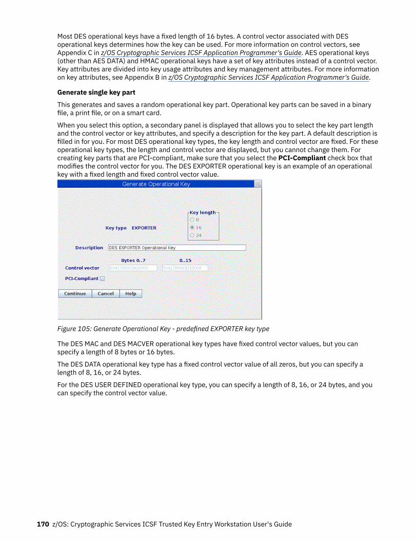
Most DES operational keys have a fixed length of 16 bytes. A control vector associated with DESoperational keys determines how the key can be used. For more information on control vectors, seeAppendix C in z/OS Cryptographic Services ICSF Application Programmer's Guide. AES operational keys(other than AES DATA) and HMAC operational keys have a set of key attributes instead of a control vector.Key attributes are divided into key usage attributes and key management attributes. For more informationon key attributes, see Appendix B in z/OS Cryptographic Services ICSF Application Programmer's Guide.
Generate single key part
This generates and saves a random operational key part. Operational key parts can be saved in a binaryfile, a print file, or on a smart card.
When you select this option, a secondary panel is displayed that allows you to select the key part lengthand the control vector or key attributes, and specify a description for the key part. A default description isfilled in for you. For most DES operational key types, the key length and control vector are fixed. For theseoperational key types, the length and control vector are displayed, but you cannot change them. Forcreating key parts that are PCI-compliant, make sure that you select the PCI-Compliant check box thatmodifies the control vector for you. The DES EXPORTER operational key is an example of an operationalkey with a fixed length and fixed control vector value.
Figure 105: Generate Operational Key - predefined EXPORTER key type
The DES MAC and DES MACVER operational key types have fixed control vector values, but you canspecify a length of 8 bytes or 16 bytes.
The DES DATA operational key type has a fixed control vector value of all zeros, but you can specify alength of 8, 16, or 24 bytes.
For the DES USER DEFINED operational key type, you can specify a length of 8, 16, or 24 bytes, and youcan specify the control vector value.
170 z/OS: Cryptographic Services ICSF Trusted Key Entry Workstation User's Guide

Figure 106: Generate Operational Key - USER DEFINED
For the AES DATA operational key type, you can specify a length of 16, 24, or 32 bytes, and a fixed controlvector of all zeros is used.
All other AES operational key types and HMAC operational keys have associated key attributes instead ofa control vector. The set of key attributes for the key depends on the key type. You can select a length of16, 24, or 32 bytes for these operational key types. Default attributes are defined for each of theseoperational key types, but you can change them.
Figure 107: Generate Operational Key panel - AES MAC operational key
Click on the Change key attributes button to display a secondary panel that shows the key attributes.
Using the Crypto Module Notebook to administer CCA crypto modules 171

Figure 108: AES MAC Key Attributes panel
Click on radio buttons to change the attributes. If you want to restore the default attributes, click on theRestore all defaults button.
After you have specified the key length, description, and control vector or attributes, click on the Continuebutton. You are asked to select the target of the operational key part. When the target is a binary file orprint file, a panel is displayed allowing you to specify the target file name and location. You can save to afile in the TKE Data Directory or on a USB flash memory drive. After the operational key part is saved, youare asked if you want to save the key part in another file or location.
Attention : Removing a USB flash memory drive from a USB port while an operation that is accessing thedrive is in progress can cause hardware messages on the TKE workstation. Wait for the operation tocomplete before removing the USB flash memory drive.
When the target is a smart card, you are prompted to insert a smart card in the reader and enter the PIN.You are given the opportunity to change the description before the key part is saved on the smart card.
Generate multiple key parts
This option allows you to generate multiple key parts without having to select from the pop-up menu foreach one. Cascaded menu options select whether the key part is saved in a binary file, print file, or on asmart card.
You are asked to enter the number of operational key parts to be generated. For each operational key partto be generated, you are led through the process of specifying the length, description, and control vectoror attributes as described above, and selecting the target file or inserting the target smart card in a readerand entering the PIN.
Load single key part
This option allows you to load a single operational key part to an operational key part register, or tochange the state of one or more operational key part registers to 'Complete'.
172 z/OS: Cryptographic Services ICSF Trusted Key Entry Workstation User's Guide

For DES operational keys and the AES DATA operational key, cascaded options on the pop-up menu allowyou to select First, Add part, and Complete. For these keys, you must load at least two key parts beforecompleting the register.
For AES operational keys other than DATA and HMAC operational keys, cascaded menu options let youselect First (minimum of 2 parts), First (minimum of 3 parts), Add part, and Complete. For these keys, youmust load at least two key parts when you used the First (minimum of 2 parts) option to load the first keypart, and you must load at least three key parts when you used the First (minimum of 3 parts) option.
When loading a first operational key part, you enter a new key label to identify the operational key partregister. An error is reported if you use an existing key label. The key label must conform to valid key labelnames in the CKDS. Key labels can be up to 64 characters long. The first character must be an alphabeticor national character (#, %, or @). The remaining characters can be alphanumeric, national, or a period (.).When the key part is processed, the label is converted to uppercase.
When adding a key part or completing an operational key part register, you are given a list of key labels tochoose from. When adding a key part, only key labels for operational key part registers containing a key ofa matching type, with attributes that are compatible with the operational key part being loaded, areshown. When completing an operational key part register, only key labels for operational key partregisters containing a key of the correct type, where the required minimum number of key parts havebeen loaded, are shown.
In some cases, an exact match on the key part type or key part attributes is not required when loading keyparts. A warning is displayed for these cases, or you are asked in advance whether using an alternate typeor alternate attributes should be allowed.
Load first DES operational key part
When Load single key part --> First is selected for a DES operational key, you are asked to select thesource of the key part. The source can be a binary file, a smart card, or the keyboard. When the source is abinary file, a secondary panel is displayed asking you to select the location of the file and the file name.Files in the TKE Data Directory or on a USB flash memory drive can be selected.
After the source file is selected, a Key Part Information panel is displayed. If the key part is non-PCI-compliant, it shows the ENC-ZERO and MDC-4 hashes for the operational key part and the control vector.If the key part is PCI-compliant, it shows the ENC-ZERO and CMAC hashes for the operational key partand the control vector. To load the first operational key part, type a valid key label in the text box and clickthe Load key button.
Figure 109: Key part information - first DES key part
Using the Crypto Module Notebook to administer CCA crypto modules 173

Figure 110: Key part information - first DES key part PCI-compliant
After the key is loaded into the operational key part register, a Key Part Register Information panel isdisplayed showing the SHA1 hash and control vector for the operational key part register.
Figure 111: DES key part register information
When the source is a smart card, you are prompted to insert a smart card in the reader. The smart cardcontents are read and a list of key parts whose type matches the key type selected on the Domain Keyspage is displayed. If you select one and click on the OK button, you are asked to enter the PIN. Afterentering the PIN, a Key Part Information panel is displayed and the process continues as for a binary file.
When the source is the keyboard, an Enter Key Value panel is displayed. For most DES operational keytypes, you will not be able to change the key length or control vector value displayed on this panel. For theDES USER DEFINED operational key type, you will need to enter a valid control vector value. You canchange the default description and enter the key value in the 'key value' text boxes.
The appearance and behavior of the Enter Key Value panel depends on how the Blind Key Entry option onthe Preferences pull-down menu on the main TKE panel is set. When the Blind Key Entry option isselected, only asterisks are displayed in the Enter Key Value panel. Optional 'confirm key value' text boxesare displayed at the bottom of the panel. If used, the values entered must match the values in the 'keyvalue' boxes in order for the key part to be accepted. When the Blind Key Entry option is not selected, thecharacters entered by using the keyboard are displayed in the 'key value' text boxes and there are no'confirm key value' text boxes on the panel.
174 z/OS: Cryptographic Services ICSF Trusted Key Entry Workstation User's Guide

Figure 112: Enter key value - keyboard source for predefined EXPORTER key type
After entering a key value and clicking the Continue button, you are asked if you would like to save thekey part before loading it. If you answer Yes, you are asked to choose between saving the key part in abinary file or in a print file. You are then asked to provide the file name and location. Files in the TKE DataDirectory or on a USB flash memory drive can be used.
Attention : Removing a USB flash memory drive from a USB port while an operation accessing the drive isin progress can cause hardware messages on the TKE workstation. Wait for the operation to completebefore removing the USB flash memory drive.
Finally, a Key Part Register Information panel showing the SHA1 hash and control vector of theoperational key part register is displayed.
Note: Some DES operational key types can be substituted for other DES operational key types whenloading an operational key part register. The following substitutions are allowed:
• A DES IMPORTER key part may be used to build a DES EXPORTER operational key.• A DES EXPORTER key part may be used to build a DES IMPORTER operational key.• A DES CIPHERXI key part may be used to build a DES CIPHERXO operational key.• A DES CIPHERXO key part may be used to build a DES CIPHERXI operational key.• A DES DATAM key part may be used to build a DES DATAMV operational key.• A DES MAC key part may be used to build a DES MACVER operational key.• A DES UDATAM key part may be used to build a DES UDATAMV operational key.
When loading an operational key part register, you are either asked in advance whether thesesubstitutions should be allowed, or a warning message is displayed after you have selected a key partwhose type is different from the type selected on the Domain Keys page.
Add DES operational key part
When Load single key part --> Add part is selected for a DES operational key, the process is similar tothat for loading the first key part. You are asked to select the source of the key part. After the key part isread or entered, a Key Part Information panel is displayed. Instead of a text box for the Key Label, a dropdown menu is displayed showing key labels for operational key part registers containing a matching keytype in an appropriate state for adding the key part. Select one of these and click the Load key button.
Using the Crypto Module Notebook to administer CCA crypto modules 175
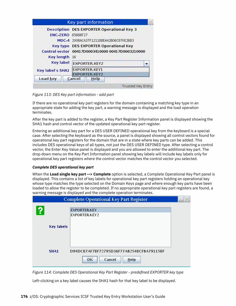
Figure 113: DES Key part information - add part
If there are no operational key part registers for the domain containing a matching key type in anappropriate state for adding the key part, a warning message is displayed and the load operationterminates.
After the key part is added to the register, a Key Part Register Information panel is displayed showing theSHA1 hash and control vector of the updated operational key part register.
Entering an additional key part for a DES USER DEFINED operational key from the keyboard is a specialcase. After selecting the keyboard as the source, a panel is displayed showing all control vectors found foroperational key part registers for the domain that are in a state where key parts can be added. Thisincludes DES operational keys of all types, not just the DES USER DEFINED type. After selecting a controlvector, the Enter Key Value panel is displayed and you are allowed to enter the additional key part. Thedrop down menu on the Key Part Information panel showing key labels will include key labels only foroperational key part registers where the control vector matches the control vector you selected.
Complete DES operational key part
When the Load single key part --> Complete option is selected, a Complete Operational Key Part panel isdisplayed. This contains a list of key labels for operational key part registers holding an operational keywhose type matches the type selected on the Domain Keys page and where enough key parts have beenloaded to allow the register to be completed. If no appropriate operational key part registers are found, awarning message is displayed and the complete operation terminates.
Figure 114: Complete DES Operational Key Part Register - predefined EXPORTER key type
Left-clicking on a key label causes the SHA1 hash for that key label to be displayed.
176 z/OS: Cryptographic Services ICSF Trusted Key Entry Workstation User's Guide

Select one or more key labels and click on the OK button to complete the selected operational keyregisters.
To select more than one key label, left-click to select the first key label. Hold down the Ctrl key on thekeyboard and left-click to select additional key labels. To select a range of key labels, left-click to selectthe first key label, then hold down the Shift key and left-click to select the last key label. To select all keylabels on the panel, hold down the Ctrl key and then press the A key.
When more than one key label is selected, a dash (-) is displayed for the SHA1 hash.
For each operational key part register that is completed, a Key Part Register Information panel isdisplayed. This shows the ENC-ZERO hash and control vector for the completed operational key partregister.
Figure 115: DES Key part register information - predefined EXPORTER key type in Complete state
AES operational keys and HMAC operational keys
Processing for AES operational keys and HMAC operational keys is similar to processing for DESoperational keys, with a few differences.
The AES DATA operational key has a control vector of all zeros. On the Key Part Information panel and KeyPart Register Information panel, an AES-VP is shown instead of the ENC-ZERO, MDC-4, and SHA1 hashes.
When loading a first AES or HMAC operational key part from a binary file, usually if the key type in the filedoes not match the key type selected on the Domain Keys page, an error message is displayed and theload processing terminates. An exception is that AES IMPORTER and AES EXPORTER key parts can besubstituted for each other.
AES operational keys (other than AES DATA) and HMAC operational keys have key attributes instead of acontrol vector. The key attributes for an operational key part or operational key part register depend onthe operational key type. The Key Part Information panel does not show a control vector for AES andHMAC operational keys, but instead indicates whether the key part has the default attributes or customattributes. The Key Part Information panel has either a Display key attributes button or a Change keyattributes button, which can be used to display or change some attributes.
Figure 116: Key Part Information panel for an AES operational key other than DATA
Using the Crypto Module Notebook to administer CCA crypto modules 177

Similarly, the Key Part Register Information panel does not show a control vector. Instead, it indicateswhether the operational key part register contains a key with the default attributes or custom attributes.It has a Display key attributes button that allows you to view the attributes for the key part in the keypart register.
Figure 117: Key Part Register Information panel for an AES operational key other than DATA
On both panels, for AES operational keys, an AES-VP is shown, and for HMAC operational keys, an HMAC-VP is shown.
When generating an AES or HMAC operational key part, a set of attributes is selected and saved with thekey part. For some key types, some of the saved attributes can be changed when loading a firstoperational key part into an operational key register:
• When loading a first AES CIPHER operational key part, you can change the encrypt control and datatranslate control attributes.
• When loading a first AES MAC operational key part, you can change the generate/verify controlattributes.
• When loading a first AES PINPROT operational key part, you can change the encrypt control attributes.• When loading a first AES PINPRW operational key part, you can change the generate/verify control
attributes.• When loading a first HMAC operational key part, you can change the generate/verify control attributes.
For these key types, the Key Part Information panel has a Change key attributes button that allows youto change the indicated attributes before the key part is loaded. Other attributes are grayed out, and youare not allowed to change them.
Similarly, when loading an additional key part, you are asked whether these attributes in the selected keypart should be ignored. If you answer No, the Key Part Information panel will show only key labels wherethe attributes match exactly. If you answer Yes, the Key Part Information panel will include key labels withmismatches on these attributes. After the additional key part is loaded, the operational key part registerwill continue to have the attribute settings that were loaded with the first key part.
Load all key parts
This option allows you to fully load an operational key part register without having to open and choosefrom the pop-up menu for each part. Cascaded options on the pop-up menu allow you to choose thesource type (smart cards, binary files, or the keyboard).
You are asked to enter the number of key parts. You can optionally clear the operational key part register.You are then led through the process of loading each of the key parts from the selected source type.
When loading key parts from smart cards, you can use different smart cards for each key part, if desired.
View
This option allows you to view the operational key part registers that exist in the domain for a particularkey type. It displays a list of key labels for the key type, and you are allowed to select one or more of thesekey labels. After you click on the OK button, a Key Part Information Panel is displayed for each of theselected key labels showing additional information.
178 z/OS: Cryptographic Services ICSF Trusted Key Entry Workstation User's Guide

For DES operational keys, the SHA1 hash is displayed. For AES operational keys, the AES-VP is shown. ForHMAC operational keys, the HMAC-VP is shown.
Figure 118: View Operational Key Part Register panel - AES CIPHER operational key
Left-click on a key label to select it. To select more than one key label, left-click to select the first keylabel and then hold down the Ctrl key on the keyboard and left-click to select additional key labels. Toselect a range of key labels, left-click to select the first key label, then hold down the Shift key and left-click to select the last key label. To select all key labels on the panel, hold down the Ctrl key and thenpress the A key.
After you have selected one or more key labels and clicked on the OK button, a Key Part RegisterInformation panel is shown for each of the selected key labels. This shows the key type, hash pattern orverification pattern, control vector or key attributes, key length, key label, and state of the register.
Figure 119: Key Part Register Information panel - AES CIPHER operational key
To view the full key attributes, click the Display key attributes button. This displays a secondary panelshowing the key attributes. DES operational keys and AES DATA operational keys have a control vectorrather than key attributes and therefore, do not have a button to display a key attributes panel.
The DES USER DEFINED operational key type is a special case. When you select the View option for thiskey type, the View Operational Key Part Register panel shows the key labels in the domain for all DESoperational key types, not just those created as DES USER DEFINED types. This is because a DES USERDEFINED key can have any valid control vector value, including the fixed values assigned for other DESoperational key types.
Clear
This option allows you to clear operational key part registers for the domain.
After you confirm your intention to clear one or more operational key part registers for the domain, a ClearOperational Key Part Register panel is displayed showing the existing key labels for operational key part
Using the Crypto Module Notebook to administer CCA crypto modules 179

registers in the domain for the selected key type. Select one or more of these and click on the OK buttonto remove the key label from the set of active operational key part registers for the domain.
Figure 120: Clear Operational Key Part Register panel -- AES CIPHER operational key
Left-click on a key label to select it. To select more than one key label, left-click to select the first keylabel and then hold down the Ctrl key on the keyboard and left-click to select additional key labels. Toselect a range of key labels, left-click to select the first key label, then hold down the Shift key and left-click to select the last key label. To select all key labels on the panel, hold down the Ctrl key and thenpress the A key.
After you select one or more key labels and click on the OK button, the key part registers are cleared.
The DES USER DEFINED operational key type is a special case. When you select the Clear option for thiskey type, a Clear Operational Key Part Register panel is displayed showing the existing key labels for allDES operational key types, not just those created as DES USER DEFINED types. This is because a DESUSER DEFINED key can have any valid control vector value, including the fixed values assigned for otherDES operational key types.
DES operational key: Load to Key Storage
This selection is only possible for operational IMP-PKA keys. The IMP-PKA key-encrypting keys are usedto protect RSA keys during transport from the workstation to ICSF. After selecting Load to Key Storage,the user chooses one of the following key parts to load to the workstation key storage:
• First• Intermediate• Last
The contents of the container depend upon the user's selection.
If the user selected First, the container shows all keys in the workstation key storage usable as IMP-PKAkey encrypting keys. The user can utilize these as skeletons for composing the new key label.
If the user selected Intermediate or Last, the container shows all keys in the workstation key storagethat have been installed with the first key part. It also shows any optional intermediate key parts thathave been installed. The user must select one of these as the key label.
A window opens for the user to specify the workstation key label and whether this IMP-PKA key will beused to protect an RSA key to be generated at the workstation or a clear RSA key to be enciphered at theworkstation.
180 z/OS: Cryptographic Services ICSF Trusted Key Entry Workstation User's Guide

Figure 121: Install IMP-PKA Key Part in Key Storage
Note: For the RSA key to be loaded into the PKDS, the same IMP-PKA key value must be stored in theCKDS. See “Load single key part” on page 172.
AES operational key: Load to Key Storage
This selection is only possible for AES IMPORTER keys. An AES IMPORTER key can be used to protect RSAkeys during transport from the workstation to ICSF as long as the 'Key can be used for IMPORT', 'Key canbe used for GENERATE-PUB' and 'Key can wrap RSA keys' attributes are set to 'Yes' in the key's attributes.After selecting Load to Key Storage, the user chooses one of the following key parts to load to theworkstation key storage:
• First...• Intermediate...• Last...
The contents of the container depend upon the user's selection.
If the user selected First, the container shows all keys in the workstation key storage usable as AESIMPORTER key encrypting keys. The user can utilize these as skeletons for composing the new key label.
If the user selected Intermediate or Last, the container shows all keys in the workstation key storagethat have been installed with the first key part. It also shows any optional intermediate key parts thathave been installed. The user must select one of these as the key label.
Using the Crypto Module Notebook to administer CCA crypto modules 181

Figure 122: Install AES IMPORTER Key Part in Key Storage
Note: For the RSA key to be loaded into the PKDS, the AES IMPORTER key value must be stored in theCKDS. See “Load single key part” on page 172.
Secure key part entry
To save known key part values to a TKE smart card, use secure key part entry. Refer to Appendix A,“Secure key part entry,” on page 313 for details on using this function.
RSA keys
Generate RSA Key
This selection initiates RSA key generation at the workstation. The generated RSA key is protected with apreviously generated DES IMP-PKA or AES IMPORTER key, and the encrypted RSA key is saved in a file.
Notes:
• RSA keys can also be generated and saved in the host PKDS using ICSF panels and services (CSNDPKGfor generate, and CSNDKRC or CSNDKRW to write to the host PKDS.) For more information, see z/OSCryptographic Services ICSF Application Programmer's Guide.
• An RSA key with a length of 1024 or less can be wrapped with a DES IMP-PKA or AES IMPORTER key.• An RSA key with a length greater than 1024 must be wrapped with an AES IMPORTER key.
From the Domain Keys page, right-click RSA key in the Key Types container and select Generate. TheGenerate RSA Key window opens.
182 z/OS: Cryptographic Services ICSF Trusted Key Entry Workstation User's Guide

Figure 123: Generate RSA Key
In the Generate RSA key window, specify the following information:RSA key usage control
Specifies whether or not the RSA key can be used for key management purposes (encryption of DESkeys). All RSA keys can be used for signature generation and verification.
Key lengthLength of the modulus of the RSA key in bits. For RSA keys protected by a DES EXPORTER key, anylength between 512 and 1024 is allowed. For RSA keys protected by an AES EXPORTER key, anylength between 512 and 1024, and lengths of 2048 and 4096 are allowed. When a length of 2048 or4096 is selected, the AES EXPORTER key should be at least 24 bytes long. If not, a message isdisplayed.
Public exponentValue of the public exponent of the RSA key.
PKDS key labelLabel to be given the imported RSA key at the host. The information provided in this field can bechanged when you load the RSA key to the host.
Private key nameText string that is included in the RSA key token and cryptographically related to the key. The privatekey name can be used for access control for the key. The information you entered in the PKDS keylabel field is copied to this field and can be edited.
DescriptionOptional free text that is saved with the RSA key and displayed when you retrieve the key.
Workstation DES EXPORTER keysThis container displays the labels of the DES EXPORTER keys currently in TKE workstation DES keystorage that can be used to protect RSA keys generated at the TKE workstation. When these keyswere loaded into TKE DES key storage, key usage of "for RSA key generation" was specified. To selectone of these keys, click Workstation DES EXPORTER keys and select a key label.
Workstation AES EXPORTER keysThis container displays the labels of the AES EXPORTER keys currently in TKE workstation AES keystorage that can be used to protect RSA keys generated at the TKE workstation. Only keys with setattributes including "Key can be used for IMPORT", "Key can be used for GENERATE-PUB", and "Keycan wrap RSA keys" are listed. To select one of these keys, click Workstation AES EXPORTER keysand select a key label.
Using the Crypto Module Notebook to administer CCA crypto modules 183

Host CKDS key labelThe CKDS key label at the host used to import the RSA key. The selected workstation DES EXPORTERor AES EXPORTER key label is copied to this field and can be edited. This information can be changedwhen you load the RSA key to the host.
When the key is generated, a window opens that prompts the user to specify the file location (USB flashmemory drive or TKE Data Directory) and file name for saving the generated RSA key.
Attention : Do not remove a USB flash memory drive from the USB port before you complete theoperation that is using the drive, or before you respond to a message related to the operation that is usingthe drive. If you do remove a drive before the operation is complete, hardware messages might begenerated on the TKE workstation.
Encipher RSA Key
This selection allows an RSA key to be read from a clear key file, encrypted with a previously generatedIMP-PKA key encrypting key, and saved in a file. The format of the clear key file is described in AppendixD, “Clear RSA key format,” on page 331.
Having selected the Encipher action, the Encipher RSA Key window is displayed:
Figure 124: Encipher RSA Key
In the Encipher RSA key window, specify the following information:
• RSA key usage control — Specifies whether the RSA key can be used for key management purposes(encryption of DES keys). All RSA keys can be used for signature generation and verification.
• PKDS key label — Label to be given the imported RSA key at the host. The information provided in thisfield can be changed when you load the RSA key to the host.
• Private key name — Text string that is included in the RSA key token and cryptographically related tothe key. The private key name can be used for access control for the key. The information you entered inthe PKDS key label field is copied to this field and can be edited.
• Description — Optional free text that is saved with the RSA key and displayed when you retrieve the key.• Workstation DES EXPORTER keys — This container displays the labels of the DES EXPORTER keys
currently in TKE workstation DES key storage that can be used to protect RSA keys entered from a clearkey file. When these keys were loaded into TKE DES key storage, key usage of "for RSA key enciphering"was specified. AES EXPORTER keys in TKE workstation AES key storage cannot be used to encipher anRSA key. Select a key label by clicking it.
184 z/OS: Cryptographic Services ICSF Trusted Key Entry Workstation User's Guide

• Host DES IMP_PKA key label — The CKDS key label at the host used to import the RSA key. Theselected workstation DES EXPORTER key label is copied to this field and can be edited. This informationcan be changed when you load the RSA key to the host.
When the key is enciphered, a file chooser window is displayed for the user to specify the file location(USB flash memory drive or TKE Data Directory) and file name for saving the encrypted RSA key.
Attention : Do not remove a USB flash memory drive from the USB port before you complete theoperation that is using the drive, or before you respond to a message related to the operation that is usingthe drive. If you do remove a drive before the operation is complete, hardware messages might begenerated on the TKE workstation.
Load RSA Key to PKDS
This selection allows the user to load an RSA key to the host and install it in the PKDS. Using this function,it is only possible to load the RSA key to the PKDS in the TKE Host logical partition (LPAR). For loading RSAkeys to TKE target LPARs, see “Load RSA key to host dataset ” on page 185.
Having selected Load to PKDS, a dialog box is displayed for selecting the input file holding the encryptedRSA key. When completed, the Load RSA key to PKDS window is displayed.
Figure 125: Load RSA Key to PKDS
In the Load RSA key to PKDS window, specify the following information:
• PKDS key label — Label to be given the imported RSA key at the host. Change this field as needed.• Private key name — Text string that is included in the RSA key token and cryptographically related to
the key. The private key name can be used for access control for the key. The information you entered inthe PKDS key label field is copied to this field and can be edited.
• Description — Optional free text that was saved with the RSA key.• Workstation DES EXPORTER key label — Label of the workstation DES IMP-PKA key that protects the
RSA key. Displayed when the key-encrypting key is a DES IMP-PKA key.• Workstation AES EXPORTER key label — Label of the workstation AES IMPORTER key that protects the
RSA key. Displayed when the key-encrypting key is an AES IMPORTER key.• Host DES IMP-PKA key label — Label of the DES IMP-PKA key stored in the host CKDS that will be used
to import the RSA key. Displayed when the key-encrypting key is a DES IMP-PKA key. Change this fieldas needed.
• Host AES IMPORTER key label — Label of the AES IMPORTER key stored in the host CKDS that will beused to import the RSA key. Displayed when the key-encrypting key is an AES IMPORTER key. Changethis field as needed.
Load RSA key to host dataset
This selection allows the user to load an RSA key to a host data set as an external key token. From thisdata set it is possible to install the key in the PKDS by means of TSO/E ICSF panels.
Using the Crypto Module Notebook to administer CCA crypto modules 185

The host data set must be defined in advance. If a workstation DES EXPORTER key was used to protectthe RSA key at the time the RSA key was generated or enciphered, the host data set must have thefollowing attributes:
recfm fixed, lrecl=1500, partitioned
If a workstation AES EXPORTER key was used to protect the RSA key at the time the key was generated,the host data set must have the following attributes:
recfm fixed, lrecl=3000, partitioned
Using this installation method, it is possible to load RSA keys into any PKDS in any LPAR. For informationabout the TSO/E ICSF interface, “Installing RSA keys in the PKDS from a data set” on page 248.
The steps are the same as for loading an RSA key to PKDS (see “Load RSA Key to PKDS” on page 185),except that the user has to specify the full data set and member name. If you do not specify the data setand member name in quotes, the high level qualifier for the data set is the TSO/E logon of theadministrator/host user ID.
Figure 126: Load RSA Key to Dataset
Domain Controls pagesThe Domain Controls pages display the cryptographic functions that are allowed for the domain andallows you to make changes to them. The 'Controls-Desc' page displays the domain controls sorted bydescription, and the 'Controls-ACP' page displays the domain controls sorted by ACP value.
• To change a setting, click on it. Changing a setting on one domain controls page changes thecorresponding setting on the other domain controls page.
• To upload the controls settings to the crypto module, click Send updates.• To leave the controls settings unaltered after you have made changes to the page, click Discard
changes.• To save the displayed domain control settings to a file, click Save to file.• To load the domain control settings from a previously saved file, click Load from file. This option
changes the displayed control settings. Click Send updates to upload the displayed settings to thecrypto module.
The last two options cause a window to open that allows you to select the file to use.
Notebooks for a host crypto module at CCA 5.2 or later will also show an ACP Tracking button. See“Access Control Tracking” on page 188 for more information about the function of the ACP Trackingbutton.
186 z/OS: Cryptographic Services ICSF Trusted Key Entry Workstation User's Guide

Figure 127: Domain Controls page
Note: When managing domain controls through a TKE workstation, some services displayed on theDomain Controls panel might not be available on the host crypto module. Enabling a service on this panelthat is not supported by the host crypto module does not make this service available.
Working with Domain Controls settings
You can enable and disable access control points to ISPF Services, API Cryptographic Services and UserDefined Extensions (UDX) from these pages.
There are expandable folders for the Domain Cryptographic services. Some services cannot be disabledbecause they are “required”. This is indicated on the panel. You can enable or disable services within thefollowing folders:
• ISPF Services• Coprocessor Configuration• API Cryptographic Services• UDXs (appears only if you have created UDXs on your system)
The access control points displayed on the Domain Controls pages depend on the level of ICSF used tocommunicate with the host crypto module. Later versions of ICSF may support additional access controlpoints not supported on earlier versions.
Some access control points displayed on the Domain Controls pages may not be implemented on the hostcrypto module. You can change the value of these access control points, but they do not affect theoperation of the host crypto module.
When moving to a later version of ICSF, you may need to manually set or reset the new access controlpoints that are displayed.
ISPF Services
Under the ISPF Services folder, there are check boxes for the services that you can enable or disable.These services are for loading and setting the DES, AES, ECC (APKA), and RSA master keys on supportedhost crypto modules through the ICSF panel interface. These services are listed in Appendix E, 'CCAaccess control points and ICSF utilities', in z/OS Cryptographic Services ICSF Administrator's Guide.
Using the Crypto Module Notebook to administer CCA crypto modules 187

Coprocessor Configuration
Under the Coprocessor Configuration folder are all of the controls that govern the key wrapping behaviorof ICSF callable services. See the table, 'Access control points affecting multiple services or requiringspecial consideration', in z/OS Cryptographic Services ICSF Application Programmer's Guide.
API Cryptographic Services
Under the API Cryptographic Services folder are all the ICSF services that can be enabled or disabledfrom the TKE workstation. See the table, 'Access control points – Callable Services', in z/OS CryptographicServices ICSF Application Programmer's Guide for the correlation between the access control point andthe ICSF callable service.
UDXs
The UDX folder appears only if there are User Defined Extensions on your system. The UDXs folder listsyour extensions and allows you to enable or disable them.
Access Control Tracking
Beginning with CCA 5.2, CCA host crypto modules can keep track of the access control points that arechecked as applications run. Tracking is done on a per domain basis. The tracking information can be usedto tailor the domain controls that are enabled for the domain.
To enable tracking and to view the tracking data, click on the ACP Tracking button. This brings up asecondary panel with tracking information displayed in a tree format and buttons at the bottom of thepanel to control tracking. A signature key must be loaded in order to obtain and display the tracking data.
A check mark next to the tracking information indicates that an application running in the domainattempted to run a function that required the access control point to be enabled. A check mark indicatesonly that execution was attempted and not that the execution request was granted.
The Access Control Tracking panel has the following buttons:Start
Starts access control tracking for the domain. This button is displayed only when access controltracking is off.
StopStops access control tracking for the domain. This button is displayed only when access controltracking is on.
RefreshObtains and then re-displays the tracking data. Clicking on the Start, Stop, and Clear buttons alsorefreshes the panel.
ClearClears the access control tracking data for the domain.
SaveSaves the access control tracking data for the domain to a file.
PrintPrints the access control tracking data for the domain. This button is displayed only when printsupport is enabled.
DoneCloses the Access Control Tracking panel.
HelpDisplays the online help information for the Access Control Tracking panel.
The ACP Tracking button is displayed only for the CCA host crypto modules that support access controltracking.
188 z/OS: Cryptographic Services ICSF Trusted Key Entry Workstation User's Guide

Domain Decimalization Tables pageDecimalization tables map hexadecimal digits to decimal digits, and are used in certain host cryptomodule operations that process Personal Identification Numbers (PINs). By selecting Use Only ValidDecimalization Table in the domain controls for a domain, you can restrict the set of alloweddecimalization tables for the domain. Only decimalization tables with a status of “Active” in theDecimalization Tables page are allowed to be used.
Decimalization tables can contain only decimal digits (0 through 9) and must be exactly 16 digits long.Every domain has slots for 100 decimalization tables. These tables can be managed only from a TKEworkstation. You can load, activate, or delete tables from this page. The Decimalization Tables page isdisplayed only for host crypto modules that support decimalization tables.
Figure 128: Decimalization tables page
To manage a table entry, right-click on an entry to display command options. The available options are:
• Load• Activate• Activate All• Delete• Delete All
Using the Crypto Module Notebook to administer CCA crypto modules 189

Figure 129: Table entry options
There are three access control points that control the ability to manage decimalization Tables. They are:
• Load Decimalization Tables• Delete Decimalization Tables• Activate Decimalization Tables
A table entry can be in any of the following states:
• Empty• Active• Loaded
Load table
Right-click on a table entry to display the table options. Select the load option. From the “Enter newdecimalization table value” screen, enter a 16-digit decimalization table value. The table can contain onlydecimal digits (0 through 9). Press the Continue button to create the table entry.
Figure 130: Enter new decimalization table value
Notes:
1. You must have the “load” ACP in order to load a table.2. If the status of a table entry is “Active”, you must also have the “Delete” ACP to load a new table. You
must be allowed to delete the current table.3. If you load a table, and you also have the “activate” ACP, the new table is immediately activated.
Activate or Activate All
Right-click on a table entry to display the table options. Select the Activate or Activate All option. After thecommand completes successfully, press the Close button in the information message box.
Notes:
1. Only tables with a current state of “Loaded, Not Active” can be activated.2. You must have the “activate” ACP to activate a table.
190 z/OS: Cryptographic Services ICSF Trusted Key Entry Workstation User's Guide

Delete or Delete All
Right-click on a table entry to display the table options. Select the Delete or Delete All option. After thecommand completes successfully, press the Close button in the information message box.
Note:
1. Only tables with a current state of “Loaded, Not Active” or “Active” can be deleted.2. You must have the “delete” ACP to delete a table.
Domain Restricted PINs pageYou can restrict the use of weak or trivial Personal Identification Numbers (PINs) in a domain by using theDomain Restricted PINs page. You can specify up to 20 PIN values to be disallowed. Disallowing a PINvalue prevents users from changing a PIN to the disallowed value, and prevents CCA verbs from evergenerating the disallowed PIN value. Disallowing a PIN value on the Domain Restricted PINs page doesnot affect the use of existing PINs, however, even if they have the disallowed value.
The PINs to be disallowed can be 4 - 12 digits long, and can contain only decimal digits (0 through 9). TheDomain Restricted PINs page is displayed only for host crypto modules that support restricting weak ortrivial PINs.
Figure 131: Domain Restricted PINs page
To manage an entry, right-click on the entry to display command options. The available options are:
• Load• Activate• Activate All• Delete• Delete All
Options that are not valid are disabled. An option might be invalid because of the state of the selectedentry (you cannot delete an empty entry, for example), or because the role of the current authority doesnot allow the option.
There are three access control points in roles that control the ability to manage what PINs are restricted:
Using the Crypto Module Notebook to administer CCA crypto modules 191

• Load Restricted PIN• Activate Restricted PIN• Delete Restricted PIN
When you select the Load option, a window opens in which you can enter the value of the PIN to berestricted. You can enter 4 - 12 decimal digits. If the role of the current authority has both the load andthe activate ACPs selected, the entry goes to the “Active” state. If the role of the current authority hasonly the load but not the activate ACP selected, the entry goes to the “Loaded, Not Active” state. SeparateACPs for the load and activate options supports dual control of adding a PIN to the restricted PINs list, forusers who require dual control.
You can load an entry that is already in the “Loaded, Not Active” or “Active” state, if the role of the currentauthority has the Delete Restricted PIN ACP. This ACP is required because reloading an entry effectivelydeletes the current entry.
The Activate option changes the state of the entry from “Loaded, Not Active” to “Active”.
The Delete option removes the PIN and changes the state of the entry to “Empty”.
The Activate All option activates all entries that are in the “Loaded, Not Active” state.
The Delete All option deletes all entries in the table.
Domain Certificates pageBeginning with the CEX6C crypto module, each domain can load and manage a set of parent X.509certificates for validating operational X.509 certificates that are used by applications in the domain.
Certificates are identified by a certificate label. The Domain Certificates page displays the set ofcertificates that have been loaded for the domain. Right-clicking in the panel displays a pop-up menu thatallows you to perform the following operations:Load certificate
Loads a certificate from a file on the TKE workstation or from USB memory.Activate certificate
A certificate must be activated before it can be used by applications. If the role associated with thecurrent signature key and index has both load and activate authority, the certificate is activatedautomatically when it is loaded.
Delete certificateRemoves the certificate from the domain.
Display certificateDisplays information from the certificate, such as the issuer and period of validity.
Change certificate labelAllows you to choose a new label to associate with the certificate.
Replace certificateReplaces an installed certificate. The replacement certificate must have the same public key as theoriginal certificate. This can be used to replace an expired certificate without requiring dual control.
Validate certificateAllows you to determine whether the input certificate is validated by one of the installed parentcertificates in the domain. The certificate to be validated can be in a file on the TKE workstation or onUSB memory.
192 z/OS: Cryptographic Services ICSF Trusted Key Entry Workstation User's Guide

Figure 132: Domain certificates
Domain Roles pageBeginning with the CEX6C crypto module, domains can exist in various modes or distinct operationalstates. Domains in imprint mode or PCI-compliant mode are administered by using domain-specific rolesand authorities.
When a domain changes from normal mode to imprint mode, extra tabs are displayed at the bottom of thecrypto module notebook panel that allow you to work with the domain roles, domain authorities, anddomain audit log.
When the Domain Roles tab is selected, the set of domain-specific roles that are installed in the domainis displayed. This panel looks the same as the panel for module-wide roles. Right-clicking in the paneldisplays a pop-up menu with options to create, change, delete, and view domain-specific roles for thedomain.
When you create or change a domain-specific role, the set of access control points that the role is allowedto have is different than for the module-wide roles. To meet PCI requirements for dual control, domain-specific roles cannot have certain combinations of access control points that are enabled in the same role:
• A role cannot have both issue and cosign authority for a given operation.• For domain decimalization tables, domain PINs, and domain certificates, a role cannot have both load
and activate authority.• A role cannot have both load new first key part and combine new middle key part authority for a given
master key type.• A role cannot have both load new first key part and combine new final key part authority for a given
master key type.• For DES, AES, AES KEK, and HMAC operational keys, a role cannot have both load first key part and load
additional key part authority.
The INITADDM role is automatically created when a domain enters imprint mode and cannot be changedor deleted. It can be used only while the domain is in imprint mode.
Using the Crypto Module Notebook to administer CCA crypto modules 193

Domain Authorities pageDomains in imprint mode and PCI-compliant mode are administered by using domain-specific roles andauthorities.
The Domain Authorities tab displays the set of domain-specific authorities that are installed in thedomain. The panel looks the same as the panel for module-wide authorities. Right-clicking in the paneldisplays a pop-up menu with options to create, change, delete, and view domain-specific authorities forthe domain and to generate an authority signature key.
Domain-specific authorities must be assigned an authority index in the range 100 to 999. When a domainenters imprint mode, a domain-specific authority with index 100 is automatically created. It is assignedthe INITADDM role and a default signature key. Users are allowed to change and delete the domain-specific authority with index 100. On the transition to PCI-compliant mode, if the domain-specificauthority with index 100 still exists and uses the default signature key, it is deleted automatically.
Domain Audit Log pageFor domains in imprint mode and PCI-compliant mode, a domain audit log is displayed to users and isactive.
Figure 133: Domain audit log
The domain audit log has room for 512 entries. If the log fills, most TKE administrative operations in thedomain are blocked until space is available in the log to create more audit log entries. The domain auditlog can be read and cleared by clicking the Download to file button.
The Domain Audit Log page displays how many entries in the domain audit log are currently used. Thisinformation is also displayed on the Domain General page.
The audit log entries that are displayed on the Domain Audit Log page are those that have beendownloaded to a file on the TKE workstation. Audit log entries still on the crypto module are notdisplayed.
To work with the audit log files on the TKE workstation by using the TKE File Management utility, you mustsign on the TKE console by using the AUDITOR privileged mode ID.
194 z/OS: Cryptographic Services ICSF Trusted Key Entry Workstation User's Guide

Crypto Module Notebook Co-Sign tabFor co-signing a pending command in a host crypto module, open the notebook for that crypto moduleand select the Co-Sign tab. The Co-Sign tab panel displays the following information on the command toco-sign:
• Pending command – Name of the pending command• Pending command reference – Unique hexadecimal number returned to the issuer of the command• Loading Authority – Issuer of the command• Pending command details container – Important parts of the pending command• Signature requirements container – Current status for the fulfillment of the signature requirements
For a host crypto module, exactly two signatures are required for a dual-signature command. Theauthority index and name of each authority allowed to sign the pending command are displayed.
Authorities who have already signed the command are indicated by a Yes in the column labeled Signed.
Pressing the Co-sign push button initiates the signing of the pending command. It opens windows inwhich you can choose the source of the authority signature key and then choose the authority indexassociated with that key. The possible authority signature key sources are as follows:
• Current key - Uses the currently loaded signature key• Smart card - Reads an authority signature key from a TKE smart card• Binary file - Reads an authority signature key from a hard disk or diskette• Key storage - Reads an authority signature key from PKA key storage• Default key - Uses the default authority signature key hardcoded into TKE
Press Delete if you want to delete the pending command.
Host crypto module index valuesAfter a host or domain group is opened, a list of cryptographic modules is displayed. Table 32 on page195 shows the crypto module index value that is displayed based on the type of module and the mode itis running.
Notes:
• A host cryptographic coprocessor running IBM Common Cryptographic Architecture (CCA) code isrunning in CCA mode.
• A host cryptographic coprocessor running IBM Enterprise PKCS #11 (EP11) code is running in EP11mode.
Table 32: Module index type displayed on the TKE.
Host cryptographic coprocessor type andmode
Module index type displayed on the TKE
TKE 8.0 or later Prior to TKE 8.0
Crypto Express6S running in EP11 6Pxx N/A
Crypto Express6S running in CAA mode 6Cxx N/A
Crypto Express5S running in EP11 mode 5Pxx N/A
Crypto Express5S running in CAA mode 5Cxx N/A
Crypto Express4S running in EP11 mode 4Pxx SPxx
Using the Crypto Module Notebook to administer CCA crypto modules 195

Table 32: Module index type displayed on the TKE. (continued)
Host cryptographic coprocessor type andmode
Module index type displayed on the TKE
TKE 8.0 or later Prior to TKE 8.0
Crypto Express4S running in CAA mode 4Cxx SCxx
Crypto Express3 running in CAA mode 3Cxx Gxx
Crypto Express2 running in CAA mode 2Cxx Exx
Placing a domain in PCI-compliant modeBeginning with Crypto Express6S running in Common Cryptographic Architecture (CCA) mode, host cryptomodule domains can be configured to run in PCI-compliant mode. Two of the PCI requirements makemanaging a PCI-compliant domain different from managing a normal mode domain:
• Administrative actions that are done in a PCI-compliant domain must be performed by domain-specificauthorities.
• When managing a PCI-compliant domain, it must take at least two authorities to perform sensitiveadministrative actions. That is, management requires dual controls.
Note: TKE already provides the ability to manage settings with dual controls. Therefore, this might not bea change to your host crypto module security management policy.
For information about required dual controls, see “Required dual controls” on page 196. For informationon how to configure a domain to be in PCI-compliant mode, see “Configuring a domain to be in PCI-compliant mode” on page 196.
Required dual controlsA key requirement of PCI standards is that one authority cannot have a role that allows them to do anentire sensitive configuration operation by themselves. There are two methods for enforcing dualcontrols:Issue and co-sign
If the role of the authority can issue a sensitive command, the role cannot also have thecorresponding co-sign authority for that command. Three examples of commands that use the issueand co-sign mechanism are:
• Create and change role.• Create and change authority.• Changing domain controls.
Multiple commandsIf it takes two commands to complete a sensitive action, the role of the authority cannot include theauthority to do all of the commands that are needed to complete the operation. An example of thissituation is the load master key operation. When you load ANY key from the TKE, you must enter atleast two key parts. The role of the authority that can load the first part cannot have the authority toload the corresponding intermediate or last key part.
Any attempt to create or change a domain-specific role, such that it violates any required dual controlrules, fails.
Configuring a domain to be in PCI-compliant modeThere are four steps to move a domain from normal to PCI-compliant mode:
1. Create the smart cards that are needed to hold the domain-specific authority signature keys and keyparts that are used when managing the PCI-compliant domain.
196 z/OS: Cryptographic Services ICSF Trusted Key Entry Workstation User's Guide
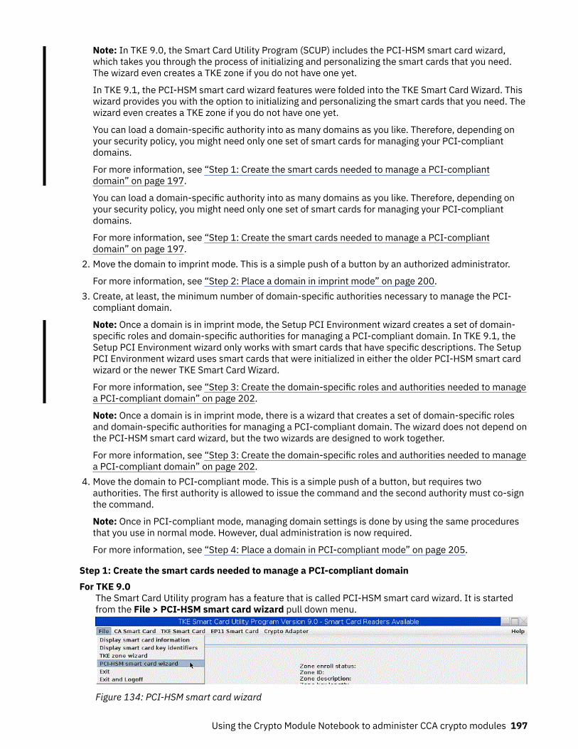
Note: In TKE 9.0, the Smart Card Utility Program (SCUP) includes the PCI-HSM smart card wizard,which takes you through the process of initializing and personalizing the smart cards that you need.The wizard even creates a TKE zone if you do not have one yet.
In TKE 9.1, the PCI-HSM smart card wizard features were folded into the TKE Smart Card Wizard. Thiswizard provides you with the option to initializing and personalizing the smart cards that you need. Thewizard even creates a TKE zone if you do not have one yet.
You can load a domain-specific authority into as many domains as you like. Therefore, depending onyour security policy, you might need only one set of smart cards for managing your PCI-compliantdomains.
For more information, see “Step 1: Create the smart cards needed to manage a PCI-compliantdomain” on page 197.
2. Move the domain to imprint mode. This is a simple push of a button by an authorized administrator.
For more information, see “Step 2: Place a domain in imprint mode” on page 200.3. Create, at least, the minimum number of domain-specific authorities necessary to manage the PCI-
compliant domain.
Note: Once a domain is in imprint mode, the Setup PCI Environment wizard creates a set of domain-specific roles and domain-specific authorities for managing a PCI-compliant domain. In TKE 9.1, theSetup PCI Environment wizard only works with smart cards that have specific descriptions. The SetupPCI Environment wizard uses smart cards that were initialized in either the older PCI-HSM smart cardwizard or the newer TKE Smart Card Wizard.
For more information, see “Step 3: Create the domain-specific roles and authorities needed to managea PCI-compliant domain” on page 202.
Note: Once a domain is in imprint mode, there is a wizard that creates a set of domain-specific rolesand domain-specific authorities for managing a PCI-compliant domain. The wizard does not depend onthe PCI-HSM smart card wizard, but the two wizards are designed to work together.
For more information, see “Step 3: Create the domain-specific roles and authorities needed to managea PCI-compliant domain” on page 202.
4. Move the domain to PCI-compliant mode. This is a simple push of a button, but requires twoauthorities. The first authority is allowed to issue the command and the second authority must co-signthe command.
Note: Once in PCI-compliant mode, managing domain settings is done by using the same proceduresthat you use in normal mode. However, dual administration is now required.
For more information, see “Step 4: Place a domain in PCI-compliant mode” on page 205.
Step 1: Create the smart cards needed to manage a PCI-compliant domainFor TKE 9.0
The Smart Card Utility program has a feature that is called PCI-HSM smart card wizard. It is startedfrom the File > PCI-HSM smart card wizard pull down menu.
Figure 134: PCI-HSM smart card wizard
Using the Crypto Module Notebook to administer CCA crypto modules 197

The wizard presents you with a welcome screen.
Figure 135: PCI-HSM smart card wizard - Welcome screen
Starting in TKE 9.1The Smart Card Utility program has a feature that is called TKE Smart Card Wizard. It is started fromthe File > TKE Smart Card Wizard pull down menu.
Figure 136: TKE smart card wizard
The wizard presents you with a welcome screen.
Figure 137: TKE smart card wizard - Welcome screen
198 z/OS: Cryptographic Services ICSF Trusted Key Entry Workstation User's Guide

After you press Next, select the smart cards you want to create. Select the 'TKE smart cards formanaging CCA host crypto domains running in imprint and PCI-compliant mode' check box. Select the'Certificate Authority (CA) smart cards' check box if you want to create a new zone.
Figure 138: TKE smart card wizard - Creation screen
The wizard takes you through the process of creating the smart cards that are needed to implement abasic PCI-compliant domain management policy. In this policy, two authorities are used for managing thedomain settings that are not related to key management and two or three authorities are used for doingmaster key management. The wizard takes you through the process of creating all the smart cards thatare listed in Table 33 on page 199. If you already have a CA smart card with a minimum zone strength ofRSA 2048, you can skip the create CA and create CA backup steps of the wizard.
Notes:
• If you log on to the TKE workstation with a profile that has the role of SCTKEADM or TKEADM or anequivalent authority, you can also use this wizard to enroll your TKE in your TKE zone that uses your newor existing CA smart card.
• None of the screens and prompts for the PCI-HSM smart card wizard or TKE Smart Card Wizardareincluded in this topic.
Table 33: Smart cards
Type of smart card Purpose Wizard-provided smart carddescription
CA smart card A Certificate Authority (CA) smart card defines aTKE zone. The zone must have a minimum keystrength of RSA 2048. The TKE smart cards areenrolled in the TKE zone.
Note: If you already have a 2048 strength CAsmart card, you can add the TKE smart cards tothe existing TKE zone.
N/A
(User provided description.)
Using the Crypto Module Notebook to administer CCA crypto modules 199
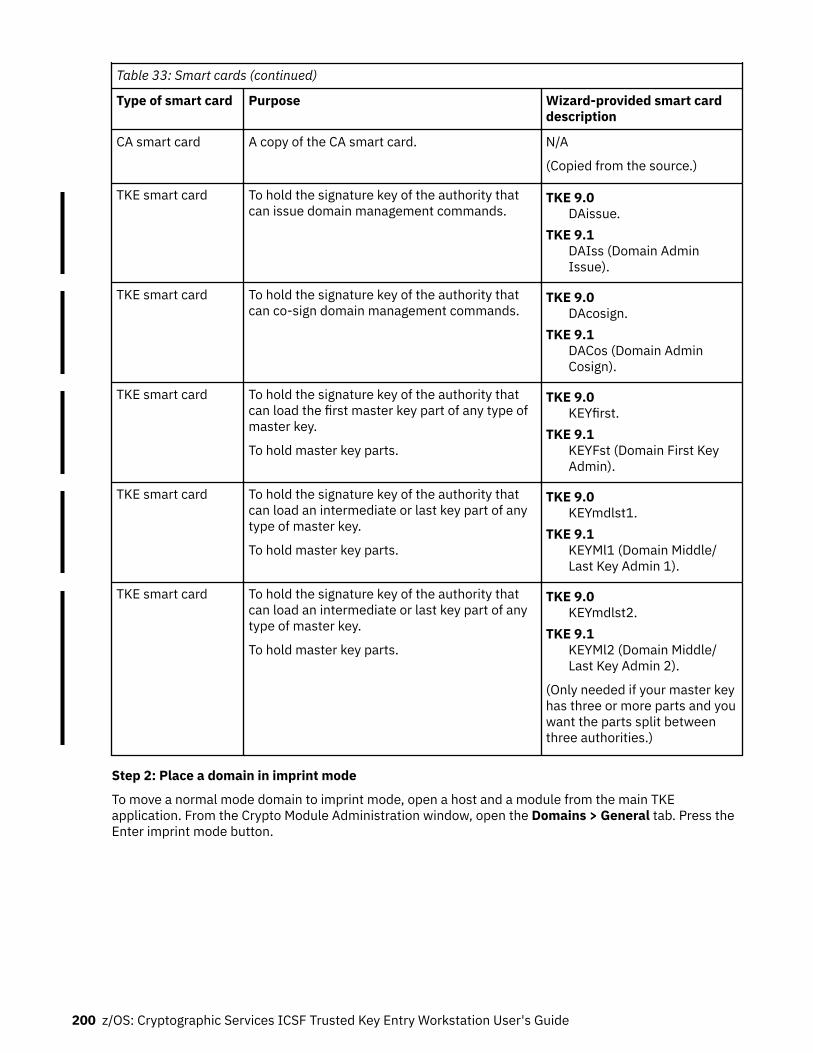
Table 33: Smart cards (continued)
Type of smart card Purpose Wizard-provided smart carddescription
CA smart card A copy of the CA smart card. N/A
(Copied from the source.)
TKE smart card To hold the signature key of the authority thatcan issue domain management commands.
TKE 9.0DAissue.
TKE 9.1DAIss (Domain AdminIssue).
TKE smart card To hold the signature key of the authority thatcan co-sign domain management commands.
TKE 9.0DAcosign.
TKE 9.1DACos (Domain AdminCosign).
TKE smart card To hold the signature key of the authority thatcan load the first master key part of any type ofmaster key.
To hold master key parts.
TKE 9.0KEYfirst.
TKE 9.1KEYFst (Domain First KeyAdmin).
TKE smart card To hold the signature key of the authority thatcan load an intermediate or last key part of anytype of master key.
To hold master key parts.
TKE 9.0KEYmdlst1.
TKE 9.1KEYMl1 (Domain Middle/Last Key Admin 1).
TKE smart card To hold the signature key of the authority thatcan load an intermediate or last key part of anytype of master key.
To hold master key parts.
TKE 9.0KEYmdlst2.
TKE 9.1KEYMl2 (Domain Middle/Last Key Admin 2).
(Only needed if your master keyhas three or more parts and youwant the parts split betweenthree authorities.)
Step 2: Place a domain in imprint mode
To move a normal mode domain to imprint mode, open a host and a module from the main TKEapplication. From the Crypto Module Administration window, open the Domains > General tab. Press theEnter imprint mode button.
200 z/OS: Cryptographic Services ICSF Trusted Key Entry Workstation User's Guide

Figure 139: Enter imprint mode
For a new or zeroized module, you can use either the Default key for index 0 or the Default key for index99 to enter imprint mode.
Figure 140: Select source for signature key for command
You might be prompted to set the clock of the crypto module because the module’s clock must be setbefore you can enter imprint mode.
If you do not use a default key to enter imprint mode, the role of the current authority index must have thefollowing Access Control Points (ACPs):Enter Imprint Mode, IssueEnter Imprint Mode, Co-sign
You can assign this ACP to a second authority and require them to explicitly co-sign the command.
Using the Crypto Module Notebook to administer CCA crypto modules 201

Set ClockOnly needed if the clock has not been set yet.
Domain Access xxWhere xx is the domain that is being placed in imprint mode.
Step 3: Create the domain-specific roles and authorities needed to manage a PCI-compliant domain
When a domain is in imprint mode, all domain administration must be done by using domain-specificauthorities. Authority index 100 is provided for doing the initial role and authority index creation. Dualcontrols can be used, but are not required until you enter PCI-compliant mode.
A wizard is provided to create the domain-specific roles and domain-specific authorities that are neededto implement the basic PCI security policy that is first described in “Step 1: Create the smart cardsneeded to manage a PCI-compliant domain” on page 197. The wizard also generates authority signaturekeys onto the smart cards if requested.
The wizard is started by pressing the Setup PCI Environment button.
Note: Not all of the screens and prompts for the Setup PCI Environment wizard are included in this topic.Only significant highlights are included.
Figure 141: Setup PCI Environment
You see the wizard’s welcome screen:
202 z/OS: Cryptographic Services ICSF Trusted Key Entry Workstation User's Guide

Figure 142: Setup PCI Environment - Welcome screen
After you press OK, the wizard tells you it is going to create the domain-specific roles that are described inthe welcome screen.
The wizard creates the domain-specific roles that are listed in the welcome screen. After the wizardcreates the set of domain-specific roles, you are provided a summary of the activity.
Figure 143: Setup domain-specific roles
The Setup PCI Environment wizard was redesigned in TKE 9.1. There is a new interface for creating thedomain-specific authorities. With the new design, you are asked to insert any of the smart cards that areused by the administrators and key managers for when configuring the domain.
Figure 144: Setup PCI environment
When you insert the smart card, the wizard verifies that the smart card is one of the smart cards it islooking for. This is done by making sure the smart card description matches the one that would have beenassigned by the Smart Card Utility Program (SCUP) PCI-HSM Smart Card wizard or TKE Smart CardWizard.
Using the Crypto Module Notebook to administer CCA crypto modules 203

If the smart card contains an Authority Signature Key, the wizard creates an Authority Index using theAuthority Signature key. If it does not find a key, one is created for you. You are allowed to select the keystrength if the wizard has more than one choice. In general, you should pick the strongest possible keystrength.
After the index has been created, you are asked if you want to create another Authority Index. When youare done, press No.
Figure 145: Setup domain specific authorities
After you press no, you are provided with a list of all the Authorities that were created during the wizardsession. The list is provided in the order that the authorities were created.
Figure 146: Setup domain specific authorities - Summary
The smart cards, domain-specific roles, and domain-specific authorities that are needed to manage yourPCI-compliant domain have all been created. The domain management part of the security policy hasbeen implemented by using the PCI-HSM Smart Card Wizard or TKE Smart Card Wizard and the SetupPCI Environment Wizard.
Table 34: Smart cards and purpose
Type of smartcard (SC)
Purpose SC contains authoritysignature key forauthority index
Role of theauthority index
TKE smart card To hold the signature key of theauthority that can issue domainmanagement commands.
201 DAissue
TKE smart card To hold the signature key of theauthority that can co-sign domainmanagement commands.
202 DAcosign
204 z/OS: Cryptographic Services ICSF Trusted Key Entry Workstation User's Guide
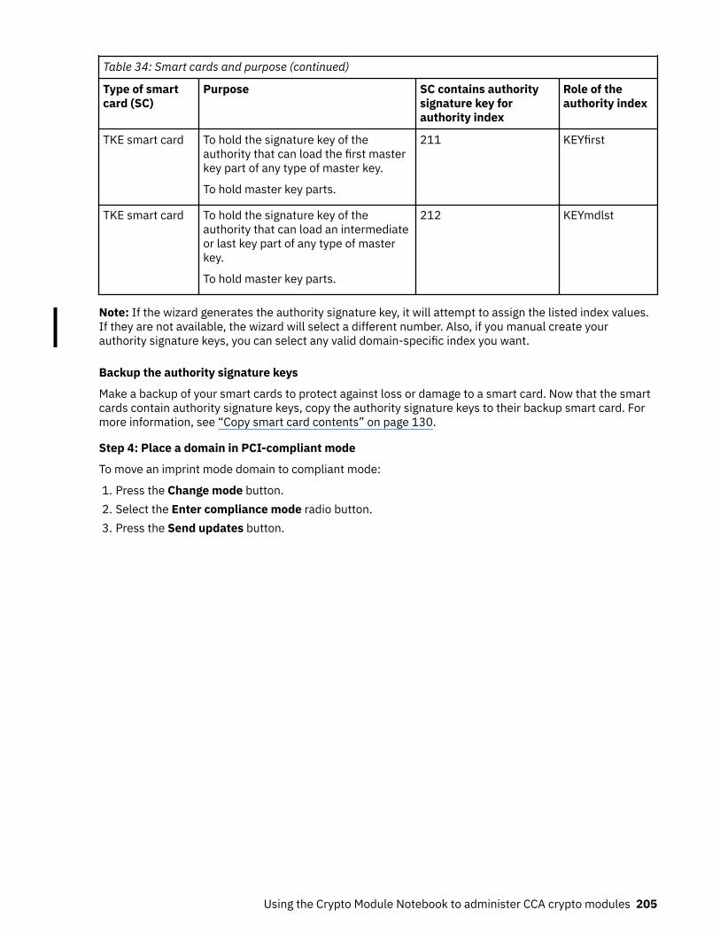
Table 34: Smart cards and purpose (continued)
Type of smartcard (SC)
Purpose SC contains authoritysignature key forauthority index
Role of theauthority index
TKE smart card To hold the signature key of theauthority that can load the first masterkey part of any type of master key.
To hold master key parts.
211 KEYfirst
TKE smart card To hold the signature key of theauthority that can load an intermediateor last key part of any type of masterkey.
To hold master key parts.
212 KEYmdlst
Note: If the wizard generates the authority signature key, it will attempt to assign the listed index values.If they are not available, the wizard will select a different number. Also, if you manual create yourauthority signature keys, you can select any valid domain-specific index you want.
Backup the authority signature keys
Make a backup of your smart cards to protect against loss or damage to a smart card. Now that the smartcards contain authority signature keys, copy the authority signature keys to their backup smart card. Formore information, see “Copy smart card contents” on page 130.
Step 4: Place a domain in PCI-compliant mode
To move an imprint mode domain to compliant mode:
1. Press the Change mode button.2. Select the Enter compliance mode radio button.3. Press the Send updates button.
Using the Crypto Module Notebook to administer CCA crypto modules 205

Figure 147: Move an imprint mode domain to compliant mode
After you press the Send updates button, you see the current authority error message, similar to:
Figure 148: Authority error message
Explanation of the error messageWhen you enter imprint mode for the first time, the only authority that can be used to create newdomain-specific roles and authorities is the default domain-specific authority with index 100. The rolefor index 100 is not allowed to move the domain to PCI-compliant mode.
After you press the Retry button, you are asked for a new authority signature key. When you use the TKEwizards to create your smart cards and setup the PCI environment, you need to load the authoritysignature key for the authority with index 201. You can place the smart card with the signature key forindex 201 into any available reader.
206 z/OS: Cryptographic Services ICSF Trusted Key Entry Workstation User's Guide

Figure 149: Select source
When the command is issued, it must be co-signed.
Figure 150: Enter PCI mode - Co-sign
After you press the Co-sign button, you are taken to the co-sign pending command screen. You can seewho has already signed the command (the authority with index 201) and who can co-sign the command(the authority with index 202).
Note: The remaining part of the co-sign procedure is not shown in this topic.
Figure 151: Co-sign pending
Using the Crypto Module Notebook to administer CCA crypto modules 207

The domain is now in PCI-compliant mode. All domain management must be done by using the domain-specific authorities, which enforce dual controls. However, the processes for managing domain settings,like loading master keys or changing domain controls, has not changed.
Figure 152: PCI-compliant mode
208 z/OS: Cryptographic Services ICSF Trusted Key Entry Workstation User's Guide

Chapter 8. Using the Crypto Module Notebook toadminister EP11 crypto modules
The Crypto Module Notebook is the central point for displaying and changing all information that is relatedto a crypto module. It is used for single crypto modules and domain groups. The contents of some pagesvary depending on whether you selected a single crypto module or a domain group.
The TKE Main Window lists the crypto modules available on each host machine to which the TKEWorkstation is connected, and also lists any crypto module groups and domain groups you created.Double-click a crypto module or domain group in the TKE Main Window to open the Crypto ModuleNotebook and work with the selected crypto module or domain group. There are two versions of theCrypto Module Notebook — one for CCA crypto modules (CEX2C, CEX3C, CEX4C, CEX5C, and CEX6C) andone for EP11 crypto modules (CEX4P, CEX5P, and CEX6P).
This topic describes how to use the Crypto Module Notebook for EP11 crypto modules. For informationabout how to use the Crypto Module Notebook for CCA crypto modules, see Chapter 7, “Using the CryptoModule Notebook to administer CCA crypto modules,” on page 135.
In the main TKE window, when you open an EP11 host crypto module or a domain group made up of EP11host crypto modules, the Crypto Module Notebook for EP11 crypto modules is displayed. The CryptoModule Notebook opens on the Module General tab.
Figure 153: Crypto Module Notebook for EP11 - Module General page
The Crypto Module Notebook is the central point for displaying and changing all information that is relatedto a crypto module or a domain group. Most panels are the same when referencing a single host cryptomodule versus a domain group, but there are minor differences on some panels for the two cases.
Note: Master key parts for EP11 host crypto modules and administrator signature keys are heldexclusively on smart cards. Smart card readers must be enabled to perform most administrative tasks. Toenable smart card readers, check the Enable Smart Card Readers option on the Preferences pull-down
© Copyright IBM Corp. 2000, 2019 209

menu on the TKE main window. The main TKE application needs to be restarted for this option to takeeffect.
The Setup Module Policy button appears only when the module is in imprint mode. If you press thisbutton, it launches the Setup Module Policy Wizard. The Setup Module Policy Wizard helps you create aset of EP11 administrators and adds them to the list of known module-wide administrators on yourmodule or modules in your domain group. Once you have added the administrators to the list of knownadministrators, the Setup Module Policy Wizard takes your module or the modules in your domain groupout of imprint mode. The Setup Module Policy Wizard does this by setting the Signature Threshold andRevocation Signature Threshold values to 2.
Note: EP11 administrator signature keys must be stored on smart cards. The Setup Module Policy Wizarduses smart cards that were created using the Smart Card Utility Program (SCUP) TKE Smart Card Wizard.
Notebook modeThe notebook is opened in one of three possible modes:
• UPDATE MODE• READ-ONLY MODE• LOCKED READ-ONLY MODE - domain group notebooks only
The mode is displayed in the lower-right corner on all crypto module notebook pages.
In UPDATE MODE, you are able to display crypto module information and to perform updates to thecrypto module.
In READ-ONLY MODE, you are able to display crypto module information but not update it.
In LOCKED READ-ONLY MODE, you are able to display crypto module information for the master moduleand to compare the reduced group of crypto modules. You are not allowed to do updates. TKE was notable to access one or more crypto modules of the domain group. This mode applies to domain groupnotebooks only.
Imprint modeImprint mode is a temporary operational mode for EP11 crypto modules and domains and is intended forinitial setup only. A crypto module and all domains are placed in imprint mode when:
• Segments 2 and 3 of an EP11 crypto module are loaded for the first time• Ownership of segments 2 and 3 is surrendered and segments 2 and 3 are reloaded• An EP11 crypto module is zeroized
A domain reenters imprint mode when it is zeroized.
In imprint mode, most commands are executed without requiring command signatures. Administratorscan be added and removed, attributes can be changed, the crypto module can be enabled and disabled,and the domain or crypto module in imprint mode can be zeroized. But other commands are not allowed.Imprint mode is used for initial crypto module setup, before master keys can be loaded and control pointscan be reset to restrict domain functionality.
The concept of "imprint mode" exists at both the crypto module level and the domain level. You must exitimprint mode at the crypto module level before you are allowed to exit imprint mode in any domain on thecrypto module.
When a crypto module or its domains are placed in imprint mode, the signature threshold and revocationsignature threshold values are set to zero. The crypto module threshold values are shown on the ModuleAttributes tab. Domain threshold values are shown on the Domain Attributes tabs. To exit imprint mode,the signature threshold and revocation signature threshold must be changed to nonzero values. Thecommand to change the signature threshold value to a nonzero value must be signed, with the number of
210 z/OS: Cryptographic Services ICSF Trusted Key Entry Workstation User's Guide

required signatures equal to the new signature threshold value. If you try to set the signature threshold orrevocation signature threshold to a number larger than the number of administrators that are installed inthe crypto module or domain, an error is signaled.
When a module or domain is in imprint mode, the Setup Module Policy or Setup Domain Policy wizardsare available to you. These wizards provide a simple path for adding your administrators and taking yourmodules or domains out of imprint mode.
Crypto Module Notebook Function menuThe selections under the Function pull-down menu are:
• Refresh Notebook. This option refreshes the notebook by reading information from the host.Performing a refresh might change the mode of the notebook.
• Manage Signature Keys. Use this option to predefine the smart card readers that are checked foradministrator signature keys when signatures are needed for administrative commands to the hostcrypto module. If no smart card readers are selected using this option, you are prompted to insert asmart card with an administrator signature key in smart card reader 1 for each required signature. Theresult can be frequent prompts to insert or replace a smart card in smart card reader 1.
If this option predefines smart card readers as the source of signature keys, commands that requireadministrator signatures automatically use the smart cards in those readers to generate signatureswhenever signatures are needed. If the smart card reader does not initially contain a smart card, youare prompted to insert a smart card and enter the PIN. After a valid smart card is inserted in the readerand the PIN is entered, the card can be used to generate additional signatures without further useraction.
All smart card readers are automatically selected as sources of administrator signature keys under thisoption when the TKE workstation crypto adapter is initialized for smart card use.
• Release Crypto Module. An update lock maintained by ICSF prevents attempts to update a host cryptomodule by more than one TKE workstation at a time. If communication between TKE and a host cryptomodule is abnormally terminated, the update lock might not be released. If the TKE attempts toreconnect to the host crypto module, it is not able to obtain the update lock and displays a warningindicating the user ID that currently owns the update lock. Selecting the Release Crypto Module optionreleases the update lock and reassigns it to the current user. Be aware, however, that releasing a cryptomodule can damage an on-going operation initiated by another user. Use this option only if you arecertain that the crypto module must be released.
A dialog prompts you to confirm that you want to release the crypto module.
Figure 154: Window to release crypto module
You can confirm release of the crypto module by clicking Yes.• Display Crypto Module Settings. This produces a summary report of how the crypto module isconfigured, which can include what module and domain administrators are defined, the module anddomain attributes, the master key register status and hash values for each domain, and the domaincontrol points for each domain. You are asked to select what information to collect and display.
The information is displayed on a new panel with tabs for each of the selected categories. A Save buttonallows you to save the information in a file, and a Print button allows you to print the information.
In a domain group notebook, the displayed information is for the crypto module containing the masterdomain.
Using the Crypto Module Notebook to administer EP11 crypto modules 211

• Download EP11 Audit Data. This function copies the audit data from the EP11 module into the file ofyour choice. The file can be placed directly onto a USB flash memory drive that is formatted for TrustedKey Entry data or onto your TKE local hard drive.
Note: Starting in TKE 9.1, the data is presented in human-readable form.
In TKE 9.0, the data is unformatted. The format of the audit data can be found in Enterprise PKCS#11(EP11) Library structure in the PCIeCC2 Enterprise PCKS #11 (EP11) section at CryptoCards(www.ibm.com/security/cryptocards). The event types that can generate an audit record are found insection 5.4.3 of this document. You can map these audit event names to the audit event values found insection 8.9.1 of this document.
• Compare Group. This option is displayed only when working with a domain group. It comparesmembers of the group and identifies any differences between them. Group members should beconfigured the same (for example, all member domains should have the same set of installedadministrators and the same signature threshold) in order for group operations to complete successfullyon all group members.
• Compare Group (Same Domain Index). This selection is only displayed if working with a domain group.This compare highlights differences between domains with the same index. For example, domain 0 anddomain 1 can have different settings. However, the compare only highlights the differences between thedomains with the same index, not differences between domain 0 and domain 1.
• Close. This option closes the crypto module notebook.
Tabular pagesTabular pages available in the crypto module notebook for EP11 are:
• Module General: see “Crypto Module Notebook Module General tab” on page 212.• Module Details: see “Crypto Module Notebook Module Details tab” on page 214.• Module Administrators: see “Crypto Module Notebook Module Administrators tab” on page 215.• Module Attributes: see “Crypto Module Notebook Module Attributes tab” on page 217.• Domains: see “Crypto Module Notebook Domains tab” on page 219.
The notebook opens to the Module General tab.
Crypto Module Notebook Module General tabThe contents of this page are:Description
This field is an optional free text description for the crypto module. For a domain group, this field is anoptional description for the crypto module that contains the master domain for the group. You canchange the description by typing the new description in the text box and clicking Send updates.
Host IDThis field is the ID of the host that contains the crypto module, or, in the case of a domain group, thatcontains the crypto module with the master domain for the domain group.
Host DescriptionThis field is the description of the host that contains the crypto module, or, in the case of a domaingroup, that contains the crypto module with the master domain for the domain group.
Crypto Module IndexThis field is the index of the crypto module or of the crypto module with the master domain for thedomain group. Together with the crypto module type, the index uniquely identifies a crypto modulewithin a host. The index value is 00 through 63.
Crypto Module TypeFor the crypto modules that TKE currently supports, this field is always set to Crypto Coprocessor.
212 z/OS: Cryptographic Services ICSF Trusted Key Entry Workstation User's Guide

StatusA crypto module is either enabled or disabled. When a crypto module is enabled, it is available forprocessing. You can change the status of the module by clicking Enable Crypto Module or DisableCrypto Module.
When the crypto module is enabled, Disable Crypto Module is displayed at the bottom of the page. Whenthe crypto module is disabled, Enable Crypto Module is displayed.
If you click Disable Crypto Module in a domain group notebook, all crypto modules with at least onedomain in the domain group are disabled. This action disables the crypto module for the entire system,not just the LPAR that issued the disable. You are asked to confirm this choice.
On CEX6C crypto modules and later, if you click Set Clock, an editable clock displays the date and UTCtime that the crypto module on the host is set to. Changing this value and clicking OK sets the date andUTC time of the clock to the new value.
If you click Zeroize Crypto Module in a domain group, all crypto modules with at least one domain in thedomain group are zeroized. You are asked to confirm this choice.
Zeroizing a crypto module has the following effects:
• The signature threshold and revocation signature threshold for the crypto module are set to zero, andthe crypto module reenters imprint mode. See “Imprint mode” on page 210.
• The crypto module permissions, attribute controls, and operational mode bits are set to their defaultvalues.
• All crypto module administrators are removed.• All domains on the crypto module are zeroized. Zeroizing a domain makes the following changes to the
domain:
– Sets the domain signature threshold and revocation signature threshold to zero, and causes thedomain to re-enter imprint mode.
– Sets the domain permissions, attribute controls, and operational mode bits to their default values.– Removes all domain administrators.– Clears the new and current master keys in the domain.– Re-enables all domain control points.
The Setup Module Policy button appears only when the module is in imprint mode. If you press thisbutton, it launches the Setup Module Policy Wizard. The Setup Module Policy Wizard helps you create aset of EP11 administrators and adds them to the list of known module-wide administrators on yourmodule or modules in your domain group. Once you have added the administrators to the list of knownadministrators, the Setup Module Policy Wizard takes your module or the modules in your domain groupout of imprint mode. The Setup Module Policy Wizard does this by setting the Signature Threshold andRevocation Signature Threshold values to 2.
Note: EP11 administrator signature keys must be stored on smart cards. The Setup Module Policy Wizarduses smart cards that were created using the Smart Card Utility Program (SCUP) TKE Smart Card Wizard.
Intrusion latchUnder normal operation, the intrusion latch of a cryptographic card is tripped when the card is removed.This trip causes all master keys to be erased, all administrators to be removed, and all other configurationsettings to revert to their default values. The card and all domains reenter imprint mode. See “Imprintmode” on page 210.
A situation might arise where a cryptographic card needs to be removed. For example, you might need toremove a card for service. If you must remove a card, and you do not want the installation data to becleared, perform the following procedure to disable the card. This procedure requires you to switchbetween the TKE application, the ICSF Coprocessor Management panel, and the Support Element.
1. Open an emulator session on the TKE workstation and log on to your TSO/E user ID on the hostsystem where the card will be removed.
Using the Crypto Module Notebook to administer EP11 crypto modules 213

2. From the ICSF Primary Option Menu, select Option 1 for Coprocessor Management.3. Leave the Coprocessor Management panel displayed during the rest of this procedure. You will be
required to press Enter on the Coprocessor Management panel at different times.
Important: Do not exit this panel.4. Open the TKE Host where the card will be removed. Open the crypto module notebook for the host
crypto module. Click Disable Crypto Module.5. After the crypto module is disabled within TKE, press the Enter key on the ICSF Coprocessor
Management panel. The status should change to DISABLED.
Note: You do not need to deactivate a disabled card before configuring it OFFLINE.6. Configure Off the card from the Support Element. The Support Element is a dedicated workstation
used for monitoring and operating Z hardware. A user authorized to perform actions on the SupportElement must complete this step.
7. After the card is Offline, press the Enter key on the Coprocessor Management panel. The statusshould change to OFFLINE.
8. Remove the card. Perform whatever operation needs to be done. Replace the card.9. Configure On the card from the Support Element. The Support Element is a dedicated workstation
used for monitoring and operating Z hardware. A user authorized to perform actions on the SupportElement must complete this step.
10. When the initialization process is complete, press the Enter key on the Coprocessor Managementpanel. The status should change to DISABLED.
11. From the TKE Workstation Crypto Module General page, click Enable Crypto Module.12. After the card is enabled from TKE, press the Enter key on the Coprocessor Management panel. The
Status should return to its original state. If the Status was ACTIVE in step 2, when the card is enabledit should return to ACTIVE.
All master keys, administrators, and other configuration data should still be available. The data was notcleared with the card removal because it was DISABLED first using the TKE workstation.
Crypto Module Notebook Module Details tabThe Module Details tab contains three pages, which can be selected by clicking the tabs on the right sideof the window. The pages and their contents are:
• Crypto Module - Shows basic information needed to recognize a host crypto module. Differentinformation is displayed, depending on the crypto module type. The following fields may be displayedon this page:
– Crypto Module ID - Unique identifier burned into the crypto module during the manufacturingprocess.
– Public Modulus - For crypto modules with an RSA OA signature key, the modulus of the key. TKE usesthe public key to verify signed replies from the host crypto module.
– Modulus Length - For crypto modules with an RSA OA signature key, the length of the modulus, inbits.
– ECC Public Key - For crypto modules with an ECC OA signature key, the ECC public key.– Key Identifier - The SHA-256 hash over the public part of the OA signature key. For RSA keys, the
hash is over the DER-encoded modulus and public exponent. For ECC keys, the hash is over the ECCpublic key.
• Crypto Services (Function Control Vector Values)
– CDMF availability– 56-bit DES availability– Triple DES availability
214 z/OS: Cryptographic Services ICSF Trusted Key Entry Workstation User's Guide

– 128-bit AES availability– 192-bit AES availability– 256-bit AES availability– SET services– Maximum modulus for key management– Maximum elliptic curve field size in bits for key management
• Other CM Info
– API Ordinal Number– Firmware Identifier– API Version– CSP Version– Firmware Configuration ID– API Configuration ID– CSP Configuration ID
Crypto Module Notebook Module Administrators tabAn administrator controls a signature key that allows him or her to sign commands to a host cryptomodule. Administrator signature keys are stored on smart cards. The administrator has physicalpossession of the smart card and knows the smart card Personal Identification Number (PIN).
Up to eight administrators can be defined for each domain on a host crypto module, and eight additionaladministrators can be defined for the host crypto module as a whole. Domain-level administrators areallowed to sign commands to that domain. Crypto-module-level administrators can sign commands toany domain on the crypto module and to the crypto module as a whole.
The signature threshold and revocation signature threshold values on the Module Attributes tabdetermine how many administrators are required to sign commands to the crypto module. Somecommands require only a single signature, regardless of how the signature threshold is set. The signaturethreshold and revocation signature threshold values on the Domain Attributes tab determine how manyadministrators are required to sign commands to that domain.
Administrators are allowed to sign any command. For EP11 crypto modules, there is no concept of "role"(in which the role associated with an administrator defines the set of commands the administrator isallowed to sign).
To work with the crypto-module-level administrators, click the Module Administrators tab on the maincrypto module notebook page. To work with domain-level administrators, click the Domains tab on themain crypto module notebook page, select a domain, and then click the Domain Administrators tab forthat domain. Right clicking in these pages displays a pop-up menu with options to add or remove anadministrator, or generate an administrator signature key and store it on a smart card.
Using the Crypto Module Notebook to administer EP11 crypto modules 215

Figure 155: Module Administrators page
EP11 crypto modules identify administrators by using a 32-byte Subject Key Identifier, which is a hashof the signature key. The TKE workstation allows users to associate a name of up to 30 characters witheach administrator. Users are encouraged to assign unique, meaningful names for each administratorsignature key created. The administrator name and subject key identifier are displayed in theadministrators list on the Module Administrators page. Both the name and the subject key identifier arewritten to audit records when commands are signed.
Generate signature keyTo generate an administrator signature key and save it on a smart card, right click in the ModuleAdministrators page to display the pop-up menu. From the pop-up menu, select the Generate SignatureKey option.
Figure 156: Generate Signature Key
You are asked to enter an administrator name. Users are encouraged to select unique, meaningful namesfor each signature key created. After entering the administrator name, you are prompted to insert a smartcard in a reader and enter the PIN to complete the operation. The generated key is a 320-bit BrainpoolECC key.
216 z/OS: Cryptographic Services ICSF Trusted Key Entry Workstation User's Guide

Add administratorTo add an administrator, right click in the Module Administrators page to display the pop-up menu. Fromthe pop-up menu, select the Add Administrator option.
You are asked to insert a smart card that contains an administrator signature key in a smart card readerand enter the PIN. The public key and administrator name are read from the smart card and used todefine an administrator to the EP11 crypto module. Up to eight administrators can be defined.
Remove administratorTo remove an administrator, right-click on the administrator in the list of administrators to display a pop-up menu. Click Remove Administrator from the pop-up menu. You are not allowed to remove anadministrator if removing the administrator would reduce the number of administrators below thesignature threshold value or revocation signature threshold value.
Setup Module PolicyThe Setup Module Policy option appears only when the module is in imprint mode. If you select thisoption, it launches the Setup Module Policy Wizard. The Setup Module Policy Wizard helps you create aset of EP11 administrators and adds them to the list of known module-wide administrators on yourmodule or modules in your domain group. Once you have added the administrators to the list of knownadministrators, the Setup Module Policy Wizard takes your module or the modules in your domain groupout of imprint mode. The Setup Module Policy Wizard does this by setting the Signature Threshold andRevocation Signature Threshold values to 2.
Note: EP11 administrator signature keys must be stored on smart cards. The Setup Module Policy Wizarduses smart cards that were created using the Smart Card Utility Program (SCUP) TKE Smart Card Wizard.
Crypto Module Notebook Module Attributes tabUse the Module Attributes tab to display a set of attributes associated with the crypto module and changethem.
To change the crypto module attributes, type new values in the Signature Threshold and RevocationSignature Threshold fields and select or clear check boxes in the attributes trees. Then click Sendupdates. If you change your mind you can click Discard changes. Your changes are discarded and thepage is refreshed with attributes reread from the crypto module.
Using the Crypto Module Notebook to administer EP11 crypto modules 217

Figure 157: Module Attributes page
Using the Crypto Module Notebook Module Attributes Tab, you can set the following attributes:
• Signature Threshold and Revocation Signature Threshold.
The signature threshold controls the number of signatures needed to execute most commands to thecrypto module. Some commands require a single signature, regardless of how this attribute is set. Eachdomain on the crypto module has its own signature threshold attribute, which controls the number ofsignatures required for most commands sent to that domain. The maximum signature threshold valuethat can be set is 8.
The revocation signature threshold controls the number of signatures required to remove a cryptomodule administrator. The maximum revocation signature threshold value that can be set is 8.
When the crypto module is zeroized, the signature threshold and revocation signature threshold are setto 0 and the crypto module is put in imprint mode. In imprint mode commands to the crypto module donot require administrator signatures. Imprint mode is intended for initial crypto module setup, beforethe crypto module is used to manage master keys. To exit imprint mode, set the signature threshold andrevocation signature threshold to nonzero values. You must exit imprint mode at the crypto modulelevel before you can exit imprint mode in any domain on the crypto module.
• Permissions.
– Threshold values of 1 allowed - When checked, the signature threshold and revocation signaturethreshold can be set to 1. If not checked, the signature threshold and revocation signature thresholdmust be set to values greater than 1.
– Zeroize with one signature - When checked, zeroizing the crypto module requires just one signature,regardless of the signature threshold value. When not checked, the signature threshold valuespecifies the number of signatures required to zeroize the crypto module.
• Attribute Controls
These check boxes restrict changes to other fields on the panel. After the crypto module is zeroized,these check boxes are all selected and any attribute on the panel can be changed. If you clear one ofthese check boxes and click Send updates, the corresponding attribute is frozen and you are not
218 z/OS: Cryptographic Services ICSF Trusted Key Entry Workstation User's Guide

allowed to change it. You can clear these fields, but you cannot select them again. The crypto modulemust be zeroized to select them again. You are asked to confirm your choice if you clear one of thesefields and click Send updates. The attributes controls are:
– May change signature threshold This control allows the crypto module signature threshold value tobe changed.
– May change revocation signature threshold This control allows the crypto module revocationsignature threshold to be changed.
– May change threshold values of 1 permission This control allows the Threshold values of 1allowed permission to be changed.
– May change zeroize with one signature permission This control allows the Zeroize with onesignature permission to be changed.
• Operational Mode. The operational mode bits are:
– No longer in imprint mode. This bit is read-only and indicates whether the crypto module is inimprint mode. Imprint mode is a temporary condition used for initial setup. Setting the signaturethreshold and revocation signature threshold to nonzero values exits imprint mode.
– Zeroize crypto module when intrusion latch tripped. When checked this bit specifies that the entirecrypto module is to be zeroized when the intrusion latch is set. Physically removing a crypto modulefrom a host system sets the intrusion latch.
– Zeroize only master keys when intrusion latch tripped. When checked, this bit specifies that onlythe master keys on the crypto module are to be zeroized when the intrusion latch is set. Physicallyremoving a crypto module from a host system sets the intrusion latch. This bit is ignored when theZeroize crypto module when intrusion latch tripped bit is set.
– Battery is low. This bit is read-only and indicates the battery on the EP11 crypto module needs to bereplaced.
– Crypto module is enabled. This bit is read-only and indicates whether the crypto module is enabledor disabled. The crypto module can be enabled and disabled by clicking Enable Crypto Module andDisable Crypto Module on the Module General page.
Clicking Enable Crypto Module and Disable Crypto Module on the Module General tab changes thestate of the Crypto module is enabled bit, the Zeroize crypto module when intrusion latch trippedbit, and the Zeroize only master keys when intrusion latch tripped bit. When Disable CryptoModule is clicked on the Module General tab, all 3 bits are cleared. This allows the crypto module tobe physically removed from the host system without losing configuration data. See “Intrusion latch”on page 213 for the procedure to follow when moving a host crypto module. When the crypto moduleis enabled by clicking Enable Crypto Module, this bit and the Zeroize crypto module when intrusionlatch tripped bits are checked, but the Zeroize only master keys when intrusion latch tripped bitremains unchecked.
• Standards Compliance Settings. These bits indicate whether all domains on the crypto module areconfigured to conform to the indicated industry standard. Domains conform to a standard based on theircontrol point settings. Each domain has its own Standards Compliance Settings attribute. If one or moredomains does not conform to a standard, the crypto module as a whole is shown to not conform to thestandard. The EP11 crypto module is always compliant with the FIPS 2009 standard, so that StandardsCompliance Settings attribute is always set. These bits are read-only.
Crypto Module Notebook Domains tabTo manage the administrators, attributes, master keys, and control points for the domains on an EP11crypto module, click the Domains tab in the crypto module notebook. Use the set of tabs on the right sideof this page to select a domain to manage. Tabs are present only for those domains configured using theSupport Element as control domains for the TKE workstation. Select a domain by clicking it. A set of tabsis displayed at the bottom of the page with functions to manage domain facilities: Domain General,Domain Administrators, Domain Attributes, Domain Keys, and Domain Control Points.
Using the Crypto Module Notebook to administer EP11 crypto modules 219

When ICSF FMID HCR77B1 with APAR OA49067, or later, runs in the logical partition that servicesrequests from the TKE workstation, the configured usage domain will be indicated by an asterisk on oneof the numbered domain tabs.
In a domain group notebook, the Domains tab is replaced by a Domain tab, and there is no list of controldomains on the right side of the page. In a domain group notebook, the displayed attributes,administrators, keys, and control points are from the master domain of the group. Updates made in adomain group notebook are made to all member domains of the group, or to all crypto modules with atleast one domain in the domain group.
Domain General pageThe domain general page displays the domain index and domain description for the domain, and containsa Zeroize domain push button that allows the domain to be zeroized. For domain groups, the index anddescription of the master domain are displayed, and a Zeroize domain group push button replaces theZeroize domain push button. Clicking Zeroize domain group causes all member domains to be zeroized.
You can change the domain description by typing a new description in the text box and clicking Sendupdates. If you change your mind after entering a new description, you can click Discard changes. Yourchanges are discarded and the existing domain description is refetched from ICSF. Updating thedescription in a domain group notebook causes the description of all member domains to be updated.
Zeroizing a domain has the following effects:
• The signature threshold and revocation signature threshold are set to zero, and the domain re-entersimprint mode. See “Imprint mode” on page 210.
• The domain permissions, attribute controls, and operational mode bits are set to their default values.• All domain administrators are removed.• The domain new master key and current master key are erased. Any data in the ICSF PKCS #11 token
data set (TKDS) encrypted by the current master key becomes unrecoverable.• All domain control points are set.
The Setup Domain Policy button appears only when the module is in imprint mode. If you press thisbutton, it launches the Setup Domain Policy Wizard. The Setup Domain Policy Wizard helps you create aset of EP11 administrators and adds them to the list of known module-wide administrators on yourdomain or domains in your domain group. Once you have added the administrators to the list of knownadministrators, the Setup Domain Policy Wizard takes your domain or the domains in your domain groupout of imprint mode. The Setup Domain Policy Wizard does this by setting the Signature Threshold andRevocation Signature Threshold values to 2.
Note: EP11 administrator signature keys must be stored on smart cards. The Setup Domain Policy Wizarduses smart cards that were created using the Smart Card Utility Program (SCUP) TKE Smart Card Wizard.
220 z/OS: Cryptographic Services ICSF Trusted Key Entry Workstation User's Guide

Figure 158: Domain General page
Domain Administrators pageThe domain administrators page is identical to the module administrators page, but manages the domainadministrators rather than the crypto module administrators. See “Crypto Module Notebook ModuleAdministrators tab” on page 215 for a description of this page.
Domain Attributes pageUse the Domain Attributes tab to display a set of attributes associated with the domain and change them.The attributes displayed are:
• Signature Threshold• Revocation Signature Threshold• Permissions• Attribute Controls• Operational Mode• Standards Compliance Settings
To change the domain attributes, type new signature thresholds in the text fields or select or clear checkboxes in the attributes trees. Then click Send updates. If you change your mind, you can click Discardchanges. Your changes are discarded and the page is refreshed with domain attributes reread from thecrypto module.
Using the Crypto Module Notebook to administer EP11 crypto modules 221
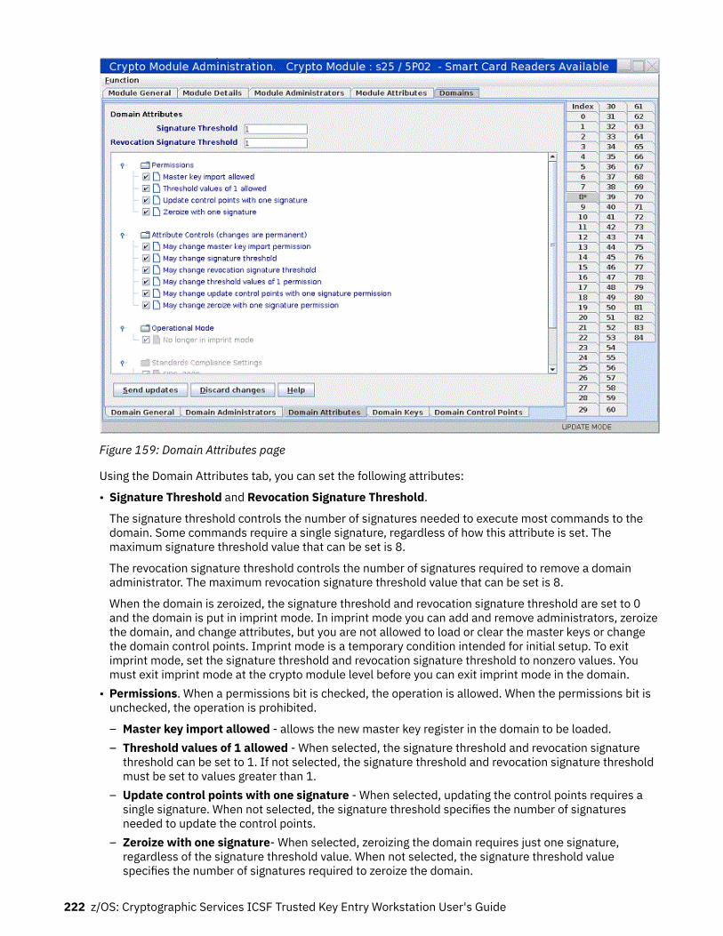
Figure 159: Domain Attributes page
Using the Domain Attributes tab, you can set the following attributes:
• Signature Threshold and Revocation Signature Threshold.
The signature threshold controls the number of signatures needed to execute most commands to thedomain. Some commands require a single signature, regardless of how this attribute is set. Themaximum signature threshold value that can be set is 8.
The revocation signature threshold controls the number of signatures required to remove a domainadministrator. The maximum revocation signature threshold value that can be set is 8.
When the domain is zeroized, the signature threshold and revocation signature threshold are set to 0and the domain is put in imprint mode. In imprint mode you can add and remove administrators, zeroizethe domain, and change attributes, but you are not allowed to load or clear the master keys or changethe domain control points. Imprint mode is a temporary condition intended for initial setup. To exitimprint mode, set the signature threshold and revocation signature threshold to nonzero values. Youmust exit imprint mode at the crypto module level before you can exit imprint mode in the domain.
• Permissions. When a permissions bit is checked, the operation is allowed. When the permissions bit isunchecked, the operation is prohibited.
– Master key import allowed - allows the new master key register in the domain to be loaded.– Threshold values of 1 allowed - When selected, the signature threshold and revocation signature
threshold can be set to 1. If not selected, the signature threshold and revocation signature thresholdmust be set to values greater than 1.
– Update control points with one signature - When selected, updating the control points requires asingle signature. When not selected, the signature threshold specifies the number of signaturesneeded to update the control points.
– Zeroize with one signature- When selected, zeroizing the domain requires just one signature,regardless of the signature threshold value. When not selected, the signature threshold valuespecifies the number of signatures required to zeroize the domain.
222 z/OS: Cryptographic Services ICSF Trusted Key Entry Workstation User's Guide

• Attribute Controls. Use these check boxes to restrict changes to other fields on the panel. After thedomain is zeroized, these check boxes are all selected and any attribute on the panel can be changed. Ifyou clear one of these check boxes and click Send updates, the corresponding attribute is frozen andyou are not allowed to change it. You can clear these check boxes, but you cannot reselect them. Thedomain must be zeroized to select them again. You are asked to confirm your choice if you clear one ofthese check boxes and click Send updates.
– May change master key import permission - controls whether the Master key import allowedpermission can be changed.
– May change signature threshold - controls whether the domain signature threshold value can bechanged.
– May change revocation signature threshold - controls whether the domain revocation signaturethreshold value may be changed.
– May change threshold values of 1 permission - controls whether the Threshold values of 1 allowedpermission can be changed.
– May change update control points with one signature permission - controls whether the Updatecontrol points with one signature permission can be changed.
– May change zeroize with one signature permission - controls whether the Zeroize with onesignature permission can be changed.
• Operational Mode. The operational mode bits are:
– No longer in imprint mode. This bit is read-only and indicates whether the domain is in imprintmode. Imprint mode is a temporary condition used for initial setup. Setting the signature thresholdand revocation signature threshold to nonzero values exits imprint mode.
• Standards Compliance Settings. These bits indicate whether the domain is configured to conform tothe indicated industry standard. Domains conform to a standard based on their control point settings.These bits are read-only.
Domain Keys pageThe domain keys page displays the status and verification pattern of the new master key register andcurrent master key register for the domain.
The current master key encrypts all data stored for the domain in the ICSF PKCS #11 token data set(TKDS). To change the current master key, first the new master key register must be loaded, using two ormore key parts stored on smart cards.
Right clicking in the page causes a pop-up menu to be displayed. From this menu you can select thefollowing operations:
• Generate key part - Generate a random master key part value and save it on a smart card.• Load new master key - Load the new master key register on the host crypto module using two or more
key parts previously saved on smart cards.• Commit new master key - Commit the value in the new master key register. The value in the new
master key register must be committed before ICSF can use it to re-encrypt data in the TKDS for thedomain.
• Set, immediate - Sets the new master key, but without re-encrypting the data in the TKDS for thedomain.
Normally, use ICSF procedures or services that coordinate setting the master key with initializing or re-encrypting TKDS. This option sets the master key but does not change TKDS. If used inappropriately,this option causes the data in the TKDS to become unusable when accessed by ICSF in the domain.
Use this option only when the TKDS does not need to be initialized or re-encrypted when the master keyis set. For example, this option can be used to reload the previous master key value if a host cryptomodule has been inadvertently zeroized.
• Clear new master key - Clear the new master key register.
Using the Crypto Module Notebook to administer EP11 crypto modules 223

• Clear current master key - Clear the current master key register. Use this option with caution. Any datastored in the ICSF TKDS for the domain becomes unusable. You are asked to confirm this choice
• Coordinated change master key and TKDS - Run a wizard-like feature to re-encipher the current ICSFtoken key data set (TKDS) under the new P11 master key, set the P11 master key, and make the re-enciphered TKDS the active in-store TKDS used by ICSF.
This option is enabled only if the 'Coordinated change master key and KDS' operation is permitted in theTKE crypto adapter role associated with the current TKE crypto adapter user.
• Secure key part entry - Use the PIN pad on the smart card reader to enter a known key part value andsave it on a smart card.
After the new master key register is loaded and its value is committed, ICSF can re-encrypt data in theTKDS for the domain. After all data is re-encrypted, ICSF can finalize the new master key. Finalizingmoves the value in the new master key register to the current master key register and changes the stateof the new master key register to Empty.
The domain keys panel in a domain group notebook shows the status and verification patterns of themaster key registers in the master domain. When load, commit, and clear options are executed in adomain group, commands are sent to each member domain of the domain group.
Figure 160: Domain Keys page
Generate key part
To generate one or more P11 master key parts and save them on smart cards, right click in the DomainKeys page to display the pop-up menu. From the pop-up menu, select the Generate key part option.
You are asked to enter the number of key parts you want to generate. For each key part, you are guidedthrough the process of selecting a smart card reader to use, inserting a smart card in the reader, enteringthe PIN, and entering a description to associate with the key part. You can cancel at any time.
224 z/OS: Cryptographic Services ICSF Trusted Key Entry Workstation User's Guide

Load new master key
To load the new master key register for the domain, right click in the Domain Keys page to display thepop-up menu. From the pop-up menu, select the Load new master key option.
You are asked to enter the total number of key parts to be loaded. For each key part, you are guidedthrough the process of selecting a smart card reader to use, inserting a smart card in the reader, enteringthe PIN, and selecting the key part on the smart card to be loaded. You can cancel at any time.
Key parts on the smart card are encrypted for transport to the host crypto module using Elliptic CurveDiffie-Hellman (ECDH). The first step in ECDH is to generate an IMPORTER key on the crypto module.Generating the key requires a signed command. Therefore, signatures are collected twice when you runthe Load New Master Key option – once to generate an IMPORTER key and once to do the final load. Bothcommands require only a single signature, regardless of how the domain signature threshold is set.
Coordinated change master key and TKDS
This function is the same as the 'coordinated change master keys and CKDS' function in the CCA cryptomodule notebook, but uses the P11 master key and token key data set (TKDS).
Secure key part entry
To enter a known value for an P11 master key part onto a smart card, right click in the Domain Keys pageto display the pop-up menu. From the pop-up menu, select the Secure key part entry option.
The same process is followed for secure key part entry of P11 master key parts as for secure key partentry of other key types. See Appendix A, “Secure key part entry,” on page 313 for details on this process.
Domain Control Points pageUse the Domain control points page to display the set of control points that are currently active for thedomain and change them. When selected, a control point permits an operation in the domain. When notselected, the operation is not allowed.
To change control points, select or clear check boxes to select or deselect individual control points. Thenclick Send updates to send the changes to the host crypto module. If you change your mind, you can clickDiscard changes. Any changes you made are discarded and the page is refreshed with the current controlpoints for the domain.
You can save the displayed control points to a file by clicking Save to file. You can load the control pointsfrom a previously saved file by clicking Load from file. In both cases, a window opens in which you canselect the file to use. After loading the control points from a file, click Send updates to send the changesto the host crypto module.
Right click in an open area of the page to display a pop-up menu. From this menu you can resetcollections of control points to ensure conformity with an operating standard such as FIPS or BSI. Afterselecting the wanted standard, click Send updates to send the updates to the host crypto module.
Use care when deselecting control points in the Control Point Management category. These control pointscan be used to prevent further updates to the control points for the domain. After these control points areturned off, further updates to the control points are not permitted. The domain must be zeroized beforethe control points can be changed again. You are asked to confirm your choice when turning off thesecontrol points.
Using the Crypto Module Notebook to administer EP11 crypto modules 225

Figure 161: Domain Control Points page
226 z/OS: Cryptographic Services ICSF Trusted Key Entry Workstation User's Guide

Chapter 9. Auditing
TKE implements logging of security relevant operations that occur on the TKE workstation. TKE providesauditors with a trail of activities on the TKE workstation that are not currently tracked. Security actionsthat are performed on the TKE workstation are recorded in a security log and tied to a user identity. TKEsecurity audit records are in addition to the System Management Facilities (SMF) records that are alreadycut on the host system that are triggered by requests from TKE.
To perform auditing tasks or configure auditing settings on the TKE workstation, you must log on with theAUDITOR user name. When logged on to the TKE Workstation as AUDITOR, you are able to:
• Use the TKE Audit Configuration Utility to turn TKE auditing on and off.• Use Service Management functions to:
– View the security log.– Archive the security logs.
• Use the TKE Audit Record Upload Configuration Utility to configure audit record upload to a Z host,where the audit records are saved in the z/OS SMF data set.
• Use the TKE Security Event Viewer to view the security event Logs.• Set heartbeat interval.
ICSF also uses SMF record type 82 to record certain ICSF events. ICSF writes to subtype 16 whenever aTKE workstation either issues a command request to, or receives a reply response from, a CCA or EP11crypto module. In addition to the subtype 16 records, you can use the TKE Audit Record UploadConfiguration Utility to send Trusted Key Entry workstation security audit records to a Z host. Thesesecurity audit records are stored in the SMF data set as a type 82 subtype 29 record.
TKE Audit Configuration utilityTo configure auditing, log on with the AUDITOR user name, select Trusted Key Entry and then select theAudit Configuration Utility.
The TKE Audit Configuration Utility is displayed.
By default, all available auditing is enabled.
© Copyright IBM Corp. 2000, 2019 227

Figure 162: Default settings for auditing
You can customize the auditing utility to your wanted preference. To turn off auditing, click Stop Auditingto change the status to Auditing Off.
Figure 163: Auditing is off
228 z/OS: Cryptographic Services ICSF Trusted Key Entry Workstation User's Guide

If you want to enable and disable specific audit records (both successes and failures), you can expandeach audit point to see the individual audit records associated with the group by clicking the symbol to theleft of the audit point.
Figure 164: Example of expanded auditing points
When you expand an audit point, you can configure the individual audit records as wanted.
If you want to enable or disable all success or failure audit points, you can click the successes or failurescheck box on the line corresponding to the audit points group.
To reset the utility, click the Reset button. This button reestablishes the default state of auditing. Thedefault state is Auditing On and all events are selected to write audit records. Also, the heartbeat intervalis set to one day.
If you want to change the interval of the heartbeat record, click Set Heartbeat Interval and select aninterval that best suits your requirements. If auditing is active, a heartbeat audit record is written if noother audit records have been written during the specified interval.
Figure 165: Set heartbeat interval
Service Management auditing functionsYou can use Service Management functions to perform the following auditing tasks:
Auditing 229

• View the security log• Archive the security logs
View security logsThe security logs can be viewed on the TKE, but only when you are logged in with the AUDITOR username. The security log has a maximum size of 30 MB.
When the security log reaches 75% full, a hardware message alerts the user on the TKE console. The ViewSecurity Logs task determines whether the message displays. By default, the message displays.
When the security log reaches 100% capacity, the oldest third of the audit records are deleted.
In order to avoid deleting records you can archive the security logs (see “Archive security logs” on page235).
In order to view the security logs, log in as the AUDITOR user, select Service Management and selectView Security Logs.
Figure 166: Viewing the security logs
230 z/OS: Cryptographic Services ICSF Trusted Key Entry Workstation User's Guide

This log displays 1000 records per page. The 1000 record pages can be navigated by clicking on ShowEarlier Events and Show Later Events.
If the audit record contains an asterisk (*) next to the line saying 'TKE Audit Record', this means that thereare further details available to view. You can view the details by selecting the radio button correspondingto the desired audit record and clicking Details.
Figure 167: Viewing additional details of the security logs
Audit and log managementAudit and log management copies the console events log, security log, and tasks performed log to a USBflash memory drive. Select Service Management and, from the service management window, selectAudit and Log Management.
The Audit and Log Management dialog box is displayed.
Auditing 231

Figure 168: Audit and Log Management dialog
The log data can be formatted in either HTML or XML format.
The starting and ending date and time values may be specified to limit the amount of log data that willappear in the report.
The types of data (console events, security log, and tasks performed log) can also be specified to limit theamount of data that appears in the report. Note that the events related to the TKE utilities are logged inthe security log.
232 z/OS: Cryptographic Services ICSF Trusted Key Entry Workstation User's Guide

Figure 169: Audit and Log Management dialog (security log data selected)
After pressing OK, the log data is formatted in either HTML or XML format, and is displayed in a window.
Auditing 233

Figure 170: Security Log
This window contains the report produced from the log data. To save the report to a USB flash memorydrive, click Save. The Export Data window opens.
234 z/OS: Cryptographic Services ICSF Trusted Key Entry Workstation User's Guide

Figure 171: Export Data
Note: If a USB flash memory drive is not currently present, nothing is listed under Select a Device. Towrite to a USB flash memory, drive insert the drive, wait for the USB Device Status window to appear, andthen click Refresh. When OK is clicked, the report is saved with the specified file name to the USB flashmemory drive.
A pop-up window is displayed to indicate that the report was saved successfully.
Archive security logsIf you wish to archive the security logs you must be logged onto the TKE console with the AUDITOR username. Archiving the security logs saves the security log's event data in another file on the USB flashmemory drive, and then erases enough events from the security log to reduce its size to 20% of itsmaximum capacity.
In order to Archive the Security log, log in as the AUDITOR user and select Service Management. Fromthe service management window select Archive Security Logs.
Note: You must have a USB flash memory drive that is formatted with no volume label or a volume label ofACTSECLG. Use the Format Media utility to format the flash memory drive (see “Format media” on page359).
Auditing 235

Figure 172: Archiving the security logs
With a valid USB flash memory drive inserted, click Archive.
While the security log is being archived, an "Archiving Security Log..." message box displays. After thearchiving is completed, a message box displays indicating that the archive operation has completed.
TKE Security Events ViewerUse the TKE Security Events Viewer to view TKE-specific security events within a specified date range.
TKE security events are displayed in a tree format, where each node is a TKE security event with acorresponding timestamp. Expand the security event to see the security event details and headerinformation. Expand the security event details and header information to further view the detailedinformation. Collapse to hide the content.
236 z/OS: Cryptographic Services ICSF Trusted Key Entry Workstation User's Guide
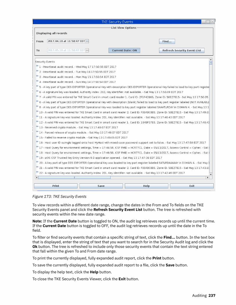
Figure 173: TKE Security Events
To view records within a different date range, change the dates in the From and To fields on the TKESecurity Events panel and click the Refresh Security Event List button. The tree is refreshed withsecurity events within the new date range.
Note: If the Current Date button is toggled to ON, the audit log retrieves records up until the current time.If the Current Date button is toggled to OFF, the audit log retrieves records up until the date in the Tofield.
To filter or find security events that contain a specific string of text, click the Find... button. In the text boxthat is displayed, enter the string of text that you want to search for in the Security Audit log and click theOk button. The tree is refreshed to include only those security events that contain the text string enteredthat fall within the given To and From date range.
To print the currently displayed, fully expanded audit report, click the Print button.
To save the currently displayed, fully expanded audit report to a file, click the Save button.
To display the help text, click the Help button.
To close the TKE Security Events Viewer, click the Exit button.
Auditing 237

TKE Audit Record Upload Configuration utilityICSF uses SMF record type 82 to record certain ICSF events. ICSF writes to subtype 16 whenever a TKEworkstation either issues a command request to, or receives a reply response from, a CCA or EP11 cryptomodule. In addition to the subtype 16 records, you can use the TKE Audit Record Upload ConfigurationUtility to send Trusted Key Entry workstation security audit records to a Z host, where they will be saved inthe z/OS System Management Facilities (SMF) dataset. Each TKE security audit record is stored in theSMF dataset as a type 82 subtype 29 record.
Note: The audit upload process does not remove any data from the TKE Workstation. Copies of securityaudit records are sent to the host system and all data is retained by the TKE Workstation.
Starting the TKE Audit Record Upload Configuration utilityTo use the TKE Audit Record Upload Configuration utility, you must first sign on to the Trusted Key Entryconsole in Privileged Mode Access with the AUDITOR user ID. To do this:
1. Close the Trusted Key Entry Console.2. From the Welcome to the Trusted Key Entry Console screen select Privileged Mode Access.3. From the Trusted Key Entry Console Logon screen, enter the user name AUDITOR and the password.
(The default password is PASSWORD, but this can be changed by the user. See “Change password ” onpage 354.)
4. Press the Logon push button.
To start the TKE Audit Record Upload Configuration utility, go to the Trusted Key Entry Console Workplacewindow and select TKE Audit Record Upload Utility.
The TKE Audit Record Upload Configuration Utility window is displayed.
Figure 174: TKE Audit Record Upload Configuration utility
Using the TKE Audit Record Upload Configuration utility, you can:
• Specify the host machine to which the audit records will be sent. See “Configure TKE for audit dataupload” on page 239 for more information.
• Upload audit records to the target host. See “Uploading audit records” on page 240 for moreinformation.
238 z/OS: Cryptographic Services ICSF Trusted Key Entry Workstation User's Guide

• Enable automatic audit record upload. When enabled, audit records will be uploaded every time theworkstation is rebooted. See “Enabling and disabling automatic audit record upload” on page 240 formore information.
Configure TKE for audit data uploadTo upload audit data to a host system, you need to add the target host to the TKE Audit Record Uploadutility's host list, and make the target host the current host:
1. Add the target host to the TKE Audit Record Upload utility's host list:
a. In the TKE Audit Record Upload Configuration Utility window, right-click to display a pop-up menu,and select the Add Host menu item.
The Specify Host Information dialog is displayed.
Figure 175: Specify Host Information dialogb. In the Specify Host Information dialog's Host name field, enter the host name.c. In the Specify Host Information dialog's Port field, enter the port number that is assigned to the
TKE Host Transaction Program.d. Click the Ok button.
The Specify Host Information dialog closes and the host name is added to the TKE Audit RecordUpload Configuration Utility's host list. The host name appears in the Other hosts and associatedtimestamps area of the window.
Figure 176: Other hosts and associated timestamps2. Make the target host the current host. To complete this step, you must have a user ID and password for
the target host.
Auditing 239

a. In the TKE Audit Record Upload utility window's Other hosts and associated upload timestampsarea, right-click on the target host name to display a pop-up menu, and select the Specify currenthost menu item.
The Specify Host Login Information dialog is displayed.
Figure 177: Specify Host Login Informationb. In the Specify Host Login Information dialog, enter the user ID and password, and click the Ok
button.
The target host is made the current host. The host name appears in the Current Host field of theTKE Audit Record Upload Configuration Utility.
After the target host has been identified in the TKE Audit Record Upload utility, you can:
• Upload audit records to the target host. For more information, see “Uploading audit records” on page240.
• Enable automatic audit record upload. When enabled, audit records are uploaded every time that theworkstation is rebooted. For more information, see “Enabling and disabling automatic audit recordupload” on page 240.
Uploading audit recordsOnce you have used the TKE Audit Record Upload Configuration utility to specify the target host (asdescribed in “Configure TKE for audit data upload” on page 239), you can upload audit records to thetarget host. If you have not already logged onto the host system during this session, the Specify HostLogon Information dialog will prompt you for a user ID and password before the audit records will beuploaded. To complete this task, you must have a user ID and password for the target host.
In the TKE Audit Record Upload Utility window, click the Start uploading push button.
Note: If you have not already logged onto the host system, the Specify Host Logon Information dialog willprompt you for a user ID and password.
The TKE Audit Record Upload Configuration utility will begin uploading the audit records to the targethost. The TKE Audit Record Upload Configuration Utility window's Upload status field will indicate thestatus of the upload operation.
• Pressing the Refresh push button will refresh the TKE Audit Record Upload Utility window. In particular,the Timestamp of last record uploaded field will be updated.
• Pressing the Stop uploading push button will stop the audit record upload.
You can also enable automatic audit record upload. When enabled, audit records will be uploaded everytime the workstation is rebooted. See “Enabling and disabling automatic audit record upload” on page240 for more information.
Enabling and disabling automatic audit record uploadOnce you have used the TKE Audit Record Upload Configuration utility to specify the target host (asdescribed in “Configure TKE for audit data upload” on page 239), you can enable automatic audit recordupload. This is called autostart mode. In autostart mode, audit records will be uploaded every time the
240 z/OS: Cryptographic Services ICSF Trusted Key Entry Workstation User's Guide

workstation is rebooted. If you have not already logged on to the host system during this session, theSpecify Host Logon Information dialog will prompt you for a user ID and password before autostart modewill be enabled. To complete this task, you must have a user ID and password for the target host.
In the TKE Audit Record Upload Utility window, click the Enable autostart push button.
Note: If you have not already logged on to the host system, the Specify Host Logon Information dialog willprompt you for a user ID and password.
The TKE Audit Record Upload Configuration Utility will enable autostart mode, and will upload auditrecords every time the workstation is rebooted. The TKE Audit Record Upload Configuration Utilitywindow's Autostart status field will indicate that autostart is enabled.
To disable automatic audit record upload, click the Disable autostart push button.
Auditing 241

242 z/OS: Cryptographic Services ICSF Trusted Key Entry Workstation User's Guide

Chapter 10. Managing keys using TKE and ICSF
Master keys are used to protect all cryptographic keys that are active on your system.
Because master key protection is essential to the security of the other keys, ICSF stores the master keyswithin the secure hardware of the cryptographic feature. This nonvolatile key storage area is unaffectedby system power outages because it has a battery backup. The values of the master keys never appear inthe clear outside the cryptographic feature.
Requirements: ICSF is required to complete some operations that are initiated from TKE:
• For CCA host crypto modules, operations that require ICSF include setting the master keys, loadingoperational keys into the CKDS, and loading RSA keys from a host data set to the PKDS.
• For CCA host crypto modules, ICSF is also required for initializing or refreshing the CKDS, disabling andenabling PKA services, PKDS initialization, PKDS reencipher, and PKDS activate.
• For EP11 host crypto modules, operations that require ICSF include first-time setting of the P11 masterkey, any subsequent P11 master key change, initializing or updating the TKDS, and reenciphering theTKDS.
For more information about these ICSF procedures, see z/OS Cryptographic Services ICSF Administrator'sGuide.
Attention: Be prepared to switch between your TKE workstation and your ICSF host session.
Note: Under normal circumstances, set master keys by using ICSF services that coordinate setting themaster key with initializing or re-enciphering key storage. Failure to do this can cause the keys or tokens inkey storage to become unusable when accessed by ICSF. There are some exceptions.
• ICSF before FMID HCR7790 allows the RSA master key to be set from TKE by using the Set option, butPKA Callable Services must be disabled first. If no online host crypto modules are at the September2011 LIC level or later, ICSF at FMID HCR7790 or later also allows the RSA master key to be set fromTKE by using the Set option.
• Beginning with TKE 7.3, the Set, immediate option allows any master key to be set from TKE. Use thisoption only when key storage does not need to be initialized or re-enciphered when the master key isset. For example, this option can be used to reload a previous master key value if a host crypto modulehas been inadvertently zeroized.
Changing master keysFor security reasons your installation should change the master keys periodically. In addition, if themaster keys have been cleared, you might want to change the master keys after you reenter the clearedmaster keys.
For CCA host crypto modules, the DES and AES master keys protect the Cryptographic Key Data Set(CKDS). There are three main steps involved in changing the DES or AES master key:
1. Load the DES or AES master key parts into the new master key register.2. Reencipher the CKDS under the new DES or AES master key.3. Change the new DES or AES master key and activate the reenciphered CKDS.
In the first step, DES and AES master key parts can be loaded using TKE, or from ICSF panels. The secondand third steps are performed using ICSF, or can be done using the Coordinated KDS Change Master Keyutility (FMID HCR7790 or higher). For information about this utility, see z/OS Cryptographic Services ICSFAdministrator's Guide.
For CCA host crypto modules, the RSA and ECC (APKA) master keys protect the Public Key Data Set(PKDS). There are six main steps involved in changing the RSA or ECC (APKA) master key:
© Copyright IBM Corp. 2000, 2019 243

1. Disable PKA Services (required to load the RSA master key).2. Enter the RSA or ECC (APKA) master key parts into the new master key register.3. Reencipher the PKDS under the new RSA or ECC (APKA) master key.4. Change the new master keys and activate the reenciphered PKDS.5. Enable PKA Services.6. Enable Dynamic PKDS Access.
RSA and ECC (APKA) master key parts can be loaded using TKE or from ICSF panels. The other steps areperformed using ICSF, or can be done using the Coordinated KDS Change Master Key utility (FMIDHCR77A0 or higher). For information about this utility, see z/OS Cryptographic Services ICSFAdministrator's Guide.
Notes:
1. On older versions of ICSF, the RSA master key is called the asymmetric master key.2. ICSF uses the term 'ECC master key'. CCA calls it the 'APKA master key'. On TKE, it is referred to as the
'ECC (APKA) master key'.3. Steps “1” on page 244, “5” on page 244, and “6” on page 244 are not required on z196/z114 and
newer systems.
For EP11 host crypto modules, the P11 master keys protect the PKCS #11 token key data set (TKDS).
If multiple instances of ICSF share the same TKDS in a sysplex environment, the P11 master key must beset to the same value for each instance. All instances must be at FMID HCR77A0 or higher, even if they donot use secure PKCS #11 services. A TKE domain group can be used to manage the multiple domains ofthe ICSF instances so that all receive the same new P11 master key value.
There are three main steps involved in changing the P11 master key:
1. Load the P11 master key parts into the new master key register.2. Create a VSAM data set to hold the reenciphered keys.3. Do a coordinated TKDS master key change.
In the first step, P11 master key parts must be loaded using TKE. There is no ICSF option to load P11master key parts. ICSF is required to perform the other steps.
For step-by-step ICSF procedures for changing master keys, see z/OS Cryptographic Services ICSFAdministrator's Guide.
Adding host crypto modules after ICSF initializationYou might want to add additional host crypto modules to your system. After the new crypto modules havebeen installed and configured by the appropriate hardware personnel, make them known to the TKEworkstation by following the appropriate procedure.
1. Open the Host where the crypto module or modules were added. You will be prompted to authenticatethe crypto module.
2. Open the new crypto module or modules.3. Use the authority 0 default signature key to administer access control (create the same roles and
authorities for the new crypto module to match the crypto modules currently on the host). Load theauthority signature keys to match the other crypto modules.
4. Load a new signature key for an authority that can load master keys. If one authority does not have theability to load all the master key parts for each master key, you may need to load additional authoritysignature keys.
5. Load the master keys.
244 z/OS: Cryptographic Services ICSF Trusted Key Entry Workstation User's Guide

Note: The keys should be the same keys that you loaded to the other crypto modules. If you areadding more than one crypto module, load the keys in all crypto modules before setting the masterkey.
6. Set the DES or AES master key on the crypto module from ICSF when everything is the same (roles,authorities, controls, master keys).
7. If desired, add the new crypto module to the group by doing a group change.
Loading operational keys to the CKDSYou can load operational key parts into operational key part registers on host crypto modules using theTKE workstation. To load the completed operational keys into a host CKDS, you need to use the ICSFOperational Key Load panel or the Key Generator Utility Program (KGUP). For KGUP details, refer to z/OSCryptographic Services ICSF Administrator's Guide.
There are two access control points that control the use of the Operational Key Load Utility:For fixed length DES and AES key tokens
X'0309' - Operational Key Load must be enabled.For variable-length AES key tokens
X'029E' - Operational Key Load - Variable-Length Tokens must be enabled.The names of the access controls depends on the release of ICSF where the utility is used:For ICSF FMID HCR7780 and older releases
X'0309' - Key Part Import - RETRKPRFor ICSF FMID HCR7790
• X'029E' - Key Part Import2 - RETRKPR• X'0309' - Key Part Import - RETRKPR
For ICSF FMID HCR77A0
• X'029E' - Key Part Import2 - RETRKPR• X'0309' - Operational Key Load
For ICSF FMID HCR77A1 and later releases
• X'029E' - Operational Key Load - Variable-Length Tokens• X'0309' - Operational Key Load
If an access control is disabled, the following panel message appears, 'ACCESS CONTROL FOR KEY PARTIMPORT - RETRKPR FAILED'. The message is meant to indicate that the access control required for yourkey is not enabled.
Before a key can be loaded into the CKDS from a key part register, it must be in the complete state. If thekey part register is not in the complete state, the error message KEY NOT COMPLETE will result.
To load operational keys into the CKDS, start at the ICSF main menu and follow these instructions:
1. Select option 1, COPROCESSOR MGMT, on the primary menu panel
Managing keys using TKE and ICSF 245

HCR77C1 ------------- Integrated Cryptographic Service Facility ---------
System Name: Crypto Domain:Enter the number of the desired option.
1 COPROCESSOR MGMT - Management of Cryptographic Coprocessors 2 KDS MANAGEMENT - Master key set or change, KDS processing 3 OPSTAT - Installation options 4 ADMINCNTL - Administrative Control Functions 5 UTILITY - ICSF Utilities 6 PPINIT - Pass Phrase Master Key/KDS Initialization 7 TKE - TKE PKA Direct Key Load 8 KGUP - Key Generator Utility processes 9 UDX MGMT - Management of User Defined Extensions
Licensed Materials - Property of IBM 5650-ZOS (C) Copyright IBM Corp. 1989, 2017. US Government Users Restricted Rights - Use, duplication or disclosure restricted by GSA ADP Schedule Contract with IBM Corp.
Press ENTER to go to the selected option. Press END to exit to the previous menu.
Figure 178: ICSF primary menu panel2. The Coprocessor Management panel appears. Put a 'K' by the coprocessor that contains the key part
register to load.
CSFCMP00 ---------------- ICSF Coprocessor Management -------------
Select the coprocessors to be processed and press ENTER.Action characters are: A, D, E, K, R, S, and V. See the help panel for details.
Serial CoProcessor Number Status AES DES ECC RSA P11 ----------- --------- ------ --- --- --- ---- ___ __ 4P00 16BA6173 Active A __ 4C01 16BBP109 Master key incorrect U U U U __ 4A02 N/A Active __ 4P03 16BBP103 Active A __ 3C04 99001650 Active A A A A __ 3C05 99001652 Active A A A A __ 3A06 N/A Active __ 3C07 99002519 Master key incorrect U U U U __ 3C08 91008972 Active A A A A __ 3C09 90008301 Active A A A A __ 4C14 16C35329 Active A A A A __ 4P15 16C2H305 Active A
Figure 179: Coprocessor Management panel3. The Operational Key Load panel appears. The coprocessor previously selected and the active CKDS are
displayed at the top of the panel.
246 z/OS: Cryptographic Services ICSF Trusted Key Entry Workstation User's Guide

CSFCMP50 ---------------- ICSF - Operational Key Load -------------------------COMMAND ===>
Coprocessor selected for new key: G41CKDS Name: SUIMGCD.PRIVATE.CRP230.SCSFCKDS
Enter the key label.
Key label===>
Control Vector ===> YES YES or NO (DES IMPORTER and EXPORTER only) Enhanced Wrapping ===> NO YES or NO (DES keys only)
Figure 180: Operational Key Load panel
a. In the Key Label field, enter the CKDS entry label for the key. The label must match the key labelspecified on the key part information window on TKE when the First key part was loaded to the keypart register. Otherwise, a KEY NOT FOUND message is displayed. See “Load single key part” onpage 172.
b. In the Control Vector field, enter YES or NO. This field only applies if the key being loaded is astandard CV IMPORTER or EXPORTER key. If it is and you specify NO, ICSF will not exclusive-or acontrol vector with the key before using it. Select NO for keys that will be exchanged with a systemthat does not use control vectors. The default is YES.
c. In the Enhanced Wrapping field, enter YES or NO. This field applies to DES keys only. If you specifyYES, the key is wrapped with the enhanced wrapped method. If you specify NO, the key is wrappedbased on the default wrapping parameter DEFAULTWRAP in the installation options data set. DESkeys that are required to be enhanced wrapped will always be wrapped with the enhanced methodand this option has no effect. When the coprocessor does not support enhanced wrapping for DESkeys, this option is ignored and has no effect.
If a record already exists in the CKDS with a label that matches the key label specified, the OperationalKey Load panel appears alerting you that CKDS RECORD EXISTS. If you want to replace the existing keywith the new key you are trying to load, press ENTER.
CSFCMP51 -------------- ICSF - DES Operational Key Load --- CKDS RECORD EXISTSCOMMAND ===>
A record with the following specifications has been found in the CKDS:
Key label: DES.IMPPKA.0305 Key type : IMP-PKA
Figure 181: Operational Key Load panel
When a DES operational key is successfully loaded, the ENC-ZERO value and control vector are displayedfor the user. When an AES operational key is successfully loaded, the AES-VP is displayed.
Managing keys using TKE and ICSF 247

CSFCMP50----------------- ICSF - Operational Key Load ------ KEY LOAD COMPLETECOMMAND ===>
Coprocessor selected for new key: G41 CKDS Name: SUIMGCD.PRIVATE.CRP230.SCSFCKDS
Enter the key label.
Key label ===> DES.IMPPKA.0305
Control Vector ===> YES YES or NO (DES IMPORTER and EXPORTER only)Enhanced Wrapping ===> YES YES or NO (DES keys only) ENC-ZERO VP: 77C92984
Control vector: 0042050003410000 0042050003210000
Figure 182: Operational Key Load Panel - ENC-ZERO and CV values displayed
CSFCMP50----------------- ICSF - Operational Key Load ------ KEY LOAD COMPLETECOMMAND ===>
Coprocessor selected for new key: G41CKDS Name: SUIMGCD.PRIVATE.CRP230.SCSFCKDS
Enter the key label.
Key label===> AES.IMPORTER.0305
Control Vector ===> YES YES or NO (DES IMPORTER and EXPORTER only)Enhanced Wrapping ===> NO YES or NO (DES keys only)
AES-VP: 8B0CEDFD74D1CC3E
Figure 183: Operational Key Load Panel - AES -VP displayed
Installing RSA keys in the PKDS from a data setIf you used TKE to load an RSA key into a host data set member, you load it from the data set to the PKDSby this method.
1. Select option 7, TKE, on the primary menu panel
248 z/OS: Cryptographic Services ICSF Trusted Key Entry Workstation User's Guide

HCR77B1 ------------- Integrated Cryptographic Service Facility ---------
System Name: Crypto Domain:Enter the number of the desired option.
1 COPROCESSOR MGMT - Management of Cryptographic Coprocessors 2 KDS MANAGEMENT - Master key set or change, KDS processing 3 OPSTAT - Installation options 4 ADMINCNTL - Administrative Control Functions 5 UTILITY - ICSF Utilities 6 PPINIT - Pass Phrase Master Key/KDS Initialization 7 TKE - TKE PKA Direct Key Load 8 KGUP - Key Generator Utility processes 9 UDX MGMT - Management of User Defined Extensions
Licensed Materials - Property of IBM 5650-ZOS (C) Copyright IBM Corp. 1989, 2015. US Government Users Restricted Rights - Use, duplication or disclosure restricted by GSA ADP Schedule Contract with IBM Corp.
Press ENTER to go to the selected option. Press END to exit to the previous menu.
Figure 184: Selecting the TKE option on the ICSF primary menu panel2. On the ICSF PKA Direct Key Load panel, enter the name of the pre-allocated partitioned data set and
the member name of the RSA key to be loaded into the PKDS.
-------------------------- ICSF - PKA Direct Key Load -------------------------COMMAND ===> Enter the data set name and the key specifications. Key Data Set Name ===> 'SUIMGCD.PRIVATE.RSAKEYS.AES(R0525A)'
Figure 185: PKA Direct Key Load
If the RSA key is loaded successfully into the PKDS, a LOAD COMPLETED message is displayed in theupper right corner. If an error occurs during the load process, an applicable error message is displayed inthe upper right corner with detailed error information displayed in the middle of the display for selectederrors. You may also press the PF1 key for more information.
Managing keys using TKE and ICSF 249

250 z/OS: Cryptographic Services ICSF Trusted Key Entry Workstation User's Guide

Chapter 11. Cryptographic Node Management utility(CNM)
The Cryptographic Node Management (CNM) utility is a Java application that provides a graphical userinterface to initialize and manage the TKE workstation crypto adapter. It is part of the IBM CryptographicCoprocessor CCA Support Program.
This topic describes the functions of CNM that are used for initializing and managing the TKE workstationcrypto adapter.
Note: Smart Card and Smart Card Group options within the CNM panels will only be available if CNM isenabled to support Smart Cards. See “Initializing the TKE workstation crypto adapter for use with smartcard profiles” on page 87.
To start CNM, click with the left mouse button on the "Trusted Key Entry" link in the left panel of the mainTrusted Key Entry Console page. Then, under the "Applications" section displayed in the right panel, clickwith the left mouse button on "Cryptographic Node Management Utility".
Figure 186: CNM main window
Crypto adapter logonTo run the Cryptographic Node Management utility (CNM), you must log on to the TKE workstation cryptoadapter. If you start CNM and are not already logged on to the TKE workstation crypto adapter, you will beprompted to select a user profile and log on (as described in “Crypto adapter logon: passphrase or smartcard” on page 99).
Only profiles authorized to run CNM will be displayed. If, when you start CNM, you are logged on to theTKE workstation crypto adapter with a profile that is not authorized to run CNM, a warning will bedisplayed and you will be asked if you want to log off and log on with a different user profile.
© Copyright IBM Corp. 2000, 2019 251

File menuFrom the File pull-down, you can choose the following actions:CNI editor
The CNI editor is a utility within the CNM utility that is used to create CNI scripts to automate some ofthe functions of CNM.
Enable smart card readersThis option enables smart card readers for CNM and for other TKE applications.
Note: When the TKE workstation crypto adapter is initialized for smart card use, this option isautomatically selected.
ExitExit the CNM application.
Exit and logoffExit the CNM application and log off from the TKE workstation crypto adapter.
Select Yes to confirm logoff. A successful message is displayed.
Crypto Node menu
TKE crypto adapter clock-calendarThe TKE workstation crypto adapter uses its clock-calendar to record time and date and to prevent replayattacks in passphrase logon.
Figure 187: CNM main window — Crypto Node Time sub-menu
Read clock-calendar
To read the TKE workstation crypto adapter clock-calendar:
1. From the Crypto Node pull-down menu, select Time. A sub-menu is displayed.2. From the sub-menu, select Read; the current date and time is displayed. The time is displayed in
Greenwich Mean Time (GMT).
252 z/OS: Cryptographic Services ICSF Trusted Key Entry Workstation User's Guide

Figure 188: Current Coprocessor Clock3. Finish the task by selecting OK.
Synchronize clock-calendar
To synchronize the TKE workstation crypto adapter clock-calendar with the TKE workstation clock:
Note: You must be logged on to the TKE workstation crypto adapter using TKEADM or an equivalentprofile.
1. From the Crypto Node pull-down menu, select Time. A sub-menu is displayed.2. From the sub-menu, select Set; a confirmation dialog is displayed.
Figure 189: Sync time with host window3. Respond Yes in the confirmation dialog to synchronize the clock-calendar with the host.4. Finish the task by selecting OK.
Access Control menuThe Access Control pull down menu provides a set of features for managing roles and profiles on thecrypto card that is on the TKE workstation. The crypto card on the TKE workstations is referred to as the“TKE local crypto adapter”. The roles and profiles on the TKE local crypto adapter control who can accessthe TKE workstation and what applications they can use once they have logged onto the TKE workstation.Each of the Access Control features are described in this section.
Recommendation: Beginning with TKE 8.1, creating role and profile definition files is discouraged. Thenew recommended method for saving and loading user defined roles and profiles is:
1. Create your set of user defined roles and profiles onto your TKE local adapter. Do not use the savebutton to create the .rol and .prf files.
2. After your set of user defined roles and profiles have been created, use the Save User Roles andProfiles feature to save the definitions in the TKESavedRoles.dat and TKESavedProfiles.dat files.
3. At a later time, use the Load User Roles and Profiles feature to load the roles and profiles onto a TKElocal crypto adapter from the TKESavedRoles.dat and TKESavedProfiles.dat files. This is only done asneeded. Examples of when you would load the roles and profiles are:
• You have a new crypto card on your TKE workstation and you want to load your user defined rolesand profiles.
• You have a new or back up TKE workstation and you put the TKESavedRoles.dat andTKESavedProfiles.dat files on the new or back up TKE workstation. Now, you want the same userdefined roles and profiles on this TKE workstation.
InitializeRecommendation: Use the crypto adapter initialization feature instead of the Initialize function.
The Initialize feature attempts to delete all the roles and profiles, except for the DEFAULT role, from theTKE local crypto adapter. To successfully complete the operation, you need to:
Cryptographic Node Management utility (CNM) 253

• Sign onto the TKE workstation with privileged mode access ADMIN.• Open the Cryptographic Node Management (CNM) utility with the DEFAULT role.• The DEFAULT role must have the ACPs listed in the tempdefault_xx.rol file, where xx matches the TKE
release level.
Note: On a properly secured TKE workstation, the DEFAULT role will be secured and will not have enoughauthority to run this feature.
You should know that:
• If you logon to CNM with a profile like TKEADM or SCTKEADM, the Initialize function stops when it triesto delete the profile you have signed on with. Only some roles and profiles are deleted in this case.
• If you log on with privileged mode access ADMIN and the DEFAULT role, when the default role issecured, you will not have enough authority to run the feature.
Managing profilesWhen you initialize the TKE workstation crypto adapter, a set of system-supplied profiles are loaded onthe adapter. You can use the CCA Node Management Utility's Profile Management window to modify thesystem-supplied profiles on the adapter, or to define and load your own profiles on the adapter.
Each of the system-supplied profiles is created from a corresponding system-supplied profile definitionfile that is stored on the TKE workstation's hard drive. You can also define your own profile definition files.The profile definition files you create can be stored on the TKE workstation's hard drive or on removablemedia. A profile definition file describes the attributes of a profile, and are important for migrationbetween versions of TKE and for recovery. We recommend that you:
• Create profile definition files for any new profiles you create. This will help during migration to a newTKE workstation or for recovery of the TKE workstation crypto adapter data. If you later modify theprofile loaded on the TKE workstation crypto adapter, you should also modify the corresponding profiledefinition file.
When creating profile definition files, we further recommend:
– Using the naming convention profile-name.pro.– Using the system-supplied roles (such as TKEUSER, SCTKEADM) whenever possible.
• Do not edit the system-supplied profile definition files. By leaving the system-supplied profile definitionfiles unedited, you preserve the ability to restore system-supplied profiles to their default settings,including the default passwords. If you edit the system-supplied profiles, we recommend you save themodified settings to a new profile definition file instead of editing the original profile definition file.
To open the CCA Node Management Utility's Profile Management window:
1. Go to the CCA Node Management Utility main window.2. From the Access Control pull-down menu, select Profiles.
The CCA Node Management Utility's Profile Management window is displayed. Initially, this windowlists the profiles currently loaded on the TKE workstation crypto adapter.
254 z/OS: Cryptographic Services ICSF Trusted Key Entry Workstation User's Guide

Figure 190: Profile Management window listing the profiles on the TKE's local crypto adapter
You can use the Profile Management window to manage the profiles on the TKE workstation cryptoadapter and to manage any associated profile definition files. You can use:
• the New push button to create a new smart card, passphrase, or group profile.• the Edit push button to edit a profile on the TKE workstation crypto adapter.• the Delete push button to delete a profile by highlighting it and pressing the Delete button. To do this,
you first select the profile in the window and then click the Delete button.• the Refresh push button refresh the list in the window.• the Open push button to open a profile definition file.• the Done push button to close the window.
Clicking the New, Edit, or Open push buttons will all eventually open a window for modifying profilesettings. The window will differ slightly depending on the type of profile – either a passphrase profile, asmart card profile, or a group profile. From this window, you will be able to load the settings as a profile onthe TKE workstation crypto adapter (provided a profile of the same name is not already loaded on theadapter), or save the settings as a profile definition file on the TKE workstation's hard drive or onremovable media.
To replace a profile that is already loaded on the TKE workstation crypto adapter, you will always want touse the Edit push button. Only by clicking the Edit push button will you be able to replace an already-loaded profile.
Creating a new profile or profile definition
Recommendation: Beginning with TKE 8.1, creating role and profile definition files is discouraged. Thenew recommended method for saving and loading user defined roles and profiles is:
1. Create your set of user defined roles and profiles onto your TKE local adapter. Do not use the savebutton to create the .rol and .prf files.
2. After your set of user defined roles and profiles have been created, use the Save User Roles andProfiles feature to save the definitions in the TKESavedRoles.dat and TKESavedProfiles.dat files.
3. At a later time, use the Load User Roles and Profiles feature to load the roles and profiles onto a TKElocal crypto adapter from the TKESavedRoles.dat and TKESavedProfiles.dat files. This is only done asneeded.
Cryptographic Node Management utility (CNM) 255

From the CCA Node Management Utility main window, you can select Access Control –> Profiles off themenu bar to display the CCA Node Management Utility's Profile Management window. Initially, thiswindow lists the profiles currently loaded on the TKE workstation crypto adapter.
To create a new profile or profile definition file, it does not matter if a profile name is highlighted in theCCA Node Management window, or if the list is empty. To create a new profile or profile definition file:
1. From the CCA Node Management Utility's Profile Management window, click on the New push button.
Figure 191: From the CCA Node Management Utility's Profile Management window, click on the Newpush button
A dialog window opens, prompting you for the type of profile you want to create.
Figure 192: Select profile type2. In the dialog window, select the type of profile you want to create and click the Continue push button.
A secondary window opens for modifying profile settings and then either loading those settings as aprofile on the TKE workstation crypto adapter (provided a profile of the same name is not alreadyloaded on the adapter) or saving those settings in a profile definition file. The window is populated withthe default attributes and settings for a new passphrase profile, smart card profile, or group profile.
Editing a profile on the TKE workstation crypto adapter
From the CCA Node Management Utility main window, you can select Access Control –> Profiles off themenu bar to display the CCA Node Management Utility's Profile Management window. Initially, thiswindow lists the profiles currently loaded on the TKE workstation crypto adapter.
To edit a profile that is currently loaded on the TKE workstation crypto adapter:
1. In the list of profiles, click on the name of the profile you want to edit.
The profile name is reverse highlighted (white on black) to show that it is selected.2. Click on the Edit push button.
256 z/OS: Cryptographic Services ICSF Trusted Key Entry Workstation User's Guide

Figure 193: Select profile and click Edit
A secondary window opens for modifying profile settings and then either replacing profile on the TKEworkstation crypto adapter or saving those settings in a profile definition file. This secondary window ispopulated with the attributes of the selected profile.
Opening a profile definition file
Profile definition files have all the attributes and settings necessary to create or update a profile on theTKE workstation crypto adapter. Unlike a profile, a profile definition file is not loaded onto the TKEworkstation crypto adapter, but is instead stored on the TKE workstation's hard drive or on removablemedia. Keep in mind that:
• You can have a profile definition file for a profile that is not currently loaded on the TKE workstationcrypto adapter.
• It is possible that the settings in a profile definition file do not currently match the settings of the actualprofile on the TKE workstation crypto adapter.
From the CCA Node Management Utility main window, you can select Access Control –> Profiles off themenu bar to display the CCA Node Management Utility's Profile Management window. Initially, thiswindow lists the profiles currently loaded on the TKE workstation crypto adapter.
To open a profile definition file, it does not matter if a profile name is highlighted in the CCA Node ProfileManagement window, or if the list is empty. This is because you are not opening a profile on the TKEworkstation crypto adapter. Instead, you are opening a file on the TKE workstation's hard drive or onremovable media.
To open a profile definition file:
1. From the CCA Node Management Utility's Profile Management window, click on the Open push button.
Figure 194: From the CCA Node Management Utility's Profile Management window, click on the Openpush button
The Specify file to open dialog is displayed.
Cryptographic Node Management utility (CNM) 257

Figure 195: Specify file to open dialog2. In the Specify file to open dialog:
a. In the list of files, click on the name of the profile definition file you want to open. Profile definitionfiles typically follow the naming convention profile_name.pro.
The profile name is reverse highlighted (white on black) to show that it is selected.b. Click the Open push button.
A secondary window opens for modifying profile settings and then either loading those settings as aprofile on the TKE workstation crypto adapter (provided a profile of the same name is not alreadyloaded on the adapter) or saving those settings in a profile definition file. This secondary window ispopulated with the attributes of the selected profile definition file.
Making changes to a profile or profile definition file
From the CCA Node Management Utility main window, you can select Access Control –> Profiles off themenu bar to display the CCA Node Management Utility's Profile Management window. Initially, thiswindow lists the profiles currently loaded on the TKE workstation crypto adapter. When you click the New,Edit, or Open push button on the initial window, a secondary window opens for modifying profile settingsand then either loading those settings as a profile on the TKE workstation crypto adapter or saving thosesettings in a profile definition file.
• The New push button will first prompt you for the type of profile and then will open the window andpopulate it with default attributes for that profile type.
• The Edit push button will open the window and populate it with the attributes of the selected profile.• The Open push button will open the window and populate it with the attributes of the selected profiledefinition file.
The window will differ slightly depending on the type of profile you are modifying – either a passphraseprofile, a smart card profile, or a group profile.
Making changes to a passphrase profile or passphrase profile definition file
From the CCA Node Management Utility main window, you can select Access Control –> Profiles off themenu bar to display the CCA Node Management Utility's Profile Management window. Initially, thiswindow lists the profiles currently loaded on the TKE workstation crypto adapter. When you click the New,Edit, or Open push button on the initial window, a secondary window opens for modifying profile settings
258 z/OS: Cryptographic Services ICSF Trusted Key Entry Workstation User's Guide

and then either loading those settings as a profile on the TKE workstation crypto adapter or saving thosesettings in a profile definition file.
If the profile or profile definition file is for a passphrase profile, a window is displayed for making changesto a passphrase profile. In particular, fields are presented for entering the passphrase and passphraseexpiration date.
Figure 196: Profile Management window for passphrase profiles
To make changes to a passphrase profile or a passphrase profile definition file:
1. Edit the text entry fields and use the window's controls to modify the displayed attributes as desired.
• The User ID field shows the name of the profile. It is a case-sensitive character string with amaximum length of 8 characters.
• The Comment field shows an optional character string with a maximum length of 20 characters.• The Activation Date field determines the first date the user can log on. This field defaults to the
current date.• The Expiration Date field determines the last date the user can log on. When a new profile is being
created, the date will default to the current date. Remember to adjust this date.• The Role field shows the name of the role that defines the permissions granted to the profile. Select
a role from the list.
Note: Individual profiles that are intended to be used only as group members should be given a rolethat has very few or no permitted operations (such as the DEFAULT role). This is done to ensure theprofile has very little authority outside the group.
• The Passphrase field contains the case-sensitive character string that the user must enter to log onto the TKE workstation crypto adapter. The passphrase must:
– Have a length between 8 and 64 characters.– Contain at least 2 letters and at least 2 numbers.– Must not contain the user ID.
• The Confirm Passphrase field must contain the same case-sensitive character string as thePassphrase field.
• The Passphrase Expiration Date contains the expiration date for the passphrase. When a newprofile is created, the date defaults to three months after the current date. Remember to adjust thisdate.
Cryptographic Node Management utility (CNM) 259

2. Load the settings as a profile on the TKE workstation crypto adapter, save the settings in the profiledefinition file, or change just the passphrase for the profile.
Note: If you want to save the settings as a profile definition file, and also either change the passphrasefor the profile or load the profile on the TKE workstation crypto adapter, save the profile definition filefirst. When you change the passphrase for a profile or load a profile, the CCA Node ManagementUtility's Profile Management window closes. If you try to change the passphrase or load the profilefirst, the window will close before you have a chance to save the profile definition file.
• To save a profile definition file:
a. Click the Save push button.
A standard save file dialog is displayed. We recommend you use the naming conventionprofile_name.pro.
b. If you do not want to also change the passphrase or load the profile on the TKE workstationcrypto adapter, you can click the Done push button. Clicking the Done push button closes thewindow.
• To load the profile on the TKE workstation crypto adapter:
a. Click the Load push button.
The profile is loaded on the TKE workstation crypto adapter, and the window is closed.• To change the passphrase for the profile:
a. Click the Change Passphrase push button. The passphrase profile on the TKE workstation cryptoadapter is updated with the new passphrase and passphrase expiration date. No other changeswill be make to the passphrase profile.
Notes:
1. You can click the Done push button to close this window at any time. Any changes you made that werenot loaded or saved prior to pressing the Done push button will be lost.
2. You can click the Open push button at any time to select a new profile definition file to edit. Anychanges you made that were not loaded or saved will be lost when the window is populated with theattributes of the new profile definition file.
Making changes to a smartcard profile or smartcard profile definition file
From the CCA Node Management Utility main window, you can select Access Control –> Profiles off themenu bar to display the CCA Node Management Utility's Profile Management window. Initially, thiswindow lists the profiles currently loaded on the TKE workstation crypto adapter. When you click the New,Edit, or Open push button on the initial window, a secondary window opens for modifying profile settingsand then either loading those settings as a profile on the TKE workstation crypto adapter or saving thosesettings in a profile definition file.
If the profile or profile definition file is for a smartcard profile, a window is displayed for making changesto a smart card profile. In particular, the public modulus and key identifier for the TKE workstation cryptoadapter logon key is displayed.
260 z/OS: Cryptographic Services ICSF Trusted Key Entry Workstation User's Guide

Figure 197: Profile Management window for smart card profiles
To make changes to a smartcard profile or a smartcard profile definition file:
1. Edit the text entry fields and use the window's controls to modify the displayed attributes as desired.Some of the fields are informational, and cannot be edited.
• The User ID field shows the name of the profile. The name of the profile is obtained from the profile,the smart card, or a profile definition file. This value cannot my changed.
• The Comment field shows an optional character string with a maximum length of 20 characters.• The Activation Date field determines the first date the user can log on. This field defaults to the
current date.• The Expiration Date field determines the last date the user can log on. When a new profile is being
created, the date will default to the current date. Remember to adjust this date.• The Role field shows the name of the role that defines the permissions granted to the profile. Select
a role from the list.
Note: Individual profiles that are intended to be used only as group members should be given a rolethat has very few or no permitted operations (such as the DEFAULT role). This is done to ensure theprofile has very little authority outside the group.
• The Public Modulus fields shows the public modulus of the TKE workstation crypto adapter logonkey. This value is read from the profile, profile definition file, or smart card. This value cannot bechanged.
• The Key Identifier field shows a SHA-256 hash of the DER-encoded public modulus and publicexponent of the TKE workstation crypto adapter logon key for this profile. This field cannot bechanged.
2. Load the settings as a profile on the TKE workstation crypto adapter or save the settings in the profiledefinition file.
Note: If you want to both save the settings as a profile definition file, and also load the profile on theTKE workstation crypto adapter, save the profile definition file first. When you load a profile, the CCANode Management Utility's Profile Management window closes. If you try to save load the profile first,the window will close before you have a chance to save the profile definition file.
• To save a profile definition file:
a. Click the Save push button.
Cryptographic Node Management utility (CNM) 261

A standard save file dialog is displayed. We recommend you use the naming conventionprofile_name.pro.
b. If you do not want to also load the profile on the TKE workstation crypto adapter, you can click theDone push button. Clicking the Done push button closes the window.
• To load the profile on the TKE workstation crypto adapter:
a. Click either the Load or Replace push button. (If, from the initial Profile Management window, youselected the New push button to create a new profile, or the Open push button to open a profiledefinition file, this secondary window will contain a Load push button. If, from the initial ProfileManagement window, you selected the Edit push button to edit a profile already loaded on theTKE workstation crypto adapter, this secondary window will contain a Replace push button.)
The profile is loaded on the TKE workstation crypto adapter, and the window is closed.
If the profile is already loaded on the TKE workstation crypto adapter, and you click the Loadpush button, the load operation will fail. Go back to the initial Profile Management window andselect the Edit push button to edit the profile. This window will then contain a Replace pushbutton for replacing the already-loaded profile.
Notes:
1. You can click the Done push button to close this window at any time. Any changes you made that werenot loaded or saved prior to pressing the Done push button will be lost.
2. You can click the Open push button at any time to select a new profile definition file to edit. Anychanges you made that were not loaded or saved will be lost when the window is populated with theattributes of the new profile definition file.
Making changes to a group profile or group profile definition file
From the CCA Node Management Utility main window, you can select Access Control –> Profiles off themenu bar to display the CCA Node Management Utility's Profile Management window. Initially, thiswindow lists the profiles currently loaded on the TKE workstation crypto adapter. When you click the New,Edit, or Open push button on the initial window, a secondary window opens for modifying profile settingsand then either loading those settings as a profile on the TKE workstation crypto adapter or saving thosesettings in a profile definition file.
If the profile or profile definition file is for a group profile, a window is displayed for making changes to agroup profile. In particular, group member information is displayed.
Figure 198: Profile Management window for group profiles
To make changes to a group profile or a group profile definition file:
262 z/OS: Cryptographic Services ICSF Trusted Key Entry Workstation User's Guide

1. Edit the text entry fields and use the window's controls to modify the displayed attributes as desired.
• The Group ID field shows the name of the profile. It is a case-sensitive character string with amaximum length of 8 characters.
• The Comment field shows an optional character string with a maximum length of 20 characters.• The Activation Date field determines the first date the user can log on. This field defaults to the
current date.• The Expiration Date field determines the last date the user can log on. When a new profile is being
created, the date will default to the current date. Remember to adjust this date.• The Role field shows the name of the role that defines the permissions granted to the profile. Select
a role from the list.
Note: The role of the group will override the roles of the individual users.• The Passphrase profiles and two Smart card profiles radio buttons determine the type or profiles
that can be members of the group. All the profiles in a group must use the same authenticationmethod. That is, all the profiles in the group must use passphrase logon, smart cards using RSAlogon keys, or smart cards using EC logon keys.
• The Group members required for log on: field shows the number of users that must sign on tocomplete the group sign on. The value must be between 1 and the number of profiles in the group. Agroup cannot contain more than 10 profiles.
• The Available profiles area lists the profiles the selected type (passphrase profiles or smart cardprofiles) that are not currently members of the group, while the Group members area lists theprofiles that are members of the group.
– To add a profile to the group:
a. In the list of Available profiles, click on the name of the profile you want to add to the group.
The profile name is reverse highlighted (white on black) to show that it is selected.b. Click the Add push button.
The profile name appears in the Group members list to show that it is now a member of thegroup.
– To remove a profile from the group:
a. In the list of Group members, click on the name of the profile you want to remove from thegroup.
The profile name is reverse highlighted (white on black) to show that it is selected.b. Click the Remove push button.
The profile name is removed from the Group Members list to show that it is no longer amember of the group.
2. Load the settings as a profile on the TKE workstation crypto adapter or save the settings in the profiledefinition file.
Note: If you want to both save the settings as a profile definition file, and also load the profile on theTKE workstation crypto adapter, save the profile definition file first. When you load a profile, the CCANode Management Utility's Profile Management window closes. If you try to save load the profile first,the window will close before you have a chance to save the profile definition file.
• To save a profile definition file:
a. Click the Save push button.
A standard save file dialog is displayed. We recommend you use the naming conventionprofile_name.pro.
b. If you do not want to also load the profile on the TKE workstation crypto adapter, you can click theDone push button. Clicking the Done push button closes the window.
• To load the profile on the TKE workstation crypto adapter:
Cryptographic Node Management utility (CNM) 263

a. Click either the Load or Replace push button. (If, from the initial Profile Management window, youselected the New push button to create a new profile, or the Open push button to open a profiledefinition file, this secondary window will contain a Load push button. If, from the initial ProfileManagement window, you selected the Edit push button to edit a profile already loaded on theTKE workstation crypto adapter, this secondary window will contain a Replace push button.)
The profile is loaded on the TKE workstation crypto adapter, and the window is closed.
If the profile is already loaded on the TKE workstation crypto adapter, and you click the Loadpush button, the load operation will fail. Go back to the initial Profile Management window andselect the Edit push button to edit the profile. This window will then contain a Replace pushbutton for replacing the already-loaded profile.
Notes:
1. You can click the Done push button to close this window at any time. Any changes you made that werenot loaded or saved prior to pressing the Done push button will be lost.
2. You can click the Open push button at any time to select a new profile definition file to edit. Anychanges you made that were not loaded or saved will be lost when the window is populated with theattributes of the new profile definition file.
Managing rolesWhen you initialize the TKE workstation crypto adapter, a set of system-supplied roles are loaded on theadapter. You can use the CCA Node Management Utility's Role Management window to modify thesystem-supplied roles on the adapter, or to define and load your own roles on the adapter.
Each of the system-supplied roles is created from a corresponding system-supplied role definition filethat is stored on the TKE workstation's hard drive. You can also define your own role definition files. Therole definition files you create can be stored on the TKE workstations's hard drive or on removable media.A role definition file describes the attributes of a role, and are important for migration between versions ofTKE and for recovery. We recommend that you:
• Create role definition files for any new roles you create. This will help during migration to a new TKEworkstation or for recovery of the TKE workstation crypto adapter data. If you later modify the roleloaded on the TKE workstation crypto adapter, you should also modify the corresponding role definitionfile.
When creating role definition files, we recommend using the naming convention role-name.rol.• Do not edit the system-supplied role definition files. By leaving the system-supplied role definition files
unedited, you preserve the ability to restore system-supplied roles to their default settings, includingthe default passwords. If you edit the system-supplied roles, we recommend you save the modifiedsettings to a new role definition file instead of editing the original role definition file.
To open the CCA Node Management Utility's Role Management window:
1. Go to the CCA Node Management Utility main window.2. From the Access Control pull-down menu, select Roles.
The CCA Node Management Utility's Role Management window is displayed. Initially, this window lists theroles currently loaded on the TKE workstation crypto adapter.
264 z/OS: Cryptographic Services ICSF Trusted Key Entry Workstation User's Guide
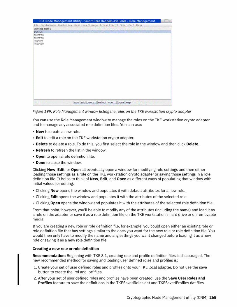
Figure 199: Role Management window listing the roles on the TKE workstation crypto adapter
You can use the Role Management window to manage the roles on the TKE workstation crypto adapterand to manage any associated role definition files. You can use:
• New to create a new role.• Edit to edit a role on the TKE workstation crypto adapter.• Delete to delete a role. To do this, you first select the role in the window and then click Delete.• Refresh to refresh the list in the window.• Open to open a role definition file.• Done to close the window.
Clicking New, Edit, or Open all eventually open a window for modifying role settings and then eitherloading those settings as a role on the TKE workstation crypto adapter or saving those settings in a roledefinition file. It helps to think of New, Edit, and Open as different ways of populating that window withinitial values for editing.
• Clicking New opens the window and populates it with default attributes for a new role.• Clicking Edit opens the window and populates it with the attributes of the selected role.• Clicking Open opens the window and populates it with the attributes of the selected role definition file.
From that point, however, you'll be able to modify any of the attributes (including the name) and load it asa role on the adapter or save it as a role definition file on the TKE workstation's hard drive or on removablemedia.
If you are creating a new role or role definition file, for example, you could open either an existing role orrole definition file that has settings similar to the ones you want for the new role or role definition file. Youwould then only have to modify the name and any settings you want changed before loading it as a newrole or saving it as a new role definition file.
Creating a new role or role definition
Recommendation: Beginning with TKE 8.1, creating role and profile definition files is discouraged. Thenew recommended method for saving and loading user defined roles and profiles is:
1. Create your set of user defined roles and profiles onto your TKE local adapter. Do not use the savebutton to create the .rol and .prf files.
2. After your set of user defined roles and profiles have been created, use the Save User Roles andProfiles feature to save the definitions in the TKESavedRoles.dat and TKESavedProfiles.dat files.
Cryptographic Node Management utility (CNM) 265

3. At a later time, use the Load User Roles and Profiles feature to load the roles and profiles onto a TKElocal crypto adapter from the TKESavedRoles.dat and TKESavedProfiles.dat files. This is only done asneeded.
From the CCA Node Management Utility main window, you can select Access Control –> Roles off themenu bar to display the CCA Node Management Utility's Role Management window. Initially, this windowlists the roles currently loaded on the TKE workstation crypto adapter.
To create a new role or role definition file, it does not matter if a role name is highlighted in the CCA NodeRole Management window, or if the list is empty. To create a new role or role definition file:
1. From the CCA Node Management Utility's Role Management window, click on the New push button.
Figure 200: From the CCA Node Management Utility's Role Management window, click on the New pushbutton
A secondary window opens for modifying role settings and then either loading those settings as a roleon the TKE workstation crypto adapter or saving those settings in a role definition file. Because youselected the New push button, this secondary window is populated with the default attributes andsettings for a new role.
Editing a role on the TKE workstation crypto adapter
From the CCA Node Management Utility main window, you can select Access Control –> Roles off themenu bar to display the CCA Node Management Utility's Role Management window. Initially, this windowlists the roles currently loaded on the TKE workstation crypto adapter.
To edit a role that is currently loaded on the TKE workstation crypto adapter:
1. In the list of roles, click on the name of the role you want to edit.
The role name is reverse highlighted (white on black) to show that it is selected.2. Click on the Edit push button.
Figure 201: Select role and click Edit
A secondary window opens for modifying role settings and then either loading those settings as a roleon the TKE workstation crypto adapter or saving those settings in a role definition file. This secondarywindow is populated with the attributes of the selected role.
Opening a role definition file
Role definition files have all the attributes and settings necessary to create or update a role on the TKEworkstation crypto adapter. Unlike a role, a role definition file is not loaded onto the TKE workstation
266 z/OS: Cryptographic Services ICSF Trusted Key Entry Workstation User's Guide

crypto adapter, but is instead stored on the TKE workstation's hard drive or on removable media. Keep inmind that:
• You can have a role definition file for a role that is not currently loaded on the TKE workstation cryptoadapter.
• It is possible that the settings in a role definition file do not currently match the settings of the actualrole on the TKE workstation crypto adapter.
From the CCA Node Management Utility main window, you can select Access Control –> Roles off themenu bar to display the CCA Node Management Utility's Role Management window. Initially, this windowlists the roles currently loaded on the TKE workstation crypto adapter.
To open a role definition file, it does not matter if a role name is highlighted in the CCA Node RoleManagement window, or if the list is empty. This is because you are not opening a role on the TKEworkstation crypto adapter. Instead, you are opening a file on the TKE workstation's hard drive or onremovable media.
To open a role definition file:
1. From the CCA Node Management Utility's Role Management window, click on the Open push button.
Figure 202: From the CCA Node Management Utility's Role Management window, click on the Open pushbutton
The Specify file to open dialog is displayed.
Figure 203: Specify file to open dialog2. In the Specify file to open dialog:
Cryptographic Node Management utility (CNM) 267

a. In the list of files, click on the name of the role definition file you want to open. Role definition filestypically follow the naming convention role_name.rol.
The role name is reverse highlighted (white on black) to show that it is selected.b. Click the Open push button.
A secondary window opens for modifying role settings and then either loading those settings as arole on the TKE workstation crypto adapter or saving those settings in a role definition file. Thissecondary window is populated with the attributes of the selected role definition file.
Making changes to a role or role definition file
From the CCA Node Management Utility main window, you can select Access Control –> Roles off themenu bar to display the CCA Node Management Utility's Role Management window. Initially, this windowlists the roles currently loaded on the TKE workstation crypto adapter. When you click the New, Edit, orOpen push button on the initial window, a secondary window opens for modifying role settings and theneither loading those settings as a role on the TKE workstation crypto adapter or saving those settings in arole definition file.
• The New push button will open the window and populate it with default attributes for a new role.• The Edit push button will open the window and populate it with the attributes of the selected role.• The Open push button will open the window and populate it with the attributes of the selected roledefinition file.
Regardless of how the window was opened and populated with attributes, you can use the window tomodify any of the attributes. By changing the Role ID, in fact, you can create a new role or role definitionfile. Once you have modified the attributes as desired, you can load the role on the TKE workstation crytpoadapter, or save the settings as a role definition file on the TKE workstations's hard drive or on removablemedia. When making changes to a role you have created, in fact, you will likely want to also create ormodify an associated role definition file for migration or recovery purposes.
Note: Do not edit the system-supplied role definition files. By leaving the system-supplied role definitionfiles unedited, you preserve the ability to restore system-supplied profiles to their default settings,including the default passwords. If you edit the system-supplied roles, we recommend you save themodified settings to a new role definition file instead of editing the original role definition file.
Figure 204: Role Management window modifying role attributes
To make changes to a role or role definition file:
1. Edit the text entry fields and use the window's controls to modify the displayed attributes as desired.
268 z/OS: Cryptographic Services ICSF Trusted Key Entry Workstation User's Guide

• The Role ID field shows the name of the role. It is a case-sensitive character string with a maximumlength of 8 characters.
• The Required authentication strength field shows the level of authentication required to log on touser profiles with this role. Passphrase profiles created on the TKE have passphrases which havestrength of 50. For a new role, this field defaults to 0.
• Valid times in GMT (Start – End) fields show the range of hours during the valid days that the user isallowed to log on. For a new role, these fields default to the entire day.
• The Valid days check boxes identify the days of the week that the user is allowed to log on. Bydefault, none of the days are selected for a new role.
• The Restricted operations area list of functions the role is not allowed to use, while the Permittedoperations area lists the functions the role is allowed to use.
– To permit the role to use a particular function:
a. In the list of Restricted Operations, click on the name of the function.
The function name is reverse highlighted (white on black) to show that it is selected.b. Click the Permit push button.
The function name appears in the Permitted Operations list to show the role can use thatfunction.
– To restrict the role from using a particular function:
a. In the list of Permitted Operations, click on the name of the function.
The function name is reverse highlighted (white on black) to show that it is selected.b. Click the Restrict push button.
The function name appears in the Restricted Operations list to show the role is not allowed touse that function.
– To permit the role to use all functions, click on the Permit All push button.– To restrict the role from using any function, click on the Restict All push button.
2. Load the settings as a role on the TKE workstation crypto adapter or save the settings in a roledefinition file.
Note: If you want to both save the settings as a role definition file, and also load the role on the TKEworkstation crypto adapter, save the role definition file first. When you load a role, the CCA NodeManagement Utility's Role Management window closes. If you try to save load the role first, thewindow will close before you have a chance to save the role definition file.
• To save a role definition file:
a. Click the Save push button.
A standard save file dialog is displayed. We recommend you use the naming conventionrole_name.rol.
b. If you do not want to also load the role on the TKE workstation crypto adapter, you can click theDone push button. Clicking the Done push button closes the window.
• To load the role on the TKE workstation crypto adapter:
a. Click the Load push button.
The role is loaded on the TKE workstation crypto adapter, and the window is closed.
Notes:
1. You can click the Done push button to close this window at any time. Any changes you made that werenot loaded or saved prior to pressing the Done push button will be lost.
2. You can click the Open push button at any time to select a new role definition file to edit. Any changesyou made that were not loaded or saved will be lost when the window is populated with the attributesof the new role definition file.
Cryptographic Node Management utility (CNM) 269

Save user roles and profilesThe 'Save user roles and profiles' function saves all your user defined roles and profiles that are on theTKE local crypto adapter using a single operation. When you select this feature, the TKE workstationdetermines if you have created any user-defined roles and profiles onto the TKE local crypto adapter. Ifyou have any user defined roles, they are saved in the file TKESavedRoles.dat. If you have any userdefined profiles, they are saved in the file TKESavedProfiles.dat. These files are used with thecorresponding Load User Roles and Profiles feature of the CNM utility.
Note: The passphrase of a passphrase profile is not saved.
The save and load user roles and profile features work together. This is the quickest and easiest way toback up your user defined roles and profiles. The user defined roles and profiles can be restored on thesame TKE workstation local crypto adapter at any time. In addition, the TKESavedRoles.dat andTKESavedProfiles.dat files can be moved to other TKE workstations. Once the files are on the other TKEworkstation, the Load User Roles and Profiles option can be used to apply the user defined roles andprofiles to the new or back up TKE’s local crypto adapter.
Load user roles and profilesThe 'Load user roles and profiles' function looks for the files TKESavedRoles.dat andTKESavedRoles.dat on the TKE workstation. If it finds the file TKESavedRoles.dat, it loads the userdefined roles onto the TKE local crypto adapter. If it finds the file TKESavedProfiles.dat, it loads the userdefined profiles onto the TKE local crypto adapter. If a role or profile already exists, it is replaced.
Note: The passphrase of a passphrase profile is not saved. Therefore, when a passphrase profile isrestored, you must enter a new passphrase for the profile.
The save and load user roles and profile features work together. This is the quickest and easiest way toback up your user defined roles and profiles. The user defined roles and profiles can be restored on thesame TKE workstation local crypto adapter at any time. In addition, the TKESavedRoles.dat andTKESavedProfiles.dat files can be moved to other TKE workstations. Once the files are on the other TKEworkstation, the Load User Roles and Profiles option can be used to apply the user defined roles andprofiles to the new or back up TKE’s local crypto adapter.
Check TKE crypto adapter group profilesWhen you initialize the TKE local crypto adapter using the TKE’s Crypto Adapter Initialization application,the role TKEGRPMB is created. The TKEGRPMB role has access only to the required ACPs and does notprovide access to any TKE capabilities. The TKEGRPMB role should be assigned to members of groupprofiles, which prevents each group member from having access to anything outside the group.
The 'Check TKE crypto adapter group profiles' function examines the role of every individual profile that isa member of a TKE local crypto adapter group profile. If the individual does not have the role TKEGRPMB,a change profile command is issued to change the role of the profile to TKEGRPMB. If the individualprofile that is being changed is a passphrase profile, you have to set a new passphrase for the profile.
Load TKEGRPMB roleThe 'Load TKEGRPMB role' function verifies that the TKEGRPMB role is on the TKE Local crypto adapterand that it does not have access that it should not have. If the TKE workstation determines that someonehas added access to the TKEGRPMB role or that the TKEGRPMB role does not exist, a command is issuedto create or change the TKEGRPMB role. If the role exists with the correct ACPs, a message lets you knowthat the TKEGRPMB role is correct.
TKE Workstation Logon Profile WizardThe TKE Workstation Logon Profile Wizard is one of six TKE security policy wizards that work together toimplement a comprehensive set of security policies for managing access to the TKE workstation andmanaging host crypto modules and their domains. The TKE Workstation Logon Profile Wizard implementsa security policy for accessing your TKE workstation.
270 z/OS: Cryptographic Services ICSF Trusted Key Entry Workstation User's Guide

The TKE Workstation Logon Profile Wizard allows you to do three things:
1. Create individual smart card TKE local crypto adapter profiles, which you need to logon to the TKElocal crypto adapter so that you can manage the TKE workstation.
2. Create individual smart card TKE local crypto adapter profiles, which you need to logon to the TKElocal crypto adapter so that you can manage Host Crypto Modules.
3. Place individual smart card TKE local crypto adapter profiles into TKE local crypto adapter groupprofiles.
Note: The TKE Workstation Logon Profile Wizard uses smart cards that you created using the TKE SmartCard Wizard, found in the Smart Card Utility Program.
Master Key menuThe Master Key pull-down menu has menu items for the following key stores you can manage:
• DES/PKA Master Key• AES Master Key
These menu items have additional items for the following tasks you can perform:
• Auto set…• Create Random Master Key… (Only available for DES/PKA master key)• Clear New …• Parts• Smart Card Parts (TKE must be enabled for use with smart cards)• Set…• Verify
Figure 205: CNM main window — Master Key pull-down menu
The master keys are stored in the tamper-resistant TKE workstation crypto adapter.
The DES/PKA master keys are used to encipher other keys. Each master key is a 24 byte DES key (192bits). However, because DES keys contain 1 parity bit per byte, it has an effective length of 168 bits of"real" key material. Random master keys are generated and set when the TKE workstation crypto adapter
Cryptographic Node Management utility (CNM) 271

is initialized. If a master key of unknown value is lost, you cannot recover the keys enciphered under it. Werecommend that you load a new master key by entering clear key parts or by loading key parts that arestored on smart cards.
The AES master key is used to encipher other keys.
Each master key on the TKE workstation crypto adapter has three registers:
• Current Master Key Register. The active master key is stored in the current master key register.• Old Master Key Register. The previous master key is stored in the old master key register.• New Master Key Register. The new master key register is an interim location used to combine master
key parts to form a new master key
Auto Set and Create Random Master KeyThe Auto Set and Create Random Master Key pull-down menu options use different methods to generateand set new master key values.
The Create Random Master Key option is only available for DES/PKA master keys pull-down.
Note: If a master key of unknown value is lost, you cannot recover the keys enciphered under it. Werecommend that you load a new master key by entering clear key parts or by entering key parts generatedto TKE smart cards.
Clear newThe Clear New pull-down menu option allows you to clear the new master key registers. If a new masterkey register has a value in it, you must clear it before you can do load a first key part. To clear the newmaster key register:
1. From the Master Key pull-down menu, select Clear New...
A confirmation dialog displays, prompting you to verify that you want to clear the new master keyregister.
Figure 206: Clear New Master Key Register — confirm clearing2. If you are certain you want to clear the new master key register, click the confirmation dialog's Yes
push button.
An information box informs you that the new master key register is cleared. Select OK to finish.
Figure 207: Clear New Master Key Register — register cleared
Parts — Loading a new master key from clear key partsTo load new master key parts into the TKE workstation crypto adapter, load the first key part, any middlekey parts, and the last key part into the new master key register, and then load the new master key. Thefirst and last key parts are required. Middle key parts are optional; you can load multiple middle key parts.
1. From the Master Key –> DES/PKA Master Key or Master Key –> AES Master Key pull-down menuitems, select the Parts menu option.
272 z/OS: Cryptographic Services ICSF Trusted Key Entry Workstation User's Guide
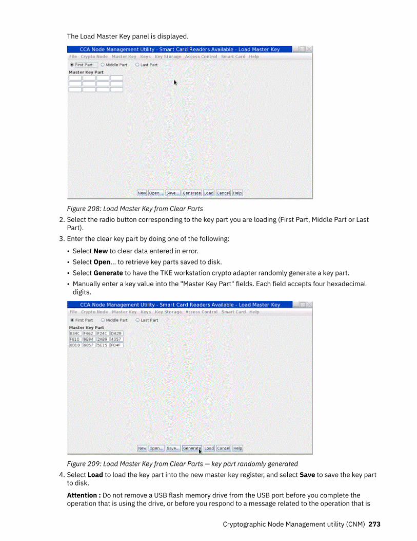
The Load Master Key panel is displayed.
Figure 208: Load Master Key from Clear Parts2. Select the radio button corresponding to the key part you are loading (First Part, Middle Part or Last
Part).3. Enter the clear key part by doing one of the following:
• Select New to clear data entered in error.• Select Open... to retrieve key parts saved to disk.• Select Generate to have the TKE workstation crypto adapter randomly generate a key part.• Manually enter a key value into the "Master Key Part" fields. Each field accepts four hexadecimal
digits.
Figure 209: Load Master Key from Clear Parts — key part randomly generated4. Select Load to load the key part into the new master key register, and select Save to save the key part
to disk.
Attention : Do not remove a USB flash memory drive from the USB port before you complete theoperation that is using the drive, or before you respond to a message related to the operation that is
Cryptographic Node Management utility (CNM) 273

using the drive. If you do remove a drive before the operation is complete, hardware messages mightbe generated on the TKE workstation.
Figure 210: Load Master Key from Clear Parts — key part successfully loaded
Note: Key parts saved to disk are not enciphered.5. Repeat the preceding steps to load the remaining key parts into the new master key register.6. From the Master Key pull-down menu, select Set... This will do the following:
a. Transfer the key in the current master key register to the old master key register and delete theformer old master key.
b. Transfer the key in the new master key register to the current master key register.
After setting a new master key, reencipher the keys currently in key storage. (Refer to “Reenciphering keystorage” on page 279.)
We recommend a dual control security policy. With a dual control security policy, the first and last keyparts are loaded by different people.
Smart card parts — generating master key parts to a smart cardSteps for generating master key parts and saving them on a TKE or EP11 smart card are as follows:
1. From the Master Key pull-down menu, select DES/PKA Master Keys or AES Master Key and thenselect Smart Card Parts. You will be prompted to insert a TKE or EP11 smart card into smart cardreader 2. A Smart Card Master Key Parts panel is displayed. Any TKE workstation crypto adaptermaster key parts stored on the smart card are listed in the container. The smart card description isdisplayed. Ensure this is the correct smart card you want to save the key part on.
Note: Make sure that the TKE workstation crypto adapter and the smart card are in the same zone. Todetermine the zone for a smart card, use CNM, see “Display smart card details” on page 282 or SCUP“Display smart card information” on page 294. To determine the zone of the TKE workstation cryptoadapter, use SCUP “View current zone for the crypto adapter” on page 310. To use SCUP, you mustfirst exit from CNM.
274 z/OS: Cryptographic Services ICSF Trusted Key Entry Workstation User's Guide
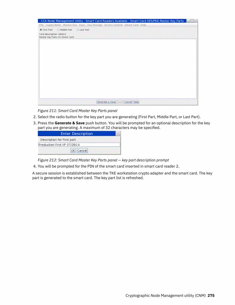
Figure 211: Smart Card Master Key Parts panel2. Select the radio button for the key part you are generating (First Part, Middle Part, or Last Part).3. Press the Generate & Save push button. You will be prompted for an optional description for the key
part you are generating. A maximum of 32 characters may be specified.
Figure 212: Smart Card Master Key Parts panel — key part description prompt4. You will be prompted for the PIN of the smart card inserted in smart card reader 2.
A secure session is established between the TKE workstation crypto adapter and the smart card. The keypart is generated to the smart card. The key part list is refreshed.
Cryptographic Node Management utility (CNM) 275

Figure 213: Smart Card Master Key Parts panel — key part generated
Note: The key parts in the list are prefixed as follows:
• Key Part: Crypto Adapter master key part, first - <optional description follows>• Key Part: Crypto Adapter master key part, middle - <optional description follows>• Key Part: Crypto Adapter master key part, last - <optional description follows>
A First and Last key part is required. Middle key parts are optional. We recommend a dual control securitypolicy. With a dual control security policy, the first and last key parts are generated to different smartcards so that no one person has access to the complete key. At this point, we recommend that you inserta different smart card in smart card reader 2 to generate middle or last key parts. Repeat the precedingsteps to generate any middle or last key parts.
Smart card parts — loading master key parts from a smart cardSteps for loading TKE workstation crypto adapter master key parts from a TKE or EP11 smart card are asfollows:
1. From the Master Key pull-down menu, select DES/PKA Master Keys or AES Master Key, and thenselect Smart Card Parts. You are prompted to insert a TKE or EP11 smart card into smart card reader2. A Smart Card Master Key Parts panel is displayed. Any TKE workstation crypto adapter master keyparts stored on the smart card are listed in the container. The smart card description is displayed.Ensure that this is the correct smart card you want to work with.
2. Highlight the key part you want to load into the selected TKE workstation crypto adapter new masterkey register. Click Load. You are prompted for the PIN of the smart card inserted in smart card reader2.
276 z/OS: Cryptographic Services ICSF Trusted Key Entry Workstation User's Guide

Figure 214: Master Key Part Smart Card panel — loading a Crypto Adapter key part from a smart card3. A secure session is established between the TKE workstation crypto adapter and the smart card. A
pop-up message displays, indicating that the key part was successfully loaded.
Figure 215: Master key part successfully loaded4. Repeat steps “1” on page 276 through “3” on page 277 to load additional key parts into the TKE
workstation crypto adapter new master key register. If the key parts are on different smart cards,remove the smart card from smart card reader 2 and insert the smart card that contains the next keypart to load.
Note: Key parts must be loaded in order. Specifically, a first key part must be loaded first (Key Part:Crypto Adapter master key part, first) and the last key part (Key Part: Crypto Adapter master key part,last) must be loaded last.
Set — setting the master key valueTo set the master key value:
1. From the Master Key pull-down menu, select DES/PKA Master Keys or AES Master Key, and thenselect Set... This will do the following:
• Transfer the key in the current master key register to the old master key register and delete theformer old master key.
• Transfer the key in the new master key register to the current master key register.2. After setting a new master key, reencipher the keys currently in key storage. See “Reenciphering key
storage” on page 279.
Verify — verifying the master keyA verification pattern (VP) is generated for each master key stored in the master-key registers (new,current and old). The VP can be used to verify that the correct key part was entered, for instance, when
Cryptographic Node Management utility (CNM) 277

you have many key parts stored to disk or smart cards. It can also be used to verify that the key part wasentered correctly, particularly when key parts are entered manually. The VP is zero when the register isempty. After each key part is entered, the key part is combined with the existing key in the register andthe VP is updated. The VP does not reveal information about the clear key value.
The VP can be saved to disk for future reference. For example, in the event the TKE workstation cryptoadapter is initialized, the master key registers are cleared. When the master key is reloaded, you cancompare the VP of the master key register to the VP saved to disk. If they are identical, it indicates thatthe correct master key parts were loaded. Then you can set the master key. If they are different, you canclear the new master key register and load the correct key parts.
To verify a master key, do the following:
1. From the Master Key pull-down menu, select Verify. A sub-menu is displayed.
Figure 216: Master Key Verify sub-menu2. From the submenu, select the master key register you wish to verify - New, Current or Old. Typically,
you will choose New. You cannot change the current or old master key.3. The VP is displayed in the Master Key Register Verification panel.
Figure 217: Master Key Register Verification panel - verification pattern is displayed
278 z/OS: Cryptographic Services ICSF Trusted Key Entry Workstation User's Guide

4. Select Save to save the VP to a file. A file chooser will be displayed for the user to specify both a filename, and where to save the file (USB flash memory drive or CNM Data Directory).
Attention : Do not remove a USB flash memory drive from the USB port before you complete theoperation that is using the drive, or before you respond to a message related to the operation that isusing the drive. If you do remove a drive before the operation is complete, hardware messages mightbe generated on the TKE workstation.
5. Select Compare to compare the VP to a VP previously saved to disk. A file chooser will be displayed forthe user to specify the location and filename of the saved VP.
Figure 218: Master Key Register VP compare successful
Key Storage menuThe Key Storage pull-down menu of the CNM main window contains menu items to manage or initializeDES, PKA, or AES key storage.
Figure 219: CNM main window — Key Storage pull-down menu
Reenciphering key storageKey storage is a repository of keys that you access by key label. DES keys, PKA (RSA) keys, and AES keysare held in separate storage systems. The keys in key storage are enciphered under the current TKEworkstation crypto adapter master key. When a new master key is set, thereby becoming the currentmaster key, the keys must be reenciphered to the current master key.
To reencipher the keys in storage, do the following:
1. From the Key Storage pull-down menu, select DES Key Storage, PKA Key Storage, or AES KeyStorage. A sub-menu is displayed.
2. From the sub-menu, select Manage. A Key Storage Management panel is displayed. The panel lists thelabels of the keys in key storage.
Cryptographic Node Management utility (CNM) 279

Figure 220: Key Storage Management Panel – key labels list3. Select Reencipher...; the keys are reenciphered using the key in the current master key register.
Smart card menuThe Smart Card pull-down menu of the CNM main window contains the following menu items.
• Change PIN• Generate Crypto Adapter Logon Key• Display Smart Card Details• Manage Smart Card contents• Copy Smart Card
280 z/OS: Cryptographic Services ICSF Trusted Key Entry Workstation User's Guide

Figure 221: CNM main menu — Smart Card pull-down menu
Change PINTKE and EP11 smart cards are secured with a PIN. You can change your PIN using this function. You mustknow your current PIN. If your smart card is blocked due to too many incorrect PIN attempts, thisfunction will fail.
To change the PIN, perform the following steps:
1. From the Smart Card pull-down menu, select Change PIN. An informational window will prompt youto insert your smart card into smart card reader 2. Insert your smart card and press OK to continue.
Figure 222: Change PIN — insert smart card prompt2. You will be prompted for your current PIN. Enter your current PIN on the smart card reader 2 PIN pad.
Figure 223: Change PIN — enter current PIN prompt3. You will be prompted for your new PIN. The new PIN must be entered twice and both PINs must
match.
Figure 224: Change PIN — enter new PIN prompt4. The PIN is successfully changed on the smart card.
Cryptographic Node Management utility (CNM) 281

Generate TKE crypto adapter logon keyA Crypto Adapter logon key allows a user to log on to the TKE workstation crypto adapter using a TKE orEP11 smart card to access functions not allowed in the default role. A Crypto Adapter logon key is an RSApublic/private key pair generated within the smart card. The private key never leaves the smart card. Thepublic key is read from the smart card and loaded to the TKE workstation crypto adapter when a userprofile is defined.
To generate a Crypto Adapter logon key, do the following:
1. From the Smart Card pull-down menu, select Generate Crypto Adapter Logon Key. You will beprompted for a TKE or EP11 smart card. Insert the smart card into smart card reader 2.
Figure 225: Generate Crypto Adapter Logon Key — insert smart card2. You will be prompted for a PIN. Enter the PIN on the smart card reader 2 PIN pad.
Figure 226: Generate Crypto Adapter Logon Key — PIN prompt3. You will be prompted for a user ID for the smart card. This user ID will be read from the smart card
when defining a smart card user profile.
Figure 227: Generate Crypto Adapter Logon Key — User ID prompt4. The Crypto Adapter logon key is generated.
Figure 228: Generate Crypto Adapter Logon Key — key generated
Display smart card detailsUse this function to display public information about a TKE or EP11 smart card.
1. From the Smart Card pull-down menu, select Display Smart Card Details. You will be prompted for aTKE or EP11 smart card. Insert the smart card into smart card reader 2.
Figure 229: Display Smart Card Details — insert smart card prompt
The smart card is read and the public information is displayed.
282 z/OS: Cryptographic Services ICSF Trusted Key Entry Workstation User's Guide

Figure 230: Display Smart Card Details — public information displayed
The following information is displayed for a TKE or EP11 smart card:Card type
TKE smart card or EP11 smart cardApplet version number
Version number of applet loaded on smart cardCard description
Description of the smart card. The smart card description was entered when the smart card waspersonalized
PIN statusThe PIN status can be OK/blocked/not set. The PIN is set when the smart card is personalized
Crypto Adapter User IDUser ID entered when a Crypto Adapter logon key is generated. The User ID may be blank if thesmart card does not have a Crypto Adapter logon key
Crypto Adapter Logon KeyStatus can be present/not present
Zone IDSet when the smart card is initialized
Zone DescriptionSet when the smart card is initialized
Manage smart card contentsUse this function to delete keys or key parts from a TKE or EP11 smart card. A TKE or EP11 smart cardcan hold up to 50 key parts, a TKE authority signature key or EP11 administrator signature key, and acrypto adapter logon key. To display the smart card contents using the Manage Smart Card Contentsfunction, do the following:
1. From the Smart Card pull-down menu, select Manage Smart Card contents. You will be prompted fora TKE or EP11 smart card. Insert the source smart card into smart card reader 2.
Cryptographic Node Management utility (CNM) 283

Figure 231: Manage Smart Card contents — contents of smart card are displayed2. The smart card description is displayed. Ensure this is the correct smart card you want to work with.
Highlight the keys and/or key parts you want to delete. Press the Delete push button.3. You will be prompted for your PIN. Enter your PIN on the smart card reader 2 PIN pad.4. You will be asked to confirm the deletion of the selected objects. Press OK to continue.
Figure 232: Manage Smart Card contents — confirm delete prompt5. The objects are deleted and the list is refreshed.
284 z/OS: Cryptographic Services ICSF Trusted Key Entry Workstation User's Guide

Figure 233: Manage Smart Card contents
Attention: If you delete a crypto adapter logon key, you will not be able to log on to the TKEworkstation crypto adapter until you generate a new crypto adapter logon key and theadministrator updates your crypto adapter user profile.
If you delete a TKE authority signature key, you will not be able to sign a TKE command until theadministrator generates a new authority signature key and uploads it to the host.
Copy smart cardUse this function to copy a key or key part or parts from one TKE smart card to another TKE smart card, orfrom one EP11 smart card to another EP11 smart card. The two smart cards must belong to the samezone or share an alternative zone. Specifically, the two smart cards must have the same Zone ID or sharean alternative Zone ID. Use Display Smart Card Details to verify the Zone ID of the smart cards.
Notes:
1. AES key parts cannot be copied to a TKE smart card that does not have the TKE applet version 0.4 orlater. ECC (APKA) key parts cannot be copied to a TKE smart card that does not have the TKE appletversion 0.6 or later.
2. ECC authority signature keys cannot be copied to a TKE smart card that does not have the TKE appletversion 0.10 or later.
3. Smart card copy does not overwrite the target smart card. If there is not enough room on the targetsmart card, you get an error message. You can either delete some of the keys on the target smart card(see “Manage smart card contents” on page 283) or use a different smart card.
4. TKE Version 6.0 was the final release that supported DataKey smart cards. Copying a DataKey smartcard is the only procedure that is still supported. You can only copy data from a DataKey smart card.You cannot copy to a DataKey smart card.
To copy smart card contents:
1. From the Smart Card pull-down menu, select Copy Smart Card. You are prompted to insert the firstTKE or EP11 smart card into smart card reader 1. The contents of the smart card are displayed in thetop container.
Cryptographic Node Management utility (CNM) 285

Figure 234: Copy Smart Card — insert first smart card2. You are prompted for a second smart card. The second smart card must be the same type (TKE or
EP11) as the first smart card. Insert the second smart card into smart card reader 2. The contents ofthe smart card are displayed in the bottom container.
Figure 235: Copy Smart Card — asked for the TKE or EP11 smart card
Figure 236: Copy Smart Card — smart card contents are displayed3. Highlight the objects in the container you want to copy to the other container. Press the button that
relates to the applicable direction to copy the parts. For example, Figure 237 on page 287 shows thatthe selected parts are the first container so the Copy 1 to 2 button copies from container 1 tocontainer 2.
286 z/OS: Cryptographic Services ICSF Trusted Key Entry Workstation User's Guide

Figure 237: Copy Smart Card — highlight object to copy and direction4. You are prompted for the PIN of the first smart card in smart card reader 1. Enter the PIN on the smart
card reader 1 PIN pad.
Figure 238: Copy Smart Card — first smart card PIN prompt5. You are prompted for the PIN of the second smart card in smart card reader 2. Enter the PIN on the
smart card reader 2 PIN pad. A secure session is established between the two smart cards and theselected object or objects are copied. The contents of the target container is refreshed.
Figure 239: Copy Smart Card — second smart card PIN prompt
Figure 240: Establishing a secure session between the two smart cards
Figure 241: Objects are copied to the target smart card
Cryptographic Node Management utility (CNM) 287

Figure 242: Copy Smart Card — objects are copied to the target container
TKE and EP11 smart cards can hold a maximum of 50 key parts, in addition to a crypto adapter logon keyand a TKE authority signature key or an EP11 administrator signature key.
CNM common errorsMessage: “Incorrect passphrase”Return Code: 4Reason Code: 2042Explanation: Check that you typed in the passphrase correctly. Thepassphrase is case sensitive.
Message: “Access is denied for this function”Return Code: 8Reason Code: 90Explanation: The role associated with your profile does not allow you toperform this function. Log off the crypto module and log on using a profileassociated with a role that allows this function.
Message: “Your user profile has expired”Return Code: 8Reason Code: 92Explanation: The TKE administrator must reset the expiration date onthe user profile.
Message: “Your authentication data (for example, passphrase) has expired.”Return Code: 8Reason Code: 94Explanation: The TKE administrator must change the passphrase and resetthe passphrase expiration date on the user profile. Then, select Replace toload the profile into the workstation coprocessor.
Message: “The user profile does not exist”Return Code: 8Reason Code: 773Explanation: Make sure you typed in the user ID correctly. The user ID iscase sensitive.
288 z/OS: Cryptographic Services ICSF Trusted Key Entry Workstation User's Guide

Message: “The group logon failed because authentication of one or moregroup members failed.”Return Code: 8Reason Code: 2084Explanation: One or more user profiles in the group failed authentication(for example, passphrase expired or profile expired) causing the group logonto fail. The group logon window will indicate which user failed and thereason for the logon failure. Correct the user profile or attempt grouplogon again and select a different member in the group members listfor logon.
Message: “The profile is included in one or more groups”Return Code: 8Reason Code: 2085Explanation: You attempted to delete a user profile that is currently amember of a group profile. You must remove the user profile from the groupmember list before deleting the profile.
Message: “The group role does not exist.”Return Code: 8Reason Code: 2086Explanation: You attempted group logon using a group profile that isassociated with a role that does not exist. The TKE administrator must definethe role and load it to the TKE workstation crypto adapter before the groupprofile may be used.
Message: “Your group profile has not yet reached its activation date”Return Code : 8Reason Code: 2087Explanation: The group profile has an activation date that is later than thecurrent date. The TKE administrator must change the activation date beforethe group profile may be used or wait until the activation date arrives.
Message: “Your group profile has expired.”Return Code: 8Reason Code: 2088Explanation: The group profile has surpassed its expiration date.The TKE administrator must change the expiration date before the groupprofile may be used.
Cryptographic Node Management utility (CNM) 289

290 z/OS: Cryptographic Services ICSF Trusted Key Entry Workstation User's Guide

Chapter 12. Smart Card Utility Program (SCUP)
The TKE Smart Card Utility Program (SCUP) allows you to create and manage CA, TKE, and EP11 smartcards and to enroll the TKE workstation crypto adapter in a zone. TKE and EP11 smart cards can holdmaster and operational key parts for host crypto modules, an authority or administrator signature keyused to sign host commands, and a logon key for the TKE workstation crypto adapter.
SCUP supports these general functions:
• “Display smart card information” on page 294• “Display smart card key identifiers” on page 296• “TKE zone wizard” on page 298• “TKE Smart Card wizard” on page 298
For CA smart cards, SCUP supports these functions:
• “Initialize and personalize a CA smart card” on page 299• “Create a backup CA smart card” on page 301• “Change the CA smart card PINs” on page 302
For TKE and EP11 smart cards, SCUP supports these functions:
• “Initialize and enroll a smart card” on page 302• “Personalize a smart card” on page 303• “Unblock PIN on a smart card” on page 304• “Change PIN of a smart card” on page 304• “Enroll smart card in an alternate zone” on page 304• “Remove alternate zone from smart card” on page 304
For the TKE workstation crypto adapter, SCUP supports these functions:
• “Enroll a TKE cryptographic adapter in a primary zone” on page 305• “View current zone for the crypto adapter” on page 310
To create and manage the smart cards used for configuration migration (MCA, IA, and KPH smart cards),use the Configuration Migration Tasks utility.
General informationWhen entering PINs, the PIN prompt appears on both the TKE workstation screen as well as on the smartcard reader. When certain tasks will take over one minute for SCUP to execute, information messages arereturned. Be patient so that you do not have to restart the task.
Beginning in TKE 7.2, TKE supports 2, 3, or 4 smart card readers. The additional readers were added toreduce the amount of smart card swapping needed during the command signature phase for PKCS #11(EP11) functions. However, the additional readers can be used in other operations too. Some screens inSCUP look different when more than 2 readers are present.
Note: On TKE workstation feature codes #0847 or older, there are only 6 USB ports. This is enough portsfor the mouse, keyboard, and 4 smart card readers. However, this configuration does not leave any USBports for removable media. If you want to have 4 smart card readers and have ports available for USBflash memory, we recommend the purchase of an unpowered 2 or 4 slot USB hub. Plug the smart cardreaders into the hub which will leave other USB ports available for USB flash memory drivers.
The utility is capable of overwriting your smart cards. You will be prompted to reply OK before the card isoverwritten.
© Copyright IBM Corp. 2000, 2019 291

To start SCUP, click on Trusted Key Entry in the main workstation screen. This will display variousworkstation functions.
Note: You can use the Smart Card Utility Program if you are logged on at the console as ADMIN orTKEUSER. In addition, you must be logged onto the TKE workstation crypto adapter with a profile definedwhen you configured the TKE workstation from CNM. You are prompted to logon to the TKE workstationcrypto adapter if you are not currently logged on.
Click on Applications. Under Applications, click on Smart Card Utility Program. The Smart Card UtilityProgram screen appears.
Figure 243: First screen of TKE Smart Card Utility Program (SCUP) with 2 readers
292 z/OS: Cryptographic Services ICSF Trusted Key Entry Workstation User's Guide

Figure 244: First screen of TKE Smart Card Utility Program (SCUP) with more than 2 readers
Starting point for all the TKE policy wizardsStarting with TKE 9.1, the TKE workstation provides six wizards that work together to implement acomprehensive set of security policies for managing access to the TKE workstation and managing hostcrypto modules and their domains. All of the policies require that something be stored on a smart card.Therefore, the first wizard, the TKE Smart Card Wizard, is found in the Smart Card Utility Program(SCUP). The TKE Smart Card Wizard creates all the smart cards that the other wizards need.
Gemalto smart card reader considerationsThe following smart card reader considerations apply:
• You can carry your HID/OMNIKEY smart card readers from older TKEs forward to your TKE 9.0 system.
– If you use HID/OMNIKEY smart card readers on your TKE 9.0 system, any initialized smart cards canbe used on TKE 9.0. However, you are subject to any smart card part limitations that exist for thesmart card part on TKE 8.1.
• Any smart card that is initialized and personalized on TKE 9.0 can be used in either the HID/OMNIKEY orGemalto smart card reader.
• TKE 9.0 supports any combination of HID/OMNIKEY and Gemalto smart card readers at the same time.• The Gemalto smart card reader requires you to press the green Enter button after you enter:
– The PIN.– A character in the secure key entry process.
Important: Gemalto CT700 readers work only with smart cards that have applets that are loaded fromTKE 8.1 or later. Therefore, you must carry Omnikey Cardman 3821 smart card readers forward to use
Smart Card Utility Program (SCUP) 293

smart cards with pre-TKE 8.1 applets on TKE 9.0. See Table 35 on page 294 for the actions that arerequired to move to smart cards that work in Gemalto smart card readers:
Table 35: Smart card migration actions
Type of smart card Smart card migration actions
TKE and EP11 smart cards • Initialize and personalize the new smart cards ona TKE at TKE 8.1 or later.
• Copy the contents from an old smart card to anew smart card.
– If the copy is done on a TKE 9.0 system, thesource smart card must be in an HID/OMNIKEY smart card reader.
CA and MCA smart cards • Initialize and personalize the new smart cards byusing the CA and MCA backup procedure on aTKE at TKE 8.1 or later.
– If the backup operation is done on a TKE 9.0system, the source smart card must be in anHID/OMNIKEY smart card reader.
IA and KPH smart cards • Initialize and personalize new smart cards on aTKE at TKE 8.1 or later.
– There is no data to copy from one IA or KPHcard to another.
– For old KPH smart cards, if you have anyexiting collect files that were created with KPHcertificates from old KPH smart cards, you canuse these files in an apply operation if the oldKPH smart cards are put in an HID/OMNIKEYreader during the apply operation.
File menu functions
Display smart card informationAfter you have created a smart card, you are advised to check the results. If you are copying keys fromone smart card to another, you might also want to verify that all of the keys were correctly copied to theother smart card.
1. Insert the smart cards to be displayed in the smart card readers. From the File menu, click Displaysmart card information.
294 z/OS: Cryptographic Services ICSF Trusted Key Entry Workstation User's Guide

Figure 245: Display smart card information
The panel provides the following information about the smart card:Card type
Identifies the type and applet version of the smart card in the reader. TKE supports CA, TKE, EP11,MCA, IA, and KPH smart cards.
Card IDA 9-digit identifier that is generated when the smart card is initialized.
Card descriptionThe description that you entered when creating the smart card. Can be 30 characters in length.
PIN statusCan be OK, Blocked, or Not set.
Authority or Administrator keyFor TKE smart cards, displays the authority index and name. For EP11 smart cards, displays theadministrator name.
Crypto Adapter Logon KeyFor TKE and EP11 smart cards, the value is Present or Not Present.
Zone enroll statusIndicates whether the smart card is enrolled in a primary zone. It is either Enrolled or Not enrolled.
Zone IDThe zone ID from the CA or MCA smart card that is used to initialize and enroll the smart card. This isthe zone ID of the primary zone.
Zone DescriptionThe optional zone description from the CA or MCA smart card that is used to initialize and enroll thesmart card. This is the zone description of the primary zone. Can be up to 12 characters in length.
Zone key lengthThe length in bits of the modulus of the public key that defines the primary zone.
Smart Card Utility Program (SCUP) 295

Alternate zone enroll statusIndicates whether the smart card is enrolled in an alternate zone. The status is Enrolled or Notenrolled, or blank if the smart card does not support an alternate zone.
Alternate zone IDThe zone ID from the CA smart card that is used to establish an alternate zone. Blank if the smart carddoes not support an alternate zone or if the smart card is not enrolled in an alternate zone.
Alternate zone descriptionThe optional zone description from the CA smart card that is used to establish an alternate zone.Blank if the smart card does not support an alternate zone or is not enrolled in an alternate zone.
Alternate zone key lengthThe length in bits of the modulus of the public key that defines the alternate zone. Blank if the smartcard does not support an alternate zone or is not enrolled in an alternate zone.
Only TKE and EP11 smart cards store key parts, so fields in the Key parts table are filled in only for thesesmart card types.Key type
Operational key parts, TKE crypto adapter master key parts, or ICSF master key parts.Description
Description of key part (optional).Origin
Crypto Adapter or PIN-PAD.MDC-4
MDC-4 hash value of the key part.SHA-1
SHA-1 hash value of the key part.ENC-ZERO
ENC-ZERO hash value of the key part.AES-VP
AES verification pattern of the key part.Control vector or key attributes
For DES operational key parts and AES DATA operational key parts, contains the control vector. ForAES non-DATA operational key parts, indicates whether the key part uses the default key attributes orcustom key attributes. Blank for master key parts.
Length8, 16, 24 or 32 bytes.
Display smart card key identifiersThis function displays the key identifiers and key lengths for the TKE Authority Key or EP11 AdministratorKey, and the Crypto Adapter Logon Key, on a TKE or EP11 smart card. Some information from the Displaysmart card information panel is repeated to provide context.
1. Insert smart card or cards to be displayed in smart card reader 1 or 2. From the File menu, clickDisplay smart card key identifiers.
296 z/OS: Cryptographic Services ICSF Trusted Key Entry Workstation User's Guide

Figure 246: Display of smart card key identifiers
The panel provides this information about the smart card:
• Card type: Identifies the type and applet version of the smart card in the reader. TKE supports CA, TKE,EP11, MCA, IA, and KPH smart cards.
• Card ID: A 9-digit identifier generated when the smart card is initialized.• Card description: This is the description you entered when creating the smart card. Can be 30
characters in length.• PIN status: OK, Blocked or Not set• Authority or Administrator key: For TKE smart cards, displays the authority index and name. For EP11
smart cards, displays the administrator name.• Authority or Administrator key identifier: For TKE and EP11 smart cards, identifies the authority or
administrator key. The key identifier is the SHA-256 hash of the public part of the signature key.• Authority or Administrator key length: The type of the authority or administrator signature key, if
present. The type (either RSA or ECC) is indicated along with either the key size in bits (RSA) or curvesize in bits (ECC).
• Crypto Adapter Logon Key: For TKE and EP11 smart cards, the value can be Present or Not Present.• Crypto Adapter Logon Key Identifier: For TKE and EP11 cards, identifies the crypto adapter logon key.
The key identifier is the SHA-256 hash of the DER-encoded public modulus and public exponent of theRSA key pair.
• Crypto Adapter Logon key length: The length of the RSA key (in bits) on the smart card used to log onto the TKE workstation crypto adapter.
• Zone enroll status: The Zone enroll status is the status of the card. It is either Enrolled or Not enrolled.
Smart Card Utility Program (SCUP) 297

• Zone ID: When a CA or MCA smart card is created, the system will generate an 8-digit zone number.• Zone Description: This is the description you entered when creating the CA or MCA smart card. Can be
12 characters in length.• Zone key length: The length of the zone certificate public modulus in bits.
TKE zone wizardA TKE zone is defined by a Certificate Authority (CA) smart card. Members of the TKE zone include extracopies of the CA smart card, TKE smart cards initialized by using the CA smart card, and EP11 smart cardsinitialized by using the CA smart card. In addition, the TKE’s local crypto adapter must be enrolled in thesame zone as a TKE or EP11 smart card when you do any type of load key operation. The TKE zone wizardprovides a feature that can be used to:
• Create a Certificate Authority (CA) smart card.• Create any number of backup CA smart cards.• Create any number of TKE smart cards.• Create any number of EP11 smart cards.• Enrolling the TKE workstation in the zone.
Note: You must be signed onto the TKE’s local crypto adapter with a profile that has the role ofSCTKEADM, TKEADM, or an equivalent authority to enroll the TKE workstation in the TKE zone.
To create a smart card:
1. Initialize the smart card. In this step, the applet is loaded on the smart card.2. Personalize the smart card. In this step, the PIN or PINs are set and the card description is added.
After you start the TKE zone wizard, you can do all the tasks or just the ones you need. For example, if youwant to add two TKE smart cards to an existing TKE zone, you can skip the create CA smart card andcreate backup CA smart card steps of the TKE zone wizard. The created TKE smart card step initializesand personalizes both cards in one process flow.
TKE Smart Card wizardThe TKE Smart Card Wizard is the first wizard in a family of wizards designed to implement a complete setof security policies for managing the TKE workstation and your host crypto modules. All of the securitypolicies depend on smart cards. The TKE Smart Card Wizard creates the smart cards that you need beforeyou can use any of the other wizards to deploy a security policy. Specifically, you can use this wizard to:Create Certificate Authority (CA) smart cards
A Certificate Authority (CA) smart card defines a TKE zone. You must have a CA smart card before youcan create any TKE or EP11 smart cards.
Create TKE smart cardsYou need specific TKE smart cards if you are responsible for managing:
• The TKE workstation.• CCA host crypto module-wide or normal mode domain-specific settings.• CCA domains in either imprint or PCI-compliant mode settings.
Create EP11 smart cardsYou need specific EP11 smart cards if you are responsible for managing:
• EP11 module-wide settings.• EP11 domain-specific settings.
Enroll the TKE workstation in a zoneThe TKE workstation must be enrolled in the same zone as the TKE or EP11 smart card when keyparts are placed onto the smart card or loaded onto a host crypto module.
298 z/OS: Cryptographic Services ICSF Trusted Key Entry Workstation User's Guide
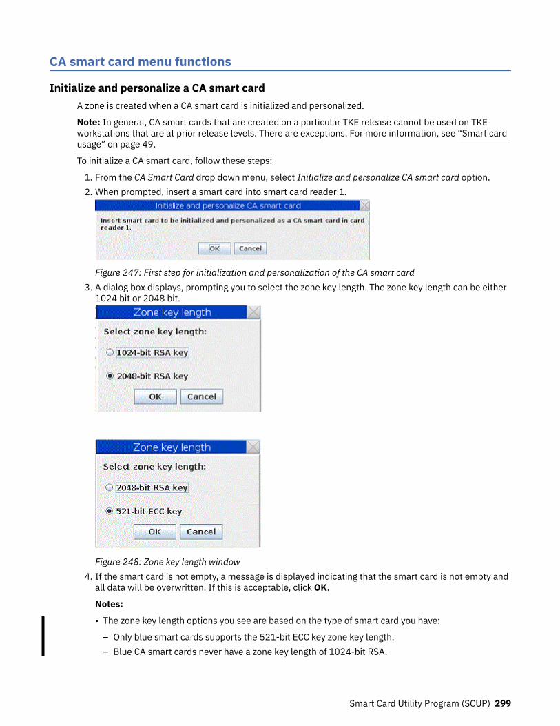
CA smart card menu functions
Initialize and personalize a CA smart cardA zone is created when a CA smart card is initialized and personalized.
Note: In general, CA smart cards that are created on a particular TKE release cannot be used on TKEworkstations that are at prior release levels. There are exceptions. For more information, see “Smart cardusage” on page 49.
To initialize a CA smart card, follow these steps:
1. From the CA Smart Card drop down menu, select Initialize and personalize CA smart card option.2. When prompted, insert a smart card into smart card reader 1.
Figure 247: First step for initialization and personalization of the CA smart card3. A dialog box displays, prompting you to select the zone key length. The zone key length can be either
1024 bit or 2048 bit.
Figure 248: Zone key length window4. If the smart card is not empty, a message is displayed indicating that the smart card is not empty and
all data will be overwritten. If this is acceptable, click OK.
Notes:
• The zone key length options you see are based on the type of smart card you have:
– Only blue smart cards supports the 521-bit ECC key zone key length.– Blue CA smart cards never have a zone key length of 1024-bit RSA.
Smart Card Utility Program (SCUP) 299

• If you create a CA with a zone key length of 521-bit ECC, all the smart cards enrolled in the zonehave to be blue smart cards.
• 1024-bit RSA should not be used because it is considered too weak.
Figure 249: Message if card is not empty5. The smart card will now be initialized.
Figure 250: Initialization message for CA smart card6. At the next prompt, enter a 6-digit PIN number twice. This is the first CA smart card PIN.
Figure 251: Enter first PIN for CA smart card7. At the next prompt, enter a 6-digit PIN number twice. This is the second CA smart card PIN. For dual
control, it is recommended that different administrators enter the first and second CA smart card PINand the PINs should not be the same.
Figure 252: Enter second PIN twice for CA smart card8. A dialog displays, prompting you to enter a zone description. A zone description helps you visually
identify which zone you are using so ensure that each zone you make has a unique description.
Figure 253: Enter zone description for CA smart card9. A dialog displays, prompting you to enter a CA smart card description. A smart card description helps
you visually identify a smart card so ensure that each smart card you make has a unique description.After the description is entered, the CA smart card is built.
300 z/OS: Cryptographic Services ICSF Trusted Key Entry Workstation User's Guide

Figure 254: Enter card description for CA smart card
Figure 255: Building a CA smart card10. You get a message that a CA smart card was successfully created.
Create a backup CA smart cardThe CA smart card defines the zone. If the CA smart card is lost or blocked, the administrator is not ableto initialize and enroll TKE smart cards, unblock TKE smart cards, or enroll TKE workstation cryptoadapters in the zone. It is recommended that the CA smart card is backed up and stored in a secure place.
Note: Although Datakey smart cards are no longer supported in TKE 7.0 or later, you can still back up CAsmart cards to IBM part number 45D3398, 74Y0551, or 00JA710 smart cards.
To back up a CA smart card, follow these steps:
1. From the CA Smart Card drop down menu, select the Backup CA smart card option.2. When prompted, insert the CA smart card to be backed up into smart card reader 1.
Figure 256: Begin creation of backup CA smart card3. Enter the first CA smart card PIN.4. Enter the second CA smart card PIN.5. Insert the target CA smart card in smart card reader 2.6. If the target smart card is not empty, you are asked to overwrite all of the data on the smart card.7. The target smart card is initialized.
Figure 257: Initialization of backup CA smart card
Figure 258: Continue creation of backup CA smart card
Smart Card Utility Program (SCUP) 301

Figure 259: Establish secure connection for backup CA smart card8. At the prompts, enter the first and second CA PINs of the original CA smart card on the smart card
reader 2.
Figure 260: Building backup CA smart card9. You get a message that a CA smart card was successfully copied.
Change the CA smart card PINsTo change the PIN of a CA smart card, follow these steps:
1. From the CA Smart Card drop down menu, select Change PIN option.2. Insert the CA smart card in smart card reader 1.3. A dialog displays, prompting you to select either first CA PIN or second CA PIN.
Figure 261: Select first CA PIN4. Enter the current 6-digit PIN once.5. Enter the new PIN twice — when prompted.6. You will get a message that the PIN was successfully changed.
TKE smart card menu functionsThe purpose of a TKE smart card is to hold key material for CCA host crypto modules (CEX2C, CEX3C,CEX4C, CEX5C, and CEX6C crypto modules). Before the TKE smart card can hold key material, however, itmust be initialized and personalized. The TKE Smart Card menu contains options for initializing andpersonalizing a TKE smart card. Menu options are also available to unblock and change the smart card'sPIN.
Initialize and enroll a smart cardIn general, TKE smart cards created on a particular TKE release cannot be used on TKE workstations thatare at prior release levels. There are exceptions. See “Smart card usage” on page 49 for more information.
To initialize a TKE smart card, follow these steps:
1. From the TKE Smart Card drop down menu, select Initialize and enroll TKE smart card option.2. At the prompt, insert a CA smart card (into smart card reader 1) belonging to the zone you want to
enroll the TKE smart card in.
302 z/OS: Cryptographic Services ICSF Trusted Key Entry Workstation User's Guide

3. Enter the first CA PIN on the PIN pad of smart card reader 1.4. Enter the second CA PIN on the PIN pad of smart card reader 1.
Note: If you have entered the two PINs for the CA card, have not restarted SCUP, and have notremoved the CA card, the two PINs (of the CA smart card) may not require reentry when you areinitializing TKE smart cards. This feature is only used when initializing TKE smart cards. All otherfunctions that require the CA PINs will require reentry every time.
5. At the prompt, insert in smart card reader 2 a smart card to be initialized as a TKE smart card.
Figure 262: Initialize and enroll TKE smart card6. If the card is not empty, you will be asked to overwrite all of the data on the smart card.7. You will see screens indicating that the smart card is being initialized and then the TKE smart card is
being built.
Figure 263: Initializing TKE smart card
Figure 264: Building TKE smart card8. When complete, you will get a message that the TKE smart card was successfully created. The TKE
smart card must be personalized before it can be used for storing keys and key parts.
Personalize a smart cardTo personalize a TKE smart card, follow these steps:
1. From the TKE Smart Card drop down menu, select the Personalize TKE smart card option.2. You are prompted to insert an initialized TKE smart card in smart card reader 2.
Figure 265: Personalizing TKE smart card3. A window opens, prompting you to enter a 6-digit PIN twice on the PIN pad of smart card reader 2.
Enter the 6-digit PIN when prompted.4. At the prompt, enter a card description for the TKE smart card. A card description helps you visually
tell one TKE smart card from other TKE smart cards so ensure that the card description is unique.5. When complete, you get a message that the TKE smart card personalization was successful.
Smart Card Utility Program (SCUP) 303

Unblock PIN on a smart cardIf a TKE smart card PIN is entered incorrectly 3 times, the card becomes blocked and will be unusableuntil it is unblocked. When you unblock the PIN, the PIN does not change. You still need to enter thecorrect PIN and will have 3 more attempts to enter the PIN correctly.
To unblock the PIN on a TKE smart card, follow these steps:
1. From the TKE Smart Card drop down menu, select Unblock TKE smart card option.2. Insert the CA smart card in smart card reader 1 when prompted.3. Enter the first CA PIN on the PIN pad of smart card reader 1.4. Enter the second CA PIN on the PIN pad of smart card reader 1.5. At the prompt, insert the TKE smart card to be unblocked in smart card reader 2.6. You will get a message that the TKE smart card was successfully unblocked.
Change PIN of a smart cardTo change the PIN of a TKE smart card, follow these steps:
1. From the TKE Smart Card drop down menu, select Change PIN option.2. Insert the TKE smart card in smart card reader 2.3. Enter the current PIN once. For TKE Version 7.0 or later, this is a 6-digit PIN. For versions of TKE before
7.0, this is a 4-digit PIN.4. At the prompt, enter the new PIN twice.5. You get a message that the PIN was successfully changed.
Enroll smart card in an alternate zoneTo enroll a TKE smart card in an alternate zone:
1. From the TKE Smart Card drop down menu, select Enroll TKE smart card in alternate zone.
Figure 266: Enroll TKE smart card in alternate zone2. Insert the CA smart card for the alternate zone in smart card reader 1.3. Insert the TKE smart card to be enrolled in the alternate zone in smart card reader 2.4. At the prompts, enter the CA smart card PINs on smart card reader 1.5. At the prompt, enter the TKE smart card PIN on smart card reader 2.6. You get a message that the TKE smart card was successfully enrolled in the alternate zone.
Alternate zone restrictions:
• A blue smart card may not have an alternate zone with a key length of 1024-bit RSA. Ff you need tomove data onto a blue smart card, see “Moving data from a TKE smart card in a 1024-bit zone to a bluesmart card” on page 55.
• Only blue smart cards can have an alternate zone with a key length of 521-bit ECC.
Remove alternate zone from smart cardTo remove the alternate zone from a TKE smart card:
1. From the TKE Smart Card drop down menu, select Remove alternate zone from TKE smart card.
304 z/OS: Cryptographic Services ICSF Trusted Key Entry Workstation User's Guide

2. Insert the TKE smart card whose alternate zone is to be removed in smart card reader 2.3. When prompted, enter the TKE smart card PIN on smart card reader 2.4. You get a message that the alternate zone was successfully removed from the TKE smart card.
EP11 smart card menu functionsThe purpose of an EP11 smart card is to hold key material for EP11 host crypto modules (CEX4P, CEX5P,and CEX6P crypto modules). This key material can include P11 master key parts, key parts for TKEworkstation crypto adapter master key registers, a TKE crypto adapter logon key, and an EP11administrator signature key.
The EP11 Smart Card pull-down menu contains the same options as the TKE Smart Card pull-downmenu, and the EP11 options operate the same as the TKE options.
Crypto adapter menu functions
Enroll a TKE cryptographic adapter in a primary zoneA TKE workstation with a crypto adapter can be enrolled locally or remotely.
Note: Enrolling of the TKE workstation crypto adapter must be done before loading key parts from TKE orEP11 smart cards.
You can check if the TKE workstation crypto adapter is enrolled in a zone from the Crypto Adapter dropdown menu: select View current zone option. If it is not, a message window will indicate that the cryptoadapter is not enrolled in a zone.
Figure 267: View current zone for a TKE cryptographic adapter
Local TKE workstations that have access to the CA Card may be enrolled locally. If you have offsite TKEworkstations without access to the CA card, you may use the remote enroll application to enroll theseworkstations in the same zone.
If the enroll does not occur as part of the initialization, the current DEFAULT role will not have thenecessary ACPs to perform the enroll. You can log on with a profile using SCTKEADM or equivalentauthority, or you can reload the TEMPDEFAULT role (see “Managing roles” on page 264). If theTEMPDEFAULT role is used, then, once the enroll is complete, it is critical that the TEMPDEFAULT role bereturned to the normal DEFAULT role. The TEMPDEFAULT role cannot be allowed to stay loaded as thisrole has ACPs for all functions.
Local crypto adapter enrollment
1. From the Crypto Adapter drop down menu, select Enroll Crypto Adapter option.2. Select local when prompted for enrollment type.
Smart Card Utility Program (SCUP) 305

Figure 268: Select local zone3. At the prompt, insert the CA smart card in smart card reader 1.4. At the prompt, enter the first CA PIN on the PIN pad of smart card reader 1.5. At the prompt, enter the second CA PIN on the PIN pad of smart card reader 1.6. You will get a message that the enrollment for the crypto adapter was successful.
Figure 269: Certifying request for local Crypto Adapter enrollment
Figure 270: Message for successful Crypto Adapter enrollment7. View the zone information after the crypto adapter is enrolled by selecting View current zone from the
Crypto Adapter drop down menu.
Figure 271: View current zone after Crypto Adapter enrollment
Remote crypto adapter enrollment
The "Begin Zone Remote Enroll Process" and the "Complete Zone Remote Enroll Process" applicationswork together. You can use them to enroll a TKE workstation in the same zone as another TKE workstationat a remote site when you do not have the CA smart card at the site where the TKE workstation to beenrolled is located. Use remote enrollment only under the following conditions:
• The TKE workstation that is to be enrolled in the zone is not at the same location as the TKE that isenrolled in the zone.
• The CA smart card is not available (and will never be available) at the site where the TKE workstationthat must be enrolled is located.
Guideline: It is highly preferable that CA smart cards be available at both locations and that you use localzone enrollment in place of remote enrollment.
306 z/OS: Cryptographic Services ICSF Trusted Key Entry Workstation User's Guide

Note: Without a CA smart card, you cannot create any TKE or EP11 smart cards. Instead, you must createTKE and EP11 smart cards at the location with the CA smart card, and send them to the location withoutthe CA smart card.
The following tasks are required to complete the remote zone enrollment on a TKE:
1. Task 1: If necessary, format a USB flash memory drive for Trusted Key Entry data. For moreinformation, see “Formatting a USB flash memory drive for Trusted Key data (task 1)” on page 307.
2. Task 2: Create a remote zone enrollment request.
From the TKE workstation that is to be enrolled, use the "Begin Zone Remote Enroll Process"application to create an enrollment request file. After the request file is created, it must be taken to theTKE that is enrolled in the zone. For more information, see “Creating a remote zone enrollment request(task 2)” on page 308.
3. Task 3: Process the remote zone enrollment request.
From the TKE workstation that is enrolled in the zone, use the "remote enrollment" function of thesmart card utility program (SCUP) to process the request. This function produces an enrollmentcertificate file. After the certificate file is created, it must be taken back to the TKE that is to beenrolled in the zone. For more information, see “Processing the remote zone enrollment request (task3)” on page 309
Requirement: The SCUP remote enroll operation requires a CA smart card.4. Task 4: Complete the remote zone enrollment.
From the TKE workstation that is to be enrolled, use the "Complete Zone Remote Enroll Process"application to finish the zone enrollment. For more information, see “Completing the remote zoneenrollment (task 4)” on page 310.
Formatting a USB flash memory drive for Trusted Key data (task 1)This task is the first task in the remote zone enrollment process. You can use a USB flash memory drive tomove files between the TKE workstation that is going to be enrolled and the TKE workstation that isalready enrolled in the zone. The USB flash memory drive must be formatted for Trusted Key Entry data.
About this taskIf your USB flash memory drive is not formatted for Trusted Key Entry data, follow these instructions.Otherwise, skip to the next task, “Creating a remote zone enrollment request (task 2)” on page 308
Procedure
1. Install the USB flash memory drive in any open USB port and wait for the device to report in.It can take up to 30 seconds.
2. From the Trusted Key Entry console, click Service Management.3. Open the Format Media application.4. Click Trusted Key Entry data.5. Click Format.6. Click the choice for your USB flash memory device.7. Click OK
The format process starts.8. Click Format. Do not change the file system format.9. Click Yes to allow the media to be overwritten.
A window with a completion message opens when the format process is complete.10. Click OK to close the message window.
Smart Card Utility Program (SCUP) 307

ResultsThe USB flash memory drive is formatted for Trusted Key Entry data. Continue to the next task, “Creatinga remote zone enrollment request (task 2)” on page 308.
Creating a remote zone enrollment request (task 2)This task is the second task in the remote zone enrollment process.
Before you begin
• You must have a USB flash memory drive that is formatted for Trusted Key Entry data. For moreinformation, see “Formatting a USB flash memory drive for Trusted Key data (task 1)” on page 307.
• You must know the strength of the zone in which you are enrolling. It is either 1024 or 2048.
About this taskPerform this task on the TKE workstation that is to be enrolled in the remote zone.
Attention: After you complete this task, you must not reset the device key on this TKE workstationbefore you complete the zone enrollment. If you do, the remote zone enrollment fails and youmust restart the remote zone enrollment process. Specifically, you must not take any of thefollowing actions:
• Use the Cryptographic Node Management utility to initialize the TKE workstation’s local cryptoadapter.
• Use the TKE workstation’s Crypto Adapter initialization application to initialize the TKE’s localcrypto adapter.
• Locally enroll the TKE in a zone.
If you take any of these actions, the error exception during application install isissued at the end of task 4.
Procedure
1. Install the USB flash memory drive that is formatted for Trusted Key Entry data.2. From the Trusted Key Entry console, click Trusted Key Entry.3. Open the "Begin Zone Remote Enroll Process" application.4. If necessary, log on to the crypto adapter.5. Click Yes when you see the message Begin remote enroll.6. Respond to the message about the remote zone key length:
• Click Yes if the strength of the zone is 1024.• Click No if the strength of the zone is 2048.
7. If you are prompted to confirm the 2048 zone strength, click Yes.8. If you are prompted to confirm that the existing enrollment is to be replaced, click Yes.
Note: This step removes the TKE workstation from its current zone. The TKE workstation is notenrolled in a zone until the entire remote crypto adapter enrollment process is complete. If youcancel the process after this point, you must restart and complete the remote crypto adapterenrollment process or perform a local "enroll crypto adapter" operation from the Smart Card Utilityprogram.
9. When the "save the enrollment request file" window opens, respond:
• Click USB Flash Memory drive• Enter a file name. For example, MyEnrollmentRequestForTKExxxx• Click Save.
10. When a window opens with a completion message, click OK to close the window.11. When a window opens with a logoff message, click OK.
308 z/OS: Cryptographic Services ICSF Trusted Key Entry Workstation User's Guide

Either logoff option is acceptable.12. Remove the USB flash memory drive and send it to the remote location of the TKE that is enrolled in
the zone.
ResultsYou created a remote zone enrollment request, saved the request to a USB flash memory drive, and sentthe drive to the remote location. Continue to the next task, “Processing the remote zone enrollmentrequest (task 3)” on page 309.
Processing the remote zone enrollment request (task 3)This task is the third task in the remote zone enrollment process.
Before you begin
• You must have the CA smart card.• You must have the USB flash memory drive that has the enrollment request file. This file was created in
task 2 (“Creating a remote zone enrollment request (task 2)” on page 308.
About this taskPerform this task on the TKE workstation that is enrolled in the zone.
Procedure
1. Install the USB flash memory drive that has the enrollment request file on the TKE workstation.2. From the Trusted Key Entry console, click Trusted Key Entry.3. Open the Smart Card Utility Program (SCUP).4. If necessary, log on to the crypto adapter.
You must log on with a profile that has TKEADM, SCTKEADM, or equivalent authority.5. Click Crypto Adapter > Enroll Crypto Adapter.6. Click Remote.7. Click OK.
A window opens with a message that asks if the file is available.8. Click OK.9. Insert the CA smart card in reader 1 and press the OK button.
10. Enter the PINs when you are prompted.The "open file that contains enrollment request" window opens.
11. Open the enrollment request file.a) Select USB Flash Memory drive.b) Select the enrollment request file that was created in task 2.c) Click Open.
A window with the message do you want to enroll this adapter opens.12. Click OK.
An enrollment certificate chain is created. A window with the message enrollment has beengranted opens.
13. Save the enrollment certificate chain on the USB flash memory drive.a) Click USB Flash Memory drive.b) Enter a file name.
For example, EnrollmentCertForTKExxxx.a) Click Save.
14. Click OK on the informational message.
Smart Card Utility Program (SCUP) 309

15. Click File > Exit and Logoff to close the SCUP application.16. Remove the USB flash memory drive and send it to the location of the TKE workstation that is to be
enrolled in the zone.
ResultsAn enrollment certificate was created and saved to the USB flash memory drive. Continue to the next task,“Completing the remote zone enrollment (task 4)” on page 310.
Completing the remote zone enrollment (task 4)This task is the fourth and last task in the remote zone enrollment process.
Before you beginYou must have the USB flash memory drive that contains the enrollment certificate file that was created intask 3 (“Processing the remote zone enrollment request (task 3)” on page 309).
About this taskPerform this task on the TKE workstation that is to be enrolled in the remote zone.
If you receive the error exception during application install during this task, you probablyreset the device key before you completed the zone enrollment. You must restart the remote zoneenrollment process. For more information, see “Creating a remote zone enrollment request (task 2)” onpage 308.
Procedure
1. Install the USB flash memory drive that contains the enrollment certificate file on the TKE workstation.2. From the Trusted Key Entry console, click Trusted Key Entry.3. Open the application "Complete Zone Remote Enroll Process for a Crypto Adapter".4. If necessary, log on to the crypto adapter.5. Click Yes on the "Complete remote enroll" window.6. If necessary, click Yes to allow the enrollment to replace an existing enrollment.7. Open the enrollment request certificate.
a) On the "open the enrollment request certificate" window, select USB Flash Memory drive.b) Select the enrollment certificate that you created in task 3.c) Click Open.
A window opens with the message Crypto adapter has been enrolled.8. Click Yes.
A window opens with a logoff message.9. Click Yes.
Either logoff option is acceptable.
ResultsThe remote zone enrollment is complete.
View current zone for the crypto adapterUse the View current zone function to determine the current zone of the TKE workstation crypto adapter.You may want to compare it to the zone of a TKE or EP11 smart card when working with key parts.
To view the current zone of the TKE workstation crypto adapter, follow these steps:
1. From the Crypto Adapter drop down menu, select View current zone option.
310 z/OS: Cryptographic Services ICSF Trusted Key Entry Workstation User's Guide

Figure 272: View current zone after crypto adapter enrollment
A window is returned with the Zone ID, Zone Key Length, and the Zone description (if you had previouslyentered a zone ID description).
Smart Card Utility Program (SCUP) 311

312 z/OS: Cryptographic Services ICSF Trusted Key Entry Workstation User's Guide
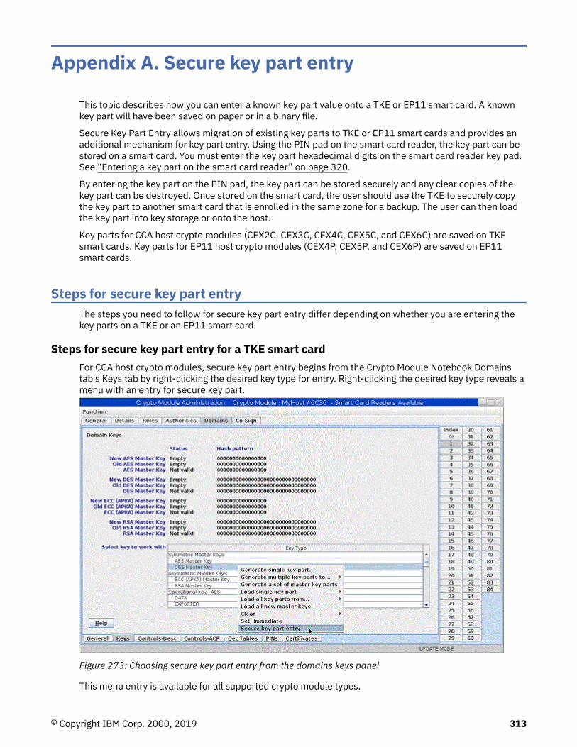
Appendix A. Secure key part entry
This topic describes how you can enter a known key part value onto a TKE or EP11 smart card. A knownkey part will have been saved on paper or in a binary file.
Secure Key Part Entry allows migration of existing key parts to TKE or EP11 smart cards and provides anadditional mechanism for key part entry. Using the PIN pad on the smart card reader, the key part can bestored on a smart card. You must enter the key part hexadecimal digits on the smart card reader key pad.See “Entering a key part on the smart card reader” on page 320.
By entering the key part on the PIN pad, the key part can be stored securely and any clear copies of thekey part can be destroyed. Once stored on the smart card, the user should use the TKE to securely copythe key part to another smart card that is enrolled in the same zone for a backup. The user can then loadthe key part into key storage or onto the host.
Key parts for CCA host crypto modules (CEX2C, CEX3C, CEX4C, CEX5C, and CEX6C) are saved on TKEsmart cards. Key parts for EP11 host crypto modules (CEX4P, CEX5P, and CEX6P) are saved on EP11smart cards.
Steps for secure key part entryThe steps you need to follow for secure key part entry differ depending on whether you are entering thekey parts on a TKE or an EP11 smart card.
Steps for secure key part entry for a TKE smart cardFor CCA host crypto modules, secure key part entry begins from the Crypto Module Notebook Domainstab's Keys tab by right-clicking the desired key type for entry. Right-clicking the desired key type reveals amenu with an entry for secure key part.
Figure 273: Choosing secure key part entry from the domains keys panel
This menu entry is available for all supported crypto module types.
© Copyright IBM Corp. 2000, 2019 313
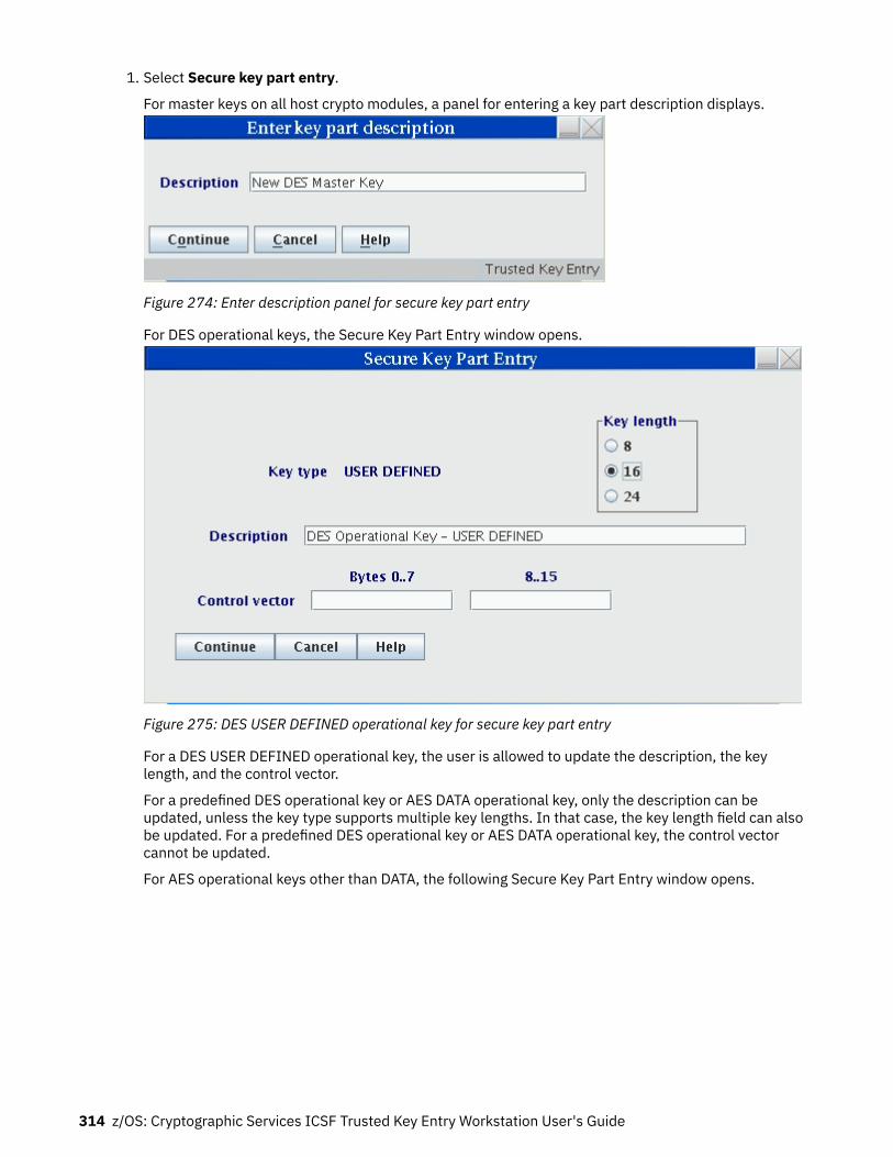
1. Select Secure key part entry.
For master keys on all host crypto modules, a panel for entering a key part description displays.
Figure 274: Enter description panel for secure key part entry
For DES operational keys, the Secure Key Part Entry window opens.
Figure 275: DES USER DEFINED operational key for secure key part entry
For a DES USER DEFINED operational key, the user is allowed to update the description, the keylength, and the control vector.
For a predefined DES operational key or AES DATA operational key, only the description can beupdated, unless the key type supports multiple key lengths. In that case, the key length field can alsobe updated. For a predefined DES operational key or AES DATA operational key, the control vectorcannot be updated.
For AES operational keys other than DATA, the following Secure Key Part Entry window opens.
314 z/OS: Cryptographic Services ICSF Trusted Key Entry Workstation User's Guide

Figure 276: AES non-DATA operational key for secure key part entry
The key part description can be updated. Click Change key attributes to modify the key attributes.2. After all the appropriate information has been entered for master and operational keys, the user is
prompted to insert a TKE smart card into reader 2.
Figure 277: Secure key part entry — insert TKE smart card into reader3. Enter the PIN on the smart card reader PIN pad when prompted.
Figure 278: Secure key part entry — enter key part digits
A dialog displays information about the TKE smart card.4. If the TKE smart card information is correct, press Yes to continue.
Secure key part entry 315

Figure 279: Secure key part entry card identification
The Secure Key Part Entry dialog displays.5. Enter the known key part digits, which will have been saved on paper or in a binary file. See “Entering a
key part on the smart card reader” on page 320.
Note: Make sure that the TKE workstation crypto adapter and the TKE smart cards are in the samezone. To display the zone of a TKE smart card, exit TKE and use either the Cryptographic NodeManagement Utility or the Smart Card Utility Program under Trusted Key Entry Applications. See“Display smart card information” on page 294 or “Display smart card key identifiers” on page 296.
Figure 280: Secure key part entry — enter key part digits
The dialog shows the progress of each hexadecimal digit entered with an asterisk (*).6. After the key part value has been successfully entered on the PIN pad, a window opens showing
information about the key part just entered. Verify that you entered the information correctly.
• For a DES key part, the ENC-ZERO, MDC-4, and SHA1 values are shown.• For an AES or ECC (APKA) key part, the AES-VP value is shown.• For a DES or AES DATA operational key, the control vector (CV) is also displayed.• For an AES non-DATA operational key, the window allows you to display key attributes.
Click OK to continue.
316 z/OS: Cryptographic Services ICSF Trusted Key Entry Workstation User's Guide

Figure 281: Secure key part entry — DES key part information for a master key
Figure 282: Secure key part entry — AES key part information for a master key
Figure 283: Secure key part entry — DES key part information for operational key
Secure key part entry 317

Figure 284: Secure key part entry — AES DATA operational key
Figure 285: Secure key part entry — AES non-DATA key7. A message is displayed if the command executed successfully.
Figure 286: Secure key part entry — message for successful execution
Steps for secure key part entry for a EP11 smart cardFor EP11 host crypto modules, secure key part entry begins from the Keys tab for a domain in the CryptoModule Notebook. Right-click in the domain keys window to display a menu, and click Secure key partentry.
318 z/OS: Cryptographic Services ICSF Trusted Key Entry Workstation User's Guide

Figure 287: Choosing secure key part entry from the domain keys window
You are prompted to enter a description for the key part. After entering the description, you are promptedto select the smart card reader to use, to insert an EP11 smart card in the reader, and to enter the PIN.After the PIN is entered, a confirmation window opens showing the smart card's zone description, entityID, and card description.
Figure 288: Secure key part entry card identification
Note: The smart card must be in the same zone as the TKE workstation crypto adapter in order for securekey part entry to be successful.
If you accept this smart card, you are prompted to enter the hexadecimal digits for the key part on thesmart card reader PIN pad. To enter each hexadecimal digit, you must press two buttons on the PIN pad.For example, press "0" and "2" for the hexadecimal digit 2, or "1" and "4" for the hexadecimal digit E.After each hexadecimal digit is entered, an asterisk (*) is displayed on the panel to show how manyhexadecimal digits have been entered.
Secure key part entry 319

Figure 289: Secure key part entry -- enter key part digits
After all hexadecimal digits for the key part have been entered, a Smart Card key part information windowopens showing the AES-VP for the key part that was entered.
Figure 290: Secure key part entry -- key part information window
Entering a key part on the smart card readerA key part is hexadecimal. The PIN pad on the smart card reader does not provide hexadecimal digits, soyou must enter two digits that represent the decimal equivalent of a hexadecimal digit. The valid range ofdecimal digit input is 00–15. This range is equivalent to the hexadecimal digit input range of 0–F. Aconversion table is provided (Table 36 on page 321).
Except for RSA keys, all other key types for all crypto module types can be entered securely on the smartcard reader PIN pad. These key parts can then be used to load master or operational key registers on thehost.
Secure key part entry on the smart card reader PIN pad works as follows:
• A key part is separated into blocks. The key length in bytes (2 hexadecimal characters per byte) isdivided by 4 and gives you the number of blocks.
• A block on the smart card reader PIN pad consists of 8 hexadecimal digits.• Once a hexadecimal digit has been entered, the value cannot be changed.• After entering the two digit decimal equivalent, the smart card reader records a hexadecimal digit,
updating the smart card reader display with an '*' in the section depicting the number of hexadecimaldigits that have been recorded in the current block.
• After all the hexadecimal digits in a block have been entered, a running counter of the number of blockscompleted on the screen is updated and the current block display is reset.
• Once a block is updated with a hexadecimal digit, the values cannot be changed.
320 z/OS: Cryptographic Services ICSF Trusted Key Entry Workstation User's Guide

• On the OmniKey reader, there is blank space for entering the two decimal digits. A single lock image isdepicted on the right.
• The current decimal digit input can be changed. If an invalid two decimal digit input is entered, a changemust occur. The Backspace key (yellow button labeled with a <-) on the smart card reader PIN pad canbe used to undo entered decimal digits. The <- button lets the user change the first decimal of the hexdigit. Example: if you entered 0_ you can use the <-button to reenter the 0. The abort key (red buttonlabeled with an X) on the smart card reader PIN pad can be used to reset the current decimal digit. Itcan also be used to cancel the secure key entry process.
Example
Key part type: 8-byte DES data operational keyKey part hexadecimal digits: AB CD EF 12 34 56 78 90Number of blocks: 2Number of hexadecimal digits per block: 8Initial Block Counter Value: 1/2Two decimal digit conversion of key part hexadecimal digits:1011 1213 1415 0102 0304 0506 0708 0900
Table 36: Decimal to Hexadecimal Conversion Table
Hexadecimal Digit Decimal Digits Entered on PIN PAD
0 00
1 01
2 02
3 03
4 04
5 05
6 06
7 07
8 08
9 09
A 10
B 11
C 12
D 13
E 14
F 15
Secure key part entry 321

322 z/OS: Cryptographic Services ICSF Trusted Key Entry Workstation User's Guide

Appendix B. LPAR considerations
Host image profiles for logical partitions must be correctly configured in order to use the TKE workstationto manage keys and perform other operations. The host support element is used to set and change theconfiguration.
When customizing an image profile using the support element, four fields are specified:
• Usage domain index – The domain associated with the logical partition.• Control domain index – The set of domains that can be managed from this logical partition. It must
include the usage domain index value for this logical partition. A logical partition used as the TKE hostincludes the usage domain index values for all logical partitions the TKE workstation may manage.
• Cryptographic Candidate List – The set of cryptographic coprocessors that the logical partition mayaccess.
• Cryptographic Online List – The set of cryptographic coprocessors that will be brought online when thelogical partition is activated.
If a command is sent to a domain that is not in a logical partition's control domain index, ICSF returns anerror (return code 12, reason code 2015).
There is no specific field to identify a logical partition as a TKE host when you are customizing imageprofiles. You must decide which logical partition will be the TKE host and set up the control domain indexand Cryptographic Candidate List appropriately. The control domain index for this partition must includethe usage domain index values for all logical partitions that the TKE workstation will control, and theCryptographic Candidate List for this partition must include all entries in the Cryptographic CandidateLists for the logical partitions that the TKE workstation will control. The control domain index must alsoinclude the usage domain index value for the TKE host partition itself.
Multiple logical partitions can specify the same usage domain index, provided there are no commonentries on their Cryptographic Candidate Lists. (Logical partitions may not share the same domain on thesame cryptographic coprocessor, but can use the same domain index value on different cryptographiccoprocessors.) In order to control these partitions, however, the TKE host partition must have a uniqueusage domain index, because its Cryptographic Candidate List must include all coprocessors of the logicalpartitions being controlled.
The example in Figure 291 on page 324 has 3 LPARs and 4 cryptographic coprocessors: 00, 01, 02, 03.There is no domain sharing. In this case, all the cryptographic coprocessors can be specified in theCandidate List for each LPAR.
© Copyright IBM Corp. 2000, 2019 323

Figure 291: An example of TKE host and TKE target LPARs without domain sharing
The example in Figure 292 on page 324 has 4 LPARs, 2 sharing the same domain and 4 cryptographiccoprocessors: 00, 01, 02, 03. In this case, LPAR 1 and LPAR 2 share the same domain, but the CandidateList does not share any of the same cryptographic coprocessors.
Figure 292: An example of TKE host and TKE target LPARs with domain sharing
If the same domain is specified by more than one LPAR and the Candidate List has any of the samecryptographic coprocessors, the first LPAR that is activated will IPL without error, but the other LPARswith the same domain will fail activation.
324 z/OS: Cryptographic Services ICSF Trusted Key Entry Workstation User's Guide
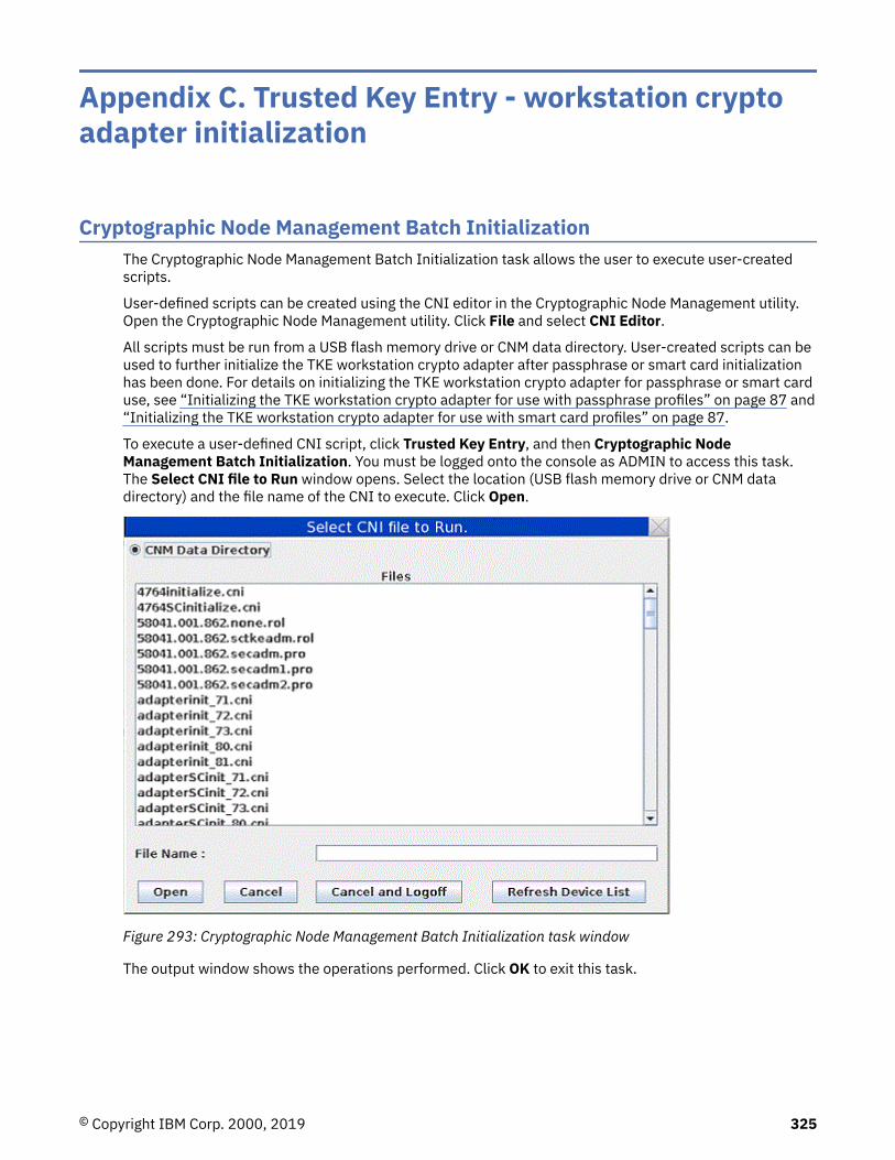
Appendix C. Trusted Key Entry - workstation cryptoadapter initialization
Cryptographic Node Management Batch InitializationThe Cryptographic Node Management Batch Initialization task allows the user to execute user-createdscripts.
User-defined scripts can be created using the CNI editor in the Cryptographic Node Management utility.Open the Cryptographic Node Management utility. Click File and select CNI Editor.
All scripts must be run from a USB flash memory drive or CNM data directory. User-created scripts can beused to further initialize the TKE workstation crypto adapter after passphrase or smart card initializationhas been done. For details on initializing the TKE workstation crypto adapter for passphrase or smart carduse, see “Initializing the TKE workstation crypto adapter for use with passphrase profiles” on page 87 and“Initializing the TKE workstation crypto adapter for use with smart card profiles” on page 87.
To execute a user-defined CNI script, click Trusted Key Entry, and then Cryptographic NodeManagement Batch Initialization. You must be logged onto the console as ADMIN to access this task.The Select CNI file to Run window opens. Select the location (USB flash memory drive or CNM datadirectory) and the file name of the CNI to execute. Click Open.
Figure 293: Cryptographic Node Management Batch Initialization task window
The output window shows the operations performed. Click OK to exit this task.
© Copyright IBM Corp. 2000, 2019 325

Figure 294: Cryptographic Node Management Batch Initialization task output window
CCA CLU (Code Load utility)The CCA CLU task is used for loading and checking code on the TKE workstation crypto adapter.
CLU requires exclusive access to the TKE workstation crypto adapter. No other TKE applications can usethe TKE crypto adapter while CLU is active, and no TKE crypto adapter user can be logged on. If TKE auditrecord upload is active at the time CLU is started, audit records are not uploaded to the host system untilCLU is ended.
Note: CLU should be executed only when directed by support system. CLU functions can take severalminutes to execute.
To invoke the CLU utility, click Trusted Key Entry, then select CCA CLU. You must be logged on as ADMINto access this task.
Note: The CCA levels that are depicted in the screen captures might not be entirely accurate due to CCAfixes that might have been made to your system.
CLU processingWhen CLU is invoked, the Non-Factory Mode is displayed. You can select any combination of CLUcommand check boxes.
Figure 295: CLU command check boxes
326 z/OS: Cryptographic Services ICSF Trusted Key Entry Workstation User's Guide

When you click RUN, the commands execute in the order they appear on the application window.
If a command fails, the commands checked after the failing command do not execute and remainchecked.
After clicking Run, view the Output Log or the Command History to check the output from the CLUcommands. Both can be viewed by clicking View and then clicking Output Log or Command History.
Figure 296: CLU View menu
Figure 297: Output log file
The CLU output log file is available to the user in the CNM Data Directory.
Trusted Key Entry - workstation crypto adapter initialization 327

Figure 298: CLU command history
The CLU command history window shows the CLU commands and output for the current CLU session. Itcan be erased by clicking on the Clear button and is erased automatically on exit from the CLU utility.
If all CLU commands complete without error, a message indicating that all CLU commands completedsuccessfully is displayed.
Figure 299: Successful completion of CLU commands
Checking coprocessor statusBefore loading code you should check the coprocessor status. To use the CLU utility check statuscommand (ST), you must select the Check Coprocessor Status check box and then click Run.
View the results in the Output Log or Command History.
Loading coprocessor codeIBM 4768 crypto adapters are supported.
328 z/OS: Cryptographic Services ICSF Trusted Key Entry Workstation User's Guide

1. Change segment 1:
a. If the segment 1 image name indicates ... Factory ..., set the application to Factory Mode (File >Factory Mode). The Factory Mode CLU window opens.
Figure 300: CLU File menu
Reload segment 1 with the CCA segment 1 file by selecting Load Factory Segment 1 and clickingRun.
b. If the segment 1 image name does not indicate ... Factory ..., and the segment 1 revision level isless than 60003, reload segment 1 with the CCA segment 1.
Note: This choice is only available when the application is not in Factory Mode (File > FactoryMode).
2. Change segments 2 and 3:
a. If segment 2 ROM status indicates Unowned… Set the application to Factory Mode (File > FactoryMode). Select Load Factory Segments 2 and 3(establish_ownership_then_emergency_reload_seg2_seg3_TKE_6.0.xx.clu) and click Run.
b. If segment 2 and 3 ROM status both indicate owner 02… Select Load Owned Segments 2 and 3(reload_seg2_seg3_TKE_6.0.xx.clu) and click Run.
Note: This choice is only available when the application is not in Factory Mode (File > FactoryMode).
3. When you have successfully completed this process, a check of the coprocessor status or validate ofthe coprocessor code indicates that the segments contain:Segment 1 Image: 6.0.xx Pxx Segment 2Image: 6.0.xx 1xx Segment 3 Image: 6.0.xx CCA TKE where the xx values are dependent on themaintenance level of the TKE.
View the results in the Output Log or Command History.
Validating coprocessor codeIf you want to validate the code loaded on the crypto adapter use the CLU utility validate command (VA).Select the appropriate check box for your TKE workstation crypto adapter and click Run.
View the results in the Output Log or Command History.
Checking system statusIf you want to check the system status of your TKE workstation crypto adapter, use the CLU utility checksystem status command (SS). Select the Check System Status check box and click Run.
View the results in the Output Log or Command History.
Resetting coprocessorIf you need to reset the TKE workstation crypto adapter use the CLU utility reset coprocessor command(RS). You must enter Factory mode by clicking Factory Mode under the File menu. Then select the ResetCoprocessor check box and click Run.
View the results in the Output Log or Command History.
Trusted Key Entry - workstation crypto adapter initialization 329

Removing coprocessor CCA code and zeroizing CCATo Zeroize the CCA node and remove the CCA Coprocessor Code from segments 2 and 3, select theZeroize and Unown Segments 2 and 3 check box and click Run. This should result in the segment 2 and3 ROM Status indicated Unowned.
View the results in the Output Log or Command History.
Help menuThe CLU Utility has a help page. To view the help, click Contents from the Help menu.
330 z/OS: Cryptographic Services ICSF Trusted Key Entry Workstation User's Guide

Appendix D. Clear RSA key format
An RSA key can be imported from a file holding the unencrypted RSA key. The file must be an ASCII textfile. CR/LF can be inserted at any place for enhanced readability of the file.
The contents of the file are:
Description Length (characters)
Key modulus length in bits (hex value) 4
Length of Modulus field in bytes (hex value) 4
Length of Public exponent field in bytes (hex value) 4
Length of Private exponent field in bytes (hex value) 4
Modulus (hex value) -
Public exponent (hex value) -
Private exponent (hex value) -
The format follows the key_value_structure format defined for the PKA Key token Build (CSNDPKB)callable service.
These are examples of two file contents for the same clear RSA key. The key length is 512 bits and thepublic exponent is 65537.
Example 1:
020000800003008000000000000000000000000000000000000000000000000000000000000000000000000000000000000000000000000000000000000000000000000000000000800000000000000001AE28DA4606D885EB7E0340D6BAAC51991C0CD0EAE835AFD9CFF3CD7E7EA74141DADD24A6331BEDF41A6626522CCF15767D167D01A16F97010001000000000000000000000000000000000000000000000000000000000000000000000000000000000000000000000000000000000000000000000000000000000252BDAD4252BDAD425A8C6045D41AFAF746BEBD5F085D574FCD9C07F0B38C2C45017C2A1AB919ED2551350A76606BFA6AF2F1609A00A0A48DD719A55E9CA801
Example 2:
0200004000030040800000000000000001AE28DA4606D885EB7E0340D6BAAC51991C0CD0EAE835AFD9CFF3CD7E7EA74141DADD24A6331BEDF41A6626522CCF15767D167D01A16F970100010252BDAD4252BDAD425A8C6045D41AFAF746BEBD5F085D574FCD9C07F0B38C2C45017C2A1AB919ED2551350A76606BFA6AF2F1609A00A0A48DD719A55E9CA801
© Copyright IBM Corp. 2000, 2019 331

332 z/OS: Cryptographic Services ICSF Trusted Key Entry Workstation User's Guide

Appendix E. Trusted Key Entry applications andutilities
The TKE console supports a variety of tasks, applications, and utilities.
The set of tasks, applications, and utilities available depends on the console user name specified whenthe console is initially started. The default console user name is TKEUSER. Other console user names areAUDITOR, ADMIN, and SERVICE. See “Trusted Key Entry console” on page 11 for more information.
Table 37: Tasks, applications and utilities accessible by console user name
Navigation Task
Privilegedmodeaccess ID- None
Privilegedmodeaccess ID- ADMIN
Privilegedmodeaccess ID-AUDITOR
Privilegedmodeaccess ID- SERVICE
Trusted KeyEntry
Applications Begin Zone Remote Enroll Process for aCrypto Adapter
X X
CCA CLU X
Complete Zone Remote Enroll Process fora Crypto Adapter
X X
Cryptographic Node Management BatchInitialization
X
Cryptographic Node Management Utility X X
Migrate Host Crypto Module PublicConfiguration Data
X X
Configuration Migration Tasks X X
TKE Workstation Setup X
Migrate Roles Utility X X
Smart Card Utility Program X X
TKE's Crypto Adapter Initialization X
Trusted Key Entry X X
Utilities Edit TKE Files X X
TKE File Management Utility X X X X
TKE Workstation Code Information X X
Configure Displayed Hash Size X
Enhanced Password Encryption Policy X
Configure Printers X
TKE Audit Configuration Utility X
TKE Audit Record Upload Utility X
© Copyright IBM Corp. 2000, 2019 333

Table 37: Tasks, applications and utilities accessible by console user name (continued)
Navigation Task
Privilegedmodeaccess ID- None
Privilegedmodeaccess ID- ADMIN
Privilegedmodeaccess ID-AUDITOR
Privilegedmodeaccess ID- SERVICE
TKE Security Event Viewer X
ServiceManagement
Lock Console X X X X
Shutdown or Restart X X X X
Hardware Messages X X X X
Network Diagnostic Information X X X X
Users and Tasks X X X X
View Console Information X X X X
View Console Service History X
View Licenses X X X X
Format Media X X X X
Backup Critical Console Data X X
Offload Virtual RETAIN Data to RemovableMedia
X
Rebuild Vital Product Data X
Save Upgrade Data X X
Save/Restore Customizable Console Data X X
Transmit Console Service Data X
Manage Print Screen Files X X X X
Console Logs View Console Events X X X X
View Console Tasks Performed X X
Audit and Log Management X X X X
View Security Logs X
Archive Security Logs X
ConsoleInternal Code
Analyze Console Internal Code X
Authorize Internal Code Changes X
Change Console Internal Code X
Configuration Configure 3270 Emulators X X X X
Configure Backup Settings X X
Customize Console Date/Time X X
Customize Network Settings X X
334 z/OS: Cryptographic Services ICSF Trusted Key Entry Workstation User's Guide

Table 37: Tasks, applications and utilities accessible by console user name (continued)
Navigation Task
Privilegedmodeaccess ID- None
Privilegedmodeaccess ID- ADMIN
Privilegedmodeaccess ID-AUDITOR
Privilegedmodeaccess ID- SERVICE
Customize Scheduled Operations X X
Reassign Trusted Key Entry Console X
Password Protect Console X X
Change Password X X X
Certificate Management X X
Manage SSH Keys X X
Using USB flash memory drives with TKE applications and utilitiesTrusted Key Entry applications and utilities tasks recognize a USB flash memory drive and allow you touse the drive (if applicable for the task) only if the supported drive meets these requirements:
• It is plugged into a USB port on the TKE.• It is 1 GB or larger in size.• It has been formatted with the appropriate data label and format type for the application or utility. For a
list of supported format types and labels and the applications that use them, see Table 38 on page 360.
Otherwise, Trusted Key Entry Applications and Utilities tasks do not recognize the drive and you are notable to use it.
Do not remove a USB flash memory drive from the USB port before you complete the operation that isusing the drive, or before you respond to a message related to the operation that is using the drive. If youdo remove a drive before the operation is complete, hardware messages might be generated on the TKEworkstation.
Begin Zone Remote Enroll ProcessThis task is for an IBM Crypto Adapter. It is for use on the remote TKE to begin the zone enrollmentprocess.
See “Remote crypto adapter enrollment” on page 306.
CCA CLUThis task is for loading code onto the TKE workstation crypto adapter.
See “CCA CLU (Code Load utility)” on page 326.
Complete Zone Remote Enroll ProcessThis task is for an IBM Crypto Adapter. It is for use on the remote TKE to complete the zone enrollmentprocess.
See “Remote crypto adapter enrollment” on page 306
Trusted Key Entry applications and utilities 335
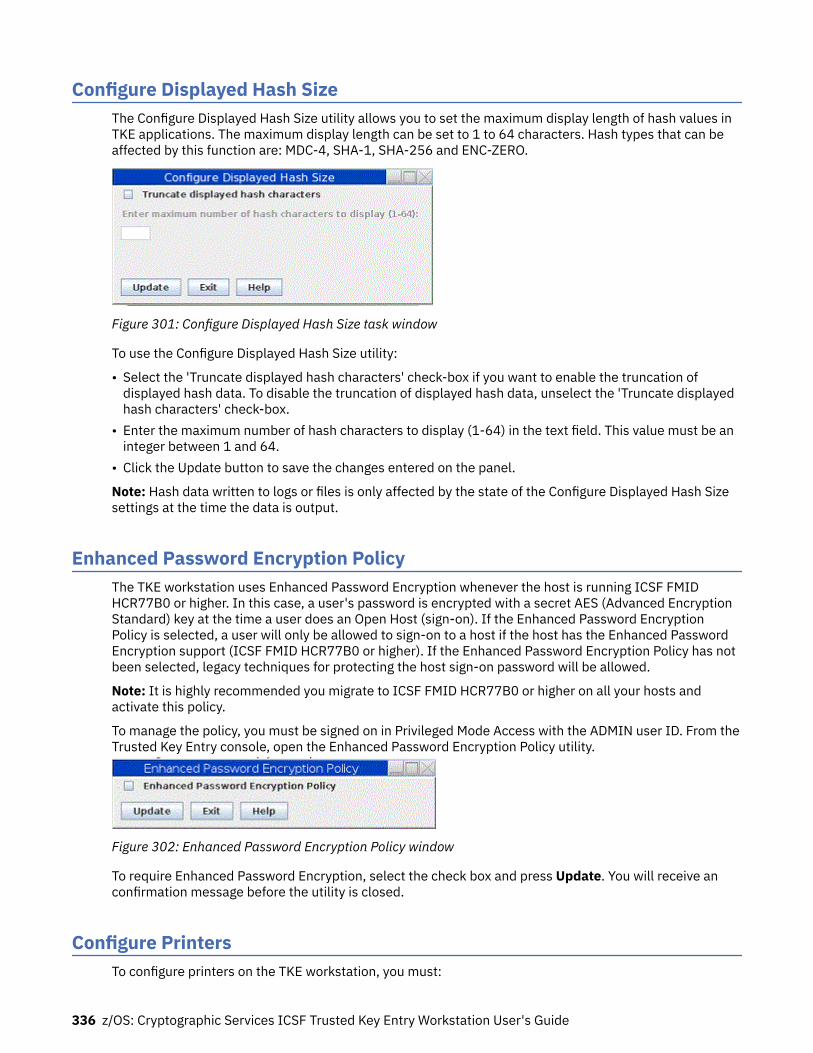
Configure Displayed Hash SizeThe Configure Displayed Hash Size utility allows you to set the maximum display length of hash values inTKE applications. The maximum display length can be set to 1 to 64 characters. Hash types that can beaffected by this function are: MDC-4, SHA-1, SHA-256 and ENC-ZERO.
Figure 301: Configure Displayed Hash Size task window
To use the Configure Displayed Hash Size utility:
• Select the 'Truncate displayed hash characters' check-box if you want to enable the truncation ofdisplayed hash data. To disable the truncation of displayed hash data, unselect the 'Truncate displayedhash characters' check-box.
• Enter the maximum number of hash characters to display (1-64) in the text field. This value must be aninteger between 1 and 64.
• Click the Update button to save the changes entered on the panel.
Note: Hash data written to logs or files is only affected by the state of the Configure Displayed Hash Sizesettings at the time the data is output.
Enhanced Password Encryption PolicyThe TKE workstation uses Enhanced Password Encryption whenever the host is running ICSF FMIDHCR77B0 or higher. In this case, a user's password is encrypted with a secret AES (Advanced EncryptionStandard) key at the time a user does an Open Host (sign-on). If the Enhanced Password EncryptionPolicy is selected, a user will only be allowed to sign-on to a host if the host has the Enhanced PasswordEncryption support (ICSF FMID HCR77B0 or higher). If the Enhanced Password Encryption Policy has notbeen selected, legacy techniques for protecting the host sign-on password will be allowed.
Note: It is highly recommended you migrate to ICSF FMID HCR77B0 or higher on all your hosts andactivate this policy.
To manage the policy, you must be signed on in Privileged Mode Access with the ADMIN user ID. From theTrusted Key Entry console, open the Enhanced Password Encryption Policy utility.
Figure 302: Enhanced Password Encryption Policy window
To require Enhanced Password Encryption, select the check box and press Update. You will receive anconfirmation message before the utility is closed.
Configure PrintersTo configure printers on the TKE workstation, you must:
336 z/OS: Cryptographic Services ICSF Trusted Key Entry Workstation User's Guide
1. Log on to the TKE workstation console through Privileged Access Mode as ADMIN.
Note: You can only add printers if the device driver for the printer is included with the TKE. TKEincludes the GUTENPRINT and HPLIP device driver packages. The TKE workstation does not allow youto load your own printer device drivers. Also, ensure that you have at least one profile with a role thathas the "print files" ACP.
2. Open the Configure Printers application under Utilities.3. Select the Administration tab.4. Select Add Printer.5. If you have printers plugged in, they show up in the Local Printers list. Otherwise, ensure that the
printer you are trying to use is properly plugged in.6. Change the name and description of the printer and press Continue. (Optional)7. TKE finds the appropriate device driver. If not, select the appropriate device driver from the list and
press Add Printer.8. Enter the default options and press Set Default Options.
The printer is now defined. Information about each configured printer shows up in the Printers tab. Thetab provides maintenance and administrative functions to use on the printer. To ensure that the printer isset up correctly, select Maintenance and choose Print Test Page.
Cryptographic Node Management batch initializationThis task is for using a batch interface to execute a user-created CNI file. A user-created CNI file can beused to initialize a TKE workstation crypto adapter differently than the TKE Crypto Adapter Initializationtask. To create the user CNI, use the Cryptographic Node Management Utility, CNI Editor function.
See “Cryptographic Node Management Batch Initialization” on page 325
Cryptographic Node Management utilityThis task is for managing the TKE workstation crypto adapter (create and manage Roles and Profiles,manage workstation master keys, et cetera).
See Chapter 11, “Cryptographic Node Management utility (CNM),” on page 251.
Edit TKE filesThe Edit TKE Files task provides a way to edit and browse files on a USB flash memory drive or within thefour allowed TKE-related data directories on the hard drive:
• TKE Data Directory• Migration Backup Data Directory• CNM Data Directory• SCUP Data Directory
Files in the Configuration Data Directory cannot be accessed by the Edit TKE Files task and should bereviewed using the review functions in the configuration migration applications.
To open the Edit TKE Files task, click Trusted Key Entry and then click Edit TKE Files.
You must be logged on to the TKE workstation crypto adapter for this task. If you are not currently loggedonto the adapter, a logon window is displayed. You will need to select a profile to log on to the adapter. Ifyou are already logged onto the adapter, no logon window will be displayed (the current logon will beused).
Trusted Key Entry applications and utilities 337

In the Open Text Editor window, select a file from the displayed list or manually enter a file name. If youmanually enter a file name that does not exist, a new file by that name will be created in the locationspecified.
If the crypto adapter profile currently being used is authorized to print files, the Print button is shown inthe Open Text Editor window.
Figure 303: Edit TKE Files task window
You can edit the file within the edit text box and use File -> Save menu item to save the file.
338 z/OS: Cryptographic Services ICSF Trusted Key Entry Workstation User's Guide

Figure 304: Editor - File menu items
Attention : Do not remove a USB flash memory drive from the USB port before you complete theoperation that is using the drive, or before you respond to a message related to the operation that is usingthe drive. If you do remove a drive before the operation is complete, hardware messages might begenerated on the TKE workstation.
The editor provides options for Undo, Cut, Copy, Paste, along with Line Selection and Search/Replace.
Trusted Key Entry applications and utilities 339

Figure 305: Editor - Edit menu items
In addition, there are options for Fonts, line wrap, and background.
340 z/OS: Cryptographic Services ICSF Trusted Key Entry Workstation User's Guide

Figure 306: Editor - Style Menu Items
Migrate Roles utilityThis utility, introduced in TKE 7.1, simplifies the process of adding new ACPs to existing roles on your TKEworkstation crypto adapter. This is useful during migration, because new ACPs are not automaticallyadded to existing roles during the migration process.
See “Adding new ACPs to existing roles using the Migrate Roles utility” on page 90 for more information.
Smart Card Utility ProgramThis task is used for initializing smart cards, enrolling smart cards in a zone, and enrolling TKEworkstations in a zone.
See Chapter 12, “Smart Card Utility Program (SCUP),” on page 291.
Trusted Key Entry applications and utilities 341

TKE Audit Configuration utilityThis utility starts and stops auditing of security-relevant events on the TKE workstation, and controls whatevents will create audit records. You must log on with a console user name of AUDITOR to use this utility.
See “TKE Audit Configuration utility” on page 227 for more information
TKE Audit Record Upload Configuration utilityThis utility enables you to send TKE workstation security audit records to a Z host where they will besaved in the z/OS System Management Facilities (SMF) data set. Each TKE security audit record is storedin the SMF dataset as a type 82 subtype 29 record. This allows you to place TKE security audit recordsfrom 1 or more TKE Workstations into a single SMF data set on a target host. From the host, a securityofficer can use SMF features to analyze and archive the TKE security audit data.
See “TKE Audit Record Upload Configuration utility” on page 238 for more information
TKE File Management utilityAttention: DVD-RAM is not supported on TKE 7.2 or later systems. If you have a DVD-RAM that isformatted for TKEDATA (TKEDATA DVD-RAM) and you want to use the files from the TKEDATADVD-RAM on a TKE 7.2 or later system, see “DVD-RAM is not supported on a TKE 7.2 or latersystem” on page 57 for additional information.
The TKE File Management Utility task allows you to manage files on a USB flash memory drive, or withinsupported data directories on the local hard drive. It provides the ability to delete, rename, and copy files.
To invoke this task, click on Trusted Key Entry and then click on the TKE File Management Utility.
You must be logged on to the TKE workstation crypto adapter for this task. If you are not currently loggedon to the adapter, a logon window is displayed. You will need to select a profile to log on to the adapter. Ifyou are already logged onto the adapter, no logon window will be displayed (the current logon will beused).
When the TKE File Management Utility is opened the user is presented with the following task window.
342 z/OS: Cryptographic Services ICSF Trusted Key Entry Workstation User's Guide

Figure 307: TKE File Management Utility task window
In the File Management Utility window, selecting the hard drive for either Source or Target will allow youto select from one of five data directories:
• TKE Data Directory• Migration Backup Data Directory• CNM Data Directory• SCUP Data Directory• Configuration Data Directory
Trusted Key Entry applications and utilities 343

Figure 308: TKE File Management - directory options
From the displayed list you can select a single file, numerous files, blocks of files, or the entire display.
• For a single file, just click on the desired file.• To select more than one file click on the first file, hold down the Ctrl key and click on each additional file.• To select a block of files, click on the first file, hold down the Shift key and click on the last file. All files
between the two selected files will be selected.• To select all the files, hold down the Ctrl key and type an 'a'.
Clicking on Delete will display a confirmation window.
Figure 309: Delete confirmation window
Clicking on Rename will present a window for inputting a filename.
Figure 310: Window for inputting a filename
Attention : Do not remove a USB flash memory drive from the USB port before you complete theoperation that is using the drive, or before you respond to a message related to the operation that is using
344 z/OS: Cryptographic Services ICSF Trusted Key Entry Workstation User's Guide

the drive. If you do remove a drive before the operation is complete, hardware messages might begenerated on the TKE workstation.
TKE workstation code informationThe TKE Workstation Code Information window shows information about the code used by the TKEapplications. The information can be useful in problem determination. Updates to TKE application codeare reflected in this window. This task does not give information about the code on the TKE workstationcrypto adapter.
To invoke this task, click Trusted Key Entry and then click TKE Workstation Code Information.
Figure 311: TKE Workstation Code Information window
Configuration migrationThe TKE workstation provides tools to securely capture host crypto module configuration data to a file,and then apply this data to another host crypto module. Tools are provided for both CCA and EP11 hostcrypto modules. These tools simplify the task of installing new or replacement host crypto modules, andcan be used for backup and disaster recovery.
For CCA crypto modules, three tools are provided:
• One tool migrates only public configuration data (roles, authorities, and domain control settings).• A second tool migrates all configuration data, including secret data such as master key values. The
protocol for migrating secret data is more complex than the protocol for migrating only public data and
Trusted Key Entry applications and utilities 345

requires the participation of several smart card holders. This tool results in a complete replacement ofthe configuration on the target crypto modules.
• A third tool migrates only the configuration settings for a single source domain to one or more targetdomains. The existing module-level configuration settings on the target crypto modules (roles andauthorities) and domain-level configuration settings for non-targeted domains are not changed. Thistool can be used to transfer desired domain configuration settings to other domains on the same cryptomodule or on different crypto modules. This tool also relies on a protocol for handling secret data thatrequires the participation of several smart card holders.
For EP11 crypto modules, only the tool used to migrate all configuration data (including master keys) andthe tool used to migrate only the configuration settings for a single source domain are supported.
To migrate only public configuration data on CCA crypto modules, click Migrate Host Crypto ModulePublic Configuration Data on the Trusted Key Entry menu. To use the other tools, click ConfigurationMigration Tasks on the Trusted Key Entry menu. The Enroll source module in migration zone andCollect configuration data buttons can be used to collect configuration data. The Apply configurationdata button does a full replace of configuration data, and the Domain-only apply button replaces onlydomain-level configuration settings for the target domains. When doing a domain-only apply, the sourceconfiguration data file must contain data for just one domain
Migrate Host Crypto Module Public Configuration DataUse this utility to save host crypto module configuration data (such as roles, authorities, and domaincontrol settings) to a file on the TKE workstation, and to load a host crypto module with configuration datathat was previously saved to a file. The utility simplifies the task of restoring the configuration when a hostcrypto module is replaced. This utility supports only CCA crypto modules and CCA domain groups.
The utility saves and loads only public configuration data. Private data, such as the value of master keyregisters, is not accessed.
The utility supports the following four tasks:
• Collecting configuration data from a host crypto module and saving it in a file.• Applying previously saved configuration data to a host crypto module.• Collecting configuration data from one host crypto module and applying it to a different host crypto
module in one operation.• Reviewing previously saved configuration information in a file.
The source and target can be either a single host crypto module or a domain group. When the source is adomain group, the crypto module containing the master domain of the group is located and used as thesource crypto module. When the target is a domain group, all crypto modules with at least one domain inthe domain group are updated with the configuration data read from a file.
To apply configuration data to a target host crypto module, you must use an authority that allows rolesand authorities to be created on the target, such an authority with the predefined INITADM role. When theutility applies configuration data to a domain group, the current authority signature key is checked beforeeach crypto module in the group is updated. If it does not have the required authority, you can load adifferent authority signature key.
The apply task creates and uses a temporary role and authority, which it removes when finished. In somecases, the temporary role cannot be removed. Because a temporary authority is used, 99 authorities arethe most that can be migrated by the utility. If 100 authorities are defined in the source configuration, theauthority at index 99 must be created on the target manually. A warning is displayed for these specialcases.
Target crypto modules must support all cryptographic services of the source configuration. To ensure thatthis requirement is met, the utility checks that the CCA version on the target module is at a higher levelthan the source configuration. If it is not, migration is not allowed.
In the apply task, existing roles, authorities, and domain control settings on target crypto modules areremoved and replaced with the configuration data from the file. Domains optionally can be zeroized
346 z/OS: Cryptographic Services ICSF Trusted Key Entry Workstation User's Guide

before you apply configuration data. This action clears the master key registers. Only control domains canbe zeroized. For more information about control domains, see Appendix B, “LPAR considerations,” onpage 323.
Files that are used by the configuration migration utility are created in, and read from, the ConfigurationData Directory. The TKE File Management utility can copy, rename, and delete files in this directory.
Note: The apply task reserves target host crypto modules for update. If a target host crypto module isalready reserved for update by another application, the apply task fails with an error message. The otherapplication must be closed before the apply task can be run. In abnormal situations, it might be necessaryto take the following steps to force release of the target host crypto module:
1. Start the main TKE application.2. Open a crypto module notebook for the reserved host crypto module.3. Select Release Crypto Module from the Function menu of the crypto module notebook. This function
forcibly releases the host crypto module from the application that was holding it and reserves it for thecrypto module notebook.
4. Close the crypto module notebook to release the host crypto module.
Configuration migration tasksThis application provides access to utilities used to securely migrate configuration data, including secretdata such as master key values, from one crypto module to another. This application can be used for bothCCA crypto modules and EP11 crypto modules. When you select this application, the ConfigurationMigration Tasks panel is displayed.
Figure 312: Configuration Migration Tasks panel
To use this application, you must create a set of smart cards that defines a migration zone. The smartcards are used as part of a secure protocol to protect secret configuration data while in transit from onecrypto module to another. The protocol generates a 256-bit AES transport key for encryptingconfiguration data that is split into as many as 10 parts.
Three smart card types support configuration migration that includes master keys: Migration CertificateAuthority (MCA) smart cards, Injection Authority (IA) smart cards, and Key Part Holder (KPH) smart cards.
The MCA smart card defines the migration zone. A migration zone is a set of smart cards that worktogether to accomplish a migration task. When the migration zone is created, two policies are setindicating the number of smart cards needed for the tasks. The "M-of-N" policy indicates the number ofparts the transport key is split into (N), and the number of parts needed to reconstruct the transport key(M). The maximum value for N is 10, and M must be less than or equal to N. The "K" policy indicates the
Trusted Key Entry applications and utilities 347

number of IA smart cards required to apply configuration data to a target host crypto module. Themaximum value for K is 10.
The MCA smart card is used to create IA and KPH smart cards. These smart cards become part of thatmigration zone, and can be used only in that migration zone. An unlimited number of migration zones canbe created, but each migration zone has its own MCA smart card (and backup MCA smart cards) and set ofIA and KPH smart cards.
The IA smart card authorizes application of configuration data to a target host crypto module or domaingroup.
The KPH smart card authorizes reconstruction of the transport key.
These smart cards can be created using the associated pull-down menus at the top of the ConfigurationMigration Tasks panel, or you can select the Migration zone wizard option on the File menu to start awizard that guides you through the task.
For CCA crypto modules, before configuration data can be collected from a source host crypto module,the source host crypto module must be enrolled in the migration zone using the Enroll source module inmigration zone task. EP11 crypto modules do not need to be enrolled in the migration zone.
During the Collect configuration data task, the source host crypto module generates a transport key andsplits it into "N" parts. (The key splitting algorithm allows the key to be recovered with only "M" of theoriginal "N" parts. It does not matter which "M" parts are provided.) Each key part is encrypted using thepublic key from one of the "N" KPH smart cards. The source host crypto module captures theconfiguration data and encrypts it using the transport key. The encrypted configuration data and "N"encrypted key parts are returned.
During the Apply configuration data task, the target crypto module generates and returns a targetdecryption public key. It also returns an Outbound Authentication (OA) signature over the targetdecryption public key and the target host crypto module OA certificate chain.
"K" IA smart cards approve the target crypto module and target decryption public key, with help from theOA proxy (see “OA proxy” on page 351).
"M" KPH smart cards approve reconstructing the transport key, with help from the OA proxy (see “OAproxy” on page 351). KPH smart cards receive the transport key part that was encrypted with their publickey, decrypt it using their private key, re-encrypt it using the target decryption public key, and return theresult.
The target crypto module receives the encrypted configuration data and the "M" rewrapped key parts. Itdecrypts the rewrapped key parts using its private key, reconstructs the transport key, and decrypts andapplies the configuration data.
The target of the apply task can be either a single crypto module or a domain group. When the target is adomain group, the configuration data is applied to each crypto module with at least one domain in thegroup.
For the Domain-only apply task, processing is similar, but on the target crypto modules, only theconfiguration settings for the target domains are updated. Module-level configuration settings anddomain-level configuration settings for non-target domains are not changed. When the target of thedomain-only apply task is a single crypto module, you select the target domains to receive the newconfiguration. When the target is a domain group, each domain in the domain group receives the newconfiguration. To use the domain-only apply task, the source configuration data file must contain data forjust one domain.
Signature collectionCCA and EP11 crypto modules have different command authentication architectures. CCA is role-based.Commands are signed by authorities whose roles allow the action. EP11 uses a signature thresholdapproach, where all administrators have equal authority to issue commands but must be installed on thetarget domain or crypto module. Each target domain and crypto module independently specifies thenumber of administrator signatures that are required to issue commands (the signature threshold).
348 z/OS: Cryptographic Services ICSF Trusted Key Entry Workstation User's Guide

Because of the different architectures, signature collection for configuration migration commands isdifferent. For CCA, the role of the current authority is checked before each command is issued. You canload a different signature key if the authority is not authorized to issue the command.
For EP11, for each required signature you are prompted to insert a smart card with an administratorsignature key in smart card reader 1. If that signature key does not match one of the installedadministrators on the target crypto module or domain, you are prompted to insert a different smart card.This prompting continues until a valid signature key is found or until you cancel.
For EP11, you can bypass the prompting for each signature by predefining smart card readers as a sourcefor signatures. After a smart card is inserted in the reader and the PIN is entered, signatures are collectedautomatically as needed, without further prompting. You can predefine signature key sources by using theManage EP11 Signature Keys option on the File menu.
Window actionsFile menu
This menu includes options to predefine smart card readers as the source of signatures for commandsto EP11 crypto modules; to invoke a wizard for creating the MCA, IA, and KPH smart cards needed todefine a migration zone; and to exit the Configuration Migration Tasks application.
MCA Smart Card menuThis menu includes options to display the contents of an MCA smart card, initialize and personalize anMCA smart card, back up an MCA smart card, or change the PIN on an MCA smart card.
IA Smart Card menuThis menu includes options to display the contents of an IA smart card, initialize and enroll an IAsmart card in a migration zone, personalize an IA smart card (set the PIN and description), unblock anIA smart card, or change the PIN on an IA smart card.
KPH Smart Card menuThis menu includes options to display the contents of a KPH smart card, initialize and enroll a KPHsmart card in a migration zone, personalize a KPH smart card (set the PIN and description), unblock aKPH smart card, or change the PIN on a KPH smart card.
Migration Zones menuUse the Work with migration zones function on this menu to display the list of migration zones thatare known to the TKE workstation, and add or delete entries.
To minimize the number of times an MCA smart card must be inserted in a card reader duringmigration tasks, the TKE workstation maintains a list of known migration zones. The list is updatedautomatically when a new MCA smart card is created. If you must add or remove migration zones fromthis list, you can use this function. To add a migration zone to the list, you must insert the MCA smartcard for the zone in the smart card reader and enter the PINs.
KPH Certificates menuUse the Work with KPH certificates function on this menu to display the list of KPH smart cards thatare known to the TKE workstation, and add or delete entries.
To minimize the number of times KPH smart cards must be inserted in a card reader during migrationtasks, the TKE workstation maintains a list of known KPH certificates. The list is updatedautomatically when a new KPH smart card is created. If you must add or remove a KPH certificatefrom this list, you can use this function. To add a KPH certificate to the list, you must insert the KPHsmart card in the smart card reader.
Enroll source module in migration zoneThis option starts a wizard that takes you through the steps to enroll a source host crypto module in amigration zone. The source crypto module must be enrolled in a migration zone before configurationdata can be collected from it. This action is not needed for EP11 crypto modules.
You need to know what migration zone you will use before you run this wizard. If you must define anew migration zone, you can use the MCA Smart Card menu to create a new MCA smart card. If youdefine a new migration zone, you also must create IA and KPH smart cards to use in the zone.
Trusted Key Entry applications and utilities 349

To run this wizard, you must load a signature key that permits the Certificate Insert operation on thesource crypto module. If the signature key has insufficient authority, you can load a different signaturekey.
Collect configuration dataThis option starts a wizard that takes you through the steps to collect configuration data from a sourcehost crypto module and save it in a file. Before you run this wizard on a CCA host crypto module, youmust enroll the host crypto module in the migration zone.
You must know what migration zone and what KPH smart cards you will use before you run thiswizard. Only KPH smart cards for the selected migration zone can be used.
In this wizard, you indicate the set of domains that you want to collect configuration data from.Configuration data for only those domains is saved in the configuration data file. During the apply task,configuration data for domains that are not saved in the configuration data file is set to the defaultvalue.
To run this wizard on a CCA crypto module, you must load a signature key that permits the Crypto DataExtract operation on the source host crypto module. If the signature key has insufficient authority, youcan load a different signature key.
Starting with CCA 6.1, you are allowed to skip collecting configuration settings for optional, lesscommonly used features on CCA crypto modules. This reduces the amount of collected configurationdata and the time it takes to collect and apply this data. Configuration settings not collected are set totheir default values on the target crypto module. If you are uncertain about what optional features youuse, collect all configuration settings (the default).
Starting with CCA 6.1 and TKE 9.1, you are allowed to collect configuration settings from domains inimprint mode and PCI-compliant mode. This includes the domain-specific roles and authorities for thedomain. Prior to CCA 6.1 and TKE 9.1, you are allowed to collect configuration settings only fromdomains in normal mode. To collect configuration settings from domains in imprint mode and PCI-compliant mode, you must use smart cards with a P521 ECC zone.
Apply configuration dataThis option starts a wizard that takes you through the steps to apply configuration data to a target hostcrypto module or target domain group.
The wizard prompts you to insert IA smart cards in the smart card reader and enter the PIN. The "K"policy for the migration zone specifies the required number of IA smart cards.
The wizard prompts you to insert KPH smart cards in the smart card reader and enter the PIN. "M" ofthe "M-of-N" policy for the migration zone is the required number of KPH smart cards.
To run this wizard on a CCA crypto module, you must load a signature key that permits the TargetPrepare and Crypto Target Inject operations on the target host crypto module or target group. If thesignature key has insufficient authority, you can load a different signature key. The default role andauthority that is created when a host crypto module is initialized allow you to run these operations.
Starting with CCA 6.1, you are allowed to skip collecting configuration settings for optional, lesscommonly used features on CCA crypto modules. This reduces the amount of collected configurationdata and the time it takes to collect and apply this data. Configuration settings not collected are set totheir default values on the target crypto module. If uncertain about what optional features you use,collect all configuration settings (the default).
Starting with CCA 6.1 and TKE 9.1, you are allowed to collect configuration settings for domains inimprint mode and PCI-compliant mode. This includes the domain-specific roles and authorities for thedomain. Prior to CCA 6.1 and TKE 9.1, you are allowed to collect configuration settings only fromdomains in normal mode. To collect configuration settings from domains in imprint mode and PCI-compliant mode, you must use smart cards with a P521 ECC zone.
Domain-only applyThis option starts a wizard that takes you through the steps to apply configuration data from a singlesource domain to one or more target domains. The wizard steps and protocol are similar to those forthe Apply configuration data option.
350 z/OS: Cryptographic Services ICSF Trusted Key Entry Workstation User's Guide

When using this option, the source configuration data file must contain data for a single domain. Whena single crypto module is selected as the target, you select the domains on that crypto module toreceive the configuration data. When a domain group is selected as the target, each domain in thedomain group is updated with the source configuration. In both cases, module-level configurationsettings and domain-level configuration settings for non-target domains are not changed.
Review Configuration DataThis option starts a wizard that displays the non-secret contents of a configuration data file that youselect.
Different data is saved in the configuration data file for CCA and EP11 host crypto modules. For bothcrypto module types, the saved data includes the serial number and code level of the source cryptomodule, the date and time that the configuration data was collected, the migration zone and KPHcertificates used, and what domains were collected. For CCA it includes a list of the roles andauthorities collected, the domain controls for collected domains, and key register status and keyhashes for collected domains. For EP11 it includes the crypto module administrators and attributes,and the domain administrators, attributes, control points, and key status and hash values for collecteddomains.
Instructions for migrating key materialIf you want to migrate configuration data that includes master key values, follow these steps:
1. Decide what migration zone you are using. If you are not using an existing migration zone, create anMCA smart card that defines the new zone. You must define the M-of-N and K policies. "N" is thenumber of parts the transport key is split into and must be 1 - 10. "M" is the number of key parts thatare required to reconstruct the transport key and must be between 1 and "N". "K" is the number ofInjection Authorities that are required to approve applying configuration data on the target host cryptomodule and must be 1 - 10.
Guideline: Create a backup whenever you create a new MCA smart card.2. Use the Migration Zones menu to check that the migration zone you want to use is listed. If it is not
listed, add it.3. If you are using a new migration zone, create IA and KPH smart cards. You must create at least "K" IA
smart cards and "N" KPH smart cards for the migration zone, but you can create more.4. Decide what KPH smart cards you are using. Use the KPH Certificates menu to check that the KPH
smart cards you want to use are listed. If they are not listed, add them.5. Run the "Enroll source module in migration zone" wizard to enroll the source host crypto module in the
migration zone. This step is not needed for EP11 crypto modules.6. Run the "Collect configuration data" wizard to collect configuration data on the source host crypto
module. The wizard prompts you to enter the media type and a file name for storing the encryptedconfiguration data.
7. Run the "Apply configuration data" wizard to apply configuration data on the target host crypto module.As the wizard runs, the IA and KPH smart card holders are prompted to insert their smart cards in asmart card reader and enter their PINs.
OA proxyWhen migrating configuration data from one host crypto module to another, the Injection Authority (IA)and Key Part Holder (KPH) smart cards verify outputs from the source and target host crypto modules.These outputs are signed by the host crypto modules' private keys, as part of a process called OutboundAuthentication. In addition to the OA signature, the source and target host crypto modules provide theirOA certificate chain, which terminates in an IBM root certificate.
Some IBM host crypto modules use key sizes for their OA signatures and certificate chains that are largerthan what is supported by currently available smart cards. To handle these host crypto modules, the TKEworkstation crypto adapter acts as an OA proxy for the smart cards. The TKE workstation crypto adapterverifies the OA signature and certificate chain and signs the output data using a specially-generated OAproxy signing key.
Trusted Key Entry applications and utilities 351

Each migration zone on the workstation needs to create an OA proxy certificate for this OA proxy signingkey. The OA proxy certificate is created automatically when Migration Certificate Authority (MCA) smartcards are created, and when the migration zone is added or updated using the Migration Zones pull-downmenu on the Configuration Migration Tasks panel.
If the TKE workstation crypto adapter is replaced or re-initialized, these OA proxy certificates are nolonger valid. The migration zones listed under the Migration Zones pull-down menu will be removedautomatically and must be re-registered using the MCA smart cards. Users who wish to change the OAproxy signing key can do so by manually deleting all migration zones found using the Migration Zonespull-down menu and then re-adding them.
Smart card applet level for configuration migrationTo apply configuration data for the CEX5C, CEX5P, and later crypto modules, you must use IA and KPHsmart cards with an applet version of 0.3 or greater. Earlier IA and KPH applet versions do not support thetype of OA proxy signature used for these crypto module types.
Service Management tasksThe Service Management category contains tasks and utilities to service, manage, configure and maintainthe TKE console. The tasks vary with the user name used to log on.
The following tasks are displayed if you are logged in as Service:
• “Analyze console internal code” on page 353• “Authorize internal code changes” on page 353• “Change console internal code” on page 354• “Offload virtual RETAIN data to removable media” on page 364• “Transmit console service data” on page 367• “View console service history” on page 372• “Rebuild vital product data” on page 364
The following tasks are displayed if you are logged in as Auditor:
• “Archive security logs” on page 353• “View security logs” on page 376
The following tasks are displayed for multiple user names:
• “Audit and log management” on page 361• “Backup critical console data” on page 353• “Change password ” on page 354• “Configure 3270 emulators” on page 94• “Customize console date and time” on page 85• “Customize network settings” on page 83• “Customize scheduled operations” on page 355• “Format media” on page 359• “Hardware messages” on page 361• “Lock console ” on page 363• “Manage print screen files” on page 363• “Network diagnostic information” on page 364• “Password protect console” on page 365• “Save/restore customizable console data” on page 365
352 z/OS: Cryptographic Services ICSF Trusted Key Entry Workstation User's Guide

• “Save upgrade data” on page 365• “Shutdown or restart” on page 366• “Users and tasks” on page 369• “View console events” on page 370• “View console information” on page 371• “View console tasks performed” on page 374• “View licenses” on page 375
Analyze console internal codeThis task is used to work with temporary internal code fixes or to debug problems if errors occur during acode fix install. This task should only be invoked by your IBM Customer Engineer or when directed by IBMProduct Engineering. You must log on with a console user name of SERVICE to use this task.
For details, see Z Service Guide for TKE Workstations.
Archive security logsThis task saves the TKE console's default security log to a USB flash memory drive, then erases up to 80percent of the oldest entries to make room for additional audit records. You must log on with a consoleuser name of AUDITOR to use this task.
See “Archive security logs” on page 235 for more information.
Authorize internal code changesThis task is used to verify or change the setting that allows using this TKE workstation to performinstallation and activation of internal code changes and other subsequent operations. This task shouldonly be invoked by your IBM Customer Engineer or when directed by IBM Product Engineering. You mustlog on with a console name of SERVICE to use this task.
For details, see Z Service Guide for TKE Workstations.
Backup critical console dataThis task performs the same operation as the 'Backup critical hard disk information' operation in theCustomize Scheduled Operations task. This task performs the operation immediately rather than at ascheduled date and time. The operation copies critical files from the Trusted Key Entry workstation to aUSB flash memory drive, an FTP server, or both.
To invoke this task, log on as either ADMIN or SERVICE, click on Service Management and then click onBackup Critical Console Data.
Figure 313: Backup Critical Console Data -- select backup destination
You are asked to select the destination of the backup data. You can select a USB flash memory drive, anFTP server, or both. If a USB flash memory drive is selected as a backup destination, it must be formattedwith a volume identification of ACTBKP using the Format Media task. To select an FTP server as a backupdestination, you must first configure the server using the Configure Backup and Upgrade Settings task.
Trusted Key Entry applications and utilities 353

Figure 314: Backup Critical Console Data -- in progress
When the operation is complete, the status field will be updated to indicate success.
Figure 315: Backup Critical Console Data -- final status
Change console internal codeThis task is used to work with internal code changes for the TKE workstation. Code changes can beretrieved, installed and activated, removed, and accepted. This task should only be invoked by your IBMCustomer Engineer or when directed by IBM Product Engineering. You must log on with a consolename of SERVICE to use this task.
For details, see Z Service Guide for TKE Workstations.
Change passwordThe Trusted Key Entry workstation is shipped with predefined console user names and default passwords.The Change Password task appears in the Service Management tree when you are logged on as any of thefollowing Privileged Mode Access user IDs.
• ADMIN - the default password is PASSWORD• AUDITOR - the default password is PASSWORD• SERVICE - the default password is SERVMODE
After logging on the first time with one of these console user names, the user should change the passwordby selecting Service Management and Change Password.
If you are logged on as ADMIN, you can change the ADMIN, AUDITOR, and SERVICE passwords. If you arelogged on as AUDITOR or SERVICE, you can change only your own password.
When the task is executed, the user is required to enter the current password and then the new passwordtwice. When done successfully, and if the new password conforms to the password rules, the task ends.
354 z/OS: Cryptographic Services ICSF Trusted Key Entry Workstation User's Guide

Note: When the TKE workstation is migrated to a new version, the password values are preserved. Theydo not revert to the default values.
Password requirements
Password requirements for the user's password are as follows:
• Password must be between 4 and 8 characters.• The password may be alphanumeric but may not contain any special characters.
No other restrictions, such as password history rules or repeating characters, apply.
Customize scheduled operationsUse this task to customize a schedule for backing up critical hard disk information to USB flash memorydrive. You must log on with a console user name of SERVICE or ADMIN to use this task.
It is important to back up critical console data regularly so that the latest system changes and updates areavailable for recovery situations.
Note: The USB flash memory drive that is used for the backup must be formatted with the label ACTBKP.See “Format media” on page 359 for details.
Figure 316: Customize Scheduled Operations task window
The backup USB flash memory drive is intended for use only during a hard disk restore operation, whichcompletely replaces the contents of the hard disk drive. The hard disk restore operation loads the systemimage from the installation DVD (shipped with your TKE workstation) and then restores the data from thebackup USB flash memory drive.
The backup USB flash memory drive includes any microcode fixes (MCFs) and microcode loads (MCLs)that were applied to the system. Also included is TKE-related data. After the restore/reload operation thesystem is back to the service level and TKE level of the last backup.
Scheduled operations are helpful for situations where automatic, delayed, or repetitious processing ofsystem operations is necessary. A scheduled operation is started at a specified time, without operatorassistance. A schedule can be set for one operation or repeated many times.
To open this task, click Service Management and then click Customize Scheduled Operations.
The Customize Scheduled Operations window opens.
Click Options on the menu bar to select:New
To create a new scheduled operationDelete
To remove a scheduled operation
Trusted Key Entry applications and utilities 355
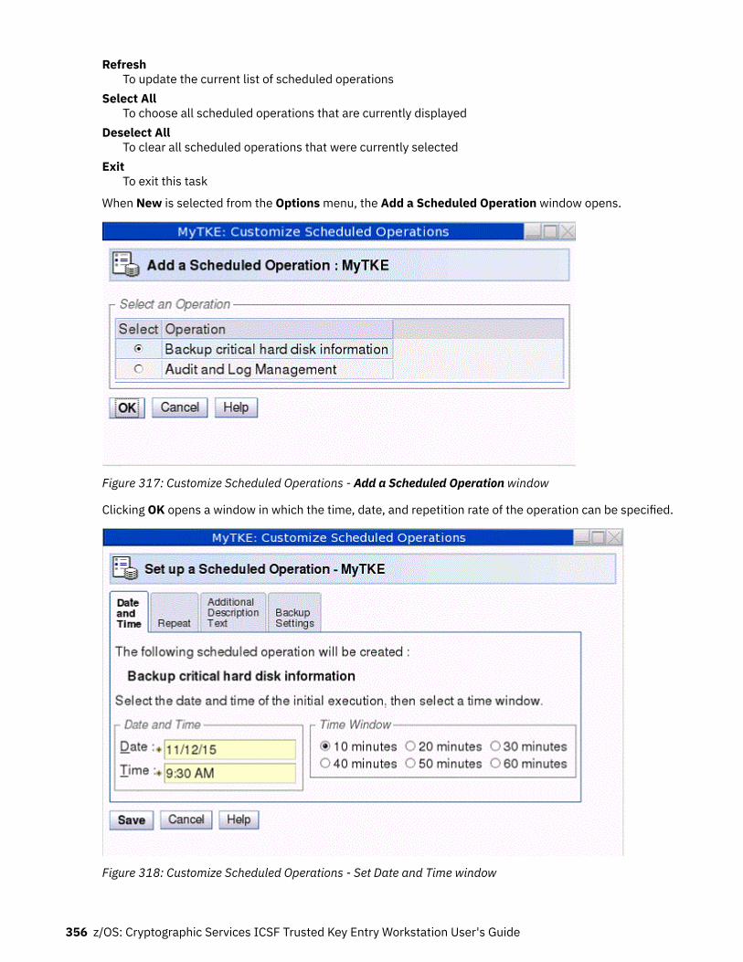
RefreshTo update the current list of scheduled operations
Select AllTo choose all scheduled operations that are currently displayed
Deselect AllTo clear all scheduled operations that were currently selected
ExitTo exit this task
When New is selected from the Options menu, the Add a Scheduled Operation window opens.
Figure 317: Customize Scheduled Operations - Add a Scheduled Operation window
Clicking OK opens a window in which the time, date, and repetition rate of the operation can be specified.
Figure 318: Customize Scheduled Operations - Set Date and Time window
356 z/OS: Cryptographic Services ICSF Trusted Key Entry Workstation User's Guide

Enter the date and time for a scheduled operation in the Date and Time area. The Time Window areadefines the time frame in which the scheduled operation must start.
After you specify the date, time, and time window, click the Repeat tab.
Select whether the operation is a single occurrence or repeats. Select the days of the week you want toperform the operation. The Interval field specifies the number of weeks to elapse before the scheduledoperation is performed again. The Repetitions field specifies the number of times you want the scheduledoperations to be performed.
Figure 319: Customize Scheduled Operations - Set repetition of operation
After all the information is selected, click Save to complete the scheduling of the operation.
Figure 320: Completion window for Adding Scheduled Operation
Trusted Key Entry applications and utilities 357

Figure 321: Customize Scheduled Operations
Click Sort on the menu bar to specify how you want to view the list of scheduled operations: by date andtime, by object, or by operation. The Date and time option sorts the list according to date in descendingorder with the most recent operation at the top. The By Object and By Operation options have nomeaning for TKE. The only object is TKE and the only operation is Backup Critical Console Data.
Click View on the menu bar to select:Schedule Details
Used to display schedule information for the selected scheduled operation. For TKE, Object andOperation are not relevant.
New Time RangeUsed to specify a definite time range (days, weeks, months, or displayed scheduled operations) forthe selected operation.
358 z/OS: Cryptographic Services ICSF Trusted Key Entry Workstation User's Guide

Figure 322: Details view of scheduled operation
Figure 323: New time range window for scheduled operation
Format mediaThe Format Media task is used to format USB flash memory drives.
1. To invoke this task, click on Service Management and then click on Format Media.
The Format Media dialog is displayed.
Trusted Key Entry applications and utilities 359

Figure 324: Format Media dialog2. In the Format Media dialog, select the appropriate format type from the list. The format type you
select will determine how the media is formatted and what label is written on it.
Table 38: Allowable labels when formatting USB flash memory
Format Label Description:
Backup/restore ACTBKP This formatted media is used inthe Backup Critical Console Datatask and the CustomizeScheduled Operations task. Tochoose this format type, selectBackup/restore.
Trusted Key Entry data TKEDATA This formatted media is used inthe TKE applications and tasks.TKE data can be related to TKE,SCUP, CNM, the Migration utility,or user defined. To choose thisformat type, select Trusted KeyEntry data.
Service data SRVDAT This formatted media is used inthe Transmit Console ServiceData task. To choose this formattype, select Service data.
Upgrade data ACTUPG This formatted media is used inthe Save Upgrade Data task. Tochoose this format type, selectUpgrade data.
Security log ACTSECLG This formatted media is used inthe Archive Security Logs or theLog Offload Support forCustomer Audit tasks. Tochoose this format type, selectSecurity log.
360 z/OS: Cryptographic Services ICSF Trusted Key Entry Workstation User's Guide

Table 38: Allowable labels when formatting USB flash memory (continued)
Format Label Description:
Virtual RETAIN VIRTRET This formatted media is used inthe Offload Virtual RETAIN Datato Removable Media task. Tochoose this format type, selectVirtual RETAIN.
User-specified label
3. In the Format Media dialog, click the Format push button. If you selected "User specified label", adialog will prompt you for a label name. Type in the name, and click the Format push button.
The Select Media Device dialog is displayed.
Figure 325: Select Media Device4. In the Select Media Device dialog, select the radio button for the desired device, and click the OK push
button.
A confirmation dialog displays a warning that the format media action will remove all data on theremovable media selected.
5. If you wish to continue the format media action, click the confirmation dialog's Yes push button.
An informational window will display when the Format Media action has completed.
Audit and log managementThis task copies the TKE console's default security log to an ASCII format file on a USB flash memorydrive. The default security log on the TKE console is not changed. You must logon with a console username of AUDITOR to use this task. See “Audit and log management” on page 231 for more information.
Hardware messagesThis task displays messages about hardware activity on the Trusted Key Entry workstation.
When the green 'Status OK' icon (lower left corner of the TKE Console), changes to the blue 'StatusMessages' icon it indicates that a Hardware Message is pending. The message can be viewed by clickingon the Status icon or by invoking this task.
To invoke the Hardware Messages task, click on Service Management and then click on HardwareMessages.
Trusted Key Entry applications and utilities 361

Messages are listed from the oldest to the newest message, with the oldest message displayed at the topof the list.Date
Displays the date the message was sent.Time
Displays the time the message was sent.Message Text
Displays the message.
Figure 326: Hardware Messages window
Hardware messages notify you of events that involve or affect the TKE workstation hardware or internalcode.
To promptly view, act on, or delete messages:
1. Select a message, then click Details to display details.
Figure 327: Hardware Messages - details window2. If messages details are available and intervention is required, perform the action recommended in the
details.3. To delete the selected message, click Delete.
A message is displayed until an action causes it to be deleted.
Some messages are deleted automatically after the message or its details are displayed, if available.These messages generally provide information only, and are deleted automatically because no furtheraction is required.
362 z/OS: Cryptographic Services ICSF Trusted Key Entry Workstation User's Guide

Messages that require further action provide message details that include a recommended action. Themessage and its details remain available until it is deleted manually. This allows reviewing the messagedetails to assist intervention. But the message must be deleted when its information is no longer required.
Deleting messages provides greater assurance that new messages will be displayed as they are received.
Lock consoleThis task is used to allow customers to lock the TKE console. The Lock Console task appears in theService Management tree when you are logged in as ADMIN, SERVICE, AUDITOR, or TKEUSER.
To invoke this task, click on Service Management and then click on Lock Console.
This task prompts the user for a password in order to lock the TKE console. Passwords can be up to any12 characters except a space, backspace (\), *, and -. If any of these characters are entered you willreceive an error message.
Figure 328: Prompt for password
The user must enter a password and confirm it.
Once you have entered a password value, confirmed it, and selected OK, a screen saver will lock the TKEConsole. To unlock the console, move the mouse or touch the keyboard and you will be prompted for thepassword.
Figure 329: Prompt to unlock console
At the Console Password prompt, each keystroke appears as a question mark on the password prompt. Ifthe correct password is entered, the user returns to the TKE console. If an incorrect password is entered,an error message will be displayed informing the user.
Manage print screen filesThe Manage Print Screen Files task can be used to print individual windows on the TKE console to a file orto print the entire screen. Print screen files can be viewed, copied to a USB flash memory drive, anddeleted using this task.
Trusted Key Entry applications and utilities 363

Network diagnostic informationThe Network Diagnostic Information task displays network information such as TCP/IP addresses andEthernet settings. It can test network connections by sending an echo request (ping) to a remote host.
Rebuild vital product dataThis task is used to rebuild the Vital Product Data for the TKE machine.
Note: This task will only be displayed when logged on with the SERVICE user name.
Offload virtual RETAIN data to removable mediaNote: This task will only be displayed when logged on as the SERVICE ID.
This task is used to select, by problem number, specific virtual RETAIN data to offload to a USB flashmemory drive.
To invoke this task, click on Service Management and then click on Offload Virtual RETAIN Data toremovable media.
Note: The removable media must be formatted with volume identification label VIRTRET, using theFormat Media task.
Figure 330: Virtual RETAIN Data Offload window
In the Virtual RETAIN Data Offload window, select the Problem Number and click OK. The selected virtualRETAIN data is off-loaded to the removable media.
When the virtual RETAIN data is offloaded successfully, a message is displayed indicating the offload wassuccessful.
Figure 331: Successful offload of data
If you insert removable media that has not been formatted or that has the wrong label, an error messageis displayed.
364 z/OS: Cryptographic Services ICSF Trusted Key Entry Workstation User's Guide

Figure 332: Virtual RETAIN Data Offload incorrect media error
Password protect consoleThis task allows you to require a password for the default console user and to specify the password value.
You can also use this task to change the current password for the default console user or to specify that apassword is no longer required.
Save/restore customizable console dataThis task allows you to save and restore console data using USB memory or an FTP server. You can selectto save or restore console user passwords, TKE data files, or both.
This task can be used to transfer console data to a different TKE or to recover console data after an install.You must be logged on the console as ADMIN or SERVICE to use this task.
Save upgrade dataThe Save Upgrade Data task is used when a customer is upgrading to a new TKE image. The task shouldonly be executed when an engineering change (EC) upgrade or miscellaneous equipment specification(MES) instructs you to save the Trusted Key Entry workstation's upgrade data. You must log on with aconsole user name of ADMIN or SERVICE to use this task.
All data pertinent to the TKE workstation (for example, TKE-related data directories, emulator sessions,and TCP/IP information) will be saved. Upgrading the Trusted Key Entry workstation requires saving itsupgrade data before installing new EC or MES code, then restoring the upgrade data afterwards.
To invoke this task, click on Service Management and then click on Save Upgrade Data.
Figure 333: Save Upgrade window
Some upgrade procedures save and restore the Trusted Key Entry workstation's upgrade dataautomatically, and there is no need to use this console action. Otherwise, if you are following an upgrade
Trusted Key Entry applications and utilities 365

procedure that instructs you to save the Trusted Key Entry workstation's upgrade data, you must use thisconsole action to save it manually.
Note: The USB flash memory drive for this task must be formatted with a volume identification label ofACTUPG, using the Format Media task.
Figure 334: Save upgrade success window
Shutdown or restartThis task allows you to restart the application/console or power off.
To invoke this task, click on Service Management and then click on Shutdown or Restart.
The Shutdown or Restart dialog displays.
Figure 335: Shutdown or Restart task window
Select one of the following options from the dialog and press OK.
366 z/OS: Cryptographic Services ICSF Trusted Key Entry Workstation User's Guide

Restart ApplicationTo close the Trusted Key Entry workstation and restart the application, select Restart application.
Restart ConsoleTo close the Trusted Key Entry workstation, perform a system power-on reset, and restart the console,select Restart console.
Power-off consoleTo close the Trusted Key Entry workstation, shut down the operating system, and power-off thehardware, select Power-off console.
Selecting any option will present you with a confirmation window. Press Yes to continue.
Figure 336: Confirmation window
Transmit console service dataThis task is used to select the types of service data and the method to send the data to aid in the problemdetermination. You must log on with a console user name of SERVICE to use this task.
To invoke this task, click on Service Management and then click on Transmit Console Service Data.
Figure 337: Transmit Console Service Data
Service data is a set of program and event traces and storage dumps. The data in the traces and thecontents of storage assists in servicing the system.
Use the Transmit Console Service Data window only when directed by your service representative orsupport system. Select the service data categories requested by the support system. Service data inselected categories is collected in a file or group of files for transmission to the support system.
Note: Some service data categories may not be available for selection. Such categories appear grayed.This indicates that no data is available for that category.
Service Categories:
Trusted Key Entry applications and utilities 367

Service Data SelectionsUse the displayed categories in this topic to select the types of service data to send to the supportsystem.
Service Data DestinationUse this topic to specify how your service data is sent to the support system.
Virtual RETAIN FilesUse this topic to copy to a USB flash memory drive selected virtual RETAIN files for the specifiedproblem number.
Note: You can select and copy virtual RETAIN files to a USB flash memory drive for only a single problemnumber at a time.
Note: When using a USB flash memory drive for service data it must first be formatted specifically forService Data. See “Format media” on page 359 for details.
Successful completion will present the following window.
Figure 338: Transmit Console Service Data - successful completion
For Virtual RETAIN Files, enter the problem number in the Virtual RETAIN Files for Problem Number fieldand click on Select Files.
Figure 339: Update problem number for virtual RETAIN file
Select the applicable Virtual RETAIN Files and click OK.
368 z/OS: Cryptographic Services ICSF Trusted Key Entry Workstation User's Guide

Figure 340: Select the virtual RETAIN files
Click on Send to transmit the selected Virtual RETAIN files to Media.
Insert the selected media when prompted.
Figure 341: Copying data to selected media
An information window will display when the data has been written to the required media.
Users and tasksThe Users and Tasks task window displays the users and running tasks on the TKE Workstation and allowsyou to switch to a currently running task or terminate a task that perhaps will not complete.
You can only switch to Service Management type tasks. If you attempt to switch to a Trusted Key Entrytask (Applications and Utilities) you will be presented with a window stating 'This function is not availablefor Trusted Key Entry tasks. Switch To only works with Service Management tasks'.
The Terminate option can be used to terminate either Trusted Key Entry tasks or Service Managementtasks. The only exception is the Trusted Key Entry CCA CLU task. If you attempt to terminate CLU from thistask you will be presented with a window stating 'You cannot terminate the CCA CLU Utility from the LoginDetails and Task menu. If you need to terminate CLU you must use the Exit option of the CLU Utility.'
Trusted Key Entry applications and utilities 369

Figure 342: Users and Tasks window
View console eventsThis task displays console events logged by the Trusted Key Entry workstation.
To invoke this task, click on Service Management and then click View Console Events.
Figure 343: View Console Events window
The Trusted Key Entry workstation automatically keeps a log of significant operations and activities,referred to as console events, that occur while the application is running.
370 z/OS: Cryptographic Services ICSF Trusted Key Entry Workstation User's Guide

This window displays all console events currently logged and lists them in reverse order of occurrence,from the most recent event to the oldest event. You can select a different time and date range for theevents displayed using an option on the View pull-down menu.
View console informationThis task shows the Machine Information (Type, Model Number, and Serial Number) and the InternalCode Change History. The information contained here may be useful for problem determination.
To invoke this task, click on Service Management and then click on View Console Information.
The View Console Information window is displayed.
Figure 344: View Console Information window
For additional information about an internal code change, select an EC number, then click EC Details.
The Internal Code Change Details window is displayed.
Trusted Key Entry applications and utilities 371
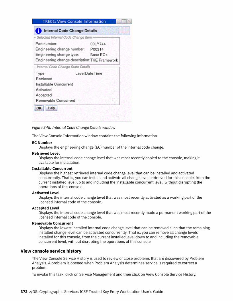
Figure 345: Internal Code Change Details window
The View Console Information window contains the following information.
EC NumberDisplays the engineering change (EC) number of the internal code change.
Retrieved LevelDisplays the internal code change level that was most recently copied to the console, making itavailable for installation.
Installable ConcurrentDisplays the highest retrieved internal code change level that can be installed and activatedconcurrently. That is, you can install and activate all change levels retrieved for this console, from thecurrent installed level up to and including the installable concurrent level, without disrupting theoperations of this console.
Activated LevelDisplays the internal code change level that was most recently activated as a working part of thelicensed internal code of the console.
Accepted LevelDisplays the internal code change level that was most recently made a permanent working part of thelicensed internal code of the console.
Removable ConcurrentDisplays the lowest installed internal code change level that can be removed such that the remaininginstalled change level can be activated concurrently. That is, you can remove all change levelsinstalled for this console, from the current installed level down to and including the removableconcurrent level, without disrupting the operations of this console.
View console service historyThe View Console Service History is used to review or close problems that are discovered by ProblemAnalysis. A problem is opened when Problem Analysis determines service is required to correct aproblem.
To invoke this task, click on Service Management and then click on View Console Service History.
372 z/OS: Cryptographic Services ICSF Trusted Key Entry Workstation User's Guide

The View Console Service History window is displayed.
Figure 346: View Console Service History window
Each record of a problem includes detailed information about the problem and indicates whether theservice required to correct the problem is still pending (Open), is already completed (Closed), or no longerneeded (Closed).
View on the menu bar:
• Problem summary lists information about the problem and what actions are needed to diagnose andcorrect it.
Figure 347: Problem summary• The Problem Analysis Panels show System name, Date, Time, Problem Description, and Corrective
Actions that a user can take.
Trusted Key Entry applications and utilities 373

Figure 348: Problem Analysis• Cancel exits this task and returns to the Trusted Key Entry Console.
Clicking Close on the menu bar brings up two options:
• Selected Problem changes the status of the selected problem to Closed.• All Problems changes the status of all open problems to Closed.
View console tasks performedThe View Console Tasks Performed task window shows a summary of the console tasks performed withthe date and time associated with each task. The most recent tasks invoked are appended to the bottomof the list. This information is useful in determining past activity performed on the TKE Workstation forauditing or problem determination.
To invoke this task, click on Service Management and then click on View Console Tasks Performed. TheView Console Tasks Performed window is displayed.
You must scroll the display to the right until you see the inner right scroll bar for moving the display upand down.
374 z/OS: Cryptographic Services ICSF Trusted Key Entry Workstation User's Guide

Figure 349: View Console Tasks Performed window
View licensesThis task is used to view the open source licenses for the Trusted Key Entry Console.
To view a specific license, click on it. When you are done viewing the license information click on OK toexit.
If you have not viewed any license information through this task, the first TKE related task that you invokewill display the license information. This will only be done once.
Trusted Key Entry applications and utilities 375

Figure 350: View Licenses window
View security logsThis task displays the TKE console's default security log. The security log is a record of the security-relevant events that have occurred on or have been initiated by the TKE workstation. You must log on witha console user name of AUDITOR to use this task.
See “View security logs” on page 230 for more information.
376 z/OS: Cryptographic Services ICSF Trusted Key Entry Workstation User's Guide

Appendix F. TKE best practices
This information describes the setup required for TKE to manage host crypto modules, and a set of setupsteps to perform on the TKE workstation. TKE workstations initialized for passphrase and initialized forsmart card use are considered separately.
Checklist for loading a TKE machine - passphraseExpectations
• You are working with CCA host crypto modules• The support element has enabled TKE on these host crypto modules• LPARs are established• TKE licensed internal code (LIC) is loaded on the TKE workstation• Segments 1, 2, and 3 have been loaded on the TKE workstation crypto adapter• The TKE host transaction program has been configured and started in the host TKE LPAR• ICSF is started in each LPAR
Setup
• 2 TKEs both running the same level of software
– One for production– One for backup
• 2 Central electronic complex (CEC) cards being shared
– One Test LPARs (Domain 0)– Three Production LPARs (Domain 1, 2, 3)
TKE can load the master key in a group of domains as defined by a domain group.• Host TKE LPAR 1
When defining the LPAR activation profile, the usage domain will be 1 and the control domain will be 0,1, 2, 3.
The following User IDs are used to restrict access to the TKE workstation crypto adapter:
• TKEUSER - can run the main TKE application• TKEADM - can create and update TKE roles and profiles• KEYMAN1 - can clear TKE new master keys and load first master key parts• KEYMAN2 - can load TKE middle and last key parts and reencipher TKE workstation key storage
Authorities are used to restrict access to the CCA crypto modules on the host machine.
One way to control access to CCA host crypto modules is with a minimum of seven host authorities.
• ISSUER
– Disable host crypto module– Enable host crypto module issue– Access control issue– Zeroize domain issue– Domain control change issue
• COSIGN
© Copyright IBM Corp. 2000, 2019 377

– Access control co-sign– Enable host crypto module co-sign– Zeroize domain co-sign– Domain control change co-sign
• MKFIRST
– AES, DES, ECC (APKA), or RSA load first master key part– Clear new master key register– Clear old master key register
• MKMIDDLE
– AES, DES, ECC (APKA), or RSA combine middle master key parts• MKLAST
– AES, DES, ECC (APKA), or RSA combine final master key part– Set RSA master key
• FIRSTCLEAR
– Load first operational key part– Clear operational key register
• ADDCOMP
– Load additional operational key part– Complete key
The following tasks should be run using the TKE workstation to set up the TKE workstation and the hostcrypto modules for use. Be aware that the Service Management tasks available to you will vary dependingon the console user name you used to log on. Refer to “Service Management tasks” on page 352 for moreinformation.
1. Customize Network Settings2. Customize Console Date/Time3. Initialize the TKE workstation crypto adapter for passphrase use
a. Predefined TKE roles and profiles are loaded.b. The TKE master keys are set and TKE key storages are initialized.
4. Logon to CNM with KEYMAN1 - OPTIONAL
a. Clear the new DES/PKA and AES master key registersb. Enter known first master key parts for the DES/PKA and AES master keys.c. Logoff
5. Logon to CNM with KEYMAN2 - OPTIONAL
a. Enter known middle and last master key parts for the DES/PKA and AES master keys.b. Reencipher DES, PKA, and AES key storagec. Logoff
6. Logon to CNM with TKEADM
a. Create user defined roles - OPTIONALb. Create user defined profiles - OPTIONALc. Create groups and add users - OPTIONAL
Note: Group members should already be defined.d. Change the passphrases for all of the predefined profiles - TKEADM, TKEUSER, KEYMAN1, and
KEYMAN2
378 z/OS: Cryptographic Services ICSF Trusted Key Entry Workstation User's Guide

7. Log on to the main TKE application with TKEUSER profile or another profile with the same authority
a. Load the default authority key for key index 0b. Change these options of your security policy via the TKE preferences menu
• Blind Key Entry• Removable media only
c. Create a Hostd. Create domain groups - OPTIONALe. Open a host or a domain group (requires host logon)f. Open a crypto module notebook or domain group notebook
g. Create role or rolesh. Generate authority key or keys and save them to binary file or filesi. Create different authorities using the different authority key or keys that were just generated.j. Delete the authority 00 or change the authority key to a key that is not the default key. If you
delete authority 00 make sure that you have 2 other known authority keys that have the Domaincontrol change issue and co-sign.
8. Configure 3270 Emulators9. Backup Critical Console Data onto a USB flash memory drive.
10. Customize Scheduled Operations to schedule the backup critical console data task
Checklist for loading a TKE machine - smart cardExpectations:
• You are working with CCA or EP11 host crypto modules.• The support element has enabled TKE on these host crypto modules.• LPARs are established (set up and predefined).• TKE licensed internal code (LIC) is loaded on the TKE workstation.• Segments 1, 2, and 3 have been loaded on the TKE workstation crypto adapter.• The TKE host transaction program has been configured and started in the host TKE LPAR.• ICSF is started in each LPAR.• Smart card readers are attached.
Setup
• 2 TKEs both running the same level of software
– One for production– One for backup
• 2 CECs cards being shared
– One Test LPARs (Domain 0)– Three Production LPARs (Domain 1, 2, 3)
TKE can load the master key in a group of domains as defined by a domain group.• Host TKE LPAR 1
When defining the LPAR activation profile, the usage domain will be 1 and the control domain will be 0,1, 2, 3.
Profiles and roles are used to restrict access to the TKE workstation crypto adapter. There are two roles,listed below, that are needed to use the TKE and CNM applications. Profiles are created by first generatinga crypto adapter logon key and then creating a profile using the crypto adapter logon key.
TKE best practices 379

• SCTKEUSR - can run the main TKE application• SCTKEADM - can run CNM to create and update TKE roles and profiles
Authorities are used to restrict access to the CCA crypto modules on the host machine.
Administrators are used to restrict access to the EP11 crypto modules on the host machine.
One way to control access to the CCA host crypto modules is with a minimum of seven host authorities.
• ISSUER
– Disable host crypto module– Enable host crypto module issue– Access control issue– Zeroize domain issue– Domain control change issue
• COSIGN
– Access control co-sign– Enable host crypto module co-sign– Zeroize domain co-sign– Domain control change co-sign
• MKFIRST
– AES, DES, ECC (APKA), or RSA load first master key part– Clear new master key register– Clear old master key register
• MKMIDDLE
– AES, DES, ECC (APKA), or RSA combine middle master key parts• MKLAST
– AES, DES, ECC (APKA), or RSA combine final master key part– Set RSA master key
• FIRSTCLEAR
– Load first operational key part– Clear operational key register
• ADDCOMP
– Load additional operational key part– Complete key
The steps to set up the TKE workstation for smart card use are as follows. Be aware that the ServiceManagement tasks available to you will vary depending on the console user name you used to log on.Refer to “Service Management tasks” on page 352 for more information.
1. Customize Network Settings.2. Customize Console Date/Time.3. Initialize the TKE workstation crypto adapter for smart card use:
a. Predefined TKE roles and profiles are loaded.b. The TKE master keys are set and TKE key storages are initialized.
4. Open the SCUP application.
a. Create a CA smart card.b. Backup CA smart cards.
380 z/OS: Cryptographic Services ICSF Trusted Key Entry Workstation User's Guide

c. Create TKE smart cards.
Note: In general, smart cards created on a particular TKE release cannot be used on TKEworkstations that are at prior release levels. There are exceptions. See “Smart card usage” onpage 49.
d. Create EP11 smart cards.e. Enroll the TKE workstation crypto adapter with the CA card.
5. Open CNM.
Note: Choose the "Default Logon". The temp default role will be used, and has full access to doeverything on the crypto adapter.
a. Enter known DES/PKA and AES master keys. (Optional)
• Do this only if you want to have known master keys to use again.b. Reencipher DES, PKA, and AES key storage. (Optional)
• Do this only if you entered your own master keys.c. Generate TKE workstation crypto adapter logon keys for each smart card that will be logging on to
the TKE or CNM applications.d. Create new profile or profiles for the smart cards under the Access Control menu. The roles for
these profiles are loaded in the crypto adapter when TKE's Crypto Adapter Initialization task isrun.
e. Create group or groups and add users.
Note: Group members should already be defined.f. Load the default role.
• When the TKE workstation crypto adapter is initialized the TEMPDEFAULT role is loaded. Youneed to load the DEFAULT role to secure the TKE workstation.
6. Log on to the main TKE application with the SCTKEUSR profile or another profile with the sameauthority.
a. Load the default authority key for key index 0.b. Change these options of your security policy via the TKE preferences menu
• Blind Key Entry• Removable media only
c. Create a Host.d. Create domain groups. (Optional)e. Open a host or a domain group (requires host logon).f. Open a crypto module notebook or domain group notebook.
g. For CCA host crypto modules:
1) Create roles.2) Generate authority keys and save them to TKE smart cards.
Note: You can generate and save 1024-bit and 2048-bit RSA keys and BP-320 ECC keys onTKE smart cards. Authorities with 2048-bit RSA keys are supported starting with the CEX3C.Authorities with BP-320 ECC keys are supported starting with the CEX5C.
3) Create different authorities using the different authority keys that were just generated.4) Delete the authority 00 or change the authority key to a key that is not the default key. If you
delete authority 00 make sure that you have 2 other known authority keys that have theDomain control change issue and cosign.
h. For EP11 host crypto modules:
1) Generate administrator keys and save them to EP11 smart cards.
TKE best practices 381

2) Zeroize the host crypto module or the set of domains you want to administer. Zeroizing a hostcrypto module or domain puts it in "imprint mode", where administrators can be added withoutusing signed commands.
3) Add crypto module and domain administrators.4) Set the signature threshold and revocation signature threshold on each crypto module and
domain. This ends imprint mode.7. Configure 3270 Emulators.8. Backup Critical Console Data.9. Customize Scheduled Operations to schedule the backup critical console data task.
10. If using the same set of smart cards on another TKE, you need to use the Remote Enroll feature forTKE.
382 z/OS: Cryptographic Services ICSF Trusted Key Entry Workstation User's Guide

Appendix G. TKE hardware support and migrationinformation
This information includes the following topics:
• “TKE release and feature codes available by CEC levels” on page 383• “Smart card readers and smart cards orderable by TKE release” on page 383• “TKE (LIC) upgrade paths” on page 385• “Host cryptographic modules managed by TKE” on page 385
TKE release and feature codes available by CEC levelsTable 39 on page 383 shows the TKE licensed internal code (LIC) that is orderable based on the date andtype of your CEC.
Most of the time, a new version of the TKE workstation is released at the same time as a new CEC. Whenyou order a new TKE workstation, you receive the latest TKE hardware with the latest TKE licensedinternal code (LIC) installed on it. For example, if you had placed an order for a new TKE workstationbetween September of 2012 and September of 2013, you would have received TKE 7.2 (or, in orderwords, hardware feature code 0841 with LIC feature code 0850).
Table 39: TKE release and feature codes available by CEC level.
TKErelease(LIC)
Feature codes CEC information
Hardware LIC Initial releasedate
z9-109z9EC2094
z9BC2096
z10EC2097
z10BC2098
z10ECGA3z10BCGA2
z196 z114 zEC12 zBC12 z13 z13s z14
TKE 5.3 0839 0854 Oct 2008 Yes Yes Yes Yes N/A N/A N/A N/A N/A N/A N/A N/A
TKE 6.0 0840 0858 Nov 2009 Yes Yes Yes Yes N/A N/A N/A N/A N/A N/A N/A N/A
TKE 7.0 0841 0860 Sept 2010 N/A N/A Yes Yes Yes Yes Yes N/A N/A N/A N/A N/A
TKE 7.1 0841 0867 Sept 2011 N/A N/A Yes Yes Yes Yes Yes N/A N/A N/A N/A N/A
TKE 7.2 0841 0850 Sept 2012 N/A N/A N/A N/A N/A Yes Yes Yes N/A N/A N/A N/A
TKE 7.3 0842 0872 Sept 2013 N/A N/A N/A N/A N/A Yes Yes Yes Yes N/A N/A N/A
TKE 8.0 0847 0877 Feb 2015 N/A N/A N/A N/A N/A N/A N/A Yes Yes Yes Yes Yes
TKE 8.1 0847 or 0097 0878 Feb 2016 N/A N/A N/A N/A N/A N/A N/A Yes Yes Yes Yes Yes
TKE 9.0 0085 or 0086 0879 Sept 2017 N/A N/A N/A N/A N/A N/A N/A N/A Yes Yes Yes Yes
TKE 9.1 0085 or 0086 0880 Nov 2018 N/A N/A N/A N/A N/A N/A N/A N/A N/A Yes Yes Yes
Your host cryptographic environment determines the level of TKE LIC that you can use. To determinewhich host cryptographic modules are supported by your TKE, see Table 42 on page 386.
Smart card readers and smart cards orderable by TKE releaseTable 40 on page 384 shows the smart card readers and smart cards that can be ordered for each TKErelease.
© Copyright IBM Corp. 2000, 2019 383

Table 40: Smart card readers and smart cards orderable by TKE release.
TKE release (LIC) Smart card reader Smart card
Feature code Type Feature code Part number
TKE 5.3 0885 Omnikey/HID 0884 45D3398
TKE 6.0 0885 Omnikey/HID 0884 45D3398
74Y0551* #
TKE 7.0 0885 Omnikey/HID 0884 45D3398
74Y0551* #
TKE 7.1 0885 Omnikey/HID 0884 45D3398
74Y0551*
TKE 7.2 0885 Omnikey/HID 0884 74Y0551*
TKE 7.3 0885 Omnikey/HID 0884 74Y0551*
TKE 8.0 0885 or 0891 Omnikey/HID 0884 or 0892 00JA710
TKE 8.1 0885 or 0891 @ Omnikey/HID/Gemalto
0884 or 0892 00JA710
TKE 9.0 0885 or 0891 @ Omnikey/HID/Gemalto/IDENTIV
0892 00JA710
TKE 9.1 0891 IDENTIV 0900 00RY790
*Part number 74Y0551 replaced part number 45D3398 in feature code 0884.
#An MCL is required to support part number 74Y0551 on TKE 6.0 and TKE 7.0.
@
• Clients in the United States, Canada, and European Union (EU) might receive Gemalto CT700readers.
• With Gemalto smart card readers, you must press the green Enter button after you enter the PIN ora character during the secure key entry process.
There are restrictions on what smart card part numbers can be used to create different smart card types.For more information, see “Smart card compatibility issues” on page 46.
DATAKEY smart cards are not supported on TKE 7.0 or later. If you are upgrading from TKE 6.0 to TKE 7.0or later and have DATAKEY smart cards, you need to back up your CA smart cards by using a more currentsmart card part number and copy keys and key parts from your TKE smart cards onto TKE smart cardsthat are created from a more current smart card part number. See “Datakey card usage” on page 50 forinformation on migrating data to a new smart card.
To identify the part number of your smart card, look for the following:DATAKEY
Has blue and orange art work and DATAKEY printed on them.45D3398
Are white and do not have any part number printed on them.74Y0551
Has part number 74Y0551 printed on them.00JA710
Has part number 00JA710 printed on them.
384 z/OS: Cryptographic Services ICSF Trusted Key Entry Workstation User's Guide

TKE (LIC) upgrade pathsTable 41 on page 385 shows which TKE licensed internal code (LIC) can be upgraded to a new LIC level.
Table 41: Summary of when a TKE workstation can be upgraded.
Starting point Upgradable to TKE LIC level
TKErelease(LIC)
Hard-warefeaturecode
TKEcryptoadapter type
TKE 6.0(FC 0858)
TKE 7.0(FC 0860)
TKE 7.1(FC 0867)
TKE 7.2(FC 0850)
TKE 7.3(FC 0872)
TKE 8.0(FC 0877)
TKE 8.1(FC 0878)
TKE 9.0(FC 0879)
TKE 9.1(FC 0880)
TKE 5.3 0839 4764 Yes No No No No No No No No
TKE 6.0 0839 4764 Base* No No No No No No No No
0840
TKE 7.0 0841 4765 N/A Base* Yes Yes Yes No No No No
TKE 7.1 0841 4765 N/A N/A Base* Yes Yes No No No No
TKE 7.2 0841 4765 N/A N/A N/A Base* Yes No No No No
TKE 7.3 0841 4765 N/A N/A N/A N/A Base* No No No No
0842 4765 N/A N/A N/A N/A Base* Yes Yes Yes Yes
TKE 8.0 0847 4767 N/A N/A N/A N/A N/A Base* Yes Yes Yes
TKE 8.1 0847 4767 N/A N/A N/A N/A N/A N/A Base* Yes Yes
0097
TKE 9.0 0085 4768 N/A N/A N/A N/A N/A N/A N/A Base* Yes
0086
TKE 9.1 0085 4768 N/A N/A N/A N/A N/A N/A N/A N/A Base*
0086
Base*The initial TKE LIC level installed on the TKE workstation before it was shipped.
Note: In general, you cannot upgrade the LIC level of your TKE workstation if the new LIC level requires anew TKE crypto adapter type. An exception is that upgrades from TKE 7.3 with hardware feature code0842 to TKE 8.0 or TKE 8.1 are permitted, but the TKE crypto adapter must be replaced.
Notes about upgrading to TKE 9.0
• When TKE workstation feature 0842 or 0847 is upgraded to TKE 9.0, it becomes workstation feature0849.
• When TKE workstation feature 0097 is upgraded to TKE 9.0, it becomes workstation feature 0080.• When TKE workstation feature 0098 is upgraded to TKE 9.0, it becomes workstation feature 0081,
The upgrade to TKE 9.0 does not include the new secure workstation features of TKE. You must purchasea new TKE 9.0 workstation to obtain the new capability.
When you upgrade the LIC level of your TKE workstation, you can keep your user data. See Chapter 3,“TKE upgrade and migration actions,” on page 57 for more information.
Host cryptographic modules managed by TKETKE manages host cryptographic modules on any CEC where that particular host cryptographic module issupported. In other words, for example, TKE is unaware whether a CEX3C module is running on an IBM
TKE hardware support and migration information 385

System z10, IBM zEnterprise 196, IBM zEnterprise 114, IBM zEnterprise EC12, IBM zEnterprise BC12,IBM z13, IBM z13s, or IBM z14.
Table 42 on page 386 identifies the host cryptographic modules that each TKE release can manage.
Table 42: Host cryptographic modules managed by TKE LIC.
TKE release(LIC)
Host cryptographic modules supported by TKE release
CEX2C CEX3C CEX4C CEX4P CEX5C CEX5P CEX6C CEX6P
TKE 5.2 Yes No No No No No No No
TKE 5.3 Yes Yes No No No No No No
TKE 6.0 Yes Yes Sometimes* No No No No No
TKE 7.0 Yes Yes Sometimes* No No No No No
TKE 7.1 Yes Yes Sometimes* No No No No No
TKE 7.2 Yes Yes Yes Yes# No No No No
TKE 7.3 Yes Yes Yes Yes# No No No No
TKE 8.0 Yes Yes Yes Yes# Yes@,+ Yes#, $ No No
TKE 8.1 Yes Yes Yes Yes# Yes@,+ Yes#, $ No No
TKE 9.0 Yes Yes Yes Yes# Yes@,+ Yes#, $ Yes Yes#
TKE 9.1 Yes Yes Yes Yes# Yes@,+ Yes#, $ Yes Yes#
+TKE 8.1 with the TKE Tower Code level of 3 or higher is required to manage a CEX5C at level CCA 5.3.The TKE Tower Code is include in TKE LIC Control Level 004 and beyond.
*A Crypto Express4 that is running in Common Cryptographic Architecture (CCA) mode as a CEX4C isonly supported when running ICSF FMID HCR7790 or lower with the toleration APAR OA39075 thatallows the CEX4C to report in as a CEX3C. In this case, ICSF sees the module as a CEX3C andmanages it as a CEX3C.
#Modules running in EP11 mode require smart cards to hold administrator certificates and master keymaterial. Smart card readers must be attached to the TKE workstation to administer these host cryptomodule types.
@You must be using one of the following levels of ICSF:
• ICSF FMID HCR77B0.• ICSF FMID HCR77A1, HCR77A0, HCR7790, or HCR7780 in toleration mode (APAR OA45547) and
also have the new function APAR OA44910.
$You must be using one of the following levels of ICSF:
• ICSF FMID HCR77B0.• ICSF FMID HCR77A1 in toleration mode (APAR OA45547) and also have the new function APAR
OA44910.
Some host cryptographic configurations (in other words, specific cryptographic features or combinationsof the CEC, host cryptographic module, CCA or EP11 level, and ICSF) require minimum levels of TKE tosupport the environment.
386 z/OS: Cryptographic Services ICSF Trusted Key Entry Workstation User's Guide

Appendix H. Hardware Security Module (HSM) eventlog entries that CCA version 6.0.3 supports
Table 43 on page 387 shows all the possible Hardware Security Module (HSM) event log entries that CCAversion 6.0.3 supports.
Table 43: Hardware Security Module (HSM) event log entries
Event ID Description Notes for the event type
0 Initialize card-scoped role inactive.
1 Initialize card-scoped role activate.
2 Initialize domain-scoped role inactive.
3 Initialize domain-scoped role activate.
4 Replace card-scoped role inactive.
5 Replace card-scoped role activate.
6 Replace domain-scoped role inactive.
7 Replace domain-scoped role activate.
8 Initialize card-scoped profile inactive.
9 Initialize card-scoped profile activate.
10 Initialize domain-scoped profile inactive.
11 Initialize domain-scoped profile activate.
12 Change expiration date card-scoped profile.
13 Change expiration date domain-scopedprofile.
14 Passphrase change card-scoped profile.
15 Passphrase change domain-scoped profile.
16 Reset failed logon count card-scopedprofile.
17 Reset failed logon count domain-scopedprofile.
18 Replace card-scoped profile inactive.
19 Replace card-scoped profile activate.
20 Replace domain-scoped profile inactive.
21 Replace domain-scoped profile activate.
22 Delete card-scoped role inactive.
23 Delete card-scoped role activate.
24 Reserved.
25 Delete domain-scoped role inactive.
© Copyright IBM Corp. 2000, 2019 387

Table 43: Hardware Security Module (HSM) event log entries (continued)
Event ID Description Notes for the event type
26 Delete domain-scoped role activate.
27 Delete card-scoped profile inactive.
28 Delete card-scoped profile activate.
29 Reserved.
30 Delete domain-scoped profile inactive.
31 Delete domain-scoped profile activate.
32 Failed logon count exceeded.
33 Logon failed.
34 Clear range card-scoped audit log inactive.
35 Clear range card-scoped audit log activate.
36 Clear range domain-scoped audit loginactive.
37 Clear range domain-scoped audit logactivate.
38 Clear all card-scoped audit log inactive.
39 Clear all card-scoped audit log activate.
40 Clear all domain-scoped audit log inactive.
41 Clear all domain-scoped audit log activate.
42 Firmware update. The log message contains three (32-bit)integer fields. Each field corresponding to theimage revision codes of segments 1, 2, and 3.
43 Set AES master key.
44 Load first AES master key part.
45 Load middle AES master key part.
46 Load last AES master key part.
47 Clear new AES master key register.
48 Clear old AES master key register.
49 Set APKA (ECC) master key.
50 Load first APKA (ECC) master key part.
51 Load middle APKA (ECC) master key part.
52 Load last APKA (ECC) master key part.
53 Clear new APKA (ECC) master key register.
54 Clear old APKA (ECC) master key register.
55 Set DES master key.
56 Load first DES master key part.
57 Load middle DES master key part.
388 z/OS: Cryptographic Services ICSF Trusted Key Entry Workstation User's Guide

Table 43: Hardware Security Module (HSM) event log entries (continued)
Event ID Description Notes for the event type
58 Load last DES master key part.
59 Clear new DES master key register.
60 Clear old DES master key register.
61 Generate random new DES master key.
62 Set RSA master key.
63 Load first RSA master key part.
64 Load middle RSA master key part.
65 Load last RSA master key part.
66 Clear new RSA master key register.
67 Clear old RSA master key register.
68 Generate random new RSA master key.
69 Set DES and AES master keys.
70 Load first DES and AES master key part.
71 Load middle DES and AES master key part.
72 Load last DES and AES master key part.
73 Clear new DES and AES master keyregisters.
74 Clear old DES and AES master key registers.
75 Generate random new DES and AES masterkey.
76 Load Function Control Vector.
77 Clear Function Control Vector.
78 Set clock.
79 Load decimalization table or tables.
80 Delete decimalization table or tables.
81 Enter imprint mode inactive.
82 Enter PCI-compliant mode inactive.
83 Enter PCI-compliant mode activate.
84 Remove PCI-compliant mode inactive.
85 Remove PCI-compliant mode activate.
86 Enter migration mode inactive.
87 Enter migration mode activate.
88 Start secure audit log wrap.
89 Start secure audit log nowrap.
90 Stop secure audit log.
Hardware Security Module (HSM) event log entries that CCA version 6.0.3 supports 389

Table 43: Hardware Security Module (HSM) event log entries (continued)
Event ID Description Notes for the event type
91 Load certificate inactive.
92 Load certificate activate.
93 Load first DES operational key part.
94 Load additional DES operational key part.
95 Complete DES operational key.
96 Clear DES operational key part register.
97 Load first AES operational key part.
98 Load additional AES operational key part.
99 Complete AES operational key.
100 Clear AES operational key part register.
101 Load first AES operational key part (VAR-AES).
102 Load additional AES operational key part(VAR-AES).
103 Complete AES operational key (VAR-AES).
104 Clear AES operational key part register(VAR-AES).
105 Load first HMAC operational key part.
106 Load additional HMAC operational key part.
107 Complete HMAC operational key.
108 Clear HMAC operational key part register.
109 Diffie-Hellman key load, load 4096-bit RSA.
110 Diffie-Hellman key load, combine 4096-bitRSA.
111 Diffie-Hellman key load, clear 4096-bit RSA.
112 Diffie-Hellman key load, load ECC.
113 Diffie-Hellman key load, combine ECC.
114 Diffie-Hellman key load, clear ECC.
115 Start access control tracking.
116 Stop access control tracking.
117 Clear access control tracking data.
118 Collect configuration data, card.
119 Collect configuration data, domain.
120 Apply configuration data, card. This audit record will not be cut if the auditinglevel is off both before and after the applyoperation.
390 z/OS: Cryptographic Services ICSF Trusted Key Entry Workstation User's Guide
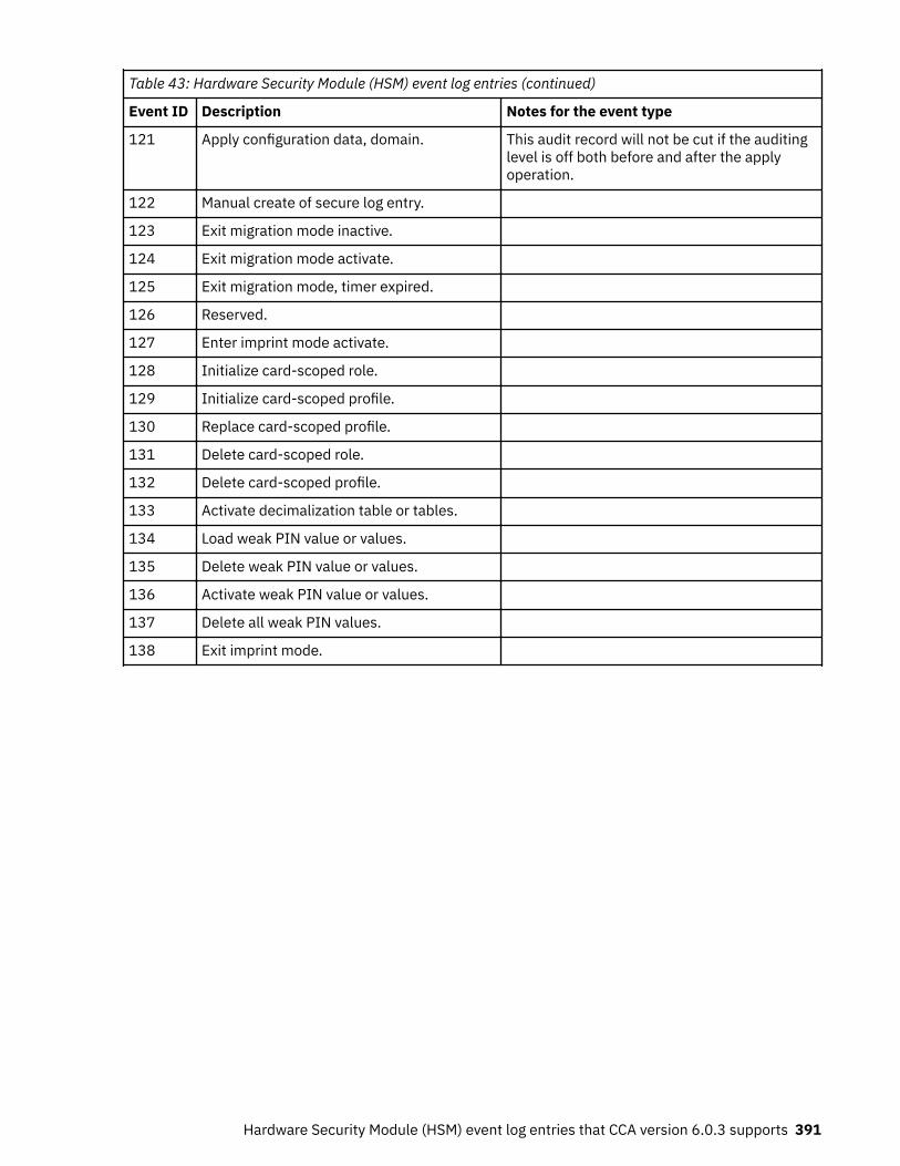
Table 43: Hardware Security Module (HSM) event log entries (continued)
Event ID Description Notes for the event type
121 Apply configuration data, domain. This audit record will not be cut if the auditinglevel is off both before and after the applyoperation.
122 Manual create of secure log entry.
123 Exit migration mode inactive.
124 Exit migration mode activate.
125 Exit migration mode, timer expired.
126 Reserved.
127 Enter imprint mode activate.
128 Initialize card-scoped role.
129 Initialize card-scoped profile.
130 Replace card-scoped profile.
131 Delete card-scoped role.
132 Delete card-scoped profile.
133 Activate decimalization table or tables.
134 Load weak PIN value or values.
135 Delete weak PIN value or values.
136 Activate weak PIN value or values.
137 Delete all weak PIN values.
138 Exit imprint mode.
Hardware Security Module (HSM) event log entries that CCA version 6.0.3 supports 391

392 z/OS: Cryptographic Services ICSF Trusted Key Entry Workstation User's Guide

Appendix I. Multi-Factor Authentication (MFA) andthe TKE
On a system using Multi-Factor Authentication (MFA), you use an alternative authentication mechanism,such as RSA SecureID, to get a one-time use token instead of using a password. The token is used toauthenticate your user ID to the z/OS application to which you are running. Since the token is one-timeuse, any authentication after that would require a new token.
If you use Multi-Factor Authentication (MFA) with the TKE:
• After a TKE OPEN HOST is done, the TKE replays the user ID and password credentials for somecommands sent to the HOST.
• You must run some of the commands that require the replay while you configure host crypto modules.• By default, MFA uses one-time use only credentials and will not allow you to replay the same credential
multiple times.
Therefore, you cannot use a one-time use MFA credential to open a host and configure crypto modules onthat host.
There are two ways to handle the TKE replay issue for MFA:
1. You can use the IBM Multi-Factor Authentication Out-of-band server to get a token that allows replayand is valid for the time needed to configure crypto modules on that host. You pick a timeout value thatmakes sense to you (for example, one hour or one day). When the token expires, you have to close thehost and reopen it with a new token. For more information, see “Out-of-Band cache token credential(CTC)” on page 393.
2. You can add the TKE RACF Authorization application (CSFTTKE) to the application exclusion list forMFA to exclude the TKE RACF Authorization application from MFA processing so that only the user IDand RACF password are needed. For more information, see “Bypassing MFA” on page 394.
For more information about IBM MFA, Out-of-Band, the cache token credential, and exclusion listsupport, see:
• IBM Multi-Factor Authentication for z/OS Installation and Customization (www.ibm.com/servers/resourcelink/svc00100.nsf/pages/zOSV2R3sc278447/$file/azfi100_v1r3.pdf)
• IBM Multi-Factor Authentication for z/OS User’s Guide (www.ibm.com/servers/resourcelink/svc00100.nsf/pages/zOSV2R3sc278448/$file/azfu100_v1r3.pdf)
Out-of-Band cache token credential (CTC)
A cache token credential (CTC) allows reuse of an MFA token for a limited time. A CTC is generated byproviding a token from an application such as RSA SecureID to an IBM MFA Out-of-Band server. The CTCreturned by the Out-of-Band server can then be used and reused instead of having to provide a new tokenfor every transaction requiring authentication.
To specify that a CTC is going to be used for a given length of time, create an MFA policy such as the onebelow:
FACTORS = AZFSIDP1 TOKEN TIMEOUT = 00003600 REUSE = YES
Where:
© Copyright IBM Corp. 2000, 2019 393
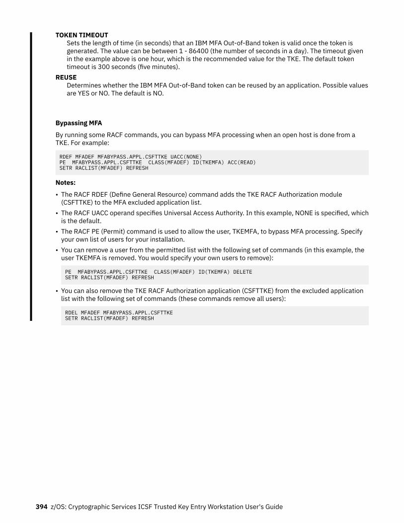
TOKEN TIMEOUTSets the length of time (in seconds) that an IBM MFA Out-of-Band token is valid once the token isgenerated. The value can be between 1 - 86400 (the number of seconds in a day). The timeout givenin the example above is one hour, which is the recommended value for the TKE. The default tokentimeout is 300 seconds (five minutes).
REUSEDetermines whether the IBM MFA Out-of-Band token can be reused by an application. Possible valuesare YES or NO. The default is NO.
Bypassing MFA
By running some RACF commands, you can bypass MFA processing when an open host is done from aTKE. For example:
RDEF MFADEF MFABYPASS.APPL.CSFTTKE UACC(NONE)PE MFABYPASS.APPL.CSFTTKE CLASS(MFADEF) ID(TKEMFA) ACC(READ)SETR RACLIST(MFADEF) REFRESH
Notes:
• The RACF RDEF (Define General Resource) command adds the TKE RACF Authorization module(CSFTTKE) to the MFA excluded application list.
• The RACF UACC operand specifies Universal Access Authority. In this example, NONE is specified, whichis the default.
• The RACF PE (Permit) command is used to allow the user, TKEMFA, to bypass MFA processing. Specifyyour own list of users for your installation.
• You can remove a user from the permitted list with the following set of commands (in this example, theuser TKEMFA is removed. You would specify your own users to remove):
PE MFABYPASS.APPL.CSFTTKE CLASS(MFADEF) ID(TKEMFA) DELETESETR RACLIST(MFADEF) REFRESH
• You can also remove the TKE RACF Authorization application (CSFTTKE) from the excluded applicationlist with the following set of commands (these commands remove all users):
RDEL MFADEF MFABYPASS.APPL.CSFTTKESETR RACLIST(MFADEF) REFRESH
394 z/OS: Cryptographic Services ICSF Trusted Key Entry Workstation User's Guide

Appendix J. Accessibility
Accessible publications for this product are offered through IBM Knowledge Center (www.ibm.com/support/knowledgecenter/SSLTBW/welcome).
If you experience difficulty with the accessibility of any z/OS information, send a detailed email messageto [email protected].
Accessibility features
Accessibility features help users who have physical disabilities such as restricted mobility or limited visionuse software products successfully. The accessibility features in z/OS can help users do the followingtasks:
• Run assistive technology such as screen readers and screen magnifier software.• Operate specific or equivalent features by using the keyboard.• Customize display attributes such as color, contrast, and font size.
Consult assistive technologiesAssistive technology products such as screen readers function with the user interfaces found in z/OS.Consult the product information for the specific assistive technology product that is used to access z/OSinterfaces.
Keyboard navigation of the user interfaceYou can access z/OS user interfaces with TSO/E or ISPF. The following information describes how to useTSO/E and ISPF, including the use of keyboard shortcuts and function keys (PF keys). Each guide includesthe default settings for the PF keys.
• z/OS TSO/E Primer• z/OS TSO/E User's Guide• z/OS ISPF User's Guide Vol I
Dotted decimal syntax diagramsSyntax diagrams are provided in dotted decimal format for users who access IBM Knowledge Center witha screen reader. In dotted decimal format, each syntax element is written on a separate line. If two ormore syntax elements are always present together (or always absent together), they can appear on thesame line because they are considered a single compound syntax element.
Each line starts with a dotted decimal number; for example, 3 or 3.1 or 3.1.1. To hear these numberscorrectly, make sure that the screen reader is set to read out punctuation. All the syntax elements thathave the same dotted decimal number (for example, all the syntax elements that have the number 3.1)are mutually exclusive alternatives. If you hear the lines 3.1 USERID and 3.1 SYSTEMID, your syntaxcan include either USERID or SYSTEMID, but not both.
The dotted decimal numbering level denotes the level of nesting. For example, if a syntax element withdotted decimal number 3 is followed by a series of syntax elements with dotted decimal number 3.1, allthe syntax elements numbered 3.1 are subordinate to the syntax element numbered 3.
© Copyright IBM Corp. 2000, 2019 395

Certain words and symbols are used next to the dotted decimal numbers to add information about thesyntax elements. Occasionally, these words and symbols might occur at the beginning of the elementitself. For ease of identification, if the word or symbol is a part of the syntax element, it is preceded by thebackslash (\) character. The * symbol is placed next to a dotted decimal number to indicate that thesyntax element repeats. For example, syntax element *FILE with dotted decimal number 3 is given theformat 3 \* FILE. Format 3* FILE indicates that syntax element FILE repeats. Format 3* \* FILEindicates that syntax element * FILE repeats.
Characters such as commas, which are used to separate a string of syntax elements, are shown in thesyntax just before the items they separate. These characters can appear on the same line as each item, oron a separate line with the same dotted decimal number as the relevant items. The line can also showanother symbol to provide information about the syntax elements. For example, the lines 5.1*, 5.1LASTRUN, and 5.1 DELETE mean that if you use more than one of the LASTRUN and DELETE syntaxelements, the elements must be separated by a comma. If no separator is given, assume that you use ablank to separate each syntax element.
If a syntax element is preceded by the % symbol, it indicates a reference that is defined elsewhere. Thestring that follows the % symbol is the name of a syntax fragment rather than a literal. For example, theline 2.1 %OP1 means that you must refer to separate syntax fragment OP1.
The following symbols are used next to the dotted decimal numbers.? indicates an optional syntax element
The question mark (?) symbol indicates an optional syntax element. A dotted decimal numberfollowed by the question mark symbol (?) indicates that all the syntax elements with a correspondingdotted decimal number, and any subordinate syntax elements, are optional. If there is only one syntaxelement with a dotted decimal number, the ? symbol is displayed on the same line as the syntaxelement, (for example 5? NOTIFY). If there is more than one syntax element with a dotted decimalnumber, the ? symbol is displayed on a line by itself, followed by the syntax elements that areoptional. For example, if you hear the lines 5 ?, 5 NOTIFY, and 5 UPDATE, you know that thesyntax elements NOTIFY and UPDATE are optional. That is, you can choose one or none of them.The ? symbol is equivalent to a bypass line in a railroad diagram.
! indicates a default syntax elementThe exclamation mark (!) symbol indicates a default syntax element. A dotted decimal numberfollowed by the ! symbol and a syntax element indicate that the syntax element is the default optionfor all syntax elements that share the same dotted decimal number. Only one of the syntax elementsthat share the dotted decimal number can specify the ! symbol. For example, if you hear the lines 2?FILE, 2.1! (KEEP), and 2.1 (DELETE), you know that (KEEP) is the default option for theFILE keyword. In the example, if you include the FILE keyword, but do not specify an option, thedefault option KEEP is applied. A default option also applies to the next higher dotted decimalnumber. In this example, if the FILE keyword is omitted, the default FILE(KEEP) is used. However, ifyou hear the lines 2? FILE, 2.1, 2.1.1! (KEEP), and 2.1.1 (DELETE), the default optionKEEP applies only to the next higher dotted decimal number, 2.1 (which does not have an associatedkeyword), and does not apply to 2? FILE. Nothing is used if the keyword FILE is omitted.
* indicates an optional syntax element that is repeatableThe asterisk or glyph (*) symbol indicates a syntax element that can be repeated zero or more times. Adotted decimal number followed by the * symbol indicates that this syntax element can be used zeroor more times; that is, it is optional and can be repeated. For example, if you hear the line 5.1* dataarea, you know that you can include one data area, more than one data area, or no data area. If youhear the lines 3* , 3 HOST, 3 STATE, you know that you can include HOST, STATE, bothtogether, or nothing.
Notes:
1. If a dotted decimal number has an asterisk (*) next to it and there is only one item with that dotteddecimal number, you can repeat that same item more than once.
2. If a dotted decimal number has an asterisk next to it and several items have that dotted decimalnumber, you can use more than one item from the list, but you cannot use the items more thanonce each. In the previous example, you can write HOST STATE, but you cannot write HOST HOST.
396 z/OS: Cryptographic Services ICSF Trusted Key Entry Workstation User's Guide

3. The * symbol is equivalent to a loopback line in a railroad syntax diagram.
+ indicates a syntax element that must be includedThe plus (+) symbol indicates a syntax element that must be included at least once. A dotted decimalnumber followed by the + symbol indicates that the syntax element must be included one or moretimes. That is, it must be included at least once and can be repeated. For example, if you hear the line6.1+ data area, you must include at least one data area. If you hear the lines 2+, 2 HOST, and2 STATE, you know that you must include HOST, STATE, or both. Similar to the * symbol, the +symbol can repeat a particular item if it is the only item with that dotted decimal number. The +symbol, like the * symbol, is equivalent to a loopback line in a railroad syntax diagram.
Accessibility 397

398 z/OS: Cryptographic Services ICSF Trusted Key Entry Workstation User's Guide

Notices
This information was developed for products and services that are offered in the USA or elsewhere.
IBM may not offer the products, services, or features discussed in this document in other countries.Consult your local IBM representative for information on the products and services currently available inyour area. Any reference to an IBM product, program, or service is not intended to state or imply that onlythat IBM product, program, or service may be used. Any functionally equivalent product, program, orservice that does not infringe any IBM intellectual property right may be used instead. However, it is theuser's responsibility to evaluate and verify the operation of any non-IBM product, program, or service.
IBM may have patents or pending patent applications covering subject matter described in this document.The furnishing of this document does not grant you any license to these patents. You can send licenseinquiries, in writing, to:
IBM Director of LicensingIBM CorporationNorth Castle Drive, MD-NC119Armonk, NY 10504-1785United States of America
For license inquiries regarding double-byte character set (DBCS) information, contact the IBM IntellectualProperty Department in your country or send inquiries, in writing, to:
Intellectual Property LicensingLegal and Intellectual Property LawIBM Japan Ltd.19-21, Nihonbashi-Hakozakicho, Chuo-kuTokyo 103-8510, Japan
The following paragraph does not apply to the United Kingdom or any other country where suchprovisions are inconsistent with local law: INTERNATIONAL BUSINESS MACHINES CORPORATIONPROVIDES THIS PUBLICATION "AS IS" WITHOUT WARRANTY OF ANY KIND, EITHER EXPRESS ORIMPLIED, INCLUDING, BUT NOT LIMITED TO, THE IMPLIED WARRANTIES OF NON-INFRINGEMENT,MERCHANTABILITY OR FITNESS FOR A PARTICULAR PURPOSE. Some states do not allow disclaimer ofexpress or implied warranties in certain transactions, therefore, this statement may not apply to you.
This information could include technical inaccuracies or typographical errors. Changes are periodicallymade to the information herein; these changes will be incorporated in new editions of the publication.IBM may make improvements and/or changes in the product(s) and/or the program(s) described in thispublication at any time without notice.
This information could include missing, incorrect, or broken hyperlinks. Hyperlinks are maintained in onlythe HTML plug-in output for the Knowledge Centers. Use of hyperlinks in other output formats of thisinformation is at your own risk.
Any references in this information to non-IBM websites are provided for convenience only and do not inany manner serve as an endorsement of those websites. The materials at those websites are not part ofthe materials for this IBM product and use of those websites is at your own risk.
IBM may use or distribute any of the information you supply in any way it believes appropriate withoutincurring any obligation to you.
Licensees of this program who wish to have information about it for the purpose of enabling: (i) theexchange of information between independently created programs and other programs (including thisone) and (ii) the mutual use of the information which has been exchanged, should contact:
IBM CorporationSite Counsel2455 South Road
© Copyright IBM Corp. 2000, 2019 399

Poughkeepsie, NY 12601-5400USA
Such information may be available, subject to appropriate terms and conditions, including in some cases,payment of a fee.
The licensed program described in this document and all licensed material available for it are provided byIBM under terms of the IBM Customer Agreement, IBM International Program License Agreement or anyequivalent agreement between us.
Any performance data contained herein was determined in a controlled environment. Therefore, theresults obtained in other operating environments may vary significantly. Some measurements may havebeen made on development-level systems and there is no guarantee that these measurements will be thesame on generally available systems. Furthermore, some measurements may have been estimatedthrough extrapolation. Actual results may vary. Users of this document should verify the applicable datafor their specific environment.
Information concerning non-IBM products was obtained from the suppliers of those products, theirpublished announcements or other publicly available sources. IBM has not tested those products andcannot confirm the accuracy of performance, compatibility or any other claims related to non-IBMproducts. Questions on the capabilities of non-IBM products should be addressed to the suppliers ofthose products.
All statements regarding IBM's future direction or intent are subject to change or withdrawal withoutnotice, and represent goals and objectives only.
This information contains examples of data and reports used in daily business operations. To illustratethem as completely as possible, the examples include the names of individuals, companies, brands, andproducts. All of these names are fictitious and any similarity to the names and addresses used by anactual business enterprise is entirely coincidental.
COPYRIGHT LICENSE:
This information contains sample application programs in source language, which illustrate programmingtechniques on various operating platforms. You may copy, modify, and distribute these sample programsin any form without payment to IBM, for the purposes of developing, using, marketing or distributingapplication programs conforming to the application programming interface for the operating platform forwhich the sample programs are written. These examples have not been thoroughly tested under allconditions. IBM, therefore, cannot guarantee or imply reliability, serviceability, or function of theseprograms. The sample programs are provided "AS IS", without warranty of any kind. IBM shall not beliable for any damages arising out of your use of the sample programs.
Terms and conditions for product documentationPermissions for the use of these publications are granted subject to the following terms and conditions.
Applicability
These terms and conditions are in addition to any terms of use for the IBM website.
Personal use
You may reproduce these publications for your personal, noncommercial use provided that all proprietarynotices are preserved. You may not distribute, display or make derivative work of these publications, orany portion thereof, without the express consent of IBM.
Commercial use
You may reproduce, distribute and display these publications solely within your enterprise provided thatall proprietary notices are preserved. You may not make derivative works of these publications, or
400 z/OS: Cryptographic Services ICSF Trusted Key Entry Workstation User's Guide

reproduce, distribute or display these publications or any portion thereof outside your enterprise, withoutthe express consent of IBM.
Rights
Except as expressly granted in this permission, no other permissions, licenses or rights are granted, eitherexpress or implied, to the publications or any information, data, software or other intellectual propertycontained therein.
IBM reserves the right to withdraw the permissions granted herein whenever, in its discretion, the use ofthe publications is detrimental to its interest or, as determined by IBM, the above instructions are notbeing properly followed.
You may not download, export or re-export this information except in full compliance with all applicablelaws and regulations, including all United States export laws and regulations.
IBM MAKES NO GUARANTEE ABOUT THE CONTENT OF THESE PUBLICATIONS. THE PUBLICATIONS AREPROVIDED "AS-IS" AND WITHOUT WARRANTY OF ANY KIND, EITHER EXPRESSED OR IMPLIED,INCLUDING BUT NOT LIMITED TO IMPLIED WARRANTIES OF MERCHANTABILITY, NON-INFRINGEMENT,AND FITNESS FOR A PARTICULAR PURPOSE.
IBM Online Privacy StatementIBM Software products, including software as a service solutions, ("Software Offerings") may use cookiesor other technologies to collect product usage information, to help improve the end user experience, totailor interactions with the end user, or for other purposes. In many cases no personally identifiableinformation is collected by the Software Offerings. Some of our Software Offerings can help enable you tocollect personally identifiable information. If this Software Offering uses cookies to collect personallyidentifiable information, specific information about this offering’s use of cookies is set forth below.
Depending upon the configurations deployed, this Software Offering may use session cookies that collecteach user’s name, email address, phone number, or other personally identifiable information for purposesof enhanced user usability and single sign-on configuration. These cookies can be disabled, but disablingthem will also eliminate the functionality they enable.
If the configurations deployed for this Software Offering provide you as customer the ability to collectpersonally identifiable information from end users via cookies and other technologies, you should seekyour own legal advice about any laws applicable to such data collection, including any requirements fornotice and consent.
For more information about the use of various technologies, including cookies, for these purposes, seeIBM’s Privacy Policy at ibm.com/privacy and IBM’s Online Privacy Statement at ibm.com/privacy/details inthe section entitled “Cookies, Web Beacons and Other Technologies,” and the “IBM Software Productsand Software-as-a-Service Privacy Statement” at ibm.com/software/info/product-privacy.
Policy for unsupported hardwareVarious z/OS elements, such as DFSMS, JES2, JES3, and MVS™, contain code that supports specifichardware servers or devices. In some cases, this device-related element support remains in the producteven after the hardware devices pass their announced End of Service date. z/OS may continue to serviceelement code; however, it will not provide service related to unsupported hardware devices. Softwareproblems related to these devices will not be accepted for service, and current service activity will cease ifa problem is determined to be associated with out-of-support devices. In such cases, fixes will not beissued.
Notices 401

Minimum supported hardwareThe minimum supported hardware for z/OS releases identified in z/OS announcements can subsequentlychange when service for particular servers or devices is withdrawn. Likewise, the levels of other softwareproducts supported on a particular release of z/OS are subject to the service support lifecycle of thoseproducts. Therefore, z/OS and its product publications (for example, panels, samples, messages, andproduct documentation) can include references to hardware and software that is no longer supported.
• For information about software support lifecycle, see: IBM Lifecycle Support for z/OS (www.ibm.com/software/support/systemsz/lifecycle)
• For information about currently-supported IBM hardware, contact your IBM representative.
TrademarksIBM, the IBM logo, and ibm.com® are trademarks or registered trademarks of International BusinessMachines Corp., registered in many jurisdictions worldwide. Other product and service names might betrademarks of IBM or other companies. A current list of IBM trademarks is available on the Web atCopyright and Trademark information (www.ibm.com/legal/copytrade.shtml).
Adobe is either a registered trademark or trademark of Adobe Systems Incorporated in the United States,and/or other countries.
Java and all Java-based trademarks and logos are trademarks or registered trademarks of Oracle and/orits affiliates.
Linux is a trademark of Linus Torvalds in the United States, other countries, or both.
Microsoft, Windows, and the Windows logo are trademarks of Microsoft Corporation in the United States,other countries, or both.
UNIX is a registered trademark of The Open Group in the United States and other countries.
Other company, product, or service names may be trademarks or service marks of others.
402 z/OS: Cryptographic Services ICSF Trusted Key Entry Workstation User's Guide

Index
Numerics3270 emulation session 973270 emulation session, TLS (SSL) 96
Aaccess control menu
CNM 253access control tracking 188accessibility
contact IBM 395features 395
addDES operational key part 175
adding cryptographic coprocessor 244AES
operational keys 177AES key storage
deleting an entry 128alternate zone
enroll 304remove 304
API cryptographic services 188assistive technologies 395auditing 227authorities
changing 153creating 148, 154deleting 153guided create 154
authorities page 145authority administration
generating signature keys 146authority default signature key 6authority signature key
load 121unload 123
authority signature keysgenerating 146
automated recognitioncrypto module 104
Bback up
CA smart card 301backup
host files 106binary file key part
copy 131
CCA smart card
back up 301
CA smart card (continued)change PIN 302initialize 299personalize 299
callable servicescontrols for key wrapping behavior of 188
cancel TKE server 79CCA CLU utility 326CCA crypto module notebook 135CCA host crypto module
API cryptographic ISPF services 187API cryptographic services 188clear 179disabling 138domain keys page 169encipher RSA key 184generate operational key parts 170, 336generate RSA key 182generating keys 163load 163load RSA key to host data set 185load RSA key to PKDS 185load to key part register - add part 173load to key part register - complete 176load to key part register - first 172load to key storage 180operational keys 169roles 141UDXs 188
CCA key partscreate 132
change PINCNM 281
change signature index 136changing entries
authorities 153host 109
changing master keys 243clear 179clearing new master key register
CNM 272clock
setting 85clock-calendar
read 252synchronize 253
closing 110CLU (Code Load utility) 326CMID 3CNM
access control menu 253change PIN 281check group profiles 270clearing new master key register 272crypto node menu 252description 251display smart card details 282
403

CNM (continued)errors 288file menu 252generate crypto adapter logon key 282generating master key parts to a smart card 274initialize 253key storage menu 279load user profiles 270load user roles 270loading a new master key from key parts 272loading master key parts from a smart card 276manage smart card contents 283master key menu 271read clock-calendar 252reenciphering key storage 279save user profiles 270save user roles 270smart card menu 280starting 251synchronize clock-calendar 253TKE crypto adapter group profiles 270TKEGRPMB role 270verifying master key parts 277
co-sign pagedescription 195
Code Load utility (CLU) 326commands
dual-signature 7, 141single-signature 7
configuration migrationall data 345, 347domain-only apply 345, 347public data 346
configuringTCP/IP 83
contactz/OS 395
Coprocessor Management panel, ICSF 246copy
binary file key part 131create
CCA key parts 132creating entries
authorities 148crypto adapter, TKE workstation
initializing 86local enrollment 305remote enrollment 306roles and profiles 16view zone 310
crypto module group 121crypto module ID 3, 104crypto module notebook, CCA
authorities page 145change signature index 136co-sign page 195compare group 136description 135details page 139domain controls 186domains page 155functions 136general page 137modes 135
crypto module notebook, CCA (continued)refresh notebook 136release crypto module 136roles 141tabular pages 137
crypto module notebook, EP11description 209domain administrators page 221domain attributes page 221domain control points page 225domain general page 220domain keys page 223domains page 219function menu 211modes 210module administrators page 215module attributes page 217module details page 214module general tab 212
crypto module, hostauthenticating 104automated recognition 104index values 195signature key 7using 110
crypto module, releasing 347crypto node menu
CNM 252cryptographic adapters supported 3cryptographic coprocessor
adding 244
Ddatakey smart card 50decimalization tables, managing 189default signature key 6, 105deleting entries
AES key storage 128authorities 153DES key storage 126host 109PKA key storage 127
DES key storagedeleting an entry 126
disabling crypto module 138display
crypto module settings 136, 211smart card information 294
display smart card detailsCNM 282
domain access 141domain audit log page 194domain authorities page 194domain certificates page 192domain controls and domain control points 9domain controls pages
description 186domain group
changing 115checking overlap 118comparing 120creating 113viewing 117
404

domain group (continued)working with in TKE main window 111
domain keys pageclear 168encipher RSA key 184generate 163generate RSA key 182load 163load RSA key to host data set 185load RSA key to PKDS 185load to key storage 180
domain modeschanging 156
domain roles page 193domain-only apply 345, 347domains
domain general page 155domains general page
zeroize domain 156domains keys page 157domains page 155dual-signature commands 7, 141duplicate
EP11 smart cards 133TKE smart cards 133
DVD-RAM 57, 58
Eemulation session, 3270 TLS (SSL) 96emulator session
configuring 94encipher RSA key 184enrolling an entity
description 52entering a key part
smart card reader 320EP11 crypto module notebook 209EP11 master key parts
generate 133EP11 smart card
description 53EP11 smart cards
duplicate 133
Ffeedback xxvfile menu
CNM 252files
backing up 105flash memory drives
shipped with TKE 2USB 307using with TKE 58, 335
GGemalto smart card reader
using 45general page 137generate
generate (continued)EP11 master key parts 133key parts 172
generate RSA key 182generate TKE crypto adapter logon key
CNM 282generating
administrator signature keys 216authority signature keys 146master key parts 163operational key parts 170, 336
generating master key parts to a smart card 274groups
crypto module 121domain 111
guided create authorities 154guided create roles 143
Hhardware for trusted key entry 1hash display, truncated 336HMAC
operational keys 177host
ACP for managing 93, 94changing 109creating 108deleting 109logon 109
host crypto moduledescription 3RSA key 4
host filesbacking up 106
host transaction programinstallation 76
hosts, multiple 10
Iimprint mode
CCA 9EP11 210
INITADM role 141initial authorities 105initializing
TKE workstation crypto adapter 86installation
recovery 72integrity 4intrusion latch 138, 213ISPF services 187
Kkey part
DES operational 175key parts
generate multiple 172load 178
key storage menuCNM 279
405

key wrapping behavior of ICSF callable services, controls for188key-exchange protocol 8keyboard
input from keyboard 165navigation 395PF keys 395shortcut keys 395
keys, masterchanging 243
Lload
key parts 178load new
input from binary file 166input from keyboard 165input from TKE smart card 164
load RSA key to host data set 185load RSA key to PKDS 185load to key part register - add part 173load to key part register - complete 176load to key part register - first 172load to key storage
AES 181DES 180
loading a new master key from key partsCNM 272
loading master key parts from a smart card 276loading to CKDS
operational keys 169logon key
for crypto adapter, generating 282LPAR considerations 10, 108
Mmain window
function menu 121load authority signature key 121unload authority signature key 123utilities 125
Manage Host List ACP 93, 94manage smart card contents
CNM 283master key
coordinated change 168, 169, 225set 168set, immediate 168
master key menuCNM 271
master keyschanging 243
migrationof configuration data 346
modelocked read-only 135pending command 135read-only 135update 135
module policysetup 145, 154, 217
multiple hosts 10multiple workstations 10multiple zones 52
Nnavigation
keyboard 395normal mode 9
OOA signature key 7operational keys
clear 179generate key part 170load key part 172load to host CKDS 245load to TKE key storage 180, 181view 178
outbound authentication 7
Ppanels
ICSF Coprocessor Management 246ICSF Operational Key Load 247, 248ICSF Primary Menu 246, 249
password protect console 365PCI-compliant mode 9PCI-HSM
improved security 5overview 4requirements 4, 5
PINchanging 281disallowing values for 191
PKA key storagedeleting an entry 127
primary menu panel, ICSF 246, 249printer support 336
Rrecovery installation 72reenciphering key storage
CNM 279refresh notebook 136release crypto module 136, 347remote cryptographic adapter
enroll 306roles
changing 142creating 142, 143deleting 143description 141guided create 143
RSA keyencipher 184generate 182host crypto module 4installing in the PKDS 248load to host data set 185
406

RSA key (continued)load to PKDS 185
SSCUP
back up the CA smart card 301change PIN of a CA smart card 302change PIN of a smart card 304description 291display smart card 294enroll a TKE cryptographic adapter 305initialize and enroll a smart card 302initialize and personalize the CA smart card 299personalize a smart card 303unblock PIN on a smart card 304view zone 310
secure key part entrydescription 313entering a key part 320steps 313
security policydefining 10
sending to IBMreader comments xxv
setupmodule policy 145, 154, 217
Setup wizard for the workstationintroduction 80loading and saving customer roles and profiles 82overview 80running 82
shortcut keys 395signature collection 348signature threshold 348single-signature commands 7smart card
copying key from one to another 285display information 294managing contents 283
smart card menuCNM 280
smart card readerconsiderations 46secure key part entry 320using 44, 45
smart card supportauthentication 51CA smart card 51considerations 46description 50enrolling an entity 52EP11 smart card 53managing contents 128multiple zones 52preparation and planning 44requirements 43setting up 54terminology 43TKE smart card 53using the Gemalto smart card reader 45using the smart card reader 44, 45zone creation 51zone description 51
smart card support (continued)zone identifier 51
start TKE server 79support element, description 11
TTCP/IP
configure 83setup 75
TKEhost transaction program 76smart card support 43
TKE enablement 11TKE policy wizards
starting point 293TKE smart card
change PIN 304description 53initialize and enroll 302personalize 303unblock PIN 304
TKE smart card wizard 298TKE smart cards
duplicate 133TKE workstation crypto adapter
initializing 86local enrollment 305remote enrollment 306roles and profiles 16view zone 310
TKE Workstation Logon Profile wizard 270TKE Workstation Setup wizard
loading and saving customer roles and profiles 82overview 80running 82
TKE zone wizard 298TKEDATA DVD-RAM files 57, 58TLS (SSL) 3270 emulation session 96transport key policy
defining 123trusted key entry
activating the host 109authorities 5authority default signature key 6authority signature key 5concepts 3crypto module signature key 7exiting 124hardware 1integrity 4interaction with ICSF 243key-exchange protocol 8LPAR 10main window 107operational considerations 9software 2system hardware 1terms 3workstation logon 99
407

UUDXs 188USB flash memory drives
formatting for Trusted Key Entry data 307shipped with TKE 2using with TKE 58, 335
user interfaceISPF 395TSO/E 395
utilitiescopying smart card contents 130managing AES keys 128managing DES keys 125managing PKA keys 126managing smart card contents 128
VV2R2 changed information TKE 8.1 xxixV2R2 deleted information TKE 8.1 xxixV2R2 new information TKE 8.1 xxviiiV2R3 changed information TKE 9.0 xxviiiV2R3 changed information TKE 9.1 xxviiV2R3 deleted information TKE 9.0 xxviiiV2R3 deleted information TKE 9.1 xxviiV2R3 new information TKE 9.0 xxviiV2R3 new information TKE 9.1 xxviverifying master key parts
CNM 277view
role 143
Wwizard
for workstation setup 80TKE Workstation Logon Profile 270
workstationlogon 99
workstation logonpassphrase 99
Workstation Setup wizardloading and saving customer roles and profiles 82overview 80running 82
Zzeroize domain 156zone
concepts 50creation 51description 44
zone description 51zone identifier 51
408


IBM®
SC14-7511-08
Copyright © 2022 FDOKUMEN