IBM Nways RouteSwitch Implementation Guide - IBM Documents List
Upload
khangminh22Category
view
2download
0
Page Printer Formatting AidVersion 1, Release 1.0
User's Guide
IBM
S544-5284-13

Note
Before using this information and the product it supports, read the information in “Notices” on page563.
This edition applies to Page Printer Formatting Aid/370 Version 1 Release 1 Modification 0, Program Number 5688-190,and to all subsequent releases and modifications until otherwise indicated in new editions.
This edition replaces S544-5284-12.© Copyright International Business Machines Corporation 1985, 2016.US Government Users Restricted Rights – Use, duplication or disclosure restricted by GSA ADP Schedule Contract withIBM Corp.
Contents
List of Figures..................................................................................................... xiiiList of Tables.......................................................................................................xix
About this publication.........................................................................................xxiWho Should Use This Publication?............................................................................................................xxiAbbreviations.............................................................................................................................................xxiRelated Publications.................................................................................................................................xxiiReading Syntax Diagrams........................................................................................................................xxiii
Style Rules:.........................................................................................................................................xxiiiSymbols:............................................................................................................................................. xxiiiRequired Parameters:........................................................................................................................ xxivOptional Parameters:......................................................................................................................... xxivRepeating Parameters:.......................................................................................................................xxivFragment Elements............................................................................................................................. xxv
Summary of changes........................................................................................ xxviiHow to send your comments to IBM................................................................. xxviii
If you have a technical problem............................................................................................................ xxviii
Part 1. What is PPFA?............................................................................................ 1
Chapter 1. Introducing Page Printer Formatting Aid...................................................................................3Summary of a Form Definition................................................................................................................4Summary of a Page Definition................................................................................................................ 5Formatting Output of Different Data File Types.....................................................................................6PPFA Concepts....................................................................................................................................... 7PPFA Basic Terms................................................................................................................................... 8Definitions of Command, Subcommand, and Parameter....................................................................11Basic Controls in Traditional Line Data................................................................................................ 11Basic Controls in Record Format Line Data......................................................................................... 12Structured Fields in Line Data..............................................................................................................12Normal Duplex and Tumble Duplex..................................................................................................... 13
Part 2. Examples of Using PPFA........................................................................... 15
Chapter 2. Using Form Definition Commands...........................................................................................17Copy Groups and Subgroups................................................................................................................17Commands Required to Create a Form Definition...............................................................................18Positioning a Logical Page on a Sheet..................................................................................................19OFFSET Subcommand with Rotated Print Direction........................................................................... 20Specifying Copies and Electronic Overlays..........................................................................................20Printing Constant Forms.......................................................................................................................22Duplex Printing..................................................................................................................................... 23Duplex Printing in Portrait and Landscape Presentations...................................................................25Specifying Page Presentation on Continuous-Forms Printers............................................................ 27
When to Use the PRESENT and DIRECTION Subcommands........................................................ 28When the PRESENT and DIRECTION Subcommands Are Not Required...................................... 28The DOWN Direction for Continuous Forms Printers.....................................................................28
Print Quality Control............................................................................................................................. 30
Chapter 3. Using Page Definition Commands for Traditional Line Data................................................... 31
iii

Page Formats within Page Definitions................................................................................................. 31Page Definition Command Nesting...................................................................................................... 32Defining Logical Page Size....................................................................................................................32Positioning the First Line of Data......................................................................................................... 33Changing Logical Page Print Direction................................................................................................. 35Printing Line Data on a Print Server Printer......................................................................................... 36Processing Fields..................................................................................................................................40
POSITION Subcommand in Processing Fields Example............................................................... 41FIELD Command in Processing Fields Example............................................................................ 41
Varying Fonts on a Page....................................................................................................................... 41Printing Lines in Two Directions on a Page.......................................................................................... 44Printing Fields in Two Directions on the Same Page........................................................................... 45Rotating Fonts...................................................................................................................................... 46Using Traditional Kanji Formatting.......................................................................................................47Printing Multiple-Up Pages.................................................................................................................. 48
Chapter 4. Using Page Definition Commands for Record Format Line Data and XML Data.....................51Record Formatting Function.................................................................................................................51
Record Format Page Definition.......................................................................................................52Record ID Data Format................................................................................................................... 53LAYOUT Command..........................................................................................................................54FIELD Command............................................................................................................................. 55Defining Logical Page Size.............................................................................................................. 58Positioning the Data........................................................................................................................59Processing Fields............................................................................................................................ 63Varying Fonts on a Page..................................................................................................................66Rotating Fonts.................................................................................................................................68Using Traditional Kanji Formatting................................................................................................. 69Record Formatting Examples......................................................................................................... 69
XML Page Definition Formatting Function........................................................................................... 80POSITION Subcommand................................................................................................................81XML Data Element Example........................................................................................................... 82XML Data Format Example............................................................................................................. 83
Chapter 5. Creating Complex Printouts.....................................................................................................99Combining Field Processing and an Electronic Overlay...................................................................... 99Using Suppressions to Vary Data Presentation.................................................................................101Incorporating Fixed Text into a Page Definition................................................................................ 102Combining Two Reports into One Printout........................................................................................ 104
Chapter 6. Conditional Processing.......................................................................................................... 107General Description........................................................................................................................... 107Using Conditional Processing versus Normal Line Data Processing.................................................107Using Conditional Processing to Set Up the Environment................................................................ 108Subpage Description and Processing................................................................................................ 110Record Reprocessing Description and Processing............................................................................111Conditional Processing Rules, Restrictions, and Considerations..................................................... 113
Multiple Conditions.......................................................................................................................113Record Reprocessing....................................................................................................................113Interaction Between a CONDITION Command and a REPEAT Subcommand............................114Interaction Between the CONDITION Command and the CHANNEL Subcommand................. 114WHEN CHANGE is Always False at Start of a Page Format......................................................... 116Relationship of CC and TRC fields to the START Subcommand.................................................. 116Using the CONDITION Command to Select a Copy Group and a Page Format.......................... 117Variable Length Records and the CONDITION Command...........................................................118Truncation of Blanks and the CONDITION Command.................................................................118
Conditional Processing Examples......................................................................................................119Jog Output Example..................................................................................................................... 119
iv
Duplex Output with Different Front and Back Print Directions................................................... 119Record Reprocessing Example.....................................................................................................120Selecting Paper from an Alternate Bin Example..........................................................................121Multiple CONDITION Commands.................................................................................................121Field Processing When PRINTLINEs Are Repeated.....................................................................123
Chapter 7. N_UP Printing.........................................................................................................................129N_UP Partitions and Partition Arrangement......................................................................................129Basic N_UP Printing........................................................................................................................... 136Enhanced N_UP Printing.................................................................................................................... 140Additional N_UP Considerations........................................................................................................146Medium Overlays and Page Overlays................................................................................................ 147N_UP Compared to Multiple-up.........................................................................................................148
Chapter 8. AFP Color Management......................................................................................................... 151Color management resources............................................................................................................151
Types of CMRs.............................................................................................................................. 151CMR processing modes................................................................................................................ 154CMR creation and installation...................................................................................................... 156
Data objects........................................................................................................................................156Types of data objects....................................................................................................................156Data object creation and installation........................................................................................... 157
Resource library management...........................................................................................................158Tips and best practices...................................................................................................................... 159CMRTAGFIDELITY Subcommand (FORMDEF).................................................................................. 159DEFINE CMRNAME Subcommand (FORMDEF and all PAGEDEF types)...........................................160
Parameters................................................................................................................................... 160Code Example...............................................................................................................................161How to copy and paste a name from the AFP Resource Installer...............................................162
CMR Subcommand (FORMDEF).........................................................................................................163Parameters................................................................................................................................... 163Code Example...............................................................................................................................163
RENDER Subcommand (FORMDEF).................................................................................................. 164Parameters................................................................................................................................... 164Code Example...............................................................................................................................165
CMR Subcommand (COPYGROUP).................................................................................................... 166Parameters................................................................................................................................... 166Code Example...............................................................................................................................166
RENDER Subcommand (COPYGROUP)..............................................................................................167Parameters................................................................................................................................... 167Code Example...............................................................................................................................168
CMR Subcommand (PAGEFORMAT).................................................................................................. 168Parameters................................................................................................................................... 169Code Example...............................................................................................................................169
RENDER Subcommand (in a PAGEFORMAT)..................................................................................... 170Parameters................................................................................................................................... 170Code Example...............................................................................................................................171
OBJECT Command (Traditional, Record Format, XML).....................................................................171Code Example...............................................................................................................................173
FIELD command (All Page Definition Types).....................................................................................174Subcommand................................................................................................................................174Code Example...............................................................................................................................174
EXTREF Command............................................................................................................................. 175Subcommands.............................................................................................................................. 175Code Example...............................................................................................................................178
DRAWGRAPHIC Command (Record Format and XML)..................................................................... 178Subcommands.............................................................................................................................. 179Code Example...............................................................................................................................180
v
Part 3. PPFA Commands and Syntax...................................................................181
Chapter 9. PPFA Command Syntax......................................................................................................... 183Rules for Creating a PPFA Command Stream....................................................................................183
Token Rules...................................................................................................................................183Character Set................................................................................................................................ 184Command Delimiters....................................................................................................................184Blanks and Blank Lines.................................................................................................................184Names........................................................................................................................................... 184Comments.....................................................................................................................................185Literals.......................................................................................................................................... 186Numeric Values.............................................................................................................................186
Units of Measurement........................................................................................................................186Diagram Shorthand............................................................................................................................ 187
Chapter 10. Form Definition Command Reference.................................................................................189Sequence of Commands for Form Definitions...................................................................................189COPYGROUP Command..................................................................................................................... 191
Subcommands.............................................................................................................................. 193FORMDEF Command..........................................................................................................................216
Subcommands.............................................................................................................................. 218OVERLAY Command...........................................................................................................................241
Subcommands.............................................................................................................................. 242SETUNITS Command......................................................................................................................... 242
Subcommand................................................................................................................................243SUBGROUP Command....................................................................................................................... 243
Subcommands.............................................................................................................................. 244SUPPRESSION Command..................................................................................................................247
Chapter 11. Page Definition Command Reference ................................................................................ 249Sequence of Traditional Commands for Page Definitions with PRINTLINE..................................... 249Sequence of Record Formatting Commands for Page Definitions with LAYOUT............................. 250Sequence of Commands for XML Page Definitions with XLAYOUT...................................................250Diagram Shorthand............................................................................................................................ 251CONDITION Command...................................................................................................................... 251
Long Form Subcommands............................................................................................................252Short Form Subcommands...........................................................................................................257
DEFINE COLOR Command................................................................................................................. 258Subcommands.............................................................................................................................. 258
DEFINE QTAG Command (XML only)................................................................................................. 259DOFONT Command ........................................................................................................................... 260
Subcommands.............................................................................................................................. 263Data Object Font Examples.......................................................................................................... 265
DRAWGRAPHIC - BOX Command (Record Format and XML only)................................................... 267Subcommands.............................................................................................................................. 268
DRAWGRAPHIC - LINE Command (Record Format and XML only).................................................. 274Subcommands.............................................................................................................................. 275
DRAWGRAPHIC - CIRCLE Command (Record Format and XML only).............................................. 280Subcommands.............................................................................................................................. 281
DRAWGRAPHIC - ELLIPSE Command (Record Format and XML only).............................................287Subcommands.............................................................................................................................. 288
ENDGRAPHIC Command (Record Format and XML only).................................................................293Subcommands.............................................................................................................................. 293
ENDSUBPAGE Command (Traditional Only)......................................................................................294EXTREF Command............................................................................................................................. 294
Subcommands.............................................................................................................................. 295
vi
FIELD Command................................................................................................................................ 299Subcommands.............................................................................................................................. 304
FONT Command................................................................................................................................. 338Subcommands.............................................................................................................................. 340
LAYOUT Command (Record Format)................................................................................................. 343Subcommands.............................................................................................................................. 345
OBJECT Command.............................................................................................................................363Subcommands.............................................................................................................................. 365
OVERLAY Command...........................................................................................................................378Subcommands.............................................................................................................................. 379
PAGEDEF Command...........................................................................................................................381Subcommands.............................................................................................................................. 382Code Example...............................................................................................................................390
PAGEFORMAT Command .................................................................................................................. 392Subcommands.............................................................................................................................. 393Code Example...............................................................................................................................398
PRINTLINE Command .......................................................................................................................400Subcommands.............................................................................................................................. 402
SEGMENT Command..........................................................................................................................417SETUNITS Command ........................................................................................................................ 418
Subcommand................................................................................................................................419TRCREF Command (Traditional)........................................................................................................ 420
Subcommands.............................................................................................................................. 420XLAYOUT Command (XML)................................................................................................................ 422
Subcommands.............................................................................................................................. 424Example of printing XML data with a page definition.................................................................. 437
Appendix A. System Dependencies for PPFA...................................................... 439VSE Environment..................................................................................................................................... 439z/OS Environment.................................................................................................................................... 440VM Environment.......................................................................................................................................441
PAGEDEF Parameter.......................................................................................................................... 442FORMDEF Parameter......................................................................................................................... 442LISTING Parameter............................................................................................................................443RUN and OPTIONS file....................................................................................................................... 443
Appendix B. More about Direction...................................................................... 445
Appendix C. Differences in Measurements and REPEATs with AFP Utilities..........447
Appendix D. More About Bar Code Parameters....................................................449Bar Code Data.......................................................................................................................................... 449MOD Parameter....................................................................................................................................... 456Check Digit Calculation Method.............................................................................................................. 476Bar code Exception Conditions............................................................................................................... 480Data-Check Exceptions........................................................................................................................... 484Data Matrix Special-Function Parameters.............................................................................................. 484MaxiCode Special-Function Parameters.................................................................................................489PDF417 Special-Function Parameters....................................................................................................493QR Code Special-Function Parameters...................................................................................................497
Appendix E. Set Media Origin (SMO)................................................................... 505Background..............................................................................................................................................505FORMDEF PRESENT and DIRECTION Parameters................................................................................. 507
The SMO Reference Pages.................................................................................................................508
vii
Appendix F. PPFA Keywords...............................................................................525
Appendix G. PPFA Media Names........................................................................ 527
Appendix H. Fill Patterns for DRAWGRAPHIC Commands................................... 529
Appendix I. PPFA Messages and Codes...............................................................531PPFA Messages and Their Meanings.......................................................................................................531
AKQ001E ........................................................................................................................................... 531AKQ002E ........................................................................................................................................... 532AKQ003E ........................................................................................................................................... 532AKQ004E ........................................................................................................................................... 532AKQ101E ........................................................................................................................................... 532AKQ102E ........................................................................................................................................... 532AKQ103E ........................................................................................................................................... 532AKQ104E ........................................................................................................................................... 532AKQ105E ........................................................................................................................................... 533AKQ106E ........................................................................................................................................... 533AKQ107E ........................................................................................................................................... 533AKQ108E ........................................................................................................................................... 533AKQ109E ........................................................................................................................................... 533AKQ110E ........................................................................................................................................... 533AKQ111E ........................................................................................................................................... 534AKQ112E ........................................................................................................................................... 534AKQ113E ........................................................................................................................................... 534AKQ114E ........................................................................................................................................... 534AKQ115E ........................................................................................................................................... 534AKQ116E ........................................................................................................................................... 535AKQ117E ........................................................................................................................................... 535AKQ118E ........................................................................................................................................... 535AKQ119E ........................................................................................................................................... 535AKQ120I ............................................................................................................................................ 535AKQ121W .......................................................................................................................................... 535AKQ122W .......................................................................................................................................... 535AKQ201E ........................................................................................................................................... 536AKQ202E ........................................................................................................................................... 536AKQ203W .......................................................................................................................................... 536AKQ204E ........................................................................................................................................... 536AKQ205E ........................................................................................................................................... 536AKQ206E ........................................................................................................................................... 536AKQ210E ........................................................................................................................................... 536AKQ211E ........................................................................................................................................... 537AKQ212W .......................................................................................................................................... 537AKQ213E ........................................................................................................................................... 537AKQ214E ........................................................................................................................................... 537AKQ215E ........................................................................................................................................... 537AKQ216E ........................................................................................................................................... 538AKQ217W .......................................................................................................................................... 538AKQ218E ........................................................................................................................................... 538AKQ219E ........................................................................................................................................... 538AKQ220E ........................................................................................................................................... 538AKQ221E ........................................................................................................................................... 538AKQ222W .......................................................................................................................................... 538AKQ223E ........................................................................................................................................... 539AKQ224E ........................................................................................................................................... 539AKQ225E ........................................................................................................................................... 539
viii

AKQ226E ........................................................................................................................................... 539AKQ227E ........................................................................................................................................... 539AKQ228E ........................................................................................................................................... 539AKQ229W .......................................................................................................................................... 540AKQ231E ........................................................................................................................................... 540AKQ232E ........................................................................................................................................... 540AKQ233E ........................................................................................................................................... 540AKQ234E ........................................................................................................................................... 540AKQ235E ........................................................................................................................................... 540AKQ238E ........................................................................................................................................... 540AKQ239E ........................................................................................................................................... 541AKQ240E ........................................................................................................................................... 541AKQ241E ........................................................................................................................................... 541AKQ242E ........................................................................................................................................... 541AKQ243E ........................................................................................................................................... 541AKQ244E ........................................................................................................................................... 541AKQ245E ........................................................................................................................................... 542AKQ246E ........................................................................................................................................... 542AKQ247E ........................................................................................................................................... 542AKQ248E ........................................................................................................................................... 542AKQ249E ........................................................................................................................................... 542AKQ250E ........................................................................................................................................... 542AKQ251W .......................................................................................................................................... 542AKQ252E ........................................................................................................................................... 543AKQ253E ........................................................................................................................................... 543AKQ254E ........................................................................................................................................... 543AKQ255E ........................................................................................................................................... 543AKQ256E ........................................................................................................................................... 543AKQ257W .......................................................................................................................................... 543AKQ258W .......................................................................................................................................... 544AKQ259W .......................................................................................................................................... 544AKQ260E ........................................................................................................................................... 544AKQ261E ........................................................................................................................................... 544AKQ262E ........................................................................................................................................... 544AKQ263E ........................................................................................................................................... 544AKQ264W .......................................................................................................................................... 544AKQ265W .......................................................................................................................................... 545AKQ266E ........................................................................................................................................... 545AKQ267E ........................................................................................................................................... 545AKQ268E ........................................................................................................................................... 545AKQ269E ........................................................................................................................................... 545AKQ270E ........................................................................................................................................... 545AKQ271E ........................................................................................................................................... 546AKQ275I ............................................................................................................................................ 546AKQ2MMS ..........................................................................................................................................546AKQ301I ............................................................................................................................................ 546AKQ302I ............................................................................................................................................ 546AKQ303S ........................................................................................................................................... 546AKQ304S ........................................................................................................................................... 547AKQ305S ........................................................................................................................................... 547AKQ311I ............................................................................................................................................ 547AKQ312I ............................................................................................................................................ 547AKQ313E ........................................................................................................................................... 547AKQ321I ............................................................................................................................................ 547AKQ322I ............................................................................................................................................ 547AKQ323E ........................................................................................................................................... 548AKQ350T ........................................................................................................................................... 548AKQ360E ........................................................................................................................................... 548
ix
AKQ361E ........................................................................................................................................... 548AKQ362E ........................................................................................................................................... 548AKQ363W .......................................................................................................................................... 548AKQ364E ........................................................................................................................................... 548AKQ365W .......................................................................................................................................... 549AKQ370E ........................................................................................................................................... 549AKQ371E ........................................................................................................................................... 549AKQ372W .......................................................................................................................................... 549AKQ373W .......................................................................................................................................... 549AKQ374W .......................................................................................................................................... 549AKQ401E ........................................................................................................................................... 550AKQ402T ........................................................................................................................................... 550AKQ403T ........................................................................................................................................... 550AKQ404T ........................................................................................................................................... 550AKQ405T ........................................................................................................................................... 550AKQ410T ........................................................................................................................................... 550AKQ411T ........................................................................................................................................... 550AKQ412T ........................................................................................................................................... 551AKQ413T ........................................................................................................................................... 551AKQ414T ........................................................................................................................................... 551AKQ415T ........................................................................................................................................... 551AKQ416T ........................................................................................................................................... 551AKQ417T ........................................................................................................................................... 551AKQ418T ........................................................................................................................................... 551AKQ420T ........................................................................................................................................... 551AKQ421T ........................................................................................................................................... 552AKQ422T ........................................................................................................................................... 552AKQ501T ........................................................................................................................................... 552AKQ502T ........................................................................................................................................... 552AKQ503T ........................................................................................................................................... 552AKQ504T ........................................................................................................................................... 552AKQ510T ........................................................................................................................................... 552AKQ511T ........................................................................................................................................... 552AKQ512T ........................................................................................................................................... 553AKQ513T ........................................................................................................................................... 553AKQ514T ........................................................................................................................................... 553AKQ515T ........................................................................................................................................... 553AKQ516T ........................................................................................................................................... 553AKQ517T ........................................................................................................................................... 553AKQ518T ........................................................................................................................................... 553AKQ519T ........................................................................................................................................... 554AKQ520T ........................................................................................................................................... 554AKQ522T ........................................................................................................................................... 554AKQ540T ........................................................................................................................................... 554AKQ541T ........................................................................................................................................... 554AKQ600T ........................................................................................................................................... 554AKQ601T ........................................................................................................................................... 554AKQ602T ........................................................................................................................................... 555AKQ603T ........................................................................................................................................... 555AKQ604T ........................................................................................................................................... 555AKQ605T ........................................................................................................................................... 555AKQ606T ........................................................................................................................................... 555AKQ607T ........................................................................................................................................... 555AKQ608T ........................................................................................................................................... 555AKQ610T ........................................................................................................................................... 555AKQ611T ........................................................................................................................................... 556AKQ612T ........................................................................................................................................... 556AKQ613T ........................................................................................................................................... 556
x

AKQ620T ........................................................................................................................................... 556AKQ621T ........................................................................................................................................... 556AKQ622T ........................................................................................................................................... 556AKQ624T ........................................................................................................................................... 556AKQ625T ........................................................................................................................................... 556AKQ639T ........................................................................................................................................... 557AKQ640T ........................................................................................................................................... 557AKQ641T ........................................................................................................................................... 557AKQ700I ............................................................................................................................................ 557
Appendix J. Accessibility................................................................................... 559Accessibility features.............................................................................................................................. 559Consult assistive technologies................................................................................................................ 559Keyboard navigation of the user interface.............................................................................................. 559Dotted decimal syntax diagrams.............................................................................................................559
Notices..............................................................................................................563Policy for unsupported hardware............................................................................................................564Minimum supported hardware................................................................................................................564Trademarks.............................................................................................................................................. 564
Glossary............................................................................................................ 567Index................................................................................................................ 587
xi

xii

List of Figures
2. Form Definition and Page Definition Environment....................................................................................... 43. Formatted and Unformatted Print Records.................................................................................................. 64. Example of Record Format Line Data............................................................................................................75. Baseline Direction and Inline Direction........................................................................................................ 96. Portrait and Landscape Presentations........................................................................................................107. Origin of Logical Page.................................................................................................................................. 198. Origin of a Logical Page on a 3900 Sheet................................................................................................... 209. The Meaning of OFFSET Parameters within a Landscape Page.................................................................2010. Form Definition with Two Overlays...........................................................................................................2111. Two Electronic Overlays Incorporated into Two Subgroups....................................................................2212. Six-Page Formatted Data File................................................................................................................... 2313. Result of Using a Pair of FRONT and BACK Subgroups............................................................................2414. Form Definition EFGH Using DUPLEX with BOTH.....................................................................................2515. DUPLEX NORMAL: Portrait and Landscape Presentation........................................................................ 2616. Result when Either TUMBLE or RNORMAL Is Specified...........................................................................2717. Narrow and Wide Continuous Forms........................................................................................................2818. The Results of Not Specifying PRESENT LANDSCAPE and DIRECTION DOWN on a Continuous
Forms Printer..............................................................................................................................................2919. The Results of Specifying PRESENT LANDSCAPE and DIRECTION DOWN on a Continuous Forms
Printer......................................................................................................................................................... 3020. Logical Page Dimensions.......................................................................................................................... 3321. LINEONE Coordinates...............................................................................................................................3322. Logical Page Print Directions in Relation to Origin................................................................................... 3623. Line-Data File............................................................................................................................................ 3724. Data File Printed on a Line Printer............................................................................................................ 3725. Printout Examples Specifying POSITION MARGIN TOP.......................................................................... 3826. Printout Example Specifying POSITION MARGIN 4.1............................................................................. 3927. Printout Example Specifying POSITION MARGIN TOP and POSITION MARGIN 4.1............................. 3928. Field-processing example for the PRINTLINE command........................................................................4029. Unformatted Print Data File......................................................................................................................4030. Data Arranged on the Printed Page.......................................................................................................... 4131. Data File Printed Using a Single Font........................................................................................................4232. Font Change Using TRCREF Command.................................................................................................... 4333. Font Change Using FONT Commands and Subcommands...................................................................... 4434. A Printout with More Than One Line Direction......................................................................................... 4535. Field Direction........................................................................................................................................... 4636. Character Rotation.................................................................................................................................... 4637. Example of Assumed Data File and Rotation Specifications................................................................... 4738. AFP Printer Tate Presentation.................................................................................................................. 48
xiii

39. Multiple-Up Page Layout...........................................................................................................................4940. Multiple-Up Page Layout after Page Definition Modification................................................................... 5041. Sample Page Header and Trailer.............................................................................................................. 5542. Sample Commands and Data With Delimiters......................................................................................... 5643. Sample Page Formatting...........................................................................................................................5744. Logical Page Dimensions.......................................................................................................................... 5945. Logical Page Print Directions in Relation to Origin................................................................................... 6146. Relationship of Margin Definition to Text Orientation.............................................................................. 6247. Field-processing example for the LAYOUT command............................................................................. 6348. Unformatted Print Data File......................................................................................................................6349. Data Arranged on the Printed Page.......................................................................................................... 6350. A Printout with More Than One Line Direction......................................................................................... 6551. Field Direction........................................................................................................................................... 6652. Line Data for Single Font Example............................................................................................................6653. Data File Printed Using a Single Font........................................................................................................6754. Line Data for Two Font Example............................................................................................................... 6755. Font Change Using FONT Commands and Subcommands...................................................................... 6756. Character Rotation.................................................................................................................................... 6857. Example of Assumed Data File and Rotation Specifications................................................................... 6958. AFP Printer Tate Presentation.................................................................................................................. 6959. Bank Statement (Page 1 of 2)...................................................................................................................7160. Bank Statement (Page 2 of 2)...................................................................................................................7261. Statement that Uses the Repeating Box Option...................................................................................... 7862. XML Data Elements................................................................................................................................... 8263. XML Data File (Part 1 of 5)........................................................................................................................ 8464. XML Data File (Part 2 of 5)........................................................................................................................ 8565. XML Data File (Part 3 of 5)........................................................................................................................ 8666. XML Data File (Part 4 of 5)........................................................................................................................ 8767. XML Data File (Part 5 of 5)........................................................................................................................ 8868. XML Data Printed Output (Part 1 of 2)......................................................................................................8969. XML Data Printed Output (Part 2 of 2)......................................................................................................9070. Page Definition for XML Output (Part 1 of 7)............................................................................................ 9171. Page Definition for XML Output (Part 2 of 7)............................................................................................ 9272. Page Definition for XML Output (Part 3 of 7)............................................................................................ 9373. Page Definition for XML Output (Part 4 of 7)............................................................................................ 9474. Page Definition for XML Output (Part 5 of 7)............................................................................................ 9575. Page Definition for XML Output (Part 6 of 7)............................................................................................ 9676. Page Definition for XML Output (Part 7 of 7)............................................................................................ 9777. Electronic Overlay and Data File for a Sales Report.............................................................................. 10078. Sales Report............................................................................................................................................10179. Selective Suppression.............................................................................................................................10280. Input for the Corporate Version of an Individual Sales Report............................................................. 10381. The Corporate Version of the Sales Report with Fixed Text.................................................................. 104
xiv

82. Input for a New Report Produced from the Combined Data Files.........................................................10583. The Sales and the Commission Reports.................................................................................................10684. Jog Output Example............................................................................................................................... 11985. Duplex Output......................................................................................................................................... 12086. Record Reprocessing Example............................................................................................................... 12087. Alternate bin example.............................................................................................................................12188. INCORRECT Solution Example............................................................................................................... 12289. CORRECT Solution Example................................................................................................................... 12390. REPEAT n type FIELD Example...............................................................................................................12491. REPEAT n type LINE Example.................................................................................................................12492. (Input) Line Data..................................................................................................................................... 12593. Input Line Data Sample Output 1...........................................................................................................12694. Input Line Data Sample Output 2...........................................................................................................12795. N_UP 1 Partition Numbering, Front Sheet-Side.....................................................................................13096. N_UP 2 Partition Numbering, Front Sheet-Side.....................................................................................13097. N_UP 3 Partition Numbering, Front Sheet-Side.....................................................................................13198. N_UP 4 Partition Numbering, Front Sheet-Side.....................................................................................13199. N_UP 1 Partition Numbering, Back Sheet-Side, Normal Duplex........................................................... 132100. N_UP 2 Partition Numbering, Back Sheet-Side, Normal Duplex.........................................................132101. N_UP 3 Partition Numbering, Back Sheet-Side, Normal Duplex.........................................................133102. N_UP 4 Partition Numbering, Back Sheet-Side, Normal Duplex.........................................................133103. N_UP 1 Partition Numbering, Back Sheet-Side, Tumble Duplex.........................................................134104. N_UP 2 Partition Numbering, Back Sheet-Side, Tumble Duplex.........................................................134105. N_UP 3 Partition Numbering, Back Sheet-Side, Tumble Duplex.........................................................135106. N_UP 4 Partition Numbering, Back Sheet-Side, Tumble Duplex.........................................................135109. Basic N_UP Using INVOKE and OVERLAY............................................................................................137110. Form Definition for Basic N_UP Using INVOKE and OVERLAY............................................................ 138111. Basic N_UP Normal Duplex.................................................................................................................. 139112. Form Definition for Basic N_UP Normal Duplex...................................................................................139113. Basic N_UP 2 Tumble Duplex............................................................................................................... 140114. Form Definition for Basic N_UP 2 Tumble Duplex............................................................................... 140117. Enhanced N_UP Using PLACE.............................................................................................................. 142118. Form Definition for Enhanced N_UP Using PLACE...............................................................................142119. Enhanced N_UP Using CONSTANT and OVERLAY............................................................................... 143120. Form Definition for Enhanced N_UP Using CONSTANT and OVERLAY................................................144121. Enhanced N_UP Asymmetric Pages.....................................................................................................145122. Form Definition for Enhanced N_UP Asymmetric Pages..................................................................... 146123. Page Overlay Invoked by an IPO Structured Field...............................................................................148124. Page Overlay Invoked by a PRINTLINE Command..............................................................................148125. Medium Overlay Invoked by a Form Definition....................................................................................148126. Page Overlay in a Simple N_UP Form Definition..................................................................................148127. Page Overlay in an Enhanced N_UP Form Definition...........................................................................148129. Generic Halftone CMRs.........................................................................................................................162
xv

130. Generic Tone Transfer Curve CMRs......................................................................................................162141. Offsetting the Page Origin for Rotated Pages...................................................................................... 212143. PELSPERINCH example........................................................................................................................232144. Offsetting the Page Origin for Rotated Pages...................................................................................... 238155. Spaced Boxes (not to scale)................................................................................................................. 270156. Boxes Spaced 0 (not to scale).............................................................................................................. 271159. Repeating circles with 0.45 inches spacing (not to scale).................................................................. 283160. Repeating circles with DIAMETER spacing (not to scale)................................................................... 283162. Ellipse parameters................................................................................................................................291171. Example Showing the Use of XSPACE..................................................................................................347176. PELSPERINCH example........................................................................................................................385183. Example of XML data with the associated page definition..................................................................425184. Example Showing the Use of XSPACE..................................................................................................426185. XML data for printing............................................................................................................................ 437186. Page definition used to print XML data................................................................................................ 438187. VM EXEC Example.................................................................................................................................443188. VM OPTIONS Example..........................................................................................................................443189. Printing Across a Landscape Page....................................................................................................... 445190. Printing Down a Portrait Page...............................................................................................................445191. Code 128 Code Page (CPGID = 1303)................................................................................................. 456192. Example of a MaxiCode Bar Code Symbol with Zipper and Contrast Block....................................... 492193. Subset of EBCDIC code page 500 that can be translated to GLI 0.....................................................494194. Subset of EBCDIC Code Page 500 that can be translated to ECI 000020......................................... 501195. Fixed Media Origins for the IBM 3800–3 Printer.................................................................................505196. Fixed Media Origins for the IBM 3820 Printer..................................................................................... 506197. Differences in Media Origin Between the IBM 3800–3 and IBM 3820 Printers.................................506198. Rotated Text and Image Data...............................................................................................................507199. Cut-Sheet Printer Summary of Set Medium Origin.............................................................................. 509200. Cut-Sheet Printer with a Medium Origin of X'00'................................................................................. 510201. Cut-Sheet Printer with a Medium Origin of X'01'................................................................................. 511202. Cut-Sheet Printer with a Medium Origin of X'04'................................................................................. 512203. Cut-Sheet Printer with a Medium Origin of X'05'................................................................................. 513204. Wide Continuous Forms Printer Paper Summary of Set Media Origin................................................ 514205. Wide Continuous Forms Printer Paper with a Medium Origin of X'00'................................................515206. Wide Continuous Forms Printer Paper with a Medium Origin of X'01'................................................516207. Wide Continuous Forms Printer Paper with a Medium Origin of X'04'................................................517208. Wide Continuous Forms Printer Paper with a Medium Origin of X'05'................................................518209. Narrow Continuous Forms Printer Paper Summary of Set Media Origin............................................ 519210. Narrow Continuous Forms Printer Paper with a Medium Origin of X'00'............................................ 520211. Narrow Continuous Forms Printer Paper with a Medium Origin of X'01'............................................ 521212. Narrow Continuous Forms Printer Paper with a Medium Origin of X'04'............................................ 522213. Narrow Continuous Forms Printer Paper with a Medium Origin of X'05'............................................ 523214. Cut-Sheet Emulation for Continuous Forms Printer Wide and Narrow Paper Set Media Origin........ 524
xvi

215. Fill Patterns for DRAWGRAPHIC Commands.......................................................................................529
xvii

xviii

List of Tables
1. Form Definition Tasks..................................................................................................................................172. Duplex Specifications..................................................................................................................................273. Page Definition Tasks.................................................................................................................................. 314. Record Format Page Definition Tasks......................................................................................................... 525. Form Definitions and Page Definition Tasks............................................................................................... 996. Conditional Processing Tasks................................................................................................................... 1077. Object Types that can be referenced as Secondary Resources...............................................................1788. Character Length for PPFA Names........................................................................................................... 1849. XType and XOper values........................................................................................................................... 20310. Form Length (LEN) and Form Width (WID) for Cutsheet and Narrow Fanfold Paper............................21411. Form Length (LEN) and Form Width (WID) for Wide Fanfold Paper...................................................... 21412. Object Types that can be referenced as Secondary Resources............................................................ 29713. Non-OCA Objects supported by IOB......................................................................................................35514. Object Types that can be referenced as Secondary Resources............................................................ 35515. Non-OCA Objects supported by IOB......................................................................................................36716. Object Types that can be referenced as Secondary Resources............................................................ 36717. Non-OCA Objects supported by IOB......................................................................................................41218. Object Types that can be referenced as Secondary Resources............................................................ 41219. The Effect of Additive DIRECTIONs on Formatting and Font Prefixes.................................................. 44620. Differences in Measurements and REPEATs with AFP Utilities............................................................. 44721. Valid Code Pages and Type Styles..........................................................................................................44922. Valid Characters and Data Lengths........................................................................................................ 45023. Characters and Code Points used in the BCOCA Symbologies; Excluding Code 128...........................45324. Modifier Values by Bar Code Type..........................................................................................................45725. Valid EBCDIC-based Code Points for Japan Postal Bar Code............................................................... 46826. Table Shows How to Convert Data to Hex Values.................................................................................. 46927. Check Digit Calculation Methods For Each Bar Code.............................................................................47628. Supported Sizes for a Data Matrix symbol............................................................................................. 48629. Caption.................................................................................................................................................... 49630. Supported Version for a QR Code symbol.............................................................................................. 50131. Registered Media Types Sorted By Media Name................................................................................... 52732. Return Codes...........................................................................................................................................531
xix

xx

About this publication
This publication describes how to use the Page Printer Formatting Aid (PPFA) to create and compile pagedefinitions and form definitions for printing or viewing files with Advanced Function Presentationproducts, such as Print Services Facility.
Notes:
1. All PPFA/370 functions that are described are available on the z/OS® operating system. However,because functions on PSF/VM and PSF/VSE and PPFA/370 functions for VM and VSE are not updated,some of the PPFA/370 functions that are described are not available on the VM and VSE operatingsystems.
2. Not all of the functions that are provided by PPFA are supported in all print server licensed programs.See the information for the print server licensed program that you are using to determine whichfunctions are supported. For more information about a specific environment, see Appendix A, “SystemDependencies for PPFA,” on page 439 for the steps that are required to process page definitions andform definitions.
Who Should Use This Publication?This publication is for anyone who wants to use PPFA to create form definitions and page definitions(traditional and record format). This publication assumes that you are one of these:
• A first-time user
You are using PPFA for the first time to create form definitions and page definitions. You are familiarwith system commands, but you are not familiar with Print Services Facility (PSF) concepts and PagePrinter Formatting Aid parameters. You need to read all of the information that is contained in thispublication, and then use it as a reference.
For more information about z/OS, VM, or VSE, see the Application Programming Guide for the operatingsystem that you are using.
• An intermediate user
You are familiar with print server concepts and with Page Printer Formatting Aid parameters and youknow the difference between a logical page and a physical page. You already know how to create anduse form definitions and page definitions. Use this publication as a reference to learn more about PPFAcommands and syntax. Refer to the examples for useful information.
• An advanced user
You understand print server concepts and have used PPFA to create form definitions and pagedefinitions. You understand the use of data stream processing. You are using this publication mostly asa reference. Chapter 5, “Creating Complex Printouts,” on page 99 might be especially helpful.
AbbreviationsAFP
Advanced Function PresentationBCOCA
Bar Code Object Content ArchitectureCMR
Color management resourceIOCA
Image Object Content Architecture
© Copyright IBM Corp. 1985, 2016 xxi

IPDSIntelligent Printer Data Stream
LCDSLine Conditioned Data Stream
MO:DCAMixed Object Document Content Architecture
MO:DCA-PMixed Object Document Content Architecture-Presentation
PCSProfile Connection Space
PMFPrint Management Facility
PFFAPage Printer Formatting Aid
PSFPrint Services Facility
Related PublicationsYou can obtain the publications that are listed in this section from the AFP Consortium web page (http://www.afpcinc.org) and the z/OS Internet Library (www.ibm.com/servers/resourcelink/svc00100.nsf/pages/zosInternetLibrary).
Publication Order Number
Advanced Function Presentation: Programming Guide and Line Data Reference S544-3884
AFP Conversion and Indexing Facility User's Guide S550-0436
AFP: Printer Information G544-3290
Bar Code Object Content Architecture (BCOCA) Reference AFPC-0005
Color Management Object Content Architecture (CMOCA) Reference AFPC-0006
Font Object Content Architecture Reference S544-3285
Graphic Object Content Architecture for AFP Reference AFPC-0008
IBM AFP Fonts: Font Summary G544-3810
IBM AFP Fonts: Technical Reference for Code Pages S544-3802
IBM Infoprint Fonts: Font Summary G544-5846
Image Object Content Architecture Reference AFPC-0003
Intelligent Printer Data Stream Reference AFPC-0001
Mixed Object Document Content Architecture Reference AFPC-0004
Overlay Generation Language/370 User's Guide and Reference S544-3702
Presentation Text Object Content Architecture Reference SC31-6803
Print Services Facility/VM: Application Programming Guide S544-3677
Print Services Facility/VM: System Programming Guide S544-3680
Print Services Facility/VSE: Application Programming Guide S544-3666
Print Services Facility/VSE: System Programming Guide S544-3665
xxii About this publication
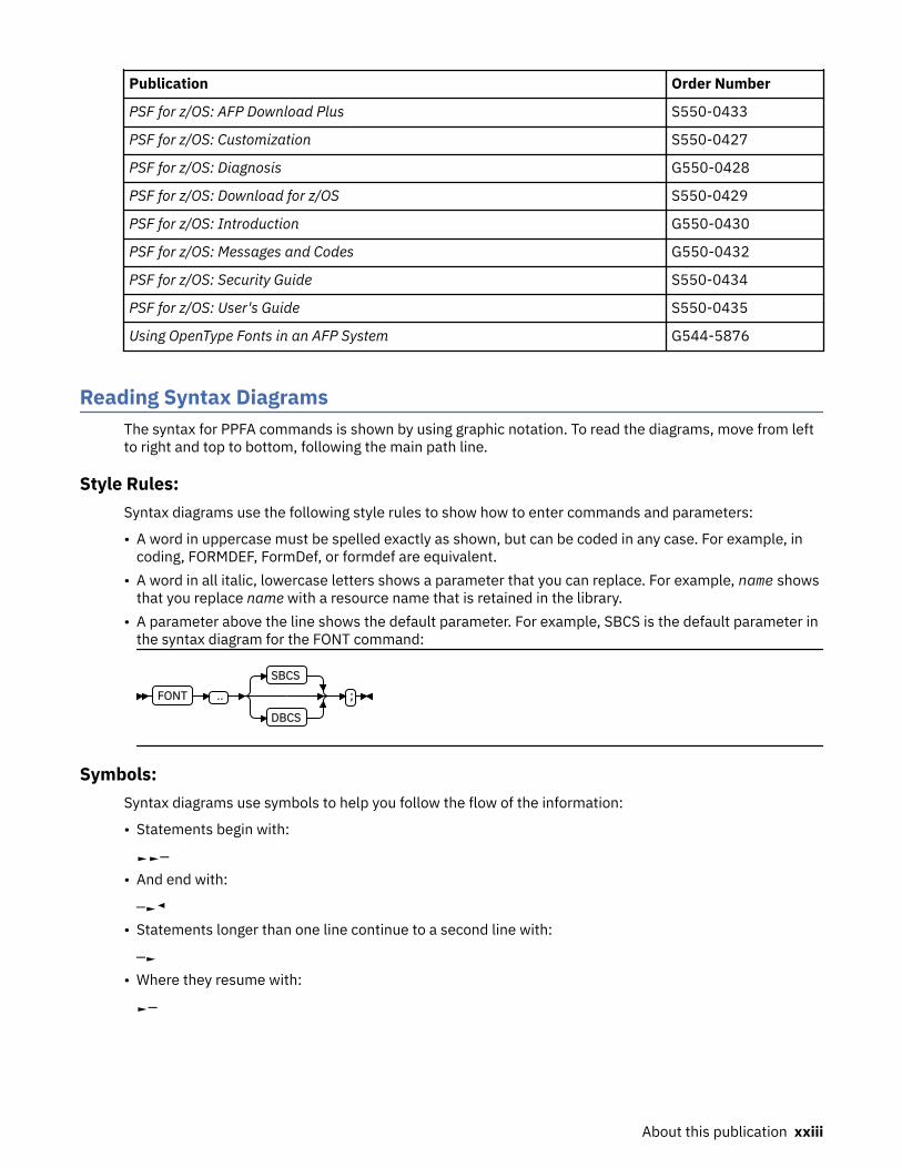
Publication Order Number
PSF for z/OS: AFP Download Plus S550-0433
PSF for z/OS: Customization S550-0427
PSF for z/OS: Diagnosis G550-0428
PSF for z/OS: Download for z/OS S550-0429
PSF for z/OS: Introduction G550-0430
PSF for z/OS: Messages and Codes G550-0432
PSF for z/OS: Security Guide S550-0434
PSF for z/OS: User's Guide S550-0435
Using OpenType Fonts in an AFP System G544-5876
Reading Syntax DiagramsThe syntax for PPFA commands is shown by using graphic notation. To read the diagrams, move from leftto right and top to bottom, following the main path line.
Style Rules:Syntax diagrams use the following style rules to show how to enter commands and parameters:
• A word in uppercase must be spelled exactly as shown, but can be coded in any case. For example, incoding, FORMDEF, FormDef, or formdef are equivalent.
• A word in all italic, lowercase letters shows a parameter that you can replace. For example, name showsthat you replace name with a resource name that is retained in the library.
• A parameter above the line shows the default parameter. For example, SBCS is the default parameter inthe syntax diagram for the FONT command:
FONT ‥
SBCS
DBCS
;
Symbols:Syntax diagrams use symbols to help you follow the flow of the information:
• Statements begin with:
►►─• And end with:
─►◄• Statements longer than one line continue to a second line with:
─►• Where they resume with:
►─
About this publication xxiii

Required Parameters:A parameter that you must include is displayed on the main path line. For example, the syntax diagram forthe SEGMENT command shows that you must follow SEGMENT with its required parameter:
SEGMENT name ;
If you can choose from two or more required parameters, the parameters are shown with the first choiceon the main path line and the other choices on branch lines under it. For example, this partial syntaxdiagram shows the DIRECTION command:
DIRECTION ACROSS
DOWN
BACK
UP
You must type the command in any of the following ways:
• DIRECTION ACROSS• DIRECTION DOWN• DIRECTION BACK• DIRECTION UP
Optional Parameters:Parameters that you can include with a command are displayed on the branch line below the main pathline. For example, this partial syntax diagram shows the COPYGROUP command:
COPYGROUP name
CUTSHEET - NO
CUTSHEET - YES
You can type the command in one of these ways:
• COPYGROUP name1 CUTSHEET YES ;• COPYGROUP name1 CUTSHEET NO ;• COPYGROUP name1;
Branch lines can include branch lines of their own. For example, this is the partial syntax diagram for theSUBGROUP command with the optional BIN parameter:
SUBGROUPBIN 1
BIN n
MANUAL
ENVELOPE
Repeating Parameters:An arrow on a line above a parameter means that you can either repeat the parameter or enter more thanone of the listed parameters. An example of this is the partial syntax diagram for the SUPPRESSIONsubcommand in the SUBGROUP command:
xxiv About this publication
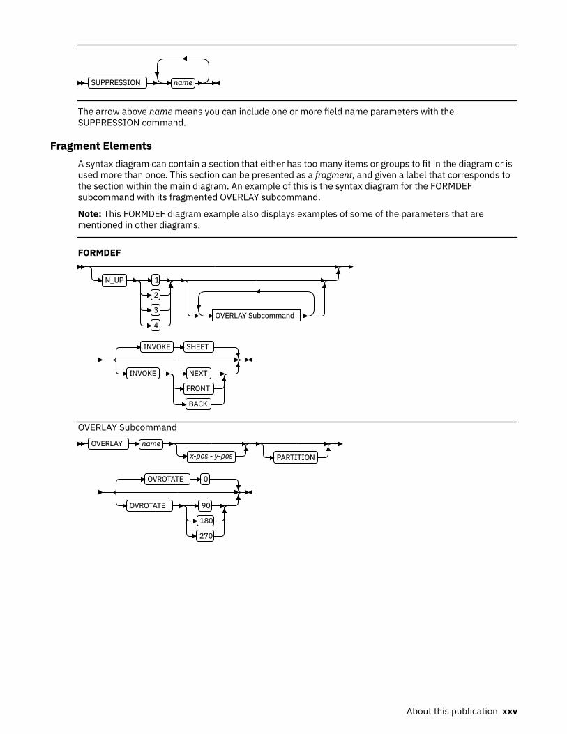
SUPPRESSION name
The arrow above name means you can include one or more field name parameters with theSUPPRESSION command.
Fragment ElementsA syntax diagram can contain a section that either has too many items or groups to fit in the diagram or isused more than once. This section can be presented as a fragment, and given a label that corresponds tothe section within the main diagram. An example of this is the syntax diagram for the FORMDEFsubcommand with its fragmented OVERLAY subcommand.
Note: This FORMDEF diagram example also displays examples of some of the parameters that arementioned in other diagrams.
FORMDEF
N_UP 1
2
3
4OVERLAY Subcommand
INVOKE SHEET
INVOKE NEXT
FRONT
BACK
OVERLAY SubcommandOVERLAY name
x-pos - y-pos PARTITION
OVROTATE 0
OVROTATE 90
180
270
About this publication xxv

xxvi Page Printer Formatting Aid: User's Guide

Summary of changes
This publication contains additions and changes to information previously presented in Page PrinterFormatting Aid (PPFA) User's Guide, S544-5284-12. The technical additions and changes are marked witha revision bar (|) in the left margin.
The following information is new or updated:
• The note for the COMMENT subcommand in the FORMDEF command is updated for clarification. See“COMMENT qstring” on page 231.
• Minor text and formatting changes are made to support accessibility and translation.
© Copyright IBM Corp. 1985, 2016 xxvii
How to send your comments to IBM
We appreciate your input on this documentation. Please provide us with any feedback that you have,including comments on the clarity, accuracy, or completeness of the information.
Use one of the following methods to send your comments:
Important: If your comment regards a technical problem, see instead “If you have a technical problem”on page xxviii.
• Send an email to [email protected].• Send an email from the Contact z/OS web page (www.ibm.com/systems/z/os/zos/webqs.html).
Include the following information:
• Your name and address• Your email address• Your phone or fax number• The publication title and order number:
Page Printer Formatting Aid: User's GuideS544-5284-13
• The topic and page number or URL of the specific information to which your comment relates• The text of your comment.
When you send comments to IBM®, you grant IBM a nonexclusive right to use or distribute the commentsin any way appropriate without incurring any obligation to you.
IBM or any other organizations use the personal information that you supply to contact you only about theissues that you submit.
If you have a technical problemDo not use the feedback methods that are listed for sending comments. Instead, take one or more of thefollowing actions:
• Visit the IBM Support Portal (support.ibm.com).• Contact your IBM service representative.• Call IBM technical support.
xxviii Page Printer Formatting Aid: User's Guide

Part 1. What is PPFA?
This section contains Chapter 1, “Introducing Page Printer Formatting Aid,” on page 3, which describes:
• Form definitions and page definitions• Basic data types for printing• PPFA concepts• PPFA terms and definitions• Line data controls and structured fields• Types of duplex printing
© Copyright IBM Corp. 1985, 2016 1

2 Page Printer Formatting Aid: User's Guide

Chapter 1. Introducing Page Printer Formatting Aid
Page Printer Formatting Aid is a program that enables users of Advanced Function Presentation (AFP)products to create their own formatting resources, called form definitions and page definitions. The formdefinitions and page definitions are stored in libraries1 as AFP resources. Using AFP resources requiresIBM Print Services Facility (PSF) or AFP Conversion and Indexing Facility (ACIF), which merges resourceswith user data files. This merging creates a data stream for printing or viewing.
Using a form definition or a page definition that is created by PPFA requires you to do three steps:
1. Write a set of PPFA commands that define how to position the data or handle the physical sheets.2. Run PPFA to build the specified page definition or form definition and store the output as resources in
a library.3. Use your print server to submit the print file, specifying the page definition and form definition that are
needed to accomplish the results you want.
Notes:
1. All PPFA/370 functions that are described are available on the z/OS operating system. However,because functions on PSF/VM and PSF/VSE and PPFA/370 functions for VM and VSE are not updated,some of the PPFA/370 functions that are described are not available on the VM and VSE operatingsystems.
2. Not all functions that are provided by PPFA are supported in all printers and printer server licensedprograms. Refer to the information for the printer and printer server licensed program that you areusing to determine which functions are supported.
Figure 1 on page 4 shows how form definition and page definition relate to PSF. In Figure 1 on page4, the area inside the broken line represents steps 1 and 2. The area outside of the broken line showshow PSF merges resources with the specified print job to form a single print stream and sends it to a pageprinter.
1 The term library includes z/OS and VSE libraries, and VM files.
© Copyright IBM Corp. 1985, 2016 3
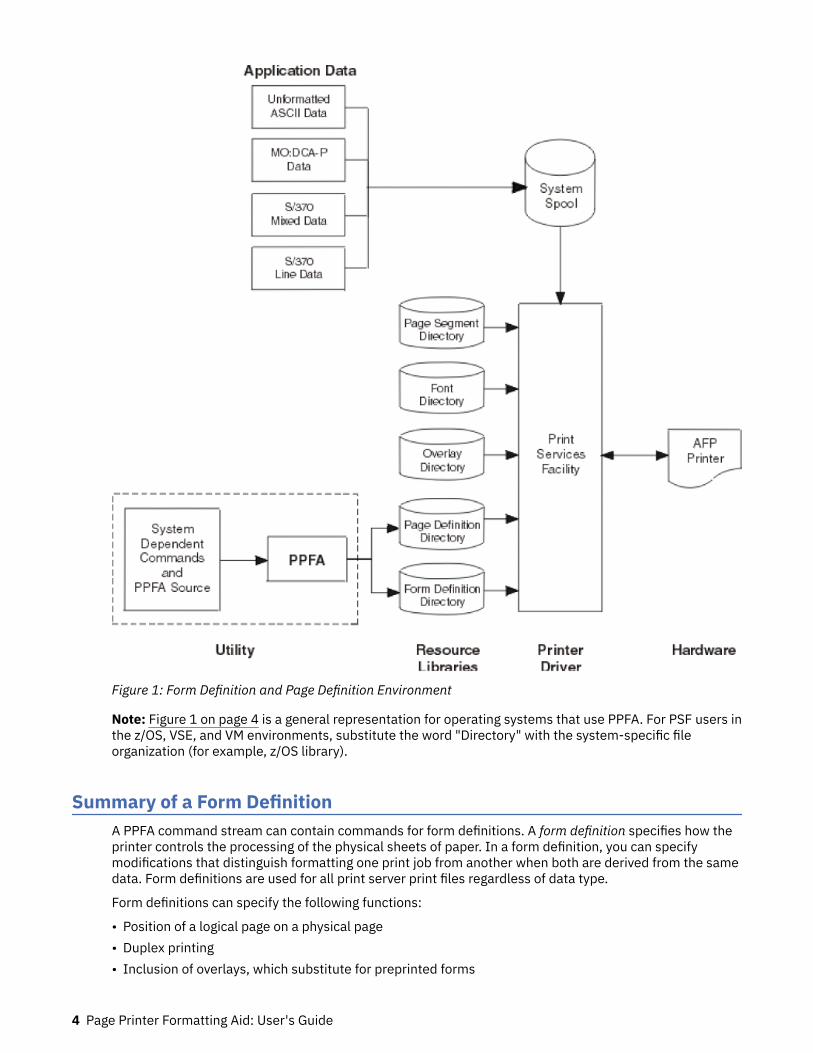
Figure 1: Form Definition and Page Definition Environment
Note: Figure 1 on page 4 is a general representation for operating systems that use PPFA. For PSF users inthe z/OS, VSE, and VM environments, substitute the word "Directory" with the system-specific fileorganization (for example, z/OS library).
Summary of a Form DefinitionA PPFA command stream can contain commands for form definitions. A form definition specifies how theprinter controls the processing of the physical sheets of paper. In a form definition, you can specifymodifications that distinguish formatting one print job from another when both are derived from the samedata. Form definitions are used for all print server print files regardless of data type.
Form definitions can specify the following functions:
• Position of a logical page on a physical page• Duplex printing• Inclusion of overlays, which substitute for preprinted forms
4 Page Printer Formatting Aid: User's Guide

• Flash (the use of a forms flash - only on 3800 printers)• Selection of the number of copies for any page of data• Suppression (the exclusion of selected fields of data in one printed version of a page of data but not in
another)• Jog (the offset stacking of cut-sheet output or copy marking on continuous-forms output)• Selection among paper sources in a cut-sheet printer• Adjustment of the horizontal position of the print area on the sheet (only on 3800 printers)• Quality (selection among print quality levels)• Constant (allows front or back printing of a page without variable data)• Printing one, two, three, or four logical pages on a single side of a page• Post-processing controls, such as:
– Selecting functions
Selecting device-dependent functions that are defined by the post-processing device• Finishing operations:
– Center Fold In– Corner Staple– Edge Staple– Saddle Stitch (In and Out)– Separation Cut– Perforation Cut– Fold– Z-Fold– Punch– UP3i Finishing
Summary of a Page DefinitionA page definition specifies how you want data to be positioned on the logical page. A page definition cancontrol the following functions:
• Dimensions of the logical page• Print direction of the logical page• Print direction of text lines and fields relative to the logical page• Conditional processing (different formats on different pages, based on content of data)• Text line spacing (number of lines per inch)• Location of individual text lines and fields• Number of text lines per page• Page segments for inclusion in printed output• Overlays for inclusion in printed output (positioned anywhere on the page)• Page-ejection points• Fonts and font rotation that are used on a page• Multiple-up printing (placing more than one subpage on one side of a single sheet)• Colors to be used (on printers that support this function)• One and two dimensional bar codes (on printers that support this function)• External objects for inclusion in printed output (can be positioned anywhere on the page)
Introducing Page Printer Formatting Aid 5

• Preloading and preripping of external objects and overlays
Formatting Output of Different Data File TypesThe basic types of data that are printed on the print server printers are:
Line-data filesTraditional line dataRecord format line dataMixed-data filesMO:DCA-P data filesXML data
Line-data files and mixed-data files require a page definition and a form definition. MO:DCA-P data filesrequire only a form definition.
Line-Data Files
Line data is EBCDIC data that is arranged for printing on line printers. These records can contain line-printer control characters such as carriage control characters (CC or FCFC), table-reference characters(TRC), or only data. To compose pages for the page printer from line data, the print server separates theincoming print records into pages according to specifications in a page definition. A page definition isalways required for printing line data with the print server. You can create your own page definition or usea page definition that is provided with the print server. The two types of line data are traditional andrecord format.
The line data input to the print server can consist of records that are fully formatted; it can consist ofrecords that contain only the fields of data to be printed; or it can consist of records of both types. You canuse the page definition resource to format fields of line data outside of the application program. See PSFfor z/OS: User's Guide for additional information.
The following example shows two types of line data. The first type is data that is arranged as it prints; thesecond is data that requires field processing.
Figure 2: Formatted and Unformatted Print Records
The technique of mapping the unformatted data to locations on the output pages is known as fieldprocessing or record processing and is available by using page definition controls. Field processing isexplained in detail in “Processing Fields” on page 40.
Traditional Line Data
Traditional line data is data that is formatted for printing on a line printer. Fully formatted line data can beprinted on a line printer without a page definition; however, all line data needs a page definition to beprinted on a page printer.
6 Page Printer Formatting Aid: User's Guide

A traditional line data record can contain a 1-byte carriage control character and a 1-byte table referencecharacter followed by the data to be printed. (With a line printer, the maximum number of data bytes in asingle input record is 208. With a page printer, the maximum number is 32,768 bytes). See Chapter 3,“Using Page Definition Commands for Traditional Line Data,” on page 31 for additional information aboutusing traditional line data.
Record Format Line Data
The record formatting function allows an application to specify a format identifier (record ID) with each setof data fields (data record). The format identifier references a specific layout format in a Page Definition(PAGEDEF). At print time, each layout format (referenced by a record ID in a data record) is retrieved fromthe PAGEDEF and used to position and format the associated data records or fields on the output page.The PAGEDEF can contain any number of layout formats. The application can use a PAGEDEF layoutformat to either insert an end of page when a specified last line point is exceeded on the output page orforce an end of page. See Chapter 4, “Using Page Definition Commands for Record Format Line Data andXML Data,” on page 51 for information about using record format line data.
statmid Justin Case 123 Sligo Lane Longmont CO 80501 ckheaderckdata 352 01/04/07 $ 321.50 Blind Squirrel Golfckdata 353 01/05/07 $ 100.00 Janie's Pancake Spotckdata 354 01/10/07 $ 122.30 History Bookstoreckdata 355 01/11/07 $ 59.95 Kristina's Pretty Thingsckdata 356 01/15/07 $ 852.33 Pirie Racing Enterprisesckdata 357 01/30/07 $ 500.35 Skippy's Music CenterCkend
Figure 3: Example of Record Format Line Data
Mixed-Data Files
Mixed-data files consist of MO:DCA-P data and line data. Such files might specify the beginning andending of pages and might contain page addresses and data controls for page printing. The line-dataportion of such files must be formatted for page printers by page-definition controls.
MO:DCA-P Data Files
MO:DCA-P data files are formed into pages before the print server receives them. These files alreadycontain the embedded controls for printing on page printers. They contain such things as page addressesand data controls for page printing functions.
Note: See Mixed Object Document Content Architecture Reference and Advanced Function PresentationProgramming Guide and Line Data Reference for more information about MO:DCA-P data. User applicationprograms can also generate MO:DCA-P data.
PPFA ConceptsThe concepts of physical page, logical page, and subpage are basic to understanding form definition andpage definition controls.
Physical Page
A physical page is the sheet of paper or other medium (a sheet of labels, for instance) that moves throughthe printer.
Logical Page
A logical page is the area that you define in a PPFA command stream as the space on the physical pagewhere data is printed. The logical page is positioned in relation to the media origin. For more informationabout the media origin of your printer, see your printer documentation. The positioning of the logical pageon the sheet of paper is described in “Positioning a Logical Page on a Sheet” on page 19.
Introducing Page Printer Formatting Aid 7
You can use an N_UP command to place one, two, three, or four logical pages on a single sheet. N_UP is incontrast to multiple up, which places subpages on one logical page.
Subpage
A subpage is a part of a logical page on which line data can be placed. Subpages are used only withconditional processing. Multiple-up printing can be done with or without defining subpages. In the pagedefinition, multiple subpages can be placed on the physical page based on changes in the print data. Anexample is the use of multiple-up printing, which is printing two or four pages on a single side of a sheet.For more information, see “Subpage Description and Processing” on page 110.
PPFA Basic TermsThe following terms have meanings that are special to PPFA:
• Printline• Layout• Direction• Rotation• Presentation• N_UP partitions• Modifications
Printline
Printline is a single line of text, and is the traditional command that is synonymous with the recordformatting Layout command. In the formatting of line data, a printline is normally the output that isgenerated by one record in the print file. However, printlines and print records are not the same.
PRINTLINE commands in the PPFA page definition define the number and position of printlines on a page.Each record in the print file is written to a single printline on a page. Usually, one print record is written toeach printline. However, control information in the print data can specify that two or more print records bewritten to the same printline, providing overprinting. Controls also can specify that print records skipprintlines. For example, a print record might skip the remaining printlines on a page and instead print onthe first printline of a new page.
Layout
Layout specifies a single line of text, and is the record formatting command that is synonymous with thetraditional Printline command. In the formatting of line data, a layout is normally the output that isgenerated by one record in the print file. However, layouts and print records are not the same.
LAYOUT commands in the PPFA page definition define the number and position of layouts on a page. Eachrecord in the print file is written to a single layout on a page. Usually, one print record is written to eachlayout. However, control information in the print data can specify that two or more print records be writtento the same layout, providing overprinting. Controls also can specify that print records skip layouts. Forexample, a print record might skip the remaining layouts on a page and instead print on the first layout ofa new page.
Direction
Text can be printed in four print directions. A print direction is a combination of both inline and baselinedirections. For each of the directions, characters can be printed in four rotations.
The line direction is the direction in which successive characters are added to a line of text. The four linedirections are:ACROSS
Text characters are placed in a line from left to right across the page.
8 Page Printer Formatting Aid: User's Guide
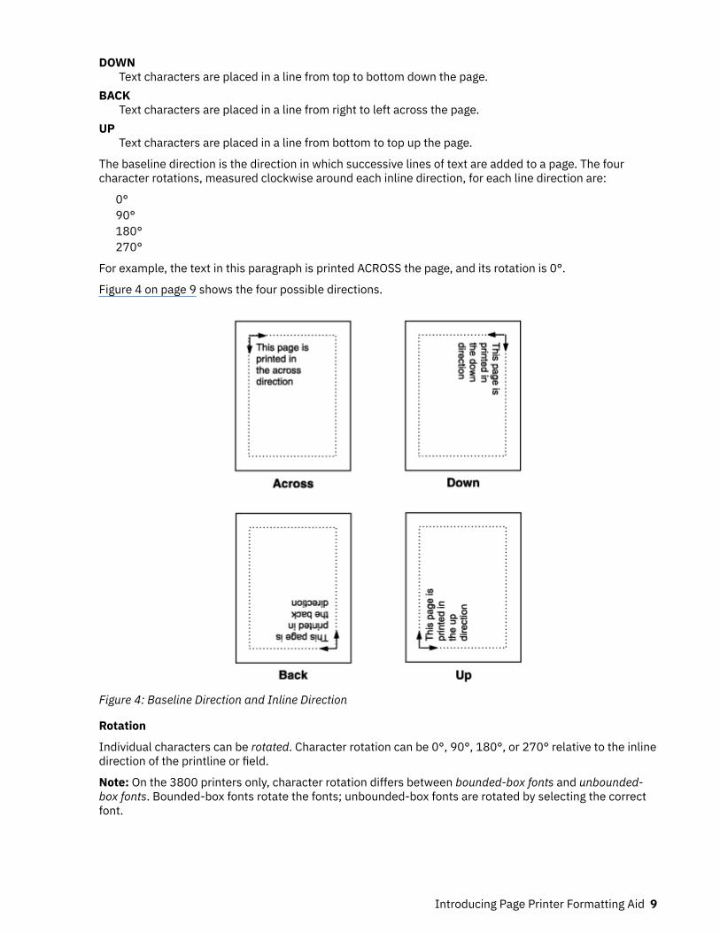
DOWNText characters are placed in a line from top to bottom down the page.
BACKText characters are placed in a line from right to left across the page.
UPText characters are placed in a line from bottom to top up the page.
The baseline direction is the direction in which successive lines of text are added to a page. The fourcharacter rotations, measured clockwise around each inline direction, for each line direction are:
0°90°180°270°
For example, the text in this paragraph is printed ACROSS the page, and its rotation is 0°.
Figure 4 on page 9 shows the four possible directions.
Figure 4: Baseline Direction and Inline Direction
Rotation
Individual characters can be rotated. Character rotation can be 0°, 90°, 180°, or 270° relative to the inlinedirection of the printline or field.
Note: On the 3800 printers only, character rotation differs between bounded-box fonts and unbounded-box fonts. Bounded-box fonts rotate the fonts; unbounded-box fonts are rotated by selecting the correctfont.
Introducing Page Printer Formatting Aid 9

Presentation
Presentation describes the shape of the page as it is viewed by the reader. Figure 5 on page 10 shows anexample of how text is presented (positioned) on the page. The two page presentations are portrait andlandscape:Portrait
Designed to be viewed with the short side at the top of the page.Landscape
Designed to be viewed with the long side at the top of the page.
Figure 5: Portrait and Landscape Presentations
N_UP Partitions
Some printers allow the physical sheet of paper to be divided into equal-sized partitions. For two or threepartitions, each sheet is divided along one or two lines that are equally spaced along the longer side of thesheet. The printer positions a logical page of print data in each partition, which enables printing multiplelogical pages with different formats and modifications on a single sheet of paper.
The size and arrangement of the partitions on the sheet depends on the number of partitions and theshape and size of the paper. For two or three partitions, each sheet is divided at two or three points thatare equally spaced along the longer side of the sheet. For four partitions, each sheet is equally dividedboth vertically and horizontally. See Chapter 7, “N_UP Printing,” on page 129 for more information.
Modifications
Modifications are sets of form definition controls that apply to one page of a data file. With these controls,you can:
• Define the type of duplex printing to be done.• Define one, two, three, or four partitions for N_UP.• Select an overlay.• Suppress the appearance of a field.• Select the forms flash option (only for the 3800 printer).• Specify the number of copies for a set of modifications.• Specify post-printing processing options.
10 Page Printer Formatting Aid: User's Guide

You can specify different sets of modifications for the same page of data in one form definition. Therefore,in one print job you can specify a series of SUBGROUP commands. For example, a form definition with twoSUBGROUP commands has two sets of modifications. The same page of data is printed for each set ofmodifications, resulting in a slightly different output for each printing.
Definitions of Command, Subcommand, and ParameterCommands, subcommands, and parameters are terms that are used throughout this publication to referto the contents of PPFA control statements. Chapter 10, “Form Definition Command Reference,” on page189 and Chapter 11, “Page Definition Command Reference ,” on page 249 describe these commands withall their applicable subcommands.
Commands
Commands are the major controls that compose form definitions and page definitions.
Subcommands
Subcommands are used to further define commands. The absence of subcommands means that thedefault values specified with those subcommands are used. Three command terms also appear assubcommand terms: FONT, OVERLAY, and SUPPRESSION. These subcommand terms further define othercommands.
Parameters
You can specify parameters with subcommands or accept the defaults; valid entries and their defaults areshown in the command reference chapters.
Basic Controls in Traditional Line DataThe following line-printer controls can be included in a line data file and can be used by a page definitionto enable AFP functions:
• Carriage control characters• Table-reference characters• Record IDs
Carriage Control Characters (CC)
Carriage control characters, which control line skipping, line spacing, and page ejection on line printers,are fields within line-data records. They are compatible with page printers when page definitions formatthe printed data. In page definitions, you can specify CHANNEL subcommands that correspond to carriagecontrol characters corresponding to channels 1 - 12 in the data. When you do so, the carriage controlcharacters operate just as they do in a line-printer environment.
Note: ASCII ANSI, ANSI, and EBCDIC (machine) handle carriage control characters differently. See theSPACE_THEN_PRINT subcommand listed in “Long Form Subcommands” on page 252 for moreinformation.
Table-Reference Characters (TRC)
Table-reference characters (TRCs) control font selection in line-data output. Page definitions can be usedto map table-reference characters to AFP fonts for use with page printers.
For more information about Table-reference characters, see the Advanced Function Presentation:Programming Guide and Line Data Reference.
Record ID
Record IDs are only used with the record formatting function.
Introducing Page Printer Formatting Aid 11

Basic Controls in Record Format Line DataRecord format line data is a new form of line data that is supported by the print server and formatted by apage definition. With this format, each data record contains a 10-byte record identifier that selects therecord descriptor (RCD) in a record format page definition that is used to format the line data. This RCDmight contain a carriage control (CC) byte.
• Carriage control characters• Table-reference characters (not applicable in record format)
Carriage Control Characters (CC)
The CC byte is required when record format data is mixed with MO:DCA-P data, but is ignored. The CCbyte is optional for record format line data at all other times; however, if you enter it, you must inform theprint server that it is there.
Many functions that are used in the line descriptor (LND) to format traditional line data are used in RCD toformat record format line data. Others, such as header and trailer processing, are unique to RCDs.
Traditional line data is similar to record format line data in that neither is formatted into pages. However,traditional line data can be printed on line printers while record format line data cannot. For moreinformation, see Chapter 4, “Using Page Definition Commands for Record Format Line Data and XMLData,” on page 51.
Note: ASCII ANSI, ANSI, and EBCDIC (machine) handle carriage control characters differently. See theSPACE_THEN_PRINT subcommand listed in “Long Form Subcommands” on page 252 for moreinformation.
Table-Reference Characters (TRC)
Table-reference characters (TRCs) cannot be used in record formatted line data.
Record ID
Record IDs are only used with the record formatting function. They are in the first 10 characters of eachline data record, and control the layout type that is selected for each specified record. These 10characters are reserved for record IDs and are not included as part of a defined field or conditional area.
Structured Fields in Line DataNote: Structured fields are not supported by XML data.
To use the full function of page definitions and form definitions, MO:DCA-P structured fields might berequired in the users data. The following MO:DCA-P structured fields can be included in a line-data file toactivate AFP functions:
• Invoke Data Map• Invoke Medium Map• Include Page Segment• Include Page Overlay• Include Object• Include Presentation Text (PTX)• No Operation (NOP)
Note: For information about mixed mode, see the Advanced Function Presentation: Programming Guideand Line Data Reference.
12 Page Printer Formatting Aid: User's Guide

Invoke Data Map
Add the Invoke Data Map structured field to the line-data file at a point that requires switching from onepage format to another. The term data map is the name that is used for the term page format in PSFpublications and PSF terminology.
Invoke Medium Map
Add the Invoke Medium Map structured field to the line-data file at a point that requires switching fromone copy group to another. The term medium map is the name that is used for the term copy group in PSFpublications and PSF terminology.
Include Page Segment
Position the Include Page Segment structured field within the line data for placing the page segment onthe page.
Include Page Overlay
Position the Include Page Overlay structured field within the line data for placing the overlay anywhere onthe page.
Include Object
Position the Include Object structured field for placing an object that contains other object types (forexample, IOCA or BCOCA) for placing the object anywhere on the page.
Presentation Text
A presentation text object can be included in line data by using the Presentation Text (PTX) structuredfield, which is a self-contained object that consists of line spacing, page margin, data position, and fontsettings. See the AFP Programming Guide and Line Data Reference and the Presentation Text ObjectContent Architecture Reference for additional information.
No Operation
A No Operation (NOP) structured field can be placed in the line data stream. It can be used to insertinformation, such as a comment, into the data stream.
Normal Duplex and Tumble DuplexSome page printers can print on both sides of a sheet, which is called duplex printing. Duplex printing canbe done in four ways:
• Normal duplex• Tumble duplex• Rotated normal duplex• Rotated tumble duplex
In normal duplex, both sides have the same orientation, as in most books. In tumble duplex, the back ofeach page is upside down compared to the front of the page: the top of one side of the sheet is at thesame edge as the bottom of the other side. With these two types of duplex, you can specify top binding orside binding of the printed pages.
Duplex also involves the commands RNORMAL (rotated normal) and RTUMBLE (rotated tumble), whichare used with landscape-presentation pages to specify the type of duplex printing. See Figure 14 on page26 and Figure 15 on page 27 for illustrations of duplex printing.
Introducing Page Printer Formatting Aid 13

14 Page Printer Formatting Aid: User's Guide
Part 2. Examples of Using PPFA
This section contains information about:
• Using form definition commands• Using page definition commands• Creating complex printouts• Conditional processing• N_UP printing• AFP color management
© Copyright IBM Corp. 1985, 2016 15

16 Page Printer Formatting Aid: User's Guide

Chapter 2. Using Form Definition Commands
A form definition is a resource that is used by the print server to specify how the printer controls theprocessing of the sheets of paper. With form definitions, you can do the tasks that are listed in Table 1 onpage 17.
Table 1: Form Definition Tasks
Task Location of Example
Create a form definition. “Commands Required to Create a Form Definition”on page 18
Position a logical page. “Positioning a Logical Page on a Sheet” on page19
Specify landscape presentation. “OFFSET Subcommand with Rotated PrintDirection” on page 20
Specify copies and electronic overlays. “Specifying Copies and Electronic Overlays” onpage 20
Print constant forms. “Printing Constant Forms” on page 22
Duplex print in two orientation. “Duplex Printing” on page 23
Print portrait and landscape. “Duplex Printing in Portrait and LandscapePresentations” on page 25
Specify the page presentation on continuous-formsprinters.
“Specifying Page Presentation on Continuous-Forms Printers” on page 27
Copy Groups and SubgroupsA single form definition can contain several subsets of page controls, called copy groups. Copy groupsdefine each physical page in the file. When you are printing jobs in duplex, the copy group defines bothsides of the physical paper. Copy groups, in turn, can contain up to 127 subgroups, each of which createsa different set of modifications for the same page of data.
A series of copy groups can be used where either the data or the printing requirements call for variouspage control schemes. Part of the file can be printed from one (bin) paper source and part from another.Part can be printed duplex; part can be printed simplex. Duplex commands can be specified for a printerthat does not support this function. This command treats the two adjacent pages as duplexed. Variouscontrols can be contained in one form definition that has several copy groups.
You can control the following options within a copy group:
• Position of the logical page on a sheet of paper• Duplex printing• Type of cut-sheet paper to be printed on (by choosing between paper input sources in page printers that
have more than one paper source)• Offset stacking or copy marking of parts of a print job in the output stacker• Printing one, two, three, or four logical pages on a single side of a sheet• Vendor-attached devices for post-processing functions to be done on the sheet• Print-quality level
© Copyright IBM Corp. 1985, 2016 17
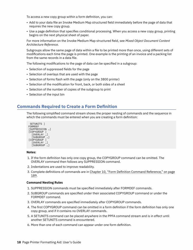
To access a new copy group within a form definition, you can:
• Add to your data file an Invoke Medium Map structured field immediately before the page of data thatrequires the new copy group.
• Use a page definition that specifies conditional processing. When you access a new copy group, printingbegins on the next physical sheet of paper.
For more information on the Invoke Medium Map structured field, see Mixed Object Document ContentArchitecture Reference.
Subgroups allow the same page of data within a file to be printed more than once, using different sets ofmodifications each time the page is printed. One example is the printing of an invoice and a packing listfrom the same records in a data file.
The following modifications to the page of data can be specified in a subgroup:
• Selection of suppressed fields for the page• Selection of overlays that are used with the page• Selection of forms flash with the page (only on the 3800 printer)• Selection of the modification for front, back, or both sides of a sheet• Selection of the number of copies of the subgroup to print• Selection of the input bin
Commands Required to Create a Form DefinitionThe following simplified command stream shows the proper nesting of commands and the sequence inwhich the commands must be entered when you are creating a form definition:
SETUNITS ]FORMDEF[SUPPRESSION …][COPYGROUP ] [OVERLAY …] [SUBGROUP …][COPYGROUP ] [OVERLAY …] [SUBGROUP …]
Notes:
1. If the form definition has only one copy group, the COPYGROUP command can be omitted. TheOVERLAY command then follows any SUPPRESSION command.
2. Indentations are used to improve readability.3. Complete definitions of commands are in Chapter 10, “Form Definition Command Reference,” on page
189.
Command Nesting Rules
1. SUPPRESSION commands must be specified immediately after FORMDEF commands.2. SUBGROUP commands are specified under their associated COPYGROUP command or under the
FORMDEF command.3. OVERLAY commands are specified immediately after COPYGROUP commands.4. The first COPYGROUP command can be omitted in a form definition if the form definition has only one
copy group, and if it contains no OVERLAY commands.5. A SETUNITS command can be placed anywhere in the PPFA command stream and is in effect until
another SETUNITS command is encountered.6. More than one of each command can appear under one form definition.
18 Page Printer Formatting Aid: User's Guide
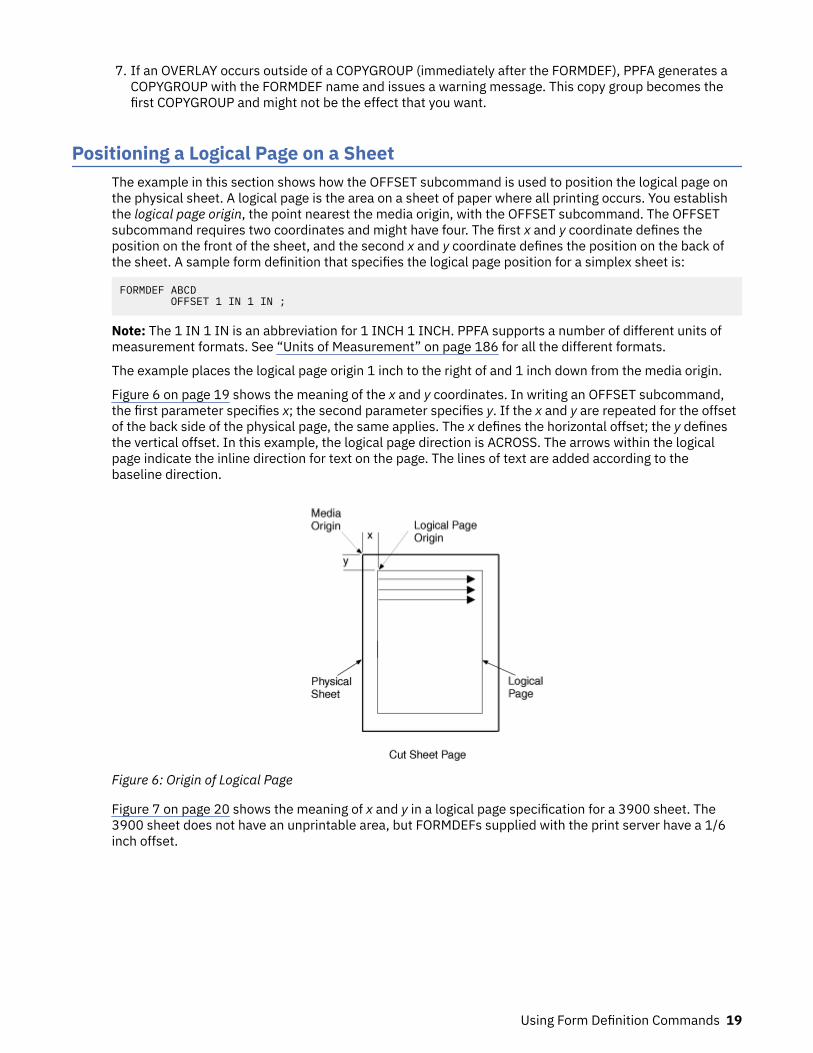
7. If an OVERLAY occurs outside of a COPYGROUP (immediately after the FORMDEF), PPFA generates aCOPYGROUP with the FORMDEF name and issues a warning message. This copy group becomes thefirst COPYGROUP and might not be the effect that you want.
Positioning a Logical Page on a SheetThe example in this section shows how the OFFSET subcommand is used to position the logical page onthe physical sheet. A logical page is the area on a sheet of paper where all printing occurs. You establishthe logical page origin, the point nearest the media origin, with the OFFSET subcommand. The OFFSETsubcommand requires two coordinates and might have four. The first x and y coordinate defines theposition on the front of the sheet, and the second x and y coordinate defines the position on the back ofthe sheet. A sample form definition that specifies the logical page position for a simplex sheet is:
FORMDEF ABCD OFFSET 1 IN 1 IN ;
Note: The 1 IN 1 IN is an abbreviation for 1 INCH 1 INCH. PPFA supports a number of different units ofmeasurement formats. See “Units of Measurement” on page 186 for all the different formats.
The example places the logical page origin 1 inch to the right of and 1 inch down from the media origin.
Figure 6 on page 19 shows the meaning of the x and y coordinates. In writing an OFFSET subcommand,the first parameter specifies x; the second parameter specifies y. If the x and y are repeated for the offsetof the back side of the physical page, the same applies. The x defines the horizontal offset; the y definesthe vertical offset. In this example, the logical page direction is ACROSS. The arrows within the logicalpage indicate the inline direction for text on the page. The lines of text are added according to thebaseline direction.
Figure 6: Origin of Logical Page
Figure 7 on page 20 shows the meaning of x and y in a logical page specification for a 3900 sheet. The3900 sheet does not have an unprintable area, but FORMDEFs supplied with the print server have a 1/6inch offset.
Using Form Definition Commands 19
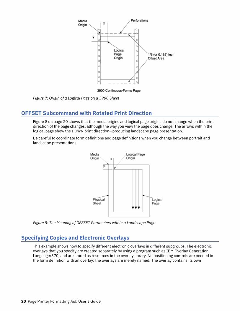
Figure 7: Origin of a Logical Page on a 3900 Sheet
OFFSET Subcommand with Rotated Print DirectionFigure 8 on page 20 shows that the media origins and logical page origins do not change when the printdirection of the page changes, although the way you view the page does change. The arrows within thelogical page show the DOWN print direction—producing landscape page presentation.
Be careful to coordinate form definitions and page definitions when you change between portrait andlandscape presentations.
Figure 8: The Meaning of OFFSET Parameters within a Landscape Page
Specifying Copies and Electronic OverlaysThis example shows how to specify different electronic overlays in different subgroups. The electronicoverlays that you specify are created separately by using a program such as IBM Overlay GenerationLanguage/370, and are stored as resources in the overlay library. No positioning controls are needed inthe form definition with an overlay; the overlays are merely named. The overlay contains its own
20 Page Printer Formatting Aid: User's Guide
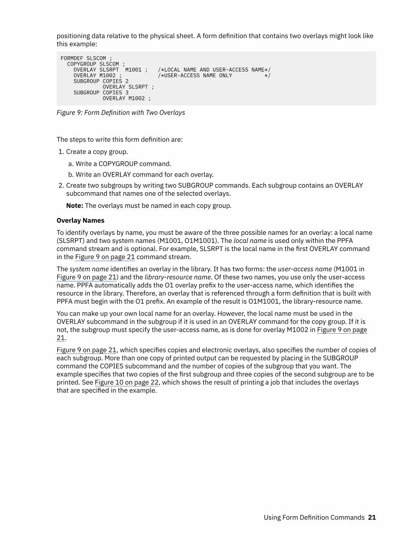
positioning data relative to the physical sheet. A form definition that contains two overlays might look likethis example:
FORMDEF SLSCOM ; COPYGROUP SLSCOM ; OVERLAY SLSRPT M1001 ; /*LOCAL NAME AND USER-ACCESS NAME*/ OVERLAY M1002 ; /*USER-ACCESS NAME ONLY */ SUBGROUP COPIES 2 OVERLAY SLSRPT ; SUBGROUP COPIES 3 OVERLAY M1002 ;
Figure 9: Form Definition with Two Overlays
The steps to write this form definition are:
1. Create a copy group.
a. Write a COPYGROUP command.b. Write an OVERLAY command for each overlay.
2. Create two subgroups by writing two SUBGROUP commands. Each subgroup contains an OVERLAYsubcommand that names one of the selected overlays.
Note: The overlays must be named in each copy group.
Overlay Names
To identify overlays by name, you must be aware of the three possible names for an overlay: a local name(SLSRPT) and two system names (M1001, O1M1001). The local name is used only within the PPFAcommand stream and is optional. For example, SLSRPT is the local name in the first OVERLAY commandin the Figure 9 on page 21 command stream.
The system name identifies an overlay in the library. It has two forms: the user-access name (M1001 inFigure 9 on page 21) and the library-resource name. Of these two names, you use only the user-accessname. PPFA automatically adds the O1 overlay prefix to the user-access name, which identifies theresource in the library. Therefore, an overlay that is referenced through a form definition that is built withPPFA must begin with the O1 prefix. An example of the result is O1M1001, the library-resource name.
You can make up your own local name for an overlay. However, the local name must be used in theOVERLAY subcommand in the subgroup if it is used in an OVERLAY command for the copy group. If it isnot, the subgroup must specify the user-access name, as is done for overlay M1002 in Figure 9 on page21.
Figure 9 on page 21, which specifies copies and electronic overlays, also specifies the number of copies ofeach subgroup. More than one copy of printed output can be requested by placing in the SUBGROUPcommand the COPIES subcommand and the number of copies of the subgroup that you want. Theexample specifies that two copies of the first subgroup and three copies of the second subgroup are to beprinted. See Figure 10 on page 22, which shows the result of printing a job that includes the overlaysthat are specified in the example.
Using Form Definition Commands 21
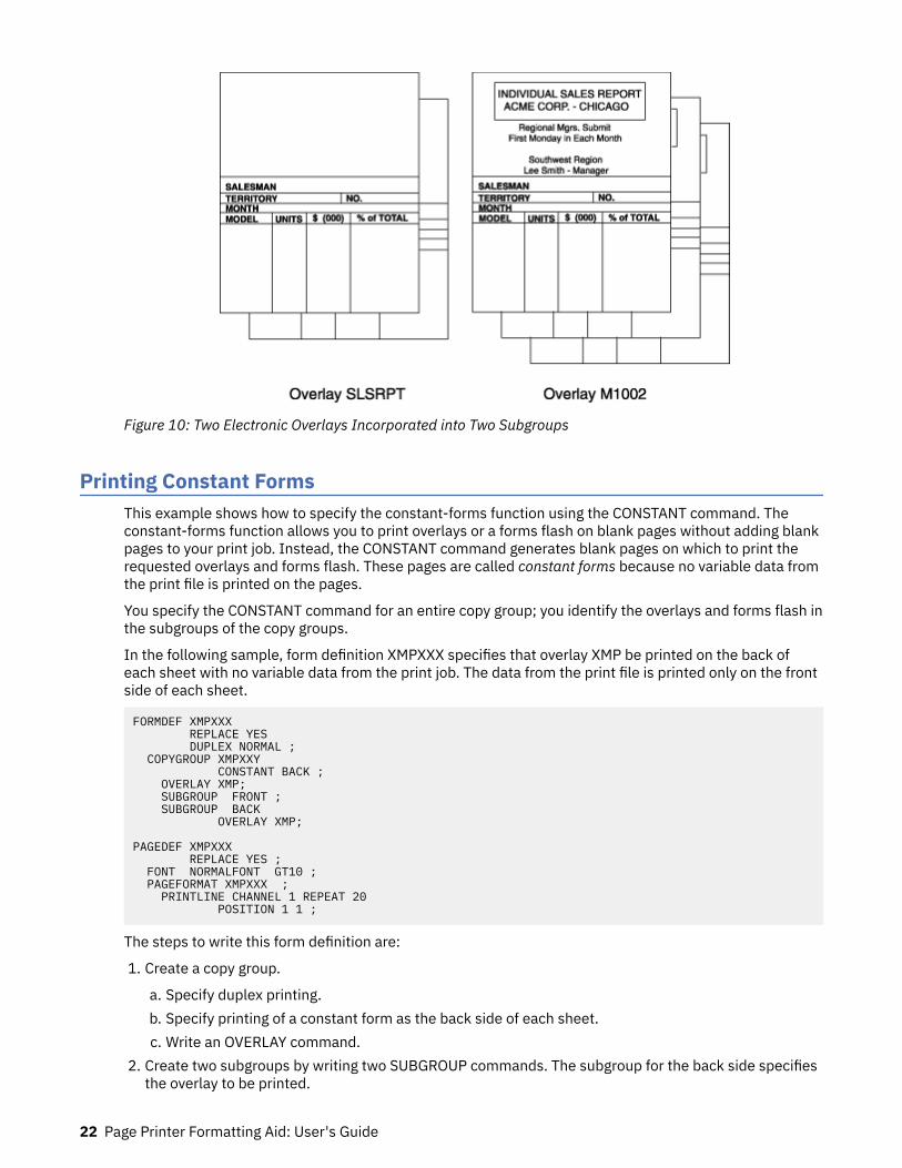
Figure 10: Two Electronic Overlays Incorporated into Two Subgroups
Printing Constant FormsThis example shows how to specify the constant-forms function using the CONSTANT command. Theconstant-forms function allows you to print overlays or a forms flash on blank pages without adding blankpages to your print job. Instead, the CONSTANT command generates blank pages on which to print therequested overlays and forms flash. These pages are called constant forms because no variable data fromthe print file is printed on the pages.
You specify the CONSTANT command for an entire copy group; you identify the overlays and forms flash inthe subgroups of the copy groups.
In the following sample, form definition XMPXXX specifies that overlay XMP be printed on the back ofeach sheet with no variable data from the print job. The data from the print file is printed only on the frontside of each sheet.
FORMDEF XMPXXX REPLACE YES DUPLEX NORMAL ; COPYGROUP XMPXXY CONSTANT BACK ; OVERLAY XMP; SUBGROUP FRONT ; SUBGROUP BACK OVERLAY XMP; PAGEDEF XMPXXX REPLACE YES ; FONT NORMALFONT GT10 ; PAGEFORMAT XMPXXX ; PRINTLINE CHANNEL 1 REPEAT 20 POSITION 1 1 ;
The steps to write this form definition are:
1. Create a copy group.
a. Specify duplex printing.b. Specify printing of a constant form as the back side of each sheet.c. Write an OVERLAY command.
2. Create two subgroups by writing two SUBGROUP commands. The subgroup for the back side specifiesthe overlay to be printed.
22 Page Printer Formatting Aid: User's Guide

Note: If you do not specify an overlay in the subgroup for the back, the back side of each sheet is blank.
Duplex PrintingPrinting on both sides of a sheet (duplex printing) can be done in two ways: by the use of the FRONT andBACK subcommand combination or by the use of the BOTH subcommand. If FRONT and BACK arechosen, the number of copies that are requested for each must be the same.
To demonstrate some of the functions available for duplex printing, assume that you want to print a six-page data file (a simplified version is shown in Figure 11 on page 23).
Figure 11: Six-Page Formatted Data File
Assume, too, that the file is already composed and formatted, so only a form definition is needed. The firstform definition follows:
FORMDEF ABCD DUPLEX NORMAL ; OVERLAY AB ; SUBGROUP FRONT OVERLAY AB ; SUBGROUP BACK ;
In this command stream, form definition ABCD contains two subgroups, one specified with a FRONTsubcommand and the other with a BACK subcommand.
By including a pair of FRONT and BACK subcommands within the copy group, you can specify that thefront and back of printed sheets are to be controlled by different subgroups. The purpose is to allowmodifications (for example, overlays or suppressions) to be separately specified for the front and back ofsheets. Figure 12 on page 24 shows the result of using this control where the front sheets have a header(OVERLAY AB) that the backs do not have.
Using Form Definition Commands 23
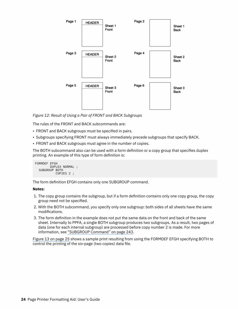
Figure 12: Result of Using a Pair of FRONT and BACK Subgroups
The rules of the FRONT and BACK subcommands are:
• FRONT and BACK subgroups must be specified in pairs.• Subgroups specifying FRONT must always immediately precede subgroups that specify BACK.• FRONT and BACK subgroups must agree in the number of copies.
The BOTH subcommand also can be used with a form definition or a copy group that specifies duplexprinting. An example of this type of form definition is:
FORMDEF EFGH DUPLEX NORMAL ; SUBGROUP BOTH COPIES 2 ;
The form definition EFGH contains only one SUBGROUP command.
Notes:
1. The copy group contains the subgroup, but if a form definition contains only one copy group, the copygroup need not be specified.
2. With the BOTH subcommand, you specify only one subgroup: both sides of all sheets have the samemodifications.
3. The form definition in the example does not put the same data on the front and back of the samesheet. Internally to PPFA, a single BOTH subgroup produces two subgroups. As a result, two pages ofdata (one for each internal subgroup) are processed before copy number 2 is made. For moreinformation, see “SUBGROUP Command” on page 243.
Figure 13 on page 25 shows a sample print resulting from using the FORMDEF EFGH specifying BOTH tocontrol the printing of the six-page (two copies) data file.
24 Page Printer Formatting Aid: User's Guide
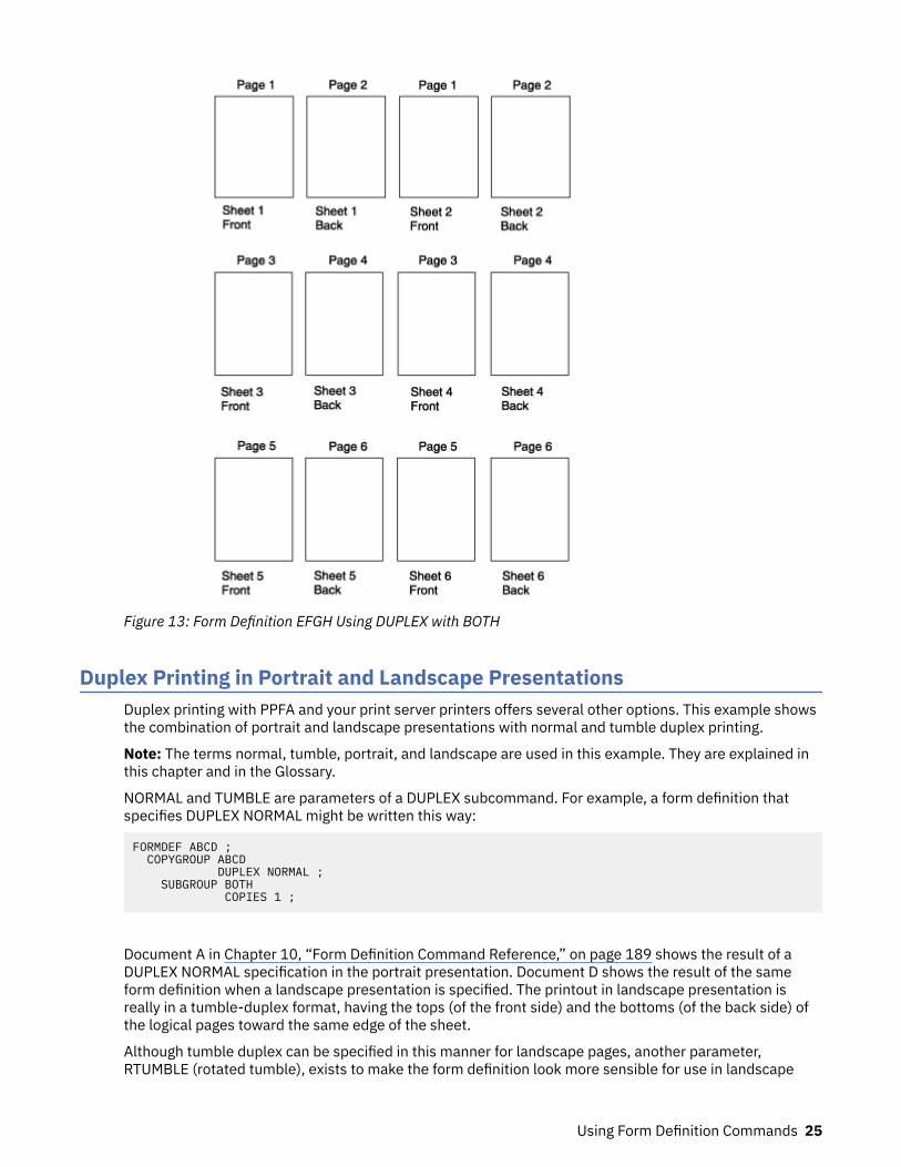
Figure 13: Form Definition EFGH Using DUPLEX with BOTH
Duplex Printing in Portrait and Landscape PresentationsDuplex printing with PPFA and your print server printers offers several other options. This example showsthe combination of portrait and landscape presentations with normal and tumble duplex printing.
Note: The terms normal, tumble, portrait, and landscape are used in this example. They are explained inthis chapter and in the Glossary.
NORMAL and TUMBLE are parameters of a DUPLEX subcommand. For example, a form definition thatspecifies DUPLEX NORMAL might be written this way:
FORMDEF ABCD ; COPYGROUP ABCD DUPLEX NORMAL ; SUBGROUP BOTH COPIES 1 ;
Document A in Chapter 10, “Form Definition Command Reference,” on page 189 shows the result of aDUPLEX NORMAL specification in the portrait presentation. Document D shows the result of the sameform definition when a landscape presentation is specified. The printout in landscape presentation isreally in a tumble-duplex format, having the tops (of the front side) and the bottoms (of the back side) ofthe logical pages toward the same edge of the sheet.
Although tumble duplex can be specified in this manner for landscape pages, another parameter,RTUMBLE (rotated tumble), exists to make the form definition look more sensible for use in landscape
Using Form Definition Commands 25

print jobs. It also produces the results that are shown in Figure 14 on page 26, depending on whetherthe form definition called for portrait or landscape presentation. For landscape, the form definition iswritten as follows:
FORMDEF ABCD PRESENT LANDSCAPE ; COPYGROUP ABCD DUPLEX RTUMBLE ; SUBGROUP BOTH COPIES 1 ;
Note: The example is for continuous printers. You must use N_UP for cut-sheet printers. In Chapter 10,“Form Definition Command Reference,” on page 189, see the PRESENT subcommand of COPYGROUP.
Figure 14: DUPLEX NORMAL: Portrait and Landscape Presentation
The DUPLEX NORMAL and DUPLEX RTUMBLE controls produce the same result on the physical page.RTUMBLE is used to maintain an association between duplex specifications and logical page printdirection. The same relationship exists between the RNORMAL and the TUMBLE parameters as existsbetween the NORMAL and the RTUMBLE parameters; that is, within the two sets the terms areinterchangeable.
For example, you can write a form definition with DUPLEX TUMBLE as follows:
FORMDEF DEFG ; COPYGROUP DEFG DUPLEX TUMBLE ; SUBGROUP BOTH COPIES 1 ;
Documents C and B in Figure 15 on page 27 are the results, depending on how page definition directionis specified to achieve either a portrait page or a landscape page.
26 Page Printer Formatting Aid: User's Guide
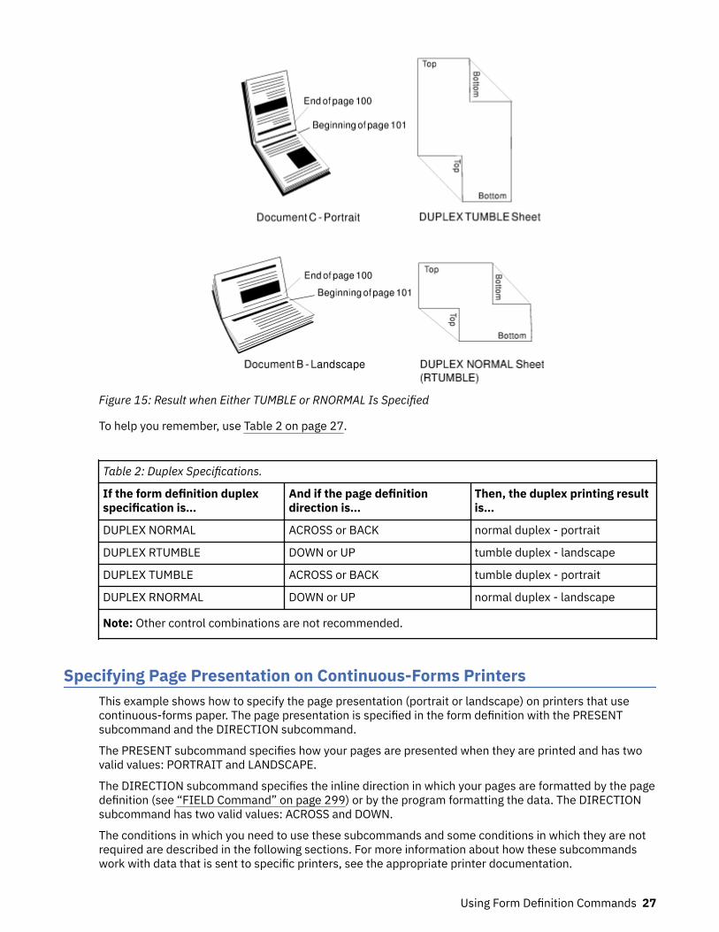
Figure 15: Result when Either TUMBLE or RNORMAL Is Specified
To help you remember, use Table 2 on page 27.
Table 2: Duplex Specifications.
If the form definition duplexspecification is…
And if the page definitiondirection is…
Then, the duplex printing resultis…
DUPLEX NORMAL ACROSS or BACK normal duplex - portrait
DUPLEX RTUMBLE DOWN or UP tumble duplex - landscape
DUPLEX TUMBLE ACROSS or BACK tumble duplex - portrait
DUPLEX RNORMAL DOWN or UP normal duplex - landscape
Note: Other control combinations are not recommended.
Specifying Page Presentation on Continuous-Forms PrintersThis example shows how to specify the page presentation (portrait or landscape) on printers that usecontinuous-forms paper. The page presentation is specified in the form definition with the PRESENTsubcommand and the DIRECTION subcommand.
The PRESENT subcommand specifies how your pages are presented when they are printed and has twovalid values: PORTRAIT and LANDSCAPE.
The DIRECTION subcommand specifies the inline direction in which your pages are formatted by the pagedefinition (see “FIELD Command” on page 299) or by the program formatting the data. The DIRECTIONsubcommand has two valid values: ACROSS and DOWN.
The conditions in which you need to use these subcommands and some conditions in which they are notrequired are described in the following sections. For more information about how these subcommandswork with data that is sent to specific printers, see the appropriate printer documentation.
Using Form Definition Commands 27
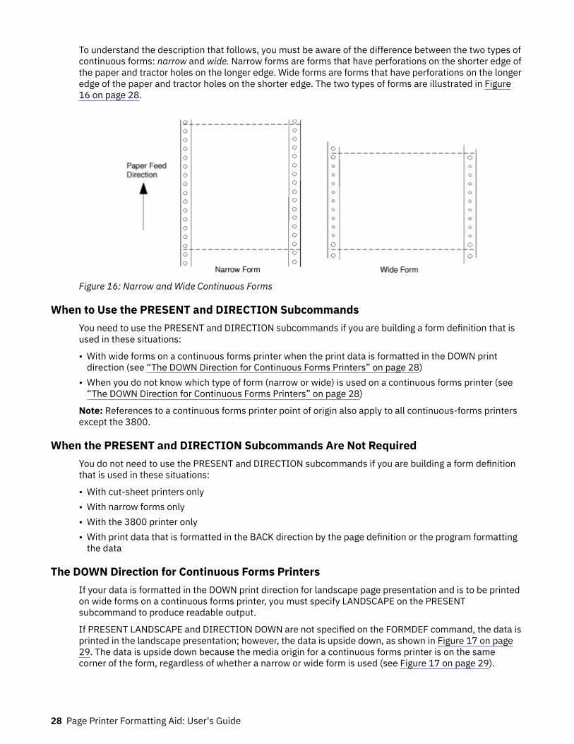
To understand the description that follows, you must be aware of the difference between the two types ofcontinuous forms: narrow and wide. Narrow forms are forms that have perforations on the shorter edge ofthe paper and tractor holes on the longer edge. Wide forms are forms that have perforations on the longeredge of the paper and tractor holes on the shorter edge. The two types of forms are illustrated in Figure16 on page 28.
Figure 16: Narrow and Wide Continuous Forms
When to Use the PRESENT and DIRECTION SubcommandsYou need to use the PRESENT and DIRECTION subcommands if you are building a form definition that isused in these situations:
• With wide forms on a continuous forms printer when the print data is formatted in the DOWN printdirection (see “The DOWN Direction for Continuous Forms Printers” on page 28)
• When you do not know which type of form (narrow or wide) is used on a continuous forms printer (see“The DOWN Direction for Continuous Forms Printers” on page 28)
Note: References to a continuous forms printer point of origin also apply to all continuous-forms printersexcept the 3800.
When the PRESENT and DIRECTION Subcommands Are Not RequiredYou do not need to use the PRESENT and DIRECTION subcommands if you are building a form definitionthat is used in these situations:
• With cut-sheet printers only• With narrow forms only• With the 3800 printer only• With print data that is formatted in the BACK direction by the page definition or the program formatting
the data
The DOWN Direction for Continuous Forms PrintersIf your data is formatted in the DOWN print direction for landscape page presentation and is to be printedon wide forms on a continuous forms printer, you must specify LANDSCAPE on the PRESENTsubcommand to produce readable output.
If PRESENT LANDSCAPE and DIRECTION DOWN are not specified on the FORMDEF command, the data isprinted in the landscape presentation; however, the data is upside down, as shown in Figure 17 on page29. The data is upside down because the media origin for a continuous forms printer is on the samecorner of the form, regardless of whether a narrow or wide form is used (see Figure 17 on page 29).
28 Page Printer Formatting Aid: User's Guide

Figure 17: The Results of Not Specifying PRESENT LANDSCAPE and DIRECTION DOWN on a ContinuousForms Printer
If PRESENT LANDSCAPE and DIRECTION DOWN are specified on the FORMDEF command, the data isprinted as shown in Figure 18 on page 30. In this example, line data is formatted by using a pagedefinition.
PRESENT LANDSCAPE and DIRECTION DOWN can also be specified for data that is formatted in theDOWN print direction and printed on narrow forms. Although PRESENT LANDSCAPE and DIRECTIONDOWN do not need to be specified to produce readable output, specifying them lets you use the sameform definition regardless of whether the data is printed on wide forms or narrow forms.
Note: If you are building a form definition that can be used with both wide and narrow forms, the leftmargin as viewed by the reader becomes the top margin from the printer's perspective (and vice versa).Because many printers have an unprintable area at the margins, you must position the logical page withthe OFFSET subcommand in the form definition so data is placed in the unprintable area on either wide ornarrow forms.
Using Form Definition Commands 29
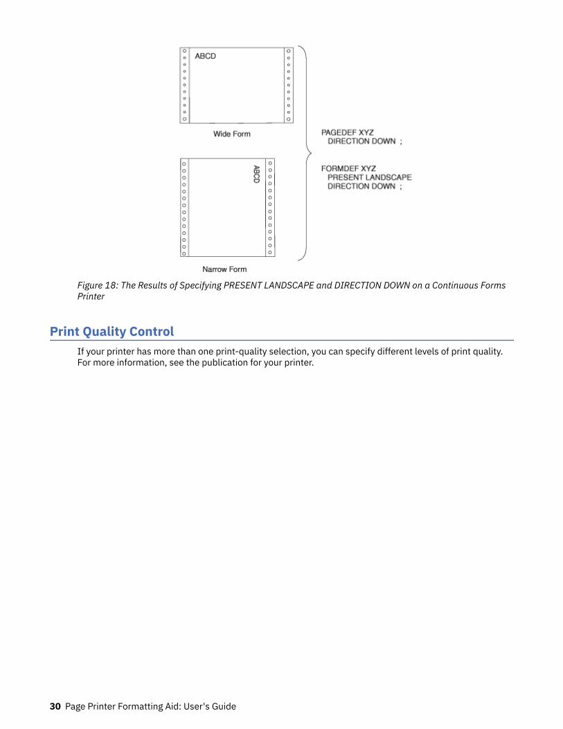
Figure 18: The Results of Specifying PRESENT LANDSCAPE and DIRECTION DOWN on a Continuous FormsPrinter
Print Quality ControlIf your printer has more than one print-quality selection, you can specify different levels of print quality.For more information, see the publication for your printer.
30 Page Printer Formatting Aid: User's Guide

Chapter 3. Using Page Definition Commands forTraditional Line Data
A page definition specifies how you want to position data on the logical page.
A page definition is a resource that is used by print servers to define the rules of transforming line datainto composed pages and text controls for printing. With page definitions, you can do the tasks that arelisted in Table 3 on page 31.
Table 3: Page Definition Tasks
Task Location of an Example
Create a page definition. “Page Definition Command Nesting” on page 32
Define logical page size. “Defining Logical Page Size” on page 32
Position data on a logical page. “Positioning the First Line of Data” on page 33
Change the print direction. “Changing Logical Page Print Direction” on page35
Print line data. “Printing Line Data on a Print Server Printer” onpage 36
Process fields. “Processing Fields” on page 40
Change fonts. “Varying Fonts on a Page” on page 41
Print in different directions. “Printing Lines in Two Directions on a Page” onpage 44
Print fields in two directions. “Printing Fields in Two Directions on the SamePage” on page 45
Rotate fonts. “Rotating Fonts” on page 46
Print kanji. “Using Traditional Kanji Formatting” on page 47
Print multiple up. “Printing Multiple-Up Pages” on page 48
Page Formats within Page DefinitionsJust as form definitions can include more than one copy group, page definitions can include several pageformats. Page formats use the same subcommands (except REPLACE) as page definitions, and if asubcommand is specified in a page format, it overrides the value that is specified in the page definition forthe page format. A single page definition can contain multiple page formats. If pages in a file are to beformatted differently, specify more than one page format in your page definition. Within a page definition,page formats are generated in the order in which they are specified.
Using more than one page format to control different pages requires one of these:
• Adding the Invoke Data Map structured field to the data file each time you want to change page formats• Using conditional processing.
See Advanced Function Presentation: Programming Guide and Line Data Reference for more informationabout the Invoke Data Map structured field.
© Copyright IBM Corp. 1985, 2016 31

Page Definition Command NestingThe following simplified command stream shows the proper nesting of commands and the order in whichthey must be entered when you create a page definition:
[SETUNITS]PAGEDEF [FONT] [OBJECT] [PAGEFORMAT] [TRCREF] [OBJECT] [SEGMENT] [OVERLAY] PRINTLINE [FIELD] [CONDITION] [ENDSUBPAGE][SETUNITS]
Notes:
1. Brackets enclosing a command mean that the command is optional.2. A command and its subcommands end with a semicolon.3. Indentations are used to improve readability.4. Complete definitions of all commands are included in Chapter 11, “Page Definition Command
Reference ,” on page 249.
Command Nesting Rules
1. FONT commands must be specified immediately after PAGEDEF commands.2. A SETUNITS command can be specified anywhere in the PPFA command stream and is in effect until
another SETUNITS command is specified.3. OBJECT commands can appear after the FONT command, and before any PAGEFORMAT command
(global objects) or after a specific PAGEFORMAT command. A global object is defined for all pageformats in the page definition. Otherwise, the object is defined for the PAGEFORMAT in which it isspecified.
4. TRCREF, SEGMENT, and OVERLAY commands must be specified under their associated PAGEFORMATcommand.
5. The first PAGEFORMAT command can be omitted in a page definition, if the page definition has onlyone page format.
6. At least one PRINTLINE command is required.
Defining Logical Page Size“Positioning a Logical Page on a Sheet” on page 19 shows how to establish the origin point of a logicalpage, relative to the media origin on a sheet of paper, by using the OFFSET subcommand. The followingexample shows you how to establish the width and height of the logical page relative to this origin point.This example illustrates how the dimensions of a logical page are determined by form definitions andpage definitions.
FORMDEF ABCD OFFSET (1)(2) ;PAGEDEF ABCD WIDTH (3) HEIGHT (4) ; PRINTLINE ;
32 Page Printer Formatting Aid: User's Guide

Note: The parenthetical numbers represent dimensions. Figure 19 on page 33 shows how thesedimensions relate to the logical page.
Normally, all parameters consist of a number and a unit of measurement, for example, 6 IN. (See “Units ofMeasurement” on page 186 for information on units that are available.) Numbers can be specified with upto three decimal places. The PRINTLINE command is included in the example because at least one isrequired for all page definitions. See “PRINTLINE Command ” on page 400 for more information.
Figure 19: Logical Page Dimensions
The OFFSET subcommand (1) (2) in the sample form definition establishes the corner or origin of thelogical page relative to the physical sheet. The WIDTH and HEIGHT subcommands, (3) and (4), specify thedimensions of the logical page relative to the logical page origin.
Note: Be careful not to define a logical page larger than the physical sheet. PPFA does not check the sizeof the physical sheet.
“Positioning the First Line of Data” on page 33 shows you two ways to position the first line of data onthe page.
Positioning the First Line of Data“Defining Logical Page Size” on page 32 shows how to define the size of a logical page. The next twoexamples show you how to position the first line of data inside the logical page by using the LINEONEsubcommand. This subcommand position is relative to the logical page origin, as shown in Figure 20 onpage 33. The two coordinates, (1) and (2), of the LINEONE parameter define the starting point for thefirst line of text.
Figure 20: LINEONE Coordinates
Using Page Definition Commands for Traditional Line Data 33

This starting point works with the POSITION, MARGIN, and TOP subcommands (of the PRINTLINEcommand) to position lines of print on a page.
The defaults for LINEONE are:
• x = 0• y = 80% of one line space from the top of the logical page. For example:
– 80% of 1/6 inch if lines per inch (lpi) = 6– 80% of 1/8 inch if lpi = 8
These defaults leave room for the character ascenders in the first line of text.
Note: PPFA subtracts one logical unit (L-unit) from the y value to compensate for the fact that the printercounts L-units beginning with the number 0. Therefore, if you use the LINEONE subcommand to specifythe offsets to the first line in L-units (PELS is the measurement command for L-units), you must rememberto subtract one L-unit from the y offset value. This subtraction is necessary to prevent descenders on thelast printed line from dropping off the bottom of the logical page.
The following examples illustrate two methods for positioning the first line of text:
1. The position of the first line of data defaults by specifying the SETUNITS command before thePAGEDEF command; for example:
SETUNITS 1 IN 1 IN LINESP 8 LPI;FORMDEF ABCD OFFSET 0 .5;PAGEDEF ABCD WIDTH 7.5 HEIGHT 10 DIRECTION ACROSS; FONT GS12 GS12; PRINTLINE REPEAT 60 FONT GS12 POSITION 0 TOP;
Note: The LINESP subcommand (of the SETUNITS command) must precede the PAGEDEF commands.
If the LINESP subcommand follows the PAGEDEF command, PPFA then uses the default LINESP valueto calculate the y offset value, which is used to position the first line of print.
The default for the LINESP subcommand of the SETUNITS command is 6 lpi. If LINEONE is allowed todefault, based on the LINESP default, the LINEONE value is 31 L-units:
LINEONE = ( ( 240 L-units / 6 lpi ) x 80% ) - 1 L-unit= 31 L-units.
This value is the vertical (y) position of the printline because TOP is specified in a later POSITIONsubcommand. However, this value might cause the data to exceed the bottom boundary of the logicalpage if the LINESP value is changed later.
2. Another way that you can specify the starting position for the first print line is to specify LINEONEexplicitly; for example:
FORMDEF ABCD OFFSET 0 .5;PAGEDEF ABCD WIDTH 7.5 HEIGHT 10 LINEONE 0 PELS 23 PELS DIRECTION ACROSS;SETUNITS 1 IN 1 IN LINESP 8 LPI; FONT GS12 GS12; PRINTLINE REPEAT 60 FONT GS12 POSITION 0 TOP;
34 Page Printer Formatting Aid: User's Guide
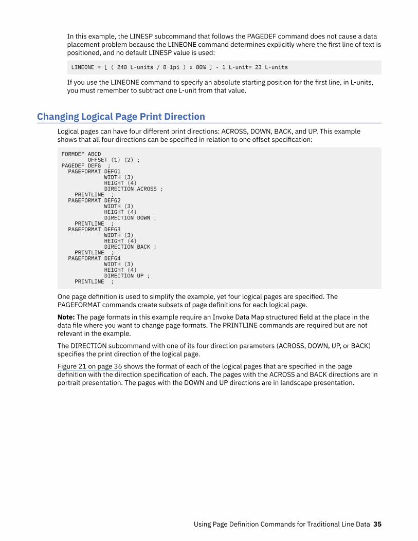
In this example, the LINESP subcommand that follows the PAGEDEF command does not cause a dataplacement problem because the LINEONE command determines explicitly where the first line of text ispositioned, and no default LINESP value is used:
LINEONE = [ ( 240 L-units / 8 lpi ) x 80% ] - 1 L-unit= 23 L-units
If you use the LINEONE command to specify an absolute starting position for the first line, in L-units,you must remember to subtract one L-unit from that value.
Changing Logical Page Print DirectionLogical pages can have four different print directions: ACROSS, DOWN, BACK, and UP. This exampleshows that all four directions can be specified in relation to one offset specification:
FORMDEF ABCD OFFSET (1) (2) ;PAGEDEF DEFG ; PAGEFORMAT DEFG1 WIDTH (3) HEIGHT (4) DIRECTION ACROSS ; PRINTLINE ; PAGEFORMAT DEFG2 WIDTH (3) HEIGHT (4) DIRECTION DOWN ; PRINTLINE ; PAGEFORMAT DEFG3 WIDTH (3) HEIGHT (4) DIRECTION BACK ; PRINTLINE ; PAGEFORMAT DEFG4 WIDTH (3) HEIGHT (4) DIRECTION UP ; PRINTLINE ;
One page definition is used to simplify the example, yet four logical pages are specified. ThePAGEFORMAT commands create subsets of page definitions for each logical page.
Note: The page formats in this example require an Invoke Data Map structured field at the place in thedata file where you want to change page formats. The PRINTLINE commands are required but are notrelevant in the example.
The DIRECTION subcommand with one of its four direction parameters (ACROSS, DOWN, UP, or BACK)specifies the print direction of the logical page.
Figure 21 on page 36 shows the format of each of the logical pages that are specified in the pagedefinition with the direction specification of each. The pages with the ACROSS and BACK directions are inportrait presentation. The pages with the DOWN and UP directions are in landscape presentation.
Using Page Definition Commands for Traditional Line Data 35

Figure 21: Logical Page Print Directions in Relation to Origin
The media origins and logical page origins do not change with the presentation of the data on the page.The OFFSET subcommand of the form definition need not change. However, the width and heightdimensions do change; that is, the WIDTH subcommand always governs the horizontal (inline) dimensionas you view the page, and the HEIGHT subcommand always governs the vertical (baseline) dimensionwhether the page is in portrait or in landscape presentation. Ensure that these specifications do not causethe logical page to cross the edge of the physical page.
However, if the DOWN direction is specified for use with a continuous forms printer, the PRESENT andDIRECTION subcommands might need to be specified in the form definition. See “Specifying PagePresentation on Continuous-Forms Printers” on page 27 for more information.
Printing Line Data on a Print Server PrinterThis example shows how you can print a data file that is developed for a line printer on a page printerwithout altering the data. The example compares the effects of line printer controls with thecorresponding controls in the PPFA commands and subcommands. PRINTLINE, LINESP, POSITION,CHANNEL, and REPEAT are page definition controls related to the lines of text in your printout. Lineprinter controls examined are the forms control buffer (FCB) and carriage control characters.
As shown in Figure 22 on page 37, a file that consists of 13 records is to be printed. Several differentprintouts of this data are formatted in the following examples. In the first two printouts, records 1 - 6 areprinted on page 1, records 7 - 9 on page 2, and records 10 - 13 on page 3.
36 Page Printer Formatting Aid: User's Guide

Figure 22: Line-Data File
Figure 23 on page 37 shows the formatting process that is used when the file is printed on a line printer.For many line printers, an FCB is used to format the output in the z/OS, VM, and VSE environment. Thesample FCB represented in Figure 23 on page 37 determines that no printed page contains more thaneight lines. A page can have exactly eight lines without using carriage control characters in the data. Apage can contain any number of lines fewer than eight by placing fewer than eight records between thecarriage control characters in the data. In the data file in Figure 22 on page 37, fewer than eight recordsare, in all cases, placed between channel 1 carriage control characters. A ninth record, if encounteredbefore a carriage control character, would cause a page eject and a return to the beginning of the FCB. Theprintout that is shown in Figure 23 on page 37 results from an FCB that formats the data.
Figure 23: Data File Printed on a Line Printer
Using Page Definition Commands for Traditional Line Data 37

A page definition can work the same way. Consider the following example:
SETUNITS 1 IN 1 IN LINESP 6 LPI ;PAGEDEF ABCD WIDTH 5 HEIGHT 7 LINEONE .5 .5 ; PRINTLINE CHANNEL 1 POSITION MARGIN TOP REPEAT 8 ;
This command stream contains one new command (PRINTLINE) and four new subcommands (LINESP,CHANNEL, POSITION, and REPEAT) related to controlling individual lines.
• The subcommand has the same function as the LPI specifications in the FCB or in a Printer File; itdefines the line density iLINESPn lines per inch.
• The PRINTLINE command contains the controls for one or more lines.• The CHANNEL subcommand has the same function as the channel 1 control character in the FCB,
causing a page eject at each channel 1 control character that is encountered in the data records.• The POSITION subcommand establishes the location of the first line relative to the upper-left corner of
the logical page. This example uses the MARGIN and TOP parameters; however, numeric parameterssimilar to the ones that are used with the OFFSET subcommand can also be used. Those values are alsorelative to the logical page.
• The REPEAT subcommand is a commonly used control in PPFA text formatting. It is the way that youspecify the total number of PRINTLINEs in a logical page.
Note: The constraints in specifying a REPEAT value and thus, the number of lines per page, are: the linesper inch specification, the height of the logical page, and the font selection. The REPEAT variable 8 ischosen to equal the maximum number of records to be printed per page. As in the line printer version, ifa ninth record were encountered before a channel 1 carriage control character, a page eject would occurand the line would be printed as the first line at the top of the next page.
The result of this page definition is represented in Figure 24 on page 38.
Figure 24: Printout Examples Specifying POSITION MARGIN TOP
Changing line printing specifications for the following example is shown in Figure 25 on page 39.
38 Page Printer Formatting Aid: User's Guide

Figure 25: Printout Example Specifying POSITION MARGIN 4.1
SETUNITS 1 IN 1 IN LINESP 6 LPI ;PAGEDEF ABCD WIDTH 5 HEIGHT 7 LINEONE .1 .1 ; PRINTLINE CHANNEL 1 POSITION MARGIN 4.1 REPEAT 8 ;
Observe that the second parameter of POSITION is no longer TOP; instead, it is 4.1, which places the firstline of text 4.1 inches down the page rather than at the top (Figure 25 on page 39).
Figure 26: Printout Example Specifying POSITION MARGIN TOP and POSITION MARGIN 4.1
The following example and Figure 26 on page 39 show a third version of the possible formats for the datathat is represented in Figure 23 on page 37.
SETUNITS 1 IN 1 IN LINESP 6 LPI ;PAGEDEF ABCD WIDTH 5 HEIGHT 7 LINEONE .1 .1 ; PRINTLINE CHANNEL 1 POSITION MARGIN TOP REPEAT 8 ; PRINTLINE CHANNEL 1
Using Page Definition Commands for Traditional Line Data 39
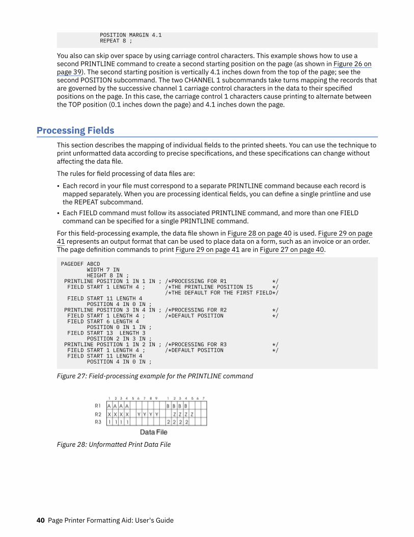
POSITION MARGIN 4.1 REPEAT 8 ;
You also can skip over space by using carriage control characters. This example shows how to use asecond PRINTLINE command to create a second starting position on the page (as shown in Figure 26 onpage 39). The second starting position is vertically 4.1 inches down from the top of the page; see thesecond POSITION subcommand. The two CHANNEL 1 subcommands take turns mapping the records thatare governed by the successive channel 1 carriage control characters in the data to their specifiedpositions on the page. In this case, the carriage control 1 characters cause printing to alternate betweenthe TOP position (0.1 inches down the page) and 4.1 inches down the page.
Processing FieldsThis section describes the mapping of individual fields to the printed sheets. You can use the technique toprint unformatted data according to precise specifications, and these specifications can change withoutaffecting the data file.
The rules for field processing of data files are:
• Each record in your file must correspond to a separate PRINTLINE command because each record ismapped separately. When you are processing identical fields, you can define a single printline and usethe REPEAT subcommand.
• Each FIELD command must follow its associated PRINTLINE command, and more than one FIELDcommand can be specified for a single PRINTLINE command.
For this field-processing example, the data file shown in Figure 28 on page 40 is used. Figure 29 on page41 represents an output format that can be used to place data on a form, such as an invoice or an order.The page definition commands to print Figure 29 on page 41 are in Figure 27 on page 40.
PAGEDEF ABCD WIDTH 7 IN HEIGHT 8 IN ; PRINTLINE POSITION 1 IN 1 IN ; /*PROCESSING FOR R1 */ FIELD START 1 LENGTH 4 ; /*THE PRINTLINE POSITION IS */ /*THE DEFAULT FOR THE FIRST FIELD*/ FIELD START 11 LENGTH 4 POSITION 4 IN 0 IN ; PRINTLINE POSITION 3 IN 4 IN ; /*PROCESSING FOR R2 */ FIELD START 1 LENGTH 4 ; /*DEFAULT POSITION */ FIELD START 6 LENGTH 4 POSITION 0 IN 1 IN ; FIELD START 13 LENGTH 3 POSITION 2 IN 3 IN ; PRINTLINE POSITION 1 IN 2 IN ; /*PROCESSING FOR R3 */ FIELD START 1 LENGTH 4 ; /*DEFAULT POSITION */ FIELD START 11 LENGTH 4 POSITION 4 IN 0 IN ;
Figure 27: Field-processing example for the PRINTLINE command
Figure 28: Unformatted Print Data File
40 Page Printer Formatting Aid: User's Guide
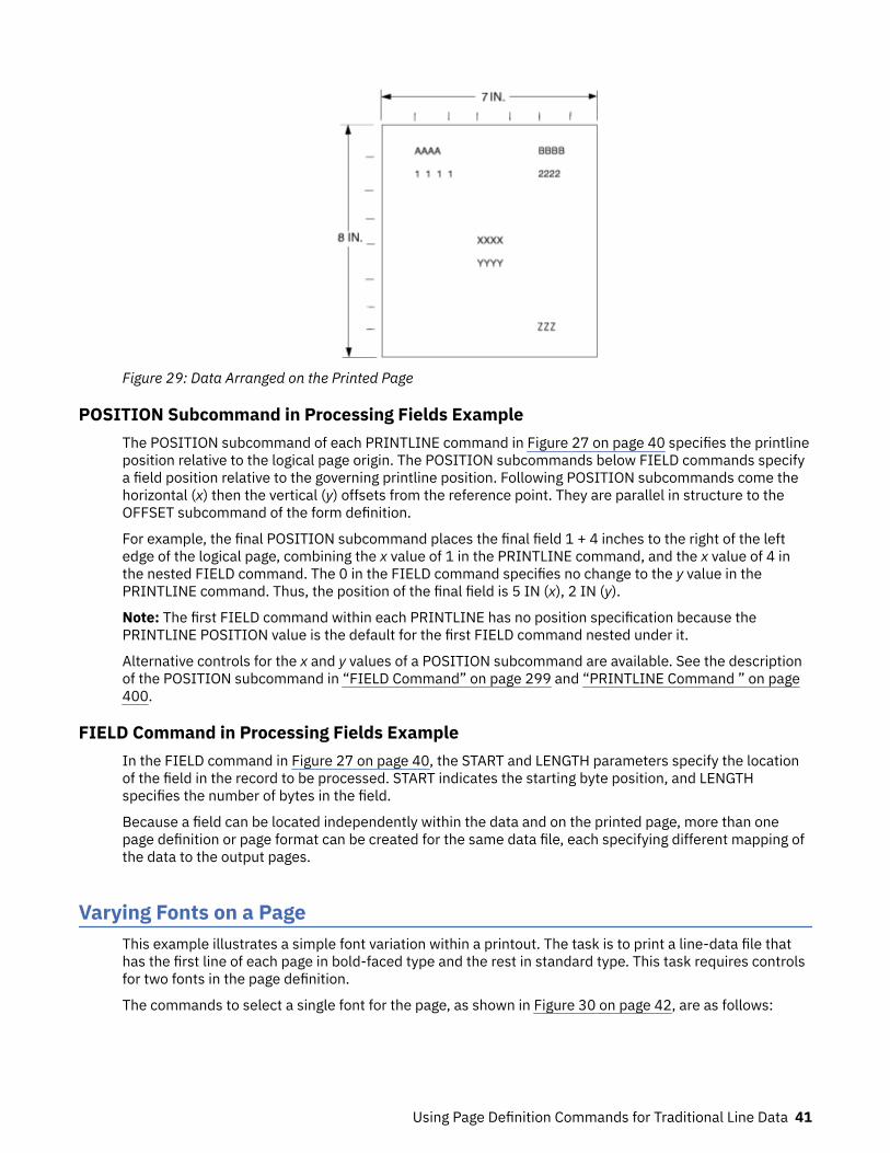
Figure 29: Data Arranged on the Printed Page
POSITION Subcommand in Processing Fields ExampleThe POSITION subcommand of each PRINTLINE command in Figure 27 on page 40 specifies the printlineposition relative to the logical page origin. The POSITION subcommands below FIELD commands specifya field position relative to the governing printline position. Following POSITION subcommands come thehorizontal (x) then the vertical (y) offsets from the reference point. They are parallel in structure to theOFFSET subcommand of the form definition.
For example, the final POSITION subcommand places the final field 1 + 4 inches to the right of the leftedge of the logical page, combining the x value of 1 in the PRINTLINE command, and the x value of 4 inthe nested FIELD command. The 0 in the FIELD command specifies no change to the y value in thePRINTLINE command. Thus, the position of the final field is 5 IN (x), 2 IN (y).
Note: The first FIELD command within each PRINTLINE has no position specification because thePRINTLINE POSITION value is the default for the first FIELD command nested under it.
Alternative controls for the x and y values of a POSITION subcommand are available. See the descriptionof the POSITION subcommand in “FIELD Command” on page 299 and “PRINTLINE Command ” on page400.
FIELD Command in Processing Fields ExampleIn the FIELD command in Figure 27 on page 40, the START and LENGTH parameters specify the locationof the field in the record to be processed. START indicates the starting byte position, and LENGTHspecifies the number of bytes in the field.
Because a field can be located independently within the data and on the printed page, more than onepage definition or page format can be created for the same data file, each specifying different mapping ofthe data to the output pages.
Varying Fonts on a PageThis example illustrates a simple font variation within a printout. The task is to print a line-data file thathas the first line of each page in bold-faced type and the rest in standard type. This task requires controlsfor two fonts in the page definition.
The commands to select a single font for the page, as shown in Figure 30 on page 42, are as follows:
Using Page Definition Commands for Traditional Line Data 41

The FONT command contains two names: the local (STANDARD) name and the user-access (M101) namefor the selected font.
PAGEDEF ABCD ; FONT STANDARD M101 ; PRINTLINE ;
Note: Fonts cannot be an FGID. Also, all page definitions require a PRINTLINE command.
Figure 30: Data File Printed Using a Single Font
The next command stream changes the font by incorporating a TRCREF command. Assume the data file tobe formatted incorporates table reference characters (TRCs) as shown in Figure 31 on page 43.
PAGEDEF ABCD ; FONT STANDARD M101 ; /*CREATING LOCAL FONT NAMES */ FONT BOLDFACE M102 ; PAGEFORMAT ABCD ; TRCREF 0 /*DEFINING THE TRC VALUES */ FONT STANDARD ; TRCREF 1 FONT BOLDFACE ; PRINTLINE CHANNEL 1 POSITION 1 IN 1 IN REPEAT 8 ;
42 Page Printer Formatting Aid: User's Guide

Figure 31: Font Change Using TRCREF Command
The TRCs in the data cause the font switch to be made. The TRCREF command equates a TRC in the datafile with the local name of a font that is specified in the FONT command. The FONT command alsocontains the user-access name for the font. See Table 8 on page 184 for information on local names anduser-access names. Because of the relationship among the user-access name, the local name, and theTRC number that is established in the page definition, the TRCs in the data can cause a font switchautomatically.
You can specify fonts within a PRINTLINE command when the data file contains no TRCs. For example,assume the data file represented in the sample print in Figure 32 on page 44 is to be formatted by thispage definition:
PAGEDEF ABCD ; FONT M101 ; FONT BOLDFACE M102 ; PRINTLINE CHANNEL 1 /*BOLDFACE LINE */ POSITION MARGIN TOP FONT BOLDFACE ; PRINTLINE POSITION MARGIN NEXT /*STANDARD-TYPE LINE */ FONT M101 REPEAT 7 ;
This command stream, based on a data file without TRCs, works on the principle that each line of outputwhose font you want to change from the font in the previous line must be controlled by a separatePRINTLINE command. The FONT subcommand of the PRINTLINE command names the font that isdesired for that line. In this example, two PRINTLINE commands are used because one font change andtwo fonts are intended for the output. The user-access font names appear in the two FONT commandsimmediately below the PAGEDEF command and optionally, a local name. M101 and M102 in the exampleare user-access names; BOLDFACE is a local name. Use the local name in the FONT subcommand ofPRINTLINE if it is included in the corresponding FONT command, as is done for the first PRINTLINEcommand.
Using Page Definition Commands for Traditional Line Data 43

Figure 32: Font Change Using FONT Commands and Subcommands
Changing fonts field by field is similar to changing them in PRINTLINEs. You map each field individuallywith a FIELD command; include a FONT subcommand in the FIELD command. If a font change is wantedfor a field, as with the FONT subcommand of a PRINTLINE command, the font must be previously namedin a FONT command.
Two possible defaults apply in case you do not specify a font within a field. If the governing PRINTLINEhas a FONT subcommand, it contains the font default for the field. If the governing PRINTLINE has no fontspecification, the print server assigns a font according to its default rules.
Printing Lines in Two Directions on a PageLines can be printed in any of four directions, depending on the type of printer that is used.
The four parameters for line direction are ACROSS, DOWN, BACK, and UP. The PPFA commands that areused to format a line-data file with lines that are printed in more than one direction (as shown in Figure 33on page 45) are stated in the following page definition:
PAGEDEF ATOG DIRECTION ACROSS ; PRINTLINE POSITION 1 IN 1 IN /*LINES A-E */ REPEAT 5 ; PRINTLINE POSITION .5 IN 6 IN /*LINE F */ DIRECTION UP ; PRINTLINE POSITION 1 IN 6 IN ; /*LINE G */
44 Page Printer Formatting Aid: User's Guide

Figure 33: A Printout with More Than One Line Direction
In this page definition, the logical page direction ACROSS is specified. ACROSS is the default, but itsinclusion clarifies that no direction control is needed for lines A–E. The default direction of a printline isthe direction specification of the logical page of which it is part. The PRINTLINE command for the record Fhas a DIRECTION subcommand because the direction specification changes from the specification of theprevious line. Record G is to be printed in the ACROSS direction again. However, a direction is notspecified because the ACROSS direction is the default for all lines in this page definition.
Note: If you are building the page definition for use with the 3800 printer, and if the input data containstable reference characters, you can use the DIRECTION subcommand of the TRCREF command to specifya font that prints UP on the page, as in line F. For more information, see “TRCREF Command (Traditional)”on page 420.
Printing Fields in Two Directions on the Same PageThis example is similar to “Printing Lines in Two Directions on a Page” on page 44, except that you learnhow to control direction field by field. This method creates a field-processing page definition and placesdirection controls in the FIELD commands. This command stream contains a portion of the page definitioncontrols, showing only the PRINTLINE commands:
PRINTLINE POSITION MARGIN TOP ; FIELD START 1 LENGTH 4 ;PRINTLINE POSITION 2 IN 4 IN ; FIELD START 7 LENGTH 4 DIRECTION UP ;
As expected in field processing, FIELD commands are nested within PRINTLINE commands. Figure 34 onpage 46 shows a simplified portion of an unformatted file and two pages of the printout that is formattedby the page definition, part of which is shown in the command stream. Two PRINTLINEs are specifiedbecause, as Figure 34 on page 46 shows, the data file contains two input record formats (1 and 3 arealike; 2 and 4 are alike) and because the fields are mapped to two different positions in the output. Theassumption of this sample is that the data file is much longer than the portion shown. However, if therecords in the file alternate in format as the first four do, the two PRINTLINEs of this page definitionformat as many records as are presented, two to a page, on pages 1 - n.
If more than two mappings are required by the print job, more than two PRINTLINE commands arerequired in the page definition.
Using Page Definition Commands for Traditional Line Data 45
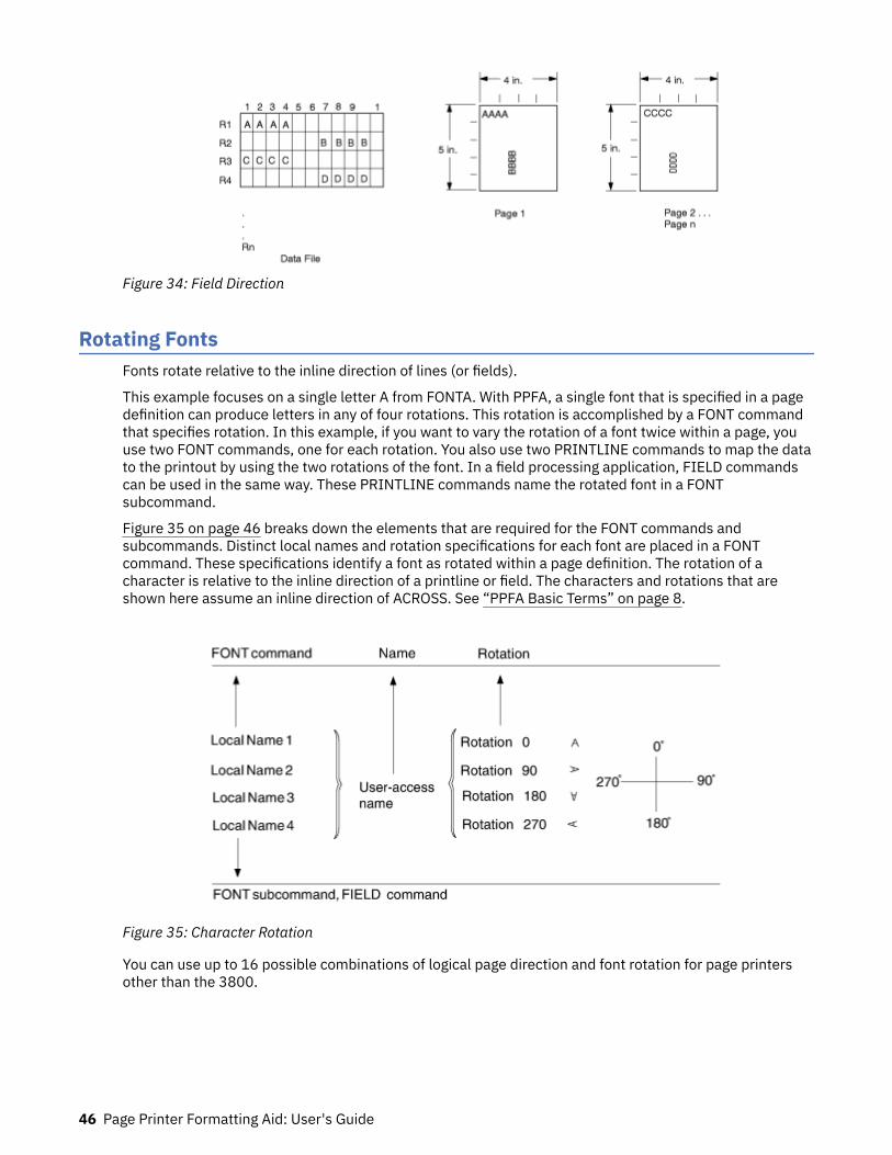
Figure 34: Field Direction
Rotating FontsFonts rotate relative to the inline direction of lines (or fields).
This example focuses on a single letter A from FONTA. With PPFA, a single font that is specified in a pagedefinition can produce letters in any of four rotations. This rotation is accomplished by a FONT commandthat specifies rotation. In this example, if you want to vary the rotation of a font twice within a page, youuse two FONT commands, one for each rotation. You also use two PRINTLINE commands to map the datato the printout by using the two rotations of the font. In a field processing application, FIELD commandscan be used in the same way. These PRINTLINE commands name the rotated font in a FONTsubcommand.
Figure 35 on page 46 breaks down the elements that are required for the FONT commands andsubcommands. Distinct local names and rotation specifications for each font are placed in a FONTcommand. These specifications identify a font as rotated within a page definition. The rotation of acharacter is relative to the inline direction of a printline or field. The characters and rotations that areshown here assume an inline direction of ACROSS. See “PPFA Basic Terms” on page 8.
Figure 35: Character Rotation
You can use up to 16 possible combinations of logical page direction and font rotation for page printersother than the 3800.
46 Page Printer Formatting Aid: User's Guide
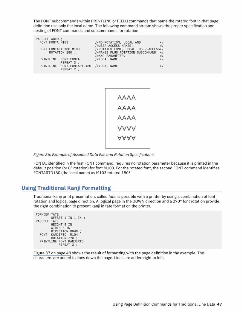
The FONT subcommands within PRINTLINE or FIELD commands that name the rotated font in that pagedefinition use only the local name. The following command stream shows the proper specification andnesting of FONT commands and subcommands for rotation.
PAGEDEF ABCD ; FONT FONTA M103 ; /*NO ROTATION, LOCAL AND */ /*USER-ACCESS NAMES. */ FONT FONTARTD180 M103 /*ROTATED FONT, LOCAL, USER-ACCESS*/ ROTATION 180 ; /*NAMES PLUS ROTATION SUBCOMMAND */ /*AND PARAMETER. */ PRINTLINE FONT FONTA /*LOCAL NAME */ REPEAT 3 ; PRINTLINE FONT FONTARTD180 /*LOCAL NAME */ REPEAT 2 ;
Figure 36: Example of Assumed Data File and Rotation Specifications
FONTA, identified in the first FONT command, requires no rotation parameter because it is printed in thedefault position (or 0° rotation) for font M103. For the rotated font, the second FONT command identifiesFONTARTD180 (the local name) as M103 rotated 180°.
Using Traditional Kanji FormattingTraditional kanji print presentation, called tate, is possible with a printer by using a combination of fontrotation and logical page direction. A logical page in the DOWN direction and a 270° font rotation providethe right combination to present kanji in tate format on the printer.
FORMDEF TATE OFFSET 1 IN 1 IN ;PAGEDEF TATE HEIGHT 5 IN WIDTH 6 IN DIRECTION DOWN ; FONT KANJIRTD M104 ROTATION 270 ; PRINTLINE FONT KANJIRTD REPEAT 3 ;
Figure 37 on page 48 shows the result of formatting with the page definition in the example. Thecharacters are added to lines down the page. Lines are added right to left.
Using Page Definition Commands for Traditional Line Data 47
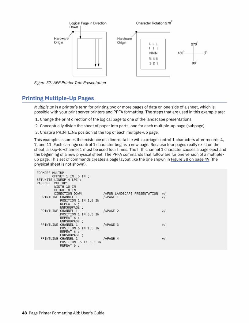
Figure 37: AFP Printer Tate Presentation
Printing Multiple-Up PagesMultiple up is a printer’s term for printing two or more pages of data on one side of a sheet, which ispossible with your print server printers and PPFA formatting. The steps that are used in this example are:
1. Change the print direction of the logical page to one of the landscape presentations.2. Conceptually divide the sheet of paper into parts, one for each multiple-up page (subpage).3. Create a PRINTLINE position at the top of each multiple-up page.
This example assumes the existence of a line-data file with carriage control 1 characters after records 4,7, and 11. Each carriage control 1 character begins a new page. Because four pages really exist on thesheet, a skip-to-channel 1 must be used four times. The fifth channel 1 character causes a page eject andthe beginning of a new physical sheet. The PPFA commands that follow are for one version of a multiple-up page. This set of commands creates a page layout like the one shown in Figure 38 on page 49 (thephysical sheet is not shown).
FORMDEF MULTUP OFFSET 1 IN .5 IN ;SETUNITS LINESP 4 LPI ;PAGEDEF MULTUP1 WIDTH 10 IN HEIGHT 8 IN DIRECTION DOWN /*FOR LANDSCAPE PRESENTATION */ PRINTLINE CHANNEL 1 /*PAGE 1 */ POSITION 1 IN 1.5 IN REPEAT 6 ; ENDSUBPAGE ; PRINTLINE CHANNEL 1 /*PAGE 2 */ POSITION 1 IN 5.5 IN REPEAT 6 ; ENDSUBPAGE ; PRINTLINE CHANNEL 1 /*PAGE 3 */ POSITION 6 IN 1.5 IN REPEAT 6 ; ENDSUBPAGE ; PRINTLINE CHANNEL 1 /*PAGE 4 */ POSITION 6 IN 5.5 IN REPEAT 6 ;
48 Page Printer Formatting Aid: User's Guide
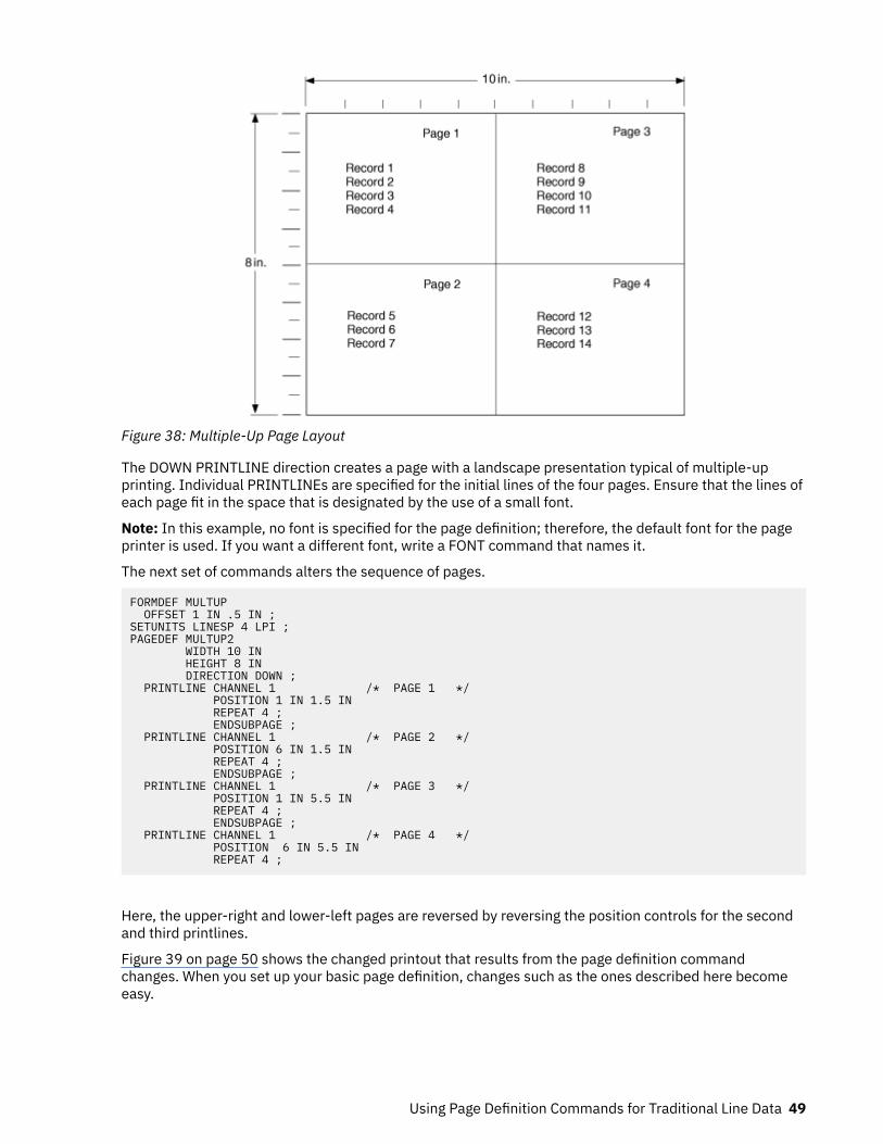
Figure 38: Multiple-Up Page Layout
The DOWN PRINTLINE direction creates a page with a landscape presentation typical of multiple-upprinting. Individual PRINTLINEs are specified for the initial lines of the four pages. Ensure that the lines ofeach page fit in the space that is designated by the use of a small font.
Note: In this example, no font is specified for the page definition; therefore, the default font for the pageprinter is used. If you want a different font, write a FONT command that names it.
The next set of commands alters the sequence of pages.
FORMDEF MULTUP OFFSET 1 IN .5 IN ;SETUNITS LINESP 4 LPI ;PAGEDEF MULTUP2 WIDTH 10 IN HEIGHT 8 IN DIRECTION DOWN ; PRINTLINE CHANNEL 1 /* PAGE 1 */ POSITION 1 IN 1.5 IN REPEAT 4 ; ENDSUBPAGE ; PRINTLINE CHANNEL 1 /* PAGE 2 */ POSITION 6 IN 1.5 IN REPEAT 4 ; ENDSUBPAGE ; PRINTLINE CHANNEL 1 /* PAGE 3 */ POSITION 1 IN 5.5 IN REPEAT 4 ; ENDSUBPAGE ; PRINTLINE CHANNEL 1 /* PAGE 4 */ POSITION 6 IN 5.5 IN REPEAT 4 ;
Here, the upper-right and lower-left pages are reversed by reversing the position controls for the secondand third printlines.
Figure 39 on page 50 shows the changed printout that results from the page definition commandchanges. When you set up your basic page definition, changes such as the ones described here becomeeasy.
Using Page Definition Commands for Traditional Line Data 49
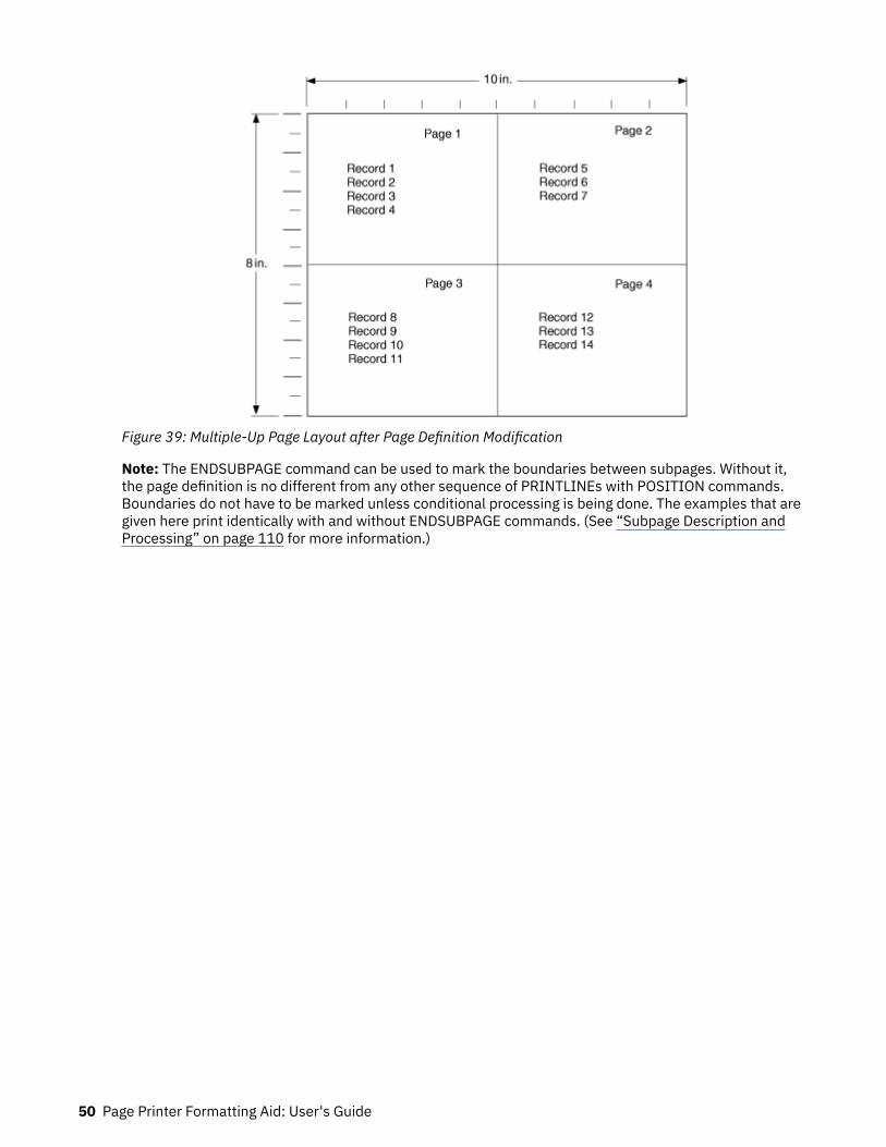
Figure 39: Multiple-Up Page Layout after Page Definition Modification
Note: The ENDSUBPAGE command can be used to mark the boundaries between subpages. Without it,the page definition is no different from any other sequence of PRINTLINEs with POSITION commands.Boundaries do not have to be marked unless conditional processing is being done. The examples that aregiven here print identically with and without ENDSUBPAGE commands. (See “Subpage Description andProcessing” on page 110 for more information.)
50 Page Printer Formatting Aid: User's Guide
Chapter 4. Using Page Definition Commands forRecord Format Line Data and XML Data
This chapter describes the record formatting function and the XML page definition formatting function.
Record Formatting FunctionThe record formatting function allows an application to specify a format identifier (Record ID) with eachset of output data fields (Data Record). The format identifier references a specific layout format in a pagedefinition (PAGEDEF). At print time, each layout format (referenced by a Record ID in a Data Record) isretrieved from the PAGEDEF and used to position and format the associated Data Records/fields on theoutput page.
The purpose of the record formatting capabilities is to move more of the output formatting function intothe PAGEDEF and allow for greater flexibility in creating and changing output pages without changing thebase application. Rather than the application generating page headers, page trailers, and group headersfor each page (and thus fixing the page endings), the page headers, page trailers, and group headers canbe generated by a PAGEDEF layout, which allows the page endings to change as font sizes or data layoutschange.
To visualize how the record formatting function can be used, review the first six pages of “RecordFormatting Examples” on page 69. These examples show the output of an application before and after itis formatted with PAGEDEF by using the record formatting functions.
These functions are provided by several new PPFA commands (LAYOUT, DEFINE COLOR, DRAWGRAPHIC,and ENDGRAPHIC), and modifications to the PAGEDEF, PAGEFORMAT, FONT, CONDITION, and FIELDcommands. This chapter provides an explanation of the record formatting functions with examples oftheir use. For details on the syntax of these commands, see Chapter 11, “Page Definition CommandReference ,” on page 249.
Some of the functions that can be accomplished in a layout format with the record formatting commandsinclude:
• Selecting different formatting for different types of Data Records/fields based on the Record ID. Theoutput formatting can change mid-page independent of where the output occurs on a page.
• Defining page headers and trailers to be automatically printed on subsequent pages. The headers andtrailers can incorporate data from the associated Data Record.
• Numbering the output pages.• Inserting page ejects can be automatic when text reaches the bottom margin.• Creating group headings to be printed at the beginning of a group of data. For example, you can create
group headings (including column headings) to be repeated each time a different account type isformatted on a banking statement. An active group heading is automatically repeated on subsequentpages until the data group ends.
• Forcing page ejects to occur in the output.• Creating boxes with or without black and white or color shading. A set of boxes for a table can be
started in a group header and automatically ended and restarted on subsequent pages until the tablecompletes.
• Creating graphical objects, such as circles, ellipses, lines, and graphs, in color or black and white output.• Formatting database records created with field delimiters (rather than fixed-length fields).• Aligning field output to the left or right.
© Copyright IBM Corp. 1985, 2016 51

Record Format Page DefinitionA record format page definition specifies how you want data to be positioned on the logical page.
A record format page definition is a resource that is used by the print server that defines the rules oftransforming line data into composed pages and text controls for printing. With record format pagedefinitions, you can do the tasks that are listed in Table 4 on page 52.
Table 4: Record Format Page Definition Tasks
Task Location of an Example
Create a page definition. “Page Definition Command Nesting” on page 53
Assign a record ID. “Record ID Data Format” on page 53
Use the LAYOUT command. “LAYOUT Command” on page 54
Use the FIELD command. “FIELD Command” on page 55
Define logical page size. “Defining Logical Page Size” on page 58
Position data on a logical page. “Positioning the Data” on page 59
Change the print direction. “Changing Logical Page Print Direction” on page59
Process fields. “Processing Fields” on page 63
Print in different directions. “Printing Lines in Two Directions on a Page” onpage 64
Print fields in two directions. “Printing Fields in Two Directions on the SamePage” on page 65
Change fonts. “Varying Fonts on a Page” on page 66
Rotate fonts. “Rotating Fonts” on page 68
Print kanji. “Using Traditional Kanji Formatting” on page 69
Use record formatting and commands. “Record Formatting Examples” on page 69
Page Formats within Page Definitions
Just as form definitions can include more than one copy group, page definitions can include several pageformats. Page formats use basically the same subcommands as page definitions, and if a subcommand isspecified in a page format, it overrides the value that is specified in the page definition for the pageformat. A single page definition can contain multiple page formats. If pages in a file are to be formatteddifferently, specify more than one page format in your page definition. Within a page definition, pageformats are generated in the order in which they are specified.
Using more than one page format to control different pages requires one of these:
• Adding the Invoke Data Map structured field to the data file each time you want to change page formats.• Using conditional processing.
See Advanced Function Presentation: Programming Guide and Line Data Reference for more informationabout the Invoke Data Map structured field.
52 Page Printer Formatting Aid: User's Guide

Page Definition Command Nesting
The following simplified command stream shows the proper nesting of commands and the order in whichthey must be entered when you create a page definition:
[SETUNITS]PAGEDEFFONT[OBJECT][DEFINE COLOR][PAGEFORMAT] [SEGMENT] [OVERLAY] [LAYOUT] [CONDITION] [FIELD] [DRAWGRAPHIC] [ENDGRAPHIC][PAGEFORMAT] [SEGMENT] [OVERLAY] [LAYOUT] [CONDITION] [FIELD] [DRAWGRAPHIC] [ENDGRAPHIC]
Notes:
1. Brackets enclosing a command mean that the command is optional.2. Indentations are used to improve readability.3. Complete definitions of all commands are included in Chapter 11, “Page Definition Command
Reference ,” on page 249.
Rules
1. Record format LAYOUT commands and traditional PRINTLINE commands cannot be used within thesame PAGEDEF. At least one LAYOUT command is required per page format for a record formattingpage definition.
2. A SETUNITS command can be placed before any other PPFA command. The values that are set are ineffect until the next SETUNITS command.
3. SEGMENT and OVERLAY commands must be specified under their associated PAGEFORMATcommand.
4. The first PAGEFORMAT command can be omitted in a page definition, if the page definition containsonly one page format. If the PAGEFORMAT command is omitted, the PAGEDEF command parametersare used to define the page format.
5. One file can contain multiple sets of page definitions.
Record ID Data FormatIn order to allow different formats for different groups (or tables) of data, each of which have anunpredictable number of entries, a Record ID is assigned to each output record to identify the type ofrecord and control layout formatting. An application can group data fields that are to be formattedtogether as an entity into Data Records with a specific Record ID. For example, in a bank statement, thedata fields for a check transaction might be grouped with a Record ID identifying that record as a checktransaction. The PAGEDEF would then define a special layout format for a check transaction with amatching Record ID (see “Record Formatting Examples” on page 69 for detailed examples).
Record formatting in PPFA is achieved by identifying each input record in the data file with a 10-byte ID,similar to an expanded carriage control (CC) (see “Basic Controls in Record Format Line Data” on page 12for additional information). Each record in the data file must contain a Record ID if record formatting isused. The Record ID must be the first 10 bytes in every print record in the data file.
Using Page Definition Commands for Record Format Line Data and XML Data 53

Even though the Record ID is specified as a character string, the Record ID is treated as a hexadecimalstring, not a character string. This means that there is no translation from ASCII to EBCDIC or vice versawhen the Record ID is processed. The Record ID in the input data must match exactly the string that isspecified for the LAYOUT Record ID in the page definition in order for correct processing to occur.
When a record is read from the data file at print time, the print server uses the 10-byte Record ID todetermine which LAYOUT command in the page definition must be used to format the record.
TRCs (Table Reference Characters) cannot be used with record format data. If you have TRCs in the dataand tell the print server that TRCs are present at print time, the print server uses the TRC byte as the firstbyte of the Record ID, and the Record ID is not recognized as such.
Data files can contain both carriage controls and Record IDs. If your data file is mixed mode (line dataplus MO:DCA structured fields), then you must have a CC byte in the data. The CC byte is not counted aspart of the 10-byte Record ID. If your file is plain line data, then CCs are allowed but not required. (See“Basic Controls in Record Format Line Data” on page 12 for additional information.)
LAYOUT CommandWhen record formatting, the LAYOUT command is used instead of traditional PRINTLINE commands inthe page definition. You cannot mix record format LAYOUT and traditional PRINTLINE commands in thepage definition. With LAYOUT (see “LAYOUT Command (Record Format)” on page 343), you can identifyfour types of Data Records:
• Body Records• Page Headers• Page Trailers• Group Headers
Each of the record types is discussed in the following sections. No matter which types of record you areformatting, you can control the positioning, font, color, and direction for the print record.
The POSITION keyword on the LAYOUT command is used to set the initial print position for subsequenttext and graphics that are placed with the FIELD and DRAWGRAPHIC commands.
• The horizontal position can be specified as LEFTMARGIN, at the same position as the previous layout, orat an absolute or relative location that is given in inches, millimeters, centimeters, points, or pels (see“PAGEDEF Command” on page 381).
• The vertical position can be specified as TOPMARGIN, at the same position as the previous layout, at thenext vertical position (with the current LINESP value), or at an absolute or relative location that is givenin inches, millimeters, centimeters, points, or pels (see “PAGEDEF Command” on page 381).
Body Records
The BODY layout type is used for most of the data in the user's input file. That is, any record that is notused for special processing as a page header, page trailer, or group header, contains data to be formattedand placed on the page.
Body records are positioned initially with the LAYOUT command. The default x (horizontal) position foreach body record is to be at the same horizontal position as the previous LAYOUT. If it is the first LAYOUTon a logical page, the default horizontal position is 0.
The default y (vertical) position is to place the layout record down one line (as defined in the LINESPsubcommand of the last SETUNITS command) from the previous field. If it is the first LAYOUT on a logicalpage, the default vertical position is one line down from the top margin of the logical page. See “PAGEDEFCommand” on page 381 for details about margins.
You can specify the rotation of data with the DIRECTION keyword on LAYOUT. All of the fields that aredefined for this record layout use the same direction unless it is overridden on the FIELD command. Onrelative LAYOUTs and their fields, the rotation must be ACROSS so that they have the same net rotation asthe page format.
54 Page Printer Formatting Aid: User's Guide
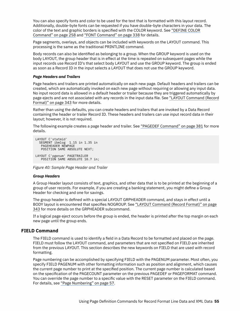
You can also specify fonts and color to be used for the text that is formatted with this layout record.Additionally, double-byte fonts can be requested if you have double-byte characters in your data. Thecolor of the text and graphic borders is specified with the COLOR keyword. See “DEFINE COLORCommand” on page 258 and “FONT Command” on page 338 for details.
Page segments, overlays, and objects can be included with keywords on the LAYOUT command. Thisprocessing is the same as the traditional PRINTLINE command.
Body records can also be identified as belonging to a group. When the GROUP keyword is used on thebody LAYOUT, the group header that is in effect at the time is repeated on subsequent pages while theinput records use Record ID's that select body LAYOUT and use the GROUP keyword. The group is endedas soon as a Record ID in the input selects a LAYOUT that does not use the GROUP keyword.
Page Headers and Trailers
Page headers and trailers are printed automatically on each new page. Default headers and trailers can becreated, which are automatically invoked on each new page without requiring or allowing any input data.No input record data is allowed in a default header or trailer because they are triggered automatically bypage ejects and are not associated with any records in the input data file. See “LAYOUT Command (RecordFormat)” on page 343 for more details.
Rather than using the defaults, you can create headers and trailers that are invoked by a Data Recordcontaining the header or trailer Record ID. These headers and trailers can use input record data in theirlayout; however, it is not required.
The following example creates a page header and trailer. See “PAGEDEF Command” on page 381 for moredetails.
LAYOUT C'statmid' SEGMENT ibmlog 1.15 in 1.35 in PAGEHEADER NEWPAGE POSITION SAME ABSOLUTE NEXT;
LAYOUT C'pgenum' PAGETRAILER POSITION SAME ABSOLUTE 10.7 in;
Figure 40: Sample Page Header and Trailer
Group Headers
A Group Header layout consists of text, graphics, and other data that is to be printed at the beginning of agroup of user records. For example, if you are creating a banking statement, you might define a GroupHeader for checking and one for savings.
The group header is defined with a special LAYOUT GRPHEADER command, and stays in effect until aBODY layout is encountered that specifies NOGROUP. See “LAYOUT Command (Record Format)” on page343 for more details on the GRPHEADER subcommand.
If a logical page eject occurs before the group is ended, the header is printed after the top margin on eachnew page until the group ends.
FIELD CommandThe FIELD command is used to identify a field in a Data Record to be formatted and placed on the page.FIELD must follow the LAYOUT command, and parameters that are not specified on FIELD are inheritedfrom the previous LAYOUT. This section describes the new keywords on FIELD that are used with recordformatting.
Page numbering can be accomplished by specifying FIELD with the PAGENUM parameter. Most often, youspecify FIELD PAGENUM with other formatting information such as position and alignment, which causesthe current page number to print at the specified position. The current page number is calculated basedon the specification of the PAGECOUNT parameter on the previous PAGEDEF or PAGEFORMAT command.You can override the page number to a specific value with the RESET parameter on the FIELD command.For details, see “Page Numbering” on page 57.
Using Page Definition Commands for Record Format Line Data and XML Data 55
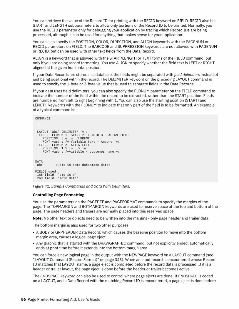
You can retrieve the value of the Record ID for printing with the RECID keyword on FIELD. RECID also hasSTART and LENGTH subparameters to allow only portions of the Record ID to be printed. Normally, youuse the RECID parameter only for debugging your application by tracing which Record IDs are beingprocessed, although it can be used for anything that makes sense for your application.
You can also specify the POSITION, COLOR, DIRECTION, and ALIGN keywords with the PAGENUM orRECID parameters on FIELD. The BARCODE and SUPPRESSION keywords are not allowed with PAGENUMor RECID, but can be used with other text fields from the Data Record.
ALIGN is a keyword that is allowed with the START/LENGTH or TEXT forms of the FIELD command, butonly if you are doing record formatting. You use ALIGN to specify whether the field text is LEFT or RIGHTaligned at the given horizontal position.
If your Data Records are stored in a database, the fields might be separated with field delimiters instead ofjust being positional within the record. The DELIMITER keyword on the preceding LAYOUT command isused to specify the 1-byte or 2-byte value that is used to separate fields in the Data Records.
If your data uses field delimiters, you can also specify the FLDNUM parameter on the FIELD command toindicate the number of the field within the record to be extracted, rather than the START position. Fieldsare numbered from left to right beginning with 1. You can also use the starting position (START) andLENGTH keywords with the FLDNUM to indicate that only part of the field is to be formatted. An exampleof a typical command is:
COMMANDS . . . LAYOUT 'abc' DELIMITER '*'; FIELD FLDNUM 1 START 2 LENGTH 8 ALIGN RIGHT POSITION 5.6 in CURRENT FONT varb ; /* Variable text - Amount */ FIELD FLDNUM 2 ALIGN LEFT POSITION 1.1 in .9 in FONT varb ; /*variable - customer name */
DATA abc *Here is some data*more data*
FIELDS used 1st field 'ere is s' 2nd field 'more data'
Figure 41: Sample Commands and Data With Delimiters.
Controlling Page Formatting
You use the parameters on the PAGEDEF and PAGEFORMAT commands to specify the margins of thepage. The TOPMARGIN and BOTMARGIN keywords are used to reserve space at the top and bottom of thepage. The page headers and trailers are normally placed into this reserved space.
Note: No other text or objects need to be written into the margins - only page header and trailer data.
The bottom margin is also used for two other purposes:
• A BODY or GRPHEADER Data Record, which causes the baseline position to move into the bottommargin area, causes a logical page eject.
• Any graphic that is started with the DRAWGRAPHIC command, but not explicitly ended, automaticallyends at print time before it extends into the bottom margin area.
You can force a new logical page in the output with the NEWPAGE keyword on a LAYOUT command (see“LAYOUT Command (Record Format)” on page 343). When an input record is encountered whose RecordID matches that LAYOUT name, a page eject is completed before the record data is processed. If it is aheader or trailer layout, the page eject is done before the header or trailer becomes active.
The ENDSPACE keyword can also be used to control where page ejects are done. If ENDSPACE is codedon a LAYOUT, and a Data Record with the matching Record ID is encountered, a page eject is done before
56 Page Printer Formatting Aid: User's Guide
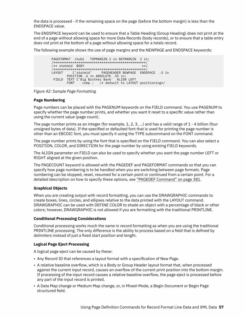
the data is processed - if the remaining space on the page (before the bottom margin) is less than theENDSPACE value.
The ENDSPACE keyword can be used to ensure that a Table Heading (Group Heading) does not print at theend of a page without allowing space for more Data Records (body records), or to ensure that a table entrydoes not print at the bottom of a page without allowing space for a totals record.
The following example shows the use of page margins and the NEWPAGE and ENDSPACE keywords:
PAGEFORMAT chub1 TOPMARGIN 2 in BOTMARGIN 2 in; /************************************************/ /** statmid BODY **/ /************************************************/ LAYOUT C'statmid' PAGEHEADER NEWPAGE ENDSPACE .5 in POSITION .6 in ABSOLUTE .55 in; FIELD TEXT C'Big Brother Bank' ALIGN LEFT FONT comp ; /* default to LAYOUT positioning*/
Figure 42: Sample Page Formatting
Page Numbering
Page numbers can be placed with the PAGENUM keywords on the FIELD command. You use PAGENUM tospecify whether the page number prints, and whether you want it reset to a specific value rather thanusing the current value (page count).
The page number prints as an integer (for example, 1, 2, 3, …) and has a valid range of 1 - 4 billion (fourunsigned bytes of data). If the specified or defaulted font that is used for printing the page number isother than an EBCDIC font, you must specify it using the TYPE subcommand on the FONT command.
The page number prints by using the font that is specified on the FIELD command. You can also select aPOSITION, COLOR, and DIRECTION for the page number by using existing FIELD keywords.
The ALIGN parameter on FIELD can also be used to specify whether you want the page number LEFT orRIGHT aligned at the given position.
The PAGECOUNT keyword is allowed with the PAGEDEF and PAGEFORMAT commands so that you canspecify how page numbering is to be handled when you are switching between page formats. Pagenumbering can be stopped, reset, resumed for a certain point or continued from a certain point. For adetailed description on how to specify these options, see “PAGEDEF Command” on page 381.
Graphical Objects
When you are creating output with record formatting, you can use the DRAWGRAPHIC commands tocreate boxes, lines, circles, and ellipses relative to the data printed with the LAYOUT command.DRAWGRAPHIC can be used with DEFINE COLOR to shade an object with a percentage of black or othercolors; however, DRAWGRAPHIC is not allowed if you are formatting with the traditional PRINTLINE.
Conditional Processing Considerations
Conditional processing works much the same in record formatting as when you are using the traditionalPRINTLINE processing. The only difference is the ability to process based on a field that is defined bydelimiters instead of just a fixed start position and length.
Logical Page Eject Processing
A logical page eject can be caused by these:
• Any Record ID that references a layout format with a specification of New Page.• A relative baseline overflow, which is a Body or Group Header layout format that, when processed
against the current input record, causes an overflow of the current print position into the bottom margin.If processing of the input record causes a relative baseline overflow, the page eject is processed beforeany part of the input record is printed.
• A Data Map change or Medium Map change, or, in Mixed-Mode, a Begin Document or Begin Pagestructured field.
Using Page Definition Commands for Record Format Line Data and XML Data 57
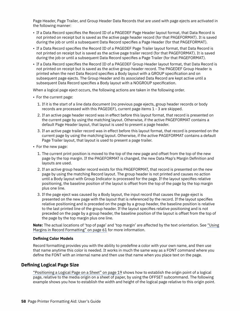
Page Header, Page Trailer, and Group Header Data Records that are used with page ejects are activated inthe following manner:
• If a Data Record specifies the Record ID of a PAGEDEF Page Header layout format, that Data Record isnot printed on receipt but is saved as the active page header record (for that PAGEFORMAT). It is savedduring the job or until a subsequent Data Record specifies a Page Header (for that PAGEFORMAT).
• If a Data Record specifies the Record ID of a PAGEDEF Page Trailer layout format, that Data Record isnot printed on receipt but is saved as the active page trailer record (for that PAGEFORMAT). It is savedduring the job or until a subsequent Data Record specifies a Page Trailer (for that PAGEFORMAT).
• If a Data Record specifies the Record ID of a PAGEDEF Group Header layout format, that Data Record isnot printed on receipt but is saved as the active group header record. The PAGEDEF Group Header isprinted when the next Data Record specifies a Body layout with a GROUP specification and onsubsequent page ejects. The Group Header and its associated Data Record are kept active until asubsequent Data Record specifies a Body layout with a NOGROUP specification.
When a logical page eject occurs, the following actions are taken in the following order.
• For the current page:
1. If it is the start of a line data document (no previous page ejects, group header records or bodyrecords are processed with this PAGEDEF), current page items 1 - 3 are skipped.
2. If an active page header record was in effect before this layout format, that record is presented onthe current page by using the matching layout. Otherwise, if the active PAGEFORMAT contains adefault Page Header layout, that layout is used to present a page header.
3. If an active page trailer record was in effect before this layout format, that record is presented on thecurrent page by using the matching layout. Otherwise, if the active PAGEFORMAT contains a defaultPage Trailer layout, that layout is used to present a page trailer.
• For the new page:
1. The current print position is moved to the top of the new page and offset from the top of the newpage by the top margin. If the PAGEFORMAT is changed, the new Data Map's Margin Definition andlayouts are used.
2. If an active group header record exists for this PAGEFORMAT, that record is presented on the newpage by using the matching Record layout. The group header is not printed and causes no actionuntil a Body layout with Group Indicator is processed for the page. If the layout specifies relativepositioning, the baseline position of the layout is offset from the top of the page by the top marginplus one line.
3. If the page eject was caused by a Body layout, the input record that causes the page eject ispresented on the new page with the layout that is referenced by the record. If the layout specifiesrelative positioning and is preceded on the page by a group header, the baseline position is relativeto the last printed line of the group header. If the layout specifies relative positioning and is notpreceded on the page by a group header, the baseline position of the layout is offset from the top ofthe page by the top margin plus one line.
Note: The actual locations of ‘top of page’ and ‘top margin’ are affected by the text orientation. See “UsingMargins in Record Formatting” on page 61 for more information.
Defining Color Models
Record formatting provides you with the ability to predefine a color with your own name, and then usethat name anytime this color is needed. It works in much the same way as a FONT command where youdefine the FONT with an internal name and then use that name when you place text on the page.
Defining Logical Page Size“Positioning a Logical Page on a Sheet” on page 19 shows how to establish the origin point of a logicalpage, relative to the media origin on a sheet of paper, by using the OFFSET subcommand. The followingexample shows you how to establish the width and height of the logical page relative to this origin point.
58 Page Printer Formatting Aid: User's Guide
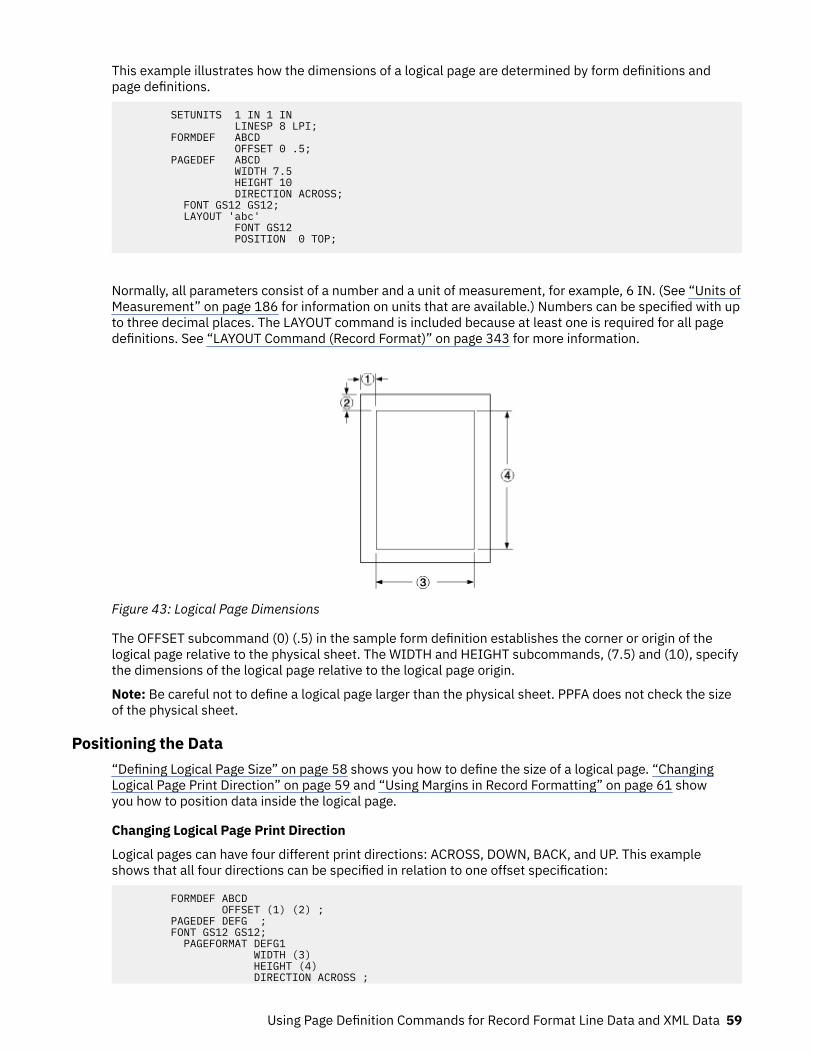
This example illustrates how the dimensions of a logical page are determined by form definitions andpage definitions.
SETUNITS 1 IN 1 IN LINESP 8 LPI; FORMDEF ABCD OFFSET 0 .5; PAGEDEF ABCD WIDTH 7.5 HEIGHT 10 DIRECTION ACROSS; FONT GS12 GS12; LAYOUT 'abc' FONT GS12 POSITION 0 TOP;
Normally, all parameters consist of a number and a unit of measurement, for example, 6 IN. (See “Units ofMeasurement” on page 186 for information on units that are available.) Numbers can be specified with upto three decimal places. The LAYOUT command is included because at least one is required for all pagedefinitions. See “LAYOUT Command (Record Format)” on page 343 for more information.
Figure 43: Logical Page Dimensions
The OFFSET subcommand (0) (.5) in the sample form definition establishes the corner or origin of thelogical page relative to the physical sheet. The WIDTH and HEIGHT subcommands, (7.5) and (10), specifythe dimensions of the logical page relative to the logical page origin.
Note: Be careful not to define a logical page larger than the physical sheet. PPFA does not check the sizeof the physical sheet.
Positioning the Data“Defining Logical Page Size” on page 58 shows you how to define the size of a logical page. “ChangingLogical Page Print Direction” on page 59 and “Using Margins in Record Formatting” on page 61 showyou how to position data inside the logical page.
Changing Logical Page Print Direction
Logical pages can have four different print directions: ACROSS, DOWN, BACK, and UP. This exampleshows that all four directions can be specified in relation to one offset specification:
FORMDEF ABCD OFFSET (1) (2) ; PAGEDEF DEFG ; FONT GS12 GS12; PAGEFORMAT DEFG1 WIDTH (3) HEIGHT (4) DIRECTION ACROSS ;
Using Page Definition Commands for Record Format Line Data and XML Data 59
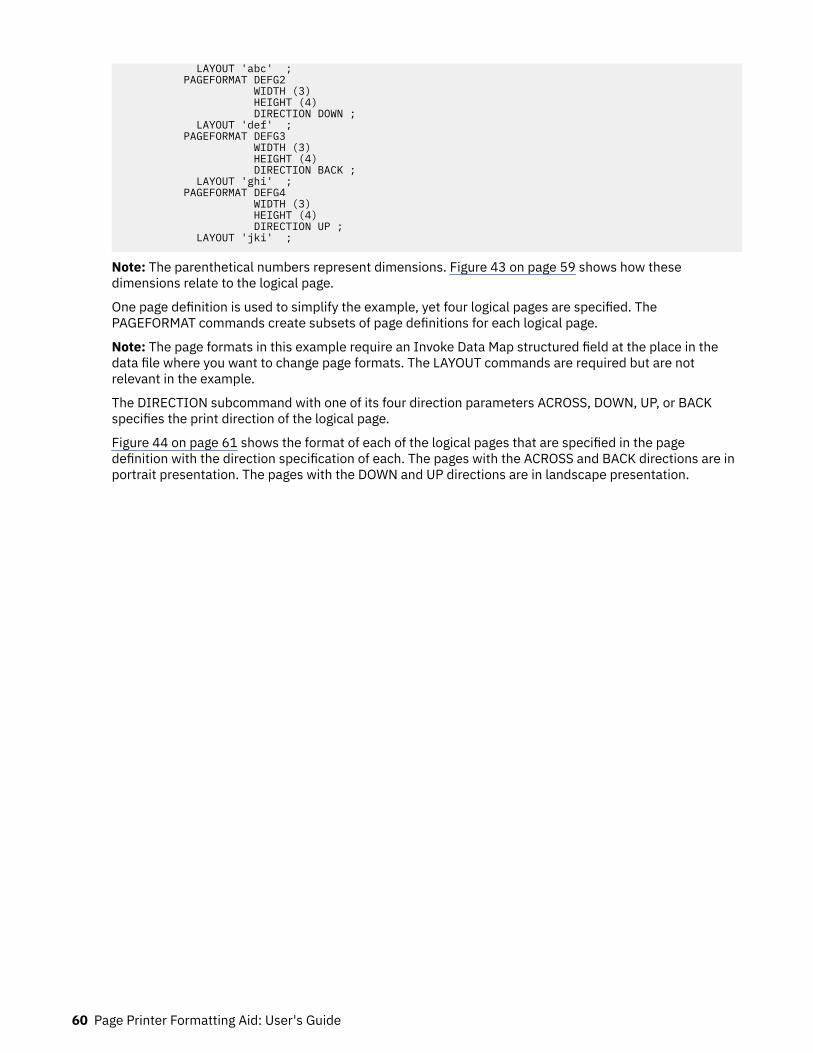
LAYOUT 'abc' ; PAGEFORMAT DEFG2 WIDTH (3) HEIGHT (4) DIRECTION DOWN ; LAYOUT 'def' ; PAGEFORMAT DEFG3 WIDTH (3) HEIGHT (4) DIRECTION BACK ; LAYOUT 'ghi' ; PAGEFORMAT DEFG4 WIDTH (3) HEIGHT (4) DIRECTION UP ; LAYOUT 'jki' ;
Note: The parenthetical numbers represent dimensions. Figure 43 on page 59 shows how thesedimensions relate to the logical page.
One page definition is used to simplify the example, yet four logical pages are specified. ThePAGEFORMAT commands create subsets of page definitions for each logical page.
Note: The page formats in this example require an Invoke Data Map structured field at the place in thedata file where you want to change page formats. The LAYOUT commands are required but are notrelevant in the example.
The DIRECTION subcommand with one of its four direction parameters ACROSS, DOWN, UP, or BACKspecifies the print direction of the logical page.
Figure 44 on page 61 shows the format of each of the logical pages that are specified in the pagedefinition with the direction specification of each. The pages with the ACROSS and BACK directions are inportrait presentation. The pages with the DOWN and UP directions are in landscape presentation.
60 Page Printer Formatting Aid: User's Guide

Figure 44: Logical Page Print Directions in Relation to Origin
The media origins and logical page origins do not change with the presentation of the data on the page.The OFFSET subcommand of the form definition need not change. However, the width and heightdimensions do change; that is, the WIDTH subcommand always governs the horizontal (inline) dimensionas you view the page, and the HEIGHT subcommand always governs the vertical (baseline) dimensionwhether the page is in portrait or in landscape presentation. Ensure that these specifications do not causethe logical page to cross the edge of the physical page.
However, if the DOWN direction is specified for use with a continuous forms printer, the PRESENT andDIRECTION subcommands might need to be specified in the form definition. See “Specifying PagePresentation on Continuous-Forms Printers” on page 27 for more information.
Using Margins in Record Formatting
Margins follow the inline direction of the page. For example, if the text orientation is ACROSS, the upper-left diagram in Figure 45 on page 62 shows the left, top, right, and bottom margins. When specified,these margins define a bounding box for the PAGEFORMAT as indicated by the dotted lines.
If the text orientation is changed, the same bounding box applies to the new orientation, but the names ofthe margins change in the new orientation. For example, if the new text orientation is DOWN, as shown inthe upper-right diagram of this same figure, the top margin in the new orientation is now defined on thelong side of the page.Left Margin
Specifies the offset of the left margin along the i axis from the left edge of the page. The left edge ofthe page is the zero position on the i axis.
Using Page Definition Commands for Record Format Line Data and XML Data 61
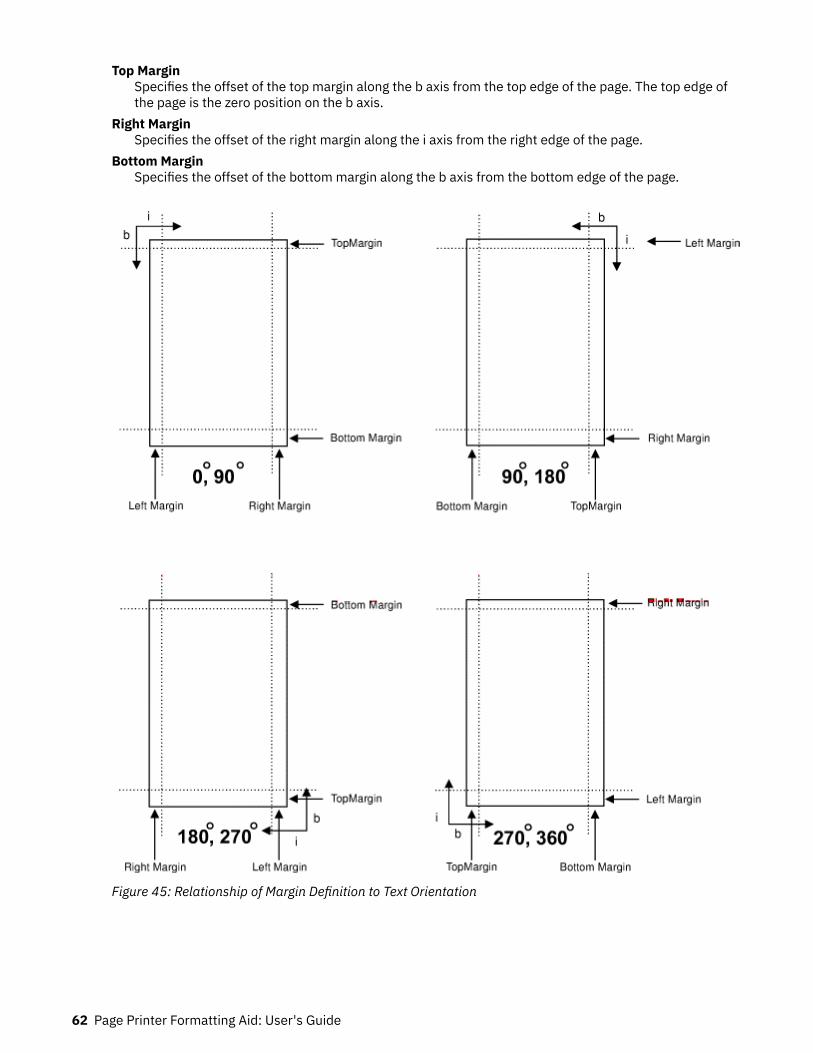
Top MarginSpecifies the offset of the top margin along the b axis from the top edge of the page. The top edge ofthe page is the zero position on the b axis.
Right MarginSpecifies the offset of the right margin along the i axis from the right edge of the page.
Bottom MarginSpecifies the offset of the bottom margin along the b axis from the bottom edge of the page.
Figure 45: Relationship of Margin Definition to Text Orientation
62 Page Printer Formatting Aid: User's Guide

Processing FieldsThis section describes the mapping of individual fields to the printed sheets. You can use this technique toprint unformatted data according to precise specifications, and these specifications can change withoutaffecting the data file.
The rule for field processing of data files is: Each FIELD command must follow its associated LAYOUTcommand, and more than one FIELD command can be specified for a single LAYOUT command.
For this field-processing example, the data file shown in Figure 47 on page 63 is used. Figure 48 on page63 represents an output format that might be used to place data on a form, such as an invoice or anorder. The page definition commands to print Figure 48 on page 63 are in Figure 46 on page 63.
PAGEDEF ABCD WIDTH 7 IN HEIGHT 8 IN ;FONT GS12 GS12;LAYOUT 'abc' POSITION 1 IN ABSOLUTE 1 IN ; /*PROCESSING FOR R1 */ FIELD START 1 LENGTH 4 ; /*THE LAYOUT POSITION IS */ /*THE DEFAULT FOR THE FIRST FIELD*/ FIELD START 11 LENGTH 4 POSITION 4 IN 0 IN ; LAYOUT 'def' POSITION 3 IN ABSOLUTE 4 IN ; /*PROCESSING FOR R2 */ FIELD START 1 LENGTH 4 ; /*DEFAULT POSITION */ FIELD START 6 LENGTH 4 POSITION 0 IN 1 IN ; FIELD START 13 LENGTH 3 POSITION 2 IN 3 IN ; LAYOUT 'ghi' POSITION 1 IN ABSOLUTE 2 IN ; /*PROCESSING FOR R3 */ FIELD START 1 LENGTH 4 ; /*DEFAULT POSITION */ FIELD START 11 LENGTH 4 POSITION 4 IN 0 IN ;
Figure 46: Field-processing example for the LAYOUT command
Figure 47: Unformatted Print Data File
Figure 48: Data Arranged on the Printed Page
Using Page Definition Commands for Record Format Line Data and XML Data 63
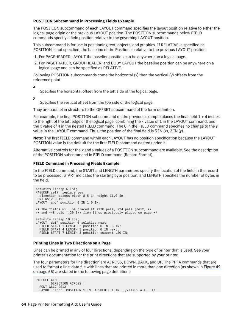
POSITION Subcommand in Processing Fields Example
The POSITION subcommand of each LAYOUT command specifies the layout position relative to either thelogical page origin or the previous LAYOUT position. The POSITION subcommands below FIELDcommands specify a field position relative to the governing LAYOUT position.
This subcommand is for use in positioning text, objects, and graphics. If RELATIVE is specified orPOSITION is not specified, the baseline of the Position is relative to the previous LAYOUT position.
1. For PAGEHEADER LAYOUT the baseline position can be anywhere on a logical page.2. For PAGETRAILER, GROUPHEADER, and BODY LAYOUT the baseline position can be anywhere on a
logical page and can be specified as RELATIVE.
Following POSITION subcommands come the horizontal (x) then the vertical (y) offsets from thereference point.x
Specifies the horizontal offset from the left side of the logical page.y
Specifies the vertical offset from the top side of the logical page.
They are parallel in structure to the OFFSET subcommand of the form definition.
For example, the final POSITION subcommand on the previous example places the final field 1 + 4 inchesto the right of the left edge of the logical page, combining the x value of 1 in the LAYOUT command, andthe x value of 4 in the nested FIELD command. The 0 in the FIELD command specifies no change to the yvalue in the LAYOUT command. Thus, the position of the final field is 5 IN (x), 2 IN (y).
Note: The first FIELD command within each LAYOUT has no position specification because the LAYOUTPOSITION value is the default for the first FIELD command nested under it.
Alternative controls for the x and y values of a POSITION subcommand are available. See the descriptionof the POSITION subcommand in FIELD command (Record Format).
FIELD Command in Processing Fields Example
In the FIELD command, the START and LENGTH parameters specify the location of the field in the recordto be processed. START indicates the starting byte position, and LENGTH specifies the number of bytes inthe field.
setunits linesp 6 lpi;PAGEDEF rel9 replace yes direction across width 8.5 in height 11.0 in;FONT GS12 GS12;LAYOUT 'abc' position 0 IN 1.0 IN; /* The fields will be placed at +120 pels, +24 pels (next) *//* and +48 pels (.20 IN) from lines previously placed on page */ setunits linesp 10 lpi;LAYOUT 'def' position 0 relative next; FIELD START 1 LENGTH 3 position 0 IN .5 IN; FIELD START 4 LENGTH 3 position 0 IN next; FIELD START 7 LENGTH 3 position current .20 IN;
Printing Lines in Two Directions on a Page
Lines can be printed in any of four directions, depending on the type of printer that is used. See yourprinter's documentation for the print directions that are supported by your printer.
The four parameters for line direction are ACROSS, DOWN, BACK, and UP. The PPFA commands that areused to format a line-data file with lines that are printed in more than one direction (as shown in Figure 49on page 65) are stated in the following page definition:
PAGEDEF ATOG DIRECTION ACROSS ; FONT GS12 GS12; LAYOUT 'abc' POSITION 1 IN ABSOLUTE 1 IN ; /*LINES A-E */
64 Page Printer Formatting Aid: User's Guide

LAYOUT 'def' POSITION .5 IN ABSOLUTE 6 IN /*LINE F */ DIRECTION UP ; LAYOUT 'ghi' POSITION 1 IN ABSOLUTE 6 IN ; /*LINE G */
Figure 49: A Printout with More Than One Line Direction
In the page definition, the logical page direction ACROSS is specified. This value is the default, but itsinclusion clarifies that no direction control is needed for lines A - E. The default direction of a layout is thedirection specification of the logical page of which it is part. The LAYOUT command for the record F has aDIRECTION subcommand because the direction specification changes from the specification of theprevious line. Record G is to be printed in the ACROSS direction again. However, a direction is notspecified because the ACROSS direction is the default for all lines in the page definition.
Printing Fields in Two Directions on the Same Page
This example is similar to Printing Lines in Two Directions on a Page, except that you learn how to controldirection field by field. This method creates a field-processing page definition and places directioncontrols in the FIELD commands. This command stream contains a portion of the page definition controls,showing only the LAYOUT commands:
LAYOUT 'abc' POSITION LEFTMARGIN TOPMARGIN NEWPAGE; FIELD START 1 LENGTH 4 ;LAYOUT 'def' POSITION 2 IN ABSOLUTE 4 IN ; FIELD START 7 LENGTH 4 DIRECTION UP ;
As expected in field processing, FIELD commands are nested within LAYOUT commands. Figure 50 onpage 66 shows a simplified portion of an unformatted file and two pages of the printout that is formattedby the page definition, part of which is shown in the command stream. Two layouts are specified becausethe data file contains two input record formats (1 and 3 are alike; 2 and 4 are alike) and because the fieldsare mapped to two different positions in the output. The assumption of this sample is that the data file ismuch longer than the portion shown. However, if the records in the file alternate in format as the first fourdo, the two LAYOUTs of the page definition format as many records as are presented, two to a page, onpages 1 - n.
If more than two mappings are required by the print job, more than two LAYOUT commands are requiredin the page definition.
Using Page Definition Commands for Record Format Line Data and XML Data 65

Figure 50: Field Direction
Varying Fonts on a PageThis example illustrates a simple font variation within a printout. The task is to print a line-data file withthe first line of each page in bold-faced type and the rest in standard type. This task requires controls fortwo fonts in the page definition.
The commands to select a single font for the page, as shown in Figure 52 on page 67, are as follows:
The FONT command contains two names: the local (STANDARD) name and the user-access (M101) namefor the selected font.
PAGEDEF ABCD ; FONT STANDARD M101; FONT BOLDFACE M102; LAYOUT 'abc' FONT BOLDFACE NEWPAGE; LAYOUT 'def' FONT STANDARD NEWPAGE; LAYOUT 'ghi' FONT STANDARD;
Note: Fonts cannot be a Font Typeface Global Identifier (FGID). Also, all page definitions require aLAYOUT command.
The following example shows line data that uses a single font:
def Record 1ghi Record 2ghi Record 3ghi Record 4ghi Record 5ghi Record 6def Record 7ghi Record 8ghi Record 9def Record 10ghi Record 11ghi Record 12ghi Record 13
Figure 51: Line Data for Single Font Example
66 Page Printer Formatting Aid: User's Guide
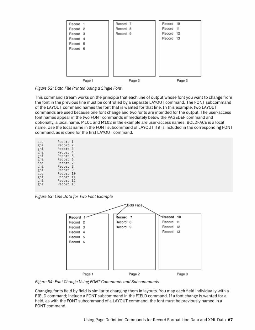
Figure 52: Data File Printed Using a Single Font
This command stream works on the principle that each line of output whose font you want to change fromthe font in the previous line must be controlled by a separate LAYOUT command. The FONT subcommandof the LAYOUT command names the font that is wanted for that line. In this example, two LAYOUTcommands are used because one font change and two fonts are intended for the output. The user-accessfont names appear in the two FONT commands immediately below the PAGEDEF command andoptionally, a local name. M101 and M102 in the example are user-access names; BOLDFACE is a localname. Use the local name in the FONT subcommand of LAYOUT if it is included in the corresponding FONTcommand, as is done for the first LAYOUT command.
abc Record 1ghi Record 2ghi Record 3ghi Record 4ghi Record 5ghi Record 6abc Record 7ghi Record 8ghi Record 9abc Record 10ghi Record 11ghi Record 12ghi Record 13
Figure 53: Line Data for Two Font Example
Figure 54: Font Change Using FONT Commands and Subcommands
Changing fonts field by field is similar to changing them in layouts. You map each field individually with aFIELD command; include a FONT subcommand in the FIELD command. If a font change is wanted for afield, as with the FONT subcommand of a LAYOUT command, the font must be previously named in aFONT command.
Using Page Definition Commands for Record Format Line Data and XML Data 67

Rotating FontsFonts rotate relative to the inline direction of lines (or fields).
This example focuses on a single letter A from FONTA. With PPFA, a single font that is specified in a pagedefinition can produce letters in any of four rotations. This formatting is accomplished by a FONTcommand that specifies rotation. If you want to vary the rotation of a font twice within a page, you usetwo FONT commands, one for each rotation. You also use two LAYOUT commands to map the data to theprintout by using the two rotations of the font. In a field processing application, FIELD commands can beused in the same way. These LAYOUT commands name the rotated font in a FONT subcommand.
Figure 55 on page 68 breaks down the elements that are required for the FONT commands andsubcommands. Distinct local names and rotation specifications for each font are placed in a FONTcommand. These specifications identify a font as rotated within a page definition. The rotation of acharacter is relative to the inline direction of a field or LAYOUT. The characters and rotations that areshown here assume an inline direction of ACROSS.
Figure 55: Character Rotation
You can use up to 16 possible combinations of logical page direction and font rotation for page printersother than the 3800.
The FONT subcommands within LAYOUT or FIELD commands that name the rotated font in that pagedefinition use only the local name. The following command stream shows the proper specification andnesting of FONT commands and subcommands for rotation.
PAGEDEF ABCD ; FONT FONTA M103 ; /*NO ROTATION, LOCAL AND */ /*USER-ACCESS NAMES. */ FONT FONTARTD180 M103 /*ROTATED FONT, LOCAL, USER-ACCESS*/ ROTATION 180 ; /*NAMES PLUS ROTATION SUBCOMMAND */ /*AND PARAMETER. */ LAYOUT 'abc' FONT FONTA ; /*LOCAL NAME */ LAYOUT 'def' FONT FONTARTD180 ; /*LOCAL NAME */
68 Page Printer Formatting Aid: User's Guide
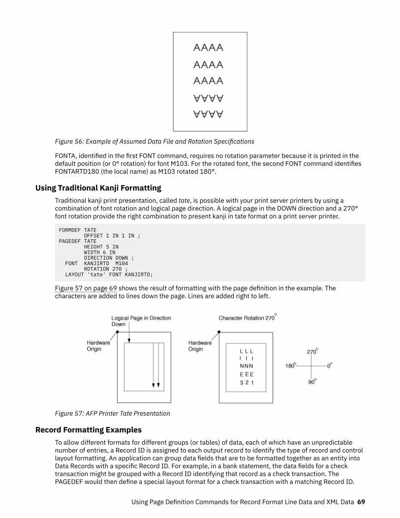
Figure 56: Example of Assumed Data File and Rotation Specifications
FONTA, identified in the first FONT command, requires no rotation parameter because it is printed in thedefault position (or 0° rotation) for font M103. For the rotated font, the second FONT command identifiesFONTARTD180 (the local name) as M103 rotated 180°.
Using Traditional Kanji FormattingTraditional kanji print presentation, called tate, is possible with your print server printers by using acombination of font rotation and logical page direction. A logical page in the DOWN direction and a 270°font rotation provide the right combination to present kanji in tate format on a print server printer.
FORMDEF TATE OFFSET 1 IN 1 IN ;PAGEDEF TATE HEIGHT 5 IN WIDTH 6 IN DIRECTION DOWN ; FONT KANJIRTD M104 ROTATION 270 ; LAYOUT 'tate' FONT KANJIRTD;
Figure 57 on page 69 shows the result of formatting with the page definition in the example. Thecharacters are added to lines down the page. Lines are added right to left.
Figure 57: AFP Printer Tate Presentation
Record Formatting ExamplesTo allow different formats for different groups (or tables) of data, each of which have an unpredictablenumber of entries, a Record ID is assigned to each output record to identify the type of record and controllayout formatting. An application can group data fields that are to be formatted together as an entity intoData Records with a specific Record ID. For example, in a bank statement, the data fields for a checktransaction might be grouped with a Record ID identifying that record as a check transaction. ThePAGEDEF would then define a special layout format for a check transaction with a matching Record ID.
Using Page Definition Commands for Record Format Line Data and XML Data 69

The same thing might be done for a deposit transaction, customer account information, deposit totals,and check totals. If the customer account information is going to be used in a page header on each page,the PAGEDEF can define a special layout format for a customer information record that automaticallygenerates a page header for each page.
This section shows two complete examples that use the record formatting process. Each is divided intothree parts - the output you want (after PAGEDEF processing), the application output (before PAGEDEFprocessing), and the PPFA commands.
Example 1 - Bank Statement
Figure 58 on page 71 and Figure 59 on page 72 show the printed output for a bank statement afterPAGEDEF processing (the second figure is resized). “Application Output (before PAGEDEF Processing)” onpage 73 and “PPFA Commands” on page 74 show the user data and the PPFA commands that createthe printed output.
70 Page Printer Formatting Aid: User's Guide
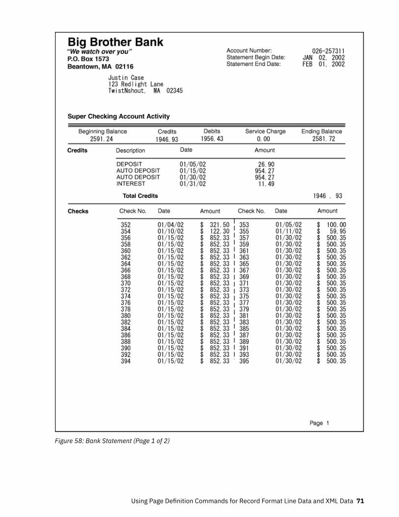
Figure 58: Bank Statement (Page 1 of 2)
Using Page Definition Commands for Record Format Line Data and XML Data 71
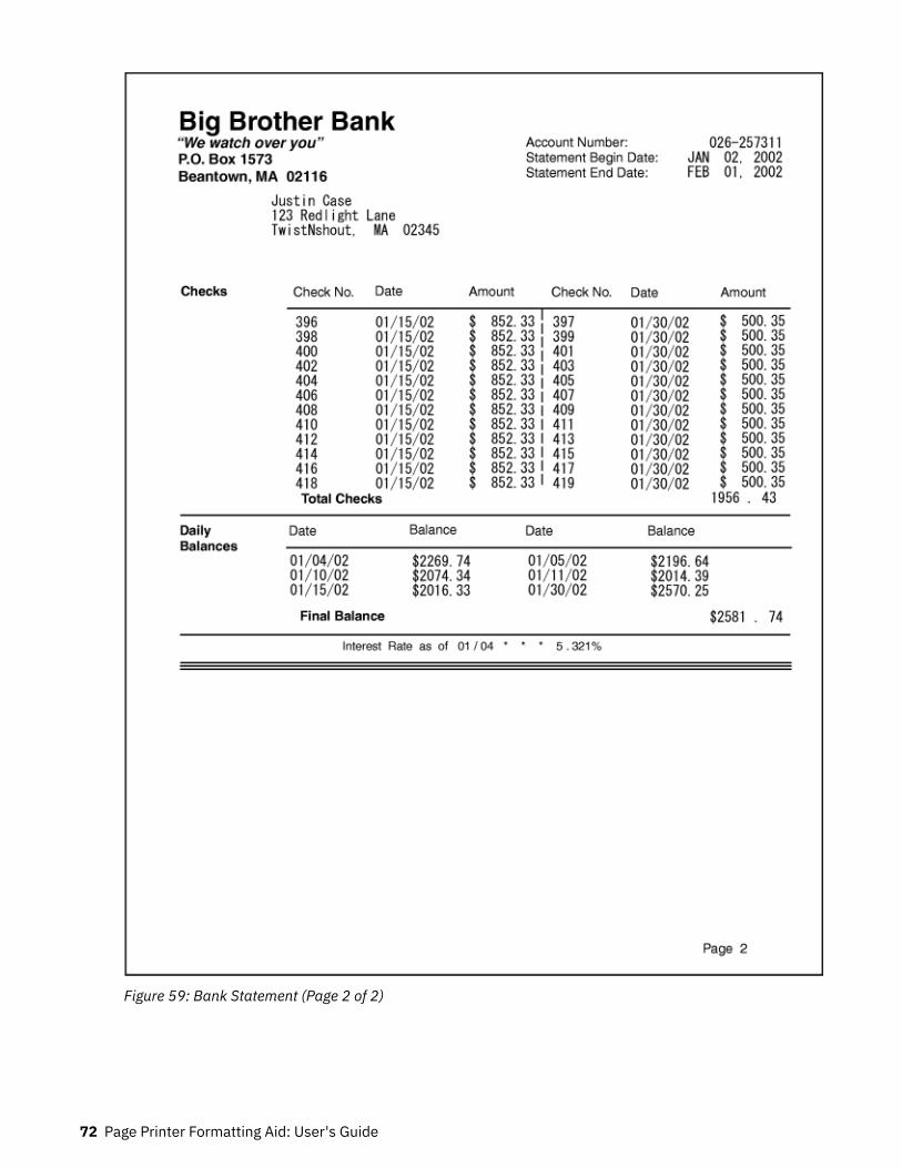
Figure 59: Bank Statement (Page 2 of 2)
72 Page Printer Formatting Aid: User's Guide

Application Output (before PAGEDEF Processing)
Each layout record contains all information for a specified layout. Because of lack of space, only the first80 bytes are shown here. The first 10 characters must contain the layout ID.
1111111111222222222233333333334444444444555555555566666666667777777777812345678901234567890123456789012345678901234567890123456789012345678901234567890statmid 026-257311Justin Case 123 Redlight Lane Twistnshout MA 02345statsum $2591.24 $1946.93 $1956.43 $0.00 $2581.72pgenumcrheadercrdata DEPOSIT 01/05/02 $ 26.90crdata AUTO DEPOSIT 01/15/02 $ 954.27crdata AUTO DEPOSIT 01/30/02 $ 954.27crdata INTEREST 01/31/02 $ 11.49crtotal $1946.93ckheaderckdatal 352 01/04/02 $ 321.50ckdatar 353 01/05/02 $ 100.00ckdatal 354 01/10/02 $ 122.30ckdatar 355 01/11/02 $ 59.95ckdatal 356 01/15/02 $ 852.33ckdatar 357 01/30/02 $ 500.35ckdatal 358 01/15/02 $ 852.33ckdatar 359 01/30/02 $ 500.35ckdatal 360 01/15/02 $ 852.33ckdatar 361 01/30/02 $ 500.35ckdatal 362 01/15/02 $ 852.33ckdatar 363 01/30/02 $ 500.35ckdatal 364 01/15/02 $ 852.33ckdatar 365 01/30/02 $ 500.35ckdatal 366 01/15/02 $ 852.33ckdatar 367 01/30/02 $ 500.35ckdatal 368 01/15/02 $ 852.33ckdatar 369 01/30/02 $ 500.35ckdatal 370 01/15/02 $ 852.33ckdatar 371 01/30/02 $ 500.35ckdatal 372 01/15/02 $ 852.33ckdatar 373 01/30/02 $ 500.35ckdatal 374 01/15/02 $ 852.33ckdatar 375 01/30/02 $ 500.35ckdatal 376 01/15/02 $ 852.33ckdatar 377 01/30/02 $ 500.35ckdatal 378 01/15/02 $ 852.33ckdatar 379 01/30/02 $ 500.35ckdatal 380 01/15/02 $ 852.33ckdatar 381 01/30/02 $ 500.35ckdatal 382 01/15/02 $ 852.33ckdatar 383 01/30/02 $ 500.35ckdatal 384 01/15/02 $ 852.33ckdatar 385 01/30/02 $ 500.35ckdatal 386 01/15/02 $ 852.33ckdatar 387 01/30/02 $ 500.35ckdatal 388 01/15/02 $ 852.33ckdatar 389 01/30/02 $ 500.35ckdatal 390 01/15/02 $ 852.33ckdatar 391 01/30/02 $ 500.35ckdatal 392 01/15/02 $ 852.33ckdatar 393 01/30/02 $ 500.35ckdatal 394 01/15/02 $ 852.33ckdatar 395 01/30/02 $ 500.35ckdatal 396 01/15/02 $ 852.33ckdatar 397 01/30/02 $ 500.35ckdatal 398 01/15/02 $ 852.33ckdatar 399 01/30/02 $ 500.35ckdatal 400 01/15/02 $ 852.33ckdatar 401 01/30/02 $ 500.35ckdatal 402 01/15/02 $ 852.33ckdatar 403 01/30/02 $ 500.35ckdatal 404 01/15/02 $ 852.33ckdatar 405 01/30/02 $ 500.35ckdatal 406 01/15/02 $ 852.33ckdatar 407 01/30/02 $ 500.35ckdatal 408 01/15/02 $ 852.33ckdatar 409 01/30/02 $ 500.35ckdatal 410 01/15/02 $ 852.33ckdatar 411 01/30/02 $ 500.35ckdatal 412 01/15/02 $ 852.33ckdatar 413 01/30/02 $ 500.35ckdatal 414 01/15/02 $ 852.33
Using Page Definition Commands for Record Format Line Data and XML Data 73
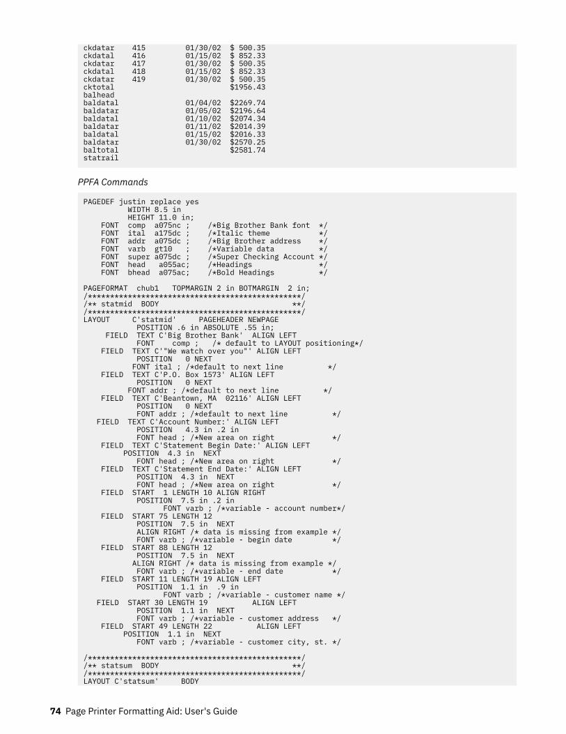
ckdatar 415 01/30/02 $ 500.35ckdatal 416 01/15/02 $ 852.33ckdatar 417 01/30/02 $ 500.35ckdatal 418 01/15/02 $ 852.33ckdatar 419 01/30/02 $ 500.35cktotal $1956.43balheadbaldatal 01/04/02 $2269.74baldatar 01/05/02 $2196.64baldatal 01/10/02 $2074.34baldatar 01/11/02 $2014.39baldatal 01/15/02 $2016.33baldatar 01/30/02 $2570.25baltotal $2581.74statrail
PPFA Commands
PAGEDEF justin replace yes WIDTH 8.5 in HEIGHT 11.0 in; FONT comp a075nc ; /*Big Brother Bank font */ FONT ital a175dc ; /*Italic theme */ FONT addr a075dc ; /*Big Brother address */ FONT varb gt10 ; /*Variable data */ FONT super a075dc ; /*Super Checking Account */ FONT head a055ac; /*Headings */ FONT bhead a075ac; /*Bold Headings */
PAGEFORMAT chub1 TOPMARGIN 2 in BOTMARGIN 2 in; /************************************************//** statmid BODY **/ /************************************************/ LAYOUT C'statmid' PAGEHEADER NEWPAGE POSITION .6 in ABSOLUTE .55 in; FIELD TEXT C'Big Brother Bank' ALIGN LEFT FONT comp ; /* default to LAYOUT positioning*/ FIELD TEXT C'"We watch over you"' ALIGN LEFT POSITION 0 NEXT FONT ital ; /*default to next line */ FIELD TEXT C'P.O. Box 1573' ALIGN LEFT POSITION 0 NEXT FONT addr ; /*default to next line */ FIELD TEXT C'Beantown, MA 02116' ALIGN LEFT POSITION 0 NEXT FONT addr ; /*default to next line */ FIELD TEXT C'Account Number:' ALIGN LEFT POSITION 4.3 in .2 in FONT head ; /*New area on right */ FIELD TEXT C'Statement Begin Date:' ALIGN LEFT POSITION 4.3 in NEXT FONT head ; /*New area on right */ FIELD TEXT C'Statement End Date:' ALIGN LEFT POSITION 4.3 in NEXT FONT head ; /*New area on right */ FIELD START 1 LENGTH 10 ALIGN RIGHT POSITION 7.5 in .2 in FONT varb ; /*variable - account number*/ FIELD START 75 LENGTH 12 POSITION 7.5 in NEXT ALIGN RIGHT /* data is missing from example */ FONT varb ; /*variable - begin date */ FIELD START 88 LENGTH 12 POSITION 7.5 in NEXT ALIGN RIGHT /* data is missing from example */ FONT varb ; /*variable - end date */ FIELD START 11 LENGTH 19 ALIGN LEFT POSITION 1.1 in .9 in FONT varb ; /*variable - customer name */ FIELD START 30 LENGTH 19 ALIGN LEFT POSITION 1.1 in NEXT FONT varb ; /*variable - customer address */ FIELD START 49 LENGTH 22 ALIGN LEFT POSITION 1.1 in NEXT FONT varb ; /*variable - customer city, st. */
/************************************************//** statsum BODY **/ /************************************************/LAYOUT C'statsum' BODY
74 Page Printer Formatting Aid: User's Guide
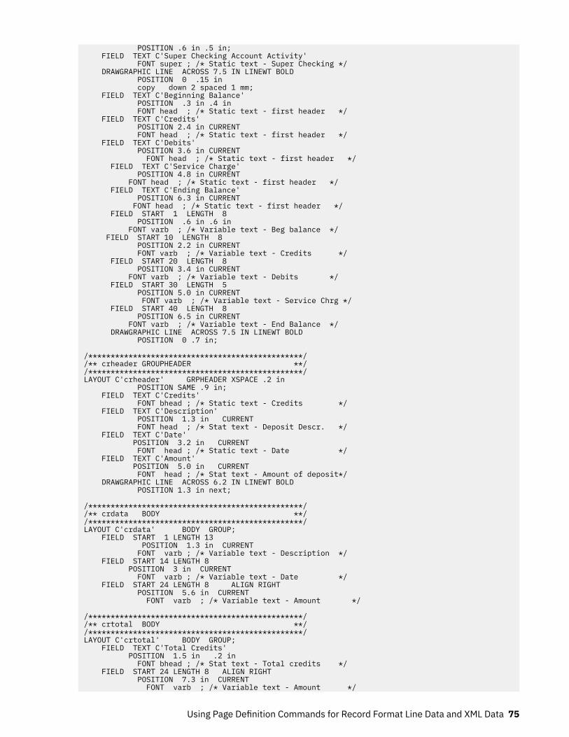
POSITION .6 in .5 in; FIELD TEXT C'Super Checking Account Activity' FONT super ; /* Static text - Super Checking */ DRAWGRAPHIC LINE ACROSS 7.5 IN LINEWT BOLD POSITION 0 .15 in copy down 2 spaced 1 mm; FIELD TEXT C'Beginning Balance' POSITION .3 in .4 in FONT head ; /* Static text - first header */ FIELD TEXT C'Credits' POSITION 2.4 in CURRENT FONT head ; /* Static text - first header */ FIELD TEXT C'Debits' POSITION 3.6 in CURRENT FONT head ; /* Static text - first header */ FIELD TEXT C'Service Charge' POSITION 4.8 in CURRENT FONT head ; /* Static text - first header */ FIELD TEXT C'Ending Balance' POSITION 6.3 in CURRENT FONT head ; /* Static text - first header */ FIELD START 1 LENGTH 8 POSITION .6 in .6 in FONT varb ; /* Variable text - Beg balance */ FIELD START 10 LENGTH 8 POSITION 2.2 in CURRENT FONT varb ; /* Variable text - Credits */ FIELD START 20 LENGTH 8 POSITION 3.4 in CURRENT FONT varb ; /* Variable text - Debits */ FIELD START 30 LENGTH 5 POSITION 5.0 in CURRENT FONT varb ; /* Variable text - Service Chrg */ FIELD START 40 LENGTH 8 POSITION 6.5 in CURRENT FONT varb ; /* Variable text - End Balance */ DRAWGRAPHIC LINE ACROSS 7.5 IN LINEWT BOLD POSITION 0 .7 in;
/************************************************/ /** crheader GROUPHEADER **/ /************************************************/LAYOUT C'crheader' GRPHEADER XSPACE .2 in POSITION SAME .9 in; FIELD TEXT C'Credits' FONT bhead ; /* Static text - Credits */ FIELD TEXT C'Description' POSITION 1.3 in CURRENT FONT head ; /* Stat text - Deposit Descr. */ FIELD TEXT C'Date' POSITION 3.2 in CURRENT FONT head ; /* Static text - Date */ FIELD TEXT C'Amount' POSITION 5.0 in CURRENT FONT head ; /* Stat text - Amount of deposit*/ DRAWGRAPHIC LINE ACROSS 6.2 IN LINEWT BOLD POSITION 1.3 in next;
/************************************************//** crdata BODY **/ /************************************************/LAYOUT C'crdata' BODY GROUP; FIELD START 1 LENGTH 13 POSITION 1.3 in CURRENT FONT varb ; /* Variable text - Description */ FIELD START 14 LENGTH 8 POSITION 3 in CURRENT FONT varb ; /* Variable text - Date */ FIELD START 24 LENGTH 8 ALIGN RIGHT POSITION 5.6 in CURRENT FONT varb ; /* Variable text - Amount */
/************************************************//** crtotal BODY **/ /************************************************/LAYOUT C'crtotal' BODY GROUP; FIELD TEXT C'Total Credits' POSITION 1.5 in .2 in FONT bhead ; /* Stat text - Total credits */ FIELD START 24 LENGTH 8 ALIGN RIGHT POSITION 7.3 in CURRENT FONT varb ; /* Variable text - Amount */
Using Page Definition Commands for Record Format Line Data and XML Data 75

DRAWGRAPHIC LINE ACROSS 7.5 IN LINEWT BOLD POSITION 0 next;
/************************************************//** ckheader GROUPHEADER **/ /************************************************/LAYOUT C'ckheader' GRPHEADER XSPACE .2 in POSITION SAME .6 in; FIELD TEXT C'Checks' FONT bhead ; /* Static text - Checks */ FIELD TEXT C'Check No.' POSITION 1.4 in CURRENT FONT head ; /* Stat text - Check number */ FIELD TEXT C'Date' POSITION 2.5 in CURRENT FONT head ;/* Stat text - Date of check */ FIELD TEXT C'Amount' POSITION 3.5 in CURRENT FONT head ;/* Static text - Amount of check*/ FIELD TEXT C'Check No.' POSITION 4.6 in CURRENT FONT head ; /* Stat text - Check number */ FIELD TEXT C'Date' POSITION 5.6 in CURRENT FONT head ;/* Stat text - Date of check */ FIELD TEXT C'Amount' POSITION 6.8 in CURRENT FONT head ;/* Static text - Amount of check*/ DRAWGRAPHIC LINE ACROSS 6.2 IN LINEWT BOLD POSITION 1.3 in next; DRAWGRAPHIC LINE DOWN LINETYPE shortdash POSITION 4.5 in CPOS;
/************************************************//** ckdatal BODY left side **/ /************************************************/LAYOUT C'ckdatal' BODY GROUP POSITION SAME NEXT; FIELD START 2 LENGTH 3 POSITION 1.4 in CURRENT FONT varb ; /* Variable text - Check number */ FIELD START 14 LENGTH 8 POSITION 2.4 in CURRENT FONT varb ; /* Variable text - Date */ FIELD START 24 LENGTH 8 ALIGN RIGHT POSITION 4.4 in CURRENT FONT varb ; /* Variable text - Amount */
/************************************************/ /** ckdatar BODY right side **/ /************************************************/LAYOUT C'ckdatar' BODY GROUP POSITION SAME SAME; FIELD START 2 LENGTH 3 POSITION 4.6 in CURRENT FONT varb ; /* Variable text - Check number */ FIELD START 14 LENGTH 8 POSITION 5.6 in CURRENT FONT varb ; /* Variable text - Date */ FIELD START 24 LENGTH 8 ALIGN RIGHT POSITION 7.5 in CURRENT FONT varb ; /* Variable text - Amount */
/************************************************/ /** cktotal BODY **/ /************************************************/LAYOUT C'cktotal' BODY GROUP; ENDGRAPHIC LPOS; /*ends dashed line between checks */ FIELD TEXT C'Total Checks' POSITION 1.5 in .2 in FONT bhead ; /* Stat text - Total checks */ FIELD START 24 LENGTH 8 ALIGN RIGHT POSITION 7.3 in CURRENT FONT varb ; /* Variable text - Amount */ DRAWGRAPHIC LINE ACROSS 7.5 IN LINEWT BOLD POSITION 0 next;
/************************************************//** balhead GROUPHEADER **/ /************************************************/LAYOUT C'balhead' GRPHEADER XSPACE .2 in POSITION SAME .6 in;
76 Page Printer Formatting Aid: User's Guide

FIELD TEXT C'Daily' FONT bhead ; /* Static text - Daily Balance */ FIELD TEXT C'Date' POSITION 1.3 in CURRENT FONT head ;/* Stat text - Date of balance */ FIELD TEXT C'Balance' POSITION 2.8 in CURRENT FONT head ;/* Static text - Balance */ FIELD TEXT C'Date' POSITION 4.3 in CURRENT FONT head ; / Stat text - Date of balance */ FIELD TEXT C'Balance' POSITION 5.8 in CURRENT FONT head ; /*Static text - Balance */ FIELD TEXT C'Balances' POSITION 0 NEXT FONT bhead ; /*Static text - Daily Balance */ DRAWGRAPHIC LINE ACROSS 6.2 IN LINEWT BOLD POSITION 1.3 in CPOS;
/************************************************//** baldatal BODY left side **/ /************************************************/LAYOUT C'baldatal' BODY GROUP POSITION SAME NEXT; FIELD START 14 LENGTH 8 POSITION 1.3 in CURRENT FONT varb ; /* Variable text - Date */ FIELD START 24 LENGTH 8 ALIGN RIGHT POSITION 3.6 in CURRENT FONT varb ; /* Variable text - Amount */
/************************************************/ /** baldatar BODY right side **/ /************************************************/LAYOUT C'baldatar' BODY GROUP POSITION SAME SAME; FIELD START 14 LENGTH 8 POSITION 4.3 in CURRENT FONT varb ; /* Variable text - Date */ FIELD START 24 LENGTH 8 ALIGN RIGHT POSITION 6.6 in CURRENT FONT varb ; /* Variable text - Amount */
/************************************************/ /** baltotal BODY **/ /************************************************/LAYOUT C'baltotal' BODY GROUP; FIELD TEXT C'Final Balance' POSITION 1.5 in .2 in FONT bhead ; /* Stat text - Final balance */ FIELD START 24 LENGTH 8 ALIGN RIGHT POSITION 7.3 IN CURRENT FONT varb ; /* Variable text - Amount */
/************************************************//** statrail BODY **/ /************************************************/LAYOUT C'statrail' BODY POSITION SAME .4 in; DRAWGRAPHIC LINE ACROSS 7.5 IN LINEWT BOLD POSITION 0 CPOS; FIELD TEXT C'Interest Rate ' POSITION 2.0 in NEXT FONT bhead ; /* Static text - Interest rate */ FIELD TEXT C'As of 01/04 * * * 5.321%' POSITION CURRENT CURRENT FONT varb ; /* Static text */ DRAWGRAPHIC LINE ACROSS 7.5 IN LINEWT BOLD POSITION 0 NEXT copy down 2 spaced 1 mm;
/************************************************//** pgenum PAGE NUMBER **/ /************************************************/LAYOUT C'pgenum' PAGETRAILER POSITION SAME ABSOLUTE 10.7 in; FIELD TEXT C 'Page ' POSITION 6.5 in CURRENT FONT varb;/* placement of page number */ FIELD PAGENUM PRINT RESET 1 /* request page numbering*/
Using Page Definition Commands for Record Format Line Data and XML Data 77

FONT varb /* placement of page number */ POSITION CURRENT CURRENT;
Example 2 - Statement that Uses Repeated and Unended Boxes
Figure 60 on page 78 shows the printed output for a statement that uses the repeated box option, asingle circle and some unended boxes during PAGEDEF processing. “Application Output (before PAGEDEFProcessing)” on page 78 and “PPFA Commands” on page 78 show the user data and the PPFAcommands that create the printed output.
Figure 60: Statement that Uses the Repeating Box Option
Application Output (before PAGEDEF Processing)
1111111111222222222233333333334444444444555555555566666666667712345678901234567890123456789012345678901234567890123456789012345678901
statmid Justin Case 123 Redlight Lane Twistnshout MA 02345ckheaderckdata 352 01/04/02 $ 321.50 WalMartckdata 353 01/05/02 $ 100.00 Searsckdata 354 01/10/02 $ 122.30 Boulder Bookstoreckdata 355 01/11/02 $ 59.95 Kathy's Pretty Thingsckdata 356 01/15/02 $ 852.33 Pirie Racing Enterprisesckdata 357 01/30/02 $ 500.35 Rockley's Music Centerckend
PPFA Commands
PAGEDEF rept1 replace yes; FONT addr a075dc ; /*customer address */ FONT varb gt10 ; /*Variable data */ FONT bhead a075ac; /*Bold Headings */ SETUNITS LINESP .25 in ; /* Line spacing */
PAGEFORMAT rept1 BOTMARGIN 2 in; SEGMENT ibmlog; /*IBM logo */
78 Page Printer Formatting Aid: User's Guide

/************************************************/ /** statmid PAGEHEADER **/ /************************************************/ LAYOUT C'statmid' SEGMENT ibmlog 1.15 in 1.35 in PAGEHEADER NEWPAGE POSITION SAME ABSOLUTE NEXT; DRAWGRAPHIC CIRCLE RADIUS .5 in /* 1 inch circle */ POSITION 1.5 in 1.5 in; DRAWGRAPHIC BOX BOXSIZE 2.6 IN .25 IN ROUNDED LARGE LINEWT 0 /* invisible border */ POSITION 4 IN 1 IN COPY DOWN 2 SPACED 0 FILL ALL DOT02; FIELD START 2 LENGTH 19 ALIGN LEFT POSITION 4.2 in 1.2 in FONT addr ; /*variable - customer name */ FIELD START 21 LENGTH 19 ALIGN LEFT POSITION 4.2 in NEXT FONT addr ; /*variable - customer address */ FIELD START 40 LENGTH 22 ALIGN LEFT POSITION 4.2 in NEXT FONT addr ; /*variable - customer city, st. */ /************************************************/ /** ckheader GROUPHEADER **/ /************************************************/ LAYOUT C'ckheader' GRPHEADER XSPACE .25 in POSITION 1 in ABSOLUTE 2.5 in; /* set position */ DRAWGRAPHIC BOX BOXSIZE .95 IN .3 IN POSITION 0 0; DRAWGRAPHIC BOX BOXSIZE .95 IN /* box started for data */ POSITION 0 .3 in; /* no vertical size */ FIELD TEXT C'Date' POSITION .3 in .2 in FONT bhead ; /* Stat text - Date of check */ DRAWGRAPHIC BOX BOXSIZE .8 IN .3 IN POSITION .95 IN 0; DRAWGRAPHIC BOX BOXSIZE .8 IN /* box started for data */ POSITION .95 in .3 in; /* no vertical size */ FIELD TEXT C'Check No.' POSITION 1 in .2 in FONT bhead ; /* Stat text - Check number */ DRAWGRAPHIC BOX BOXSIZE 3 IN .3 IN POSITION 1.75 IN 0; DRAWGRAPHIC BOX BOXSIZE 3 IN /* box started for data */ POSITION 1.75 in .3 in; /* no vertical size */ FIELD TEXT C'Payable to:' POSITION 2.9 in .2 in FONT bhead ; /* Static text - Payable to: */ DRAWGRAPHIC BOX BOXSIZE .95 IN .3 IN POSITION 4.75 IN 0 in; DRAWGRAPHIC BOX BOXSIZE .95 in /* box started for data */ POSITION 4.75 in .3 in; /* no vertical size */ FIELD TEXT C'Amount' POSITION 5 in .2 in FONT bhead ; /* Stat text - Amount of check */ /************************************************/ /** ckdata BODY w/ un-ended boxes **/ /************************************************/ LAYOUT C'ckdata' BODY GROUP; FIELD START 2 LENGTH 3 ALIGN LEFT POSITION 1.2 in CURRENT FONT varb ; /* Variable text - Check number */ FIELD START 14 LENGTH 8 ALIGN LEFT POSITION .1 in CURRENT FONT varb ; /* Variable text - Date */ FIELD START 35 LENGTH 25 ALIGN LEFT POSITION 2.0 in CURRENT FONT varb ; /* Variable text - Payable to: */ FIELD START 24 LENGTH 8 ALIGN RIGHT POSITION 5.6 in CURRENT FONT varb ; /* Variable text - Amount */ /************************************************/ /** ckend BODY to end boxes **/ /************************************************/ LAYOUT C'ckend' BODY GROUP; /* If this layout and command are */ ENDGRAPHIC LPOS; /* not issued, the boxes should be */ /* closed anyway. But if there was */ /* a trailer, they may not end in */ /* the right place. */
Using Page Definition Commands for Record Format Line Data and XML Data 79
XML Page Definition Formatting FunctionThe XML page definition formatting function allows an application to specify formatting instructions forXML data by specifying an XLAYOUT command with specific formatting instructions for the data. TheXLAYOUT command addresses an XML data item by specifying a QTAG (qualified tag) for that data. AQTAG is a series of XML start tags that fully identify the XML data item. For example, in Figure 61 on page82, for your customer's first name, the QTAG would be Customer, name, and first. To define a localname of first for easy reference, you can use the following DEFINE command:
DEFINE first QTAG 'Customer','name','first';
You can then reference it with the following XLAYOUT command by using the defined local name offirst:
XLAYOUT first POSITION …;
Before it prints the data, PSF scans the XML data item and matches it to an XLAYOUT command in thepage definition by using its QTAG. The matching XLAYOUT command in the page definition is used toposition and format the associated XML data item and its attributes on the printed page.
The XML page definition function has the following new PPFA concepts:
Relative Inline Positioning:Relative inline positioning places data relative to the current position. If you position a text field andthen place the text, the end of the text becomes the new current position. Graphics, bar codes,objects, segments, and overlays do not change the current position after they are originallypositioned. For example, if you position a line with a DRAWGRAPHIC LINE command, the new currentposition is the starting point of that line. The length of the graphic line does not change the currentposition.
Be aware of several restrictions when you are using relative inline positioning:
1. XLAYOUT commands with relative positioning cannot contain any of these:
• FIELD commands with inline positioning relative to the XLAYOUT (LPOS)• FIELD ATTR (attribute) with inline positioning relative to the XLAYOUT (LPOS)• FIELD commands with bar codes• DRAWGRAPHIC commands• OBJECT subcommands• SEGMENT subcommands• OVERLAY subcommands
2. You can use the SAME parameter for inline positioning on the XLAYOUT command only when thepreviously used XLAYOUT command used absolute inline positioning.
Absolute Inline Positioning:Allows absolute inline positioning on a FIELD command for specific placement of elements.
Attributes are Special FIELDs:The attribute is identified by name and the data that is printed is from the attribute value or a portionof the attribute value and not from the element content.
Notes:
1. If a FIELD is used for presenting any piece of data on the XLAYOUT command, FIELD commands mustbe used for all pieces of data that is presented on the XLAYOUT command. Because an attribute is aspecial field, if you want to print both an attribute value and the element data, you need to code theattribute field for the attribute value and a regular field for the element data.
2. PSF suppresses leading and trailing blanks (X'40' for EBCDIC or X'20' for ASCII) in the data. Multipleembedded blanks are reduced to one blank.
80 Page Printer Formatting Aid: User's Guide
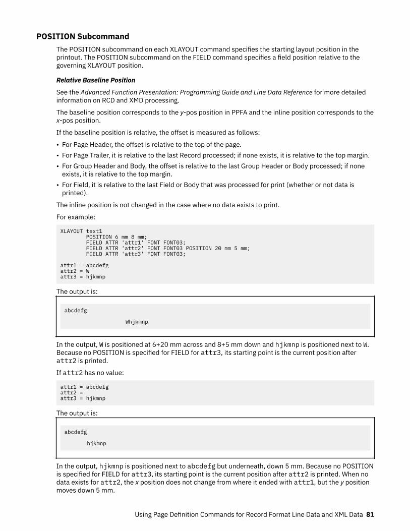
POSITION SubcommandThe POSITION subcommand on each XLAYOUT command specifies the starting layout position in theprintout. The POSITION subcommand on the FIELD command specifies a field position relative to thegoverning XLAYOUT position.
Relative Baseline Position
See the Advanced Function Presentation: Programming Guide and Line Data Reference for more detailedinformation on RCD and XMD processing.
The baseline position corresponds to the y-pos position in PPFA and the inline position corresponds to thex-pos position.
If the baseline position is relative, the offset is measured as follows:
• For Page Header, the offset is relative to the top of the page.• For Page Trailer, it is relative to the last Record processed; if none exists, it is relative to the top margin.• For Group Header and Body, the offset is relative to the last Group Header or Body processed; if none
exists, it is relative to the top margin.• For Field, it is relative to the last Field or Body that was processed for print (whether or not data is
printed).
The inline position is not changed in the case where no data exists to print.
For example:
XLAYOUT text1 POSITION 6 mm 8 mm; FIELD ATTR 'attr1' FONT FONT03; FIELD ATTR 'attr2' FONT FONT03 POSITION 20 mm 5 mm; FIELD ATTR 'attr3' FONT FONT03;
attr1 = abcdefgattr2 = Wattr3 = hjkmnp
The output is:
abcdefg
Whjkmnp
In the output, W is positioned at 6+20 mm across and 8+5 mm down and hjkmnp is positioned next to W.Because no POSITION is specified for FIELD for attr3, its starting point is the current position afterattr2 is printed.
If attr2 has no value:
attr1 = abcdefgattr2 = attr3 = hjkmnp
The output is:
abcdefg
hjkmnp
In the output, hjkmnp is positioned next to abcdefg but underneath, down 5 mm. Because no POSITIONis specified for FIELD for attr3, its starting point is the current position after attr2 is printed. When nodata exists for attr2, the x position does not change from where it ended with attr1, but the y positionmoves down 5 mm.
Using Page Definition Commands for Record Format Line Data and XML Data 81

XML Data Element ExampleAn application can group XML data elements to be formatted together as an entity by grouping thoseelements hierarchically under a collection XML data element. The data order normally does not matter informatting the data elements unless the elements are to be placed relative to each other in the inlinedirection. Any elements to be placed inline relative to each other must be ordered in inline presentationorder. Use the XLAYOUT/FIELD commands to place the data on the presentation device. Figure 61 onpage 82 is an example of a bank customer with the name and address fields that are placed together:
<Customer> <name> <title>Dr.</title> <first>Kelly</first> <last>Green</last> </name> <address> <strno>1911</strno> <street>Colt Lane</street> <city>Longmont</city> <state>CO</state> <zip>80501</zip> </address></Customer>
Figure 61: XML Data Elements
The example in Figure 61 on page 82 results in the following printed output:
Dr. Kelly Green1911 Colt LaneLongmont, CO 80501
The page definition that is used to create the output is as follows:
PAGEDEF xmp101 UDTYPE ebcdic REPLACE yes;/*------------------------------------------------------*//* Font definitions:/*------------------------------------------------------*/FONT E21H0C TYPE EBCDIC;
/*------------------------------------------------------*//* Use QTAG definitions to define short alias names *//* that make coding the XLAYOUTs easier. Do the *//* messy work here, allowing us to code on the XLAYOUT: *//* XLAYOUT zip … *//* instead of: *//* XLAYOUT QTAG 'Customer','address','zip' … *//*------------------------------------------------------*/Define cust QTAG 'Customer' ;Define title QTAG 'Customer','name' ,'title';Define first QTAG 'Customer','name' ,'first';Define last QTAG 'Customer','name' ,'last' ;Define strno QTAG 'Customer','address' ,'strno' ;Define street QTAG 'Customer','address' ,'street' ;Define city QTAG 'Customer','address','city' ;Define state QTAG 'Customer','address' ,'state' ;Define zip QTAG 'Customer','address' ,'zip' ;
/*------------------------------------------------------*//* Print first line "Dr. Kelly Green" *//* NOTE:-The "collector" Customer starts a new page *//* -RELATIVE 0 is not the same as SAME *//* -RELATIVE 0.167 is equivalent to a 6 CPI space *//* along with FIELD TEXT, giving us 2 ways to *//* leave a space. *//* -Watch out for the POSITION defaults on XLAYOUT *//* and FIELDs */
/*------------------------------------------------------*/XLAYOUT cust NEWPAGE;XLAYOUT title POSITION ABSOLUTE 1 in ABSOLUTE 1 in;XLAYOUT first POSITION RELATIVE 0 in RELATIVE 0; FIELD TEXT''; FIELD START 1 LENGTH *;XLAYOUT last POSITION RELATIVE 0.167 in RELATIVE 0;
82 Page Printer Formatting Aid: User's Guide
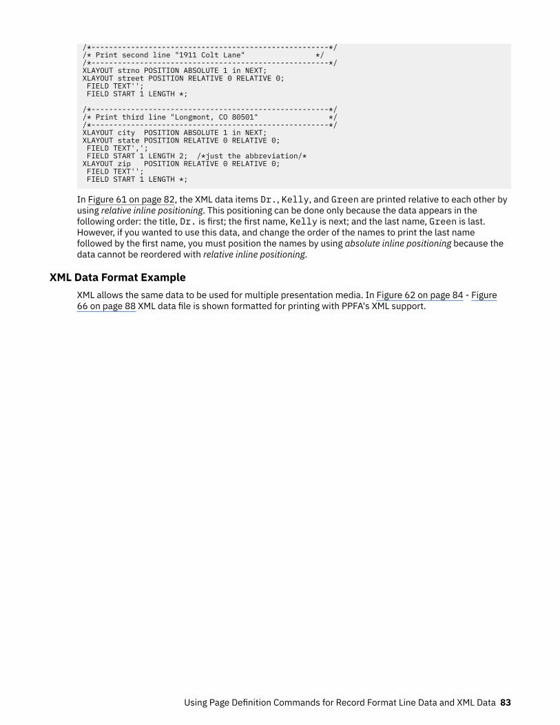
/*------------------------------------------------------*//* Print second line "1911 Colt Lane" *//*------------------------------------------------------*/XLAYOUT strno POSITION ABSOLUTE 1 in NEXT;XLAYOUT street POSITION RELATIVE 0 RELATIVE 0; FIELD TEXT''; FIELD START 1 LENGTH *;
/*------------------------------------------------------*//* Print third line "Longmont, CO 80501" *//*------------------------------------------------------*/XLAYOUT city POSITION ABSOLUTE 1 in NEXT;XLAYOUT state POSITION RELATIVE 0 RELATIVE 0; FIELD TEXT','; FIELD START 1 LENGTH 2; /*just the abbreviation/*XLAYOUT zip POSITION RELATIVE 0 RELATIVE 0; FIELD TEXT''; FIELD START 1 LENGTH *;
In Figure 61 on page 82, the XML data items Dr., Kelly, and Green are printed relative to each other byusing relative inline positioning. This positioning can be done only because the data appears in thefollowing order: the title, Dr. is first; the first name, Kelly is next; and the last name, Green is last.However, if you wanted to use this data, and change the order of the names to print the last namefollowed by the first name, you must position the names by using absolute inline positioning because thedata cannot be reordered with relative inline positioning.
XML Data Format ExampleXML allows the same data to be used for multiple presentation media. In Figure 62 on page 84 - Figure66 on page 88 XML data file is shown formatted for printing with PPFA's XML support.
Using Page Definition Commands for Record Format Line Data and XML Data 83

<?xml version="1.0" ?><?xml:stylesheet type="text/xsl" href=bbbank.xsl"?><!-- --><!-- Data for XML Example --><!-- --><document><bankstatement> <customer> <acctno>026-257311</acctno> <name>Justin Case</name> <street>123 Redlight Lane</street> <cityst>Twistnshout, MA 02345</cityst> </customer> <begindate>JAN 02, 2002</begindate> <enddate>FEB 01, 2002</enddate><!-- --><!-- Page number generator --><!-- --> <pagenumber><!-- --><!-- New account type = Super Checking Account --><!-- --> <supercheckingactivity type="superchk"> <balance> <begin>2591.24</begin> <credit>1946.93</credit> <debit>1956.43</debit> <svchg>0.00</svchg> <end>0.00</end> </balance><!-- --><!-- Credit --><!-- --> <credits> <transaction> <type>DEPOSIT</type> <date>01/05/2002</date> <amt> 26.90</amt> </transaction> <transaction> <type>AUTO DEPOSIT</type> <date>01/05/2002</date> <amt> 954.27</amt> </transaction> <transaction> <type>AUTO DEPOSIT</type> <date>01/30/2002</date> <amt> 954.27</amt> </transaction>
Figure 62: XML Data File (Part 1 of 5)
84 Page Printer Formatting Aid: User's Guide

<transaction> <type>INTEREST</type> <date>01/31/2002</date> <amt> 11.49</amt> </transaction> <total> </credits><!-- --><!-- Checks --><!-- --> <checks> <transaction> <chkno>352</chkno> <date>01/04/2002</date> <amt> 321.50</amt> <transaction> <transaction> <chkno>353</chkno> <date>01/05/2002</date> <amt> 100.00</amt> <transaction> <transaction> <chkno>354</chkno> <date>01/10/2002</date> <amt> 122.30</amt> <transaction> <transaction> <chkno>355</chkno> <date>01/11/2002</date> <amt> 59.95</amt> <transaction> <transaction> <chkno>356</chkno> <date>01/15/2002</date> <amt> 852.33</amt> <transaction> <transaction> <chkno>357</chkno> <date>01/30/2002</date> <amt> 500.35</amt> <transaction> </checks><!-- --><!-- Daily Balances --><!-- --> <balances> <baldata> <date>01/04/2002</date> <bal>2269.74</bal> </baldata> <baldata> <date>01/05/2002</date> <bal>2196.64</bal> </baldata> <baldata> <date>01/10/2002</date> <bal>2074.34</bal> </baldata> <baldata> <date>01/11/2002</date> <bal>2014.39</bal> </baldata>
Figure 63: XML Data File (Part 2 of 5)
Using Page Definition Commands for Record Format Line Data and XML Data 85
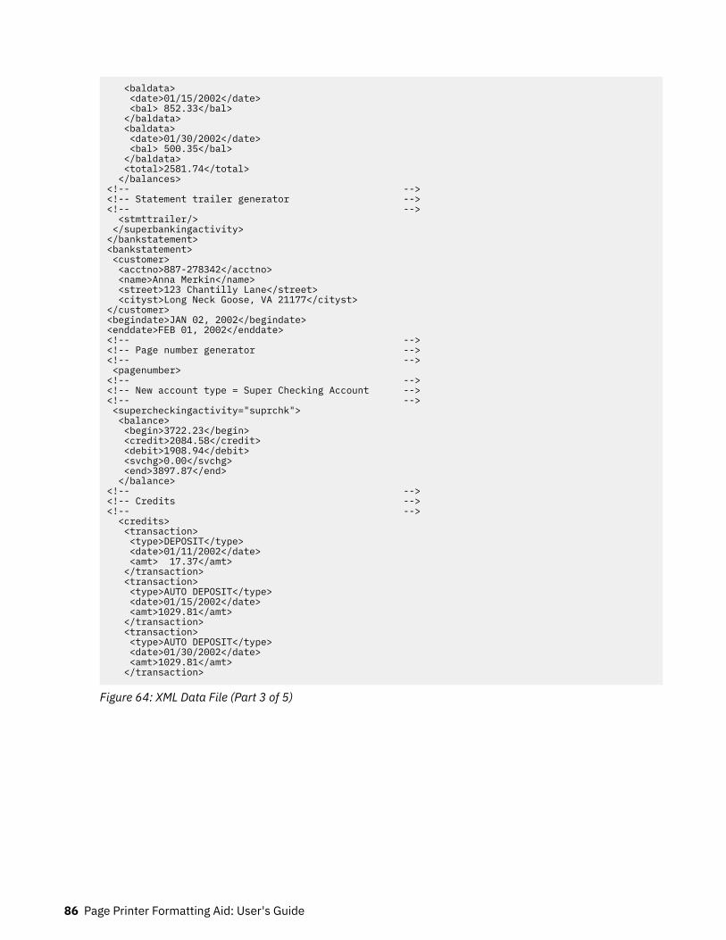
<baldata> <date>01/15/2002</date> <bal> 852.33</bal> </baldata> <baldata> <date>01/30/2002</date> <bal> 500.35</bal> </baldata> <total>2581.74</total> </balances><!-- --><!-- Statement trailer generator --><!-- --> <stmttrailer/> </superbankingactivity></bankstatement><bankstatement> <customer> <acctno>887-278342</acctno> <name>Anna Merkin</name> <street>123 Chantilly Lane</street> <cityst>Long Neck Goose, VA 21177</cityst></customer><begindate>JAN 02, 2002</begindate><enddate>FEB 01, 2002</enddate><!-- --><!-- Page number generator --><!-- --> <pagenumber><!-- --><!-- New account type = Super Checking Account --><!-- --> <supercheckingactivity="suprchk"> <balance> <begin>3722.23</begin> <credit>2084.58</credit> <debit>1908.94</debit> <svchg>0.00</svchg> <end>3897.87</end> </balance><!-- --><!-- Credits --><!-- --> <credits> <transaction> <type>DEPOSIT</type> <date>01/11/2002</date> <amt> 17.37</amt> </transaction> <transaction> <type>AUTO DEPOSIT</type> <date>01/15/2002</date> <amt>1029.81</amt> </transaction> <transaction> <type>AUTO DEPOSIT</type> <date>01/30/2002</date> <amt>1029.81</amt> </transaction>
Figure 64: XML Data File (Part 3 of 5)
86 Page Printer Formatting Aid: User's Guide

<transaction> <type>INTEREST</type> <date>01/31/2002</date> <amt> 7.59</amt> </transaction> <total>2084.58</total> </credits><!-- --><!-- Checks --><!-- --> <checks> <transaction> <chkno>759</chkno> <date>01/03/2002</date> <amt> 144.00</amt> </transaction> <transaction> <chkno>760</chkno> <date>01/04/2002</date> <amt> 93.11</amt> </transaction> <transaction> <chkno>761</chkno> <date>01/09/2002</date> <amt> 322.72</amt> </transaction> <transaction> <chkno>762</chkno> <date>01/11/2002</date> <amt> 102.43</amt> </transaction> <transaction> <chkno>763</chkno> <date>01/17/2002</date> <amt> 794.46</amt> </transaction> <transaction> <chkno>764</chkno> <date>01/29/2002</date> <amt> 452.22</amt> </transaction> </checks>
Figure 65: XML Data File (Part 4 of 5)
Using Page Definition Commands for Record Format Line Data and XML Data 87
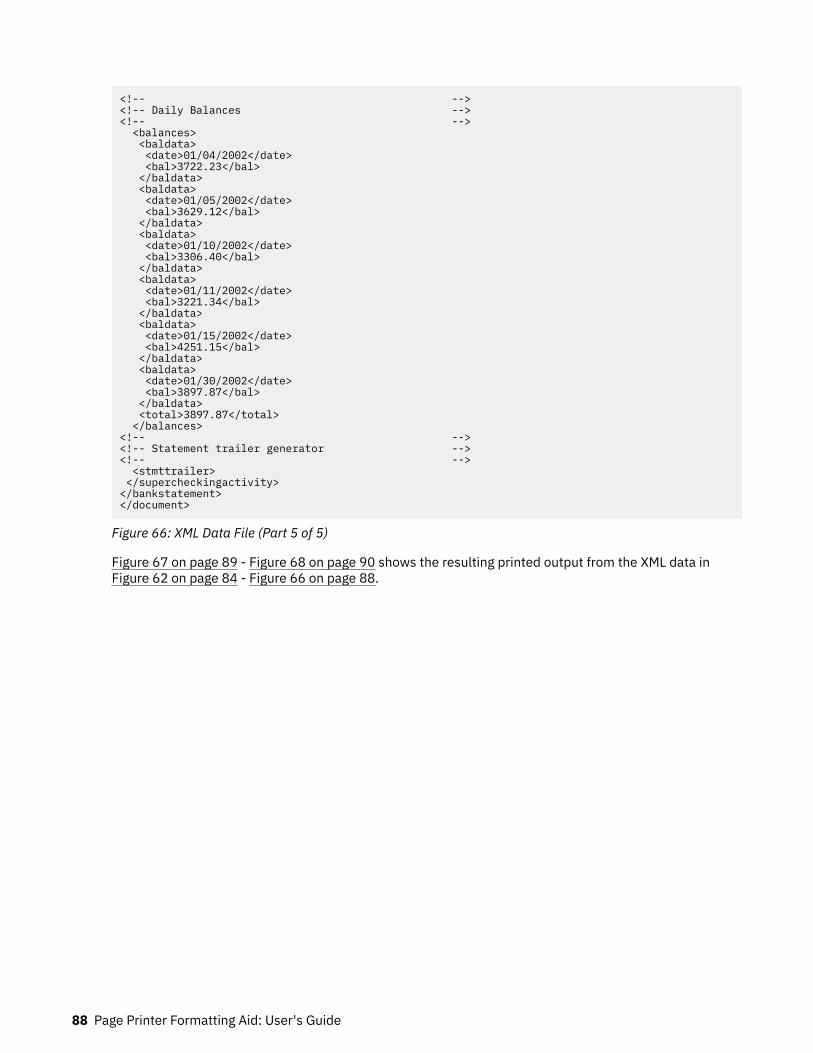
<!-- --><!-- Daily Balances --><!-- --> <balances> <baldata> <date>01/04/2002</date> <bal>3722.23</bal> </baldata> <baldata> <date>01/05/2002</date> <bal>3629.12</bal> </baldata> <baldata> <date>01/10/2002</date> <bal>3306.40</bal> </baldata> <baldata> <date>01/11/2002</date> <bal>3221.34</bal> </baldata> <baldata> <date>01/15/2002</date> <bal>4251.15</bal> </baldata> <baldata> <date>01/30/2002</date> <bal>3897.87</bal> </baldata> <total>3897.87</total> </balances><!-- --><!-- Statement trailer generator --><!-- --> <stmttrailer> </supercheckingactivity></bankstatement></document>
Figure 66: XML Data File (Part 5 of 5)
Figure 67 on page 89 - Figure 68 on page 90 shows the resulting printed output from the XML data inFigure 62 on page 84 - Figure 66 on page 88.
88 Page Printer Formatting Aid: User's Guide

Figure 67: XML Data Printed Output (Part 1 of 2)
Using Page Definition Commands for Record Format Line Data and XML Data 89
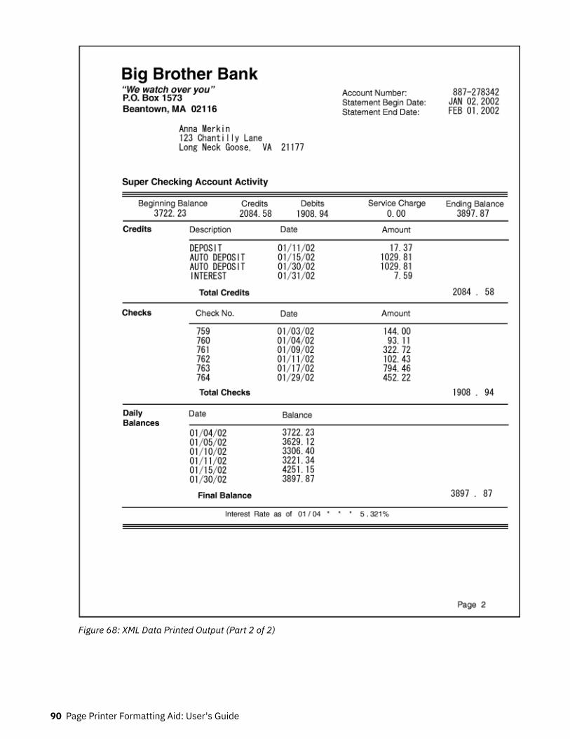
Figure 68: XML Data Printed Output (Part 2 of 2)
90 Page Printer Formatting Aid: User's Guide

The page definition that is used to create the output in Figure 67 on page 89 - Figure 68 on page 90 isshown in Figure 69 on page 91 - Figure 75 on page 97:
PAGEDEF bbbank replace yes WIDTH 8.5 in HEIGHT 11.0 in UDTYPE EBCDIC; FONT comp a075nc TYPE EBCDIC;/*Big Brother Bank font */ FONT ital a175dc TYPE EBCDIC;/*Italic theme */ FONT addr a075dc TYPE EBCDIC;/*Big Brother address */ FONT varb gt10 TYPE EBCDIC;/*Variable data */ FONT super a075dc TYPE EBCDIC;/*Super Checking Account */ FONT head a055ac TYPE EBCDIC;/*Headings */ FONT bhead a075ac TYPE EBCDIC;/*Bold Headings */ /************************************************/ /** QTAG declarations **/ /************************************************/ /*---- statmid declarations --------------------*/ DEFINE statmid QTAG C'document', C'bankstatement',C'customer'; DEFINE acctno QTAG C'document', C'bankstatement',C'customer',C'acctno'; DEFINE name QTAG C'document', C'bankstatement',C'customer',C'name'; DEFINE street QTAG C'document', C'bankstatement',C'customer',C'street'; DEFINE cityst QTAG C'document', C'bankstatement',C'customer',C'cityst'; DEFINE begindate QTAG C'document', C'bankstatement',C'begindate'; DEFINE enddate QTAG C'document', C'bankstatement',C'enddate'; /*---- statsum declarations --------------------*/ DEFINE statsum QTAG C'document', C'bankstatement',C'supercheckingactivity' C'balance' ; DEFINE statsumf1 QTAG C'document', C'bankstatement',C'supercheckingactivity' C'balance', c'begin'; DEFINE statsumf2 QTAG C'document', C'bankstatement',C'supercheckingactivity' C'balance', c'credit'; DEFINE statsumf3 QTAG C'document', C'bankstatement',C'supercheckingactivity' C'balance', c'debit'; DEFINE statsumf4 QTAG C'document', C'bankstatement',C'supercheckingactivity' C'balance', c'svchg'; DEFINE statsumf5 QTAG C'document', C'bankstatement',C'supercheckingactivity' C'balance', c'end'; /*---- crdata declarations --------------------*/ DEFINE crheader QTAG C'document', C'bankstatement',C'supercheckingactivity', C'credits'; DEFINE crdata1 QTAG C'document', C'bankstatement',C'supercheckingactivity', C'credits',C'transaction',C'type' ; DEFINE crdata2 QTAG C'document', C'bankstatement',C'supercheckingactivity', C'credits',C'transaction',C'date' ;
Figure 69: Page Definition for XML Output (Part 1 of 7)
Using Page Definition Commands for Record Format Line Data and XML Data 91

DEFINE crdata3 QTAG C'document', C'bankstatement',C'supercheckingactivity', C'credits',C'transaction',C'amt' ; DEFINE crtotal QTAG C'document', C'bankstatement',C'supercheckingactivity', C'credits',C'total'; /*---- ckdata declarations --------------------*/ DEFINE ckheader QTAG C'document', C'bankstatement',C'supercheckingactivity', C'checks' ; DEFINE ckdata1 QTAG C'document', C'bankstatement',C'supercheckingactivity', C'checks',C'transaction',C'chkno' ; DEFINE ckdata2 QTAG C'document', C'bankstatement',C'supercheckingactivity', C'checks',C'transaction',C'date' ; DEFINE ckdata3 QTAG C'document', C'bankstatement',C'supercheckingactivity', C'checks',C'transaction',C'amt' ; DEFINE cktotal QTAG C'document', C'bankstatement',C'supercheckingactivity', C'checks', C'total'; /*---- baldata declarations --------------------*/ DEFINE balhead QTAG C'document', C'bankstatement',C'supercheckingactivity', C'balances'; DEFINE baldata1 QTAG C'document', C'bankstatement',C'supercheckingactivity', C'balances',C'baldata',C'date' ; DEFINE baldata2 QTAG C'document', C'bankstatement',C'supercheckingactivity', C'balances',C'baldata',C'bal' ; DEFINE baltotal QTAG C'document', C'bankstatement',C'supercheckingactivity', C'balances', C'total'; /*---- misc. declarations --------------------*/ DEFINE statrail QTAG C'document', C'bankstatement',C'supercheckingactivity', C'stmttrailer'; DEFINE pgenum QTAG C'document', C'bankstatement',C'pagenumber'; /*----------------------------------------------*/ /*---- end of QTAG declarations ----------------*/ /*----------------------------------------------*/ PAGEFORMAT xchub1 TOPMARGIN 2 in BOTMARGIN 1 in; /************************************************/ /** statmid HEADER **/ /************************************************/ XLAYOUT statmid PAGEHEADER NEWPAGE POSITION .6 in ABSOLUTE .55 in; FIELD TEXT C'Big Brother Bank' ALIGN LEFT FONT comp ; /* default to LAYOUT positioning */ FIELD TEXT C'"We watch over you"' ALIGN LEFT POSITION 0 NEXT FONT ital ; /*default to next line */ FIELD TEXT C'P.O. Box 1573' ALIGN LEFT POSITION 0 NEXT FONT addr ; /*default to next line */
Figure 70: Page Definition for XML Output (Part 2 of 7)
92 Page Printer Formatting Aid: User's Guide

FIELD TEXT C'Beantown, MA 02116' ALIGN LEFT POSITION 0 NEXT FONT addr ; /*default to next line */ FIELD TEXT C'Account Number:' ALIGN LEFT POSITION 4.3 in .2 in FONT head ; /*New area on right */ FIELD TEXT C'Statement Begin Date:' ALIGN LEFT POSITION 4.3 in NEXT FONT head ; /*New area on right */ FIELD TEXT C'Statement End Date:' ALIGN LEFT POSITION 4.3 in NEXT FONT head ; /*New area on right */ XLAYOUT acctno PAGEHEADER CONTINUE POSITION SAME SAME; FIELD START 1 LENGTH 10 ALIGN RIGHT POSITION 7.5 in .2 in FONT varb ; XLAYOUT begindate PAGEHEADER CONTINUE POSITION SAME SAME; FIELD START 1 LENGTH 12 POSITION 7.5 in .37 in ALIGN RIGHT FONT varb ; XLAYOUT enddate PAGEHEADER CONTINUE POSITION SAME SAME; FIELD START 1 LENGTH 12 POSITION 7.5 in .53 in ALIGN RIGHT FONT varb ; XLAYOUT name PAGEHEADER CONTINUE POSITION SAME SAME; FIELD START 1 LENGTH 19 ALIGN LEFT POSITION 1.1 in .9 in FONT varb ; XLAYOUT street PAGEHEADER CONTINUE POSITION SAME SAME; FIELD START 1 LENGTH 19 ALIGN LEFT POSITION 1.1 in 1.07 in FONT varb ; XLAYOUT cityst PAGEHEADER CONTINUE POSITION SAME SAME; FIELD START 1 LENGTH 22 ALIGN LEFT POSITION 1.1 in 1.23 in FONT varb ; /************************************************/ /** statsum BODY **/ /************************************************/ XLAYOUT statsum BODY POSITION .6 in .5 in; FIELD TEXT C'Super Checking Account Activity' FONT super ; /* Static text - Super Checking */ DRAWGRAPHIC LINE ACROSS 7.5 IN LINEWT BOLD POSITION 0 .15 in copy down 2 spaced 1 mm; FIELD TEXT C'Beginning Balance' POSITION .3 in .4 in FONT head ; /* Static text - first header */ FIELD TEXT C'Credits' POSITION 2.4 in CURRENT FONT head ; /* Static text - first header */
Figure 71: Page Definition for XML Output (Part 3 of 7)
Using Page Definition Commands for Record Format Line Data and XML Data 93
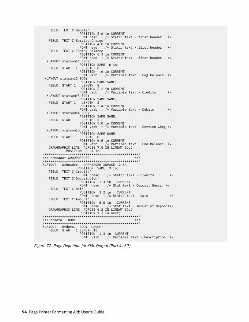
FIELD TEXT C'Debits' POSITION 3.6 in CURRENT FONT head ; /* Static text - first header */ FIELD TEXT C'Service Charge' POSITION 4.8 in CURRENT FONT head ; /* Static text - first header */ FIELD TEXT C'Ending Balance' POSITION 6.3 in CURRENT FONT head ; /* Static text - first header */ XLAYOUT statsumf1 BODY POSITION SAME .6 in; FIELD START 1 LENGTH 8 POSITION .6 in CURRENT FONT varb ; /* Variable text - Beg balance */ XLAYOUT statsumf2 BODY POSITION SAME SAME; FIELD START 1 LENGTH 8 POSITION 2.2 in CURRENT FONT varb ; /* Variable text - Credits */ XLAYOUT statsumf3 BODY POSITION SAME SAME; FIELD START 1 LENGTH 8 POSITION 3.4 in CURRENT FONT varb ; /* Variable text - Debits */ XLAYOUT statsumf4 BODY POSITION SAME SAME; FIELD START 1 LENGTH 5 POSITION 5.0 in CURRENT FONT varb ; /* Variable text - Service Chrg */ XLAYOUT statsumf5 BODY POSITION SAME SAME; FIELD START 1 LENGTH 8 POSITION 6.5 in CURRENT FONT varb ; /* Variable text - End Balance */ DRAWGRAPHIC LINE ACROSS 7.5 IN LINEWT BOLD POSITION 0 .1 in; /************************************************/ /** crheader GROUPHEADER **/ /************************************************/ XLAYOUT crheader GRPHEADER XSPACE .2 in POSITION SAME .3 in; FIELD TEXT C'Credits' FONT bhead ; /* Static text - Credits */ FIELD TEXT C'Description' POSITION 1.3 in CURRENT FONT head ; /* Stat text - Deposit Descr. */ FIELD TEXT C'Date' POSITION 3.2 in CURRENT FONT head ; /* Static text - Date */ FIELD TEXT C'Amount' POSITION 5.0 in CURRENT FONT head ; /* Stat text - Amount of deposit*/ DRAWGRAPHIC LINE ACROSS 6.2 IN LINEWT BOLD POSITION 1.3 in next; /************************************************/ /** crdata BODY **/ /************************************************/ XLAYOUT crdata1 BODY GROUP; FIELD START 1 LENGTH 13 POSITION 1.3 in CURRENT FONT varb ; /* Variable text - Description */
Figure 72: Page Definition for XML Output (Part 4 of 7)
94 Page Printer Formatting Aid: User's Guide

XLAYOUT crdata2 BODY GROUP position same same; FIELD START 1 LENGTH 8 POSITION 3 in CURRENT FONT varb ; /* Variable text - Date */ XLAYOUT crdata3 BODY GROUP position same same; FIELD START 1 LENGTH 8 ALIGN RIGHT POSITION 5.6 in CURRENT FONT varb ; /* Variable text - Amount */ /************************************************/ /** crtotal BODY **/ /************************************************/ XLAYOUT crtotal BODY GROUP; FIELD TEXT C'Total Credits' POSITION 1.5 in .2 in FONT bhead ; /* Stat text - Total credits */ FIELD START 1 LENGTH 8 ALIGN RIGHT POSITION 7.3 in CURRENT FONT varb ; /* Variable text - Amount */ DRAWGRAPHIC LINE ACROSS 7.5 IN LINEWT BOLD POSITION 0 next; /************************************************/ /** ckheader GROUPHEADER **/ /************************************************/ XLAYOUT ckheader GRPHEADER XSPACE .2 IN POSITION SAME .6 in; FIELD TEXT C'Checks' FONT bhead ; /* Static text - Checks */ FIELD TEXT C'Check No.' POSITION 1.3 in CURRENT FONT head ; /* Stat text - Check number */ FIELD TEXT C'Date' POSITION 3.2 in CURRENT FONT head ; /* Stat text - Date of check */ FIELD TEXT C'Amount' POSITION 5.0 in CURRENT FONT head ; /* Static text - Amount of check*/ DRAWGRAPHIC LINE ACROSS 6.2 IN LINEWT BOLD POSITION 1.3 in next; /************************************************/ /** ckdata BODY **/ /************************************************/ XLAYOUT ckdata1 BODY GROUP POSITION SAME NEXT; FIELD START 1 LENGTH 3 POSITION 1.5 in CURRENT FONT varb ; /* Variable text - Check number */ XLAYOUT ckdata2 BODY GROUP position same same; FIELD START 1 LENGTH 8 POSITION 3.0 in CURRENT FONT varb ; /* Variable text - Date */ XLAYOUT ckdata3 BODY GROUP position same same; FIELD START 1 LENGTH 8 ALIGN RIGHT POSITION 5.6 in CURRENT FONT varb ; /* Variable text - Amount */ /************************************************/ /** cktotal BODY **/ /************************************************/ XLAYOUT cktotal BODY GROUP; FIELD TEXT C'Total Checks' POSITION 1.5 in .2 in FONT bhead ; /* Stat text - Total checks */
Figure 73: Page Definition for XML Output (Part 5 of 7)
Using Page Definition Commands for Record Format Line Data and XML Data 95
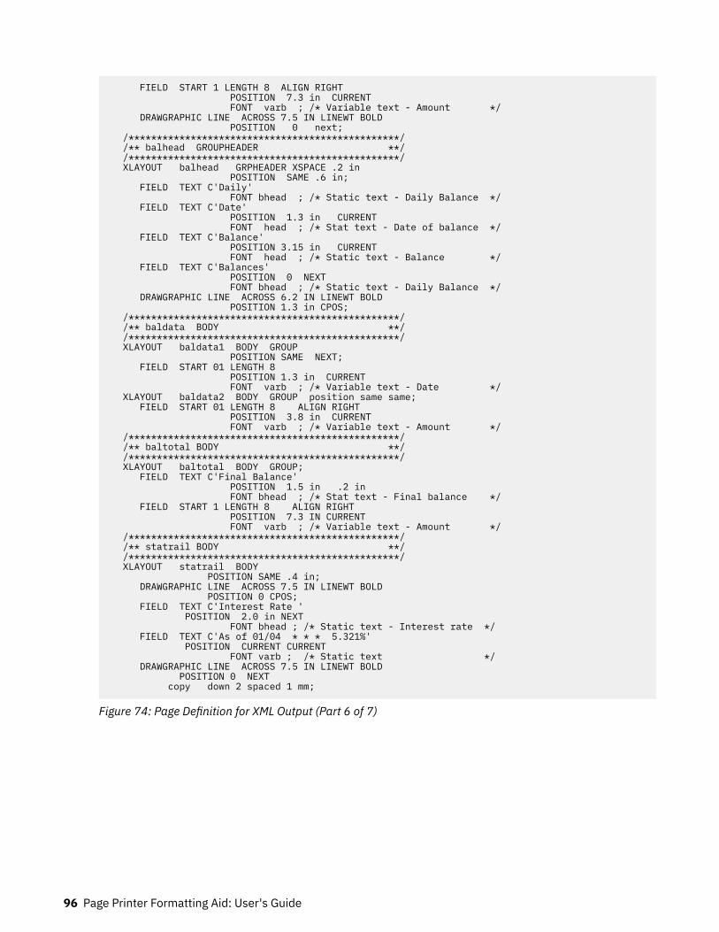
FIELD START 1 LENGTH 8 ALIGN RIGHT POSITION 7.3 in CURRENT FONT varb ; /* Variable text - Amount */ DRAWGRAPHIC LINE ACROSS 7.5 IN LINEWT BOLD POSITION 0 next; /************************************************/ /** balhead GROUPHEADER **/ /************************************************/ XLAYOUT balhead GRPHEADER XSPACE .2 in POSITION SAME .6 in; FIELD TEXT C'Daily' FONT bhead ; /* Static text - Daily Balance */ FIELD TEXT C'Date' POSITION 1.3 in CURRENT FONT head ; /* Stat text - Date of balance */ FIELD TEXT C'Balance' POSITION 3.15 in CURRENT FONT head ; /* Static text - Balance */ FIELD TEXT C'Balances' POSITION 0 NEXT FONT bhead ; /* Static text - Daily Balance */ DRAWGRAPHIC LINE ACROSS 6.2 IN LINEWT BOLD POSITION 1.3 in CPOS; /************************************************/ /** baldata BODY **/ /************************************************/ XLAYOUT baldata1 BODY GROUP POSITION SAME NEXT; FIELD START 01 LENGTH 8 POSITION 1.3 in CURRENT FONT varb ; /* Variable text - Date */ XLAYOUT baldata2 BODY GROUP position same same; FIELD START 01 LENGTH 8 ALIGN RIGHT POSITION 3.8 in CURRENT FONT varb ; /* Variable text - Amount */ /************************************************/ /** baltotal BODY **/ /************************************************/ XLAYOUT baltotal BODY GROUP; FIELD TEXT C'Final Balance' POSITION 1.5 in .2 in FONT bhead ; /* Stat text - Final balance */ FIELD START 1 LENGTH 8 ALIGN RIGHT POSITION 7.3 IN CURRENT FONT varb ; /* Variable text - Amount */ /************************************************/ /** statrail BODY **/ /************************************************/ XLAYOUT statrail BODY POSITION SAME .4 in; DRAWGRAPHIC LINE ACROSS 7.5 IN LINEWT BOLD POSITION 0 CPOS; FIELD TEXT C'Interest Rate ' POSITION 2.0 in NEXT FONT bhead ; /* Static text - Interest rate */ FIELD TEXT C'As of 01/04 * * * 5.321%' POSITION CURRENT CURRENT FONT varb ; /* Static text */ DRAWGRAPHIC LINE ACROSS 7.5 IN LINEWT BOLD POSITION 0 NEXT copy down 2 spaced 1 mm;
Figure 74: Page Definition for XML Output (Part 6 of 7)
96 Page Printer Formatting Aid: User's Guide

/************************************************/ /** pgenum PAGE NUMBER **/ /************************************************/ XLAYOUT pgenum PAGETRAILER POSITION SAME ABSOLUTE 10.7 in; FIELD TEXT C 'Page ' POSITION 6.5 in CURRENT FONT varb; /* placement of page number */ FIELD PAGENUM PRINT /* request page numbering */ FONT varb /* placement of page number */ POSITION CURRENT CURRENT;
Figure 75: Page Definition for XML Output (Part 7 of 7)
Using Page Definition Commands for Record Format Line Data and XML Data 97

98 Page Printer Formatting Aid: User's Guide
Chapter 5. Creating Complex Printouts
You are now ready to learn about some formatting tasks that might apply to more complex printouts. Youhave learned in other chapters about the basic form definition and page definition elements. This chapterdescribes how these elements are combined to create complete print jobs.
The advanced techniques that are covered in this section are illustrated in the following examples:
Table 5: Form Definitions and Page Definition Tasks
Task Example location
Combine field processing with an overlay. “Combining Field Processing and an ElectronicOverlay” on page 99
Suppress data. “Using Suppressions to Vary Data Presentation” onpage 101
Include fixed text. “Incorporating Fixed Text into a Page Definition” onpage 102
Combine two reports. “Combining Two Reports into One Printout” onpage 104
The examples in this chapter build on a single sales application, showing different sales reports beingformatted by form definitions and page definitions.
Combining Field Processing and an Electronic OverlayThis example involves printing a monthly individual sales report for a specified distribution. The followingitems are needed to generate the sales report:
• A pre-designed electronic overlay for the sales report• An unformatted print data file with periodic sales statistics
An example of the overlay and data file is shown in Figure 76 on page 100.
© Copyright IBM Corp. 1985, 2016 99

Figure 76: Electronic Overlay and Data File for a Sales Report
The code example that follows contains a form definition and a page definition. The page definition mapsthe file to the overlay.
In Figure 76 on page 100, the 0,0 point is the upper-left corner of the overlay, which means that thelogical page origin must coincide with the overlay origin in this example. POSITION subcommands arerelative to the logical page origin. The overlay origin point that positions the overlay is specified in theOverlay Generation Language/370 that creates the overlay, but can be modified in the page definition. Inmapping to an overlay, you must check the input to the overlay creation program so you can coordinate itsorigin with the logical page origin. You can reposition the overlay through the PRINTLINE command.
01 FORMDEF SLSRPT OFFSET 0 0 ;02 OVERLAY SLSRPT ;03 SUBGROUP OVERLAY SLSRPT ;0405 PAGEDEF SLSRPT ;06 PRINTLINE POSITION 2 IN 1.3 IN ; /* RECORD 1 */07 FIELD START 1 LENGTH 23 ;08 PRINTLINE POSITION 2 IN 1.70 IN ; /* RECORD 2 */09 FIELD START 1 LENGTH 9 ; /* DEFAULT POSITION */10 FIELD START 10 LENGTH 511 POSITION 4.3 IN * ; /* THE ASTERISK MEANS */12 /* CURRENT LINE */13 PRINTLINE POSITION 1.5 IN 6 IN ; /* RECORD 3 */14 FIELD START 1 LENGTH 4 ;15 SETUNITS LINESP 4 LPI ;16 PRINTLINE REPEAT 4 /* RECORDS 4-7 */17 POSITION 1.5 IN 3.6 IN ;18 FIELD START 1 LENGTH 7 ; /* DEFAULT POSITION */19 FIELD START 10 LENGTH 320 POSITION 1.5 IN * ;21 FIELD START 16 LENGTH 322 POSITION 2.5 IN * ;23 FIELD START 21 LENGTH 324 POSITION 3.5 IN * ;
A time-saving device is to use the REPEAT subcommand (line 16), which maps a single printline with itsfield subsets to records 4 - 7 with all model names and sales statistics. The length values in the repeated
100 Page Printer Formatting Aid: User's Guide

fields are 7, 3, 3, and 3, which are sufficient to accommodate the largest model name, unit value, $(000),and percentage fields mapped by this FIELD command.
Figure 77 on page 101 shows the report that is formatted by the resources that are generated in thecommand stream of this example.
Figure 77: Sales Report
Using Suppressions to Vary Data PresentationYou use PPFA and your print server printers to produce variations of the same report in a single job. Theessential function for this capability is called suppression. Suppression involves the coordinatedspecification of elements in both the page definition and the form definition. You create a suppression inthe page definition and turn it on or off in a subgroup within a form definition.
This example shows how to alter the controls in the previous example (“Combining Field Processing andan Electronic Overlay” on page 99) to generate a second report along with the one already created.
First, change the page definition by adding a SUPPRESSION subcommand to the third field in therepeated PRINTLINE (the PRINTLINE that mapped the models and sales figures in “Combining FieldProcessing and an Electronic Overlay” on page 99). The suppression is, in effect, created by theSUPPRESSION subcommand in the FIELD command. The following example shows the addition at line23.
18 FIELD START 1 LENGTH 7 ;19 FIELD START 10 LENGTH 320 POSITION 1.5 IN * ;21 FIELD START 16 LENGTH 322 POSITION 2.5 IN *23 SUPPRESSION SALES ; /*ADDED LINE */24 FIELD START 21 LENGTH 325 POSITION 3.5 IN * ;
The SUPPRESSION subcommand creates the potential for selective suppression of the data in the$(000) field of the report.
Then, rewrite the form definition, creating two subgroups within the copy group. Next, write aSUPPRESSION command immediately after the FORMDEF command. Finally, place a SUPPRESSIONsubcommand in the subgroup in which you want to suppress the data. The subcommand names thesuppression. The resulting form definition command stream is as follows:
FORMDEF SECRPT ; SUPPRESSION SALES ; /*NAMING THE SUPPRESSION */ COPYGROUP SECRPT ; OVERLAY SLSRPT ; /*NAMING THE OVERLAY */ SUBGROUP COPIES 1 OVERLAY SLSRPT ; SUBGROUP COPIES 1 OVERLAY SLSRPT SUPPRESSION SALES ; /*TURNING ON THE SUPPRESSION */
Creating Complex Printouts 101

The result is shown in Figure 78 on page 102. The second subgroup creates the second output page of thesame data with a second set of modifications; in this case, modifications means a suppression that is notin the first subgroup.
Figure 78: Selective Suppression
Review the steps in this example. To suppress a field, identify the field as suppressible in the pagedefinition under the FIELD command in question. Then, create a subgroup, activating this suppressionwith a SUPPRESSION subcommand in the form definition.
The first subgroup produces an output identical to the report in “Combining Field Processing and anElectronic Overlay” on page 99. It contains no suppression.
Note: This example can be printed in simplex only.
Incorporating Fixed Text into a Page DefinitionFixed text can be incorporated into an electronic overlay by using programs, such as Overlay GenerationLanguage/370. By having another place (the page definition) to incorporate fixed text, you can formatdocuments more efficiently.
In “Combining Field Processing and an Electronic Overlay” on page 99, a territory sales report forsalesman John Smith is created. Here, the territory sales report is incorporated into a larger format thatgoes to ACME's corporate headquarters in Chicago. Therefore, the identification for the region needs toappear on the report form. An overlay is used as a header for the composite report, which means that twooverlays appear in the command stream: one carries over from “Combining Field Processing and anElectronic Overlay” on page 99 and the other is the header.
So, as shown in Figure 79 on page 103, three fixed inputs generate the final report: overlay SLSRPT,overlay HDR, and the fixed regional identification text. (It is the second item that is worked into the pagedefinition in this example.)
102 Page Printer Formatting Aid: User's Guide
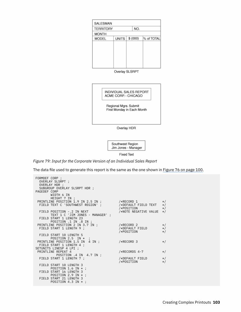
Figure 79: Input for the Corporate Version of an Individual Sales Report
The data file used to generate this report is the same as the one shown in Figure 76 on page 100.
FORMDEF CORP ; OVERLAY SLSRPT ; OVERLAY HDR ; SUBGROUP OVERLAY SLSRPT HDR ;PAGEDEF CORP WIDTH 6 IN HEIGHT 7 IN ; PRINTLINE POSITION 1.9 IN 2.5 IN ; /*RECORD 1 */ FIELD TEXT C 'SOUTHWEST REGION' ; /*DEFAULT FIELD TEXT */ /*POSITION */ FIELD POSITION -.2 IN NEXT /*NOTE NEGATIVE VALUE */ TEXT 1 C 'JIM JONES - MANAGER' ; FIELD START 1 LENGTH 23 POSITION .1 IN .8 IN ; PRINTLINE POSITION 2 IN 3.7 IN ; /*RECORD 2 */ FIELD START 1 LENGTH 9 ; /*DEFAULT FIELD */ /*POSITION */ FIELD START 10 LENGTH 5 POSITION 2.5 IN * ; PRINTLINE POSITION 1.5 IN 4 IN ; /*RECORD 3 */ FIELD START 1 LENGTH 4 ;SETUNITS LINESP 4 LPI ; PRINTLINE REPEAT 4 /*RECORDS 4-7 */ POSITION .4 IN 4.7 IN ; FIELD START 1 LENGTH 7 ; /*DEFAULT FIELD */ /*POSITION */ FIELD START 10 LENGTH 3 POSITION 1.6 IN * ; FIELD START 16 LENGTH 3 POSITION 2.9 IN * ; FIELD START 21 LENGTH 3 POSITION 4.3 IN * ;
Creating Complex Printouts 103
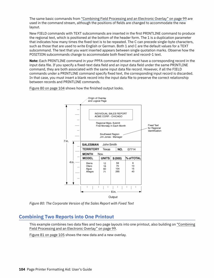
The same basic commands from “Combining Field Processing and an Electronic Overlay” on page 99 areused in the command stream, although the positions of fields are changed to accommodate the newlayout.
New FIELD commands with TEXT subcommands are inserted in the first PRINTLINE command to producethe regional text, which is positioned at the bottom of the header form. The 1 is a duplication parameterthat indicates how many times the fixed text is to be repeated. The C can precede single-byte characters,such as those that are used to write English or German. Both 1 and C are the default values for a TEXTsubcommand. The text that you want inserted appears between single quotation marks. Observe how thePOSITION subcommands change to accommodate both fixed text and record-1 text.
Note: Each PRINTLINE command in your PPFA command stream must have a corresponding record in theinput data file. If you specify a fixed-text data field and an input data field under the same PRINTLINEcommand, they are both associated with the same input data file record. However, if all the FIELDcommands under a PRINTLINE command specify fixed text, the corresponding input record is discarded.In that case, you must insert a blank record into the input data file to preserve the correct relationshipbetween records and PRINTLINE commands.
Figure 80 on page 104 shows how the finished output looks.
Figure 80: The Corporate Version of the Sales Report with Fixed Text
Combining Two Reports into One PrintoutThis example combines two data files and two page layouts into one printout, also building on “CombiningField Processing and an Electronic Overlay” on page 99.
Figure 81 on page 105 shows the new data and a new overlay.
104 Page Printer Formatting Aid: User's Guide
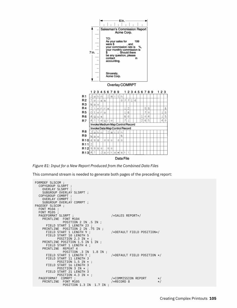
Figure 81: Input for a New Report Produced from the Combined Data Files
This command stream is needed to generate both pages of the preceding report:
FORMDEF SLSCOM ; COPYGROUP SLSRPT ; OVERLAY SLSRPT ; SUBGROUP OVERLAY SLSRPT ; COPYGROUP COMRPT ; OVERLAY COMRPT ; SUBGROUP OVERLAY COMRPT ;PAGEDEF SLSCOM ; FONT M104 ; FONT M105 ; PAGEFORMAT SLSRPT ; /*SALES REPORT*/ PRINTLINE FONT M104 POSITION 2 IN .5 IN ; FIELD START 1 LENGTH 23 ; PRINTLINE POSITION 2 IN .75 IN ; FIELD START 1 LENGTH 9 ; /*DEFAULT FIELD POSITION*/ FIELD START 10 LENGTH 5 POSITION 2.3 IN * ; PRINTLINE POSITION 1.5 IN 1 IN ; FIELD START 1 LENGTH 4 ; PRINTLINE REPEAT 4 POSITION .3 IN 1.8 IN ; FIELD START 1 LENGTH 7 ; /*DEFAULT FIELD POSITION */ FIELD START 11 LENGTH 3 POSITION 1.5 IN * ; FIELD START 16 LENGTH 3 POSITION 3 IN * ; FIELD START 21 LENGTH 3 POSITION 4.3 IN * ; PAGEFORMAT COMRPT ; /*COMMISSION REPORT */ PRINTLINE FONT M105 /*RECORD 8 */ POSITION 1.3 IN 1.7 IN ;
Creating Complex Printouts 105
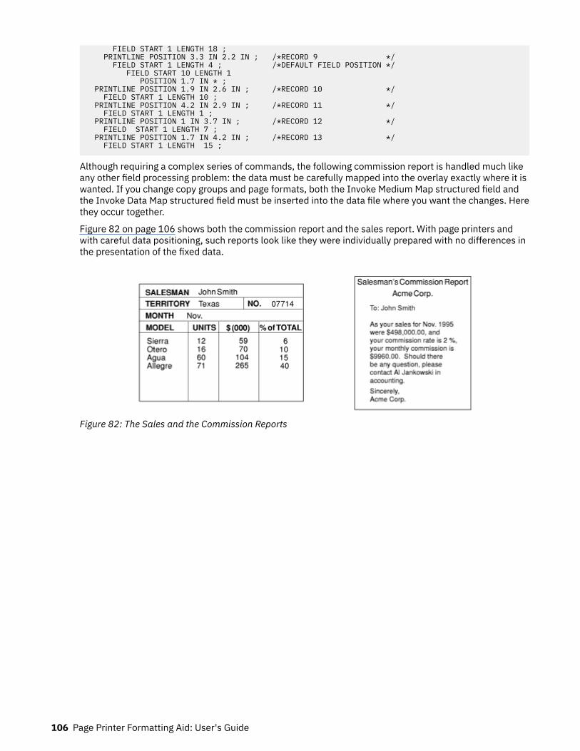
FIELD START 1 LENGTH 18 ; PRINTLINE POSITION 3.3 IN 2.2 IN ; /*RECORD 9 */ FIELD START 1 LENGTH 4 ; /*DEFAULT FIELD POSITION */ FIELD START 10 LENGTH 1 POSITION 1.7 IN * ; PRINTLINE POSITION 1.9 IN 2.6 IN ; /*RECORD 10 */ FIELD START 1 LENGTH 10 ; PRINTLINE POSITION 4.2 IN 2.9 IN ; /*RECORD 11 */ FIELD START 1 LENGTH 1 ; PRINTLINE POSITION 1 IN 3.7 IN ; /*RECORD 12 */ FIELD START 1 LENGTH 7 ; PRINTLINE POSITION 1.7 IN 4.2 IN ; /*RECORD 13 */ FIELD START 1 LENGTH 15 ;
Although requiring a complex series of commands, the following commission report is handled much likeany other field processing problem: the data must be carefully mapped into the overlay exactly where it iswanted. If you change copy groups and page formats, both the Invoke Medium Map structured field andthe Invoke Data Map structured field must be inserted into the data file where you want the changes. Herethey occur together.
Figure 82 on page 106 shows both the commission report and the sales report. With page printers andwith careful data positioning, such reports look like they were individually prepared with no differences inthe presentation of the fixed data.
Figure 82: The Sales and the Commission Reports
106 Page Printer Formatting Aid: User's Guide

Chapter 6. Conditional Processing
You use conditional processing to test fields within an input line data record (for example, a customernumber). Based on the results of the test, you can specify the action to be taken, such as to change copygroups or page formats. This chapter provides:
• An explanation of how conditional processing works• A detailed list of rules, restrictions, and considerations• Examples showing how conditional processing can be used to do some commonly requested functions
General DescriptionWith conditional processing, you can:
• Test the input data by using the CONDITION command.• Choose the copy group and page format to be used when you are printing the data.• Change to a different copy group or page format after the data is read. You can specify that the new
copy group or page format is used:
– Before the current subpage is printed.– Before the current line is printed.– After the current line is printed.– After the current subpage is printed.
Table 6 on page 107 shows the tasks that you can do with conditional processing.
Table 6: Conditional Processing Tasks
Task Location of the Example
Stack offset from previous jobs. “Jog Output Example” on page 119
Use different print directions for frontand back sides of a sheet.
“Duplex Output with Different Front and Back PrintDirections” on page 119
Do record reprocessing. “Record Reprocessing Example” on page 120
Select different paper sources. “Selecting Paper from an Alternate Bin Example” on page 121
Use multiple CONDITION commands. “Multiple CONDITION Commands” on page 121
Use repeat PRINTLINE commands. “Field Processing When PRINTLINEs Are Repeated” on page123
Using Conditional Processing versus Normal Line Data ProcessingNormal line-data processing consists of:
• Setting up the physical page environment by defining a copy group• Setting up the logical page environment by defining a page format
Input records correspond to PRINTLINE commands that determine such things as where the inputrecords are to be printed, which font to use and what print direction to use. Only one copy group and pageformat can be used for processing each input record.
© Copyright IBM Corp. 1985, 2016 107
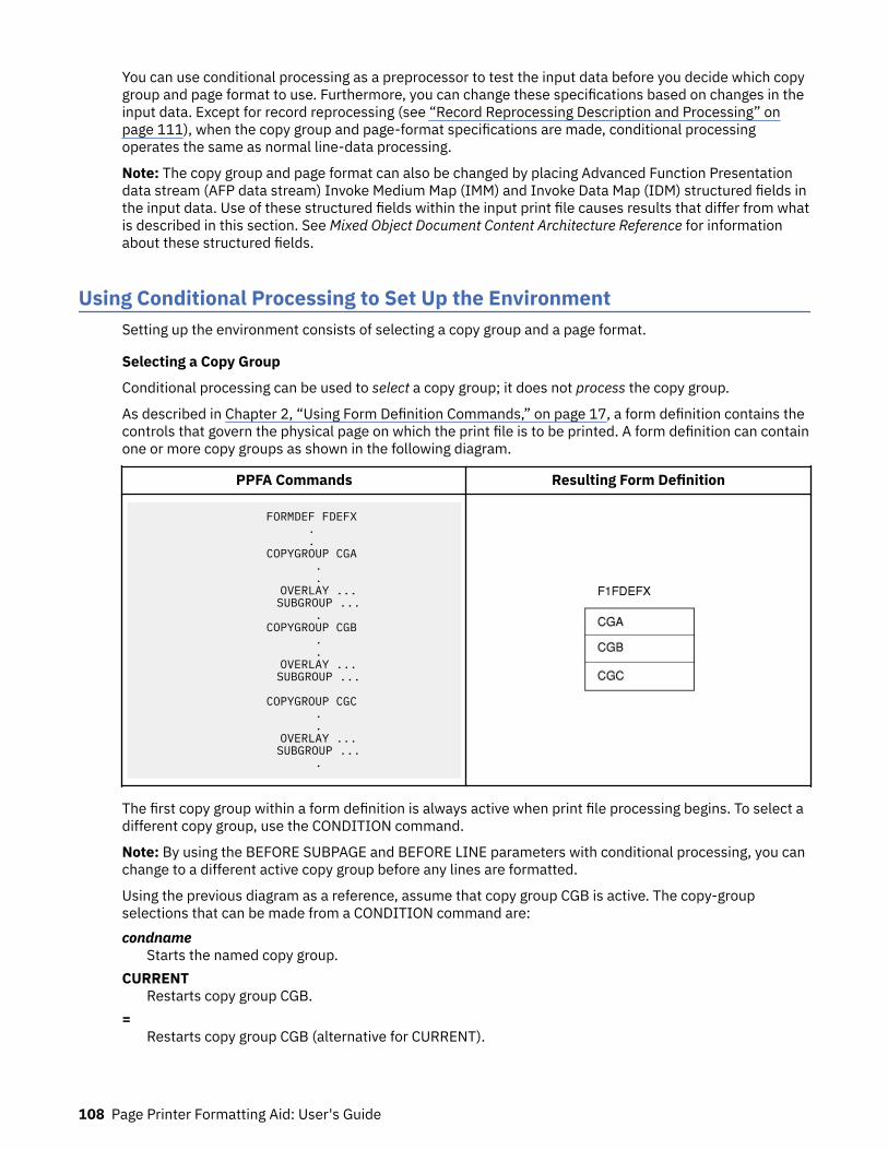
You can use conditional processing as a preprocessor to test the input data before you decide which copygroup and page format to use. Furthermore, you can change these specifications based on changes in theinput data. Except for record reprocessing (see “Record Reprocessing Description and Processing” onpage 111), when the copy group and page-format specifications are made, conditional processingoperates the same as normal line-data processing.
Note: The copy group and page format can also be changed by placing Advanced Function Presentationdata stream (AFP data stream) Invoke Medium Map (IMM) and Invoke Data Map (IDM) structured fields inthe input data. Use of these structured fields within the input print file causes results that differ from whatis described in this section. See Mixed Object Document Content Architecture Reference for informationabout these structured fields.
Using Conditional Processing to Set Up the EnvironmentSetting up the environment consists of selecting a copy group and a page format.
Selecting a Copy Group
Conditional processing can be used to select a copy group; it does not process the copy group.
As described in Chapter 2, “Using Form Definition Commands,” on page 17, a form definition contains thecontrols that govern the physical page on which the print file is to be printed. A form definition can containone or more copy groups as shown in the following diagram.
PPFA Commands Resulting Form Definition
FORMDEF FDEFX . .
COPYGROUP CGA . .
OVERLAY ... SUBGROUP ...
. COPYGROUP CGB
. .
OVERLAY ... SUBGROUP ...
COPYGROUP CGC
. .
OVERLAY ... SUBGROUP ...
.
The first copy group within a form definition is always active when print file processing begins. To select adifferent copy group, use the CONDITION command.
Note: By using the BEFORE SUBPAGE and BEFORE LINE parameters with conditional processing, you canchange to a different active copy group before any lines are formatted.
Using the previous diagram as a reference, assume that copy group CGB is active. The copy-groupselections that can be made from a CONDITION command are:condname
Starts the named copy group.CURRENT
Restarts copy group CGB.=
Restarts copy group CGB (alternative for CURRENT).
108 Page Printer Formatting Aid: User's Guide

NEXTStarts copy group CGC.
FIRSTStarts copy group CGA.
NULLDoes not change the current copy group processing.
/Does not change the current copy group processing (alternative for NULL).
See “Using the CONDITION Command to Select a Copy Group and a Page Format” on page 117 for moreinformation about each option.
Selecting a Page Format
Conditional processing can be used to select an active page format. Selecting the page format does notchange the basic rules for processing a page format:
• PRINTLINE commands are processed sequentially unless skip-to-channel or spacing commands areused.
• When the end of the page format is reached, processing returns to the first PRINTLINE command in thesame page format. Processing does not continue with the next page format (if any) in the pagedefinition.
However, conditional processing does involve some additional considerations:Subpages
A page format consists of one or more subpages. A subpage is defined by a group of PRINTLINEcommands followed by an ENDSUBPAGE command. If an ENDSUBPAGE command is not defined,then the entire page format is one subpage. See “Subpage Description and Processing” on page 110for more information.
Record reprocessingRecord reprocessing is used when input records are processed according to one set of copy-group andpage-format specifications, and then new specifications are invoked for the same input records. See“Record Reprocessing Description and Processing” on page 111 for more information.
As described in Chapter 3, “Using Page Definition Commands for Traditional Line Data,” on page 31, apage definition is a set of controls for formatting line-data files for printing on a logical page. A pagedefinition can contain one or more page formats as shown in the following diagram.
PPFA Commands Resulting Page Definition
PAGEDEF PDEFX . .
PAGEFORMAT PFMTA . .
PRINTLINE ... PRINTLINE ...
. PAGEFORMAT PFMTB
. .
PRINTLINE ... PRINTLINE ...
.
PAGEFORMAT PFMTC . .
PRINTLINE ... PRINTLINE ...
.
Conditional Processing 109
The first page format in the page definition is always active when print file processing begins. To invoke anew page format, use the CONDITION command.
Note: By using the BEFORE SUBPAGE and BEFORE LINE parameters, it is possible to change to a differentactive page format before any lines are formatted.
Using the previous diagram as a reference, assume that page format PFMTB is active. The page-formatselections that can be made from a CONDITION command are:condname
Starts the named page format.CURRENT
Restarts page format PFMTB.=
Restarts page format PFMTB (alternative for CURRENT).NEXT
Starts page format PFMTC.FIRST
Starts page format PFMTA.NULL
Does not change the current page format processing./
Does not change the current page format processing (alternative for NULL).
See “Using the CONDITION Command to Select a Copy Group and a Page Format” on page 117 for moreinformation about each option.
Subpage Description and ProcessingA page format consists of one or more subpages. A subpage is defined by a group of PRINTLINEcommands followed by an ENDSUBPAGE command. If an ENDSUBPAGE command is not defined, thenthe entire page format is one subpage. The following considerations apply to subpages:
• Subpages are necessary only with conditional processing. Multiple-up printing can be done with orwithout defining them as subpages, but to change the page format or copy group at the level of one ofthe multiple-up pages, the multiple-up pages must be defined as subpages. In the following diagram,pages 1 - 4 can be defined as four separate subpages within one page format, or all defined within onesubpage. However, to present the data on page 3 (for example) in a format different from the formatthat is used for pages 1 and 2, the four pages must be defined as subpages.
110 Page Printer Formatting Aid: User's Guide

• A subpage is processed sequentially starting from the beginning of the page format. Moving from onesubpage to the next subpage is done by processing all the PRINTLINE commands for a specifiedsubpage, or by skipping (with the CHANNEL subcommand) or spacing to a PRINTLINE command in adifferent subpage.
Note: Conditional processing cannot be used to select a subpage except by default. When a page formatis started (or the current one is restarted), processing begins with the first PRINTLINE command of thepage format. The effect is to select the first subpage in the page format.
Record Reprocessing Description and ProcessingRecord reprocessing is used when input records are processed according to one set of copy group andpage format specifications, and then new specifications are invoked for the same input records. If the newspecifications are to be applied with either the BEFORE SUBPAGE or the BEFORE LINE parameter, thenthe input records must be processed again with the new specifications instead of the original ones.
Note: Input records are not printed twice; record reprocessing just changes the specifications that areused when formatting the records.
The process is shown in the following diagram.
Conditional Processing 111

PPFA Commands Input Records
PAGEFORMAT PFMTA ;
PRINTLINE POSITION 1 IN 1 IN DIRECTION ACROSS
REPEAT 5 ;
CONDITION cond1 START 2 LENGTH 1
WHEN EQ ’B‘ BEFORE SUBPAGE
NULL PAGEFORMAT PFMTB ;
PAGEFORMAT PFMTB ;
PRINTLINE POSITION 7 IN 1 IN DIRECTION DOWN
REPEAT 5 ;
CONDITION cond2 START 4 LENGTH 1
WHEN EQ ’Y‘ BEFORE SUBPAGE
NULL PAGEFORMAT PFMTA ;
Assume that page format PFMTA is active. Under normal processing, the first input record would print inthe ACROSS direction, starting at a horizontal offset of 1 inch and a vertical offset of 1 inch. However, thethird record satisfies the CONDITION statement and causes a new page format (PFMTB) to be started.Since CONDITION cond1 specifies BEFORE SUBPAGE, the first two records must be reprocessed by usingpage format PFMTB. As a result, all of the records are printed in a DOWN direction, starting at a horizontaloffset of 7 inches and a vertical offset of 1 inch.
If allowed to operate without restrictions, record reprocessing might force PSF into an infinite loop. Forexample:
PPFA Commands Input Records
PAGEFORMAT PFMTA ;
PRINTLINE POSITION 1 IN 1 IN DIRECTION ACROSS
REPEAT 5 ;
CONDITION cond1 START 2 LENGTH 1
WHEN EQ ’B‘ BEFORE SUBPAGE
NULL PAGEFORMAT PFMTB ;
PAGEFORMAT PFMTB ;
PRINTLINE POSITION 7 IN 1 IN DIRECTION DOWN
REPEAT 5 ;
CONDITION cond2 START 4 LENGTH 1
WHEN EQ ’Y‘ BEFORE SUBPAGE
NULL PAGEFORMAT PFMTA ;
As in the previous example, page format PFMTA is initially active, and input record 3 results in theselection of page format PFMTB. However, page format PFMTB has a condition that checks position fourfor the character ‘Y’, which is satisfied by input record 5. Therefore, if no restrictions exist, page formatPFMTA would again be selected, the input data would be reprocessed (starting with input record 1),leading to an infinite loop.
112 Page Printer Formatting Aid: User's Guide

To prevent this situation, after a BEFORE condition is satisfied, all other BEFORE conditions are ignoreduntil data is formatted. See “Record Reprocessing” on page 113 for detailed information on thisrestriction.
Conditional Processing Rules, Restrictions, and ConsiderationsThis section describes the rules, restrictions, and considerations for conditional processing in thesesituations:
• Multiple conditions• Record reprocessing• Interaction between a CONDITION command and a REPEAT subcommand• Interaction between the CONDITION command and the CHANNEL subcommand• When CHANGE is always false at start of a page format• CC and TRC fields relationship to the START subcommand• Using the CONDITION command to select a copy group and a page format• Variable length records and the CONDITION command• Truncation of blanks and the CONDITION command
Multiple ConditionsConditional processing supports:
• Multiple PRINTLINE commands in each subpage• Multiple CONDITION commands on one PRINTLINE command• Multiple WHEN statements on one CONDITION command
Rule
For all these situations, the rule is the same; the first true condition is the one processed, and anyfollowing true conditions are ignored.
Conditional Processing Considerations
Conditions are evaluated when they are encountered. For example, if a true condition is not detectedwhen an OTHERWISE statement is encountered, the OTHERWISE statement always results in a truecondition. (An exception to this consideration is explained in “Interaction Between the CONDITIONCommand and the CHANNEL Subcommand” on page 114.)
See “Multiple CONDITION Commands” on page 121 for an example of multiple CONDITION commands.
Record Reprocessing
Conditional Processing Restrictions
To prevent an infinite program loop, be aware that the following restrictions apply:
1. When the conditional action is to take place before the current subpage:
a. Actions, which are specified as taking place before the current subpage, are shut off until thecurrent subpage end.
b. Actions, which are specified as taking place before the current line, are shut off for one line (the firstline that is processed in the subpage).
2. When the conditional action is to take place before the current line, actions, which are specified astaking place before the current subpage or before the current line, are shut off for one line.
Conditional Processing 113
Considerations
• If a before subpage condition is true and causes a switch to a new page format, all before subpageconditions in the new page format are ignored.
• If a before line condition is true and causes a switch to a new page format, all before subpage and beforeline conditions in the new page format are ignored until one line is processed.
The consequence of this is that, after a true condition, at least one line must be processed before the nextbefore condition is considered. This consequence can be confusing because a condition that wouldotherwise yield a true result can be ignored.
See “Record Reprocessing Example” on page 120 for an example of record reprocessing.
Interaction Between a CONDITION Command and a REPEAT SubcommandSee “Interaction Between the CONDITION Command and the CHANNEL Subcommand” on page 114 forwhat can appear to be an exception to the following rules.
Rule for a CONDITION Command and a REPEAT Subcommand
The REPEAT subcommand is used with the PRINTLINE command to specify the number of printlines(typically greater than one) that are to be constructed with the same specifications (such as font anddirection). The CONDITION command is used to invoke conditional processing based on the data in aparticular line. When the REPEAT and CONDITION commands are both specified for the same PRINTLINEcommand, every line that is described by the PRINTLINE command is checked for the specified conditionuntil either the condition is satisfied or no more lines are described by the PRINTLINE command.
Note: This interaction is different from how the CHANNEL and POSITION subcommands interact with thePRINTLINE command. The CHANNEL and POSITION subcommands apply only to the first line describedby the PRINTLINE command.
Rule for a CONDITION Command With an OTHERWISE Subcommand
The REPEAT subcommand is used with the PRINTLINE command to specify the number of printlines(typically greater than one) that are to be constructed with the same specifications (such as font anddirection). The CONDITION command is used to invoke conditional processing based on the data in aparticular line. The CONDITION command includes one or more WHEN subcommands and can include anOTHERWISE subcommand. If an OTHERWISE is coded, and none of the preceding WHEN conditions aretrue, the OTHERWISE condition is always true. If an OTHERWISE command is not coded, it is treated as anull.
Considerations
For the situation where REPEAT and CONDITION with OTHERWISE are coded for the same PRINTLINEcommand, the first input line determines the processing to be done. This situation happens becauseeither one of the WHEN conditions or the OTHERWISE condition is always true for the first line.
Interaction Between the CONDITION Command and the CHANNEL Subcommand
Rule
A condition is checked if its associated PRINTLINE command is processed.
Note: ANSI carriage controls and machine (EBCDIC) carriage controls are processed differently. See theSPACE_THEN_PRINT subcommand in “Long Form Subcommands” on page 252 for more information.ANSI
A skip or space occurs before the line is printed.Machine
The line is printed and then skipping or spacing is done.For a CONDITION to be checked, it must be associated with the PRINTLINE command that is used forprinting.
114 Page Printer Formatting Aid: User's Guide
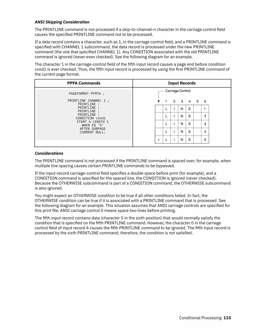
ANSI Skipping Consideration
The PRINTLINE command is not processed if a skip-to-channel-n character in the carriage control fieldcauses the specified PRINTLINE command not to be processed.
If a data record contains a character, such as 1, in the carriage control field, and a PRINTLINE command isspecified with CHANNEL 1 subcommand, the data record is processed under the new PRINTLINEcommand (the one that specified CHANNEL 1). Any CONDITION associated with the old PRINTLINEcommand is ignored (never even checked). See the following diagram for an example.
The character 1 in the carriage-control field of the fifth input record causes a page end before conditioncond1 is ever checked. Thus, the fifth input record is processed by using the first PRINTLINE command ofthe current page format.
PPFA Commands Input Records
PAGEFORMAT PFMTA ;
PRINTLINE CHANNEL 1 ; PRINTLINE ; PRINTLINE ; PRINTLINE ; PRINTLINE ;
CONDITION cond1 START 6 LENGTH 1
WHEN EQ ’5‘ AFTER SUBPAGE CURRENT NULL;
Considerations
The PRINTLINE command is not processed if the PRINTLINE command is spaced over; for example, whenmultiple line spacing causes certain PRINTLINE commands to be bypassed.
If the input-record carriage-control field specifies a double space before print (for example), and aCONDITION command is specified for the spaced line, the CONDITION is ignored (never checked).Because the OTHERWISE subcommand is part of a CONDITION command, the OTHERWISE subcommandis also ignored.
You might expect an OTHERWISE condition to be true if all other conditions failed. In fact, theOTHERWISE condition can be true if it is associated with a PRINTLINE command that is processed. Seethe following diagram for an example. This situation assumes that ANSI carriage controls are specified forthis print file. ANSI carriage control 0 means space two lines before printing.
The fifth input record contains data (character 5 in the sixth position) that would normally satisfy thecondition that is specified on the fifth PRINTLINE command. However, the character 0 in the carriagecontrol field of input record 4 causes the fifth PRINTLINE command to be ignored. The fifth input record isprocessed by the sixth PRINTLINE command; therefore, the condition is not satisfied.
Conditional Processing 115
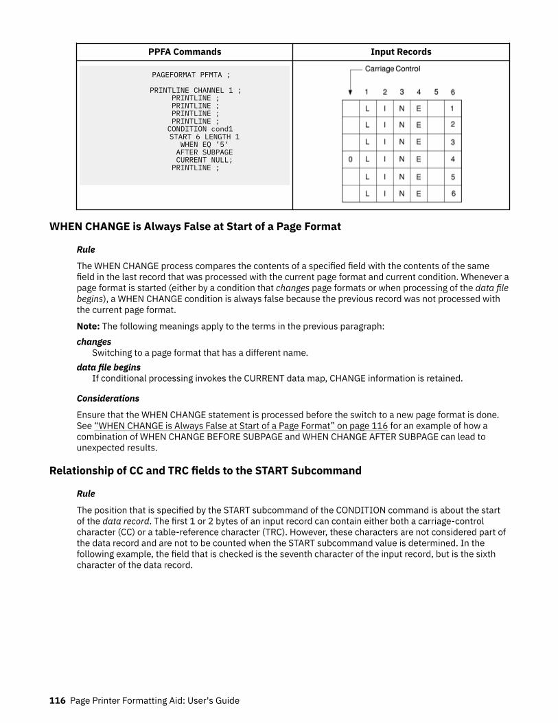
PPFA Commands Input Records
PAGEFORMAT PFMTA ;
PRINTLINE CHANNEL 1 ; PRINTLINE ; PRINTLINE ; PRINTLINE ; PRINTLINE ;
CONDITION cond1 START 6 LENGTH 1
WHEN EQ ’5‘ AFTER SUBPAGE CURRENT NULL;
PRINTLINE ;
WHEN CHANGE is Always False at Start of a Page Format
Rule
The WHEN CHANGE process compares the contents of a specified field with the contents of the samefield in the last record that was processed with the current page format and current condition. Whenever apage format is started (either by a condition that changes page formats or when processing of the data filebegins), a WHEN CHANGE condition is always false because the previous record was not processed withthe current page format.
Note: The following meanings apply to the terms in the previous paragraph:changes
Switching to a page format that has a different name.data file begins
If conditional processing invokes the CURRENT data map, CHANGE information is retained.
Considerations
Ensure that the WHEN CHANGE statement is processed before the switch to a new page format is done.See “WHEN CHANGE is Always False at Start of a Page Format” on page 116 for an example of how acombination of WHEN CHANGE BEFORE SUBPAGE and WHEN CHANGE AFTER SUBPAGE can lead tounexpected results.
Relationship of CC and TRC fields to the START Subcommand
Rule
The position that is specified by the START subcommand of the CONDITION command is about the startof the data record. The first 1 or 2 bytes of an input record can contain either both a carriage-controlcharacter (CC) or a table-reference character (TRC). However, these characters are not considered part ofthe data record and are not to be counted when the START subcommand value is determined. In thefollowing example, the field that is checked is the seventh character of the input record, but is the sixthcharacter of the data record.
116 Page Printer Formatting Aid: User's Guide

PPFA Commands Input Records
PAGEFORMAT PFMTA ;
PRINTLINE CHANNEL 1 ; PRINTLINE ; PRINTLINE ; PRINTLINE ; PRINTLINE ;
CONDITION cond1 START 6 LENGTH 1
WHEN EQ ’5‘ AFTER SUBPAGE CURRENT NULL;
PRINTLINE ;
Using the CONDITION Command to Select a Copy Group and a Page Format
Rules
1. Within the CONDITION command, a copy group and a page format can be specified by using either aspecific name or a parameter (CURRENT or =, FIRST, NEXT), NULL or / can be specified. The use of theNULL or / parameters differs from the use of the others:Others
When any parameter other than NULL or / is specified, the specifications for the copy group or pageformat that is selected replace the current specifications. When the current specifications arereplaced, the action is referred to as starting or restarting the copy group or page format. In AFPterminology, an Invoke Medium Map (IMM) command is generated for a copy group and an InvokeData Map (IDM) command is generated for a page format.
NULL or /When NULL or / is specified, no IMM or IDM is generated and processing continues as if nocondition check was present.
2. The COPYGROUP and the PAGEFORMAT parameters are positional. If both parameters are specified,the COPYGROUP parameter must be first. If you want only to specify the copy group, the PAGEFORMATparameter can be omitted, or specified as NULL or /. However, if you want only to specify the pageformat, the COPYGROUP parameter must be specified as NULL or /.
Considerations
• Starting or Restarting a Copy Group
When a copy group is started (or restarted), the remaining input data is forced to the start on the nextsheet. Therefore, if duplex output was expected, but the copy group is restarted while the front side of asheet is processed, the remaining data starts on the front side of the next sheet rather than on the backside of the current sheet.
See “Duplex Output with Different Front and Back Print Directions” on page 119 for an example.
Furthermore, observe that any copy group action except NULL restarts the page format (see thefollowing item).
• Starting or Restarting a Page Format
When a page format is started (or restarted), the remaining input data is forced to the start on the nextside. Furthermore, that data is processed starting with the first PRINTLINE command in the specifiedpage format. This situation is true even if CURRENT is specified as the page format parameter.
• Not Restarting a Copy Group
If the copy group is not to be restarted, specify NULL or /. Do not specify COPYGROUP NULL orCOPYGROUP /. The following example illustrates this point. The command sequence in the Incorrect
Conditional Processing 117

Format column invokes a copy group named NULL. The command sequence in the Correct Formatcolumn leaves the current copy group active.
Incorrect Format Correct Format
CONDITION condname START ... . . . WHEN ... COPYGROUP NULL . .
CONDITION condname START ... . . . WHEN ... NULL . .
• Not Restarting a Page Format
If the page format is not to be restarted, specify NULL or / (or omit the specification). Do not specifyPAGEFORMAT NULL or PAGEFORMAT /.
The following example illustrates this point. The command sequence in the Incorrect Format columninvokes a page format named NULL. The command sequence in the Correct Format column leaves thecurrent page format active.
Incorrect Format Correct Format
CONDITION condname START ... . . . WHEN ... COPYGROUP CGA PAGEFORMAT NULL . .
CONDITION condname START ... . . . WHEN ... COPYGROUP CGA NULL . .
Variable Length Records and the CONDITION Command
Considerations
The CONDITION command inspects a field that starts at a particular position and extends for a certainlength. If the entire field is not available within the input record, the condition is always false. If the inputfile contains variable-length records, the record might not extend the full length that is specified by theSTART and LENGTH subcommands. In this way, a condition that seems as if it is satisfied can fail.
Truncation of Blanks and the CONDITION Command
Considerations
Truncation occurs when blank characters are removed from the end of records on the spool. If blanktruncation is in effect, the result can be the same as if the input file contained variable-length records.
Blank truncation is a consideration at the time the input records are passed to the print server. In theJES2 environment, blank truncation occurs unless the BLNKTRNC=NO parameter is specified. In the JES3environment, blank truncation occurs unless the TRUNC=NO parameter is specified as part of either theBUFFER or SYSOUT initialization statements. Blank truncation can affect conditional processing becausea field might disappear by being truncated and cause a WHEN/OTHERWISE clause not to run.
118 Page Printer Formatting Aid: User's Guide

Conditional Processing ExamplesThis section provides conditional processing examples. The examples are grouped into functionallysimilar applications and are increasingly complex. The examples are:
• Jog output based on a change in the input data• Duplex output with different front and back print directions• Record reprocessing• Select paper from an alternate bin• Multiple CONDITION commands
Jog Output ExampleFigure 83 on page 119 shows how to jog the printed output, based on a change in the input data.
Copy group CGJOG specifies JOG YES. Page format PFJOG contains a CONDITION command that checksfor any change in positions 8 - 10. If a change is detected, copy group CGJOG is restarted. Observe thatthe only result is to start printing on a new sheet and to jog that sheet.
FORMDEF TJOG; COPYGROUP CGJOG JOG YES; PAGEDEF TJOG; PAGEFORMAT PFJOG WIDTH 11 IN HEIGHT 8.5; PRINTLINE REPEAT 50 CHANNEL 1; CONDITION NUPAGE START 8 LENGTH 3 WHEN CHANGE BEFORE SUBPAGE COPYGROUP CGJOG;
Figure 83: Jog Output Example
Duplex Output with Different Front and Back Print DirectionsFigure 84 on page 120 shows how to establish one print direction on the front side and a different printdirection on the back side of a duplex sheet.
The page definition in this example contains two page formats, each of which has a CONDITIONstatement that always returns a true value. The value is true because the character in position 1 alwayshas a value greater than or equal to hexadecimal zero. Therefore, every time a page change occurs (frontto back, or back to next front) a different page format is started. The different DIRECTION statements inthe two page formats change the layout of the text on the page.
Observe that the COPYGROUP parameter is specified as NULL. If a parameter other than NULL or / isspecified for COPYGROUP, the copy group restarts every time a page change occurs. Because restarting acopy group forces data to a new sheet, duplex printing does not occur.
Conditional Processing 119

FORMDEF XMPDUP DUPLEX NORMAL; PAGEDEF XMPDUP WIDTH 8.5 HEIGHT 11.0; PAGEFORMAT P2FRONT DIRECTION ACROSS; PRINTLINE CHANNEL 1 POSITION 0.75 TOP; CONDITION GOTOBACK START 1 LENGTH 1 WHEN GE X'00' AFTER SUBPAGE NULL PAGEFORMAT P2BACK; PRINTLINE REPEAT 59; PAGEFORMAT P2BACK DIRECTION UP; PRINTLINE CHANNEL 1 POSITION 0.25 TOP; CONDITION GOTOFRNT START 1 LENGTH 1 WHEN GE X'00' AFTER SUBPAGE NULL PAGEFORMAT P2FRONT; PRINTLINE REPEAT 59;
Figure 84: Duplex Output
Record Reprocessing ExampleFigure 85 on page 120 uses the BEFORE SUBPAGE function with record reprocessing because the copygroup and page format cannot be determined until input record 3 for each subpage is read.
Notes:
1. This example includes two subpages.2. The CONDITION command specifies that the action to be done is NEWFORM. Therefore, if the
condition is satisfied, the data in the current subpage is forced to start on the next form. If the data isalready at the start of a new form, no action is done. In other words, a blank page is not generated.
/* Page definition for 2-up printing *//* Test field in line 3 of each subpage *//* Eject to new sheet if the field changes. */ PAGEDEF REPROC WIDTH 10.6 HEIGHT 8.3 DIRECTION DOWN; PAGEFORMAT PFREPROC; /* Definition of first subpage */ PRINTLINE CHANNEL 1 REPEAT 2 POSITION MARGIN TOP; PRINTLINE REPEAT 1 POSITION MARGIN NEXT; CONDITION EJECT START 5 LENGTH 5 WHEN CHANGE BEFORE SUBPAGE NEWFORM; PRINTLINE REPEAT 40 POSITION MARGIN NEXT; ENDSUBPAGE; /* Definition of second subpage */ PRINTLINE CHANNEL 1 REPEAT 2 POSITION 5.3 TOP; PRINTLINE REPEAT 1 POSITION 5.3 NEXT; CONDITION EJECT; PRINTLINE REPEAT 40 POSITION 5.3 NEXT; ENDSUBPAGE;
Figure 85: Record Reprocessing Example
120 Page Printer Formatting Aid: User's Guide

Selecting Paper from an Alternate Bin ExampleFigure 86 on page 121 selects the first sheet from the alternate bin and all other pages from the primarybin. This function is useful when special paper (such as one having the company logo) is used for the firstpage of a document.
Note: If the form defined to each bin is the same form number, bin selection is overridden by the printer.Only the primary bin is selected.
/* The form definition contains two copy groups -- *//* ALTBIN - for the first page *//* PRIBIN - for all other pages */ FORMDEF BINEX DUPLEX NO; COPYGROUP ALTBIN BIN 2; COPYGROUP PRIBIN BIN 1; PAGEDEF BINEX WIDTH 8.3 HEIGHT 10.6; /* Pageformat for first page - bin 2 */ PAGEFORMAT FIRST; PRINTLINE CHANNEL 1 POSITION MARGIN TOP; CONDITION GOTOPRIM START 1 LENGTH 1 WHEN GE X'00' AFTER SUBPAGE COPYGROUP PRIBIN PAGEFORMAT REST; PRINTLINE REPEAT 59; /* Pageformat for all other pages - bin 1 */ PAGEFORMAT REST; PRINTLINE CHANNEL 1 POSITION MARGIN TOP REPEAT 60;
Figure 86: Alternate bin example
Multiple CONDITION CommandsTwo examples are shown here. The first example shows how two CONDITION commands can interact togive unintended results. The second example shows how to use the two CONDITION commands toachieve the correct results.
Example 1 - Incorrect Solution
The example in Figure 87 on page 122 demonstrates how two CONDITION commands can interact to giveunintended results. Specifically, one CONDITION command causes a change of page format and then asecond CONDITION command inspects a field with a WHEN CHANGE subcommand.
The purpose of condition:NEWREP
Starts a new report on a new sheet of paper whenever the specified field changes and jogs the outputso the report can be easily located.
SHIFTB and SHIFTFHandles the situation where all four subpages of the front (or back) contain data.
In this situation, the objective is to change the print direction of the text on the page.
In the situation where both conditions seem to be true at the same time, the results might be unexpected.
Note: Condition SHIFTB (or SHIFTF) takes effect after the current subpage; therefore, it precedes thebefore subpage processing that is defined by condition NEWREP. Because condition SHIFTB starts a newpage format, condition NEWREP returns a false value, and the expected new report processing is notdone.
Conditional Processing 121
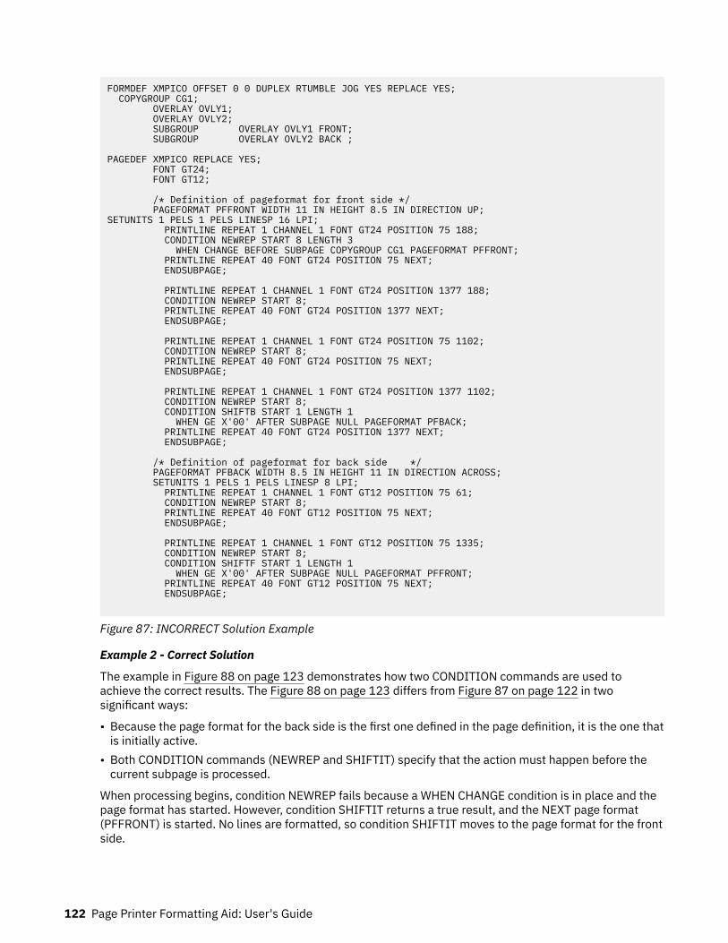
FORMDEF XMPICO OFFSET 0 0 DUPLEX RTUMBLE JOG YES REPLACE YES; COPYGROUP CG1; OVERLAY OVLY1; OVERLAY OVLY2; SUBGROUP OVERLAY OVLY1 FRONT; SUBGROUP OVERLAY OVLY2 BACK ; PAGEDEF XMPICO REPLACE YES; FONT GT24; FONT GT12; /* Definition of pageformat for front side */ PAGEFORMAT PFFRONT WIDTH 11 IN HEIGHT 8.5 IN DIRECTION UP;SETUNITS 1 PELS 1 PELS LINESP 16 LPI; PRINTLINE REPEAT 1 CHANNEL 1 FONT GT24 POSITION 75 188; CONDITION NEWREP START 8 LENGTH 3 WHEN CHANGE BEFORE SUBPAGE COPYGROUP CG1 PAGEFORMAT PFFRONT; PRINTLINE REPEAT 40 FONT GT24 POSITION 75 NEXT; ENDSUBPAGE; PRINTLINE REPEAT 1 CHANNEL 1 FONT GT24 POSITION 1377 188; CONDITION NEWREP START 8; PRINTLINE REPEAT 40 FONT GT24 POSITION 1377 NEXT; ENDSUBPAGE; PRINTLINE REPEAT 1 CHANNEL 1 FONT GT24 POSITION 75 1102; CONDITION NEWREP START 8; PRINTLINE REPEAT 40 FONT GT24 POSITION 75 NEXT; ENDSUBPAGE; PRINTLINE REPEAT 1 CHANNEL 1 FONT GT24 POSITION 1377 1102; CONDITION NEWREP START 8; CONDITION SHIFTB START 1 LENGTH 1 WHEN GE X'00' AFTER SUBPAGE NULL PAGEFORMAT PFBACK; PRINTLINE REPEAT 40 FONT GT24 POSITION 1377 NEXT; ENDSUBPAGE; /* Definition of pageformat for back side */ PAGEFORMAT PFBACK WIDTH 8.5 IN HEIGHT 11 IN DIRECTION ACROSS; SETUNITS 1 PELS 1 PELS LINESP 8 LPI; PRINTLINE REPEAT 1 CHANNEL 1 FONT GT12 POSITION 75 61; CONDITION NEWREP START 8; PRINTLINE REPEAT 40 FONT GT12 POSITION 75 NEXT; ENDSUBPAGE; PRINTLINE REPEAT 1 CHANNEL 1 FONT GT12 POSITION 75 1335; CONDITION NEWREP START 8; CONDITION SHIFTF START 1 LENGTH 1 WHEN GE X'00' AFTER SUBPAGE NULL PAGEFORMAT PFFRONT; PRINTLINE REPEAT 40 FONT GT12 POSITION 75 NEXT; ENDSUBPAGE;
Figure 87: INCORRECT Solution Example
Example 2 - Correct Solution
The example in Figure 88 on page 123 demonstrates how two CONDITION commands are used toachieve the correct results. The Figure 88 on page 123 differs from Figure 87 on page 122 in twosignificant ways:
• Because the page format for the back side is the first one defined in the page definition, it is the one thatis initially active.
• Both CONDITION commands (NEWREP and SHIFTIT) specify that the action must happen before thecurrent subpage is processed.
When processing begins, condition NEWREP fails because a WHEN CHANGE condition is in place and thepage format has started. However, condition SHIFTIT returns a true result, and the NEXT page format(PFFRONT) is started. No lines are formatted, so condition SHIFTIT moves to the page format for the frontside.
122 Page Printer Formatting Aid: User's Guide
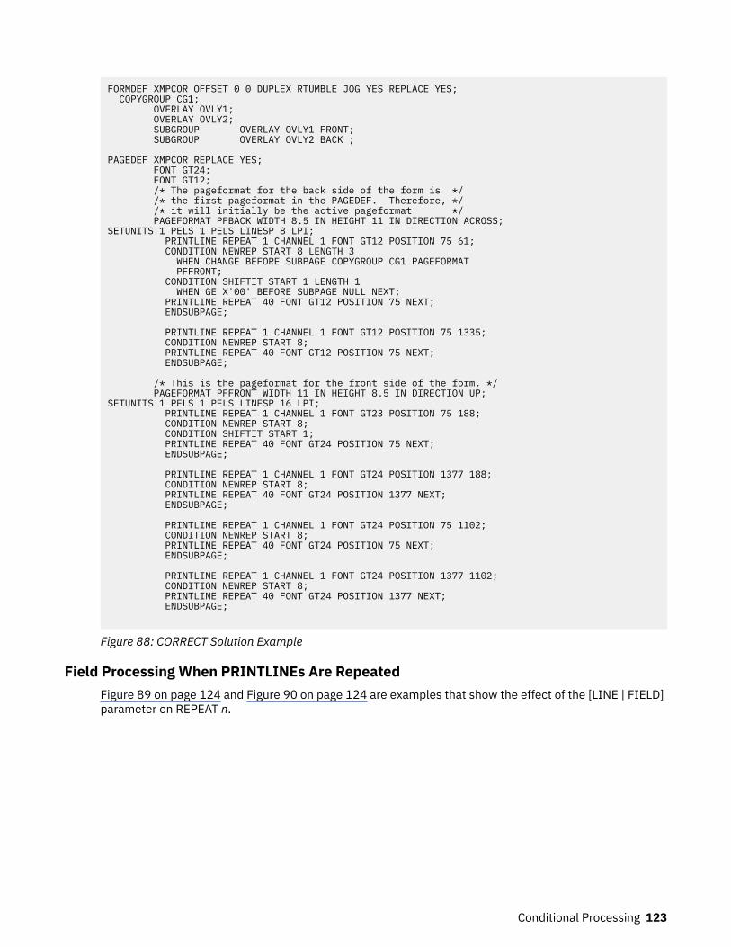
FORMDEF XMPCOR OFFSET 0 0 DUPLEX RTUMBLE JOG YES REPLACE YES; COPYGROUP CG1; OVERLAY OVLY1; OVERLAY OVLY2; SUBGROUP OVERLAY OVLY1 FRONT; SUBGROUP OVERLAY OVLY2 BACK ; PAGEDEF XMPCOR REPLACE YES; FONT GT24; FONT GT12; /* The pageformat for the back side of the form is */ /* the first pageformat in the PAGEDEF. Therefore, */ /* it will initially be the active pageformat */ PAGEFORMAT PFBACK WIDTH 8.5 IN HEIGHT 11 IN DIRECTION ACROSS;SETUNITS 1 PELS 1 PELS LINESP 8 LPI; PRINTLINE REPEAT 1 CHANNEL 1 FONT GT12 POSITION 75 61; CONDITION NEWREP START 8 LENGTH 3 WHEN CHANGE BEFORE SUBPAGE COPYGROUP CG1 PAGEFORMAT PFFRONT; CONDITION SHIFTIT START 1 LENGTH 1 WHEN GE X'00' BEFORE SUBPAGE NULL NEXT; PRINTLINE REPEAT 40 FONT GT12 POSITION 75 NEXT; ENDSUBPAGE; PRINTLINE REPEAT 1 CHANNEL 1 FONT GT12 POSITION 75 1335; CONDITION NEWREP START 8; PRINTLINE REPEAT 40 FONT GT12 POSITION 75 NEXT; ENDSUBPAGE; /* This is the pageformat for the front side of the form. */ PAGEFORMAT PFFRONT WIDTH 11 IN HEIGHT 8.5 IN DIRECTION UP;SETUNITS 1 PELS 1 PELS LINESP 16 LPI; PRINTLINE REPEAT 1 CHANNEL 1 FONT GT23 POSITION 75 188; CONDITION NEWREP START 8; CONDITION SHIFTIT START 1; PRINTLINE REPEAT 40 FONT GT24 POSITION 75 NEXT; ENDSUBPAGE; PRINTLINE REPEAT 1 CHANNEL 1 FONT GT24 POSITION 1377 188; CONDITION NEWREP START 8; PRINTLINE REPEAT 40 FONT GT24 POSITION 1377 NEXT; ENDSUBPAGE; PRINTLINE REPEAT 1 CHANNEL 1 FONT GT24 POSITION 75 1102; CONDITION NEWREP START 8; PRINTLINE REPEAT 40 FONT GT24 POSITION 75 NEXT; ENDSUBPAGE; PRINTLINE REPEAT 1 CHANNEL 1 FONT GT24 POSITION 1377 1102; CONDITION NEWREP START 8; PRINTLINE REPEAT 40 FONT GT24 POSITION 1377 NEXT; ENDSUBPAGE;
Figure 88: CORRECT Solution Example
Field Processing When PRINTLINEs Are RepeatedFigure 89 on page 124 and Figure 90 on page 124 are examples that show the effect of the [LINE | FIELD]parameter on REPEAT n.
Conditional Processing 123
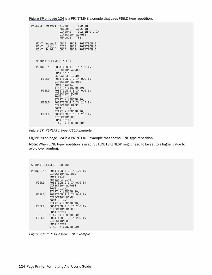
Figure 89 on page 124 is a PRINTLINE example that uses FIELD type repetition.
PAGEDEF rept01 WIDTH 8.0 IN HEIGHT 10.5 IN LINEONE 0.2 IN 0.2 IN DIRECTION ACROSS REPLACE YES; FONT normal CR10 SBCS ROTATION 0; FONT italic CI10 SBCS ROTATION 0; FONT bold CB10 SBCS ROTATION 0; . . . SETUNITS LINESP 6 LPI; PRINTLINE POSITION 1.0 IN 1.0 IN DIRECTION ACROSS FONT bold REPEAT 3 FIELD; FIELD POSITION 0.0 IN 0.0 IN DIRECTION ACROSS FONT normal START * LENGTH 20; FIELD POSITION 2.5 IN 0.0 IN DIRECTION DOWN FONT normal START * LENGTH 20; FIELD POSITION 2.5 IN 2.5 IN DIRECTION BACK FONT normal START * LENGTH 20; FIELD POSITION 0.0 IN 2.5 IN DIRECTION UP FONT normal START * LENGTH 20;
Figure 89: REPEAT n type FIELD Example
Figure 90 on page 124 is a PRINTLINE example that shows LINE type repetition.
Note: When LINE type repetition is used, SETUNITS LINESP might need to be set to a higher value toavoid over printing.
⋮SETUNITS LINESP 3.0 IN; PRINTLINE POSITION 5.0 IN 1.0 IN DIRECTION ACROSS FONT bold REPEAT 3 LINE; FIELD POSITION 0.0 IN 0.0 IN DIRECTION ACROSS FONT normal START * LENGTH 20; FIELD POSITION 2.0 IN 0.0 IN DIRECTION DOWN FONT normal START * LENGTH 20; FIELD POSITION 2.0 IN 2.0 IN DIRECTION BACK FONT normal START * LENGTH 20; FIELD POSITION 0.0 IN 2.0 IN DIRECTION UP FONT normal START * LENGTH 20;
Figure 90: REPEAT n type LINE Example
124 Page Printer Formatting Aid: User's Guide

Figure 91 on page 125 shows an example of Input Line Data.
Field Type Repeat Field Type Repeat Field Type Repeat Field Type RepeatField Type Repeat Field Type Repeat Field Type Repeat Field Type RepeatField Type Repeat Field Type Repeat Field Type Repeat Field Type RepeatLine Type Repeat Line Type Repeat Line Type Repeat Line Type RepeatLine Type Repeat Line Type Repeat Line Type Repeat Line Type RepeatLine Type Repeat Line Type Repeat Line Type Repeat Line Type RepeatField Type Repeat Notice that the fields are repeated based on the priorinstance of the same field, and not the printline. This has advantages ifspecial effects are desired.Line Type Repeat is based on the printline. Good for sales tickets.Generally, this type of repeat needs a SETUNITS LINESP command... ...so that lines won't overlap! This is SETUNITS LINESP 3 IN
Figure 91: (Input) Line Data
When Figure 91 on page 125 is processed by the print server, the output in Figure 92 on page 126 andFigure 93 on page 127 is printed.
Conditional Processing 125
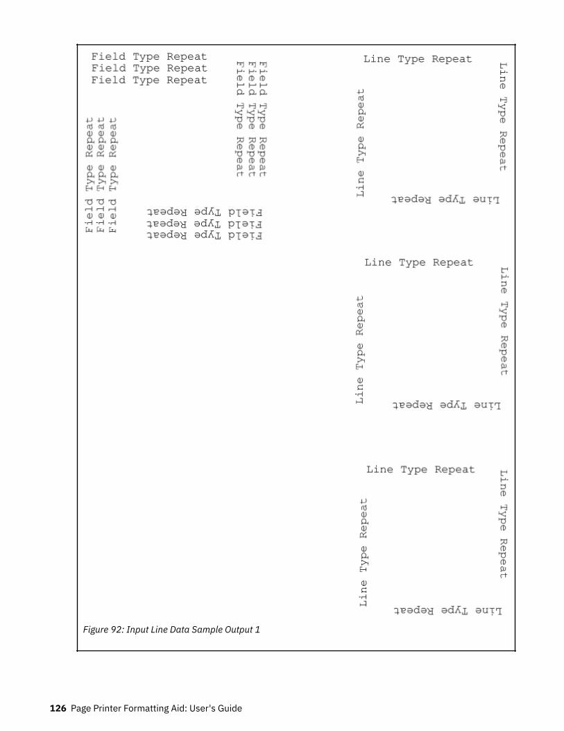
Figure 92: Input Line Data Sample Output 1
126 Page Printer Formatting Aid: User's Guide

Figure 93: Input Line Data Sample Output 2
Conditional Processing 127

128 Page Printer Formatting Aid: User's Guide

Chapter 7. N_UP Printing
With N_UP printing, which is defined in the form definition, you can print up to four pages on a sheet ofpaper in simplex mode and up to eight pages in duplex mode. Each page is independent, allowing the useof different page formats and copy groups for each page. This format provides significantly more flexibilityand function than the traditional multiple-up capability, which is defined in the page definition. See “N_UPCompared to Multiple-up” on page 148 for more differences between N_UP printing and multiple-upprinting.
Two levels of N_UP exist:2
• Basic N_UP supported by older AFP printers: 3825, 3827, 3828, 3829, 3835, and 3900-001. • Enhanced N_UP supported by printers with the Advanced Function Common Control Unit (AFCCU).
N_UP Partitions and Partition ArrangementA key concept in N_UP printing is the partition. In both basic and enhanced N_UP, each sheet of paper isdivided into equal size areas called partitions. Pages are placed in these partitions in sequential order inbasic N_UP. Pages are placed in relation to one or more of these partitions in enhanced N_UP. Knowingthe partition arrangement is critical to designing applications that use N_UP.
Note: If you are using basic N_UP printing with PSF set to DATACK=BLOCK, data must fall within theboundary of the partition. Any data that is placed outside the edge of the partition boundary is not printed,and no error message is generated. However, enhanced N_UP printing allows pages to overlap partitions.The only limits are that the pages must not extend beyond the boundaries of the physical sheet, and thepages must not exceed the total number of N_UP partitions that are specified for the sheet.
The number, size, and position of partitions are determined by three things:
• N_UP value (1, 2, 3, or 4)• Size and shape of the sheet of paper• Form definition presentation options (PRESENT and DIRECTION)
When printing in duplex mode, the same number of partitions is also defined for the back of the sheet. Fornormal duplex, back partitions are placed as if the sheet were flipped around its right side or y-axis. Fortumble duplex, they are placed as if the sheet were flipped around its top edge, or x-axis. See Figure 95on page 130 and Figure 96 on page 131 for illustrations of duplex partitions.
Figure 94 on page 130 through Figure 105 on page 135 show the partition arrangement that results fromevery combination of N_UP value, paper size, and presentation option. The hex values (X'00', X'01', X'04',X'05', X'02', X'03') indicate how the Medium Orientation Triplet (X'68') specifies the position andorientation of the medium presentation space on the physical medium.
Use these figures to determine how your N_UP application is formatted by the printer. In the figures, eachequal-sized partition has a number that indicates its default presentation sequence. The origin for eachpartition is in the same relative position as the origin point shown for the medium. This point serves as theupper-left corner for a page that is printed in the ACROSS (or 0°) printing direction.
2 You must have the correct level of PPFA to generate basic or enhanced N_UP commands and the correctlevel of PSF for your operating system to drive the printer in the basic or enhanced N_UP mode.
© Copyright IBM Corp. 1985, 2016 129

Figure 94: N_UP 1 Partition Numbering, Front Sheet-Side
Figure 95: N_UP 2 Partition Numbering, Front Sheet-Side
130 Page Printer Formatting Aid: User's Guide
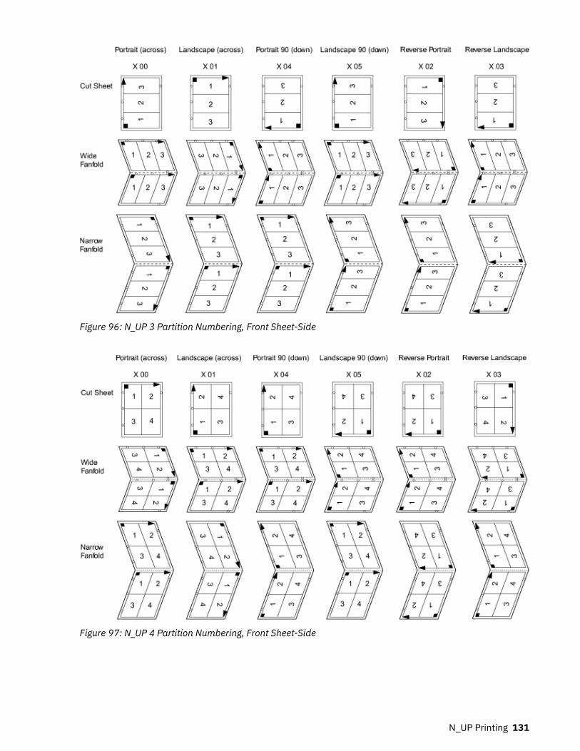
Figure 96: N_UP 3 Partition Numbering, Front Sheet-Side
Figure 97: N_UP 4 Partition Numbering, Front Sheet-Side
N_UP Printing 131

Figure 98: N_UP 1 Partition Numbering, Back Sheet-Side, Normal Duplex
Figure 99: N_UP 2 Partition Numbering, Back Sheet-Side, Normal Duplex
132 Page Printer Formatting Aid: User's Guide

Figure 100: N_UP 3 Partition Numbering, Back Sheet-Side, Normal Duplex
Figure 101: N_UP 4 Partition Numbering, Back Sheet-Side, Normal Duplex
N_UP Printing 133

Figure 102: N_UP 1 Partition Numbering, Back Sheet-Side, Tumble Duplex
Figure 103: N_UP 2 Partition Numbering, Back Sheet-Side, Tumble Duplex
134 Page Printer Formatting Aid: User's Guide

Figure 104: N_UP 3 Partition Numbering, Back Sheet-Side, Tumble Duplex
Figure 105: N_UP 4 Partition Numbering, Back Sheet-Side, Tumble Duplex
N_UP Printing 135
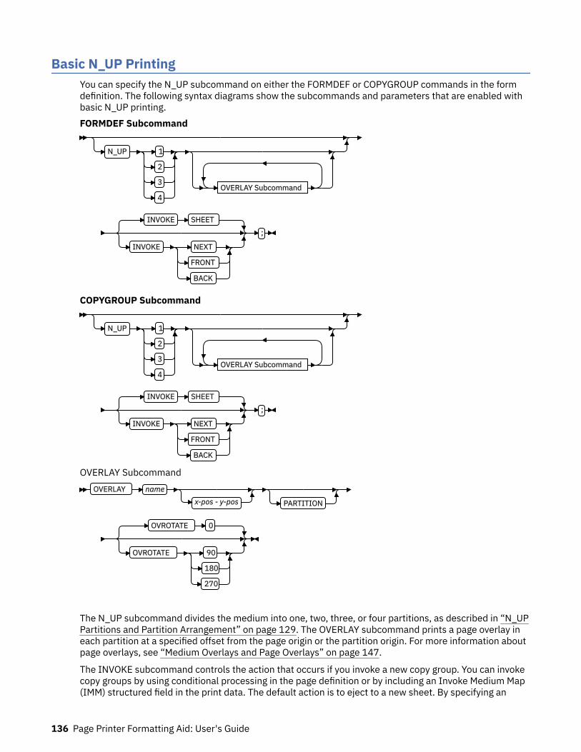
Basic N_UP PrintingYou can specify the N_UP subcommand on either the FORMDEF or COPYGROUP commands in the formdefinition. The following syntax diagrams show the subcommands and parameters that are enabled withbasic N_UP printing.FORMDEF Subcommand
N_UP 1
2
3
4OVERLAY Subcommand
INVOKE SHEET
INVOKE NEXT
FRONT
BACK
;
COPYGROUP Subcommand
N_UP 1
2
3
4OVERLAY Subcommand
INVOKE SHEET
INVOKE NEXT
FRONT
BACK
;
OVERLAY SubcommandOVERLAY name
x-pos - y-pos PARTITION
OVROTATE 0
OVROTATE 90
180
270
The N_UP subcommand divides the medium into one, two, three, or four partitions, as described in “N_UPPartitions and Partition Arrangement” on page 129. The OVERLAY subcommand prints a page overlay ineach partition at a specified offset from the page origin or the partition origin. For more information aboutpage overlays, see “Medium Overlays and Page Overlays” on page 147.
The INVOKE subcommand controls the action that occurs if you invoke a new copy group. You can invokecopy groups by using conditional processing in the page definition or by including an Invoke Medium Map(IMM) structured field in the print data. The default action is to eject to a new sheet. By specifying an
136 Page Printer Formatting Aid: User's Guide

INVOKE subcommand on a COPYGROUP command, you can instead eject to a new N_UP partition, whichmight be on the same sheet. If printing in duplex mode, you can specify whether to eject to a partition onthe front or back side of the sheet.
You must use page overlays instead of medium overlays if you want to change overlays while you areejecting to a new partition. PSF accepts the NEXT, FRONT, and BACK values of the INVOKE subcommandonly if the new copy group has the same medium modifications as the previous copy group. Mediummodifications include duplexing, bin, page offset, N_UP values, presentation, direction, and mediumoverlays. If any of these modifications differ, PSF ejects to a new sheet when the copy group is invoked.
By combining INVOKE with the N_UP OVERLAY subcommand, you can place different page overlays indifferent partitions when you change copy groups. This format is illustrated in “Example 1: Basic N_UPUsing INVOKE and OVERLAY” on page 137.
The following examples show the use of basic N_UP. Because each example builds on the previous one,read them in sequential order to better understand basic N_UP. All the pages that are used in theexamples are formatted in the ACROSS printing direction. Their orientation on the media is the result ofusing the available PRESENT and DIRECTION combinations in the FORMDEF command.
Example 1: Basic N_UP Using INVOKE and OVERLAY
Figure 106: Basic N_UP Using INVOKE and OVERLAY
N_UP Printing 137

FORMDEF TWOUPS ; COPYGROUP A N_UP 2 OVERLAY A INVOKE NEXT ; COPYGROUP B N_UP 2 OVERLAY B INVOKE NEXT ;
Figure 107: Form Definition for Basic N_UP Using INVOKE and OVERLAY
Figure 106 on page 137 shows the INVOKE and OVERLAY functions of basic N_UP printing. SpecifyingINVOKE NEXT on the COPYGROUP command ensures that when the copy group is invoked by an InvokeMedium Map (IMM) structured field with conditional processing, the next page is placed in the nextpartition of the N_UP form.
The OVERLAY subcommand specifies a page overlay, which can be positioned relative to the page originor relative to the partition origin. In basic N_UP, the OVERLAY subcommand prints the overlay with thepage data in every partition on the sheet. However, as shown in this example, by using INVOKE NEXT, theapplication can use different overlays in different partitions.
Example 1 is defined as N_UP 2 simplex with the default PORTRAIT ACROSS presentation, which resultsin the partitions that are illustrated in Figure 106 on page 137. The application uses different pageformats on different application pages. With N_UP, changing page formats ejects to the next partition, justas it ejects to a new page in applications without N_UP.
The application also needs different overlays on different pages. Because the overlays are specified onN_UP in the COPYGROUP subcommand, the application can put different overlay on different pages bychanging copy groups. Without the INVOKE subcommand, changing the copy group forces an eject to anew physical sheet. However, because INVOKE NEXT is specified, the eject is to the next partition.Changing to copy group B after page 1 is written places page 2 in partition 2 of the same physical sheet. Ifthe change is made after a page is placed in partition 2, the eject to the next partition is to partition 1 ofthe next sheet. The page is printed with the overlay that is specified in the new copy group.
Notes:
1. The pages in this example are line-format print data, which is formatted with a page definition. Theexample is the same for MO:DCA data, except that page formats are not used.
2. You can select the copy groups and page formats by including IMM and IDM structured fields in theprint data or by using conditional processing in the page formats.
3. Overlays can be defined as page overlays in the page definition or in the form definition N_UP or PLACEsubcommands. Overlays can also be defined as medium overlays in the form definition SUBGROUPcommand. If you want to change overlays when you are ejecting to a new partition, use page overlaysinstead of medium overlays. See “Medium Overlays and Page Overlays” on page 147 for informationabout page and medium overlays.
Example 2: Basic N_UP Normal Duplex
138 Page Printer Formatting Aid: User's Guide

Figure 108: Basic N_UP Normal Duplex
FORMDEF NUPDUP N_UP 2 PRESENT PORTRAIT DIRECTION ACROSS DUPLEX NORMAL ;
Figure 109: Form Definition for Basic N_UP Normal Duplex
Figure 108 on page 139 shows the partition order for duplexed pages. This figure also shows thepartitions into which the sheet is divided for N_UP 2 with PORTRAIT presentation and ACROSS direction.With normal duplex, the sheet is rotated around its y-axis, which is the right edge of the sheet. The resultis that partition 2 for the back side of the sheet is on the back of partition 1 for the front side, and page 4is on the back of page 1. The tops of pages 3 and 4 are aligned with the tops of pages 1 and 2.
Example 3: Basic N_UP 2 Tumble Duplex
N_UP Printing 139

Figure 110: Basic N_UP 2 Tumble Duplex
FORMDEF NUPTUM N_UP 2 PRESENT PORTRAIT DIRECTION ACROSS DUPLEX TUMBLE ;
Figure 111: Form Definition for Basic N_UP 2 Tumble Duplex
Figure 110 on page 140 shows the partition order for tumble duplex pages. This figure also shows thepartitions into which the sheet is divided for N_UP 2 with PORTRAIT presentation and ACROSS direction.With tumble duplex, the sheet is rotated around its x-axis, which is the top of the sheet. The result is thatpartition 1 of the back of the sheet falls on the back of partition 1 for the front, and page 3 falls on theback of page 1. The tops of pages 3 and 4 are aligned with the bottoms of pages 1 and 2. For moreinformation about normal and tumble duplex printing, see “Normal Duplex and Tumble Duplex” on page13.
Enhanced N_UP PrintingEnhanced N_UP is supported on AFP continuous forms printers. In addition to all the function of basicN_UP, enhanced N_UP includes the powerful PLACE subcommand.
Using the PLACE subcommand, you can place pages in the partitions in any sequence, specify uniqueoverlays for each page, and rotate both the page and the overlays in the partitions. You can place multiplepages in the same partition and no pages in other partitions, and you can extend pages across partitionboundaries. In short, you can place pages of any size at any location on the front or back of the sheet, inany orientation. The only limits are that the pages must not extend outside the boundaries of the physicalsheet, and the pages must not exceed the total number of N_UP partitions that are specified for the sheet.
You use a single PLACE command to place each page of data on the sheet. You must specify the samenumber of PLACE commands as the number of N_UP partitions for the sheet. This specification is requiredfor error recovery and restart integrity. If you do not want to place as many pages as partitions, you can
140 Page Printer Formatting Aid: User's Guide

specify CONSTANT on a PLACE command to indicate that no data is to be placed in the partition. You canspecify the OVERLAY subcommand with the CONSTANT subcommand to place overlays without user'sdata. The following syntax diagrams show the subcommands and parameters that are enabled withenhanced N_UP printing.
For most applications, place constant overlays before you place data on the sheet because the overlay isnot placed until the next page of data is placed. If your application changes copy groups or runs out ofpages on the sheet before it reaches the constant overlay PLACE subcommand, the constant overlay isnot printed. However, if you do not want the overlays to print in these cases, place the constant overlayafter you place the page data.
FORMDEF
N_UP 1
2
3
4OVERLAY Subcommand
PLACE Subcommand
INVOKE SHEET
INVOKE NEXT
FRONT
BACK
COPYGROUP
N_UP 1
2
3
4OVERLAY Subcommand
PLACE Subcommand
INVOKE SHEET
INVOKE NEXT
FRONT
BACK
OVERLAY SubcommandOVERLAY name
x-pos - y-pos PARTITION
OVROTATE 0
OVROTATE 90
180
270
PLACE Subcommand
N_UP Printing 141

1PLACE n
FRONT
BACK CONSTANT OFFSET x-pos y-pos
OVERLAY Subcommand
ROTATION 0
ROTATION 90
180
270
VIEW YES
VIEW NO
Notes:1 The use of the PLACE subcommand indicates enhanced N_UP printing.
The following examples show enhanced N_UP printing. Read these examples in sequence to betterunderstand enhanced N_UP printing.
Example 1: Enhanced N_UP Using PLACE
Figure 112: Enhanced N_UP Using PLACE
FORMDEF BOOKLT DUPLEX NORMAL N_UP 2 /* Page 1 */ PLACE 2 FRONT /* page 2 */ PLACE 1 BACK /* Page 3 */ PLACE 2 BACK /* Page 4 */ PLACE 1 FRONT ;
Figure 113: Form Definition for Enhanced N_UP Using PLACE
Figure 112 on page 142 shows the function of the PLACE subcommand in specifying the sequence ofpartitions into which pages are placed. This example is N_UP 2 duplex. The default partition sequence is
142 Page Printer Formatting Aid: User's Guide

from left to right. Notice that when printing in normal duplex, partition 1 on the back of the sheet alignswith partition 2 on the front of the sheet. See “Example 2: Basic N_UP Normal Duplex” on page 138 and“Example 3: Basic N_UP 2 Tumble Duplex” on page 139 for information on N_UP duplex partitions.
For this booklet, you do not want to print pages in the default order: partitions 1 and 2 on the front,followed by partitions 1 and 2 on the back. Instead, print the pages so that when the sheet is folded, youhave a booklet, with page 1 on the front outside of the booklet, pages 2 and 3 inside the folded booklet,and page 4 on the back outside of the booklet. The form definition that is shown in Figure 113 on page142 uses the PLACE subcommand of enhanced N_UP to place pages in the partitions in the order that isneeded. The application writes the pages in order, page 1 through page 4, and the N_UP form definitionprovides the correct sequencing in the partitions.
Example 2: Enhanced N_UP Using CONSTANT and OVERLAY
Figure 114: Enhanced N_UP Using CONSTANT and OVERLAY
N_UP Printing 143
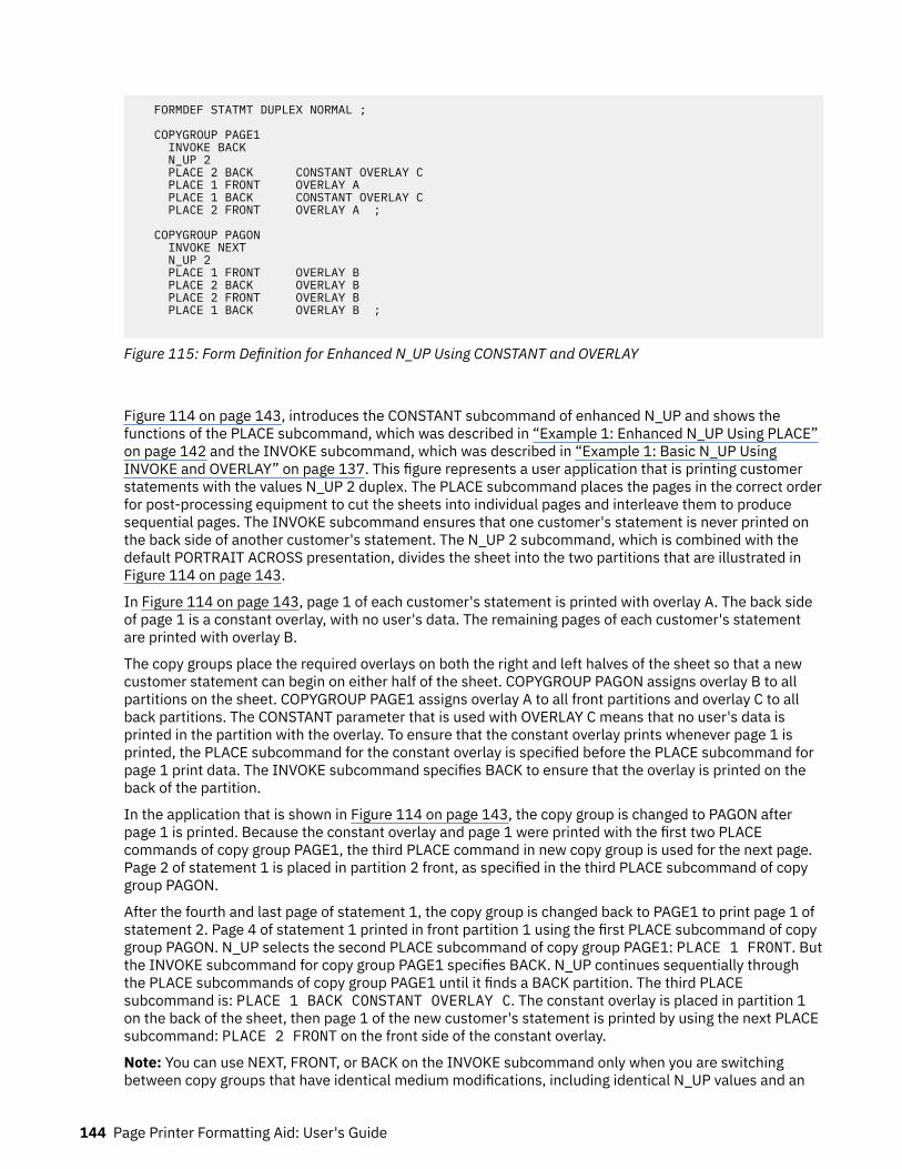
FORMDEF STATMT DUPLEX NORMAL ; COPYGROUP PAGE1 INVOKE BACK N_UP 2 PLACE 2 BACK CONSTANT OVERLAY C PLACE 1 FRONT OVERLAY A PLACE 1 BACK CONSTANT OVERLAY C PLACE 2 FRONT OVERLAY A ; COPYGROUP PAGON INVOKE NEXT N_UP 2 PLACE 1 FRONT OVERLAY B PLACE 2 BACK OVERLAY B PLACE 2 FRONT OVERLAY B PLACE 1 BACK OVERLAY B ;
Figure 115: Form Definition for Enhanced N_UP Using CONSTANT and OVERLAY
Figure 114 on page 143, introduces the CONSTANT subcommand of enhanced N_UP and shows thefunctions of the PLACE subcommand, which was described in “Example 1: Enhanced N_UP Using PLACE”on page 142 and the INVOKE subcommand, which was described in “Example 1: Basic N_UP UsingINVOKE and OVERLAY” on page 137. This figure represents a user application that is printing customerstatements with the values N_UP 2 duplex. The PLACE subcommand places the pages in the correct orderfor post-processing equipment to cut the sheets into individual pages and interleave them to producesequential pages. The INVOKE subcommand ensures that one customer's statement is never printed onthe back side of another customer's statement. The N_UP 2 subcommand, which is combined with thedefault PORTRAIT ACROSS presentation, divides the sheet into the two partitions that are illustrated inFigure 114 on page 143.
In Figure 114 on page 143, page 1 of each customer's statement is printed with overlay A. The back sideof page 1 is a constant overlay, with no user's data. The remaining pages of each customer's statementare printed with overlay B.
The copy groups place the required overlays on both the right and left halves of the sheet so that a newcustomer statement can begin on either half of the sheet. COPYGROUP PAGON assigns overlay B to allpartitions on the sheet. COPYGROUP PAGE1 assigns overlay A to all front partitions and overlay C to allback partitions. The CONSTANT parameter that is used with OVERLAY C means that no user's data isprinted in the partition with the overlay. To ensure that the constant overlay prints whenever page 1 isprinted, the PLACE subcommand for the constant overlay is specified before the PLACE subcommand forpage 1 print data. The INVOKE subcommand specifies BACK to ensure that the overlay is printed on theback of the partition.
In the application that is shown in Figure 114 on page 143, the copy group is changed to PAGON afterpage 1 is printed. Because the constant overlay and page 1 were printed with the first two PLACEcommands of copy group PAGE1, the third PLACE command in new copy group is used for the next page.Page 2 of statement 1 is placed in partition 2 front, as specified in the third PLACE subcommand of copygroup PAGON.
After the fourth and last page of statement 1, the copy group is changed back to PAGE1 to print page 1 ofstatement 2. Page 4 of statement 1 printed in front partition 1 using the first PLACE subcommand of copygroup PAGON. N_UP selects the second PLACE subcommand of copy group PAGE1: PLACE 1 FRONT. Butthe INVOKE subcommand for copy group PAGE1 specifies BACK. N_UP continues sequentially throughthe PLACE subcommands of copy group PAGE1 until it finds a BACK partition. The third PLACEsubcommand is: PLACE 1 BACK CONSTANT OVERLAY C. The constant overlay is placed in partition 1on the back of the sheet, then page 1 of the new customer's statement is printed by using the next PLACEsubcommand: PLACE 2 FRONT on the front side of the constant overlay.
Note: You can use NEXT, FRONT, or BACK on the INVOKE subcommand only when you are switchingbetween copy groups that have identical medium modifications, including identical N_UP values and an
144 Page Printer Formatting Aid: User's Guide

identical number of PLACE subcommands. If the copy groups have different values, the INVOKEcommand causes an eject to a new physical sheet.
Example 3: Enhanced N_UP Asymmetric Pages
Figure 116: Enhanced N_UP Asymmetric Pages
Figure 116 on page 145 shows the flexibility and power of enhanced N_UP printing. With enhanced N_UPprinting, you can place pages relative to any partition on the sheet, front or back, in any sequence. Pagesare not limited by partition boundaries. The only limitations are that pages must not print outside thephysical form boundaries, and you cannot place more pages on a sheet than the number specified in theN_UP subcommand. For an N_UP 4 duplex page, the limit is eight pages total on front and back sidescombined. For N_UP 3 duplex, the limit is six pages on the front and back combined.
Note: In the duplex examples in Figure 116 on page 145 all of the pages can be on one side, with theother side blank.
N_UP Printing 145

FORMDEF ASYMET DUPLEX NORMAL ; COPYGROUP FIRST PRESENT LANDSCAPE DIRECTION ACROSS N_UP 4 /* Constant*/ PLACE 1 BACK OFFSET 4 0 CONSTANT OVERLAY B /* Page 1 */ PLACE 1 FRONT OFFSET 0 0 Overlay A /* Page 2 */ PLACE 1 FRONT OFFSET 12 0 /* Page 3 */ PLACE 1 BACK OFFSET 0 0 /* Page 4 */ PLACE 1 FRONT OFFSET 12 4 /* Page 5 */ PLACE 1 BACK OFFSET 0 4 /* Page 6 */ PLACE 1 FRONT OFFSET 12 8 /* Page 7 */ PLACE 1 BACK OFFSET 0 8 ; COPYGROUP SECOND PRESENT PORTRAIT DIRECTION ACROSS N_UP 3 /* Constant*/ PLACE 1 BACK OFFSET 0 0 CONSTANT OVERLAY C /* Page 8 */ PLACE 1 FRONT OFFSET 0 0 /* Page 9 */ PLACE 1 FRONT OFFSET 0 4 /* Page 10 */ PLACE 1 FRONT OFFSET 6 0 /* Page 11 */ PLACE 1 FRONT OFFSET 6 4 /* 6th place */ PLACE 1 BACK OFFSET 0 0 CONSTANT ;
Figure 117: Form Definition for Enhanced N_UP Asymmetric Pages
To achieve the asymmetrical page placement that is shown in this example, place all the pages relative tothe origin of partition 1 on the front or the back side of the sheet. You can place the pages relative to theorigin of any of the partitions, but if you use partition 1, it simplifies the calculations for page positions.
With N_UP 4, the default PORTRAIT presentation and ACROSS direction place the origin at the upper rightof the partition on wide, continuous-form paper. In this example, specifying LANDSCAPE ACROSS sets theorigin at the upper-left corner to achieve the correct page arrangement.
The coding of the form definition is shown in Figure 116 on page 145. Copy group FIRST specifies N_UP 4,which requires eight PLACE subcommands for the duplex page. Observe that the constant overlay B onthe back of the sheet represents one of the eight PLACE subcommands. COPYGROUP SECOND used forthe second sheet specifies N_UP 3. You must use six PLACE subcommands. Four pages are placed on thefront side, and a constant overlay is placed on the back, with five of the six PLACE subcommands. ACONSTANT page is specified without an overlay to fill the sixth PLACE subcommand. Nothing is printedwith this PLACE subcommand, but it is required to ensure a correct internal page count for recovery andrestart.
Note: In each copy group, the PLACE subcommand for the constant overlay is placed in front of all thePLACE subcommands for page data. This placement ensures that the constant overlay prints if any pagesare printed on the sheet. Otherwise, if you change copy groups or run out of pages before the PLACEcommand for the constant overlay, the overlay does not print.
Additional N_UP ConsiderationsN_UP can affect the scope of other PPFA commands that operate on a page or a medium.COPIES
The COPIES subcommand in the SUBGROUP of the form definition operates on the physical medium.When you specify five copies with N_UP 2, you get five sheets of the N_UP 2 data.
SUPPRESSIONThe SUPPRESSION subcommand in the SUBGROUP of the form definition operates on the physicalmedium. The suppression names in the SUBGROUP operate on all N_UP pages on the sheet.
OVERLAYYou can specify an OVERLAY subcommand in multiple places in the form definition and can alsospecify an overlay in the page definition. The result is either a page overlay or a medium overlay. See
146 Page Printer Formatting Aid: User's Guide

“Medium Overlays and Page Overlays” on page 147 for a description of the differences between thesecommands and the uses of these overlays.
PRESENT DIRECTIONYou use the PRESENT and DIRECTION subcommands of the form definition with the N_UPsubcommand to determine partition arrangement. These commands, which are described in thisupdate guide, now affect all N_UP printers, including cut-sheet printers.
CONDITIONYou can use the CONDITION command of the page definition with N_UP just as you use it with nonN_UP jobs. However, the NEWSIDE and NEWFORM parameters might operate differently than youexpect. NEWSIDE, which is equivalent to invoking a new page format, ejects to the next partition,which might not be on a new side of an N_UP sheet. NEWFORM, which is equivalent to invoking a newcopy group, ejects to a new sheet with basic N_UP. The effect with enhanced N_UP depends on thecoding of the INVOKE subcommand.
Medium Overlays and Page OverlaysAn AFP overlay can be used as a page overlay or as a medium overlay. Different actions are done on thesetwo different types of overlays. Page overlays apply to the page and are placed relative to the page origin.Medium overlays always apply to the entire medium and are placed at the medium origin. When used withN_UP, the medium overlay still applies to the entire sheet of paper, not to the individual partitions.
The same overlay can be either a page overlay or a medium overlay, depending on the method that is usedto invoke it for printing. An overlay that is invoked by a page definition or by an Include Page Overlay (IPO)structured field is always a page overlay. An overlay that is invoked by a form definition without N_UP is
N_UP Printing 147

always a medium overlay. When N_UP is specified in the form definition, you can specify commands toinvoke a page overlay. The following examples show the ways in which overlays can be invoked.
PAGEDEF EXMPL1 ; PAGEFORMAT P2EXMPL1; OVERLAY EXMPL1; /* Allows this page overlay to be */ /* invoked by an IPO structured field */ PRINTLINE REPEAT 60; /* coded in the print data */
Figure 118: Page Overlay Invoked by an IPO Structured Field
PAGEDEF EXMPL2 ; PAGEFORMAT P2EXMPL2; OVERLAY EXMPL2; /* Optional. Stores overlay for reuse */ PRINTLINE REPEAT 1 POSITION 1 IN 1 IN OVERLAY EXMPL2 /* Prints overlay if data prints on printline */ -1 IN -1 IN ; /* Positions overlay relative to printline */ PRINTLINE REPEAT 50;
Figure 119: Page Overlay Invoked by a PRINTLINE Command
FORMDEF EXMPL3 ; COPYGROUP F2EXMPL3 DUPLEX NORMAL ; OVERLAY XMPL3F; /* Allows SUBGROUP to invoke overlay */ OVERLAY XMPL3B; /* Allows SUBGROUP to invoke overlay */ SUBGROUP FRONT OVERLAY XMPL3F; /* Prints overlay on front of every form */ SUBGROUP BACK OVERLAY XMPL3B; /* Prints overlay on back of every form */
Figure 120: Medium Overlay Invoked by a Form Definition
FORMDEF EXMPL4 ; COPYGROUP F2EXMPL4 N_UP 2 OVERLAY EXMPL4 /* Prints overlay with page in every */ 0 0 ; /* Partition at the page origin (0,0) */
Figure 121: Page Overlay in a Simple N_UP Form Definition
FORMDEF EXMPL5 ; COPYGROUP F2EXMPL5 N_UP 2 PLACE 1 OVERLAY XMPL51 /* Prints overlay in Partition 1 */ 0 0 PARTITION /* Places it relative to Partition */ PLACE 2 OVERLAY XMPL52 /* Prints overlay in Partition 2 */ 0 0 PARTITION ; /* Places it relative to Partition */
Figure 122: Page Overlay in an Enhanced N_UP Form Definition
N_UP Compared to Multiple-upWith the addition of the N_UP capability, AFP now provides two methods to format multiple applicationpages on a single sheet:
• N_UP as defined in a form definition• Multiple-up as defined in a page definition
The multiple-up function is available for line-format data that is printed on AFP printers. Multiple-upachieves the appearance of multiple pages on a sheet by formatting multiple groups of print lines as asingle AFP page. The output is still a single AFP page on a side of a sheet, and the entire output isformatted by a single page format. If the application pages within that sheet require different printlayouts, you must design a different page format for all possible arrangements of data. For example, if one
148 Page Printer Formatting Aid: User's Guide

side of a 2-up sheet has 10 different print layouts, you need 100 different page formats to cover all thepossible combinations.
In contrast, N_UP is used to place multiple AFP pages on a side of a sheet, which means that each of theN_UP pages can be formatted with a different page format. You can change page formats between eachN_UP page without ejecting to a new side of the sheet. For the same example with N_UP, you need only10 page formats for a 2-up sheet with 10 different print layouts.
N_UP also means that you can place multiple pages of fully composed AFP data (or MO:DCA data) on asingle sheet. This was not possible with the multiple-up function that is defined in the page definitionbecause AFP data does not use a page definition.
N_UP Printing 149

150 Page Printer Formatting Aid: User's Guide

Chapter 8. AFP Color Management
You can use various ways to print color data with Advanced Function Presentation (AFP). However, toimplement an AFP color printing solution with full color management, you must use color managementresources (CMRs). Also, for best results, install all of your color images as data objects and associateCMRs with them.
Color management resourcesColor management resources (CMRs) are the foundation of color management in AFP print systems. CMRsare AFP resources that provide all the color management information, such as ICC profiles and halftones,that an AFP system needs to process a print job and maintain consistent color from one device to another.
CMRs share some characteristics with other AFP resources, but are different in some important ways.
CMRs are similar to other AFP resources in these ways:
• CMRs can be associated with elements of a print job at various levels of the hierarchy.
Normal hierarchy rules apply, so CMRs specified at lower levels override the ones that are specified atthe higher level. For example, a CMR set on a data object overrides a default CMR set on a print file.
• CMRs can be included in a print job in an inline resource group and referenced in a form definition, pageenvironment, object environment, or an include Object (IOB) structured field.
Note: CMRs can vary in size from several hundred bytes to several megabytes. If your print job usesrelatively few CMRs, including them in the print file might not have an impact on the performance ofyour system. However, if your print job uses more than 10 CMRs, the size of the print job can increase somuch that file transfer rates and network traffic are affected.
• CMRs can be stored centrally in a resource library, so you do not need to include them in every print job.You can configure all your print servers so they can access the CMRs.
• For the print server to find CMRs, the resource library must be listed in the AFP resource search path onthe print server.
CMRs are different from other AFP resources in these ways:
• You cannot copy CMRs into a resource library as you can other AFP resources.
To store CMRs in a central resource library, you must install them using an application such as AFPResource Installer.
• CMRs and data objects must be stored in resource libraries that have resource access tables (RATs).
AFP Resource Installer creates the RAT when CMRs and data objects are installed. For best results,install CMRs and data objects in separate resource libraries and store resources that do not requireRATs (such as form definitions, page definitions, and overlays) in other resource libraries.
• CMRs installed in a resource library can have names longer than 8 characters, and you can use thenames in the print data stream. These names are created when you install the CMR with AFP ResourceInstaller and are UTF-16BE encoded.
Types of CMRsDifferent situations call for different types of CMRs. Some CMRs are created by product manufacturers soyou can download and use them, while others are created by your printer or other color managementsoftware. If you have the appropriate information, you can also create CMRs yourself.
Some CMRs are used to interpret input files (similar to the function done by ICC input profiles), whileothers are used to prepare the final print job output for a specific printer (similar to the function done byICC output profiles).
© Copyright IBM Corp. 1985, 2016 151
Color conversion CMR
Color conversion CMRs are used to convert colors to and from the ICC Profile Connection Space (PCS), adevice-independent color space. You can use them to prepare images for color or grayscale printing.
Color conversion CMRs are an essential element of any AFP color management system because they areICC profiles encapsulated in AFP structures. The AFP structures add information that your colormanagement system can use, but it leaves the ICC profile unaltered.
You can use color conversion CMRs to produce consistent colors on different devices. In a color system,color conversion CMRs help ensure that the colors on your monitor are as close as possible to the onesthat are printed. If you move the print job to a different printer, the colors are adjusted again to match thenew printer.
In a grayscale system, color conversion CMRs map colors to appropriate shades of gray to produce high-quality black and white images.
Pass-through CMRs are color conversion CMRs that indicate that no color processing is done if the colorspace of the presentation device is the same as the color space of the CMR. Pass-through CMRs containno data.
Link color conversion CMR
Link color conversion CMRs combine the processing information that is required to directly convert animage from the color space of an input device to the color space of the output device. Essentially, linkcolor conversion CMRs replace a pair of color conversion CMRs.
Converting color images to and from the PCS takes a significant amount of processing resources, in partbecause the process includes two conversions. Link color conversion CMRs combine the two conversionsand make them more efficient. The printer can use the link color conversion CMR to convert colors directlyfrom the color space of the input device to the color space of the output device with the same colorfidelity they would have if the printer did both of the conversions. As a result, link color conversion CMRscan improve system performance.
The two types of link color conversion CMRs are:Link CMRs
Link (LK) CMRs are unique. You cannot create a link CMR yourself and you do not include references tolink CMRs in your print jobs. The print system creates and uses link CMRs automatically.
If you use AFP Resource Installer, link CMRs are generated automatically when you create or install acolor conversion CMR. As a result, your resource library always contains link CMRs for everycombination of color conversion CMRs in audit (input) and instruction (output) processing modes.When link CMRs are created, AFP Resource Installer marks them as capturable, so the printer cansave them to be used in other print jobs.
If you do not use AFP Resource Installer, your printer might create link CMRs when it processes printjobs. For example, if you send a print job to an InfoPrint 5000, the printer controller looks at the auditcolor conversion CMRs that are specified. Then, the print controller looks at the link CMRs that it hasavailable to find one that combines the audit color conversion CMR with the appropriate instructioncolor conversion CMR. If it does not find one, the print controller creates the link CMR and uses it. Theprint controller might save the link CMRs that it creates, but they can be removed during normaloperation; for example, if the printer runs out of storage or is shut down. If the link is removed, theprinter must create a new link CMR the next time it is needed.
When a link CMR is created, the print system evaluates the conversion algorithms to and from thePCS. The system then combines the algorithms, so a data object can be converted directly from onecolor space to the other without being converted to the PCS.
Device link CMRsDevice link (DL) CMRs use an ICC device link profile to convert directly from an input color space to anoutput color space without reference to an audit-mode or instruction-mode CMR. An ICC device linkprofile is a special ICC profile that is used to convert the input device color space to the color space ofan output or display device. ICC device link profiles are not embedded in images.
152 Page Printer Formatting Aid: User's Guide
You can create, install, and uninstall device link CMRs yourself. Device link CMRs are referenced in theMO:DCA data stream and take precedence over audit color conversion CMRs. A device link CMRspecifies its own rendering intent, which is indicated in the header of the ICC device link profile. Thisrendering intent overrides any other rendering intent that is active.
The biggest advantage of using device link CMRs is that they preserve the black channel (Kcomponent) of the input color space when they are converting from CMYK to CMYK.
Halftone CMRs
Halftone CMRs carry the information that a printer uses to convert print jobs into a pattern of dots that itcan put on paper. Halftone CMRs can be used with both color and grayscale print jobs.
Halftone CMRs generally specify the line screen frequency, halftone pattern, and rotation of the halftonethat they carry. Device-specific halftone CMRs might also include the printer resolution.
A printer that uses AFP color management to print color or grayscale print jobs must use a halftone CMRto convert the print job into a format that the printer can reproduce in ink or toner. If a halftone CMR is notspecified in the print job, the printer applies a default halftone CMR.
Note: If you send your color print jobs to an InfoPrint 5000 printer, halftones are applied by the printengine. As a result, the printer ignores halftone CMR requests.
You can associate device-specific halftone CMRs or generic halftone CMRs with print jobs:
• If you know which printer is printing the job, you can associate a device-specific halftone CMR with theprint job (or with AFP resources inside the print job). The printer uses the halftone CMR that you specify.
• If you do not know which printer is printing the job, but you want to ensure that it uses a halftone CMRthat has certain characteristics, such as a specific line screen frequency, you can associate a generichalftone CMR with the print job.
Because it is difficult to know which halftone CMRs must be used for the current conditions on the currentprinter, specify halftone CMRs generically and let the printer choose the most appropriate CMR that isavailable.
Generic halftone CMRs
You can use generic halftone CMRs when you want to choose one or more characteristics of the halftoneCMR for a print job, but you do not know exactly which halftone CMRs are available.
When a print job specifies a generic halftone CMR, the print server looks in the resource library forhalftone CMRs that match the printer device type and model. If the print server finds an appropriate CMR,it sends the device-specific halftone CMR to the printer with the print job. If the print server does not findan appropriate halftone CMR, it sends the generic halftone CMR to the printer.
If a print job that arrives at the printer is requesting a generic halftone CMR, the printer compares therequested characteristics with the available device-specific halftone CMRs. If a match exists, the printeruses the selected device-specific halftone CMR when it processes the print job. If no match exists, theprinter uses the halftone CMR whose line screen frequency value is closest to the one requested.
The Color Management Object Content Architecture (CMOCA) defines a variety of generic halftone CMRs,which cover the most common line screen frequencies and halftone types. A print server that supportsCMOCA can interpret generic halftone CMRs if it has device-specific halftone CMRs available to it in aresource library. If you use AFP Resource Installer, the generic halftone CMRs are installed in everyresource library that you create and populate by using AFP Resource Installer.
Printers that support CMOCA must be able to interpret those generic CMRs and associate them withdevice-specific halftone CMRs.
Indexed CMRs
Indexed (IX) CMRs map indexed colors in the data to presentation device colors or colorant combinations.
Indexed CMRs provide rules about how to render indexed colors. Indexed CMRs apply to indexed colorsthat are specified by using the highlight color space. They do not apply to indexed colors found within
AFP Color Management 153
PostScript or other non-IPDS data objects. For Indexed CMRs, both instruction and audit processingmodes are valid. However, only indexed CMRs with an instruction processing mode are used; indexedCMRs with an audit processing mode are ignored. The tags in the indexed CMR let the CMR use variouscolor spaces in the descriptions. These color spaces can be grayscale, named colorants, RGB, CMYK, orCIELAB.
Tone transfer curve CMRs
Tone transfer curve CMRs are used to carry tone transfer curve information for an AFP print job, so youcan modify the values of a particular color component and adjust the appearance of some of the colors byincreasing or decreasing the amount of ink that is used to emphasize or reduce the effects of dot gain onthe final output.
Like halftone CMRs, tone transfer curve CMRs are associated with print jobs specifically or generically. Ifthey are specified generically, the print server looks in the resource library for tone transfer curve CMRsthat match the printer device type and model. If the print server finds an appropriate CMR, it sends thedevice-specific tone transfer curve CMR to the printer with the print job. If the print server does not findan appropriate tone transfer curve CMR, it sends the generic tone transfer curve CMR to the printer.
If a print job that arrives at the printer is requesting a generic tone transfer curve CMR, the printercompares the requested characteristics with the device-specific tone transfer curve CMRs that it hasavailable. If a match exists, the print server or printer uses the selected device-specific tone transfercurve CMR when it processes the print job. If the printer cannot find a good match for the generic tonetransfer curve CMR, it ignores the request and uses its default tone transfer curve CMR.
The Color Management Object Content Architecture (CMOCA) defines several generic tone transfer curveCMRs with different appearance values. You can use the appearance values to specify how to print yourjob in regard to the reported dot gain of the printer.
Generic tone transfer curves can be used to select these appearance values:Dark
The output is adjusted to show a dot gain of 33% for a 50% dot.Accutone
The output is adjusted to show a dot gain of 22% for a 50% dot.Highlight Midtone
The output is adjusted to show a dot gain of 14% for a 50% dot. This appearance might be used toemphasize the brightest part of an image.
StandardThe output is adjusted enough to account for the effects of dot gain, effectively counteracting the dotgain.
If you use AFP Resource Installer, it installs the generic tone transfer curve CMRs on your systemautomatically.
CMR processing modesCMR processing modes tell the print system how to apply a CMR to the print data it is associated with. Youspecify a CMR processing mode whenever you specify a CMR, although not all modes are valid for all CMRtypes.
Audit processing mode
CMRs with the audit processing mode refer to processing that is already applied to a resource. In mostcases, audit CMRs describe input data and are similar to ICC input profiles.
The audit processing mode is used primarily with color conversion CMRs. In audit processing mode, thoseCMRs indicate which ICC profile must be applied to convert the data into the Profile Connection Space(PCS).
For example, to take a photograph with a digital camera and then include the photograph in an AFP printjob, you can use AFP Resource Installer to:
154 Page Printer Formatting Aid: User's Guide
1. Create a color conversion CMR by using the ICC profile of your camera.2. Install your photograph in a resource library.3. Associate the color conversion CMR with the data object, indicating the audit processing mode.
Then, you create a print job that includes the data object. When the print job is processed, the systemuses the color conversion CMR to convert the colors in the image into the PCS. The colors can then beconverted into the color space of the printer that is printing it.
Instruction processing mode
CMRs with the instruction processing mode refer to processing that is done to prepare the resource for aspecific printer by using a certain paper or another device. Generally, instruction CMRs refer to outputdata and are similar to ICC output profiles.
The instruction processing mode is used with color conversion, tone transfer curve, and halftone CMRs. Ininstruction processing mode, these CMRs indicate how the system must convert a resource so it printscorrectly on the target printer. The manufacturer of your printer needs to provide ICC profiles or variousCMRs that you can use. Those ICC profiles and CMRs might be installed in the printer controller, includedwith the printer on a CD, or available for download from the manufacturer's website.
If you send a color AFP print job to a printer that supports AFP Color Management, color conversion andtone transfer curve CMRs in instruction processing mode can be associated with the job. When the printerprocesses the print job, it applies the CMRs in this order:
1. Color conversion CMRs in audit processing mode to convert the resources into the ICC ProfileConnection Space (PCS)
2. Color conversion and tone transfer curve CMRs in instruction processing mode to convert theresources into the color space of the printer
3. Halftone CMR in instruction processing mode to convert the job pages from their digital format into thepattern of dots that the printer can produce
In some cases, CMRs that are used as instruction CMRs can be used as audit CMRs. For example, if yousend a large print job to a high-speed printer, the images in the print job are converted into the color spaceof that printer by using a color conversion CMR with the instruction processing mode. However, if youmust reprint part of the job on a different printer, the system must convert the print job into the colorspace of the second printer. In that case, the color conversion CMR of the first printer is used in the auditprocessing mode to move the images back into the PCS. Then, the system uses a color conversion CMR ofthe second printer in instruction mode to convert the images into its color space.
Link processing mode
CMRs with the link processing mode are used to link an input color space in the presentation data(sometimes defined by an audit CMR) to the output color space of the presentation device (sometimesdefined by an instruction CMR). Only link (LK) and device link (DL) CMRs can be used in link processingmode.
Whenever you install or uninstall audit or instruction color conversion CMRs in your resource library byusing AFP Resource Installer or a similar software product, the AFP Resource Installer automaticallycreates or deletes link (LK) CMRs for every combination of audit and instruction color conversion CMR.
When a print job calls for a specified audit-instruction combination, the print server checks the resourcelibrary for a link (LK) CMR for that combination. If the print server finds an appropriate link CMR, it sendsthe CMR to the printer with the print job. Your printer can use the link (LK) CMRs whenever a print jobindicates that it uses a particular combination of audit and instruction CMRs.
If you do not use AFP Resource Installer or a similar program to install your resources, your color printermust either create link (LK) CMRs while it processes your print jobs or convert the colors in your jobstwice, first from the original color space to the PCS and then from the PCS to the color space of the printer.
AFP Color Management 155

CMR creation and installationDevice manufacturers and groups that support AFP color standards create CMRs that you can use in yourcolor printing systems. You can also create CMRs yourself, based on your needs.
The AFP Consortium, the group that defined the AFP Color Management Object Content Architecture(CMOCA), identified a set of color conversion CMRs that are most often used in audit processing mode.The set includes color conversion CMRs for common color spaces, such as:
• Adobe RGB (1998)• sRGB• SMPTE-C RGB• SWOP CMYK
The standard CMRs are included with AFP Resource Installer, although they are not installed by default.You can install the standard CMRs that you plan to use. In addition, AFP Resource Installer automaticallyinstalls all the generic halftone and tone transfer curve CMRs in any resource library you create.
You can download device-specific CMRs for printers, such as the InfoPrint 5000, from the RicohProduction Print Software (http://rpp.ricoh-usa.com/products/software/).
If you need more CMRs, you can create them using wizards that are provided in AFP Resource Installer.See online help for details about the wizard.
If you use AFP Resource Installer to create a CMR, the software automatically installs the CMR in aresource library. You can also use AFP Resource Installer to install CMRs that you get from your printermanufacturer.
Data objectsPresentation data objects contain a single type of data (such as GIF, JPEG, PNG, and TIFF images) andcan be used in your print jobs. These data objects can be placed directly in a page or overlay or can bedefined as resources and included in pages or overlays. Using a data object as a resource is more efficientwhen that object appears more than once in a print job; resources are downloaded to the printer once andreferenced as needed.
Data objects can either be included inline with a print job or installed in a resource library by usingsoftware such as AFP Resource Installer. If you install your data objects in a resource library, you canassociate color conversion CMRs with them.
See “Resource library management” on page 158 for more information about characteristics of resourcelibraries.
Types of data objectsImage data objects can be stored in a number of different formats, including AFPC JPEG Subset, EPS, GIF,IOCA, PDF, PNG, and TIFF. These image types are device-independent so they can be used by differentsystems and still be interpreted consistently.AFPC JPEG Subset (JPEG)
AFPC (AFP Consortium) JPEG Subset files, formerly called JPEG File Interchange Format (JFIF) files,are bitmap image files that are compressed by using Joint Photographic Experts Group (JPEG)compression. As a result, AFPC JPEG Subset files are most commonly referred to as JPEG files. JPEGfiles most commonly use the file extension .jpg, but can also use .jpeg, .jpe, .jfif, and .jif.
JPEG compression deletes information that it considers unnecessary from images when it convertsthem. JPEG files vary from having small amounts of compression to having large amounts ofcompression. The more an image is compressed, the more information is lost. If the image iscompressed only once, no noticeable effect typically exists on the image. However, if the image iscompressed and decompressed repeatedly, the effects of deleting information become morenoticeable.
156 Page Printer Formatting Aid: User's Guide

JPEG compression is commonly used for photographs, especially photographs that are transmitted ordisplayed on web pages. The compression makes the files small enough to transmit on a networkefficiently, but leaves enough information that the image is still visually appealing.
Encapsulated PostScript (EPS)EPS is a PostScript graphics file format that follows conventions that Adobe Systems defined. EPS filessupport embedded ICC profiles.
Graphics Interchange Format (GIF)GIF files are bitmap image files that are limited to a palette of 256 RGB colors. Because of the limitedcolor range that it can contain, GIF is not a good format for reproducing photographs, but it is typicallyadequate for logos or charts. GIF images are widely used on the internet because they are typicallysmaller than other image formats. GIF files use the file extension .gif.
Image Object Content Architecture (IOCA)IOCA is an architecture that provides a consistent way to represent images, including conventions anddirections for processing and exchanging image information. The architecture defines imageinformation independently of all data objects and environments in which it might exist and uses self-identifying terms; each field contains a description of itself along with its contents.
Portable Document Format (PDF)PDF is a standard file format that Adobe Systems developed.
PDF files can be used and stored on various operating systems and contain all the required image andfont data. Design attributes in a PDF are kept in a single compressed package.
Note: Single-page and multiple-page PDF files can be used as data objects in AFP print jobs.
Portable Network Graphics (PNG)PDF is a standard file format that Adobe Systems developed.
PNG files are bitmap image files that support indexed colors, palette-based images with 24-bit RGB or32-bit RGBA colors, grayscale images, an optional alpha channel, and lossless compression. PNG isused for transferring images on the internet, but not for print graphics. PNG files use the fileextension .png.
Tagged Image File Format (TIFF)TIFF files are bitmap image files that include headers to provide more information about the image.
TIFF files use the file extensions .tif or .tiff. TIFF files support embedded ICC profiles. If an ICC profileis embedded in a file, the characteristics of the input color space are known whenever the file is used;however, the profiles increase the file size. When you save a file in the TIFF format, you can usevarious compression algorithms.
Note: Single-image and multiple-image TIFF files can be used as data objects in AFP print jobs.
Not all printers support all types of data objects.
The embedded ICC profiles in EPS, JPEG, and TIFF files contain the information that a printer uses toconvert colors in the image from an input color space into the Profile Connection Space (PCS). The inputcolor space might be an industry-standard space or it can describe the color reproduction capabilities of adevice, such as a scanner, digital camera, monitor, or printer.
Data object creation and installationYou can use a wide variety of software applications to create or manipulate images to include in print jobs.If you want to store them in central resource repositories, you can use AFP Resource Installer to installthem.
Data object creation
Most types of data objects are images of some kind. They might be photographs that are taken with adigital camera, charts or diagrams that are generated by a software tool, or digital drawings created withgraphics software. Regardless of how images are created, you generally need to manipulate them toinclude them in print jobs.
AFP Color Management 157

The changes include:
• Convert the image into a file type that is appropriate for printing. For example, the file types that manygraphics applications (such as Adobe Illustrator, CorelDRAW, and Corel Paint Shop Pro) use to storeimages while you work on them are not appropriate for printing. To use images that you create by usingany of those programs, you can save or export those files as a different file type, such as EPS, JPEG, orTIFF.
• Make sure that your image files are associated with an appropriate color space or input profile. Followthe instructions that are provided with your graphics software to set up color management, includinginstalling and using ICC profiles for digital cameras and monitors, and customizing color managementsettings. The instructions also explain how to change the color profile that an image uses and how tosave an image with an embedded profile.
• Follow the tips and best practices that are provided in “Tips and best practices” on page 159 forcreating images and managing them as data object resources.
Data object installation
You can use AFP Resource Installer to install your images in a resource library. AFP Resource Installerincludes wizards that can guide you through the process of installing an image as a data object. When youinstall an EPS, JPEG, or TIFF image with an embedded ICC profile with AFP Resource Installer, you canchoose how you want to handle the profile:
• Leave the profile in the file without creating a CMR.• Leave the profile in the file, but also copy the profile and create a CMR from the copy. Associate the new
CMR with the data object.• Remove the profile from the file (to reduce the file size) and make the profile into a CMR. Associate the
new CMR with the data object.
Resource library managementIf you store CMRs and data objects in central resource libraries, you must understand some of thecharacteristics of resource libraries to make sure that your resources are available when and where youneed them.
Resource libraries that AFP Resource Installer creates use a resource access table (RAT) as the index ofthe resource library. The index is stored as a file in the library that it refers to. You must store CMRs inresource libraries that use a RAT. It is also a good idea to store data objects in resource libraries that use aRAT.
When you use AFP Resource Installer to create a resource library, it creates a RAT and stores it in thelibrary. When you install a CMR or data object, AFP Resource Installer updates the RAT with informationabout the resource. When a print server looks in a resource library for a resource, it first looks in the RATto see whether the resource is listed.
The print server relies on the RAT; if it is incorrect, the print server cannot find resources in the resourcelibrary. As a result, you must always use AFP Resource Installer to manage your resource libraries,including to:Add CMRs and data objects to a resource library.
Do not copy CMRs or data objects directly into the resource libraries that AFP Resource Installer uses.If you copy CMRs or data objects into these resource libraries, the RAT is not updated so the printserver cannot use it to find the CMRs or data objects.
Modify properties of data objects and CMRs listed in the RAT.Do not directly edit the RAT or any of the files in a resource library. Do not replace an existing versionof a CMR or data object with a new version by copying the new version directly into the resourcelibrary; use AFP Resource Installer to update the resource.
158 Page Printer Formatting Aid: User's Guide
Install CMRs or data objects in a different resource library or replicate a resource library in adifferent location.
Do not copy CMRs or data objects from a resource library and store them in another location.
For more information about completing these tasks, see AFP Resource Installer help system.
Tips and best practicesThe following general guidelines about creating and managing images and other color resources canimprove the performance of your AFP color printing system.
Tips for images
To optimize the performance of your AFP color printing system, follow the following guidelines for creatingand including images in print jobs.
When you want to use color images in your print jobs:
• Get the original electronic versions of images instead of scanning existing documents.
Almost unnoticeable specks of color in the background of images that are scanned can greatly increasethe size of the image. If you must scan an image, use an image-editing tool to clean up the backgroundas much as possible.
• Save all images in the same standard color space so you need only one input profile for all of them.
Adobe RGB (1998) is the recommended color space for images that are to be printed.• Flatten multi-layer images (images you create in graphics tools such as Adobe Illustrator and Corel
Paint Shop Pro) before you include them in print jobs.
Unflattened images are large and more difficult to work with. Save a copy of the original image for futureediting, but flatten the version that you include in your print job.
Tips for resources
To optimize the performance of your AFP color printing system, follow the following guidelines formanaging color resources.
You can use AFP Resource Installer to:
• Install all the CMRs for your printer in a resource library.• Install the data objects that you use frequently in a resource library.• Mark the CMRs and data objects that are reused regularly as non-private, capturable resources so they
can be saved on the printer and used for other print jobs without being downloaded every time.
Note: This option is not advisable for secure resources, such as signature files.• Install CMRs and data objects in resource libraries that the print server can access, so they need only to
be stored in one place and can be used by all print servers.• Associate audit color conversion CMRs with data objects that require color management, so the
embedded profiles can be removed from the image files.
CMRTAGFIDELITY Subcommand (FORMDEF)The following subcommand on the FORMDEF command describes the exception continuation andreporting rules for Color Management Resource (CMR) tag exceptions. A CMR tag exception is detectedwhen an unsupported CMR tag is encountered in a CMR. Having CMR tag fidelity allows more CMR tags tobe added in the future without necessarily causing exceptions in printers that do not support the newtags.
AFP Color Management 159
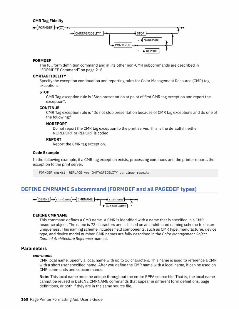
CMR Tag FidelityFORMDEF …
CMRTAGFIDELITY STOP
CONTINUE
NOREPORT
REPORT
FORMDEFThe full form definition command and all its other non-CMR subcommands are described in“FORMDEF Command” on page 216.
CMRTAGFIDELITYSpecify the exception continuation and reporting rules for Color Management Resource (CMR) tagexceptions.STOP
CMR Tag exception rule is "Stop presentation at point of first CMR tag exception and report theexception".
CONTINUECMR Tag exception rule is "Do not stop presentation because of CMR tag exceptions and do one ofthe following:"NOREPORT
Do not report the CMR tag exception to the print server. This is the default if neitherNOREPORT or REPORT is coded.
REPORTReport the CMR tag exception.
Code Example
In the following example, if a CMR tag exception exists, processing continues and the printer reports theexception to the print server.
FORMDEF cmrXm1 REPLACE yes CMRTAGFIDELITY continue report;
DEFINE CMRNAME Subcommand (FORMDEF and all PAGEDEF types)DEFINE cmr-lname CMRNAME 'cmr-name'
X16'cmr-name'
DEFINE CMRNAMEThis command defines a CMR name. A CMR is identified with a name that is specified in a CMRresource object. The name is 73 characters and is based on an architected naming scheme to ensureuniqueness. This naming scheme includes field components, such as CMR type, manufacturer, devicetype, and device model number. CMR names are fully described in the Color Management ObjectContent Architecture Reference manual.
Parameterscmr-lname
CMR local name. Specify a local name with up to 16 characters. This name is used to reference a CMRwith a short user specified name. After you define the CMR name with a local name, it can be used onCMR commands and subcommands.
Note: This local name must be unique throughout the entire PPFA source file. That is, the local namecannot be reused in DEFINE CMRNAME commands that appear in different form definitions, pagedefinitions, or both if they are in the same source file.
160 Page Printer Formatting Aid: User's Guide
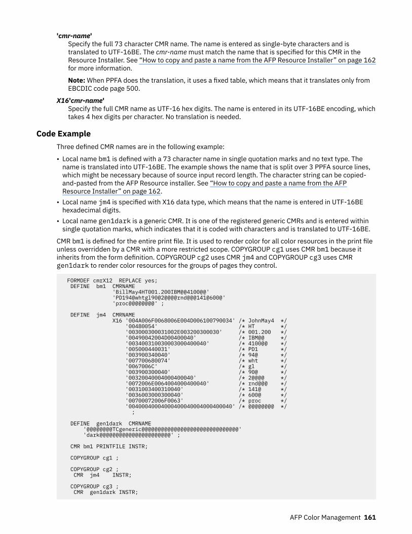
'cmr-name'Specify the full 73 character CMR name. The name is entered as single-byte characters and istranslated to UTF-16BE. The cmr-name must match the name that is specified for this CMR in theResource Installer. See “How to copy and paste a name from the AFP Resource Installer” on page 162for more information.
Note: When PPFA does the translation, it uses a fixed table, which means that it translates only fromEBCDIC code page 500.
X16'cmr-name'Specify the full CMR name as UTF-16 hex digits. The name is entered in its UTF-16BE encoding, whichtakes 4 hex digits per character. No translation is needed.
Code ExampleThree defined CMR names are in the following example:
• Local name bm1 is defined with a 73 character name in single quotation marks and no text type. Thename is translated into UTF-16BE. The example shows the name that is split over 3 PPFA source lines,which might be necessary because of source input record length. The character string can be copied-and-pasted from the AFP Resource installer. See “How to copy and paste a name from the AFPResource Installer” on page 162.
• Local name jm4 is specified with X16 data type, which means that the name is entered in UTF-16BEhexadecimal digits.
• Local name gen1dark is a generic CMR. It is one of the registered generic CMRs and is entered withinsingle quotation marks, which indicates that it is coded with characters and is translated to UTF-16BE.
CMR bm1 is defined for the entire print file. It is used to render color for all color resources in the print fileunless overridden by a CMR with a more restricted scope. COPYGROUP cg1 uses CMR bm1 because itinherits from the form definition. COPYGROUP cg2 uses CMR jm4 and COPYGROUP cg3 uses CMRgen1dark to render color resources for the groups of pages they control.
FORMDEF cmrX12 REPLACE yes; DEFINE bm1 CMRNAME 'BillMay4HT001.200IBM@@4100@@' 'PD194@whtgl90@2@@@@rnd@@@141@600@' 'proc@@@@@@@@' ;
DEFINE jm4 CMRNAME X16 '004A006F0068006E004D006100790034' /* JohnMay4 */ '00480054' /* HT */ '003000300031002E003200300030' /* 001.200 */ '00490042004D00400040' /* IBM@@ */ '003400310030003000400040' /* 4100@@ */ '005000440031' /* PD1 */ '003900340040' /* 94@ */ '007700680074' /* wht */ '0067006C' /* gl */ '003900300040' /* 90@ */ '00320040004000400040' /* 2@@@@ */ '0072006E0064004000400040' /* rnd@@@ */ '0031003400310040' /* 141@ */ '0036003000300040' /* 600@ */ '00700072006F0063' /* proc */ '00400040004000400040004000400040' /* @@@@@@@@ */ ;
DEFINE gen1dark CMRNAME '@@@@@@@@TCgeneric@@@@@@@@@@@@@@@@@@@@@@@@@@@@@@' 'dark@@@@@@@@@@@@@@@@@@@@@@' ;
CMR bm1 PRINTFILE INSTR;
COPYGROUP cg1 ;
COPYGROUP cg2 ; CMR jm4 INSTR;
COPYGROUP cg3 ; CMR gen1dark INSTR;
AFP Color Management 161
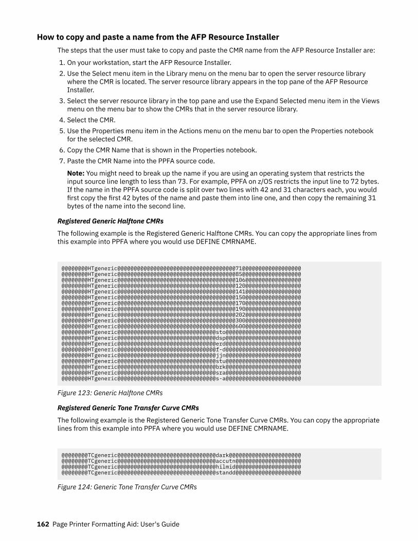
How to copy and paste a name from the AFP Resource InstallerThe steps that the user must take to copy and paste the CMR name from the AFP Resource Installer are:
1. On your workstation, start the AFP Resource Installer.2. Use the Select menu item in the Library menu on the menu bar to open the server resource library
where the CMR is located. The server resource library appears in the top pane of the AFP ResourceInstaller.
3. Select the server resource library in the top pane and use the Expand Selected menu item in the Viewsmenu on the menu bar to show the CMRs that in the server resource library.
4. Select the CMR.5. Use the Properties menu item in the Actions menu on the menu bar to open the Properties notebook
for the selected CMR.6. Copy the CMR Name that is shown in the Properties notebook.7. Paste the CMR Name into the PPFA source code.
Note: You might need to break up the name if you are using an operating system that restricts theinput source line length to less than 73. For example, PPFA on z/OS restricts the input line to 72 bytes.If the name in the PPFA source code is split over two lines with 42 and 31 characters each, you wouldfirst copy the first 42 bytes of the name and paste them into line one, and then copy the remaining 31bytes of the name into the second line.
Registered Generic Halftone CMRs
The following example is the Registered Generic Halftone CMRs. You can copy the appropriate lines fromthis example into PPFA where you would use DEFINE CMRNAME.
@@@@@@@@HTgeneric@@@@@@@@@@@@@@@@@@@@@@@@@@@@@@@@@@@@71@@@@@@@@@@@@@@@@@@@@@@@@@@HTgeneric@@@@@@@@@@@@@@@@@@@@@@@@@@@@@@@@@@@@85@@@@@@@@@@@@@@@@@@@@@@@@@@HTgeneric@@@@@@@@@@@@@@@@@@@@@@@@@@@@@@@@@@@@106@@@@@@@@@@@@@@@@@@@@@@@@@HTgeneric@@@@@@@@@@@@@@@@@@@@@@@@@@@@@@@@@@@@120@@@@@@@@@@@@@@@@@@@@@@@@@HTgeneric@@@@@@@@@@@@@@@@@@@@@@@@@@@@@@@@@@@@141@@@@@@@@@@@@@@@@@@@@@@@@@HTgeneric@@@@@@@@@@@@@@@@@@@@@@@@@@@@@@@@@@@@150@@@@@@@@@@@@@@@@@@@@@@@@@HTgeneric@@@@@@@@@@@@@@@@@@@@@@@@@@@@@@@@@@@@170@@@@@@@@@@@@@@@@@@@@@@@@@HTgeneric@@@@@@@@@@@@@@@@@@@@@@@@@@@@@@@@@@@@190@@@@@@@@@@@@@@@@@@@@@@@@@HTgeneric@@@@@@@@@@@@@@@@@@@@@@@@@@@@@@@@@@@@202@@@@@@@@@@@@@@@@@@@@@@@@@HTgeneric@@@@@@@@@@@@@@@@@@@@@@@@@@@@@@@@@@@@300@@@@@@@@@@@@@@@@@@@@@@@@@HTgeneric@@@@@@@@@@@@@@@@@@@@@@@@@@@@@@@@@@@@600@@@@@@@@@@@@@@@@@@@@@@@@@HTgeneric@@@@@@@@@@@@@@@@@@@@@@@@@@@@@@sto@@@@@@@@@@@@@@@@@@@@@@@@@@@@@@@HTgeneric@@@@@@@@@@@@@@@@@@@@@@@@@@@@@@dsp@@@@@@@@@@@@@@@@@@@@@@@@@@@@@@@HTgeneric@@@@@@@@@@@@@@@@@@@@@@@@@@@@@@erd@@@@@@@@@@@@@@@@@@@@@@@@@@@@@@@HTgeneric@@@@@@@@@@@@@@@@@@@@@@@@@@@@@@f-d@@@@@@@@@@@@@@@@@@@@@@@@@@@@@@@HTgeneric@@@@@@@@@@@@@@@@@@@@@@@@@@@@@@jjn@@@@@@@@@@@@@@@@@@@@@@@@@@@@@@@HTgeneric@@@@@@@@@@@@@@@@@@@@@@@@@@@@@@stu@@@@@@@@@@@@@@@@@@@@@@@@@@@@@@@HTgeneric@@@@@@@@@@@@@@@@@@@@@@@@@@@@@@brk@@@@@@@@@@@@@@@@@@@@@@@@@@@@@@@HTgeneric@@@@@@@@@@@@@@@@@@@@@@@@@@@@@@sra@@@@@@@@@@@@@@@@@@@@@@@@@@@@@@@HTgeneric@@@@@@@@@@@@@@@@@@@@@@@@@@@@@@s-a@@@@@@@@@@@@@@@@@@@@@@@
Figure 123: Generic Halftone CMRs
Registered Generic Tone Transfer Curve CMRs
The following example is the Registered Generic Tone Transfer Curve CMRs. You can copy the appropriatelines from this example into PPFA where you would use DEFINE CMRNAME.
@@@@@@@@TCgeneric@@@@@@@@@@@@@@@@@@@@@@@@@@@@@@dark@@@@@@@@@@@@@@@@@@@@@@@@@@@@@@TCgeneric@@@@@@@@@@@@@@@@@@@@@@@@@@@@@@accutn@@@@@@@@@@@@@@@@@@@@@@@@@@@@TCgeneric@@@@@@@@@@@@@@@@@@@@@@@@@@@@@@hilmid@@@@@@@@@@@@@@@@@@@@@@@@@@@@TCgeneric@@@@@@@@@@@@@@@@@@@@@@@@@@@@@@standd@@@@@@@@@@@@@@@@@@@@
Figure 124: Generic Tone Transfer Curve CMRs
162 Page Printer Formatting Aid: User's Guide
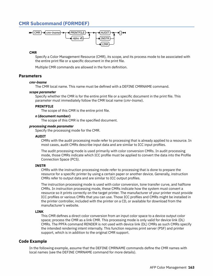
CMR Subcommand (FORMDEF)CMR cmr-lname PRINTFILE
n (doc #)
AUDIT
INSTR
LINK
;
CMRSpecify a Color Management Resource (CMR), its scope, and its process mode to be associated withthe entire print file or a specific document in the print file.
Multiple CMR commands are allowed in the form definition.
Parameterscmr-lname
The CMR local name. This name must be defined with a DEFINE CMRNAME command.scope parameter
Specify whether the CMR is for the entire print file or a specific document in the print file. Thisparameter must immediately follow the CMR local name (cmr-lname).PRINTFILE
The scope of this CMR is the entire print file.n (document number)
The scope of this CMR is the specified document.processing mode parameter
Specify the processing mode for the CMR.AUDIT
CMRs with the audit processing mode refer to processing that is already applied to a resource. Inmost cases, audit CMRs describe input data and are similar to ICC input profiles.
The audit processing mode is used primarily with color conversion CMRs. In audit processingmode, those CMRs indicate which ICC profile must be applied to convert the data into the ProfileConnection Space (PCS).
INSTRCMRs with the instruction processing mode refer to processing that is done to prepare theresource for a specific printer by using a certain paper or another device. Generally, instructionCMRs refer to output data and are similar to ICC output profiles.
The instruction processing mode is used with color conversion, tone transfer curve, and halftoneCMRs. In instruction processing mode, these CMRs indicate how the system must convert aresource so it prints correctly on the target printer. The manufacturer of your printer must provideICC profiles or various CMRs that you can use. Those ICC profiles and CMRs might be installed inthe printer controller, included with the printer on a CD, or available for download from themanufacturer's website.
LINKThis CMR defines a direct color conversion from an input color space to a device output colorspace; process the CMR as a link CMR. This processing mode is only valid for device link (DL)CMRs. The PPFA command RENDER is not used with device link (DL) CMRs as such CMRs specifythe intended rendering intent internally. This function requires print server (PSF) and printersupport, which is in addition to the original CMR support.
Code ExampleIn the following example, assume that the DEFINE CMRNAME commands define the CMR names withlocal names (see the DEFINE CMRNAME command for more details).
AFP Color Management 163
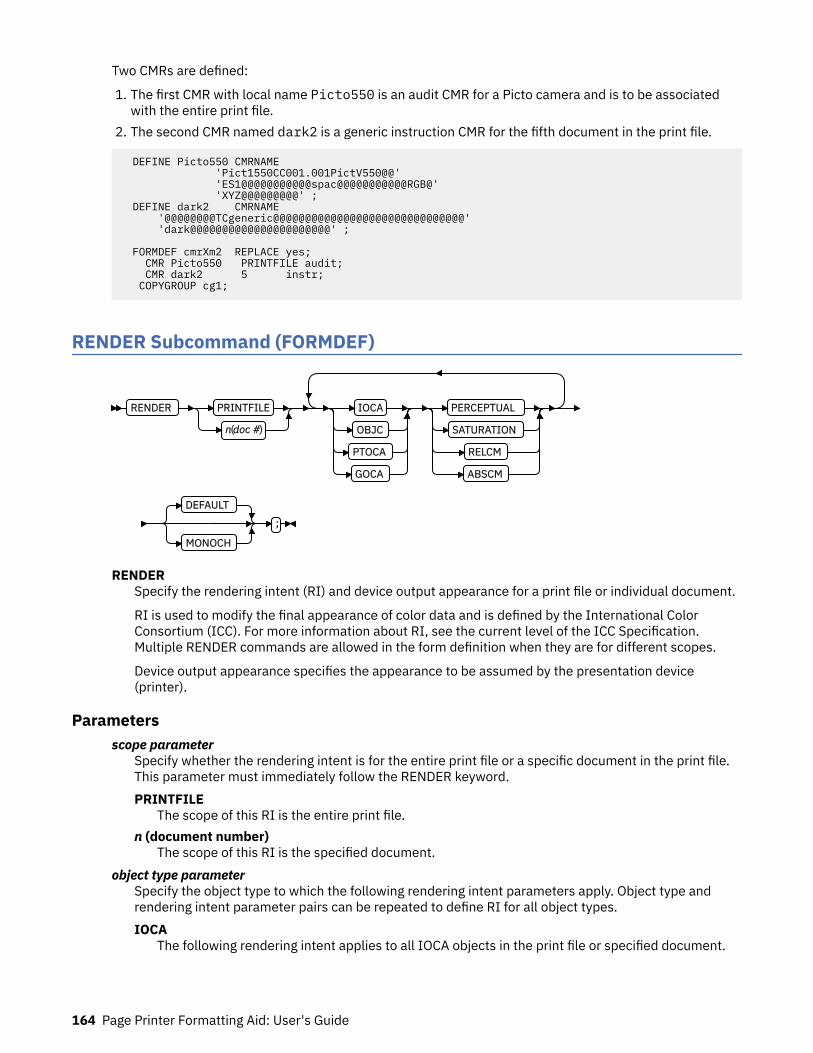
Two CMRs are defined:
1. The first CMR with local name Picto550 is an audit CMR for a Picto camera and is to be associatedwith the entire print file.
2. The second CMR named dark2 is a generic instruction CMR for the fifth document in the print file.
DEFINE Picto550 CMRNAME 'Pict1550CC001.001PictV550@@' 'ES1@@@@@@@@@@@spac@@@@@@@@@@@RGB@' 'XYZ@@@@@@@@@' ; DEFINE dark2 CMRNAME '@@@@@@@@TCgeneric@@@@@@@@@@@@@@@@@@@@@@@@@@@@@@' 'dark@@@@@@@@@@@@@@@@@@@@@@' ;
FORMDEF cmrXm2 REPLACE yes; CMR Picto550 PRINTFILE audit; CMR dark2 5 instr; COPYGROUP cg1;
RENDER Subcommand (FORMDEF)
RENDER PRINTFILE
n(doc #)
IOCA
OBJC
PTOCA
GOCA
PERCEPTUAL
SATURATION
RELCM
ABSCM
DEFAULT
MONOCH
;
RENDERSpecify the rendering intent (RI) and device output appearance for a print file or individual document.
RI is used to modify the final appearance of color data and is defined by the International ColorConsortium (ICC). For more information about RI, see the current level of the ICC Specification.Multiple RENDER commands are allowed in the form definition when they are for different scopes.
Device output appearance specifies the appearance to be assumed by the presentation device(printer).
Parametersscope parameter
Specify whether the rendering intent is for the entire print file or a specific document in the print file.This parameter must immediately follow the RENDER keyword.PRINTFILE
The scope of this RI is the entire print file.n (document number)
The scope of this RI is the specified document.object type parameter
Specify the object type to which the following rendering intent parameters apply. Object type andrendering intent parameter pairs can be repeated to define RI for all object types.IOCA
The following rendering intent applies to all IOCA objects in the print file or specified document.
164 Page Printer Formatting Aid: User's Guide

OBJCThe following rendering intent applies to all non-OCA object containers in the print file or specifieddocument.
PTOCAThe following rendering intent applies to all PTOCA objects in the print file or specified document.
GOCAThe following rendering intent applies to all GOCA objects in the print file or specified document.
rendering intent parameterSpecify the rendering intent for the preceding object type.PERCEPTUAL
Perceptual rendering intent. It can be abbreviated as PERCP. With this rendering intent, gamutmapping is vendor-specific, and colors are adjusted to give a pleasing appearance. This intent istypically used to render continuous-tone images.
SATURATIONSaturation rendering intent. It can be abbreviated as SATUR. With this rendering intent, gamutmapping is vendor-specific, and colors are adjusted to emphasize saturation. This intent results invivid colors and is typically used for business graphics.
RELCMMedia-relative colorimetric rendering intent. In-gamut colors are rendered accurately, and out-of-gamut colors are mapped to the nearest value within the gamut. Colors are rendered in regard tothe source white point and are adjusted for the media white point. Therefore, colors that areprinted on two different media with different white points do not match colorimetrically, but mightmatch visually. This intent is typically used for vector graphics.
ABSCMICC-absolute colorimetric rendering intent. In-gamut colors are rendered accurately, and out-of-gamut colors are mapped to the nearest value within the gamut. Colors are rendered only inregard to the source white point and are not adjusted for the media white point. Therefore, colorsthat are printed on two different media with different white points must match colorimetrically,but might not match visually. This intent is typically used for logos.
device output appearance parameterSpecify one of a set of architected appearances to be assumed by the presentation device.DEFAULT
Default appearance. The device assumes its normal appearance. For example, the defaultappearance of a process-color printer would be to generate full color output.
MONOCHMonochrome appearance. The device assumes a monochrome appearance such that the device'sdefault color is used for presentation. The device can simulate color values with gray scale byusing the default color, or it can simulate color values by substituting the default color, or it canuse some combination of the two.
Code ExampleFour RENDER subcommands are defined in the following example. Multiple RENDER subcommands forthe same scope are not allowed:
1. The first RENDER is for the entire print file, and defines the RI for IOCA objects as perceptual. It alsospecifies the device output appearance to be monochromatic.
2. The second RENDER is for the document 5, and defines the RI for non-OCA objects as saturation. Italso specifies the device output appearance as the device default, which means full color output for acolor printer.
3. The third RENDER is for the document 7, and defines the RI for PTOCA objects as media-relativecolorimetric. No device output appearance is specified.
AFP Color Management 165

4. The fourth RENDER is for the document 9, and defines the RI for all supported objects. It also specifiesthe device output appearance to be monochromatic.
FORMDEF cmrXm3 REPLACE yes; RENDER PRINTFILE IOCA perceptual MONOCH ; RENDER 5 OBJC saturation DEFAULT; RENDER 7 PTOCA relcm ; RENDER 9 OBJC abscm IOCA relcm PTOCA satur GOCA percp MONOCH; COPYGROUP cg1;
CMR Subcommand (COPYGROUP)CMR cmr-lname AUDIT
INSTR
LINK
;
CMRSpecify a Color Management Resource (CMR) and its process mode for the collection of pages that aredefined by a COPYGROUP. The command is to be placed after the COPYGROUP command for which itis intended.
Multiple CMR commands are allowed in the form definition.
Parameterscmr-lname
The CMR local name. This name must be defined with a DEFINE CMRNAME command.processing mode parameter
Specify the processing mode for the CMR.AUDIT
CMRs with the audit processing mode refer to processing that is already applied to a resource. Inmost cases, audit CMRs describe input data and are similar to ICC input profiles.
The audit processing mode is used primarily with color conversion CMRs. In audit processingmode, those CMRs indicate which ICC profile must be applied to convert the data into the ProfileConnection Space (PCS).
INSTRCMRs with the instruction processing mode refer to processing that is done to prepare theresource for a specific printer by using a certain paper or another device. Generally, instructionCMRs refer to output data and are similar to ICC output profiles.
The instruction processing mode is used with color conversion, tone transfer curve, and halftoneCMRs. In instruction processing mode, these CMRs indicate how the system must convert aresource so it prints correctly on the target printer. The manufacturer of your printer must provideICC profiles or various CMRs that you can use. Those ICC profiles and CMRs might be installed inthe printer controller, included with the printer on a CD, or available for download from themanufacturer's website.
LINKThis CMR defines a direct color conversion from an input color space to a device output colorspace; process the CMR as a link CMR. This processing mode is only valid for device link (DL)CMRs. The PPFA command RENDER is not used with device link (DL) CMRs as such CMRs specifythe intended rendering intent internally. This function requires print server (PSF) and printersupport, which is in addition to the original CMR support.
Code ExampleThe following example shows two copy groups with defined CMRs.
166 Page Printer Formatting Aid: User's Guide

• COPYGROUP picto defines a CMR for presenting digital pictures that are taken with a Picto camera (anaudit CMR), and a generic instruction CMR, which is replaced with a device-specific CMR or the defaultprinter CMR.
• COPYGROUP snap defines a CMR for presenting digital pictures that are taken with a Snap camera (anaudit CMR), and a generic instruction CMR, which are replaced with a device-specific CMR or the defaultprinter CMR.
FORMDEF cmrX13 REPLACE yes; DEFINE Picto550 CMRNAME 'Pict1550CC001.001PictV550@@' 'ES1@@@@@@@@@@@spac@@@@@@@@@@@RGB@' 'XYZ@@@@@@@@@' ; DEFINE snap1 CMRNAME '[email protected]@DSC-R1' 'CS@@@@@@@@@@@@spac@@@@@@@@@@@RGB@' 'XYZ@@@@@@@@@';
COPYGROUP picto ; CMR picto550 AUDIT; COPYGROUP snap ; CMR snap1 AUDIT;
RENDER Subcommand (COPYGROUP)
RENDER IOCA
OBJC
PTOCA
GOCA
PERCEPTUAL
SATURATION
RELCM
ABSCM
DEFAULT
MONOCH
;
RENDERSpecify the Rendering Intent (RI) and device output appearance for the collection of pages presentedby a COPYGROUP. The command is to be placed after the COPYGROUP command for which it isintended.
Parametersobject type parameters
Specify the object type to which the following rendering intent parameters apply. Object type andrendering intent parameter pairs can be repeated to define RI for all object types.IOCA
The following rendering intent applies to all IOCA objects in the pages that are presented by theCOPYGROUP.
OBJCThe following rendering intent applies to all non-OCA object in the pages that are presented by theCOPYGROUP.
PTOCAThe following rendering intent applies to all PTOCA objects in the pages that are presented by theCOPYGROUP.
GOCAThe following rendering intent applies to all GOCA objects in the pages that are presented by theCOPYGROUP.
rendering intent parameterSpecify the rendering intent for the preceding object type.
AFP Color Management 167

PERCEPTUALPerceptual rendering intent. It can be abbreviated as PERCP. With this rendering intent, gamutmapping is vendor-specific, and colors are adjusted to give a pleasing appearance. This intent istypically used to render continuous-tone images.
SATURATIONSaturation rendering intent. It can be abbreviated as SATUR. With this rendering intent, gamutmapping is vendor-specific, and colors are adjusted to emphasize saturation. This intent results invivid colors and is typically used for business graphics.
RELCMMedia-relative colorimetric rendering intent. In-gamut colors are rendered accurately, and out-of-gamut colors are mapped to the nearest value within the gamut. Colors are rendered in regard tothe source white point and are adjusted for the media white point. Therefore, colors that areprinted on two different media with different white points do not match colorimetrically, but mightmatch visually. This intent is typically used for vector graphics.
ABSCMICC-absolute colorimetric rendering intent. In-gamut colors are rendered accurately, and out-of-gamut colors are mapped to the nearest value within the gamut. Colors are rendered only inregard to the source white point and are not adjusted for the media white point. Therefore, colorsthat are printed on two different media with different white points must match colorimetrically,but might not match visually. This intent is typically used for logos.
device output appearance parameterSpecify one of a set of architected appearances to be assumed by the presentation device.DEFAULT
Default appearance. The device assumes its normal appearance. For example, the defaultappearance of a process-color printer would be to generate full color output.
MONOCHMonochrome appearance. The device assumes a monochrome appearance such that the device'sdefault color is used for presentation. The device can simulate color values with grayscale byusing the default color, or it can simulate color values by substituting the default color, or it canuse some combination of the two.
Code ExampleThe following example shows two copy groups, one with IOCA RI defined and monochromaticappearance, and one with RI for all object types and the device default appearance.
FORMDEF cmrXm4 REPLACE yes; COPYGROUP cg1; RENDER IOCA percp MONOCH ; COPYGROUP cg2; RENDER DEFAULT OBJC abscm IOCA relcm PTOCA satur GOCA percp;
CMR Subcommand (PAGEFORMAT)CMR cmr-lname AUDIT
INSTR
LINK
;
CMRAssociate a Color Management Resource (CMR) with pages that are presented by a PAGEFORMAT. Thecommand is to follow the PAGEFORMAT command. Multiple CMR commands are allowed in aPAGEFORMAT.
168 Page Printer Formatting Aid: User's Guide
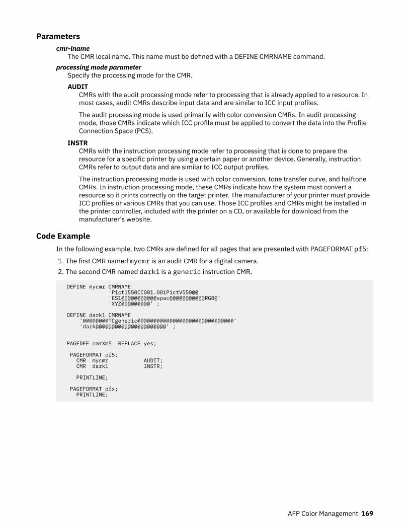
Parameterscmr-lname
The CMR local name. This name must be defined with a DEFINE CMRNAME command.processing mode parameter
Specify the processing mode for the CMR.AUDIT
CMRs with the audit processing mode refer to processing that is already applied to a resource. Inmost cases, audit CMRs describe input data and are similar to ICC input profiles.
The audit processing mode is used primarily with color conversion CMRs. In audit processingmode, those CMRs indicate which ICC profile must be applied to convert the data into the ProfileConnection Space (PCS).
INSTRCMRs with the instruction processing mode refer to processing that is done to prepare theresource for a specific printer by using a certain paper or another device. Generally, instructionCMRs refer to output data and are similar to ICC output profiles.
The instruction processing mode is used with color conversion, tone transfer curve, and halftoneCMRs. In instruction processing mode, these CMRs indicate how the system must convert aresource so it prints correctly on the target printer. The manufacturer of your printer must provideICC profiles or various CMRs that you can use. Those ICC profiles and CMRs might be installed inthe printer controller, included with the printer on a CD, or available for download from themanufacturer's website.
Code ExampleIn the following example, two CMRs are defined for all pages that are presented with PAGEFORMAT pf5:
1. The first CMR named mycmr is an audit CMR for a digital camera.2. The second CMR named dark1 is a generic instruction CMR.
DEFINE mycmr CMRNAME 'Pict1550CC001.001PictV550@@' 'ES1@@@@@@@@@@@spac@@@@@@@@@@@RGB@' 'XYZ@@@@@@@@@' ;
DEFINE dark1 CMRNAME '@@@@@@@@TCgeneric@@@@@@@@@@@@@@@@@@@@@@@@@@@@@@' 'dark@@@@@@@@@@@@@@@@@@@@@@' ;
PAGEDEF cmrXm5 REPLACE yes;
PAGEFORMAT pf5; CMR mycmr AUDIT; CMR dark1 INSTR;
PRINTLINE;
PAGEFORMAT pfx; PRINTLINE;
AFP Color Management 169
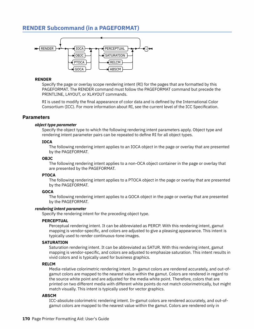
RENDER Subcommand (in a PAGEFORMAT)
RENDER IOCA
OBJC
PTOCA
GOCA
PERCEPTUAL
SATURATION
RELCM
ABSCM
;
RENDERSpecify the page or overlay scope rendering intent (RI) for the pages that are formatted by thisPAGEFORMAT. The RENDER command must follow the PAGEFORMAT command but precede thePRINTLINE, LAYOUT, or XLAYOUT commands.
RI is used to modify the final appearance of color data and is defined by the International ColorConsortium (ICC). For more information about RI, see the current level of the ICC Specification.
Parametersobject type parameter
Specify the object type to which the following rendering intent parameters apply. Object type andrendering intent parameter pairs can be repeated to define RI for all object types.IOCA
The following rendering intent applies to an IOCA object in the page or overlay that are presentedby the PAGEFORMAT.
OBJCThe following rendering intent applies to a non-OCA object container in the page or overlay thatare presented by the PAGEFORMAT.
PTOCAThe following rendering intent applies to a PTOCA object in the page or overlay that are presentedby the PAGEFORMAT.
GOCAThe following rendering intent applies to a GOCA object in the page or overlay that are presentedby the PAGEFORMAT.
rendering intent parameterSpecify the rendering intent for the preceding object type.PERCEPTUAL
Perceptual rendering intent. It can be abbreviated as PERCP. With this rendering intent, gamutmapping is vendor-specific, and colors are adjusted to give a pleasing appearance. This intent istypically used to render continuous-tone images.
SATURATIONSaturation rendering intent. It can be abbreviated as SATUR. With this rendering intent, gamutmapping is vendor-specific, and colors are adjusted to emphasize saturation. This intent results invivid colors and is typically used for business graphics.
RELCMMedia-relative colorimetric rendering intent. In-gamut colors are rendered accurately, and out-of-gamut colors are mapped to the nearest value within the gamut. Colors are rendered in regard tothe source white point and are adjusted for the media white point. Therefore, colors that areprinted on two different media with different white points do not match colorimetrically, but mightmatch visually. This intent is typically used for vector graphics.
ABSCMICC-absolute colorimetric rendering intent. In-gamut colors are rendered accurately, and out-of-gamut colors are mapped to the nearest value within the gamut. Colors are rendered only in
170 Page Printer Formatting Aid: User's Guide

regard to the source white point and are not adjusted for the media white point. Therefore, colorsthat are printed on two different media with different white points must match colorimetrically,but might not match visually. This intent is typically used for logos.
Code ExampleFour different pages (PAGEFORMATs) with RENDER commands are defined in the following example:
1. The first page RENDER command defines the RI for IOCA objects as perceptual.2. The second page RENDER command defines the RI for non-OCA objects as saturation.3. The third page RENDER command defines the RI for PTOCA objects as media-relative colorimetric.4. The fourth page RENDER command defines the RI for all supported objects.
PAGEDEF cmrXm6 REPLACE yes;
PAGEFORMAT pf6a; RENDER IOCA perceptual; PRINTLINE;
PAGEFORMAT pf6b; RENDER OBJC saturation; PRINTLINE;
PAGEFORMAT pf6c; RENDER PTOCA relcm; PRINTLINE;
PAGEFORMAT pf6d; RENDER OBJC abscm IOCA relcm PTOCA satur GOCA percp; PRINTLINE;
OBJECT Command (Traditional, Record Format, XML)OBJECT … OBTYPE PSEG
IOCA
BCOCA
GOCA
OTHER OBID component-id
type-name
… RENDER
PERCEPTUAL
SATURATION
RELCM
ABSCM
…
OB2CMR cmr-lname AUDIT
INSTR
LINK
NOPRELOAD
PRELOAD
… ;
OBJECTThe full OBJECT command and all its other non-CMR subcommands are described in “OBJECTCommand” on page 363.
AFP Color Management 171
OBTYPESpecifies the object type.PSEG
No change, see “PSEG” on page 366.GOCA
No change, see “GOCA” on page 366.BCOCA
No change, see “BCOCA” on page 366.IOCA
No change, see “IOCA” on page 366.OTHER
No change, see “OTHER” on page 366.OBID
No change, see “OBID” on page 366.RENDER
Subcommand on the OBJECT command to specify the rendering intent (RI) for an object within a pagedefinition.
RI is used to modify the final appearance of color data and is defined by the International ColorConsortium (ICC). For more information about RI, see the current level of the ICC Specification.
Notes:
1. Rendering intent on a BCOCA object is fixed as media-relative colorimetric (RELCM), so RENDERdoes not need to be coded for a BCOCA object. But if you do specify something other than RELCM,PPFA flags an error.
2. A page segment (PSEG object type) can contain many object types. If you specify RENDER for aPSEG, PPFA sets that rendering intent type for all object types in the page segment.
rendering intent parameterSpecify the rendering intent for the preceding object type.PERCEPTUAL
Perceptual rendering intent. It can be abbreviated as PERCP. With this rendering intent, gamutmapping is vendor-specific, and colors are adjusted to give a pleasing appearance. This intent istypically used to render continuous-tone images.
SATURATIONSaturation rendering intent. It can be abbreviated as SATUR. With this rendering intent, gamutmapping is vendor-specific, and colors are adjusted to emphasize saturation. This intent results invivid colors and is typically used for business graphics.
RELCMMedia-relative colorimetric rendering intent. In-gamut colors are rendered accurately, and out-of-gamut colors are mapped to the nearest value within the gamut. Colors are rendered concerningthe source white point and are adjusted for the media white point. Therefore, colors that areprinted on two different media with different white points do not match colorimetrically, but mightmatch visually. This intent is typically used for vector graphics.
ABSCMICC-absolute colorimetric rendering intent. In-gamut colors are rendered accurately, and out-of-gamut colors are mapped to the nearest value within the gamut. Colors are rendered concerningonly the source white point and are not adjusted for the media white point. Therefore, colors thatare printed on two different media with different white points must match colorimetrically, butmight not match visually. This intent is typically used for logos.
OB2CMRSpecify a Color Management Resource (CMR) and its process mode for a data object within the pagedefinition. CMRs are secondary objects when used at this level. Multiple OB2CMR subcommands areallowed on the OBJECT command.
172 Page Printer Formatting Aid: User's Guide
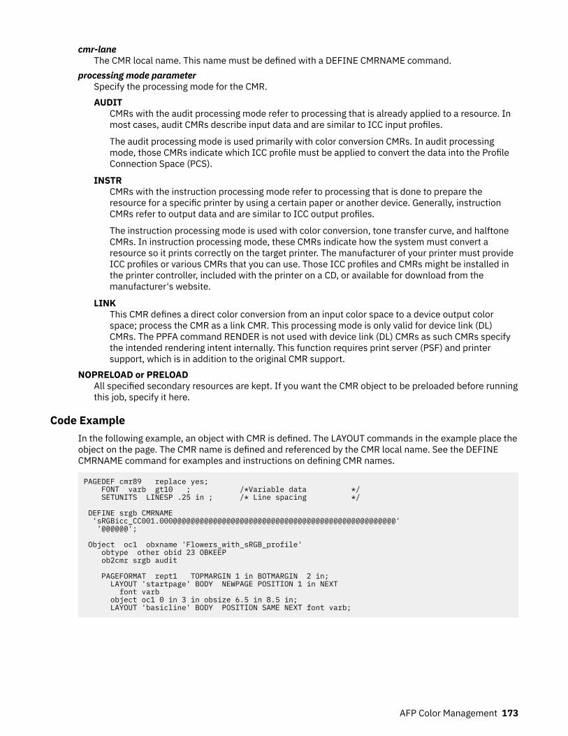
cmr-laneThe CMR local name. This name must be defined with a DEFINE CMRNAME command.
processing mode parameterSpecify the processing mode for the CMR.AUDIT
CMRs with the audit processing mode refer to processing that is already applied to a resource. Inmost cases, audit CMRs describe input data and are similar to ICC input profiles.
The audit processing mode is used primarily with color conversion CMRs. In audit processingmode, those CMRs indicate which ICC profile must be applied to convert the data into the ProfileConnection Space (PCS).
INSTRCMRs with the instruction processing mode refer to processing that is done to prepare theresource for a specific printer by using a certain paper or another device. Generally, instructionCMRs refer to output data and are similar to ICC output profiles.
The instruction processing mode is used with color conversion, tone transfer curve, and halftoneCMRs. In instruction processing mode, these CMRs indicate how the system must convert aresource so it prints correctly on the target printer. The manufacturer of your printer must provideICC profiles or various CMRs that you can use. Those ICC profiles and CMRs might be installed inthe printer controller, included with the printer on a CD, or available for download from themanufacturer's website.
LINKThis CMR defines a direct color conversion from an input color space to a device output colorspace; process the CMR as a link CMR. This processing mode is only valid for device link (DL)CMRs. The PPFA command RENDER is not used with device link (DL) CMRs as such CMRs specifythe intended rendering intent internally. This function requires print server (PSF) and printersupport, which is in addition to the original CMR support.
NOPRELOAD or PRELOADAll specified secondary resources are kept. If you want the CMR object to be preloaded before runningthis job, specify it here.
Code ExampleIn the following example, an object with CMR is defined. The LAYOUT commands in the example place theobject on the page. The CMR name is defined and referenced by the CMR local name. See the DEFINECMRNAME command for examples and instructions on defining CMR names.
PAGEDEF cmr89 replace yes; FONT varb gt10 ; /*Variable data */ SETUNITS LINESP .25 in ; /* Line spacing */
DEFINE srgb CMRNAME 'sRGBicc_CC001.000@@@@@@@@@@@@@@@@@@@@@@@@@@@@@@@@@@@@@@@@@@@@@@@@@@' '@@@@@@'; Object oc1 obxname 'Flowers_with_sRGB_profile' obtype other obid 23 OBKEEP ob2cmr srgb audit PAGEFORMAT rept1 TOPMARGIN 1 in BOTMARGIN 2 in; LAYOUT 'startpage' BODY NEWPAGE POSITION 1 in NEXT font varb object oc1 0 in 3 in obsize 6.5 in 8.5 in; LAYOUT 'basicline' BODY POSITION SAME NEXT font varb;
AFP Color Management 173
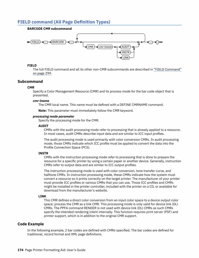
FIELD command (All Page Definition Types)BARCODE CMR subcommand
FIELD … BARCODE …
CMR cmr-lname AUDIT
INSTR
LINK
… ;
FIELDThe full FIELD command and all its other non-CMR subcommands are described in “FIELD Command”on page 299.
SubcommandCMR
Specify a Color Management Resource (CMR) and its process mode for the bar code object that ispresented.cmr-lname
The CMR local name. This name must be defined with a DEFINE CMRNAME command.
Note: This parameter must immediately follow the CMR keyword.
processing mode parameterSpecify the processing mode for the CMR.AUDIT
CMRs with the audit processing mode refer to processing that is already applied to a resource.In most cases, audit CMRs describe input data and are similar to ICC input profiles.
The audit processing mode is used primarily with color conversion CMRs. In audit processingmode, those CMRs indicate which ICC profile must be applied to convert the data into theProfile Connection Space (PCS).
INSTRCMRs with the instruction processing mode refer to processing that is done to prepare theresource for a specific printer by using a certain paper or another device. Generally, instructionCMRs refer to output data and are similar to ICC output profiles.
The instruction processing mode is used with color conversion, tone transfer curve, andhalftone CMRs. In instruction processing mode, these CMRs indicate how the system mustconvert a resource so it prints correctly on the target printer. The manufacturer of your printermust provide ICC profiles or various CMRs that you can use. Those ICC profiles and CMRsmight be installed in the printer controller, included with the printer on a CD, or available fordownload from the manufacturer's website.
LINKThis CMR defines a direct color conversion from an input color space to a device output colorspace; process the CMR as a link CMR. This processing mode is only valid for device link (DL)CMRs. The PPFA command RENDER is not used with device link (DL) CMRs as such CMRsspecify the intended rendering intent internally. This function requires print server (PSF) andprinter support, which is in addition to the original CMR support.
Code ExampleIn the following example, 2 bar codes are defined with CMRs specified. The bar codes are defined fortraditional, record format and XML page definitions.
174 Page Printer Formatting Aid: User's Guide

Note: The DEFINE CMRNAMEs for mycmr and dark1 are used in each page definition but defined onlyonce. Page definitions that are in the same source file can define a local CMR name only once because aDEFINE CMRNAME definition is global for all page definitions and form definitions in the same sourcecode file.
DEFINE mycmr CMRNAME 'Pict1550CC001.001PictV550@@' 'CS@@@@@@@@@@@@spac@@@@@@@@@@@RGB@' 'XYZ@@@@@@@@@' ; DEFINE dark1 CMRNAME '@@@@@@@@TCgeneric@@@@@@@@@@@@@@@@@@@@@@@@@@@@@@' 'dark@@@@@@@@@@@@@@@@@@@@@@' ;
/* Traditional Pagedef */ PAGEDEF cmr10P REPLACE yes; PRINTLINE; FIELD Start 1 Length 20 BARCODE TYPE code39 MOD 1 CMR myCMR audit; FIELD Start 21 Length 40 BARCODE TYPE code39 MOD 1 CMR dark1 instr;
/* Record Layout Pagedef */ PAGEDEF cmr10L REPLACE yes; Font f1; LAYOUT 'l1'; FIELD Start 1 Length 20 BARCODE TYPE code39 MOD 1 CMR myCMR audit; FIELD Start 21 Length 40 BARCODE TYPE code39 MOD 1 CMR dark1 instr;
/* XML Pagedef */ PAGEDEF cmr10X REPLACE yes; Font f1 TYPE ebcdic; XLAYOUT QTAG 'x1'; FIELD Start 1 Length 20 BARCODE TYPE code39 MOD 1 CMR myCMR audit; FIELD Start 21 Length 40 BARCODE TYPE code39 MOD 1 CMR dark1 instr;
EXTREF CommandThe EXTREF command specifies resources that are to be mapped in the page. It is a way in PPFA to mapobjects that would not otherwise be mapped. If an object contains another mapped object, the containedobject must be mapped, but PPFA does not automatically map that object.
EXTREFThe full EXTREF command and all its other non-CMR subcommands are described in “EXTREFCommand” on page 294.
SubcommandsOB2CMR
OB2CMR lname AUDIT
INSTR
LINK
Specify a Color Management Resource (CMR) and its process mode for a data object specified withinan included object. CMRs are secondary objects when used at this level. An object that is specifiedhere is mapped with "object" scope.
AFP Color Management 175

lnameThe CMR local name. This name must be defined with a CMRNAME command.
processing-mode-parameterSpecify the processing mode for the CMR.AUDIT
CMRs with the audit processing mode refer to processing that is already applied to a resource.In most cases, audit CMRs describe input data and are similar to ICC input profiles.
The audit processing mode is used primarily with color conversion CMRs. In audit processingmode, those CMRs indicate which ICC profile must be applied to convert the data into theProfile Connection Space (PCS).
INSTRCMRs with the instruction processing mode refer to processing that is done to prepare theresource for a specific printer by using a certain paper or another device. Generally, instructionCMRs refer to output data and are similar to ICC output profiles.
The instruction processing mode is used with color conversion, tone transfer curve, andhalftone CMRs. In instruction processing mode, these CMRs indicate how the system mustconvert a resource so it prints correctly on the target printer. The manufacturer of your printermust provide ICC profiles or various CMRs that you can use. Those ICC profiles and CMRsmight be installed in the printer controller, included with the printer on a CD, or available fordownload from the manufacturer's website.
LINKThis CMR defines a direct color conversion from an input color space to a device output colorspace; process the CMR as a link CMR. This processing mode is only valid for device link (DL)CMRs. The PPFA command RENDER is not used with device link (DL) CMRs as such CMRsspecify the intended rendering intent internally. This function requires print server (PSF) andprinter support, which is in addition to the original CMR support.
OB2ROB2R
i2name
'i2name'
C'i2name'
E 'i2name'
A'i2name'
X 'hhhh'
OB2XNAME x2name
'x2name'
C'x2name'
E 'x2name'
A'x2name'
X 'hhhh'
U8'x2name'
U16'x2name'
x8'hhhh'
x16'hhhh'
Specify a secondary object to be mapped.
If an included object contains a reference to one or more secondary objects, you must identify themhere. Specify the internal name for the secondary resource as specified in the included resource. Ifthe internal name contains special characters, such as periods or blanks, then quotation marks mustsurround the name.
i2nameUnquoted name up to 250 characters long is folded to uppercase and translated into EBCDIC ifnecessary.
'i2name'Quoted name up to 250 characters long is accepted as-is with no case folding or translation.
176 Page Printer Formatting Aid: User's Guide
C'i2name'Quoted name with a C for Character is treated the same as a quoted name of up to 250 characters.No folding or translation is done.
E'i2name'Quoted name with an E for EBCDIC entered with up to 250 characters is accepted as-is if on anEBCDIC operating system or translated to EBCDIC if on an ASCII operating system. Thetranslation is made with no case folding.
A'i2name'Quoted name with an A for ASCII entered with up to 250 single-byte characters is accepted as-isif on an ASCII operating system or translated to ASCII if on an EBCDIC operating system. Thetranslation is made with no case folding.
X'hhhh'Quoted name with an X for Hexadecimal entered with up to 500 hexadecimal characters. Thecharacters are translated to hexadecimal, but no assumptions of data type are made.
OB2XNAME x2nameSpecifies the external name for a secondary resource object. The name can be up to 250 characters.If the name contains special characters or blanks, then quotation marks must surround the name.x2name
Unquoted name up to 250 characters long is folded to uppercase and translated into EBCDIC ifnecessary.
'x2name'Quoted name up to 250 characters long are accepted as-is with no case folding or translation.
C'x2name'Quoted name with an C for Character is treated the same as a quoted name up to 250 characters.No folding or translation is done.
E'x2name'Quoted name with an E for EBCDIC entered with up to 250 single-byte characters is accepted as-is if on an EBCDIC operating system or translated to EBCDIC if on an ASCII operating system. Thetranslation is made with no case folding.
A'x2name'Quoted name with an A for ASCII entered with up to 250 single-byte characters are accepted as-ison an ASCII operating system or translated to ASCII if on an EBCDIC operating system. Thetranslation is made with no case folding.
X'hhhh'Quoted name with an X for Hexadecimal entered with up to 500 hexadecimal characters. Thecharacters are translated to hexadecimal, but no assumption of data type is made.
U8'x2name'Quoted name with a U8 for UTF-8 entered with up to 250 single-byte characters are translated toUTF-8.
X8'hhhh'Quoted name with an X8 for UTF-8 HEX entered with up to 500 single-byte hexadecimalcharacters are translated to hexadecimal and assumed to be data type UTF-8. A multiple of 2hexadecimal characters must be entered.
U16'x2name'Quoted name with a U16 for UTF-16 entered with up to 125 single-byte characters are translatedto UTF-16.
X16'hhhh'Quoted name with an X16 for UTF-16 HEX entered with up to 500 single-byte hexadecimalcharacters are translated to hexadecimal and assumed to be data type UTF-16. A multiple of 4hexadecimal characters must be entered.
AFP Color Management 177

OB2ID n | type-nameOB2ID n
type-name
Component type identifier for secondary resource uses an object type number as specified in Objecttype list adjustments. Use an object type number from the Component-ID column or a type namefrom the Type-Name of the following table:
Table 7: Object Types that can be referenced as Secondary Resources
Type-Name Component-ID Description of OID Type-Name
PDFRO 26 PDF Resource Object (new)
RESCLRPRO 46 Resident Color Profile Resource Object
IOCAFS45RO 47 IOCA FS45 Resource Object Tile (new)
Code ExampleIn the following example, the CMR rtvc is mapped in the Object Environment Group (OEG) of an objectthat is being included in the page.
Note: If you code rtvc with a CMR command (as in the commented out CMR command), it is mapped andis active for the entire page; however, you want it to be active only for the object in whose OEG it ismapped.
DEFINE rvtc CMRNAME 'RevVideoTC001.000@@@@@@@@@@@@@@@@@@@@@@@@@@@@@@@@@@@@@@@@@@@@@@@@@@' '@@@@@@' DNXCMR; SETUNITS LINESP .25 in ; /* Line spacing */ PAGEFORMAT rept1 TOPMARGIN .25 in; EXTREF OB2CMR rvtc instr;
DRAWGRAPHIC Command (Record Format and XML)PAGEDEF - CMR and RENDER Subcommands on DRAWGRAPHIC command
DRAWGRAPHIC BOX
LINE
CIRCLE
ELLIPSE
…
RENDER PERCEPTUAL
SATURATION
RELCM
ABSCM
CMR cmr-lname AUDIT
INSTR
LINK
;
DRAWGRAPHICThe full DRAWGRAPHIC command and all its other non-CMR subcommands are described in:
• “DRAWGRAPHIC - BOX Command (Record Format and XML only)” on page 267• “DRAWGRAPHIC - LINE Command (Record Format and XML only)” on page 274• “DRAWGRAPHIC - CIRCLE Command (Record Format and XML only)” on page 280
178 Page Printer Formatting Aid: User's Guide

• “DRAWGRAPHIC - ELLIPSE Command (Record Format and XML only)” on page 287
SubcommandsRENDER
Subcommand on the DRAWGRAPHIC command to specify the rendering intent (RI) for the graphicsobject being presented.
RI is used to modify the final appearance of color data and is defined by the International ColorConsortium (ICC). For more information about RI, see the current level of the ICC Specification.
rendering intent parameterSpecify the rendering intent for the defined graphic (GOCA) object.PERCEPTUAL
Perceptual rendering intent. It can be abbreviated as PERCP. With this rendering intent, gamutmapping is vendor-specific, and colors are adjusted to give a pleasing appearance. This intentis typically used to render continuous-tone images.
SATURATIONSaturation rendering intent. It can be abbreviated as SATUR. With this rendering intent, gamutmapping is vendor-specific, and colors are adjusted to emphasize saturation. This intentresults in vivid colors and is typically used for business graphics.
RELCMMedia-relative colorimetric rendering intent. In-gamut colors are rendered accurately, andout-of-gamut colors are mapped to the nearest value within the gamut. Colors are rendered inregard to the source white point and are adjusted for the media white point. Therefore, colorsthat are printed on two different media with different white points do not matchcolorimetrically, but might match visually. This intent is typically used for vector graphics.
ABSCMICC-absolute colorimetric rendering intent. In-gamut colors are rendered accurately, and out-of-gamut colors are mapped to the nearest value within the gamut. Colors are rendered only inregard to the source white point and are not adjusted for the media white point. Therefore,colors that are printed on two different media with different white points must matchcolorimetrically, but might not match visually. This intent is typically used for logos.
CMRSpecify a Color Management Resource (CMR) and its process mode for a graphics object within thepage definition.cmr-lname
The CMR local name. This name must be defined with a DEFINE CMRNAME command.
Note: This parameter must immediately follow the CMR keyword.
processing mode parameterSpecify the processing mode for the CMR.AUDIT
CMRs with the audit processing mode refer to processing that is already applied to a resource.In most cases, audit CMRs describe input data and are similar to ICC input profiles.
The audit processing mode is used primarily with color conversion CMRs. In audit processingmode, those CMRs indicate which ICC profile must be applied to convert the data into theProfile Connection Space (PCS).
INSTRCMRs with the instruction processing mode refer to processing that is done to prepare theresource for a specific printer by using a certain paper or another device. Generally, instructionCMRs refer to output data and are similar to ICC output profiles.
The instruction processing mode is used with color conversion, tone transfer curve, andhalftone CMRs. In instruction processing mode, these CMRs indicate how the system mustconvert a resource so it prints correctly on the target printer. The manufacturer of your printer
AFP Color Management 179
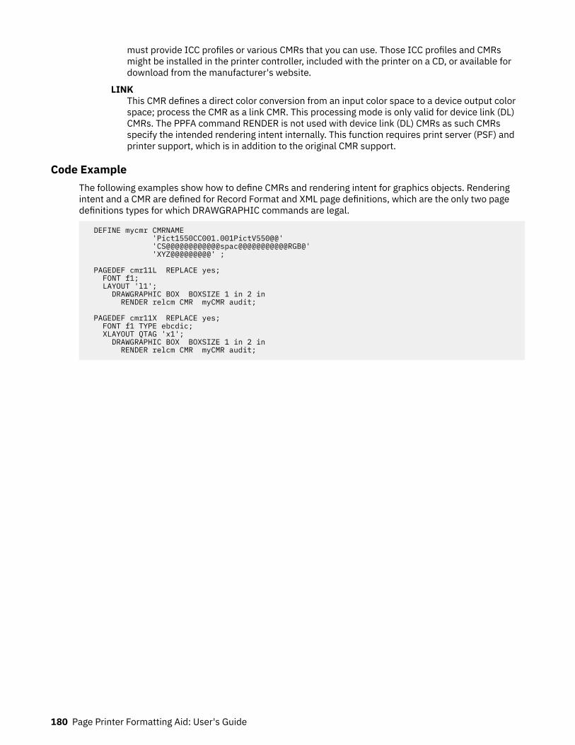
must provide ICC profiles or various CMRs that you can use. Those ICC profiles and CMRsmight be installed in the printer controller, included with the printer on a CD, or available fordownload from the manufacturer's website.
LINKThis CMR defines a direct color conversion from an input color space to a device output colorspace; process the CMR as a link CMR. This processing mode is only valid for device link (DL)CMRs. The PPFA command RENDER is not used with device link (DL) CMRs as such CMRsspecify the intended rendering intent internally. This function requires print server (PSF) andprinter support, which is in addition to the original CMR support.
Code ExampleThe following examples show how to define CMRs and rendering intent for graphics objects. Renderingintent and a CMR are defined for Record Format and XML page definitions, which are the only two pagedefinitions types for which DRAWGRAPHIC commands are legal.
DEFINE mycmr CMRNAME 'Pict1550CC001.001PictV550@@' 'CS@@@@@@@@@@@@spac@@@@@@@@@@@RGB@' 'XYZ@@@@@@@@@' ;
PAGEDEF cmr11L REPLACE yes; FONT f1; LAYOUT 'l1'; DRAWGRAPHIC BOX BOXSIZE 1 in 2 in RENDER relcm CMR myCMR audit;
PAGEDEF cmr11X REPLACE yes; FONT f1 TYPE ebcdic; XLAYOUT QTAG 'x1'; DRAWGRAPHIC BOX BOXSIZE 1 in 2 in RENDER relcm CMR myCMR audit;
180 Page Printer Formatting Aid: User's Guide
Part 3. PPFA Commands and Syntax
This section contains information about:
• PPFA command syntax• Form definition commands• Page definition commands
© Copyright IBM Corp. 1985, 2016 181

182 Page Printer Formatting Aid: User's Guide

Chapter 9. PPFA Command Syntax
PPFA controls are made up of four elements: commands, subcommands, parameters, and literals.
• Commands are controls that represent the major functions of PPFA and are separated from othercommands by semicolons. Each command has its own entry in Chapter 10, “Form Definition CommandReference,” on page 189 and in Chapter 11, “Page Definition Command Reference ,” on page 249.
• Subcommands fall within commands and specify the function of that command.• Parameters specify the values for one subcommand.• Literals consist of fixed text included in a field definition or as constant data for comparison in a
conditional processing definition.
Rules for Creating a PPFA Command StreamWhen you create a PPFA command stream, follow these rules:
• Before PPFA processes the commands, it converts lowercase characters into uppercase characters,except the ones in literals. Thus, it does not discriminate between uppercase and lowercase characters.For example, OVERLAY abc and overlay ABC produce the same results because both overlay andabc are converted to uppercase.
• User names for form definitions and page definitions must not be the same as PPFA command namesand subcommand names, which are reserved words. For a list of the reserved words, see Appendix F,“PPFA Keywords,” on page 525. For example, REPEAT or CHANNEL must not be form-definition names.
• The subcommands that are governed by a command can be entered in any order; however, the name ofa font or form definition, for example, must come immediately after the object that is named.Parameters that are defined in a subcommand must be entered immediately after the subcommand.
• Commands must end with a semicolon.• A command or subcommand can start in any column and can continue on the next line without a
continuation indicator.• More than one form definition and page definition can be specified in a job stream.• PPFA does not check or set default values for items that depend on printer hardware.
Token RulesTokens are character strings, within a set of PPFA commands, that PPFA recognizes as units. Tokensinclude:
• Both local names and user-access names for fonts, form definitions, page definitions, overlays, andsuppressions
• Commands• Subcommands• Parameters• Literals• Special characters
The only PPFA element that is not a token is a blank. A token cannot be split between two lines.
To create a token, you must separate a string from the previous token by either a special character or ablank. See the list of special characters in “Character Set” on page 184. Thus, A+B is the same as A + Bbecause + is a special character. But AB is not the same as A B. The blank in A B creates two tokens.
© Copyright IBM Corp. 1985, 2016 183

Character SetThe four types of characters are alphabetic, numeric, blank, and special. Characters of each type are asfollows:PPFA alphabetic characters
A B C D E F G H I J K L M N O P Q R S T U V W X Y Za b c d e f g h i j k l m n o p q r s t u v w x y z# @ $
PPFA numeric characters
0 1 2 3 4 5 6 7 8 9
Blank characterCharacter code of X'20' in ASCII (which is the data stream that is used for creating the form definitionor page definition).
Note: In EBCDIC data, the blank character has a character code of X'40'.
PPFA special characters
. ( +* ) – % ' = ; ⁄ &
EBCDIC shift-out and shift-in codes
X'0E', the shift-out (SO) codeX'0F', the shift-in (SI) code
Other character codes are also allowed within comments and literals. See “Comments” on page 185 and“Literals” on page 186 for details of what can be included.
Command DelimitersA command always ends with a semicolon. One command can extend over several lines and does not enduntil a semicolon appears.
Blanks and Blank LinesBlanks and blank lines can occur anywhere and have no effect on the processing of PPFA. The ; is thecommand delimiter.
NamesThe maximum number of alphanumeric characters in a PPFA name varies. Table 8 on page 184 shows thenumber of characters that are allowed in the PPFA names.
Table 8: Character Length for PPFA Names.
Type of Name Number of Characters Allowed
Form Definition
COPYGROUP 1 – 8
DEFINE CMRNAME (local name) 1 – 16
DEFINE CMRNAME (user-access name) 73
184 Page Printer Formatting Aid: User's Guide

Table 8: Character Length for PPFA Names. (continued)
Type of Name Number of Characters Allowed
FORMDEF 1 – 6
OVERLAY (local name) 1 – 16
OVERLAY (user-access name) 1 – 6
SUPPRESSION 1 – 8
Page Definition
BARCODE 1 – 8
CONDITION 1 – 8
DEFINE COLOR 1 – 10
DEFINE CMRNAME (local name) 1 – 16
DEFINE CMRNAME (user-access name) 73
DEFINE QTAG (local name) 1 – 16
DEFINE QTAG (XML tag names) 1 – 125
DOFONT (local name) 1 – 16
DOFONT (user-access name) 1 – 125
FONT (local name) 1 – 16
FONT (user-access name) 1 – 6
OBJECT (local-name) 1 – 16
OBJECT (external name) (See note) 1 – 250
Secondary OBJECT (internal name) (See note) 1 – 250
Secondary OBJECT (external name) (See note) 1 – 250
OVERLAY 1 – 6
PAGEDEF 1 – 6
PAGEFORMAT 1 – 8
SEGMENT 1 – 6
Note: This name is further restricted to 250 bytes. For data type UTF-16, the maximum is 125characters or less if surrogate characters are required. Some operating systems have a limit of 8characters.
CommentsProgrammer comments that are used to document PPFA command streams are allowed anywhere withinthe command stream. Comments must be enclosed with the delimiters ⁄* and *⁄. A comment is allowedanywhere that a blank is allowed and can continue for any number of lines.
The following example shows the available variations in comment formats:
FIELD /* comment */ FONT GT10 /* comment, multiline comment, more comment */ START * + 10 LENGTH 5 ;FIELD LENGTH 10 ; FIELD START * + 10 LENGTH 15 ;
PPFA Command Syntax 185

Notes:
1. A comment must end with the closing delimiter (*⁄).2. For VSE, a comment must not start at the beginning of the line. A ⁄* specified as the first 2 bytes of a
record in PPFA running under VSE is interpreted as the end of system input.3. Double-byte character codes in comments must be enclosed within SO (X'0E') and SI (X'0F') on
EBCDIC operating systems.
LiteralsA literal is any string that is specified in single quotation marks. Literals can be used within a:
• TEXT subcommand to create fixed text for a page definition• WHEN subcommand to define constant text for comparison
Literals can contain any characters in any position, except the ones that have special syntactic meanings.Single quotation marks can be used within a literal only if they are entered in pairs ('). PPFA translates apair of single quotation marks into one quotation mark. For example, 'JOAN''S' yields JOAN'S.
A literal can continue for any number of lines. For example:
TEXT 'THIS IS ' 'A LITERAL' /* The four separated */ 'THE TEXT SPANS' /* text elements will produce*/ 'THREE LINES' ; /* one sequence of text */ TEXT X'0101' /* Hexadecimal literals */ X'ABAB' /* spanning three lines */ X'BBBB' ; TEXT K'100,200' /* kanji numbers */ K'321,400' ; /* specified sequentially */
This example is invalid:
TEXT 'THIS IS' K'100,200' ; /* Mixing single-byte and double-byte characters in one field is not allowed */
A double-byte literal must be enclosed within apostrophe shift-out (X'7D0E') and shift-in apostrophe(X'0F7D').
Numeric ValuesNumeric variables are specified as decimal numbers; up to three decimal places can be specified.
Units of MeasurementNumbers that are used to specify dimensions in form definitions and page definitions can be in any of fiveunits of measurement. They are specified in a command stream as follows:IN
InchesMM
MillimetersCM
CentimetersPOINTS
Points are a common measurement in printing that are used to measure character height, as in 20-point type. A point is approximately 1/72 inch.
186 Page Printer Formatting Aid: User's Guide
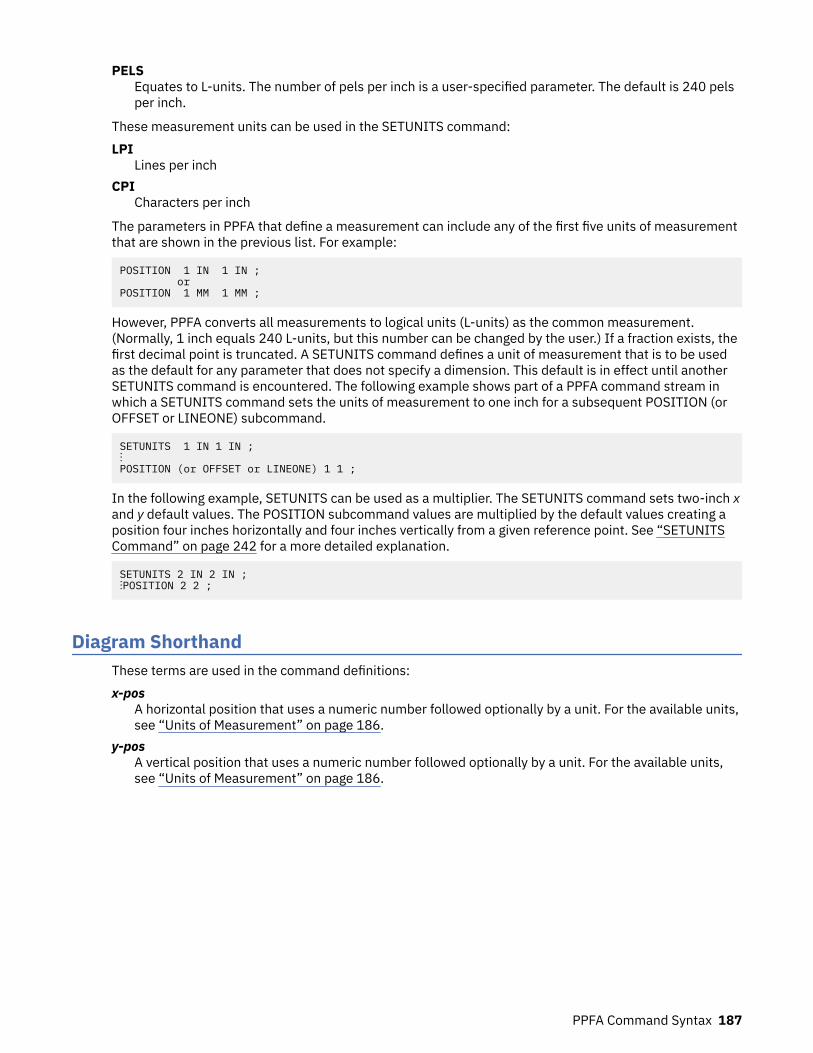
PELSEquates to L-units. The number of pels per inch is a user-specified parameter. The default is 240 pelsper inch.
These measurement units can be used in the SETUNITS command:LPI
Lines per inchCPI
Characters per inch
The parameters in PPFA that define a measurement can include any of the first five units of measurementthat are shown in the previous list. For example:
POSITION 1 IN 1 IN ; orPOSITION 1 MM 1 MM ;
However, PPFA converts all measurements to logical units (L-units) as the common measurement.(Normally, 1 inch equals 240 L-units, but this number can be changed by the user.) If a fraction exists, thefirst decimal point is truncated. A SETUNITS command defines a unit of measurement that is to be usedas the default for any parameter that does not specify a dimension. This default is in effect until anotherSETUNITS command is encountered. The following example shows part of a PPFA command stream inwhich a SETUNITS command sets the units of measurement to one inch for a subsequent POSITION (orOFFSET or LINEONE) subcommand.
SETUNITS 1 IN 1 IN ;⋮POSITION (or OFFSET or LINEONE) 1 1 ;
In the following example, SETUNITS can be used as a multiplier. The SETUNITS command sets two-inch xand y default values. The POSITION subcommand values are multiplied by the default values creating aposition four inches horizontally and four inches vertically from a given reference point. See “SETUNITSCommand” on page 242 for a more detailed explanation.
SETUNITS 2 IN 2 IN ;⋮POSITION 2 2 ;
Diagram ShorthandThese terms are used in the command definitions:x-pos
A horizontal position that uses a numeric number followed optionally by a unit. For the available units,see “Units of Measurement” on page 186.
y-posA vertical position that uses a numeric number followed optionally by a unit. For the available units,see “Units of Measurement” on page 186.
PPFA Command Syntax 187

188 Page Printer Formatting Aid: User's Guide
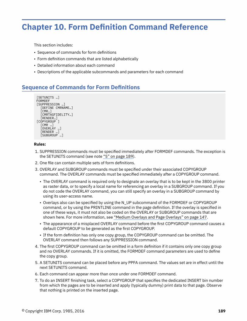
Chapter 10. Form Definition Command Reference
This section includes:
• Sequence of commands for form definitions• Form definition commands that are listed alphabetically• Detailed information about each command• Descriptions of the applicable subcommands and parameters for each command
Sequence of Commands for Form Definitions[SETUNITS …]FORMDEF[SUPPRESSION …] [DEFINE CMRNAME…] [CMR…] [CMRTAGFIDELITY…] [RENDER…][COPYGROUP ] [CMR …] [OVERLAY …] [RENDER …] [SUBGROUP …]
Rules:
1. SUPPRESSION commands must be specified immediately after FORMDEF commands. The exception isthe SETUNITS command (see note “5” on page 189).
2. One file can contain multiple sets of form definitions.3. OVERLAY and SUBGROUP commands must be specified under their associated COPYGROUP
command. The OVERLAY commands must be specified immediately after a COPYGROUP command.
• The OVERLAY command is required only to designate an overlay that is to be kept in the 3800 printeras raster data, or to specify a local name for referencing an overlay in a SUBGROUP command. If youdo not code the OVERLAY command, you can still specify an overlay in a SUBGROUP command byusing its user-access name.
• Overlays also can be specified by using the N_UP subcommand of the FORMDEF or COPYGROUPcommand, or by using the PRINTLINE command in the page definition. If the overlay is specified inone of these ways, it must not also be coded on the OVERLAY or SUBGROUP commands that areshown here. For more information, see “Medium Overlays and Page Overlays” on page 147.
• The appearance of a misplaced OVERLAY command before the first COPYGROUP command causes adefault COPYGROUP to be generated as the first COPYGROUP.
• If the form definition has only one copy group, the COPYGROUP command can be omitted. TheOVERLAY command then follows any SUPPRESSION command.
4. The first COPYGROUP command can be omitted in a form definition if it contains only one copy groupand no OVERLAY commands. If it is omitted, the FORMDEF command parameters are used to definethe copy group.
5. A SETUNITS command can be placed before any PPFA command. The values set are in effect until thenext SETUNITS command.
6. Each command can appear more than once under one FORMDEF command.7. To do an INSERT finishing task, select a COPYGROUP that specifies the dedicated INSERT bin number
from which the pages are to be inserted and apply (typically dummy) print data to that page. Observethat nothing is printed on the inserted page.
© Copyright IBM Corp. 1985, 2016 189

Note: The INSERT bin number is printer-specific. See the documentation for the specific printer that isused.
190 Page Printer Formatting Aid: User's Guide
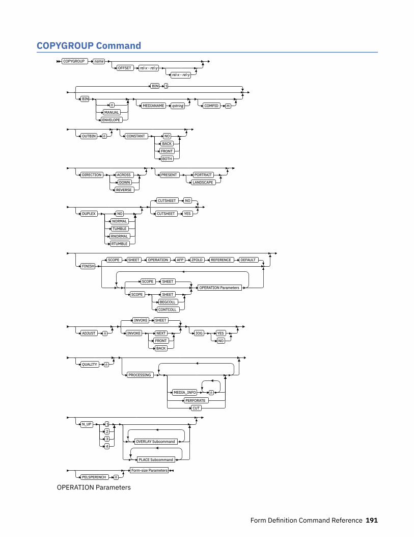
COPYGROUP CommandCOPYGROUP name
OFFSET rel-x - rel-y
rel-x - rel-y
BIN 1
BINn
MANUAL
ENVELOPE
MEDIANAME qstring COMPID m
OUTBIN n CONSTANT NO
BACK
FRONT
BOTH
DIRECTION ACROSS
DOWN
REVERSE
PRESENT PORTRAIT
LANDSCAPE
DUPLEX NO
NORMAL
TUMBLE
RNORMAL
RTUMBLE
CUTSHEET NO
CUTSHEET YES
FINISH
SCOPE SHEET OPERATION AFP ZFOLD REFERENCE DEFAULT
SCOPE SHEET
SCOPE SHEET
BEGCOLL
CONTCOLL
OPERATION Parameters
ADJUST n
INVOKE SHEET
INVOKE NEXT
FRONT
BACK
JOG YES
NO
QUALITY n
PROCESSING
MEDIA_INFO n
PERFORATE
CUT
N_UP 1
2
3
4OVERLAY Subcommand
PLACE Subcommand
PELSPERINCH n
Form-size Parameters
OPERATION Parameters
Form Definition Command Reference 191
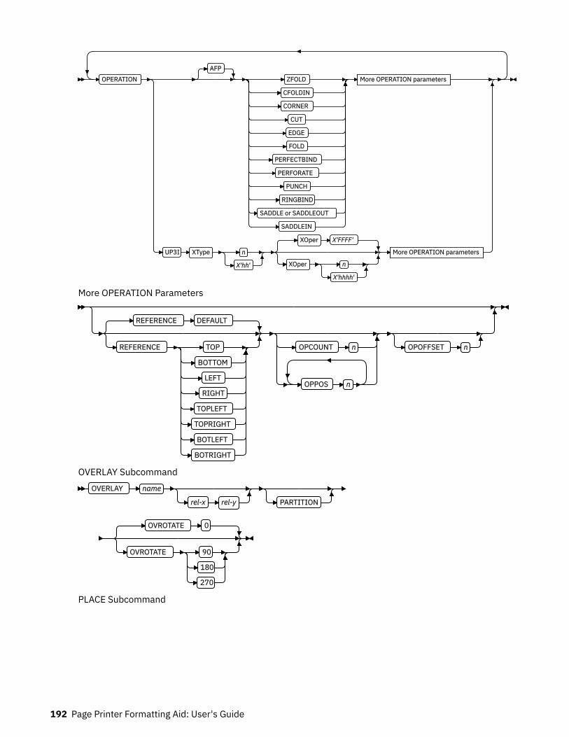
OPERATIONAFP
ZFOLD
CFOLDIN
CORNER
CUT
EDGE
FOLD
PERFECTBIND
PERFORATE
PUNCH
RINGBIND
SADDLE or SADDLEOUT
SADDLEIN
More OPERATION parameters
UP3I XType n
X'hh'
XOper X'FFFF'
XOper n
X'hhhh'
More OPERATION parameters
More OPERATION Parameters
REFERENCE DEFAULT
REFERENCE TOP
BOTTOM
LEFT
RIGHT
TOPLEFT
TOPRIGHT
BOTLEFT
BOTRIGHT
OPCOUNT n
OPPOS n
OPOFFSET n
OVERLAY SubcommandOVERLAY name
rel-x rel-y PARTITION
OVROTATE 0
OVROTATE 90
180
270
PLACE Subcommand
192 Page Printer Formatting Aid: User's Guide

PLACE1
n
FRONT
BACK CONSTANT OFFSET rel-x rel-y
Overlay Subcommand
ROTATION 0
ROTATION 90
180
270
VIEW YES
VIEW NO
;
Notes:1 The use of the PLACE subcommand indicates enhanced N_UP printing.
Form-size Parameters
XMSIZE x
units
YMSIZE y
units
Copy groups are subsets of a form definition. A form definition can contain one or several copy groups.Copy groups are nested within a form definition that follows any SUPPRESSION command. COPYGROUPsubcommands have no fixed defaults; if any subcommand is omitted, its value is selected from thecorresponding subcommand in the FORMDEF command.
Notes:
1. Subsets of copy groups are called subgroups.2. If you specified DUPLEX NO anywhere in the copy group, output is simplex regardless of any other
DUPLEX subcommand within the same copy group.3. If a form definition has only one copy group, the COPYGROUP command can be omitted. If omitted, a
name is automatically assigned by PPFA to the copy group, by using the form definition resource name,including the F1 prefix. All values for the copy group are given the values from the FORMDEF commandand subcommands. You need to know this name if you use conditional processing and need to invokethis copy group by name. Copy groups are placed within the form definition in the order in which theyare generated.
4. To change copy groups during formatting, use conditional processing.5. Another way to change copy groups after the resource is stored is to insert an Invoke Medium Map
structured field into your print data file (copy groups are known to the print server as medium maps). Ifno Invoke Medium Map structured field is found and no conditional processing is being done, the firstcopy group in the form definition is used for the job.
COPYGROUP nameDefines an alphanumeric name of 1 - 8 characters. This name must be unique in a single formdefinition. If any names are duplicated, PPFA issues an error message and does not create the formdefinition.
SubcommandsOFFSET
OFFSET rel-x - rel-y
rel-x - rel-y
Form Definition Command Reference 193
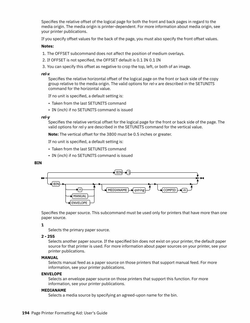
Specifies the relative offset of the logical page for both the front and back pages in regard to themedia origin. The media origin is printer-dependent. For more information about media origin, seeyour printer publications.
If you specify offset values for the back of the page, you must also specify the front offset values.
Notes:
1. The OFFSET subcommand does not affect the position of medium overlays.2. If OFFSET is not specified, the OFFSET default is 0.1 IN 0.1 IN3. You can specify this offset as negative to crop the top, left, or both of an image.
rel-xSpecifies the relative horizontal offset of the logical page on the front or back side of the copygroup relative to the media origin. The valid options for rel-x are described in the SETUNITScommand for the horizontal value.
If no unit is specified, a default setting is:
• Taken from the last SETUNITS command• IN (inch) if no SETUNITS command is issued
rel-ySpecifies the relative vertical offset for the logical page for the front or back side of the page. Thevalid options for rel-y are described in the SETUNITS command for the vertical value.
Note: The vertical offset for the 3800 must be 0.5 inches or greater.
If no unit is specified, a default setting is:
• Taken from the last SETUNITS command• IN (inch) if no SETUNITS command is issued
BIN
BIN 1
BINn
MANUAL
ENVELOPE
MEDIANAME qstring COMPID m
Specifies the paper source. This subcommand must be used only for printers that have more than onepaper source.
1Selects the primary paper source.
2 - 255Selects another paper source. If the specified bin does not exist on your printer, the default papersource for that printer is used. For more information about paper sources on your printer, see yourprinter publications.
MANUALSelects manual feed as a paper source on those printers that support manual feed. For moreinformation, see your printer publications.
ENVELOPESelects an envelope paper source on those printers that support this function. For moreinformation, see your printer publications.
MEDIANAMESelects a media source by specifying an agreed-upon name for the bin.
194 Page Printer Formatting Aid: User's Guide

qstringUp to 12 characters within single quotation marks, specifying the media source name. Onsome printers, this name is preset into the printer; on other printers, it can also be entered intothe printer by the user. For a current list of the valid media names, see Appendix G, “PPFAMedia Names,” on page 527. See your printer publications for more information.
Notes:
1. BIN selection is overridden by the printer if the form defined to each bin is the same formnumber. Only the primary bin is selected.
2. The primary source usually contains either letter-size (US) or A4 (ISO) paper. Other papersources are used for less common paper sizes (such as legal-size) and for special paper(such as colored stock or preprinted letterhead on heavy bond).
3. If duplexing is requested and you select from the front side from one bin and the back sidefrom another bin, a warning message is issued and the printer takes the paper from the binthat is specified on the front side.
COMPIDSelects a bin based on the component ID.m
For a current list of component IDs, see Appendix G, “PPFA Media Names,” on page 527.Component IDs 12,288 - 268,435,455 are reserved for the user.
OUTBIN n
OUTBIN n
Specifies the destination bin number for any pages that are directed by this COPYGROUP. Subgroupsin this form definition that do not specify an output bin number inherit this one.
nOutput bin number
CONSTANT
CONSTANT NO
BACK
FRONT
BOTH
Specifies whether the constant-forms function is on or off and whether constant form is to be printedon the front or back sides of a sheet.
NOSpecifies that the constant forms function is off.
BACKSpecifies that a constant form is to be printed on the back side without variable data.
FRONTSpecifies that a constant form is to be printed on the front side without variable data.
BOTHSpecifies that a constant form is to be printed on both sides without variable data.
Form Definition Command Reference 195
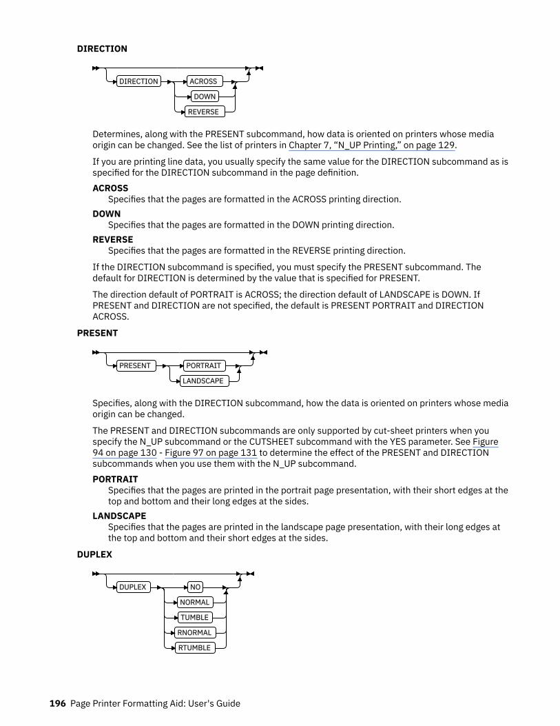
DIRECTION
DIRECTION ACROSS
DOWN
REVERSE
Determines, along with the PRESENT subcommand, how data is oriented on printers whose mediaorigin can be changed. See the list of printers in Chapter 7, “N_UP Printing,” on page 129.
If you are printing line data, you usually specify the same value for the DIRECTION subcommand as isspecified for the DIRECTION subcommand in the page definition.ACROSS
Specifies that the pages are formatted in the ACROSS printing direction.DOWN
Specifies that the pages are formatted in the DOWN printing direction.REVERSE
Specifies that the pages are formatted in the REVERSE printing direction.
If the DIRECTION subcommand is specified, you must specify the PRESENT subcommand. Thedefault for DIRECTION is determined by the value that is specified for PRESENT.
The direction default of PORTRAIT is ACROSS; the direction default of LANDSCAPE is DOWN. IfPRESENT and DIRECTION are not specified, the default is PRESENT PORTRAIT and DIRECTIONACROSS.
PRESENT
PRESENT PORTRAIT
LANDSCAPE
Specifies, along with the DIRECTION subcommand, how the data is oriented on printers whose mediaorigin can be changed.
The PRESENT and DIRECTION subcommands are only supported by cut-sheet printers when youspecify the N_UP subcommand or the CUTSHEET subcommand with the YES parameter. See Figure94 on page 130 - Figure 97 on page 131 to determine the effect of the PRESENT and DIRECTIONsubcommands when you use them with the N_UP subcommand.PORTRAIT
Specifies that the pages are printed in the portrait page presentation, with their short edges at thetop and bottom and their long edges at the sides.
LANDSCAPESpecifies that the pages are printed in the landscape page presentation, with their long edges atthe top and bottom and their short edges at the sides.
DUPLEX
DUPLEX NO
NORMAL
TUMBLE
RNORMAL
RTUMBLE
196 Page Printer Formatting Aid: User's Guide
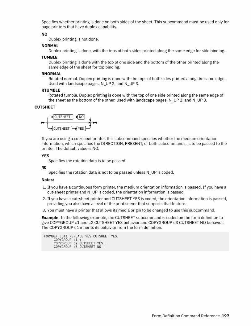
Specifies whether printing is done on both sides of the sheet. This subcommand must be used only forpage printers that have duplex capability.
NODuplex printing is not done.
NORMALDuplex printing is done, with the tops of both sides printed along the same edge for side binding.
TUMBLEDuplex printing is done with the top of one side and the bottom of the other printed along thesame edge of the sheet for top binding.
RNORMALRotated normal. Duplex printing is done with the tops of both sides printed along the same edge.Used with landscape pages, N_UP 2, and N_UP 3.
RTUMBLERotated tumble. Duplex printing is done with the top of one side printed along the same edge ofthe sheet as the bottom of the other. Used with landscape pages, N_UP 2, and N_UP 3.
CUTSHEET
CUTSHEET NO
CUTSHEET YES
If you are using a cut-sheet printer, this subcommand specifies whether the medium orientationinformation, which specifies the DIRECTION, PRESENT, or both subcommands, is to be passed to theprinter. The default value is NO.
YESSpecifies the rotation data is to be passed.
NOSpecifies the rotation data is not to be passed unless N_UP is coded.
Notes:
1. If you have a continuous form printer, the medium orientation information is passed. If you have acut-sheet printer and N_UP is coded, the orientation information is passed.
2. If you have a cut-sheet printer and CUTSHEET YES is coded, the orientation information is passed,providing you also have a level of the print server that supports that feature.
3. You must have a printer that allows its media origin to be changed to use this subcommand.
Example: In the following example, the CUTSHEET subcommand is coded on the form definition togive COPYGROUP c1 and c2 CUTSHEET YES behavior and COPYGROUP c3 CUTSHEET NO behavior.The COPYGROUP c1 inherits its behavior from the form definition.
FORMDEF cut1 REPLACE YES CUTSHEET YES; COPYGROUP c1 ; COPYGROUP c2 CUTSHEET YES ; COPYGROUP c3 CUTSHEET NO ;
Form Definition Command Reference 197

FINISH
FINISH
SCOPE SHEET OPERATION AFP ZFOLD REFERENCE DEFAULT
SCOPE SHEET
SCOPE SHEET
BEGCOLL
CONTCOLL
OPERATION Parameters
A finishing operation is to be done on this COPYGROUP. This option is to be used only on a document,set of documents, or an entire print file.
SCOPEDetermines to which sheets the finishing operation is applied.
Note: SCOPE can be repeated within a FINISH subcommand, but only one SCOPE of a particulartype is allowed in each COPYGROUP command. For example, only one SCOPE BEGCOLL is allowedin a COPYGROUP command.
single sheet scopeOperations with this SCOPE are applied to a single sheet.SHEET
Single sheet Medium-map level scope. The specified finishing operation is applied to eachsheet individually.
collection scopeCollection/Medium-map level scope. All sheets that are generated by this medium map arecollected and the specified finishing operations are applied to this collection.
Note: Some finishing operation combinations are not compatible. Compatible combinationsare dependent upon the presentation-device.
BEGCOLLBegin medium-map level collections, which causes a sheet eject and starts a medium-map-level media collection for the specified operation. If a collection for the samefinishing operation is already in progress from a previous medium map, that collection isended and its specified finishing operation is applied. The media collection started withBEGCOLL continues until:
1. The end of the document is reached.2. A medium map is invoked that is not CONTINUE COLLECTION for this same operation
command.
When a finishing collection is ended for either reason, the specified finishing operation isapplied.
CONTCOLLContinue medium-map level collection, which continues a medium-level media collectionthat was started for the same finishing operation by a previous medium map. The mediacollection started with CONTCOLL continues until:
1. The end of the document is reached.2. A medium map is invoked that is not CONTINUE COLLECTION for this same operation
command.
When a finishing collection is ended for either reason, the specified finishing operation isapplied.
198 Page Printer Formatting Aid: User's Guide
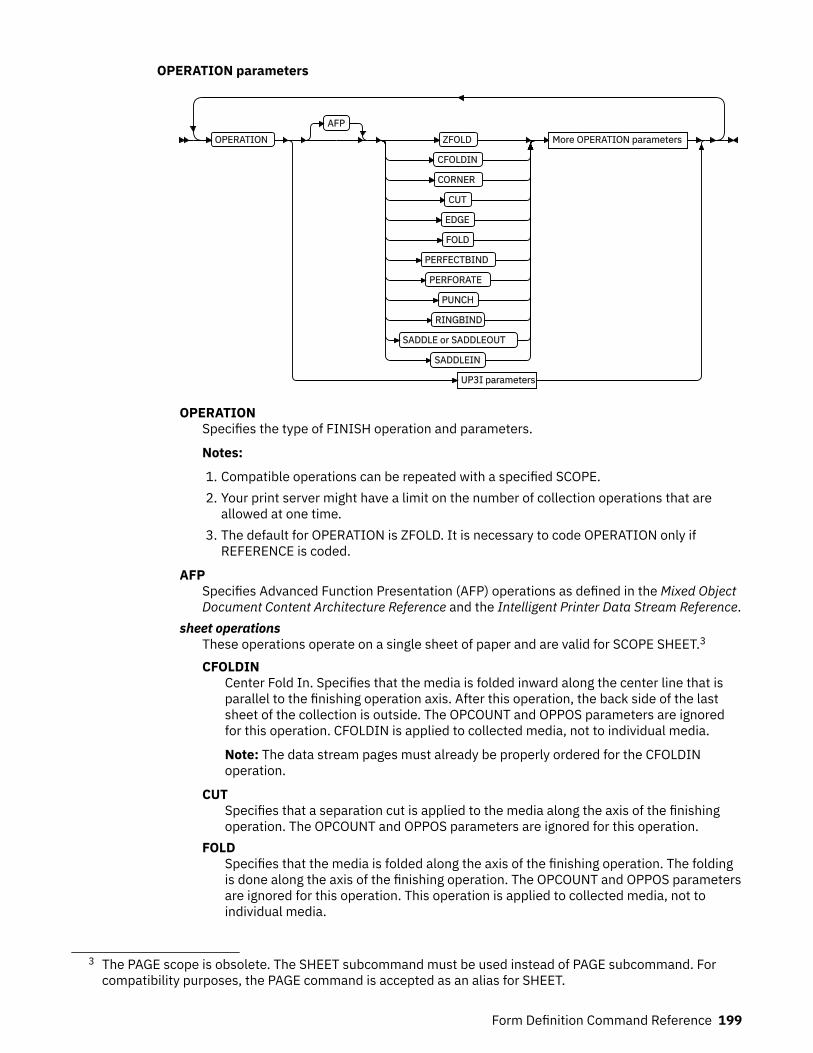
OPERATION parameters
OPERATIONAFP
ZFOLD
CFOLDIN
CORNER
CUT
EDGE
FOLD
PERFECTBIND
PERFORATE
PUNCH
RINGBIND
SADDLE or SADDLEOUT
SADDLEIN
More OPERATION parameters
UP3I parameters
OPERATIONSpecifies the type of FINISH operation and parameters.
Notes:
1. Compatible operations can be repeated with a specified SCOPE.2. Your print server might have a limit on the number of collection operations that are
allowed at one time.3. The default for OPERATION is ZFOLD. It is necessary to code OPERATION only if
REFERENCE is coded.
AFPSpecifies Advanced Function Presentation (AFP) operations as defined in the Mixed ObjectDocument Content Architecture Reference and the Intelligent Printer Data Stream Reference.
sheet operationsThese operations operate on a single sheet of paper and are valid for SCOPE SHEET.3
CFOLDINCenter Fold In. Specifies that the media is folded inward along the center line that isparallel to the finishing operation axis. After this operation, the back side of the lastsheet of the collection is outside. The OPCOUNT and OPPOS parameters are ignoredfor this operation. CFOLDIN is applied to collected media, not to individual media.
Note: The data stream pages must already be properly ordered for the CFOLDINoperation.
CUTSpecifies that a separation cut is applied to the media along the axis of the finishingoperation. The OPCOUNT and OPPOS parameters are ignored for this operation.
FOLDSpecifies that the media is folded along the axis of the finishing operation. The foldingis done along the axis of the finishing operation. The OPCOUNT and OPPOS parametersare ignored for this operation. This operation is applied to collected media, not toindividual media.
3 The PAGE scope is obsolete. The SHEET subcommand must be used instead of PAGE subcommand. Forcompatibility purposes, the PAGE command is accepted as an alias for SHEET.
Form Definition Command Reference 199

PERFORATESpecifies that a perforation cut is applied to the media along the axis of the finishingoperation. The OPCOUNT and OPPOS parameters are ignored for this operation.
PUNCHSpecifies that one or more holes are to be punched or drilled into the media along thefinishing axis. PUNCH is applied to the collected media, not to individual media.
ZFOLDPerform a ZFOLD operation along the finishing edge (axis). Z-Folding causes the sheetto first be folded in half inwards (the front side of the sheet is now inside the fold)along a line parallel to the reference edge. The half of the sheet originally furthest fromthe reference edge is again folded in half outwards along a line parallel to thereference edge. For example, when Z-Folding is applied to an 11 by 17-inch sheet withthe reference edge along a short side, the result is an 8.5 by 11 inch fold-out. TheOPOFFSET, OPCOUNT, and OPPOS parameters are ignored for this operation. Thisoperation is applied to an individual sheet.
Note: REFERENCE is the only parameter that is allowed for ZFOLD and the onlyreference edges that are allowed are DEFAULT, TOP, BOTTOM, LEFT, and RIGHT.
afp collection operationsThese operations operate on a collection of sheets and are valid with BEGCOLL andCONTCOLL.CFOLDIN
Center Fold In. Specifies that the media is folded inward along the center line that isparallel to the finishing operation axis. After this operation, the back side of the lastsheet of the collection is outside. The OPCOUNT and OPPOS parameters are ignoredfor this operation. CFOLDIN is applied to collected media, not to individual media.
Note: The data stream pages must already be properly ordered for the CFOLDINoperation.
CORNERSpecifies that one staple is driven into the media at the reference corner (seeREFERENCE parameter). For corner staples, the offset and angle of the staple from theselected corner is device-dependent. The OPCOUNT and OPPOS parameters areignored for this operation. This operation is applied to collected media, not toindividual media.
CUTSpecifies that a separation cut is applied to the media along the axis of the finishingoperation. The OPCOUNT and OPPOS parameters are ignored for this operation.
EDGESpecifies that one or more staples are driven into the media along the axis of thefinishing operation. This operation is applied to collected media, not to individualmedia.
FOLDSpecifies that the media is folded along the axis of the finishing operation. The foldingis done along the axis of the finishing operation. The OPCOUNT and OPPOS parametersare ignored for this operation. This operation is applied to collected media, not toindividual media.
PERFECTBINDThis operation specifies a type of book binding that glues the sheets of the grouptogether at the reference edge (spine). When you specify PERFECTBIND, theOPOFFSET, OPCOUNT, and OPPOS parameters are ignored.
PERFORATESpecifies that a perforation cut is applied to the media along the axis of the finishingoperation. The OPCOUNT and OPPOS parameters are ignored for this operation.
200 Page Printer Formatting Aid: User's Guide
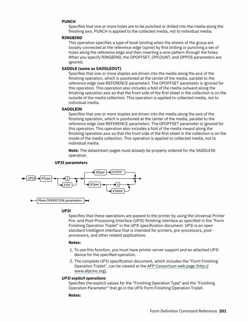
PUNCHSpecifies that one or more holes are to be punched or drilled into the media along thefinishing axis. PUNCH is applied to the collected media, not to individual media.
RINGBINDThis operation specifies a type of book binding when the sheets of the group areloosely connected at the reference edge (spine) by first drilling or punching a set ofholes along the reference edge and then inserting a wire pattern through the holes.When you specify RINGBIND, the OPOFFSET, OPCOUNT, and OPPOS parameters areignored.
SADDLE (same as SADDLEOUT)Specifies that one or more staples are driven into the media along the axis of thefinishing operation, which is positioned at the center of the media, parallel to thereference edge (see REFERENCE parameter). The OPOFFSET parameter is ignored forthis operation. This operation also includes a fold of the media outward along thefinishing operation axis so that the front side of the first sheet in the collection is on theoutside of the media collection. This operation is applied to collected media, not toindividual media.
SADDLEINSpecifies that one or more staples are driven into the media along the axis of thefinishing operation, which is positioned at the center of the media, parallel to thereference edge (see REFERENCE parameter). The OPOFFSET parameter is ignored forthis operation. This operation also includes a fold of the media inward along thefinishing operation axis so that the front side of the first sheet in the collection is on theinside of the media collection. This operation is applied to collected media, not toindividual media.
Note: The datastream pages must already be properly ordered for the SADDLEINoperation.
UP3I parameters
UP3I XType n
X'hh'
XOper X'FFFF'
XOper n
X'hhhh'
More OPERATION parameters
UP3iSpecifies that these operations are passed to the printer by using the Universal PrinterPre- and Post-Processing Interface (UP3i) finishing interface as specified in the "FormFinishing Operation Triplet" in the UP3i specification document. UP3i is an openstandard intelligent interface that is intended for printers, pre-processors, post-processors, and other related applications.
Notes:
1. To use this function, you must have printer server support and an attached UP3idevice for the specified operation.
2. The complete UP3i specification document, which includes the "Form FinishingOperation Triplet", can be viewed at the AFP Consortium web page (http://www.afpcinc.org).
UP3i explicit operationsSpecifies the explicit values for the "Finishing Operation Type" and the "FinishingOperation Parameter" that go in the UP3i Form Finishing Operation Triplet.
Notes:
Form Definition Command Reference 201

1. PPFA does not check that the XType, XOper, or operation parameters arecontextually correct. Therefore, new UP3i operations and parameters can be codedwithout having to install a new PPFA module. However, it also allows contextuallyincorrect operation and parameter values to be entered.
2. See Table 9 on page 203 for values of XType and XOper.
XTypeExplicit Operation Type. Specify in hexadecimal or a decimal equivalent numberthe Finishing Operation Type. A value of 0 specifies a No Operation/Pass throughpaper operation. When 0 is coded in this field, the XOper field is ignored. Enter 2hexadecimal digits or a decimal number less than or equal to 255.
XOperExplicit Operation or Operation Parameter. Specify in hexadecimal or a decimalequivalent number the Finishing Operation Type. A value of X'FFFF' specifies thedevice default operation for the specified finishing operation for the specifiedFinishing Operation Type in the XType parameter. Enter 4 hexadecimal digits or adecimal number less than or equal to 65535.
More OPERATION parameters
REFERENCE DEFAULT
REFERENCE TOP
BOTTOM
LEFT
RIGHT
TOPLEFT
TOPRIGHT
BOTLEFT
BOTRIGHT
OPCOUNT n
OPPOS n
OPOFFSET n
These operation parameters apply to both AFP and UP3i Operations with the notedexceptions.
REFERENCESelects the reference edge or corner for the finishing operation. The REFERENCEsubcommand is optional and, when omitted, the DEFAULT attribute is the default.DEFAULT
Specifies that the device default edge determines the reference edge.TOPLEFT
Specifies that the reference corner is positioned at the top in the left corner. ThisREFERENCE parameter can be used only for CORNER operations.
TOPRIGHTSpecifies that the reference corner is positioned at the top in the right corner. ThisREFERENCE parameter can be used only for CORNER operations.
BOTRIGHTSpecifies that the reference corner is positioned at the bottom in the right corner.This REFERENCE parameter can be used only for CORNER operations.
BOTLEFTSpecifies that the reference corner is positioned at the bottom in the left corner.This REFERENCE parameter can be used only for CORNER operations.
TOPSpecifies that the reference is positioned along the top edge.
202 Page Printer Formatting Aid: User's Guide
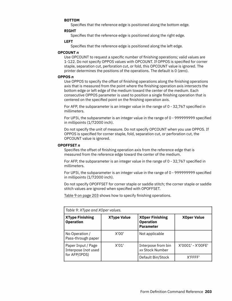
BOTTOMSpecifies that the reference edge is positioned along the bottom edge.
RIGHTSpecifies that the reference edge is positioned along the right edge.
LEFTSpecifies that the reference edge is positioned along the left edge.
OPCOUNT nUse OPCOUNT to request a specific number of finishing operations; valid values are1-122. Do not specify OPPOS values with OPCOUNT. If OPPOS is specified for cornerstaple, separation cut, perforation cut, or fold, this OPCOUNT value is ignored. Theprinter determines the positions of the operations. The default is 0 (zero).
OPPOS nUse OPPOS to specify the offset of finishing operations along the finishing operationsaxis that is measured from the point where the finishing operation axis intersects thebottom edge or left edge of the medium toward the center of the medium. Eachconsecutive OPPOS parameter is used to position a single finishing operation that iscentered on the specified point on the finishing operation axis.
For AFP, the subparameter is an integer value in the range of 0 - 32,767 specified inmillimeters.
For UP3i, the subparameter is an integer value in the range of 0 - 999999999 specifiedin millipoints (1/72000 inch).
Do not specify the unit of measure. Do not specify OPCOUNT when you use OPPOS. IfOPPOS is specified for corner staple, fold, separation cut, or perforation cut, theOPCOUNT value is ignored.
OPOFFSET nSpecifies the offset of finishing operation axis from the reference edge that ismeasured from the reference edge toward the center of the medium.
For AFP, the subparameter is an integer value in the range of 0 - 32,767 specified inmillimeters.
For UP3i, the subparameter is an integer value in the range of 0 - 999999999 specifiedin millipoints (1/72000 inch).
Do not specify OPOFFSET for corner staple or saddle stitch; the corner staple or saddlestitch values are ignored when specified with OPOFFSET.
Table 9 on page 203 shows how to specify finishing operations.
Table 9: XType and XOper values.
XType FinishingOperation
XType Value XOper FinishingOperationParameter
XOper Value
No Operation /Pass-through paper
X'00' Not applicable
Paper Input / PageInterpose (not usedfor AFP/IPDS)
X'01' Interpose from binxx Stock Number
X'0001' - X'00FE'
Default Bin/Stock X'FFFF'
Form Definition Command Reference 203

Table 9: XType and XOper values. (continued)
XType FinishingOperation
XType Value XOper FinishingOperationParameter
XOper Value
Fold X'03' Folding parametersfrom fold catalog
X'100D'
No Fold X'0000'
Default X'FFFF'
Staple / Stitch X'04' Corner Staple X'0001'
Saddle Stitch In X'0002'
Saddle Stitch Out X'0003'
Edge Stitch X'0004'
Default X'FFFF'
Cut X'05' Separation Cut X'0001'
Perforation Cut X'0002'
Cross Cut X'0003'
Default X'FFFF'
Trim X'06' Front Edge X'0001'
1 Edge X'0002'
3 Edge X'0003'
5 Edge X'0004'
Default X'FFFF'
Offset / GroupSeparator / JobSeparator
X'07' Offset to Left X'0001'
Offset to Right X'0002'
Device Default X'FFFF'
Stack X'08' Alternate OffsetStack
X'0001'
Device Default X'FFFF'
Rotate X'09' 90° Clockwise X'0001'
180° Clockwise X'0002'
270° Clockwise X'0003'
Device Default X'FFFF'
Punch X'0A' Round Hole X'0001'
Rectangular Hole X'0002'
Device Default X'FFFF'
Bind X'0B' Device Default X'FFFF'
204 Page Printer Formatting Aid: User's Guide
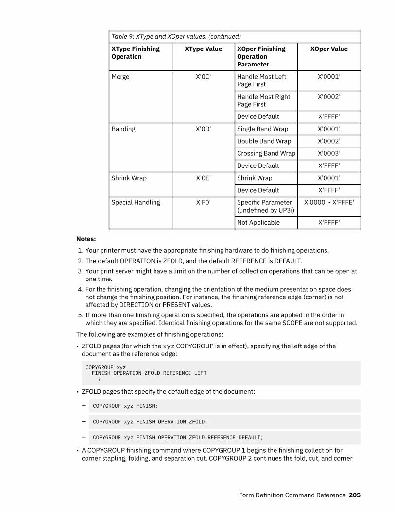
Table 9: XType and XOper values. (continued)
XType FinishingOperation
XType Value XOper FinishingOperationParameter
XOper Value
Merge X'0C' Handle Most LeftPage First
X'0001'
Handle Most RightPage First
X'0002'
Device Default X'FFFF'
Banding X'0D' Single Band Wrap X'0001'
Double Band Wrap X'0002'
Crossing Band Wrap X'0003'
Device Default X'FFFF'
Shrink Wrap X'0E' Shrink Wrap X'0001'
Device Default X'FFFF'
Special Handling X'F0' Specific Parameter(undefined by UP3i)
X'0000' - X'FFFE'
Not Applicable X'FFFF'
Notes:
1. Your printer must have the appropriate finishing hardware to do finishing operations.2. The default OPERATION is ZFOLD, and the default REFERENCE is DEFAULT.3. Your print server might have a limit on the number of collection operations that can be open at
one time.4. For the finishing operation, changing the orientation of the medium presentation space does
not change the finishing position. For instance, the finishing reference edge (corner) is notaffected by DIRECTION or PRESENT values.
5. If more than one finishing operation is specified, the operations are applied in the order inwhich they are specified. Identical finishing operations for the same SCOPE are not supported.
The following are examples of finishing operations:
• ZFOLD pages (for which the xyz COPYGROUP is in effect), specifying the left edge of thedocument as the reference edge:
COPYGROUP xyz FINISH OPERATION ZFOLD REFERENCE LEFT ;
• ZFOLD pages that specify the default edge of the document:
– COPYGROUP xyz FINISH;
– COPYGROUP xyz FINISH OPERATION ZFOLD;
– COPYGROUP xyz FINISH OPERATION ZFOLD REFERENCE DEFAULT;
• A COPYGROUP finishing command where COPYGROUP 1 begins the finishing collection forcorner stapling, folding, and separation cut. COPYGROUP 2 continues the fold, cut, and corner
Form Definition Command Reference 205
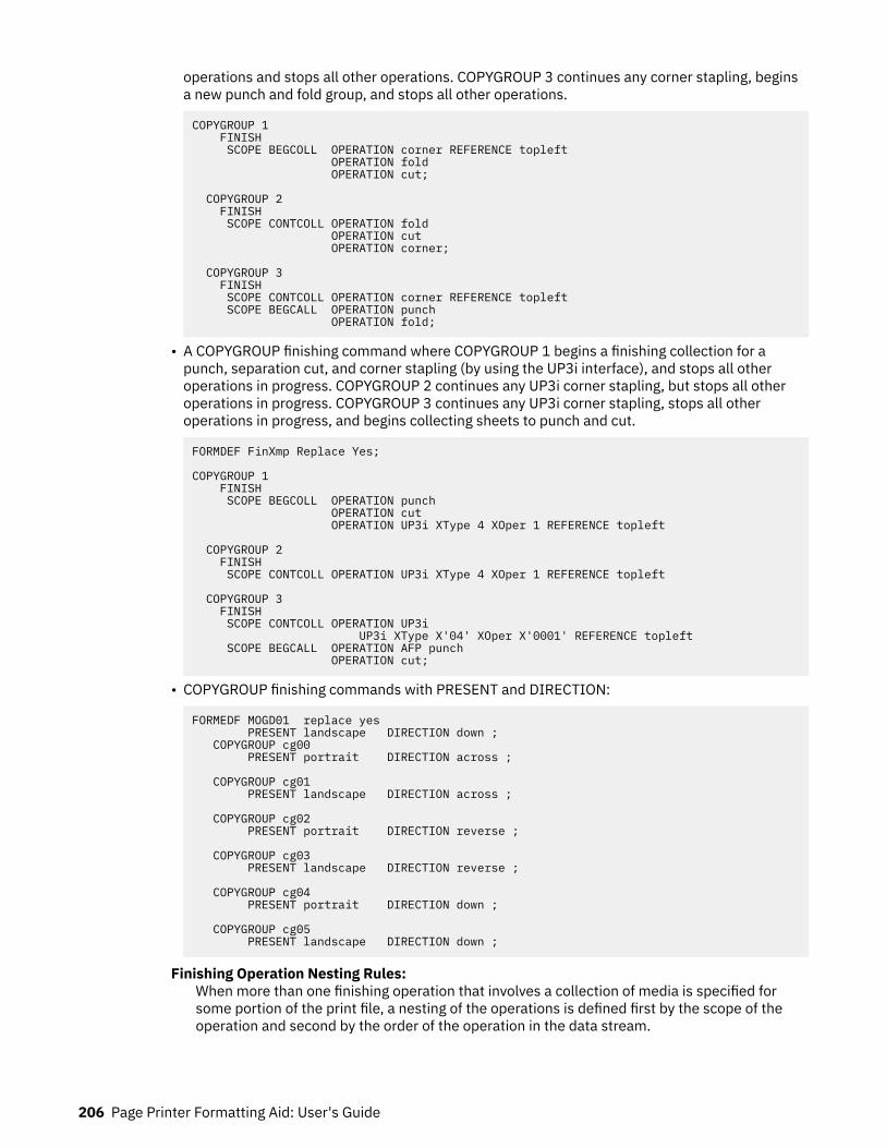
operations and stops all other operations. COPYGROUP 3 continues any corner stapling, beginsa new punch and fold group, and stops all other operations.
COPYGROUP 1 FINISH SCOPE BEGCOLL OPERATION corner REFERENCE topleft OPERATION fold OPERATION cut;
COPYGROUP 2 FINISH SCOPE CONTCOLL OPERATION fold OPERATION cut OPERATION corner;
COPYGROUP 3 FINISH SCOPE CONTCOLL OPERATION corner REFERENCE topleft SCOPE BEGCALL OPERATION punch OPERATION fold;
• A COPYGROUP finishing command where COPYGROUP 1 begins a finishing collection for apunch, separation cut, and corner stapling (by using the UP3i interface), and stops all otheroperations in progress. COPYGROUP 2 continues any UP3i corner stapling, but stops all otheroperations in progress. COPYGROUP 3 continues any UP3i corner stapling, stops all otheroperations in progress, and begins collecting sheets to punch and cut.
FORMDEF FinXmp Replace Yes;
COPYGROUP 1 FINISH SCOPE BEGCOLL OPERATION punch OPERATION cut OPERATION UP3i XType 4 XOper 1 REFERENCE topleft
COPYGROUP 2 FINISH SCOPE CONTCOLL OPERATION UP3i XType 4 XOper 1 REFERENCE topleft
COPYGROUP 3 FINISH SCOPE CONTCOLL OPERATION UP3i UP3i XType X'04' XOper X'0001' REFERENCE topleft SCOPE BEGCALL OPERATION AFP punch OPERATION cut;
• COPYGROUP finishing commands with PRESENT and DIRECTION:
FORMEDF MOGD01 replace yes PRESENT landscape DIRECTION down ; COPYGROUP cg00 PRESENT portrait DIRECTION across ;
COPYGROUP cg01 PRESENT landscape DIRECTION across ;
COPYGROUP cg02 PRESENT portrait DIRECTION reverse ;
COPYGROUP cg03 PRESENT landscape DIRECTION reverse ;
COPYGROUP cg04 PRESENT portrait DIRECTION down ;
COPYGROUP cg05 PRESENT landscape DIRECTION down ;
Finishing Operation Nesting Rules:When more than one finishing operation that involves a collection of media is specified forsome portion of the print file, a nesting of the operations is defined first by the scope of theoperation and second by the order of the operation in the data stream.
206 Page Printer Formatting Aid: User's Guide

Finishing operations with a broader scope are nested outside of finishing operations with anarrower scope. The following scopes are listed in descending order:
1. Print-file level finishing (SCOPE PRINTFILE)2. Document-level finishing, each document in the print file (SCOPE ALL)3. Document-level finishing, a selected document in the PRINTFILE (SCOPE n)4. Medium-map-level finishing, a collection of sheets (SCOPE BEGCOLL)
Finishing Operation Implementation Notes:
1. AFP environments limit the number of finishing operations that can be nested at themedium map (COPYGROUP) level. Check your PSF documentation for these limits.
2. In AFP environments, the nesting of identical finishing operations at the medium-map-levelis not supported. Two finishing operations are identical if the OPERATION, REFERENCE,OPCOUNT or OPPOS, and OPOFFSET are the same.
3. For some printers, the JOG function cannot be combined with a finishing operation. In thiscase, the JOG function is ignored. Check your printer documentation.
ADJUST n
ADJUST n
Establishes the range of horizontal adjustment for the print area on the sheet.
nThe adjustment range can be set 0 - 20 L-units. After a value is set, it is the maximum amountavailable in both directions, plus and minus.
Notes:
1. If you specify ADJUST, the maximum logical page size (in the horizontal direction) is reduced bythe amount you specified here.
2. The ADJUST n subcommand is used only on the IBM 3800 printers.
INVOKE
INVOKE SHEET
INVOKE NEXT
FRONT
BACK
Specifies where the next page of data is placed when this copy group is activated by conditionalprocessing or by an Invoke Medium Map structured field.
INVOKE SHEET, which is the default, places the next page of data on a new sheet. The NEXT, FRONT,and BACK parameters place the next page in a subsequent partition on the same sheet or, if nopartitions are available, on the next sheet. If FRONT or BACK is specified, INVOKE selects onlypartitions on the front or back.
The print server honors the NEXT, FRONT, and BACK values of the INVOKE subcommand only if thenew copy group has the same medium modifications as the previous copy group. Some examples ofmedium modifications are duplexing, input bin, output bin, page offset, N_UP values, presentation,direction, medium (not page) overlays, text suppression, processing functions, print quality, finishing,jogging, and constant forms control. See the Media Eject Control Triplet (X'45') section in the MixedObject Document Content Architecture Reference for a full description of the factors that allow aconditional eject to the next partition instead of the next sheet.
Form Definition Command Reference 207
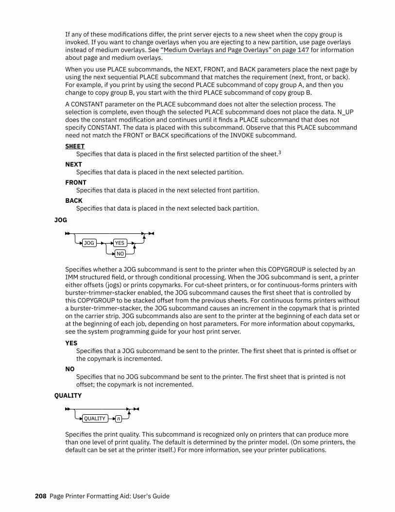
If any of these modifications differ, the print server ejects to a new sheet when the copy group isinvoked. If you want to change overlays when you are ejecting to a new partition, use page overlaysinstead of medium overlays. See “Medium Overlays and Page Overlays” on page 147 for informationabout page and medium overlays.
When you use PLACE subcommands, the NEXT, FRONT, and BACK parameters place the next page byusing the next sequential PLACE subcommand that matches the requirement (next, front, or back).For example, if you print by using the second PLACE subcommand of copy group A, and then youchange to copy group B, you start with the third PLACE subcommand of copy group B.
A CONSTANT parameter on the PLACE subcommand does not alter the selection process. Theselection is complete, even though the selected PLACE subcommand does not place the data. N_UPdoes the constant modification and continues until it finds a PLACE subcommand that does notspecify CONSTANT. The data is placed with this subcommand. Observe that this PLACE subcommandneed not match the FRONT or BACK specifications of the INVOKE subcommand.SHEET
Specifies that data is placed in the first selected partition of the sheet.3
NEXTSpecifies that data is placed in the next selected partition.
FRONTSpecifies that data is placed in the next selected front partition.
BACKSpecifies that data is placed in the next selected back partition.
JOG
JOG YES
NO
Specifies whether a JOG subcommand is sent to the printer when this COPYGROUP is selected by anIMM structured field, or through conditional processing. When the JOG subcommand is sent, a printereither offsets (jogs) or prints copymarks. For cut-sheet printers, or for continuous-forms printers withburster-trimmer-stacker enabled, the JOG subcommand causes the first sheet that is controlled bythis COPYGROUP to be stacked offset from the previous sheets. For continuous forms printers withouta burster-trimmer-stacker, the JOG subcommand causes an increment in the copymark that is printedon the carrier strip. JOG subcommands also are sent to the printer at the beginning of each data set orat the beginning of each job, depending on host parameters. For more information about copymarks,see the system programming guide for your host print server.
YESSpecifies that a JOG subcommand be sent to the printer. The first sheet that is printed is offset orthe copymark is incremented.
NOSpecifies that no JOG subcommand be sent to the printer. The first sheet that is printed is notoffset; the copymark is not incremented.
QUALITY
QUALITY n
Specifies the print quality. This subcommand is recognized only on printers that can produce morethan one level of print quality. The default is determined by the printer model. (On some printers, thedefault can be set at the printer itself.) For more information, see your printer publications.
208 Page Printer Formatting Aid: User's Guide

nYou can select a level of print quality by entering any whole number 1 - 10. Higher numberscorrespond to higher levels of print quality; lower numbers correspond to lower levels. For moreinformation, see your printer publications.
Print quality is determined by a numerical code in the range of 1 - 254 (hexadecimal X'01' - X'FE').The codes corresponding to the possible QUALITY parameters are:
1 = 15 (X'0F')2 = 40 (X'28')3 = 65 (X'41')4 = 90 (X'5A')5 = 115 (X'73')6 = 140 (X'8C')7 = 165 (X'A5')8 = 190 (X'BE')9 = 215 (X'D7')10 = 240 (X'F0')
PROCESSING
PROCESSING
MEDIA_INFO n
PERFORATE
CUT
Specifies more post processing capabilities for selected printers and attached equipment. This optioncan be used only on a single sheet or collection of sheets. This subcommand expects 1 - 3 of thefollowing keywords:
MEDIA_INFO nThis parameter specifies the ID of fixed medium information that a printer or printer-attacheddevice applies to a sheet. Examples include color plates logos, letter heads, and other fixedimages.
The numeric values that can be included are:0 - 254
These numeric values select a particular fixed medium local ID that the printer or printer-attached device applies to a sheet. One or more IDs can be specified within this range.
255This value selects all the current fixed medium local IDs that the printer or printer-attacheddevices applies to a sheet.
PERFORATESpecifies a perforation cut at one or more fixed locations on the sheet according to the printer orprinter-attached device.
CUTSpecifies a separation cut at one or more fixed locations on the sheet according to the printer orprinter-attached device.
Form Definition Command Reference 209

N_UP
N_UP 1
2
3
4OVERLAY Subcommand
PLACE Subcommand
PELSPERINCH n
{ 1 | 2 | 3 | 4 }Specifies the number 1, 2, 3, or 4 of equal-size partitions into which the sheet is divided. See thelist of printers that support the N_UP subcommand.
If you do not specify the N_UP subcommand in the COPYGROUP command, the N_UPsubcommand from the FORMDEF command is the default for the COPYGROUP command. You canmix N_UP printing and non-N_UP printing by specifying or not specifying the N_UP subcommandin each copy group and by not specifying N_UP in the FORMDEF command.
OVERLAY SubcommandOVERLAY name
rel-x rel-y PARTITION
OVROTATE 0
OVROTATE 90
180
270
nameSpecifies the user access name (up to 6 characters) of an overlay to be placed with every pagein each of the N_UP partitions. You can specify a maximum of 254 OVERLAY subcommands ina copy group.
Notes:
1. The prefix ‘O1’ is not part of the six-character user-access name. The overlay name can bean alphanumeric.
2. This name is not related to names as defined on the OVERLAY command.
rel-x rel-ySpecifies the horizontal and vertical adjustment to the position of the overlay. This adjustmentis in addition to any offset values built into the overlay. The x and y values can be positive (+) ornegative (-). You can specify them in inches (IN), millimeters (MM), centimeters (CM), POINTS,or PELS. If you do not specify a unit value, PPFA uses the unit value that is specified in the lastSETUNITS command or uses a default unit value of inches.
Note: This OVERLAY subcommand cannot be specified if the PLACE subcommand is specified.
PARTITIONSpecifies that the overlay is to be placed relative to the partition origin.
OVROTATESpecifies the rotation of the placed overlay in regard to the x-axis of the page.
210 Page Printer Formatting Aid: User's Guide

Example: Assuming the overlay has ( 0,0 ) placement coordinates, this causes page overlay01x2 to be placed 1.5 inches to the right and 2.7 inches below the beginning of the page androtated 90 degrees clockwise in regard to the page.
Formdef xmp1 N_UP 1 PLACE 1 FRONT OVERLAY x2 1.5 in 2.7 in OVROTATE 90;
PLACE Subcommand
PLACE n
FRONT
BACK CONSTANT OFFSET rel-x rel-y
OVERLAY Subcommand
ROTATION 0
ROTATION 90
180
270
VIEW YES
VIEW NO
Places a page of data or a constant modification relative to a partition. Each PLACE subcommandspecifies the number n of a partition on either the front or back side of the sheet. FRONT is thedefault, if you do not specify this subcommand. You must specify the same number of PLACEsubcommands as the number of partitions on the sheet. The sequence of the PLACEsubcommands is the sequence in which incoming pages are placed in the partitions.
Notes:
1. The use of the PLACE subcommand indicates enhanced N_UP printing.2. The PLACE subcommand is valid only on printers that support enhanced N_UP printing. If
PLACE is not specified, pages are placed in partitions in the default partition sequence.
nSpecifies the numbered partition (1 - 4) into which the page of data is placed. See Figure 94 onpage 130 through Figure 97 on page 131 for the locale of each numbered partition.
FRONTSpecifies that this partition is placed on the front side of the sheet.
BACKSpecifies that this partition is placed on the back side of the sheet.
CONSTANTSpecifies that no page data is placed by this PLACE subcommand.
Use CONSTANT when you are placing overlays without user's data or are placing fewer datapages on the sheet than the number of partitions that are specified in the N_UP subcommand.
For an example of using the CONSTANT parameter with overlays and to understand how theordering of the PLACE subcommand affects overlays, see “Example 3: Enhanced N_UPAsymmetric Pages” on page 145.
OFFSETSpecifies a relative offset of the page horizontally (x) and vertically (y) from the partition origin.rel-x rel-y
The default value is 0.1 inches for both x and y offsets. This OFFSET parameter overridesany other OFFSET parameters that are specified on the FORMDEF or COPYGROUPcommand. You can specify the units in inches (in), millimeters (mm), centimeters (cm),points, or pels. If you do not specify a unit value, PPFA uses the unit value that is specifiedin the last SETUNITS command or uses a default unit value of inches.
Form Definition Command Reference 211

Note: You can specify this offset as negative to crop the top, left, or both of an image.
OVERLAY SubcommandSee OVERLAY Subcommand.
ROTATION { 0 | 90 | 180 | 270 }Specifies the clockwise rotation of the page and associated page overlays placed by thisPLACE command.
Rotation turns the page and its associated page overlays around their fixed origin points. If yourotate the page without moving its origin point, you might rotate it off the physical medium. Toprevent this situation, always offset the page origin to the place you want it to be for therotated page, as shown in Figure 125 on page 212.
Figure 125: Offsetting the Page Origin for Rotated Pages
VIEWDetermines whether this N_UP PLACE page is viewable. VIEW is relevant only when the pageis being presented on a display. VIEW is ignored if the page is being printed. If VIEW is notcoded, it is equivalent to specifying VIEW YES.YES
Specifies that this N_UP page is viewable and is presented.NO
Specifies that this N_UP page is not to be presented.OVERLAY Subcommand
See OVERLAY Subcommand for the syntax. Specifies the user access name (up to 6 characters) ofan overlay to be placed with this PLACE subcommand. The overlay is placed relative to the pageorigin or, if the PARTITION keyword is specified, to the partition origin. You can specify multipleOVERLAY parameters in each PLACE subcommand.
Note: This OVERLAY subcommand cannot be specified if the PLACE subcommand is specified.
rel-x rel-ySpecifies the horizontal and vertical adjustment to the position of the overlay. This adjustmentis in addition to any offset values built into the overlay. The x and y values can be positive (+)and negative (-). You can specify them in inches (in), millimeters (mm), centimeters (cm),points, or pels. If you do not specify a unit value, PPFA uses the unit value that is specified inthe last SETUNITS command or uses a default value of inches.
PARTITIONSpecifies that the previous offset is from the partition origin. If not present, the offset is fromthe page origin, which is subject to the OFFSET parameter.
212 Page Printer Formatting Aid: User's Guide
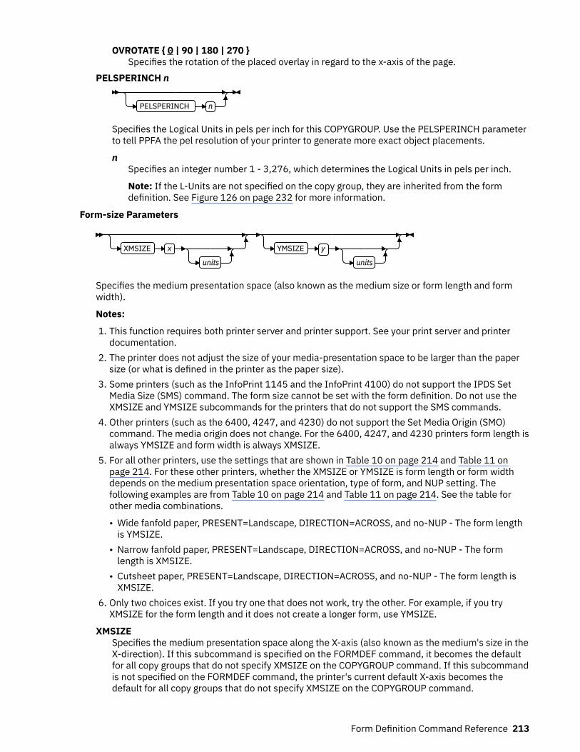
OVROTATE { 0 | 90 | 180 | 270 }Specifies the rotation of the placed overlay in regard to the x-axis of the page.
PELSPERINCH n
PELSPERINCH n
Specifies the Logical Units in pels per inch for this COPYGROUP. Use the PELSPERINCH parameterto tell PPFA the pel resolution of your printer to generate more exact object placements.
nSpecifies an integer number 1 - 3,276, which determines the Logical Units in pels per inch.
Note: If the L-Units are not specified on the copy group, they are inherited from the formdefinition. See Figure 126 on page 232 for more information.
Form-size Parameters
XMSIZE x
units
YMSIZE y
units
Specifies the medium presentation space (also known as the medium size or form length and formwidth).
Notes:
1. This function requires both printer server and printer support. See your print server and printerdocumentation.
2. The printer does not adjust the size of your media-presentation space to be larger than the papersize (or what is defined in the printer as the paper size).
3. Some printers (such as the InfoPrint 1145 and the InfoPrint 4100) do not support the IPDS SetMedia Size (SMS) command. The form size cannot be set with the form definition. Do not use theXMSIZE and YMSIZE subcommands for the printers that do not support the SMS commands.
4. Other printers (such as the 6400, 4247, and 4230) do not support the Set Media Origin (SMO)command. The media origin does not change. For the 6400, 4247, and 4230 printers form length isalways YMSIZE and form width is always XMSIZE.
5. For all other printers, use the settings that are shown in Table 10 on page 214 and Table 11 onpage 214. For these other printers, whether the XMSIZE or YMSIZE is form length or form widthdepends on the medium presentation space orientation, type of form, and NUP setting. Thefollowing examples are from Table 10 on page 214 and Table 11 on page 214. See the table forother media combinations.
• Wide fanfold paper, PRESENT=Landscape, DIRECTION=ACROSS, and no-NUP - The form lengthis YMSIZE.
• Narrow fanfold paper, PRESENT=Landscape, DIRECTION=ACROSS, and no-NUP - The formlength is XMSIZE.
• Cutsheet paper, PRESENT=Landscape, DIRECTION=ACROSS, and no-NUP - The form length isXMSIZE.
6. Only two choices exist. If you try one that does not work, try the other. For example, if you tryXMSIZE for the form length and it does not create a longer form, use YMSIZE.
XMSIZESpecifies the medium presentation space along the X-axis (also known as the medium's size in theX-direction). If this subcommand is specified on the FORMDEF command, it becomes the defaultfor all copy groups that do not specify XMSIZE on the COPYGROUP command. If this subcommandis not specified on the FORMDEF command, the printer's current default X-axis becomes thedefault for all copy groups that do not specify XMSIZE on the COPYGROUP command.
Form Definition Command Reference 213
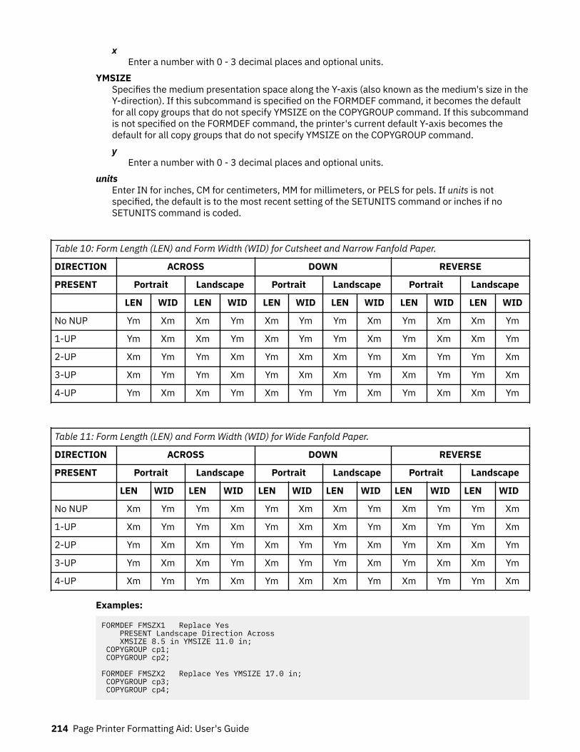
xEnter a number with 0 - 3 decimal places and optional units.
YMSIZESpecifies the medium presentation space along the Y-axis (also known as the medium's size in theY-direction). If this subcommand is specified on the FORMDEF command, it becomes the defaultfor all copy groups that do not specify YMSIZE on the COPYGROUP command. If this subcommandis not specified on the FORMDEF command, the printer's current default Y-axis becomes thedefault for all copy groups that do not specify YMSIZE on the COPYGROUP command.y
Enter a number with 0 - 3 decimal places and optional units.units
Enter IN for inches, CM for centimeters, MM for millimeters, or PELS for pels. If units is notspecified, the default is to the most recent setting of the SETUNITS command or inches if noSETUNITS command is coded.
Table 10: Form Length (LEN) and Form Width (WID) for Cutsheet and Narrow Fanfold Paper.
DIRECTION ACROSS DOWN REVERSE
PRESENT Portrait Landscape Portrait Landscape Portrait Landscape
LEN WID LEN WID LEN WID LEN WID LEN WID LEN WID
No NUP Ym Xm Xm Ym Xm Ym Ym Xm Ym Xm Xm Ym
1-UP Ym Xm Xm Ym Xm Ym Ym Xm Ym Xm Xm Ym
2-UP Xm Ym Ym Xm Ym Xm Xm Ym Xm Ym Ym Xm
3-UP Xm Ym Ym Xm Ym Xm Xm Ym Xm Ym Ym Xm
4-UP Ym Xm Xm Ym Xm Ym Ym Xm Ym Xm Xm Ym
Table 11: Form Length (LEN) and Form Width (WID) for Wide Fanfold Paper.
DIRECTION ACROSS DOWN REVERSE
PRESENT Portrait Landscape Portrait Landscape Portrait Landscape
LEN WID LEN WID LEN WID LEN WID LEN WID LEN WID
No NUP Xm Ym Ym Xm Ym Xm Xm Ym Xm Ym Ym Xm
1-UP Xm Ym Ym Xm Ym Xm Xm Ym Xm Ym Ym Xm
2-UP Ym Xm Xm Ym Xm Ym Ym Xm Ym Xm Xm Ym
3-UP Ym Xm Xm Ym Xm Ym Ym Xm Ym Xm Xm Ym
4-UP Xm Ym Ym Xm Ym Xm Xm Ym Xm Ym Ym Xm
Examples:
FORMDEF FMSZX1 Replace Yes PRESENT Landscape Direction Across XMSIZE 8.5 in YMSIZE 11.0 in; COPYGROUP cp1; COPYGROUP cp2;
FORMDEF FMSZX2 Replace Yes YMSIZE 17.0 in; COPYGROUP cp3; COPYGROUP cp4;
214 Page Printer Formatting Aid: User's Guide

• In the first example, the printer is a 4400 thermal printer, which supports both SMS and SMO IPDScommands. The form definition that is named FMSZX1 defines a form length of 8.5 inches and formwidth of 11.0 inches. COPYGROUP cp1 and cp2 inherit those sizes from the form definition.
• In the second example, the printer is a 6400 printer and you want to define the form length. Theform definition that is named FMSZX2 defines form length as 17 inches and leaves the form width asthe printer default. COPYGROUP cp3 and cp4 inherit those sizes from the form definition.
• If this example is run on z/OS with FORMLEN defined in the JCL, the JCL definition is used.
Form Definition Command Reference 215

FORMDEF CommandFORMDEF name
OFFSET rel-x - rel-y
rel-x - rel-y
REPLACE NO
REPLACE YES
BIN 1
BINn
MANUAL
ENVELOPE
MEDIANAME qstring COMPID m
OUTBIN n CONSTANT NO
BACK
FRONT
BOTH
CUTSHEET NO
CUTSHEET YES DIRECTION ACROSS
DOWN
REVERSE
DUPLEX NO
NORMAL
TUMBLE
RNORMAL
RTUMBLE
PRESENT PORTRAIT
LANDSCAPE
FINISH
SCOPE PRINTFILE
SCOPE ALL
n
OPERATION Parameters
ADJUST n
INVOKE SHEET
INVOKE NEXT
FRONT
BACK
JOG YES
NO
QUALITY n
CMRTAGFIDELITY STOP
CONTINUE
NOREPORT
REPORT
PROCESSING
MEDIA_INFO n
PERFORATE
CUT
COMMENT qstring
COMPATPGP1
PELSPERINCH n BINERROR STOP
CONTINUE
COLORVALUERR STOP
COLORVALUERR CONTINUE
NOREPORT
REPORT
FINERROR CONTINUE REPORT
FINERROR STOP
CONTINUE
NOREPORT
REPORT
FONTFID NO
FONTFID YES
TONERSAVER DEVSETTING
TONERSAVER OFF
ON
N_UP 1
2
3
4OVERLAY Subcommand
PLACE Subcommand
VFYSETUP verificationID
VFYSETUPD decimal/verificationIDs
TEXTERROR STOP
CONTINUE
NOREPORT
REPORT
Form-size Parameters
OPERATION Parameters
216 Page Printer Formatting Aid: User's Guide
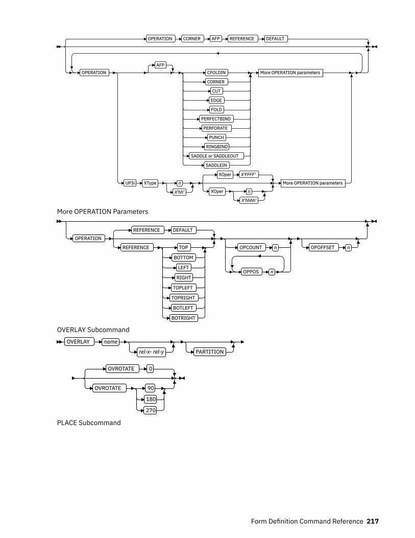
OPERATION CORNER AFP REFERENCE DEFAULT
OPERATIONAFP
CFOLDIN
CORNER
CUT
EDGE
FOLD
PERFECTBIND
PERFORATE
PUNCH
RINGBIND
SADDLE or SADDLEOUT
SADDLEIN
More OPERATION parameters
UP3i XType n
X'hh'
XOper X'FFFF'
XOper n
X'hhhh'
More OPERATION parameters
More OPERATION Parameters
OPERATION
REFERENCE DEFAULT
REFERENCE TOP
BOTTOM
LEFT
RIGHT
TOPLEFT
TOPRIGHT
BOTLEFT
BOTRIGHT
OPCOUNT n
OPPOS n
OPOFFSET n
OVERLAY SubcommandOVERLAY name
rel-x- rel-y PARTITION
OVROTATE 0
OVROTATE 90
180
270
PLACE Subcommand
Form Definition Command Reference 217

PLACE1
n
FRONT
BACK CONSTANT OFFSET rel-x rel-y
OVERLAY Subcommand
ROTATION 0
ROTATION 90
180
270
VIEW YES
VIEW NO
;
Notes:1 The use of the PLACE subcommand indicates enhanced N_UP printing.
Form-size Parameters
XMSIZE x
units
YMSIZE y
units
A form definition is a resource that contains all the controls that relate to the physical sheet. A FORMDEFcommand must be specified when you define a new form definition. When subcommands (except for theREPLACE, PRESENT, and DIRECTION subcommands) are specified, they become the defaults for allCOPYGROUP commands nested within this form definition.FORMDEF
Identifies the form definition to be used with the print job.name
Defines an alphanumeric name of 1 - 8 characters for the form definition. When you create a formdefinition, PPFA assigns a prefix of F1 to the name you specify. F1nnnnnn is the external resourcename in the form-definition library.
SubcommandsOFFSET
OFFSET rel-x - rel-y
rel-x - rel-y
Specifies the offset of the logical page for both the front and back pages in regard to the media origin.The media origin is printer-dependent. For more information about media origin, see your printerpublications or Advanced Function Presentation: Printer Information.
If you specify offset values for the back of the page, you must also specify the front offset values.
Notes:
1. The OFFSET subcommand does not affect the position of medium overlays.2. You can specify this offset as negative to crop the top, left, or both of an image.
218 Page Printer Formatting Aid: User's Guide
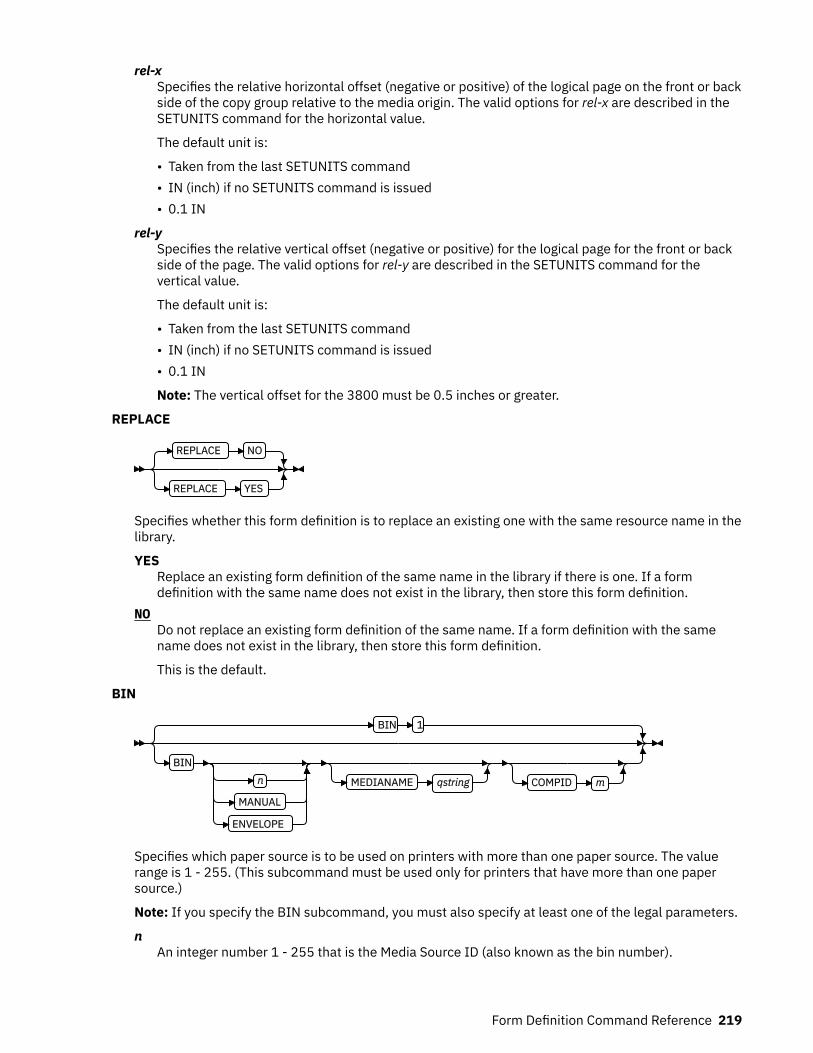
rel-xSpecifies the relative horizontal offset (negative or positive) of the logical page on the front or backside of the copy group relative to the media origin. The valid options for rel-x are described in theSETUNITS command for the horizontal value.
The default unit is:
• Taken from the last SETUNITS command• IN (inch) if no SETUNITS command is issued• 0.1 IN
rel-ySpecifies the relative vertical offset (negative or positive) for the logical page for the front or backside of the page. The valid options for rel-y are described in the SETUNITS command for thevertical value.
The default unit is:
• Taken from the last SETUNITS command• IN (inch) if no SETUNITS command is issued• 0.1 IN
Note: The vertical offset for the 3800 must be 0.5 inches or greater.
REPLACE
REPLACE NO
REPLACE YES
Specifies whether this form definition is to replace an existing one with the same resource name in thelibrary.
YESReplace an existing form definition of the same name in the library if there is one. If a formdefinition with the same name does not exist in the library, then store this form definition.
NODo not replace an existing form definition of the same name. If a form definition with the samename does not exist in the library, then store this form definition.
This is the default.
BIN
BIN 1
BINn
MANUAL
ENVELOPE
MEDIANAME qstring COMPID m
Specifies which paper source is to be used on printers with more than one paper source. The valuerange is 1 - 255. (This subcommand must be used only for printers that have more than one papersource.)
Note: If you specify the BIN subcommand, you must also specify at least one of the legal parameters.
nAn integer number 1 - 255 that is the Media Source ID (also known as the bin number).
Form Definition Command Reference 219

1Selects the primary paper source.
2 - 255Selects another paper source. If the specified bin does not exist on your printer, the default papersource for that printer is used. For more information about paper sources on your printer, see yourprinter publications. Using a value of 100 is the same as specifying MANUAL.
MANUALSelects manual feed as a paper source on those printers that support manual feed. For moreinformation, see your printer publications.
ENVELOPESelects an envelope paper source on those printers that support this function. For moreinformation, see your printer documentation.
MEDIANAMESelects a media source by specifying an agreed upon name for the bin. For a list of the valid medianames, see Appendix G, “PPFA Media Names,” on page 527.qstring
Up to 12 characters within single quotation marks that specify the media source name. Onsome printers, this name is preset in the printer; on others, it also can be entered in the printerby the user. See your printer documentation for further information.
COMPID mSelects a bin based on the component ID.
Note: For a current list of component IDs, see Appendix G, “PPFA Media Names,” on page 527.Component IDs 12,288 - 268,435,455 are reserved for the user.
Notes:
1. BIN selection is overridden by the printer if the form defined to each bin is the same form number.Only the primary bin is selected.
2. The primary source usually contains either letter-size (US) or A4 (I.S.O.) paper. Other papersources are used for less common paper sizes (such as legal-size) and for special paper (such ascolored stock or preprinted letterhead on heavy bond).
3. If duplexing is requested and you select from the front side from one bin and the back side fromanother bin, a warning message is issued and the printer takes the paper from the bin that isspecified on the front side.
OUTBIN n
OUTBIN n
Specifies the destination bin number for any pages that are directed by this form definition. Copygroups and subgroups in this form definition that do not specify an output bin number inherit this binnumber.
nSpecifies the output bin number.
CONSTANT
CONSTANT NO
BACK
FRONT
BOTH
220 Page Printer Formatting Aid: User's Guide

Specifies whether the constant-forms function is on or off and whether constant form is to be printedon the front or back sides of a sheet.
NOSpecifies that the constant forms function is off.
BACKSpecifies that a constant form is to be printed on the back side without variable data.
FRONTSpecifies that a constant form is to be printed on the front side without variable data.
BOTHSpecifies that a constant form is to be printed on both sides without variable data.
CUTSHEET
CUTSHEET NO
CUTSHEET YES
If you are using a cut-sheet printer, this subcommand specifies whether the medium orientationinformation, which is coded by using the DIRECTION, PRESENT, or both subcommands, is to bepassed to that printer. Not coding the CUTSHEET subcommand is equivalent to coding CUTSHEET NO.
NOSpecifies that the rotation data is not to be passed unless N_UP is coded.
YESSpecifies that the rotation data is to be passed.
Notes:
1. As always: If you have a continuous form printer, the medium orientation information is passed. Ifyou have a cut-sheet printer and N_UP is coded, the orientation information is passed. The defaultfor a COPYGROUP for which no CUTSHEET subcommand is coded is to inherit the behavior of theFORMDEF.
2. New: If you have a cut-sheet printer and CUTSHEET YES is coded, the orientation information ispassed if you also have a level of print server that supports the CUTSHEET feature.
3. In all cases: Before you use this command, you must have a printer that allows its media origin tobe changed.
DIRECTION
DIRECTION ACROSS
DOWN
REVERSE
Determines, along with the PRESENT subcommand, how data is oriented on printers whose mediaorigin can be changed. See the list of printers under the PRESENT subcommand.
If you are printing line data, you usually specify the same value for the DIRECTION subcommand as isspecified for the DIRECTION subcommand in the page definition.ACROSS
Specifies that the pages are formatted in the ACROSS printing direction.DOWN
Specifies that the pages are formatted in the DOWN printing direction.REVERSE
Specifies that the pages are formatted in the REVERSE printing direction.
Form Definition Command Reference 221
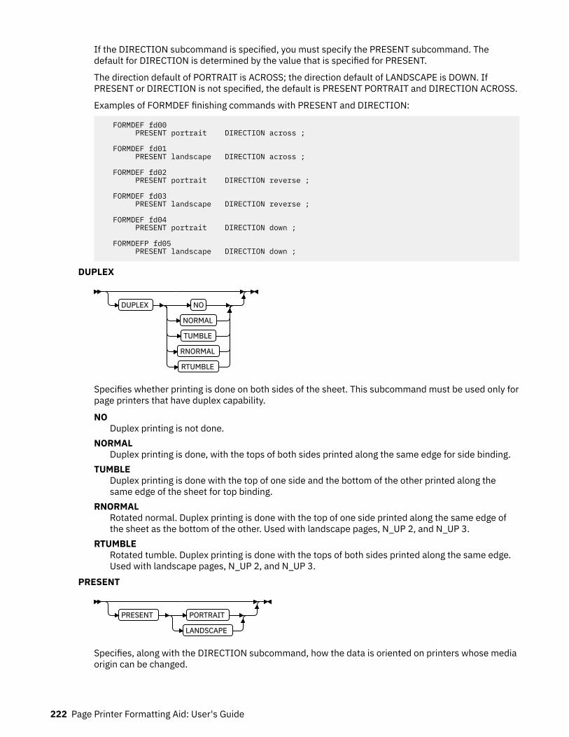
If the DIRECTION subcommand is specified, you must specify the PRESENT subcommand. Thedefault for DIRECTION is determined by the value that is specified for PRESENT.
The direction default of PORTRAIT is ACROSS; the direction default of LANDSCAPE is DOWN. IfPRESENT or DIRECTION is not specified, the default is PRESENT PORTRAIT and DIRECTION ACROSS.
Examples of FORMDEF finishing commands with PRESENT and DIRECTION:
FORMDEF fd00 PRESENT portrait DIRECTION across ;
FORMDEF fd01 PRESENT landscape DIRECTION across ;
FORMDEF fd02 PRESENT portrait DIRECTION reverse ;
FORMDEF fd03 PRESENT landscape DIRECTION reverse ;
FORMDEF fd04 PRESENT portrait DIRECTION down ;
FORMDEFP fd05 PRESENT landscape DIRECTION down ;
DUPLEX
DUPLEX NO
NORMAL
TUMBLE
RNORMAL
RTUMBLE
Specifies whether printing is done on both sides of the sheet. This subcommand must be used only forpage printers that have duplex capability.
NODuplex printing is not done.
NORMALDuplex printing is done, with the tops of both sides printed along the same edge for side binding.
TUMBLEDuplex printing is done with the top of one side and the bottom of the other printed along thesame edge of the sheet for top binding.
RNORMALRotated normal. Duplex printing is done with the top of one side printed along the same edge ofthe sheet as the bottom of the other. Used with landscape pages, N_UP 2, and N_UP 3.
RTUMBLERotated tumble. Duplex printing is done with the tops of both sides printed along the same edge.Used with landscape pages, N_UP 2, and N_UP 3.
PRESENT
PRESENT PORTRAIT
LANDSCAPE
Specifies, along with the DIRECTION subcommand, how the data is oriented on printers whose mediaorigin can be changed.
222 Page Printer Formatting Aid: User's Guide
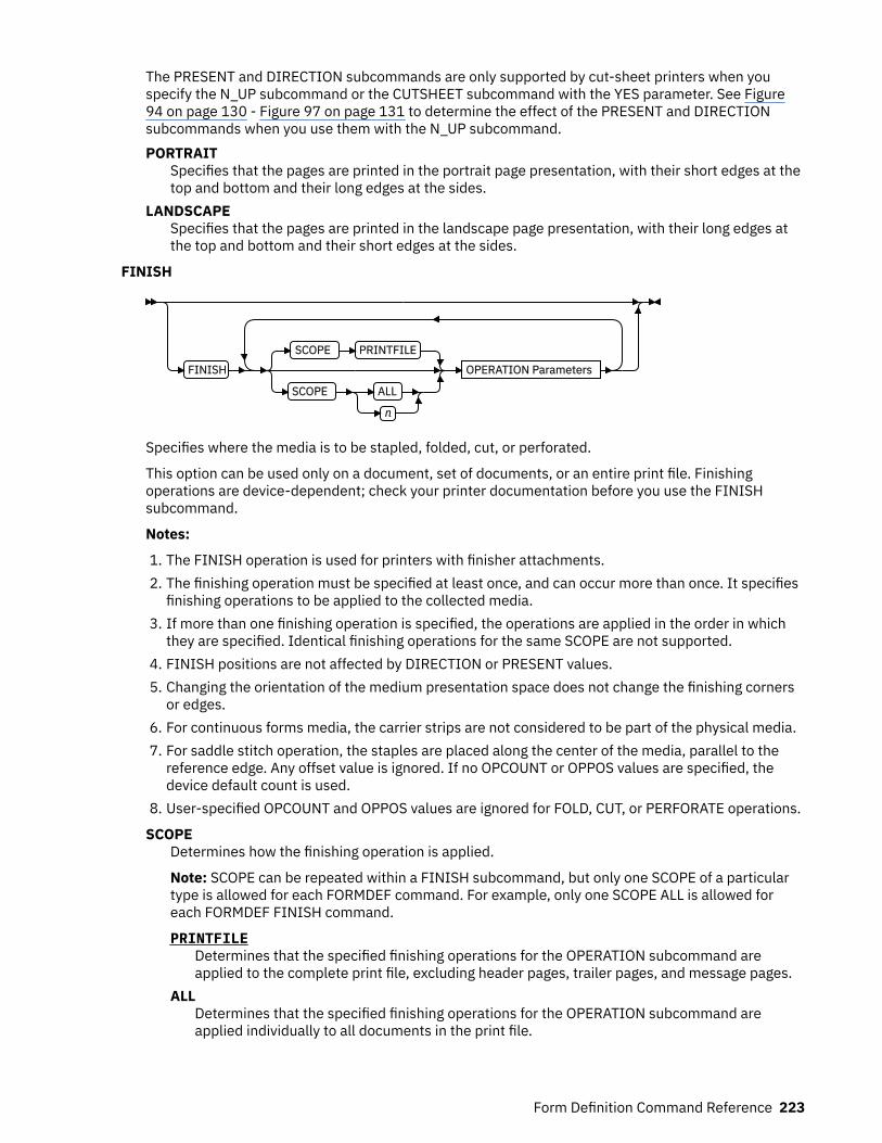
The PRESENT and DIRECTION subcommands are only supported by cut-sheet printers when youspecify the N_UP subcommand or the CUTSHEET subcommand with the YES parameter. See Figure94 on page 130 - Figure 97 on page 131 to determine the effect of the PRESENT and DIRECTIONsubcommands when you use them with the N_UP subcommand.PORTRAIT
Specifies that the pages are printed in the portrait page presentation, with their short edges at thetop and bottom and their long edges at the sides.
LANDSCAPESpecifies that the pages are printed in the landscape page presentation, with their long edges atthe top and bottom and their short edges at the sides.
FINISH
FINISH
SCOPE PRINTFILE
SCOPE ALL
n
OPERATION Parameters
Specifies where the media is to be stapled, folded, cut, or perforated.
This option can be used only on a document, set of documents, or an entire print file. Finishingoperations are device-dependent; check your printer documentation before you use the FINISHsubcommand.
Notes:
1. The FINISH operation is used for printers with finisher attachments.2. The finishing operation must be specified at least once, and can occur more than once. It specifies
finishing operations to be applied to the collected media.3. If more than one finishing operation is specified, the operations are applied in the order in which
they are specified. Identical finishing operations for the same SCOPE are not supported.4. FINISH positions are not affected by DIRECTION or PRESENT values.5. Changing the orientation of the medium presentation space does not change the finishing corners
or edges.6. For continuous forms media, the carrier strips are not considered to be part of the physical media.7. For saddle stitch operation, the staples are placed along the center of the media, parallel to the
reference edge. Any offset value is ignored. If no OPCOUNT or OPPOS values are specified, thedevice default count is used.
8. User-specified OPCOUNT and OPPOS values are ignored for FOLD, CUT, or PERFORATE operations.
SCOPEDetermines how the finishing operation is applied.
Note: SCOPE can be repeated within a FINISH subcommand, but only one SCOPE of a particulartype is allowed for each FORMDEF command. For example, only one SCOPE ALL is allowed foreach FORMDEF FINISH command.
PRINTFILEDetermines that the specified finishing operations for the OPERATION subcommand areapplied to the complete print file, excluding header pages, trailer pages, and message pages.
ALLDetermines that the specified finishing operations for the OPERATION subcommand areapplied individually to all documents in the print file.
Form Definition Command Reference 223
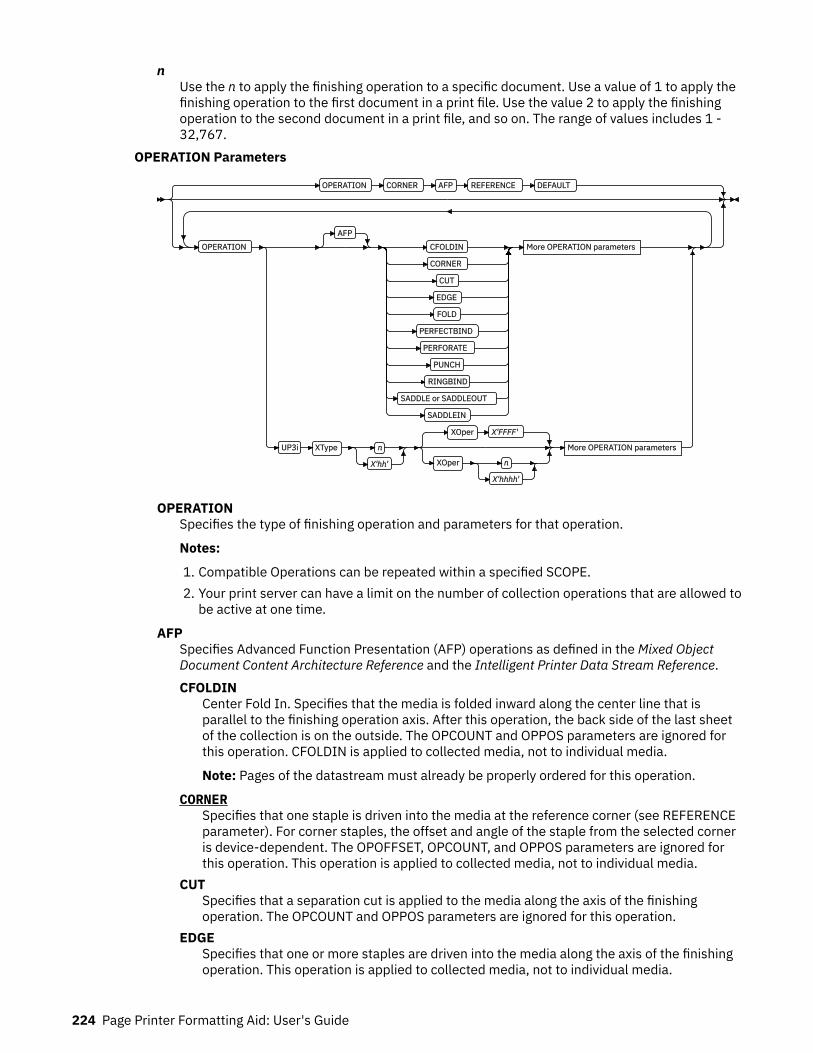
nUse the n to apply the finishing operation to a specific document. Use a value of 1 to apply thefinishing operation to the first document in a print file. Use the value 2 to apply the finishingoperation to the second document in a print file, and so on. The range of values includes 1 -32,767.
OPERATION Parameters
OPERATION CORNER AFP REFERENCE DEFAULT
OPERATIONAFP
CFOLDIN
CORNER
CUT
EDGE
FOLD
PERFECTBIND
PERFORATE
PUNCH
RINGBIND
SADDLE or SADDLEOUT
SADDLEIN
More OPERATION parameters
UP3i XType n
X'hh'
XOper X'FFFF'
XOper n
X'hhhh'
More OPERATION parameters
OPERATIONSpecifies the type of finishing operation and parameters for that operation.
Notes:
1. Compatible Operations can be repeated within a specified SCOPE.2. Your print server can have a limit on the number of collection operations that are allowed to
be active at one time.
AFPSpecifies Advanced Function Presentation (AFP) operations as defined in the Mixed ObjectDocument Content Architecture Reference and the Intelligent Printer Data Stream Reference.CFOLDIN
Center Fold In. Specifies that the media is folded inward along the center line that isparallel to the finishing operation axis. After this operation, the back side of the last sheetof the collection is on the outside. The OPCOUNT and OPPOS parameters are ignored forthis operation. CFOLDIN is applied to collected media, not to individual media.
Note: Pages of the datastream must already be properly ordered for this operation.
CORNERSpecifies that one staple is driven into the media at the reference corner (see REFERENCEparameter). For corner staples, the offset and angle of the staple from the selected corneris device-dependent. The OPOFFSET, OPCOUNT, and OPPOS parameters are ignored forthis operation. This operation is applied to collected media, not to individual media.
CUTSpecifies that a separation cut is applied to the media along the axis of the finishingoperation. The OPCOUNT and OPPOS parameters are ignored for this operation.
EDGESpecifies that one or more staples are driven into the media along the axis of the finishingoperation. This operation is applied to collected media, not to individual media.
224 Page Printer Formatting Aid: User's Guide
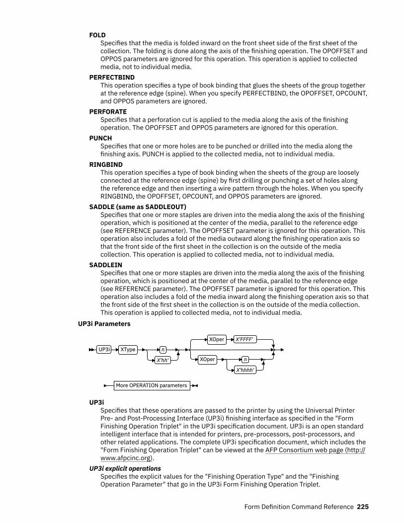
FOLDSpecifies that the media is folded inward on the front sheet side of the first sheet of thecollection. The folding is done along the axis of the finishing operation. The OPOFFSET andOPPOS parameters are ignored for this operation. This operation is applied to collectedmedia, not to individual media.
PERFECTBINDThis operation specifies a type of book binding that glues the sheets of the group togetherat the reference edge (spine). When you specify PERFECTBIND, the OPOFFSET, OPCOUNT,and OPPOS parameters are ignored.
PERFORATESpecifies that a perforation cut is applied to the media along the axis of the finishingoperation. The OPOFFSET and OPPOS parameters are ignored for this operation.
PUNCHSpecifies that one or more holes are to be punched or drilled into the media along thefinishing axis. PUNCH is applied to the collected media, not to individual media.
RINGBINDThis operation specifies a type of book binding when the sheets of the group are looselyconnected at the reference edge (spine) by first drilling or punching a set of holes alongthe reference edge and then inserting a wire pattern through the holes. When you specifyRINGBIND, the OPOFFSET, OPCOUNT, and OPPOS parameters are ignored.
SADDLE (same as SADDLEOUT)Specifies that one or more staples are driven into the media along the axis of the finishingoperation, which is positioned at the center of the media, parallel to the reference edge(see REFERENCE parameter). The OPOFFSET parameter is ignored for this operation. Thisoperation also includes a fold of the media outward along the finishing operation axis sothat the front side of the first sheet in the collection is on the outside of the mediacollection. This operation is applied to collected media, not to individual media.
SADDLEINSpecifies that one or more staples are driven into the media along the axis of the finishingoperation, which is positioned at the center of the media, parallel to the reference edge(see REFERENCE parameter). The OPOFFSET parameter is ignored for this operation. Thisoperation also includes a fold of the media inward along the finishing operation axis so thatthe front side of the first sheet in the collection is on the outside of the media collection.This operation is applied to collected media, not to individual media.
UP3i Parameters
UP3i XType n
X'hh'
XOper X'FFFF'
XOper n
X'hhhh'
More OPERATION parameters
UP3iSpecifies that these operations are passed to the printer by using the Universal PrinterPre- and Post-Processing Interface (UP3i) finishing interface as specified in the "FormFinishing Operation Triplet" in the UP3i specification document. UP3i is an open standardintelligent interface that is intended for printers, pre-processors, post-processors, andother related applications. The complete UP3i specification document, which includes the"Form Finishing Operation Triplet" can be viewed at the AFP Consortium web page (http://www.afpcinc.org).
UP3i explicit operationsSpecifies the explicit values for the "Finishing Operation Type" and the "FinishingOperation Parameter" that go in the UP3i Form Finishing Operation Triplet.
Form Definition Command Reference 225
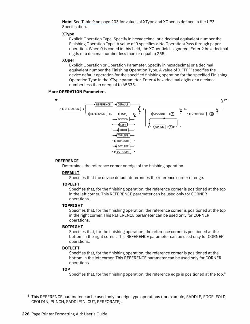
Note: See Table 9 on page 203 for values of XType and XOper as defined in the UP3iSpecification.
XTypeExplicit Operation Type. Specify in hexadecimal or a decimal equivalent number theFinishing Operation Type. A value of 0 specifies a No Operation/Pass through paperoperation. When 0 is coded in this field, the XOper field is ignored. Enter 2 hexadecimaldigits or a decimal number less than or equal to 255.
XOperExplicit Operation or Operation Parameter. Specify in hexadecimal or a decimalequivalent number the Finishing Operation Type. A value of X'FFFF' specifies thedevice default operation for the specified finishing operation for the specified FinishingOperation Type in the XType parameter. Enter 4 hexadecimal digits or a decimalnumber less than or equal to 65535.
More OPERATION Parameters
OPERATION
REFERENCE DEFAULT
REFERENCE TOP
BOTTOM
LEFT
RIGHT
TOPLEFT
TOPRIGHT
BOTLEFT
BOTRIGHT
OPCOUNT n
OPPOS n
OPOFFSET n
REFERENCEDetermines the reference corner or edge of the finishing operation.DEFAULT
Specifies that the device default determines the reference corner or edge.TOPLEFT
Specifies that, for the finishing operation, the reference corner is positioned at the topin the left corner. This REFERENCE parameter can be used only for CORNERoperations.
TOPRIGHTSpecifies that, for the finishing operation, the reference corner is positioned at the topin the right corner. This REFERENCE parameter can be used only for CORNERoperations.
BOTRIGHTSpecifies that, for the finishing operation, the reference corner is positioned at thebottom in the right corner. This REFERENCE parameter can be used only for CORNERoperations.
BOTLEFTSpecifies that, for the finishing operation, the reference corner is positioned at thebottom in the left corner. This REFERENCE parameter can be used only for CORNERoperations.
TOPSpecifies that, for the finishing operation, the reference edge is positioned at the top.4
4 This REFERENCE parameter can be used only for edge type operations (for example, SADDLE, EDGE, FOLD,CFOLDIN, PUNCH, SADDLEIN, CUT, PERFORATE).
226 Page Printer Formatting Aid: User's Guide

BOTTOMSpecifies that, for the finishing operation, the reference edge is positioned at thebottom.5
LEFTSpecifies that, for the finishing operation, the reference edge is positioned at the left.5
RIGHTSpecifies that, for the finishing operation, the reference edge is positioned at the right.5
OPCOUNT nUse OPCOUNT to request a specific number of finishing operations; valid values are 1 -122. Do not specify OPPOS values with OPCOUNT. If OPPOS is specified for corner staple,separation cut, perforation cut or fold, this OPCOUNT value is ignored. The printerdetermines the positions of the operations. The default is 0 (zero).
OPPOS nUse OPPOS to specify the offset of finishing operation along the finishing operation axisthat is measured from the point where the finishing operation axis intersects the bottomedge or left edge of the medium toward the center of the medium. Each consecutiveOPPOS parameter is used to position a single finishing operation that is centered on thespecified point on the finishing operation.
For AFP, the subparameter is an integer value in the range of 0 - 32,767, specified inmillimeters.
For UP3i, the subparameter is an integer value in the range of 0 - 999999999, specified inmillipoints (1/72000 inch).
Do not specify the unit of measure. Do not specify OPCOUNT when you use OPPOS. IfOPPOS is specified for corner staple, fold, separation cut, or perforation cut, the OPCOUNTvalue is ignored.
OPOFFSET nSpecifies the offset of finishing operation axis from the reference edge, which is measuredfrom the reference edge toward the center of the medium.
For AFP, the subparameter is an integer value in the range of 0 - 32,767, specified inmillimeters.
For UP3i, the subparameter is an integer value in the range of 0 - 999999999, specified inmillipoints (1/72000 inch).
Do not specify OPOFFSET for corner staple or saddle stitch; the corner staple or saddlestitch values are ignored when specified with OPOFFSET.
The following examples show how to specify finishing operations.
• To request scope as the entire print job with one corner staple in the top-left corner, specify:
FINISH SCOPE PRINTFILE OPERATION CORNER REFERENCE TOPLEFT;
• Sometimes a user wants to request multiple finishing operations. To request that the fifthdocument in the job stream is finished with top-left corner staple and the ninth document isedge stitched only at the print default location, specify:
FINISH SCOPE 5 OPERATION CORNER REFERENCE TOPLEFT SCOPE 9 OPERATION EDGE;
• The following example requests that SCOPE 5 (the fifth document in the job stream):
5 This REFERENCE parameter can be used only for edge type operations.
Form Definition Command Reference 227
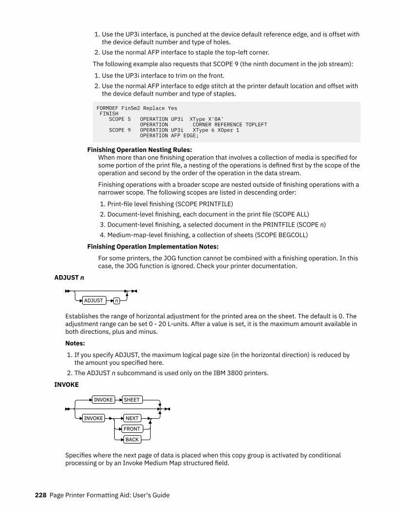
1. Use the UP3i interface, is punched at the device default reference edge, and is offset withthe device default number and type of holes.
2. Use the normal AFP interface to staple the top-left corner.
The following example also requests that SCOPE 9 (the ninth document in the job stream):
1. Use the UP3i interface to trim on the front.2. Use the normal AFP interface to edge stitch at the printer default location and offset with
the device default number and type of staples.
FORMDEF FinSm2 Replace Yes FINISH SCOPE 5 OPERATION UP3i XType X'0A' OPERATION CORNER REFERENCE TOPLEFT SCOPE 9 OPERATION UP3i XType 6 XOper 1 OPERATION AFP EDGE;
Finishing Operation Nesting Rules:When more than one finishing operation that involves a collection of media is specified forsome portion of the print file, a nesting of the operations is defined first by the scope of theoperation and second by the order of the operation in the data stream.
Finishing operations with a broader scope are nested outside of finishing operations with anarrower scope. The following scopes are listed in descending order:
1. Print-file level finishing (SCOPE PRINTFILE)2. Document-level finishing, each document in the print file (SCOPE ALL)3. Document-level finishing, a selected document in the PRINTFILE (SCOPE n)4. Medium-map-level finishing, a collection of sheets (SCOPE BEGCOLL)
Finishing Operation Implementation Notes:
For some printers, the JOG function cannot be combined with a finishing operation. In thiscase, the JOG function is ignored. Check your printer documentation.
ADJUST n
ADJUST n
Establishes the range of horizontal adjustment for the printed area on the sheet. The default is 0. Theadjustment range can be set 0 - 20 L-units. After a value is set, it is the maximum amount available inboth directions, plus and minus.
Notes:
1. If you specify ADJUST, the maximum logical page size (in the horizontal direction) is reduced bythe amount you specified here.
2. The ADJUST n subcommand is used only on the IBM 3800 printers.
INVOKE
INVOKE SHEET
INVOKE NEXT
FRONT
BACK
Specifies where the next page of data is placed when this copy group is activated by conditionalprocessing or by an Invoke Medium Map structured field.
228 Page Printer Formatting Aid: User's Guide
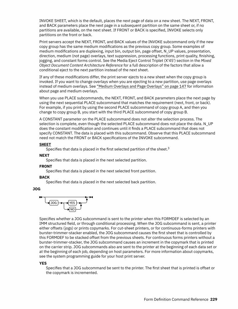
INVOKE SHEET, which is the default, places the next page of data on a new sheet. The NEXT, FRONT,and BACK parameters place the next page in a subsequent partition on the same sheet or, if nopartitions are available, on the next sheet. If FRONT or BACK is specified, INVOKE selects onlypartitions on the front or back.
Print servers accept the NEXT, FRONT, and BACK values of the INVOKE subcommand only if the newcopy group has the same medium modifications as the previous copy group. Some examples ofmedium modifications are duplexing, input bin, output bin, page offset, N_UP values, presentation,direction, medium (not page) overlays, text suppression, processing functions, print quality, finishing,jogging, and constant forms control. See the Media Eject Control Triplet (X'45') section in the MixedObject Document Content Architecture Reference for a full description of the factors that allow aconditional eject to the next partition instead of the next sheet.
If any of these modifications differ, the print server ejects to a new sheet when the copy group isinvoked. If you want to change overlays when you are ejecting to a new partition, use page overlaysinstead of medium overlays. See “Medium Overlays and Page Overlays” on page 147 for informationabout page and medium overlays.
When you use PLACE subcommands, the NEXT, FRONT, and BACK parameters place the next page byusing the next sequential PLACE subcommand that matches the requirement (next, front, or back).For example, if you print by using the second PLACE subcommand of copy group A, and then youchange to copy group B, you start with the third PLACE subcommand of copy group B.
A CONSTANT parameter on the PLACE subcommand does not alter the selection process. Theselection is complete, even though the selected PLACE subcommand does not place the data. N_UPdoes the constant modification and continues until it finds a PLACE subcommand that does notspecify CONSTANT. The data is placed with this subcommand. Observe that this PLACE subcommandneed not match the FRONT or BACK specifications of the INVOKE subcommand.SHEET
Specifies that data is placed in the first selected partition of the sheet.3
NEXTSpecifies that data is placed in the next selected partition.
FRONTSpecifies that data is placed in the next selected front partition.
BACKSpecifies that data is placed in the next selected back partition.
JOG
JOG YES
NO
Specifies whether a JOG subcommand is sent to the printer when this FORMDEF is selected by anIMM structured field, or through conditional processing. When the JOG subcommand is sent, a printereither offsets (jogs) or prints copymarks. For cut-sheet printers, or for continuous-forms printers withburster-trimmer-stacker enabled, the JOG subcommand causes the first sheet that is controlled bythis FORMDEF to be stacked offset from the previous sheets. For continuous forms printers without aburster-trimmer-stacker, the JOG subcommand causes an increment in the copymark that is printedon the carrier strip. JOG subcommands also are sent to the printer at the beginning of each data set orat the beginning of each job, depending on host parameters. For more information about copymarks,see the system programming guide for your host print server.
YESSpecifies that a JOG subcommand be sent to the printer. The first sheet that is printed is offset orthe copymark is incremented.
Form Definition Command Reference 229

NOSpecifies that no JOG subcommand be sent to the printer. The first sheet that is printed is notoffset; the copymark is not incremented.
QUALITY n
QUALITY n
Specifies the print quality. This subcommand is recognized only on printers that can produce morethan one level of print quality. The default is determined by the printer model. (On some printers, thedefault can be set at the printer itself.) For more information, see your printer publications.
nYou can select a level of print quality by entering any whole number 1 - 10. Higher numberscorrespond to higher levels of print quality; lower numbers correspond to lower levels. For moreinformation, see your printer publications.
Print quality is determined by a numerical code in the range of 1 to 254 (hexadecimal X'01' -X'FE'). The codes corresponding to the possible QUALITY parameters are:
1 = 15 (X'0F')2 = 40 (X'28')3 = 65 (X'41')4 = 90 (X'5A')5 = 115 (X'73')6 = 140 (X'8C')7 = 165 (X'A5')8 = 190 (X'BE')9 = 215 (X'D7')10 = 240 (X'F0')
CMRTAGFIDELITY
CMRTAGFIDELITY STOP
CONTINUE
NOREPORT
REPORT
Specify the exception continuation and reporting rules for Color management resource (CMR) tagexceptions.
Note: See Chapter 8, “AFP Color Management,” on page 151 for more information about using theCMRTAGFIDELITY subcommand.
STOPCMR Tag exception rule is "Stop presentation at point of first CMR tag exception and report theexception".
CONTINUECMR Tag exception rule is "Do not stop presentation because of CMR tag exceptions and do one ofthe following:"NOREPORT
Do not report the CMR tag exception to the print server. This is the default if NOREPORT orREPORT is not coded.
REPORTReport the CMR tag exception.
230 Page Printer Formatting Aid: User's Guide

PROCESSING
PROCESSING
MEDIA_INFO n
PERFORATE
CUT
Specifies more post-processing capabilities for selected printers and attached equipment. This optioncan be used only on a single page or a set of pages. The subcommand expects one to three of thefollowing keywords:
MEDIA_INFO nThis parameter specifies the ID of fixed medium information that a printer or printer-attacheddevice applies to a page. Examples such as color plates logos, letter heads, and other fixedimages.
The numeric values that can be included are:0 - 254
These numeric values select a particular fixed medium local ID that the printer or printer-attached device applies to a sheet. One or more IDs can be specified within this range.
255This value selects all the current fixed medium local IDs that the printer or printer-attacheddevices applies to a sheet.
PERFORATESpecifies a perforation cut at one or more fixed locations on the sheet according to the printer orprinter-attached device.
CUTSpecifies a separation cut at one or more fixed locations on the sheet according to the printer orprinter-attached device.
COMMENT qstring
COMMENT qstring
Specifies a string comment. Use COMMENT to mark a form definition with a user comment. The stringis placed in the NOP structured field of the form definition.
qstringSpecifies a quoted set of strings up to a total of 255 characters.
Note: In PPFA, a keyword or parameter (token) cannot extend across a line. Therefore, you mustbreak the string into several strings to have a comment string that is longer than what fits on one line.Each string must be a complete token with beginning and ending quotation marks. Be sure to add ablank before the ending quotation mark if you want the comment lines separated. For example:
FORMDEF replace yes COMMENT 'first line of comment ' 'second line of comment';
Form Definition Command Reference 231
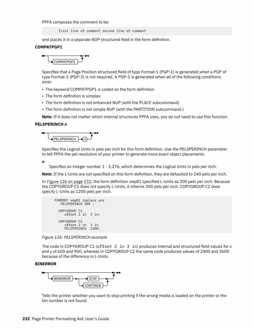
PPFA composes the comment to be:
first line of comment second line of comment
and places it in a separate NOP structured field in the form definition.
COMPATPGP1
COMPATPGP1
Specifies that a Page Position structured field of type Format-1 (PGP-1) is generated when a PGP oftype Format-2 (PGP-2) is not required. A PGP-1 is generated when all of the following conditionsexist:
• The keyword COMPATPGP1 is coded on the form definition• The form definition is simplex• The form definition is not enhanced NUP (with the PLACE subcommand)• The form definition is not simple NUP (with the PARTITION subcommand.)
Note: If it does not matter which internal structures PPFA uses, you do not need to use this function.
PELSPERINCH n
PELSPERINCH n
Specifies the Logical Units in pels per inch for this form definition. Use the PELSPERINCH parameterto tell PPFA the pel resolution of your printer to generate more exact object placements.
nSpecifies an integer number 1 - 3,276, which determines the Logical Units in pels per inch.
Note: If the L-Units are not specified on this form definition, they are defaulted to 240 pels per inch.
In Figure 126 on page 232, the form definition xmp01 specified L-Units as 300 pels per inch. Becausethe COPYGROUP C1 does not specify L-Units, it inherits 300 pels per inch. COPYGROUP C2 doesspecify L-Units as 1200 pels per inch.
FORMDEF xmp01 replace yes PELSPERINCH 300 ; COPYGROUP C1 offset 2 in 3 in; COPYGROUP C2 offset 2 in 3 in PELSPERINCH 1200;
Figure 126: PELSPERINCH example
The code in COPYGROUP C1 (offset 2 in 3 in) produces internal and structured field values for xand y of 600 and 900, whereas in COPYGROUP C2 the same code produces values of 2400 and 3600because of the difference in L-Units.
BINERROR
BINERROR STOP
CONTINUE
Tells the printer whether you want to stop printing if the wrong media is loaded on the printer or thebin number is not found.
232 Page Printer Formatting Aid: User's Guide

This subcommand is displayed only on the FORMDEF command, not the COPYGROUP or theSUBGROUP commands, since the scope of the subcommand is throughout the FORMDEF. Printingcontrol is based on the status of the media that is loaded as it pertains to the BIN subcommand ineffect at the time.STOP
If the specified input bin is in error, stop the print job and hold it in a state from which it can beresubmitted.
CONTINUEIf the specified input bin is in error, continue printing by using the printer default input bin.
COLORVALUERR
COLORVALUERR STOP
COLORVALUERR CONTINUE
NOREPORT
REPORT
When the form definition contains color values that the printer cannot render exactly as specified, youcan request that the printer substitute colors and continue job processing, or you can request theprinter to stop. If you request STOP, the printer issues an error and stops processing. If you requestCONTINUE, you can ask for an error report.
STOPSpecifies that an error is issued by the printer and the job is ended if the printer reports a colorexception. A color exception is reported if the color specification in the data stream cannot berendered as specified. Also, a color exception is reported if the host print server supports colorfidelity and the target printer does not.
CONTINUESpecifies that an exception condition is ignored. Also, the printer substitutes colors for any that itcannot render, and the job continues.REPORT
Specifies that the error is reported by the printer.NOREPORT
Specifies that the error is not to be reported by the printer. NOREPORT is the default ifCOLORVALUERR CONTINUE is coded and REPORT or NOREPORT is not coded.
Note: When the printer reports a color value exception, the following actions are taken:
• If the print server and the printer both support Color Fidelity and the COLORVALUERR subcommandis coded, printing occurs as previously described.
• If the print server and the printer both support Color Fidelity and the COLORVALUERR subcommandis not coded, the print server instructs the printer to reset to defaults at the beginning of the job.
• Whenever the print server supports Color Fidelity but the printer does not, the following rules apply:
1. If no COLORVALUERR subcommand is issued, printing continues. However, color exceptionerrors are reported and ignored.
2. If the COLORVALUERR subcommand is issued, you might receive print server errors or thecommand might be ignored, depending on the level of PSF you installed and your operatingsystem (for example, z/OS, VM, or VSE). Therefore, you must not use the COLORVALUERRsubcommand if you do not have a host print server that supports it.
• Whenever the printer supports Color Fidelity but the print server does not, the following rules apply:
1. If no COLORVALUERR subcommand is issued, printing continues. However, color exceptionerrors are reported and ignored.
Form Definition Command Reference 233
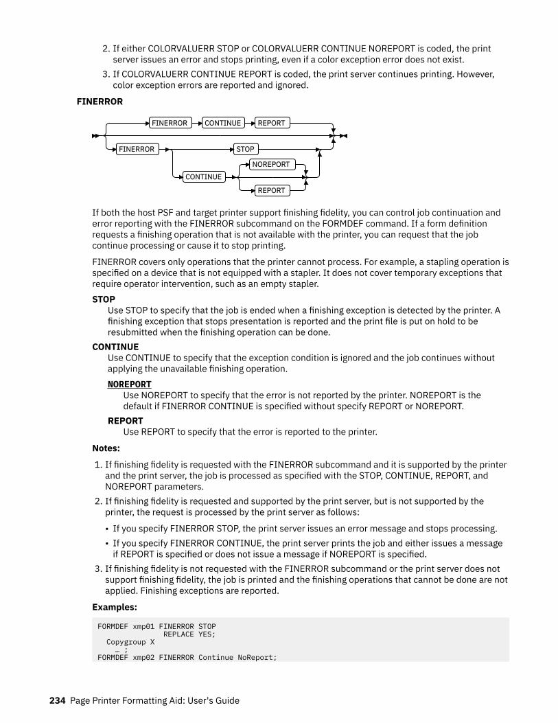
2. If either COLORVALUERR STOP or COLORVALUERR CONTINUE NOREPORT is coded, the printserver issues an error and stops printing, even if a color exception error does not exist.
3. If COLORVALUERR CONTINUE REPORT is coded, the print server continues printing. However,color exception errors are reported and ignored.
FINERROR
FINERROR CONTINUE REPORT
FINERROR STOP
CONTINUE
NOREPORT
REPORT
If both the host PSF and target printer support finishing fidelity, you can control job continuation anderror reporting with the FINERROR subcommand on the FORMDEF command. If a form definitionrequests a finishing operation that is not available with the printer, you can request that the jobcontinue processing or cause it to stop printing.
FINERROR covers only operations that the printer cannot process. For example, a stapling operation isspecified on a device that is not equipped with a stapler. It does not cover temporary exceptions thatrequire operator intervention, such as an empty stapler.STOP
Use STOP to specify that the job is ended when a finishing exception is detected by the printer. Afinishing exception that stops presentation is reported and the print file is put on hold to beresubmitted when the finishing operation can be done.
CONTINUEUse CONTINUE to specify that the exception condition is ignored and the job continues withoutapplying the unavailable finishing operation.NOREPORT
Use NOREPORT to specify that the error is not reported by the printer. NOREPORT is thedefault if FINERROR CONTINUE is specified without specify REPORT or NOREPORT.
REPORTUse REPORT to specify that the error is reported to the printer.
Notes:
1. If finishing fidelity is requested with the FINERROR subcommand and it is supported by the printerand the print server, the job is processed as specified with the STOP, CONTINUE, REPORT, andNOREPORT parameters.
2. If finishing fidelity is requested and supported by the print server, but is not supported by theprinter, the request is processed by the print server as follows:
• If you specify FINERROR STOP, the print server issues an error message and stops processing.• If you specify FINERROR CONTINUE, the print server prints the job and either issues a message
if REPORT is specified or does not issue a message if NOREPORT is specified.3. If finishing fidelity is not requested with the FINERROR subcommand or the print server does not
support finishing fidelity, the job is printed and the finishing operations that cannot be done are notapplied. Finishing exceptions are reported.
Examples:
FORMDEF xmp01 FINERROR STOP REPLACE YES; Copygroup X … ;FORMDEF xmp02 FINERROR Continue NoReport;
234 Page Printer Formatting Aid: User's Guide
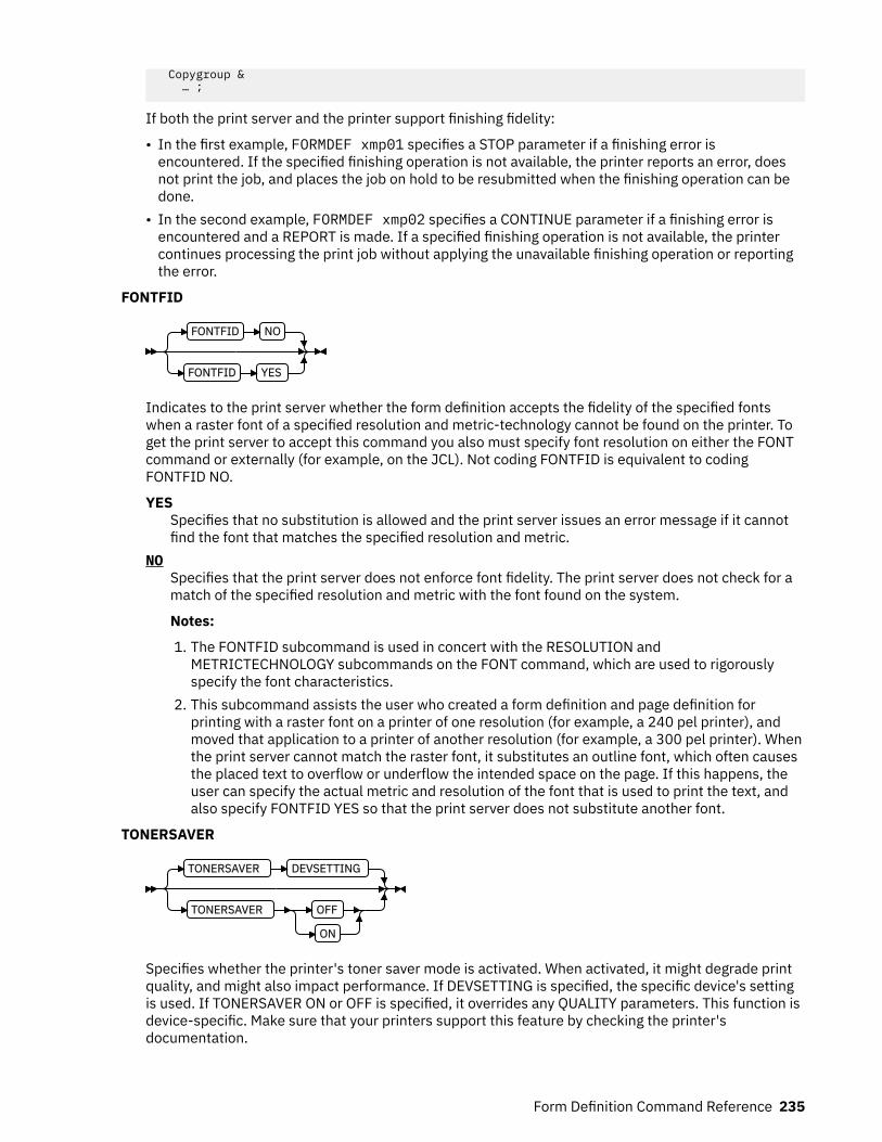
Copygroup & … ;
If both the print server and the printer support finishing fidelity:
• In the first example, FORMDEF xmp01 specifies a STOP parameter if a finishing error isencountered. If the specified finishing operation is not available, the printer reports an error, doesnot print the job, and places the job on hold to be resubmitted when the finishing operation can bedone.
• In the second example, FORMDEF xmp02 specifies a CONTINUE parameter if a finishing error isencountered and a REPORT is made. If a specified finishing operation is not available, the printercontinues processing the print job without applying the unavailable finishing operation or reportingthe error.
FONTFID
FONTFID NO
FONTFID YES
Indicates to the print server whether the form definition accepts the fidelity of the specified fontswhen a raster font of a specified resolution and metric-technology cannot be found on the printer. Toget the print server to accept this command you also must specify font resolution on either the FONTcommand or externally (for example, on the JCL). Not coding FONTFID is equivalent to codingFONTFID NO.
YESSpecifies that no substitution is allowed and the print server issues an error message if it cannotfind the font that matches the specified resolution and metric.
NOSpecifies that the print server does not enforce font fidelity. The print server does not check for amatch of the specified resolution and metric with the font found on the system.
Notes:
1. The FONTFID subcommand is used in concert with the RESOLUTION andMETRICTECHNOLOGY subcommands on the FONT command, which are used to rigorouslyspecify the font characteristics.
2. This subcommand assists the user who created a form definition and page definition forprinting with a raster font on a printer of one resolution (for example, a 240 pel printer), andmoved that application to a printer of another resolution (for example, a 300 pel printer). Whenthe print server cannot match the raster font, it substitutes an outline font, which often causesthe placed text to overflow or underflow the intended space on the page. If this happens, theuser can specify the actual metric and resolution of the font that is used to print the text, andalso specify FONTFID YES so that the print server does not substitute another font.
TONERSAVER
TONERSAVER DEVSETTING
TONERSAVER OFF
ON
Specifies whether the printer's toner saver mode is activated. When activated, it might degrade printquality, and might also impact performance. If DEVSETTING is specified, the specific device's settingis used. If TONERSAVER ON or OFF is specified, it overrides any QUALITY parameters. This function isdevice-specific. Make sure that your printers support this feature by checking the printer'sdocumentation.
Form Definition Command Reference 235

N_UP
N_UP 1
2
3
4OVERLAY Subcommand
PLACE Subcommand
{ 1 | 2 | 3 | 4 }Specifies the number (1, 2, 3, or 4) of equal-size partitions into which the sheet is divided. See thelist of printers that support the N_UP subcommand.
If you do not specify the N_UP subcommand in the COPYGROUP command, the N_UPsubcommand from the FORMDEF command is the default for the COPYGROUP command. You canmix N_UP printing and non-N_UP printing by specifying or not specifying the N_UP subcommandin each copy group and by not specifying N_UP in the FORMDEF command.
OVERLAY Subcommand
OVERLAY name
rel-x - rel-y PARTITION
OVROTATE 0
OVROTATE 90
180
270
Specifies the name of an overlay to be placed with every page in each of the N_UP partitions. Theoverlay is placed relative to the page origin, or if the PARTITION parameter is specified, relative tothe partition origin. You can specify a maximum of 254 OVERLAY subcommands in a copy group.
rel-x rel-ySpecifies the horizontal and vertical adjustment to the position of the overlay. This adjustmentis in addition to any offset values built into the overlay. The x and y values can be positive (+)and negative (-). You can specify them in inches (IN), millimeters (MM), centimeters (CM),points, or pels. If you do not specify a unit value, PPFA uses the unit value that is specified inthe last SETUNITS command or uses a default unit value of inches.
Note: This OVERLAY subcommand cannot be specified if the PLACE subcommand is specified.Use the OVERLAY parameter of the PLACE subcommand instead.
PARTITIONSpecifies that the overlay is to be placed relative to the partition origin.
OVROTATE { 0 | 90 | 180 | 270 }Specifies the rotation of the placed overlay in regard to the x-axis of the page.
Example: Assuming the overlay has ( 0,0 ) placement coordinates, this causes page overlayx2 to be placed 1.5 inches to the right and 2.7 inches below the beginning of the page androtated 90 degrees clockwise in regard to the page.
Formdef f1 N_UP 1 PLACE 1 FRONT OVERLAY x2 1.5 in 2.7 in OVROTATE 90;
236 Page Printer Formatting Aid: User's Guide

PLACE Subcommand
PLACE n
FRONT
BACK CONSTANT OFFSET rel-x rel-y
OVERLAY Subcommand
ROTATION 0
ROTATION 90
180
270
VIEW YES
VIEW NO
Places a page of data or a constant modification relative to a partition. Each PLACE subcommandspecifies the number n of a partition on either the front or back side of the sheet. FRONT is thedefault, if you do not specify this subcommand. You must specify the same number of PLACEsubcommands as the number of partitions on the sheet. The sequence of the PLACEsubcommands is the sequence in which incoming pages are placed in the partitions.
Notes:
1. The use of the PLACE subcommand indicates enhanced N_UP printing.2. The PLACE subcommand is valid only on printers that support enhanced N_UP printing. If
PLACE is not specified, pages are placed in partitions in the default partition sequence.
nSpecifies the numbered partition (1 - 4) into which the page of data is placed.
FRONTSpecifies that this partition is placed on the front side of the sheet.
BACKSpecifies that this partition is placed on the back side of the sheet.
CONSTANTSpecifies that no page data is placed by this PLACE subcommand.
Use CONSTANT when you are placing overlays without user's data or are placing fewer datapages on the sheet than the number of partitions that are specified in the N_UP subcommand.
For an example of using the CONSTANT parameter with overlays and to understand how theordering of the PLACE subcommand affects overlays, see “Example 3: Enhanced N_UPAsymmetric Pages” on page 145.
OFFSET rel-x rel-ySpecifies a relative offset of the page horizontally (x) and vertically (y) from the partition origin.If OFFSET is not coded, PPFA uses the value of 0.1 inches for both the x and y offsets. ThisOFFSET parameter overrides any other OFFSET parameters that are specified on theFORMDEF or COPYGROUP command. You can specify the units in inches (in), millimeters(mm), centimeters (cm), points, or pels. If you do not specify a unit value, PPFA uses the unitvalue that is specified in the last SETUNITS command or uses a default unit value of inches.
Note: You can specify this offset as negative to crop the top, left, or both of an image.
OVERLAY SubcommandSee OVERLAY Subcommand for the syntax.
Form Definition Command Reference 237

nameSpecifies the name of an overlay to be placed with this PLACE subcommand. The overlay isplaced relative to the page origin or, if the PARTITION keyword is specified, to the partitionorigin. You can specify multiple OVERLAY parameters in each PLACE subcommand.
rel-x rel-ySpecifies the horizontal and vertical adjustment to the position of the overlay. Thisadjustment is in addition to any offset values built into the overlay. The x and y values canbe positive (+) and negative (-). You can specify them in inches (IN), millimeters (MM),centimeters (CM), points, or pels. If you do not specify a unit value, PPFA uses the unitvalue that is specified in the last SETUNITS command or uses a default value of inches.
PARTITIONSpecifies that the previous offset is from the partition origin. If not present, the offset isfrom the page origin, which is subject to the OFFSET parameter.
OVROTATE { 0 | 90 | 180 | 270 }Specifies the rotation of the placed overlay in regard to the x-axis of the page.
ROTATION {0 | 90 | 180 | 270 }Specifies the clockwise rotation of the page and associated page overlays placed by thisPLACE command.
Rotation turns the page and its associated page overlays around their fixed origin points. If yourotate the page without moving its origin point, you might rotate it off the physical medium. Toprevent this rotation, always offset the page origin to the place you want it to be for the rotatedpage, as shown in Figure 127 on page 238.
Figure 127: Offsetting the Page Origin for Rotated Pages
VIEWDetermines whether this N_UP PLACE page is viewable. VIEW is relevant only when the pageis being presented on a display. VIEW is ignored if the page is being printed. If VIEW is notcoded, it is equivalent to specifying VIEW YES.YES
Specifies that this N_UP page is viewable and is presented.NO
Specifies that this N_UP page is not to be presented.
238 Page Printer Formatting Aid: User's Guide
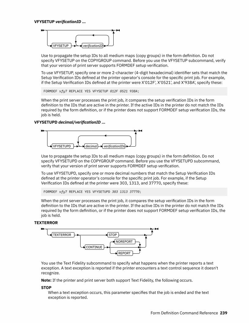
VFYSETUP verificationID …
VFYSETUP verificationID
Use to propagate the setup IDs to all medium maps (copy groups) in the form definition. Do notspecify VFYSETUP on the COPYGROUP command. Before you use the VFYSETUP subcommand, verifythat your version of print server supports FORMDEF setup verification.
To use VFYSETUP, specify one or more 2-character (4-digit hexadecimal) identifier sets that match theSetup Verification IDs defined at the printer operator's console for the specific print job. For example,if the Setup Verification IDs defined at the printer were X'012F', X'0521', and X'938A', specify these:
FORMDEF vfy7 REPLACE YES VFYSETUP 012F 0521 938A;
When the print server processes the print job, it compares the setup verification IDs in the formdefinition to the IDs that are active in the printer. If the active IDs in the printer do not match the IDsrequired by the form definition, or if the printer does not support FORMDEF setup verification IDs, thejob is held.
VFYSETUPD decimal/verificationID …
VFYSETUPD decimal verificationIDs
Use to propagate the setup IDs to all medium maps (copy groups) in the form definition. Do notspecify VFYSETUPD on the COPYGROUP command. Before you use the VFYSETUPD subcommand,verify that your version of print server supports FORMDEF setup verification.
To use VFYSETUPD, specify one or more decimal numbers that match the Setup Verification IDsdefined at the printer operator's console for the specific print job. For example, if the SetupVerification IDs defined at the printer were 303, 1313, and 37770, specify these:
FORMDEF vfy7 REPLACE YES VFYSETUPD 303 1313 37770;
When the print server processes the print job, it compares the setup verification IDs in the formdefinition to the IDs that are active in the printer. If the active IDs in the printer do not match the IDsrequired by the form definition, or if the printer does not support FORMDEF setup verification IDs, thejob is held.
TEXTERROR
TEXTERROR STOP
CONTINUE
NOREPORT
REPORT
You use the Text Fidelity subcommand to specify what happens when the printer reports a textexception. A text exception is reported if the printer encounters a text control sequence it doesn'trecognize.
Note: If the printer and print server both support Text Fidelity, the following occurs.
STOPWhen a text exception occurs, this parameter specifies that the job is ended and the textexception is reported.
Form Definition Command Reference 239
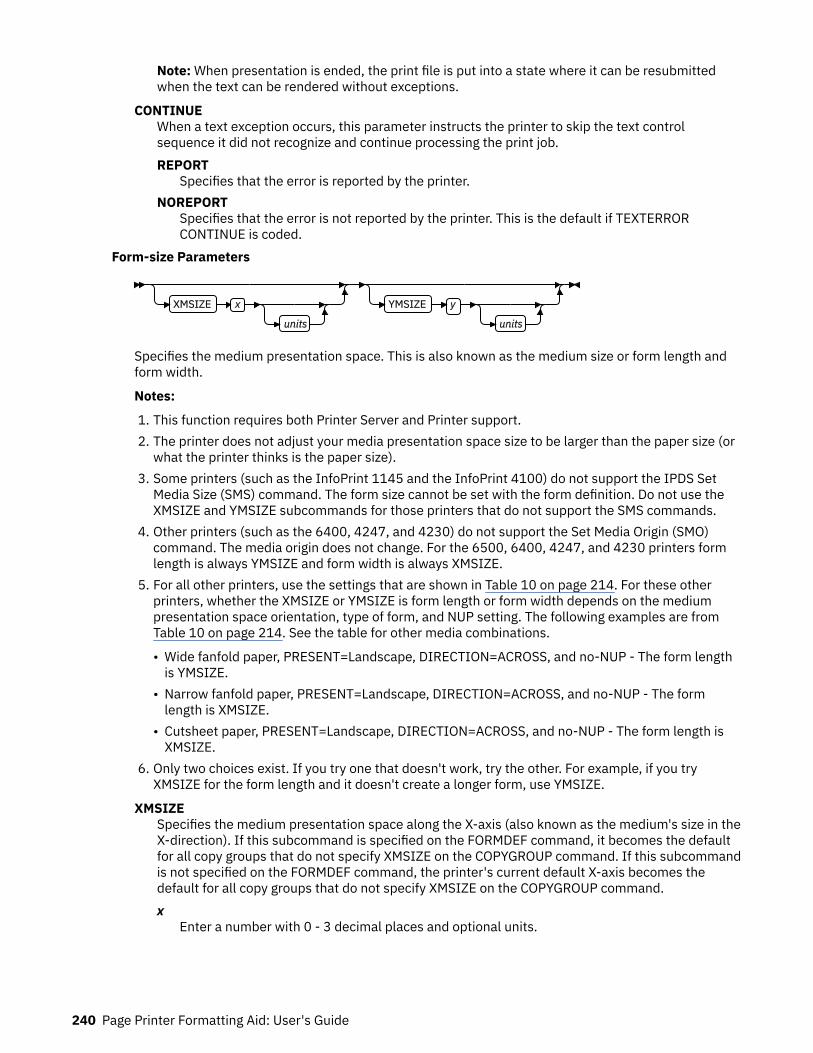
Note: When presentation is ended, the print file is put into a state where it can be resubmittedwhen the text can be rendered without exceptions.
CONTINUEWhen a text exception occurs, this parameter instructs the printer to skip the text controlsequence it did not recognize and continue processing the print job.REPORT
Specifies that the error is reported by the printer.NOREPORT
Specifies that the error is not reported by the printer. This is the default if TEXTERRORCONTINUE is coded.
Form-size Parameters
XMSIZE x
units
YMSIZE y
units
Specifies the medium presentation space. This is also known as the medium size or form length andform width.
Notes:
1. This function requires both Printer Server and Printer support.2. The printer does not adjust your media presentation space size to be larger than the paper size (or
what the printer thinks is the paper size).3. Some printers (such as the InfoPrint 1145 and the InfoPrint 4100) do not support the IPDS Set
Media Size (SMS) command. The form size cannot be set with the form definition. Do not use theXMSIZE and YMSIZE subcommands for those printers that do not support the SMS commands.
4. Other printers (such as the 6400, 4247, and 4230) do not support the Set Media Origin (SMO)command. The media origin does not change. For the 6500, 6400, 4247, and 4230 printers formlength is always YMSIZE and form width is always XMSIZE.
5. For all other printers, use the settings that are shown in Table 10 on page 214. For these otherprinters, whether the XMSIZE or YMSIZE is form length or form width depends on the mediumpresentation space orientation, type of form, and NUP setting. The following examples are fromTable 10 on page 214. See the table for other media combinations.
• Wide fanfold paper, PRESENT=Landscape, DIRECTION=ACROSS, and no-NUP - The form lengthis YMSIZE.
• Narrow fanfold paper, PRESENT=Landscape, DIRECTION=ACROSS, and no-NUP - The formlength is XMSIZE.
• Cutsheet paper, PRESENT=Landscape, DIRECTION=ACROSS, and no-NUP - The form length isXMSIZE.
6. Only two choices exist. If you try one that doesn't work, try the other. For example, if you tryXMSIZE for the form length and it doesn't create a longer form, use YMSIZE.
XMSIZESpecifies the medium presentation space along the X-axis (also known as the medium's size in theX-direction). If this subcommand is specified on the FORMDEF command, it becomes the defaultfor all copy groups that do not specify XMSIZE on the COPYGROUP command. If this subcommandis not specified on the FORMDEF command, the printer's current default X-axis becomes thedefault for all copy groups that do not specify XMSIZE on the COPYGROUP command.x
Enter a number with 0 - 3 decimal places and optional units.
240 Page Printer Formatting Aid: User's Guide
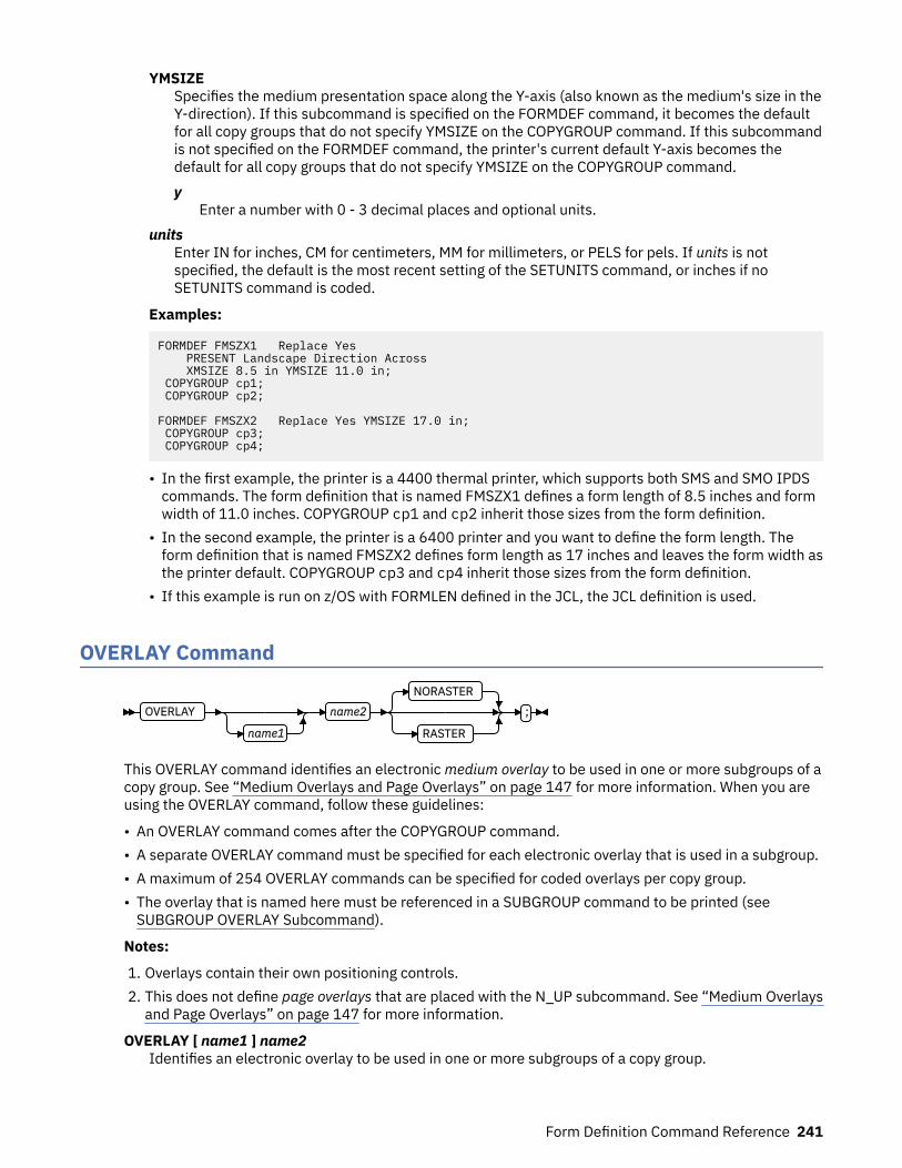
YMSIZESpecifies the medium presentation space along the Y-axis (also known as the medium's size in theY-direction). If this subcommand is specified on the FORMDEF command, it becomes the defaultfor all copy groups that do not specify YMSIZE on the COPYGROUP command. If this subcommandis not specified on the FORMDEF command, the printer's current default Y-axis becomes thedefault for all copy groups that do not specify YMSIZE on the COPYGROUP command.y
Enter a number with 0 - 3 decimal places and optional units.units
Enter IN for inches, CM for centimeters, MM for millimeters, or PELS for pels. If units is notspecified, the default is the most recent setting of the SETUNITS command, or inches if noSETUNITS command is coded.
Examples:
FORMDEF FMSZX1 Replace Yes PRESENT Landscape Direction Across XMSIZE 8.5 in YMSIZE 11.0 in; COPYGROUP cp1; COPYGROUP cp2;
FORMDEF FMSZX2 Replace Yes YMSIZE 17.0 in; COPYGROUP cp3; COPYGROUP cp4;
• In the first example, the printer is a 4400 thermal printer, which supports both SMS and SMO IPDScommands. The form definition that is named FMSZX1 defines a form length of 8.5 inches and formwidth of 11.0 inches. COPYGROUP cp1 and cp2 inherit those sizes from the form definition.
• In the second example, the printer is a 6400 printer and you want to define the form length. Theform definition that is named FMSZX2 defines form length as 17 inches and leaves the form width asthe printer default. COPYGROUP cp3 and cp4 inherit those sizes from the form definition.
• If this example is run on z/OS with FORMLEN defined in the JCL, the JCL definition is used.
OVERLAY Command
OVERLAY
name1
name2
NORASTER
RASTER
;
This OVERLAY command identifies an electronic medium overlay to be used in one or more subgroups of acopy group. See “Medium Overlays and Page Overlays” on page 147 for more information. When you areusing the OVERLAY command, follow these guidelines:
• An OVERLAY command comes after the COPYGROUP command.• A separate OVERLAY command must be specified for each electronic overlay that is used in a subgroup.• A maximum of 254 OVERLAY commands can be specified for coded overlays per copy group.• The overlay that is named here must be referenced in a SUBGROUP command to be printed (see
SUBGROUP OVERLAY Subcommand).
Notes:
1. Overlays contain their own positioning controls.2. This does not define page overlays that are placed with the N_UP subcommand. See “Medium Overlays
and Page Overlays” on page 147 for more information.
OVERLAY [ name1 ] name2Identifies an electronic overlay to be used in one or more subgroups of a copy group.
Form Definition Command Reference 241
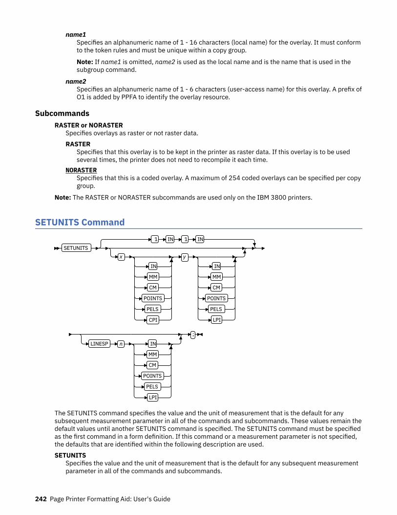
name1Specifies an alphanumeric name of 1 - 16 characters (local name) for the overlay. It must conformto the token rules and must be unique within a copy group.
Note: If name1 is omitted, name2 is used as the local name and is the name that is used in thesubgroup command.
name2Specifies an alphanumeric name of 1 - 6 characters (user-access name) for this overlay. A prefix ofO1 is added by PPFA to identify the overlay resource.
SubcommandsRASTER or NORASTER
Specifies overlays as raster or not raster data.RASTER
Specifies that this overlay is to be kept in the printer as raster data. If this overlay is to be usedseveral times, the printer does not need to recompile it each time.
NORASTERSpecifies that this is a coded overlay. A maximum of 254 coded overlays can be specified per copygroup.
Note: The RASTER or NORASTER subcommands are used only on the IBM 3800 printers.
SETUNITS Command
SETUNITS 1 IN 1 IN
x
IN
MM
CM
POINTS
PELS
CPI
y
IN
MM
CM
POINTS
PELS
LPI
LINESP n IN
MM
CM
POINTS
PELS
LPI
;
The SETUNITS command specifies the value and the unit of measurement that is the default for anysubsequent measurement parameter in all of the commands and subcommands. These values remain thedefault values until another SETUNITS command is specified. The SETUNITS command must be specifiedas the first command in a form definition. If this command or a measurement parameter is not specified,the defaults that are identified within the following description are used.SETUNITS
Specifies the value and the unit of measurement that is the default for any subsequent measurementparameter in all of the commands and subcommands.
242 Page Printer Formatting Aid: User's Guide
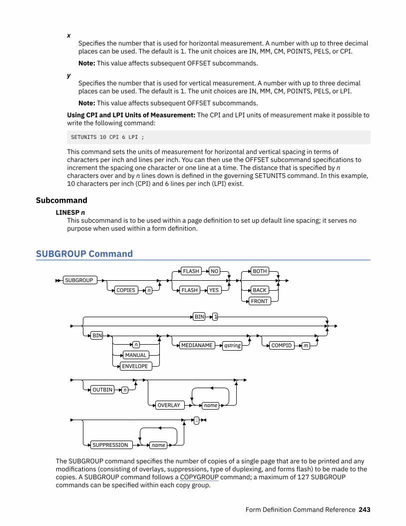
xSpecifies the number that is used for horizontal measurement. A number with up to three decimalplaces can be used. The default is 1. The unit choices are IN, MM, CM, POINTS, PELS, or CPI.
Note: This value affects subsequent OFFSET subcommands.
ySpecifies the number that is used for vertical measurement. A number with up to three decimalplaces can be used. The default is 1. The unit choices are IN, MM, CM, POINTS, PELS, or LPI.
Note: This value affects subsequent OFFSET subcommands.
Using CPI and LPI Units of Measurement: The CPI and LPI units of measurement make it possible towrite the following command:
SETUNITS 10 CPI 6 LPI ;
This command sets the units of measurement for horizontal and vertical spacing in terms ofcharacters per inch and lines per inch. You can then use the OFFSET subcommand specifications toincrement the spacing one character or one line at a time. The distance that is specified by ncharacters over and by n lines down is defined in the governing SETUNITS command. In this example,10 characters per inch (CPI) and 6 lines per inch (LPI) exist.
SubcommandLINESP n
This subcommand is to be used within a page definition to set up default line spacing; it serves nopurpose when used within a form definition.
SUBGROUP Command
SUBGROUP
COPIES n
FLASH NO
FLASH YES
BOTH
BACK
FRONT
BIN 1
BINn
MANUAL
ENVELOPE
MEDIANAME qstring COMPID m
OUTBIN n
OVERLAY name
SUPPRESSION name
;
The SUBGROUP command specifies the number of copies of a single page that are to be printed and anymodifications (consisting of overlays, suppressions, type of duplexing, and forms flash) to be made to thecopies. A SUBGROUP command follows a COPYGROUP command; a maximum of 127 SUBGROUPcommands can be specified within each copy group.
Form Definition Command Reference 243

Notes:
1. The BOTH subcommand causes two subgroups to be generated. Thus, a maximum of 63 subgroupscan be specified when the BOTH subcommand is used.
2. When you specify the DUPLEX subcommand (with a parameter other than NO) in the COPYGROUPcommand, you must include one SUBGROUP command for each side of a sheet, or you can specify theBOTH subcommand in a single SUBGROUP command.
SubcommandsCOPIES n
COPIES n
Specifies how many copies of each page are to be printed.
nDefines the number of copies (the maximum number is 255). When BACK is specified within aSUBGROUP command, the system counts the front pages printed (the actual number of sheets)not copies made (front and back). The default is 1.
FLASH
FLASH NO
FLASH YES
Specifies whether to use forms flash.
NOSpecifies that forms flash does not occur.
YESSpecifies that forms flash occurs.
Notes:
1. When forms flash is used, its name must be specified in the job control language for the print job.The operator must place the correct negative into the 3800 when the job is ready to print.
2. The FLASH subcommand is used only on the IBM 3800 printers.
side subcommands
BOTH
BACK
FRONT
These optional subcommands specify whether the subgroup is for both sides of a sheet or for only thefront or the back side.
Rules:
1. Subgroups must specify FRONT and BACK if an overlay, suppression, or forms flash appears on oneside but not on the other.
2. The FRONT and BACK subgroups must have the same number of copies.
If the number of copies differs, the COPIES parameter of the BACK subgroup is ignored, and awarning message is issued.
3. The FRONT and BACK subcommands must occur in pairs.
244 Page Printer Formatting Aid: User's Guide
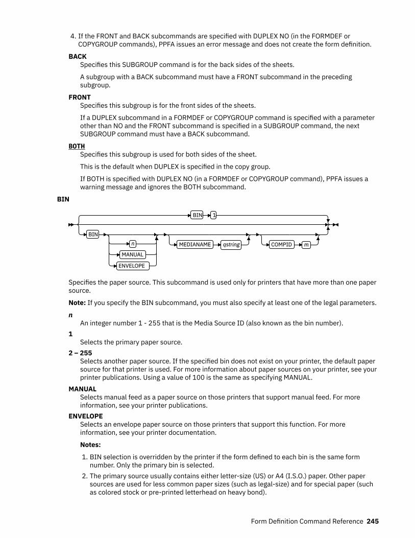
4. If the FRONT and BACK subcommands are specified with DUPLEX NO (in the FORMDEF orCOPYGROUP commands), PPFA issues an error message and does not create the form definition.
BACKSpecifies this SUBGROUP command is for the back sides of the sheets.
A subgroup with a BACK subcommand must have a FRONT subcommand in the precedingsubgroup.
FRONTSpecifies this subgroup is for the front sides of the sheets.
If a DUPLEX subcommand in a FORMDEF or COPYGROUP command is specified with a parameterother than NO and the FRONT subcommand is specified in a SUBGROUP command, the nextSUBGROUP command must have a BACK subcommand.
BOTHSpecifies this subgroup is used for both sides of the sheet.
This is the default when DUPLEX is specified in the copy group.
If BOTH is specified with DUPLEX NO (in a FORMDEF or COPYGROUP command), PPFA issues awarning message and ignores the BOTH subcommand.
BIN
BIN 1
BINn
MANUAL
ENVELOPE
MEDIANAME qstring COMPID m
Specifies the paper source. This subcommand is used only for printers that have more than one papersource.
Note: If you specify the BIN subcommand, you must also specify at least one of the legal parameters.
nAn integer number 1 - 255 that is the Media Source ID (also known as the bin number).
1Selects the primary paper source.
2 – 255Selects another paper source. If the specified bin does not exist on your printer, the default papersource for that printer is used. For more information about paper sources on your printer, see yourprinter publications. Using a value of 100 is the same as specifying MANUAL.
MANUALSelects manual feed as a paper source on those printers that support manual feed. For moreinformation, see your printer publications.
ENVELOPESelects an envelope paper source on those printers that support this function. For moreinformation, see your printer documentation.
Notes:
1. BIN selection is overridden by the printer if the form defined to each bin is the same formnumber. Only the primary bin is selected.
2. The primary source usually contains either letter-size (US) or A4 (I.S.O.) paper. Other papersources are used for less common paper sizes (such as legal-size) and for special paper (suchas colored stock or pre-printed letterhead on heavy bond).
Form Definition Command Reference 245
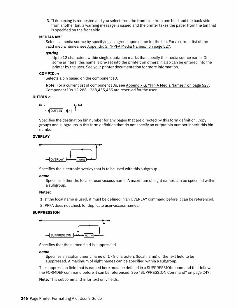
3. If duplexing is requested and you select from the front side from one bind and the back sidefrom another bin, a warning message is issued and the printer takes the paper from the bin thatis specified on the front side.
MEDIANAMESelects a media source by specifying an agreed upon name for the bin. For a current list of thevalid media names, see Appendix G, “PPFA Media Names,” on page 527.qstring
Up to 12 characters within single quotation marks that specify the media source name. Onsome printers, this name is pre-set into the printer; on others, it also can be entered into theprinter by the user. See your printer documentation for more information.
COMPID mSelects a bin based on the component ID.
Note: For a current list of component IDs, see Appendix G, “PPFA Media Names,” on page 527.Component IDs 12,288 - 268,435,455 are reserved for the user.
OUTBIN n
OUTBIN n
Specifies the destination bin number for any pages that are directed by this form definition. Copygroups and subgroups in this form definition that do not specify an output bin number inherit this binnumber.
OVERLAY
OVERLAY name
Specifies the electronic overlay that is to be used with this subgroup.
nameSpecifies either the local or user-access name. A maximum of eight names can be specified withina subgroup.
Notes:
1. If the local name is used, it must be defined in an OVERLAY command before it can be referenced.2. PPFA does not check for duplicate user-access names.
SUPPRESSION
SUPPRESSION name
Specifies that the named field is suppressed.
nameSpecifies an alphanumeric name of 1 - 8 characters (local name) of the text field to besuppressed. A maximum of eight names can be specified within a subgroup.
The suppression field that is named here must be defined in a SUPPRESSION command that followsthe FORMDEF command before it can be referenced. See “SUPPRESSION Command” on page 247.
Note: This subcommand is for text only fields.
246 Page Printer Formatting Aid: User's Guide
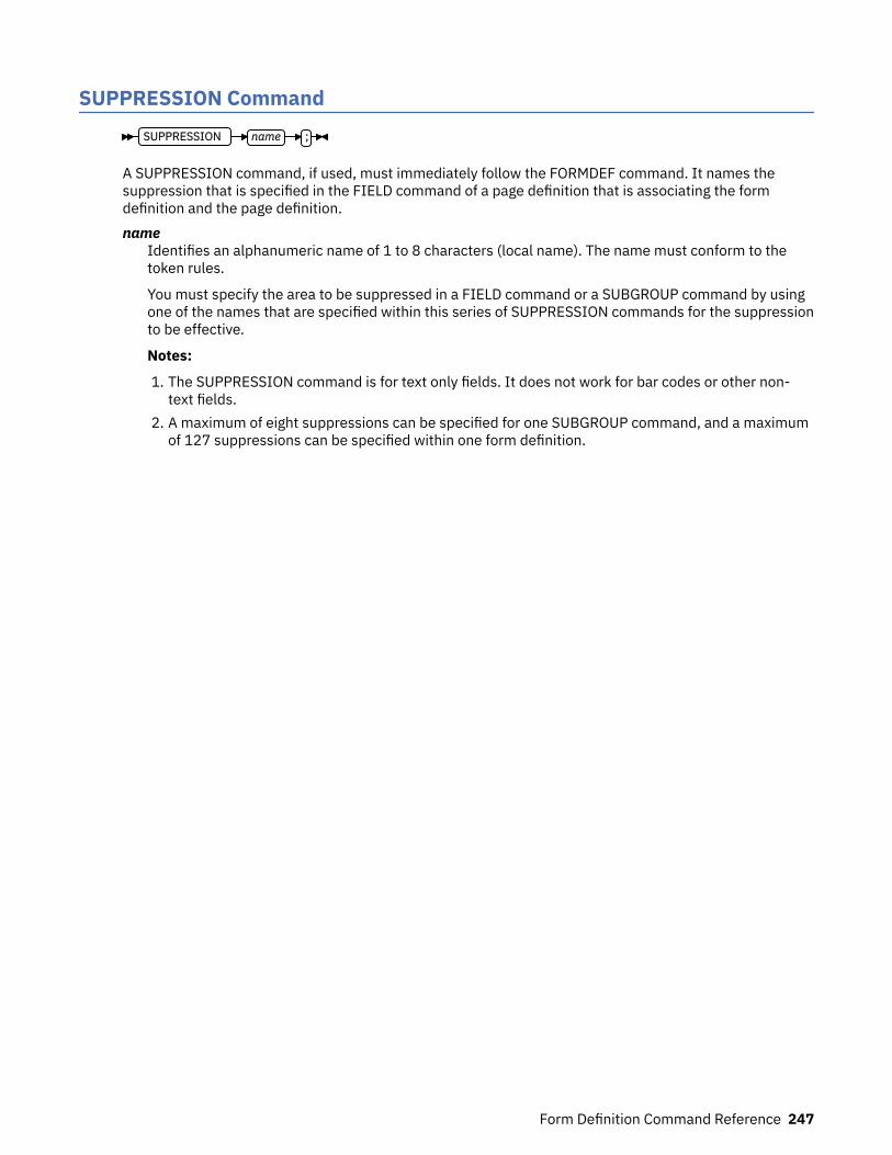
SUPPRESSION CommandSUPPRESSION name ;
A SUPPRESSION command, if used, must immediately follow the FORMDEF command. It names thesuppression that is specified in the FIELD command of a page definition that is associating the formdefinition and the page definition.name
Identifies an alphanumeric name of 1 to 8 characters (local name). The name must conform to thetoken rules.
You must specify the area to be suppressed in a FIELD command or a SUBGROUP command by usingone of the names that are specified within this series of SUPPRESSION commands for the suppressionto be effective.
Notes:
1. The SUPPRESSION command is for text only fields. It does not work for bar codes or other non-text fields.
2. A maximum of eight suppressions can be specified for one SUBGROUP command, and a maximumof 127 suppressions can be specified within one form definition.
Form Definition Command Reference 247

248 Page Printer Formatting Aid: User's Guide
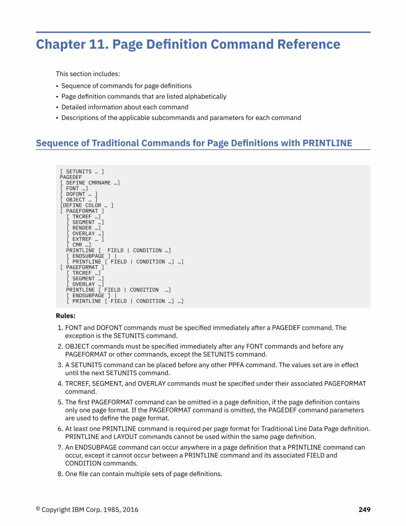
Chapter 11. Page Definition Command Reference
This section includes:
• Sequence of commands for page definitions• Page definition commands that are listed alphabetically• Detailed information about each command• Descriptions of the applicable subcommands and parameters for each command
Sequence of Traditional Commands for Page Definitions with PRINTLINE
[ SETUNITS … ]PAGEDEF[ DEFINE CMRNAME …][ FONT …][ DOFONT … ][ OBJECT … ][DEFINE COLOR … ][ PAGEFORMAT ] [ TRCREF …] [ SEGMENT …] [ RENDER …] [ OVERLAY …] [ EXTREF … ] [ CMR …] PRINTLINE [ FIELD | CONDITION …] [ ENDSUBPAGE ] | [ PRINTLINE [ FIELD | CONDITION …] …][ PAGEFORMAT ] [ TRCREF …] [ SEGMENT …] [ OVERLAY …] PRINTLINE [ FIELD | CONDITION …] [ ENDSUBPAGE ] | [ PRINTLINE [ FIELD | CONDITION …] …]
Rules:
1. FONT and DOFONT commands must be specified immediately after a PAGEDEF command. Theexception is the SETUNITS command.
2. OBJECT commands must be specified immediately after any FONT commands and before anyPAGEFORMAT or other commands, except the SETUNITS command.
3. A SETUNITS command can be placed before any other PPFA command. The values set are in effectuntil the next SETUNITS command.
4. TRCREF, SEGMENT, and OVERLAY commands must be specified under their associated PAGEFORMATcommand.
5. The first PAGEFORMAT command can be omitted in a page definition, if the page definition containsonly one page format. If the PAGEFORMAT command is omitted, the PAGEDEF command parametersare used to define the page format.
6. At least one PRINTLINE command is required per page format for Traditional Line Data Page definition.PRINTLINE and LAYOUT commands cannot be used within the same page definition.
7. An ENDSUBPAGE command can occur anywhere in a page definition that a PRINTLINE command canoccur, except it cannot occur between a PRINTLINE command and its associated FIELD andCONDITION commands.
8. One file can contain multiple sets of page definitions.
© Copyright IBM Corp. 1985, 2016 249

Sequence of Record Formatting Commands for Page Definitions withLAYOUT
[ SETUNITS …]PAGEDEFFONT[ DOFONT … ][OBJECT … ][DEFINE COLOR… ][ PAGEFORMAT ] [ SEGMENT …] [ OVERLAY …] [ RENDER …] [ EXTREF … ] [ CMR …] [ LAYOUT …] [ CONDITION …] [ FIELD …] [ DRAWGRAPHIC …] [ ENDGRAPHIC …][ PAGEFORMAT ] [ SEGMENT …] [ OVERLAY …] [ LAYOUT …] [ CONDITION …] [ FIELD …] [ DRAWGRAPHIC …] [ ENDGRAPHIC …]
Rules:
1. LAYOUT, XLAYOUT, and PRINTLINE commands cannot be mixed within the same PAGEDEF. At leastone LAYOUT command is required per page format for a record formatting page definition.
2. FONT and DOFONT commands must be specified immediately after a PAGEDEF command.3. A SETUNITS command can be placed before any other PPFA command. The values set are in effect
until the next SETUNITS command.4. SEGMENT, OVERLAY, and EXTREF commands must be specified under their associated PAGEFORMAT
command.5. The first PAGEFORMAT command can be omitted in a page definition, if the page definition contains
only one page format. If the PAGEFORMAT command is omitted, the PAGEDEF command parametersare used to define the page format.
6. One file can contain multiple sets of page definitions.7. At least one FONT or DOFONT command is required for each PAGEDEF command.
Sequence of Commands for XML Page Definitions with XLAYOUT[ SETUNITS …]PAGEDEFFONT[ DOFONT … ][OBJECT … ][DEFINE COLOR… ][DEFINE QTAG …][ PAGEFORMAT ] [ SEGMENT …] [ OVERLAY …] [ RENDER …] [ EXTREF … ] [ CMR …] [ XLAYOUT …] [ CONDITION …] [ FIELD …] [ DRAWGRAPHIC …] [ ENDGRAPHIC …][ PAGEFORMAT ] [ SEGMENT …]
250 Page Printer Formatting Aid: User's Guide

[ OVERLAY …] [ XLAYOUT …] [ CONDITION …] [ FIELD …] [ DRAWGRAPHIC …] [ ENDGRAPHIC …]
Rules:
1. LAYOUT, XLAYOUT, and PRINTLINE commands cannot be mixed within the same PAGEDEF. At leastone XLAYOUT command is required per page format for an XML page definition. At least one FONT orDOFONT command is required for each PAGEDEF command.
2. FONT and DOFONT commands must be specified immediately after a PAGEDEF command.3. A SETUNITS command can be placed before any other PPFA command. The values set are in effect
until the next SETUNITS command.4. SEGMENT, OVERLAY, and EXTREF commands must be specified under their associated PAGEFORMAT
command.5. The first PAGEFORMAT command can be omitted in a page definition, if the page definition contains
only one page format. If the PAGEFORMAT command is omitted, the PAGEDEF command parametersare used to define the page format.
6. One file can contain multiple sets of page definitions.7. DOFONT commands must be after the PAGEDEF command and before the first PAGEFORMAT
command.8. EXTREF must be after a PAGEFORMAT (the scope if for that page format) and before the first
PRINTLINE, LAYOUT, or XLAYOUT.
Diagram ShorthandThese terms are used in the command definitions:x-pos
A vertical position that uses a numeric number followed optionally by a unit. For the available units,see “Units of Measurement” on page 186.
y-posA horizontal position that uses a numeric number followed optionally by a unit. For the available units,see “Units of Measurement” on page 186.
CONDITION CommandCONDITION condname START (Traditional) START (Record Format and XML)
START (Traditional)
START n LENGTH n
SPACE_THEN_PRINT YES
SPACE_THEN_PRINT NO
START (Record Format and XML)START n LENGTH n
FLDNUM n
START - 1
START n
LENGTH longest
LENGTH n
Page Definition Command Reference 251
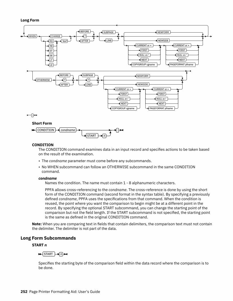
Long Form
WHEN CHANGE
EQ
NE
GT
GE
LT
LE
'text'
BEFORE
?
AFTER
SUBPAGE
LINE
NEWFORM
NEWSIDE
CURRENT or =
FIRST
NULL or ⁄
NEXT
COPYGROUP cgname
CURRENT or =
FIRST
NULL or ⁄
NEXT
PAGEFORMAT pfname
OTHERWISE
BEFORE
?
AFTER
SUBPAGE
?
LINE
NEWFORM
NEWSIDE
CURRENT or =
FIRST
NULL or ⁄
NEXT
COPYGROUP cgname
CURRENT or =
FIRST
NULL or ⁄
NEXT
PAGEFORMAT pfname
;
Short FormCONDITION condname
START n
;
CONDITIONThe CONDITION command examines data in an input record and specifies actions to be taken basedon the result of the examination.
• The condname parameter must come before any subcommands.• No WHEN subcommand can follow an OTHERWISE subcommand in the same CONDITION
command.
condnameNames the condition. The name must contain 1 - 8 alphanumeric characters.
PPFA allows cross-referencing to the condname. The cross-reference is done by using the shortform of the CONDITION command (second format in the syntax table). By specifying a previouslydefined condname, PPFA uses the specifications from that command. When the condition isreused, the point where you want the comparison to begin might be at a different point in therecord. By specifying the optional START subcommand, you can change the starting point of thecomparison but not the field length. If the START subcommand is not specified, the starting pointis the same as defined in the original CONDITION command.
Note: When you are comparing text in fields that contain delimiters, the comparison text must not containthe delimiter. The delimiter is not part of the data.
Long Form SubcommandsSTART n
START n
Specifies the starting byte of the comparison field within the data record where the comparison is tobe done.
252 Page Printer Formatting Aid: User's Guide

nSpecifies the number of bytes from the first data byte in the record as the starting point of thecomparison field. The first data byte position of an input record is 1.
Note: The carriage-control character and the table-reference character are not considered data.
LENGTH nLENGTH n
Specifies the length of the comparison field.
nSpecifies the number of bytes in the data record to be compared, beginning with the positionspecified in START. Valid values are numbers 1 - 8000. The length of the constant text must be thesame as defined in this parameter or the results are invalid.
Comparisons are done on a byte-by-byte basis. Because the comparison field and the constanttext must have the same lengths, padding is not necessary.
Note: If any part of the comparison field that is specified by the combination of START and LENGTH isoutside the boundaries of the data record, no conditional processing is done. No WHEN is started. Ifan OTHERWISE is present, it is not started either.
FLDNUM (Record Format and XML only)
FLDNUM n
START 1
START n
LENGTH longest
LENGTH n
Field number to be used in comparison. This keyword is used only if the DELIMITER field was used inthe LAYOUT command. Fields cannot be counted without specifying delimiters in the database. Whenfields are counted, the first field after the record ID is to be considered FLDNUM 1.
To identify a part of a field that is numbered, you can specify the starting position (from the delimiter)and the length of the field to be used in the WHEN condition (the default of the longest parameter isthe length of the longest condition or when no specific condition is specified, it is from the startingposition to the end of the field.)
SPACE_THEN_PRINT (Traditional only)
SPACE_THEN_PRINT YES
SPACE_THEN_PRINT NO
Specifies whether ANSI carriage controls for spacing are enabled for the first record on the newlogical page that follows the execution of the CONDITION command. The abbreviation of thiscommand is SPACE.
YESSpecifies that the ANSI carriage-control character in the first print record of the new page isenabled for spacing. The spacing action that is specified in the carriage control is done after theeject to the new page. For example, if the carriage-control byte in the first record of the new pageis a blank (skip one line before printing), then the first record skips the first line of the new pageand prints at the second printline position.
NOSpecifies the ANSI carriage-control character spacing action is suppressed for the first printrecord of the new page. If this record contains a carriage-control spacing value, such as blank, 0,or –, the spacing is ignored and the record prints at the first printline position on the new page.Channel code values are not ignored. If the first print record contains a valid channel code value of1 - 9, or A - C, then the first record on the new page prints at the printline defined with thatchannel code.
Page Definition Command Reference 253

Note: This subcommand is effective for print files that contain ANSI carriage controls. It is not usedfor data files that contain machine carriage controls, or a mixture of ANSI and machine carriagecontrols.
WHEN
WHEN CHANGE
EQ
NE
GT
GE
LT
LE
'text'
BEFORE
?
AFTER
SUBPAGE
LINE
NEWFORM
NEWSIDE
CURRENT or =
FIRST
NULL or ⁄
NEXT
COPYGROUP cgname
CURRENT or =
FIRST
NULL or ⁄
NEXT
PAGEFORMAT pfname
Marks the start of the conditional comparison parameters. At least one WHEN subcommand isrequired.
comparison typeSpecifies the type of comparison that is to be done between the data in the comparison field (theportion of the record that is specified by START and LENGTH) and the constant text that is definedin the text parameter.
The values are:EQ
Equal toNE
Not equal toGT
Greater thanGE
Greater than or equal toLT
Less thanLE
Less than or equal to
textSpecifies constant text for comparison with the comparison field text. The constant text lengthmust be the same as the value on the LENGTH subcommand, with a maximum length of 8000bytes. Examples of valid text are:
2C(3)'AB'K'321,400'X'41FE7799' 2 'CHARS'
Any values or parameters that are valid for the TEXT subcommand within the FIELD command canbe used as text.
CHANGESpecifies that the contents of the comparison field in this record are to be compared with the fieldin the record last processed by the same CONDITION command.
This parameter is an alternative to the comparisontype and text parameter combination but can bespecified only once in a CONDITION command.
The result of the comparison is either TRUE or FALSE.
254 Page Printer Formatting Aid: User's Guide

TRUEWhen the contents of the comparison field change from one record to the next.
FALSEWhen the print server processes the data, if the comparison field lies outside the boundary ofthe current record, which might occur with variable-length records or with truncated trailingblanks, the current record is not used in future comparisons.
CHANGE is always false if used with the first WHEN subcommand of a series (no previousrecord to compare against). Whenever a new data map (one with a different name) is invoked,all the CHANGE comparisons are reset. Field values in the previous data map are not retained.
BEFORESpecifies that the conditional action takes place before the current line or subpage is processed.This is the default.
AFTERSpecifies that the conditional action takes place after the current line or subpage is processed.
LINESpecifies that the conditional action takes place either before or after the current line.
SUBPAGE (Traditional only)Specifies that the conditional action takes place either before or after the current subpage.Between LINE and SUBPAGE, SUBPAGE is the default.
For a description of subpages, see “Logical Page” on page 7.
PAGE (Record Format and XML only)Specifies that the conditional action takes place either before or after the current page. This is thedefault. Between LINE and PAGE, PAGE is the default.
Note: For CONDITION commands in a Record Format or XML page definition, the keywordSUBPAGE is acceptable but obsolete. Record Format and XML page definitions do not havesubpages.
NEWFORMSpecifies that the only action to be taken is skipping to the front of a new form (sheet) andrestarting the page format.
Note: This parameter is an alternative to using the COPYGROUP and PAGEFORMAT parameters,and is equivalent to specifying CURRENT for the COPYGROUP parameter and NULL for thePAGEFORMAT parameter. CURRENT NULL are the respective defaults for COPYGROUP andPAGEFORMAT parameters; therefore, NEWFORM is the default action.
NEWSIDESpecifies that the only action to be taken is skipping to a new side (either the back of the currentsheet or the front of a new sheet) and restarting the page format.
Notes:
1. This parameter is an alternative to using the COPYGROUP and PAGEFORMAT parameters, andis equivalent to specifying NULL for the COPYGROUP parameter and CURRENT for thePAGEFORMAT parameter.
2. Conditional processing does not result in unnecessary blank pages.
If the line currently being processed is the first line on a side, then:
• A COPYGROUP or NEWFORM action that takes effect BEFORE LINE does not force an additionalnew form.
• A PAGEFORMAT or NEWSIDE action that takes effect BEFORE LINE does not force an additionalnew side.
Similarly, additional sides or forms are not forced by BEFORE SUBPAGE if the line currently beingprocessed is in the first subpage on a side or a form.
Page Definition Command Reference 255

copygroup optionsSpecifies a copy group to be invoked if the condition is true.
Note: Any copy group action (except NULL) restarts the page format.
{ CURRENT or = }Invoke the current copy group again. This results in ending printing on the current sheet andresuming on the front side of a new sheet. This is the default.
The page format is restarted, which means that the first input record to go on the new page isprinted with the first PRINTLINE command of the current page format. For example, data thatis to be printed as subpage 4 on the sheet might be printed on subpage 1 on the new sheet.
Note: The character = can be used for CURRENT.
FIRSTInvokes the first copy group in the current form definition.
{ NULL or ⁄ }Retains the current copy group, taking no action. The character ⁄ can be used for NULL.
NEXTInvokes the next copy group in the current form definition.
Note: If NEXT is specified from the last copy group in the form definition, the first copy groupin the form definition is used.
COPYGROUP cgnameUses the named copy group that is defined in the current form definition. The name mustcontain 1 - 8 alphanumeric characters.
pageformat optionsSpecifies a page format to be invoked if the condition is true.{ CURRENT or = }
Invokes the current page format again. This results in ending printing on the current sheet andresuming on the front side of a new sheet.
The page format is restarted, which means that the first input record to go on the new page isprinted with the first PRINTLINE command of the current page format.
The character = can be used for CURRENT.
FIRSTInvokes the first page format in the current page definition.
{ NULL or ⁄ }Retains the current page format, taking no action. The character / can be used for NULL. Thisis the default.
NEXTInvokes the next page format in the current page definition.
Note: If NEXT is specified from the last page format in the page definition, the first pageformat in the page definition is used.
PAGEFORMAT pfnameUses the named page format that is defined in the current page definition. The name mustcontain 1 - 8 alphanumeric characters.
256 Page Printer Formatting Aid: User's Guide
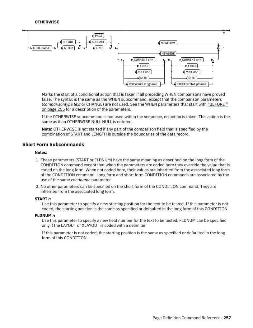
OTHERWISE
OTHERWISE
BEFORE
AFTER
SUBPAGE
PAGE
LINE
NEWFORM
NEWSIDE
CURRENT or =
FIRST
NULL or ⁄
NEXT
COPYGROUP cgname
CURRENT or =
FIRST
NULL or ⁄
NEXT
PAGEFORMAT pfname
Marks the start of a conditional action that is taken if all preceding WHEN comparisons have provedfalse. The syntax is the same as the WHEN subcommand, except that the comparison parameters(comparisontype text or CHANGE) are not used. See the WHEN parameters that start with “BEFORE ”on page 255 for a description of the parameters.
If the OTHERWISE subcommand is not used within the sequence, no action is taken. This action is thesame as if an OTHERWISE NULL NULL is entered.
Note: OTHERWISE is not started if any part of the comparison field that is specified by thecombination of START and LENGTH is outside the boundaries of the data record.
Short Form SubcommandsNotes:
1. These parameters (START or FLDNUM) have the same meaning as described on the long form of theCONDITION command except that when the parameters are coded here they override the value that iscoded on the long form. When not coded here, their values are inherited from the associated long formof the CONDITION command. Long form and short form CONDITION commands are associated by theuse of the same condname parameter.
2. No other parameters can be specified on the short form of the CONDITION command. They areinherited from the associated long form.
START nUse this parameter to specify a new starting position for the text to be tested. If this parameter is notcoded, the starting position is the same as specified or defaulted in the long form of this CONDITION.
FLDNUM nUse this parameter to specify a new field number for the text to be tested. FLDNUM can be specifiedonly if the LAYOUT or XLAYOUT is coded with a delimiter.
If this parameter is not coded, the starting position is the same as specified or defaulted in the longform of this CONDITION.
Page Definition Command Reference 257
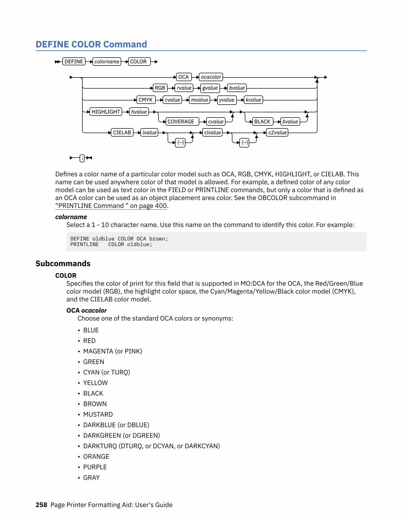
DEFINE COLOR CommandDEFINE colorname COLOR
OCA ocacolor
RGB rvalue gvalue bvalue
CMYK cvalue mvalue yvalue kvalue
HIGHLIGHT hvalue
COVERAGE cvalue BLACK bvalue
CIELAB lvalue
(–)
clvalue
(–)
c2value
;
Defines a color name of a particular color model such as OCA, RGB, CMYK, HIGHLIGHT, or CIELAB. Thisname can be used anywhere color of that model is allowed. For example, a defined color of any colormodel can be used as text color in the FIELD or PRINTLINE commands, but only a color that is defined asan OCA color can be used as an object placement area color. See the OBCOLOR subcommand in“PRINTLINE Command ” on page 400.colorname
Select a 1 - 10 character name. Use this name on the command to identify this color. For example:
DEFINE oldblue COLOR OCA brown;PRINTLINE COLOR oldblue;
SubcommandsCOLOR
Specifies the color of print for this field that is supported in MO:DCA for the OCA, the Red/Green/Bluecolor model (RGB), the highlight color space, the Cyan/Magenta/Yellow/Black color model (CMYK),and the CIELAB color model.OCA ocacolor
Choose one of the standard OCA colors or synonyms:
• BLUE• RED• MAGENTA (or PINK)• GREEN• CYAN (or TURQ)• YELLOW• BLACK• BROWN• MUSTARD• DARKBLUE (or DBLUE)• DARKGREEN (or DGREEN)• DARKTURQ (DTURQ, or DCYAN, or DARKCYAN)• ORANGE• PURPLE• GRAY
258 Page Printer Formatting Aid: User's Guide
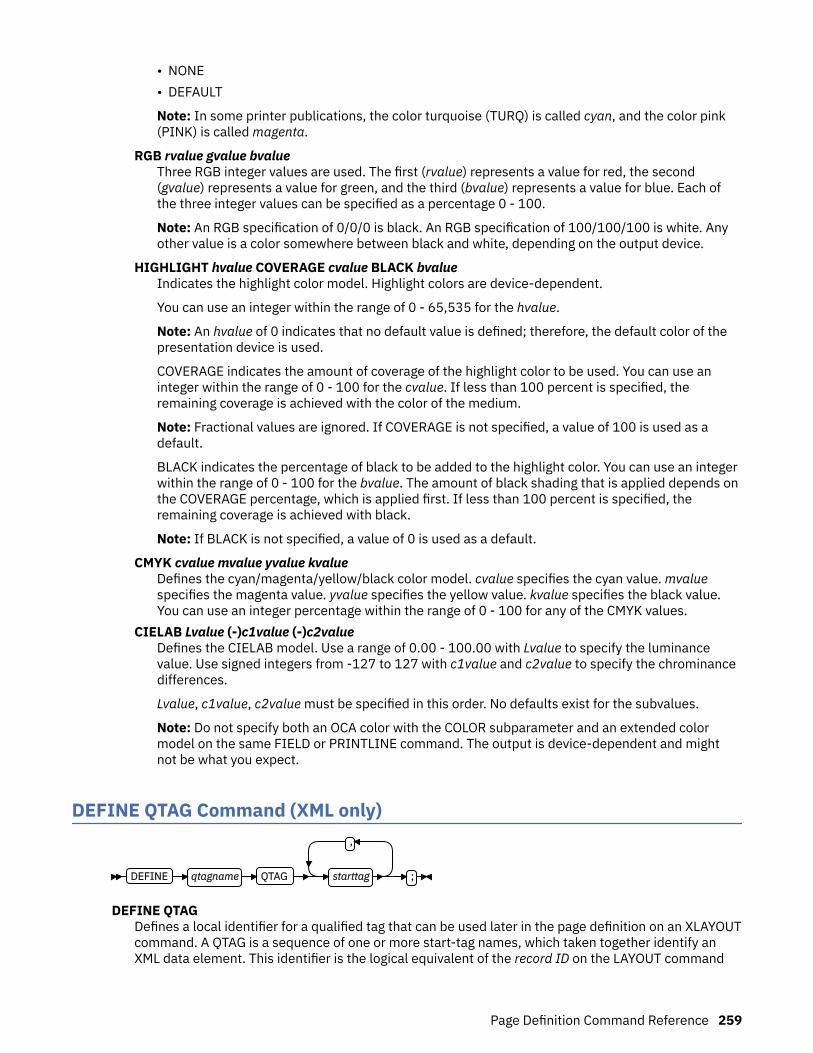
• NONE• DEFAULT
Note: In some printer publications, the color turquoise (TURQ) is called cyan, and the color pink(PINK) is called magenta.
RGB rvalue gvalue bvalueThree RGB integer values are used. The first (rvalue) represents a value for red, the second(gvalue) represents a value for green, and the third (bvalue) represents a value for blue. Each ofthe three integer values can be specified as a percentage 0 - 100.
Note: An RGB specification of 0/0/0 is black. An RGB specification of 100/100/100 is white. Anyother value is a color somewhere between black and white, depending on the output device.
HIGHLIGHT hvalue COVERAGE cvalue BLACK bvalueIndicates the highlight color model. Highlight colors are device-dependent.
You can use an integer within the range of 0 - 65,535 for the hvalue.
Note: An hvalue of 0 indicates that no default value is defined; therefore, the default color of thepresentation device is used.
COVERAGE indicates the amount of coverage of the highlight color to be used. You can use aninteger within the range of 0 - 100 for the cvalue. If less than 100 percent is specified, theremaining coverage is achieved with the color of the medium.
Note: Fractional values are ignored. If COVERAGE is not specified, a value of 100 is used as adefault.
BLACK indicates the percentage of black to be added to the highlight color. You can use an integerwithin the range of 0 - 100 for the bvalue. The amount of black shading that is applied depends onthe COVERAGE percentage, which is applied first. If less than 100 percent is specified, theremaining coverage is achieved with black.
Note: If BLACK is not specified, a value of 0 is used as a default.
CMYK cvalue mvalue yvalue kvalueDefines the cyan/magenta/yellow/black color model. cvalue specifies the cyan value. mvaluespecifies the magenta value. yvalue specifies the yellow value. kvalue specifies the black value.You can use an integer percentage within the range of 0 - 100 for any of the CMYK values.
CIELAB Lvalue (-)c1value (-)c2valueDefines the CIELAB model. Use a range of 0.00 - 100.00 with Lvalue to specify the luminancevalue. Use signed integers from -127 to 127 with c1value and c2value to specify the chrominancedifferences.
Lvalue, c1value, c2value must be specified in this order. No defaults exist for the subvalues.
Note: Do not specify both an OCA color with the COLOR subparameter and an extended colormodel on the same FIELD or PRINTLINE command. The output is device-dependent and mightnot be what you expect.
DEFINE QTAG Command (XML only)
DEFINE qtagname QTAG
,
starttag ;
DEFINE QTAGDefines a local identifier for a qualified tag that can be used later in the page definition on an XLAYOUTcommand. A QTAG is a sequence of one or more start-tag names, which taken together identify anXML data element. This identifier is the logical equivalent of the record ID on the LAYOUT command
Page Definition Command Reference 259
for a record formatting page definition. But, instead of identifying an entire record as the LAYOUTcommand does, the QTAG identifies a single XML data element.
When used, the local identifier makes the coding of an XLAYOUT command easier by allowing the useof a locally defined name instead of the fully qualified set of start tags. It also makes the XLAYOUTcommand syntax similar to the LAYOUT command.
qtagnameThe internal name that is assigned to the fully qualified QTAG. This name can be used on theXLAYOUT command to identify the XML data item. This name is not case-sensitive. It can be up to16 characters in length.
starttagAn XML element name. This name must match exactly to the element name in the XML data. Topreserve the case for the name, put it in quotation marks. Otherwise, the name is folded touppercase. If necessary, the name is translated to the data type specified or defaulted by theUDTYPE subcommand on the PAGEDEF command. For example, if the page definition is coded onan EBCDIC operating system, but the UTDTYPE specifies UTF8, PPFA converts the start tags fromEBCDIC code page 500 to UTF-8.
See the “XLAYOUT Command (XML)” on page 422 for an example of using a defined QTAG with anXLAYOUT command.
DOFONT Command
260 Page Printer Formatting Aid: User's Guide

DOFONT lname 'ttfname'
X16'uuuuuuuu...'
HEIGHT 10 POINTS
HEIGHT n
POINTS
IN
CM
MM
PELS
RATIO percent
ROTATION 0
ROTATION 0
90
180
270
PRELOAD
UDType of the PAGEDEF
UDType EBCDIC
CP 'T1V10500'
CP code-page-name
EBCDIC2 CP code-page-name
ASCII
CP 'T1000819'
CP code-page-name
UTF8
UTF16
MICR
INLINE
;
The DOFONT command defines a Data Object font and specifies its attributes. Data Object fonts includeTrueType and OpenType fonts. A font installer is used to install Data Object fonts and a Resource AccessTable (RAT). The RAT contains a table which, when accessed with the full font name that is provided bythe user, gives the file access name for the font. All names in the RAT are encoded in UTF-16. For moreinformation, see Using OpenType Fonts in an AFP System.
To use Data Object fonts, do these:
• Non-PPFA requirements:
– You need a printer and a print server (PSF or IPM) that supports Data Object fonts.– You must install a Resource Access Table (RAT) and the Data Object fonts that are used. For more
information, see Using OpenType Fonts in an AFP System.• PPFA requirements:
– Define the font by using a DOFONT command.– Reference the font in one of the following two ways:
- Reference the font with the PRINTLINE, LAYOUT, XLAYOUT, FIELD, or FIELD BARCODE commandsby using the local name.
Page Definition Command Reference 261
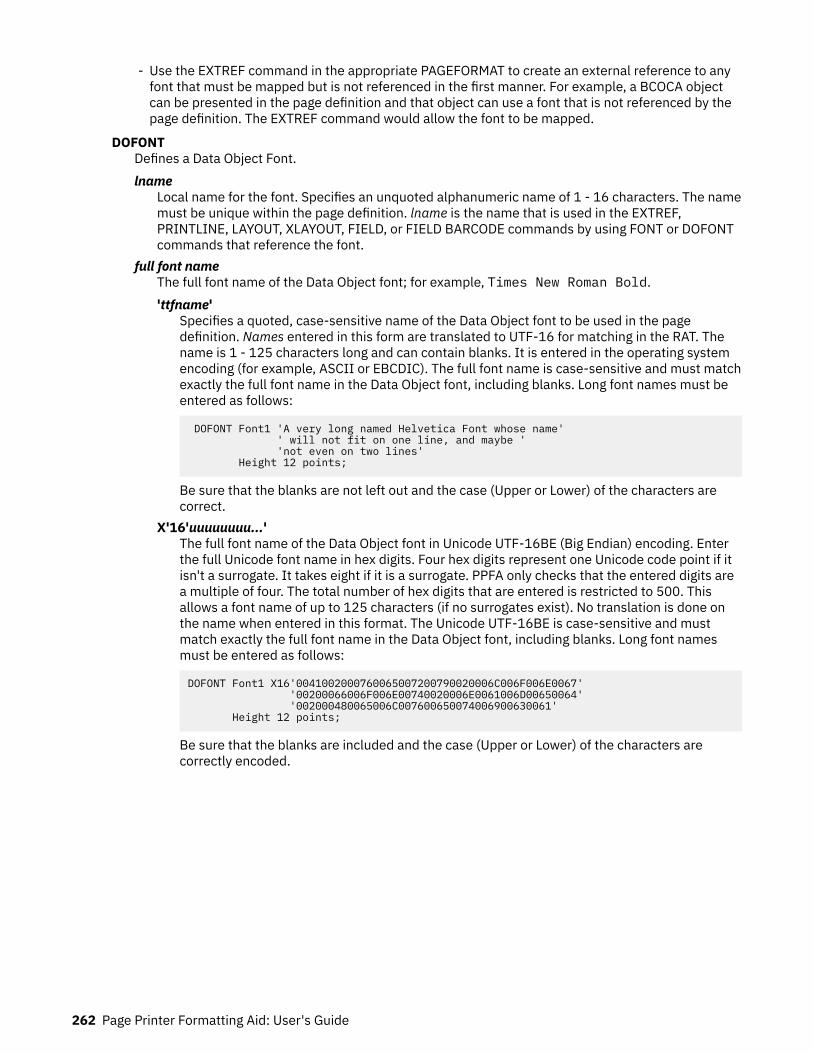
- Use the EXTREF command in the appropriate PAGEFORMAT to create an external reference to anyfont that must be mapped but is not referenced in the first manner. For example, a BCOCA objectcan be presented in the page definition and that object can use a font that is not referenced by thepage definition. The EXTREF command would allow the font to be mapped.
DOFONTDefines a Data Object Font.lname
Local name for the font. Specifies an unquoted alphanumeric name of 1 - 16 characters. The namemust be unique within the page definition. lname is the name that is used in the EXTREF,PRINTLINE, LAYOUT, XLAYOUT, FIELD, or FIELD BARCODE commands by using FONT or DOFONTcommands that reference the font.
full font nameThe full font name of the Data Object font; for example, Times New Roman Bold.'ttfname'
Specifies a quoted, case-sensitive name of the Data Object font to be used in the pagedefinition. Names entered in this form are translated to UTF-16 for matching in the RAT. Thename is 1 - 125 characters long and can contain blanks. It is entered in the operating systemencoding (for example, ASCII or EBCDIC). The full font name is case-sensitive and must matchexactly the full font name in the Data Object font, including blanks. Long font names must beentered as follows:
DOFONT Font1 'A very long named Helvetica Font whose name' ' will not fit on one line, and maybe ' 'not even on two lines' Height 12 points;
Be sure that the blanks are not left out and the case (Upper or Lower) of the characters arecorrect.
X'16'uuuuuuuu...'The full font name of the Data Object font in Unicode UTF-16BE (Big Endian) encoding. Enterthe full Unicode font name in hex digits. Four hex digits represent one Unicode code point if itisn't a surrogate. It takes eight if it is a surrogate. PPFA only checks that the entered digits area multiple of four. The total number of hex digits that are entered is restricted to 500. Thisallows a font name of up to 125 characters (if no surrogates exist). No translation is done onthe name when entered in this format. The Unicode UTF-16BE is case-sensitive and mustmatch exactly the full font name in the Data Object font, including blanks. Long font namesmust be entered as follows:
DOFONT Font1 X16'0041002000760065007200790020006C006F006E0067' '00200066006F006E00740020006E0061006D00650064' '002000480065006C007600650074006900630061' Height 12 points;
Be sure that the blanks are included and the case (Upper or Lower) of the characters arecorrectly encoded.
262 Page Printer Formatting Aid: User's Guide
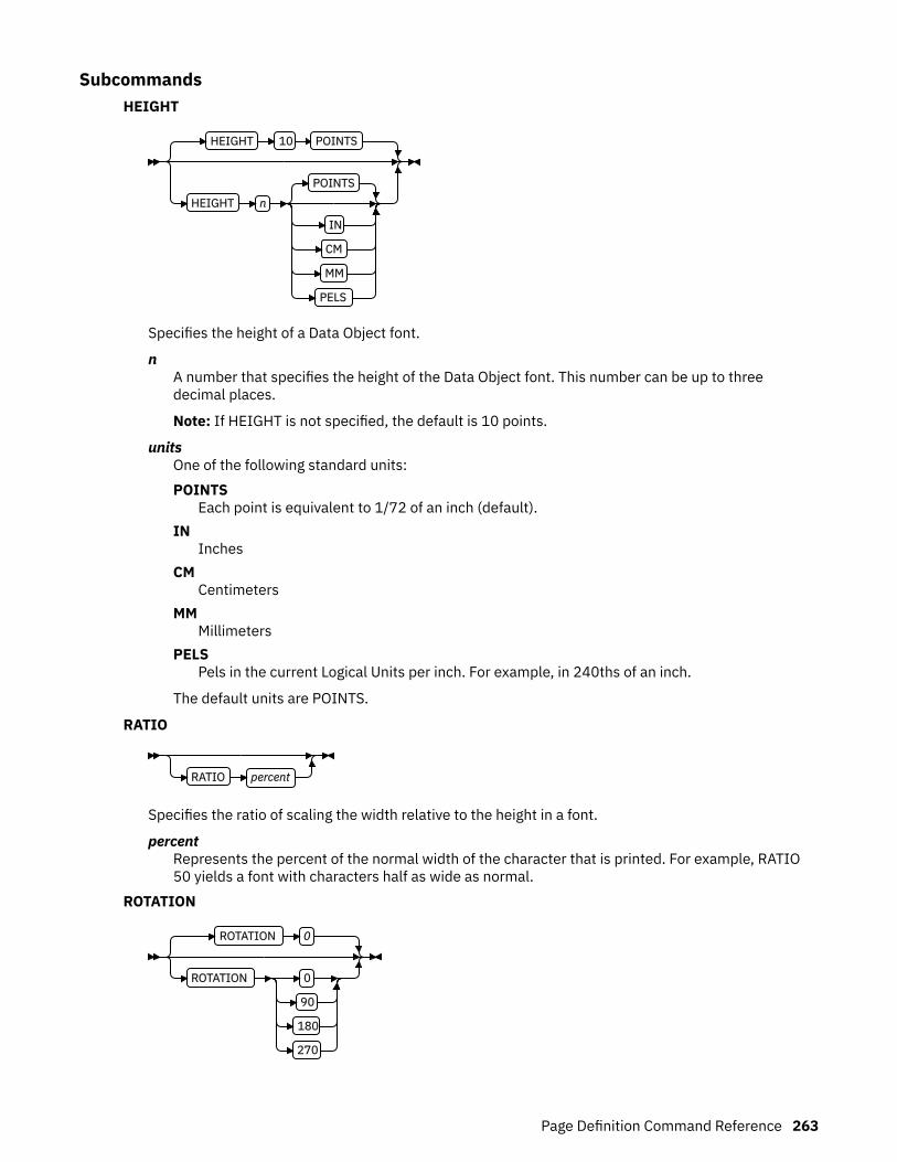
SubcommandsHEIGHT
HEIGHT 10 POINTS
HEIGHT n
POINTS
IN
CM
MM
PELS
Specifies the height of a Data Object font.
nA number that specifies the height of the Data Object font. This number can be up to threedecimal places.
Note: If HEIGHT is not specified, the default is 10 points.
unitsOne of the following standard units:POINTS
Each point is equivalent to 1/72 of an inch (default).IN
InchesCM
CentimetersMM
MillimetersPELS
Pels in the current Logical Units per inch. For example, in 240ths of an inch.
The default units are POINTS.
RATIO
RATIO percent
Specifies the ratio of scaling the width relative to the height in a font.
percentRepresents the percent of the normal width of the character that is printed. For example, RATIO50 yields a font with characters half as wide as normal.
ROTATION
ROTATION 0
ROTATION 0
90
180
270
Page Definition Command Reference 263

Specifies the rotation of characters in degrees. The specified value is relative to the inline direction ofthe line to be printed. Valid rotations are 0, 90, 180, and 270. Zero is the default.
PRELOAD
PRELOAD
If you want the font to be preloaded before starting the print job, specify it here. Preloaded fontsenhance print performance. The printer must support this function.
UDType
UDType of the PAGEDEF
UDType EBCDIC
CP 'T1V10500'
CP code-page-name
EBCDIC2 CP code-page-name
ASCII
CP 'T1000819'
CP code-page-name
UTF8
UTF16
The UDType subcommand specifies the user's data type and optionally, the code page name formapping the font.
If UDType is not coded on the DOFONT command, it defaults to the coded or default UDType of thepage definition.
Notes:
1. Using a code page with a UDType specifies the code page that is used by the application to createthe data.
2. To use multiple font mappings for a line in ASCII, UTF8, or UTF16 you must use the FIELDcommand, since automatic font switching for single and double byte text is only done for EBCDICdata.
EBCDICSingle-byte EBCDIC.CP
Code page name. This parameter is optional here and, if not coded, the default is single-byteEBCDIC code page T1V10500.code-page-name
Enter a quoted or unquoted string for the code page name. If the string is unquoted, it canbe up to 6 characters. The string is folded to uppercase and the two character prefix T1 isadded. If the string is quoted, it can be up to 8 characters, retain the case, and no prefix isadded.
EBCDIC2Double byte EBCDIC.CP
Code page name. This parameter is mandatory.
264 Page Printer Formatting Aid: User's Guide

code-page-nameEnter a quoted or unquoted string for the code page name. If the string is unquoted, it canbe up to 6 characters. The string is folded to uppercase and the two character prefix T1 isadded. If the string is quoted it can be up to 8 characters, retain the case, and no prefix isadded.
ASCIISingle-byte ASCII.CP
Code page name. This parameter is optional here and, if not coded, the default is single-byteASCII code page T1000819.code-page-name
Enter a quoted or unquoted string for the code page name. If the string is unquoted, it canbe up to 6 characters. The string is folded to uppercase and the two character prefix T1 isadded. If the string is quoted, it can be up to 8 characters, retain the case, and no prefix isadded.
UTF8Unicode encoding form UTF-8.
UTF16Unicode encoding form UTF-16.
MICR
MICR
Specifies that this font is to be used for MICR print. MICR print defines that the font is to be used forMagnetic Ink Character Recognition (MICR) printing. When MICR printing is requested, the font needsto be designed for use in MICR applications. MICR text is normally printed with a toner that is mixedwith a magnetic material.
INLINE
INLINE
Specifies that this font resource is to be found in an inline resource group when the line data isprocessed and no additional resource libraries are searched. Its use is intended to correspond to adata object font resource used with complex text that is contained in a PTOCA text object. This PTOCAtext object is included by using the OBJECT command in PPFA.
Complex text languages provide different layouts for the presentation of text and its storage.Bidirectional (BIDI) languages present text normally from right to left; however, some text such asnumbers and embedded Latin, Cyrillic, and Greek scripts, are written from left to right. Theselanguages include Arabic, Urdu, Farsi, and Hebrew.
It is recommended that you place all TrueType/OpenType fonts that are used for complex textrendering in the print file resource group (inline). To ensure that only a font from the print file resourcegroup is used by the presentation system, it is recommended that the INLINE parameter is used forsuch fonts. The user is responsible for including the font in an inline printfile resource group.
Data Object Font ExamplesThe following page definition shows these examples of font coding:
• Two AFP fonts are defined, myfont and font1.• Four Data Object fonts are defined, fontU, font2, font3, and font4.
– fontU is not referenced in the page definition, but is specified as referenced externally, because it isused in the GOCA object AmFlag.
Page Definition Command Reference 265

– Fonts myfont, font1, font2, font3, and font4 are referenced normally on a PRINTLINEcommand.
– font2 uses the UDTYPE subcommand with a named code page.– font3 specifies a height and is preloaded.– font4 specifies its name in Unicode UTF-16BE (Traditional only).– font4 specifies its name in Unicode UTF-16 (Record Format and XML only).
Pagedef ttxmp1 replace yes; FONT myfont 'XZM32F'; FONT font1 M32F;
DOFONT fontU 'Unreferenced Font, Used in OBJECT AmFlag'; DOFONT font2 'Times New Roman' UDTYPE EBCDIC CP 'T1V10037'; DOFONT font3 'New Goethic Condensed' PRELOAD Height 12; DOFONT font4 X16'00480065006C00760065' /*Helve */ '0074006900630061'; /* tica */ DOFONT micr1 'Times New Roman' HEIGHT 12 MICR; OBJECT amflg OBXNAME 'AmFlag' OBTYPE goca OBKEEP;
PAGEFORMAT PF1; EXTREF fontU; Printline Font myfont; Printline Font font1 ; Printline Font font2 ; Printline Font font3 ; Printline Font font4 OBJECT amflg; Printline; FIELD Start 21 Length 16 FONT micr1;
DOFONT tnreb 'Times New Roman WT J' Height 12 UDTYPE EBCDIC CP 'T1V10500'; DOFONT tnreb 'Times New Roman WT J' Height 12 UDTYPE EBCDIC2 CP 'T10300'; DOFONT tnras 'Times New Roman WT J' Height 12 UDTYPE ASCII; DOFONT tnru8 'Times New Roman WT J' Height 12 UDTYPE UTF8; DOFONT tnru16 'Times New Toman WT J' Height 12 UDTYPE UTF16;
266 Page Printer Formatting Aid: User's Guide

DRAWGRAPHIC - BOX Command (Record Format and XML only)DRAWGRAPHIC BOX
GRAPHID 00
GRAPHID nn
POSITION - LPOS - NEXT
POSITION LPOS
LPOS
(+)
(-)
horiz
IN
MM
CM
POINTS
PELS
NEXT
LPOS (+)
(-)
vert
IN
MM
CM
POINTS
PELS
LPOS
CPOS (+)
(-)
vert
IN
MM
CM
POINTS
PELS
BOXSIZE width
IN
MM
CM
POINTS
PELS
height
IN
MM
CM
POINTS
PELS
ROUNDED MEDIUM
SMALL
LARGE
MAX
LINEWT - MEDIUM
LINEWT MEDIUM
LIGHT
BOLD
n
LINETYPE - SOLID
LINETYPE SOLID
DOTTED
SHORTDASH
DASHDOT
DBLDOT
LONGDASH
DSHDBLDOT
COLOR colorname
COPY ACROSS
DOWN
n
SPACED - 0
SPACED n
IN
MM
CM
POINTS
PELS
FILLALL
BOX n
SOLID
NOFILL
DOT01
DOT02
DOT03
DOT04
DOT05
DOT06
DOT07
DOT08
VERTLN
HORZLN
BLTR1
BLTR2
TLBR1
TLBR2
COLOR colorname
RENDER PERCEPTUAL
SATURATION
RELCM
ABSCM
CMR cmr-lname AUDIT
INSTR
LINK
;
You use the DRAWGRAPHIC - BOX command to draw boxes on the page with GOCA (Graphics ObjectContent Architecture) objects.
Page Definition Command Reference 267
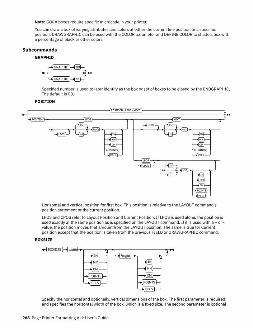
Note: GOCA boxes require specific microcode in your printer.
You can draw a box of varying attributes and colors at either the current line position or a specifiedposition. DRAWGRAPHIC can be used with the COLOR parameter and DEFINE COLOR to shade a box witha percentage of black or other colors.
SubcommandsGRAPHID
GRAPHID 00
GRAPHID nn
Specified number is used to later identify as the box or set of boxes to be closed by the ENDGRAPHIC.The default is 00.
POSITION
POSITION - LPOS - NEXT
POSITION LPOS
LPOS
(+)
(-)
horiz
IN
MM
CM
POINTS
PELS
NEXT
LPOS (+)
(-)
vert
IN
MM
CM
POINTS
PELS
LPOS
CPOS (+)
(-)
vert
IN
MM
CM
POINTS
PELS
Horizontal and vertical position for first box. This position is relative to the LAYOUT command'sposition statement or the current position.
LPOS and CPOS refer to Layout Position and Current Position. If LPOS is used alone, the position isused exactly at the same position as is specified on the LAYOUT command. If it is used with a + or -value, the position moves that amount from the LAYOUT position. The same is true for Currentposition except that the position is taken from the previous FIELD or DRAWGRAPHIC command.
BOXSIZE
BOXSIZE width
IN
MM
CM
POINTS
PELS
height
IN
MM
CM
POINTS
PELS
Specify the horizontal and optionally, vertical dimensions of the box. The first parameter is requiredand specifies the horizontal width of the box, which is a fixed size. The second parameter is optional
268 Page Printer Formatting Aid: User's Guide
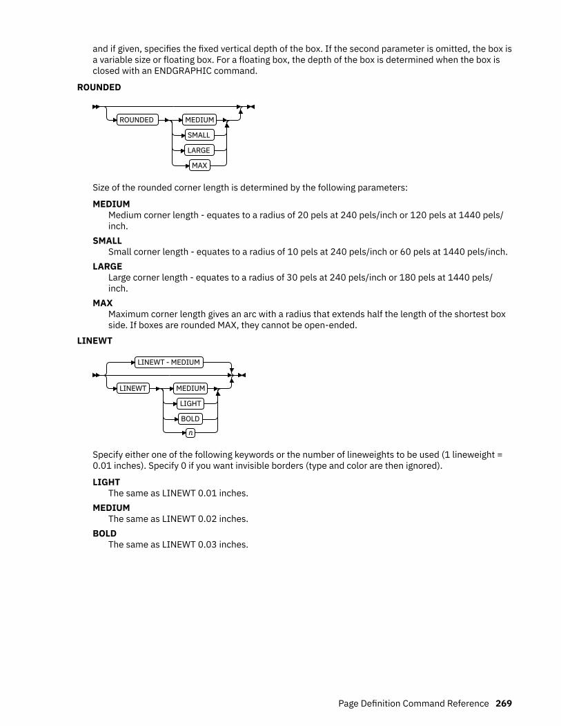
and if given, specifies the fixed vertical depth of the box. If the second parameter is omitted, the box isa variable size or floating box. For a floating box, the depth of the box is determined when the box isclosed with an ENDGRAPHIC command.
ROUNDED
ROUNDED MEDIUM
SMALL
LARGE
MAX
Size of the rounded corner length is determined by the following parameters:
MEDIUMMedium corner length - equates to a radius of 20 pels at 240 pels/inch or 120 pels at 1440 pels/inch.
SMALLSmall corner length - equates to a radius of 10 pels at 240 pels/inch or 60 pels at 1440 pels/inch.
LARGELarge corner length - equates to a radius of 30 pels at 240 pels/inch or 180 pels at 1440 pels/inch.
MAXMaximum corner length gives an arc with a radius that extends half the length of the shortest boxside. If boxes are rounded MAX, they cannot be open-ended.
LINEWT
LINEWT - MEDIUM
LINEWT MEDIUM
LIGHT
BOLD
n
Specify either one of the following keywords or the number of lineweights to be used (1 lineweight =0.01 inches). Specify 0 if you want invisible borders (type and color are then ignored).
LIGHTThe same as LINEWT 0.01 inches.
MEDIUMThe same as LINEWT 0.02 inches.
BOLDThe same as LINEWT 0.03 inches.
Page Definition Command Reference 269

LINETYPE
LINETYPE - SOLID
LINETYPE SOLID
DOTTED
SHORTDASH
DASHDOT
DBLDOT
LONGDASH
DSHDBLDOT
COLOR colorname
Specify one of the following keywords for the border type:
SOLIDDOTTEDSHORTDASHDASHDOTDBLDOT (double dot)LONGDASHDSHDBLDOT (dash double dot)
COLORColor to be used for the box border. The color name must be either one of the pre-defined OCAkeywords or the color name from the DEFINE COLOR command.
COPY
COPY ACROSS
DOWN
n
SPACED - 0
SPACED n
IN
MM
CM
POINTS
PELS
Repeat the same box at regular intervals either across or down the page. Total number of boxes is onemore than the value specified on this parameter.
Restriction: If boxes are repeated in the DOWN direction, they cannot be open-ended.
Figure 128: Spaced Boxes (not to scale).
270 Page Printer Formatting Aid: User's Guide
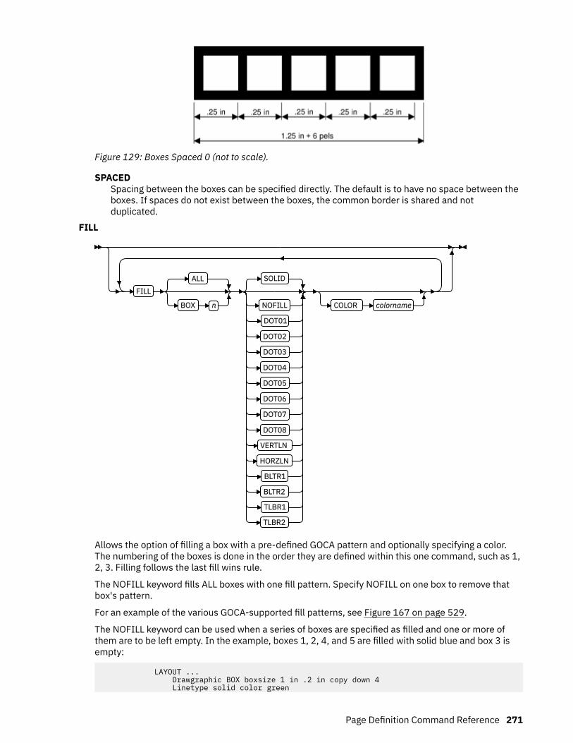
Figure 129: Boxes Spaced 0 (not to scale).
SPACEDSpacing between the boxes can be specified directly. The default is to have no space between theboxes. If spaces do not exist between the boxes, the common border is shared and notduplicated.
FILL
FILLALL
BOX n
SOLID
NOFILL
DOT01
DOT02
DOT03
DOT04
DOT05
DOT06
DOT07
DOT08
VERTLN
HORZLN
BLTR1
BLTR2
TLBR1
TLBR2
COLOR colorname
Allows the option of filling a box with a pre-defined GOCA pattern and optionally specifying a color.The numbering of the boxes is done in the order they are defined within this one command, such as 1,2, 3. Filling follows the last fill wins rule.
The NOFILL keyword fills ALL boxes with one fill pattern. Specify NOFILL on one box to remove thatbox's pattern.
For an example of the various GOCA-supported fill patterns, see Figure 167 on page 529.
The NOFILL keyword can be used when a series of boxes are specified as filled and one or more ofthem are to be left empty. In the example, boxes 1, 2, 4, and 5 are filled with solid blue and box 3 isempty:
LAYOUT ... Drawgraphic BOX boxsize 1 in .2 in copy down 4 Linetype solid color green
Page Definition Command Reference 271

FILL ALL SOLID Color Blue FILL Box 3 NOFILL;
ALLAll boxes are filled.
BOXn boxes are numbered starting at 1 for the initial box in this command, and increasing by using theCOPY parameter.
RENDER
RENDER PERCEPTUAL
SATURATION
RELCM
ABSCM
Subcommand on the DRAWGRAPHIC command that is used to specify the rendering intent (RI) for anobject within a page definition. RI is used to modify the final appearance of color data and is definedby the International Color Consortium (ICC). For more information about RI, see the current level ofthe ICC Specification.
Note: See Chapter 8, “AFP Color Management,” on page 151 for more information about using theRENDER subcommand.
rendering intent parameterSpecify the rendering intent for the defined graphic (GOCA) object.PERCEPTUAL
Perceptual rendering intent. It can be abbreviated as PERCP. With this rendering intent, gamutmapping is vendor-specific, and colors are adjusted to give a pleasing appearance. This intentis typically used to render continuous-tone images.
SATURATIONSaturation rendering intent. It can be abbreviated as SATUR. With this rendering intent, gamutmapping is vendor-specific, and colors are adjusted to emphasize saturation. This intentresults in vivid colors and is typically used for business graphics.
RELCMMedia-relative colorimetric rendering intent. In-gamut colors are rendered accurately, andout-of-gamut colors are mapped to the nearest value within the gamut. Colors are rendered inregard to the source white point and are adjusted for the media white point. Therefore, colorsthat are printed on two different media with different white points do not matchcolorimetrically, but might match visually. This intent is typically used for vector graphics.
ABSCMICC-absolute colorimetric rendering intent. In-gamut colors are rendered accurately, and out-of-gamut colors are mapped to the nearest value within the gamut. Colors are rendered only inregard to the source white point and are not adjusted for the media white point. Therefore,colors that are printed on two different media with different white points must matchcolorimetrically, but might not match visually. This intent is typically used for logos.
CMR
CMR cmr-lname AUDIT
INSTR
LINK
272 Page Printer Formatting Aid: User's Guide
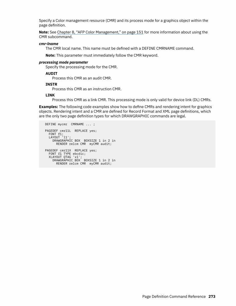
Specify a Color management resource (CMR) and its process mode for a graphics object within thepage definition.
Note: See Chapter 8, “AFP Color Management,” on page 151 for more information about using theCMR subcommand.
cmr-lnameThe CMR local name. This name must be defined with a DEFINE CMRNAME command.
Note: This parameter must immediately follow the CMR keyword.
processing mode parameterSpecify the processing mode for the CMR.AUDIT
Process this CMR as an audit CMR.INSTR
Process this CMR as an instruction CMR.LINK
Process this CMR as a link CMR. This processing mode is only valid for device link (DL) CMRs.
Examples: The following code examples show how to define CMRs and rendering intent for graphicsobjects. Rendering intent and a CMR are defined for Record Format and XML page definitions, whichare the only two page definition types for which DRAWGRAPHIC commands are legal.
DEFINE mycmr CMRNAME ... ;
PAGEDEF cmr11L REPLACE yes; FONT f1; LAYOUT 'l1'; DRAWGRAPHIC BOX BOXSIZE 1 in 2 in RENDER relcm CMR myCMR audit;
PAGEDEF cmr11X REPLACE yes; FONT f1 TYPE ebcdic; XLAYOUT QTAG 'x1'; DRAWGRAPHIC BOX BOXSIZE 1 in 2 in RENDER relcm CMR myCMR audit;
Page Definition Command Reference 273

DRAWGRAPHIC - LINE Command (Record Format and XML only)
DRAWGRAPHIC LINE
GRAPHID 00
GRAPHID nn
POSITION - LPOS - NEXT
POSITION LPOS
LPOS
(+)
(–)
horiz
IN
MM
CM
POINTS
PELS
NEXT
LPOS (+)
(–)
vert
IN
MM
CM
POINTS
PELS
LPOS
CPOS (+)
(–)
vert
IN
MM
CM
POINTS
PELS
ACROSS length
IN
MM
CM
POINTS
PELS
DOWN
length
IN
MM
CM
POINTS
PELS
TO
(–)
horiz
IN
MM
CM
POINTS
PELS
(–)
vert
IN
MM
CM
POINTS
PELS
LINEWT - MEDIUM
LINEWT MEDIUM
LIGHT
BOLD
n
LINETYPE - SOLID
LINETYPE SOLID
DOTTED
SHORTDASH
DASHDOT
DBLDOT
LONGDASH
DSHDBLDOT
COLOR colorname
COPY ACROSS
DOWN
n SPACED n
IN
MM
CM
POINTS
PELS
RENDER PERCEPTUAL
SATURATION
RELCM
ABSCM
CMR cmr-lname AUDIT
INSTR
LINK
;
You use the DRAWGRAPHIC - LINE command to:
274 Page Printer Formatting Aid: User's Guide
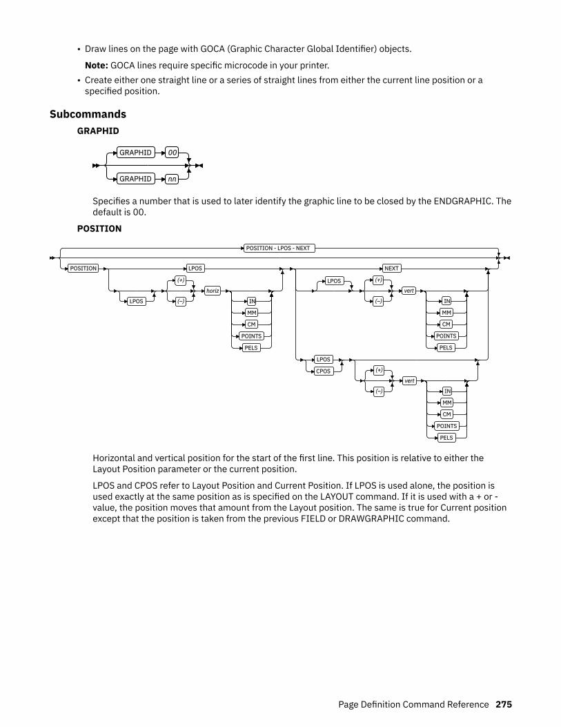
• Draw lines on the page with GOCA (Graphic Character Global Identifier) objects.
Note: GOCA lines require specific microcode in your printer.• Create either one straight line or a series of straight lines from either the current line position or aspecified position.
SubcommandsGRAPHID
GRAPHID 00
GRAPHID nn
Specifies a number that is used to later identify the graphic line to be closed by the ENDGRAPHIC. Thedefault is 00.
POSITION
POSITION - LPOS - NEXT
POSITION LPOS
LPOS
(+)
(–)
horiz
IN
MM
CM
POINTS
PELS
NEXT
LPOS (+)
(–)
vert
IN
MM
CM
POINTS
PELS
LPOS
CPOS (+)
(–)
vert
IN
MM
CM
POINTS
PELS
Horizontal and vertical position for the start of the first line. This position is relative to either theLayout Position parameter or the current position.
LPOS and CPOS refer to Layout Position and Current Position. If LPOS is used alone, the position isused exactly at the same position as is specified on the LAYOUT command. If it is used with a + or -value, the position moves that amount from the Layout position. The same is true for Current positionexcept that the position is taken from the previous FIELD or DRAWGRAPHIC command.
Page Definition Command Reference 275
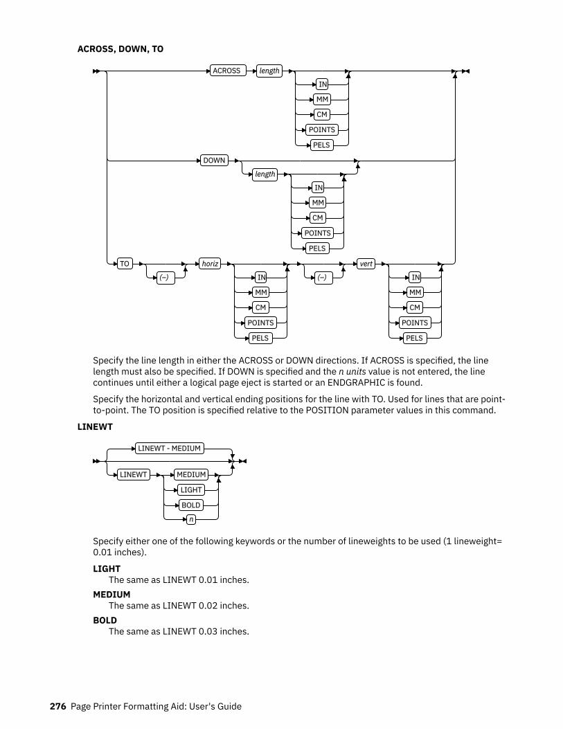
ACROSS, DOWN, TO
ACROSS length
IN
MM
CM
POINTS
PELS
DOWN
length
IN
MM
CM
POINTS
PELS
TO
(–)
horiz
IN
MM
CM
POINTS
PELS
(–)
vert
IN
MM
CM
POINTS
PELS
Specify the line length in either the ACROSS or DOWN directions. If ACROSS is specified, the linelength must also be specified. If DOWN is specified and the n units value is not entered, the linecontinues until either a logical page eject is started or an ENDGRAPHIC is found.
Specify the horizontal and vertical ending positions for the line with TO. Used for lines that are point-to-point. The TO position is specified relative to the POSITION parameter values in this command.
LINEWT
LINEWT - MEDIUM
LINEWT MEDIUM
LIGHT
BOLD
n
Specify either one of the following keywords or the number of lineweights to be used (1 lineweight=0.01 inches).
LIGHTThe same as LINEWT 0.01 inches.
MEDIUMThe same as LINEWT 0.02 inches.
BOLDThe same as LINEWT 0.03 inches.
276 Page Printer Formatting Aid: User's Guide

LINETYPE
LINETYPE - SOLID
LINETYPE SOLID
DOTTED
SHORTDASH
DASHDOT
DBLDOT
LONGDASH
DSHDBLDOT
COLOR colorname
Specify one of the following keywords for the line type:
SOLIDDOTTEDSHORTDASHDASHDOTDBLDOT (double dot)LONGDASHDSHDBLDOT (dash double dot)
COLORColor to be used for the line. The color name must be either one of the pre-defined OCA keywordsor the color name from the DEFINE COLOR command.
COPY
COPY ACROSS
DOWN
n SPACED n
IN
MM
CM
POINTS
PELS
Repeat the same line at regular intervals either across or down the page. Total number of lines is onemore than the value specified on this parameter.
RENDER
RENDER PERCEPTUAL
SATURATION
RELCM
ABSCM
Subcommand on the DRAWGRAPHIC command that is used to specify the rendering intent (RI) for anobject within a page definition. RI is used to modify the final appearance of color data and is definedby the International Color Consortium (ICC). For more information about RI, see the current level ofthe ICC Specification.
Note: See Chapter 8, “AFP Color Management,” on page 151 for more information about using theRENDER subcommand.
Page Definition Command Reference 277

rendering intent parameterSpecify the rendering intent for the defined graphic (GOCA) object.PERCEPTUAL
Perceptual rendering intent. It can be abbreviated as PERCP. With this rendering intent, gamutmapping is vendor-specific, and colors are adjusted to give a pleasing appearance. This intentis typically used to render continuous-tone images.
SATURATIONSaturation rendering intent. It can be abbreviated as SATUR. With this rendering intent, gamutmapping is vendor-specific, and colors are adjusted to emphasize saturation. This intentresults in vivid colors and is typically used for business graphics.
RELCMMedia-relative colorimetric rendering intent. In-gamut colors are rendered accurately, andout-of-gamut colors are mapped to the nearest value within the gamut. Colors are rendered inregard to the source white point and are adjusted for the media white point. Therefore, colorsthat are printed on two different media with different white points do not matchcolorimetrically, but might match visually. This intent is typically used for vector graphics.
ABSCMICC-absolute colorimetric rendering intent. In-gamut colors are rendered accurately, and out-of-gamut colors are mapped to the nearest value within the gamut. Colors are rendered only inregard to the source white point and are not adjusted for the media white point. Therefore,colors that are printed on two different media with different white points must matchcolorimetrically, but might not match visually. This intent is typically used for logos.
CMR
CMR cmr-lname AUDIT
INSTR
LINK
Specify a Color management resource (CMR) and its process mode for a graphics object within thepage definition.
Note: See Chapter 8, “AFP Color Management,” on page 151 for more information about using theCMR subcommand.
cmr-lnameThe CMR local name. This name must be defined with a DEFINE CMRNAME command.
Note: This parameter must immediately follow the CMR keyword.
processing mode parameterSpecify the processing mode for the CMR.AUDIT
Process this CMR as an audit CMR.INSTR
Process this CMR as an instruction CMR.LINK
Process this CMR as a link CMR. This processing mode is only valid for device link (DL) CMRs.
Examples: The following code examples show how to define CMRs and rendering intent for graphicsobjects. Rendering intent and a CMR are defined for Record Format and XML page definitions, whichare the only two page definition types for which DRAWGRAPHIC commands are legal.
DEFINE mycmr CMRNAME ... ;
PAGEDEF cmr11L REPLACE yes;
278 Page Printer Formatting Aid: User's Guide

FONT f1; LAYOUT 'l1'; DRAWGRAPHIC BOX BOXSIZE 1 in 2 in RENDER relcm CMR myCMR audit;
PAGEDEF cmr11X REPLACE yes; FONT f1 TYPE ebcdic; XLAYOUT QTAG 'x1'; DRAWGRAPHIC BOX BOXSIZE 1 in 2 in RENDER relcm CMR myCMR audit;
Page Definition Command Reference 279
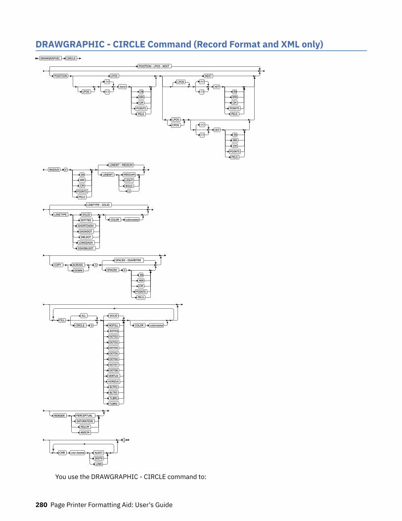
DRAWGRAPHIC - CIRCLE Command (Record Format and XML only)DRAWGRAPHIC CIRCLE
POSITION - LPOS - NEXT
POSITION LPOS
LPOS
(+)
(-)
horiz
IN
MM
CM
POINTS
PELS
NEXT
LPOS (+)
(-)
vert
IN
MM
CM
POINTS
PELS
LPOS
CPOS (+)
(-)
vert
IN
MM
CM
POINTS
PELS
RADIUS n
IN
MM
CM
POINTS
PELS
LINEWT - MEDIUM
LINEWT MEDIUM
LIGHT
BOLD
n
LINETYPE - SOLID
LINETYPE SOLID
DOTTED
SHORTDASH
DASHDOT
DBLDOT
LONGDASH
DSHDBLDOT
COLOR colorname
COPY ACROSS
DOWN
n
SPACED - DIAMETER
SPACED n
IN
MM
CM
POINTS
PELS
FILLALL
CIRCLE n
SOLID
NOFILL
DOT01
DOT02
DOT03
DOT04
DOT05
DOT06
DOT07
DOT08
VERTLN
HORZLN
BLTR1
BLTR2
TLBR1
TLBR2
COLOR colorname
RENDER PERCEPTUAL
SATURATION
RELCM
ABSCM
CMR cmr-lname AUDIT
INSTR
LINK
;
You use the DRAWGRAPHIC - CIRCLE command to:
280 Page Printer Formatting Aid: User's Guide
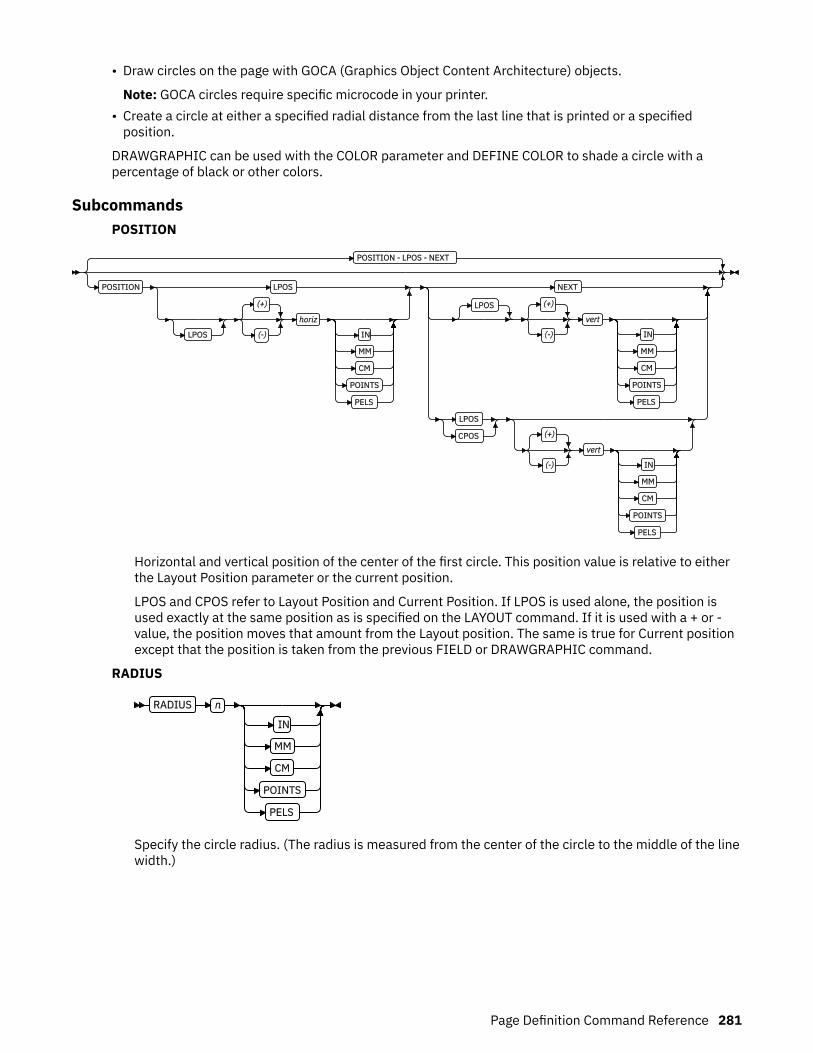
• Draw circles on the page with GOCA (Graphics Object Content Architecture) objects.
Note: GOCA circles require specific microcode in your printer.• Create a circle at either a specified radial distance from the last line that is printed or a specified
position.
DRAWGRAPHIC can be used with the COLOR parameter and DEFINE COLOR to shade a circle with apercentage of black or other colors.
SubcommandsPOSITION
POSITION - LPOS - NEXT
POSITION LPOS
LPOS
(+)
(-)
horiz
IN
MM
CM
POINTS
PELS
NEXT
LPOS (+)
(-)
vert
IN
MM
CM
POINTS
PELS
LPOS
CPOS (+)
(-)
vert
IN
MM
CM
POINTS
PELS
Horizontal and vertical position of the center of the first circle. This position value is relative to eitherthe Layout Position parameter or the current position.
LPOS and CPOS refer to Layout Position and Current Position. If LPOS is used alone, the position isused exactly at the same position as is specified on the LAYOUT command. If it is used with a + or -value, the position moves that amount from the Layout position. The same is true for Current positionexcept that the position is taken from the previous FIELD or DRAWGRAPHIC command.
RADIUS
RADIUS n
IN
MM
CM
POINTS
PELS
Specify the circle radius. (The radius is measured from the center of the circle to the middle of the linewidth.)
Page Definition Command Reference 281
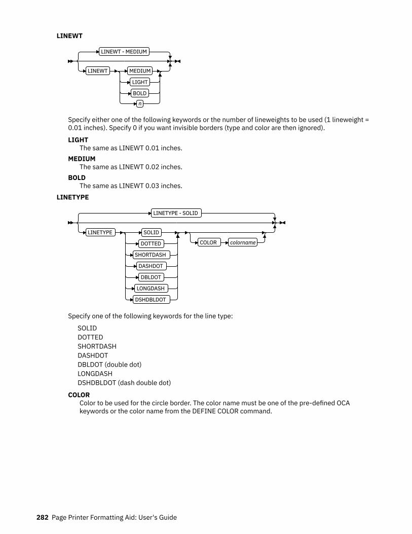
LINEWT
LINEWT - MEDIUM
LINEWT MEDIUM
LIGHT
BOLD
n
Specify either one of the following keywords or the number of lineweights to be used (1 lineweight =0.01 inches). Specify 0 if you want invisible borders (type and color are then ignored).
LIGHTThe same as LINEWT 0.01 inches.
MEDIUMThe same as LINEWT 0.02 inches.
BOLDThe same as LINEWT 0.03 inches.
LINETYPE
LINETYPE - SOLID
LINETYPE SOLID
DOTTED
SHORTDASH
DASHDOT
DBLDOT
LONGDASH
DSHDBLDOT
COLOR colorname
Specify one of the following keywords for the line type:
SOLIDDOTTEDSHORTDASHDASHDOTDBLDOT (double dot)LONGDASHDSHDBLDOT (dash double dot)
COLORColor to be used for the circle border. The color name must be one of the pre-defined OCAkeywords or the color name from the DEFINE COLOR command.
282 Page Printer Formatting Aid: User's Guide

COPY
COPY ACROSS
DOWN
n
SPACED - DIAMETER
SPACED n
IN
MM
CM
POINTS
PELS
Repeat the same circle at regular intervals either across or down the page. Repeating ACROSS orDOWN with the DIAMETER indication means that the circles are placed to join at one point with thecenter positions of each being one diameter width apart. See following figures for a pictorial view ofrepeating circles.
Total number of circles is one more than the value specified on this parameter.
Figure 130: Repeating circles with 0.45 inches spacing (not to scale).
Figure 131: Repeating circles with DIAMETER spacing (not to scale).
Page Definition Command Reference 283
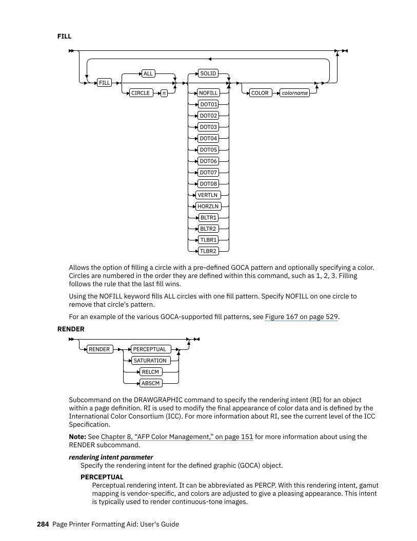
FILL
FILLALL
CIRCLE n
SOLID
NOFILL
DOT01
DOT02
DOT03
DOT04
DOT05
DOT06
DOT07
DOT08
VERTLN
HORZLN
BLTR1
BLTR2
TLBR1
TLBR2
COLOR colorname
Allows the option of filling a circle with a pre-defined GOCA pattern and optionally specifying a color.Circles are numbered in the order they are defined within this command, such as 1, 2, 3. Fillingfollows the rule that the last fill wins.
Using the NOFILL keyword fills ALL circles with one fill pattern. Specify NOFILL on one circle toremove that circle's pattern.
For an example of the various GOCA-supported fill patterns, see Figure 167 on page 529.
RENDER
RENDER PERCEPTUAL
SATURATION
RELCM
ABSCM
Subcommand on the DRAWGRAPHIC command to specify the rendering intent (RI) for an objectwithin a page definition. RI is used to modify the final appearance of color data and is defined by theInternational Color Consortium (ICC). For more information about RI, see the current level of the ICCSpecification.
Note: See Chapter 8, “AFP Color Management,” on page 151 for more information about using theRENDER subcommand.
rendering intent parameterSpecify the rendering intent for the defined graphic (GOCA) object.PERCEPTUAL
Perceptual rendering intent. It can be abbreviated as PERCP. With this rendering intent, gamutmapping is vendor-specific, and colors are adjusted to give a pleasing appearance. This intentis typically used to render continuous-tone images.
284 Page Printer Formatting Aid: User's Guide

SATURATIONSaturation rendering intent. It can be abbreviated as SATUR. With this rendering intent, gamutmapping is vendor-specific, and colors are adjusted to emphasize saturation. This intentresults in vivid colors and is typically used for business graphics.
RELCMMedia-relative colorimetric rendering intent. In-gamut colors are rendered accurately, andout-of-gamut colors are mapped to the nearest value within the gamut. Colors are rendered inregard to the source white point and are adjusted for the media white point. Therefore, colorsthat are printed on two different media with different white points do not matchcolorimetrically, but might match visually. This intent is typically used for vector graphics.
ABSCMICC-absolute colorimetric rendering intent. In-gamut colors are rendered accurately, and out-of-gamut colors are mapped to the nearest value within the gamut. Colors are rendered only inregard to the source white point and are not adjusted for the media white point. Therefore,colors that are printed on two different media with different white points must matchcolorimetrically, but might not match visually. This intent is typically used for logos.
CMR
CMR cmr-lname AUDIT
INSTR
LINK
Specify a Color management resource (CMR) and its process mode for a graphics object within thepage definition.
Note: See Chapter 8, “AFP Color Management,” on page 151 for more information about using theCMR subcommand.
cmr-lnameThe CMR local name. This name must be defined with a DEFINE CMRNAME command.
Note: This parameter must immediately follow the CMR keyword.
processing mode parameterSpecify the processing mode for the CMR.AUDIT
Process this CMR as an audit CMR.INSTR
Process this CMR as an instruction CMR.LINK
Process this CMR as a link CMR. This processing mode is only valid for device link (DL) CMRs.
Examples: The following code examples show how to define CMRs and rendering intent for graphicsobjects. Rendering intent and a CMR are defined for Record Format and XML page definitions, whichare the only two page definition types for which DRAWGRAPHIC commands are legal.
DEFINE mycmr CMRNAME ... ;
PAGEDEF cmr11L REPLACE yes; FONT f1; LAYOUT 'l1'; DRAWGRAPHIC BOX BOXSIZE 1 in 2 in RENDER relcm CMR myCMR audit;
PAGEDEF cmr11X REPLACE yes; FONT f1 TYPE ebcdic; XLAYOUT QTAG 'x1';
Page Definition Command Reference 285

DRAWGRAPHIC BOX BOXSIZE 1 in 2 in RENDER relcm CMR myCMR audit;
286 Page Printer Formatting Aid: User's Guide
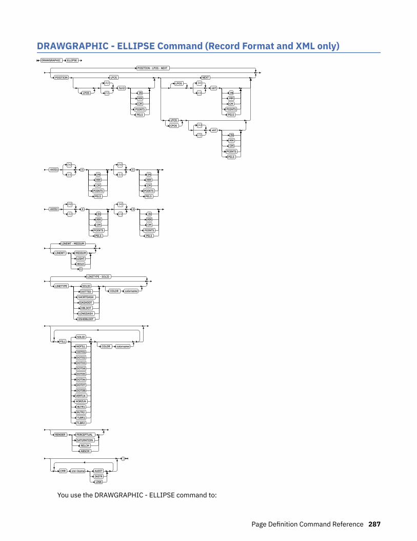
DRAWGRAPHIC - ELLIPSE Command (Record Format and XML only)DRAWGRAPHIC ELLIPSE
POSITION - LPOS - NEXT
POSITION LPOS
LPOS
(+)
(-)
horiz
IN
MM
CM
POINTS
PELS
NEXT
LPOS (+)
(-)
vert
IN
MM
CM
POINTS
PELS
LPOS
CPOS (+)
(-)
vert
IN
MM
CM
POINTS
PELS
AXIS1
(+)
(-)
n
IN
MM
CM
POINTS
PELS
(+)
(-)
n
IN
MM
CM
POINTS
PELS
AXIS2
(+)
(-)
n
IN
MM
CM
POINTS
PELS
(+)
(-)
n
IN
MM
CM
POINTS
PELS
LINEWT - MEDIUM
LINEWT MEDIUM
LIGHT
BOLD
n
LINETYPE - SOLID
LINETYPE SOLID
DOTTED
SHORTDASH
DASHDOT
DBLDOT
LONGDASH
DSHDBLDOT
COLOR colorname
FILL
SOLID
NOFILL
DOT01
DOT02
DOT03
DOT04
DOT05
DOT06
DOT07
DOT08
VERTLN
HORZLN
BLTR1
BLTR2
TLBR1
TLBR2
COLOR colorname
RENDER PERCEPTUAL
SATURATION
RELCM
ABSCM
CMR cmr-lname AUDIT
INSTR
LINK
;
You use the DRAWGRAPHIC - ELLIPSE command to:
Page Definition Command Reference 287
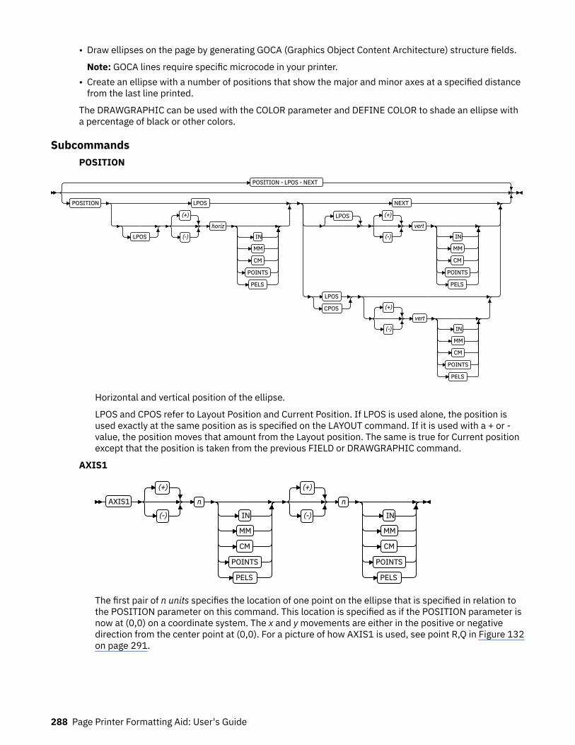
• Draw ellipses on the page by generating GOCA (Graphics Object Content Architecture) structure fields.
Note: GOCA lines require specific microcode in your printer.• Create an ellipse with a number of positions that show the major and minor axes at a specified distance
from the last line printed.
The DRAWGRAPHIC can be used with the COLOR parameter and DEFINE COLOR to shade an ellipse witha percentage of black or other colors.
SubcommandsPOSITION
POSITION - LPOS - NEXT
POSITION LPOS
LPOS
(+)
(-)
horiz
IN
MM
CM
POINTS
PELS
NEXT
LPOS (+)
(-)
vert
IN
MM
CM
POINTS
PELS
LPOS
CPOS (+)
(-)
vert
IN
MM
CM
POINTS
PELS
Horizontal and vertical position of the ellipse.
LPOS and CPOS refer to Layout Position and Current Position. If LPOS is used alone, the position isused exactly at the same position as is specified on the LAYOUT command. If it is used with a + or -value, the position moves that amount from the Layout position. The same is true for Current positionexcept that the position is taken from the previous FIELD or DRAWGRAPHIC command.
AXIS1
AXIS1
(+)
(-)
n
IN
MM
CM
POINTS
PELS
(+)
(-)
n
IN
MM
CM
POINTS
PELS
The first pair of n units specifies the location of one point on the ellipse that is specified in relation tothe POSITION parameter on this command. This location is specified as if the POSITION parameter isnow at (0,0) on a coordinate system. The x and y movements are either in the positive or negativedirection from the center point at (0,0). For a picture of how AXIS1 is used, see point R,Q in Figure 132on page 291.
288 Page Printer Formatting Aid: User's Guide

AXIS2
AXIS2
(+)
(-)
n
IN
MM
CM
POINTS
PELS
(+)
(-)
n
IN
MM
CM
POINTS
PELS
LINEWT - MEDIUM
LINEWT MEDIUM
LIGHT
BOLD
n
The second pair of n units specifies the location of second point on the ellipse that is specified inrelation to the POSITION parameter on this command. This location is specified as if the POSITIONparameter is now at (0,0) on a coordinate system. The x and y movements are either in the positive ornegative direction from the center point at (0,0). For a picture of how AXIS2 is used, see point P,S inFigure 132 on page 291.
LINEWT
LINEWT - MEDIUM
LINEWT MEDIUM
LIGHT
BOLD
n
Specify either a keyword or the number of lineweights to be used (1 lineweight = 0.01 inches). Specify0 if you want invisible borders (type and color are then ignored).
LIGHTThe same as LINEWT 0.01 inches.
MEDIUMThe same as LINEWT 0.02 inches.
BOLDThe same as LINEWT 0.03 inches.
Page Definition Command Reference 289
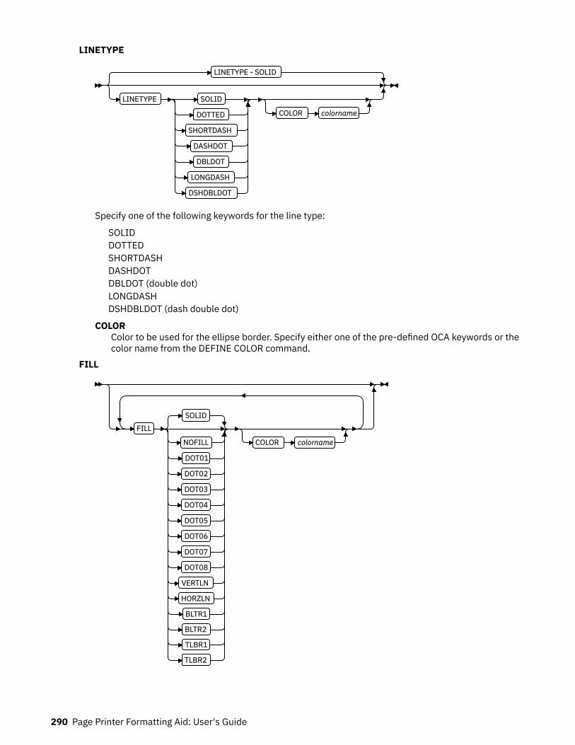
LINETYPE
LINETYPE - SOLID
LINETYPE SOLID
DOTTED
SHORTDASH
DASHDOT
DBLDOT
LONGDASH
DSHDBLDOT
COLOR colorname
Specify one of the following keywords for the line type:
SOLIDDOTTEDSHORTDASHDASHDOTDBLDOT (double dot)LONGDASHDSHDBLDOT (dash double dot)
COLORColor to be used for the ellipse border. Specify either one of the pre-defined OCA keywords or thecolor name from the DEFINE COLOR command.
FILL
FILL
SOLID
NOFILL
DOT01
DOT02
DOT03
DOT04
DOT05
DOT06
DOT07
DOT08
VERTLN
HORZLN
BLTR1
BLTR2
TLBR1
TLBR2
COLOR colorname
290 Page Printer Formatting Aid: User's Guide
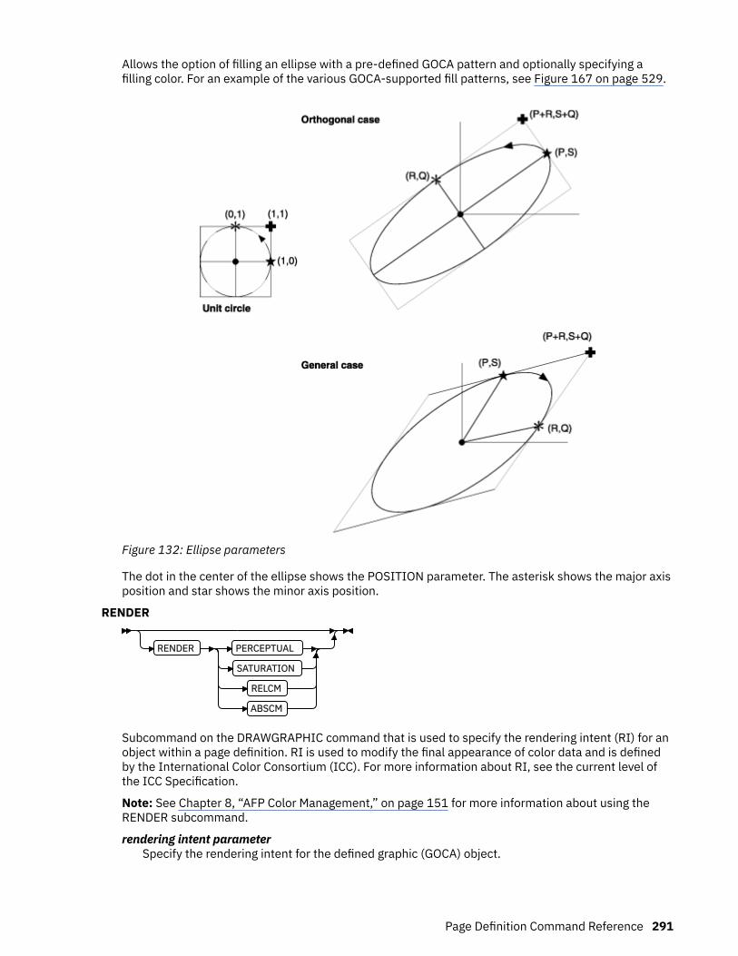
Allows the option of filling an ellipse with a pre-defined GOCA pattern and optionally specifying afilling color. For an example of the various GOCA-supported fill patterns, see Figure 167 on page 529.
Figure 132: Ellipse parameters
The dot in the center of the ellipse shows the POSITION parameter. The asterisk shows the major axisposition and star shows the minor axis position.
RENDER
RENDER PERCEPTUAL
SATURATION
RELCM
ABSCM
Subcommand on the DRAWGRAPHIC command that is used to specify the rendering intent (RI) for anobject within a page definition. RI is used to modify the final appearance of color data and is definedby the International Color Consortium (ICC). For more information about RI, see the current level ofthe ICC Specification.
Note: See Chapter 8, “AFP Color Management,” on page 151 for more information about using theRENDER subcommand.
rendering intent parameterSpecify the rendering intent for the defined graphic (GOCA) object.
Page Definition Command Reference 291

PERCEPTUALPerceptual rendering intent. It can be abbreviated as PERCP. With this rendering intent, gamutmapping is vendor-specific, and colors are adjusted to give a pleasing appearance. This intentis typically used to render continuous-tone images.
SATURATIONSaturation rendering intent. It can be abbreviated as SATUR. With this rendering intent, gamutmapping is vendor-specific, and colors are adjusted to emphasize saturation. This intentresults in vivid colors and is typically used for business graphics.
RELCMMedia-relative colorimetric rendering intent. In-gamut colors are rendered accurately, andout-of-gamut colors are mapped to the nearest value within the gamut. Colors are rendered inregard to the source white point and are adjusted for the media white point. Therefore, colorsthat are printed on two different media with different white points do not matchcolorimetrically, but might match visually. This intent is typically used for vector graphics.
ABSCMICC-absolute colorimetric rendering intent. In-gamut colors are rendered accurately, and out-of-gamut colors are mapped to the nearest value within the gamut. Colors are rendered only inregard to the source white point and are not adjusted for the media white point. Therefore,colors that are printed on two different media with different white points must matchcolorimetrically, but might not match visually. This intent is typically used for logos.
CMR
CMR cmr-lname AUDIT
INSTR
LINK
Specify a Color management resource (CMR) and its process mode for a graphics object within thepage definition.
Note: See Chapter 8, “AFP Color Management,” on page 151 for more information about using theCMR subcommand.
cmr-lnameThe CMR local name. This name must be defined with a DEFINE CMRNAME command.
Note: This parameter must immediately follow the CMR keyword.
processing mode parameterSpecify the processing mode for the CMR.AUDIT
Process this CMR as an audit CMR.INSTR
Process this CMR as an instruction CMR.LINK
Process this CMR as a link CMR. This processing mode is only valid for device link (DL) CMRs.
Examples: The following code examples show how to define CMRs and rendering intent for graphicsobjects. Rendering intent and a CMR are defined for Record Format and XML page definitions, whichare the only two page definition types for which DRAWGRAPHIC commands are legal.
DEFINE mycmr CMRNAME ... ;
PAGEDEF cmr11L REPLACE yes; FONT f1; LAYOUT 'l1'; DRAWGRAPHIC BOX BOXSIZE 1 in 2 in
292 Page Printer Formatting Aid: User's Guide
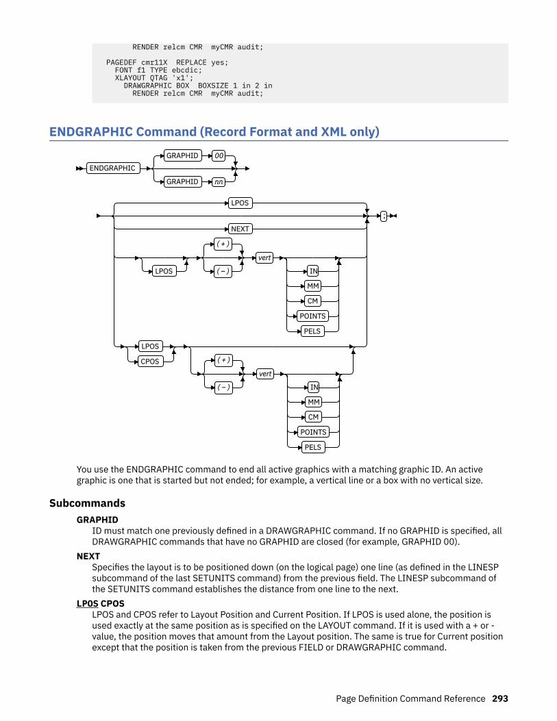
RENDER relcm CMR myCMR audit;
PAGEDEF cmr11X REPLACE yes; FONT f1 TYPE ebcdic; XLAYOUT QTAG 'x1'; DRAWGRAPHIC BOX BOXSIZE 1 in 2 in RENDER relcm CMR myCMR audit;
ENDGRAPHIC Command (Record Format and XML only)
ENDGRAPHIC
GRAPHID 00
GRAPHID nn
LPOS
NEXT
LPOS
( + )
( – )
vert
IN
MM
CM
POINTS
PELS
LPOS
CPOS ( + )
( – )
vert
IN
MM
CM
POINTS
PELS
;
You use the ENDGRAPHIC command to end all active graphics with a matching graphic ID. An activegraphic is one that is started but not ended; for example, a vertical line or a box with no vertical size.
SubcommandsGRAPHID
ID must match one previously defined in a DRAWGRAPHIC command. If no GRAPHID is specified, allDRAWGRAPHIC commands that have no GRAPHID are closed (for example, GRAPHID 00).
NEXTSpecifies the layout is to be positioned down (on the logical page) one line (as defined in the LINESPsubcommand of the last SETUNITS command) from the previous field. The LINESP subcommand ofthe SETUNITS command establishes the distance from one line to the next.
LPOS CPOSLPOS and CPOS refer to Layout Position and Current Position. If LPOS is used alone, the position isused exactly at the same position as is specified on the LAYOUT command. If it is used with a + or -value, the position moves that amount from the Layout position. The same is true for Current positionexcept that the position is taken from the previous FIELD or DRAWGRAPHIC command.
Page Definition Command Reference 293
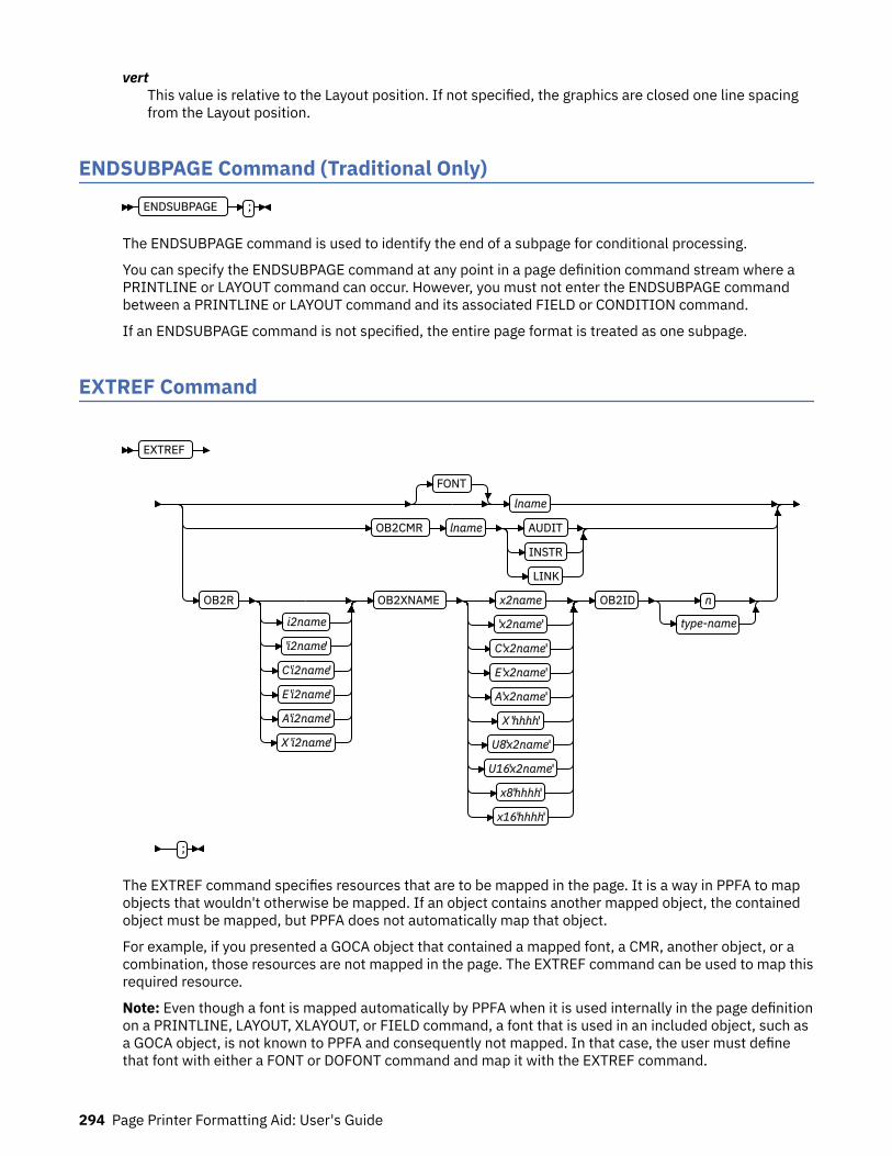
vertThis value is relative to the Layout position. If not specified, the graphics are closed one line spacingfrom the Layout position.
ENDSUBPAGE Command (Traditional Only)ENDSUBPAGE ;
The ENDSUBPAGE command is used to identify the end of a subpage for conditional processing.
You can specify the ENDSUBPAGE command at any point in a page definition command stream where aPRINTLINE or LAYOUT command can occur. However, you must not enter the ENDSUBPAGE commandbetween a PRINTLINE or LAYOUT command and its associated FIELD or CONDITION command.
If an ENDSUBPAGE command is not specified, the entire page format is treated as one subpage.
EXTREF Command
EXTREF
FONT
lname
OB2CMR lname AUDIT
INSTR
LINK
OB2R
i2name
'i2name'
C'i2name'
E 'i2name'
A'i2name'
X 'i2name'
OB2XNAME x2name
'x2name'
C'x2name'
E 'x2name'
A'x2name'
X 'hhhh'
U8'x2name'
U16'x2name'
x8'hhhh'
x16'hhhh'
OB2ID n
type-name
;
The EXTREF command specifies resources that are to be mapped in the page. It is a way in PPFA to mapobjects that wouldn't otherwise be mapped. If an object contains another mapped object, the containedobject must be mapped, but PPFA does not automatically map that object.
For example, if you presented a GOCA object that contained a mapped font, a CMR, another object, or acombination, those resources are not mapped in the page. The EXTREF command can be used to map thisrequired resource.
Note: Even though a font is mapped automatically by PPFA when it is used internally in the page definitionon a PRINTLINE, LAYOUT, XLAYOUT, or FIELD command, a font that is used in an included object, such asa GOCA object, is not known to PPFA and consequently not mapped. In that case, the user must definethat font with either a FONT or DOFONT command and map it with the EXTREF command.
294 Page Printer Formatting Aid: User's Guide
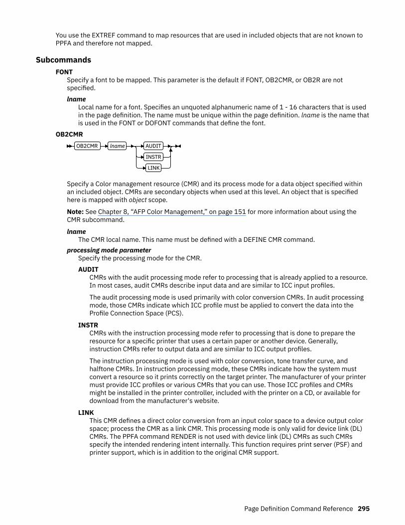
You use the EXTREF command to map resources that are used in included objects that are not known toPPFA and therefore not mapped.
SubcommandsFONT
Specify a font to be mapped. This parameter is the default if FONT, OB2CMR, or OB2R are notspecified.lname
Local name for a font. Specifies an unquoted alphanumeric name of 1 - 16 characters that is usedin the page definition. The name must be unique within the page definition. lname is the name thatis used in the FONT or DOFONT commands that define the font.
OB2CMROB2CMR lname AUDIT
INSTR
LINK
Specify a Color management resource (CMR) and its process mode for a data object specified withinan included object. CMRs are secondary objects when used at this level. An object that is specifiedhere is mapped with object scope.
Note: See Chapter 8, “AFP Color Management,” on page 151 for more information about using theCMR subcommand.
lnameThe CMR local name. This name must be defined with a DEFINE CMR command.
processing mode parameterSpecify the processing mode for the CMR.AUDIT
CMRs with the audit processing mode refer to processing that is already applied to a resource.In most cases, audit CMRs describe input data and are similar to ICC input profiles.
The audit processing mode is used primarily with color conversion CMRs. In audit processingmode, those CMRs indicate which ICC profile must be applied to convert the data into theProfile Connection Space (PCS).
INSTRCMRs with the instruction processing mode refer to processing that is done to prepare theresource for a specific printer that uses a certain paper or another device. Generally,instruction CMRs refer to output data and are similar to ICC output profiles.
The instruction processing mode is used with color conversion, tone transfer curve, andhalftone CMRs. In instruction processing mode, these CMRs indicate how the system mustconvert a resource so it prints correctly on the target printer. The manufacturer of your printermust provide ICC profiles or various CMRs that you can use. Those ICC profiles and CMRsmight be installed in the printer controller, included with the printer on a CD, or available fordownload from the manufacturer's website.
LINKThis CMR defines a direct color conversion from an input color space to a device output colorspace; process the CMR as a link CMR. This processing mode is only valid for device link (DL)CMRs. The PPFA command RENDER is not used with device link (DL) CMRs as such CMRsspecify the intended rendering intent internally. This function requires print server (PSF) andprinter support, which is in addition to the original CMR support.
Page Definition Command Reference 295

OB2ROB2R
i2name
'i2name'
C'i2name'
E 'i2name'
A'i2name'
X 'hhhh'
OB2XNAME x2name
'x2name'
C'x2name'
E 'x2name'
A'x2name'
X 'hhhh'
U8'x2name'
U16'x2name'
x8'hhhh'
x16'hhhh'
Specify a secondary object to be mapped.
If an included object contains a reference to one or more secondary objects, you must identify them.Specify the internal name for the secondary resource as specified in the included resource. If theinternal name contains special characters such as periods or blanks, then quotation marks mustsurround the name.
i2nameUnquoted name up to 250 characters long is folded to uppercase and translated into EBCDIC ifnecessary.
'i2name'Quoted name up to 250 characters long is accepted as-is with no case folding or translation.
C'i2name'Quoted name with a C for Character is treated the same as a quoted name of up to 250 characters.No folding or translation is done.
E'i2name'Quoted name with an E for EBCDIC entered with up to 250 characters is accepted as-is if on anEBCDIC operating system or translated to EBCDIC if on an ASCII operating system. Thetranslation is made with no case folding.
A'i2name'Quoted name with an A for ASCII entered with up to 250 single-byte characters is accepted as-isif on an ASCII operating system or translated to ASCII if on an EBCDIC operating system. Thetranslation is made with no case folding.
X'hhhh'Quoted name with an X for Hexadecimal entered with up to 500 hexadecimal characters. Thecharacters are translated to hexadecimal, but no assumptions of data type are made.
OB2XNAME x2nameSpecifies the external name for a secondary resource object. The name can be up to 250 characters.If the name contains special characters or blanks, then quotation marks must surround the name.x2name
Unquoted name up to 250 characters long is folded to uppercase and translated into EBCDIC ifnecessary.
'x2name'Quoted name up to 250 characters long is accepted as-is with no case folding or translation.
C'x2name'Quoted name with an C for Character is treated the same as a quoted name up to 250 characters.No folding or translation is done.
296 Page Printer Formatting Aid: User's Guide
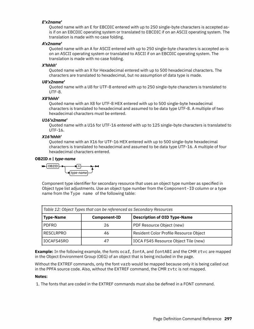
E'x2name'Quoted name with an E for EBCDIC entered with up to 250 single-byte characters is accepted as-is if on an EBCDIC operating system or translated to EBCDIC if on an ASCII operating system. Thetranslation is made with no case folding.
A'x2name'Quoted name with an A for ASCII entered with up to 250 single-byte characters is accepted as-ison an ASCII operating system or translated to ASCII if on an EBCDIC operating system. Thetranslation is made with no case folding.
X'hhhh'Quoted name with an X for Hexadecimal entered with up to 500 hexadecimal characters. Thecharacters are translated to hexadecimal, but no assumption of data type is made.
U8'x2name'Quoted name with a U8 for UTF-8 entered with up to 250 single-byte characters is translated toUTF-8.
X8'hhhh'Quoted name with an X8 for UTF-8 HEX entered with up to 500 single-byte hexadecimalcharacters is translated to hexadecimal and assumed to be data type UTF-8. A multiple of twohexadecimal characters must be entered.
U16'x2name'Quoted name with a U16 for UTF-16 entered with up to 125 single-byte characters is translated toUTF-16.
X16'hhhh'Quoted name with an X16 for UTF-16 HEX entered with up to 500 single-byte hexadecimalcharacters is translated to hexadecimal and assumed to be data type UTF-16. A multiple of fourhexadecimal characters entered.
OB2ID n | type-nameOB2ID n
type-name
Component type identifier for secondary resource that uses an object type number as specified inObject type list adjustments. Use an object type number from the Component-ID column or a typename from the Type name of the following table:
Table 12: Object Types that can be referenced as Secondary Resources
Type-Name Component-ID Description of OID Type-Name
PDFRO 26 PDF Resource Object (new)
RESCLRPRO 46 Resident Color Profile Resource Object
IOCAFS45RO 47 IOCA FS45 Resource Object Tile (new)
Example: In the following example, the fonts ocaf, fontA, and fontABI and the CMR rtvc are mappedin the Object Environment Group (OEG) of an object that is being included in the page.
Without the EXTREF commands, only the font varb would be mapped because only it is being called outin the PPFA source code. Also, without the EXTREF command, the CMR rvtc is not mapped.
Notes:
1. The fonts that are coded in the EXTREF commands must also be defined in a FONT command.
Page Definition Command Reference 297
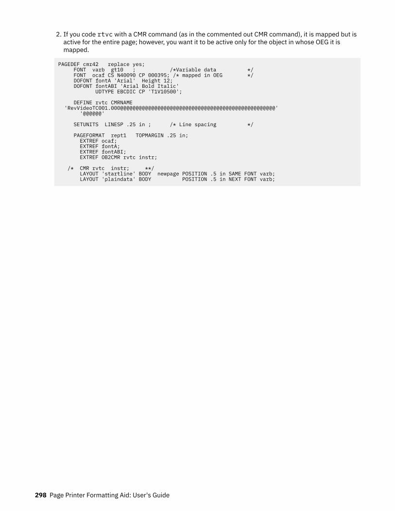
2. If you code rtvc with a CMR command (as in the commented out CMR command), it is mapped but isactive for the entire page; however, you want it to be active only for the object in whose OEG it ismapped.
PAGEDEF cmr42 replace yes; FONT varb gt10 ; /*Variable data */ FONT ocaf CS N40090 CP 000395; /* mapped in OEG */ DOFONT fontA 'Arial' Height 12; DOFONT fontABI 'Arial Bold Italic' UDTYPE EBCDIC CP 'T1V10500'; DEFINE rvtc CMRNAME 'RevVideoTC001.000@@@@@@@@@@@@@@@@@@@@@@@@@@@@@@@@@@@@@@@@@@@@@@@@@@' '@@@@@@' SETUNITS LINESP .25 in ; /* Line spacing */ PAGEFORMAT rept1 TOPMARGIN .25 in; EXTREF ocaf; EXTREF fontA; EXTREF fontABI; EXTREF OB2CMR rvtc instr; /* CMR rvtc instr; **/ LAYOUT 'startline' BODY newpage POSITION .5 in SAME FONT varb; LAYOUT 'plaindata' BODY POSITION .5 in NEXT FONT varb;
298 Page Printer Formatting Aid: User's Guide

FIELD CommandFIELD Command (Traditional only)
FIELD TEXT
Dn
C
X
G
K
L(m)
'text'
START n
LENGTH n
POSITION CURRENT or * CURRENT or *
POSITION –
x-pos
CURRENT or *
– y-pos
NEXT
CURRENT or *
DIRECTION ACROSS
DIRECTION DOWN
BACK
UP
FONT name1
, name2
SUPPRESSION name
COLOR colorname
RGB rvalue gvalue bvalue
HIGHLIGHT hvalue
COVERAGE cvalue BLACK bvalue
CMYK cvalue mvalue yvalue kvalue
CIELAB lvalue
(–)
clvalue
(–)
c2value
BARCODEname TYPE n
type-name
Other BARCODE Parameters
;
Page Definition Command Reference 299
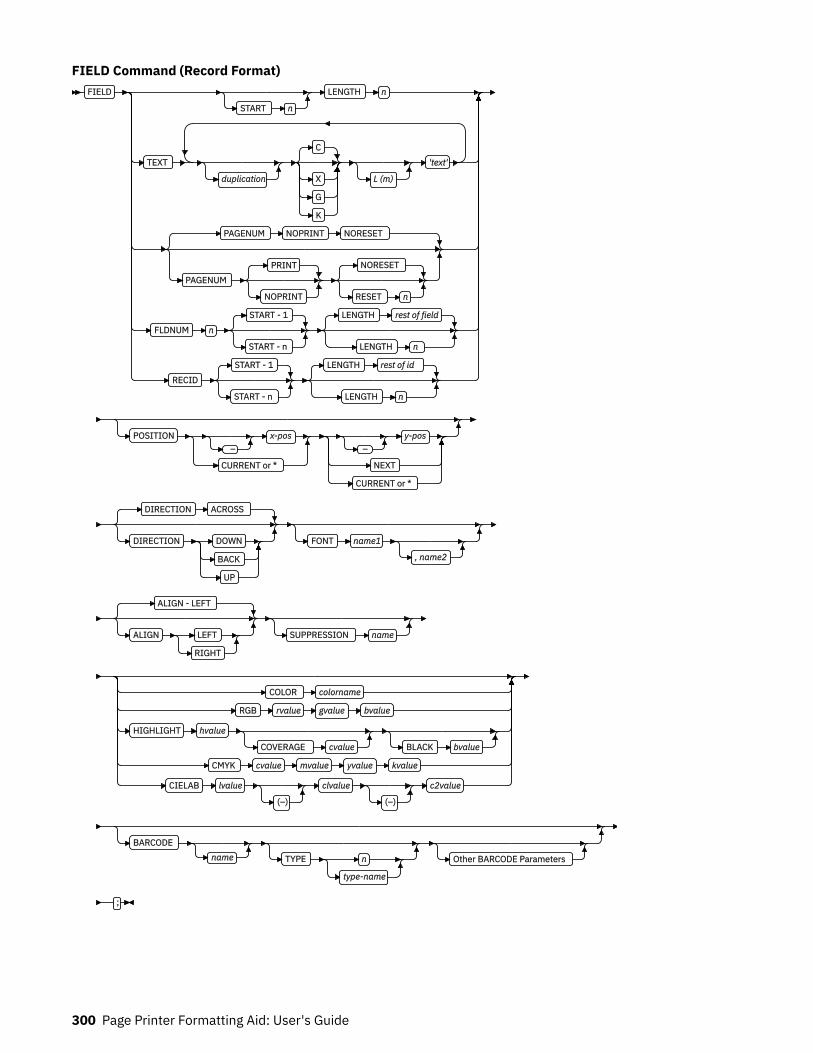
FIELD Command (Record Format)FIELD
START n
LENGTH n
TEXT
duplication
C
X
G
K
L (m)
'text'
PAGENUM NOPRINT NORESET
PAGENUMPRINT
NOPRINT
NORESET
RESET n
FLDNUM n
START - 1
START - n
LENGTH rest of field
LENGTH n
RECID
START - 1
START - n
LENGTH rest of id
LENGTH n
POSITION –
x-pos
CURRENT or *
– y-pos
NEXT
CURRENT or *
DIRECTION ACROSS
DIRECTION DOWN
BACK
UP
FONT name1
, name2
ALIGN - LEFT
ALIGN LEFT
RIGHT
SUPPRESSION name
COLOR colorname
RGB rvalue gvalue bvalue
HIGHLIGHT hvalue
COVERAGE cvalue BLACK bvalue
CMYK cvalue mvalue yvalue kvalue
CIELAB lvalue
(–)
clvalue
(–)
c2value
BARCODEname TYPE n
type-name
Other BARCODE Parameters
;
300 Page Printer Formatting Aid: User's Guide

FIELD Command (XML)FIELD
START n
LENGTH n
*
TEXT
duplication
C
X
G
K
L (m)
'text'
PAGENUM NOPRINT NORESET
PAGENUMPRINT
NOPRINT
NORESET
RESET n
FLDNUM n
START - 1
START - n
LENGTH rest of field
LENGTH n
*
STAG
START - 1
START - n
LENGTH rest of id
LENGTH n
*
ATTR aname
START - 1
START - n
LENGTH rest of attribute
LENGTH n
*
POSITION CURRENT CURRENT
POSITION
LPOS - x pos
LPOS
0
x pos
CPOS
0
x pos
APOS x pos
CURRENT or *
LPOS - x pos
NEXT
CURRENT or *
DIRECTION ACROSS
DIRECTION DOWN
BACK
UP
FONT name1
, name2
ALIGN - LEFT
ALIGN LEFT
RIGHT
SUPPRESSION name
COLOR colorname
RGB rvalue gvalue bvalue
HIGHLIGHT hvalue
COVERAGE cvalue BLACK bvalue
CMYK cvalue mvalue yvalue kvalue
CIELAB lvalue
(–)
clvalue
(–)
c2value
BARCODEname TYPE n
type-name
Other BARCODE Parameters
;
Other BARCODE Parameters
Page Definition Command Reference 301

Common BARCODE Parameters Common 2D BARCODE Parameters
Concatenated BARCODE Parameters
Common BARCODE Parameters
MOD n HRI ON
ABOVE
BELOW
OFF
ONLY
HRIFONT fontname
SSASTERISK ON
OFF
WIDTH n
IN
MM
CM
POINTS
PELS
HEIGHT n
IN
MM
CM
POINTS
PELS
MODWIDTH OPTIMAL
MODWIDTH n
OPTIMAL
SMALL
BCCOLOR colorname
RGB rvalue gvalue bvalue
HIGHLIGHT hvalue
COVERATE cvalue BLACK bvalue
CMYK cvalue mvalue yvalue kvalue
CIELAB lvalue (-) cvluae (-) c2value
SUPPBLANKS RATIO n
CMR cmr-lname AUDIT
INSTR
LINK
Common 2D BARCODE Parameters
302 Page Printer Formatting Aid: User's Guide

BCXPARMS
ESC
NOESC
NOE2A
E2A
CP500
CP290
CP1027
CV1390To943
CV1399To943
CV1390To942
CV1399To942
CV1390To932
CV1399To932
Data Matrix 2D Parameters
MaxiCode 2D Parameters
PDF417 2D Parameters
QRCODE 2D Parameters
Concatenated BARCODE ParametersBCDSYMB symname
BCDSEQ seq#
BCDNEW
Data Matrix 2D Parametersunspecified
SIZE rows
BY
cols
SEQUENCE seq
OF
totID 1 1
ID uidHi uidLo
USERDEF
FNC1UCC
FN1IND
RDRPROG
MAC5
MAC6
ENCODE type
MaxiCode 2D Parameters
Page Definition Command Reference 303
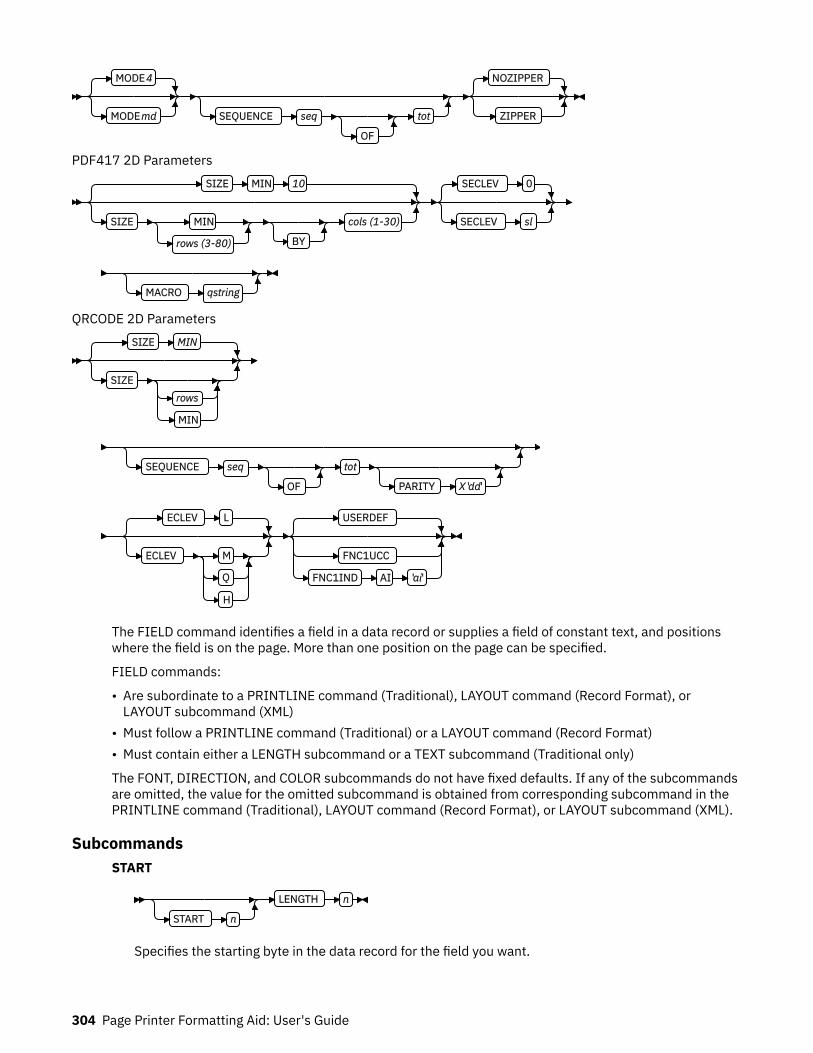
MODE 4
MODE md SEQUENCE seq
OF
tot
NOZIPPER
ZIPPER
PDF417 2D ParametersSIZE MIN 10
SIZE MIN
rows (3-80) BY
cols (1-30)
SECLEV 0
SECLEV sl
MACRO qstring
QRCODE 2D ParametersSIZE MIN
SIZErows
MIN
SEQUENCE seq
OF
tot
PARITY X 'dd'
ECLEV L
ECLEV M
Q
H
USERDEF
FNC1UCC
FNC1IND AI 'ai'
The FIELD command identifies a field in a data record or supplies a field of constant text, and positionswhere the field is on the page. More than one position on the page can be specified.
FIELD commands:
• Are subordinate to a PRINTLINE command (Traditional), LAYOUT command (Record Format), orLAYOUT subcommand (XML)
• Must follow a PRINTLINE command (Traditional) or a LAYOUT command (Record Format)• Must contain either a LENGTH subcommand or a TEXT subcommand (Traditional only)
The FONT, DIRECTION, and COLOR subcommands do not have fixed defaults. If any of the subcommandsare omitted, the value for the omitted subcommand is obtained from corresponding subcommand in thePRINTLINE command (Traditional), LAYOUT command (Record Format), or LAYOUT subcommand (XML).
SubcommandsSTART
START n
LENGTH n
Specifies the starting byte in the data record for the field you want.
304 Page Printer Formatting Aid: User's Guide

nSpecifies the number of bytes from the first data byte in the record to be used as the starting pointof the field. The first data byte position of an input record is 1.
Note: The carriage-control character, table-reference character, and record ID are not considereddata.
*Denotes the next byte after the field identified in the previous FIELD command, excluding FIELDcommands with constant TEXT.
+ nAdds the value of n to the * byte position.
- nSubtracts the value of n from the * byte position.
If START is omitted and LENGTH is specified, then START * is assumed.
LENGTH nSpecifies the number (n) of bytes to process from the data record, beginning with the positionspecified in START.
Record Format: When the maximum length of the field is determined, the print server truncates all ofthe fields not containing data.
TEXT
TEXT
Dn
C
X
G
K
L(m)
'text'
Specifies the constant text that is to be printed in the output. A maximum of 65,535 bytes of text canbe provided in one page format.
Note: This text is considered constant in that the same text is printed each time. In regard to theCONSTANT command within a form definition, this text is considered variable because the text printsonly where variable data is allowed to print.Dn
Specifies the number of times the text is to be duplicated (use a decimal number). The maximumtimes the text is repeated varies depending on the size of the text. The default is 1.
text typeSpecifies the type of text.C
Indicates that the text contains single-byte code characters, which include all Romanalphabetic characters (for example, the ones used for English). Any valid character code canbe specified, including blanks. This is the default.
XIndicates that the text contains hexadecimal codes (in groups of two hexadecimal codes) thatspecify values from X'00' - X'FE'.
GIndicates that the text contains double-byte code characters (for example, kanji characters).
Characters in type G text must start with shift-out (SO X'0E') and end with shift-in (SI X'0F')characters within opening and closing apostrophes (X'7D' for EBCDIC operating systems andX'27 ' for ASCII operating systems).
Page Definition Command Reference 305

KIndicates that the text contains kanji numbers that are enclosed in apostrophes. Kanjinumbers are separated by commas:
K'321,400'
Valid double-byte character set (DBCS) codes are from X'41' - X'FE' for each byte. Code X'4040'(blank) is the only exception.Valid
X'4040', X'4141', X'41FE' X'FE41', X'FEFE'Invalid
X'2040', X'413E', X'4100' X'7F00', X'FE3E'
L(m)Specifies the length of text (use a decimal number in parentheses). When the actual length of thetext is different from m, the m specification is accepted. That is, the text is either padded withblanks to the right or truncated.
'text'Specifies the text.
Examples:
• When TEXT 2C(3)‘AB’ is specified, ‘AB AB ’ is generated. The blanks are generated because ofthe (3) specification.
• TEXT 2C(1)‘AB’ generates ‘AA’, truncating the Bs.
PAGENUM n (Record Format and XML)
PAGENUM NOPRINT NORESET
PAGENUMPRINT
NOPRINT
NORESET
RESET n
Although parameters are specified as optional, at least one must be specified.
Page numbers can be set to start with the value specified as n; otherwise, they follow the specificationthat is made in the PAGEDEF or PAGEFORMAT command.
The POSITION parameters that are specified with the PAGENUM parameter reflect the position of thepage number only.
If you do not want a page number to be printed, either do not use this parameter or specify NOPRINT.
The RESET parameter is only used when you want to reset the page number that is to be used withthis page.
Note: You must define a font that specifies the font type to be used for printing page numbers.
FLDNUM (Record Format and XML)
FLDNUM n
START - 1
START - n
LENGTH rest of field
LENGTH n
This keyword must only be used if the DELIMITER field was used in the LAYOUT command. Fieldscannot be counted without specifying delimiters in the database.
To allow for the identification of a part of a field that is field delimited, you can specify the startingposition (from the delimiter), and optionally the length of the part of the field you want to use. The
306 Page Printer Formatting Aid: User's Guide

LENGTH default is to use the entire remainder of the field from the start position to the endingdelimiter.
RECID (Record Format only)
RECID
START - 1
START - n
LENGTH rest of id
LENGTH n
You use this keyword to access characters in the first n characters of a record. This area is reserved forthe record identifier, and all other field starts and lengths are calculated after this area. These startsand lengths reference only the area within the record ID.
If no record length is specified, the remaining bytes of the n-byte field are assumed.
STAG (XML only)
STAG
START - 1
START - n
LENGTH rest of id
LENGTH n
*
You use this keyword to access characters in the START tag. It also includes the < and > delimiters;position 1 is always the < delimiter.
If no record length is specified, the remaining bytes of the START tag are assumed. If no START isspecified, 1 is assumed.
LENGTH * means that the remainder of the field is used for the length.
ATTR (XML only)
ATTR aname
START - 1
START - n
LENGTH rest of attribute
LENGTH n
*
You use this keyword to access attribute values from the data. Multiple attribute fields can access thesame attribute, which allows subsets of the value to be printed.
If no record length is specified, the remaining bytes of the attribute are assumed. If not START isspecified, 1 is assumed.
anameThe attribute name. To preserve the case, enter the name in quotation marks. The name isconverted to the data type you specify, by using UDTYPE on the page definition, or it is defaulted.
START nThe starting position of the attribute to extract the data. If this parameter is omitted, position 1 isassumed.
LENGTH nThe length of the attribute to be placed. If this parameter is omitted or LENGTH * is coded, the restof the field is assumed for the length.
POSITION
Traditional
Page Definition Command Reference 307
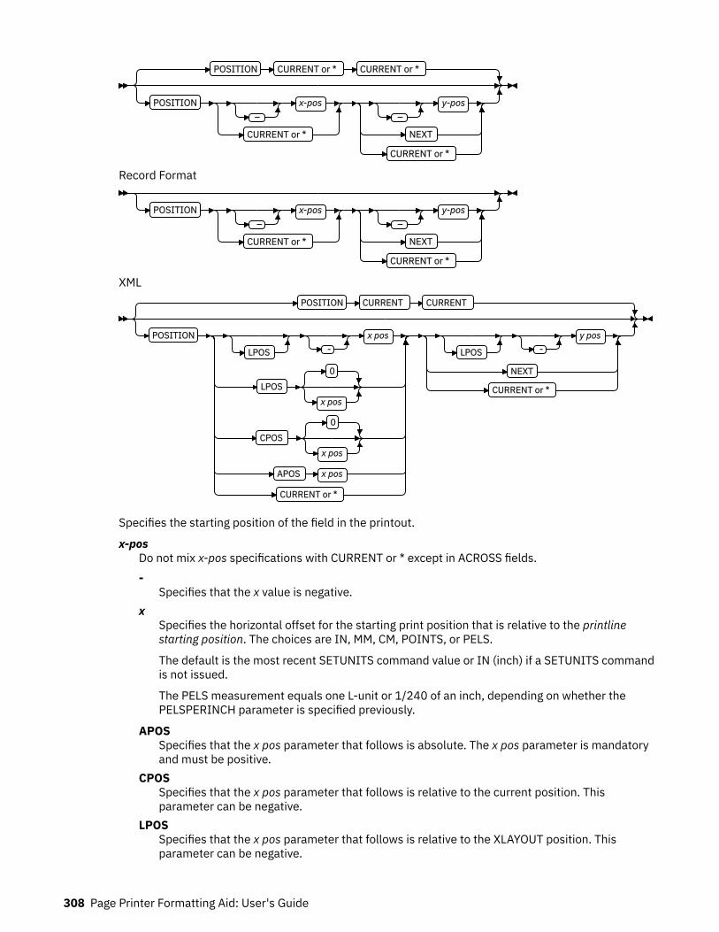
POSITION CURRENT or * CURRENT or *
POSITION –
x-pos
CURRENT or *
– y-pos
NEXT
CURRENT or *
Record Format
POSITION –
x-pos
CURRENT or *
– y-pos
NEXT
CURRENT or *
XMLPOSITION CURRENT CURRENT
POSITION
LPOS - x pos
LPOS
0
x pos
CPOS
0
x pos
APOS x pos
CURRENT or *
LPOS - y pos
NEXT
CURRENT or *
Specifies the starting position of the field in the printout.
x-posDo not mix x-pos specifications with CURRENT or * except in ACROSS fields.-
Specifies that the x value is negative.x
Specifies the horizontal offset for the starting print position that is relative to the printlinestarting position. The choices are IN, MM, CM, POINTS, or PELS.
The default is the most recent SETUNITS command value or IN (inch) if a SETUNITS commandis not issued.
The PELS measurement equals one L-unit or 1/240 of an inch, depending on whether thePELSPERINCH parameter is specified previously.
APOSSpecifies that the x pos parameter that follows is absolute. The x pos parameter is mandatoryand must be positive.
CPOSSpecifies that the x pos parameter that follows is relative to the current position. Thisparameter can be negative.
LPOSSpecifies that the x pos parameter that follows is relative to the XLAYOUT position. Thisparameter can be negative.
308 Page Printer Formatting Aid: User's Guide
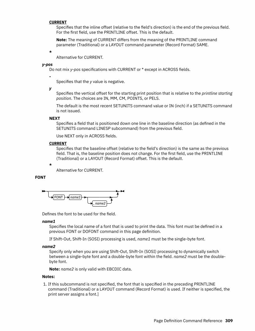
CURRENTSpecifies that the inline offset (relative to the field's direction) is the end of the previous field.For the first field, use the PRINTLINE offset. This is the default.
Note: The meaning of CURRENT differs from the meaning of the PRINTLINE commandparameter (Traditional) or a LAYOUT command parameter (Record Format) SAME.
*Alternative for CURRENT.
y-posDo not mix y-pos specifications with CURRENT or * except in ACROSS fields.-
Specifies that the y value is negative.y
Specifies the vertical offset for the starting print position that is relative to the printline startingposition. The choices are IN, MM, CM, POINTS, or PELS.
The default is the most recent SETUNITS command value or IN (inch) if a SETUNITS commandis not issued.
NEXTSpecifies a field that is positioned down one line in the baseline direction (as defined in theSETUNITS command LINESP subcommand) from the previous field.
Use NEXT only in ACROSS fields.
CURRENTSpecifies that the baseline offset (relative to the field's direction) is the same as the previousfield. That is, the baseline position does not change. For the first field, use the PRINTLINE(Traditional) or a LAYOUT (Record Format) offset. This is the default.
*Alternative for CURRENT.
FONT
FONT name1
, name2
Defines the font to be used for the field.
name1Specifies the local name of a font that is used to print the data. This font must be defined in aprevious FONT or DOFONT command in this page definition.
If Shift-Out, Shift-In (SOSI) processing is used, name1 must be the single-byte font.
name2Specify only when you are using Shift-Out, Shift-In (SOSI) processing to dynamically switchbetween a single-byte font and a double-byte font within the field. name2 must be the double-byte font.
Note: name2 is only valid with EBCDIC data.
Notes:
1. If this subcommand is not specified, the font that is specified in the preceding PRINTLINEcommand (Traditional) or a LAYOUT command (Record Format) is used. If neither is specified, theprint server assigns a font.]
Page Definition Command Reference 309
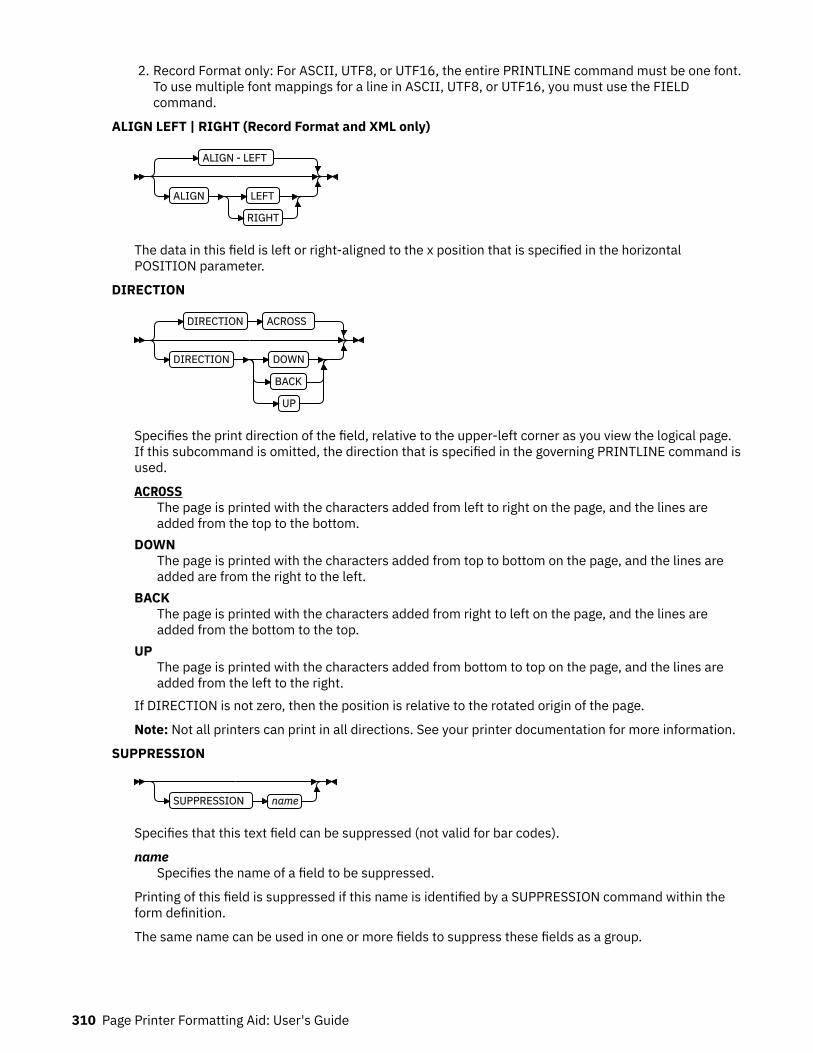
2. Record Format only: For ASCII, UTF8, or UTF16, the entire PRINTLINE command must be one font.To use multiple font mappings for a line in ASCII, UTF8, or UTF16, you must use the FIELDcommand.
ALIGN LEFT | RIGHT (Record Format and XML only)
ALIGN - LEFT
ALIGN LEFT
RIGHT
The data in this field is left or right-aligned to the x position that is specified in the horizontalPOSITION parameter.
DIRECTION
DIRECTION ACROSS
DIRECTION DOWN
BACK
UP
Specifies the print direction of the field, relative to the upper-left corner as you view the logical page.If this subcommand is omitted, the direction that is specified in the governing PRINTLINE command isused.
ACROSSThe page is printed with the characters added from left to right on the page, and the lines areadded from the top to the bottom.
DOWNThe page is printed with the characters added from top to bottom on the page, and the lines areadded are from the right to the left.
BACKThe page is printed with the characters added from right to left on the page, and the lines areadded from the bottom to the top.
UPThe page is printed with the characters added from bottom to top on the page, and the lines areadded from the left to the right.
If DIRECTION is not zero, then the position is relative to the rotated origin of the page.
Note: Not all printers can print in all directions. See your printer documentation for more information.
SUPPRESSION
SUPPRESSION name
Specifies that this text field can be suppressed (not valid for bar codes).
nameSpecifies the name of a field to be suppressed.
Printing of this field is suppressed if this name is identified by a SUPPRESSION command within theform definition.
The same name can be used in one or more fields to suppress these fields as a group.
310 Page Printer Formatting Aid: User's Guide
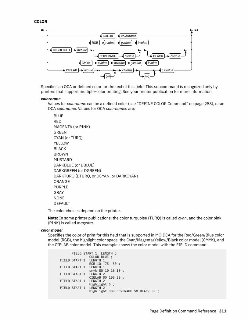
COLOR
COLOR colorname
RGB rvalue gvalue bvalue
HIGHLIGHT hvalue
COVERAGE cvalue BLACK bvalue
CMYK cvalue mvalue yvalue kvalue
CIELAB lvalue
(–)
clvalue
(–)
c2value
Specifies an OCA or defined color for the text of this field. This subcommand is recognized only byprinters that support multiple-color printing. See your printer publication for more information.
colornameValues for colorname can be a defined color (see “DEFINE COLOR Command” on page 258), or anOCA colorname. Values for OCA colornames are:
BLUEREDMAGENTA (or PINK)GREENCYAN (or TURQ)YELLOWBLACKBROWNMUSTARDDARKBLUE (or DBLUE)DARKGREEN (or DGREEN)DARKTURQ (DTURQ, or DCYAN, or DARKCYAN)ORANGEPURPLEGRAYNONEDEFAULT
The color choices depend on the printer.
Note: In some printer publications, the color turquoise (TURQ) is called cyan, and the color pink(PINK) is called magenta.
color modelSpecifies the color of print for this field that is supported in MO:DCA for the Red/Green/Blue colormodel (RGB), the highlight color space, the Cyan/Magenta/Yellow/Black color model (CMYK), andthe CIELAB color model. This example shows the color model with the FIELD command:
FIELD START 1 LENGTH 5 COLOR BLUE ; FIELD START 1 LENGTH 1 RGB 10 75 30 ; FIELD START 1 LENGTH 1 cmyk 80 10 10 10 ; FIELD START 1 LENGTH 2 CIELAB 80 100 20 ; FIELD START 1 LENGTH 2 highlight 5 ; FIELD START 1 LENGTH 2 highlight 300 COVERAGE 50 BLACK 30 ;
Page Definition Command Reference 311

RGB rvalue gvalue bvalue
RGB rvalue gvalue bvalue
Three RGB integer values are used. The first (rvalue) represents a value for red, the second(gvalue) represents a value for green, and the third (bvalue) represents a value for blue. Eachof the three integer values can be specified as a percentage 0 - 100.
Note: An RGB specification of 0/0/0 is black. An RGB specification of 100/100/100 is white.Any other value is a color somewhere between black and white, depending on the outputdevice.
HIGHLIGHT hvalue COVERAGE cvalue BLACK bvalue
HIGHLIGHT hvalue
COVERAGE cvalue BLACK bvalue
Indicates the highlight color model. Highlight colors are device-dependent.
You can use an integer within the range of 0 - 65535 for the hvalue.
Note: An hvalue of 0 indicates that no default value is defined; therefore, the default color ofthe presentation device is used.
COVERAGE indicates the amount of coverage of the highlight color to be used. You can use aninteger within the range of 0 - 100 for the cvalue. If less than 100 percent is specified, theremaining coverage is achieved with the color of the medium.
Note: Fractional values are ignored. If COVERAGE is not specified, a value of 100 is used as adefault.
BLACK indicates the percentage of black to be added to the highlight color. You can use aninteger within the range of 0 - 100 for the bvalue. The amount of black shading that is applieddepends on the COVERAGE percentage, which is applied first. If less than 100 percent isspecified, the remaining coverage is achieved with black.
Note: If BLACK is not specified, a value of 0 is used as a default.
CMYK cvalue mvalue yvalue kvalue
CMYK cvalue mvalue yvalue kvalue
Defines the cyan/magenta/yellow/black color model. Cvalue specifies the cyan value. Mvaluespecifies the magenta value. Yvalue specifies the yellow value. Kvalue specifies the blackvalue. You can use an integer percentage within the range of 0 to 100 for any of the CMYKvalues.
CIELAB Lvalue (-)c1value (-)c2value
CIELAB lvalue
(–)
clvalue
(–)
c2value
Defines the CIELAB model. Use a range of 0.00 - 100.00 with Lvalue to specify the luminancevalue. Use signed integers from -127 to 127 with c1value and c2value to specify thechrominance differences.
Lvalue, c1value, c2value must be specified in this order. No defaults exist for the subvalues.
312 Page Printer Formatting Aid: User's Guide

Note: Do not specify both an OCA color with the COLOR subparameter and an extended colormodel on the same FIELD or PRINTLINE command. The output is device-dependent andmight not be what you expect.
BARCODE
BARCODEname TYPE n
type-name
Other BARCODE Parameters
Specifies a bar code in a page definition. The following are valid bar code type-names:
• CODE39 (same as 1)• MSI (same as 2)• UPCA (same as 3)• UPCE (same as 5)• UPC2SUPP (same as 6)• UPC5SUPP (same as 7)• EAN8 (same as 8)• EAN13 (same as 9)• IND2OF5 (same as 10)• MAT2OF5 (same as 11)• ITL2OF5 (same as 12)• CDB2OF7 (same as 13)• CODE128 (same as 17)• EAN2SUP (same as 22)• EAN5SUP (same as 23)• POSTNET (same as 24)• RM4SCC (same as 26)• JPOSTAL (same as 27)• 2DMATRIX (same as 28)• 2DMAXI (same as 29)• 2DPDF417 (same as 30)• APOSTAL (same as 31)• 2DQRCODE (same as 32)• CODE93 (same as 33)• US4STATE (same as 34)• REDTAG (same as 35)• DATABAR (same as 36)
The bar code name can be 1 - 8 characters long. See your printer documentation for more informationabout bar code support. Ensure that the bar code fits on the page or you errors occur at print time.
Read your printer hardware documentation before you use bar codes. The documentation indicateswhich bar code types, modifiers, MODWIDTH, element heights, and ratio values are valid for theprinter.
PPFA does minimal verification of the bar code values. If you use the MOD, HEIGHT, MODWIDTH, andRATIO parameters, ensure that the values you specify are valid for your printer.
Page Definition Command Reference 313
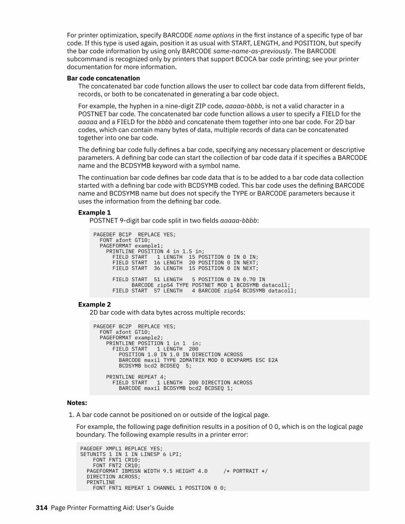
For printer optimization, specify BARCODE name options in the first instance of a specific type of barcode. If this type is used again, position it as usual with START, LENGTH, and POSITION, but specifythe bar code information by using only BARCODE same-name-as-previously. The BARCODEsubcommand is recognized only by printers that support BCOCA bar code printing; see your printerdocumentation for more information.Bar code concatenation
The concatenated bar code function allows the user to collect bar code data from different fields,records, or both to be concatenated in generating a bar code object.
For example, the hyphen in a nine-digit ZIP code, aaaaa-bbbb, is not a valid character in aPOSTNET bar code. The concatenated bar code function allows a user to specify a FIELD for theaaaaa and a FIELD for the bbbb and concatenate them together into one bar code. For 2D barcodes, which can contain many bytes of data, multiple records of data can be concatenatedtogether into one bar code.
The defining bar code fully defines a bar code, specifying any necessary placement or descriptiveparameters. A defining bar code can start the collection of bar code data if it specifies a BARCODEname and the BCDSYMB keyword with a symbol name.
The continuation bar code defines bar code data that is to be added to a bar code data collectionstarted with a defining bar code with BCDSYMB coded. This bar code uses the defining BARCODEname and BCDSYMB name but does not specify the TYPE or BARCODE parameters because ituses the information from the defining bar code.Example 1
POSTNET 9-digit bar code split in two fields aaaaa-bbbb:
PAGEDEF BC1P REPLACE YES; FONT afont GT10; PAGEFORMAT example1; PRINTLINE POSITION 4 in 1.5 in; FIELD START 1 LENGTH 15 POSITION 0 IN 0 IN; FIELD START 16 LENGTH 20 POSITION 0 IN NEXT; FIELD START 36 LENGTH 15 POSITION 0 IN NEXT; FIELD START 51 LENGTH 5 POSITION 0 IN 0.70 IN BARCODE zip54 TYPE POSTNET MOD 1 BCDSYMB datacoll; FIELD START 57 LENGTH 4 BARCODE zip54 BCDSYMB datacoll;
Example 22D bar code with data bytes across multiple records:
PAGEDEF BC2P REPLACE YES; FONT afont GT10; PAGEFORMAT example2; PRINTLINE POSITION 1 in 1 in; FIELD START 1 LENGTH 200 POSITION 1.0 IN 1.0 IN DIRECTION ACROSS BARCODE maxil TYPE 2DMATRIX MOD 0 BCXPARMS ESC E2A BCDSYMB bcd2 BCDSEQ 5; PRINTLINE REPEAT 4; FIELD START 1 LENGTH 200 DIRECTION ACROSS BARCODE maxil BCDSYMB bcd2 BCDSEQ 1;
Notes:
1. A bar code cannot be positioned on or outside of the logical page.
For example, the following page definition results in a position of 0 0, which is on the logical pageboundary. The following example results in a printer error:
PAGEDEF XMPL1 REPLACE YES;SETUNITS 1 IN 1 IN LINESP 6 LPI; FONT FNT1 CR10; FONT FNT2 CR10; PAGEFORMAT IBMSSN WIDTH 9.5 HEIGHT 4.0 /* PORTRAIT */ DIRECTION ACROSS; PRINTLINE FONT FNT1 REPEAT 1 CHANNEL 1 POSITION 0 0;
314 Page Printer Formatting Aid: User's Guide
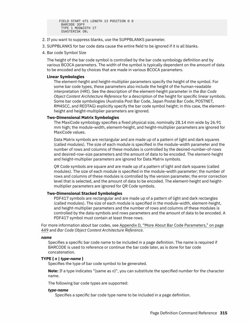
FIELD START 671 LENGTH 13 POSITION 0 0 BARCODE 3OF9 TYPE 1 MODWIDTH 17 SSASTERISK ON;
2. If you want to suppress blanks, use the SUPPBLANKS parameter.3. SUPPBLANKS for bar code data cause the entire field to be ignored if it is all blanks.4. Bar code Symbol Size
The height of the bar code symbol is controlled by the bar code symbology definition and byvarious BCOCA parameters. The width of the symbol is typically dependent on the amount of datato be encoded and by choices that are made in various BCOCA parameters.Linear Symbologies
The element-height and height-multiplier parameters specify the height of the symbol. Forsome bar code types, these parameters also include the height of the human-readableinterpretation (HRI). See the description of the element-height parameter in the Bar CodeObject Content Architecture Reference for a description of the height for specific linear symbols.Some bar code symbologies (Australia Post Bar Code, Japan Postal Bar Code, POSTNET,RM4SCC, and REDTAG) explicitly specify the bar code symbol height; in this case, the element-height and height-multiplier parameters are ignored.
Two-Dimensional Matrix SymbologiesThe MaxiCode symbology specifies a fixed physical size, nominally 28.14 mm wide by 26.91mm high; the module-width, element-height, and height-multiplier parameters are ignored forMaxiCode values.
Data Matrix symbols are rectangular and are made up of a pattern of light and dark squares(called modules). The size of each module is specified in the module-width parameter and thenumber of rows and columns of these modules is controlled by the desired-number-of-rowsand desired-row-size parameters and the amount of data to be encoded. The element-heightand height-multiplier parameters are ignored for Data Matrix symbols.
QR Code symbols are square and are made up of a pattern of light and dark squares (calledmodules). The size of each module is specified in the module-width parameter; the number ofrows and columns of these modules is controlled by the version parameter, the error correctionlevel that is selected, and the amount of data to be encoded. The element-height and height-multiplier parameters are ignored for QR Code symbols.
Two-Dimensional Stacked SymbologiesPDF417 symbols are rectangular and are made up of a pattern of light and dark rectangles(called modules). The size of each module is specified in the module-width, element-height,and height-multiplier parameters and the number of rows and columns of these modules iscontrolled by the data-symbols and rows parameters and the amount of data to be encoded. APDF417 symbol must contain at least three rows.
For more information about bar codes, see Appendix D, “More About Bar Code Parameters,” on page449 and Bar Code Object Content Architecture Reference.
nameSpecifies a specific bar code name to be included in a page definition. The name is required ifBARCODE is used to reference or continue the bar code later, as is done for bar codeconcatenation.
TYPE { n | type-name }Specifies the type of bar code symbol to be generated.
Note: If a type indicates "(same as n)", you can substitute the specified number for the charactername.
The following bar code types are supported:type-name
Specifies a specific bar code type name to be included in a page definition.
Page Definition Command Reference 315

CODE39 (same as 1)Specifies a bar code type of Code 39 (3-of-9 code), Automatic IdentificationManufacturers Uniform Symbol Specification 39.
MSI (same as 2)Specifies a bar code type of modified Plessey code.
UPCA (same as 3)Specifies a bar code type of Universal Product Code (United States) and the CanadianGrocery Product Code, Version A.
UPCE (same as 5)Specifies a bar code type of Universal Product Code (United States) and the CanadianGrocery Product Code, Version E.
UPC2SUPP (same as 6)Specifies a bar code type of Universal Product Code (United States) two-digitSupplemental (periodicals).
UPC5SUPP (same as 7)Specifies a bar code type of Universal Product Code (United States) five-digitSupplemental (paperbacks).
EAN8 (same as 8)Specifies a bar code type of European Article Numbering 8 (includes Japanese ArticleNumbering-short).
EAN13 (same as 9)Specifies a bar code type of European Article Numbering 13 (includes Japanese ArticleNumbering-standard).
IND2OF5 (same as 10)Specifies a bar code type of Industrial 2-of-5.
MAT2OF5 (same as 11)Specifies a bar code type of Matrix 2-of-5.
ITL2OF5 (same as 12)Specifies a bar code type of Interleaved 2-of-5, Automatic Identification ManufacturersUniform Symbol Specification-I 2/5.
CDB2OF7 (same as 13)Specifies a bar code type of Codabar, 2-of-7, Automatic Identification ManufacturersUniform Symbol Specification-Codabar.
CODE128 (same as 17)Specifies a bar code type of Code 128, Automatic Identification Manufacturers UniformSymbol Specification-128.
Note: A subset of CODE128 exists that is called EAN128. These EAN128 bar codes can beproduced with PPFA by specifying CODE128 for the bar code type in the PAGEDEF andincluding the extra parts of the bar code in the data. The UCC-128 bar code format is:
startcode FNC1 ai nnnnnnnnnnnnnnnnnn m c stopchar
The string of ns represents the bar code data. The start code, stop character, and 'c' valueare generated by the printer microcode for BCOCA bar codes. The FNC1 is a hexadecimal8F character. The ai is an application identifier and needs to be defined for use by eachEAN128 application. The m is a modulo 10 check digit that must be calculated by theapplication and included in the bar code data.
Not all printers generate the EAN128 bar codes; thus, you might need to verify that the barcode that is produced in this manner is readable by your bar code scanner.
For more information about the EAN128 bar codes, see the AFP Consortium web page(http://www.afpcinc.org).
316 Page Printer Formatting Aid: User's Guide

EAN2SUP (same as 22)Specifies a bar code type of European Article Numbering, Two-digit Supplemental.
EAN5SUB (same as 23)Specifies a bar code type of European Article Numbering, Five-digit Supplemental.
POSTNET (same as 24)Specifies a bar code type of POSTal Numeric Encoding Technique (United States PostalService), and defines specific values for the BSD module width, element height, heightmultiplier, and wide-to-narrow ratio fields.
Note: POSTNET MOD 4 is normally called PLANET bar code. POSTNET MOD 4 is supportedby PPFA and some AFP printers.
RM4SCC (same as 26)Specifies a 4-state customer code that is defined by the Royal Mail Postal Service ofEngland for bar coding postal code information.
JPOSTAL (same as 27)A complete Japan Postal Bar Code symbol consists of a set of distinct bars and spaces foreach character followed by a modulo 19 checksum character and enclosed by a uniquestart character, stop character and quiet zones.
2DMATRIX (same as 28)Specifies a Data Matrix two-dimensional bar code. Two-dimensional matrix symbologies(sometimes called area symbologies) allow large amounts of information to be encoded ina two-dimensional matrix. These symbologies are typically rectangular and require a quietzone around all four sides; for example, the Data Matrix symbology requires a quiet zone atleast one module wide around the symbol. Two-dimensional matrix symbologies useextensive data compaction and error correction codes, allowing large amounts of characteror binary data to be encoded.
2DMAXI (same as 29)Specifies a MaxiCode two-dimensional stacked bar code. Two-dimensional stackedsymbologies allow large amounts of information to be encoded by effectively stackingshort one-dimensional symbols in a row/column arrangement. This arrangement reducesthe amount of space that is typically used by conventional linear bar code symbols andallows for a large variety of rectangular bar code shapes.
2DPDF417 (same as 30)Specifies a PDF417 two-dimensional stacked bar code. Two-dimensional stackedsymbologies allow large amounts of information to be encoded by effectively stackingshort one-dimensional symbols in a row/column arrangement. This arrangement reducesthe amount of space that is typically used by conventional linear bar code symbols andallows for a large variety of rectangular bar code shapes.
APOSTAL (same as 31)Specifies the bar code type as defined by the Australian Postal Service.
2DQRCODE (same as 32)Specifies a QR Code two-dimensional bar code. QR Code consists of a matrix of dark andlight squares (modules). The matrix is also square and 40 sizes exist that range from amatrix of 21 by 21 modules and increase by steps of 4 up to a matrix of 177 by 177modules. Thus, up to 7089 numeric characters, 4296 alphabetic characters, 2953 8-bitcharacters, or 1817 Kanji characters can be contained on a single symbol, and up to 16symbols can be logically linked together.
Since squares (modules) are square, the size of a module is determined by the MODWIDTHparameter only. The HEIGHT and RATIO parameters are not used.
CODE93 (same as 33)Specifies a bar code type as defined by the AIM Uniform Symbology Specification - Code93. This linear bar code is similar to Code 39, but more complex.
Page Definition Command Reference 317
US4STATE (same as 34 or US4ST)Specifies a United States Postal Service (USPS) Four-State bar code. This parameter canbe abbreviated as US4ST. This bar code is also known as the Intelligent Mail Bar Code.
The USPS Four-State bar code symbol has a fixed size; therefore, the HEIGHT and RATIOparameters are not applicable and ignored. This bar code symbol allows a MODWIDTHparameter with two sizes SMALL and OPTIMAL. If you specify any other MODWIDTH, PPFAissues a warning message (RC=4), defaults to OPTIMAL, and continues generating thepage definition. MODWIDTH SMALL prints a symbol approximately 2.575 inches wide andMODWIDTH OPTIMAL prints a symbol approximately 2.9 inches wide.
The input data is all numeric and consists of five data fields. The first four are fixed length;the fifth is variable length. The five fields are:
1. Application ID (2 digits) - the second digit must be 0 - 4 so that the valid values are 00 -04, 01 - 14, and so on, through 90 - 94.
2. Special Services (3 digits) - assigned by the USPS. Valid values are 000 - 999.3. Customer Identifier (6 digits) - assigned by the USPS. Valid values are 000000 -
999999.4. Sequence Number (9 digits) - assigned by the mailer. Valid values are 000000000 -
999999999.5. Delivery Point ZIP Code (0, 5, 9, or 11 digits) - see the following MOD parameter for
valid values.
USPS Four-State modifiers (MOD) are defined as follows:X'00'
Present a USPS Four-State bar code symbol with no Delivery Point ZIP Code. The inputdata for this bar code symbol must be 20 numeric digits.
X'01'Present a USPS Four-State bar code symbol with a 5-digit Delivery Point ZIP Code. Theinput data for this bar code symbol must be 25 numeric digits. The valid values for theDelivery Point ZIP code are 00000 - 99999.
X'02'Present a USPS Four-State bar code symbol with a 9-digit Delivery Point ZIP Code. Theinput data for this bar code symbol must be 29 numeric digits. The valid values for theDelivery Point ZIP code are 000000000 - 999999999.
X'03'Present a USPS Four-State bar code symbol with an 11-digit Delivery Point ZIP Code.The input data for this bar code symbol must be 31 numeric digits. The valid values forthe Delivery Point ZIP code are 00000000000 - 99999999999.
Note: You can print HRI with this symbol but it is not currently (Oct 2004) defined by theUSPS. Therefore, PPFA defaults the HRI parameter to HRI OFF for this symbol. The USPSsays that they plan to define HRI for some Special Services. "Track and Confirm" is anexample of a Special Service that USPS does not currently define HRI but might in thefuture.
REDTAG (same as 35)Specifies a 4-state bar code type that is defined by the Royal Mail Postal Service ofEngland as RED TAG.
DATABAR (same as 36)Specifies a bar code type of GS1 DataBar.
Other BARCODE Parameters
318 Page Printer Formatting Aid: User's Guide

Common BARCODE Parameters Common 2D BARCODE Parameters
Concatenated BARCODE Parameters
Common BARCODE Parameters
MOD n HRI ON
ABOVE
BELOW
OFF
ONLY
HRIFONT fontname
SSASTERISK ON
OFF
WIDTH n
IN
MM
CM
POINTS
PELS
HEIGHT n
IN
MM
CM
POINTS
PELS
MODWIDTH OPTIMAL
MODWIDTH n
OPTIMAL
SMALL
BCCOLOR colorname
RGB rvalue gvalue bvalue
HIGHLIGHT hvalue
COVERATE cvalue BLACK bvalue
CMYK cvalue mvalue yvalue kvalue
CIELAB lvalue (-) cvluae (-) c2value
SUPPBLANKS RATIO n
CMR cmr-lname AUDIT
INSTR
LINK
Page Definition Command Reference 319

MOD
MOD n
Specifies more processing information about the bar code symbol to be generated (forexample, MOD specifies whether a check-digit 6 must be generated for the bar code symbol).
nThe meaning of n differs between the types. For more information, see Table 24 on page457.
If MOD is not specified, the MOD value defaults as follows, depending on the bar code typespecified:
TYPE MOD TYPE MOD
1 1 22 0
2 1 23 0
3 0 24 0
5 0 26 0
6 0 27 0
7 0 28 0
8 0 29 0
9 0 30 0
10 1 31 1
11 1 32 2
12 1 33 0
13 1 35 1
17 2 36 0
HRI
HRI ON
ABOVE
BELOW
OFF
ONLY
HRIFONT fontname
Specifies the human-readable interpretation (text characters) to be generated and placedabove or below the bar code symbol, as directed.
ONSpecifies that HRI must be generated at the default location for the bar code type.
ABOVESpecifies that HRI must be placed above the bar code symbol.
BELOWSpecifies that HRI must be placed below the bar code symbol.
6 Check digits are a method of verifying data integrity during the bar code reading process.
320 Page Printer Formatting Aid: User's Guide
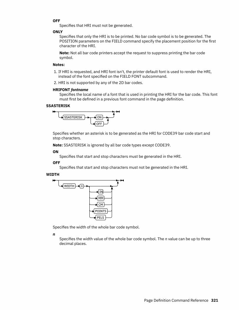
OFFSpecifies that HRI must not be generated.
ONLYSpecifies that only the HRI is to be printed. No bar code symbol is to be generated. ThePOSITION parameters on the FIELD command specify the placement position for the firstcharacter of the HRI.
Note: Not all bar code printers accept the request to suppress printing the bar codesymbol.
Notes:
1. If HRI is requested, and HRI font isn't, the printer default font is used to render the HRI,instead of the font specified on the FIELD FONT subcommand.
2. HRI is not supported by any of the 2D bar codes.
HRIFONT fontnameSpecifies the local name of a font that is used in printing the HRI for the bar code. This fontmust first be defined in a previous font command in the page definition.
SSASTERISK
SSASTERISK ON
OFF
Specifies whether an asterisk is to be generated as the HRI for CODE39 bar code start andstop characters.
Note: SSASTERISK is ignored by all bar code types except CODE39.ON
Specifies that start and stop characters must be generated in the HRI.OFF
Specifies that start and stop characters must not be generated in the HRI.
WIDTH
WIDTH n
IN
MM
CM
POINTS
PELS
Specifies the width of the whole bar code symbol.
nSpecifies the width value of the whole bar code symbol. The n value can be up to threedecimal places.
Page Definition Command Reference 321

HEIGHT
HEIGHT n
IN
MM
CM
POINTS
PELS
Specifies the height of bar code element. For UPC and EAN bar codes, the total height includesthe bar code and the HRI characters.
If HEIGHT is not specified, the printer default height is used.
Note: HEIGHT is ignored by bar code types that explicitly specify the element heights (forexample, POSTNET or RM4SCC).
nSpecifies the height of the bar code. The n value can be up to three decimal places.
unitSpecifies a unit of measurement for the HEIGHT parameter. The choices are IN, MM, CM,POINTS, or PELS.
Notes:
1. If no unit is specified, the default is the most recent SETUNITS command value or IN(inch) if a SETUNITS command is not issued.
2. Height for the 2D bar code. PDF417 specifies the height of a bar or row (not the totalheight of the symbol).
MODWIDTHMODWIDTH OPTIMAL
MODWIDTH n
OPTIMAL
SMALL
Specifies the width of the smallest defined bar code element by using mils (thousandths of aninch). The range of values is 1 - 254. If MODWIDTH is not specified, the printer defaultMODWIDTH is used; the printer default yields the optimum scannable symbol.
nSpecifies the width of each module by using thousandths of an inch (1⁄1000) as the unit ofmeasurement.
OPTIMALSpecifies that the printer chooses the optimal module width. This value is recommended.It is the default value when MODWIDTH is not coded.
SMALLSpecifies that the PPFA chooses a module width that produces the smallest symbol thatmeets the symbology tolerances.
Note: Because this symbol is at the lower boundary of the symbology-defined tolerancerange, external conditions, such as printer contrast setting, toner consistency, and paperabsorbency, might cause this symbol to scan improperly.
322 Page Printer Formatting Aid: User's Guide
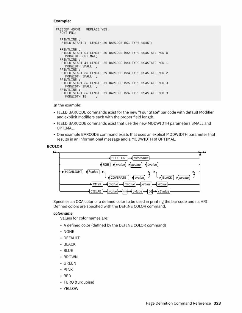
Example:
PAGEDEF 4SXM1 REPLACE YES; FONT FN1;
PRINTLINE ; FIELD START 1 LENGTH 20 BARCODE BC1 TYPE US4ST;
PRINTLINE ; FIELD START 01 LENGTH 20 BARCODE bc2 TYPE US4STATE MOD 0 MODWIDTH OPTIMAL; PRINTLINE ; FIELD START 41 LENGTH 25 BARCODE bc3 TYPE US4STATE MOD 1 MODWIDTH SMALL ; PRINTLINE ; FIELD START 66 LENGTH 29 BARCODE bc4 TYPE US4STATE MOD 2 MODWIDTH SMALL ; PRINTLINE ; FIELD START 66 LENGTH 31 BARCODE bc5 TYPE US4STATE MOD 3 MODWIDTH SMALL ; PRINTLINE ; FIELD START 66 LENGTH 31 BARCODE bc6 TYPE US4STATE MOD 3 MODWIDTH 15 ;
In the example:
• FIELD BARCODE commands exist for the new "Four State" bar code with default Modifier,and explicit Modifiers each with the proper field length.
• FIELD BARCODE commands exist that use the new MODWIDTH parameters SMALL andOPTIMAL.
• One example BARCODE command exists that uses an explicit MODWIDTH parameter thatresults in an informational message and a MODWIDTH of OPTIMAL.
BCOLOR
BCCOLOR colorname
RGB rvalue gvalue bvalue
HIGHLIGHT hvalue
COVERATE cvalue BLACK bvalue
CMYK cvalue mvalue yvalue kvalue
CIELAB lvalue (-) cvluae (-) c2value
Specifies an OCA color or a defined color to be used in printing the bar code and its HRI.Defined colors are specified with the DEFINE COLOR command.
colornameValues for color names are:
• A defined color (defined by the DEFINE COLOR command)• NONE• DEFAULT• BLACK• BLUE• BROWN• GREEN• PINK• RED• TURQ (turquoise)• YELLOW
Page Definition Command Reference 323
• ORANGE• PURPLE• MUSTARD• GRAY• DARKBLUE• DARKGREEN• DARKTURQ (dark turquoise)
The color choices depend on the printer. NONE is the color of the medium. DEFAULT is theprinter default color.
color modelSpecifies the color of print for this field that is supported in MODCA for the Red/Green/Blue color model (RGB), the highlight color space, the Cyan/Magenta/Yellow/Black colormodel (CMYK), and the CIELAB color model.
Example: In the following code example, four bar codes are defined that use color.
1. The first uses a predefined non-OCA color.2. The second uses an OCA color that is not predefined.3. The third uses a predefined OCA color.4. The fourth uses a CMYK color model directly.
/*--------------------------------------------------------*/ /* CMRX13 - Full Color on Bar Code */ /* */ /* */ /*--------------------------------------------------------*/ /* Traditional pagedef */ /*--------------------------------------------------------*/ Pagedef cmx14P replace yes;
DEFINE ocablue COLOR OCA blue ; DEFINE cymkyel COLOR CMYK 50 30 30 30 ;
FONT fte egt12 TYPE ebcdic;
PAGEFORMAT pf1; PRINTLINE; FIELD START 50 LENGTH 8 RGB 30 25 25 BARCODE AUST1 TYPE APOSTAL MOD 2 BCCOLOR cymkyel /* PRE-DEFINED NON-OCA COLOR */ HEIGHT .5 IN; FIELD START 5 LENGTH 5 BARCODE BCCO TYPE POSTNET BCCOLOR RED /* OCA COLOR */ HEIGHT .5 IN; FIELD START 5 LENGTH 5 BARCODE BCCO1 TYPE POSTNET BCCOLOR ocablue /* Defined OCA COLOR */ HEIGHT .5 IN; FIELD START 5 LENGTH 5 BARCODE BCCO2 TYPE POSTNET CMYK 50 30 30 30 /* direct cmyk color */ HEIGHT .5 IN;
/*--------------------------------------------------------*/ /* Record Fmt pagedef */ /*--------------------------------------------------------*/ Pagedef cmx14L replace yes;
DEFINE ocablue COLOR OCA blue ; Define rgbred COLOR RGB 30 25 25 ; DEFINE cymkyel COLOR CMYK 50 30 30 30 ; DEFINE HIgreen COLOR HIGHLIGHT 100 coverage 50; DEFINE cieblue COLOR cielab 40 90 95 ;
FONT fte egt12 TYPE ebcdic; /* type ebcdic */
PAGEFORMAT pf1; LAYOUT 'l1'; FIELD START 50 LENGTH 8 RGB 30 25 25 BARCODE AUST1 TYPE APOSTAL MOD 2 BCCOLOR cymkyel /* PRE-DEFINED NON-OCA COLOR */
324 Page Printer Formatting Aid: User's Guide

HEIGHT .5 IN; FIELD START 5 LENGTH 8 BARCODE AUST2 TYPE APOSTAL MOD 2 BCCOLOR RED /* NON PRE-DEFINED OCA COLOR */ HEIGHT .5 IN; FIELD START 5 LENGTH 5 BARCODE BCCO TYPE POSTNET BCCOLOR OCABLUE /* PRE-DEFINED OCA COLOR */ HEIGHT .5 IN; FIELD START 5 LENGTH 5 BARCODE BCCO2 TYPE POSTNET CMYK 50 30 30 30 /* direct cmyk color */ HEIGHT .5 IN;
/*--------------------------------------------------------*/ /* XML pagedef */ /*--------------------------------------------------------*/ Pagedef cmx14X replace yes;
DEFINE ocablue COLOR OCA blue ; Define rgbred COLOR RGB 30 25 25 ; DEFINE cymkyel COLOR CMYK 50 30 30 30 ; DEFINE HIgreen COLOR HIGHLIGHT 100 coverage 50; DEFINE cieblue COLOR cielab 40 90 95 ;
DEFINE cn QTAG 'cust','name' ; FONT fte egt12 TYPE ebcdic; /* type ebcdic */
PAGEFORMAT pf1; XLAYOUT cn; FIELD START 50 LENGTH 8 RGB 30 25 25 BARCODE AUST1 TYPE APOSTAL MOD 2 BCCOLOR cymkyel /* PRE-DEFINED NON-OCA COLOR */ HEIGHT .5 IN; FIELD START 5 LENGTH 8 BARCODE AUST2 TYPE APOSTAL MOD 2 BCCOLOR RED /* NON PRE-DEFINED OCA COLOR */ HEIGHT .5 IN; FIELD START 5 LENGTH 5 BARCODE BCCO TYPE POSTNET BCCOLOR OCABLUE /* PRE-DEFINED OCA COLOR */ HEIGHT .5 IN; FIELD START 5 LENGTH 5 BARCODE BCCO2 TYPE POSTNET CMYK 50 30 30 30 /* direct cmyk color */ HEIGHT .5 IN;
SUPPBLANKS
SUPPBLANKS
Suppress the trailing blanks in the data field that is used to generate the bar code.
When the page definition selects any of the EAN, UPC or POSTNET bar code types andmodifiers and also requests that trailing blanks be truncated for the bar code field, the printserver examines the resulting data length and choose the correct bar code type and modifierfor the bar code object created.
Note: If the data length does not match any of the bar code type and modifier combinations,the print server uses the original bar code type and modifier that is requested to build the barcode object.
RATIO
RATIO n
Specifies the ratio between the width of the wide and the narrow bar code elements. Therange of values is 100 - 500, but you must specify a value appropriate for your printer and barcode type or you errors occur at print time.
If RATIO is not specified, the printer default ratio is used.n
The RATIO is specified as a percent value. For example, form nnn. For example, 200represents a ratio of 2 to 1; 250 represents a ratio of 2.5 to 1. For most bar code symbols,the RATIO value is 200 - 300. For bar code types that explicitly specify the module width
Page Definition Command Reference 325

(for example, POSTNET and RM4SCC, this field is ignored. If RATIO is not specified, thedefault ratio for the bar code symbol is used.
CMR
CMR cmr-lname AUDIT
INSTR
LINK
Specify a Color management resource (CMR) and its process mode for a bar code object withinthe page definition.
Note: See Chapter 8, “AFP Color Management,” on page 151 for more information about usingthe CMR subcommand.
cmr-lnameThe CMR local name. This name must be defined with a DEFINE CMRNAME command.
Note: This parameter must immediately follow the CMR keyword.
processing mode parameterSpecify the processing mode for the CMR.AUDIT
Process this CMR as an audit CMR.INSTR
Process this CMR as an instruction CMR.LINK
Process this CMR as a link CMR. This processing mode is only valid for device link (DL)CMRs.
Example: In the following code example, 2 bar codes are defined with CMRs specified. Thebar codes are defined for traditional, record format and XML page definitions.
Note: The DEFINE CMRNAMEs for mycmr and dark1 are used in each page definition butdefined only once. Page definitions that are compiled together can define a local CMR nameonly once. This requirement is because a DEFINE CMRNAME definition is global for all pagedefinitions and form definitions in the same set of source code.
DEFINE mycmr CMRNAME ... ; DEFINE dark1 CMRNAME ... ;
/* Traditional Pagedef */ PAGEDEF cmr10P REPLACE yes; PRINTLINE; FIELD Start 1 Length 20 BARCODE TYPE code39 MOD 1 CMR myCMR audit; FIELD Start 21 Length 40 BARCODE TYPE code39 MOD 1 CMR dark1 instr;
/* Record Layout Pagedef */ PAGEDEF cmr10L REPLACE yes; Font f1; LAYOUT 'l1'; FIELD Start 1 Length 20 BARCODE TYPE code39 MOD 1 CMR myCMR audit; FIELD Start 21 Length 40 BARCODE TYPE code39 MOD 1 CMR dark1 instr;
/* XML Pagedef */
326 Page Printer Formatting Aid: User's Guide
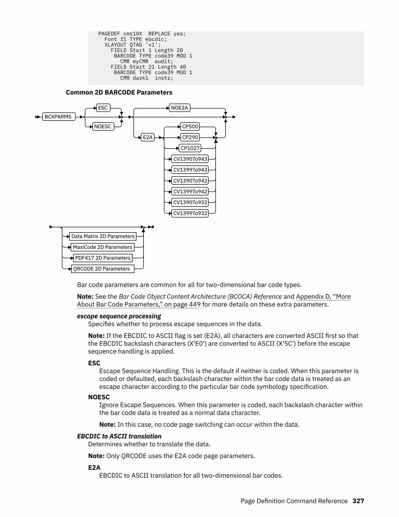
PAGEDEF cmr10X REPLACE yes; Font f1 TYPE ebcdic; XLAYOUT QTAG 'x1'; FIELD Start 1 Length 20 BARCODE TYPE code39 MOD 1 CMR myCMR audit; FIELD Start 21 Length 40 BARCODE TYPE code39 MOD 1 CMR dark1 instr;
Common 2D BARCODE Parameters
BCXPARMS
ESC
NOESC
NOE2A
E2A
CP500
CP290
CP1027
CV1390To943
CV1399To943
CV1390To942
CV1399To942
CV1390To932
CV1399To932
Data Matrix 2D Parameters
MaxiCode 2D Parameters
PDF417 2D Parameters
QRCODE 2D Parameters
Bar code parameters are common for all for two-dimensional bar code types.
Note: See the Bar Code Object Content Architecture (BCOCA) Reference and Appendix D, “MoreAbout Bar Code Parameters,” on page 449 for more details on these extra parameters.
escape sequence processingSpecifies whether to process escape sequences in the data.
Note: If the EBCDIC to ASCII flag is set (E2A), all characters are converted ASCII first so thatthe EBCDIC backslash characters (X'E0') are converted to ASCII (X'5C') before the escapesequence handling is applied.
ESCEscape Sequence Handling. This is the default if neither is coded. When this parameter iscoded or defaulted, each backslash character within the bar code data is treated as anescape character according to the particular bar code symbology specification.
NOESCIgnore Escape Sequences. When this parameter is coded, each backslash character withinthe bar code data is treated as a normal data character.
Note: In this case, no code page switching can occur within the data.
EBCDIC to ASCII translationDetermines whether to translate the data.
Note: Only QRCODE uses the E2A code page parameters.
E2AEBCDIC to ASCII translation for all two-dimensional bar codes.
Page Definition Command Reference 327
• For Data Matrix and MaxiCode, the printer converts each byte of the data from EBCDICcode page 500 to ASCII code page 819.
• For PDF417, the printer converts each byte of the bar code data and each byte of theMacro PDF417 control block data from a subset of EBCDIC code page 500 into ASCII.This translation covers 181 code points, which includes alphanumerics and manysymbols. The code points that are not covered by the translation do not occur in EBCDICand are mapped, by the printer, to the X'7F' (127) code point. Do not use the followingEBCDIC code points for PDF417:
X'04' X'06' X'08' X'09' X'0A' X'14' X'15' X'17'
X'1A' X'1B' X'20' X'21' X'22' X'23' X'24' X'28'
X'29' X'2A' X'2B' X'2C' X'30' X'31' X'33' X'34'
X'35' X'36' X'38' X'39' X'3A' X'3B' X'3E' X'46'
X'62' X'64' X'65' X'66' X'6A' X'6B' X'6C' X'6D'
X'6E' X'6F' X'70' X'72' X'73' X'74' X'75' X'76'
X'77' X'78' X'80' X'8C' X'8D' X'8E' X'9D' X'9F'
X'AC' X'AD' X'AE' X'AF' X'B4' X'B5' X'B6' X'B9'
X'BC' X'BD' X'BE' X'BF' X'CA' X'CF' X'DA' X'EB'
X'ED' X'EE' X'EF' X'FA' X'FB' X'FD' X'FE' X'FF'
• QRCODE - The default coding for QRCODE is ECI 000020, which is equivalent to the IBMASCII code page 897. When translation is required, you must enter the code page to usefor translation. Three choices exist. Each choice causes the printer to translate from thecode page into ASCII code page 897 before the data is used to build the bar codesymbol:
– EBCDIC code page 500 (International #5). Only 128 bytes of this code page can betranslated into ECI 000020. These code points are specified in “QR Code Special-Function Parameters” on page 497.
– EBCDIC code page 290 (Japanese Katakana Extended).– EBCDIC code page 1027 (Japanese Latin Extended).
The first three values are used when the input data is encoded with a single-byte EBCDICcode page. The parameter identifies the EBCDIC code page that encodes single-byteEBCDIC bar code data:CP500
Code page 500 (International #5) Only 128 of the characters within ECI 000020 canbe specified in code page 500. The code page 500 characters that can be translatedare shown in the Bar Code Object Content Architecture Reference.
CP290Code page 290 (Japanese Katakana Extended)
CP1027Code page 1027 (Japanese Latin Extended)
The following parameters are used when the input data is SOSI. Each parameter identifiesa specific conversion from EBCDIC SOSI input data to a specific mixed-byte ASCIIencoding:CV1390To943
Translates EBCDIC data CCSID 1390 code points to ASCII Shift-JIS CCSID 943 codepoints.
328 Page Printer Formatting Aid: User's Guide

CV1399To943Translates EBCDIC data CCSID 1399 code points to ASCII Shift-JIS CCSID 943 codepoints.
CV1390To932Translates EBCDIC data CCSID 1390 code points to ASCII Shift-JIS CCSID 932 codepoints.
CV1399To932Translates EBCDIC data CCSID 1399 code points to ASCII Shift-JIS CCSID 932 codepoints.
CV1390To942Translates EBCDIC data CCSID 1390 code points to ASCII Shift-JIS CCSID 942 codepoints.
CV1399To942Translates EBCDIC data CCSID 1399 code points to ASCII Shift-JIS CCSID 942 codepoints.
Note: CCSID definitions:CCSID 932
Japanese PC Data Mixed including 1880 UDC.CCSID 942
Japanese PC Data Mixed including 1880 UDC, Extended SBCS.CCSID 943
Japanese PC Data Mixed for Open environment (Multi-vendor code): 6878 JIS X0208-1990 chars, 386 IBM selected DBCS chars, 1880 UDC (X'F040' to X'F9FC')
CCSID 1390Extended Japanese Katakana-Kanji Host Mixed for JIS X0213 including 6205 UDC,Extended SBCS (includes SBCS and DBCS euro)
CCSID 1399Extended Japanese Latin-Kanji Host Mixed for JIS X0213 including 6205 UDC,Extended SBCS (includes SBCS and DBCS euro)
NOE2ANo translation. This is the default if neither is coded. This parameter is used for all two-dimensional bar codes. No translation is done by the printer or PPFA. The bar code data isassumed to be the default coding as defined in the AIM Uniform Symbology Specification.
Page Definition Command Reference 329

Data Matrix 2D parametersunspecified
SIZE rows
BY
cols
SEQUENCE seq
OF
totID 1 1
ID uidHi uidLo
USERDEF
FNC1UCC
FN1IND
RDRPROG
MAC5
MAC6
ENCODE type
These parameters are for Data Matrix 2D bar codes:
SIZEunspecified
SIZE rows
BY
cols
The size of the two-dimensional bar code. The number of rows and columns (row size) inthe symbol. The allowable values for rows and columns are specified in Table 28 on page486. If size is not coded, the size is marked as unspecified and the appropriate number ofrows and columns are used based on the amount of data.
unspecifiedUnspecified size. The SIZE parameter isn't coded. The appropriate number of rows andcolumns are used based on the amount of data that is presented.
rows BY colsThe number of rows that are wanted including the finder pattern, and the number ofcolumns (or modules) in each row that are wanted including the finder pattern. Thekeyword BY is optional. The rows and columns must be one of the allowedcombinations in Table 28 on page 486.
SEQUENCE
SEQUENCE seq
OF
totID 1 1
ID uidHi uidLo
Structured append sequence indicator. Some two-dimensional bar codes can be logicallylinked together to encode large amounts of data. The logically linked symbols can bepresented on the same or different media and are logically recombined after they arescanned. PPFA checks the numbers for obvious errors and the proper number range. Forexample, SEQUENCE 5 OF 3 is wrong.
330 Page Printer Formatting Aid: User's Guide

sqnStructured-append sequence indicator. This parameter is an integer whose acceptablerange of values depends on the bar code type. The range for this parameter is 1 - 16.
OFOptional parameter for readability.
totTotal number of structured-append symbols. This parameter is an integer whoseacceptable range of values depends on the bar code type. The range of this parameteris 2 - 16.
ID uidHi uidLoThe high and low-order bytes of a unique file identification for a set of structured-appendsymbols. Each is a unique number 1 - 254 and identifies this set of symbols. The actualFile ID is computed by 256 times uidHi plus uidLo.
data matrix special functionsUSERDEF
FNC1UCC
FN1IND
RDRPROG
MAC5
MAC6
ENCODE type
Special functions that can be used only with a Data Matrix symbol. If not coded, thedefault is USERDEF (user-defined symbol).
FNC1UCCUCC/EAN FNC1 alternate data type identifier. An FNC1 is added in the first dataposition (or fifth position of a structured append symbol) to indicate that this bar codesymbol conforms to the UCC/EAN application identifier standard format.
FNC1INDIndustry FNC1 alternate data type identifier. An FNC1 is added in the second dataposition (or sixth data position of a structured append symbol) to indicate that this barcode symbol conforms to a particular industry standard format.
RDRPROGUsed when the symbol contains a message that is used to program the bar codereader. In this case, the bar code symbol cannot be a part of a structured appendsequence.
MAC5This provides instructions to the bar code reader to insert an industry-specific headerand trailer around the symbol data. The bar code symbol contains a 05 Macrocodeword. The bar code symbol cannot be a part of a structured append sequence.
MAC6Same as MAC5 except the bar code symbol contains a 06 Macro codeword. The barcode symbol cannot be a part of a structured append sequence.
ENCODEData Matrix bar code encodation scheme.
typeSpecifies the Data Matrix bar code encodation scheme. These encodation schemes aresupported:
Page Definition Command Reference 331
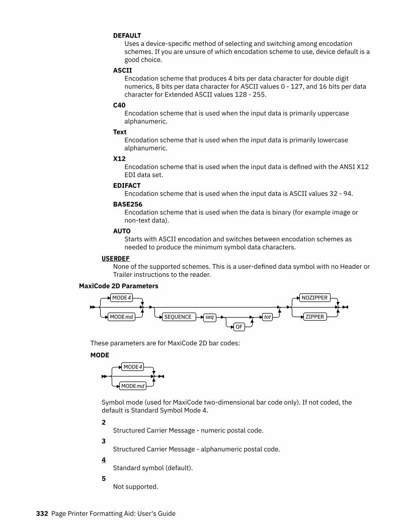
DEFAULTUses a device-specific method of selecting and switching among encodationschemes. If you are unsure of which encodation scheme to use, device default is agood choice.
ASCIIEncodation scheme that produces 4 bits per data character for double digitnumerics, 8 bits per data character for ASCII values 0 - 127, and 16 bits per datacharacter for Extended ASCII values 128 - 255.
C40Encodation scheme that is used when the input data is primarily uppercasealphanumeric.
TextEncodation scheme that is used when the input data is primarily lowercasealphanumeric.
X12Encodation scheme that is used when the input data is defined with the ANSI X12EDI data set.
EDIFACTEncodation scheme that is used when the input data is ASCII values 32 - 94.
BASE256Encodation scheme that is used when the data is binary (for example image ornon-text data).
AUTOStarts with ASCII encodation and switches between encodation schemes asneeded to produce the minimum symbol data characters.
USERDEFNone of the supported schemes. This is a user-defined data symbol with no Header orTrailer instructions to the reader.
MaxiCode 2D ParametersMODE 4
MODE md SEQUENCE seq
OF
tot
NOZIPPER
ZIPPER
These parameters are for MaxiCode 2D bar codes:
MODEMODE 4
MODE md
Symbol mode (used for MaxiCode two-dimensional bar code only). If not coded, thedefault is Standard Symbol Mode 4.
2Structured Carrier Message - numeric postal code.
3Structured Carrier Message - alphanumeric postal code.
4Standard symbol (default).
5Not supported.
332 Page Printer Formatting Aid: User's Guide
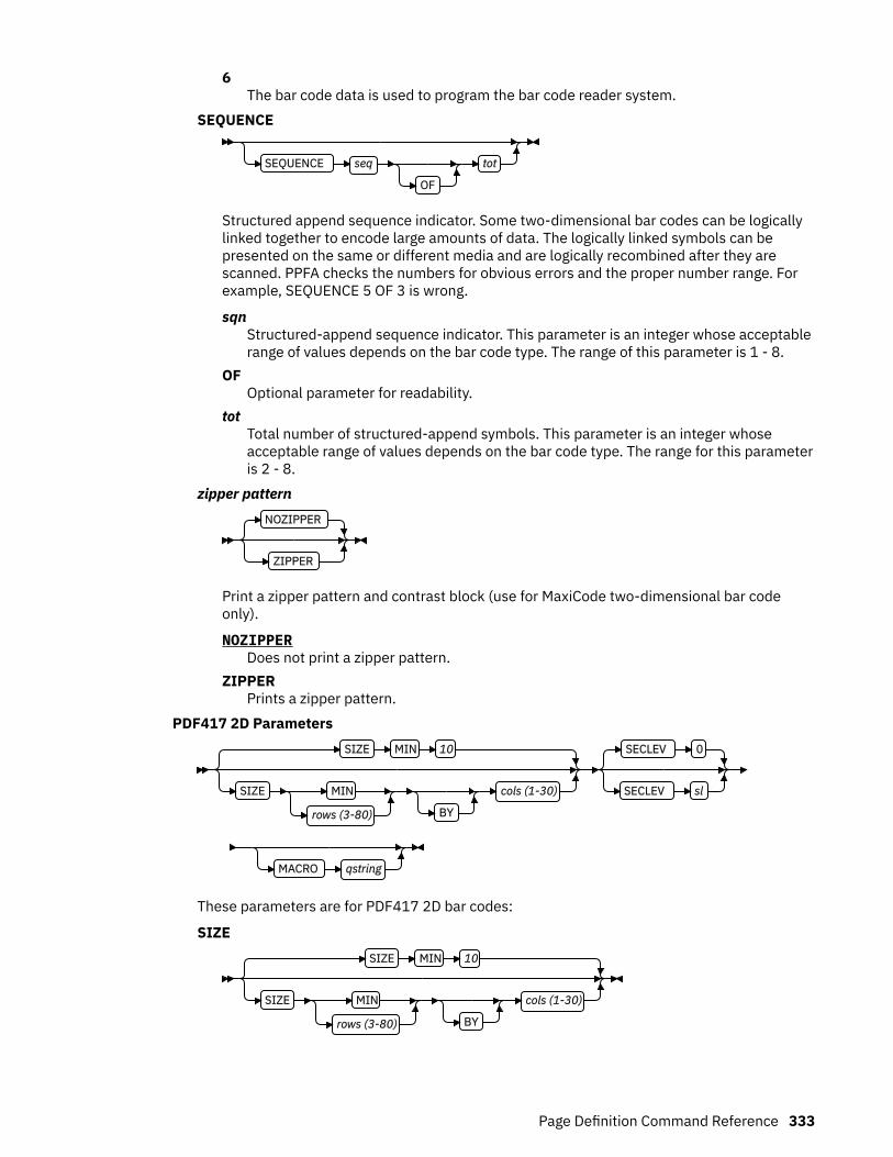
6The bar code data is used to program the bar code reader system.
SEQUENCE
SEQUENCE seq
OF
tot
Structured append sequence indicator. Some two-dimensional bar codes can be logicallylinked together to encode large amounts of data. The logically linked symbols can bepresented on the same or different media and are logically recombined after they arescanned. PPFA checks the numbers for obvious errors and the proper number range. Forexample, SEQUENCE 5 OF 3 is wrong.
sqnStructured-append sequence indicator. This parameter is an integer whose acceptablerange of values depends on the bar code type. The range of this parameter is 1 - 8.
OFOptional parameter for readability.
totTotal number of structured-append symbols. This parameter is an integer whoseacceptable range of values depends on the bar code type. The range for this parameteris 2 - 8.
zipper patternNOZIPPER
ZIPPER
Print a zipper pattern and contrast block (use for MaxiCode two-dimensional bar codeonly).
NOZIPPERDoes not print a zipper pattern.
ZIPPERPrints a zipper pattern.
PDF417 2D ParametersSIZE MIN 10
SIZE MIN
rows (3-80) BY
cols (1-30)
SECLEV 0
SECLEV sl
MACRO qstring
These parameters are for PDF417 2D bar codes:
SIZESIZE MIN 10
SIZE MIN
rows (3-80) BY
cols (1-30)
Page Definition Command Reference 333
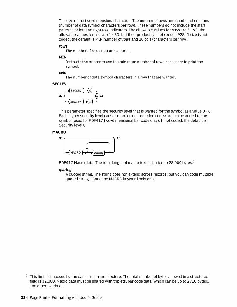
The size of the two-dimensional bar code. The number of rows and number of columns(number of data symbol characters per row). These numbers do not include the startpatterns or left and right row indicators. The allowable values for rows are 3 - 90, theallowable values for cols are 1 - 30, but their product cannot exceed 928. If size is notcoded, the default is MIN number of rows and 10 cols (characters per row).
rowsThe number of rows that are wanted.
MINInstructs the printer to use the minimum number of rows necessary to print thesymbol.
colsThe number of data symbol characters in a row that are wanted.
SECLEVSECLEV 0
SECLEV sl
This parameter specifies the security level that is wanted for the symbol as a value 0 - 8.Each higher security level causes more error correction codewords to be added to thesymbol (used for PDF417 two-dimensional bar code only). If not coded, the default isSecurity level 0.
MACRO
MACRO qstring
PDF417 Macro data. The total length of macro text is limited to 28,000 bytes.7
qstringA quoted string. The string does not extend across records, but you can code multiplequoted strings. Code the MACRO keyword only once.
7 This limit is imposed by the data stream architecture. The total number of bytes allowed in a structuredfield is 32,000. Macro data must be shared with triplets, bar code data (which can be up to 2710 bytes),and other overhead.
334 Page Printer Formatting Aid: User's Guide
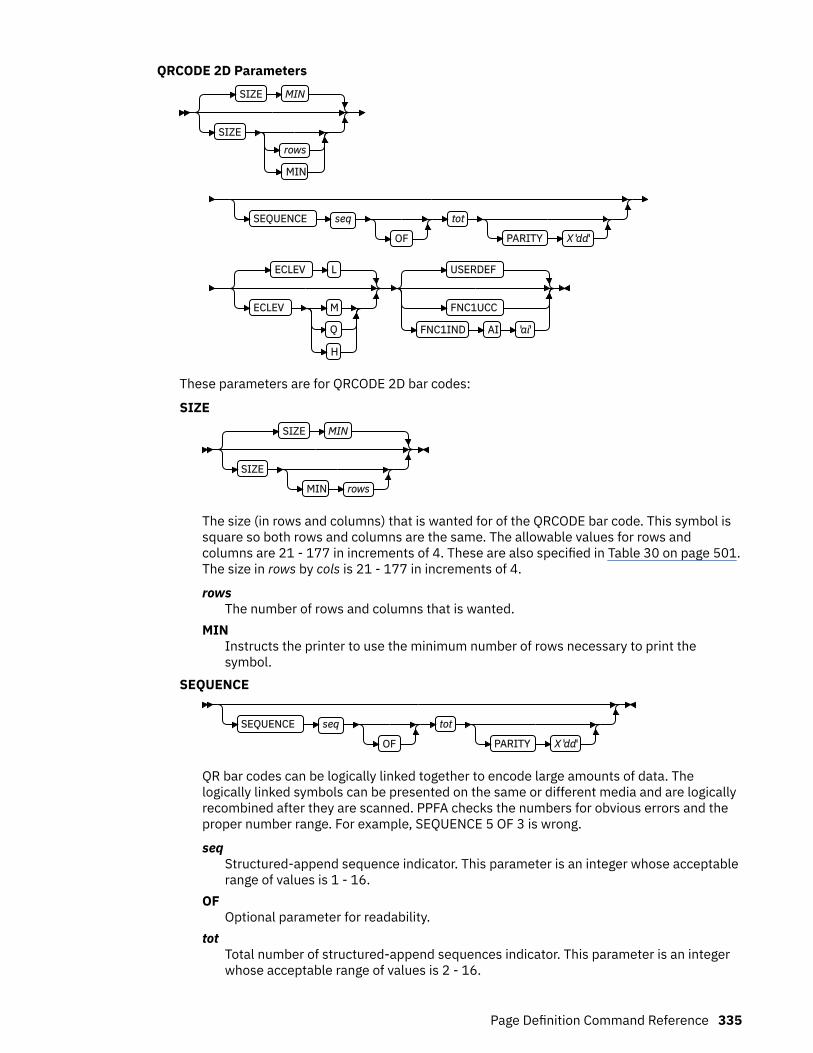
QRCODE 2D ParametersSIZE MIN
SIZErows
MIN
SEQUENCE seq
OF
tot
PARITY X 'dd'
ECLEV L
ECLEV M
Q
H
USERDEF
FNC1UCC
FNC1IND AI 'ai'
These parameters are for QRCODE 2D bar codes:
SIZESIZE MIN
SIZE
MIN rows
The size (in rows and columns) that is wanted for of the QRCODE bar code. This symbol issquare so both rows and columns are the same. The allowable values for rows andcolumns are 21 - 177 in increments of 4. These are also specified in Table 30 on page 501.The size in rows by cols is 21 - 177 in increments of 4.
rowsThe number of rows and columns that is wanted.
MINInstructs the printer to use the minimum number of rows necessary to print thesymbol.
SEQUENCE
SEQUENCE seq
OF
tot
PARITY X 'dd'
QR bar codes can be logically linked together to encode large amounts of data. Thelogically linked symbols can be presented on the same or different media and are logicallyrecombined after they are scanned. PPFA checks the numbers for obvious errors and theproper number range. For example, SEQUENCE 5 OF 3 is wrong.
seqStructured-append sequence indicator. This parameter is an integer whose acceptablerange of values is 1 - 16.
OFOptional parameter for readability.
totTotal number of structured-append sequences indicator. This parameter is an integerwhose acceptable range of values is 2 - 16.
Page Definition Command Reference 335

PARITY X'dd'Structured append parity data. This parameter is used for the QR Code 2D bar codeonly when it has linked structured-append symbols. The parameter specifies the paritybyte for the entire collection of linked structured-append symbols. The parity byte isthe same for each symbol in the collection and is obtained by doing an "exclusive or"function on all of the bytes of the ASCII data in all symbols of the collection. If thissymbol is not structured-append symbol, the parity parameter is ignored.X'dd'
The parity data byte. It must be entered as two hexadecimal digits (X'0' - X'F'). Asfor all hexadecimal digits in PPFA, the digits must be uppercase if they are X'A' -X'F'.
ECLEVECLEV L
ECLEV M
Q
H
Error Correction Level. It specifies the level of error correction to be used for thesymbol. Each higher level of error correction causes more error correction code wordsto be added to the symbol; therefore, fewer code words are left for the data. See theparticular bar code symbology specification for more information. Four different levelsof Reed-Solomon error correction can be selected:
LLevel L allows recovery of 7% of symbol code words.
MLevel M allows recovery of 15% of symbol code words.
QLevel Q allows recovery of 25% of symbol code words.
HLevel H allows recovery of 30% of symbol code words.
special functionsUSERDEF
FNC1UCC
FNC1IND AI 'ai'
Special functions that can be used with QR Code 2D symbols. If not coded, the defaultis USERDEF (user-defined symbol).
FNC1UCCUCC/EAN FNC1 alternate data type identifier. The symbol indicates that this QRCode symbol conforms to the UCC/EAN application identifiers standard.
FNC1INDIndustry FNC1 alternate data type identifier. The symbol indicates that this QRCode symbol conforms to the specific industry or application specificationspreviously agreed with AIM International. When this standard is selected, anapplication indicator must be specified.AI 'ai'
Application indicator for Industry FNC1. This value is coded as a singleuppercase or lowercase alphabetic character, or a 2-digit number. It must be
336 Page Printer Formatting Aid: User's Guide
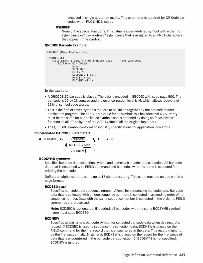
enclosed in single quotation marks. This parameter is required for QR Code barcodes when FNC1IND is coded.
USERDEFNone of the special functions. This value is a user-defined symbol with either nosignificance or "user-defined" significance that is assigned to all FNC1 charactersthat appear in the symbol.
QRCODE Barcode Example:
PAGEDEF QNXmp Replace Yes;
PRINTLINE; FIELD START 1 LENGTH 4400 BARCODE bc3p TYPE 2DQRCODE BCXPARMS E2A CP500 noesc SIZE 025 ECLEV M SEQUENCE 1 of 7 PARITY x'7A' FNC1IND AI 'a' ;
In the example:
• A QRCODE 2D bar code is placed. The data is encoded in EBCDIC with code page 500. Thebar code is 25 by 25 squares and the error correction level is M, which allows recovery of15% of symbol code words.
• This is the first of seven symbols that are to be linked together by the bar code readerapplication program. The parity-data value for all symbols is a hexadecimal X'7A'. Paritymust be the same for all the linked symbols and is obtained by doing an "exclusive or"function on all of the bytes of the ASCII value of all the original input data.
• The QRCODE symbol conforms to industry specifications for application indicator a.
Concatenated BARCODE ParametersBCDSYMB symname
BCDSEQ seq#
BCDNEW
BCDSYMB symnameSpecifies bar code data collection symbol and names a bar code data collection. All bar codedata that is described with FIELD command and bar codes with this name is collected forprinting the bar code.
Defines an alpha-numeric name up to 16 characters long. This name must be unique within apage format.
BCDSEQ seq#Specifies bar code data sequence number. Allows for sequencing bar code data. Bar codedata that is collected with unique sequence numbers is collected in ascending order of itssequence number. Data with the same sequence number is collected in the order its FIELDcommands are processed.
Note: BCDSEQ is optional but if it coded, all bar codes with the same BCDSYMB symbolname must code BCDSEQ.
BCDNEWSpecifies to start a new bar code symbol for collected bar code data when this record isreused. If BCDSEQ is used to sequence the collection data, BCDNEW is placed on theFIELD command for the first record that is encountered in the data. This record might notbe the first sequentially. In general, BCDNEW is placed on the record for the first piece ofdata that is encountered in the bar code data collection. If BCDSYMB is not specified,BCDNEW is ignored.
Page Definition Command Reference 337
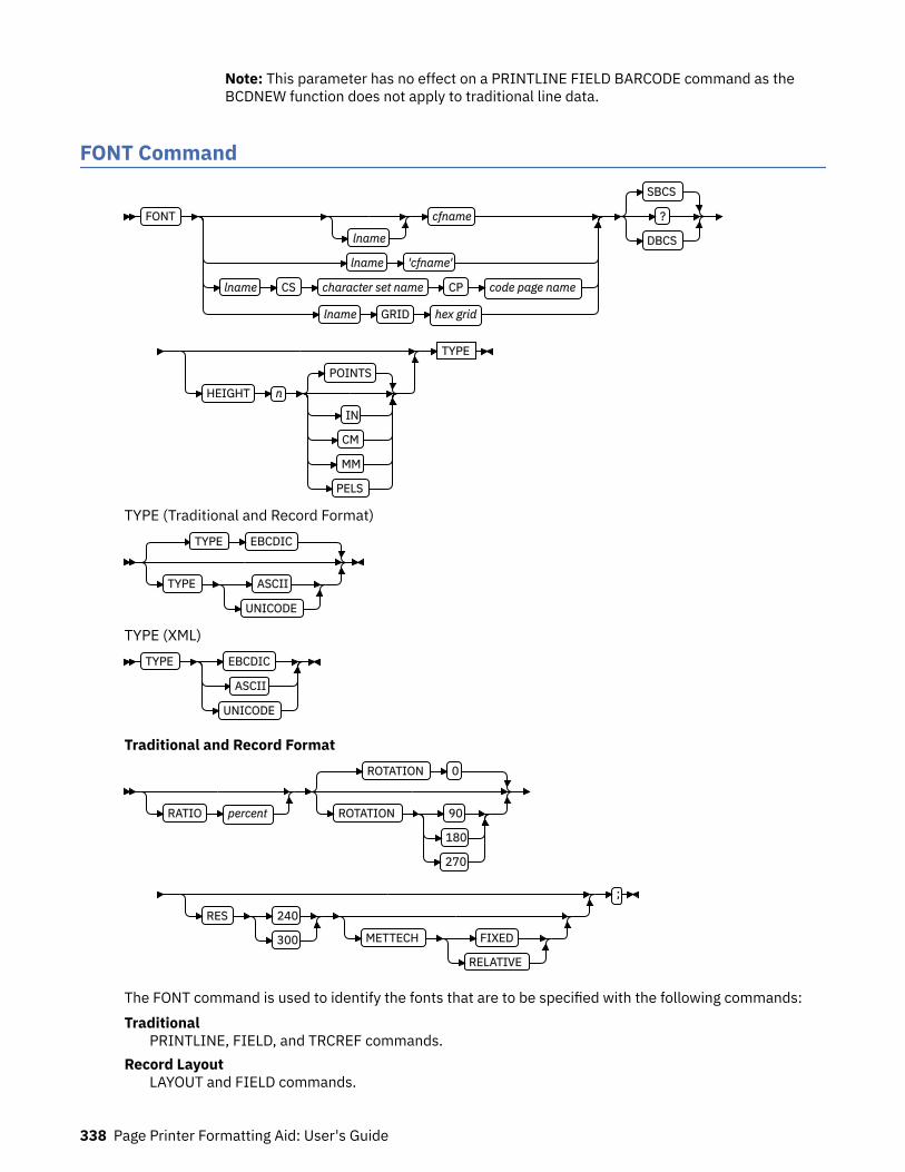
Note: This parameter has no effect on a PRINTLINE FIELD BARCODE command as theBCDNEW function does not apply to traditional line data.
FONT Command
FONT
lname
cfname
lname 'cfname'
lname CS character set name CP code page name
lname GRID hex grid
SBCS
?
DBCS
HEIGHT n
POINTS
IN
CM
MM
PELS
TYPE
TYPE (Traditional and Record Format)TYPE EBCDIC
TYPE ASCII
UNICODE
TYPE (XML)TYPE EBCDIC
ASCII
UNICODE
Traditional and Record Format
RATIO percent
ROTATION 0
ROTATION 90
180
270
RES 240
300 METTECH FIXED
RELATIVE
;
The FONT command is used to identify the fonts that are to be specified with the following commands:Traditional
PRINTLINE, FIELD, and TRCREF commands.Record Layout
LAYOUT and FIELD commands.
338 Page Printer Formatting Aid: User's Guide

XMLXLAYOUT and FIELD commands.
A maximum of 127 font names for each page definition can be identified.
Note: Naming a font with the FONT command does not, by itself, affect your output. You must specify thefont in one of the listed commands for the font to become effective. You must name at least one font in aRecord Format or XML page definition.
FONT commands immediately follow the PAGEDEF command. A separate FONT command is required:
• For each font used within a page definition• For each rotation of the same font
Note: For Traditional, see the “TRCREF Command (Traditional)” on page 420 for the exception.
FONTFONT
lname
cfname
lname 'cfname'
lname CS character set name CP code page name
lname GRID hex grid
Identifies the fonts to be specified in the preceding commands.lname
Local name for the font. Specifies an unquoted alphanumeric name of 1 - 16 characters (localname) of the font to be used in the page definition. The name must conform to the token rules andmust be unique within the page definition.
lname is used with the following commands:Traditional
PRINTLINE, FIELD, and TRCREF commands.Record Layout
LAYOUT and FIELD commands.XML
XLAYOUT and FIELD commands.
lname is optional if cfname is specified.
cfnameCoded font name. Specifies an alphanumeric name of 1 - 6 characters (user-access name) of thecoded font to be used in the page definition. Specify this name without the Xn prefix.
'cfname'Quoted full user-access name. Specifies a quoted alphanumeric name of 1 - 8 characters of thecoded font to be used in the page definition. The name can contain blanks and special characters.No uppercase folding or prefix is added to the name. The 'cfname' variable is intended for outlinefonts and allows them to be selected without overriding the HEIGHT specified in the CFIstructured field in the coded font. Enter the full outline font name as a quoted name and do notenter the HEIGHT parameter. For example, if you enter the following command, the outline fontXZM32F is used with no overriding HEIGHT parameters:
FONT myfont 'XZM32F'
Notes:
1. The quoted name of the font name is primarily intended for outline fonts. If you use a quotedname for a raster font, you must be sure that you have the name corresponding to the correctrotation of the font.
Page Definition Command Reference 339
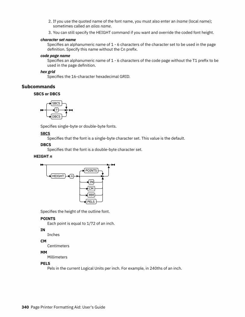
2. If you use the quoted name of the font name, you must also enter an lname (local name);sometimes called an alias name.
3. You can still specify the HEIGHT command if you want and override the coded font height.
character set nameSpecifies an alphanumeric name of 1 - 6 characters of the character set to be used in the pagedefinition. Specify this name without the Cn prefix.
code page nameSpecifies an alphanumeric name of 1 - 6 characters of the code page without the T1 prefix to beused in the page definition.
hex gridSpecifies the 16-character hexadecimal GRID.
SubcommandsSBCS or DBCS
SBCS
?
DBCS
Specifies single-byte or double-byte fonts.
SBCSSpecifies that the font is a single-byte character set. This value is the default.
DBCSSpecifies that the font is a double-byte character set.
HEIGHT n
HEIGHT n
POINTS
IN
CM
MM
PELS
Specifies the height of the outline font.
POINTSEach point is equal to 1/72 of an inch.
INInches
CMCentimeters
MMMillimeters
PELSPels in the current Logical Units per inch. For example, in 240ths of an inch.
340 Page Printer Formatting Aid: User's Guide

TYPE (Traditional and Record Format)
TYPE EBCDIC
TYPE ASCII
UNICODE
The TYPE subcommand indicates the type of font that is used.
EBCDICThis parameter is normally used for fonts on OS390–based systems. This value is the default.
ASCIIThis parameter is normally used for fonts on workstation–based systems.
UNICODEThis parameter is used with Unicode type fonts.
TYPE (XML only)TYPE EBCDIC
ASCII
UNICODE
The TYPE subcommand indicates the type of font that is used. This parameter is required for fonts inan XML page definition.
EBCDICThis parameter is normally used for fonts on OS390–based systems.
ASCIIThis parameter is normally used for fonts on workstation–based systems.
UNICODEThis parameter is used with Unicode type fonts (fixed 2-byte UNICODE without surrogates).
Note: TYPE indicates what type of font is being used, OS390 or workstation, for the printing ofPRINTLINE, LAYOUT or XLAYOUT commands. UDTYPE (on the PAGEDEF) is the user’s data type(EBCDIC, ASCII, UTF8, UTF16) that is being placed with the font. The font TYPE and user dataUDTYPE must match but certain combinations of TYPE and UDTYPE are permitted.
• Data is UTF-8 and Font is ASCII or UNICODE• Data is UTF-16 and Font is UNICODE
Otherwise, message AKQ271E results.
RATIO
RATIO percent
Specifies the ratio of scaling the width relative to the height in an outline font.
percentRepresents the percent of the normal width of the character that is printed. For example,specifying RATIO 50 yields a font with characters half as wide as normal, and specifying RATIO200 yields a font with characters twice as wide (200% as wide) as normal. If RATIO is specified,you must also specify the HEIGHT.
Page Definition Command Reference 341

ROTATION
ROTATION 0
ROTATION 90
180
270
Specifies the rotation of characters in degrees. The specified value is relative to the inline direction ofa printline or field. Valid rotations are 0°, 90°, 180°, or 270°; 0° is the default.
RESOLUTION
RES 240
300 METTECH FIXED
RELATIVE
Specifies the resolution and metric technology on a font. Examples of resolution command inputs are:
RES or RESOLUTIONThe raster-pattern resolution units in pels per inch:
240 240 pels per inch 300 300 pels per inch
METTECH or METRICTECHNOLOGYThe metric technology that is used for this raster font:
FIXED Fixed-metric technology RELATIVE Relative-metric technology
Notes:
1. The resolution and metric technology subcommands allow rigorous font specifications for use withfont fidelity. See the font fidelity subcommand FONTFID on the FORMDEF command.
2. For a description of metric technologies, see:
• Intelligent Printer Data Stream Reference• Font Object Content Architecture Reference
3. RESOLUTION can be abbreviated as RES; METRICTECHNOLOGY can be abbreviated as METTECH.
In the following example, the form definition xmp01 specifies font fidelity and the page definitionspecifies a font that has 240 pels per inch resolution and fixed-metric technology. If a font withexactly those characteristics is not accessible by the printer, an error occurs and processing stops.
FORMDEF xmp01 FONTFID YES ;
PAGEDEF xmp01 replace yes ; FONT xx2 res 240 mettech fixed ; PRINTLINE font xx2 ;
342 Page Printer Formatting Aid: User's Guide
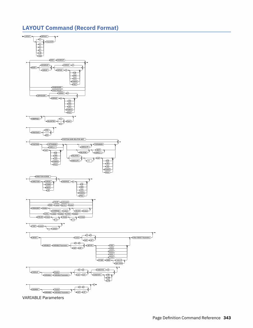
LAYOUT Command (Record Format)LAYOUT DEFAULT
C
X
A
E
U8
U16
'record ID'
BODY NOGROUP
BODY
NOGROUP
GROUP
XSPACE 0
XSPACE n
IN
MM
CM
POINTS
PELS
PAGEHEADER
PAGETRAILER
GRPHEADER
XSPACE 0
XSPACE n
IN
MM
CM
POINTS
PELS
NEWPAGE
DELIMITER
C
X
'bytes'
PRINTDATA
YES
NO
POSITION-SAME-RELATIVE-NEXT
POSITION LEFTMARGIN
SAME or =
horiz
IN
MM
CM
POINTS
PELS
ABSOLUTE
TOPMARGIN
RELATIVE
NEXT
SAME or =
RELATIVE
ABSOLUTE (–)
vert
IN
MM
CM
POINTS
PELS
DIRECTION ACROSS
DIRECTION ACROSS
DOWN
BACK
UP
ENDSPACE n
IN
MM
CM
POINTS
PELS
COLOR colorname
RGB rvalue gvalue bvalue
HIGHLIGHT hvalue
COVERAGE cvalue BLACK bvalue
CMYK cvalue mvalue yvalue kvalue
CIELAB lvalue
(–)
clvalue
(–)
c2value
FONT name1
, name2
OBJECT lname
0 0
relX relY
VARIABLE VARIABLE Parameters
0 0
relX relY
OBTYPE PSEG
IOCA
BCOCA
GOCA
PTOCA
OTHER OBID comp-id
type-name
Other OBJECT Parameters
OVERLAY Xname
VARIABLE VARIABLE Parameters
0 0
relX relY
OVROTATE 0
OVROTATE 90
180
270
SEGMENT Xname
VARIABLE VARIABLE Parameters
0 0
relX relY
;
VARIABLE Parameters
Page Definition Command Reference 343
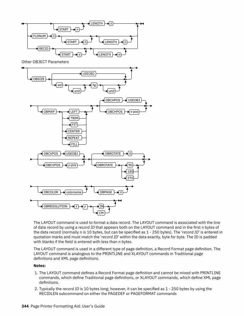
START n
LENGTH n
FLDNUM n
START n LENGTH n
RECID
START n LENGTH n
Other OBJECT Parameters
OBSIZE
USEOBJ
wd
unit
hg
unit
OBMAP LEFT
TRIM
FIT
CENTER
REPEAT
FILL
OBCHPOS USEOBJ
OBCHPOS x-pos
OBCVPOS USEOBJ
OBCVPOS y-pos
OBROTATE 0
OBROTATE 90
180
270
OBCOLOR colorname OBPAGE n
OBRESOLUTION x y IN
CM
The LAYOUT command is used to format a data record. The LAYOUT command is associated with the lineof data record by using a record ID that appears both on the LAYOUT command and in the first n bytes ofthe data record (normally n is 10 bytes, but can be specified as 1 - 250 bytes). The 'record ID' is entered inquotation marks and must match the 'record ID' within the data exactly, byte for byte. The ID is paddedwith blanks if the field is entered with less than n bytes.
The LAYOUT command is used in a different type of page definition, a Record Format page definition. TheLAYOUT command is analogous to the PRINTLINE and XLAYOUT commands in Traditional pagedefinitions and XML page definitions.
Notes:
1. The LAYOUT command defines a Record Format page definition and cannot be mixed with PRINTLINEcommands, which define Traditional page definitions, or XLAYOUT commands, which define XML pagedefinitions.
2. Typically the record ID is 10 bytes long; however, it can be specified as 1 - 250 bytes by using theRECIDLEN subcommand on either the PAGEDEF or PAGEFORMAT commands
344 Page Printer Formatting Aid: User's Guide

SubcommandsDEFAULT
DEFAULT
C
X
A
E
U8
U16
'record ID'
This 'record ID' is used only when the layout type is either PAGEHEADER or PAGETRAILER and noname is needed.
'record ID'The 'record ID' is a quoted name up to 250 characters long that is accepted as is with no casefolding or translation.
C'record ID'The C'record ID' is a quoted name with a C for Character that is treated the same as a quotedname up to 250 characters. No folding or translation is done.
A'record ID'The A'record ID' is a quoted name with an A for ASCII entered with up to 250 single-bytecharacters that are accepted as-is if on an ASCII operating system or translated to ASCII if on anEBCDIC operating system. The translation is made with no case folding.
E'record ID'The E'record ID' is a quoted name with an E for EBCDIC entered with up to 250 single-bytecharacters that are accepted as-is if on an EBCDIC operating system or translated to EBCDIC if onan ASCII operating system. The translation is made with no case folding.
X'hhhh'The X'hhhh' is a quoted name with an X for Hexadecimal entered with up to 500 hexadecimalcharacters. The characters are translated to hexadecimal, but no assumption of data type is made.
Note: All X'00' and X'FF' values are considered reserved and must not be used to specify thehexadecimal name value.
U8'record ID'The U8'record ID' is a quoted name with a U8 for UTF-8 entered with up to 250 single-bytecharacters that are translated to UTF-8.
U16'record ID'The U16'record ID' is a quoted name with a U16 for UTF-16 entered with up to 125 single-bytecharacters that are translated to UTF-16.
Page Definition Command Reference 345

BODY
BODY NOGROUP
BODY
NOGROUP
GROUP
XSPACE 0
XSPACE n
IN
MM
CM
POINTS
PELS
PAGEHEADER
PAGETRAILER
GRPHEADER
XSPACE 0
XSPACE n
IN
MM
CM
POINTS
PELS
The BODY layout type is used for most of data in the user's database, normally printed line by line.This is the default.
GROUPThe GROUP parameter indicates that the existing group header must be saved and used forsubsequent pages. If this parameter is not set when processing starts on a BODY layout, theactive group header record is discarded and not reprinted on subsequent pages.
PAGEHEADERThis layout type specifies a header that is to be printed on each new page. The baseline position ofthis layout is normally in the top margin, but can be anywhere on a logical page. If RELATIVE isspecified, the position is considered to be relative to the page origin. Usually contains customer'sname, address, account number, and so forth. Only one default PAGEHEADER layout can bespecified in a PAGEFORMAT and no input record data can be specified in a default layout.
GRPHEADERThis layout type specifies a header that is to be printed at the beginning of a group of data. If alogical page eject occurs before the group of data ends, the header is printed after the top marginon each new page until the group ends. The baseline position of this layout can be specified asRELATIVE. It can include column headings.XSPACE
XSPACE indicates the amount of extra space from the position of the layout to the bottom ofthe group header area. This allows the user to identify the amount of extra space in excess ofone text line that is used by the header so that the baseline moves down and the followinggroup data is not placed on top of the header area. This space is not calculated by PPFA andmust be explicitly defined by the user. See Figure 133 on page 347 (shaded space showsgroup header area):
346 Page Printer Formatting Aid: User's Guide

Figure 133: Example Showing the Use of XSPACE.
When a Group Header record is processed and is still active when it leaves the PAGEFORMAT, thegroup header record is saved by the presentation services program. Whenever the samePAGEFORMAT is reinvoked, the saved group header record is presented again if the first bodyrecord after reinvoking the PAGEFORMAT selects a Body record that has the Group Indicator on.
PAGETRAILERThis layout type specifies a trailer that is to be printed on each new page. The baseline position ofthis layout is normally in the bottom margin, but can be located anywhere on a logical page andcan be specified as RELATIVE. Only one default PAGETRAILER layout can be specified in aPAGEFORMAT and no input record data is processed with a default layout. It can contain the nameof the form or a footnote.
NEWPAGE
NEWPAGE
This parameter indicates that a new page must be started with this layout name. If it is a header ortrailer layout, the print position is moved to the start of a new page before this header or trailerbecomes the active header or trailer.
DELIMITER
DELIMITER
C
X
'bytes'
The delimiter is a one or two-byte code that is specified in either character or hex indicates adelimiting character within the customer's database and is used to separate fields. PPFA translatesthe character data to the data type specified by the UDType subcommand on the PAGEDEF command.Hex characters must be entered in uppercase within the quotation marks and are not translated.
Notes:
1. Delimiters that are specified after the Record ID are ignored.2. You cannot mix delimited and non-delimited fields on the same LAYOUT command.3. A single-byte delimiter character is ignored when EBCDIC double byte text (SOSI) is processed.
PRINTDATA
PRINTDATA
YES
NO
Specifies whether the line of data that is associated with the current LAYOUT must be printed. ThePRINTDATA subcommand is useful when the data stream is interspersed with lines of comments,blank lines, or lines without data that is not meant to be printed.
Page Definition Command Reference 347

YESSpecifies that the data for the current LAYOUT is printed. YES is the default.
NOSpecifies that the data for the current LAYOUT is not printed.
POSITION
POSITION-SAME-RELATIVE-NEXT
POSITION LEFTMARGIN
SAME or =
horiz
IN
MM
CM
POINTS
PELS
ABSOLUTE
TOPMARGIN
RELATIVE
NEXT
SAME or =
RELATIVE
ABSOLUTE (–)
vert
IN
MM
CM
POINTS
PELS
Used in positioning FIELD, DRAWGRAPHIC, and ENDGRAPHIC text and graphics. If RELATIVE isspecified or POSITION is not specified, the baseline of the POSITION is relative to the previousLAYOUT position.
1. For PAGEHEADER RCD: The baseline position can be anywhere on a logical page, but cannot bespecified as Relative.
2. For PAGETRAILER, GROUPHEADER and BODY RCDs: The baseline position can be anywhere on alogical page and can be specified as RELATIVE.
Specifies the starting position of the layout in the printout.
horizontal positionx-pos
Specifies the horizontal offset from the left side of the logical page. The value is a number withup to three decimal places. The valid options for x-pos are described in the SETUNITScommand for the horizontal value.
LEFTMARGINSpecifies that this line starts at the position that is specified as the horizontal (x) value in theprevious LEFTMARGIN subcommand within the page definition.
SAMESpecifies this line starts at the same horizontal offset position as the previously codedLAYOUT. If applied to the first LAYOUT of a logical page, the horizontal position is 0, which isthe default.
=Alternative for SAME.
RELATIVESpecifies that the following vertical position value is to be processed as a relative value. TheLAYOUT is positioned relative to the last LAYOUT placed on the page.
Notes:
1. If both TOP and RELATIVE are requested for the y-pos value, the RELATIVE request is ignored.2. When PPFA uses RELATIVE positioning, it does not flag off-the-page conditions for the position
of a LAYOUT or for any overlays, segments, or objects placed relative to that LAYOUT. LAYOUTsthat fall outside the bounds of the logical page are flagged by the print server at run time.
348 Page Printer Formatting Aid: User's Guide

3. When you are specifying RELATIVE, use the minus sign to indicate any negative values for theLAYOUT vertical position; you can use the plus sign to indicate positive values. If no sign isused, a positive value is assumed.
4. The DIRECTION for a relative LAYOUT must be ACROSS. Fields that are associated with arelative LAYOUT must have the same DIRECTION as the LAYOUT and must match thePAGEFORMAT DIRECTION.
5. If RELATIVE is specified with SAME or = as the y-pos value, the relative value in the LAYOUT is+0.
6. RELATIVE positioning is allowed on a LAYOUT command only if the LAYOUT and all itsassociated FIELD commands are formatted to print in the same direction as the PAGEFORMAT.That is, the DIRECTION parameter in the LAYOUT and any associated FIELD commands mustspecify (or default to) ACROSS. The DIRECTION in the PAGEFORMAT or PAGEDEF command isany allowable value: ACROSS, DOWN, BACK, or UP.
vertical positiony-pos
Specifies the vertical offset from the top side of the logical page. The value options for y-posare described in the SETUNITS command for the vertical value.
TOPMARGINSpecifies that the LAYOUT is placed in the position that is specified as the vertical (y) value inthe TOPMARGIN subcommand within the page definition.
NEXTSpecifies the layout is to be positioned down (on the logical page) one line (as defined in theLINESP subcommand of the last SETUNITS command) from the previews LAYOUT. The LINESPsubcommand of the SETUNITS command establishes the distance from one line to the next.
When NEXT is specified for the first LAYOUT of a logical page, the starting position of the line isone line down from the top of the logical page, as defined by the TOPMARGIN subcommand.
Note: The down direction is determined by the direction of the logical page (as specified in thepage format), not the LAYOUT direction. Therefore, NEXT is mainly useful in ACROSS LAYOUTs.
SAMESpecifies this LAYOUT starts at the same vertical position as the previous LAYOUT.
=Alternative for SAME.
DIRECTION
DIRECTION ACROSS
DIRECTION ACROSS
DOWN
BACK
UP
Specifies the print direction of the line relative to the upper-left corner as you view the logical page.Not all printers can print in all print directions. For more information about your printer, see yourprinter documentation.
If DIRECTION is not specified, the direction that is specified in the PAGEFORMAT command is used.Observe that this direction is additive to the direction specified in the PAGEFORMAT command. See“PAGEFORMAT Command ” on page 392.ACROSS
The layout direction is rotated 0 degrees relative to the direction specified in the PAGEFORMAT(the layouts are oriented in the same direction as the page).
Page Definition Command Reference 349

DOWNThe layout direction is rotated 90 degrees relative to the direction specified in the PAGEFORMAT.
BACKThe layout direction is rotated 180 degrees relative to the direction specified in the PAGEFORMAT.
UPThe layout direction is rotated 270 degrees relative to the direction specified in the PAGEFORMAT.
ENDSPACE
ENDSPACE n
IN
MM
CM
POINTS
PELS
If the remaining body space is less than the value specified, ENDSPACE causes a logical page eject tobe done. This can be used, for example, on a GRPHEADER layout to ensure that a group header doesnot print at the end of a page without the first data record of the group. ENDSPACE does not includethe space within the bottom margin (specified on the PAGEDEF or PAGEFORMAT command). Thisindicator is ignored on a PAGEHEADER or PAGETRAILER layout.
COLOR
COLOR colorname
RGB rvalue gvalue bvalue
HIGHLIGHT hvalue
COVERAGE cvalue BLACK bvalue
CMYK cvalue mvalue yvalue kvalue
CIELAB lvalue
(–)
clvalue
(–)
c2value
Specifies an OCA or defined color for the text of this field. This subcommand is recognized only byprinters that support multiple-color printing. See your printer publication for information about thecolors that can printed.
colornameValues for colorname can be a defined color (see “DEFINE COLOR Command” on page 258), or anOCA colorname. Values for OCA colornames are:
NONEDEFAULTBLACKBLUEBROWNGREENREDPINK (or MAGENTA)TURQ (or CYAN)YELLOWDARKBLUE (or DBLUE)
350 Page Printer Formatting Aid: User's Guide

ORANGEPURPLEMUSTARDGRAYDARKGREEN (or DGREEN)DARKTURQ (DTURQ, or DCYAN, or DARKCYAN)
The color choices depend on the printer.
If you do not enter one of these colors, the default color for that printer is used. NONE is the colorof the medium; DEFAULT is the printer default color.
Note: In some printer manuals, the color turquoise (TURQ) is called cyan, and the color pink(PINK) is called magenta.
PPFA supports the following synonyms:
• CYAN for TURQ• DARKCYAN for DARKTURQ• DBLUE for DARKBLUE• DCYAN for DARKTURQ• DGREEN for DARKGREEN• DTURQ for DARKTURQ• MAGENTA for PINK
color modelsSpecifies the color of print for this field that is supported in MO:DCA for the Red/Green/Blue colormodel (RGB), the highlight color space, the Cyan/Magenta/Yellow/Black color model (CMYK), andthe CIELAB color model.RGB rvalue gvalue bvalue
Three RGB integer values are used. The first (rvalue) represents a value for red, the second(gvalue) represents a value for green, and the third (bvalue) represents a value for blue. Eachof the three integer values can be specified as a percentage 0 - 100.
Note: An RGB specification of 0/0/0 is black. An RGB specification of 100/100/100 is white.Any other value is a color somewhere between black and white, depending on the outputdevice.
HIGHLIGHT hvalue COVERAGE cvalue BLACK bvalueIndicates the highlight color model. Highlight colors are device-dependent.
You can use an integer within the range of 0 - 65535 for the hvalue.
Note: An hvalue of 0 indicates that no default value is defined; therefore, the default color ofthe presentation device is used.
COVERAGE indicates the amount of coverage of the highlight color to be used. You can use aninteger within the range of 0 - 100 for the cvalue. If less than 100 percent is specified, theremaining coverage is achieved with the color of the medium.
Note: Fractional values are ignored. If COVERAGE is not specified, a value of 100 is used as adefault.
BLACK indicates the percentage of black to be added to the highlight color. You can use aninteger within the range of 0 - 100 for the bvalue. The amount of black shading that is applieddepends on the COVERAGE percentage, which is applied first. If less than 100 percent isspecified, the remaining coverage is achieved with black.
Note: If BLACK is not specified, a value of 0 is used as a default.
Page Definition Command Reference 351
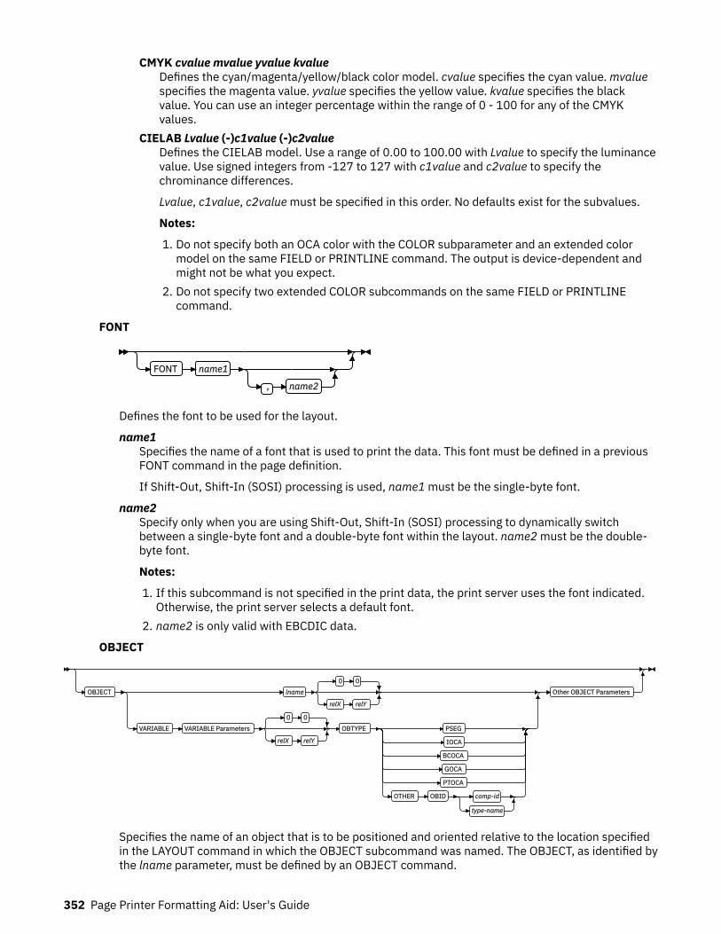
CMYK cvalue mvalue yvalue kvalueDefines the cyan/magenta/yellow/black color model. cvalue specifies the cyan value. mvaluespecifies the magenta value. yvalue specifies the yellow value. kvalue specifies the blackvalue. You can use an integer percentage within the range of 0 - 100 for any of the CMYKvalues.
CIELAB Lvalue (-)c1value (-)c2valueDefines the CIELAB model. Use a range of 0.00 to 100.00 with Lvalue to specify the luminancevalue. Use signed integers from -127 to 127 with c1value and c2value to specify thechrominance differences.
Lvalue, c1value, c2value must be specified in this order. No defaults exist for the subvalues.
Notes:
1. Do not specify both an OCA color with the COLOR subparameter and an extended colormodel on the same FIELD or PRINTLINE command. The output is device-dependent andmight not be what you expect.
2. Do not specify two extended COLOR subcommands on the same FIELD or PRINTLINEcommand.
FONT
FONT name1
, name2
Defines the font to be used for the layout.
name1Specifies the name of a font that is used to print the data. This font must be defined in a previousFONT command in the page definition.
If Shift-Out, Shift-In (SOSI) processing is used, name1 must be the single-byte font.
name2Specify only when you are using Shift-Out, Shift-In (SOSI) processing to dynamically switchbetween a single-byte font and a double-byte font within the layout. name2 must be the double-byte font.
Notes:
1. If this subcommand is not specified in the print data, the print server uses the font indicated.Otherwise, the print server selects a default font.
2. name2 is only valid with EBCDIC data.
OBJECT
OBJECT lname
0 0
relX relY
VARIABLE VARIABLE Parameters
0 0
relX relY
OBTYPE PSEG
IOCA
BCOCA
GOCA
PTOCA
OTHER OBID comp-id
type-name
Other OBJECT Parameters
Specifies the name of an object that is to be positioned and oriented relative to the location specifiedin the LAYOUT command in which the OBJECT subcommand was named. The OBJECT, as identified bythe lname parameter, must be defined by an OBJECT command.
352 Page Printer Formatting Aid: User's Guide

Note: Multiple page/image objects that are used without specifying a page with OBPAGE default tousing the first page in the object.
You can place multiple objects on the same LAYOUT command and you can place the same objectmultiple times. Each placement must have its own set of placement parameters, as follows:
lnameSpecifies the local name of an object that is up to 16 alphanumeric characters in length. Thelname is used to match the LAYOUT OBJECT subcommand to its definition from the OBJECTcommand. An object must be defined with this local name by the OBJECT command.
relX relYSpecifies the number of units (such as inches or mm) that are added to the position of the currentLAYOUT to position the top-left corner of the object. The values for the horizontal and verticalpositioning are limited by the type of printer that is used and the L-units that are specified with thePELSPERINCH parameter on the PAGEDEF or PAGEFORMAT command.
Each position specification can be a positive or negative number with up to three decimal places.The units that are specified can be one of these: IN, MM, CM, POINTS, or PELS.
VARIABLE
VARIABLE
VARIABLE Parameters
0 0
relX relY
OBTYPE
PSEG
IOCA
BCOCA
GOCA
PTOCA
OTHER OBID comp-id
type-name
Indicates that the actual name of the object is read from the data record. The Variable-Name-Locator field specifies where in the data to get the name.
Notes:
1. Any object that is to be included in this manner must be defined in the PAGEDEF by using theOBJECT command. Defining objects enhances performance.
2. If you specify VARIABLE for the OBJECT name and don't want to print the name, then you musthave at least one field command, or code PRINTDATA NO on the LAYOUT command.
VARIABLE Parameters
START n
LENGTH n
FLDNUM n
START n LENGTH n
RECID
START n LENGTH n
START nThe starting position in the data record to get the overlay name. The first data byte positionof the input record is 1. If START is not coded, 1 is assumed.
Page Definition Command Reference 353

LENGTH nLength of field. Specifies the number (n) of bytes to process from the data record,beginning with the position specified in START. The maximum length is 8.
FLDNUM n START n LENGTH nThe field number. This is the same as in the FIELD command. The overlay name is takenfrom the n field of the input data record. START n and LENGTH n describe which portion ofthe n field is used. If omitted, the entire field is used to form the overlay name.
RECIDGets the name from the record ID. This is the same as in the FIELD command. Use STARTn and LENGTH n to use only a portion of the record ID, or leave them out to use the entirerecord field.
OBTYPE
VARIABLE OBTYPE PSEG
IOCA
BCOCA
GOCA
PTOCA
OTHER OBID comp-id
type-name
Used to specify the type of the object. Observe that each of the object types restricts the typeof mapping option that is allowed in the placement of the object (OBMAP on the OBJECTsubcommand on the PRINTLINE command).
PSEGSpecifies a page segment object, as described in the Mixed Object Document ContentArchitecture Reference. All mapping types (OBMAP) are allowed by PPFA; however, theprint server issues an error if any of the objects that are contained in the page segment arenot compatible with the coded OBMAP parameter.
GOCASpecifies a graphic object, as described in the Graphics Object Content ArchitectureReference. You use GOCA to specify TRIM, FIT, CENTER, REPEAT, and FILL parameters onthe OBMAP subcommand.
BCOCASpecifies a bar code object, as described in the Bar Code Object Content ArchitectureReference. You use BCOCA to specify only the LEFT parameter on the OBMAPsubcommand.
IOCASpecifies an image object, as described in the Image Object Content ArchitectureReference. You use IOCA to specify TRIM, FIT, CENTER, REPEAT, and FILL parameters onthe OBMAP subcommand.
PTOCASpecifies a presentation text object with Object Environment Group (OEG) as described inthe Presentation Text Object Content Architecture Reference and the Mixed Object DocumentContent Architecture Reference. You use the PTOCA object type to specify the LEFTparameter in the OBMAP subcommand.
OTHERSpecifies other object data. The object data to be included is a paginated presentationobject with a format that might or might not be defined by an AFP architecture. When youspecify OTHER, you must also specify the OBID parameter. You use OTHER to specifyTRIM, FIT, CENTER, REPEAT, and FILL parameters on the OBMAP subcommand.
354 Page Printer Formatting Aid: User's Guide
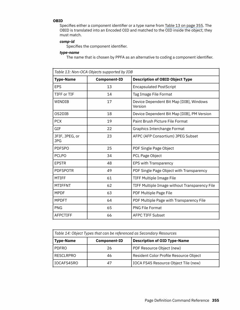
OBIDSpecifies either a component identifier or a type name from Table 13 on page 355. TheOBID is translated into an Encoded OID and matched to the OID inside the object; theymust match.comp-id
Specifies the component identifier.type-name
The name that is chosen by PPFA as an alternative to coding a component identifier.
Table 13: Non-OCA Objects supported by IOB
Type-Name Component-ID Description of OBID Object Type
EPS 13 Encapsulated PostScript
TIFF or TIF 14 Tag Image File Format
WINDIB 17 Device Dependent Bit Map [DIB], WindowsVersion
OS2DIB 18 Device Dependent Bit Map [DIB], PM Version
PCX 19 Paint Brush Picture File Format
GIF 22 Graphics Interchange Format
JFIF, JPEG, orJPG
23 AFPC (AFP Consortium) JPEG Subset
PDFSPO 25 PDF Single Page Object
PCLPO 34 PCL Page Object
EPSTR 48 EPS with Transparency
PDFSPOTR 49 PDF Single Page Object with Transparency
MTIFF 61 TIFF Multiple Image File
MTIFFNT 62 TIFF Multiple Image without Transparency File
MPDF 63 PDF Multiple Page File
MPDFT 64 PDF Multiple Page with Transparency File
PNG 65 PNG File Format
AFPCTIFF 66 AFPC TIFF Subset
Table 14: Object Types that can be referenced as Secondary Resources
Type-Name Component-ID Description of OID Type-Name
PDFRO 26 PDF Resource Object (new)
RESCLRPRO 46 Resident Color Profile Resource Object
IOCAFS45RO 47 IOCA FS45 Resource Object Tile (new)
Page Definition Command Reference 355

Other OBJECT parameters
OBSIZE
USEOBJ
wd
unit
hg
unit
OBMAP LEFT
TRIM
FIT
CENTER
REPEAT
FILL
OBCHPOS USEOBJ
OBCHPOS x-pos
OBCVPOS USEOBJ
OBCVPOS y-pos
OBROTATE 0
OBROTATE 90
180
270
OBCOLOR colorname OBPAGE n
OBRESOLUTION x y IN
CM
OBSIZE
OBJECT
OBSIZE
USEOBJ
wd
unit
hg
unit
Specifies the size of the object placement area. When no OBSIZE is specified, the default isthe size that is specified in the object. If no size is specified in the object, the size of the pageis used. The page width is as specified on the PAGEDEF or PAGEFORMAT commands, or itdefaults to 8.3 inches by 10.8 inches.
wdSpecifies the width of an object placement area as a number with up to three decimalplaces. The allowable width might vary with the type of printer that is used and the L-unitsthat are specified with the PELSPERINCH parameter on the PAGEDEF or PAGEFORMATcommand.
hgSpecifies the height of the object placement area as a number with up to three decimalplaces. The allowable height might vary with the type of printer that is used and the L-units
356 Page Printer Formatting Aid: User's Guide
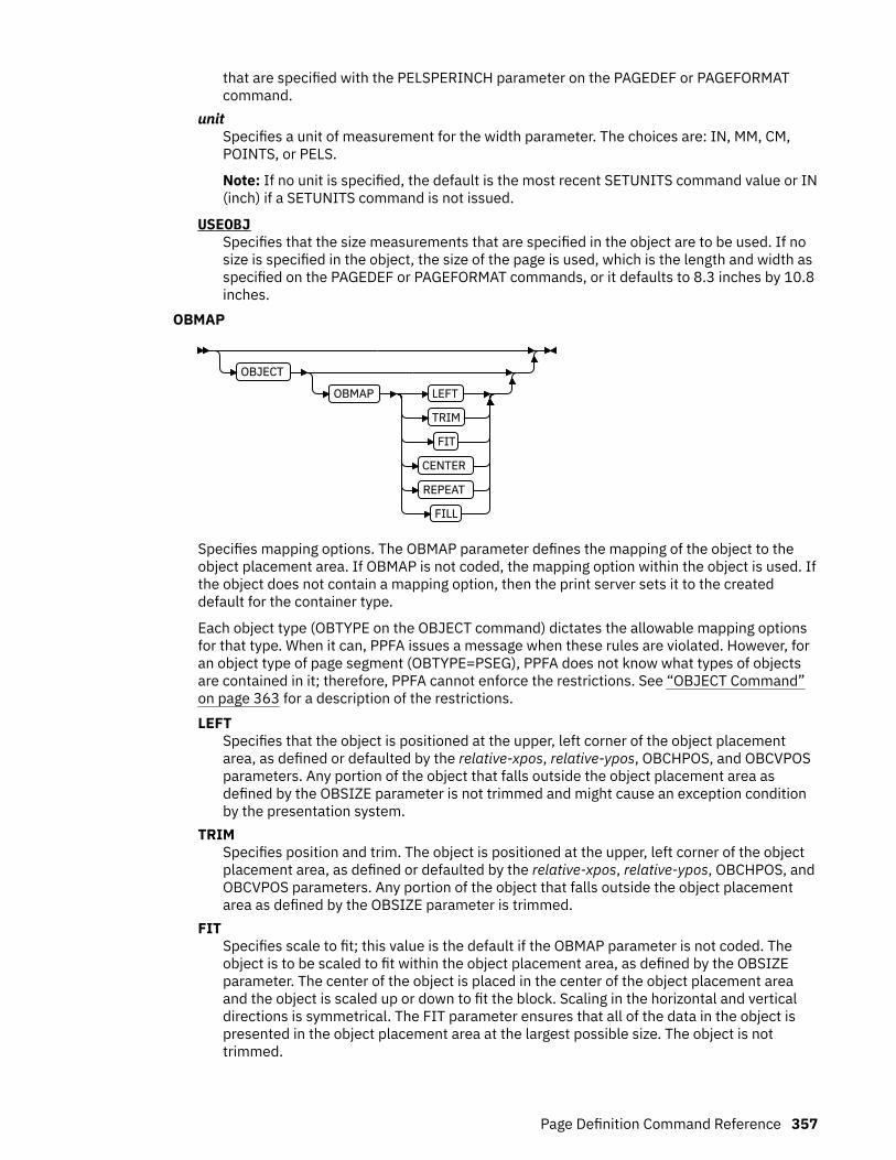
that are specified with the PELSPERINCH parameter on the PAGEDEF or PAGEFORMATcommand.
unitSpecifies a unit of measurement for the width parameter. The choices are: IN, MM, CM,POINTS, or PELS.
Note: If no unit is specified, the default is the most recent SETUNITS command value or IN(inch) if a SETUNITS command is not issued.
USEOBJSpecifies that the size measurements that are specified in the object are to be used. If nosize is specified in the object, the size of the page is used, which is the length and width asspecified on the PAGEDEF or PAGEFORMAT commands, or it defaults to 8.3 inches by 10.8inches.
OBMAP
OBJECT
OBMAP LEFT
TRIM
FIT
CENTER
REPEAT
FILL
Specifies mapping options. The OBMAP parameter defines the mapping of the object to theobject placement area. If OBMAP is not coded, the mapping option within the object is used. Ifthe object does not contain a mapping option, then the print server sets it to the createddefault for the container type.
Each object type (OBTYPE on the OBJECT command) dictates the allowable mapping optionsfor that type. When it can, PPFA issues a message when these rules are violated. However, foran object type of page segment (OBTYPE=PSEG), PPFA does not know what types of objectsare contained in it; therefore, PPFA cannot enforce the restrictions. See “OBJECT Command”on page 363 for a description of the restrictions.LEFT
Specifies that the object is positioned at the upper, left corner of the object placementarea, as defined or defaulted by the relative-xpos, relative-ypos, OBCHPOS, and OBCVPOSparameters. Any portion of the object that falls outside the object placement area asdefined by the OBSIZE parameter is not trimmed and might cause an exception conditionby the presentation system.
TRIMSpecifies position and trim. The object is positioned at the upper, left corner of the objectplacement area, as defined or defaulted by the relative-xpos, relative-ypos, OBCHPOS, andOBCVPOS parameters. Any portion of the object that falls outside the object placementarea as defined by the OBSIZE parameter is trimmed.
FITSpecifies scale to fit; this value is the default if the OBMAP parameter is not coded. Theobject is to be scaled to fit within the object placement area, as defined by the OBSIZEparameter. The center of the object is placed in the center of the object placement areaand the object is scaled up or down to fit the block. Scaling in the horizontal and verticaldirections is symmetrical. The FIT parameter ensures that all of the data in the object ispresented in the object placement area at the largest possible size. The object is nottrimmed.
Page Definition Command Reference 357

CENTERSpecifies that the center of the object is positioned at the center of the object placementarea. Any portion of the object that falls outside the object placement area is trimmed.
REPEATSpecifies that the origin of the data object is positioned with the origin of the objectplacement area. The object is then replicated in the X and Y directions. If the lastreplicated data does not fit in the object area, it is trimmed to fit.
FILLSpecifies that the center of the data object is positioned coincident with the center of theobject placement area. The data object is then scaled so that it totally fills the objectplacement area in both the X and Y directions. This might require that the object isasymmetrically scaled by different scale factors in the X and Y directions.
OBCHPOS
OBJECT
OBCHPOS USEOBJ
OBCHPOS x-pos
Specifies the horizontal offset of the object contents within the object placement area as anumber.
x-posSpecifies a positive or negative number. The valid options for x-pos are described in theSETUNITS command for the horizontal value.
USEOBJSpecifies that the offset value from the object is to be used. If no value is set in the object,the value defaults to 0.
OBCVPOS
OBJECT
OBCVPOS USEOBJ
OBCVPOS y-pos
Specifies the vertical offset of the object contents within the object placement area, as definedby the OBSIZE parameter. If OBCVPOS is not specified, it defaults to USEOBJ and uses thevalue set in the object. If no value is set in the object, the value defaults to 0. The OBCHPOSparameter is used only in LEFT and TRIM mapping of the object into the object placementarea.
y-posSpecifies a positive or negative number. The valid options for y-pos are described in theSETUNITS command for the vertical value.
USEOBJSpecifies that the offset value from the object is to be used. If no value is set in the object,the value defaults to 0.
358 Page Printer Formatting Aid: User's Guide

OBROTATE {0|90|180|270}
OBJECT
OBROTATE 0
OBROTATE 90
180
270
Specifies the object rotation in regard to the current LND's coordinate system.
OBCOLOR
OBJECT
OBCOLOR colorname
Specifies the color to be used as the default color or initial color for the object placement area.The OBCOLOR parameter is used only for objects of the PSEG, GOCA, BCOCA, and IOCA type.If the object type is OTHER, this parameter is ignored.
colornameValues for colorname can be a defined color (see “DEFINE COLOR Command” on page258) or one of these OCA color spaces:
NONEDEFAULTBLACKBLUEBROWNGREENREDPINK (or MAGENTA)TURQ (or CYAN)YELLOWDARKBLUE (or DBLUE)ORANGEPURPLEMUSTARDGRAYDARKGREEN (or DGREEN)DARKTURQ (DTURQ, or DCYAN, or DARKCYAN)
In the following example, the page definition pd1 defines an object with an external nameof PSEGxyz, of object type PSEG. The object has an internal name of xyzintname. Theinternal name identifies the object for the LAYOUT OBJECT subcommand when the objectis placed. Observe that case is not significant on either the internal nor the externalnames.
PAGEDEF pd1 Replace Yes COMMENT 'this is my program'; FONT XF1 ;
OBJECT xyzIntName OBXNAME PSEGxyz OBTYPE PSEG ;
PAGEFORMAT pf1; LAYOUT 'abc' POSITION 2 in 1 in; OBJECT xyzintname 1.1 in 2.1 in
Page Definition Command Reference 359
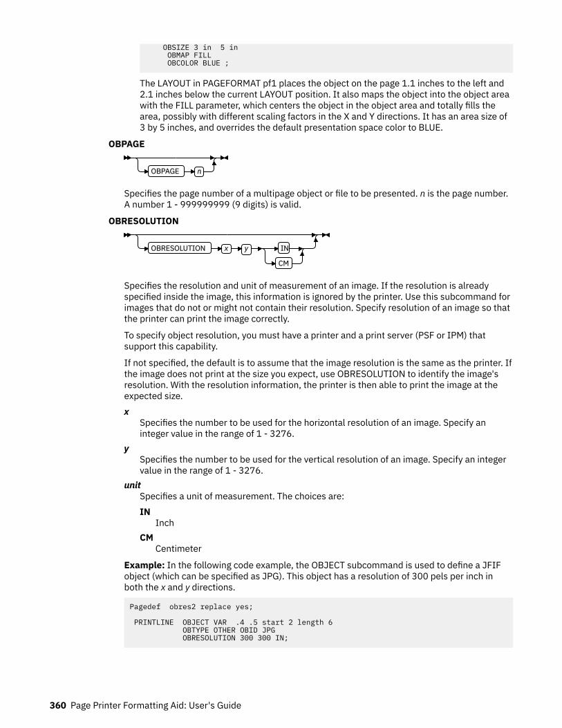
OBSIZE 3 in 5 in OBMAP FILL OBCOLOR BLUE ;
The LAYOUT in PAGEFORMAT pf1 places the object on the page 1.1 inches to the left and2.1 inches below the current LAYOUT position. It also maps the object into the object areawith the FILL parameter, which centers the object in the object area and totally fills thearea, possibly with different scaling factors in the X and Y directions. It has an area size of3 by 5 inches, and overrides the default presentation space color to BLUE.
OBPAGE
OBPAGE n
Specifies the page number of a multipage object or file to be presented. n is the page number.A number 1 - 999999999 (9 digits) is valid.
OBRESOLUTION
OBRESOLUTION x y IN
CM
Specifies the resolution and unit of measurement of an image. If the resolution is alreadyspecified inside the image, this information is ignored by the printer. Use this subcommand forimages that do not or might not contain their resolution. Specify resolution of an image so thatthe printer can print the image correctly.
To specify object resolution, you must have a printer and a print server (PSF or IPM) thatsupport this capability.
If not specified, the default is to assume that the image resolution is the same as the printer. Ifthe image does not print at the size you expect, use OBRESOLUTION to identify the image'sresolution. With the resolution information, the printer is then able to print the image at theexpected size.x
Specifies the number to be used for the horizontal resolution of an image. Specify aninteger value in the range of 1 - 3276.
ySpecifies the number to be used for the vertical resolution of an image. Specify an integervalue in the range of 1 - 3276.
unitSpecifies a unit of measurement. The choices are:IN
InchCM
Centimeter
Example: In the following code example, the OBJECT subcommand is used to define a JFIFobject (which can be specified as JPG). This object has a resolution of 300 pels per inch inboth the x and y directions.
Pagedef obres2 replace yes; PRINTLINE OBJECT VAR .4 .5 start 2 length 6 OBTYPE OTHER OBID JPG OBRESOLUTION 300 300 IN;
360 Page Printer Formatting Aid: User's Guide

OVERLAY
OVERLAY Xname
VARIABLE
VARIABLE Parameters
0 0
relX relY
OVROTATE 0
OVROTATE 90
180
270
Specifies the name of an overlay that is to be positioned relative to the location specified in theLAYOUT command in which the OVERLAY subcommand was named. The PAGEFORMAT OVERLAYcommand can contain the named overlays. The maximum number of overlays that are specified for aPAGEFORMAT including the LAYOUT OVERLAY subcommand is 254.
Specifies the electronic overlay that is to be used with this subgroup.Xname
Specifies the user-access name as defined in the OVERLAY command.
Notes:
1. PPFA checks for duplication of local names. If a duplication exists, the page definition isgenerated, but a warning message is issued.
2. PPFA does not check for duplicate user-access names.
relX relYSpecifies the number of units (such as inches or mm) that are added to the position of the layoutto position the top-left corner of the overlay. The values for horizontal and vertical can be (+) or (-).The maximum value is + or - 32760 L-units. For example:
• OVERLAY NAME1 2 in 1 in• OVERLAY NAME2 5 mm 1 mm
Note: Any offset coded in the overlay itself is added to this offset.
VARIABLEIndicates that the actual name of the overlay, including the O1 prefix, is read from the data record.The Variable-Name-Locator field specifies where in the data to get the name.
Notes:
1. Any overlay that is to be included in this manner must be defined in the PAGEFORMAT by usingthe OVERLAY command. Any overlay that is included but not defined causes a runtime printerror for a missing MPO structured field, for example APS263I.
2. If you specify VARIABLE for the OVERLAY name and don't want to print the name, then youmust have at least one field command, or code PRINTDATA NO on the LAYOUT command.
VARIABLE ParametersSee “VARIABLE Parameters” on page 353 for the syntax. The field number and record ID areonly used for Record Layout and XML Page definitions.
OVROTATE {0|90|180|270}Specifies the rotation of the placed overlay in regard to the x-axis of the page.
See “FORMDEF Command” on page 216 for an OVROTATE example, which is presented in theFORMDEF description.
Page Definition Command Reference 361

SEGMENT
SEGMENT Xname
VARIABLE
VARIABLE Parameters
0 0
relX relY
Specifies the name of a segment that is to be positioned relative to the location specified in theLAYOUT command in which the SEGMENT subcommand was named. The PAGEFORMAT SEGMENTcommand can contain the named segments. The maximum number of segments that are specified fora PAGEFORMAT including the LAYOUT SEGMENT subcommand is 127.
Specifies the page segment that is to be used with this subgroup.Xname
Specifies the user-access name as defined in the SEGMENT command.
Notes:
1. PPFA checks for duplication of local names. If a duplication exists, the page definition isgenerated, but a warning message is issued.
2. PPFA does not check for duplicate user-access names.
relX relYSpecifies the number of units (such as inches or mm) that are added to the position of the layoutto position the top-left corner of the page segment. The values for horizontal and vertical can be(+) or (-). The maximum value is + or - 32760 L-units. For example:
• SEGMENT MYSEG1 2 in 1 in• SEGMENT MYSEG1 5 mm 1 mm
VARIABLEIndicates that the actual name of the segment, including the S1 prefix, is read from the datarecord. The Variable-Name-Locator field specifies where in the data to get the name.
Note: If you specify VARIABLE for the SEGMENT name and don't want to print the name, then youmust have at least one field command, or code PRINTDATA NO on the LAYOUT command.
VARIABLE ParametersSee “VARIABLE Parameters” on page 353 for the syntax. The field number and record ID areonly used for Record Layout and XML Page definitions.
362 Page Printer Formatting Aid: User's Guide
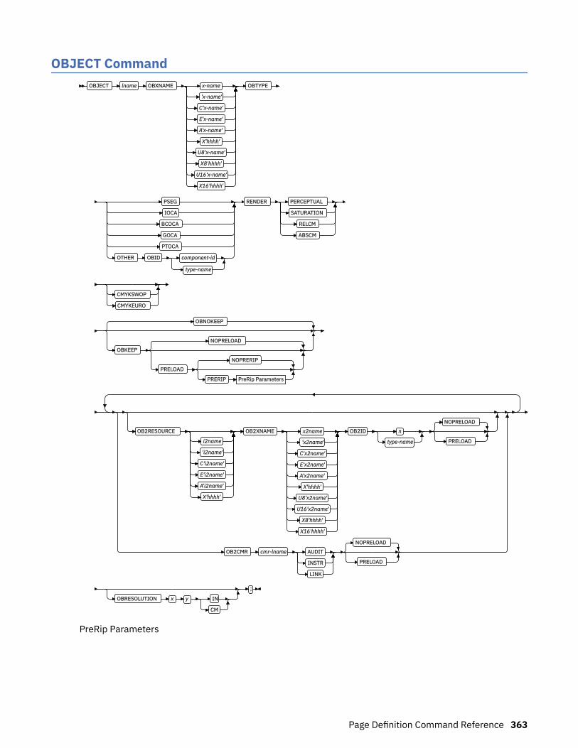
OBJECT CommandOBJECT lname OBXNAME x-name
'x-name'
C'x-name'
E'x-name'
A'x-name'
X'hhhh'
U8'x-name'
X8'hhhh'
U16'x-name'
X16'hhhh'
OBTYPE
PSEG
IOCA
BCOCA
GOCA
PTOCA
OTHER OBID component-id
type-name
RENDER PERCEPTUAL
SATURATION
RELCM
ABSCM
CMYKSWOP
CMYKEURO
OBNOKEEP
OBKEEP
NOPRELOAD
PRELOAD
NOPRERIP
PRERIP PreRip Parameters
OB2RESOURCE
i2name
'i2name'
C'i2name'
E'i2name'
A'i2name'
X'hhhh'
OB2XNAME x2name
'x2name'
C'x2name'
E'x2name'
A'x2name'
X'hhhh'
U8'x2name'
U16'x2name'
X8'hhhh'
X16'hhhh'
OB2ID n
type-name
NOPRELOAD
PRELOAD
OB2CMR cmr-lname AUDIT
INSTR
LINK
NOPRELOAD
PRELOAD
OBRESOLUTION x y IN
CM
;
PreRip Parameters
Page Definition Command Reference 363

RIPSIZE
USEOBJ
wd
unit
hg
unit
RIPMAP LEFT
TRIM
FIT
CENTER
FILL
RIPOFFSET rel x
unit
rel y
unit
RIPROTATE 0
RIPROTATE 0
90
180
270
RIPPAGE n
ALL
You use the OBJECT command to define an external object to PPFA. Then, you can use the PRINTLINEcommand (Traditional) or the LAYOUT command (Record Format and XML) with the OBJECT subcommandto place the defined object on a page.
You can use one PRINTLINE command (Traditional), LAYOUT command (Record Format), or XLAYOUTcommand (XML) to place one or many defined objects multiple times with different placementparameters on each placement. On the PRINTLINE OBJECT subcommand, enter information about thepositioning, rotation, color, object size, page number, and mapping instructions. All positioning is relativeto the print line coordinate system. The lname appears on both the OBJECT command and on thePRINTLINE OBJECT subcommand (Traditional), the LAYOUT OBJECT command (Record Format), and theXLAYOUT OBJECT command (XML), and is used similar to the way overlays and page segments aredefined and placed (or printed).
Notes:
1. The lname is case insensitive but the lname of the OBJECT command and of the PRINTLINE OBJECTsubcommand (Traditional), the LAYOUT OBJECT command (Record Format), and the XLAYOUTOBJECT command (XML) must match exactly.
2. This function requires both the print server and printer support. Check your print server and printerdocumentation.
3. Fonts that are used by the OBJECT must be mapped. You can use the EXTREF command to map a font.4. CMRs used by the OBJECT must be mapped. You can use the EXTREF OB2CMR command to map a
CMR.
OBJECT lnameIdentifies the object and also is used to match a PRINTLINE OBJECT subcommand (Traditional), theLAYOUT OBJECT command (Record Format), and the XLAYOUT OBJECT command (XML). The lnamecan be no more than 16 alphanumeric characters.
364 Page Printer Formatting Aid: User's Guide
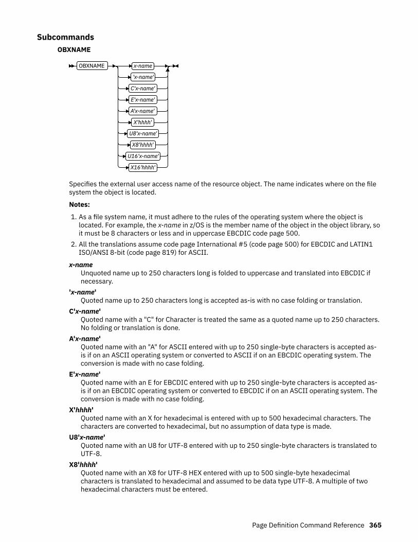
SubcommandsOBXNAME
OBXNAME x-name
'x-name'
C'x-name'
E'x-name'
A'x-name'
X'hhhh'
U8'x-name'
X8'hhhh'
U16'x-name'
X16'hhhh'
Specifies the external user access name of the resource object. The name indicates where on the filesystem the object is located.
Notes:
1. As a file system name, it must adhere to the rules of the operating system where the object islocated. For example, the x-name in z/OS is the member name of the object in the object library, soit must be 8 characters or less and in uppercase EBCDIC code page 500.
2. All the translations assume code page International #5 (code page 500) for EBCDIC and LATIN1ISO/ANSI 8-bit (code page 819) for ASCII.
x-nameUnquoted name up to 250 characters long is folded to uppercase and translated into EBCDIC ifnecessary.
'x-name'Quoted name up to 250 characters long is accepted as-is with no case folding or translation.
C'x-name'Quoted name with a "C" for Character is treated the same as a quoted name up to 250 characters.No folding or translation is done.
A'x-name'Quoted name with an "A" for ASCII entered with up to 250 single-byte characters is accepted as-is if on an ASCII operating system or converted to ASCII if on an EBCDIC operating system. Theconversion is made with no case folding.
E'x-name'Quoted name with an E for EBCDIC entered with up to 250 single-byte characters is accepted as-is if on an EBCDIC operating system or converted to EBCDIC if on an ASCII operating system. Theconversion is made with no case folding.
X'hhhh'Quoted name with an X for hexadecimal is entered with up to 500 hexadecimal characters. Thecharacters are converted to hexadecimal, but no assumption of data type is made.
U8'x-name'Quoted name with an U8 for UTF-8 entered with up to 250 single-byte characters is translated toUTF-8.
X8'hhhh'Quoted name with an X8 for UTF-8 HEX entered with up to 500 single-byte hexadecimalcharacters is translated to hexadecimal and assumed to be data type UTF-8. A multiple of twohexadecimal characters must be entered.
Page Definition Command Reference 365
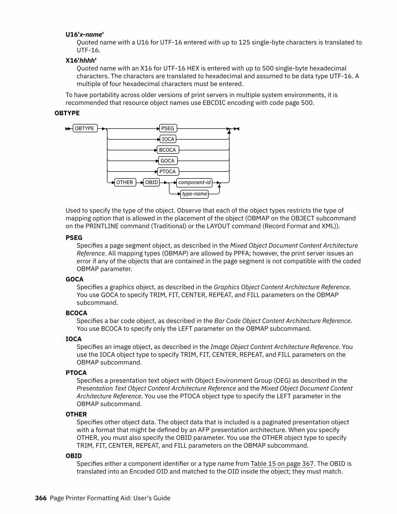
U16'x-name'Quoted name with a U16 for UTF-16 entered with up to 125 single-byte characters is translated toUTF-16.
X16'hhhh'Quoted name with an X16 for UTF-16 HEX is entered with up to 500 single-byte hexadecimalcharacters. The characters are translated to hexadecimal and assumed to be data type UTF-16. Amultiple of four hexadecimal characters must be entered.
To have portability across older versions of print servers in multiple system environments, it isrecommended that resource object names use EBCDIC encoding with code page 500.
OBTYPE
OBTYPE PSEG
IOCA
BCOCA
GOCA
PTOCA
OTHER OBID component-id
type-name
Used to specify the type of the object. Observe that each of the object types restricts the type ofmapping option that is allowed in the placement of the object (OBMAP on the OBJECT subcommandon the PRINTLINE command (Traditional) or the LAYOUT command (Record Format and XML)).
PSEGSpecifies a page segment object, as described in the Mixed Object Document Content ArchitectureReference. All mapping types (OBMAP) are allowed by PPFA; however, the print server issues anerror if any of the objects that are contained in the page segment is not compatible with the codedOBMAP parameter.
GOCASpecifies a graphics object, as described in the Graphics Object Content Architecture Reference.You use GOCA to specify TRIM, FIT, CENTER, REPEAT, and FILL parameters on the OBMAPsubcommand.
BCOCASpecifies a bar code object, as described in the Bar Code Object Content Architecture Reference.You use BCOCA to specify only the LEFT parameter on the OBMAP subcommand.
IOCASpecifies an image object, as described in the Image Object Content Architecture Reference. Youuse the IOCA object type to specify TRIM, FIT, CENTER, REPEAT, and FILL parameters on theOBMAP subcommand.
PTOCASpecifies a presentation text object with Object Environment Group (OEG) as described in thePresentation Text Object Content Architecture Reference and the Mixed Object Document ContentArchitecture Reference. You use the PTOCA object type to specify the LEFT parameter in theOBMAP subcommand.
OTHERSpecifies other object data. The object data that is included is a paginated presentation objectwith a format that might be defined by an AFP presentation architecture. When you specifyOTHER, you must also specify the OBID parameter. You use the OTHER object type to specifyTRIM, FIT, CENTER, REPEAT, and FILL parameters on the OBMAP subcommand.
OBIDSpecifies either a component identifier or a type name from Table 15 on page 367. The OBID istranslated into an Encoded OID and matched to the OID inside the object; they must match.
366 Page Printer Formatting Aid: User's Guide

component-idSpecifies the component identifier.
type-nameType-name is a name that is chosen by PPFA as an alternative to coding a componentidentifier.
Table 15: Non-OCA Objects supported by IOB.
Type-Name Component-ID Description of OBID Object Type
EPS 13 Encapsulated PostScript
TIFF or TIF 14 Tag Image File Format
WINDIB 17 Device Dependent Bit Map [DIB], WindowsVersion
OS2DIB 18 Device Dependent Bit Map [DIB], PM Version
PCX 19 Paintbrush Picture File Format
GIF 22 Graphics Interchange Format
JFIF, JPEG, or JPG 23 AFPC (AFP Consortium) JPEG Subset
PDFSPO 25 PDF Single Page Object
PCLPO 34 PCL Page Object
EPSTR 48 EPS with Transparency
PDFSPOTR 49 PDF Single Page Object with Transparency
MTIFF 61 TIFF Multiple Image File
MTIFFNT 62 TIFF Multiple Image without TransparencyFile
MPDF 63 PDF Multiple Page File
MPDFT 64 PDF Multiple Page with Transparency File
PNG 65 PNG File Format
AFPCTIFF 66 AFPC TIFF subset
Table 16: Object Types that can be referenced as Secondary Resources
Type-Name Component-ID Description of OID Type-Name
PDFRO 26 PDF Resource Object (new)
RESCLRPRO 46 Resident Color Profile Resource Object
IOCAFS45RO 47 IOCA FS45 Resource Object Tile (new)
RENDER
RENDER PERCEPTUAL
SATURATION
RELCM
ABSCM
Page Definition Command Reference 367

Subcommand on the OBJECT command to specify the rendering intent (RI) for an object within a pagedefinition.
RI is used to modify the final appearance of color data and is defined by the International ColorConsortium (ICC). For more information about RI, see the current level of the ICC Specification.
Not all object types have rendering intent; in that case, rendering intent is ignored. The following listshows object types that can be specified as parameters on the OBTYPE subcommand, and theresulting rendering intent object type:
• PSEG - rendering intent that is specified on a PSEG is used for all object types• IOCA - supported• BCOCA - not supported. Rendering intent for BCOCA objects is fixed as media-relative colorimetric
(RELCM).• GOCA - supported• PTOCA - supported• OTHER - supported
rendering intent parameterSpecify the rendering intent for the preceding object type.PERCEPTUAL
Perceptual rendering intent. It can be abbreviated as PERCP. With this rendering intent, gamutmapping is vendor-specific, and colors are adjusted to give a pleasing appearance. This intentis typically used to render continuous-tone images.
SATURATIONSaturation rendering intent. It can be abbreviated as SATUR. With this rendering intent, gamutmapping is vendor-specific, and colors are adjusted to emphasize saturation. This intentresults in vivid colors and is typically used for business graphics.
RELCMMedia-relative colorimetric rendering intent. In-gamut colors are rendered accurately, andout-of-gamut colors are mapped to the nearest value within the gamut. Colors are rendered inregard to the source white point and are adjusted for the media white point. Therefore, colorsthat are printed on two different media with different white points do not matchcolorimetrically, but might match visually. This intent is typically used for vector graphics.
ABSCMICC-absolute colorimetric rendering intent. In-gamut colors are rendered accurately, and out-of-gamut colors are mapped to the nearest value within the gamut. Colors are rendered only inregard to the source white point and are not adjusted for the media white point. Therefore,colors that are printed on two different media with different white points must matchcolorimetrically, but might not match visually. This intent is typically used for logos.
CMYKSWOP | CMYKEURO
CMYKSWOP
CMYKEURO
Indicates the color profile if it is required by the object.
368 Page Printer Formatting Aid: User's Guide
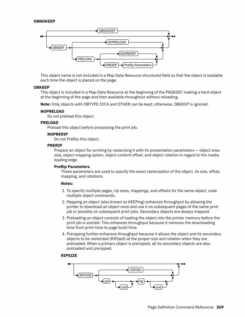
OBNOKEEP
OBNOKEEP
OBKEEP
NOPRELOAD
PRELOAD
NOPRERIP
PRERIP PreRip Parameters
This object name is not included in a Map Data Resource structured field so that the object is loadableeach time the object is placed on the page.
OBKEEPThis object is included in a Map Data Resource at the beginning of the PAGEDEF making a hard objectat the beginning of the page and then available throughout without reloading.
Note: Only objects with OBTYPE IOCA and OTHER can be kept; otherwise, OBKEEP is ignored.
NOPRELOADDo not preload this object.
PRELOADPreload this object before processing the print job.NOPRERIP
Do not PreRip this object.PRERIP
Prepare an object for printing by rasterizing it with its presentation parameters — object areasize, object mapping option, object content offset, and object rotation in regard to the medialeading edge.PreRip Parameters
These parameters are used to specify the exact rasterization of the object, its size, offset,mapping, and rotations.
Notes:
1. To specify multiple pages, rip sizes, mappings, and offsets for the same object, codemultiple object commands.
2. Mapping an object (also known as KEEPing) enhances throughput by allowing theprinter to download an object once and use it on subsequent pages of the same printjob or possibly on subsequent print jobs. Secondary objects are always mapped.
3. Preloading an object consists of loading the object into the printer memory before theprint job is started. This enhances throughput because it removes the downloadingtime from print-time to page build time.
4. Preripping further enhances throughput because it allows the object and its secondaryobjects to be rasterized (RIPped) at the proper size and rotation when they arepreloaded. When a primary object is preripped, all its secondary objects are alsopreloaded and preripped.
RIPSIZE
RIPSIZE
USEOBJ
wd
unit
hg
unit
Page Definition Command Reference 369

Specifies the size of the object placement area. When no RIPSIZE is specified, thedefault is the size that is specified in the object. If no size is specified in the object, thesize of the page is used. The page width is specified on the PAGEDEF or PAGEFORMATcommands, or it defaults to 8.3 inches by 10.8 inches.
USEOBJSpecifies that the size measurements that are specified in the object are to beused. If no size is specified in the object, the size of the page is used, which is thelength and width as specified on the PAGEDEF or PAGEFORMAT commands, or itdefaults to 8.3 inches by 10.8 inches.
wdSpecifies the width of an object placement area as a number with up to threedecimal places. The allowable width can vary with the type of printer that is usedand the L-units that are specified with the PELSPERINCH parameter on thePAGEDEF or PAGEFORMAT command.
hgSpecifies the height of an object placement area as a number with up to threedecimal places. The allowable height can vary with the type of printer that is usedand the L-units that are specified with the PELSPERINCH parameter on thePAGEDEF or PAGEFORMAT command.
unitSpecifies a unit of measurement for the width parameter. The choices are: IN, MM,CM, POINTS, or PELS.
Note: If no unit is specified, the default is the most recent SETUNITS commandvalue or IN (inch) if a SETUNITS command is not issued.
RIPMAP
RIPMAP LEFT
TRIM
FIT
CENTER
FILL
Specifies mapping options. The RIPMAP parameter defines the mapping of the objectto the object placement area. If RIPMAP is not coded, the mapping option within theobject is used. If the object does not contain mapping option, then the print server setsit to the created default for container type. Each object type (OBTYPE on the OBJECTcommand) specifies the allowable mapping options for that type. See the OBJECTOBTYPE parameter for a description of the restrictions.
FITSpecifies scale to fit. This is the default value of the RIPMAP parameter is notcoded. The object is to be scaled to fit within the object placement area, as definedby the RIPSIZE parameter. The center of the object is placed in the center of theobject placement area and the object is scaled up or down to fit the block. Scalingin the horizontal and vertical directions is symmetrical. The FIT parameter ensuresthat all of the data in the object is presented in the object placement area at thelargest possible size. The object is not trimmed.
FILLSpecifies that the center of the data object is positioned coincident with the centerof the object placement area. The data object is then scaled so that it totally fillsthe object placement area in both the X and Y directions. This might require thatthe object is asymmetrically scaled by different scale factors in the X and Ydirections.
370 Page Printer Formatting Aid: User's Guide

LEFTSpecifies that the object is positioned at the upper, left corner of the objectplacement area, as defined or defaulted by the relative-xpos, relative-ypos, andRIPOFFSET parameters. Any portion of the object that falls outside the objectplacement area as defined by the RIPSIZE parameter is not trimmed and mightcause an exception condition by the presentation system. This mapping type isinvalid with an IOCA object.
TRIMSpecifies position and trim. The object is positioned at the upper, left corner of theobject placement area, as defined or defaulted by the relative-xpos, relative-ypos,and RIPOFFSET parameters. Any portion of the object that falls outside the objectplacement area as defined by the RIPSIZE parameter is trimmed.
CENTERSpecifies that the center of the object is positioned at the center of the objectplacement area. Any portion of the object that falls outside the object placementarea is trimmed.
RIPOFFSET
RIPOFFSET rel x
unit
rel y
unit
Object Content Offset - Specifies the horizontal and vertical offset of the objectcontents within the object placement area, as defined by the RIPSIZE parameter. IfRIPOFFSET is not specified, the object is preprocessed and cached at its full size. Thecontent offset specified at Include time is then used to place and possibly trim theobject to the object area, with an associated performance penalty.
The RIPOFFSET parameter is used only in LEFT and TRIM mapping of the object intothe object placement area.
rel xSpecifies the offset along the X-axis of the object area coordinates system. Thiscan be a positive or negative number.
rel ySpecifies the offset along the Y-axis of the object area coordinates system. Thiscan be a positive or negative number.
unitSpecifies a unit of measurement for the width parameter. The choices are: IN, MM,CM, POINTS, or PELS.
Note: If no unit is specified, the default is the most recent SETUNITS commandvalue or IN (inch) if a SETUNITS command is not issued.
RIPROTATE { 0 │ 90 │ 180 │ 270 }
RIPROTATE 0
RIPROTATE 0
90
180
270
Page Definition Command Reference 371
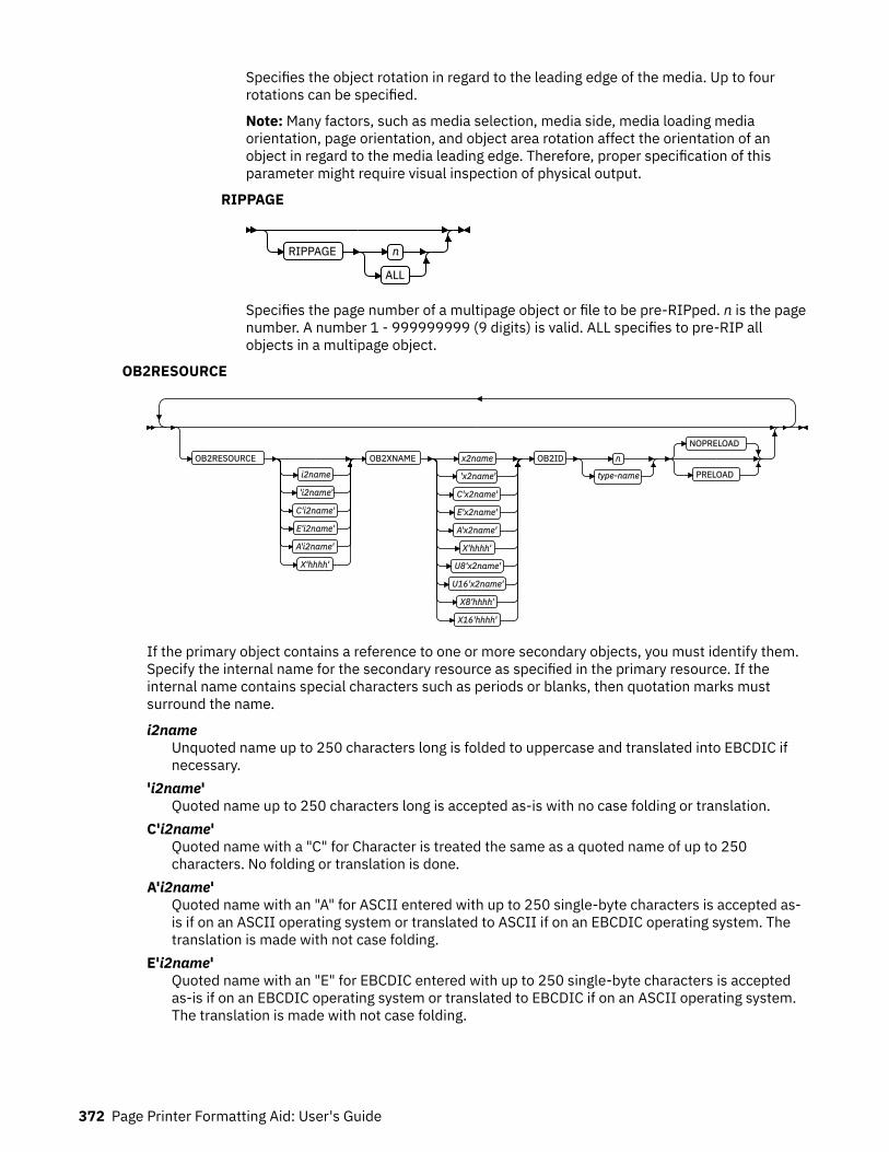
Specifies the object rotation in regard to the leading edge of the media. Up to fourrotations can be specified.
Note: Many factors, such as media selection, media side, media loading mediaorientation, page orientation, and object area rotation affect the orientation of anobject in regard to the media leading edge. Therefore, proper specification of thisparameter might require visual inspection of physical output.
RIPPAGE
RIPPAGE n
ALL
Specifies the page number of a multipage object or file to be pre-RIPped. n is the pagenumber. A number 1 - 999999999 (9 digits) is valid. ALL specifies to pre-RIP allobjects in a multipage object.
OB2RESOURCE
OB2RESOURCE
i2name
'i2name'
C'i2name'
E'i2name'
A'i2name'
X'hhhh'
OB2XNAME x2name
'x2name'
C'x2name'
E'x2name'
A'x2name'
X'hhhh'
U8'x2name'
U16'x2name'
X8'hhhh'
X16'hhhh'
OB2ID n
type-name
NOPRELOAD
PRELOAD
If the primary object contains a reference to one or more secondary objects, you must identify them.Specify the internal name for the secondary resource as specified in the primary resource. If theinternal name contains special characters such as periods or blanks, then quotation marks mustsurround the name.
i2nameUnquoted name up to 250 characters long is folded to uppercase and translated into EBCDIC ifnecessary.
'i2name'Quoted name up to 250 characters long is accepted as-is with no case folding or translation.
C'i2name'Quoted name with a "C" for Character is treated the same as a quoted name of up to 250characters. No folding or translation is done.
A'i2name'Quoted name with an "A" for ASCII entered with up to 250 single-byte characters is accepted as-is if on an ASCII operating system or translated to ASCII if on an EBCDIC operating system. Thetranslation is made with not case folding.
E'i2name'Quoted name with an "E" for EBCDIC entered with up to 250 single-byte characters is acceptedas-is if on an EBCDIC operating system or translated to EBCDIC if on an ASCII operating system.The translation is made with not case folding.
372 Page Printer Formatting Aid: User's Guide

X'hhhh'Quoted name with an X for Hexadecimal entered with up to 500 hexadecimal characters. Thecharacters are translated to hexadecimal, but no assumption of data type is made.
OB2XNAME
OB2XNAME x2name
'x2name'
C'x2name'
E'x2name'
A'x2name'
X'hhhh'
U8'x2name'
U16'x2name'
X8'hhhh'
X16'hhhh'
Specifies the external name for a secondary resource object. The name can be up to 250 characters.If the name contains special characters or blanks, it must be enclosed in blanks.
Note: A file system name must adhere to the rules of the operating system where the object islocated. This might further restrict the following sizes.
x2nameUnquoted name up to 250 characters long is folded to uppercase and translated into EBCDIC ifnecessary.
'x2name'Unquoted name up to 250 characters long is accepted as-is with no case folding or translation.
C'x2name'Quoted name with a C for Character is treated the same as a quoted name up to 250 characters.No folding or translation is done.
A'x2name'Quoted name with an A for ASCII entered with up to 250 single-byte characters is accepted as-isif on an ASCII operating system or translated to ASCII if on an EBCDIC operating system. Thetranslation is made with no case folding.
E'x2name'Quoted name with an E for EBCDIC entered with up to 250 single-byte characters is accepted as-is if on an EBCDIC operating system or translated to EBCDIC if on an ASCII operating system. Thetranslation is made with no case folding.
X'hhhh'Quoted name with an X for Hexadecimal entered with up to 500 hexadecimal characters. Thecharacters is translated to hexadecimal, but no assumption of data type is made.
U8'x2name'Quoted name with an U8 for UTF-8 entered with up to 250 single-byte characters is translated toUTF-8.
X8'hhhh'Quoted name with an X8 for UTF-8 HEX entered with up to 500 single-byte hexadecimalcharacters is translated to hexadecimal and assumed to be data type UTF-8. A multiple of twohexadecimal characters must be entered.
U16'x2name'Quoted name with an U16 for UTF-16 entered with up to 125 single-byte characters is translatedto UTF-16.
Page Definition Command Reference 373
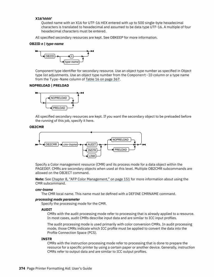
X16'hhhh'Quoted name with an X16 for UTF-16 HEX entered with up to 500 single-byte hexadecimalcharacters is translated to hexadecimal and assumed to be data type UTF-16. A multiple of fourhexadecimal characters must be entered.
All specified secondary resources are kept. See OBKEEP for more information.
OB2ID n | type-name
OB2ID n
type-name
Component type identifier for secondary resource. Use an object type number as specified in Objecttype list adjustments. Use an object type number from the Component-ID column or a type namefrom the Type-Name column of Table 16 on page 367.
NOPRELOAD | PRELOAD
NOPRELOAD
PRELOAD
All specified secondary resources are kept. If you want the secondary object to be preloaded beforethe running of this job, specify it here.
OB2CMR
OB2CMR cmr-lname AUDIT
INSTR
LINK
NOPRELOAD
PRELOAD
Specify a Color management resource (CMR) and its process mode for a data object within thePAGEDEF. CMRs are secondary objects when used at this level. Multiple OB2CMR subcommands areallowed on the OBJECT command.
Note: See Chapter 8, “AFP Color Management,” on page 151 for more information about using theCMR subcommand.
cmr-lnameThe CMR local name. This name must be defined with a DEFINE CMRNAME command.
processing mode parameterSpecify the processing mode for the CMR.AUDIT
CMRs with the audit processing mode refer to processing that is already applied to a resource.In most cases, audit CMRs describe input data and are similar to ICC input profiles.
The audit processing mode is used primarily with color conversion CMRs. In audit processingmode, those CMRs indicate which ICC profile must be applied to convert the data into theProfile Connection Space (PCS).
INSTRCMRs with the instruction processing mode refer to processing that is done to prepare theresource for a specific printer by using a certain paper or another device. Generally, instructionCMRs refer to output data and are similar to ICC output profiles.
374 Page Printer Formatting Aid: User's Guide

The instruction processing mode is used with color conversion, tone transfer curve, andhalftone CMRs. In instruction processing mode, these CMRs indicate how the system mustconvert a resource so it prints correctly on the target printer. The manufacturer of your printermust provide ICC profiles or various CMRs that you can use. Those ICC profiles and CMRsmight be installed in the printer controller, included with the printer on a CD, or available fordownload from the manufacturer's website.
LINKThis CMR defines a direct color conversion from an input color space to a device output colorspace; process the CMR as a link CMR. This processing mode is only valid for device link (DL)CMRs. The PPFA command RENDER is not used with device link (DL) CMRs as such CMRsspecify the intended rendering intent internally. This function requires print server (PSF) andprinter support, which is in addition to the original CMR support.
NOPRELOAD|PRELOADAll specified secondary resources are kept. If you want the CMR object to be preloaded before therunning of this job, specify it here.
Example: In the following code example, an object with CMR is defined. The following LAYOUTcommands place the object on the page. The CMR name is defined and referenced by the CMR localname. See the DEFINE CMRNAME command for examples and instructions on defining CMR names.
PAGEDEF cmr89 replace yes; FONT varb gt10 ; /*Variable data */ SETUNITS LINESP .25 in ; /* Line spacing */
DEFINE srgb CMRNAME 'sRGBicc_CC001.000@@@@@@@@@@@@@@@@@@@@@@@@@@@@@@@@@@@@@@@@@@@@@@@@@@' '@@@@@@'; Object oc1 obxname 'Flowers_with_sRGB_profile' obtype other obid 23 OBKEEP ob2cmr srgb audit PAGEFORMAT rept1 TOPMARGIN 1 in BOTMARGIN 2 in; LAYOUT 'startpage' BODY NEWPAGE POSITION 1 in NEXT font varb object oc1 0 in 3 in obsize 6.5 in 8.5 in; LAYOUT 'basicline' BODY POSITION SAME NEXT font varb;
OBRESOLUTION
OBRESOLUTION x y IN
CM
Specifies the resolution and unit of measurement of an image. If the resolution is already specifiedinside the image, this information is ignored by the printer. Use this subcommand for images that donot or might not contain their resolution. Specify resolution of an image so that the printer can printthe image correctly.
To specify object resolution, you must have a printer and a print server (PSF or IPM) that support thiscapability.
If not specified, the default is to assume that the image resolution is the same as the printer. If theimage does not print at the size you expect, use OBRESOLUTION to identify the image's resolution.With the resolution information, the printer is then able print the image at the expected size.x
Specifies the number to be used for the horizontal resolution of an image. Specify an integer valuein the range of 1 - 3276.
ySpecifies the number to be used for the vertical resolution of an image. Specify an integer value inthe range of 1 - 3276.
Page Definition Command Reference 375

unitSpecifies a unit of measurement. The choices are:IN
InchCM
Centimeter
In the following code example, the OBJECT command is used to define two JFIF objects. One is pre-ripped and the other is not. One has a resolution of 300 pels per inch in both the x and y directions.The other has a resolution of 600 pels per inch in both the x and y directions.
SETUNITS 2 in 2 in;Pagedef obxres OBJECT obres1 OBXNAME xpseg23 OBTYPE other OBID JFIF OBRESOLUTION 300 300 IN;OBJECT obres2 OBXNAME xpseg24 OBTYPE other OBID JFIF OBRESOLUTION 600 600 IN; PRINTLINE OBJECT obres1 23 PELS 01 PELS OBMap TRIM OBSIZE 1.2 in 1.3 in ;PRINTLINE OBJECT obres2 34 PELS 01 PELS OBMap TRIM OBSIZE 1.2 in 1.3 in ;
ExamplesExample 1
In the following page definition, several examples of long names are shown, which is for illustrationonly.
• OBU8 — The primary object name is specified in U8 format, which means that it is specified as acharacter string and translated to UTF-8 encoding.
The secondary object that is defined on object OBU8 is referenced in the primary object with anidentifier that is the equivalent of hexadecimal X'ABF8'. The external name for that object isspecified in C format, which means that the name is accepted as it with no translation or folding ofcase.
• OBU16 — This object name is specified in U16 format, which means that it is specified as acharacter string and translated to UTF-16 encoding.
• OBX16 — This object name is specified in X16 format, which means that it is specified as ahexadecimal string that represents the UTF-16 encoding. It is not translated. The only check thatPPFA makes is that its length is a multiple of 4.
PAGEDEF LNNG2P REPLACE YES; FONT FN1 GT10; OBJECT obU8 OBXNAME u8'A Long Object Name in UFT8' ' Which is continued on a second line' ' And could also be continued on a subsequent line' OBTYPE IOCA OBKEEP PRELOAD OB2RESOURCE X'ABF8' OB2XNAME C'A plain old Character ' ' type Secondary Object name which will be used as typed' ' in the code page of the User' OB2ID PDFRO PRELOAD;
OBJECT OBU16 OBXNAME U16'abcdef4' OBTYPE IOCA OBKEEP PRELOAD;
OBJECT obx16 OBXNAME X16'006100620063' '0064006500660034' OBTYPE IOCA OBKEEP PRELOAD;
printline object obU8 FONT fn1; printline object obU16; printline object obX16;
Example 2In the following page definition, an IOCA object is defined and placed. The object is to be mapped,preloaded, and preripped in 3 orientations (0, 90, 270). Object area size and offset mapping are
376 Page Printer Formatting Aid: User's Guide
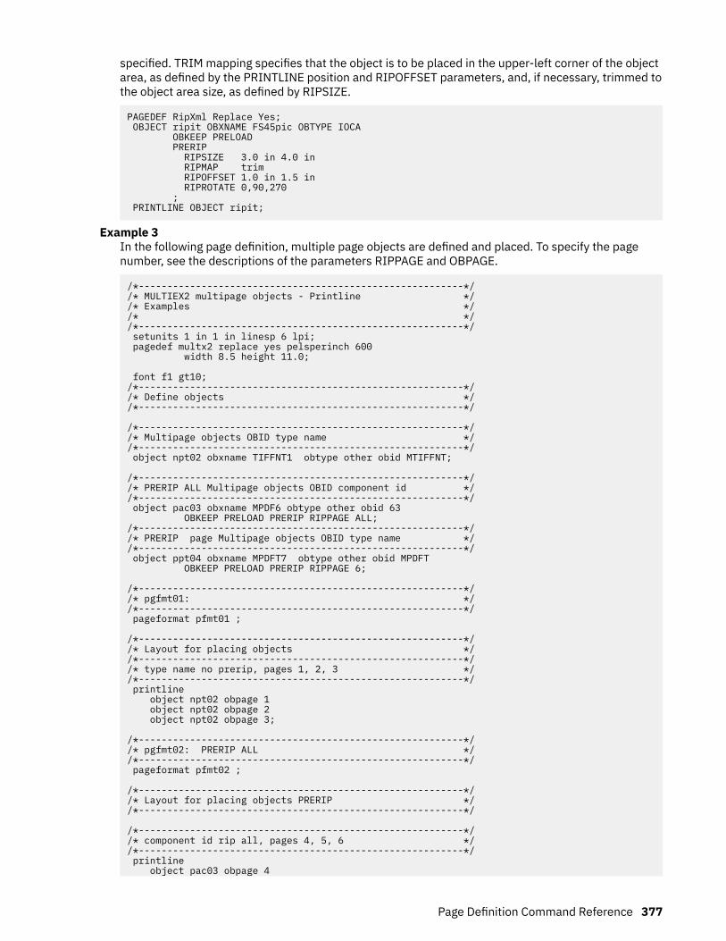
specified. TRIM mapping specifies that the object is to be placed in the upper-left corner of the objectarea, as defined by the PRINTLINE position and RIPOFFSET parameters, and, if necessary, trimmed tothe object area size, as defined by RIPSIZE.
PAGEDEF RipXml Replace Yes; OBJECT ripit OBXNAME FS45pic OBTYPE IOCA OBKEEP PRELOAD PRERIP RIPSIZE 3.0 in 4.0 in RIPMAP trim RIPOFFSET 1.0 in 1.5 in RIPROTATE 0,90,270 ; PRINTLINE OBJECT ripit;
Example 3In the following page definition, multiple page objects are defined and placed. To specify the pagenumber, see the descriptions of the parameters RIPPAGE and OBPAGE.
/*---------------------------------------------------------*//* MULTIEX2 multipage objects - Printline *//* Examples *//* *//*---------------------------------------------------------*/ setunits 1 in 1 in linesp 6 lpi; pagedef multx2 replace yes pelsperinch 600 width 8.5 height 11.0; font f1 gt10; /*---------------------------------------------------------*//* Define objects *//*---------------------------------------------------------*/
/*---------------------------------------------------------*//* Multipage objects OBID type name *//*---------------------------------------------------------*/ object npt02 obxname TIFFNT1 obtype other obid MTIFFNT;
/*---------------------------------------------------------*//* PRERIP ALL Multipage objects OBID component id *//*---------------------------------------------------------*/ object pac03 obxname MPDF6 obtype other obid 63 OBKEEP PRELOAD PRERIP RIPPAGE ALL; /*---------------------------------------------------------*//* PRERIP page Multipage objects OBID type name *//*---------------------------------------------------------*/ object ppt04 obxname MPDFT7 obtype other obid MPDFT OBKEEP PRELOAD PRERIP RIPPAGE 6; /*---------------------------------------------------------*//* pgfmt01: *//*---------------------------------------------------------*/ pageformat pfmt01 ; /*---------------------------------------------------------*//* Layout for placing objects *//*---------------------------------------------------------*//* type name no prerip, pages 1, 2, 3 *//*---------------------------------------------------------*/ printline object npt02 obpage 1 object npt02 obpage 2 object npt02 obpage 3; /*---------------------------------------------------------*//* pgfmt02: PRERIP ALL *//*---------------------------------------------------------*/ pageformat pfmt02 ; /*---------------------------------------------------------*//* Layout for placing objects PRERIP *//*---------------------------------------------------------*/ /*---------------------------------------------------------*//* component id rip all, pages 4, 5, 6 *//*---------------------------------------------------------*/ printline object pac03 obpage 4
Page Definition Command Reference 377

object pac03 obpage 5 object pac03 obpage 6; /*---------------------------------------------------------*//* pgfmt03: PRERIP page 6 *//*---------------------------------------------------------*/ pageformat pfmt03 ; /*---------------------------------------------------------*//* Layout for placing objects PRERIP *//*---------------------------------------------------------*/ /*---------------------------------------------------------*//* type name rip 6, page 6 *//*---------------------------------------------------------*/ printline object ppt04 obpage 6;
OVERLAY CommandOVERLAY x-name
NOPRELOAD
PRELOAD
PRERIP
RIPROTATE 0
RIPROTATE 0
90
180
270
;
The OVERLAY command is used to identify an electronic overlay to be included in the print file. Thisfunction is similar to the SEGMENT command. A separate OVERLAY command is required for each overlay,including all overlay names that can be used with the OVERLAY VARIABLE keyword on PRINTLINE,LAYOUT, or XLAYOUT. A maximum of 254 OVERLAY commands (each of the 254 names must be unique)can be specified for each page format.
The OVERLAY commands are nested within the PAGEFORMAT command. For Traditional:
PAGEFORMAT [ TRCREF ] [SEGMENT ] [ OVERLAY ] … [ OVERLAY ]
For Record Format and XML:
PAGEFORMAT [SEGMENT ] [ OVERLAY ] … [ OVERLAY ]
An overlay can be requested in the following two ways:
• Place the overlay by using the OVERLAY subcommand on the PRINTLINE command (Traditional), theLAYOUT command (Record Format), or the XLAYOUT command (XML).
378 Page Printer Formatting Aid: User's Guide

• Enter an Include Page Overlay (IPO) structured field in the line data. The name of the overlay on the IPOstructured field must match exactly the overlay that is identified by this command. The IPO mustspecify a value of X'FFFFFF' for the X and Y offset parameters if the overlay is to be placed relative tothe current line position.
To include page overlays without using the IPO structured field, see the “PRINTLINE Command ” on page400.OVERLAY
Identifies the overlay that is positioned on the page.x-name
The user access name (external name) for the overlay. x-name can be unquoted or enclosed inquotation marks.unquoted-name
An unquoted overlay name can be up to 6 characters. It is folded to uppercase, has an O1prefix added to it, and is translated to EBCDIC code page 500 if necessary.
'quoted-name'A quoted overlay name can be up to 8 characters. No translation or case folding is done.
SubcommandsThese subcommands are used to specify whether to preload overlays, PreRip overlays, or both.
Notes:
1. The printer must support the preloading and preripping functions.2. Mapping an overlay enhances throughput by allowing the printer to download an object once and use it
on subsequent pages of the same print job or possibly on subsequent print jobs. Overlays are alwaysmapped so it is not necessary for you to request mapping. Mapping an overlay provides sufficientperformance for most applications.
3. Preloading an overlay consists of loading the object into printer memory before the print job is started.Preloading enhances throughput by removing downloading time from real time to the page build time.
4. Preripping enhances throughput by allowing the resources to be rasterized (RIPped) at the proper sizeand rotation when they are preloaded.
NOPRELOADDo not preload the overlay.
PRELOADPreload the overlay before the print job is processed.NOPRERIP
Do not PreRip the overlay.PRERIP
Prepare the overlay for printing by rasterizing it with its presentation rotation in regard to themedia leading edge.RIPROTATE { 0 │ 90 │ 180 │ 270 }
Specifies the overlay rotation in regard to the leading edge of the media. Up to four rotationscan be specified.
Note: Many factors, such as media selection, media side media loading, media orientation,page rotation, and overlay area rotation affect the orientation of the overlay in regard to themedia leading edge. Therefore, proper specification of this parameter might require visualinspection of physical output.
Note: The prefix O1 is not part of the six-character user-access name. The overlay name can bealphanumeric.
Page Definition Command Reference 379

Example
In the following example, an overlay is defined and placed. The overlay is preripped in two orientations,180 and 0.
PAGEDEF RipXm2 Replace Yes; PAGEFORMAT pf1; OVERLAY ripit PRELOAD PRERIP OVBROTATE 180,0 ;
PRINTLINE OVERLAY ripit;
380 Page Printer Formatting Aid: User's Guide

PAGEDEF Command
PAGEDEF name
COMMENT qstring
WIDTH 8.3 IN
WIDTH n
unit
HEIGHT 10.8 IN
HEIGHT n
unit
LINEONE x-pos y-pos
DIRECTION ACROSS
DIRECTION DOWN
BACK
UP
REPLACE NO
?
REPLACE YES
PELSPERINCH n 1TOPMARGIN n
IN
MM
CM
POINTS
PELS
1BOTMARGIN n
IN
MM
CM
POINTS
PELS
1LEFTMARGIN n
IN
MM
CM
POINTS
PELS
1RIGHTMARGIN n
IN
MM
CM
POINTS
PELS
SOSIFONTS sbcs-font , dbcs-font
UDType (EBCDIC or ASCII)2
UDType EBCDIC
ASCII
UTF8
UTF16
RECIDLEN 10
RECIDLEN n
;
Notes:
Page Definition Command Reference 381
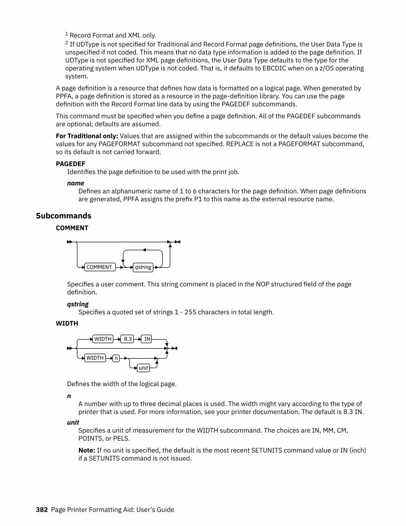
1 Record Format and XML only.2 If UDType is not specified for Traditional and Record Format page definitions, the User Data Type isunspecified if not coded. This means that no data type information is added to the page definition. IfUDType is not specified for XML page definitions, the User Data Type defaults to the type for theoperating system when UDType is not coded. That is, it defaults to EBCDIC when on a z/OS operatingsystem.
A page definition is a resource that defines how data is formatted on a logical page. When generated byPPFA, a page definition is stored as a resource in the page-definition library. You can use the pagedefinition with the Record Format line data by using the PAGEDEF subcommands.
This command must be specified when you define a page definition. All of the PAGEDEF subcommandsare optional; defaults are assumed.
For Traditional only: Values that are assigned within the subcommands or the default values become thevalues for any PAGEFORMAT subcommand not specified. REPLACE is not a PAGEFORMAT subcommand,so its default is not carried forward.
PAGEDEFIdentifies the page definition to be used with the print job.name
Defines an alphanumeric name of 1 to 6 characters for the page definition. When page definitionsare generated, PPFA assigns the prefix P1 to this name as the external resource name.
SubcommandsCOMMENT
COMMENT qstring
Specifies a user comment. This string comment is placed in the NOP structured field of the pagedefinition.
qstringSpecifies a quoted set of strings 1 - 255 characters in total length.
WIDTH
WIDTH 8.3 IN
WIDTH n
unit
Defines the width of the logical page.
nA number with up to three decimal places is used. The width might vary according to the type ofprinter that is used. For more information, see your printer documentation. The default is 8.3 IN.
unitSpecifies a unit of measurement for the WIDTH subcommand. The choices are IN, MM, CM,POINTS, or PELS.
Note: If no unit is specified, the default is the most recent SETUNITS command value or IN (inch)if a SETUNITS command is not issued.
382 Page Printer Formatting Aid: User's Guide

HEIGHT
HEIGHT 10.8 IN
HEIGHT n
unit
Defines the height of the logical page.
nA number with up to three decimal places is used. The height might vary according to the type ofprinter that is used. For more information, see your printer documentation. The default is 10.8 IN.
unitSpecifies a unit of measurement for the HEIGHT subcommand. The choices are IN, MM, CM,POINTS, and PELS.
Note: If no unit is specified, the default is the most recent SETUNITS command value or IN (inch)if a SETUNITS command is not issued.
LINEONE (Traditional only)
LINEONE x-pos y-pos
Specifies the values for the MARGIN and TOP parameters that are used in the POSITIONsubcommand of the PRINTLINE command.
x-posSpecifies the offset from the left edge of the logical page (margin position). The valid options for x-pos are described in the SETUNITS command for the horizontal value.
Note: If no unit is specified, the default is the most recent SETUNITS command value or IN (inch)if a SETUNITS command is not issued.
y-posSpecifies the vertical offset from the top of the logical page (top line position). The valid optionsfor y-pos are described in the SETUNITS command for the vertical value.
Note: If no unit is specified, the default is the most recent SETUNITS command value or IN (inch)if a SETUNITS command is not issued.
DIRECTION
DIRECTION ACROSS
DIRECTION DOWN
BACK
UP
Specifies the print direction of the logical page. Not all printers can print in all print directions. Formore information, see your printer documentation.
Note: Some printers have a different media origin and require different direction settings than mostpage printers. For printing in the landscape page presentation when you are using wide forms, thePRESENT subcommand must be specified on the FORMDEF command to produce readable output.Alternatively, if you have existing page definitions, the UP direction can be used in the page definitionwithout changes to the form definition to produce the same result.
Page Definition Command Reference 383

ACROSSThe page is printed with the characters added left to right in each line, and the lines added fromthe top to the bottom.
DOWNThe page is printed with the characters added to the page from top to bottom, and the lines addedfrom the right to the left.
BACKThe page is printed with the characters added to the page from right to left, and the lines addedfrom the bottom to the top.
UPThe page is printed with the characters added to the page from bottom to top, and the lines addedfrom the left to the right.
REPLACE
REPLACE NO
?
REPLACE YES
Specifies whether the page definition replaces an existing page definition with the same resourcename in the library.
NOThe page definition does not replace a page definition with the same resource name in the library.
If a page definition with the same resource name does not exist in the library, the page definitionis stored.
YESIf a page definition with the same resource name exists in the library, the page definition replacesit.
If a page definition with the same resource name does not exist in the library, the page definitionis stored.
PELSPERINCH n
PELSPERINCH n
Specifies the Logical Units in pels per inch for the page definition. Use the PELSPERINCH parameter totell PPFA the pel resolution of your printer to generate more exact object placements.
nSpecifies an integer number 1 - 3,276, which determines the Logical Units in pels per inch.
Note: If the L-Units are not specified on the page definition, they are defaulted to 240 pels per inch.
In Figure 134 on page 385, the page definition xmp01 specifies L-Units as 300 pels per inch. Becausethe PAGEFORMAT P1 does not specify L-Units, it inherits 300 pels per inch. PAGEFORMAT P2 doesspecify L-Units as 1200 pels per inch. The width and height in PAGEFORMAT P1 (7 in, 3 in) produces
384 Page Printer Formatting Aid: User's Guide

internal and structured field values of 2100 and 900, whereas in PAGEFORMAT P2 the same codeproduces values of 8400 and 3600 because of the difference in L-Units.
PAGEDEF xmp01 replace yes PELSPERINCH 300 ;
PAGEFORMAT P1 width 7 in height 3 in; PRINTLINE;
PAGEFORMAT P2 width 7 in height 3 in PELSPERINCH 1200; PRINTLINE;
Figure 134: PELSPERINCH example
TOPMARGIN (Record Format and XML)
TOPMARGIN n
IN
MM
CM
POINTS
PELS
This keyword with parameters specifies the amount of space to be reserved at the top of the page.
The default is 80% of the current line spacing.
BOTMARGIN (Record Format and XML)
BOTMARGIN n
IN
MM
CM
POINTS
PELS
This keyword with parameters specifies the amount of space to be reserved at the bottom of the page.Only PAGETRAILER data can be written into this area. If a graphic is not ended at the time informationis being placed in the bottom margin, the graphic is ended before the bottom margin. The default is 0.
LEFTMARGIN (Record Format and XML)
LEFTMARGIN n
IN
MM
CM
POINTS
PELS
This keyword with parameters specifies the amount of space to be reserved at the left of the page.This keyword is to be used only with the DRAWGRAPHIC commands. Although PPFA collects the left
Page Definition Command Reference 385
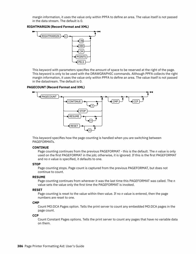
margin information, it uses the value only within PPFA to define an area. The value itself is not passedin the data stream. The default is 0.
RIGHTMARGIN (Record Format and XML)
RIGHTMARGIN n
IN
MM
CM
POINTS
PELS
This keyword with parameters specifies the amount of space to be reserved at the right of the page.This keyword is only to be used with the DRAWGRAPHIC commands. Although PPFA collects the rightmargin information, it uses the value only within PPFA to define an area. The value itself is not passedin the datastream. The default is 0.
PAGECOUNT (Record Format and XML)
PAGECOUNT
CONTINUEn
STOP
RESUMEn
RESETn
CMP CCP
This keyword specifies how the page counting is handled when you are switching betweenPAGEFORMATs.
CONTINUEPage counting continues from the previous PAGEFORMAT - this is the default. The n value is onlyused on the first PAGEFORMAT in the job; otherwise, it is ignored. If this is the first PAGEFORMATand no n value is specified, it defaults to one.
STOPPage counting stops. Page count is captured from the previous PAGEFORMAT, but does notcontinue to count.
RESUMEPage counting continues from wherever it was the last time this PAGEFORMAT was called. The nvalue sets the value only the first time the PAGEFORMAT is invoked.
RESETPage counting is reset to the value within then value. If no n value is entered, then the pagenumbers are reset to one.
CMPCount MO:DCA Pages option. Tells the print server to count any embedded MO:DCA pages in thepage count.
CCPCount Constant Pages options. Tells the print server to count any pages that have no variable dataon them.
386 Page Printer Formatting Aid: User's Guide

SOSIFONTS
SOSIFONTS sbcs-font , dbcs-font
The SOSIFONTS subcommand causes a Single-Byte Character Set (SBCS) font and a Double-ByteCharacter Set (DBCS) font to be mapped in a manner that allows the proper font switching when Shift-in and Shift-out control sequences are encountered in printed text.
sbcs-fontA Single-Byte Character Set font. This font is selected by the print server when a Shift-In (SI)control byte is encountered in text that is presented.
dbcs-fontA Double-Byte Character Set font. This font is selected by the print server when a Shift-Out (SO)control byte is encountered in text that is presented.
Use one of these methods to use SOSI fonts in a page definition:
• In the PAGEDEF, use the FONT placement subcommand to specify both the SBCS and DBCS fonts tobe used. To use this method, define both a single-byte and double-byte font with the FONT orDOFONT commands. Then, reference both fonts, separated by a comma, on the FONT subcommandon the FIELD, PRINTLINE, XLAYOUT, or LAYOUT commands. The single-byte font goes first.
Examples:
1. In a traditional page definition:
Pagedef sosiP1 replace yes; FONT sb1 GT10 SBCS; FONT db1 M40F DBCS; PAGEFORMAT PF1; PRINTLINE POSITION 1 in 1.2 in FONT sb1,db1;
2. In a Record Format or XML page definition:
Pagedef sosiP1 replace yes; FONT sb1 GT10 SBCS; FONT db1 M40F DBCS; PAGEFORMAT PF1; LAYOUT 'l1' POSITION 1 in 1.2 in FONT sb1,db1;
• In the PAGEDEF, use the PAGEFORMAT subcommand SOSIFONTS to ensure that a single-byte fontis mapped first and a double-byte font is mapped second in the PAGEFORMAT. To use this method,code both a single-byte and double-byte font with the FONT command. Then, use the SOSIFONTSsubcommand on the PAGEFORMAT command with the SBCS font coded first and the DBCS fontcoded next.
Examples:
1. In a traditional page definition:
Pagedef sosiL1 replace yes; FONT sb1 GT10 SBCS; FONT db1 M40F DBCS; PAGEFORMAT PF1 SOSIFONTS sb1,db1;
PRINTLINE POSITION 1 in 1.2 in;
2. In a Record Format or XML page definition:
Pagedef sosiP1 replace yes; FONT sb1 GT10 SBCS; FONT db1 M40F DBCS; PAGEFORMAT PF1 SOSIFONTS sb1,db1;
LAYOUT 'l1' POSITION 1 in 1.2;
Page Definition Command Reference 387

Note: The SOSIFONTS subcommand can also be coded on the PAGEFORMAT command. AnyPAGEFORMATs that do not code a SOSIFONTS subcommand inherit from the PAGEDEF.
• Specify fonts by using the CHARS JCL parameter and either no fonts in the PAGEDEF or the defaultPAGEDEF. Using this method, the first font that is defined in CHARS is a SBCS font and the second isa DBCS font.
• Traditional only: Use the TRCREF command to define the SBCS font as 0 and the DBCS font as 1. Donot specify a FONT subcommand on PRINTLINE, FIELD, and other commands when you are usingthis method. This method is used only with a Traditional page definition. For example:
Pagedef sosiL1 replace yes; FONT sb1 GT10 SBCS; FONT db1 M40F DBCS; PAGEFORMAT PF1; TRCREF 0 FONT sb1; TRCREF 1 FONT db1; PRINTLINE;
Note: You cannot mix Data Object fonts (defined with the DOFONT command) with FOCA fonts(defined with the FONT command) in the page definition in any but the first method of specifying SOSIfonts.
UDType
UDType (EBCDIC or ASCII)1
UDType EBCDIC
ASCII
UTF8
UTF16
Notes:1 If UDType is not specified for Traditional and Record Format page definitions, the User Data Typeis unspecified if not coded. This means that no data type information is added to the pagedefinition. If UDType is not specified for XML page definitions, the User Data Type defaults to thetype for the operating system when UDType is not coded. That is, it defaults to EBCDIC when on az/OS operating system or ASCII when on an AIX® or Windows operating system.
This subcommand identifies the encoding of your data. If UDType is not coded on the PAGEDEF, itdefaults to either ASCII or EBCDIC to match the operating system. For example, if PPFA is run on az/OS operating system and UDType is not coded it defaults to EBCDIC.
UDType on the PAGEDEF command is used for several things:
1. Allow PPFA to translate fixed text to the specified UDType from either ASCII or EBCDIC accordingto the operating system on which the PPFA compile is done.
2. Set the default for all DOFONT (Data Object Font) commands so you do not need to code UDTypeon each DOFONT command.
3. Pass encoding information to the printer for converting non-UTF16 user data to UTF16 when youare using a DOFONT command. (TrueType is an example of a DOFONT).
4. Allows PSF or ACIF to know to look for a Byte Order Mark (BOM) when your data type is UTF8 orUTF16 and contains a BOM.
If the data does not match the operating system data type, PPFA translates the following constantpage definition data to the encoding specified by UDType:
• FIELD command text (all page definitions)• CONDITION text (all page definitions)• LAYOUT command 'record ID' (Record Format page definition only)• LAYOUT command delimiter (Record Format page definition only)
388 Page Printer Formatting Aid: User's Guide
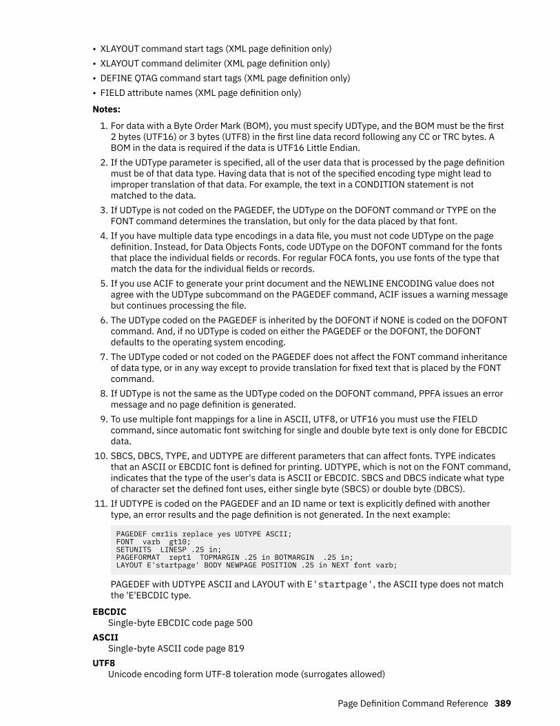
• XLAYOUT command start tags (XML page definition only)• XLAYOUT command delimiter (XML page definition only)• DEFINE QTAG command start tags (XML page definition only)• FIELD attribute names (XML page definition only)
Notes:
1. For data with a Byte Order Mark (BOM), you must specify UDType, and the BOM must be the first2 bytes (UTF16) or 3 bytes (UTF8) in the first line data record following any CC or TRC bytes. ABOM in the data is required if the data is UTF16 Little Endian.
2. If the UDType parameter is specified, all of the user data that is processed by the page definitionmust be of that data type. Having data that is not of the specified encoding type might lead toimproper translation of that data. For example, the text in a CONDITION statement is notmatched to the data.
3. If UDType is not coded on the PAGEDEF, the UDType on the DOFONT command or TYPE on theFONT command determines the translation, but only for the data placed by that font.
4. If you have multiple data type encodings in a data file, you must not code UDType on the pagedefinition. Instead, for Data Objects Fonts, code UDType on the DOFONT command for the fontsthat place the individual fields or records. For regular FOCA fonts, you use fonts of the type thatmatch the data for the individual fields or records.
5. If you use ACIF to generate your print document and the NEWLINE ENCODING value does notagree with the UDType subcommand on the PAGEDEF command, ACIF issues a warning messagebut continues processing the file.
6. The UDType coded on the PAGEDEF is inherited by the DOFONT if NONE is coded on the DOFONTcommand. And, if no UDType is coded on either the PAGEDEF or the DOFONT, the DOFONTdefaults to the operating system encoding.
7. The UDType coded or not coded on the PAGEDEF does not affect the FONT command inheritanceof data type, or in any way except to provide translation for fixed text that is placed by the FONTcommand.
8. If UDType is not the same as the UDType coded on the DOFONT command, PPFA issues an errormessage and no page definition is generated.
9. To use multiple font mappings for a line in ASCII, UTF8, or UTF16 you must use the FIELDcommand, since automatic font switching for single and double byte text is only done for EBCDICdata.
10. SBCS, DBCS, TYPE, and UDTYPE are different parameters that can affect fonts. TYPE indicatesthat an ASCII or EBCDIC font is defined for printing. UDTYPE, which is not on the FONT command,indicates that the type of the user's data is ASCII or EBCDIC. SBCS and DBCS indicate what typeof character set the defined font uses, either single byte (SBCS) or double byte (DBCS).
11. If UDTYPE is coded on the PAGEDEF and an ID name or text is explicitly defined with anothertype, an error results and the page definition is not generated. In the next example:
PAGEDEF cmr1is replace yes UDTYPE ASCII; FONT varb gt10; SETUNITS LINESP .25 in; PAGEFORMAT rept1 TOPMARGIN .25 in BOTMARGIN .25 in; LAYOUT E'startpage' BODY NEWPAGE POSITION .25 in NEXT font varb;
PAGEDEF with UDTYPE ASCII and LAYOUT with E'startpage', the ASCII type does not matchthe 'E'EBCDIC type.
EBCDICSingle-byte EBCDIC code page 500
ASCIISingle-byte ASCII code page 819
UTF8Unicode encoding form UTF-8 toleration mode (surrogates allowed)
Page Definition Command Reference 389

UTF16Unicode encoding form UTF-16
Note: The PAGEDEF is created in UTF-16BE (Big Endian). If the data is in UTF16LE, PSF translatesit to UTF-16BE before processing.
RECIDLENRECIDLEN 10
RECIDLEN n
Specifies the length of the Record Descriptor ID in bytes. This is also known as the LAYOUT name. Ifthe RECIDLEN parameter is not coded on a PAGEFORMAT command, it inherits the value from thespecified or default value on the page definition. If the RECIDLEN parameter is not coded on aPAGEDEF command, the default length is 10 bytes.
Notes:
1. Use the RECIDLEN keyword on Record Format page definition only.2. This parameter can be used only in a Record Format page definition.
nSpecifies that the 'record ID' on the LAYOUT command is to be n bytes long. The allowable valueof n is 1 - 250. UTF-16 data characters are 2 bytes long allowing up to 125 UTF-16 characters.Any 'record ID' on a LAYOUT command that is less than this length is padded to the specifiedlength with blanks of the type that is specified or defaulted in the UDType subcommand on thePAGEDEF command. A 'record ID' that is longer than n is flagged as an error by PPFA and no pagedefinition is generated.
Note: If the User Data Type (UDType) is UTF16 and this number is odd, it is rounded up to the nexteven number.
Code ExampleIn the following example, User Data Type UTF16 and RECIDLEN 24 are specified on the PAGEDEFcommand and the RECIDLEN 26 is specified on the second PAGEFORMAT command (pf2).
For the two page formats pf1 and pf2:
1. pf1 inherits a RECIDLEN of 24 bytes from the page definition, and the User Data Type for the entirepage definition is UTF-16.
a. The LAYOUT name 'Long Name 1' is translated to UTF-16 and padded to 24 bytes with UTF-16.b. The delimiter '/' on the LAYOUT is translated to UTF-16.c. The FIELD command text 'abcd' is translated to UTF-16.
2. pf2 specifies a RECIDLEN of 26 bytes and gets UDType UTF-16 from the page definition.
a. The LAYOUT name 'Long Name 2' is translated to UTF-16 and padded to 26 bytes with UTF-16.b. The CONDITION command text 'ABCDEFGH' is translated to UTF-16.
Note: The field length of the 8-character string is 16 bytes because each character is 2 bytes long.
PAGEDEF xmp1 UDType UTF16 RECIDLEN 24 REPLACE yes;
FONT comp a075nc TYPE UNICODE FONT comp2 a075bg TYPE UNICODE
PAGEFORMAT pf1; LAYOUT 'Long Name 1' DELIMITER '/' Position 2 1 FONT comp; FIELD TEXT 'abcd' Position 2.5 1.5,
PAGEFORMAT pf2 RECIDLEN 26; LAYOUT 'Long Name 2' POSITION 2 1 FONT comp2;
390 Page Printer Formatting Aid: User's Guide

CONDITION cn1 START 13 Length 16 WHEN EQ 'ABCDEFGH' NULL Pageformat pf1;
Page Definition Command Reference 391
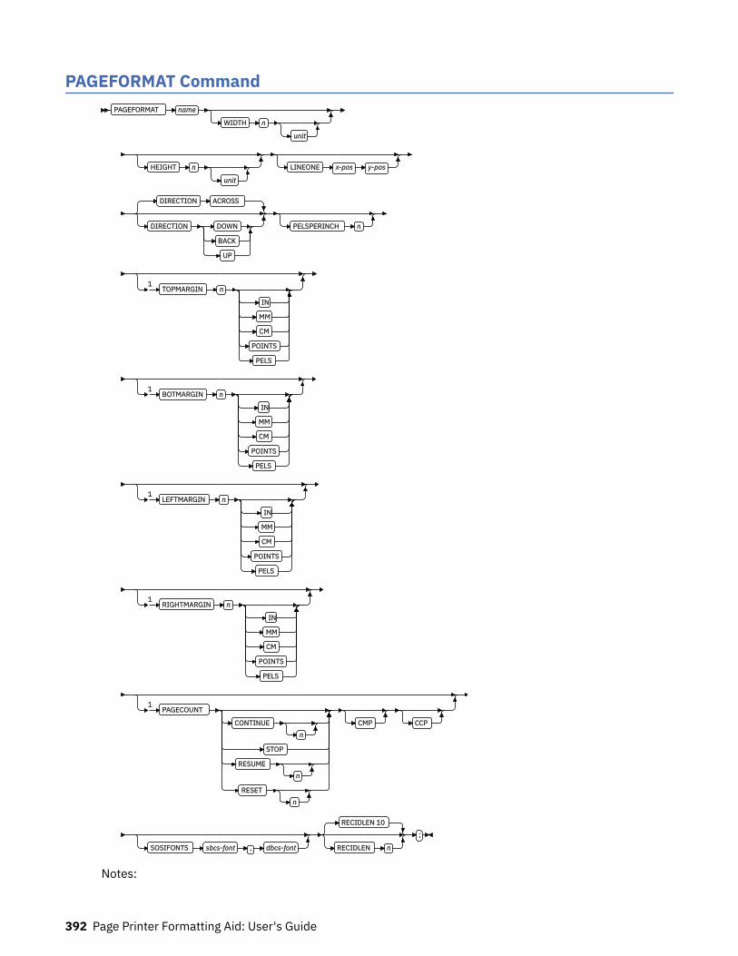
PAGEFORMAT CommandPAGEFORMAT name
WIDTH n
unit
HEIGHT n
unit
LINEONE x-pos y-pos
DIRECTION ACROSS
DIRECTION DOWN
BACK
UP
PELSPERINCH n
1TOPMARGIN n
IN
MM
CM
POINTS
PELS
1BOTMARGIN n
IN
MM
CM
POINTS
PELS
1LEFTMARGIN n
IN
MM
CM
POINTS
PELS
1RIGHTMARGIN n
IN
MM
CM
POINTS
PELS
1PAGECOUNT
CONTINUEn
STOP
RESUMEn
RESETn
CMP CCP
SOSIFONTS sbcs-font , dbcs-font
RECIDLEN 10
RECIDLEN n
;
Notes:
392 Page Printer Formatting Aid: User's Guide

1 Record Format and XML only.
Page formats are subsets of page definitions. If you want to use more than one set of specifications toformat a page within a single print job, you must use more than one page format. To change page formats,use conditional processing or insert an Invoke Data Map structured field in your print file. (Page formatsare known to the print server as data maps.) If you do not use conditional processing or if you do notinsert an Invoke Data Map structured field, the print server uses only the first page format in the pagedefinition. Page formats are placed in the page definition in the order in which they are generated.
PAGEFORMAT subcommands have no fixed defaults. The entire PAGEFORMAT command and all of itssubcommands can assume defaults. If any PAGEFORMAT subcommand is omitted, its value is selectedfrom the corresponding subcommand in the governing PAGEDEF command.
This command can be omitted for the first page format in a page definition if only one page format is used.If omitted, PPFA assigns a page format name by using the page-definition name, including the P1 prefix.PAGEFORMAT name
Specifies an alphanumeric name of 1 - 8 characters. This name must be unique within the pagedefinition.
The following subcommands are used for each page format. They can be issued in the same way as ina page definition. Values that are specified in the PAGEDEF subcommands are used if any of thefollowing subcommands are not defined within a page format.
SubcommandsWIDTH
WIDTH n
unit
Defines the width of the logical page.
nA number with up to three decimal places is used. The width might vary according to the type ofprinter that is used. For more information, see your printer documentation.
unitSpecifies a unit of measurement for the WIDTH subcommand. The choices are IN, MM, CM,POINTS, or PELS.
Note: If no unit is specified, the default is the most recent SETUNITS command value or IN (inch)if a SETUNITS command is not issued.
HEIGHT
HEIGHT n
unit
Defines the height of the logical page.
nA number with up to three decimal places is used. The height might vary according to the type ofprinter that is used. For more information, see your printer documentation.
unitSpecifies a unit of measurement for the HEIGHT parameter. The choices are IN, MM, CM, POINTS,or PELS.
Note: If no unit is specified, the default is the most recent SETUNITS command value or IN (inch)if a SETUNITS command is not issued.
Page Definition Command Reference 393
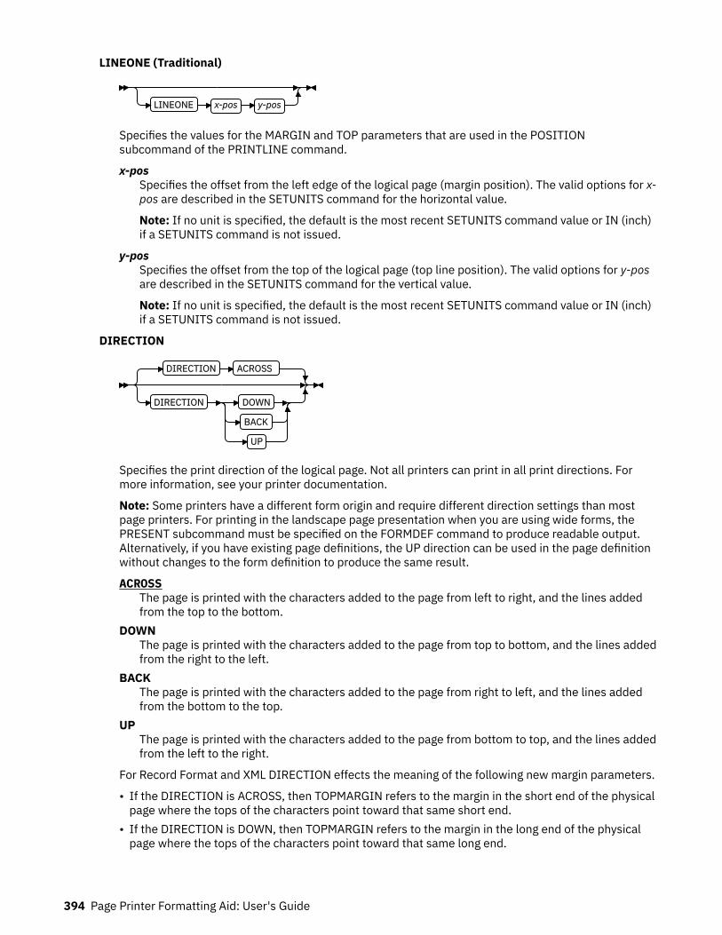
LINEONE (Traditional)
LINEONE x-pos y-pos
Specifies the values for the MARGIN and TOP parameters that are used in the POSITIONsubcommand of the PRINTLINE command.
x-posSpecifies the offset from the left edge of the logical page (margin position). The valid options for x-pos are described in the SETUNITS command for the horizontal value.
Note: If no unit is specified, the default is the most recent SETUNITS command value or IN (inch)if a SETUNITS command is not issued.
y-posSpecifies the offset from the top of the logical page (top line position). The valid options for y-posare described in the SETUNITS command for the vertical value.
Note: If no unit is specified, the default is the most recent SETUNITS command value or IN (inch)if a SETUNITS command is not issued.
DIRECTION
DIRECTION ACROSS
DIRECTION DOWN
BACK
UP
Specifies the print direction of the logical page. Not all printers can print in all print directions. Formore information, see your printer documentation.
Note: Some printers have a different form origin and require different direction settings than mostpage printers. For printing in the landscape page presentation when you are using wide forms, thePRESENT subcommand must be specified on the FORMDEF command to produce readable output.Alternatively, if you have existing page definitions, the UP direction can be used in the page definitionwithout changes to the form definition to produce the same result.
ACROSSThe page is printed with the characters added to the page from left to right, and the lines addedfrom the top to the bottom.
DOWNThe page is printed with the characters added to the page from top to bottom, and the lines addedfrom the right to the left.
BACKThe page is printed with the characters added to the page from right to left, and the lines addedfrom the bottom to the top.
UPThe page is printed with the characters added to the page from bottom to top, and the lines addedfrom the left to the right.
For Record Format and XML DIRECTION effects the meaning of the following new margin parameters.
• If the DIRECTION is ACROSS, then TOPMARGIN refers to the margin in the short end of the physicalpage where the tops of the characters point toward that same short end.
• If the DIRECTION is DOWN, then TOPMARGIN refers to the margin in the long end of the physicalpage where the tops of the characters point toward that same long end.
394 Page Printer Formatting Aid: User's Guide
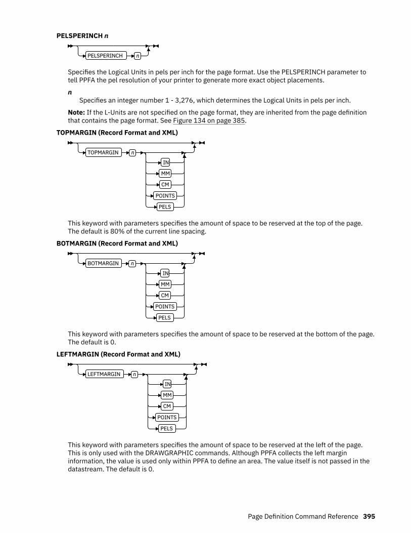
PELSPERINCH n
PELSPERINCH n
Specifies the Logical Units in pels per inch for the page format. Use the PELSPERINCH parameter totell PPFA the pel resolution of your printer to generate more exact object placements.
nSpecifies an integer number 1 - 3,276, which determines the Logical Units in pels per inch.
Note: If the L-Units are not specified on the page format, they are inherited from the page definitionthat contains the page format. See Figure 134 on page 385.
TOPMARGIN (Record Format and XML)
TOPMARGIN n
IN
MM
CM
POINTS
PELS
This keyword with parameters specifies the amount of space to be reserved at the top of the page.The default is 80% of the current line spacing.
BOTMARGIN (Record Format and XML)
BOTMARGIN n
IN
MM
CM
POINTS
PELS
This keyword with parameters specifies the amount of space to be reserved at the bottom of the page.The default is 0.
LEFTMARGIN (Record Format and XML)
LEFTMARGIN n
IN
MM
CM
POINTS
PELS
This keyword with parameters specifies the amount of space to be reserved at the left of the page.This is only used with the DRAWGRAPHIC commands. Although PPFA collects the left margininformation, the value is used only within PPFA to define an area. The value itself is not passed in thedatastream. The default is 0.
Page Definition Command Reference 395

RIGHTMARGIN (Record Format and XML)
RIGHTMARGIN n
IN
MM
CM
POINTS
PELS
This keyword with parameters specifies the amount of space to be reserved at the right of the page.This is only to be used with the DRAWGRAPHIC commands. Although PPFA collects the right margininformation, it uses the value only within PPFA to define an area. This value itself is not passed in thedatastream. The default is 0.
PAGECOUNT (Record Format and XML)
PAGECOUNT
CONTINUEn
STOP
RESUMEn
RESETn
CMP CCP
This keyword specifies how the page counting is handled when you are switching between pageformats.
CONTINUEPage counting continues from the previous page format - this is the default. The n value is usedonly on the first PAGEFORMAT in the job; otherwise, it is ignored. If this is the first PAGEFORMATand no n value is specified, it defaults to one.
STOPPage counting stops. Page count is captured from the previous page format, but does not continueto count.
RESUMEPage counting continues from wherever it was the last time the page format was called. The nvalue sets the value only the first time page format is invoked.
RESETPage counting is reset to the value within the n value. If no n value is entered, then the pagenumbers are reset to one.
CMPCount MO:DCA Pages option. Tells the print server to count any embedded MO:DCA pages in thepage count.
CCPCount Constant Pages options. Tells the print server to count any pages that have no variable dataon them.
SOSIFONTS
SOSIFONTS sbcs-font , dbcs-font
396 Page Printer Formatting Aid: User's Guide

The SOSIFONTS subcommand causes a Single-Byte Character Set (SBCS) font and a Double-ByteCharacter Set (DBCS) font to be mapped in a manner that allows the proper font switching when Shift-in and Shift-out control sequences are encountered in printed text.
sbcs-fontA Single-Byte Character Set font. This font is selected by the print server when a Shift-In (SI)control byte is encountered in text that is presented.
dbcs-fontA Double-Byte Character Set font. This font is selected by the print server when a Shift-Out (SO)control byte is encountered in text that is presented.
Use one of these methods to use SOSI fonts in a page definition:
• In the PAGEDEF, use the FONT placement subcommand to specify both the SBCS and DBCS fonts tobe used. To use this method, define both a single-byte and double-byte font with the FONT orDOFONT commands. Then, reference both fonts, separated by a comma, on the FONT subcommandon the FIELD, PRINTLINE, or LAYOUT commands. The single-byte font goes first.
Examples:
1. In a traditional page definition:
Pagedef sosiP1 replace yes; FONT sb1 GT10 SBCS; FONT db1 M40F DBCS; PAGEFORMAT PF1; PRINTLINE POSITION 1 in 1.2 in FONT sb1,db1;
2. In a Record Format or XML page definition:
Pagedef sosiP1 replace yes; FONT sb1 GT10 SBCS; FONT db1 M40F DBCS; PAGEFORMAT PF1; LAYOUT 'l1' POSITION 1 in 1.2 in FONT sb1,db1;
• In the PAGEDEF, use the PAGEFORMAT subcommand SOSIFONTS to ensure that a single-byte fontis mapped first and a double-byte font is mapped second in the PAGEFORMAT. To use this method,code both a single-byte and double-byte font with the FONT command. Then, use the SOSIFONTSsubcommand on the PAGEFORMAT command with the SBCS font coded first and the DBCS fontcoded next.
Examples:
1. In a traditional page definition:
Pagedef sosiL1 replace yes; FONT sb1 GT10 SBCS; FONT db1 M40F DBCS; PAGEFORMAT PF1 SOSIFONTS sb1,db1;
PRINTLINE POSITION 1 in 1.2 in;
2. In a Record Format or XML page definition:
Pagedef sosiL1 replace yes; FONT sb1 GT10 SBCS; FONT db1 M40F DBCS; PAGEFORMAT PF1 SOSIFONTS sb1,db1;
LAYOUT 'l1' POSITION 1 in 1.2;
Note: The SOSIFONTS subcommand can also be coded on the PAGEFORMAT command. It isinherited on any PAGEFORMATs that do not code a SOSIFONTS subcommand.
• Define fonts by using the CHARS JCL parameter and either no fonts in the PAGEDEF or the defaultPAGEDEF. Using this method, the first font that is defined in the CHARS is an SBCS font and thesecond is a DBCS font.
Page Definition Command Reference 397
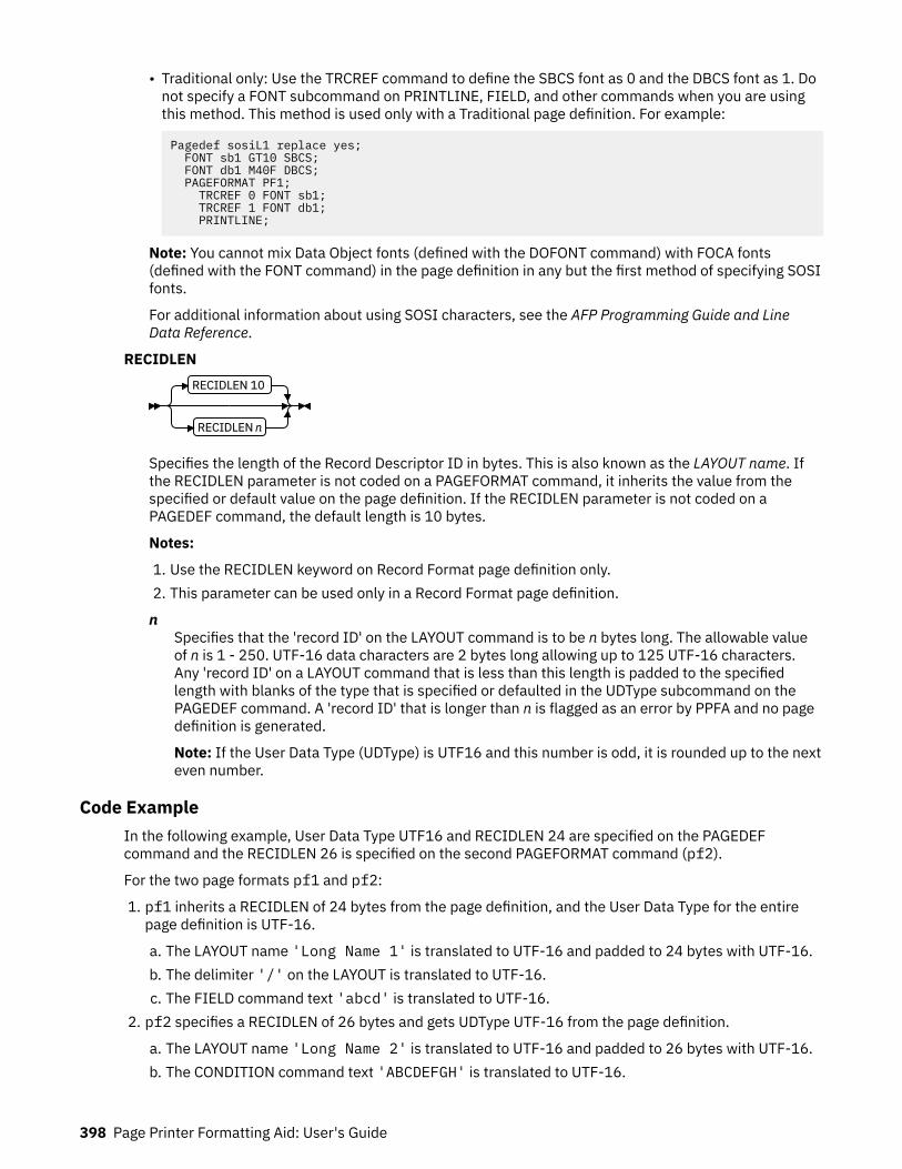
• Traditional only: Use the TRCREF command to define the SBCS font as 0 and the DBCS font as 1. Donot specify a FONT subcommand on PRINTLINE, FIELD, and other commands when you are usingthis method. This method is used only with a Traditional page definition. For example:
Pagedef sosiL1 replace yes; FONT sb1 GT10 SBCS; FONT db1 M40F DBCS; PAGEFORMAT PF1; TRCREF 0 FONT sb1; TRCREF 1 FONT db1; PRINTLINE;
Note: You cannot mix Data Object fonts (defined with the DOFONT command) with FOCA fonts(defined with the FONT command) in the page definition in any but the first method of specifying SOSIfonts.
For additional information about using SOSI characters, see the AFP Programming Guide and LineData Reference.
RECIDLENRECIDLEN 10
RECIDLEN n
Specifies the length of the Record Descriptor ID in bytes. This is also known as the LAYOUT name. Ifthe RECIDLEN parameter is not coded on a PAGEFORMAT command, it inherits the value from thespecified or default value on the page definition. If the RECIDLEN parameter is not coded on aPAGEDEF command, the default length is 10 bytes.
Notes:
1. Use the RECIDLEN keyword on Record Format page definition only.2. This parameter can be used only in a Record Format page definition.
nSpecifies that the 'record ID' on the LAYOUT command is to be n bytes long. The allowable valueof n is 1 - 250. UTF-16 data characters are 2 bytes long allowing up to 125 UTF-16 characters.Any 'record ID' on a LAYOUT command that is less than this length is padded to the specifiedlength with blanks of the type that is specified or defaulted in the UDType subcommand on thePAGEDEF command. A 'record ID' that is longer than n is flagged as an error by PPFA and no pagedefinition is generated.
Note: If the User Data Type (UDType) is UTF16 and this number is odd, it is rounded up to the nexteven number.
Code ExampleIn the following example, User Data Type UTF16 and RECIDLEN 24 are specified on the PAGEDEFcommand and the RECIDLEN 26 is specified on the second PAGEFORMAT command (pf2).
For the two page formats pf1 and pf2:
1. pf1 inherits a RECIDLEN of 24 bytes from the page definition, and the User Data Type for the entirepage definition is UTF-16.
a. The LAYOUT name 'Long Name 1' is translated to UTF-16 and padded to 24 bytes with UTF-16.b. The delimiter '/' on the LAYOUT is translated to UTF-16.c. The FIELD command text 'abcd' is translated to UTF-16.
2. pf2 specifies a RECIDLEN of 26 bytes and gets UDType UTF-16 from the page definition.
a. The LAYOUT name 'Long Name 2' is translated to UTF-16 and padded to 26 bytes with UTF-16.b. The CONDITION command text 'ABCDEFGH' is translated to UTF-16.
398 Page Printer Formatting Aid: User's Guide

Note: The field length of the 8-character string is 16 bytes because each character is 2 bytes long.
PAGEDEF xmp1 UDType UTF16 RECIDLEN 24 REPLACE yes;
FONT comp a075nc TYPE UNICODE FONT comp2 a075bg TYPE UNICODE
PAGEFORMAT pf1; LAYOUT 'Long Name 1' DELIMITER '/' Position 2 1 FONT comp; FIELD TEXT 'abcd' Position 2.5 1.5,
PAGEFORMAT pf2 RECIDLEN 26; LAYOUT 'Long Name 2' POSITION 2 1 FONT comp2; CONDITION cn1 START 13 Length 16 WHEN EQ 'ABCDEFGH' NULL Pageformat pf1;
Page Definition Command Reference 399

PRINTLINE CommandPRINTLINE
REPEAT nFIELD
LINE
CHANNEL n
FONT name1
, name2
PRINTDATA YES
PRINTDATA NO
POSITION SAME NEXT
POSITION MARGIN
SAME or =
x-pos
RELATIVE
TOP
NEXT
SAME or =
y-pos
COLOR colorname
RGB rvalue gvalue bvalue
HIGHLIGHT hvalue
COVERAGE cvalue BLACK bvalue
CMYK cvalue mvalue yvalue kvalue
CIELAB lvalue
(–)
clvalue
(–)
c2value
OVERLAY Xname
VARIABLE
START n
LENGTH n
0 0
relX relY
OVROTATE 0
OVROTATE 90
180
270
SEGMENT Xname
VARIABLE
START n
LENGTH n
0 0
relX relY
DIRECTION ACROSS
DIRECTION DOWN
BACK
UP
OBJECT lname
0 0
relX relY
VARIABLE
START n
LENGTH n
0 0
relX relY
OBTYPE Parameters
Other OBJECT Parameters
OBTYPE Parameters
400 Page Printer Formatting Aid: User's Guide

OBTYPE PSEG
IOCA
BCOCA
GOCA
PTOCA
OTHER OBID comp-id
type-name
Other OBJECT Parameters
OBSIZE
USEOBJ
wd
unit
hg
unit
OBMAP LEFT
TRIM
FIT
CENTER
REPEAT
FILL
OBCHPOS USEOBJ
OBCHPOS x-pos
OBCVPOS USEOBJ
OBCVPOS y-pos
OBROTATE 0
OBROTATE 90
180
270
OBCOLOR color-name OBPAGE n
OBRESOLUTION x y IN
CM
PRINTLINEThe PRINTLINE command specifies the printing of one data record on a line. If a formatted printline isto be printed, one or more FIELD commands must follow the governing PRINTLINE command; at leastone is required. If one FIELD command is not used, field processing is not done and the unformatteddata is printed.
Note: The PRINTLINE command defines a traditional page definition and cannot be mixed withLAYOUT commands that define Record Formatting page definitions or XLAYOUT commands thatdefine XML page definitions.
Page Definition Command Reference 401

SubcommandsREPEAT
REPEAT nFIELD
LINE
Specifies the number of printlines that are to be printed on a logical page. The direction and font thatis specified within this printline applies to all lines printed. By using this command, you do not have towrite specifications for each line.
Note: If the REPEAT subcommand is omitted, only one line is printed for this PRINTLINE command.
nThis value specifies the number of printlines for a logical page; the maximum value is 65,535.REPEAT 0
Not valid.REPEAT 1
Only one line is printed.
If the CHANNEL or POSITION subcommands are specified within this PRINTLINE command, theyapply only to the first line.
If this PRINTLINE is followed by several FIELD commands, the related field controls are alsorepeated.
FIELDSpecifies that fields that are associated with repetitions of this PRINTLINE are to be positionedbased on the first instance of the same field.
This parameter has no effect in fields with the same direction as the PRINTLINE of which they area part.
This parameter specifies that the direction of repetition for a field is the direction of the firstinstance of the field plus 90°. Therefore, every field of an ACROSS PRINTLINE is repeated downthe page, regardless of the direction of the FIELD.
LINESpecifies that fields that are associated with repetitions of this printline are to be positioned basedon the repetition of the PRINTLINE itself.
This parameter has no effect in fields with the same direction as the PRINTLINE of which they area part.
This parameter specifies that the direction of repetition for a field is the direction of the associatedPRINTLINE plus 90°. Therefore, every field of an ACROSS PRINTLINE is repeated down the page,regardless of the direction of the FIELD.
CHANNEL n
CHANNEL n
Used to specify line spacing, skipping within a logical page, or page ejection (skipping to a new page).This subcommand is equivalent to the Forms Control Buffer (FCB) channel.
nThe range of channels is 1 - 12. The channels correspond to carriage-control characters in thedata. No default exists.
402 Page Printer Formatting Aid: User's Guide

FONT
FONT name1
, name2
Defines the font to be used for the printline.
name1Specifies the name of a font that is used to print the data. This font must be defined in a previousFONT command in the page definition.
If Shift-Out, Shift-In (SOSI) processing is used, name1 must be the single-byte font.
name2Specify only when you are using Shift-Out, Shift-In (SOSI) processing to dynamically switchbetween a single-byte font and a double-byte font within the printline. name2 must be thedouble-byte font.
Notes:
1. If this subcommand is not specified and TRC (Table Reference Character) bytes are specified in theprint data, the print server uses the font indicated by the TRC byte. Otherwise, the print serverselects a default font.
2. For ASCII, UTF8, or UTF16 the entire PRINTLINE command must be one font. To use multiple fontmappings for a line in ASCII, UTF8, or UTF16, you must use the FIELD command.
PRINTDATA
PRINTDATA YES
PRINTDATA NO
Specifies whether the line of data that is associated with the current PRINTLINE must be printed. ThePRINTDATA subcommand is useful when the data stream is interspersed with lines of comments,blank lines, or lines without data that are not meant to be printed.
YESSpecifies that the data for the current PRINTLINE is printed. YES is the default.
NOSpecifies that the data for the current PRINTLINE is not printed.
Note: Any FIELD command that is associated with a PRINTLINE that specifies PRINTDATA NO isignored and an error message is issued.
The default position for a YES command that specifies PRINTDATA NO is position same. The followingexample is for PRINTLINE NO.
PAGEDEF xmp01 ; SETUNITS LINESP 1 LPI ;
PRINTLINE ; PRINTLINE PrintData NO ; PRINTLINE PrintData yes ; PRINTLINE ; PRINTLINE Segment X PrintData NO Overlay Y Position Same Next ; PRINTLINE PrintData yes ;
The LINESP parameter specifies that one line per inch is to be printed.
1. The first line of data is read and printed.2. The second line of data is read, but not printed.3. The third line of data is read and printed 1 inch down from the first line.
Page Definition Command Reference 403
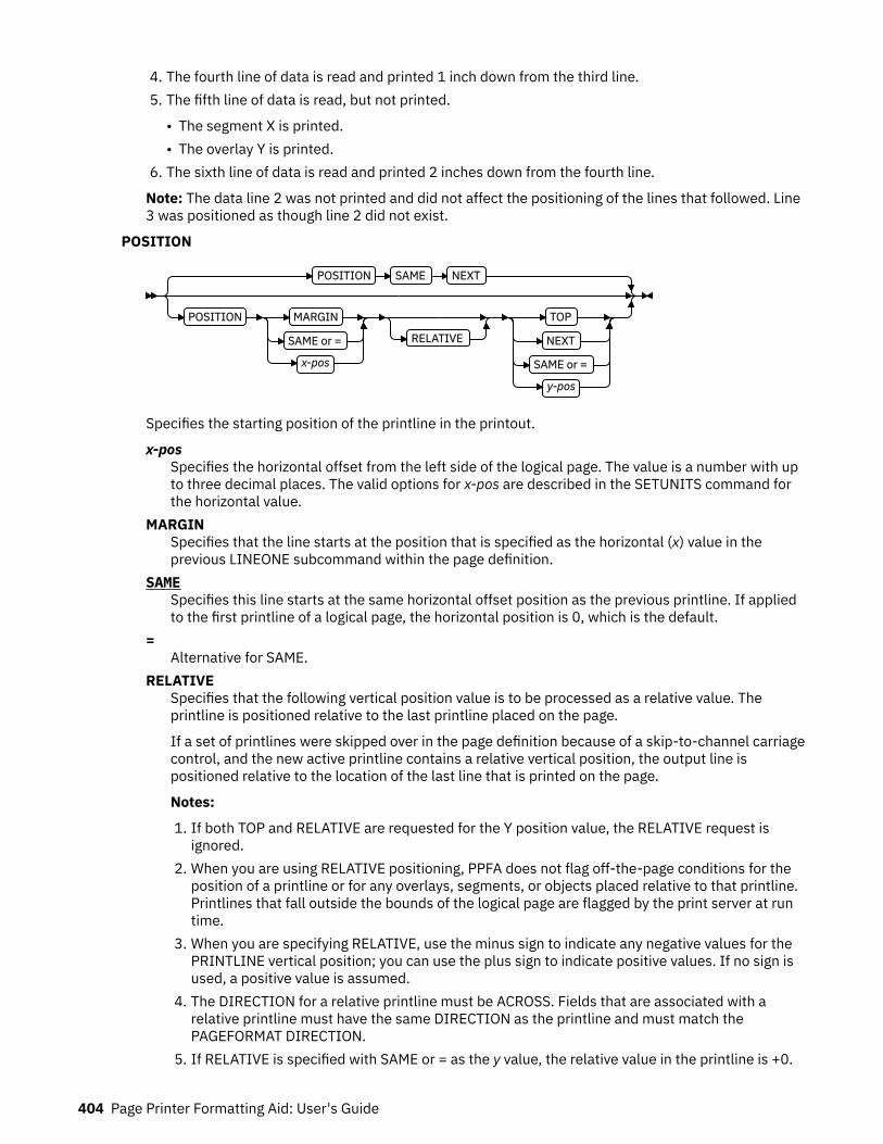
4. The fourth line of data is read and printed 1 inch down from the third line.5. The fifth line of data is read, but not printed.
• The segment X is printed.• The overlay Y is printed.
6. The sixth line of data is read and printed 2 inches down from the fourth line.
Note: The data line 2 was not printed and did not affect the positioning of the lines that followed. Line3 was positioned as though line 2 did not exist.
POSITION
POSITION SAME NEXT
POSITION MARGIN
SAME or =
x-pos
RELATIVE
TOP
NEXT
SAME or =
y-pos
Specifies the starting position of the printline in the printout.
x-posSpecifies the horizontal offset from the left side of the logical page. The value is a number with upto three decimal places. The valid options for x-pos are described in the SETUNITS command forthe horizontal value.
MARGINSpecifies that the line starts at the position that is specified as the horizontal (x) value in theprevious LINEONE subcommand within the page definition.
SAMESpecifies this line starts at the same horizontal offset position as the previous printline. If appliedto the first printline of a logical page, the horizontal position is 0, which is the default.
=Alternative for SAME.
RELATIVESpecifies that the following vertical position value is to be processed as a relative value. Theprintline is positioned relative to the last printline placed on the page.
If a set of printlines were skipped over in the page definition because of a skip-to-channel carriagecontrol, and the new active printline contains a relative vertical position, the output line ispositioned relative to the location of the last line that is printed on the page.
Notes:
1. If both TOP and RELATIVE are requested for the Y position value, the RELATIVE request isignored.
2. When you are using RELATIVE positioning, PPFA does not flag off-the-page conditions for theposition of a printline or for any overlays, segments, or objects placed relative to that printline.Printlines that fall outside the bounds of the logical page are flagged by the print server at runtime.
3. When you are specifying RELATIVE, use the minus sign to indicate any negative values for thePRINTLINE vertical position; you can use the plus sign to indicate positive values. If no sign isused, a positive value is assumed.
4. The DIRECTION for a relative printline must be ACROSS. Fields that are associated with arelative printline must have the same DIRECTION as the printline and must match thePAGEFORMAT DIRECTION.
5. If RELATIVE is specified with SAME or = as the y value, the relative value in the printline is +0.
404 Page Printer Formatting Aid: User's Guide

6. Relative positioning is allowed on a PRINTLINE command only if the PRINTLINE and all itsassociated FIELD commands are formatted to print in the same direction as the PAGEFORMAT.That is, the DIRECTION parameter in the PRINTLINE and any associated FIELD commandsmust specify (or default to) ACROSS. The DIRECTION in the PAGEFORMAT or PAGEDEFcommand can be any allowable value: ACROSS, DOWN, BACK, or UP.
7. The PRINTLINE command in which relative positioning is used can specify a CHANNELparameter. The n value that is specified for the CHANNEL parameter cannot be used for anyother PRINTLINE in the same PAGEFORMAT.
setunits linesp 6 lpi;PAGEDEF rel9 replace yes direction across width 8.5 in height 11.0 in;PRINTLINE channel 1 repeat 7 position 0 IN 1.0 IN; /* The fields will be placed at +120 pels, +24 pels (next) *//* and +48 pels (.20 IN) from lines previously placed on page */ setunits linesp 10 lpi;PRINTLINE channel 2 repeat 2 position 0 relative next; FIELD START 1 LENGTH 3 position 0 IN .5 IN; FIELD START 4 LENGTH 3 position 0 IN next; FIELD START 7 LENGTH 3 position current .20 IN;
y-posSpecifies the vertical offset from the top side of the logical page. The value options for y-pos aredescribed in the SETUNITS command for the vertical value.
TOPSpecifies that the printline is placed in the position that is specified as the vertical (y) value in theprevious LINEONE subcommand within the page definition.
NEXTSpecifies the PRINTLINE is to be positioned down (on the logical page) one line (as defined in theLINESP subcommand of the last SETUNITS command) from the previous PRINTLINE. The LINESPsubcommand of the SETUNITS command establishes the distance from one line to the next.
When NEXT is specified for the first PRINTLINE of a logical page, the starting position of the line isone line down from the top of the logical page, which is the default.
Note: The down direction is determined by the direction of the logical page (as specified in thepage format), not the printline direction. Therefore, NEXT is useful in ACROSS printlines.
SAMESpecifies this printline starts at the same vertical position as the previous printline. If applied tothe first printline of a logical page, the horizontal position is 0, which is the default.
=Alternative for SAME.
COLOR
COLOR colorname
RGB rvalue gvalue bvalue
HIGHLIGHT hvalue
COVERAGE cvalue BLACK bvalue
CMYK cvalue mvalue yvalue kvalue
CIELAB lvalue
(–)
clvalue
(–)
c2value
Specifies an OCA or defined color for the text of this field. This subcommand is recognized only byprinters that support multiple-color printing. See your printer publication for information about the
Page Definition Command Reference 405
colors that can be printed. See Chapter 8, “AFP Color Management,” on page 151 for moreinformation about using color.
colornameValues for colorname can be a defined color (see “DEFINE COLOR Command” on page 258), or anOCA colorname. Values for OCA colornames are:
NONEDEFAULTBLACKBLUEBROWNGREENREDPINK (or MAGENTA)TURQ (or CYAN)YELLOWDARKBLUE (or DBLUE)ORANGEPURPLEMUSTARDGRAYDARKGREEN (or DGREEN)DARKTURQ (DTURQ, or DCYAN, or DARKCYAN)
The color choices depend on the printer.
If you do not enter one of these colors, the default color for that printer is used. NONE is the colorof the medium. DEFAULT is the printer default color.
Note: In some printer manuals, the color turquoise (TURQ) is called cyan, and the color pink(PINK) is called magenta.
PPFA supports the following synonyms:
• CYAN for TURQ• DARKCYANN for DARKTURQ• DBLUE for DARKBLUE• DCYAN for DARKTURQ• DGREEN for DARKGREEN• DTURQ for DARKTURQ• MAGENTA for PINK
color modelsSpecifies the color of print for this field that is supported in MO:DCA for the Red/Green/Blue colormodel (RGB), the highlight color space, the Cyan/Magenta/Yellow/Black color model (CMYK), andthe CIELAB color model.RGB rvalue gvalue bvalue
Three RGB integer values are used. The first (rvalue) represents a value for red, the second(gvalue) represents a value for green, and the third (bvalue) represents a value for blue. Eachof the three integer values can be specified as a percentage 0 - 100.
Note: An RGB specification of 0/0/0 is black. An RGB specification of 100/100/100 is white.Any other value is a color somewhere between black and white, depending on the outputdevice.
HIGHLIGHT hvalue COVERAGE cvalue BLACK bvalueIndicates the highlight color model. Highlight colors are device-dependent.
406 Page Printer Formatting Aid: User's Guide

You can use an integer within the range of 0 - 65535 for the hvalue.
Note: An hvalue of 0 indicates that no default value is defined; therefore, the default color ofthe presentation device is used.
COVERAGE indicates the amount of coverage of the highlight color to be used. You can use aninteger within the range of 0 - 100 for the cvalue. If less than 100 percent is specified, theremaining coverage is achieved with the color of the medium.
Note: Fractional values are ignored. If COVERAGE is not specified, a value of 100 is used as adefault.
BLACK indicates the percentage of black to be added to the highlight color. You can use aninteger within the range of 0 - 100 for the bvalue. The amount of black shading that is applieddepends on the COVERAGE percentage, which is applied first. If less than 100 percent isspecified, the remaining coverage is achieved with black.
Note: If BLACK is not specified, a value of 0 is used as a default.
CMYK cvalue mvalue yvalue kvalueDefines the cyan/magenta/yellow/black color model. cvalue specifies the cyan value. mvaluespecifies the magenta value. yvalue specifies the yellow value. Kvalue specifies the blackvalue. You can use an integer percentage within the range of 0 - 100 for any of the CMYKvalues.
CIELAB Lvalue (-)c1value (-)c2valueDefines the CIELAB model. Use a range of 0.00 - 100.00 with Lvalue to specify the luminancevalue. Use signed integers from -127 to 127 with c1value and c2value to specify thechrominance differences.
Lvalue, c1value, c2value must be specified in this order. No defaults exist for the subvalues.
Notes:
1. Do not specify both an OCA color with the COLOR subparameter and an extended colormodel on the same FIELD or PRINTLINE command. The output is device-dependent andmight not be what you expect.
2. Do not specify two extended COLOR subcommands on the same FIELD or PRINTLINEcommand.
OVERLAY
OVERLAY Xname
VARIABLE
START n
LENGTH n
0 0
relX relY
OVROTATE 0
OVROTATE 90
180
270
Specifies the name of an overlay that is to be positioned relative to the location specified in thePRINTLINE command in which the OVERLAY subcommand was named. The PAGEFORMAT OVERLAYcommand can contain the named overlays. The maximum number of overlays that are specified for aPAGEFORMAT including the PRINTLINE OVERLAY subcommand is 254.
The OVERLAY can be identified by specifying a name (xname) or by getting the name from the inputdata record (use VARIABLE command).Xname
The user access name (external name). It can be unquoted or quoted with descriptor tags,indicating the data type (for example, ASCII) of the data in the field.unquoted-name
An unquoted external name can be up to 6 characters. It is folded to uppercase, has an O1prefix added to it, and is translated to EBCDIC code page 500 if necessary.
Page Definition Command Reference 407
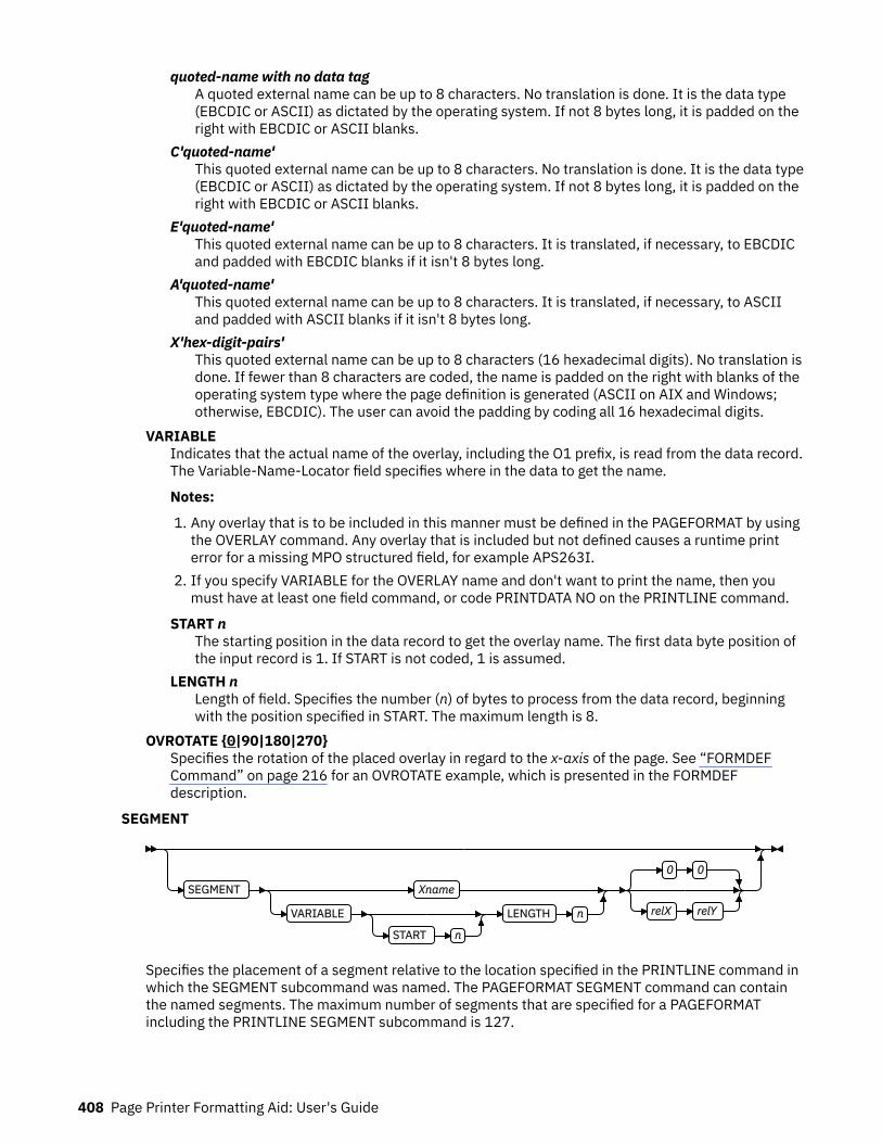
quoted-name with no data tagA quoted external name can be up to 8 characters. No translation is done. It is the data type(EBCDIC or ASCII) as dictated by the operating system. If not 8 bytes long, it is padded on theright with EBCDIC or ASCII blanks.
C'quoted-name'This quoted external name can be up to 8 characters. No translation is done. It is the data type(EBCDIC or ASCII) as dictated by the operating system. If not 8 bytes long, it is padded on theright with EBCDIC or ASCII blanks.
E'quoted-name'This quoted external name can be up to 8 characters. It is translated, if necessary, to EBCDICand padded with EBCDIC blanks if it isn't 8 bytes long.
A'quoted-name'This quoted external name can be up to 8 characters. It is translated, if necessary, to ASCIIand padded with ASCII blanks if it isn't 8 bytes long.
X'hex-digit-pairs'This quoted external name can be up to 8 characters (16 hexadecimal digits). No translation isdone. If fewer than 8 characters are coded, the name is padded on the right with blanks of theoperating system type where the page definition is generated (ASCII on AIX and Windows;otherwise, EBCDIC). The user can avoid the padding by coding all 16 hexadecimal digits.
VARIABLEIndicates that the actual name of the overlay, including the O1 prefix, is read from the data record.The Variable-Name-Locator field specifies where in the data to get the name.
Notes:
1. Any overlay that is to be included in this manner must be defined in the PAGEFORMAT by usingthe OVERLAY command. Any overlay that is included but not defined causes a runtime printerror for a missing MPO structured field, for example APS263I.
2. If you specify VARIABLE for the OVERLAY name and don't want to print the name, then youmust have at least one field command, or code PRINTDATA NO on the PRINTLINE command.
START nThe starting position in the data record to get the overlay name. The first data byte position ofthe input record is 1. If START is not coded, 1 is assumed.
LENGTH nLength of field. Specifies the number (n) of bytes to process from the data record, beginningwith the position specified in START. The maximum length is 8.
OVROTATE {0|90|180|270}Specifies the rotation of the placed overlay in regard to the x-axis of the page. See “FORMDEFCommand” on page 216 for an OVROTATE example, which is presented in the FORMDEFdescription.
SEGMENT
SEGMENT Xname
VARIABLE
START n
LENGTH n
0 0
relX relY
Specifies the placement of a segment relative to the location specified in the PRINTLINE command inwhich the SEGMENT subcommand was named. The PAGEFORMAT SEGMENT command can containthe named segments. The maximum number of segments that are specified for a PAGEFORMATincluding the PRINTLINE SEGMENT subcommand is 127.
408 Page Printer Formatting Aid: User's Guide
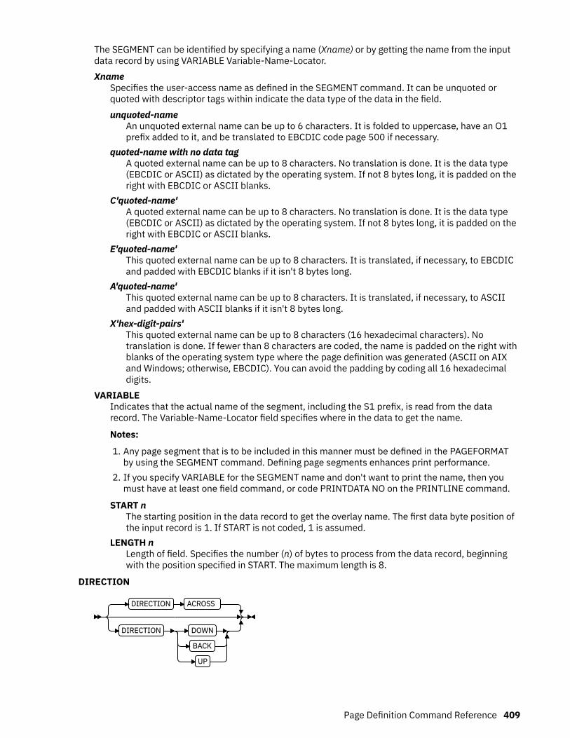
The SEGMENT can be identified by specifying a name (Xname) or by getting the name from the inputdata record by using VARIABLE Variable-Name-Locator.Xname
Specifies the user-access name as defined in the SEGMENT command. It can be unquoted orquoted with descriptor tags within indicate the data type of the data in the field.unquoted-name
An unquoted external name can be up to 6 characters. It is folded to uppercase, have an O1prefix added to it, and be translated to EBCDIC code page 500 if necessary.
quoted-name with no data tagA quoted external name can be up to 8 characters. No translation is done. It is the data type(EBCDIC or ASCII) as dictated by the operating system. If not 8 bytes long, it is padded on theright with EBCDIC or ASCII blanks.
C'quoted-name'A quoted external name can be up to 8 characters. No translation is done. It is the data type(EBCDIC or ASCII) as dictated by the operating system. If not 8 bytes long, it is padded on theright with EBCDIC or ASCII blanks.
E'quoted-name'This quoted external name can be up to 8 characters. It is translated, if necessary, to EBCDICand padded with EBCDIC blanks if it isn't 8 bytes long.
A'quoted-name'This quoted external name can be up to 8 characters. It is translated, if necessary, to ASCIIand padded with ASCII blanks if it isn't 8 bytes long.
X'hex-digit-pairs'This quoted external name can be up to 8 characters (16 hexadecimal characters). Notranslation is done. If fewer than 8 characters are coded, the name is padded on the right withblanks of the operating system type where the page definition was generated (ASCII on AIXand Windows; otherwise, EBCDIC). You can avoid the padding by coding all 16 hexadecimaldigits.
VARIABLEIndicates that the actual name of the segment, including the S1 prefix, is read from the datarecord. The Variable-Name-Locator field specifies where in the data to get the name.
Notes:
1. Any page segment that is to be included in this manner must be defined in the PAGEFORMATby using the SEGMENT command. Defining page segments enhances print performance.
2. If you specify VARIABLE for the SEGMENT name and don't want to print the name, then youmust have at least one field command, or code PRINTDATA NO on the PRINTLINE command.
START nThe starting position in the data record to get the overlay name. The first data byte position ofthe input record is 1. If START is not coded, 1 is assumed.
LENGTH nLength of field. Specifies the number (n) of bytes to process from the data record, beginningwith the position specified in START. The maximum length is 8.
DIRECTION
DIRECTION ACROSS
DIRECTION DOWN
BACK
UP
Page Definition Command Reference 409

Specifies the print direction of the line relative to the upper-left corner as you view the logical page.Not all printers can print in all print directions. For more information about your printer, see yourprinter documentation.
If DIRECTION is not specified, the direction that is specified in the PAGEFORMAT command is used.Observe that this direction is additive to the direction specified in the PAGEFORMAT command. SeePAGEFORMAT DIRECTION Subcommand .ACROSS
The printline direction is rotated 0° relative to the direction specified in the PAGEFORMAT (theprintlines are oriented in the same direction as the page).
DOWNThe printline direction is rotated 90° relative to the direction specified in the PAGEFORMAT.
BACKThe printline direction is rotated 180° relative to the direction specified in the PAGEFORMAT.
UPThe printline direction is rotated 270° relative to the direction specified in the PAGEFORMAT.
OBJECT
OBJECT lname
0 0
relX relY
VARIABLE
START n
LENGTH n
0 0
relX relY
OBTYPE Parameters
Other OBJECT Parameters
Specifies the placement of a resource object. If an internal name is coded, it is a known object that isdefined by an OBJECT command. Otherwise, the object is a variable-named object whose name isextracted from fields in the line data as described by the START, LENGTH, FLDNUM, or RECIDparameters. No OBJECT command exists for these objects; they must be specified with the OBTYPEand OBID parameters.
Notes:
1. All of the OBJECT parameters are treated as positional parameters. All positional parameters mustbe coded in the exact position and order as specified in the syntax diagram.
2. Multiple page/image objects that are used without specifying a page with OBPAGE default to usingthe first page in the object.
lnameSpecifies the local name of an object that is up to 16 alphanumeric characters in length. Thelname is used to match the PRINTLINE OBJECT subcommand to its definition from the OBJECTcommand. An object must be defined with this internal name by the OBJECT command.
relX relYSpecifies the number of units (such as inches or mm) that are added to the position of the currentprintline to position the top-left corner of the object. The values for the horizontal and verticalpositioning are limited by the type of printer that is used and the L-units that are specified with thePELSPERINCH parameter on the PAGEDEF or PAGEFORMAT command. Each position specificationcan be a positive or negative number with up to three decimal places. The units that are specifiedcan be one of these: IN, MM, CM, POINTS, or PELS.
VARIABLEIndicates that the actual name of the object is read from the data record. The Variable-Name-Locator field specifies where in the data to get the name.
Notes:
1. Any object that is to be included in this manner must be defined in the PAGEDEF by using theOBJECT command. Defining objects enhances print performance.
410 Page Printer Formatting Aid: User's Guide
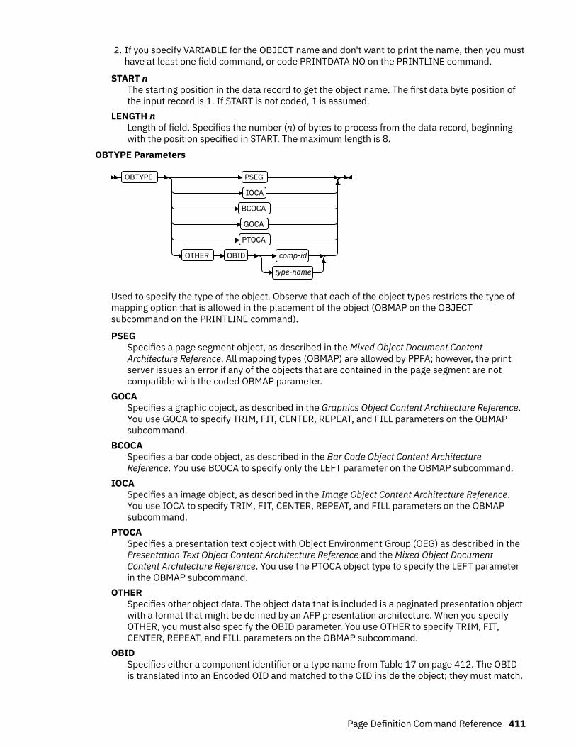
2. If you specify VARIABLE for the OBJECT name and don't want to print the name, then you musthave at least one field command, or code PRINTDATA NO on the PRINTLINE command.
START nThe starting position in the data record to get the object name. The first data byte position ofthe input record is 1. If START is not coded, 1 is assumed.
LENGTH nLength of field. Specifies the number (n) of bytes to process from the data record, beginningwith the position specified in START. The maximum length is 8.
OBTYPE Parameters
OBTYPE PSEG
IOCA
BCOCA
GOCA
PTOCA
OTHER OBID comp-id
type-name
Used to specify the type of the object. Observe that each of the object types restricts the type ofmapping option that is allowed in the placement of the object (OBMAP on the OBJECTsubcommand on the PRINTLINE command).
PSEGSpecifies a page segment object, as described in the Mixed Object Document ContentArchitecture Reference. All mapping types (OBMAP) are allowed by PPFA; however, the printserver issues an error if any of the objects that are contained in the page segment are notcompatible with the coded OBMAP parameter.
GOCASpecifies a graphic object, as described in the Graphics Object Content Architecture Reference.You use GOCA to specify TRIM, FIT, CENTER, REPEAT, and FILL parameters on the OBMAPsubcommand.
BCOCASpecifies a bar code object, as described in the Bar Code Object Content ArchitectureReference. You use BCOCA to specify only the LEFT parameter on the OBMAP subcommand.
IOCASpecifies an image object, as described in the Image Object Content Architecture Reference.You use IOCA to specify TRIM, FIT, CENTER, REPEAT, and FILL parameters on the OBMAPsubcommand.
PTOCASpecifies a presentation text object with Object Environment Group (OEG) as described in thePresentation Text Object Content Architecture Reference and the Mixed Object DocumentContent Architecture Reference. You use the PTOCA object type to specify the LEFT parameterin the OBMAP subcommand.
OTHERSpecifies other object data. The object data that is included is a paginated presentation objectwith a format that might be defined by an AFP presentation architecture. When you specifyOTHER, you must also specify the OBID parameter. You use OTHER to specify TRIM, FIT,CENTER, REPEAT, and FILL parameters on the OBMAP subcommand.
OBIDSpecifies either a component identifier or a type name from Table 17 on page 412. The OBIDis translated into an Encoded OID and matched to the OID inside the object; they must match.
Page Definition Command Reference 411
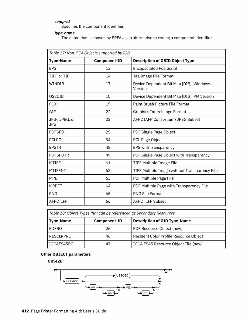
comp-idSpecifies the component identifier.
type-nameThe name that is chosen by PPFA as an alternative to coding a component identifier.
Table 17: Non-OCA Objects supported by IOB
Type-Name Component-ID Description of OBID Object Type
EPS 13 Encapsulated PostScript
TIFF or TIF 14 Tag Image File Format
WINDIB 17 Device Dependent Bit Map [DIB], WindowsVersion
OS2DIB 18 Device Dependent Bit Map [DIB], PM Version
PCX 19 Paint Brush Picture File Format
GIF 22 Graphics Interchange Format
JFIF, JPEG, orJPG
23 AFPC (AFP Consortium) JPEG Subset
PDFSPO 25 PDF Single Page Object
PCLPO 34 PCL Page Object
EPSTR 48 EPS with Transparency
PDFSPOTR 49 PDF Single Page Object with Transparency
MTIFF 61 TIFF Multiple Image File
MTIFFNT 62 TIFF Multiple Image without Transparency File
MPDF 63 PDF Multiple Page File
MPDFT 64 PDF Multiple Page with Transparency File
PNG 65 PNG File Format
AFPCTIFF 66 AFPC TIFF Subset
Table 18: Object Types that can be referenced as Secondary Resources
Type-Name Component-ID Description of OID Type-Name
PDFRO 26 PDF Resource Object (new)
RESCLRPRO 46 Resident Color Profile Resource Object
IOCAFS45RO 47 IOCA FS45 Resource Object Tile (new)
Other OBJECT parametersOBSIZE
OBSIZE
USEOBJ
wd
unit
hg
unit
412 Page Printer Formatting Aid: User's Guide

Specifies the size of the object placement area. When no OBSIZE is specified, the default isthe size that is specified in the object. If no size is specified in the object, the size of the pageis used. The page width is as specified on the PAGEDEF or PAGEFORMAT commands, or itdefaults to 8.3 inches by 10.8 inches.
wdSpecifies the width of an object placement area as a number with up to three decimalplaces. The allowable width might vary with the type of printer that is used and the L-unitsthat are specified with the PELSPERINCH parameter on the PAGEDEF or PAGEFORMATcommand.
hgSpecifies the height of the object placement area as a number with up to three decimalplaces. The allowable height might vary with the type of printer that is used and the L-unitsthat are specified with the PELSPERINCH parameter on the PAGEDEF or PAGEFORMATcommand.
unitSpecifies a unit of measurement for the width parameter. The choices are: IN, MM, CM,POINTS, or PELS.
Note: If no unit is specified, the default is the most recent SETUNITS command value or IN(inch) if a SETUNITS command is not issued.
USEOBJSpecifies that the size measurements that are specified in the object are to be used. If nosize is specified in the object, the size of the page is used, which is the length and width asspecified on the PAGEDEF or PAGEFORMAT commands, or it defaults to 8.3 inches by 10.8inches.
OBMAP
OBMAP LEFT
TRIM
FIT
CENTER
REPEAT
FILL
Specifies mapping options. The OBMAP parameter defines the mapping of the object to theobject placement area. If OBMAP is not coded, the mapping option within the object is used. Ifthe object does not contain a mapping option, then the print server sets it to the createddefault for the container type.
Each object type (OBTYPE on the OBJECT command) specifies the allowable mapping optionsfor that type. When it can, PPFA issues a message when these rules are violated. However, foran object type of page segment (OBTYPE=PSEG), PPFA does not know what types of objectsare contained in it; therefore, PPFA cannot enforce the restrictions. See “OBJECT Command”on page 363 for a description of the restrictions.LEFT
Specifies that the object is positioned at the upper, left corner of the object placementarea, as defined or defaulted by the relative-xpos, relative-ypos, OBCHPOS, and OBCVPOSparameters. Any portion of the object that falls outside the object placement area asdefined by the OBSIZE parameter is not trimmed and might cause an exception conditionby the presentation system.
TRIMSpecifies position and trim. The object is positioned at the upper, left corner of the objectplacement area, as defined or defaulted by the relative-xpos, relative-ypos, OBCHPOS, and
Page Definition Command Reference 413
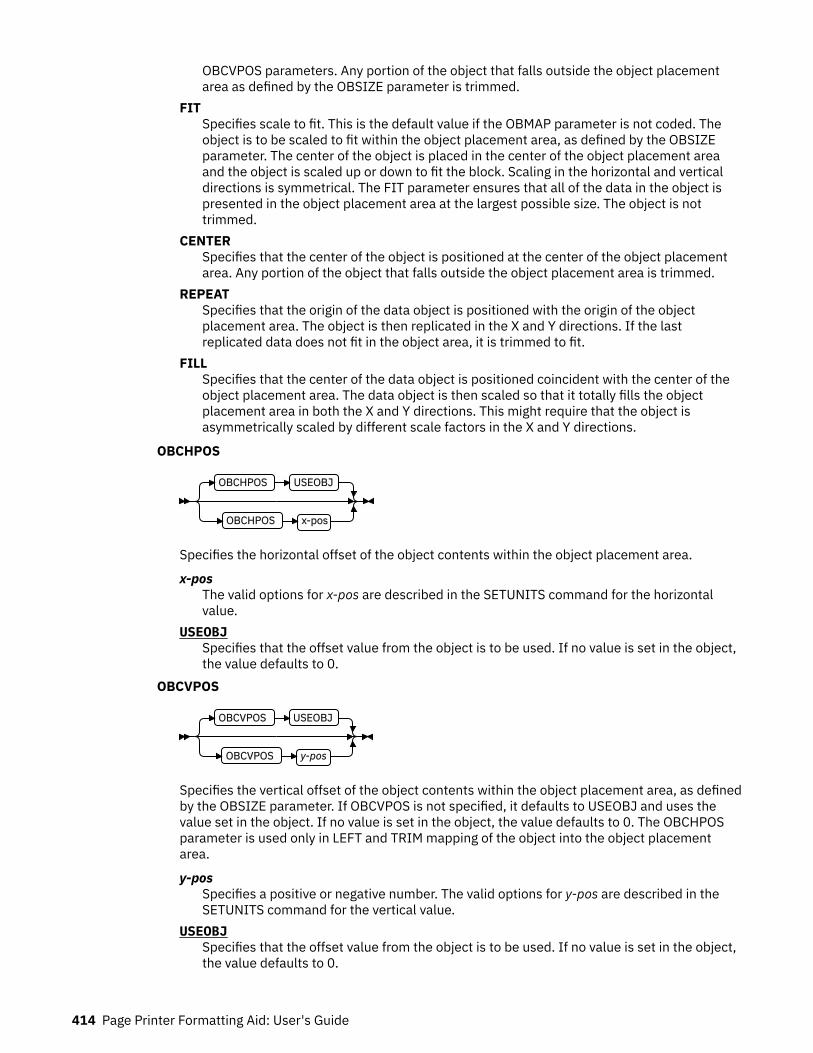
OBCVPOS parameters. Any portion of the object that falls outside the object placementarea as defined by the OBSIZE parameter is trimmed.
FITSpecifies scale to fit. This is the default value if the OBMAP parameter is not coded. Theobject is to be scaled to fit within the object placement area, as defined by the OBSIZEparameter. The center of the object is placed in the center of the object placement areaand the object is scaled up or down to fit the block. Scaling in the horizontal and verticaldirections is symmetrical. The FIT parameter ensures that all of the data in the object ispresented in the object placement area at the largest possible size. The object is nottrimmed.
CENTERSpecifies that the center of the object is positioned at the center of the object placementarea. Any portion of the object that falls outside the object placement area is trimmed.
REPEATSpecifies that the origin of the data object is positioned with the origin of the objectplacement area. The object is then replicated in the X and Y directions. If the lastreplicated data does not fit in the object area, it is trimmed to fit.
FILLSpecifies that the center of the data object is positioned coincident with the center of theobject placement area. The data object is then scaled so that it totally fills the objectplacement area in both the X and Y directions. This might require that the object isasymmetrically scaled by different scale factors in the X and Y directions.
OBCHPOS
OBCHPOS USEOBJ
OBCHPOS x-pos
Specifies the horizontal offset of the object contents within the object placement area.
x-posThe valid options for x-pos are described in the SETUNITS command for the horizontalvalue.
USEOBJSpecifies that the offset value from the object is to be used. If no value is set in the object,the value defaults to 0.
OBCVPOS
OBCVPOS USEOBJ
OBCVPOS y-pos
Specifies the vertical offset of the object contents within the object placement area, as definedby the OBSIZE parameter. If OBCVPOS is not specified, it defaults to USEOBJ and uses thevalue set in the object. If no value is set in the object, the value defaults to 0. The OBCHPOSparameter is used only in LEFT and TRIM mapping of the object into the object placementarea.
y-posSpecifies a positive or negative number. The valid options for y-pos are described in theSETUNITS command for the vertical value.
USEOBJSpecifies that the offset value from the object is to be used. If no value is set in the object,the value defaults to 0.
414 Page Printer Formatting Aid: User's Guide
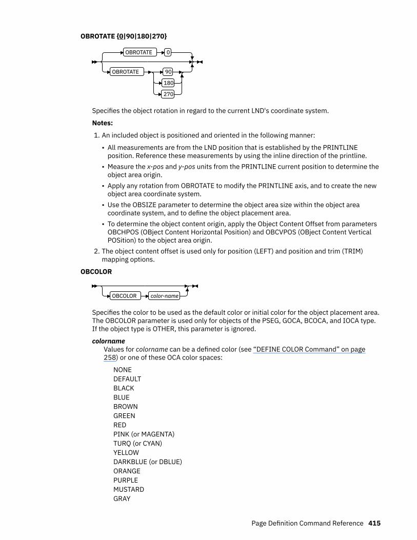
OBROTATE {0|90|180|270}
OBROTATE 0
OBROTATE 90
180
270
Specifies the object rotation in regard to the current LND's coordinate system.
Notes:
1. An included object is positioned and oriented in the following manner:
• All measurements are from the LND position that is established by the PRINTLINEposition. Reference these measurements by using the inline direction of the printline.
• Measure the x-pos and y-pos units from the PRINTLINE current position to determine theobject area origin.
• Apply any rotation from OBROTATE to modify the PRINTLINE axis, and to create the newobject area coordinate system.
• Use the OBSIZE parameter to determine the object area size within the object areacoordinate system, and to define the object placement area.
• To determine the object content origin, apply the Object Content Offset from parametersOBCHPOS (OBject Content Horizontal Position) and OBCVPOS (OBject Content VerticalPOSition) to the object area origin.
2. The object content offset is used only for position (LEFT) and position and trim (TRIM)mapping options.
OBCOLOR
OBCOLOR color-name
Specifies the color to be used as the default color or initial color for the object placement area.The OBCOLOR parameter is used only for objects of the PSEG, GOCA, BCOCA, and IOCA type.If the object type is OTHER, this parameter is ignored.
colornameValues for colorname can be a defined color (see “DEFINE COLOR Command” on page258) or one of these OCA color spaces:
NONEDEFAULTBLACKBLUEBROWNGREENREDPINK (or MAGENTA)TURQ (or CYAN)YELLOWDARKBLUE (or DBLUE)ORANGEPURPLEMUSTARDGRAY
Page Definition Command Reference 415
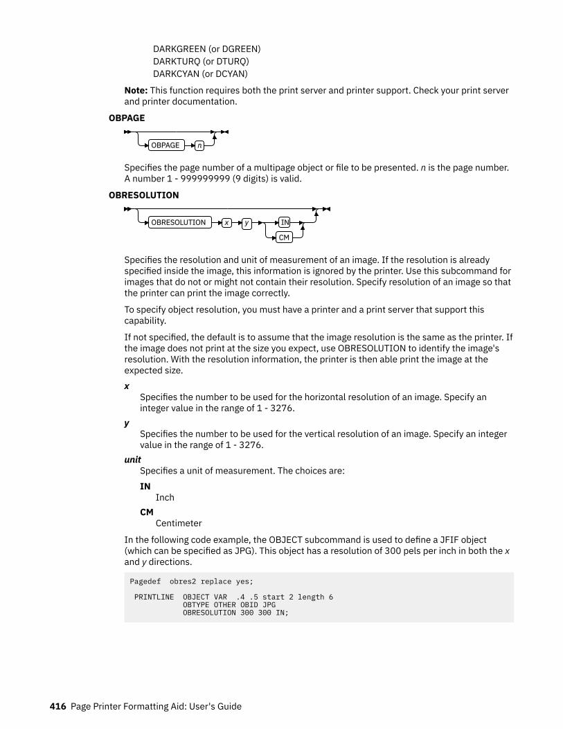
DARKGREEN (or DGREEN)DARKTURQ (or DTURQ)DARKCYAN (or DCYAN)
Note: This function requires both the print server and printer support. Check your print serverand printer documentation.
OBPAGE
OBPAGE n
Specifies the page number of a multipage object or file to be presented. n is the page number.A number 1 - 999999999 (9 digits) is valid.
OBRESOLUTION
OBRESOLUTION x y IN
CM
Specifies the resolution and unit of measurement of an image. If the resolution is alreadyspecified inside the image, this information is ignored by the printer. Use this subcommand forimages that do not or might not contain their resolution. Specify resolution of an image so thatthe printer can print the image correctly.
To specify object resolution, you must have a printer and a print server that support thiscapability.
If not specified, the default is to assume that the image resolution is the same as the printer. Ifthe image does not print at the size you expect, use OBRESOLUTION to identify the image'sresolution. With the resolution information, the printer is then able print the image at theexpected size.x
Specifies the number to be used for the horizontal resolution of an image. Specify aninteger value in the range of 1 - 3276.
ySpecifies the number to be used for the vertical resolution of an image. Specify an integervalue in the range of 1 - 3276.
unitSpecifies a unit of measurement. The choices are:IN
InchCM
Centimeter
In the following code example, the OBJECT subcommand is used to define a JFIF object(which can be specified as JPG). This object has a resolution of 300 pels per inch in both the xand y directions.
Pagedef obres2 replace yes; PRINTLINE OBJECT VAR .4 .5 start 2 length 6 OBTYPE OTHER OBID JPG OBRESOLUTION 300 300 IN;
416 Page Printer Formatting Aid: User's Guide

ExampleIn the following example, the page definition pd1 defines an object with an external name of PSEGxyz, ofobject type PSEG. The object has an internal name of xyzintname. The internal name identifies theobject for the PRINTLINE OBJECT subcommand when the object is placed.
PAGEDEF pd1 Replace Yes COMMENT ‘this is my program’;
OBJECT xzZIntName OBXNAME PSEGxyz OBTYPE PSEG ;
PAGEFORMAT pf1; PRINTLINE OBJECT xyzintname -1.1 in 2.1 in OBSIZE 3 in 5 in OBMAP FILL OBCOLOR BLUE ;
The PRINTLINE in PAGEFORMAT pf1 places the object on the page 1.1 inches to the left and 2.1 inchesbelow the current printline position. It also maps the object into the object area with the FILL parameter,which centers the object in the object area and totally fills the area, possibly with different scaling factorsin the X and Y directions. It has an area size of 3 by 5 inches, and overrides the default presentation spacecolor to BLUE.
SEGMENT CommandSEGMENT name ;
Use the SEGMENT command only if you want page segments to be loaded to the printer before the pagebegins printing. If segments are used repeatedly and need to be available in the printer, this commandeliminates the need to load them each time. However, they do take up raster-pattern storage.
A separate SEGMENT command is required for each page segment with a maximum of 127 SEGMENTcommands within a single page format. A SEGMENT command is nested within the page format andfollows the PAGEFORMAT command.
For Traditional
PAGEFORMAT TRCREF SEGMENT … SEGMENT
Note: To include a page segment on a page without using an Include Page Segment structured fieldwithin the user data, see the “PRINTLINE Command ” on page 400.
For Record Format and XML
PAGEFORMAT SEGMENT … SEGMENT
SEGMENT nameSpecifies the alphanumeric name of 1 - 6 characters (user-access name) of the page segment. Eachname must be unique within a single page format.
Note: The prefix S1 is not part of the six-character user-access name.
Page Definition Command Reference 417

SETUNITS Command
SETUNITS 1 IN 1 IN
x
IN
MM
CM
POINTS
PELS
CPI
y
IN
MM
CM
POINTS
PELS
LPI
LINESP n IN
MM
CM
POINTS
PELS
LPI
;
The SETUNITS command specifies the value and the unit of measurement that are the defaults for anysubsequent measurement parameter in all of the commands and subcommands. These values remain thedefault values until another SETUNITS command is specified. The SETUNITS command must be specifiedas the first command in a page definition. If this command or a measurement parameter is not specified,the defaults that are identified within the following description are used.SETUNITS
Specifies the value and the unit of measurement that are the defaults for any subsequentmeasurement parameter in all of the commands and subcommands.x
Specifies the number that is used for horizontal measurement. A number with up to three decimalplaces is used. The default is 1. The choices are IN, MM, CM, POINTS, PELS, or LPI. The default isIN.
Note: This value affects subsequent OFFSET subcommands.
ySpecifies the number that is used for vertical measurement. A number with up to three decimalplaces is used. The default is 1. The choices are IN, MM, CM, POINTS, PELS, or LPI. The default isIN.
Note: This value affects subsequent OFFSET subcommands.
Using CPI and LPI Units of Measurement: The CPI and LPI units of measurement make it possible towrite the following command:
SETUNITS 10 CPI 6 LPI ;
This command sets the units of measurement for horizontal and vertical spacing in terms ofcharacters per inch and lines per inch. You can then use the OFFSET subcommand specifications toincrement the spacing one character or one line at a time. The distance that is specified by ncharacters over and by n lines down is defined in the governing SETUNITS command. This exampleshows 10 characters per inch (CPI) and 6 lines per inch (LPI).
418 Page Printer Formatting Aid: User's Guide
SubcommandLINESP
Determines the line density or leading of the text. Any unit of measurement can be used.For Traditional
This subcommand value affects:
• The following PRINTLINE NEXT subcommand• The vertical (y) position of the first line on a logical page when the LINEONE subcommand is notspecified and the default is assumed
The default is 6 LPI. If LINESP is allowed to default to 6 LPI, the LINEONE default is one L-unitless than 80% of 1/6 inch.
For Record Format and XMLThis subcommand value affects the LAYOUT NEXT subcommand:n
The meaning is determined by the type of unit-of-measurement that is specified in the unitparameter.LPI
The number of lines per inchAll others
The distance between linesunit
Specifies a unit of measurement. The choices are:IN
InchLPI
Lines-per-inchMM
MillimeterCM
CentimeterPELS
L-units per inch (The number of L-units per inch can be defined by the user or can defaultto 240 L-units in an inch)
POINTSPoints per inch (72 points in an inch)
Page Definition Command Reference 419
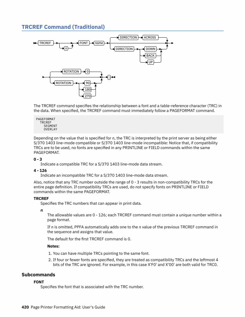
TRCREF Command (Traditional)
TRCREFn
FONT name
DIRECTION ACROSS
DIRECTION DOWN
BACK
UP
ROTATION 0
ROTATION 90
180
270
;
The TRCREF command specifies the relationship between a font and a table-reference character (TRC) inthe data. When specified, the TRCREF command must immediately follow a PAGEFORMAT command.
PAGEFORMAT TRCREF SEGMENT OVERLAY
Depending on the value that is specified for n, the TRC is interpreted by the print server as being eitherS/370 1403 line-mode compatible or S/370 1403 line-mode incompatible: Notice that, if compatibilityTRCs are to be used, no fonts are specified in any PRINTLINE or FIELD commands within the samePAGEFORMAT.0 - 3
Indicate a compatible TRC for a S/370 1403 line-mode data stream.4 - 126
Indicate an incompatible TRC for a S/370 1403 line-mode data stream.Also, notice that any TRC number outside the range of 0 - 3 results in non-compatibility TRCs for theentire page definition. If compatibility TRCs are used, do not specify fonts on PRINTLINE or FIELDcommands within the same PAGEFORMAT.TRCREF
Specifies the TRC numbers that can appear in print data.n
The allowable values are 0 - 126; each TRCREF command must contain a unique number within apage format.
If n is omitted, PPFA automatically adds one to the n value of the previous TRCREF command inthe sequence and assigns that value.
The default for the first TRCREF command is 0.
Notes:
1. You can have multiple TRCs pointing to the same font.2. If four or fewer fonts are specified, they are treated as compatibility TRCs and the leftmost 4
bits of the TRC are ignored. For example, in this case X'F0' and X'00' are both valid for TRC0.
SubcommandsFONT
Specifies the font that is associated with the TRC number.
420 Page Printer Formatting Aid: User's Guide

nameSpecifies the local name of a font; the font must be one that is named in a FONT command.
If you used both the user-access name and the local name in the FONT command, use the localname here. If you used only the user-access name, use it here.
DIRECTIONSpecifies the print direction of the line relative to the upper-left corner as you view the logical page.Not all printers can print in all print directions. For more information about your printer, see yourprinter documentation.
The DIRECTION on the TRCREF command must match the DIRECTION of the PRINTLINE commandwith which the TRC is to be used. If TRCREF DIRECTION subcommand is not specified, DIRECTIONACROSS is assumed. Observe that this direction is additive to the direction specified in thePAGEFORMAT command.ACROSS
The page is printed with the characters added to the page from left to right, and the lines addedfrom the top to the bottom.
DOWNThe page is printed with the characters added to the page from top to bottom, and the lines addedfrom the right to the left.
BACKThe page is printed with the characters added to the page from right to left, and the lines addedfrom the bottom to the top.
UPThe page is printed with the characters added to the page from bottom to top, and the lines addedfrom the left to the right.
ROTATIONSpecifies the rotation of characters in degrees. The specified value is relative to the inline direction ofthe printline.
Valid rotations are 0°, 90°, 180°, or 270°; 0 is the default.
If the TRCREF ROTATION subcommand is not specified, the default is the rotation value that isspecified on the FONT command.
Page Definition Command Reference 421
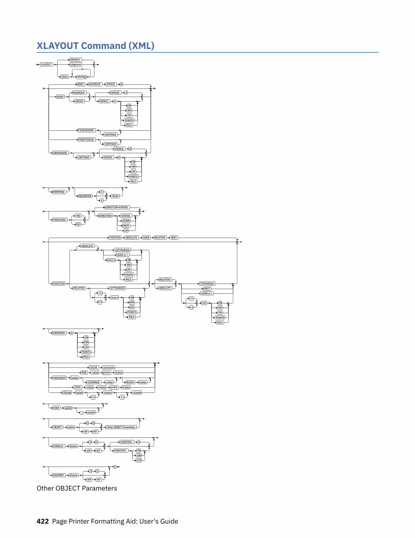
XLAYOUT Command (XML)XLAYOUT
DEFAULT
qtagname
QTAG starttag
BODY NOGROUP XSPACE 0
BODY
NOGROUP
GROUP
XSPACE 0
XSPACE n
IN
MM
CM
POINTS
PELS
PAGEHEADER
CONTINUE
PAGETRAILER
CONTINUE
GRPHEADER
CONTINUE
XSPACE 0
XSPACE n
IN
MM
CM
POINTS
PELS
NEWPAGE
DELIMITER
C
X
'bytes'
PRINTDATA
YES
NO
DIRECTION ACROSS
DIRECTION ACROSS
DOWN
BACK
UP
POSITION ABSOLUTE SAME RELATIVE NEXT
POSITION
ABSOLUTE
LEFTMARGIN
SAME or =
horiz n IN
MM
CM
POINTS
PELS
RELATIVE LEFTMARGIN
(+)
(-)
horiz n IN
MM
CM
POINTS
PELS
RELATIVE
ABSOLUTE
TOPMARGIN
NEXT
SAME or =
(+)
(-)
vert IN
MM
CM
POINTS
PELS
ENDSPACE n
IN
MM
CM
POINTS
PELS
COLOR colorname
RGB rvalue gvalue bvalue
HIGHLIGHT hvalue
COVERAGE cvalue BLACK bvalue
CMYK cvalue mvalue yvalue kvalue
CIELAB lvalue
(–)
clvalue
(–)
c2value
FONT name1
, name2
OBJECT lname
0 0
relX relY
Other OBJECT Parameters
OVERLAY Xname
0 0
relX relY
OVROTATE 0
OVROTATE 90
180
270
SEGMENT Xname
0 0
relX relY
;
Other OBJECT Parameters
422 Page Printer Formatting Aid: User's Guide
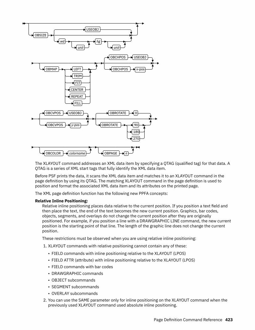
OBSIZE
USEOBJ
wd
unit
hg
unit
OBMAP LEFT
TRIM
FIT
CENTER
REPEAT
FILL
OBCHPOS USEOBJ
OBCHPOS x-pos
OBCVPOS USEOBJ
OBCVPOS y-pos
OBROTATE 0
OBROTATE 90
180
270
OBCOLOR colorname OBPAGE n
The XLAYOUT command addresses an XML data item by specifying a QTAG (qualified tag) for that data. AQTAG is a series of XML start tags that fully identify the XML data item.
Before PSF prints the data, it scans the XML data item and matches it to an XLAYOUT command in thepage definition by using its QTAG. The matching XLAYOUT command in the page definition is used toposition and format the associated XML data item and its attributes on the printed page.
The XML page definition function has the following new PPFA concepts:
Relative Inline Positioning:Relative inline positioning places data relative to the current position. If you position a text field andthen place the text, the end of the text becomes the new current position. Graphics, bar codes,objects, segments, and overlays do not change the current position after they are originallypositioned. For example, if you position a line with a DRAWGRAPHIC LINE command, the new currentposition is the starting point of that line. The length of the graphic line does not change the currentposition.
These restrictions must be observed when you are using relative inline positioning:
1. XLAYOUT commands with relative positioning cannot contain any of these:
• FIELD commands with inline positioning relative to the XLAYOUT (LPOS)• FIELD ATTR (attribute) with inline positioning relative to the XLAYOUT (LPOS)• FIELD commands with bar codes• DRAWGRAPHIC commands• OBJECT subcommands• SEGMENT subcommands• OVERLAY subcommands
2. You can use the SAME parameter only for inline positioning on the XLAYOUT command when thepreviously used XLAYOUT command used absolute inline positioning.
Page Definition Command Reference 423

Absolute Inline Positioning:Allows absolute inline positioning on a FIELD command for specific placement of elements.
Attributes are Special FIELDs:The attribute is identified by name and the data that is printed is from the attribute value or a portionof the attribute value and not from the element content.
Notes:
1. If a FIELD is used for presenting any piece of data on the XLAYOUT command, FIELD commands mustbe used for all pieces of data that is presented on the XLAYOUT command. Because an attribute is aspecial field, if you want to print both an attribute value and the element data, you need to code theattribute field for the attribute value and a regular field for the element data.
2. PSF suppresses leading and trailing blanks (X'40' for EBCDIC or X'20' for ASCII) in the data. Multipleembedded blanks are reduced to one blank.
3. The XLAYOUT command defines an XML page definition and cannot be mixed with PRINTLINEcommands, which define traditional page definitions, or LAYOUT commands, which define RecordFormatting page definitions.
Subcommands
DEFAULT
qtagname
QTAG starttag
DEFAULTThis keyword is used only when the layout type is either PAGEHEADER or PAGETRAILER, and noname is needed. Only one default PAGEHEADER or PAGETRAILER can be specified in aPAGEFORMAT.
qtagnameThe qtagname is a defined Qualified Tag. It is defined by the DEFINE qtagname QTAG command atthe beginning of the page definition.
QTAG starttagAn explicit Qualified Tag. It is defined by coding a series of start tags that are separated bycommas. A start tag is an XML data element name. Put the start tag in quotation marks if you wantto preserve its case. Otherwise, it is folded to uppercase.
In Figure 135 on page 425, person, name, and first are start tags. The qualifying tag for thedata item Case is 'person','name','last'. In the example page definition, both of the x andy XLAYOUT commands address the same XML data item Case.
424 Page Printer Formatting Aid: User's Guide

<person> <name> <first>Justin</first> <last>Case</last> </name></person>
PAGEDEF xxx…; DEFINE lname QTAG 'person','name', 'last'; … Pageformat x … XLAYOUT lname POSITION… … Pageformat y … XLAYOUT QTAG 'person','name','last' POSITION … …
Figure 135: Example of XML data with the associated page definition
BodyBODY NOGROUP XSPACE 0
BODY
NOGROUP
GROUP
XSPACE 0
XSPACE n
IN
MM
CM
POINTS
PELS
PAGEHEADER
CONTINUE
PAGETRAILER
CONTINUE
GRPHEADER
CONTINUE
XSPACE 0
XSPACE n
IN
MM
CM
POINTS
PELS
The BODY layout type is used for most of data in your database. This is the default.
GROUPThe GROUP parameter indicates that the existing group header must be saved and used forsubsequent pages. If this parameter is not set when processing starts on a BODY layout, theactive group header record is discarded and not reprinted on subsequent pages.
XSPACEXSPACE indicates the amount of extra space from the position of the layout to the bottom of thegroup header area. The user can identify the amount of extra space in excess of one text line that
Page Definition Command Reference 425

is used by the header so that the baseline moves down and the following group data is not placedon top of the header area. This space is not calculated by PPFA and must be explicitly defined bythe user. See Figure 136 on page 426 (shaded space shows group header area):
Figure 136: Example Showing the Use of XSPACE.
When a Group Header record is processed and is still active when the PAGEFORMAT is left, thegroup header record is saved by the presentation services program. Whenever the samePAGEFORMAT is reinvoked, this saved group header record is presented again if the first bodyrecord after reinvoking the PAGEFORMAT selects a Body record that has the Group Indicator on.
PAGEHEADERThis layout type specifies a header that is to be printed on each new page. The baseline position ofthis layout is normally in the top margin, but can be anywhere on a logical page. If RELATIVE isspecified, the position is considered to be relative to the page origin. Usually contains customer'sname, address, account number, and so forth. Only one default PAGEHEADER layout can bespecified in a PAGEFORMAT and no input record data can be specified in a default layout.CONTINUE
The CONTINUE parameter indicates that this XLAYOUT command is a continuation of the PageHeader definition. The formation of the Page Header might require the data from more thanone data element, which is done by specifying the CONTINUE parameter.
PAGETRAILERThis layout type specifies a trailer that is to be printed on each new page. The baseline position ofthis layout is normally in the bottom margin, but can be located anywhere on a logical page andcan be specified as RELATIVE. Only one default PAGETRAILER layout can be specified in aPAGEFORMAT and no input record data is processed with a default layout. It can contain the nameof the form or a footnote.CONTINUE
The CONTINUE parameter indicates that this XLAYOUT command is a continuation of the PageTrailer definition. The formation of the Page Trailer might require the data from more than onedata element, which is done by specifying the CONTINUE parameter.
GRPHEADERThis layout type specifies a header that is to be printed at the beginning of a group of data. If alogical page eject occurs before the group of data ends, the header is printed after the top marginon each new page until the group ends. The baseline position of this layout can be specified asRELATIVE. It can include column headings.CONTINUE
The CONTINUE parameter indicates that this XLAYOUT command is a continuation of theGroup Header definition. The formation of the Group Header might require the data from morethan one data element, which is done by specifying the CONTINUE parameter.
NEWPAGE
NEWPAGE
This parameter indicates that a new page must be started with this layout name. If it is a header ortrailer layout, the print position is moved to the start of a new page before this header or trailerbecomes the active header or trailer.
426 Page Printer Formatting Aid: User's Guide
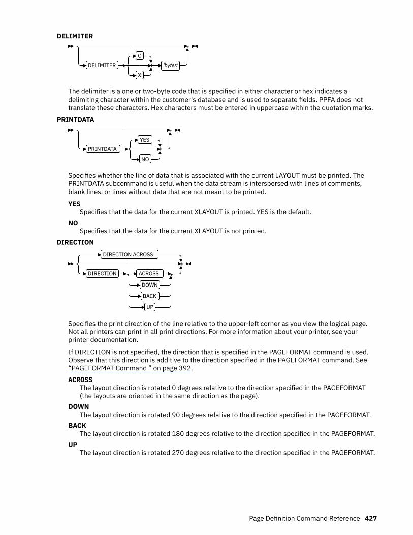
DELIMITER
DELIMITER
C
X
'bytes'
The delimiter is a one or two-byte code that is specified in either character or hex indicates adelimiting character within the customer's database and is used to separate fields. PPFA does nottranslate these characters. Hex characters must be entered in uppercase within the quotation marks.
PRINTDATA
PRINTDATA
YES
NO
Specifies whether the line of data that is associated with the current LAYOUT must be printed. ThePRINTDATA subcommand is useful when the data stream is interspersed with lines of comments,blank lines, or lines without data that are not meant to be printed.
YESSpecifies that the data for the current XLAYOUT is printed. YES is the default.
NOSpecifies that the data for the current XLAYOUT is not printed.
DIRECTIONDIRECTION ACROSS
DIRECTION ACROSS
DOWN
BACK
UP
Specifies the print direction of the line relative to the upper-left corner as you view the logical page.Not all printers can print in all print directions. For more information about your printer, see yourprinter documentation.
If DIRECTION is not specified, the direction that is specified in the PAGEFORMAT command is used.Observe that this direction is additive to the direction specified in the PAGEFORMAT command. See“PAGEFORMAT Command ” on page 392.ACROSS
The layout direction is rotated 0 degrees relative to the direction specified in the PAGEFORMAT(the layouts are oriented in the same direction as the page).
DOWNThe layout direction is rotated 90 degrees relative to the direction specified in the PAGEFORMAT.
BACKThe layout direction is rotated 180 degrees relative to the direction specified in the PAGEFORMAT.
UPThe layout direction is rotated 270 degrees relative to the direction specified in the PAGEFORMAT.
Page Definition Command Reference 427
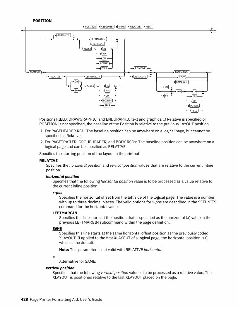
POSITIONPOSITION ABSOLUTE SAME RELATIVE NEXT
POSITION
ABSOLUTE
LEFTMARGIN
SAME or =
horiz n IN
MM
CM
POINTS
PELS
RELATIVE LEFTMARGIN
(+)
(-)
horiz n IN
MM
CM
POINTS
PELS
RELATIVE
ABSOLUTE
TOPMARGIN
NEXT
SAME or =
(+)
(-)
vert IN
MM
CM
POINTS
PELS
Positions FIELD, DRAWGRAPHIC, and ENDGRAPHIC text and graphics. If Relative is specified orPOSITION is not specified, the baseline of the Position is relative to the previous LAYOUT position.
1. For PAGEHEADER RCD: The baseline position can be anywhere on a logical page, but cannot bespecified as Relative.
2. For PAGETRAILER, GROUPHEADER, and BODY RCDs: The baseline position can be anywhere on alogical page and can be specified as RELATIVE.
Specifies the starting position of the layout in the printout.
RELATIVESpecifies the horizontal position and vertical position values that are relative to the current inlineposition.horizontal position
Specifies that the following horizontal position value is to be processed as a value relative tothe current inline position.x-pos
Specifies the horizontal offset from the left side of the logical page. The value is a numberwith up to three decimal places. The valid options for x-pos are described in the SETUNITScommand for the horizontal value.
LEFTMARGINSpecifies this line starts at the position that is specified as the horizontal (x) value in theprevious LEFTMARGIN subcommand within the page definition.
SAMESpecifies this line starts at the same horizontal offset position as the previously codedXLAYOUT. If applied to the first XLAYOUT of a logical page, the horizontal position is 0,which is the default.
Note: This parameter is not valid with RELATIVE horizontal.
=Alternative for SAME.
vertical positionSpecifies that the following vertical position value is to be processed as a relative value. TheXLAYOUT is positioned relative to the last XLAYOUT placed on the page.
428 Page Printer Formatting Aid: User's Guide
y-posSpecifies the vertical offset from the top side of the logical page. The value options for y-pos are described in the SETUNITS command for the vertical value.
TOPMARGINSpecifies that the XLAYOUT is placed in the position that is specified as the vertical (y)value in the TOPMARGIN subcommand within the page definition.
NEXTSpecifies the layout is to be positioned down (on the logical page) one line (as defined inthe LINESP subcommand of the last SETUNITS command) from the previous field. TheLINESP subcommand of the SETUNITS command establishes the distance from one line tothe next.
When NEXT is specified for the first XLAYOUT of a logical page, the starting position of theline is one line down from the top of the logical page, as defined by the TOPMARGINsubcommand.
Note: The down direction is determined by the direction of the logical page (as specified inthe page format), not the XLAYOUT direction. Therefore, NEXT is useful in ACROSSXLAYOUTs.
SAMESpecifies this XLAYOUT starts at the same vertical position as the previous XLAYOUT.
=Alternative for SAME.
Notes:
1. If both TOP and RELATIVE are requested for the y-pos value, the RELATIVE request isignored.
2. When you are using RELATIVE positioning, PPFA does not flag off-the-page conditions forthe position of an XLAYOUT or for any overlays, segments, or objects placed relative to thatXLAYOUT. XLAYOUTs that fall outside the bounds of the logical page are flagged by the printserver at run time.
3. When you are specifying RELATIVE, use the minus sign to indicate any negative values forthe XLAYOUT vertical position; you can use the plus sign to indicate positive values. If nosign is used, a positive value is assumed.
4. The DIRECTION for a relative XLAYOUT must be ACROSS. Fields that are associated with arelative XLAYOUT must have the same DIRECTION as the XLAYOUT and must match thePAGEFORMAT DIRECTION.
5. If RELATIVE is specified with SAME or = as the y value, the relative value in the XLAYOUT is+0.
6. RELATIVE positioning is allowed on an XLAYOUT command only if the XLAYOUT and all itsassociated FIELD commands are formatted to print in the same direction as thePAGEFORMAT. That is, the DIRECTION parameter in the XLAYOUT and any associatedFIELD commands must specify (or default to) ACROSS. The DIRECTION in thePAGEFORMAT or PAGEDEF command can be any allowable value: ACROSS, DOWN, BACK,or UP.
Page Definition Command Reference 429
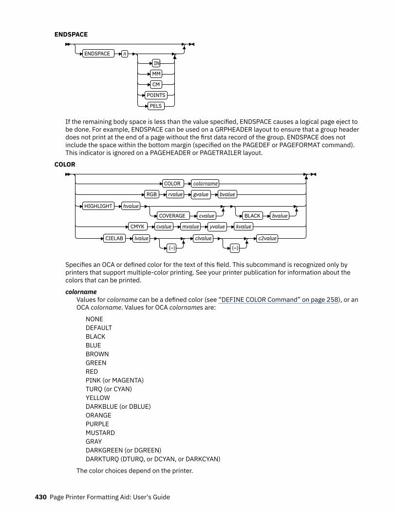
ENDSPACE
ENDSPACE n
IN
MM
CM
POINTS
PELS
If the remaining body space is less than the value specified, ENDSPACE causes a logical page eject tobe done. For example, ENDSPACE can be used on a GRPHEADER layout to ensure that a group headerdoes not print at the end of a page without the first data record of the group. ENDSPACE does notinclude the space within the bottom margin (specified on the PAGEDEF or PAGEFORMAT command).This indicator is ignored on a PAGEHEADER or PAGETRAILER layout.
COLOR
COLOR colorname
RGB rvalue gvalue bvalue
HIGHLIGHT hvalue
COVERAGE cvalue BLACK bvalue
CMYK cvalue mvalue yvalue kvalue
CIELAB lvalue
(–)
clvalue
(–)
c2value
Specifies an OCA or defined color for the text of this field. This subcommand is recognized only byprinters that support multiple-color printing. See your printer publication for information about thecolors that can be printed.
colornameValues for colorname can be a defined color (see “DEFINE COLOR Command” on page 258), or anOCA colorname. Values for OCA colornames are:
NONEDEFAULTBLACKBLUEBROWNGREENREDPINK (or MAGENTA)TURQ (or CYAN)YELLOWDARKBLUE (or DBLUE)ORANGEPURPLEMUSTARDGRAYDARKGREEN (or DGREEN)DARKTURQ (DTURQ, or DCYAN, or DARKCYAN)
The color choices depend on the printer.
430 Page Printer Formatting Aid: User's Guide

If you do not enter one of these colors, the default color for that printer is used. NONE is the colorof the medium. DEFAULT is the printer default color.
Note: In some printer manuals, the color turquoise (TURQ) is called cyan, and the color pink(PINK) is called magenta.
PPFA supports the following synonyms:
• CYAN for TURQ• DARKCYANN for DARKTURQ• DBLUE for DARKBLUE• DCYAN for DARKTURQ• DGREEN for DARKGREEN• DTURQ for DARKTURQ• MAGENTA for PINK
color modelsSpecifies the color of print for this field that is supported in MO:DCA for the Red/Green/Blue colormodel (RGB), the highlight color space, the Cyan/Magenta/Yellow/Black color model (CMYK), andthe CIELAB color model.RGB rvalue gvalue bvalue
Three RGB integer values are used. The first (rvalue) represents a value for red, the second(gvalue) represents a value for green, and the third (bvalue) represents a value for blue. Eachof the three integer values can be specified as a percentage 0 - 100.
Note: An RGB specification of 0/0/0 is black. An RGB specification of 100/100/100 is white.Any other value is a color somewhere between black and white, depending on the outputdevice.
HIGHLIGHT hvalue COVERAGE cvalue BLACK bvalueIndicates the highlight color model. Highlight colors are device-dependent.
You can use an integer within the range of 0 - 65535 for the hvalue.
Note: An hvalue of 0 indicates that no default value is defined; therefore, the default color ofthe presentation device is used.
COVERAGE indicates the amount of coverage of the highlight color to be used. You can use aninteger within the range of 0 - 100 for the cvalue. If less than 100 percent is specified, theremaining coverage is achieved with the color of the medium.
Note: Fractional values are ignored. If COVERAGE is not specified, a value of 100 is used as adefault.
BLACK indicates the percentage of black to be added to the highlight color. You can use aninteger within the range of 0 - 100 for the bvalue. The amount of black shading that is applieddepends on the COVERAGE percentage, which is applied first. If less than 100 percent isspecified, the remaining coverage is achieved with black.
Note: If BLACK is not specified, a value of 0 is used as a default.
CMYK cvalue mvalue yvalue kvalueDefines the cyan/magenta/yellow/black color model. cvalue specifies the cyan value. mvaluespecifies the magenta value. yvalue specifies the yellow value. kvalue specifies the blackvalue. You can use an integer percentage within the range of 0 - 100 for any of the CMYKvalues.
CIELAB Lvalue (-)c1value (-)c2valueDefines the CIELAB model. Use a range of 0.00 - 100.00 with Lvalue to specify the luminancevalue. Use signed integers from -127 to 127 with c1value and c2value to specify thechrominance differences.
Lvalue, c1value, c2value must be specified in this order. No defaults exist for the subvalues.
Page Definition Command Reference 431
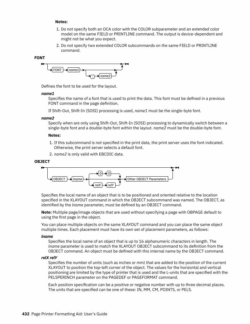
Notes:
1. Do not specify both an OCA color with the COLOR subparameter and an extended colormodel on the same FIELD or PRINTLINE command. The output is device-dependent andmight not be what you expect.
2. Do not specify two extended COLOR subcommands on the same FIELD or PRINTLINEcommand.
FONT
FONT name1
, name2
Defines the font to be used for the layout.
name1Specifies the name of a font that is used to print the data. This font must be defined in a previousFONT command in the page definition.
If Shift-Out, Shift-In (SOSI) processing is used, name1 must be the single-byte font.
name2Specify when are only using Shift-Out, Shift-In (SOSI) processing to dynamically switch between asingle-byte font and a double-byte font within the layout. name2 must be the double-byte font.
Notes:
1. If this subcommand is not specified in the print data, the print server uses the font indicated.Otherwise, the print server selects a default font.
2. name2 is only valid with EBCDIC data.
OBJECT
OBJECT lname
0 0
relX relY
Other OBJECT Parameters
Specifies the local name of an object that is to be positioned and oriented relative to the locationspecified in the XLAYOUT command in which the OBJECT subcommand was named. The OBJECT, asidentified by the lname parameter, must be defined by an OBJECT command.
Note: Multiple page/image objects that are used without specifying a page with OBPAGE default tousing the first page in the object.
You can place multiple objects on the same XLAYOUT command and you can place the same objectmultiple times. Each placement must have its own set of placement parameters, as follows:lname
Specifies the local name of an object that is up to 16 alphanumeric characters in length. Thelname parameter is used to match the XLAYOUT OBJECT subcommand to its definition from theOBJECT command. An object must be defined with this internal name by the OBJECT command.
relX relYSpecifies the number of units (such as inches or mm) that are added to the position of the currentXLAYOUT to position the top-left corner of the object. The values for the horizontal and verticalpositioning are limited by the type of printer that is used and the L-units that are specified with thePELSPERINCH parameter on the PAGEDEF or PAGEFORMAT command.
Each position specification can be a positive or negative number with up to three decimal places.The units that are specified can be one of these: IN, MM, CM, POINTS, or PELS.
432 Page Printer Formatting Aid: User's Guide

Other OBJECT ParametersOBSIZE
OBSIZE
USEOBJ
wd
unit
hg
unit
Specifies the size of the object placement area. When no OBSIZE is specified, the default isthe size that is specified in the object. If no size is specified in the object, the size of the pageis used. The page width is as specified on the PAGEDEF or PAGEFORMAT commands, or itdefaults to 8.3 inches by 10.8 inches.
wdSpecifies the width of an object placement area as a number with up to three decimalplaces. The allowable width might vary with the type of printer that is used and the L-unitsthat are specified with the PELSPERINCH parameter on the PAGEDEF or PAGEFORMATcommand.
hgSpecifies the height of the object placement area as a number with up to three decimalplaces. The allowable height might vary with the type of printer that is used and the L-unitsthat are specified with the PELSPERINCH parameter on the PAGEDEF or PAGEFORMATcommand.
unitSpecifies a unit of measurement for the width parameter. The choices are: IN, MM, CM,POINTS, or PELS.
Note: If no unit is specified, the default is the most recent SETUNITS command value or IN(inch) if a SETUNITS command is not issued.
USEOBJSpecifies that the size measurements that are specified in the object are to be used. If nosize is specified in the object, the size of the page is used, which is the length and width asspecified on the PAGEDEF or PAGEFORMAT commands, or it defaults to 8.3 inches by 10.8inches.
OBMAP
OBMAP LEFT
TRIM
FIT
CENTER
REPEAT
FILL
Specifies mapping options. The OBMAP parameter defines the mapping of the object to theobject placement area. If OBMAP is not coded, the mapping option within the object is used. Ifthe object does not contain a mapping option, then the print server sets it to the createddefault for the container type.
Each object type (OBTYPE on the OBJECT command) dictates the allowable mapping optionsfor that type. When it can, PPFA issues a message when these rules are violated. However, foran object type of page segment (OBTYPE=PSEG), PPFA does not know what types of objectsare contained in it; therefore, PPFA cannot enforce the restrictions. See “OBJECT Command”on page 363 for a description of the restrictions.
Page Definition Command Reference 433

LEFTSpecifies that the object is positioned at the upper, left corner of the object placementarea, as defined or defaulted by the relative-xpos, relative-ypos, OBCHPOS, and OBCVPOSparameters. Any portion of the object that falls outside the object placement area asdefined by the OBSIZE parameter is not trimmed and might cause an exception conditionby the presentation system.
TRIMSpecifies position and trim. The object is positioned at the upper, left corner of the objectplacement area, as defined or defaulted by the relative-xpos, relative-ypos, OBCHPOS, andOBCVPOS parameters. Any portion of the object that falls outside the object placementarea as defined by the OBSIZE parameter is trimmed.
FITSpecifies scale to fit. This is the default value if the OBMAP parameter is not coded. Theobject is to be scaled to fit within the object placement area, as defined by the OBSIZEparameter. The center of the object is placed in the center of the object placement areaand the object is scaled up or down to fit the block. Scaling in the horizontal and verticaldirections is symmetrical. The FIT parameter ensures that all of the data in the object ispresented in the object placement area at the largest possible size. The object is nottrimmed.
CENTERSpecifies that the center of the object is positioned at the center of the object placementarea. Any portion of the object that falls outside the object placement area is trimmed.
REPEATSpecifies that the origin of the data object is positioned with the origin of the objectplacement area. The object is then replicated in the X and Y directions. If the lastreplicated data does not fit in the object area, it is trimmed to fit.
FILLSpecifies that the center of the data object is positioned coincident with the center of theobject placement area. The data object is then scaled so that it totally fills the objectplacement area in both the X and Y directions. This might require that the object isasymmetrically scaled by different scale factors in the X and Y directions.
OBCHPOS
OBCHPOS USEOBJ
OBCHPOS x-pos
Specifies the horizontal offset of the object contents within the object placement area as anumber.
x-posSpecifies a positive or negative number. The valid options for x-pos are described in theSETUNITS command for the horizontal value.
USEOBJSpecifies that the offset value from the object is to be used. If no value is set in the object,the value defaults to 0.
OBCVPOSOBCVPOS USEOBJ
OBCVPOS y-pos
Specifies the vertical offset of the object contents within the object placement area, as definedby the OBSIZE parameter. If OBCVPOS is not specified, it defaults to USEOBJ and uses the
434 Page Printer Formatting Aid: User's Guide

value set in the object. If no value is set in the object, the value defaults to 0. The OBCHPOSparameter is used only in LEFT and TRIM mapping of the object into the object placementarea.
y-posSpecifies a positive or negative number. The valid options for y-pos are described in theSETUNITS command for the vertical value.
USEOBJSpecifies that the offset value from the object is to be used. If no value is set in the object,the value defaults to 0.
OBROTATE {0|90|180|270}OBROTATE 0
OBROTATE 90
180
270
Specifies the object rotation in regard to the current LND's coordinate system.
OBCOLOR
OBCOLOR colorname
Specifies the color to be used as the default color or initial color for the object placement area.The OBCOLOR parameter is used only for objects of the PSEG, GOCA, BCOCA, and IOCA type.If the object type is OTHER, this parameter is ignored.
colornameValues for colorname can be a defined color (see “DEFINE COLOR Command” on page258) or one of these OCA color spaces:
NONEDEFAULTBLACKBLUEBROWNGREENREDPINK (or MAGENTA)TURQ (or CYAN)YELLOWDARKBLUE (or DBLUE)ORANGEPURPLEMUSTARDGRAYDARKGREEN (or DGREEN)DARKTURQ (DTURQ, or DCYAN, or DARKCYAN)
OBPAGE
OBPAGE n
Specifies the page number of a multipage object or file to be presented. n is the page number.A number 1 - 999999999 (9 digits) is valid.
Page Definition Command Reference 435

OVERLAY
OVERLAY Xname
0 0
relX relY
OVROTATE 0
OVROTATE 90
180
270
Specifies the name of an overlay that is to be positioned relative to the location specified in theXLAYOUT command in which the OVERLAY subcommand was named. The PAGEFORMAT OVERLAYcommand can contain the named overlays. The maximum number of overlays that are specified for aPAGEFORMAT including the XLAYOUT OVERLAY subcommand is 254.
Specifies the electronic overlay that is to be used with this subgroup.Xname
Specifies the user-access name as defined in the OVERLAY command.
Notes:
1. PPFA checks for duplication of local names. If a duplication exists, the page definition isgenerated, but a warning message is issued.
2. PPFA does not check for duplicate user-access names.
relX relYSpecifies the number of units (such as inches or mm) that are added to the position of the layoutto position the top-left corner of the overlay. The values for horizontal and vertical can be (+) or (-).The maximum value is + or - 32760 L-units. For example:
• OVERLAY NAME1 2 in 1 in• OVERLAY NAME2 5 mm 1 mm
Note: Any offset coded in the overlay itself is added to this offset.
OVROTATE {0|90|180|270}Specifies the rotation of the placed overlay in regard to the x-axis of the page.
See “FORMDEF Command” on page 216 for an OVROTATE example, which is presented in theFORMDEF description.
SEGMENT
SEGMENT Xname
0 0
relX relY
Specifies the name of a segment that is to be positioned relative to the location specified in theXLAYOUT command in which the SEGMENT subcommand was named. The PAGEFORMAT SEGMENTcommand can contain the named segments. The maximum number of segments that are specified fora PAGEFORMAT including the XLAYOUT SEGMENT subcommand is 127.
Specifies the page segment that is to be used with this subgroup.Xname
Specifies the user-access name as defined in the SEGMENT command.
Notes:
1. PPFA checks for duplication of local names. If a duplication exists, the page definition isgenerated, but a warning message is issued.
2. PPFA does not check for duplicate user-access names.
436 Page Printer Formatting Aid: User's Guide
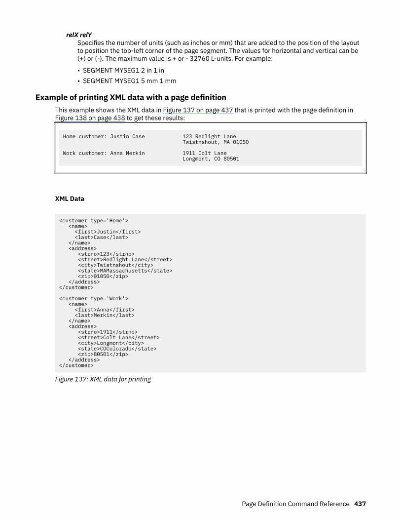
relX relYSpecifies the number of units (such as inches or mm) that are added to the position of the layoutto position the top-left corner of the page segment. The values for horizontal and vertical can be(+) or (-). The maximum value is + or - 32760 L-units. For example:
• SEGMENT MYSEG1 2 in 1 in• SEGMENT MYSEG1 5 mm 1 mm
Example of printing XML data with a page definitionThis example shows the XML data in Figure 137 on page 437 that is printed with the page definition inFigure 138 on page 438 to get these results:
Home customer: Justin Case 123 Redlight Lane Twistnshout, MA 01050
Work customer: Anna Merkin 1911 Colt Lane Longmont, CO 80501
XML Data
<customer type='Home'> <name> <first>Justin</first> <last>Case</last> </name> <address> <strno>123</strno> <street>Redlight Lane</street> <city>Twistnshout</city> <state>MAMassachusetts</state> <zip>01050</zip> </address></customer>
<customer type='Work'> <name> <first>Anna</first> <last>Merkin</last> </name> <address> <strno>1911</strno> <street>Colt Lane</street> <city>Longmont</city> <state>COColorado</state> <zip>80501</zip> </address></customer>
Figure 137: XML data for printing
Page Definition Command Reference 437

Page Definition
SETUNITS 1 IN 1 IN LINESP 6 LPI;Pagedef XMLxml replace yes UDType EBCDIC; FONT E21H0C TYPE EBCDIC; DEFINE cust QTAG 'customer'; DEFINE name QTAG 'customer','name'; DEFINE fname QTAG 'customer','name','first'; DEFINE lname QTAG 'customer','name','last'; DEFINE addr QTAG 'customer','address'; DEFINE strno QTAG 'customer','address','strno'; DEFINE street QTAG 'customer','address','street'; DEFINE city QTAG 'customer','address','city'; DEFINE state QTAG 'customer','address','state'; DEFINE zip QTAG 'customer','address','zip';
XLAYOUT cust POSITION ABSOLUTE 0 FIELD ATTR 'type' ; FIELD TEXT ' customer:' ; XLAYOUT fname POSITION ABSOLUTE 2.5 SAME; XLAYOUT lname POSITION RELATIVE 0.167 SAME; XLAYOUT strno POSITION ABSOLUTE 5.5 SAME; XLAYOUT street POSITION RELATIVE 0 SAME; FIELD TEXT ' ' ; FIELD START 1 LENGTH *; XLAYOUT city POSITION ABSOLUTE 5.5 NEXT; FIELD START 1 LENGTH *; FIELD TEXT ', '; XLAYOUT state POSITION RELATIVE 0 SAME; FIELD START 1 LENGTH 2; FIELD TEXT ' '; XLAYOUT zip POSITION RELATIVE 0 SAME;
Figure 138: Page definition used to print XML data
438 Page Printer Formatting Aid: User's Guide
Appendix A. System Dependencies for PPFA
PPFA is a cross system product that operates on:
• Virtual Machine (VM)• Virtual Storage Extended (VSE)• z/OS
For the level of the operating system on which PPFA can run, See the PPFA/370: Licensed ProgramSpecification, G544-3696.
PPFA creates page definitions and form definitions that are used for printing by PSF for z/OS and PSF/VM.Page definitions and form definitions that are created on one system can be used for printing on anothersystem. However, not all versions of print servers support all functions that are provided by PPFA. Use theProgramming Guide or User's Guide for your print server system to determine which functions aresupported by your system.
While page definitions and form definitions created on one system can be used on any of the systems, themethod of creating these resources is different.
Each system is presented to show how PPFA creates page definitions and form definitions. In theexamples, the prefixes F1 and P1 are automatically added by PPFA to the user name designated for formdefinitions and page definitions.
Note: All PPFA/370 functions that are described in this document are available on the z/OS operatingsystem. However, because functions on PSF/VM and PSF/VSE and PPFA/370 functions for VM and VSE arenot updated, some of the PPFA/370 functions that are described in this document are not available on theVM and VSE operating systems.
VSE EnvironmentPPFA can operate in any partition of VSE. It operates in batch mode but is able to operate in a partitionthat is occupied by an interactive processor.
Storing PPFA Resources
Form definitions and page definitions are stored by name in a library. In VSE, sublibraries are created forform-definition and page-definition storage within the system library.
© Copyright IBM Corp. 1985, 2016 439
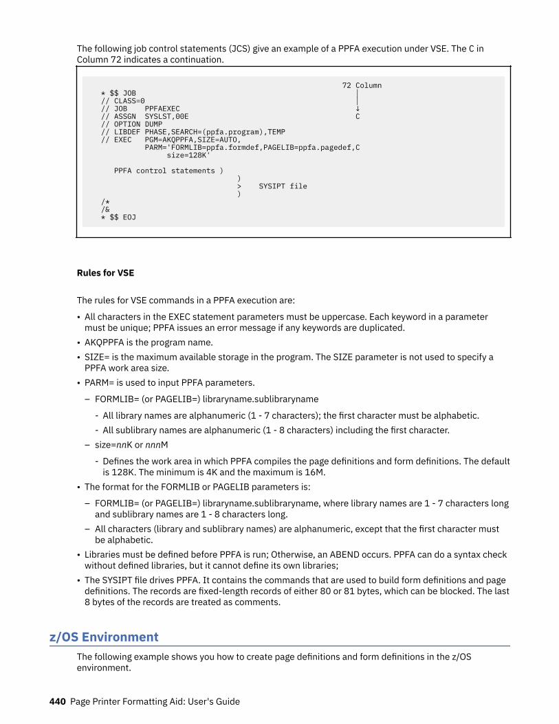
The following job control statements (JCS) give an example of a PPFA execution under VSE. The C inColumn 72 indicates a continuation.
72 Column * $$ JOB │ // CLASS=0 │ // JOB PPFAEXEC ↓ // ASSGN SYSLST,00E C // OPTION DUMP // LIBDEF PHASE,SEARCH=(ppfa.program),TEMP // EXEC PGM=AKQPPFA,SIZE=AUTO, PARM='FORMLIB=ppfa.formdef,PAGELIB=ppfa.pagedef,C size=128K' PPFA control statements ) ) > SYSIPT file ) /* /& * $$ EOJ
Rules for VSE
The rules for VSE commands in a PPFA execution are:
• All characters in the EXEC statement parameters must be uppercase. Each keyword in a parametermust be unique; PPFA issues an error message if any keywords are duplicated.
• AKQPPFA is the program name.• SIZE= is the maximum available storage in the program. The SIZE parameter is not used to specify a
PPFA work area size.• PARM= is used to input PPFA parameters.
– FORMLIB= (or PAGELIB=) libraryname.sublibraryname
- All library names are alphanumeric (1 - 7 characters); the first character must be alphabetic.- All sublibrary names are alphanumeric (1 - 8 characters) including the first character.
– size=nnK or nnnM
- Defines the work area in which PPFA compiles the page definitions and form definitions. The defaultis 128K. The minimum is 4K and the maximum is 16M.
• The format for the FORMLIB or PAGELIB parameters is:
– FORMLIB= (or PAGELIB=) libraryname.sublibraryname, where library names are 1 - 7 characters longand sublibrary names are 1 - 8 characters long.
– All characters (library and sublibrary names) are alphanumeric, except that the first character mustbe alphabetic.
• Libraries must be defined before PPFA is run; Otherwise, an ABEND occurs. PPFA can do a syntax checkwithout defined libraries, but it cannot define its own libraries;
• The SYSIPT file drives PPFA. It contains the commands that are used to build form definitions and pagedefinitions. The records are fixed-length records of either 80 or 81 bytes, which can be blocked. The last8 bytes of the records are treated as comments.
z/OS EnvironmentThe following example shows you how to create page definitions and form definitions in the z/OSenvironment.
440 Page Printer Formatting Aid: User's Guide
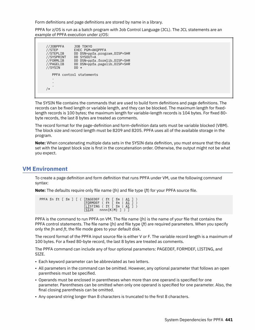
Form definitions and page definitions are stored by name in a library.
PPFA for z/OS is run as a batch program with Job Control Language (JCL). The JCL statements are anexample of PPFA execution under z/OS:
//JOBPPFA JOB TOKYO //STEP EXEC PGM=AKQPPFA //STEPLIB DD DSN=ppfa.program,DISP=SHR //SYSPRINT DD SYSOUT=A //FORMLIB DD DSN=ppfa.formlib,DISP=SHR //PAGELIB DD DSN=ppfa.pagelib,DISP=SHR //SYSIN DD * PPFA control statements . . . /*
The SYSIN file contains the commands that are used to build form definitions and page definitions. Therecords can be fixed length or variable length, and they can be blocked. The maximum length for fixed-length records is 100 bytes; the maximum length for variable-length records is 104 bytes. For fixed 80-byte records, the last 8 bytes are treated as comments.
The record format for the page-definition and form-definition data sets must be variable blocked (VBM).The block size and record length must be 8209 and 8205. PPFA uses all of the available storage in theprogram.
Note: When concatenating multiple data sets in the SYSIN data definition, you must ensure that the dataset with the largest block size is first in the concatenation order. Otherwise, the output might not be whatyou expect.
VM EnvironmentTo create a page definition and form definition that runs PPFA under VM, use the following commandsyntax:
Note: The defaults require only file name (fn) and file type (ft) for your PPFA source file.
PPFA fn ft [ fm ] [ ( [PAGEDEF ( ft [ fm | A1 ] ) [FORMDEF ( ft [ fm | A1 ] ) [LISTING ( ft [ fm | A1 ] ) [SIZE nnnn{K|M} ] ) ]
PPFA is the command to run PPFA on VM. The file name (fn) is the name of your file that contains thePPFA control statements. The file name (fn) and file type (ft) are required parameters. When you specifyonly the fn and ft, the file mode goes to your default disk.
The record format of the PPFA input source file is either V or F. The variable record length is a maximum of100 bytes. For a fixed 80-byte record, the last 8 bytes are treated as comments.
The PPFA command can include any of four optional parameters: PAGEDEF, FORMDEF, LISTING, andSIZE.
• Each keyword parameter can be abbreviated as two letters.• All parameters in the command can be omitted. However, any optional parameter that follows an open
parenthesis must be specified.• Operands must be enclosed in parentheses when more than one operand is specified for one
parameter. Parentheses can be omitted when only one operand is specified for one parameter. Also, thefinal closing parenthesis can be omitted.
• Any operand string longer than 8 characters is truncated to the first 8 characters.
System Dependencies for PPFA 441
• Any parameter or operand can be separated from others by parentheses or blanks. The only exceptionsare the K and the M operands of a size parameter. For example, in size 256K you cannot separate the256 from the K.
• The same parameter must not be specified more than once in a command. If duplicate parameters oroperands appear, PPFA issues an error message and ends the program.
• For errors associated with a VM execution command, PPFA issues an error message with a return code20, and does not generate any files (object or listing).
• No optional parameters can follow the open parenthesis that occurs after the input source file ID.• The size parameter varies according to the size of the command stream. Most command streams do not
need a size value because the default specifies enough space for processing. The minimum size is 4Kand the maximum size is 16M.
PAGEDEF ParameterPAGEDEF (which can be abbreviated as PA) is the keyword that is used to specify the name of a page-definition resource. (The file type is required; the file mode is optional. If you do not specify a file mode,A1 is assumed.) The page-definition file name is obtained from your input file, and P1 is prefixed to thatname.
An example is this command:
PPFA PCOM DATA A1 ( PAGEDEF ( PAGEOBJ B1 ) )
In the example, the input file, PCOM DATA A1, contains the following control statements:
PAGEDEF PAGE1; PRINTLINE; FORMDEF FORM1;
The result is a page-definition resource file with the file name P1PAGE1, the file type PAGEOBJ, and thefile mode B1.
If the page definition parameter is not used, a page-definition resource with the default name P1 (thepage definition name from input file) PDEF38PP A1 is created.
The record format of the object file is VM and VA (5A records). 5A records contain the character X'5A' inthe first byte of each record. The record size is up to 8205 bytes.
FORMDEF ParameterFORMDEF (which can be abbreviated as FO) is the keyword that is used to specify the name of a form-definition resource. (The file type is required; the file mode is optional.) The file name is obtained fromyour input file, and F1 is prefixed to that name.
An example is this command:
PPFA PCOM DATA A1 ( FORMDEF ( FORMOBJ B1 ) )
In the example, the input file, PCOM DATA A1, contains the following control statements:
PAGEDEF PAGE1; PRINTLINE; FORMDEF FORM1;
The result is a form-definition resource file with the file name F1FORM1, the file type FORMOBJ, and thefile mode B1.
If the form-definition parameter is not used, a form-definition resource with the default name F1 (form-definition name from input file) FDEF38PP A1 is created.
The record format of the object file is VM and VA (5A records). The record size is up to 8205 bytes.
442 Page Printer Formatting Aid: User's Guide

LISTING ParameterLISTING (which can be abbreviated as LI) is the keyword that is used to specify the name of an outputlisting file. You can specify the file type and file mode of the resource; the file type is required. If you donot specify a file mode, A1 is assumed. The file name is the same as the PPFA input file name.
For this command example, the result is an output listing file with the name PCOM LISTOUT B1:
PPFA PCOM DATA A1 ( LISTING ( LISTOUT B1 )
If the LISTING parameter is not used, an output listing file with the default name (PPFA input file name)LISTING A1 is created.
The record format of an output listing file is VA. The record length is 121 bytes (120 bytes + 1 byte(channel control number)). CC numbers are 0 - 12 in the first column of the line data file.
RUN and OPTIONS fileFigure 139 on page 443 and Figure 140 on page 443 are examples of the VM files that print your data filewith the form definition and page definition that you specify.
*********************************************************************/*THE ENVIRONMENT IS NOW SET UP TO PRINT */'CP SP PRT TO NET NOHOLD CLASS A FORM PRT035 COPY 1';'CP TAG DEV PRT WASVM SYSTEM';'PSF EXAMP1 PRTDATA A1 ( OPTIONS (EXAMP1) )';/*RESTORE THE ENVIRONMENT TO PRINT SOMETHING OTHER THAN THIS EXAMPLE*/*********************************************************************
Figure 139: VM EXEC Example
*********************************************************************FORMDEF ( F1EXAMP1 FDEF38PP ) SEND*********************************************************************PAGEDEF ( P1EXAMP1 PDEF38PP ) SYSDISK*********************************************************************OVERLAY ( * OVLY38PP ) SYSDISK********************************************************************** COMMON OPTIONS*********************************************************************CCNOTRCBIN 1CKPTPAGE 0DATACK UNBLOCKNODUMPFILE SENDFONT ( * FONT3820 ) SYSDISKMESSAGES NONOOPTPAGESEG ( * PSEG38PP ) SYSDISKTRACE OFF*********************************************************************
Figure 140: VM OPTIONS Example
System Dependencies for PPFA 443

444 Page Printer Formatting Aid: User's Guide

Appendix B. More about Direction
In PPFA, directions that are specified with the PRINTLINE and TRCREF commands are relative to thedirection specified in the PAGEFORMAT command. If no PAGEFORMAT command is specified, thedirection that is specified in the PAGEDEF command is used. If no direction is specified in either of thesecommands, the default direction for the page format is ACROSS.
The PRINTLINE and TRCREF commands add their DIRECTION values to the DIRECTION value specifiedwith the PAGEFORMAT command. Thus, you can select a PAGEFORMAT direction and code PRINTLINEsand TRCREFs relative to the PAGEFORMAT direction. For more information about the PRINTLINE andTRCREF commands, see Chapter 3, “Using Page Definition Commands for Traditional Line Data,” on page31.
For instance, if a page is to be printed in the landscape page presentation on a printer that requires theDOWN or UP print direction to generate landscape output, the PAGEFORMAT command can specify DOWNas its DIRECTION. When this direction is established, you can view the page as a landscape page andspecify the PRINTLINE and the TRCREF commands with the ACROSS direction. Output that is specified inthis way prints ACROSS relative to the landscape page, as shown in Figure 141 on page 445.
Figure 141: Printing Across a Landscape Page
If you specify the DOWN direction for the PRINTLINE or the TRCREF command in this case, the outputlooks like Figure 142 on page 445 because the direction of the page format is also DOWN.
Figure 142: Printing Down a Portrait Page
Table 19 on page 446 shows the final result when all of the possible combinations of DIRECTION arespecified. The final direction that PPFA computes from the PAGEFORMAT, PRINTLINE, and TRCREFcommands determines the prefix that is assigned to the font names specified in the page definition. Thefinal direction is important when printing on the 3800 printer because its unbounded-box font
© Copyright IBM Corp. 1985, 2016 445
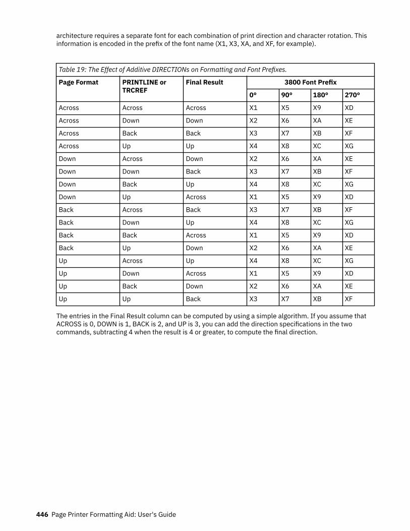
architecture requires a separate font for each combination of print direction and character rotation. Thisinformation is encoded in the prefix of the font name (X1, X3, XA, and XF, for example).
Table 19: The Effect of Additive DIRECTIONs on Formatting and Font Prefixes.
Page Format PRINTLINE orTRCREF
Final Result 3800 Font Prefix
0° 90° 180° 270°
Across Across Across X1 X5 X9 XD
Across Down Down X2 X6 XA XE
Across Back Back X3 X7 XB XF
Across Up Up X4 X8 XC XG
Down Across Down X2 X6 XA XE
Down Down Back X3 X7 XB XF
Down Back Up X4 X8 XC XG
Down Up Across X1 X5 X9 XD
Back Across Back X3 X7 XB XF
Back Down Up X4 X8 XC XG
Back Back Across X1 X5 X9 XD
Back Up Down X2 X6 XA XE
Up Across Up X4 X8 XC XG
Up Down Across X1 X5 X9 XD
Up Back Down X2 X6 XA XE
Up Up Back X3 X7 XB XF
The entries in the Final Result column can be computed by using a simple algorithm. If you assume thatACROSS is 0, DOWN is 1, BACK is 2, and UP is 3, you can add the direction specifications in the twocommands, subtracting 4 when the result is 4 or greater, to compute the final direction.
446 Page Printer Formatting Aid: User's Guide

Appendix C. Differences in Measurements andREPEATs with AFP Utilities
When you repeat a DRAWRULE (OGL), PRINTLINE (PPFA), DRAWGRAPHIC (PPFA), or Line (PMF),differences exist in the measurements of the repeated lines. For OGL, REPEAT indicates the number ofrepetitions in addition to the first. For DRAWGRAPHIC (PPFA), REPEAT is the same as OGL. Therefore,REPEAT yields 2 DRAWRULEs. For PPFA, REPEAT indicates the total number of PRINTLINEs. Therefore,REPEAT yields 2 PRINTLINEs.
Another difference occurs when the line spacing (set by SETUNITS in OGL and PPFA, and by a screen itemin PMF) results in the distance from one line to the next not being a whole number of pels. Each producthandles the fractional pel differently. Because the printer cannot print parts of a pel, fractional pelscannot be represented at the printer. When line spacing calculations result in a fractional pel per linespace, these occur:OGL
Carries the fractions until they add up to a whole pel, then adds it in. The result is that the final spot ofa repeat is within a pel of where it is expected. Therefore, not all of the spaces between rules areeven; they can vary by 1 pel.
PPFATruncates the fractional pel before the repeat. Therefore, the spaces between the lines are even, butthe total might be shorter than expected.
PMFRounds the fractional pel before the repeat. Therefore, the spaces between the lines are even, but thetotal might be shorter or longer than expected. If the fractional pel is less than 0.5, it is handled thesame as PPFA and the line space is shorter. If the fractional pel is greater than or equal to 0.5, the linespace is longer.
Use line spacing in all products that result in a whole number of pels. To resolve existing problems, selectthe resource that you don't want to change, and code the remaining resource without using REPEATbecause of the way the other products handle the fractional pels.
The following example shows what occurs if you want to print at 9 lines per inch, and repeat it for 20 lines.Starting at zero, and adding 9 lines per inch (converted to pels it is 240/9 = 26.6670), you see the resultsthat are illustrated in Table 20 on page 447.
Table 20: Differences in Measurements and REPEATs with AFP Utilities.
Repetition
Mathematics OGL PPFA PMF
Position FromLast Position FromLast Position FromLast Position FromLast
0.000 -.--- 0 --- 0 --- 0 ---
1 26.667 26.667 26 26 26 26 27 27
2 53.333 26.667 53 27 52 26 54 27
3 80.000 26.667 80 27 78 26 81 27
4 106.667 26.667 106 26 104 26 108 27
5 133.333 26.667 133 27 130 26 135 27
6 160.000 26.667 160 27 156 26 162 27
7 186.667 26.667 186 26 182 26 189 27
8 213.333 26.667 213 27 208 26 216 27
© Copyright IBM Corp. 1985, 2016 447
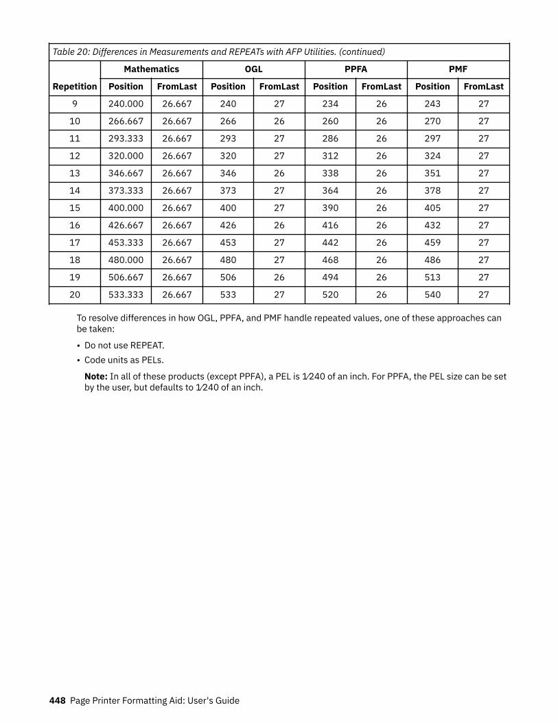
Table 20: Differences in Measurements and REPEATs with AFP Utilities. (continued)
Repetition
Mathematics OGL PPFA PMF
Position FromLast Position FromLast Position FromLast Position FromLast
9 240.000 26.667 240 27 234 26 243 27
10 266.667 26.667 266 26 260 26 270 27
11 293.333 26.667 293 27 286 26 297 27
12 320.000 26.667 320 27 312 26 324 27
13 346.667 26.667 346 26 338 26 351 27
14 373.333 26.667 373 27 364 26 378 27
15 400.000 26.667 400 27 390 26 405 27
16 426.667 26.667 426 26 416 26 432 27
17 453.333 26.667 453 27 442 26 459 27
18 480.000 26.667 480 27 468 26 486 27
19 506.667 26.667 506 26 494 26 513 27
20 533.333 26.667 533 27 520 26 540 27
To resolve differences in how OGL, PPFA, and PMF handle repeated values, one of these approaches canbe taken:
• Do not use REPEAT.• Code units as PELs.
Note: In all of these products (except PPFA), a PEL is 1⁄240 of an inch. For PPFA, the PEL size can be setby the user, but defaults to 1⁄240 of an inch.
448 Page Printer Formatting Aid: User's Guide

Appendix D. More About Bar Code Parameters
This section contains supplemental information about Bar Code Object Content Architecture (BCOCA)specified by the BARCODE subcommand of the FIELD command, and includes the following topics:
• Bar code data• MOD parameter
For more complete information, see Bar Code Object Content Architecture Reference.
Bar Code DataThe data is specified as a series of single-byte code points from a specific code page. Some symbologieslimit the valid code points to just the 10 numerals (0 - 9), other symbologies allow a richer set of codepoints. The bar code symbol is produced from these code points; the code points are also used, alongwith a particular type style, when HRI is produced.
Table 21 on page 449 lists, for each symbology, the valid code page from which characters are chosenand the type style that is used when HRI is printed in terms of a registered CPGID and FGID. Moreinformation about these values can be found in IBM AFP Fonts: Font Summary and in IBM AFP Fonts:Technical Reference for Code Pages.
Table 21: Valid Code Pages and Type Styles
Type Bar Code Symbology EBCDIC-BasedCPGID
FGID
1 Code 39 (3-of-9 Code), AIM USS-39 500 Device specific
2 MSI (modified Plessey code) 500 Device specific
3 UPC/CGPC — Version A 893 3 (OCR-B)
5 UPC/CGPC — Version E 893 3 (OCR-B)
6 UPC — Two-digit Supplemental (Periodicals) 893 3 (OCR-B)
7 UPC — Five-digit Supplemental (Paperbacks) 893 3 (OCR-B)
8 EAN-8 (includes JAN-short) 893 3 (OCR-B)
9 EAN-13 (includes JAN-standard) 893 3 (OCR-B)
10 Industrial 2-of-5 500 Device specific
11 Matrix 2-of-5 500 Device specific
12 Interleaved 2-of-5, AIM USS-I 2/5 500 Device specific
13 Codabar, 2-of-7, AIM USS-Codabar 500 Device specific
17 Code 128, AIM USS-128 1303 Device specific
22 EAN Two-digit Supplemental 893 3 (OCR-B)
23 EAN Five-digit Supplemental 893 3 (OCR-B)
24 POSTNET 500 None
26 RM4SCC 500 None
© Copyright IBM Corp. 1985, 2016 449
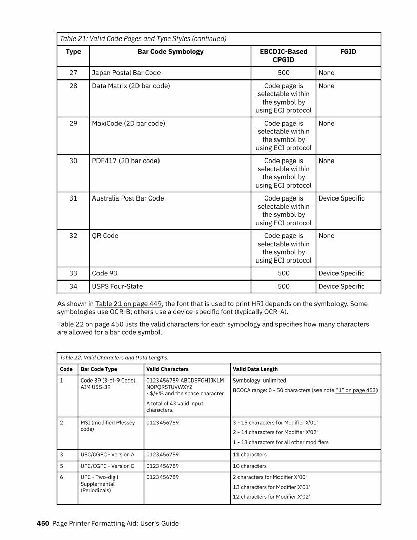
Table 21: Valid Code Pages and Type Styles (continued)
Type Bar Code Symbology EBCDIC-BasedCPGID
FGID
27 Japan Postal Bar Code 500 None
28 Data Matrix (2D bar code) Code page isselectable within
the symbol byusing ECI protocol
None
29 MaxiCode (2D bar code) Code page isselectable within
the symbol byusing ECI protocol
None
30 PDF417 (2D bar code) Code page isselectable within
the symbol byusing ECI protocol
None
31 Australia Post Bar Code Code page isselectable within
the symbol byusing ECI protocol
Device Specific
32 QR Code Code page isselectable within
the symbol byusing ECI protocol
None
33 Code 93 500 Device Specific
34 USPS Four-State 500 Device Specific
As shown in Table 21 on page 449, the font that is used to print HRI depends on the symbology. Somesymbologies use OCR-B; others use a device-specific font (typically OCR-A).
Table 22 on page 450 lists the valid characters for each symbology and specifies how many charactersare allowed for a bar code symbol.
Table 22: Valid Characters and Data Lengths.
Code Bar Code Type Valid Characters Valid Data Length
1 Code 39 (3-of-9 Code),AIM USS-39
0123456789 ABCDEFGHIJKLMNOPQRSTUVWXYZ-.$/+% and the space character
A total of 43 valid inputcharacters.
Symbology: unlimited
BCOCA range: 0 - 50 characters (see note “1” on page 453)
2 MSI (modified Plesseycode)
0123456789 3 - 15 characters for Modifier X'01'
2 - 14 characters for Modifier X'02'
1 - 13 characters for all other modifiers
3 UPC/CGPC - Version A 0123456789 11 characters
5 UPC/CGPC - Version E 0123456789 10 characters
6 UPC - Two-digitSupplemental(Periodicals)
0123456789 2 characters for Modifier X'00'
13 characters for Modifier X'01'
12 characters for Modifier X'02'
450 Page Printer Formatting Aid: User's Guide

Table 22: Valid Characters and Data Lengths. (continued)
Code Bar Code Type Valid Characters Valid Data Length
7 UPC - Five-digitSupplemental(Paperbacks)
0123456789 5 characters for Modifier X'00'
16 characters for Modifier X'01'
15 characters for Modifier X'02'
8 EAN-8 (includes JAN-short)
0123456789 7 characters
9 EAN-13 (includes JAN-standard)
0123456789 12 characters
10 Industrial 2-of-5 0123456789 Symbology: unlimited
BCOCA range: 0 - 50 characters (see note “1” on page 453)
11 Matrix 2-of-5 0123456789 Symbology: unlimited
BCOCA range: 0 - 50 characters (see note “1” on page 453)
12 Interleaved 2-of-5, AIMUSS-I 2/5
0123456789 Symbology: unlimited
BCOCA range: 0 - 50 characters (see note “1” on page 453)
13 Codabar, 2-of-7, AIMUSS-Codabar
0123456789-$:/.+ABCD
16 characters plus 4 start/stopcharacters (ABCD) (Note “2” onpage 453)
Symbology: unlimited
BCOCA range: 0 - 50 characters (see note “1” on page 453)
17 Code 128, AIM USS-128(modifier X'02')
All characters that are defined inthe Code 128 code page
Symbology: unlimited
BCOCA range: 0 - 50 characters (see note “1” on page 453)
UCC/EAN 128 (modifiersX'03' and X'04')
0123456789 ABCDEFGHIJKLMNOPQRSTUVWXYZabcdefghijklm nopqrstuvwxyzFNC1
Symbology: unlimited
BCOCA range: 0 - 50 characters (see note “1” on page 453)
22 EAN Two-digitSupplemental
0123456789 2 characters for Modifier X'00'
14 characters for Modifier X'01'
23 EAN Five-digitSupplemental
0123456789 5 characters for Modifier X'00'
17 characters for Modifier X'01'
24 POSTNET 0123456789 5 characters for Modifier X'00'
9 characters for Modifier X'01'
11 characters for Modifier X'02'
11 characters for Modifier X'04'
BCOCA range for Modifier X'03': 0 - 50 characters (seenote “1” on page 453)
26 Royal Mail(RM4SCC,modifier X'00')
0123456789 ABCDEFGHIJKLMNOPQRSTUVWXYZ
Symbology: unlimited
BCOCA range: 0 - 50 characters (see note “1” on page 453)
Royal Mail (Dutch KIXvariation, modifier X'01')
0123456789 ABCDEFGHIJKLMNOPQRSTUVWXYZabcdefghijklm nopqrstuvwxyz
Symbology: unlimited
BCOCA range: 0 - 50 characters (see note “1” on page 453)
27 Japan Postal Bar Code(Modifier X'00')
0123456789 ABCDEFGHIJKLMNOPQRSTUVWXYZ- (hyphen)
Symbology: 7 or more
BCOCA range: 7 - 50 characters (see note “1” on page 453)
Japan Postal Bar Code(Modifier X'01')
0123456789 CC1,CC2,CC3,CC4,CC5,CC6,CC7,CC8- (hyphen)start, stop
No length checking done; refer to the modifier X'01'description.
More About Bar Code Parameters 451

Table 22: Valid Characters and Data Lengths. (continued)
Code Bar Code Type Valid Characters Valid Data Length
28 Data Matrix Any 1-byte character or binarydata
Symbology: up to 3116 depending on whether the data ischaracter or numeric; refer to the symbology specification.
BCOCA range: 0 - 3116 characters (see note “1” on page453)
29 MaxiCode Any 1-byte character that isallowed by the symbol mode
Symbology: up to 93 alphanumeric characters per symboldepending on encoding overhead or up to 138 numericcharacters per symbol; refer to the symbologyspecification.
BCOCA range: 0 - 138 characters
30 PDF417 Any 1-byte character or binarydata
Symbology: up to 1850 text characters, 2710 ASCIInumeric digits, or 1108 bytes of binary data per symboldepending on the security level; refer to the symbologyspecification.
BCOCA range: 0 - 2710 characters
31 Australia Post Bar Code –Refer to the modifier (byte 13) description to see which characters are valid in specific parts of the symbol.
Modifier X'01' –Standard CustomerBarcode
0123456789 Symbology: 8 digits
BCOCA range: 8 digits
Modifier X'02' –Customer Barcode 2using Table N
0123456789 Symbology: 8 - 16 digits
BCOCA range: 8 - 16 digits
Modifier X'03' –Customer Barcode 2using Table C
0123456789 ABCDEFGHIJKLMNOPQRSTUVWXYZabcdefghijklm nopqrstuvwxyz(space)# (number sign)
Symbology: 8 - 13 characters
BCOCA range: 8 - 13 characters
Modifier X'04' –Customer Barcode 2using proprietaryencoding
0123456789 for sorting code0 - 3 for customer information
Symbology: 8 - 24 digits
BCOCA range: 8 - 24 digits
Modifier X'05' –Customer Barcode 3using Table N
0123456789 Symbology: 8 - 23 digits
BCOCA range: 8 - 23 digits
Modifier X'06' –Customer Barcode 3using Table C
0123456789 ABCDEFGHIJKLMNOPQRSTUVWXYZabcdefghijklm nopqrstuvwxyz(space)# (number sign)
Symbology: 8 - 18 characters
BCOCA range: 8 - 18 characters
Modifier X'07' –Customer Barcode 3using proprietaryencoding
0123456789 for sorting code0 - 3 for customer information
Symbology: 8 - 39 digits
BCOCA range: 8 - 39 digits
Modifier X'08' – ReplyPaid Barcode
0123456789 Symbology: 8 digits
BCOCA range: 8 digits
32 QR Code Any 1-byte character or binarydata
Symbology: Up to 7,089 characters depending on the sizeand type of the data; refer to the symbology specification.
BCOCA range: 0 - 7,089 characters
452 Page Printer Formatting Aid: User's Guide
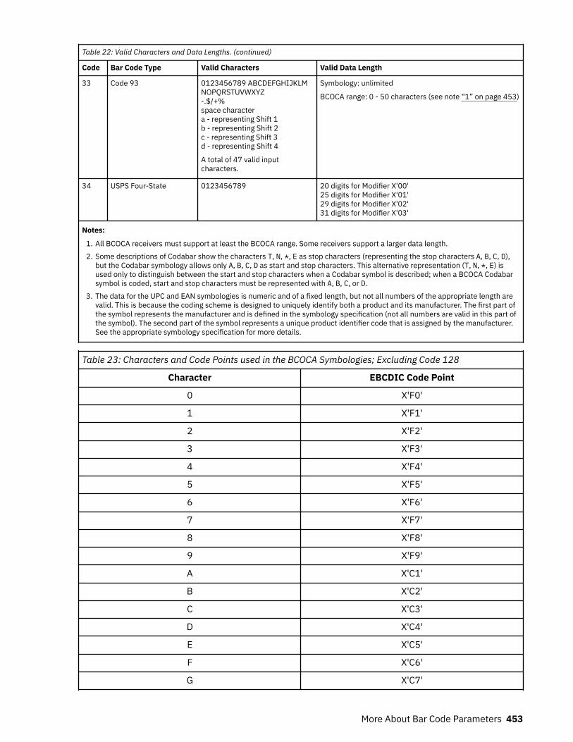
Table 22: Valid Characters and Data Lengths. (continued)
Code Bar Code Type Valid Characters Valid Data Length
33 Code 93 0123456789 ABCDEFGHIJKLMNOPQRSTUVWXYZ-.$/+%space charactera - representing Shift 1b - representing Shift 2c - representing Shift 3d - representing Shift 4
A total of 47 valid inputcharacters.
Symbology: unlimited
BCOCA range: 0 - 50 characters (see note “1” on page 453)
34 USPS Four-State 0123456789 20 digits for Modifier X'00'25 digits for Modifier X'01'29 digits for Modifier X'02'31 digits for Modifier X'03'
Notes:
1. All BCOCA receivers must support at least the BCOCA range. Some receivers support a larger data length.2. Some descriptions of Codabar show the characters T, N, *, E as stop characters (representing the stop characters A, B, C, D),
but the Codabar symbology allows only A, B, C, D as start and stop characters. This alternative representation (T, N, *, E) isused only to distinguish between the start and stop characters when a Codabar symbol is described; when a BCOCA Codabarsymbol is coded, start and stop characters must be represented with A, B, C, or D.
3. The data for the UPC and EAN symbologies is numeric and of a fixed length, but not all numbers of the appropriate length arevalid. This is because the coding scheme is designed to uniquely identify both a product and its manufacturer. The first part ofthe symbol represents the manufacturer and is defined in the symbology specification (not all numbers are valid in this part ofthe symbol). The second part of the symbol represents a unique product identifier code that is assigned by the manufacturer.See the appropriate symbology specification for more details.
Table 23: Characters and Code Points used in the BCOCA Symbologies; Excluding Code 128
Character EBCDIC Code Point
0 X'F0'
1 X'F1'
2 X'F2'
3 X'F3'
4 X'F4'
5 X'F5'
6 X'F6'
7 X'F7'
8 X'F8'
9 X'F9'
A X'C1'
B X'C2'
C X'C3'
D X'C4'
E X'C5'
F X'C6'
G X'C7'
More About Bar Code Parameters 453
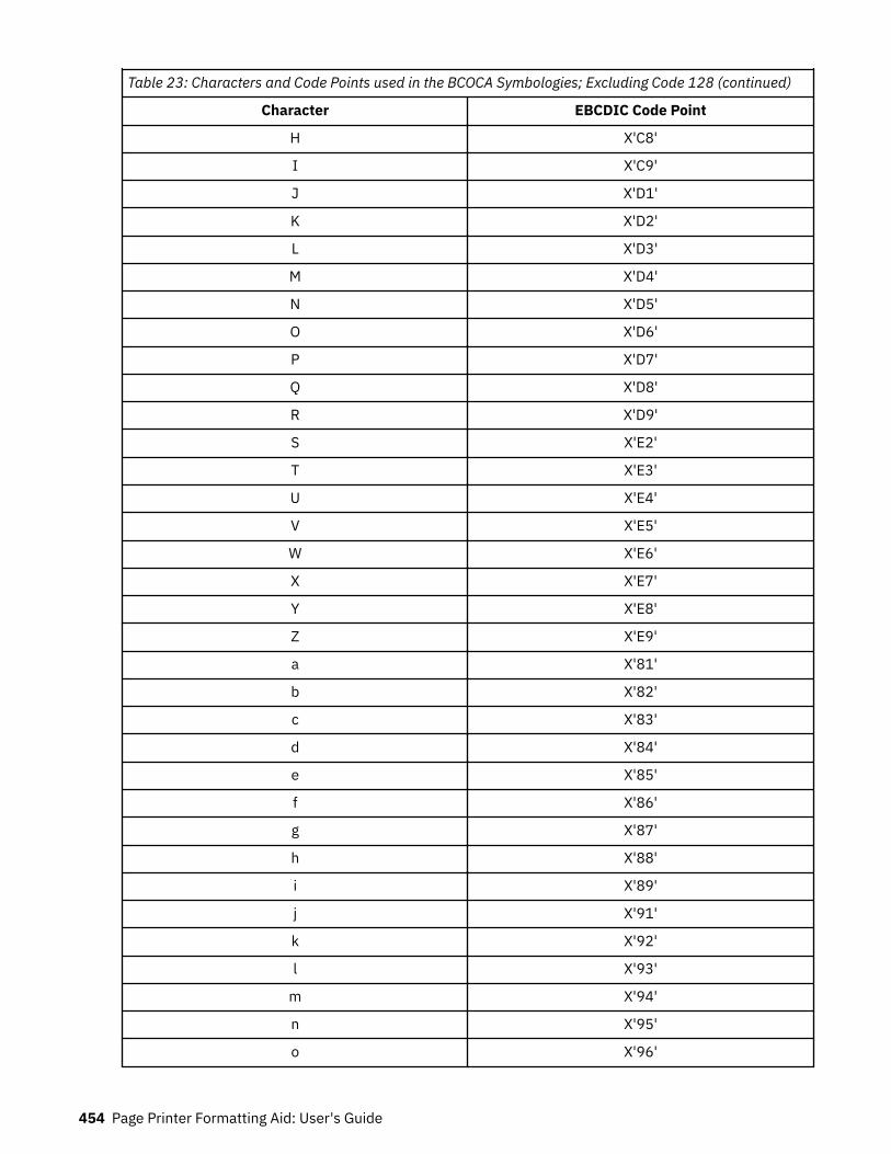
Table 23: Characters and Code Points used in the BCOCA Symbologies; Excluding Code 128 (continued)
Character EBCDIC Code Point
H X'C8'
I X'C9'
J X'D1'
K X'D2'
L X'D3'
M X'D4'
N X'D5'
O X'D6'
P X'D7'
Q X'D8'
R X'D9'
S X'E2'
T X'E3'
U X'E4'
V X'E5'
W X'E6'
X X'E7'
Y X'E8'
Z X'E9'
a X'81'
b X'82'
c X'83'
d X'84'
e X'85'
f X'86'
g X'87'
h X'88'
i X'89'
j X'91'
k X'92'
l X'93'
m X'94'
n X'95'
o X'96'
454 Page Printer Formatting Aid: User's Guide
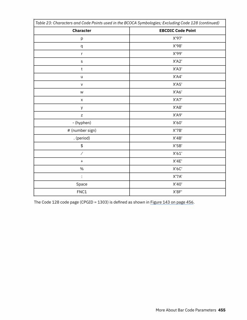
Table 23: Characters and Code Points used in the BCOCA Symbologies; Excluding Code 128 (continued)
Character EBCDIC Code Point
p X'97'
q X'98'
r X'99'
s X'A2'
t X'A3'
u X'A4'
v X'A5'
w X'A6'
x X'A7'
y X'A8'
z X'A9'
- (hyphen) X'60'
# (number sign) X'7B'
. (period) X'4B'
$ X'5B'
⁄ X'61'
+ X'4E'
% X'6C'
: X'7A'
Space X'40'
FNC1 X'8F'
The Code 128 code page (CPGID = 1303) is defined as shown in Figure 143 on page 456.
More About Bar Code Parameters 455
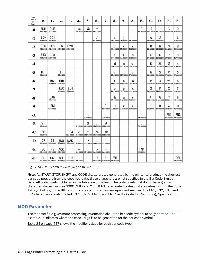
Figure 143: Code 128 Code Page (CPGID = 1303)
Note: All START, STOP, SHIFT, and CODE characters are generated by the printer to produce the shortestbar code possible from the specified data; these characters are not specified in the Bar Code SymbolData. All code points not listed in the table are undefined. The code points that do not have graphiccharacter shapes, such as X'00' (NUL) and X'8F' (FN1), are control codes that are defined within the Code128 symbology; in the HRI, control codes print in a device-dependent manner. The FN1, FN2, FN3, andFN4 characters are also called FNC1, FNC2, FNC3, and FNC4 in the Code 128 Symbology Specification.
MOD ParameterThe modifier field gives more processing information about the bar code symbol to be generated. Forexample, it indicates whether a check-digit is to be generated for the bar code symbol.
Table 24 on page 457 shows the modifier values for each bar code type.
456 Page Printer Formatting Aid: User's Guide
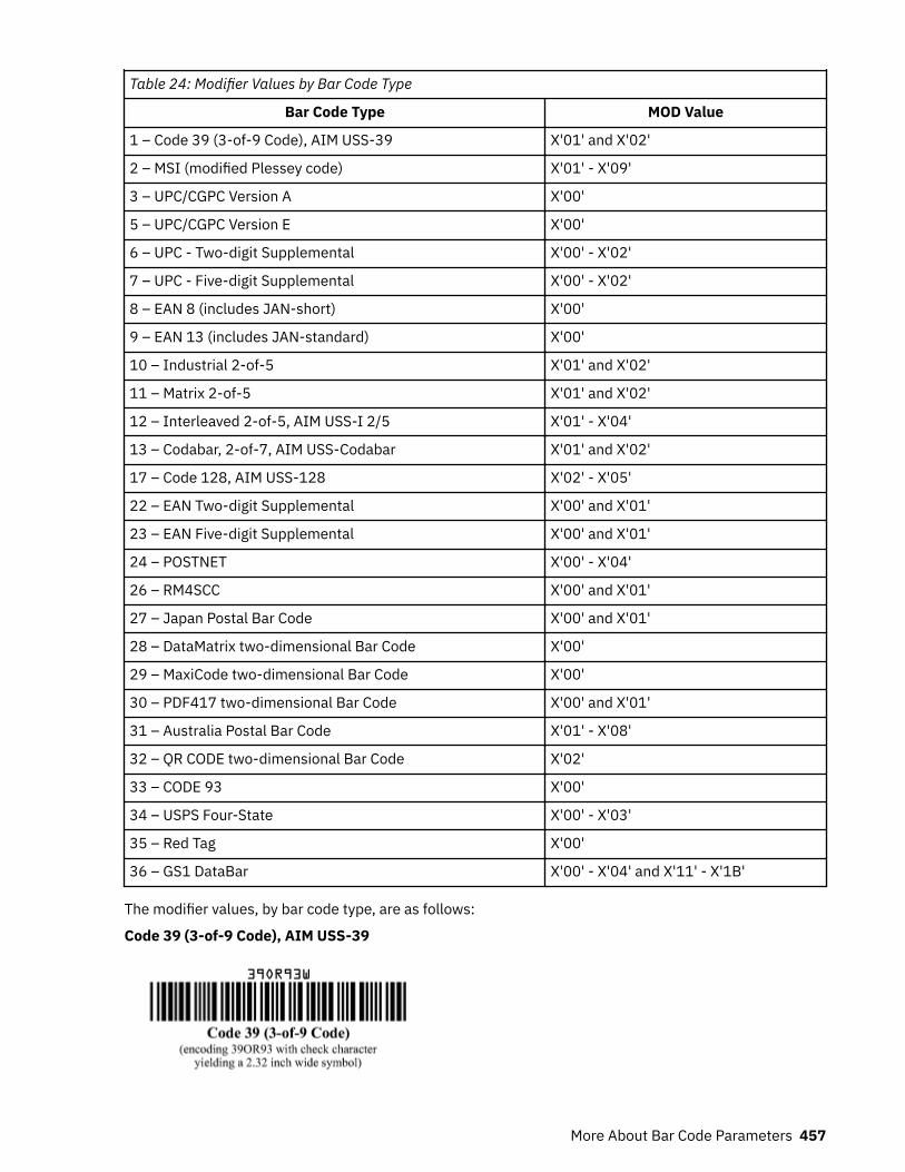
Table 24: Modifier Values by Bar Code Type
Bar Code Type MOD Value
1 – Code 39 (3-of-9 Code), AIM USS-39 X'01' and X'02'
2 – MSI (modified Plessey code) X'01' - X'09'
3 – UPC/CGPC Version A X'00'
5 – UPC/CGPC Version E X'00'
6 – UPC - Two-digit Supplemental X'00' - X'02'
7 – UPC - Five-digit Supplemental X'00' - X'02'
8 – EAN 8 (includes JAN-short) X'00'
9 – EAN 13 (includes JAN-standard) X'00'
10 – Industrial 2-of-5 X'01' and X'02'
11 – Matrix 2-of-5 X'01' and X'02'
12 – Interleaved 2-of-5, AIM USS-I 2/5 X'01' - X'04'
13 – Codabar, 2-of-7, AIM USS-Codabar X'01' and X'02'
17 – Code 128, AIM USS-128 X'02' - X'05'
22 – EAN Two-digit Supplemental X'00' and X'01'
23 – EAN Five-digit Supplemental X'00' and X'01'
24 – POSTNET X'00' - X'04'
26 – RM4SCC X'00' and X'01'
27 – Japan Postal Bar Code X'00' and X'01'
28 – DataMatrix two-dimensional Bar Code X'00'
29 – MaxiCode two-dimensional Bar Code X'00'
30 – PDF417 two-dimensional Bar Code X'00' and X'01'
31 – Australia Postal Bar Code X'01' - X'08'
32 – QR CODE two-dimensional Bar Code X'02'
33 – CODE 93 X'00'
34 – USPS Four-State X'00' - X'03'
35 – Red Tag X'00'
36 – GS1 DataBar X'00' - X'04' and X'11' - X'1B'
The modifier values, by bar code type, are as follows:
Code 39 (3-of-9 Code), AIM USS-39
More About Bar Code Parameters 457

X'01'Present the bar code without a generated check digit.
X'02'Generate a check digit and present it with the bar code.
Note: The Code 39 character set contains 43 characters that include numbers, uppercasealphabetics, and some special characters. The Code 39 Specification also provides a method ofencoding all 128 ASCII characters by using 2 bar code characters for those ASCII characters that arenot in the standard Code 39 character set. This is sometimes referred to as Extended Code 39 and issupported by all BCOCA receivers. In this case, the 2 bar code characters that are used to specify theextended character are shown in the Human-Readable Interpretation and the bar code scannerinterprets the 2-character combination bar/space pattern.
MSI (modified Plessey code)
X'01'Present the bar code without check digits that are generated by the printer. Specify 3 - 15 digits ofinput data.
X'02'Present the bar code with a generated IBM modulo-10 check digit. This check digit is the secondcheck digit; the first check digit is the last character of the data as defined in the associated FIELDSTART and LENGTH subcommands. Specify 2 - 14 digits of input data.
X'03'Present the bar code with two check digits. Both check digits are generated by using the IBMmodulo-10 algorithm. Specify 1 - 13 digits of input data.
X'04'Present the bar code with two check digits. The first check digit is generated by using the NCRmodulo-11 algorithm; the second using the IBM modulo-10 algorithm. The first check digit equalsthe remainder; exception condition EC-0E00 exists if the first check-digit calculation results in avalue of 10. Specify 1 - 13 digits of input data.
X'05'Present the bar code with two check digits. The first check digit is generated by using the IBMmodulo-11 algorithm; the second using the IBM modulo-10 algorithm. The first check digit equalsthe remainder; exception condition EC-0E00 exists if the first check-digit calculation results in avalue of 10. Specify 1 - 13 digits of input data.
X'06'Present the bar code with two check digits. The first check digit is generated by using the NCRmodulo-11 algorithm; the second using the IBM modulo-10 algorithm. The first check digit equals11 minus the remainder; a first check digit value of 10 is assigned the value zero. Specify 1 - 13digits of input data.
X'07'Present the bar code with two check digits. The first check digit is generated by using the IBMmodulo-11 algorithm; the second using the IBM modulo-10 algorithm. The first check digit equals11 minus the remainder; a first check digit value of 10 is assigned the value zero. Specify 1 - 13digits of input data.
458 Page Printer Formatting Aid: User's Guide
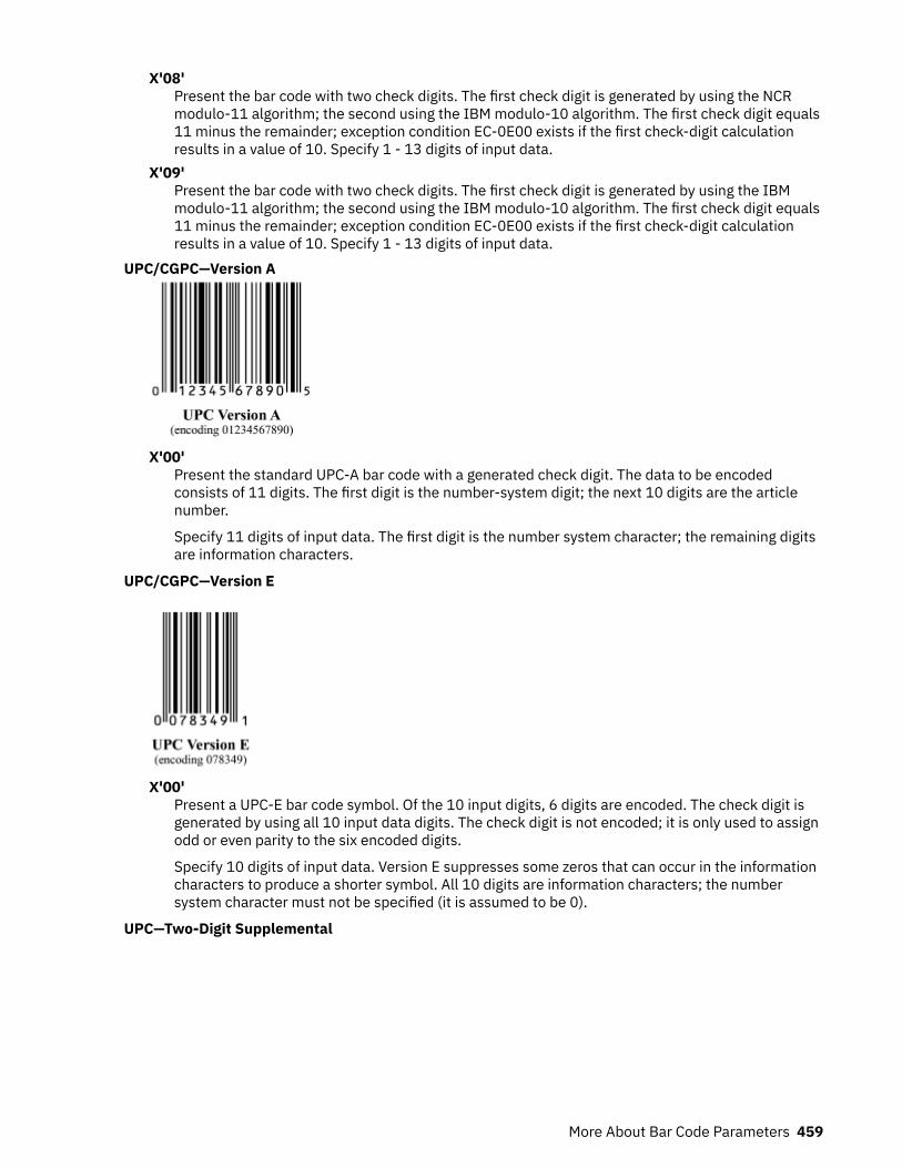
X'08'Present the bar code with two check digits. The first check digit is generated by using the NCRmodulo-11 algorithm; the second using the IBM modulo-10 algorithm. The first check digit equals11 minus the remainder; exception condition EC-0E00 exists if the first check-digit calculationresults in a value of 10. Specify 1 - 13 digits of input data.
X'09'Present the bar code with two check digits. The first check digit is generated by using the IBMmodulo-11 algorithm; the second using the IBM modulo-10 algorithm. The first check digit equals11 minus the remainder; exception condition EC-0E00 exists if the first check-digit calculationresults in a value of 10. Specify 1 - 13 digits of input data.
UPC/CGPC—Version A
X'00'Present the standard UPC-A bar code with a generated check digit. The data to be encodedconsists of 11 digits. The first digit is the number-system digit; the next 10 digits are the articlenumber.
Specify 11 digits of input data. The first digit is the number system character; the remaining digitsare information characters.
UPC/CGPC—Version E
X'00'Present a UPC-E bar code symbol. Of the 10 input digits, 6 digits are encoded. The check digit isgenerated by using all 10 input data digits. The check digit is not encoded; it is only used to assignodd or even parity to the six encoded digits.
Specify 10 digits of input data. Version E suppresses some zeros that can occur in the informationcharacters to produce a shorter symbol. All 10 digits are information characters; the numbersystem character must not be specified (it is assumed to be 0).
UPC—Two-Digit Supplemental
More About Bar Code Parameters 459
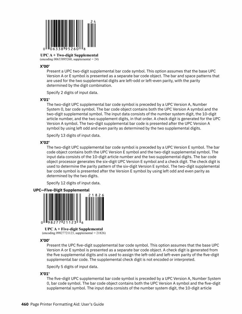
X'00'Present a UPC two-digit supplemental bar code symbol. This option assumes that the base UPCVersion A or E symbol is presented as a separate bar code object. The bar and space patterns thatare used for the two supplemental digits are left-odd or left-even parity, with the paritydetermined by the digit combination.
Specify 2 digits of input data.
X'01'The two-digit UPC supplemental bar code symbol is preceded by a UPC Version A, NumberSystem 0, bar code symbol. The bar code object contains both the UPC Version A symbol and thetwo-digit supplemental symbol. The input data consists of the number system digit, the 10-digitarticle number, and the two supplement digits, in that order. A check digit is generated for the UPCVersion A symbol. The two-digit supplemental bar code is presented after the UPC Version Asymbol by using left odd and even parity as determined by the two supplemental digits.
Specify 13 digits of input data.
X'02'The two-digit UPC supplemental bar code symbol is preceded by a UPC Version E symbol. The barcode object contains both the UPC Version E symbol and the two-digit supplemental symbol. Theinput data consists of the 10-digit article number and the two supplemental digits. The bar codeobject processor generates the six-digit UPC Version E symbol and a check digit. The check digit isused to determine the parity pattern of the six-digit Version E symbol. The two-digit supplementalbar code symbol is presented after the Version E symbol by using left odd and even parity asdetermined by the two digits.
Specify 12 digits of input data.
UPC—Five-Digit Supplemental
X'00'Present the UPC five-digit supplemental bar code symbol. This option assumes that the base UPCVersion A or E symbol is presented as a separate bar code object. A check digit is generated fromthe five supplemental digits and is used to assign the left-odd and left-even parity of the five-digitsupplemental bar code. The supplemental check digit is not encoded or interpreted.
Specify 5 digits of input data.
X'01'The five-digit UPC supplemental bar code symbol is preceded by a UPC Version A, Number System0, bar code symbol. The bar code object contains both the UPC Version A symbol and the five-digitsupplemental symbol. The input data consists of the number system digit, the 10-digit article
460 Page Printer Formatting Aid: User's Guide
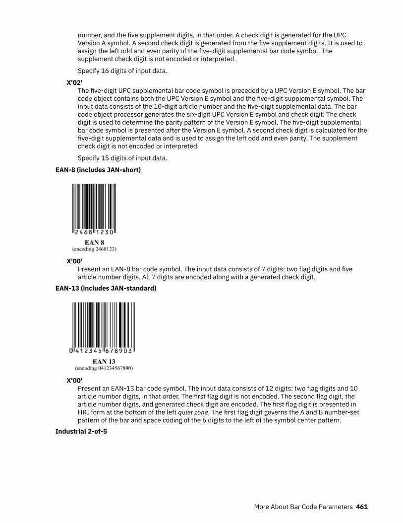
number, and the five supplement digits, in that order. A check digit is generated for the UPCVersion A symbol. A second check digit is generated from the five supplement digits. It is used toassign the left odd and even parity of the five-digit supplemental bar code symbol. Thesupplement check digit is not encoded or interpreted.
Specify 16 digits of input data.
X'02'The five-digit UPC supplemental bar code symbol is preceded by a UPC Version E symbol. The barcode object contains both the UPC Version E symbol and the five-digit supplemental symbol. Theinput data consists of the 10-digit article number and the five-digit supplemental data. The barcode object processor generates the six-digit UPC Version E symbol and check digit. The checkdigit is used to determine the parity pattern of the Version E symbol. The five-digit supplementalbar code symbol is presented after the Version E symbol. A second check digit is calculated for thefive-digit supplemental data and is used to assign the left odd and even parity. The supplementcheck digit is not encoded or interpreted.
Specify 15 digits of input data.
EAN-8 (includes JAN-short)
X'00'Present an EAN-8 bar code symbol. The input data consists of 7 digits: two flag digits and fivearticle number digits. All 7 digits are encoded along with a generated check digit.
EAN-13 (includes JAN-standard)
X'00'Present an EAN-13 bar code symbol. The input data consists of 12 digits: two flag digits and 10article number digits, in that order. The first flag digit is not encoded. The second flag digit, thearticle number digits, and generated check digit are encoded. The first flag digit is presented inHRI form at the bottom of the left quiet zone. The first flag digit governs the A and B number-setpattern of the bar and space coding of the 6 digits to the left of the symbol center pattern.
Industrial 2-of-5
More About Bar Code Parameters 461

X'01'Present the bar code without a generated check digit.
X'02'Generate a check digit and present it with the bar code.
Matrix 2-of-5
X'01'Present the bar code symbol without a generated check digit.
X'02'Generate a check digit and present it with the bar code.
Interleaved 2-of-5, AIM USS-I 2/5
The Interleaved 2-of-5 symbology requires an even number of digits. The printer adds a leading zero ifnecessary to meet this requirement.X'01'
Present the bar code symbol without a check digit.X'02'
Generate a check digit and present it with the bar code.Codabar, 2-of-7, AIM USS-Codabar
462 Page Printer Formatting Aid: User's Guide

X'01'Present the bar code without a generated check digit. The input data consists of a start character,digits to be encoded, and a stop character, in that order. Start and stop characters can be A, B, C,or D, and can be used only at the beginning and end of the symbol.
X'02'Generate a check digit and present it with the bar code. The input data consists of a startcharacter, digits to be encoded, and a stop character, in that order. Start and stop characters canbe A, B, C, or D, and can be used only at the beginning and end of the symbol.
Code 128, AIM USS-128 (modifier values X'02' through X'04')
The 1986 symbology definition for Code 128 defined an algorithm for generating a start character andthen changed that algorithm in 1993 to accommodate the UCC/EAN 128 variation of this bar code.Many BCOCA printers implemented the 1986 version (with modifier X'02'), some BCOCA printerschanged to use the 1993 algorithm (with modifier X'02'), and some BCOCA printers support bothalgorithms. When UCC/EAN 128 bar codes are produced for printers that explicitly support UCC/EAN128, modifier X'03' or modifier X'04' must be specified. For printers that do not explicitly supportUCC/EAN 128, specifying modifier X'02' might produce a valid UCC/EAN 128 bar code (see notes inthe modifier descriptions).
The data for UCC/EAN 128 bar codes is in the form:
"FNC1, ai, data, m, FNC1, ai, data, m, FNC1, ..., ai, data, m"
FNC1 is the FNC1 function character (X'8F'), ai is an application identifier, data is defined for eachregistered application identifier, and m is a modulo 10 check digit (calculated with the same checkdigit algorithm that is used for UPC version A bar codes). Not all application identifiers require amodulo 10 check digit (m). Also, all except the firstFNC1 are field separator characters that appearonly when the preceding ai data is of variable length. See UCC/EAN-128 APPLICATION IDENTIFIERSTANDARD from the Uniform Code Council, Inc. for a description of application identifiers and the useof FNC1. To build the bar code symbol, the printer must:
• Produce a start character based on the 1993 algorithm.• Bar encode the data, including the FNC1, ai, data, and m check digit.• Produce a modulo 103 check digit.• Produce a stop character.
Modifier X'02' – Code 128 symbol, with original (1986) start-character algorithm
More About Bar Code Parameters 463

Generate a Code 128 symbol with subset A, B, or C to produce the shortest possible bar code from thespecified data, by using the start-character algorithm that was published in the original (1986) editionof the Code 128 Symbology Specification. The Code 128 code page (CPGID = 1303, GCSGID = 1454)is used to interpret the bar code symbol data. Generate a check digit and present it with the bar code.
Notes:
1. Some IPDS printers use the modifier X'03' start-character algorithm even when modifier X'02' isspecified. This produces a valid UCC/EAN 128 symbol when valid UCC/EAN 128 data is provided.However, in general, modifier X'02' must not be used to produce UCC/EAN 128 symbols becausethis value causes other IPDS printers to use the original Code 128 start-symbol algorithm, whichgenerates a Start (Code B) instead of the Start (Code C) that UCC/EAN 128 requires. Some barcode scanners can handle either start character for a UCC/EAN 128 symbol, but others require theStart (Code C) character.
2. These printers use the UCC/EAN 128 start-character algorithm when modifier X'02' is specified:4312, 4317, 4324, InfoPrint 20, InfoPrint 21, InfoPrint 32, InfoPrint 40, InfoPrint 45, InfoPrint 70,InfoPrint 2070, InfoPrint 2085, and InfoPrint 2105. Other IPDS printers use the original start-character algorithm when modifier X'02' is specified.
Modifier X'03' – UCC/EAN 128 symbol, without parenthesis in the HRI
Generate a Code 128 symbol with subset A, B, or C to produce the shortest possible bar code from thespecified data, by using the version of the start-character algorithm that was modified for producingUCC/EAN 128 symbols. If the first data character is FNC1 (as is required for a UCC/EAN 128 symbol)and is followed by valid UCC/EAN 128 data, the printer generates a Start (Code C) character. The Code128 code page (CPGID = 1303, GCSGID = 1454) is used to interpret the bar code symbol data.Generate a check digit and present it with the bar code.
The UCC/EAN 128 data is checked for validity and exception condition EC-1200 exists if one or moreof the following conditions are encountered:
• FNC1 is not the first data character.• Invalid application identifier (ai) value encountered.• Data for an ai doesn't match the ai definition.• Insufficient (or no) data that follows an ai.• Too much data for an ai.• Invalid use of FNC1 character.
Notes:
1. UCC/EAN 128 is a variation of Code 128 that begins with an FNC1 character, followed by anApplication Identifier and the data to be bar encoded. All of these characters (including the FNC1character) must be supplied within the Bar Code Symbol Data (BSA). UCC/EAN 128 also requiresthat the symbol begin in subset C.
2. For UCC/EAN 128 symbols, the start character, the FNC1 characters, the modulo 103 check digit,and the stop character are not shown in the human readable format.
464 Page Printer Formatting Aid: User's Guide

Modifier X'04' – UCC/EAN 128 symbol, with parenthesis in the HRI
Generate a Code 128 symbol in the same manner as for modifier X'03', but use parenthesis in the HRIto distinguish each application identifier (ai). The printer inserts the parenthesis in the printed HRIwhen modifier X'04' is specified; these parentheses are not part of the input data.
EAN Two-Digit Supplemental
X'00'Present the EAN two-digit supplemental bar code symbol. This option assumes that the baseEAN-13 symbol is presented as a separate bar code object. The value of the two digitsupplemental data determines their bar and space patterns that are chosen from number sets Aand B.
Specify 2 digits of input data.
X'01'The two-digit supplemental bar code symbol is preceded by a normal EAN-13 bar code symbol.The bar code object contains both the EAN-13 symbol and the two-digit supplemental symbol.The two-digit supplemental bar code is presented after the EAN-13 symbol by using left odd andeven parity as determined by the two supplemental digits that are chosen from number sets A andB.
Specify 14 digits of input data.
Note: Used for both books and paperbacks.
EAN Five-Digit Supplemental
More About Bar Code Parameters 465

X'00'Present the EAN five-digit supplemental bar code. This option assumes that the base EAN-13symbol is presented as a separate bar code object. A check digit is calculated from the fivesupplemental digits. The check digit is also used to assign the bar and space patterns fromnumber sets A and B for the five supplemental digits. The check digit is not encoded orinterpreted.
Specify 5 digits of input data.
X'01'The five-digit supplemental bar code symbol is preceded by a normal EAN-13 bar code symbol.The bar code object contains both the EAN-13 symbol and the five-digit supplemental symbol. Acheck digit is generated from the five-digit supplemental data. The check digit is used to assignthe bar and space patterns from number sets A and B. The check digit is not encoded orinterpreted.
Specify 17 digits of input data.
Note: Used for books and paperbacks.
POSTNET and PLANET
For all POSTNET modifiers that follow, the BSA HRI flag field and the BSD module width, elementheight, height multiplier, and wide-to-narrow ratio fields are not applicable to the POSTNET bar codesymbology. These fields are ignored because the POSTNET symbology defines specific values forthese parameters.X'00'
Present a POSTNET ZIP Code bar code symbol. The ZIP Code to be encoded is defined as a five-digit, numeric (0 - 9), data variable to the BSA data structure. The POSTNET ZIP Code bar codeconsists of a leading frame bar, the encoded ZIP Code data, a correction digit, and a trailing framebar.
X'01'Present a POSTNET ZIP+4 bar code symbol. The ZIP+4 code to be encoded is defined as a nine-digit, numeric (0 - 9), data variable to the BSA data structure. The POSTNET ZIP+4 bar codeconsists of a leading frame bar, the encoded ZIP+4 data, a correction digit, and a trailing framebar.
X'02'Present a POSTNET Advanced Bar Code (ABC) bar code symbol. The ABC code to be encoded isdefined as an 11-digit, numeric (0 - 9), data variable to the BSA data structure. The POSTNET ABCbar code consists of a leading frame bar, the encoded ABC data, a correction digit, and a trailingframe bar.
Note: An 11-digit POSTNET bar code is called a Delivery Point bar code.
X'03'Present a POSTNET variable-length bar code symbol. The data to be encoded is defined as an n-digit, numeric (0 - 9), data variable to the BSA data structure. The bar code symbol is generatedwithout length checking; the symbol is not guaranteed to be scannable or interpretable. ThePOSTNET variable-length bar code consists of a leading frame bar, the encoded data, a correctiondigit, and a trailing frame bar.
X'04'Present a PLANET Code symbol. The PLANET Code is a reverse topology variation of POSTNETthat encodes 11 digits of data; the first 2 digits represent a service code (such as 21 = OriginConfirm and 22 = Destination Confirm) and the next 9 digits identify the mailpiece. A 12th digit is
466 Page Printer Formatting Aid: User's Guide

generated by the printer as a check digit. The PLANET Code symbol consists of a leading framebar, the encoded data, a check digit, and a trailing frame bar.
Royal Mail (RM4SCC and Dutch KIX)
A 4-state customer code that is defined by the Royal Mail Postal service of England for use in barcoding postal code information. This symbology is also called the Royal Mail bar code or the 4-Statecustomer code. The symbology (as defined for modifier X'00') is used in the United Kingdom and inSingapore. A variation that is called KIX (KlantenIndeX = customer index, as defined for modifierX'01') is used in the Netherlands.X'00'
Present a RM4SCC bar code symbol with a generated start bit, checksum character, and stop bit.The start and stop bits identify the beginning and end of the bar code symbol and also theorientation of the symbol.
X'01'Present a RM4SCC bar code symbol with no start bar, no checksum character, and no stop bar.
Note: Modifier X'01' is also known as Dutch Kix Postal Bar Code. In addition to the charactersallowed in Modifier X'00', it allows lowercase alphabetical characters, which are folded touppercase by the printer.
Japan Postal Bar Code (JPOSTAL)
A complete Japan Postal Bar Code symbol that consists of a set of distinct bars and spaces for eachcharacter, followed by a modulo 19 checksum character and enclosed by a unique start character,stop character, and quiet zones.X'00'
Present a Japan Postal Bar Code symbol with a generated start character, checksum character,and stop character.
The generated bar code symbol consists of a start code, a 7-digit new postal code, a 13-digitaddress indication number, a check digit, and a stop code. The variable data to be encoded (BSAbytes 5-n) is used as follows:
1. The first few digits represent the new postal code in either the form nnn-nnnn or the formnnnnnnn; the hyphen, if present, is ignored and the other 7 digits must be numeric. The 7 digitsare placed in the new postal code field of the bar code symbol.
2. If the next digit is a hyphen, it is ignored and is not used in generating the bar code symbol.3. The remainder of the BSA data is the address indication number, which can contain numbers,
hyphens, and alphabetic characters (A-Z). Each number and each hyphen represents one digitin the bar code symbol; each alphabetic character is represented by a combination of a controlcode (CC1, CC2, or CC3) and a numerical code, and handled as two digits in the bar codesymbol. Thirteen digits of this address indication number data are placed in the addressindication number field of the bar code symbol.
• If fewer than 13more digits are present, the shortage is filled in with the bar codecorresponding to control code CC4 up to the thirteenth digit.
More About Bar Code Parameters 467

• If more than 13 more digits are present, the first 13 are used and the remainder are ignored,with no exception condition reported. However, if the thirteenth digit is the control code foran alphabetic (A-Z) character, only the control code is included and the numeric part isomitted.
X'01'Present a Japan Postal Bar Code symbol directly from the bar code data. Each valid character inthe BSA data field is converted into a bar/space pattern, with no validity or length checking. Theprinter does not generate start, stop, or check digits.
To produce a valid bar code symbol, the bar code data must contain a start code, a 7-digit newpostal code, a 13-digit address indication number, a valid check digit, and a stop code. The newpostal code must consist of 7 numeric digits. The address indication number must consist of 13characters, which can be numeric, hyphen, or control characters (CC1 through CC8). The followingtable lists the valid code points for modifier X'01':
Table 25: Valid EBCDIC-based Code Points for Japan Postal Bar Code
Bar CodeCharacter
Code Point NumericalChecking
Value
Bar CodeCharacter
Code Point NumericalChecking
Value
start X'4C' 0 X'F0' 0
stop X'6E' 1 X'F1' 1
hyphen X'60' 10 2 X'F2' 2
CC1 X'5A' 11 3 X'F3' 3
CC2 X'7F' 12 4 X'F4' 4
CC3 X'7B' 13 5 X'F5' 5
CC4 X'E0' 14 6 X'F6' 6
CC5 X'6C' 15 7 X'F7' 7
CC6 X'50' 16 8 X'F8' 8
CC7 X'7D' 17 9 X'F9' 9
CC8 X'4D' 18
Notes:
1. Do not attempt to use the Start and Stop characters in calculating the check digit. You can usethe remaining characters to generate check digits; they are the only characters that are validfor check digits. Use the Numeric Checking Values to calculate the check digits.
2. You supply data generation for mod 1. The check digit is the sum of the digits module 19,which is a remainder of X. The check digit is 19 minus X, converted to hex. If this is doneincorrectly, the print server displays message APS830I.
The hyphen has a hex value of X'60' and a checking digit numerical of 10.
The following example is a generation of the customer bar code where 154-0023 is the newpostal code and 3 - 1 6 - 4 is the address indication number:
address 154 3-16-4, Wakabayshi, Setagaya-ku
New postal code + address indication number:
154-0023-3-16-4
468 Page Printer Formatting Aid: User's Guide

Delete hyphens between the third and fourth digits of the new postal code and between thenew postal code and address indication number, as follows:
15400233-16-4
If the address indication number is shorter than 13 digits, use CC4s to fill the remainingspaces, as in the following example.
15400233-16-4 CC4 CC4 CC4 CC4 CC4 CC4 CC4
The first 7 digits are ignored as the postal code and the remaining digits are the addressindication number. Remember to count hyphens as digits. In the previous example, the postalcode is 1540023 and the address indication number is 3 - 1 6 - 4 plus seven CC4 characters.
Calculate the check digit (CD), based on the table of correspondence between characters forbar code and checking numerals. See Table 25 on page 468 for more information about checkdigits.
1+5+4+0+0+2+3+3+10+1+6+10+4+14+14+14+14+14+14+14+CD = 147 + CD = integral multiple of 19
Using the integral multiple of 19, 152 - 147 = 5 for the check digit, based on the table ofcorrespondence between characters for bar code and checking numerals. Five corresponds tochecking numerical five.
For the previous postal code and address indication number, calculate the hex value of thecheck digit. The following table shows how to convert the data to hex values. Add the checkdigit (CD), start code (STC), and stop code (SPC), as follows:
Table 26: Table Shows How to Convert Data to Hex Values.
Start Code (STC) HEX
1 F1
5 F5
4 F4
0 F0
0 F0
2 F2
3 F3
3 F3
- 60
1 F1
6 F6
- 60
4 F4
CC4 E0
CC4 E0
CC4 E0
CC4 E0
More About Bar Code Parameters 469

Table 26: Table Shows How to Convert Data to Hex Values. (continued)
Start Code (STC) HEX
CC4 E0
CC4 E0
CC4 E0
CD(5) F5
SPC 6E
Notice that the check digit (CD) equals 5 and is converted to the hex value of F5.
The following are examples of various Japanese postal bar codes.
PAGEDEF SLSRPT; PRINTLINE POSITION 2 IN 2 IN; FIELD START 1 LENGTH 23 POSITION CURRENT NEXT DIRECTION ACROSS BARCODE JAPAN TYPE JPOSTAL MOD 1;
This bar code used numeric postal codes only. The 7-digit field contains the start, stop, andchecksum characters. The printer does not generate start, stop, or checksum characters.
PAGEDEF SLSRPT; PRINTLINE POSITION 2 IN 2 IN; FIELD START 1 LENGTH 23 POSITION CURRENT NEXT DIRECTION ACROSS BARCODE JAPAN TYPE JPOSTAL MOD 1;
This bar code used alphanumeric postal codes only. The 13-digit field contains start, stop,checksum, and command codes. The printer does not generate start, stop, or checksumcharacters.
PAGEDEF SLSRPT; PRINTLINE POSITION 2 IN 2 IN; FIELD START 1 LENGTH 7 POSITION CURRENT NEXT DIRECTION ACROSS BARCODE JAPAN TYPE JPOSTAL MOD 0;
This bar code used numeric postal codes only. This is a 7-digit character field.
PAGEDEF SLSRPT; PRINTLINE POSITION 2 IN 2 IN; FIELD START 1 LENGTH 13 POSITION CURRENT NEXT DIRECTION ACROSS BARCODE JAPAN TYPE JPOSTAL MOD 0;
This bar code used alphanumeric postal codes only. This is a 13-digit character field.
Data Matrix (2DMATRIX)
470 Page Printer Formatting Aid: User's Guide

A two-dimensional matrix bar code symbology that is defined as an AIM International SymbologySpecification.X'00'
Present a Data Matrix Bar Code symbol by using Error Checking and Correcting (ECC) algorithm200.
The bar code data is assumed to start with the default character encodation (ECI 000003 = ISO8859-1). This is an international Latin 1 code page that is equivalent to the ASCII code page 819.To change to a different character encodation within the data, the ECI protocol as defined in theAIM International Symbology Specification - Data Matrix, must be used. This means that whenevera byte value of X'5C' (an escape code) is encountered in the bar code data, the next six charactersmust be decimal digits (byte values X'30' - X'39') or the next character must be another X'5C'.When the X'5C' character is followed by six decimal digits, the six decimal digits are interpreted asthe ECI number, which changes the interpretation of the characters that follow the decimal digits.When the X'5C' character is followed by another X'5C' character, this is interpreted as one X'5C'character (which is a backslash in the default character encodation); alternatively, the escape-sequence handling flag can be used to treat X'5C' as a normal character.
Since the default character encodation for this bar code is ASCII, the EBCDIC-to-ASCII translationflag can be used when all of the data for the bar code is EBCDIC. If the bar code data containsmore than one-character encodation or if the data needs to be encoded within the bar codesymbol in a form other than the default character encodation (such as, in EBCDIC), the bar codedata must begin in the default encodation, the EBCDIC-to-ASCII translation flag must be set toB'0', and the ECI protocol must be used to switch into the other encodation.
Note: For more information about 2DMATRIX two-dimensional matrix bar codes, see “Data MatrixSpecial-Function Parameters” on page 484.
MaxiCode (2DMAXI)
A two-dimensional matrix bar code symbology that is defined as an AIM International SymbologySpecification.X'00'
Present a MaxiCode bar code symbol.
The bar code data is assumed to start with the default character encodation (ECI 000003 = ISO8859-1). This is an international Latin 1 code page that is equivalent to the ASCII code page 819. Tochange to a different character encodation within the data, the ECI protocol as defined in section4.15.2 of the AIM International Symbology Specification - MaxiCode, must be used. This means thatwhenever a byte value of X'5C' (an escape code) is encountered in the bar code data, the next six
More About Bar Code Parameters 471
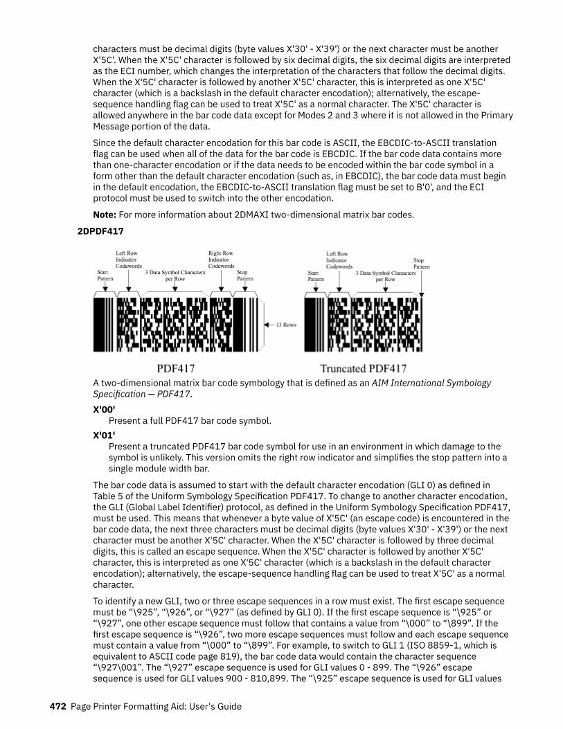
characters must be decimal digits (byte values X'30' - X'39') or the next character must be anotherX'5C'. When the X'5C' character is followed by six decimal digits, the six decimal digits are interpretedas the ECI number, which changes the interpretation of the characters that follow the decimal digits.When the X'5C' character is followed by another X'5C' character, this is interpreted as one X'5C'character (which is a backslash in the default character encodation); alternatively, the escape-sequence handling flag can be used to treat X'5C' as a normal character. The X'5C' character isallowed anywhere in the bar code data except for Modes 2 and 3 where it is not allowed in the PrimaryMessage portion of the data.
Since the default character encodation for this bar code is ASCII, the EBCDIC-to-ASCII translationflag can be used when all of the data for the bar code is EBCDIC. If the bar code data contains morethan one-character encodation or if the data needs to be encoded within the bar code symbol in aform other than the default character encodation (such as, in EBCDIC), the bar code data must beginin the default encodation, the EBCDIC-to-ASCII translation flag must be set to B'0', and the ECIprotocol must be used to switch into the other encodation.
Note: For more information about 2DMAXI two-dimensional matrix bar codes.
2DPDF417
A two-dimensional matrix bar code symbology that is defined as an AIM International SymbologySpecification — PDF417.X'00'
Present a full PDF417 bar code symbol.X'01'
Present a truncated PDF417 bar code symbol for use in an environment in which damage to thesymbol is unlikely. This version omits the right row indicator and simplifies the stop pattern into asingle module width bar.
The bar code data is assumed to start with the default character encodation (GLI 0) as defined inTable 5 of the Uniform Symbology Specification PDF417. To change to another character encodation,the GLI (Global Label Identifier) protocol, as defined in the Uniform Symbology Specification PDF417,must be used. This means that whenever a byte value of X'5C' (an escape code) is encountered in thebar code data, the next three characters must be decimal digits (byte values X'30' - X'39') or the nextcharacter must be another X'5C' character. When the X'5C' character is followed by three decimaldigits, this is called an escape sequence. When the X'5C' character is followed by another X'5C'character, this is interpreted as one X'5C' character (which is a backslash in the default characterencodation); alternatively, the escape-sequence handling flag can be used to treat X'5C' as a normalcharacter.
To identify a new GLI, two or three escape sequences in a row must exist. The first escape sequencemust be “\925”, “\926”, or “\927” (as defined by GLI 0). If the first escape sequence is “\925” or“\927”, one other escape sequence must follow that contains a value from “\000” to “\899”. If thefirst escape sequence is “\926”, two more escape sequences must follow and each escape sequencemust contain a value from “\000” to “\899”. For example, to switch to GLI 1 (ISO 8859-1, which isequivalent to ASCII code page 819), the bar code data would contain the character sequence“\927\001”. The “\927” escape sequence is used for GLI values 0 - 899. The “\926” escapesequence is used for GLI values 900 - 810,899. The “\925” escape sequence is used for GLI values
472 Page Printer Formatting Aid: User's Guide
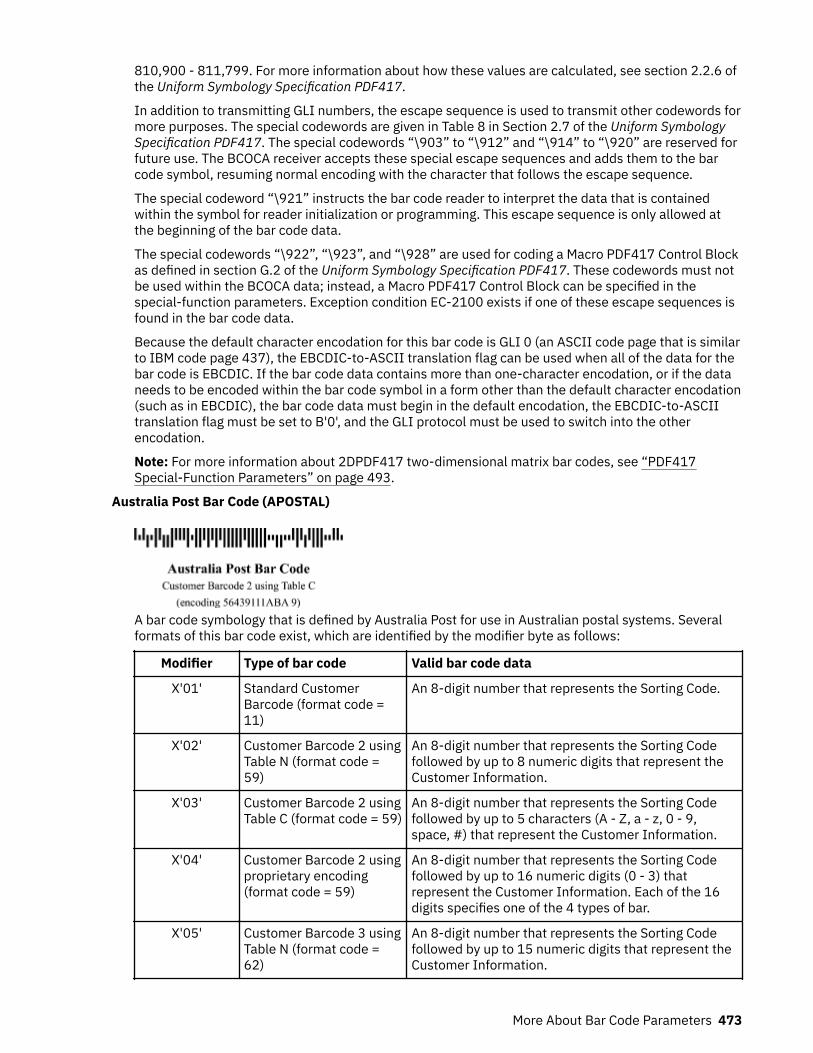
810,900 - 811,799. For more information about how these values are calculated, see section 2.2.6 ofthe Uniform Symbology Specification PDF417.
In addition to transmitting GLI numbers, the escape sequence is used to transmit other codewords formore purposes. The special codewords are given in Table 8 in Section 2.7 of the Uniform SymbologySpecification PDF417. The special codewords “\903” to “\912” and “\914” to “\920” are reserved forfuture use. The BCOCA receiver accepts these special escape sequences and adds them to the barcode symbol, resuming normal encoding with the character that follows the escape sequence.
The special codeword “\921” instructs the bar code reader to interpret the data that is containedwithin the symbol for reader initialization or programming. This escape sequence is only allowed atthe beginning of the bar code data.
The special codewords “\922”, “\923”, and “\928” are used for coding a Macro PDF417 Control Blockas defined in section G.2 of the Uniform Symbology Specification PDF417. These codewords must notbe used within the BCOCA data; instead, a Macro PDF417 Control Block can be specified in thespecial-function parameters. Exception condition EC-2100 exists if one of these escape sequences isfound in the bar code data.
Because the default character encodation for this bar code is GLI 0 (an ASCII code page that is similarto IBM code page 437), the EBCDIC-to-ASCII translation flag can be used when all of the data for thebar code is EBCDIC. If the bar code data contains more than one-character encodation, or if the dataneeds to be encoded within the bar code symbol in a form other than the default character encodation(such as in EBCDIC), the bar code data must begin in the default encodation, the EBCDIC-to-ASCIItranslation flag must be set to B'0', and the GLI protocol must be used to switch into the otherencodation.
Note: For more information about 2DPDF417 two-dimensional matrix bar codes, see “PDF417Special-Function Parameters” on page 493.
Australia Post Bar Code (APOSTAL)
A bar code symbology that is defined by Australia Post for use in Australian postal systems. Severalformats of this bar code exist, which are identified by the modifier byte as follows:
Modifier Type of bar code Valid bar code data
X'01' Standard CustomerBarcode (format code =11)
An 8-digit number that represents the Sorting Code.
X'02' Customer Barcode 2 usingTable N (format code =59)
An 8-digit number that represents the Sorting Codefollowed by up to 8 numeric digits that represent theCustomer Information.
X'03' Customer Barcode 2 usingTable C (format code = 59)
An 8-digit number that represents the Sorting Codefollowed by up to 5 characters (A - Z, a - z, 0 - 9,space, #) that represent the Customer Information.
X'04' Customer Barcode 2 usingproprietary encoding(format code = 59)
An 8-digit number that represents the Sorting Codefollowed by up to 16 numeric digits (0 - 3) thatrepresent the Customer Information. Each of the 16digits specifies one of the 4 types of bar.
X'05' Customer Barcode 3 usingTable N (format code =62)
An 8-digit number that represents the Sorting Codefollowed by up to 15 numeric digits that represent theCustomer Information.
More About Bar Code Parameters 473
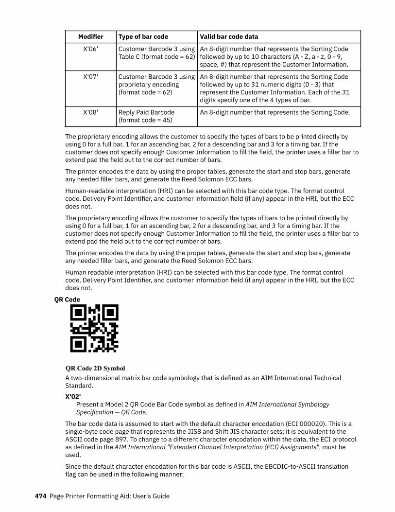
Modifier Type of bar code Valid bar code data
X'06' Customer Barcode 3 usingTable C (format code = 62)
An 8-digit number that represents the Sorting Codefollowed by up to 10 characters (A - Z, a - z, 0 - 9,space, #) that represent the Customer Information.
X'07' Customer Barcode 3 usingproprietary encoding(format code = 62)
An 8-digit number that represents the Sorting Codefollowed by up to 31 numeric digits (0 - 3) thatrepresent the Customer Information. Each of the 31digits specify one of the 4 types of bar.
X'08' Reply Paid Barcode(format code = 45)
An 8-digit number that represents the Sorting Code.
The proprietary encoding allows the customer to specify the types of bars to be printed directly byusing 0 for a full bar, 1 for an ascending bar, 2 for a descending bar and 3 for a timing bar. If thecustomer does not specify enough Customer Information to fill the field, the printer uses a filler bar toextend pad the field out to the correct number of bars.
The printer encodes the data by using the proper tables, generate the start and stop bars, generateany needed filler bars, and generate the Reed Solomon ECC bars.
Human-readable interpretation (HRI) can be selected with this bar code type. The format controlcode, Delivery Point Identifier, and customer information field (if any) appear in the HRI, but the ECCdoes not.
The proprietary encoding allows the customer to specify the types of bars to be printed directly byusing 0 for a full bar, 1 for an ascending bar, 2 for a descending bar, and 3 for a timing bar. If thecustomer does not specify enough Customer Information to fill the field, the printer uses a filler bar toextend pad the field out to the correct number of bars.
The printer encodes the data by using the proper tables, generate the start and stop bars, generateany needed filler bars, and generate the Reed Solomon ECC bars.
Human readable interpretation (HRI) can be selected with this bar code type. The format controlcode, Delivery Point Identifier, and customer information field (if any) appear in the HRI, but the ECCdoes not.
QR Code
A two-dimensional matrix bar code symbology that is defined as an AIM International TechnicalStandard.X'02'
Present a Model 2 QR Code Bar Code symbol as defined in AIM International SymbologySpecification — QR Code.
The bar code data is assumed to start with the default character encodation (ECI 000020). This is asingle-byte code page that represents the JIS8 and Shift JIS character sets; it is equivalent to theASCII code page 897. To change to a different character encodation within the data, the ECI protocolas defined in the AIM International "Extended Channel Interpretation (ECI) Assignments", must beused.
Since the default character encodation for this bar code is ASCII, the EBCDIC-to-ASCII translationflag can be used in the following manner:
474 Page Printer Formatting Aid: User's Guide

• When all of the input data for the bar code is single-byte EBCDIC that uses one of the supportedcode pages (500, 290, or 1027), set the EBCDIC-to-ASCII translation flag to B'1' and select thecorrect code page in the conversion parameter.
• When all of the input data for the bar code is mixed-byte EBCDIC AFP Line Data that uses SO and SIcontrols (SOSI data), set the EBCDIC-to-ASCII translation flag to B'1' and select the conversionvalue you want in the conversion parameter.
If the bar code data contains more than one-character encodation or if the data needs to be encodedwithin the bar code symbol in a form other than the ones that are previously mentioned (such as in anEBCDIC code page that is not supported by the EBCDIC-to-ASCII translation flag), the bar code datamust begin in the default encodation, the EBCDIC-to-ASCII translation flag must be set to B'0', andthe ECI protocol must be used to switch to the other encodations.
A quiet zone must exist around the symbol that is at least four modules wide on each of the four sidesof the symbol.
Note: For more information about QRCODE two-dimensional bar code see “QR Code Special-FunctionParameters” on page 497.
Code 93
A linear bar code symbology similar to Code 39, but more compact than Code 39. Code 93 bar codesymbols are made up of a series of characters each of which is represented by 9 modules that arearranged into 3 bars with their adjacent spaces. The bars and spaces very between 1 module wideand 4 modules wide.X'00'
Present a Code 93 bar code symbol as defined in AIM International Symbology Specification —Code 93.
The Code 93 character set contains 47 characters, including numeric digits, uppercase alphabetics,four shift characters (a, b, c, and d), and seven special characters. The Code 93 Specification alsoprovides a method of encoding all 128 ASCII characters by using two bar code characters for thoseASCII characters that are not in the standard Code 93 character set. This is sometimes referred to asExtended Code 93. In this case, the two bar code characters that are used to specify the extendedcharacter are shown in the Human-Readable Interpretation (as a ▪ followed by the second character)and the bar code scanner interprets the two-character combination bar/space pattern.
The Human-Readable Interpretation of the Start and Stop characters is represented as an open box(☐) and the shift characters (a, b, c, and d) are represented as a filled box (▪).A quiet zone must precede and follow the symbol that is at least 10 modules wide.
USPS Four-State
The USPS Four-State bar code symbology8 limits the symbol size; therefore, BSD element height,height multiplier, and wide-to-narrow ratio fields are not applicable to this symbology and are ignoredby BCOCA receivers. The module width field allows for two symbol sizes (small and optimal); the smallsymbol is approximately 2.575 inches wide and the optimal symbol is approximately 2.9 inches wide.
8 The United States Postal Service (USPS) developed this symbology for use in the USPS mailstream andnamed it the OneCodeSOLUTION Barcode. The bar code is also known as the 4-state Customer Barcode and isabbreviated in several ways: OneCode (4CB), OneCode (4-CB), 4CB, or 4-CB.
More About Bar Code Parameters 475
The input data is all numeric and consists of 5 data fields. The first four fields are fixed length and the5th field can have one of four lengths; the bar code modifier is used to specify the length of the 5thfield. The total length of the input data can be 20, 25, 29, or 31 digits and is defined as follows:
• Bar code ID (2 digits) - assigned by USPS, the 2nd digit must be 0 - 4. Thus, the valid values are: 00 -04, 10 - 14, 20 - 24, 30 - 34, 40 - 44, 50 - 54, 60 - 64, 70 - 74, 80 - 84, and 90 - 94.
• Service Code (3 digits) - assigned by USPS; valid values are 000 - 999.• Subscriber ID (6 digits) - assigned by USPS; valid values are 000000 - 999999.• Unique ID (9 digits) - assigned by the mailer; valid values are 000000000 - 999999999.• Routing ZIP Code (0, 5, 9, or 11 digits) - refer to the modifier for valid values.
USPS Four-State modifier values are defined as follows:X'00'
Present a USPS Four-State bar code symbol with no Delivery Point ZIP Code. The input data forthis bar code symbol must be 20 number digits.
X'01'Present a USPS Four-State bar code symbol with a 5-digit Delivery Point ZIP Code. The input datafor this bar code symbol must be 25 number digits; the valid values for the Delivery Point ZIP Codeare 00000 - 99999.
X'02'Present a USPS Four-State bar code symbol with a 9-digit Delivery Point ZIP Code. The input datafor this bar code symbol must be 29 number digits; the valid values for the Delivery Point ZIP Codeare 000000000 - 999999999.
X'03'Present a USPS Four-State bar code symbol with an 11-digit Delivery Point ZIP Code. The inputdata for this bar code symbol must be 31 number digits; the valid values for the Delivery Point ZIPCode are 00000000000 - 99999999999.
Human-Readable Interpretation (HRI) can be printed with a USPS Four-State symbol, but HRI is notused with all types of special services. See Introducing 4-state Customer Barcode for a description ofwhen HRI is appropriate.
A quiet zone must surround the symbol (all four sides) that is at least 0.04 inches above and belowand at least 0.125 inches on both sides of the symbol.
Check Digit Calculation MethodSome bar code types and modifiers call for the calculation and presentation of check digits. Check digitsare a method of verifying data integrity during the bar coding reading process. Except for UPC Version E,the check digit is always presented in the bar code bar and space patterns, but is not always presented inthe HRI. The following table shows the check digit calculation methods for each bar code type and thepresence or absence of the check digit in the HRI.
Table 27: Check Digit Calculation Methods For Each Bar Code.
Bar Code Type Modifier In HRI? Check Digit Calculation
1 – Code 39 (3-of-9 Code),AIM USS-39
X'02' Yes Modulo 43 of the sum of the datacharacters' numerical values as describedin a Code 39 specification. The start andstop codes are not included in thecalculation.
476 Page Printer Formatting Aid: User's Guide

Table 27: Check Digit Calculation Methods For Each Bar Code. (continued)
Bar Code Type Modifier In HRI? Check Digit Calculation
2 – MSI (modified Plesseycode)
X'02' - X'09' No IBM Modulus 10 check digit:
1. Multiply each digit of the originalnumber by a weighting factor of 1 or 2as follows: multiply the units digit by 2,the tens digit by 1, the hundreds digit by2, the thousands digit by 1, and so forth.
2. Sum the digits of the products from step1. This is not the same as summing thevalues of the products.
3. The check digit is described by thefollowing equation where sum is theresulting value of step 2: (10 - (summodulo 10)) modulo 10
IBM Modulus 11 check digit:
1. Multiply each digit of the originalnumber by a repeating weighting factorpattern of 2, 3, 4, 5, 6, 7 as follows:multiply the units digit by 2, the tensdigit by 3, the hundreds digit by 4, thethousands digit by 5, and so forth.
2. Sum the products from step 1.3. The check digit depends on the bar code
modifier. The check digit as theremainder is described by the followingequation where sum is the resultingvalue of step 2: (sum modulo 11)
The check digit as 11 minus theremainder is described by the followingequation: (11 - (sum modulo 11))modulo 11
NCR Modulus 11 check digit:
1. Multiply each digit of the originalnumber by a repeating weighting factorpattern of 2, 3, 4, 5, 6, 7, 8, 9 as follows:multiply the units digit by 2, the tensdigit by 3, the hundreds digit by 4, thethousands digit by 5, and so forth.
2. Sum the products from step 1.3. The check digit depends on the bar code
modifier. The check digit as theremainder is described by the followingequation where sum is the resultingvalue of step 2: (sum modulo 11)
The check digit as 11 minus theremainder is described by the followingequation: (11 - (sum modulo 11))modulo 11
More About Bar Code Parameters 477

Table 27: Check Digit Calculation Methods For Each Bar Code. (continued)
Bar Code Type Modifier In HRI? Check Digit Calculation
3 – UPC/CGPC Version A X'00' Yes UPC/EAN check digit calculation:
1. Multiply each digit of the originalnumber by a weighting factor of 1 or 3as follows: multiply the units digit by 3,the tens digit by 1, the hundreds digit by3, the thousands digit by 1, and so forth.
2. Sum the products from step 1.3. The check digit is described by the
following equation where sum is theresulting value of step 2: (10 - (summodulo 10)) modulo 10
5 – UPC/CGPC Version E X'00' Yes See UPC/CGPC Version A
8 – EAN 8 (includes JAN-short)
X'00' Yes See UPC/CGPC Version A
9 – EAN 13 (includes JAN-standard)
X'00' Yes See UPC/CGPC Version A
10 – Industrial 2-of-5 X'02' Yes See UPC/CGPC Version A
11 – Matrix 2-of-5 X'02' Yes See UPC/CGPC Version A
12 – Interleaved 2-of-5 X'02' Yes See UPC/CGPC Version A
13 – Codabar, 2-of-7, AIMUSS-Codabar
X'02' No Codabar check digit calculation:
1. Sum of the data characters' numericalvalues as described in a Codabarspecification. All data characters areused, including the start and stopcharacters.
2. The check digit is described by thefollowing equation where sum is theresulting value of step 1: (16 - (summodulo 16)) modulo 16
17 – Code 128, AIMUSS-128
X'02' No Code 128 check digit calculation:
1. Going left to right starting at the startcharacter, sum the value of the startcharacter and the weighted values ofdata and special characters. Theweights are 1 for the first data or specialcharacter, 2 for the second, 3 for thethird, and so forth. The stop character isnot included in the calculation.
2. The check digit is modulo 103 of theresulting value of step 1.
24 – POSTNET X'00' - X'04' NA The POSTNET check digit is (10 - (summodulo 10)) modulo 10, where sum is thesum of the ZIP code data.
478 Page Printer Formatting Aid: User's Guide
Table 27: Check Digit Calculation Methods For Each Bar Code. (continued)
Bar Code Type Modifier In HRI? Check Digit Calculation
26 – RM4SCC X'00' NA The RM4SCC checksum digit is calculatedby using an algorithm that weights each ofthe 4 bars within a character in relation toits position within the character.
X'01' NA None.
27 – Japan Postal Bar CodeJPOSTAL
X'00' N/A The Japan Postal Bar Code check digitcalculation:
Convert each character in the bar code datainto decimal numbers. Numeric charactersare converted to decimal. Each hyphencharacter is converted to the number 10.Each alphabetic character is converted totwo numbers according to the symbologydefinition.
For example, A becomes 11 and 0, Bbecomes 11 and 1,…, J becomes 11 and9, K becomes 12 and 0, L becomes 12and 1, …, T becomes 12 and 9, Ubecomes 13 and 0, V becomes 13 and1, …, and Z becomes 13 and 5.
Sum the resulting decimal numbers andcalculate the remainder modulo 19.
The check digit is 19 minus the remainder.
X'01' N/A None
28 – DataMatrix(2DMATRIX)
X'00' N/A The DataMatrix symbology uses a Reed-Solomon error checking and correctingalgorithm.
29 – MaxiCode 2DMAXI X'00' N/A The MaxiCode symbology uses a Reed-Solomon error checking and correctingalgorithm.
30 – PDF417 X'00' - X'01' N/A The PDF417 symbology uses a Reed-Solomon error checking and correctingalgorithm.
31 – Australia Post Bar CodeAPOSTAL
X'01' - X'08' No The Australian Post Bar Code uses a ReedSolomon error correction code based onGalois Field 64.
32 — QR Code X'02' NA The QR Code symbology uses a Reed-Solomon Error Checking and Correcting(ECC) algorithm.
33 — Code 93 X'00' No Both check digits (C and K) are calculatedas Modulo 47 of the sum of the products ofthe data-character numerical values asdescribed in the Code 93 specification anda weighting sequence. The start and stopcodes are not included in the calculation.
More About Bar Code Parameters 479
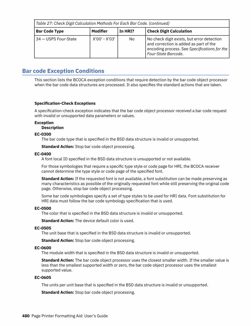
Table 27: Check Digit Calculation Methods For Each Bar Code. (continued)
Bar Code Type Modifier In HRI? Check Digit Calculation
34 — USPS Four-State X'00' - X'03' No No check digit exists, but error detectionand correction is added as part of theencoding process. See Specifications for theFour-State Barcode.
Bar code Exception ConditionsThis section lists the BCOCA exception conditions that require detection by the bar code object processorwhen the bar code data structures are processed. It also specifies the standard actions that are taken.
Specification-Check Exceptions
A specification-check exception indicates that the bar code object processor received a bar code requestwith invalid or unsupported data parameters or values.Exception
DescriptionEC-0300
The bar code type that is specified in the BSD data structure is invalid or unsupported.
Standard Action: Stop bar code object processing.
EC-0400A font local ID specified in the BSD data structure is unsupported or not available.
For those symbologies that require a specific type style or code page for HRI, the BCOCA receivercannot determine the type style or code page of the specified font.
Standard Action: If the requested font is not available, a font substitution can be made preserving asmany characteristics as possible of the originally requested font while still preserving the original codepage. Otherwise, stop bar code object processing.
Some bar code symbologies specify a set of type styles to be used for HRI data. Font substitution forHRI data must follow the bar code symbology specification that is used.
EC-0500The color that is specified in the BSD data structure is invalid or unsupported.
Standard Action: The device default color is used.
EC-0505The unit base that is specified in the BSD data structure is invalid or unsupported.
Standard Action: Stop bar code object processing.
EC-0600The module width that is specified in the BSD data structure is invalid or unsupported.
Standard Action: The bar code object processor uses the closest smaller width. If the smaller value isless than the smallest supported width or zero, the bar code object processor uses the smallestsupported value.
EC-0605
The units per unit base that is specified in the BSD data structure is invalid or unsupported.
Standard Action: Stop bar code object processing.
480 Page Printer Formatting Aid: User's Guide
EC-0700The element height that is specified in the BSD data structure is invalid or unsupported.
Standard Action: The bar code object processor uses the closest smaller height. If the smaller valueis less than the smallest supported element height or zero, the bar code object processor uses thesmallest supported value.
EC-0705The presentation space extents that are specified in the BSD data structure are invalid orunsupported.
Standard Action: Stop bar code object processing.
EC-0800The height multiplier that is specified in the BSD data structure is invalid.
Standard Action: The bar code object processor uses X'01'.
EC-0900The wide-to-narrow ratio that is specified in the BSD data structure is invalid or unsupported.
Standard Action: The bar code object processor uses the default wide-to-narrow ratio. The defaultratio is in the range of 2.25 - 3.00 to 1. The MSI bar code, however, uses a default wide-to-narrowratio of 2.00 to 1.
EC-0A00The bar code origin (Xoffset value or Yoffset value) given in the BSA data structure is invalid orunsupported.
Standard Action: Stop bar code object processing.
EC-0B00The bar code modifier in the BSD data structure is invalid or unsupported for the bar code type that isspecified in the same BSD.
Standard Action: Stop bar code object processing.
EC-0C00The length of the variable data that is specified in the BSA data structure plus any bar code objectprocessor generated check digits is invalid or unsupported.
Standard Action: Stop bar code object processing.
EC-0E00The first check-digit calculation resulted in a value of 10; this is defined as an exception condition insome of the modifier options for MSI bar codes in the BSD data structure.
Standard Action: Stop bar code object processing.
EC-0F00Either the matrix row size value or the number of rows value that is specified in the BSA data structureis unsupported. Both of these values must be within the range of supported sizes for the symbology.
Standard Action: Use X'0000' for the unsupported value so that an appropriate size is used based onthe amount of symbol data.
EC-0F01An invalid structured append sequence indicator was specified in the BSA data structure. For a DataMatrix symbol, the sequence indicator must be 1 - 16. For a MaxiCode symbol, the sequence indicatormust be 1 - 8.
Standard Action: Present the bar code symbol without structured append information.
EC-0F02A structured append sequence indicator that is specified in the BSA data structure is larger than thetotal number of structured append symbols.
Standard Action: Present the bar code symbol without structured append information.
More About Bar Code Parameters 481
EC-0F03Mismatched structured append information was specified in the BSA data structure. One of thesequence-indicator and total-number-of-symbols parameters was X'00', but the other was not X''.
Standard Action: Present the bar code symbol without structured append information.
EC-0F04An invalid number of structured append symbols was specified in the BSA data structure. For a DataMatrix symbol, the total number of symbols must be 2 - 16. For a MaxiCode symbol, the total numberof symbols must be 2 - 8.
Standard Action: Present the bar code symbol without structured append information.
EC-0F05For a MaxiCode symbol, the symbol mode value that is specified in the BSA data structure is invalid.
Standard Action: Stop bar code object processing.
EC-0F06For a PDF417 symbol, the number of data symbol characters per row value that is specified in the BSAdata structure is invalid.
Standard Action: Stop bar code object processing.
EC-0F07For a PDF417 symbol, the desired number of rows value that is specified in the BSA data structure isinvalid.
This exception condition can also occur when the number of rows times the number of data symbolcharacters per row is greater than 928.
Standard Action: Proceed as if X'FF' was specified.
EC-0F08For a PDF417 symbol, too much data is specified in the BSA data structure.
Standard Action: Stop bar code object processing.
EC-0F09For a PDF417 symbol, the security level value that is specified in the BSA data structure is invalid.
Standard Action: Proceed as if security level 8 was specified.
EC-0F0AAn incompatible combination of Data Matrix parameters was specified in the BSA data structure. Thefollowing conditions can cause this exception condition:
• A structured append was specified (byte 10 not X'00'), but either the reader programming flag wasset to B'1' or a hdr/trl macro was specified.
• The UCC/EAN FNC1 flag was set to B'1', but either the industry FNC1 flag was set to B'1', the readerprogramming flag was set to B'1', or a hdr/trl macro was specified.
• The industry FNC1 flag was set to B'1', but either the UCC/EAN FNC1 flag was set to B'1', the readerprogramming flag was set to B'1', or a hdr/trl macro was specified.
• The reader programming flag was set to B'1', but either a structured append was specified, one ofthe FNC1 flags was set to B'1', or a hdr/trl macro was specified.
• A hdr/trl macro was specified, but either a structured append was specified, one of the FNC1 flagswas set to B'1', or the reader programming flag was set to B'1'.
Standard Action: Stop bar code object processing.
EC-0F0BAn invalid structured append file identification value was specified in the BSA data structure. Eachbyte of the 2-byte file identification value must be in the range X'01' - X'FE'.
Standard Action: Present the bar code symbol without structured append information.
482 Page Printer Formatting Aid: User's Guide
EC-0F0CA Macro PDF417 Control Block length value that is specified in the BSA data structure is invalid.
Standard Action: Stop bar code object processing.
EC-0F0DData within a Macro PDF417 Control Block that is specified in the BSA data structure is invalid.
Standard Action: Present the bar code symbol without a Macro PDF417 Control Block.
EC-0F0EFor a QR Code symbol, an invalid EBCDIC-code page value was specified in the BSA data structure.
Standard Action: Stop the bar code object processing.
EC-0F0FFor a QR Code symbol, an invalid version value was specified in the BSA data structure.
Standard Action: Proceed as if X'00' is specified.
EC-0F10For a QR Code symbol, an invalid error-correction level value was specified in the BSA data structure.
Standard Action: Proceed as if X'03' is specified.
EC-0F11For a QR Code symbol, an invalid combination of special-function flags was specified in the BSA datastructure. Only one of the FNC1 flags can be B'1'.
Standard Action: Stop the bar code object processing.
EC-0F12For a QR Code symbol, an invalid application-indicator value was specified in the BSA data structure.
Standard Action: Present the bar code symbol without structured append information.
EC-1000The human-readable interpretation location that is specified in the BSA data structure is invalid.
Standard Action: Stop bar code object processing.
EC-1100A portion of the bar code, including the bar and space patterns and the HRI, extends outside of either:
• The bar code presentation space• The intersection of the mapped bar code presentation space and the controlling environment object
area• The maximum presentation area.
Standard Action: Stop bar code object processing.
All bar code symbols must be presented in their entirety. Whenever a partial bar code pattern ispresented, for whatever reason, it is obscured to make it unscannable.
EC-1200Invalid data is encountered in a UCC/EAN 128 symbol; one or more of the following conditions wasencountered:
• FNC1 is not the first data character.• Invalid application identifier (ai) value is encountered.• Data for an ai does not match the ai definition.• Insufficient (or no) data follows an ai.• Too much data for an ai.• Invalid use of FNC1 character.
Standard Action: Stop bar code object processing.
More About Bar Code Parameters 483
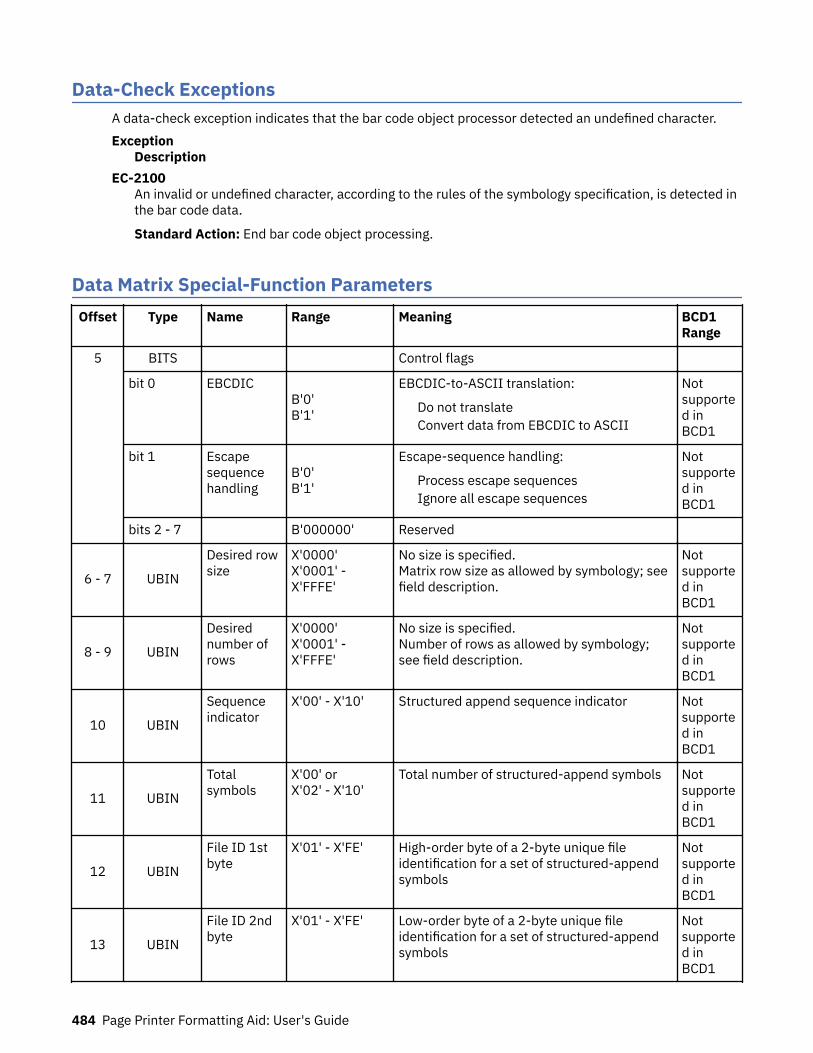
Data-Check ExceptionsA data-check exception indicates that the bar code object processor detected an undefined character.Exception
DescriptionEC-2100
An invalid or undefined character, according to the rules of the symbology specification, is detected inthe bar code data.
Standard Action: End bar code object processing.
Data Matrix Special-Function ParametersOffset Type Name Range Meaning BCD1
Range
5 BITS Control flags
bit 0 EBCDIC B'0'B'1'
EBCDIC-to-ASCII translation:
Do not translateConvert data from EBCDIC to ASCII
Notsupported inBCD1
bit 1 Escapesequencehandling
B'0'B'1'
Escape-sequence handling:
Process escape sequencesIgnore all escape sequences
Notsupported inBCD1
bits 2 - 7 B'000000' Reserved
6 - 7 UBIN
Desired rowsize
X'0000'X'0001' -X'FFFE'
No size is specified.Matrix row size as allowed by symbology; seefield description.
Notsupported inBCD1
8 - 9 UBIN
Desirednumber ofrows
X'0000'X'0001' -X'FFFE'
No size is specified.Number of rows as allowed by symbology;see field description.
Notsupported inBCD1
10 UBIN
Sequenceindicator
X'00' - X'10' Structured append sequence indicator Notsupported inBCD1
11 UBIN
Totalsymbols
X'00' orX'02' - X'10'
Total number of structured-append symbols Notsupported inBCD1
12 UBIN
File ID 1stbyte
X'01' - X'FE' High-order byte of a 2-byte unique fileidentification for a set of structured-appendsymbols
Notsupported inBCD1
13 UBIN
File ID 2ndbyte
X'01' - X'FE' Low-order byte of a 2-byte unique fileidentification for a set of structured-appendsymbols
Notsupported inBCD1
484 Page Printer Formatting Aid: User's Guide

Offset Type Name Range Meaning BCD1Range
14
BITS Special-function flags
bit 0 UCC/EANFNC1
B'0'B'1'
Alternate data type identifier:
User-defined symbolSymbol conforms to UCC/EAN standards
Notsupported inBCD1
bit 1 IndustryFNC1
B'0'B'1'
Alternate data type identifier:
User-defined symbolSymbol conforms to industry standards
Notsupported inBCD1
bit 2 Readerprogramming
B'0'B'1'
Reader programming symbol:
Symbol encodes a data symbol.Symbol encodes a message that is used toprogram the reader system.
Notsupported inBCD1
bit 3 - 4 Hdr/TrlMacro
B'00'B'01'B'10'B'11'
Header and trailer instructions to the barcode reader:
No header or trailerUse the 05 Macro header/trailerUse the 06 Macro header/trailerNo header or trailer
Notsupported inBCD1
bit 5 - 7 B'000' Reserved
A desired symbol size can be specified in bytes 6 - 9, but the actual size of the symbol depends on theamount of data to be encoded. If not enough data is supplied, the symbol is padded with null data toreach the requested symbol size. If too much data is supplied for the requested symbol size, the symbol isbigger than requested, but the aspect ratio is maintained as closely as possible.Byte 5
Control flags.
These flags control how the bar code data (bytes n+1 to end) is processed by the BCOCA receiver.Bit 0
EBCDIC-to-ASCII translation.
If this flag is B'0', the data is assumed to begin in the default character encodation and notranslation is done.
If this flag is B'1', the BCOCA receiver converts each byte of the bar code data from EBCDIC codepage 500 into ASCII code page 819 before this data is used to build the bar code symbol.
Bit 1Escape-sequence handling.
If this flag is B'0', each X'5C' (backslash) within the bar code data is treated as an escapecharacter according to the Data Matrix symbology specification.
If this flag is B'1', each X'5C' within the bar code data is treated as a normal data character andtherefore all escape sequences are ignored. In this case, no ECI code page switching can occurwithin the data.
Note: If the EBCDIC-to-ASCII translation flag is also set to B'1', all EBCDIC backslash characters(X'E0') are first converted into X'5C' before the escape-sequence handling flag is applied.
Bits 2 - 7Reserved.
More About Bar Code Parameters 485

Bytes 6 - 7Desired row size.
For a Data Matrix symbol, this parameter specifies the desired number of modules in each row,including the finder pattern. An even number of modules per row and an even number of rows mustexist. Square symbols exist with sizes from 10x10 to 144x144, and rectangular symbols exist withsizes from 8x18 to 16x48 not including quiet zones. The following table lists the complete set ofsupported sizes. Exception condition EC-0F00 exists EC-0F00 if an unsupported size value isspecified.
If X'0000' is specified for this parameter, an appropriate row size is used based on the amount ofsymbol data.
Table 28: Supported Sizes for a Data Matrix symbol.
Square Symbols Rectangular Symbols
Symbol Size Data Region Symbol Size Data Region
Number ofrows Row size Size Number Number of
rows Row size Size Number
10 10 8x8 1 8 18 6x6 1
12 12 10x10 1 8 32 6x14 2
14 14 12x12 1 12 26 10x24 1
16 16 14x14 1 12 36 10x16 2
18 18 16x16 1 16 36 14x16 2
20 20 18x18 1 16 48 14x22 2
22 22 20x20 1
24 24 22x22 1
26 26 24x24 1
32 32 14x14 4
36 36 16x16 4
40 40 18x18 4
44 44 20x20 4
48 48 22x22 4
52 52 24x24 4
64 64 14x14 16
72 72 16x16 16
80 80 18x18 16
88 88 20x20 16
96 96 22x22 16
104 104 24x24 16
120 120 18x18 36
132 132 20x20 36
486 Page Printer Formatting Aid: User's Guide
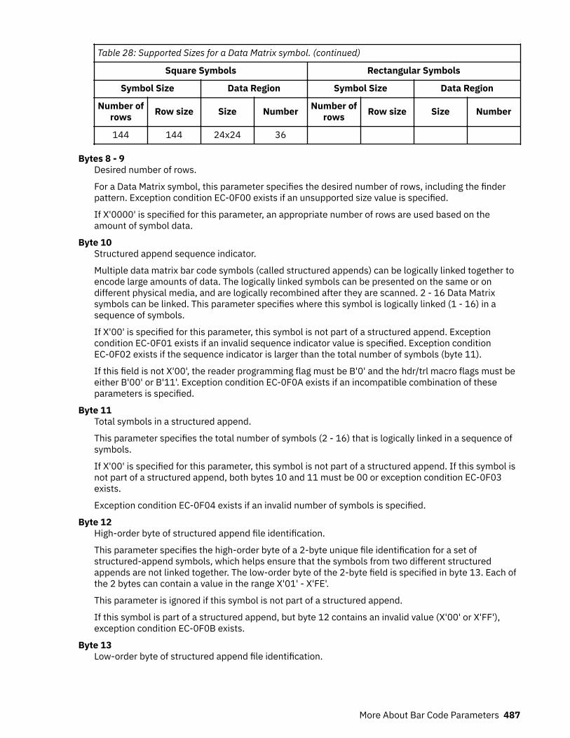
Table 28: Supported Sizes for a Data Matrix symbol. (continued)
Square Symbols Rectangular Symbols
Symbol Size Data Region Symbol Size Data Region
Number ofrows Row size Size Number Number of
rows Row size Size Number
144 144 24x24 36
Bytes 8 - 9Desired number of rows.
For a Data Matrix symbol, this parameter specifies the desired number of rows, including the finderpattern. Exception condition EC-0F00 exists if an unsupported size value is specified.
If X'0000' is specified for this parameter, an appropriate number of rows are used based on theamount of symbol data.
Byte 10Structured append sequence indicator.
Multiple data matrix bar code symbols (called structured appends) can be logically linked together toencode large amounts of data. The logically linked symbols can be presented on the same or ondifferent physical media, and are logically recombined after they are scanned. 2 - 16 Data Matrixsymbols can be linked. This parameter specifies where this symbol is logically linked (1 - 16) in asequence of symbols.
If X'00' is specified for this parameter, this symbol is not part of a structured append. Exceptioncondition EC-0F01 exists if an invalid sequence indicator value is specified. Exception conditionEC-0F02 exists if the sequence indicator is larger than the total number of symbols (byte 11).
If this field is not X'00', the reader programming flag must be B'0' and the hdr/trl macro flags must beeither B'00' or B'11'. Exception condition EC-0F0A exists if an incompatible combination of theseparameters is specified.
Byte 11Total symbols in a structured append.
This parameter specifies the total number of symbols (2 - 16) that is logically linked in a sequence ofsymbols.
If X'00' is specified for this parameter, this symbol is not part of a structured append. If this symbol isnot part of a structured append, both bytes 10 and 11 must be 00 or exception condition EC-0F03exists.
Exception condition EC-0F04 exists if an invalid number of symbols is specified.
Byte 12High-order byte of structured append file identification.
This parameter specifies the high-order byte of a 2-byte unique file identification for a set ofstructured-append symbols, which helps ensure that the symbols from two different structuredappends are not linked together. The low-order byte of the 2-byte field is specified in byte 13. Each ofthe 2 bytes can contain a value in the range X'01' - X'FE'.
This parameter is ignored if this symbol is not part of a structured append.
If this symbol is part of a structured append, but byte 12 contains an invalid value (X'00' or X'FF'),exception condition EC-0F0B exists.
Byte 13Low-order byte of structured append file identification.
More About Bar Code Parameters 487

This parameter specifies the low-order byte of a 2-byte unique file identification for a set ofstructured-append symbols. The high-order byte of the 2-byte field is specified in byte 12. Each of the2 bytes can contain a value in the range X'01' - X'FE'.
This parameter is ignored if this symbol is not part of a structured append.
If this symbol is part of a structured append, but byte 13 contains an invalid value (X'00' or X'FF'),exception condition EC-0F0B exists.
Byte 14Special-function flags.
These flags specify special functions that can be used with a Data Matrix symbol.Bit 0
UCC/EAN FNC1 alternate data type identifier.
If this flag is B'1', an FNC1 is added in the first data position (or fifth position of a structuredappend symbol) to indicate that this symbol conforms to the UCC/EAN application identifierstandard format. In this case, the industry FNC1 flag must be B'0', the reader programming flagmust be B'0', and the hdr/trl macro must be B'00' or B'11'. Exception condition EC-0F0A exists ifan incompatible combination of these parameters is specified.
Bit 1Industry FNC1 alternate data type identifier.
If this flag is B'1', an FNC1 is added in the second data position (or sixth position of a structuredappend symbol) to indicate that this symbol conforms to a particular industry standard format. Inthis case, the UCC/EAN FNC1 flag must be B'0', the reader programming flag must be B'0', and thehdr/trl macro must be B'00' or B'11'. Exception condition EC-0F0A exists if an incompatiblecombination of these parameters is specified.
Bit 2Reader programming.
If this flag is B'1', this symbol encodes a message that is used to program the reader system. Inthis case, the structured append sequence indicator must be X'00', the UCC/EAN FNC1 andindustry FNC1 flags must both be B'0', and the hdr/trl macro flags must be either B'00' or B'11'.Exception condition EC-0F0A exists if an incompatible combination of these parameters isspecified.
Bits 3 - 4Header and trailer instructions to the bar code reader.
This field provides a means of instructing the bar code reader to insert an industry-specific headerand trailer around the symbol data.
If this field is B'00' or B'11', no header or trailer is inserted. If this field is B'01', the bar codesymbol contains a 05 Macro codeword. If this field is B'10', the bar code symbol contains a 06Macro codeword.
If these flags are B'01' or B'10', the structured append sequence indicator must be X'00', theUCC/EAN FNC1 and industry FNC1 flags must both be B'0', and the reader programming flag mustbe B'0'. Exception condition EC-0F0A exists if an incompatible combination of these parameters isspecified.
Bits 5 - 7Reserved.
488 Page Printer Formatting Aid: User's Guide

MaxiCode Special-Function ParametersOffset Type Name Range Meaning BCD1
Range
5 BITS Control flags
bit 0 EBCDIC B'0'B'1'
EBCDIC-to-ASCII translation:
Do not translateConvert data from EBCDIC to ASCII
Notsupported inBCD1
bit 1 Escapesequencehandling
B'0'B'1'
Escape-sequence handling:
Process escape sequencesIgnore all escape sequences
Notsupported inBCD1
bits 2 - 7 B'000000' Reserved
6 CODE
SymbolMode
X'02'X'03'X'04'X'05'X'06'
Mode 2Mode 3Mode 4Mode 5Mode 6
Notsupported inBCD1
7 UBIN
Sequenceindicator
X'00' - X'08' Structured append sequence indicator Notsupported inBCD1
8 UBIN
Totalsymbols
X'00' or X'02' -X'08'
Total number of structured-append symbols Notsupported inBCD1
9
BITS Special-function flags
bit 0 Zipper B'0'B'1'
No zipper patternVertical zipper pattern on right
Notsupported inBCD1
bit 1 - 7 B'0000000' Reserved
Byte 5Control flags.
These flags control how the bar code data (bytes n+1 to end) is processed by the BCOCA receiver.Bit 0
EBCDIC-to-ASCII translation.
If this flag is B'0', the data is assumed to begin in the default character encodation and notranslation is done.
If this flag is B'1', the BCOCA receiver converts each byte of the bar code data from EBCDIC codepage 500 into ASCII code page 819 before this data is used to build the bar code symbol.
Bit 1Escape-sequence handling.
If this flag is B'0', each X'5C' (backslash) within the bar code data is treated as an escapecharacter according to the MaxiCode symbology specification.
More About Bar Code Parameters 489

If this flag is B'1', each X'5C' within the bar code data is treated as a normal data character andtherefore all escape sequences are ignored. In this case, no ECI code page switching can occurwithin the data.
Note: If the EBCDIC-to-ASCII translation flag is also set to B'1', all EBCDIC backslash characters(X'E0') are first converted into X'5C' before the escape-sequence handling flag is applied.
Bits 2 - 7Reserved.
Byte 6Symbol mode.Mode 2
Structured Carrier Message - numeric postal code.
This mode is designed for use in the transport industry, encoding the postal code, country code,and service class with the postal code that is numeric. The bar code data must be structured asdescribed in B.2.1 and B.3.1 of the AIM International Symbology Specification - MaxiCode. Thepostal code, country code, and service class are placed in the primary message portion of theMaxiCode symbol and the rest of the bar code data is placed in the secondary message portion ofthe MaxiCode symbol. The first part of the bar code data includes in order the postal code, countrycode, and service class, which are separated by the [GS] character (X'1D'). This information can bepreceded by the character sequence "[)>RS01GSyy", where RS and GS are single characters andyy are two decimal digits that represent a year. This character sequence is represented in hexbytes X'5B293E1E30311Dxxxx', where each xx is a value X'30' - X'39'. This sequence indicatesthat the message conforms to particular open system standards. This first portion of the bar codedata must be encoded by using the MaxiCode default character set (ECI 000003 = ISO 8859-1).This first portion of the bar code data must not contain the backslash escape character to changethe ECI character set. The postal code must be 1 - 9 decimal digits with each digit that isrepresented by the byte values from X'30' - X'39'. The country code must be 1 - 3 decimal digitswith each digit a byte value X'30' - X'39'. The service code must also be 1 - 3 decimal digits, againwith each digit a byte value X'30' - X'39'. The primary message portion of the MaxiCode symboluses Enhanced Error Correction (EEC) and the secondary message portion of the MaxiCodesymbol uses Standard Error Correction (SEC).
When the postal code portion of the Structured Carrier Message is numeric, mode 2 must be used.
Mode 3Structured Carrier Message - alphanumeric postal code.
This mode is designed for use in the transport industry, encoding the postal code, country code,and service class with the postal code that is alphanumeric. The bar code data must be structuredas described in B.2.1 and B.3.1 of the AIM International Symbology Specification - MaxiCode. Thepostal code, country code, and service class are placed in the primary message portion of theMaxiCode symbol and the rest of the bar code data is placed in the secondary message portion ofthe MaxiCode symbol. The first part of the bar code data includes in order the postal code, countrycode, and service class,which are separated by the [GS] character (X'1D'). This information can bepreceded by the character sequence "[)>RS01GSyy", where RS and GS are single characters andyy are two decimal digits that represent a year. This character sequence is represented in hexbytes X'5B293E1E30311Dxxxx', where each xx is a value from X'30' - X'39'. This sequenceindicates that the message conforms to particular open system standards. This first portion of thebar code data must be encoded by using the MaxiCode default character set (ECI 000003 = ISO8859-1). This first portion of the bar code data must not contain the backslash escape characterto change the ECI character set. The postal code must be 1 -6 alphanumeric characters with eachcharacter one of the printable characters in MaxiCode Code Set A. Postal codes fewer than 6characters are padded with trailing spaces; postal codes longer than 6 characters are truncated.These characters include the letters A to Z (X'41' - X'5A'), the space character (X'20'), the specialcharacters (X'22' - X'2F'), the decimal digits (X'30' - X'39'), and the colon (X'3A'). The countrycode must be 1 -3 decimal digits with each digit a byte value X'30' - X'39'. The service code mustalso be 1 - 3 decimal digits, again with each digit a byte value X'30' - X'39'. The primary message
490 Page Printer Formatting Aid: User's Guide
portion of the MaxiCode symbol uses Enhanced Error Correction (EEC) and the secondarymessage portion of the MaxiCode symbol uses Standard Error Correction (SEC).
When the postal code portion of the Structured Carrier Message is alphanumeric, mode 3 must beused.
Mode 4Standard Symbol.
The symbol employs EEC for the Primary Message and SEC for the Secondary Message. The firstnine codewords are placed in the Primary Message and the rest of the codewords are placed in theSecondary Message. This mode provides for a total of 93 codewords for data. If the bar code dataconsists of only characters from MaxiCode Code Set A, the number of codewords matches thenumber of bar code data characters. However, if the bar code data contains other characters, thenumber of codewords is greater than the number of bar code data characters due to the overheadof switching to and from the different code sets. The Code Set A consists of the byte values X'0D',X'1C' to X'1E', X'20', X'22' to X'3A', and X'41' to X'5A'.
Mode 5Full ECC Symbol.
The symbol employs EEC for the Primary Message and EEC for the Secondary Message. The firstnine codewords are placed in the Primary Message and the rest of the codewords are placed in theSecondary Message. This mode provides for a total of 77 codewords for data. If the bar code dataconsists of only characters from MaxiCode Code Set A, the number of codewords matches thenumber of bar code data characters. However, if the bar code data contains other characters, thenumber of codewords is greater than the number of bar code data characters due to the overheadof switching to and from the different code sets. The Code Set A consists of the byte values X'0D',X'1C' to X'1E', X'20', X'22' to X'3A', and X'41' to X'5A'.
Mode 6Reader Program, SEC.
The symbol employs EEC for the Primary Message and SEC for the Secondary Message. The datain the symbol is used to program the bar code reader system. The first nine codewords are placedin the Primary Message and the rest of the codewords are placed in the Secondary Message. Thismode provides for a total of 93 codewords for data. If the bar code data consists of onlycharacters from MaxiCode Code Set A, the number of codewords matches the number of bar codedata characters. However, if the bar code data contains other characters, the number ofcodewords is greater than the number of bar code data characters due to the overhead ofswitching to and from the different code sets. The Code Set A consists of the byte values X'0D',X'1C' to X'1E', X'20', X'22' to X'3A', and X'41' to X'5A'.
Exception condition EC-0F05 exists if an invalid symbol-mode value is specified.
Byte 7Structured append sequence indicator.
Multiple MaxiCode bar code symbols (called structured appends) can be logically linked together toencode large amounts of data. The logically linked symbols can be presented on the same or ondifferent physical media, and are logically recombined after they are scanned. MaxiCode symbols 2 - 8can be linked. This parameter specifies where this particular symbol is logically linked (1&–8) in asequence of symbols.
If X'00' is specified for this parameter, this symbol is not part of a structured append. Exceptioncondition EC-0F01 exists if an invalid sequence indicator value is specified. Exception conditionEC-0F02 exists if the sequence indicator is larger than the total number of symbols (byte 8).
Byte 8Total symbols in a structured append.
This parameter specifies the total number of symbols (2 - 8) that is logically linked in a sequence ofsymbols.
More About Bar Code Parameters 491

If X'00' is specified for this parameter, this symbol is not part of a structured append. If this symbol isnot part of a structured append, both bytes 6 and 7 must be X'00', or exception condition EC-0F03exists.
Exception condition EC-0F04 exists if an invalid number of symbols is specified.
Byte 9Special-function flags.
These flags specify special functions that can be used with a MaxiCode symbol.Bit 0
Zipper pattern.
If this flag is B'1', a vertical zipper-like test pattern and a contrast block are printed to the right ofthe symbol. The zipper provides a quick visual check for printing distortions. If the symbolpresentation space is rotated, the zipper and contrast block are rotated along with the symbol.
To maintain consistency among printers, the zipper pattern and contrast block must approximatethe guideline dimensions that are shown in Figure 144 on page 492. The zipper pattern andcontrast block is made up of several filled rectangles that must be created such that eachrectangle is as close to the specified dimensions as possible for the particular printer pelresolution, then the pattern is repeated to yield an evenly spaced zipper pattern and contrastblock.
Figure 144: Example of a MaxiCode Bar Code Symbol with Zipper and Contrast Block
492 Page Printer Formatting Aid: User's Guide
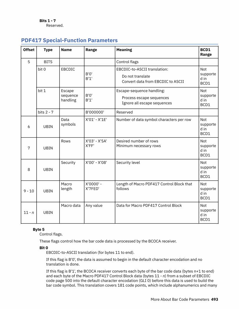
Bits 1 - 7Reserved.
PDF417 Special-Function ParametersOffset Type Name Range Meaning BCD1
Range
5 BITS Control flags
bit 0 EBCDIC B'0'B'1'
EBCDIC-to-ASCII translation:
Do not translateConvert data from EBCDIC to ASCII
Notsupported inBCD1
bit 1 Escapesequencehandling
B'0'B'1'
Escape-sequence handling:
Process escape sequencesIgnore all escape sequences
Notsupported inBCD1
bits 2 - 7 B'000000' Reserved
6 UBIN
Datasymbols
X'01' - X'1E' Number of data symbol characters per row Notsupported inBCD1
7 UBIN
Rows X'03' - X'5A'X'FF'
Desired number of rowsMinimum necessary rows
Notsupported inBCD1
8 UBIN
Security X'00' - X'08' Security level Notsupported inBCD1
9 - 10 UBIN
Macrolength
X'0000' -X'7FED'
Length of Macro PDF417 Control Block thatfollows
Notsupported inBCD1
11 - n UBIN
Macro data Any value Data for Macro PDF417 Control Block Notsupported inBCD1
Byte 5Control flags.
These flags control how the bar code data is processed by the BCOCA receiver.Bit 0
EBCDIC-to-ASCII translation (for bytes 11 to end).
If this flag is B'0', the data is assumed to begin in the default character encodation and notranslation is done.
If this flag is B'1', the BCOCA receiver converts each byte of the bar code data (bytes n+1 to end)and each byte of the Macro PDF417 Control Block data (bytes 11 - n) from a subset of EBCDICcode page 500 into the default character encodation (GLI 0) before this data is used to build thebar code symbol. This translation covers 181 code points, which include alphanumerics and many
More About Bar Code Parameters 493
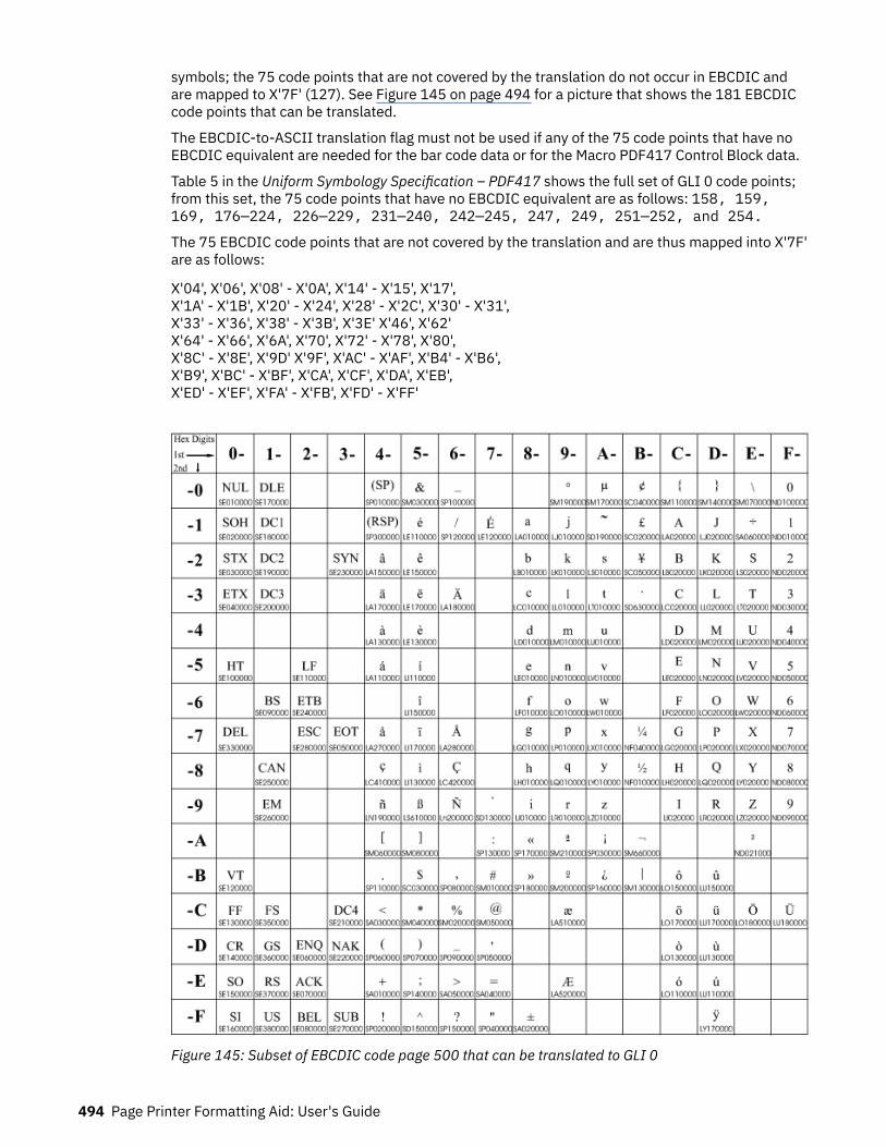
symbols; the 75 code points that are not covered by the translation do not occur in EBCDIC andare mapped to X'7F' (127). See Figure 145 on page 494 for a picture that shows the 181 EBCDICcode points that can be translated.
The EBCDIC-to-ASCII translation flag must not be used if any of the 75 code points that have noEBCDIC equivalent are needed for the bar code data or for the Macro PDF417 Control Block data.
Table 5 in the Uniform Symbology Specification – PDF417 shows the full set of GLI 0 code points;from this set, the 75 code points that have no EBCDIC equivalent are as follows: 158, 159,169, 176—224, 226—229, 231—240, 242—245, 247, 249, 251—252, and 254.
The 75 EBCDIC code points that are not covered by the translation and are thus mapped into X'7F'are as follows:
X'04', X'06', X'08' - X'0A', X'14' - X'15', X'17',X'1A' - X'1B', X'20' - X'24', X'28' - X'2C', X'30' - X'31',X'33' - X'36', X'38' - X'3B', X'3E' X'46', X'62'X'64' - X'66', X'6A', X'70', X'72' - X'78', X'80',X'8C' - X'8E', X'9D' X'9F', X'AC' - X'AF', X'B4' - X'B6',X'B9', X'BC' - X'BF', X'CA', X'CF', X'DA', X'EB',X'ED' - X'EF', X'FA' - X'FB', X'FD' - X'FF'
Figure 145: Subset of EBCDIC code page 500 that can be translated to GLI 0
494 Page Printer Formatting Aid: User's Guide
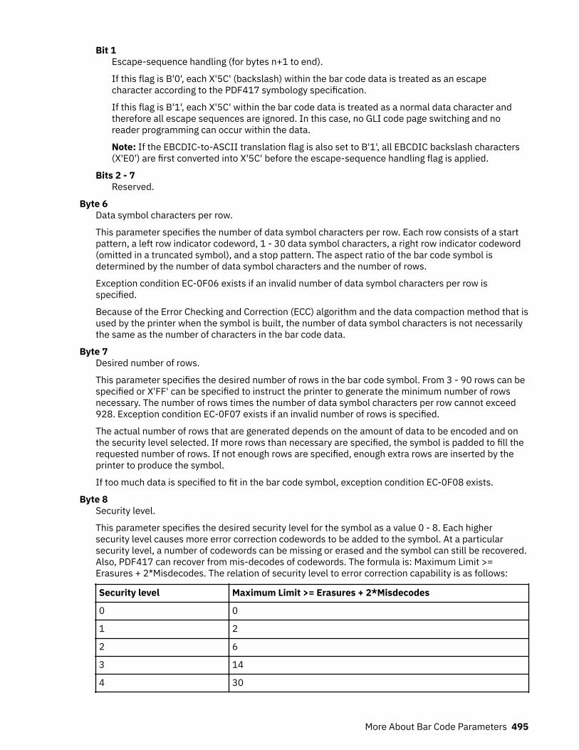
Bit 1Escape-sequence handling (for bytes n+1 to end).
If this flag is B'0', each X'5C' (backslash) within the bar code data is treated as an escapecharacter according to the PDF417 symbology specification.
If this flag is B'1', each X'5C' within the bar code data is treated as a normal data character andtherefore all escape sequences are ignored. In this case, no GLI code page switching and noreader programming can occur within the data.
Note: If the EBCDIC-to-ASCII translation flag is also set to B'1', all EBCDIC backslash characters(X'E0') are first converted into X'5C' before the escape-sequence handling flag is applied.
Bits 2 - 7Reserved.
Byte 6Data symbol characters per row.
This parameter specifies the number of data symbol characters per row. Each row consists of a startpattern, a left row indicator codeword, 1 - 30 data symbol characters, a right row indicator codeword(omitted in a truncated symbol), and a stop pattern. The aspect ratio of the bar code symbol isdetermined by the number of data symbol characters and the number of rows.
Exception condition EC-0F06 exists if an invalid number of data symbol characters per row isspecified.
Because of the Error Checking and Correction (ECC) algorithm and the data compaction method that isused by the printer when the symbol is built, the number of data symbol characters is not necessarilythe same as the number of characters in the bar code data.
Byte 7Desired number of rows.
This parameter specifies the desired number of rows in the bar code symbol. From 3 - 90 rows can bespecified or X'FF' can be specified to instruct the printer to generate the minimum number of rowsnecessary. The number of rows times the number of data symbol characters per row cannot exceed928. Exception condition EC-0F07 exists if an invalid number of rows is specified.
The actual number of rows that are generated depends on the amount of data to be encoded and onthe security level selected. If more rows than necessary are specified, the symbol is padded to fill therequested number of rows. If not enough rows are specified, enough extra rows are inserted by theprinter to produce the symbol.
If too much data is specified to fit in the bar code symbol, exception condition EC-0F08 exists.
Byte 8Security level.
This parameter specifies the desired security level for the symbol as a value 0 - 8. Each highersecurity level causes more error correction codewords to be added to the symbol. At a particularsecurity level, a number of codewords can be missing or erased and the symbol can still be recovered.Also, PDF417 can recover from mis-decodes of codewords. The formula is: Maximum Limit >=Erasures + 2*Misdecodes. The relation of security level to error correction capability is as follows:
Security level Maximum Limit >= Erasures + 2*Misdecodes
0 0
1 2
2 6
3 14
4 30
More About Bar Code Parameters 495
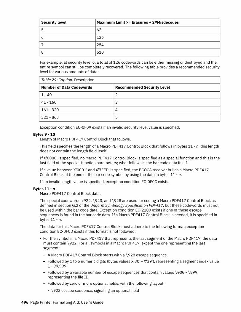
Security level Maximum Limit >= Erasures + 2*Misdecodes
5 62
6 126
7 254
8 510
For example, at security level 6, a total of 126 codewords can be either missing or destroyed and theentire symbol can still be completely recovered. The following table provides a recommended securitylevel for various amounts of data:
Table 29: Caption. Description
Number of Data Codewords Recommended Security Level
1 - 40 2
41 - 160 3
161 - 320 4
321 - 863 5
Exception condition EC-0F09 exists if an invalid security level value is specified.
Bytes 9 - 10Length of Macro PDF417 Control Block that follows.
This field specifies the length of a Macro PDF417 Control Block that follows in bytes 11 - n; this lengthdoes not contain the length field itself.
If X'0000' is specified, no Macro PDF417 Control Block is specified as a special function and this is thelast field of the special-function parameters; what follows is the bar code data itself.
If a value between X'0001' and X'7FED' is specified, the BCOCA receiver builds a Macro PDF417Control Block at the end of the bar code symbol by using the data in bytes 11 - n.
If an invalid length value is specified, exception condition EC-0F0C exists.
Bytes 11 - nMacro PDF417 Control Block data.
The special codewords \922, \923, and \928 are used for coding a Macro PDF417 Control Block asdefined in section G.2 of the Uniform Symbology Specification PDF417, but these codewords must notbe used within the bar code data. Exception condition EC-2100 exists if one of these escapesequences is found in the bar code data. If a Macro PDF417 Control Block is needed, it is specified inbytes 11 - n.
The data for this Macro PDF417 Control Block must adhere to the following format; exceptioncondition EC-0F0D exists if this format is not followed:
• For the symbol in a Macro PDF417 that represents the last segment of the Macro PDF417, the datamust contain \922. For all symbols in a Macro PDF417, except the one representing the lastsegment:
– A Macro PDF417 Control Block starts with a \928 escape sequence.– Followed by 1 to 5 numeric digits (bytes values X'30' - X'39'), representing a segment index value
1 - 99,999.– Followed by a variable number of escape sequences that contain values \000 - \899,
representing the file ID.– Followed by zero or more optional fields, with the following layout:
- \923 escape sequence, signaling an optional field
496 Page Printer Formatting Aid: User's Guide
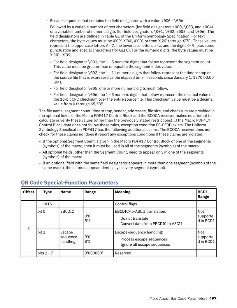
- Escape sequence that contains the field designator with a value \000 - \006- Followed by a variable number of text characters (for field designators \000, \003, and \004)
or a variable number of numeric digits (for field designators \001, \002, \005, and \006). Thefield designators are defined in Table G1 of the Uniform Symbology Specification. For textcharacters, the byte values must be X'09', X'0A', X'0D', or from X'20' through X'7E'. These valuesrepresent the uppercase letters A - Z, the lowercase letters a - z, and the digits 0- 9, plus somepunctuation and special characters (for GLI 0). For the numeric digits, the byte values must beX'30' - X'39'.
• For field designator \001, the 1 - 5 numeric digits that follow represent the segment count.This value must be greater than or equal to the segment index value.
• For field designator \002, the 1 - 11 numeric digits that follow represent the time stamp onthe source file that is expressed as the elapsed time in seconds since January 1, 1970 00:00GMT.
• For field designator \005, one or more numeric digits must follow.• For field designator \006, the 1 - 5 numeric digits that follow represent the decimal value of
the 16-bit CRC checksum over the entire source file. This checksum value must be a decimalvalue from 0 through 65,535.
The file name, segment count, time stamp, sender, addressee, file size, and checksum are provided inthe optional fields of the Macro PDF417 Control Block and the BCOCA receiver makes no attempt tocalculate or verify these values (other than the previously stated restrictions). If the Macro PDF417Control Block data does not follow these rules, exception condition EC-0F0D exists. The UniformSymbology Specification PDF417 has the following additional claims. The BCOCA receiver does notcheck for these claims nor does it report any exceptions conditions if these claims are violated:
• If the optional Segment Count is given in the Macro PDF417 Control Block of one of the segments(symbols) of the macro, then it must be used in all of the segments (symbols) of the macro.
• All optional fields, other than the Segment Count, need to appear only in one of the segments(symbols) of the macro.
• If an optional field with the same field designator appears in more than one segment (symbol) of thesame macro, then it must appear identically in every segment (symbol).
QR Code Special-Function ParametersOffset Type Name Range Meaning BCD1
Range
5
BITS Control flags
bit 0 EBCDIC B'0'B'1'
EBCDIC-to-ASCII translation:
Do not translateConvert data from EBCDIC to ASCII
Notsupported in BCD1
bit 1 Escapesequencehandling
B'0'B'1'
Escape-sequence handling:
Process escape sequencesIgnore all escape sequences
Notsupported in BCD1
bits 2 - 7 B'000000' Reserved
More About Bar Code Parameters 497

Offset Type Name Range Meaning BCD1Range
6 CODE
EBCDICcode page
X'00'X'01'X'02'X'03'
EBCDIC code page that is used to encodedata:
No code page specifiedCode page 500 (International #5)Code page 290 (Japanese Katakana Ext.)Code page 1027 (Japanese LatinExtended)
Notsupported in BCD1
7 CODE
Version X'00'X'01' - X'28'
Version of symbol:
Smallest symbolVersion number (1 - 40)
Notsupported in BCD1
8 CODE
Errorcorrectionlevel
X'00'X'01'X'02'X'03'
Level of error correction:
Level L (7% recovery)Level M (15% recovery)Level Q (25% recovery)Level H (30% recovery)
Notsupported in BCD1
9 UBINSequenceindicator
X'00' - X'10' Structured append sequence indicator Notsupported in BCD1
10 UBINTotalsymbols
X'00' or X'02' -X'10'
Total number of structured-append symbols Notsupported in BCD1
11 UBIN Parity Data X'00' - X'FF' Structured append parity data X'00' -X'FF'
12
BITS Special-function flags
bit 0 UCC/EANFNC1
B'0'B'1'
Alternate data type identifier:
User-defined symbolSymbol conforms to UCC/EAN standards
Notsupported in BCD1
bit 1 IndustryFNC1
B'0'B'1'
Alternate data type identifier:
User-defined symbolSymbol conforms to industry standards
Notsupported in BCD1
bits 2 - 7 B'000000' Reserved
13CODE Application
indicatorSee fielddescription
Application indicator for Industry FNC1 Notsupported in BCD1
A desired symbol size is specified by the version parameter (byte 7), but the actual size of the symboldepends on the amount of data to be encoded. If not enough data is supplied, the symbol is padded withnull data to reach the requested symbol size. If too much data is supplied for the requested symbol size,the symbol is bigger than requested and is the smallest symbol that can accommodate that amount ofdata.Byte 5
Control flags.
498 Page Printer Formatting Aid: User's Guide

These flags control how the bar code data (bytes n+1 to end) is processed by the BCOCA receiver; thereceiver can be an IPDS printer or any other product that processes BCOCA objects.Bit 0
EBCDIC-to-ASCII translation.
If this flag is B'0', the data is assumed to begin in the default character encodation (ECI 000020)and no translation is done.
If this flag is B'1' and an EBCDIC code page is selected in byte 6, the BCOCA receiver convertseach byte of the bar code data from the EBCDIC code page that is specified in byte 6 into ASCIIcode page 897 before this data is used to build the bar code symbol. The following EBCDIC codepages can be used to encode the bar code data:
• Code page 500 (International #5) — specify X'01' in byte 6.
Only 128 of the characters within ECI 000020 can be specified in code page 500. The code page500 characters that can be translated are shown in
• Code page 290 (Japanese Katakana Extended) — specify X'02' in byte 6.• Code page 1027 (Japanese Latin Extended) — specify X'03' in byte 6.
EBCDIC characters that are not defined within ECI 000020 are mapped to X'7F' (DEL).
Bit 1Escape-sequence handling.
If this flag is B'0', each X'5C' within the bar code data is treated as an escape character accordingto the QR Code symbology specification.
If this flag is B'1', each X'5C' within the bar code data is treated as a normal data character andtherefore all escape sequences are ignored. In this case, no ECI code page switching can occurwithin the data.
Note: If the EBCDIC-to-ASCII translation flag is also set to B'1', all EBCDIC characters are firstconverted into X'5C' before the escape-sequence handling flag is applied.
Byte 6Conversion.
When the EBCDIC-to-ASCII translation flag is B'1', this parameter specifies the method that is used toconvert EBCDIC input data into the default character encodation. When the EBCDIC-to-ASCIItranslation flag is B'0', this parameter is not used and must be set to X'00'.
For the first three values (used when the input data is encoded with a single-byte EBCDIC code page),this parameter identifies the EBCDIC code page that encodes single-byte EBCDIC bar code data. Thefollowing EBCDIC code pages are supported:X'01'
Code page 500 (International #5).
Only 128 of the characters within ECI 000020 can be specified in code page 500. The code page500 characters that can be translated are shown in Figure 146 on page 501.
X'02'Code page 290 (Japanese Katakana Extended).
X'03'Code page 1027 (Japanese Latin Extended).
For the remaining values (used when the input data is SOSI), this parameter identifies the desiredconversion from EBCDIC SOSI input data to a specific mixed-byte ASCII encoding.
Note: The values X'04' - X'09' are defined for the Additional Bar Code Parameters (X'7B') triplet that isused with AFP Line Data; these values are not valid within a BCOCA object that is built for a non-line-data environment, such as MO:DCA and IPDS. See Advanced Function Presentation: ProgrammingGuide and Line Data Reference for a description of the Additional Bar Code Parameters (X'7B') triplet.
More About Bar Code Parameters 499

The following choices are supported:X'04'
CCSID 1390 - CCSID 943Convert from:
CCSID 1390 – Extended Japanese Katakana-Kanji Host Mixed for JIS X0213 including 6205UDC, Extended SBCS (includes SBCS & DBCS euro).
Convert to:CCSID 943 – Japanese PC Data Mixed for Open environment (Multi-vendor code): 6878 JIS X0208-1990 chars, 386 IBM selected DBCS chars, 1880 UDC (X'F040' - X'F9FC').
X'05'CCSID 1399 - CCSID 943Convert from:
CCSID 1399 – Extended Japanese Latin-Kanji Host Mixed for JIS X0213 including 6205 UDC,Extended SBCS (includes SBCS & DBCS euro).
Convert to:CCSID 943 – Japanese PC Data Mixed for Open environment (Multi-vendor code): 6878 JIS X0208-1990 chars, 386 IBM selected DBCS chars, 1880 UDC (X'F040' - X'F9FC').
X'06'CCSID 1390 - CCSID 932Convert from:
CCSID 1390 – Extended Japanese Katakana-Kanji Host Mixed for JIS X0213 including 6205UDC, Extended SBCS (includes SBCS & DBCS euro).
Convert to:CCSID 932 – Japanese PC Data Mixed including 1880 UDC.
X'07'CCSID 1399 - CCSID 932Convert from:
CCSID 1399 – Extended Japanese Latin-Kanji Host Mixed for JIS X0213 including 6205 UDC,Extended SBCS (includes SBCS & DBCS euro).
Convert to:CCSID 932 – Japanese PC Data Mixed including 1880 UDC.
X'08'CCSID 1390 - CCSID 942Convert from:
CCSID 1390 – Extended Japanese Katakana-Kanji Host Mixed for JIS X0213 including 6205UDC, Extended SBCS (includes SBCS & DBCS euro).
Convert to:CCSID 942 – Japanese PC Data Mixed including 1880 UDC, Extended SBCS.
X'09'CCSID 1399 - CCSID 942Convert from:
CCSID 1399 – Extended Japanese Latin-Kanji Host Mixed for JIS X0213 including 6205 UDC,Extended SBCS (includes SBCS & DBCS euro).
Convert to:CCSID 942 – Japanese PC Data Mixed including 1880 UDC, Extended SBCS.
EBCDIC characters that are not defined within ECI 000020 are mapped to the substitute character,X'7F' or X'FCFC'; exception condition EC-2100 exists when an undefined character is encountered.
Exception condition EC-0F0E exists if an invalid or unsupported conversion value is specified.
500 Page Printer Formatting Aid: User's Guide

Figure 146: Subset of EBCDIC Code Page 500 that can be translated to ECI 000020
Byte 7Version of symbol.
This parameter specifies the desired size of the symbol; each version specifies a particular number ofmodules per row and column. The size of each square module is specified by the module widthparameter (byte 17 in the BSD). The following table lists the complete set of supported versions.Exception condition EC-0F0F exists if an invalid version value is specified.
Table 30: Supported Version for a QR Code symbol
Version Symbol Size Version Symbol Size
0 (X'00') smallest 21 (X'15') 101x01
1 (X'01') 21x21 22 (X'16') 105x105
2 (X'02') 25x25 23 (X'17') 109x109
3 (X'03') 29x29 24 (X'18') 113x113
More About Bar Code Parameters 501
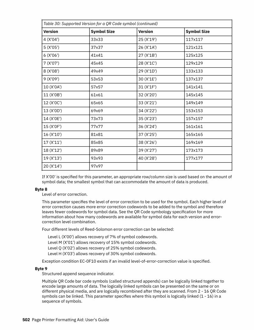
Table 30: Supported Version for a QR Code symbol (continued)
Version Symbol Size Version Symbol Size
4 (X'04') 33x33 25 (X'19') 117x117
5 (X'05') 37x37 26 (X'1A') 121x121
6 (X'06') 41x41 27 (X'1B') 125x125
7 (X'07') 45x45 28 (X'1C') 129x129
8 (X'08') 49x49 29 (X'1D') 133x133
9 (X'09') 53x53 30 (X'1E') 137x137
10 (X'0A') 57x57 31 (X'1F') 141x141
11 (X'0B') 61x61 32 (X'20') 145x145
12 (X'0C') 65x65 33 (X'21') 149x149
13 (X'0D') 69x69 34 (X'22') 153x153
14 (X'0E') 73x73 35 (X'23') 157x157
15 (X'0F') 77x77 36 (X'24') 161x161
16 (X'10') 81x81 37 (X'25') 165x165
17 (X'11') 85x85 38 (X'26') 169x169
18 (X'12') 89x89 39 (X'27') 173x173
19 (X'13') 93x93 40 (X'28') 177x177
20 (X'14') 97x97
If X'00' is specified for this parameter, an appropriate row/column size is used based on the amount ofsymbol data; the smallest symbol that can accommodate the amount of data is produced.
Byte 8Level of error correction.
This parameter specifies the level of error correction to be used for the symbol. Each higher level oferror correction causes more error correction codewords to be added to the symbol and thereforeleaves fewer codewords for symbol data. See the QR Code symbology specification for moreinformation about how many codewords are available for symbol data for each version and error-correction level combination.
Four different levels of Reed-Solomon error correction can be selected:
Level L (X'00') allows recovery of 7% of symbol codewords.Level M (X'01') allows recovery of 15% symbol codewords.Level Q (X'02') allows recovery of 25% symbol codewords.Level H (X'03') allows recovery of 30% symbol codewords.
Exception condition EC-0F10 exists if an invalid level-of-error-correction value is specified.
Byte 9Structured append sequence indicator.
Multiple QR Code bar code symbols (called structured appends) can be logically linked together toencode large amounts of data. The logically linked symbols can be presented on the same or ondifferent physical media, and are logically recombined after they are scanned. From 2 - 16 QR Codesymbols can be linked. This parameter specifies where this symbol is logically linked (1 - 16) in asequence of symbols.
502 Page Printer Formatting Aid: User's Guide
If X'00' is specified for this parameter, this symbol is not part of a structured append. Exceptioncondition EX-0F01 exists if an invalid sequence indicator value is specified. Exception conditionEC-0F02 exists if the sequence indicator is larger than the total number of symbols (byte 10).
Byte 10Total number of structured-append symbols.
This parameter specifies the total number of symbols (2 - 16) that is logically linked in a sequence ofsymbols.
If X'00' is specified for this parameter, this symbol is not part of a structured append. If this symbol isnot part of a structured append, both bytes 9 and 10 must be X'00', or exception condition EC-0F03exists.
Exception condition EC-0F04 exists if an invalid number of symbols is specified.
Byte 11Structured append parity data.
This parameter specified parity data for a structured append symbol. The parity-data value must becalculated from the entire message that is broken into structured-append symbols; the parity-datavalue must be the same in each of the structured-append symbols.
The parity-data value is obtained by XORing byte by byte the ASCII/JIS values of all the original inputdata before division into structured-append symbols.
If this symbol is not a structured append, this parameter is ignored and must be set to X'00'.
Byte 12Special-function flags.
These flags specify special functions that can be used with a QR Code symbol.Bit 0
UCC/EAN FNC1 alternate data type identifier.
If this flag is B'1', this QR Code symbol indicates that it conforms to the UCC/EAN applicationidentifiers standard. In this case, the industry FNC1 flag must be B'0'. Exception conditionEC-0F11 exists if an incompatible combination of these bits is specified.
Bit 1Industry FNC1 alternate data type identifier.
If this flag is B'1', this QR Code symbol indicates that it conforms to the specific industry orapplication specifications previously agreed with AIM International. In this case, the UCC/EANFNC1 flag must be B'0'. Exception condition EC-0F11 exists if an incompatible combination ofthese bits is specified.
When this flag is B'1', an application indicator is specified in byte 13.
Bits 2 - 7Reserved.
Byte 13Application indicator for Industry FNC1.
When the Industry FNC1 flag is B'1', this parameter specifies an application indicator. The applicationindicator is a 1-byte value that is specified either as an alphabetic value (from the ASCII set a-z, A-Z)plus 100 or as a two-digit number (00 - 99 represented as a hexadecimal value). For example:
For application indicator a (ASCII value X'61'), specify X'C5'.For application indicator Z (ASCII value X'5A'), specify X'BE'.For application indicator 01, specify X'01'.For application indicator 99, specify X'63'.
When the Industry FNC1 flag is B'0', this parameter is ignored and must be set to X'00'.
Exception condition EC0F12 exists if an invalid application-indicator value is specified.
More About Bar Code Parameters 503

504 Page Printer Formatting Aid: User's Guide
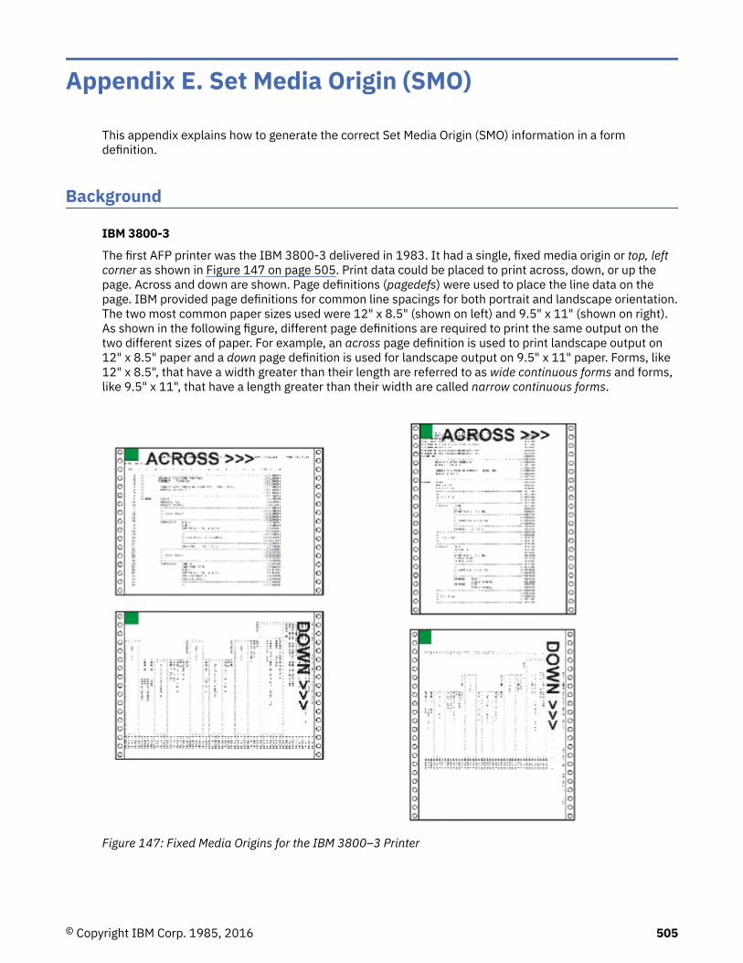
Appendix E. Set Media Origin (SMO)
This appendix explains how to generate the correct Set Media Origin (SMO) information in a formdefinition.
Background
IBM 3800-3
The first AFP printer was the IBM 3800-3 delivered in 1983. It had a single, fixed media origin or top, leftcorner as shown in Figure 147 on page 505. Print data could be placed to print across, down, or up thepage. Across and down are shown. Page definitions (pagedefs) were used to place the line data on thepage. IBM provided page definitions for common line spacings for both portrait and landscape orientation.The two most common paper sizes used were 12" x 8.5" (shown on left) and 9.5" x 11" (shown on right).As shown in the following figure, different page definitions are required to print the same output on thetwo different sizes of paper. For example, an across page definition is used to print landscape output on12" x 8.5" paper and a down page definition is used for landscape output on 9.5" x 11" paper. Forms, like12" x 8.5", that have a width greater than their length are referred to as wide continuous forms and forms,like 9.5" x 11", that have a length greater than their width are called narrow continuous forms.
Figure 147: Fixed Media Origins for the IBM 3800–3 Printer
© Copyright IBM Corp. 1985, 2016 505

IBM 3820
In 1985 the IBM 3820 was introduced. It was the first IBM AFP cut-sheet printer. Like the 3800-3, it alsohad a single, fixed media origin as shown. The 3820 could print in the same directions as the 3800-3 plusone new direction, back. As shown in Figure 148 on page 506, it had similar print directioncharacteristics as a 3800-3 using 9.5" x 11" paper.
Figure 148: Fixed Media Origins for the IBM 3820 Printer
The Problem
Many customers had both 3800-3s and 3820s. The 3800-3 was the fastest printer of its time at 215impressions per minute. To achieve that speed, it had to use the 12" x 8.5" paper. This paper had theadditional benefit of reducing maintenance charges because the 3800s usage charge was based on thenumber of linear feet printed. The use of the shorter, 12" x 8.5" paper cost less per page than the longer,9.5" x 11" paper. Unfortunately, when the 12" x 8.5" paper is used on the 3800-3 it causes anincompatibility with the 3820. As shown in Figure 149 on page 506, the 3800-3 with 12" x 8.5" paperhas a different media orientation than the 3820.
Figure 149: Differences in Media Origin Between the IBM 3800–3 and IBM 3820 Printers
The 3800-3’s media origin is at the left end of the long edge and the 3820’s is at the left end of the shortedge. Because of this, different page definitions would be needed to print the same output on bothprinters. For example, to print landscape output, an across page definition would be used on the 3800-3and a "down" page definition for the 3820. This would require different page definitions to be specified foreach printer.
506 Page Printer Formatting Aid: User's Guide
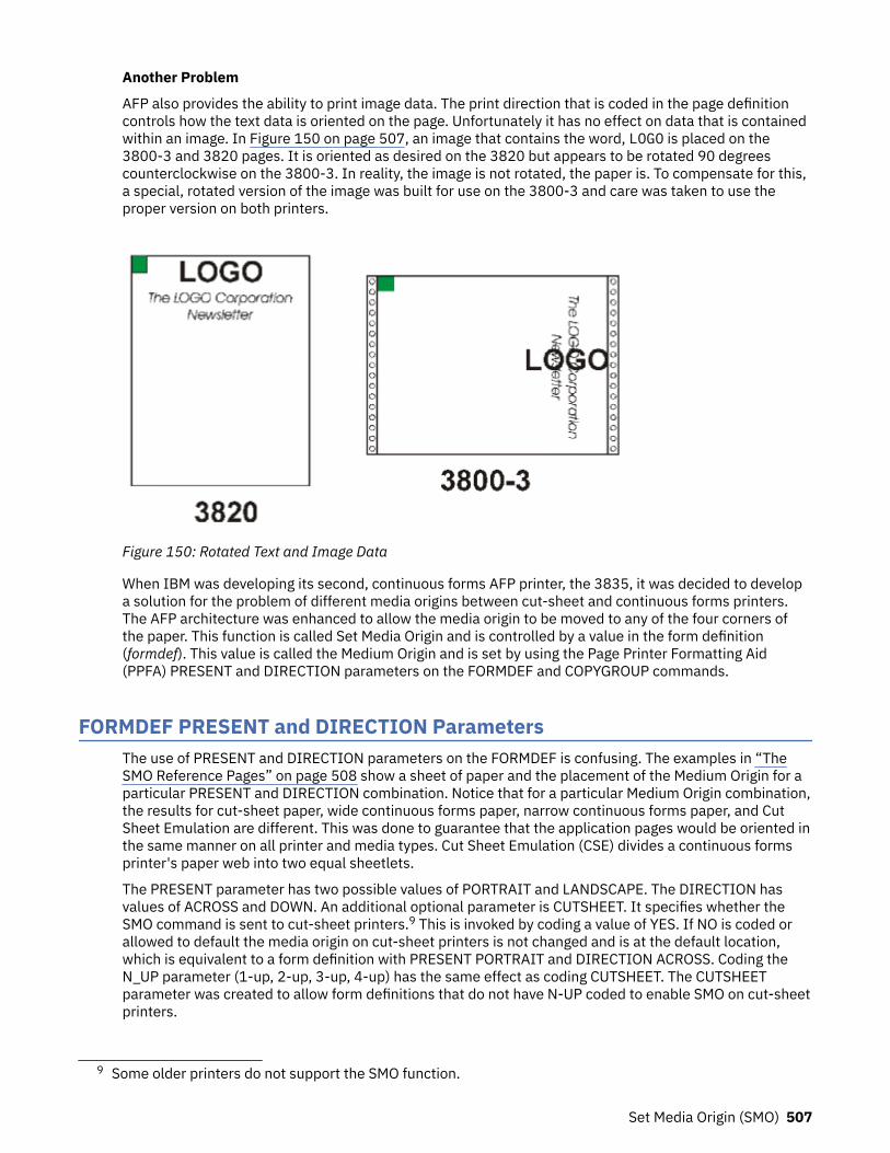
Another Problem
AFP also provides the ability to print image data. The print direction that is coded in the page definitioncontrols how the text data is oriented on the page. Unfortunately it has no effect on data that is containedwithin an image. In Figure 150 on page 507, an image that contains the word, LOGO is placed on the3800-3 and 3820 pages. It is oriented as desired on the 3820 but appears to be rotated 90 degreescounterclockwise on the 3800-3. In reality, the image is not rotated, the paper is. To compensate for this,a special, rotated version of the image was built for use on the 3800-3 and care was taken to use theproper version on both printers.
Figure 150: Rotated Text and Image Data
When IBM was developing its second, continuous forms AFP printer, the 3835, it was decided to developa solution for the problem of different media origins between cut-sheet and continuous forms printers.The AFP architecture was enhanced to allow the media origin to be moved to any of the four corners ofthe paper. This function is called Set Media Origin and is controlled by a value in the form definition(formdef). This value is called the Medium Origin and is set by using the Page Printer Formatting Aid(PPFA) PRESENT and DIRECTION parameters on the FORMDEF and COPYGROUP commands.
FORMDEF PRESENT and DIRECTION ParametersThe use of PRESENT and DIRECTION parameters on the FORMDEF is confusing. The examples in “TheSMO Reference Pages” on page 508 show a sheet of paper and the placement of the Medium Origin for aparticular PRESENT and DIRECTION combination. Notice that for a particular Medium Origin combination,the results for cut-sheet paper, wide continuous forms paper, narrow continuous forms paper, and CutSheet Emulation are different. This was done to guarantee that the application pages would be oriented inthe same manner on all printer and media types. Cut Sheet Emulation (CSE) divides a continuous formsprinter's paper web into two equal sheetlets.
The PRESENT parameter has two possible values of PORTRAIT and LANDSCAPE. The DIRECTION hasvalues of ACROSS and DOWN. An additional optional parameter is CUTSHEET. It specifies whether theSMO command is sent to cut-sheet printers.9 This is invoked by coding a value of YES. If NO is coded orallowed to default the media origin on cut-sheet printers is not changed and is at the default location,which is equivalent to a form definition with PRESENT PORTRAIT and DIRECTION ACROSS. Coding theN_UP parameter (1-up, 2-up, 3-up, 4-up) has the same effect as coding CUTSHEET. The CUTSHEETparameter was created to allow form definitions that do not have N-UP coded to enable SMO on cut-sheetprinters.
9 Some older printers do not support the SMO function.
Set Media Origin (SMO) 507

When Print Services Facility (PSF) converts an output file to Intelligent Printer Data Stream (IPDS) to sendto the printer, it includes an SMO value if SMO is supported by the printer. This value is calculated byexamining the Medium Origin of the form definition and then checking to see whether the printer is cut-sheet, wide continuous, or narrow continuous. CSE on the printer reports back wide or narrow continuous.PSF/IPM then specifies the proper SMO. The resulting SMO values are included in the figures forcompleteness.
The SMO Reference PagesThe following pages show how the four possible SMO combinations behave on the following four differentprinter types:
• Cut-sheet• Continuous forms with wide paper• Continuous forms with narrow paper• Continuous forms with Cut Sheet Emulation enabled.
Four summary pages show the media origin and print directions for the listed printer types. Thesesummary pages are followed by detail pages. The top of each detail page shows the:
• Printer type.• Values for Presentation and Direction that are coded on the form definition that is used.• Medium Origin value that this combination produces.
Each detail page shows six images of a single paper sheet. The media origin is also called the top, leftcorner. Three sheets show how data is oriented for:
• Simplex sheet or front of a duplex sheet• Back of a normal duplex sheet• Back of a tumble duplex sheet
Simulated hole punches and rotation axis lines are provided to help visualize how the back of a duplexsheet relates to the front. An image that is made from a photograph is included on these sheets to helpunderstand the orientation. The top, left corner of the image is in the same corner as the media origin.
One sheet shows the four print directions and how they relate to the media origin; one sheet showssample line data that is formatted by using a page definition that is coded with an across print direction;and one sheet shows data that is formatted with a page definition that is coded with a down printdirection. The page definition name, its direction, total lines, and lines-per-inch spacing are given for eachpage definition page.
Cut-Sheet Printer
508 Page Printer Formatting Aid: User's Guide
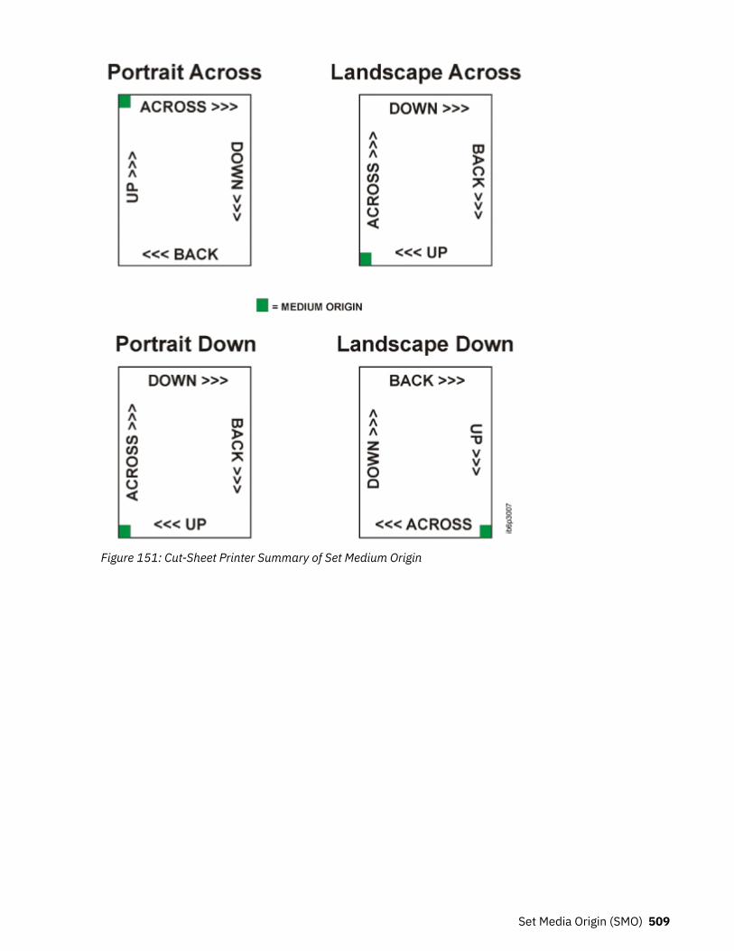
Figure 151: Cut-Sheet Printer Summary of Set Medium Origin
Set Media Origin (SMO) 509
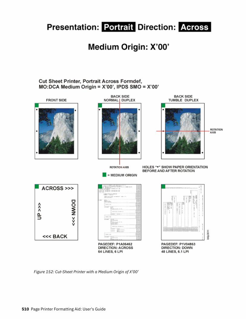
Figure 152: Cut-Sheet Printer with a Medium Origin of X'00'
510 Page Printer Formatting Aid: User's Guide

Figure 153: Cut-Sheet Printer with a Medium Origin of X'01'
Set Media Origin (SMO) 511
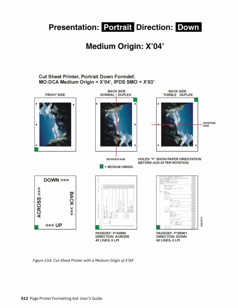
Figure 154: Cut-Sheet Printer with a Medium Origin of X'04'
512 Page Printer Formatting Aid: User's Guide

Figure 155: Cut-Sheet Printer with a Medium Origin of X'05'
Wide Continuous Forms Paper
Set Media Origin (SMO) 513
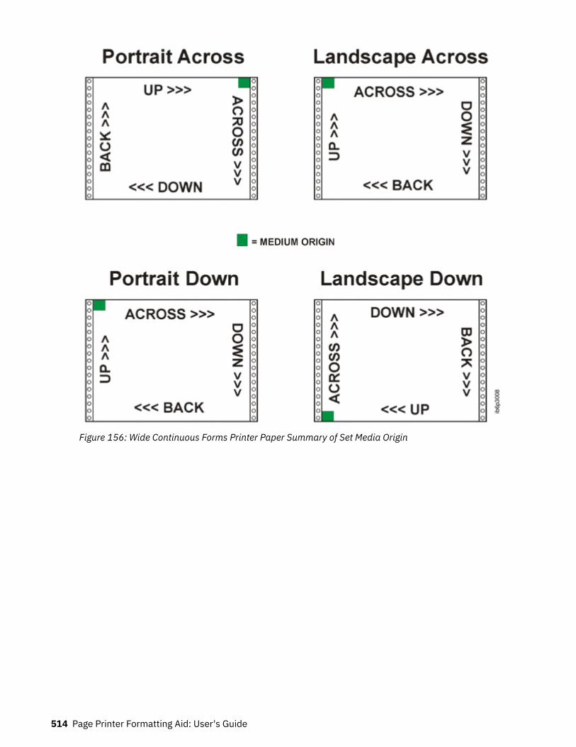
Figure 156: Wide Continuous Forms Printer Paper Summary of Set Media Origin
514 Page Printer Formatting Aid: User's Guide
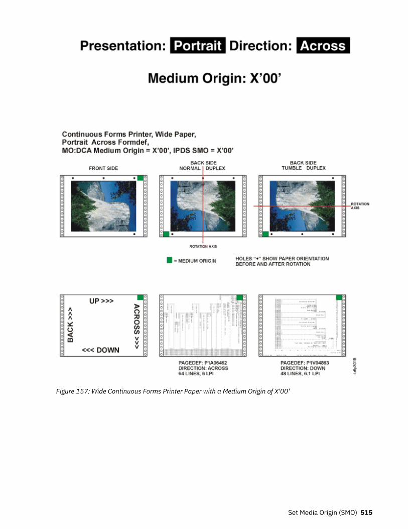
Figure 157: Wide Continuous Forms Printer Paper with a Medium Origin of X'00'
Set Media Origin (SMO) 515

Figure 158: Wide Continuous Forms Printer Paper with a Medium Origin of X'01'
516 Page Printer Formatting Aid: User's Guide

Figure 159: Wide Continuous Forms Printer Paper with a Medium Origin of X'04'
Set Media Origin (SMO) 517

Figure 160: Wide Continuous Forms Printer Paper with a Medium Origin of X'05'
Narrow Continuous Forms Paper
518 Page Printer Formatting Aid: User's Guide

Figure 161: Narrow Continuous Forms Printer Paper Summary of Set Media Origin
Set Media Origin (SMO) 519

Figure 162: Narrow Continuous Forms Printer Paper with a Medium Origin of X'00'
520 Page Printer Formatting Aid: User's Guide
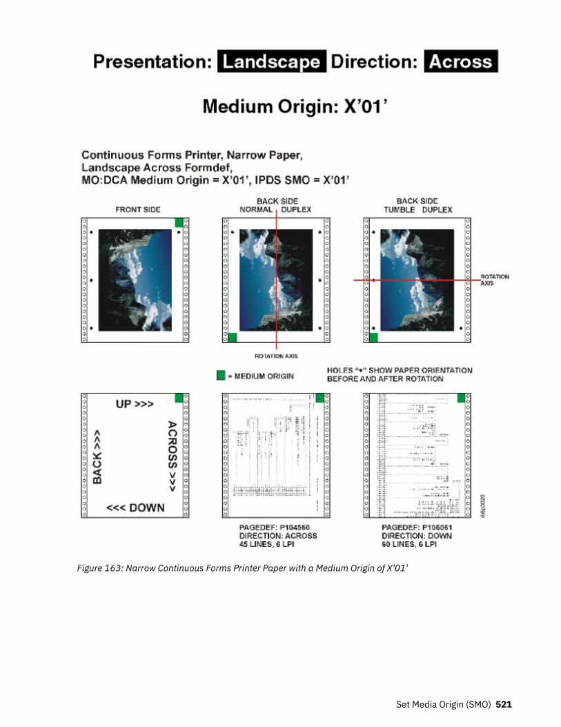
Figure 163: Narrow Continuous Forms Printer Paper with a Medium Origin of X'01'
Set Media Origin (SMO) 521

Figure 164: Narrow Continuous Forms Printer Paper with a Medium Origin of X'04'
522 Page Printer Formatting Aid: User's Guide

Figure 165: Narrow Continuous Forms Printer Paper with a Medium Origin of X'05'
Cut-Sheet Emulation
Set Media Origin (SMO) 523

Figure 166: Cut-Sheet Emulation for Continuous Forms Printer Wide and Narrow Paper Set Media Origin
524 Page Printer Formatting Aid: User's Guide

Appendix F. PPFA Keywords
A keyword is a word in PPFA that must be entered exactly as shown. Keywords cannot be used as secondnames for commands (like FONT and OVERLAY), which can have two positional parameters as names.This is less restrictive than prior versions of PPFA.
Note: When keywords are longer than 5 characters, they can be abbreviated to the first 5 characters. Theshorthand form of the keyword must also be avoided as a name. For example, since PAGEH and CONDIare 5 character forms for PAGEHEADER and CONDITION, they cannot be used as second names.
PPFA reserved keywords are shown in the following list:
ABSOLUTEACROSSADJUSTAFIELDALIGNAXIS1AXIS2BACKBARCODEBCCOLORBCXPARMSBINBINERRORBODYBOTHBOXBOXSIZECHANNELCIELABCIRCLECLRTRAPCMRCMRNAMECMRTAGFIDELITYCMYKCOLORCOLORVALUERRCOMMENTCOMPATPGP1
CONDITIONCONSTANTCOPIESCOPY
COPYGROUPHRICPCSCUTSHEETCVERRORDBCSDEFINEDEFINE CMRNAMEDELIMITERDIRECTIONDOWNDOFONTDRAWGRAPHICDUPLEXELLIPSEENDGRAPHICENDSPACEENDSUBPAGEEXTREFFIELDFILLFINISHFLASHFLDNUMFONTFONTFIDFORMDEFFRONTGRAPHIDGRIDGROUPGRPHEADERHEIGHT
HILITEHRIFONTINVOKEJOGLAYOUTLENGTHLINELINEONELINESPLINETYPELINEWTMEDIUMMETRICTECHNOLOGYMETTECHMODMODWIDTHNN_UPNEWPAGENOGROUPNOPRELOADNORASTEROBIDOBJECTOBKEEPOBNOKEEPOBTYPEOBXNAMEOB2CMROB2IDOB2RESOURCEOB2TYPEOB2XNAMEOCA
OFFSETOPCOUNTOPERATIONOPOFFSETOPPOSOTHERWISEOUTBINOVERLAYOVROTATEPAGECOUNTPAGEDEFPAGEFORMATPAGEHEADERPAGENUMPAGETRAILERPARTITIONPLACEPOSITIONPRELOADPRESENTPRINTDATAPRINTLINEPROCESSINGQUALITYRADIUSRASTERRATIORECIDREFERENCERELATIVERENDERREPEATREPLACERES
RESOLUTIONRGBROTATIONSBCSSCOPESEGMENTSETUNITSSOSIFONTSPACE_THEN_PRINTSSASTERISKSTARTSUBGROUPSUPPBLANKSSUPPRESSIONTEXTTEXTERRORTOTONERSAVERTRCREFTYPEUDTYPEWHENWIDTHXATTRXLAYOUTXMSIZEXSPACEYMSIZE
© Copyright IBM Corp. 1985, 2016 525

526 Page Printer Formatting Aid: User's Guide

Appendix G. PPFA Media Names
Table 31 on page 527 lists the PPFA media names, media types, and component identifiers.
Note: The range of component IDs 12,288 - 268,435,455 is reserved for user-defined media types.
Table 31: Registered Media Types Sorted By Media Name
Media Name Media Type Component ID
BSNS ENV North American business envelope 143
COM 10 ENV Com10 envelope (9.5 x 4.125 in) 75
C5 ENV C5 envelope (229 x 110 mm) 79
DL ENV DL envelope (220 x 110 mm) 77
EXEC North American executive (7.25 x 10.5 in) 65
INDEX CD Index Card 150
ISO A3 ISO A3 white (297 x 420 mm) 10
ISO A3 CO ISO A3 colored 11
ISO A4 ISO A4 white (210 x 297 mm) 0
ISO A4 CO ISO A4 colored 1
ISO A4 TAB ISO A4 tab (225 x 297 mm) 7
ISO A4 THD ISO 1/3 A4 5
ISO A4 TR ISO A4 transparent 2
ISO A5 ISO A5 white (148.5 x 210 mm) 20
ISO A5 CO ISO A5 colored 21
ISO A6 PC ISO A6 Postcard 152
ISO B4 ISO B4 white (257 x 364 mm) 30
ISO B4 CO ISO B4 colored 31
ISO B4 ENV ISO B4 envelope 83
ISO B5 ISO B5 white (176 x 250 mm) 40
ISO B5 CO ISO B5 colored 41
ISO B5 ENV ISO B5 envelope 73
ISO C4 ENV ISO C4 envelope 93
ISO C5 ENV ISO C5 envelope 103
ISO LNG ENV ISO long envelope 113
JIS B4 JIS B4 (257 x 364 mm) 42
JIS B5 JIS B5 (182 x 257 mm) 43
JP PC Japan postcard (Hagaki) (100 x 148 mm) 81
© Copyright IBM Corp. 1985, 2016 527
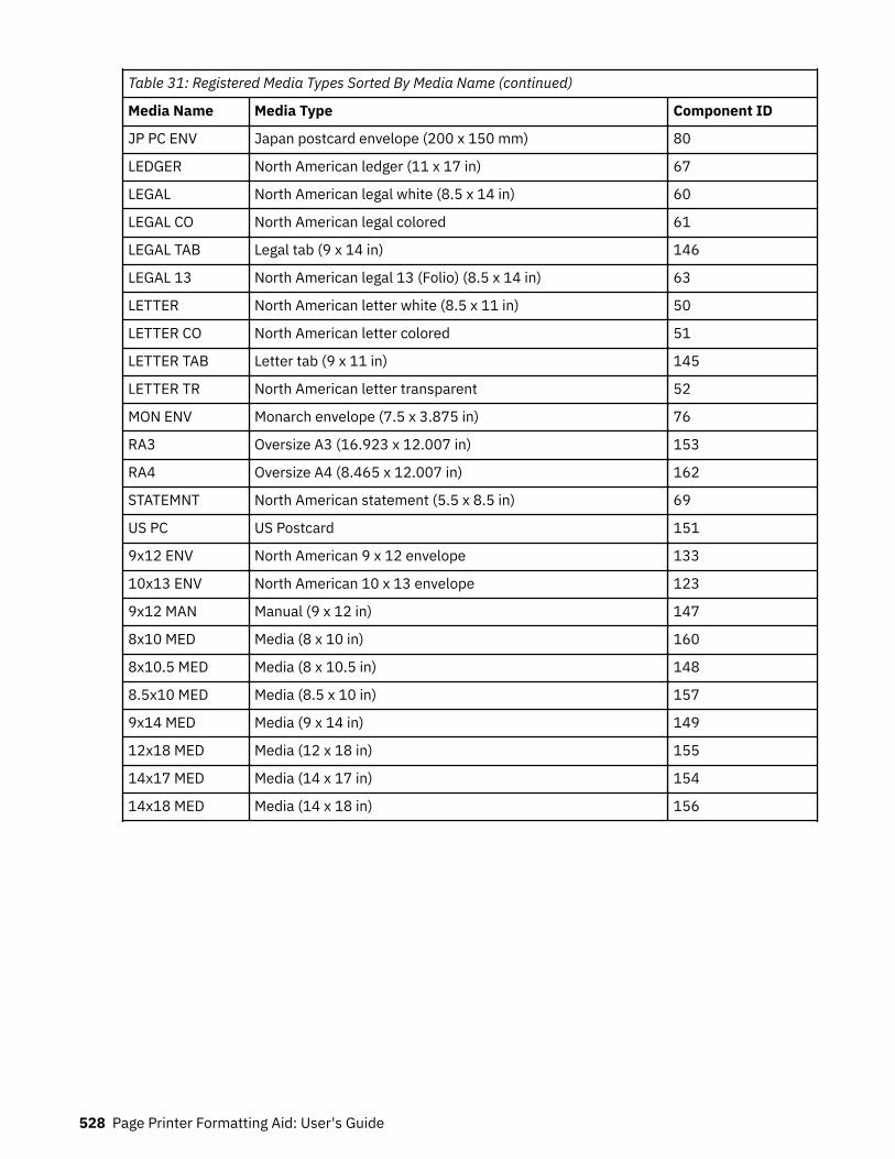
Table 31: Registered Media Types Sorted By Media Name (continued)
Media Name Media Type Component ID
JP PC ENV Japan postcard envelope (200 x 150 mm) 80
LEDGER North American ledger (11 x 17 in) 67
LEGAL North American legal white (8.5 x 14 in) 60
LEGAL CO North American legal colored 61
LEGAL TAB Legal tab (9 x 14 in) 146
LEGAL 13 North American legal 13 (Folio) (8.5 x 14 in) 63
LETTER North American letter white (8.5 x 11 in) 50
LETTER CO North American letter colored 51
LETTER TAB Letter tab (9 x 11 in) 145
LETTER TR North American letter transparent 52
MON ENV Monarch envelope (7.5 x 3.875 in) 76
RA3 Oversize A3 (16.923 x 12.007 in) 153
RA4 Oversize A4 (8.465 x 12.007 in) 162
STATEMNT North American statement (5.5 x 8.5 in) 69
US PC US Postcard 151
9x12 ENV North American 9 x 12 envelope 133
10x13 ENV North American 10 x 13 envelope 123
9x12 MAN Manual (9 x 12 in) 147
8x10 MED Media (8 x 10 in) 160
8x10.5 MED Media (8 x 10.5 in) 148
8.5x10 MED Media (8.5 x 10 in) 157
9x14 MED Media (9 x 14 in) 149
12x18 MED Media (12 x 18 in) 155
14x17 MED Media (14 x 17 in) 154
14x18 MED Media (14 x 18 in) 156
528 Page Printer Formatting Aid: User's Guide
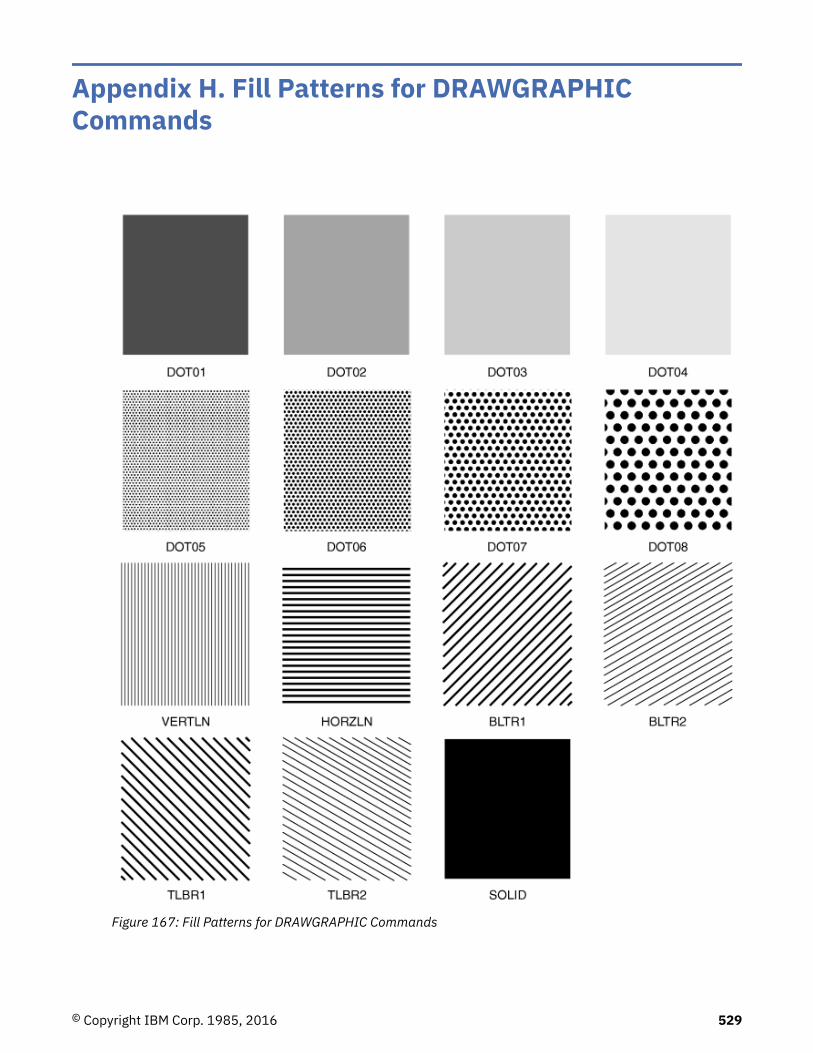
Appendix H. Fill Patterns for DRAWGRAPHICCommands
Figure 167: Fill Patterns for DRAWGRAPHIC Commands
© Copyright IBM Corp. 1985, 2016 529

530 Page Printer Formatting Aid: User's Guide

Appendix I. PPFA Messages and Codes
At the end of processing for each command, the maximum error level that is encountered duringprocessing is printed on the system printer, providing the error was not caused by the system printeritself. The meaning of the return codes is shown in Table 32 on page 531.
Table 32: Return Codes
Return Code Severity Description
Return Code 0 I = Information; the command isprocessed.
PPFA did not encounter any problems. No warning,error, severe-error, or termination-error message wasissued.
Return Code 4 W = Warning; the command isprocessed.
PPFA encountered at least one non-terminating error,which was solved by an assumption. At least onewarning message was issued. No error, severe-error,or terminating-error message was issued. Therequested function was most likely correctly done. Theprogram ran to completion.
Return Code 8 E = Error; the command is partiallyprocessed.
PPFA encountered at least one error, but no severe orterminating error. A requested function might bepartially incomplete.
Return Code 12 S = Severe error; the command isnot processed.
PPFA encountered a severe error. The program ran tocompletion, but some of the functions requested werenot done.
Return Code 16 T = Termination error; the job isended.
PPFA encountered a terminating error. The programended prematurely.
PPFA Messages and Their MeaningsThe general format of the error message is as follows:
All messages consist of a standard seven-character prefix, followed by the message text:AKQnnns THIS IS THE MESSAGE TEXT . . .
• AKQ is the three-character identifier of Page Printer Formatting Aid (PPFA).• nnn is the message number.• s is the message-severity indicator. The severity indicators are defined in Table 32 on page 531.
Notes:
1. You cannot use the psfmsg command to view PPFA messages.2. PPFA errors are written to a listing file.3. PPFA issues a maximum of 269 user errors that are generated within a source file, and one additional
message that is used for the message queue to indicate an out-of-storage condition.
AKQ001E END OF COMMENT (*⁄) IS NOTSPECIFIED.
Explanation
The end mark of a comment (*⁄) is not specified.
System action
The page definition or form definition is not generated.The syntax check might be ended.
© Copyright IBM Corp. 1985, 2016 531

Operator response
Specify the end mark of a comment.
AKQ002E DBCS STRING DOES NOT ENDWITH SHIFT-IN.
Explanation
DBCS strings in comments must end with shift-in.
System action
The form definition or page definition is not generated.The syntax check continues, assuming shift-in.
Operator response
Specify a valid DBCS string that is enclosed by SO andSI.
AKQ003E LITERAL DOES NOT END WITHAPOSTROPHE.
Explanation
A literal must end with an apostrophe.
System action
The page definition is not generated. The syntax checkcontinues, assuming an apostrophe.
Operator response
Specify a valid literal that is enclosed by apostrophes.An apostrophe in a literal is specified by consecutivedouble apostrophes.
AKQ004E DBCS LITERAL DOES NOT ENDWITH SHIFT-IN ANDAPOSTROPHE.
Explanation
A DBCS literal must end with shift-in and apostrophe.
System action
The page definition is not generated. The syntax checkcontinues, assuming the end of the DBCS literal at theend of a record.
Operator response
Specify a valid literal that is ended by shift-in andapostrophe.
AKQ101E COMMAND SEQUENCE ISINVALID.
Explanation
The command sequence is invalid.
System action
A page definition or form definition is not generated.The syntax check continues from a valid command.
Operator response
Specify commands in a valid sequence.
AKQ102E INVALID COMMAND (erroneousentry) IS SPECIFIED.
Explanation
An invalid command is specified in the input data.
System action
A page definition or form definition is not generated.The syntax check continues from a valid command.
Operator response
Specify a valid command.
AKQ103E INVALID SUBCOMMAND (value) ISSPECIFIED.
Explanation
An invalid subcommand was specified in the inputdata. This message is often issued when a semicolon(;) is missing
System action
A page definition or form definition is not generated.The syntax check continues from the next keyword.
Operator response
Specify a valid subcommand.
AKQ104E (command or parameter name)NAME IS NOT SPECIFIED.
Explanation
The required name is not specified.
System action
A page definition or form definition is not generated.The syntax check continues, assuming blanks ordefault as the name.
532 Page Printer Formatting Aid: User's Guide

Operator response
Specify the required name.
AKQ105E REQUIRED PARAMETER IN(subcommand name) IS NOTSPECIFIED.
Explanation
The subcommand that is indicated in the messagerequires a correct PPFA format.
System action
A page definition or form definition is not generated.The syntax check continues, assuming the defaultvalues.
Operator response
See the command reference section of this publicationfor help in specifying a valid subcommand parameter.
AKQ106E (command or parameter name)NAME IS SPECIFIED WITHINVALID SYNTAX.
Explanation
The required name is specified with invalid syntax. SeeTable 8 on page 184 for the correct length of names.
System action
A page definition or form definition is not generated.The syntax check continues.
Operator response
Specify a valid name.
AKQ107E PARAMETER IN (subcommandname) IS INVALID.
Explanation
The parameter in the subcommand is invalid (invalidformat or out of range).
System action
A page definition or form definition is not generated.The syntax check continues, assuming the defaultvalues as the parameter.
Operator response
Specify a valid parameter value.
AKQ108E (subcommand name)SUBCOMMAND IS DUPLICATED INONE COMMAND.
Explanation
The subcommand that is indicated in the message wasspecified more than once in the same command. Onlyone such subcommand is allowed within thiscommand.
System action
A page definition or form definition is not generated.The syntax check continues, ignoring the duplicatesubcommand.
Operator response
Delete one subcommand.
AKQ109E (subcommand name)SUBCOMMAND CONFLICTS WITH(subcommand name)SUBCOMMAND.
Explanation
One subcommand conflicts with another (FONT,PRINTLINE, FIELD, OPCOUNT, OPPOS)
System action
A page definition or form definition is not generated.The syntax check continues, ignoring the lattersubcommand.
User response
Delete one of the subcommands.
AKQ110E THE VALUE OF THE (commandname) SUBCOMMAND IS TOOLARGE OR TOO SMALL.
Explanation
The parameter in the subcommand is out of range.IN
136.5MM
3467.1CM
346.7POINTS
9828.0PELS (L-units)
32760
PPFA Messages and Codes 533
These values are specified in:
FORMDEF N_UP OVERLAY relative_xposrelative_yposPAGEDEF PRINTLINE OVERLAY / SEGMENTrelative_xpos relative_ypos
Note: The values that are specified for the CPI and LPIare set in the SETUNITS subcommand.
System action
No form definition or page definition is generated.PPFA continues syntax checking.
Operator response
Specify a valid parameter value.
AKQ111E SUBCOMMAND SEQUENCE ISINVALID: (subcommand name)OCCURS AFTER (subcommandname)
Explanation
For example, a WHEN subcommand occurs after anOTHERWISE subcommand in a CONDITION command.
System action
A page definition or form definition is not generated.The syntax check continues, ignoring thesubcommand.
Operator response
Reorder or rewrite the conditions.
AKQ112E CONDITION COMMAND DOES NOTALLOW ‘*’ IN ITS STARTSUBCOMMAND.
Explanation
A relative position (‘*’, ‘* + n’, or ‘* - n’) was specified ina START subcommand of a CONDITION command.
System action
A page definition or form definition is not generated.The syntax check continues from the validsubcommand.
Operator response
Specify an absolute starting position.
AKQ113E MORE THAN ONE ‘WHEN’SUBCOMMAND SPECIFIED THECHANGE PARAMETER.
Explanation
More than one WHEN subcommand specified CHANGEfor its field comparison.
System action
A page definition or form definition is not generated.The syntax check continues from the validsubcommand.
Operator response
Remove the extra subcommands that specify theCHANGE parameter.
AKQ114E NUMBER OF PARAMETERSEXCEED LIMIT FOR (subcommandname) SUBCOMMAND ORKEYWORD.
Explanation
The named subcommand or keyword in the messagelimits the number of parameters that can be codedwith a single subcommand or keyword. The number ofparameters that can be coded with the namedsubcommand or keyword is defined in Chapter 10,“Form Definition Command Reference,” on page 189and Chapter 11, “Page Definition CommandReference ,” on page 249.
System action
The form definition is not generated. The syntax checkcontinues from the valid subcommand.
Operator response
Remove the extra parameters.
AKQ115E REQUIRED PARAMETER(S)(PARM1, PARM2, …) IN(COMMAND OR SUBCOMMAND) IS(ARE) NOT SPECIFIED.
Explanation
This generic message indicates that one or moreparameters are missing on a subcommand orcommand. For example, a DRAWGRAPHIC BOX musthave a BOXSIZE subcommand coded.
System action
A page or form definition is not generated.
Operator response
Provide the correct parameters on the command orsubcommand.
534 Page Printer Formatting Aid: User's Guide

AKQ116E PARAMETER (PARM1) IN(COMMAND OR SUBCOMMAND) ISINVALID.
Explanation
This generic message indicates that a parameter in asubcommand or command is invalid.
System action
A page or form definition is not generated.
Operator response
Provide the correct parameter on the command orsubcommand.
AKQ117E PARAMETER (PARM1) IN(COMMAND OR SUBCOMMAND) ISDUPLICATED.
Explanation
This generic message indicates that a parameter in asubcommand or command is coded more than once.For example, …LINEWT LIGHT BOLD… shows twodifferent line weights in the same subcommand.
System action
A page or form definition is not generated.
Operator response
Remove one of the parameters.
AKQ118E MUTUALLY EXCLUSIVEPARAMETERS ON THE (INSERT1)COMMAND OR SUBCOMMAND AREDUPLICATED.
Explanation
A command or subcommand contains more than onemutually exclusive parameter. For example, thePAGECOUNT subcommand on the PAGEDEF commandcannot have both STOP and CONTINUE coded.
System action
A page or form definition is not generated.
Operator response
Remove one of the parameters.
AKQ119E GRAPHICS-TYPE (BOX, LINE,CIRCLE, ELLIPSE) MUSTIMMEDIATELY FOLLOWDRAWGRAPHIC.
Explanation
The DRAWGRAPHIC command must have the graphicstype (BOX, LINE, CIRCLE, ELLIPSE) immediatelyfollowing the command.
System action
A page or form definition is not generated.
Operator response
Code one of the graphics types.
AKQ120I UNKNOWN COMPONENT ID. PPFAWILL ASSUME IT IS SUPPORTED.
Explanation
PPFA allows the use of numeric component IDs whenthe object type is OTHER so that new OTHER objecttypes can be supported without a new release ofPPFA. The unknown component ID is one of them.
System action
A PAGEDEF is generated.
Operator response
Ensure that the object type component ID is supportedby your printer and PSF service level.
AKQ121W COMMAND SEQUENCE ISINVALID. A (insert-1) OCCURSBEFORE A (insert-2).
Explanation
For example, an overlay occurs outside a copy group.
System action
A dummy copy group is created that is the first copygroup. The FORMDEF is generated.
Operator response
Reorder the command statements.
AKQ122W THE (insert-1) IS TOO LONG. IT ISTRUNCATED TO (insert-2) BYTES.
Explanation
The input length of a parameter is exceeded. Forexample, the maximum length of a bar code Macro is4096 bytes.
PPFA Messages and Codes 535
System action
Only the first (insert-2) bytes of a parameter are used.Processing continues. A PAGEDEF is generated.
Operator response
Use a shorter text parameter.
AKQ201E (subcommand name)SUBCOMMAND IS NOTSPECIFIED.
Explanation
The required subcommand is not specified.
System action
A page definition or form definition is not generated.The syntax check continues, assuming the default.
Operator response
Specify the required subcommand.
AKQ202E SPECIFIED (command name)NAME IS NOT DEFINED.
Explanation
A resource name (OVERLAY, SUPPRESSION, FONT,OBJECT, QTAG, or COLOR) is not defined.
System action
A page definition or form definition is not generated.The syntax check continues.
Operator response
Correct the name.
AKQ203W (command name) NAME ISDUPLICATED.
Explanation
The required name must be unique for OVERLAY,COPYGROUP, FONT, PAGEFORMAT, OBJECT, orSUPPRESSION.
System action
A page definition or form definition is generated.
Operator response
Specify a unique name.
AKQ204E (object) NAME IS DUPLICATED.
Explanation
The name must be unique (OVERLAY, COPYGROUP,FONT, PAGEFORMAT, SEGMENT).
System action
A page definition or form definition is not generated.The syntax check continues.
Operator response
Specify a unique name.
AKQ205E PAGEFORMAT (pageformat name)WAS NOT FOUND IN THIS PAGEDEFINITION.
Explanation
A WHEN or OTHERWISE subcommand of CONDITIONspecifies a PAGEFORMAT name that is not found in thepage definition that is processed.
System action
A page definition or form definition is not generated.The syntax check continues.
Operator response
Specify a pageformat name that is in the pagedefinition.
AKQ206E CONDITION (condition name) HASALREADY BEEN DEFINED.
Explanation
A CONDITION command specifies LENGTH, WHEN, orOTHERWISE, and the condition with this conditionname is already defined by an earlier CONDITIONcommand.
System action
A page definition is not generated. The syntax checkcontinues.
Operator response
Define the condition only the first time it occurs.
AKQ210E THE RELATIVE POSITION VALUEEXCEEDS THE ALLOWED RANGE
System action
The value that is specified for the relative x position orrelative y position on the N_UP subcommand (for anOVERLAY) or PRINTLINE command (for an OVERLAY orSEGMENT) exceeds the range of +32760 to -32760 L-
536 Page Printer Formatting Aid: User's Guide
units. For example, assuming the default of 240 pelsper inch is being used, the values must be equal to, orless than these units:IN
136.5MM
3467.1CM
346.7POINTS
9828.0PELS (L-units)
32760 (+ or -)CPI
*LPI
*The value that is specified for CPI or LPI in theSETUNITS command determines whether the valueexceeds 32760 L-units.
System action
The page definition or form definition is not generated.The syntax check continues.
Operator response
Correct the relative x and y position values within theallowed range.
AKQ211E FRONT/BACK SIDE IS NOTSPECIFIED FOR DUPLEX.
Explanation
The SUBGROUP specified with BACK does not existafter the SUBGROUP specified with FRONT, or theSUBGROUP specified with FRONT does not existbefore the SUBGROUP specified with BACK.
System action
A form definition is not generated. The syntax checkcontinues.
Operator response
Specify subgroups for both sides.
AKQ212W PAPER SIDE IS SPECIFIED FORSIMPLEX.
Explanation
A subgroup that is specified with BOTH, FRONT, orBACK is invalid with single-sided printing.
System action
A form definition is generated, which ignores thesubcommand that specifies the paper side.
User response
Either delete the subcommand that specified thepaper side or specify DUPLEX.
AKQ213E LOGICAL PAGE POSITIONEXCEEDS THE LIMIT.
Explanation
The logical page position that is specified by theOFFSET subcommand in the FORMDEF orCOPYGROUP command exceeds the limits.
System action
A form definition is not generated. The syntax checkcontinues.
Operator response
Correct the error.
AKQ214E MORE THAN 127 SUPPRESSIONSARE SPECIFIED IN ONE FORMDEF.
Explanation
More than 127 suppressions are specified in oneFORMDEF.
System action
A form definition is not generated. The syntax checkcontinues.
Operator response
Correct the error.
AKQ215E MORE THAN 127 OVERLAYS ARESPECIFIED IN ONE COPYGROUP.
Explanation
More than 127 OVERLAYs are specified in one copygroup. PPFA can issue this message for an N_UPsubcommand that specifies more than 127 overlays.
System action
No form definition is generated. The syntax checkcontinues.
User response
Correct the error.
PPFA Messages and Codes 537

AKQ216E MORE THAN ONE RASTEROVERLAY IS SPECIFIED IN ONECOPYGROUP.
Explanation
More than one raster OVERLAY is specified in one copygroup.
System action
A form definition is not generated. The syntax checkcontinues.
Operator response
Correct the error.
AKQ217W LOGICAL PAGE POSITION FORBACK SIDE OF PAGE SPECIFIEDIN SIMPLEX PROCESSING
Explanation
The logical-page position that is specified by theOFFSET subcommand in a FORMDEF or COPYGROUPcommand for the back side of a page was specified,but simplex was specified in a COPYGROUP command.
System action
A form definition is generated, with the back sidelogical page position included, as if duplex is specified.The syntax check continues.
Operator response
Correct the error by specifying duplex in theCOPYGROUP command or remove the second set ofcoordinates in the OFFSET subcommand.
AKQ218E MORE THAN 255 COPIES ARESPECIFIED IN ONE COPYGROUP.
Explanation
More than 255 copies are specified in a COPYGROUP.
System action
A form definition is not generated. The syntax checkcontinues.
Operator response
Correct the error.
AKQ219E MORE THAN 127 SUBGROUPS ARESPECIFIED IN ONE COPYGROUP.
Explanation
More than 127 subgroups are specified in aCOPYGROUP.
System action
A form definition is not generated. The syntax checkcontinues.
Operator response
Correct the error.
AKQ220E MORE THAN 8 OVERLAYS ARESPECIFIED IN ONE SUBGROUP.
Explanation
More than eight overlays are specified in oneSUBGROUP.
System action
A form definition is not generated. The syntax checkcontinues.
Operator response
Correct the error.
AKQ221E MORE THAN 8 SUPPRESSIONSARE SPECIFIED IN ONESUBGROUP.
Explanation
More than eight suppressions are specified in oneSUBGROUP.
System action
A form definition is not generated. The syntax checkcontinues.
Operator response
Correct the error.
AKQ222W DIFFERENT NUMBERS OF COPIESARE SPECIFIED FOR EACH SIDEOF DUPLEX.
Explanation
The number of copies for BACK side is not equal to theones for FRONT side.
System action
A form definition is generated, which assumes thenumber of copies that are specified for front side.
538 Page Printer Formatting Aid: User's Guide

Operator response
Check the number of copies.
AKQ223E LOGICAL PAGE POSITION FOR(page side) SIDE OF PAGEEXCEEDS THE LIMIT.
Explanation
The logical-page position that is specified by theOFFSET subcommand in a FORMDEF or COPYGROUPcommand exceeds the limit for the current side of thepage.
System action
A form definition is not generated. The syntax checkcontinues.
Operator response
Correct the positioning OFFSET parameter.
AKQ224E MORE THAN 254 OVERLAYS ARESPECIFIED IN A PAGEFORMAT.
Explanation
The maximum number of OVERLAY commands is 254.PPFA can issue this message for the OVERLAYsubcommand of the PRINTLINE command.
System action
A page definition is not generated. The syntax checkcontinues.
User response
Specify a valid number of OVERLAY commands.
AKQ225E CONSTANT SUBCOMMANDPARAMETER (parameter)SPECIFIED IN SIMPLEXPROCESSING
Explanation
The BACK or BOTH parameter is specified for theCONSTANT subcommand within simplex processing.
System action
A form definition is not generated. The syntax checkcontinues.
Operator response
Correct this CONSTANT subcommand or indicateDUPLEX.
AKQ226E DIRECTION SUBCOMMAND ONLYALLOWED WITH PRESENTSUBCOMMAND.
Explanation
The DIRECTION subcommand is specified, but thePRESENT subcommand is not.
System action
A form definition is not generated. The syntax checkcontinues.
Operator response
Either add the PRESENT subcommand or remove theDIRECTION subcommand.
AKQ227E THE ORIGIN OF THE RESOURCE(name) NAMED IN THE PRINTLINECOMMAND IS OFF THE LOGICALPAGE.
Explanation
The relative position of the PRINTLINE overlay orsegment that is named is off the logical page. Theorigin of the overlay or segment that is specified forthe resource that is named in the N_UP subcommandis off the medium.
System action
The page definition that has the overlay or segment inquestion is not generated. PPFA continues the syntaxcheck, ignoring the problem.
Operator response
Correct the x-position and y-position for the OVERLAYor SEGMENT subcommand.
AKQ228E THE ORIGIN OF THE OVERLAY(overlay name) NAMED IN THE(command) COMMAND IS OFF THEMEDIUM
Explanation
The resource position values position the resourcesuch that at least part of the resource is off themedium (physical page).
System action
The form definition that has the overlay in question isnot generated. PPFA continues the syntax check,ignoring the problem.
PPFA Messages and Codes 539
User response
Correct the relative x-position and relative y-positionvalues for the OVERLAY named in the N_UPsubcommand.
AKQ229W SUBGROUPS FOR FRONT ANDBACK OF SAME SHEET USEDDIFFERENT BINS.
Explanation
In your subgroup command, you specified FRONT andBACK parameters. However, your COPYGROUP hasdifferent bins that are specified.
System action
A form definition is generated that specifies the binthat is used for the front side.
Operator response
Check the number of copies and correct the binsetting.
AKQ231E PRINTLINE OR LAYOUT IS NOTSPECIFIED.
Explanation
No PRINTLINE or LAYOUT command exists in the pageformat.
System action
A page definition is not generated. The syntax checkcontinues.
Operator response
Specify either a PRINTLINE or LAYOUT command.
AKQ232E REQUIRED SUBCOMMAND TEXTOR LENGTH IS NOT SPECIFIED.
Explanation
A FIELD subcommand must have a TEXT or LENGTHsubcommand.
System action
A page definition is not generated. The syntax checkcontinues.
Operator response
Specify either a TEXT subcommand or a LENGTHsubcommand.
AKQ233E THE LOGICAL PAGE SIZE IS TOOLARGE OR TOO SMALL.
Explanation
The specified page size is too large or too small. Thepage size must be 1 - 32767 pels. The HEIGHT andWIDTH subcommands must be 1 - 32767 pels or thesame measurements expressed in other units.
System action
A page definition is not generated. The syntax checkcontinues, assuming the defaults.
Operator response
Correct the error.
AKQ234E POSITION OF LINEONE EXCEEDSTHE LOGICAL PAGE BOUNDARY.
Explanation
The TOP or MARGIN position that is specified by theLINEONE subcommand exceeds the logical pageboundary. This error message is issued only if TOP orMARGIN is specified.
System action
A page definition is not generated. The syntax checkcontinues.
Operator response
Specify a valid position value.
AKQ235E MORE THAN 127 SEGMENTS ARESPECIFIED IN ONE PAGEFORMAT.
Explanation
More than 127 segments are specified in a singlePAGEFORMAT command. PPFA can issue this messagefor the SEGMENT subcommand of the PRINTLINEcommand.
System action
No page definition is generated. The syntax checkcontinues.
User response
Correct the error.
AKQ238E MORE THAN 127 FONTS ARESPECIFIED IN ONE PAGEFORMAT.
540 Page Printer Formatting Aid: User's Guide

Explanation
More than 127 fonts are specified in one PAGEFORMATor the specified TRC number exceeds 126. PPFAcounts each use of a font in more than one direction orrotation as a separate font.
System action
A page definition is not generated. The syntax checkcontinues.
Operator response
Correct the error.
AKQ239E PRINT POSITION EXCEEDS THELOGICAL PAGE BOUNDARY.
Explanation
The print position that is specified by POSITIONsubcommand exceeds the logical page boundary.
System action
A page definition is not generated. The syntax checkcontinues.
Operator response
Correct the error.
AKQ240E NUMBER OF PRINTLINES, FIELDS,AND CONDITIONS EXCEEDS65,535 IN ONE PAGEFORMAT.
Explanation
The total number of PRINTLINEs, FIELDs, andCONDITIONs exceeds 65,535 in one page format.
System action
A page definition is not generated. The syntax checkcontinues.
Operator response
Reduce the number of PRINTLINEs, FIELDs, orCONDITIONs in the page format.
AKQ241E TOTAL LENGTH OF TEXT DATAEXCEEDS 65,534 BYTES.
Explanation
The total length of text can be up to 65,534 bytes.
System action
A page definition is not generated. The syntax checkcontinues.
Operator response
Correct the error.
AKQ242E THE VALUE OF THE STARTINGPOSITION OF A RECORD IS TOOLARGE OR TOO SMALL.
Explanation
The START position of a record exceeds the maximum(65,535) or minimum (1) value.
System action
A page definition is not generated. The syntax checkcontinues.
Operator response
Correct the error.
AKQ243E DBCS LENGTH IS NOT A MULTIPLEOF 2.
Explanation
The number of bytes of DBCS must be a multiple oftwo. Therefore, the value of the LENGTH parametermust be a multiple of two.
System action
A page definition is not generated. The syntax checkcontinues.
Operator response
Specify a valid length or a valid DBCS.
AKQ244E INVALID CODE IS SPECIFIED INTHE TEXT.
Explanation
SBCS text must be within code range X'00' to X'FE'.
Valid double-byte character set (DBCS) codes arebetween X'41' and X'FE' for each byte. PPFA checksthis range. Code X'4040' (blank) is the only exception.For example, the following are valid DBCS codes:X'4040', X'4141', X'41FE', X'FE41', X'FEFE'.
System action
A page definition is not generated. The syntax checkcontinues.
PPFA Messages and Codes 541

Operator response
Specify a valid code.
AKQ245E HEXADECIMAL TEXT IS INVALID.
Explanation
Hexadecimal text is specified in an invalid format.Hexadecimal text must have an even length parameterand be in hexadecimal notation ('0' to 'F').
System action
A page definition is not generated. The syntax checkcontinues.
Operator response
Specify valid hexadecimal text.
AKQ246E NULL LITERAL IS SPECIFIED.
Explanation
The literal has no string.
System action
A page definition is not generated. The syntax checkcontinues.
Operator response
Specify a valid literal.
AKQ247E KANJI NUMBER TEXT IS INVALID.
Explanation
A Kanji number is specified in invalid format. Kanjinumber text must be a string of Kanji numbers that aredelimited by commas. Each Kanji number must be adecimal number equal to a valid DBCS code, minusX'4000'.
System action
A page definition is not generated. The syntax checkcontinues.
Operator response
Specify valid kanji numbers in a valid format.
AKQ248E TEXT ATTRIBUTE CONFLICTSWITH FONT.
Explanation
SBCS font is specified for DBCS text (type G, K), orDBCS font is specified for SBCS text (type C).
System action
A page definition is not generated. The syntax checkcontinues.
Operator response
Correct the error.
AKQ249E TEXT ATTRIBUTE CONFLICTSWITH TEXT TYPE.
Explanation
The literal type conflicts with text type. SBCS literal isspecified as type G or X, and DBCS literal is specifiedas type C, X, or K.
System action
A page definition is not generated. The syntax checkcontinues.
Operator response
Correct the error.
AKQ250E TRC NUMBER IS DUPLICATED.
Explanation
The specified TRC number is duplicated in one pageformat.
System action
A page definition is not generated. The syntax checkcontinues.
Operator response
Correct the error.
AKQ251W SPECIFIED LENGTH IS SHORTERTHAN THE TEXT AND WASTRUNCATED.
Explanation
The LENGTH parameter of the TEXT subcommand isshorter than the length of the specified literal, which istruncated to a specified length.
System action
The operation continues, truncating the literal.
Operator response
Check the truncation.
542 Page Printer Formatting Aid: User's Guide
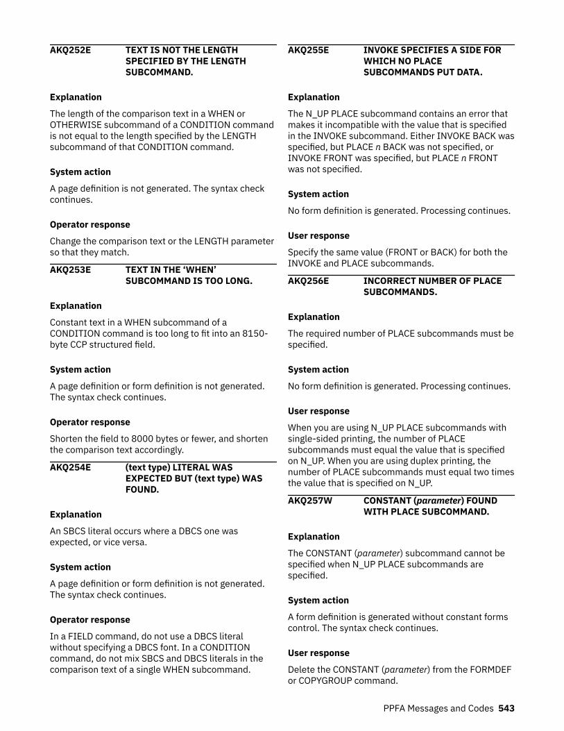
AKQ252E TEXT IS NOT THE LENGTHSPECIFIED BY THE LENGTHSUBCOMMAND.
Explanation
The length of the comparison text in a WHEN orOTHERWISE subcommand of a CONDITION commandis not equal to the length specified by the LENGTHsubcommand of that CONDITION command.
System action
A page definition is not generated. The syntax checkcontinues.
Operator response
Change the comparison text or the LENGTH parameterso that they match.
AKQ253E TEXT IN THE ‘WHEN’SUBCOMMAND IS TOO LONG.
Explanation
Constant text in a WHEN subcommand of aCONDITION command is too long to fit into an 8150-byte CCP structured field.
System action
A page definition or form definition is not generated.The syntax check continues.
Operator response
Shorten the field to 8000 bytes or fewer, and shortenthe comparison text accordingly.
AKQ254E (text type) LITERAL WASEXPECTED BUT (text type) WASFOUND.
Explanation
An SBCS literal occurs where a DBCS one wasexpected, or vice versa.
System action
A page definition or form definition is not generated.The syntax check continues.
Operator response
In a FIELD command, do not use a DBCS literalwithout specifying a DBCS font. In a CONDITIONcommand, do not mix SBCS and DBCS literals in thecomparison text of a single WHEN subcommand.
AKQ255E INVOKE SPECIFIES A SIDE FORWHICH NO PLACESUBCOMMANDS PUT DATA.
Explanation
The N_UP PLACE subcommand contains an error thatmakes it incompatible with the value that is specifiedin the INVOKE subcommand. Either INVOKE BACK wasspecified, but PLACE n BACK was not specified, orINVOKE FRONT was specified, but PLACE n FRONTwas not specified.
System action
No form definition is generated. Processing continues.
User response
Specify the same value (FRONT or BACK) for both theINVOKE and PLACE subcommands.
AKQ256E INCORRECT NUMBER OF PLACESUBCOMMANDS.
Explanation
The required number of PLACE subcommands must bespecified.
System action
No form definition is generated. Processing continues.
User response
When you are using N_UP PLACE subcommands withsingle-sided printing, the number of PLACEsubcommands must equal the value that is specifiedon N_UP. When you are using duplex printing, thenumber of PLACE subcommands must equal two timesthe value that is specified on N_UP.
AKQ257W CONSTANT (parameter) FOUNDWITH PLACE SUBCOMMAND.
Explanation
The CONSTANT (parameter) subcommand cannot bespecified when N_UP PLACE subcommands arespecified.
System action
A form definition is generated without constant formscontrol. The syntax check continues.
User response
Delete the CONSTANT (parameter) from the FORMDEFor COPYGROUP command.
PPFA Messages and Codes 543

AKQ258W MORE THAN 122 OPERATIONPOSITIONS SPECIFIED FOR AFINISH OPERATION.
Explanation
More than 122 finishing operation positions arespecified.
System action
A form definition is generated with 122 finishingpositions. All others are ignored.
User response
Move extraneous operator position values.
AKQ259W OPCOUNT AND OPPOS VALUESSPECIFIED. OPCOUNT IGNORED.
Explanation
Both OPCOUNT and OPPOS are specified.
System action
A form definition is not generated.
Operator response
If OPCOUNT is specified, OPPOS is ignored. When youare using OPPOS for controlling the position of eachoperation on the operation axis, OPCOUNT is ignored.
AKQ260E (insert-1) not allowed with/on a(insert-2).
Explanation
This generic message indicates a contextuallyincorrect combination of PPFA commands orsubcommands. If this message indicates that anaction is not allowed with or on a CMR of this type, theprocessing mode is not valid for that type of CMR.LINK is valid only for device link (DL) CMRs and devicelink (DL) CMRs can have only processing mode LINK.Any other use of LINK processing mode results in errormessage AKQ260E.
System action
A page definition or form definition is not generated.
Operator response
Correct the incorrect parameter and rerun the job.
AKQ261E (insert-1) requires (insert-2).
Explanation
This generic message indicates that a PPFA commandor subcommand is missing.
System action
A page definition is not generated.
Operator response
Add the required parameter and rerun the job.
AKQ262E (insert-1) specifies a (insert-2)which is not a (insert-3).
Explanation
This generic message indicates a contextuallyincorrect combination of PPFA commands orsubcommands. For example, an ENDGRAPHICcommand is specified or defaulted to a GRAPHID thatdoes not match a floating DRAWGRAPHIC BOX orDRAWGRAPHIC LINE.
System action
A page definition is not generated.
Operator response
Correct the indicated problem.
AKQ263E (insert-1) exceeds (insert-2).
Explanation
This generic message indicates an out of boundcondition for some parameters. For example, aDRAWGRAPHIC CIRCLE is positioned off the logicalpage.
System action
A page definition is not generated.
Operator response
Correct the indicated problem.
AKQ264W (insert-1) is ignored (insert-2).
Explanation
This generic message indicates that a contextuallyincorrect combination of PPFA commands orsubcommands is clearly incorrect and is ignored. Forexample, if a LINEONE subcommand was coded on aRecord Format PAGEDEF (for example, one usingLAYOUT), the LINEONE subcommand is ignored.
544 Page Printer Formatting Aid: User's Guide

System action
A page definition is generated.
Operator response
No action necessary unless the result is not what youwanted.
AKQ265W (insert-1) exceeds (insert-2).
Explanation
This generic message indicates an out of boundscondition for some parameters, which is notnecessarily critical. For example, a DRAWGRAPHICCIRCLE is positioned outside the margin boundary butis still on the logical page.
System action
A page definition is generated.
Operator response
No action necessary unless the result is not what youwanted.
AKQ266E PAGEDEF CONTAINS BOTHLAYOUT AND PRINTLINECOMMANDS.
Explanation
Lines are placed in a record format page definition byusing LAYOUT commands or in an XML page definitionby using XLAYOUT command; otherwise, lines areplaced with PRINTLINE commands. The commandscannot be mixed in the same page definition.
System action
A page definition is not generated.
Operator response
Remove either the LAYOUT, XLAYOUT, or PRINTLINEcommands.
AKQ267E MORE THAN ONE DEFAULTPAGEHEADER OR PAGETRAILERIN A PAGEFORMAT.
Explanation
Only one LAYOUT DEFAULT PAGEHEADER orPAGETRAILER can be coded in a PAGEFORMAT.
System action
A page definition is not generated.
Operator response
Remove one of the duplicates.
AKQ268E SPECIFIED MARGINS FOR THISPAGEFORMAT OVERLAP.
Explanation
Either the left margin is defined on or right of the rightmargin or the top margin is defined on or below thebottom margin.
System action
A page definition is not generated.
Operator response
Redefine the margins so that they do not overlap.
AKQ269E A RECORD FORMAT PAGEDEFREQUIRES AT LEAST ONE FONTDEFINITION.
Explanation
At least one font must be defined whether one isreferenced.
System action
A page definition is not generated.
Operator response
Define a font.
AKQ270E PDF417 MACRO DATA BYTE(insert-1), CODEPOINT (insert-2)CANNOT BE TRANSLATED TO GLI0 ENCODATION
Explanation
All code points in an ASCII bar code must ultimatelyend up as ASCII. The printer translates EBCDIC codepoints if you tell it, but it translates both the macrodata and the regular data.
When EBCDIC to ASCII translation is requested for aPDF417 bar code and the PAGEDEF is being compiledon an ASCII operating system, macro data that existsis in ASCII. You now have mixed data, which cannot betranslated. Therefore, PPFA must translate the ASCIImacro data to EBCDIC so that both are the same. Theprinter can now translate the data and print the barcode. However, not all EBCDIC code points translate toGLI0, as the message indicates.
PPFA Messages and Codes 545

System action
The PAGEDEF is not generated.
Operator response
Make sure that all the PDF417 macro text translates toEBCDIC code points.
AKQ271E THE FONT TYPE AND USER DATATYPE (UDTYPE) SPECIFIEDCAUSES A DATATRANSFORMATION THAT IS NOTSUPPORTED
Explanation
When the User's Data Type (UDType) and fontencoding are different, the printer must translate yourdata to the encoding type of the font. For example, ifthe UDType is UTF8 and the font is an ASCII font, thenthe printer must translate your data from UTF8 toASCII. Therefore, combinations are restricted to these:UDType of UTF8
Fonts can be only ASCII or UNICODE.UDType of UTF16
Fonts can be only UNICODE.
System action
PAGEDEF is not generated.
User response
Chooses an appropriately encoded font.
AKQ275I (insert-1)
Explanation
This generic informational message contains variabletext inserts. Two examples are:
1. EXTERNAL OBJECT NAME IS DUPLICATED.2. KEYWORD USED AS A NAME. CHECK NAME NOT
OMITTED. PROCESSING CONTINUES.
System action
Compilation continues. This definition is generated andstored or replaced.
Operator response
Make sure that the situation warned against is whatyou want. For example, make sure that the keywordthat is used as a name is not a missing name, or thatthe duplicated object name is intended.
AKQ2MMS NUMBER OF MESSAGES EXCEEDSTHE 270 ALLOWED LIMIT.PROGRAM TERMINATES.
Explanation
PPFA allows only 270 messages, including thismessage. When this limit is reached, the messages areprinted and the program ends.
System action
The program ends.
Operator response
Correct the PPFA code for the messages that areissued and redo.
AKQ301I PAGE PRINTER FORMATTING AIDENDED, MAX RETURN CODE =(max return code).
Explanation
This message accompanies the output listings of allform definitions and page definitions with themaximum return code for that particular object. Theobject is generated only when the return code is lessthan 8.
System action
None.
Operator response
None.
AKQ302I NO ERRORS FOUND IN (resourcename) DEFINITION.
Explanation
One definition is processed. No statements wereflagged in this definition.
System action
This definition is generated, and stored or replaced.
Operator response
None.
AKQ303S NO CONTROL STATEMENT(S) ARESPECIFIED IN INPUT DATA.
Explanation
No control statements exist in the input data.
546 Page Printer Formatting Aid: User's Guide
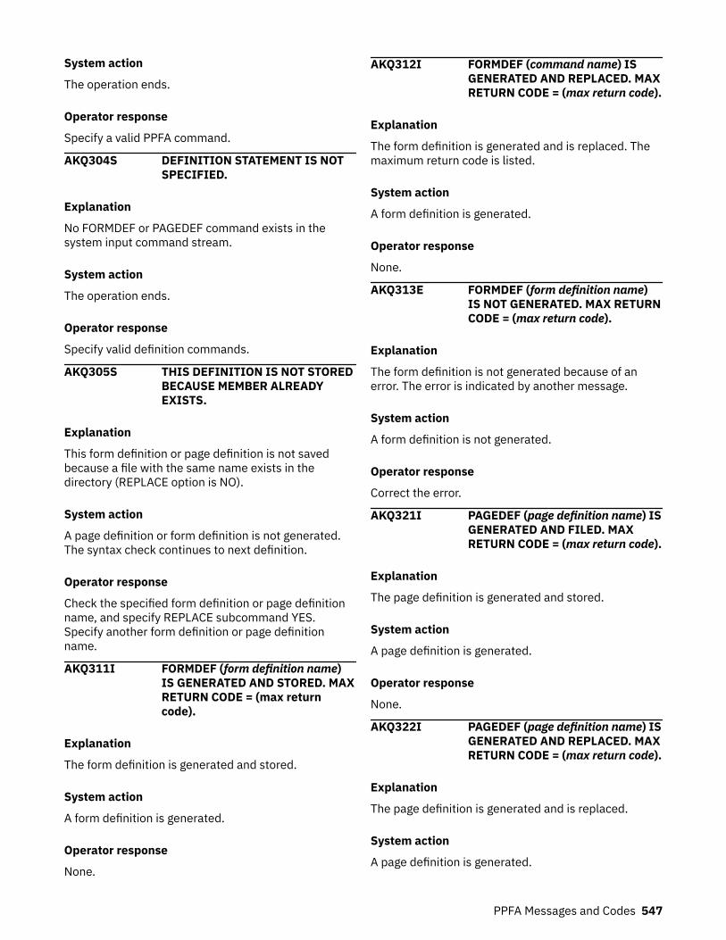
System action
The operation ends.
Operator response
Specify a valid PPFA command.
AKQ304S DEFINITION STATEMENT IS NOTSPECIFIED.
Explanation
No FORMDEF or PAGEDEF command exists in thesystem input command stream.
System action
The operation ends.
Operator response
Specify valid definition commands.
AKQ305S THIS DEFINITION IS NOT STOREDBECAUSE MEMBER ALREADYEXISTS.
Explanation
This form definition or page definition is not savedbecause a file with the same name exists in thedirectory (REPLACE option is NO).
System action
A page definition or form definition is not generated.The syntax check continues to next definition.
Operator response
Check the specified form definition or page definitionname, and specify REPLACE subcommand YES.Specify another form definition or page definitionname.
AKQ311I FORMDEF (form definition name)IS GENERATED AND STORED. MAXRETURN CODE = (max returncode).
Explanation
The form definition is generated and stored.
System action
A form definition is generated.
Operator response
None.
AKQ312I FORMDEF (command name) ISGENERATED AND REPLACED. MAXRETURN CODE = (max return code).
Explanation
The form definition is generated and is replaced. Themaximum return code is listed.
System action
A form definition is generated.
Operator response
None.
AKQ313E FORMDEF (form definition name)IS NOT GENERATED. MAX RETURNCODE = (max return code).
Explanation
The form definition is not generated because of anerror. The error is indicated by another message.
System action
A form definition is not generated.
Operator response
Correct the error.
AKQ321I PAGEDEF (page definition name) ISGENERATED AND FILED. MAXRETURN CODE = (max return code).
Explanation
The page definition is generated and stored.
System action
A page definition is generated.
Operator response
None.
AKQ322I PAGEDEF (page definition name) ISGENERATED AND REPLACED. MAXRETURN CODE = (max return code).
Explanation
The page definition is generated and is replaced.
System action
A page definition is generated.
PPFA Messages and Codes 547
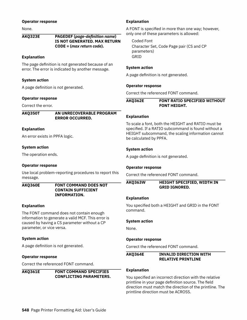
Operator response
None.
AKQ323E PAGEDEF (page-definition name)IS NOT GENERATED. MAX RETURNCODE = (max return code).
Explanation
The page definition is not generated because of anerror. The error is indicated by another message.
System action
A page definition is not generated.
Operator response
Correct the error.
AKQ350T AN UNRECOVERABLE PROGRAMERROR OCCURRED.
Explanation
An error exists in PPFA logic.
System action
The operation ends.
Operator response
Use local problem-reporting procedures to report thismessage.
AKQ360E FONT COMMAND DOES NOTCONTAIN SUFFICIENTINFORMATION.
Explanation
The FONT command does not contain enoughinformation to generate a valid MCF. This error iscaused by having a CS parameter without a CPparameter, or vice versa.
System action
A page definition is not generated.
Operator response
Correct the referenced FONT command.
AKQ361E FONT COMMAND SPECIFIESCONFLICTING PARAMETERS.
Explanation
A FONT is specified in more than one way; however,only one of these parameters is allowed:
Coded FontCharacter Set, Code Page pair (CS and CPparameters)GRID
System action
A page definition is not generated.
Operator response
Correct the referenced FONT command.
AKQ362E FONT RATIO SPECIFIED WITHOUTFONT HEIGHT.
Explanation
To scale a font, both the HEIGHT and RATIO must bespecified. If a RATIO subcommand is found without aHEIGHT subcommand, the scaling information cannotbe calculated by PPFA.
System action
A page definition is not generated.
Operator response
Correct the referenced FONT command.
AKQ363W HEIGHT SPECIFIED, WIDTH INGRID IGNORED.
Explanation
You specified both a HEIGHT and GRID in the FONTcommand.
System action
None.
Operator response
Correct the referenced FONT command.
AKQ364E INVALID DIRECTION WITHRELATIVE PRINTLINE
Explanation
You specified an incorrect direction with the relativeprintline in your page definition source. The fielddirection must match the direction of the printline. Theprintline direction must be ACROSS.
548 Page Printer Formatting Aid: User's Guide

System action
A page definition is not generated.
Operator response
Correct the referenced DIRECTION subcommand.
AKQ365W COLOR AND EXTENDED COLORSPECIFIED
Explanation
Both COLOR and one of the extended color keywords(RGB, CMYK, HIGHLIGHT, CIELAB) was specified.
System action
Both requests are placed into the output resource.Output depends on printer function.
Operator response
If output does not print as expected, remove one ofthe specifications.
AKQ370E BARCODE NAME WAS NOTPREVIOUSLY DEFINED.
Explanation
You attempted to reference a bar code name that wasnot defined.
System action
A page definition is not generated.
Operator response
Correct the referenced BARCODE subcommand of theFIELD command.
AKQ371E BARCODE NAME WASPREVIOUSLY DEFINED.
Explanation
You attempted to define a bar code name that waspreviously defined.
System action
A page definition is not generated.
Operator response
Correct the referenced BARCODE subcommand of theFIELD command.
AKQ372W BARCODE MODIFICATIONUNDEFINED FOR TYPE GIVEN.
Explanation
You specified a modification for a bar code that is notdefined for the type specified.
See Appendix D, “More About Bar Code Parameters,”on page 449 for more information.
System action
A page definition is generated as specified so that, asnew bar code types and modifications are introduced,you can create page definitions for them. However, youreceived this warning because the specification mightalso be an error.
Operator response
Correct the referenced BARCODE subcommand of theFIELD command, if appropriate.
AKQ373W BARCODE TYPE IS UNDEFINED.
Explanation
You specified a bar code type that is not defined.
System action
A page definition is generated as specified so that, asnew bar code types and modifications are introduced,you can create page definitions for them. However, youreceived this warning because this specification mightalso be an error.
Operator response
Correct the referenced BARCODE subcommand of theFIELD command, if appropriate.
AKQ374W INVALID DATA LENGTH FORSELECTED BARCODE TYPE ANDMODIFICATION.
Explanation
You specified a data length for a defined bar code typeand modification that is invalid for that combination oftype and modification. When extra control charactersare used (for example, in QRCode SOSI data), the dataafter translation might not exceed the limit.
See Appendix D, “More About Bar Code Parameters,”on page 449 for more information.
System action
A page definition is generated as specified so that, asnew bar code types and modifications are introduced,you can create page definitions for them. However, youreceived this warning because this specification mightalso be an error.
PPFA Messages and Codes 549
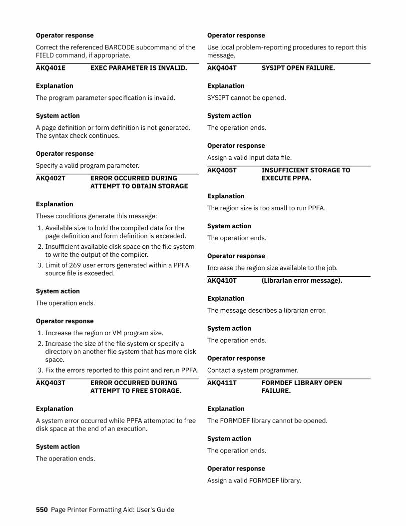
Operator response
Correct the referenced BARCODE subcommand of theFIELD command, if appropriate.
AKQ401E EXEC PARAMETER IS INVALID.
Explanation
The program parameter specification is invalid.
System action
A page definition or form definition is not generated.The syntax check continues.
Operator response
Specify a valid program parameter.
AKQ402T ERROR OCCURRED DURINGATTEMPT TO OBTAIN STORAGE
Explanation
These conditions generate this message:
1. Available size to hold the compiled data for thepage definition and form definition is exceeded.
2. Insufficient available disk space on the file systemto write the output of the compiler.
3. Limit of 269 user errors generated within a PPFAsource file is exceeded.
System action
The operation ends.
Operator response
1. Increase the region or VM program size.2. Increase the size of the file system or specify a
directory on another file system that has more diskspace.
3. Fix the errors reported to this point and rerun PPFA.
AKQ403T ERROR OCCURRED DURINGATTEMPT TO FREE STORAGE.
Explanation
A system error occurred while PPFA attempted to freedisk space at the end of an execution.
System action
The operation ends.
Operator response
Use local problem-reporting procedures to report thismessage.
AKQ404T SYSIPT OPEN FAILURE.
Explanation
SYSIPT cannot be opened.
System action
The operation ends.
Operator response
Assign a valid input data file.
AKQ405T INSUFFICIENT STORAGE TOEXECUTE PPFA.
Explanation
The region size is too small to run PPFA.
System action
The operation ends.
Operator response
Increase the region size available to the job.
AKQ410T (Librarian error message).
Explanation
The message describes a librarian error.
System action
The operation ends.
Operator response
Contact a system programmer.
AKQ411T FORMDEF LIBRARY OPENFAILURE.
Explanation
The FORMDEF library cannot be opened.
System action
The operation ends.
Operator response
Assign a valid FORMDEF library.
550 Page Printer Formatting Aid: User's Guide
AKQ412T FORMDEF LIBRARY I/O ERROR.
Explanation
An I/O error occurred during attempted access of aform definition directory.
System action
The operation ends.
Operator response
Check the permissions of the directory. If you do nothave access, contact the owner of the directory. If thisaction does not resolve the problem, contact a systemprogrammer.
AKQ413T FORMDEF DIRECTORY CANNOT BEUPDATED.
Explanation
The FORMDEF member cannot be registered on thedirectory.
System action
The operation ends.
Operator response
Contact a system programmer.
AKQ414T FORMDEF LIBRARY CLOSEFAILURE.
Explanation
A form definition directory cannot be closed.
System action
The operation ends.
Operator response
Use local problem-reporting procedures to report thismessage.
AKQ415T PAGEDEF LIBRARY OPENFAILURE.
Explanation
The PAGEDEF library cannot be opened.
System action
The operation ends.
Operator response
Assign a valid PAGEDEF library.
AKQ416T PAGEDEF LIBRARY I/O ERROR.
Explanation
I/O error occurs during attempted access of a pagedefinition directory.
System action
The operation ends.
Operator response
Check the permissions of the directory. If you do nothave access, contact the owner of the directory. If thisaction does not resolve the problem, contact a systemprogrammer.
AKQ417T PAGEDEF DIRECTORY CANNOT BEUPDATED.
Explanation
A page definition file cannot be registered on thedirectory.
System action
The operation ends.
Operator response
Contact a system programmer.
AKQ418T PAGEDEF LIBRARY CLOSEFAILURE.
Explanation
A page definition directory cannot be closed.
System action
The operation ends.
Operator response
Use local problem-reporting procedures to report thismessage.
AKQ420T SYSTEM ERROR. ABEND CODE =(ABEND code).
Explanation
System forces PPFA to end abnormally.
PPFA Messages and Codes 551
System action
The operation ends.
Operator response
Contact a system programmer. See the documentationfor your operating system.
AKQ421T FORMDEF LIBRARY IS FULL.
Explanation
The file system into which PPFA attempted to save theform definition is full.
System action
The operation ends.
Operator response
Increase the size of the file system or specify adirectory on a file system that has more disk space.
AKQ422T PAGEDEF LIBRARY IS FULL.
Explanation
The file system into which PPFA attempted to save thepage definition is full.
System action
The operation ends.
Operator response
Increase the size of the file system or specify adirectory on a file system that has more disk space.
AKQ501T SYSIN OPEN FAILURE.
Explanation
The PPFA input source file cannot be opened.
System action
The operation ends.
Operator response
Specify a valid input source file.
AKQ502T SPANNED RECORD OF SYSIN ISNOT SUPPORTED.
Explanation
The spanned record of the PPFA input source file is notsupported.
System action
The operation ends.
Operator response
Specify a valid input record format.
AKQ503T UNDEFINED LENGTH RECORD OFSYSIN IS NOT SUPPORTED.
Explanation
An undefined length record of PPFA input source file isnot supported.
System action
The operation ends.
Operator response
Specify a valid input record format.
AKQ504T LOGICAL RECORD LENGTH OFSYSIN EXCEEDS LIMIT.
Explanation
The logical record length of the PPFA input source fileexceeds the limit of 100 bytes or the z/OS variablelength of 104.
System action
The operation ends.
Operator response
Correct the logical record length of the file.
AKQ510T FORMDEF/PAGEDEF LIBRARYOPEN FAILURE.
Explanation
The FORMDEF or PAGEDEF directory cannot beopened.
System action
The operation ends.
Operator response
Specify a valid FORMDEF or PAGEDEF or check tomake sure that the directory is correct.
AKQ511T I/O ERROR OCCURRED DURING(FORMDEF/PAGEDEF) DIRECTORYSEARCH. RETURN CODE = (return
552 Page Printer Formatting Aid: User's Guide

code) REASON CODE = (reasoncode)
Explanation
I/O error occurred during the FIND function.
System action
The operation ends.
Operator response
Contact a system programmer.
AKQ512T LOGICAL RECORD LENGTH OFFORMDEF/PAGEDEF EXCEEDSLIMIT.
Explanation
The logical record length exceeds maximum orminimum value.
System action
The operation ends.
Operator response
Specify a file name that has a valid record length.
AKQ513T BLOCK SIZE OF FORMDEF/PAGEDEF EXCEEDS LIMIT.
Explanation
The block size exceeds maximum or minimum value.
System action
The operation ends.
Operator response
Assign a file name that has a valid block size.
AKQ514T UNDEFINED LENGTH RECORD ISNOT SUPPORTED IN FORMDEF/PAGEDEF LIBRARY.
Explanation
An undefined length record is not supported inFORMDEF/PAGEDEF directory.
System action
The operation ends.
Operator response
Assign a valid record format.
AKQ515T FIXED LENGTH RECORD IS NOTSUPPORTED IN FORMDEF/PAGEDEF LIBRARY.
Explanation
The fixed-length record is not supported in theFORMDEF or PAGEDEF library.
System action
The operation ends.
Operator response
Assign a valid record format.
AKQ516T NO CONTROL CHARACTERRECORD IS SUPPORTED INFORMDEF/PAGEDEF LIBRARY.
Explanation
No control character record is supported in FORMDEF/PAGEDEF directory.
System action
The operation ends.
Operator response
Assign a valid record format.
AKQ517T NO SPACE IN FORMDEF/PAGEDEFDIRECTORY.
Explanation
No space was available in the FORMDEF directory orthe PAGEDEF directory to add or replace the resource.
System action
The operation ends.
Operator response
Increase the directory space or specify a directory onanother file system that has more disk space.
AKQ518T I/O ERROR OCCURRED WHILEUPDATING FORMDEF/PAGEDEFDIRECTORY. RETURN CODE =(return code). REASON CODE =(reason code).
PPFA Messages and Codes 553

Explanation
A permanent I/O error was detected, the specifieddata control block is not opened, or insufficient diskspace exists to do the write function.
System action
The operation ends.
Operator response
Contact a system programmer.
AKQ519T I/O ERROR OCCURRED DURINGWRITE.
Explanation
The error message is displayed.
System action
The operation ends.
Operator response
Contact a system programmer.
AKQ520T SPANNED RECORD IS NOTSUPPORTED IN FORMDEF/PAGEDEF LIBRARY.
Explanation
The spanned record is not supported in the FORMDEFor PAGEDEF library.
System action
The operation ends.
Operator response
Remove the SPAN attribute and assign a valid data set.
AKQ522T BLOCK SIZE IS NOT SPECIFIEDFOR FORMDEF/PAGEDEF DATASET.
Explanation
A block size is not specified for FORMDEF/PAGEDEFdata set.
System action
The operation ends.
Operator response
Specify a BLKSIZE in the DD statement.
AKQ540T SYSTEM ABEND (code) OCCURREDIN PPFA PROCESS.
Explanation
A system ABEND (code) occurred in PPFA. The ESTAEmacro instruction ended processing.
System action
The operation ends.
Operator response
Contact a system programmer. See System Messagesfor your operating system.
AKQ541T USER ABEND (code) OCCURRED INPPFA/OS/390 PROCESS.
Explanation
A user ABEND (code) occurred in PPFA. The ESTAEmacro instruction ended processing.
System action
The operation ends.
Operator response
Use local problem-reporting procedures to report thismessage.
AKQ600T INPUT FILENAME NOT SPECIFIED.
Explanation
You did not specify an input file name.
System action
The operation ends.
Operator response
Enter the input file name.
AKQ601T INPUT FILETYPE NOT SPECIFIED.
Explanation
You did not specify an input file type.
System action
The operation ends.
Operator response
Enter the input file type.
554 Page Printer Formatting Aid: User's Guide

AKQ602T COMMAND SYNTAX IS NOT VALID.
Explanation
The command syntax that you entered was notaccepted.
System action
The operation ends.
Operator response
Enter a valid command.
AKQ603T FILEMODE FOR (FORMDEF/PAGEDEF/LISTING) IS INVALID.
Explanation
You entered an invalid file mode for FORMDEF,PAGEDEF, or LISTING.
System action
The operation ends.
Operator response
Enter a valid file extension.
AKQ604T INVALID PARAMETER ISSPECIFIED IN (FORMDEF/PAGEDEF/LISTING/SIZE) OPTION.
Explanation
You entered an invalid parameter for FORMDEF,PAGEDEF, LISTING, or SIZE.
System action
The operation ends.
Operator response
Enter a valid option parameter.
AKQ605T (FORMDEF/PAGEDEF/LISTING/SIZE) KEYWORD IS DUPLICATED.
Explanation
You entered a duplicate keyword for FORMDEF,PAGEDEF, LISTING, or SIZE.
System action
The operation ends.
Operator response
Enter a unique keyword.
AKQ606T FILETYPE FOR (FORMDEF/PAGEDEF/LISTING) NOTSPECIFIED.
Explanation
The file type for FORMDEF, PAGEDEF, or LISTING wasnot entered.
System action
The operation ends.
Operator response
Enter an appropriate file type.
AKQ607T INVALID KEYWORD SPECIFIED.
Explanation
The keyword that you entered was not accepted.
System action
The operation ends.
Operator response
Enter a valid keyword.
AKQ608T INVALID SIZE PARAMETERSPECIFIED.
Explanation
The size parameter that is specified is not valid.
System action
The operation ends.
Operator response
Enter a valid size parameter.
AKQ610T SIZE PARAMETER VALUEEXCEEDS THE ALLOWABLEMAXIMUM.
Explanation
The size that is entered exceeds the maximumallowable.
System action
The operation ends.
PPFA Messages and Codes 555
Operator response
Enter a valid size value.
AKQ611T SIZE PARAMETER VALUE IS TOOSMALL.
Explanation
The size that is entered is too small for running inPPFA/VM.
System action
The operation ends.
Operator response
Enter a valid size value.
AKQ612T INVALID FILE IDENTIFIER ‘*’SPECIFIED FOR INPUT FILE.
Explanation
‘*’ is specified for input file name or file type.
System action
The operation ends.
Operator response
Enter a valid file name or file type.
AKQ613T SIZE PARAMETER VALUE ISMISSING.
Explanation
You did not specify a size parameter
System action
The operation ends.
Operator response
Specify a valid size parameter.
AKQ620T INPUT FILE WAS NOT FOUND.
Explanation
The input file name entered was not found.
System action
The operation ends.
Operator response
Correct the input file name.
AKQ621T NO READ/WRITE (file mode) DISKACCESSED FOR (INPUT/LISTING/FORMDEF/PAGEDEF /OUTPUT).
Explanation
The disk on which the file is saved cannot be read fromor written to because it either was not accessed or wasaccessed with an invalid access mode.
System action
The operation ends.
Operator response
Access the file system by using a valid access mode.
AKQ622T INPUT FILE EXCEEDS THEALLOWABLE LOGICAL RECORDLENGTH MAXIMUM.
Explanation
The logical record length of the input file exceeds thelimit of 100 bytes or the z/OS variable record length of104.
System action
The operation ends.
Operator response
Correct the logical record length of the file.
AKQ624T I/O ERROR OCCURRED IN(AKQINIO/AKQLBIO/AKQPRIO)MODULE. RC = (return code fromFWRITE/FGETS macro instruction).
Explanation
An I/O error occurred during either FGETS or FWRITEprocessing of module AKQINIO, AKQLBIO, orAKQPRIO.
System action
The operation ends.
Operator response
Contact your system programmer.
AKQ625T DISK (file mode) IS FULL.
Explanation
Not enough space is available on the specified filesystem to write the file.
556 Page Printer Formatting Aid: User's Guide

System action
The operation ends.
Operator response
Erase some files from the specified file disk and rerun.
AKQ639T ABEND EXIT ROUTINE FAILED TOEXECUTE. RC = (return code fromABNEXIT macro)
Explanation
ABEND exit routine cannot be established.
System action
The operation ends.
Operator response
Contact your system programmer.
AKQ640T SYSTEM ABEND (code) OCCURREDIN PPFA/VM PROCESS.
Explanation
A system ABEND occurred during processing. TheABEND exit routine ended processing.
System action
The operation ends.
Operator response
Use local problem-reporting procedures to report thismessage.
AKQ641T USER ABEND (code) OCCURRED INPPFA/VM PROCESS.
Explanation
A user-initiated ABEND occurred during processing.The ABEND exit routine ended the processing.
System action
The operation ends.
Operator response
Use local problem-reporting procedures to report thismessage.
AKQ700I SIZE PARAMETER IS NO LONGERNECESSARY IN PPFA/370.
Explanation
The storage that is required to contain the messagesand control blocks is not automatically set at 32K and128K. If the control block storage is used up, anadditional 128K is obtained and chained to theprevious storage. All storage necessary to do thecompile is obtained during processing.
System action
The compile process continues.
Operator response
None.
PPFA Messages and Codes 557

558 Page Printer Formatting Aid: User's Guide
Appendix J. Accessibility
Accessible publications for this product are offered through IBM Knowledge Center (www.ibm.com/support/knowledgecenter/SSLTBW/welcome).
If you experience difficulty with the accessibility of any z/OS information, send a detailed message to theContact z/OS web page (www.ibm.com/systems/z/os/zos/webqs.html) or use the following mailingaddress.
IBM CorporationAttention: MHVRCFS Reader CommentsDepartment H6MA, Building 7072455 South RoadPoughkeepsie, NY 12601-5400United States
Accessibility features
Accessibility features help users who have physical disabilities such as restricted mobility or limited visionuse software products successfully. The accessibility features in z/OS can help users do the followingtasks:
• Run assistive technology such as screen readers and screen magnifier software.• Operate specific or equivalent features by using the keyboard.• Customize display attributes such as color, contrast, and font size.
Consult assistive technologiesAssistive technology products such as screen readers function with the user interfaces found in z/OS.Consult the product information for the specific assistive technology product that is used to access z/OSinterfaces.
Keyboard navigation of the user interfaceYou can access z/OS user interfaces with TSO/E or ISPF. The following information describes how to useTSO/E and ISPF, including the use of keyboard shortcuts and function keys (PF keys). Each guide includesthe default settings for the PF keys.
• z/OS TSO/E Primer• z/OS TSO/E User's Guide• z/OS V2R2 ISPF User's Guide Vol I
Dotted decimal syntax diagramsSyntax diagrams are provided in dotted decimal format for users who access IBM Knowledge Center witha screen reader. In dotted decimal format, each syntax element is written on a separate line. If two ormore syntax elements are always present together (or always absent together), they can appear on thesame line because they are considered a single compound syntax element.
© Copyright IBM Corp. 1985, 2016 559

Each line starts with a dotted decimal number; for example, 3 or 3.1 or 3.1.1. To hear these numberscorrectly, make sure that the screen reader is set to read out punctuation. All the syntax elements thathave the same dotted decimal number (for example, all the syntax elements that have the number 3.1)are mutually exclusive alternatives. If you hear the lines 3.1 USERID and 3.1 SYSTEMID, your syntaxcan include either USERID or SYSTEMID, but not both.
The dotted decimal numbering level denotes the level of nesting. For example, if a syntax element withdotted decimal number 3 is followed by a series of syntax elements with dotted decimal number 3.1, allthe syntax elements numbered 3.1 are subordinate to the syntax element numbered 3.
Certain words and symbols are used next to the dotted decimal numbers to add information about thesyntax elements. Occasionally, these words and symbols might occur at the beginning of the elementitself. For ease of identification, if the word or symbol is a part of the syntax element, it is preceded by thebackslash (\) character. The * symbol is placed next to a dotted decimal number to indicate that thesyntax element repeats. For example, syntax element *FILE with dotted decimal number 3 is given theformat 3 \* FILE. Format 3* FILE indicates that syntax element FILE repeats. Format 3* \* FILEindicates that syntax element * FILE repeats.
Characters such as commas, which are used to separate a string of syntax elements, are shown in thesyntax just before the items they separate. These characters can appear on the same line as each item, oron a separate line with the same dotted decimal number as the relevant items. The line can also showanother symbol to provide information about the syntax elements. For example, the lines 5.1*, 5.1LASTRUN, and 5.1 DELETE mean that if you use more than one of the LASTRUN and DELETE syntaxelements, the elements must be separated by a comma. If no separator is given, assume that you use ablank to separate each syntax element.
If a syntax element is preceded by the % symbol, it indicates a reference that is defined elsewhere. Thestring that follows the % symbol is the name of a syntax fragment rather than a literal. For example, theline 2.1 %OP1 means that you must refer to separate syntax fragment OP1.
The following symbols are used next to the dotted decimal numbers.? indicates an optional syntax element
The question mark (?) symbol indicates an optional syntax element. A dotted decimal numberfollowed by the question mark symbol (?) indicates that all the syntax elements with a correspondingdotted decimal number, and any subordinate syntax elements, are optional. If there is only one syntaxelement with a dotted decimal number, the ? symbol is displayed on the same line as the syntaxelement, (for example 5? NOTIFY). If there is more than one syntax element with a dotted decimalnumber, the ? symbol is displayed on a line by itself, followed by the syntax elements that areoptional. For example, if you hear the lines 5 ?, 5 NOTIFY, and 5 UPDATE, you know that thesyntax elements NOTIFY and UPDATE are optional. That is, you can choose one or none of them.The ? symbol is equivalent to a bypass line in a railroad diagram.
! indicates a default syntax elementThe exclamation mark (!) symbol indicates a default syntax element. A dotted decimal numberfollowed by the ! symbol and a syntax element indicate that the syntax element is the default optionfor all syntax elements that share the same dotted decimal number. Only one of the syntax elementsthat share the dotted decimal number can specify the ! symbol. For example, if you hear the lines 2?FILE, 2.1! (KEEP), and 2.1 (DELETE), you know that (KEEP) is the default option for theFILE keyword. In the example, if you include the FILE keyword, but do not specify an option, thedefault option KEEP is applied. A default option also applies to the next higher dotted decimalnumber. In this example, if the FILE keyword is omitted, the default FILE(KEEP) is used. However, ifyou hear the lines 2? FILE, 2.1, 2.1.1! (KEEP), and 2.1.1 (DELETE), the default optionKEEP applies only to the next higher dotted decimal number, 2.1 (which does not have an associatedkeyword), and does not apply to 2? FILE. Nothing is used if the keyword FILE is omitted.
* indicates an optional syntax element that is repeatableThe asterisk or glyph (*) symbol indicates a syntax element that can be repeated zero or more times. Adotted decimal number followed by the * symbol indicates that this syntax element can be used zeroor more times; that is, it is optional and can be repeated. For example, if you hear the line 5.1* dataarea, you know that you can include one data area, more than one data area, or no data area. If you
560 Page Printer Formatting Aid: User's Guide

hear the lines 3* , 3 HOST, 3 STATE, you know that you can include HOST, STATE, bothtogether, or nothing.
Notes:
1. If a dotted decimal number has an asterisk (*) next to it and there is only one item with that dotteddecimal number, you can repeat that same item more than once.
2. If a dotted decimal number has an asterisk next to it and several items have that dotted decimalnumber, you can use more than one item from the list, but you cannot use the items more thanonce each. In the previous example, you can write HOST STATE, but you cannot write HOST HOST.
3. The * symbol is equivalent to a loopback line in a railroad syntax diagram.
+ indicates a syntax element that must be includedThe plus (+) symbol indicates a syntax element that must be included at least once. A dotted decimalnumber followed by the + symbol indicates that the syntax element must be included one or moretimes. That is, it must be included at least once and can be repeated. For example, if you hear the line6.1+ data area, you must include at least one data area. If you hear the lines 2+, 2 HOST, and2 STATE, you know that you must include HOST, STATE, or both. Similar to the * symbol, the +symbol can repeat a particular item if it is the only item with that dotted decimal number. The +symbol, like the * symbol, is equivalent to a loopback line in a railroad syntax diagram.
Accessibility 561

562 Page Printer Formatting Aid: User's Guide

Notices
This information was developed for products and services offered in the U.S.A. or elsewhere.
IBM may not offer the products, services, or features discussed in this document in other countries.Consult your local IBM representative for information on the products and services currently available inyour area. Any reference to an IBM product, program, or service is not intended to state or imply that onlythat IBM product, program, or service may be used. Any functionally equivalent product, program, orservice that does not infringe any IBM intellectual property right may be used instead. However, it is theuser's responsibility to evaluate and verify the operation of any non-IBM product, program, or service.
IBM may have patents or pending patent applications covering subject matter described in this document.The furnishing of this document does not give you any license to these patents. You can send licenseinquiries, in writing, to:
IBM Director of LicensingIBM CorporationNorth Castle DriveArmonk, NY 10504-1785U.S.A
For license inquiries regarding double-byte character set (DBCS) information, contact the IBM IntellectualProperty Department in your country or send inquiries, in writing, to:
Intellectual Property LicensingLegal and Intellectual Property LawIBM Japan, Ltd.19-21, Nihonbashi-Hakozakicho, Chuo-kuTokyo 103-8510, Japan
The following paragraph does not apply to the United Kingdom or any other country where suchprovisions are inconsistent with local law: INTERNATIONAL BUSINESS MACHINES CORPORATIONPROVIDES THIS PUBLICATION "AS IS" WITHOUT WARRANTY OF ANY KIND, EITHER EXPRESS ORIMPLIED, INCLUDING, BUT NOT LIMITED TO, THE IMPLIED WARRANTIES OF NON-INFRINGEMENT,MERCHANTABILITY OR FITNESS FOR A PARTICULAR PURPOSE. Some states do not allow disclaimer ofexpress or implied warranties in certain transactions, therefore, this statement may not apply to you.
This information could include technical inaccuracies or typographical errors. Changes are periodicallymade to the information herein; these changes will be incorporated in new editions of the publication.IBM may make improvements and/or changes in the product(s) and/or the program(s) described in thispublication at any time without notice.
Any references in this information to non-IBM Web sites are provided for convenience only and do not inany manner serve as an endorsement of those Web sites. The materials at those Web sites are not part ofthe materials for this IBM product and use of those Web sites is at your own risk.
IBM may use or distribute any of the information you supply in any way it believes appropriate withoutincurring any obligation to you.
Licensees of this program who wish to have information about it for the purpose of enabling: (i) theexchange of information between independently created programs and other programs (including thisone) and (ii) the mutual use of the information which has been exchanged, should contact:
Site CounselIBM Corporation2455 South RoadPoughkeepsie, NY 12601-5400USA
© Copyright IBM Corp. 1985, 2016 563
Such information may be available, subject to appropriate terms and conditions, including in some cases,payment of a fee.
The licensed program described in this information and all licensed material available for it are providedby IBM under terms of the IBM Customer Agreement, IBM International Program License Agreement, orany equivalent agreement between us.
Information concerning non-IBM products was obtained from the suppliers of those products, theirpublished announcements or other publicly available sources. IBM has not tested those products andcannot confirm the accuracy of performance, compatibility or any other claims related to non-IBMproducts. Questions on the capabilities of non-IBM products should be addressed to the suppliers ofthose products.
All statements regarding IBM's future direction or intent are subject to change or withdrawal withoutnotice, and represent goals and objectives only.
If you are viewing this information softcopy, the photographs and color illustrations may not appear.
COPYRIGHT LICENSE:
This information might contain sample application programs in source language, which illustrateprogramming techniques on various operating platforms. You may copy, modify, and distribute thesesample programs in any form without payment to IBM, for the purposes of developing, using, marketingor distributing application programs conforming to the application programming interface for theoperating platform for which the sample programs are written. These examples have not been thoroughlytested under all conditions. IBM, therefore, cannot guarantee or imply reliability, serviceability, or functionof these programs. The sample programs are provided "AS IS", without warranty of any kind. IBM shall notbe liable for any damages arising out of your use of the sample programs.
Policy for unsupported hardwareVarious z/OS elements, such as DFSMS, HCD, JES2, JES3, and MVS™, contain code that supports specifichardware servers or devices. In some cases, this device-related element support remains in the producteven after the hardware devices pass their announced End of Service date. z/OS may continue to serviceelement code; however, it will not provide service related to unsupported hardware devices. Softwareproblems related to these devices will not be accepted for service, and current service activity will cease ifa problem is determined to be associated with out-of-support devices. In such cases, fixes will not beissued.
Minimum supported hardwareThe minimum supported hardware for z/OS releases identified in z/OS announcements can subsequentlychange when service for particular servers or devices is withdrawn. Likewise, the levels of other softwareproducts supported on a particular release of z/OS are subject to the service support lifecycle of thoseproducts. Therefore, z/OS and its product publications (for example, panels, samples, messages, andproduct documentation) can include references to hardware and software that is no longer supported.
• For information about software support lifecycle, see: IBM Lifecycle Support for z/OS (www.ibm.com/software/support/systemsz/lifecycle)
• For information about currently-supported IBM hardware, contact your IBM representative.
TrademarksIBM, the IBM logo, and ibm.com® are trademarks or registered trademarks of International BusinessMachines Corp., registered in many jurisdictions worldwide. Other product and service names might betrademarks of IBM or other companies. A current list of IBM trademarks is available at Copyright andTrademark information (www.ibm.com/legal/copytrade.shtml).
564 Page Printer Formatting Aid: User's Guide

Adobe and PostScript are either registered trademarks or trademarks of Adobe Systems Incorporated inthe United States, and/or other countries.
Windows is a trademark of Microsoft Corporation in the United States, other countries, or both.
Notices 565

566 Page Printer Formatting Aid: User's Guide

Glossary
This glossary defines technical terms and abbreviations that are used in PSF for z/OS documentation. Ifyou do not find the term that you are looking for, see IBM Glossary of Computing Terms (www.ibm.com/software/globalization/terminology).
These cross-references are used in this glossary:Contrast with.
Refers to a term that has an opposed or substantively different meaning.See.
Refers to preferred synonyms or to defined terms for acronyms and abbreviations.See also.
Refers to related terms that have similar, but not synonymous, meanings, or to contrasted terms thathave opposite or substantively different meanings.
Synonym for.Indicates that the term has the same meaning as a preferred term, which is defined in its proper placein the glossary.
Synonymous with.Indicates a backward reference from a defined term to all other terms that have the same meaning.
AACIF
See AFP conversion and indexing facility.Advanced Function Presentation
A set of licensed programs, together with user applications, that use the all-points-addressableconcept to print data on a wide variety of printers or to display data on various display devices. AFPincludes creating, formatting, archiving, retrieving, viewing, distributing, and printing information.
AFPSee Advanced Function Presentation.
AFP Conversion and Indexing Facility (ACIF)A print server utility program that converts a print file into AFP, MO:DCA-P, creates an index file forinput data, and collects resources that are used by an AFP document into a separate file.
all-points addressability (APA)The capability to address, reference, and position data elements at any addressable position in apresentation space or on a physical medium. An example of all points addressability is the positioningof text, graphics, and images at any addressable point on the physical medium. See also pictureelement.
all-points-addressable modeSynonym for page mode.
alphanumeric stringA sequence of characters that consist solely of the letters a - z and the numerals 0 - 9.
American National Standards Institute (ANSI)An organization that consists of producers, consumers, and general interest groups. ANSI establishesthe procedures by which accredited organizations create and maintain voluntary industry standards inthe United States. It is the United States constituent body of the International Organization forStandardization (ISO).
ANSISee American National Standards Institute.
APASee all-points addressability.
© Copyright IBM Corp. 1985, 2016 567
applicationThe use to which an information system is put.A collection of software components that are used to do specific types of work on a computer.
application programA program that is written for or by a user that applies to the user’s work.
ascenderThe parts of certain lowercase letters, such as b, d, or f, which at zero-degree character rotation riseabove the top edge of other lowercase letters such as a, c, and e. Contrast with descender.
aspect ratioThe ratio of the length (or height) of a bar to the length (or width) of the linear bar code symbol.
attributeA property or characteristic of one or more constructs. For example, character attribute, colorattribute, current drawing attributes, default drawing attributes, line attributes, marker attributes, andpattern attributes.
Bbar
In bar codes, the darker element of a printed bar code symbol.bar code
An array of parallel rectangular bars and spaces that together represent data elements or charactersof a particular type. The bars and spaces are arranged in a predetermined pattern that followsunambiguous rules that are defined by the symbology.
bar code command setIn the IPDS architecture, a collection of commands used to present bar code symbols in a page, pagesegment, or overlay.
bar code densityThe number of characters per inch (cpi) in a bar code symbology. In most cases, the range is 3-10 cpi.
bar code object areaThe rectangular area on a logical page in which a bar code presentation space is mapped.
Bar Code Object Content Architecture (BCOCA)An architected collection of constructs that are used to interchange and present bar code data.
bar code symbolA combination of characters that form a complete, scannable entity, including start and stopcharacters, quiet zones, data characters, and check characters that are required by a particular barcode type.
bar code symbologyA bar code language. Bar code symbologies are defined and controlled by various industry groups andstandards organizations. Bar code symbologies are described in public domain bar code specificationdocuments. Synonymous with symbology. Examples of bar code symbology include: CanadianGrocery Product Code (CGPC), European Article Numbering (EAN), Japanese Article Numbering (JAN),and Universal Product Code (UPC).
bar heightIn bar codes, the bar dimension perpendicular to the bar width. Synonymous with bar length andheight.
bar lengthIn bar codes, the bar dimension perpendicular to the bar width. Synonymous with bar height andheight.
bar widthIn bar codes, the thickness of a bar measured from the edge closest to the symbol start character tothe trailing edge of the same bar.
baselineA conceptual line in regard to which successive characters are aligned.
568 Page Printer Formatting Aid: User's Guide
baseline directionThe direction in which successive lines of text appear on a logical page.
bearer barsA bar across the top and bottom edge of a linear bar code. Partial scans of bar code symbologies, suchas Interleaved 2 of 5, can produce valid, but incorrect, reads by self-discriminating scanners. Bearerbars help prevent such errors and increase reliability.
Note: A self-discriminating scanner is one that automatically determines which bar code symbology itis reading.
BCOCASee Bar Code Object Content Architecture.
binThe standard-size paper source on cut-sheet page printers that have more than one paper source.Each printer is set up with either A4 or letter-size paper as the standard size. Contrast with cassette.
BITSA data type for architecture syntax, indicating one or more bytes to be interpreted as bit stringinformation.
bodyOn a printed page, the area between the top and bottom margins that can contain data.In a book, the portion between the front matter and the back matter.
boldfaceA heavy-faced type.Printing in heavy-faced type.
Ccarriage control character
If present, the first character of an output record (line) that is to be printed or spaced; it determineshow many lines are skipped before the line. See also control character.
cassetteA removable storage device that is the source for alternative sizes of paper on page printers that havemore than one paper source. Contrast with bin.
CDB2OF7A parameter that specifies a bar code type of Codabar, 2-of-7, Automatic Identification ManufacturersUniform Symbol Specification-Codabar.
CGPCCanadian Grocery Product Code.
CHARA data type for architecture syntax, indicating one or more bytes to be interpreted as characterinformation.
characterA member of a set of elements that are used for the organization, control, or representation of data. Acharacter can be either a graphic character or a control character. See also control character andgraphic character.In bar codes, a single group of bars and spaces that represent an individual number, letter,punctuation mark, or other symbol.
character ascenderSee ascender.
character attributeA characteristic that controls the appearance of a character or character string.
character baselineA conceptual reference line that is coincident with the X axis of the character coordinate system.
Glossary 569

character codeAn element of a code page or a cell in a code table to which a character can be assigned. The elementis associated with a binary value. The assignment of a character to an element of a code pagedetermines the binary value that is used to represent each occurrence of the character in a characterstring.
character descenderSee descender.
character identifierThe unique name for a graphic character. See also graphic character identifier.
character rotationThe alignment of a character in regard to its character baseline, which is measured in degrees in aclockwise direction. Examples are 0°, 90°, 180°, and 270°. Zero-degree character rotation existswhen a character is in its customary alignment with the baseline. Character rotation and font inlinesequence are related in that character rotation is a clockwise rotation; font inline sequence is acounterclockwise rotation. See also orientation and rotation.
character setA finite set of different graphic or control characters that is complete for a specified purpose. Forexample, the character set in ISO Standard 646, 7-bit Coded Character Set for Information ProcessingInterchange. See also control character and font character set.
character set attributeAn attribute that is used to specify a coded font.
check characterThe result of some mathematical combination of the characters in the field that is bar coded. Used asa check of the accuracy of both the input of the data field and the scanning of the bar code. A bar codecan have 0, 1, 2, or sometimes more check characters.
check digitSame as a check character, but limited to decimal digits only.
CodabarA bar code symbology that is characterized by a discrete, self-checking, numeric code with eachcharacter represented by a stand-alone group or four bars and three spaces between them.
Code128A bar code symbology that is characterized by a variable-length, alphanumeric code with 128characters.
Code39A bar code symbology that is characterized by a variable-length, bidirectional, discrete, self-checking,alphanumeric code. Three of the nine elements are wide and six are narrow. It is the standard forLOGMARS (the Department of Defense) and the AIAG.
coded fontA resource that contains elements of a code page and a font character set, and is used for presentingtext, graphics character strings, and bar code HRI. See also code page and font character set.In FOCA, a resource that contains the resource names of a valid pair of font character set and codepage resources. The graphic character set of the font character set must match the graphic characterset of the code page for the coded font resource pair to be valid.In the IPDS architecture, a raster font resource that contains code points that are directly paired tofont metrics and the raster representation of character shapes, for a specific graphic character set.In the IPDS architecture, a font resource that contains descriptive information, a code page, fontmetrics, and a digital-technology representation of character shapes for a specific graphic characterset.
coded graphic character set global identifier (CGCSGID)A four-byte binary or a ten-digit decimal identifier that consists of the concatenation of a GCSGID anda CPGID. The CGCSGID identifies the code point assignments in the code page for a specific graphiccharacter set, from among all the graphic characters that are assigned in the code page.
570 Page Printer Formatting Aid: User's Guide
code pageA resource object that contains descriptive information, graphic character identifiers, and code pointscorresponding to a coded graphic character set. Graphic characters can be added over time;therefore, to specifically identify a code page, both a GCSGID and a CPGID is used.A set of assignments, each of which assigns a code point to a character. Each code page has a uniquename or identifier. Within a specific code page, a code point is assigned to one character. More thanone character set can be assigned code points from the same code page. See also coded font.
code page global identifier (CPGID)A unique 5-digit decimal or 2-byte binary identifier that is assigned to a code page. The range ofvalues is 00001 - 65534 (X'0001' - X'FFFE').
code pointA unique bit pattern that can serve as an element of a code page or a site in a code table, to which acharacter can be assigned. The element is associated with a binary value. The assignment of acharacter to an element of a code page determines the binary value that is used to represent eachoccurrence of the character in a character string. Code points are one or more bytes long.
color attributeAn attribute that affects the color values that are provided in a graphics primitive, a text controlsequence, or an IPDS command. Examples of color attributes are foreground color and backgroundcolor.
color modelThe method by which a color is specified. For example, the RGB color space specifies color in terms ofthree intensities for red (R), green (G), and blue (B).
commandA request from a terminal or automated operator for the performance of an operation or service, or arequest in a batch-processing job or print file for the operation or execution of a particular program. InPage Printer Formatting Aid, commands are control statements for major formatting functions. Forexample, FORMDEF and COPYGROUP are commands. Commands are further specified bysubcommands and parameters.
command streamThe sequence of Page Printer Formatting Aid commands that is submitted with the job controlstatements in a Page Printer Formatting Aid execution. The commands and subcommands are thecontrol statements that define the object or objects to be generated.
compatibility modeThe use of table reference characters (TRCs) that are acceptable to line printers and page printers andthat access page definitions with little or no change to the user's data or to the job command stream.Contrast with page mode.
composed-text data fileA file that contains text data and text control information that dictates the format, placement, andappearance of the data to be printed.
conditional processingA page definition function that allows input data records to partially control their own formatting.
constructAn architected set of data such as a structured field or a triplet.
continuous codeA linear bar code in which each character starts immediately after the preceding character. No spaceor gap exists between characters. Interleaved 2 of 5 is an example of a continuous bar code.
control characterA character that denotes the start, modification, or end of a control function. A control character canbe recorded for use in a subsequent action, and it can have a graphic representation. See alsocharacter.A control function the coded representation of which consists of a single code point.
Glossary 571

copy groupA subset of a form definition that contains a set of controls for the physical pages of a printout. Suchfunctions as the selection of either of two paper sources on the page printer, the use of duplexprinting, or the positioning of the reference point for all printing on the sheet are available in the copygroup.
cmCentimeters.
CMSConversational Monitor System.
cpiCharacters per inch.
cut-sheet mediaUnconnected sheets.
Ddata map
An internal object whose structured fields control the formatting of data on a logical page of aprintout. Created by a PAGEDEF command or a PAGEFORMAT command.
data streamA continuous stream of data that is a defined format. An example of a defined format is a structuredfield.
DBCSDouble-byte character set.
defaultPertaining to an attribute, value, or option that is assumed when none is explicitly specified and one isneeded to continue processing.
densityA measure of the number of characters per inch or per millimeter represented by the bar code. A high-density bar code represents more characters per inch than a low-density bar code.
The bar code symbology helps determine the density. Within a specific symbology, factors that affectthe density of a bar code are: the x-dimension (width of the narrow bar) and the wide-to-narrow ratio(width of a wide bar relative to the narrow bar).
descenderIn a font, the distance from the baseline to the bottom of the character box. This value might differ fordifferent characters in a specific font. Contrast with ascender.
directionThe print position of data in a logical page, line, or field. In Page Printer Formatting Aid, the ultimatereference point for all direction controls on a page is the hardware origin. Secondary and tertiaryreference points are possible as well, allowing more than one print direction on a page.
discrete codeA linear bar code that is constructed with groups of bars and spaces that represent individualcharacters and having a space or intercharacter gap between each group. This gap is used solely toseparate characters and contains no data. Code 3 of 9 is a discrete bar code.
documentA machine-readable collection of one or more objects that represents a composition, a work, or acollection of data.A publication or other written material.
double-byte character set (DBCS)A character set, such as a set of Japanese ideographs, requiring 2 bytes to identify each character.
duplex printingPrinting on both sides of a sheet.
572 Page Printer Formatting Aid: User's Guide

y-coordinateThe vertical or baseline position that defines a page origin or the starting point of a line or field.
EEAN
See European Article Numbering.EAN2SUP
A parameter that specifies a bar code type of European Article Numbering, Two-digit Supplemental.EAN5SUB
A parameter that specifies a bar code type of European Article Numbering, Five-digit Supplemental.EAN8
A parameter that specifies a bar code type of European Article Numbering 8 (includes JapaneseArticle Numbering-short).
EAN13A parameter that specifies a bar code type of European Article Numbering 13 (includes JapaneseArticle Numbering-standard).
EBCDICSee Extended Binary Coded Decimal Interchange Code.
electronic overlayIn IBM Print Server Facility, a collection of constant data that is electronically composed in the hostprocessor and can be merged with variable data on a sheet during printing. Contrast with pagesegment. See also overlay and preprinted form.
European Article Numbering (EAN)The bar code symbology that is used to code grocery items in Europe.
Extended Binary Coded Decimal Interchange Code (EBCDIC)A coded character set that consists of 8-bit coded characters.
external library resource (member)Objects that can be used by other licensed programs while printing jobs; for example, coded fonts,code pages, font character sets, form definitions, page definitions, and page segments. Synonym forresource object.
external objectSynonym for resource object.
FFCB
Forms control buffer.field
In a record, a specified area that is used for a particular class of data; for example, a group ofcharacter positions that are used to enter or display wage rates on a screen.In Page Printer Formatting Aid, any area of a record singled out for particular formatting treatment.
field processingMapping individual fields to a page of output with special formatting controls.
fileA named set of records that are stored or processed as a unit.
first read rateThe percentage of the bar code scans that read correctly on the first scan of the bar code. A 99% orhigher first read is desirable. Anything below 85% is normally not acceptable.
fixed medium informationInformation that can be applied to a sheet by a printer or printer-attached device that is independentof data that is provided through the data stream. Fixed medium information does not mix with thedata that is provided by the data stream and is presented on a sheet either before or after the text,
Glossary 573
image, graphics, or bar code data provided within the data stream. Fixed medium information can beused to create preprinted forms, or other types of printing, such as colored logos or letterheads, thatcannot be created conveniently within the data stream.
FOCASee Font Object Content Architecture.
fontA family or assortment of characters of a specific size and style; for example, 9-point Bodoni Modern.
font character setA FOCA resource that contains descriptive information, font metrics, and the digital representation ofcharacter shapes for a specified graphic character set.
Font Object Content Architecture (FOCA)An architected collection of constructs that are used to describe fonts and to interchange those fontdescriptions.
font typeface global identifier (FGID)See global resource identifier (GRID).
formA physical piece of paper or other medium on which output data is printed. For cut-sheet printers, aform is one sheet of paper or other medium. For continuous-forms printers, the form is the area ofpaper (or other medium) defined to the printer as a single physical page, which for fan-fold paper isnormally the area between perforations. See also medium, page, and sheet.
formatThe arrangement or layout of data on a physical medium or in a presentation space.
formatted dataIn FD:OCA, data whose implied syntax and semantics are represented by architected controls thataccompany the data.
formatted data object (FDO)An object that contains formatted data. See also object.
Formatted Data Object Content Architecture (FD:OCA)An architected collection of constructs that are used to interchange formatted data.
formatterA process that is used to prepare a document for presentation.
formdefSee form definition.
form definitionIn IBM Print Server Facility, a resource object that defines the characteristics of the form, whichinclude: overlays to be used, text suppression, position of page data on the form, and modificationsand number of copies of a page.
forms control buffer (FCB)A line printer control. In the 3800 Printing Subsystem, a buffer for controlling the vertical format ofprinted output.
forms flashIn the 3800 Printing Subsystem, the function of the printer that allows user-prepared images to beprinted with variable page data. An operator must insert the image holder when forms overlay printingis wanted.The photographic negative of a predefined design to be exposed to the photoconductor by a flash oflight. The forms overlay can be merged with variable data during printing. See also electronic overlay.
GGCGID
See graphic character global identifier.
574 Page Printer Formatting Aid: User's Guide

GCSGIDSee graphic character set global identifier.
GIDSee global identifier.
global identifier (GID)Any of these identifiers:
• Coded character set identifier (CCSID).• Coded graphic character set global identifier (CGCSGID)• Code page global identifier (CPGID)• Font typeface global identifier (FGID)• Global resource identifier (GRID)• Graphic character global identifier (GCGID)• Graphic character set global identifier (GCSGID)• Object identifier (OID)• In MO:DCA, an encoded graphic character string that provides a reference name for a document
element.
global resource identifier (GRID)An 8-byte identifier that identifies a coded font resource. A GRID contains the following fields in theorder shown:
1. GCSGID of a minimum set of graphic characters that are required for presentation. It can be acharacter set that is associated with the code page, or with the font character set, or with both.
2. CPGID of the associated code page3. FGID of the associated font character set4. Font width in 1440ths of an inch.
GOCASee Graphics Object Content Architecture.
graphic characterA member of a set of symbols that represent data. Graphic characters can be letters, digits,punctuation marks, or other symbols. Synonymous with glyph. See also character.
graphic character global identifier (GCGID)An alphanumeric character string that is used to identify a specific graphic character. A GCGID can be4 - 8 bytes long.
graphic character identifierThe unique name for a graphic character in a font or in a graphic character set. See also characteridentifier.
graphic character set global identifier (GCSGID)A unique graphic character set identifier that can be expressed as either a 2-byte binary or a five-digitdecimal value.
graphics command setIn the IPDS architecture, a collection of commands that are used to present GOCA data in a page,page segment, or overlay.
graphics objectAn object that contains graphics data. See also object.
graphics object areaA rectangular area on a logical page into which a graphics presentation space window is mapped.
Graphics Object Content Architecture (GOCA)An architected collection of constructs that are used to interchange and present graphics data.
Glossary 575

GRIDSee global resource identifier.
guard barsThe bars at both ends and the center of an EAN, JAN, or UPC symbol, that provide reference points forscanning.
Hheight
In Page Printer Formatting Aid, refers to the vertical dimension of a logical page and is controlled bythe HEIGHT subcommand.In bar codes, the bar dimension perpendicular to the bar width. Synonymous with bar height and barlength.
hexadecimalA number system with a base of sixteen. The decimal digits 0 - 9 and characters A through F are usedto represent hexadecimal digits. The hexadecimal digits A- F correspond to the decimal numbers 10 -15. An example of a hexadecimal number is X'1B', which is equal to the decimal number 27.
highlightingThe emphasis of displayed or printed information. Examples are increased intensity of selectedcharacters on a display screen and exception highlighting on an IPDS printer.
hostIn the IPDS architecture, a computer that drives a printer.In IOCA, the host is the controlling environment.
HRISee human-readable interpretation.
human-readable interpretation (HRI)The printed translation of bar code characters into equivalent Latin alphabetic characters, Arabicnumeral decimal digits, and common special characters that are typically used for printed humancommunication.
Iimage
An electronic representation of a picture that is produced by using sensing light, sound, electronradiation, or other emanations that come from the picture or reflected by the picture. An image canalso be generated directly by software without reference to an existing picture.
image contentImage data and its associated image data parameters.
Image Object Content Architecture (IOCA)An architected collection of constructs used to interchange and present images.
inInches.
IND2OF5A parameter that specifies a bar code type of Industrial 2-of-5.
inlineIn printing, the direction of successive characters in a line of text. Synonymous with inline direction.
inline directionSynonym for inline.
Intelligent Printer Data Stream (IPDS)An architected host-to-printer data stream that contains both data and controls that define how thedata is to be presented.
intercharacter gapThe space between characters in a discrete bar code symbology.
576 Page Printer Formatting Aid: User's Guide

International Organization for Standardization (ISO)An organization of national standards bodies from various countries that are established to promotedevelopment of standards to facilitate international exchange of goods and services, and developcooperation in intellectual, scientific, technological, and economic activity.
Invoke Data MapA control record that is placed in the user's data to begin a new page format.
Invoke Medium MapA control record that is placed in the user's data to begin a new copy group.
IOCASee Image Object Content Architecture.
IPDSSee Intelligent Printer Data Stream.
ISOSee International Organization for Standardization.
italicsA typeface with characters that slant upward to the right. In FOCA, italics is the common name for thedefined inclined typeface posture attribute or parameter.
ITL2OF5A parameter that specifies a bar code type of Interleaved 2-of-5, Automatic IdentificationManufacturers Uniform Symbol Specification-I 2/5.
JJAN
See Japanese Article Numbering.Japanese Article Numbering (JAN)
The bar code symbology that is used to code grocery items in Japan.jog
Offset stacking of individual sheets or sets of sheets in the output hopper of a page printer or copymark in a continuous forms printer.
Kkanji
A graphic character set consisting of symbols that are used in Japanese ideographic alphabets. Eachcharacter is represented by 2 bytes.
keywordA two-part self-defining parameter that consists of a 1-byte identifier and a 1-byte value.
Lladder orientation
Linear bar code orientation where the bars are parallel to the base of the document (like the rungs of aladder). Sometimes called vertical orientation (because that is the direction of the scan).
landscape presentationThe position of a printed sheet that has its long edges at the top and bottom and its short edges at thesides. Contrast with portrait presentation.
languageA set of symbols, conventions, and rules that is used for conveying information.
leadingA printer's term for the distance between lines of type that is measured in points. It refers to the leadslug placed between lines of type in traditional typesetting.
librarySystem storage for generated form definitions and page definitions.
Glossary 577
library resource (member)A named collection of records or statements in a library.
library resource nameA name by which an object can be called from a library by IBM Print Server Facility as part of a printjob. Includes the two-character prefix for the type of object, such as P1 for page definitions, F1 forform definitions, or O1 for overlays (also known as resource name).
line attributesThose attributes that pertain to straight and curved lines. Examples of line attributes are line type andline width.
line data filesFiles that are formatted for printing on line printers.
line printerA device that prints a line of characters as a unit. Synonymous with line-at-a-time printer. Contrastwith page printer.
line typeA line attribute that controls the appearance of a line. Examples of line types are dashed, dotted, andsolid. Contrast with line width.
line widthA line attribute that controls the appearance of a line. Examples of line width are light, medium, andbold. Contract with line type.
lines per inch (lpi)On a printer, a measurement of the number of lines per vertical inch of paper.A unit of measure for specifying the baseline increment.
local nameA name for a suppression, an overlay, or a font that is used only within the Page Printer Formatting Aidcommand stream. Contrast with user-access name.
locationA site within a data stream. A location is specified in terms of an offset in the number of structuredfields from the beginning of a data stream, or in the number of bytes from another location within thedata stream.
logical pageThe area on a surface of a form that is formatted for printing.A collection of data that can be printed on one side of a sheet of paper. See also form and page.
logical page originThe user-defined point that acts as a reference for all positioning of printed material on the page.The point nearest the hardware origin where printing can occur.
logical unit (L-unit)A unit of linear measurement that is expressed with a unit base and units per unit-base value. Forexample, in Page Printer Formatting Aid, 1 logical unit = 1/240 inch (unit base = 10 inches, units perunit base = 2400).
lpiLines per inch.
lowercasePertaining to small letters as distinguished from capital letters. Examples of small letters are a, b, andg. Contrast with uppercase.
L-unitA unit of linear measurement that is expressed with a unit base and units per unit-base value. In otherwords, the number of units in a linear inch. Synonymous with logical unit.
578 Page Printer Formatting Aid: User's Guide

MMAT2OF5
A parameter that specifies a bar code type of Matrix 2-of-5.media origin
The first hardware addressable point on the physical page. The point from which the logical pageorigin is positioned by the medium map.
mediumThe physical material (for example, paper) on which data is printed. See also form.
medium mapAn internal object whose structured fields control the physical sheets of a printout, including thechoice of duplex printing, the beginning print position, and the paper source to use. Controlled by aCOPYGROUP command in a Page Printer Formatting Aid command stream.
medium overlaySynonym for overlay.
mixed data filesFiles consisting of composed and uncomposed portions.
mmMillimeters.
MODA parameter that specifies more processing information about the bar code symbol to be generated.See Bar Code Object Content Architecture Reference for more information.
Mixed Object Document Content Architecture (MO:DCA)An architected, device-independent data stream for interchanging documents.Print data that is composed into pages. Text formatting programs can produce composed text datathat consists entirely of structured fields.
MO:DCASee Mixed Object Document Content Architecture.
MO:DCA-PMixed Object Document Content Architecture for Presentation.
moduleIn a bar code symbology, the nominal width of the smallest element of a bar or space. Actual bar codesymbology bars and spaces can be a single module wide or some multiple of the module width. Themultiple need not be an integer.
MODWIDTHA parameter that specifies the width of the smallest defined bar code element by using mils(thousandths of an inch).
MSIA parameter that specifies a bar code type of modified Plessey code.
multiple upThe printing of more than one page on a single side of a sheet of paper.
Nname
A table heading for architecture syntax. The entries under this heading are short names that give ageneral indication of the contents of the construct.
noncompatibility modeThe use of table reference character (TRC) numbers not compatible with a line printer.
normal duplex printingDuplex printing for sheets that are to be bound on the long edge of the paper, regardless of whetherthe printing is portrait or landscape. Contrast with tumble duplex printing.
Glossary 579

N_UPThe printing of more than one logical page on a single side of a medium.
Oobject
A collection of data that is referred to by a single name. Form definitions and page definitions that arestored in a library are resources.
offsetA table heading for architecture syntax. The entries under this heading indicate the numericdisplacement into a construct. The offset is measured in bytes and starts with byte zero. Individualbits can be expressed as displacements within bytes.
orderIn GOCA, a graphic construct that the controlling environment builds to instruct a drawing processorabout what to draw and how to draw it.
orientationThe angular distance a presentation space or object area is rotated in a specified coordinate system,expressed in degrees and minutes. For example, the orientation of printing on a physical medium,relative to the Xm axis of the Xm,Ym coordinate system.
originA picture element (pel).
outline fontA shape technology in which the graphic character shapes are represented in digital form by a seriesof mathematical expressions that define the outer edges of the strokes. The resultant graphiccharacter shapes can be either solid or hollow.
overlayA collection of predefined data such as lines, shading, text, boxes, bar codes, or logos, that can bemerged with variable data on a page during printing. See electronic overlay.
Overlay Generation Language (OGL)A programming language that is used to produce electronic overlays.
Ppage
A collection of data that can be printed on one side of a sheet of paper or a form.The boundary for determining the limits of printing. See also logical page and physical page.
page definitionA resource that contains a set of Page Printer Formatting Aid formatting controls for printing pages ofdata. Includes controls for number of lines per printed sheet, font selection, print direction, andmapping of individual fields in the data to positions on the printed sheets.
page ejectionThe point at which the printer finishes printing on one sheet and moves to the beginning of the nextsheet.
page formatA subset of a page definition, containing all the same controls for formatting printed output as a pagedefinition. Includes controls for number of lines per printed sheet, font selection, print direction, andmapping of individual fields in the data to positions on the printed sheets.
page modeThe mode of operation in which an AFP printer can accept a page of data from a host processor to beprinted on an all-points-addressable output medium. Printed data can consist of pages that arecomposed of text, images, overlays, and page segments. Contrast with compatibility mode.
page printerA device that prints a page at a time. Contrast with line printer.
580 Page Printer Formatting Aid: User's Guide
Page Printer Formatting Aid (PPFA)An IBM licensed program that creates and stores form definitions and page definitions, which areresource objects for print-job management. By writing a command stream that specifies formdefinitions, page definitions, or both, for running Page Printer Formatting Aid, you can store theobjects that are specified in the library. These objects can then be used to format printed output.
page segmentAn object that can contain text and images and be included at any addressable point on a page orelectronic overlay. It assumes the environment of an object it is included in.A library resource that contains the definition of a page segment. Contrast with electronic overlay.
parameterA variable that is given a constant value for a specified application and that can denote theapplication.In Page Printer Formatting Aid, the values specified for a subcommand.
partitionDividing the medium presentation space into a specified number of equal-sized areas in a manner thatis determined by the current physical media.In FD:OCA, a conceptual subdivision of a string of data fields. A partition can be further divided intosubpartitions.
pelPicture element. The smallest printable or displayable unit on a physical medium. In computergraphics, the smallest element of a physical medium that can be independently assigned color andintensity. Synonymous with picture element and pixel.
PELSIn Page Printer Formatting Aid, a unit of measure under the SETUNITS command. See also logical unit.
physical pageA single surface (front or back) of a sheet. See also form and page.
picket fence orientationLinear bar code orientation where the bars are perpendicular to the base of the document (like thepickets in a picket fence). Sometimes called horizontal orientation (because that is the direction of thescan).
picture elementIn computer graphics, the smallest element of a display space that can be independently assignedcolor and intensity.The smallest area that can be individually toned by the printer.
pixelThe smallest printable or displayable unit on a physical medium. Synonymous with pel and pictureelement.
PMFPrint Management Facility.
pointIn printing, a unit of about 1/72 of an inch used in measuring typographical material; for example, 10-point Helvetica. 12 points equal a pica.
portrait presentationThe position of a printed sheet that has its short edges at the top and bottom and its long edges at thesides. Contrast with landscape presentation.
positionThe location specified for a line or field on the output page.
POSTNETA parameter that specifies a bar code type of POSTal Numeric Encoding Technique (United StatesPostal Service), and defines specific values for the BSD module width, element height, heightmultiplier, and wide-to-narrow ratio fields.
Glossary 581

PPFAPage Printer Formatting Aid.
preprinted formA sheet of paper that contains a preprinted design of constant data. Variable data can be merged withthe constant data on such a form. See also electronic overlay and forms flash.
print lineA single line of text. In the formatting of line data, it refers to the output generated by one data record.Governed by the PRINTLINE command.
Print Management Facility (PMF)A program that can create fonts, segments, page definitions, and form definitions.
Print Server Facility (PSF)A program that produces printer commands from the data sent to it.
printer–attached deviceEither a preprocessor or postprocessor that is attached to the printer.
PSFPrint Server Facility.
Qquiet zone
A blank area before and following a bar code. This required space enables the scanner to differentiatethe start and stop of a bar code. The size of the quiet zone is usually 10 times the x-dimension or 1/4inch, whichever is larger.
Rrange
A table heading for architecture syntax. The entries under this heading give numeric ranges applicableto a construct. The ranges can be expressed in binary, decimal, or hexadecimal. The range can consistof a single value.
rasterIn computer graphics, a predetermined pattern of lines that provides uniform coverage of a displayspace.In AFP printers, an on-or-off pattern of electrostatic images produced by the laser print head.
RASTER / NORASTER subcommandA subcommand that specifies whether an overlay is to be kept in the printer (3800 only) as rasterdata.
RATIOA parameter that specifies the ratio of the wide-element dimension to the narrow-element dimensionwhenever two different size elements exist.
ratioThe relationship in quantity, amount, or size between two or more things.
recordIn programming languages, an aggregate that consists of data objects, possibly with differentattributes, with identifiers typically attached to them. In some programming languages, records arecalled structures.A set of data that is treated as a unit.A set of one or more related data items that are grouped for processing.
RM4SCCA parameter that specifies a 4-state customer code that is defined by the Royal Mail Postal Service ofEngland for bar coding postal code information. See Royal Mail 4 State Customer Code.
582 Page Printer Formatting Aid: User's Guide

resourceA collection of printing instructions, and sometimes data to be printed, that consists entirely ofstructured fields. A resource object is stored as a member of a library and can be called for by IBMPrint Server Facility when needed. The different resource objects are page segments, overlays, formdefinitions, and page definitions.
resource objectIn AFP, a collection of printing instructions, and sometimes data to be printed, that consists entirely ofstructured fields. A resource object is stored as a member (or file) of a library and can be called for byPSF when needed. The different resource objects include coded font, font character set, code page,page segment, overlay, form definition, and page definition.
RNORMALRotated normal. A Page Printer Formatting Aid parameter that specifies the type of duplex printing.The tops of both sides of a duplex-printed sheet are toward the same physical edge of the sheet, forside binding of the document. Used with landscape-presentation pages.
rotationThe orientation of the characters of a font in regard to the baseline.
Royal Mail 4 State Customer Code (RM4SCC)A two-dimensional bar code symbology that is developed by the United Kingdom's Royal Mail postalservice for use in automated mail-sorting processes.
RTUMBLERotated tumble. A Page Printer Formatting Aid parameter that specifies a type of duplex printing. Itmeans the top of one side of a duplex-printed sheet and the bottom of the other are toward onephysical edge of the sheet, for top binding of the document. Used with landscape-presentation pages.
ruleA solid line of any line width.
x-dimensionThe width (usually in thousandths of an inch) of the narrow bar or space of the bar code symbology.
SSBCS
Single-byte character set.scanner
In bar codes, an electronic device that converts optical information into electrical signals. Sometimescalled a reader or decoder.
segmentA collection of composed text and images, which are prepared before formatting and included in adocument when it is printed. See page segment.The resource that contains the structured-field definition of a page segment.
sheetA single piece of paper. For cut-sheet printers, a synonym for form.
shift-in and shift-out characters (SOSI)Characters that are used to delimit literals in Page Printer Formatting Aid command streams: X'0E'and X'0F'.
simplex printingA method that is used to print data on one side of a sheet; the other side is left blank. Contrast withduplex printing.
single-byte character setA character set whose codes require a single byte of data. The character set used for English is anexample.
skip-to-channel controlA line printer control that appears in line data. Allows space to be left between print lines. Compatiblewith page printers when the data is formatted by page definitions.
Glossary 583

spaceIn bar codes, the lighter element of a printed bar code symbol, which is typically formed by thebackground between bars.
space widthIn bar codes, the thickness of a bar code symbol space measured from the edge closest to the symbolstart character to the trailing edge of the same space.
SSASTERISKA parameter that specifies whether an asterisk is to be generated as the HRI for CODE39 bar codestart and stop characters.
start-stop character or patternIn bar codes, a special bar code character that provides the scanner with start and stop readinginstructions and a scanning direction indicator. The start character is normally at the left end and thestop character at the right end of a horizontally oriented bar code symbol.
structured fieldA self-identifying string of bytes and its data or parameters.
subcommandIn Page Printer Formatting Aid, the next level of control under commands.A request for an operation that is within the scope of work that is requested by a previously issuedcommand.
subgroupA subset of a form definition that is used to reprint the same page of data more than once. Subgroupsprovide for variations in the same page of data within one print job. Modifications that distinguish onesubgroup from another are number of copies, type of duplex printing, inclusion of overlays, inclusionof suppressions, and (only for the 3800 printer) forms flash. A set of modifications within a copy groupthat applies to a certain number of copies of a form. A copy group can contain more than onesubgroup.
subpageA part of a logical page on which line data can be placed. In the page definition, multiple subpages canbe placed on a physical page based on changes in the print data.
suppressionThe electronic equivalent of a spot carbon, preventing selected data from being printed on certaincopies.
symbologyA bar code language. Bar code symbologies are defined and controlled by various industry groups andstandards organizations. Bar code symbologies are described in public domain bar code specificationdocuments. Synonymous with bar code symbology. See also European Article Numbering (EAN),Japanese Article Numbering (JAN), and Universal Product Code (UPC).
syntaxThe rules that govern the structure of a construct.
Ttable reference character (TRC)
Usually, the second byte on a line in the user’s data. This byte contains a value (0 - 126) that is used toselect a font to be used to print that line.
tateThe Japanese word for top-to-bottom, as applied to the formatting of writing and printing. Thetraditional arrangement of Japanese kanji characters on the page. Pronounced "ta-tay".
textA graphic representation of information on an output medium. Text can consist of alphanumericcharacters and symbols that are arranged in paragraphs, tables, columns, and other shapes.
TRCTable reference character.
584 Page Printer Formatting Aid: User's Guide

truncationPlanned or unplanned end of a presentation space or data presentation.
tumble duplex printingDuplex printing for sheets that are to be bound on the top, as is often done for legal documents. Thetop of one side of each sheet is at the same edge as the bottom of the other side. Contrast with normalduplex printing.
tripletA three-part self-defining variable-length parameter that consists of a length byte, an identifier byte,and one or more parameter-value bytes.
typeA table heading for architecture syntax. The entries under this heading indicate the types of datapresent in a construct. Examples include: BITS, CHARCODE, SBIN, UBIN, UNDF.
TYPEA parameter that specifies the kind of bar code symbol to be generated. For example, CODE39, MSI,UPCA, and UPCE.
type fontSee font.
type weightA parameter that indicates the degree of boldness of a typeface. A character's stroke thicknessdetermines its type weight. Examples are light, medium, and bold.
type widthA parameter that indicates a relative change from the font's normal width-to-height ratio. Examplesare normal, condensed, and expanded.
Uunformatted print data
Data that is not formatted for printing. A page definition can contain controls that map unformattedprint data to its output format.
Uniform Symbol Specification (USS)A series of bar code symbology specifications that are published by AIM. The specifications that arecurrently included are USS-Interleaved 2 of 5, USS-39, USS-93, USS-Codabar, and USS-128.
Universal Character Set (USC)A printer feature that permits the use of various character arrays. Synonymous with font.
Universal Product Code (UPC)A standard bar code symbology, commonly used to mark the price of items in stores, that can be readand interpreted by a computer.
unprintable areaThe area of a sheet of paper on which no printing can be done because of printer and hardwarelimitations.
UPCSee Universal Product Code.
UPCAA parameter that specifies a bar code type of Universal Product Code (United States) and theCanadian Grocery Product Code, Version A.
UPCEA parameter that specifies a bar code type of Universal Product Code (United States) and theCanadian Grocery Product Code, Version E.
UPC2SUPPA parameter that specifies a bar code type of Universal Product Code (United States) two-digitSupplemental (periodicals).
Glossary 585
UPC5SUPPA parameter that specifies a bar code type of Universal Product Code (United States) five-digitSupplemental (paperbacks).
uppercasePertaining to capital letters. Examples of capital letters are A, B, and C. Contrast with lowercase.
user-access nameThe library resource name of a font or an overlay, less its two-character prefix. Contrast with localname.
USSSee Uniform Symbol Specification.
Wwide-to-narrow ratio
The ratio of the width of the wide bar or space to the narrow bar (x-dimension) or space in a two-widthsymbology. This ratio is usually in the range of 2:1 to 3:1.
widthIn Page Printer Formatting Aid, refers to the horizontal dimension of a logical page, is specified in thepage definition, and is controlled by the WIDTH subcommand.
Xx-coordinate
The horizontal or inline position that defines a page origin or the starting point of a line or field.x-dimension
The width (usually in thousandths of an inch) of the narrow bar or space of the bar code symbology.
586 Page Printer Formatting Aid: User's Guide

Index
Numerics2DMATRIX 470, 4792DMAXI 471, 4792DPDF417 472, 4793900 Printing Subsystem
restrictions on printing area of sheet 19
Aabsolute inline positioning
in XML page definition 80with XLAYOUT command 424
access a new copy group 18accessibility
contact IBM 559features 559
AFP print systemscolor management 151
AFP Resource installerinstalling data objects 158
AFP Resource Installercopying and pasting a name 162installing CMRs 151storing CMRs 151
alphabetic characters 184alphanumeric characters
maximum number allowed 184APOSTAL 473, 479Appendix A
System Dependencies for PPFA 439arrangement of N_UP partitions 129assistive technologies 559asymmetrical page placement 146audit processing mode, CMR 154Australia Post Bar Code 450, 452Australia Postal Bar Code 457
BBACK subcommand
duplexing pages 23rules 24
bar code dataBCOCA characters 449BCOCA code points 449characters 449code 128 code page
CPGID 449code pages 449type styles 449
bar codesBar Code Object Content Architecture (BCOCA) 449
BARCODE subcommandsupplemental information 449
baseline directiondescription 8
basic N_UP printingcompared to enhanced N_UP 129description 136examples
normal duplex 139tumble duplex 140using INVOKE and OVERLAY 138
list of printers 129subcommands and parameters enabled 136
best practicescolor resources 159images 159
blank characters 184blank lines in command streams 184blank truncation, conditional processing 118body records
LAYOUT Command 54page definition 54record format 54
BOTH subcommandduplexing pages 23
BOTMARGIN subcommandPAGEDEF (record format) Command 56PAGEFORMAT (record format) Command 56
bounded-box fontsdescription 9
boxescreate with LAYOUT Command 57
Ccarriage control characters 6, 11carriage control characters (CC)
relationship with START subcommand 116change copy group
with conditional processing 107change overlays when ejecting new partition 137change page format
with conditional processing 107character rotation 9Character Set
four types 184character sets
description 184types 184
charactersalphabetic 184blank 184number allowed 184numeric 184shift-out/shift-in codes 184special 184
choose copy groupwith conditional processing 107
choose page formatwith conditional processing 107
circles
587

circles (continued)create with LAYOUT Command 57
CMR (Form Definition)syntax diagram 163
CMR subcommand (COPYGROUP)Code Example 166syntax diagram 166
CMR subcommand (Form Definition)Code Example 163
CMR subcommand (PAGEFORMAT)syntax diagram 168
CMRsaudit processing modes 154color conversion 152creating 156generic halftone 153halftone 153installing 156instruction processing modes 155link color conversion 152link processing mode 155storing 151tone transfer curve 154
Codabar 449, 451, 457, 462Code 128 449, 451, 455, 457, 463Code 39 449, 450, 457Code 93 453, 479CODE 93 457Code Example
for CMR subcommand (COPYGROUP) 166for CMR subcommand (Form Definition) 163form definition
RENDER subcommand (COPYGROUP) 168color conversion CMR 152color management
AFP print systems 151color management resources (CMRs) 151command delimiters
description 184Command Delimiters 184command stream, examples of
defining literals 186defining logical page size 32, 59for form definitions 17for page definitions 31, 51for record formatting 51programmer comments 186units of measurement 187
commandsCONDITION 251COPYGROUP 191DEFINE COLOR 258DEFINE QTAG 259description 11DOFONT 260DRAWGRAPHIC - BOX 267DRAWGRAPHIC - CIRCLE 280DRAWGRAPHIC - ELLIPSE 287DRAWGRAPHIC - LINE 274ENDGRAPHIC 293ENDSUBPAGE 294EXTREF 294FIELD 299FONT 338
commands (continued)FORMDEF 18, 216LAYOUT 343nesting rules
form definition 18page definition 32
OBJECT 363OVERLAY 241, 378PAGEDEF 381PAGEFORMAT 392PRINTLINE 400rules 183SEGMENT 417SETUNITS 242, 418SUBGROUP 243SUPPRESSION 247syntax 183token rules 183TRCREF 420XLAYOUT 422
comments in command streamsdelimiters 185location 185
complex printoutscreating 99example 99field processing 99overlay, electronic 99
CONDITION commandsubcommands 252syntax diagram 251using with enhanced N_UP 147
CONDITION Commandblank truncation, consideration 118interaction with CHANNEL subcommand 114interaction with REPEAT subcommand 114selecting copy groups and page formats 117variable-length records, consideration 118
condition processingchange copy group 107change page format 107choose copy group 107choose page format 107
conditional processingblank truncation 118considerations 113copy group, selection 108, 117description 107duplex output example 119examples 119in PRINTLINE Command 109offset stacking (jog) example 119page format, selection 109, 117paper (bin) selection example 121record reprocessing 111record reprocessing example 120repeated printlines examples 123restrictions 113rules 113setting the environment 108subpage, description 110using multiple conditions, examples 121variable-length records 118versus normal line data processing 107
588
conditional processing (continued)WHEN CHANGE always false 116
conditional processing considerationsLAYOUT (record format) Command 57PAGEDEF (record format) Command 57
constant formsdescription 22example 22
constant overlaysplacement 141
CONSTANT subcommandenhanced N_UP printing example 143example 22
contactz/OS 559
continuous formsexample 27narrow 28rules 28specifying page presentation 27wide 28
continuous forms printersspecifying page presentation for 28
control informationprint data 8
control page ejects 56control record
Invoke Data Map (IDM) structured fieldin PAGEFORMAT command 393
controlling page formattingLAYOUT (record format) Command 56
COPIES subcommandexample 21using with enhanced N_UP 146
copy groupaccessing 18description 17purpose 17selection, conditional processing 108, 117starting or restarting 117
COPYGROUP commandsubcommands 193syntax diagram 191
COPYGROUP Commandspecifying overlays 20specifying the N_UP subcommand
basic N_UP printing 136copying and pasting a name
AFP Resource Installer 162create
boxesLAYOUT Command 57
circlesLAYOUT Command 57
ellipsesLAYOUT Command 57
linesLAYOUT Command 57
creating CMRs 156
Ddata
positioning 59
data (continued)positioning first line 33
data file typesline 6mixed 7MO:DCA-P 7
data lengths 449data map
description 13invoke 13PAGEFORMAT command 393
Data Matrix 452Data Matrix (2D barcode) 450Data Object fonts
examplesDOFONT command 265
supportDOFONT command 260
data objectsdescription 156
Data Record Types 54DataMatrix two-dimensional Bar Code 457default x-pos
body records 54default y-pos
body records 54DEFINE COLOR command
subcommands 258syntax diagram 258
DEFINE QTAG Commandsyntax diagram 259
defining color modelsLAYOUT (record format) Command 58PAGEDEF (record format) Command 58
delimitersdescription 184
diagramshorthand 251
diagram shorthand 187, 251differences in measurements and REPEATs 447dimensions of logical page 32direction
baseline, description 8change print direction of logical page 35, 59inline, description 8of fonts 46, 68relationship to duplex 27specifying
for fields 45, 65for lines 44, 64in a page definition 35, 59
DIRECTION subcommandchanging logical page print direction 35, 59description 28example 35, 44, 59, 65LAYOUT Command 54using with enhanced N_UP 147when to use 28
DOFONT commandnon-PPFA requirements 261PPFA requirements 261subcommands 263syntax diagram 260
double-byte font 309
589
DRAWGRAPHIC - BOX commandsubcommands 268syntax diagram 267
DRAWGRAPHIC - CIRCLE commandsubcommands 281syntax diagram 280
DRAWGRAPHIC - ELLIPSE commandsubcommands 288syntax diagram 287
DRAWGRAPHIC - LINE commandsubcommands 275syntax diagram 274
duplex 17duplex printing
conditional processing example 119description 13example of basic N_UP printing 139in landscape presentation 25in portrait presentation 25normal duplex 13possible combinations 27rotated normal duplex 13rotated tumble duplex 13specifying in form definition 23tumble duplex 13using BACK subcommand 23using BOTH subcommand 23using FRONT subcommand 23
DUPLEX subcommandexample 23, 25NORMAL parameter 26RNORMAL parameter 26RTUMBLE parameter 26TUMBLE parameter 26
DUTCH KIX 479Dutch KIX bar code 451
EEAN 449, 451, 461, 465EAN 13 (includes JAN-standard) 457EAN 8 (includes JAN-short) 457EAN Five-digit Supplemental 457EAN Two-digit Supplemental 457EBCDIC data
blank characters 184shift-out/shift-in codes 184
ellipsescreate with LAYOUT Command 57
Encapsulated PostScript (EPS)image data object 157
ENDGRAPHIC commandsubcommands 293syntax diagram 293
ENDSUBPAGE commandsyntax diagram 294
enhanced N_UP printingcompared to basic N_UP 129examples
asymmetric pages 145using CONSTANT and OVERLAY 143using PLACE 142
list of printers 129subcommands and parameters enabled 140
error messages 531examples for Data Object fonts
DOFONT command 265examples for OpenType fonts
DOFONT command 265examples for TrueType fonts
DOFONT command 265EXTREF command
subcommands 295syntax diagram 294
Ffield
direction of 45, 65Field (record format) Command
LAYOUT Command 55FIELD command
bar code, supplemental information 449subcommands 304SUPPRESSION subcommand
name 310syntax diagram 299
FIELD Commandexample 40, 45, 63, 65LENGTH parameter 41, 64nesting in LAYOUT Commands 65nesting in PRINTLINE Commands 45specifying location 41, 64START parameter 41, 64
field processingcombining data 104combining with overlay 99positioning fields 41, 64rule 63rules 40selection of fields 41, 64use of fixed text with 102
fields, printingin two directions 45, 65
first line of datapositioning 33
fixed textexample 102in page definition 102
FONT commandexample 41, 46, 66, 68rotating fonts 46, 68subcommands 340syntax diagram 338
FONT subcommandexample 47, 68rotating data 47, 68
fontsbounded-box 9in tate presentation 47, 69naming in a page definition 41, 66rotation of 46, 68specified
for PRINTLINE Command 43unbounded-box 9varying on a page 41, 66
fonts, examples for Data ObjectDOFONT command 265
590

fonts, examples for OpenTypeDOFONT command 265
fonts, examples for TrueTypeDOFONT command 265
fonts, support for Data ObjectDOFONT command 260
fonts, support for Open TypeDOFONT command 260
fonts, support for TrueTypeDOFONT command 260
form definitionCMR subcommand (COPYGROUP) 166CMR subcommand (Form Definition) 163CMR subcommand (PAGEFORMAT) 168command nesting 18command reference 189contents of 4copy groups in 17COPYGROUP command 191defining overlays 21description 4duplex printing
using NORMAL 25using RTUMBLE 26using subgroups 23using TUMBLE 26
example command streams 17examples
asymmetric pages 146normal duplex 139tumble duplex 140using CONSTANT and OVERLAY 144using INVOKE and OVERLAY 138using PLACE 142
FORMDEF command 216logical pages 19OVERLAY command 241page definition 3print jobs requiring 6RENDER subcommand (COPYGROUP) 167RENDER subcommand (FORMDEF) 164RENDER subcommand (in a PAGEFORMAT) 170sequence of commands for 189SETUNITS command 242specifying the N_UP subcommand 136steps for creating 3storage location 3SUBGROUP command 243SUPPRESSION command 247using commands 17
formatting multiple applications pageson a single sheet 148
FORMDEF commandsubcommands 218syntax diagram 216
FORMDEF Commandspecifying DIRECTION DOWN 28specifying the N_UP subcommand
basic N_UP printing 136enhanced N_UP printing 141
FORMDEF ParametersPPFA system dependencies 442VM 442
FRONT subcommand
FRONT subcommand (continued)duplexing pages 23rules 24
Ggeneric halftone CMR 153graphical objects subcommand
LAYOUT (record format) Command 57PAGEDEF (record format) Command 57
Graphics Interchange Format (GIF)image data object 157
Group HeadersLAYOUT Command 55
guideslines about creating and managingcolor resources 159images 159
Hhalftone CMR 153HEIGHT subcommand
example 32, 59
Iidentify filed in Data Record 55IDM structured field
and the PAGEFORMAT command 393image data object
Encapsulated PostScript (EPS) 157Graphics Interchange Format (GIF) 157Image Object Content Architecture (IOCA) 157Portable Document Format (PDF) 157Portable Network Graphics (PNG) 157Tagged Image File Format (TIFF) 157
image data objects in print jobs 157Image Object Content Architecture (IOCA)
image data object 157in COPYGROUP Command 141Industrial 2-of-5 449, 451, 457, 461inline direction
description 8installing CMRs 156installing data objects
AFP Resource Installer 158instruction processing mode, CMR 155Interleaved 2-of-5 449, 451, 457, 462invoke
new copy group 136Invoke Data Map (IDM) structured field
and the PAGEFORMAT command 393INVOKE subcommand
basic N_UP printing example 138
JJapan Postal Bar Code 450, 451, 457job control language (JCL) for z/OS 441job control statements (JCS) for VSE 440jog (offset stacking),
conditional processing example 119JPOSTAL 467, 479
591
Kkanji print presentation
example 47, 69tate 47, 69
keyboardnavigation 559PF keys 559shortcut keys 559
Llandscape presentation
description 10specifying on continuous-forms printers 27with duplex printing 25with OFFSET subcommand 20
layoutdescription 8
LAYOUT (record format) Commandconditional processing considerations 57defining color models 58graphical objects subcommand 57logical page eject processing 57PAGE NUMBERING subcommand 57record formatting examples 69
LAYOUT commandsubcommands 345syntax diagram 343
LAYOUT Commandexample 64Field (record format) Command 55GROUP Headers 55in field processing 63Page Headers and Trailers 55printing direction of 64types of Data Records 54
LAYOUT Commandsin page definition 54
layout position 64library-resource name
description 21line data
description 6printing, print server printer 36record format 7structured fields 12traditional 6
line data processingversus conditional processing 107
LINEONE subcommandexample 33positioning first line of data 33
linescreate with LAYOUT Command 57
lines, printingin four directions 64in two directions 44
LINESP subcommandpositioning the first line of data 34
link color conversion CMR 152link processing mode, CMR 155literals
description 186
literals (continued)syntax 186used in TEXT subcommand 186used in WHEN subcommand 186
local namedescription 21
logical pagedefining size 32, 58description 7height 58positioning 19size 32, 58specifying the origin 19width 58
logical page dimensions 32logical page eject processing
LAYOUT (record format) Command 57PAGEDEF (record format) Command 57
logical page originprintline position 41
logical page position 17
Mmanaging resource library 158mapping fields
to printed sheets 63mapping fields to printed sheets 40margins 61Matrix 2-of-5 449, 451, 457, 462MaxiCode 452MaxiCode (2D barcode) 450MaxiCode two-dimensional Bar Code 457measurement
differences in repeated lines 447units, described 186
media origin 7medium map
description 13invoke 13
medium overlaydescription 147using with N_UP 147
messages and codes 531mixed data
description 7MO:DCA-P data
description 7MOD parameter
bar code type 456MOD value 456
modificationsdescription 10
MSI 449, 450, 457, 458multiple conditions, conditional processing examples 121multiple-up function 148multiple-up printing
compared to N_UP printing 8, 148conditional processing 110description 48example 48
592
NN_UP considerations
CONDITION subcommand 147COPIES subcommand 146DIRECTION subcommand 147OVERLAY subcommand 146PRESENT subcommand 147SUPPRESSION subcommand 146
N_UP partitionsarrangement 129description 10, 129
N_UP printingbasic description 129basic N_UP printing 129compared to multiple-up printing 8, 148enhanced N_UP printing 129examples
asymmetric pages 145normal duplex 139tumble duplex 140using CONSTANT and OVERLAY 143using INVOKE and OVERLAY 138using PLACE 142
list of printers 129partition arrangement 129partitions 129
N_UP subcommandbasic N_UP printing 136in COPYGROUP Command 136in FORMDEF Command 136, 141
nameSUPPRESSION subcommand
for FIELD command 310names
character length allowed 184library-resource 21local 21overlay 21resource 21user-access 21
NAMES in PPFA 184narrow forms
definition 28navigation
keyboard 559nesting rules
commandsform definition 18page definition 32
NEWFORM parameterusing with enhanced N_UP 147
NEWSIDE parameterusing with enhanced N_UP 147
No Operation (NOP) 13normal duplex
definition 13example 139
normal line data processingversus conditional processing 107
NORMAL parameterdescription 25
Notices 563numeric characters 184
numeric values description 186
Oobject
include 13OBJECT command
subcommands 365syntax diagram 363
offset stackingexample, conditional processing 119
OFFSET subcommandexample 19, 20landscape presentation 20positioning a logical page 19rotated print directions 20
Open Type fontssupport
DOFONT command 260OpenType fonts
examplesDOFONT command 265
originlogical page, definition 19specifying with OFFSET subcommand 19
OTHERWISE subcommandinteraction with REPEAT subcommand 114
outputformatting different data types 6
overlayinvoked by a form definition 147invoked by a page definition 147
OVERLAY commandsubcommands 242, 379syntax diagram 241, 378
OVERLAY Commandexample 20
OVERLAY subcommandbasic N_UP printing example 138enhanced N_UP printing example 143using with enhanced N_UP 146
overlayscombining with field processing 99examples of invoking 148form definition example 21local name 21names 21system name 21
overlays in different subgroups 20
Ppage definition
command nesting 32, 53CONDITION command 251contents of 5defining font rotation 47, 68defining individual lines 38description 5example command streams 31, 51field processing 41, 63fixed text 102FONT command 338
593
page definition (continued)formatting lines 44, 65incorporating fixed text into 102multiple-up printing 48naming fonts 41, 66OBJECT command 363OVERLAY command 378page formats in 31, 52page sequence, alteration of 49PAGEDEF command 381PAGEFORMAT command 392positioning of data 59positioning the first line of data 33print jobs requiring 6PRINTLINE command 400SEGMENT command 417sequence of commands for 249SETUNITS command 418size of logical pages 32, 58steps for creating 3tasks 31TRCREF command 420using commands 31, 51
page definitions, sequence of commands for 250page ejects 56page format
purpose 31, 52selecting with conditional processing 109, 117starting or restarting 117
Page Headers and TrailersLAYOUT Command 55
page margins 56, 61page numbering subcommand
LAYOUT (record format) Command 57PAGEDEF (record format) Command 57
page overlaydescription 147include 13
page presentationexample 27
page printers, use of line data with 36page segment
include 13page sequence
altering 49PAGEDEF command
subcommands 382syntax diagram 381
PAGEDEF ParametersPPFA system dependencies 442VM 442
PAGEFORMAT commandand the IDM structured field 393subcommands 393, 402syntax diagram 392
paper sourceselection, conditional processing example 121
parametersdescription 11entry order 183for CMR subcommand (COPYGROUP) 166for CMR subcommand (FORMDEF) 163for DEFINE CMRNAME subcommand (FORMDEF and allPAGEDEF types) 160
parameters (continued)for RENDER subcommand 167, 170for RENDER subcommand (FORMDEF) 164
PDF417 452PDF417 (2D barcode) 450PDF417 two-dimensional Bar Code 457physical page
description 7place pages in partitions
any sequence 140PLACE subcommand
enhanced N_UP printing 140example 142
Portable Document Format (PDF)image data object 157
Portable Network Graphics (PNG)image data object 157
portrait presentationdescription 10specifying on continuous-forms printers 27with duplex printing 25
position first line of datalogical page 33
position of logical page 17POSITION subcommand
first line of data 33in PRINTLINE Command 41processing fields 41, 64
positioning data 59POSTNET 449, 451, 457, 466PPFA
basic terms 8concepts 7
PPFA command streamrules for creating 183
PPFA Commands and Syntax 181predefine a color 58PRESENT subcommand
description 28example 27producing readable output 28specifying LANDSCAPE 28using with enhanced N_UP 147when to use 28
presentationdescription 10example 27landscape 20specifying for continuous-forms printers 27
presentation text 13print data
control information 8print direction
baseline 8inline 8
print directionschanging 35
print jobsincluding image data objects 157
print qualityselection 30specifying level 30
printersused in N_UP printing 129
594
printingBACK subcommand 23basic N_UP 136basic N_UP example
normal duplex 139tumble duplex 140using INVOKE and OVERLAY 138
BOTH subcommand 23constant forms 22controlling direction 45, 65duplex
landscape presentation 25portrait presentation 25
duplex example 23enhanced N_UP 140enhanced N_UP example
asymmetric pages 145using CONSTANT and OVERLAY 143using PLACE 142
FRONT subcommand 23line data 36lines in four directions 64lines in two directions 44multiple up 48on both sides 23two versions of same data 101using form definitions 3using page definitions 3
printing areafor 3900 19
printing page numbers 57printline
description 8PRINTLINE command
syntax diagram 400PRINTLINE Command
conditional processing 109defining individual lines 38example 38, 44in field processing 40printing direction of 44specifying fonts for 43
printline positionlogical page origin 41
QQR Code 452, 479QR CODE two-dimensional Bar Code 457
Rrecord format command sequence
for record format page definitions 250record format commands
command sequence 250record format line data
basic controls 12carriage control characters 12description 7record ID characters 12table-reference characters 12
record formats
record formats (continued)body records 54group headers 55page headers 55page trailers 55
record formattingexample command streams 51purpose 51using commands 51
record formatting commandspurpose 51
record formatting examplesLAYOUT (record format) Command 69PAGEDEF (record format) Command 69
Record ID 53record reprocessing
conditional processing 111considerations 114example 120restriction 113
relative inline positioningin XML page definition 80with XLAYOUT command 423
RENDER subcommandsyntax diagram 164
RENDER subcommand (COPYGROUP)Code Example 168syntax diagram 167
RENDER subcommand (in a PAGEFORMAT)syntax diagram 170
reportscombining 104
resource access tables (RATs)storing CMRs 151
resource library management 158restrictions
conditional processing 113record reprocessing 113
return codes 531RM4SCC 449, 451, 457, 467rotation
description 9of fonts 46, 68tate 47, 69
rotation of dataDIRECTION keyword 54
Royal Mail bar code 451rule
field processing 63rules
command nesting in form definitions 18command nesting in page definitions 32, 53conditional processing 113continuous forms 28field processing 40for BACK subcommand 24for creating a command stream 183for FRONT subcommand 24for tokens 183
RulesVSE 440
595
SSEGMENT command
syntax diagram 417selecting a copy group
conditional processing 108, 117selecting a page format
conditional processing 109, 117sending comments to IBM xxviiisequence of commands
for form definitions 189for page definitions 249
sequence of commands for page definitions 250sequence of commands for XML page definitions 250SETUNIT command
subcommands 243SETUNITS command
subcommands 419syntax diagram 242, 418Units of Measurement
Using CPI 418Using LPI 418
SETUNITS Commandpositioning the first line of data 34
shortcut keys 559shorthand
diagram 251specifying the N_UP subcommand 141START subcommand
relationship with CC and TRC fields 116storing CMRs 151, 158storing data objects 158structured fields
in line data 12subcommands
CMR (COPYGROUP) 166CMR (Form Definition) 163CMR (PAGEFORMAT) 168description 11entry order 183EXTREF command 295for CONDITION command 252for COPYGROUP command 193for DEFINE COLOR command 258for DRAWGRAPHIC - BOX command 268for DRAWGRAPHIC - CIRCLE command 281for DRAWGRAPHIC - ELLIPSE command 288for DRAWGRAPHIC - LINE command 275for ENDGRAPHIC command 293for FIELD command 304for FONT command 340for FORMDEF command 218for LAYOUT command 345for OBJECT command 365for OVERLAY command 242, 379for PAGEDEF command 382for SETUNIT command 243for SETUNITS command 419for SUBGROUP command 244for TRCREF command 420for XLAYOUT command 424PAGEFORMAT command 393, 402RENDER (COPYGROUP) 167RENDER (FORMDEF) 164
subcommands (continued)RENDER (in a PAGEFORMAT) 170
SUBGROUP commandsubcommands 244syntax diagram 243
subgroupsdescription 18use in duplex printing 23
subommandsfor DOFONT command 263
subpageconditional processing 110description 8
support for Data Object fontsDOFONT command 260
support for Open Type fontsDOFONT command 260
support for TrueType fontsDOFONT command 260
suppressiondescription 101example 101
SUPPRESSION commandsyntax diagram 247
SUPPRESSION subcommandname
for FIELD command 310using with enhanced N_UP 146
syntaxliterals 186
syntax diagramfor DEFINE QTAG command 259for DRAWGRAPHIC - BOX command 267for DRAWGRAPHIC - CIRCLE command 280for DRAWGRAPHIC - ELLIPSE command 287for DRAWGRAPHIC - LINE command 274for ENDGRAPHIC command 293for LAYOUT command 343for XLAYOUT command 422form definition
CMR (Form Definition) 163CMR subcommand (COPYGROUP) 166COPYGROUP command 191for FORMDEF command 216OVERLAY command 241RENDER subcommand 164RENDER subcommand (COPYGROUP) 167RENDER subcommand (in a PAGEFORMAT) 170SETUNITS command 242SUBGROUP command 243SUPPRESSION command 247
page definitionCMR subcommand (PAGEFORMAT) 168CONDITION command 251DEFINE COLOR command 258DOFONT command 260ENDSUBPAGE command 294EXTREF command 294FIELD command 299FONT command 338OBJECT command 363OVERLAY command 378PAGEDEF command 381PAGEFORMAT command 392
596
syntax diagram (continued)page definition (continued)
PRINTLINE command 400SEGMENT command 417SETUNITS command 418TRCREF command 420
syntax diagramsfragment elements xxvhow to interpret xxiiioptional parameters xxivreading order xxiiirepeating parameters xxivrequired parameters xxivstyle rules xxiiisymbols xxiii
SYSIN data definition, z/OS 441System Dependencies for PPFA
Appendix A 439system name
description 21
Ttable reference characters (TRC)
relationship with START subcommand 116table-reference characters 6, 11Tagged Image File Format (TIFF)
image data object 157tate 47, 69test input data
with conditional processing 107token rules 183tokens
creating 183definition 183
tone transfer curve CMR 154TOPMARGIN subcommand
PAGEDEF (record format) Command 56PAGEFORMAT (record format) Command 56
traditional line databasic controls 11carriage control characters 11description 6record ID characters 11table-reference characters 11
TRCREF commandsubcommands 420syntax diagram 420
TrueType fontsexamples
DOFONT command 265support
DOFONT command 260tumble duplex
definition 13example 140
TUMBLE parameterdescription 25
tumble printingexample of basic N_UP printing 140
two sides, printing on 23
UUCC/EAN 128 451, 463–465unbounded-box fonts
description 9units of measurement
description 186specifying 186
unprintable areafor 3900 19
UPC 449, 450, 457, 459UPC - Five-digit Supplemental 457UPC - Two-digit Supplemental 457UPC/CGPC Version E 457user interface
ISPF 559TSO/E 559
user-access namedescription 21
USPS Four-State 453, 457
Vvariable-length records, conditional processing 118VM
FORMDEF Parameters 442PAGEDEF Parameters 442PPFA execution 441PPFA system dependencies 441, 442
VSEPPFA execution 440Rules 440
VSE EnvironmentPPFA system dependencies 439
WWHEN subcommand
at start of a page format 116wide forms
definition 28WIDTH subcommand
example 32, 59
XXLAYOUT command
absolute inline positioning 424relative inline positioning 423subcommands 424syntax diagram 422
XML command sequencefor XML page definitions 250
XML commandscommand sequence 250
XML data elements 82XML page definition
absolute inline positioning 80formatting function 80relative inline positioning 80sequence of commands for 250
597

Zz/OS
multiple data sets, concatenating 441PPFA execution 441PPFA system dependencies 440
598


IBM®
S544-5284-13
Copyright © 2022 FDOKUMEN