User's Guide - humph.org
161
User's Guide for Macintosh
-
Upload
khangminh22 -
Category
Documents
-
view
0 -
download
0
Transcript of User's Guide - humph.org

User's Guidefor Macintosh

ii
Copyright 1999 by Microtek International, Inc.All rights reserved.
Trademarks
Microtek, ScanMaker, and ScanWizard 5 are trademarks of Microtek International, Inc. IBM PC is thetrademark of International Business Machines Corporation. Windows and MS-DOS are trademarks ofMicrosoft Corporation. Other product or company names are trademarks or registered trademarks of theirrespective holders.
Important
Documents that you scan may be protected under copyright law. The unauthorized use of such documentscould be a violation of the rights of the copyright holder. Microtek bears no responsibility for theunauthorized use of copyrighted materials.
To obtain optimal results from the Microtek scanning software and user's manual, you should be familiar withsuch Windows concepts as pointing, clicking, dragging, and selecting from menus and dialog boxed. If thesethings are new to you, refer to your Microsoft Windows User's Guide.
September 1999
Microtek Lab, Inc.3715 Doolittle DriveRedondo Beach, CA 90278-1226Main: 310-297-5000Sales: 800-653-4160FAX: 310-297-5050Technical Support: 310-297-5151http://www.microtek.com
Microtek Europe B.V.Max Euwelaan 68NL-3062 MA RotterdamThe NetherlandsTEL: 31-10-2425688FAX: 31-10-2425699
Microtek International, Inc.6, Industry East Road 3Science Based Industrial ParkHsinchu, 30077, Taiwan, R.O.C.TEL: 886-3-5772155FAX: 886-3-5772598

iii
Contents
1. Before You Begin 1-1What is ScanWizard 5? ............................................................................................... 1-1
Switching between two Modes .................................................................................. 1-1
Running ScanWizard as a Stand-alone program ......................................................... 1-1
The Tutorial Guide .................................................................................................... 1-1
Standard & Advance Control Panels .......................................................................... 1-2
Who Should Use the Standard Control Panel? ..................................................... 1-2
Who Should Use the Advanced Control Panel? ................................................... 1-2
Switching between Standard and Advanced Modes ............................................. 1-2
Scanner Control ................................................................................................. 1-3
Power Saving ............................................................................................... 1-3
Compression Capability ............................................................................... 1-4
Scanner Information ........................................................................................... 1-5
ScanWizard 5 Help Features ...................................................................................... 1-6
On-Line-Tutorial from ScanWizard 5-Standard Control Panel .............................. 1-6
Tutorial Guide ............................................................................................. 1-6
About ScanWizard 5 .................................................................................... 1-6
Installations .............................................................................................................. 1-7
Installing ScanWizard 5 ...................................................................................... 1-7
Installing your Image Editor ............................................................................... 1-8
Installing your E-mail/Web Browser .................................................................... 1-8
2. Introduction to ScanWizard 5 Windows 2-1ScanWizard 5-Standard Control Panel ....................................................................... 2-1
The ScanWizard 5-Standard Main Window................................................................ 2-2
Instant Help for Beginners ......................................................................................... 2-3
Tutorial, the Beginner's Guide .................................................................................... 2-3
Control Panel Switch Button ..................................................................................... 2-4
ScanWizard 5-Advanced Control Panel ...................................................................... 2-5
Output Image Information ........................................................................................ 2-6
3. Your First Scan with ScanWizard 5-Standard 3-1Launching/Exiting ScanWizard 5 ............................................................................... 3-1
When Launching from Scanner Start Buttons and Assistant Buttons .................... 3-1

iv
Previewing Your Original Scan Material ...................................................................... 3-2
Create and Manipulate a Scan Frame Selection .................................................... 3-2
Plotting a Scan Frame Area from Preview Image ........................................... 3-3
Resizing a Scan Frame ................................................................................. 3-3
Moving Scan Frame ..................................................................................... 3-3
Specifying a New Scan Frame ...................................................................... 3-4
Enlarging/shrinking Your Preview Image ............................................................. 3-4
Viewing Hidden Areas of Magnified Image ................................................... 3-4
Resizing Main Preview Window ................................................................... 3-5
Scanned image type .................................................................................................. 3-6
Resolution of Output Image ...................................................................................... 3-7
Scaling image size ...................................................................................................... 3-8
Improving Image Before Final Scan ............................................................................ 3-8
Output Image Setting Information ............................................................................. 3-9
Reset and Revert to Default Settings ........................................................................... 3-9
Final Scan and Output Image Destinations .............................................................. 3-10
Using ScanWizard 5 under an Application ........................................................ 3-10
Using ScanWizard 5 as a Stand-Alone Program ................................................. 3-10
Saving Scanned Image to a File .................................................................. 3-10
Bringing the Saved Image to an Application ................................................ 3-11
Batch Saving of Outputs from ADF Equipped Scanners .............................. 3-12
Batch Sending of ADF scanned Images to an Application ............................ 3-12
Copying (Printing Image) .......................................................................... 3-12
Scan to File ............................................................................................... 3-13
Attach Output Image to an E-mail ............................................................. 3-14
Setting Preferences in ScanWizard 5-Standard .......................................................... 3-15
Preference Dialog Box ....................................................................................... 3-15
4. Sample Scanning 4-1Introducing ScanWizard 5-Advanced Control Panel ................................................... 4-2
Thr ScanWizard 5-Advanced Control Panel Interface ................................................. 4-2
How to Scan a Color Photographic Print .................................................................. 4-10
How to Scan a Color Positive Transparency .............................................................. 4-12
How to Scan a Color Negative ................................................................................. 4-14
How to Scan a Line Art Image ................................................................................. 4-16
How to Scan and Display an Image on a 640 x 480 Monitor ..................................... 4-18
How to Do Multiple Scan Jobs ................................................................................. 4-20
Supplementary Information .................................................................................... 4-22

v
Image Types ..................................................................................................... 4-23
Scan Frame, Scaling, and Output ...................................................................... 4-25
Using Advanced Image Correction .................................................................... 4-27
Using the Information Window ........................................................................ 4-29
Using the Scan Job Window ............................................................................. 4-31
Using the Scanner Driver Manager feature ......................................................... 4-35
Color Matching fro Advanced Users .................................................................. 4-36
5. Reference 5-1The Interface ............................................................................................................. 5-1
The Preview Window ................................................................................................ 5-2
The Menu Bar .................................................................................................... 5-4
The File Menu ............................................................................................. 5-5
The Scanner Menu ...................................................................................... 5-6
The View Menu ........................................................................................... 5-8
The Preferences Menu ............................................................................... 5-11
Scan Material ...................................................................................... 5-11
Color Matching .................................................................................. 5-13
White/Black Point Setup ..................................................................... 5-15
Cursor Auxiliary Lines ........................................................................ 5-16
Overview Setup .................................................................................. 5-17
Prescan Setup ..................................................................................... 5-19
Invert ................................................................................................. 5-20
Retain Scan Module after Scan ............................................................ 5-20
More .................................................................................................. 5-20
The Correction Menu ................................................................................ 5-22
The Toolbar ..................................................................................................... 5-23
Scan Frame tool ........................................................................................ 5-24
Zoom tool ................................................................................................. 5-24
Pane tool ................................................................................................... 5-26
Info Window tool ...................................................................................... 5-27
Overview, Prescan, and Scan ...................................................................... 5-29
Rulers ....................................................................................................... 5-30
Unit of Measurement ................................................................................. 5-30
The Settings Window .............................................................................................. 5-31
Image Types ..................................................................................................... 5-33
Resolution ........................................................................................................ 5-35

vi
Scan Frame, Scaling, Output, and Transform .................................................... 5-36
The Advanced Image Correction Tools ..................................................................... 5-39
Elements of the Advanced Image Correction screen ........................................... 5-40
White/Black Points ........................................................................................... 5-43
Tone Curve ...................................................................................................... 5-46
Brightness and Contrast ................................................................................... 5-49
Color Correction .............................................................................................. 5-51
Filters .............................................................................................................. 5-53
Descreen .......................................................................................................... 5-55
Custom Settings ............................................................................................... 5-56
The Information Window ........................................................................................ 5-57
Using the Scan Job Window .................................................................................... 5-63
Appendix A-1Appendix A: Color Matching for Advanced Users ...................................................... A-1
Appendix B: Kodak Color Management System ......................................................... B-1
Appendix C: ScanWizard 5 Assistant .........................................................................C-1Appendix D: Glossary ...............................................................................................D-1

Before You Begin 1-1
Before you BeginWhat is ScanWizard 5?
ScanWizard 5 is the scanner driver program for Microtek scanners. This driverprogram consists of two panels: Standard Control Panel and Advanced ControlPanel.
Standard & Advanced Control Panels
Standard Control Panel The Standard Control Panel is best for beginners whoneed a simple and easy way to scan an image. This panel provides basic tools foradjusting and enhancing your original image to final scan.
Advanced Control Panel The Advanced Panel provides advanced color imageenhancement tools tailored for those already familiar with the scanning process.
Switching between two Modes
Depending on the scanner you purchase, either the Standard Control Panel orthe Advanced Control Panel will appear when ScanWizard 5 is launched. Toswitch between modes, click on the Switch button.
1
Running ScanWizard as a Stand-aloneprogram
When ScanWizard 5 is run as a stand-alone program from your scanner's "Go"push button, you are provided with options to copy the scanned image to yourprinter or to store it to a file. Under the "scan to file" option, the Standard Control Panel launches your Internet browser application and displays the scanned image in your image-editing application.
The Tutorial Guide
The Tutorial Guide in the Standard Control Panel shows you step-by-stepprocedures on scanning.

1-2 Microtek ScanWizard 5 User's Guide (Macintosh version)
Standard & Advanced Control Panels
Who Should Use the Standard Control Panel?If you are new to the world of image scanning, the ScanWizard 5-StandardControl Panel was designed for you. The SW-Standard Control Panel will giveyou the power to scan photos or documents without having to learn the art ofprofessional digital imaging. It provides a simple but straightforward controlover the look of your preview images before they are scanned. It integrates a“follow-me” tutorial that guides beginners through an actual step-by-stepscanning session. This easy-to-follow tutorial is an instant educator for anyonewho wants to learn the basics of producing digital image from an original photoor document. And though it is simple to operate, it uses advanced artificialintelligence programming to automate the scanning process.
Who Should Use the Advanced Control Panel?The ScanWizard 5-Advanced Control Panel provides advanced color imageenhancement tools tailored for those already familiar with the scanning process.You can scan originals individually or scan them in multiple batches. Thescanned image can be reproduced optimally using the Advanced ImageCorrection (AIC) tools. The ability to perform correction at scan stage eliminatesthe need of exporting output image to an image application program for furtherediting.
Switching between Standard and AdvancedModesTo switch betweenStandard and AdvancedModes, click on theSwitch icon on the Titlebar (see right figure).Within a few seconds, thecurrent program exits andswitches to the othercontrol panel mode.
Click this icon to switch controlpanels between Standard &
Advanced modes

Before You Begin 1-3
Scanner Control
Power-SavingAn energy-saving feature is built into recent scanners models, in which thescanning lamp switches to power-saving mode when the scanner remains idlefor a defined period of time. The scanner reverts to full power mode as soon asthe Preview, Scan, Scan to, Copy, or E-mail button is executed. Aside fromsaving power, the feature also helps extend the service life of the lamp andprevents the caking and deformation of your film original resulting from longexposure to lamp heat.
Each scanner model has its own default idle time to induce the scanning lampinto power-saving mode and its own factory set time for warm-up, revert to full power,and start scanning operation. You may define your own idle time or disable thefeature altogether by clicking on the Scanner icon from the Title bar in StandardMode or from the Scanner menu of the Menu bar in Advanced Mode. Thenfrom the resulting menu, choose Scanner Control. The following ScannerControl dialog box will then display to allow you to change the default settings.
NOTENOTE If your scanner does not support the 'Power-Saving'and 'Compression' features, "Scanner Control" will not displayfrom the menu.
If only 'Power-Saving' is supported ('Compression' notsupported), "Compression" is grayed out (disabled) from thedialog box. Likewise, if "Compression" is enabled, but only either"Lossless" or "Lossy" compression mode is supported, only thesupported mode is enabled. The non-supported mode is grayedout.
Click Scanner icon forStandard mode (top), or
Scanner menu forAdvanced mode (bottom),
then choose ScannerControl. The energy
saving dialog box will thenappear

1-4 Microtek ScanWizard 5 User's Guide (Macintosh version)
Define idle time interval forPower-Saving mode to take
effect (60 minutes maximum)
Uncheck this box todisable Power-Saving feature
CompressionPane isenabled
only if thescannersupports
compressionfeature (seenext page)
Compression CapabilityCompression is supported in certain scanner models. If your scanner doesnot support any of the compression modes (Lossless or Lossy), theCompression pane in the Scanner Control dialog box is grayed out (see figurein previous page).
If Lossless compression is available, the scanner will scan and compress theimage before sending the image data to ScanWizard 5. The image data is thenautomatically decompressed without losing its image quality by ScanWizard 5.
If Lossy compression is supported, the scanner will scan and compress theimage before sending the image data to ScanWizard 5 where it is automaticallydecompressed. The level of compression and decompression is dictated by thesetting provided in the Lossy slide meter. Take note that the higher thecompression, the lower the image decompression quality, and vice versa.
Standard Mode

Before You Begin 1-5
Scanner Information
ScanWizard 5 is constantly in touch with your scanner, monitoring the scanneravailability, serviceability, as well as its make and model. To see how yourscanner is doing, simply click the Scanner menu from the ScanWizard 5-Advanced Menu bar, or click the scanner icon from the ScanWizard 5-StandardTitle bar (see figure above). From their respective menus, choose the itempertaining to scanner information. The Scanner Information dialog box willthen display as shown below.
Standard ModeAdvanced Mode
Click Scanner menubar (Advanced mode,top) or Scanner icon
(Standard mode,bottom), then choose
scanner informationfrom their respectivemenus to display theScanner Information
window

1-6 Microtek ScanWizard 5 User's Guide (Macintosh version)
ScanWizard 5 Help Features
On-Line-Tutorial from ScanWizard 5-StandardControl Panel
Aside from on-line-help, the Help [ ? ] icon on the Title bar also provides accessto the Tutorial Guide program and ScanWizard 5-Standard version information.
Tutorial GuideScanWizard 5-Standard has a simple but effective tutorial that guides you to scan,step-by- step.
To access the tutorial, simply click on the Help [?] icon near the right end of theTitle bar, then choose Tutorial Guide from the resulting menu.
About ScanWizard 5To learn more about theversion and release date ofyour ScanWizard 5, clickon About from the menuunder the Help icon. Thefollowing splash screenwill appear.
Click Help [?] icon to accesson-line-help, Tutorial, and
ScanWizard 5-Standard versioninformation

Before You Begin 1-7
InstallationThis section emphasizes the important areas that should be taken intoconsideration when installing ScanWizard 5 and other TWAIN-compliantsoftware interfacing with ScanWizard 5. For full installation details, refer to theInstallation Guide that came with your scanner package.
Installing ScanWizard 5
Install the ScanWizard 5-Standard driver program as instructed in theInstallation Guide that comes with your scanner.
NOTE NOTE For ScanWizard 5-Standard to work properly afterinstallation, the correct scanner model should be properlyconnected to your host beforehand. The scanner needs to bepowered on before you start ScanWizard 5.

1-8 Microtek ScanWizard 5 User's Guide (Macintosh version)
Installing Your Image Editor
If you intend to deliver your scanned image to an image-editing program such asAdobe Photoshop, you also need to install that particular image-editingprogram.
ScanWizard 5 supports Photoshop and the PhotoDeluxe image-editing program.
Installing Your E-mail/Web Browser
If you are going to send out your scanned image via e-mail or wish to view thescanned image with a web browser (e.g., Microsoft IE or Netscape Navigator),you will also need to install your Internet program. Refer to the table below forweb browser and e-mail programs supported by ScanWizard 5. Installation andsetup details for these programs are described in the Appendix section of thismanual.
Embedded in the ScanWizard 5 is a modest “Internet Mail” mail program thatallows you to send scanned images via the Internet without the hassle of goingthrough commercial Internet e-mail programs.
Web Browsers E-Mail Processors
Netscape Navigator Netscape Messenger 4.6
Internet Explorer QualComm Eudora Pro 3.x
Outlook Express
Microsoft Outlook 97/98

Introduction 2-1
Introduction toScanWizard 5 Windows
ScanWizard 5-Standard Control Panel
ScanWizard 5-Standard is a single-window program that offers a simple andstraightforward way of navigating through a scanning session. It is a program designedfor beginners or for those who wish to accomplish scanning jobs quickly.Despite its simplicity, ScanWizard 5-Standard offers the essential tools foradjusting and enhancing your original image before final scanning.
When ScanWizard 5 is launched from an image editing application, the scannedoutput image is directly delivered to your image processing application. When itis run on its own or as a stand-alone program from your program manager (orrun from the scanner 's “Go” or “Scan” start button, or from its desktopAssistant buttons), you are provided with options to either store the outputimage to a file, copy it to your printer, or attach it to an e-mail. You can alsoinstruct ScanWizard 5-Standard to automatically launch your image and web browserapplications and have the recently saved image opened in it.
Aside from the “Go” or “Scan” start button, ScanWizard 5-Standard alsosupports and may be launched from scanners equipped with the “Copy” and “E-mail” start buttons. The “Go” or “Scan” start button provides access to allavailable destinations; the “Copy” and “E-mail” buttons provide shortcut access to printerand e-mail functions respectively. You may, however, change the predefineddestinations to assign other destinations before final scanning.
Integrated with ScanWizard 5-Standard is a “follow-me” tutorial that will guidefirst-timers on a step-by-step scanning. The easy-to-follow tutorial will instantlyeducate new scanner users on how to produce a digitized image from a printedgraphic through the scanner.
2

2-2 Microtek ScanWizard 5 User's Guide (Macintosh)
Prescans andpreviews scan
material
Performs final scanand select a
destination for thescanned image Clicks on this button
for scanner info andpower-save
ScanWizard 5tutorial guide
Specifies scan materialtype
Selects outputimage type (color,gray, or B&W)
Specifies imageresolution to matchtarget application
Selects output imagesize (in aspect ratio)
Image enhancementtools
Cancels settings youhave made andreverts to defaultsettings
Opens "Preference"dialog box forscanning functionssetup, also repaintsStandard ControlPanel windowDrags Pan Button to
pan around an enlargedpreview image
Zoom down (-)button to shrinkpreview image
Zooms up (+) button toenlarge preview image
Encloses Previewimage in a dotted
frame for final scan
Click on Zoom Scale toresize preview image
(magnify toward the top)
Status bar showssummary settings for
output image. Clickbutton for detailed info.
The same status baralso serves as a
progress status barwhen scanning is in
process
Switches toAdvanced
Control Panelmode
Drag this cornerto resize
preview window
Exit button quitsScanWizard 5 to
desktop
The ScanWizard 5 Main Window

Introduction 2-3
Instant Help for Beginners
When you move the mouse pointer over any of the capsule-shaped buttons, aballoon shape callout containing hints on function and information of thebutton will display. You may hide Balloon Help from the Preferences dialogbox.
Tutorial, the Beginner's Guide
Standard Control Panel provides a simple and informative Tutorial that guidesyou, step-by-step, to scan an image.
To Accesse the Tutorial, click on the Help (?) button in the upper right corner ofthe Title bar. Then Choose Tutorial Guide from the resulting menu.

2-4 Microtek ScanWizard 5 User's Guide (Macintosh)
Click this switch button to switch from Standard Control Panel to Advanced
Control Panel mode
Control Panel Switch Button
Once you know how to scan in the Standard Control Panel mode, youmay wish to explore the Advanced Control Panel.To switch between Advanced Panel and Standard Control Panel mode, click on the Panel Switch button.
The Advanced Panel provides you with more image enhancementsettings before the final scan.

Introduction 2-5
ScanWizard 5-Advanced Control Panel
The ScanWizard 5-Advanced Control Panel has four major windows consistingof the Preview, Settings,, Information , and Scan Job Queu windows.
The Preview and Settings windows will always appear automatically wheneverScanWizard 5 is started up. The Information and Scan Job Queue windowswill appear when you bring up ScanWizard for the first time but will notreappear if you have hidden these windows the last time you ran ScanWizard. Youmay show (or hide again) the Information and Scan Job Queue window byclicking on the View menu (on Preview window menu bar) and click on Show(or Hide) Info/Scan Job Window.
Scan JobQueue
windowprovides
managementof scan jobs
Settings windowwhere output
image parametersare defined and
includes theAdvanced ImageCorrection (AIC)
tools for enhancingimages at scan
stage
Informationwindowprovidessampling ofpixels of theprescanimages
Preview windowhas the commandsand tools forinterfacing with thescanner

2-6 Microtek ScanWizard 5 User's Guide (Macintosh)
Output Image Information
The Standard Control Panel displays information relating to your scanned imagein the Status Bar (located at the bottom of Standard Control Panel window). Forcomplete image information, click on the Information button (i) at the left endof the Status Bar. The Image Information box appears, listing the complete settings ofyour output image. Default settings are displayed if no image adjustments havebeen made.
Status bar shows summarysettings of the output image
Clicks this button to displaydetailed image information
Drags this corner to resizepreview window

Your First Scan 3-1
Your First Scan withScanWizard 5-Standard
Launching/Exiting ScanWizard 5Be sure to launch from your image processor if you wish to further edit ormanipulate the scanned image with your application. Launch from your scannerstart buttons, ScanWizard 5 Assistant button, or Macintosh ScanWizard 5 folderif you are going to save, print, browse, or e-mail the output image.
To quit ScanWizard 5, simply click on the close button at upper left corner ofthe ScanWizard 5-Standard window.
When Launching from Scanner Start Buttons andAssistant ButtonsIf your scanner is equipped with the “Go”, or the combination of “Scan”,“Copy”, and “E-mail” start buttons, you may launch ScanWizard 5-Standard bypressing any of the buttons (or clicking from the desktop Assistant buttons).ScanWizard 5-Standard will run as a stand-alone program, but varying defaultoutput image destinations will result in each type of button:
“Go”/“Scan” start button runs ScanWizard 5-Standard as if it were launchedfrom Start menu. The last function defined for the scan button willbe the default for the next scanning session. You may change outputimage destinations as you please.
“Copy” start button runs ScanWizard 5-Standard with the primarypurpose of printing your output image. Hence, you are promptedwith a printer setup dialog box before final scanning. You may,however, abort printing and redirect output image to otherdestinations as in regular operation.
“E-mail” start button runs ScanWizard 5-Standard with the intent ofattaching the output image to your e-mail composer. Hence, youare prompted with a dialog box where “E-mail” or “Internet Mail”are the only possible destinations for the output image after it issaved to file. You may, however, abort the e-mail processing andredirect output image to other destinations.
3

3-2 Microtek ScanWizard 5 User's Guide (Macintosh version)
Previewing Your Original Scan Material
When you launch ScanWizard 5, your image must already be in the scanningarea. The Standard Control Panel automatically detects the image, performs apreview of the image, and displays in the preview window.
If the auto preview function is disabled, ScanWizard 5 will assume your imagetype is color and perform a preview. You still can specify the image type by firstclicking on the original button. From the submenu, select the scan material type.
NOTE NOTE There is no sequence of order in defining attributes ofyour images, i.e., Original, Scan Type, Purpose, Scale Output,and Adjust buttons.
Create and Manipulate a Scan Frame Selection
If you wish to scan only a segment of your scan material, you can do so byplotting a scan frame (or a scan job selection) around the chosen area within thepreview image. The area outside the scan frame is excluded from the finalscanned output image.

Your First Scan 3-3
Plotting a Scan Frame Area from the Preview ImageTo plot a scan frame, point at any corner ofyour intended scan frame. When the crosshairpointer appears, drag diagonally until theselection is enclosed in a frame, then release themouse. Your actual scan frame border nowturns into cascading lines.
Resizing a Scan FrameYou may adjust the size of your scan frame bypointing at any side of the scan frame. Whenthe 2-way arrow pointer appears, draghorizontally or vertically until you haveachieved the desired adjustment of the widthand height of the scan frame.
You can also adjust the scan frame width andlength together by pointing at any corner of thescan frame. When the diagonal 2-way arrowpointer appears, drag diagonally until youachieve the desired adjustment to the scanframe.
Moving Scan FrameWhen you wish to maintain or use the existingscan frame size and then select another part ofthe image, just move the existing scan frameover to the new part to be scanned. Toaccomplish this, point anywhere within theexisting scan frame. When the 4-way arrowpointer appears, drag the scan frame to thelocation of the new part to be scanned.
Crosshair pointer
5
2-way arrow pointers
Ö
Ö
4-way arrow pointer
E
Scan Frame
Ö Ö

3-4 Microtek ScanWizard 5 User's Guide (Macintosh version)
Specifying a New Scan FrameTo create a new scan frame (instead of using theexisting one), point at any corner over theimage. This changes the pointer to a crosshair.When the crosshair pointer appears, dragdiagonally until you get the frame you need.When you release the mouse button, theprevious scan frame is discarded.
Enlarging/shrinking Your Preview ImageScanWizard 5-Standard allows you to enlarge the preview image up to 4 times(400%) the size of your original. The zoom scale bar (located at the right side ofyour preview image) supports zooming of your preview image. To enlargeimage, select from full scale (100%) to 4 times (400%). To reduce image, clicktoward the bottom (or minus [-] button) of the bar; the image is scaled down atthe same increment, with the original size as minimum.
Viewing Hidden Areas of Magnified ImageWhen the enlarged image is too large to fit within the preview window, click anddrag the Pane tool (see figure above). A panning frame occurs displaying athumbnail image. Drag the pane pointer toward the direction of the off-the-screen area in the thumbnail image, the image will display in the previewwindow.
Drag crosshair pointerto plot a new scan
frame selection.(previous selection is
discarded.)
Previous selection orexisting scan frame
To magnify image, click on plus(+) button or on higher scales
To shrink image, clickon minus (+) button oron lower scales
To view hidden area ofmagnified image,click Pane tool (left).When panning frameoccurs, drag panepointer (right) towardhidden area of image

Your First Scan 3-5
Resizing Main Preview WindowAnother way to view the off-the-screen area of an enlarged image, isto expand the size of the previewwindow. Simply point at the bottom-right corner of the window. Toexpand the window, drag the cornerdown when the diagonal 2-wayarrow pointer occurs.
If you have a small-size original (e.g.,pocket book photo, match box, slide,etc.), expanding the preview windowbefore clicking the Preview buttonwill allow you to view a larger sizeand a clearer preview of youroriginal. This will make selection of ascan frame from the preview imageeasier.
Ö
Point at this corner. Then drag the 2-way arrow pointer downward diagonallyto expand preview window and expose
hidden area of magnified image

3-6 Microtek ScanWizard 5 User's Guide (Macintosh version)
Scanned image typeWith the preview image displayed in the previewwindow, you can specify your image type. To do this,click the Scan Type button. ScanWizard 5-Standardoffers 4 image types: True color, Web Color, Gray,and Black & White. Not all image types aresupported; see the table below.
Text Document
Graphics
Photo
Magazine
Art Magazine
Newspaper
Positive Film
Negative Film
X X X ü
ü ü ü ü
ü ü ü ü
ü ü ü ü
ü ü ü ü
ü ü ü ü
ü ü ü X
ü ü ü X
Web Color True Color Gray Black & White

Your First Scan 3-7
Resolution of Output Image
The Purpose button lets you see the resolutionof scanned image. ScanWizard 5-Standardprovides predefined resolutions that match theimage type of your original scan material.
From the menu select the setting that will bestmatch the intended device application for yourscanned image. Different types of originals mayhave different predefined values of resolution;see the following table.
Normal Screen
Fine Screen
Ink Jet Printer
300 Laser Printer
600 Laser Printer
Fax
OCR
If none of the predefined resolution matches your need, you may define yourown resolution by selecting 'Custom' and then enter your own resolution valuein the Edit box provided at the bottom of the menu. Note that the higher theresolution, the larger the resulting file will be.
TextDocument
Graphic and Magazine
72 dpi 72 dpi 72 dpi
96 dpi 96 dpi 96 dpi
300 dpi 200 dpi 300 dpi
300 dpi 100 dpi 300 dpi
600 dpi 150 dpi 300 dpi
200 dpi 200 dpi 200 dpi
300 dpi 300 dpi 300 dpi
Photo and + / - Film
Select "Custom" andenter custom resolutionin the Edit box
3-8 Microtek ScanWizard 5 User's Guide (Macintosh version)
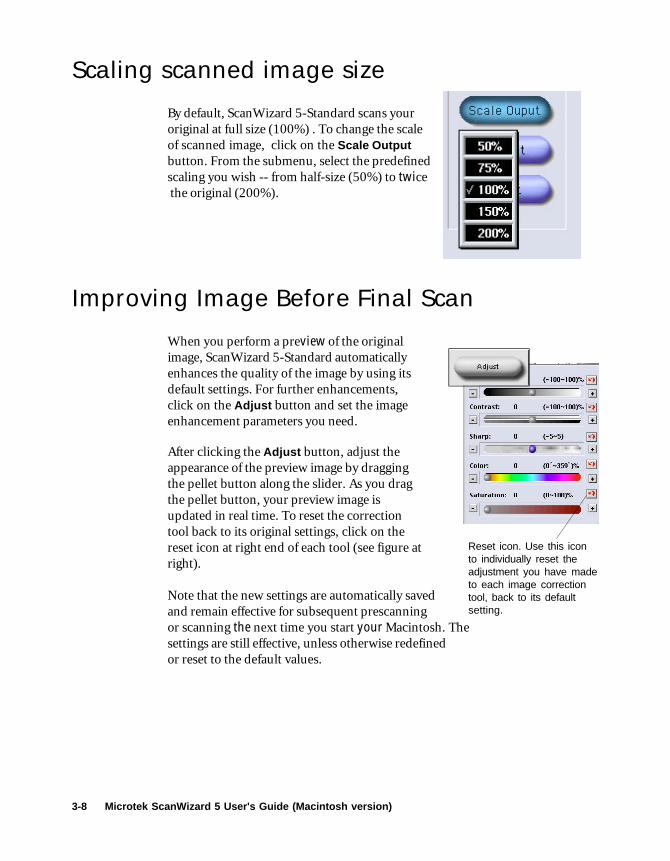
Scaling scanned image size
By default, ScanWizard 5-Standard scans youroriginal at full size (100%) . To change the scaleof scanned image, click on the Scale Outputbutton. From the submenu, select the predefinedscaling you wish -- from half-size (50%) to twice the original (200%).
Improving Image Before Final Scan
When you perform a preview of the originalimage, ScanWizard 5-Standard automaticallyenhances the quality of the image by using itsdefault settings. For further enhancements,click on the Adjust button and set the imageenhancement parameters you need.
After clicking the Adjust button, adjust theappearance of the preview image by draggingthe pellet button along the slider. As you dragthe pellet button, your preview image isupdated in real time. To reset the correctiontool back to its original settings, click on thereset icon at right end of each tool (see figure atright).
Note that the new settings are automatically savedand remain effective for subsequent prescanningor scanning the next time you start your Macintosh. Thesettings are still effective, unless otherwise redefinedor reset to the default values.
Reset icon. Use this iconto individually reset theadjustment you have madeto each image correctiontool, back to its defaultsetting.

Your First Scan 3-9
Output Image Setting Information
As you perform adjustments and define various settings for the output of youroriginal image (as reflected in the preview image), ScanWizard 5-Standardmonitors and makes records of them. Part of the defined settings are displayedin the Status Bar (at the bottom of ScanWizard 5-Standard window) as soon aschanges are made, while a separate and more comprehensive record of thechanges are kept at the same time. To view a complete record of your settings,click on the Information icon [ i ] at the left end of Status Bar. The ImageInformation window then appears, listing all the current settings for your outputimage. If you have not made any adjustment, the default settings will display.
Reset and Revert to Default Settings
When you feel like abandoning the adjustments you have just made, you caneasily revert to ScanWizard 5-Standard default settings and start all over again.Click on the Reset button. All changes you have made in the menus andcontrol panels under Original, Scan Type, Purpose, Scale Output, andAdvance buttons are then reset back to ScanWizard 5-Standard defaults.
NOTE NOTE The settings you have made to dialog boxes underPreference and Scan/Scan to/Copy/E-mail buttons are notaffected with the execution of the Reset button.
Status bar showing summarysettings for output image
Click icon to display detailedinfo box (right)
Drag this corner to resizepreview window

3-10 Microtek ScanWizard 5 User's Guide (Macintosh version)
Final Scan and Output Image DestinationsWhen you are satisfied with the appearance of the image in preview window,you may now click the Scan (or Scan to) button.
Using ScanWizard 5 under an ApplicationIf you launched ScanWizard 5-Standard from an image editing application (e.g.,Adobe Photoshop), the scanned image is controlled by the Scan button. Uponcompletion of scanning, the scanned image is delivered directly to your imageediting application. From your application, you may further edit and save theimage.
Using ScanWizard 5 as a Stand-Alone ProgramIf you launched ScanWizard 5-Standard from the desktop or from the “Go” buttonof your scanner, the scan button will appear as the Scan to button, Copy or E-mail button, depending on which option was last used. Default is Scan to.
Saving Scanned Image to a FileTo save the scanned image as a file, click the Scan tobutton. The Save As dialog box displays.
If the current button shown as Copy, hold thepointer on the button for about two seconds or untilthe submenu appears. When the submenu displays,choose Scan to file. The Save As dialog box displays(see next page) and the button turns into Scan tobutton.
Hold pointer on the buttonfor about 2 seconds todisplay the menu for
selecting destination ofoutput image

Your First Scan 3-11
You may modify the folder and filename in the Save in and Filename panes,then click the Save button. The image is scanned and saved as a file.
NOTENOTE By default, files are saved in a 'Data' folder located inthe same folder as your ScanWizard 5.
Bringing the Saved Image to an ApplicationCheck the "Send image to application" if you wish to do any of the following: Ifyou wish to edit the scanned image with your image editing software; if youwish to send the image as attachment to your e-mail; if you wish to display theimage with your browser. Then select your application from the application icon.
ScanWizard 5-Standard is designed to automatically detect the following imageand internet applications, as shown in the table (see next page).
Check to launch your image editingsoftware (Photoshop in this samplefigure) and to open the saved image
into your image editing application.
You may revise the default filename.During batch scanning with a scanner
equipped with an auto documentfeeder (ADF), you may provide a root
filename. ScanWizard 5 namessubsequent files with a suffix user's
number.
Applications icon. Your availableimage editing software and Internet
application programs are auto-detected and listed here for your
selection.

3-12 Microtek ScanWizard 5 User's Guide (Macintosh version)
Batch Saving of Outputs from ADF Equipped ScannersIf you are using a scanner equipped with the automatic document feeder (ADF)that allows multiple-page scanning, you can auto scan and save scanned imagesin batches.
In this case, ScanWizard 5 will automatically assign serial filenames for thebatch images and store them when the images are scanned in sequence.
Batch sending of ADF Scanned Images to an ApplicationMultiple images can also be sent in batches to your application after they arescanned. Check the "Send images to application" check box, and click theSave button. After all images have been scanned and saved, the selected imageediting software application is launched. Then it opens the images from files (inthe same sequence as they were saved) and displays them in your application.
If an E-mail application is selected, the files are attached to your e-mail asmultiple attachments.
If an Internet Mail application was selected, the files are delivered to theMicrotek e-mail editor in one batch as multiple attachments.
Copying (Printing Image)You need the Copy button to send an image directlyto the printer. Set your printer from the Choosersubmenu of Apple menu. Click this button, and thePrinter dialog box displays.
Image Processor Internet/Mail
Photoshop PhotoDeluxe Netscape Navigator Netscape Messenger 4.6
Internet Explorer QualComm Eudora Pro 3.x
Outlook Express Microsoft Outlook 97/98
Your First Scan 3-13
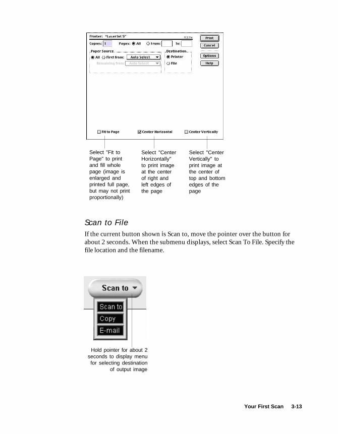
Select "CenterHorizontally"to print imageat the centerof right andleft edges ofthe page
Select "CenterVertically" toprint image atthe center oftop and bottomedges of thepage
Select "Fit toPage" to printand fill wholepage (image isenlarged andprinted full page,but may not printproportionally)
Scan to FileIf the current button shown is Scan to, move the pointer over the button forabout 2 seconds. When the submenu displays, select Scan To File. Specify thefile location and the filename.
Hold pointer for about 2seconds to display menufor selecting destination
of output image
3-14 Microtek ScanWizard 5 User's Guide (Macintosh version)
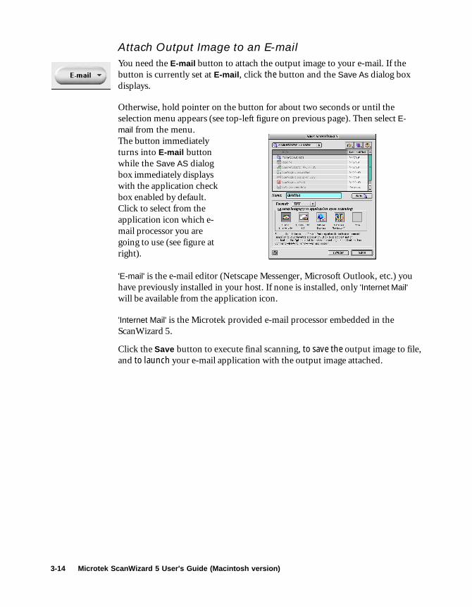
Attach Output Image to an E-mailYou need the E-mail button to attach the output image to your e-mail. If thebutton is currently set at E-mail, click the button and the Save As dialog boxdisplays.
Otherwise, hold pointer on the button for about two seconds or until theselection menu appears (see top-left figure on previous page). Then select E-mail from the menu.The button immediatelyturns into E-mail buttonwhile the Save AS dialogbox immediately displayswith the application checkbox enabled by default.Click to select from theapplication icon which e-mail processor you aregoing to use (see figure atright).
'E-mail' is the e-mail editor (Netscape Messenger, Microsoft Outlook, etc.) youhave previously installed in your host. If none is installed, only 'Internet Mail'will be available from the application icon.
'Internet Mail' is the Microtek provided e-mail processor embedded in theScanWizard 5.
Click the Save button to execute final scanning, to save the output image to file,and to launch your e-mail application with the output image attached.

Your First Scan 3-15
Setting Preferences in ScanWizard 5-Standard
When ScanWizard 5-Standard is launched for the first time, it will auto detect,by default, the type of scan material you have placed in your scanner andautomatically perform a prescan on the original material. The prescan image isthen placed in the preview area of the ScanWizard 5-Standard window. At thesame time, it has a default window painted in "sky" blue tinted colors. You maychange all these default conditions using the options offered in the Preferencesdialog box described below.
NOTE NOTE The customized settings you have made will remain ineffect at subsequent ScanWizard 5-Standard start-ups untilredefined.
Preference Dialog BoxThe Preferences setup dialog box provides options on how you would likeScanWizard 5-Standard to handle your scan material when the program islaunched. You may also disable the balloon screen tip feature in this dialog boxif you are already well-acquainted with the function of each button.
From the Preferences dialog box, you can also access the Appearance setupdialog box where coloring options are available for repainting your ScanWizard5-Standard window. This includes all the buttons and the window background.

3-16 Microtek ScanWizard 5 User's Guide (Macintosh version)
Left-handed users may also relocate the button pane location from the right to theleftside of the window for added convenience.
To redefine Preferences setup, click on the Preferences button. When thePreferences dialog box displays, pick your options as illustrated in thefollowing page.
Uncheck to change prescanimage preview from auto to
manual operation
Change the unit ofmeasurement for image
selection as displayed in thestatus bar (bottom of
ScanWizard 5-Standardwindow)
Uncheck to change imagedetection and selection of the
original scan material, anddefinition of output image type,from auto to manual operation
Check to disable screen'balloon' tips function

Sample Scanning 4-1
Introducing ScanWizard 5Advanced Control Panel
ScanWizard 5 is an easy-to-use twin-panel scanner controller program thatlets you scan images accurately andefficiently.
ScanWizard 5 Advanced Control Panelpacks many powerful features, includ-ing a sophisticated color matchingsystem that lets you take advantage ofthe many advances made recently in thearea of color matching.
And ScanWizard 5 is ColorSync™-savvy as well, allowing you to usestandard ICC color profiles for accuratecolor matching when outputting yourimages.
4 Sample Scanning
Other important features of ScanWizard 5include the following:
• Overview function that lets you previewthe entire scan bed.
• Prescan function that lets you preview aselected area in high resolution for viewingthe image in greater detail. Multipleprescans can also be done, and you canswitch easily among the various views.
• Advanced Image Correction foradjusting and enhancing images, with“before” and “after” thumbnails. Allchanges are shown in real time on theresizable Preview window.
• Dynamic scaling and input / outputcontrols for precise calculation of imagedimensions.
• Information window for identifying andisolating colors with accuracy and precision.

4-2 Microtek ScanWizard 5 User’s Guide (Macintosh)
The ScanWizard 5 Advanced Control Panel Interface
Shows the current scan job, corresponding to the currentscan job in the Scan Job window and the selected imagein the Preview window (“Three girls” in this example).
Resolution level, in pixelsper inch or lines per inch.
Scan Frame, Scaling, and Output controls.See pages that follow for more details.
Image Type of the currentscan job. See pages thatfollow for more details.
Advanced ImageCorrectioncontrols: Foradjusting andenhancing imagequality. See pagesthat follow formore details.
Informationwindow
Settings window
Scan Job window
Function buttons
Check: Indicatesjob will be
scanned whenyou press theScan button.
Unit of measurement
Transform tool for horizontaland vertical flipping, or 90˚rotation, of images.
Scan Frame options
Current scan job, indicated by boldface type
Selected scan job,which is the
highlighted job.There can be
multiple selectedscan jobs (severalhighlighted), which
may or may notinclude the current
scan job (in boldfacetype).
Thumbnailshowingprescan image
Lets you select / switchimage type
Sample Scanning 4-3
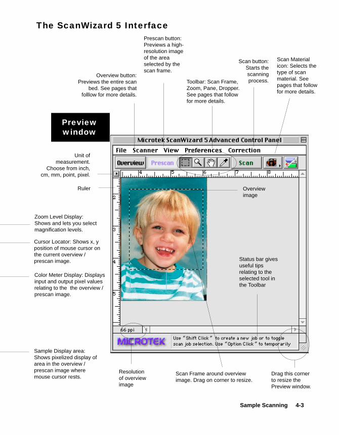
Zoom Level Display:Shows and lets you selectmagnification levels.
Color Meter Display: Displaysinput and output pixel valuesrelating to the the overview /prescan image.
Sample Display area:Shows pixelized display ofarea in the overview /prescan image wheremouse cursor rests.
Cursor Locator: Shows x, yposition of mouse cursor onthe current overview /prescan image.
Previewwindow
Overview button:Previews the entire scan
bed. See pages thatfolllow for more details.
Prescan button:Previews a high-resolution imageof the areaselected by thescan frame.
Scan Frame around overviewimage. Drag on corner to resize.
Scan Materialicon: Selects thetype of scanmaterial. Seepages that followfor more details.
Scan button:Starts thescanningprocess.
Unit ofmeasurement.
Choose from inch,cm, mm, point, pixel.
Ruler Overviewimage
Toolbar: Scan Frame,Zoom, Pane, Dropper.See pages that followfor more details.
The ScanWizard 5 Interface
Drag this cornerto resize thePreview window.
Status bar givesuseful tipsrelating to theselected tool inthe Toolbar
Resolutionof overviewimage

4-4 Microtek ScanWizard 5 User’s Guide (Macintosh)
Image Types
ScanWizard 5 supports a variety of image types, including RGB, Grayscale,and bitmapped (Line Art, and B&W Diffusion).
The three most common image types are described below, and informationon other image types is available in the Supplementary Information sectionof the manual.
• RGB Color: RGB (Red, Green, and Blue)images use three colors to reproduce up to68.7 billion colors. RGB mode is used formost color images and is generally the modeemployed for on-screen multimediaprojects. ScanWizard 5 offers 24-bit RGBand 48-bit RGB color selection. The 48-bitoption is exclusively available forMicrotek’s high-end professional pre-pressscanners.
Zoom tool: Zooms in (enlarges) orzooms out (reduces) the view of thepreview image. To zoom in, click insidethe image. To zoom out, hold down theOption key and click the mouse.
Scan Frame tool: Lets you define the areato be scanned. The area of the overviewor prescan image selected by the scanframe is the part that is scanned when youclick the Scan button. To resize a scanframe, drag on the corner or edge of thescan frame surrounding the image, andresize the frame to the desired area.
The Toolbar
Pane tool: Scrolls through a zoomed-inimage.
Dropper tool: Lets you use the Informa-tion window feature of ScanWizard 5,and also lets you set the black and whitepoints. For more details, see “Using theInformation Window” in the Supple-mentary Information section.
The Scan Material iconAppearance of the iconwhen scanning innegative film mode.
Appearance of the iconwhen scanning inreflective mode.
Appearance of the iconwhen scanning in positivetransparency mode.
• Grayscale: Grayscale images use shades ofgray to simulate gradations of color or tonalvalues, and contain 8 bits per pixel. TheGrayscale 16-bit option is provided inScanWizard 5 for professional pre-pressscanners.
• Line Art: Line Art images are made up ofone bit of color (black or white) per pixel.Few editing options are available in thismode, but this mode is useful for imagesconsisting purely of black and white or evensingle colors, such as mechanical drawings,blueprints, or fine-line illustrations.

Sample Scanning 4-5
Scan Frame, Scaling, Output
The Scan Frame, Scaling, and Output settings allow you to control with precision the dimensions foryour scanned image.
Scaling
ScanFrame
settings
Outputsettings
ScanFrame
options
Unit ofmeasurement
Take note of the following important points:
• For the Scan Frame settings (width and height edit boxes), enter the values manually; or use theScan Frame tool to draw a scan frame in your preview window, and the scan frame dimensionswill then be displayed in the edit boxes.
• Keep Scaling at 100% if you are outputting at the same size (ex. a 4” x 5” output at the samesize). Increase or reduce the scaling if outputting at a larger or smaller size, respectively.
• Checking or unchecking the Scan Frame options will affect the relationship between the varioussettings. If the Fixed Scan Frame option is checked, for instance, changing the Scaling willchange the Output settings accordingly, or vice versa.
• To use any of the Scan Frame options correctly, enter the desired values in the edit boxes firstbefore checking the corresponding option. For instance, if you know your exact input values andwish to “lock” the settings of your scan frame, enter the values in the Scan Frame width andheight edit boxes first, then check the Fixed Scan Frame option; the procedure cannot be done inreverse order. This principle applies to the Fixed Output Size option as well.
• Make sure you choose the unit of measurement (inch, pixel, etc.) to fit your need. Otherwise,you may obtain out-of-range values. If you enter a value that is illegal or out of range, the valuewill appear in red as a flag or warning.
For more details on scaling, refer to the scenario sketched out in “How to Scan and Display anImage” in the Sample Scenarios section of the manual. For a fuller discussion, see “Scan Frame,Scaling, and Output” in the Supplementary Information section.
4-6 Microtek ScanWizard 5 User’s Guide (Macintosh)
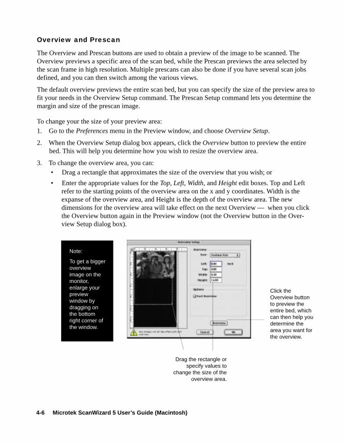
Overview and Prescan
The Overview and Prescan buttons are used to obtain a preview of the image to be scanned. TheOverview previews a specific area of the scan bed, while the Prescan previews the area selected bythe scan frame in high resolution. Multiple prescans can also be done if you have several scan jobsdefined, and you can then switch among the various views.
The default overview previews the entire scan bed, but you can specify the size of the preview area tofit your needs in the Overview Setup command. The Prescan Setup command lets you determine themargin and size of the prescan image.
To change your the size of your preview area:1. Go to the Preferences menu in the Preview window, and choose Overview Setup.
2. When the Overview Setup dialog box appears, click the Overview button to preview the entirebed. This will help you determine how you wish to resize the overview area.
3. To change the overview area, you can: • Drag a rectangle that approximates the size of the overview that you wish; or
• Enter the appropriate values for the Top, Left, Width, and Height edit boxes. Top and Leftrefer to the starting points of the overview area on the x and y coordinates. Width is theexpanse of the overview area, and Height is the depth of the overview area. The newdimensions for the overview area will take effect on the next Overview — when you clickthe Overview button again in the Preview window (not the Overview button in the Over-view Setup dialog box).
Click theOverview buttonto preview theentire bed, whichcan then help youdetermine thearea you want forthe overview.
Drag the rectangle orspecify values to
change the size of theoverview area.
Note:
To get a biggeroverviewimage on themonitor,enlarge yourpreviewwindow bydragging onthe bottomright corner ofthe window.

Sample Scanning 4-7
To change the margin or size of the prescan image:
1. Go to the Preferences menu in the Preview window, and choose Prescan Setup.
2. When the Prescan Setup dialog box appears, specify your choices.
• Prescan Image Margin: The options here let you specify how wide or narrow the marginaround the scan frame is in the prescan image.
This is helpful because selecting the exact scan frame (through the Scan Frame tool) cannever be a completely accurate process, and what appears to have been selected by the scanframe when you view the image in the lower-resolution overview may or may not actuallyinclude the portion you wish. The margin — depending on how wide or narrow it is — canthen provide a berth or allowance for extending the boundaries of the scan frame around theprescan image.
• Prescan Image Dimension: This option lets you specify how large the prescan image will be(full screen, 75%, 50%, or fit current preview window). This allows you to either shrink thepreview window to maximize the use of space on your monitor, or to expand the view of theimage to full screen to see it in greater detail.

4-8 Microtek ScanWizard 5 User’s Guide (Macintosh)
Advanced Image Correction
1 Go to the Settings window; the AdvancedImage Correction controls can be found onthe lower half of the window. Thesecontrols have their counterparts on theCorrection menu in the Preview window.
2 To use the controls:A. Click any of the buttons on the left-
hand side; orB. Choose from the drop down menu on
the right-hand side for custom options.For more details, see “Using AdvancedImage Correction” in the Supplemen-tary Information section of the manual.
3 If you click any of the buttons on the left-hand side, the AIC dialog box for theselected control will appear, allowing youto adjust the image.
The example on the next page shows theColor Correction dialog box, which lets youadjust or apply a color cast to an image bymeans of the color wheel.
The left thumbnail is the “before” versionof the image, and the right thumbnail is the“after” version of the image, adjusted for aslightly reddish cast.
If the Preview option is checked in the AICdialog box, the correction will show up inreal time in the Preview window as well,without you having to close the AIC dialogbox.
The Advanced Image Correction (AIC) features are an integral part of ScanWizard 5, allowing you tomake corrections to the scanned image. Changes to the image can be viewed in real time in thePreview window and in the “before” and “after” thumbnails of the AIC dialog box.
BA
For more details on the use of each of the AIC tools, see “Using the Advanced Image CorrectionTools” in the Supplementary Information section of the manual.

Sample Scanning 4-9
Sample AIC dialog box(for the Color Correction option)
“Before”thumbnail, prior to
image correction
“After” thumbnail,showing imagecorrection
Check this box toobserve changeson the Previewwindow in real time.
Show / hidethumbnails
Function buttons
Function buttons:
ResetClicking this button brings up the Reset dialogbox, where you can specify which settings are tobe reset to their default values.
RevertClicking this button cancels out the changes youmade with the current AIC tool. If you usedseveral tools, using Revert will cancel the effectof only the current tool and preserve the effectsof the other preceding tools. Example: If youchanged brightness and added a filter, thenclicked Revert, the filter is not applied but thealtered brightness settings remain in effect.
Add to menuClicking this button lets you add a customsetting to the AIC menus in the Settings window(right-hand side of the AIC controls).
CancelClicking this button cancels all image-adjust-ment changes made to the image, and then closesthe AIC dialog box.
OKClicking this button accepts whatever enhance-ments you have made to the image, and thencloses the AIC dialog box.

4-10 Microtek ScanWizard 5 User’s Guide (Macintosh)
How to Scan a Color Photographic Print
1 Place the scan material to be scanned on your scanner’s glass bed.
2 Go to the Preview window and click the Scan Material icon. From the submenu thatappears, choose Reflective. You will notice the change in the appearance of the icon.
3 Click the Overview button to start an overview, and you will see the image appear inyour Preview window.
4 Select the Scan Frame tool from the Toolbar in the Preview window, and choose thearea to be scanned by dragging a rectangle around it. You will see a flashing frame(marquee) around the selected area.
5 If you like what you see in the Preview window, click the Scan button to start scanning.
If you want to.... Before the Final Scan••••• Select an output image type (after step 2)
Go to the Settings window, and from the Type box, choose the appropriate image type for theimage to be scanned. For more details, see “Image Types” in the Supplementary Informationsection of the manual.
••••• Specify output dimensions (after step 2)Go to the Settings window, and enter the desired output dimensions (width and height) in theoutput dimension edit boxes. The scan frame may change slightly, and you may want to go backto the Preview window to move the scan frame and enclose the area you want. For more details,see “Scan Frame, Scaling, and Output” in the Supplementary Information section of the manual.
••••• Change output image resolution (before step 5)Go to the Settings window, and enter the resolution value in the Resolution edit box.
••••• See a more detailed preview image (after step 4)Go to the Preview window, highlight the scan job you wish to see in detail, and click the Prescanbutton. For more details, see “Overview and Prescan” in the Basic Setup and Features section ofthe manual.
••••• Fine-tune the preview image with image processing options (after step 4)Go to the Preview window, and select the desired image-processing option from the Correctionmenu. Alternatively, you can go to the Settings window and click an image processing button;the Advanced Image Correction dialog box will then appear. For more details, see “AdvancedImage Correction” in the Basic Setup and Features section and Supplementary Informationsection of the manual.

Sample Scanning 4-11
Scanning a Color Photographic Print
2
4
3
5

4-12 Microtek ScanWizard 5 User’s Guide (Macintosh)
How to Scan a Color Positive Transparency
1 For dual bed-scanners, place the film to be scanned on the appropriate template, and insertthe film and template into your scanner’s lower bed. For flatbed scanners, use a Transpar-ent Media Adapter.
2 Go to the Preview window and click the Scan Material icon. From the submenu thatappears, choose Positive Transparency. You will notice the change in the appearance of theicon.
3 Click the Overview button to start an overview, and you will see the image appear in yourPreview window.
4 Select the Scan Frame tool from the Toolbar in the Preview window, and choose the areato be scanned by dragging a rectangle around it. You will see a flashing frame (marquee)around the selected area.
5 If you like what you see in the Preview window, click the Scan button to start scanning.
••••• Select an output image type (after step 2)Go to the Settings window, and from the Type box, choose the appropriate image type for theimage to be scanned. For more details, see “Image Types” in the Supplementary Informationsection of the manual.
••••• Specify output dimensions (after step 2)Go to the Settings window, and enter the desired output dimensions (width and height) in theoutput dimension edit boxes. The scan frame may change slightly, and you may want to go backto the Preview window to move the scan frame and enclose the area you want. For more details,see “Scan Frame, Scaling, and Output” in the Supplementary Information section of the manual.
••••• Change output image resolution (before step 5)Go to the Settings window, and enter the resolution value in the Resolution edit box.
••••• See a more detailed preview image (after step 4)Go to the Preview window, highlight the scan job you wish to see in detail, and click the Prescanbutton. For more details, see “Overview and Prescan” in the Basic Setup and Features section ofthe manual.
••••• Fine-tune the preview image with image processing options (after step 4)Go to the Preview window, and select the desired image-processing option from the Correctionmenu. Alternatively, you can go to the Settings window and click an image processing button;the Advanced Image Correction dialog box will then appear. For more details, see “AdvancedImage Correction” in the Basic Setup and Features section and Supplementary Informationsection of the manual.
If you want to.... Before the Final Scan

Sample Scanning 4-13
Scanning a Color Positive Transparency
3
2
4 5

4-14 Microtek ScanWizard 5 User’s Guide (Macintosh)
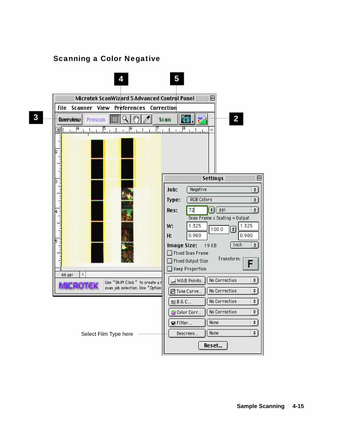
How to Scan a Color Negative
1 For dual bed-scanners, place the film to be scanned on the appropriate template, and insertthe film and template into your scanner’s lower bed. For flatbed scanners, use a Transpar-ent Media Adapter.
2 Go to the Preview window and click the Scan Material icon. From the submenu thatappears, choose Negative Film. You will notice the change in the appearance of the icon.
3 Click the Overview button to start an overview, and you will see the image appear in yourPreview window.
4 Select the Scan Frame tool from the Toolbar in the Preview window, and choose the areato be scanned by dragging a rectangle around it. You will see a flashing frame (marquee)around the selected area.
5 If you like what you see in the Preview window, click the Scan button to start scanning.
••••• Select an output image type (after step 2)Go to the Settings window, and from the Type box, choose the appropriate image type for theimage to be scanned. For more details, see “Image Types” in the Supplementary Informationsection of the manual.
••••• Specify output dimensions (after step 2)Go to the Settings window, and enter the desired output dimensions (width and height) in theoutput dimension edit boxes. The scan frame may change slightly, and you may want to go backto the Preview window to move the scan frame and enclose the area you want. For more details,see “Scan Frame, Scaling, and Output” in the Supplementary Information section of the manual.
••••• See a more detailed preview image (after step 4)Go to the Preview window, highlight the scan job you wish to see in detail, and click the Prescanbutton. For more details, see “Overview and Prescan” in the Basic Setup and Features section ofthe manual.
••••• Fine-tune the preview image with image processing options (after step 4)Go to the Preview window, and select the desired image-processing option from the Correctionmenu. Alternatively, you can go to the Settings window and click an image processing button;the Advanced Image Correction dialog box will then appear. For more details, see “AdvancedImage Correction” in the Basic Setup and Features section and Supplementary Informationsection of the manual.
••••• Adjust film type (before step 5)Go to the Film Type menu in the Settings window and select the film type and manufacturer.
If you want to.... Before the Final Scan
Sample Scanning 4-15
Scanning a Color Negative
3 2
4 5
Select Film Type here
4-16 Microtek ScanWizard 5 User’s Guide (Macintosh)
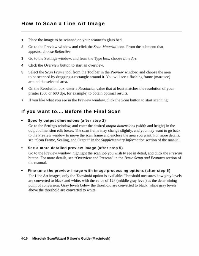
How to Scan a Line Art Image
1 Place the image to be scanned on your scanner’s glass bed.
2 Go to the Preview window and click the Scan Material icon. From the submenu thatappears, choose Reflective.
3 Go to the Settings window, and from the Type box, choose Line Art.
4 Click the Overview button to start an overview.
5 Select the Scan Frame tool from the Toolbar in the Preview window, and choose the areato be scanned by dragging a rectangle around it. You will see a flashing frame (marquee)around the selected area.
6 On the Resolution box, enter a Resolution value that at least matches the resolution of yourprinter (300 or 600 dpi, for example) to obtain optimal results.
7 If you like what you see in the Preview window, click the Scan button to start scanning.
••••• Specify output dimensions (after step 2)Go to the Settings window, and enter the desired output dimensions (width and height) in theoutput dimension edit boxes. The scan frame may change slightly, and you may want to go backto the Preview window to move the scan frame and enclose the area you want. For more details,see “Scan Frame, Scaling, and Output” in the Supplementary Information section of the manual.
••••• See a more detailed preview image (after step 5)Go to the Preview window, highlight the scan job you wish to see in detail, and click the Prescanbutton. For more details, see “Overview and Prescan” in the Basic Setup and Features section ofthe manual.
••••• Fine-tune the preview image with image processing options (after step 5)For Line Art images, only the Threshold option is available. Threshold measures how gray levelsare converted to black and white, with the value of 128 (middle gray level) as the determiningpoint of conversion. Gray levels below the threshold are converted to black, while gray levelsabove the threshold are converted to white.
If you want to.... Before the Final Scan

Sample Scanning 4-17
Scanning a Line Art Image
4 2
3
5 6
6

4-18 Microtek ScanWizard 5 User’s Guide (Macintosh)
How to Scan and Display an Image on a 640 x 480 Monitor
1 Place the image to be scanned on your scanner.
2 Go to the Preview window and click the Scan Material icon. From the submenu that appears,choose the correct scan material type.
3 Click the Overview button to start an overview, and you will see the image appear in yourPreview window.
4 Go to the Settings window, and choose pixels as your unit of measurement. Then, enter theresolution value in the Resolution edit box — 72 dpi in this case for monitor display. If youchange the resolution after specifying the output dimensions, the dimensions will change, andyou will then need to re-enter the correct output dimensions again.
5 Change to an initial scaling value of 200% in the scaling menu.
6 In the Output edit boxes, enter “640” for width and “480” for height. You will notice that thescan frame in your preview image changes.
7 Check the Fixed Output Size box. Adjust or move the scan frame to enclose the area you wish.A flashing frame (marquee) will be around the selected area.
8 If you like what you see in the Preview window, click the Scan button in the Preview windowto start scanning.
••••• Select an output image type (after step 2)Go to the Settings window, and from the Type box, choose the appropriate image type for theimage to be scanned. For monitor display of images, choose RGB, Grayscale, or Web / Internetcolors. For more details, see “Image Types” in the Supplementary Information section of themanual.
••••• See a more detailed preview image (after step 7)Go to the Preview window, highlight the scan job you wish to see in detail, and click the Prescanbutton. For more details, see “Overview and Prescan” in the Basic Setup and Features section ofthe manual.
••••• Fine-tune the preview image with image processing options (after step 7)Go to the Preview window, and select the desired image-processing option from the Correctionmenu. Alternatively, you can go to the Settings window and click on an image processing button.For more details, see “Advanced Image Correction” in the Basic Setup and Features section andSupplementary Information section of the manual.
If you want to.... Before the Final Scan
At times, you may wish to scan an image and then scale or resize the image so that it can bedisplayed on your monitor (either as a screen saver or wallpaper). The sample scenario below showshow this can be done.

Sample Scanning 4-19
Scanning and Displaying an Image on a 640 x 480 monitor
23
8
7
46
5

4-20 Microtek ScanWizard 5 User’s Guide (Macintosh)
How to Do Multiple Scan Jobs
1 Place the images to be scanned on your scanner.
2 Go to the Preview window, click the Scan Material icon, and choose the correct scan materialtype.
3 In the Preferences menu, choose More, then check the Smoked Glass option. This feature willhelp you distinguish the different scan jobs created, especially if each one is of a different imagetype (RGB color, grayscale; shown in example below).
4 Click the Overview button to start an overview. The images will appear in the Preview window.
5 If the Scan Job window is not open, go to the View menu and choose Show Scan Job window.
6 Create the other scan jobs that you need. To do this, use the Duplicate or New button, orShift+Drag the current scan frame to form new ones. For more details, see “Using the Batch ScanFeature” in the Supplementary Information section of the manual.
7 Define the settings for each scan job. To do this, highlight the scan job title in the Scan Jobwindow, then specify the appropriate settings (type, resolution, etc.) in the Settings window forthat scan job.
8 If you like what you see in the Preview window, click the Scan button to start scanning.
••••• Select an output image type (after step 7)Go to the Settings window, and from the Type box, choose the appropriate image type for eachscan job. For more details, see “Image Types” in the Supplementary Information section of themanual.
••••• Specify output dimensions (after step 7)Go to the Settings window, and enter the desired output dimensions (width and height) in theoutput dimension edit boxes for each scan job. The scan frame may change slightly, and youmay want to go back to the Preview window to move the scan frame and enclose the area youwant. For more details, see “Scan Frame, Scaling, and Output” in the Supplementary Informa-tion section of the manual.
••••• Change output image resolution (before step 8)Go to the Settings window, and enter the resolution value in the Resolution edit box for eachscan job.
••••• See a more detailed preview image or do multiple prescans (after step 7)Go to the Preview window, highlight the scan job you wish to see in detail, and click the Prescanbutton. You can also do multiple prescans if you have multiple scan jobs. Simply choose all the
If you want to.... Before the Final Scan
Oftentimes, you will need to scan several images at a time or find yourself wanting to scan multiplejobs to save time. The sample scenario below shows how this can be done.

Sample Scanning 4-21
Doing multiple scan jobs
4
8
2
3
6
5
7
scan jobs in the Scan Job window, then click the Prescan button. To view the various prescanimages, go to the View menu and switch among the different views possible.
••••• Fine-tune the preview image with image processing options (after step 7)Go to the Preview window, and select the desired image-processing option for each scan jobfrom the Correction menu. Alternatively, you can go to the Settings window and click on animage processing button; the Advanced Image Correction dialog box will then appear. For moredetails, see “Advanced Image Correction” in the Basic Setup and Features section and Supple-mentary Information section of the manual.

4-22 Microtek ScanWizard 5 User’s Guide (Macintosh)
SupplementaryInformation
• Image Types
• Scan Frame, Scaling, and Output
• Using Advanced Image Correction
• Using the Information Window
• Using the Scan Job Window
• Color Matching for Advanced Users
• Using the Scanner Driver Manager

Sample Scanning 4-23
RGB Color: RGB (Red, Green, and Blue) images use
three colors to reproduce up to 68.7 billioncolors. Because scanners and monitors areRGB devices, the RGB color space is themost commonly used space for capturingand displaying images. ScanWizard 5 offersstandard RGB and 48-bit RGB colorselection, with the 48-bit option availablefor Microtek professional pre-press scan-ners.
Image Types
ScanWizard 5 allows direct scanning in the following color spaces described below. The desiredcolor space in ScanWizard 5 can be selected in the Type box in the Settings window.
RGB color: 622K

4-24 Microtek ScanWizard 5 User’s Guide (Macintosh)
Grayscale: Grayscale images use
shades of gray tosimulate gradations ofcolor or tonal values,and contain 8 bits perpixel. The Grayscale16-bit option isprovided inScanWizard 5 forprofessional pre-press
scanners.
Line Art: Line Art images are made up of one bit
of color (black or white) per pixel. Fewediting options are available in thismode, but this mode is useful forimages consisting purely of black andwhite or even single colors, such asmechanical drawings, blueprints, orfine-line illustrations.
• Palette: The Palette option lets you choosethe method for creating the color palettetable. Uniform uses a 6-6-6 fixed colorpalette table. Adaptive (default) creates acolor palette table from the more commonlyused areas of the color spectrum thatappears in the image.
• Dither: The Dither option can improve thecolor quality of the 256-indexed colorimage, using a technique of mixing avail-able colors to simulate missing colors. Noneprovides no dithering. Pattern uses astructured pattern to simulate missingcolors. Diffusion (default) uses the errordiffusion technique to dither colors andproduces the best quality for 256 colors.
Web / Internet Colors: This mode is useful for displaying images on the Web or Internet.
Output for the Web / Internet color mode in ScanWizard 5 is 8-bit, 256indexed color images.
256 Colors (Default) / 256 Colors (Custom)
These are single-channel images (8 bits per pixel) that use a color lookuptable containing up to 256 colors. The file size is smaller for images inthis mode. As an initial setting, selecting 256 Colors (Default) uses anAdaptive palette with Diffusion. If the 256 Colors (Custom) option isselected, the dialog box below appears.
Black-and-White Diffusion: This is a single-bit black-and-white image
dithered with error diffusion. The black andwhite pixels are arranged in a way as to“fool” the eye into seeing gray.
Grayscale: 208K
Indexed color: 208K

Sample Scanning 4-25
Scan Frame, Scaling, and Output
The input / output dimensions of your image are controlled by the Scan Frame Settings, Scaling, andthe Output Settings. Together with the Scan Frame options, these fields allow to you control withprecision the size of the image to be scanned or output.
The edit boxes forScan Frame
settings, Scaling,and Output settings.
Scan Frameoptions
Scan Frame settings
The Scan Frame settings (width and height)represent the area on the scan bed that you wishto scan.
To specify your settings, enter the dimensionsmanually in the width and height edit boxes; oruse the Scan Frame tool to define or resize yourscan frame. Changes made in the Previewwindow are automatically displayed in the ScanFrame setting edit boxes.
Scaling
Scaling lets you create larger or smaller imagesfrom the original source image. Take note of thefollowing:
• Keep the scaling at 100% if you are output-ting at the same size (e.g., a 4” x 5” originalto be output at the same size).
• Reduce the scaling if you are outputting yourimage at a smaller size (e.g., a 4” x 5”original to be output to 2” x 2.5”). Increasethe scaling if outputting at a larger size.
To choose the scaling percentage, click the up/down arrow next to the scaling box, or enter avalue in the scaling edit box.
In the default settings of ScanWizard 5, where none of the Scan Frame options are checked or arebeing used, take note of the following:• Changing the Scan Frame settings (width or height) will change the Output settings (width or
height).
• Changing the Scaling will change the Output settings (width AND height).
• Changing the Output settings (width or height) will change the Scan Frame settings (width orheight).

4-26 Microtek ScanWizard 5 User’s Guide (Macintosh)
Output Settings
The Output settings (width and height) representthe dimensions of image when it is output (toeither monitor or printer). If the size of the imageto be output is different from the size of theoriginal source image, adjust the scaling percent-age, or manually increase / decrease the outputvalues accordingly.
Additional Notes
• When none of the Scan Frame options arechecked, all five edit boxes are enabled,allowing you to edit or enter values into anyof the boxes.
• The Fixed Scan Frame and Fixed OutputSize options are mutually exclusive. Thismeans that only one of the options can bechecked at any time; checking anotheroption will automatically uncheck the otherone.
• When an illegal value is entered (e.g., theinput width exceeds the scan frame size), thevalue will appear in red as a flag or warningindicating an out-of-range value.
2. Fixed Output Size
When the Fixed Output Size option ischecked, the values specified for outputwidth and height remain unchanged. If anyof the input values are changed, the scalingwill be adjusted automatically to preservethe output dimensions correctly.
If you know the exact output size for yourimage, enter the output width and heightvalues first, then check Fixed Output Size.The image will then be scanned and outputat the values you specify.
1. Fixed Scan Frame
This option lets you lock in the settings ofyour scan frame, so that the width andheight dimensions of the frame are alwayspreserved no matter where you move theframe in your preview image.
If you know the exact input size for yourimage, or if you wish to “lock” the settingsof your scan frame to a particular size, enterthe Scan Frame width and height valuesfirst, then check Fixed Scan Frame. Yourscan frame will be “fixed” at those values,so even if you move the scan frame aroundthe preview image, the dimensions of theframe itself will remain unchanged.
3. Keep Proportion
When the Keep Proportion option ischecked, the width and height values of theimage are kept in proportion despite changesmade to either setting. This preserves theaspect ratio of the image.
This option is automatically checked wheneither “Fixed Scan Frame” or “Fixed OutputSize” is selected.Scan Frame options
The Scan Frame options include Fixed ScanFrame, Fixed Output Size, and Keep Proportion.
Unit of Measurement
The unit of measurement lets you select yourdesired unit (inch, cm, mm, point, pixel). Makesure you select the correct unit of measurementbefore entering values for the width or heightsettings in the edit boxes.
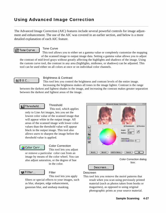
Sample Scanning 4-27
Tone Curve This tool allows you to either set a gamma value or completely customize the mappingof the scanned image to output image data. Setting a gamma value allows you to adjust
the contrast of mid-level grays without greatly affecting the highlights and shadows of the image. Usingthe custom curve tool, the contrast in any area (highlights, midtones, or shadows) can be adjusted. Thistool can be used either on all colors at once or on individual color channels.
Brightness & ContrastThis tool lets you control the brightness and contrast levels of the entire image.Increasing the brightness makes all tones in the image lighter. Contrast is the range
between the darkest and lightest shades in the image, and increasing the contrast makes greater separationbetween the darkest and lightest areas of the image.
Using Advanced Image Correction
The Advanced Image Correction (AIC) features include several powerful controls for image adjust-ment and enhancement. The use of the AIC was covered in an earlier section, and below is a moredetailed explanation of each AIC feature.
Color Correction dialogbox:
FilterThis tool lets you apply
filters or special effects to your images, suchas blur, sharpen, edge enhancement,gaussian blur, and unsharp masking.
Color CorrectionThis tool lets you adjust
or remove a particular color cast from animage by means of the color wheel. You canalso adjust saturation, or the degree of hue
in the color.
Threshold This tool, which applies
only to Line Art images, lets you set thelowest color value of the scanned image thatwill appear white in the output image. Allareas of the scanned image with lower colorvalues than the threshold value will appearblack in the output image. This tool alsoallows users to sharpen the image before thethreshold value is applied.
DescreenThis tool lets you remove the moiré patterns that
result when you scan using previously printedmaterial (such as photos taken from books ormagazines), as opposed to using originalphotographic prints as your source material.

4-28 Microtek ScanWizard 5 User’s Guide (Macintosh)
Custom Settings
You can also create custom settings in each Advanced Image Correction control, and then add themto the Settings window menus for quick access to those settings.
To create a custom setting:
1. Choose the desired AIC control in theSettings window, and select Custom fromthe drop-down menu on the right side.
2. When the AIC dialog box for the selectedcontrol comes up, adjust the setting the wayyou want it, then click the Add to Menubutton at the bottom of the dialog box.
3. Enter a name for the Custom Setting (ex:More Red Tint), then click OK.The newcustom setting is added to the menu.
To remove a custom setting:
1. Choose the desired AIC control in theSettings window, and select Remove CustomSetting from the drop-down menu on theright side.
2. When a dialog box appears, highlight thecustom setting to be removed, then click theRemove button. The custom setting isdeleted from the menu.
Note: To delete the custom setting, youMUST click the Remove button (not justselect and click OK).
3. Click OK to close the dialog box.

Sample Scanning 4-29
Using the Information Window
The Information window is a floating window used to display color information about the Overviewand Prescan buttons at precise “x” and “y” locations. The Information window can also be used tochange zoom levels for varying magnification rates. Closely related to the Information window is thefunction of Information window, which is explained later in this section.
To view the Information window: Go to the View menu in the Preview window, and choose the ShowInfo window command (toggle to hide the window).
The Color Input Meter displays the input(density) pixel values at the specific X/Ylocation. Take note of the following:• For all color image types (RGB), the
density values of the raw image aredisplayed.
• For grayscale images, the gray (K) channelis displayed.
• For single-bit images such as line art, thissection is disabled.
The Color Output Meter displays the outputvalues of the pixel at the specific X/Y locationTake note of the following:
• The left part of the displayed values is the“Before” value, or the pixel value beforeimage correction.
• The right part of the displayed values isthe “After” value, or the pixel value of thefinal output image after all image correc-tions.
The Mouse Cursor Position displays theposition of the mouse cursor on the X and Yaxis of the image.
The Zoom Level Display shows and lets youselect the levels of magnification obtainable —100%, 200%, 400%, and 800%.
Sample Display area shows a pixelized displayof the specific X/Y location. The size of thedisplay area depends on the selection made inthe Color Meter Options (discussed nextsectiion).

4-30 Microtek ScanWizard 5 User’s Guide (Macintosh)
Color MeterOptions
Color Meter Options
The Color Meter options let you choose whetheryou wish to display color information innumbers or percentages, and also let you choosethe area of the sample size.
• If Value is chosen, the numbers representvalues in the 0-to-255 pixel scale.
• If Percent is chosen, the numbers representpercentage of intensity (divided by 255).
• The Sample Size lets you choose the squaresize in pixels (default is 1x1), andScanWizard 5 displays the average value ofthe square.
Sample Size display, with 1x1option shown here (white square is1 pixel square)

Sample Scanning 4-31
Using the Scan Job Window
The Scan Job window is a floating window that shows your scan jobs. By definition, a scan job is ascan that contains the following elements: a set of scanning parameters (shown in the Settingswindow); a scan frame (shown in the Preview window); and a scan job item (shown inthe Scan Jobwindow).
To view the Scan Job window, go to the View menu in the Preview window, and choose the ShowScan Job window command.
1. The current scan job is indicated by bold-face type; there can only be one current scanjob. The current scan job is shown as well inthe Job box of the Settings window.
2. The selected scan job is the highlighteditem. You can have multiple selected scanjobs, which may or may not include thecurrent scan job.
3. To make another scan job the current scanjob, simply click on the job in the scan joblist. The contents of the Settings windowand the current scan frame will be updatedaccordingly, showing you the settings andscan frame of the new current scan job.
4. A scan job can be checked or unchecked,and only checked jobs are scanned whenyou click the Scan button in the Previewwindow. The check box is a toggle forchecking / unchecking a scan job, and youcan also use the Check button.
5. To change the order of scan jobs in thewindow, click on the Up / Down arrows, orsimply highlight the scan job and move it upor down the list.
6. To edit a scan job title, highlight the scan joband hold down the mouse. The title will beready for editing, and simply type over thenew name.
How to Read the Scan Job window
Thumbnail of image obtained after using thePrescan function (in the Preview window)
CheckedScan Job Title of scan job
Image size ofscan job
Function buttons formanipulating scan jobs
Menu for changingimage type
Current scan job (boldface type)Selected scan job (highlighted)

4-32 Microtek ScanWizard 5 User’s Guide (Macintosh)
Multiple Job Selections
The function buttons at the bottom of the ScanJob window (except the New and Load / Savebuttons) can be used for multiple job selections.
For example, you can select multiple scan jobsand then click the Delete button to remove allthe jobs simultaneously. To select multiple scanjobs, press the Shift key and click on the jobs tobe selected.
Adding a New Scan Job
1. Click on the New button.
2. When a text box appears, accept the defaultname or enter a name for the new scan job.
3. Define the scan frame in the Previewwindow for the new scan job.
4. In the Settings window, specify the settingsfor the new scan job.
With the creation of a new scan job, the newscan job becomes the current scan job.
Duplicating a Scan Job
1. From the list of scan jobs available, selectthe scan job(s) to be duplicated
2. Click on the Duplicate button. The selectedscan job(s) will be duplicated. The Dupli-cate function is very useful when scanningseveral images at the same settings (a batchscan).
Removing a Scan Job
To delete a scan job, select the scan job to beremoved, then click on the Delete button.

Sample Scanning 4-33
Loading and Saving Scan Jobs
This feature lets you save scan jobs, which you can then load when necessary. The idea of saving andloading scan jobs has important applications, especially for scanners with different templates or“trays”. Saving / loading scan jobs is also useful if you consistently work in a specific format, scanthe same kind of images, or if the scanner is used by several users who have their own sets of jobs.
If your scanner has several trays, for instance, you may wish to create a scan job for each “tray”—for example, one for your 4”x5” transparencies and another for your 35mm positives. You can alsocreate scan jobs to fit the needs of your users, with User A having Scan Job Folder 1 for example, andUser B having Scan Job Folder 2.
Your currentscan jobsScan Job
folders
New folder
To use the Load / Save feature:
1. Click on the Load / Save button in the ScanJob window.
2. When a dialog box appears, go to the folderof your choice . The sample dialog boxbelow shows the following:
• The left-hand side of the dialog boxshows your scan job folders. In thisexample, a folder called Scan JobManager has been created. Inside thefolder are individual folders —35mmpositives and 4x5 transparencies.
• On the right-hand side of the dialog boxare your current scan jobs — Scan Job 1and Scan Job 2.
Note:
If you click the OK buttonand there are no scan jobson the right-hand side, adialog box will appear. Youwill then be asked if you wishScanWizard 5 to automati-cally create a scan job withdefault settings for you.

4-34 Microtek ScanWizard 5 User’s Guide (Macintosh)
To add the contents of a folder to the scan joblist:
1. Select the folder on the left-hand side, anddouble-click on it.
2. Click the Add button in the middle columnof the dialog box. All the contents inside thefolder are added to the scan job list on theright-hand side.
To save scan jobs to a folder:
1. Select a folder on the left-hand side, anddouble-click on the folder.
2. Highlight the scan job to be added on theright-hand side.
3. Click the Save button in the middle columnof the dialog box. The selected scan job issaved to your selected folder.
To remove scan job(s):
1. Highlight the scan job(s) to be removed.2. Click the Remove or Remove All button at
the bottom of the dialog box.
To remove a folder:
Folders cannot be removed from the level of theScan Job Manager or from the level ofScanWizard 5. To remove folders, you will needto go to the level of your Macintosh operatingsystem and then delete the folders by movingthem to the Trash.
To close the dialog box: Click the OK button atthe bottom of the dialog box.
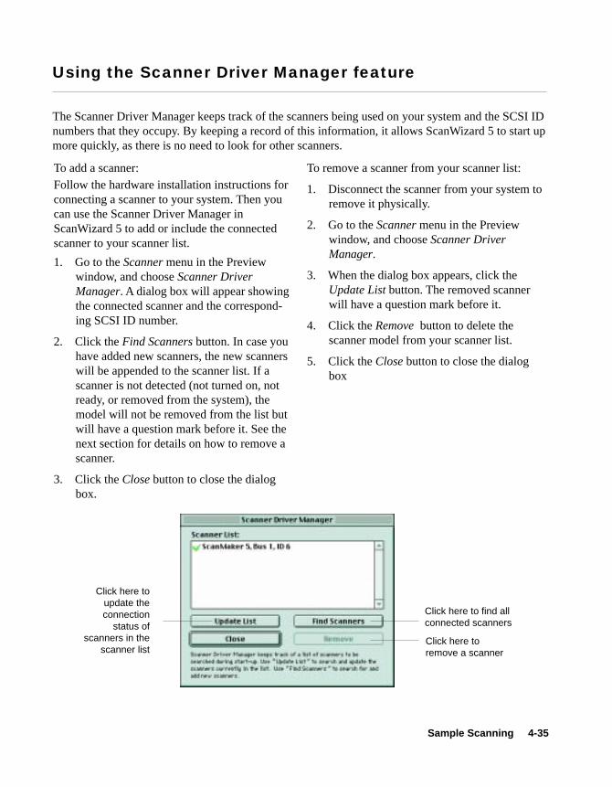
Sample Scanning 4-35
Using the Scanner Driver Manager feature
The Scanner Driver Manager keeps track of the scanners being used on your system and the SCSI IDnumbers that they occupy. By keeping a record of this information, it allows ScanWizard 5 to start upmore quickly, as there is no need to look for other scanners.
To add a scanner:Follow the hardware installation instructions forconnecting a scanner to your system. Then youcan use the Scanner Driver Manager inScanWizard 5 to add or include the connectedscanner to your scanner list.
1. Go to the Scanner menu in the Previewwindow, and choose Scanner DriverManager. A dialog box will appear showingthe connected scanner and the correspond-ing SCSI ID number.
2. Click the Find Scanners button. In case youhave added new scanners, the new scannerswill be appended to the scanner list. If ascanner is not detected (not turned on, notready, or removed from the system), themodel will not be removed from the list butwill have a question mark before it. See thenext section for details on how to remove ascanner.
3. Click the Close button to close the dialogbox.
Click here toupdate theconnection
status ofscanners in the
scanner list
Click here to find allconnected scanners
To remove a scanner from your scanner list:
1. Disconnect the scanner from your system toremove it physically.
2. Go to the Scanner menu in the Previewwindow, and choose Scanner DriverManager.
3. When the dialog box appears, click theUpdate List button. The removed scannerwill have a question mark before it.
4. Click the Remove button to delete thescanner model from your scanner list.
5. Click the Close button to close the dialogbox
Click here toremove a scanner

4-36 Microtek ScanWizard 5 User’s Guide (Macintosh)
This section contains important information on further steps you need to take to achieve colormatching across your devices. The procedures to be performed include monitor calibration and howto set up ScanWizard 5 with the Apple ColorSync™ system and the Adobe Photoshop software.Some recommendations are also given in order to achieve color matching across devices. For moredetailed information on the ColorSync or Adobe Photoshop functions covered in this section, refer tothe respective user guides of those programs.
Setting up the System (Monitor) Profile using ColorSync
ColorSync is Apple’s industry-standard color matching system. The notes below pertain to configur-ing ColorSync to ensure that it works properly with ScanWizard 5.
Calibrating your monitor
Proper monitor calibration is important for achieving higher precision in color matching. MonitorICC profiles may be created specifically for your monitor by calibrating your monitor through thefollowing utilities:
• ColorSync 2.5 Monitors & Sound Control Panel Calibration function• Adobe Gamma utility, from Adobe Photoshop 5.0• Any third-party calibration programs or hardware calibrator
Color Matching for Advanced Users
If you have ColorSync 2.1.2 or earlier, do thefollowing:1. In the ColorSync System Profile control
panel, select your desired System Profilesettings.
2. In the Monitors & Sound control panel, setthe Gamma to “Uncorrected Gamma”.
In addition, make sure you disable or removeany utilities or third-party control panels thatalter monitor display. Your System Profile is theprofile describing the monitor you are using.
If you have ColorSync 2.5, do the following inthe exact order below:1. Open the Monitors & Sound control panel to
select your desired profile in the MonitorProfile list box.
2. Open the ColorSync Control Panel to verifythe desired monitor profile as the SystemProfile.
The settings in these two control panels shouldbe the same. If you select a profile in Monitors& Sound, your ColorSync System Profile willchange accordingly.
In addition, make sure you disable or removeany utilities or third-party control panels thatalter monitor display.

Sample Scanning 4-37
Using Adobe Photoshop 5.0
B. ScanWizard 5 Setup:
1. Go to the Preferences / CMS Setup dialogbox. Check and see that the monitorselection is the same as that in theColorSync System Profile selection (yourcurrent monitor setup). If you need tochange your monitor, do this in theColorSync Control Panel.
2. Make sure that the Display using monitorcompensation check box is checked.
3. For RGB destination settings, select yourdesired profiles. These selections specifyScanWizard 5’s output color space for RGBmages, respectively.
4. Make sure the RGB destination settingmatches Photoshop 5.0’s RGB Settingin theRGB Setup dialog box, respectively.
5. To enable RGB color matching, make surethe RGB Color Matching check box ischecked. Otherwise, raw RGB image datawill be scanned. It is not desirable to scan inraw data and then perform ColorSync dataconversion using the ColorSync plug-in orImage / Mode / Profile to Profile... conver-sion in Photoshop 5.0.
A. Adobe Photoshop 5.0 Setup:
1. In the File / Color Settings / RGB dialogbox, select your desired RGB workspace.
2. Check and enable the Display using MonitorCompensation check box. Take note of thefollowing:
• Make sure that the selected RGBworkspace in Photoshop matchesScanWizard 5’s RGB Destinationselection. This way, the scanned imagesshown in Photoshop will match thepreview image that was shown inScanWizard 5. Do not change yourmonitor profile (i.e., ColorSync SystemProfile) in the middle of operatingScanWizard 5. If you want to change themonitor profile, do it after exitingScanWizard 5.
• Take note that it is not desirable to scan inraw data and then perform ColorSyncdata conversion using the ColorSyncplug-in or the Image / Mode / Profile toProfile... conversion in Photoshop 5.0.
Note: Since Photoshop 5.0 allows users tocustomize their own color space as well as selectfrom a few built-in color spaces (such as sRGB,Apple RGB, CIE RGB, etc.), you may click“Save” in the RGB Setup dialog box to save thecurrent Photoshop RGB workspace as an ICCColorSync profile. This can then be selected inScanWizard 5. Please note that when you savethe Photoshop RGB profile, the file name youspecify may not be the same as the profileselection you see in ScanWizard 5’s RGBDestination pop-up menu (where the profileinformation string is shown). For example, ifyou save “Photoshop sRGB” as a profile, it willappear as “sRGB IEC61966-2.1” in ScanWizard5’s pop-up menu. If you are not sure about theprofile you want, click the “Load” button to load
the profile by file name directly.
For more information on Photoshop’s colormanagement features, visit Adobe’s site on theInternet http://www.Adobe.com.

4-38 Microtek ScanWizard 5 User’s Guide (Macintosh)
Using Adobe Photoshop 4.0
A. Adobe Photoshop 4.0 Setup:
Photoshop 4.0 does not have color-manage-ment capabilities for RGB images. InPhotoshop 4.0, RGB data is simply“dumped” or transferred to the monitor. As aresult, the colors may appear to be differentin Photoshop 4.0 compared to ScanWizard5, regardless of the ColorSync version thatyou are using.
To display colors consistently on bothPhotoshop 4.0 and ScanWizard 5, make surethat the “Display using monitor compensa-tion” check box is NOT checked in the CMSSetup dialog box in ScanWizard 5.
B. ScanWizard 5 Setup:
1. Go to the Preferences / CMS Setup dialogbox. Check and see that the monitorselection is the same as that in theColorSync System Profile selection (yourcurrent monitor setup). If you need tochange your monitor, do this in theColorSync Control Panel.
2. Make sure that the Display using monitorcompensation check box is NOT checked.
3. To enable RGB color matching, make surethe RGB Color Matching check box ischecked. Otherwise, raw RGB image datawill be scanned. It is not desirable to scan inraw data and then perform ColorSync dataconversion.
Note that it is not desirable to convert the imageif you have previously chosen to scan as rawdata; the result will not be what you expect.Always let ScanWizard 5 perform the colormatching for you.

5-1Reference
The Interface
ScanWizard 5 consists of four major windows: Preview, Settings, Information, and Scan Job. ThePreview, Settings, and Scan Job windows appear automatically after ScanWizard 5 is started up.The Information window, however, is hidden, and to see it, go to the View menu in the Previewwindow and click the Show Info Window command.
Previewwindow
Informationwindow
Scan Jobwindow
Settings window
5 Reference

5-2 Microtek ScanWizard 5 User's Guide (Macintosh version)
The Preview Window
The Preview window is the most prominent window of the four major windows, and it includes thevarious commands and tools for controlling the scanner and for showing your preview image.
7
9
12
11
3 4 6
1
2
10
5
8
13 13

5-3Reference
1 The Menu Bar includes the different menusfor controlling and operating the scanner.
2 The Unit of measurement provides thefollowing options: inch, cm, mm, point,pixel.
3 The Overview button previews a specificarea of the scan bed.
4 The Prescan button previews one or morehigh-resolution images of the area(s)selected by the Scan Frame tool.
5 The Toolbar selects actions to be performedon the Overview or Prescan image. TheToolbar includes the Scan Frame, Zoom,Pane, and Info Window.
6 The Scan button starts the final scanningprocess.
7 The Scan Material icon shows your scanmaterial — Reflective (photos and prints),Positive Transparency, or Negative Film.
8 The Preview image or Overview imageappears when you click the Preview andOverview buttons, respectively.
9 The Preview Area is where the overview orprescan image appears after you click theOverview or Prescan button.
10 The resolution of the Prescan or Overviewimage is 40 ppi and is shown above theMicrotek logo.
11 The Status Bar gives useful tips relating tothe selected tool in the Toolbar.
12 Drag this corner to resizeryour Previewwindow. The size of the preview imagewill not change until a new Overview isdone.
13 The Switch button toggles the softwarebetween Standard Control Panel andAdvanced Control Panel.

5-4 Microtek ScanWizard 5 User's Guide (Macintosh version)
The Menu Bar

5-5Reference
The File Menu
The File Menu contains only one submenu -- theQuit command.
Quit
This command lets you exit ScanWizard 5.

5-6 Microtek ScanWizard 5 User's Guide (Macintosh version)
Get Scanner Probe Info
This command lets you see the SCSI devices onyour SCSI chain and the SCSI ID number of thedevices.
The Scanner Menu
The Scanner Menu lets you do the following:
• Show your scanner model or select a scannerif you have multiple scanners
• Get information about your scanner
• Get information about the SCSI chain
• Exit ScanWizard 5
Scanner Model
The top of the scanner menu displays thescanner model you're using and its SCSI bus andID. If you have multiple scanners on yoursystem, all the scanners are shown with theirrespective SCSI bus, IDs, and the currentscanner in use is indicated by a check.
Only one scanner can be accessed at a time. Toswitch among various scanners, select thescanner to be used.
Get Current Scanner Info
This command provides information about yourcurrent scanner, and a dialog box appearsshowing the scanner model, SCSI bus, SCSI IDnumber, firmware version, and driver informa-tion.
To use the Get SCSI Chain Info feature:
1. Choose the Get SCSI Chain Info command.The SCSI Check dialog box will appear.
2. If your scanner does not show, click theProbe button. Make sure your scanner isconnected and turned on.
3. Check the numbered box corresponding tothe SCSI ID of your scanner or scanners.Click OK to close the dialog box.
Click here toupdate SCSI
deviceinformation
SCSI devicesare shownwith theirSCSI IDnumbers

5-7Reference
Scanner Driver Manager
The Scanner Driver Manager keeps track of thescanners being used on your system and theSCSI bus / ID numbers occupied by the scan-ners. By keeping a record of this information,the Scanner Driver Manager allows ScanWizard5 to start up more quickly, as there is no need tolook for devices on the other SCSI buses.
To add a scanner:
Follow the hardware installation instructions forconnecting a scanner to your system. Then youcan use the Scanner Driver Manager inScanWizard 5 to add or include the connectedscanner to your scanner list.
1. Go to the Scanner menu in the Previewwindow, and choose Scanner Driver Man-ager. A dialog box will appear showing theconnected scanner and the correspondingSCSI bus / ID number.
2. Click the Find Scanners button. In case youhave added new scanners, the newly foundscanners will be appended to the scanner list.If a scanner on the list is not detected (notturned on, not ready, or removed from thesystem), the model will not be removed fromthe list but will have a question mark beforeit. See below for details on how to remove ascanner.
3. Click the Close button to close the dialogbox.
To remove a scanner from your scanner list:
1. Go to the Scanner menu in the Previewwindow, and choose Scanner Driver Man-ager.
2. Click the Remove button to delete thescanner model from your scanner list.
3. Click the Close button to close the dialogbox.
Update Scanner Menu
This command refreshes the SCSI buses andupdates the Scanner menu with the currentscanner list.
This is most useful when ScanWizard 5 isbrought up but one of the scanners is not turnedon or has not become ready.
Only the current scanner list is used, andScanWizard 5 will not find or add any newscanners to the scanner list. This is a short-cutcommand without invoking the Scanner DriverManager.
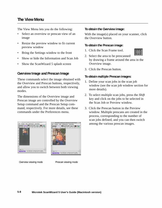
5-8 Microtek ScanWizard 5 User's Guide (Macintosh version)
The View Menu
The View Menu lets you do the following:
• Select an overview or prescan view of animage
• Resize the preview window to fit currentpreview window
• Bring the Settings window to the front
• Show or hide the Information and Scan Job
• Show the ScanWizard 5 splash screen
Overview Image and Prescan Image
These commands select the image obtained withthe Overview and Prescan buttons, respectively,and allow you to switch between both viewingmodes.
The dimensions of the Overview image andPrescan image are controlled by the OverviewSetup command and the Prescan Setup com-mand, respectively. For more details, see thesecommands under the Preferences menu.
To obtain the Overview image:With the image(s) placed on your scanner, clickthe Overview button.
To obtain the Prescan image:1. Click the Scan Frame tool.
2. Select the area to be prescannedby drawing a frame around the area in theOverview image.
3. Click the Prescan button.
To obtain multiple Prescan images:1. Define your scan jobs in the scan job
window (see the scan job window section formore details).
2. To select multiple scan jobs, press the Shiftkey and click on the jobs to be selected inthe Scan Job or Preview window.
3. Click the Prescan button in the Previewwindow. Multiple prescans are created in theprocess, corresponding to the number ofscan jobs defined, and you can then switchamong the various prescan images.
Overview viewing mode Prescan viewing mode

5-9Reference
Resize Window to Fit
This command resizes the Preview window, which you may find helpful for conserving space onyour desktop monitor especially after enlarging the Preview window.
To use this feature:
Choose the command Resize window to Fit. You can also do this by pressing Command + R (theApple Command and R keys) simultaneously.
To verify the zoom level, open the Information window (choose Show Info Window command fromthe View menu), and look up the zoom level.
Before resizing After resizing
Zoomlevelshownhere
5-10 Microtek ScanWizard 5 User's Guide (Macintosh version)
Bring Settings Window to Front
This command brings the Settings window tothe forefront, which is useful if you have theSettings window hidden behind other windowsor if you have expanded your Preview windowsuch that it covers the Settings window.
Show / Hide ... Window commands
These commands allow you to toggle betweenshowing or hiding the Settings, Scan Job andInformation windows of ScanWizard 5, as thecase may be.
About
This command displays the ScanWizard 5 splashscreen and shows program version and copy-right information.

Reference 5-11
The Preferences Menu
The Preferences menu lets you do the following:
• Choose the desired scan material
• Specify color matching parameters
• Set up white / black points
• Show / hide cursor auxiliary lines to helpyou with alignment of the scan frame
• Control the size of your preview window
• Keep your scan module after you finishscanning
• Create effects like invert and mirror
• Activates the smoked glass backgroundeffect to help distinguish the active scanframe(s)
• Set other options, such as specifying aworking directory for files
Scan Material
This command allows you to select your scanmaterial — whether it is Reflective (photographsand prints), Positive Transparency, or NegativeFilm.
If you are using a dual-bed scanner such as theArtixScan 2020 or ScanMaker 4, all three scanmaterial options will be available for you tochoose from.
If you are using a flatbed scanner, the PositiveTransparency and Negative Film options willnot be available for selection unless you use aTransparency Media Adapter with the scanner,which will then let you scan transparencies andfilm media.
To select the scan material:
1. Choose the Scan Material command in thePreferences menu. From the submenu thatappears, select your scan material.
2. Alternatively, you can also click the ScanMaterial icon (beside the Scan button), andthen choose the correct scan material fromthe drop-down menu that appears.

5-12 Microtek ScanWizard 5 User's Guide (Macintosh version)
The appearance of the Scan Material icon willchange, according to your choice.
Appearance of the Scan Materialicon for Reflective materials.
Appearance of the Scan Materialicon for Positive Transparency.Note the "perforations" on the topand bottom to distinguish this fromthe Reflective icon.
Appearance of the Scan Materialicon for Negative Film.

Reference 5-13
Color Matching
Color Matching is an important feature of ScanWizard 5 that ensures color is displayed consistently— from the initial input stage when an image is captured by the scanner, to the final output stagewhen the image is output to your monitor or printer (through either the Kodak CMS or AppleColorSync™ technology). Color matching was developed to allow an equivalent "mapping" of colorsfrom one device or from one color space to another, ensuring that no major color shifts occur in thetransferrence process.
To use the ScanWizard 5 color matching function:
1. Set up the Kodak CMS and Apple ColorSync features correctly at the time that ScanWizard 5 isinstalled. For more information on this procedure, refer to your Kodak or Apple system docu-mentation.
2. The first time you launch ScanWizard 5, you will be prompted to set up color matching for yourscanner. You may access the color matching parameters for ScanWizard 5 at any time in thefuture, however, by choosing the Color Matching Setup command in the Preferences menu.ScanWizard 5 includes several industry-standard ICC color profiles
4
5
67
3
2
1

5-14 Microtek ScanWizard 5 User's Guide (Macintosh version)
1 Display using monitor compensation: Thisbox pertains to how your monitor displayscolor, relative to the RGB Destination colorspace. It is best to have this box checked sothat there are no unexpected color shiftsbetween your selected RGB Destinationspace and your monitor. See the Appendixfor more information.
2 Monitor: The monitor selection shown hereis the monitor set in your Apple ColorSyncControl Panel.
To verify this information, go to your AppleMenu, select Control Panel, then ColorSync. Your selected monitor will be shown,which should be the same as the entry in thisdialog box.
This setting only affects how the image isshown on the screen — not the final scannedimage.
3 RGB Color Matching: This box shouldgenerally be checked unless you want toscan raw color data, in which case you losethe compensatory effects of the ColorMatching system.
Note: It is not desirable to scan in raw dataand then perform ColorSync data conver-sion, which will not generate the correctCMS effect.
4 (to be added)
5 RGB Destination: This feature lets youselect the ICC profile in the ColorSyncprofile folder for outputting images to theRGB color space.
You may select from monitor, RGB printer(e.g., inkjet printers), a special color space,or the Adobe Photoshop 5.0 internal colorspace profile. For Photoshop 5.0 users, thisshould always be the same as your RGB
working space as defined in the Photoshop5.0 RGB Setup.
A large number of RGB profiles is suppliedby ScanWizard 5. If you do not see the ICCprofile for your monitor or RGB device,contact your device manufacturer. To load aspecific ICC profile from a different folder,click the RGB profile button and select theprofile.
6 Preview check box: This immediatelyupdates the Preview window image when anew color profile is selected. This will reflectcolors consistent with the newly selectedprofile.
7 Profile Information button: This lets you getinformation on currently used ICC profiles.
Note: For advanced users who wishto know more about color matching,refer to the Appendix at the end ofthe manual.

Reference 5-15
White / Black Point Setup
This command provides your with advanced controls for setting the clipping points for your whiteand black points, as well as determining the output levels for the white/black points on your printer.
To use this feature:
1. Choose the White/Black Points Setup command from the Preferences menu.
2. As an alternative, you can click this command from the Color Correction Menu. This is also thesame thing as clicking the White/Black points tool in the Settings window and then clicking theSetup button from the dialog box that comes up. When the dialog box comes up, specify yourpreferences.
Auto White / Black Point Clipping
The Auto White Point clipping and Auto BlackPoint clipping fields allow you to specify thepercentage by which the white and black points,respectively, can be clipped from the histogram.The clipping is done after you click the Autobutton in the White/Black Points dialog box.
For example, if you specify 10 percent as yourWhite Point clipping value and then click theAuto button, the white point on the histogram isadjusted so that 10 percent of the color informa-tion is "clipped" or ignored. The resulting 90percent information leftover is then remapped,resulting in an image with less highlight detail.
The same principle above applies to the AutoBlack Point clipping feature, which governs theblack point for shadows.
These fields are normally used by more ad-vanced users, and the features are taken care ofautomatically if you have set up Color Matchingcorrectly early on in ScanWizard 5.
Minimum / Maximum Output LevelThe Minimum Output Level lets you set theminimum output level of the black point. Thehigher the percentage value, the lower thecontrast will be.
The Maximum Output Level lets you set theoutput level of the white point. The lower thepercentage value, the lower the contrast will be.

5-16 Microtek ScanWizard 5 User's Guide (Macintosh version)
Cursor Auxiliary Lines
This command allows you to show or hidecursor auxiliary lines to help you define a scanframe or measurement off the rulers moreprecisely. The cursor auxiliary lines show onlywhen the Scan Frame tool is selected.
To use this feature:
1. Choose the Cursor Auxiliary Lines com-mand in the Preferences menu. From thesubmenu that appears, select how thecursor lines will appear.• On both the x (horizontal) and y (verti-
cal) axis• On the x axis only• On the y axis only• None (no cursor lines)
2. Click the Scan Frame tool. When you movethe pointer to the image, the cursor auxiliarylines will appear.
Cursorauxiliary lineson the x and y
axis

Reference 5-17
Overview Setup
This command lets you set the area you want to overview off the scanner bed and provides someoverview options as well.
By default, ScanWizard 5 overviews the maximum scan area as determined by your scanner model'sbed size. You can, however, customize the overview area so that the scanner consistently overviewsonly the specific dimensions you have in mind. For example, if your maximum scan area is 8.5" x14", you can customize the overview area so that it consistently overviews, say, 4" x 8" of the bedsize.
As a rule of thumb, it is best to use the default maximum settings. You should change the overviewarea only if your subsequent overview is too large to be shown in entirety, or too small for reliablepreviewing. A smaller overview area will increase the overview resolution for clearer imageviewing. You may also wish to change the size of your overview to improve performance. Gener-ally, a shorter overview time results from the scanner motor travelling at a lesser distance.
4
2
3
5
6
1

5-18 Microtek ScanWizard 5 User's Guide (Macintosh version)
1 Overview Area: This represents the scanbed size. The dimensions of this overviewarea, however, will depend on the size asstipulated by #2 and #3 below.
2 Size: This option lets you choose whether todo an overview of the Maximum area or aCustom area.
• Maximum refers to the maximum areathat can be overviewed. The dimensionsof the maximum area vary, depending onyour scanner model from 8.5" x 11.7 to8.5" x 14". Take note that transmissivescan areas are smaller.
• Custom refers to the area as determinedby the dimensions you specify in #3below.
3 Left, Top, Width, Height: These edit boxeslet you specify the dimensions of theoverview area.
• Top and Left refer to the starting pointsof the overview area on the X and Ycoordinates.
• Width is the expanse of the overviewarea. Height is the depth of the overviewarea.
4 Overview Option: Fast Overview speeds upthe overview process. .
5 Overview button: This button lets you do anew overview and is helpful if you havespecified custom settings or changed thedimensions.
6 OK: Clicking this button accepts thesettings and dimensions specified in thedialog box.
To change the size of your preview area:1. Go to the Preferences menu in the Preview
window, and choose Overview Setup.
2. When the Overview Setup dialog boxappears, click the Overview button topreview the entire bed. This will help youdetermine how you wish to resize theoverview area.
3. To change the overview area, you can:
• Drag a rectangle that approximates thesize of the overview that you wish; or
• Enter the appropriate values for the Top,Left, Width, and Height edit boxes. Thenew dimensions will take effect on thenext Overview — when you click theOverview button again in the Previewwindow (not the Overview button in theOverview Setup dialog box).
A
B

Reference 5-19
Prescan Setup
The Prescan Setup command lets you determine the margin surrounding the prescan image and thesize of the prescan image.
To change the margin or size of the prescan image:
1. Go to the Preferences menu in the Preview window, and choose Prescan Setup.
2. When the Prescan Setup dialog box appears, specify your choices.
• Prescan Image Margin: The options here let you specify how wide or narrow the marginaround the scan frame is in the prescan image.
This is helpful because selecting the exact scan frame (through the Scan Frame tool) cannever be a completely accurate process, and what appears to have been selected by the scanframe when you view the image in the lower-resolution overview may or may not actuallyinclude the portion you wish. The margin — depending on how wide or narrow it is — canthen provide a berth or allowance for extending the boundaries of the scan frame around theprescan image. Margin options include minimal, small, medium, and large.
•. Prescan Image Dimension: This option lets you specify how large the prescan image willbe: Full screen, 75%, 50%, or fit current preview window.
This option allows you to either shrink the preview window to maximize the use of space onyour monitor, or to expand the view of the image to full screen to see it in greater detail.The larger the size, the higher the prescan resolution. The maximum prescan resolution isthe scanner's optical resolution.

5-20 Microtek ScanWizard 5 User's Guide (Macintosh version)
More...
This command shows the More Preferencesdialog box, where you can specify other optionsfor ScanWizard 5.
A. Keep Overview ImageThis option lets you retain the last overviewimage you used. The next time you startScanWizard 5, this last preview image is againdisplayed in the preview window.
B. Keep All Prescan ImagesThis option lets you retain all prescan images ifyou have done several prescans, allowing you toswitch among the various prescan images in theView menu. Otherwise, the image is automati-cally deleted when you exit ScanWizard 5.
Invert
This command inverts images of all scan jobs tonegatives. Take note that all scan jobs areinverted at the same time; you cannot invert anindividual scan job alone.
When an image is inverted, the brightness valueof each pixel is converted to its inverse value. Inthe case of 24-bit images, for example, a pixelin a positive image with a value of 255 ischanged to 0, and a pixel with a value of 5 ischanged to 250.
To use this feature:
Choose the Invert command in the Preferencesmenu. A check appears next to the commandwhen it is enabled.
Retain Scan Module after Scan
This command allows you to keep theScanWizard 5 interface running after scanningis completed and the image delivered to yourimage-editing software.
This way, you do not have to go back to theFile-Acquire process to start ScanWizard 5 allover again.
Note: This command can be used only inapplications (such as Adobe Photoshop) thatallow you to retain the scan module after a scanis completed. Some applications will not retainthe scan module even if this option is enabled.
To use this feature:
Choose the command Retain Scan Module afterScan in the Preferences menu. A check appearsnext to the command when it is enabled. If youwish to see the scanned image in your image-editing software after scanning is completed,you will need to quit ScanWizard 5 to see theimage.
InvertOriginal

Reference 5-21
C. Smoked Glass as BackgroundThis option lets you apply a smoked glassbackground that makes your scan jobs stand outmore clearly. This feature can also be used ifyou have multiple scan jobs in their respectiveimage modes, and this will be shown clearly inthe Preview window (example: 1 job in color,another in B&W).
D. Scan QualityThis option allows you to select the imagequality by controlling the scanner hardware andthe maximum image processing depth.
• Speed: Choose this option if your primaryconcern during scanning is speed. Imagedata is delivered faster and the image datais processed in 8 bits per channel.
• Quality: This is the default setting. Scanneddata is delivered a little slower but in highquality, and the image data is processed in 8bits per channel.
• Best: This setting is available only tohigher-depth scanners (10-, 12-bit, orhigher). Scanned data is delivered a littleslower but in high quality, and image data isprocessed in maximum bits per channel(i.e., 10-, 12-bit, or higher), and thenconverted to the desired output depth. Thisspecial operation results in the best imagequality possible.
E. Memory UsageThis option controls the way ScanWizard 5 usesmemory. Three options are provided:
• Application: ScanWizard 5 will only usethe memory inside the application heap asits image buffer. Make sure you allocate alarge number of memory in your applica-tion for this purpose. Otherwise,ScanWizard 5 may not have enoughmemory to run. Use this option only if youdon't want ScanWizard 5 to use memoryoutside your application.
• System: ScanWizard 5 will use the memoryin the system heap as its image buffer, andonly a limited amount of memory is used inthe application heap. This option is best ifyou have only a small memory allocationfor your application but a large amount ofsystem memory.
• Auto: This is the default setting.ScanWizard 5 maximizes the memoryusage from both system and application,looking for memory first from the systemheap and then from the application heap.
G. Scratch DirectoryThe scratch directory is the folder whereScanWizard 5 creates temporary files, with the
Smoked glass background turned on showsmultiple scan jobs in their respecitve imagemodes (color or grayscale)
Grayscaleimage

5-22 Microtek ScanWizard 5 User's Guide (Macintosh version)
The Correction Menu
The Correction Menu lets you use the AdvancedImage Correction (AIC) features of ScanWizard5. The commands in the Correction menucorrespond to the AIC buttons in the Settingswindow.
For more information, see the section of themanual on Advanced Image Correction.
temporary files deleted at the end of an opera-tion. You should change to a different folderonly if the scratch directory is located in a diskvolume that is too small for scanning operations.To specify a new scratch directory, chooseOther Directory... from the menu.

5-23Reference
The Toolbar
Zoom
Scan Frame
Pane
Info Window
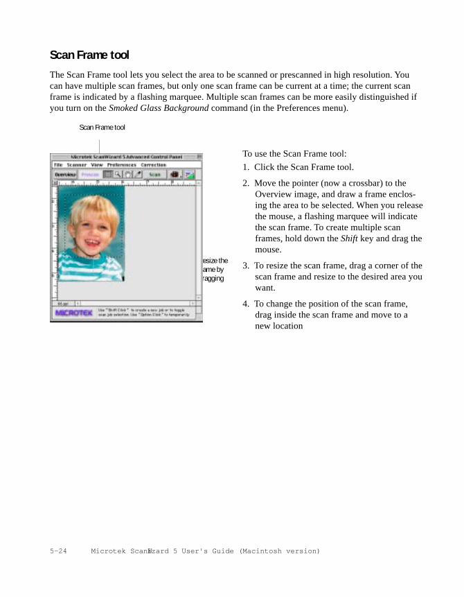
5-24 Microtek ScanW izard 5 User's Guide (Macintosh version)
Scan Frame tool
The Scan Frame tool lets you select the area to be scanned or prescanned in high resolution. Youcan have multiple scan frames, but only one scan frame can be current at a time; the current scanframe is indicated by a flashing marquee. Multiple scan frames can be more easily distinguished ifyou turn on the Smoked Glass Background command (in the Preferences menu).
To use the Scan Frame tool:
1. Click the Scan Frame tool.
2. Move the pointer (now a crossbar) to theOverview image, and draw a frame enclos-ing the area to be selected. When you releasethe mouse, a flashing marquee will indicatethe scan frame. To create multiple scanframes, hold down the Shift key and drag themouse.
3. To resize the scan frame, drag a corner of thescan frame and resize to the desired area youwant.
4. To change the position of the scan frame,drag inside the scan frame and move to anew location
Scan Frame tool
Resize theframe bydragging

5-25Reference
Zoom tool
The Zoom tool lets you zoom in (magnify) andzoom out (reduce) your view of the image. Onlyyour view of the preview image is changed; theactual size of the image remains unaffected.
Each click of the zoom tool magnifies orreduces by a factor of 2. Thus, the magnificationlevels increase from 100% to 200%, to 400%,and to the maximum 800%. When you reach themaximum magnification factor, the center of theZoom tool will appear empty.
To zoom out (reduce), hold down the Optionkey and with the Zoom tool selected, click theimage. A minus sign will be in the middle of thelens to indicate the image is being zoomed out.
To use the Zoom tool:
1. Click the Zoom tool.
2. Place the pointer — now a lens with a plussign inside it — on the image and click. Toreduce the view, hold down the Option key(the Zoom tool changing to show a minussign inside it), and click again.
Original image
View enlarged withZoom tool

5-26 Microtek ScanW izard 5 User's Guide (Macintosh version)
Pane tool
The Pane tool lets you scroll through anoverview or prescan image, allowing you tomove parts of the image into view quicklywithout using the scroll bars.
You can use the Pane tool for scrolling throughzoomed-in images that were enlarged throughthe Zoom tool, or for scrolling through parts ofan image not included completely within theframe of the preview window.
To use the Pane tool:
1. Click the Pane tool.
2. Move the pointer (now in the form of a hand)to the image. Hold down the mouse andmove the Panel tool left, right, up, or down,and you will see portions of the image comeinto view.
Original image
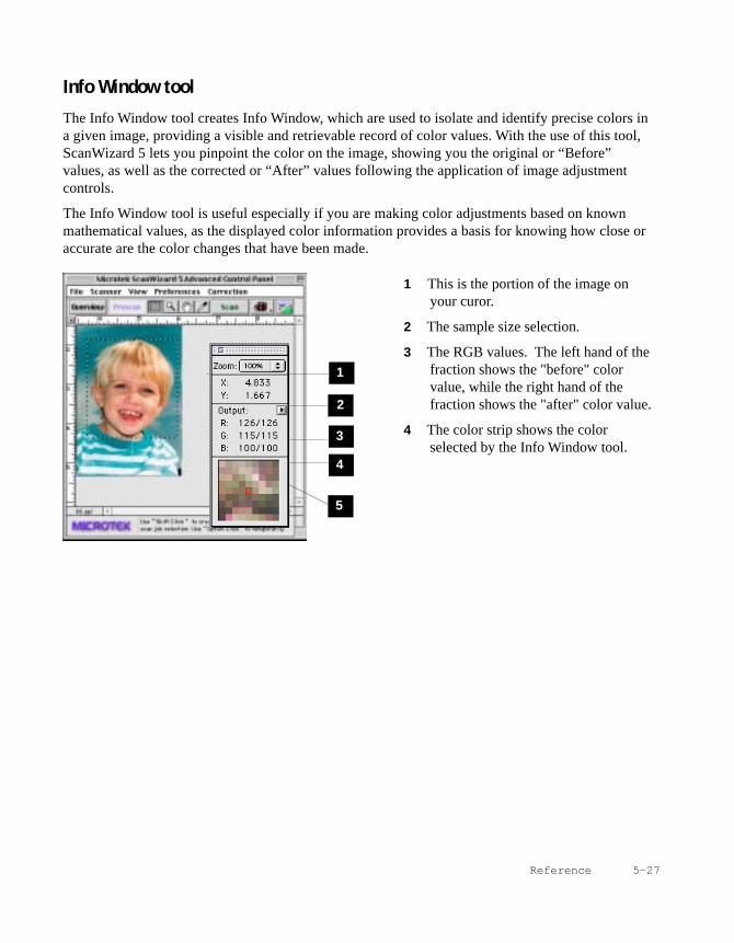
5-27Reference
Info Window tool
The Info Window tool creates Info Window, which are used to isolate and identify precise colors ina given image, providing a visible and retrievable record of color values. With the use of this tool,ScanWizard 5 lets you pinpoint the color on the image, showing you the original or “Before”values, as well as the corrected or “After” values following the application of image adjustmentcontrols.
The Info Window tool is useful especially if you are making color adjustments based on knownmathematical values, as the displayed color information provides a basis for knowing how close oraccurate are the color changes that have been made.
1 This is the portion of the image onyour curor.
2 The sample size selection.
3 The RGB values. The left hand of thefraction shows the "before" colorvalue, while the right hand of thefraction shows the "after" color value.
4 The color strip shows the colorselected by the Info Window tool.
2
3
4
5
1

5-28 Microtek ScanW izard 5 User's Guide (Macintosh version)
You can also change the sample size of the InfoWindow tool and specify whether you aresampling a 1x1 pixel area, 2x2, and so forth.The sample size is changed in the Informationwindow.
To change the sample size of the Info Windowtool:
1. Open the Information window by choosingthe Show Info Window command in the Viewmenu.
2. Click the Sample Size button, located to theright of the RGB values in the Informationwindow.
3. Choose your options.
• Select Value or Percent to determine howthe pixel information will be displayed.
• Select the sample size. For instance, the 1by 1 option will display the value of onepixel — the one in the middle of theSample Display area. The 3 by 3 optionreads the average value of an area that is3x3 pixels.
For more information on this subject, see thesection on The Information Window.

5-29Reference
Overview, Prescan, and Scan
The Overview button previews theimage in the scan bed.
By default, the entire scan bed is previewedwhen you click the Overview button. To changethe area to be previewed, specify the dimensionsin the Overview Setup command (in thePreferences menu).
The Scan button scans the imagesin your scanner and delivers theimages to your image-editing
software. The images that are scanned are thescan jobs that have been checked in the ScanJob window.
Note: If the Retain Scan Module After Scanoption (in the Preferences menu) is checked, youwill need to exit ScanWizard 5 to see thescanned image in your image-editing software.The Prescan button previews in
high resolution the area selectedby the scan frame tool. Multiple prescans can bedone if you have selected several scan jobs.Options governing the prescan function can befound in the Prescan Setup command in thePreferences menu.
To obtain multiple prescan images:
1. Define your scan jobs in the scan jobwindow (see the scan job window section formore details).
2. To select multiple scan jobs, press the Shiftkey and click on the jobs to be selected in theScan Job or Preview window.
3. Click the Prescan button in the Previewwindow. Multiple prescans are created in theprocess, corresponding to the number of scanjobs defined, and you can then switch amongthe various prescan images.

5-30 Microtek ScanW izard 5 User's Guide (Macintosh version)
Rulers
The rulers on the top and left sides of thePreview window help you with measurementand alignment, marking off measurementaccording to the selected unit (inch, pica, pixel,etc.).
The rulers change when dimensions are alteredin the preview area of the Overview Setupcommand (in the Preferences menu). Forexample, if you change the preview area sizefrom 5" x 8" to 6" x 9", the rulers will changeaccordingly.
Unit of Measurement
The unit of measurement can be selected in twoways:
• Through the Unit box in the Settingswindow.
• Through the arrow at the corner where therulers meet in the Preview window.
The options for unit of measurement includeinch, centimeter, millimeter, point, and pixel.The pixel option is dimmed if the selectedresolution unit is lpi.
Select unit ofmeasurementhere
Ruler

5-31Reference
The Settings WindowThe Settings window contains the commands for outputting your scanned image and includes theimage-enhancement tools of the ScanWizard 5.
2
1
3
10
9
4
5
7
11
12
68
14 15
13

5-32 Microtek ScanWizard 5 User's Guide (Macintosh)
1 Job: This shows the current scan job asindicated by the Scan Job window and bythe selected image in the Preview win-dow.
2 Type: This shows the image type of thecurrent scan job.
3 Resolution: This lets you specify theoutput resolution in your final scan.
4 Resolution list box: This providespredefined resolution values for easierselection of the resolution setting.
5 Resolution unit: This provides the unit ofselection for resolution. Choose from ppiand several lpi options.
6 Scan Frame settings: These settings(which include the Scan Frame width andheight edit boxes) represent the area onthe scan bed that you wish to scan.
7 Output settings: These settings (whichinclude the Output width and height editboxes) represent the dimensions of theimage when it is output to either a monitoror printer.
8 Scaling: This lets you scale images,creating larger or smaller images from theoriginal source image in the process. TheScaling list box beside the scaling editbox provides predefined scaling percent-ages.
9 Image size: This shows the size of the filewhen the image is scanned. The resultingfile size depends on the image type (color,grayscale, etc); resolution; and dimen-sions of the image.
10 Scan Frame options: These optionsinfluence the behavior of the scan framerelative to the overview image.
11 Unit of measurement: This lets you chooseyour desired unit of measurement, whichwill then be reflected in the rulersalongside the Preview window. Choosefrom inch, cm, mm, point, or pixel.
12 Transform: This lets you flip horizontallyor rotate the image in increments of 90degrees.
13 Advanced Image Correction (AIC)controls: These controls let you adjust andenhance the image, and image correctionscan be displayed in real time.
14 Custom options: These allow you to addor remove custom settings for each AICcontrol.
15 Reset: This button changes settings in theAdvanced Image Correction controls totheir default values.

5-33Reference
Line Art
Line Art images are made up of one bit of color(black or white) per pixel. Few editing optionsare available in this mode, but this mode isuseful for images consisting purely of black andwhite or even single colors, such as mechanicaldrawings, blueprints, or fine-line illustrations.
Web / Internet Colors
This mode is useful fordisplaying images on theWeb or Internet. Output forthe Web / Internet colormode in ScanWizard 5 is 8-bit, 256 indexed colorimages.
Indexed color: 208K
Grayscale
Grayscale images useshades of gray to simulategradations of color or tonalvalues, and contain 8 bitsper pixel. The Grayscale 16-bit option is provided inScanWizard 5 for profes-sional pre-press scanners.
Grayscale: 208K
Black-and-White Diffusion
This is a single-bit black-and-white imagedithered with error diffusion. The black andwhite pixels are arranged in a way as to “fool”the eye into seeing gray.
RGB Color
RGB (Red, Green, and Blue) images use threecolors to reproduce up to 68.7 billion colors.Because scanners and monitors are RGBdevices, the RGB color space is the mostcommonly used space for capturing anddisplaying images. ScanWizard 5 offers stan-dard RGB and 48-bit RGB color selection, withthe 48-bit option available for the ScanMaker 5,ScanMaker 2000, and other Microtek profes-sional pre-press scanners.
Image Types
ScanWizard 5 allows direct scanning in the following color spaces described below. The desiredcolor space in ScanWizard 5 can be selected in the Type box in the Settings window.
RGB color: 622K

5-34 Microtek ScanWizard 5 User's Guide (Macintosh)
Palette:The Palette option lets you choose the methodfor creating the color palette table. Uniform usesa 6-6-6 fixed color palette table. Adaptive(default) creates a color palette table from themore commonly used areas of the color spec-trum that appears in the image.
Dither:The Dither option can improve the color qualityof the 256-indexed color image for photographsor continuous-tone images, using a technique ofmixing available colors to simulate missingcolors. None provides no dithering. Pattern usesa structured pattern to simulate missing colors.Diffusion (default) uses the error diffusiontechnique to dither colors and produces the bestquality for 256 colors.
256 Colors (Default) / 256 Colors (Custom)
These are single-channel images (8 bits perpixel) that use a color lookup table containingup to 256 colors. The file size is smaller forimages in this mode. As an initial setting,selecting 256 Colors (Default) uses an Adap-tive palette with Diffusion. If the 256 Colors(Custom) option is selected, the dialog boxbelow appears.

5-35Reference
To select your resolution unit:
• Choose ppi if your scanned images areintended for on-screen display; you do nothave to go higher than the target resolutionof your monitor (usually 72 dpi forMacintosh and 96 dpi for Windows). Ahigher resolution will simply increase thefile size of your image without any percep-tive improvement in image quality.
• Choose lpi if your scanned images are to beprinted. If you choose 1x, for instance, yourscanned image will be printed at 133 linesper inch, resulting in a 133-dpi image. At1.5x, the image will be printed at 199.5 dpi;and at 2x, the image will be printed at 266dpi. The Custom option allows you to set anlpi value of your own specification.
In choosing an appropriate lpi value, keepin mind that if the resolution is too low,pixelization of the image results, in whichthe Postcript language uses a single pixel'scolor values to create more than onehalftone dot. If the resolution is too high,the file size becomes unwieldy and your fileends up containing more information thanthe printer needs, slowing down the printingprocess.
Resolution
Resolution is the sampling of image pixel permeasurement unit or the amount of pixelinformation stored in an image. Together, theimage resolution and dimensions determine thefile size of the image, which is measured inkilobytes (KB) or megabytes (MB).
The resolution of an image is important indetermining the quality of the output image.Resolution is also directly related to file size,and the higher the resolution, the larger theresulting file size will be.
When dealing with resolution, remember todistinguish between optical resolution andinterpolated resolution.
Optical resolution is the "real" resolution asmeasured by the scanner's optics. Interpolatedresolution is software-enhanced resolution andcan be useful for enlarging very small images orfor printing line art to obtain superior results.
Resolution Unit
The unit of measurement for resolution is in ppi(pixels per inch) or lpi (lines per inch). Lpisettings are dimmed if the ruler unit is in pixels.

5-36 Microtek ScanWizard 5 User's Guide (Macintosh)
Scan Frame, Scaling, Output, and Transform
The input / output dimensions of your image are controlled by the Scan Frame Settings, Scaling,and the Output Settings. Together with the Scan Frame options, these fields allow to you controlwith precision the size of the image to be scanned or output.
Scan Frame settings
The Scan Frame settings (width and height)represent the area on the scan bed that you wishto scan.
To specify your settings, enter the dimensionsmanually in the width and height edit boxes; oruse the Scan Frame tool to define or resize yourscan frame. Changes made in the Previewwindow are automatically displayed in the ScanFrame setting edit boxes.
Scaling
Scaling lets you create larger or smaller imagesfrom the original source image. Take note of thefollowing:
• Keep the scaling at 100% if you are output-ting at the same size (e.g., a 4” x 5” originalto be output at the same size).
• Reduce the scaling if you are outputting yourimage at a smaller size (e.g., a 4” x 5”original to be output to 2” x 2.5”). Increasethe scaling if outputting at a larger size.
To choose the scaling percentage, click the up/down arrow next to the scaling box, or enter avalue in the scaling edit box.
In the default settings of ScanWizard 5, where none of the Scan Frame options are checked, takenote of the following:
• Changing the Scan Frame settings (width or height) will change the Output settings (width orheight).
• Changing the Scaling will change the Output settings (width AND height).
• Changing the Output settings (width or height) will change the Scan Frame settings (width orheight).
The edit boxes for ScanFrame settings, Scaling,
and Output settings.
Scan Frameoptions
Transform or flip animage in 90˚increments
5-37Reference
Output Settings
The Output settings (width and height) representthe dimensions of the image when it is output (toeither monitor or printer). If the size of the imageto be output is different from the size of theoriginal source image, adjust the scaling percent-age, or manually increase / decrease the outputvalues accordingly.
Scan Frame options
The Scan Frame options include Fixed ScanFrame, Fixed Output Size, and Keep Proportion.
1. Fixed Scan FrameThis option lets you lock in the settings ofyour scan frame, so that the width andheight dimensions of the frame are alwayspreserved no matter where you move theframe in your preview image.
If you know the exact input size for yourimage, or if you wish to “lock” the settingsof your scan frame to a particular size, enterthe Scan Frame width and height valuesfirst, then check Fixed Scan Frame. Yourscan frame will be “fixed” at those values,so even if you move the scan frame aroundthe preview image, the dimensions of theframe itself will remain unchanged.
2. Fixed Output Size When the Fixed Output Size option is
checked, the values specified for outputwidth and height remain unchanged. If anyof the input values are changed, the scalingwill be adjusted automatically to preservethe output dimensions correctly.
If you know the exact output size for yourimage, enter the output width and heightvalues first, then check Fixed Output Size.The image will then be scanned and outputat the values you specify.
Unit of Measurement
The unit of measurement lets you select thedesired unit (inch, cm, mm, point, pixel) for yourimage dimensions.
Important: Make sure you select the correctunit of measurement before entering any of thevalues for width or height in the Scan FrameSettings or Output Settings.
Additional Notes• When none of the Scan Frame options are
checked, all five edit boxes are enabled,allowing you to edit or enter values into anyof the boxes.
• The Fixed Scan Frame and Fixed OutputSize options are mutually exclusive. Thismeans that only one of the options can bechecked at any time; checking another optionwill automatically uncheck the other one.
• When an illegal value is entered (e.g., theinput width exceeds the scan frame size), thevalue will appear in red as a flag or warningindicating an out-of-range value.
3. Keep ProportionWhen the Keep Proportion option ischecked, the width and height values of theimage are kept in proportion despitechanges made to either setting. Thispreserves the aspect ratio of the image.
This option is automatically checked wheneither “Fixed Scan Frame” or “FixedOutput Size” is selected.

5-38 Microtek ScanWizard 5 User's Guide (Macintosh)
Transform
The Transform command allows you to rotateand / or flip the image in increments of 90degrees.
The effects of the Transform command are seenonly after you click the Scan button and scan theimage in; the effects are not shown in thePreview or Overview modes.
To use the Transform command,
1. Click on the Transform button in theSettings window.
2. From the options that appear, choose thedegree of rotation you wish.
3. Click the Scan button in the Previewwindow. When the image is scanned, it willbe rotated or transformed according to theselected option.

5-39Reference
The Advanced Image Correction Tools
The Advanced Image Correction (AIC) tools are an integral part of ScanWizard 5 and includeseveral powerful mechanisms for adjusting or enhancing your images. These tools include White &Black Points, Tone Curve, Brightness & Contrast, Color Correction, Filters, and Descreen. Takenote of the following:
1. To access an AIC tool, click a particular tool in the Settings window or choose its counterpart inthe Correction menu in the Preview window.
2. After clicking a tool, the AIC dialog box appears. The elements of the AIC dialog box areexplained in the next section.
Note: For scanning innegative mode, theDescreen menu isreplaced by the FilmType menu.
1
2

5-40 Microtek ScanWizard 5 User's Guide (Macintosh version)
Elements of the Advanced Image Corrrection screen
1 Left Thumbnail: This shows the imagebefore enhancements are applied.
2 Right Thumbnail: This shows the imageafter enhancements are applied. In theexample shown, the brightness and contrastfeatures of the image have been altered.Updates to the image are shown in real time.
3 Advanced Image Correction Tools (AIC):These tools let adjust or enhance yourimages. Click any tool in this area, and seehow the core of the AIC screen (#6) changesto reflect the properties of that tool.
4 Preview option: If checked, changes orenhancements are applied immediately tothe Preview window image (for bothOverview and Prescan images). If un-checked, changes are seen only after youclose the AIC dialog box
5 Thumbnail option: If checked, the beforeand after thumbnails are shown in the AICscreen. You can choose to uncheck thisoption and hide the thumbnails, sincechanges can be previewed in the Previewwindow. If unchecked, the screen collapsesto show only the lower portion of the dialogbox.
6 Core of the AIC screen: This is the heart ofthe AIC screen, and the content herechanges to reflect your selected AIC tool.
7 Action Buttons: These carry out a specificaction. See the next section for more details.
2
4
5
6
7
1
3

5-41Reference
The Action Buttons
The Action buttons in the AIC dialog box carry out a specific action. Details follow.
Reset buttonThis button brings up the Reset dialog box,where you can specify the settings to be reset bychecking the box next to the targeted settings. Ifyou click the Reset button, the settings arerestored to their default values; if you click theCancel button, the operation has no effect, andthe settings remain in force.
Example: If you changed the tone curve andbrightness, then checked the brightness optionand clicked Reset, the brightness setting of thescan job is restored to its default value. Thealtered tone curve, however, remains in effect.If you reset both tools, then both are restored todefault.
OK buttonThis button applies to the current scan jobwhatever image enhancements you haveperformed, and then closes the AIC dialog box.
Example: If you increased brightness, changedthe saturation, and then clicked OK, all thechanges are applied, and you exit the AIC dialogbox.
Cancel buttonThis button cancels out all image-enhancementchanges you have made to the current scan job,and then closes the AIC dialog box.
Example: If you applied filters, changed thecurve, and then clicked Cancel, none of thechanges will take effect, and you exit the AICdialog box.

5-42 Microtek ScanWizard 5 User's Guide (Macintosh version)
Revert buttonThis button cancels out the changes that weremade with the current image-enhancement tool.This means that if you used several AIC tools,Revert cancels the effect of only the last used(or current) tool, and preserves the effects of theother preceding tools.
Example: If you changed the tone curve, appliedfilters, changed brightness, then clicked Revert,the brightness changes will be cancelled out, butthe altered tone curve and filters settings remainin effect.
Add to Menu buttonThis button adds the settings you have per-formed to the menu in the Settings window, sothat you can retrieve and load the settings in thefuture if necessary.

5-43Reference
White / Black Points
The histogram located in the White & Black points screen shows the total distribution of color databefore user corrections are applied. This tool lets you adjust the white and black point of thescanned image. The white / black point controls which color value of the image to be scannedappears as absolute white / black in the output image. Other color values are adjusted in a similarmanner.
For example, moving the black point indicator to the right in an image which contains very littleshadow data will allow more contrast in the highlight area of the image. Conversely, moving thewhite point indicator to the left (to lower color values) in an image with very little highlight datawill allow more contrast in the shadow area of the image. This tool can be used either on all colorsat once or on individual color channels.
The White/Black Points screen is available for all color images types and grayscale images. Thechannels are RGB or Gray.
1
3 2
4
5
6
2
7

5-44 Microtek ScanWizard 5 User's Guide (Macintosh version)
1 Histogram: The histogram is a graphicrepresentation of how all the pixels in animage are distributed across brightness anddarkness levels. The darkest pixels are at theleft; the lightest pixels are at the right.
A histogram skewed heavily to the leftindicates that the image has many more darkpixels than light. Conversely, a histogramskewed heavily to the right will indicate alight image as it has more light pixels thandark. The height of the histogram indicates thenumber of pixels at that point in the histo-gram.
2 Sliders: The sliders are used to adjust theBlack and White points of the image. Thevalues of the black and white points arereflected in the edit boxes below.
3 Auto: The Auto button automatically judgesthe darkest and whitest points and clipsexcessive black or white points. The clippingpercentage of the white/black points isaccessible by clicking the Setup button.
4 Channel: The channel button lets you controlthe shadow and highlight settings for aparticular color channel (red, green, or blue),or for the Master channel (red, green, and bluesimultaneously). For CMYK images, thechannel selections are cyan, magenta, yellowand black (for K).
5 Input, Count, Percent: These figures provideinformation about the histogram. The figureswill appear only when the cursor is on thehistogram or if a slider is being moved.
• The Input value indicates the color valueof the data displayed in the histogram.
• The Count value indicates the number ofpixels at the Input value. If Input value is2 and Count value is 1300, then there are1300 pixels in the image at the Inputvalue of 2.
• The Percent value is the percentage ofall pixels in the image where colorvalue is less than or equal to the inputvalue. For example, if Percent is 15%and Input value is 2, it means that 15%of all pixels in the image have a valueof 2 or less.
6 Pickers: The Pickers can be used instead ofthe sliders to set the Black and White points,based on color values in the preview image.The Picker on the left sets the Black point;the Picker on the right sets the White point.
• To set the White point: Click the Pickeron the right, then click on the previewimage to define the reference point.
• To set the Black point: Click the Pickeron the left, then click on the previewimage to define the reference point.
7 Setup: This button provides you withadvanced controls for setting the white/black clipping points, as well as for deter-mining the output levels for the white/blackpoints on your printer.
For more information on how to use theoptions in the dialog box, see the section"White/Black Point Setup" under ThePreferences Menu section of the manual.

5-45Reference
To use the White & Black Point tool:1. Choose the Channel in which the histogram
will be modified.
• If your Image Type is RGB, selectMaster to modify the tone curve in thered, green, and blue color channels of theimage simultaneously; or select the colorchannels individually (red, green, blue)to modify that particular color channel.
• If your Image Type is Grayscale, onlythe Gray channel is available forselection.
2. Move the black and white sliders to newpoints on the histogram.
• Moving the black slider to the right willyield more contrast in the highlight areasof the image, so that more detail emergesin the highlight areas.
• Moving the white slider to the left willyield more contrast in the shadow areasof the image, so that more detail emergesin the shadow areas.
Another alternative is to simply click theAuto button, so that the dynamic range forthe image is determined automatically.
3. When the changes are done, click OK. Formore details on the effects of the other actionbuttons, see the section The Action Buttons.

5-46 Microtek ScanWizard 5 User's Guide (Macintosh version)
Tone Curve
The Tone Curve tool lets you adjust the tonal range of an image. However, instead of makingadjustments using just three variables (highlights, shadows, and midtones), you can adjust any pointalong the 0-to-255 scale (for 8-bit images; 0-to 4096 scale for 12-bit images). The Tone Curve toolapplies to grayscale and all color images and is not available for line art or halftone scan modes.
How to Read the Curve
The Curve shows the relationship of thebrightness changes across the middle pixelsbetween the resulting image and the original.When you open the Curves dialog box, theline on the graph is diagonal because theInput and Output values are the same.
When the curve is moved up or down, therelationship between input value and outputvalue changes accordingly.
• In areas where the curve is moved down,pixels in that portion of the image aredarkened.
• In areas where the curve is moved up,pixels in that portion of the image arelightened.
Contrast in an image can be seen by theangle of the line. The steeper the slope, thehigher the contrast. The closer the line is tohorizontal, the lower the contrast.
Modified curve
Original curve

5-47Reference
1 Curve: The Curve is a graphic representationof the tone curve showing scanner inputfrom dark on the left to light on the right.
2 Method: The Method sets the kind of curveyou wish to have. Select from Line, Curve,or Gamma.
3 Channel: The Channel allows you to choosethe color or gray channel in which thegamma will be affected.
How to Use the Tone Curve
4 Input, Output, Zoom:• Input shows the horizontal value of
wherever the cursor is inside the curve,reflecting the scanner's full depth. Theexample above shows the cursor pointingto the middle of the curve and having avalue of 1696 on the 0-to-4095 pixel scale,for a 36-bit scanner like the ScanMaker 5.For 24-bit scanners, the pixel range isfrom 0 to 255.
• Output shows the vertical value ofwherever the cursor is inside the curve,reflecting the scanner's full depth. Theexample above shows the cursor pointingto the exact middle of the curve, with avalue of 1973.
• Zoom indicates the magnification level ofthe curve box. At 100% zoom, the curve isseen in its entirety. Using the zoom frametool (discussed below) to magnifiy thecurve will zoom in or enlarge your view ofthe curve, resulting in a higher zoompercentage.
1
2
3
4
56
7
GammaCurveLine

5-48 Microtek ScanWizard 5 User's Guide (Macintosh version)
Use the Curve Pointer tool todefine points in the curve that willbe modified. When you click onany point in the curve, a blackhandle appears to mark yourposition. To remove the handle,drag it off the graph.
Pointer
Use the Curve Zoom Frame tool tozoom in and out on a particularpoint in the curve. Once the area iszoomed in, you can then use theCurve Pointer tool to define newpoints for better precision. This isparticularly useful for workingwith 12-bit images, as more detailcan be seen in such images. Thezoom level can be seen in theZoom field. To zoom out, useOption-click.
ZoomFrame
Use the Curve Pane tool to scrollthrough the curve if the curve hasbeen zoomed in. This curve tool canbe used only if the curve has beenzoomed in with the Curve ZoomFrame button (above). Otherwise,the Curve Panel tool will bedimmed.
Pane
To use the Tone Curve tool:1. Choose the Channel in which the curve will
be modified.
• If your Image Type is RGB, selectMaster to modify the tone curve in thered, green, and blue color channels of theimage simultaneously; or select the colorchannels individually (red, green, blue)to modify that particular color channel.
• If your Image Type is Grayscale, onlythe Gray channel is available forselection.
2. Choose the Method in which the curve willbe modified. Select from Line, Curve, orGamma.
3. Click the Curve Pointer tool, then click onthe gamma curve to define the points wherethe curve will be modified. You can theneither raise or lower the curve at that pointand see changes to the image accordingly.
4. When the changes are done, click OK. Formore details on the effects of the other actionbuttons, see the section The Action Buttons.
5. To save a curve, click the Save button. Toload a previously saved curve, click the Loadbutton and specify the curve setting to beloaded.
5 Curve Tools: The Curve Tools let youmodify the curve. The tools are the curvepointer, the curve zoom frame, and the curvepane.
6 Load: The Load button lets you load apreviously saved tone curve for use withanother image. Photoshop-saved curves canalso be loaded.
7 Save: The Save button lets you save a tonecurve together with its settings so that thecurve can be used in the future if necessary.
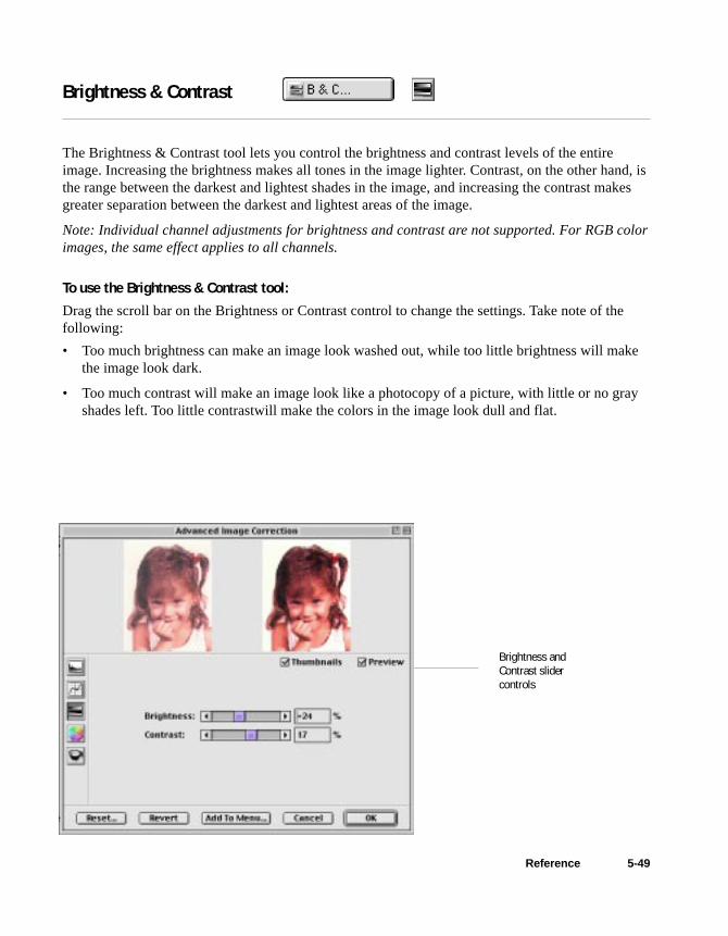
5-49Reference
Brightness & Contrast
The Brightness & Contrast tool lets you control the brightness and contrast levels of the entireimage. Increasing the brightness makes all tones in the image lighter. Contrast, on the other hand, isthe range between the darkest and lightest shades in the image, and increasing the contrast makesgreater separation between the darkest and lightest areas of the image.
Note: Individual channel adjustments for brightness and contrast are not supported. For RGB colorimages, the same effect applies to all channels.
To use the Brightness & Contrast tool:Drag the scroll bar on the Brightness or Contrast control to change the settings. Take note of thefollowing:
• Too much brightness can make an image look washed out, while too little brightness will makethe image look dark.
• Too much contrast will make an image look like a photocopy of a picture, with little or no grayshades left. Too little contrastwill make the colors in the image look dull and flat.
Brightness andContrast slidercontrols

5-50 Microtek ScanWizard 5 User's Guide (Macintosh version)
Threshold (for Line Art images)
For Line Art images, the Brightness & Contrast screen becomes the Threshold setting, and theThreshold dialog box appears instead.
Threshold is the dividing line between black and white; the range is 0 to 255, and the default is 128.Thus, gray levels below the Threshold are converted to black, while gray levels equal to or abovethe Threshold are converted to white, resulting in a high-contrast, black-and-white representation ofthe image.
To use the Threshold feature:1. Drag the sliders to change the Threshold.
• To darken the original, drag the slider tothe right. This increases the Thresholdvalue so that more pixels are turned toblack, resulting in a darker image.
• To lighten the original, drag the slider tothe left. This lowers the Threshold valueso that more pixels are turned to white,resulting in a lighter image.
2. Alternatively, you can enter a value in theThreshold edit box to change the Threshold.
3. The Sharpen option lets you sharpen the LineArt image.
1
3
2
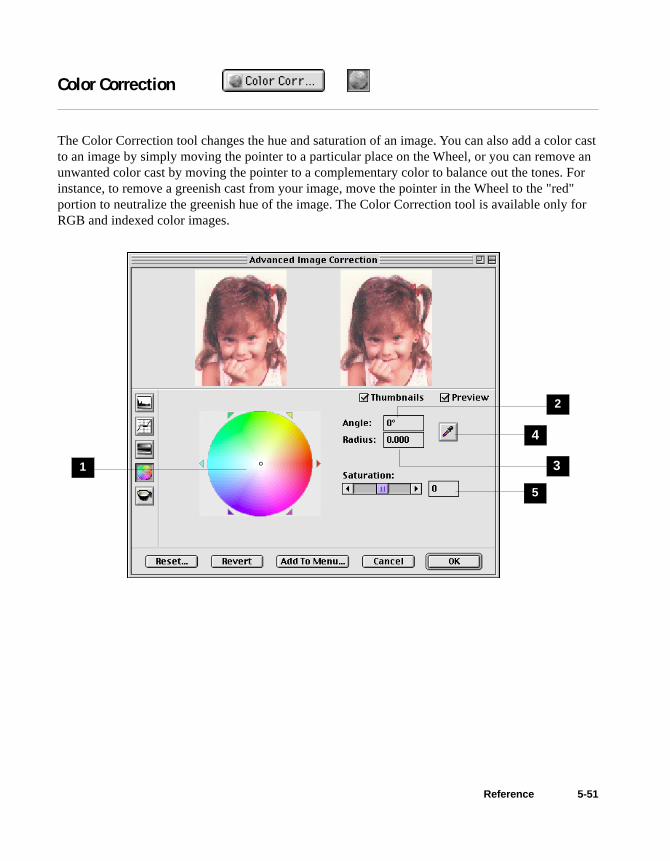
5-51Reference
Color Correction
The Color Correction tool changes the hue and saturation of an image. You can also add a color castto an image by simply moving the pointer to a particular place on the Wheel, or you can remove anunwanted color cast by moving the pointer to a complementary color to balance out the tones. Forinstance, to remove a greenish cast from your image, move the pointer in the Wheel to the "red"portion to neutralize the greenish hue of the image. The Color Correction tool is available only forRGB and indexed color images.
4
3
2
1
5

5-52 Microtek ScanWizard 5 User's Guide (Macintosh version)
To use the Color Wheel:1. To change the hue of an image, move the
pointer in the color wheel to its new colorposition in the wheel.
2. To change the saturation of an image, dragon the saturation bar. Dragging the scroll barto the left decreases saturation; dragging it tothe right increases saturation.
3. Use the Angle, Radius, and Picker asnecessary.
4. Click an action button. For more details, seethe section The Action buttons.
1 Color Wheel: The Color Wheel allows youto add or remove a color cast from an image.
2 Angle: This shows the angle of the pointer onthe Color Wheel as measured in degrees, anda value can also be entered directly in theedit box to move the cursor to any point inthe Wheel.
Example: 0˚ corresponds to the color red onthe Wheel, 60˚ to the color yellow, 120˚ tothe color green, 180˚ to the color cyan, 240˚to the color blue, and 300˚ to the colormagenta.
3 Radius: This field shows the amount of shifttowards a particular color and works intandem with the Angle field. The Radiusrange extends from 0 located at the center ofthe Color Wheel and indicating the leastconcentration of color, to 1, located at theperiphery of the Wheel and indicating thegreatest concentration of color.
Example: If your angle is 0˚ (red on theColor Wheel) and the radius is 1, this resultsin an intense reddish cast on the entireimage.
The Angle-Radius feature works differentlyfrom that of the Saturation bar, whichincreases the saturation of all hues in theimage without tending towards any particu-lar color cast.
4 Picker: The Picker lets you pick a knownneutral gray shade in your image and adjustsit to a closer, truer gray. The grays in animage may have a particular color castwhich can be verified through the colorinformation in the Information window. Agray that tends towards a reddish tint, forinstance, will have its R value skewed higherthan the G and B values. By using the Pickeron a gray area, the gray is adjusted so thatthe RGB values become approximatelyequal.
5 Saturation bar: This lets you change theintensity of the hues (colors) in your image.Use Saturation selectively, because increas-ing saturation will increase the intensity ofall hues in the image.

5-53Reference
Filters
The Filters tool lets you apply or create special effects to your images. The filters include Blur, BlurMore, Sharpen, Sharpen More, Edge Enhancement, Emboss, Unsharp Masking, and Gaussian Blur.
In using the Filters tool, keep in mind that the image you obtain in the preview window may differfrom the way the image appears when you finally scan it in. The appearance of the image in thepreview window and how it is affected by a filter will depend on the resolution of the image. Thehigher the resolution, the less obvious the effect of certain filters (such as Blur).
To use the Filters:Click the Filter box, and from the drop-down menu that appears, select the filter to be used
Filter box

5-54 Microtek ScanWizard 5 User's Guide (Macintosh version)
Blur filters
The Blur filters eliminate noise in the parts ofthe image where significant color transitionsoccur. These filters decrease the contrastbetween adjacent pixels, making the imageappear hazy and out of focus.
• Blur smooths out the transitions by lighten-ing pixels next to the hard edges of definedlines and shaded areas.
• Blur More produces an effect three or fourtimes stronger than Blur.
Sharpen filters
The Sharpen filters do the opposite of the Blurfilters and increase the contrast of adjacentpixels, making images appear sharper and morefocused.
Both Sharpen and Sharpen More filters improveclarity, with the Sharpen More filter having astronger sharpening effect than the Sharpenfilter.
Edge Enhancement filter
The Edge Enhancement filter gives greatercontrast to edges. The filter can do this becauseedges are areas in an image where gray or colorlevels change abruptly. It is best to use this toolfor improving geometrical contoured shapes.
Emboss filter
The Emboss filter makes a selection appearraised or stamped by suppressing the colorwithin the selection and then tracing its edgeswith black.
Original Blur
Blur More
Original Sharpen
Sharpen More
Original Edge Enhancement
Original Emboss

5-55Reference
Descreen
The Descreen tool lets you remove moiré patterns in the scan process. Moirés occur when you scana screened original (mostly reflective materials, such as pictures from a newspaper or magazine),and these patterns appear to the naked eye like a series of cross-hatching lines, as shown in theexample below.
To use Descreen:1. Click the Descreen tool.
2. When the Descreen dialog box comes up, enter a value that best corresponds to the dot qualityof the original in which the moiré is to be removed. You may use a screen finder to measure theprint screen lpi. Please contact your local print shop for more information on how to obtain ascreen finder.
• Set a value from 50 to 85 if the original image has a coarse dot pattern, as in images takenfrom a newspaper.
• Set a value from 100 to 133 if the original image has a fine dot pattern, as in images takenfrom a magazine.
• Set a value from 200 to 250 if the original image has a very fine dot pattern with a near-photographic quality, as in images taken from a high-quality art magazine.
Before Descreen After Descreen

5-56 Microtek ScanWizard 5 User's Guide (Macintosh version)
Custom Settings
You can also create custom settings in each Advanced Image Correction control, and then add themto the Settings window menus for quick access to those settings.
To create a custom setting:
1. Choose the desired AIC control (e.g., W&BPoints, etc.) in the Settings window, andselect Custom from the drop-down menu onthe right side.
To remove a custom setting:
1. Choose the desired AIC control in theSettings window, and select Remove CustomSetting from the drop-down menu on theright side.
2. When a dialog box appears, highlight thecustom setting to be removed, then click theRemove button. The custom setting isdeleted from the menu.
Note: To delete the custom setting, youMUST click the Remove button (not justselect and click OK).
3. Click OK to close the dialog box.
Customdrop-downmenu
2. When the AIC dialog box for the selectedcontrol comes up, adjust the setting the wayyou want it, then click the Add to Menubutton at the bottom of the dialog box.
3. Enter a name for the Custom Setting (ex:More Red Tint), then click OK.The newcustom setting is added to the menu.
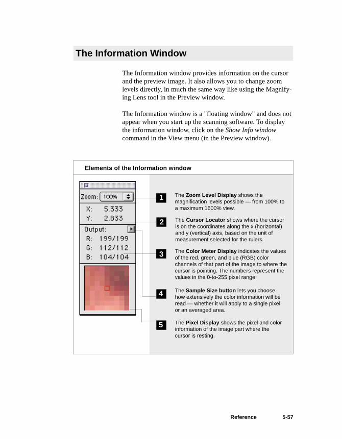
5-57Reference
The Information window provides information on the cursorand the preview image. It also allows you to change zoomlevels directly, in much the same way like using the Magnify-ing Lens tool in the Preview window.
The Information window is a "floating window" and does notappear when you start up the scanning software. To displaythe information window, click on the Show Info windowcommand in the View menu (in the Preview window).
The Information Window
Elements of the Information window
The Zoom Level Display shows themagnification levels possible — from 100% toa maximum 1600% view.
1
4 The Sample Size button lets you choosehow extensively the color information will beread — whether it will apply to a single pixelor an averaged area.
The Pixel Display shows the pixel and colorinformation of the image part where thecursor is resting.
5
2 The Cursor Locator shows where the cursoris on the coordinates along the x (horizontal)and y (vertical) axis, based on the unit ofmeasurement selected for the rulers.
3 The Color Meter Display indicates the valuesof the red, green, and blue (RGB) colorchannels of that part of the image to where thecursor is pointing. The numbers represent thevalues in the 0-to-255 pixel range.

5-58 Microtek ScanWizard 5 User's Guide (Macintosh version)
Using the Zoom Level Display
The Zoom Level Display magnifies your view of an image,much like the Magnifying Lens tool in the Preview Window.
The magnification factor in both Zoom Level Display and theMagnifying Lens tool is by a factor of 2. Thus, the magnifica-tion levels increase from 100% to 200%, to 400%, to 800%and to the maximum 1600%.
To use the Zoom Level Display:Click on the Zoom Level box. From the drop-down menu thatappears, select your zoom or magnification level.
Click here todisplay the drop-down menu, andthen select yourzoom level.
Using the Cursor Locator
The Cursor Locator shows you where the cursor is on the x(horizontal) and y (vertical) coordinates of the axis. Thisfeature is useful for operations that require very precisemeasurements and alignment.

5-59Reference
Using the Color Meter Display
The Color Meter Display is useful if you wish to adjust theshadow and highlight points of an image.
As you pass over a point in the image, the Color MeterDisplay will show the appropriate RGB values of that point inthe image. The significance of the numbers is explainedbelow.
• There are two numbers shown in the Color MeterDisplay. The first number represents the raw color datataken by the scanner; the second number represents theresulting value after color correction or image enhance-ment is applied to the image.
• The values can be anywhere from 0 to 255, with 0 as theblack point, 255 as pure white, and all other values inbetween corresponding to shades from black to white.
• The values as a whole represent color information for thesample size selected in the Sample Size button (discussedbelow). For instance, if you chose 3 x 3 as your samplesize and your R value reads 23, that shows your red valueof 23 is the average of a 3-pixel by 3-pixel area.
The numbers canbe from 0 to 255,
with 0 as the blackpoint, 255 aswhite, and all
values in betweencorresponding to
shades from blackto white.
The first number israw color data; thesecond number iscolor data followingenhancement ormodification.

5-60 Microtek ScanWizard 5 User's Guide (Macintosh version)
Pixel-value information is useful especially if you are makingcolor corrections based on color values. Knowing this, youcan modify the shadow and highlight points of an image, thencome back to the same point in the image, and verify throughthe Color Meter Display that the RGB values have indeedchanged.
The Color Meter Display can also be used in conjunction withthe Color Picker tool. For more details, see the Color Pickertopic in the Preview Window section of the Reference.

5-61Reference
Using the Sample Size button
The Sample Size button provides options for choosing howextensively the color information will be read — whether thecolor information will apply to a pixel, a 2-pixel by 2-pixelarea, or a wider expanse (maximum 5-pixel by 5-pixel area).
When you click on the Sample Size button, the drop-downmenu below appears:
Determines how the numbers inthe Color Meter Display areshown — in absolute values orin percentages
Determines the size of thesampling area
Numbershere are inValues
Value and Percent• If you choose Value, the numbers in the Color Meter
Display represent the values in the 0-to-255 pixel scale. Forinstance, an R value of 23 indicates that the sampling sizeselected has a red color value of 23. Value is calculated bymultiplying the percentage by the constant 255 (value =255 x percent).
• If you choose Percent, the numbers represent the percent-age of the maximum intensity of the pixel. For instance, aG value of 35% indicates that the sampling size selectedhas a green color value to be 35 percent intense (out of 100percent). Percent is calculated by dividing the constant 255by the value (percent = 255 ÷ value).
Numbershere are inPercentages

5-62 Microtek ScanWizard 5 User's Guide (Macintosh version)
Sample Size OptionsThis determines the expanse of color information to be madeavailable. For instance, if you choose 5 x 5 as your samplearea, this means your RGB values will represent colorinformation for a 5-pixel by 5-pixel area. If you choose 1 x 1,the color information pertains to a single pixel — the one inthe middle of the Pixel Display.
The 1 x 1 sample size meansthe RGB numbers represent the
color value of a single pixel —the one in the middle of the
Pixel Display.
The 5 x 5 sample size meansthe RGB numbers represent
the average value of a 5-pixelby 5-pixel area. This would
include the whole of the PixelDisplay (which is 5 pixels long
and 5 pixels wide).
PixelDisplay
Using the Pixel Display
The Pixel Display helps you see how color pixels are orga-nized and distributed. The display can then help you make aninformed judgment on how best to modify image characteris-tics such as shadows and highlights, and also allow you toverify any changes that are made.

5-63Reference
Using the Scan Job Window
The Scan Job window is a floating window that shows your scan jobs. By definition, a scan jobcontains the following elements: a set of scanning parameters (shown in the Settings window); a scanframe (shown in the Preview window); and a scan job item (shown in the Scan Job window).
Note: If the Scan Job window is closed, go to the View menu in the Preview window, and choose theShow Scan Job window command.
9
8
7
65
1 2
3
4

5-64 Microtek ScanWizard 5 User’s Guide (Macintosh version)
1 Menu for changing image type: To changethe image type, click on the arrow to the leftof the thumbnail and select the new imagetype from the drop-down list that appears.
2 Thumbnail of prescan image: A thumbnailappears for the selected scan job after youclick the Prescan button in the Previewwindow and perform a prescan for the scanjob.
3 Checked scan job: Checked scan jobs are theones that are scanned when you click theScan button in the Preview window. Thecheck box is a toggle for checking /unchecking a scan job. To check a box, youcan either click on the check box or use theCheck button at the bottom of the Scan Jobwindow.
4 Up / down arrows: These arrows let youchange the order of scan jobs in the window.You can also move a scan job up and downthe list by simply highlight the selected scanjob and dragging it to its intended place andorder in the window.
5 The selected scan job is the highlighted item.You can have multiple selected scan jobs,which may or may not include the currentscan job. In this example, “Festival” is theselected scan job, and clicking on a functionbutton (#9) will have the effect of that buttonperformed on the selected scan job.
6 The current scan job is indicated by boldfacetype; there can only be one current scan job.In this example, “Three girls” is the selectedscan job. The current scan job is also shownin the Job box of the Settings window.
7 Title: The title of each scan job is shown. Toedit a scan job title, highlight the scan joband hold down the mouse at the job title for asecond or two. The title will be ready forediting, and simply type over the new name.If you wish, you may exit ScanWizard 5 andedit the scan job file directly in the Finder.
8 Image size: This is the image size of thescan job.
9 Function buttons: These buttons perform aspecific action on the selected scan job. TheDuplicate, Delete, and Check buttons can beused on multiple selected scan jobs. TheNew and Load / Save button can be used ononly one selected scan job.

5-65Reference
Multiple Job Selections
The function buttons at the bottom of the ScanJob window can be used for multiple jobselections. The New and Load / Save button canbe used on only one selected scan job. TheDuplicate, Delete, and Check buttons can beused, however, on multiple selected scan jobs.
For example, you can select multiple scan jobs,and then click the Delete button to remove allthe jobs simultaneously.
To select multiple scan jobs, press the Shift keyand click on the jobs to be selected.
Adding a New Scan Job
1. Click the New button.
2. When a text box appears, accept the defaultname or enter a name for the new scan job.
3. Define the scan frame in the Previewwindow for the new scan job.
4. In the Settings window, specify the settingsfor the new scan job.
With the creation of a new scan job, the newscan job becomes the current scan job.
Duplicating a Scan Job
1. From the list of scan jobs available, selectthe scan job(s) to be duplicated
2. Click the Duplicate button. The selectedscan job(s) will be duplicated. The Dupli-cate function is very useful when scanningseveral images at the same settings.
Removing a Scan Job
To delete a scan job, highlight the scan job to beremoved, then click the Delete button.

5-66 Microtek ScanWizard 5 User’s Guide (Macintosh version)
Loading and Saving Scan Job Templates
This feature lets you save scan jobs that can be loaded at a later time when necessary. The idea ofsaving and loading scan jobs has important applications, especially for scanners with differenttemplates or “trays”. Saving / loading scan jobs is also useful if you consistently work in a specificformat, scan the same kind of images, or if the scanner is used by several users who have their ownsets of jobs.
If your scanner has several trays, for instance, you may wish to create a scan job for each “tray”—for example, one for your 4”x5” transparencies and another for your 35mm positives. You can alsocreate scan jobs to fit the needs of your users, with User A having Scan Job Folder 1 for example, andUser B having Scan Job Folder 2.
In addition, you may use this feature along with the ScanWizard 5 Context to increase the flexibilityof your scanning and create different scanning possibilities.
To use the Load / Save feature:1. Click the Load / Save button in the Scan Job window.
2. When a dialog box appears, go to the folder of your choice. The sample dialog box below showsthe following:
• The left-hand side of the dialog box shows your scan job folders in the Finder. In this ex-ample, a folder called Scan Job Manager contains two folders —35mm positives and 4x5transparencies.
• On the right-hand side of the dialog box are your current scan jobs in the queue — Scan Job 1and Scan Job 2.
Note: If you click theOK button and there areno scan jobs on theright-hand side, a dialogbox will appear. You willthen be asked if youwish ScanWizard 5 toautomatically create ascan job with defaultsettings for you.
Your currentscan jobsScan Job
folders
New folder
5-67Reference
To add the scan job template to the scanjob list:
1. Select the folder on the left-hand side, anddouble-click it to open the folder.
2. Click the Add button to add highlighted orselected templates, or click the Add Allbutton to add all the scan job templates in thefolder.
Note: You may also add individual scan jobs tothe scan job list.
To save scan jobs as a template:
1. Select a folder on the left-hand side, anddouble-click the folder to open the folder.
2. Highlight the scan job to be saved on theright-hand side.
3. Click the Save button in the middle columnof the dialog box. The selected scan job issaved as a template to your selected folder.
To remove scan job(s) from the queue:
1. Highlight the scan job(s) to be removed onthe right side of the dialog box.
2. Click the Remove or Remove All button at thebottom of the dialog box.
To close the dialog box: Click the OK button atthe bottom of the dialog box.
If you remove all scan jobs in the queue andclose the dialog box, you will be informed that adefault scan will be automatically created, oryou will return to the dialog box for manuallyadding at least one scan job. This is becausethere should always be at least one scan job inScanWizard 5.

A-1Color Matching for Advanced Users
Setting up the System (Monitor) Profile using ColorSync
ColorSync is Apple’s industry-standard color matching system. The notes below pertain to configur-ing ColorSync to ensure that it works properly with ScanWizard 5.
Calibrating your monitor
Proper monitor calibration is important for achieving higher precision in color matching. MonitorICC profiles may be created specifically for your monitor by calibrating your monitor through thefollowing utilities:
• ColorSync 2.5 Monitors & Sound Control Panel Calibration function
• Adobe Gamma utility, from Adobe Photoshop 5.0
• Any third-party calibration programs or hardware calibrator
Appendix A: Color Matching for Advanced Users
This section contains important information on further steps you need to take to achieve colormatching across your devices. The procedures to be performed include monitor calibration and howto set up ScanWizard 5 with the Apple ColorSync™ system and the Adobe Photoshop software.Some recommendations are also given in order to achieve color matching across devices. For moredetailed information on the ColorSync or Adobe Photoshop functions covered in this section, referto the respective user guides of those programs.
If you have ColorSync 2.1.2 or earlier, do thefollowing:
1. In the ColorSync System Profile controlpanel, select your desired System Profilesettings.
2. In the Monitors & Sound control panel, setthe Gamma to “Uncorrected Gamma”.
In addition, make sure you disable or removeany utilities or third-party control panels thatalter monitor display. Your System Profile is theprofile describing the monitor you are using.
If you have ColorSync 2.5, do the following inthe exact order below:
1. Open the Monitors & Sound control panel toselect your desired profile in the MonitorProfile list box.
2. Open the ColorSync Control Panel to verifythe desired monitor profile as the SystemProfile.
The settings in these two control panels shouldbe the same. If you select a profile in Monitors& Sound, your ColorSync System Profile willchange accordingly.
In addition, make sure you disable or removeany utilities or third-party control panels thatalter monitor display.

A-2 Microtek ScanWizard 5 User’s Guide (Macintosh version)
Using Adobe Photoshop 5.0
B. ScanWizard 5 Setup:1. Go to the Preferences / CMS Setup dialog
box. Check and see that the monitor selec-tion is the same as that in the ColorSyncSystem Profile selection (your currentmonitor setup). If you need to change yourmonitor, do this in the ColorSync ControlPanel.
2. Make sure that the Display using monitorcompensation check box is checked.
3. For both RGB and CMYK destinationsettings, select your desired profiles. Theseselections specify ScanWizard 5’s outputcolor space for RGB and CMYK images,respectively.
4. Make sure the RGB / CMYK destinationsetting matches Photoshop 5.0’s RGBSetting / CMYK Setting in the RGB Setup /CMYK Setup dialog box, respectively.
5. To enable RGB color matching, make surethe RGB Color Matching check box ischecked. Otherwise, raw RGB image datawill be scanned.
A. Adobe Photoshop 5.0 Setup:1. In the File / Color Settings / RGB Setup
dialog box, select your desired RGBworkspace.
2. Check and enable the Display using MonitorCompensation check box.
3. Make sure that the selected RGB workspacein Photoshop matches ScanWizard 5’s RGBDestination selection. This way, the scannedimages shown in Photoshop will match thepreview image that was shown inScanWizard 5. Do not change your monitorprofile (i.e., ColorSync System Profile) inthe middle of operating ScanWizard 5. If youwant to change the monitor profile, do itafter exiting ScanWizard 5.
4. The same principle above applies to CMYKimages: Make sure that the settings in theCMYK Setup in Photoshop 5.0 match theCMYK Destination in the CMS Setup inScanWizard 5.
Take note that it is not desirable to scan inraw data and then perform ColorSync dataconversion using the ColorSync plug-in orthe Image / Mode / Profile to Profile...conversion in Photoshop 5.0.
Note:
Since Photoshop 5.0 allows users to customizetheir own color space as well as select from afew built-in color spaces (such as sRGB, AppleRGB, CIE RGB, etc.), you may click “Save” inthe RGB Setup dialog box to save the currentPhotoshop RGB workspace as an ICCColorSync profile. The saved profile can then beselected in ScanWizard 5.
Take note that when you save the PhotoshopRGB profile, the file name you specify may notbe the same as the profile selection you see in
ScanWizard 5’s RGB Destination pop-up menu(where the profile information string is shown).For example, if you save “Photoshop sRGB” asa profile, it will appear as “sRGB IEC61966-2.1” in ScanWizard 5’s pop-up menu. If you arenot sure about the profile you want, click the“Load” button to load the profile by file namedirectly.
For more information on Photoshop’s colormanagement features, visit Adobe’s site on theInternet http://www.Adobe.com.

A-3Color Matching for Advanced Users
Additional NotesThese additional notes pertain to the use of theBatch Scan feature of ScanWizard 5.
When creating your batch command, you needto make sure that the color space where imageswill be output is set up correctly in ScanWizard5’s CMS Setup dialog box.
After images are scanned, saved as files, andthen opened in Photoshop 5.0, you may beasked to convert the images when the assumedRGB profile setting (in Photoshop File / ColorSettings / Profile Setup dialog box) does notmatch your RGB workspace (in File / ColorSettings / RGB Setup dialog box). Select “Don’tConvert”, because the images have beenscanned according to your color space require-ment.
Please note that it is not desirable to convert theimage if you have previously chosen to scan asraw data; the result will not be what you expect.Always let ScanWizard 5 perform the colormatching for you.
Using Adobe Photoshop 4.0
A. Adobe Photoshop 4.0 Setup:Photoshop 4.0 does not have color-managementcapabilities for RGB images. In Photoshop 4.0,RGB data is simply “dumped” or transferred tothe monitor. As a result, the colors may appearto be different in Photoshop 4.0 compared toScanWizard 5, regardless of the ColorSyncversion that you are using.
To display colors consistently on bothPhotoshop 4.0 and ScanWizard 5, make surethat the “Display using monitor compensation”check box is NOT checked in the CMS Setupdialog box in ScanWizard 5.
B. ScanWizard 5 Setup:1. Go to the Preferences / CMS Setup dialog
box. Check and see that the monitor selec-tion is the same as that in the ColorSyncSystem Profile selection (your currentmonitor setup). If you need to change yourmonitor, do this in the ColorSync ControlPanel.
2. Make sure that the Display using monitorcompensation check box is NOT checked.
3. To enable RGB color matching, make surethe RGB Color Matching check box ischecked. Otherwise, raw RGB image datawill be scanned. It is not desirable to scan inraw data and then perform ColorSync dataconversion.
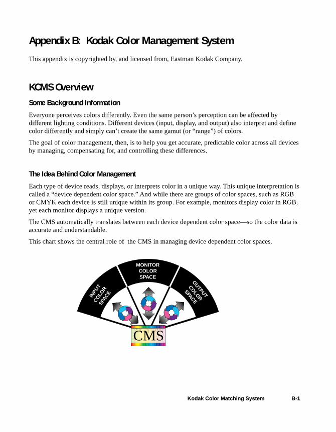
B-1Kodak Color Matching System
Appendix B: Kodak Color Management System
This appendix is copyrighted by, and licensed from, Eastman Kodak Company.
KCMS OverviewSome Background Information
Everyone perceives colors differently. Even the same person’s perception can be affected bydifferent lighting conditions. Different devices (input, display, and output) also interpret and definecolor differently and simply can’t create the same gamut (or “range”) of colors.
The goal of color management, then, is to help you get accurate, predictable color across all devicesby managing, compensating for, and controlling these differences.
The Idea Behind Color Management
Each type of device reads, displays, or interprets color in a unique way. This unique interpretation iscalled a “device dependent color space.” And while there are groups of color spaces, such as RGBor CMYK each device is still unique within its group. For example, monitors display color in RGB,yet each monitor displays a unique version.
The CMS automatically translates between each device dependent color space—so the color data isaccurate and understandable.
This chart shows the central role of the CMS in managing device dependent color spaces.
INPU
TCO
LOR
SPAC
E
MONITORCOLORSPACE
OUTPUT
COLOR
SPACE
CMS

B-2 Microtek ScanWizard 5 User's Guide (Macintosh version)
How Color Management Works
The aim of color management is to preserve true color information by making up for the differencesin the way devices communicate color. Your CMS does this by using a scientifically designedsystem including:
• A Color Matching Processor
• A Device-Independent color space, frequently called a Reference Color Space or Profile Con-nection Space (PCS), which acts as a Rosette Stone in the translation process
• Device Color Profiles (DCPs) DCPs relate a device dependent color space to the Profile Connection Space. The CMS uses the
Color Profile to translate from one device dependent color space to another.
How CMS Translates between Devices
When you scan an image, a CMS uses the information about the scanner—stored in the ScannerColor Profile—to translate the RGB image from the scanner to the Profile Connection Space. TheCMS then uses the information about your monitor—stored in the Monitor Color Profile—totranslate the image from the Profile Connection Space to your monitor color space, where you see itdisplayed.
In this example, the scanner is the “source” device, and the monitor is the “destination” device.

B-3Kodak Color Matching System
When you print the image, the CMS again translates the image data from the monitor’s RGB colorspace to the printer’s CMYK color space—using the information about both devices as stored intheir Color Profiles.
So, although all of the devices in this example use different device dependent color spaces, theCMS is able to translate between them and produce accurate, predictable color.
What are Device Color ProfilesColor Management Systems use Device Color Profiles to interpret color data between devices.DCPs are a collection of one or more ICC Profile data files. ICC Profiles contain color characteris-tics of a given device (input, display, or output).
ICC profiles conform to the International Color Consortium profile specification, allowing the samedevice profiles to be used across multiple platforms.
Where Do Color Profiles Come From?
Color Profiles are created by either Kodak scientists or other color professionals using specializedsoftware packages, sometimes known as profile building tools.
Kodak scientists use sensitive, specialized equipment to measure the color characteristics of arepresentative example of each device, as supplied by the manufacturer, to determine the intrinsicproperties of the device.
From these measurements they develop a “characterization” of the device, called a Device ColorProfile, for each make and model measured.
The Color Profile includes color tables that relates the device’s color space to a Profile ConnectionSpace, as well as information about key attributes of the device for use by CMS-based applications.

B-4 Microtek ScanWizard 5 User's Guide (Macintosh version)
A Word about Source and Destination
People often get confused about what is the “source” of an image and what is its “destination,” solet’s clarify this.
In general, the “source” of an image refers to where the image currently is, and the “destination” iswhere you want the image to go.
In CMS terms, “source” means the Color Profile used to bring the image data into the ProfileConnection Space (PCS). “Destination” means which Color Profile is used to get it from PCS to thedestination device. For example, when you scan in an image, you want it to appear on your monitor.So the source is your scanner, and its related Color Profile, and the destination is your monitor,using its Color Profile.
Likewise, when you open a Photo CD image, the source is the Photo CD, plus the Color Profile thatrelates the color data to the PCS, and the destination is the monitor, plus the Color Profile thatrelates the PCS to the monitor’s color space.
Here’s another example: Let’s say you manipulate the image on your monitor screen, and print it.
The source this time is the monitor (plus the Color Profile that relates it to the PCS), and thedestination is a printer (plus the Color Profile that relates the PCS to the printer’s color space).
So, Source and Destination mirror a logical two-step process most Color Management Systems useto translate images between device color spaces;
• The Source Profile brings the image into the PCS
• The Destination Profile connects the image from the PCS to the output device, such as a Moni-tor, Printer, or Proofer.
However, this is not the case with a Kodak CMS.
Kodak has patented its composition technology. This technology takes the Source and DestinationProfiles and composes them into a single color transforming profile.

B-5Kodak Color Matching System
This technology adds significant improvement in the quality and performance of the Color Manage-ment System.
Note: You use the Source/Destination information when you setup or use your CMS-based applica-tion, such as PageMaker 6.5.
Controlling UCR & GCRControlling UCR and GCR with Professional CMYK Profiles
In the final stages of color prepress production, the issues change: And your role changes with them.You become that of a professional separator. And it becomes a question of how skilled you are atmaking good films, films that run correctly on press, avoiding downtime, rework, and expense.
Kodak Digital Science Professional CMYK Profiles helps you with your separations. It expandsyour selection of undercolor removal (UCR) and gray component replacement (GCR) options, soyou can produce correct, quality separations.
Some Background
It is difficult to print four wet layers of ink on top of one another. This is one of the physicalconstraints of the printing process.
In theory, if you printed a 100% of each CMYK layer, you would have 400% Total Area Coverage(TAC). Real-world experience proves this to be impractical. It is difficult to print jobs that havemore than 340% TAC, and most printers feel more comfortable with 280% TAC.
Another area of practical concern is in how process inks are combined. Most printers can notproduce a clear, dense black from cyan, magenta, and yellow. Black is needed to produce betterdetails, contrast, and to get a desirable density. Adding black to CMY reduces ink coverage TAC,and thus improves the ability of paper to firmly hold each layer of wet ink, known as ink trapping.
So, from the concerns about ink coverage and ink combinations have come tried-and-true ap-proaches to producing excellent films for excellent separations.
Two aspects of the offset printing process are undercolor removal (UCR) and gray componentreplacement (GCR).
UCR
Undercolor removal is the practice of removing quantities of yellow, magenta, and cyan ink fromthe dark neutral areas in a reproduction and replacing what was removed with an appropriateamount of black. Kodak implements UCR in its Color Profiles within a TAC constraint: CMY getsreplaced by the maximum amount of K up to the TAC limit—so you get the highest possibledensity.

B-6 Microtek ScanWizard 5 User's Guide (Macintosh version)
The neutral center of both diagrams show different UCR/TAC settings. With UCR applied, lessprocess inks and more black increases the density in the shadows.
85% C72% M72% Y91% K320% TAC
L E S S U C R M O R E U C R
90% C80% M80% Y70% K320% TAC
Advantages & Disadvantages to UCR
Undercolor removal within a TAC constraint reduces the problem of printing four solid layers ofink, one on top of the other, while each previous layer is still wet. Reducing the ink coverage, TAC,improves the ability of the paper to firmly hold each layer of wet ink.
Less ink means better control, and faster drying times. Also, replacing cmy ink with the lessexpensive black ink has proven more cost efficient on long runs that use more ink.
Also, blacks and neutrals that print black are not influenced easily by shifts in the chromatic inkswhich cause color casts in the shadow tones. Separations produced with greater UCR producedarker blacks which result in better shadow detail.
However, some printers don’t like high UCR because of on-press dot gain and contrasty rosettes.
GCR
Gray component replacement is a variation on undercolor removal. The theory is simple: Wheneveramounts of cyan, magenta, and yellow are present in the same color, that color has a gray compo-nent. Some or all of this gray component can be printed with black ink while maintaining theoriginal color appearances.
In contrast to UCR, GCR involves a more general color replacement, with black being substitutedover all colors.
The neutral center of both diagrams looks the same. With more GCR applied, less color ink andmore black ink produces the same color.

B-7Kodak Color Matching System
L E S S G C R M O R E G C R
27% C24% M24% Y 8% K83% TotalInk
24% C20% M20% Y13% K77% TotalInk
Advantages & Problems of GCR
The main advantage of GCR is it reduces the effects of variations on press, so when ink coveragevaries, the colors become slightly lighter or darker, rather than changing hue.
Increased amounts of GCR also allows your printing company to use a somewhat higher proportionof black ink, thus reducing cost—which saves you money.
High levels of GCR and/or UCR expand the overall gamut, so darker and more saturated colors areachievable. However, with too light GCR you may not get as saturated a color as with higher levelsof GCR.
Professional CMYK Profiles PackageWhat You Get with Professional CMYK Profiles Package
“Professional CMYK Profiles” was developed for the serious professional, who is concerned aboutproductivity, quality separations, and color fidelity.
With “Professional CMYK Profiles”, you get six different UCR/GCR settings that conform togeneric CMYK SWOP, Japanese Ink Standard, and Euroscale standards—Letting you select the bestvalues for your printing conditions.
Any of these combinations give you the control you need to optimize your separations for yourproofing and printing applications, reduce your printing costs, and minimize ink trapping problemson press.
However, check with your printer as to the optimal UCR/GCR setting to select for your printingconditions. The following two pages list the settings for the three standards.

B-8 Microtek ScanWizard 5 User's Guide (Macintosh version)
EUROPEAN PRINTING STANDARDS:
Filename Profile Description GCR Maximum TAC
eucmyk02.pf Light GCR 260 UCR CMYK Light 260%Euro Positive Proofing
eucmyk04.pf Light GCR 280 UCR CMYK Light 280%Euro Positive Proofing
eucmyk06.pf Light GCR 300 UCR CMYK Light 300%Euro Positive Proofing
eucmyk08.pf Light GCR 320 UCR CMYK Light 320%Euro Positive Proofing
eucmyk10.pf Light GCR 340 UCR CMYK Light 340%Euro Positive Proofing
eucmyk50.pf Light GCR 360 UCR CMYK Light 360%Euro Positive Proofing
U.S. CMYK SWOP PRINTING STANDARDS:
Filename Profile Description GCR Maximum TAC
gncmyk02.pf Light GCR 260 UCR CMYK Light 260%US Negative Proofing
gncmyk04.pf Light GCR 280 UCR CMYK Light 280%US Negative Proofing
gncmyk08.pf Light GCR 320 UCR CMYK Light 320%US Negative Proofing
gncmyk10.pf Light GCR 340 UCR CMYK Light 340%US Negative Proofing
gncmyk14.pf Medium GCR 280 UCR CMYK Medium 280%US Negative Proofing
gncmyk18.pf Medium GCR 320 UCR CMYK Medium 320%US Negative Proofing
gncmyk28.pf Heavy GCR 320 UCR CMYK Heavy 320%US Negative Proofing
gncmyk50.pf Light GCR 360 UCR CMYK Light 360%US Negative Proofing

B-9Kodak Color Matching System
JAPANESE PRINTING STANDARDS:
Filename Profile Description GCR Maximum TAC
jpcmyk02.pf Light GCR 260 UCR CMYK Light 260%Japan Std. Proofing
jpcmyk04.pf Light GCR 280 UCR CMYK Light 280%Japan Std. Proofing
jpcmyk06.pf Light GCR 300 UCR CMYK Light 300%Japan Std. Proofing
jpcmyk08.pf Light GCR 320 UCR CMYK Light 320%Japan Std. Proofing
jpcmyk10.pf Light GCR 340 UCR CMYK Light 340%Japan Std. Proofing
jpcmyk50.pf Light GCR 360 UCR CMYK Light 360%Japan Std. Proofing
You read these settings as follows:
• All TAC percentages have the maximum degree of UCR in order to attain the highest densityblacks within that TAC limit.
• A Light GCR means a small percentage of the possible gray component is replaced with black.
Check With Your Service Provider
These DCPs were created with the following conditions in mind. You will want to check with yourservice provider to confirm the laydown order.
Colorant Laydown Order: Yellow, Magenta, Cyan, Black
This DCP assumes that your imagesetter has been linearized. So, it’s important that you use somekind of calibration software for your imagesetter.

ScanWizard 5 Assistant C-1
ScanWizard 5 Assistant is a companion utility toScanWizard 5. ScanWizard Assistant is installedsimultaneously with ScanWizard 5, so no specialinstallation for the Assistant is needed, and itappears on your desktop as shown in the figurebelow. This utility works as a shortcut toolbox,allowing you easy access to ScanWizard 5’sfrequently used functions -- Scan to File, Copy,and E-mail.
After ScanWizard 5 is launched, the preview imageappears in the preview window. The function buttonin the preview window will vary, depending on thefunction you choose in the Assistant’s panel (Scan,Copy, or E-mail)
Appendix C: ScanWizard 5 Assistant
Operating ScanWizard 5Assistant
Before operating ScanWizard 5 Assistant, check tomake sure that --
• Your scanner is connected to your computer.
• The scanner power is turned on.
• Your document has been placed on thescanner glass.
There are three buttons on the ScanWizard 5Assistant’s panel. These are Scan, Copy andE-mail, respectively. Click on any of these buttons,and ScanWizard 5 Assistant will activateScanWizard 5 and also ask the scanner to performa preview.
Clicking will show .
Clicking will show .
Clicking will show .
Here are the descriptions for each function.
Scan Lets you scan an image and save it to aspecified file.
Copy Lets you scan an image and send itdirectly to the printer.
E-mail Lets you scan an image and append it asan attachment to your E-mail.
Functionbutton

C-2 Microtek ScanWizard 5 User’s Guide (Macintosh version)
Setting Preferences
The Preferences command allows you to modifythe appearance of the toolbox.
To set the preferences, click on the Edit menufrom the menu bar, then select Preferences.
The Preferences dialog box appears, as shownbelow.
Window shape
Lets you select the appearance of the ScanWizard5 Assistant Toolbox. The Toolbox is vertical bydefault.
Open ScanWizard 5 Assistant at Start-up
If you check this option, the ScanWizard 5Assistant toolbox appears on the screen each timeyou start your computer. If you uncheck thisoption, the ScanWizard 5 Assistant Toolbox willnot display unless you select it from theScanWizard 5 Assistant Preferences command inthe Edit menu.
Show Icon Name
If you uncheck this option, the icon name ishidden, as shown below. The icon name is shownby default.
Show Balloon Help
If you check this option, the Balloon Help appearswhen you move the cursor over any of the 3buttons for at least 5 seconds, showing you thefunction of the selected button.
The Show/hide balloon help option is selectedfrom the menu bar.
Troubleshooting
Problem: ScanWizard 5 Assistant cannot find, oris unable to launch, ScanWizard 5 successfully.
Solution : Reinstall ScanWizard 5.
Problem: Not enough memory to launchScanWizard 5 in ScanWizard 5 Assistant.
Solution : Close applications not being used tofree up memory.

D-11Glossary
Advanced Image Correction
An integral feature of ScanWizard 5 which includes powerful tools for adjusting or enhancingyour images. These tools include Tone Curve, Brightness & Contrast, Color Correction, Filters,and Descreen.
Batch scan
A feature of ScanWizard 5 which lets you set up "batches" of jobs beforehand and then allowsyou to start the scanning process when you are ready to do so with a simple click of a button.
Bit
The smallest unit of memory in the computer. A bit can be either off or on, representing a valueof 0 or 1. Greater bit-depth translates to more complexity in image information. A single-bitimage, for instance, uses just one bit of data to record each pixel — which is either black orwhite. An 8-bit grayscale image contains 256 possible shades of gray, a 24-bit color image canprovide up to 16.7 million possible color combinations, while a 36-bit color image has up to68.7 billion colors.
Blur
The Blur filters eliminate noise in parts of the image where significant color transitions occur.The Blur filters include Blur and Blur More.
Brightness
The balance of light and dark shades in an image. Brightness is distinct from contrast, whichmeasures the range between the darkest and lightest shades in an image. Brightness determinesthe intensity of shades; contrast determines the number of shades you get.
Color channel
Refers to the red, green, and blue components from which colors are created.
Color correction
An Advanced Image Correction tool that lets you change the hue and saturation of an image.
Color image
An image type that contains the most complex information (compared to single-bit andgrayscale images). To capture color images, scanners use a process based on the RGB colormodel.
Appendix D: GlossaryCross-referenced entries are indicated in bold type .

D-2 Microtek Scan Wizard 5 User's Guide (Macintosh version)
Color matching
An important feature of ScanWizard 5 that ensures color is displayed consistently — from theinitial input stage when an image is captured by the scanner, to the final output stage when theimage is output to your monitor or printer.
Colormeter
An element of the Information Window with input and output components showing pixelvalues of an image at a specific x/y location.
Context
The context as a concept in ScanWizard 5 refers to a complete scan setup or environment, witheach context having its own characteristics (such as scan material, ColorSync profile selections,etc.). Contexts allow you to customize your scan jobs to your particular needs and workenvironment.
Contrast
The relationship between the light and dark areas of an image. Contrast is the range betweenthe darkest and lightest shades in an image, while brightness is the balance of light and darkshades. Contrast determines the number of shades you get; brightness determines the intensityof the shades. An image with low contrast tends to look dull and flat.
Descreen
An Advanced Image Correction tool that lets you remove moiré patterns during the scanningprocess.
Dpi
Stands for dots per inch, the measure of resolution. The greater the dpi number, the higher theresolution.
Edge Enhancement
The Edge Enhancement filter gives greater contrast to edges and is best used for improvinggeometrical contoured shapes.
Emboss
The Emboss filter makes a selection appear raised or stamped by suppressing the color withinthe selection and then tracing its edges with black.
Filters
Tools that allow you to apply or create special effects to your images. Filters in ScanWizard 5include Blur, Blur More, Sharpen, Sharpen More, Edge Enhancement, Emboss, UnsharpMasking, and Gaussian Blur.

D-3Glossary
Grayscale
An image type that contains more than just black and white, and includes actual shades of gray.In a grayscale image, each pixel has more bits of information encoded in it, allowing moreshades to be recorded and shown. 4 bits are needed to reproduce up to 16 levels of gray, and 8bits can reproduce a photo-realistic 256 shades of gray.
Halftone
A type of single-bit image composed of a pattern of black dots that fool the eye into seeingshades of gray. Examples of halftone images are the pictures you see in a newspaper. Theseimages usually look very coarse.
Highlights
The lightest portions of an image.
Histogram
A graphic representation of how brightness and darkness pixels are distributed in an image. Ahistogram skewed heavily to the left indicates a dark image, while a histogram skewed to theright indicates a light image.
Hue
The aspect of color that distinguishes it from another color (what makes a color red or green orblue). Hue is distinct from saturation, which measures the intensity of the hue (more red, moregreen).
Image-editing software
Software that is used to edit images, such as Adobe Photoshop.
Image Type
The way you wish an image to be scanned and processed. ScanWizard 5 allows direct scanningof images into the following image types: RGB color, CMYK color, Lab color, Web/Internetcolors, 256 colors, Grayscale, and Line art.
Interpolated resolution
Resolution enhanced through software; thus also known as software-enhanced resolution. Forinstance, if your optical resolution is 300 dpi, you may be able to enhance images up to 600dpi through software interpolation. Interpolated resolution may capture less detail than theoptical, but it is useful for certain tasks, such as scanning line art or enlarging small originals.
Line art
A type of single-bit image that is just purely black and white, such as a pencil or ink sketch.Line art may also include one-color images, such as mechanical blueprints or drawings.

D-4 Microtek Scan Wizard 5 User's Guide (Macintosh version)
Lpi (lines per inch)
The resolution of printed images. Lpi is distinct from dpi, which measures the resolution ofelectronic images.
Midtones
The parts of an image between the lighter and darker areas, at around 50% gray.
Moiré
An undesirable pattern in color printing that results from incorrect screen angles of overprintinghalftones. Moirés usually result when you scan a halftone or when you scan images takendirectly from a magazine (instead of scanning a photographic original or a transparency).
Optical resolution
The true resolution of a scanner and is the key factor in determining the amount of detail visiblein an image. Optical resolution is one type of resolution; the other is interpolated resolution.
Overview button
The Overview button is found in the Previe window and previews the image in the scan bed.By default, the entire scan bed is previewed, but new dimensions can be specified for theOverview through the Overview Setup command in the Preferences menu.
Pixel
A unit used by the computer to describe picture elements and to represent image information ina digital format. An image file, for instance, is simply a representation of hundreds (or thou-sands) of pixels arranged in a grid.
Prescan button
The Prescan button is found in the Preview window and previews in high resolution the areaselected by the scan frame. Options governing the prescan function can be found in the PrescanSetup command in the Preferences menu.
Preview window
This window is the most prominent window of ScanWizard 5 and includes the various com-mands and tools for controlling the scanner and for showing your preview image.
Resolution
The level of detail in an image, expressed in dots per inch (dpi), or lines per inch (lpi ). Thegreater the dpi number, the higher the resolution and the resulting file size. There are two typesof resolution: optical resolution, and interpolated resolution.

D-5Glossary
RGB
The color model in which every color is composed of a varying amount of the three colors ofred, green, and blue.
Saturation
The intensity of a color, or the amount of color in a specific hue. For instance, the image of abright red apple will appear to be "more red" if the colors are saturated.
Scaling
The process of creating larger or smaller images in ScanWizard, so that the images don't haveto be resized later when they are delivered to the image-editing program. Scaling has an inverserelation to resolution: The lower the resolution, the larger the image can be scaled. At thehighest resolution, images can only be scaled smaller.
Scan button
The Scan button is found in the Preview window and scans the image in your scanner, deliver-ing the scanned image afterwards to your image-editing software. Images that are scanned arethe scan jobs checked in the Scan Job window.
Scan Job window
This is a floating window that shows your scan jobs.
Scan material
The type of material for your image. Scan materials can be generally classified into the follow-ing: reflectives, such as photographs or prints; positives, such as slides; and negatives, like thenegative film used in cameras.
Settings window
This window contains the commands for outputting your scanned image, and includes theimage-enhancement tools of ScanWizard 5.
Shadows
The darkest areas of an image.
Sharpen
The Sharpen filters increase the contrast of adjacent pixels, making images appear sharper andmore focused. The Sharpen filters include Sharpen and Sharpen More.
Single-bit image
Single-bit images are the simplest kind of image, using just one bit of data to record each pixel.Single-bit images come in two types: line art , and halftone.

D-6 Microtek Scan Wizard 5 User's Guide (Macintosh version)
Info Window
Windows created from the use of the Info Window tool and which are used to isolate andidentify precise colors in a given image, providing a visible values.
Threshold
A special resistor pack or a block of resistors that tells the computer where the end of the SCSIchain is and ensures the electrical integrity of the bus signals. The dividing line between blackand white; the default value is 128. Gray levels equal to or above the Threshold are convertedto white; gray levels below the Threshold are converted to black.
Tone Curve
An Advanced Image Correction tool that lets you adjust the tonal range of an image.
Transparent Medi a Adapter (TMA)
A scanner accessory used for scanning transparencies, slides and filmstrips. The TMA has aunique lighting device that prevents transparent originals from being exposed to too much lightand getting washed out as a result.
Zoom
The ability to magnify the view of an image in the preview window.