COLOR TELEVISION USER'S GUIDE
36
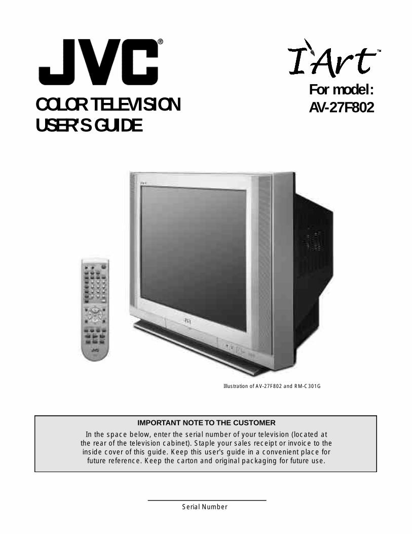
For model: AV-27F802 COLOR TELEVISION USER'S GUIDE Illustration of AV-27F802 and RM-C301G IMPORTANT NOTE TO THE CUSTOMER In the space below, enter the serial number of your television (located at the rear of the television cabinet). Staple your sales receipt or invoice to the inside cover of this guide. Keep this user's guide in a convenient place for future reference. Keep the carton and original packaging for future use. Serial Number
-
Upload
khangminh22 -
Category
Documents
-
view
1 -
download
0
Transcript of COLOR TELEVISION USER'S GUIDE
For model:AV-27F802COLOR TELEVISION
USER'S GUIDE
Illustration of AV-27F802 and RM-C301G
IMPORTANT NOTE TO THE CUSTOMER
In the space below, enter the serial number of your television (located at the rear of the television cabinet). Staple your sales receipt or invoice to the inside cover of this guide. Keep this user's guide in a convenient place for
future reference. Keep the carton and original packaging for future use.
Serial Number

IMPORTANT SAFEGUARDS
CAUTION:
Please read and retain for your safety.Electrical energy can perform many useful functions. This TV
set has been engineered and manufactured to assure your
personal safety. But improper use can result in potential electri-
cal shock or fire hazards. In order not to defeat the safeguards
incorporated in this TV set, observe the following basic rules
for its installation, use and servicing.
And also follow all warnings and instructions marked on your
TV set.
INSTALLATION1 Your TV set is equipped with a polarized AC line plug (one
blade of the plug is wider than the other).
This safety feature allows the plug to fit into the power outlet
only one way. Should you be unable to insert the plug fully
into the outlet, try reversing the plug.
Should it still fail to fit, contact your electrician.
2 Operate the TV set only from a power source as indicated
on the TV set or refer to the operating instructions for this
information. If you are not sure of the type of power supply
to your home, consult your TV set dealer or local power
company. For battery operation, refer to the operating
instructions.
3 Overloaded AC outlets and extension cords are dangerous,
and so are frayed power cords and broken plugs. They may
result in a shock or fire hazard. Call your service technician
for replacement.
4 Do not allow anything to rest on or roll over the power cord,
and do not place the TV set where power cord is subject to
traffic or abuse. This may result in a shock or fire hazard.
5 Do not use this TV set near water — for example, near a
bathtub, washbowl, kitchen sink, or laundry tub, in a wet
basement, or near swimming pool, etc.
WARNING: TO PREVENT FIRE OR SHOCKHAZARDS, DO NOT EXPOSE THISTV SET TO RAIN OR MOISTURE.
CAUTION: TO INSURE PERSONAL SAFETY,OBSERVE THE FOLLOWINGRULES REGARDING THE USE OFTHIS UNIT.
1. Operate only from the power source speci-fied on the unit.
2. Avoid damaging the AC plug and power cord .3. Avoid Improper installation and never posi-
tion the unit where good ventilation is unat-tainable.
4. Do not allow objects or liquid into the cabi-net openings.
5. In the event of trouble, unplug the unit andcall a service technician. Do not attempt torepair it yourself or remove the rear cover.
Changes or modifications not approved by JVCcould void the warranty.
* When you don’t use this TV set for a longperiod of time, be sure to disconnect both thepower plug from the AC outlet and antenna foryour safety.
* To prevent electric shock do not use thispolarized plug with an extension cord, recepta-cle or other outlet unless the blades can befully inserted to prevent blade exposure.
C AU T I O N :To reduce the risk of electric shock .Do not remove cover (or back ) .
No user serv i c e a ble parts inside.R e fer servicing to qualified service pers o n n e l .
The lightning flash with arrowhead symbol,within an equilateral triangle is intended to alertthe user to the presence of uninsulated “dan-gerous voltage” within the product’s enclosurethat may be of sufficient magnitude to consti-tute a risk of electric shock to persons.
The exclamation point within an equilateral tri-angle is intended to alert the user to the pres-ence of important operating and maintenance(servicing) instructions in the literature accom-panying the appliance.
(POLARIZED-TYPE)
IMPORTANT SAFETY PRECAUTIONS
RISK OF ELECTRIC SHOCKDO NOT OPEN
CAUTION

6 If an outside antenna is connected to the TV set, be sure the
antenna system is grounded so as to provide some pro t e c t i o n
against voltage surges and built-up static charges. Section 810
of the National Electrical Code provides information with re s p e c t
to proper grounding of the mast and supporting stru c t u re ,
g rounding of the lead-in wire to an antenna discharge unit, size
of grounding conductors, location of antenna discharge unit,
connection re q u i rements for the grounding electro d e .
7 An outside antenna system should not be located in the
vicinity of overhead power lines or other electric light or
power circuits, or where it can fall into such power lines or
circuits. When installing an outside antenna system, extreme
care should be taken to keep from touching such power
lines or circuits as contact with them might be fatal.
8 TV sets are provided with ventilation openings in the cabinet
to allow heat generated during operation to be released.
Therefore:
— Never block the bottom ventilation slots of a portable TV
set by placing it on a bed, sofa, rug, etc.
— Never place a TV set in a “built-in” enclosure unless
proper ventilation is provided.
— Never cover the openings with a cloth or other material.
— Never place the TV set near or over a radiator or heat re g i s t e r.
9 To avoid personal injury:
— Do not place a TVset on a sloping shelf unless properly secure d .
— Use only a cart or stand recommended by the TV s e t
m a n u f a c t u re r.
— Do not try to roll a cart with small casters across thresh-
olds or deep pile carpets.
— Wall or shelf mounting should follow the manufacturer’s
instructions, and should use a mounting kit approved by
the manufacturer.
USE10 Caution children about dropping or pushing objects into the TV set
t h rough cabinet openings. Some internal parts carry hazard o u s
voltages and contact can result in a fire or electrical shock.
11 Unplug the TV set from the wall outlet before cleaning. Do
not use liquid or an aerosol cleaner.
12 Never add accessories to a TV set that has not been designed for
this purpose. Such additions may result in a hazard .
13 For added protection of the TV set during a lightning storm or
when the TV set is to be left unattended for an extended peri-
od of time, unplug it from the wall outlet and disconnect the
antenna. This will prevent damage to product due to lightning
s t o rms or power line surg e s .
14 A TV set and cart combination should be moved with care .
Quick stops, excessive force, and uneven surfaces may cause
the TV set and cart combination to overt u rn .
SERVICE15 Unplug this TV set from the wall outlet and refer servicing to
qualified service personnel under the following conditions:
A. When the power cord or plug is damaged or frayed.
B. If liquid has been spilled into the TV set.
C. If the TV set has been exposed to rain or water.
D. If the TV set does not operate normally by following the
operating instructions. Adjust only those controls that are
c o v e red in the operating instructions as improper adjust-
ment of other controls may result in damage and will often
re q u i re extensive work by a qualified technician to re s t o re
the TV set to normal operation.
E. If the TV set has been dropped or damaged in any way.
F. When the TV set exhibits a distinct change in perform-
ance — this indicates a need for service.
1 6 Do not attempt to service this TV set yourself as opening or
removing covers may expose you to dangerous voltage or
other hazards. Refer all servicing to qualified service person-
n e l .
17 When replacement parts are re q u i red, have the service tech-
nician verify in writing that the replacement parts he uses
have the same safety characteristics as the original part s .
Use of manufacture r’s specified replacement parts can pre-
vent fire, shock, or other hazard s .
18 Upon completion of any service or repairs to this TV s e t ,
please ask the service technician to perf o rm the safety check
described in the manufacture r’s service literature .
19 When a TV set reaches the end of its useful life, improper dis-
posal could result in a picture tube implosion. Ask a qualified
s e rvice technician to dispose of the TV set.
20 Note to CATV system installer.
This reminder is provided to call the CATV system
installer’s attention to Article 820-40 of the NEC that pro-
vides guidelines for proper grounding and, in particular,
specifies that the cable ground shall be connected to the
grounding system of the building, as close to the point of
cable entry as practical.
EXAMPLE OF ANTENNA GROUNDINGAS PER NATIONAL ELECTRICAL CODE

WELCOME!Congratulations on your new television purchase! We thank you for choosing JVC.
We know you are anxious to start watching your new television, but before you operate it, please readthis guide and then keep it handy for future reference. After all you just bought a great TV with a lot of
terrific features, you should know what each feature is and how to use it properly!
Again, congratulations and thank you for choosing JVC! Enjoy!
TABLE OF CONTENTS
CONNECTIONSConnections Checklist . . . . . . . . . . . . . . 5Panel Diagrams . . . . . . . . . . . . . . . . . . 5Cable and VCR Connections . . . . . . . . . . . 6Connecting to a DVD Player . . . . . . . . . . . 8Connecting to an External Amplifier . . . . . . . . 8Connecting to JVC AV Compu Link . . . . . . . . 9Connecting to a Camcorder . . . . . . . . . . . . 9
GETTING STARTEDRemote Control . . . . . . . . . . . . . . . . . 10Power . . . . . . . . . . . . . . . . . . . . . . 1 1Adjusting Volume . . . . . . . . . . . . . . . . 11Changing Channels . . . . . . . . . . . . . . . 11Remote Programming . . . . . . . . . . . . . . 12CATV & Satellite Codes . . . . . . . . . . . . . 12VCR Codes . . . . . . . . . . . . . . . . . . . 13DVD Codes . . . . . . . . . . . . . . . . . . . 14
MENU FUNCTIONSUsing the Menu . . . . . . . . . . . . . . . . . 15Plug In Menu
I n t ro d u c t i o n. . . . . . . . . . . . . . . 1 6L a n g u a g e. . . . . . . . . . . . . . . . 1 6Auto Tuner Setup . . . . . . . . . . . . 16Set Clock
Auto (XDS). . . . . . . . . . . . 17M a n u a l. . . . . . . . . . . . . . 1 7
F i n i s h. . . . . . . . . . . . . . . . . . . 1 7Channel Summary. . . . . . . . . . . . . . . . 1 8V- C h i p. . . . . . . . . . . . . . . . . . . . . . 1 9
Set Lock Code. . . . . . . . . . . . . . 22Picture Settings
Tint . . . . . . . . . . . . . . . . . . . . 23Color . . . . . . . . . . . . . . . . . . . 23Picture . . . . . . . . . . . . . . . . . . 23Bright . . . . . . . . . . . . . . . . . . 2 3Detail . . . . . . . . . . . . . . . . . 2 3Noise Muting . . . . . . . . . . . . . . 23Set Video Status . . . . . . . . . . . . . 23
Sound Settings Bass . . . . . . . . . . . . . . . . . . . 24Treble . . . . . . . . . . . . . . . . . . 2 4Balance . . . . . . . . . . . . . . . . . 2 4MTS (Multi-channel TV Sound) . . . . . 24Some Sound Advice . . . . . . . . . . . 24
Menu Functions (Continued)General Items
On/Off Timer . . . . . . . . . . . . . . . 25T V Speaker . . . . . . . . . . . . . . . 2 6Audio Out . . . . . . . . . . . . . . . . 26V4 Component-In . . . . . . . . . . . . 26Closed Caption . . . . . . . . . . . . . 26
BUTTON FUNCTIONSM e n u. . . . . . . . . . . . . . . . . . . . . . . 2 7E x i t / P I P O ff. . . . . . . . . . . . . . . . . . . . 2 7Display . . . . . . . . . . . . . . . . . . . . . . 27Video Status . . . . . . . . . . . . . . . . . . . 27Sleep Timer . . . . . . . . . . . . . . . . . . . 27B B E. . . . . . . . . . . . . . . . . . . . . . . . 2 8Hyper Surround . . . . . . . . . . . . . . . . . 28Muting . . . . . . . . . . . . . . . . . . . . . . 28Number Buttons (10 Key Pad) . . . . . . . . . . 28100+ . . . . . . . . . . . . . . . . . . . . . . . 28R e t u rn +. . . . . . . . . . . . . . . . . . . . . . 2 8I n p u t. . . . . . . . . . . . . . . . . . . . . . . 2 9VCR Buttons . . . . . . . . . . . . . . . . . . . 29DVD Buttons . . . . . . . . . . . . . . . . . . . 29TV/CATV Switch . . . . . . . . . . . . . . . . . 29VCR/DVD Switch . . . . . . . . . . . . . . . . 29L i g h t. . . . . . . . . . . . . . . . . . . . . . . 2 9PIP (Picture-In-Picture)
I n t ro d u c t i o n. . . . . . . . . . . . . . . 3 0O n / M o v e. . . . . . . . . . . . . . . . . 3 0F re e z e. . . . . . . . . . . . . . . . . . 3 0S w a p. . . . . . . . . . . . . . . . . . . 3 0Channel +/-. . . . . . . . . . . . . . . . 30S o u rc e. . . . . . . . . . . . . . . . . . 3 0
APPENDICESTroubleshooting . . . . . . . . . . . . . . . . . 3 1Limited Warranty . . . . . . . . . . . . . . . . . 32Authorized Service Centers . . . . . . . . . . . 33N o t e s. . . . . . . . . . . . . . . . . . . . . . . 3 4S p e c i f i c a t i o n s. . . . . . . . . . . . . . . . . . 3 6
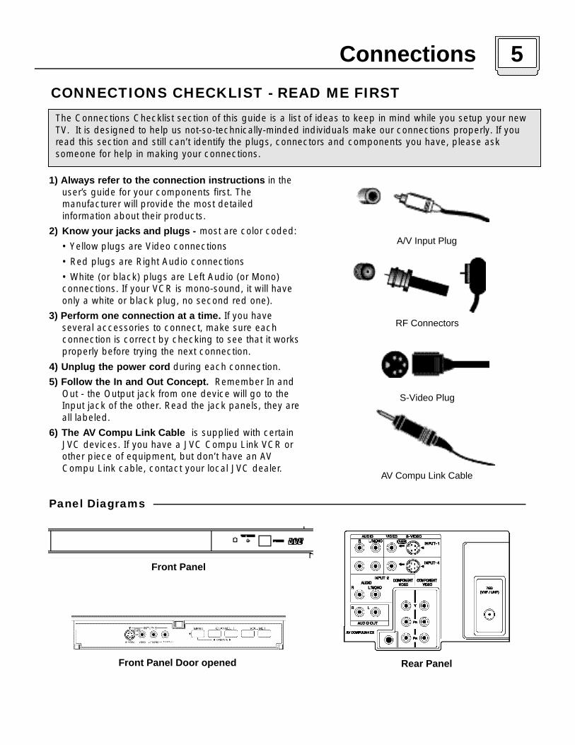
1) Always refer to the connection instructions in the user’s guide for your components first. The manufacturer will provide the most detailed information about their products.
2) Know your jacks and plugs - most are color coded:
• Yellow plugs are Video connections
• Red plugs are Right Audio connections
• White (or black) plugs are Left Audio (or Mono) connections. If your VCR is mono-sound, it will have only a white or black plug, no second red one).
3) Perform one connection at a time. If you have several accessories to connect, make sure each connection is correct by checking to see that it worksproperly before trying the next connection.
4) Unplug the power cord during each connection.
5) Follow the In and Out Concept. Remember In and Out - the Output jack from one device will go to the Input jack of the other. Read the jack panels, they areall labeled.
6) The AV Compu Link Cable is supplied with certain JVC devices. If you have a JVC Compu Link VCR or other piece of equipment, but don’t have an AVCompu Link cable, contact your local JVC dealer.
Connections 5
CONNECTIONS CHECKLIST - READ ME FIRST
The Connections Checklist section of this guide is a list of ideas to keep in mind while you setup your newTV. It is designed to help us not-so-technically-minded individuals make our connections properly. If youread this section and still can’t identify the plugs, connectors and components you have, please ask someone for help in making your connections.
A/V Input Plug
RF Connectors
S-Video Plug
AV Compu Link Cable
Panel Diagrams
Rear Panel
Front Panel
Front Panel Door opened

6 Connections
There are three basic types of antenna or cable connections:
• If you have an antenna or have a cable system that does not require you use a cable box to select channels, please refer to Diagram #1.
• If you have a cable system that requires the use of a cable box to access all the channels, please refer to Diagram #2. If you cannot operate your Picture-In-Picture function using Diagram #2, try the connection shown in Diagram #3. It is possible your cable box allows the signal of only one channel at a time to be sent to your television.
• If you have a cable system that requires the use of a cable box to access certain premium channels,but not “basic” cable channels, please refer to Diagram #3.
• For your convenience, connection to a VCR is also shown in the following diagrams. A VCR is not necessary for operation of the television or Picture-In-Picture (PIP) function. You may omit the VCR from your connections if you wish.
• For instructions on connecting a VCR only, please see the Quick Setup Guide.
• For information on using PIP, please see page 30.
The connection diagrams are intended to show some basic general connections. Some cable companies may require special connections to properly use your television or 2-tuner PIP function.If you follow these diagrams and either the television or PIP does not work properly, contact your localcable operator for more connection information.
Cable and VCR Connections
1
1) Connect the antenna or cable TV wire from the wall outlet, in to the RF Input of the two-way splitter.2) Connect an RF cable from the one of the RF Outputs on the splitter, in to the RF Input on the back of the VCR.
3) Connect an RF cable from the other the RF Output on the splitter, in to the RF Input on the back of the TV.
4) Connect the yellow video cable out from the VCR’s Video Output, in to the TV’s Video Input jack, OR connect an S-Video cable from the Camcorder’s S-Video output, to the TV’s S-Video input.
5) Connect the white audio cable out from the VCR’s Left Audio Output, in to the TV’s Left Audio Input Jack.6) Connect the red audio cable out from the VCR’s Right Audio Output, in to the TV’s Right Audio Input jack.
• If your VCR is a mono sound unit, it will have only one Audio Out jack. Connect it to the TV’s Left Audio Input.
• Please consult your VCR’s owner’s manual for more information on its operation.

Connections 7
2
Audio/Video Connections - Continued
1) Connect the antenna or cable TV wire from the wall outlet, in to the RF Input of the cable box.
2) Connect an RF cable from the cable box RF Output, in to the RF Input on the back of the VCR.
3) Connect an RF cable from the RF Output on the VCR, in to the RF Input on the back of the TV.4) Connect the yellow video cable out from the VCR’s Video Output, in to the TV’s Video Input jack, OR
connect an S-Video cable from the Camcorder’s S-Video output, to the TV’s S-Video input.
5) Connect the white audio cable out from the VCR’s Left Audio Output, in to the TV’s Left Audio Input Jack.
6) Connect the red audio cable out from the VCR’s Right Audio Output, in to the TV’s Right Audio Input jack.
1) Connect the antenna or cable TV wire from the wall outlet, in to the RF Input of the two-way splitter.
2) Connect an RF cable from the one of the RF Outputs on the splitter, in to the cable box RF I n p u t .
3) Connect an RF cable from the Cable Box Output, in to the VCR R F I n p u t .4) Connect an RF cable from the other the RF Output on the splitter, in to the RF Input on the back of the TV.
5) Connect the yellow video cable out from the VCR’s Video Output, in to the TV’s Video Input jack, OR connect an S-Video cable from the Camcorder’s S-Video output, to the TV’s S-Video input.
6) Connect the white audio cable out from the VCR’s Left Audio Output, in to the TV’s Left Audio Input Jack.7) Connect the red audio cable out from the VCR’s Right Audio Output, in to the TV’s Right Audio Input jack.
3
8 Connections
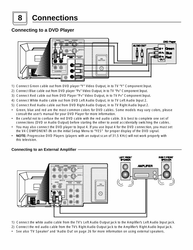
1) Connect the white audio cable from the TV’s Left Audio Output jack to the Amplifier’s Left Audio Input jack.
2 ) Connect the red audio cable from the TV’s Right Audio Output jack to the Amplifier’s Right Audio Input jack.• See also ‘TV Speaker’ and ‘Audio Out’ on page 26 for more information on using external speakers.
Connecting to an External Amplifier
Connecting to a DVD Player
1) Connect Green cable out from DVD player “Y” Video Output, in to TV “Y” Component Input.
2) Connect Blue cable out from DVD player “PB” Video Output, in to TV “ PB” Component Input.
3) Connect Red cable out from DVD Player “PR” Video Output, in to TV PR” Component Input.
4) Connect White Audio cable out from DVD Left Audio Output, in to TV Left Audio Input 2.
5) Connect Red Audio cable out from DVD Right Audio Output, in to TV Right Audio Input 2.
• Green, blue and red are the most common colors for DVD cables. Some models may vary colors, please consult the user’s manual for your DVD Player for more information.
• Be careful not to confuse the red DVD cable with the red audio cable. It is best to complete one set of connections (DVD or Audio Output) before starting the other to avoid accidentally switching the cables.
• You may also connect the DVD player to Input 4. If you use Input 4 for the DVD connection, you must set the V4 COMPONENT-IN on the initial Setup Menu to “YES” for proper display of the DVD signal.
• NOTE: Progressive DVD Players (players with an output scan of 31.5 KHz) will not work properly with this television.

Connections 9
JVC’s AV Compu Link feature makes playing video tapes or DVDs totally automatic. Simply insert a pre-recorded tape* into your JVC-brand VCR or DVD into your JVC DVD player and the device will automaticallyturn on and begin playback. At the same time, using the AV Compu Link, the VCR or DVD player sends a signal to the television telling it to turn on and switch to the proper video input• The AV Compu Link cable may be included with the JVC AV Compu Link accessory you wish to connect.
If it is not, contact an authorized JVC Service Center for part # EWP 805-012.
• AV Compu Link can only be used with JVC-brand products.
NOTES (For AV Compu Link):* In order for the VCR playback to begin automatically, the re c o rding tabs must be removed from the VHS tape. If the tab is in place,
automatic switching will occur when you push the VCR’s PL AY b u t t o n .• The AV Compu Link cable has a male 3.5 mm (mono) plug on each end.• If your JVC-brand VCR has “A Code/B Code Remote Control Switching” (see your VCR’s instruction book), using VCR A Code will
switch the TV to input 1.• To connect a JVC HiFi receiver or amplifier for a completely automated home theater, see the HiFi’s connection instructions for detailed
connection inform a t i o n .• AV C O M P U LINK EX is compatible with the following receivers: RX-664V, RX-665V, RX-668VBK, RX-774V, RX-778VBK, RX-884V,
RX-888VBK, RX-1024V, RX-1028VBK, and later receiver models.
To Connect: Plug one end of the AV Compu Link cable into the AV Compu Link input on your VCR, DVD, or other CompuLink device. Plug the other end of the AV Compu Link cable into the AV Compu Link input at the rear of the television.
Connecting to JVC AV Compu Link Capable Components
1) Connect the yellow video cable out from the Camcorder’s Video Output, in to the TV’s Video Input jack OR connect an S-Video cable from the Camcorder’s S-Video output, to the TV’s S-Video input.
2) Connect the white audio cable out from the Camcord e r’s Left Audio Output, in to the TV’s Left Audio Input Jack.3) Connect the red audio cable out from the Camcord e r’s Right Audio Output, in to the TV’s Right Audio Input jack.• If your Camcorder is a mono sound model it will have only one audio jack. Connect to the TV’s Left Audio Jack.
Connecting to a CamcorderYou may connect a camcorder to your television by using the front Input Jacks (Input 3) located under the frontpanel door. To access, press lightly on the door to open it. You may also connect a game console or other equipment using these jacks. Camcorders may also be connected to the television’s rear input jacks.
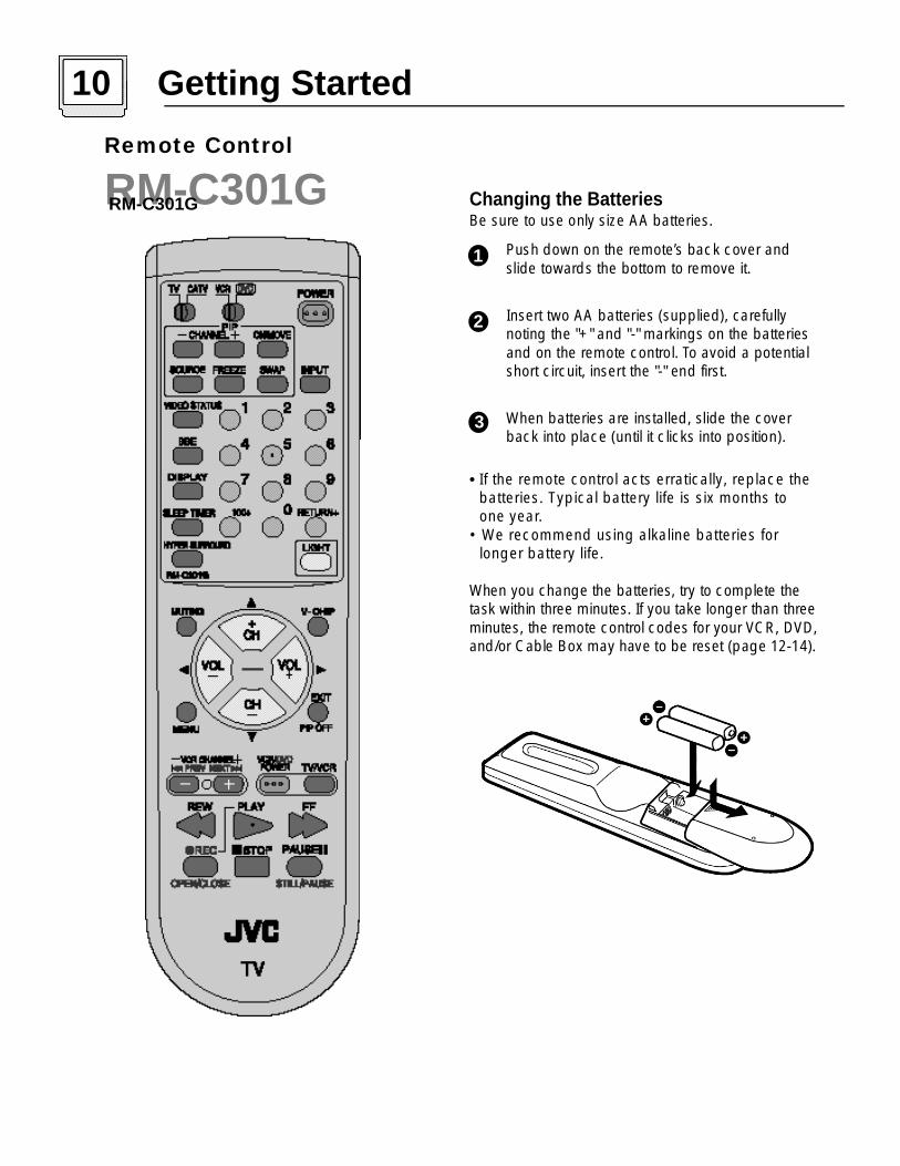
Changing the BatteriesBe sure to use only size AA b a t t e r i e s .
Push down on the re m o t e ’s back cover and slide towards the bottom to remove it.
I n s e rt two AA batteries (supplied), carefully noting the "+" and "-" markings on the batteries and on the remote control. To avoid a potential s h o rt circuit, insert the "-" end first.
When batteries are installed, slide the cover back into place (until it clicks into position).
• If the remote control acts erratically, replace the batteries. Typical battery life is six months to one year.
• We recommend using alkaline batteries for longer battery life.
When you change the batteries, try to complete thetask within three minutes. If you take longer than thre eminutes, the remote control codes for your VCR, DVD,and/or Cable Box may have to be reset (page 12-14).
10 Getting Started
1
2
3
Remote Control
RM-C301GRM-C301G

10 key direct access
To move directly to a specific channel, press that channel's numbers on the remote's 10 key pad. For single-digitchannel numbers, press "0" then the channel number. For channels above 100, press the 100+ button, then theremaining two digits on the 10 key pad.
CHANNEL -/+ BUTTON
To scan through the channels, press either the CH A N N E L + or CH A N N E L - button. You will move through the channels in numerical ord e r.
• After you operate the Auto Tuner Setup (page 16), all of the empty channels will be removed from scanning. When you scan you will only receive clear, active channels.
H y p e rs c a n
With JVC's Hyperscan feature you can zip through the channels at a rate of five per second. To use Hyperscan,p ress and hold either the CH A N N E L+ or CH A N N E L- buttons. After the first few channels scan at normal speed, therest will move by at five per second. To scan at normal speed, press and release the CH A N N E L+ / - b u t t o n .
Regular Return
P ress and release the RE T U R N+ button to re t u rn to the previous channel viewed. For example select a channel.Then select another channel using the 10 key pad buttons. You can now flip back and forth between these twochannels by pressing RE T U R N+.
RETURN+
With RE T U R N+ You can program your TV to always re t u rn to a specific channel. Press and hold down the RE T U R N+button for three seconds. The message, "RETURN C H A N N E L P R O G R A M M E D ! " will appear on-screen. Nowwhen you scan through the channels, pressing RE T U R N+ will bring you back to your programmed channel.
To cancel the RE T U R N+ channel, press and hold the RE T U R N+ button for three seconds. The message "RETURNC H A N N E L C A N C E L L E D ! " will appear on-scre e n .
• Pressing any number key or turning off the TV will also cancel the RE T U R N+ c h a n n e l .
• Press the PO W E R button on the remote control or the front panel of the TV. The On Timer lamp will glow re d .
• Make sure the TV/CAT V switch on the remote is set to TV. Move the switch to CAT V only if you plan to operatea cable box. On the CATV setting the remote will only operate the cable box functions.
• To turn the power off, press the PO W E R button again. The On Timer lamp will go out.
• The On Timer lamp will glow red when the On/Off Timer is set (page 25), even when the TV power is off.
Getting Started 11
1
2
3
4
POWER
To control the volume level, use the VO L U M E+/- b u t t o n s on the remote control or on the TV's front panel. Usethe VO L U M E - button to lower the volume. Press the VOLUME+ button to raise the volume.
Press the MUTING button to instantly turn the volume to zero. Press MUTING again to return to the previous volume level.
ADJUSTING VOLUME
CHANGING CHANNELS
VOLUME 13|||||||-------------------

12 Remote Programming
Setting the CATV, VCR and DVD CodesYou can program your remote to operate your cable box, satellite receiver, VCR or DVD player by usingthe instructions and codes listed below. If the equipment does not respond to any of the codes listedbelow or to the code search function, use the remote control supplied by the manufacturer.
Cable Box or Satellite setup
The remote control is programmed with CATV and/or Satellite codes for power on, power off, channel up,channel down, and 10 key operation.1) Find the CATV/Satellite brand from the list of codes shown below.2) Slide the 2-way selector switch to “CATV”.3) Press and hold down the DISPLAY button.4) With the DISPLAY button held down, enter the first code number listed using the 10 key pad.5) Release the DISPLAY button.6) Confirm the operation of the Cable Box/Satellite receiver.• If your CATV or Satellite box does not respond to the first code, try the others listed. If it does not
respond to any code, try the Search Codes Function at the bottom of the page.
Search Codes Function:1) Slide the 2-Way Mode Selector switch to CATV.2) Press the TV POWER and RETURN+ buttons. Hold for at least three seconds and release.3) Press TV POWER, see if the CATV or Satellite box responds.4) If there was a response, press RETURN+. The operating codes are now set. If there was no response,
repeat Step 3. If you repeat Step 3 52 times without a response, use the remote control which came with the equipment.
5) Press RETURN+ to exit.

Remote Programming 13
VCR setup The remote control is programmed with VCR codes for power on, power off, play, stop, fast-forward,rewind, pause, record, channel up, and channel down operation.1) Find the VCR brand from the list of codes shown below.2) Slide the first 2-way selector switch to “TV” and the other 2-way selector switch to “VCR”. 3) Press and hold down the DISPLAY button.4) With the DISPLAY button held down, enter the first code number listed with the 10 key pad.5) Release the DISPLAY button.6) Confirm the operation of the VCR.• If your VCR does not respond to the first code, try the others listed. If it does not respond to any code,
try the Search Codes Function at the bottom of the page.• Some manufacturer’s VCR’s may not respond to the TV/VCR button, even if other buttons work properly.• To Record, hold down the REC button on the remote and press PLAY.
Search Codes Function:1) Slide the first 2-way selector switch to “TV” and the other 2-way selector switch to “VCR”.2) Press the VCR POWER and RETURN+ buttons. Hold for at least three seconds and release.3) Press VCR POWER, see if the VCR responds.4) If there was a response, press RETURN+. The operating codes are now set. If there was no response,
repeat Step 3. If you repeat Step 3 80 times without a response, use the manufacturers remote control which came with the VCR.
5) Press RETURN+ to exit.

14 Remote Programming
The remote control is programmed with DVD codes for power on, power off, play, stop, fast-forward,rewind, previous chapter, next chapter, tray open/close, and still/pause operation.1) Find the DVD player brand from the list of codes shown below.2) Slide the first 2-way selector switch to “TV” and the other 2-way selector switch to “DVD”.3) Press and hold down the DISPLAY button.4) With the DISPLAY button held down, enter the first code number listed with the 10 key pad.5) Release the DISPLAY button.6) Confirm the operation of the DVD player.• If your DVD player does not respond to the first code, try the others listed. If it does not respond to any
code, try the Search Codes Function at the bottom of the page.• After you program your remote, some DVD buttons may not work properly. If some buttons do not work
properly, use the remote control which came with your DVD player.
Search Codes Function:1) Slide the first 2-way selector switch to “TV” and the other 2-way selector switch to “DVD”.2) Press the DVD POWER and RETURN+ buttons. Hold for at least three seconds and release.3) Press DVD POWER, see if the DVD player responds.4) If there was a response, press RETURN+. The operating codes are now set. If there was no response,
repeat Step 3. If you repeat Step 3 30 times without a response, use the manufacturers remote control which came with the DVD player.
5) Press RETURN+ to exit.
DVD setup

Using this GuideC e rtain symbols are used throughout this guide to help you learn aboutthe features of your new television. The ones you will see most fre-quently are :
Up and Down arrows mean press the CH A N N E L UP or CH A N N E L
DO W N buttons. Pressing the UP or DO W N buttons let you:
• Move vertically in a main menu scre e n• Move through a submenu scre e n• Move to the next letter, number, or other choice in a submenu• Back up to correct an erro r• Scan through TV channels (when not in a menu scre e n )
Left and right arrows mean press the VO L U M E LE F T o r VO L U M E
RI G H T buttons to:• Select a highlighted menu item• Select an item in a submenu• Select numbers in certain menu options• Tu rn the volume up or down (when not in a menu scre e n )
The "Press Button" icon means you should press the button named on your remote control. (Button names appear in SM A L L CA P I TA L LE T T E R S. )
The ‘Helping Hand’ points to the highlighted or selected item in a m e n u .
The Onscreen Menus:To bring up the onscreen menu, press the MENU button on theremote control. The item that appears in yellow is the one currentlyselected. If you press the MENU button again, the onscreen display willskip to the next menu screen.
The “Plug In Menu’ will appear the first time the TV is plugged in.Notes: Menus shown in this book are illustrations, not exact replications of thetelevision’s onscreen displays.
Initial Setup Items1
PLUG IN MENU
LANGUAGE ENG FRE SPAAUTO TUNER SETUPSET CLOCK
FINISH
SELECT BYOPERATE BY EXIT BY
EXIT
INITIAL SETUP
PREVIOUS
AUTO TUNER SETUP CHANNEL SUMMARYV-CHIPSET LOCK CODE
NEXT PAGE
SELECT BYOPERATE BY EXIT BY
EXIT
Picture Settings
General Items
Sound Settings
2
3
5
6
4
PICTURE ADJUST
PREVIOUS
TINTCOLORPICTUREBRIGHTDETAIL
NEXT PAGE
SELECT BYOPERATE BY EXIT BY
EXIT
-----------------------------------------------------------------------------------------------------------------------------
PICTURE ADJUST
PREVIOUS
NOISE MUTING ON OFF SET VIDEO STATUS
NEXT PAGE
SELECT BYOPERATE BY EXIT BY
EXIT
SOUND ADJUST
PREVIOUS
BASS TREBLEBALANCEMTS STEREO SAP MONO
NEXT PAGE
SELECT BYOPERATE BY EXIT BY
EXIT
ON AIR
---------------------------------------------------------------------------
CLOCK/TIMERSPREVIOUS
SET CLOCK ON/OFF TIMER
NEXT PAGE
SELECT BYOPERATE BY EXIT BY
EXIT
INITIAL SETUP
PREVIOUS
TV SPEAKER ON OFF AUDIO OUT VARI FIXV4 COMPONENT-IN YES NOLANGUAGE ENG FRE SPACLOSED CAPTION
NEXT PAGE
SELECT BYOPERATE BY EXIT BY
EXIT
Menu Screen Order
If you use the Menu button on the TV’s front panel instead of the remote, an additionalmenu screen showing channel number and input will appear between menus 1 and 2.
Using the Menu 15
16 Plug In MenuAuto Tuner Setup
In Auto Tuner Setup, the TV automatically scanst h rough all available channels, memorizing the activeones and skipping over blank ones or channels withweak signals. This means when you scan (using theCH A N N E L +/- b u t t o n s ) you will receive only clear, active channels.
P ress the ME N U b u t t o n
To AUTO TUNER SETUP
To operate
To choose CABLE or AIR
To move to START
To start Auto Tuner Setup
Programming will take approximately 1 to 2 minutes.
• Noise Muting will not work during Auto Tuner Setup.
NOTE:
TUNER MODE : CABLE AIR
START
NOW PROGRAMMING !
PROGRAMMING OVER!
48
IntroductionThe Plug In Menu comes up automatically whenyou first turn on the TV after plugging it in. ThePlug In Menu helps you to get your TV ready touse by letting you set your preferences for:
• The Language in which you want the onscreen menus to appear,
• The Auto Tuner Setup of which channels you wish to receive,
• Setting the TV’s clock to the correct time so your timer functions will work properly.
Descriptions of each of the Plug In Menu featuresappear on this page and the next. We recommendyou complete the Plug In Menu setup first so yourTV is set up just the way you want, right away.
LanguageYou can choose to view your onscreen menus inthree languages: English, French, or Spanish.
P ress the ME N U b u t t o n
To LANGUAGE
To choose a language
EXIT/PIP OFF when finished
LANGUAGE ENG FRE SPA
• If you exit the Plug In Menu, or wish to change your preferences later, all the Plug In Menu options can be found in the regular onscreen menus.
NOTES:
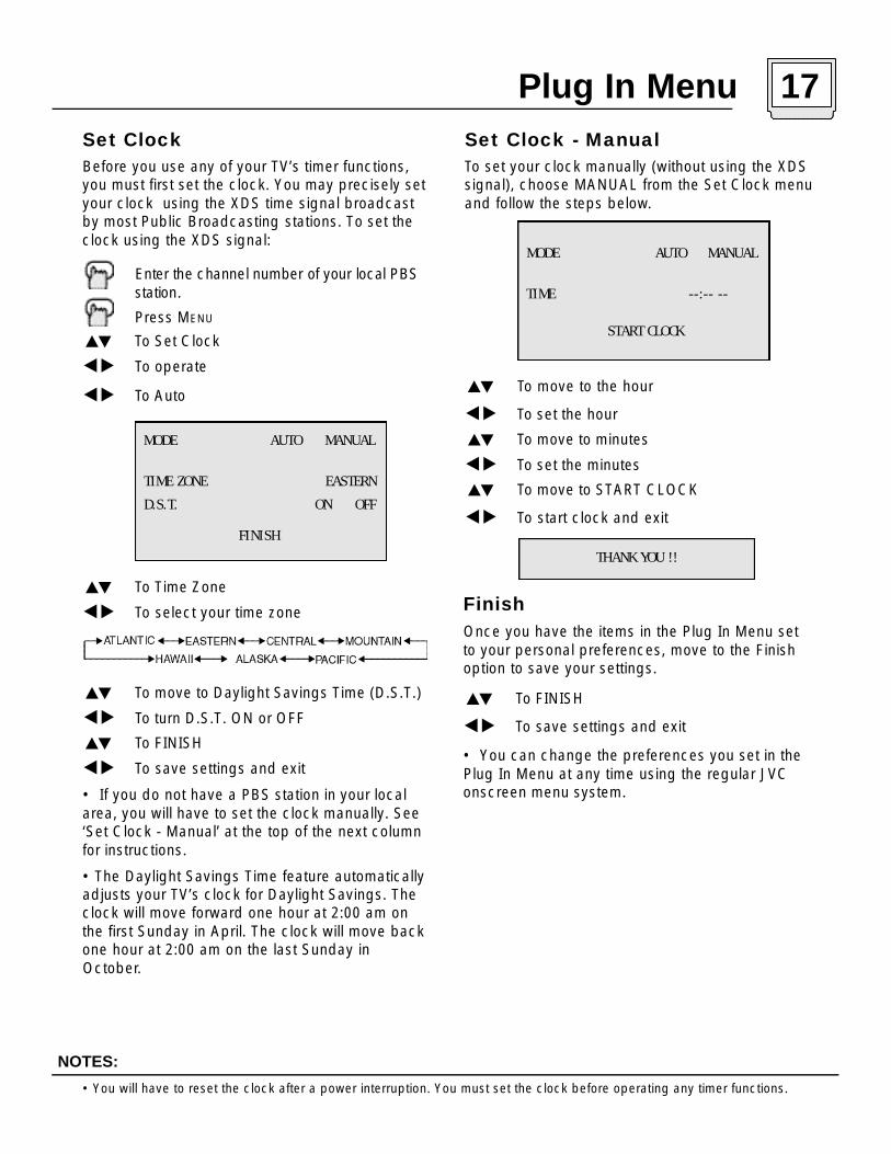
Set ClockBefore you use any of your TV’s timer functions,you must first set the clock. You may precisely setyour clock using the XDS time signal broadcastby most Public Broadcasting stations. To set theclock using the XDS signal:
Enter the channel number of your local PBS station.
Press MENU
To Set Clock
To operate
To Auto
To Time Zone
To select your time zone
To move to Daylight Savings Time (D.S.T.)
To turn D.S.T. ON or OFF
To FINISH
To save settings and exit
• If you do not have a PBS station in your localarea, you will have to set the clock manually. See‘Set Clock - Manual’ at the top of the next columnfor instructions.
• The Daylight Savings Time feature automaticallyadjusts your TV’s clock for Daylight Savings. Theclock will move forward one hour at 2:00 am onthe first Sunday in April. The clock will move backone hour at 2:00 am on the last Sunday inOctober.
Set Clock - ManualTo set your clock manually (without using the XDSsignal), choose MANUAL from the Set Clock menuand follow the steps below.
To move to the hour
To set the hour
To move to minutes
To set the minutes
To move to START CLOCK
To start clock and exit
MODE AUTO MANUAL
TIME ZONE EASTERN
D.S.T. ON OFF
FINISH
• You will have to reset the clock after a power interruption. You must set the clock before operating any timer functions.
Finish
Once you have the items in the Plug In Menu setto your personal preferences, move to the Finishoption to save your settings.
To FINISH
To save settings and exit
• You can change the preferences you set in thePlug In Menu at any time using the regular JVConscreen menu system.
MODE AUTO MANUAL
TIME --:-- --
START CLOCK
THANK YOU !!
Plug In Menu 17

18 Channel Summary
Channel SummaryChannel Summary allows you to customize theline-up of channels received by your TV. You canadd or delete channels from the line-up or prevent any unauthorized viewers from watchingany or all 181 channels.
P ress the ME N U b u t t o n
To CHANNEL SUMMARY
To operate
The Channel Summary screen (below) will nowbe displayed with the channels set to scanmarked with an "ü". You can delete channelsfrom the scan by removing the "ü". If any channels were missed during Auto Tuner Setupand you wish to add them, you may by placing an "ü" next to the channel number.
To the SCAN column
To include or delete from scan
EXIT/PIP OFF when finished
C H NO. SCAN C H NO. SCAN
0 1 06 ü
0 2 ü 07
0 3 ü 08
0 4 ü 09 ü
0 5 ü 10 ü
Channel Summary - Lock
To CHANNEL S U M M A RY
To operate
To the Lock Column
ZERO to lock or unlock that channel
EXIT/PIP OFF when finished
Channel Guard MessageWhen a viewer attempts to watch a guarded channel,the following message appears:
To watch a channel that you have locked, enter theLock Code using the 10 key pad (see “Set LockCode” - at the top of the next column).
If the wrong code is entered, this message will flashon the scre e n :
The channel cannot be accessed until the corre c tcode is entere d .
• Once a channel has been unlocked, it will remain unlocked until the television is turned off.
THIS CHANNEL IS LOCKED BY
CHANNEL GUARD.
PLEASE ENTER LOCK CODE BY
10 KEY PAD TO UNLOCK IT.
NO. - - - -
INVALID LOCK CODE !
C H NO. SCAN C H NO. SCAN
0 1 ü 0 6 ü
0 2 ü 0 7
0 3 ü 0 8
0 4 ü 0 9 ü
0 5 ü 1 0 ü
• Some cable systems experience interference from radio frequencies on cable Channel 95. You may delete this channel
from your scan by removing the "ü" next to it on the Channel Summary screen.
NOTE:

U.S. PARENTAL RATING SYSTEMSP rograms with the following Ratingsa re appropriate for Childre n .
❒ TV Y is Appropriate for All Children.P rograms are created for very young viewersand should be suitable for all ages, includingc h i l d ren ages 2 - 6.
❒ TV Y7 is for Older Children.Most parents would find such programssuitable for children 7 and above. They maycontain some mild fantasy violence orcomedic violence, which children should beable to discern from reality.
P rograms with the following Ratingsa re designed for the entire audience.
❒ TV G stands for General Audience.Most parents would find these programssuitable for all age groups. They contain littleor no violence, no strong language, and littleor no sexual dialog or situations.
❒ TV PG Parental Guidance Suggested.May contain some, but not much, stronglanguage, limited violence, and somesuggestive sexual dialog or situations. It i srecommended that parents watch theseprograms first, or with their children.
❒ TV 14 Parents Strongly Cautioned.Programs contain some material that may beunsuitable for children under the age of 14including possible intense violence, sexualsituations, strong coarse language, orintensely suggestive dialog. Parents arecautioned against unattended viewing bychildren under 14.
❒ TV MA Mature Audiences Only.These programs are specifically for adultsand may be unsuitable for anyone under 17years of age. TV MA programs may haveextensive V, S, L, or D.
V-ChipYour TV is equipped with V-Chip technology whichenables TV P a rental Guideline and Movie (MPA A )Guideline controls. V-Chip technology allows you top rogram your TV to receive, or not to receive, p rograms based on content according to the guidelines. Programs which exceed the ratings limitsyou set will be blocked.
When a viewer attempts to watch a blocked channel,this message appears:
To watch a blocked channel, enter the lock code(page 14) using the 10 key pad.
To set up the TV Parental GuidelineRatings:
P ress the ME N U b u t t o n
To V-CHIP
To operate (Lock icon will appear)
Press ZERO to access the V-Chip menu
To turn V-Chip ON or OFF
To move to SET US TV RATINGS
To operate (see page 19 for details)
Viewing Guidelines• V/FV is for VIOLENCE/FANTASY VIOLENCE • S stands for SEXUAL CONTENT• L stands for strong LANGUAGE• D stands for suggestive DIALOG
THIS PROGRAMMING EXCEEDSYOUR RATINGS LIMITS.PLEASE ENTER LOCK CODE BY10 KEY PAD TO UNLOCK IT.
NO. - - - -
V-CHIP ON OFFSET US TV RATINGSSET MOVIE RATINGS
UNRATED VIEW BLOCK
FINISH
— — — — — —V/FV — — — — S — — — L — — — D — —
TVY7
TVMA
TVPG
TVG
TV14
TVY
FINISH
V-Chip 19

20 V-Chip
• V-Chip function is based on specifications for the United States and therefore may not work properly in Canada.
NOTE (For Canadian Viewers):
D i rections to set up Movie Ratings:
Press the MENU button
To V-CHIP
To operate (Lock icon appears)
Press ZERO to access V-Chip setupoptionsTo SET MOVIE RATINGS
To enter movies menu
❒ NR - Not Rated.This is a film which has no rating. In manycases these films were imported from countrieswhich do not use the MPA A ratings system.Other NR films may be from amateur pro d u c e r swho didn’t intend to have their film widelyre l e a s e d .NR (Not Rated) Programming may containall types of programming including children's programming, foreign programs,or adult material.
❒ G – General Audience.In the opinion of the review board, thesefilms contain nothing in the way of sexualcontent, violence, or language that would beunsuitable for audiences of any age.
❒ PG – Parental Guidance.P a rental Guidance means the movie maycontain some contents such as mild violence,some brief nudity, and strong language. Thecontents are not deemed intense.
❒ PG-13 – Parents Strongly Cautioned.Parents with children under 13 are cautionedthat the content of movies with this ratingmay include more explicit sexual, language,and violence content than movies rated PG.
Directions to Block Viewing:Line up the cursor in the column (TV PG, TV G ,etc.) with the content row (V/FV, S, etc.) and pre s sthe o r to move the cursor to the corre c t
location. Press or to turn the locking featureon or off. An item is locked if the iconappears instead of a “—”.
For example. To block viewing of all TV 14shows:
Move the cursor to the top row of that columnand add a lock icon. Once you've put a lock onthe top row, everything in that column isautomatically locked.
To the TV 14 Column
To turn on the lock
To FINISH
To save settings and exit
• If you want to change the setup, move thecursor to the top column and change the lockicon to "—". You may then select individualcategories to block.
Special Note about Ratings
Some programs are not broadcast with aratings signal. Therefore, even if you setupV-Chip ratings limits, these programs willnot be blocked. Parents are cautioned to
preview the contents of these programs ormovies.
— — — — —V/FV — — — S — — L — — D —
TVY7
TVMA
TVPG
TVG
TV14
TVY
FINISH
X NC -17 R PG -13 PG G N R— — — — — — —
FINISH

Notes About Unrated Programs:
Unrated programming refers to anyprogramming which does not contain a ratingsignal. Programming on television stationswhich do not broadcast rating signals will beplaced in the “Unrated Programming" category.
Examples of Unrated programs:
Emergency BulletinsLocally Originated ProgrammingNewsPolitical ProgramsPublic Service AnnouncementsReligious ProgramsSportsWeatherSome Commercials
• TV programs or movies that do not have ratingsignals will be blocked if the Unrated Category is set to LOCK.
D i rections to Block Unrated Pro g r a m s :
You can block programs that are not rated.
Press the MENU button
To V-CHIP
To operate (The lock icon appears)
Press ZERO to access V-Chip setupoptions
To UNRATED
To View or Block
Press EXIT/PIP OFF when done
❒ R Restricted.These films contain material that is explicit innature and is not recommended forunsupervised children under the age of 17.
❒ NC-17 No One Under 17.These movies contain content which mostp a rents would feel is too adult for their childre nto view. Content can consist of strong language,n u d i t y, violence, and suggestive or explicitsubject matter.
❒ X No One under 18.Inappropriate material for anyone under 18.
D i rections to Block Movie Vi e w i n g :
To block viewers from any or all of these ratingscategories, press the or to move the cursorto the correct location. Press the or buttons to turn the locking feature on or off. Anitem is blocked if the icon appears instead of a “—".
For example, to block viewing of X and NC-17rated from shows:
To the X Column
To turn on the lock
To the NC-17 Column
To turn on the lock
To FINISH
To save settings and exit
• In order for V-Chip settings to take effect, V-Chip settings must be turned ON in the V-Chip menu (page 19).• You can automatically unblock all of your restrictions by turning V-Chip settings OFF in the V-Chip menu (page 19).
• You can always unblock a restriction by re-entering the V-Chip menu and removing the lock icon.
NOTES:
X NC -1 7 R PG -1 3 P G G N R— — — — — —
UNRATED VIEW BLOCK
FINISH
X NC -17 R PG -1 3 PG G N R— — — — —
FINISH
V-Chip 21

22 V-Chip
Example 2:
If you want to set your V-Chip settings to blockall programming above a current setting suchas TV PG-V (with violence):
Press ZERO when TV-PG - V is displayed
All Programming above TV PG withViolence will be blocked!
Accessing V-Chip Information:
To access Rating information about a certainprogram, press the V-CHIP button while viewingthat program. A display like this will appear:
If you decide you want to block this category ofviewing, press "0" while the above screen isvisible, and all programs from that category willbe blocked.
Example 1:
If you want to set your V-Chip settings to blockall programming above TV PG:
Press ZERO when TV-PG isdisplayed
All Programming above TV PG will beblocked.
PROGRAM IS RATED :TV-PG - V
— — —V/FV —SLD
TVY7
TVMA
TVPG
TVG
TV14
TVY
— — — — — —V/FV —S — — — L — — — D — —
TVY7
TVMA
TVPG
TVG
TV14
TVY
Set Lock Code
Channel Guard and V-Chip settings are protectedby a four-digit Lock Code. Your TV comes pre-setwith a Lock Code of "0000". You may change thecode to any four-digit number you wish. Tochange the Lock Code, follow the steps below.
P ress the ME N U b u t t o n
To SET LOCK CODE
To operate
The padlock icon appears
Press ZERO to access the Lock Code
The first digit will be highlighted
To select the number
To move to the next digit
Continue to follow these directions for all fournumbers
To FINISH
To save settings and exit
Your Lock Code is now set.
LOCK CODE 0 0 0 0
FINISH
• After a power interruption you must reset the Lock Code.
• Write your Lock Code number down and keep it hidden from potential viewers.
• If you forget the Lock Code, a new code may be set using the steps listed above.
• For Children's programming you can blockTV-Y and Y programs by Pressing “0” when Y isdisplayed during a program. Programming foraudiences other than children’s audiences willnot be affected.
NOTES:
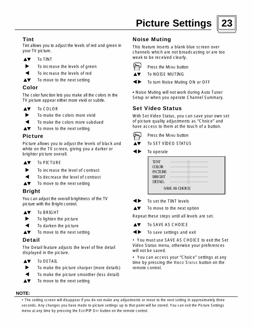
Noise MutingThis feature inserts a blank blue screen overchannels which are not broadcasting or are tooweak to be received clearly.
P ress the ME N U b u t t o n
To NOISE MUTING
To turn Noise Muting ON or OFF
• Noise Muting will not work during Auto TunerSetup or when you operate Channel Summary.
Set Video StatusWith Set Video Status, you can save your own setof picture quality adjustments as “Choice” andhave access to them at the touch of a button.
P ress the ME N U b u t t o n
To SET VIDEO STATUS
To operate
To set the TINT levels
To move to the next option
Repeat these steps until all levels are set.
To SAVE AS CHOICE
To save settings and exit
• You must use SAVE AS CHOICE to exit the SetVideo Status menu, otherwise your preferenceswill not be saved.
• You can access your “Choice” settings at anytime by pressing the VIDEO STATUS button on theremote control.
• The setting screen will disappear if you do not make any adjustments or move to the next setting in approximately three
seconds. Any changes you have made to picture settings up to that point will be stored. You can exit the Picture Settings
menu at any time by pressing the EXIT/PIP OFF button on the remote control.
TintTint allows you to adjust the levels of red and green inyour TV picture .
To TINT
To increase the levels of green
To increase the levels of red
To move to the next setting
ColorThe color function lets you make all the colors in theTV picture appear either more vivid or subtle.
To COLOR
To make the colors more vivid
To make the colors more subdued
To move to the next setting
PicturePicture allows you to adjust the levels of black andwhite on the TV screen, giving you a darker orbrighter picture overall.
To PICTURE
To increase the level of contrast
To decrease the level of contrast
To move to the next setting
BrightYou can adjust the overall brightness of the TVp i c t u re with the Bright contro l .
To BRIGHT
To lighten the picture
To darken the picture
To move to the next setting
DetailThe Detail feature adjusts the level of fine detaildisplayed in the picture.
To DETAIL
To make the picture sharper (more details)
To make the picture smoother (less detail)
To move to the next setting
NOTE:
TINT -------------||-------------COLOR -------------||-------------PICTURE -------------||-------------BRIGHT -------------||-------------DETAIL -------------||-------------
SAVE AS CHOICE
Picture Settings 23
24 Sound Settings
• You can leave the Sound Settings menu at any time by pressing the EXIT/PIP OFF button on the remote control.
NOTE:
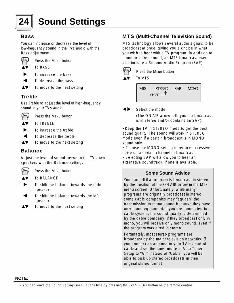
MTS (Multi-Channel Television Sound)MTS technology allows several audio signals to bebroadcast at once, giving you a choice in whatyou wish to hear with a TV program. In addition tomono or stereo sound, an MTS broadcast mayalso include a Second Audio Program (SAP).
P ress the ME N U b u t t o n
To MTS
Select the mode
(The ON AIR arrow tells you if a broadcast is in Stereo and/or contains an SAP).
• Keep the TV in STEREO mode to get the bestsound quality. The sound will work in STEREOmode even if a certain broadcast is in MONOsound only.• Choose the MONO setting to reduce excessivenoise on a certain channel or broadcast.• Selecting SAP will allow you to hear an alternative soundtrack, if one is available.
BassYou can increase or decrease the level of l o w - f requency sound in the TV’s audio with the Bass adjustment.
P ress the ME N U b u t t o n
To BASS
To increase the bass
To decrease the bass
To move to the next setting
TrebleUse Treble to adjust the level of high-fre q u e n c ysound in your TV’s audio.
P ress the ME N U b u t t o n
To TREBLE
To increase the treble
To decrease the treble
To move to the next setting
BalanceAdjust the level of sound between the TV’s twospeakers with the Balance setting.
P ress the ME N U b u t t o n
To BALANCE
To shift the balance towards the right speaker
To shift the balance towards the left speaker
To move to the next setting
Some Sound AdviceYou can tell if a program is broadcast in stereoby the position of the ON AIR arrow in the MTSmenu screen. Unfortunately, while many programs are originally broadcast in stereo,some cable companies may “squash” the transmission to mono sound because they haveonly mono equipment. If you are connected to acable system, the sound quality is determinedby the cable company. If they broadcast only inmono, you will receive only mono sound, even ifthe program was aired in stereo.
Fortunately, most stereo programs arebroadcast by the major television networks. Ifyou connect an antenna to your TV instead ofcable and set the tuner mode in Auto TunerSetup to “Air” instead of “Cable” you will beable to pick up stereo broadcasts in their original stereo format
MTS STEREO SAP MONO
ON AIR

On/Off TimerThe On/Off timer lets you program your televisionto turn itself on or off. You can use it as an alarmto wake up, to help you remember important programs, or as a decoy when you're not home.
P ress the ME N U b u t t o n
To ON/OFF TIMER
To operate (begins with ON TIME)
To set the hour (AM/PM) you want the TVto turn on
To move to minutes
To set the minutes
To accept ON TIME and move to OFFTIME (the time the TV will turn off). Set the OFF TIME the same way as ON TIME
To accept OFF TIME and move to CHANNEL
To select channel
To move to MODE
Choose ONCE or EVERYDAY
To ON/OFF TIMER
Choose YES to accept the timer setting, choose NO if you don't wish to accept
To FINISH
To save settings
ON TIME 7:00 PMOFF TIME 10:00 PMCHANNEL 02MODE ONCE EVERYDAYON/OFF TIMER YES NO
FINISH
NOTE:• On/Off Timer cannot be set to locked or guarded channels. In order for the On/Off Timer to work, the clock must be set.
After a power interruption Timer settings must be reset.
Timer Note:If the television is on when a timed event is aboutto start a Timer Preview window will appear. TheTimer Preview window will appear in the lower rightcorner of the screen seven seconds before thetimer is programmed to begin. When the timer activates, the Preview picture will become the mainpicture.
Seven seconds before TimerActivates....
(Preview of ON/OFF TimedProgram)
Timer Activates
Seven seconds later...
33
4
33
TimerActivated
4
General Items 25
2 6 General Items
• Closed Captions subtitles are usually found on caption channel CC1. Some programs may include additional text
information which is usually found on text channel T1. The other channels are available for future use.
• Closed captioning may not work correctly if the signal being received is weak or if you are playing a video tape.
• Most broadcasts containing Closed Captioning will display a notice at the start of the program.
• External Speakers: When using external speakers or amplifiers, shut off the TV Speakers (see ‘TV Speakers’) above.
NOTES:
Closed CaptionUse this function to display the Closed Captioningtext onscreen (when included in a bro a d c a s t ) .
P ress the ME N U b u t t o n
To CLOSED CAPTION
To operate
To select CAPTION, TEXT, or OFF
To CAPTION or TEXT
To select a caption (CC1 to CC4) or text channel (T1 to T4)
To accept that selection and move to FINISH
To save settings and exit
MODE : CAPTION
CAPTION : CC1 CC2 CC3 CC4TEXT : T1 T2 T3 T4
FINISH
TV SpeakerIf your TV is connected to a stereo system, you cant u rn off the TV speakers and listen to the audiot h rough your stereo.
P ress the ME N U b u t t o n
To TV SPEAKER
To turn the TV's speakers ON or OFF
EX I T/PIP OF F when finished
• Before you turn the TV Speaker setting from OFF toON, make sure that the T V volume level is low ! I fthe TV volume is set too high, the sound level will bee x t remely loud.
• After a power interruption, the TV Speaker settingswill re t u rn to “ON”.
TV SPEAKER ON OFF
Audio OutIf your television is connected to an externalspeaker source, Audio Out gives you the option ofcontrolling the volume level with your TV’s remotecontrol.
Press the MENU button
To AUDIO OUT
To VARI or FIX
EX I T/ P I P OF F when finished
VARI: Lets you adjust the volume of the external
speakers using the VOLUME +/- buttons on yourTV’s remote control.
FIX: The volume of the external speakers isadjusted using the audio device’s remote control.
V4 Component-InGet the best quality video from your DVD playerby using this setting and the DVD inputs at therear of the television. Set either to YES for component input (for DVD) or to NO for compositevideo input (for a regular VCR).
Press the MENU button
To V4 COMPONENT-IN
To turn the input ON or OFF
EXIT/PIP OFF when finished
• This option should be used with DVD playersonly. For information on connecting VCR’s seepage 6. For more information on connecting aDVD player, see page 8.
V4 COMPONENT-IN YES NO
AUDIO OUT VARI FIX

Video StatusThe VIDEO STATUS button gives you a choice ofthree TV picture display settings, including a display of your own preferences.
Standard - Resets the picture display to the factory settings.
Choice - Displays the setting levels you specifiedon the "Set Video Status" Menu (see page 23).
Theater - Gives a rich, film-like look to video.
P ress the VI D E O STAT U S b u t t o n
Sleep TimerThe Sleep Timer can turn the TV o ff for you after youfall asleep. Program it to work in intervals of 15 minutes, for a total time of up to 180 minutes.
P ress the SL E E P TI M E R b u t t o n
Sleep Timer Message
20 seconds before the automatic shutoff, this message will appear:
You then have 20 seconds to press the Sleep Ti m e rbutton to delay the shutoff for another 15 minutes.
• Please note that if the Clock, Sleep Timer or On/Off Timer are not set, the Display screen will show: "Clock Not Set",
"Sleep Timer OFF", and "On/Off Timer Off" respectively.
DisplayThe Display screen shows the current status of timersand inputs.
P ress the DI S P L AY b u t t o n
• The channel or AV input (Channel 07)• The current time (12:20 pm)
• Sleep Timer status/minutes remaining (The Sleep Timer is off)
• On/Off Timer status (Set to turn on everyday at 7:00 PM, off at 10:00 PM)
• Each Press of the DISPLAY button changes the display mode:
Display - Full screen shown above
Time - Shows the current time only
Channel - Shows the current channel
Off - Turns Display off
• You may also turn off the Display at any step by pressing EXIT/PIP OFF.
NOTE:
07NOW 12:20 PMSLEEP TIMER OFFON/OFF TIMER EVERYDAY
ON TIME 7:00 PMOFF TIME 10:00 PM
GOOD NIGHT!!
PUSH SLEEP TIMER BUTTON
TO EXTEND.
MenuThe ME N U button allows you to access JVC’so n s c reen menu system. Press ME N U to activate theo n s c reen menu system.
• See individual topics (like “Sound Settings) forspecific information on using menus.
Exit/PIP OffP ress the EX I T/ P I P OF F button to leave a menu scre e nor to turn off the PIP f e a t u re (page 30).
Button Functions 27

28 Button Functions
Return+The RETURN+ button has two functions:
Return - Returns to the channel viewed justbefore the channel currently onscreen.
Return+ - Lets you program a specific channel toreturn to while scanning through the channels.
RETURN+ and hold for three seconds
Scan using the Channel+/- buttons
RETURN+
You will re t u rn to your programmed channel.
• To cancel your Return+ channel, press and hold theRE T U R N+ button for three seconds. The message“RETURN CHANNEL CANCELLED!” will appear.• Return+ works only with CHANNEL+/-. Pressingany number key will cancel Return+.• Return+ does not effect the PIP channel.• For more information on Return and Return+,please see page 11.
Number Buttons - 10 Key PadTo move directly to a specific channel, enter the channel number with the number buttons on theremote. For example, to move to Channel 7:
0 (zero )
7 (seven)
100+ ButtonUse the 100+ button to directly access channelsabove Channel 99. For example to move to channel1 2 4 :
1 0 0 +
2 (two)
4 (four)
RETURN CHANNEL
PROGRAMMED !
• BBE is a registered trademark of BBE Sound, Inc. For U.S., licensed from BBE Sound, Inc. under USP 4638258, 4482866
and 5510572. For Canada, licensed from BBE Sound, Inc. BBE is a registered trademark of BBE Sound, Inc.
NOTE:
BBEBBE high definition audio adds natural, clear andextraordinary sound quality to any program. TurnBBE On or Off using the BBE button.
Hyper SurroundCreates a deep, three-dimensional sound effect by channeling the audio through the TV's front-firing speakers. Press the HYPER SURROUND
button to turn the effect on or off.
MutingThe MUTING button instantly turns the volume downcompletely when you press it.
MU T I N G
The volume level will instantly go to zero.
• To restore the volume to its previous level, pressMUTING again.
BBE ON OFF
HYPER SURROUND ON OFF

VCR Buttons
You can use this remote control to operate the basicfunctions of your VCR. These functions include: play,re c o rd, rewind, fast-forw a rd, stop, pause, channelscan, TV / VCR, power on, and power off.
Move the selector switch to VCR to operate.
• The remote is preset with the code 000 to controlJVC-brand VCR’s. For any other manufacturer’sbrand VCR, please see the code chart andinstructions on page 13.
DVD Buttons
You can also use this remote control to operate thebasic functions of your DVD p l a y e r. These functionsinclude: play, rewind, fast-forw a rd, stop, still/pause,p revious/next, tray open/close, power on, andpower off .
Move the selector switch to DVD to operate.
• The remote is preset with the code 000 to controlJVC-brand DVD players. For any other manufac-turer’s brand DVD player, please see the codechart and instructions on page 14.
TV/CATV Switch
Use either the television’s own tuner or a cable boxto select channels. Set this switch to TV to operatethe television’s built-in tuner. Move the switch toC ATV to operate a cable box.
• See page 12 for information on pro g r a m m i n gyour remote for cable box operation.
VCR/DVD Switch
You can control a VCR or DVD player with the buttons on the lower part of the remote control. Usethe VCR/DVD selector switch to choose either VCRor DVD o p e r a t i o n .
• See pages 13 and 14 for information on p rogramming your remote with VCR and DVDoperating codes.
Button Functions 29
InputSelects the signal input source for the television:TV (for Antenna or Cable) or Video1, 2, 3, or 4 forvideo devices like VCR’s, DVD players, or camcorders.
IN P U T
LightThe RM-301G remote includes illuminated buttons forkey features like CH A N N E L + / - and VO L U M E + / -. Pre s sthe LI G H T button to turn the illumination on.
LIGHT
30 Button Functions - PIP
ON/MOVE
Turn PIP on by pressing the ON/MOVE button.
(PIP) ON/MOVE
EXIT/PIP OFF to turn PIP off
Once PIP is turned on, you can move the PIP window to any of the TV’s main picture’s four corners with the ON/MOVE button.
ON/MOVE
• Each press of ON/MOVE will shift the PIP window to a different corner.
FREEZE
Use the FREEZE button to lock a single, still imageonto the PIP window.
FREEZE
• If PIP is off when FREEZE is pressed, a snapshot of the main screen is taken and placed in the PIP window.
• If PIP is on when FREEZE is pressed, the image in the window when the button was pressed is held.
SOURCE
You can select the signal source for the PIP window image.
SOURCE
• If the PIP does not have a signal, the window will be blue.
• If you connect a DVD to Video-2 or Video-4, the PIP window will be blue.
CHANNEL +/- For PIPLike the main CHANNEL +/- buttons, CHANNEL +/-for PIP lets you scan through the channels in thePIP window.
CHANNEL +/-
• Direct channel selection with the 10 key pad forPIP is not possible.
SWAP
You can exchange the channel displayed on themain screen for the one shown in the PIP windowby pressing SWAP.
SWAP
02
07
• The PIP window is 1/9 the size of the full screen.
• PIP will not display blocked channels or programs. A blue screen will display instead.
NOTES:
PIP (Picture-In-Picture)PIP displays two separate pictures on screen. Your television has 2-Tuner PIP, meaning you canview pictures from two d i ff e re n t channels simulta-n e o u s l y. A special set of PIP c o n t rol buttons arelocated on the upper part of the remote contro l .Descriptions of each button appear on this page.

Troubleshooting 31
32 Limited WarrantyFor Canadian model televisions, see separate sheets for Warranty/Garantie and
JVC Authorized Service Centers in Canada.
JVC COMPANYOF AMERICAwarrants this product and all parts thereof, except as set forth below ONLYTO THE ORIGINALPURCHASER AT RETAILto be FREE FROM DEFECTIVE MATERIALS AND WORKMANSHIPfrom the date of original retail purchase for the period shown below (the “WarrantyPeriod”) (PICTURE TUBE is covered for Two (2) years.)
THIS LIMITED WARRANTY IS VALID ONLY IN THE FIFTY (50) UNITED STATES, THE DISTRICT OF COLUMBIA AND COMMONWEALTH OFPUERTO RICO.
WHAT WE WILL DO:If this product is found to be defective within the warranty period, JVC will repair or replace defective parts at no charge to the original owner. Such repair and replacement services shall be rendered by JVC during regular business hours at JVC authorized service centers. Parts used for replacement are warranted only for the remainder of this Warranty Period. All products and partsthereof may be brought to a JVC authorized service center on a carry-in basis. Televisions with a screen size of 25 inches and larger may be covered on an in-home basis where such service is available.
WHAT YOU MUST DO FOR WARRANTY SERVICE:To determine if in-home service is available in your area, either contact the selling dealer (retailer) or call 1-800-537-5722 to locate the nearest JVC authorized service center. Service locations can also be obtained from our website h t t p : / / w w w. j v c s e r v i c e . c o m. In-home service, if available, will requireclear access to the Television by the service representatives. If in-home service is not available, carry in service will be provided.
If service is not locally available, box the product carefully, preferably in its original carton,and ship,insured,with a copy of your bill of saleplus a letter of explanation of the problem to the nearest JVC Factory Service Center, the name and location which will be given to you bythe toll free number.
If you have any questions concerning your JVCProduct,please contact our Customer Relations Department.
WHAT IS NOT COVERED:This limited warranty provided by JVC does not cover:1) P roducts which have been subject to abu s e, a c c i d e n t , a l t e r a t i o n , m o d i f i c a t i o n , t a m p e r i n g , n e g l i ge n c e, m i s u s e, f a u l t y
installation, lack of reasonable care, or if repaired or serviced by anyone other than a service facility authorized by JVC to render such service, or if affixed to any attachment not provided with the products, or if the model or serial number has been altered,tampered with, defaced or removed;
2) Initial installation, installation and removal from "built-in" entertainment centers and other mounting systems;3) Operational adjustments covered in the Owner’s Manual,normal maintenance, video and audio head cleaning;4) Damage that occurs in shipment,due to an act of God,and cosmetic damage;5) Signal reception problems and failures due to line power surge;6) Video Pick-up Tubes/CCD Image Sensor, Cartridge, Stylus (Needle) are covered for 90 days from the date of purchase;7) Accessories;8) Batteries (except that Rechargeable Batteries are covered for 90 days from date of purchase.)
There are no express warranties except as listed above.
THE DURATION OF ANY IMPLIED WARRANTIES, INCLUDING THE IMPLIED WARRANTY OF MERCHANTABILTY, IS LIMITED TO THE DURATION OF THE EXPRESS WARRANTY HEREIN.
JVC SHALL NOT BE LIABLE FOR THE LOSS OF USE OF THE PRODUCT, INCONVENIENCE,OR ANY OTHER DAMAGES,WHETHER DIRECT,INCIDENTAL OR CONSEQUENTIAL (INCLUDING,WITHOUT LIMITATION, DAMAGE TO TAPES,RECORDS OR DISCS) RESULTING FROM THEUSE OF THIS PRODUCT, OR ARISING OUT OF ANY BREACH OF THIS WARRANTY, ALL EXPRESS AND IMPLIED WARRANTIES,INCLUDINGTHE WARRANTIES OF MERCHANTABILITY AND FITNESS FOR PARTICULAR PURPOSE, ARE LIMITED TO THE WARRANTY PERIOD SETFORTH ABOVE.
Some states do not allow the exclusion of incidental or consequential damages or limitations on how long the warranty lasts, so these exclusions or limitations may not apply to you.This warranty gives you specific legal rights and you may also have other rights which varystate to state.
JVCCOMPANY OF AMERICA 1700 Valley RoadDIVISION OF JVC AMERICAS CORP. Wayne, New Jersey 07470
h t t p : / / w w w. j v c s e r v i c e . c o m
REFURBISHED PRODUCTS CARRY A SEPA R ATE WA R R A N T Y. THIS WARRANTY DOES NOT APPLY FOR DETAILS OFREFURBISHED PRODUCT WA R R A N T Y. PLEASE REFER TO THE REFURBISHED PRODUCT WARRANTY INFORMATIONPACKAGED WITH EACH REFURBISHED PRODUCT.
For customer use:Enter below the Model No. and Serial No. which is located either on the rear, bottom or side of the cabinet.Retain this information for future reference.
Model No.: Serial No.:Purchase Date: Name Of Dealer:
Parts Labor
1 YEAR1 YEAR

Authorized Service Centers 33
QUALITY SERVICE
Dear Customer;In order to receive the most satisfaction from your purchase, read the instruction booklet before operating the unit. In theevent that repair is necessary, or for the address nearest your location, please refer to the factory service center list belowor within the Continental United States, call 1-800-537-5722 for your authorized servicer. Remember to retain your Bill ofSale for Warranty Service.
— JVC
TOLL FREE: 1 (800) 537-5722http://www.jvcservice.com
HOW TO LOCATE YOUR JVC SERVICE CENTER
Dear customer;
In order to receive the most satisfaction from your purchase, read this guide before operating the unit, and before calling fors e rvice make sure you check the Troubleshooting pages at the end of this book. In the event that repair is necessary, or forthe address nearest you, please refer to the factory service center list below, or within the continental United States, call thetoll free number above for an authorized service center. Remember to retain your bill of sale for warranty serv i c e .
10 New Maple AvenuePine Brook, NJ 07058-9641(973) 396-1000
5665 Corporate AvenueCypress, CA 90630-0024(714) 229-8011
13 Cummings ParkWoburn, MA 01801(781) 376-9100
1500 Lakes ParkwayLawrenceville, GA 30243-5857(770) 339-2582
2969 Mapunapuna PlaceHonolulu, HI 96819-2040(808) 833-5828
8192 State Road 84Davie, FL 33324(954) 472-1960
705 Enterprise StreetAurora, IL 60504-8149(630) 851-7855
10700 Hammerly Suite 110Houston, TX 77043(713) 935-9331
890 Dubuque AvenueSouth San Francisco, CA 94080-1804(650) 871-2666
JVC SERVICE & ENGINEERINGCOMPANY OF AMERICA
DIVISION OF JVC AMERICAS CORP.
FACTORY SERVICE CENTER LOCATIONS
IF YOU SHIP THE PRODUCT
Pack your JVC unit in the original carton or one of equivalentsize and strength. Enclose, with the unit, a letter stating the problem or symptom that exists and also a copy of the receipt orbill of sale you received when you purchased your JVC unit. Printyour home return address on the outside and inside of the carton, Send to the appropriate JVC Factory Service Center aslisted above.
Don’t service it yourself
CAUTION
To prevent electrical shock, do not open thecabinet. No user serviceable parts inside.Refer to qualified service personnel.
ACCESSORIES
To purchase accessories for your JVC product, you may contact your local JVC Dealer. Or from the48 Continental United States call toll free : 1 (800) 882-2345
Sophisticated electronic products may require occasional service. Just as quality is a keyword in the engineering andproduction of the wide array of JVC products, service is key to maintaining the high level of performance for which JVCis world famous. The JVC service and engineering organization stands behind our products.
NATIONAL HEADQUARTERSJVC SERVICE & ENGINEERING COMPANY OF AMERICA
DIVISION OF JVC AMERICAS CORP.1700 Valley Road
Wayne, New Jersey 07470

34 Notes

Notes 35
JVC COMPANY OF AMERICADivision of JVC Americas Corp.
1700 Valley RoadWayne, New Jersey, 07470
JVC CANADA, INC.21 Finchdene SquareScarborough, Ontario
Canada, M1X 1A7
LCT0821-001A-A0800-TN-JII-JIM
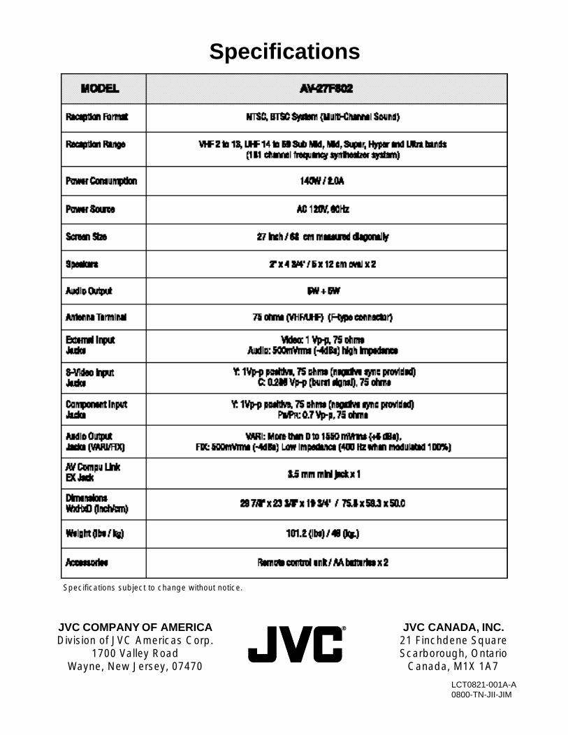
Specifications subject to change without notice.
Specifications