Kontron User's Guide «
133
If it's embedded, it's Kontron. » Kontron User's Guide « AT8020 Document Revision 1.3 December 2009
-
Upload
khangminh22 -
Category
Documents
-
view
1 -
download
0
Transcript of Kontron User's Guide «

» Kontron User's Guide «
AT8020
Document Revision 1.3December 2009
If it's embedded, it's Kontron.

Revision History
Customer Service
Visit our site at: www.kontron.com
© 2009 Kontron, an International Corporation. All rights reserved.
The information in this user's guide is provided for reference only. Kontron does not assume any liability arising out of the application or use of the information or products described herein. This user's guide may contain or reference information and products protected by copyrights or patents and does not convey any license under the patent rights of Kontron, nor the rights of others.
Kontron is a registered trademark of Kontron. All trademarks, registered trademarks, and trade names used in this user's guide are the property of their respective owners. All rights reserved. Printed in Canada. This user's guide contains information proprietary to Kontron. Customers may reprint and use this user's guide in other publications. Customers may alter this user's guide and publish it only after they remove the Kontron name, cover, and logo.
Kontron reserves the right to make changes without notice in product or component design as warranted by evolution in user needs or progress in engineering or manufacturing technology. Changes that affect the operation of the unit will be documented in the next revision of this user's guide.
Rev. Index Brief Description of Changes Date of Issue
1.0 First Release March 2007
1.1 Second Release May 2008
1.2 Third Release May 2009
1.3 Fourth Release December 2009
Contact Information: Kontron Canada, Inc. 4555 Ambroise-LafortuneBoisbriand, Québec, Canada J7H 0A4Tel: (450) 437-5682
(800) 354-4223 Fax: (450) 437-8053E-mail: [email protected]
Kontron Modular Computer GMBH Sudetenstrasse 7 87600 Kaufbeuren Germany +49 (0) 8341 803 333
+49 (0) 8341 803 339 [email protected]
i AT8020
www.kontron.com

Table of Contents
Table of Contents
Safety Instructions . . . . . . . . . . . . . . . . . . . . . . . . . . . . . . . . . . . . . . . . . . . . . . . . . . . . . . viii
Before You Begin . . . . . . . . . . . . . . . . . . . . . . . . . . . . . . . . . . . . . . . . . . . . . . . . . . . . . . . . . . . . . . viii
Preventing Electrostatic Discharge . . . . . . . . . . . . . . . . . . . . . . . . . . . . . . . . . . . . . . . . . . . . . . . . . ix
Preface . . . . . . . . . . . . . . . . . . . . . . . . . . . . . . . . . . . . . . . . . . . . . . . . . . . . . . . . . . . . . . . . . x
How to Use This Guide . . . . . . . . . . . . . . . . . . . . . . . . . . . . . . . . . . . . . . . . . . . . . . . . . . . . . . . . . . . .x
Customer Comments. . . . . . . . . . . . . . . . . . . . . . . . . . . . . . . . . . . . . . . . . . . . . . . . . . . . . . . . . . . . . xi
Advisory Conventions . . . . . . . . . . . . . . . . . . . . . . . . . . . . . . . . . . . . . . . . . . . . . . . . . . . . . . . . . . . . xi
Unpacking . . . . . . . . . . . . . . . . . . . . . . . . . . . . . . . . . . . . . . . . . . . . . . . . . . . . . . . . . . . . . . . . . . . . xii
Powering Up the System. . . . . . . . . . . . . . . . . . . . . . . . . . . . . . . . . . . . . . . . . . . . . . . . . . . . . . . . . xii
Adapter Cables . . . . . . . . . . . . . . . . . . . . . . . . . . . . . . . . . . . . . . . . . . . . . . . . . . . . . . . . . . . . . . . . xii
Storing Boards . . . . . . . . . . . . . . . . . . . . . . . . . . . . . . . . . . . . . . . . . . . . . . . . . . . . . . . . . . . . . . . . xii
Regulatory Compliance Statements . . . . . . . . . . . . . . . . . . . . . . . . . . . . . . . . . . . . . . . . . . . . . . . . xiii
Limited Warranty . . . . . . . . . . . . . . . . . . . . . . . . . . . . . . . . . . . . . . . . . . . . . . . . . . . . . . . . . . . . . . xiv
1. Product Description . . . . . . . . . . . . . . . . . . . . . . . . . . . . . . . . . . . . . . . . . . . . . . . . . . . . . . . 1
1.1 Product Overview. . . . . . . . . . . . . . . . . . . . . . . . . . . . . . . . . . . . . . . . . . . . . . . . . . . . . . . . . . . . . 1
1.2 What’s Included. . . . . . . . . . . . . . . . . . . . . . . . . . . . . . . . . . . . . . . . . . . . . . . . . . . . . . . . . . . . . . 1
1.3 Board Specifications . . . . . . . . . . . . . . . . . . . . . . . . . . . . . . . . . . . . . . . . . . . . . . . . . . . . . . . . . . 1
1.4 Compliance . . . . . . . . . . . . . . . . . . . . . . . . . . . . . . . . . . . . . . . . . . . . . . . . . . . . . . . . . . . . . . . . . 3
1.5 Hot-Plug Capability . . . . . . . . . . . . . . . . . . . . . . . . . . . . . . . . . . . . . . . . . . . . . . . . . . . . . . . . . . . 4
1.6 Interfacing with the Environment . . . . . . . . . . . . . . . . . . . . . . . . . . . . . . . . . . . . . . . . . . . . . . . 4
1.6.1 RTM (rear transition module) . . . . . . . . . . . . . . . . . . . . . . . . . . . . . . . . . . . . . . . . . . . . . . . .4
1.6.2 AMC Mezzanine . . . . . . . . . . . . . . . . . . . . . . . . . . . . . . . . . . . . . . . . . . . . . . . . . . . . . . . . . . .4
2. Board Features . . . . . . . . . . . . . . . . . . . . . . . . . . . . . . . . . . . . . . . . . . . . . . . . . . . . . . . . . . . 5
2.1 Block Diagram . . . . . . . . . . . . . . . . . . . . . . . . . . . . . . . . . . . . . . . . . . . . . . . . . . . . . . . . . . . . . . . 5
2.2 System Core . . . . . . . . . . . . . . . . . . . . . . . . . . . . . . . . . . . . . . . . . . . . . . . . . . . . . . . . . . . . . . . . . 6
2.2.1 Processors . . . . . . . . . . . . . . . . . . . . . . . . . . . . . . . . . . . . . . . . . . . . . . . . . . . . . . . . . . . . . .6
2.2.2 Intel E7520 Chipset . . . . . . . . . . . . . . . . . . . . . . . . . . . . . . . . . . . . . . . . . . . . . . . . . . . . . . .7
2.3 USB 2.0 Interfaces. . . . . . . . . . . . . . . . . . . . . . . . . . . . . . . . . . . . . . . . . . . . . . . . . . . . . . . . . . . . 7
2.4 Onboard Flash Drive. . . . . . . . . . . . . . . . . . . . . . . . . . . . . . . . . . . . . . . . . . . . . . . . . . . . . . . . . . . 8
2.5 Serial Ports . . . . . . . . . . . . . . . . . . . . . . . . . . . . . . . . . . . . . . . . . . . . . . . . . . . . . . . . . . . . . . . . . 8
2.5.1 Serial Port 1 (J5) . . . . . . . . . . . . . . . . . . . . . . . . . . . . . . . . . . . . . . . . . . . . . . . . . . . . . . . . .8
2.5.2 Serial Port 2 . . . . . . . . . . . . . . . . . . . . . . . . . . . . . . . . . . . . . . . . . . . . . . . . . . . . . . . . . . . . .9
ii AT8020
www.kontron.com

Table of Contents
2.6 Real Time Clock & NVRAM . . . . . . . . . . . . . . . . . . . . . . . . . . . . . . . . . . . . . . . . . . . . . . . . . . . . . . 9
2.7 Ethernet Interfaces . . . . . . . . . . . . . . . . . . . . . . . . . . . . . . . . . . . . . . . . . . . . . . . . . . . . . . . . . . 10
2.7.1 i82551QM Ethernet Management . . . . . . . . . . . . . . . . . . . . . . . . . . . . . . . . . . . . . . . . . . . .10
2.7.2 i82571EB Base Interface. . . . . . . . . . . . . . . . . . . . . . . . . . . . . . . . . . . . . . . . . . . . . . . . . . .10
2.7.3 i82571EB Fabric Interface Port 0 . . . . . . . . . . . . . . . . . . . . . . . . . . . . . . . . . . . . . . . . . . . .11
2.7.4 i82571EB Fabric Interface Port 1 (Daughter Card) . . . . . . . . . . . . . . . . . . . . . . . . . . . . . . .11
2.8 SAS (Daughter Card) . . . . . . . . . . . . . . . . . . . . . . . . . . . . . . . . . . . . . . . . . . . . . . . . . . . . . . . . . 11
2.9 Crosspoint Switches . . . . . . . . . . . . . . . . . . . . . . . . . . . . . . . . . . . . . . . . . . . . . . . . . . . . . . . . . 12
2.10 AMC Mezzanines. . . . . . . . . . . . . . . . . . . . . . . . . . . . . . . . . . . . . . . . . . . . . . . . . . . . . . . . . . . . . 12
2.10.1 AMC Ports Mapping AMC B1. . . . . . . . . . . . . . . . . . . . . . . . . . . . . . . . . . . . . . . . . . . . . . . . .13
2.10.2 AMC Ports Mapping AMC B2. . . . . . . . . . . . . . . . . . . . . . . . . . . . . . . . . . . . . . . . . . . . . . . . .14
2.11 Redundant BIOS Flash . . . . . . . . . . . . . . . . . . . . . . . . . . . . . . . . . . . . . . . . . . . . . . . . . . . . . . . . 15
2.12 Redundant IPMC Flash & FWUM. . . . . . . . . . . . . . . . . . . . . . . . . . . . . . . . . . . . . . . . . . . . . . . . . 15
2.13 FPGA . . . . . . . . . . . . . . . . . . . . . . . . . . . . . . . . . . . . . . . . . . . . . . . . . . . . . . . . . . . . . . . . . . . . . . 15
2.14 Telecom Clock Option . . . . . . . . . . . . . . . . . . . . . . . . . . . . . . . . . . . . . . . . . . . . . . . . . . . . . . . . 16
2.15 Hardware Management . . . . . . . . . . . . . . . . . . . . . . . . . . . . . . . . . . . . . . . . . . . . . . . . . . . . . . . 16
2.15.1 Hardware Management Overview . . . . . . . . . . . . . . . . . . . . . . . . . . . . . . . . . . . . . . . . . . . .16
2.15.2 Sensor Data Record (SDR). . . . . . . . . . . . . . . . . . . . . . . . . . . . . . . . . . . . . . . . . . . . . . . . . .17
2.15.3 IPMI Sensors. . . . . . . . . . . . . . . . . . . . . . . . . . . . . . . . . . . . . . . . . . . . . . . . . . . . . . . . . . . .18
2.15.4 Events supported . . . . . . . . . . . . . . . . . . . . . . . . . . . . . . . . . . . . . . . . . . . . . . . . . . . . . . . .23
2.15.5 Field Replaceable Unit (FRU) Information . . . . . . . . . . . . . . . . . . . . . . . . . . . . . . . . . . . . .24
2.15.6 IPMI Over LAN (IOL) support. . . . . . . . . . . . . . . . . . . . . . . . . . . . . . . . . . . . . . . . . . . . . . . .35
2.15.7 Serial Over LAN support (SOL). . . . . . . . . . . . . . . . . . . . . . . . . . . . . . . . . . . . . . . . . . . . . . .37
2.15.8 IPMC Firmware Code . . . . . . . . . . . . . . . . . . . . . . . . . . . . . . . . . . . . . . . . . . . . . . . . . . . . . .37
2.15.9 Updating the AT8020 . . . . . . . . . . . . . . . . . . . . . . . . . . . . . . . . . . . . . . . . . . . . . . . . . . . . .37
2.15.10 IPMI Commands Set . . . . . . . . . . . . . . . . . . . . . . . . . . . . . . . . . . . . . . . . . . . . . . . . . . . . . .38
2.15.11 OEM IPMI Commands . . . . . . . . . . . . . . . . . . . . . . . . . . . . . . . . . . . . . . . . . . . . . . . . . . . . .44
2.15.12 Hot-Swap Process . . . . . . . . . . . . . . . . . . . . . . . . . . . . . . . . . . . . . . . . . . . . . . . . . . . . . . . .47
2.16 Debugging Features. . . . . . . . . . . . . . . . . . . . . . . . . . . . . . . . . . . . . . . . . . . . . . . . . . . . . . . . . . 51
2.16.1 Lamp Test . . . . . . . . . . . . . . . . . . . . . . . . . . . . . . . . . . . . . . . . . . . . . . . . . . . . . . . . . . . . . .51
3. Installing the Board. . . . . . . . . . . . . . . . . . . . . . . . . . . . . . . . . . . . . . . . . . . . . . . . . . . . . . 52
3.1 Setting Jumpers . . . . . . . . . . . . . . . . . . . . . . . . . . . . . . . . . . . . . . . . . . . . . . . . . . . . . . . . . . . . 52
3.1.1 Jumper Description . . . . . . . . . . . . . . . . . . . . . . . . . . . . . . . . . . . . . . . . . . . . . . . . . . . . . .52
3.1.2 Setting Jumpers & Locations . . . . . . . . . . . . . . . . . . . . . . . . . . . . . . . . . . . . . . . . . . . . . . .52
3.2 Processor . . . . . . . . . . . . . . . . . . . . . . . . . . . . . . . . . . . . . . . . . . . . . . . . . . . . . . . . . . . . . . . . . . 53
3.3 Memory . . . . . . . . . . . . . . . . . . . . . . . . . . . . . . . . . . . . . . . . . . . . . . . . . . . . . . . . . . . . . . . . . . . 53
3.3.1 Memory Installation. . . . . . . . . . . . . . . . . . . . . . . . . . . . . . . . . . . . . . . . . . . . . . . . . . . . . .55
iii AT8020
www.kontron.com

Table of Contents
3.4 Onboard Interconnectivity and Indicators . . . . . . . . . . . . . . . . . . . . . . . . . . . . . . . . . . . . . . . . 56
3.4.1 Onboard Connectors and Headers. . . . . . . . . . . . . . . . . . . . . . . . . . . . . . . . . . . . . . . . . . . .56
3.4.2 Front Plate Symbol Chart . . . . . . . . . . . . . . . . . . . . . . . . . . . . . . . . . . . . . . . . . . . . . . . . . .56
3.5 Board Hot Swap and Installation . . . . . . . . . . . . . . . . . . . . . . . . . . . . . . . . . . . . . . . . . . . . . . . 57
3.5.1 Installing the Board in the Chassis. . . . . . . . . . . . . . . . . . . . . . . . . . . . . . . . . . . . . . . . . . .57
3.5.2 Removing the Board . . . . . . . . . . . . . . . . . . . . . . . . . . . . . . . . . . . . . . . . . . . . . . . . . . . . . .57
3.5.3 Installing an AMC . . . . . . . . . . . . . . . . . . . . . . . . . . . . . . . . . . . . . . . . . . . . . . . . . . . . . . . .58
3.5.4 Removing an AMC . . . . . . . . . . . . . . . . . . . . . . . . . . . . . . . . . . . . . . . . . . . . . . . . . . . . . . . .58
3.5.5 Installing a RTM . . . . . . . . . . . . . . . . . . . . . . . . . . . . . . . . . . . . . . . . . . . . . . . . . . . . . . . . .58
3.5.6 Removing a RTM . . . . . . . . . . . . . . . . . . . . . . . . . . . . . . . . . . . . . . . . . . . . . . . . . . . . . . . . .58
4. Building an ATCA System . . . . . . . . . . . . . . . . . . . . . . . . . . . . . . . . . . . . . . . . . . . . . . . . . . 59
4.1 Building an ATCA System . . . . . . . . . . . . . . . . . . . . . . . . . . . . . . . . . . . . . . . . . . . . . . . . . . . . . . 59
4.1.1 Backplane. . . . . . . . . . . . . . . . . . . . . . . . . . . . . . . . . . . . . . . . . . . . . . . . . . . . . . . . . . . . . .59
4.1.2 Rear-Panel I/O . . . . . . . . . . . . . . . . . . . . . . . . . . . . . . . . . . . . . . . . . . . . . . . . . . . . . . . . . .60
4.1.3 External Storage Devices . . . . . . . . . . . . . . . . . . . . . . . . . . . . . . . . . . . . . . . . . . . . . . . . . .60
4.1.4 Power Supply . . . . . . . . . . . . . . . . . . . . . . . . . . . . . . . . . . . . . . . . . . . . . . . . . . . . . . . . . . .60
4.1.5 Mechanical Keying and Alignment . . . . . . . . . . . . . . . . . . . . . . . . . . . . . . . . . . . . . . . . . . .60
5. Software Setup. . . . . . . . . . . . . . . . . . . . . . . . . . . . . . . . . . . . . . . . . . . . . . . . . . . . . . . . . . 61
5.1 AMI BIOS Setup Program . . . . . . . . . . . . . . . . . . . . . . . . . . . . . . . . . . . . . . . . . . . . . . . . . . . . . . 61
5.1.1 Accessing the BIOS Setup Utility. . . . . . . . . . . . . . . . . . . . . . . . . . . . . . . . . . . . . . . . . . . . .61
5.1.2 Menu Bar . . . . . . . . . . . . . . . . . . . . . . . . . . . . . . . . . . . . . . . . . . . . . . . . . . . . . . . . . . . . . .63
5.1.3 Main Menu . . . . . . . . . . . . . . . . . . . . . . . . . . . . . . . . . . . . . . . . . . . . . . . . . . . . . . . . . . . . .65
5.1.4 Advanced Menu. . . . . . . . . . . . . . . . . . . . . . . . . . . . . . . . . . . . . . . . . . . . . . . . . . . . . . . . . .65
5.1.5 Security Menu . . . . . . . . . . . . . . . . . . . . . . . . . . . . . . . . . . . . . . . . . . . . . . . . . . . . . . . . . . .77
5.1.6 Boot Menu . . . . . . . . . . . . . . . . . . . . . . . . . . . . . . . . . . . . . . . . . . . . . . . . . . . . . . . . . . . . .78
5.1.7 System Management Menu . . . . . . . . . . . . . . . . . . . . . . . . . . . . . . . . . . . . . . . . . . . . . . . . .79
5.1.8 Exit Menu . . . . . . . . . . . . . . . . . . . . . . . . . . . . . . . . . . . . . . . . . . . . . . . . . . . . . . . . . . . . . .82
5.2 Boot Utilities . . . . . . . . . . . . . . . . . . . . . . . . . . . . . . . . . . . . . . . . . . . . . . . . . . . . . . . . . . . . . . . 83
5.2.1 Pressing <Del> (or <F4> from a Console Redirection terminal) . . . . . . . . . . . . . . . . . . . . . .83
5.2.2 Pressing <F11> (or <F3> from a Console Redirection terminal) . . . . . . . . . . . . . . . . . . . . .83
5.2.3 BOOT Menu POP-UP. . . . . . . . . . . . . . . . . . . . . . . . . . . . . . . . . . . . . . . . . . . . . . . . . . . . . . .83
5.3 Console Redirection (VT100 Mode). . . . . . . . . . . . . . . . . . . . . . . . . . . . . . . . . . . . . . . . . . . . . . 83
5.3.1 Requirements . . . . . . . . . . . . . . . . . . . . . . . . . . . . . . . . . . . . . . . . . . . . . . . . . . . . . . . . . . .83
5.3.2 Running Without a Terminal . . . . . . . . . . . . . . . . . . . . . . . . . . . . . . . . . . . . . . . . . . . . . . . .84
5.3.3 ANSI and VT100 Keystroke Mapping . . . . . . . . . . . . . . . . . . . . . . . . . . . . . . . . . . . . . . . . . .84
5.3.4 VT-UTF8 Keystroke Mapping . . . . . . . . . . . . . . . . . . . . . . . . . . . . . . . . . . . . . . . . . . . . . . . .85
5.4 Installing Drivers. . . . . . . . . . . . . . . . . . . . . . . . . . . . . . . . . . . . . . . . . . . . . . . . . . . . . . . . . . . . 85
iv AT8020
www.kontron.com

Table of Contents
A. Memory & I/O Maps . . . . . . . . . . . . . . . . . . . . . . . . . . . . . . . . . . . . . . . . . . . . . . . . . . . . . .A-1
A.1 Memory Mapping . . . . . . . . . . . . . . . . . . . . . . . . . . . . . . . . . . . . . . . . . . . . . . . . . . . . . . . . . . . .A-1
A.2 I/O Mapping . . . . . . . . . . . . . . . . . . . . . . . . . . . . . . . . . . . . . . . . . . . . . . . . . . . . . . . . . . . . . . . .A-2
A.3 PCI IDSEL and Device numbers . . . . . . . . . . . . . . . . . . . . . . . . . . . . . . . . . . . . . . . . . . . . . . . . .A-3
B. Kontron Extension Registers . . . . . . . . . . . . . . . . . . . . . . . . . . . . . . . . . . . . . . . . . . . . . . .B-1
B.1 FPGA/CPLD Registers Definition . . . . . . . . . . . . . . . . . . . . . . . . . . . . . . . . . . . . . . . . . . . . . . . .B-1
B.2 Sossaman Addressing Space . . . . . . . . . . . . . . . . . . . . . . . . . . . . . . . . . . . . . . . . . . . . . . . . . . .B-1
C. Connector Pinouts . . . . . . . . . . . . . . . . . . . . . . . . . . . . . . . . . . . . . . . . . . . . . . . . . . . . . . . C-1
C.1 Connectors and Headers Summary . . . . . . . . . . . . . . . . . . . . . . . . . . . . . . . . . . . . . . . . . . . . . . C-1
C.2 ATCA I/O RTM Connector (J7) . . . . . . . . . . . . . . . . . . . . . . . . . . . . . . . . . . . . . . . . . . . . . . . . . C-2
C.3 USB Port (J13). . . . . . . . . . . . . . . . . . . . . . . . . . . . . . . . . . . . . . . . . . . . . . . . . . . . . . . . . . . . . . C-2
C.4 Serial Port(J14) . . . . . . . . . . . . . . . . . . . . . . . . . . . . . . . . . . . . . . . . . . . . . . . . . . . . . . . . . . . . C-3
C.5 Telco Clock(J17) . . . . . . . . . . . . . . . . . . . . . . . . . . . . . . . . . . . . . . . . . . . . . . . . . . . . . . . . . . . . C-3
C.6 AMC B1 & AMC B2 (J20 & J23). . . . . . . . . . . . . . . . . . . . . . . . . . . . . . . . . . . . . . . . . . . . . . . . . . C-4
C.7 ATCA I/O ATCA 3.1 (J21) . . . . . . . . . . . . . . . . . . . . . . . . . . . . . . . . . . . . . . . . . . . . . . . . . . . . . . C-5
C.8 Power (P10). . . . . . . . . . . . . . . . . . . . . . . . . . . . . . . . . . . . . . . . . . . . . . . . . . . . . . . . . . . . . . . . C-6
D. BIOS Setup Error Codes . . . . . . . . . . . . . . . . . . . . . . . . . . . . . . . . . . . . . . . . . . . . . . . . . . D-1
D.1 Bootblock Initialization Code Checkpoints. . . . . . . . . . . . . . . . . . . . . . . . . . . . . . . . . . . . . . . .D-1
D.2 Bootblock Recovery Code Checkpoints . . . . . . . . . . . . . . . . . . . . . . . . . . . . . . . . . . . . . . . . . . .D-2
D.3 POST Code Checkpoints . . . . . . . . . . . . . . . . . . . . . . . . . . . . . . . . . . . . . . . . . . . . . . . . . . . . . . .D-2
D.4 DIM Code Checkpoints . . . . . . . . . . . . . . . . . . . . . . . . . . . . . . . . . . . . . . . . . . . . . . . . . . . . . . . .D-5
D.5 ACPI Runtime Checkpoints . . . . . . . . . . . . . . . . . . . . . . . . . . . . . . . . . . . . . . . . . . . . . . . . . . . .D-6
D.6 Memory Initialization ERROR Code . . . . . . . . . . . . . . . . . . . . . . . . . . . . . . . . . . . . . . . . . . . . . .D-6
E. Software Update . . . . . . . . . . . . . . . . . . . . . . . . . . . . . . . . . . . . . . . . . . . . . . . . . . . . . . . . E-1
E.1 Flash BIOS Update Procedure . . . . . . . . . . . . . . . . . . . . . . . . . . . . . . . . . . . . . . . . . . . . . . . . . . E-1
E.2 IPMC Firmware Update Procedure . . . . . . . . . . . . . . . . . . . . . . . . . . . . . . . . . . . . . . . . . . . . . . . E-1
F. Getting Help . . . . . . . . . . . . . . . . . . . . . . . . . . . . . . . . . . . . . . . . . . . . . . . . . . . . . . . . . . . . F-1
F.1 Returning Defective Merchandise. . . . . . . . . . . . . . . . . . . . . . . . . . . . . . . . . . . . . . . . . . . . . . . F-1
F.2 When Returning a Unit . . . . . . . . . . . . . . . . . . . . . . . . . . . . . . . . . . . . . . . . . . . . . . . . . . . . . . . F-2
G. Glossary . . . . . . . . . . . . . . . . . . . . . . . . . . . . . . . . . . . . . . . . . . . . . . . . . . . . . . . . . . . . . . .G-1
v AT8020
www.kontron.com

List of Figures
vi AT8020
www.kontron.com
List of Figures
Figure 2-1: Block Diagram . . . . . . . . . . . . . . . . . . . . . . . . . . . . . . . . . . . . . . . . . . . . . . . . . . . . . . . . . . . . . .5
Figure 3-1: Setting Jumpers & Locations . . . . . . . . . . . . . . . . . . . . . . . . . . . . . . . . . . . . . . . . . . . . . . . . .52
Figure 3-2: Memory Installation . . . . . . . . . . . . . . . . . . . . . . . . . . . . . . . . . . . . . . . . . . . . . . . . . . . . . . . .55
Figure 3-3: Front Plate Symbol Chart . . . . . . . . . . . . . . . . . . . . . . . . . . . . . . . . . . . . . . . . . . . . . . . . . . . . .56
Figure 4-1: ATCA Chassis . . . . . . . . . . . . . . . . . . . . . . . . . . . . . . . . . . . . . . . . . . . . . . . . . . . . . . . . . . . . . .59

List of Tables
vii AT8020
www.kontron.com
List of Tables
Table 1-1 Board Specifications. . . . . . . . . . . . . . . . . . . . . . . . . . . . . . . . . . . . . . . . . . . . . . . . . . . . . . . . . . 1
Table 2-1 USB Connector Pinout . . . . . . . . . . . . . . . . . . . . . . . . . . . . . . . . . . . . . . . . . . . . . . . . . . . . . . . . 8
Table 2-2 Serial Ports Communication Mode and Output Path . . . . . . . . . . . . . . . . . . . . . . . . . . . . . . . . . . 8
Table 2-3 Serial Port Pinout (J5) . . . . . . . . . . . . . . . . . . . . . . . . . . . . . . . . . . . . . . . . . . . . . . . . . . . . . . . . 9
Table 2-4 AMC Ports Mapping AMC B1. . . . . . . . . . . . . . . . . . . . . . . . . . . . . . . . . . . . . . . . . . . . . . . . . . . . 13
Table 2-5 AMC Ports Mapping AMC B2. . . . . . . . . . . . . . . . . . . . . . . . . . . . . . . . . . . . . . . . . . . . . . . . . . . . 14
Table 2-6 IPMI Sensors . . . . . . . . . . . . . . . . . . . . . . . . . . . . . . . . . . . . . . . . . . . . . . . . . . . . . . . . . . . . . . 18
Table 2-7 Sensor Types. . . . . . . . . . . . . . . . . . . . . . . . . . . . . . . . . . . . . . . . . . . . . . . . . . . . . . . . . . . . . . . 23
Table 2-8 Type 14 - Atca Board Point-To-Point Connectivity Record . . . . . . . . . . . . . . . . . . . . . . . . . . . . . 25
Table 2-9 Type 17 - Carrier Activation And Current Management Record . . . . . . . . . . . . . . . . . . . . . . . . . 26
Table 2-10 Type 18 - Carrier Point-To-Point Connectivity Record . . . . . . . . . . . . . . . . . . . . . . . . . . . . . . . 27
Table 2-11 Type 19h - AMC Point-To-Point Connectivity Record(1 of 4)(MCH PCI Express Port C) . . . . . . . 29
Table 2-12 Type 19h - AMC Point-To-Point Connectivity Record (2 of 4) (MCH PCI Express Port B) . . . . . . 30
Table 2-13 Type 19h - AMC Point-To-Point Connectivity Record (3 of 4) (Xpoint GbE) . . . . . . . . . . . . . . . 32
Table 2-14 Type 19h - AMC Point-To-Point Connectivity Record (4 of 4). . . . . . . . . . . . . . . . . . . . . . . . . . 33
Table 2-15 Type 1Ah - Carrier Information Table . . . . . . . . . . . . . . . . . . . . . . . . . . . . . . . . . . . . . . . . . . . 35
Table 2-16 IPMI Over Lan Default Users . . . . . . . . . . . . . . . . . . . . . . . . . . . . . . . . . . . . . . . . . . . . . . . . . . 36
Table 2-17 IPMI Commands Set . . . . . . . . . . . . . . . . . . . . . . . . . . . . . . . . . . . . . . . . . . . . . . . . . . . . . . . . 38
Table 2-18 OEM IPMI Commands . . . . . . . . . . . . . . . . . . . . . . . . . . . . . . . . . . . . . . . . . . . . . . . . . . . . . . . 44
Table 2-19 Reset BIOS Flash Type. . . . . . . . . . . . . . . . . . . . . . . . . . . . . . . . . . . . . . . . . . . . . . . . . . . . . . . 44
Table 2-20 Set Control State . . . . . . . . . . . . . . . . . . . . . . . . . . . . . . . . . . . . . . . . . . . . . . . . . . . . . . . . . . 44
Table 2-21 Get Control State . . . . . . . . . . . . . . . . . . . . . . . . . . . . . . . . . . . . . . . . . . . . . . . . . . . . . . . . . . 45
Table 2-22 GetBoardDeviceChannelPortSelection . . . . . . . . . . . . . . . . . . . . . . . . . . . . . . . . . . . . . . . . . . 45
Table 2-23 SetBoardDeviceChannelPortSelection . . . . . . . . . . . . . . . . . . . . . . . . . . . . . . . . . . . . . . . . . . 46
Table 2-24 Controls Identifier Table . . . . . . . . . . . . . . . . . . . . . . . . . . . . . . . . . . . . . . . . . . . . . . . . . . . . . 46
Table 2-25 Hot-Swap LED State . . . . . . . . . . . . . . . . . . . . . . . . . . . . . . . . . . . . . . . . . . . . . . . . . . . . . . . . 47
Table 2-26 Hot-Swap LED Status . . . . . . . . . . . . . . . . . . . . . . . . . . . . . . . . . . . . . . . . . . . . . . . . . . . . . . . 48
Table 2-27 OOS Led (ATCA LED 1) State . . . . . . . . . . . . . . . . . . . . . . . . . . . . . . . . . . . . . . . . . . . . . . . . . . 48
Table 2-28 OOS Led (ATCA LED 1) “Short Blink” Mode . . . . . . . . . . . . . . . . . . . . . . . . . . . . . . . . . . . . . . . 49
Table 2-29 Health Led (ATCA LED 2) State . . . . . . . . . . . . . . . . . . . . . . . . . . . . . . . . . . . . . . . . . . . . . . . . 49
Table 2-30 Health LED Sensors Agregation . . . . . . . . . . . . . . . . . . . . . . . . . . . . . . . . . . . . . . . . . . . . . . . 49
Table 3-1 Jumper Description . . . . . . . . . . . . . . . . . . . . . . . . . . . . . . . . . . . . . . . . . . . . . . . . . . . . . . . . . 52
Table 3-2 Onboard Connectors and Headers. . . . . . . . . . . . . . . . . . . . . . . . . . . . . . . . . . . . . . . . . . . . . . . 56

Safety Instructions
Safety InstructionsBefore You BeginBefore handling the board, read the instructions and safety guidelines on the following pages to prevent damage to the product and to ensure your own personal safety. Refer to the "Advisories" section in the Preface for advisory conventions used in this user's guide, including the distinction between Warnings, Cautions, Important Notes, and Notes.
• Always use caution when handling/operating the computer. Only qualified, experienced, authorized electronics service personnel should access the interior of the computer. The power supplies produce high voltages and energy hazards, which can cause bodily harm.
• Use extreme caution when installing or removing components. Refer to the installation instructions in this user's guide for precautions and procedures. If you have any questions, please contact Kontron Technical Support
WARNINGHigh voltages are present inside the chassis when the unit's power cord is plugged into an electrical outlet. Turn off system power, turn off the power supply, and then disconnect the power cord from its source before removing the chassis cover. Turning off the system power switch does not remove power to components.
viii AT8020
www.kontron.com

Safety Instructions
Preventing Electrostatic DischargeStatic electricity can harm system boards. Perform service at an ESD workstation and follow proper ESD procedure to reduce the risk of damage to components. Kontron strongly encourages you to follow proper ESD procedure, which can include wrist straps and smocks, when servicing equipment.
Take the following steps to prevent damage from electrostatic discharge (ESD):
• When unpacking a static-sensitive component from its shipping carton, do not remove the component's antistatic packing material until you are ready to install the component in a computer. Just before unwrapping the antistatic packaging, be sure you are at an ESD workstation or grounded. This will discharge any static electricity that may have built up in your body.
• When transporting a sensitive component, first place it in an antistatic container or packaging.
• Handle all sensitive components at an ESD workstation. If possible, use antistatic floor pads and workbench pads.
• Handle components and boards with care. Don't touch the components or contacts on a board. Hold a board by its edges or by its metal mounting bracket.
• Do not handle or store system boards near strong electrostatic, electromagnetic, magnetic, or radioactive fields.
• When you want to remove the protective foil (if present), make sure you are properly grounded and that you touch a metalic part of the board.
CAUTIONRemoving the protective foil from the top and bottom cover might create static. When you remove those protections, make sure you follow the proper ESD procedure.
ix AT8020
www.kontron.com

Preface
PrefaceHow to Use This GuideThis user's guide is designed to be used as step-by-step instructions for installation, and as a reference for operation, troubleshooting, and upgrades.
For the circuits, descriptions and tables indicated, Kontron assumes no responsibility as far as patents or other rights of third parties are concerned.
The following is a summary of chapter contents:
• Chapter 1, Product Description
• Chapter 2, Board Features
• Chapter 3, Installing the board
• Chapter 4, Building an ATCA System
• Chapter 5, Software Setup
• Appendix A, Memory & I/O Maps
• Appendix B, Extension Registers
• Appendix C, Connector Pinout
• Appendix D, BIOS Setup Error Codes
• Appendix E, Software Update
• Appendix F, Getting Help
• Appendix G, Glossary
x AT8020
www.kontron.com

Preface
Customer CommentsIf you have any difficulties using this user's guide, discover an error, or just want to provide some feedback, please send a message to: [email protected]. Detail any errors you find. We will correct the errors or problems as soon as possible and post the revised user's guide on our Web site.
Advisory ConventionsSeven types of advisories are used throughout the user guides to provide helpful information or to alert you to the potential for hardware damage or personal injury. They are Note, Signal Paths, Jumpers Settings, BIOS Settings, Software Usage, Cautions, and Warnings. The following is an example of each type of advisory. Use caution when servicing electrical components.
Disclaimer: We have tried to identify all situations that may pose a warning or a caution condition in this user's guide. However, Kontron does not claim to have covered all situations that might require the use of a Caution or a Warning.
Note:Indicate information that is important for you to know.
Signal Path:Indicate the places where you can fin the signal on the board.
Jumper Settings:Indicate the jumpers that are related to this sections.
BIOS Settings:Indicate where you can set this option in the BIOS.
Software Usage:Indicates how you can access this feature through software.
CAUTIONIndicate potential damage to hardware and tells you how to avoid the problem.
WARNINGIndicates potential for bodily harm and tells you how to avoid the problem.
xi AT8020
www.kontron.com

Preface
UnpackingFollow these recommendations while unpacking:
• Remove all items from the box. If any items listed on the purchase order are missing, notify Kontron customer service immediately.
• Inspect the product for damage. If there is damage, notify Kontron customer service immediately.
• Save the box and packing material for possible future shipment.
Powering Up the SystemBefore any installation or setup, ensure that the board is unplugged from power sources or subsystems.
If you encounter a problem, verify the following items:
• Make sure that all connectors are properly connected.
• Verify your boot devices.
• If the system does not start properly, try booting without any other I/O peripherals attached, including AMC adapters.
Make sure your system provides the minimum DC voltages required at the board's slot, especially if DC power is carried by cables.
If you are still not able to get your board running, contact our Technical Support for assistance.
Adapter CablesBecause adapter cables come from various manufacturers, pinouts can differ. The direct crimp design offered by Kontron allows the simplest cable assembly. All cables are available from Kontron Sales Department.
Storing BoardsElectronic boards are sensitive devices. Do not handle or store device near strong electrostatic, electromagnetic, magnetic or radioactive fields.
xii AT8020
www.kontron.com

Preface
Regulatory Compliance StatementsFCC Compliance Statement for Class B Devices
This equipment has been tested and found to comply with the limits for a Class B digital device, pursuant to Part 15 of the FCC Rules. These limits are designed to provide reasonable protection against harmful interference in a residential installation. This equipment generated, uses and can radiate radio frequency energy and, if not installed and used in accordance with the instructions may cause harmful interference to radio communications. However, there is no guarantee that interference will not occur in a particular installation. If this equipment does cause harmful interference to radio or television reception, which can be determined by turning the equipment off and on, the user is encouraged to try to correct the interference by one or more of the following measures:
• Reorient or relocate the receiving antenna.
• Increase the separation between the equipment and receiver.
• Connect the equipment into an outlet on a circuit different from that to which the receiver is connected.
• Consult the dealer or an experience radio/TV technician for help.
Safety Certification
All Kontron equipment meets or exceeds safety requirements based on the IEC/EN/UL/CSA 60950-1 family of standards entitled, "Safety of information technology equipment." All components are chosen to reduce fire hazards and provide insulation and protection where necessary. Testing and reports when required are performed under the international IECEE CB Scheme. Please consult the "Kontron Safety Conformity Policy Guide" for more information. For Canada and USA input voltage must not exceed -60Vdc for safety compliance.
CE Certification
The product(s) described in this user's guide complies with all applicable European Union (CE) directives if it has a CE marking. For computer systems to remain CE compliant, only CE-compliant parts may be used. Maintaining CE compliance also requires proper cable and cabling techniques. Although Kontron offers accessories, the customer must ensure that these products are installed with proper shielding to maintain CE compliance. Kontron does not offer engineering services for designing cabling systems. In addition, Kontron will not retest or recertify systems or components that have been reconfigured by customers.
WARNINGThis is a Class B product. If not installed in a properly shielded enclosure and used in accordance with this User's Guide, this product may cause radio interference in which case users may need to take additional measures at their own expense.
xiii AT8020
www.kontron.com

Preface
Limited WarrantyKontron grants the original purchaser of Kontron's products a TWO YEAR LIMITED HARDWARE WARRANTY as described in the following. However, no other warranties that may be granted or implied by anyone on behalf of Kontron are valid unless the consumer has the express written consent of Kontron.
Kontron warrants their own products, excluding software, to be free from manufacturing and material defects for a period of 24 consecutive months from the date of purchase. This warranty is not transferable nor extendible to cover any other users or long- term storage of the product. It does not cover products which have been modified, altered or repaired by any other party than Kontron or their authorized agents. Furthermore, any product which has been, or is suspected of being damaged as a result of negligence, improper use, incorrect handling, servicing or maintenance, or which has been damaged as a result of excessive current/voltage or temperature, or which has had its serial number(s), any other markings or parts thereof altered, defaced or removed will also be excluded from this warranty.
If the customer's eligibility for warranty has not been voided, in the event of any claim, he may return the product at the earliest possible convenience to the original place of purchase, together with a copy of the original document of purchase, a full description of the application the product is used on and a description of the defect. Pack the product in such a way as to ensure safe transportation (see our safety instructions).
Kontron provides for repair or replacement of any part, assembly or sub-assembly at their own discretion, or to refund the original cost of purchase, if appropriate. In the event of repair, refunding or replacement of any part, the ownership of the removed or replaced parts reverts to Kontron, and the remaining part of the original guarantee, or any new guarantee to cover the repaired or replaced items, will be transferred to cover the new or repaired items. Any extensions to the original guarantee are considered gestures of goodwill, and will be defined in the "Repair Report" issued by Kontron with the repaired or replaced item.
Kontron will not accept liability for any further claims resulting directly or indirectly from any warranty claim, other than the above specified repair, replacement or refunding. In particular, all claims for damage to any system or process in which the product was employed, or any loss incurred as a result of the product not functioning at any given time, are excluded. The extent of Kontron liability to the customer shall not exceed the original purchase price of the item for which the claim exists.
Kontron issues no warranty or representation, either explicit or implicit, with respect to its products reliability, fitness, quality, marketability or ability to fulfil any particular application or purpose. As a result, the products are sold "as is," and the responsibility to ensure their suitability for any given task remains that of the purchaser. In no event will Kontron be liable for direct, indirect or consequential damages resulting from the use of our hardware or software products, or documentation, even if Kontron were advised of the possibility of such claims prior to the purchase of the product or during any period since the date of its purchase.
Please remember that no Kontron employee, dealer or agent is authorized to make any modification or addition to the above specified terms, either verbally or in any other form, written or electronically transmitted, without the company's consent.
xiv AT8020
www.kontron.com

Product Description
1. Product Description1.1 Product OverviewThe Kontron AT8020 AdvancedTCA processor board features one or two Intel® Dual-Core Xeon® processors and support for two AdvancedMC modules. The result is an open modular processing platform that will increase the number of deployments of AdvancedTCA solutions at the heart of every compute intensive mobile-IMS network element — from the transcoding of live multimedia mobile content on a Multimedia Resource Function Processor (MRFP) to concurrent processing of subscriber data on Home Subscriber Locator (HLR) systems.
1.2 What’s IncludedThis board is shipped with the following items:
• One AT8020 board
• One CD-ROM containing documentations and drivers
• Cables that have been ordered
• AMCs gap fillers
If any item is missing or damaged, contact the supplier.
1.3 Board SpecificationsTable 1-1: Board Specifications
Features Description
Processors• One or Two Dual-Core Intel Xeon LV Processors 2.0GHz• Passive heatsinks
Cache Memory• 32KB L1 instruction and 32KB L1 data cache dedicated for each core.• 2MB L2 cache on each processor chip shared by both cores.
Chipset• North Bridge: Intel E7520• South Bridge: Intel 6300ESB
Bus Interface• CPUs Front Side bus at 667 MHz, 64-bit data, 36-bit address• Memory bus at 400 MHz, 144-bit data (2 channel)• Six onboard PCI-Express x4
Expansion Slot • 2 Mid-size AdvancedMC bays AMC.1 Type 4 compliant – x4 PCI Express, AMC.2 Type E2 compliant – 2 X1000Base-BX Ports, AMC.3 compliant – dual port SAS/SATA
1 AT8020
www.kontron.com

Product Description
System Memory• Up to 16 GB on 4x240-pin latching DDR-2 400MHz SDRAM (PC2-3200)• ECC support, support S4EC/D4ED when using x4 SDRAM devices• 2 DDR-2 channels
Flash Memory• Two redundant 1MB BIOS (Field software upgradeable)• Roll back functionality controlled by IPMC
Storage• 4 ports SAS available through each AdvancedMC modules or through Rear I/O• One 2GBytes onboard flash drive
Connectors • Front Panel: Serial (RJ-45), USB, Ethernet Management Port (RJ-45)
Board Specifications
• PICMG 3.0• PICMG AMC.0 (Compatible)• PICMG AMC.1• PICMG AMC.2• PICMG AMC.3
BIOS Features
• AMI BIOS• Save CMOS in NVRAM option• Boot from gigabit Ethernet (Base and Fabric interfaces) • Boot from Ethernet Management port• Boot from SAS• Boot from USB 2.0 (Floppy, CD-ROM, Hard Disk)• Auto configuration and extended setup• Diskless, Keyboard less, and battery less operation extensions• System and LAN BIOS shadowing• HDD S.M.A.R.T. support• Advanced Configuration and Power Interface (ACPI 1.0, 2.0 & 3.0) (advanced thermal
management such as overheat alarm and auto slow down)• Console redirection to serial port (VT100) with CMOS setup access• Field updateable BIOS• Event (SERR, PERR, correctable/uncorrectable ECC, POST errors, PCI-Express) log support to
IPMC
IPMI Features
• Management Controller is compatible to PICMG 3.0, AMC.0 and IPMI v1.5 rev 1.1.• Management Controller is run time field reprogrammable without payload impact.• Robust fail safe reprogramming implementation (which includes two firmware images) that can
perform automatic or manual rollback if a problem occurs during critical reprogramming phase.• Remote upgrade capability from all IPMI interfaces (CPU Host Interface/IPMB-0/LAN).• Management Controller self test which can detect failure under its code integrity and trigger an
automatic rollback.• Initiation of a Host CPU reboot on a redundant BIOS image base on a BIOS-IPMC handshake
result.• Fast interrupt driven SMS host interface compliant to IPMI-KCS v1.5 rev 1.1• Serial Over LAN (SOL) redirection of the Host CPU serial controller traffic to enable
asynchronous serial-based OS and pre-OS communication via standard RMCP LAN application through the Management Controller.
• Standard Management Controller message bridging to AMC via IPMB-L• Management Controller support standard PCI Hot Plug for PCI-Express AMC.• Management Controller can initiate standard graceful OS shutdown via ACPI support.
Supervisory
• Supports a system management interface via an IPMI V1.5 compliant controller• Watchdog for BIOS execution and OS loading (through IPMI and FPGA watchdogs)• Hardware system monitor (voltages, temperature), CPU temperature monitor / alarm; board
temperature sensor, power failure through IPMC
OS Compatibility • Red Hat Enterprise Linux V.4 and V.5
Power Requirements 200W maximum including AMC modules. Additional 25W maximum for RTM (see note on page 3)
Features Description
2 AT8020
www.kontron.com

Product Description
1.4 ComplianceThis product conforms to the following specifications:
• PICMG3.0R2.0 (Advanced TCA core specification)
• PICMG3.1R1.0 (Ethernet/Fiber Channel over Advanced TCA)
• Compatible to AMC.0 R2.0 (Advanced mezzaninne card base specification)
• AMC.1 R1.0 (Advance mezzaninne card PCI-Express)
Environmental Temperature
Operating: 0-55°C/32-131°F with 30CFM airflowStorage and Transit: -40 to +70°C/-40 to 158°F
Environmental HumidityOperating: 15% to 90% @55°C/131°F non-condensing Storage and Transit: 5% to 95% @ 40°C/104°F non-condensing
Environmental AltitudeOperating: 4,000 m / 13,123 ftStorage and Transit: 15,000 m / 49,212 ft
Environmental ShockOperating: 3G, half-sine 11ms, each axis Storage and Transit: 18G half-sine 6ms
Environmental VibrationOperating: 0.2G 5-200Hz each axis Storage and Transit: 0.2G 5-200Hz each axis
Random Vibrations
Operating: - 5 Hz to 10 Hz @ +12 dB/oct (slope up)- 10 Hz to 50 Hz @ 0.02 m2/s3 (0.0002g2/Hz) (flat)- 50 Hz to 100 Hz @ -12 dB/oct (slope down)- 30 minutes per each 3 axes.
Storage and Transit: - 5 Hz to 20 Hz @ 1 m2/s3 (0.01 g2 /Hz) (flat)- 20 Hz to 200 Hz @ -3 dB/oct (slop down)- 30 minutes per each 3 axes.
Reliability• Whole board protected by active breakers• USB voltage protected by active breakers
Safety / EMC
Meets or exceeds:• Safety: UL 60950-1; CSA C22.2 No 60950-1-03; EN 60950-1:2001; CB report and certificate to
IEC 60950-1• EMI/EMC: FCC 47 CFR Part 15, Class B; CE Mark to EN55022/EN55024/EN300386
Warranty Two years limited warranty
Note:Most Shelf Manager will only allow a maximum of 200W per slot (by default). This includes the board, the AMCs and the RTM. Therefore, the power budget could be exceeded causing the last entity to ask for activation to stay in power state M3.If the environment allows to exceed 200W per slot and still meets temperature requirements, it is possible to modify the shelf manager’s settings in order to grant more power.
Features Description
3 AT8020
www.kontron.com

Product Description
1.5 Hot-Plug CapabilityThe AT8020 supports Full Hot Plug capability as per PICMG3.0R1.0. It can be removed from or installed in the system while it is on (without powering-down the system). Please refer to the PICMG3.0R1.0 specification for additional details.
1.6 Interfacing with the Environment1.6.1 RTM (rear transition module)The RTM8020 is a single slot (6HP) ATCA Rear Transition Module. This module provides additional connectivity for AT8020 CPU front blade and complies to:
• PICMG3.0 R2.0 ECN002 - Advanced Telecommunication Computing Architecture
• SAS1R10 - Serial Attached SCSI - 1.1 Revision 10. (SAS-1.1)
• SFF-8470 (T10 Technical Committee and SCSI Trade Association)
1.6.2 AMC MezzanineThe AT8020 has two AMC bays. Using a mezzanine allows to add storage or I/O not provided on board.
See Kontron's mezzanine offering for additional I/O capabilities.
Both AMC sites provide the same feature set. Each slot provides a AMC.1 type 8SE2. This mean that the following signalling are supported:
• PCI-Express X4 on AMC port 4-7
• PCI-Express clock on FCLKA
• Gigabit Ethernet on AMC port 0 and 1
• Telco clock on CLK1
• SAS on AMC port 2 and 3
4 AT8020
www.kontron.com

Board Features
2. Board Features2.1 Block DiagramFigure 2-1: Block Diagram
�������
���� ��
���������������
�
������
������������ ���������������� ��!
�"#$%�&�
# * � +�,�������&��
�- '.��� �/�'���0�� 1'%$
�����2� ��#����0+���
���2�23�
���*�
'3� ���*��
��24�$��� ���
-�56
��6,���5�
�&7�5
��*���.� ��!
�.
0$%�5&&
��)��
�/�'���0��
#���)8 ���
.��97
������3�
:,55��0
�.��2����8*�!
0$%:6�
,&),&
#���
�#
.��97
#�
"#$%�,��550$%�7:��)��
�#
�#�.�;��::'<"#�����)��
�#
"=����;�,'<"#,�
�#���7:-0
�#���7:-0
>�����0�������� ?�2�
#%'%
�%'%�5@�
��0�5" ����#����
A��
A����1�7" ����#�����
%$'�B�::&�.C
�����:�D;�55�.C
�������
��2��� +
�*���
���8���97�(�97�(�7�
��#
���8���8�E�
5
>������#�05;�
#���67�����'<"#�����)��
>������+�29���24
'��2����24�*��� ?�2�
������
������
�E*�23�
���8��,9,�(��9��
�
���F3�� �� )�
��24�$��� ���
��6"$�5�
#���)8 ������24
������3�
��0�5
%5@�%��
#���)�
0���88� !
%�9��
�*��*C��
'��-
#���
05 0��
#���
)�)�)�
������������ ���������������� ��!
�"#$%�&�
�- '.��� �/�'���0�� 1'%$
�����2� ��#����0+���
���2�23�
���*�
'3� ���*��
���������55� �F*��� �������
���������55� �F*��� �������
������
���77�<�����F� ���8� ���1�7" ����#�����
�5��55D����'�
�%'%�5@�
�E*�23� 795�(��97�(��9��(��97�(��9��(��957�
'#�������*�������!
#�
#�
#,
>AG���
"%0���.�
#�
#�
#,
>AG���
"%0���.�
"=.�5'��A#�5
�#
"=.��'��A#�5
�#
#5
#�
#�
#,
>AG��,
�'�
�
��,�5�
���E*�23�
��������
0�����E� !
%�9��
�*��*C��
'��-
#��� )�
#5
#5
#5
#�
#�
#,
#5
#�
#�
#,
#5
#�
#�
#,
� , � 7 : & �
#:
#&
#�
�'���*�4(�����
��7&��0
A83*
�%G�%�
#���
�%G�0�
��7&��0
A83*
�%G�%�
#���
�%G�0�
A��
A��
�
��,�5�
���E*�23�
��������
�
� , � 7 : & �
#�
#�
#�
#5
��&�&,
�#�%'��.%GG��9
>AG���
�#�%'��.
#5�'A�#7
�%�
�'.�%��%��%��%��'.
�%�
�'.
�'.
�'.
#7
#�5#6
#6#�
�$0"�%�.
A���'��
���F3�� �� (�%�(�
"�D *2�����'���;A�'+8�
$*F���3
%�+
�%�
.���E�8
2��� ���� ����?� �%�(@��'�(�,9,�
��0���'��
�0��
"��
"��
5 AT8020
www.kontron.com

Board Features
2.2 System Core2.2.1 ProcessorsThe Dual-Core Intel® Xeon® processor LV 2.0 GHz is a member of Intel’s growing product line of multi-core processors. This processor combines the benefits of dual-core with dual-processor capabilities providing four high-performance cores per platform. While incorporating advanced processor technology, this dual-core processor remains software-compatible with previous 32-bit Intel® Architecture processors. Product highlights are listed below.
• Two complete execution cores in one processor package provide advancements in simultaneous computing such as multi-threaded applications and multi-tasking environments.
• 667 MHz front-side bus (FSB). Combined with dual-core processing, this supports up to four simultaneous threads on the system.
• Enhanced Intel SpeedStep® technology allows a system to dynamically adjust processor voltage and core frequency, decreasing average power consumption and average heat production.
• Intel Smart Cache Design allows two execution cores to share 2 MB of L2 cache, reducing FSB traffic and enhancing system responsiveness.
• Intel Advanced Thermal Manager supports new digital temperature sensors and thermal monitors on each execution core to enhance thermal monitoring accuracy.
• Streaming SIMD Extensions 3 (SSE3) provides significant performance enhancement for multi-media applications. Additional instructions designed to improve thread synchronization, complex arithmetic, graphics, and video encoding.
• Fully code compatible with existing Intel architecture-based 32-bit application software.
• FSB address, data, and response parity protection provides a key reliability and data integrity feature for the communications, storage, and other embedded market segments.
• Enhanced 36-bit memory addressing supports up to 16 GB of DDR2 memory, when paired with the Intel E7520 chipset.
6 AT8020
www.kontron.com

Board Features
2.2.2 Intel E7520 ChipsetThe Intel E7520 Memory Controller Hub (MCH) includes PCI Express serial I/O technology and DDR2 memory technology to help increase I/O bandwidth and reduce system latency for data-intensive applications. It is the central hub for all data passing among the core system elements, including processors, memory, PCI Express I/O, and legacy I/O subsystems. Product Highlights are listes below.
2.2.2.1 Memory
Intel E7520 chipset-based platforms is designed to support single- or dual-channel DDR2-400 memory (up to 16 GB). The memory subsystem interface to the MCH is dual channel, supporting two registered DIMMs per channel for a total system bandwidth of up to 6.4 GB/s.
2.2.2.2 PCI Express
For demanding I/O and networking applications, PCI Express interfaces attach a variety of I/O components and adapters directly to the Intel E7520 MCH at throughput speeds of up to 10 GB/s on each x4 interface, allowing I/O to keep pace with the rest of the platform. The MCH has three x8 PCI Express interfaces which can each be bifurcated into two x4 interfaces for additional configuration flexibility.
2.2.2.3 Intel 6300ESB I/O Controller Hub
Available as the I/O controller hub for legacy I/O support, the Intel 6300ESB I/O Controller Hub (ICH) attaches directly to the MCH through the Intel Hub Interface 1.5 connection. Four Hi-Speed USB 2.0 ports allow easy I/O connection while offering improved bandwidth compared to USB 1.1 devices. The Intel 6300ESB ICH incorporates the functionality of two 16550 compatible serial ports and of two 8259 interrupt controllers that provide system interrupts for the ISA compatible interrupts.
2.3 USB 2.0 InterfacesUSB features include:
• Capability to daisy chain as many as 127 devices per interface
• Fast bi-directional
• Isochronous/asynchronous interface
• 480 Mb/s transfer rate
• Standardization of peripheral interfaces into a single format
• Retro compatible with USB 1.1 devices
USB supports Plug and Play and hot-swapping operations (OS level). These features allow USB devices to be automatically attached, configured and detached, without reboot or running setup.
7 AT8020
www.kontron.com

Board Features
Table 2-1: USB Connector Pinout
2.4 Onboard Flash DriveThere is a 2GBytes onboard flash drive on the AT8020. This drive is connected through the Primary IDE logical interface and is set in master mode. This drive supports ATA/IDE protocol with up to PIO Mode4 and Multi-word DMA Mode-2 interface.
2.5 Serial PortsTwo serial ports are provided on board for asynchronous serial communications. They support 8-byte FIFO buffers for transfer rates from 50bps to 115,2Kbps.
Each serial port is specified as follows:
Table 2-2: Serial Ports Communication Mode and Output Path
UART registers are individually addressable and fully programmable.
2.5.1 Serial Port 1 (J14)Serial Port A is buffered directly for RS-232 operation. Signals include the complete signal set for handshaking, modem control, interrupt generation, and data transfer. Serial Port A (COM1) is automatically switched to the front plate when a terminal is connected in the front panel RJ-45 connector. When assigned as Serial Port A, it is 100% compatible with the IBM-AT serial port in RS-232 mode.
Pin Signal
1 VCC
2 DATA-
3 DATA+
4 GND
Signal Path:The USB Port is available through the front plate (J13) and through the RTM connector.
Designation Communication Mode Output Path
Serial Port A (COM1) RS-232 Front Plate Serial port or IPMI over LAN
Serial Port B (COM2) RS-232 RTM
8 AT8020
www.kontron.com

Board Features
Table 2-3: Serial Port Pinout (J14)
2.5.2 Serial Port 2Serial Port 2 is only available on the RTM. Serial port signals are connected to the RTM through J7.
2.6 Real Time Clock & NVRAMThe AT8020 is a battery less board. The real time clock and non-volatile RAM integrated in the 6300ESB ICH are powered by the main supply when available or by a double layer SuperCap when the main power is absent. The SuperCap will keep the real time clock running for a minimum of 2 hours.
Although it is possible to save the CMOS setup in NVRAM (or CMOS RAM), the default configuration saves the setup in flash. So, when the AT8020 is unpowered for a long time, only the time will be lost.
Pin Signal
1 RTS
2 DTR
3 TX#
4 GND/DCD
5 GND
6 RX#
7 DSR
8 CTS
Note:Standard product uses a RJ-45 8 pins connector. RI (ring indicator) and DCD (data carrier detect) signals are not available.The pinout is a custom one, it is not the same as RS-232D TIA/EIA-561.
Signal Path:The Serial Port A signals are always available in front access through J14 or through the IPMC.
BIOS Settings:There is no BIOS settings, but Serial Port A is fixed to the following address: 3F8h, IRQ 4
BIOS Settings:There is no BIOS settings, but Serial Port B is fixed to the following address: 2F8h, IRQ 3
9 AT8020
www.kontron.com
Board Features
2.7 Ethernet InterfacesThe AT8020 has a dual 1000 Base-T (supports also 10 Base-T and 100 Base-TX) interfaces to the base interface and two dual 1000 Base-BX interfaces to the fabric interface. Three (two onboard and one on the dauther card) 82571EB dual gigabit Ethernet controllers provide those interfaces. The AT8020 also has a 10/100 management port connected with a i82551QM controller.
2.7.1 i82551QM Ethernet ManagementThe management port is implemented with a i82551QM Ethernet chip. It supports a 10/100 Base-T connection with autonegociation.
The i82551QM features high performance with TCP/IP and UDP/IP checksum offloading for IPv4 and IPv6, packet filtering, and jumbo frame up to 16K. Consult www.intel.com for additional details on the i82551QM.
The AT8020 has boot from LAN capability (PXE) on this port. This option must be enabled from the BIOS Setup Program.
2.7.2 i82571EB Base InterfaceThe ATCA base interface is implemented with a i82571EB twin-gigabit Ethernet controller. It supports 10/100/1000 Base-T connections with autonegociation to the base interface channel 1 and 2.
The i82571EB features high performance with TCP/IP and UDP/IP checksum offloading for IPv4 and IPv6, packet filtering, and jumbo frame up to 16K. Consult www.intel.com for additional details on the i82571.
The AT8020 has boot from LAN capability (PXE) on those ports. This option must be enabled from the BIOS Setup Program.
BIOS Settings:Advanced --> Expansion ROM Configuration --> Ethernet 82551QM Expansion ROM
Signal Path:The Ethernet Management is located on the faceplate RJ45 connector J15.
BIOS Settings:Advanced --> Expansion ROM Configuration --> Ethernet BI Expansion ROM
10 AT8020
www.kontron.com

Board Features
2.7.3 i82571EB Fabric Interface Port 0A second i82571EB is used. Both ethernet ports are routed to the fabric channel port 0. The fist one is connected to channel 1 and the second is connected to channel 2.
The i82571EB features high performance with TCP/IP and UDP/IP checksum offloading for IPv4 and IPv6, packet filtering, and jumbo frame up to 16K.Consult www.intel.com for additional details on the i82571EB.
The AT8020 has boot from LAN capability (PXE) on those ports. This option must be enabled from the BIOS Setup Program.
2.7.4 i82571EB Fabric Interface Port 1 (Daughter Card)A third i82571EB is used in various configurations through a daughter card. Both ethernets ports are routed to the fabric channel 1 and channel 2 of port 1. The fist one is connected to channel 1 and the second is connected to channel 2.
The i82571EB features high performance with TCP/IP and UDP/IP checksum offloading for IPv4 and IPv6, packet filtering, and jumbo frame up to 16K. Consult www.intel.com for additional details on the i82571EB.
The AT8020 has boot from LAN capability (PXE) on those ports. This option must be enabled from the BIOS Setup Program.
2.8 SAS (Daughter Card)SAS interface is provided through a daughter card. Both AMC slots have the same SAS connectivity. For a particular AMC, there is one link from the SAS controller to the AMC (for an AMC based SAS HDD) and a second link is connected directly from the AMC to the RTM.The SAS controller used on the daughter card is the LSISAS1064e from LSI . SAS HDD can be used either with one CPU board (no connection to the RTM) or as a two CPU boards (two HDD redundant pair). In this case both CPU boards have access to both HDDs via the RTM and cabling.
BIOS Settings:Advanced --> Expansion ROM Configuration --> Ethernet FI Expansion ROM
BIOS Settings:Advanced --> Expansion ROM Configuration --> Ethernet MEZ Expansion ROM
11 AT8020
www.kontron.com

Board Features
2.9 Crosspoint SwitchesThe crosspoint switches are multiport devices that allow connecting any inputs to any ouputs. Two 8x8 crosspoint switches are used (Vitesse VSC3108). Those switches are protocol-agnostic and can carry SERDES type signals at up to 6.5Gb/s NRZ data. This means that any compatible endpoint can be connected. The connectivity is controlled by the IPMI e-keying. After the initialisation, the configuration is static.
The crosspoint switches also act as a buffer between the AMC ports 0-1 and the fabric interface to properly configure the I/O depending on the daughter card that is installed.
2.10 AMC MezzaninesTwo AMC sites are available. Characteristics of each AMC are as follow:
• Type B+
• Support mid-size single width mechanical format
• PCI-Express X4 with reference clock on AMC FCLKA
• Fully compliant PCI hot-swap support
• Port 0 and 1 connected to crosspoint switches (LAN)
• Provision for telecom clocks on TCLKA-B-C
• Both AMC slots have a SAS link to the daughter card and an other SAS link to the RTM connector.
• Compliant to AMC.1, AMC.2 and AMC.3; compatible to AMC.0 R2.0.
• The electric power budget for one AMC is limited to 42W; 60W total for both AMCs and it is controlled by the IPMI.
As per AMC.1 R2.0, the carrier board (AT8020) is required to provide PCI-E 100MHz reference clock to the AMC on FCLKA. However, modules are not required to use it. Kontron recommends using AMC-Express modules that use the reference clock on FCLKA. If the module makes its own reference clock, then the spread spectrum of the AT8020 clock synthetizer needs to be disabled in the BIOS setup, otherwise the behavior of the PCI-Express link will be erratic at best.
The telco clock signal allows the AT8020 to provide clock to the AMC on TCLKA. For possible clock frequency and connection with the backplane, refer to section Telecom Clock Option.
Note:All electromagnetic compatibility tests have been done with spread spectrum. Disabling the spread spectrum can complicate EMC.
12 AT8020
www.kontron.com

Board Features
2.10.1 AMC Ports Mapping AMC B1Table 2-4: AMC Ports Mapping AMC B1
* Note: For each possible Telco clock connection, it is hardware wise possible (software may need to be implemented) to transmit or receive clock.
** Using this option with the T5511B daughter card would mean the daughter card's 82571EB Ethernet ports wouldn't be connected to the Fabric Channel 1 P1 and Channel 2 P1
Ports Connection type Standard Other possiblilities
TCLKA Telco clock* J20 CLK2 RX J20 CLK1 OR J20 CLK2 TX OR J20 CLK3
TCLKB Telco clock* None J20 CLK1 OR J20 CLK2 TX OR J20 CLK3
TCLKC Telco clock* None J20 CLK1 OR J20 CLK2 TX OR J20 CLK3
TCLKD Telco clock* N/C N/C
FCLKA Fabric clock 100MHz PCIe CLK None
0 Ethernet None **Fabric CH1 P1 OR Fabric CH2 P1 OR Daughther P7 OR Daugther P8
1 Ethernet None **Fabric CH1 P1 OR Fabric CH2 P1 OR Daughther P7 OR Daugther P8
2 SAS/SATA Daughter card P3 None
3 SAS/SATA None RTM P2
4 PCIe MCH None
5 PCIe MCH None
6 PCIe MCH None
7 PCIe MCH None
8 N/C N/C N/C
9 N/C N/C N/C
10 N/C N/C N/C
11 N/C N/C N/C
12 N/C N/C N/C
13 N/C N/C N/C
14 N/C N/C N/C
15 N/C N/C N/C
16 N/C N/C N/C
17 N/C N/C N/C
18 N/C N/C N/C
19 N/C N/C N/C
20 N/C N/C N/C
13 AT8020
www.kontron.com

Board Features
2.10.2 AMC Ports Mapping AMC B2Table 2-5: AMC Ports Mapping AMC B2
* Note: For each possible Telco clock connection, it is hardware wise possible (software may need to be implemented) to transmit or receive clock.
** Using this option with the T5511B daughter card would mean the daughter card's 82571EB Ethernet ports wouldn't be connected to the Fabric Channel 1 P1 and Channel 2 P1
Ports Connection type Standard Other possiblilities
TCLKA Telco clock* J20 CLK2 RX J20 CLK1 OR J20 CLK2 TX OR J20 CLK3
TCLKB Telco clock* None J20 CLK1 OR J20 CLK2 TX OR J20 CLK3
TCLKC Telco clock* None J20 CLK1 OR J20 CLK2 TX OR J20 CLK3
TCLKD Telco clock* N/C N/C
FCLKA Fabric Clock 100MHz PCIe CLK None
0 Ethernet Fabric CH1 P2 Fabric CH2 P2 OR Fabric CH1 P3 OR Fabric CH2 P3
1 Ethernet Fabric CH2 P2 Fabric CH1 P2 OR Fabric CH2 P3 OR Fabric CH1 P3
2 SAS/SATA Daughter card P2 None
3 SAS/SATA None RTM Port3
4 PCIe MCH None
5 PCIe MCH None
6 PCIe MCH None
7 PCIe MCH None
8 Ethernet None **Daughter card P9 through Daughter card P7 can be connected to Fabric Chanel 1 P1 OR to Channel 2 P1 OR to AMC B1 P0 OR to AMC B1 P1
9 Ethernet None **Daughter card P10 through Daughter card P8 can be connected to Fabric Chanel 1 P1 OR to Channel 2 P1 OR to AMC B1 P0 OR to AMC B1 P1
10 N/C None None
11 N/C None None
12 N/C None None
13 N/C None None
14 N/C None None
15 Serial port None Serial port to RTM
16 N/C None None
17 N/C None None
18 N/C None None
19 N/C None None
20 N/C None None
14 AT8020
www.kontron.com

Board Features
2.11 Redundant BIOS FlashTwo BIOS flashes (firmware hub or FWH) are present on the AT8020. If a BIOS update corrupts a flash and prevents the CPU from completing the boot sequence, the IPMC will force a reboot from the other BIOS flash.
2.12 Redundant IPMC Flash & FWUMThe IPMC runs a firmware from its internal 512KB flash. It is programmed by an other microcontroller named FWUM (Firmware Update Manager). The FWUM keeps the last two copies of the IPMC firmware in dedicated flash memories. The FWUM acts as a watchdog to the IPMC and can rollback a firmware update in the IPMC in case of problems.
The FWUM itself is a microcontroller with internal flash. The FWUM firmware is field updatable possibly with payload impact however.
2.13 FPGAThe FPGA has many functions. One of them is to act as a companion chip to the IPMC. The states of all the critical signals controlled by the IPMC are memorized in the FPGA and are preserved while the IPMC firmware is being updated.
The FPGA is a RAM-based chip that is preloaded from a separate flash memory at power-up. Two such flash memory devices are provided. One that can only be programmed in factory and an other one that can be updated in the field. The factory flash can be selected by inserting jumper JP1 pins 13-14. Field updates require a power cycle of the board.
The appropriate procedure to upgrade the FPGA will be provided with the update code when needed.
Note:Since the CMOS setup is saved in flash, this will also restore the previous BIOS setup.
Note:The IPMC and the FWUM have an internal hardware watchdog.
15 AT8020
www.kontron.com

Board Features
2.14 Telecom Clock OptionThis board provides an elaborate set of Telecom clocks (also called Telco clocks), which allows several configurations. It can generate its own clock, which can be routed to the backplane or to an AMC. It can also receive the signal from the backplane and route it to an AMC and vice versa.
The circuit is made of Multipoint-Low-Voltage Differential Signaling (MLVDS) buffers, a Complex Programmable Logic Device (CPLD) and a Digital Phase Locked Loop (DPLL). It could generate or receive clocks in the backplane, as specified in the PICMG3.0 specification, for a variety of SONET/SDH standard frequencies ranging from 2 kHz to 19.44 MHz. These clocks could be either driven or received on the following signals: CLK1A+/-, CLK1B+/-, CLK2A+/-, CLK2B+/-, CLK3A+/-, CLK3B+/-. The same goes for the telecom clocks interfaces provided by the AMC.0 specification. These clocks are defined as TCLKA+/-, TCLKB+/- and TCLKC+/-. No clock can be used on TCLKD+/- signal.
Interrupts could also be generated based on a PICMG3.0 or AMC.0 clock. For a detailed solution, please consult your local technical support.
2.15 Hardware Management2.15.1 Hardware Management OverviewThe main processors communicate with the Intelligent Management Controller (IPMC) using the Keyboard Controller Style (KCS) system management interface. BIOS uses SMM interface. The base address of the LPC interface for SMS is 0xCA2 and 0xCA4 for SMM operation. Besides that, the BIOS is able to communicate with the IPMC for POST error logging purposes and fault resilient purposes.
The memory subsystem of the IPMC consists of an integrated flash memory to hold the IPMC operation code and integrated RAM for data. The field replacement unit (FRU) inventory information is stored in the nonvolatile memory on an EEPROM connected via a local I2C interface to the IPMC microcontroller. It is possible to store up to 4 KBytes within the FRU inventory information. Event generation over IPMB bus to reach the ShMc SEL ensures that 'post-mortem' logging information is available even if the main processor becomes disabled. The IPMC also implements it’s own SEL that can store up to 1023 events.
The IPMC provides six I2C bus connections. Two are used as the redundant IPMB bus connections to the backplane. One is used for IPMB-L bus with AMC modules. One is used for LAN connections for the IPMI over LAN support. An other one is also used by the monitoring chip and the last one is for local EEPROM storage.
If an IPMB bus fault or IPMC failure occurs, IPMB isolators are used to switch and isolate the backplane/system IPMB bus from the faulted board. Where possible, the IPMC will isolate the failure line and will use the other bus to re-establish system management communication to report the fault.
The onboard DC voltages, currents, and temperature are monitored by the IPMC microcontroller device. The IPMC will log an event into the ShMc SEL if any thresholds are exceeded.
To increase the reliability of the AT8020 management subsystem, an external watchdog supervisor only for the IPMC is implemented. The IPMC must strobe the external watchdog at two-second intervals to ensure continuity of operation of the board's management subsystem. If the IPMC ceases to strobe the watchdog
16 AT8020
www.kontron.com
Board Features
supervisor, the watchdog isolates the IPMC from the IPMBs and resets the IPMC. The watchdog supervisor does not reset the payload power; the restart of the IPMC will not affect the payload and will restore the previous Hot Swap state and power level negotiated with the ShMc. The watchdog timeout expires after six seconds if strobes are not generated. The external watchdog supervisor is not configurable and must not be confused with the IPMI v1.5 watchdog timer commands.
This external watchdog of the IPMC is implemented in a second microcontroller. This microcontroller is responsible to monitor the IPMC and to manage IPMC fail-safe firmware upgrade process. The name of this second microcontroller is the Firmware Upgrade Manager (FWUM). The FWUM can handle two Firmware codes that are stored in two external SEPROM memories. If a failure occurs during firmware upgrade, the FWUM will automatically rollback to the redundant IPMC firmware image.
2.15.2 Sensor Data Record (SDR)Every sensor on the baseboard is associated with a Sensor Data Record (SDR). Sensor Data Records contain information about the sensors identification such as sensor type, sensor name, sensor unit. SDR also contain the configuration of a specific sensor such as threshold/hystheresis, event generation capabilities that specifies sensor behavior. Some field of the sensor SDR are configurable through IPMI v1.5 command and are set to built-in initial value. Finally one field which is the sensor owner must reflect the baseboard addresses that allow the ShMc to identify the owner of the SDR when it is scanned from the satellite management controller and saved within the ShMc SDR repository.
The AT8020 management controller is set up as a satellite management controller (SMC). It does support sensor devices, and use the IPMI dynamic sensor population feature of IPMI v1.5 to merge the hot swapped AMC and RTM sensors with the AT8020 sensors population. The usual way the ShMc is informed about an AMC insertion is through the AMC carrier Hot Swap sensor. However, to remain compliant to IPMI v1.5, the IPMC updates the population change indicator timestamp accessible through the Get Device SDR Info command. All SDRs can be queried using Device SDR commands to the firmware. Baseboard sensors that have been implemented are listed below.
Note:The SDR is based on version: SDR #38.
17 AT8020
www.kontron.com

Board Features
2.15.3 IPMI SensorsTable 2-6: IPMI Sensors
IPMI sensor ID Sensor Name Description
0 FRU0 Hot Swap ATCA Board FRU Hot Swap Sensor
1 FRU1 Hot Swap AMC Bay B1 Hot Swap sensor
2 FRU2 Hot Swap AMC Bay B2 Hot Swap sensor
3 FRU3 Hot Swap RTM Hot swap sensor
4 FRU0 Reconfig Sensor Population Change on Carrier
5 Temp Air InletUpper Non-Critical event: 45 deg C.Upper Critical event: 50 deg C.
6 Temp CPU 0 VcoreUpper Non-Critical event: 85 deg C.Upper Critical event: 90 deg C.Upper Non-Recoverable: 105 deg C.
7 Temp CPU0
Temperature of CPU-0Upper Non-Critical event: 85 deg C.Upper Critical event: 90 deg C.Upper Non-Recoverable: 100 deg C.
8 Temp CPU1
Temperature of CPU-1Upper Non-Critical event: 85 deg C.Upper Critical event: 90 deg C.Upper Non-Recoverable: 100 deg C.
9 Temp DIMMA InletUpper Critical event: 60 deg C.Upper Non-Critical event:55 deg C.
10 Temp DIMMB InletUpper Critical event: 60 deg C.Upper Non-Critical event:55 deg C.
11 Temp DIMM OutletUpper Critical event: 68 deg C.Upper Non-Critical event:62 deg C.
12 Temp MCHUpper Critical event: 85 deg C.Upper Non-Critical event:80 deg C.
13 Temp MCH InletUpper Critical event: 80 deg C.Upper Non-Critical event:75 deg C.
14 Temp LAN BIntfUpper Critical event: 90 deg C.Upper Non-Critical event:85 deg C.
15 Temp LAN FIntfUpper Critical event: 90 deg C.Upper Non-Critical event:85 deg C.
16 Temp Mez AreaUpper Critical event: 80 deg C.Upper Non-Critical event:75 deg C.
17 Power Good Current power status
18 Power Good Event Power status event that occured since the last power on or reset.
19 VCORE 0CPU 0 Core VoltageUpper Critical event: +1.377VUpper Non-Critical event: +0.783V
20 VCORE 1CPU 1 Core VoltageUpper Critical event: +1.377VUpper Non-Critical event: +0.783V
18 AT8020
www.kontron.com

Board Features
22 Vcc -48V
Voltage on -48v board input power supplyUpper Critical event: -75VLower Critical Event: -37.8VHysteresis:1.25V
23 Vcc +12V
Voltage on 12v board power supplyUpper Critical event: 12.60v (5%)Lower Critical Event: 11.40v (5%)Hysteresis: 0.180v (1.5%)
24 Vcc +5V
Voltage on 5v board power supplyUpper Critical event: 5.25v (5%)Lower Critical Event: 4.75v (5%)Hysteresis: 0.075v (1.5%)
25 Vcc +5V SUS
Voltage on 5v suspend (management) board power supplyUpper Critical event: 5.25v (5%)Lower Critical Event: 4.75v (5%)Hysteresis: 0.075v (1.5%)
26 Vcc +3.3V
Voltage on 3.3v board power supplyUpper Critical event: 3.47v (5%)Lower Critical Event: 3.13v (5%)Hysteresis: 0.050v (1.5%)
27 Vcc +3.3V SUS
Voltage on 3.3v suspend (management) board power supplyUpper Critical event: 3.47v (5%)Lower Critical Event: 3.13v (5%)Hysteresis: 0.050v (1.5%)
28 Vcc +2.5V
Voltage on 2.5v board power supplyUpper Critical event: 2.63v (5%)Lower Critical Event: 2.37v (5%)Hysteresis: 0.038v (1.5%)
29 Vcc Ref +2.5V
Voltage on 2.5v board power supplyUpper Critical event: 2.63v (5%)Lower Critical Event: 2.37v (5%)Hysteresis: 0.038v (1.5%)
30 Vcc +2.5V SUS
Voltage on 2.5v suspend (management) board power supply Upper Critical event: 2.63v (5%)Lower Critical Event: 2.37v (5%)Hysteresis: 0.038v (1.5%)
31 Vcc +1.8V
Voltage on 1.8v suspend (management) board power supply Upper Critical event: 1.89v (5%)Lower Critical Event: 1.71v (5%)Hysteresis: 0.027v (1.5%)
32 Vcc +1.5V
Voltage on 1.5v board power supply Upper Critical event: 1.58v (10%)Lower Critical Event: 1.42v (10%)Hysteresis: 0.025v (1.5%)
33 Vcc +1.5V SUS
Voltage on 1.5v suspend (management) board power supply Upper Critical event: 1.58v (10%)Lower Critical Event: 1.42v (10%)Hysteresis: 0.025v (1.5%)
IPMI sensor ID Sensor Name Description
19 AT8020
www.kontron.com

Board Features
34 Vcc +1.2V SUS
Voltage on 1.2v suspend (management) board power supply Upper Critical event: 1.26v (10%)Lower Critical Event: 1.14v (10%)Hysteresis: 0.018v (1.5%)
35 Vcc +1.1V SUS
Voltage on 1.2v board power supply Upper Critical event: 1.16v (10%)Lower Critical Event: 1.04v (10%)Hysteresis: 0.017v (1.5%)
36 Vcc VTT DDR
Voltage on the memory (1.05)Upper Critical event: 1.11v (10%)Lower Critical Event: 0.99v (10%)Hysteresis: 0.016v (1.5%)
37 -48V A Pres-Fuse Fuse presence and fault detection -48 V on supply A
38 -48V B Pres-Fuse Fuse presence and fault detection -48 V on supply B
39 FRU0 PowerFRU 0 Power consumption in wattsUpper Critical : (0xBC)+180.480 Upper Non-Critical : (0xAC)+165.120
40 FRU1 PowerFRU 1 Power consumption in wattsUpper Critical : (0x40) +30.080 Upper Non-Critical : (0x3A) +27.260
41 FRU2 PowerFRU 2 Power consumption in wattsUpper Critical : (0x40) +30.080 Upper Non-Critical : (0x3A) +27.260
42 FRU3 PowerFRU 3 Power consumption in wattsUpper Critical : (0x72) +24.966 Upper Non-Critical : (0x61) +21.243
43 Board Reset System Reset
44 EventRcv ComLost Specify if the communication with the event receiver has been lost.
45 IPMI WatchdogIPMI Watchdog As defined in the IPMI specification
46 IPMB0 Link StateIPMB-0 fault detection sensorAs defined by PICMG 3.0 specification
47 FRU0 IPMBL State IPMB-L fault detection sensor
48 FRU1 IPMBL State IPMB-L fault detection sensor
49 FRU2 IPMBL State IPMB-L fault detection sensor
50 FRU23IPMBL State IPMB-L fault detection sensor
51 ACPI State ACPI State
52 Health Error
General health statusAggregation of critical sensorsThis list is flexible and could be adjusted based on Customer requirements.
53 CPU 0 Status
CPU 0 StatusIncludes the following supported offset type:00h - IERR05h - Configuration Error07h - Processor Presence Detected (no event)
IPMI sensor ID Sensor Name Description
20 AT8020
www.kontron.com

Board Features
54 CPU 0 ThermTrip 01h - Thermal Trip
55 CPU 1 Status
CPU 1 StatusIncludes the following supported offset type:00h - IERR05h - Configuration Error07h - Processor Presence Detected (no event)
56 CPU 1 ThermTrip 01h - Thermal Trip
57 Memory
Memory StatusIncludes the following supported offset type:00h - Correctable ECC01h - Uncorrectable ECC03h - Memory Scrub Failed (stuck bit)04h - Memory Device Disabled05h - Correctable ECC / Memory logging limit Reach
58 POST ValueCurrent POST CodeGenerates an event with current post CODE in data2/data3
59 POST Error
System Firmware ProgressIncludes the following supported offset type:00h System Firmware Error (Post Error)Event Data 2:00h - Unspecified (CMOS settings wrong, CMOS checksum bad, CMOS Date/Time Not set)01h - No system memory is physically installed in the system02h - No usable system memory03h - Unrecoverable hard-disk/ATAPI/IDE device failure04h - Unrecoverable system-board failure0Dh - CPU speed matching failure
60 Critical Int
Critical InterruptIncludes the following supported offset type:00h - Front Panel NMI 04h - PCI PERR05h - PCI SERR
61 Boot ErrorBoot ErrorIncludes the following supported offset type:00h - No bootable media
62 CmosMemorySizePOST Memory ResizeSensor Type: 0EhIndicates if CMOS memory size is wrong
63 Preboot Password
Platform Security Violation AttemptSensor Type: 06hSensor Specific Offset:01h - Pre-Boot Password Violation, User password (BIOS password check location is critical)04h - Other Pre-Boot Password Violation (BIOS password check location is not critical)
64 FWH 0 Boot ErrorFirmware Hub 0 Boot Error.Specifies if it was unable to boot from the BIOS on the Firmware Hub 0
IPMI sensor ID Sensor Name Description
21 AT8020
www.kontron.com

Board Features
For more details on IPMI sensors, consult “AN09004 - AT8020 Sensor User Guide” on Kontron web site.
65 FWH 1 Boot ErrorFirmware Hub 1 Boot Error.Specifies if it was unable to boot from the BIOS on the Firmware Hub 1
66 FRU1 Mp Over Icc FRU 1 Management Power Over Current
67 FRU1 Over Icc FRU 1 Over Current
68 FRU1 Sensor Err FRU 1 Error during Sensor discovery
69 FRU2 Mp Over Icc FRU 2 Management Power Over Current
70 FRU2 Over Icc FRU 2 Over Current
71 FRU2 Sensor Err FRU 2 Error during Sensor discovery
72 FRU3 Mp Over Icc FRU 3 Management Power Over Current
73 FRU3 Over Icc FRU 3 Over Current
74 FRU3 Sensor Err FRU 3 Error during Sensor discovery
75 FRU0 Pwr Denied FRU 0 Power Denied
76 FRU1 Pwr Denied FRU 1 Power Denied
77 FRU2 Pwr Denied FRU 2 Power Denied
78 FRU3 Pwr Denied FRU 3 Power Denied
79 FRU0 FRU Agent Board FRU 0 Data agent that verifies FRU Data validity (checksum/E-key/etc)
80 FRU1 FRU Agent Board FRU 0 Data agent that verifies FRU Data validity (checksum/E-key/etc)
81 FRU2 FRU Agent Board FRU 0 Data agent that verifies FRU Data validity (checksum/E-key/etc)
82 FRU3 FRU Agent Board FRU 0 Data agent that verifies FRU Data validity (checksum/E-key/etc)
83 IPMC Storage Err Management sub-system health: non volatile memory error.
84 Firmware Upg Mng Firmware Upgrade Manager Status
85 IpmC Reboot IPMC reboot detection
86 Ver change IPMC firmware upgrade detection
87 SEL StateSEL stateSpecifies if the SEL is full
88 IPMI Info-1 Internal IPMC firmware diagnostic
89 IPMI Info-2 Internal IPMC firmware diagnostic
91 DCM: Temp Board
92 DCM:Temp LAN
93 DCM:Vcc +1.1V
94 DCM:Vcc +1.2V
95 DCM:Vcc +1.8V
96 DCM:Vcc +3.3V
97 DCM:Vcc +3.3VSUS
98 DCM:Vcc +12V
IPMI sensor ID Sensor Name Description
22 AT8020
www.kontron.com

Board Features
2.15.4 Events supported
2.15.4.1 IPMB Link Sensor
The AT8020 provides two IPMB links to increase communication reliability to the shelf manager and other IPM devices on the IPMB bus. These IPMB links work together for increased throughput where both busses are actively used for communication at any point. A request might be received over IPMB Bus A, and the response is sent over IPMB Bus B. All requests that time out are retried on the redundant IPMB bus. In the events of any link state changes, the events are written to the AT8020 SEL. The IPMC monitors the bus for any link failure and isolates itself from the bus if it detects that it is causing errors on the bus. Events are sent to notify the failure of a bus or, conversely, the recovery of a bus.
2.15.4.2 FRU Hot Swap
The hot-swap event message conveys the previous and the current state of the FRU. Also, as the FRU state changes, the IPMC determines the cause and that info is added to the event. Refer to PICMG 3.0 specifications for further details about the hot-swap state.
2.15.4.3 OEM Sensor Types
Table 2-7: Sensor Types
OEM Name OEM Number Descriptions(Including Associated Event/Reading type code)
OEM Firmware Info C0h
Sensor giving info about firmware state. According to the Event/Reading Type, the 2 first bits will have assertion mask set. Associated event/reading type code:0x70-OEM Firmware Info 10x71-OEM Firmware Info 20x75-OEM Firmware Info 2
IPMB-L Link State C3h
On an AMC carrier, the IPMB-L (for IPMB Local) is the link between the IPMC and the MMC. The IPMB-L doesn't require to support a failure detection sensor, as opposed to the IPMB-0, which is connected between the ShMC and the IPMC. However, since the AMC.0 specification contains several requirements about AMC IPMB-L fault detection and isolation, it was decided to include an IPMB-L failure detection sensor. This IPMB-L Link State sensor matches the PICMG 3.0 IPMB-0 Link State sensor (defined sensor type F1h). IPMB-0 sensor includes redundant channels IPMB-A and IPMB-B. See ATCA specification PICMG 3.0 R2.0 section 3.8.4 for all details related to this sensor. To define IPMB-L sensor, we had to take an OEM sensor type because the IPMB-0 type is reserved for Port Link A & B.IPMB-L Sensor Port Link is placed at the same location as IPMB-A of IPMB-0 sensor. Compare to IPMB-0, all bytes related to IPMB-B are set to "enable-working" state. The sensor will only use the following bit offset.Sensor byte 4 bit offset:[0] Reserved[1] Reserved[2] 1b = IPMB L disabled[3] 1b = IPMB L enabledAssociated event/reading type code:This sensor match the ATCA defined type F1h.
23 AT8020
www.kontron.com

Board Features
2.15.5 Field Replaceable Unit (FRU) InformationThe FRU Information provides specific data about a board for servicing usage. Typical information, like the part number and board's version can be read via IPMI software tools. This information is retrieved by the shelf manager (ShMC), enabling reports of board-specific information through an out-of-band mechanism.
The following are definitions of multirecord implemented by the firmware as part of FRU data.
2.15.5.1 E-Keying
E-Keying has been defined in the PICMG 3.0 Specification to prevent board damage, prevent misoperation, and verify fabric compatibility. The FRU data contains the board point-to-point connectivity record as described in Section 3.7.2.3 of the PICMG 3.0 specification.
When the board enters M3 power state, the shelf manager reads in the board point-to-point connectivity record from FRU and determines whether the board can enable the Fibre Channel ports to the back plane. Set/Get Port State IPMI commands defined by the PICMG 3.0 specification are used for either granting or rejecting the E-keys.
Additionnal E-Keying is prodived for connectivity between the AMC carrier and the AMC bays as described in the Section 3.9 and 3.7 of the AMC.0 RC.2.0 specification. The Set/Get AMC Port State IPMI commands defined by the AMC.0 specification are used for either granting or rejecting the E-keys.
ATCA Reset Sensor C4h
Sensor giving information about board reset source. All defined bits will have assertion event mask set.Associated event/reading type code:6Fh - IPMI Sensor Specific (Formerly 76h OEM ATCA Reset Sensor)
FIA Error Sensor C5h
Sensor indicating if there has been an error during the FRU Information Agent scan (used for E-Keying )Associated event/reading type code:0Ah - DMI-Based Availability
Post Value Sensor C6h
Sensor indicating the BIOS POST error code.Associated event/reading type code:6Fh - IPMI Sensor Specific (Formerly 78h OEM POST value Sensor)
FWUM Status C7h
Sensor indicating the state of the Firmware Update Manager (for rollback and such )Associated event/reading type code:6Fh - IPMI Sensor Specific(Formerly 79h OEM FWUM Status)
OEM Name OEM Number Descriptions(Including Associated Event/Reading type code)
24 AT8020
www.kontron.com
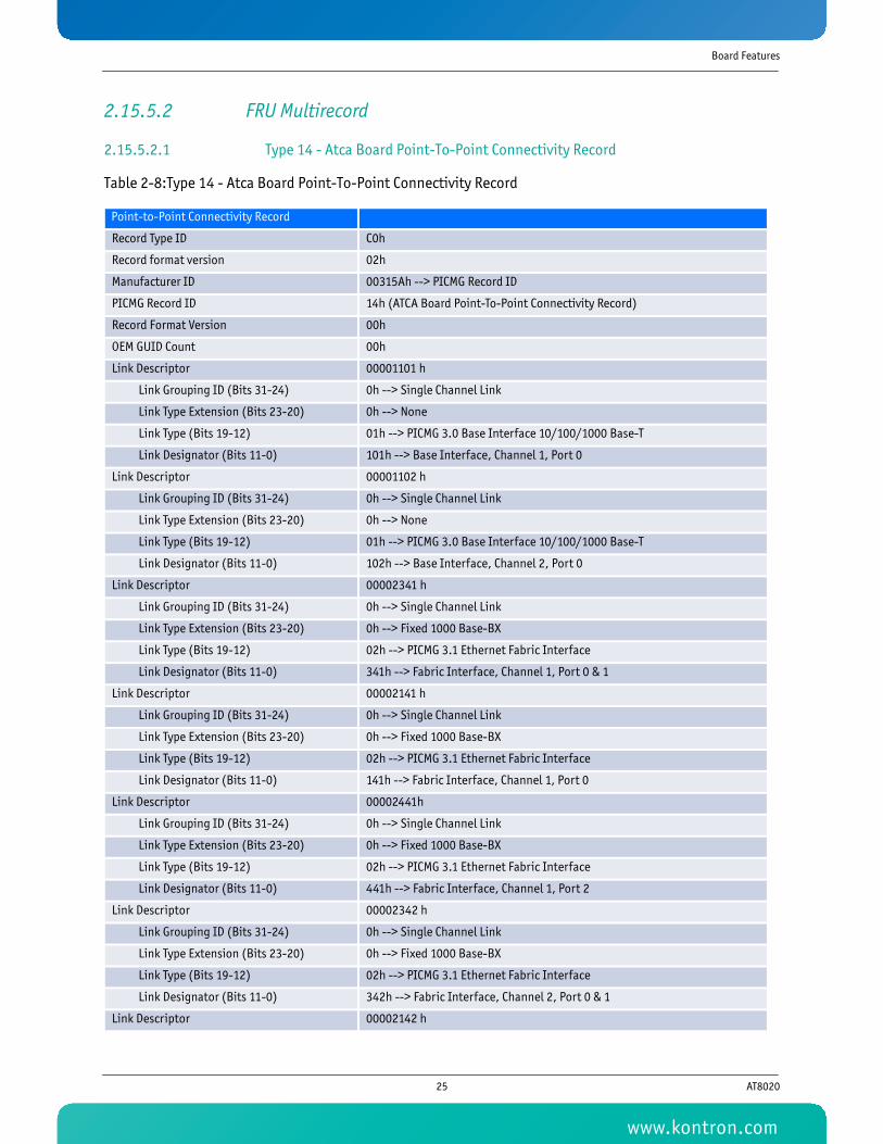
Board Features
2.15.5.2 FRU Multirecord
2.15.5.2.1 Type 14 - Atca Board Point-To-Point Connectivity Record
Table 2-8:Type 14 - Atca Board Point-To-Point Connectivity Record
Point-to-Point Connectivity Record
Record Type ID C0h
Record format version 02h
Manufacturer ID 00315Ah --> PICMG Record ID
PICMG Record ID 14h (ATCA Board Point-To-Point Connectivity Record)
Record Format Version 00h
OEM GUID Count 00h
Link Descriptor 00001101 h
Link Grouping ID (Bits 31-24) 0h --> Single Channel Link
Link Type Extension (Bits 23-20) 0h --> None
Link Type (Bits 19-12) 01h --> PICMG 3.0 Base Interface 10/100/1000 Base-T
Link Designator (Bits 11-0) 101h --> Base Interface, Channel 1, Port 0
Link Descriptor 00001102 h
Link Grouping ID (Bits 31-24) 0h --> Single Channel Link
Link Type Extension (Bits 23-20) 0h --> None
Link Type (Bits 19-12) 01h --> PICMG 3.0 Base Interface 10/100/1000 Base-T
Link Designator (Bits 11-0) 102h --> Base Interface, Channel 2, Port 0
Link Descriptor 00002341 h
Link Grouping ID (Bits 31-24) 0h --> Single Channel Link
Link Type Extension (Bits 23-20) 0h --> Fixed 1000 Base-BX
Link Type (Bits 19-12) 02h --> PICMG 3.1 Ethernet Fabric Interface
Link Designator (Bits 11-0) 341h --> Fabric Interface, Channel 1, Port 0 & 1
Link Descriptor 00002141 h
Link Grouping ID (Bits 31-24) 0h --> Single Channel Link
Link Type Extension (Bits 23-20) 0h --> Fixed 1000 Base-BX
Link Type (Bits 19-12) 02h --> PICMG 3.1 Ethernet Fabric Interface
Link Designator (Bits 11-0) 141h --> Fabric Interface, Channel 1, Port 0
Link Descriptor 00002441h
Link Grouping ID (Bits 31-24) 0h --> Single Channel Link
Link Type Extension (Bits 23-20) 0h --> Fixed 1000 Base-BX
Link Type (Bits 19-12) 02h --> PICMG 3.1 Ethernet Fabric Interface
Link Designator (Bits 11-0) 441h --> Fabric Interface, Channel 1, Port 2
Link Descriptor 00002342 h
Link Grouping ID (Bits 31-24) 0h --> Single Channel Link
Link Type Extension (Bits 23-20) 0h --> Fixed 1000 Base-BX
Link Type (Bits 19-12) 02h --> PICMG 3.1 Ethernet Fabric Interface
Link Designator (Bits 11-0) 342h --> Fabric Interface, Channel 2, Port 0 & 1
Link Descriptor 00002142 h
25 AT8020
www.kontron.com

Board Features
2.15.5.2.2 Type 17 - Carrier Activation And Current Management Record
Table 2-9: Type 17 - Carrier Activation And Current Management Record
Link Grouping ID (Bits 31-24) 0h --> Single Channel Link
Link Type Extension (Bits 23-20) 0h --> Fixed 1000 Base-BX
Link Type (Bits 19-12) 02h --> PICMG 3.1 Ethernet Fabric interface
Link Designator (Bits 11-0) 141h --> Fabric Interface, Channel 2, Port 0
Link Descriptor 00002442 h
Link Grouping ID (Bits 31-24) 0h --> Single Channel Link
Link Type Extension (Bits 23-20) 0h --> Fixed 1000 Base-BX
Link Type (Bits 19-12) 02h --> PICMG 3.1 Ethernet Fabric interface
Link Designator (Bits 11-0) 442h --> Fabric Interface, Channel 2, Port 2
Point-to-Point Connectivity Record
Record Type ID C0h
Record format version 02h
Manufacturer ID 00315Ah
PICMG Record ID 17h
Record Format Version 00h
Maximum Internal Current 1Eh (3.0 Amps at 12 V => 36 Watts)
Allowance for Module Activation Readiness 002h
Module Activation and Power Descriptor Count 03h
Carrier Activation and Power Descriptors. 7Ah, 19h, FFh
Local IPMB Address 7Ah
Maximum Module Current 19h (2.5 Amps at 12 V => 30 Watts)
Reserved FFh
Carrier Activation and Power Descriptors. 7Ch, 19h, FFh
Local IPMB Address 7Ch
Maximum Module Current 19h (2.5 Amps at 12 V => 30 Watts)
Reserved FFh
Carrier Activation and Power Descriptors. 90h, 15h, FFh
Local IPMB Address 90h
Maximum Module Current 15h (2.1 Amps at 12 V => 25.2 Watts)
Reserved FFh
Point-to-Point Connectivity Record
26 AT8020
www.kontron.com
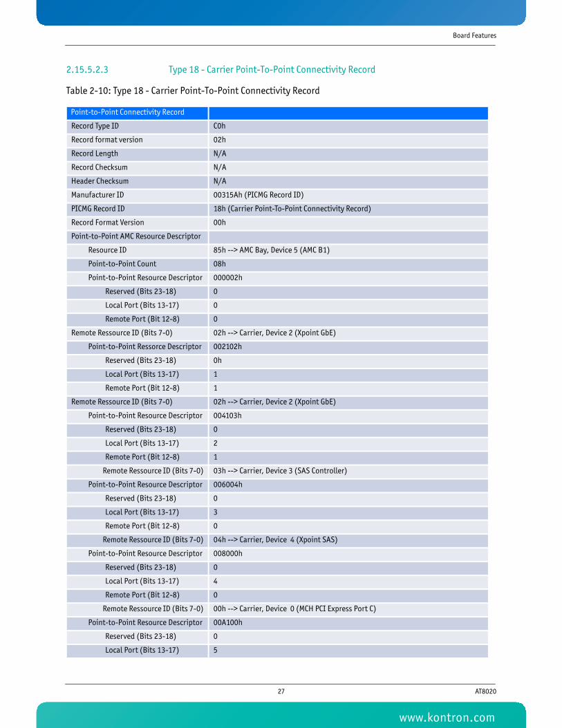
Board Features
2.15.5.2.3 Type 18 - Carrier Point-To-Point Connectivity Record
Table 2-10: Type 18 - Carrier Point-To-Point Connectivity Record
Point-to-Point Connectivity Record
Record Type ID C0h
Record format version 02h
Record Length N/A
Record Checksum N/A
Header Checksum N/A
Manufacturer ID 00315Ah (PICMG Record ID)
PICMG Record ID 18h (Carrier Point-To-Point Connectivity Record)
Record Format Version 00h
Point-to-Point AMC Resource Descriptor
Resource ID 85h --> AMC Bay, Device 5 (AMC B1)
Point-to-Point Count 08h
Point-to-Point Resource Descriptor 000002h
Reserved (Bits 23-18) 0
Local Port (Bits 13-17) 0
Remote Port (Bit 12-8) 0
Remote Ressource ID (Bits 7-0) 02h --> Carrier, Device 2 (Xpoint GbE)
Point-to-Point Ressorce Descriptor 002102h
Reserved (Bits 23-18) 0h
Local Port (Bits 13-17) 1
Remote Port (Bit 12-8) 1
Remote Ressource ID (Bits 7-0) 02h --> Carrier, Device 2 (Xpoint GbE)
Point-to-Point Resource Descriptor 004103h
Reserved (Bits 23-18) 0
Local Port (Bits 13-17) 2
Remote Port (Bit 12-8) 1
Remote Ressource ID (Bits 7-0) 03h --> Carrier, Device 3 (SAS Controller)
Point-to-Point Resource Descriptor 006004h
Reserved (Bits 23-18) 0
Local Port (Bits 13-17) 3
Remote Port (Bit 12-8) 0
Remote Ressource ID (Bits 7-0) 04h --> Carrier, Device 4 (Xpoint SAS)
Point-to-Point Resource Descriptor 008000h
Reserved (Bits 23-18) 0
Local Port (Bits 13-17) 4
Remote Port (Bit 12-8) 0
Remote Ressource ID (Bits 7-0) 00h --> Carrier, Device 0 (MCH PCI Express Port C)
Point-to-Point Resource Descriptor 00A100h
Reserved (Bits 23-18) 0
Local Port (Bits 13-17) 5
27 AT8020
www.kontron.com

Board Features
Remote Port (Bit 12-8) 1
Remote Ressource ID (Bits 7-0) 00h --> Carrier, Device 0 (MCH PCI Express Port C)
Point-to-Point Resource Descriptor 00C200h
Reserved (Bits 23-18) 0
Local Port (Bits 13-17) 6
Remote Port (Bit 12-8) 2
Remote Ressource ID (Bits 7-0) 00h --> Carrier, Device 0 (MCH PCI Express Port C)
Point-to-Point Resource Descriptor 00E300h
Reserved (Bits 23-18) 0
Local Port (Bits 13-17) 7
Remote Port (Bit 12-8) 3
Remote Ressource ID (Bits 7-0) 00h --> Carrier, Device 0 (MCH PCI Express Port C)
Point-to-Point AMC Resource Descriptor
Resource ID 86h --> AMC Bay, Device 6 (AMC B2)
Point-to-Point Count 08
Point-to-Point Resource Descriptor 000202h
Reserved (Bits 23-18) 0
Local Port (Bits 13-17) 0
Remote Port (Bit 12-8) 2
Remote Ressource ID (Bits 7-0) 02h --> Carrier, Device 2 (Xpoint GbE)
Point-to-Point Resource Descriptor 002302h
Reserved (Bits 23-18) 0
Local Port (Bits 13-17) 1
Remote Port (Bit 12-8) 3
Remote Ressource ID (Bits 7-0) 02h --> Carrier, Device 2 (Xpoint GbE)
Point-to-Point Resource Descriptor 004003h
Reserved (Bits 23-18) 0
Local Port (Bits 13-17) 2
Remote Port (Bit 12-8) 0
Remote Ressource ID (Bits 7-0) 03h --> Carrier, Device 3 (SAS Controller)
Point-to-Point Resource Descriptor 006104h
Reserved (Bits 23-18) 0
Local Port (Bits 13-17) 3
Remote Port (Bit 12-8) 1
Remote Ressource ID (Bits 7-0) 04h --> Carrier, Device 4 (Xpoint SAS)
Point-to-Point Resource Descriptor 008001h
Reserved (Bits 23-18) 0
Local Port (Bits 13-17) 4
Remote Port (Bit 12-8) 0
Remote Ressource ID (Bits 7-0) 00h --> Carrier, Device 1 (MCH PCI Express Port B)
Point-to-Point Resource Descriptor 00A101h
Reserved (Bits 23-18) 0
Point-to-Point Connectivity Record
28 AT8020
www.kontron.com

Board Features
2.15.5.2.4 Type 19h - AMC Point-To-Point Connectivity Record(1 of 4)(MCH PCI Express Port C)
Table 2-11: Type 19h - AMC Point-To-Point Connectivity Record(1 of 4)(MCH PCI Express Port C)
Local Port (Bits 13-17) 5
Remote Port (Bit 12-8) 1
Remote Ressource ID (Bits 7-0) 00h --> Carrier, Device 1 (MCH PCI Express Port B)
Point-to-Point Resource Descriptor 00C201h
Reserved (Bits 23-18) 0
Local Port (Bits 13-17) 6
Remote Port (Bit 12-8) 2
Remote Ressource ID (Bits 7-0) 00h --> Carrier, Device 1 (MCH PCI Express Port B)
Point-to-Point Connectivity Record
Record Type ID C0h
Record format version 02h
Record Length N/A
Record Checksum N/A
Header Checksum N/A
Manufacturer ID 00315Ah --> PICMG Record ID
PICMG Record ID 19h --> AMC Point-To-Point Connectivity Record
Record Format Version 00h
Record Type/Connected-device ID 00h --> On-Carrier device, Device 0 (MCH PCI Express Port C)
AMC Channel Descriptor Count 01h
AMC Channel Descriptor 0F18820h
Reserved (Bits 23-20) 0Fh
Lane 3 Port Number (Bits 19-15) 03h
Lane 2 Port Number (Bits 14-10) 02h
Lane 1 Port Number (Bits 9-5) 01h
Lane 0 Port Number (Bits 4-0) 00h
AMC Link Descriptor FE00102F00 h
Reserved (Bits 39-34) 03Fh
AMC Asymmetric Match (Bits 33-32) 10b --> This Carrier provides a Secondary PCI Express Port (Matches with '01b')
Link Grouping ID (Bits 31-24) 00h --> Single Channel Link
AMC Link Type Extension (Bits 23-20) 01h --> Carrier: Reference clock is spread spectrum
AMC Link Type (Bits 19-12) 002h --> AMC.1 PCI Express
AMC Link Designator (Bits 11-0) 0F00h --> AMC Channel 0, lane 0, 1, 2 and 3
AMC Link Descriptor FE00002F00 h
Reserved (Bits 39-34) 03Fh
AMC Asymmetric Match (Bits 33-32) 10b --> This Carrier provides a Secondary PCI Express Port (Matches with '01b')
Point-to-Point Connectivity Record
29 AT8020
www.kontron.com

Board Features
2.15.5.2.5 Type 19h - AMC Point-To-Point Connectivity Record (2 of 4) (MCH PCI Express Port B)
Table 2-12: Type 19h - AMC Point-To-Point Connectivity Record (2 of 4) (MCH PCI Express Port B)
Link Grouping ID (Bits 31-24) 00h --> Single Channel Link
AMC Link Type Extension (Bits 23-20) 00h --> Carrier: Reference clock is not spread spectrum
AMC Link Type (Bits 19-12) 002h --> AMC.1 PCI Express
AMC Link Designator (Bits 11-0) 0F00h --> AMC Channel 0, lane 0, 1, 2 and 3
AMC Link Descriptor FE00102100 h
Reserved (Bits 39-34) 03Fh
AMC Asymmetric Match (Bits 33-32) 10b --> This Carrier provides a Secondary PCI Express Port (Matches with '01b')
Link Grouping ID (Bits 31-24) 00h --> Single Channel Link
AMC Link Type Extension (Bits 23-20) 01h --> Carrier: Reference clock is spread spectrum
AMC Link Type (Bits 19-12) 002h --> AMC.1 PCI Express
AMC Link Designator (Bits 11-0) 0100h --> AMC Channel 0, lane 0
AMC Link Descriptor FE00002100 h
Reserved (Bits 39-34) 03Fh
AMC Asymmetric Match (Bits 33-32) 10b --> This Carrier provides a Secondary PCI Express Port (Matches with '01b')
Link Grouping ID (Bits 31-24) 00h --> Single Channel Link
AMC Link Type Extension (Bits 23-20) 00h --> Carrier: Reference clock is not spread spectrum
AMC Link Type (Bits 19-12) 002h --> AMC.1 PCI Express
AMC Link Designator (Bits 11-0) 0100h --> AMC Channel 0, lane 0
Point-to-Point Connectivity Record
Record Type ID C0h
Record format version 02h
Record Length N/A
Record Checksum N/A
Header Checksum N/A
Manufacturer ID 00315Ah --> PICMG Record ID
PICMG Record ID 19h --> AMC Point-To-Point Connectivity Record
Record Format Version 00h
Record Type/Connected-device ID 01h --> On-Carrier device, Device 1 (MCH PCI Express Port B)
AMC Channel Descriptor Count 01h
AMC Channel Descriptor 0F18820h
Reserved (Bits 23-20) 0Fh
Lane 3 Port Number (Bits 19-15) 03h
Lane 2 Port Number (Bits 14-10) 02h
Lane 1 Port Number (Bits 9-5) 01h
Point-to-Point Connectivity Record
30 AT8020
www.kontron.com

Board Features
Lane 0 Port Number (Bits 4-0) 00h
AMC Link Descriptor FE00102F00 h
Reserved (Bits 39-34) 03Fh
AMC Asymmetric Match (Bits 33-32) 10b --> This Carrier provides a Secondary PCI Express Port (Matches with '01b')
Link Grouping ID (Bits 31-24) 00h --> Single Channel Link
AMC Link Type Extension (Bits 23-20) 01h --> Carrier: Reference clock is spread spectrum
AMC Link Type (Bits 19-12) 002h --> AMC.1 PCI Express
AMC Link Designator (Bits 11-0) 0F00h --> AMC Channel 0, lane 0, 1, 2 and 3
AMC Link Descriptor FE00102100 h
Reserved (Bits 39-34) 03Fh
AMC Asymmetric Match (Bits 33-32) 10b --> This Carrier provides a Secondary PCI Express Port (Matches with '01b')
Link Grouping ID (Bits 31-24) 00h --> Single Channel Link
AMC Link Type Extension (Bits 23-20) 01h --> Carrier: Reference clock is spread spectrum
AMC Link Type (Bits 19-12) 002h --> AMC.1 PCI Express
AMC Link Designator (Bits 11-0) 0100h --> AMC Channel 0, lane 0
AMC Link Descriptor FE00102F01 h
Reserved (Bits 39-34) 03Fh
AMC Asymmetric Match (Bits 33-32) 10b --> This Carrier provides a Secondary PCI Express Port (Matches with '01b')
Link Grouping ID (Bits 31-24) 00h --> Single Channel Link
AMC Link Type Extension (Bits 23-20) 01h --> Carrier: Reference clock is spread spectrum
AMC Link Type (Bits 19-12) 002h --> AMC.1 PCI Express
AMC Link Designator (Bits 11-0) 0F01h --> AMC Channel 1, lane 0, 1, 2 and 3
AMC Link Descriptor FE00002F01 h
Reserved (Bits 39-34) 03Fh
AMC Asymmetric Match (Bits 33-32) 10b --> This Carrier provides a Secondary PCI Express Port (Matches with '01b')
Link Grouping ID (Bits 31-24) 00h --> Single Channel Link
AMC Link Type Extension (Bits 23-20) 00h --> Carrier: Reference clock is not spread spectrum
AMC Link Type (Bits 19-12) 002h --> AMC.1 PCI Express
AMC Link Designator (Bits 11-0) 0F01h --> AMC Channel 1, lane 0, 1, 2 and 3
AMC Link Descriptor FE00102101 h
Reserved (Bits 39-34) 03Fh
AMC Asymmetric Match (Bits 33-32) 10b --> This Carrier provides a Secondary PCI Express Port (Matches with '01b')
Link Grouping ID (Bits 31-24) 00h --> Single Channel Link
AMC Link Type Extension (Bits 23-20) 01h --> Carrier: Reference clock is spread spectrum
AMC Link Type (Bits 19-12) 002h --> AMC.1 PCI Express
AMC Link Designator (Bits 11-0) 0101h --> AMC Channel 1, lane 0
AMC Link Descriptor FE00002101 h
Reserved (Bits 39-34) 03Fh
Point-to-Point Connectivity Record
31 AT8020
www.kontron.com

Board Features
2.15.5.2.6 Type 19h - AMC Point-To-Point Connectivity Record (3 of 4) (Xpoint GbE)
Table 2-13: Type 19h - AMC Point-To-Point Connectivity Record (3 of 4) (Xpoint GbE)
AMC Asymmetric Match (Bits 33-32) 10b --> This Carrier provides a Secondary PCI Express Port (Matches with '01b')
Link Grouping ID (Bits 31-24) 00h --> Single Channel Link
AMC Link Type Extension (Bits 23-20) 00h --> Carrier: Reference clock is not spread spectrum
AMC Link Type (Bits 19-12) 002h --> AMC.1 PCI Express
AMC Link Designator (Bits 11-0) 0101h --> AMC Channel 1, lane 0
Point-to-Point Connectivity Record
Record Type ID C0h
Record format version 02h
Record Length N/A
Record Checksum N/A
Header Checksum N/A
Manufacturer ID 00315Ah --> PICMG Record ID
PICMG Record ID 19h --> AMC Point-To-Point Connectivity Record
Record Format Version 00h
Record Type/Connected-device ID 01h' On-Carrier device, Device 2 (Xpoint GbE)
AMC Channel Descriptor Count 04h
AMC Channel Descriptor 0FFFFE0h
Reserved (Bits 23-20) 0Fh
Lane 3 Port Number (Bits 19-15) 1Fh
Lane 2 Port Number (Bits 14-10) 1Fh
Lane 1 Port Number (Bits 9-5) 1Fh
Lane 0 Port Number (Bits 4-0) 00h
AMC Channel Descriptor 0FFFFE1h
Reserved (Bits 23-20) 0Fh
Lane 3 Port Number (Bits 19-15) 1Fh
Lane 2 Port Number (Bits 14-10) 1Fh '
Lane 1 Port Number (Bits 9-5) 1Fh '
Lane 0 Port Number (Bits 4-0) 01h
AMC Channel Descriptor 0FFFFE2h
Reserved (Bits 23-20) 0Fh
Lane 3 Port Number (Bits 19-15) 1Fh
Lane 2 Port Number (Bits 14-10) 1Fh
Lane 1 Port Number (Bits 9-5) 1Fh
Lane 0 Port Number (Bits 4-0) 02h
AMC Channel Descriptor 0FFFFE3h
Reserved (Bits 23-20) 0Fh
Point-to-Point Connectivity Record
32 AT8020
www.kontron.com

Board Features
2.15.5.2.7 Type 19h - AMC Point-To-Point Connectivity Record (4 of 4)
Table 2-14: Type 19h - AMC Point-To-Point Connectivity Record (4 of 4)
Lane 3 Port Number (Bits 19-15) 1Fh
Lane 2 Port Number (Bits 14-10) 1Fh '
Lane 1 Port Number (Bits 9-5) 1Fh '
Lane 0 Port Number (Bits 4-0) 03h
AMC Link Descriptor FC00005104h
Reserved (Bits 39-34) 03Fh
AMC Asymmetric Match (Bits 33-32) 00b --> Exact match
Link Grouping ID (Bits 31-24) 00h --> Single-Channel link
AMC Link Type Extension (Bits 23-20) 01h --> 1000 Base BX
AMC Link Type (Bits 19-12) 005h --> AMC.2 Ethernet
AMC Link Designator (Bits 11-0) 0104h --> AMC Channel 4, lane 0
AMC Link Descriptor FC00005105h
Reserved (Bits 39-34) 03Fh
AMC Asymmetric Match (Bits 33-32) 00h --> Exact match
Link Grouping ID (Bits 31-24) 00h --> Single-Channel link
AMC Link Type Extension (Bits 23-20) 00h --> 1000 Base BX
AMC Link Type (Bits 19-12) 005h --> AMC.2 Ethernet
AMC Link Designator (Bits 11-0) 0105h --> AMC Channel 5, lane 0
Point-to-Point Connectivity Record
Record Type ID C0h
Record format version 02h
Record Length N/A
Record Checksum N/A
Header Checksum N/A
Manufacturer ID 00315Ah --> PICMG Record ID
PICMG Record ID 19h --> AMC Point-To-Point Connectivity Record
Record Format Version 00h
Record Type/Connected-device ID 03h --> On-Carrier device, Device 3 (SAS Controller)
AMC Channel Descriptor Count 02h
AMC Channel Descriptor FFFFE0h
Reserved (Bits 23-20) 0Fh
Lane 3 Port Number (Bits 19-15) 1Fh
Lane 2 Port Number (Bits 14-10) 1Fh
Lane 1 Port Number (Bits 9-5) 1Fh
Lane 0 Port Number (Bits 4-0) 00h
AMC Channel Descriptor FFFFE1h
Point-to-Point Connectivity Record
33 AT8020
www.kontron.com

Board Features
Reserved (Bits 23-20) 0Fh
Lane 3 Port Number (Bits 19-15) 1Fh
Lane 2 Port Number (Bits 14-10) 1Fh
Lane 1 Port Number (Bits 9-5) 1Fh
Lane 0 Port Number (Bits 4-0) 01h
AMC Link Descriptor FC00207106h
Reserved (Bits 39-34) 03Fh
AMC Asymmetric Match (Bits 33-32) 00b --> Exact match
Link Grouping ID (Bits 31-24) 00h --> Single-Channel link
AMC Link Type Extension (Bits 23-20) 02h --> Serially Attached SCSI/SATA
AMC Link Type (Bits 19-12) 007h --> AMC.3 Storage
AMC Link Designator (Bits 11-0) 0106h --> AMC Channel 6, lane 0
AMC Link Descriptor FE00107106h
Reserved (Bits 39-34) 03Fh
AMC Asymmetric Match (Bits 33-32) 02h --> Implements SATA Client Interface
Link Grouping ID (Bits 31-24) 00h --> Single-Channel link
AMC Link Type Extension (Bits 23-20) 01h --> Serial ATA
AMC Link Type (Bits 19-12) 007h --> AMC.3 Storage
AMC Link Designator (Bits 11-0) 0106h --> AMC Channel 6, lane 0
AMC Link Descriptor FC00207107h
Reserved (Bits 39-34) 03Fh
AMC Asymmetric Match (Bits 33-32) 020b --> Exact match
Link Grouping ID (Bits 31-24) 00h --> Single-Channel link
AMC Link Type Extension (Bits 23-20) 02h --> Serially Attached SCSI/SATA
AMC Link Type (Bits 19-12) 007h --> AMC.3 Storage
AMC Link Designator (Bits 11-0) 0107h --> AMC Channel 7, lane 0
AMC Link Descriptor FE00107107h
Reserved (Bits 39-34) 03Fh
AMC Asymmetric Match (Bits 33-32) 02h --> Implements SATA Client Interface
Link Grouping ID (Bits 31-24) 00h --> Single-Channel link
AMC Link Type Extension (Bits 23-20) 01h --> Serial ATA
AMC Link Type (Bits 19-12) 007h --> AMC.3 Storage
AMC Link Designator (Bits 11-0) 0107h --> AMC Channel 7, lane 0
Point-to-Point Connectivity Record
34 AT8020
www.kontron.com

Board Features
2.15.5.2.8 Type 1Ah - Carrier Information Table
Table 2-15: Type 1Ah - Carrier Information Table
2.15.6 IPMI Over LAN (IOL) supportThe AT8020 provides IPMI Over LAN support over the 2 Ethernet connections of the base interface. The 82571EB chip connected to the base interface is also connected to the IPMC. The IPMI Over LAN solution is compatible with the IPMI 1.5 and IPMI 2.0 specification and support both RMCP and RMCP+ payload type. It is also supporting the SOL payload type as described in the section 2.16.7.
The 2 channels are referred as channel 1 and channel 2. They can be accessed through those numbers when you use the IPMI commands related to channels. Only one channel can be activated at a time.
The implementation supports up to 4 simultaneous sessions (only one can enable SOL payload).
If a session is inactive for 1 minute it will be closed automatically.
The BIOS provides some basic functionality to see and configure the IPMI Over LAN. Using the BIOS, the following parameters can be seen/configured: IP address, MAC address, Subnet Mask, Gateway address, Active LAN channel. Theses settings are available in the BIOS section LAN configuration.
The recommended IPMI Over Lan / Serial Over LAN tools for Linux is IPMITool. This utility is available from the following web site: http://ipmitool.sourceforge.net/index.html.
Point-to-Point Connectivity Record
Record Type ID C0h
Record format version 02h
Record Length N/A
Record Checksum N/A
Header Checksum N/A
Manufacturer ID 00315Ah (PICMG Record ID)
PICMG Record ID 1Ah (Carrier Information Table)
Record Format Version 00h
AMC.0 Extension Version 01h (AMC.0 R2.0)
Carrier Site Number Count 02h
Carrier Site Number 05h
Carrier Site Number 06h
35 AT8020
www.kontron.com

Board Features
2.15.6.1 Authentication, Integrity and Confidentiality
The AT8020 support 2 types of authentication for RMCP session connections: "None" and "Straight Password".
For RMCP+ session connections, the AT8020 support from Cipher ID 0 to Cipher Id 3. The following algorithms are supported:
• Authentication: RAKP-none, RAKP-HMAC-SHA1
• Integrity: None, HMAC-SHA1-96
• Confidentiality: None, AES-CBC-128
When RMCP authentication "NONE" or RMCP+ Cipher ID 0 is used, privilege level is limited to "User".
2.15.6.2 Users
5 users are available for IPMI Over LAN connections. The user 1 is defined by the IPMI specification and cannot be changed. The following tables show the pre-defined users. They can be changed using the proper IPMI commands (See supported IPMI commands set on AT8020 at section 2.16.12).
Table 2-16: IPMI Over Lan Default Users
User ID User Name Password Can be modified Privileges
1 NULL NULL No User
2 “admin” “admin” Yes Administrator
3 Undefined Undefined Yes Undefined
4 Undefined Undefined Undefined Undefined
5 Undefined Undefined Undefined Undefined
36 AT8020
www.kontron.com
Board Features
2.15.7 Serial Over LAN support (SOL)Serial Over LAN (SOL) is the name for the redirection of baseboard serial controller traffic over an IPMI Session. The IPMC has connections to the primary serial port connected to the front panel and to the management port of the base interface Ethernet controller. The serial port is implemented in such way that if there is a cable connected to the RJ-45 connector, the traffic is directed to the cable and the IPMC only monitors traffic. If there is no cable connected, the traffic is directed to the IPMC. The AT8020 supports SOL payload within a RMCP+ connection as defined in the IPMI 2.0 specification.
To setup SOL, use the following procedure:
• Configure the IP address, Subnet Mask and Gateway address in the BIOS LAN configuration page.
• Set Active the LAN channel to use.
• In the BIOS menu Remote Access Configuration (See section 5.1), set the following parameters:
• Remote Access to "enabled".
• Primary Serial port number to COM1 or "both" for dual output (COM1 and COM2).
• Serial Port Mode to the desire speed.
• Flow control to "Software "or "hardware". (Flow control is required, do not use "None")
• Terminal type to the desire value.
The recommended IPMI Over Lan / Serial Over LAN tools for Linux is IPMITool. This utility is available from the following web site: http://ipmitool.sourceforge.net/index.html.
2.15.8 IPMC Firmware CodeIPMC firmware code is organized into boot code and operational code, both of which are stored in a flash module. Upon an IPMC reset, the IPMC executes the boot code and performs the following:
1 Self test to verify the status of its hardware and memory.
2 Performs a checksum of the operational code.
3 Communicates with the Firmware Upgrade Manager (FWUM) in order to inform the IPMC watchdog that the actual IPMC firmware is suitable for execution.
Upon successful verification of the operational code checksum, the firmware will jump to the operational code.
2.15.9 Updating the AT8020To update the software of your board, it is recommended to use the Kontron update CD. A version of this CD can be found on the CD/DVD provided with your board. The latest version is available from the Kontron Canada’s FTP site.
37 AT8020
www.kontron.com
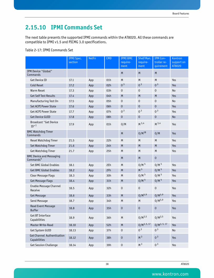
Board Features
2.15.10 IPMI Commands SetThe next table presents the supported IPMI commands within the AT8020. All these commands are compatible to IPMI v1.5 and PICMG 3.0 specifications.
Table 2-17: IPMI Commands Set
IPMI Spec. section
NetFn CMD IPMI BMC require-ment
Shelf Man. require-ment
IPM Con-troller re-quirement
Kontron support on AT8020
IPM Device "Global" Commands M M M
Get Device ID 17.1 App 01h M M M Yes
Cold Reset 17.2 App 02h O 3 O 3 O 3 Yes
Warm Reset 17.3 App 03h O O O No
Get Self Test Results 17.4 App 04h M M M Yes
Manufacturing Test On 17.5 App 05h O O O No
Set ACPI Power State 17.6 App 06h O O O Yes
Get ACPI Power State 17.7 App 07h O 3 O 3 O 3 Yes
Get Device GUID 17.8 App 08h O O O No
Broadcast "Get Device ID"1 17.9 App 01h O/M M 3,4 M 3,4 Yes
BMC Watchdog Timer Commands M O/M18 O/M Yes
Reset Watchdog Timer 21.5 App 22h M M M Yes
Set Watchdog Timer 21.6 App 24h M M M Yes
Get Watchdog Timer 21.7 App 25h M M M Yes
BMC Device and Messaging Commands5 M M O
Set BMC Global Enables 18.1 App 2Eh M O/M 5 O/M 5 Yes
Get BMC Global Enables 18.2 App 2Fh M M 5 O/M 5 Yes
Clear Message Flags 18.3 App 30h M O/M 5 O/M 5 Yes
Get Message Flags 18.4 App 31h M O/M 5 O/M 5 Yes
Enable Message Channel Receive
18.5 App 32h O O O Yes
Get Message 18.6 App 33h M O/M5,9 O/M5,9 Yes
Send Message 18.7 App 34h M M O/M5,9 Yes
Read Event Message Buffer
18.8 App 35h O O O Yes
Get BT Interface Capabilities
18.9 App 36h M O/M3,5 O/M3,5 Yes
Master Write-Read 18.10 App 52h M O/M3, 5, 17 O/M3, 5, 17 Yes
Get System GUID 18.13 App 37h O O 3 O 3 No
Get Channel Authentication Capabilities
18.12 App 38h O M 3 O 3 Yes
Get Session Challenge 18.14 App 39h O M 3 O 3 Yes
38 AT8020
www.kontron.com

Board Features
Activate Session 18.15 App 3Ah O M 3 O 3 Yes
Set Session Privilege Level 18.16 App 3Bh O M 3 O 3 Yes
Close Session 18.17 App 3Ch O M 3 O 3 Yes
Get Session Info 18.18 App 3Dh O M 3 O 3 Yes
Get AuthCode 18.19 App 3Fh O M O Yes
Set Channel Access 18.20 App 40h O M 3 O 3 Yes
Get Channel Access 18.21 App 41h O M 3 O 3 Yes
Get Channel Info 18.22 App 42h O M 3 O 3 Yes
Set User Access 18.23 App 43h O M 3 O 3 Yes
Get User Access 18.24 App 44h O M 3 O 3 Yes
Set User Name 18.25 App 45h O M 3 O 3 Yes
Get User Name 18.26 App 46h O M 3 O 3 Yes
Set User Password 18.27 App 47h O M 3 O 3 Yes
Chassis Device Commands O O O
Get Chassis Capabilities 22.1 Chassis 00h M M6 O Yes
Get Chassis Status 22.2 Chassis 01h O/M3 M6 O Yes
Chassis Control 22.3 Chassis 02h O/M3 M6 O Yes
Chassis Reset 22.4 Chassis 03h O O O No
Chassis Identify 22.5 Chassis 04h O O O No
Set Chassis Capabilities 22.6 Chassis 05h O O O No
Set Power Restore Policy 22.7 Chassis 06h O O O No
Get System Restart Cause 22.9 Chassis 07h O 3 O 3 O 3 No
Get System Restart Cause 22.10 Chassis 08h O 3 O 3 O 3 No
Get System Restart Cause 22.11 Chassis 09h O 3 O 3 O 3 No
Get System Restart Cause 22.12 Chassis 0Fh O 3 O 3 O 3 No
Event Commands M M M
Set Event Receiver 23.1 S/E 01h M M M Yes
Get Event Receiver 23.2 S/E 02h M M M Yes
Platform Event (a.k.a. "Event Message")
23.3 S/E 03h M M M Yes
PEF and Alerting Commands O O O
Get PEF Capabilities 24.1 S/E 10h M3 M3 M3 No
Arm PEF Postpone Timer 24.2 S/E 11h M3 M3 M3 No
Set PEF Configuration Parameters
24.3 S/E 12h M3 M3 M3 No
Get PEF Configuration Parameters
24.4 S/E 13h M3 M3 M3 No
Set Last Processed Event ID 24.5 S/E 14h M3 M3 M3 No
Get Last Processed Event ID 24.6 S/E 15h M3 M3 M3 No
Alert Immediate 24.7 S/E 16h O 3 O 3 O 3 No
PET Acknowledge 24.8 S/E 17h O 3 O 3 O 3 No
IPMI Spec. section
NetFn CMD IPMI BMC require-ment
Shelf Man. require-ment
IPM Con-troller re-quirement
Kontron support on AT8020
39 AT8020
www.kontron.com

Board Features
Sensor Device Commands O M M
Get Device SDR Info 29.2 S/E 20h O M M Yes
Get Device SDR 29.3 S/E 21h O 3 M3 M3 Yes
Reserve Device SDR Repository
29.4 S/E 22h O 3 M3 M3 Yes
Get Sensor Reading Factors 29.5 S/E 23h O 3 O 3 M3 No
Set Sensor Hysteresis 29.6 S/E 24h O O O Yes
Get Sensor Hysteresis 29.7 S/E 25h O O O Yes
Set Sensor Threshold 29.8 S/E 26h O O O Yes
Get Sensor Threshold 29.9 S/E 27h O 3 O 3 O 3 Yes
Set Sensor Event Enable 29.10 S/E 28h O O O Yes
Get Sensor Event Enable 29.11 S/E 29h O 3 O 3 O 3 Yes
Re-arm Sensor Events 29.12 S/E 2Ah O 3 O 3 O 3 No
Get Sensor Event Status 29.13 S/E 2Bh O O O No
Get Sensor Reading 29.14 S/E 2Dh M M M Yes
Set Sensor Type 29.15 S/E 2Eh O O O No
Get Sensor Type 29.16 S/E 2Fh O 3 O 3 O 3 No
FRU Device Commands M M M
Get FRU Inventory Area Info 28.1 Storage 10h M M M Yes
Read FRU Data 28.2 Storage 11h M M M Yes
Write FRU Data 28.3 Storage 12h M M M Yes
SDR Device Commands M M7 O7
Get SDR Repository Info 27.9 Storage 20h M M M No
Get SDR Repository Allocation Info
27.10 Storage 21h O O O No
Reserve SDR Repository 27.11 Storage 22h M M M No
Get SDR 27.12 Storage 23h M3 M3 M3 No
Add SDR 27.13 Storage 24h M3 M3,16 O/M3, 5 No
Partial Add SDR 27.14 Storage 25h M3 M3,16 O/M3, 5 No
Delete SDR 27.15 Storage 26h O 3 O 3 O 3 No
Clear SDR Repository 27.16 Storage 27h M3 M3,16 O/M3, 5 No
Get SDR Repository Time 27.17 Storage 28h O/M3 O/M3 O/M3 No
Set SDR Repository Time 27.18 Storage 29h O/M3 O/M3 O/M3 No
Enter SDR Repository Update Mode
27.19 Storage 2Ah O 3 O 3 O 3 No
Exit SDR Repository Update Mode
27.20 Storage 2Bh M3 M3 M3 No
Run Initialization Agent 27.21 Storage 2Ch O 3 O 3 O 3 No
SEL Device Commands M M O 8
Get SEL Info 25.2 Storage 40h M M M Yes
Get SEL Allocation Info 25.3 Storage 41h O O O No
IPMI Spec. section
NetFn CMD IPMI BMC require-ment
Shelf Man. require-ment
IPM Con-troller re-quirement
Kontron support on AT8020
40 AT8020
www.kontron.com

Board Features
Reserve SEL 25.4 Storage 42h O 3 O 3 O 3 No
Get SEL Entry 25.5 Storage 43h M M M Yes
Add SEL Entry 25.6 Storage 44h M3 M3 M3 Yes
Partial Add SEL Entry 25.7 Storage 45h M3 M3 M3 Yes
Delete SEL Entry 25.8 Storage 46h O O O No
Clear SEL 25.9 Storage 47h M M M Yes
Get SEL Time 25.10 Storage 48h M M M Yes
Set SEL Time 25.11 Storage 49h M M M Yes
Get Auxiliary Log Status 25.12 Storage 5Ah O O O No
Set Auxiliary Log Status 25.13 Storage 5Bh O 3 O 3 O 3 No
LAN Device Commands O M O
Set LAN Configuration Parameters
19.1 Transport 01h O/M3 M3 O/M3 Yes
Get LAN Configuration Parameters
19.2 Transport 02h O/M3 M3 O/M3 Yes
Suspend BMC ARPs 19.3 Transport 03h O/M3 O/M3 O/M3 Yes
Get IP/UDP/RMCP Statistics 19.4 Transport 04h O O O No
Serial/Modem Device Commands O O O
Set Serial/Modem Configuration
20.1 Transport 10h O/M3 O/M3 O/M3 No
Get Serial/Modem Configuration
20.2 Transport 11h O/M3 O/M3 O/M3 No
Set Serial/Modem Mux 20.3 Transport 12h O 3 O 3 O 3 No
Get TAP Response Codes 20.4 Transport 13h O 3 O 3 O 3 No
Set PPP UDP Proxy Transmit Data
20.5 Transport 14h O 3 O 3 O 3 No
Get PPP UDP Proxy Transmit Data
20.6 Transport 15h O 3 O 3 O 3 No
Send PPP UDP Proxy Packet 20.7 Transport 16h O 3 O 3 O 3 No
Get PPP UDP Proxy Receive Data
20.8 Transport 17h O 3 O 3 O 3 No
Serial/Modem Connection Active
20.9 Transport 18h O/M3 O/M3 O/M3 No
Callback 20.10 Transport 19h O O O No
Set User Callback Options 20.11 Transport 1Ah O 3 O 3 O 3 No
Get User Callback Options 20.12 Transport 1Bh O 3 O 3 O 3 No
Bridge Management Commands (ICMB)2 O O O
Get Bridge State ICMB Bridge 00h O/M2 O/M2 O No
Set Bridge State ICMB Bridge 01h O/M2 O/M2 O No
Get ICMB Address ICMB Bridge 02h O/M2 O/M2 O No
Set ICMB Address ICMB Bridge 03h O/M2 O/M2 O No
IPMI Spec. section
NetFn CMD IPMI BMC require-ment
Shelf Man. require-ment
IPM Con-troller re-quirement
Kontron support on AT8020
41 AT8020
www.kontron.com

Board Features
Set Bridge Proxy Address ICMB Bridge 04h O/M2 O/M2 O No
Get Bridge Statistics ICMB Bridge 05h O/M2 O/M2 O No
Get ICMB Capabilities ICMB Bridge 06h O/M2 O/M2 O No
Clear Bridge Statistics ICMB Bridge 08h O/M2 O/M2 O No
Get Bridge Proxy Address ICMB Bridge 09h O/M2 O/M2 O No
Get ICMB Connector Info ICMB Bridge 0Ah O/M2 O/M2 O No
Get ICMB Connection ID ICMB Bridge 0Bh O/M2 O/M2 O No
Send ICMB Connection ID ICMB Bridge 0Ch O/M2 O/M2 O No
Discovery Commands (ICMB)2 O O O
Prepare For Discovery ICMB Bridge 10h O/M2 O/M2 O No
Get Addresses ICMB Bridge 11h O/M2 O/M2 O No
Set Discovered ICMB Bridge 12h O/M2 O/M2 O No
Get Chassis Device ID ICMB Bridge 13h O/M2 O/M2 O No
Set Chassis Device ID ICMB Bridge 14h O/M2 O/M2 O No
Bridging Commands (ICMB)2 O O O
Bridge Request ICMB Bridge 20h O/M2 O/M2 O No
Bridge Message ICMB Bridge 21h O/M2 O/M2 O No
Event Commands (ICMB) 2 O O O
Get Event Count ICMB Bridge 30h O/M2 O/M2 O No
Set Event Destination ICMB Bridge 31h O/M2 O/M2 O No
Set Event Reception State ICMB Bridge 32h O/M2 O/M2 O No
Send ICMB Event Message ICMB Bridge 33h O/M2 O/M2 O No
Get Event Destination ICMB Bridge 34h O/M2 O/M2 O No
Get Event Reception State ICMB Bridge 35h O/M2 O/M2 O No
OEM Commands for Bridge NetFn O O O
OEM Commands ICMB Bridge C0h-FEh O/M2 O/M2 O No
Other Bridge Commands O O O
Error Report ICMB Bridge FFh O/M2 O/M2 O No
AdvancedTCA10 PICMG 3.0 Table M M
Get PICMG Properties 3-9 PICMG 00h M M Yes
Get Address Info 3-8 PICMG 01h M M12 Yes
Get Shelf Address Info 3-13 PICMG 02h M O No
Set Shelf Address Info 3-14 PICMG 03h M O No
FRU Control 3-22 PICMG 04h M M Yes
Get FRU LED Properties 3-24 PICMG 05h M M Yes
Get LED Color Capabilities 3-25 PICMG 06h M M Yes
Set FRU LED State 3-26 PICMG 07h M M Yes
Get FRU LED State 3-27 PICMG 08h M M Yes
Set IPMB State 3-51 PICMG 09h M M Yes
IPMI Spec. section
NetFn CMD IPMI BMC require-ment
Shelf Man. require-ment
IPM Con-troller re-quirement
Kontron support on AT8020
42 AT8020
www.kontron.com

Board Features
1 This command is sent using the Broadcast format on IPMB. See command description for details.
2 See ICMB specification for details. If an ICMB is implemented, then these commands are mandatory. However, methods to implement dual Shelf Managers with ICMB interfaces are not defined by either PICMG 3.0 or the ICMB specification.
3 Additional constraints apply, see appropriate IPMI v1.5 section for details.
4 PICMG 3.0 requires IPMB-0 (Channel 0) for ShMC to IPM Controller communication.
5 PICMG 3.0 doesn't require the implementation of KCS, SMIC or BT system interfaces on any IPM controller, including a ShMC. PICMG 3.0 designates a Payload Interface between an IPM Controller and its Payload, but does not constrain the implementation of that interface. However, if any IPMI-defined system interface is to be implemented, these commands are mandatory.
6 The Shelf Manager shall apply this command to an entire Shelf.
7 PICMG 3.0 does not require a centralized SDR Repository in the Shelf Manager, though a partial SDR repository is necessary on the Shelf Manager.
8 IPMI does not allow for multiple SELs. However, PICMG 3.0 does allow for optional SELs on the IPM Controllers since it may be appropriate for some architectures.
9 These commands are required if a System Manager Interface or other Channels are supported.
10 All AdvancedTCA and PICMG specific request commands use the NetFN 2Ch with the PICMG identifier 00h. The response uses NetFN 2Dh with the PICMG identifier 00h.
11 These commands are required by the IPM Controllers that control Shelf fans.
12 IPM Controllers are only required to support a subset of this command, see Section 3.2.3, "Addressing," for details.
13 These commands are only mandatory for Boards that implement E-Keying-governed interfaces.
14 These commands are only mandatory for Boards that implement E-Keying-governed shared bus interfaces, namely the Synchronization Clocks and Metallic Test Bus.
15 Mandatory group for Shelf Managers that act as either an active or backup Shelf Manager.
16 Mandatory for at least the System Manager Interface on the Shelf Manager.
17 Since non-intelligent devices are not allowed to attach to either IPMB-A or IPMB-B, this command is optional for those two buses.
18 For the Shelf Manager, these WDT commands are mandatory only if there is a Payload function associated with the ShMC.
19 Mandatory for IPM Controllers that incorporate an IPMB-0 Hub
Set FRU Activation Policy 3-17 PICMG 0Ah M M Yes
Get FRU Activation Policy 3-18 PICMG 0Bh M M Yes
Set FRU Activation 3-16 PICMG 0Ch M M Yes
Get Device Locator Record ID
3-29 PICMG 0Dh O/M15 M Yes
Set Port State 3-41 PICMG 0Eh O/M13 O/M13 Yes
Get Port State 3-42 PICMG 0Fh O/M13 O/M13 Yes
Compute Power Properties 3-60 PICMG 10h M15 M Yes
Set Power Level 3-62 PICMG 11h M15 M Yes
Get Power Level 3-61 PICMG 12h M15 M Yes
Renegotiate Power 3-66 PICMG 13h M O No
Get Fan Speed Properties 3-63 PICMG 14h M11 M11 No
Set Fan Level 3-65 PICMG 15h O/M11 O/M11 No
Get Fan Level 3-64 PICMG 16h O/M11 O/M11 No
Bused Resource 3-44 PICMG 17h O/M O/M14 No
Get IPMB Link Info 3-49 PICMG 18h O/M19 O/M19 No
IPMI Spec. section
NetFn CMD IPMI BMC require-ment
Shelf Man. require-ment
IPM Con-troller re-quirement
Kontron support on AT8020
43 AT8020
www.kontron.com

Board Features
2.15.11 OEM IPMI CommandsThis section documents the OEM style IPMI commands implemented and supported on the AT8020.
Table 2-18: OEM IPMI Commands
2.15.11.1 Reset BIOS Flash Type
This command resets the processor and changes the BIOS bank select signal so that CPU boots off redundant BIOS bank.
Table 2-19: Reset BIOS Flash Type
2.15.11.2 Set Control State
This command sets the state of a control pin and overrides the control pin's auto state.
Table 2-20: Set Control State
Command Name NetFunction Command
Reset BIOS Flash Type 3Ah 01h
SetBoardDeviceChannelPortSelection 3Ah 10h
GetBoardDeviceChannelPortSelection 3Ah 11h
GetBoardDevicePossibleSelection 3Ah 13h
Set Control State 3Eh 20h
Get Control State 3Eh 21h
7 6 5 4 3 2 1 0
NetFn/LUN NetFn = 3Ah (OEM Request) RsLUN
Command Cmd = 01h
Byte 1BIOS checksum success/failure indication00h Checksum success01h Checksum failure
Byte 1 Completion code
7 6 5 4 3 2 1 0
NetFn/LUN NetFn = 3Eh (OEM Request) RsLUN
Command Cmd = 20h
Byte 1 Control number
Byte 2 Control state, 0 = Deassert, 1 = Assert, 3 = Reserved, FF = Don't change settings
Byte 1 Completion code
44 AT8020
www.kontron.com
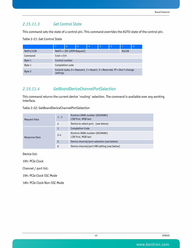
Board Features
2.15.11.3 Get Control State
This command sets the state of a control pin. This command overrides the AUTO-state of the control pin.
Table 2-21: Get Control State
2.15.11.4 GetBoardDeviceChannelPortSelection
This command returns the current device 'routing' selection. The command is available over any working interface.
Table 2-22: GetBoardDeviceChannelPortSelection
Device list:
19h: PCIe Clock
Channel / port list:
19h: PCIe Clock SSC Mode
1Ah: PCIe Clock Non-SSC Mode
7 6 5 4 3 2 1 0
NetFn/LUN NetFn = 3Eh (OEM Request) RsLUN
Command Cmd = 21h
Byte 1 Control number
Byte 1 Completion code
Byte 2 Control state, 0 = Deassert, 1 = Assert, 3 = Reserved, FF = Don't change settings
Request Data1 - 3
Kontron IANA number (003A98h)LSB first, MSB last
4 Device to select port. (see below)
Response Data
1 Completion Code
2-4Kontron IANA number (003A98h)LSB first, MSB last
5 Device channel/port selection (see below)
6 Device channel/port HW setting (see below)
45 AT8020
www.kontron.com

Board Features
2.15.11.5 SetBoardDeviceChannelPortSelection
This command selects the onboard device port 'routing' as specified in the request data bytes. The command is available on any working interface.
Table 2-23: SetBoardDeviceChannelPortSelection
Device list:
19h: PCIe Clock
Channel / port list:
19h: PCIe Clock SSC Mode
1Ah: PCIe Clock Non-SSC Mode
2.15.11.6 Controls Identifier Table
This table lists the control identifiers that can be used with Set/Get Control State IPMI commands to query or set information on certain controls in the firmware.
Table 2-24: Controls Identifier Table
Request Data
1 - 3Kontron IANA number (003A98h)LSB first, MSB last
4 Device to select port. (see below)
5 Device channel/port selection (see below)
Response Data
1 Completion Code
2 - 4Kontron IANA number (003A98h)LSB first, MSB last
Control Description Control Number
FWH Hub (for BIOS bank information)0 0
46 AT8020
www.kontron.com
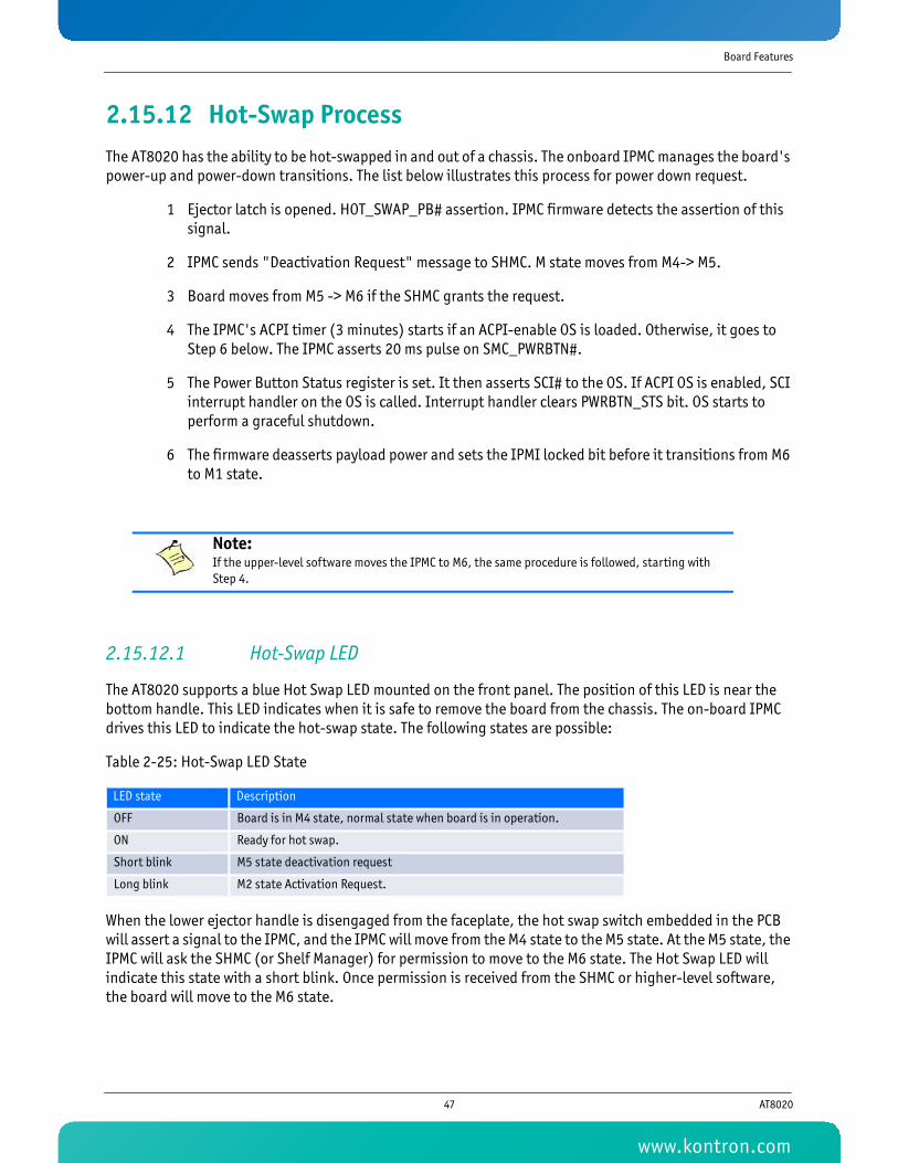
Board Features
2.15.12 Hot-Swap ProcessThe AT8020 has the ability to be hot-swapped in and out of a chassis. The onboard IPMC manages the board's power-up and power-down transitions. The list below illustrates this process for power down request.
1 Ejector latch is opened. HOT_SWAP_PB# assertion. IPMC firmware detects the assertion of this signal.
2 IPMC sends "Deactivation Request" message to SHMC. M state moves from M4-> M5.
3 Board moves from M5 -> M6 if the SHMC grants the request.
4 The IPMC's ACPI timer (3 minutes) starts if an ACPI-enable OS is loaded. Otherwise, it goes to Step 6 below. The IPMC asserts 20 ms pulse on SMC_PWRBTN#.
5 The Power Button Status register is set. It then asserts SCI# to the OS. If ACPI OS is enabled, SCI interrupt handler on the OS is called. Interrupt handler clears PWRBTN_STS bit. OS starts to perform a graceful shutdown.
6 The firmware deasserts payload power and sets the IPMI locked bit before it transitions from M6 to M1 state.
2.15.12.1 Hot-Swap LED
The AT8020 supports a blue Hot Swap LED mounted on the front panel. The position of this LED is near the bottom handle. This LED indicates when it is safe to remove the board from the chassis. The on-board IPMC drives this LED to indicate the hot-swap state. The following states are possible:
Table 2-25: Hot-Swap LED State
When the lower ejector handle is disengaged from the faceplate, the hot swap switch embedded in the PCB will assert a signal to the IPMC, and the IPMC will move from the M4 state to the M5 state. At the M5 state, the IPMC will ask the SHMC (or Shelf Manager) for permission to move to the M6 state. The Hot Swap LED will indicate this state with a short blink. Once permission is received from the SHMC or higher-level software, the board will move to the M6 state.
Note:If the upper-level software moves the IPMC to M6, the same procedure is followed, starting with Step 4.
LED state Description
OFF Board is in M4 state, normal state when board is in operation.
ON Ready for hot swap.
Short blink M5 state deactivation request
Long blink M2 state Activation Request.
47 AT8020
www.kontron.com

Board Features
The SHMC or higher level software can reject the request to move to the M6 state. If this occurs, the Hot Swap LED returns to a solid off condition, indicating that the board has returned to M4 state.
If the board reaches the M6 state, either through an extraction request through the lower ejector handle or a direct command from higher-level software and an ACPI-enabled OS is loaded on the board, the IPMC communicates to the OS that the module must discontinue operation in preparation for removal. The Hot Swap LED continues to flash during this preparation time, just like it does at the M5 state. When main board power is successfully removed from the AT8020, the Hot Swap LED remains lit, indicating it is safe to remove it from the chassis.
Table 2-26: Hot-Swap LED Status
2.15.12.2 Ejector Mechanism
In addition to captive retaining screws, the AT8020 has two ejector mechanisms to provide a positive cam action; this ensures the blade is properly seated. The bottom ejector handle also has a switch that is connected to the IPMC.
2.15.12.3 OOS Led (ATCA LED 1)
The AT8020 supports a red Out Of Servive LED mounted on the front panel. The LED is near the Lan A connector. The on-board FWUM or the IPMC can drives this LED to indicate the service state of the IPMC. The OEM application can also drive this LED using the PICMG LED control APIs. The following states are possible:
Table 2-27: OOS Led (ATCA LED 1) State
Other, application defined LED usage may be implemented.
The AT8020 AMC.0 carrier board also implements the OOS LED "Short blink" mode for its AdvancedMC mates on detection of "power denied" conditions.
LED Status Meaning
Off Normal status
Blinking Blue Preparing for removal/insertion: Long blink indicates activation is in progress, short blink when deactivation is in progress.
Solid Blue Ready for hot swap
LED state Description
OFF Normal/Idle board is in service, unless blue led is on
ON Out of service condition, IPMC is hold in reset
Short blinkPower denied condition detected:Payload has been left in M3 for more than 30secs or SetPowerLevel '0' has been received while in M2 or M3
Blink (50/50) The FWUM is currently programming the IPMC
48 AT8020
www.kontron.com

Board Features
Table 2-28: OOS Led (ATCA LED 1) “Short Blink” Mode
As per AMC.0, if the AMC current draw requirements exceed AMC.0 carrier power budget, the AT8020 will keep the AMC in M1 state with the blue HotSwap LED in the ON state.
2.15.12.4 Health Led (ATCA LED 2)
The AT8020 supports a green/amber health LED mounted on the front panel. The LED is located under the OOS Led. The on-board FWUM or the IPMC can drives this LED to indicate the health status. The OEM application can also drive this LED using the PICMG LED control APIs. The following states are possible:
Table 2-29: Health Led (ATCA LED 2) State
Other, application defined LED usage may be implemented.
Below is the Health sensors agregation.
Table 2-30: Health LED Sensors Agregation
LED state Description
Short blinkPower denied condition detected:AMC current draw requirements exceed carrier power budget or SetPowerLevel '0' has been received while in M2 or M3
LED state Description
Green Health OK
Amber Health Error (Critical) / Payload power down or in reset
Application Defined May be controlled by an application using PICMG API
Sensor Name
TEMP_BOARD_INLET_ID
TEMP_CPU0_VCORE_ID
TEMP_CPU0_DIODE_ID
TEMP_CPU1_DIODE_ID
TEMP_DIMM_CHNLA_INLET_ID
TEMP_DIMM_CHNLB_INLET_ID
TEMP_DIMM_OUTLET_ID
TEMP_MCH_TEMP_ID
TEMP_MCH_INLET_ID
TEMP_BI_OPHIR_ID
TEMP_FI_OPHIR_ID
TEMP_MEZ_ID
TEMP_BOARD_INLET_ID
BOARD_VCORE_CPU0_VOLTAGE
49 AT8020
www.kontron.com

Board Features
BOARD_VCORE_CPU1_VOLTAGE
BOARD_DMX_NEG5V_VOLTAGE
BOARD_NEG48V_VOLTAGE
BOARD_12V_VOLTAGE
BOARD_5V_VOLTAGE
BOARD_5VSUS_VOLTAGE
BOARD_3V3_VOLTAGE
BOARD_3V3SUS_VOLTAGE
BOARD_2V5_VOLTAGE
BOARD_2V5REF_VOLTAGE
BOARD_2V5SUS_VOLTAGE
BOARD_1V8_VOLTAGE
BOARD_1V5_VOLTAGE
BOARD_1V5SUS_VOLTAGE
BOARD_1V2SUS_VOLTAGE
BOARD_1V1_VOLTAGE
BOARD_VTT_VOLTAGE
PWRGOOD_EVENT_ID
BOARD_POWER_ID
AMC_B1_POWER
AMC_B2_POWER
RTM_POWER
OEM_RESET_ID
WATCHDOG_ID
POST_ERROR
POST_VALUE
CRITICAL_INT
MEMORY_ERR
MOS_MEMORY_SIZE
PREBOOT_PASSWORD
FWH0_BOOT_ERROR
FWH1_BOOT_ERROR
FWUM
Sensor Name
50 AT8020
www.kontron.com

Board Features
2.16 Debugging Features2.16.1 Lamp TestThe lamp test does the sequence shown below in the order 1-2-3-4-1-2-3- etc. Step 4 is not displayed when the regional bit is set for Europe (no red allowed). The lamp test can be initiated by keeping the reset pushbutton pressed.
LED arrangement and face plate finish may vary depending on board configuration.
No LEDs #1
All green & blue LEDs #2
All amber LEDs #3
All red LEDs #4
51 AT8020
www.kontron.com

Installing the Board
3. Installing the Board3.1 Setting Jumpers3.1.1 Jumper DescriptionTable 3-1: Jumper Description
3.1.2 Setting Jumpers & LocationsFigure 3-1: Setting Jumpers & Locations
Name Description Jumper
Watchdog When the jumper is ON, it disables the watchdog. JP1 (1-2)
Shelf Manager Activation When the jumper is ON, it overrides the shelf manager activation. JP1 (3-4)
IPMI When the jumper is ON, the board is always on; it overrides the IPMI. JP1 (5-6)
AMC Activation When the jumper is ON, it overrides the AMC activation. JP1 (7-8)
Reserved Leave the jumper OUT. JP1 (9-10)
FWH Top-block Protect When the jumper is ON, write protect is disabled JP1 (11-12)
FPGA PROM Selection When the jumper is ON, it’s the factory PROM; when it’s OUT, it’s the user PROM. JP1 (13-14)
Reserved Leave the jumper OUT. JP2 (1-2)
Postcodes Display When the jumper is ON, it display the postcodes. JP2 (3-4)
BIOS Serial Recovery When the jumper is ON, it does a BIOS serial recovery. JP2 (5-6)
Reserved Leave the jumper OUT. JP2 (7-8)
Reserved Leave the jumper OUT. JP2 (9-10)
Clear CMOS Setup in Flash When the jumper is ON, it restores on boot the CMOS‘setup in flash. JP2 (11-12)
Flash drive write protect When the jumper is ON, it disables the possibility to write on the onboard flash drive. JP2 (13-14)
52 AT8020
www.kontron.com

Installing the Board
3.2 ProcessorThis product ships with the CPU installed and a thermal solution installed. The thermal solution is custom and the thermal interface is critical for passive cooling, Kontron does not guarantee thermal performance if the heatsink is removed and then reinstalled by the end user.
3.3 MemoryThe unit supports four 240-pin, 22.5 degree DIMM sockets. There are two parallel memory channels operating as a logical one, wide memory channel. The unit can also be operated with a single memory channel only (the chipset also enables these memory channels to operate in mirrored mode or to use spare DIMMs). When both memory channels are used there must be at least two DIMMs. These DIMMs in parallel must be identical (identical size, speed and organization).
The memory bus operates at 200MHz clock speed with dual data rate (data is transferred at 400MHz). DDR2-400, 1.8V, max 1.2 inches high registered DIMMs must be used. The maximum DDR2 SDRAM size is 16GB. This maximum will depend on the board configuration. The minimum size of DDR2 SDRAM is 256MB, if only a single 256MB DIMM is used in single channel mode. For dual channel mode the minimum size is 512MB with two DIMMs.
The unit does support "single sided" and "dual sided" memory modules. All DIMM types supported by the MCH are supported by the AT8020. Also, both one row and two row DIMMs are supported.
Only use validated memory with this product. Thermal issues or other problems may arise if you don’t use recommended modules. At the time of publication of this user guide, the following memory were confirmed functional with the product. As the memory market is volatile, this list is subject to change, please consult your local technical support for an up to date list.
Manufacturer Part Number Description Company
MT18HTF12872Y-40EA2 DIMM DDR2-400 1GB 128M*72 REG ECC 1.2" Micron Technology, Inc.
HYS72T128000HR-5-A DIMM DDR2-400 1GB 128M*72 REG ECC 1.2" INFINEON TECHNOLOGIES
M393T2950BZ0-CCC DIMM DDR2-400 1GB 128M*72 REG ECC 1.2" Samsung Semiconductor
MT18HTF12872Y-40EB3 DIMM DDR2-400 1GB 128M*72 REG ECC 1.2" Micron Technology, Inc.
VL393T5663-D5S DIMM DDR2-533 2GB 256M*72 X8 REG ECC LP VIRTIUM
VL393T5663-D5E DIMM DDR2-533 2GB 256M*72 X8 REG ECC LP VIRTIUM
VL393T5663-D5F DIMM DDR2-533 2GB 256M*72 X8 REG ECC LP VIRTIUM
VL393T2953-D5S DIMM DDR2-533 1GB 128M*72 REG ECC 1.18" VIRTIUM
53 AT8020
www.kontron.com

Installing the Board
Memory should have the following characteristics:
• DDR2 400
• 1.8V only
• Single-sided or double-sided
• 1 layer of BGA on PCB side
• X4 or X8 configuration supported
• Serial Presence Detect (SPD) EEPROM
• 72-bit DIMMs only
• 1.2 inch maximum height
• Registered and ECC DIMMs
WARNINGBecause static electricity can cause damage to electronic devices, take the following precautions:
Keep the board in its anti-static package, until you are ready to install memory.
Wear a grounding wrist strap before removing the board from its package; this will discharge any static electricity that may have built up in your body.
Handle the board by the faceplate or its edges.
54 AT8020
www.kontron.com

Installing the Board
3.3.1 Memory InstallationFigure 3-2: Memory Installation
On an anti-static plane, place the board so that you are facing the memory sockets
Insert the memory module into any available socket, aligning the notches on the module with the
socket’s key inserts.
Push down the memory module until the retaining clips clip on each side.
Repeat these steps to populate the other socket.
To remove a memory module from a socket, push sideway the retaining clips on each side of the
socket, to release the module. Pull out the memory from the socket.
55 AT8020
www.kontron.com

Installing the Board
3.4 Onboard Interconnectivity and Indicators
3.4.1 Onboard Connectors and HeadersTable 3-2: Onboard Connectors and Headers
3.4.2 Front Plate Symbol ChartFigure 3-3: Front Plate Symbol Chart
Description Connector Comments
CPU J5 Second CPU
CPU J6 First CPU. This CPU must always be present
RTM Connector J7 RTM connector to connect to the RTM8020
DDR-2 Memory Connectors J8, J9, J10 & J11 4 angled memory sockets
XDP J12
USB 2.0 Connector J13
Serial Port J14 RJ45 serial port connector
Telco Clock Connector & Fabric Interface J17
Daughter Card Connectors J18 & J19
AMC B1 J20
Base Interface Connector J21
AMC B2 J23
Power Connector P1
56 AT8020
www.kontron.com

Installing the Board
3.5 Board Hot Swap and InstallationBecause of the high-density pinout of the hard-metric connector, some precautions must be taken when connecting or disconnecting a board to/from a backplane:
1 Rail guides must be installed on the enclosure to slide the board to the backplane.
2 Do not force the board if there is mechanical resistance while inserting the board.
3 Screw the frontplate to the enclosure to firmly attach the board to its enclosure.
4 Use extractor handles to disconnect and extract the board from its enclosure.
3.5.1 Installing the Board in the ChassisTo install a board in a chassis:
1 Remove the filler panel of the slot or see "Removing the Board" below.
2 Ensure the board is configured properly.
3 Carefully align the PCB edges in the bottom and top card guide.
4 Insert the board in the system until it makes contact with the backplane connectors.
5 Using both ejector handles, engage the board in the backplane connectors until both ejectors are locked.
6 Fasten screws at the top and bottom of the faceplate.
3.5.2 Removing the BoardIf you would like to remove a board from your chassis please follow carefully these steps:
1 Unscrew the top and the bottom screw of the front panel.
2 Unlock the lower handle latch, depending on the software step, this may initiate a clean shutdown of the operating system.
3 Wait until the blue LED is fully ON, this mean that the hot swap sequence is ready for board removal.
4 Use both ejectors to disengage the board from the backplane.
5 Pull the board out of the chassis.
WARNINGAlways use a grounding wrist wrap before installing or removing the board from a chassis.
57 AT8020
www.kontron.com

Installing the Board
3.5.3 Installing an AMCTo install an AMC:
1 Remove the AMC filler panel.
2 Carefully engage the AMC into the card guide. Push the AMC until it fully mates with it's connector. Secure the AMC handle to the locking position.
3 In normal condition, the blue LED shall turn ON as soon as the AMC is fully inserted. It will turn OFF at the end of the hot swap sequence.
3.5.4 Removing an AMCTo remove an AMC:
1 Pull out the handle to unlock the AMC.
2 Wait for the blue LED to turn on.
3 Pull out the AMC using the handle.
3.5.5 Installing a RTMTo install a RTM:
1 Remove the filler panel of the slot.
2 Ensure the board is configured properly.
3 Carefully align the PCB edges in the bottom and top card guide.
4 Insert the board in the system until it makes contact with the CPU board.
5 Using both ejector handles, engage the board in the CPU board connectors until both ejectors are locked.
6 Fasten screws at the top and bottom of the faceplate.
3.5.6 Removing a RTMTo remove a RTM:
1 Unscrew the top and the bottom screw of the faceplate.
2 Unlock the lower handle latch.
3 Wait until the blue LED is fully ON, this mean that the hot swap sequence is ready for board removal.
4 Use both ejectors to disengage the board from the CPU board.
5 Pull the board out of the chassis.
58 AT8020
www.kontron.com
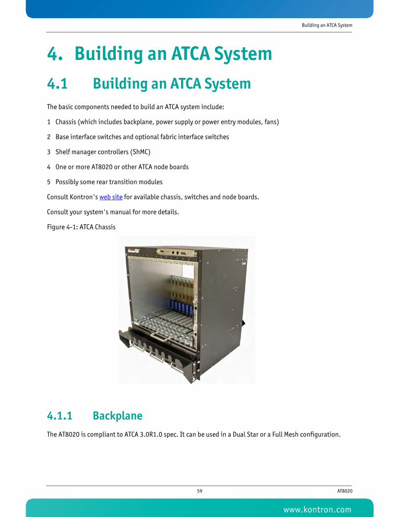
Building an ATCA System
4. Building an ATCA System4.1 Building an ATCA SystemThe basic components needed to build an ATCA system include:
1 Chassis (which includes backplane, power supply or power entry modules, fans)
2 Base interface switches and optional fabric interface switches
3 Shelf manager controllers (ShMC)
4 One or more AT8020 or other ATCA node boards
5 Possibly some rear transition modules
Consult Kontron's web site for available chassis, switches and node boards.
Consult your system's manual for more details.
Figure 4-1: ATCA Chassis
4.1.1 BackplaneThe AT8020 is compliant to ATCA 3.0R1.0 spec. It can be used in a Dual Star or a Full Mesh configuration.
59 AT8020
www.kontron.com

Building an ATCA System
4.1.2 Rear-Panel I/OThis feature is intended to extend the I/O capabilities of the AT8020 to the rear of the enclosure using a RTM I/O.
The RTM I/O module gathers all the I/O signals of the CPU board and makes them easily accessible through standard headers and connectors located at the rear of enclosure.
4.1.3 External Storage DevicesThe AT8020 supports external storage device through the SAS connector available on the RTM
4.1.4 Power SupplyThe AT8020 expects two -48V feeds as per PICMG3.0R1.0. The AT8020 is fully working over a range of -38V to -72V as required by the specification.
4.1.5 Mechanical Keying and AlignmentAlthough ATCA systems are managed by electronic keying (E-Keying), mechanical features are also defined for keying and alignment of the front board, backplane and RTM.
Different angle positions are defined in the PICMG 3.0 specification and each rotation corresponds to a unique value.
ATCA backplanes and front boards A1/K1 (Alignment/Keying) values are 1/1, for a zero degree rotation. These values are mandatory for all ATCA boards.
However, the RTM keying is defined by the front board manufacturer. Currently, Kontron also uses the A2/K2 values of 1/1 in order to match the front CPU board to the RTM.
If unwanted mechanical matching ever happens in the field, E-Keying would prevent connection of such incompatible components, through the supervision of the Intelligent Platform Management Controller (IPMC).
WARNINGAlways use Kontron's RTM with your Kontron's board, if not permanent damage could occur.
Note:10W Management power can be lightly exceeded when the power feed is between -60V and -72V
60 AT8020
www.kontron.com

Software Setup
5. Software Setup5.1 AMI BIOS Setup ProgramAll relevant information for operating the board and connected peripherals are stored in the CMOS memory backed-up by a supercap or in the main BIOS flash.
5.1.1 Accessing the BIOS Setup UtilityThe system BIOS (Basic Input Output System) provides an interface between the operating system and the hardware of the AT8020. It uses the AMI Setup program, a setup utility in flash memory that is accessed by pressing the <DELETE> key at the appropriate time during system boot. This utility is used to set configuration data in CMOS RAM.
To run the AMI Setup program incorporated in the ROM BIOS:
• Turn on or reboot the system.
• When you get the following messages, hit <DELETE> key (or F4 on Remote Keyboard) to enter SETUP.
AMIBIOS(C)2005 American Megatrends, Inc.KONTRON AT8020CPU : Intel(R) Xeon(TM) CPU @ 2.00GHz Speed : 2.00 GHz Count : 2
Press DEL to run Setup (F4 on Remote Keyboard)Press F12 if you want to boot from the networkPress F11 for BBS POPUP (F3 on Remote Keyboard)
(C) American Megatrends, Inc.
61 AT8020
www.kontron.com

Software Setup
The main menu of the AMI BIOS CMOS Setup Utility appears on screen.
Setup Default values provide optimum performance settings for all devices and system features.
BIOS Setup Utility Main Advanced Security Boot System Management Exit System Overview--------------------------------------------------- AMIBIOS BIOS Version 08.00.14 Build Date 08/16/07 BIOS ID 5004_300 Boot Block Version 3.00 FPGA Ver. 2.07
Channel A1 Memory Size 1 GB Channel B1 Memory Size 1 GB Channel A2 Memory Size 1 GB Channel B2 Memory Size 1 GB
System Memory Speed 400 MHz System Memory 642 KB Extended Memory 4192768 KB
System Time [16:56:04] System Date [08:08:2007]
Use [ENTER], [TAB] or [SHIFT-TAB] to select a field.
Use [+] or [-] to configure system Time.
Select Screen
Select Item +- Change Field Tab Select Field F1 General Help F10 Save and Exit ESC Exit
v02.59 (C)Copyright 1985-2005, American Megatrends, Inc.
Note:The CMOS setup option described in this section is based on BIOS Version 3.40 The options and default settings may change in a new BIOS release.
Note:When an asterisk(*) is present in the menu this mean that this menu is optional and it will be present only with certain options.
CAUTIONThese parameters have been provided to give control over the system. However, the values for these options should be changed only if the user has a full understanding of the timing relationships involved.
Note:All options in Bold are the default settings.
62 AT8020
www.kontron.com

Software Setup
5.1.2 Menu BarThe Menu Bar at the top of the window lists these selections:
Use the left and right arrows keys to make a selection.
5.1.2.1 Legend Bar
Use the keys listed in the legend bar on the bottom to make your selections or exit the current menu. The chart on the following page describes the legend keys and their alternates.
To select an item, use the arrow keys to move the cursor to the field you want. Then use the plus-and-minus value keys to select a value for that field. To save value commands in the Exit Menu, save the values displayed in all menus.
To display a submenu, use the arrow keys to move the cursor to the submenu you want. Then press <Enter>. A pointer ( ?) marks all sub-menus.
5.1.2.2 Field Help Window
The help window on the right side of each menu displays the help text for the selected field.
It updates as you move the cursor to each field.
Menu Selection Description
Main Use this menu for basic system configuration.
Advanced Use this menu to set the Advanced Features available on your system.
Security Use this menu to configure Security features.
Boot Use this menu to determine the booting device order.
System Management Use this menu to set the System Managment on your system.
Exit Use this menu to choose Exits option.
Key Function
<F1> General Help windows (see 4.1.2.2).
<Esc> Exit this menu.
--> arrow keys Select a different menu.
<Home> or <End> Move cursor to top or bottom of window.
<-> Select the Previous Value for the field.
<+> Select the Next Value for the field.
<F2> and <F3> Change colors used in Setup.
<F7> Disacard the changes for all menus.
<F9> Load the Optimal Default Configuration values for all menus.
<F10> Save and exit.
<Enter> Execute Command, display possible value for this field or Select the sub-menu.
63 AT8020
www.kontron.com

Software Setup
5.1.2.3 General Help Windows
Pressing <F1>on any menu brings up the General Help window that describes the legend keys and their alternates:
General Help
Select Screen +- Change Option/Field PGDN Next Page HOME Go to Top of Screen F2/F3 Change Colors F10 Save and Exit
Select Item Enter Go to Sub Screen PGUP Previous Page END Go to Bottom of Screen F7 Discard Changes F9 Load Optimal Defaults ESC Exit
[OK]
64 AT8020
www.kontron.com

Software Setup
5.1.3 Main Menu
5.1.4 Advanced Menu
5.1.4.1 Advanced Processor Configuration sub-menu
Feature Option Help text
BIOS VersionX.YY.RX.YY.K
N/A
Build Date X.YY N/A
BIOS ID N/A
Boot Block Version N/A
FPGA Version N/A
Channel A1 Memory Size X KB/MB/GB N/A
Channel B1 Memory Size X KB/MB/GB N/A
Channel A2 Memory Size X KB/MB/GB N/A
Channel B2 Memory Size X KB/MB/GB N/A
System Memory Speed X MHz N/A
System Memory X KB N/A
Extended Memory X KB N/A
System Time HH:MM:SS Use [+] or [-] to configure system time.
System Date MM/DD/YYYY Use [+] or [-] to configure system date.
Feature Option Help text
Advanced Processor Configuration N/A N/A
IDE Configuration N/A N/A
ACPI Configuration N/A N/A
Event Log Configuration N/A N/A
Expansion ROM Configuration N/A N/A
PCI Express Configuration N/A N/A
USB Configuration N/A N/A
Advanced Chipset Control N/A N/A
MPS Revision1.11.4
Multiprocessor specification revision level.
Feature Option Help text
Physical Processors 2 N/A
Logical Processors 4 N/A
Processor Type Sossaman N/A
Processor 0 Speed Varies N/A
Processor 1 Speed Varies N/A
FSB Speed Varies N/A
65 AT8020
www.kontron.com

Software Setup
5.1.4.2 SpeedStep Configuration sub-menu
Processor 0 MicrocodeCPUID: XXXUpdate Revision: XXXX
N/A
Processor 0 L2 Cache Size 2 MB N/A
Processor 1 MicrocodeCPUID: XXXUpdate Revision: XXXX
N/A
Processor 1 L2 Cache Size 2 MB N/A
Processor VirtualizationEnabledDisabled
Enabled: Processor virtualization in use.Disabled: Processor virtualization not in use.Setting can only be changed after power ON. After a reset or a soft reboot, this option stay in grey and can not be changed.
SpeedStep N/A Configures SpeedStep technology.
Thermal Management N/A Configures thermal monitors.
Feature Option Help text
SpeedStep
Maximum SpeedMinimum SpeedVariable SpeedFixed SpeedDisabled
Maximum: CPU speed is set to maximum. Minimum: CPU speed is set to minimum.Variable: CPU speed is controlled by operating systemFixed: CPU speed is set to fixed value.Disabled: Default CPU speed is used.
Processor 0 Speed
1000 MHz(here all supported speeds between LFM and HFM as supported by Intel)2000 MHz(2300 MHz later)
Minimum speed: 1000 MHzMaximum speed: 2000 MHz
Processor 0 Core 0 Enabled N/A
Processor 0 Core 1Enabled Disabled
Enabled: CMP is in use for processor 0 and processor 1 i.e. both cores are available for both processors.Disabled: CMP is not used for either processor.
Processor 1 Speed
1000 MHz(here all supported speeds between LFM and HFM as supported by Intel)2000 MHz(2300 MHz later)
Minimum speed: 1000 MHzMaximum speed: 2000 MHz
Processor 1 Core 0 Enabled N/A
Processor 1 Core 1EnabledDisabled
N/A
Feature Option Help text
66 AT8020
www.kontron.com

Software Setup
5.1.4.3 Thermal Management sub-menu
5.1.4.4 IDE Configuration sub-menu
Feature Option Help text
Thermal Monitor 1Enabled Disabled
Enabled: TM1 in use. Disabled: TM1 not in use. Use only for testing purposes.
Thermal Monitor 2EnabledDisabled
Enabled: TM2 in use. Disabled: TM2 not in use. Use only for testing purposes.
Digital Thermal SensorEnabledDisabled
Enabled: DTS for each core is in use.
Feature Option Help text
IDE Configuration
DisabledP-ATA OnlyS-ATA OnlyP-ATA & S-ATA
Select IDE Mode.P-ATA Only: 4 P-ATA & 2 S-ATAS-ATA Only: 2 S-ATAP-ATA & S-ATA: 2 P-ATA & 2 S-ATA
Primary IDE Master This is a sub-menuWhile entering setup BIOS auto detects the presence of IDE devices. This displays the status of auto detection of IDE devices.
Primary IDE Slave This is a sub-menuWhile entering setup BIOS auto detects the presence of IDE devices. This displays the status of auto detection of IDE devices.
Secondary IDE Master This is a sub-menuWhile entering setup BIOS auto detects the presence of IDE devices. This displays the status of auto detection of IDE devices.
Secondary IDE Slave This is a sub-menuWhile entering setup BIOS auto detects the presence of IDE devices. This displays the status of auto detection of IDE devices.
Third IDE Master This is a sub-menuWhile entering setup BIOS auto detects the presence of IDE devices. This displays the status of auto detection of IDE devices.
Fourth IDE Master This is a sub-menuWhile entering setup BIOS auto detects the presence of IDE devices. This displays the status of auto detection of IDE devices.
Hard Disk Write ProtectEnabledDisabled
Disabled/Enabled device write protection. This will be effective only if device is accessed through BIOS.
IDE Detect Time Out
05101520253035
Configures the time out value for detecting ATA/ATAPI device(s).
67 AT8020
www.kontron.com

Software Setup
5.1.4.4.1 Primary IDE Master
Feature Options Description
Primary IDE Master
DeviceVendorSizeLBA ModeBlock ModePIO ModeAsync DMAUltra DMAS.M.A.R.T.
This is a list of modes and features supported by the drive, not how it is setup.
Type
Not installedAutoCD/DVDARMD
Select the type of device connected to the system.
LBA/Large ModeDisabledAuto
Disabled: Disables LBA Mode.Auto: Enables LBA Mode if the device supports it and the device is not already formatted with LBA Mode3 disabled
Block (Multi-Sector Transfer)
DisabledAuto
Disabled: the data transfer from and to the device occurs one sector at the time. Auto: the data transfer from and to the device occurs multiple sector at a time it the device supports it.
PIO Mode
Auto01234
Select PIO Mode.
DMA Mode
AutoSWDMA0SWDMA1SWDMA2MWDMA0MWDMA1MWDMA2UDMA0UDMA1UDMA2UDMA3UDMA4
Select DMA Mode.Auto: Auto detectSWDMAn: SingleWordDMAnMWDMAn: MultiWordDMAnUDMAn: UltraDMAn
32Bit Data TransferDisabledEnabled
Enable/Disabled32-bit Data Transfer.
68 AT8020
www.kontron.com
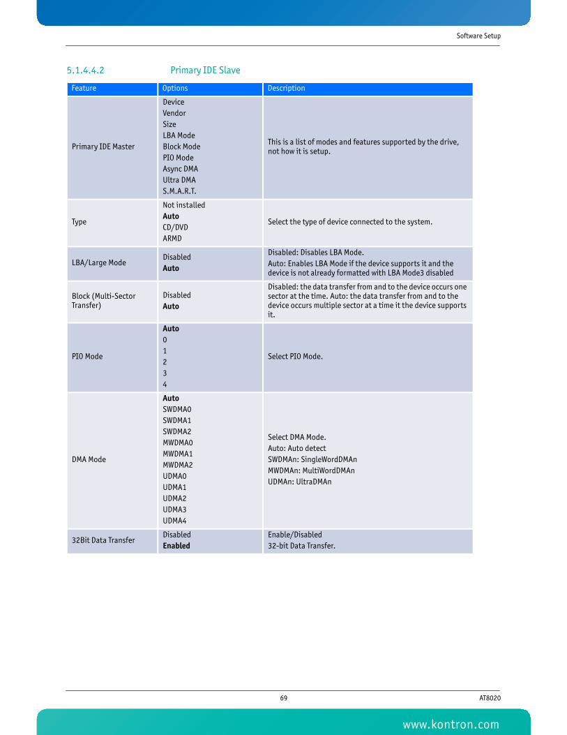
Software Setup
5.1.4.4.2 Primary IDE Slave
Feature Options Description
Primary IDE Master
DeviceVendorSizeLBA ModeBlock ModePIO ModeAsync DMAUltra DMAS.M.A.R.T.
This is a list of modes and features supported by the drive, not how it is setup.
Type
Not installedAutoCD/DVDARMD
Select the type of device connected to the system.
LBA/Large ModeDisabledAuto
Disabled: Disables LBA Mode.Auto: Enables LBA Mode if the device supports it and the device is not already formatted with LBA Mode3 disabled
Block (Multi-Sector Transfer)
DisabledAuto
Disabled: the data transfer from and to the device occurs one sector at the time. Auto: the data transfer from and to the device occurs multiple sector at a time it the device supports it.
PIO Mode
Auto01234
Select PIO Mode.
DMA Mode
AutoSWDMA0SWDMA1SWDMA2MWDMA0MWDMA1MWDMA2UDMA0UDMA1UDMA2UDMA3UDMA4
Select DMA Mode.Auto: Auto detectSWDMAn: SingleWordDMAnMWDMAn: MultiWordDMAnUDMAn: UltraDMAn
32Bit Data TransferDisabledEnabled
Enable/Disabled32-bit Data Transfer.
69 AT8020
www.kontron.com

Software Setup
5.1.4.4.3 Secondary IDE Master
Feature Options Description
Secondary IDE Master
DeviceVendorSizeLBA ModeBlock ModePIO ModeAsync DMAUltra DMAS.M.A.R.T.
This is a list of modes and features supported by the drive, not how it is setup.
Type
Not installedAutoCD/DVDARMD
Select the type of device connected to the system.
LBA/Large ModeDisabledAuto
Disabled: Disables LBA Mode.Auto: Enables LBA Mode if the device supports it and the device is not already formatted with LBA Mode3 disabled
Block (Multi-Sector Transfer)
DisabledAuto
Disabled: the data transfer from and to the device occurs one sector at the time. Auto: the data transfer from and to the device occurs multiple sector at a time it the device supports it.
PIO Mode
Auto01234
Select PIO Mode.
DMA Mode
AutoSWDMA0SWDMA1SWDMA2MWDMA0MWDMA1MWDMA2UDMA0UDMA1UDMA2UDMA3UDMA4
Select DMA Mode.Auto: Auto detectSWDMAn: SingleWordDMAnMWDMAn: MultiWordDMAnUDMAn: UltraDMAn
32Bit Data TransferDisabledEnabled
Enable/Disabled32-bit Data Transfer.
70 AT8020
www.kontron.com

Software Setup
5.1.4.4.4 Secondary IDE Slave
Feature Options Description
Secondary IDE Slave
DeviceVendorSizeLBA ModeBlock ModePIO ModeAsync DMAUltra DMAS.M.A.R.T.
This is a list of modes and features supported by the drive, not how it is setup.
Type
Not installedAutoCD/DVDARMD
Select the type of device connected to the system.
LBA/Large ModeDisabledAuto
Disabled: Disables LBA Mode.Auto: Enables LBA Mode if the device supports it and the device is not already formatted with LBA Mode3 disabled
Block (Multi-Sector Transfer)
DisabledAuto
Disabled: the data transfer from and to the device occurs one sector at the time. Auto: the data transfer from and to the device occurs multiple sector at a time it the device supports it.
PIO Mode
Auto01234
Select PIO Mode.
DMA Mode
AutoSWDMA0SWDMA1SWDMA2MWDMA0MWDMA1MWDMA2UDMA0UDMA1UDMA2UDMA3UDMA4
Select DMA Mode.Auto: Auto detectSWDMAn: SingleWordDMAnMWDMAn: MultiWordDMAnUDMAn: UltraDMAn
32Bit Data TransferDisabledEnabled
Enable/Disabled32-bit Data Transfer.
71 AT8020
www.kontron.com

Software Setup
5.1.4.4.5 Third IDE Master
Feature Options Description
Third IDE Master
DeviceVendorSizeLBA ModeBlock ModePIO ModeAsync DMAUltra DMAS.M.A.R.T.
This is a list of modes and features supported by the drive, not how it is setup.
Type
Not installedAutoCD/DVDARMD
Select the type of device connected to the system.
LBA/Large ModeDisabledAuto
Disabled: Disables LBA Mode.Auto: Enables LBA Mode if the device supports it and the device is not already formatted with LBA Mode3 disabled
Block (Multi-Sector Transfer)
DisabledAuto
Disabled: the data transfer from and to the device occurs one sector at the time. Auto: the data transfer from and to the device occurs multiple sector at a time it the device supports it.
PIO Mode
Auto01234
Select PIO Mode.
DMA Mode
AutoSWDMA0SWDMA1SWDMA2MWDMA0MWDMA1MWDMA2UDMA0UDMA1UDMA2UDMA3UDMA4
Select DMA Mode.Auto: Auto detectSWDMAn: SingleWordDMAnMWDMAn: MultiWordDMAnUDMAn: UltraDMAn
32Bit Data TransferDisabledEnabled
Enable/Disabled32-bit Data Transfer.
72 AT8020
www.kontron.com

Software Setup
5.1.4.4.6 Fourth IDE Master
Feature Options Description
Fourth IDE Master
DeviceVendorSizeLBA ModeBlock ModePIO ModeAsync DMAUltra DMAS.M.A.R.T.
This is a list of modes and features supported by the drive, not how it is setup.
Type
Not installedAutoCD/DVDARMD
Select the type of device connected to the system.
LBA/Large ModeDisabledAuto
Disabled: Disables LBA Mode.Auto: Enables LBA Mode if the device supports it and the device is not already formatted with LBA Mode3 disabled
Block (Multi-Sector Transfer)
DisabledAuto
Disabled: the data transfer from and to the device occurs one sector at the time. Auto: the data transfer from and to the device occurs multiple sector at a time it the device supports it.
PIO Mode
Auto01234
Select PIO Mode.
DMA Mode
AutoSWDMA0SWDMA1SWDMA2MWDMA0MWDMA1MWDMA2UDMA0UDMA1UDMA2UDMA3UDMA4
Select DMA Mode.Auto: Auto detectSWDMAn: SingleWordDMAnMWDMAn: MultiWordDMAnUDMAn: UltraDMAn
32Bit Data TransferDisabledEnabled
Enable/Disabled32-bit Data Transfer.
73 AT8020
www.kontron.com

Software Setup
5.1.4.5 ACPI Configuration sub-menu
5.1.4.6 Event Log Configuration sub-menu
Feature Option Help text
ACPI Version FeaturesACPI v1.0ACPI v2.0ACPI v3.0
Enabled: RSDP pointer to 64-bit Fixed System Description Tables. Different ACPI version has some addition.
ACPI APIC SupportEnabledDisabled
Enabled: ACPI APIC table support.Disabled: ACPI APIC table not supported.
Headless ModeEnabledDisabled
Enabled: Headless operation mode through ACPI supported.Disabled: Headless operation mode through ACPI not supported.
Feature Option Help text
Event Log capacitySpace AvailableNo Space
Shows if space is available in the Event Log for new log events.
Event LoggingEnabledDisabled
Enabled: Event Log is used.Disabled: Event Log is not used. If this option is disabled no SEL events are available from this blade!
View Event Log Enter View all unread events in the Event Log.
Mark Events as read Enter Mark all unread events as read in the Event Log.
Clear all Event Logs Enter Discard all events in the Event Log.
DRAM Data Integrity Mode
ECCNon-ECC
ECC: x4 Chip-Fail ECC used in dual channel mode. 72-bit ECC used in single channel mode.Non-ECC: Use only for testing purposes.
ECC Event LoggingEnabledDisabled
Enabled: ECC event logging enabled.Disabled: ECC event logging disabled.
ECC Error Reporting
CorrectableUncorrectableBothDisabled
"Correctable" ECC for testing purposes."Uncorrectable" ECC errors reported."Both" ECC errors for testing purposes.Disabled: ECC errors not reported.
Hub Interface Event Logging
EnabledDisabled
Enabled: Hub interface event logging enabled.Disabled: Hub interface event logging disabled.
System Bus Event Logging
EnabledDisabled
Enabled: System bus event logging enabled.Disabled: System bus event logging disabled.
Memory Buffer Event Logging
EnabledDisabled
Enabled: Memory buffer event logging enabled.Disabled: Memory buffer event logging disabled.
PCI Error LoggingEnabledDisabled
Enabled: PCI error event logging enabled.Disabled: PCI error event logging disabled.
PCI Express Error Logging
EnabledDisabled
Enabled: PCI-E error event logging enabled.Disabled: PCI-E errror event logging disabled.
PCI Express Error Masking N/A N/A
74 AT8020
www.kontron.com

Software Setup
5.1.4.7 PCI Express Error Masking sub-menu
5.1.4.8 Expansion ROM Configuration sub-menu
Feature Option Help text
Mask duplicate ErrorsYesNo
Yes: Mask duplicate errors found in successive SMI interruptsNo: Duplicate errors found in successive SMI interrupts are not masked. Note: Duplicate errors in single SMI interrupt are always masked.
Mask Unsupported Requests
YesNo
Yes: Unsupported request errors can be masked.No: Default mask is used.
Feature Option Help text
Ethernet BI Expansion ROM
EnabledDisabled
Enabled: Initializes base interface PXE expansion ROM.Disabled: Base interface PXE expansion ROM not used. If disabled, remote LAN boot via BI is not available to boot the system!
Ethernet FI Expansion ROM
EnabledDisabled
Enabled: Initializes fabric interface PXE expansion ROM.Disabled: Fabric interface PXE expansion ROM not used. If disabled, remote LAN boot via FI is not available to boot the system!
Ethernet MEZ Expansion ROM
EnabledDisabled
Enabled: Initializes mezzanine PXE expansion ROM.Disabled: Mezzanine PXE expansion ROM not used. If disabled, remote LAN boot is not available to boot the system!
Ethernet 82551QM Expansion ROM
EnabledDisabled
Enabled: Initializes mezzanine PXE expansion ROM.Disabled: Mezzanine interface PXE expansion ROM not used. If disabled, remote LAN boot is not available to boot the system!
FC / SAS Expansion ROMEnabledDisabled
Enabled: Initializes FC / SAS expansion ROM.Disabled: FC / SAS expansion ROM not used. If disabled, any FC / SAS devices attached to the system are not available to boot the system!
AMC Slot 1 Expansion ROM
EnabledDisabled
Enabled: Initializes AMC slot 1 expansion ROM.Disabled: AMC slot 1 expansion ROM not used.
AMC Slot 2 Expansion ROM
EnabledDisabled
Enabled: Initializes AMC slot 2 expansion ROM.Disabled: AMC slot 2 expansion ROM not used.
75 AT8020
www.kontron.com

Software Setup
5.1.4.9 PCI Express Configuration sub-menu
5.1.4.10 USB Configuration sub-menu
5.1.4.11 USB Mass Storage Device Configuration sub-menu
Feature Option Help text
Hot Plug Support - AMC B1
EnabledDisabled
Enabled: Set PCI Express Hot Plug capability.Disabled: Hot Plug is not available on this port.
Hot Plug Support - AMC B2
EnabledDisabled
Enabled: Set PCI Express Hot Plug capability.Disabled: Hot Plug is not available on this port.
Actual Clock Mode StateSSCNon-SSC
Display Only
Clock Mode SettingSSCNon-SSC
Select thePCI Express Clock Mode. Warning! To change the PCI Express Clock Mode, you need to re-insert the blade into the shelf. AMC ekeying use this setting to allow “SSC” or “non-SSC” PCI Express AMC.
Feature Option Help text
USB Devices Enabled: N/A
USB 2.0 Controller ModeFullSpeedHiSpeed
FullSpeed: 12 MbpsHiSpeed: 480 Mbps
BIOS EHCI Hand-OffEnabledDisabled
Enabled: EHCI hand-off support enabled.Disabled: EHCI hand-off support disabled.
USB Mass Storage Device Configuration (only present if USB Mass Storage detected)
N/A Configure the USB Mass Storage Class Devices.
Feature Option Help text
USB Mass Storage Reset Delay
10 Sec20 Sec30 Sec40 Sec
N/A
Device # 1-6 N/A N/A
Emulation Type(For each device)
AutoFloppyForced FDDHard DiskCDROM
If Auto, USB devices less than 530MB will be emulated as Floppy and remaining as hard drive. Forced FDD option can be used to force a HDD formatted drive to boot as FDD.
76 AT8020
www.kontron.com

Software Setup
5.1.4.12 Advanced Chipset Control sub-menu
5.1.5 Security Menu
Feature Option Help text
Memory RemappingEnabledDisabled
Enabled: Allows remapping of overlapped PCI memory above the total physical memory. Requires PAE support in OS.Disabled: Memory remapping not allowed.
Memory Mirroring / Sparing
MirroringSparingDisabled
Mirroring: Memory mirroring feature enabled if supported.Sparing: Memory sparing feature enabled if supported by memory configuration.Disabled: Memory RAS features disabled.
DMA ControllerEnabledDisabled
Enabled: DMA controller enabled.Disabled: DMA controller disabled.
DDR2 Refresh3.9 μS7.8 μSAuto
Allows override selection of the DDR2 refresh rate for normal operation.
Spread Spetrum Clocking Mode
EnabledDisabled
Enabled: Allows setting of Clock Spread Spectrumfor EMI control.Disabled: Denies setting of Clock Spread Spectrum for EMI control.
Feature Option Help text
Supervisor PasswordInstalledNot Installed
Indicates the status of the supervisor password.
User PasswordInstalledNot Installed
Indicates the status of the user password.
Set Supervisor Password EnterInstall or change the supervisor password.Only the first 5 characters will be used.
Set User Password EnterInstall or change the user password.Only the first 5 characters will be used.
Clear User Password Enter Clears user password.
User Access Level
No AccessView OnlyLimitedFull Access
Controls access to the setup utility.No Access: Prevents user access.View only: allows read only user access.Limited: Allows limited fields to be changed.Full Access: Allows unlimited user access.
Execute Disable BitEnabledDisabled
Enabled: Allows processor to prevent application code access to certain memory areas. Needs supporting operating system.Disabled: No restrictions to application code memory area access by processor.
77 AT8020
www.kontron.com

Software Setup
5.1.6 Boot Menu
5.1.6.1 Boot Settings Configuration sub-menu
5.1.6.2 Boot Device Priority sub-menu
5.1.6.3 Hard Disk, removable, CD/DVD, USB, Network and other drives sub-menu
Feature Option Help text
Boot Settings Configuration N/A Configure Settings during System Boot.
Boot Device Priority N/A Specifies the priority of the available boot sources.
Hard Disk Drives N/A Lists available hard disk drives in priority order.
Removable Drives N/A Lists available removable disk drives in priority order.
CD / DVD Drives N/A Lists available CD /DVD drives in priority order.
USB Drives N/A Lists available USB drives in priority order.
Network Drives N/A Lists available network drives in priority order.
Other Drives N/A Specifies the Lists available other drives in priority order.
Feature Option Help text
Quick Boot ModeEnabledDisabled
Enabled: Allows skipping the memory tests during a cold boot.Disabled: Allows the extended memory test to be executed during a cold boot.
Extended Memory TestEnabledDisabled
Enabled: Extended memory test is applicable when Quick Boot is disabled and a cold reset occurs.Disabled: Extended memory test is not performed in a reset.
Feature Option Help text
1st Boot Device Type: Boot deviceSpecifies the boot sequence from the available devices.A device enclosed in parenthesis has been disabled in the corresponding type menu.
...
Nth Boot Device Type: Boot deviceSpecifies the boot sequence from the available devices.A device enclosed in parenthesis has been disabled in the corresponding type menu.
Feature Option Help text
1st Drive VariesSpecifies the boot priority of the available devices.Select the boot device with UpArrow or DownArrow key.Press Enter to set the selection as the intended boot device.
...
Nth Drive VariesSpecifies the boot priority of the available devices.Select the boot device with UpArrow or DownArrow key.Press Enter to set the selection as the intended boot device.
78 AT8020
www.kontron.com

Software Setup
5.1.7 System Management Menu
5.1.7.1 Remote Access Configuration sub-menu
Feature Option Help text
Remote Access Configuration N/A N/A
Set LAN Configuration N/A IPMI over LAN (and Serial Over LAN)
Watchdog Timers N/A N/A
System Information N/A N/A
Feature Option Help text
Serial Port NumberCOM1COM2
Select serial port for console redirection.
Serial Port 1 I/O address 3F8/IRQ4 Hardware address of the COM 1 port.
Serial Port 2 I/O address 2F8/IRQ3 Hardware address of the COM 2 port.
Baud Rate
9.6 KB19.2 KB38.4 KB57.6 KB115.2 KB
Select serial port Baud rate.
Data Bits78
Select the number of data bits in each transmitted or received serial character.
ParityEvenOddNone
Select if parity bit is generated (transmit data) or checked (receive data) between the last data word bit and stop bit of the serial data.
Stop Bits12
Select the number of stop bits transmitted and received in each serial character.
Flow ControlHardwareSoftwareNone
Select flow control for console redirection.
Terminal TypeANSIVT100VTUTF8
Select the type of console emulation used.
Terminal Size 80x24 N/A
Terminal Display ModeNormal ModeRecorder Mode
Select terminal display mode.
BIOS PrintoutsEnabledDisabled
Select if BIOS POST messages are duplicated in a separate reserved memory region for OS examination.
79 AT8020
www.kontron.com

Software Setup
5.1.7.2 Set LAN Configuration Sub-menu
5.1.7.3 IP Configuration sub-menu
5.1.7.4 MAC Address Configuration sub-menu
Feature Option Help text
Channel Number0102
Enter Channel Number for SET LAN Config Command.Proper value below 16.
Channel Status Valid or Invalid (display only)
IP Address N/A Enter for IP Address Configuration.
MAC Address N/A Enter for MAC Address Configuration.
Subnet Mask N/A Enter for Subnet Mask Configuration.
Gateway Address N/A Enter for Gateway IP Address Configuration.
Active LAN Channel Number
Disabled0102Both
Enter Active LAN Channel Number for Set LAN Configuration Command.Only one LAN Channel can be activated.
Feature Option Help text
LAN Parameter Selector 03 N/A
Channel Number0102
Enter Channel Number for SET LAN Config Command.Proper value below 16.
Channel Status Valid or Invalid (display only) N/A
IP Address xxx.xxx.xxx.xxx Enter IP Address in decimal in the form of XXX.XXX.XXX.XXX (XXX less than 256 and in decimal only).
Current IP Address xxx.xxx.xxx.xxx N/A
Feature Option Help text
LAN Parameter Selector 05 N/A
Channel Number0102
Enter Channel Number for SET LAN Config Command.Proper value below 16.
Channel Status Valid or Invalid (display only) N/A
Current MAC Address xx.xx.xx.xx.xx.xx (display only) N/A
80 AT8020
www.kontron.com

Software Setup
5.1.7.5 Subnet Mask Configuration sub-menu
5.1.7.6 Gateway Address Configuration sub-menu
5.1.7.7 Watchdog Timer sub-menu
Feature Option Help text
LAN Parameter Selector 06 N/A
Channel Number0102
Enter Channel Number for SET LAN Config Command.Proper value below 16.
Channel Status Valid or Invalid (display only) N/A
Subnet Mask xxx.xxx.xxx.xxx Enter Subnet Mask in decimal in the form of XXX.XXX.XXX.XXX (XXX less than 256 and in decimal only).
Current Subnet Mask xxx.xxx.xxx.xxx N/A
Feature Option Help text
LAN Parameter Selector 12 N/A
Channel Number0102
Enter Channel Number for SET LAN Config Command.Proper value below 16.
Channel Status: Valid or Invalid (display only) N/A
Gateway Address xxx.xxx.xxx.xxx Enter Gateway IP Address in decimal in the form of XXX.XXX.XXX.XXX (XXX less than 256 and in decimal only).
Current Gateway Address: xxx.xxx.xxx.xxx N/A
Feature Option Help text
BIOS POST Timeout
060120150300600
Select the BIOS POST IPMI HW watchdog timeout value.
BIOS POST Action
No ActionHard ResetPower DownPower Cycle
Select which action to take when the BIOS POST IPMI HW watchdog expires.
OS Load Timeout
060120150300600
Select the OS Load IPMI HW watchdog timeout value.Set to 0 to disable watchdog.
OS Load Action
No ActionHard ResetPower DownPower Cycle
Select which action to take when the OS Load IPMI HW watchdog expires.
81 AT8020
www.kontron.com

Software Setup
5.1.7.8 System Information sub-menu
5.1.7.9 IPMI Device and FW Info sub-menu
5.1.8 Exit Menu
Feature Option Help text
Board Product Name AT8020 N/A
Board Vendor Kontron N/A
Board Serial Number Varies N/A
Board Part Number Varies N/A
Chassis Slot 1..16 N/A
FWH In UsePrimarySecondary
Display Only
IPMI Device and FW Info N/A N/A
Feature Option Help text
IPMI Version 1.5 N/A
IPMI Device ID Varies N/A
IPMI Device Revision Varies N/A
IPMI Firmware Version Varies N/A
SDR Revision Varies Display Only
Feature Option Help text
Save Changes and Exit N/AExit system setup after saving the changes.F10 key can be used for this operation.
Discard Changes and Exit N/A
Exit system setup without saving any changes.ESC key can be used for this operation.
Load Optimal Defaults N/ALoad Optimal Default values for all the setup questions.F9 key can be used for this operation.
Discard Changes N/ADiscards changes done so far to any of the setup questions.F7 key can be used for this operation.
Exit & Update BIOS N/A Force BIOS recovery mode on next system reset.
Exit & Execute BIOS swap N/A Swap BIOS FWH without saving any changes.
82 AT8020
www.kontron.com

Software Setup
5.2 Boot UtilitiesAMI Boot Utilities are: Menu POP-UP
Boot Menu POP-UP is a boot screen that displays a selection of boot devices from which you can boot your operating system.
5.2.1 Pressing <Del> (or <F4> from a Console Redirection terminal)
Pressing < Del > (or <F4> from a Console Redirection terminal) during POST enters Setup.
5.2.2 Pressing <F11> (or <F3> from a Console Redirection terminal)
Pressing <F11> (or <F3> from a Console Redirection terminal) displays the Boot Menu POP-UP with these options:
1 Load the operating system from a boot device of your choice.
2 Exit the Boot Menu POP-UP (with <ESC>) and load the operating system from the boot devices in the order specified in Setup.
5.2.3 BOOT Menu POP-UPThe BOOT Menu POP-UP expands your boot options by letting you choose your boot device, which could be a hard disk, floppy disk, CDROM, Flash Disk, SCSI or LAN. You can select your boot device in Setup, or you can choose a different device each time you boot during POST by selecting your boot device in the Boot device <F11> (or <F3> from a Console Redirection terminal).
5.3 Console Redirection (VT100 Mode)The VT100 operating mode allows remote setup of the board. This configuration requires a remote terminal that must be connected to the board through a serial communication link.
5.3.1 RequirementsThe terminal should emulate a VT100 or an ANSI terminal. Terminal emulation programs such as Telix©, HyperTerminal(Windows), minicom(Linux) or ProComm©(Windows) can also be used.
83 AT8020
www.kontron.com

Software Setup
5.3.2 Running Without a TerminalThe board can boot up without a screen or terminal attached. If the speed is set to Auto and no terminal is connected, the speed is set to 115,200 bauds.
5.3.3 ANSI and VT100 Keystroke Mapping
Note:Refer to "Serial Port 1 (J5)" section for connector location and pinout.
Up <ESC>[A
Down <ESC>[B
Right <ESC>[C
Left <ESC>[D
Home <ESC>[H
End <ESC>[K
F1 <ESC>OP
F2 <ESC>OQ
F3 <ESC>OR
F4 <ESC>OT
RXD
TXD
DSR
DTR
CTS
RTS
GND
TXD
RXD
DTR
DSR
RTS
CTS
DCD
GND
TXD
RXD
DTR
DSR
RTS
CTS
DCD
GND
SB
C B
oar
d
VT
100
Ter
min
al
COMConnector
Full Setup Partial Setup
SB
C B
oar
d
COMConnector
RXD
TXD
GND
VT
100
Ter
min
al
84 AT8020
www.kontron.com

Software Setup
5.3.4 VT-UTF8 Keystroke MappingThe following "escape sequences" are defined in the "Conventions for Keys Not in VT100 Terminal Definition and ASCII Character Set" section of "Standardizing Out-of-Band Management Console Output and Terminal Emulation (VT-UTF8 and VT100+)",available for download at microsoft.com.
These "escape sequences" are supported by VT-UTF8 compliant terminal connections, such as Windows Server 2003 Emergency Management Services (EMS).
AMIBIOS8 Serial Redirection supports these key sequences under two configurations:
• "Terminal Type" setup question is set to "VT-UTF8"
• "Terminal Type" setup question is set to "VT100" or "ANSI" and "VTUTF8 Combo Key Support" setup question is set to "Enabled"
5.4 Installing DriversVarious drivers are provided for different operating systems and software. To install a driver, use the Setup program located on the CD/DVD (provided with your board). For other operating system drivers and installa-tion instructions or for more information, visit our Web site at www.kontron.com or our FTP site at ftp.kon-tron.ca/support/ or you may also contact Kontron's Technical Support department.
F1 Key <ESC>1
F2 Key <ESC>2
F3 Key <ESC>3
F4 Key <ESC>4
F5 Key <ESC>5
F6 Key <ESC>6
F7 Key <ESC>7
F8 Key <ESC>8
F9 Key <ESC>9
F10 Key <ESC>0
F11 Key <ESC>!
F12 Key <ESC>@
Alt Modifier <ESC>^A
Control Modifier <ESC>^C
Home Key <ESC>h
End Key <ESC>k
Insert Key <ESC>+
Delete Key <ESC>-
Page Up Key <ESC>?
Page Down Key <ESC>/
85 AT8020
www.kontron.com

A. Memory & I/O MapsA.1 Memory Mapping
Address Function
00000-9B7FF 0-622 KB DRAM
9B800-9FFFF 622KB - 640 KB XBDA; USB Legacy / BIOS Stack
A0000-BFFFF Video DRAM
C0000-DBFFFOptional ROM (Free)LAN BIOS around 30KB if activated, address may varyExternal Fiber Channel BIOS 18KB-64KB , address may vary
E0000-FFFFF System BIOS
100000-PCI Memory DRAM available
1MB to top of DRAM
System BIOS
See detailed mapto the right
0 - 622KB DRAM
Optional ROM (free)
Video DRAM
Fibre Channel / SAS BIOS(18KB at runtime)(if activated)
LAN BIOS (if activated) (~30KB)
100000h
A0000h
FFFFFh
E0000h
See Note 1
C0000h
A0000h
Note 1 : LAN BIOS address may vary
Note2: Fibre Channel / SAS BIOS address may vary. Size is only 2KB if no device.
Optional ROM (Free)
See Note 2
XBDA; USB Legacy / BIOS Stack
A-1 AT8020
www.kontron.com

A.2 I/O MappingAddress Optional Address Function
000-01F DMA Controller 1
020-03F Interrupt Controller 1
040-05F Timer
060-06F Keyboard
070-07F Real-time clock
080-09F DMA Page Register
0A0-0BF Interrupt Controller 2
0C0-0DF DMA Controller 2
0F0-0F1, 0F8-0FF Math Coprocessor
1F0-1F7, 3F6 Primary IDE
170-177, 376 Secondary IDE
378-37F Parallel Port (Used as PLD POD)
3F8-3FF (COM1) 2F8-2FF (COM2) Serial Port 1 (COM1 by default)
2F8-2FF (COM2) 3F8-3FF (COM1) Serial Port 2 (COM2 by default)
400-9FF Chipset Reserved
A00-A1F Kontron Registers (on-board)
B00-0FFF Chipset Reserved
A-2 AT8020
www.kontron.com

A.3 PCI IDSEL and Device numbersA.3.1 All configurations
BUS# DEV# V. ID D. ID Funct. # Description PCI Description
0 0 8086h 3590h 0 E7520 - Memory Controller Hub Bridge, host-bridge, multi-function
0 0 8086h 3591h 1 E7520 - Memory Error Reporting Bridge, host-bridge, multi-function
0 1 8086h 3594h 0 E7520 - DMA Controller System peripheral, non-specific, single-function
0 2 8086h 3595h 0E7520 - Host-to-PCI Express A Bridge (x8 or x4)
Bridge, PCI-to-PCI, single-function, type 1 header
0 3 8086h 3596h 0 E7520 - Host-to-PCI Express A1 Bridge (x4 only)
Bridge, PCI-to-PCI, single-function, type 1 header
0 4 8086h 3597h 0E7520 - Host-to-PCI Express B Bridge (x8 or x4) - (Support Hot-Plug)
Bridge, PCI-to-PCI, single-function, type 1 header
0 5 8086h 3598h 0 E7520 - Host-to-PCI Express B1 Bridge (x4 only)
Bridge, PCI-to-PCI, single-function, type 1 header
0 6 8086h 3599h 0E7520 - Host-to-PCI Express C Bridge (x8 or x4) - (Support Hot-Plug)
Bridge, PCI-to-PCI, single-function, type 1 header
0 7 8086h 359Ah 0 E7520 - Host-to-PCI Express C1 Bridge (x4 only)
Bridge, PCI-to-PCI, single-function, type 1 header
0 7 8086h 359Bh 0 E7520 - Extended Configuration Registers
0 28 8086h 25Aeh 0 i6300ESB ICH - HUB Interface to PCI-X Bridge
0 29 8086h 25A9h 0 i6300ESB ICH - USB UHCI Controller #1
0 29 8086h 25Aah 1 i6300ESB ICH - USB UHCI Controller #2
0 29 8086h 25Abh 4 i6300ESB ICH - Watchdog Controller
0 29 8086h 25Ach 5 i6300ESB ICH - IOAPIC bus B
0 29 8086h 25Adh 7 i6300ESB ICH - USB EHCI Controller
0 30 8086h 25A1h 0 i6300ESB ICH - HUB Interface to PCI Bridge
0 31 8086h 25A2h 0 i6300ESB ICH - LPC Interface
0 31 8086h 25A1h 1 i6300ESB ICH - IDE Controller
0 31 8086h 25A3h 2 i6300ESB ICH - Serial-ATA Controller
0 31 8086h 25A4h 3 i6300ESB ICH - SMBus Controller
1 1 8086h 1209h 0 Intel Corporation 8255xLR / 82551IT Fast Ethernet Controller Ethernet Controller
3 0 8086h 105Eh 0 Intel Corporation 82571EB Gigabit Ethernet Controller (rev 06) Ethernet Controller
A-3 AT8020
www.kontron.com
3 0 8086h 105Eh 1 Intel Corporation 82571EB Gigabit Ethernet Controller (rev 06) Ethernet Controller
4 0 8086h 1060h 0 Intel Corporation 82571EB Gigabit Ethernet Controller (rev 06) Ethernet Controller
4 0 8086h 1060h 1 Intel Corporation 82571EB Gigabit Ethernet Controller (rev 06) Ethernet Controller
5 0 1000h 0056h 0LSI Logic / Symbios Logic SAS1064E PCI-Express Fusion-MPT SAS (rev 02)
SCSI Storage Controller
5 0 1000h 0056h 1 Ethernet Controller
6 0 8086h 1060h 1 Intel Corporation 82571EB Gigabit Ethernet Controller (rev 06) Ethernet Controller
6 0 8086h 1060h 1 Intel Corporation 82571EB Gigabit Ethernet Controller (rev 06) Ethernet Controller
BUS# DEV# V. ID D. ID Funct. # Description PCI Description
A-4 AT8020
www.kontron.com

B. Kontron Extension RegistersB.1 FPGA/CPLD Registers DefinitionUnused bits are reserved. To insure compatibility with other products and upgrades to this product, do not modify unused bits. Bits marked NU are not used on this board. Writing to such bit does nothing and reading is undefined, either 0 or 1 may be returned.
Legend:
B.2 Sossaman Addressing Space The following ranges will be used on Kontron Canada ATCA boards:
• I/O 0080-0081h for 16-bit postcodes
• I/O 0A00-0A1Fh to reserve permanently 32 locations in I/O space for on-board resources
• I/O 0378-037Ah hidden legacy LPT port for Xilinx JTAG programmer
Not all those I/O locations are used, but the LPC bridge will answer the cycle in zero wait-state.
Symbol Signification
U Unchanged (stay unchanged after reset)
X Not Defined (bit not used on this board)
NU Not Used
B-1 AT8020
www.kontron.com

B.2.1 Summary of On-board RegistersThose registers are physically implemented in the AT8020 FPGA.
* in case of hardware conflict, possible alternate addresses are:
• LPT1: 378-37Ah
• LPT2: 278-27Ah
• LPT3: 3BC-3BFh
B.2.2 80-81h: Postcodes
Postcodes Postcodes are captured in this register as they are written. Be careful postcodes are not always 16-bit. The high byte in register 81h could be unrelated to the content of register 80h. Also, the legacy floppy disk controller (if any) MUST be disabled. The LPC bridge in this design does a full decode and cycle acknowledge on I/O 81h and this will conflict with any other resources that decodes this address.
Address Function
80-81h Postcodes
A00h Version
A01h Debug LED and Mfg flag
A02h Firmware Update Manager (FWUM) related
A03h BIOS to IPMC Mailbox
A04h Development features (for in-house use only)
A05h LED configuration and RTM test
A06h Jumpers and PCB version
A07h BOM version (component straps)
A08h T2604 Flash control
A09h RTM PLD Version
A0Ah Reset History
A0Bh Mezzanine presence and identification
A10-A1Fh Reserved for future ATCA boards
378-37Ah* Legacy LPT port for FPGA upgrade exclusively.
600-7FFh Reserved for customer extension
Address Action D7 D6 D5 D4 D3 D2 D1 D0
80/81h
Read Postcode
Write Postcode
Reset 00h
B-2 AT8020
www.kontron.com

B.2.3 A00h: Version
Customer Customer identification.
000: generic Kontron board
001: customer #1 (additional customer-only registers are present)
others: reserved
MajorVersion FPGA major version. For the production test software to verify that the latest code was used in the JTAG programming phase (i.e. trap production mistakes). See also LPC-A04h for minor version.
B.2.4 A01h: Debug LED & Mfg flag
MfgFlag A memory element used by the BIOS and test software in manufacturing.
B.2.5 A02h: FWUM
RESET FWUM reset. The power-up state of this bit will be 0 under normal operating conditions. When the T2604 is present with its jumper inserted or a jumper is inserted between pin #1 and #2 of the T2604 connector, the power-up state will be '1' (FWUM and IPMC in reset). Alternately, the jumper identified as "IPMI Override" has the same effect as the T2604 jumper. Note that this bit is not affected by a reset other than a power up.
Address Action D7 D6 D5 D4 D3 D2 D1 D0
A00h
Read Customer MajorVersion
Write NU NU
Reset NA NA
Address Action D7 D6 D5 D4 D3 D2 D1 D0
A01h
Read MfgFlag 0 0 0 0 0 0 0
Write MfgFlag NU NU NU NU NU NU NU
Reset 0/NA NA NA NA NA NA NA NA
Note:This bit is cleared on a power-up but is not affected by a reset.
Note:Unused bits are reserved for alternate LED functionality.
Address Action D7 D6 D5 D4 D3 D2 D1 D0
A02h
Read NU RTM Status DoProg RollBack UART MODE RESET
Write NU RTM NU DoProg RollBack UART MODE RESET
Reset NU 0 NU 0 0 0 1 0/1
B-3 AT8020
www.kontron.com

MODE FWUM mode pin.
UART Set this bit to connect UART1 to the internal FWUM for programming.
Deassert to connect UART1 to the RTM FWUM for programming.
RollBack Set to 1 for manual rollback (in conjunction with DoProg)
Leave to 0 for normal operation
DoProg Set to 1 then to 0 to start programming the IPMC with the new code.
Status 1 : FWUM Ready
0 : FWUM Busy
RTM Asserting this bit will assert signal RTM_RESET in the RTM connector. Depending on the type of RTM used, the behavior will be as follow:
•Non-intelligent RTM: reset payload devices (futur : RTM ignore this signal).
•Intelligent RTM: Put the FWUM on the RTM in firmware upgrade mode.
Use this bit only for firmware update and leave it to '0' otherwise.
B.2.6 A03h: BIOS to IPMC Mailbox
* Blade insertion only. No reset after that.
MI[0..7] Message from BIOS to IPMC. The state written here is copied to a register in the IPMC address space. Readback by the BIOS is a local readback. The IPMC can clear any of those bits by writing a 1 the corresponding IPMC register. Definition of those bits is entirely left to the software. Definitions may be copied here for convenience.
Note:When RTM='1', the ICH second serial port will automatically be connected to the RTM.
Address Action D7 D6 D5 D4 D3 D2 D1 D0
A03h
Read MI7 MI6 MI5 MI4 MI3 MI2 MI1 MI0
Write MI7 MI6 MI5 MI4 MI3 MI2 MI1 MI0
Reset* 0 0 0 0 0 0 0 0
B-4 AT8020
www.kontron.com

B.2.7 A04h: Development Features
MinorVersion Minor version that doesn't impact the IPMC. For in-house minor version tracking.
SSC0 Special Serial Connection bit 0
SSC1 Special Serial Connection bit 1
Those bits define special connections between serial devices that are meaningless to the end user. They are development and/or manufacturing facilities. Leave those bits in their default state for end-user operation.
B.2.8 A05h: LEDs Configuration & RTM Test
RtmTest The value written to this bit is transferred to the RTM in the RTM-Link. The value received by the RTM can be read from location A20h when a production RTM is used (T5702). The RTM also returns the bit through the RTM-Link. The value read from this register comes from the RTM-Link.
Testing procedure:
• set bit RtmTest
• wait for the round trip
• read bit RtmTest (must be 1)
• clear bit RtmTest
• wait for the round trip
Address Action D7 D6 D5 D4 D3 D2 D1 D0
A04h
Read MinorVersion NU NU SSC1 SSC0
Write NU NU NU NU NU NU SSC1 SSC0
Reset NU NU NU NU NU NU 1 1
SSC[1:0] Effect
11 Normal operation (no development tricks).
01 Float FW_RXD pin. Use this to program the FWUM with the POD.
10 Connect FW_RXD and FW_TXD to RJ45 RS232 port
00 Connect B1 (IPMC uart 1) to ICH UART1
Address Action D7 D6 D5 D4 D3 D2 D1 D0
A05h
Read RtmTest 0 0 0 0 0 0 0
Write RtmTest NU NU NU NU NU NU NU
Reset 0 NU NU NU NU NU NA NA
B-5 AT8020
www.kontron.com

•read bit RtmTest (must be 0)
B.2.9 A06h: Jumpers and PCB version
PCB[3..0] PCB Version
JMP[2..0] Various jumpers:
JMP2: clear CMOS in flash (for BIOS use)
JMP1: reserved for now
JMP0: reserved for now
PROM Indicate which PROM is currently selected for the FPGA (based on selection jumper).
1 = Jumper absent, user PROM selected.
0 = Jumper present, factory PROM selected
B.2.10 A07h: BOM version
BOM[7..0] BOM Version. Spare bit may be redefined for other use.
Note:This register may be redefined to add LED configuration information (MagJack vs SerDes, etc).
Address Action D7 D6 D5 D4 D3 D2 D1 D0
A06h
Read PROM JMP2 JMP1 JMP0 PCB3 PCB2 PCB1 PCB0
Write NU NU NU NU NU NU NU NU
Reset NU NU NU NU NU NU NU NU
Address Action D7 D6 D5 D4 D3 D2 D1 D0
A07h
Read BOM7 BOM6 BOM5 BOM4 BOM3 BOM2 BOM1 BOM0
Write NU NU NU NU NU NU NU NU
Reset NU NU NU NU NU NU NU NU
BOM Option
7 6 5 4 3 2 1 0
X X X X X X X 1 Flash Drive presence.
X X X X X X 1 X Management LAN presence
X X X X X 1 X X Reserved
X X X X 1 X X X FML Interface used
B-6 AT8020
www.kontron.com

B.2.11 A08h: T2604 Mezzanine Flash & BIOS EEPROM Control
* not cleared by a reset; power-up only
EEWR Serial EEPROM write protect. 1 = write protected, 0 = unprotected. An equivalent bit exists in the IPMC address space. The EEPROM is not protected if either the BIOS or the IPMC wants to access it.
ID0 Indicate the current state of FWHs ID0 input. When '1', a T2604 is present and is the active FWH. When cleared (will always be cleared when HIDE='1'), indicate that an onboard FWH is active.
HIDE Hide T2604 flash. When this bit is cleared, the LPC Flash on the T2604 has an ID0 of 0 and the flashes on the board will be forced to different addresses. When this bit is set, the T2604 flash will be at a higher ID. From the board main CPU point of view, this is almost like removing the T2604. This bit will be typically used to program its on-board flash for the first time.
TestMode When set, indicate that the alternate setup default (manufacturing configuration) must be used by the BIOS. This bit reflects the presence of the jumper on the T2604.
X X X 0 X X X X Reserved
X X 0 X X X X X Reserved
X 0 X X X X X X Reserved
0 X X X X X X X Reserved
Note:The FPGA/IPMC must adapt to the fact that there is no -5V rail.
Note:The telecom clock functionality has an entire byte to specify the configuration or absence (return FF) of the circuit
Address Action D7 D6 D5 D4 D3 D2 D1 D0
A08h
Read EEWP NU NU NU NU ID0 TestMode HIDE
Write EEWP NU NU NU NU NU NU HIDE
Reset 1* NU NU NU NU NU N/A 0*
BOM Option
B-7 AT8020
www.kontron.com

B.2.12 A09h: RTM PLD Version
Valid When set, indicate that field RPLD is valid.
RPLD[3..0] PLD Version
B.2.13 A0Ah: Reset History
LastReset This value indicates the last reset that happened. In case of multiple back-to-back resets, only the last one is reported here. Interpretation is as follow:
0000: Reserved
0001: Power up
0010: Reserved (Initial WD)
0011: Reserved (Prog wd cold)
0100: Reserved (Prog wd warm)
0101: Software initiated cold reset (ICH's CF9h write)
0110: Software initiated warm reset (ICH's CF9h write)
0111: Cold reset initiated by IPMC
1000: Warm reset initiated by IPMC
1001: Warm reset initiated by front panel pushbutton
Others: reserved
Address Action D7 D6 D5 D4 D3 D2 D1 D0
A09h
Read NU NU NU VALID RPLD3 RPLD2 RPLD1 RPLD0
Write NU NU NU NU NU NU NU NU
Reset NU NU NU NU NU NU NU NU
Address Action D7 D6 D5 D4 D3 D2 D1 D0
A0Ah
Read 0 0 0 0 LastReset
Write NU NU NU NU NU NU NU NU
Reset NU NU NU NU NU NU NU NU
B-8 AT8020
www.kontron.com

B.2.14 A0Bh: Mezzanine Identification
MezzPr Indicate that the PCI-Express mezzanine (daughter card, piggy back, storage mezzanine) is present. If not present, MezzID is not valid (see below). Note that this bit will not switch to 1 immediately on a power up. The FPGA has to read the mezzanine identification through a shift register. As soon as the ID has been read, the presence bit is asserted
MezzID Mezzanine ID. Indicate the type of mezzanine that is present. If MezzPr=0, this field is meaningless. Currently supported mezzanines are listed in the table below. Note that the FPGA reads the mezzanine information continuously but some delay is required immediately at power up. The IPMI subsystem is left in reset as long as the status of the mezzanine is unknowned.
Removal of the mezzanine while the power is ON is an illegal operation.
B.2.15 A0C-A0Fh: Telcom Clock InterfacePlease refer to section B3 for more details on the actual configuration used.
Address Action D7 D6 D5 D4 D3 D2 D1 D0
A0Ch
Read 0 0 LoopIn MezzPr MezzID3 MezzID2 MezzID1 MezzID0
Write NU NU LoopOut NU NU NU NU NU
PowerUp NU NU 0 NU NU NU NU NU
MezzPr MezzID Description
0 XXXX No mezzanine board.
1 1111 SATA Bypass mezzanine. Fully passive. The FPGA does nothing special for this one.
1 0001 T5511, SAS-only mezzanine. The FPGA will sequence the power supplies and grab various statuses from the mezzanine.
1 0010 FC mezzanine. The FPGA will sequence the power supplies and grab various statuses from the mezzanine.
1 0100 T5511, 1000Base-BX only mezzanine. The FPGA will sequence the power supplies and grab various statuses from the mezzanine.
1 0101 T5511, SAS & 1000Base-BX mezzanine. The FPGA will sequence the power supplies and grab various statuses from the mezzanine.
1 Others Reserved for now.
B-9 AT8020
www.kontron.com

B.2.16 378-37Ah: Xilinx DLC5 JTAG Programmer Emulator
B.2.16.1 378h: LPT data register
LD[7..0] LPT data write and readback. Only a subset of those pins has a physical implementation.
B.2.16.2 379h: LPT status register
BUSY Printer busy.
ACK Printer acknowledge. Always return 1 (no ack).
PE Printer out of paper (paper empty).
SLCTI Select in.
ERR Error.
IRQ# Interrupt status. Always return 1 (no interrupt).
B.2.16.3 37Ah: LPT control register
SLCTO# Printer Select Output.
INIT Reset printer. 0=reset, 1=normal.
ALF# Auto Line Feed.
STRB# Strobe.
Address Action D7 D6 D5 D4 D3 D2 D1 D0
378h
Read LD7 LD6 LD5 LD4 LD3 LD2 LD1 LD0
Write LD7 LD6 LD5 LD4 LD3 LD2 LD1 LD0
Reset 0 0 0 0 0 0 0 0
Address Action D7 D6 D5 D4 D3 D2 D1 D0
379h
Read BUSY# ACK# PE SLCTI ERR IRQ# 0 0
Write NU NU NU NU NU NU NU NU
Reset NU NU NU NU NU NU NU NU
Address Action D7 D6 D5 D4 D3 D2 D1 D0
37Ah
Read 0 0 0 0 SlctO# INIT ALF# STRB#
Write NU NU NU NU SlctO# INIT ALF# STRB#
Reset NU NU NU NU 1 1 1 1
B-10 AT8020
www.kontron.com

C. Connector PinoutsC.1 Connectors and Headers Summary
Connector Description
J7 RTM Connector
J13 USB 2.0 Connector
J14 Serial Port Connector
J17 Telco Clock Connector & Fabric Interface
J20 AMC B1
J21 Base Interface Connector
J23 AMC B2
P1 Power Connector
C-1 AT8020
www.kontron.com

C.2 ATCA I/O RTM Connector (J7)
C.3 USB Port (J13)
Pin ROW A ROW B ROW C ROW D ROW E ROW F
1 V_12V_1 V_12V_5 V_12V_2 V_3V2_SUS RTM_EJECT RTM_PRSNT#
2 V_12V_3 V_12V_6 V_12V_4 IPMC_INT# IPMC_SCL IPMC_SDA
3 SP_TX SP_RX SP_DTR SP_RTS SP_CTS SP_DSR
4 Reserved Reserved Reserved Reserved RTML_TX RTML_RX
5 N.C. N.C. N.C. N.C. N.C. N.C.
6 N.C. N.C. N.C. N.C. N.C. N.C.
7 N.C. N.C. N.C. N.C. N.C. N.C.
8 N.C. N.C. N.C. N.C. N.C. N.C.
9 P0_TX+ P0_TX- P0_RX- P1_TX+ P1_TX- P1_TX-
10 P2_TX+ P2_TX- P2_RX+ P2_RX- P3_TX+ P3_TX-
Pin ROW G ROW H ROW AB ROW CD ROW EF ROW GH
1 RTM_HS_LED RTM_EN# GND GND GND GND
2 USB1_D+R USB1_D-R GND GND GND GND
3 N.C. N.C. GND GND GND GND
4 RTML_CLK N.C. GND GND GND GND
5 N.C. N.C. GND GND GND GND
6 N.C. N.C. GND GND GND GND
7 N.C. N.C. GND GND GND GND
8 N.C. N.C. GND GND GND GND
9 P1_RX+ P1_RX- GND GND GND GND
10 P3_RX+ P3_RX- GND GND GND GND
Signal Pin
VCC 1
DATA- 2
DATA+ 3
GND 4
C-2 AT8020
www.kontron.com

C.4 Serial Port(J14)
C.5 Telco Clock(J17)
Signal Pin Pin Signal
RTS 1 5 GND
DTR 2 6 RX#
TX# 3 7 DSR
GND/DCD 4 8 CTS
Pin ROW A ROW B ROW C ROW D ROW E ROW F
1 CLK1A+ CLK1A- CLK1B+ CLK1B- CLK2A+ CLK2A-
2 Tx4(UP)+ Tx4(UP)- Rx4(UP)+ Rx4(UP)- CLK3A+ CLK3A-
3 Tx2(UP)+ Tx2(UP)- Rx2(UP)+ Rx2(UP)- Tx3(UP)+ Tx3(UP)-
4 Tx0(UP)+ Tx0(UP)- Rx0(UP)+ Rx0(UP)- Tx1(UP)+ Tx1(UP)-
5 Tx2[15]+(N.C.) Tx2[15]-(N.C.) Rx2[15]+(N.C.) Rx2[15]-(N.C.) Tx3[15]+(N.C.) Tx3[15]-(N.C.)
6 Tx0[15]+(N.C.) Tx0[15]-(N.C.) Rx0[15]+(N.C.) Rx0[15]-(N.C.) Tx1[15]+(N.C.) Tx1[15]-(N.C.)
7 Tx2[14]+(N.C.) Tx2[14]-(N.C.) Rx2[14]+(N.C.) Rx2[14]-(N.C.) Tx3[14]+(N.C.) Tx3[14]-(N.C.)
8 Tx0[14]+(N.C.) Tx0[14]-(N.C.) Rx0[14]+(N.C.) Rx0[14]-(N.C.) Tx1[14]+(N.C.) Tx1[14]-(N.C.)
9 Tx2[13]+(N.C.) Tx2[13]-(N.C.) Rx2[13]+(N.C.) Rx2[13]-(N.C.) Tx3[13]+(N.C.) Tx3[13]-(N.C.)
10 Tx0[13]+(N.C.) Tx0[13]-(N.C.) Rx0[13]+(N.C.) Rx0[13]-(N.C.) Tx1[13]+(N.C.) Tx1[13]-(N.C.)
Pin ROW G ROW H ROW AB ROW CD ROW EF ROW GH
1 CLK2B+ CLK2B- GND GND GND GND
2 CLK3B+ CLK3B- GND GND GND GND
3 Rx3(UP)+ Rx3(UP)- GND GND GND GND
4 Rx1(UP)+ Rx1(UP)- GND GND GND GND
5 Rx3[15]+(N.C.) Rx3[15]-(N.C.) GND GND GND GND
6 Rx1[15]+(N.C.) Rx1[15]-(N.C.) GND GND GND GND
7 Rx3[14]+(N.C.) Rx3[14]-(N.C.) GND GND GND GND
8 Rx1[14]+(N.C.) Rx1[14]-(N.C.) GND GND GND GND
9 Rx3[13]+(N.C.) Rx3[13]-(N.C.) GND GND GND GND
10 Rx1[13]+(N.C.) Rx1[13]-(N.C.) GND GND GND GND
C-3 AT8020
www.kontron.com

C.6 AMC B1 & AMC B2 (J20 & J23)Pin Signal Pin Signal Pin Signal Pin Signal
B1 GND B43 GND B86 GND B129 TxD15-
B2 12V B44 RxD4+ B87 TxD8- B130 TxD15+
B3 PS1# B45 RxD4- B88 TxD8+ B131 GND
B4 MP_3V3 B46 GND B89 GND B132 RxD15-
B5 GA0 B47 TxD4+ B90 RxD8- B133 RxD15+
B6 RSV B48 TxD4- B91 RxD8+ B134 GND
B7 GND B49 GND B92 GND B135 TCLKC+
B8 RSV B50 RxD5+ B93 TxD9- B136 TCLKC-
B9 12V B51 RxD5- B94 TxD9+ B137 GND
B10 GND B52 GND B95 GND B138 TCLKD+
B11 RxD0+ B53 TxD5+ B96 RxD9- B139 TCLKD-
B12 RxD0- B54 TxD5- B97 RxD9+ B140 GND
B13 GND B55 GND B98 GND B141 TxD17-
B14 TxD0+ B56 IPMB-L-SCL B99 TxD10- B142 TxD17+
B15 TxD0- B57 12V B100 TxD10+ B143 GND
B16 GND B58 GND B101 GND B144 RxD17-
B17 GA1 B59 RxD6+ B102 RxD10- B145 RxD17+
B18 12V B60 RxD6- B103 RxD10+ B146 GND
B19 GND B61 GND B104 GND B147 TxD18-
B20 RxD1+ B62 TxD6+ B105 TxD11- B148 TxD18+
B21 RxD1- B63 TxD6- B106 TxD11+ B149 GND
B22 GND B64 GND B107 GND B150 RxD18-
B23 TxD1+ B65 RxD7+ B108 RxD11- B151 RxD18+
B24 TxD1- B66 RxD7- B109 RxD11+ B152 GND
B25 GND B67 GND B110 GND B153 TxD19-
B26 GA2 B68 TxD7+ B111 TxD12- B154 TxD19+
B27 12V B69 TxD7- B112 TxD12+ B155 GND
B28 GND B70 GND B113 GND B156 RxD19-
B29 RxD2+ B71 IPMB_SDA B114 RxD12- B157 RxD19+
B30 RxD2- B72 12V B115 RxD12+ B158 GND
B31 GND B73 GND B116 GND B159 TxD20-
B32 TxD2+ B74 TCLKA+ B117 TxD13- B160 TxD20+
B33 TxD2- B75 TCLKA- B118 TxD13+ B161 GND
B34 GND B76 GND B119 GND B162 RxD20-
B35 RxD3+ B77 TCLKB+ B120 RxD13- B163 RxD20+
B36 RxD3- B78 TCLKB- B121 RxD13+ B164 GND
B37 GND B79 GND B122 GND B165 TCLK
B38 TxD3+ B80 FCLKA+ B123 TxD14- B166 TMS
B39 TxD3- B81 FCLKA- B124 TxD14+ B167 TRST#
C-4 AT8020
www.kontron.com

C.7 ATCA I/O ATCA 3.1 (J21)
B40 GND B82 GND B125 GND B168 TDO
B41 ENABLE# B83 PS0#(GND) B126 RxD14- B169 TDI
B42 12V B84 12V B127 RxD14+ B170 GND
B85 GND B128 GND
Pin ROW A ROW B ROW C ROW D ROW E ROW F
1 Tx2[2]+ Tx2[2]- Rx2[2]+ Rx2[2]- Tx3[2]+ Tx3[2]-
2 Tx0[2]+ Tx0[2]- Rx0[2]+ Rx0[2]- Tx1[2]+ Tx1[2]-
3 Tx2[1]+ Tx2[1]- Rx2[1]+ Rx2[1]- Tx3[1]+ Tx3[1]-
4 Tx0[1]+ Tx0[1]- Rx0[1]+ Rx0[1]- Tx1[1]+ Tx1[1]-
5 BI_DA1+ BI_DA1- BI_DB1+ BI_DB1- BI_DC1+ BI_DC1-
6 BI_DA2+ DI_DA2- BI_DB2+ BI_DB2- DI_DC2+ BI_DC2-
7 N.C. N.C. N.C. N.C. N.C. N.C.
8 N.C. N.C. N.C. N.C. N.C. N.C.
9 N.C. N.C. N.C. N.C. N.C. N.C.
10 N.C. N.C. N.C. N.C. N.C. N.C.
Pin ROW G ROW H ROW AB ROW CD ROW EF ROW GH
1 Rx3[2]+ Rx3[2]- GND GND GND GND
2 Rx1[2]+ Rx1[2]- GND GND GND GND
3 Rx3[1]+ Rx3[1]- GND GND GND GND
4 Rx1[1]+ Rx1[1]- GND GND GND GND
5 BI_DD1+ BI_DD1- GND GND GND GND
6 BI_DD2+ DI_DD2- GND GND GND GND
7 N.C. N.C. GND GND GND GND
8 N.C. N.C. GND GND GND GND
9 N.C. N.C. GND GND GND GND
10 N.C. N.C. GND GND GND GND
Pin Signal Pin Signal Pin Signal Pin Signal
C-5 AT8020
www.kontron.com

C.8 Power (P10)Signal Pin Pin Signal
N.P. 1 2 N.P.
N.P. 3 4 N.P.
HA0 5 6 HA1
HA2 7 8 HA3
HA4 9 10 HA5
HA6 11 12 HA7/P
IPMBA_SCL 13 14 SDA_A
SCL_B 15 16 SDA_B
N.C. 17 18 N.C.
N.C. 19 20 N.C.
N.C. 21 22 N.C.
N.C. 23 24 N.C.
SHELF_GND 25 26 LOGIC_GND
ENABLE_B 27 28 VRTN_A
VRTN_B 29 30 EARLY_A
EARLY_B 31 32 ENABLE_A
-48V_A 33 34 -48V_B
C-6 AT8020
www.kontron.com

D. BIOS Setup Error CodesD.1 Bootblock Initialization Code
Checkpoints The Bootblock initialization code sets up the chipset, memory and other components before system memory is available. The following table describes the type of checkpoints that may occur during the bootblock initialization portion of the BIOS:
Checkpoint Description
Before D1 Early chipset initialization is done. Early super I/O initialization is done including RTC and keyboard controller. NMI is disabled.
D1 Perform keyboard controller BAT test. Check if waiking up from power management suspend state. Save power-on CPUID value in scratch CMOS.
D0 Go to flat mode with 4GB limit and GA20 enabled. Verify the bootblock checksum.
D2 Disable CACHE before memory detection. Execute full memory sizing module. Verify that flat mode is enabled.
D3 If memory sizing module not executed, start memory refresh and do memory sizing in Bootblock code. Do additional chipset initialization. Re-enable CACHE. Verify that flat mode is enabled.
D4 Test base 512KB memory. Adjust policies and cache first 8MB. Set stack.
D5 Bootblock code is copied from ROM to lower system memory and control is given to it. BIOS now executes out of RAM.
D6
Both key sequence and OEM specific method is checked to determine if BIOS recovery is forced. Main BIOS checksum is tested. If BIOS recovery is necessary, control flows to checkpoint E0. See Bootblock Recovery Code Checkpoints section of document for more information.
D7 Restore CPUID value back into register. The Bootblock-Runtime interface module is moved to system memory and control is given to it. Determine whether to execute serial flash.
D8 The Runtime module is uncompressed into memory. CPUID information is stored in memory.
D9 Store the Uncompressed pointer for future use in PMM. Copying Main BIOS into memory. Leaves all RAM below 1MB Read-Write including E000 and F000 shadow areas but closing SMRAM.
DA Restore CPUID value back into register. Give control to BIOS POST (ExecutePOSTKernel). See POST Code Checkpoints section of document for more information.
E1-E8
EC-EE OEM memory detection/configuration error. This range is reserved for chipset vendors & system manufacturers. The error associated with this value may be different from one platform to the next. Refer to memory initialization ERROR CODE D.5
D-1 AT8020
www.kontron.com

D.2 Bootblock Recovery Code CheckpointsThe Bootblock recovery code gets control when the BIOS determines that a BIOS recovery needs to occur because the user has forced the update or the BIOS checksum is corrupt. The following table describes the type of checkpoints that may occur during the Bootblock recovery portion of the BIOS
D.3 POST Code Checkpoints The POST code checkpoints are the largest set of checkpoints during the BIOS pre-boot process. The following table describes the type of checkpoints that may occur during the POST portion of the BIOS:
Checkpoint Description
E0 Initialize the floppy controller in the super I/O (if present). Some interrupt vectors are initialized. DMA controller is initialized. 8259 interrupt controller is initialized. L1 cache is enabled.
E9 Set up floppy controller and data. Attempt to read from media.
EA Enable ATAPI hardware. Attempt to read from ARMD and ATAPI CDROM.
EB Disable ATAPI hardware. Jump back to checkpoint E9.
EF Read error occurred on media. Jump back to checkpoint EB.
F0 Search for pre-defined recovery file name in root directory.
F1 Recovery file not found.
F2 Start reading FAT table and analyze FAT to find the clusters occupied by the recovery file.
F3 Start reading the recovery file cluster by cluster.
FA Validate the recovery file configuration with the current configuration of the flash
FB Enable flash write through chipset and OEM specific method. Detect proper flash part. Verify that the found flash part is the same size than the recovery file.
F4 The recovery file size does not equal the found flash part size.
FC Erase the flash part.
FD Program the flash part.
FF The flash has been updated successfully. Make flash write disabled. Disable ATAPI hardware. Restore CPUID value back into register. Give control to F000 ROM at F000:FFF0h.
Checkpoint Description
03 Disable NMI, Parity, video for EGA, and DMA controllers. Initialize BIOS, POST, Runtime data area. Also initialize BIOS modules on POST entry and GPNV area. Initialized CMOS as mentioned in the Kernel Variable "wCMOSFlags."
04
Check CMOS diagnostic byte to determine if battery power is OK and CMOS checksum is OK. Verify CMOS checksum manually by reading storage area. If the CMOS checksum is bad, update CMOS with power-on default values and clear passwords. Initialize status register A. Initializes data variables that are based on CMOS setup questions. Initializes both the 8259 compatible PICs in the system
05 Initializes the interrupt controlling hardware (generally PIC) and interrupt vector table.
06 Do R/W test to CH-2 count reg. Initialize CH-0 as system timer. Install the POSTINT1Ch handler. Enable IRQ-0 in PIC for system timer interrupt. Traps INT1Ch vector to "POSTINT1ChHandlerBlock."
D-2 AT8020
www.kontron.com

08 Initializes the CPU. The BAT test is being done on KBC. Program the keyboard controller command byte is being done after Auto detection of KB/MS using AMI KB-5.
C0 Early CPU Init Start -- Disable Cache - Init Local APIC
C1 Set up boot strap processor Information
C2 Set up boot strap processor for POST
C5 Enumerate and set up application processors
C6 Re-enable cache for boot strap processor
C7 Early CPU Init Exit
0A Initializes the 8042 compatible Key Board Controller.
0B Detects the presence of PS/2 mouse.
0C Detects the presence of Keyboard in KBC port.
0E Testing and initialization of different Input Devices. Also, update the Kernel Variables. Traps the INT09h vector, so that the POST INT09h handler gets control for IRQ1. Uncompress all available language, BIOS logo, and Silent logo modules.
13 Early POST initialization of chipset registers.
24 Uncompress and initialize any platform specific BIOS modules.
30 Initialize System Management Interrupt.
2A Initializes different devices through DIM. See DIM Code Checkpoints section of document for more information.
2C Initializes different devices. Detects and initializes the video adapter installed in the system that have optional ROMs.
2E Initializes all the output devices.
31 Allocate memory for ADM module and uncompress it. Give control to ADM module for initialization. Initialize language and font modules for ADM. Activate ADM module.
33 Initializes the silent boot module. Set the window for displaying text information.
37 Displaying sign-on message, CPU information, setup key message, and any OEM specific information.
38 Initializes different devices through DIM. See DIM Code Checkpoints section of document for more information.
39 Initializes DMAC-1 & DMAC-2.
3A Initialize RTC date/time.
3B Test for total memory installed in the system. Also, Check for DEL or ESC keys to limit memory test. Display total memory in the system.
3C Mid POST initialization of chipset registers.
40 Detect different devices (Parallel ports, serial ports, and coprocessor in CPU, … etc.) successfully installed in the system and update the BDA, EBDA…etc.
50 Programming the memory hole or any kind of implementation that needs an adjustment in system RAM size if needed.
52 Updates CMOS memory size from memory found in memory test. Allocates memory for Extended BIOS Data Area from base memory.
60 Initializes NUM-LOCK status and programs the KBD typematic rate.
75 Initialize Int-13 and prepare for IPL detection.
78 Initializes IPL devices controlled by BIOS and option ROMs.
7A Initializes remaining option ROMs.
7C Generate and write contents of ESCD in NVRam.
Checkpoint Description
D-3 AT8020
www.kontron.com

84 Log errors encountered during POST.
85 Display errors to the user and gets the user response for error.
87 Execute BIOS setup if needed / requested.
8C Late POST initialization of chipset registers.
8D Build ACPI tables (if ACPI is supported)
8E Program the peripheral parameters. Enable/Disable NMI as selected
90 Late POST initialization of system management interrupt.
A0 Check boot password if installed.
A1 Clean-up work needed before booting to OS.
A2 Takes care of runtime image preparation for different BIOS modules. Fill the free area in F000h segment with 0FFh. Initializes the Microsoft IRQ Routing Table. Prepares the runtime language module. Disables the system configuration display if needed.
A4 Initialize runtime language module.
A7 Displays the system configuration screen if enabled. Initialize the CPU's before boot, which includes the programming of the MTRR's.
A8 Prepare CPU for OS boot including final MTRR values.
A9 Wait for user input at config display if needed.
AA Uninstall POST INT1Ch vector and INT09h vector. Deinitializes the ADM module.
AB Prepare BBS for Int 19 boot.
AC End of POST initialization of chipset registers.
B1 Save system context for ACPI.
00 Passes control to OS Loader (typically INT19h).
61-70 OEM POST Error. This range is reserved for chipset vendors & system manufacturers. The error associated with this value may be different from one platform to the next.
DD-DE OEM PCI init debug POST code during DIMM init, See DIM Code Checkpoints section of document for more information.
Checkpoint Description
D-4 AT8020
www.kontron.com

D.4 DIM Code Checkpoints The Device Initialization Manager (DIM) gets control at various times during BIOS POST to initialize different system busses. The following table describes the main checkpoints where the DIM module is accessed:
While control is in the different functions, additional checkpoints are output to port 80h as a word value to identify the routines under execution. The low byte value indicates the main POST Code Checkpoint. The high byte is divided into two nibbles and contains two fields. The details of the high byte of these checkpoints are as follows:
HIGH BYTE XY
The upper nibble 'X' indicates the function number that is being executed. 'X' can be from 0 to 7.
0 = func#0, disable all devices on the BUS concerned.
1 = func#1, static devices initialization on the BUS concerned.
2 = func#2, output device initialization on the BUS concerned.
3 = func#3, input device initialization on the BUS concerned.
4 = func#4, IPL device initialization on the BUS concerned.
5 = func#5, general device initialization on the BUS concerned.
6 = func#6, error reporting for the BUS concerned.
7 = func#7, add-on ROM initialization for all BUSes.
8 = func#8, BBS ROM initialization for all BUSes.
The lower nibble 'Y' indicates the BUS on which the different routines are being executed. 'Y' can be from 0 to 5.
Checkpoint Description
2A
Initialize different buses and perform the following functions: Reset, Detect, and Disable (function 0); Static Device Initialization (function 1); Boot Output Device Initialization (function 2). Function 0 disables all device nodes, PCI devices, and PnP ISA cards. It also assigns PCI bus numbers. Function 1 initializes all static devices that include manual configured onboard peripherals, memory and I/O decode windows in PCI-PCI bridges, and noncompliant PCI devices. Static resources are also reserved. Function 2 searches for and initializes any PnP, PCI, or AGP video devices.
38
Initialize different buses and perform the following functions: Boot Input Device Initialization (function 3); IPL Device Initialization (function 4); General Device Initialization (function 5). Function 3 searches for and configures PCI input devices and detects if system has standard keyboard controller. Function 4 searches for and configures all PnP and PCI boot devices. Function 5 CONFIGURES all onboard peripherals that are set to an automatic configuration and configures all remaining PnP and PCI devices.
DD-DE OEM PCI init debug POST code during DIMM init. DEh during BUS number assignment and DDh during ressource allocation, Hight byte is the BUS number.
D-5 AT8020
www.kontron.com
0 = Generic DIM (Device Initialization Manager).
1 = On-board System devices.
2 = ISA devices.
3 = EISA devices.
4 = ISA PnP devices.
5 = PCI devices.
D.5 ACPI Runtime Checkpoints ACPI checkpoints are displayed when an ACPI capable operating system either enters or leaves a sleep state. The following table describes the type of checkpoints that may occur during ACPI sleep or wake events:
D.6 Memory Initialization ERROR Code
Checkpoint Description
AC First ASL check point. Indicates the system is running in ACPI mode.
AA System is running in APIC mode.
01, 02, 03, 04, 05 Entering sleep state S1, S2, S3, S4, or S5.
10, 20, 30, 40, 50 Waking from sleep state S1, S2, S3, S4, or S5.
Checkpoint Description
E1h Memory Error - No memory installed.
E2h Memory Error - Memory type mismatch.
E3h Memory Error - Unsupported DIMM type.
E4h Memory Error - Channel mismatch.
EAh Memory Error - Memory timing error
EEh Memory Error - Memory unsupported size.
EFh Memory Error - Memory population order.
F1h Memory Error - DIMM configuration error.
F3h Memory Error - Error code for unsuccessful Memory Test.
F4h Memory Error - Error code for unsuccessful ECC and Memory Initialization
F5h Memory Error - Receive enable is busted so halt here
D-6 AT8020
www.kontron.com

E-1 AT8020
www.kontron.com
E. Software UpdateE.1 Flash BIOS Update ProcedureThe Flash BIOS update procedure is detailed in a ReadMe file included with the Flash BIOS package as well as the update utility. This package can be downloaded from our website www.kontron.com or from our FTP site ftp://ftp.kontron.ca/Support
E.2 IPMC Firmware Update ProcedureThe IPMC Firmware update procedure is detailed in a ReadMe file included with the IPMC Firmware package as well as the update utility. This package can be downloaded from our website http://www.kontron.com or from our FTP site ftp://ftp.kontron.ca/Support

F. Getting HelpIf, at any time, you encounter difficulties with your application or with any of our products, or if you simply need guidance on system setups and capabilities, contact our Technical Support at:
North America EMEA
Tel.: (450) 437-5682 Tel.: +49 (0) 8341 803 333
Fax: (450) 437-8053 Fax: +49 (0) 8341 803 339
If you have any questions about Kontron, our products, or services, visit our Web site at: www.kontron.com
You also can contact us by E-mail at:
North America: [email protected]
EMEA: [email protected]
Or at the following address:
North America EMEA
Kontron Canada, Inc. Kontron Modular Computers GmbH
4555, Ambroise-Lafortune Sudetenstrasse 7
Boisbriand, Québec 87600 Kaufbeuren
J7H 0A4 Canada Germany
F.1 Returning Defective MerchandiseBefore returning any merchandise please do one of the following:
• Call
1 Call our Technical Support department in North America at (450) 437-5682 and in EMEA at +49 (0) 8341 803 333. Make sure you have the following on hand: our Invoice #, your Purchase Order #, and the Serial Number of the defective unit.
2 Provide the serial number found on the back of the unit and explain the nature of your problem to a service technician.
F-1 AT8020
www.kontron.com

3 The technician will instruct you on the return procedure if the problem cannot be solved over the telephone.
4 Make sure you receive an RMA # from our Technical Support before returning any merchandise.
1 Send us an e-mail at: [email protected] in North America and at: [email protected] in EMEA. In the e-mail, you must include your name, your company name, your address, your city, your postal/zip code, your phone number, and your e-mail. You must also include the serial number of the defective product and a description of the problem.
F.2 When Returning a Unit
• In the box, you must include the name and telephone number of a contact person, in case further explanations are required. Where applicable, always include all duty papers and invoice(s) associated with the item(s) in question.
• Ensure that the unit is properly packed. Pack it in a rigid cardboard box.
• Clearly write or mark the RMA number on the outside of the package you are returning.
• Ship prepaid. We take care of insuring incoming units.
North America EMEA
Kontron Canada, Inc. Kontron Modular Computers GmbH
4555, Ambroise-Lafortune Sudetenstrasse 7
Boisbriand, Québec 87600 Kaufbeuren
J7H 0A4 Canada Germany
F-2 AT8020
www.kontron.com

G. GlossaryAcronyms Descriptions
ACPI Advanced Configuration & Power Interface
AdvancedMC (Same as AMC). Advanced Mezzanine Card.
AMC (Same as AdvancedMC). Advanced Mezzanine Card.
AMC.0 Advanced Mezzanine Card Base Specification.
AMC.1 PCI Express and Advanced Switching on AdvancedMC. A subsidiary specification to the Advanced Mezzanine Card Base Specification (AMC.0).
AMC.2 Ethernet Advanced Mezzanine Card Specification. A subsidiary specification to the Advanced Mezzanine Card Base Specification (AMC.0).
AMC.3 Advanced Mezzanine Card Specification for Storage. A subsidiary specification to the Advanced Mezzanine Card Base Specification (AMC.0).
ANSI American National Standards Institute
API Application Programming Interface
APIC Advanced Programmable Interrupt Controller
ASCII American Standard Code for Information Interchange. ASCII codes represent text in computers, communications equipment, and other devices that work with text.
ATA Advanced Technology Attachment
ATAPI Advanced Technology Attachment Packet Interface
ATCA Advanced Telecommunications Computing Architecture
BBS BIOS Boot Specification
BI Base Interface. Backplane connectivity defined by the ATCA.
BIOS Basic Input/Output System
BMC Base Management Controller
CD Compact Disk
CDROM (Same as CD-ROM). Compact Disk Read-Only Memory.
CD-ROM (Same as CDROM). Compact Disk Read-Only Memory.
CFM Cubic Foot per Minute
CLI Command-Line Interface
CLK1 AdvancedTCA bused resource Synch clock group 1
CLK1A AdvancedTCA bused resource Synch clock group 1, bus A
CLK1B AdvancedTCA bused resource Synch clock group 1, bus A
CLK2 AdvancedTCA bused resource Synch clock group 2
CLK2A AdvancedTCA bused resource Synch clock group 2, bus A
CLK2B AdvancedTCA bused resource Synch clock group 2, bus B
CLK3 AdvancedTCA bused resource Synch clock group 3
CLK3A AdvancedTCA bused resource Synch clock group 3 , bus A
CLK3B AdvancedTCA bused resource Synch clock group 3 , bus B
CMOS Complementary Metal Oxide Semiconductor. Also refers to the small amount of battery (or capacitor) powered CMOS memory to hold the date, time, and system setup parameters.
CPLD Complex Programmable Logic Device
CP-TA Communications Platforms Trade Association
CPU Central Processing Unit. This sometimes refers to a whole blade, not just a processor component.
G-1 AT8020
www.kontron.com

CTS Clear To Send
DDR3 DDR3 SDRAM or Double-Data-Rate three (3) Synchronous Dynamic Random Access Memory.
DHCP Dynamic Host Configuration Protocol
DIMM Dual In-line Memory Module
DMA Direct Memory Access
DMI Desktop Management Interface
DTC Data Transfer Controller
DTR Data Terminal Ready
DTS Digital Thermal Sensor in IA32 processors.
DVD Digital Video Disk
ECC Error Checking and Correction
EMI ElectroMagnetic Interference
ETH Same as Ethernet.
FC Fibre Channel
FCC Federal Communications Commission
FI Fabric Interface. Backplane connectivity defined by the ATCA.
FIFO First In First Out
FPGA Field-Programmable Gate Array
FRU Field Replaceable Unit. Any entity that can be replaced by a user in the field. Not all FRUs are hot swappable.
FWH FirmWare Hub. Boot flash connected to the LPC bus containing BIOS FW.
Gb Gigabit
GB (Same as GByte) GigaByte.
GByte (Same as GB) GigaByte.
GbE Gigabit Ethernet
GHz GigaHertz
GND GrouND
HDD Hard Disc Drive
HPM PICMG Hardware Platform Management specification family
HPM.1 Hardware Platform Management IPM Controller Firmware Upgrade Specification
HW HardWare
I2C Inter Integrated Circuit bus
ICH I/O Controller Hub
ICT In-Circuit Test
ID IDentification
IEEE Institute of Electrical and Electronics Engineers
IMVP-6Intel Mobile Voltage Positioning. The Intel Mobile Voltage Positioning specification for the Intel® Core™ Duo Processor. It is a DC-DC converter module that supplies the required voltage and current to a single processor.
IO (Same as I/O). Input Output
IOH I/O Hub
IOL IPMI-Over-LAN
IP Internet Protocol
Acronyms Descriptions
G-2 AT8020
www.kontron.com

IPM Intelligent Platform Management
IPMB Intelligent Platform Management Bus
IPMB-0 Intelligent Platform Management Bus Channel 0, the logical aggregation of IPMB-A and IPMB-B.
IPMB-A Intelligent Platform Management Bus A
IPMB-B Intelligent Platform Management Bus B
IPMB-L Intelligent Platform Management Bus Local
IPMC Intelligent Platform Management Controller
IPMI Intelligent Platform Management Interface
IPMIFWU Intelligent Platform Management Interface FirmWare Update
IPv6 Internet Protocol version 6
IRQ Interrupt ReQuest
JTAG Joint Test Action Group
KHz KiloHertz
LAN Local Area Network
LED Light-Emitting Diode
LFM Low Frequency Mode. The lowest operating speed for the processor.
LPC Low Pin Count port
MAC Media Access Controller address of a computer networking device.
MB MegaByte
MCH Memory Controller Hub
MHz MegaHertz
MMC Module Management Controller. MMCs are linked to the IPMC.
NC Not Connected
OOS Out Of Service
OS Operating System
PHYPHYsical layer. Generic electronics term referring to a special electronic integrated circuit or functional block of a circuit that takes care of encoding and decoding between a pure digital domain (on-off) and a modulation in the analog domain.
PICMG PCI Industrial Computer Manufacturers Group
PICMG® PCI Industrial Computer Manufacturers Group
POST Power-On Self-Test
prAMC Processor AMC
RAID Redundant Array of Independent Disks / Redundant Array of Inexpensive Disks.
RAM Random Access Memory
RHEL Red Hat Enterprise Linux
RoHS Restriction of the Use of Certain Hazardous Substances
RS-232 (Same as RS232). Recommended Standard 232.
RS232 (Same as RS-232). Recommended Standard 232.
RTC Real Time Clock
RTM Rear Transition Module
RTM-Link Rear Transition Module Link. Kontron 3-wire protocol.
RTS Request To Send
Acronyms Descriptions
G-3 AT8020
www.kontron.com

SAS Serial Attached SCSI
SATA Serial ATA
SEL System Event Log
SFP Small Form-factor Pluggable
ShMC Shelf Management Controller
SMB (Same as SMBus/SMBUS). System Management Bus.
SMBIOS System Management BIOS
SMBUS (Same as SMB/SMBus). System Management Bus.
SMBus (Same as SMB/SMBUS). System Management Bus.
SOL Serial Over LAN
SPI Serial Peripheral Interface
SpeedStep (Same as EIST). Enhanced Intel SpeedStep Technology.
SSE2 Streaming SIMD Extension 2. SIMD is "Single Instruction, Multiple Data".
SSE3 Streaming SIMD Extension 3. SIMD is "Single Instruction, Multiple Data".
SSH Secure SHell. A network protocol that allows data to be exchanged over a secure channel between two computers.
TCLKA Telecom CLocK A. AMC Clock Interface.
TCLKB Telecom CLocK B. AMC Clock Interface.
TCLKC Telecom CLocK C. AMC Clock Interface.
TCLKD Telecom CLocK D. AMC Clock Interface.
TX Transmit
TXD Transmit
UART Universal Asynchronous Receiver Transmitter
USB Universal Serial Bus
VCC Power supply
VLAN Virtual Local Area Network
XAUI X (meaning ten) Attachement Unit Interface. A standard for connecting 10 Gigabit Ethernet (10GbE) ports.
Acronyms Descriptions
G-4 AT8020
www.kontron.com