User's Guide - Applied Wireless
10
1 User’s Guide Instructions for Installation and Operation 2.4 GHZ SPREAD SPECTRUM REMOTE CONTROLS Handheld Transmitter Model KTXW24SSA1 KTXW24SSA2 KTXW24SSA4 KTXW24SSA6 KTXW24SSA12 Remote Control Receiver w/Relays Model RCR24SSA-6R Long Range Wireless Applications 2 This page intentionally left blank.
-
Upload
khangminh22 -
Category
Documents
-
view
2 -
download
0
Transcript of User's Guide - Applied Wireless

1
User’s Guide Instructions for Installation and Operation
2.4 GHZ SPREAD SPECTRUM REMOTE CONTROLS
Handheld Transmitter Model KTXW24SSA1 KTXW24SSA2 KTXW24SSA4 KTXW24SSA6 KTXW24SSA12
Remote Control Receiver w/Relays Model RCR24SSA-6R
Long Range Wireless Applications 2
This page intentionally left blank.

3
Applied Wireless Inc.
Remote Control Transmitters Models KTXW24SSA1,-2,-4,-6, KTX24SSA12
Remote Control Receiver
Models RCR24SSA-6R
Product Descriptions These remote control receivers and transmitters are designed to provide a quick and cost effective solution for a variety of wireless remote control applications. The receiver utilizes Spread Spectrum technology and offers excellent electromagnetic interference (EMI) tolerance - often found in AC and DC motor applications. The receiver includes three low voltage, internal, 10-Amp, SPDT relays and an external whip antenna. Expected range with these products is 350 to 500 feet*. The range may be increased through the use of a higher gain antenna (800253-5-RC) at the receiver. These products will not interfere with or be affected by Wi-Fi systems.
The receiver runs on 12 to 24 Volts AC or DC (supply not included).
Through the use of jumper settings on the receiver board, the receiver can be operated in momentary, latched (one button on, another button off), or toggle modes. It can be configured to operate as channels 1 through 6 (default) or channels 7 to 12.
The receiver can quickly “learn” up to 60 Applied Wireless transmitters with different address codes. All keyfob transmitters come from the factory with a unique ID code. A receiver will only respond to the transmitter whose ID code has been “learned”. All other transmissions from transmitters with different ID codes will be ignored. Multiple transmitters and receivers may be used in the same area without interfering with each other.
Power for the 6-button handheld is supplied by a 3V CR123 battery (included).
Power for the 12-button handheld transmitter is supplied by two AA batteries. An indicator LED indicates the transmitter is transmitting.
* Unobstructed, straight line-of-sight range, when used with the standard antennas included with the receiver.
4
Installation Instructions
Before Beginning the Installation Plan your installation carefully. The physical location and orientation of the receiver will have a significant influence on reception, particularly at longest ranges. For best results, the receiver antenna, should be positioned vertically (pointing either up or down). If necessary, use double-sided foam tape or hook & loop fasteners (not supplied) to secure the transmitter to a non-metallic vertical surface. Also, keep in mind that the RF signal from the transmitter will travel through most non-metallic building materials (wood, stucco, brick, etc.), however maximum stated reception range is based on unobstructed line of sight conditions.
Keyfob Button / Relay Assignment
Relays in the receivers respond to the buttons on the transmitters as follows:
Transmitter Type
Transmitter Button Number
Corresponding Relay in RCR24SSA-6R or -12R Receiver
Six-Button KTX
1 Relay #1 2 Relay #2 3 Relay #3 4 Relay #4 5 Relay #5 6 Relay #6
Twelve-Button KTX
1 Relay #1 2 Relay #2 3 Relay #3 4 Relay #4 5 Relay #5 6 Relay #6 7 Relay #7 8 Relay #8 9 Relay #9 10 Relay #10 11 Relay #11 12 Relay #12

5
RCR24SSA-6R Programming and Configuration
Transmitter Learn Mode The receiver will learn up to 4 transmitter IDs, storing the IDs in non-volatile flash memory. To learn a transmitter, perform the following steps:
1. Power up the receiver. 2. Remove the receiver antenna. 3. Momentarily press the LEARN button. The LEARN LED will illuminate. 4. Press any button on the transmitter. When the LEARN LED turns off, the transmitter has been learned. 5. To learn another transmitter, repeat steps 3 and 4.
When a fifth transmitter is learned, the first (oldest) transmitter that was learned is eliminated from the receiver’s memory and will thus no longer operate the system. Similarly, if the Learn Mode procedure is performed four times with the same transmitter, all previously learned transmitters (with different IDs) will be erased from the receiver’s memory and will no longer operate the system. Relay Response Mode Configuration (DIP Switch S1) Each of the six relays of the 6-channel remote control receiver may be configured for one of three possible “Response Modes.” A Response Mode defines how a relay functions when that relay’s associated button is pressed on the handheld transmitter (part number KTXWSSA6). The individual Response Modes for Relay 1 through Relay 6 are determined by the settings of DIP Switches S1-1 through S1-6 respectively, as shown in Fig. 1. The three available Response Modes are Momentary (factory default), Toggle, and Latched. The following sections describe in detail the characteristics of, and configuration settings for, the various Relay Response Modes.
S3
S3-1
S3-2
S3-3
S3-4
S3-1 ,S3-2 S3-3
S3-4
6
Momentary Mode (factory-default) A relay energizes when its associated button on the transmitter is pressed. The relay deactivates when the transmitter’s button is released (or reception of the transmitter’s signal ceases). A relay is configured for Momentary Mode when that relay’s associated section of DIP Switch S1 is set to the center (MOM) position. Toggle Mode A relay energizes when its associated button on the transmitter is pressed, and remains energized after the button is released. A subsequent press of the same button on the transmitter will deactivate the relay. In this mode, each of the relays is completely independent of the others, thus any number of relays configured for Toggle Mode may be energized at any given time. A relay is configured for Toggle Mode when that relay’s associated section of DIP Switch S1 is switched down to the TOG position. Latched Mode The following applies to only those buttons where S1 setting is set to LATCHED mode. Otherwise they will be TOGGLE or MOMENTARY as set by S1. (DIP Switch S3) A relay energizes when its associated button on the transmitter is pressed, and remains energized after the button is released. That relay is turned off when another Latched Mode relay is activated. A relay is configured for Latched Mode when that relay’s associated section of DIP Switch S1 is switched up to the LATCH position. If any relays are configured for Latched Mode, a “Latch Group” must also be selected via DIP Switch S3 (refer to Fig. 1). A Latch Group consists of two or more relays. Only one relay within a Latch Group can be energized at any given time. The receiver offers four different Latch Groups: Horizontal, Vertical, Corner, and Global. Each Latch Group is organized by the physical orientation of the buttons on the handheld transmitter, as shown in the following four illustrations. The desired Latch Group may be selected via DIP Switch S3 (refer to Fig. 1).

7
LATCH GROUPING OPTIONS
S3-1
S3-2
S3-3
S3-1
8
Master Reset Function (optional) In addition to the Latch Groups described above, the 6-channel receiver provides an optional Master Reset function. If the Master Reset function is enabled, pressing Button 6 on the transmitter will turn off any relay(s) that is(are) energized (either latched or toggled) at that time. When the Master Reset function is enabled, Relay 6 is nonfunctional (does not respond to Button 6 on the transmitter), regardless of the Response Mode to which it is configured (via DIP Switch S1-6). The Master Reset function is enabled by setting DIP Switch S3-4 to its ON position. Miscellaneous Considerations for Configuration • When changing any DIP Switch settings, the receiver MUST be disconnected from power. Configuration changes do not take effect until the receiver is powered up (i.e. the DIP Switches are only interrogated by the receiver’s microprocessor at power-up initialization). • DIP Switch S1-7 and S1-8 are not used. They are reserved for future product enhancements. • For DIP Switches S3-1, S3-2, and S3-3 only the highest-numbered switch is recognized if more than one is turned on. This does not apply to S3-4 (Master Reset). LED Indicators (Receiver) Power LED: Indicates that voltage is applied to the receiver.
Relay LED’s (6): They indicate for each relay whether the relay is activated.
Learn LED: Indicates when “Learn” mode is activated.
Controlling 120V Circuits and High Amperage Loads
The RCR receiver is not UL listed, and 110 or higher voltage circuits should not be directly connected to the receiver relays. These circuits can be controlled however by using a contactor with a 24-VAC coil (AW PN 269006, 25A contactor).
For low voltage loads over 10 Amps, Applied Wireless offers internal 16A relay option or high current relays (AWPN 269007, 30A 12VDC Relay) that can be controlled by the RCR receiver.

9
RCR24SSA-6R Programming and Configuration
Frequency Setting (DIP Switch S2)
It is recommended that you do not change this setting unless needed.
In order for more than one system to operate in the same area, up to 16 different frequency settings are available. Remove the lid from the case of the RCR24SS-6R receiver. S2 is a 4 position dip switch which is near the edge of the board and can be set to up to 16 unique patterns that correspond to 16 different frequency settings. The pattern set in the receiver frequency switch has to match the pattern set in the transmitter frequency switch, which is also a 4 position dip switch exposed when the case is taken apart.
Bank Switch Setting
To allow 2ea RCR24SS-6R receivers to be used with 12 channel transmitters an internal jumper setting is available. When the lid is removed from the case of the RCR24SS-6R receiver, a jumper setting near relay K5 in the 6 channel receiver is a 3 position header with a jumper installed. If the jumper is installed between the center pin and the pin marked “A” then the 6 relays will respond to Buttons 1 thru 6. If the jumper is moved to between the center pin and the pin marked “B” then the relays will respond to Buttons 7 thru 12.
10
Board Switch & Jumper Locations

11
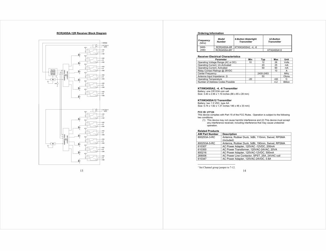
RCR24SSA-6R Receiver Block Diagram
+12 V-
+
MO
MEN
TARY
TO
GGLE
AND
LATC
HING
LOG
IC
RX24SSASUPERHETRECEIVER/DECODER
REG
LEARN
+12 V
+12 V
+12 V
+12 V
+12 V
+12 V
ANTENNA
+12 TO 24 VAC/DC
NC1
C1
NO1
NC2
C2
NO2
NC3
C3
NO3
NC4
C4
NO4
NC5
C5
NO5
NC6
C6
NO6
12
RCR24SSA-6R Receiver Package Information
6.50 6.00
3.85
O .190
4.35
1.36
1.42
4.00
ANTENNA
POWERDATALEARN LED
RELAY 6RELAY 5RELAY 4RELAY 3RELAY 2RELAY 1
LEARN SWITCH
12-24V AC/DC
RELAY 1
RELAY 2
RELAY 3
RELAY 4
RELAY 5
RELAY 6NC6C6
NO6NC5C5
N05NC4C4
N04NC3C3
N03NC2C2
N02NC1C1
N01
1.239
1.239
NC-Normally Closed Contact Cx- Common Contact NO- Normally Open Contact- Terminal Strips may be “unplugged” for ease of installation.
13
RCR24SSA-12R Receiver Block Diagram
+12 V-
+
MO
MEN
TARY
TO
GGLE
AND
LATC
HING
LO
GIC
RX24SSASUPERHETRECEIVER/DECODER
REG
LEARN
+12 V
+12 V
+12 V
+12 V
+12 V
+12 V
ANTENNA
+12 TO 24 VAC/DC
NC1
C1
NO1
NC2
C2
NO2
NC3
C3
NO3
NC4
C4
NO4
NC5
C5
NO5
NC6
C6
NO6
+12 V-
+
MOM
ENTA
RY T
OGGL
EAN
DLA
TCHI
NG L
OGI
C
REG+12 V
+12 V
+12 V
+12 V
+12 V
+12 V
+12 TO 24 VAC/DC
NC1
C1
NO1
NC2
C2
NO2
NC3
C3
NO3
NC4
C4
NO4
NC5
C5
NO5
NC6
C6
NO6
14
Ordering Information
Frequency
(MHz)
Model
Number
6-Button Watertight Transmitter
12-Button Transmitter
2400-2483
RCR24SSA-6R KTXW24SSA2, -4, -6 RCR24SSA-6R1 KTX24SSA12
Receiver Electrical Characteristics Parameter Min Typ Max Unit
Operating Voltage Range (AC or DC) 10 12 26 Volts Operating Current, Un-Activated 20 25 mA Operating Current, Activated 50 60 mA Relay Contact Ratings @ 28VDC 10 A Center Frequency 2400-2483 MHz Antenna Input Impedance Ω 50 Ohms Operating Temperature -20 +60 C Number of Address Codes Possible 4.2 Billion
KTXW24SSA2, -4, -6 Transmitter Battery: one CR123A coin cell Size: 3.40 x 2.56 x 1.10 inches (86 x 65 x 28 mm)
KTXW24SSA12 Transmitter Battery: two 1.5 VDC, type AA Size: 5.74 x 1.82 x 1.31 inches 146 x 46 x 33 mm)
FCC ID: UY124 This device complies with Part 15 of the FCC Rules. Operation is subject to the following two conditions:
(1) This device may not cause harmful interference and (2) This device must accept any interference received, including interference that may cause undesired operation.
Related Products AW Part Number Description 800253A-3-RC Antenna, Rubber Duck, 3dBi, 110mm, Swivel, RPSMA
(included) 800253A-5-RC Antenna, Rubber Duck, 5dBi, 190mm, Swivel, RPSMA 610307 AC Power Adapter, 120VAC -12VDC, 200mA 610300 AC Power Transformer, 120VAC-24VAC, 20VA 800216 AC Power Adapter, 120VAC-12VDC, 500mA 269006 AC Power Line Contactor, SPST, 25A, 24VAC coil 610347 AC Power Adapter, 120VAC-24VDC, 0.8A
1 Set Channel group jumper to 7-12.

15
Application Circuit – DC Motor Forward/Reverse Circuit
This is an example of using the RCR24SSA-6R Receiver for wireless forward and reverse remote control of a DC motor. The wiring diagram shows the motor connected to Relays 1 and 2. Thus it follows that Buttons 1 and 2 on the handheld transmitter would control the motor (e.g. Button 1 for forward, Button 2 for reverse). With Relays 1 and 2 configured for Momentary Mode (factory default), the motor runs in the desired direction only when the appropriate button on the transmitter is pressed. When the button is released, the motor stops. If the motor is equipped with limit switches, Relays 1, 2, and 3 could be configured for Latched Mode. In this configuration, a momentary press of Button 1 or 2 would cause the motor to run continuously in the appropriate direction, until it reaches the limit switch. Button 3 can be used to stop the motor at any time (Relay 3 would not be connected to anything).
RECEIVER
16
For Models: KTXW24SSAn and HTXW24SSAn where n=number of channels: FCC ID: UY124 “This device complies with Part 15 of the FCC Rules. Operation is subject to the following two conditions: (1) this device may not cause harmful interference, and (2) this device must accept any interference received, including interference that may cause undesired operation.” INSTRUCTION TO THE USER Note: This equipment has been tested and found to comply with the limits for a Class B digital device, pursuant to part 15 of the FCC Rules. These limits are designed to provide reasonable protection against harmful interference in a residential installation. This equipment generates, uses and can radiate radio frequency energy and, if not installed and used in accordance with the instructions, may cause harmful interference to radio communications. However, there is no guarantee that interference will not occur in a particular installation. If this equipment does cause harmful interference to radio or television reception, which can be determined by turning the equipment off and on, the user is encouraged to try to correct the interference by one or more of the following measures:
—Connect the equipment into an outlet on a circuit different from that to which the receiver is connected. —Consult an experienced radio/TV technician for help. ‐‐‐Reorient or relocate the receiving antenna. ‐‐‐Increase the separation between the equipment and receiver.
Changes or modifications not expressly approved by Applied Wireless could void the user's authority to operate the equipment.
ONE YEAR LIMITED WARRANTY (USA)
Products manufactured by APPLIED WIRELESS, INC. (AW) and sold to purchasers in the USA are warranted by AW according to the following terms and conditions. You should read this Warranty thoroughly.
WHAT IS COVERED, AND DURATION OF
COVERAGE: AW warrants the product to be free from defects in materials and workmanship for one (1) year from the date of purchase by the original end user purchaser.
WHAT IS NOT COVERED: This warranty does not apply to the following: 1. Damage caused by accident, physical or
electrical misuse or abuse, improper installation, failure to follow instructions
contained in the User’s Guide, any use contrary to the product’s intended function, unauthorized service or alteration (i.e. service or alteration by anyone other than AW).
2. Damage occurring during shipment. 3. Damage caused by acts of God, including
without limitation: earthquake, fire, flood, storms, or other acts of nature.
4. Damage or malfunction caused by the intrusion of moisture or other contamination within the product.
5. Batteries supplied by AW in or for the product.
17
6. Cosmetic deterioration of chassis, cases, or pushbuttons resulting from wear and tear typical of normal use.
7. Any cost or expense related to trouble-shooting to determine whether a malfunction is due to a defect in the product itself, in the installation, or any combination thereof.
8. Any cost or expense related to repairing or correcting the installation of an AW product.
9. Any cost or expense related to the removal or reinstallation of the product.
10. Any product whose serial number or date code is altered, defaced, obliterated, destroyed, or removed.
This warranty is extended to the original purchaser of the product(s) only, and is not transferable to any subsequent owner or owners of the product(s). AW reserves the right to make changes or improvements in its products without incurring any obligation to similarly alter products previously purchased.
EXCLUSION OF INCIDENTAL OR
CONSEQUENTIAL DAMAGES: AW expressly disclaims liability for incidental and consequential damages caused (or allegedly caused) by the product. The term “incidental or consequential damages” refers (but is not limited) to: 1. Expenses of transporting the product to
AW to obtain service. 2. Loss of use of the product. 3. Loss of the original purchaser’s time.
LIMITATION OF IMPLIED WARRANTIES: This warranty limits AW’s liability to the repair or replacement of the product. AW makes no express warranty of merchantability or fitness for use. Any implied warranties, including fitness for use and merchantability, are limited in duration to the period of the one (1) year express limited warranty set forth herein. The remedies provided under this warranty are exclusive and in lieu of all others. AW neither assumes nor authorizes any person or organization to make any warranties or assume any liability in connection with the sale, installation, or use of this product.
Some states do not allow limitations on how long an implied warranty lasts, and some states do not allow the exclusion or limitation of liability for incidental or consequential damages so the limitations or exclusions stated herein may not apply to you. This warranty gives you specific legal rights and you may have other rights which vary from state to state.
(continued on next page)
18
ONE YEAR LIMITED WARRANTY (USA), cont.
HOW TO OBTAIN WARRANTY SERVICE: If a product covered by this warranty and sold in the USA by AW proves to be defective during the warranty period AW will, at its sole option, repair it or replace it with a comparable new or reconditioned product without charge for parts and labor, when said product is returned in compliance with the following requirements: 1. You must first contact AW at the following address/phone for assistance:
APPLIED WIRELESS, INC. 1250 Avenida Acaso, Suite F
Camarillo, CA 93012 Phone: (805) 383-9600
If you are instructed to return your product directly to the factory, a Return Merchandise Authorization number (RMA) will be issued to you.
2. You must package the product carefully and ship it insured and prepaid. The RMA number must be clearly indicated on the outside of the shipping container. Any product returned without an RMA number will be refused delivery.
3. In order for AW to perform service under warranty, you must include the following: (a) Your name, return shipping address (not a PO Box), and daytime telephone number. (b) Proof of purchase showing the date of purchase. (c) A detailed description of the defect or problem.
Upon completion of service, AW will ship the product to the specified return shipping address. The method of shipping shall be at AW’s sole discretion. The cost of return shipping (within USA) shall be borne by AW.

19
Troubleshooting Guide
Symptom Possible Problem Notes
Poor Range Antenna Receiver Antenna connected, vertically oriented and placed preferably at least 7' high and away from metal surfaces.
Antenna will not work inside a metal box
RF Interference Check equipment operation at a different location.
Battery If the remote transmitter has an indicator LED, does it light brightly when button is pressed? If not, replace battery.
Doesn't Work Power Check power to receiver (power LED lit?)
Relay Connection Verify connected to the correct Relay.
ID Code Match Re-"Learn" remote to receiver. MUST BE DONE WITH ANTENNA REMOVED.
Re-Boot Needed Remove power from receiver for at least 5 seconds.
20
Applied Wireless products are designed and manufactured
with pride in the United States of America
Copyright 2014 by Applied Wireless, Inc. All rights reserved. Specifications subject to change without notice.
APPLIED WIRELESS, INC. 1250 Avenida Acaso, Suite F, Camarillo, CA 93012
Phone: 805-383-9600 Fax: 805-383-9001 Email: [email protected]
www.appliedwireless.com
Pub. # UG-RCR24SSA Rev. Date 3/15