Wireless Infrastructure
168
Wireless Infrastructure Solutions for remote radio systems and conventional cell sites Edition 2012
-
Upload
khangminh22 -
Category
Documents
-
view
0 -
download
0
Transcript of Wireless Infrastructure

Wire
less
Infra
struc
ture
– E
ditio
n 20
12
Wireless Infrastructure Solutions for remote radio systems and conventional cell sites
Edition 2012

Count on proven wireless Technology

Excellence in Connectivity Solutions
Your partner for connectivity solutions
The HUBER+SUHNER group is a leading global supplier of com-ponents and systems for electrical and optical connectivity. Our customers in communication, industry and transportation appre-ciate that we are specialists with detailed knowledge of practical applications. We offer expertise in radio frequency, fiber optics and low frequency all under one roof, thus providing a unique basis for continual innovation which is focused on the needs of our customers all over the world.
Our motto: “EXCELLENCE in CONNECTIVITY SOLUTIONS”. At the heart of our offering is a broad range of products that can be relied on to meet high quality standards, backed up by flexible, depen-dable services with fast response times worldwide. In the wireless market, we concentrate on solutions that allow us to stand out by adding value with special product features, application-specific innovations, reduction of total cost of ownership and excellence in delivery performance.


5www.wireless-infrastructure.com 5
Work with the Leader for Remote Radio Installation Solutions
Remote radio technology Remote Radio systems evolved as the dominating technology in the wireless communication industry. Remote radio heads (RRH) significantly reduce the network’s energy consumption while at the same time improving the network performance. The number of RRH installations surpassed conventional corrugated cell site installa-tions and poses new challenges for operators, installers and system integrators. The installation industry needs to adapt to new cable technologies, e.g. fiber optics, work with new logistic models, and acquire fundamen-tally different installation know-how. HUBER+SUHNER helps to build reliable passive infrastructure fulfilling today’s and tomorrow’s network requirements.
HUBER+SUHNER provides complete installation solutionsHUBER+SUHNER is the global leader for remote radio installation solutions. We have a comprehensive offering of FTTA (fiber-to-the-antenna) and PTTA (power-to-the-antenna) products which are tailored to the customer’s needs. We advise operators about which installation methods are available and what are their ad-vantages. We are experts on how to make savings on installation costs and expensive follow-up costs can be saved. HUBER+SUHNER implements future-proof passive cable network infrastructures which are compatible with all vendor systems and endure the future generations of active equipment.
Be ready for LTELTE systems use remote radio technology. HUBER+SUHNER offers solutions that enables an efficient migration from corrugated copper systems to RRHs systems while keeping the real-estate changes at the cell site to an absolute minimum. HUBER+SUHNER has the optimum solution independent of the number or type of RRHs deployed on the mast.


7www.wireless-infrastructure.com
Do not compromise your wireless Network Quality
Conventional cell sites technologyHUBER+SUHNER is an established full-range supplier of antenna supply lines for conventional cell site solutions. From SUCOFEED corrugated cables in all sizes with matching easy-to-install QUICK-FIT connectors on antenna supply lines, to RF LISCA jumpers for connecting the antenna to the network on top of the mast, to lightning protection solutions of all types and additional products for efficient installation. HUBER+SUHNER supplies complete updated passive low PIM (passive intermodulation) components for existing or 4th genera-tion LTE applications.
Global design & manufacturing leader of low passive intermodulation componentsHUBER+SUHNER’s passive radio frequency components have an outstanding low PIM performance. Our products and material expertise in combination with application know-how enables us to keep inter- modulation in the entire signal path small and to minimize unwanted PIM generated signals in the uplink. This performance is of particular importance for operators moving to LTE, where frequency bands ranging from 700 MHz up to 2.6 GHz are used in parallel. Our RF products do not compromise your wireless network performance.

HUBER+SUHNER – a World Class Supplier for wireless Infrastructure
A guarantee of qualityContinuous quality improvement is a top priority for our organisation. For all our employees, high quality means the complete fulfilment of all the expectations of our outside and in-house customers. Our systematic quality and environmental management systems ensure that international standards are observed. Our global management system is certified according to ISO 9001, ISO 14001 and in our automotive units we also have ISO/TS 16949.
A truly global companyMarket proximity is the advantage of our global presence, with subsidiaries in Australia, Brazil, Canada, China, Denmark, Germany, France, India, Malaysia, Poland, Singapore, Sweden, Thailand, United Kingdom and the US plus representatives in over 60 countries. Our customers benefit from all the advantages of a global supplier, while being supported by local engineering teams, manufacturing and logistics.
Operational excellenceConsiderable cost efficiency for us and our customers is made possible by our specialised competence centres in our three most important markets, namely Europe, the Americas and Asia. Our global, IT-supported production and logistics operations are managed and coordinated centrally, minimising purchasing and ware-housing costs and maximising flexibility with regard to fluctuations in demand. We ensure we are able to meet the logistic expectations of our customers, independent of high volume bulk shipments or fast and flexible on-site services with short lead-time requirements. Fulfilling challenging expectations for us is a matter of course.

9www.wireless-infrastructure.com
Innovation and competenceWe develop superior products and services in close collaboration with our customers. We are one of the few globally active companies producing components and systems with the key technologies radio frequency, fiber optics and low frequency under one roof – a unique and necessary combination for the leading solution provider for remote radio installations. Our production facilities are state of the art; being based in Switzerland, a hotbed of innovation, and offering high-quality products are both very important factors for us. Our outstan-ding research and production capabilities mean that we enjoy a great deal of credibility among customers and stakeholders alike.
Corporate cultureOur corporate culture entails taking the long-term view and keeping an eye on the big picture. The cornerstone of our present and future success is the dedication shown by our staff, who benefit from competitive employ-ment conditions and attractive career development opportunities. Openness, mutual respect and teamwork are the means by which we create a working environment where trust and an entrepreneurial spirit reign. Sound finances and an optimally diversified portfolio of business activities give us the independence to guarantee continuity within our company.

Solutions for Cell Sites

Standard solution with discrete cables 16
Multi -riser cable with distribution box 26
Multi -riser cable with compact divider 54
Re-use of corrugated copper cables 62
Hybrid solutions 70
Accessories 80
Fiber optic interfaces for remote radio heads 86
RF jumpers LISCA 104
SUCOFEED corrugated cables 110
QUICK-FIT coaxial connectors 124
Lightning protectors 132
Accessories for conventional cell sites 144
Power splitters 154
Radio frequency antennas 162
Contents
Excellence in Connectivity Solutions
Remote radio installation solutions 12
Conventional cell site solutions 102

Remote Radio Installation Solutions

www.wireless-infrastructure.com
Request your best practices guide: How to install remote radio systems
The installation of remote radio systems poses new challenges for mobile operators, installers and system integrators. What installation methods are available and what are their advantages? How can a network operator install a future-proof passive infrastructure? How can savings be made on installation costs and follow-up costs? HUBER+SUHNER offers expert answers to these questions and discusses optimum installation solutions.
Download the White Paper
http://ipaper.ipapercms.dk/HUBERSUHNER/Market-segments/Communication/RemoteRadioInstallationEN/
Order paper copy of White PaperItem no. Language
84118113 english version
84118112 german version
Visit www.wireless-infrastructure.com
The microsite is a powerful guide to design your optimum RRH installation solution and provides compre-hensive information about available installation options. It also contains detailed product data sheets, success stories, market news and is an information platform for mobile operators, installation companies and system integrators.
13

HUBER+SUHNER
#1 Individual cables #2 Multi-riser cables and box
Fiber optic: 2-fiber riser cables
Power supply: 2-wire copper cables
Fiber optic: MASTERLINE classic HT with 6 up to 24 fibers and FTTA Box
Power supply: Multi-wire power cable with grounded PTTA box
See page 16 See page 26
Suitable cell sites co-located and distributed antennas only co-located antennas
Flexibility during RRH replacement no yes
Scalable for 3 to 12 RRHs no yes
Future-proof no yes
Overlength management limited yes
Installation time medium efficient
Cost efficiency / overall costs € - €€ €
Spread / frequency in practice system vendor solution rapid growth
Overview of RRH Installation Options
14

www.wireless-infrastructure.com
#3 MASTERLINE extreme #4 Re-use of corrugated cables #5 Hybrid cables
Fiber optic: MASTERLINE extreme with 3 up to 9 break-outs
Power supply: MASTERLINE extreme power with multi-wire power cable
Fiber optic: MASTERLINE classic HT with special feed-through cable, 6 to 12 fibers
Power supply: Smart DC kitCombined fiber optic and power cables
See page 54 See page 62 See page 70
only co-located antennas only co-located antennas limited application
yes yes yes
up to 9 RRHs up to 6 RRHs no
yes yes no
limited yes limited
plug-and-play efficient medium
€ € €€€
rapid growth swap used under special conditions
Overview of RRH Installation Options
15

16 HUBER+SUHNER
Standard Solution with discrete Cables
The standard solution with discrete cables supports every type of cell site installation whether if the remote radios are co-located (mast-top installation) or distributed on rooftops of buildings. HUBER+SUHNER has a leading role in the design and manufacturing of harsh environment connectors (e.g. ODC or Q-XCO) and cable assemblies for remote radio systems. The installation method with discrete cables is the preferred choice of mobile system vendors and HUBER+SUHNER is an approved and qualified cable assembly supplier for the majority of the tier 1 and tier 2 vendors.
LISCA RF jumper (page 104)
Fiber optic (FTTA) feeder (page 18)
Power supply cable (page 24)
Mounting clamps (page 80 and 144)
Overlength box (page 81)
PTTA box (optional) (page 38)

17www.wireless-infrastructure.com
Application and features Suited for co-located antennas (e.g. mast-top installation) and distributed antennas (e.g. roof-top installation)Method supports any type of cell site installation
Benefits Simplest and preferred method of system vendors HUBER+SUHNER deliver customized cable assemblies (e.g. in increments of 10 m)Vendor approved cable assemblies and guaranteed system compatibility Short lead-time to fulfil stringent installation requirementsAuxiliary material available for trouble-free installation
Issues For three sectors six cables need to be installed Sub-optimum for longer distances due to time-consuming and complex cable installation Minor flexibility with regard to RRH or interface replacement Method does not support system expansions or network evolution Cables not compatible in case of use of different systems/vendors in same network (e.g. different interfaces or fiber types).

18 HUBER+SUHNER
FTTA Fiber-to-the-Antenna Feeder
Features FTTA feeders available for all types of RRHs and systems (2G, 3G, 4G, Wimax, Microwave point-to-point links) Ruggedized design and installation proof Standard assemblies and customized lengths available in short lead-time Cable diameter 4.8 mm, 5.5 mm or 7 mm All cables rodent resistant and monkey bite protected on requestAll cable assemblies factory-terminated and tested
Specifications
Outer cable diameter 4.8 mm 5.5 mm 7 mm
Jacket material LSFH™ LSFH™ LSFH™
Maximum tensile strength (during installation/service)
300/500 N 500/1000 N 650/1000 N
Cable crush resistance (short-term/long-term)
200/400 N/cm 200/400 N/cm 300/1000 N/cm
Temperature range – 40 °C to + 95 °C – 40 °C to + 80 °C – 40 °C to + 80 °C
Flame resistance IEC 60332-1, IEC 60332-3-24, UL1666
UL approved none OFNR OFNR
UV resistant yes yes yes
HUBER+SUHNER cables are deployed on a global scale
Year by year, HUBER+SUHNER produces tens of thousands of FTTA feeder cables and is globally a leading supplier to major system vendors and operators. Our customers value our quality products which are manufactured on all continents close to the local markets.
HUBER+SUHNER is also innovation leader for remote radio interfaces and is owner of globally successful products like ODC, XCO or Q-XCO.

19www.wireless-infrastructure.com
FTTA Fiber-to-the-Antenna Feeder
LC feeder with metal divider and ruggedized break-out, Ø 5.5 mm cable, low-bend fiber
Length Item no. Description Length Item no. Description
1 m 84122153 09H02FGG-LB-88/88-2-1.26 NN 60 m 84120595 09H02FGG-LB-88/88-2-60.26 NN
2 m 84122154 09H02FGG-LB-88/88-2-2.26 NN 70 m 84120596 09H02FGG-LB-88/88-2-70.26 NN
5 m 84120589 09H02FGG-LB-88/88-2-5.26 NN 80 m 84120597 09H02FGG-LB-88/88-2-80.26 NN
10 m 84120590 09H02FGG-LB-88/88-2-10.26 NN 90 m 84120598 09H02FGG-LB-88/88-2-90.26 NN
20 m 84120591 09H02FGG-LB-88/88-2-20.26 NN 100 m 84120599 09H02FGG-LB-88/88-2-100.26 NN
30 m 84120592 09H02FGG-LB-88/88-2-30.26 NN 125 m 84120600 09H02FGG-LB-88/88-2-125.26 NN
40 m 84120593 09H02FGG-LB-88/88-2-40.26 NN 150 m 84120601 09H02FGG-LB-88/88-2-150.26 NN
50 m 84120594 09H02FGG-LB-88/88-2-50.26 NN
Also available with 4.8 mm cable.
Ordering information
ODC feeder with Ø 5.5 mm cable
Length Item no. singlemode low-bend
Item no. multimode Description
1 m 84122151 84124943 09H02FG.-..-A4/88-2-1 ..
2 m 84122152 84124942 09H02FG.-..-A4/88-2-2 ..
5 m 84078725 84078739 09H02FG.-..-A4/88-2-5 ..
10 m 84078726 84078740 09H02FG.-..-A4/88-2-10 ..
15 m 84078727 84078741 09H02FG.-..-A4/88-2-15 ..
20 m 84078728 84078742 09H02FG.-..-A4/88-2-20 ..
30 m 84078729 84078743 09H02FG.-..-A4/88-2-30 ..
40 m 84078730 84078744 09H02FG.-..-A4/88-2-40 ..
50 m 84078731 84078745 09H02FG.-..-A4/88-2-50 ..
60 m 84078732 84078746 09H02FG.-..-A4/88-2-60 ..
70 m 84078733 84078747 09H02FG.-..-A4/88-2-70 ..
80 m 84078734 84078748 09H02FG.-..-A4/88-2-80 ..
90 m 84078735 84078749 09H02FG.-..-A4/88-2-90 ..
100 m 84078736 84078750 09H02FG.-..-A4/88-2-100 ..
125 m 84078737 84078751 09H02FG.-..-A4/88-2-125 ..
150 m 84078738 84078752 09H02FG.-..-A4/88-2-150 ..
ODC feeder also available with 7 mm cable diameter or as 1-fiber version.

20 HUBER+SUHNER
FTTA Fiber-to-the-Antenna Feeder
FullAXS feeder with 4.8 mm cable, singlemode low-bend fiber
Length Item no. singlemode Description
1 m 84137909 09H02FGG-LB-Z4/88-2-1 NN
2 m 84137910 09H02FGG-LB-Z4/88-2-2 NN
5 m 84137911 09H02FGG-LB-Z4/88-2-5 NN
10 m 84137912 09H02FGG-LB-Z4/88-2-10 NN
15 m 84137913 09H02FGG-LB-Z4/88-2-15 NN
20 m 84137914 09H02FGG-LB-Z4/88-2-20 NN
30 m 84137915 09H02FGG-LB-Z4/88-2-30 NN
40 m 84137916 09H02FGG-LB-Z4/88-2-40 NN
50 m 84137917 09H02FGG-LB-Z4/88-2-50 NN
60 m 84137918 09H02FGG-LB-Z4/88-2-60 NN
70 m 84137919 09H02FGG-LB-Z4/88-2-70 NN
80 m 84137920 09H02FGG-LB-Z4/88-2-80 NN
90 m 84137921 09H02FGG-LB-Z4/88-2-90 NN
100 m 84137922 09H02FGG-LB-Z4/88-2-100 NN
125 m 84137923 09H02FGG-LB-Z4/88-2-125 NN
150 m 84137924 09H02FGG-LB-Z4/88-2-150 NN
LC feeder with Ø 5.5 mm cable
Length Item no. singlemode low-bend
Item no. multimode Description
2.5 m 84122419 84122420 09H02FG.-..-88/88-2-2.5 ..
5 m 84122418 84104136 09H02FG.-..-88/88-2-5 ..
15 m 84104111 84104137 09H02FG.-..-88/88-2-15 ..
30 m 84104112 84104138 09H02FG.-..-88/88-2-30 ..
50 m 84104113 84104139 09H02FG.-..-88/88-2-50 ..
70 m 84104114 84104140 09H02FG.-..-88/88-2-70 ..
85 m 84104115 84104142 09H02FG.-..-88/88-2-85 ..
100 m 84104116 84104143 09H02FG.-..-88/88-2-100 ..
150 m 84104117 84104144 09H02FG.-..-88/88-2-150 ..
200 m 84104118 84104145 09H02FG.-..-88/88-2-200 ..
250 m 84104120 84104146 09H02FG.-..-88/88-2-250 ..
300 m 84104121 84104147 09H02FG.-..-88/88-2-300 ..

21www.wireless-infrastructure.com
LC feeder with Ø 7 mm cable
Length Item no. singlemode low-bend
Item no. multimode Description
1 m 84106141 84117532 09H02FG.-..-88/88-2-1 ..
2 m 84106142 84085209 09H02FG.-..-88/88-2-2 ..
3 m 84106143 84114473 09H02FG.-..-88/88-2-3 ..
4 m 84125503 84125500 09H02FG.-..-88/88-2-4 ..
5 m 84105041 84085208 09H02FG.-..-88/88-2-5 ..
6 m 84125504 84125501 09H02FG.-..-88/88-2-6 ..
8 m 84125507 84125502 09H02FG.-..-88/88-2-8 ..
10 m 84104280 84115234 09H02FG.-..-88/88-2-10 ..
15 m 84106144 84115236 09H02FG.-..-88/88-2-15 ..
20 m 84106145 84085207 09H02FG.-..-88/88-2-20 ..
30 m 84106146 84085200 09H02FG.-..-88/88-2-30 ..
40 m 84106147 84085201 09H02FG.-..-88/88-2-40 ..
50 m 84106148 84085202 09H02FG.-..-88/88-2-50 ..
60 m 84106149 84124945 09H02FG.-..-88/88-2-60 ..
70 m 84106150 84085203 09H02FG.-..-88/88-2-70 ..
80 m 84106151 84084612 09H02FG.-..-88/88-2-80 ..
90 m 84106152 84124946 09H02FG.-..-88/88-2-90 ..
100 m 84106153 84085204 09H02FG.-..-88/88-2-100 ..
125 m 84106154 84124947 09H02FG.-..-88/88-2-125 ..
150 m 84106155 84085205 09H02FG.-..-88/88-2-150 ..
200 m 84124944 84085206 09H02FG.-..-88/88-2-200 ..
FTTA Fiber-to-the-Antenna Feeder

22 HUBER+SUHNER
FTTA Fiber-to-the-Antenna Feeder
LC feeder with 90° boot, Ø 7 mm cable, multimode fiber
Only available for vendor approved companies.
Length Item no. Description
2 m 84082925 09H02FG0-50-8C/8C-2-2 MM
5 m 84122156 09H02FG0-50-8C/8C-2-5 MM
10 m 84083054 09H02FG0-50-8C/8C-2-10 MM
20 m 84083071 09H02FG0-50-8C/8C-2-20 MM
30 m 84083074 09H02FG0-50-8C/8C-2-30 MM
40 m 84083079 09H02FG0-50-8C/8C-2-40 MM
50 m 84083081 09H02FG0-50-8C/8C-2-50 MM
75 m 84083084 09H02FG0-50-8C/8C-2-75 MM
100 m 84083086 09H02FG0-50-8C/8C-2-100 MM
200 m 84083087 09H02FG0-50-8C/8C-2-200 MM
LC feeder with straight boot, Ø 7 mm cable
Only available for vendor approved companies.
Length Item no. singlemode low-bend
Item no. multimode Description
1 m 84124936 84124933 09H02FG.-..-8A/88-2-1 ..
2 m 84124937 84124024 09H02FG.-..-8A/88-2-2 ..
5 m 84124938 84124054 09H02FG.-..-8A/88-2-5 ..
10 m 84125616 84123456 09H02FG.-..-8A/88-2-10 ..
15 m 84125617 84124055 09H02FG.-..-8A/88-2-20 ..
20 m 84125618 84124056 09H02FG.-..-8A/88-2-30
30 m 84062386 84124057 09H02FG.-..-8A/88-2-30 ..
50 m 84062387 84062408 09H02FG.-..-8A/88-2-50 ..
70 m 84062388 84062409 09H02FG.-..-8A/88-2-70 ..
90 m 84062389 84062410 09H02FG.-..-8A/88-2-90 ..
110 m 84062390 84062411 09H02FG.-..-8A/88-2-110 ..
130 m 84062391 84062412 09H02FG.-..-8A/88-2-130 ..
150 m 84062392 84062413 09H02FG.-..-8A/88-2-150 ..
170 m 84062393 84062414 09H02FG.-..-8A/88-2-170 ..
190 m 84062394 84062415 09H02FG.-..-8A/88-2-190 ..
210 m 84062395 84062416 09H02FG.-..-8A/88-2-210 ..

23www.wireless-infrastructure.com
FTTA Fiber-to-the-Antenna Feeder
ODC-4 feeder with Ø 5.5 mm cable
Length [m] Fiber type Description
L singlemode low-bend 09H04FGG-LB-J2/88-3-L NN
L multimode 09H04FG0-50-J2/88-3-L MM
Q-XCO feeder with Ø 5.5 mm cable
Length [m] Fiber type Description
L singlemode low-bend 09H02FGG-LB-XA/88-2-L NN
L multimode 09H02FG0-50-XA/88-2-L MM
XCO feeder with Ø 5.5 mm cable
Length [m] Fiber type Description
L singlemode low-bend 09H02FGG-LB-X1/88-2-L NN
L multimode 09H02FG0-50-X1/88-2-L MM
Further FTTA feeders for all types of remote radio systems available (e.g. R2CT, LC push-pull connector, industrial LC connector).

24 HUBER+SUHNER
2 Wire Power Supply Cable
Features
2 2 2 2,2
Specifications
2
2 2
Cross section 2 x 4 mm2 2 x 6 mm2 2 x 10 mm2 2 x 16 mm2 2 x 25 mm2
34 44
252 4
Ordering information
Cross section Item no. Description 2
2
2
2
2


26 HUBER+SUHNER
Multi-riser Cable with Distribution Box
This solution uses multi-riser cables for fiber optic and copper that are routed in separate connection boxes (or in a combined hybrid box) which are then linked to the RRHs with short jumper cables. This installation method is cost- effective and installation friendly and is therefore the preferred choice of mobile network operators who have control over network design and deployment. The passive cable infrastructure is future-proof, supports network expansions and saves on installation and follow-up costs. HUBER+SUHNER is a complete solution provider and manufacturer for the passive cable infrastructure between base station and antenna.
RRH jumper (page 37)
LISCA RF jumper (page 104)
Power jumper (page 61)
FTTA box (page 28)
PTTA box (page 38)
MASTERLINE classicHT (page 32)
Power feeder (page 49)
CTB 19" termination box [optional] (page 65)
LC patchcord [optional] (page 66)

27www.wireless-infrastructure.com
Application and features Optimum for co-located antennas, e.g. mast-top installation Preferred method of network operatorsPassive cable infrastructure is system and vendor independent Cable installation systems designed for 20-years life time to support network evolution over future generations of active equipment
Benefits Reduced installation times, lower level of investment (CAPEX) For 3-sector site, just 2 multi-riser cables instead of 6 individual cables, plug-and playScalable for 3 up to 12 RRHs, perfect for planned LTE roll-outs and expansionsFuture-proof as the passive cable infrastructure supports all aspects of network evolutionBest flexibility in case of RRH replacement as short jumpers can be easily exchangedHUBER+SUHNER designs and delivers complete systems
Issues Limited suitability for cell sites with distributed antennas

28 HUBER+SUHNER
FTTA Fiber-to-the-Antenna Box
Features Ruggedized outdoor fiber distribution box Supports up to 8/12 remote radio heads Fitted with bend radius limiting mandrelsSuitable for mounting on poles, walls and tower legs with round-, L-, V- and -shape. Easy to mount and install with integrated screws and pre-mounted bracketsCompatible with splice cassettes and MTP modules Fully electrically isolated / RoHs compliantProtective vent to equalize pressure and prevent condensation
Specifications
small FTTA box medium FTTA box
Number of RRH 3, 6, 8 RRH up to 12 RRH up to 12 RRH
Compatible with MASTERLINE classicHT 6, 12, 16 fibers 24 fibers 24 fibers or 2 x 12 fibers
Compatible with MASTERLINE MTPTM 12 fibers no 24 fibers
Dimensions 255 x 180 x 65 mm 300 x 230 x 85 mm 250 x 320 x 138 mm
Cable entry (left knock-out holes)
2 x M16 for MASTERLINE classicHT up to 16 fibers or MASTERLINE MTPTM
1 x M26 for MASTERLINE classicHT 24 fibers
1 x M26 for MASTERLINE classicHT 24 fibers 2 x M16 for MASTERLINE MTPTM
Cable exit (right knock-out holes)
2 x M25 for 3(4)-fold cable gland
2 x M32 for 6-fold cable gland
4 x M25 for 3-fold cable gland
Material glass-filled polycarbonate, halogen free
Material flammability rating UL 94 V0
Ingress protection IP 66/67 (EN 60529), NEMA 1, 4, 4X, 6, 12 and 13
Impact resistance IK 07 (EN 62262)
Operating temperature – 40 °C to +85 °C
Customized or hybrid boxes are available upon request.
HUBER+SUHNER’s MASTERLINE solution is a win for LTE
The multi-fiber cabling and box solution makes the infrastructure easier to deploy, reduces field failures, and supports multi-vendor installations. By installing additional fibers, the sites are ready for LTE roll-outs and scalable for future applications. Global and local operators are convinced of the benefits of this cabling system. Therefore, names like Vodafone, T-Mobile, Telenor, Bouygues Telecom and many others trust and rely on HUBER+SUHNER’s MASTERLINE solution to make their passive infrastructure future-proof, scalable and ready for LTE.

29www.wireless-infrastructure.com
FTTA Fiber-to-the-Antenna Box
Ordering information and accessories
FTTA boxes
Description Feature Item no. Picture
FTTA box smallup to 8 RRH MASTERLINE classicHT MASTERLINE MTPTM
84074085
FTTA box medium (old) (phase out 2012)
up to 12 RRH MASTERLINE classicHT 84112317
FTTA box medium (new) (available Q1 2012)
Up to 12 RRH MASTERLINE classicHT MASTERLINE MTPTM
84125865
Quick hose clampThe quick hose clamps for mounting the FTTA box onto a mast are available in 2 sizes.Description Feature Item no. Picture
Quick hose clamp smallclamping diameter 30 – 155 mm stainless steel
84076411
Quick hose clamp largeclamping diameter 60 – 500 mm stainless steel
84076412
Installation kitThe installation kit includes LC duplex adapters for singlemode or multimode, cable glands, blind plugs, a protective vent, a laser label and description labels for the jumper cables.
Description Item no. Compatibility Picture
Installation kit singlemode for 3 RRH
84121039
FTTA box smallInstallation kit multimode for 3 RRH
84121041
Installation kit singlemode for 6 RRH
84121040FTTA box small and mediumInstallation kit multimode
for 6 RRH84121042
Installation kit singlemode for 12 RRH
84136955
FTTA box medium (new)Installation kit multimode for 12 RRH
84137033

30 HUBER+SUHNER
FTTA Fiber-to-the-Antenna Box
Ordering information for single components
Description Feature Item no. Picture
LC duplex adapter
singlemode, blue 84083886
multimode, beige 84090245
Nut for MASTERLINE (always supplied with the MASTERLINE)
M16 for MASTERLINE classicHT up to 12 fibers and MASTERLINE MTPTM
23040540
M26 for MASTERLINE classicHT 24 fibers
23236878
Cable gland M25 3-fold seal cable Ø 5.5 – 7.0 mm
84121958
Cable gland M32 6-fold seal cable Ø 5.5 – 7.0 mm
84113000
Blind plugs 84090788
Protective ventand moisture
23038472
Laser label warning label LASER PRODUCT 84005276
Description labelsdescription labels for jumper cables RRH 1, RRH 2,…, RHH 12
84137099

31www.wireless-infrastructure.com
19" CTB Cable Termination Box
Features • Spacesaving19“rackinstallation• Cableentryfromthefront• FrontplatewithmountedLCduplexadapters• Pullouttrayforeasyaccess• 3mandrelsforoverlengthmanagementofthe
MASTERLINEcablesystem• Materialstandardaluminum
Description Numbers of fibers Fiber type Ordering code Item no.
CTB19“fiberframe,LCadapters
12singlemode CB1-B88-06ML-09-00-00-00-00SNK 84138010
multimode CB1-B88-06ML-50-00-00-00-00SMK 84126559
24singlemode CB1-B88-12ML-09-00-00-00-00SNK 84125915
multimode CB1-B88-12ML-50-00-00-00-00SNK 84127072
LC Patchcord
Description Fiber type Length Ordering code Item no.
LCunibootpatchcord
singlemode
0.5m 21H02VE0-LB-8U/8U-2-0.5NN 84138001
0.7m 21H02VE0-LB-8U/8U-2-0.7NN 84125518
1.0m 21H02VE0-LB-8U/8U-2-1NN 84125519
1.5m 21H02VE0-LB-8U/8U-2-1.5NN 84138003
multimode
0.5m 21H02VM0-53-8U/8U-2-0.5MM 84138007
0.7m 21H02VM0-53-8U/8U-2-0.7MM 84125520
1.0m 21H02VM0-53-8U/8U-2-1MM 84125521
1.5m 21H02VM0-53-8U/8U-2-1.5MM 84138009

32 HUBER+SUHNER
Fiber Optic MASTERLINE classicHT
Features Pre-assembled plug-and-play cabling systemRuggedized design with robust pulling tube Outdoor and indoor with high flame resistance Temperature range – 40 °C up to + 75 °CLoose tube cables with up to 24 fibers, rodent-protected and UV resistant Fibers and connectors colour-coded for easy channel identification Easy and time-saving installationEach system factory testedRodent resistant
Specifications
Number of fibers up to 12 up to 24
Divider small medium
Build-in hole dimension 15.6 – 16.4 mm 25.5 – 26.5 mm
Pulling tube with pulling eye
Outer diameter 23.5 mm 31 mm
Maximum tensile strength 1000 N 1000 N
Crush resistance 250 N/cm 250 N/cm
Ingress protection IP 67 IP 67
Glass-armoured loose-tube cable
Jacket material LSFH™
Cable diameter 2 – 24 fibers 8.5 mm
Tensile strength during installation in service
3000 N 1500 N
Crush resistance short-term long-term
400 N/cm 200 N/cm
Temperature range installation service
– 25 °C to + 75 °C – 40 °C to + 75 °C
Flame resistance IEC 60332-1 IEC 60332-3-24
passed
longest lengthpigtail: shortest length
pulling eye for installationpulling tube (tread-proof, waterproof)pulling tube (screwed down)
divider with thread and mounting groove
installed length
seal ring

33
www.wireless-infrastructure.com
Fiber Optic MASTERLINE classicHT
Standard portfolioMASTERLINE classicHT with 6, 12, and 24 fibers Both sides terminated with colour-coded LC duplex connectorsSmall FTTA box compatible with 6 and 12 fibers, medium FTTA box with 24 fibers
Colour codingRRH 1+7 RRH 2+8 RRH 3+9 RRH 4+10 RRH 5+11 RRH 6+12
red green blue yellow white black
Ordering information
MASTERLINE classicHT
6 fibers 3 RRH
12 fibers 6 RRH
24 fibers 12 RRH
Length Fiber type Item number
20 m
singlemode
84117833 84117846 84117858
30 m 84117834 84117847 84117859
40 m 84117835 84117848 84117860
50 m 84117836 84117849 84117861
60 m 84117837 84117850 84117862
70 m 84117838 84117851 84117863
80 m 84117839 84117852 84117864
90 m 84117840 84117853 84117865
100 m 84117841 84117854 84117866
125 m 84117842 84117855 84117867
150 m 84117843 84117856 84117868
200 m 84117845 84117857 84117869
20 m
multimode OM2
84117870 84117882 84117895
30 m 84117871 84117883 84117896
40 m 84117872 84117884 84117897
50 m 84117873 84117885 84117898
60 m 84117874 84117886 84117899
70 m 84117875 84117887 84117900
80 m 84117876 84117888 84117901
90 m 84117877 84117889 84117902
100 m 84117878 84117890 84117903
125 m 84117879 84117891 84117904
150 m 84117880 84117892 84117905
200 m 84117881 84117894 84117906

34 HUBER+SUHNER
Fiber Optic MASTERLINE MPO / MTP ™
Features Pre-assembled plug-and-play cabling systemMTP connector with up to 12 fibersRuggedized design with robust pulling tube Outdoor and indoor with high flame resistance Temperature range – 40 °C up to + 75 °CLoose tube cables, rodent-protected and UV resistant Easy and time-saving installationEach system factory testedCompatible with FTTA boxes in combination with MTP cassette
Specifications
Number of fibers up to 12 up to 24
Number of MTP connectors (without pins) 1 2
Compatibility small FTTA Box medium FTTA Box
MASTERLINE divider small Ø 16 mm small Ø 16 mm
Whip cable diameter 3.5 mm
Pulling tube with pulling eye
Outer diameter 23.5 mm
Maximum tensile strength 1000 N
Crush resistance 250 N/cm
Ingress protection IP 67

35
MTP module 24 fibers MTP module 12 fibers MTP module 6 fibers
www.wireless-infrastructure.com
MTP Module for FTTA Box
Features Pre-assembled MTP fiber module with fan-out to LC duplex adaptersCompatible to mount into FTTA box small and FTTA box mediumWith 6, 12 and 24 fibers availableLC adapters colour-coded
Ordering information (module only / without box)
Description Compatibility No. of fibers Fiber type Item no.
MTP module, 6 fibers MTP (in), 3 LC duplex (out)
FTTA box medium (new), for hybrid configuration
6singlemode 84122225
multimode 84122226
MTP module, 12 fibers MTP (in), 6 LC duplex (out)
FTTA box small 12singlemode 84122227
multimode 84122228
MTP module, 24 fibers MTP (in), 12 LC duplex (out)
FTTA box medium (new) 24singlemode 84132113
multimode 84132184
Ordering information for FTTA box see page 29.

36 HUBER+SUHNER
Ordering information
MASTERLINE MTP to MTP
Length
Singlemode Multimode
6 fibers 3 RRH
12 fibers 6 RRH
24 fibers 12 RRH
6 fibers 3 RRH
12 fibers 6 RRH
24 fibers 12 RRH
20 m 84121976 84121988 84132694 84122000 84122012 84132707
30 m 84121977 84121989 84132695 84122001 84122013 84132708
40 m 84121978 84121990 84132697 84122002 84122014 84132709
50 m 84121979 84121991 84132698 84122003 84122015 84132710
60 m 84121980 84121992 84132699 84122004 84122016 84132711
70 m 84121981 84121993 84132700 84122005 84122017 84132712
80 m 84121982 84121994 84132701 84122006 84122018 84132713
90 m 84121983 84121995 84132702 84122007 84122019 84132714
100 m 84121984 84121996 84132703 84122008 84122020 84132715
125 m 84121985 84121997 84132704 84122009 84122021 84132716
150 m 84121986 84121998 84132705 84122010 84122022 84132717
200 m 84121987 84121999 84132706 84122011 84122023 84132718
MASTERLINE classic HT to MTP
Length
Singlemode Multimode
6 fibers 3 RRH
12 fibers 6 RRH
24 fibers 12 RRH
6 fibers 3 RRH
12 fibers 6 RRH
24 fibers 12 RRH
20 m 84122024 84122036 84127419 84122048 84122060 84132682
30 m 84122025 84122037 84127420 84122049 84122061 84132683
40 m 84122026 84122038 84127421 84122050 84122062 84132684
50 m 84122027 84122039 84127422 84122051 84122063 84132685
60 m 84122028 84122040 84127423 84122052 84122064 84132686
70 m 84122029 84122041 84127424 84122053 84122065 84132687
80 m 84122030 84122042 84127425 84122054 84122066 84132688
90 m 84122031 84122043 84127426 84122055 84122067 84132689
100 m 84122032 84122044 84127427 84122056 84122068 84132690
125 m 84122033 84122045 84127428 84122057 84122069 84132691
150 m 84122034 84122046 84127429 84122058 84122070 84132692
200 m 84122035 84122047 84127430 84122059 84122071 84132693
MASTERLINE MTP™ Standard Portfolio

37www.wireless-infrastructure.com
RRH Jumpers
Features
Ordering information
Jumper description LengthItem no. singlemode low-bend
Item no. multimode
Picture of RRH connec-tor (second connector LCD)
–
–
–
–
–
–
–

38 HUBER+SUHNER
Specifications
PTTA box small PTTA box medium
Number of RRH up to 3 RRH up to 6 RRH
Dimension 250 x 200 x 115 mm 361 x 252 x 165 mm
UN rated voltage – 48 V DC
IN rated current per RRH
Box material polycarbonate glass-filled, halogen free, UV resistant
Flammability rating UL 94 V0
Ingress protection IP 66 (EN 60529)
Impact resistance IK 08
Ambient temperature range – 40 °C to + 55 °C
Screw terminalsUp to 16 mm2 stranded with wire end sleeve, up to 25 mm2 without
wire end sleeve
Circuit breaker Miniature circuit breaker C 20A, type 5SY6120-7
Surge protection device SPD type 1 + 2 / class I + II or type 2 / class II
PTTA Power-to-the-Antenna Box
HUBER+SUHNER power-to-the-antenna boxes with pre-installed components and wiring, support up to 3 remote radio heads in the small version and up to 6 remote radio heads in the medium version. Aside customized box configurations, there are 8 standard configurations available with screw terminals only or optionally with circuit breakers (CB) and/or surge protection devices (SPD).
The boxes include a protective vent to equalize the pressure, preventing the ingress of moisture around seals and
condensation.Pre-mounted brackets allow an easy installation on poles, walls and tower legs with different shapes.Each box runs through a high voltage test, an electrical continuity test and a potential equalization test and has CE conformity.
Features Ruggedized outdoor power distribution boxSupports 3 or 6 remote radio headsDifferent configurations, with circuit breakers or/and surge protection devicesSuitable for mounting on poles, walls and tower legs with round, L, V and -shapeEasy to mount and install with integrated screws and pre-mounted bracketsProtective vent to equalize pressure and prevent condensationEach box is fully electrical tested

39www.wireless-infrastructure.com
PTTA Power-to-the-Antenna Box
Power entry For the PTTA (power-to-the-antenna) boxes we recommend HUBER+SUHNER shielded copper cables, either 6 wire cables up to 10 mm2 or 2 wire cables up to 25 mm2. The 6 wire cable is suited for individual power supply for 3 RRH, special when using circuit breakers. The PTTA box medium has optional a second power entry cable gland. This is useful when a bigger cross section is needed in case of long distances. The cross section can be increased up to 32 mm2 (2 x 16 mm2). Further, the second power entry is needed when using 2 separated power supplies, one for RRH 1 – 3 and the other for RRH 4 – 6.
Power exitThe PTTA box exits are compatible with shielded 2 wire cables (cross section 4 mm2 or 6 mm2).
EarthingAll boxes have a cable gland and screw terminals for an earthing cable with a cross section up to 16 mm2.
Circuit breakerThe ambient temperatures to which the PTTA box is exposed have a big influence on the maximum current load. The self-heating of the circuit breaker in combination with the ambient temperature is a key issue to choose the right circuit breaker.
Surge protection deviceIn the standard configurations SPD type 2 / class II are used to protect the Remote Radio Heads against surge voltage. SPD type 2 are capable of handling 40 kA (8/20 µs) maximum discharge current due to deployed high-capacity varistor and spark gap.For lightning protection SPD type 1 + 2 / class I + II with coordinated spark gab technology are optional available. The current discharge capacity is 100 kA (10/350 µs).

40 HUBER+SUHNER
PTTA Power-to-the-Antenna Box
Ordering information
Description
PTTA– Number of input cables
1 1 cable
2 2 cables
Number of RRH
3 3 RRH
6 6 RHH
Cable gland for earthing
G cable gland M20 for Ø 5 – 13mm
0 no cable gland for earthing
– Diameter range of input cable
18–25 18 – 25 mm (H+S cable 6 x 6 mm2, 6 x 10 mm2, 2 x 10 mm2, 2 x 16 mm2)
yy–zz other diameter range
– Diameter range of output cable
08–17 8 – 17mm (H+S cable 2 x 4 mm2, 2 x 6 mm2)
yy–zz other diameter range
– Circuit breaker
00 none
20 20 A type C, for each RRH
zz other
Surge protection device
0 none
1 surge protection type 1 + 2 (lightning protection)
2 surge protection type 2
Description Features Item no.
PTTA-13G-18-25-08-17-000 3 RRH, only screw terminals 84137118
PTTA-13G-18-25-08-17-200 3 RRH, CB 20A type C 84137119
PTTA-13G-18-25-08-17-002 3 RRH, SPD type 2 84137120
PTTA-13G-18-25-08-17-202 3 RRH, CB 20A type C, SPD type 2 84137121
PTTA-16G-18-25-08-17-000 6 RRH, only screw terminals 84137122
PTTA-16G-18-25-08-17-200 6 RRH, CB 20A type C 84137123
PTTA-16G-18-25-08-17-002 6 RRH, SPD type 2 84137124
PTTA-16G-18-25-08-17-202 6 RRH, CB 20A type C, SPD type 2 84137125
Ordering information for accessories Description Feature Item no. Picture
Quick hose clamp (stainless steel) clamping diameter 30 – 155 mm 84076411
clamping diameter 60 – 500 mm 84076412

41www.wireless-infrastructure.com
Configuration for 3 RRH only Screw Terminals
Specifications
PTTA box small 250 x 200 x 115 mm
Screw terminals up to 16 mm2 (25 mm²)
Power entry1 cable Ø 18 – 25 mm 6 x 6 mm², 6 x 10 mm² 2 x 10 mm², 2 x 16 mm²
Power exit3 cables Ø 8 – 17 mm 2 x 4 mm², 2 x 6 mm²
Earthing1 cable Ø 5 – 13 mm 1 x 16 mm²
IN rated current per RRH 16.7 A
Including removable bridges for using multiwire cable
Description Features Item no.
PTTA-13G-18-25-08-17-000 3 RRH, only screw terminals 84137118

42 HUBER+SUHNER
Specifications
PTTA box small 250 x 200 x 115 mm
Screw terminals up to 16 mm2 (25 mm²)
Power entry1 cable Ø 18 – 25 mm 6 x 6 mm², 6 x 10 mm² 2 x 10 mm², 2 x 16 mm²
Power exit3 cables Ø 8 – 17 mm 2 x 4 mm², 2 x 6 mm²
Earthing1 cable Ø 5 – 13 mm 1 x 16 mm²
Circuit breaker class C 20 A
IN rated current per RRH 13.3 A
Including removable bridges for using multiwire cable
Description Features Item no.
PTTA-13G-18-25-08-17-200 3 RRH, CB 20A type C 84137119
Configuration for 3 RRH with Circuit Breakers

43www.wireless-infrastructure.com
Specifications
PTTA box small 250 x 200 x 115 mm
Screw terminals up to 16 mm2 (25 mm²)
Power entry1 cable Ø 18 – 25 mm 2 x 10 mm², 2 x 16 mm²
Power exit3 cables Ø 8 – 17 mm 2 x 4 mm², 2 x 6 mm²
Earthing1 cable Ø 5 – 13 mm 1 x 16 mm²
Surge protection device type 2 / class II
IN rated current per RRH 16.7 A
Optional available with SPD type1 + 2 / class I + II
Description Features Item no.
PTTA-13G-18-25-08-17-002 3 RRH, SPD type 2 84137120
Configuration for 3 RRH with Surge Protection Device Type 2

44 HUBER+SUHNER
Specifications
PTTA box small 250 x 200 x 115 mm
Screw terminals up to 16 mm2 (25 mm²)
Power entry1 cable Ø 18 – 25 mm 2 x 10 mm², 2 x 16 mm²
Power exit3 cables Ø 8 – 17 mm 2 x 4 mm², 2 x 6 mm²
Earthing1 cable Ø 5 – 13 mm 1 x 16 mm²
Circuit breaker class C 20 A
Surge protection device type 2 / class II
IN rated current per RRH 13.3 A
Optional available with SPD type1 + 2 / class I + II
Description Features Item no.
PTTA-13G-18-25-08-17-202 3 RRH, CB 20A type C, SPD type 2 84137121
Configuration 3 RRH with Circuit Breakers and Surge Protection Device Type 2

45www.wireless-infrastructure.com
Specifications
PTTA box medium 361 x 252 x 165 mm
Screw terminals up to 16 mm2 (25mm²)
Power entry2 cable Ø 18 – 25 mm 2 x 10 mm², 2 x 16 mm²
Power exit6 cables Ø 8 – 17 mm 2 x 4 mm², 2 x 6 mm²
Earthing1 cable Ø 5 – 13 mm 1 x 16 mm²
IN rated current per RRH 15 A
Description Features Item no.
PTTA-16G-18-25-08-17-000 6 RRH, only screw terminals 84137122
Configuration for 6 RRH only Screw Terminals

46 HUBER+SUHNER
Specifications
PTTA box medium 361 x 252 x 165 mm
Screw terminals up to 16 mm2 (25 mm²)
Power entry2 cable Ø 18 – 25 mm 2 x 10 mm², 2 x 16 mm²
Power exit6 cables Ø 8 – 17 mm 2 x 4 mm², 2 x 6 mm²
Earthing1 cable Ø 5 – 13 mm 1 x 16 mm²
Circuit breaker class C 20 A
IN rated current per RRH 11.7 A
Description Features Item no.
PTTA-16G-18-25-08-17-200 6 RRH, CB 20A type C 84137123
Configuration for 6 RRH with Circuit Breakers

47www.wireless-infrastructure.com
Description Features Item no.
PTTA-16G-18-25-08-17-002 6 RRH, SPD type 2 84137124
Specifications
PTTA box medium 361 x 252 x 165 mm
Screw terminals up to 16 mm2 (25 mm²)
Power entry2 cable Ø 18 – 25 mm 2 x 10 mm², 2 x 16 mm²
Power exit6 cables Ø 8 – 17 mm 2 x 4 mm², 2 x 6 mm²
Earthing1 cable Ø 5 – 13 mm 1 x 16 mm²
Surge protection device type 2 / class II
IN rated current per RRH 15 A
Optional available with SPD type1 + 2 / class I + II
Configuration for 6 RRH with Surge Protection Device Type 2

48
Configuration 6 RRH with Circuit Breakers and Surge Protection Device Type 2
HUBER+SUHNER
Specifications
Screw terminals up to 16 mm2 (25 mm²)
Power entry2 cable Ø 18 – 25 mm 2 x 10 mm², 2 x 16 mm²
Power exit6 cables Ø 8 – 17 mm 2 x 4 mm², 2 x 6 mm²
Earthing1 cable Ø 5 – 13 mm 1 x 16 mm²
Circuit breaker class C 20 A
Surge protection device type 2 / class II
IN rated current per RRH 11.7 A
Optional available with SPD type1 + 2 / class I + II
Description Features Item no.
PTTA-16G-18-25-08-17-202 6 RRH, CB 20A type C, SPD type 2 84137125

49www.wireless-infrastructure.com
2 and 6 Wire Power Supply and Jumper Cable
Features
2
2 2
Specifications
2 2
2 2
2 and 6 wire shielded power supply cable for connection between BTS and PTTA box
6 wire cable 2 wire cable2 2 2 2 2
3922
2 wire shielded power supply for connection between PTTA box and RRH
Jumper cable2 2
34 44
4
Ordering information
Cross section Item no. Description2
2
2
2
2
2
2

Copper Shield
PTTA-BoxTOP
SPDType 1 + 2/TTClass I + II
PTTA-BoxBottom
SPDType 1 + 2/TTClass I + II
AC
DC
Converter DC/AC
RRH
0 V DC – 48 V DC
50 HUBER+SUHNER
Surge Protection Device (SPD) Type 1+2, Class I + II
Features
Specifications
Electrical data
n
Ordering information
Description Item no.
RRH protection circuits for 48 V DC, 60 V (UN) max.SPD acc. EN 61643-1: type 1/2 IEC 61643-1: class I/II

Copper Shield
PTTA-BoxTOP
SPDType 2/Class II
PTTA-BoxBottom
SPDType 2/Class II
AC
DC
Converter DC/AC
RRH
0 V DC – 48 V DC
www.wireless-infrastructure.com
Surge Protection Device (SPD) Type 2, Class II
Specifications
Electrical data
n
Ordering information
Description Item no.
RRH DC protection circuit for 48 V DC, max. 60 V (UN)SPD acc. EN 61643-11: type 2 IEC 61643-1: class II
Features

52 HUBER+SUHNER
Specifications miniature circuit breaker 5SY6120-7Standards EN 60898-1, EN 60947-2
Operational voltage 60 V DC
Rated current (at 30 °C) 20 A
Rated switching capacity 6 kA DC (EN 60898)
Tripping characteristic C
Poles 1 pole
Conductor cross-sections0.75 … 35 mm² (solid and stranded) 0.75 … 25 mm² (finely stranded, with end sleeve)
Ambient temperature – 25 °C … + 55 °C, max. 95 % humidity
Storage temperature – 40 °C … + 75 °C
Shock 150 m/s² for 11 ms half-sine (IEC 60068-2-27)
Resistance to vibrations 50 m/s² at 25 .. 150 Hz and 60 at 35 Hz (4 sec) (IEC 60068-2-6)
Tripping characteristic C at ambient temperature + 30 °C for 5SY6120-7, rated current 20 AStandard Thermal trips Electromagnetic trips
limiting test current
tripping time > 1h
minimum test current
tripping time < 1 h
hold
tripping time > 0.1 s
latest tripping instant
tripping time < 0.1 s
IEC/EN 60898–122.6 A (1.13 x IN)
29 A (1.45 x IN)
100 A (5 x IN)
200 A (10 x IN)
See picture tripping characteristic C
Circuit Breaker (CB)
Features Circuit breaker type 5SY6120-7 with 20 A rated currentSwitching capacity 6 kAThe devices are approved for worldwide use accor-ding to IEC standards for systems up to 60 V DC.

53www.wireless-infrastructure.com
Circuit Breaker (CB)
Dependence of the permissible continuous load current on the ambient temperature in the PTTA box for 5SY6120–7The permissible load current changes at different ambient temperatures according to the correction factor for the rated current (20 A).
Thermal trips at different ambient temperatures
(Standard IEC/EN 60898-1)
Temperature in the PTTA box Reduction factor Limiting test current at tripping time > 1 h
–30 °C 1.30 29.4 A
–10 °C 1.22 27.6 A
10 °C 1.12 25.3 A
30 °C 1.00 22.6 A
50 °C 0.87 19.7 A
70 °C 0.73 16.5 A
Tripping characteristic C at 30°C Reduction factor for long time current at different ambient temperatures

54 HUBER+SUHNER
Multi-riser Cable with compact Divider
This installation method uses robust cable divider instead of distribution boxes which makes the solution compact and space-saving. The genuine plug-and-play cabling system makes this method most cost-effective and installation friendly. It is the preferred choice of network installers who care about reliable and efficient field deployment without troubles. HUBER+SUHNER’s MASTERLINE extreme product family is unique in the market and provides the best value for money. The resulting passive cable infrastructure is future-proof, supports network expansions and saves installation and follow-up costs.
LISCA RF jumper (page 104)
FTTA extension jumpers (page 58)
Power extension jumpers (page 61)
MASTERLINE extreme (page 56)
MASTERLINE extreme power (page 60)
Overlength box (page 81)

55www.wireless-infrastructure.com
Application and features Optimum for co-located antennas, e.g. mast-top installation Preferred method of network installers Use of ODC jumper cables makes the passive cable infrastructure system and vendor independent Cable system designed for 20-years life time which enables network evolution for future generations of active equipment
Benefits The most cost-effective installation method (CAPEX)Minimum installation times, genuine plug-and-play system Flexible in relation to RRH replacement with ODC jumpers Scalable for 3 up to 9 RRH, supports planned LTE roll-outs and network expansionsFuture-proof as passive cable infrastructure supports all aspects of network evolutionSpace saving and low wind load
Issues Limited suitability for cell sites with distributed antennasSlightly reduced flexibility and scalability in comparison with the box solution

56 HUBER+SUHNER
Fiber Optic MASTERLINE extreme
Features Pre-assembled plug-and-play cabling systemTerminated with ODC or with RRH-specific interface Ruggedized design with robust break-out cablesOutdoor and indoor with high flame resistanceTemperature range – 40 °C up to + 75 °CLoose tube cables with up to 24 fibers, rodent-protected and UV resistant Fibers and connectors colour-coded for easy channel identification Easy and time-saving installation
Specifications
Number of fibers 6 up to 18
Numer of RRHs 3 up to 9
Divider small medium
Build-in hole dimension 15.6 –16.4 mm 25.5 – 26.5 mm
Tensile load on individual break-out cables 600 N
Ingress protection with ODC connector IP68
Maximum break-out lengths 4 m
Break-out cable diameter Ø 5 mm
Glass-armoured loose-tube cable
Jacket material LSFHTM
Cable diameter 2 – 24 fibers 8.5 mm
Tensile strength during installation 3000 N
in service 1500 N
Crush resistanceshort-term 400 N/cm
long-term 200 N/cm
Temperature rangeinstallation – 25 °C to + 75 °C
in service – 40 °C to + 75 °C
Flame resistanceIEC 60332-1, IEC 60332-3-24
passed
longest lengthpigtail: shortest length
divider with thread and mounting groove
installed length
seal ring

57
www.wireless-infrastructure.com
MASTERLINE extreme
Standard portfolioMASTERLINE extreme with 6, 8, and 12 fibersSide A (RRH) terminated with ODC connectors Side B (base station) terminated with LC connectors (MASTERLINE classic HT)Adaptation to any RRH interface with ODC extension jumpers Colour-coded connectors
Colour codingRRH 1+7 RRH 2+8 RRH 3+9 RRH 4+10 RRH 5+11 RRH 6+12
red green blue yellow white black
Ordering information
MASTERLINE extreme with ODC / MASTERLINE classic HT with LC duplex connectors
6 fibers – 3 RRH 8 fibers – 4 RRH 12 fibers – 6 RRH
Length Fiber type Item number
20 m
singlemode
84118386 84118411 84118435
30 m 84118387 84118412 84118436
40 m 84118388 84118413 84118437
50 m 84118389 84118414 84118438
60 m 84118390 84118415 84118439
70 m 84118391 84118416 84118440
80 m 84118392 84118417 84118441
90 m 84118393 84118418 84118442
100 m 84118395 84118419 84118443
125 m 84118396 84118420 84118444
150 m 84118397 84118421 84118445
200 m 84118398 84118422 84118446
20 m
multimode OM2
84118399 84118423 84118447
30 m 84118400 84118424 84118448
40 m 84118401 84118425 84118449
50 m 84118402 84118426 84118450
60 m 84118403 84118427 84118451
70 m 84118404 84118428 84118452
80 m 84118405 84118429 84118453
90 m 84118406 84118430 84118454
100 m 84118407 84118431 84118455
125 m 84118408 84118432 84118456
150 m 84118409 84118433 84118457
200 m 84118410 84118434 84118458

58 HUBER+SUHNER
ODC Extension Jumpers
Fiber Optic MASTERLINE
Further MASTERLINE product configurations are available upon request.
MASTERLINE extreme with ODC / MASTERLINE classic HT with MTP connector
MASTERLINE extreme with RRH specific connectors for direct mating
Features Ruggedized and robust cable extension - easy and reliable to install ODC extension connector (female) compatible with ODC plug connector (male) Used in combination with MASTERLINE extreme terminated with ODC connectorsExtension jumpers available for all types of RRH Cable diameter 4.8 mm, 5.5 mm or 7 mm Standard lengths of 1, 2 or 5 m, any customized length available. Ingress protection IP 68 Tensile load 800 N On request, colour-coded jumpers for easy installation available

59www.wireless-infrastructure.com
ODC Extension Jumpers
Ordering information
Jumper description LengthItem no. singlemode low-bend
Item no. multimode Picture
Extension jumper with LC duplex and metal divider
Cable Ø 5.5 mm
1 m 84094368 –
2 m 84122229 –
5 m 84122230 –
Extension jumper with FullAXS
Cable Ø 4.8 mm
1 m 84137925 available Q2/2012
2 m 84137926
5 m 84137927
Extension jumper with LC duplex
Cable Ø 5.5 mm
1 m 84124951 84124954
2 m 84124952 84124955
5 m 84124953 84124956
Extension jumper with LC duplex
Cable Ø 7 mm
1.5 m 84124948 84096703
3 m 84124949 84096917
6 m 84124950 84096918
Extension jumper with LC boot 90 degree
Cable Ø 7 mm
1 m 84132088 84122231
2 m 84132087 84122232
5 m 84132085 84122233
Extension jumper with LC straight degree
Cable Ø 7 mm
1 m 84124959 84087050
2 m 84124960 84124957
5 m 84124961 84124958
Further jumpers for all types for remote radio systems available (e.g. Q-XCO, XCO, R2CT, LC push-pull connector, industrial LC connector). NSN boot only available for approved companies.
MASTERLINE extreme - a preferred solution in North American and European market
This ruggedized cable systems reduces the installation time and helps operators to roll out their networks efficiently. Installers are positive about the real plug-and-play system which proved to be extremely robust and hard-wearing in the field.HUBER+SUHNER has delivered thousands of MASTERLINE extreme solutions to operators, e.g. Sasktel, and additional network roll-outs are planned in North America and Europe.

60 HUBER+SUHNER
MASTERLINE extreme power
Features Pre-assembled plug-and-play power cabling systemOpen-end or terminated with power connector Ruggedized design with robust break-out cables Heat, moisture and sunlight (UV) resistant Outdoor and indoor with high flame resistance Colour coding for easy channel identification Easy and time-saving installationBreak-out cable available with cross section 2 x 4 mm2 (AWG 12) and 2 x 6 mm2 (AWG 10)Main-cable available with cross section 6 x 6 mm2 (AWG 10), 6 x 10 mm2 (AWG 8) and 2 x 16 mm2 (AWG 6)Optional with additional power jumpers for higher installation flexibility
Specifications
Enclosure aluminium, black anodized
Connector polyimide, UL94V-0/UV resistant
Contacts nickel brass, 32 A
Temperature range – 40 °C to + 75 °C
Ingress protection IP 68
Tensile load 1700 N (depended on cable type)
Max. available length 200 m
Packaging individual cable reels
Cable European version (under development) US version
Jacket material heat, moisture, and sunlight resistant LSFH™ jacket heat, moisture, and sunlight resistant polyvinyl chloride (PVC) jacket
Conductor tinned copper stranded class B stranded, soft drawn, bare copper conductors
Braid tinned copper tinned copper (85 % coverage)
Ground wires no 3 symmetrical wires
Bending radius 200 mm 230 mm (AWG 10) / 300mm (AWG 8)
Temperature range – 40 °C to + 70 °C – 40 °C to + 90 °C
Flammability rating flame resistant FT4 vertical flame test
Voltagebreakdown 300 VRMS, 60 Hz, 1 minute between conductors
voltage rating 600 V
Cable diameter 6 x 6 mm2 14.50 ± 0.50 mm 6 x 10 AWG 20.1 ± 0.50 mm
6 x 10 mm2 19.20 ± 0.80 mm 6 x 8 AWG 24.5 ± 1 mm
MASTERLINE extreme power, connectorized
Please contact HUBER+SUHNER for customized MASTERLINE extreme power solutions.

61www.wireless-infrastructure.com
MASTERLINE extreme power Jumpers
Features Power jumper for connection between MASTERLINE extreme power and RRH Plug-and-play for direct deployment (no tools required)Open-end or terminated with second RRH power connector Heat moisture and sunlight (UV) resistant Outdoor and indoor with high flame resistance Easy and time-saving installationBreak-out cable available with cross section 2 x 4 mm2 (AWG 12) and 2 x 6 mm2 (AWG 10)
Specifications
Connector polyamide, UL94V-0/UV resistant
Contacts nickel brass, 32A
Temperature range – 40 °C to + 75 °C
Ingress protection IP 68
Jacket material LSFH™ PVC
Conductor tinned copper stranded bare copper
Braid tinned copper tinned copper
Temperature range – 40 °C to + 70 °C – 40 °C to + 90 °C
Cable diameter 2 x 4 mm2 9.4 mm 2 x 12 AWG 10.9 mm
2 x 6 mm2 10.6 mm –
Power jumper for MASTERLINE extreme power
Please contact HUBER+SUHNER for customized MASTERLINE extreme power solutions.

62 HUBER+SUHNER
Re-use of Corrugated Copper Cables
In recent network upgrades, conventional cell sites using corrugated cables are often converted into remote radio systems. The installed corrugated cables are decommissioned, cut at both ends and re-used as supply lines for the RRHs.The inner and outer conductor of a corrugated cable are used for the power supply. The special Power Smart DC adapter is fitted at both ends of the currugated cable, guaranteeing secure and reliable contacts. Short jumper cables are laid on both sides, leading to the base station or to the box on the mast. A thin multi-riser fiber optic cable is drawn into the inner conductor of a second corrugated cable from "above" (RRH side). The MASTERLINE classic is pre-terminated with connectors on one side and is inserted into the box, while the cable is spliced on the base station side. This installation method saves expensive work on the "cable path" and consequently, no structural work is required for wall and roof ducts, cable conduits do not need to be opened and no new cables need to be laid.
RRH jumper (page 37)
Power jumper (page 61)
FTTA box (page 28)
PTTA box (page 38)
MASTERLINE classic HT with 3.5 mm cable (page 64)
Seal kit (page 65)
Power Smart DC kit (page 68)
CTB 19" splicing box (page 65)
LC patchcord (page 66)

63www.wireless-infrastructure.com
Applications and features Conversion of conventional cell sites (with corrugated feeders) into RRH systems Re-use of corrugated feeder cables – no new cable installation required Optimum for co-located antennas, e.g. mast-top installation3 corrugated cables do support up to 6 RRHs (2 cables for power supply, 1 cable for fiber optic routing)
Benefits Significant savings per converted cell siteNo expensive installation work on the "cable path" required Reduced installation times, lower level of investment (CAPEX) Scalable for 3 up to 6 RRH, suited for planned LTE roll-outs and expansionsFuture-proof because the passive cable infrastructure supports all aspects of network evolutionBest flexibility in case of RRH replacement as short jumpers can be easily exchanged
Issues Limited suitability for cell sites with distributed antennas

64 HUBER+SUHNER
Fiber Optic MASTERLINE classic HT for Corrugated Cables
Features Special cabling system pulled to inner conductor of corrugated copper cable Compatible with 7/8", 1 1/4" and 1 5/8" cablesCable drawn from "above" (RRH side) - tested for cable runs up to 50 m (with repeated bendings)System supports up to 12 fibers (6 RRHs) MASTERLINE classic HT plugged into FTTA box and spliced at base station Ruggedized design with robust pulling tube Easy and time-saving installation
Specifications
General MASTERLINE classic HT specifications see page 32
Cable type multifiber loose-tube cable
Cable jacket PE flame retardant / halogen-free
Cable diameter 3.5 mm
Tensile strength during installation 900 N
in service 250 N
Crush resistance
short-term 300 N/cm
long-term 100 N/cm
in service 35 mm
Temperature rangeinstallation – 25 °C to + 50 °C
in service – 40 °C to + 70 °C
Contact HUBER+SUHNER to design and order MASTERLINE classic HT for corrugated feeders.
MASTERLINE classicHT 3.5 mm cable with 12 fibers (for 6 RRHs) Lenght Fiber type Item no. Description
10 m
singlemode
84132007 H0112-B0010C-SG038Z000008800NK
20 m 84132009 H0112-B0020C-SG038Z000008800NK
30 m 84131108 H0112-B0030C-SG038Z000008800NK
40 m 84127492 H0112-B0040C-SG038Z000008800NK
50 m 84131114 H0112-B0050C-SG038Z000008800NK
60 m 84124014 H0112-B0060C-SG038Z000008800NK
70 m 84131121 H0112-B0070C-SG038Z000008800NK
80 m 84132016 H0112-B0080C-SG038Z000008800NK
90 m 84132018 H0112-B0090C-SG038Z000008800NK
100 m 84132020 H0112-B0100C-SG038Z000008800NK
Multimode upon request.

65www.wireless-infrastructure.com
Features Sealing of fiber optic cable entry into corrugated feedersField mountable kitSeal kits for 7/8", 1 1/4" and 1 5/8" cablesIngress protection IP 67
Seal Kit for Corrugated Cables
Ordering information
Description Quantity Item no.
Seal kit 7/8" 2 seals 84074074
Seal kit 1 1/4" and 1 5/8" 2 seals 84074075
19" CTB Cable Termination Box
Features Space saving 19" rack installationCable entry from the frontFront plate with mounted LC duplex adaptersPullout tray for easy accessInterface for MCM splice cassette with bend radius 35 mm throughoutLC pigtails for splicing includedMaterial standard aluminum
Ordering information
Description Number of fibers Fiber type Ordering code Item no.
CTB 19“ fiber frame, MCM splice cassette, LC pigtails, LC adapters
12 singlemode CB1-B88-0612-09-11-S1-00-00SNK 84138011
12 multimode CB1-B88-0612-50-11-S1-00-00SMK 84138012
24 singlemode CB1-B88-1224-09-11-S1-00-00SNK 84125914
24 multimode CB1-B88-1224-50-11-S1-00-00SNK 84127071

66 HUBER+SUHNER
LC Connector Patchcords
Features LC patchcord to connect 19" CTB to active equipment (base station)Robust 2 mm cableDuplex patchcords availableUpon request, colour-coded connectors
Ordering information
Description Length Item no. Ordering code
LC uniboot patchcord singlemode
0.5 m 84138001 21H02VE0-LB-8U/8U-2-0.5 NN
0.7 m 84125518 21H02VE0-LB-8U/8U-2-0.7 NN
1.0 m 84125519 21H02VE0-LB-8U/8U-2-1 NN
1.5 m 84138003 21H02VE0-LB-8U/8U-2-1.5 NN
LC uniboot patchcord multimode
0.5 m 84138007 21H02VM0-53-8U/8U-2-0.5 MM
0.7 m 84125520 21H02VM0-53-8U/8U-2-0.7 MM
1.0 m 84125521 21H02VM0-53-8U/8U-2-1 MM
1.5 m 84138009 21H02VM0-53-8U/8U-2-1.5 MM

67www.wireless-infrastructure.com
Additional products
FTTA Fiber-to-the-antenna boxSee page 28
RRH jumpers See page 37
Re-use of corrugated cables – HUBER+SUHNER pioneered first successful roll-out with Vodafone Germany
An increasing number of traditional base stations using corruga-ted feeder cables are converted into RRH systems. With the use of HUBER+SUHNER’s Smart DC Kits and MASTERLINE classic, cell sites can be upgraded with minimum downtime and with completely avoiding expensive cable routing. These advantages saved millions of Euros of installation costs for Vodafone Germany. HUBER+SUHNER was the preferred partner to upgrade the 3G network. More conver-sions all over Europe are on their way, especially with the increasing number of LTE installations.
Re-use of Corrugated Copper Cables

68 HUBER+SUHNER
Smart DC Kits
Features For the connection of DC power cable to corrugated copper cableKits for cables sizes 7/8", 1 1/4" and 1 5/8"Available as stand-alone kit or pigtail version with 2 x 10 mm2 or 2 x 16 mm2 DC cable (solid or stranded wire) DC current rating 40/60 ALightning current handling 50 kAMultibrand corrugated cable compatibility
BenefitsSaving installation time and costsQuick and easy field installationTooling support for both – stripping and easy coax flaring
Specifications
Product conformity (TÜV approved) IEC/EN 61984
Corrugated cable compatibility list refer to datasheets
DC current rating 7/8": 40 A; 1 1/4" and 1 5/8": 60 A1)
DC voltage rating 100 V
Rated impulse voltage 1.5 kV, 1.2/50 μs
Overvoltage category IEC 60664-1 III
Partial lightning current handling 50 kA, 10/350 μs, 3 pulses
IP rating IEC 60529 IP 67
Pollution degree 1
Upper limiting temperature + 85 °C
Lower limiting temperature – 40 °C
Cable retention / cable gland
Material
Body brass, nickel plated
Contact holder brass, nickel plated
Centre contact CuBe or bronze, nickel plated
Cable gland brass, nickel plated
1) With 2 x 10 mm2 DC cable 40 A only

69www.wireless-infrastructure.com
Smart DC Kits
Ordering informationSmart DC kits H+S type Item no. Description
Smart DC kits for solid wire 2 x 10 mm2 cable NYCWY 2 x 10RE/10
7/8"
73_Z-50-23-5 84117348 no pigtail
73_Z-50-23-8 84123654 assembled with 5 m DC cable
73_Z-50-23-9 84123656 assembled with 10 m DC cable
1 1/4"
73_Z-50-32-5 84122432 no pigtail
73_Z-50-32-8 84123745 assembled with 5 m DC cable
73_Z-50-32-9 84123754 assembled with 10 m DC cable
1 5/8"
73_Z-50-42-5 84122550 no pigtail
73_Z-50-42-8 84123742 assembled with 5 m DC cable
73_Z-50-42-9 84123743 assembled with 10 m DC cable
Smart DC kits for solid wire 2 x 16 mm2 cable NYCWY 2 x 16RE/16
7/8"
73_Z-50-23-5 84117348 no pigtail
73_Z-50-23-6 84115873 assembled with 5 m DC cable
73_Z-50-23-7 84115875 assembled with 10 m DC cable
1 1/4"
73_Z-50-32-5 84122432 no pigtail
73_Z-50-32-6 84122548 assembled with 5 m DC cable
73_Z-50-32-7 84122549 assembled with 10 m DC cable
1 5/8"
73_Z-50-42-5 84122550 no pigtail
73_Z-50-42-6 84122553 assembled with 5 m DC cable
73_Z-50-42-7 84122557 assembled with 10 m DC cable
Smart DC kits for stranded wire 2 x 16 mm2 cable N2XC2Y 2 x 16
7/8" 73_Z-50-23-15 84123563 no pigtail
1 1/4" 73_Z-50-32-15 84123734 no pigtail
1 5/8" 73_Z-50-42-15 84123746 no pigtail
Trimming and flaring tools for coaxial cable
7/8" 74_Z-0-23-18 84074476 trimming tool
1 1/4"74_Z-0-32-14 23010533 jacket stripping
74_Z-0-32-15 84120843 flaring tool
1 5/8"74_Z-0-42-14 23010534 jacket stripping
74_Z-0-42-15 84085074 flaring tool
Additional products
PTTA Power-to-the-Antenna box
See page 38
Power supply cable
See page 24

70 HUBER+SUHNER
Hybrid Solutions
Hybrid cables combine glass fibers and copper wires in a single cable and are used to supply RRH directly. At first glance, hybrid seems to be easy and straight-forward. In fact, hybrid cables are the most complex and cost-intensive installation method and certain hybrid solutions can even be regarded as an obstable to installation. Nevertheless, there are installation scenarios and niche-applications for which hybrid cables can be the optimum choice. In contrast to corrugated feeder or power supply cables, hybrid cables can not be cut to length in the field and terminated. Cutting hybrid cables to length requires either that the fiber optic connectors are able to be terminated in the field or that the optical fibers are spliced with pre-terminated connector pigtails. Most RRH interfaces require harsh environment connectors or ruggedized cable designs which can only be factory produced. Field-termination of fiber optic connectors is simply a no-go. The other option is fusion splicing of optical fibers. Splicing requires special skills and equipment but is a realiable process in protected environments, e.g. inside telecom rooms or cabinets. Ho-wever, at roof-top or mast applications, remote radios are exposed to extreme temperature changes, vibrations due to wind load and changes in humidity. These extreme conditions can lead to breakage of fusion splices resulting in drop outs of the radio cells. Fusion splices bear an unpredictable network reliablity risk.
Hybrid
Splicing on mastField-termination connector
Factory terminated (fixed length)
Cut-to-length in field
Overlength management
Hybrid, corrugated
Hybrid, standard
Factory terminated cables are always delivered with a certain excess length to prevent installation failures because of cables that are too short. Cable overlength management is necessary and is usually done at the bottom of the mast or inside the cabinet. While storage of thin and flexible fiber optic excess cable is common practice, overlength management for thick and bulky hybrid cable can be a real challenge and is a waste of expensive copper cable. Standard hybrid cables with braided shieldings are relatively flexible and the copper part of the cable can be strip-ped back avoiding space consuming cable storage. Corrugated hybrid cables are more rigid, provide no flexibility in terms of overlength management and are comparatively expensive. However, standard grounding and mounting clamps for corrugated copper cables can be used.

71www.wireless-infrastructure.com
Applications and features Only suited for special installation scenarios Complex and expensive installation methodDisadvantageous combination of two cable technologies which are fundamentally different – Fiber optic cables are bending radius sensitive, factory terminated, connectorized, and delivered at
pre-defined lengths – Copper cables can be cut and clamped in the field, need to be shielded and grounded, and are
3 to 5 times thicker than fiber optic cables. Fiber optic cables can support distances beyond 1 km while hybrid cables are limited to distances of about 100 m.
Benefits Only one cable needs to be installed.
Disadvantages Hybrid cables are always more expensive than separated fiber optic and power supply cablesLong site installation times and inefficient Hybrid cable overlength management challenging or impossible for pre-assembled systems Field termination of hybrid cables is very complex and entails high levels of risk in terms of installation and reliabilityCorrugated hybrid cables are not compatible with RRH interfaces and required cable diameters.

72 HUBER+SUHNER
MASTERLINE extreme hybrid
This factory-terminated hybrid cable assembly minimizes the amount of cables running up the mast. A compact divider splits the multi-fiber / wire cable into individual ruggedized outdoor cables which are linked to the RRHs –either directly or via extension jumpers. The jumpers allow an adaptation to different RRH interfaces and therefore make the solution independent from the system vendor’s hardware.
MASTERLINE extreme hybrid is tailored for mobile operators who do not have own tower infrastructure but rent the majority of their tower cell sites. A common cost model is that the tower owner charges a variable rental fee based on the amount of cables running up the mast. The hybrid solution minimizes the annually recurring rental fee at the one-time cost of a more expensive and complex cable infrastructure. However, without having this special rental requirement, a cable infrastructure with separated fiber optic cables and power cables is the better choice.
LISCA RF jumper (page 104)
FTTA jumpers (page 18)
Power jumpers (page 61)
MASTERLINE extreme hybrid (page 73)
CTB 19" splicing box (optional) (page 65)
LC patchcord (optional) (page 66)

73www.wireless-infrastructure.com
MASTERLINE extreme hybrid
Features Hybrid cabling system for 3 up to 6 RRHsRuggedized enclosure with robust break-out cablesOverlength management - easy to strip and cut power cable at base stationNo special installation tools requiredRobust pulling tubes for cable lifting Supplied on double-flange reels for straight-forward unspooling Fiber optic breakout cables terminated with ODC plugs to connect to FTTA extension jumpersPower cable connectorized or open endedColour coding for easy channel identification
Specifications
Enclosure aluminium, black anodized Ø 90 mm, height 230 mm
Pulling tube force braided sleeve with pulling eye 2000 N (short-term during installation)
Temperature range service installation
– 40 °C to + 75 °C – 25 °C to + 65°C
Ingress protection radio end base station (with protection tube)
IP 68 IP 65
Cable retention force at enclosure fiber break-out cable power break-out cable hybrid cable
200 N 500 N 1000 N
Break-out cable length fiber power
0.5 m (customized lengths possible) 4 m (customized lengths possible)
Salt mist IEC 61300-2-26 96 h
Vibration IEC 61300-2-1 10 – 500 Hz/ 10 g
Shock IEC 61300-2-9 100 g
Cable head connectors (radio end) fiber power
ODC plug or RRH connector open end or connectorized
Cable head connectors (base station) fiber power
MASTERLINE classicHT with LC duplex open ended
Packaging individual double-flange reels Ø 810 mm, width 510 mm

74
HUBER+SUHNER
Hybrid cable
Jacket material PVC, resistant to sunlight (UV), moisture, and corrosive agents
Installation suitable for use in duct, conduits, arial, exposed runs, cable trays, and direct burial installations
Copper 6 mm2 (10 AWG) or 10 mm2 (8 AWG)
Conductors class C stranded, bare copper
Drain wire class B stranded, bare copper
Cable shielding copper/mylar tape (100 % coverage)
Fiber optic 5 mm loose-tube cable with up to 12 fibers (singlemode or multimode)
Voltage rating 600 V
Flammability rating UL 1685 (UL 1581) vertical tray flame test (70 000 BTU/hr)
Colour codingRRH 1 RRH 2 RRH 3 RRH 4 RRH 5 RRH 6
red green blue yellow white black
MASTERLINE extreme hybrid
MASTERLINE extreme hybrid is currently deployed nationwide in US.
A large American operator has selected the hybrid solution in order to minimize the variable rental fee based on the amount of cables running up the mast. The cabling system is a real plug-and-play solution and has excellent installation features – like robust pulling tubes and a field-manageable method to strip and cut the excess power cable at the base station. MASTERLINE extreme does not need any special tools for installation and allows for cable overlength manage-ment. These unique features convince operators and installers at the same time – there no other hybrid solution which comes close.

75www.wireless-infrastructure.com
MASTERLINE extreme hybrid
Installation features
UnspoolingThe MASTERLINE extreme hybrid is supplied on a double-flange reel which allows for easy and straight-forward unspooling while lifting the cable up the mast.
Pulling The product is equipped with a robust pulling tube which protects the break-out cables and withstands a installation tensile load of 2000 N. Once the cable is lifted and attached to the mast, the pulling tube can be easily removed with standard tools.
RRH connection The remote radios are connected with variable fiber extension jumpers, which are terminated with ODC extension connectors and RRH compatible interfaces.
The copper cable is cut to the correct length and either clamped or connected with a field-termination power connector.
Grounding The shielding of the hybrid cable can be grounded with standard grounding kits. There is not need for special tools or installation processes.
Base station connection The pre-terminated LC fiber optic connectors are protected with a IP65 protection tube. Once the protection tube is screwed-off, the installer has access to the fiber optic break-out cables and the individual copper/ground wires.
Overlength management The hybrid cable is designed in a way that the outer jacket and shielding can be easily stripped off over a distance of several me-ters. This allows the installer to cut the excess length of the copper wire while the ovelength of the pre-terminated fiber cable is stored inside the base station or in an overlength box.
Example of required installation tools

76 HUBER+SUHNER
MASTERLINE extreme hybrid
MASTERLINE extreme hybrid for 3 RRHs (3/3 configuration)
Length Item no. Description Power Fiber
30 m 84132544 MLE Hybrid 3/3-10AWG-SM-30m
6 x 6 mm2 (10 AWG)
6 fibers
singlemode
40 m 84132546 MLE Hybrid 3/3-10AWG-SM-40m
50 m 84132547 MLE Hybrid 3/3-10AWG-SM-50m
60 m 84132548 MLE Hybrid 3/3-10AWG-SM-60m
70 m 84132549 MLE Hybrid 3/3-8AWG-SM-70m
6 x 10 mm2 (8 AWG)80 m 84132550 MLE Hybrid 3/3-8AWG-SM-80m
90 m 84132551 MLE Hybrid 3/3-8AWG-SM-90m
100 m 84132552 MLE Hybrid 3/3-8AWG-SM-100m
MASTERLINE extreme hybrid with 5/6 configuration
Length Item no. Description Power Fiber
30 m 84132554 MLE Hybrid 5/6-10AWG-SM-30m
10 x 6 mm2 (10 AWG)
12 fibers
singlemode
40 m 84132555 MLE Hybrid 5/6-10AWG-SM-40m
50 m 84132556 MLE Hybrid 5/6-10AWG-SM-50m
60 m 84132557 MLE Hybrid 5/6-10AWG-SM-60m
70 m 84132558 MLE Hybrid 5/6-8AWG-SM-70m
10 x 10 mm2 (8 AWG)80 m 84132559 MLE Hybrid 5/6-8AWG-SM-80m
90 m 84132560 MLE Hybrid 5/6-8AWG-SM-90m
100 m 84132561 MLE Hybrid 5/6-8AWG-SM-100m
Ordering information

77www.wireless-infrastructure.com
For customized MASTERLINE extreme hybrid solutions contact HUBER+SUHNER.
MASTERLINE extreme hybrid

78 HUBER+SUHNER
Hybrid Roof Top Application
In urban areas and highly populated areas, antennas are often mounted on rooftops of tall buildings. In the case of traditional corrugated feeder systems, large and heavy base stations need to be lifted by crane to the rooftops and require high-power provisioning. Remote radio systems allow for longer distances between antennas and the base station which can therefore be located in special telecoms room inside the building.
On the rooftop, cables need be laid from a distribution box (or base station) to the individual RRHs close to the an-tennas. In this scenario, factory-terminated hybrid cable can be the optimum choice. Instead of running separated signal and power supply cables in special conduits, ruggedized hybrid cables (e.g. reinforced against being stepped on) are routed. Additionally, the required cable runs are usually well known and the hybrid cable can be terminated at the exact required length at the factory – overlength management is not an issue in this case.
Hybrid cable assembly (page 79)
Hybrid box
MASTERLINE classicHT (page 32)
Power feeder (page 49)

79www.wireless-infrastructure.com
Hybrid Assemblies
Features Pre-assembled hybrid cable at pre-defined length Integrated power cable with braided shieldingRuggedized cable design and splitterPower cable connectorized at RRH or open ended at both sidesFiber optic cable connectorized at both endsPlug-and-play installation – no field termination / wrapping / preparation necessaryAvailable in all dimensions and fiber types upon request Outdoor and indoor with high flame resistance
Specifications
Cable divider glued heat shrink
Ingress protection connectors, cable and divider IP 68
Cable head connectors (radio end)
fiber power
ODC plug or RRH connector open end or connectorized
Cable head connectors (base station)
fiber power
LC duplex or ODC plug open ended
Break-out cables fiber power
Ø 5.5 mm (2 or 4 fibers) shielded copper cables
Copper cross section 2 x 4 mm2, 2 x 6 mm2, or 2 x 10 mm2
Cable diameter hybrid 15 – 20 mm (depending cross section)
Temperature range service installation
– 40 °C to + 75 °C – 25 °C to + 65 °C
Tensile load fiber break-out cable power break-out cable
800 N 1000 N
Salt mist IEC61300-2-26 96 h
Vibration IEC 61300-2-1 10 – 500 Hz/ 10 g
Shock IEC 61300-2-9 100 g
Portfolio / orderingThere does not exist a standard portfolio since too many combinations of parameters are possible.
Please contact HUBER+SUHNER to define your customized product.Singlemode or multimode, 2 or 4 fibers Cross-section of copper wires (2 x 4 mm2, 2 x 6 mm2, or 2 x 10 mm2)Shielded or un-shielded Type of fiber optic connectors (ODC, RRH compatible connector, LC) Type of power termination (connectorized or open-ended) Assembly length (dependent on cross-section)Break-out length at remote radio and at base station

80 HUBER+SUHNER
Accessories for Remote Radio Installation Solutions
HUBER+SUHNER is an experienced partner for remote radio installation and we are close to the installers working in the field. We understand the daily installation issues and the need for field-proven tools and accessories. Excess cable boxes help to safely store fiber optic cable at the bottom of the mast or in 19" racks. Cleaning kits and robust fiber-check tools enable installers to detect and potentially eliminate failures directly on-site. Further, we offer a basic cable clamp portfolio, which covers most of the RRH installation solutions and cable combinations. The used clamps are field-proven, easy to install and allow for an upgrade or exchange of cables.

81www.wireless-infrastructure.com
Excess Length Box
Features Outdoor and indoor installationStore up to 20 m cable excess length (depending on cable diameter)Easy mountable on poles, on walls or in 19" racks (1U) Supplied with fixing brackets, screws, a laser warning label and some hook and loop cable ties
Fiber optic cleaning, checking and installation tools
Description Type Item no.
1Installation and cleaning kit. Content 1a, 1b, 1c (2x), 1d (2x25 pcs.)
FIBER OPTIC CLEANING KIT 84038056
1 a
1 b
1 c
1 d
Red bag
QbE cube cleaning system
MX cleaning pen
Fiber optic cleaning swabs
QbE FO cleaning system
FW2150 Electro-Wash MX
pen
51121 cleaning swab
—
84041085
84041105
84041108
2 IBC cleaner 1.25 mm ferrule cleaner, IBC, 1.25 mm 84108852
3 Torque wrench 1 Nm 74_Z-0-0-321 84016417
4Fiber check tool for 2.5 mm ferrule connectors
TOOL-MEAS-LIGT-CHECK 23032064
5 ODC adapter for fiber check toolTOOL-MEAS-LIGT-CHECK-ADA-1-25
84041807
Ordering information
Description Item no.
Excess length box 84103325

82
13 -
25
13 -
25
3 - 12 Ø 3 - 12
HUBER+SUHNER
Cable Clamps for FTTA/PTTA Installations
Features Suited for FTTA/PTTA installations, combined solution for power cables (DC) and fiber optic cables (FO)Easy and quick installation High corrosion resistance Defined clamping ranges for secure fixing of the fiber and power cable
MCC clamps Description Mounting profile Picture
Main features
Components
Material
MRF clamps Description Mounting profile Picture
Main features
Components
Material
OXM clamps Description Mounting profile Picture
Main features
Components
Material

83www.wireless-infrastructure.com
Combined Clamps for Fiber and Power
Combined clamps for standard solution
Item no. Description Fiber Power cable Picture
Cable diameter Cable diameter Cross section
84138624 MCCX_0_0114_0105-0
Ø 4.8 mm
Ø 11 – 14 mm 2 x 4 mm²
84138630 MCCX_0_0117_0105-0 Ø 14 – 17 mm 2 x 6 mm²
84138744 MCCX_0_0120_0205-0 Ø 17 – 20 mm 2 x 10 mm²
84138627 MCCX_0_0114_0107-0
Ø 5.5 – 7 mm
Ø 11 – 14 mm 2 x 4 mm²
84138633 MCCX_0_0117_0107-0 Ø 14 – 17 mm 2 x 6 mm²
84138747 MCCX_0_0120_0207-0 Ø 17 – 20 mm 2 x 10 mm²
84138625 MCCX_0_0114_0105-3
Ø 4.8 mm
Ø 11 – 14 mm 2 x 4 mm²
84138631 MCCX_0_0117_0105-3 Ø 14 – 17 mm 2 x 6 mm²
84138745 MCCX_0_0120_0205-3 Ø 17 – 20 mm 2 x 10 mm²
84138628 MCCX_0_0114_0107-3
Ø 5.5 – 7 mm
Ø 11 – 14 mm 2 x 4 mm²
84138634 MCCX_0_0117_0107-3 Ø 14 – 17 mm 2 x 6 mm²
84138748 MCCX_0_0120_0207-3 Ø 17 – 20 mm 2 x 10 mm²
84138626 MCCX_0_0114_0105-6
Ø 4.8 mm
Ø 11 – 14 mm 2 x 4 mm²
84138632 MCCX_0_0117_0105-6 Ø 14 – 17 mm 2 x 6 mm²
84138746 MCCX_0_0120_0205-6 Ø 17 – 20 mm 2 x 10 mm²
84138629 MCCX_0_0114_0107-6
Ø 5.5 – 7 mm
Ø 11 – 14 mm 2 x 4 mm²
84138635 MCCX_0_0117_0107-6 Ø 14 – 17 mm 2 x 6 mm²
84138749 MCCX_0_0120_0207-6 Ø 17 – 20 mm 2 x 10 mm²
Combined clamps for multi-riser cables
Item no. Description Fiber Power cable Picture
Cable diameter Cable diameter Cross section
84138636 MCCX_0_0120_0209-0 Ø 8.5 mm Ø 17 – 20 mm6 x 6 mm²
2 x 10 mm²
84138638 MCCX_0_0123_0209-0 Ø 8.5 mm Ø 20 – 23 mm6 x 10 mm²
2 x 16 mm²
84138743 OXMX_0_0134_SAT_0209-0 Ø 8.5 mm Ø 22 – 34 mm 2 x 25 mm²

84 HUBER+SUHNER
FTTA installation scenarios
Item no. Description Fiber Picture
Cable diameter
84138594 MRFX_E_0105-0 Ø 4.8 mm
84138597 MRFX_E_0106-0 Ø 5.5 mm
84138600 MRFX_E_0107-0 Ø 7.0 mm
84138603 MRFX_E_0109-0 Ø 8.5 mm
84138595 MRFX_E_0305-0 Ø 4.8 mm
84138598 MRFX_E_0306-0 Ø 5.5 mm
84138601 MRFX_E_0307-0 Ø 7.0 mm
Clamps for power cables
PTTA installation scenarios
Item no. Description Power cable Picture
Cable diameter Cross section
84138614 OXMX_0_0122-0 Ø 12 – 22 mm
2 x 4 mm²
2 x 6 mm²
2 x 10 mm²
2 x 16 mm²
84138742 OXMX_0_0134-0 Ø 22 – 34 mm 2 x 25 mm
84138615 OXMX_0_0322-0 Ø 12 – 22 mm
2 x 4 mm²
2 x 6 mm²
2 x 10 mm²
2 x 16 mm²
Clamps for Fiber Optic Cables

85www.wireless-infrastructure.com
Overview of HUBER+SUHNER Cable Combinations
Solution Fiber cable Power cable
Cable diameter Cross section
With discrete cables
4.8 mm (FTTA feeder) Ø 13.9 mm 2 x 4 mm²
5.5 mm (FTTA feeder) Ø 15.6 mm 2 x 6 mm²
7 mm (FTTA feeder) Ø 17.9 mm 2 x10 mm²
With multi-riser cables
8.5 mm (MASTERLINE)
Ø 17.9 mm 6 x 6 mm²
Ø 21.7 mm 6x10 mm²
Ø 17.9 mm 2 x10 mm²
Ø 20.4 mm 2 x16 mm²
Ø 23.5 mm 2 x 25 mm²

86 HUBER+SUHNER
Fiber Optic Interfaces for Remote Radio Heads
HUBER+SUHNER is the leading supplier of harsh environment fiber optic interfaces for remote radio heads. RRH are installed in many different types of environments like coastal areas, urban buildings or rural tower sites and ex-treme temperatures, vibration, salt mist, corrosive gases and humidity are all typical challenges. Therefore robustness and reliablity are crucial for the design of RRH interfaces. Additionally, the interface needs to be safe to install and must not cause for any installation errors – this is essential to compensate for unskilled installers. Damage to fiber optic interfaces is the number one cause of defects during RRH installation. Innovation and field-experience enables HUBER+SUHNER to design leading RRH interfaces like the ODC.

87www.wireless-infrastructure.com
Content
Q-XCO quick-lock ruggedized SFP connector 88
ODC®-2 outdoor connector plug / socket 92
Q-ODC® outdoor connector plug / socket 94
ODC®-4 outdoor connector plug / socket 96
FullAXS ruggedized sealing system 98
XCO ruggedized exchangeable SFP connector 100

88 HUBER+SUHNER
Q-XCO – Quick-lock ruggedized SFP Connector
Features• Quick-lock mating connector for remote radio head
and industrial applications• Ruggedized outdoor design with 2 x LC interface• Plugs directly into SFP module, compatible with all
standard SFP modules• Full compensation of positioning tolerances and SFP
module tolerances• Bayonet, blind-mating mechanism and highest
installation safety• Full protection of optical interface during installation• Access and exchange of SFP module possible• RoHs compliant
Mating mechanism
Mating1-step blind mating bayonet
mating references visual and latch
Compensation of positioning tolerances of SFP module
z-axis ± 2.25 mm
x,y-axis: ± 0.4 mm (± 0.6 mm depending on SFP module)
± 0.6 mm (± 0.8 mm depending on SFP module)
Latching of LC connector use of LC HQ technology automating latching and unlatching
Mating durability IEC 61300-2-2 100 cycles
Force on SFP module no force in mated state
Specifications
Technology LC full ceramic ferrules
Housing materialconnector high-performance plastic
socket die-casting with zinc plating
Material flammability rating UL 94-V0
Mechanical performance
IEC 61300-2-4 ≤400Ntensileload
IEC 61300-2-42 ≤30Nstaticsideload
IEC 61300-2-5 180° cable torsion, passed
Thermal performanceoperation, IEC 61300-2-22 – 40 °C to + 85 °C
installation – 40 °C to + 55 °C
Ingress protection IEC 60529-20 IP 67 (mated or with dust cap)
Salt mist IEC 61300-2-26, MIL-STD-202G Method 101E 192 h
Vibration IEC 61300-2-1, MIL-STD-202G, Method 204G passed 10 Hz – 500 Hz / 10 g
Shock IEC 61300-3-3, MIL-STD-202G, Method 213B passed 50 g
UV resistance ISO 4982-2 passed 2000 h @ 2000 MJ/m2
Optical performance
Insertion losssinglemode typ.≤0.20dB 97%≤0.45dB
multimode typ.≤0.20dB 97%≤0.50dB
Return loss singlemode ≥50dB

89www.wireless-infrastructure.com
Q-XCO – Quick-lock ruggedized SFP Connector
Q-XCO plug
Q-XCO flange small
hole pattern
Q-XCO flange large with asymmetric build-in dimension
Description Picture Dust cap
XA (for assembly code) Q-XCO connector
Item no. 84108683 Q-XCO flange small
Item no. 84108684 Q-XCO flange large

90
± 0.6 mm
± 2.25 mm
HUBER+SUHNER
Installation safety for LTE and microwave links
Q-XCO is the most installation safe fiber optic interface on the market. The connector is designed for harsh outdoor applications and for installation in challenging environments like high up on radio masts under any atmos-pheric condition. Its "one-hand" blind mating performance in combination with full SFP tolerance compensation makes this connector the best in its class. For that reason, leading system vendors have chosen Q-XCO as the fiber optic interface for LTE remote radios and for state-of-the-art microwave backhaul systems – simply to have better connections.
Q-XCO – Quick-lock ruggedized SFP Connector
Mating sequence
Slide connector into flange and rotate 155° until snap-in position
Rotate to find correct keying position
Tolerance compensation
The connector compensates for all tolerances of SFP modules and for
mounting tolerances
Exchange of SFP module Release and pull SFP module
Connector mated with visual reference for correct installation

91www.wireless-infrastructure.com
SFP cage positioning specification
Exclusion zone for connector mating
Q-XCO – Quick-lock ruggedized SFP Connector

92 HUBER+SUHNER
Features2 fibers, singlemode or multimode Compact design with 2 x 1.25 mm ferrulesBuilt-in socket with square or hexagonal flangeExtension connector for cable chainingScrewed locking mechanism Easy and safe installationWaterproof, dust proof and corrosion resistantWaterproof protection capsEMI protectedRoHs compliantFull compatibility with previous versionFulfills performance standard IEC 61753-1 Cat. E
ODC®-2 outdoor Connector Plug / Socket
Specifications
Technology full ceramic ferrule and sleeve
Housing material nickel-plated brass
Mechanical performance ODC plug
ODC socket
Installation torque force min. 1 Nm max. 2 Nm
Operating temperature1) IEC 61300-2-22 – 40 °C up to + 85 °C
Mating durability 1000 cycles2)
Ingress protection (mated) IEC 60529 IP 68
Salt mist IEC 61300-2-26 30 days passed
Vibration IEC 61300-2-1 passed 10 – 500 Hz / 10g
Shock IEC 61300-2-9 passed 100 g1) depending on cable type 2) with repeated cleaning
Optical performance
Insertion loss IEC 61300-3-34
singlemode
multimode
Return loss singlemode
Standard type A1, A4: ODC-2 plug
Standard type E1, E3: ODC-2 extension

93www.wireless-infrastructure.com
ODC – Worldwide the most often installed remote radio interface
We believe there is no country in the world in which ODC assemblies have not been installed yet. There is no other RRH interface which is used more often and which was chosen by more system vendors. The success comes from the fact that ODC is an extremely robust outdoor connector which withstands all installation hazards – and most important – does not permit handling errors. ODC makes mobile networks more reliable and guarantees 100% performance.
Overview of ODC-2 connector types
Type Connector Dust cap
A1
ODC-2 plug
screwed cap with chain
A4screwed cap with pulling feature
E1
ODC-2 extension (socket type)
screwed cap
E3 screwed cap with chain
C1ODC-2 socket, square small
screwed cap
C3 screwed cap with chain
ODC®-2 outdoor Connector Plug / Socket
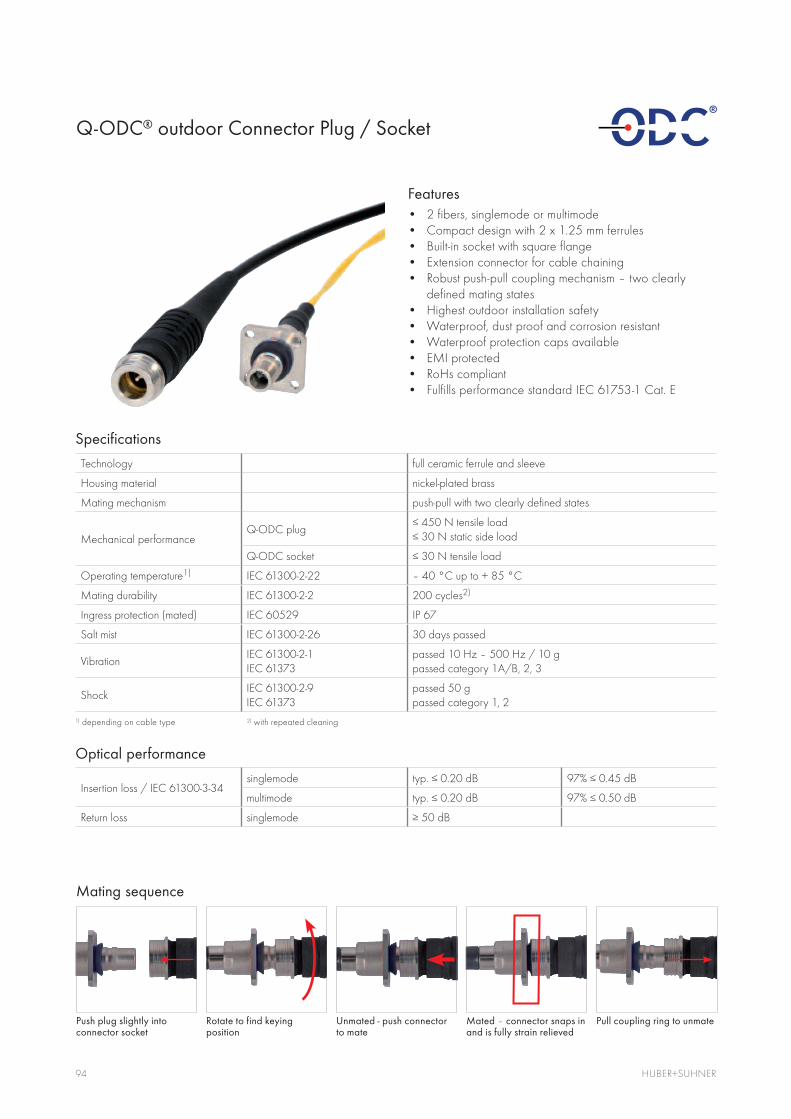
94 HUBER+SUHNER
Features2 fibers, singlemode or multimode Compact design with 2 x 1.25 mm ferrulesBuilt-in socket with square flangeExtension connector for cable chainingRobust push-pull coupling mechanism – two clearly defined mating states Highest outdoor installation safety Waterproof, dust proof and corrosion resistant Waterproof protection caps availableEMI protectedRoHs compliantFulfills performance standard IEC 61753-1 Cat. E
Q-ODC® outdoor Connector Plug / Socket
Mating sequence
Specifications
Technology full ceramic ferrule and sleeve
Housing material nickel-plated brass
Mating mechanism push-pull with two clearly defined states
Mechanical performance Q-ODC plug
Q-ODC socket
Operating temperature1) IEC 61300-2-22 – 40 °C up to + 85 °C
Mating durability IEC 61300-2-2 200 cycles2)
Ingress protection (mated) IEC 60529 IP 67
Salt mist IEC 61300-2-26 30 days passed
Vibration IEC 61300-2-1 IEC 61373
passed 10 Hz – 500 Hz / 10 g passed category 1A/B, 2, 3
ShockIEC 61300-2-9 IEC 61373
passed 50 g passed category 1, 2
1) depending on cable type 2) with repeated cleaning
Optical performance
Insertion loss / IEC 61300-3-34singlemode
multimode
Return loss singlemode
Rotate to find keying position
Unmated - push connector to mate
Mated – connector snaps in and is fully strain relieved
Pull coupling ring to unmate Push plug slightly into connector socket

95www.wireless-infrastructure.com
Q-ODC® outdoor Connector Plug / Socket
Overview of Q-ODC connector types
Type Connector Dust cap
QA
Q-ODC plug
push-on IP54
QC snap-on IP67
QB snap-on with chain IP67
QE
Q-ODC extension
push-on IP54
QF snap-on IP67
QG snap-on with chain IP67
QS
Q-ODC socket square
push-on IP54
QT snap-on IP67
QU snap-on with chain IP67
Q-ODC – Push-pull connector for modular cell site installations
Q-ODC is used by a growing number of operators who build a modular and flexible cell site cable infrastructure. The push-pull connectors allows for quick and reliable cable connections, e.g. for top-mast boxes or jumpers. Additionally, the interface is designed that it is either mated or unmated – nothing in between. This makes each installation of cell site infrastructure safe.

96 HUBER+SUHNER
Features4 fibers, singlemode or multimode Compact design with 4 x 1.25 mm ferrulesBuilt-in socket with square or hexagonal flangeExtension connector for cable chainingScrewed locking mechanismEasy and safe installationWaterproof, dust proof and corrosion resistantWaterproof protection capsEMI protectedRoHs compliantFull compatibility with previous versionFulfills performance standard IEC 61753-1 Cat. E
ODC®-4 outdoor Connector Plug / Socket
Type J2, J3: ODC-4 plug
Specifications
Technology full ceramic ferrule and sleeve
Housing material nickel-plated brass
Mechanical performance ODC-4 plug
ODC-4 socket
Installation torque force min. 1 Nm max. 2 Nm
Operating temperature1) IEC 61300-2-22 – 40 °C up to + 85 °C
Mating durability 1000 cycles2)
Ingress protection (mated) IEC 60529 IP68
Salt mist IEC 61300-2-26 30 days passed
Vibration IEC 61300-2-1 passed 10 – 500 Hz / 10g
Shock IEC 61300-2-9 passed 100 g1) depending on cable type 2) with repeated cleaning
Optical performance
Insertion loss IEC 61300-3-34
singlemode
multimode
Return loss singlemode
Type E4, E6: ODC-4 extension

97www.wireless-infrastructure.com
Standard type K2, K3: ODC-4 socket – hexagonal
ODC®-4 outdoor Connector Plug / Socket
Standard type K6, K7: ODC-4 socket – square small
Overview of ODC-4 connector types
Type Connector Dust cap
J2
ODC-4 plug
screwed cap with pulling feature
J3 screwed cap with chain
E4
ODC-4 extension (socket type)
screwed cap
E6 screwed cap with chain
K2
ODC-4 socket, hexagonal
screwed cap
K3 screwed cap with chain
K6
ODC-4 socket, square small
screwed cap
K7 screwed cap with chain
hole pattern
hole pattern

98 HUBER+SUHNER
FeaturesRuggedized sealing system for fiber-to-the-antenna and industrial applicationOpen bulkhead for easy access to SFP Positive mechanical feedback to operator when fully mated Duplex LC interfaceRobust bayonet locking for easy, fast, and secure matingWater proof (IP 65), dust proof and corrosion resistant.Expansion to RJ45 and power possible
FullAXS – ruggedized sealing System
Specifications
Mating mechanism bayonet style locking
Housing material high performance plastic
Technology LC with full ceramic ferrules
Mechanical performance tensile load 150 N
static side load 30 N
Operating temperature – 40 °C to + 70 °C
Mating durability IEC 61300-2-2 100 cycles
Ingress protection (mated) IEC 60529 IP 65
Vibration IEC 61300-2-1 passed 10 Hz – 500 Hz / 10 g
Performance standards IEC 61753-1 cat. E compliant
Telcordia GR 3120 compliant
Optical performance
Insertion loss singlemode
multimode
Return loss singlemode
Available Q1 2012

99www.wireless-infrastructure.com
69.6
36.0
16.3
0.5
36.0 23.0
23.8
4.5 (4x)Screw holes
Type Z4: FullAXS plug
FullAXS – ruggedized sealing System
Type: FullAXS build-in flange
Type Connector Picture Dust cap
Z4 FullAXS plug
84143159 FullAXS build-in flange
84143964 FullAXS adapter
FullAXS is a registered trademark of TE.

100 HUBER+SUHNER
XCO - ruggedized exchangeable SFP Connector
Features2 fibers, singlemode or multimodeStandard LC duplex interfaceRuggedized outdoor connector for fiber-to-the-antenna and industrial applications Exchange and service of SFP module possible Easy manual installation – no tool required High installation safety due to reliable snap-in strain relief system (patent pending)Waterproof protection cap with pulling eyeEMI protectedRoHs compliant
Specifications
Technology LC with full ceramic ferrules
Housing material nickel-plated brass
Mating mechanism snap-in strain relief system
Mechanical performance
Operating temperature1) – 40 °C up to + 85 °C
Mating durability IEC 61300-2-2 500 cycles
Ingress protection (mated) IEC 60529 IP 67
Salt mist IEC 61300-2-26 30 days passed
Vibration IEC 61300-2-1 passed 10 Hz – 500 Hz / 10 g
Shock IEC 61300-2-9 passed 50 g1) depending on cable type
Optical performance
Insertion losssinglemode
multimode
Return loss singlemode
Mating sequence
Remove protection cap and slide back connector housing
Snap connector into flange – full strain relief
Remove LC dust caps and plug LC duplex connectors into SFP module
Screw-on housing to seal connector

101
Lateral mounting tolerance between SFP module and XCO flange = ± 0.5 mm
Top view
PCB Cage
Front face of housing
Transceiver
recommended 0.2
www.wireless-infrastructure.com
XCO - ruggedized exchangeable SFP Connector
Type X1: XCO connector plug
Type: XCO build-in flange
Description Connector Dust cap
X1 XCO connector IP 67
Item no. 84074439 XCO build-in flange IP 67
Item no. 84102696
Suitable for cable with a diameter from 5 to 9 mm
XCO adapter IP 67
Positioning dimensions of SFP module
hole pattern

Conventional Cell Site Solutions

103
Content
Conventional cell site solutions 102
www.wireless-infrastructure.com
Standard solution with discrete cables 16
Multi -riser cable with distribution box 26
Multi -riser cable with compact divider 54
Re-use of corrugated copper cables 62
Hybrid solutions 70
Accessories 80
Fiber optic interfaces for remote radio heads 86
RF jumpers LISCA 104
SUCOFEED corrugated cables 110
QUICK-FIT coaxial connectors 124
Lightning protectors 132
Accessories for conventional cell sites 144
Power splitters 154
Radio frequency antennas 162
Content
Remote radio installation solutions 12

104 HUBER+SUHNER
RF Jumpers - LISCA
LISCA products are designed to meet customer specifications, delivery requirements and budgets.
LISCA – Low Loss and Low Intermodulation Soldered Corrugated Cable Assembly.

105105www.wireless-infrastructure.com
Application This product line is designed to be used:
As jumper cables for indoor and outdoor applicationsAs internal connections for mobile phone base stationsIn antenna linksAs test leads for low intermodulation test equipmentIn general radio transceivers with requirements for low reflection (VSWR), low attenuation and low intermodulation products
Features Excellent RF performanceHigh RF shielding efficiency Low attenuationMoisture protection IP68High flexibility and small bending radiusLow, stable intermodulation products
Benefits RoHS compliant (2002/95/EC)Wide variety of corrugated cable and connector typesStandard products as well as customized assemblies with special Lengths and markings according to customer specificationsHigh volume capacity thanks to standard assembly processing at all main HUBER+SUHNER production sites worldwide

106 HUBER+SUHNER
RF Jumpers – LISCA
Description LISCA cable assemblies are specially developed for applications where low VSWR and low attenuation combined with low inter modulaiton products are required. The excellent performance is achieved by utilizing corrugated cables with low intermodulation connectors and a controlled assembly process with HUBER+SUHNER solder technology.
These products are factory-made cable assemblies and can only be ordered in predetermined lengths. A hot-polyamide moulding between connector and cable jacket guarantees highest stability and tightness.
Standard LISCA assembliesThese assemblies are produced under stringent quality manufacturing standards in order to achieve consistent high performance. All standard products are based on SUCOFEED cables with black PE jacket material. The assemblies are 100% tested for attenuation and return loss according to the technical data. These LISCA products are factory-made cable assemblies and can only be ordered in predetermined lengths.
Customized LISCA assembliesHUBER+SUHNER’s strengths also include the produc-tion of products according to customer specifications. This product line offers additional possibilities for demanding customer wishes based on the LISCA standard requirements.
Additional features:Improved return loss valuesExample: better –28 dB at 2.2 GHz with straight N or DIN 7/16 connectors 100% factory tested products for intermodulation Example: max. –155 dBc at 1.8 GHz with 2 x 20 W carriersFactory tested products on phase length/tolerance and delay timeSpecified for frequencies up to 6 GHzCustomized marking, labelling and product packaging Special connector designsProducts with lengths up to 150 m

107www.wireless-infrastructure.com
RF Jumpers – LISCA
Assembly length: tolerance +/– 1%
Plug to plug Plug to jack Plug to right angle plug
Assembly performance code
Performance code LIS...-51 LIS...-52 LIS...-71 LIS…-81 LIS…-01
Description Standard LTE* USA1) Test leads Customer specific
Impedance
Frequency (max. operating) 6 GHz 6 GHz 6 GHz 6 GHz 6 GHz 6 GHz
Length of assemblies
Return loss
DC ..1.0 GHz >1.0 .. 2.2 GHz >2.2 .. 2.7 GHz >2.2 .. 4.0 GHz >4.0 .. 6.0 GHz
– – –
– –
– –
–
–
– – –
open
Intermodulation IM3 (2 x 20 W) –162 dBc (typical)–150 dBc –162 dBc (typical)
–160 dBc–165 dBc QN: –155 dBc
open
RF power see cable specification
Attenuation see cable specification
LTE = Long Term Evolution
1) special marking on cable
Order number for standard LISCA
Example: LIS - C9F - 11 716 -16 716- 02000 - 51
Product name
SUCOFEED_1/4_HF C5
SUCOFEED_3/8_HF C7
SUCOFEED_1/2_HF C9 Cable type
SUCOFEED_1/2 C12
Flame retardant: F PE: no indication
Straight male 11 Pattern of connector 1
Right angle male 16
Straight female 21 Pattern of connector 2
DIN 7/16 716 Connector interface 1 2
N N
QN QN
Assembly length in mm
Jumper performance code example: 51 Technical performance

108 HUBER+SUHNER
RF Jumpers – LISCA
LISCA connector pattern
Description Series DIN 7/16 Series N Series QN
Straight male
(Pattern code: 11)
cable: C5, C7, C9, C12 cable: C5, C7, C9, C12 cable: C5, C7, C9, C12
Right angle male
(Pattern code: 16)
cable: C5, C7, C9, C12 cable: C5, C7, C9, C12 cable: C5, C7, C9, C12
Straight female
(Pattern code: 21)
cable: C5, C7, C9, C12 cable: C5, C7, C9, C12
Straight bulkhead female
(Pattern code: 24)
cable: C5, C7, C9 cable: C5, C7
Right angle bulkhead female
(Pattern code: 29)
cable: C5, C7 cable: C7
Straight bulkhead female
(Pattern code: 25)
cable: C5, C7

109www.wireless-infrastructure.com

110 HUBER+SUHNER
SUCOFEED – Corrugated Cables
HUBER+SUHNER SUCOFEED product range of foam corrugated coaxial cables with suitable stripping tools and connectors has excellent electrical, mechanical and climatic properties for indoor as well as for outdoor installations.
The cables guarantee optimal shielding, low attenuation, low VSWR, excellent intermodulation perfor-mance and flexibility for handling and installation on sites.

111www.wireless-infrastructure.com
Applications Antenna links and internal connection of cellular base stationJumper cables and feeder lines
Features Low attenuation design availableHigh power capabilityHigh shielding effectivenessUV-resistantGuaranteed performance up to 3 GHz
Benefits In copper and aluminumLong history and experienceDesigned for: – Harsh environments in polar regions – Extreme heat in the desert – High humidity in the rain forest

112 HUBER+SUHNER
SUCOFEED – Corrugated Cables
1/4" high-flex
Cable design
Order/ type no.
SUCOFEED_1/4_HF SUCOFEED_1/4_HF_FR SUCOFEED_1/4_HF_FR_UL
Dimension 1/4" high-flex 1/4" high-flex 1/4" high-flex
Cable group M5 M5 M5
Jacket version standard flame retardant flame retardant / UL-listed
Inner conductor (Ø in mm) 1.90
Dielectric (Ø in mm) 4.60 4.40
Outer conductor (Ø in mm) 6.40
Jacket (Ø in mm) 7.60 7.95
Electrical data
Typ. operating frequency (GHz)
Impedance (W) 50 ± 1
Capacitance (pF/m) 79.7 80
Relative signal propagation (%) 83.5 83
Signal delay (ns/m) 4.00
Max. operating voltage (kVrms) 0.6
Typ. attenuation @ 1 GHz (dB/100m) 19.54 19.56
Typ. attenuation @ 2 GHz (dB/100m) 28.45 28.53
Typ. attenuation @ 2.2 GHz (dB/100m) 29.98 30.08
Typ. attenuation @ 2.5 GHz (dB/100m) 32.17 32.30
Typ. attenuation @ 3.0 GHz (dB/100m) 35.60 35.77
Max. power @ 1 GHz (40°C) (kW)
Max. power @ 2 GHz (40°C) (kW)
Max. power @ 2.2 GHz (40°C) (kW)
Max. power @ 2.5 GHz (40°C) (kW)
Max. power @ 3.0 GHz (40°C) (kW)
General data
Temp. range operating (°C) – 55 / + 85 – 40 / + 85
Temp. range installation (°C) – 25 / + 60
Typ. weight (kg/100m) 7.5 8.7
Min. bending radius (mm) 25
For detailed data sheets please go to www.hubersuhner.com and then search for type “SUCOFEED”.

113www.wireless-infrastructure.com
3/8" high-flex
Cable design
Order/ type no.
SUCOFEED_3/8_HF SUCOFEED_3/8_HF_FR SUCOFEED_3/8_HF_FR_UL
Dimension 3/8" high-flex 3/8" high-flex 3/8" high-flex
Cable group M7 M7 M7
Jacket version standard flame retardant flame retardant / UL-listed
Inner conductor (Ø in mm) 2.80
Dielectric (Ø in mm) 7.00 6.90
Outer conductor (Ø in mm) 9.50
Jacket (Ø in mm) 10.80 11.15
Electrical data
Typ. operating frequency (GHz)
Impedance (W) 50 ± 1
Capacitance (pF/m) 79.5 80
Relative signal propagation (%) 83
Signal delay (ns/m) 4.00
Max. operating voltage (kVrms) 0.9
Typ. attenuation @ 1 GHz (dB/100m) 13.33
Typ. attenuation @ 2 GHz (dB/100m) 19.43
Typ. attenuation @ 2.2 GHz (dB/100m) 20.48
Typ. attenuation @ 2.5 GHz (dB/100m) 21.99
Typ. attenuation @ 3.0 GHz (dB/100m) 24.34
Max. power @ 1 GHz (40°C) (kW)
Max. power @ 2 GHz (40°C) (kW)
Max. power @ 2.2 GHz (40°C) (kW)
Max. power @ 2.5 GHz (40°C) (kW)
Max. power @ 3.0 GHz (40°C) (kW)
General data
Temp. range operating (°C) – 55 / + 85 – 40 / + 85
Temp. range installation (°C) –25 / +60
Typ. weight (kg/100m) 12.2 13.2 14.2
Min. bending radius (mm) 25
SUCOFEED – Corrugated Cables

114 HUBER+SUHNER
SUCOFEED – Corrugated Cables
1/2" high-flex
Cable design
Order/ type no.
SUCOFEED_1/2_HF SUCOFEED_1/2_HF_FR SUCOFEED_1/2_HF_FR_UL
Dimension 1/2" high-flex 1/2" high-flex 1/2" high-flex
Cable group M9 M9 M9
Jacket version standard flame retardant flame retardant / UL-listed
Inner conductor (Ø in mm) 3.60
Dielectric (Ø in mm) 9.0
Outer conductor (Ø in mm) 12.20 12.10
Jacket (Ø in mm) 13.40 13.65
Electrical data
Typ. operating frequency (GHz)
Impedance (W) 50 ± 1
Capacitance (pF/m) 80.3 78.5
Relative signal propagation (%) 81 85
Signal delay (ns/m) 4.00 3.90
Max. operating voltage (kVrms) 1.27
Typ. attenuation @ 1 GHz (dB/100m) 11.77 10.67
Typ. attenuation @ 2 GHz (dB/100m) 17.48 15.69
Typ. attenuation @ 2.2 GHz (dB/100m) 18.48 16.56
Typ. attenuation @ 2.5 GHz (dB/100m) 19.92 17.81
Typ. attenuation @ 3.0 GHz (dB/100m) 22.19 19.78
Max. power @ 1 GHz (40°C) (kW)
Max. power @ 2 GHz (40°C) (kW)
Max. power @ 2.2 GHz (40°C) (kW)
Max. power @ 2.5 GHz (40°C) (kW)
Max. power @ 3.0 GHz (40°C) (kW)
General data
Temp. range operating (°C) – 55 / + 85 – 40 / + 85
Temp. range installation (°C) – 25 / + 60
Typ. weight (kg/100m) 20
Min. bending radius (mm) 25
For detailed data sheets please go to www.hubersuhner.com and then search for “SUCOFEED”.

115www.wireless-infrastructure.com
1/2" annular
Cable design
Order/ type no.
SUCOFEED_1/2 SUCOFEED_1/2_FR SUCOFEED_1/2_FR_UL
Dimension 1/2" 1/2" 1/2"
Cable group M12 M12 M12
Jacket version standard flame retardant flame retardant / UL-listed
Inner conductor (Ø in mm) 4.80
Dielectric (Ø in mm) 12.10 11.90
Outer conductor (Ø in mm) 13.80 13.70
Jacket (Ø in mm) 15.90 16.00
Electrical data
Typ. operating frequency (GHz)
Impedance (W) 50 ± 1
Capacitance (pF/m) 75.9
Relative signal propagation (%) 88
Signal delay (ns/m) 3.80
Max. operating voltage (kVrms) 1.60
Typ. attenuation @ 1 GHz (dB/100m) 7.29
Typ. attenuation @ 2 GHz (dB/100m) 10.62
Typ. attenuation @ 2.2 GHz (dB/100m) 11.20
Typ. attenuation @ 2.5 GHz (dB/100m) 12.02
Typ. attenuation @ 3.0 GHz (dB/100m) 13.31
Max. power @ 1 GHz (40°C) (kW)
Max. power @ 2 GHz (40°C) (kW)
Max. power @ 2.2 GHz (40°C) (kW)
Max. power @ 2.5 GHz (40°C) (kW)
Max. power @ 3.0 GHz (40°C) (kW)
General data
Temp. range operating (°C) – 55 / + 85 – 40 / + 85
Temp. range installation (°C) – 25 / + 60
Typ. weight (kg/100m) 25.0 27.6 25.8
Min. bending radius (mm) 70
SUCOFEED – Corrugated Cables

116 HUBER+SUHNER
SUCOFEED – Corrugated Cables
7/8" high-flex and annular
Cable design
Order/ type no.
SUCOFEED_7/8_HF SUCOFEED_7/8
Dimension 7/8" high-flex 7/8"
Cable group M24 M23
Jacket version standard standard
Inner conductor (Ø in mm) 9.40 9.00
Dielectric (Ø in mm) 22.40 22.30
Outer conductor (Ø in mm) 25.00 24.80
Jacket (Ø in mm) 27.50 27.60
Electrical data
Typ. operating frequency (GHz)
Impedance (W) 50 ± 1 50 ± 1
Capacitance (pF/m) 75.4 75.8
Relative signal propagation (%) 85 88
Signal delay (ns/m) 3.90 3.80
Max. operating voltage (kVrms) 3.00 2.91
Typ. attenuation @ 1 GHz (dB/100m) 4.25 4.11
Typ. attenuation @ 2 GHz (dB/100m) 6.42 6.11
Typ. attenuation @ 2.2 GHz (dB/100m) 6.81 6.46
Typ. attenuation @ 2.5 GHz (dB/100m) 7.37 6.96
Typ. attenuation @ 3.0 GHz (dB/100m) 8.26 7.76
Max. power @ 1 GHz (40°C) (kW)
Max. power @ 2 GHz (40°C) (kW)
Max. power @ 2.2 GHz (40°C) (kW)
Max. power @ 2.5 GHz (40°C) (kW)
Max. power @ 3.0 GHz (40°C) (kW)
General data
Temp. range operating (°C) – 55 / + 85
Temp. range installation (°C) – 25 / + 60
Typ. weight (kg/100m) 48.0 53
Min. bending radius (mm) 90 120
For detailed data sheets please go to www.hubersuhner.com and then search for “SUCOFEED”.

117www.wireless-infrastructure.com
7/8" annular
Cable design
Order/ type no.
SUCOFEED_7/8_FR SUCOFEED_7/8_LA SUCOFEED_7/8_LA_FR
Dimension 7/8" 7/8" low attenuation 7/8" low attenuation
Cable group M23 M25 M25
Jacket version flame retardant standard flame retardant
Inner conductor (Ø in mm) 9.00 9.50
Dielectric (Ø in mm) 22.30 22.70
Outer conductor (Ø in mm) 24.80 25.40
Jacket (Ø in mm) 27.60 27.90
Electrical data
Typ. operating frequency (GHz)
Impedance (W) 50 ± 1 50 ± 1
Capacitance (pF/m) 75.8 73.8
Relative signal propagation (%) 88 90.3
Signal delay (ns/m) 3.80 3.70
Max. operating voltage (kVrms) 2.91 3.00
Typ. attenuation @ 1 GHz (dB/100m) 4.11 3.76
Typ. attenuation @ 2 GHz (dB/100m) 6.11 5.53
Typ. attenuation @ 2.2 GHz (dB/100m) 6.46 5.83
Typ. attenuation @ 2.5 GHz (dB/100m) 6.96 6.28
Typ. attenuation @ 3.0 GHz (dB/100m) 7.76 6.97
Max. power @ 1 GHz (40°C) (kW)
Max. power @ 2 GHz (40°C) (kW)
Max. power @ 2.2 GHz (40°C) (kW)
Max. power @ 2.5 GHz (40°C) (kW)
Max. power @ 3.0 GHz (40°C) (kW)
General data
Temp. range operating (°C) – 40 / + 85 – 55 / + 85 – 40 / + 85
Temp. range installation (°C) – 25 / + 60
Typ. weight (kg/100m) 65.0 48 52
Min. bending radius (mm) 120
SUCOFEED – Corrugated Cables

118 HUBER+SUHNER
SUCOFEED – Corrugated Cables
1 1/4" annular
Cable design
Order/ type no.
SUCOFEED_1 _1/4 SUCOFEED_1 _1/4_FR
Dimension 1 1/4" 1 1/4"
Cable group M32 M32
Jacket version standard flame retardant
Inner conductor (Ø in mm) 13.10
Dielectric (Ø in mm) 32.40
Outer conductor (Ø in mm) 35.80
Jacket (Ø in mm) 39.50
Electrical data
Typ. operating frequency (GHz)
Impedance (W) 50 ± 1
Capacitance (pF/m) 76.5
Relative signal propagation (%) 88
Signal delay (ns/m) 3.80
Max. operating voltage (kVrms) 4.20
Typ. attenuation @ 1 GHz (dB/100m) 2.94
Typ. attenuation @ 2 GHz (dB/100m) 4.43
Typ. attenuation @ 2.2 GHz (dB/100m) 4.69
Typ. attenuation @ 2.5 GHz (dB/100m) 5.08
Typ. attenuation @ 2.7 GHz (dB/100m) 5.68
Max. power @ 1 GHz (40°C) (kW)
Max. power @ 2 GHz (40°C) (kW)
Max. power @ 2.2 GHz (40°C) (kW)
Max. power @ 2.5 GHz (40°C) (kW)
Max. power @ 2.7 GHz (40°C) (kW)
General data
Temp. range operating (°C) – 55 / + 85 – 40 / + 85
Temp. range installation (°C) – 25 / + 60
Typ. weight (kg/100m) 92 110.0
Min. bending radius (mm) 200
For detailed data sheets please go to www.hubersuhner.com and then search for “SUCOFEED”.

119www.wireless-infrastructure.com
1 5/8" annular
Cable design
Order/ type no.
SUCOFEED_ 1_5/8
SUCOFEED_ 1_5/8_FR
SUCOFEED_ 1_5/8_LA
SUCOFEED_ 1_5/8_LA_FR
Dimension 1 5/8" 1 5/8" 1 5/8" low att. 1 5/8" low att.
Cable group M42 M42 M43 M43
Jacket version standard flame retardant standard flame retardant
Inner conductor (Ø in mm) 17.30 17.60
Dielectric (Ø in mm) 42.40 41.00
Outer conductor (Ø in mm) 46.50 46.50
Jacket (Ø in mm) 49.80 50.30
Electrical data
Typ. operating frequency (GHz)
Impedance (W) 50 ± 1
Capacitance (pF/m) 76.80 72.50
Relative signal propagation (%) 87.50 92
Signal delay (ns/m) 3.80
Max. operating voltage (kVrms) 5.40 5.50
Typ. attenuation @ 1 GHz (dB/100m) 2.43 2.25
Typ. attenuation @ 2 GHz (dB/100m) 3.71 3.36
Typ. attenuation @ 2.2 GHz (dB/100m) 3.94 3.56
Typ. attenuation @ 2.5 GHz (dB/100m) 4.27 3.84
Typ. attenuation @ 2.7 GHz (dB/100m) 4.48 4.02
Max. power @ 1 GHz (40°C) (kW)
Max. power @ 2 GHz (40°C) (kW)
Max. power @ 2.2 GHz (40°C) (kW)
Max. power @ 2.5 GHz (40°C) (kW)
Max. power @ 2.7 GHz (40°C) (kW)
General data
Temp. range operating (°C) – 55 / + 85 – 40 / + 80 – 55 / + 85 – 40 / + 85
Temp. range installation (°C) –25 / +60
Typ. weight (kg/100m) 144.8 160.0 110.0 130.0
Min. bending radius (mm) 300 300
SUCOFEED – Corrugated Cables

120 HUBER+SUHNER
SUCOFEED Aluminium – Corrugated Cables
ApplicationsAntenna links and internal connection of cellular base stationsJumper cables and feeder lines
FeaturesLight weightElectrical performance equal to copper cablesHUBER+SUHNER connectors are fully compatible with aluminium and copper cables Available with UV-resistant polyethylene jackets, flame-retardant jackets on request
BenefitsCost efficient solutionEasy installationFor indoor and outdoor applicationsAvailable sizes from 1/2" to 1 5/8"
HUBER+SUHNER SUCOFEED_LW is a foam dielectric corrugated coaxial cable designed with an aluminium outer conductor and a copper inner conductor. This low weight SUCOFEED_ LW family is a cost efficient alternative to the copper transmission line. The performance of the aluminium cables is equivalent to the copper transmission cables.

121www.wireless-infrastructure.com
SUCOFEED Aluminium – Corrugated Cables
1/2" and 7/8" light weight
Cable design
order/type no. SUCOFEED_1/2_LW SUCOFEED_7/8_LW_LA
dimension 1/2" 7/8" low attenuation
cable group M9 M23
jacket version PE PE
Inner conductor (Ø in mm) 4.80 9.40
Dielectric (Ø in mm) 12.20 22.80
Outer conductor (Ø in mm) 13.80 25.30
Jacket (Ø in mm) 15.90 27.90
Electrical data
Typ. Operating frequency (GHz)
Impedance (W) 50 ± 1 50 ± 1
Capacitance (pF/m) 76 74
Relative signal propagation (%) 88 90
Signal delay (ns/m) 3.80 3.80
Max. operating voltage (kVrms) 1.95 2.95
Typ. attenuation @ 1 GHz (dB/100m) 7.76 4.16
Typ. attenuation @ 2 GHz (dB/100m) 11.38 6.08
Typ. attenuation @ 2.2 GHz (dB/100m) 12.00 6.41
Typ. attenuation @ 2.5 GHz (dB/100m) 12.90 6.88
Typ. attenuation @ 3.0 GHz (dB/100m) 14.31 7.62
Max. power @ 1 GHz (40°C) (kW)
Max. power @ 2 GHz (40°C) (kW)
Max. power @ 2.2 GHz (40°C) (kW)
Max. power @ 2.5 GHz (40°C) (kW)
Max. power @ 3.0 GHz (40°C) (kW)
General data
Temp. range operating (°C) – 55 / + 85 – 55 / + 85
Tamp. range installation (°C) – 40 / + 60 – 40 / + 60
Typ. weight (kg/100m)
Min. bending radius (single/rep.) (mm) 70 / 125 120 / 250
For detailed data sheets please go to www.hubersuhner.com and then search for type «SUCOFEED»

122 HUBER+SUHNER
SUCOFEED Aluminium – Corrugated Cables
1-1/4” and 1 5/8" light weight
Cable design
order/type no. SUCOFEED_1-1/4_LW SUCOFEED_1-5/8_LW_LA
dimension 1-1/4" 1-5/8" low attenuation
cable group M32 M43
jacket version PE PE
Inner conductor (Ø in mm) 13.10 17.60
Dielectric (Ø in mm) 32.00 41.50
Outer conductor (Ø in mm) 36.00 46.50
Jacket (Ø in mm) 39.20 50.30
Electrical data
Typ. Operating frequency (GHz)
Impedance (W) 50 ± 1 50 ± 1
Capacitance (pF/m) 75 74
Relative signal propagation (%) 88 89
Signal delay (ns/m) 3.8 3.8
Max. operating voltage (kVrms) 4.2 5.6
Typ. attenuation @ 1 GHz (dB/100m) 3.20 2.48
Typ. attenuation @ 2 GHz (dB/100m) 4.70 3.69
Typ. attenuation @ 2.2 GHz (dB/100m) 4.97 3.91
Typ. attenuation @ 2.5 GHz (dB/100m) 5.34 4.21
Typ. attenuation @ 2.7 GHz (dB/100m) 5.58 4.41
Max. power @ 1 GHz (40°C) (kW)
Max. power @ 2 GHz (40°C) (kW)
Max. power @ 2.2 GHz (40°C) (kW)
Max. power @ 2.5 GHz (40°C) (kW)
Max. power @ 2.7 GHz (40°C) (kW)
General data
Temp. range operating (°C) – 55 / + 85 – 55 / + 85
Tamp. range installation (°C) – 40 / + 60 – 40 / + 60
Typ. weight (kg/100m)
Min. bending radius (single/rep.) (mm) 200 / 400 280 / 500
For detailed data sheets please go to www.hubersuhner.com and then search for type «SUCOFEED»

123www.wireless-infrastructure.com

124 HUBER+SUHNER
QUICK-FIT Coaxial Connectors
General descriptionHUBER+SUHNER QUICK-FIT connectors are worldwide approved N and 7/16 connectors for foam dielectric corrugated copper tube cables. They offer a greatly simplified and economic approach to cable preparation and assembly. The product line meets the requirements of multi-carrier, high-channel-count transceivers such as base stations of today’s mobile communication infrastructure networks.

125www.wireless-infrastructure.com
Application Rugged connectors for easy outdoor termination of corrugated feeder and jumper cablesMeeting the special requirements of BTS applications
Features Excellent RF performanceLow, stable and reproducible PIM (Passive Intermodulation Product) – typically –165 dBcSafe assembly process performance – in-field termination with reproducible electrical performanceQuick and easy assembly – 2 main connector parts, 4 steps in less than 4 minutesHigh IP rating – IP68Multi-brand, multi-design and multi-material cable compatibilityBackward compatibility
Benefits Easy field installationTime savingSimplified logisticsLow cost of ownershipSupport quality of a proven connector houseCompatible for copper and aluminium cables

126 HUBER+SUHNER
QUICK-FIT Coaxial Connectors
Technical data
Electrical data Requirements
Impedance
Frequency range (for connector interface) N: DC ... 11 GHz 7/16: DC ... 7.5 GHz
VSWR
PIM1) better than –155 dBc
Mechanical data Requirements
Recommended coupling nut torque IEC
Recommended coupling nut torque HUBER+SUHNER
Coupling nut retention force
Centre contact captivated
Durability (matings)
Environmental data Requirements
Temperature range – 40 °C ... + 85 °C / – 40 °F ... + 185 °F
IP rating
Material data
Connector part Material Plating
Cable entry brass SUCOPLATE®
Connector head brass SUCOPLATE®
Outer contact brass SUCOPLATE®
Centre contact spring bronce/brass silver
Insulators PTFE or PFA
Gaskets rubber
Some connectors may have a specification that differs from the above mentioned data. The products are designed and guaranteed to pass the above mentioned test procedures. Any additional or different requirement arising from specific applications or environmental conditions which is not covered by these test procedures is subject to request.

127www.wireless-infrastructure.com
QUICK-FIT Coaxial Connectors
For cable size 1/2"_HF; 1/2"_HF_FR and 1/2"_HF_FR_UL
Type no. Connector style Item no.Assembly instruction Stripping tool
Item no. stripping tool
DIN 7/16 male
DOC-
DIN 7/16 male right angle
DIN 7/16 female
N male
N female right angle
N female
Cable compatibility list on request.
For cable size 1/2"; 1/2"_FR and 1/2”_FR_UL
Type no. Connector style Item no.Assembly instruction Stripping tool
Item no. stripping tool
11_716-50-12-10 DIN 7/16 male
DOC- 74_Z-0-12-15
16_716-50-12-11DIN 7/16 male right angle
21_716-50-12-10 DIN 7/16 female
11_N-50-12-10 N male
N female right angle
21_N-50-12-10 N female
Cable compatibility list on request.
For cable size 7/8"; 7/8"_FR; 7/8”_LA; 7/8”_LA_FR and 7/8"_HF
Type no. Connector style Item no.Assembly instruction Stripping tool
Item no. stripping tool
DIN 7/16 male
DOC-84074476
DIN 7/16 female
N male
N female 84124062
Cable compatibility list on request.

128 HUBER+SUHNER
QUICK-FIT Coaxial Connectors
For cable size 1_1/4" and 1_1/4"_FR
Type no. Connector style Item no.Assembly instruction
Stripping/flairing tool
Item no. stripping tool
DIN 7/16 male 84116088 DOC-
DIN 7/16 female 84116150
Cable compatibility list on request.
For cable size 1_5/8"_LA
Type no. Connector style Item no.Assembly instruction
Stripping/flairing tool
Item no. stripping tool
11_716-50-42-4 DIN 7/16 male DOC- 74_Z-0-42-14/ 74_Z-0-42-15 8408507421_716-50-42-4 DIN 7/16 female
Cable compatibility list on request.

www.wireless-infrastructure.com
Tools for QUICK-FIT Coaxial Connectors
Cable stripping tools and spare partsFor easy cable preparation in one single operation (can be used manually or with electrical power tool)
Type no. Item no. Part description 1/2" HF 1/2" 7/8" 1 1/4" 1 5/8" 1 5/8"_LA
stripping tool (1/2” HF) X
74_Z-0-12-15 stripping tool (1/2”) X
84074476 stripping tool (7/8”) X
stripping tool (1_1/4”) X
flaring tool (1_1/4”) X
74_Z-0-42-14 stripping tool (1_5/8”) X X
74_Z-0-42-15 84085074 flaring tool (1_5/8”) X X
handle (for stripping tools) X4) X4) optional optional optional optional
74_Z-0-0-402 X X
74_Z-0-0-424 spanner AF 17 mm
74_Z-0-0-425 spanner AF 18 mm
74_Z-0-0-426
74_Z-0-0-427 spanner AF 21 mm X
74_Z-0-0-428 spanner AF 22 mm X X
spanner AF 24 mm X
74_Z-0-0-415 22652206 counter sink X1) X1) X1) X1)
74_Z-0-0-418 Stanley knife X X X X X X
74_Z-0-0-420 22652211 steel brush X X X X X
74_Z-0-0-422 steel measure 200 mm X2) X2) X2) X2) X2) X2)
screw driver 2) X
screw driver 4) X X X X
74_Z-0-0-12 22642718 small metal saw X X X X X X
monkey wrench X X X
Type no. Item no. Part description
blade (cutting corrugated copper tube) for 74_Z-0-12-15
blade (cutting jacket) 74_Z-0-42-14
Type no. Item no. Part description
74_Z-0-0-416 22652207
allen wrench AF 4 mm/.157 in. for removing the BIT adapter
74_Z-0-0-421 22652212
1) for assembly use either the Stanley knife or the counter sink
2) only necessary without HUBER+SUHNER stripping tool
4) handle included in QUICK-FIT stripping tool delivery

HUBER+SUHNER
Cold shrink Tubes for additional Protection
Type no. Item no. For connector pair
1/2" HF – 1/2" HF 1/2" HF – 1/2" 1/2" HF – 7/8" 1/2" – 1/2" 1/2" – 7/8" 7/8" – 7/8"
22658885
1/2" HF – 1 1/4" 1/2" HF – 1 5/8" 1/2" – 1 1/4" 1/2" – 1 5/8" 7/8" – 1 1/4" 7/8" – 1 5/8"
226588861 1/4" – 1 1/4" 1 1/4" – 1 5/8" 1 5/8" – 1 5/8"
This special cold shrink tube reliably protects coaxial connectors against humidity and harsh environmental influences like icy conditions or a polluted atmosphere. It especially allows for outdoor feeder line installations in mobile communications and other wireless systems.The simple and fast assembly of this cold shrink tube, by pulling out the supporting spiral, enables a reliable installa-tion without special tools. After the assembly the cold shrink tube provides reliable protection by its continuous radial contact pressure.
Features Quick and easy installation without toolNo torches or heat requiredAccommodates a wide range of cable sizesGood thermal stabilityResists acids and bases, ozone and UV radiationWater resistant

www.wireless-infrastructure.com
Fast-Wrap weatherproofing Kit
Fast-Wrap is a unique, time saving, weatherproofing solution for the telecom industry. The cross-linked butyl on ela-stomer carrier becomes a powerful sealing mechanism that can withstand the continued assault of outdoor elements above or below ground. This same material technology has been used successfully for over thirty years in the roofing and construction industries where it is exposed to the harshest environments. In fact, time and heat only serve to en-hance it’s self amalgamation and sealing properties. Fast-Wrap is a comprehensive replacement for common butyl tape weatherproofing kits and installs three times faster. Unlike butyl tape, Fast-Wrap is clean, easy to cut, simple to wrap, removable, and will not flow after installation.
Applications Outdoor corrugated feeder line to jumper cable connections Cable to lightning protector or antenna connectionsGrounding kitsFiber or dataline connections above or below groundComponent connections
Colour Black
Dimensions 2-1/8" x 5 ft per roll 2 rolls per kit
Specific gravity 1.08 +/– .05
Penetration 40/120
Ozone/UV resistance highdegradation
Elongation tested per ASTM D412-80
Low temperature tested per ASTM D746
Flash point
Shear strength 15 PSI min tested per ASTM D816
Peel strength
Tensile strength 50 PSI max. v per ASTM D412
Odor nil
Shelf life 10 years
Resistance to
24 hrs
Do not expose to Oil, carbon tetrachloride, naphtha, mineral spirits, gasoline
Warranty
Patent pending
For connector pair Connections per kit
1-5/8" to 1/2" 2
1-1/4" to 1/2" 2
7/8" to 1/2" 4
1/2" to 1/2" 12
7/8" to device 12
1/2" to device 12
Item number:
Inquiries to be made at HUBER+SUHNER Inc. (USA)

132 HUBER+SUHNER
Lightning Protectors
General description
Four decades of experience in developing and manufacturing coaxial lightning EMP and NEMP protectors are the foundation of the current HUBER+SUHNER RF-protection portfolio. Our products are designed to meet the stringent requirements of the RF/microwave, telecommunications and wireless industry and cover civil, security and defense applications. An extensive high-voltage impulse laboratory has been established to verify our designs in accordance with the valid international lightning, surge and NEMP standards. Important inventions are covered by worldwide patents.

133www.wireless-infrastructure.com
Application Lightning protection for all mobile communication bandsBIAS-T with lightning protection for applications with active electronics on top of the mastLightning protection for active electronics in Point to Point / Backhaul applicationsLightning protection for active electronics in GPS applicationsDC block for multiband / site sharing installations with TMAsDC line protection circuits for Radio Remote Heads in FTTA applications (for details see page 86, fiber optic chapter "Fiber Optic Interfaces for Remote Radio Heads")
Features Broadband designsExcellent RF performanceHigh lightning current handling capabilityLow residual energyPIM optimizedHigh CW and PIP power rating
Benefits Elevates system availabilityLowers operational riskLP’s perform the same before and after rated lightning pulsesBest suited for outdoor installationsEasy installation

134 HUBER+SUHNER
Broadband Cellular Lightning Protectors
Application/4 shorting stub lightning protectors for high power and low PIM applications without DC
Broadband GDT protectors for single channel or low power applicationsHybrid GDT protectors for multiple channel, high power and low PIM applicationsBias–T protectors to support active electronics with DC on top of the mastOptimized for outdoor installations
Broadband cellular
QUARTER LAMBDA SHORTING STUB 3400
Type no. 3400.17.0431 1) 3400.41.0263 1) 3400.41.0257 1)
Frequency range 690 to 2200 MHz 690 to 2200 MHz 790 to 2620 MHz
Return loss
Insertion loss
Supports AISG at – – –
RF Interface 7/16 female / female 7/16 male / female N male / female
– –
–
–
–
–
DC interface – – –
PIM 3rd order
RF power (CW) max.
RF power (PIP) max. 25 kW 25 kW –
GDT max. DC voltage
n.a. no DC
n.a. no DC
n.a. no DC
Surge current (8/20 μs) single multiple
50 kA 50 kA
80 kA 80 kA
80 kA 60 kA
Residual energy (typ.) 4 kV 1.2/50 μs; 2 kA 8/20 μs 10 μJ 10 μJ 9 μJ
Ingress protection rating IP 67 IP 67 IP 68
Order information
Item no. Type no.
84080266 3400.17.0431
84092647 3400.41.0263
84062515 3400.41.0257
1) LTE = Long term evolution

135www.wireless-infrastructure.com
Characteristics and specialitiesExcellent RF performanceHigh lightning current handling capabilityLow passive intermodulationLow residual energySupports AISG frequency (2.176 MHz)25 kW PIP performance allows the multiple channel operation with "Linear Simulcast Modulation Techniques"
GDT 3402 HYBRID 3409 BIAS T 3410
Type no. 3402.41.A 1) and 2) 3409.41.0084 1) and 2)3410.41.0029 1) and 2)
3410.41.0030 1) and 2)
Frequency range DC to 2500 MHz 690 to 2200 MHz 690 to 2200 MHz
Return loss
Insertion loss
Supports AISG at 2.176 MHz 2.176 MHz 2.176 MHz
RF Interface 7/16 female / female 7/16 male / female N male / female
– –
–
–
–
–
DC interface – – TNC female
PIM 3rd order n.a.
RF power (CW) max. dep. on GDT
RF power (PIP) max. – 25 kW 25 kW
GDT max. DC voltage
replaceable not included dep. on GDT
replaceable, 9071.99.0548/90 V
fix installed, 90 V
Surge current (8/20 μs) single multiple
30 kA 20 kA
30 kA 20 kA
30 kA 20 kA
Residual energy (typ.) 4 kV 1.2/50 μs; 2 kA 8/20 μs 350 μJ 350 μJ 20 μJ
Ingress protection rating IP 67 IP 67 IP 67
Order information
Item no. Type no.
22642813 3402.41.A
84092645 3409.41.0084
84115900 3410.41.0029
Item no. Type no.
– –84115182
3410.41.0030
2) AISG = Antenna Interface Standards Group

136 HUBER+SUHNER
Cellular Backhaul Lightning Protectors
ApplicationProtection of backhaul equipment with coaxial interfaces Protection of backhaul equipment with RJ45 interfaces
Cellular backhaul - POINT-TO-POINT radios
GDT 3402 GDT 3406
Type no.3402.17.0088
3402.17.0089
3406.17.0027
3406.17.0028
Frequency range 0 to 2500 MHz DC to 4000 MHz
Return loss
Insertion loss
RF Interface N female / female N male / female
3402.17.0088
3402.17.0089
3406.17.0027
3406.17.0028
RF power (CW) max. dep. on GDT
RJ45 – –
GDT replaceable, not included not replaceable, fix installed, 90 V
Max. DC voltage dep. on GDT 60 V
Surge current (8/20 μs) single
30 kA
10 kA
multiple 20 kA 5 kA
I nominal (line-PG) – –
Total I nominal (line-PG) – –
I nominal (shield-PG) – –
Residual energy (typ.) 4 kV 1.2/50 μs; 2 kA 8/20 μs 350 μJ 250 μJ
Ingress protection rating IP 65 IP 68
Order information
Item no. Type no.
84102700 3402.17.0088
84041874 3406.17.0027
Item no. Type no.
84102779 3402.17.0089
84041875 3406.17.0028

137www.wireless-infrastructure.com
Characteristics and specialitiesCoaxial protector with bandwidth DC to 2500 MHzOptional with self extinguishing GDT technologyData line protector supports cat. 5 class D and alternatively Gigabit Ethernet cat. 6, class EIndoor and outdoor versions available
3414.99.0001 / 3414.99.0008 3414.99.0021 / 3414.99.0022
Type no.3414.99.0001
3414.99.0008
3414.99.0021
3414.99.0022
Frequency range DC to 100 MHz DC to 250 MHz
Ethernet cabling standard cat. 5; class D cat. 6; class E
Insertion loss – –
RF Interface N female / female N male / female
– –
– –
RF power (CW) max.
RJ453414.99.0001
3414.99.0008
3414.99.0021
3414.99.0022
GDT not replaceable, fix installed not replaceable, fix installed
Max. DC voltage 58 V between pairs 58 V between pairs
Surge current (8/20 μs) single
– –
multiple – –
I nominal (line-PG) 2.5 kA 2.5 kA
Total I nominal (line-PG) 10 kA 10 kA
I nominal (shield-PG) 6 kA shield (connected) to PG
Residual energy (typ.) 4 kV 1.2/50 μs; 2 kA 8/20 μs – –
Ingress protection ratingindoor: IP 20 (3414.99.0001)
outdoor: IP 68 (3414.99.0008)
indoor: IP 20 (3414.99.0021)
outdoor: IP 68 (3414.99.0022)
Order information
Item no. Type no.
23033695 3414.99.0001
84108159 3414.99.0021
Item no. Type no.
84014284
3414.99.0008
84122191
3414.99.0022
3414.99.0001 for indoor
3414.99.0008 for outdoor
3414.99.0022 for outdoor
3414.99.0021 for indoor

138 HUBER+SUHNER
GPS Lightning Protectors
ApplicationFine protector hybrid technology to protect GPS electronics
Characteristics and specialitiesVery low residual pulse energyFull lightning protection (20kA ; 8/20μs)DC bypass functionEasy bulkhead installation
GPSFine protector 3403
Type no.3403.17.0060
3403.17.0063
Frequency range 800 to 2500 MHz
Return loss
Insertion loss
RF Interface N female / female N male / female
3403.17.0060
3403.17.0063
DC bypass voltage other voltage on request
DC bypass current
Surge current (8/20 μs) single
20 kA
multiple 10 kA
Residual energy (typ.) 4 kV 1.2/50 μs; 2 kA 8/20 μs 6 μJ
Ingress protection rating IP 67
Order information
Item no. Type no.
84030303 3403.17.0060
Item no. Type no.
84038163 3403.17.0063

139www.wireless-infrastructure.com
DC Block
ApplicationBlocking of DC (galvanic isolation of the inner conductor)Blocking or reducing of switching transients on transmission lines
Characteristics and specialitiesBraodband operation for all cellular bands
Robust and compactLow weightIP67 rated
DC block
DC block 9077
Type no. 9077.41.0035
Frequency range 350 – 3000 MHz 650 – 2700 MHz
Return loss
Insertion loss
Interface7/16 male / female
RF power (CW) max.750 W, 10 kW (peak)
RF power (PIP) max. 25 kW
PIM 3rd order
DC blocking voltage
Isolation at 100 kHz
at 10 kHz
at 1 kHz
Ingress protection rating IP 67
Order information
Item no. Type no.
84082135
9077.41.0035

140 HUBER+SUHNER
Gas Discharge Tube (GDT)
Type no. Item no.UZstat UZdyn max. IS 8/20 μs ISG 8/20 μs UARC Dim.(V) (V) (kA) (kA) (V) (mm)
9071.99.0547 23034582 230 ± 15 % 675 20 30 10 – 15 6 x 89071.99.0548 23011009 90 ± 20 % 500 20 30 10 – 15 6 x 8
Gas discharge tubes
The best fitting gas discharge tube (GDT) can be selected according to the applied continuous RF power. If a DC signal is superimposed on the RF transmission line follow the guidelines given in the Lightning protection catalogue.

141www.wireless-infrastructure.com
Features and benefits
Self-extinguishing gas discharge tube with automatic recoveryExtinguishing under any coaxial line condition including: – Malfunction of electronic fused DC supplies – Malfunction of RF line monitoring – Absence of any such mechanismCan be employed for any HUBER+SUHNER GDT protector with exchangeable gas tubeField replacement allows cost-effective system upgradesProduct options ensure availability for any applicationHigher safetyNegligible system downtime
SEMPER™ GDT units for retrofit and replacement for series 3401 and 3402
Type no. Item no.UZstat UZdyn max. IS 8/20 μs ISG 8/20 μs UARC
(V) (V) (kA) (kA) (V)9071.99.0647 84015427 230 ± 15 % 675 20 30 10 – 159071.99.0648 84010426 90 ± 20 % 500 20 30 10 – 15
SEMPER™ GDT units for retrofit and replacement for series 3409
Type no. Item no.UZstat UZdyn max. IS 8/20 μs ISG 8/20 μs UARC
(V) (V) (kA) (kA) (V)9071.99.0747 84014462 230 ± 15 % 675 20 30 10 – 159071.99.0748 84014401 90 ± 20 % 500 20 30 10 – 15
SEMPER™ – self-extinguishing Gas Discharge Tube with automatic Recovery
GDT capsule holder
Switch gap closed in normal stateSwitch gap open in activated stateLiquid silicone rubber
Gas discharge tube
Sectional view of SEMPER™ GDT module

142 HUBER+SUHNER
Grounding Kits
ApplicationSeries 9076 grounding kits enable reliable outdoor grounding of today’s usual corrugated copper tube and RG cables for radio transmitter antenna installations.
Characteristics and specialities Quick and easy installationNo loose parts
Grounding cable AWG 6 (16 mm2)Current handling capability 100 kA, 8/20 μs; 25 kA, 10/350 μsWaterproof IP 67Corrosion resistant

143www.wireless-infrastructure.com
Grounding Kits
Type no. Item no.
For cable size SUCOFEED
Andrew, Nokia, Kabelmetal, RFS, Eupen, etc. "A" (mm) "B" (mm) "C" (mm)
Stripping length (mm)
Grounding screw
9076.99.N013-50 84124422 1/2" highflex 500 50 32 26 M8
9076.99.N012-50 84124423 1/2" 500 50 32 26 M8
9076.99.N078-50 84069990 7/8", 7/8" highflex 500 50 44 26 M8
9076.99.N114-50 84069991 1 1/4" 500 50 59 26 M8
9076.99.N158 23012647 1 5/8" 840 70 69 30 M8

144 HUBER+SUHNER
Accessories for Conventional Cell Sites
General description
We offer a large selection of advanced products, which are rich in exclusive features and highly appreciated by the operators of leading companies in the sector because we provide total fastening safety along with practical and easy mounting.

145www.wireless-infrastructure.com
Application Secure fixing of the corrugated, fiberoptic and DC cables on the mast
Features Small structureResistance to atmospheric factors (rays and salty air)Fixing of 1 to 8 coaxial cables depending on version
Benefits Solutions for conventional and FTTA availableSecured components for easy and quick installationAbsolute safety for cables and installer

146 HUBER+SUHNER
General:This product summary shows only a small range of products. Clamps for other profiles or cable types on request.
RFM self clamping hanger Description For profile Picture
Main features Easy and quick installation
Resistance to atmospheric factors
Components
SAS single saddle or SAT twin saddle
Metal bow
Hexagon headed locking screw
Metal pressure plate
MaterialStainless steel AISI 301
Reglas reinforced polyamide, black
USC single clamp Description For profile Picture
Main features Space-saving block
Resistance to atmospheric factors
Components
SAM single saddle
Threaded bar M8
Flat washer RPI 10/20
Hexagonal nuts UNI 5588
Flexible hinge
Adapter self locking M8 (compact clamp)
MaterialStainless steel AISI 304 (V 2A)
Reglass HDPE., UV proof, black
UCC twin clamp Description For profile Picture
Main features Space-saving block
Resistance to atmospheric factors
Components
SAB twin saddle
Threaded bar M8
PUC steel-flanges
Hexagonal nuts UNI 5588
Elastic washer DIN 6798
Adapter self locking M8 (compact clamp)
MaterialStainless steel AISI 304 (V 2A)
Reglass HDPE, UV proof, black
Accessories for Conventional Cell Sites

147www.wireless-infrastructure.com
LCC quick-fit fastener Description For profile Picture
Main features Easy and quick installation
Resistance to atmospheric factors
Components
SAL twin saddle
Threaded bar M8
PSL steel-flanges
Hexagon nuts UNI 5588
Elastic washer DIN 6798
Adapter self locking M8 (compact clamp)
MaterialStainless steel AISI 304 (V 2A)
Reglass HDPE, UV proof, black
SCM click collar Description For profile Picture
Main features Easy and quick installation
ComponentsMetal collar
Adapter M6 (compact clamp)
Material Stainless steel AISI 304 (V 2A)

148 HUBER+SUHNER
Type: RFMSelf clamping hanger with calibrated saddles for flat 3 – 25 mm and round 8 – 25 mm profile
Number of cables:
1x 2x 3x 4x 6x
Cable type H+S descriptionNo. of cables Item no.
Quantities kit with
Weight in g L (mm) L1 (mm) h1 (mm) h2 (mm)
1/2" (Ø17)
RFM_1556_0012 1x 84107915 50 pcs 68 22 28 34 63
RFM_1556_0212 2x 84107916 50 pcs 98 22 28 63 90
RFM_1556_0312 3x 84107917 50 pcs 126 22 28 91 117
RFM_1556_0412 4x 84107918 50 pcs 160 46 53 58 93
RFM_1556_0612 6x 84107919 50 pcs 185 46 53 85 117
7/8" (Ø28)
RFM_1556_0078 1x 84045465 50 pcs 108 34 41 46 74
RFM_1556_0278 2x 84045466 50 pcs 166 34 41 87 112
RFM_1556_0378 3x 84045467 50 pcs 223 34 41 128 150
RFM_1556_0478 4x 84107920 25 pcs 240 70 77 83 117
RFM_1556_0678 6x 84107921 25 pcs 276 70 77 123 153
1-1/4" (Ø40)
RFM_1556_0114 1x 84107922 50 pcs 153 46 53 58 92
RFM_1556_2114 2x 84107923 50 pcs 238 46 53 111 143
RFM_1556_3114 3x 84107925 50 pcs 322 46 53 165 194
1-5/8" (Ø52)
RFM_1556_0158 1x 84107926 25 pcs 188 58 65 72 105
RFM_1556_2158 2x 84045469 25 pcs 211 58 65 137 169
RFM_1556_3158 3x 84045470 25 pcs 403 58 65 202 233
Accessories for Conventional Cell Sites
Main features: Easy and quick installationResistance to atmospheric factors
Components:Single saddle SAS or twin saddle SATMetal bowHexagon headed locking screwMetal pressure plate
Material: Stainless steel AISI 301Reglass reinforced polyamide, black

149www.wireless-infrastructure.com
Type: USCSingle clamp with elastic cushions including angle adapter for flat and angular 3 - 25 mm and round 8 – 26 mm profile
Number of cables:
1x 2x 3x
Cable type H+S descriptionNo. of cables Item no.
Quantities kit with
Weight in g H (mm) h1 (mm) L (mm)
1/2" (Ø17)
USC_1572_0012 1x 84107927 20 pcs 105 75 27 34
USC_1572_0212 2x 84107928 20 pcs 130 100 54 34
USC_1572_0312 3x 84107929 20 pcs 155 125 81 34
7/8" (Ø28)
USC_1572_0078 1x 84107930 20 pcs 132 100 38 45
USC_1572_0278 2x 84107931 20 pcs 170 125 76 45
USC_1572_0378 3x 84107932 20 pcs 207 200 114 45
1-1/4" (Ø40)
USC_1572_0114 1x 84107933 20 pcs 155 100 54 57
USC_1572_2114 2x 84107934 20 pcs 200 200 108 57
UCS_1572_3114 3x 84107935 20 pcs 245 250 150 57
1-5/8" (Ø52)
USC_1572_0158 1x 84107936 20 pcs 155 125 66 68
USC_1572_2158 2x 84107937 20 pcs 200 200 132 68
USC_1572_3158 3x 84107938 20 pcs 290 300 198 68
Main features: Space-saving blockResistance to atmospheric factors
Components:SAM single saddle, threaded bar M8RPI 10/20 flat washer, hexagonal nuts UNI 5588Flexible hingeAdapter self locking M8 (compact clamp)
Material: Stainless steel AISI 304 (V 2A)Reglass HDPE, UV proof, black

150 HUBER+SUHNER
Type: UCCTwin clamp with elastic cushions including angle adapter for flat 3 – 25 mm and round 8 – 26 mm profile
Number of cables:
2x 4x 6x
Cable type H+S descriptionNo. of cables Item no.
Quantities kit with
Weight in g H (mm) h1 (mm) L (mm)
1/2" (Ø17)
UCC_1560_0212 2x 84107943 20 pcs 210 75 27 68
UCC_1560_0412 4x 84107944 20 pcs 260 125 54 68
UCC_1560_0612 6x 84107945 20 pcs 310 150 81 68
7/8" (Ø28)
UCC_1560_0278 2x 84107946 20 pcs 265 100 38 90
UCC_1560_0478 4x 84107947 20 pcs 340 150 76 90
UCC_1560_0678 6x 84107949 20 pcs 415 200 114 90
1-1/4" (Ø40)
UCC_1560_2114 2x 84107950 20 pcs 310 150 54 114
UCC_1560_4114 4x 84107951 20 pcs 400 200 108 114
UCS_1560_6114 6x 84107953 20 pcs 490 250 150 114
1-5/8" (Ø52)
UCC_1560_2158 2x 84107954 20 pcs 310 150 66 137
UCC_1560_4158 4x 84107955 20 pcs 400 250 132 137
UCC_1560_6158 6x 84107956 20 pcs 580 300 198 137
Accessories for Conventional Cell Sites
Main features: Space-saving blockResistance to atmospheric factors
Components:Twin saddle SAB, threaded bar M8PUC steel-flanges, hexagonal nuts UNI 5588Elastic washers DIN 6798Adapter self locking M8 (compact clamp)
Material: Stainless steel AISI 304 (V 2A)Reglass HDPE, UV proof, black

151www.wireless-infrastructure.com
Type: LCCQuick-fit fastener with elastic cushions including angle adapter for flat and angular 3 – 25 mm and round 8 – 26 mm profile
Number of cables:
2x 4x 6x
Cable type H+S descriptionNo. of cables Item no.
Quantities kit with
Weight in g H (mm) h1 (mm) L (mm)
1/2" (Ø17)
LCC_1563_2012 2x 84107958 20 pcs 240 75 30 62
LCC_1563_4012 4x 84107960 20 pcs 270 100 54 62
LCC_1563_6012 6x 84107962 20 pcs 300 125 84 62
7/8" (Ø28)
LCC_1563_2078 2x 84107964 20 pcs 250 75 41 84
LCC_1563_4078 4x 84107965 20 pcs 290 125 79 84
LCC_1563_6078 6x 84107966 20 pcs 330 150 117 84
1-1/4" (Ø40)
LCC_1563_2114 2x 84107968 20 pcs 280 100 53 102
LCC_1563_4114 4x 84107970 20 pcs 350 150 103 102
LCS_1563_6114 6x 84107971 20 pcs 420 200 153 102
1-5/8" (Ø52)
LCC_1563_2158 2x 84107973 20 pcs 310 100 64 119
LCC_1563_4158 4x 84107974 20 pcs 390 200 125 119
LCC_1563_6158 6x 84094910 20 pcs 470 250 186 119
Main features: Easy and quick installationResistance to atmospheric factors
Components:SAL twin saddle, threaded bar M8PSL steel flanges, hexagonal nuts UNI 5588Elastic washers DIN 6798Adapter self locking M8 (compact clamp)
Material: Stainless steel AISI 304 (V 2A)Reglass HDPE, UV proof, black

152 HUBER+SUHNER
Type: SCMClick collar made in metal including angle adapter for flat and angular 3 – 25 mm and round 8 – 26 mm profile
Number of cables:
1x
Cable type H+S descriptionNo. of cables Item no.
Quantities kit with
Weight in g H (mm)
1/2" (Ø17) SCM_2012_4013 1x 84107976 20 pcs 77 44
7/8" (Ø28) SCM_2012_4020 1x 84107977 20 pcs 80 55
1-1/4" (Ø40) SCM_2012_4030 1x 84107979 20 pcs 85 67
1-5/8" (Ø52) SCM_2012_4150 1x 84107980 20 pcs 88 79
Accessories for Conventional Cell Sites
Main features: Easy and quick installation
Components:Metal collarAdapter M6 (compact clamp)
Material: Stainless steel AISI 301

153www.wireless-infrastructure.com

154 HUBER+SUHNER
General descriptionThe RF power splitters are low loss reactive splitters for the distribution of RF signals to radio transceiver antenna systems and radiating cables. The RF power is equally distributed to all outputs with excellent amplitude and phase balance.
A broad range of power splitters with N, DIN 7/16 and SMA connectors has been designed to split even high power multi-carrier signals of all existing mobile phone systems. Multiband units simplify logistics for OEMs and multi-system operators. Smaller units with SMA connectors can be provided for picocell wireless communication systems.
Power Splitters

155www.wireless-infrastructure.com
Application Power splitters for most mobile communication bandsRF signal distribution to antennas and radiating cables2-way, 3-way or 4-way RF-power splitting
Features Superior RF performance, low VSWR and insertion loss
PIM level typically -150 dBc (3rd order, N and 7/16 connector styles)Available in the frequency range from 698 MHz to 6 GHz2-way, 3-way and 4-way configurationsDC continuity for outdoor poweringRugged and reliable designWaterproof IP 65 or IP 67 (depends on the model)Protective cover kit optionally for outdoor installations available (depends on the model)
Benefits Cost efficient solution for connecting a couple or more antennas to only one radio transceiverInstaller friendly robust design
Functionality
Nominal split loss
2 way splitters 3.0 dB
3 way splitters 4.8 dB
4 way splitters 6.0 dB
Isolation between ports
2 way splitters 6.0 dB
3 way splitters 9.5 dB
4 way splitters 12.0 dB

156 HUBER+SUHNER
Power Splitters
DIN 7/16 types with frequency range 800 – 2500 MHz
Type no. 5502.41.0026 5502.41.0027 5502.41.0028
Item no. 84020588 84023443 84023731
Split 2-way 3-way 4-way
Frequency 800 - 2500 MHz 800 - 2500 MHz 800 - 2500 MHz
Input port 7/16 female 7/16 female 7/16 female
Output port 7/16 female 7/16 female 7/16 female
Return loss (input) min. 20 dB min. 20 dB min. 20 dB
Insertion loss typ. 0.3 dB typ. 0.3 dB typ. 0.2 dB
Average power 500 W 500 W 500 W
IP rating IP65 IP65 IP65
Operating temperature range – 40 °C … + 85 °C / – 40 °F … + 185 °F
Weight 0.85 kg 0.95 kg 1.05 kg
Protective cover kit 73_Z-0-0-614/--_-E 73_Z-0-0-614/--_-E 73_Z-0-0-614/--_-E
Mounting hardware9075.99.0001 9075.99.0002
9075.99.0001 9075.99.0002
9075.99.0001 9075.99.0002
Type no. 5504.17.0004 5504.17.0005
Item no. 84005364 84011465
Split 2-way 2-way
Frequency 2000 - 6000 MHz 2000 - 6000 MHz
Input port N male N female
Output port N female N female
Return loss (input) min. 20 dB min. 20 dB
Insertion loss typ. 0.2 dB typ. 0.2 dB
Average power 300 W 300 W
IP rating IP65 IP65
Operating temperature range – 40 °C … + 85 °C / – 40 °F … + 185 °F
Weight 0.8 kg 0.8 kg
Mounting hardware9075.99.0001 9075.99.0002
9075.99.0001 9075.99.0002
N types with frequency range 2000 – 6000 MHz

157www.wireless-infrastructure.com
Protective cover kitThe protective cover kit provides additonal protection for RF Power Splitters exposed to harsh environmental conditions. Important: The installation of the protective cover kit requires right angle adaptors on all output ports. As the power splitters are supplied with straight connector shapes (female) only, you will have to use either jumpers with right angle interfaces (male) or separately ordering right angle adapters as listed below
Power Splitters – Accessories
Type no. Item no. Weight (kg)
73_Z-0-0-614/---_-E 84072501 0.4334
The protective cover kit includes the protective cover with screw M8x1 and screw fixation cord and rubber bellows with hose clamp.
Type no. 53_N-50-0-4/133_UE 53_716-50-0-1/003_-E
Item no. 22658908 22641259
Shape right angle adaptor right angle adaptor
Connector series N 7/16
Connector gender plug/jack [m/f] plug/jack [m/f]
Right angle adaptors to be ordered separately 1 adapter required per output port
Type no. Item no. For mast diameter Weight (kg)
9075.99.0001 22648739 40 - 50 mm 0.35
9075.99.0002 22648738 50 - 360 mm 0.45
One set consists of a complete bracket plus two steel hose clamps adjusted to the selected mast diameter.
This mounting hardware allows you to fix RF power splitters on masts of 40 to 360 mm diameter by means of non corrosive steel hose clamps. It can be used for wall mounting (2 x 8.0 mm diameter holes) too.
Mounting hardware

158 HUBER+SUHNER
Type no. 5502.19.0004 5502.19.0005 5502.19.0006
Item no. 22650303 22650304 22650305
Split 2-way 3-way 4-way
Frequency 2000 - 2500 MHz 2100 - 2500 MHz 2100 - 2500 MHz
Input port SMA male SMA male SMA male
Output port SMA female SMA female SMA female
Return loss (input) min. 19 dB min. 17.5 dB min. 16.5 dB
Insertion loss typ. 0.2 dB typ. 0.2 dB typ. 0.2 dB
Average power 100 W 100 W 100 W
IP rating IP 20 IP 20 IP 20
Operating temperature range – 40 °C … + 85 °C / – 40 °F … + 185 °F
Weight 0.012 kg 0.014 kg 0.015 kg
SMA types with frequency range 2000 - 2500 MHz
Power Splitters
DIN 7/16 types with frequency range 698 – 2700 MHz for LTE
Type no. 5502.41.0029 5502.41.0030 5502.41.0031
Item no. 84086614 84104878 84104879
Split 2-way 3-way 4-way
Frequency 698 – 2700 MHz 698 – 2700 MHz 698 – 2700 MHz
Input port 7/16 female 7/16 female 7/16 female
Output port 7/16 female 7/16 female 7/16 female
Return loss (input) min. 24 dB min. 23 dB min. 19 dB
Insertion loss max. 0.05 dB max. 0.05 dB max. 0.05 dB
Average power 500 W 500 W 500 W
IP rating IP 67 IP 67 IP 67
Operating temperature range -35°C…+75°C / -31°F…+167°F
Weight 0.85 kg 1.00 kg 1.15 kg
Mounting hardware Wall mounting hardware included

159www.wireless-infrastructure.com
Low PIM and Cable Impairment Test Kit
Features Use of high performing PIM components
– N and DIN 7/16 – Load – Standard / source
Benefits Existing and approved technologyAll components are available for on-site IM testingHigh mating cycles
Technical data
Material
Piece part Material Surface Plating
Body Brass Tri-metal plating
Centre contact female Copper beryllium alloy Gold plating / Silver plating / Tri-metal plating
Centre contact male Brass Gold plating / Silver plating / Tri-metal plating
Order information Low PIM and cable impairment test kit, item no. 84108289
Electrical
Impedance
Frequency range 690 MHz to 2700 MHz
RF CW power 50 W
Environmental
Operating temperature 0 °C up to +40 °C
2002/95/EC (RoHS) compliant
Mechanical
Number of matings500 with max. torque of 30 Nm for DIN 716 or max. torque of 1 Nm for N interfaces, increased torque may reduce the number of matings significantly
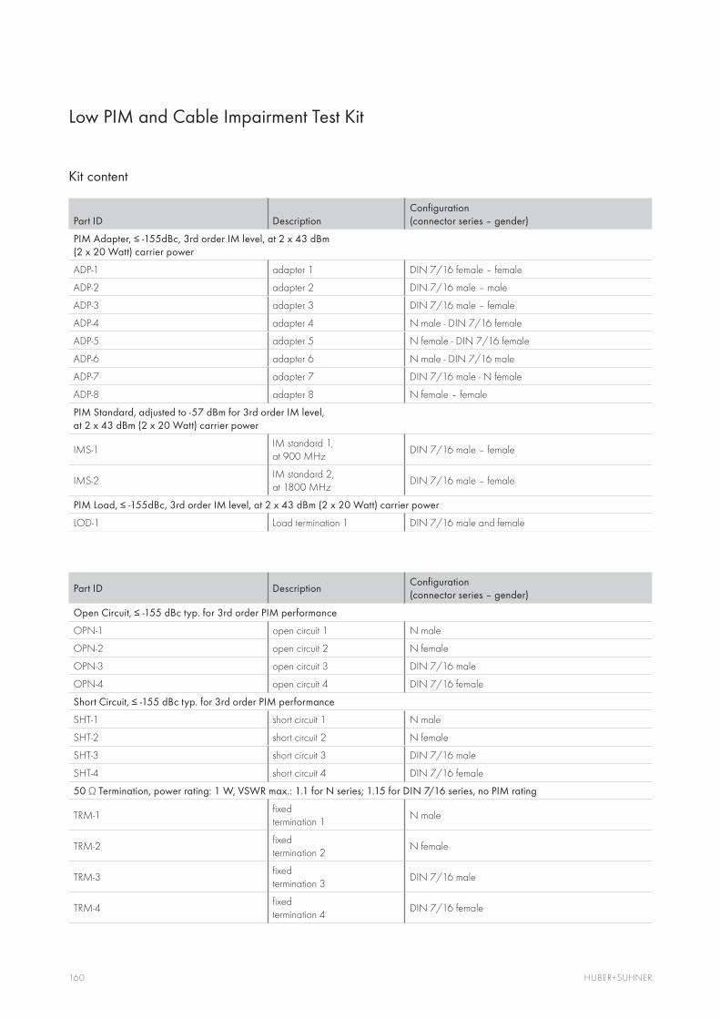
160 HUBER+SUHNER
Kit content
Part ID DescriptionConfiguration (connector series – gender)
ADP-1 adapter 1 DIN 7/16 female – female
ADP-2 adapter 2 DIN 7/16 male – male
ADP-3 adapter 3 DIN 7/16 male – female
ADP-4 adapter 4 N male - DIN 7/16 female
ADP-5 adapter 5 N female - DIN 7/16 female
ADP-6 adapter 6 N male - DIN 7/16 male
ADP-7 adapter 7 DIN 7/16 male - N female
ADP-8 adapter 8 N female – female
PIM Standard, adjusted to -57 dBm for 3rd order IM level,
IMS-1IM standard 1, at 900 MHz
DIN 7/16 male – female
IMS-2IM standard 2, at 1800 MHz
DIN 7/16 male – female
LOD-1 Load termination 1 DIN 7/16 male and female
Part ID DescriptionConfiguration (connector series – gender)
OPN-1 open circuit 1 N male
OPN-2 open circuit 2 N female
OPN-3 open circuit 3 DIN 7/16 male
OPN-4 open circuit 4 DIN 7/16 female
SHT-1 short circuit 1 N male
SHT-2 short circuit 2 N female
SHT-3 short circuit 3 DIN 7/16 male
SHT-4 short circuit 4 DIN 7/16 female
50
TRM-1fixed termination 1
N male
TRM-2fixed termination 2
N female
TRM-3fixed termination 3
DIN 7/16 male
TRM-4fixed termination 4
DIN 7/16 female
Low PIM and Cable Impairment Test Kit

161www.wireless-infrastructure.com

162 HUBER+SUHNER
Radio Frequency Antennas
Wireless communication applications have taken off over the past years. In addition to voice services, wireless systems are now also handling an increasing volume of data traffic, with the demand being for high transmission capacities.
To provide these capacities, mobile radio cells (GSM, UMTS and LTE) are steadily shrinking, allowing multiple use of frequency bands, which in turn enables capacity to be increased.
HUBER+SUHNER provides application specific antennas for base station synchronization for Radio Access Networks (RAN).

163www.wireless-infrastructure.com
GPS Antennas
General descriptionAccurate timing, phase and frequency synchronisation are essential for today’s wireless networks in the field of digital communication. Handover, TDD scheduling, interference cancellation and terminal location tracking are based on GPS or Glonass time reference. HUBER+SUHNER offers a high-quality portfolio of standard and customised GPS and GLONASS antennas for the synchronisation of mobile communication base stations and the support of position detection for mobile terminal equipment. The GPS/Glonass antennas are equipped with a low-noise preamplifier and are provided with integral lightning and overvoltage protection. This is of crucial importance in view of the often exposed position of the antennas. Through the location of the EMP protection in the antennas, separate installation of an external EMP protection can be dis-pensed with. The antennas thus combine compact size with optimal functionality and reliability.
ApplicationsFor timing and frequency synchronisation in cellular base stations derived from the GPS or GLONASS signalUse in position-detection systems for the tracking of mobile terminal equipment
FeaturesSmall and unobtrusive designLow-noise preamplifier for compensation of antenna cable lossAmplifier feed via antenna cable Integrated lightning and overvoltage protectionCone-shaped radome prevents snow, ice and dirt depositsMounting bracket for mast and wall mounting inclu-ded in the scope of supply
BenefitsReliably supports timing and frequency synchronisation in mobile communication networksCan be used with all standard GPS/GLONASS receiversSimple and time-saving installation; no special tools requiredEasy commissioning

164 HUBER+SUHNER
GPS Antennas
Product overviewType no. Item no.
1315.17.0026 84119684
1315.17.0028 84121280
1315.17.0027 84119712
1315.17.0029 84121325
1316.17.0002 84061412
1316.17.0001 84058690
Frequency [MHz] 1565 – 1585 (GPS) 1565 – 1585 (GPS) 1565 – 1625 (GPS + GLONASS)
Antenna gain [dB] 5 5 5
Antenna gain @ 10° elevation [dB]
2 2 –
LNA gain [dB] 31 40 40
Noise figure [dB] 3 3 3.5
VSWR 1.8 1.8 2
Operational voltage 4V-6V DC 4V-6V DC 4V-6V DC
Current consumption 50 mA 50 mA 50 mA
Lightning protector integrated integrated integrated
Radome colour RAL 9003(signal white) RAL 9003(signal white) RAL 7035(light grey)
Mounting bracketL- shape bracket for pole and wall mounting included
bracket not includedL- shape bracket for pole and wall mounting included
bracket not includedL- shape bracket for pole and wall mounting included
bracket not included

165www.wireless-infrastructure.com

Your Contacts at HUBER+SUHNER. Wherever you are.
AUSTRALIA HUBER+SUHNER (Australia) Pty Ltd Unit 6, 4 Skyline Place Frenchs Forest AU-Sydney NSW 2086 Tel. +61 (0)2 8977 1200 Fax +61 (0)2 9972 7549 [email protected]
BRAZIL HUBER+SUHNER América Latina Ltda Av. Rui Barbosa, 3613 Alto da Ponte BR-12212-531 São José dos Campos-SP Tel. +55 12 3946 9500 Fax +55 12 3946 9528 [email protected]
CHINA HUBER+SUHNER (Hong Kong) Ltd Unit 1101 & 1121, Level 11, Tower 1 Grand Central Plaza No. 138 Shatin Ruralo Committee Road Shatin, N.T., HK-Hong Kong Tel. +852 2866 6600 Fax +852 2866 6313 [email protected]
HUBER+SUHNER (Shanghai) Co., Ltd Part B 2-3, 2/F 333 Fu Te Xi Yi Road Waigaoqiao CN-Shanghai 200131, P.R. China Tel. +86 (0) 21 5899 3808 Fax +86 (0) 21 5899 1860 [email protected]
HUBER+SUHNER (Shanghai) Transmission & Communication Manufacture Co., Ltd 1330, Jin Hu Road Jin Qiao, Pu Dong New District CN-Shanghai 201206, P.R. China Tel. +86 (0) 21 5899 3808 Fax +86 (0) 21 5899 1860 [email protected]
DENMARK HUBER+SUHNER A/S Kirke Vaerløsevej 14 DK-3500 Vaerløse Tel. +45 48 100 500 Fax +45 48 100 555 [email protected]
FRANCE HUBER+SUHNER France 21 E, rue Jacques-Cartier FR-78960 Voisins-le-Bretonneux Tel. +33 (0)1 61 37 25 55 Fax +33 (0)1 30 64 73 68 [email protected]
GERMANY HUBER+SUHNER GmbH Mehlbeerenstr. 6 DE-82024 Taufkirchen Tel. +49 (0)89 612 01 0 Fax +49 (0)89 612 01 162 [email protected]
INDIA HUBER+SUHNER Electronics Private Limited 682, Udyog Vihar, Phase V IN-Gurgaon 122 016, Haryana Tel. +91 (0)124 452 6100/200 Fax +91 (0)124 410 27 04 [email protected]
MALAYSIA HUBER+SUHNER (Malaysia) Sdn. Bhd. Lot 24, Jln Pengacara U1/48 Temasya Industrial Park 40150 Shah Alam MY-Selangor Tel. +60 3 7628 0202 Fax +60 3 7628 0303 [email protected]
SINGAPORE HUBER+SUHNER (Singapore) Pte Ltd 11 Chang Charn Road #05-02 Shriro House SG-Singapore 159640 Tel. +65 6573 5500 Fax +65 6473 5522 [email protected]
SWEDEN HUBER+SUHNER AB Knarrarnäsgatan 7 Box 1247 SE-164 28 Kista Tel. +46 (0)8 447 5200 Fax +46 (0)8 447 5201 [email protected]
SWITZERLAND HUBER+SUHNER AG CH-9100 Herisau Tel. +41 (0)71 353 41 11 Fax +41 (0)71 353 44 44 [email protected]
HUBER+SUHNER AG CH-8330 Pfäffikon ZH Tel. +41 (0)44 952 22 11 Fax +41 (0)44 952 24 24 [email protected]
THAILAND HUBER+SUHNER (Thailand) Co., Ltd. 896/3 SV City Office Tower 1 4th Floor, Rama III Road Kwaeng Bangpongpang Khet Yannawa TH-Bangkok 10120 Tel. +66 (0)2 682 6868 Fax +66 (0)2 682 6669 [email protected]
UNITED KINGDOM HUBER+SUHNER (UK) Limited Telford Road GB-Bicester Oxfordshire OX26 4LA Tel. +44 (0)1 869 364 100 Fax +44 (0)1 869 249 046 [email protected]
USA HUBER+SUHNER, Inc. 19 Thompson Drive US-Essex Jct. VT 05452 Tel. +1 800 493 9758 Fax +1 802 878 9880 [email protected]
UAE HUBER+SUHNER Middle East Trading LLC Dubai Investments Park* European Business Center, Office 156 N 25° 00’ 13.83’’/ E 55° 09’ 19.06’’ P.O.Box 75843 Dubai (United Arab Emirates) Tel. +971 4 81 35 35 - 0 Fax +971 4 81 35 35 - 1 [email protected]

Additional Catalogues
Fiber Optic Connectors and AssembliesItem no. 84101808
Connectors and adaptersCable assembliesConnectors for harsh environmentEquipment for serial pro-duction and measurement
Fiber Optic CablesItem no. 84019826
Indoor cablesUniversal cablesOutdoor cablesSpecial cables
Distributed Antenna SytemsItem no. 84078171
RF connectors, cables, assemblies, componentsAntennasFiber management systems
RF and Microwave ComponentsItem no. 84068668
Coaxial attenuatorsTerminationsRF power splittersSpecial products
Lightning ProtectionItem no. 23002023
Lightning EMP protectorsNEMP protectorsData line protectorsDC blocks
RF Coaxial Connectors General CataloqueItem no. 84019826
Micro miniature connectorsCable connectorsSubminiature connectorsAdaptors
Fiber Optic Cabling SystemsItem no. 23029084
Pre-terminated cabling systemsMASTERLINESMARTLINEMobile cabling system

hubersuhner.com
Wire
less
Infra
struc
ture
– E
ditio
n 20
12
WAIVERIt is exclusively in writ ten agreements that we provide our customers with warrants and representations as to the tech-nical specifications and/or the fitness for any particular pur-pose. The facts and figures contained herein are carefully compiled to the best of our knowledge, but they are intended for general informational purposes only.
HUBER+SUHNER AGDegersheimerstrasse 149100 HerisauSwitzerlandTel. +41 71 353 4111Fax +41 71 353 [email protected]
HUBER+SUHNER is certified according to ISO 9001, ISO 14001, ISO/TS 16949 and IRIS.
8412
6953
Rev
. A/1
0.20
11
Wireless Infrastructure Solutions for remote radio systems and conventional cell sites