INFRASTRUCTURE & OPERATION
22
Attachment D INFRASTRUCTURE & OPERATION Cadbury Ireland Limited Rathmore Installation IPPC Licence Application Project Ref: OES1061_01 For inspection purposes only. Consent of copyright owner required for any other use. EPA Export 25-07-2013:21:16:05
-
Upload
khangminh22 -
Category
Documents
-
view
0 -
download
0
Transcript of INFRASTRUCTURE & OPERATION

Attachment D INFRASTRUCTURE & OPERATION Cadbury Ireland Limited Rathmore Installation IPPC Licence Application Project Ref: OES1061_01
For
insp
ectio
n pur
pose
s only
.
Conse
nt of
copy
right
owne
r req
uired
for a
ny ot
her u
se.
EPA Export 25-07-2013:21:16:05

Cadbury Ireland Limited February 2007 Rathmore Installation IPPC Licence Application Attachment D
OES Consulting Page 2 of 16
Attachment No. D D1 Operational Information Requirements Cadbury Ireland Limited, Rathmore Installation is a subsidiary of Cadbury-Schweppes plc, a global leader in the manufacture of beverages and confectionery products. Cadbury Ireland Limited was established in 1932, producing three products one of which included Cadbury Dairy Milk. Cadbury Ireland Limited now has three production plants, comprising of two in Co. Dublin (Coolock and Tallaght) and one in Co. Kerry (Rathmore). Cadbury Ireland Limited is an undisputed market leader in the chocolate market with a 48% share of a market worth �473 million annually. Cadbury Ireland Limited manufactures and distributes over 25 products within the Irish Market and exports a number of key lines. Cadburys has core operations in Rathmore, the UK, and Europe, serving local and global markets. Cadbury Ireland Limited uses local ingredients and is one of the largest users of indigenous Irish materials. Using local produce is a major factor in creating the legendary taste of Cadbury Ireland Limited products. Cadbury Ireland Limited, Rathmore Installation is an international provider of milk chocolate crumb, this is an intermediate product utilised in the production of milk chocolate in a number of facilities throughout the World. Cadbury Ireland Limited Rathmore Installation comprises of a crumb processing centre, laboratory, administration and engineering buildings. In addition the plant also contains storage facilities, a wastewater treatment and utility plants. Chocolate crumb is produced 24 hours per day and owing to efficient processing operations, the plant operates for 50 weeks within the year. Although the majority of unit operations are automated, Cadbury Ireland Limited retains approximately 115 permanent employees at the installation.
Control of the processes undertaken in each of the plant areas and the transfer of liquid feedstock between unit operations is highly automated. In addition to the sophisticated Programmable Logic Controller (PLC) systems, product quality is ensured through a regime of frequent, routine sampling and analysis and is regulated under a strict Quality Management System.
In addition to down time associated with feedstock availability, each plant area has a scheduled regime of plant outages. These enable cleaning in order to observe strict hygiene requirements. Cleaning operations utilise dilute acid and caustic solutions. The frequency and cleaning solution specification is governed by the requirement of each unit operation.
In situ cleaning of pipelines, vessels and other plant items is termed here ‘clean in place’ (CIP). Process control of the CIP sequence of cleaning and flushing is highly automated.
For
insp
ectio
n pur
pose
s only
.
Conse
nt of
copy
right
owne
r req
uired
for a
ny ot
her u
se.
EPA Export 25-07-2013:21:16:05
Cadbury Ireland Limited February 2007 Rathmore Installation IPPC Licence Application Attachment D
OES Consulting Page 3 of 16
D2 List of Processes The Cadbury Rathmore installation exclusively produces chocolate crumb for the domestic market. The following processes are carried out at the Rathmore installation:
D2.3 Sugar Intake Process
D2.4 Cocoa Mass Intake Process
D2.5 Production of Chocolate Crumb
D 2.6 Storage
D 2.7 Services
D 2.8 Roads and Paving
D 2.9 Laboratory
D2.10 Boiler House
D2.12 Emission Abatement Equipment
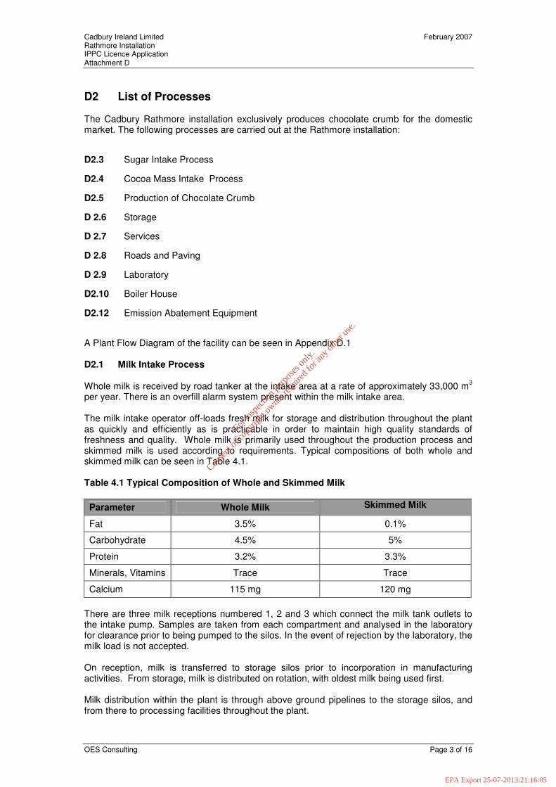
A Plant Flow Diagram of the facility can be seen in Appendix D.1 D2.1 Milk Intake Process Whole milk is received by road tanker at the intake area at a rate of approximately 33,000 m3 per year. There is an overfill alarm system present within the milk intake area. The milk intake operator off-loads fresh milk for storage and distribution throughout the plant as quickly and efficiently as is practicable in order to maintain high quality standards of freshness and quality. Whole milk is primarily used throughout the production process and skimmed milk is used according to requirements. Typical compositions of both whole and skimmed milk can be seen in Table 4.1. Table 4.1 Typical Composition of Whole and Skimmed Milk Parameter Whole Milk Skimmed Milk
Fat 3.5% 0.1%
Carbohydrate 4.5% 5%
Protein 3.2% 3.3%
Minerals, Vitamins Trace Trace
Calcium 115 mg 120 mg There are three milk receptions numbered 1, 2 and 3 which connect the milk tank outlets to the intake pump. Samples are taken from each compartment and analysed in the laboratory for clearance prior to being pumped to the silos. In the event of rejection by the laboratory, the milk load is not accepted. On reception, milk is transferred to storage silos prior to incorporation in manufacturing activities. From storage, milk is distributed on rotation, with oldest milk being used first. Milk distribution within the plant is through above ground pipelines to the storage silos, and from there to processing facilities throughout the plant.
For
insp
ectio
n pur
pose
s only
.
Conse
nt of
copy
right
owne
r req
uired
for a
ny ot
her u
se.
EPA Export 25-07-2013:21:16:05

Cadbury Ireland Limited February 2007 Rathmore Installation IPPC Licence Application Attachment D
OES Consulting Page 4 of 16
The plant produces approximately 65,000 tonnes of Chocolate Crumb per annum. Raw Material Intake There are a series of liquid intake areas associated with the main processing plant, including a primary milk intake area comprising: 1. 1 weighbridge 2. 3 reception bays 3. 2 CIP stations for washing Cleaning in Place (CIP) Milk trucks are also washed at the end of each days run. The quality control manual contains details of the cleaning schedule for the milk intake area. The CIP process is controlled according to methods detailed in the Quality manual. The key process controls are as follows: � The milk intake lines and road tankers are cleaned using a detergent - Lactrin. The quantity
and strength at which the detergent is applied varies depending on the equipment being cleaned.
Hot Water Pre - Rinse Any build up, deposits, wastes etc. are removed during this process. Circulation Wash Lactrin based solution is used on surfaces and pipelines to soften any leftover residue to ensure complete removal when rinsing. The detergent is subsequently drained and recovered. Cold Post - Rinse This removes all previously applied detergent and leaves all surfaces visually clean. Process Controls The intake process is controlled under the Milk Intake Procedure. The milk quality is tested manually everyday within the laboratory. The key process controls are as follows:
Parameter Method Frequency Records Control
Temperature Thermometer Every Delivery Log Sheet
Maximum Limit in place
Odour/Appearance Visual Inspection Every Delivery Log
Sheet
Free from foreign matter, and abnormal
odours.
Resazurin Quality Control Manual Every Delivery Log
Sheet Minimum 4 at
10 minutes Acidity (Intake Milk)
Quality Control Manual Every Delivery Log
Sheet Maximum
Limit in place
Added Water Quality Control Manual Every Delivery Log
Sheet Limit in place
Fat Quality Control Manual Every Delivery Log
Sheet N/A
Antibiotics Quality Control Manual Every Delivery Log
Sheet
If present the milk is not accepted.
For
insp
ectio
n pur
pose
s only
.
Conse
nt of
copy
right
owne
r req
uired
for a
ny ot
her u
se.
EPA Export 25-07-2013:21:16:05

Cadbury Ireland Limited February 2007 Rathmore Installation IPPC Licence Application Attachment D
OES Consulting Page 5 of 16
Parameter Method Frequency Records Control Acidity (Silo Milk)
Quality Control Manual Twice Daily Log
Sheet Limit in place
Multi spec Fat SNF Ratio
Quality Control Manual
When Silo is ready for evaporation
Log Sheet
Limit Ratio’s in Place
Milk Storage Temperature Digital Readout Daily Log
Sheet
Maximum Limit in place
D2.2 Butter Oil Intake Process Butter oil is received by road tanker at the intake area at a rate of approximately 35 tonnes per year. The butter oil is distributed within the plant though above ground pipelines from the storage silos, and from there to processing facilities throughout the plant. There is an overfill alarm system present within the butter oil intake area. The composition of the butter oil is a 99.9% fat based product produced from cream via a multi stage separation process. The butter oil intake process occurs within the main intake area of the main processing plant which comprises: 1. Weighbridge 2. Storage Silos 3. CIP Process Controls The intake process is controlled under the procedures detailed in the Quality Manual. The key process controls are as follows: Parameter Method Frequency Records Control
Moisture N/A N/A Log Sheet Maximum Limit in place (0.3%)
Peroxide value N/A N/A Log Sheet Maximum Limit in
place (0.3 m. equvi/ kg. max)
Free – Fatty acids N/A N/A Log Sheet < 0.35 % max
Flavour N/A N/A Log Sheet < 0.35 % max
Colour N/A N/A Log Sheet < 0.35 % max Storage Temperature on VDU check Read Out 2 Year
Digitherm Log Sheet < 0.35 % max
Supplier Certification N/A Every Load Log Sheet
Supplier visit N/A As Required Log Sheet
APC @ 30° C N/A Each Consignment Log Sheet 10,000g
Enteros N/A Each Consignment Log Sheet 10/g
Salmonella/Shigella (Standard Butteroil) N/A N/A Log Sheet 0/25g
Yeast and Mould (Standard Butteroil) N/A N/A Log Sheet 100/g
If butter oil does not satisfy the above quality control standards it is not accepted and returned back to the manufacturer.
For
insp
ectio
n pur
pose
s only
.
Conse
nt of
copy
right
owne
r req
uired
for a
ny ot
her u
se.
EPA Export 25-07-2013:21:16:05

Cadbury Ireland Limited February 2007 Rathmore Installation IPPC Licence Application Attachment D
OES Consulting Page 6 of 16
Cleaning is an essential element of the butter oil intake process which is dependent upon high standards of hygiene and cleanliness. Cleaning takes place as required. During CIP all process intake lines and other equipment are cleaned as are all floor areas within the manufacturing plant. D2.3 Sugar Intake Process Sugar is received by road tanker at the intake area at a rate of approximately 37,000 tonnes per year. There is an overfill alarm system present within the sugar intake area. The sugar is distributed to processing facilities within the plant though above ground pipelines from the storage silos. The sugar intake process occurs within the main intake area of the main processing plant which comprises: 1. Weighbridge 2. Storage Silos Process Controls The intake process is controlled according to procedures detailed in the Quality Manual. Humidity is monitored continuously and a maximum control limit (30-60%) is in place. Parameter Method Frequency Records Control Storage Temperature
As Required N/A Log
Sheet Maximum Limit in place
(15-33 O C) Certification visit N/A
As Required N/A Log Sheet Covering requirements of
specification
Humidity N/A Continuous Log Sheet Maximum Limit in place (30-60%)
D2.4 Cocoa Mass Intake Process Cocoa Mass is received by road tanker at the intake area at a rate of approximately 9,000 tonnes per year. There is an overfill alarm system present within the cocoa mass intake area. The cocoa mass is distributed to processing facilities within the plant though above ground pipelines. The silos are heated in order to maintain the cocoa mass in a continuous liquid state. Cocoa mass intake process occurs within the main intake area of the main processing plant which comprises: 1. Weighbridge 2. Storage Silos Process Controls The intake process is controlled under the cocoa mass intake Process Manual. The key process controls are as follows: Parameter Method Frequency Records Control
Salmonella N/A Each Delivery
Cert of Analysis
Maximum Limit in place (0/25g)
Fat N/A Daily Cert of Analysis
Maximum Limit in place (Max 49-53wb)
For
insp
ectio
n pur
pose
s only
.
Conse
nt of
copy
right
owne
r req
uired
for a
ny ot
her u
se.
EPA Export 25-07-2013:21:16:05

Cadbury Ireland Limited February 2007 Rathmore Installation IPPC Licence Application Attachment D
OES Consulting Page 7 of 16
Moisture N/A Daily Cert of Analysis
Maximum limit in place
Storage Temperature N/A N/A Log Sheet Maximum Limit in place
(50-60 O C) D2.5 Production of Chocolate Crumb A written description of the production process for chocolate crumb can be seen in Section A1.1. of Attachment A. In addition, a diagram of the process is shown in Appendix A1.3 of Attachment A. Process Controls The chocolate crumb manufacturing process is controlled under a series of procedures within the Quality manual, which cover Chocolate Crumb Production and Packaging. The intake procedures and process controls for the inputs (sugar, milk, butter oil, and cocoa mass) have been illustrated in the previous sections. The key process controls in the manufacture of chocolate crumb are as follows: Parameter Control Records
Recipe Control Load cells on batching tanks
Calibration Records/
Production Records
Raw Milk Quality Manual Testing Laboratory
Temperature Automatic and manual Thermometers PLC/Log sheet
Steam Pressure Automatic and manual PLC/Log Sheet
Mains Water Pressure In-line pressure gauge PLC
Water Quality Manual Testing Laboratory
Temperature in Cooker Continuous monitoring P.L.C./Log Sheet
Product Quality Manual - laboratory analysis Laboratory
Moisture Manual Testing Laboratory
Fat Manual check Log Sheet
Bacteriological Manual testing Laboratory Cleaning Cleaning is an essential element of the chocolate production process, which is dependent upon high standards of hygiene and cleanliness. Cleaning includes manual as well as CIP systems. Cleaning takes place as per cleaning schedules and procedures as outlined in the Quality Manual.
For
insp
ectio
n pur
pose
s only
.
Conse
nt of
copy
right
owne
r req
uired
for a
ny ot
her u
se.
EPA Export 25-07-2013:21:16:05

Cadbury Ireland Limited February 2007 Rathmore Installation IPPC Licence Application Attachment D
OES Consulting Page 8 of 16
D 2.6 Storage There is approximately 1,205 m3 and 570 tonnes of storage provided on-site for raw material, intermediate and finished product.
Bulk storage comprises stainless steel silos, which are located throughout the three main production areas in tank farms. The capacity of storage silos on site varies from approximately 1 m3 to 400 m3.
Storage is provided for the following:
Material Tank Type Approximate Storage Capacity (m3)
Milk Stainless Steel 660
Cocoa Mass Stainless Steel 210
SCM Stainless Steel 275
Butteroil Stainless Steel 60
Lactrin Stainless Steel (bunded) 5
Diesel Oil Stainless Steel (bunded) 22.2
H.F.O. Stainless Steel (bunded) 380
Sodium Hypochloride Stainless Steel (bunded) 5
Caustic Soda Stainless Steel (bunded) 17
Nitric Acid Stainless Steel (bunded) 9
Water Stainless Steel 680
Calor Gas BMS Pressurised 1.5 Arising from the way in which development has taken place at the site over the past 58 years, the degree of local bunding on individual tanks and for tank farms is limited. The tanks themselves are stainless steel and no serious tank failure has occurred at the site in the past 58 years, although minor pinhole leaks have been detected along weld seams on some tanks. The risk of serious tank rupture is considered to be low. A number of the storage tanks within the production areas receive a degree of containment through the routing of adjacent surface water drains to the wastewater treatment plant. Storage arrangements for fuels and cleaning chemicals differ from dairy storage in that all fuel oil storage tanks and cleaning (CIP) chemical storage tanks are bunded. Palletised storage is provided for vacuum dried processed chocolate crumb, which is packed in 1150 kg tote bags. Air dried crumb is stored in one of two bulk silos, from where it can be packed in containers in kibbled form or milled and stored in 750 kg. tote bags. All tote bags are then transported to one of six finished goods storerooms. D 2.7 Services The services provided on-site are as follows:
For
insp
ectio
n pur
pose
s only
.
Conse
nt of
copy
right
owne
r req
uired
for a
ny ot
her u
se.
EPA Export 25-07-2013:21:16:05

Cadbury Ireland Limited February 2007 Rathmore Installation IPPC Licence Application Attachment D
OES Consulting Page 9 of 16
� Compressed Air � Water Treatment � Heat System Compressed Air The compressed air plant provides an adequate quantity of dry air free of oil and other contamination at a pressure of 12 bar. The air compressors in use are two stage air cooled machines, which deliver oil free air for all requirements. The compressors are connected to the air inlet, the electricity and the cooling air supply. Compressed air after leaving the cooler and going into the air inlet is 100% saturated with water vapour and dried. There are three dryers in use at present: • one air cooled dryer unit • three vacuum dryer units These are connected up to the compressors as appropriate. The operation of the compressed air system is variable on demand. Wastes and Emissions Discharge from dryers consisting of water goes to a drain and is diverted from there to the effluent treatment plant. Air leaks go to the surrounding atmosphere. In the event of an oil leak suitable absorbent material is used to absorb the oil, which would be disposed of appropriately. Water Supply
The water treatment plant provides an adequate quantity of potable water to the quality standards S.I. No. 439 of 2000 for the entire site.
Well water is supplied from two principal boreholes located to the southeast of the factory in the car park. The two boreholes supply the borehole reservoir, which in turn supplies the water treatment plant. In addition, there is a top up borehole located to the south of the factory, adjacent to the administration building. Chlorination Chlorine is added to the well water. The purpose of this is to provide disinfection of the water leaving it free from disease causing organisms. Filtration Filtration of the well water occurs in sand filter beds to remove impurities in the water. The water flows down through the filter bed and out under drains to the clean water storage Silo. Storage
For
insp
ectio
n pur
pose
s only
.
Conse
nt of
copy
right
owne
r req
uired
for a
ny ot
her u
se.
EPA Export 25-07-2013:21:16:05

Cadbury Ireland Limited February 2007 Rathmore Installation IPPC Licence Application Attachment D
OES Consulting Page 10 of 16
Water is pumped from the clean water sump to the storage reservoir, which has a capacity of 570m3. One quarter of the water from the reservoir is utilised for processing and cleaning, and the remaining three quarters is reserved as fire water. D 2.8 Roads and Paving Roads and paving are generally constructed from reinforced concrete and laid to falls. The car park is surfaced with hard standing asphalt. Drainage The drainage at the facility can be categorised as follows: 1. Storm water from roads and other open areas. 2. Wastewater from manufacturing processes and associated utilities, sanitary effluent,
and storm water runoff from hi risk areas. There are two storm water drainage catchments and associated collection systems at the site. The storm water runoff from the western section of the facility flows to a drainage channel located to the west of the facility and subsequently to the River Blackwater. The eastern parts of the site currently drain to the wastewater treatment plant for treatment prior to discharge. The waste water drainage system collects process waste water, domestic sewage from the production plant, administration areas for treatment at the waste water treatment plant. Surface water from the milk and intake areas also discharges to the WWTP. D 2.9 Laboratory There is a laboratory on-site, which carries out a range of microbiological, chemical tests on raw materials, intermediates and end products. The tests undertaken include: Product quality Parameter Compositional analysis Acidity pH
Fat Content Moisture content
Microbiological quality Particle size
Solids content Protein content
D2.10 Boiler House The boiler system has been operational since 1966 when two boilers were installed, in 1978 a third boiler was installed. The primary function of the heat system at the plant is steam generation to meet the demand from process areas. In addition, the system provides hot water (65°C) for processing areas. The base steam load at the plant is met by one of two operational HFO (Heavy Fuel Oil) boilers (duty and stand-by). A third boiler is partly decommissioned and unavailable for use. Boiler feed water is made up from condensate, evaporate form the processing plant and raw water (potable water from on-site storage) where required. Boiler feed water is chemically
For
insp
ectio
n pur
pose
s only
.
Conse
nt of
copy
right
owne
r req
uired
for a
ny ot
her u
se.
EPA Export 25-07-2013:21:16:05

Cadbury Ireland Limited February 2007 Rathmore Installation IPPC Licence Application Attachment D
OES Consulting Page 11 of 16
treated to make it more suitable for boiler use using phosphate (scale inhibitor), sodium sulphate (oxygen scavenger) and caustic soda (pH buffer). Wastes and Emissions Condensate is diverted to the effluent treatment plant. Stack emissions go to atmosphere. Debris, dust, etc. accumulates in the boiler house over a period of time. This is swept up, put into rubbish bags and sent to landfill.
Evaporator trays are cleaned regularly. Waste oil, which has been drained, is put into bunded tanks, identified and sent for recycling by a number of licenced waste contractors. Wash water goes to drain and is diverted to the effluent treatment plant. Solid Waste The sources of solid waste at the Rathmore facility predominantly consist of debris from clean-up activities together with minor quantities of chocolate crumb as dust and organic waste (sludges) from the waste water treatment plant. D2.11 Process Waste Water Treatment The main sources of process waste water arising from production activities at the plant are as follows: Cleaning Operations Rigorous cleaning is undertaken in order to maintain a high standard of hygiene. Cleaning operations are undertaken at scheduled periods as specified within the Quality Manual. The Quality Manual contains details of the plant equipment which is to be cleaned, the personnel responsible, and the frequency and method in which it should be undertaken. Floor Washings Floor washings, which are generated in all process and services areas, are diverted to the Waste Water Treatment Plant (WWTP). Sanitary Effluent Sanitary effluent is collected and discharges to the wastewater treatment plant at the inlet for subsequent solids removal and secondary treatment. Production and Roof areas Runoff from roof and processing areas are collected via a network of drains which discharge to the WWTP. Once treated the water subsequently drains to the River Blackwater. Storm Water Runoff Storm water run-off from yard areas located to eastern section of the facility drain to the surface water drains and subsequently to the wastewater treatment plant. Surface water arising from the western section of the building including the car park flows into a stream which runs to the River Blackwater (SW2). D2.12 Emission Abatement Equipment Discharges to Surface Waters
For
insp
ectio
n pur
pose
s only
.
Conse
nt of
copy
right
owne
r req
uired
for a
ny ot
her u
se.
EPA Export 25-07-2013:21:16:05

Cadbury Ireland Limited February 2007 Rathmore Installation IPPC Licence Application Attachment D
OES Consulting Page 12 of 16
The drainage at the facility can be categorised as follows: 1. Storm water from roads and other open areas. 2. Wastewater from manufacturing processes and associated utilities, sanitary effluent,
and storm water runoff from hi risk areas. There are two storm water drainage catchments and associated collection systems at the site. The storm water runoff from the western section of the facility flows to a drainage channel located to the west of the facility and subsequently to the River Blackwater. The eastern parts of the site currently drain to the wastewater treatment plant for treatment prior to discharge. The waste water drainage system collects process waste water, domestic sewage from the production plant, administration areas for treatment at the waste water treatment plant. Surface water from the milk and intake areas also discharges to the WWTP. A diagram depicting the site drainage plan can be seen in Appendix D.2. The drainage plan for the Waste Water Treatment Plant (WWTP) can be seen in Appendix D.3. The process waste water from the facility is treated to a high level utilizing chemical, biological and physical separation processes within the Waste Water Treatment Plant WWTP to remove organic and inorganic substances and render the water safe prior to discharge to the River Blackwater. Some of the typical contributions to process wastewater include the following:
� Floor wash down � Cooling waters from energy centre � CIP Stations � Water treatment filter washings � Caustic soda and acids from cleaning programmes � Continuous pump and shaft water seals � Oil and chemicals from floor surfaces � Product residues from pipes, tanks, and machinery e.g. sugar, fats, solids Cadbury Ireland Rathmore prioritises implementing waste minimization strategies from processes. Where practicable targets are set in order to facilitate the reduction of unnecessary waste. The waste water treatment plant comprises the following unit operations (Refer to Appendix D1 for WWTP diagram). 1. Emergency Divert Tanks (2 No.) 2. Tsumuri Bar 3. Balance Tank 4. Dissolved Air Flotation Unit 5. Rough Filter 6. Primary Settlement Tank 7. ADF 1 8. Eastern ADF 9. ADF2 10. Western ADF 11. Thickening Tank 12. Blend Tank 13. Sludge Press 14. Sludge Disposal
For
insp
ectio
n pur
pose
s only
.
Conse
nt of
copy
right
owne
r req
uired
for a
ny ot
her u
se.
EPA Export 25-07-2013:21:16:05

Cadbury Ireland Limited February 2007 Rathmore Installation IPPC Licence Application Attachment D
OES Consulting Page 13 of 16
The water quality of the effluent from the WWTP is analysed in the onsite laboratory, in addition to permanent monitoring devices at the treatment plant itself i.e. flow and pH meters. Table 4.1 illustrates the parameters monitored at each location, the frequency at which this is undertaken, and the target result for each parameter. The accuracy of the temperature and pH probes in addition to solids instruments are checked on a regular basis, and if necessary re-calibrated using standard solution to ensure that they are operating correctly. Waste minimisation plans are implemented at the site to target an overall reduction of effluents discharged. This gives immediate benefits of reduced water consumption, less effluent treatment demand and reduced impact on the environment.
For
insp
ectio
n pur
pose
s only
.
Conse
nt of
copy
right
owne
r req
uired
for a
ny ot
her u
se.
EPA Export 25-07-2013:21:16:05

Cadbury Ireland Limited February 2007 Rathmore Installation IPPC Licence Application Attachment D
OES Consulting Page 14 of 16
Table 4.1 Waste Water Treatment Plant Monitoring Information
In addition there is a cut off level in operation at the WWTP which operated on a high high (HH), high low (HL), and low low (LL) alarm system to prevent any of the tanks from overflowing, and conversely from drying up. If the effluent surpasses the low low level it will activate a pump, and if this surpasses the high low level it will activate a second pump. In the event of one pump failing a second pump will be activated. All readings from the monitoring probes and alarm systems are registered at both the WWTP, and the processing plant. In the event of pH, and suspended solid values exceeding threshold limits an alarm will activated and divert the wastewater to one of he two emergency holding tanks, where it is aerated and gradually feed back into the balance tank.
Parameter Monitoring Point Frequency Monitoring Equipment
Target Result
Control
C.O.D. Inlet Balance Tank Ex DAF Settling Tank Final Surface Water
Daily on inlet and Final
others as required Monthly
Quality Manual � 150 ppm N/A N/A N/A N/A N/A
N/A
N/A B.O.D. Settling Tank
Final River Before River After Kerry Co – Council Sample Final
Daily
As necessary
Quality Manual
< 63 ppm
� 20 ppm
N/A > 2
Over River before
Reading
� 63 ppm
N/A N/A
< 2 over River
before Reading
< 63 ppm Temperature Final
River before River After
Daily As Required As Required
Thermometer Thermometer Thermometer
� 15 ° C N/A N/A
� 25 ° C N/A N/A
pH Inlet Final Balance Tank Inlet Final
Daily Daily Daily
Continuous Continuous
Laboratory pH meter pH meter pH meter pH meter
6.0 - 9.0
<13
6.0 - 9.0
6.0 – 9.0
Total Suspended Solids
Balance Tank Final River In DAF Surface Water
Final and Inlet Daily
Others as required
Monthly
QSMO3 4
Quality Manual
� 50 mg/l Final Others N/A
� 100 mg/l Final
Others N/A
Flow 1.Inlet 2. Final
Daily N/A N/A N/A
Total Nitrogen
1.Inlet 2.East/West Surface Water 3.Final
4 Yr
3 / year
N/A
N/A
< 5.0 ppm
N/A
5.0 ppm Total Phosphorous (as P)
1.Inlet 2.Final
3 weeks Quality Manual
2 ppm 10ppm
Ortho phosphorous
3 weeks Quality Manual < 2 ppm 10 ppm
Ammonia 1.Final 3 weeks Quality Manual 1 ppm < 2 ppm Oils/fat/grease 1.Final 3 / year N/A < 10.0 ppm 10.0 ppm Nitrate 1.Final 3 / year N/A < 5.0 ppm 5.0 ppm Ammonia (as N)
1.Final 3 / year N/A < 1.0 ppm 1.0 ppm
Phosphorous (as P)
1.Final 3 / year N/A < 2.0 ppm 10.0ppm
Non-ionised Ammonia
1.Final 3 / year N/A < 0.1 ppm 0.1 ppm
Surfactant 1.Final 3 / year N/A < 1.0 ppm 1.0 ppm Mineral Oil 1.Final 3 / year N/A
For
insp
ectio
n pur
pose
s only
.
Conse
nt of
copy
right
owne
r req
uired
for a
ny ot
her u
se.
EPA Export 25-07-2013:21:16:05

Cadbury Ireland Limited February 2007 Rathmore Installation IPPC Licence Application Attachment D
OES Consulting Page 15 of 16
Solid Wastes The plant is designed to incorporate settlement tanks where the waste products and excess organisms fall to the bottom and settle out forming a thick sludge requiring disposal. Solid waste is removed post biological treatment. Sludge from the Dissolved Air Flotation (DAF) Plant is mixed with the microbiological sludge before it is compressed and further liquid is removed in the Belt Press. The sludge is then stored in a metal skip for subsequent composting. A licensed waste disposal contractor removes the sludge and solid waste arising form the process are collected and disposes of them at a licenced facility. A report detailing the quantities of sludge produced, the location of composting and the quantities subsequently recovered is submitted to the EPA.
For
insp
ectio
n pur
pose
s only
.
Conse
nt of
copy
right
owne
r req
uired
for a
ny ot
her u
se.
EPA Export 25-07-2013:21:16:05

Cadbury Ireland Limited February 2007 Rathmore Installation IPPC Licence Application Attachment D
OES Consulting Page 16 of 16
D3 Development & Operational History of the Site The Cadbury Ireland Limited Rathmore installation has been subject to continuing upgrade and modernisation over the past 58 years to reflect changing production practices, new technologies and improved environmental controls. Developments at the site since construction of the original installation have included: � Erection of a goods store (1964) � Extension of the chocolate crumb factory (1965) � Construction of a milk processing factory (1965) � Construction of a store adjacent to factory (1965) � Extension to skim milk powder processing plant (1973) � Erection of a water cooling tower (1974) � Extension to stores (1975) � Erection of new entrance to factory (1978) � Erection of single storey offices and canteen (1978) � Alternation of existing entrance and erection of a security hut (1979) � Erection of a milk intake canopy and manifold room (1979) � Construction of a chimney stack (1979) � Construction of a building to house bulk sugar silos (1984) � Construction of a crumb silo structure and covered loading bay (1985) � Construction of a crumb storage silo (1985) � Raising level of roof on part of factory (1987) � Extension to part of factory roof (1988) � Raising of roof level of part of factory (1990) � Erection of a new silo and to raise level of factory (1991) Capital developments of a number of environmental projects at the site have resulted in improved performance. These have included: � Ongoing Energy Conservation Projects � Drainage Remediation Projects � Repair and Replacement Projects D3.1 Future Developments The following future developments are proposed for the Cadbury installation: Drains Remediation Project The Drains Remediation Project is being undertaken on a phased basis. Currently some of the drainage from the facility to the waste water treatment plant (WWTP) has been replaced. To date, three phases of the project have been completed and an additional phase is planned to complete the replacement of all drains leading to the WWTP. The purpose of this project is to reduce the potential threat of effluent leakage to surface and groundwater. The new pipelines are of stainless steel construction, with integrated stainless steel manholes. The entire system will be pressure tested as part of its commissioning. As part of the remediation project, the eastern stormwater drainage catchment will be reviewed in order to allow for the discharge of uncontaminated stormwater directly to the river. This stormwater is currently discharging to the wastewater treatment plant.
For
insp
ectio
n pur
pose
s only
.
Conse
nt of
copy
right
owne
r req
uired
for a
ny ot
her u
se.
EPA Export 25-07-2013:21:16:05

Appendix D.1 Process Flow Diagram
For
insp
ectio
n pur
pose
s only
.
Conse
nt of
copy
right
owne
r req
uired
for a
ny ot
her u
se.
EPA Export 25-07-2013:21:16:05

Legend
Note Ref.
Scale.
Issue no. CheckedDate Approved
Client
DateScanned
Title
Project No.
Figure No.
environmental health and safety engineering project management© Copyright of OES Consulting, 4 Day Place, Tralee Co. Kerry.Tel: 353 (0)667128321 Fax: 353 (0)66 7180061 Email: [email protected]
By
Rev.
NTS 1061_01
01Drawing No. 4
Cadbury Ireland Ltd
Plant Flow Diagram
Raw Milk(Whole and Skimmed)
Weighbridge
Liquid Cocoa Mass
Sugar Butter Oil
Cleaning & Process ControlsStorage Silos (1-6)(Capacity 660m3)
Storage Silos (1,2,3)(Capacity 170 Tonnes)
Storage Silos (Tank 30-33)(Capacity 210m3)
Storage Silos (Capacity 60 m3)
Crumb Production Area
Storage Area(Capacity 400 Tonnes)
Milling Area
Waste Water Treatment Plant
River Blackwater
CIP & Process Controls
Inputs
Processing and Storage
Product and Associated Outputs
Water intake
Wells
Laboratory
Buildings and Services Administration building,
Engineering Building, Canteen, toilets, and
heating system,
Process Controls
For
insp
ectio
n pur
pose
s only
.
Conse
nt of
copy
right
owne
r req
uired
for a
ny ot
her u
se.
EPA Export 25-07-2013:21:16:05

Appendix D.2 Site Drainage Plan
For
insp
ectio
n pur
pose
s only
.
Conse
nt of
copy
right
owne
r req
uired
for a
ny ot
her u
se.
EPA Export 25-07-2013:21:16:05

Note Ref
Scale.
Issue no. CheckedDate Approved
Client
Date Scanned
Legend
Title
Project No.
Figure No.
environmental health and safety engineering project management © Copyright of OES Consulting, 4 Day Place, Tralee Co. Kerry.Tel: 353 (0)667128321 Fax: 353 (0)66 7180061 Email: [email protected]
By
Rev.
Site Boundary
Roof areas
Surface Water discharge SW1
Oil Interceptors
Storm water
Eastern ADFWestern ADF
Thickening Tank
Rough Filter
Balancing TankFinal Effluent Tank
Western Divert TankSludge Tank
Final Effluent Tank
DAFDe watering Tank
Eastern Divert TankEffluent monitoring
Effluent water
River Blackwater
River Room
Primary Settling Tank
Cadbury (Ireland ) Rathmore
Site Drainage Plan
NTS 1061
01
Issue no
�
SW2
SW1
MP-1
MP-3MP-4
MP-2
Emergency Storage
Drawing No.5 A
For
insp
ectio
n pur
pose
s only
.
Conse
nt of
copy
right
owne
r req
uired
for a
ny ot
her u
se.
EPA Export 25-07-2013:21:16:05

Appendix D.3 WWTP Drainage Plan
For
insp
ectio
n pur
pose
s only
.
Conse
nt of
copy
right
owne
r req
uired
for a
ny ot
her u
se.
EPA Export 25-07-2013:21:16:05

Legend
Note Ref.
Scale.
Issue no. CheckedDate Approved
Client
DateScanned
Title
Project No.
Figure No.
environmental health and safety engineering project management© Copyright of OES Consulting, 4 Day Place, Tralee Co. Kerry.
Tel: 353 (0)667128321 Fax: 353 (0)66 7180061 Email: [email protected]
By
Rev.
NTS 1061
01Drawing No.6
Cadbury Ireland Rathmore
Waste Water Treatment Process Flow
Emergency Storage Tanks
Aeration Tank DAF
Western ADF
Composting/ Landspreading
Blend Tank
Final Effluent
To River Blackwater
Flow Measurement Sampling
Belt Press/ Dewatering Unit
Eastern ADF
Divert Sump
Rough Filter
Primary Settlement Tank
Primary Effluent Tank
Sanitary Wastewater
Thickening Tank
Recycle
System
Bar Screens
Waste Water Treatment
Sludge Treatment
Waste Water Diversion
Sludge Water DiversionProcess Wastewater
For
insp
ectio
n pur
pose
s only
.
Conse
nt of
copy
right
owne
r req
uired
for a
ny ot
her u
se.
EPA Export 25-07-2013:21:16:05