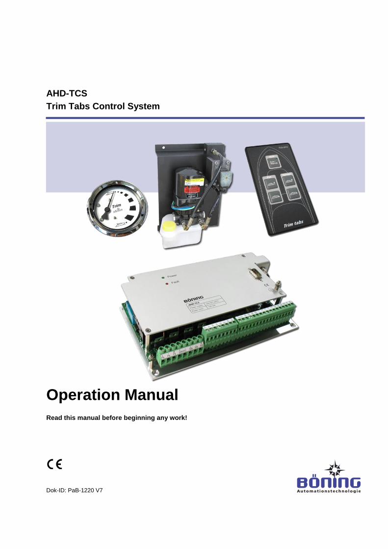
Operation Manual - Boening
48
Contents AHD-TCS Trim Tabs Control System Operation Manual Read this manual before beginning any work! Dok-ID: PaB-1220 V7
-
Upload
khangminh22 -
Category
Documents
-
view
5 -
download
0
Transcript of Operation Manual - Boening
Contents
AHD-TCS
Trim Tabs Control System
Operation Manual
Read this manual before beginning any work!
Dok-ID: PaB-1220 V7

2 V7
© Böning
Automationstechnologie GmbH & Co. KG
Am Steenöver 4
D-27777 Ganderkesee
Phone: +49 (0) 4221 9475-0
Fax: +49 (0) 4221 9475-21 /-22
Email: [email protected]
Internet: www.boening.com
AHD-TCS Trim Tabs Control System
Contents
V7 3
1 General Information ............................................................... 6
1.1 About this Operation Manual ......................................... 6
1.2 Explanation of Symbols ................................................. 6
1.3 Limitation of Liability ...................................................... 7
1.4 Copyright ........................................................................ 8
1.5 Spare Parts .................................................................... 8
1.6 Warranty Terms ............................................................. 8
1.7 Customer Care............................................................... 8
2 Safety ...................................................................................... 9
2.1 Operator's Responsibilities ............................................ 9
2.2 Personnel Requirements ............................................. 10
2.2.1 Qualifications ................................................ 10
2.2.2 Unauthorized Persons .................................. 11
2.3 Intended Purpose ........................................................ 11
3 Structure and Function ....................................................... 13
3.1 General Function ......................................................... 13
3.2 Function ....................................................................... 15
3.3 Components of the Trim Tabs Control System AHD-TCS .............................................................................. 16
3.3.1 AHD-TCS – Electronics Unit ........................ 16
3.3.2 AHD-TCS OP A – Operation Panel .............. 16
3.3.3 AHD-TCS HYD – Hydraulic Unit .................. 17
3.3.4 AHD-TCS Round Instrument (optional) ........ 17
4 Technical Information .......................................................... 18
4.1 Technical Data AHD-TCS ............................................ 18
4.2 Technical Data Hydraulic Aggregate ........................... 19
4.3 Technical Data Operation Panel AHD-TCS OP A ....... 20
4.4 Name Plates ................................................................ 21
4.4.1 Name Plate AHD-TCS .................................. 21
4.4.2 Name Plate AHD-TCS OP A ........................ 21
4.4.3 Name Plate Hydraulic Aggregate ................. 21
4.5 Dimensions .................................................................. 22
4.5.1 Device Dimensions AHD-TCS...................... 22
4.5.2 Device Dimensions AHD-TCS OP A ............ 23
4.5.2.1 Panel Cutout AHD-TCS OP A....... 24
4.5.3 Device Dimensions Hydraulic Unit ............... 25
4.6 Connection ................................................................... 26
4.6.1 Device Connections ..................................... 26
4.6.2 Terminal Assignment .................................... 27
AHD-TCS Trim Tabs Control System
Contents
4 V7
5 Transport, Packaging, and Storage ....................................29
5.1 Transport Safety Instructions .......................................29
5.2 Transport Inspection ....................................................29
5.3 Packaging ....................................................................29
6 Installation and Initial Startup .............................................31
6.1 Safety ...........................................................................31
6.2 Installation ....................................................................32
6.3 Initial Startup ................................................................35
7 Operation ..............................................................................37
7.1 Operating the Trim Tabs ..............................................37
7.2 Recording a Trim for Automatic Operation ..................38
7.3 PC Software for Downloading/Uploading the Trim Curve ............................................................................39
8 Maintenance ..........................................................................40
9 Errors .....................................................................................41
9.1 Safety ...........................................................................41
9.2 Power/Fault LED ..........................................................42
9.3 Error Correction ............................................................42
10 Disassembly .........................................................................43
10.1 Safety...... .....................................................................43
10.2 Disassembly .................................................................43
10.3 Disposal.. .....................................................................44
11 Appendix: Table Trim Tab Angle Settings .........................45
12 Index ......................................................................................46
AHD-TCS Trim Tabs Control System
General Information
V7 5
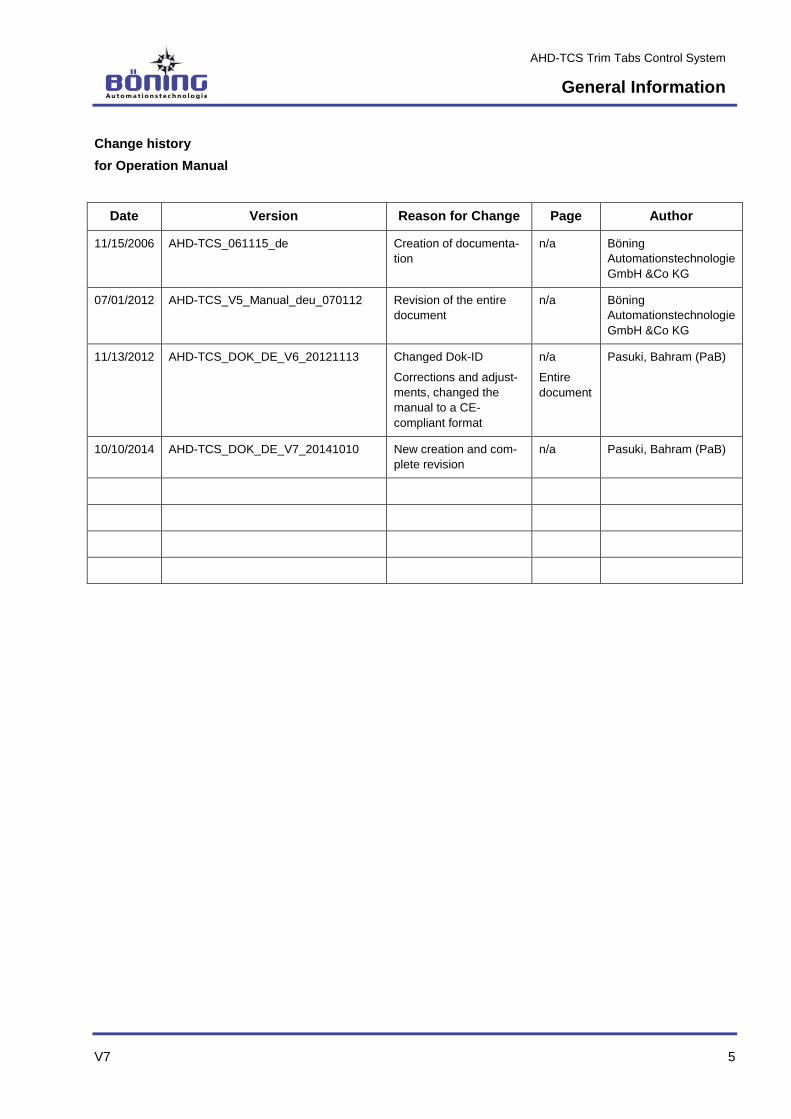
Change history
for Operation Manual
Date Version Reason for Change Page Author
11/15/2006 AHD-TCS_061115_de Creation of documenta-
tion
n/a Böning
Automationstechnologie
GmbH &Co KG
07/01/2012 AHD-TCS_V5_Manual_deu_070112 Revision of the entire
document
n/a Böning
Automationstechnologie
GmbH &Co KG
11/13/2012 AHD-TCS_DOK_DE_V6_20121113 Changed Dok-ID
Corrections and adjust-
ments, changed the
manual to a CE-
compliant format
n/a
Entire
document
Pasuki, Bahram (PaB)
10/10/2014 AHD-TCS_DOK_DE_V7_20141010 New creation and com-
plete revision
n/a Pasuki, Bahram (PaB)

AHD-TCS Trim Tabs Control System
General Information
6 V7
1 General Information
1.1 About this Operation Manual
Read this manual carefully before beginning any work! It is
part of the product and must be kept in the product’s immedi-
ate vicinity, so that the personnel can access it at any time.
Include this manual when passing the product on to third par-
ties.
This operation manual provides important product handling infor-
mation. On the following pages, this manual describes the Trim
Tabs Control System AHD-TCS.
This manual provides specific instructions, if additional, more de-
tailed documentation is available for individual components.
Adhering to all specified safety and handling instructions for the
product and all connected components is a requirement for safe
operation.
Furthermore, the local accident prevention regulations and the
general safety rules for the device’s field of application must be ob-
served.
The illustrations in this manual are intended to demonstrate its con-
tents more clearly; they are not necessarily drawn to scale and
may differ from the actual product in minor details.
This operation manual must be viewed exclusively as one unit. It is
not permitted to use excerpts from this manual as standalone doc-
umentation without referring to the entire document.
1.2 Explanation of Symbols
Warnings In this manual, warnings are marked by symbols. The symbols are
introduced by signal words indicating the degree of danger.
It is important to heed these instructions and act with caution
to avoid accidents, personal injury, and equipment damage!
DANGER!
… indicates an imminently hazardous situation that
can result in death or severe injury if not avoid-
ed.
WARNING!
… indicates a potentially hazardous situation that
can result in death or severe injury if not avoid-
ed.

AHD-TCS Trim Tabs Control System
General Information
V7 7
CAUTION!
… indicates a potentially hazardous situation that
can result in minor or light injury if not avoided.
CAUTION!
… indicates a potentially hazardous situation that
can result in equipment damage if not avoided.
Tips and Recommendations
TIP!
… points out useful tips and recommendations as
well as information about efficient and error free
operation.
1.3 Limitation of Liability
All information and instructions were compiled in consideration of
the current norms and regulations, the state of technology, as well
as our knowledge and experience of many years.
The manufacturer assumes no liability for damages resulting from:
Noncompliance with the instructions in this manual
Unintended use
Employment of untrained personnel
Unauthorized modifications
Technical modifications
Use of unauthorized spare parts
The actual scope of delivery may vary from the descriptions and il-
lustrations in this manual in case of special versions, the use of
additional ordering options, or the latest technical improvements.
In addition, the agreed upon obligations in the delivery contract, the
general terms and conditions, as well as the manufacturer’s deliv-
ery terms, and the legal regulations valid at the time of the con-
tract closing are in force.
We reserve the right to make technical changes for further devel-
opment and to improve the product’s performance characteristics.
AHD-TCS Trim Tabs Control System
General Information
8 V7
1.4 Copyright
This manual must be treated confidentially. It is intended exclusive-
ly for those persons handling the product. It is not permitted to
pass this operation manual on to third parties without the manufac-
turer’s prior written permission.
TIP!
The information, texts, drawings, images, and other
representations are subject to copyright regulations
and industrial property rights. Any improper use is
subject to prosecution.
Reproductions of any type – even in excerpts – as well as the use
and/or communication of these contents are not permitted without
the manufacturer’s written consent. Contraventions are liable to
compensation. We reserve other rights. We reserve other rights.
1.5 Spare Parts
WARNING!
Risk of injury from incorrect spare parts!
Improper or defective spare parts can lead to dam-
ages, malfunctions, or total failure as well as impair
safety.
Therefore:
– Only use the manufacturer’s original spare
parts.
Order spare parts from contracted vendors or directly from the
manufacturer. See page 2 for the address.
1.6 Warranty Terms
The warranty terms can be found in the General Terms and Condi-
tions (GTC) of the manufacturer’s sales documents.
1.7 Customer Care
Our customer care department is available to assist you with tech-
nical information.
Information about the corresponding customer contact is always
available via phone, fax, email, or the Internet. Refer to page 2 for
the manufacturer’s address.
In addition, our co-workers are always interested in new infor-
mation resulting from our products’ use and which could be of val-
ue in improving them.

AHD-TCS Trim Tabs Control System
Safety
V7 9
2 Safety
This chapter provides an overview of all important safety aspects
for the personnel’s optimal protection as well as safe and error-free
operation.
Noncompliance with the handling and safety instructions listed in
this manual can result in significant hazards.
2.1 Operator’s Responsibility
This product is used commercially. Therefore, its operation is sub-
ject to the legal regulations for occupational safety.
In addition to the workplace safety instructions in this manual, the
legal safety, accident prevention, and environmental protection
regulations for the product’s scope of operation must also be ob-
served. Especially:
The operator must inform himself about the legal workplace
safety regulations and through a risk assessment determine
any additional hazards resulting from the specific working con-
ditions at the product’s place of use. He must implement these
in the form of operating instructions for the product’s use.
During the product’s entire period of use, the operator must ver-
ify whether or not these operating instructions are in compliance
with the current state of regulations and adjust them, if neces-
sary.
The operator must clearly regulate and determine responsibili-
ties for installation, operation, maintenance, and cleaning.
The operator must ensure that all employees handling the
product have read and understood the operation manual.
Furthermore, he must train and inform the personnel about any
hazards in regular intervals.
In addition, the operator is responsible for ensuring that the product
is always in a technically sound condition.
AHD-TCS Trim Tabs Control System
Safety
10 V7
2.2 Personnel Requirements
2.2.1 Qualifications
WARNING!
Risk of injury from insufficient qualifications!
Improper use can result in significant personal inju-
ry and equipment damage.
Therefore:
– Only allow specifically qualified personnel to do
any work.
This operating manual designates the following qualifications for
various areas of activity.
Trained Person
has been trained by the operator during an orientation in the
assigned tasks and informed about possible hazards resulting
from improper execution.
Specialist
can execute the assigned tasks and recognize and avoid poten-
tial hazards independently, based on his professional educa-
tion, knowledge, and experience as well as knowledge of the
norms and regulations relevant to the situation.
Electrician
can perform work on electrical systems and independently iden-
tify and avoid potential hazards, based on his professional edu-
cation, knowledge and experience, as well as knowledge of the
norms and regulations relevant to the situation.
The electrician has been trained for the specific workplace in
which he is active and knows the relevant norms and regula-
tions.
Only those persons who can be expected to do their work reliably
are permitted as personnel. Persons whose reaction time is affect-
ed by e.g. drugs, alcohol, or medications are not permitted.
When selecting personnel, the age and professional regulations
specific to the workplace must be observed.

AHD-TCS Trim Tabs Control System
Safety
V7 11
2.2.2 Unauthorized Persons
WARNING! Danger for unauthorized persons!
Unauthorized persons who do not meet the re-
quirements described here do not know the work-
place hazards.
Therefore:
– Keep unauthorized persons away from the work
area.
– When in doubt, approach persons and remove
them from the work area.
– Discontinue any work as long as unauthorized
persons remain in the work area.
2.3 Intended Purpose
The Trim Tabs Control System AHD-TCS has been designed and
constructed exclusively for the purpose described here.
The Trim Tabs Control System TCS is used exclusively for elec-
tronically controlling the hydraulics of trim tabs on vessels.
WARNING!
Danger from unintended use!
Any use other than and/or beyond the product’s
intended use can lead to hazardous situations.
Therefore:
– Only use the product as intended.
– Strictly adhere to all instructions in this manual.
– Especially avoid the following unintended use:
– Using a supply voltage other than the one
specified
Any claims for damages resulting from unintended use are exclud-
ed.
The operator is solely responsible for any damages resulting from
unintended use.

AHD-TCS Trim Tabs Control System
Safety
12 V7
WARNING!
Danger from improper operation of the product!
Product failure or malfunction can lead to personal
injury or equipment damage in the overall system.
Therefore:
– Although the product itself is not especially dan-
gerous, the effects of failure or malfunction on
the overall system must be considered.
– Always discontinue using the products, if they
develop smoke or abnormal heat.
AHD-TCS Trim Tabs Control System
Structure and Function
V7 13
3 Structure and Function
3.1 General Function
The Trim Tabs Control System TCS has been constructed for use
on fast yachts whose cruising behavior can be significantly affected
by controlling the trim tabs.
As is customary for trim tabs, this also is an electrohydraulic con-
trol system. Each trim tab is operated by one or several hydraulic
cylinders. The control of the directional valves required for this is
electrical.
Transducers are not required for the cylinders. The piston position
– and thus the trim tabs position – is calculated by means of a flow
meters and an electronics unit. The otherwise necessary electrical
wiring on the ship’s exterior, which is often prone to error, is thus
eliminated.
A further benefit of this control system is the easy commissioning.
The trim tabs are moved to one end position and then the other.
The electronics unit records the number of impulses measured by
the flow meter for this “full stroke.” Afterwards, the tabs are re-
turned to the first end position, and the number of impulses thus
determined is also recorded. Thus, minor differences in the im-
pulse count that do not depend on the direction are compensated
for one stroke.
If a ship alarm system with a Böning color display (AHD 880 TC,
AHD 1215/AHD 1219, etc.) is already present on the yacht, this
display can show the trim tab position graphically (visually).
AHD-TCS Trim Tabs Control System
Structure and Function
14 V7
Moreover, the electronics provide an analog output (0-10 V) for
each flap. Round instruments with a corresponding scale, for ex-
ample, can be connected here.
When using one of the above stated color displays and a GPS unit
and/or an inclination sensor is connected, the trim tabs control sys-
tem can also run in automatic mode, in which several different au-
to-modes become available. In this mode, the trim tabs are auto-
matically moved into an optimized position based on the vessel’s
cruising speed (trim curve), which was determined during commis-
sioning at the shipyard. Any customer specific assignment of trim
tab positions and speed, however, can be saved as a trim curve.
Of course, manual control is always available, and it supersedes
the automatic mode.
3.2 Available Auto-Modes
The following auto-modes are available for the AHD-TCS controls:
1. Auto-Mode “Rudder”
In this mode, the trim tab position adjustments are based on the
rudder position during curving maneuvers.
Here, the trim tab positions are dependent on the rudder position;
this is specified by a configuration table.
The trim tabs thus support the boat’s curving maneuver with their
optimized position.
However, in this mode, there is no trimming based on inclination or
speed.
2. Auto-Mode “Inclination”
In this mode, the list of the boat can be corrected by the position of
the trim tabs when cruising on straight stretches. Here, the tilt is
determined by an inclination sensor, whose signals are analyzed
and processed by the electronics unit. By adjusting the trim tabs
accordingly, the control automatics ensure that the boat is always
in a horizontal position.
Furthermore, depending on the vessel’s load distribution and the
fuel levels in the tanks, a corresponding setting of the trim tabs can
automatically correct the boat’s list.
In this mode, the auto-mode “Rudder” is also available.

AHD-TCS Trim Tabs Control System
Structure and Function
V7 15
3. Auto-Mode “Speed”
This automatic function is used for optimizing the speed while sim-
ultaneously decreasing fuel consumption. When cruising in a
straight line, the system attempts to increase the boat’s speed
without changing the engine’s RPM by adjusting the trim tabs in
cyclical intervals.
A base curve for defining the position to which the trim tabs are to
be moved at what speed is specified during the configuration. At
constant speeds, the electronics attempt to increase the boat’s
speed by making slight corrections to the trim tab positions. If the
optimization of the speed is unsuccessful, the control process is
aborted, and the trim tabs are moved to their last known position.
In this mode, the auto-mode “Rudder” is also available.
3.3 Function
Pressing the ▲ (up) or ▼ (down) key on the Operating Panel
AHD-TCS OP A moves the position of the trim tab up or down and
thus pushes the vessel’s bow up or down.
Here, the key for the TCS electronics causes the hydraulic aggre-
gate to move the hydraulic cylinder forwards or backwards with oil
pressure. Depending on the directional flow of the hydraulic oil, the
flow meter sends impulses for the forward or backward movement
to the TCS electronics. The position of the trim tab is calculated
from the number of impulses and shown via the CAN bus on the
display or analog display instruments.
Alternatively, if no display is used, the GPS receiver can be con-
nected directly to the TCS electronics, when the trim tabs are to
operate automatically.
The TCS electronics with the two flow meters and hydraulic aggre-
gates can be constructed as a three-part system, consisting of the
portside aggregate, starboard aggregate, and TCS electronics.
The operation panels and displays are cascadable (e.g. for use on
the fly bridge). The operation panel has back lighting as well as an
“Automatic” LED for indicating the automatic mode. During failure
of the TCS electronics, corresponding error messages are sent to
the CAN bus and shown on e.g. the display, while it is still possible
to control the trim tabs with the ▲/▼ keys.
AHD-TCS Trim Tabs Control System
Structure and Function
16 V7
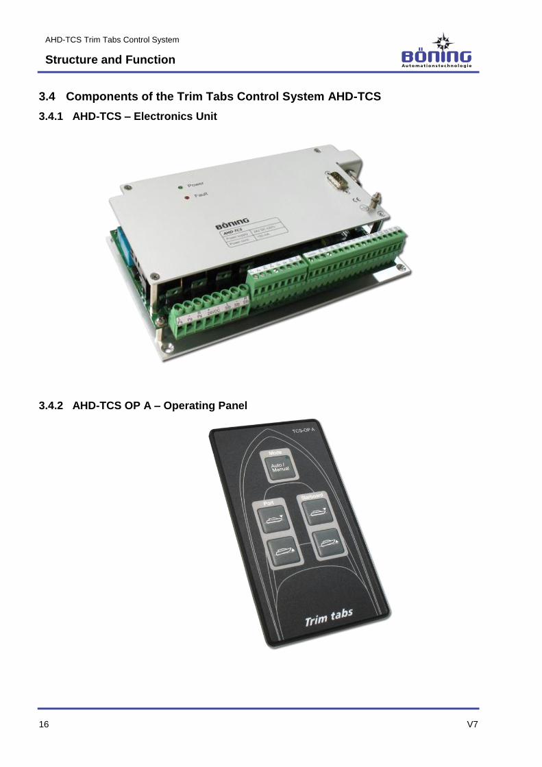
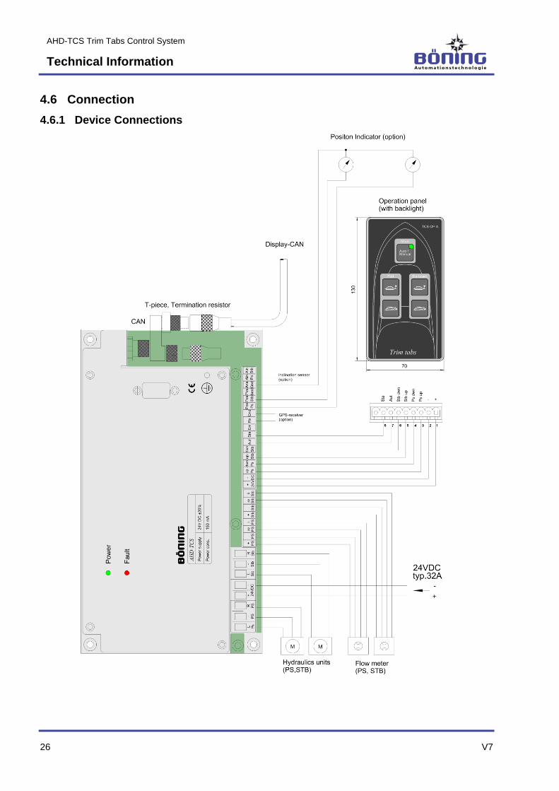
3.4 Components of the Trim Tabs Control System AHD-TCS
3.4.1 AHD-TCS – Electronics Unit
3.4.2 AHD-TCS OP A – Operating Panel
AHD-TCS Trim Tabs Control System
Structure and Function
V7 17
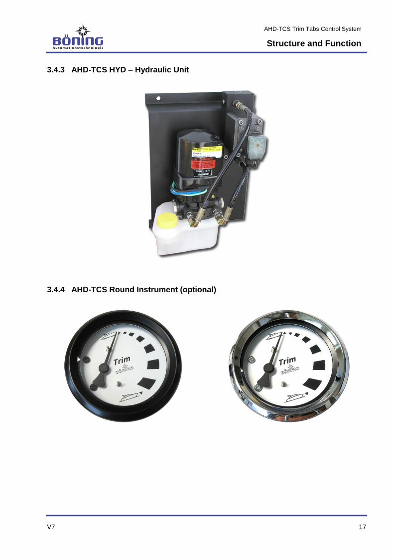
3.4.3 AHD-TCS HYD – Hydraulic Unit
3.4.4 AHD-TCS Round Instrument (optional)

AHD-TCS Trim Tabs Control System
Technical Information
18 V7
4 Technical Information
4.1 Technical Data AHD-TCS
Description Value/Unit/Type
General Data
Dimensions, W x H x D 215 mm x 120 mm x 48 mm
Weight appr. 0.7 kg
Environmental Data
Operating Temperature -25 °C…+70 °C
Storage Temperature -30 °C…+85 °C
Protection Class IP 10
Electrical Data
Power Supply 24 V DC (+30%/-25%)
Power/Current Consumption Up to 150 mA
Ports
1 x CAN, 1 x RS232
Inputs 2x Flow meters,
Operation panel
2 x 4-20 mA (e.g. for inclination
sensor)
Outputs 2x Hydraulic aggregates 2 x 0-10 V (e.g. for display in-struments)
AHD-TCS Trim Tabs Control System
Technical Information
V7 19
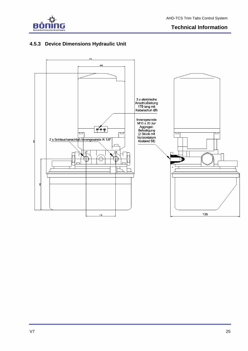
4.2 Technical Data Hydraulic Aggregate
Description Value/Unit/Type
General Data
Dimensions, W x H x D 176 mm x 269 mm x 135 mm
Weight appr. 11 kg (without hydraulic oil)
Flow Rate Type 1: 1.5 l/min
Type 2: 2.0 l/min
Pressure appr. 70 bar
Environmental Data
Operating Temperature -25 °C…+70 °C
Storage Temperature -30 °C…+85 °C
Protection Class IP 65
Electrical Data
Power Supply 24 V DC (+30%/-25%); via TCS
electronics
Power/Current Consumption Type 16 A
Connections
Inputs Hydraulic aggregate R/L
Outputs Flow meter R, L, +, -
AHD-TCS Trim Tabs Control System
Technical Information
20 V7
4.3 Technical Data Operating Panel AHD-TCS OP A
Description Value/Unit/Type
General Data
Dimensions, W x H x D 70 mm x 130 mm x 94 mm
Weight appr. 0.2 kg
Panel Cutout 60 mm x 112.5 mm
Environmental Data
Operating Temperature -25 °C…+70 °C
Storage Temperature -30 °C…+85 °C
Protection Class IP 66 (frontside)
IP 10 (rear)
Electrical Data
Power Supply 24 V DC (+30%/-25%); via TCS
electronics
Power/Current Consumption 100 mA

AHD-TCS Trim Tabs Control System
Technical Information
V7 21
4.4 Name Plates
4.4.1 Name Plate AHD-TCS
4.4.2 Name Plate AHD-TCS OP A
4.4.3 Name Plate Hydraulic Aggregate
The name plate for the hydraulic aggregate is installed by the
manufacturer. The installation location and information on the plate
can vary, depending on the production batch.

AHD-TCS Trim Tabs Control System
Technical Information
22 V7
4.5 Dimensions
4.5.1 Device Dimensions AHD-TCS
CAUTION!
Ground first, then power on!
Before powering on the device, ground it with
the provided ground terminal 3 (see above).
.
AHD-TCS Trim Tabs Control System
Technical Information
V7 23
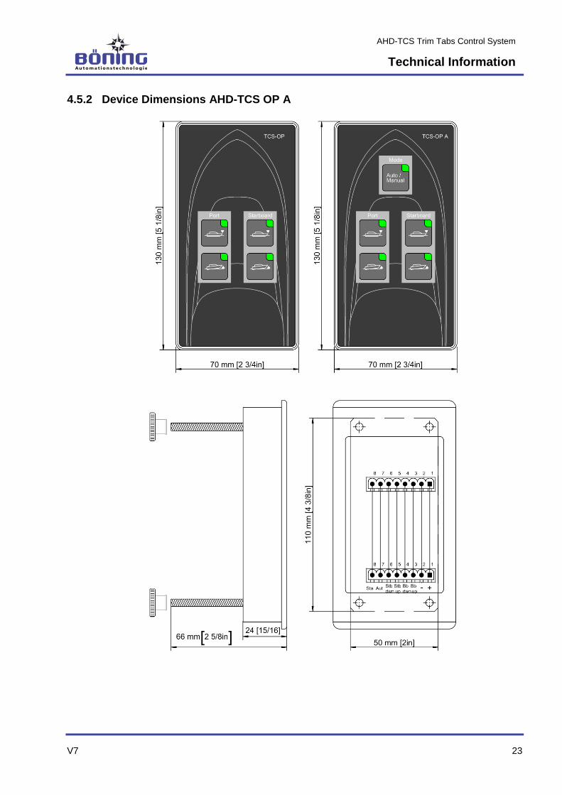
4.5.2 Device Dimensions AHD-TCS OP A

AHD-TCS Trim Tabs Control System
Technical Information
24 V7
4.5.2.1 Panel Cutout AHD-TCS OP A
AHD-TCS Trim Tabs Control System
Technical Information
V7 25
4.5.3 Device Dimensions Hydraulic Unit
AHD-TCS Trim Tabs Control System
Technical Information
26 V7
4.6 Connection
4.6.1 Device Connections
AHD-TCS Trim Tabs Control System
Technical Information
V7 27
4.6.2 Terminal Assignment
Designation Connection
CAN 1 CAN bus to the display
RS232 Serial data connection (RS232 port)
PE (ground) Potential equalization
Ain Stb Input analog-IN starboard (4-20 mA, optional)
Ain Ps Input analog-IN portside (4-20 mA, inclination sensor)
Ana Gnd Ground for analog-IN and position
Pos best Output analog value (0-10 V, optional)
Pos Stb Output analog value starboard (0-10 V)
Pos Ps Output analog value portside (0-10 V)
Gnd Ground for data reception
Rx Data input (from optional GPS; receive data)
Err Error output (error message)
Sta Status output "Auto/Manual" (status message)
Aut From key auto/manual (automatic/manual)
dwn Stb From key starboard down
up Stb From key starboard up
dwn Ps From key portside down
up Ps From key portside up
-
24 V
DC
To – pole for all keys
+ To shared + pole of all keys
le Stb (Impulse stb. left) flow meter starboard channel left
ri Stb (Impulse stb. right) flow meter starboard channel right
- Stb (Impulse stb. -) flow meter starboard power supply -
+ Stb (Impulse stb. +) flow meter starboard power supply +
le PS (Impulse ps. left) flow meter portside channel left
Designation Connection
ri PS (Impulse ps. right) flow meter portside channel right
- PS (Impulse ps. -) flow meter portside power supply -

AHD-TCS Trim Tabs Control System
Technical Information
28 V7
+ PS (Impulse ps. +) flow meter portside power supply +
R Stb (Aggregate stb. R) hydraulic aggregate starboard R
- Stb (Aggregate stb. -) hydraulic aggregate starboard R
L Stb (Aggregate stb. L) hydraulic aggregate starboard R
-
24 V
DC
(Power supply -) supply voltage -
+ (Power supply +) supply voltage +24 V
R PS (Aggregate ps. R) hydraulic aggregate portside R
- PS (Aggregate ps. -) hydraulic aggregate portside R
L PS (Aggregate ps. L) hydraulic aggregate portside R
AHD-TCS Trim Tabs Control System
Transport, Packaging, and Storage
V7 29
5 Transport, Packaging, and Storage -
5.1 Transport Safety Instructions
Improper Transport
CAUTION!
Equipment damage from improper transport!
Improper transport can cause significant equipment
damage.
Therefore:
– Proceed with caution and heed the symbols and
instructions on the packaging when unloading
the packages during delivery and on-site
transport.
– Remove the packaging only shortly before in-
stallation.
5.2 Transport Inspection
Upon receipt, the delivery must be checked immediately for com-
pleteness and damages during transport.
Proceed as follows, in case of externally visible damage:
Do not accept the delivery, or accept it only with reservations.
Note the extent of damages on the transport documents or on
the deliverer’s shipping note.
File a damage claim.
TIP!
Claim any defect as soon as it is noticed. Damage
claims can only be made within the valid reclama-
tion period.
5.3 Packaging
About the Packaging The individual packages are packaged according to the expected
transport conditions. Only environmentally friendly materials have
been used for the packaging.
The packaging is intended to protect the individual parts from
damages during transport, corrosion, and other damages until they
are installed. Therefore, the packaging must not be destroyed and
may only be removed shortly before installation.
AHD-TCS Trim Tabs Control System
Transport, Packaging, and Storage
30 V7
Handling the Packaging Materials The packaging materials must be disposed according to the cur-
rent legal provisions and local regulations.
CAUTION!
Environmental damages from improper dispos-
al!
Packaging materials are valuable resources and
can often be reused or expediently reprocessed
and recycled.
Therefore:
– Dispose packaging materials in an environmen-
tally friendly manner.
– Observe the local disposal regulations. If nec-
essary, hire a specialist company for the dis-
posal.
Storage Store the packages under the following conditions:
Do not store them outdoors.
Store them in a dry, dust free environment.
Do not expose them to aggressive media.
Protect them from sunlight.
Observe the storage temperature (see technical data).
Avoid mechanical shock.
If storing the packages for more than 3 months, regularly in-
spect the general condition of all parts and the packaging. If
necessary refresh of renew the preservative.
TIP!
In some circumstances, additional storage instruc-
tions extending beyond the requirements listed
here are located the packages. These must be fol-
lowed accordingly.
AHD-TCS Trim Tabs Control System
Installation and Initial Startup
V7 31
6 Installation and Initial Startup
6.1 Safety
Personnel The installation and initial startup may only be performed by
specially trained personnel.
Only electricians may perform any work on the electrical sys-
tem.
Basic Information
Caution!
Risk of injury from improper installation and
initial startup!
Improper installation and initial startup can result in
personal injury and equipment damage.
Therefore:
– Ensure adequate installation space before be-
ginning any work.
– Proceed with caution when handling parts with
exposed sharp edges.
– Observe orderliness and cleanliness in the in-
stallation location!
– Install parts properly.

AHD-TCS Trim Tabs Control System
Installation and Initial Startup
32 V7
6.2 Installation
In General
CAUTION!
Equipment damage from improper handling
and selection of the installation location!
Installing the products in locations that do not meet
the requirements of the technical specifications
and improper handling can lead to system errors
and equipment damage.
Therefore:
– Note the products’ specifications when select-
ing the installation location.
– The installation may only be performed by
trained personnel.
– Never install the products in areas that do not
match the specified protection class.
– Never install the products in areas with ex-
tremely high or low temperatures.
– Never install the products on ceilings that can-
not support their weight.
– Never vigorously bump or shake the products.
Installation Requirements All required connecting cables are of the required version, led to
the intended installation location with plug connectors ac-
cording to technical specifications or project drawings, and
properly installed and stripped. Free wires have a sufficient in-
stallation length and are secured against short circuit and earth
fault.
TIP!
The following minimum line diameters are required
for the installation of the AHD-TCS system:
- supply voltage 24 V DC 4 mm²
- hydraulic aggregate for AHD-TCS 2.5 mm²
- flow meters for AHD-TCS 0.75 mm²
- operation panel for AHD-TCS 0.75 mm²
TIP!
If the AHD-TCS electronics are connected to a dis-
play with a CAN bus cable, another device or a
terminating resistor must also be connected to the
T-splitter.
The product is not connected to the power supply and wired off-
circuit.
AHD-TCS Trim Tabs Control System
Installation and Initial Startup
V7 33
Installation 1. Install system components properly in the intended installation
location according to technical specifications or project draw-
ings.
TIP!
If the trim tabs are also provided by Böning
Automationstechnologie GmbH &Co KG, the sepa-
rate mounting and installation instructions must be
followed.
2. Wire all of the components’ inputs and outputs according to
technical drawings.
TIP!
The hydraulic aggregates must be installed in the
ship so that the filler necks of the hydraulic oil res-
ervoirs point vertically upwards. Here, the hydraulic
aggregates should be close to the trim tabs to keep
the length of the hydraulic hoses to the hydraulic
cylinders as short as possible. Because the hy-
draulic system is bled at its highest point, the hoses
and hydraulic cylinders should be lower than the
distributors in the manifold so that it can be bled at
the manifolds.
The AHD-TCS can be operated with single-action hydraulic cylin-
ders that have only one hydraulic oil connection as well as dual-
action cylinders with two connections. Unused hydraulic oil con-
nections in the manifold must be sealed with end caps.
3. Connect the hydraulic aggregates and flow meters to the trim
tabs’ hydraulic cylinders.
4. Place the TCS electronics inside a splash proof terminal box
(e.g. TCS box) and connect them according to the electrical
connection diagram.
5. Place the operating keys on the bridge in such a manner that
the skipper can access them while cruising.
All keys receive a shared +24 V DC feed. Any number of keys can
be connected in parallel (e.g. on the fly bridge), since the TCS
electronics has an internal lock and only processes the first incom-
ing signal.
For displaying the position of the trim tabs, it makes sense to use a
Böning display that also visualizes other ship data received via the
CAN bus.

AHD-TCS Trim Tabs Control System
Installation and Initial Startup
34 V7
Here, the two-digit CAN bus address (ID) of the TCS electronics
must be set with rotary switches on the PCB from 01 to 99 (stand-
ard-ID:03)
At the same time, the position of the trim tabs can be shown on
optional display instruments with analog inputs (e.g. on the fly
bridge).
When using an inclination sensor, it should be installed lengthwise
and in the middle of the ship, as much as possible. Afterwards, the
electrical connections to the central unit AHD-TCS (Ain Ps, Ana
GND) must be established.
Furthermore, the installation and connection instructions of the
sensor’s manufacturer must be followed.
CAUTION!
Equipment damage from incorrect cable con-
nections!
Improperly connected cables can cause system
errors and equipment damage.
Therefore:
– Always verify cable and wire designations be-
fore connecting them. Check for secure seating
of the connecting wires in the terminals.
– To avoid short circuits, verify that all wires are
connected in the terminal.
– To not over tighten the terminal clamps.
– When using pluggable terminal strips or plug
connectors, it is imperative to ensure insertion
in the correct socket and secure seating.
4. Test the system for earth/ground fault.
CAUTION!
System failure or malfunction!
During earth/ground fault, incorrect data can be
transmitted and lead to overall system failure or
malfunctions.
Therefore:
– Immediately correct any discovered
earth/ground fault.
CAUTION!
Ground first, then switch on!
Before powering on the device, ground it with
the provided ground terminal 3 (see Chapter
4.5.1)

AHD-TCS Trim Tabs Control System
Installation and Initial Startup
V7 35
6.3 Initial Startup
Startup Requirements All system components have been properly installed and are
equipped with all required connections.
All external devices connected to the AHD-TCS have also been
installed according to technical specifications or project draw-
ings and are operational.
All required power supplies are available and error-free.
The AHD-TCS and all connected external devices are not con-
nected to the power supply or have been wired off-circuit.
1. Establish the 24 V DC power supply according to technical
specifications or project drawings.
2. Establish the power supplies for all external devices con-
nected to the AHD-TCS according to their corresponding
operating instructions
3. Test the power supplies.
CAUTION!
Equipment damage from incorrect voltage!
Connecting an incorrect supply voltage can lead to
equipment damage.
Therefore:
– Review all relevant project documents and op-
eration manuals of the devices used and verify
their correct supply voltage and polarity before
connecting them.
4. Switch on the power supply of the AHD-TCS and all connect-
ed external devices from the corresponding circuit breakers in
the power distribution and the device internal starting devices
according to the corresponding operation manuals.
5. Verify the correct startup sequence according to the following
Chapter “Operation.”
6. Log any faults or functional deviations that may occur and
take appropriate measures under consideration of the errors
described in Chapter “Errors.”
7. You may need to inspect the installed configuration and adjust
it to meet the required operating conditions. Log the Final con-
figuration for the project documentation.

AHD-TCS Trim Tabs Control System
Installation and Initial Startup
36 V7
Adjusting the Inclination Sensor After installing the inclination sensor, bring the ship into a horizon-
tal position or place the sensor in the corresponding position prior
to the fastening when the vessel is in a calm position (standing
still). The sensor’s correct position can be verified with the infor-
mation on the display (if present).
Initial Startup of the Hydraulic Unit 1. First, fill the two reservoirs on the TCS mounting plate with
hydraulic oil to the maximum fill level (MAX).
2. Afterwards, bleed the system by moving the hydraulic cylin-
ders up and down with the operating keys until there is no
more air at the highest point of the hydraulic system. To do
this, release the air at the manifold’s hose connection (highest
point) at the hydraulic oil flow toward the hydraulic cylinder un-
til only hydraulic oil and no air escapes.
3. So that the TCS electronics know how many impulses the flow
meter sends between the trim tab’s top and bottom end posi-
tions (dependent on the size, type, and number of hydraulic
cylinders), a full calibration must be performed during com-
missioning.
4. Full Calibration (calibrate both end positions of the trim tabs
and determine the stroke):
Move the trim tab to the upper end position with the button
(trim tab symbol on the display blinks 3 times). From there,
move it to the lower end position, so that the TCS electronics
determines the number of impulses for the entire stroke.
Afterwards, move it to the upper end position once more (the
display signals that the end positions have been reached
when the white pointer indicating the position of the trim tabs
blinks three times).
We recommend performing a full calibration at least at the be-
ginning of every season.
5. Simple Calibration (calibrate one end position of the trim
tab):
During each engine shutdown, the trim tabs are automatically
retracted to their upper end position and calibrated there.
AHD-TCS Trim Tabs Control System
Operation
V7 37
7 Operation
7.1 Operating the Trim Tabs
Pressing the starboard and portside operating keys ▼(dwn)/▲ (up)
changes the position of the respective trim tab, whereby pressing
the ▼(dwn) key results in lowering the trim tab and bow and press-
ing ▲(up) raises the trim tab and bow. If several operating keys
are connected in parallel (e.g. for fly bridge), the trim tab’s move-
ment is stopped when different directions are activated by the keys
for the same trim tab, as the TCS electronics have an internal lock
and only allow unambiguous entries.
When the engine is shut down, the trim tabs are moved to their up-
per end position.
The position of the trim tabs is shown in angular degrees on the
display or on optional display instruments.
The Display AHD 880 TC (or any other display by Böning) shows
the positions of both trim tabs, located on the degree scale in the
form of trim tab symbols (white pointers).
By using GPS data for calculating the speed, it is possible to switch
between manual operation of the trim tabs with the ▼ (dwn)/▲
(up) keys and automatic trim tab control in the automatic version of
the TCS electronics.
In auto-mode, the trim tab is automatically moved into the position
for the best trim, as determined by the trim curve (pressing the “Au-
to/Manual” key toggles between manual and automatic modes; the
LED is lit in auto-mode). Pressing one of the ▼(dwn) or ▲(up)
keys during automatic operation exits the auto-mode, just as oper-
ating the “Auto/Manual” (LED extinguishes) does.
If the TCS electronics fail, the trim tabs can still be operated (with
the ▼ (dwn)/▲ (up) keys, as already described).
The TCS electronics can issue 3 different alerts for the starboard
and portside trim tab (stb., ps.) each over the CAN bus:
- Trim Position
(sensor fault, no signal from flow meter)
- Trim pump overload
(hydraulic aggregate, current consumption too high)
- Leakage Trim
(Counter receives more impulses than determined for the en-
tire stroke)

AHD-TCS Trim Tabs Control System
Operation
38 V7
7.2 Recording a Trim Curve for the Automatic Mode
CAUTION!
An operating error can lead to an unintended trim
curve that may impair the operation of the vessel.
However, an intact trim curve is required for the
automatic mode.
For this reason, the trim curve should only be set
and recorded by experienced specialists.
The manufacturer is not liable for incorrectly set
trim curves and any damages that may result from
this.
In automatic mode, the trim curve is used for automatically setting
the trim tab angle based on the GPS speed (only for automatic
version TCS A).
To use a trim curve other than the standard curve, it is possible to
enter a new trim curve with the aid of the Operation Panel TCS-OP
A. The programming mode is started in the trim tabs’ manual mode
by holding down the “Auto/Manual” key, and it is signaled by the
blinking of the built-in LED.
The entry of the trim curve begins with the lowest RPM and contin-
ues in equal steps up to the highest RPM. The trim curve must
consist of at least 8 values that cover a range of 1000 RPM. All in
all, up to 50 values can be recorded and here, the saved trim tab
angle applies to starboard and portside equally, so that it is im-
portant to make sure that both trim tabs are as much as possible at
the same angle when entering the values.
When receiving a value, a constant engine speed is specified and
using the “▼ (dwn)/▲ (up)” keys, the trim tab setting for achieving
the highest GPS speed is found. This value can then be recorded,
and you can proceed with the next value.
We recommend entering the recorded values of the trim curve in
the table, which can be found in the appendix of this document.
At the end of the recording process, the values determined can be
saved as a new trim curve with the configuration tool.
Below the lowest recorded RPM value, the trim tab angle accepts
the lowest recorded RPM value (for example, a lowest recorded
RPM value of 1000 RPM with a trim tab angle of -4° results in a -4°
trim tab angle at engine speeds < 1000 RPM).
Above the highest recorded RPM value, the value with the highest
recorded RPM value is accepted (for example, a highest recorded
RPM value of 2000 RPM with a trim tab angle of 3° results in a 3°
trim tab angle at engine speeds > 2000 RPM).

AHD-TCS Trim Tabs Control System
Operation
V7 39
7.3 PC Software for Uploading/Downloading the Trim Curve
CAUTION!
Uploading a new trim curve results in overwriting
the curve saved on the device.
For this reason, the trim curve should only be set
and uploaded by experienced specialists.
The manufacturer is not liable for incorrectly set
trim curves and any damages that may result from
this.

AHD-TCS Trim Tabs Control System
Maintenance
40 V7
8 Maintenance
TIP!
The electronics unit AHD-TCS as well as the oper-
ating panels AHD-TCS OP A and optional round
instruments are generally maintenance free.
Maintenance of the units is limited merely to exter-
nal cleansing and inspection.
Only use solvent-free, nonabrasive detergents for
cleaning.
CAUTION!
Risk of injury from dangerous voltages and
other hazards
Opening covers can expose you to dangerous volt-
ages or other hazards.
Therefore:
– Never perform device repairs yourself.
– Do not remove the covers for maintenance or
inspection.
– In case of product malfunctions, contact the
manufacturer or an authorized representative.
AHD-TCS Trim Tabs Control System
Errors
V7 41
9 Errors
The following table describes errors that may occur when operating
AHD-TCS, including information about causes, error recognition,
and error correction.
9.1 Safety
Personnel Some tasks may only be performed by specially trained profes-
sionals or exclusively by the manufacturer. This is specifically
indicated in the description of the individual errors.
As a rule, only electricians may perform any work on the electri-
cal system.
Basic Information
CAUTION!
Risk of injury from dangerous voltages and
other hazards
Opening covers can expose you to dangerous volt-
ages or other hazards.
Therefore:
– Never perform device repairs yourself.
– Do not remove the covers for service work.
WARNING!
Risk of injury from improper error correction!
Improper error correction can lead to severe per-
sonal injury or equipment damage.
Therefore:
– Only the manufacturer or authorized personnel
may perform device repairs.
– Ensure adequate installation space before be-
ginning any work.
– Observe orderliness and cleanliness in the in-
stallation location! Parts and tools that are
loosely stacked or lying about are accident
sources.
– If parts have been removed, ensure proper as-
sembly, reinstall all mounting elements, and ob-
serve torque limits.

AHD-TCS Trim Tabs Control System
Errors
42 V7
In case of errors As a rule:
1. Determine the cause of the error.
2. Immediately notify a responsible party on site.
3. Depending on the type of error, have authorized personnel
correct it or correct it yourself.
4. Correct the error by replacing or repairing the defective parts
(e.g. cables, plugs, etc.).
5. If the error cannot be determined with the error table, a device
defect cannot be excluded. Send the device to the manufac-
turer’s address or the address of an authorized specialist
company for repairs.
9.2 Power/Fault LED
Continuous ON Continuous OFF Blinking
Power LED Device operational Device has no power supply -
Fault LED Device has no valid configuration. Contact the manufacturer.
Device functions error-free. CAN data communication interrupted
9.3 Error Correction
Error Possible Cause Error Recognition/Correction
No function Power supply missing Power LED is not lit. Check the device’s
power supply.
If the error persists afterwards, contact
the manufacturer.
System bus not processed Connection to the system bus
interrupted
Port not terminated
Check the connection to the system bus
Check the termination of the port
Trim tabs cannot be controlled Connection to the operating
panel and/or hydraulic unit
interrupted.
Check the connection between AHD-TCS
(electronics) and operation panel as well
as AHD-TCS and hydraulic unit.
AHD-TCS Trim Tabs Control System
Disassembly
V7 43
10 Disassembly
After the device has reached its end of life, it must be disassem-
bled and disposed in an environmentally safe manner.
10.1 Safety
Personnel The disassembly may only be performed by specially trained
personnel.
Only electricians may perform any work on the electrical sys-
tem.
Basic Information
Caution!
Risk of injury from improper disassembly!
Stored residual energy, sharp parts, points and
edges on and inside the device or required tools
can cause injury.
Therefore:
– Ensure adequate space before beginning any
work.
– Proceed with caution when handling parts with
exposed sharp edges.
– Observe orderliness and cleanliness in the
workplace! Parts and tools that are loosely
stacked or lying about are accident sources.
– Disassemble parts properly.
– When in doubt, contact the manufacturer.
10.2 Disassembly
Before beginning the disassembly: Disconnect the device from
the power supply and secure it against reconnection.
Disconnect the cable connections and mark them, if necessary.
Secure free wire ends against short circuit and earth/ground
fault.
Loosen the device mountings.
Uninstall the device through proper measures.
Clean and disassemble the device for selection according to the
legal workplace and environmental protection regulations.
AHD-TCS Trim Tabs Control System
Disassembly
44 V7
10.3 Disposal
In the absence of a return or disposal agreement, recycle the dis-
assembled components:
Scrap metals.
Recycle plastic components.
Dispose the remaining sorted components according to their
material properties.
CAUTION!
Environmental damages from improper dispos-
al!
Electrical scraps, electronic components, lubricants
and other auxiliary materials are subject to hazard-
ous waste regulations and may be disposed only
by licensed specialist companies!
Your local authorities or specialized disposal companies will pro-
vide you with information about environmentally safe disposal.
AHD-TCS Trim Tabs Control System
Appendix: Table Trim Tab Angle Settings
V7 45
11 Appendix: Table Trim Tab Angle Settings
Engine
Speed
(RPM)
Max. GPS Speed (kn) Trim Tab Angle (°)
500
600
700
800
900
1000
1100
1200
1300
1400
1500
1600
1700
1800
1900
2000
2100
2200
2300
2400
2500
2600
2700
2800
2900
3000
AHD-TCS Trim Tabs Control System
Index
46 V7
12 Index
A
Appendix ............................................................ 45
C
Calibration .......................................................... 36
Copyright ...............................................................8
Customer Care......................................................8
Customer Contact .................................................8
D
Device Connections ........................................... 26
Device Dimensions
AHD-TCS ....................................................... 22
AHD-TCS OP A .............................................. 23
Hydraulic Unit ................................................. 25
Disassembly ....................................................... 43
Disposal ............................................................. 44
E
Errors ................................................................. 41
F
Fault LED ........................................................... 42
I
Inclination Sensor
Adjustments.................................................... 36
Initial Startup ...................................................... 35
Initial Startup of the Hydraulic Unit .................... 36
Installation .......................................................... 32
L
Liability ..................................................................7
M
Maintenance ...................................................... 40
N
Name Plate
AHD-TCS ....................................................... 21
AHD-TCS OP A .............................................. 21
Hydraulic Aggregate ....................................... 21
O
Operation Manual .................................................6
Operation of the Trim Tabs ................................ 37
Operator ............................................................... 9
P
Packaging .......................................................... 29
Panel Cutout AHD-TCS OP A ............................ 24
PC Software ....................................................... 39
Personnel
Disassembly ................................................... 43
Electrician ....................................................... 10
Errors .............................................................. 41
Initial Startup ................................................... 31
Installation ...................................................... 31
Requirements ................................................. 10
Specialist ........................................................ 10
Trained Person ............................................... 10
Power LED ......................................................... 42
Purpose .............................................................. 11
S
Safety ................................................................... 9
Spare Parts .......................................................... 8
Storage ......................................................... 29, 30
Structure and Function ....................................... 13
Symbols in this Manual ........................................ 6
T
Table Trim Tab Angle Settings .......................... 45
Technical Data
AHD-TCS ........................................................ 18
Hydraulic Aggregate ....................................... 19
Operating Panel AHD-TCS OP A ................... 20
Transport ............................................................ 29
Transport Inspection .......................................... 29
Trim Curve Recording ........................................ 38
U
Unauthorized Persons ....................................... 11
W
Warranty ............................................................... 8


Devices, System Installation, Monitoring and
Control Technology, Ship Automation
Böning Automationstechnologie GmbH & Co. KG
Am Steenöver 4
D-27777 Ganderkesee
Email: [email protected]
Internet: www.boening.com
Text and illustrations are non-binding.
We reserve the right to make changes due to technical progress.