Operation and Safety Manual
168
Operation and Safety Manual ANSI ® Original Instructions - Keep this manual with the machine at all times. AS/NZS Boom Lift Models 1250AJP 3121170 May 30, 2018 - Rev R
-
Upload
khangminh22 -
Category
Documents
-
view
5 -
download
0
Transcript of Operation and Safety Manual
Operation and Safety Manual
ANSI®
Original Instructions - Keep this manual with the machine at all times.
AS/NZS
Boom Lift Models1250AJP
3121170May 30, 2018 - Rev R

FOREWORD
a
s.
rs, and lessees with the precautions and operatingtended purpose.
the right to make specification changes without
3121170
FOREWORD
This manual is a very important tool! Keep it with the machine at all time
The purpose of this manual is to provide owners, users, operators, lessoprocedures essential for the safe and proper machine operation for its in
Due to continuous product improvements, JLG Industries, Inc. reservesprior notification. Contact JLG Industries, Inc. for updated information.
FOREWORD
b 3121170
SIGNAL WORDS
INDIRESUGROU
INDIRESUGROU
TIALLY HAZARDOUS SITUATION. IF NOT AVOIDED, MAY RESULTRATE INJURY. IT MAY ALSO ALERT AGAINST UNSAFE PRACTICES.
AVE A YELLOW BACKGROUND.
ATION OR A COMPANY POLICY THAT RELATES DIRECTLY OR INDI-ETY OF PERSONNEL OR PROTECTION OF PROPERTY.
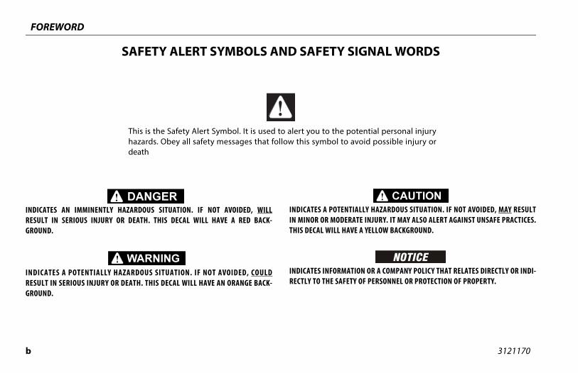
potential personal injury avoid possible injury or
SAFETY ALERT SYMBOLS AND SAFETY
CATES AN IMMINENTLY HAZARDOUS SITUATION. IF NOT AVOIDED, WILLLT IN SERIOUS INJURY OR DEATH. THIS DECAL WILL HAVE A RED BACK-ND.
CATES A POTENTIALLY HAZARDOUS SITUATION. IF NOT AVOIDED, COULDLT IN SERIOUS INJURY OR DEATH. THIS DECAL WILL HAVE AN ORANGE BACK-ND.
INDICATES A POTENIN MINOR OR MODETHIS DECAL WILL H
INDICATES INFORMRECTLY TO THE SAF
This is the Safety Alert Symbol. It is used to alert you to the hazards. Obey all safety messages that follow this symbol todeath
FOREWORD
c
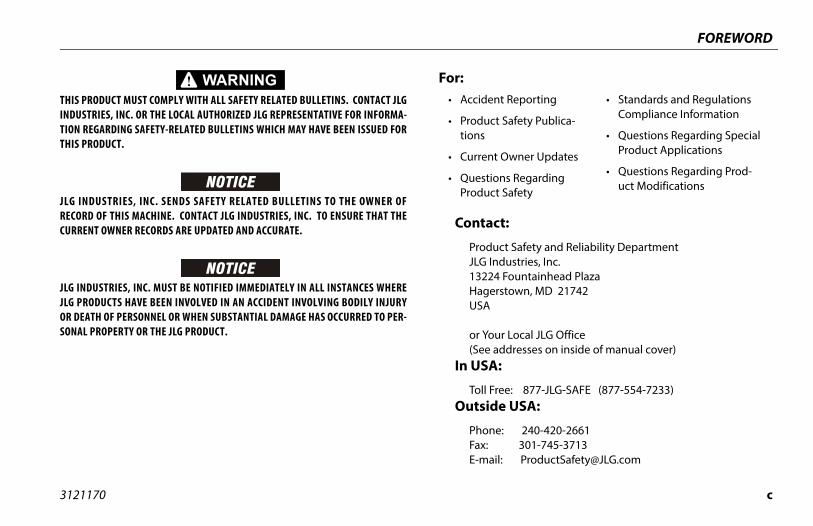
ct:
uct Safety and Reliability DepartmentIndustries, Inc.24 Fountainhead Plazaerstown, MD 21742
our Local JLG Office addresses on inside of manual cover)A:
Free: 877-JLG-SAFE (877-554-7233)de USA:
ne: 240-420-2661 301-745-3713ail: [email protected]
ent Reporting
ct Safety Publica-
nt Owner Updates
ions Regarding ct Safety
• Standards and Regulations Compliance Information
• Questions Regarding Special Product Applications
• Questions Regarding Prod-uct Modifications
3121170
THIS PRODUCT MUST COMPLY WITH ALL SAFETY RELATED BULLETINS. CONTACT JLGINDUSTRIES, INC. OR THE LOCAL AUTHORIZED JLG REPRESENTATIVE FOR INFORMA-TION REGARDING SAFETY-RELATED BULLETINS WHICH MAY HAVE BEEN ISSUED FORTHIS PRODUCT.
JLG INDUSTRIES, INC. SENDS SAFETY RELATED BULLETINS TO THE OWNER OFRECORD OF THIS MACHINE. CONTACT JLG INDUSTRIES, INC. TO ENSURE THAT THECURRENT OWNER RECORDS ARE UPDATED AND ACCURATE.
JLG INDUSTRIES, INC. MUST BE NOTIFIED IMMEDIATELY IN ALL INSTANCES WHEREJLG PRODUCTS HAVE BEEN INVOLVED IN AN ACCIDENT INVOLVING BODILY INJURYOR DEATH OF PERSONNEL OR WHEN SUBSTANTIAL DAMAGE HAS OCCURRED TO PER-SONAL PROPERTY OR THE JLG PRODUCT.
Conta
ProdJLG 132HagUSA
or Y(See
In US
Toll Outsi
PhoFax:E-m
For:• Accid
• Produtions
• Curre
• QuestProdu

FOREWORD
d 3121170
O
Re
Re
Re
Re
Re
Re
Re
Re
Re
Re
Re
Re
Re
Re
Re
Q - March 23, 2018
R - May 30, 2018
REVISION LOG
riginal Issue A - March 1, 2004
vised B - May 4, 2005
vised C - January 12, 2006
vised D - May 9, 2006
vised E - July 21, 2006
vised F - November 30, 2006
vised G - April 10, 2007
vised H - March 19, 2008
vised I - November 19, 2009
vised J - August 31, 2010
vised K - August 18, 2011
vised L - August 9, 2012
vised M - September 11, 2014
vised N - January 5, 2015
vised O - May 23, 2017
vised P - June 30, 2017
Revised
Revised

312 i
SEC PARAGRAPH, SUBJECT PAGE
TABLE OF CONTENTS
SEC
SECA
SkyGuard Function Test. . . . . . . . . . . . . . . . . . . . . . . . . . . . 2-7General . . . . . . . . . . . . . . . . . . . . . . . . . . . . . . . . . . . . . . . . . 2-10
OSCILLATING AXLE LOCKOUT TEST (IF EQUIPPED). . . . 2-11
- MACHINE CONTROLS AND INDICATORS
GENERAL . . . . . . . . . . . . . . . . . . . . . . . . . . . . . . . . . . . . . . . . . . . . 3-1CONTROLS AND INDICATORS . . . . . . . . . . . . . . . . . . . . . . . . 3-1
Ground Control Station . . . . . . . . . . . . . . . . . . . . . . . . . . . . 3-2Ground Control Indicator Panel . . . . . . . . . . . . . . . . . . . . 3-7Platform Station . . . . . . . . . . . . . . . . . . . . . . . . . . . . . . . . . . . 3-9Platform Control Indicator Panel . . . . . . . . . . . . . . . . . 3-15
- MACHINE OPERATION
DESCRIPTION . . . . . . . . . . . . . . . . . . . . . . . . . . . . . . . . . . . . . . . . 4-1HYDRAULIC SYSTEM WARM UP. . . . . . . . . . . . . . . . . . . . . . . 4-2BOOM OPERATING CHARACTERISTICS AND LIMITATIONS . . . . . . . . . . . . . . . . . . . . . . . . . . . . . . . . . . . . . . . . 4-2
Capacities . . . . . . . . . . . . . . . . . . . . . . . . . . . . . . . . . . . . . . . . . 4-2Envelope Control System . . . . . . . . . . . . . . . . . . . . . . . . . . 4-3Tower Path Control System . . . . . . . . . . . . . . . . . . . . . . . . 4-4Automatic Main Boom Control System . . . . . . . . . . . . . 4-5Slow Down System . . . . . . . . . . . . . . . . . . . . . . . . . . . . . . . . 4-5Controlled Angle . . . . . . . . . . . . . . . . . . . . . . . . . . . . . . . . . . 4-6Swing Speed Proportioning. . . . . . . . . . . . . . . . . . . . . . . . 4-6Stability . . . . . . . . . . . . . . . . . . . . . . . . . . . . . . . . . . . . . . . . . . . 4-6
1170
TION - PARAGRAPH, SUBJECT PAGE SECTION -TION - 1 - SAFETY PRECAUTIONS
1.1 GENERAL . . . . . . . . . . . . . . . . . . . . . . . . . . . . . . . . . . . . . . . . . . . . 1-11.2 PRE-OPERATION . . . . . . . . . . . . . . . . . . . . . . . . . . . . . . . . . . . . . 1-1
Operator Training and Knowledge . . . . . . . . . . . . . . . . . 1-1Workplace Inspection. . . . . . . . . . . . . . . . . . . . . . . . . . . . . . 1-2Machine Inspection. . . . . . . . . . . . . . . . . . . . . . . . . . . . . . . . 1-3
1.3 OPERATION . . . . . . . . . . . . . . . . . . . . . . . . . . . . . . . . . . . . . . . . . . 1-3General . . . . . . . . . . . . . . . . . . . . . . . . . . . . . . . . . . . . . . . . . . . 1-3Trip and Fall Hazards. . . . . . . . . . . . . . . . . . . . . . . . . . . . . . . 1-4Electrocution Hazards . . . . . . . . . . . . . . . . . . . . . . . . . . . . . 1-5Tipping Hazards . . . . . . . . . . . . . . . . . . . . . . . . . . . . . . . . . . . 1-7Crushing and Collision Hazards . . . . . . . . . . . . . . . . . . 1-10
1.4 TOWING, LIFTING, AND HAULING . . . . . . . . . . . . . . . . . . . . 1-111.5 MAINTENANCE. . . . . . . . . . . . . . . . . . . . . . . . . . . . . . . . . . . . . . 1-11
Maintenance Hazards . . . . . . . . . . . . . . . . . . . . . . . . . . . . 1-11Battery Hazards. . . . . . . . . . . . . . . . . . . . . . . . . . . . . . . . . . 1-13
TION - 2 - USER RESPONSIBILITIES, MACHINE PREPARATION, ND INSPECTION
2.1 PERSONNEL TRAINING . . . . . . . . . . . . . . . . . . . . . . . . . . . . . . . 2-1Operator Training . . . . . . . . . . . . . . . . . . . . . . . . . . . . . . . . . 2-1Training Supervision . . . . . . . . . . . . . . . . . . . . . . . . . . . . . . . 2-1Operator Responsibility . . . . . . . . . . . . . . . . . . . . . . . . . . . . 2-1
2.2 PREPARATION, INSPECTION, AND MAINTENANCE . . . . . 2-2Pre-Start Inspection. . . . . . . . . . . . . . . . . . . . . . . . . . . . . . . . 2-4Function Check. . . . . . . . . . . . . . . . . . . . . . . . . . . . . . . . . . . . 2-5
2.3
SECTION - 3
3.13.2
SECTION - 4
4.14.24.3
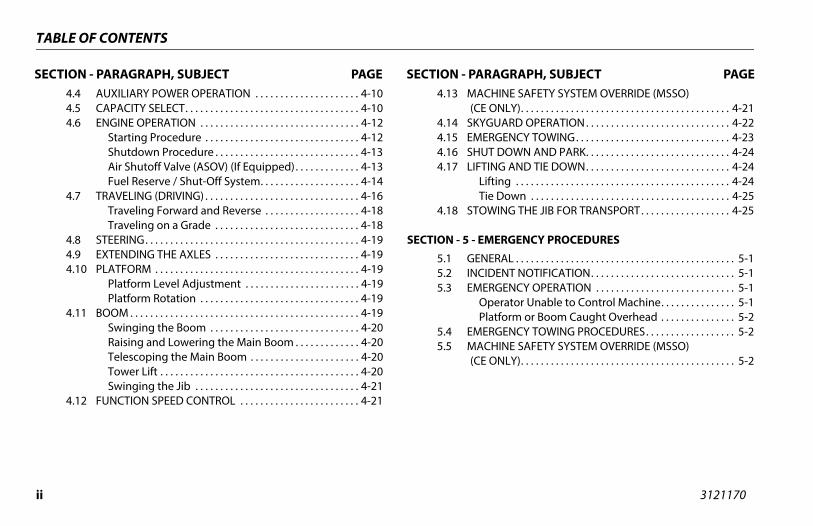
ii 3121170
TABLE OF CONTENTS
SECTIO AGRAPH, SUBJECT PAGE4.44.54.6
4.7
4.84.94.1
4.1
4.1
HINE SAFETY SYSTEM OVERRIDE (MSSO)ONLY). . . . . . . . . . . . . . . . . . . . . . . . . . . . . . . . . . . . . . . . . . 4-21UARD OPERATION . . . . . . . . . . . . . . . . . . . . . . . . . . . . . 4-22
RGENCY TOWING. . . . . . . . . . . . . . . . . . . . . . . . . . . . . . . 4-23T DOWN AND PARK. . . . . . . . . . . . . . . . . . . . . . . . . . . . . 4-24ING AND TIE DOWN. . . . . . . . . . . . . . . . . . . . . . . . . . . . . 4-24fting . . . . . . . . . . . . . . . . . . . . . . . . . . . . . . . . . . . . . . . . . . . 4-24e Down . . . . . . . . . . . . . . . . . . . . . . . . . . . . . . . . . . . . . . . . 4-25WING THE JIB FOR TRANSPORT. . . . . . . . . . . . . . . . . . 4-25
ERGENCY PROCEDURES
ERAL . . . . . . . . . . . . . . . . . . . . . . . . . . . . . . . . . . . . . . . . . . . . 5-1DENT NOTIFICATION. . . . . . . . . . . . . . . . . . . . . . . . . . . . . 5-1RGENCY OPERATION . . . . . . . . . . . . . . . . . . . . . . . . . . . . 5-1perator Unable to Control Machine. . . . . . . . . . . . . . . 5-1atform or Boom Caught Overhead . . . . . . . . . . . . . . . 5-2RGENCY TOWING PROCEDURES. . . . . . . . . . . . . . . . . . 5-2HINE SAFETY SYSTEM OVERRIDE (MSSO)ONLY). . . . . . . . . . . . . . . . . . . . . . . . . . . . . . . . . . . . . . . . . . . 5-2
N - PARAGRAPH, SUBJECT PAGE SECTION - PARAUXILIARY POWER OPERATION . . . . . . . . . . . . . . . . . . . . . 4-10CAPACITY SELECT. . . . . . . . . . . . . . . . . . . . . . . . . . . . . . . . . . . 4-10ENGINE OPERATION . . . . . . . . . . . . . . . . . . . . . . . . . . . . . . . . 4-12
Starting Procedure . . . . . . . . . . . . . . . . . . . . . . . . . . . . . . . 4-12Shutdown Procedure . . . . . . . . . . . . . . . . . . . . . . . . . . . . . 4-13Air Shutoff Valve (ASOV) (If Equipped). . . . . . . . . . . . . 4-13Fuel Reserve / Shut-Off System. . . . . . . . . . . . . . . . . . . . 4-14
TRAVELING (DRIVING) . . . . . . . . . . . . . . . . . . . . . . . . . . . . . . . 4-16Traveling Forward and Reverse . . . . . . . . . . . . . . . . . . . 4-18Traveling on a Grade . . . . . . . . . . . . . . . . . . . . . . . . . . . . . 4-18
STEERING. . . . . . . . . . . . . . . . . . . . . . . . . . . . . . . . . . . . . . . . . . . 4-19EXTENDING THE AXLES . . . . . . . . . . . . . . . . . . . . . . . . . . . . . 4-19
0 PLATFORM . . . . . . . . . . . . . . . . . . . . . . . . . . . . . . . . . . . . . . . . . 4-19Platform Level Adjustment . . . . . . . . . . . . . . . . . . . . . . . 4-19Platform Rotation . . . . . . . . . . . . . . . . . . . . . . . . . . . . . . . . 4-19
1 BOOM . . . . . . . . . . . . . . . . . . . . . . . . . . . . . . . . . . . . . . . . . . . . . . 4-19Swinging the Boom . . . . . . . . . . . . . . . . . . . . . . . . . . . . . . 4-20Raising and Lowering the Main Boom . . . . . . . . . . . . . 4-20Telescoping the Main Boom . . . . . . . . . . . . . . . . . . . . . . 4-20Tower Lift . . . . . . . . . . . . . . . . . . . . . . . . . . . . . . . . . . . . . . . . 4-20Swinging the Jib . . . . . . . . . . . . . . . . . . . . . . . . . . . . . . . . . 4-21
2 FUNCTION SPEED CONTROL . . . . . . . . . . . . . . . . . . . . . . . . 4-21
4.13 MAC(CE
4.14 SKYG4.15 EME4.16 SHU4.17 LIFT
LiTi
4.18 STO
SECTION - 5 - EM
5.1 GEN5.2 INCI5.3 EME
OPl
5.4 EME5.5 MAC
(CE
312 iii
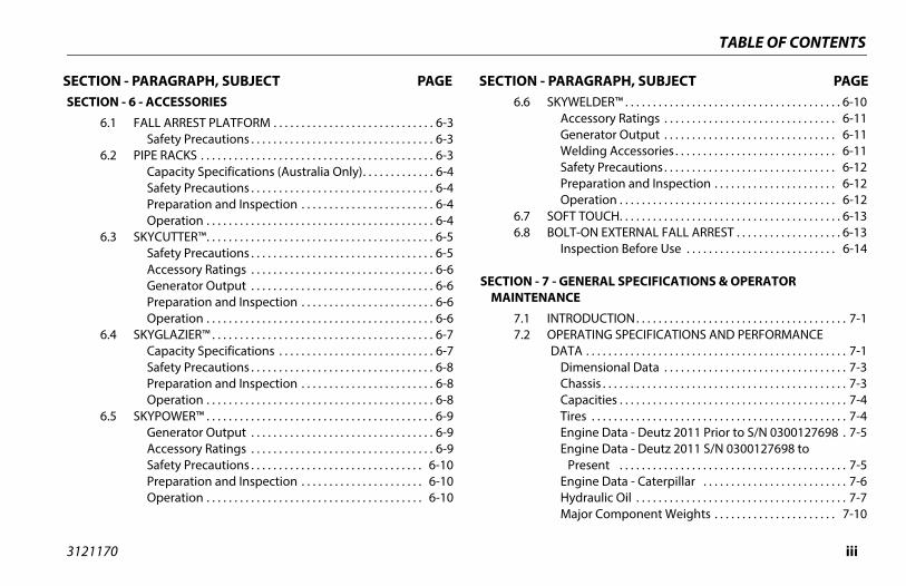
SEC PARAGRAPH, SUBJECT PAGE
TABLE OF CONTENTS
SEC SKYWELDER™ . . . . . . . . . . . . . . . . . . . . . . . . . . . . . . . . . . . . . . . 6-10Accessory Ratings . . . . . . . . . . . . . . . . . . . . . . . . . . . . . . . 6-11Generator Output . . . . . . . . . . . . . . . . . . . . . . . . . . . . . . . 6-11Welding Accessories . . . . . . . . . . . . . . . . . . . . . . . . . . . . . 6-11Safety Precautions . . . . . . . . . . . . . . . . . . . . . . . . . . . . . . . 6-12Preparation and Inspection . . . . . . . . . . . . . . . . . . . . . . 6-12Operation . . . . . . . . . . . . . . . . . . . . . . . . . . . . . . . . . . . . . . . 6-12
SOFT TOUCH. . . . . . . . . . . . . . . . . . . . . . . . . . . . . . . . . . . . . . . . 6-13BOLT-ON EXTERNAL FALL ARREST . . . . . . . . . . . . . . . . . . . 6-13
Inspection Before Use . . . . . . . . . . . . . . . . . . . . . . . . . . . 6-14
- GENERAL SPECIFICATIONS & OPERATOR ANCE
INTRODUCTION. . . . . . . . . . . . . . . . . . . . . . . . . . . . . . . . . . . . . . 7-1OPERATING SPECIFICATIONS AND PERFORMANCE DATA . . . . . . . . . . . . . . . . . . . . . . . . . . . . . . . . . . . . . . . . . . . . . . . 7-1
Dimensional Data . . . . . . . . . . . . . . . . . . . . . . . . . . . . . . . . . 7-3Chassis . . . . . . . . . . . . . . . . . . . . . . . . . . . . . . . . . . . . . . . . . . . . 7-3Capacities . . . . . . . . . . . . . . . . . . . . . . . . . . . . . . . . . . . . . . . . . 7-4Tires . . . . . . . . . . . . . . . . . . . . . . . . . . . . . . . . . . . . . . . . . . . . . . 7-4Engine Data - Deutz 2011 Prior to S/N 0300127698 . 7-5Engine Data - Deutz 2011 S/N 0300127698 to
Present . . . . . . . . . . . . . . . . . . . . . . . . . . . . . . . . . . . . . . . . . 7-5Engine Data - Caterpillar . . . . . . . . . . . . . . . . . . . . . . . . . . 7-6Hydraulic Oil . . . . . . . . . . . . . . . . . . . . . . . . . . . . . . . . . . . . . . 7-7Major Component Weights . . . . . . . . . . . . . . . . . . . . . . 7-10
1170
TION - PARAGRAPH, SUBJECT PAGE SECTION -TION - 6 - ACCESSORIES
6.1 FALL ARREST PLATFORM . . . . . . . . . . . . . . . . . . . . . . . . . . . . . 6-3Safety Precautions . . . . . . . . . . . . . . . . . . . . . . . . . . . . . . . . . 6-3
6.2 PIPE RACKS . . . . . . . . . . . . . . . . . . . . . . . . . . . . . . . . . . . . . . . . . . 6-3Capacity Specifications (Australia Only). . . . . . . . . . . . . 6-4Safety Precautions . . . . . . . . . . . . . . . . . . . . . . . . . . . . . . . . . 6-4Preparation and Inspection . . . . . . . . . . . . . . . . . . . . . . . . 6-4Operation . . . . . . . . . . . . . . . . . . . . . . . . . . . . . . . . . . . . . . . . . 6-4
6.3 SKYCUTTER™. . . . . . . . . . . . . . . . . . . . . . . . . . . . . . . . . . . . . . . . . 6-5Safety Precautions . . . . . . . . . . . . . . . . . . . . . . . . . . . . . . . . . 6-5Accessory Ratings . . . . . . . . . . . . . . . . . . . . . . . . . . . . . . . . . 6-6Generator Output . . . . . . . . . . . . . . . . . . . . . . . . . . . . . . . . . 6-6Preparation and Inspection . . . . . . . . . . . . . . . . . . . . . . . . 6-6Operation . . . . . . . . . . . . . . . . . . . . . . . . . . . . . . . . . . . . . . . . . 6-6
6.4 SKYGLAZIER™ . . . . . . . . . . . . . . . . . . . . . . . . . . . . . . . . . . . . . . . . 6-7Capacity Specifications . . . . . . . . . . . . . . . . . . . . . . . . . . . . 6-7Safety Precautions . . . . . . . . . . . . . . . . . . . . . . . . . . . . . . . . . 6-8Preparation and Inspection . . . . . . . . . . . . . . . . . . . . . . . . 6-8Operation . . . . . . . . . . . . . . . . . . . . . . . . . . . . . . . . . . . . . . . . . 6-8
6.5 SKYPOWER™ . . . . . . . . . . . . . . . . . . . . . . . . . . . . . . . . . . . . . . . . . 6-9Generator Output . . . . . . . . . . . . . . . . . . . . . . . . . . . . . . . . . 6-9Accessory Ratings . . . . . . . . . . . . . . . . . . . . . . . . . . . . . . . . . 6-9Safety Precautions . . . . . . . . . . . . . . . . . . . . . . . . . . . . . . . 6-10Preparation and Inspection . . . . . . . . . . . . . . . . . . . . . . 6-10Operation . . . . . . . . . . . . . . . . . . . . . . . . . . . . . . . . . . . . . . . 6-10
6.6
6.76.8
SECTION - 7MAINTEN
7.17.2
iv 3121170
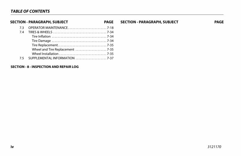
TABLE OF CONTENTS
SECTIO AGRAPH, SUBJECT PAGE7.37.4
7.5
SECTION
N - PARAGRAPH, SUBJECT PAGE SECTION - PAROPERATOR MAINTENANCE . . . . . . . . . . . . . . . . . . . . . . . . . . 7-18TIRES & WHEELS . . . . . . . . . . . . . . . . . . . . . . . . . . . . . . . . . . . . 7-34
Tire Inflation . . . . . . . . . . . . . . . . . . . . . . . . . . . . . . . . . . . . . 7-34Tire Damage . . . . . . . . . . . . . . . . . . . . . . . . . . . . . . . . . . . . . 7-34Tire Replacement. . . . . . . . . . . . . . . . . . . . . . . . . . . . . . . . . 7-35Wheel and Tire Replacement . . . . . . . . . . . . . . . . . . . . . 7-35Wheel Installation . . . . . . . . . . . . . . . . . . . . . . . . . . . . . . . . 7-35
SUPPLEMENTAL INFORMATION . . . . . . . . . . . . . . . . . . . . . 7-37
- 8 - INSPECTION AND REPAIR LOG
312 v
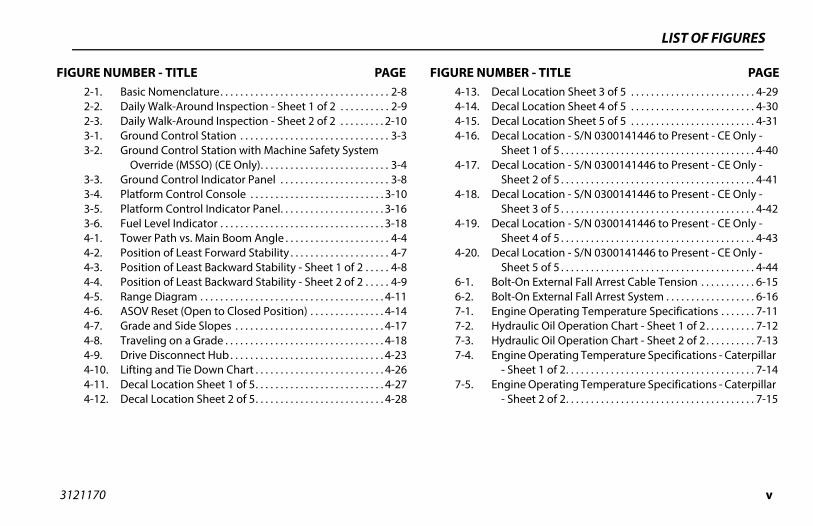
LIST OF FIGURES
FIG MBER - TITLE PAGEDecal Location Sheet 3 of 5 . . . . . . . . . . . . . . . . . . . . . . . . . 4-29Decal Location Sheet 4 of 5 . . . . . . . . . . . . . . . . . . . . . . . . . 4-30Decal Location Sheet 5 of 5 . . . . . . . . . . . . . . . . . . . . . . . . . 4-31Decal Location - S/N 0300141446 to Present - CE Only -
Sheet 1 of 5 . . . . . . . . . . . . . . . . . . . . . . . . . . . . . . . . . . . . . . . 4-40Decal Location - S/N 0300141446 to Present - CE Only -
Sheet 2 of 5 . . . . . . . . . . . . . . . . . . . . . . . . . . . . . . . . . . . . . . . 4-41Decal Location - S/N 0300141446 to Present - CE Only -
Sheet 3 of 5 . . . . . . . . . . . . . . . . . . . . . . . . . . . . . . . . . . . . . . . 4-42Decal Location - S/N 0300141446 to Present - CE Only -
Sheet 4 of 5 . . . . . . . . . . . . . . . . . . . . . . . . . . . . . . . . . . . . . . . 4-43Decal Location - S/N 0300141446 to Present - CE Only -
Sheet 5 of 5 . . . . . . . . . . . . . . . . . . . . . . . . . . . . . . . . . . . . . . . 4-44Bolt-On External Fall Arrest Cable Tension . . . . . . . . . . . 6-15Bolt-On External Fall Arrest System . . . . . . . . . . . . . . . . . . 6-16Engine Operating Temperature Specifications . . . . . . . 7-11Hydraulic Oil Operation Chart - Sheet 1 of 2. . . . . . . . . . 7-12Hydraulic Oil Operation Chart - Sheet 2 of 2. . . . . . . . . . 7-13Engine Operating Temperature Specifications - Caterpillar
- Sheet 1 of 2. . . . . . . . . . . . . . . . . . . . . . . . . . . . . . . . . . . . . . 7-14Engine Operating Temperature Specifications - Caterpillar
- Sheet 2 of 2. . . . . . . . . . . . . . . . . . . . . . . . . . . . . . . . . . . . . . 7-15
1170
URE NUMBER - TITLE PAGE FIGURE NU2-1. Basic Nomenclature. . . . . . . . . . . . . . . . . . . . . . . . . . . . . . . . . . 2-82-2. Daily Walk-Around Inspection - Sheet 1 of 2 . . . . . . . . . . 2-92-3. Daily Walk-Around Inspection - Sheet 2 of 2 . . . . . . . . . 2-103-1. Ground Control Station . . . . . . . . . . . . . . . . . . . . . . . . . . . . . . 3-33-2. Ground Control Station with Machine Safety System
Override (MSSO) (CE Only). . . . . . . . . . . . . . . . . . . . . . . . . . 3-43-3. Ground Control Indicator Panel . . . . . . . . . . . . . . . . . . . . . . 3-83-4. Platform Control Console . . . . . . . . . . . . . . . . . . . . . . . . . . . 3-103-5. Platform Control Indicator Panel. . . . . . . . . . . . . . . . . . . . . 3-163-6. Fuel Level Indicator . . . . . . . . . . . . . . . . . . . . . . . . . . . . . . . . . 3-184-1. Tower Path vs. Main Boom Angle . . . . . . . . . . . . . . . . . . . . . 4-44-2. Position of Least Forward Stability . . . . . . . . . . . . . . . . . . . . 4-74-3. Position of Least Backward Stability - Sheet 1 of 2 . . . . . 4-84-4. Position of Least Backward Stability - Sheet 2 of 2 . . . . . 4-94-5. Range Diagram . . . . . . . . . . . . . . . . . . . . . . . . . . . . . . . . . . . . . 4-114-6. ASOV Reset (Open to Closed Position) . . . . . . . . . . . . . . . 4-144-7. Grade and Side Slopes . . . . . . . . . . . . . . . . . . . . . . . . . . . . . . 4-174-8. Traveling on a Grade . . . . . . . . . . . . . . . . . . . . . . . . . . . . . . . . 4-184-9. Drive Disconnect Hub . . . . . . . . . . . . . . . . . . . . . . . . . . . . . . . 4-234-10. Lifting and Tie Down Chart . . . . . . . . . . . . . . . . . . . . . . . . . . 4-264-11. Decal Location Sheet 1 of 5. . . . . . . . . . . . . . . . . . . . . . . . . . 4-274-12. Decal Location Sheet 2 of 5. . . . . . . . . . . . . . . . . . . . . . . . . . 4-28
4-13.4-14.4-15.4-16.
4-17.
4-18.
4-19.
4-20.
6-1.6-2.7-1.7-2.7-3.7-4.
7-5.
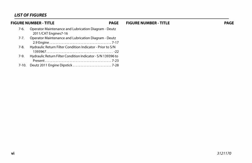
vi 3121170
LIST O
FIGURE ER - TITLE PAGE7-6.
7-7.
7-8.
7-9.
7-10
F FIGURES
NUMBER - TITLE PAGE FIGURE NUMBOperator Maintenance and Lubrication Diagram - Deutz
2011/CAT Engines7-16Operator Maintenance and Lubrication Diagram - Deutz
2.9 Engine . . . . . . . . . . . . . . . . . . . . . . . . . . . . . . . . . . . . . . . . 7-17Hydraulic Return Filter Condition Indicator - Prior to S/N
1393967. . . . . . . . . . . . . . . . . . . . . . . . . . . . . . . . . . . . . . . . . . . -22Hydraulic Return Filter Condition Indicator - S/N 139396 to
Present . . . . . . . . . . . . . . . . . . . . . . . . . . . . . . . . . . . . . . . . . . . 7-23. Deutz 2011 Engine Dipstick . . . . . . . . . . . . . . . . . . . . . . . . . 7-28
312 vii
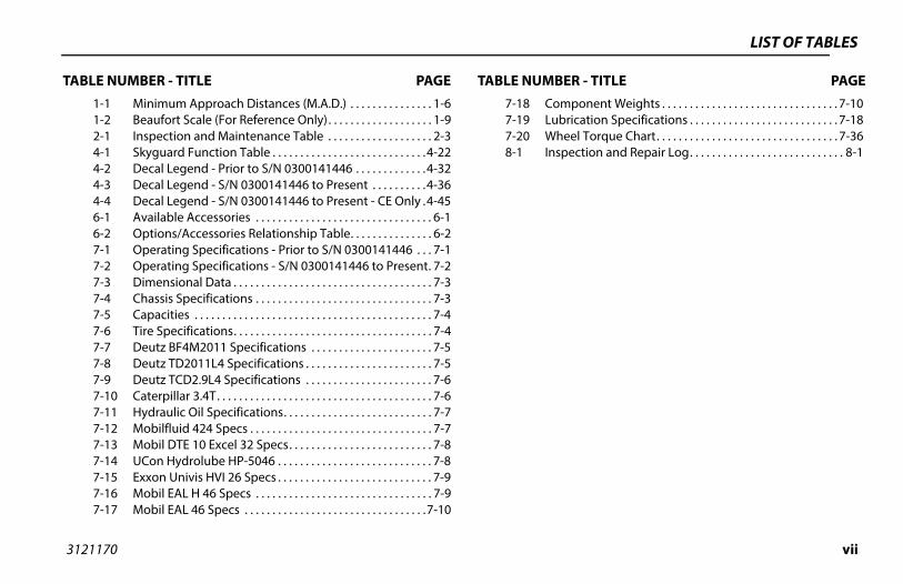
LIST OF TABLES
TAB MBER - TITLE PAGEComponent Weights . . . . . . . . . . . . . . . . . . . . . . . . . . . . . . . . 7-10Lubrication Specifications . . . . . . . . . . . . . . . . . . . . . . . . . . . 7-18Wheel Torque Chart. . . . . . . . . . . . . . . . . . . . . . . . . . . . . . . . . 7-36Inspection and Repair Log. . . . . . . . . . . . . . . . . . . . . . . . . . . . 8-1
1170
LE NUMBER - TITLE PAGE TABLE NU1-1 Minimum Approach Distances (M.A.D.) . . . . . . . . . . . . . . . 1-61-2 Beaufort Scale (For Reference Only). . . . . . . . . . . . . . . . . . . 1-92-1 Inspection and Maintenance Table . . . . . . . . . . . . . . . . . . . 2-34-1 Skyguard Function Table . . . . . . . . . . . . . . . . . . . . . . . . . . . .4-224-2 Decal Legend - Prior to S/N 0300141446 . . . . . . . . . . . . .4-324-3 Decal Legend - S/N 0300141446 to Present . . . . . . . . . .4-364-4 Decal Legend - S/N 0300141446 to Present - CE Only .4-456-1 Available Accessories . . . . . . . . . . . . . . . . . . . . . . . . . . . . . . . . 6-16-2 Options/Accessories Relationship Table. . . . . . . . . . . . . . . 6-27-1 Operating Specifications - Prior to S/N 0300141446 . . . 7-17-2 Operating Specifications - S/N 0300141446 to Present. 7-27-3 Dimensional Data . . . . . . . . . . . . . . . . . . . . . . . . . . . . . . . . . . . . 7-37-4 Chassis Specifications . . . . . . . . . . . . . . . . . . . . . . . . . . . . . . . . 7-37-5 Capacities . . . . . . . . . . . . . . . . . . . . . . . . . . . . . . . . . . . . . . . . . . . 7-47-6 Tire Specifications. . . . . . . . . . . . . . . . . . . . . . . . . . . . . . . . . . . . 7-47-7 Deutz BF4M2011 Specifications . . . . . . . . . . . . . . . . . . . . . . 7-57-8 Deutz TD2011L4 Specifications . . . . . . . . . . . . . . . . . . . . . . . 7-57-9 Deutz TCD2.9L4 Specifications . . . . . . . . . . . . . . . . . . . . . . . 7-67-10 Caterpillar 3.4T. . . . . . . . . . . . . . . . . . . . . . . . . . . . . . . . . . . . . . . 7-67-11 Hydraulic Oil Specifications. . . . . . . . . . . . . . . . . . . . . . . . . . . 7-77-12 Mobilfluid 424 Specs . . . . . . . . . . . . . . . . . . . . . . . . . . . . . . . . . 7-77-13 Mobil DTE 10 Excel 32 Specs. . . . . . . . . . . . . . . . . . . . . . . . . . 7-87-14 UCon Hydrolube HP-5046 . . . . . . . . . . . . . . . . . . . . . . . . . . . . 7-87-15 Exxon Univis HVI 26 Specs . . . . . . . . . . . . . . . . . . . . . . . . . . . . 7-97-16 Mobil EAL H 46 Specs . . . . . . . . . . . . . . . . . . . . . . . . . . . . . . . . 7-97-17 Mobil EAL 46 Specs . . . . . . . . . . . . . . . . . . . . . . . . . . . . . . . . .7-10
7-187-197-208-1

viii 3121170
LIST O
TABLE N R - TITLE PAGE
F TABLES
UMBER - TITLE PAGE TABLE NUMBE
This Page Left Blank Intentionally
SECTION 1 - SAFETY PRECAUTIONS
1-1
UTIONS
MPLY WITH THE SAFETY PRECAUTIONS LISTED IN THIS MANUAL IN MACHINE DAMAGE, PROPERTY DAMAGE, PERSONAL INJURY OR
-OPERATION
raining and Knowledge Operation and Safety Manual must be read and under-d in its entirety before operating the machine. For clarifi-
on, questions, or additional information regarding anytions of this manual, contact JLG Industries, Inc.
3121170
SECTION 1. SAFETY PRECA
1.1 GENERALThis section outlines the necessary precautions for proper andsafe machine usage and maintenance. It is mandatory that a dailyroutine is established based on the content of this manual to pro-mote proper machine usage. A maintenance program, using theinformation provided in this manual and the Service and Mainte-nance Manual, must also be established by a qualified person andmust be followed to ensure that the machine is safe to operate.
The owner/user/operator/lessor/lessee of the machine must notaccept operating responsibility until this manual has been read,training is accomplished, and operation of the machine has beencompleted under the supervision of an experienced and quali-fied operator.
This section contains the responsibilities of the owner, user, oper-ator, lessor, and lessee concerning safety, training, inspection,maintenance, application, and operation. If there are any ques-tions with regard to safety, training, inspection, maintenance,application, and operation, please contact JLG Industries, Inc.(“JLG”).
FAILURE TO COCOULD RESULTDEATH.
1.2 PRE
Operator T• The
stoocatipor
SECTION 1 - SAFETY PRECAUTIONS
1-2 3121170
pectionns to avoid all hazards in the work area must be
the user before and during operation of the machine.
perate or raise the platform from a position on trucks,ailway cars, floating vessels, scaffolds or other equip-less the application is approved in writing by JLG.
peration, check work area for overhead hazards suchic lines, bridge cranes, and other potential overheadions.
erating surfaces for holes, bumps, drop-offs, obstruc-bris, concealed holes, and other potential hazards.
e work area for hazardous locations. Do not operateine in hazardous environments unless approved forose by JLG.
hat the ground conditions are adequate to supportimum tire load indicated on the tire load decalsn the chassis adjacent to each wheel. Do not travelported surfaces.
• An operator must not accept operating responsibilities untiladequate training has been given by competent and autho-rized persons.
• Allow only those authorized and qualified personnel to oper-ate the machine who have demonstrated that they under-stand the safe and proper operation and maintenance of theunit.
• Read, understand, and obey all DANGERS, WARNINGS, CAU-TIONS, and operating instructions on the machine and in thismanual.
• Ensure that the machine is to be used in a manner which iswithin the scope of its intended application as determined byJLG.
• All operating personnel must be familiar with the emergencycontrols and emergency operation of the machine as specifiedin this manual.
• Read, understand, and obey all applicable employer, local, andgovernmental regulations as they pertain to your utilizationand application of the machine.
Workplace Ins• Precautio
taken by
• Do not otrailers, rment un
• Before oas electrobstruct
• Check options, de
• Check ththe machthat purp
• Ensure tthe maxlocated oon unsup

SECTION 1 - SAFETY PRECAUTIONS
1-3
RATION
hine operation requires your full attention. Bring thehine to a full stop before using any device, i.e. cell phones,-way radios, etc. that will distract your attention fromly operating the machine.
not use the machine for any purpose other than position-personnel, their tools, and equipment.
re operation, the user must be familiar with the machineabilities and operating characteristics of all functions.
er operate a malfunctioning machine. If a malfunctionrs, shut down the machine. Remove the unit from service
notify the proper authorities.
ot remove, modify, or disable any safety devices.
er slam a control switch or lever through neutral to anosite direction. Always return switch to neutral and stopre moving the switch to the next function. Operate con- with slow and even pressure.
not allow personnel to tamper with or operate thehine from the ground with personnel in the platform,pt in an emergency.
3121170
Machine Inspection • Do not operate this machine until the inspections and func-
tional checks as specified in Section 2 of this manual havebeen performed.
• Do not operate this machine until it has been serviced andmaintained according to the maintenance and inspectionrequirements as specified in the machine’s Service and Main-tenance Manual.
• Ensure all safety devices are operating properly. Modificationof these devices is a safety violation.
MODIFICATION OR ALTERATION OF AN AERIAL WORK PLATFORM SHALL BE MADEONLY WITH PRIOR WRITTEN PERMISSION FROM THE MANUFACTURER.
• Do not operate any machine on which the safety or instructionplacards or decals are missing or illegible.
• Check the machine for modifications to original components.Ensure that any modifications have been approved by JLG.
• Avoid accumulation of debris on platform floor. Keep mud, oil,grease, and other slippery substances from footwear and plat-form floor.
1.3 OPE
General • Mac
mactwosafe
• Do ing
• Befocap
• Nevoccuand
• Do n
• Nevoppbefotrols
• Do macexce
SECTION 1 - SAFETY PRECAUTIONS
1-4 3121170
ine will remain stationary, hydraulic oil temperature, air temperature, and boom and platform position.
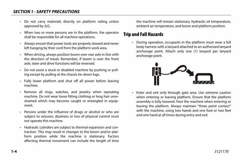
azards peration, occupants in the platform must wear a fullness with a lanyard attached to an authorized lanyarde point. Attach only one (1) lanyard per lanyarde point.
d exit only through gate area. Use extreme cautiontering or leaving platform. Ensure that the platform is fully lowered. Face the machine when entering orhe platform. Always maintain “three point contact” machine, using two hands and one foot or two feethand at all times during entry and exit.
• Do not carry materials directly on platform railing unlessapproved by JLG.
• When two or more persons are in the platform, the operatorshall be responsible for all machine operations.
• Always ensure that power tools are properly stowed and neverleft hanging by their cord from the platform work area.
• When driving, always position boom over rear axle in line withthe direction of travel. Remember, if boom is over the frontaxle, steer and drive functions will be reversed.
• Do not assist a stuck or disabled machine by pushing or pull-ing except by pulling at the chassis tie-down lugs.
• Fully lower platform and shut off all power before leavingmachine.
• Remove all rings, watches, and jewelry when operatingmachine. Do not wear loose fitting clothing or long hair unre-strained which may become caught or entangled in equip-ment.
• Persons under the influence of drugs or alcohol or who aresubject to seizures, dizziness or loss of physical control mustnot operate this machine.
• Hydraulic cylinders are subject to thermal expansion and con-traction. This may result in changes to the boom and/or plat-form position while the machine is stationary. Factorsaffecting thermal movement can include the length of time
the machambient
Trip and Fall H• During o
body haranchoraganchorag
• Enter anwhen enassemblyleaving twith theand one
SECTION 1 - SAFETY PRECAUTIONS
1-5
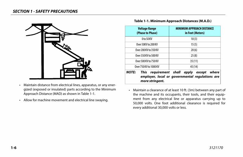
ion Hazards machine is not insulated and does not provide protection contact or proximity to electrical current.
3121170
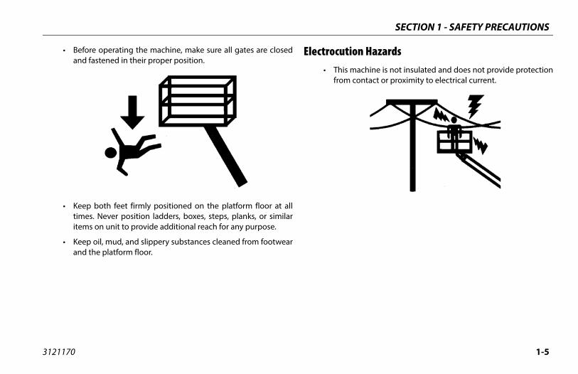
• Before operating the machine, make sure all gates are closedand fastened in their proper position.
• Keep both feet firmly positioned on the platform floor at alltimes. Never position ladders, boxes, steps, planks, or similaritems on unit to provide additional reach for any purpose.
• Keep oil, mud, and slippery substances cleaned from footwearand the platform floor.
Electrocut• This
from
SECTION 1 - SAFETY PRECAUTIONS
1-6 3121170
a clearance of at least 10 ft. (3m) between any part ofhine and its occupants, their tools, and their equip-m any electrical line or apparatus carrying up toolts. One foot additional clearance is required forditional 30,000 volts or less.
-1. Minimum Approach Distances (M.A.D.)
e Rangeto Phase)
MINIMUM APPROACH DISTANCEin Feet (Meters)
50 KV 10 (3)
V to 200 KV 15 (5)
V to 350 KV 20 (6)
V to 500 KV 25 (8)
V to 750 KV 35 (11)
V to 1000 KV 45 (14)
requirement shall apply except whereloyer, local or governmental regulations are
re stringent.
• Maintain distance from electrical lines, apparatus, or any ener-gized (exposed or insulated) parts according to the MinimumApproach Distance (MAD) as shown in Table 1-1.
• Allow for machine movement and electrical line swaying.
• Maintainthe macment fro50,000 vevery ad
Table 1
Voltag(Phase
0 to
Over 50K
Over 200 K
Over 350 K
Over 500 K
Over 750 K
NOTE: Thisempmo
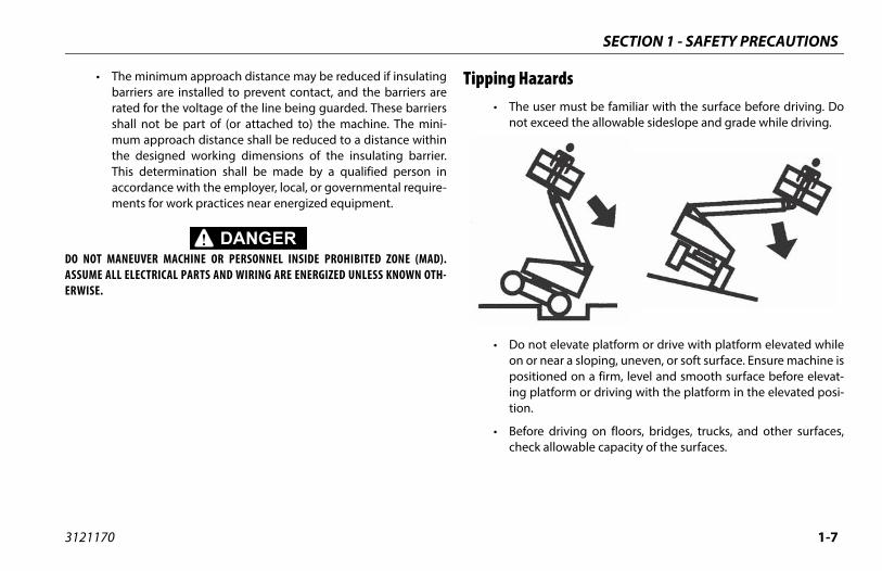
SECTION 1 - SAFETY PRECAUTIONS
1-7
azards user must be familiar with the surface before driving. Doexceed the allowable sideslope and grade while driving.
not elevate platform or drive with platform elevated whiler near a sloping, uneven, or soft surface. Ensure machine is
itioned on a firm, level and smooth surface before elevat-platform or driving with the platform in the elevated posi-.
re driving on floors, bridges, trucks, and other surfaces,ck allowable capacity of the surfaces.
3121170
• The minimum approach distance may be reduced if insulatingbarriers are installed to prevent contact, and the barriers arerated for the voltage of the line being guarded. These barriersshall not be part of (or attached to) the machine. The mini-mum approach distance shall be reduced to a distance withinthe designed working dimensions of the insulating barrier.This determination shall be made by a qualified person inaccordance with the employer, local, or governmental require-ments for work practices near energized equipment.
DO NOT MANEUVER MACHINE OR PERSONNEL INSIDE PROHIBITED ZONE (MAD).ASSUME ALL ELECTRICAL PARTS AND WIRING ARE ENERGIZED UNLESS KNOWN OTH-ERWISE.
Tipping H• The
not
• Do on oposing tion
• Befoche
SECTION 1 - SAFETY PRECAUTIONS
1-8 3121170
perate the machine when wind conditions, includingay exceed 28 mph (12.5 m/s). Factors affecting winde; platform elevation, surrounding structures, localevents, and approaching storms. Refer to Table 1-2, scale (For Reference Only) or use other means towind conditions.
eed can be significantly greater at height than atevel.
ed can change rapidly. Always consider approachingevents, the time required to lower the platform, and to monitor current and potential wind conditions.
increase surface area of the platform or the load. areas exposed to wind will decrease stability.
crease the platform size with unauthorized modifica-ttachments.
• Never exceed the maximum work load as specified on theplatform. Keep all loads within the confines of the platform,unless authorized by JLG.
• Keep the chassis of the machine a minimum of 2 ft. (0.6m)from holes, bumps, drop-offs, obstructions, debris, concealedholes, and other potential hazards at the ground level.
• Do not push or pull any object with the boom.
• Never attempt to use the machine as a crane. Do not tie-offmachine to any adjacent structure. Never attach wire, cable, orany similar items to platform.
• If boom assembly or platform is in a position that one or morewheels are off the ground, all persons must be removed beforeattempting to stabilize the machine. Use cranes, forklift trucks,or other appropriate equipment to stabilize machine.
• Do not ogusts, mspeed arweather Beaufortmonitor
• Wind spground l
• Wind speweather methods
• Do not Increased
• Do not intions or a
SECTION 1 - SAFETY PRECAUTIONS
1-9
nce Only)
Land Conditions
vertically
le in smoke
ed skin. Leaves rustle
twigs in constant motion
er raised. Small branches begin to move.
.
otion. Flags waving near horizontal. Umbrella use
ion. Effort needed to walk against the wind.
trees. Cars veer on road.
age.
3121170
DO NOT OPERATE THE MACHINE WHEN WIND CONDITIONS EXCEED 28 MPH (12.5 M/S).
Table 1-2. Beaufort Scale (For Refere
Beaufort Number
Wind SpeedDescription
mph m/s
0 0 0-0.2 Calm Calm. Smoke rises
1 1-3 0.3-1.5 Light air Wind motion visib
2 4-7 1.6-3.3 Light breeze Wind felt on expos
3 8-12 3.4-5.4 Gentle breeze Leaves and smaller
4 13-18 5.5-7.9 Moderate breeze Dust and loose pap
5 19-24 8.0-10.7 Fresh breeze Smaller trees sway
6 25-31 10.8-13.8 Strong breeze Large branches in mbecomes difficult.
7 32-38 13.9-17.1 Near Gale/Moderate Gale Whole trees in mot
8 39-46 17.2-20.7 Fresh Gale Twigs broken from
9 47-54 20.8-24.4 Strong Gale Light structure dam

SECTION 1 - SAFETY PRECAUTIONS
1-1 3121170
Cru n-operating personnel at least 6 ft. (1.8m) away from during all driving and swing operations.
ll travel conditions, the operator must limit travelcording to conditions of ground surface, congestion, slope, location of personnel, and other factors whichse collision or injury to personnel.
of stopping distances in all drive speeds. When driv-h speed, switch to low speed before stopping. Travel low speed only.
se high speed drive in restricted or close quarters orving in reverse.
extreme caution at all times to prevent obstacles fromr interfering with operating controls and persons in
orm.
that operators of other overhead and floor levels are aware of the aerial work platform’s presence. Dis-power to overhead cranes.
rsonnel not to work, stand, or walk under a raised platform. Position barricades on floor if necessary.
0
shing and Collision Hazards• Approved head gear must be worn by all operating and
ground personnel.
• Check work area for clearances overhead, on sides, and bot-tom of platform when lifting or lowering platform, and driving.
• During operation, keep all body parts inside platform railing.
• Use the boom functions, not the drive function, to position theplatform close to obstacles.
• Always post a lookout when driving in areas where vision isobstructed.
• Keep nomachine
• Under aspeed acvisibility,may cau
• Be awareing in higgrades in
• Do not uwhen dri
• Exercise striking othe platf
• Be sure machineconnect
• Warn peboom or
SECTION 1 - SAFETY PRECAUTIONS
1-11
INTENANCEb-section contains general safety precautions which musterved during maintenance of this machine. Additional pre-ns to be observed during machine maintenance ared at the appropriate points in this manual and in the Ser-d Maintenance Manual. It is of utmost importance thatnance personnel pay strict attention to these precautionsd possible injury to personnel or damage to the machineerty. A maintenance program must be established by a
ied person and must be followed to ensure that thee is safe.
nce Hazardst off power to all controls and ensure that all moving partssecured from inadvertent motion prior to performing anystments or repairs.
er work under an elevated platform until it has been fullyered to the full down position, if possible, or otherwiseported and restrained from movement with appropriatety props, blocking, or overhead supports.
NOT attempt to repair or tighten any hydraulic hoses or fit-s while the machine is powered on or when the hydraulicem is under pressure.
ays relieve hydraulic pressure from all hydraulic circuitsre loosening or removing hydraulic components.
3121170
1.4 TOWING, LIFTING, AND HAULING• Never allow personnel in platform while towing, lifting, or
hauling.
• This machine should not be towed, except in the event ofemergency, malfunction, power failure, or loading/unloading.Refer to the Emergency Procedures section of this manual foremergency towing procedures.
• Ensure boom is in the stowed position and, if equipped, theturntable locked prior to towing, lifting or hauling. The plat-form must be completely empty of tools.
• When lifting machine, lift only at designated areas of themachine. Lift the unit with equipment of adequate capacity.
• Refer to the Machine Operation section of this manual for lift-ing information.
1.5 MAThis sube obscautioinsertevice anmainteto avoior propqualifmachin
Maintena• Shu
are adju
• Nevlowsupsafe
• DO tingsyst
• Alwbefo
SECTION 1 - SAFETY PRECAUTIONS
1-1 3121170
se machine as a ground for welding.
rforming welding or metal cutting operations, pre- must be taken to protect the chassis from direct to weld and metal cutting spatter.
fuel the machine with the engine running.
approved non-flammable cleaning solvents.
eplace items critical to stability, such as batteries ors, with items of different weight or specification. Doify unit in any way to affect stability.
the Service and Maintenance Manual for the weightsl stability items.
LTERATION OF AN AERIAL WORK PLATFORM SHALL BE MADERITTEN PERMISSION FROM THE MANUFACTURER.
2
• DO NOT use your hand to check for leaks. Use a piece of card-board or paper to search for leaks. Wear gloves to help protecthands from spraying fluid.
• Ensure replacement parts or components are identical orequivalent to original parts or components.
• Never attempt to move heavy parts without the aid of amechanical device. Do not allow heavy objects to rest in anunstable position. Ensure adequate support is provided whenraising components of the machine.
• Do not u
• When pecautionsexposure
• Do not re
• Use only
• Do not rsolid tirenot mod
• Refer to of critica
MODIFICATION OR AONLY WITH PRIOR W

SECTION 1 - SAFETY PRECAUTIONS
1-13
ID IS HIGHLY CORROSIVE. AVOID CONTACT WITH SKIN AND ALL TIMES. IMMEDIATELY RINSE ANY CONTACTED AREA WITH AND SEEK MEDICAL ATTENTION.
rge batteries only in a well ventilated area.
id overfilling the battery fluid level. Add distilled water toeries only after the batteries are fully charged.
3121170
Battery Hazards• Always disconnect batteries when servicing electrical compo-
nents or when performing welding on the machine.
• Do not allow smoking, open flame, or sparks near battery dur-ing charging or servicing.
• Do not contact tools or other metal objects across the batteryterminals.
• Always wear hand, eye, and face protection when servicingbatteries. Ensure that battery acid does not come in contactwith skin or clothing.
BATTERY FLUCLOTHING ATCLEAN WATER
• Cha
• Avobatt

SECTION 1 - SAFETY PRECAUTIONS
1-1 3121170
4NOTES:
S, MACHINE PREPARATION, AND INSPECTION
2-1
REPARATION, AND INSPECTION
e safest means to operate the machine where overheadstructions, other moving equipment, and obstacles,pressions, holes, drop-offs.
eans to avoid the hazards of unprotected electrical con-ctors.
ecific job requirements or machine application.
upervisiong must be done under the supervision of a qualified per- an open area free of obstructions until the trainee hasped the ability to safely control and operate the machine.
esponsibilityerator must be instructed that he/she has the responsibil- authority to shut down the machine in case of a malfunc- other unsafe condition of either the machine or the job
SECTION 2 - USER RESPONSIBILITIE
3121170
SECTION 2. USER RESPONSIBILITIES, MACHINE P
2.1 PERSONNEL TRAININGThe aerial platform is a personnel handling device; so it is neces-sary that it be operated and maintained only by trained person-nel.
Persons under the influence of drugs or alcohol or who are sub-ject to seizures, dizziness or loss of physical control must notoperate this machine.
Operator TrainingOperator training must cover:
1. Use and limitations of the controls in the platform and at theground, emergency controls and safety systems.
2. Control labels, instructions, and warnings on the machine.
3. Rules of the employer and government regulations.
4. Use of approved fall protection device.
5. Enough knowledge of the mechanical operation of themachine to recognize a malfunction or potential malfunc-tion.
6. Thobde
7. Mdu
8. Sp
Training STraininson indevelo
Operator RThe opity andtion orsite.

SECTION 2 - USER RESPONSIBILITIES, MACHINE PREPARATION, AND INSPECTION
2-2 3121170
2.2. RECOGNIZES A FACTORY TRAINED SERVICE TECHNICIAN AS A
UCCESSFULLY COMPLETED THE JLG SERVICE TRAINING SCHOOL PRODUCT MODEL.
PREPARATION, INSPECTION, AND MAINTENANCEThe following table covers the periodic machine inspections andmaintenance required by JLG Industries, Inc. Consult local regula-tions for further requirements for aerial work platforms. The fre-quency of inspections and maintenance must be increased asnecessary when the machine is used in a harsh or hostile environ-ment, if the machine is used with increased frequency, or if themachine is used in a severe manner.
JLG INDUSTRIES, INCPERSON WHO HAS SFOR THE SPECIFIC JLG

S, MACHINE PREPARATION, AND INSPECTION
2-3
nce Table
rybility
Service Qualification
Reference
User or Operator Operator and Safety Manual
ser Qualified JLG Mechanic Service and Maintenance Manual and applicable JLG inspection form
ser Qualified JLG Mechanic Service and Maintenance Manual and applicable JLG inspection form
ser Factory Trained Service Technician(Recommended)
Service and Maintenance Manual and applicable JLG inspection form
ser Qualified JLG Mechanic Service and Maintenance Manual
ual to perform inspections.
SECTION 2 - USER RESPONSIBILITIE
3121170
Table 2-1. Inspection and Maintena
Type Frequency PrimaResponsi
Pre-Start Inspection Before using each day; or whenever there’s an Operator change.
User or Operator
Pre-Delivery Inspection (See Note)
Before each sale, lease, or rental delivery. Owner, Dealer, or U
Frequent Inspection(See Note)
In service for 3 months or 150 hours, whichever comes first; orOut of service for a period of more than 3 months; orPurchased used.
Owner, Dealer, or U
Annual Machine Inspection(See Note)
Annually, no later than 13 months from the date of prior inspection.
Owner, Dealer, or U
Preventative Maintenance At intervals as specified in the Service and Maintenance Manual.
Owner, Dealer, or U
NOTE: Inspection forms are available from JLG. Use the Service and Maintenance Man
SECTION 2 - USER RESPONSIBILITIES, MACHINE PREPARATION, AND INSPECTION
2-4 3121170
Pre tion and Safety Manuals – Make sure a copy of theor and Safety Manual, AEM Safety Manual (ANSI mar-ly), and ANSI Manual of Responsibilities (ANSI mar-
nly) is enclosed in the weather resistant storageer.
Around” Inspection – Refer to Figure 2-2.
y – Charge as required.
ombustion Engine Powered Machines) – Add the fuel as necessary.
Oil Supply – Ensure the engine oil level is at the Fulln the dipstick and the filler cap is secure.
ulic Oil – Check the hydraulic oil level. Ensure hydrau- added as required.
ories/Attachments – Refer to the Accessories sectionmanual or the accessory installed upon the machinecific inspection, operation, and maintenance instruc-
-Start InspectionThe Pre-Start Inspection should include each of the following:
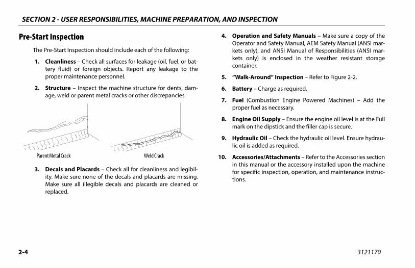
1. Cleanliness – Check all surfaces for leakage (oil, fuel, or bat-tery fluid) or foreign objects. Report any leakage to theproper maintenance personnel.
2. Structure – Inspect the machine structure for dents, dam-age, weld or parent metal cracks or other discrepancies.
3. Decals and Placards – Check all for cleanliness and legibil-ity. Make sure none of the decals and placards are missing.Make sure all illegible decals and placards are cleaned orreplaced.
4. OperaOperatkets onkets ocontain
5. “Walk-
6. Batter
7. Fuel (Cproper
8. Enginemark o
9. Hydralic oil is
10. Accessin this for spetions.
Parent Metal Crack Weld Crack
S, MACHINE PREPARATION, AND INSPECTION
2-5
heck the Function Check as follows:
om the ground control console with no load in the plat-rm:
. Check that all guards protecting the switches or locksare in place;
. Operate all functions and make sure the Boom ControlSystem warning light does not come on;
. Check auxiliary power;
. Ensure that all machine functions are disabled whenthe Emergency Stop Button is pushed in.
. Ensure all boom functions stop when the functionenable switch is released.
SECTION 2 - USER RESPONSIBILITIE
3121170
11. Function Check – Once the “Walk-Around” Inspection iscomplete, perform a functional check of all systems in anarea free of overhead and ground level obstructions. Refer toSection 4 for more specific operating instructions.
IF THE MACHINE DOES NOT OPERATE PROPERLY, TURN OFF THE MACHINE IMMEDI-ATELY! REPORT THE PROBLEM TO THE PROPER MAINTENANCE PERSONNEL. DO NOTOPERATE THE MACHINE UNTIL IT IS DECLARED SAFE FOR OPERATION.
Function CPerform
1. Frfo
a
b
c
d
e
SECTION 2 - USER RESPONSIBILITIES, MACHINE PREPARATION, AND INSPECTION
2-6 3121170
NOT
the boom over either of the rear tires and ensure thative Orientation indicator illuminates and that therientation Override switch must be used for the driven to operate.
2. From the platform control console:
a. Ensure that the control console is firmly secured in theproper location;
b. Check that all guards protecting the switches or locksare in place;
c. Operate all functions and make sure the Boom ControlSystem warning light does not come on;
d. Ensure that all machine functions are disabled whenthe Emergency Stop Button is pushed in.
3. With the platform in the stowed position:
a. Drive the machine on a grade, not to exceed the ratedgradeability, and stop to ensure the brakes hold;
b. Check the tilt sensor alarm to ensure proper operation.
c. Check that all boom functions are disabled with theaxles retracted and the boom out of transport mode.
E: The machine is in transport mode until one of the followingthree factors are exceeded: Main boom extended more than 4 ft. (1.2 m) OR Main boom 6° above horizontal (w/tower stowed) OR Tower above horizontal.
4. Swing the DrDrive Ofunctio
S, MACHINE PREPARATION, AND INSPECTION
2-7
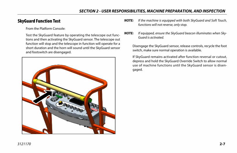
he machine is equipped with both SkyGuard and Soft Touch,ctions will not reverse, only stop.
quipped, ensure the SkyGuard beacon illuminates when Sky-ard is activated.
age the SkyGuard sensor, release controls, recycle the foot, make sure normal operation is available.
uard remains activated after function reversal or cutout,s and hold the SkyGuard Override Switch to allow normal machine functions until the SkyGuard sensor is disen-
SECTION 2 - USER RESPONSIBILITIE
3121170
SkyGuard Function Test From the Platform Console:
Test the SkyGuard feature by operating the telescope out func-tions and then activating the SkyGuard sensor. The telescope outfunction will stop and the telescope in function will operate for ashort duration and the horn will sound until the SkyGuard sensorand footswitch are disengaged.
NOTE: If tfun
NOTE: If eGu
Disengswitch
If SkyGdepresuse ofgaged.
SECTION 2 - USER RESPONSIBILITIES, MACHINE PREPARATION, AND INSPECTION
2-8 3121170
15
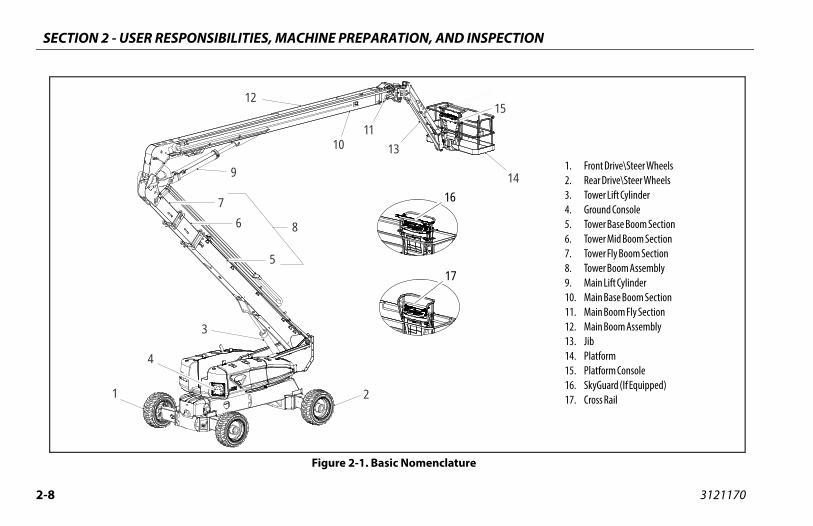
141. Front Drive\Steer Wheels2. Rear Drive\Steer Wheels3. Tower Lift Cylinder4. Ground Console5. Tower Base Boom Section6. Tower Mid Boom Section7. Tower Fly Boom Section8. Tower Boom Assembly9. Main Lift Cylinder10. Main Base Boom Section11. Main Boom Fly Section12. Main Boom Assembly13. Jib14. Platform15. Platform Console16. SkyGuard (If Equipped)17. Cross Rail
12
9
1011
76
5
8
3
4
1 2
13
16
17
Figure 2-1. Basic Nomenclature

S, MACHINE PREPARATION, AND INSPECTION
2-9
1
214
15
139
39
9
n - Sheet 1 of 2
SECTION 2 - USER RESPONSIBILITIE
3121170
10
1211
99
92
114 7
8
11
6 56511
7
9
5656
16
Figure 2-2. Daily Walk-Around Inspectio
SECTION 2 - USER RESPONSIBILITIES, MACHINE PREPARATION, AND INSPECTION
2-1 3121170
G
TO
DO
Drive - No evidence of damage.
l/Tire Assemblies - Properly secured, no missingts. Inspect for worn tread, cuts, tears or other dis-cies. Inspect wheels for damage and corrosion.
Motor, Brake, and Hub - No evidence of leakage.
Assemblies - See Inspection Note.
ary Hydraulic Pump - See Inspection Note.
draulic Cylinders - No visible damage; pivot pinsydraulic hoses undamaged, not leaking.
able Bearing - Evidence of proper lubrication. Noce of loose bolts or looseness between bearingachine.
ing Spindles and Sensors - See Inspection Note.
Hydraulic Pump - See Inspection Note.
rm Rotator - See Inspection Note.
tator - See Inspection Note.
ard (If Equipped) - See Inspection Note.
utoff Valve (ASOV) (If Equipped) - See Inspection
eet 2 of 2
0
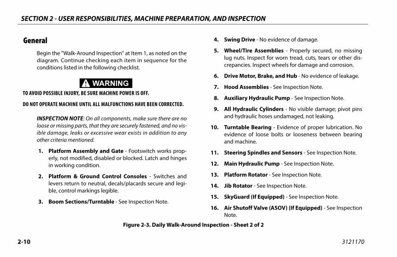
eneralBegin the "Walk-Around Inspection" at Item 1, as noted on thediagram. Continue checking each item in sequence for theconditions listed in the following checklist.
AVOID POSSIBLE INJURY, BE SURE MACHINE POWER IS OFF.
NOT OPERATE MACHINE UNTIL ALL MALFUNCTIONS HAVE BEEN CORRECTED.
INSPECTION NOTE: On all components, make sure there are noloose or missing parts, that they are securely fastened, and no vis-ible damage, leaks or excessive wear exists in addition to anyother criteria mentioned.
1. Platform Assembly and Gate - Footswitch works prop-erly, not modified, disabled or blocked. Latch and hingesin working condition.
2. Platform & Ground Control Consoles - Switches andlevers return to neutral, decals/placards secure and legi-ble, control markings legible.
3. Boom Sections/Turntable - See Inspection Note.
4. Swing
5. Wheelug nucrepan
6. Drive
7. Hood
8. Auxili
9. All Hyand h
10. Turntevidenand m
11. Steer
12. Main
13. Platfo
14. Jib Ro
15. SkyGu
16. Air ShNote.
Figure 2-3. Daily Walk-Around Inspection - Sh

S, MACHINE PREPARATION, AND INSPECTION
2-11
ve an assistant check to see that left front or right rearheel remains elevated in position off of the ground.
refully return the boom to the transport position. Whenom reaches the transport position, carefully activate Drive
release cylinders. The lockout cylinders should released allow the wheel to rest on ground.
peat the procedure for the right oscillation cylinder check-g to see that the right front or left rear wheel remains ele-ted in position off of the ground.
lockout cylinders do not function properly, have qualifiedrsonnel correct the malfunction prior to any further oper-
ion.
SECTION 2 - USER RESPONSIBILITIE
3121170
2.3 OSCILLATING AXLE LOCKOUT TEST (IF EQUIPPED)
The front axles will oscillate when the boom is in the transport posi-tion.
LOCKOUT SYSTEM TEST MUST BE PERFORMED QUARTERLY, ANY TIME A SYSTEM COM-PONENT IS REPLACED, OR WHEN IMPROPER SYSTEM OPERATION IS SUSPECTED.
NOTE: Ensure the axles are extended and the boom is fully retracted,lowered, and centered between the rear wheels prior to begin-ning lockout cylinder test.
1. Place a 6 inches (15.2 cm) high block with ascension ramp infront of left front wheel.
2. From platform control station, start engine.
3. Place the Drive control lever to the forward position andcarefully drive machine up ascension ramp until left frontwheel is on top of block.
4. Carefully extend the boom just enough to get it out of thetransport position.
5. With boom in this position, place Drive control lever toReverse and carefully drive machine off of block and ramp.
6. Haw
7. Cabotoan
8. Reinva
9. If peat
SECTION 2 - USER RESPONSIBILITIES, MACHINE PREPARATION, AND INSPECTION
2-1 3121170
2NOTES:
N 3 - MACHINE CONTROLS AND INDICATORS
3-1
ND INDICATORS
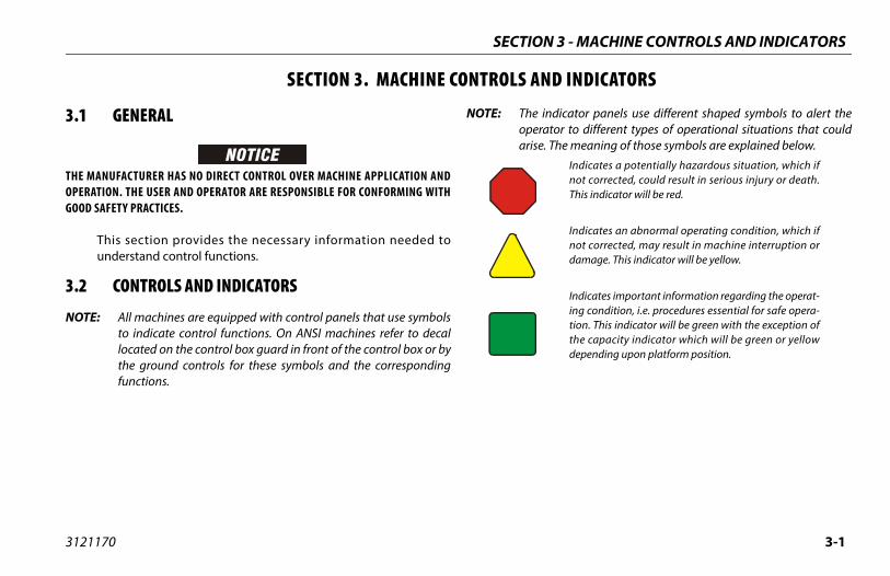
indicator panels use different shaped symbols to alert therator to different types of operational situations that could
se. The meaning of those symbols are explained below.Indicates a potentially hazardous situation, which ifnot corrected, could result in serious injury or death.This indicator will be red.
Indicates an abnormal operating condition, which ifnot corrected, may result in machine interruption ordamage. This indicator will be yellow.
Indicates important information regarding the operat-ing condition, i.e. procedures essential for safe opera-tion. This indicator will be green with the exception ofthe capacity indicator which will be green or yellowdepending upon platform position.
SECTIO
3121170
SECTION 3. MACHINE CONTROLS A
3.1 GENERAL
THE MANUFACTURER HAS NO DIRECT CONTROL OVER MACHINE APPLICATION ANDOPERATION. THE USER AND OPERATOR ARE RESPONSIBLE FOR CONFORMING WITHGOOD SAFETY PRACTICES.
This section provides the necessary information needed tounderstand control functions.
3.2 CONTROLS AND INDICATORS
NOTE: All machines are equipped with control panels that use symbolsto indicate control functions. On ANSI machines refer to decallocated on the control box guard in front of the control box or bythe ground controls for these symbols and the correspondingfunctions.
NOTE: Theopeari
SECTION 3 - MACHINE CONTROLS AND INDICATORS
3-2 3121170
TO ATOGGOFF P
Gro
(Str
NOT
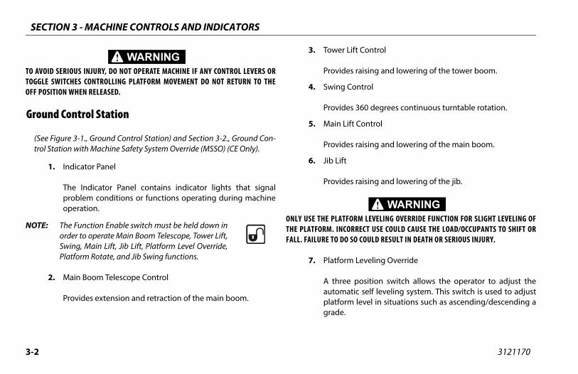
Lift Control
s raising and lowering of the tower boom.
Control
s 360 degrees continuous turntable rotation.
ift Control
s raising and lowering of the main boom.
s raising and lowering of the jib.
ORM LEVELING OVERRIDE FUNCTION FOR SLIGHT LEVELING OFORRECT USE COULD CAUSE THE LOAD/OCCUPANTS TO SHIFT OR SO COULD RESULT IN DEATH OR SERIOUS INJURY.
m Leveling Override
e position switch allows the operator to adjust theatic self leveling system. This switch is used to adjustm level in situations such as ascending/descending a
VOID SERIOUS INJURY, DO NOT OPERATE MACHINE IF ANY CONTROL LEVERS ORLE SWITCHES CONTROLLING PLATFORM MOVEMENT DO NOT RETURN TO THEOSITION WHEN RELEASED.
und Control Station
ee Figure 3-1., Ground Control Station) and Section 3-2., Ground Con-ol Station with Machine Safety System Override (MSSO) (CE Only).
1. Indicator Panel
The Indicator Panel contains indicator lights that signalproblem conditions or functions operating during machineoperation.
E: The Function Enable switch must be held down inorder to operate Main Boom Telescope, Tower Lift,Swing, Main Lift, Jib Lift, Platform Level Override,Platform Rotate, and Jib Swing functions.
2. Main Boom Telescope Control
Provides extension and retraction of the main boom.
3. Tower
Provide
4. Swing
Provide
5. Main L
Provide
6. Jib Lift
Provide
ONLY USE THE PLATFTHE PLATFORM. INCFALL. FAILURE TO DO
7. Platfor
A threautomplatforgrade.

N 3 - MACHINE CONTROLS AND INDICATORS
3-3
1. Indicator Panel2. Main Boom Telescope3. Tower Boom Lift4. Swing5. Main Boom Lift6. Jib Lift7. Platform Leveling Override8. Platform Rotate9. Jib Swing10. Platform/Ground Select Switch11. Hourmeter12. Power/Emergency Stop13. Engine Start/Auxiliary Power/Function Enable14. Not Used15. Air Shutoff Valve (ASOV) (If Equipped)
tion
SECTIO
3121170
Figure 3-1. Ground Control Sta
SECTION 3 - MACHINE CONTROLS AND INDICATORS
3-4 3121170
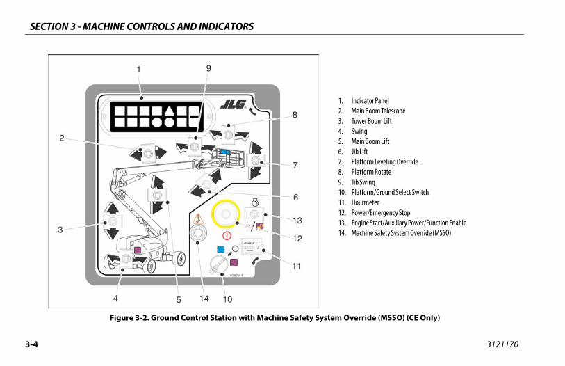
. Indicator Panel
. Main Boom Telescope
. Tower Boom Lift
. Swing
. Main Boom Lift
. Jib Lift
. Platform Leveling Override
. Platform Rotate
. Jib Swing0. Platform/Ground Select Switch1. Hourmeter2. Power/Emergency Stop3. Engine Start/Auxiliary Power/Function Enable4. Machine Safety System Override (MSSO)
Override (MSSO) (CE Only)
12345678911111
Figure 3-2. Ground Control Station with Machine Safety System

N 3 - MACHINE CONTROLS AND INDICATORS
3-5
urmeter
gisters the amount of time the machine has been in use,ith engine running. By connecting into the oil pressure cir-it of the engine, only engine run hours are recorded. Theurmeter registers up to 9,999.9 hours and cannot be reset.
en Power/Emergency Stop switch is in the “ON” position andine is not running, an alarm will sound, indicating Ignition is”.
CHINE IS SHUT DOWN THE MASTER/EMERGENCY STOP SWITCH MUST TO THE “OFF” POSITION TO PREVENT DRAINING THE BATTERY.
wer/Emergency Stop Switch
two-position red mushroom shaped switch supplieswer to PLATFORM/GROUND SELECT switch when pulledt (on). When pushed in (off ), power is shut off to the PLAT-RM/GROUND SELECT switch.
SECTIO
3121170
8. Platform Rotate
Allows rotation of the platform.
9. Jib Swing
Allows swinging of the jib.
NOTE: With PLATFORM/GROUND SELECT switch in the center position,power is shut off to controls at both operating stations.
10. Platform/Ground Select Switch
A three position, key operated switch supplies power to theplatform control console when positioned to PLATFORM.With the switch key held in the GROUND position, power isshut off to platform and only ground controls are operable.
11. Ho
Rewcuho
NOTE: Wheng“ON
WHEN THE MABE POSITIONED
12. Po
A poouFO
SECTION 3 - MACHINE CONTROLS AND INDICATORS
3-6 3121170
NOT
WHETIME
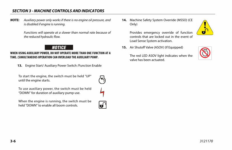
e Safety System Override (MSSO) (CE
s emergency override of functionls that are locked out in the event ofense System activation.
toff Valve (ASOV) (If Equipped)
LED ASOV light indicates when theas been actuated.
E: Auxiliary power only works if there is no engine oil pressure, andis disabled if engine is running.
Functions will operate at a slower than normal rate because ofthe reduced hydraulic flow.
N USING AUXILIARY POWER, DO NOT OPERATE MORE THAN ONE FUNCTION AT A. (SIMULTANEOUS OPERATION CAN OVERLOAD THE AUXILIARY PUMP.
13. Engine Start/ Auxiliary Power Switch /Function Enable
To start the engine, the switch must be held "UP"until the engine starts.
To use auxiliary power, the switch must be held“DOWN” for duration of auxiliary pump use.
When the engine is running, the switch must beheld "DOWN" to enable all boom controls.
14. MachinOnly)
ProvidecontroLoad S
15. Air Shu
The redvalve h

N 3 - MACHINE CONTROLS AND INDICATORS
3-7
gine Oil Temperature Indicator
dicates the temperature of the engine oil, which alsorves as engine coolant, is abnormally high and service isquired.
ow Plug Indicator
dicates the glow plugs are operating. After turning on igni-n, wait until light goes out before cranking engine.
SECTIO
3121170
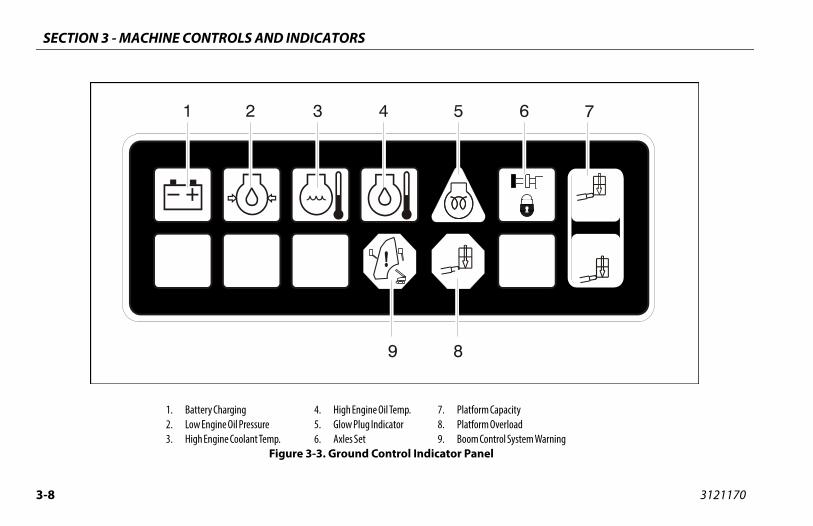
Ground Control Indicator Panel
(See Figure 3-3., Ground Control Indicator Panel)
1. Battery Charging Indicator
Indicates a problem in the battery or charging circuit, andservice is required.
2. Low Engine Oil Pressure Indicator
Indicates that engine oil pressure is below normal and ser-vice is required.
3. High Engine Temperature Indicator
Indicates that engine coolant temperature is abnormallyhigh and service is required.
4. En
Insere
5. Gl
Intio
SECTION 3 - MACHINE CONTROLS AND INDICATORS
3-8 3121170
Capacity Overload ntrol System Warningl
1. Battery Charging2. Low Engine Oil Pressure3. High Engine Coolant Temp.
4. High Engine Oil Temp.5. Glow Plug Indicator6. Axles Set
7. Platform8. Platform9. Boom Co
Figure 3-3. Ground Control Indicator Pane

N 3 - MACHINE CONTROLS AND INDICATORS
3-9
tation
e 3-4., Platform Control Console)
OUS INJURY, DO NOT OPERATE MACHINE IF ANY CONTROL LEVERS ORHES CONTROLLING PLATFORM MOVEMENT DO NOT RETURN TO THE
L POSITION WHEN RELEASED.
wer/Emergency Stop
two-position red mushroom shaped switch supplieswer to PLATFORM Controls when pulled out (on). Whenshed in (off ), power is shut off to the platform controls.
ithin about 2 seconds of pulling the switch out, theachine will perform a diagnostic check of the various elec-cal circuits, and if everything is OK, the platform alarm willep once. During this time the lights on the indicator panel
ill also blink once as a bulb check.
SECTIO
3121170
6. Axles Set Indicator
Indicates that the axles are fully extended. The indicator willflash as the axles are extending or retracting and be on solidwhen fully extended. The light will go out when the axles arefully retracted.
7. Platform Capacity Indicator
Indicates which capacity range is selected. This capacity canonly be selected at the platform control console.
8. Platform Overload Indicator (If Equipped)
Indicates the platform has been overloaded.
9. Boom Control System Warning Indicator
Indicates the platform is outside the operating area andoperation of certain boom functions may be disabled (i.e.lift, telescope). Attempts to use the disabled functions causethe indicator to flash and an alarm to sound. Immediatelyreturn the platform to the ground. If the indicator remains lit,a boom control system fault or failure has been detected. If afailure is discovered, the system must be repaired by JLGauthorized service personnel before the machine can beused.
Platform S
(See Figur
TO AVOID SERITOGGLE SWITCOFF OR NEUTRA
1. Po
A popu
Wmtribew

SECTION 3 - MACHINE CONTROLS AND INDICATORS
3-1 3121170
rol
Select
19. Platform Level Override20. Axle Extend/Retract21. Horn22. Indicator Panel
0
1. Power/Emergency Stop2. Engine Start / Aux Power3. Capacity Select4. Drive Orientation Override5. Drive/Steer6. Main Boom Telescope
7. Lights8. Jib Lift9. Soft Touch/SkyGuard Override10. Jib Swing11. Tower Boom Lift12. Soft Touch/SkyGuard Indicator
13. Platform Rotate14. Jib Stow Override15. Function Speed Cont16. Main Lift / Swing17. Drive Speed / Torque 18. Steer Select
Figure 3-4. Platform Control Console
N 3 - MACHINE CONTROLS AND INDICATORS
3-11
ive Orientation Override
hen the boom is swung over the rear tires or further inther direction, the Drive Orientation indicator will illumi-te when the drive function is selected. Push and releasee switch, and within 3 seconds move the Drive/Steer con-l to activate drive or steer. Before driving, locate the black/
hite orientation arrows on both the chassis and the plat-rm controls. Move the drive controls in a direction match-g the directional arrows.
operate the Drive Joystick, pull up on the locking ring below handle.
DRIVE control levers are spring-loaded and will automati-ly return to neutral (OFF) position when released.
ive/Steer
ovides for driving either forward or backward. The control-r is infinitely proportional to allow variable drive speed.
eering is controlled by a thumb operated switch on top ofe joystick.
SECTIO
3121170
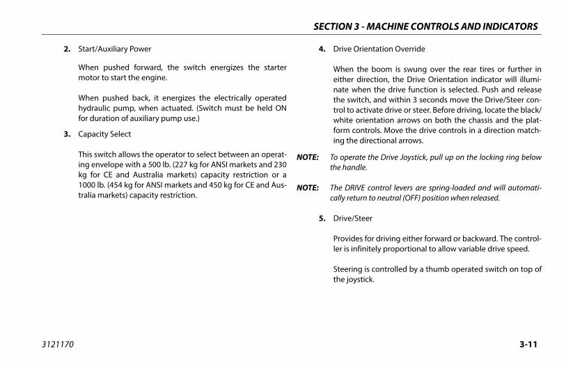
2. Start/Auxiliary Power
When pushed forward, the switch energizes the startermotor to start the engine.
When pushed back, it energizes the electrically operatedhydraulic pump, when actuated. (Switch must be held ONfor duration of auxiliary pump use.)
3. Capacity Select
This switch allows the operator to select between an operat-ing envelope with a 500 lb. (227 kg for ANSI markets and 230kg for CE and Australia markets) capacity restriction or a1000 lb. (454 kg for ANSI markets and 450 kg for CE and Aus-tralia markets) capacity restriction.
4. Dr
Weinathtrowfoin
NOTE: To the
NOTE: Thecal
5. Dr
Prle
Stth

SECTION 3 - MACHINE CONTROLS AND INDICATORS
3-1 3121170
pped with SkyGuard, the switchs functions cut out by the Sky-system to be operated again,g the operator to resume use ofe functions.
pped with both Soft Touch andrd, the switch operates likeed above and allows the opera-override the system that hasnced a cutout situation.
wing function is not operable when the Capacity Selectis in the 1000 lb. (454 kg for ANSI markets and 450 kgnd Australia markets) position.
ng
the operator to swing the jib to the left or right.
Boom Lift
raising and lowering of the tower boom by activatingwer lift and telescope cylinders as dictated by theControl System.
2
6. Main Telescope
Allows extension and retraction of the main boom.
7. Lights (If Equipped)
Operates accessory light packages if the machine is soequipped.
8. Jib Lift
Push forward to lift up, pull back to lift down. Variable liftspeed is accomplished by using the Function Speed Control.
9. Soft Touch/SkyGuard Override Switch (If equipped)
The machine can be equipped with one of three options. Itmay have Soft Touch, SkyGuard, or both Soft Touch and Sky-Guard.
If equipped with Soft Touch, the switchenables the functions that were cut outby the Soft Touch system to operateagain at creep speed, allowing theoperator to move the platform away from the obstacle thatcaused the shutdown situation.
If equienableguard allowinmachin
If equiSkyGuadescribtor to experie
NOTE: The Jib Scontrol for CE a
10. Jib Swi
Allows
11. Tower
Allowsthe toBoom
N 3 - MACHINE CONTROLS AND INDICATORS
3-13
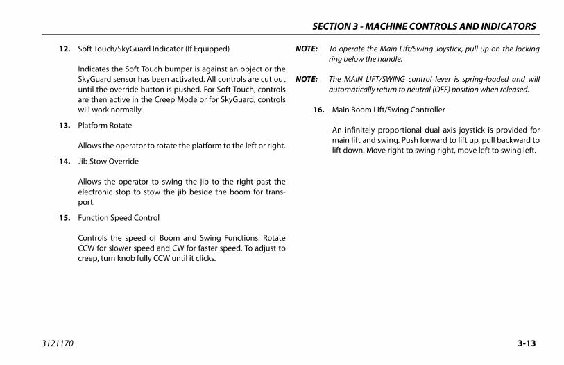
operate the Main Lift/Swing Joystick, pull up on the lockingg below the handle.
MAIN LIFT/SWING control lever is spring-loaded and willomatically return to neutral (OFF) position when released.
ain Boom Lift/Swing Controller
infinitely proportional dual axis joystick is provided forain lift and swing. Push forward to lift up, pull backward tot down. Move right to swing right, move left to swing left.
SECTIO
3121170
12. Soft Touch/SkyGuard Indicator (If Equipped)
Indicates the Soft Touch bumper is against an object or theSkyGuard sensor has been activated. All controls are cut outuntil the override button is pushed. For Soft Touch, controlsare then active in the Creep Mode or for SkyGuard, controlswill work normally.
13. Platform Rotate
Allows the operator to rotate the platform to the left or right.
14. Jib Stow Override
Allows the operator to swing the jib to the right past theelectronic stop to stow the jib beside the boom for trans-port.
15. Function Speed Control
Controls the speed of Boom and Swing Functions. RotateCCW for slower speed and CW for faster speed. To adjust tocreep, turn knob fully CCW until it clicks.
NOTE: To rin
NOTE: Theaut
16. M
Anmlif

SECTION 3 - MACHINE CONTROLS AND INDICATORS
3-1 3121170
NOT
DO NSWIT
elect
tion of the steering system is operator selectable. Theswitch position gives conventional front wheel steer-h the rear wheels unaffected. This is for normal driv-maximum speeds. The forward position is for “crab”g. When in this mode both front and rear axles steerame direction, which allows the chassis to move side-s it goes forward. This can be used for positioning thee in aisle ways or close to buildings. The back switch
n is for “coordinated” steering. In this mode the frontr axles steer in the opposite directions to produce thet turning circle for maneuvering in confined areas.
ORM LEVELING OVERRIDE FUNCTION FOR SLIGHT LEVELING OFORRECT USE COULD CAUSE THE LOAD/OCCUPANTS TO SHIFT OR SO COULD RESULT IN DEATH OR SERIOUS INJURY.
m Leveling Override
e position switch allows the operator to adjust theatic self leveling system. This switch is used to adjustm level in situations such as ascending/descending a
4
E: When boom is positioned above transport position or telescopedout and any of the following switches, DRIVE SPEED/TORQUESELECT or FUNCTION SPEED, are positioned to HIGH, high func-tion speeds are automatically cut out and the machine contin-ues to operate at a lower speed.
OT OPERATE MACHINE IF DRIVE SPEED/TORQUE SELECT OR FUNCTION SPEEDCHES OPERATE WHEN BOOM IS OUT OF TRANSPORT POSITION.
17. Drive Speed/Torque Select
The forward position gives maximum drive speed. The backposition gives maximum torque for rough terrain and climb-ing grades. The center position allows the machine to bedriven as quietly as possible.
18. Steer S
The accenter ing witing at steerinin the sways amachinpositioand reatightes
ONLY USE THE PLATFTHE PLATFORM. INCFALL. FAILURE TO DO
19. Platfor
A threautomplatforgrade.
N 3 - MACHINE CONTROLS AND INDICATORS
3-15
ontrol Indicator Panel
e 3-5., Platform Control Indicator Panel)
vel System Fault Indicator
dicates a fault in the electronic leveling system. The faultdicator will flash and an alarm sound. All functions willfault to creep if the boom is out of transport mode.
SYSTEM FAULT INDICATOR IS ILLUMINATED, SHUT DOWN THET THE EMERGENCY STOP, AND RESTART THE MACHINE. IF THE FAULT
URN THE PLATFORM TO THE STOWED POSITION, USING MANUAL LEV-IRED, AND HAVE LEVELING SYSTEM REPAIRED.
Generator (If Equipped)
dicates the generator is in operation.
atform Overload Indicator (If Equipped)
dicates the platform has been overloaded.
SECTIO
3121170
20. Axle Extend/Retract
Allows the operator to extend or retract the axles. The axlescan only be extended or retracted while the machine isbeing driven forward or reverse.
21. Horn
If pressed, this switch supplies power to the horn.
22. Indicator Panel
The LED Indicator Panel contains indicator lights that signalproblem conditions or functions operating during machineoperation.
Platform C
(See Figur
1. Le
Ininde
IF THE LEVELMACHINE, RESEPERSISTS, RETELING AS REQU
2. AC
In
3. Pl
In
SECTION 3 - MACHINE CONTROLS AND INDICATORS
3-1 3121170
tation
rol System Warning
anel
6
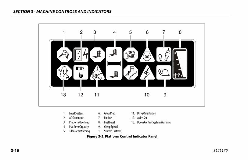
1. Level System2. AC Generator3. Platform Overload4. Platform Capacity5. Tilt Alarm Warning
6. Glow Plug7. Enable8. Fuel Level9. Creep Speed10. System Distress
11. Drive Orien12. Axles Set13. Boom Cont
Figure 3-5. Platform Control Indicator P
N 3 - MACHINE CONTROLS AND INDICATORS
3-17
ow Plug/Wait to Start Indicator
he engine fails to start due to cold temperatures or excessiveounts of smoke are produced on startup, wait for the glowg/wait to start indicator to go out before starting the engine.
dicates the glow plugs are operating. After turning on igni-n, wait until light goes out before starting engine.
SECTIO
3121170
4. Platform Capacity Indicator
Indicates the maximum platform capacity selected for theplatform.
One of the capacity lights should be on at all times. Bothlights will flash and an alarm will sound if the platform is outof the operating envelope for the selected capacity.
5. Tilt Alarm Warning Light
IF ILLUMINATED WHEN BOOM IS RAISED OR EXTENDED, RETRACT AND LOWER TOBELOW HORIZONTAL THEN REPOSITION MACHINE SO THAT IT IS LEVEL BEFOREEXTENDING BOOM OR RAISING BOOM FROM THE TRANSPORT POSITION.
Indicates that the chassis is on a slope (over 3 to 5 degrees,depending upon boom angle). If the boom is out of trans-port position and the machine is on a slope, an alarm willsound and CREEP is automatically activated.
6. Gl
NOTE: If tamplu
Intio
SECTION 3 - MACHINE CONTROLS AND INDICATORS
3-1 3121170
TO ABY B
FOOTOPER
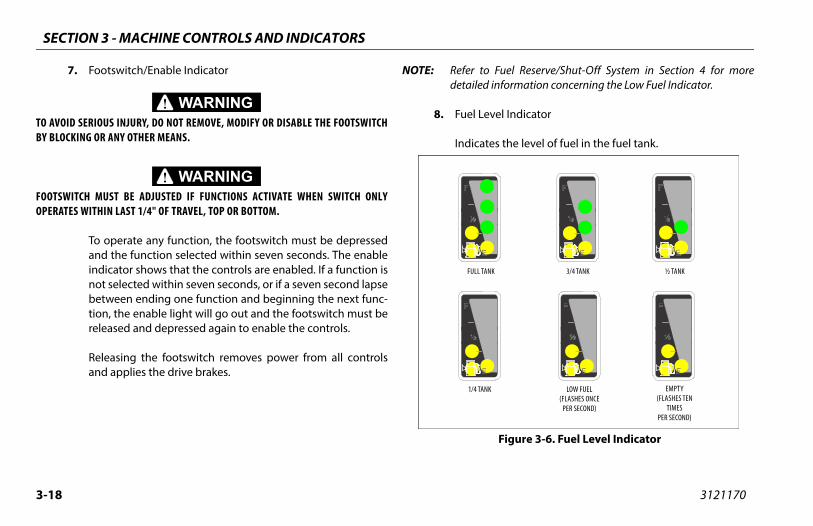
Fuel Reserve/Shut-Off System in Section 4 for more information concerning the Low Fuel Indicator.
vel Indicator
es the level of fuel in the fuel tank.
LOW FUEL(FLASHES ONCE
PER SECOND)
K
½ TANK3/4 TANKNK
EMPTY(FLASHES TEN
TIMESPER SECOND)
Figure 3-6. Fuel Level Indicator
8
7. Footswitch/Enable Indicator
VOID SERIOUS INJURY, DO NOT REMOVE, MODIFY OR DISABLE THE FOOTSWITCHLOCKING OR ANY OTHER MEANS.
SWITCH MUST BE ADJUSTED IF FUNCTIONS ACTIVATE WHEN SWITCH ONLYATES WITHIN LAST 1/4" OF TRAVEL, TOP OR BOTTOM.
To operate any function, the footswitch must be depressedand the function selected within seven seconds. The enableindicator shows that the controls are enabled. If a function isnot selected within seven seconds, or if a seven second lapsebetween ending one function and beginning the next func-tion, the enable light will go out and the footswitch must bereleased and depressed again to enable the controls.
Releasing the footswitch removes power from all controlsand applies the drive brakes.
NOTE: Refer todetailed
8. Fuel Le
Indicat
1/4 TAN
FULL TA
N 3 - MACHINE CONTROLS AND INDICATORS
3-19
les Set Indicator
dicates that the axles are fully extended. The indicator willsh as the axles are extending or retracting and be on solid
hen fully extended. The light will go out when the axles arelly retracted.
om Control System Warning Indicator
dicates the platform is outside the operating area anderation of certain boom functions may be disabled (i.e.
t, telescope). Attempts to use the disabled functions causee indicator to flash and an alarm to sound. Immediatelyturn the platform to the ground. If the indicator remains lit,boom control system fault or failure has been detected. If ailure is discovered, the system must be repaired by JLGthorized service personnel before the machine can beed.
SECTIO
3121170
9. Creep Speed Indicator
When the Function Speed Control is turned to the creepposition, the indicator acts as a reminder that all functionsare set to the slowest speed. The light flashes if the controlsystem puts the machine into creep speed and will be oncontinuously if the operator selects creep speed.
10. System Distress Indicator
The light indicates that the JLG Control System has detecteda malfunction and a Diagnostic Trouble Code has been set inthe system memory. Refer to the Service Manual for instruc-tions concerning the trouble codes and trouble coderetrieval.
The malfunction indicator light will illuminate for 2-3 sec-onds when the key is positioned to the on position to act asa self test.
11. Drive Orientation Indicator
When the boom is swung beyond the rear drive tires or fur-ther in either direction, the Drive Orientation indicator willilluminate when the drive function is selected. This is a signalfor the operator to verify that the drive control is being oper-ated in the proper direction (i.e. controls reversed situa-tions).
12. Ax
Inflawfu
13. Bo
Inoplifthrea faauus
SECTION 3 - MACHINE CONTROLS AND INDICATORS
3-2 3121170
0NOTES:
SECTION 4 - MACHINE OPERATION
4-1
RATIONimary operator control station is in the platform. From thisl station, the operator can drive and steer the machine inrward and reverse directions. The operator can raise or
he main or tower boom or swing the boom to the left ortandard boom swing is 360 degree continuous left and
f the stowed position. The machine has a Ground Control which will override the Platform Control Station. Groundls operate Boom Lift and Swing, and are to be used in an
ency to lower the platform to the ground should the oper- the platform be unable to do so.
3121170
SECTION 4. MACHINE OPE
4.1 DESCRIPTIONThis machine is a mobile elevating work platform used to posi-tion personnel, along with their necessary tools and materials atwork locations.
The prcontroboth folower tright. Sright oStationControemergator in
SECTION 4 - MACHINE OPERATION
4-2 3121170
4.2 PERATING CHARACTERISTICS AND TIONS
an be raised from the transport position with or with- in platform, if:
e is positioned on a smooth, firm and level surface.
re extended.
within manufacturer’s rated capacity.
hine systems are functioning properly.
tire pressure.
e is as originally equipped from JLG.
HYDRAULIC SYSTEM WARM UPThe control system monitors the hydraulic system in extremelycold temperatures and provides optimal performance by auto-matically limiting the function speeds of the high demand func-tions. The warm up mode automatically shuts off when system oilreaches allowable temperatures.
While the system is cold and in the warm up mode, the tower lift,main lift, and main telescope functions are limited to creepspeeds and is indicated to the operator by flashing the creep lighton the platform control panel.
Functions being operated when the warm up mode turns off willremain in the creep speed until the function is re-initiated.
4.3 BOOM OLIMITA
CapacitiesThe boom cout any load
1. Machin
2. Axles a
3. Load is
4. All mac
5. Proper
6. Machin

SECTION 4 - MACHINE OPERATION
4-3
out without auto tower lift up) or the tower lift down (tower lift down without auto tower telescope in). A back-
wer path violation can be resolved by operating the towerswitch (tower lift up without auto tower telescope out) orwer lift down switch (tower telescope in without autoift down).
tricted functions due to backward tower envelope viola-re disallowing automatic tower lift down, automatic tower
pe out, main lift up and down, main telescope in, jib,drive and steer.
stricted functions due to forward tower envelope viola-re disallowing automatic tower lift up, automatic towerpe in, main lift up and down, main telescope out, jib,
drive and steer.
tricted functions due to maximum main boom envelopeons are disallowing tower lift up and down, main lift up,
lescope in, jib, swing and drive.
tricted functions due to minimum main boom envelopens are disallowing main lift down, swing and drive.
3121170
Envelope Control SystemThe Envelope Control System is the primary means of controllingthe working positions of the tower and main boom within thestability and structural requirements of the machine.
The main boom must be controlled in maximum angle and mini-mum angle to avoid entering a position that could compromisebackward stability and avoid main boom to tower boom interfer-ence. The tower boom must be controlled by permitting onlyspecific combinations of tower length and tower angle to avoidentering a position that could compromise forward and back-ward stability (see Tower Path Control System).
Recognized failures within this system will result in control by theElectrical Retrieval System (refer to the Service Manual), reducedfunction speeds, and BCS warning light illumination. Afterretrieval the boom will be restricted from leaving the transportposition until the failure is resolved.
Boom position violations outside of the allowable envelope willresult in reduced function speeds, BCS warning light illumination,and restriction of functions. Attempts to operate restricted func-tions will cause the BCS warning light to flash and the platformalarm to sound.
Violations of the tower path (with a healthy control system) willcause the automatic combined operation of tower lift and towertelescope to be suspended. A forward tower path violation canbe resolved by operating the tower lift up switch (tower tele-
scope switchward tolift up the totower l
The restions atelescoswing,
The retions atelescoswing,
The resviolatimain te
The resviolatio
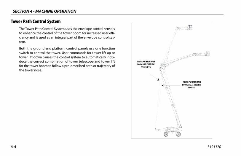
SECTION 4 - MACHINE OPERATION
4-4 3121170
Tow
TOWER PATH FOR MAIN BOOM ANGLES ABOVE 55
DEGREES
TH FOR MAIN GLES BELOW EGREES
er Path Control SystemThe Tower Path Control System uses the envelope control sensorsto enhance the control of the tower boom for increased user effi-ciency and is used as an integral part of the envelope control sys-tem.
Both the ground and platform control panels use one functionswitch to control the tower. User commands for tower lift up ortower lift down causes the control system to automatically intro-duce the correct combination of tower telescope and tower liftfor the tower boom to follow a pre-described path or trajectory ofthe tower nose.
TOWER PABOOM AN
15 D
SECTION 4 - MACHINE OPERATION
4-5
LIFT UP - MAIN BOOM ABOVE 60°
tower lift up with the main boom already above 60°, thel system will delay automatic compensation of the main angle during tower lift until the main boom reachesimately 60°. The control system will then control the mainto 60° until the tower boom has reached its maximum. Continuing to operate the tower lift up when the towers its maximum height will cause the control system to
atically raise the main boom to its original angle.
n Systemntrol system uses the envelope control sensors to auto-lly slow down the tower lift up and tower lift down at thethe tower path and to automatically slow down main lift main lift down as the minimum and maximum angles ofrking envelope are approached. The control system indi-o the operator this slow down by flashing the creep light platform display. This applies to both platform and groundls, however, no indication is made on the ground control
3121170
Automatic Main Boom Control System During combined tower lift and main lift functions, the controlsystem will maintain the tower lift speed and automatically varythe maximum main lift command as needed to compensate forthe movement of the tower.
The interaction of the main boom and the tower boom is slightlydifferent when the main boom is above or below 60° relative togravity.
TOWER LIFT UP/DOWN - MAIN BOOM BELOW 60°
During tower lift up or down with the main boom below 60°, thecontrol system will maintain the angle of the main boom read atthe start of the tower lift command or as read at the conclusion ofmain lift during combined tower and main lift commands.
TOWER LIFT DOWN - MAIN BOOM ABOVE 60°
During tower lift down with the main boom initially above 60°,the control system will lower the main boom to approximately60° before starting tower movement. The control system will thencontrol the main boom to 60° for the remainder of the tower liftdown command.
TOWER
Duringcontroboomapproxboom heightreacheautom
Slow DowThe comaticatop of up andthe wocates ton thecontropanel.
SECTION 4 - MACHINE OPERATION
4-6 3121170
Con roportioningontrol system sensors sense the distance the platformd from the centerline of rotation, allowing higherds with the platform nearest to the centerline of rota-adually slower swing speeds the further the platforme centerline of rotation.
bility is based on two (2) conditions which are calledand BACKWARD stability. The machine’s position of
RD stability is shown in (See Figure 4-2.), and its posi- BACKWARD stability is shown in (See Figure 4-4.)
OR BACKWARD TIPPING, DO NOT OVERLOAD MACHINE OR OPER- AN OUT-OF-LEVEL SURFACE.
trolled AngleThe Controlled Boom Angle System minimizes the interaction ofswing and drive functions with the envelope edges. This interac-tion is due to two factors. First, the envelope is controlled relativeto gravity regardless of ground slope and second, the turntable/boom mounting is effected by swing and drive functions whenthe ground slope varies. This can cause the boom position to varywithin the envelope or even violate the envelope edges whenswinging or driving without intentionally moving the boom. Thecontrolled boom angle system automatically activates either thetower or main boom lift up or down during swing and drive com-mands to maintain a constant boom angle relative to gravity.
Controlled boom angle is disabled with any envelope violation orfailure.
Swing Speed PThe boom cis extendeswing speetion and grgets from th
StabilityMachine staFORWARD least FORWAtion of least
TO AVOID FORWARD ATE THE MACHINE ON
SECTION 4 - MACHINE OPERATION
4-7
Stability
CHINE WILL TIP OVER IN OF ARROWS IF OVERLOADED
OR OPERATED OUT-OF-LEVEL SURFACE
3121170
Figure 4-2. Position of Least Forward
MADIRECTION
ON AN
MAIN BOOMFULLY EXTENDED
TURNTABLE ROTATED90 DEGREES FROMSTOWED POSITION
TOWER BOOMFULLY LOWERED TO
FULLY RAISED
SECTION 4 - MACHINE OPERATION
4-8 3121170
.
Figu
re 4
-3. P
osit
ion
of L
east
Bac
kwar
d St
abili
ty -
Shee
t 1 o
f 2
TURN
TABL
E ROT
ATED
90 DE
GREE
S FRO
MST
OWED
POSIT
ION
TOW
ER BO
OMFU
LLY L
OWER
EDTO
FULL
Y RAI
SED
JIB EL
EVAT
ED
MAC
HINE
WILL
TIP O
VER I
NDI
RECT
ION O
F ARR
OW IF
OVER
LOAD
EDOR
OPER
ATED
ON AN
OUT-
OF-L
EVEL
SURF
ACE
MAI
N BOO
MFU
LLY E
LEVA
TED

SECTION 4 - MACHINE OPERATION
4-9
Figu
re 4
-4. P
osit
ion
of L
east
Bac
kwar
d St
abili
ty -
Shee
t 2 o
f 2
TURN
TABL
E ROT
ATED
90 DE
GREE
S FRO
MST
OWED
POSIT
ION
TOW
ER BO
OMFU
LLY L
OWER
ED TO
FULL
Y RAI
SED
3121170
JIB EL
EVAT
ED
MAC
HINE
WILL
TIP O
VER I
NDI
RECT
ION O
F ARR
OW IF
OVER
LOAD
EDOR
OPER
ATED
ON AN
OUT-
OF-L
EVEL
SURF
ACE
MAI
N BOO
MFU
LLY E
LEVA
TED
SECTION 4 - MACHINE OPERATION
4-1 3121170
4.4
NOT
TY SELECTontrol System allows the operator to select operation227 kg for ANSI markets and 230 kg for CE and Austra- capacity restriction envelope or a 1000 lb. (454 kg forts and 450 kg for CE and Australia markets) capacity
envelope. The operator selects the desired capacityy positioning the Capacity Select switch on the plat-
le. The Capacity Indicator shows the capacity selected,pacity lights will flash and an alarm sound if the plat-
of the selected capacity range.
n in the 1000 lb. (454 kg for ANSI markets and 450 kg forustralia markets) envelope requires the jib to be fixed in
ered position.
0
AUXILIARY POWER OPERATIONThe Auxiliary Power System provides a means of moving the plat-form in the event of an engine malfunction. This system uses anelectric motor/pump unit capable of operating all boom func-tions needed to allow the platform to be lowered to ground level.
With auxiliary power activated, the control system will attempt touse the force of gravity to operate main lift down, tower lift down,and tower telescope in. If appropriate movement is not detectedby the boom sensors, the auxiliary power system will supplyhydraulic flow to power boom movement. Allow sufficient oper-ating time for system to respond.
E: To ensure sufficient battery life, where possible, use the Main Liftand Main Telescope functions to lower the platform to groundlevel before using Tower Lift. Movements of the boom using aux-iliary power will be SLOW and the movements will momentarilystop and alternate between other functions as needed. Whenoperating Tower Lift, the movements will alternate betweentower lift, tower telescope, and main lift. When operating MainLift, the movements will alternate between main lift, tower lift,and platform level.
4.5 CAPACIThe Boom Cin a 500 lb. (lia markets)ANSI markerestriction restriction bform consoand both caform is out
NOTE: OperatioCE and Athe cent
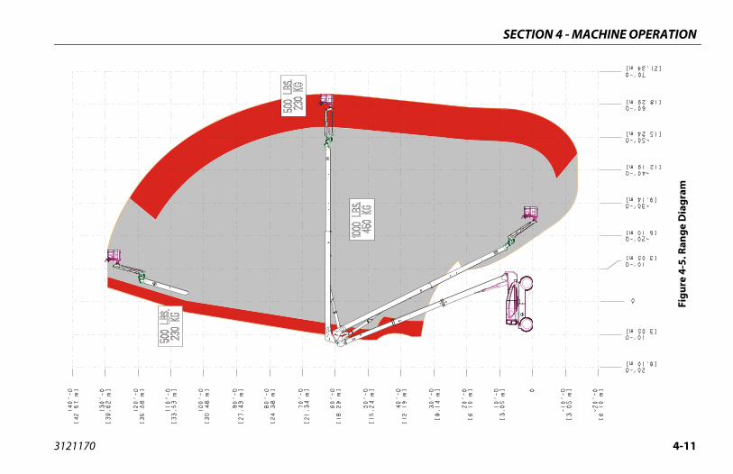
SECTION 4 - MACHINE OPERATION
4-11
Figu
re 4
-5. R
ange
Dia
gram
3121170
SECTION 4 - MACHINE OPERATION
4-1 3121170
4.6
NOT
NOT
NOT
NOT
Sta
IF ENSHOUUTESMAN
NOT
y of SELECT switch to GROUND. Position POWER/ENCY STOP switch to ON, then push the ENGINE switch until engine starts.
ARM-UP FOR A FEW MINUTES AT LOW SPEED BEFORE APPLYING
ngine has had sufficient time to warm up, shut engine
LECT switch to PLATFORM.
latform, pull POWER/EMERGENCY STOP switch out, ush the ENGINE START switch until engine starts.
tch must be in released (up) position before starter will. If starter operates with footswitch in the depressed posi- NOT OPERATE MACHINE.
2
ENGINE OPERATION
E: When operating a machine at high altitudes, a decrease inmachine performance may occur due to a decrease in air den-sity.
E: When operating a machine at high ambient temperatures, adecrease in machine performance and an increase in enginecoolant temperature may occur.
E: Contact JLG Customer Service for operation under abnormalconditions.
E: Initial starting should always be performed from the GroundControl console.
rting Procedure
GINE FAILS TO START PROMPTLY, DO NOT CRANK FOR AN EXTENDED TIME.LD ENGINE FAIL TO START AGAIN, ALLOW STARTER TO “COOL OFF” FOR 2-3 MIN-
. IF ENGINE FAILS AFTER SEVERAL ATTEMPTS, REFER TO ENGINE MAINTENANCEUAL.
E: If the engine fails to start due to cold temperatures or excessiveamounts of smoke are produced on startup, wait for the glowplug/wait to start indicator to go out before starting the engine.
1. Turn keEMERGSTART
ALLOW ENGINE TO WANY LOAD.
2. After eoff.
3. Turn SE
4. From Pthen p
NOTE: Footswioperatetion, DO

SECTION 4 - MACHINE OPERATION
4-13
f Valve (ASOV) (If Equipped)
utoff Valve (ASOV) is an overspeed protection deviceed to the engine’s air intake system. When the valve isd, it obstructs airflow intake and stops the engine. Weekly
re recommended to ensure the valve remains in goodg condition.
art the engine, running at idle.
pen the red switch guard on ASOV test switch, then acti-te toggle to test mode.
t switch is located under hood to the left of engine (look for test decal).
the ground control panel, select any nction and activate until valve actuates test RPM of 1500. Once valve actuates, gine will stop.
rn ignition to OFF.
sually inspect valve to ensure it appears in good condition.
set valve by rotating valve handle to the Open position.
handle cannot be turned unless the machine is off. Ensure ignition is moved to the OFF position.
ASOVTEST
1001227964A
3121170
Shutdown Procedure
IF AN ENGINE MALFUNCTION CAUSES AN UNSCHEDULED SHUTDOWN, DETERMINETHE CAUSE AND CORRECT IT BEFORE RESTARTING THE ENGINE.
1. Remove all load and allow engine to operate at low speed for 3-5 minutes; this allows further reduction of internal engine temperature.
2. Push POWER/EMERGENCY STOP switch in.
3. Turn MASTER switch to Off.
Refer to Engine Manufacturer’s manual for detailed information.
Air Shutof
Air Shmountactuatetests aworkin
1. St
2. Ova
NOTE: Testhe
3. Atfuaten
4. Tu
5. Vi
6. Re
NOTE: Thethe
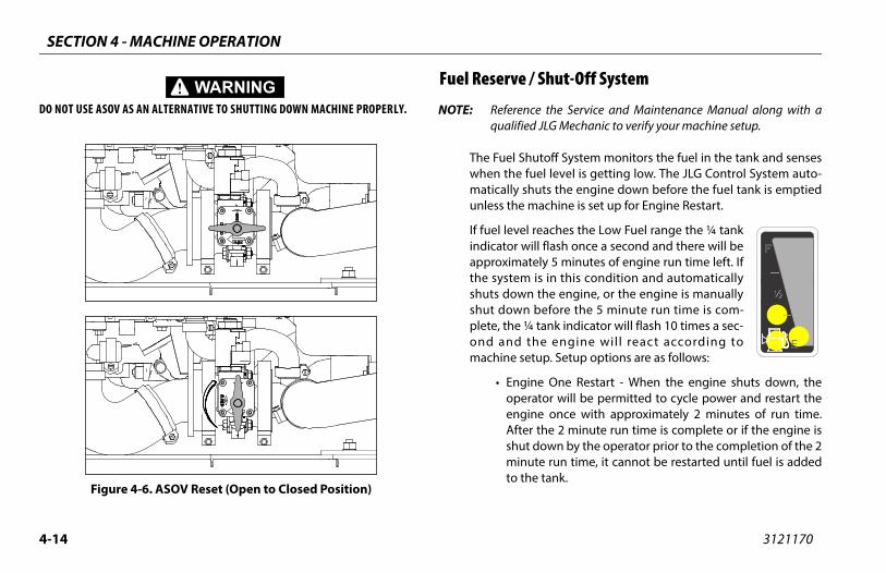
SECTION 4 - MACHINE OPERATION
4-1 3121170
DO N
Shut-Off System
e the Service and Maintenance Manual along with a JLG Mechanic to verify your machine setup.
utoff System monitors the fuel in the tank and sensesel level is getting low. The JLG Control System auto-uts the engine down before the fuel tank is emptiedachine is set up for Engine Restart.
reaches the Low Fuel range the ¼ tankill flash once a second and there will beely 5 minutes of engine run time left. If is in this condition and automatically the engine, or the engine is manuallybefore the 5 minute run time is com- tank indicator will flash 10 times a sec-he engine wil l react according totup. Setup options are as follows:
e One Restart - When the engine shuts down, theator will be permitted to cycle power and restart the
e once with approximately 2 minutes of run time. the 2 minute run time is complete or if the engine isdown by the operator prior to the completion of the 2te run time, it cannot be restarted until fuel is addede tank.
4
OT USE ASOV AS AN ALTERNATIVE TO SHUTTING DOWN MACHINE PROPERLY.
Fuel Reserve /
NOTE: Referencqualified
The Fuel Shwhen the fumatically shunless the m
If fuel level indicator wapproximatthe systemshuts downshut down plete, the ¼ond and tmachine se
• EnginoperenginAftershut minuto th
Figure 4-6. ASOV Reset (Open to Closed Position)
SECTION 4 - MACHINE OPERATION
4-15
3121170• Engine Restart - When the engine shuts down, the opera-tor will be permitted to cycle power and restart the enginefor approximately 2 minutes of run time. After the 2 min-utes of run time is complete, the operator may cycle powerand restart the engine for an additional 2 minutes of runtime. The operator can repeat this process until there is nomore fuel available.
CONTACT A QUALIFIED JLG MECHANIC IF THE MACHINE NEEDS RESTARTED AFTER NOMORE FUEL IS AVAILABLE.
• Engine Stop - The engine will shut down. No restarts willbe permitted until fuel is added to the tank.
•
SECTION 4 - MACHINE OPERATION
4-1 3121170
4.7
Se
NOT
DO NAND
TO AGRAD
DO N
USE PLAT
BEFOCHASTION
limited by two factors:
bility, which is the percent of grade of the incline the e can climb.
pe, which is the angle of the slope the machine can en across.
oom is raised or extended, the machine must not ben grades or sideslopes that are greater than that
y the tilt alarm. The tilt alarm will sound to alert theen the machine is on an unsafe slope. The machines
unction will also be cut back to low drive.
6
TRAVELING (DRIVING)
e Figure 4-7., Grade and Side Slopes
E: Refer to the Operating Specifications table for Gradeability andSideslope ratings.
All ratings for Gradeability and Sideslope are based upon themachine’s boom being in the stowed position, fully lowered, andretracted.
OT DRIVE WITH BOOM OUT OF TRANSPORT MODE EXCEPT ON A SMOOTH, FIRMLEVEL SURFACE.
VOID LOSS OF TRAVEL CONTROL OR “TIP OVER”, DO NOT DRIVE MACHINE ONES EXCEEDING THOSE SPECIFIED ON THE SERIAL NUMBER PLATE.
OT DRIVE ON SIDESLOPES WHICH EXCEED 5 DEGREES.
EXTREME CAUTION WHEN DRIVING IN REVERSE AND AT ALL TIMES WHEN THEFORM IS ELEVATED.
RE DRIVING, LOCATE THE BLACK/WHITE ORIENTATION ARROWS ON BOTH THESIS AND THE PLATFORM CONTROLS. MOVE THE DRIVE CONTROLS IN A DIREC- MATCHING THE DIRECTIONAL ARROWS.
Traveling is
1. Gradeamachin
2. Sideslobe driv
When the boperated odetected boperator whhigh drive f

SECTION 4 - MACHINE OPERATION
4-17
pes
3121170
Figure 4-7. Grade and Side Slo
SECTION 4 - MACHINE OPERATION
4-1 3121170
Tra Grade
a grade, maximum braking and traction are obtained stowed, in position over the rear axle, and in line withf travel. Drive the machine forward when climbing aeverse when descending a grade. Do not exceed theimum rated gradability.
R THE FRONT (STEER) AXLE, DIRECTION OF STEER AND DRIVE OPPOSITE FROM THE MOVEMENT OF THE CONTROLS.
Figure 4-8. Traveling on a Grade
8
veling Forward and Reverse1. At Platform Controls, pull out Emergency Stop switch, start
engine, and activate footswitch.
2. Position Drive controller to FORWARD or REVERSE as desired.
This machine is equipped with a Drive Orientation Indicator. Theyellow light on the platform control console indicates that theboom is swung beyond the rear drive tires and the machine mayDrive/Steer in the opposite direction from the movement of thecontrols. If the indicator is illuminated, operate the Drive functionin the following manner:
1. Match the black and white direction arrows on both plat-form control panel and the chassis to determine the direc-tion the machine will travel.
2. Push and release the Drive Orientation Override switch. Within 3 seconds, slowly move the Drive control toward the arrow matching the intended direction of machine travel. The indicator light will flash during the 3 second interval until the drive function is selected.
Traveling on a
When travelingwith the boomthe direction ograde, and in rmachine's max
IF THE BOOM IS OVEMOVEMENT WILL BE
SECTION 4 - MACHINE OPERATION
4-19
n the Platform/Level control switch Up or Down and holde desired platform position is obtained.
otationte the platform to the left or right, use the Platform Rotatel switch to select the direction and hold until desired posi-reached.
M
OR RAISE BOOM OUT OF TRANSPORT MODE WHEN MACHINE IS OUT
D ON TILT ALARM AS A LEVEL INDICATOR FOR THE CHASSIS.
VER, LOWER PLATFORM TO GROUND LEVEL. THEN DRIVE MACHINE TOCE BEFORE RAISING BOOM.
OUS INJURY, DO NOT OPERATE MACHINE IF ANY CONTROL LEVER ORH CONTROLLING PLATFORM MOVEMENT DOES NOT RETURN TO THEAL POSITION WHEN RELEASED.
M DOES NOT STOP WHEN A CONTROL SWITCH OR LEVER IS RELEASED,FROM FOOTSWITCH OR USE EMERGENCY STOP SWITCH TO STOP THE
3121170
4.8 STEERINGPosition thumb switch on Drive/Steer controller to RIGHT forsteering right, or to LEFT for steering left.
4.9 EXTENDING THE AXLES
NOTE: The operator must be driving the machine (forward or reverse) inorder to extend the axles.
Position the Axle Extend switch to extend the axles or to retractto retract the axles.
4.10 PLATFORM
Platform Level Adjustment
ONLY USE THE PLATFORM LEVELING OVERRIDE FUNCTION FOR SLIGHT LEVELING OFTHE PLATFORM. INCORRECT USE COULD CAUSE THE LOAD/OCCUPANTS TO SHIFT ORFALL. FAILURE TO DO SO COULD RESULT IN DEATH OR SERIOUS INJURY.
NOTE: Platform Leveling is active during all functions except duringmain boom telescope operations.
During normal operation of the machine, the platform will auto-matically maintain it’s position. To manually Level Up or Down -
Positiountil th
Platform RTo rotacontrotion is
4.11 BOO
DO NOT SWINGOF LEVEL.
DO NOT DEPEN
TO AVOID TIP OA LEVEL SURFA
TO AVOID SERITOGGLE SWITC‘OFF’ OR NEUTR
IF THE PLATFORREMOVE FOOT MACHINE.
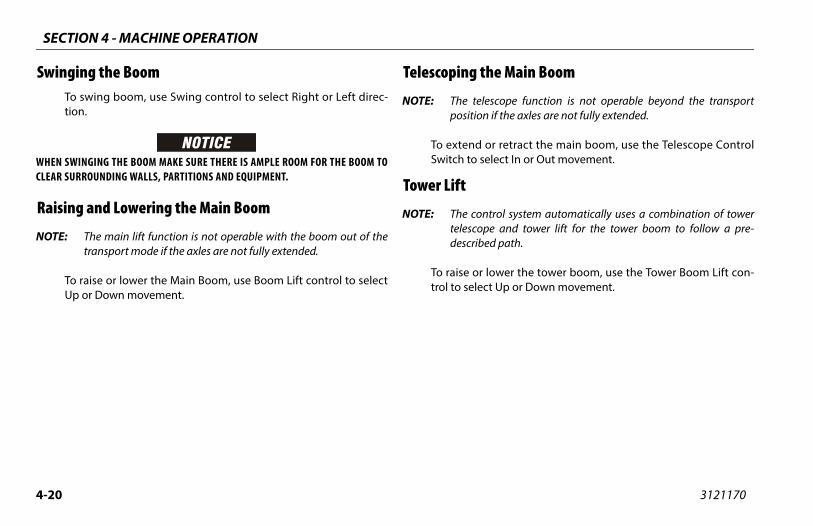
SECTION 4 - MACHINE OPERATION
4-2 3121170
Sw
WHECLEA
Rai
NOT
e Main Boom
scope function is not operable beyond the transport if the axles are not fully extended.
r retract the main boom, use the Telescope Controllect In or Out movement.
trol system automatically uses a combination of towere and tower lift for the tower boom to follow a pre-d path.
ower the tower boom, use the Tower Boom Lift con-t Up or Down movement.
0
inging the BoomTo swing boom, use Swing control to select Right or Left direc-tion.
N SWINGING THE BOOM MAKE SURE THERE IS AMPLE ROOM FOR THE BOOM TOR SURROUNDING WALLS, PARTITIONS AND EQUIPMENT.
sing and Lowering the Main Boom
E: The main lift function is not operable with the boom out of thetransport mode if the axles are not fully extended.
To raise or lower the Main Boom, use Boom Lift control to selectUp or Down movement.
Telescoping th
NOTE: The teleposition
To extend oSwitch to se
Tower Lift
NOTE: The contelescopdescribe
To raise or ltrol to selec
SECTION 4 - MACHINE OPERATION
4-21
CHINE SAFETY SYSTEM OVERRIDE (MSSO)(CE LY)achine Safety System Override (MSSO) is override function controls for Emergency
rm Retrieval only. Refer to Section 5.5,e Safety System Override (MSSO)(CE Only)rating procedures.
3121170
Swinging the Jib
NOTE: For 1000 lb. (454 kg for ANSI markets and 450 kg for CE andAustralia markets) mode operation, the jib must be centeredand the Jib Swing function is not operable. If the jib is out of thecentered position when in this mode, the jib swing function willallow the operator to center the jib again.
To swing the jib, use the Jib Swing control to select Right or Leftdirection.
4.12 FUNCTION SPEED CONTROLThis control affects the speed of all boom functions and PlatformRotate. When in the CCW maximum position, Drive is placed increep speed.
4.13 MAON
The Mused toPlatfoMachinfor ope
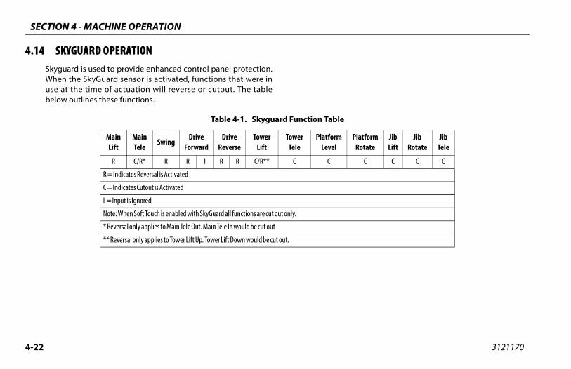
SECTION 4 - MACHINE OPERATION
4-2 3121170
4.1
PlatformRotate
JibLift
JibRotate
JibTele
C C C C
2
4 SKYGUARD OPERATIONSkyguard is used to provide enhanced control panel protection.When the SkyGuard sensor is activated, functions that were inuse at the time of actuation will reverse or cutout. The tablebelow outlines these functions.
Table 4-1. Skyguard Function Table
MainLift
MainTele
SwingDrive
ForwardDrive
ReverseTower
LiftTower
TelePlatform
Level
R C/R* R R I R R C/R** C C
R = Indicates Reversal is Activated
C = Indicates Cutout is Activated
I = Input is Ignored
Note: When Soft Touch is enabled with SkyGuard all functions are cut out only.
* Reversal only applies to Main Tele Out. Main Tele In would be cut out
** Reversal only applies to Tower Lift Up. Tower Lift Down would be cut out.
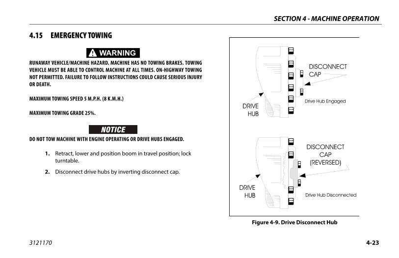
SECTION 4 - MACHINE OPERATION
4-23
Figure 4-9. Drive Disconnect Hub
3121170
4.15 EMERGENCY TOWING
RUNAWAY VEHICLE/MACHINE HAZARD. MACHINE HAS NO TOWING BRAKES. TOWINGVEHICLE MUST BE ABLE TO CONTROL MACHINE AT ALL TIMES. ON-HIGHWAY TOWINGNOT PERMITTED. FAILURE TO FOLLOW INSTRUCTIONS COULD CAUSE SERIOUS INJURYOR DEATH.
MAXIMUM TOWING SPEED 5 M.P.H. (8 K.M.H.)
MAXIMUM TOWING GRADE 25%.
DO NOT TOW MACHINE WITH ENGINE OPERATING OR DRIVE HUBS ENGAGED.
1. Retract, lower and position boom in travel position; lock turntable.
2. Disconnect drive hubs by inverting disconnect cap.
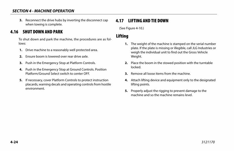
SECTION 4 - MACHINE OPERATION
4-2 3121170
4.1
AND TIE DOWN0.)
ight of the machine is stamped on the serial number f the plate is missing or illegible, call JLG Industries or the individual unit to find out the Gross Vehicle .
he boom in the stowed position with the turntable .
e all loose items from the machine.
lifting device and equipment only to the designated oints.
ly adjust the rigging to prevent damage to the e and so the machine remains level.
4
3. Reconnect the drive hubs by inverting the disconnect cap when towing is complete.
6 SHUT DOWN AND PARKTo shut down and park the machine, the procedures are as fol-lows:
1. Drive machine to a reasonably well protected area.
2. Ensure boom is lowered over rear drive axle.
3. Push in the Emergency Stop at Platform Controls.
4. Push in the Emergency Stop at Ground Controls. Position Platform/Ground Select switch to center OFF.
5. If necessary, cover Platform Controls to protect instruction placards, warning decals and operating controls from hostile environment.
4.17 LIFTING(See Figure 4-1
Lifting1. The we
plate. Iweigh Weight
2. Place tlocked
3. Remov
4. Attachlifting p
5. Propermachin
SECTION 4 - MACHINE OPERATION
4-25
WING THE JIB FOR TRANSPORTace the boom in the stowed position with the axles tracted.
ld the Jib Swing control switch to the right until the plat-rm will no longer swing.
Jib Swing function is not operable when the Capacity Selecttrol is in the 1000 lb. (454 kg for ANSI markets and 450 kg
CE and Australia markets) position.
tomatic platform leveling is disabled when stowing the jib.
sh and hold the Jib Stow Override control switch until the and platform are in the stowed position under the boom.
3121170
Tie Down
WHEN TRANSPORTING THE MACHINE, THE BOOM MUST BE FULLY LOWERED INTOTHE BOOM REST.
1. Place the boom in the stowed position with the turntable locked.
2. Remove all loose items from the machine.
3. Secure the chassis and the platform using straps or chains of adequate strength and attached to the designated tie down points.
4.18 STO1. Pl
re
2. Hofo
NOTE: Theconfor
NOTE: Au
3. Pujib

SECTION 4 - MACHINE OPERATION
4-2 3121170
15’-11”/4.85 m
’-9”/2.06 m
art
6
1705838 B 37’-7”/11.46 m
21’-8”/6.60 m
9’-9”/2.97 m 6
16’-6”/5.03 m
Figure 4-10. Lifting and Tie Down Ch
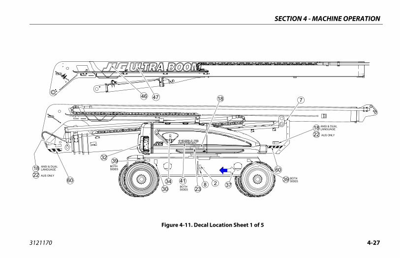
SECTION 4 - MACHINE OPERATION
4-27
BOTHSIDES
ANSI & DUALLANGUAGE
AUS ONLY22
39
7
18
60
eet 1 of 5
3121170
BOTHSIDES
AUS ONLY
ANSI & DUALLANGUAGE
BOTHSIDES 23
4746
22
308 234
18
3932
37
18
4160
Figure 4-11. Decal Location Sh

SECTION 4 - MACHINE OPERATION
4-2 3121170
3610A
A
5
8
34
SECTION A-A
37
37
22
Figure 4-12. Decal Location Sheet 2 of

SECTION 4 - MACHINE OPERATION
4-29
AUS ONLY
AGE
66
6261
22
28
15
heet 3 of 5
3121170
60
DECAL MOUNT FOR DOM DECAL MOUNT FOR DUAL LANGU
ANSI ONLY!
5258
63
951
31
335051
9
19
4345
44
24 19
59
28
20
59
59
261615
Figure 4-13. Decal Location S
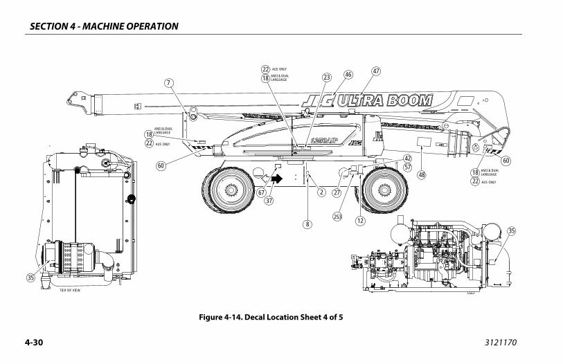
SECTION 4 - MACHINE OPERATION
4-3 3121170
3
AUS ONLY
ANSI & DUALLANGUAGE48 18
12
22
46
4257
47
60
35
35
5
0
25
AUS ONLY
AUS ONLY
ANSI & DUALLANGUAGE
ANSI & DUALLANGUAGE
37
22
22
67
2318
8
2
7
27
18
60
TIER IVF VIEW
Figure 4-14. Decal Location Sheet 4 of
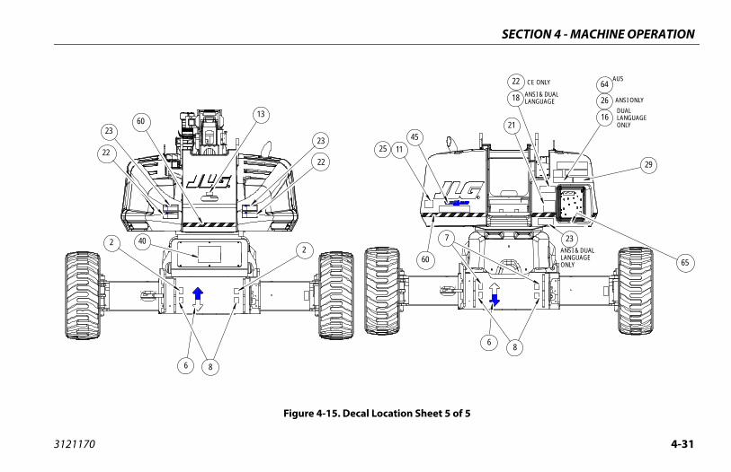
SECTION 4 - MACHINE OPERATION
4-31
t 5 of 5
ANSI & DUALLANGUAGEONLY
DUALLANGUAGEONLY
ANSI ONLYANSI & DUALLANGUAGE
CE ONLY AUS
29
6
16
23
18
7
8
21
26
22 64
65
3121170
Figure 4-15. Decal Location Shee
11
6
13
23
WARNINGWARNING
DANGER DANGER
60
60
25
8
22 40
23
2222
45
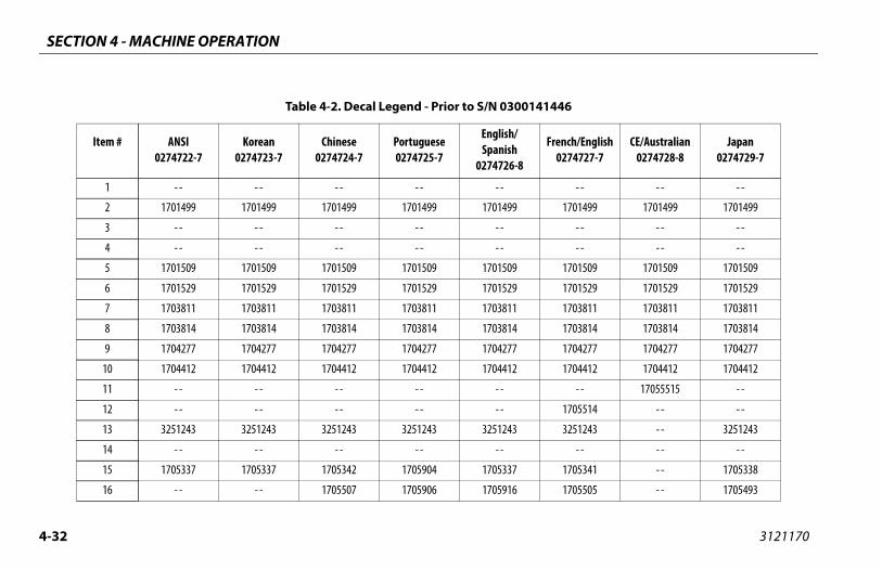
SECTION 4 - MACHINE OPERATION
4-3 3121170
141446
French/English0274727-7
CE/Australian0274728-8
Japan0274729-7
- - - - - -
1701499 1701499 1701499
- - - - - -
- - - - - -
1701509 1701509 1701509
1701529 1701529 1701529
1703811 1703811 1703811
1703814 1703814 1703814
1704277 1704277 1704277
1704412 1704412 1704412
- - 17055515 - -
1705514 - - - -
3251243 - - 3251243
- - - - - -
1705341 - - 1705338
1705505 - - 1705493
2
Table 4-2. Decal Legend - Prior to S/N 0300
Item # ANSI0274722-7
Korean0274723-7
Chinese0274724-7
Portuguese0274725-7
English/Spanish
0274726-8
1 - - - - - - - - - -
2 1701499 1701499 1701499 1701499 1701499
3 - - - - - - - - - -
4 - - - - - - - - - -
5 1701509 1701509 1701509 1701509 1701509
6 1701529 1701529 1701529 1701529 1701529
7 1703811 1703811 1703811 1703811 1703811
8 1703814 1703814 1703814 1703814 1703814
9 1704277 1704277 1704277 1704277 1704277
10 1704412 1704412 1704412 1704412 1704412
11 - - - - - - - - - -
12 - - - - - - - - - -
13 3251243 3251243 3251243 3251243 3251243
14 - - - - - - - - - -
15 1705337 1705337 1705342 1705904 1705337
16 - - - - 1705507 1705906 1705916
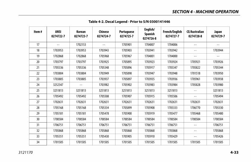
SECTION 4 - MACHINE OPERATION
4-33
07 1704006 - - - -
41 1703942 - - 1703944
01 1704000 - - - -
23 1703924 1705921 1703926
17 1705347 1705822 1705344
47 1703948 1701518 1703950
35 1703936 1705961 1703938
83 1703984 1705828 1703980
13 3251813 - - 3251813
15 1705506 - - 1705494
31 1702631 1702631 1702631
08 1705333 1706770 1705330
19 1705477 1705468 1705480
84 1700584 1700584 1700584
51 1706751 - - 1706751
68 1705868 - - 1705868
10 1705429 - - 1705426
05 1701505 1701505 1701505
300141446
sh/ish26-8
French/English0274727-7
CE/Australian0274728-8
Japan0274729-7
3121170
17 - - 1702153 - - 1705901 17040
18 1703953 1703953 1703943 1705903 17039
19 1702868 1702868 1705968 1705967 17040
20 1703797 1703797 1703925 1705895 17039
21 1705336 1705336 1705348 1705896 17059
22 1703804 1703804 1703949 1705898 17039
23 1703805 1703805 1703937 1705897 17039
24 3252347 - - 1703982 1705902 17039
25 3251813 3251813 3251813 3251813 32518
26 1705492 1705492 1705508 1705907 17059
27 1702631 1702631 1702631 1702631 17026
28 1705168 1705168 1705334 1705899 17059
29 1705181 1705181 1705478 1705900 17059
30 1700584 1700584 1700584 1700584 17005
31 1706751 1706751 1706751 1706751 17067
32 1705868 1705868 1705868 1705868 17058
33 1705351 1705351 1705430 1705905 17059
34 1701505 1701505 1701505 1701505 17015
Table 4-2. Decal Legend - Prior to S/N 0
Item # ANSI0274722-7
Korean0274723-7
Chinese0274724-7
Portuguese0274725-7
EngliSpan
02747
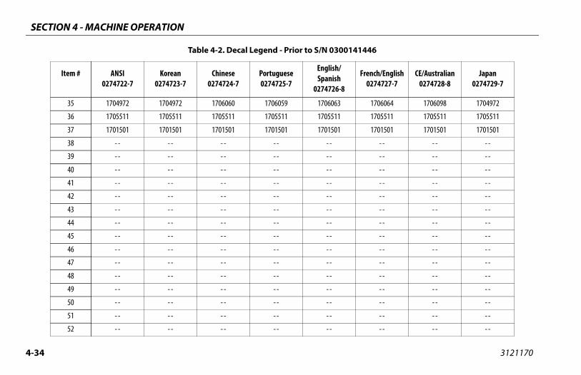
SECTION 4 - MACHINE OPERATION
4-3 3121170
1706064 1706098 1704972
1705511 1705511 1705511
1701501 1701501 1701501
- - - - - -
- - - - - -
- - - - - -
- - - - - -
- - - - - -
- - - - - -
- - - - - -
- - - - - -
- - - - - -
- - - - - -
- - - - - -
- - - - - -
- - - - - -
- - - - - -
- - - - - -
141446
French/English0274727-7
CE/Australian0274728-8
Japan0274729-7
4
35 1704972 1704972 1706060 1706059 1706063
36 1705511 1705511 1705511 1705511 1705511
37 1701501 1701501 1701501 1701501 1701501
38 - - - - - - - - - -
39 - - - - - - - - - -
40 - - - - - - - - - -
41 - - - - - - - - - -
42 - - - - - - - - - -
43 - - - - - - - - - -
44 - - - - - - - - - -
45 - - - - - - - - - -
46 - - - - - - - - - -
47 - - - - - - - - - -
48 - - - - - - - - - -
49 - - - - - - - - - -
50 - - - - - - - - - -
51 - - - - - - - - - -
52 - - - - - - - - - -
Table 4-2. Decal Legend - Prior to S/N 0300
Item # ANSI0274722-7
Korean0274723-7
Chinese0274724-7
Portuguese0274725-7
English/Spanish
0274726-8
SECTION 4 - MACHINE OPERATION
4-35
- - - - - -
- - - - - -
- - - - - -
- - - - - -
- - - - - -
- - - - - -
- - - - - -
- - - - - -
300141446
sh/ish26-8
French/English0274727-7
CE/Australian0274728-8
Japan0274729-7
3121170
53 - - - - - - - - - -
54 - - - - - - - - - -
55 - - - - - - - - - -
56 - - - - - - - - - -
57 - - - - - - - - - -
58 - - - - - - - - - -
59 - - - - - - - - - -
60 - - - - - - - - - -
Table 4-2. Decal Legend - Prior to S/N 0
Item # ANSI0274722-7
Korean0274723-7
Chinese0274724-7
Portuguese0274725-7
EngliSpan
02747
SECTION 4 - MACHINE OPERATION
4-3 3121170
Present
French/English0274727-E
Australian1001114383-E
Japan0274729-E
- - - - - -
1701499 1701499 1701499
- - - - - -
- - - - - -
1701509 1701509 1701509
1701529 1701529 1701529
1703811 1703811 1703811
1703814 1703814 1703814
1704277 1704277 1704277
1704412 1704412 1704412
- - - - - -
1705514 - - - -
3251243 - - 3251243
- - - - - -
1705341 - - 1705338
1705505 - - 1705493
6
Table 4-3. Decal Legend - S/N 0300141446 to
Item # ANSI0274722-F
Korean0274723-E
Chinese0274724-E
Portuguese0274725-E
English/Spanish
0274726-E
1 - - - - - - - - - -
2 1701499 1701499 1701499 1701499 1701499
3 - - - - - - - - - -
4 - - - - - - - - - -
5 1701509 1701509 1701509 1701509 1701509
6 1701529 1701529 1701529 1701529 1701529
7 1703811 1703811 1703811 1703811 1703811
8 1703814 1703814 1703814 1703814 1703814
9 1704277 1704277 1704277 1704277 1704277
10 1704412 1704412 1704412 1704412 1704412
11 - - - - - - - - - -
12 1705514 - - - - - - - -
13 3251243 3251243 3251243 3251243 3251243
14 - - - - - - - - - -
15 1705337 1705337 1705342 1705904 1705337
16 - - - - 1001117035 1705906 1705916
SECTION 4 - MACHINE OPERATION
4-37
- - - - - -
41 1703942 - - 1703944
01 1704000 - - - -
23 1703924 1705921 1703926
17 1705347 1705822 1705344
47 1703948 1701518 1703950
35 1703936 1705961 1703938
83 1703984 1705828 1703980
- - - - - -
15 1705506 - - 1705494
31 1702631 1702631 1702631
2373 1001122374 1706770 1001122375
2380 1001122381 1705468 1001122382
1700584 - - - -
51 1706751 - - 1706751
68 1705868 - - 1705868
10 1705429 - - 1705426
05 1701505 1701505 1701505
46 to Present
sh/ish26-E
French/English0274727-E
Australian1001114383-E
Japan0274729-E
3121170
17 - - 1702153 - - - - - -
18 1703953 1703953 1703943 1705903 17039
19 1702868 1702868 1001116846 1705967 17040
20 1703797 1703797 1703925 1705895 17039
21 1705336 1705336 1001116849 1705896 17059
22 1703804 17033951 1703949 1705898 17039
23 1703805 1703805 1001116851 1705897 17039
24 3252347 - - 1703982 1705902 17039
25 - - - - - - - - - -
26 1705492 1705492 1705508 1705907 17059
27 1702631 1702631 1702631 1702631 17026
28 1001122369 1001122370 1001122371 1001122372 100112
29 1001122376 1001122377 1001122378 1001122379 100112
30 1001131269 - - - - - - - -
31 1706751 1706751 1706751 1706751 17067
32 1705868 1705868 1705868 1705868 17058
33 1705351 1705351 1705430 1705905 17059
34 1701505 1701505 1701505 1701505 17015
Table 4-3. Decal Legend - S/N 03001414
Item # ANSI0274722-F
Korean0274723-E
Chinese0274724-E
Portuguese0274725-E
EngliSpan
02747
SECTION 4 - MACHINE OPERATION
4-3 3121170
1706064 1706098 1706062
1705511 1705511 1705511
1701501 1701501 1701501
- - - - - -
- - - - - -
- - - - - -
- - - - - -
- - - - - -
- - - - - -
- - - - - -
- - - - - -
- - - - - -
- - - - - -
- - - - - -
- - - - - -
- - - - - -
- - - - - -
- - - - - -
Present
French/English0274727-E
Australian1001114383-E
Japan0274729-E
8
35 1704972 1704972 1706060 1706059 1706063
36 1705511 1705511 1705511 1705511 1705511
37 1701501 1701501 1701501 1701501 1701501
38 - - - - - - - - - -
39 - - - - - - - - - -
40 - - - - - - - - - -
41 - - - - - - - - - -
42 - - - - - - - - - -
43 - - - - - - - - - -
44 - - - - - - - - - -
45 - - - - - - - - - -
46 - - - - - - - - - -
47 - - - - - - - - - -
48 - - - - - - - - - -
49 - - - - - - - - - -
50 - - - - - - - - - -
51 - - - - - - - - - -
52 - - - - - - - - - -
Table 4-3. Decal Legend - S/N 0300141446 to
Item # ANSI0274722-F
Korean0274723-E
Chinese0274724-E
Portuguese0274725-E
English/Spanish
0274726-E
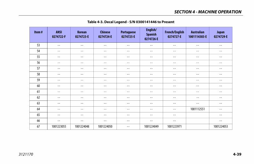
SECTION 4 - MACHINE OPERATION
4-39
- - - - - -
- - - - - -
- - - - - -
- - - - - -
- - - - - -
- - - - - -
- - - - - -
- - - - - -
- - - - - -
- - - - - -
- - - - - -
- - 1001112551 - -
- - - -
- - - -
4049 1001223971 1001224053
46 to Present
sh/ish26-E
French/English0274727-E
Australian1001114383-E
Japan0274729-E
3121170
53 - - - - - - - - - -
54 - - - - - - - - - -
55 - - - - - - - - - -
56 - - - - - - - - - -
57 - - - - - - - - - -
58 - - - - - - - - - -
59 - - - - - - - - - -
60 - - - - - - - - - -
61 - - - - - - - - - -
62 - - - - - - - - - -
63 - - - - - - - - - -
64 - - - - - - - - - -
65 - - - - - - - - - -
66 - - - - - - - - - -
67 1001223055 1001224048 1001224050 - - 100122
Table 4-3. Decal Legend - S/N 03001414
Item # ANSI0274722-F
Korean0274723-E
Chinese0274724-E
Portuguese0274725-E
EngliSpan
02747

SECTION 4 - MACHINE OPERATION
4-4 3121170
7
41
39
22
22
60
t - CE Only - Sheet 1 of 5
0
238 2
3439
3760
46
Figure 4-16. Decal Location - S/N 0300141446 to Presen
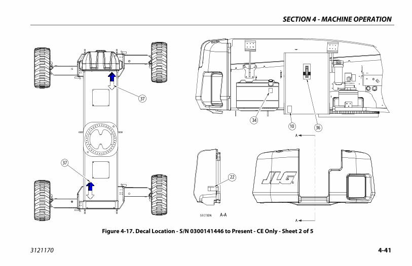
SECTION 4 - MACHINE OPERATION
4-41
3634
10
A
A
t - CE Only - Sheet 2 of 5
3121170
SECTION A-A
37
37
22
Figure 4-17. Decal Location - S/N 0300141446 to Presen

SECTION 4 - MACHINE OPERATION
4-4 3121170
22
61 62
t - CE Only - Sheet 3 of 5
2
60
58
63
66
9
51335051
9 24
52
28
2044
Figure 4-18. Decal Location - S/N 0300141446 to Presen
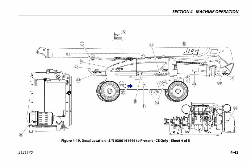
SECTION 4 - MACHINE OPERATION
4-43
253
48
1
2 27
4257 22
60
35
46
t - CE Only - Sheet 4 of 5
3121170
23
37
22
4
8
7
22
60
44
35
Figure 4-19. Decal Location - S/N 0300141446 to Presen
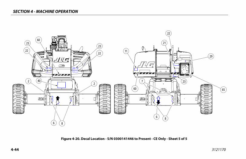
SECTION 4 - MACHINE OPERATION
4-4 3121170
nt - CE Only - Sheet 5 of 5
29
6
23
8
21
22
65
4
Figure 4-20. Decal Location - S/N 0300141446 to Prese
11
6
23
60
60
8
22 40
23
2222
7

SECTION 4 - MACHINE OPERATION
4-45
18 - -
19 - -
20 1705921
21 1705822
22 1701518
23 1705961
24 1705828
25 - -
26 - -
27 1702631
28 1706770
29 1705468
30 - -
31 - -
32 - -
33 - -
34 1701505
35 1706098
Decal Legend - S/N 0300141446 to Present - CE Only
Item # CE0274728-G
3121170
Table 4-4. Decal Legend - S/N 0300141446 to Present - CE Only
Item # CE0274728-G
1 - -
2 1701499
3 - -
4 - -
5 1701509
6 1701529
7 1703811
8 1703814
9 1704277
10 1704412
11 - -
12 - -
13 - -
14 - -
15 - -
16 - -
17 - -
Table 4-4.
SECTION 4 - MACHINE OPERATION
4-4 3121170
Ta
54 - -
55 - -
56 - -
57 - -
58 - -
59 - -
60 - -
al Legend - S/N 0300141446 to Present - CE Only
Item # CE0274728-G
6
36 1705511
37 1701501
38 - -
39 - -
40 - -
41 - -
42 - -
43 - -
44 1702773
45 - -
46 1705864
47 - -
48 - -
49 - -
50 - -
51 - -
52 - -
53 - -
ble 4-4. Decal Legend - S/N 0300141446 to Present - CE Only
Item # CE0274728-G
Table 4-4. Dec
SECTION 5 - EMERGENCY PROCEDURES
5-1
OCEDURES
NY ACCIDENT, THOROUGHLY INSPECT THE MACHINE AND TEST ALLST FROM THE GROUND CONTROLS, THEN FROM THE PLATFORM CON-
LIFT ABOVE 3 M (10 FT.) UNTIL YOU ARE SURE THAT ALL DAMAGE HASD, IF REQUIRED, AND THAT ALL CONTROLS ARE OPERATING COR-
ERGENCY OPERATION
nable to Control MachinePLATFORM OPERATOR IS PINNED, TRAPPED OR UNABLE TOTE OR CONTROL MACHINE:
ther personnel should operate the machine from ground ntrols only as required.
ther qualified personnel on the platform may use the plat-rm controls. DO NOT CONTINUE OPERATION IF CONTROLS
NOT FUNCTION PROPERLY.
anes, forklift trucks or other equipment can be used to move platform occupants and stabilize motion of the achine.
3121170
SECTION 5. EMERGENC Y PR
5.1 GENERALThis section explains the steps to be taken in case of an emer-gency situation while operating.
5.2 INCIDENT NOTIFICATIONJLG Industries, Inc. must be notified immediately of any incidentinvolving a JLG product. Even if no injury or property damage isevident, the factory should be contacted by telephone and pro-vided with all necessary details.
In USA:JLG Phone: 877-JLG-SAFE (554-7233) (8am till 4:45pm EST)
Outside USA: 240-420-2661
E-mail:
Failure to notify the manufacturer of an incident involving a JLGIndustries product within 48 hours of such an occurrence mayvoid any warranty consideration on that particular machine.
FOLLOWING AFUNCTIONS FIRTROLS. DO NOTBEEN REPAIRERECTLY.
5.3 EM
Operator UIF THE OPERA
1. Oco
2. OfoDO
3. Crrem

SECTION 5 - EMERGENCY PROCEDURES
5-2 3121170
Pla
5.4
E SAFETY SYSTEM OVERRIDE (MSSO)(CE
e Safety System Override (MSSO) isused to retrieve an operator that isapped, or unable to operate thed function controls are locked outtform due to a platform overload sit-
SSO functionality is used, the fault indicator will flashult code is set in the JLG Control System which must bea qualified JLG Service Technician.
tional checks of the MSSO system are necessary. The JLGsystem will set a Diagnostic Trouble Code if the control faulty.
he MSSO:
he ground control console, place the Platform/ Select switch in the Ground position.
t the Power/Emergency Stop control.
e engine.
nd hold the MSSO switch and the control switch for ired function.
tform or Boom Caught OverheadIf the platform or boom becomes jammed or snagged in over-head structures or equipment, rescue platform occupants prior tofreeing the machine.
EMERGENCY TOWING PROCEDURESTowing this machine is prohibited, unless properly equipped.However, provisions for moving the machine have been incorpo-rated. For specific procedures, refer to Section 4.
5.5 MACHINONLY)
The Machinonly to be pinned, trmachine anfrom the plauation.
NOTE: If the Mand a fareset by
NOTE: No funcControl switch is
To operate t
1. From tGround
2. Pull ou
3. Start th
4. Press athe des
SECTION 6 - ACCESSORIES
6-1
IES
ies
rket
E AUS Japan China
3121170
SECTION 6. ACCESSOR
Table 6-1. Available Accessor
AccessoryMa
ANSI (USA Only)
ANSI CSA C
Fall Arrest Platform (36" x 72")
Fall Arrest Platform (36" x 96")
Pipe Racks
SkyCutter™
SkyGlazier™
SkyPower™
SkyWelder™
Soft Touch
Bolt-On External Fall Arrest (36" x 72")
Bolt-On External Fall Arrest (36" x 96")
SECTION 6 - ACCESSORIES
6-2 3121170
p Table
INCOMPATIBLE WITH INTERCHANGABLE WITH (Note 2)
Pipetform MMR**, Platform MTR*,
Soft TouchSkyCutter™, SkyGlazier™,
SkyWelder™
Skylatform, Pipe Racks, Platform
MTR*, Soft TouchSkyGlazier™
Skylatform, Pipe Racks, Platform
MTR*, Soft TouchSkyCutter™, SkyWelder™
Sky
Skylatform, Pipe Racks, Platform
MTR*, Soft TouchSkyGlazier™
SoftPipe Racks, SkyCutter™,
SkyGlazier™, SkyWelder™
Not
Not
* Pl
Table 6-2. Options/Accessories Relationshi
ACCESSORY REQUIRED ITEMCOMPATIBLE WITH
(Note 1)
Racks SkyPower™Pla
Cutter™ SkyPower™ SkyWelder™4’ P
Glazier™ SkyPower™4’ P
Power™SkyCutter™, SkyGlazier™,
SkyWelder™
Welder™ SkyPower™ SkyCutter™4’ P
Touch SkyPower™
e 1: Any non-"Sky" accessory not listed under "INCOMPATIBLE WITH" is assumed to be compatible.
e 2: Can be used on same unit but not simultaneously.
atform MTR = Platform Mesh to Top Rail; ** Platform MMR = Platform Mesh to Mid Rail
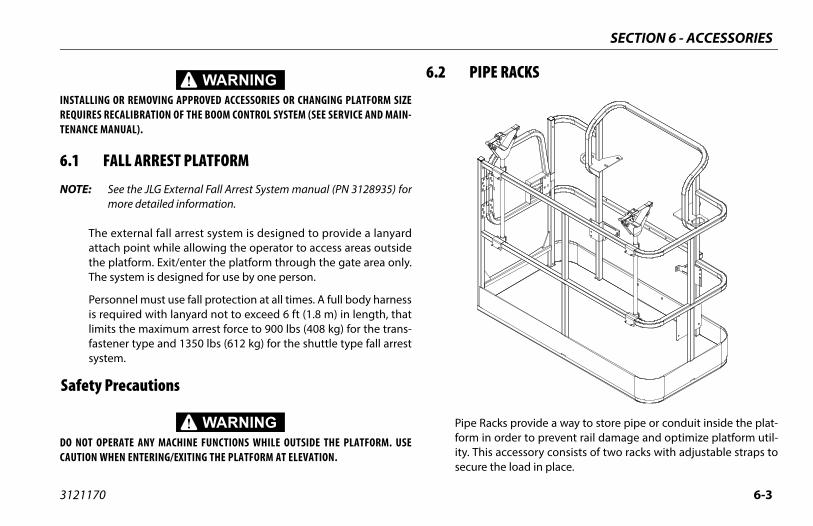
SECTION 6 - ACCESSORIES
6-3
E RACKS
cks provide a way to store pipe or conduit inside the plat- order to prevent rail damage and optimize platform util-
s accessory consists of two racks with adjustable straps to the load in place.
3121170
INSTALLING OR REMOVING APPROVED ACCESSORIES OR CHANGING PLATFORM SIZEREQUIRES RECALIBRATION OF THE BOOM CONTROL SYSTEM (SEE SERVICE AND MAIN-TENANCE MANUAL).
6.1 FALL ARREST PLATFORM
NOTE: See the JLG External Fall Arrest System manual (PN 3128935) formore detailed information.
The external fall arrest system is designed to provide a lanyardattach point while allowing the operator to access areas outsidethe platform. Exit/enter the platform through the gate area only.The system is designed for use by one person.
Personnel must use fall protection at all times. A full body harnessis required with lanyard not to exceed 6 ft (1.8 m) in length, thatlimits the maximum arrest force to 900 lbs (408 kg) for the trans-fastener type and 1350 lbs (612 kg) for the shuttle type fall arrestsystem.
Safety Precautions
DO NOT OPERATE ANY MACHINE FUNCTIONS WHILE OUTSIDE THE PLATFORM. USECAUTION WHEN ENTERING/EXITING THE PLATFORM AT ELEVATION.
6.2 PIP
Pipe Raform inity. Thisecure
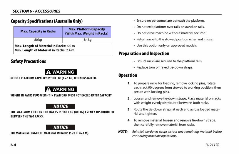
SECTION 6 - ACCESSORIES
6-4 3121170
Cap
Saf
REDU
WEIG
THE BETW
THE M
re no personnel are beneath the platform.
ot exit platform over rails or stand on rails.
ot drive machine without material secured
rn racks to the stowed position when not in use.
his option only on approved models.
nd Inspectionre racks are secured to the platform rails.
ce torn or frayed tie-down straps.
are racks for loading, remove locking pins, rotate ck 90 degrees from stowed to working position, then
with locking pins.
and remove tie-down straps. Place material on racks eight evenly distributed between both racks.
the tie-down straps at each end across loaded mate- tighten.
ove material, loosen and remove tie-down straps, refully remove material from racks.
l tie-down straps across any remaining material beforeng machine operations.
MM
acity Specifications (Australia Only)
ety Precautions
CE PLATFORM CAPACITY BY 100 LBS (45.5 KG) WHEN INSTALLED.
HT IN RACKS PLUS WEIGHT IN PLATFORM MUST NOT EXCEED RATED CAPACITY.
MAXIMUM LOAD IN THE RACKS IS 180 LBS (80 KG) EVENLY DISTRIBUTEDEEN THE TWO RACKS.
AXIMUM LENGTH OF MATERIAL IN RACKS IS 20 FT (6.1 M).
• Ensu
• Do n
• Do n
• Retu
• Use t
Preparation a• Ensu
• Repla
Operation1. To prep
each rasecure
2. Loosenwith w
3. Route rial and
4. To remthen ca
NOTE: Reinstalcontinui
Max. Capacity in Racks Max. Platform Capacity (With Max. Weight in Racks)
80 kg 184 kg
ax. Length of Material in Racks: 6.0 min. Length of Material in Racks: 2.4 m
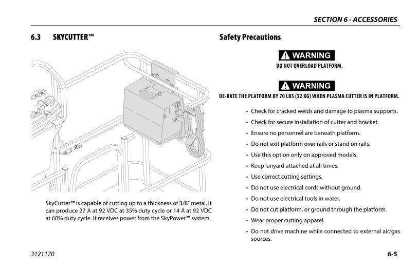
SECTION 6 - ACCESSORIES
6-5
cautions
DO NOT OVERLOAD PLATFORM.
LATFORM BY 70 LBS (32 KG) WHEN PLASMA CUTTER IS IN PLATFORM.
Check for cracked welds and damage to plasma supports.
Check for secure installation of cutter and bracket.
Ensure no personnel are beneath platform.
Do not exit platform over rails or stand on rails.
Use this option only on approved models.
Keep lanyard attached at all times.
Use correct cutting settings.
Do not use electrical cords without ground.
Do not use electrical tools in water.
Do not cut platform, or ground through the platform.
Wear proper cutting apparel.
Do not drive machine while connected to external air/gassources.
3121170
6.3 SKYCUTTER™
SkyCutter™ is capable of cutting up to a thickness of 3/8" metal. Itcan produce 27 A at 92 VDC at 35% duty cycle or 14 A at 92 VDCat 60% duty cycle. It receives power from the SkyPower™ system.
Safety Pre
DE-RATE THE P
•
•
•
•
•
•
•
•
•
•
•
•
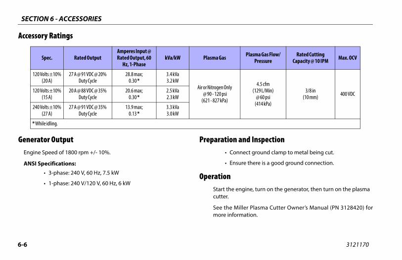
SECTION 6 - ACCESSORIES
6-6 3121170
Acc
GenEn
A
nd Inspectionect ground clamp to metal being cut.
re there is a good ground connection.
gine, turn on the generator, then turn on the plasma
ler Plasma Cutter Owner’s Manual (PN 3128420) foration.
Plasma Gas Flow/Pressure
Rated Cutting Capacity @ 10 IPM Max. OCV
4.5 cfm(129 L/Min)
@ 60 psi(414 kPa)
3/8 in(10 mm) 400 VDC
essory Ratings
erator Outputgine Speed of 1800 rpm +/- 10%.
NSI Specifications:
• 3-phase: 240 V, 60 Hz, 7.5 kW
• 1-phase: 240 V/120 V, 60 Hz, 6 kW
Preparation a• Conn
• Ensu
OperationStart the encutter.
See the Milmore inform
Spec. Rated OutputAmperes Input @ Rated Output, 60
Hz, 1-PhasekVa/kW Plasma Gas
120 Volts ±10% (20 A)
27 A @ 91 VDC @ 20% Duty Cycle
28.8 max;0.30 *
3.4 kVa3.2 kW
Air or Nitrogen Only @ 90 - 120 psi
(621 - 827 kPa)
120 Volts ±10% (15 A)
20 A @ 88 VDC @ 35% Duty Cycle
20.6 max;0.30 *
2.5 kVa2.3 kW
240 Volts ±10% (27 A)
27 A @ 91 VDC @ 35% Duty Cycle
13.9 max;0.13 *
3.3 kVa3.0 kW
* While idling.
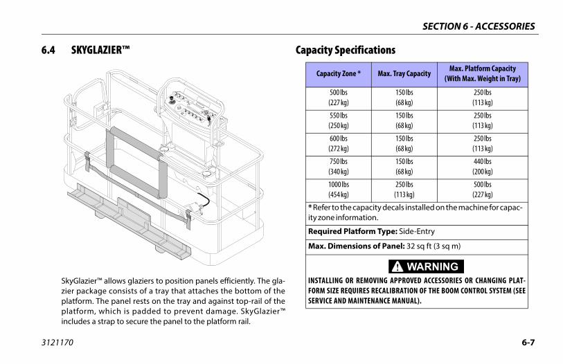
SECTION 6 - ACCESSORIES
6-7
pecifications
y Zone * Max. Tray CapacityMax. Platform Capacity
(With Max. Weight in Tray)
lbs kg)
150 lbs(68 kg)
250 lbs(113 kg)
lbs kg)
150 lbs(68 kg)
250 lbs(113 kg)
lbs kg)
150 lbs(68 kg)
250 lbs(113 kg)
lbs kg)
150 lbs(68 kg)
440 lbs(200 kg)
0 lbs kg)
250 lbs(113 kg)
500 lbs(227 kg)
the capacity decals installed on the machine for capac-nformation.
Platform Type: Side-Entry
ensions of Panel: 32 sq ft (3 sq m)
G OR REMOVING APPROVED ACCESSORIES OR CHANGING PLAT- REQUIRES RECALIBRATION OF THE BOOM CONTROL SYSTEM (SEE
ND MAINTENANCE MANUAL).
3121170
6.4 SKYGLAZIER™
SkyGlazier™ allows glaziers to position panels efficiently. The gla-zier package consists of a tray that attaches the bottom of theplatform. The panel rests on the tray and against top-rail of theplatform, which is padded to prevent damage. SkyGlazier™includes a strap to secure the panel to the platform rail.
Capacity S
Capacit
500(227
550(250
600(272
750(340
100(454
* Refer toity zone i
Required
Max. Dim
INSTALLINFORM SIZESERVICE A
SECTION 6 - ACCESSORIES
6-8 3121170
Saf
DO NWHE
WITHREDUNEW
AN INPANE
nd Inspectionk for cracked welds and damage to tray.
re tray is properly secured to platform.
re strap is not torn or frayed.
kyGlazier™ tray with panel.
the adjustable strap around the panel and tighten cure.
n panel to its desired location.
ety Precautions
ENSURE PANEL IS SECURED WITH STRAP.
OT OVERLOAD TRAY OR PLATFORM. TOTAL MACHINE CAPACITY IS REDUCEDN TRAY IS INSTALLED.
SKYGLAZIER™ INSTALLED, THE ORIGINAL PLATFORM CAPACITY RATINGS ARECED AS SPECIFIED IN THE CAPACITY SPECIFICATIONS TABLE. DO NOT EXCEED
PLATFORM CAPACITY RATINGS. REFER TO CAPACITY DECAL LOCATED ON TRAY.
CREASE OF THE AREA EXPOSED TO THE WIND WILL DECREASE STABILITY. LIMITL AREA TO 32 SQ FT (3 SQ M).
• Ensure no personnel are beneath platform.
• Do not exit platform over rails or stand on rails.
• Remove tray when not in use.
• Use this option only on approved models.
Preparation a• Chec
• Ensu
• Ensu
Operation1. Load S
2. Route until se
3. Positio
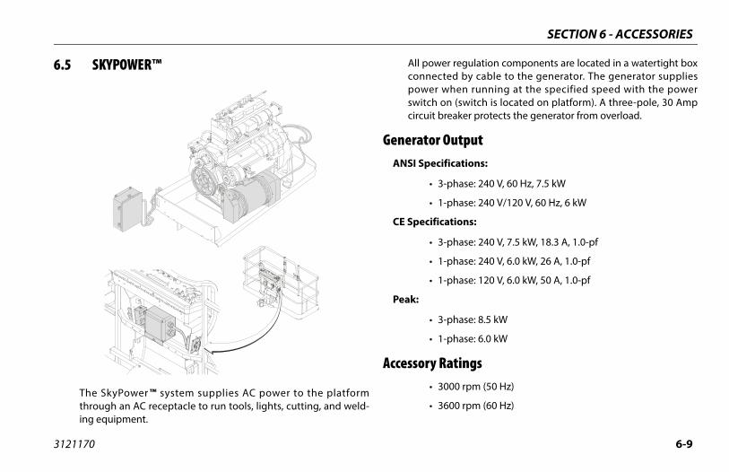
SECTION 6 - ACCESSORIES
6-9
er regulation components are located in a watertight boxcted by cable to the generator. The generator supplies when running at the specified speed with the power on (switch is located on platform). A three-pole, 30 Ampbreaker protects the generator from overload.
Outputifications:
3-phase: 240 V, 60 Hz, 7.5 kW
1-phase: 240 V/120 V, 60 Hz, 6 kW
cations:
3-phase: 240 V, 7.5 kW, 18.3 A, 1.0-pf
1-phase: 240 V, 6.0 kW, 26 A, 1.0-pf
1-phase: 120 V, 6.0 kW, 50 A, 1.0-pf
3-phase: 8.5 kW
1-phase: 6.0 kW
Ratings3000 rpm (50 Hz)
3600 rpm (60 Hz)
3121170
6.5 SKYPOWER™
The SkyPower™ system supplies AC power to the platformthrough an AC receptacle to run tools, lights, cutting, and weld-ing equipment.
All powconnepowerswitchcircuit
GeneratorANSI Spec
•
•
CE Specifi
•
•
•
Peak:
•
•
Accessory •
•
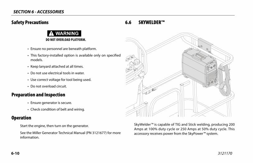
SECTION 6 - ACCESSORIES
6-1 3121170
Saf
Pre
Ope
DER™
is capable of TIG and Stick welding, producing 2000% duty cycle or 250 Amps at 50% duty cycle. Thisceives power from the SkyPower™ system.
0
ety Precautions
DO NOT OVERLOAD PLATFORM.
• Ensure no personnel are beneath platform.
• This factory-installed option is available only on specifiedmodels.
• Keep lanyard attached at all times.
• Do not use electrical tools in water.
• Use correct voltage for tool being used.
• Do not overload circuit.
paration and Inspection• Ensure generator is secure.
• Check condition of belt and wiring.
rationStart the engine, then turn on the generator.
See the Miller Generator Technical Manual (PN 3121677) for moreinformation.
6.6 SKYWEL
SkyWelder™Amps at 10accessory re
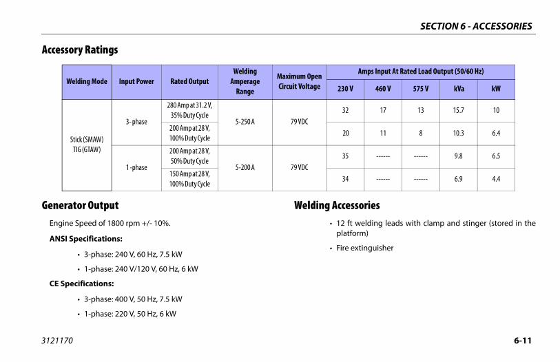
SECTION 6 - ACCESSORIES
6-11
ccessories12 ft welding leads with clamp and stinger (stored in theplatform)
Fire extinguisher
Amps Input At Rated Load Output (50/60 Hz)
230 V 460 V 575 V kVa kW
32 17 13 15.7 10
20 11 8 10.3 6.4
35 ------ ------ 9.8 6.5
34 ------ ------ 6.9 4.4
3121170
Accessory Ratings
Generator OutputEngine Speed of 1800 rpm +/- 10%.
ANSI Specifications:
• 3-phase: 240 V, 60 Hz, 7.5 kW
• 1-phase: 240 V/120 V, 60 Hz, 6 kW
CE Specifications:
• 3-phase: 400 V, 50 Hz, 7.5 kW
• 1-phase: 220 V, 50 Hz, 6 kW
Welding A•
•
Welding Mode Input Power Rated OutputWelding
Amperage Range
Maximum Open Circuit Voltage
Stick (SMAW)TIG (GTAW)
3- phase
280 Amp at 31.2 V, 35% Duty Cycle
5-250 A 79 VDC200 Amp at 28 V, 100% Duty Cycle
1 -phase
200 Amp at 28 V, 50% Duty Cycle
5-200 A 79 VDC150 Amp at 28 V, 100% Duty Cycle
SECTION 6 - ACCESSORIES
6-1 3121170
Saf
DE-R
orrect rod size and current settings.
ot use electrical cords without ground.
ot use electrical tools in water.
ot weld to the platform.
ot ground through the platform.
ot use a high frequency arc starter with TIG welder.
nd Inspectionect ground clamp to metal being welded.
re there is a good ground connection and observeer polarity.
gine, turn on the generator, then turn on the welder.
ller Welder Owner’s Manual (PN 3128957) for more.
2
ety Precautions
DO NOT OVERLOAD PLATFORM.
ATE THE PLATFORM BY 70 LBS (32 KG) WHEN WELDER IS IN THE PLATFORM.
• Check for cracked welds and damage to welder supports.
• Check for proper and secure installation of welder andbracket.
• Ensure no personnel are beneath platform.
• Do not exit platform over rails or stand on rails.
• Use this option only on approved models.
• Keep lanyard attached at all times.
• Ensure correct polarity of leads.
• Wear proper welding apparel.
• Use c
• Do n
• Do n
• Do n
• Do n
• Do n
Preparation a• Conn
• Ensuprop
OperationStart the en
See the Miinformation

SECTION 6 - ACCESSORIES
6-13
T-ON EXTERNAL FALL ARREST
n external fall arrest system is designed to provide a lan-h point while allowing the operator to access areas outsidem. Exit/Enter the platform through the gate area only. Theesigned for use by one person.
must use fall protection at all times. A full body harness isith lanyard not to exceed 6 ft. (1.8 M) in length, that limitsum arrest force to 900 lbs. (408 kg).
ll Arrest System capacity is 310 lb (140 kg) - one (1) person.
ve platform during use of the external fall arrest system.
ATE ANY MACHINE FUNCTIONS WHILE OUTSIDE OF PLATFORM. BE ENTERING/EXITING THE PLATFORM AT ELEVATION.
3121170
6.7 SOFT TOUCH
A padding kit is mounted to the platform rails and to a frame sus-pended below the platform. Limit switches deactivate platformfunctions when the padded framework contacts an adjacentstructure. A button on the platform console allows override of thesystem.
6.8 BOL
The bolt-oyard attacthe platforsystem is d
Personnelrequired wthe maxim
External Famaximum
Do not mo
DO NOT OPERCAREFUL WHEN
OVERRIDE INDICATOR LIGHTOVERRIDE BUTTON
RAIL BUMPER
LIMIT SWITCH
LIMITSWITCH
SUSPENDED FRAME AND RAIL BUMPER
SECTION 6 - ACCESSORIES
6-1 3121170
IF THDAMINSPREM
THE EFICAQUAL
fore Usell arrest system must be inspected before each use of platform. Replace components if there are any signsage.
, perform a visual inspection of the following compo-
4
E EXTERNAL FALL ARREST SYSTEM IS USED TO ARREST A FALL OR IS OTHERWISEAGED, THE ENTIRE SYSTEM MUST BE REPLACED AND THE PLATFORM FULLYECTED BEFORE RETURNING TO SERVICE. REFER TO THE SERVICE MANUAL FOROVAL AND INSTALLATION PROCEDURES.
XTERNAL FALL ARREST SYSTEM REQUIRES AN ANNUAL INSPECTION AND CERTI-TION. THE ANNUAL INSPECTION AND CERTIFICATION MUST BE PERFORMED BY A
IFIED PERSON OTHER THAN THE USER.
Inspection BeThe external fathe aerial workof wear or dam
Before each usenents:
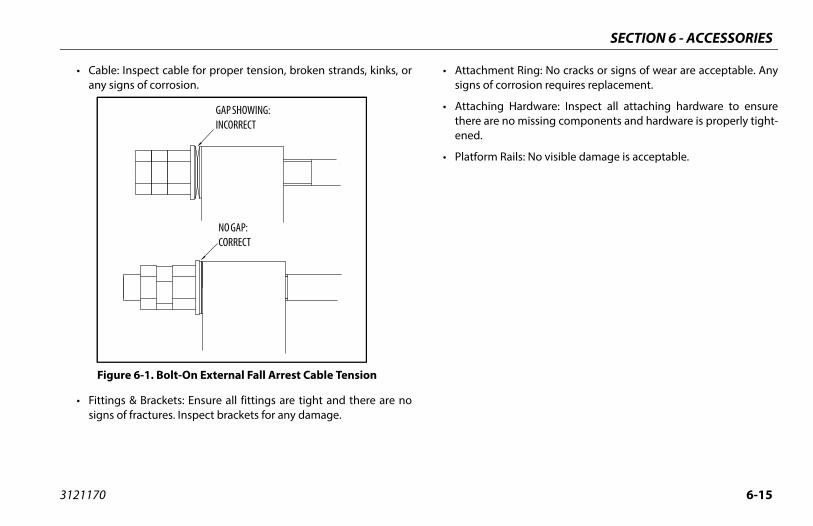
SECTION 6 - ACCESSORIES
6-15
ment Ring: No cracks or signs of wear are acceptable. Anyf corrosion requires replacement.
ing Hardware: Inspect all attaching hardware to ensurere no missing components and hardware is properly tight-
m Rails: No visible damage is acceptable.
3121170
• Cable: Inspect cable for proper tension, broken strands, kinks, orany signs of corrosion.
• Fittings & Brackets: Ensure all fittings are tight and there are nosigns of fractures. Inspect brackets for any damage.
• Attachsigns o
• Attachthere aened.
• Platfor
NO GAP: CORRECT
GAP SHOWING: INCORRECT
Figure 6-1. Bolt-On External Fall Arrest Cable Tension
GAP SHOWING:INCORRECT
NO GAP:CORRECT

SECTION 6 - ACCESSORIES
6-1 3121170
I
stem
1. Belleville Washer2. Washer3. Hex Nut4. Jam Nut5. LH Bracket6. Attachment Ring7. Cable8. RH Bracket9. Decal
6
8
71,2,3,4
6
9
5
Figure 6-2. Bolt-On External Fall Arrest Sy

PECIFICATIONS & OPERATOR MAINTENANCE
7-1
PERATOR MAINTENANCE
RATING SPECIFICATIONS AND PERFORMANCE A
. Operating Specifications - Prior to S/N 0300141446
Load (Capacity)500 lb (230 kg)1000 lb. (450 kg)
tform Height (Unrestricted) 125 ft. (38.1 m)
tform Height (Restricted) 125 ft. (38.1 m)
Platform Reach (Unrestricted) 63 ft. 2 in. (19.3 m)
Platform Reach (Restricted) 53 ft. 2 in. (16.2 m)
ght 60 ft. 7 in. (18.5 m)
ge (At Maximum Up & Over) +75° / -55°
Swing 360° Continuous
tionn
8ft. (2.44m)125° working, 210° stowed130° (+75/-55)
ystem Pressure 4600 psi (317 Bar)
SECTION 7 - GENERAL S
3121170
SECTION 7. GENERAL SPECIFICATIONS & O
7.1 INTRODUCTIONThis section of the manual provides additional necessary infor-mation to the operator for proper operation and maintenance ofthis machine.
The maintenance portion of this section is intended as informa-tion to assist the machine operator to perform daily maintenancetasks only, and does not replace the more thorough PreventiveMaintenance and Inspection Schedule included in the Serviceand Maintenance Manual.
Other Publications Available:
Service and Maintenance Manual .............................................3121171
Illustrated Parts Manual (Prior to SN 0300201017)..............3121172
Illustrated Parts Manual (SN 0300201017 to Present) ........3121737
Troubleshooting Guide .................................................................3128411
Troubleshooting CD .......................................................................3128444
7.2 OPEDAT
Table 7-1
Maximum Work Unrestricted Restricted
Max.Vertical Pla
Max.Vertical Pla
Max.Horizontal
Max.Horizontal
Up and Over Hei
Main Boom Ran
Maximum Boom
JibPLUS Length Horizontal Mo Vertical Motio
Max. Hydraulic S

SECTION 7 - GENERAL SPECIFICATIONS & OPERATOR MAINTENANCE
7-2 3121170
Max
Max
Elec
Max
Max
Ta
Max Un Re
MaxCE & Un Re
Max
Max
Max
Max
Up a
Mai
Max
T
8ft. (2.44m)125° working, 210° stowed130° (+75/-55)
Pressure 4600 psi (317 Bar)
28 mph (12.5 m/s)
ce 400 N
ge 12 Volts
23,700 lbs. (10750 kg)
tation ±90°
ating Specifications - S/N 0300141446 to Present
imum Wind Speed 28 mph (12.5 m/s)
imum Manual Force 400 N
trical System Voltage 12 Volts
Tire Load 23,700 lbs. (10750 kg)
imum Platform Rotation ±90°
ble 7-2. Operating Specifications - S/N 0300141446 to Present
imum Work Load (Capacity) - ANSIrestrictedstricted
500 lb (227 kg)1000 lb. (454 kg)
imum Work Load (Capacity)- Australiarestrictedstricted
500 lb (230 kg)1000 lb. (450 kg)
.Vertical Platform Height (Unrestricted) 125 ft. (38.1 m)
.Vertical Platform Height (Restricted) 125 ft. (38.1 m)
.Horizontal Platform Reach (Unrestricted) 63 ft. 2 in. (19.3 m)
.Horizontal Platform Reach (Restricted) 53 ft. 2 in. (16.2 m)
nd Over Height 60 ft. 7 in. (18.5 m)
n Boom Range (At Maximum Up & Over) +75° / -55°
imum Boom Swing 360° Continuous
able 7-1. Operating Specifications - Prior to S/N 0300141446
JibPLUS Length Horizontal Motion Vertical Motion
Max. Hydraulic System
Maximum Wind Speed
Maximum Manual For
Electrical System Volta
Max Tire Load
Maximum Platform Ro
Table 7-2. Oper
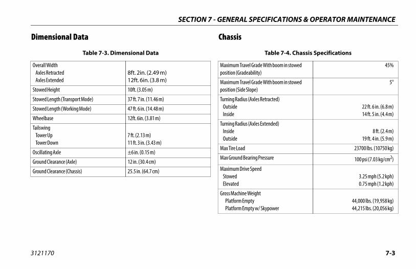
PECIFICATIONS & OPERATOR MAINTENANCE
7-3
Table 7-4. Chassis Specifications
l Grade With boom in stowed bility)
45%
l Grade With boom in stowed ope)
5°
Axles Retracted)22 ft. 6 in. (6.8 m)14 ft. 5 in. (4.4 m)
Axles Extended)8 ft. (2.4 m)
19 ft. 4 in. (5.9 m)
23700 lbs. (10750 kg)
ring Pressure 100 psi (7.03 kg/cm2)
Speed3.25 mph (5.2 kph)0.75 mph (1.2 kph)
eighttyty w/ Skypower
44,000 lbs. (19,958 kg)44,215 lbs. (20,056 kg)
SECTION 7 - GENERAL S
3121170
Dimensional Data Chassis
Table 7-3. Dimensional Data
Overall Width Axles Retracted Axles Extended
8ft. 2in. (2.49 m)12ft. 6in. (3.8 m)
Stowed Height 10ft. (3.05 m)
Stowed Length (Transport Mode) 37 ft. 7 in. (11.46 m)
Stowed Length (Working Mode) 47 ft. 6 in. (14.48 m)
Wheelbase 12ft. 6in. (3.81 m)
Tailswing Tower Up Tower Down
7 ft. (2.13 m)11 ft. 3 in. (3.43 m)
Oscillating Axle ±6 in. (0.15 m)
Ground Clearance (Axle) 12 in. (30.4 cm)
Ground Clearance (Chassis) 25.5 in. (64.7 cm)
Maximum Traveposition (Gradea
Maximum Traveposition (Side Sl
Turning Radius ( Outside Inside
Turning Radius ( Inside Outside
Max Tire Load
Max Ground Bea
Maximum Drive Stowed Elevated
Gross Machine W Platform Emp Platform Emp

SECTION 7 - GENERAL SPECIFICATIONS & OPERATOR MAINTENANCE
7-4 3121170
CapTable 7-6. Tire Specifications
445/50D710
J
18
Polyurethane HD (55 Durometer) Foam
46.45 in. (117.9 cm)
18 in. (45.7 cm)
15x28
ht 867 lbs. (393 kg)
23,700 lbs. (10750 kg)
445/65-24
Solid
45.3 in. (115.1 cm)
17.3 in. (43.9 cm)
12.00-24
ht 960 lbs. (435.4 kg)
23,700 lbs. (10750 kg)
acities Tires
Table 7-5. Capacities
Hydraulic Tank 53.3 gallons (201.7 liters)
Fuel Tank 31 gallons (117 liters)
Hydraulic System 65.4 gallons (247.5 liters)
Drive Hub Bonfiglioli Reggiana Riduttori
2.1 quarts (2 liters) ± 10%0.5 quarts (0.5 liters) ± 10%
Size
Load Range
Ply Rating
Foam Fill
Diameter
Width
Rim Size
Tire & Wheel Weig
Max Tire Load
Size
Type
Diameter
Width
Rim Size
Tire & Wheel Weig
Max Tire Load
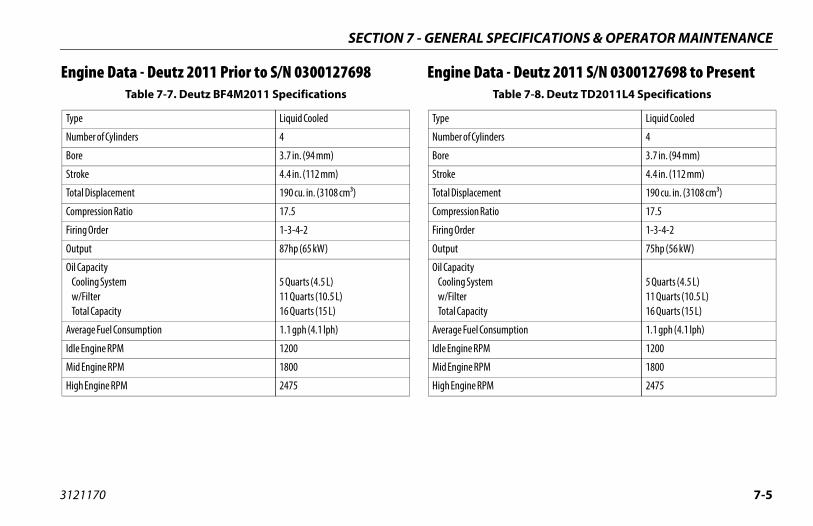
PECIFICATIONS & OPERATOR MAINTENANCE
7-5
ta - Deutz 2011 S/N 0300127698 to Present Table 7-8. Deutz TD2011L4 Specifications
Liquid Cooled
ders 4
3.7 in. (94 mm)
4.4 in. (112 mm)
ent 190 cu. in. (3108 cm³)
tio 17.5
1-3-4-2
75hp (56 kW)
5 Quarts (4.5 L) 11 Quarts (10.5 L) 16 Quarts (15 L)
nsumption 1.1 gph (4.1 lph)
1200
1800
2475
SECTION 7 - GENERAL S
3121170
Engine Data - Deutz 2011 Prior to S/N 0300127698 Engine DaTable 7-7. Deutz BF4M2011 Specifications
Type Liquid Cooled
Number of Cylinders 4
Bore 3.7 in. (94 mm)
Stroke 4.4 in. (112 mm)
Total Displacement 190 cu. in. (3108 cm³)
Compression Ratio 17.5
Firing Order 1-3-4-2
Output 87hp (65 kW)
Oil Capacity Cooling System w/Filter Total Capacity
5 Quarts (4.5 L) 11 Quarts (10.5 L) 16 Quarts (15 L)
Average Fuel Consumption 1.1 gph (4.1 lph)
Idle Engine RPM 1200
Mid Engine RPM 1800
High Engine RPM 2475
Type
Number of Cylin
Bore
Stroke
Total Displacem
Compression Ra
Firing Order
Output
Oil Capacity Cooling System w/Filter Total Capacity
Average Fuel Co
Idle Engine RPM
Mid Engine RPM
High Engine RPM
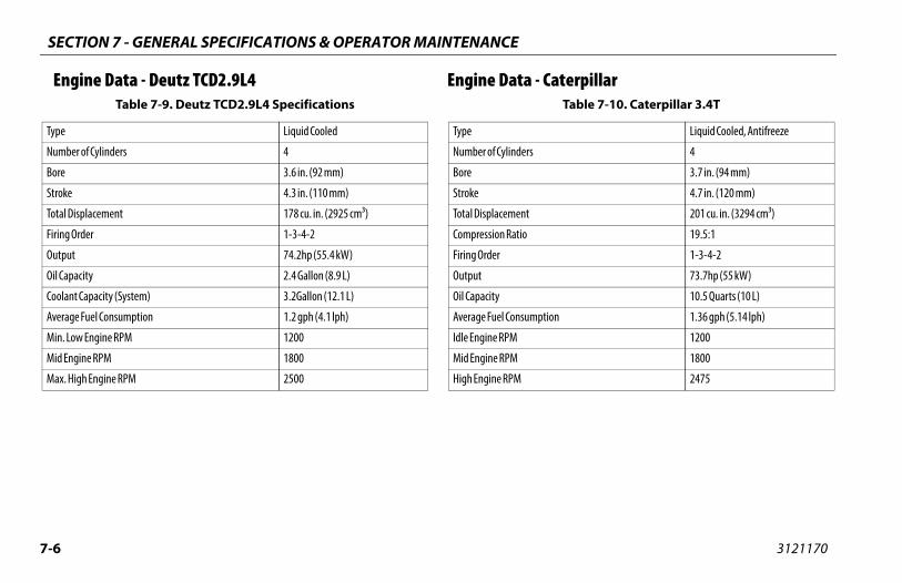
SECTION 7 - GENERAL SPECIFICATIONS & OPERATOR MAINTENANCE
7-6 3121170
E Caterpillar
Type
Num
Bore
Stro
Tota
Firin
Out
Oil C
Coo
Ave
Min
Mid
Max
Table 7-10. Caterpillar 3.4T
Liquid Cooled, Antifreeze
4
3.7 in. (94 mm)
4.7 in. (120 mm)
201 cu. in. (3294 cm³)
19.5:1
1-3-4-2
73.7hp (55 kW)
10.5 Quarts (10 L)
tion 1.36 gph (5.14 lph)
1200
1800
2475
ngine Data - Deutz TCD2.9L4 Engine Data - Table 7-9. Deutz TCD2.9L4 Specifications
Liquid Cooled
ber of Cylinders 4
3.6 in. (92 mm)
ke 4.3 in. (110 mm)
l Displacement 178 cu. in. (2925 cm³)
g Order 1-3-4-2
put 74.2hp (55.4 kW)
apacity 2.4 Gallon (8.9 L)
lant Capacity (System) 3.2Gallon (12.1 L)
rage Fuel Consumption 1.2 gph (4.1 lph)
. Low Engine RPM 1200
Engine RPM 1800
. High Engine RPM 2500
Type
Number of Cylinders
Bore
Stroke
Total Displacement
Compression Ratio
Firing Order
Output
Oil Capacity
Average Fuel Consump
Idle Engine RPM
Mid Engine RPM
High Engine RPM
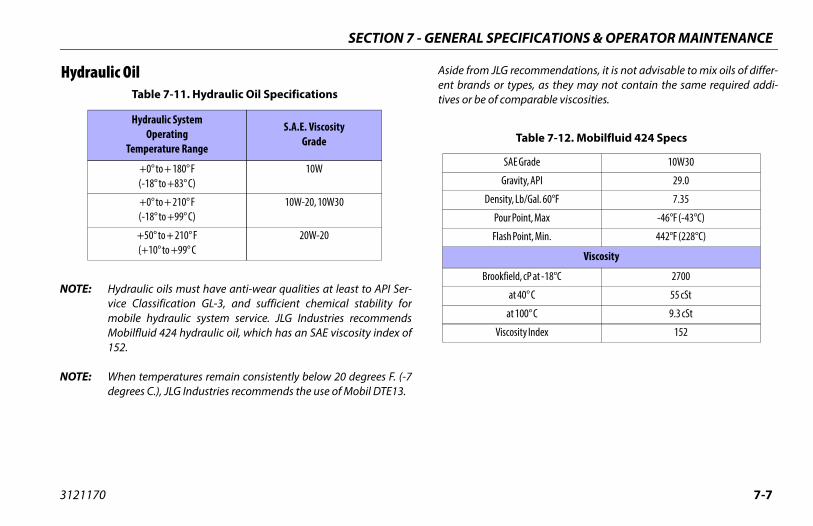
PECIFICATIONS & OPERATOR MAINTENANCE
7-7
JLG recommendations, it is not advisable to mix oils of differ- or types, as they may not contain the same required addi-
of comparable viscosities.
Table 7-12. Mobilfluid 424 Specs
SAE Grade 10W30
Gravity, API 29.0
ensity, Lb/Gal. 60°F 7.35
Pour Point, Max -46°F (-43°C)
Flash Point, Min. 442°F (228°C)
Viscosity
rookfield, cP at -18°C 2700
at 40° C 55 cSt
at 100° C 9.3 cSt
Viscosity Index 152
SECTION 7 - GENERAL S
3121170
Hydraulic Oil
NOTE: Hydraulic oils must have anti-wear qualities at least to API Ser-vice Classification GL-3, and sufficient chemical stability formobile hydraulic system service. JLG Industries recommendsMobilfluid 424 hydraulic oil, which has an SAE viscosity index of152.
NOTE: When temperatures remain consistently below 20 degrees F. (-7degrees C.), JLG Industries recommends the use of Mobil DTE13.
Aside froment brandstives or be Table 7-11. Hydraulic Oil Specifications
Hydraulic SystemOperating
Temperature Range
S.A.E. ViscosityGrade
+0° to + 180° F(-18° to +83° C)
10W
+0° to + 210° F(-18° to +99° C)
10W-20, 10W30
+50° to + 210° F(+10° to +99° C
20W-20
D
B
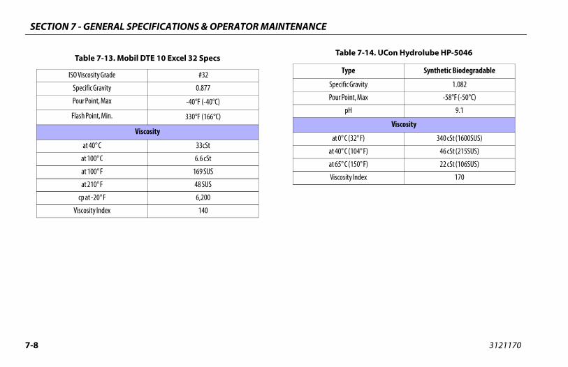
SECTION 7 - GENERAL SPECIFICATIONS & OPERATOR MAINTENANCE
7-8 3121170
ble 7-14. UCon Hydrolube HP-5046
Type Synthetic Biodegradable
ific Gravity 1.082
Point, Max -58°F (-50°C)
pH 9.1
Viscosity
° C (32° F) 340 cSt (1600SUS)
° C (104° F) 46 cSt (215SUS)
° C (150° F) 22 cSt (106SUS)
sity Index 170
Table 7-13. Mobil DTE 10 Excel 32 Specs
ISO Viscosity Grade #32
Specific Gravity 0.877
Pour Point, Max -40°F (-40°C)
Flash Point, Min. 330°F (166°C)
Viscosity
at 40° C 33cSt
at 100° C 6.6 cSt
at 100° F 169 SUS
at 210° F 48 SUS
cp at -20° F 6,200
Viscosity Index 140
Ta
Spec
Pour
at 0
at 40
at 65
Visco
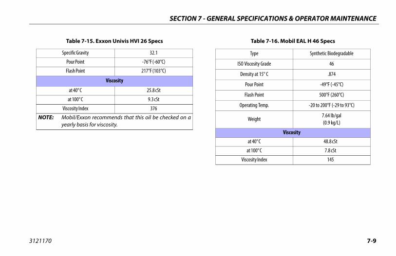
PECIFICATIONS & OPERATOR MAINTENANCE
7-9
Table 7-16. Mobil EAL H 46 Specs
Type Synthetic Biodegradable
ISO Viscosity Grade 46
Density at 15° C .874
Pour Point -49°F (-45°C)
Flash Point 500°F (260°C)
Operating Temp. -20 to 200°F (-29 to 93°C)
Weight7.64 lb/gal(0.9 kg/L)
Viscosity
at 40° C 48.8 cSt
at 100° C 7.8 cSt
Viscosity Index 145
SECTION 7 - GENERAL S
3121170
Table 7-15. Exxon Univis HVI 26 Specs
Specific Gravity 32.1
Pour Point -76°F (-60°C)
Flash Point 217°F (103°C)
Viscosity
at 40° C 25.8 cSt
at 100° C 9.3 cSt
Viscosity Index 376
NOTE: Mobil/Exxon recommends that this oil be checked on ayearly basis for viscosity.
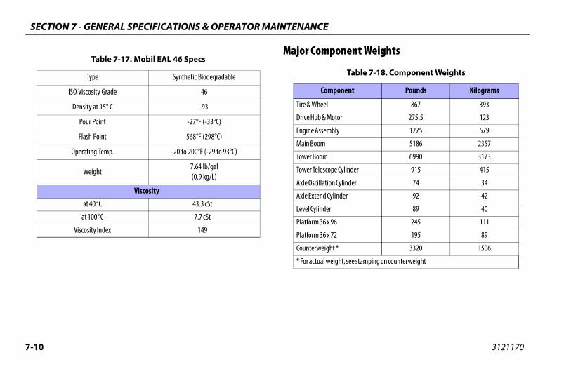
SECTION 7 - GENERAL SPECIFICATIONS & OPERATOR MAINTENANCE
7-1 3121170
ent Weights
Table 7-18. Component Weights
ent Pounds Kilograms
867 393
275.5 123
1275 579
5186 2357
6990 3173
linder 915 415
inder 74 34
er 92 42
89 40
245 111
195 89
3320 1506
, see stamping on counterweight
0
Major ComponTable 7-17. Mobil EAL 46 Specs
Type Synthetic Biodegradable
ISO Viscosity Grade 46
Density at 15° C .93
Pour Point -27°F (-33°C)
Flash Point 568°F (298°C)
Operating Temp. -20 to 200°F (-29 to 93°C)
Weight7.64 lb/gal(0.9 kg/L)
Viscosity
at 40° C 43.3 cSt
at 100° C 7.7 cSt
Viscosity Index 149
Compon
Tire & Wheel
Drive Hub & Motor
Engine Assembly
Main Boom
Tower Boom
Tower Telescope Cy
Axle Oscillation Cyl
Axle Extend Cylind
Level Cylinder
Platform 36 x 96
Platform 36 x 72
Counterweight *
* For actual weight
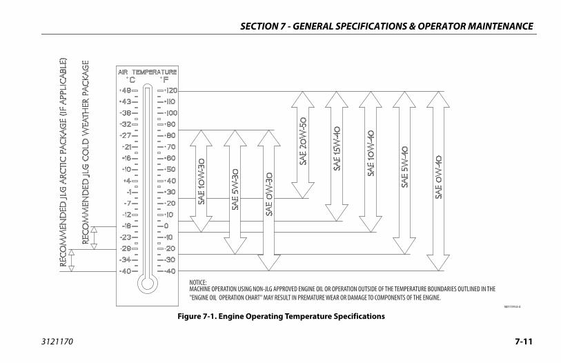
PECIFICATIONS & OPERATOR MAINTENANCE
7-11
pecifications
SECTION 7 - GENERAL S
3121170
Figure 7-1. Engine Operating Temperature S

SECTION 7 - GENERAL SPECIFICATIONS & OPERATOR MAINTENANCE
7-1 3121170
MACHINE OPERATION USING NON-JLG APPROVEDHYDRAULIC FLUIDS OR OPERATION OUTSIDE OFTHE TEMPERATURE BOUNDARIES OUTLINED INTHE "HYDRAULIC FLUID OPERATION CHART" MAYRESULT IN PREMATURE WEAR OR DAMAGE TOCOMPONENTS OF THE HYDRAULIC SYSTEM.
eet 1 of 2
2
HYDRAULIC FLUID OPERATION CHART
Figure 7-2. Hydraulic Oil Operation Chart - Sh
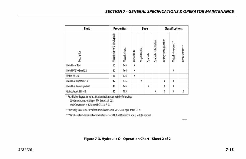
PECIFICATIONS & OPERATOR MAINTENANCE
7-13
t - Sheet 2 of 2
Classifications
Synt
hetic
Synt
hetic
Polyo
l Este
rs
Read
ily Bi
odeg
rada
ble*
Virtu
ally N
on-to
xic**
Fire R
esist
ant*
**
X
X X
X X X
X X X X
val4150740 B
SECTION 7 - GENERAL S
3121170
Figure 7-3. Hydraulic Oil Operation Char
Fluid Properties Base
Desc
riptio
n
Visco
sity a
t 40°
C (cS
t, Typ
ical)
Visco
sity I
ndex
Mine
ral O
ils
Vege
table
Oils
Mobilfluid 424 55 145 X
Mobil DTE 10 Excel 32 32 164 X
Univis HVI 26 26 376 X
Mobil EAL Hydraulic Oil 47 176 X
Mobil EAL Envirosyn H46 49 145
Quintolubric 888-46 50 185
* Readily biodegradable classification indicates one of the following: CO2 Conversion > 60% per EPA 560/6-82-003 CO2 Conversion > 80% per CEC-L-33-A-93
** Virtually Non-toxic classification indicates an LC50 > 5000 ppm per OECD 203
*** Fire Resistant classification indicates Factory Mutual Research Corp. (FMRC) Appro
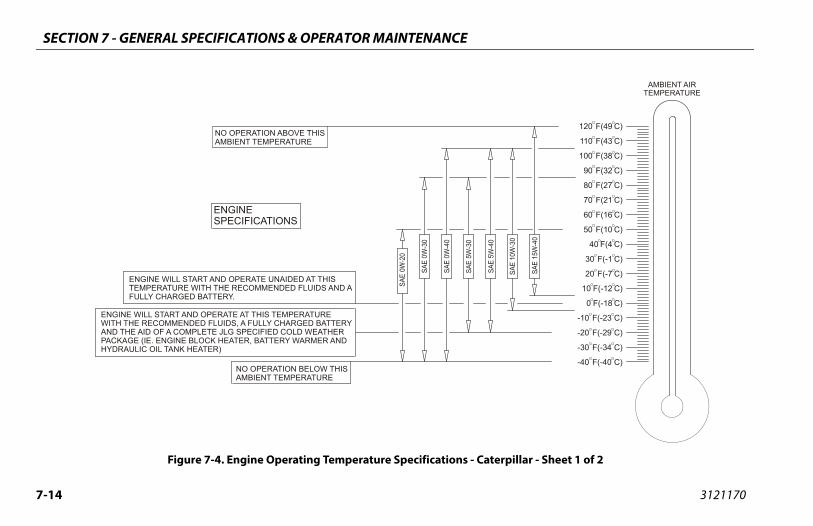
SECTION 7 - GENERAL SPECIFICATIONS & OPERATOR MAINTENANCE
7-1 3121170
-40 F(-40 C)
-30 F(-34 C)
-20 F(-29 C)
-10 F(-23 C)
0 F(-18 C)
10 F(-12 C)
20 F(-7 C)
30 F(-1 C)
40 F(4 C)
50 F(10 C)
60 F(16 C)
70 F(21 C)
80 F(27 C)
90 F(32 C)
100 F(38 C)
110 F(43 C)
120 F(49 C)
AMBIENT AIRTEMPERATURE
terpillar - Sheet 1 of 2
4
ENGINESPECIFICATIONS
ENGINE WILL START AND OPERATE AT THIS TEMPERATUREWITH THE RECOMMENDED FLUIDS, A FULLY CHARGED BATTERYAND THE AID OF A COMPLETE JLG SPECIFIED COLD WEATHERPACKAGE (IE. ENGINE BLOCK HEATER, BATTERY WARMER ANDHYDRAULIC OIL TANK HEATER)
ENGINE WILL START AND OPERATE UNAIDED AT THISTEMPERATURE WITH THE RECOMMENDED FLUIDS AND AFULLY CHARGED BATTERY.
NO OPERATION BELOW THISAMBIENT TEMPERATURE
NO OPERATION ABOVE THISAMBIENT TEMPERATURE
Figure 7-4. Engine Operating Temperature Specifications - Ca
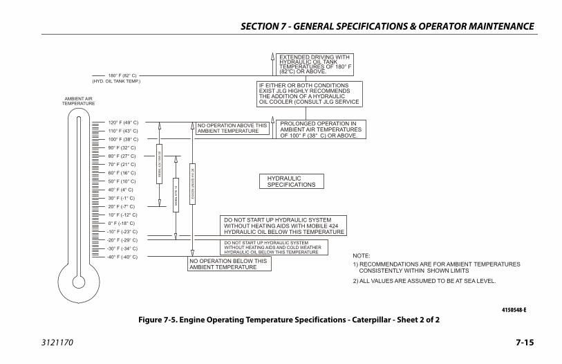
PECIFICATIONS & OPERATOR MAINTENANCE
7-15
ONSNDSICERVICE
ION INATURES
ABOVE.
ITH
80° F
RE
NOTE: 1) RECOMMENDATIONS ARE FOR AMBIENT TEMPERATURES CONSISTENTLY WITHIN SHOWN LIMITS
2) ALL VALUES ARE ASSUMED TO BE AT SEA LEVEL.
ns - Caterpillar - Sheet 2 of 24150548-E
SECTION 7 - GENERAL S
3121170
(HYD. OIL TANK TEMP.)IF EITHER OR BOTH CONDITIEXIST JLG HIGHLY RECOMMETHE ADDITION OF A HYDRAULOIL COOLER (CONSULT JLG S
180° F (82° C)
PROLONGED OPERATAMBIENT AIR TEMPEROF 100° F (38° C) OR
EXTENDED DRIVING WHYDRAULIC OIL TANKTEMPERATURES OF 1(82°C) OR ABOVE.
NO OPERATION BELOW THISAMBIENT TEMPERATURE
MO
BIL
424
10W
-30
HYDRAULICSPECIFICATIONS
NO OPERATION ABOVE THISAMBIENT TEMPERATURE
DO NOT START UP HYDRAULIC SYSTEM WITHOUT HEATING AIDS WITH MOBILE 424HYDRAULIC OIL BELOW THIS TEMPERATU
DO NOT START UP HYDRAULIC SYSTEM WITHOUT HEATING AIDS AND COLD WEATHERHYDRAULIC OIL BELOW THIS TEMPERATURE
EXXO
N U
NIV
IS H
VI 2
6
MO
BIL
DTE
13
-40° F (-40° C)
-30° F (-34° C)
-20° F (-29° C)
-10° F (-23° C)
0° F (-18° C)
10° F (-12° C)
20° F (-7° C)
30° F (-1° C)
40° F (4° C)
50° F (10° C)
60° F (16° C)
70° F (21° C)
80° F (27° C)
90° F (32° C)
100° F (38° C)
110° F (43° C)
120° F (49° C)
AMBIENT AIRTEMPERATURE
Figure 7-5. Engine Operating Temperature Specificatio
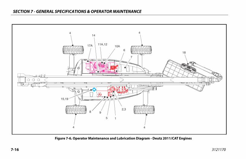
SECTION 7 - GENERAL SPECIFICATIONS & OPERATOR MAINTENANCE
7-1 3121170
- Deutz 2011/CAT Engines
18
6
Figure 7-6. Operator Maintenance and Lubrication Diagram
44
44
5
8
15,19
9
1
11A,1210A
14
2,3
6
7
17A
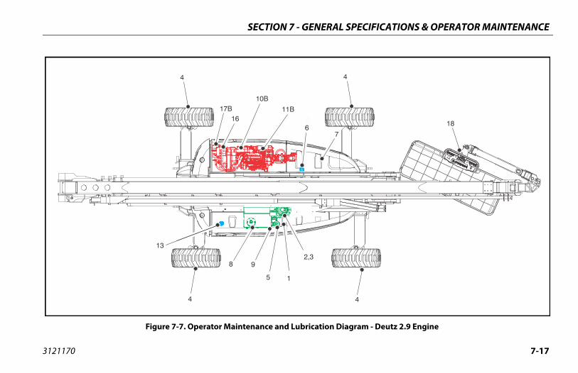
PECIFICATIONS & OPERATOR MAINTENANCE
7-17
gram - Deutz 2.9 Engine
4
18
SECTION 7 - GENERAL S
3121170
Figure 7-7. Operator Maintenance and Lubrication Dia
44
4
5
8
13
9
1
11B
10B
2,3
67
17B16
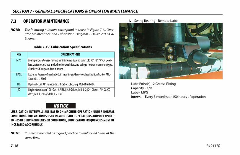
SECTION 7 - GENERAL SPECIFICATIONS & OPERATOR MAINTENANCE
7-1 3121170
7.3
NOT
LUBRCONDTO HINCR
NOT
Bearing - Remote Lube
nt(s) - 2 Grease Fitting - A/RPG Every 3 months or 150 hours of operation
8
OPERATOR MAINTENANCE
E: The following numbers correspond to those in Figure 7-6., Oper-ator Maintenance and Lubrication Diagram - Deutz 2011/CATEngines.
ICATION INTERVALS ARE BASED ON MACHINE OPERATION UNDER NORMALITIONS. FOR MACHINES USED IN MULTI-SHIFT OPERATIONS AND/OR EXPOSED
OSTILE ENVIRONMENTS OR CONDITIONS, LUBRICATION FREQUENCIES MUST BEEASED ACCORDINGLY.
E: It is recommended as a good practice to replace all filters at thesame time.
1. Swing
Lube PoiCapacityLube - MInterval -
Table 7-19. Lubrication Specifications
KEY SPECIFICATIONS
MPG Multipurpose Grease having a minimum dripping point of 350° F (177° C). Excel-lent water resistance and adhesive qualities, and being of extreme pressure type. (Timken OK 40 pounds minimum.)
EPGL Extreme Pressure Gear Lube (oil) meeting API service classification GL-5 or MIL-Spec MIL-L-2105
HO Hydraulic Oil. API service classification GL-3, e.g. Mobilfluid 424.
EO Engine (crankcase) Oil. Gas - API SF, SH, SG class, MIL-L-2104. Diesel - API CC/CD class, MIL-L-2104B/MIL-L-2104C.
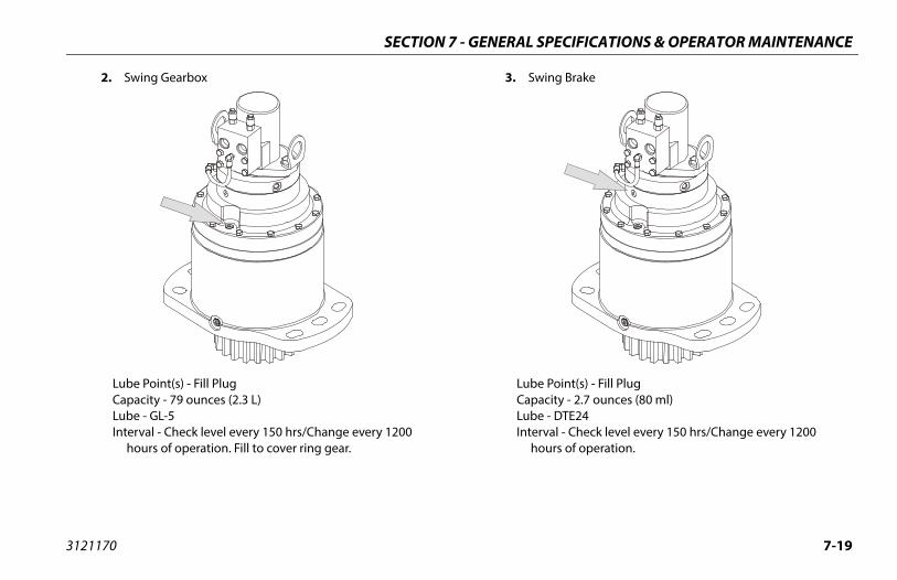
PECIFICATIONS & OPERATOR MAINTENANCE
7-19
ing Brake
e Point(s) - Fill Plugacity - 2.7 ounces (80 ml)e - DTE24rval - Check level every 150 hrs/Change every 1200ours of operation.
SECTION 7 - GENERAL S
3121170
2. Swing Gearbox
Lube Point(s) - Fill PlugCapacity - 79 ounces (2.3 L)Lube - GL-5Interval - Check level every 150 hrs/Change every 1200 hours of operation. Fill to cover ring gear.
3. Sw
LubCapLubInte h

SECTION 7 - GENERAL SPECIFICATIONS & OPERATOR MAINTENANCE
7-2 3121170
NOT
Drive Hub - Bonfiglioli (S/N 100128 to Present)
nt(s) - Level/Fill Plug - 2.1 quarts (2 liters) ± 10%GL Change after first 150 hours then every 1200 hourserationts - Place Fill port at 12 o’clock position and Check
at 8 o’clock position. Pour lubricant into fill port until ittarts to flow out of check port.
0
4. A. Wheel Drive Hub (Prior to S/N 100128)
Lube Point(s) - Level/Fill PlugCapacity - 0.5 liters (1/2 full)Lube - EPGLInterval - Change after first 150 hours then every 1200 hours of operationComments - Place Fill port at 12 o’clock position and Checkport at 3 o’clock position. Pour lubricant into fill port until itjust starts to flow out of check port.
E: After S/N 0300134389 machines may be built with either Bonfigli-oli or Reggiana Riduttori wheel drive hubs.
B: Wheel
Lube PoiCapacityLube - EPInterval -
of opCommen
port just s
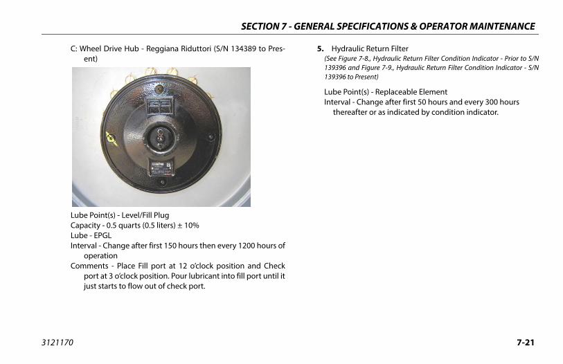
PECIFICATIONS & OPERATOR MAINTENANCE
7-21
draulic Return FilterFigure 7-8., Hydraulic Return Filter Condition Indicator - Prior to S/N96 and Figure 7-9., Hydraulic Return Filter Condition Indicator - S/N96 to Present)
e Point(s) - Replaceable Elementrval - Change after first 50 hours and every 300 hoursereafter or as indicated by condition indicator.
SECTION 7 - GENERAL S
3121170
C: Wheel Drive Hub - Reggiana Riduttori (S/N 134389 to Pres-ent)
Lube Point(s) - Level/Fill PlugCapacity - 0.5 quarts (0.5 liters) ± 10%Lube - EPGLInterval - Change after first 150 hours then every 1200 hours of
operationComments - Place Fill port at 12 o’clock position and Check
port at 3 o’clock position. Pour lubricant into fill port until itjust starts to flow out of check port.
5. Hy(See 13931393
LubInte th
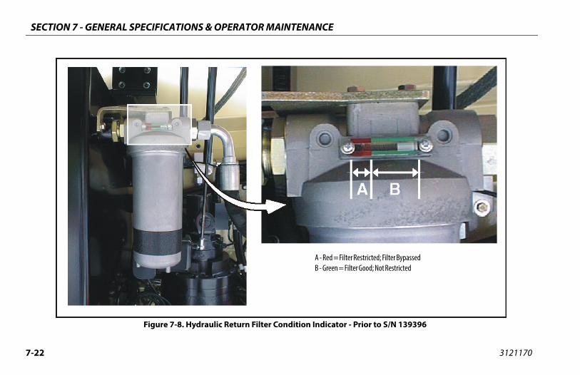
SECTION 7 - GENERAL SPECIFICATIONS & OPERATOR MAINTENANCE
7-2 3121170
er Restricted; Filter Bypassedilter Good; Not Restricted
- Prior to S/N 139396
2
A - Red = FiltB - Green = F
Figure 7-8. Hydraulic Return Filter Condition Indicator
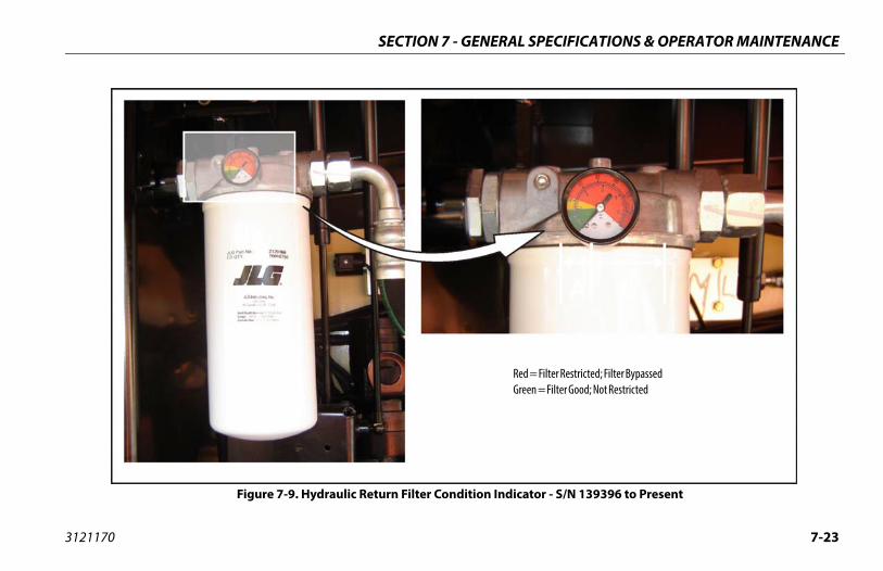
PECIFICATIONS & OPERATOR MAINTENANCE
7-23
= Filter Restricted; Filter Bypassedn = Filter Good; Not Restricted
tor - S/N 139396 to Present
SECTION 7 - GENERAL S
3121170
Red Gree
Figure 7-9. Hydraulic Return Filter Condition Indica

SECTION 7 - GENERAL SPECIFICATIONS & OPERATOR MAINTENANCE
7-2 3121170
or
nt(s) - Replaceable Element Change after first 50 hours and every 300 hourster or as indicated by condition indicator
ped)
4
6. Hydraulic Charge Filter
Lube PoiInterval - thereaf (if equip
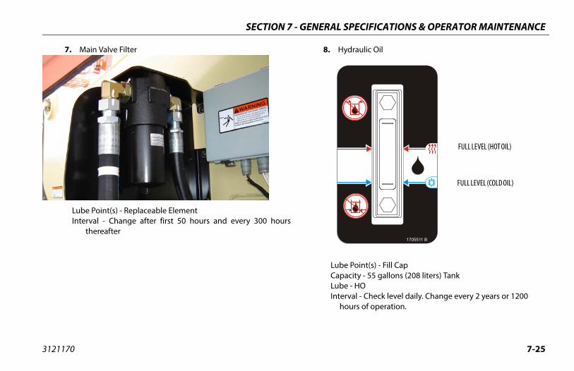
PECIFICATIONS & OPERATOR MAINTENANCE
7-25
draulic Oil
e Point(s) - Fill Capacity - 55 gallons (208 liters) Tanke - HOrval - Check level daily. Change every 2 years or 1200ours of operation.
1705511 B
FULL LEVEL (HOT OIL)
FULL LEVEL (COLD OIL)
SECTION 7 - GENERAL S
3121170
7. Main Valve Filter
Lube Point(s) - Replaceable ElementInterval - Change after first 50 hours and every 300 hours
thereafter
8. Hy
LubCapLubInte h

SECTION 7 - GENERAL SPECIFICATIONS & OPERATOR MAINTENANCE
7-2 3121170
hange w/Filter - Deutz 2011
nt(s) - Fill Cap/Spin-on Element - 11 Quarts (10.5 L) w/Filter
- Check level daily; change every 500 hours or sixs, whichever comes first. Adjust final oil level by markstick.
6
9. Suction Strainers (In Tank)
Lube Point(s) - 2Interval - Every 2 years or 1200 hours of operation. Remove and clean at time of hydraulic oil change.
10. A. Oil C
Lube PoiCapacityLube - EOInterval
monthon dip
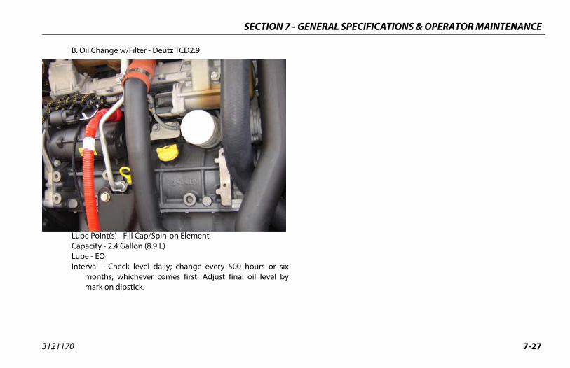
PECIFICATIONS & OPERATOR MAINTENANCE
7-27
SECTION 7 - GENERAL S
3121170
B. Oil Change w/Filter - Deutz TCD2.9
Lube Point(s) - Fill Cap/Spin-on ElementCapacity - 2.4 Gallon (8.9 L)Lube - EOInterval - Check level daily; change every 500 hours or six
months, whichever comes first. Adjust final oil level bymark on dipstick.
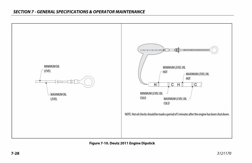
SECTION 7 - GENERAL SPECIFICATIONS & OPERATOR MAINTENANCE
7-2 3121170
ck
uld be made a period of 5 minutes after the engine has been shut down.
MINIMUM LEVEL OIL HOT MAXIMUM LEVEL OIL
HOT
LEVEL OIL MAXIMUM LEVEL OIL COLD
8
Figure 7-10. Deutz 2011 Engine Dipsti
MAXIMUM OIL LEVEL
NOTE: Hot oil checks sho
MINIMUMCOLD
MINIMUM OIL LEVEL
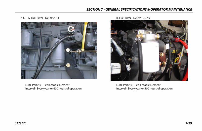
PECIFICATIONS & OPERATOR MAINTENANCE
7-29
el Filter - Deutz TCD2.9
e Point(s) - Replaceable Elementrval - Every year or 500 hours of operation
SECTION 7 - GENERAL S
3121170
11. A. Fuel Filter - Deutz 2011
Lube Point(s) - Replaceable ElementInterval - Every year or 600 hours of operation
B. Fu
LubInte
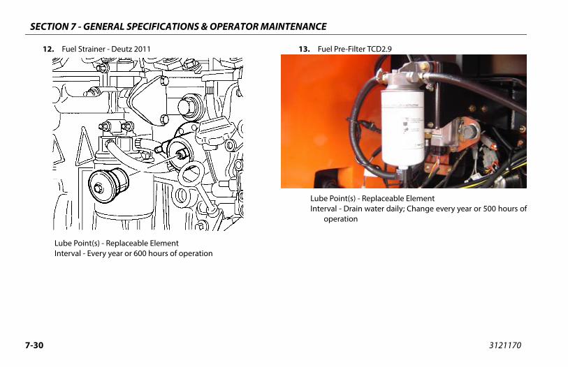
SECTION 7 - GENERAL SPECIFICATIONS & OPERATOR MAINTENANCE
7-3 3121170
e-Filter TCD2.9
nt(s) - Replaceable Element Drain water daily; Change every year or 500 hours oftion
0
12. Fuel Strainer - Deutz 2011
Lube Point(s) - Replaceable ElementInterval - Every year or 600 hours of operation
13. Fuel Pr
Lube PoiInterval -
opera

PECIFICATIONS & OPERATOR MAINTENANCE
7-31
el Filter/Water Separator - CAT
e Point(s) - Replaceable Elementrval - Drain water daily; Replace element every year or 600rs of operation
SECTION 7 - GENERAL S
3121170
14. Oil Change w/Filter - CAT
Lube Point(s) - Fill Cap/Spin-on Element (element can be accessed from below engine tray)Capacity - 10.5 Quarts (10 L)Lube - EOInterval - Check level daily; change every 150 hours or three
months, whichever comes first. Adjust final oil level by markon dipstick.
15. Fu
LubIntehou
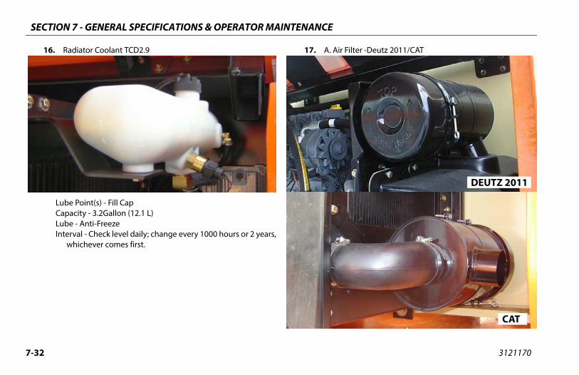
SECTION 7 - GENERAL SPECIFICATIONS & OPERATOR MAINTENANCE
7-3 3121170
ilter -Deutz 2011/CAT
DEUTZ 2011
CAT
2
16. Radiator Coolant TCD2.9
Lube Point(s) - Fill CapCapacity - 3.2Gallon (12.1 L)Lube - Anti-FreezeInterval - Check level daily; change every 1000 hours or 2 years,
whichever comes first.
17. A. Air F
PECIFICATIONS & OPERATOR MAINTENANCE
7-33
e Point(s) - Replaceable Elementrval - Every 6 months or 300 hours of operation or as indi-cated by the condition indicatorments - Check Dust Valve daily
atform Filter
e Point(s) - Replaceable Elementrval - Change after first 50 hours and then every year or600 hours of operation thereafter
SECTION 7 - GENERAL S
3121170
Lube Point(s) - Replaceable ElementInterval - Every 6 months or 300 hours of operation or as indicated by the condition indicator
B. Air Filter - Deutz TCD2.9
LubInte
Com
18. Pl
LubInte
SECTION 7 - GENERAL SPECIFICATIONS & OPERATOR MAINTENANCE
7-3 3121170
WHEELS
sure for pneumatic tires must be equal to the air pres-stenciled on the side of the JLG product or rim decal proper operational characteristics.
tires, JLG Industries, Inc. recommends that when anyis discovered that exposes sidewall or tread area cordssures must be taken to remove the JLG product fromiately. Arrangements must be made for replacemente assembly.
ne foam filled tires, JLG Industries, Inc. recommends of the following are discovered, measures must beve the JLG product from service immediately andmust be made for replacement of the tire or tire
ooth, even cut through the cord plies which exceeds 3s (7.5 cm) in total length
ears or rips (ragged edges) in the cord plies whicheds 1 inch (2.5 cm) in any direction
unctures which exceed 1 inch in diameter
4
19. Optional Fuel Filter/Water Separator
Lube Point(s) - Replaceable ElementInterval - Drain water daily; Change every year or 600 hours of
operation
7.4 TIRES &
Tire InflationThe air pressure that is for safe and
Tire Damage
For pneumaticcut, rip, or tear in the tire, measervice immedof the tire or tir
For polyurethathat when anytaken to remoarrangements assembly.
• a sminche
• any texce
• any p
PECIFICATIONS & OPERATOR MAINTENANCE
7-35
Tire Replacement
nstalled on each product model have been designed forquirements which consist of track width, tire pressure, andity. Size changes such as rim width, center piece location,maller diameter, etc., without written factory recommen-ay result in an unsafe condition regarding stability.
tallationmely important to apply and maintain proper wheel
torque.
UST BE INSTALLED AND MAINTAINED AT THE PROPER TORQUE TOE WHEELS, BROKEN STUDS, AND POSSIBLE DANGEROUS SEPARATIONM THE AXLE. BE SURE TO USE ONLY THE NUTS MATCHED TO THE CONEWHEEL.
e lug nuts to the proper torque to prevent wheels fromose. Use a torque wrench to tighten the fasteners. If you do torque wrench, tighten the fasteners with a lug wrench,
ediately have a service garage or dealer tighten the lug proper torque. Over-tightening will result in breaking theermanently deforming the mounting stud holes in thee proper procedure for attaching wheels is as follows:
SECTION 7 - GENERAL S
3121170
• any damage to the bead area cords of the tire
If a tire is damaged but is within the above noted criteria, the tiremust be inspected on a daily basis to insure the damage has notpropagated beyond the allowable criteria.
Tire Replacement
JLG recommends a replacement tire be the same size, ply and brandas originally installed on the machine. Please refer to the JLG PartsManual for the part number of the approved tires for a particularmachine model. If not using a JLG approved replacement tire, werecommend that replacement tires have the following characteris-tics:
• Equal or greater ply/load rating and size of original
• Tire tread contact width equal or greater than original
• Wheel diameter, width, and offset dimensions equal to theoriginal
• Approved for the application by the tire manufacturer(including inflation pressure and maximum tire load)
Unless specifically approved by JLG Industries Inc. do not replace afoam filled or ballast filled tire assembly with a pneumatic tire. Whenselecting and installing a replacement tire, ensure that all tires areinflated to the pressure recommended by JLG. Due to size variationsbetween tire brands, both tires on the same axle should be the same.
Wheel and
The rims istability reload capaclarger or sdations, m
Wheel InsIt is extremounting
WHEEL NUTS MPREVENT LOOSOF WHEEL FROANGLE OF THE
Tighten thcoming lonot have athen immnuts to thestuds or pwheels. Th

SECTION 7 - GENERAL SPECIFICATIONS & OPERATOR MAINTENANCE
7-3 3121170
htening of the nuts should be done in stages. Follow- recommended sequence, tighten nuts per wheel chart.
nuts should be torqued before first road use and after heel removal. Check and torque every 3 months or urs of operation.
Table 7-20. Wheel Torque Chart
TORQUE SEQUENCE
st Stage 2nd Stage 3rd Stage
5 ft. lbs.60 Nm)
100 ft. lbs.(140 Nm)
180 ft. lbs.(252 Nm)
6
1. Start all nuts by hand to prevent cross threading. DO NOTuse a lubricant on threads or nuts.
2. Tighten nuts in the following sequence:
3. The tiging thetorque
4. Wheel each w150 ho
1
4(
PECIFICATIONS & OPERATOR MAINTENANCE
7-37
SECTION 7 - GENERAL S
3121170
7.5 SUPPLEMENTAL INFORMATIONThe following information is provided in accordance with therequirements of the European Machinery Directive 2006/42/ECand is only applicable to CE machines.
For electric powered machines, the equivalent continuous A-Weighted sound pressure level at the work platform is less than70dB(A)
For combustion engine powered machines, guaranteed SoundPower Level (LWA) per European Directive 2000/14/EC (NoiseEmission in the Environment by Equipment for Use Outdoors)based on test methods in accordance with Annex III, Part B,Method 1 and 0 of the directive, is 109 dB.
The vibration total value to which the hand-arm system is sub-jected does not exceed 2,5 m/s2. The highest root mean squarevalue of weighted acceleration to which the whole body is sub-jected does not exceed 0,5 m/s2.

SECTION 7 - GENERAL SPECIFICATIONS & OPERATOR MAINTENANCE
7-3 3121170
8NOTES:
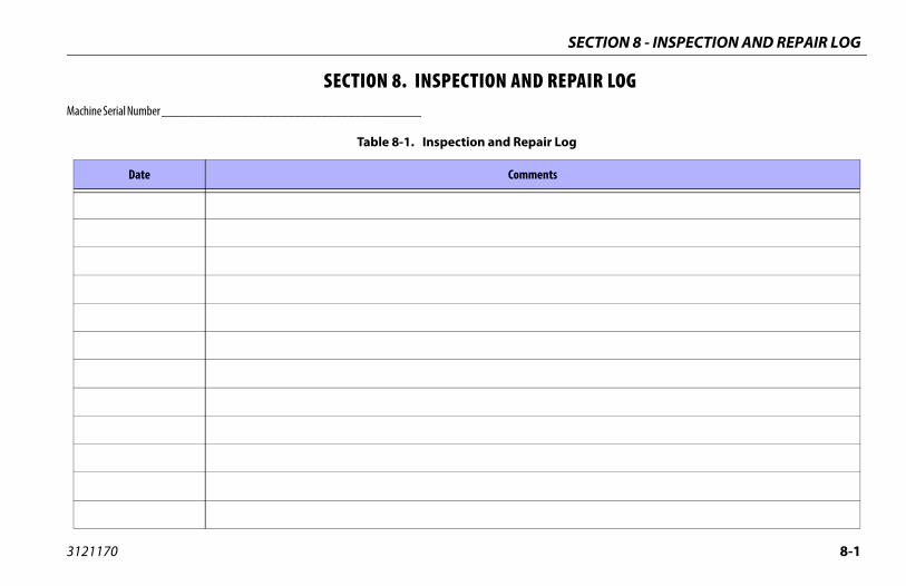
SECTION 8 - INSPECTION AND REPAIR LOG
8-1
REPAIR LOG
ir Log
nts
3121170
SECTION 8. INSPECTION ANDMachine Serial Number _______________________________________
Table 8-1. Inspection and Repa
Date Comme
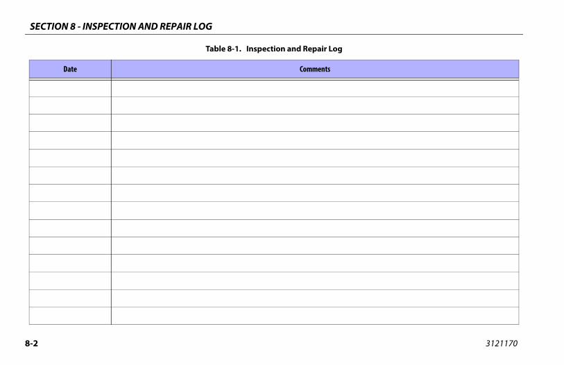
SECTION 8 - INSPECTION AND REPAIR LOG
8-2 3121170
Table 8-1. Inspection and Repair Log
Date Comments

TRA
NSF
ER O
F O
WN
ERSH
IP
To P
rodu
ct O
wne
r:If
you
now
ow
n bu
t ARE
NO
T th
e or
igin
al p
urch
aser
of t
he p
rodu
ct c
over
ed b
y th
is m
anua
l, w
e w
ould
like
to k
now
who
you
are
. For
the
purp
ose
of re
ceiv
ing
safe
ty-r
elat
ed b
ulle
tins
, it i
s ve
ry im
port
ant t
o ke
ep JL
G In
dust
ries
, Inc
. upd
ated
wit
h th
e cu
rren
t ow
ners
hip
of a
ll JL
G
prod
ucts
. JLG
mai
ntai
ns o
wne
r inf
orm
atio
n fo
r eac
h JL
G p
rodu
ct a
nd u
ses
this
info
rmat
ion
in
case
s w
here
ow
ner n
otifi
cati
on is
nec
essa
ry.
Plea
se u
se th
is fo
rm to
pro
vide
JLG
wit
h up
date
d in
form
atio
n w
ith
rega
rd to
the
curr
ent
owne
rshi
p of
JLG
pro
duct
s. P
leas
e re
turn
com
plet
ed fo
rm to
the
JLG
Pro
duct
Saf
ety
&
Relia
bilit
y D
epar
tmen
t via
facs
imile
or m
ail t
o ad
dres
s as
spe
cifie
d be
low
.
Than
k Yo
u,Pr
oduc
t Saf
ety
& R
elia
bilit
y D
epar
tmen
tJL
G In
dust
ries
, Inc
.13
224
Foun
tain
head
Pla
zaH
ager
stow
n, M
D21
742
USA
Tele
phon
e: +
1-71
7-48
5-65
91Fa
x: +
1-30
1-74
5-37
13
NO
TE: L
ease
d or
rent
ed u
nits
sho
uld
not b
e in
clud
ed o
n th
is fo
rm.
Mfg
. Mod
el:
____
____
____
___ _
____
____
____
____
____
____
____
____
____
____
____
____
____
__
Seri
al N
umbe
r: _
____
____
____
____
____
____
____
____
____
____
____
____
____
____
____
____
___
Prev
ious
Ow
ner:
__
____
____
____
____
____
____
____
____
____
____
____
____
____
____
____
____
Add
ress
: __
____
____
____
____
____
____
____
____
____
____
____
____
____
____
____
____
____
___
____
____
____
____
____
____
____
____
____
____
____
____
____
____
____
____
____
____
____
____
_
Coun
try:
___
____
____
____
____
____
____
__Te
leph
one:
(___
____
) __
____
____
____
____
____
__
Dat
e of
Tra
nsfe
r: _
____
____
____
____
____
____
____
____
____
_
Curr
ent O
wne
r: _
____
____
____
____
____
____
____
____
____
____
____
____
____
____
____
____
__
Add
ress
: __
____
____
____
____
____
____
____
____
____
____
____
____
____
____
____
____
____
___
____
____
____
____
____
____
____
____
____
____
____
____
____
____
____
____
____
____
____
____
_
Coun
try:
___
____
____
____
____
____
____
__Te
leph
one:
(___
____
) __
____
____
____
____
____
__
Who
in y
our o
rgan
izat
ion
shou
ld w
e no
tify
?
Nam
e: _
____
____
____
____
____
____
____
____
____
____
____
____
____
____
____
____
____
____
__
Titl
e:__
____
____
____
____
____
____
____
____
____
____
____
____
____
____
____
____
__
��
����
���
�
��
� ��
�
�
��
��


Corporate OfficeJLG Industries, Inc.
1 JLG DriveMcConnellsburg, PA 17233-9533 USA
(717) 485-5161 (Corporate) (877) 554-5438 (Customer Support)
(717) 485-6417
Visit our website for JLG Worldwide Locations www.jlg.com
3121170