Installation, Operation & Maintenance Manual
14
Original Instructions Installation, Operation & Maintenance Manual Sentry MVS Sampler Low Emission Samplers S-MS-IOM-00261-5 01-21
-
Upload
khangminh22 -
Category
Documents
-
view
1 -
download
0
Transcript of Installation, Operation & Maintenance Manual

Original Instructions
Installation, Operation & Maintenance ManualSentry MVS SamplerLow Emission Samplers
S-MS-IOM-00261-5 01-21

2 Sentry Equipment Corp
Table of ContentsSafety Information ............................................................................................................. 3
General Safety Precautions .............................................................................................. 4
General Description ........................................................................................................... 5
Specifications ...................................................................................................................... 6
Installation ........................................................................................................................... 7
Maintenance ........................................................................................................................ 9
Troubleshooting ...............................................................................................................10
Parts & Accessories ...........................................................................................................10
Standard Warranty ...........................................................................................................11
Customer Support ............................................................................................................12
Do not install, maintain, or operate this equipment without reading, understanding, and following the appropriate Sentry Equipment Corp instructions. Otherwise, injury, damage, or both may result.
Copyright© 2018 by Sentry Equipment Corp. All rights reserved. All product and company names are property of their respective owners. This document contains proprietary information. No part of this document may be photocopied or reproduced without the prior written consent of Sentry Equipment Corp.
Limit of LiabilitySentry Equipment Corp, its employees, agents, and the authors and contributors to this document specifi cally disclaim all liabilities and warranties, express or implied (including warranties of merchantability and fi tness for a particular purpose), for the accuracy, currency, completeness, and/or reliability of the information contained herein and/or for the fi tness for any particular use and/or for the performance of any material and/or equipment selected in whole or part with the user of/or in reliance upon information contained herein. Selection of materials and/or equipment is at the sole risk of the user of this publication.
NoteThe information contained in this document is subject to change without notice.
Sentry MVS Sampler 3
Safety InformationPlease read the entire manual before attempting to unpack, set up, or operate this product. Pay careful attention to all Warnings, Cautions, and Notes. Failure to do so could result in serious personal injury and/or equipment damage.
Use of Hazard Information
If multiple hazards exist, the signal word corresponding to the greatest hazard shall be used.
Defi nitions
DANGER indicates a hazardous situation which, if not avoided, will result in death or serious injury.
WARNING indicates a hazardous situation which, if not avoided, could result in death or serious injury.
CAUTION, used with the safety alert symbol, indicates a hazardous situation which, if not avoided, could result in minor or moderate injury.
NOTICE is used to address practices not related to personal injury.
NOTEInformation that requires special emphasis.
TIPAlternate techniques or clarifying information.
SHALL: This word is understood to be mandatory.
SHOULD: This word is understood to be advisory.

4 Sentry Equipment Corp
General Safety PrecautionsProduct Selection, Installation, and Use
Improper selection, installation, or use can cause personal injury or property damage. It is solely the responsibility of users, through their own analysis and testing, to select products suitable for their specifi c application requirements, ensure they are properly maintained, and limit their use to their intended purpose.
Follow proper local, state, and federal regulations for proper installation and operational requirements.
Always use caution and common sense when working with any chemical. Read the product label and Material Safety Data Sheets (MSDS) carefully and follow the instructions exactly.
Potential Equipment Hazards
Hot surfaces! This equipment may have very hot surfaces. If an operator contacts a hot surface, injury may occur. Use protective clothing to prevent injury. If other equipment comes in contact with a hot surface, damage to the equipment may occur. Ensure the area around this equipment is kept clear to prevent damage from occurring.
High pressures! This equipment may contain fl uids at very high pressures. Prior to installing, removing or maintaining this equipment, ensure that the equipment is isolated from all connecting piping, the equipment is depressurized, the contents have been drained, and the equipment is cool.
Moving parts! This equipment may contain moving parts. All drive guards and doors must be secured in place when this machine is being operated.
Equipment rated TX. Equipment maximum surface temperature depends on operating conditions. Ensure maximum surface temperature shall stay below ignition temperature of dust or gas atmosphere where it is installed based on process conditions. Failure to comply could result in an explosion, causing serious injury or death to personnel and damage to equipment.
If the sampler is mounted directly to a non-electrically conductive surface, sampler shall be bonded to a grounding electrode. Failure to comply could result in sparking, which could lead to an explosion, causing harm to personnel and equipment.
If the sample container is removed from the sampler, do not insert any body part or other item into the sample discharge port. Crushing will occur.
To ensure proper sampler operation, be sure the sampler is installed in a pipe large enough for the sampler plunger to extend without impacting the pipe. Failure to comply will result in equipment damage and poor sample quality.

Sentry MVS Sampler 5
General Description
Read these instructions completely before proceeding to assemble, install or operate this machine. This machine should be installed, operated and serviced by qualified individuals. Follow proper local, state and federal regulations for proper installation and operational requirements.
The Sentry® MVS manual low-emission sampler is specifically designed to collect process samples without emissions to the atmosphere or exposure to the operator. Dead volume is minimized by using a close-coupled ball valve specifically designed to provide low dead volume.
The MVS sampler uses our patented side-discharge dual needle assembly that ensures septum integrity and full venting of process vapors. This non-coring needle design punctures the septum without coring it, allowing for full resealing of the septum when the sample bottle is removed. The tapered bottle shroud enables proper septum and needle alignment, preventing accidental spillage or needle breakage. A variety of needle arrangements and sample bottle sizes are available to meet most sampling requirements. Additionally, a tube stub option is available for high viscosity fluids or those that contain particulates.
Since operator safety is of the highest concern, the sampling valve interface features an adjustable throttle stop and spring return (deadman’s) handle. This provides proper sample control and quick closure upon release of the sampling valve.
Needle TypeThe Sentry MVS manual low-emission sampler is a single valve assembly, and the valve is a shut-off valve. The sampling assembly is provided with a vent connection where vapors can be diverted to a flare or vessel. The sample is injected into a sealed bottle using a Sentry needle assembly. A second needle on this assembly vents gases from the bottle and prevents pressure buildup in the bottle.
The valve on the MVS is a spring-return redundant stop valve, with what is commonly called a deadman’s handle. The handle is rotated to begin sample flow into the bottle. Once the operator lets go of the handle, the valve will close, stopping flow into the bottle.
The valve assembly is supplied with a bottle shroud with a wire retainer that secures the bottle to the valve during the sampling operation. The shroud is matched to the sample bottle to ensure the bottle is properly aligned for septum penetration. The shroud features a slot that allows the operator to view the sample bottle and filling process.
Tube Stub TypeThe Sentry MVS also has a tube stub option, which works in a similar fashion to the needle style; however, the sample is injected into the bottle via a tube stub in lieu of needles. A vent hole in the tube stub assembly vents gases from the bottle and prevents pressure buildup in the sample bottle.
The valve assembly is supplied with a bottle adapter with a threaded connection that secures the bottle to the valve during the sampling operation. As with the needle type, the adapter is matched to the sample bottle to ensure the bottle is properly aligned.

6 Sentry Equipment Corp
Specificationswetted materials 316 stainless steel, PTFE, Viton®, Kalrez®
bottle shroud nylon
customer interface connection 1/4 in compression, 3/8 in compression or 1/2 in compressionstandard pressure rating 2200 psi at 100°F (150 bar at 38°C); 450°F at 100 psi (232°C at 7 bar)sampler interface needle assembly (OD)*
Process Vent
0.065 in 0.065 in
0.083 in 0.083 in
0.110 in 0.110 in
tube stub assembly (OD)*Process Vent
3/16 in 9/64 in*other needle/tube stube arrangements available
bottle size and typeBoston Round Schott
2 oz (60 ml) 50 ml
4 oz (125 ml) 100 ml
8 oz (250 ml) 250 ml
16 oz (500 ml) 500 ml
32 oz (1000 ml) 2000 ml
Boston Round bottle cap/thread interfaces per GPI finish standards. Schott bottle cap/thread interfaces per ISO 4796.
Standard septum material is Teflon-coated silicone.
Other bottle or septum arrangements are available.

Sentry MVS Sampler 7
InstallationThe MVS manual low-emission sampler can be supported directly by the top 1/4 in (or optional 3/4 or 1/2 in) compression connection or mounted to a panel using the bracket provided. When installing the valve assembly, verify that adequate space has been provided for the removal of the bottle from the shroud or bottle adapter.
The sample inlet connection is located at the top of the valve. The vent connection is located on the left side of the valve assembly. This line should be directed to a charcoal canister, flare or other sub-atmospheric region for collection and treatment of sample vapors. Line and fitting size from the isolation valve to the purge port should be minimized to prevent the formation of “dead legs”.
OperationWhen not actually sampling, the valve should be in the off position with the valve handle in the vertical position.
Prior to initiating sampling, insert the bottle inside the shroud until the bottle cap bottoms against the keeper nut. Secure the bottle within the shroud using the bottle support bracket. Sample flow enters the valve at the top connection. Gradually open the valve by lowering the valve handle. The valve stop provided should be adjusted so the bottle fills slowly with minimum turbulence or frothing. After the desired sample is obtained, close the valve. Allow a few seconds for vapors to exit the vent connection before removing the bottle from the shroud.
Before initially sampling a high pressure fluid, it is advisable to turn the valve stop in as far as possible. This will prevent the fluid from spurting out due to the valve being open too far. While fluid is flowing, the screw can be backed out slowly while the valve is opened to establish the desired fill rate.
Please refer to the job-specific drawings of the instruction placard for specific operating instructions.
[4]Ø 3/16"5/8" [16] 2X
1 13/16" [45]
2 3/4" [70]4 3/8" [111]
Sample Inlet
Mounting Holes
Flare/Vent
Spring-Loaded Dead Man’s Throttling Valve Handle
7 1/2" (190) 2 oz (60 ml) Bottle8 1/16" (205) 4 oz (125 ml) Bottle9 1/16" (240) 8 oz (250 ml) Bottle
10 3/8" (264) 16 oz (500 ml) Bottle12" (305) 32 oz (1000 ml) Bottle
Flare / Vent
Sample Inlet
SampleBottle
Single BlockNeedle Sample Valve
CV
8 Sentry Equipment Corp
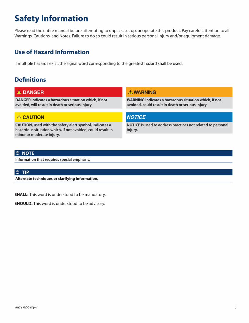
Sharp objects! The needles in the needle assembly are sharp and present a risk of injury due to penetration and/or laceration. The needles are in direct contact with the process media and may have residual substances on their surfaces. These substances may exacerbate an injury.
The needle assembly can be removed and replaced by removing the shroud and a single retaining nut. The needle assembly is equipped with o-ring seals around the fluid inlet port and the needle assembly. The area between the seals is vented to the assembly vent connection. This arrangement provides maximum protection from potential leakage as fluid leakage resulting from a defective inlet seal is diverted to vent rather than discharge to the atmosphere. The needle assembly has positive engagement to insure that the needles are correctly positioned prior to insertion.
Needle AssemblyThe locating pin must fit into the locating hole.
Piping & Instrument Diagram
Flare / Vent
Sample Inlet
SampleBottle
Single BlockNeedle Sample Valve
CV
Sentry MVS Sampler 9
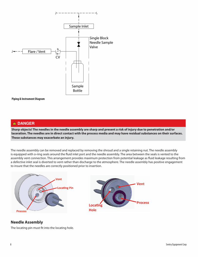
The needle assembly and orifice can be removed and replaced without valve disassembly or disruption of any fluid tubing.
MaintenanceNeedle ValveAny blockages normally can be cleared by fully opening the valve. Care must be taken to ensure that temperature and pressure limits are not exceeded during this process.
Valve PackingOccasionally during initial startup or restart of the sample panel, the low pressure/high pressure inlet isolation valve packing may leak. If this occurs, remove the handle, tighten the packing nut, and then replace the handle. If the packing continues to leak or other valves or o-rings require maintenance, please see the Parts & Accessories list in this manual.
Sample CoolerFor installation and operating instructions for the sample cooler, please see the Installation, Operation & Maintenance manual for Sentry sample coolers.
Carbon CanisterAn optional Sentry carbon canister is available. The carbon canister assembly is designed to absorb hydrocarbon gases vented from Sentry manual low-emission samplers.
The gas vent of the sampler panel is connected to the inlet of the carbon canister assembly. The gases then pass through a volume of activated carbon, where hydrocarbons, such as benzene, are absorbed. Often, there are specific gases, such as H2S – hydrogen sulfide – that also are carried in the vented gas. To remove these, specially designed products such as impregnated activated carbon are used.
Both activated carbon and impregnated activated carbon have a finite ability to remove hydrocarbons and other gases. The life of the product is dependent on concentrations and volumetric flow of the gas. An optional “tell tale” assembly can be provided with the carbon canister assembly to provide a visual indication of when the carbon canister assembly requires recharging. The carbon canister assembly is designed for easy recharging. Instructions are below.
Carbon Canister Recharging1. Remove clamp from carbon canister, allowing the container to be removed from the base assembly.
Bottle Assembly
10 Sentry Equipment Corp
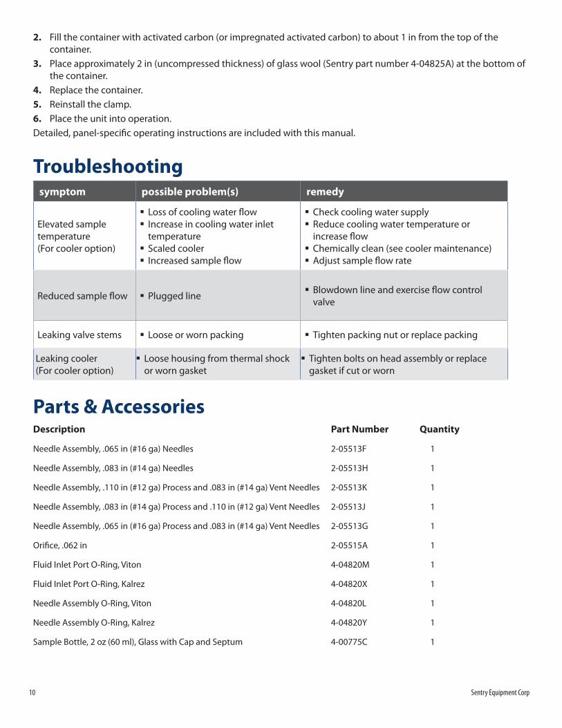
2. Fill the container with activated carbon (or impregnated activated carbon) to about 1 in from the top of the container.
3. Place approximately 2 in (uncompressed thickness) of glass wool (Sentry part number 4-04825A) at the bottom of the container.
4. Replace the container.5. Reinstall the clamp.6. Place the unit into operation.Detailed, panel-specific operating instructions are included with this manual.
Troubleshooting symptom possible problem(s) remedy
Elevated sample temperature (For cooler option)
� Loss of cooling water flow � Increase in cooling water inlet temperature
� Scaled cooler � Increased sample flow
� Check cooling water supply � Reduce cooling water temperature or increase flow
� Chemically clean (see cooler maintenance) � Adjust sample flow rate
Reduced sample flow � Plugged line � Blowdown line and exercise flow control valve
Leaking valve stems � Loose or worn packing � Tighten packing nut or replace packing
Leaking cooler (For cooler option)
� Loose housing from thermal shock or worn gasket
� Tighten bolts on head assembly or replace gasket if cut or worn
Parts & AccessoriesDescription Part Number Quantity
Needle Assembly, .065 in (#16 ga) Needles 2-05513F 1
Needle Assembly, .083 in (#14 ga) Needles 2-05513H 1
Needle Assembly, .110 in (#12 ga) Process and .083 in (#14 ga) Vent Needles 2-05513K 1
Needle Assembly, .083 in (#14 ga) Process and .110 in (#12 ga) Vent Needles 2-05513J 1
Needle Assembly, .065 in (#16 ga) Process and .083 in (#14 ga) Vent Needles 2-05513G 1
Orifice, .062 in 2-05515A 1
Fluid Inlet Port O-Ring, Viton 4-04820M 1
Fluid Inlet Port O-Ring, Kalrez 4-04820X 1
Needle Assembly O-Ring, Viton 4-04820L 1
Needle Assembly O-Ring, Kalrez 4-04820Y 1
Sample Bottle, 2 oz (60 ml), Glass with Cap and Septum 4-00775C 1

Sentry MVS Sampler 11
Sample Bottle, 4 oz (118 ml), Glass with Cap and Septum 4-04930A 1
Sample Bottle, 8 oz (237 ml), Glass with Cap and Septum 4-04931A 1
Sample Bottle, 16 oz (473 ml), Glass with Cap and Septum 4-04921A 1
Sample Bottle, 32 oz (946 ml), Glass with Cap and Septum 4-04926A 1
Bottle Septums for 2 oz (60 ml) Bottles, Pkg. of 50 4-04963A 1
Bottle Septums for 4 oz (118 ml) Bottles, Pkg. of 50 4-04963B 1
Bottle Septums for 8 oz (237 ml) Bottles, Pkg. of 50 4-04963C 1
Bottle Septums for 16 oz (473 ml) Bottles, Pkg. of 50 4-04963D 1
Bottle Septums for 32 oz (946 ml) Bottles, Pkg. of 50 4-04963E 1
Shroud with 2 oz (60 ml) Bottles 6-04081B 1
Shroud with 4 oz (118 ml) Bottles 6-04081H 1
Shroud with 8 oz (237 ml) Bottles 6-04081A 1
Shroud with 16 oz (473 ml) Bottles 6-04081D 1
Shroud with 32 oz (946 ml) Bottles 6-04081C 1
Standard WarrantySentry Equipment Corp (“Seller”) warrants products manufactured by it and supplied hereunder (“Products”) to be free from defects in workmanship and, to the extent materials are selected by Seller, to be free from defects in materials, in each case for a period as defi ned in the table below:
Product Line Product Category Warranty PeriodSentry® 1. Automatic Sampling
2. Corrosion Monitoring3. Manual Sampling4. Sample Conditioning5. Sampling & Analysis Systems6. Replacement Parts (without expiration dates)
Eighteen months from date of shipment or twelve months from startup, whichever occurs fi rst
Waters Equipment 1. Sampling & Analysis Systems2. Replacement Parts (without expiration dates)
Twelve months from date of shipment
To view the full warranty, go to www.sentry-equip.com/warranty.
12 Sentry Equipment Corp
Customer SupportWith proven sampling expertise since 1924, Sentry products and services provide business operations the critical insights to optimize process control and product quality. We deliver true representative sampling and analysis techniques to customers around the globe, empowering them to accurately monitor and measure processes for improved production effi ciency, output, and safety. Standing behind our commitments, we are determined to tackle any application, anywhere.
We know that running an effi cient operation isn’t easy. It requires thorough, careful analysis of controlled, real-time data achieved through reliable, accurate, and repeatable process monitoring, and measuring. By eff ectively conditioning, sampling, and measuring gas, liquid, slurry, powder, solids, steam, or water within their production environments, our customers obtain the critical insights they need to control and optimize their processes.
Yet, controlling your processes also means reliable customer support throughout the life cycle of your equipment.
� Customer Service—General information, warranty claims, order management.
� Installation Service—For systems that require specialized expertise upon installation.
� Technical Support—Troubleshooting, training, and technical manuals.
� Field Service & Retrofi ts—When a problem needs immediate attention.
� Replacements Parts & Consumables—Order your replacement parts and consumables.
� Sentry ProShield Services – select from four ProShield Guardian service plans providing diff erent levels of support to protect your large system investments with regularly scheduled maintenance.
To learn more, go to www.sentry-equip.com/support.

Sentry MVS Sampler 13
This page is intentionally left blank.

sentry-equip.com966 Blue Ribbon Circle North, Oconomowoc, WI 53066 U.S.A. | +1-262-567-7256 | [email protected]
Serving customers in more than 50 countries across six continents worldwide.