ST51A/ST75A/ST75AV Installation, Operation & Maintenance ...
Upload
khangminh22Category
view
3download
0
INSTALLATION, OPERATION & MAINTENANCE MANUALINTEGRATED PROGRAMMABLE CONTROLS
WWW.RENEWAIRE.COM
FOR EV450, ALL HE, LE AND RD UNITS
Carel c.pCO Mini Carel c.pCOe Expansion Board
INTEGRATED PROGRAMMABLE CONTROLS
RENEWAIRE.COM INSTALLATION, OPERATION AND MAINTENANCE MANUAL 1.800.627.44992
IMPORTANT SAFETY INFORMATION
WARNINGArc flash and electric shock hazard.
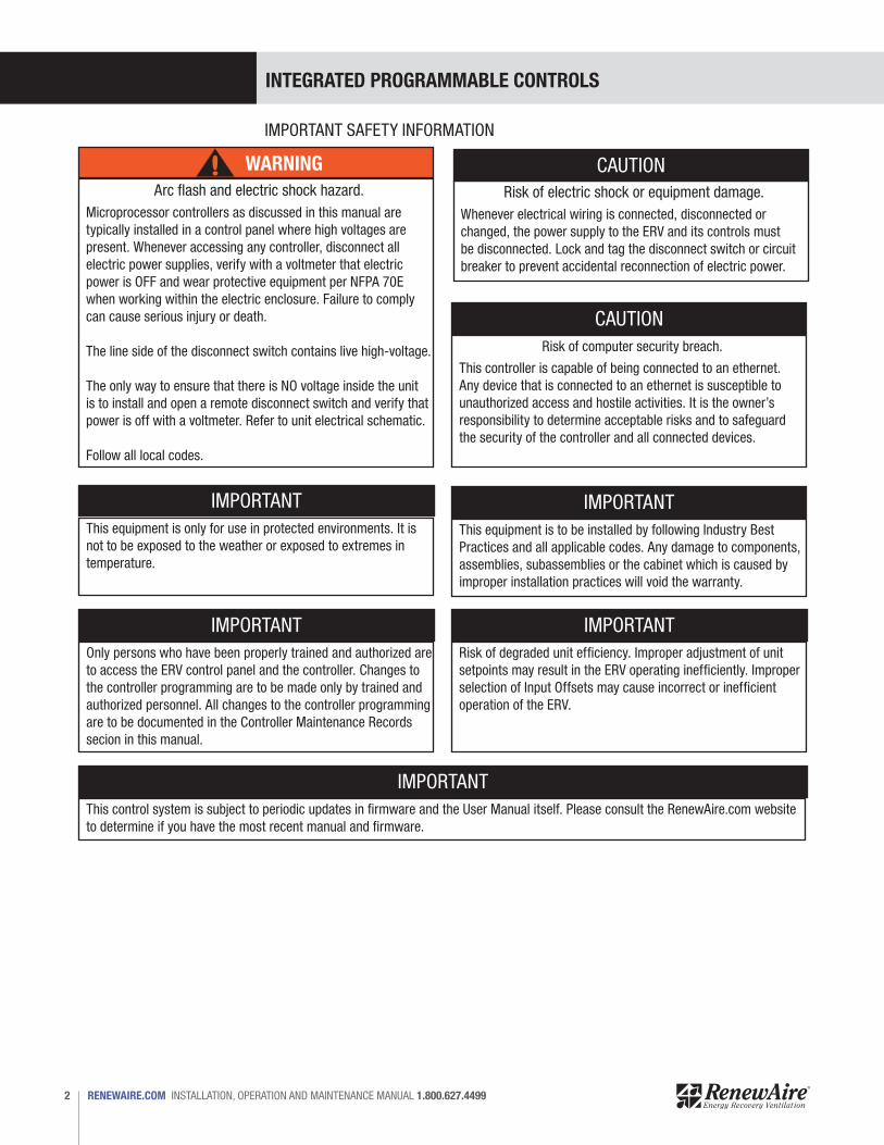
Microprocessor controllers as discussed in this manual are typically installed in a control panel where high voltages are present. Whenever accessing any controller, disconnect all electric power supplies, verify with a voltmeter that electric power is OFF and wear protective equipment per NFPA 70E when working within the electric enclosure. Failure to comply can cause serious injury or death.
The line side of the disconnect switch contains live high-voltage.
The only way to ensure that there is NO voltage inside the unit is to install and open a remote disconnect switch and verify that power is off with a voltmeter. Refer to unit electrical schematic.
Follow all local codes.
CAUTION
CAUTION
Risk of electric shock or equipment damage. Whenever electrical wiring is connected, disconnected or changed, the power supply to the ERV and its controls must be disconnected. Lock and tag the disconnect switch or circuit breaker to prevent accidental reconnection of electric power.
Risk of computer security breach.
This controller is capable of being connected to an ethernet. Any device that is connected to an ethernet is susceptible to unauthorized access and hostile activities. It is the owner’s responsibility to determine acceptable risks and to safeguard the security of the controller and all connected devices.
IMPORTANT
IMPORTANT
IMPORTANT
IMPORTANT
IMPORTANTThis equipment is only for use in protected environments. It is not to be exposed to the weather or exposed to extremes in temperature.
Only persons who have been properly trained and authorized are to access the ERV control panel and the controller. Changes to the controller programming are to be made only by trained and authorized personnel. All changes to the controller programming are to be documented in the Controller Maintenance Records secion in this manual.
This control system is subject to periodic updates in firmware and the User Manual itself. Please consult the RenewAire.com website to determine if you have the most recent manual and firmware.
Risk of degraded unit efficiency. Improper adjustment of unit setpoints may result in the ERV operating inefficiently. Improper selection of Input Offsets may cause incorrect or inefficient operation of the ERV.
This equipment is to be installed by following Industry Best Practices and all applicable codes. Any damage to components, assemblies, subassemblies or the cabinet which is caused by improper installation practices will void the warranty.

INTEGRATED PROGRAMMABLE CONTROLS
3 1.800.627.4499 INSTALLATION, OPERATION AND MAINTENANCE MANUAL RENEWAIRE.COM
OWNER INFORMATION
Record information as shown below. In the unlikely event that factory assistance is ever required, this information will be needed.
Serial Number:
ERV Model Config Code:
Locate the RenewAire unit label, to be found inside the door or a removable panel on the appliance.NOTE: This information is for purposes of identifying the specific air handling appliance. Unit-specific option data can then be obtained, as needed, from the Model Number.
NOTE: this page is to be completed by the installing contractor. The
completed document is to be turned over to the owner after start-up.
UNIT RECORDS
INTEGRATED PROGRAMMABLE CONTROLS
RENEWAIRE.COM INSTALLATION, OPERATION AND MAINTENANCE MANUAL 1.800.627.44994
OWNER INFORMATION
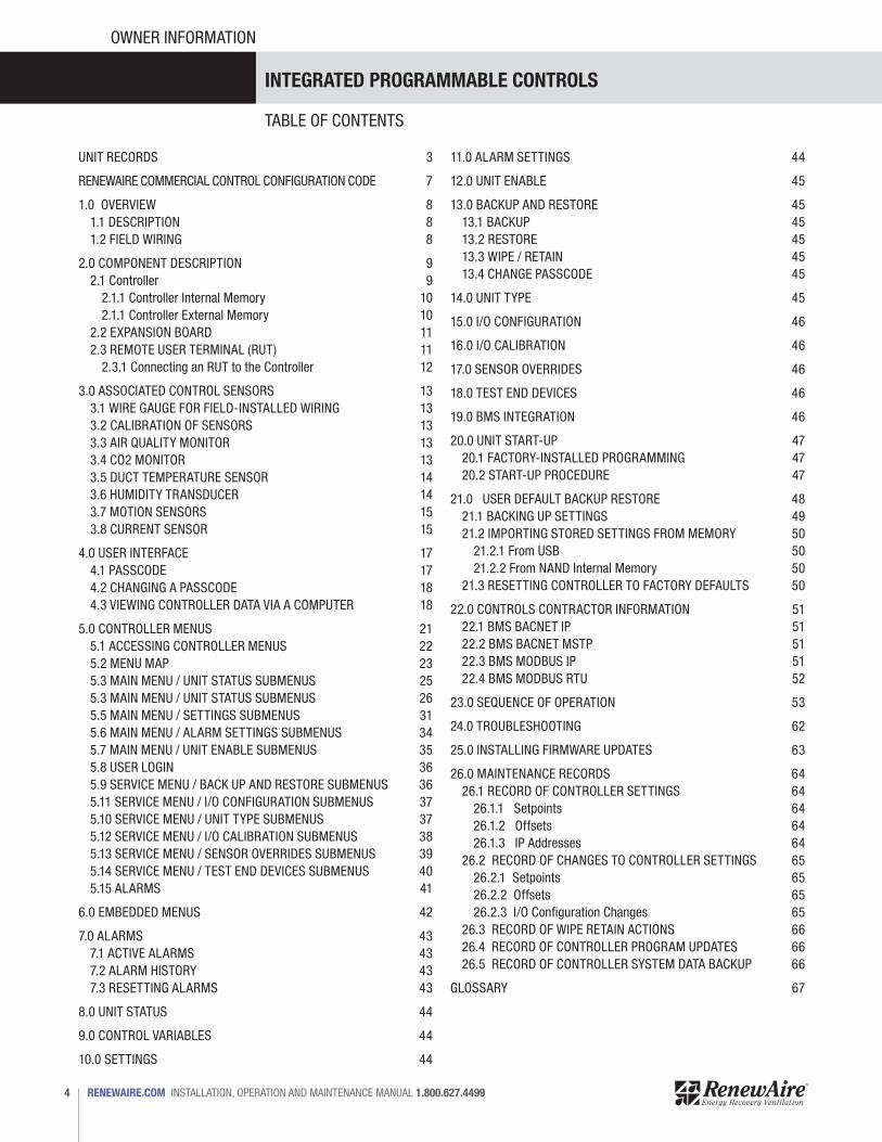
TABLE OF CONTENTS
UNIT RECORDS 3
RENEWAIRE COMMERCIAL CONTROL CONFIGURATION CODE 7
1.0 OVERVIEW 81.1 DESCRIPTION 81.2 FIELD WIRING 8
2.0 COMPONENT DESCRIPTION 92.1 Controller 9
2.1.1 Controller Internal Memory 102.1.1 Controller External Memory 10
2.2 EXPANSION BOARD 112.3 REMOTE USER TERMINAL (RUT) 11
2.3.1 Connecting an RUT to the Controller 12
3.0 ASSOCIATED CONTROL SENSORS 133.1 WIRE GAUGE FOR FIELD-INSTALLED WIRING 133.2 CALIBRATION OF SENSORS 133.3 AIR QUALITY MONITOR 133.4 CO2 MONITOR 133.5 DUCT TEMPERATURE SENSOR 143.6 HUMIDITY TRANSDUCER 143.7 MOTION SENSORS 153.8 CURRENT SENSOR 15
4.0 USER INTERFACE 174.1 PASSCODE 174.2 CHANGING A PASSCODE 184.3 VIEWING CONTROLLER DATA VIA A COMPUTER 18
5.0 CONTROLLER MENUS 215.1 ACCESSING CONTROLLER MENUS 225.2 MENU MAP 235.3 MAIN MENU / UNIT STATUS SUBMENUS 255.3 MAIN MENU / UNIT STATUS SUBMENUS 265.5 MAIN MENU / SETTINGS SUBMENUS 315.6 MAIN MENU / ALARM SETTINGS SUBMENUS 345.7 MAIN MENU / UNIT ENABLE SUBMENUS 355.8 USER LOGIN 365.9 SERVICE MENU / BACK UP AND RESTORE SUBMENUS 365.11 SERVICE MENU / I/O CONFIGURATION SUBMENUS 375.10 SERVICE MENU / UNIT TYPE SUBMENUS 375.12 SERVICE MENU / I/O CALIBRATION SUBMENUS 385.13 SERVICE MENU / SENSOR OVERRIDES SUBMENUS 395.14 SERVICE MENU / TEST END DEVICES SUBMENUS 405.15 ALARMS 41
6.0 EMBEDDED MENUS 42
7.0 ALARMS 437.1 ACTIVE ALARMS 437.2 ALARM HISTORY 437.3 RESETTING ALARMS 43
8.0 UNIT STATUS 44
9.0 CONTROL VARIABLES 44
10.0 SETTINGS 44
11.0 ALARM SETTINGS 44
12.0 UNIT ENABLE 45
13.0 BACKUP AND RESTORE 4513.1 BACKUP 4513.2 RESTORE 4513.3 WIPE / RETAIN 4513.4 CHANGE PASSCODE 45
14.0 UNIT TYPE 45
15.0 I/O CONFIGURATION 46
16.0 I/O CALIBRATION 46
17.0 SENSOR OVERRIDES 46
18.0 TEST END DEVICES 46
19.0 BMS INTEGRATION 46
20.0 UNIT START-UP 4720.1 FACTORY-INSTALLED PROGRAMMING 4720.2 START-UP PROCEDURE 47
21.0 USER DEFAULT BACKUP RESTORE 4821.1 BACKING UP SETTINGS 4921.2 IMPORTING STORED SETTINGS FROM MEMORY 50
21.2.1 From USB 5021.2.2 From NAND Internal Memory 50
21.3 RESETTING CONTROLLER TO FACTORY DEFAULTS 50
22.0 CONTROLS CONTRACTOR INFORMATION 5122.1 BMS BACNET IP 5122.2 BMS BACNET MSTP 5122.3 BMS MODBUS IP 5122.4 BMS MODBUS RTU 52
23.0 SEQUENCE OF OPERATION 53
24.0 TROUBLESHOOTING 62
25.0 INSTALLING FIRMWARE UPDATES 63
26.0 MAINTENANCE RECORDS 6426.1 RECORD OF CONTROLLER SETTINGS 64
26.1.1 Setpoints 6426.1.2 Offsets 6426.1.3 IP Addresses 64
26.2 RECORD OF CHANGES TO CONTROLLER SETTINGS 6526.2.1 Setpoints 6526.2.2 Offsets 6526.2.3 I/O Configuration Changes 65
26.3 RECORD OF WIPE RETAIN ACTIONS 6626.4 RECORD OF CONTROLLER PROGRAM UPDATES 6626.5 RECORD OF CONTROLLER SYSTEM DATA BACKUP 66
GLOSSARY 67
INTEGRATED PROGRAMMABLE CONTROLS
5 1.800.627.4499 INSTALLATION, OPERATION AND MAINTENANCE MANUAL RENEWAIRE.COM
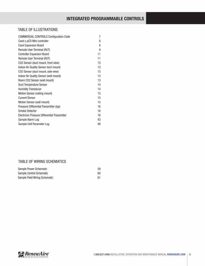
TABLE OF ILLUSTRATIONS
COMMERCIAL CONTROLS Configuration Code 7Carel c.pCO Mini controller 8Carel Expansion Board 8Remote User Terminal (RUT) 8Controller Expansion Board 11Remote User Terminal (RUT) 11CO2 Sensor (duct mount, front view) 13Indoor Air Quality Sensor duct mount) 13CO2 Sensor (duct mount, side view) 13Indoor Air Quality Sensor (wall mount) 13Room CO2 Sensor (wall mount) 13Duct Temperature Sensor 14Humidity Transducer 14Motion Sensor (ceiling mount) 15Current Sensor 15Motion Sensor (wall mount) 15Pressure Differential Transmitter (typ) 16Smoke Detector 16Electronic Pressure Differential Transmitter 16Sample Alarm Log 43Sample Unit Parameter Log 48
TABLE OF WIRING SCHEMATICS
Sample Power Schematic 59Sample Control Schematic 60Sample Field Wiring Schematic 61
INTEGRATED PROGRAMMABLE CONTROLS
RENEWAIRE.COM INSTALLATION, OPERATION AND MAINTENANCE MANUAL 1.800.627.44996
IMPORTANT USER INFORMATION
SAVE THIS MANUAL
NOTICE
NOTICE
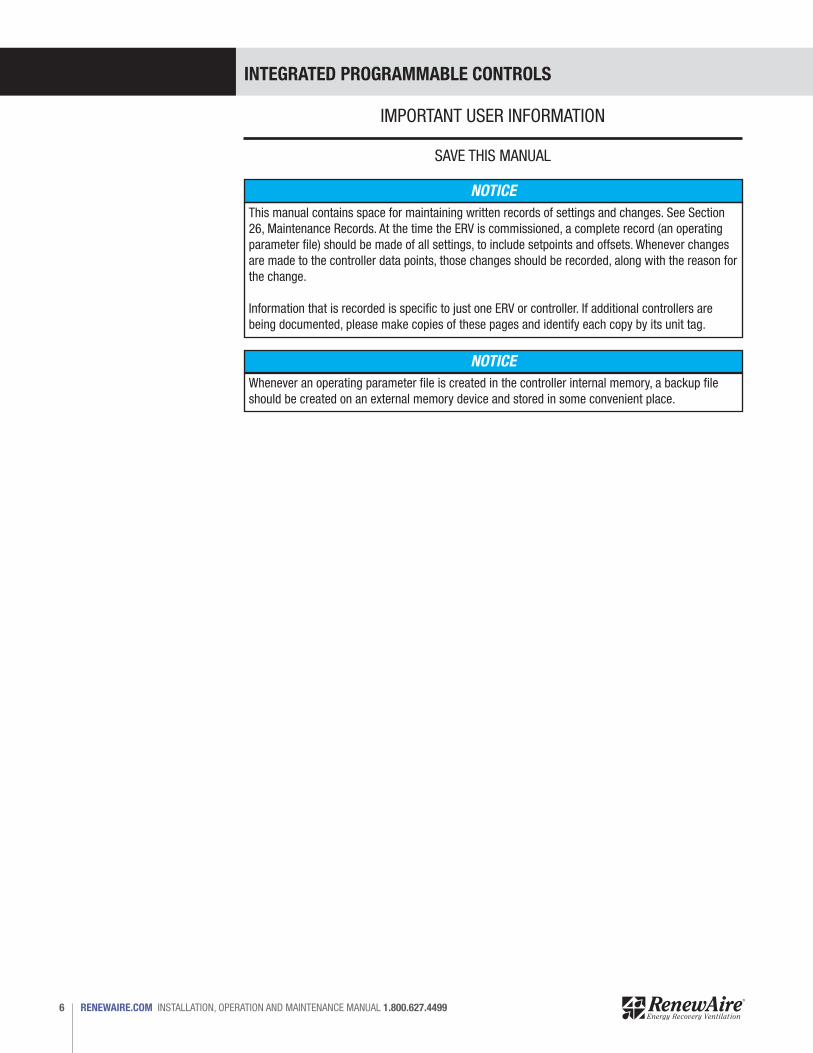
This manual contains space for maintaining written records of settings and changes. See Section 26, Maintenance Records. At the time the ERV is commissioned, a complete record (an operating parameter file) should be made of all settings, to include setpoints and offsets. Whenever changes are made to the controller data points, those changes should be recorded, along with the reason for the change.
Information that is recorded is specific to just one ERV or controller. If additional controllers are being documented, please make copies of these pages and identify each copy by its unit tag.
Whenever an operating parameter file is created in the controller internal memory, a backup file should be created on an external memory device and stored in some convenient place.
INTEGRATED PROGRAMMABLE CONTROLS
7 1.800.627.4499 INSTALLATION, OPERATION AND MAINTENANCE MANUAL RENEWAIRE.COM
CONFIGURATION CODE
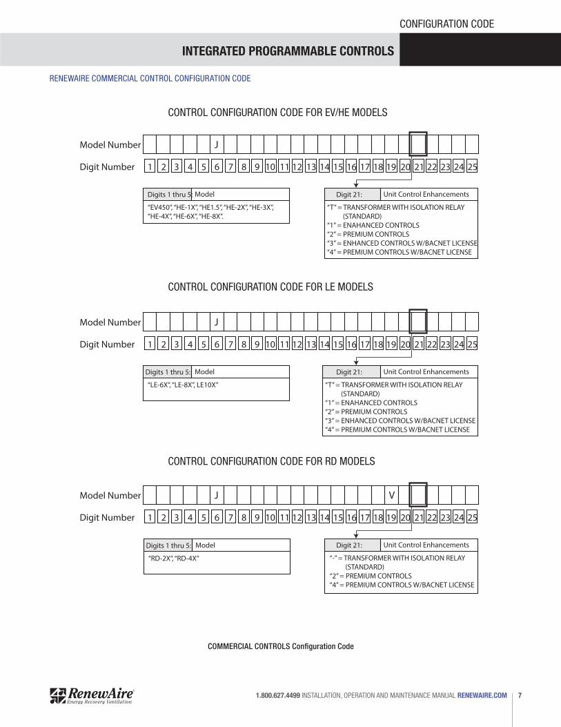
RENEWAIRE COMMERCIAL CONTROL CONFIGURATION CODE
COMMERCIAL CONTROLS Configuration Code
1 2 3 4 5 6 8 9 10 11 12 13 14 15 16 17 18 19 20 21 22 237 24 25
Model Number
Digit Number
Digits 1 thru 5:
“EV450”, “HE-1X”, “HE1.5”, “HE-2X”, “HE-3X”, “HE-4X”, “HE-6X”, “HE-8X”.
J
Model Digit 21:
“T” = TRANSFORMER WITH ISOLATION RELAY (STANDARD)“1” = ENAHANCED CONTROLS“2” = PREMIUM CONTROLS“3” = ENHANCED CONTROLS W/BACNET LICENSE“4” = PREMIUM CONTROLS W/BACNET LICENSE
Unit Control Enhancements
1 2 3 4 5 6 8 9 10 11 12 13 14 15 16 17 18 19 20 21 22 237 24 25
Model Number
Digit Number
Digits 1 thru 5:
“LE-6X”, “LE-8X”, LE10X”
J
Model Digit 21:
“T” = TRANSFORMER WITH ISOLATION RELAY (STANDARD)“1” = ENAHANCED CONTROLS“2” = PREMIUM CONTROLS“3” = ENHANCED CONTROLS W/BACNET LICENSE“4” = PREMIUM CONTROLS W/BACNET LICENSE
Unit Control Enhancements
1 2 3 4 5 6 8 9 10 11 12 13 14 15 16 17 18 19 20 21 22 237 24 25
Model Number
Digit Number
J V
Digit 21:
“-” = TRANSFORMER WITH ISOLATION RELAY (STANDARD)“2” = PREMIUM CONTROLS“4” = PREMIUM CONTROLS W/BACNET LICENSE
Unit Control EnhancementsDigits 1 thru 5:
“RD-2X”, “RD-4X”
Model
CONTROL CONFIGURATION CODE FOR EV/HE MODELS
CONTROL CONFIGURATION CODE FOR LE MODELS
CONTROL CONFIGURATION CODE FOR RD MODELS
INTEGRATED PROGRAMMABLE CONTROLS
RENEWAIRE.COM INSTALLATION, OPERATION AND MAINTENANCE MANUAL 1.800.627.44998
OVERVIEW
1.0 OVERVIEW
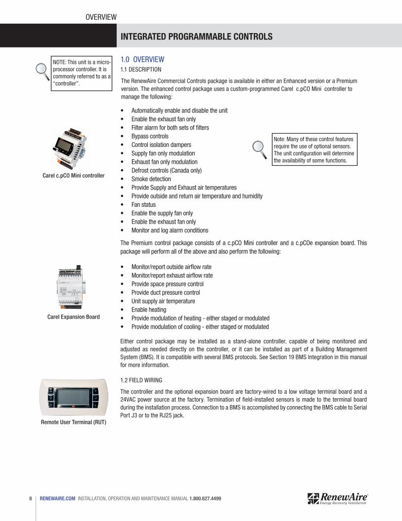
The RenewAire Commercial Controls package is available in either an Enhanced version or a Premium version. The enhanced control package uses a custom-programmed Carel c.pCO Mini controller to manage the following:
Either control package may be installed as a stand-alone controller, capable of being monitored and adjusted as needed directly on the controller, or it can be installed as part of a Building Management System (BMS). It is compatible with several BMS protocols. See Section 19 BMS Integration in this manual for more information.
NOTE: This unit is a micro-processor controller. It is commonly referred to as a “controller”.
Carel c.pCO Mini controller
Carel Expansion Board
Remote User Terminal (RUT)
• Automatically enable and disable the unit• Enable the exhaust fan only• Filter alarm for both sets of filters• Bypass controls• Control isolation dampers• Supply fan only modulation• Exhaust fan only modulation• Defrost controls (Canada only)• Smoke detection• Provide Supply and Exhaust air temperatures• Provide outside and return air temperature and humidity• Fan status• Enable the supply fan only• Enable the exhaust fan only• Monitor and log alarm conditions
Note: Many of these control features require the use of optional sensors. The unit configuration will determine the availability of some functions.
The Premium control package consists of a c.pCO Mini controller and a c.pCOe expansion board. This package will perform all of the above and also perform the following:
• Monitor/report outside airflow rate• Monitor/report exhaust airflow rate• Provide space pressure control• Provide duct pressure control• Unit supply air temperature• Enable heating• Provide modulation of heating - either staged or modulated• Provide modulation of cooling - either staged or modulated
The controller and the optional expansion board are factory-wired to a low voltage terminal board and a 24VAC power source at the factory. Termination of field-installed sensors is made to the terminal board during the installation process. Connection to a BMS is accomplished by connecting the BMS cable to Serial Port J3 or to the RJ25 jack.
1.2 FIELD WIRING
1.1 DESCRIPTION
INTEGRATED PROGRAMMABLE CONTROLS
9 1.800.627.4499 INSTALLATION, OPERATION AND MAINTENANCE MANUAL RENEWAIRE.COM
OVERVIEW
2.0 COMPONENT DESCRIPTION
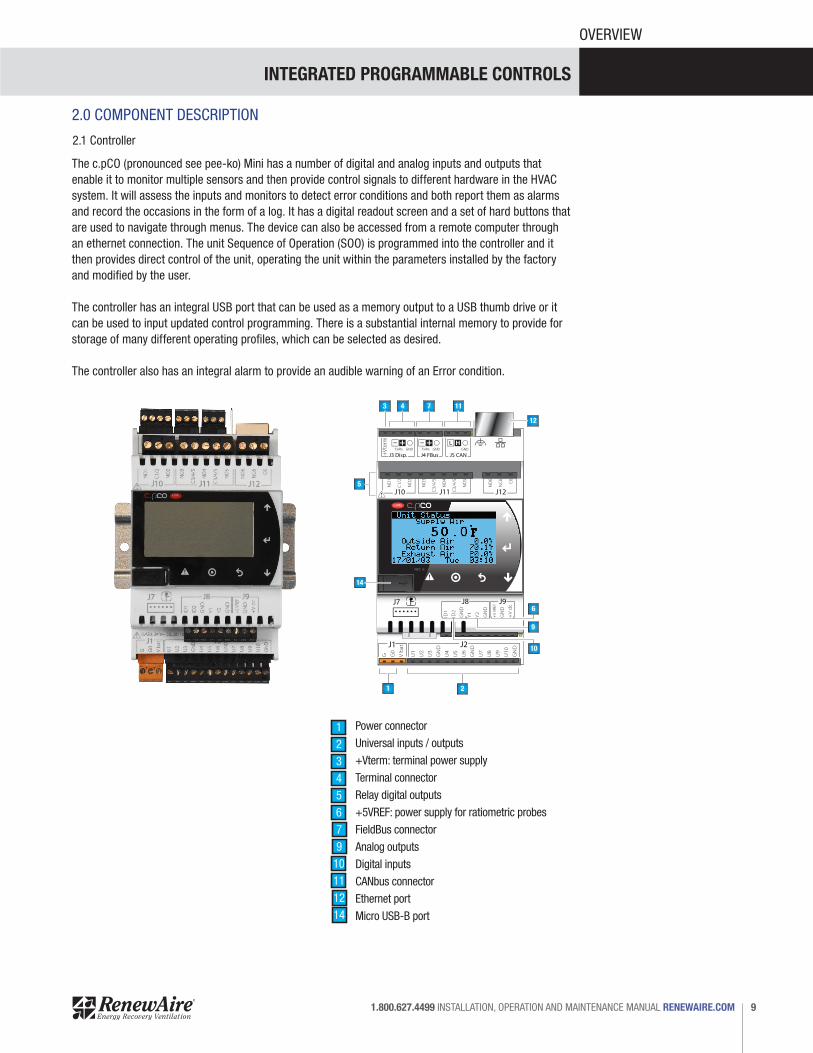
The c.pCO (pronounced see pee-ko) Mini has a number of digital and analog inputs and outputs that enable it to monitor multiple sensors and then provide control signals to different hardware in the HVAC system. It will assess the inputs and monitors to detect error conditions and both report them as alarms and record the occasions in the form of a log. It has a digital readout screen and a set of hard buttons that are used to navigate through menus. The device can also be accessed from a remote computer through an ethernet connection. The unit Sequence of Operation (SOO) is programmed into the controller and it then provides direct control of the unit, operating the unit within the parameters installed by the factory and modified by the user.
The controller has an integral USB port that can be used as a memory output to a USB thumb drive or it can be used to input updated control programming. There is a substantial internal memory to provide for storage of many different operating profiles, which can be selected as desired.
The controller also has an integral alarm to provide an audible warning of an Error condition.
C.pCO n° (03)
75.5°FTime 12:33date: 07.06.2017
14
5
3 4 7 11
12
6
9
10
1 2
2.1 Controller
Power connector
Universal inputs / outputs
+Vterm: terminal power supply
Terminal connector
Relay digital outputs
+5VREF: power supply for ratiometric probes
FieldBus connector
Analog outputs
Digital inputs
CANbus connector
Ethernet port
Micro USB-B port
12345679
10111214
INTEGRATED PROGRAMMABLE CONTROLS
RENEWAIRE.COM INSTALLATION, OPERATION AND MAINTENANCE MANUAL 1.800.627.449910
OVERVIEW
2.1.1 Controller External Memory
2.1.1 Controller Internal Memory
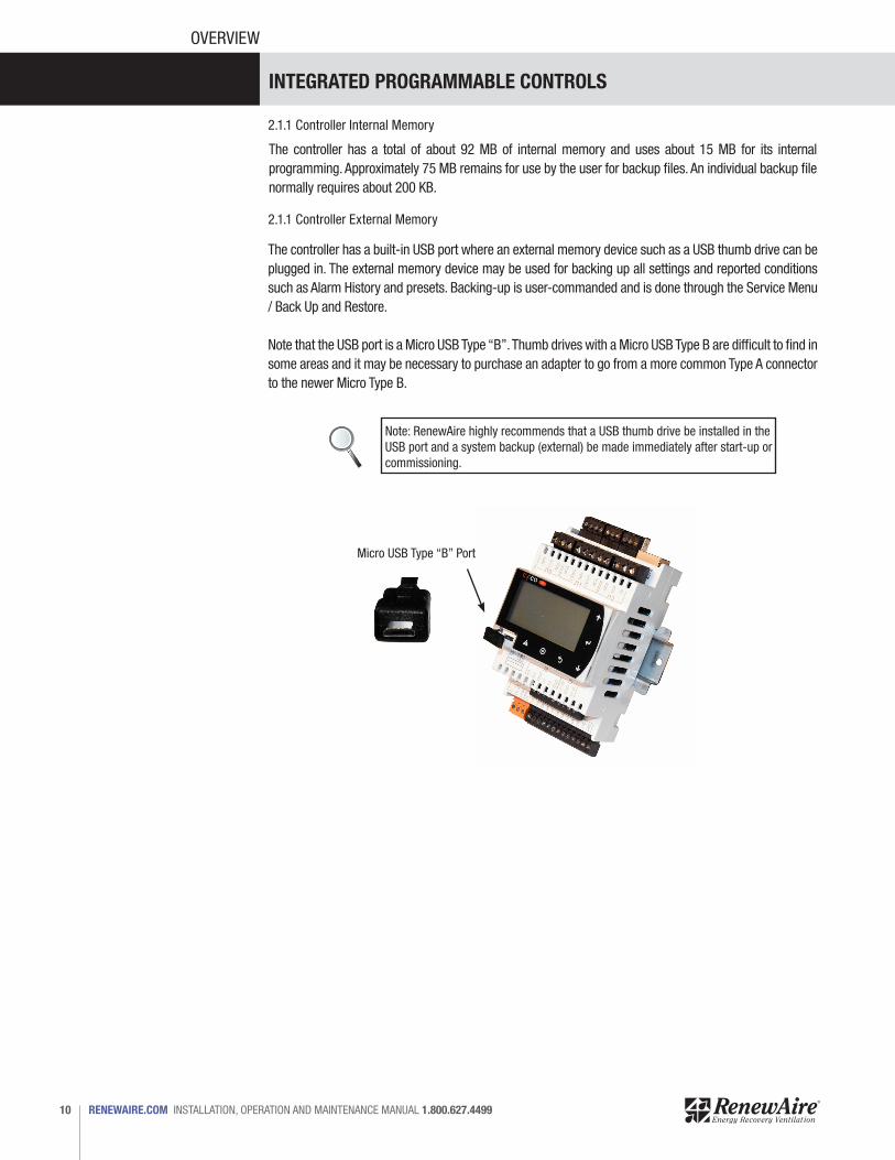
The controller has a built-in USB port where an external memory device such as a USB thumb drive can be plugged in. The external memory device may be used for backing up all settings and reported conditions such as Alarm History and presets. Backing-up is user-commanded and is done through the Service Menu / Back Up and Restore.
Note that the USB port is a Micro USB Type “B”. Thumb drives with a Micro USB Type B are difficult to find in some areas and it may be necessary to purchase an adapter to go from a more common Type A connector to the newer Micro Type B.
Micro USB Type “B” Port
Note: RenewAire highly recommends that a USB thumb drive be installed in the USB port and a system backup (external) be made immediately after start-up or commissioning.
The controller has a total of about 92 MB of internal memory and uses about 15 MB for its internal programming. Approximately 75 MB remains for use by the user for backup files. An individual backup file normally requires about 200 KB.
INTEGRATED PROGRAMMABLE CONTROLS
11 1.800.627.4499 INSTALLATION, OPERATION AND MAINTENANCE MANUAL RENEWAIRE.COM
OVERVIEW
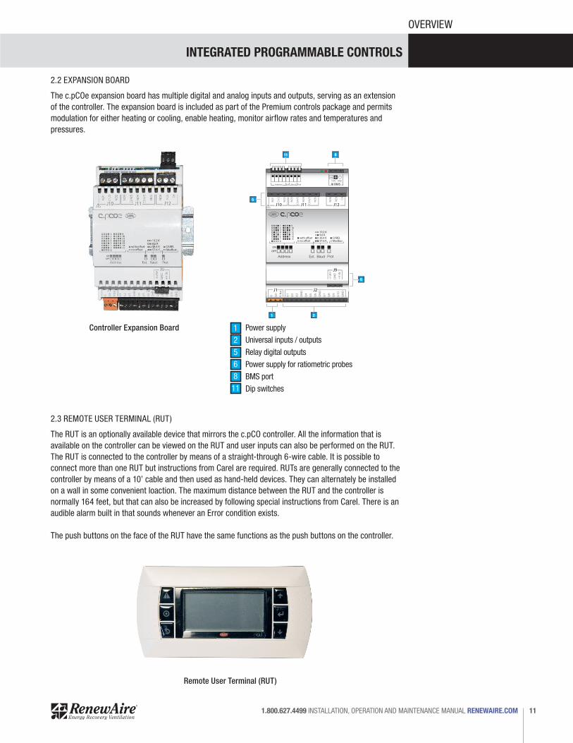
2.2 EXPANSION BOARD
The c.pCOe expansion board has multiple digital and analog inputs and outputs, serving as an extension of the controller. The expansion board is included as part of the Premium controls package and permits modulation for either heating or cooling, enable heating, monitor airflow rates and temperatures and pressures.
2.3 REMOTE USER TERMINAL (RUT)
The RUT is an optionally available device that mirrors the c.pCO controller. All the information that is available on the controller can be viewed on the RUT and user inputs can also be performed on the RUT. The RUT is connected to the controller by means of a straight-through 6-wire cable. It is possible to connect more than one RUT but instructions from Carel are required. RUTs are generally connected to the controller by means of a 10’ cable and then used as hand-held devices. They can alternately be installed on a wall in some convenient loaction. The maximum distance between the RUT and the controller is normally 164 feet, but that can also be increased by following special instructions from Carel. There is an audible alarm built in that sounds whenever an Error condition exists.
The push buttons on the face of the RUT have the same functions as the push buttons on the controller.
12345678
9101112131415 with o�set
no o�set
19.2 K9.6 K38.4 K57.6 K
CARELModbus
ONOFF
Address Ext. ProtBaud
Basic version
6
88
5
1
11
2
Address Ext Baud Prot
Controller Expansion Board
Remote User Terminal (RUT)
1256811
Power supply
Universal inputs / outputs
Relay digital outputs
Power supply for ratiometric probes
BMS port
Dip switches

INTEGRATED PROGRAMMABLE CONTROLS
RENEWAIRE.COM INSTALLATION, OPERATION AND MAINTENANCE MANUAL 1.800.627.449912
OVERVIEW
Back of RUT
The Remote User Terminal (optional accessory, field-installed) plugs into the controller by means of a six-wire cable with RJ12 jacks on each end. The six-wire cable is inserteted in the RJ12 jack on the back of the RUT and othe other end of the cable is inserted into the RJ12 adapter, found in the low voltage electrical compartment. The controller uses a pre-configured cable that plugs into the J3 jack on the controller and the other end is plugged into the RJ12 adapter. The cable from the controller to the low voltage electrical box is factory-installed.
Note: The RUT is nor-mally used as a hand-held device but it may also be mounted on a wall or other surface by means of the screw head recesses on the back of the device.
Note: Common telephone wiring is 4 conductor and uses RJ11 terminals. It is easily confused with the six-wire cable with RJ12 terminals needed for this accessory .
When connecting one RUT to the controller, a 6-wire straight-through cable is used for both data transmission and power to the RUT. If there is more than one RUT, if the distance is greater than 164 feet or if some other configuration is needed, see the Carel c.pCO User Manual.
2.3.1 Connecting an RUT to the Controller
Low VoltageElectrical
Compartment
Note that if the controller was ordered for use with a BMS and an RUT is also desired, contact the factory for further information.
INTEGRATED PROGRAMMABLE CONTROLS
13 1.800.627.4499 INSTALLATION, OPERATION AND MAINTENANCE MANUAL RENEWAIRE.COM
OVERVIEW
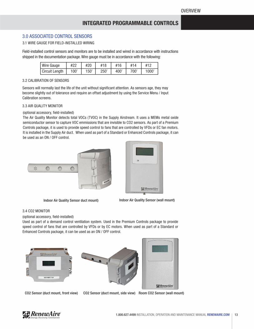
(optional accessory, field-installed) The Air Quality Monitor detects total VOCs (TVOC) in the Supply Airstream. It uses a MEMs metal oxide semiconductor sensor to capture VOC emmissions that are invisible to CO2 sensors. As part of a Premium Controls package, it is used to provide speed control to fans that are controlled by VFDs or EC fan motors. It is installed in the Supply Air duct. When used as part of a Standard or Enhanced Controls package, it can be used as an ON / OFF control.
(optional accessory, field-installed)Used as part of a demand control ventilation system. Used in the Premium Controls package to provide speed control of fans that are controlled by VFDs or by EC motors. When used as part of a Standard or Enhanced Controls package, it can be used as an ON / OFF control.
Indoor Air Quality Sensor duct mount)
CO2 Sensor (duct mount, front view) CO2 Sensor (duct mount, side view) Room CO2 Sensor (wall mount)
Indoor Air Quality Sensor (wall mount)
Field-installed control sensors and monitors are to be installed and wired in accordance with instructions shipped in the documentation package. Wire gauge must be in accordance with the following:
Wire Gauge #22 #20 #18 #16 #14 #12Circuit Length 100’ 150’ 250’ 400’ 700’ 1000’
Sensors will normally last the life of the unit without significant attention. As sensors age, they may become slightly out of tolerance and require an offset adjustment by using the Service Menu / Input Calibration screens.
3.1 WIRE GAUGE FOR FIELD-INSTALLED WIRING
3.2 CALIBRATION OF SENSORS
3.3 AIR QUALITY MONITOR
3.4 CO2 MONITOR
3.0 ASSOCIATED CONTROL SENSORS

INTEGRATED PROGRAMMABLE CONTROLS
RENEWAIRE.COM INSTALLATION, OPERATION AND MAINTENANCE MANUAL 1.800.627.449914
OVERVIEW
(replacement part only, factory-installed)Duct temperature sensors are factory-installed in EA and FA compartments. They are used in Standard, Enhanced and Premium Controls packages.
(replacement part only, factory-installed)Humidity transducers are used in both the Enhanced and the Premium Control packages. They are mounted in the OA and RA compartments and provide an output from 0-10 VDC. Used in Enhanced and Premium Controls packages.
Duct Temperature Sensor
Temperature & Humidity Sensor
3.5 DUCT TEMPERATURE SENSOR
3.6 HUMIDITY TRANSDUCER
INTEGRATED PROGRAMMABLE CONTROLS
15 1.800.627.4499 INSTALLATION, OPERATION AND MAINTENANCE MANUAL RENEWAIRE.COM
OVERVIEW
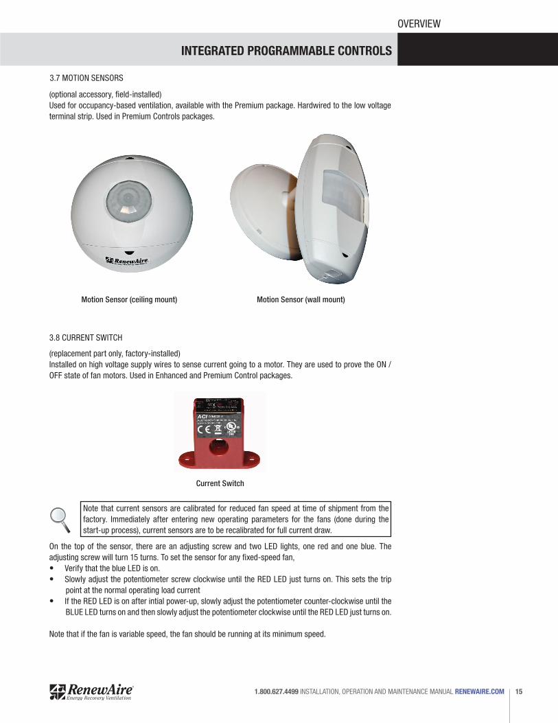
Current Switch
(optional accessory, field-installed)Used for occupancy-based ventilation, available with the Premium package. Hardwired to the low voltage terminal strip. Used in Premium Controls packages.
(replacement part only, factory-installed)Installed on high voltage supply wires to sense current going to a motor. They are used to prove the ON / OFF state of fan motors. Used in Enhanced and Premium Control packages.
Motion Sensor (ceiling mount) Motion Sensor (wall mount)
3.8 CURRENT SWITCH
3.7 MOTION SENSORS
Note that current sensors are calibrated for reduced fan speed at time of shipment from the factory. Immediately after entering new operating parameters for the fans (done during the start-up process), current sensors are to be recalibrated for full current draw.
On the top of the sensor, there are an adjusting screw and two LED lights, one red and one blue. The adjusting screw will turn 15 turns. To set the sensor for any fixed-speed fan,• Verify that the blue LED is on.• Slowly adjust the potentiometer screw clockwise until the RED LED just turns on. This sets the trip
point at the normal operating load current• If the RED LED is on after intial power-up, slowly adjust the potentiometer counter-clockwise until the
BLUE LED turns on and then slowly adjust the potentiometer clockwise until the RED LED just turns on.
Note that if the fan is variable speed, the fan should be running at its minimum speed.
INTEGRATED PROGRAMMABLE CONTROLS
RENEWAIRE.COM INSTALLATION, OPERATION AND MAINTENANCE MANUAL 1.800.627.449916
OVERVIEW
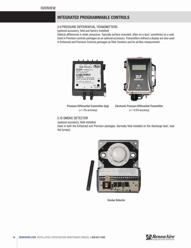
(optional accessory, field and factory-installed)Detects differences in static pressures. Typically surface-mounted, often on a duct, sometimes on a wall. Used in Premium controls packages as an optional accessory. Transmitters without a display are also used in Enhanced and Premium Controls packages as filter monitors and for airflow measurement.
(optional accessory, field-installed)Used in both the Enhanced and Premium packages. Normally field-installed on the discharge duct, near the furnace.
Pressure Differential Transmitter (typ)(+/- 2% accuracy)
Electronic Pressure Differential Transmitter(+/- 0.5% accuracy)
Smoke Detector
3.9 PRESSURE DIFFERENTIAL TRANSMITTERS
3.10 SMOKE DETECTOR
INTEGRATED PROGRAMMABLE CONTROLS
17 1.800.627.4499 INSTALLATION, OPERATION AND MAINTENANCE MANUAL RENEWAIRE.COM
OVERVIEW
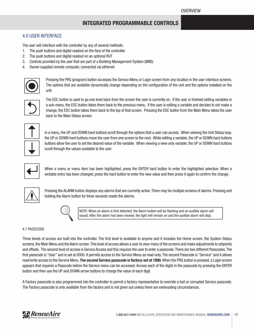
4.0 USER INTERFACE
The user will interface with the controller by any of several methods:1. The push buttons and digital readout on the face of the controller2. The push buttons and digital readout on an optional RUT3. Controls provided by the user that are part of a Building Management System (BMS)4. Owner-supplied remote computer, connected via ethernet
Pressing the PRG (program) button accesses the Service Menu or Login screen from any location in the user interface screens. The options that are available dynamically change depending on the configuration of the unit and the options installed on the unit.
The ESC button is used to go one level back from the screen the user is currently on. If the user is finished setting variables in a sub-menu, the ESC button takes them back to the previous menu. If the user is editing a variable and decides to not make a change, the ESC button takes them back to the top of that screen. Pressing the ESC button from the Main Menu takes the user back to the Main Status screen.
In a menu, the UP and DOWN hard buttons scroll through the options that a user can access. When viewing the Unit Status loop, the UP or DOWN hard buttons move the user from one screen to the next. While editing a variable, the UP or DOWN hard buttons buttons allow the user to set the desired value of the variable. When viewing a view only variable, the UP or DOWN hard buttons scroll through the values available to the user.
When a menu or menu item has been highlighted, press the ENTER hard button to enter the highlighted selection. When a writable entry has been changed, press the hard button to enter the new value and then press it again to confirm the change.
Pressing the ALARM button displays any alarms that are currently active. There may be multiple screens of alarms. Pressing and holding the Alarm button for three seconds resets the alarms.
NOTE: When an alarm is first detected, the Alarm button will be flashing and an audible alarm will sound. After the alarm has been viewed, the light will remain on and the audible alarm will stop.
4.1 PASSCODE
Three levels of access are built into the controller. The first level is available to anyone and it includes the Home screen, the System Status screens, the Main Menu and the Alarm screen. This level of access allows a user to view many of the screens and make adjustments to setpoints and offsets. The second level of access is Service Access and this requires the user to enter a passcode. There are two different Passcodes. The first passcode is “User” and is set at 0000. It permits access to the Service Menu as read-only. The second Passcode is “Service” and it allows read/write access to the Service Menu. The second Service passcode is factory-set at 1000. When the PRG button is pressed, a Login screen appears that requires a Passcode before the Service menu can be accessed. Access each of the digits in the passcode by pressing the ENTER button and then use the UP and DOWN arrow buttons to change the value of each digit.
A Factory passcode is also programmed into the controller to permit a factory representative to override a lost or corrupted Service passcode. The Factory passcode is only available from the factory and is not given out unless there are extenuating circumstances.
INTEGRATED PROGRAMMABLE CONTROLS
RENEWAIRE.COM INSTALLATION, OPERATION AND MAINTENANCE MANUAL 1.800.627.449918
OVERVIEW
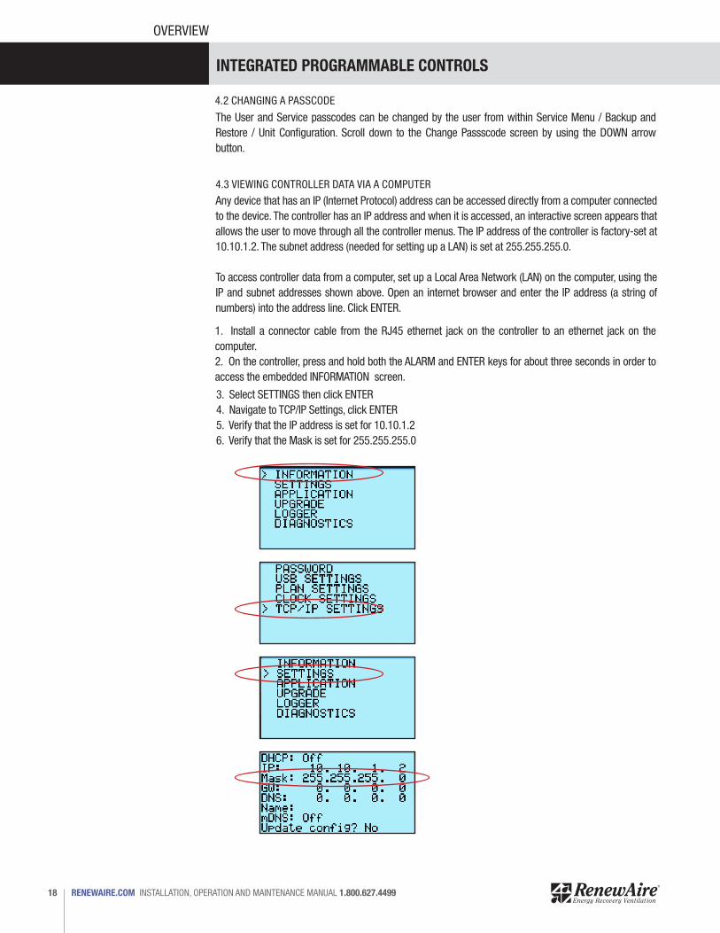
4.3 VIEWING CONTROLLER DATA VIA A COMPUTER
Any device that has an IP (Internet Protocol) address can be accessed directly from a computer connected to the device. The controller has an IP address and when it is accessed, an interactive screen appears that allows the user to move through all the controller menus. The IP address of the controller is factory-set at 10.10.1.2. The subnet address (needed for setting up a LAN) is set at 255.255.255.0.
To access controller data from a computer, set up a Local Area Network (LAN) on the computer, using the IP and subnet addresses shown above. Open an internet browser and enter the IP address (a string of numbers) into the address line. Click ENTER.
4.2 CHANGING A PASSCODE
The User and Service passcodes can be changed by the user from within Service Menu / Backup and Restore / Unit Configuration. Scroll down to the Change Passscode screen by using the DOWN arrow button.
1. Install a connector cable from the RJ45 ethernet jack on the controller to an ethernet jack on the computer.2. On the controller, press and hold both the ALARM and ENTER keys for about three seconds in order to access the embedded INFORMATION screen.
3. Select SETTINGS then click ENTER4. Navigate to TCP/IP Settings, click ENTER5. Verify that the IP address is set for 10.10.1.26. Verify that the Mask is set for 255.255.255.0
INTEGRATED PROGRAMMABLE CONTROLS
19 1.800.627.4499 INSTALLATION, OPERATION AND MAINTENANCE MANUAL RENEWAIRE.COM
OVERVIEW
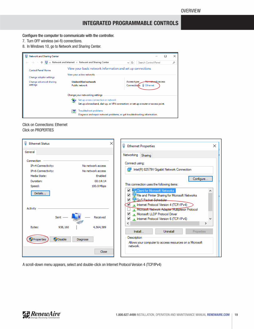
Configure the computer to communicate with the controller.7. Turn OFF wireless (wi-fi) connections. 8. In Windows 10, go to Network and Sharing Center.
Click on Connections: EthernetClick on PROPERTIES
A scroll-down menu appears, select and double-click on Internet Protocol Version 4 (TCP/IPv4)
INTEGRATED PROGRAMMABLE CONTROLS
RENEWAIRE.COM INSTALLATION, OPERATION AND MAINTENANCE MANUAL 1.800.627.449920
OVERVIEW
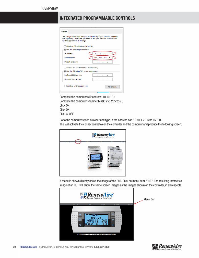
Complete the computer’s IP address: 10.10.10.1Complete the computer’s Subnet Mask: 255.255.255.0Click OKClick OKClick CLOSE
Go to the computer’s web browser and type in the address bar: 10.10.1.2 Press ENTER.This will activate the connection between the controller and the computer and produce the following screen:
A menu is shown directly above the image of the RUT. Click on menu item “RUT”. The resulting interactive image of an RUT will show the same screen images as the images shown on the controller, in all respects.
Menu Bar
INTEGRATED PROGRAMMABLE CONTROLS
21 1.800.627.4499 INSTALLATION, OPERATION AND MAINTENANCE MANUAL RENEWAIRE.COM
OVERVIEW
NOTICEIt is the user’s responsibility to establish security requirements and protocols to safeguard access to controller data and programming.
5.0 CONTROLLER MENUS
When the controller is powered-up, it automatically goes to a Home screen and then optional unit status screens. There are two sets of menus that are built into the unit, the Main Menu and the Service Menu.
The Main Menu has:• Unit Status• Control Variables• Settings• Alarm Settings• Unit Enable
The Service Menu can only be accessed after entering a Service Passcode and has:• Backup and Restore• Unit Type• I/O Configuration• I/O Calibration• Sensor Overrides• Test End Devices
Each menu item shown above has submenus associated with it.
The fully interactive image of an RUT mirrors all inputs and outputs from the controller. Commands inputted by clicking on a button shown on the screen cause the same action as though buttons were being pushed on the controller.
NOTE: The controller will only support private IP addresses which start with 192, 172, or 10.
INTEGRATED PROGRAMMABLE CONTROLS
RENEWAIRE.COM INSTALLATION, OPERATION AND MAINTENANCE MANUAL 1.800.627.449922
OVERVIEW
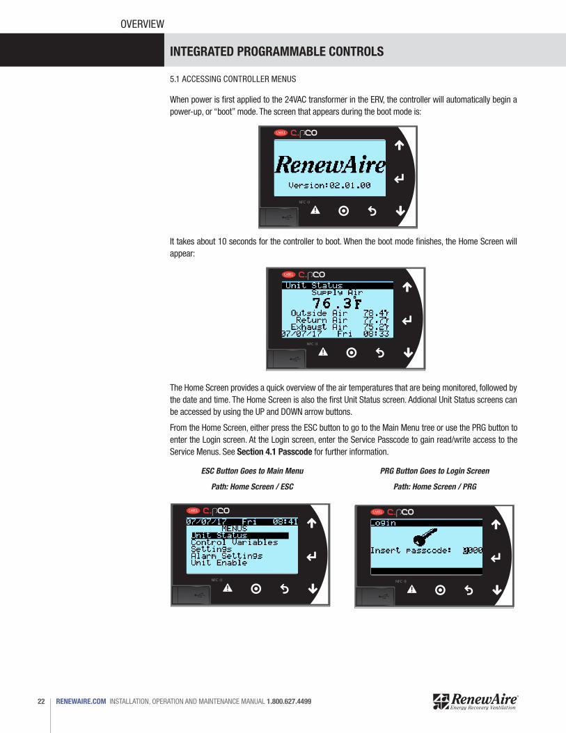
5.1 ACCESSING CONTROLLER MENUS
When power is first applied to the 24VAC transformer in the ERV, the controller will automatically begin a power-up, or “boot” mode. The screen that appears during the boot mode is:
It takes about 10 seconds for the controller to boot. When the boot mode finishes, the Home Screen will appear:
The Home Screen provides a quick overview of the air temperatures that are being monitored, followed by the date and time. The Home Screen is also the first Unit Status screen. Addional Unit Status screens can be accessed by using the UP and DOWN arrow buttons.
From the Home Screen, either press the ESC button to go to the Main Menu tree or use the PRG button to enter the Login screen. At the Login screen, enter the Service Passcode to gain read/write access to the Service Menus. See Section 4.1 Passcode for further information.
ESC Button Goes to Main Menu
Path: Home Screen / ESC Path: Home Screen / PRG
PRG Button Goes to Login Screen
INTEGRATED PROGRAMMABLE CONTROLS
23 1.800.627.4499 INSTALLATION, OPERATION AND MAINTENANCE MANUAL RENEWAIRE.COM
MENUS
HOME SCREEN
UNIT STATUS
UNIT TYPE
UNIT STATUS
ALARM SETTINGS
SENSOR OVERRIDES
MAIN MENU
CONTROL VARIABLES
I/O CONFIGURATION
SUBMENUS SEE PAGE 25
ALARM INFO SEE PAGE 36
SUBMENUS SEE PAGE 36
SUBMENUS SEE PAGE 37
SUBMENUS SEE PAGE 37
SUBMENUS SEE PAGE 38
SUBMENUS SEE PAGE 39
SUBMENUS SEE PAGE 40
SUBMENUS SEE PAGE 26
SUBMENUS SEE PAGE 31
SUBMENUS SEE PAGE 34
SUBMENU SEE PAGE 35UNIT ENABLE
TEST END DEVICES
LOGIN SCREEN
BACKUP ANDRESTORE
SERVICE MENU
SETTINGS
I/O CALIBRATION
ESC BUTTON PRG BUTTON
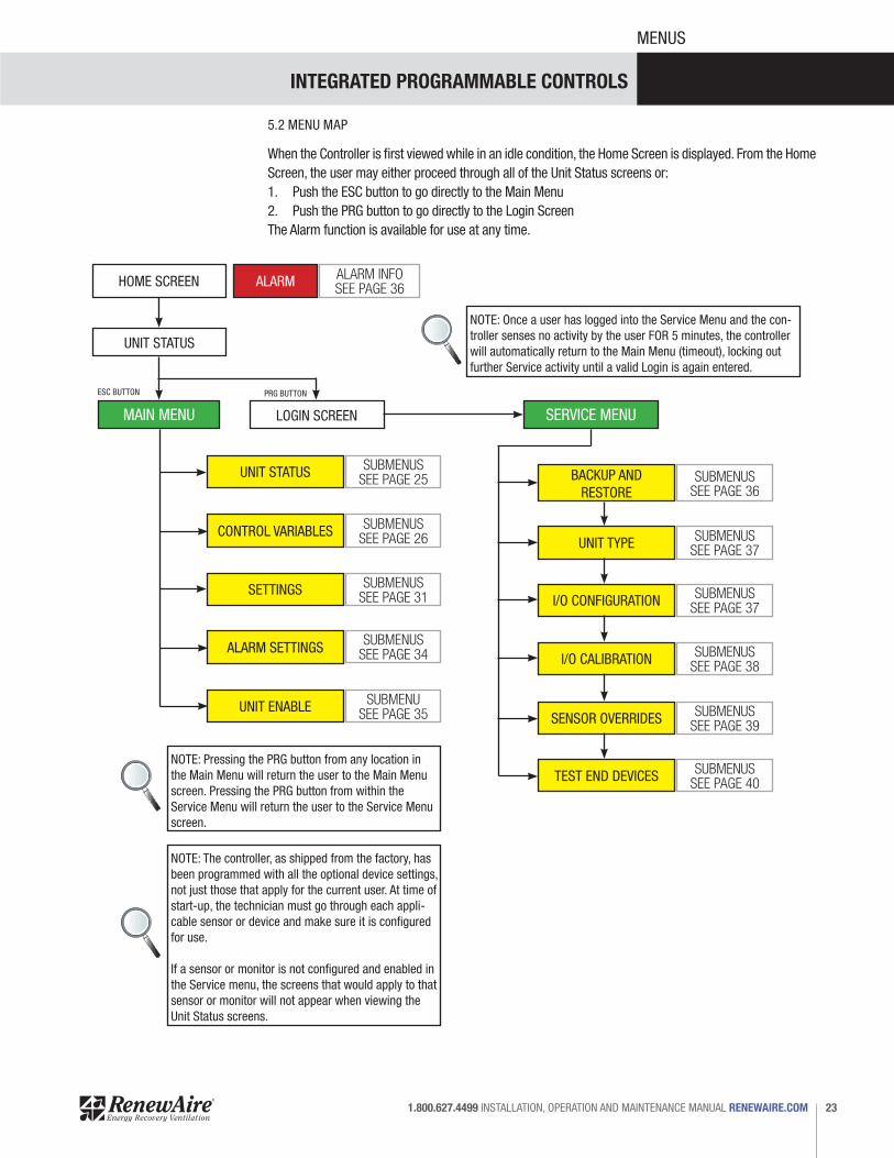
NOTE: Once a user has logged into the Service Menu and the con-troller senses no activity by the user FOR 5 minutes, the controller will automatically return to the Main Menu (timeout), locking out further Service activity until a valid Login is again entered.
NOTE: Pressing the PRG button from any location in the Main Menu will return the user to the Main Menu screen. Pressing the PRG button from within the Service Menu will return the user to the Service Menu screen.
NOTE: The controller, as shipped from the factory, has been programmed with all the optional device settings, not just those that apply for the current user. At time of start-up, the technician must go through each appli-cable sensor or device and make sure it is configured for use.
If a sensor or monitor is not configured and enabled in the Service menu, the screens that would apply to that sensor or monitor will not appear when viewing the Unit Status screens.
5.2 MENU MAP
ALARM
When the Controller is first viewed while in an idle condition, the Home Screen is displayed. From the Home Screen, the user may either proceed through all of the Unit Status screens or:1. Push the ESC button to go directly to the Main Menu2. Push the PRG button to go directly to the Login Screen The Alarm function is available for use at any time.

INTEGRATED PROGRAMMABLE CONTROLS
RENEWAIRE.COM INSTALLATION, OPERATION AND MAINTENANCE MANUAL 1.800.627.449924
MENUS
HOW TO USE THE CONTROLLER MENU
The controller menu, as shown on the following pages, has a hierarchy and is arranged in the same order as the menu items appear on the controller screen. All the possible screens are shown even though not all will appear, depending on unit configuration. Any screen that has a single-digit identifying number is a primary screen that may or may not have choices to be made on it. If a choice is embedded in the screen, there will be two or more “child” screens that will result and will be identified by .1, .2 and so on.
Example: Within the Unit Status menu, the Economizer screen appears as screen number 4. This is the first economizer screen available. Screen four has a total of three different choices that can be selected, two of which will produce a follow-up screen. These two screens are numbered 4.1 and 4.2. Each of these follow-up screens has an additional choice and will produce yet another screen. The screen produced by 4.1 is numbered 4.1.1 and the screen produced by 4.2 is numbered 4.2.1.
For every screen that appears, click the ENTER hard button to see if there is a setting choice. The cursor will move to the line where a choice is to be made. To make a choice at that line, click the UP and DOWN buttons to view the choices. When the desired choice is visible, click the ENTER button again. If there is no choice, the ENTER button will not move the blinking cursor.
SCREEN 4 HAS2 CHOICES
SCREEN 4 SCREEN 4.1 SCREEN 4.1.1
SCREEN 4.2.1SCREEN 4.2
SCREEN 4.1 HASA SINGLE CHOICE
SCREEN 4.2 HASA SINGLE CHOICE
INTEGRATED PROGRAMMABLE CONTROLS
25 1.800.627.4499 INSTALLATION, OPERATION AND MAINTENANCE MANUAL RENEWAIRE.COM
SUBMENUS
Screen 1, Supply Air
Screen 6, Space Pressure
Screen 11, Heating 1 Stage
Screen 2, Humidity
Screen 7, Duct Pressure
Screen 12, Heating 2 Stage
Screen 3, Air Flow Rate
Screen 8, Fan Enables
Screen 13, Elect Mod
Screen 14, HW Mod
Screen 4, CO2 Levels
Screen 9, Dampers Open Screen 15 Cooling 1,
Screen 5, VOC Level
Screen 10, Fan Command Screen 16, Cooling 2
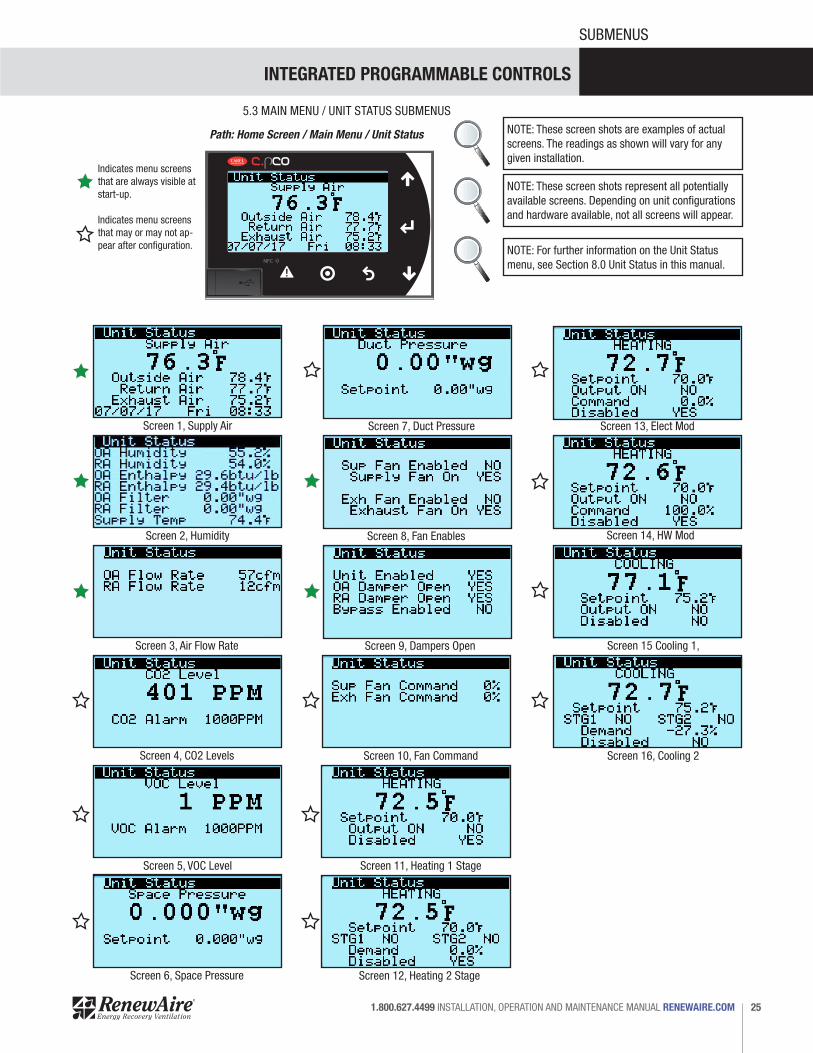
5.3 MAIN MENU / UNIT STATUS SUBMENUS
NOTE: These screen shots are examples of actual screens. The readings as shown will vary for any given installation.
NOTE: These screen shots represent all potentially available screens. Depending on unit configurations and hardware available, not all screens will appear.
NOTE: For further information on the Unit Status menu, see Section 8.0 Unit Status in this manual.
Path: Home Screen / Main Menu / Unit Status
Indicates menu screens that are always visible at start-up.
Indicates menu screens that may or may not ap-pear after configuration.

INTEGRATED PROGRAMMABLE CONTROLS
RENEWAIRE.COM INSTALLATION, OPERATION AND MAINTENANCE MANUAL 1.800.627.449926
SUBMENUS
Screen 1, Supply Fan Control
5.3 MAIN MENU / UNIT STATUS SUBMENUS
NOTE: These screen shots are examples of actual screens. The readings as shown will vary for any given installation.
NOTE: These screen shots represent all potentially available screens. Depending on unit configurations and hardware available, not all screens will appear.
NOTE: For further information on the Control Vari-ables menu, see Section 9.0 Control Variables in this manual.
Path: Home Screen / Main Menu / Control Variables
Choices Within Supply Fan Control:
• Constant Speed (Generates Constant Speed Setup Screen 1.1)
• CO2/Flow (Generates Supply Fan CO2/Airflow Control Screen 1.2)
• VOC (Generates Supply Fan VOC Control Screen 1.3)
• CO2 (Generates Supply Fan CO2 Control Screen 1.4)
• Room Static (Generates Supply Fan Room Static Control Screen 1.5)
• Duct Static (generates Supply Fan Duct Static Control Screen 1.6)
• Supply Flow (Generates Supply Fan Airflow Control Screen 1.7)
Choices Within Exhaust Fan Control:
• Constant Speed (Generates Exhaust Air Con-stant Speed Setup Screen 2.1)
• Room Static Pressure (Generates Exhaust Fan Room Static Control Screen 2.2)
• SF Flow Tracking (Generates Exhaust Air SF Flow Tracking Screen 2.3)
• SF Command Tracking (Generates Exhaust Air SF Command Tracking 2.4)
• Exhaust Flow (Generates Exhaust Air Airflow Setpoint 2.5)
Screen 1.1, Constant Speed Setup
Screen 1.3, VOC Control
Screen 1.7, Airflow Control
Screen 2.1, Constant Speed Setup
Screen 1.6, Duct Static Control
Screen 1.2, CO2 / Airflow Control
Screen 1.4, CO2 Control
Screen 1.5, Room Static Control
Screen 2, Exhaust Fan
Screen 2.2, EF Room Static Control
Screen 2.3, SF Flow Tracking
INTEGRATED PROGRAMMABLE CONTROLS
27 1.800.627.4499 INSTALLATION, OPERATION AND MAINTENANCE MANUAL RENEWAIRE.COM
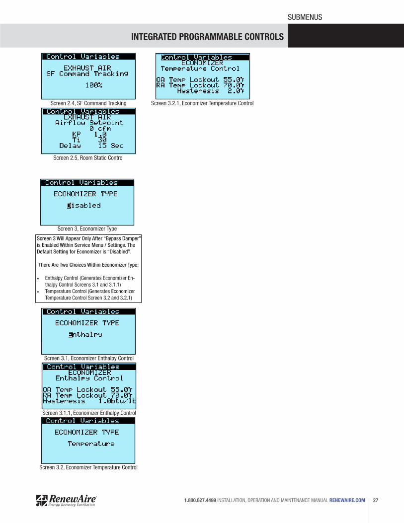
SUBMENUS
Screen 3 Will Appear Only After “Bypass Damper” is Enabled Within Service Menu / Settings. The Default Setting for Economizer is “Disabled”.
There Are Two Choices Within Economizer Type:
• Enthalpy Control (Generates Economizer En-thalpy Control Screens 3.1 and 3.1.1)
• Temperature Control (Generates Economizer Temperature Control Screen 3.2 and 3.2.1)
Screen 2.4, SF Command Tracking
Screen 2.5, Room Static Control
Screen 3, Economizer Type
Screen 3.1, Economizer Enthalpy Control
Screen 3.1.1, Economizer Enthalpy Control
Screen 3.2.1, Economizer Temperature Control
Screen 3.2, Economizer Temperature Control

INTEGRATED PROGRAMMABLE CONTROLS
RENEWAIRE.COM INSTALLATION, OPERATION AND MAINTENANCE MANUAL 1.800.627.449928
SUBMENUS
Screen 4 Will Appear Only After “Enable Heat” is Changed to YES Within Service Menu / Unit Type. The Default Setting for Heating Type is “ON / OFF”
There Are Five Choices Within Heating Type:
• ON / OFF (Generates Screen 4) • Hot Water (Generates Hot Water Screen 4A). • Gas Modulating (Generates Gas Modulating
Screen 4B)• Electric Modulating (Generates Electric Modu-
lating Screen 4C)• 2 Stage (Generates Heating 2 Stage Screen 4D)
Screen 4, Heating: ON/OFF Screen 4A, Heating: Hot Water
Screen 4.1, ON OFF Setpoint Adjust SA Ctrl
Screen 4.3.1, ON OFF Adjust RA Ctrl
Screen 4.3, ON OFF Adjust RA Ctrl
Screen 4.2, ON OFF Adjust OA Reset SA Ctrl
Screen 4.2.1, ON OFF OA Reset SA Ctrl
Screen 4.2.2, ON OFF OA Reset SA Ctrl
Screen 4A.2, Hot Water OA Reset SA Ctrl
Screen 4A.2.1, Hot Water OA Reset SA Ctrl
Screen 4A.2.2, Hot Water OA Reset SA Ctrl
Screen 4A.3, Hot Water OA Reset RA Ctrl
Screen 4A.3.1, Hot Water OA Reset RA Ctrl
Screen 4A.3.2, Hot Water OA Reset RA Ctrl
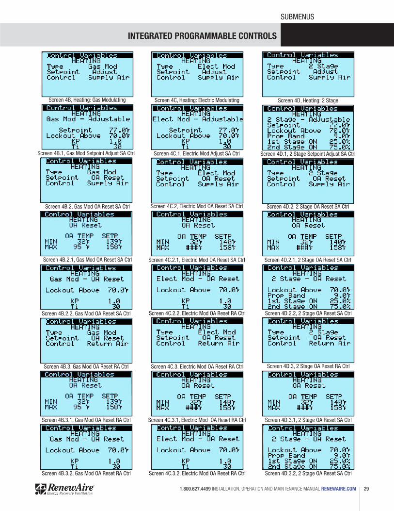
Within each Heating Type, there are additional configuration choices to be made:
Setpoint:• Adjustable Setpoint (default setting) • OA Reset
Control Type:• Supply Air Control• Return Air control
Screens that do not pertain to completed selec-tions WILL NOT APPEAR on the controller.
Screen 4A.1, Hot Water Setpoint Adjust SA Ctrl
INTEGRATED PROGRAMMABLE CONTROLS
29 1.800.627.4499 INSTALLATION, OPERATION AND MAINTENANCE MANUAL RENEWAIRE.COM
SUBMENUS
Screen 4B, Heating: Gas Modulating
Screen 4B.1, Gas Mod Setpoint Adjust SA Ctrl
Screen 4B.2, Gas Mod OA Reset SA Ctrl
Screen 4B.2.1, Gas Mod OA Reset SA Ctrl
Screen 4B.3, Gas Mod OA Reset RA Ctrl
Screen 4B.2.2, Gas Mod OA Reset SA Ctrl
Screen 4B.3.1, Gas Mod OA Reset RA Ctrl
Screen 4B.3.2, Gas Mod OA Reset RA Ctrl
Screen 4C, Heating: Electric Modulating
Screen 4C.1, Electric Mod Adjust SA Ctrl
Screen 4C.2, Electric Mod OA Reset SA Ctrl
Screen 4C.2.1, Electric Mod OA Reset SA Ctrl
Screen 4C.2.2, Electric Mod OA Reset RA Ctrl
Screen 4C.3, Electric Mod OA Reset RA Ctrl
Screen 4C.3.1, Electric Mod OA Reset RA Ctrl
Screen 4C.3.2, Electric Mod OA Reset RA Ctrl
Screen 4D, Heating: 2 Stage
Screen 4D.1, 2 Stage Setpoint Adjust SA Ctrl
Screen 4D.2, 2 Stage OA Reset SA Ctrl
Screen 4D.2.1, 2 Stage OA Reset SA Ctrl
Screen 4D.2.2, 2 Stage OA Reset SA Ctrl
Screen 4D.3, 2 Stage OA Reset RA Ctrl
Screen 4D.3.1, 2 Stage OA Reset SA Ctrl
Screen 4D.3.2, 2 Stage OA Reset SA Ctrl
INTEGRATED PROGRAMMABLE CONTROLS
RENEWAIRE.COM INSTALLATION, OPERATION AND MAINTENANCE MANUAL 1.800.627.449930
SUBMENUS
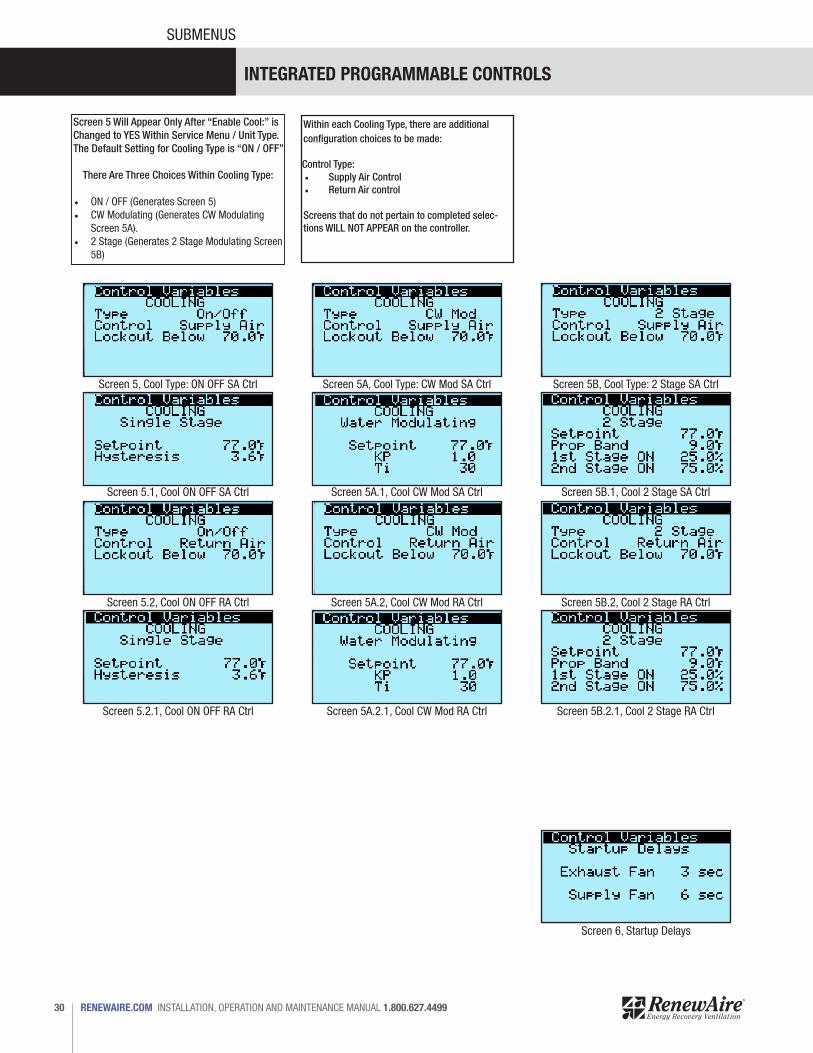
Screen 5 Will Appear Only After “Enable Cool:” is Changed to YES Within Service Menu / Unit Type. The Default Setting for Cooling Type is “ON / OFF”
There Are Three Choices Within Cooling Type:
• ON / OFF (Generates Screen 5) • CW Modulating (Generates CW Modulating
Screen 5A). • 2 Stage (Generates 2 Stage Modulating Screen
5B)
Within each Cooling Type, there are additional configuration choices to be made:
Control Type:• Supply Air Control• Return Air control
Screens that do not pertain to completed selec-tions WILL NOT APPEAR on the controller.
Screen 5, Cool Type: ON OFF SA Ctrl Screen 5A, Cool Type: CW Mod SA Ctrl
Screen 5.1, Cool ON OFF SA Ctrl Screen 5A.1, Cool CW Mod SA Ctrl
Screen 5.2, Cool ON OFF RA Ctrl
Screen 5.2.1, Cool ON OFF RA Ctrl Screen 5A.2.1, Cool CW Mod RA Ctrl
Screen 5A.2, Cool CW Mod RA Ctrl
Screen 5B, Cool Type: 2 Stage SA Ctrl
Screen 5B.1, Cool 2 Stage SA Ctrl
Screen 5B.2.1, Cool 2 Stage RA Ctrl
Screen 5B.2, Cool 2 Stage RA Ctrl
Screen 6, Startup Delays
INTEGRATED PROGRAMMABLE CONTROLS
31 1.800.627.4499 INSTALLATION, OPERATION AND MAINTENANCE MANUAL RENEWAIRE.COM
SUBMENUS
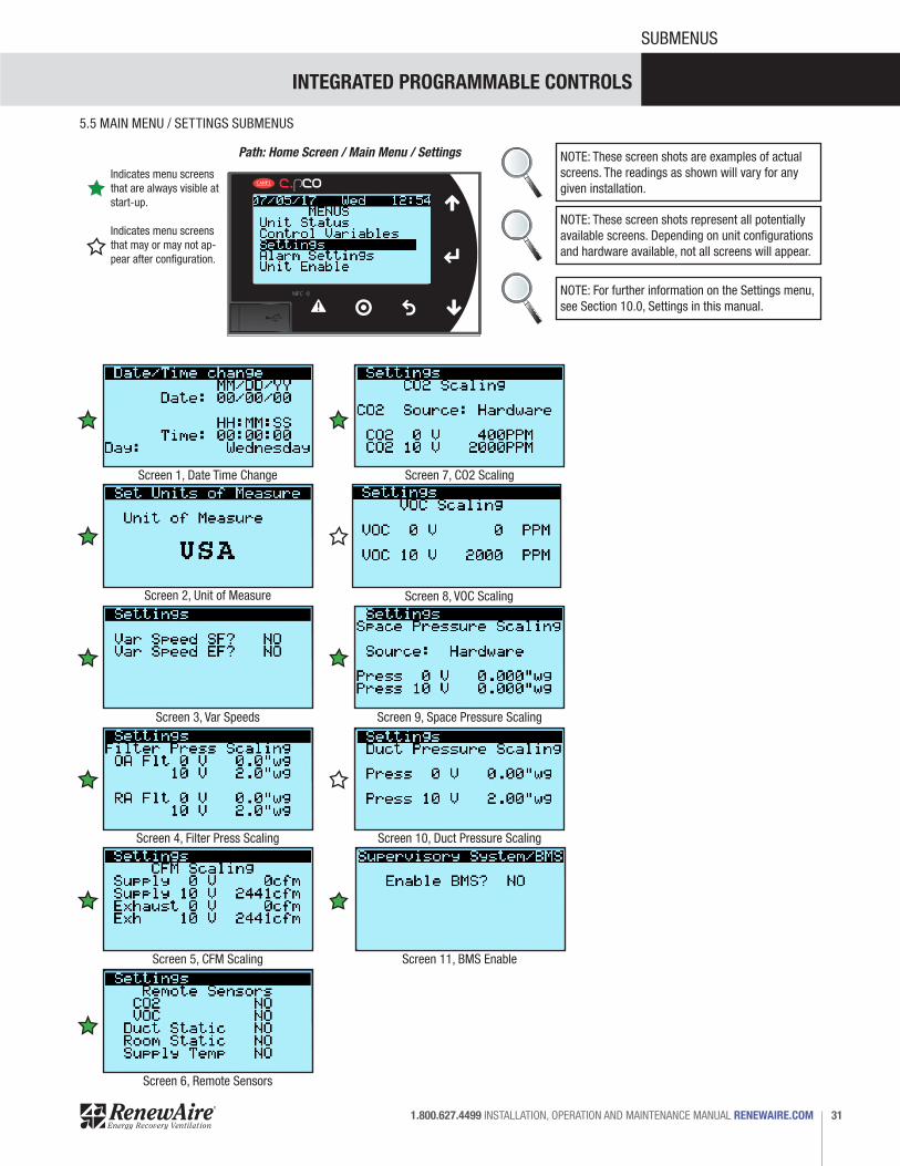
Screen 1, Date Time Change Screen 7, CO2 Scaling
Screen 8, VOC ScalingScreen 2, Unit of Measure
Screen 3, Var Speeds Screen 9, Space Pressure Scaling
Screen 4, Filter Press Scaling Screen 10, Duct Pressure Scaling
Screen 5, CFM Scaling Screen 11, BMS Enable
Screen 6, Remote Sensors
5.5 MAIN MENU / SETTINGS SUBMENUS
Path: Home Screen / Main Menu / Settings NOTE: These screen shots are examples of actual screens. The readings as shown will vary for any given installation.
NOTE: These screen shots represent all potentially available screens. Depending on unit configurations and hardware available, not all screens will appear.
NOTE: For further information on the Settings menu, see Section 10.0, Settings in this manual.
Indicates menu screens that are always visible at start-up.
Indicates menu screens that may or may not ap-pear after configuration.
INTEGRATED PROGRAMMABLE CONTROLS
RENEWAIRE.COM INSTALLATION, OPERATION AND MAINTENANCE MANUAL 1.800.627.449932
SUBMENUS
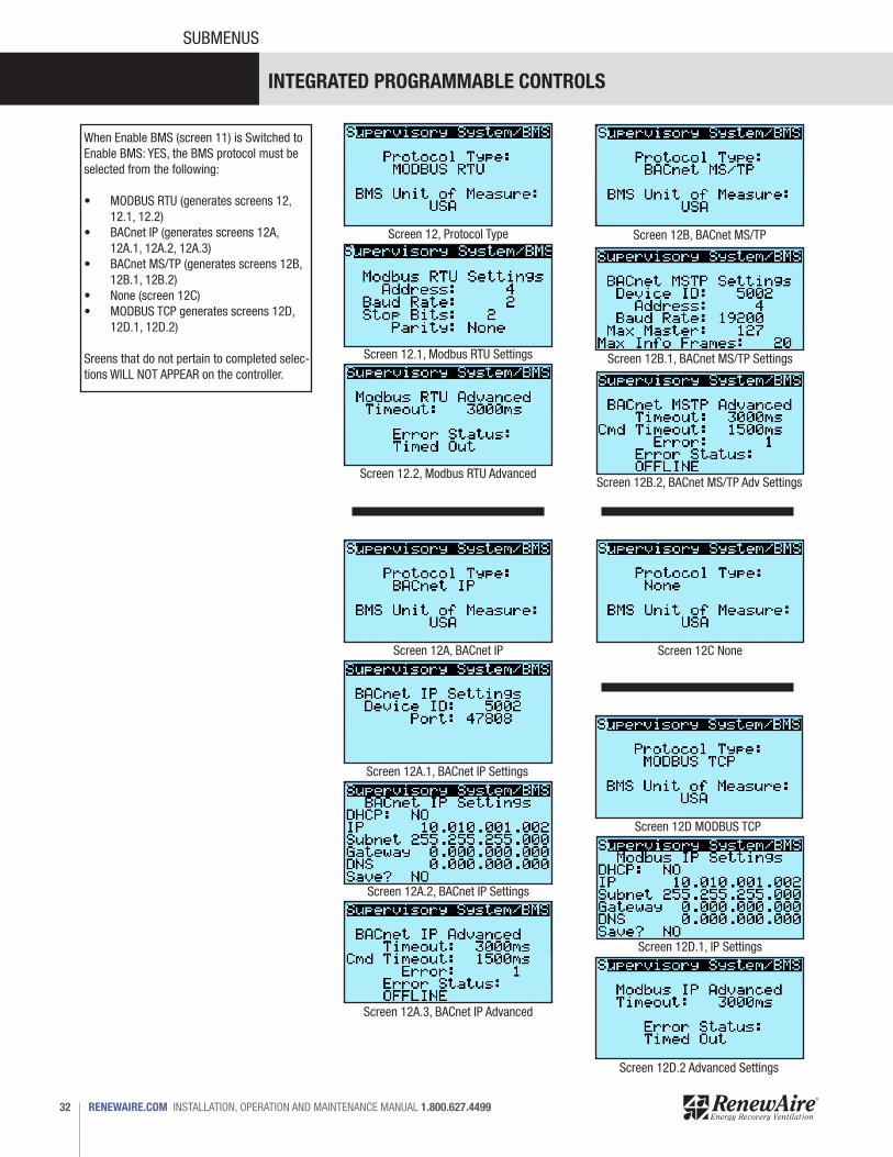
Screen 12.1, Modbus RTU Settings
Screen 12.2, Modbus RTU Advanced
Screen 12, Protocol Type
Screen 12D.2 Advanced Settings
Screen 12D.1, IP Settings
Screen 12D MODBUS TCP
Screen 12C None
Screen 12B.2, BACnet MS/TP Adv Settings
Screen 12B.1, BACnet MS/TP Settings
Screen 12A.3, BACnet IP Advanced
Screen 12B, BACnet MS/TP
Screen 12A.2, BACnet IP Settings
Screen 12A, BACnet IP
Screen 12A.1, BACnet IP Settings
When Enable BMS (screen 11) is Switched to Enable BMS: YES, the BMS protocol must be selected from the following:
• MODBUS RTU (generates screens 12, 12.1, 12.2)
• BACnet IP (generates screens 12A, 12A.1, 12A.2, 12A.3)
• BACnet MS/TP (generates screens 12B, 12B.1, 12B.2)
• None (screen 12C)• MODBUS TCP generates screens 12D,
12D.1, 12D.2)
Sreens that do not pertain to completed selec-tions WILL NOT APPEAR on the controller.
INTEGRATED PROGRAMMABLE CONTROLS
33 1.800.627.4499 INSTALLATION, OPERATION AND MAINTENANCE MANUAL RENEWAIRE.COM
SUBMENUS
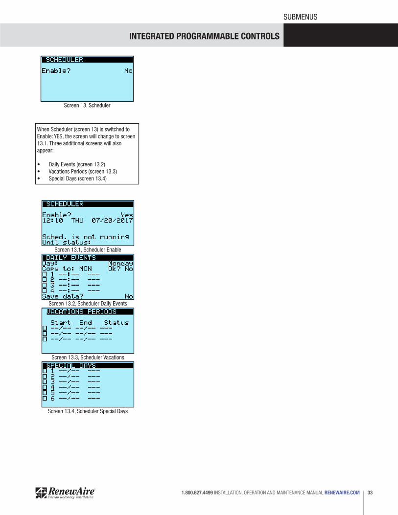
Screen 13, Scheduler
Screen 13.1, Scheduler Enable
Screen 13.3, Scheduler Vacations
Screen 13.2, Scheduler Daily Events
Screen 13.4, Scheduler Special Days
When Scheduler (screen 13) is switched to Enable: YES, the screen will change to screen 13.1. Three additional screens will also appear:
• Daily Events (screen 13.2)• Vacations Periods (screen 13.3)• Special Days (screen 13.4)
INTEGRATED PROGRAMMABLE CONTROLS
RENEWAIRE.COM INSTALLATION, OPERATION AND MAINTENANCE MANUAL 1.800.627.449934
SUBMENUS
Indicates menu screens that are always visible at start-up.
Indicates menu screens that may or may not ap-pear after configuration.
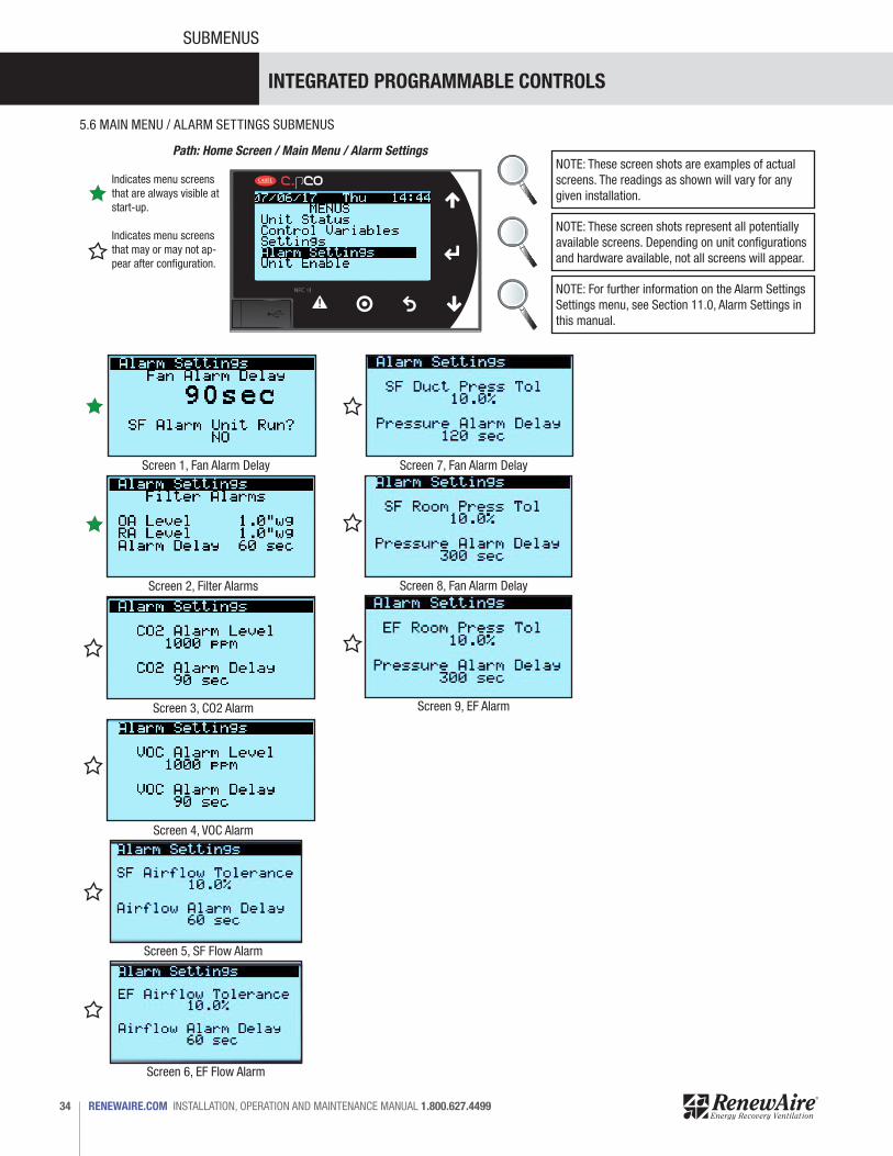
Screen 1, Fan Alarm Delay Screen 7, Fan Alarm Delay
Screen 8, Fan Alarm Delay
Screen 9, EF Alarm
Screen 6, EF Flow Alarm
Screen 2, Filter Alarms
Screen 3, CO2 Alarm
Screen 4, VOC Alarm
Screen 5, SF Flow Alarm
5.6 MAIN MENU / ALARM SETTINGS SUBMENUS
Path: Home Screen / Main Menu / Alarm SettingsNOTE: These screen shots are examples of actual screens. The readings as shown will vary for any given installation.
NOTE: These screen shots represent all potentially available screens. Depending on unit configurations and hardware available, not all screens will appear.
NOTE: For further information on the Alarm Settings Settings menu, see Section 11.0, Alarm Settings in this manual.
INTEGRATED PROGRAMMABLE CONTROLS
35 1.800.627.4499 INSTALLATION, OPERATION AND MAINTENANCE MANUAL RENEWAIRE.COM
SUBMENUS
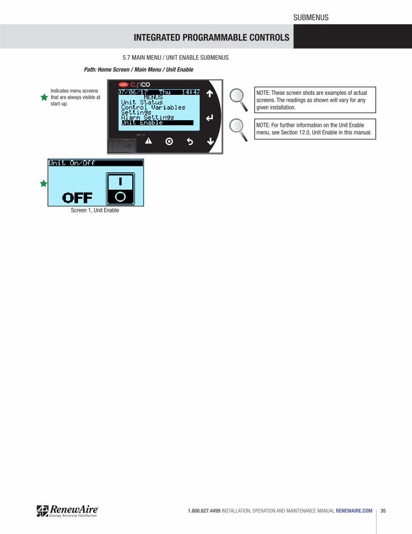
Screen 1, Unit Enable
5.7 MAIN MENU / UNIT ENABLE SUBMENUS
Path: Home Screen / Main Menu / Unit Enable
NOTE: These screen shots are examples of actual screens. The readings as shown will vary for any given installation.
NOTE: For further information on the Unit Enable menu, see Section 12.0, Unit Enable in this manual.
Indicates menu screens that are always visible at start-up.
INTEGRATED PROGRAMMABLE CONTROLS
RENEWAIRE.COM INSTALLATION, OPERATION AND MAINTENANCE MANUAL 1.800.627.449936
SUBMENUS
Path: Home Screen / PRG
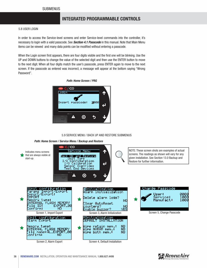
5.8 USER LOGIN
In order to access the Service-level screens and enter Service-level commands into the controller, it’s necessary to login with a valid passcode. See Section 4.1 Passcode in this manual. Note that Main Menu items can be viewed and many data points can be modified without entering a passcode.
When the Login screen first appears, there are four digits visible and the first one will be blinking. Use the UP and DOWN buttons to change the value of the selected digit and then use the ENTER button to move to the next digit. When all four digits match the user’s passcode, press ENTER again to move to the next screen. If the passcode as entered was incorrect, a message will appear at the bottom saying “Wrong Password”.
Screen 1, Import Export
Screen 2, Alarm Export
5.9 SERVICE MENU / BACK UP AND RESTORE SUBMENUS
Path: Home Screen / Service Menu / Backup and Restore
NOTE: These screen shots are examples of actual screens. The readings as shown will vary for any given installation. See Section 13.0 Backup and Restore for further information.
Screen 3, Alarm Initialization
Screen 4, Default Installation
Indicates menu screens that are always visible at start-up.
Screen 5, Change Passcode

INTEGRATED PROGRAMMABLE CONTROLS
37 1.800.627.4499 INSTALLATION, OPERATION AND MAINTENANCE MANUAL RENEWAIRE.COM
SUBMENUS
Screen 1, Unit Configuration
5.10 SERVICE MENU / UNIT TYPE SUBMENUS
Path: Home Screen / Service Menu / Unit Type
NOTE: These screen shots are examples of actual screens. The readings as shown will vary for any given installation.
Screen 1, Invert Logic
5.11 SERVICE MENU / I/O CONFIGURATION SUBMENUS
Path: Home Screen / Service Menu/ I/O Configuration
NOTE: These screen shots are examples of actual screens. The readings as shown will vary for any given installation.
NOTE: For further information on the Unit Type menu, see Section 14.0, Unit Type in this manual.
NOTE: For further information on the I/O Configura-tion menu, see Section 15.0, I/O Configuration in this manual.
Indicates menu screens that are always visible at start-up.
Indicates menu screens that are always visible at start-up.
INTEGRATED PROGRAMMABLE CONTROLS
RENEWAIRE.COM INSTALLATION, OPERATION AND MAINTENANCE MANUAL 1.800.627.449938
SUBMENUS
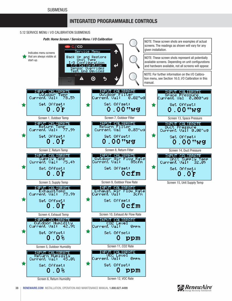
Screen 1, Outdoor Temp
Screen 6, Return Humidity
Screen 11, CO2 Rate
Screen 2, Return Temp
Screen 7, Outdoor Filter
Screen 12, VOC Rate
Screen 3, Supply Temp
Screen 8, Return Filter
Screen 13, Space Pressure
Screen 4, Exhaust Temp
Screen 9, Outdoor Flow Rate
Screen 14, Duct Pressure
Screen 5, Outdoor Humidity
Screen 10, Exhaust Air Flow Rate
Screen 15, Unit Supply Temp
5.12 SERVICE MENU / I/O CALIBRATION SUBMENUS
Path: Home Screen / Service Menu / I/O CalibrationNOTE: These screen shots are examples of actual screens. The readings as shown will vary for any given installation.
NOTE: These screen shots represent all potentially available screens. Depending on unit configurations and hardware available, not all screens will appear.
NOTE: For further information on the I/O Calibra-tion menu, see Section 16.0, I/O Calibration in this manual.
Indicates menu screens that are always visible at start-up.

INTEGRATED PROGRAMMABLE CONTROLS
39 1.800.627.4499 INSTALLATION, OPERATION AND MAINTENANCE MANUAL RENEWAIRE.COM
SUBMENUS
5.13 SERVICE MENU / SENSOR OVERRIDES SUBMENUS
Path: Home Screen / Service Menu / Sensor OverridesNOTE: These screen shots are examples of actual screens. The readings as shown will vary for any given installation.
NOTE: These screen shots represent all potentially available screens. Depending on unit configurations and hardware available, not all screens will appear.
Screen 7, OA Filter Override
Screen 14, Duct Pressure Override
Screen 13, Space Pressure OverrideScreen 1, Outdoor Temp Override
Screen 12, VOC OverrideScreen 6, Return Humidity Override
Screen 8, RA Filter Override
Screen 15, Unit Supply Temp Override
Screen 2, Return Override
Screen 9, OA Flow Rate OverrideScreen 3, Supply Override
Screen 10, EA Filter OverrideScreen 4, Exhaust Override
Screen 11, CO2 OverrideScreen 5, Humidity Override
NOTE: For further information on the Sensor Override menu, see Section 17.0, Sensor Overrides in this manual.
Indicates menu screens that are always visible at start-up.
Indicates menu screens that may or may not ap-pear after configuration.
INTEGRATED PROGRAMMABLE CONTROLS
RENEWAIRE.COM INSTALLATION, OPERATION AND MAINTENANCE MANUAL 1.800.627.449940
SUBMENUS
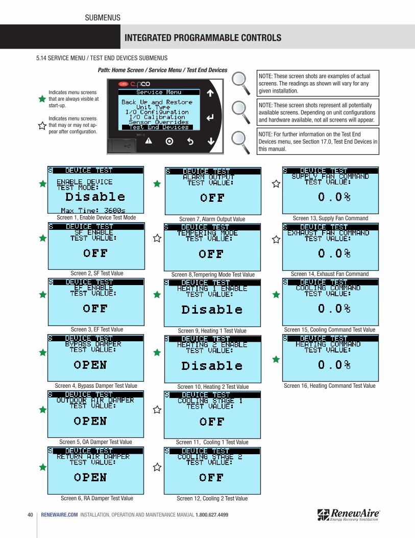
5.14 SERVICE MENU / TEST END DEVICES SUBMENUS
Path: Home Screen / Service Menu / Test End DevicesNOTE: These screen shots are examples of actual screens. The readings as shown will vary for any given installation.
NOTE: These screen shots represent all potentially available screens. Depending on unit configurations and hardware available, not all screens will appear.
Screen 7, Alarm Output Value Screen 13, Supply Fan CommandScreen 1, Enable Device Test Mode
Screen 12, Cooling 2 Test Value
Screen 8,Tempering Mode Test Value Screen 14, Exhaust Fan CommandScreen 2, SF Test Value
Screen 9, Heating 1 Test Value Screen 15, Cooling Command Test ValueScreen 3, EF Test Value
Screen 10, Heating 2 Test Value Screen 16, Heating Command Test ValueScreen 4, Bypass Damper Test Value
Screen 11, Cooling 1 Test ValueScreen 5, OA Damper Test Value
Screen 6, RA Damper Test Value
NOTE: For further information on the Test End Devices menu, see Section 17.0, Test End Devices in this manual.
Indicates menu screens that are always visible at start-up.
Indicates menu screens that may or may not ap-pear after configuration.
INTEGRATED PROGRAMMABLE CONTROLS
41 1.800.627.4499 INSTALLATION, OPERATION AND MAINTENANCE MANUAL RENEWAIRE.COM
SUBMENUS
Alarm Screen Example
Alarm Reset Screen
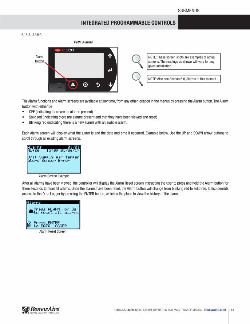
5.15 ALARMS
Path: Alarms
NOTE: These screen shots are examples of actual screens. The readings as shown will vary for any given installation.
NOTE: Also see Section 6.0, Alarms in this manual.
AlarmButton
The Alarm functions and Alarm screens are available at any time, from any other location in the menus by pressing the Alarm button. The Alarm button with either be • OFF (indicating there are no alarms present) • Solid red (indicating there are alarms present and that they have been viewed and reset)• Blinking red (indicating there is a new alarm) with an audible alarm.
Each Alarm screen will display what the alarm is and the date and time it occurred. Example below. Use the UP and DOWN arrow buttons to scroll through all existing alarm screens.
After all alarms have been viewed, the controller will display the Alarm Reset screen instructing the user to press and hold the Alarm button for three seconds to reset all alarms. Once the alarms have been reset, the Alarm button will change from blinking red to solid red. It also permits access to the Data Logger by pressing the ENTER button, which is the place to view the history of the alarm.
INTEGRATED PROGRAMMABLE CONTROLS
RENEWAIRE.COM INSTALLATION, OPERATION AND MAINTENANCE MANUAL 1.800.627.449942
SUBMENUS
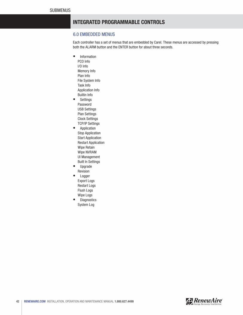
6.0 EMBEDDED MENUS
Each controller has a set of menus that are embedded by Carel. These menus are accessed by pressing both the ALARM button and the ENTER button for about three seconds.
• InformationPCO InfoI/O InfoMemory InfoPlan InfoFile System InfoTask InfoApplication InfoBuiltin Info
• SettingsPasswordUSB SettingsPlan SettingsClock SettingsTCP/IP Settings
• ApplicationStop ApplicationStart ApplicationRestart ApplicationWipe RetainWipe NVRAMUI ManagementBuilt In Settings
• UpgradeRevision
• LoggerExport LogsRestart LogsFlush LogsWipe Logs
• DiagnosticsSystem Log

INTEGRATED PROGRAMMABLE CONTROLS
43 1.800.627.4499 INSTALLATION, OPERATION AND MAINTENANCE MANUAL RENEWAIRE.COM
MENU DESCRIPTIONS
7.0 ALARMS
7.1 ACTIVE ALARMS
When the controller is first booted up, currently active alarms are displayed on the controller screen when the Alarm button is pressed. Using the UP and DOWN ARROW buttons will display each alarm individually. When an alarm condition is first detected the Alarm button will be flashing red and an audible alarm will be heard. Currently active alarms may be viewed at any time by pressing the Alarm button. After viewing all the active alarms, all active alarms can be reset by pressing and holding the Alarm button for three seconds. This will silence the audible alarm and the alarm button will remain red. Alarms appear individually with supporting information as to what the alarm is and when it occurred.
7.2 ALARM HISTORY
The controller will maintain an alarm log showing all Alarm occurrences. To go to the log, press the Alarm button to go to the first Alarm screen. At any other Alarm screen, press the UP arrow button repeatedly to get to an action screen that instructs the user to press and hold the Alarm button for three seconds to reset all alarms or press ENTER to see the Alarm data log.
Below is a sample of an Alarm Data Log. An actual Alarm Data Log will vary greatly in length.
7.3 RESETTING ALARMS
To reset alarms, follow the instructions shown above in Alarm History. Press and hold the Alarm button for three seconds to reset all alarms.
Sample Alarm Log
TIME ID NAME EVENT2017-05-31T14:12:17+00:00 3 OfflineAlrm_CPCOE_1.Active Stop2017-05-31T14:12:06+00:00 3 OfflineAlrm_CPCOE_1.Active Start2017-05-31T10:50:05+00:00 25 Al_Supply_Temp_Prb.Active Stop2017-05-31T10:41:07+00:00 25 Al_Supply_Temp_Prb.Active Start2017-05-31T10:00:24+00:00 25 Al_Supply_Temp_Prb.Active Stop2017-05-31T10:54:33+00:00 25 Al_Supply_Temp_Prb.Active Start2017-05-31T10:54:32+00:00 25 Al_Supply_Temp_Prb.Active Stop2017-05-31T10:54:32+00:00 25 Al_Supply_Temp_Prb.Active Start2017-05-31T10:51:48+00:00 25 Al_Supply_Temp_Prb.Active Start2017-05-31T10:51:47+00:00 25 Al_Supply_Temp_Prb.Active Stop2017-05-31T10:51:47+00:00 25 Al_Supply_Temp_Prb.Active Start2017-05-30T16:55:47+00:00 25 Al_Supply_Temp_Prb.Active Start2017-05-30T16:55:46+00:00 25 Al_Supply_Temp_Prb.Active Stop2017-05-30T16:55:46+00:00 25 Al_Supply_Temp_Prb.Active Start2017-05-30T16:54:24+00:00 25 Al_Supply_Temp_Prb.Active Start2017-05-30T16:54:23+00:00 25 Al_Supply_Temp_Prb.Active Stop2017-05-30T16:54:22+00:00 25 Al_Supply_Temp_Prb.Active Start
INTEGRATED PROGRAMMABLE CONTROLS
RENEWAIRE.COM INSTALLATION, OPERATION AND MAINTENANCE MANUAL 1.800.627.449944
MENU DESCRIPTIONS
9.0 CONTROL VARIABLES
8.0 UNIT STATUS
10.0 SETTINGS
11.0 ALARM SETTINGS
Settings menu screens are action screens that display a greater depth of detail to individual components.
Example: A fan may be set for CO2 control within the Control Variables menu screens. Within the Settings menu, a choice is offered for either a hardware source (CO2 sensor) or BMS. A choice is then provided to select the lowest CO2 detection setting that will provide an analog signal and the highest CO2 detection setting providing an analog signal. In other words, there is a level of CO2 below which the user wants to ignore. The pre-set condition is that any CO2 detected in quantities lower than 400 ppm is considered insignificant and the controller will not respond to any CO2 reading that is less than 400 ppm. As CO2 levels rise, the analog signal will increase until it reaches the maximum 10 vdc, which will occur when the sensor is detecting 2000 ppm.
Settings menu screens can be accessed by anyone and changes made to unit configurations even without a passcode.
The Unit Status screens are essentially data screens. They show the components that are installed, what the sensors are detecting, what offsets are applied and if the the components are enabled. These Unit Status screens can be viewed by anyone, even without a Passcode. No changes to unit configuration can be made within Unit Status.
The Control Variable screens are action screens. Each screen, when accessed, will display currently assigned settings. By entering a screen, one can navigate to a specific setting such as “Exhaust Fan Control” and change the control setting from “Constant Speed” to “Room Static Pressure”, SF Flow Tracking”, “SF Command Tracking” or “Exhaust Flow”. These choices are hidden until the user cycles through the options by selecting a specific setting and then using the UP or DOWN arrow buttons.
Example: When air handlers are shipped from the factory, fans are set to run at constant speed, at 20%. The Unit Status menu screens reveals whether the fans are enabled and if they are on. The corresponding Control Variables screen then shows how the fan is controlled (possibly Constant Speed, possibly by a CO2 sensor, etc.). When any control method is selected, an additional screen will appear that provides further information on that selection and permits changes to setpoints.
Control Variable screens can be accessed by anyone and changes to unit configuration can be made, even without a passcode.
Alarm Settings screens are action screens that identify conditions that produce alarms and permit changes to the conditions that produce the alarms.
Example: Controllers are pre-set at the factory to go into an alarm condition if the detected CO2 level is greater than 1000 ppm. This alarm-causing level can be changed by the user. There is also a delay built into the controller that permits an adjustable delay before the unit goes into alarm. The factory setting is set for CO2 levels to rise above 1000 ppm for 90 seconds before going into alarm. This can also be adjusted.
INTEGRATED PROGRAMMABLE CONTROLS
45 1.800.627.4499 INSTALLATION, OPERATION AND MAINTENANCE MANUAL RENEWAIRE.COM
MENU DESCRIPTIONS
14.0 UNIT TYPE
13.0 BACKUP AND RESTORE
Within the Backup and Restore menu, the user can create a file of all current parameters, serving as a record of user-installed settings. Once a unit is commissioned and is known to be operating properly, a backup file should be created so that at a future date, the controller can be restored to parameters that were known to be correct. Backup files are first placed in the controller memory and then a copy is generally made to a USB memory stick. When current operating parameters are backed- up, a file number is requested. This file number is the file ID.
Backing-up is normally a two-step process. The first step is to save current parameter settings to the internal memory. The second step is to create a backup file in an external memory device by exporting a specific file to a memory device.
Also see Section 21.1 Backing Up Settings in this manual.
Within the Unit Type menu, the user must verify the type of controls (whether Enhanced or Premium), and whether or not the unit is a RenewAire EV450. There are also selectable options for heating, cooling and operation of a bypass damper.
13.3 WIPE / RETAIN
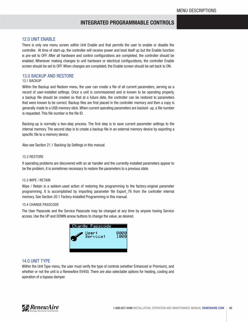
13.4 CHANGE PASSCODE
13.2 RESTORE
13.1 BACKUP
Wipe / Retain is a seldom-used action of restoring the programming to the factory-original parameter programming. It is accomplished by importing parameter file Export_76 from the controller internal memory. See Section 20.1 Factory-Installed Programming in this manual.
12.0 UNIT ENABLEThere is only one menu screen within Unit Enable and that permits the user to enable or disable the controller. At time of start-up, the controller will receive power and boot itself up but the Enable function is pre-set to OFF. After all hardware and control configurations are completed, the controller should be enabled. Whenever making changes to unit hardware or electrical configurations, the controller Enable screen should be set to OFF. When changes are completed, the Enable screen should be set back to ON.
If operating problems are discovered with an air handler and the currently-installed parameters appear to be the problem, it is sometimes necessary to restore the parameters to a previous state.
The User Passcode and the Service Passcode may be changed at any time by anyone having Service access. Use the UP and DOWN aroow buttons to change the value, as desired.
INTEGRATED PROGRAMMABLE CONTROLS
RENEWAIRE.COM INSTALLATION, OPERATION AND MAINTENANCE MANUAL 1.800.627.449946
MENU DESCRIPTIONS
16.0 I/O CALIBRATIONFrom within the I/O Calibration menu, offset values can be applied to analog inputs. A Service level passcode is required to access this menu and apply offsets. Offsets are factory-set at zero except for temperatures, which are verified in the factory and offsets are applied prior to shipment of the unit.
Offset is the value that will be added to or subracted from the measured value of the selected reading. There are instances when a sensor may give a false or incorrect reading and the sensor data must be adjusted.
Example: If the air flow rate is known to be zero and the controller is showing air movement, an offset must be applied to correct the false reading.
15.0 I/O CONFIGURATIONWithin the I/O Configuration menu, changes are made to the controller logic for specific program elements. The controller logic can be inverted for SF Status, EF Status, Unit Enable and EF Only Enable.
17.0 SENSOR OVERRIDES
18.0 TEST END DEVICES
Sensor Overrides allows the user to override any sensor reading and assign a user-selected value. The default value for each sensor is “Disabled”, which means that no override is being applied.
Sensor Overrides are commonly used as a trouble shooting aid and sometimes as a maintenance aid.
Example: Troubleshooting has determined that a temperature sensor has failed and the air handler no longer runs properly. By overriding the sensor and applying a user-determined value, the air handler can be kept in operation until a new sensor can be obtained and installed.
19.0 BMS INTEGRATIONThe c.pCO Mini controller has built-in ports for both serial and ethernet communication with a BMS. There are many different communication protocols for BMSs, some of which require a BACnet license that must be installed at the factory. If a BACnet license is not ordered with the controller, the only protocols available are Modbus RTU (serial port J3 connection) or Modbus TCP (ethernet port connection).
If a BACnet license has been ordered and installed, BACnet MS/TP (serial port J3 connection) or BACnet IP (ethernet port connection) may also be selected.
The Test End Devices menu allows the user to assert direct control over specific functions for testing purposes.
Example: The user may want to verify that a damper will open and close completely. Typical operating conditions may have positioned the damper in a partially opened or partially closed position. By entering the device test mode for that damper, the user can set the damper position to either OPEN or CLOSED. The test mode has a selectable time limit, after which the test mode will revert to normal operation.
NOTE: Whenever the BMS type is changed, power to the controller must be cycled.
INTEGRATED PROGRAMMABLE CONTROLS
47 1.800.627.4499 INSTALLATION, OPERATION AND MAINTENANCE MANUAL RENEWAIRE.COM
START-UP
20.0 UNIT START-UP
Prior to unit start-up, all sensors and monitors that are part of the system must be properly installed and wired in accordance with the unit schematic that is furnished in the unit documentation package.The air handler with its controller has been shipped from the factory with the controller screen set for Enable: OFF. This means that the controller will boot up, but the unit will not run. Units that are shipped and configured for a BMS also have the BMS control function disabled during preliminary start-up and testing. When the controller and all sensors have been shown to be operating correctly, then enable BMS control of the unit.
Upon start-up of the controller, 1. Check the Alarm function to see if there are any alarms present. This will show if any of the sensors
are either not present or are malfunctioning. There may also be alarms that result from the unit not operating, such as an over- or under- temperature condition.
2. Check the Unit Status menu to make sure that all required sensors are reading properly. See Section 8.0 Unit Status in this manual.
3. Navigate to the Control Variables menu and review the selections. See Section 9.0 Control Variables in this manual.
4. Review the Settings menu and verify that settings are correct. See Section 10.0 Settings in this manual.
5. Review the Alarm Settings menu and verify that settings are correct. These settings are preliminary and may be changed at a later date. See Section 11.0 Alarm Settings in this manual.
6. Go to the Unit Enable screen and switch the unit ON. This will permit verification of proper unit function.
7. Verify correct fan rotation direction.8. Re-calibrate the current sensors as described in Section 3.8 Current Sensors in this manual.
20.1 FACTORY-INSTALLED PROGRAMMING
20.2 START-UP PROCEDURE
Each controller is loaded with firmware that controls the operation of the air handler. The currently-installed firmware version is shown on the boot-up screen. The firmware incorporates the Sequence of Operation.
In addition to the firmware, a temporary set of operating parameters is installed at the factory that provides a platform for the user to enable and adjust all sensors and functions of the air handler. This temporary parameter file set is identified as Parameter File 76. This file appears in the controller memory as Export_76.Some parameters and unit settings are modified for safety reasons during the start-up process. • Enable is set to OFF. This means that the controller will boot-up but it will not allow the mechanical
system to run.• BMS control is set to OFF . This allows the mechanical system and controller to be tested independantly
of the BMS.• Fans are set to run at fixed speed at 20%. This prevents the fans from ramping up to full speed when
the unit is first enabled.Current sensors are calibrated for the fan start-up speed of 20% of maximum. Because of this, immediately after correct fan rotation direction is verified, the current sensors must be re-set. See Section 3.8 Current Sensor in this manual.
INTEGRATED PROGRAMMABLE CONTROLS
RENEWAIRE.COM INSTALLATION, OPERATION AND MAINTENANCE MANUAL 1.800.627.449948
BACKUP / RESTORE
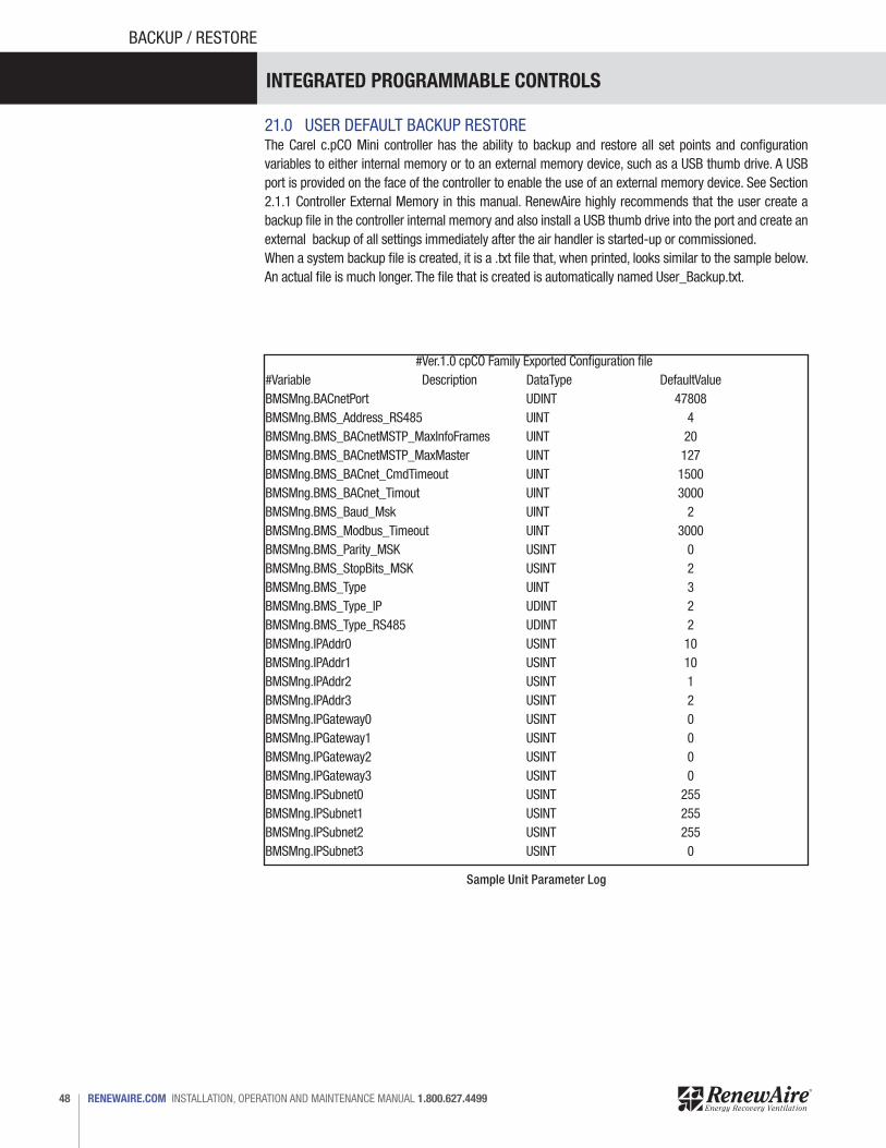
21.0 USER DEFAULT BACKUP RESTOREThe Carel c.pCO Mini controller has the ability to backup and restore all set points and configuration variables to either internal memory or to an external memory device, such as a USB thumb drive. A USB port is provided on the face of the controller to enable the use of an external memory device. See Section 2.1.1 Controller External Memory in this manual. RenewAire highly recommends that the user create a backup file in the controller internal memory and also install a USB thumb drive into the port and create an external backup of all settings immediately after the air handler is started-up or commissioned.When a system backup file is created, it is a .txt file that, when printed, looks similar to the sample below. An actual file is much longer. The file that is created is automatically named User_Backup.txt.
#Ver.1.0 cpCO Family Exported Configuration file #Variable Description DataType DefaultValueBMSMng.BACnetPort UDINT 47808BMSMng.BMS_Address_RS485 UINT 4BMSMng.BMS_BACnetMSTP_MaxInfoFrames UINT 20BMSMng.BMS_BACnetMSTP_MaxMaster UINT 127BMSMng.BMS_BACnet_CmdTimeout UINT 1500BMSMng.BMS_BACnet_Timout UINT 3000BMSMng.BMS_Baud_Msk UINT 2BMSMng.BMS_Modbus_Timeout UINT 3000BMSMng.BMS_Parity_MSK USINT 0BMSMng.BMS_StopBits_MSK USINT 2BMSMng.BMS_Type UINT 3BMSMng.BMS_Type_IP UDINT 2BMSMng.BMS_Type_RS485 UDINT 2BMSMng.IPAddr0 USINT 10BMSMng.IPAddr1 USINT 10BMSMng.IPAddr2 USINT 1BMSMng.IPAddr3 USINT 2BMSMng.IPGateway0 USINT 0BMSMng.IPGateway1 USINT 0BMSMng.IPGateway2 USINT 0BMSMng.IPGateway3 USINT 0BMSMng.IPSubnet0 USINT 255BMSMng.IPSubnet1 USINT 255BMSMng.IPSubnet2 USINT 255BMSMng.IPSubnet3 USINT 0
Sample Unit Parameter Log
INTEGRATED PROGRAMMABLE CONTROLS
49 1.800.627.4499 INSTALLATION, OPERATION AND MAINTENANCE MANUAL RENEWAIRE.COM
BACKUP / RESTORE
The system backup file is to be retained by the owner both as a record of all settings and as a means of restoring controller parameter settings, if needed. It should be available for forwarding by email to RenewAire Support group, for use by RenewAire whenever communicating with the user about any performance issues.
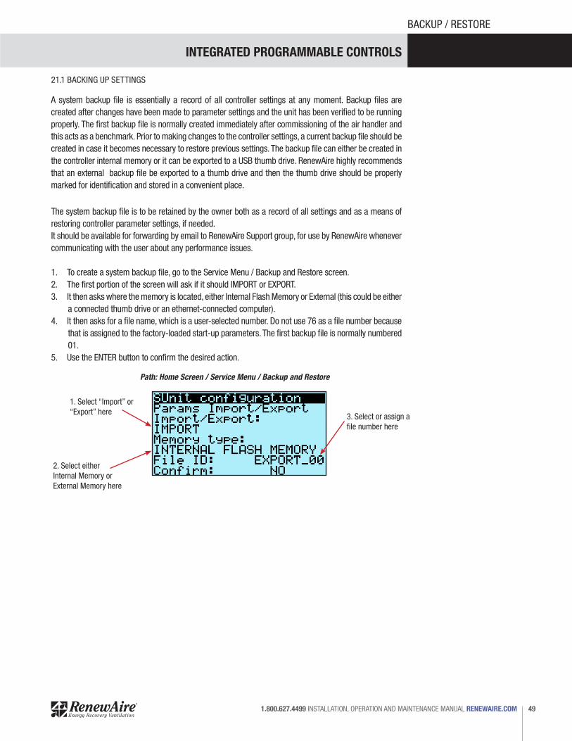
1. To create a system backup file, go to the Service Menu / Backup and Restore screen.2. The first portion of the screen will ask if it should IMPORT or EXPORT.3. It then asks where the memory is located, either Internal Flash Memory or External (this could be either
a connected thumb drive or an ethernet-connected computer).4. It then asks for a file name, which is a user-selected number. Do not use 76 as a file number because
that is assigned to the factory-loaded start-up parameters. The first backup file is normally numbered 01.
5. Use the ENTER button to confirm the desired action.
21.1 BACKING UP SETTINGS
A system backup file is essentially a record of all controller settings at any moment. Backup files are created after changes have been made to parameter settings and the unit has been verified to be running properly. The first backup file is normally created immediately after commissioning of the air handler and this acts as a benchmark. Prior to making changes to the controller settings, a current backup file should be created in case it becomes necessary to restore previous settings. The backup file can either be created in the controller internal memory or it can be exported to a USB thumb drive. RenewAire highly recommends that an external backup file be exported to a thumb drive and then the thumb drive should be properly marked for identification and stored in a convenient place.
Path: Home Screen / Service Menu / Backup and Restore
1. Select “Import” or “Export” here 3. Select or assign a
file number here
2. Select either Internal Memory or External Memory here

INTEGRATED PROGRAMMABLE CONTROLS
RENEWAIRE.COM INSTALLATION, OPERATION AND MAINTENANCE MANUAL 1.800.627.449950
BACKUP / RESTORE
21.3 RESETTING CONTROLLER TO FACTORY DEFAULTS
21.2 IMPORTING STORED SETTINGS FROM MEMORY
21.2.1 From USBIn order to restore settings from USB, the parameter file to be restored must be located in the USB drive. The USB drive must be inserted into the controller USB port and the unit must first be DISABLED. From the Backup and Restore screen, press the ENTER hard button to highlight the variable. Press the ENTER hard button to highlight the IMPORT box and then the UP or DOWN arrow hard buttons to enter the ID of the file to be loaded. Click CONFIRM to change it to YES and then click ENTER again. Cycle the power to the controller after restoring settings by this process.
21.2.2 From NAND Internal MemoryIn order to restore from NAND internal flash memory, an internal backup must have first been completed. If an internal backup exists, the Restore screen (shown below) will be available. From the Backup and Restore screen, press the ENTER hard button to highlight the variable. Press the ENTER hard button to highlight the IMPORT box and then the UP or DOWN arrow hard buttons to enter the ID of the file to be loaded. Click CONFIRM to change it to YES and then click ENTER again. Cycle the power to the controller after restoring settings by this process.
Because changes in operating parameters can sometimes cause conflicts, it may be desirable to simply erase all the user-installed operating parameters and start over with the factory installed parameters. This is referred to as WIPE/RETAIN. To perform a WIPE/RETAIN, go to the Service Menu / Backup and Restore screen and select IMPORT / FLASH MEMORY file: EXPORT_76. Confirm.
INTEGRATED PROGRAMMABLE CONTROLS
51 1.800.627.4499 INSTALLATION, OPERATION AND MAINTENANCE MANUAL RENEWAIRE.COM
CONTROLS CONTRACTOR
22.0 CONTROLS CONTRACTOR INFORMATION
22.1 BMS BACNET IP
22.2 BMS BACNET MSTP
Connection of BACnet IP requires a physical cable connection to the RJ45 jack on the controller. Prior to making the wiring connections, the controller is to be tested to verify proper control of the air handler under local (c.pCO) control. • Power down the unit and the controller, make the BMS connection • After connection is made, re-apply power and boot up the controller• Enable the BMS on the Main Menu / Settings screen.
BACnet IP requires a license which has been installed at the factory.
Connection of BACnet MSTP requires a physical cable connection, terminated at jack J3 on the controller. Prior to making the wiring connections, the controller is to be tested to verify proper control of the air handler under local (c.pCO) control.• Power down the unit and the controller.• After connection is made, re-apply power and boot up the controller.• Enable the BMS on the Main Menu / Settings screen.
BACnet MSTP requires a license which has been installed at the factory.
22.3 BMS MODBUS IP
Connection of MODBUS IP requires a physical cable connection terminated on the ethernet connection of the c.pCO controller. Prior to making the wiring connections, the controller is to be tested to verify correct control of the air handler under local (c.pCO) control.
• Power down the unit and controller.• After connection is made, re-apply power and boot up the controller.• Enable the BMS on the Main Menu / Settings screen.
MODBUS IP does not require any additional licensing.
NOTE: Whenever the BMS type is changed, power to the controller must be cycled.
• The controller has a Unit Enable switch located at Main Menu / Unit Enable• There is a BMS Enable switch located at Main Menu /Settings
When connecting a BMS, the Unit Enable (Main Menu / Unit Enable) must be set to OFF and BMS Enable (Main Menu / Settings / Screen 11) must be set of OFF. To view and select the BMS protocol, change BMS Enable to YES (Main Menu / Settings / Screen 11). Once BMS Enable is changed to YES, a protocol selection option screen will appear.
Select a BMS protocol. Once a protocol has been selected, additional BMS programming screens will appear. Change settings as needed. After the BMS protocol has been selected and protocol options have been selected, cycle power to the controller. After the controller has booted up, change the Unit Enable to
ON.
INTEGRATED PROGRAMMABLE CONTROLS
RENEWAIRE.COM INSTALLATION, OPERATION AND MAINTENANCE MANUAL 1.800.627.449952
CONTROLS CONTRACTOR
22.4 BMS MODBUS RTU
Connection of MODBUS RTU requires a physical cable connection terminated on jack J3 on the c.pCO controller. Prior to making the wiring connections, the controller is to be tested to verify correct control of the unit under local (c.pCO) control.
• Power down the unit and the controller.• After connection is made, re-apply power and boot up the controller.• Enable the BMS on the Main Menu / Settings screen.
MODBUS RTU does not require any additional licensing.
INTEGRATED PROGRAMMABLE CONTROLS
53 1.800.627.4499 INSTALLATION, OPERATION AND MAINTENANCE MANUAL RENEWAIRE.COM
SEQUENCE OF OPERATION
23.0 SEQUENCE OF OPERATIONThe Sequence of Operation (SOO) is embedded in the firmware.
Revision 0 – 05/11/2017
SUPPLY FAN OPERATION Units that do not have a VFD (variable frequency drive) or ECM (electronically commutated motor) for the supply fan will operate the supply fan at a constant speed. Units with a VFD or ECM for the supply fan can control the fan for fixed speed, supply air flow control, supply duct static pressure control, room static pressure control, CO2 control, VOC control, or CO2 Flow control (selectable, available modes depend on the unit configuration).The unit will attempt to start the supply fan when the supply fan delay timer expires. When the supply fan starts the supply fan adjustable current switch should close and remain closed until the fan is turned off.
Supply Fan StatusOnce the supply fan current switch closes heating and cooling operation, if applicable, are allowed. After a delay of 90 seconds (adjustable) from supply fan start signal, if the supply fan current switch is still open the supply fan alarm should be set to true and heating and cooling operation shall be prohibited. The supply fan status shall be set to true only when the supply fan output is on and supply fan current switch is closed. The supply fan status shall be false in all other circumstances.
Fixed Fan Speed OptionThe analog voltage command to the supply fan VFD or ECM can be set from the unit controller display or by the BMS. The adjustable range of 0% to 100% correspond to the minimum and maximum fan operating speed. This supply fan operation mode can be used to field balance the supply air flow rate.
Supply Air Flow Control OptionThe controller will adjust the supply fan VFD or ECM command to maintain the supply air flow rate at a set point. The supply air flow rate set point is entered and adjusted from the unit controller display or provided by the BMS. The minimum and maximum values for supply air flow rate set point are unit dependent. An adjustable PI (proportional & integral) loop will compare the measured supply air flow to the air flow rate set point and adjust the fan speed. If the measured supply air flow rate varies from the desired air flow rate by more than 10% (adjustable) for more than 60 seconds (adjustable) a supply air flow rate alarm will be set to true. This supply fan operation mode can be used to provide a constant supply air flow rate as the unit filters become loaded.
Supply Duct Static Pressure Control OptionThe controller will adjust the supply fan VFD or ECM command to maintain the supply duct static pressure at a set point. The supply air duct static pressure set point is entered and adjusted from the unit controller display or provided by the BMS. The minimum and maximum values for supply air duct static pressure set point are unit dependent. An adjustable PI (proportional & integral) loop will compare the measured supply air duct static pressure to the static pressure set point and adjust the fan speed. If the measured static pressure varies from the desired static pressure by more than 0.05 inches water gauge (adjustable) for more than 60 seconds (adjustable) a supply air static pressure alarm will be set to true. This supply fan operation mode can be used to provide a constant supply duct pressure for VAV systems.

INTEGRATED PROGRAMMABLE CONTROLS
RENEWAIRE.COM INSTALLATION, OPERATION AND MAINTENANCE MANUAL 1.800.627.449954
SEQUENCE OF OPERATION
Room Static Pressure Control OptionThe controller will adjust the supply fan VFD or ECM command to maintain the room static pressure at a set point. The room static pressure measurement is typically a differential pressure measurement between the room and an adjacent space or outdoors. The room static pressure set point is entered and adjusted from the unit controller display or provided by the BMS. An adjustable PI (proportional & integral) loop will compare the measured room static pressure to the static pressure set point and adjust the supply fan speed. If the measured static pressure varies from the desired static pressure by more than 0.05 inches water gauge (adjustable) for more than 60 seconds (adjustable) a supply air static pressure alarm will be set to true. This supply fan operation mode can be used to provide a constant static pressure in an area to control infiltration or exfiltration from an adjacent area or outdoors.
CO2 Control OptionThe controller will adjust the supply fan VFD or ECM command to maintain the room or return air CO2 level at a set point. The CO2 set point is entered and adjusted from the unit controller display or provided by the BMS. An adjustable PI (proportional & integral) loop will compare the measured CO2 level to the CO2 set point and adjust the fan speed. The minimum and maximum fan speed commands are adjustable. If the measured CO2 level exceeds 1000 ppm (adjustable) for more than 60 seconds (adjustable) a CO2 alarm will be set to true. This supply fan operation mode can be used to provide demand controlled ventilation of a space. The minimum fan speed will provide the required minimum outdoor air when the CO2 level is at or below the CO2 set point.
VOC Control OptionThe controller will adjust the supply fan VFD or ECM command to maintain the room or return air VOC level at a set point. The VOC set point is entered and adjusted from the unit controller display or provided by the BMS. An adjustable PI (proportional & integral) loop will compare the measured VOC level to the VOC set point and adjust the fan speed. The minimum and maximum fan speed commands are adjustable. If the measured VOC level exceeds 1000 ppm (CO2 equivalent, adjustable) for more than 60 seconds (adjustable) a VOC alarm will be set to true. This supply fan operation mode can be used to provide demand controlled ventilation of a space. The minimum fan speed will provide the required minimum outdoor air when the VOC level is at or below the VOC set point.
CO2 Flow Control OptionThe controller will adjust the supply fan VFD or ECM command based on the measured room or return air CO2 level. The supply air flow set point is derived from the user entered minimum and maximum CO2 levels and minimum and maximum desired air flow rates. When the CO2 level is at or below the minimum CO2 level the air flow set point is at the minimum and when the CO2 level is at or above the maximum CO2 level the air flow set point is at the maximum. Between the minimum and maximum CO2 levels the air flow set point is linearly scaled. If the measured CO2 level exceeds 1000 ppm (adjustable) for more than 60 seconds (adjustable) a CO2 alarm will be set to true. This supply fan operation mode can be used to provide demand controlled ventilation of a space. The minimum fan speed will provide the required minimum outdoor air when the CO2 level is at or below the CO2 set point.
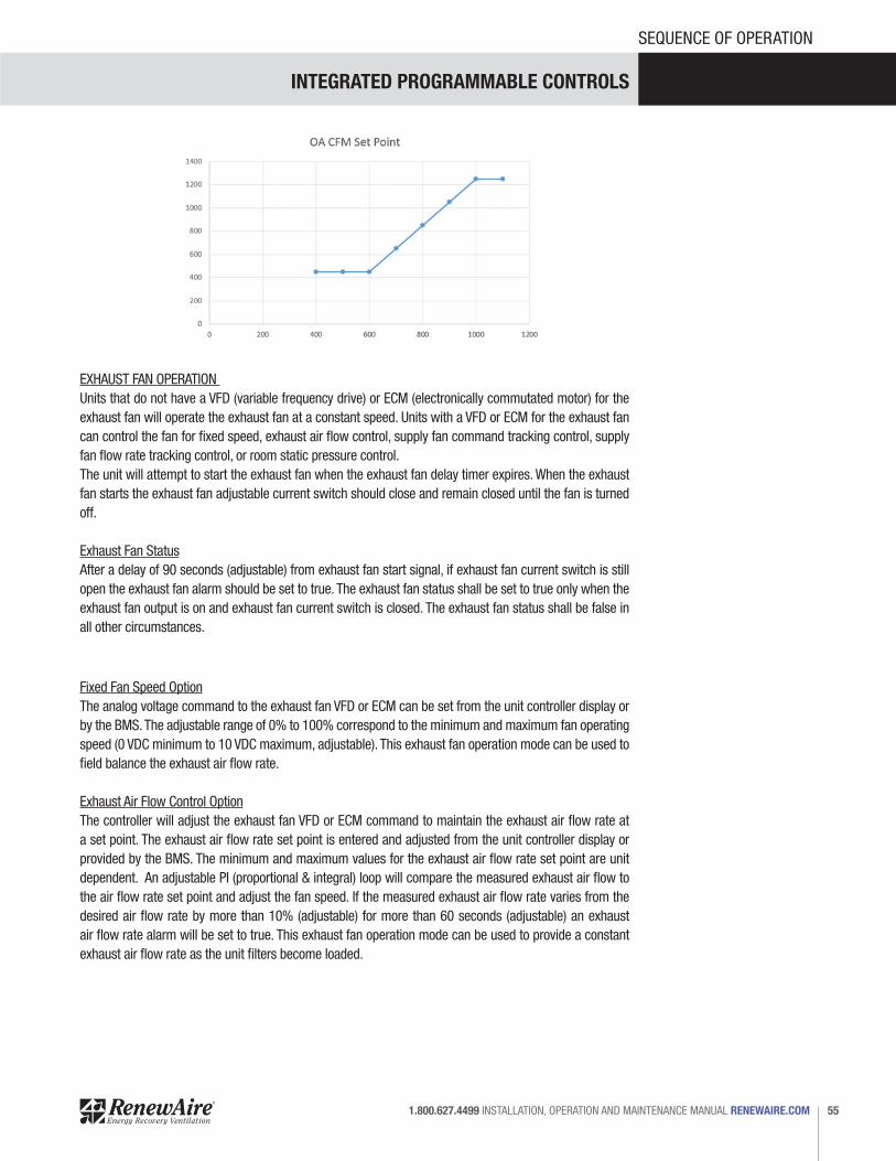
INTEGRATED PROGRAMMABLE CONTROLS
55 1.800.627.4499 INSTALLATION, OPERATION AND MAINTENANCE MANUAL RENEWAIRE.COM
SEQUENCE OF OPERATION
EXHAUST FAN OPERATION Units that do not have a VFD (variable frequency drive) or ECM (electronically commutated motor) for the exhaust fan will operate the exhaust fan at a constant speed. Units with a VFD or ECM for the exhaust fan can control the fan for fixed speed, exhaust air flow control, supply fan command tracking control, supply fan flow rate tracking control, or room static pressure control.The unit will attempt to start the exhaust fan when the exhaust fan delay timer expires. When the exhaust fan starts the exhaust fan adjustable current switch should close and remain closed until the fan is turned off.
Exhaust Fan StatusAfter a delay of 90 seconds (adjustable) from exhaust fan start signal, if exhaust fan current switch is still open the exhaust fan alarm should be set to true. The exhaust fan status shall be set to true only when the exhaust fan output is on and exhaust fan current switch is closed. The exhaust fan status shall be false in all other circumstances.
Fixed Fan Speed OptionThe analog voltage command to the exhaust fan VFD or ECM can be set from the unit controller display or by the BMS. The adjustable range of 0% to 100% correspond to the minimum and maximum fan operating speed (0 VDC minimum to 10 VDC maximum, adjustable). This exhaust fan operation mode can be used to field balance the exhaust air flow rate.
Exhaust Air Flow Control OptionThe controller will adjust the exhaust fan VFD or ECM command to maintain the exhaust air flow rate at a set point. The exhaust air flow rate set point is entered and adjusted from the unit controller display or provided by the BMS. The minimum and maximum values for the exhaust air flow rate set point are unit dependent. An adjustable PI (proportional & integral) loop will compare the measured exhaust air flow to the air flow rate set point and adjust the fan speed. If the measured exhaust air flow rate varies from the desired air flow rate by more than 10% (adjustable) for more than 60 seconds (adjustable) an exhaust air flow rate alarm will be set to true. This exhaust fan operation mode can be used to provide a constant exhaust air flow rate as the unit filters become loaded.
INTEGRATED PROGRAMMABLE CONTROLS
RENEWAIRE.COM INSTALLATION, OPERATION AND MAINTENANCE MANUAL 1.800.627.449956
SEQUENCE OF OPERATION
Supply Fan Command Tracking Control OptionThe controller will adjust the exhaust fan VFD or ECM command to track the supply fan VFD or ECM command. The minimum (50%) and maximum (200%) tracking rates are adjustable. This exhaust fan operation mode can be used to maintain proportional supply and exhaust fan commands as the supply fan modulates.
Supply Fan Flow Tracking Control OptionThe controller will adjust the exhaust fan VFD or ECM command to track the supply fan air flow rate. The offset from the supply air flow rate is adjustable from -25% to +25%. An adjustable PI (proportional & integral) loop will compare the measured exhaust air flow to the air flow rate set point and adjust the fan speed. If the measured exhaust air flow rate varies from the desired air flow rate by more than 10% (adjustable) for more than 60 seconds (adjustable) an exhaust air flow rate alarm will be set to true. This exhaust fan operation mode can be used to maintain proportional supply and exhaust air flows as the supply fan modulates and as the unit filters become loaded.
Room Static Pressure Control OptionThe controller will adjust the exhaust fan VFD or ECM command to maintain the room static pressure at a set point. The room static pressure measurement is typically a differential pressure measurement between the room and an adjacent space or outdoors. The room static pressure set point is entered and adjusted from the unit controller display or provided by the BMS. The minimum and maximum values for the exhaust fan speeds are adjustable. An adjustable PI (proportional & integral) loop will compare the measured room static pressure to the static pressure set point and adjust the exhaust fan speed. If the measured static pressure varies from the desired static pressure by more than 0.05 inches water gauge (adjustable) for more than 60 seconds (adjustable) an exhaust air static pressure alarm will be set to true. This exhaust fan operation mode can be used to provide a constant static pressure in an area to control infiltration or exfiltration from an adjacent area or outdoors.
ECONOMIZER (BYPASS) OPERATIONIf the application requires that the ERV be in economizer (bypass) mode, the controller may enter the economizer state. During normal operation the bypass damper shall remain closed and the face damper open to allow full energy recovery. During economizer operation the bypass damper will be open and the face damper will close to bypass the core. The economizer state can be controlled by temperature or enthalpy.
Temperature: The economizer will be locked out when:• The outside air temperature is less than the economizer adjustable low lockout.• The outside air temperature is greater than the economizer adjustable high lockout.
Enthalpy: The economizer will be locked out when:• The outside air enthalpy is greater than return air enthalpy.• The outside air temperature is less than the economizer field adjustable low lockout.

INTEGRATED PROGRAMMABLE CONTROLS
57 1.800.627.4499 INSTALLATION, OPERATION AND MAINTENANCE MANUAL RENEWAIRE.COM
SEQUENCE OF OPERATION
Heating OperationHeating will be locked out if the outdoor air temperature is above 70 degrees (adjustable). The temperature set point can be configured as constant (adjustable) or can be reset by the outside air temperature. The temperature control can be for the supply air temperature or the return air (room) temperature (selectable).
Constant Temperature OptionThe controller will stage the heaters or adjust the 0 to 10 VDC analog output to the heating device to maintain the air temperature at a set point. The air temperature set point is entered and adjusted from the unit controller display or provided by the BMS. The minimum and maximum values for the air temperature set point are unit dependent and are adjustable. An adjustable PI (proportional & integral) loop will compare the measured air temperature to the air temperature set point and adjust the analog output. A digital output that indicates a call for heating will also be provided. The analog and digital output can be used to control a hot water valve, electric heater, gas heater, or heat pump.
Reset Supply Air Temperature OptionThe controller will adjust the 0 to 10 VDC analog output to the heating device to maintain the air temperature at a set point. The air temperature set point is calculated based on the outdoor air temperature. The air set point is adjusted between the 100 degree F maximum (adjustable) and the 70 degree F minimum (adjustable) as the measured temperature varies from the 20 degree F minimum (adjustable) to the 70 degree F maximum (adjustable). These values are entered and adjusted from the unit controller display or provided by the BMS. An adjustable PI (proportional & integral) loop will compare the measured supply air temperature to the supply air temperature set point and adjust the 0 to 10 VDC analog output. A digital output that indicates a call for heating will also be provided. The analog and digital output can be used to control a hot water valve, electric heater, gas heater, or heat pump.Coil freeze protection must be provided by others in the field!
Cooling OperationCooling will be locked out if the outdoor air temperature is below 70 degrees (adjustable) or if heating is enabled. The temperature set point can be configured as constant (adjustable) or can be reset by the outside air temperature. The temperature control can be for the supply air temperature or the return air (room) temperature (selectable).
Constant Supply Air Temperature OptionThe controller will adjust the 0 to 10 VDC analog output to the cooling device to maintain the air temperature at a set point. The air temperature set point is entered and adjusted from the unit controller display or provided by the BMS. The minimum and maximum values for the supply air temperature set point are unit dependent and are adjustable. An adjustable PI (proportional & integral) loop will compare the measured supply air temperature to the supply air temperature set point and adjust the 0 to 10 VDC analog output. Digital outputs that indicate a call for up to 2 stages of cooling will also be provided. The analog and digital outputs can be used to control a chilled water valve, remote DX condensing units, or a heat pump.

INTEGRATED PROGRAMMABLE CONTROLS
RENEWAIRE.COM INSTALLATION, OPERATION AND MAINTENANCE MANUAL 1.800.627.449958
Reset Supply Air Temperature OptionThe controller will adjust the 0 to 10 VDC analog output to the cooling device to maintain the air temperature at a set point. The air temperature set point is calculated based on the outdoor air temperature. The air set point is adjusted between the 70 degree F maximum (adjustable) and the 55 degree F minimum (adjustable) as the measured temperature varies from the 70 degree F minimum (adjustable) to the 90 degree F maximum (adjustable). These values are entered and adjusted from the unit controller display or provided by the BMS. An adjustable PI (proportional & integral) loop will compare the measured air temperature to the air temperature set point and adjust the analog output. Digital outputs that indicate a call for up to 2 stages of cooling will also be provided. The analog and digital outputs can be used to control a chilled water valve, remote DX condensing units, or a heat pump.Coil freeze protection must be provided by others in the field!
AlarmsThe microprocessor controller includes a digital output for remote indication of an alarm condition. Possible alarms include:Dirty Filter Alarm: If the outside air or return air filter differential pressure rises above the differential pressure switch set point (adjustable), the microprocessor controller will activate an alarm.Supply and Exhaust Air Proving Alarm: Microprocessor controller monitors the current switch on each blower and displays an alarm in case of blower failure.Airflow AlarmStatic Pressure AlarmCO2 AlarmVOC AlarmSensor Alarm: Microprocessor controller will send an alarm if a failed sensor is detected (temperature, pressure, relative humidity).
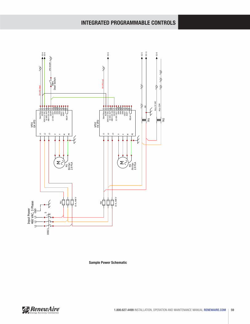
INTEGRATED PROGRAMMABLE CONTROLS
59 1.800.627.4499 INSTALLATION, OPERATION AND MAINTENANCE MANUAL RENEWAIRE.COM
CH
AN
GES
NAM
ER
EV.
DATE
SCH
EM
E
Pow
er
1
AB
CD
E
1
RD
2XIN
2 3 4 5 6 7 8 9
10
11
12
13
DIS
C1
5
Input
Pow
er
460 V
AC, 3 P
hase
10 A
, 600 V
FB1
10 A
, 600 V
FB2
L1
L2
L3
U V W PE
Sta
rt/S
top
ACO
MAIN
0-1
0 V
DC
10 V
DC
OU
TAIN
4-2
0 m
AD
CO
M
2 5 6 25 4 11
13A
13B
13C
14
30
16
17
12 V
DC
OU
TD
IND
IND
IND
OU
TAO
UT
RELAY
1
VFD
1EA V
FD
M1
EA F
an
2.9
FLA
L1
L2
L3
U V W PE
Sta
rt/S
top
ACO
MAIN
0-1
0 V
DC
10 V
DC
OU
TAIN
4-2
0 m
AD
CO
M
2 5 6 25 4 11
13A
13B
13C
14
30
16
17
12 V
DC
OU
TD
IND
IND
IND
OU
TAO
UT
RELAY
1
VFD
2FA V
FD
L1L2
L3G
ND
M
M2
FA F
an
2.9
FLA
VFD
DCO
M
TR1
TR2
Acc
y 2
4 V
AC
Acc
y C
OM
X1
1
X1
2X1
4
X1
9
X2
16
X2
12
X2
14
EA V
FD
\Red
FA V
FD
\red
X3
21
SW
1D
oor
Sw
itch
X1
6
G0
02-8
02-5
02-1
1
02-6
02-6
02-6
Sample Power Schematic
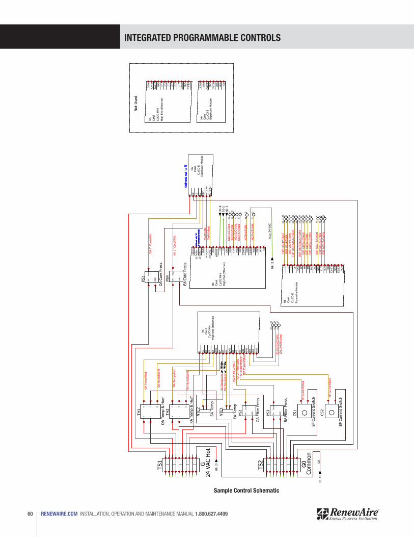
INTEGRATED PROGRAMMABLE CONTROLS
RENEWAIRE.COM INSTALLATION, OPERATION AND MAINTENANCE MANUAL 1.800.627.449960
CH
AN
GES
NAM
ER
EV.
DATE
SCH
EM
E
Contr
ol
1
AB
CD
E
2
RD
2XIN
2 3 4 5 6 7 8 9
10
11
12
13
Not
Use
d
V b
at
GN
D
+5VREF
GN
D
+V d
c
NO
6
NC6
C6
Expansi
on M
odule
N6
Care
lC.p
CO
E
X1
7
X2
13
X2
11
X2
15
X1
5
X1
3
X1
10
X1
8
X1
9
X3
30
X3
29
X3
28
X3
27
X3
26
X3
25
X3
24
X3
23
X3
22
G G0
U1
U2
GN
D
J6 T
x/R
x-
J6 T
x/R
x+
Expansi
on M
odule
N6
Care
l
C.p
CO
E
V b
at
CAN
L
CAN
H
GN
D
J7 1
J7 2
J7 3
J7 4
J7 5
J7 6
+5VREF
GN
D
+V d
c
Hig
h E
nd (
Eth
ern
et)
N5
Care
l
C.p
CO
Min
i
+ -
T OT
OA T
em
p &
Hum
TH
1
X2
18
X2
19
X2
17
G G0
U1
U2
U3
GN
D
U4
U5
U6
GN
D
U7
U8
U9
U10
GN
D
ID1
ID2
GN
D
Hig
h E
nd (
Eth
ern
et)
N5
Care
l
C.p
CO
Min
i
NTC2
SA T
em
p
Vin
Vout
GN
D
PS2
OA F
ilter
Pre
ss
NTC1
EA T
em
p
CS2
EF C
urr
ent
Sw
itch
CS1
SF C
urr
ent
Sw
itch
TS2
G0
Com
mon
Vin
Vout
GN
D
PS3
RA F
ilter
Pre
ss
TS1
G24 V
AC H
ot
+ -
T OT
RA T
em
p &
Hum
TH
2
U3
U4
U5
U6
GN
D
U7
U8
U9
U10
GN
D
NO
1
C1/2
NO
2
NO
3
C3/4
/5
NO
4
C3/4
/5
NO
5
Expansi
on M
odule
N6
Care
l
C.p
CO
E
+Vte
rm
J3 T
x/R
x -
J3 T
x/R
x +
GN
D
J4 T
x/R
x-
J4 T
x/R
x+
GN
D
Eth
ern
et
Y1
Y2
GN
D
NO
1
C1/2
NO
2
NO
3
C3/4
/5
NO
4
C3/4
/5
NO
5
NO
6
NC6
C6
Hig
h E
nd (
Eth
ern
et)
N5
Care
l
C.p
CO
Min
i
Vin
Vout
GN
D
PS4
EA C
ore
Pre
ss
Vin
Vout
GN
D
PS1
OA C
ore
Pre
ss
RA 1
" Core
\Wht
NO
3/4
/5\R
ed
NO
1/2
/C\R
ed
NO
1/2
/C\W
ht
NO
1/2
/C\B
lk
NO
3/4
/5\W
ht
NO
3/4
/5\B
lk
TX/R
X\R
ed
TX/R
X\B
lk
Accy
24 V
AC
EXP N
O1/2
/C\R
ed
EXP N
O1/2
/C\B
lkEXP N
O1/2
/C\W
ht
EXP U
8/9
/10\W
ht
EXP U
8/9
/10\B
lkEXP U
8/9
/10\R
ed
EXP U
6/G
ND
/U7\W
ht
EXP U
6/G
ND
/U7\R
ed
EXP U
3/4
/5\W
ht
EXP U
3/4
/5\B
lkEXP U
3/4
/5\R
ed
OA H
um
id\W
ht
OA T
em
p\R
ed EF
Curr
ent\
Red
SF
Curr
ent\
Red
RA 2
" Filt
er\
Wht
ID1/2
/GN
D\W
ht
ID1/2
/GN
D\R
ed
G0
RA T
em
p\R
ed
EF
Curr
ent\
Red
SF
Curr
ent\
RedO
A 2
" Filt
er\
Wht
EA T
em
p\R
ed
SA T
em
p\R
ed
RA H
um
id\W
ht
OA 1
" Core
\Wht
01-1
1
01-1
0
01-1
1
01-2
01-8
01-2
Sample Control Schematic

INTEGRATED PROGRAMMABLE CONTROLS
61 1.800.627.4499 INSTALLATION, OPERATION AND MAINTENANCE MANUAL RENEWAIRE.COM
CH
AN
GES
NAM
EREV.
DATE
SCH
EM
E
Fie
ld W
irin
g
1
AB
CD
E
3
RD
2XIN
2 3 4 5 6 7 8 9
10
11
12
13
X4
31
X4
32
X4
33
X4
34
X4
35
X4
36
X4
37
X4
38
X4
6
X4
40
Senso
r CO
M
EXP N
O 3
EXP N
O 4
EXP N
O 5
EXP C
3/4
/5
Acc
y 24 V
AC
Acc
y 24 V
AC
Acc
y CO
M
Acc
y CO
M
Open =
Heating, Clo
sed =
Coolin
g
Coolin
g S
tage 1
Coolin
g S
tage 2
X3
22
X3
23
X3
24
X3
21
0 -
10 V
DC I
nput,
CO
2 L
eve
l
0 -
10 V
DC I
nput,
VO
C L
eve
l
0 -
10 V
DC I
nput,
Space
Pre
ssure
X3
25
X3
26
X3
27
X3
28
X3
29
X3
30
0 -
10 V
DC I
nput,
Duct
Pre
ssure
0 -
10 V
DC O
utp
ut, H
eating M
odula
tion
OCC1
Occ
upanca
ncy
senso
r, d
igital in
put
Unit S
upply
Air T
em
p
Senso
r 24 V
AC
EXP U
3
EXP U
4
EXP U
5
BLK
BLK
RED
RED
X1
1
X1
2
X1
3
X1
4
Acc
y 24 V
AC
Acc
y CO
M
Acc
y CO
M
NO
4
CO
M
HO
TDAM
PER1
OA/F
A
CO
M
HO
TDAM
PER2
EA/R
A
Senso
r CO
M
EXP U
7
EXP U
8
EXP U
9H
eating E
nable
/Sta
ge 1
Heating S
tage 2
BLK
RED
Fact
ory
Jum
per
Fact
ory
Jum
per
UE1
EFEN
1
SD
1
X1
5
EXP C
1/2
X1
6
X1
8
X1
7
Acc
y CO
M
NO
3
EXP N
O 2
X2
11
X2
12
X1
10
NO
2
NO
1
EF E
n
EXP N
O 1
X1
9
X2
14
X2
15
X2
16
X2
17
X2
18
X2
19
X2
20
C1/2
+24 V
DC
SF E
n
Senso
r 24 V
AC
EF O
nly
Enable
Senso
r CO
M
Unit E
nable
X2
13
Fact
ory
Jum
per
- re
move
if dam
per
end s
witch
is
use
d
Sm
oke
Dete
ctor
Unit E
nable
Exh
Fan O
nly
Enable
CO
M
HO
TDAM
PER3
Byp
ass
Fact
ory
Jum
per
- re
move
if dam
per
end s
witch
is
use
d
NO
5EXP U
6
EXP U
10
0 -
10 V
DC O
utp
ut,
Coolin
g M
odula
tion
Vin
Vout
GN
D
Duct
Pre
ssure
Senso
r
Sample Field Wiring Schematic
INTEGRATED PROGRAMMABLE CONTROLS
RENEWAIRE.COM INSTALLATION, OPERATION AND MAINTENANCE MANUAL 1.800.627.449962
24.0 TROUBLESHOOTINGThe first step in troubleshooting is to view the Alarm screens. Press the Alarm button on the face of the controller to see all current alarms and what function or component is causing the alarm. In some cases, the Alarm pre-set may need to be adjusted or an offset may need to be changed.
Before making any changes to the controller programming, be certain to have an updated Backup file so that current settings can be easily restored, if needed.
Problems with an air handler are sometimes strictly mechanical, in which a fan or damper or some other component simply stops working. Mechanical problems are easily traced to specific components by using the prompts provided by the Alarm function button on the face of the controller.
In other cases, problems may be caused by the air handler trying to overcome a pre-set or operating parameter that has been set by the user. In these cases, a simple adjustment of the pre-set or an offset may correct the Alarm condition.
INTEGRATED PROGRAMMABLE CONTROLS
63 1.800.627.4499 INSTALLATION, OPERATION AND MAINTENANCE MANUAL RENEWAIRE.COM
25.0 INSTALLING FIRMWARE UPDATESFirmware updates that are provided by RenewAire are .AP1 files and are typically about 200 KB in size. The replacement firmware file must be installed in the UPGRADE file in the controller’s memory and then the controller must be commanded to backup.
1. Copy the replacement firmware file to a USB thumb drive. It is not necessary to use an empty or new thumb drive. This is typically done by copying the file from an email and pasting it to the USB thumb drive. Note the file name.
2. To install the replacement firmware file in the controller, connect a USB cable with a Micro USB type B connecter to the controller USB port and the other end with a USB 1(a) connector to a computer.
3. Open “This PC” and locate the controller memory, which is about 95 megabytes. Open the controller memory and find a file folder labeled UPGRADE.
4. Using “This PC”, open the memory on the thumb drive and locate the new firmware file.
5. Copy the AP1 firmware file from the thumb drive and paste the file into the controller UPGRADE file folder. The replacement file is now installed in the controller memory and is ready to replace the existing firmware.
6. Disconnect the USB cable from the controller and the computer.
7. Go to the embedded Carel menu in the controller by pressing “ALARM” and “ENTER” on the controller at the same time for about three seconds.
8. Navigate to the Upgrade menu. Press ENTER and locate the replacement firmware file that you want to install. Move the file marker caret (>) to position it in front of the new file.
9. Press ENTER to start the upgrade screens and follow the instructions on the controller screen.
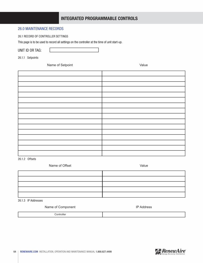
INTEGRATED PROGRAMMABLE CONTROLS
RENEWAIRE.COM INSTALLATION, OPERATION AND MAINTENANCE MANUAL 1.800.627.449964
26.1.1 Setpoints
26.1.2 Offsets
26.1.3 IP Addresses
Name of Setpoint
Name of Offset
Name of Component
Controller
Value
Value
IP Address
UNIT ID OR TAG:
26.1 RECORD OF CONTROLLER SETTINGS
This page is to be used to record all settings on the controller at the time of unit start-up.
26.0 MAINTENANCE RECORDS
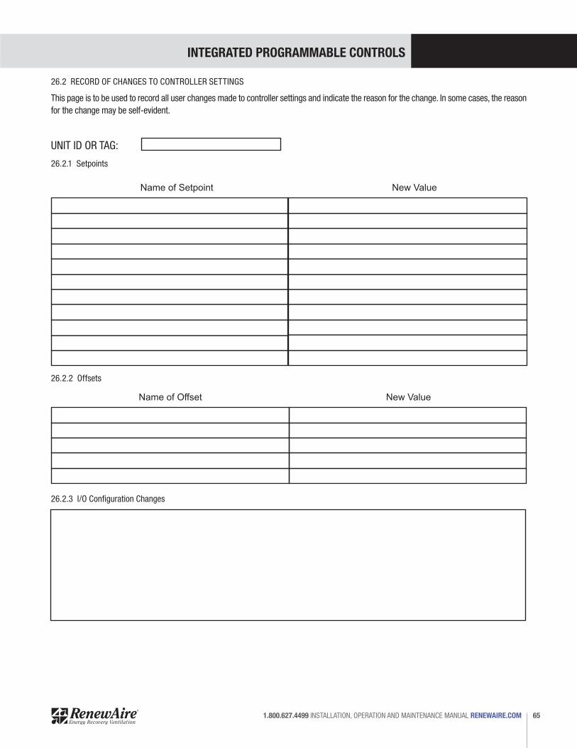
INTEGRATED PROGRAMMABLE CONTROLS
65 1.800.627.4499 INSTALLATION, OPERATION AND MAINTENANCE MANUAL RENEWAIRE.COM
26.2 RECORD OF CHANGES TO CONTROLLER SETTINGS
This page is to be used to record all user changes made to controller settings and indicate the reason for the change. In some cases, the reason for the change may be self-evident.
26.2.1 Setpoints
26.2.2 Offsets
26.2.3 I/O Configuration Changes
Name of Setpoint
Name of Offset
New Value
New Value
UNIT ID OR TAG:
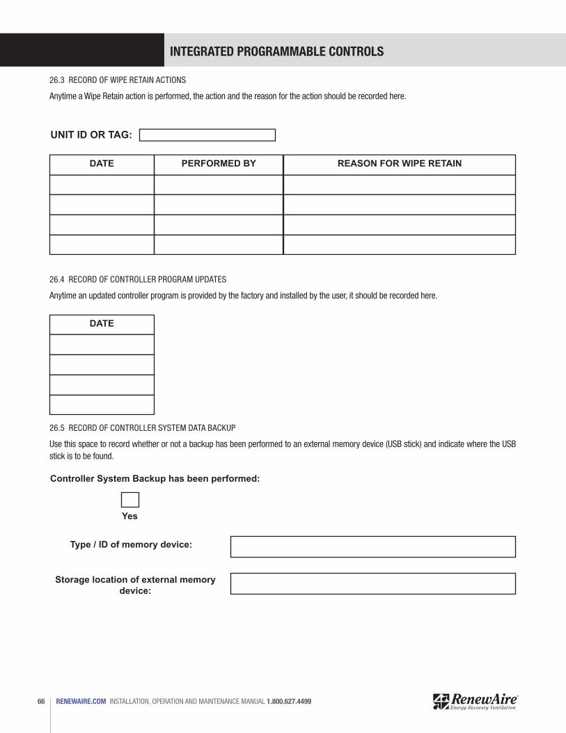
INTEGRATED PROGRAMMABLE CONTROLS
RENEWAIRE.COM INSTALLATION, OPERATION AND MAINTENANCE MANUAL 1.800.627.449966
26.3 RECORD OF WIPE RETAIN ACTIONS
Anytime a Wipe Retain action is performed, the action and the reason for the action should be recorded here.
26.4 RECORD OF CONTROLLER PROGRAM UPDATES
Anytime an updated controller program is provided by the factory and installed by the user, it should be recorded here.
26.5 RECORD OF CONTROLLER SYSTEM DATA BACKUP
Use this space to record whether or not a backup has been performed to an external memory device (USB stick) and indicate where the USB stick is to be found.
DATE
DATE
PERFORMED BY REASON FOR WIPE RETAIN
UNIT ID OR TAG:
Controller System Backup has been performed:
Type / ID of memory device:
Storage location of external memory device:
Yes
INTEGRATED PROGRAMMABLE CONTROLS
67 1.800.627.4499 INSTALLATION, OPERATION AND MAINTENANCE MANUAL RENEWAIRE.COM
GLOSSARY
Analog Control SignalAn analog signal is a varying-voltage output signal, typically between 0 and 10 volts. It is most often used to produce a specific amount of output from a variable-output device, such as a digital scroll compressor or a variable speed fan. 0 volts would represent an OFF condition and 10 volts would represent a demand for output at 100% of capacity.
BACnetBuilding Automation Control Network. BACnet is a communications protocol for building automation and control networks. It is just one of several different control systems that may be used as part of a BMS.
BACnet IP
BACnet MSTPBACnet Master Slave Token Passing - this is one of the possible BACnet protocols that may be used.
BMS A building management system (BMS) is a control system that can be used to monitor and manage the mechanical, electrical and electromechanical services in a facility. Such services can include power, heating, ventilation, air-conditioning, physical access control, pumping stations, elevators and lights.
Cat-5 Cables Cat-5 cable, sometimes called Ethernet cable, is short for Category 5 cable, a current industry standard for network wiring. This type of cable is unshielded wire containing four pairs of 24-gauge twisted copper pairs, terminating in an RJ-45 jack. If a wire is certified as Cat-5 and not just a twisted pair wire, it will have this designation printed on the outside.
ControllerDirect Digital Control is the automated control of a condition or process by a digital device (computer). The controller accepts digital or analog inputs from a variety of sensors and then follows all of its programmed instructions to produce action instructions to valves, actuators, fans, compressors and other HVAC components that can be adjusted. The Carel controller is a DDC controller.
Digital Control SignalA digital control signal is a fixed-voltage or amperage output signal, representing either an ON or OFF condition for the device it is connected to. It is typically used to activate a relay that controls operation of a device.
DIN Rail A DIN rail is a specially shaped metal strip which is used to mount relays, switches, terminals, etc. in industrial panels. The shape of the strip is such that these items can pressed onto it and a spring clip on each device slips into the bend in the rail and the device is held firmly. The strip can be mounted with screws or bolts to a wall or panel. The controller and any expansion boards are typically mounted on a DIN rail in the Main Control Panel.
Ethernet Ethernet is the standard way to connect computers on a network over a wired connection. It provides a simple interface and is used for connecting multiple devices, such as computers, routers, and switches. When the Carel controller is incorporated into a BMS, the BMS computer and the Carel controller become an ethernet.
FieldBusFieldbus is a standardized system of connecting devices so they can all communicate. It is usually characterized by daisy-chaining the devices and thus uses less wiring.
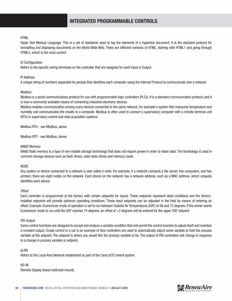
INTEGRATED PROGRAMMABLE CONTROLS
RENEWAIRE.COM INSTALLATION, OPERATION AND MAINTENANCE MANUAL 1.800.627.449968
HTMLHyper Text Markup Language. This is a set of standards used to tag the elements of a hypertext document. It is the standard protocol for formatting and displaying documents on the World Wide Web. There are different versions of HTML, starting with HTML1 and going through HTML5, which is the most current.
IO ConfigurationRefers to the specific wiring terminals on the controller that are assigned for each Input or Output
IP AddressA unique string of numbers separated by periods that identifies each computer using the Internet Protocol to communicate over a network
ModbusModbus is a serial communications protocol for use with programmable logic controllers (PLCs). It is a standard communication protocol, and it is now a commonly available means of connecting industrial electronic devices.Modbus enables communication among many devices connected to the same network, for example a system that measures temperature and humidity and communicates the results to a computer. Modbus is often used to connect a supervisory computer with a remote terminal unit (RTU) in supervisory control and data acquisition systems.
Modbus RTU - see Modbus, above
Modbus RTP - see Modbus, above
NAND MemoryNAND flash memory is a type of non-volatile storage technology that does not require power in order to retain data. The technology is used in common storage devices such as flash drives, solid-state drives and memory cards.
NODEAny system or device connected to a network is also called a node. For example, if a network connects a file server, five computers, and two printers, there are eight nodes on the network. Each device on the network has a network address, such as a MAC address, which uniquely identifies each device.
OffsetEach controller is programmed at the factory with certain setpoints for inputs. These setpoints represent ideal conditions and the factory-installed setpoints will provide optimum operating conditions. These input setpoints can be adjusted in the field by means of entering an offset. Example: Economizer mode of operation is set to run between Outside Air Temperatures (OAT) of 68 and 72 degrees. If the owner wants Economizer mode to run until the OAT reaches 74 degrees, an offset of +2 degrees will be entered for the upper OAT setpoint.
PID OutputSome control functions are designed to accept and analyze a variable condition that will permit the control function to adjust itself and maintain a constant output. Cruise control in a car is an example of how controllers are used to automatically adjust some variable to hold the process variable at the setpoint. The setpoint is where you would like the process variable to be. The output of PID controllers will change in response to a change in process variable or setpoint.
pLANRefers to the Local Area Network established as part of the Carel pCO control system.
RD-MRemote Display (hand-held/wall mount).
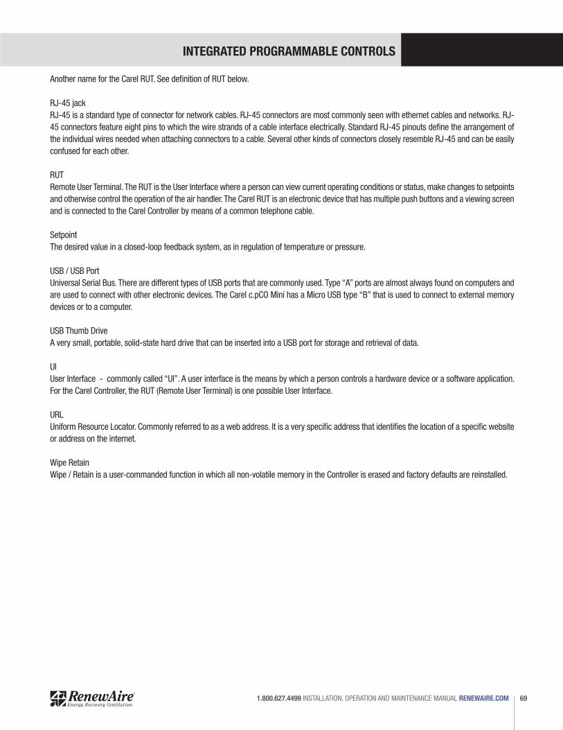
INTEGRATED PROGRAMMABLE CONTROLS
69 1.800.627.4499 INSTALLATION, OPERATION AND MAINTENANCE MANUAL RENEWAIRE.COM
Another name for the Carel RUT. See definition of RUT below.
RJ-45 jackRJ-45 is a standard type of connector for network cables. RJ-45 connectors are most commonly seen with ethernet cables and networks. RJ-45 connectors feature eight pins to which the wire strands of a cable interface electrically. Standard RJ-45 pinouts define the arrangement of the individual wires needed when attaching connectors to a cable. Several other kinds of connectors closely resemble RJ-45 and can be easily confused for each other.
RUTRemote User Terminal. The RUT is the User Interface where a person can view current operating conditions or status, make changes to setpoints and otherwise control the operation of the air handler. The Carel RUT is an electronic device that has multiple push buttons and a viewing screen and is connected to the Carel Controller by means of a common telephone cable.
SetpointThe desired value in a closed-loop feedback system, as in regulation of temperature or pressure.
USB / USB Port Universal Serial Bus. There are different types of USB ports that are commonly used. Type “A” ports are almost always found on computers and are used to connect with other electronic devices. The Carel c.pCO Mini has a Micro USB type “B” that is used to connect to external memory devices or to a computer.
USB Thumb DriveA very small, portable, solid-state hard drive that can be inserted into a USB port for storage and retrieval of data.
UIUser Interface - commonly called “UI”. A user interface is the means by which a person controls a hardware device or a software application. For the Carel Controller, the RUT (Remote User Terminal) is one possible User Interface.
URLUniform Resource Locator. Commonly referred to as a web address. It is a very specific address that identifies the location of a specific website or address on the internet.
Wipe RetainWipe / Retain is a user-commanded function in which all non-volatile memory in the Controller is erased and factory defaults are reinstalled.
INTEGRATED PROGRAMMABLE CONTROLS
RENEWAIRE.COM INSTALLATION, OPERATION AND MAINTENANCE MANUAL 1.800.627.449970
INTEGRATED PROGRAMMABLE CONTROLS
71 1.800.627.4499 INSTALLATION, OPERATION AND MAINTENANCE MANUAL RENEWAIRE.COM

72 RENEWAIRE LLC COPYRIGHT © AUG 2017
ABOUT RENEWAIRE
For over 30 years, RenewAire has been a pioneer in enhancing indoor air quality
(IAQ) in commercial and residential buildings of every size. This is achieved while
maximizing sustainability through our fifth-generation, static-plate, enthalpic-core
Energy Recovery Ventilators (ERVs) that optimize energy efficiency, lower capital
costs via load reduction and decrease operational expenses by minimizing equipment
needs, resulting in significant energy savings. Our ERVs are competitively priced,
simple to install, easy to use and maintain and have a quick payback. They also
enjoy the industry’s best warranty with the lowest claims due to long-term reliability
derived from innovative design practices, expert workmanship and Quick Response
Manufacturing (QRM).
As the pioneer of static-plate core technology in North America, RenewAire is the
largest ERV producer in the USA. We’re committed to sustainable manufacturing and
lessening our environmental footprint, and to that end our Madison, WI plant is 100%
powered by wind turbines. The facility is also one of the few buildings worldwide to be
LEED and Green Globes certified, as well as having achieved ENERGY STAR Building
status. In 2010, RenewAire joined the Soler & Palau (S&P) Ventilation Group in order
to provide direct access to the latest in energy-efficient air-moving technologies. For
more information, visit: renewaire.com
USA
(800) 627-4499 FAX: (608) 221-2824
201 RAEMISCH ROAD WAUNAKEE, WISCONSIN 53597 USA
WWW.RENEWAIRE.COM
CANADA (905) 475-8989
FAX: (905) 475-5231WWW.MITSUBISHIELECTRIC.CA
MEXICO, CENTRAL &SOUTH AMERICA
52 (222) 2 233 911 FAX: 52 (222) 2 233 914WWW.SOLER-PALAU.MX 105999_001 (AUG17)
72
Copyright © 2022 FDOKUMEN