Installation, Operation, and Maintenance Manual - Industrial ...
Upload
khangminh22Category
view
1download
0
Doc. No. 06EN003426 Rev. C

06EN003426 Rev. C ST51A/ST75A/ST75AV Mass Flow Meters
Fluid Components International LLC
Notice of Proprietary Rights This document contains confidential technical data, including trade secrets and proprietary information which is the property of Fluid Components International LLC (FCI).Disclosure of this data to you is expressly conditioned upon your assent that its use is limited to use within your company only (and does not include manufacture or processing uses). Any other use is strictly prohibited without the prior written consent of FCI.
© Copyright 2019 by Fluid Components International LLC. All rights reserved. FCI is a registered trademark of Fluid Components International LLC. Information subject to change without notice.

ST51A/ST75A/ST75AV Flow Meters 06EN003426 Rev. C
Fluid Components International LLC iii
Table of Contents Table of Contents ......................................................................................................................................................................................iii List of Figures ..........................................................................................................................................................................................vii List of Tables ........................................................................................................................................................................................... viii 1 GENERAL ......................................................................................................................................................................................... 1
Product Description ........................................................................................................................................................................... 1 Theory of Operation .......................................................................................................................................................................... 1 Safety Instructions ............................................................................................................................................................................. 1 Order Verification .............................................................................................................................................................................. 1
Hardware – Model Descriptions ................................................................................................................................................ 2 Optional Accessories ................................................................................................................................................................ 2
Specifications .................................................................................................................................................................................... 3 2 INSTALLATION ................................................................................................................................................................................. 5
Instrument Identification and Outline Dimensions ............................................................................................................................. 5 Pre-Installation .................................................................................................................................................................................. 5
Serial Number ........................................................................................................................................................................... 5 Flow Direction Alignment .......................................................................................................................................................... 5 Recommended Straight Run ..................................................................................................................................................... 7
Installing ST51A Flow Element ......................................................................................................................................................... 7 Compression Fitting Mounting .................................................................................................................................................. 7 Retractable Packing Gland Mounting ........................................................................................................................................ 9
Retraction/Removal Procedure ....................................................................................................................................... 10 Installing ST75A/ST75AV Flow Element ......................................................................................................................................... 11
Pipe Tee Installation ................................................................................................................................................................ 11 Tube Tee Installation ............................................................................................................................................................... 11 NPT Flow Tube Installation ..................................................................................................................................................... 11 Flanged Installation ................................................................................................................................................................. 11
Re-positioning the Display .............................................................................................................................................................. 11 Installing the Remote Flow Meter System ....................................................................................................................................... 12
Remote Cable ......................................................................................................................................................................... 13 Local Enclosure ....................................................................................................................................................................... 14 Remote Enclosure ................................................................................................................................................................... 15
Instrument Wiring ............................................................................................................................................................................ 17 Accessing the Interface Board Connection Terminals ............................................................................................................ 18
ESD Precautions ............................................................................................................................................................. 18 Interface Board Connections ................................................................................................................................................... 19
Power Connections ......................................................................................................................................................... 19 Signal Connections ................................................................................................................................................................. 21
4-20 mA Analog Outputs ................................................................................................................................................. 21 HART Connections .......................................................................................................................................................... 22

06EN003426 Rev. C ST51A/ST75A/ST75AV Mass Flow Meters
iv Fluid Components International LLC
Pulse Output and Alarm (Source/Sink) ........................................................................................................................... 23 Modbus Connections ....................................................................................................................................................... 24
Serial Interface Connector J9 .................................................................................................................................................. 25 3 OPERATION ................................................................................................................................................................................... 27
Overview ......................................................................................................................................................................................... 27 Instrument Configuration and Setup Using the Service Port (RS-232) ........................................................................................... 27
Main Menu .............................................................................................................................................................................. 28 Top Level Menu Commands ................................................................................................................................................... 28 Secondary Commands: CLI .................................................................................................................................................... 28
Start-up and Commissioning ........................................................................................................................................................... 28 Z Menu: Configure Flow Units and 4-20 mA Output Scaling .......................................................................................................... 29
Changing Flow Units, Example ............................................................................................................................................... 30 V Menu: Configure Outputs (4-20 mA and Source/Sink Outputs) ................................................................................................... 30
4-20 mA Configuration ............................................................................................................................................................ 32 Flow/Temperature Assignment ....................................................................................................................................... 32 NAMUR Mode ................................................................................................................................................................. 32 HART Damping Value ..................................................................................................................................................... 32
Source/Sink Output Configuration ........................................................................................................................................... 32 Source/Sink Output Functions ......................................................................................................................................... 32 Source/Sink Output Programming Parameters ............................................................................................................... 32
Serial Interface Command Reference ............................................................................................................................................. 33 Top Level Menu Commands ................................................................................................................................................... 33 CLI Commands ....................................................................................................................................................................... 34
HART Operation .............................................................................................................................................................................. 36 Process Data Operation .......................................................................................................................................................... 36 ST51A/ST75A/ST75AV HART Process Data Organization .................................................................................................... 36
ST51A/ST75A/ST75AV Process Variable Slots .............................................................................................................. 36 Primary Variable Classifications ...................................................................................................................................... 36
Device Description Files .......................................................................................................................................................... 36 EDDL Files ...................................................................................................................................................................... 37
Loading the DD Files to the 475 Field Communicator ............................................................................................................ 37 Service Data Operation ........................................................................................................................................................... 37
HART Command List Reference ..................................................................................................................................................... 40 ST51A/ST75A/ST75AV HART Universal Commands ............................................................................................................. 40 ST51A/ST75A/ST75AV HART Common Practice Commands ............................................................................................... 47 ST51A/ST75A/ST75AV HART Device Specific Commands ................................................................................................... 49 HART Command Bit Assignments .......................................................................................................................................... 52
Command Status Bytes ................................................................................................................................................... 52 Command 48, Additional Device Status Bytes ................................................................................................................ 54
HART Engineering Units Codes .............................................................................................................................................. 55

ST51A/ST75A/ST75AV Flow Meters 06EN003426 Rev. C
Fluid Components International LLC v
Modbus Operation ........................................................................................................................................................................... 56 Setting Up the ST51A/ST75A/ST75AV for Modbus Operation ............................................................................................... 56 ST51A/ST75A/ST75AV Modbus Commands .......................................................................................................................... 57 ST51A/ST75A/ST75AV Process Data Registers .................................................................................................................... 57 Totalizer Register Description ................................................................................................................................................. 58 ST51A/ST75A/ST75AV Modbus Service Registers ................................................................................................................ 59 Examples of Totalizer Service Register Access using ModScan32 ........................................................................................ 59
Checking the Totalizer Value .......................................................................................................................................... 59 Resetting the Totalizer Value .......................................................................................................................................... 61 Starting/Stopping the Totalizer Count ............................................................................................................................. 61 Checking K Factor Values ............................................................................................................................................... 62 Changing/Setting K Factor Values .................................................................................................................................. 62
Modbus Engineering Units Codes Table ................................................................................................................................. 64 Modbus Device Status Code Table ......................................................................................................................................... 64
4 MAINTENANCE .............................................................................................................................................................................. 65 Calibration ....................................................................................................................................................................................... 65 Electrical Connections ..................................................................................................................................................................... 65 Remote Enclosure ........................................................................................................................................................................... 65 Electrical Wiring .............................................................................................................................................................................. 65 Flow Element Connections ............................................................................................................................................................. 65 Flow Element Assembly .................................................................................................................................................................. 65
5 TROUBLESHOOTING .................................................................................................................................................................... 67 Application Verification .................................................................................................................................................................... 67 Equipment Needed ......................................................................................................................................................................... 67 Check Serial Numbers .................................................................................................................................................................... 67 Check the Instrument Installation .................................................................................................................................................... 67 Check for Moisture .......................................................................................................................................................................... 67 Check Application Design Requirements ........................................................................................................................................ 67 Verify Standard Versus Actual Process Conditions ........................................................................................................................ 67 Verifying Calibration Parameters (Diagnostics) .............................................................................................................................. 68 Hardware Verification ...................................................................................................................................................................... 69
Fuse Check ............................................................................................................................................................................. 69 Sensor Check .......................................................................................................................................................................... 69
Transmitter Circuit Calibration Check (Delta R Verification) ........................................................................................................... 70 References .............................................................................................................................................................................. 70 Equipment ............................................................................................................................................................................... 70 Procedure ................................................................................................................................................................................ 70

06EN003426 Rev. C ST51A/ST75A/ST75AV Mass Flow Meters
vi Fluid Components International LLC
APPENDIX A DRAWINGS .................................................................................................................................................................. 73 APPENDIX B GLOSSARY .................................................................................................................................................................. 91
Abbreviations .................................................................................................................................................................................. 91 Definitions ....................................................................................................................................................................................... 91
APPENDIX C APPROVAL INFORMATION ........................................................................................................................................ 93 EU Information ........................................................................................................................................................................ 93 Specific Conditions of Use per FM16ATEX0008X .................................................................................................................. 94 IEC Information ....................................................................................................................................................................... 95
APPENDIX D CUSTOMER SERVICE .............................................................................................................................................. 101 Customer Service/Technical Support .................................................................................................................................... 101 Warranty Repairs or Returns ................................................................................................................................................ 101 Non-Warranty Repairs or Returns ......................................................................................................................................... 101 Extended Warranty ............................................................................................................................................................... 101 Return to Stock Equipment ................................................................................................................................................... 101 Field Service Procedures ...................................................................................................................................................... 102 Field Service Rates ............................................................................................................................................................... 102

ST51A/ST75A/ST75AV Flow Meters 06EN003426 Rev. C
Fluid Components International LLC vii
List of Figures Figure 1 – Probe Serial Number, Reference Flat and Flow Direction Mark .............................................................................................. 5 Figure 2 – Serial Number Location on Interface Board (AC Version Shown) with Blind Cover Removed ................................................ 6 Figure 3 – ST51A Flow Arrow Alignment .................................................................................................................................................. 6 Figure 4 – Recommended Straight Run (ST75A Shown) ......................................................................................................................... 7 Figure 5 – Flow Element Installation, Compression Fitting ST51A ........................................................................................................... 8 Figure 6 – Flow Element Installation, Retractable Packing Gland ST51A ................................................................................................ 9 Figure 7 – Retractable Packing Gland Locking Collar Detail .................................................................................................................. 10 Figure 8 – Display Re-positioning ........................................................................................................................................................... 12 Figure 9 – Typical Remote Flow Meter System (ST51A with ½" NPT Cable Port Shown) ..................................................................... 12 Figure 10 – Remote Cable, Interconnecting ........................................................................................................................................... 13 Figure 11 – Remote Cable Installation, Local Enclosure ........................................................................................................................ 14 Figure 12 – Local Enclosure Remote Cable Wiring ................................................................................................................................ 14 Figure 13 – Remote Cable/Bracket Installation, Remote Enclosure ....................................................................................................... 16 Figure 14 – Remote Enclosure Interface Board Connector J4 Detail (AC Version Shown).................................................................... 16 Figure 15 – ST51A/ST75A/ST75AV Wiring Access ................................................................................................................................ 17 Figure 16 – Recommended Wire Routing/Internal Ground Screw .......................................................................................................... 18 Figure 17 – Power and Signal Wiring Terminals ..................................................................................................................................... 19 Figure 18 – Input Power Fuse Locations ................................................................................................................................................ 20 Figure 19 – Single Connection and Multidrop HART Setups .................................................................................................................. 22 Figure 20 – Sink Output .......................................................................................................................................................................... 23 Figure 21 – Source Output ...................................................................................................................................................................... 23 Figure 22 – Modbus Wiring ..................................................................................................................................................................... 24 Figure 23 – Serial Cable Adapter 025859-01 Plugged Into Flow Meter J9 Header ................................................................................ 25 Figure 24 – Block Diagram: Flow Meter Serial Port Connections, FC88 and Computer ........................................................................ 26 Figure 25 – Z Menu Command Structure: Units and Scaling Setup ....................................................................................................... 29 Figure 26 – V Menu Command Structure: Output Configuration Setup .................................................................................................. 31 Figure 27 – Field Communicator Easy Upgrade Utility, Import DD ......................................................................................................... 37 Figure 28 – Reference and Active Sensor Resistance Check (AC Version Shown) .............................................................................. 69 Figure 29 – Transmitter Circuit Calibration Diagram ............................................................................................................................... 71 Figure 30 – Basic Instrument Assembly: ST51A, ST75A and ST75AV .................................................................................................. 74

06EN003426 Rev. C ST51A/ST75A/ST75AV Mass Flow Meters
viii Fluid Components International LLC
List of Tables Table 1 – Optional Accessories ................................................................................................................................................................ 2 Table 2 – Compression Fitting Material .................................................................................................................................................... 8 Table 3 – Power and Signal Wiring Summary ........................................................................................................................................ 21 Table 4 – Serial Port J9 Pinout ............................................................................................................................................................... 25 Table 5 – Serial (COM) Port Configuration ............................................................................................................................................. 27 Table 6 – Typical Serial Interface Top Level Commands for Flow Meter Configuration ......................................................................... 29 Table 7 – Flow Unit Example .................................................................................................................................................................. 30 Table 8 – Top Level Menu Commands ................................................................................................................................................... 33 Table 9 – List of CLI Commands ............................................................................................................................................................ 34 Table 10 – ST51A/ST75A/ST75AV HART Process Variables ................................................................................................................ 36 Table 11 – ST51A/ST75A/ST75AV HART Device Registration Information ........................................................................................... 37 Table 12 – HART Universal Commands ................................................................................................................................................. 40 Table 13 – HART Common Practice Commands ................................................................................................................................... 47 Table 14 – HART Device Specific Commands ....................................................................................................................................... 49 Table 15 – Command Status Bytes, Bit Assignments ............................................................................................................................ 53 Table 16 – Command-Specific Response Codes ................................................................................................................................... 53 Table 17 – Command 48, Additional Device Status Bytes Bit Assignments ........................................................................................... 54 Table 18 – HART Engineering Units Codes ........................................................................................................................................... 55 Table 19 – ST51A/ST75A/ST75AV Modbus Function Codes ................................................................................................................. 57 Table 20 – ST51A/ST75A/ST75AV Modbus Process Data .................................................................................................................... 58 Table 21 –Modbus Service Data ............................................................................................................................................................. 59 Table 22 – Modbus Engineering Units Codes ........................................................................................................................................ 64 Table 23 – Device Status Code Bit Assignments, Register #4025 ......................................................................................................... 64 Table 24 – Diagnostic Test Sequence .................................................................................................................................................... 68 Table 25 – Appendix A, List of Drawings ................................................................................................................................................ 73

ST51A/ST75A/ST75AV Mass Flow Meters GENERAL
Fluid Components International LLC 1
1 GENERAL
Product Description The ST51A and ST75A/ST75AV Series are thermal dispersion, industrial process grade air/gas flow meters. They are suitable for all air and gas flow measurement applications. The ST51A is an insertion type flow meter for line sizes ranging from 2″ to 24″ [51 to 610 mm]. The ST75A is an in-line type flow meter for line sizes ranging from ¼″ to 2″ [6 mm to 51 mm]. Both ST51A and ST75A/ST75AV flow meters provide direct mass flow measuring and measures flow rate, totalized flow and temperature.
The measurements are made available to the user through dual 4-20 mA analog output channels, a separate source and sink channel (pulse output for totalizer or level output for alarm) and HART. The optional alphanumeric LCD display provides real-time process variable values, flow range and process description information. There are no moving parts to clean or maintain. These flow meters are offered in a wide selection of process connections to fit with any process piping and versions are available for temperature service from -0 °F [-18 °C] to 350 °F [177 °C].
ST51A and ST75A/ST75AV’s electronics/transmitter can be integrally mounted with the flow sensor or remote mounted up to 100′ [30 m] from the sensor element. All ST51A and ST75A/ST75AV flow meters are precision calibrated in FCI’s world-class, NIST traceable calibration facility on one of our flow stands matched to the customer’s gas application and actual installation conditions.
Theory of Operation The instrument is functionally based on the thermal dispersion operating principal. A low powered heater produces a temperature differential (ΔT) between two Resistance Temperature Detectors (RTDs) by heating one of the RTDs above process temperature. As the process mass flow rate increases, the temperature differential (ΔT) between the RTDs decreases. The ΔT between the RTDs is proportional to the process mass flow. The flow transmitter converts the RTD’s ΔT signal into a scaled flow output signal. The signal from the unheated RTD is used to provide the process temperature value.
Safety Instructions
Warning: Explosion Hazard. Do not disconnect equipment when flammable or combustible atmosphere is present.
Field wiring shall be in accordance with NEC (ANSI-NFPA 70) for Division 2 hazardous locations and CEC (CSA C22.1) for division 2
locations as applicable. The instrument must be installed, commissioned and maintained by qualified personnel trained in process automation and control
instrumentation. The installation personnel must ensure the instrument has been wired correctly according to the applicable wiring diagram. All location specific installation and wiring requirements (i.e., local electrical codes) must be met and maintained. Install an input
power circuit breaker or power disconnect switch and fuse near the flow meter to interrupt power during installation and maintenance. A switch or circuit breaker is required if installation is in a hazardous area.
The flow meter contains electrostatic discharge (ESD) sensitive devices. Use standard ESD precautions when handling the circuit board assemblies.
Hazardous Areas: The instrument is designed for use in hazardous areas. The approved area classification is identified on the nameplate along with the temperature and pressure limitations. See Agency Approvals, page 3 and APPENDIX C, page 93 for a complete listing of the instrument’s safety/hazardous areas approvals.
Order Verification Verify the received hardware matches the purchased hardware and application requirements. Verify the model number and part
number on the instrument I.D. tag matches the purchased model number part number. Review the calibration requirements as specified on the Engineering Data Sheet in the documentation package. Verify the flow,
temperature and pressure limits meet the application requirements.

GENERAL ST51A/ST75A/ST75AV Mass Flow Meters
2 Fluid Components International LLC
Hardware – Model Descriptions ST51A – Single point insertion element with flow and temperature process output ST75A – In-line element with flow and temperature process output ST75AV – Vortab In-line element with flow and temperature process output
Optional Accessories
Table 1 – Optional Accessories
Part Number Description FC88 Portable Hand-held Communicator
014108-03 PC Interface Communications Kit, for RS-232 serial port connection

ST51A/ST75A/ST75AV Mass Flow Meters GENERAL
Fluid Components International LLC 3
Specifications Instrument Media Compatibility
ST51A: Air, compressed air, nitrogen, biogas, digester gas, methane, natural gas ST75A/ST75AV: Air, compressed air, nitrogen, oxygen, argon, CO2, other inert gases, natural gas and other gases as identified in the Order Information Sheet (OIS)
Pipe/Line Size Compatibility ST51A: 2″ to 24″ [51 mm to 610 mm] ST75A/ST75AV: ¼″ to 2″ [6 mm to 51 mm]
ST51A Flow Range 0.3 SFPS to 400 SFPS [0.08 MPS to 122 MPS]
ST75A/ST75AV Flow Range* NPT Line
Size ¼" ½" ¾" 1" 1 ½" 2"
Min SCFM 0.04 0.13 0.22 0.35 0.85 1.40 Min [NCMH] [0.07] [0.22] [0.38] [0.59] [1.44] [2.38] Max SCFM 17.34 50.64 88.88 139.95 539.31 559.27 Max [NCMH] [29.47] [86.04] [151.00] [237.78] [576.48] [950.20]
Tubing Line Size ¼" ½" 1" Min SCFM 0.01 0.05 0.25 Min [NCMH] [0.01] [0.09] [0.42] Max SCFM 3.02 21.15 99.08 Max NCMH [5.14] [35.94] [168.33]
* Range subject to gas type and conditions Accuracy
ST51A/ST75A: Standard: ±2% reading ±0.5% full scale Optional: ±1% reading ±0.5% full scale ST75AV: ±1% reading ±0.5% full scale
Repeatability ±0.5% of reading
Temperature Compensation Standard: 40 to 100 °F [4 to 38 °C] Optional: 0 to 250 °F [-18 to 121 °C]
Turndown Ratio 3:1 to 100:1
Agency Approvals CE Mark Directive 2014/34/EU ATEX IECEx Scheme ATEX/IECEx: II 2 G Ex db IIC T6...T1 Gb II 2 D Ex tb IIIC T85°C...T300°C Db; IP66/IP67 Ta = -40°C to +65°C FM, FMc: Class I, Div 1, Groups B, C, D Class I, Div 2, Groups A, B, C, D Class II/III Div 1, Groups E, F, G Type 4X, IP66
Directive 2014/30/EU Electromagnetic Compatibility EMC Directive 2014/35/EU Low Voltage Directive 2011/65/EU RoHS 2 FM, FMc Explosion-proof: Class I, Div. 1, Groups B, C, D Dust-ignitionproof: Class II/III, Div. 1, Groups E, F, G; Type 4X; IP66 Nonincendive: Class I, Div. 2, Groups A, B, C, D
SIL 1 compliant; Safe Failure Fraction (SFF) 78.5% to 81.1% CRN No.: 0F0303 Contact FCI for other approvals and conditions of use.
Warranty 2 years
Flow Element Type
Thermal dispersion
Material of Construction ST51A: 316L stainless steel body with Hastelloy-C22 thermowells; 316 stainless steel compression fitting with Teflon or stainless steel ferrule. ST75A/ST75AV: All-welded 316 stainless steel probe element with Hastelloy-C22 thermowells; 316 stainless steel NPT, flange and tube fittings.
Process Connection ST51A: ½″ Male NPT or ¾″ Male NPT compression fitting with stainless steel or Teflon ferrule Insertion Length: 1″ to 6″ [25 mm to 152 mm] 1″ to 12″ [25 mm to 305 mm] 1″ to 18″ [25 mm to 457 mm]
ST75A: T-fitting [Female NPT]: ¼″, ½″, ¾″, 1″, 1-½″ or 2″ Tubing: ¼″, ½″, 1″ ST75AV: Female NPT, Male NPT Flange: ¼″, ½″, ¾″, 1″, 1-½″ or 2″
Maximum Operating Pressure ST51A stainless steel ferrule: 500 PSIG [34 bar(g)] Teflon ferrule: 150 PSIG [10 bar(g)] ST75A: T-fitting [Female NPT]: 240 PSIG [16.5 bar(g)] Tube: 600 PSIG [41 bar(g)] ST75AV: 600 PSIG [41 bar(g)]
Flow Element Temp Range ST51A stainless steel ferrule: 0 °F to 350 °F [-18 °C to 177 °C] ST75A: 0 °F to 250 °F [-18 °C to 121 °C] Teflon ferrule: 0 °F to 200 °F [-18 °C to 93 °C]

GENERAL ST51A/ST75A/ST75AV Mass Flow Meters
4 Fluid Components International LLC
Flow Transmitter Enclosure
Rating: NEMA 4X [IP67] Material: Standard – Aluminum, polyester powder-coated Optional – 316 stainless steel Cable/Wiring port: Dual ½" female NPT or M20x1.5
Operating Temperature 0 °F to 140 °F [-18 °C to 60 °C]
Maximum Relative Humidity 100%
Maximum Altitude 12,000 feet (3,658 meters)
Input Power DC: 18 VDC to 36 VDC AC: 90 VAC to 264 VAC (4.5 Watts max.; CE Mark voltage 100 VAC to 240 VAC) Instrument (Element + Sensor): 4.5 Watts Sensor only: 0.30 Watts
Analog Output Signals Two 4-20 mA outputs configured for flow rate or temperature. Typical load: 250 Ω; Max load: 500 Ω. Both outputs have fault indication per NAMUR NE43 guidelines, user selectable for high (> 21.0 mA) or low (< 3.6 mA).
Source/Sink Outputs One source output and one sink output provides totalized flow (pulse signal) or alarm setpoint (level signal). Pulse width at 50% duty cycle. 1-500 Hz pulse output for total flow. • Source: 22 ±2 VDC, 25 mA • Sink: External (user) power source and load not to exceed 40
VDC and 150 mA
Communication Port • RS-232C, standard • Modbus, standard • HART, standard
Digital Display1 Two-line x 16 character LCD; displays measured value and engineering units. Top line assigned to flow rate, second line user assignable to temperature reading, flow totalizer or alternating. Display can be rotated in 90° increments for optimum viewing orientation. 1 Display “delete” option (Blind, no display window) also available.
Input Power Fuse Part No. Type Amp
Code Ampere Rating
Max. Voltage Rating
Littelfuse Series 454: 045401.5
Slo-Blo 01.5 1.50 A 125 V
Refer to Power Fuse Replacement on page 20 for fuse replacement instructions.
Installation and Mounting ST51A – Integral with sensor element or remote mountable with interconnecting cable length of: 10′ [3 m), 25′ [7,6 m], 50′ [15 m], 100' [30 m] or custom length.
ST75A/ST75AV – In-line “T”, NPT or tube. Available in remote mountable configuration with interconnecting cable length of: 10′ [3 m], 25′ [7,6 m], 50′ [15 m], 100' [30 m] or custom length.

ST51A/ST75A/ST75AV Mass Flow Meters INSTALLATION
Fluid Components International LLC 5
2 INSTALLATION
Warning: The ambient temperature range and applicable temperature class of the ST51A and ST75A/ST75AV Series flow meters are based on the maximum process temperature for the particular application as follows; T6 for -40 °C ≤ Ta ≤ +55 °C; T3 for -40 °C ≤ Ta ≤ +65 °C.
Instrument Identification and Outline Dimensions Appendix A provides outline dimensions and mounting bracket dimensions for all integral and remote mounted electronic configurations. Verify all dimensions meet the application requirements before beginning installation.
Pre-Installation Serial Number The ST51A, ST75A and ST75AV (Vortab) flow meters can be specified with integral or remote electronics. The flow element has a serial number etched into the side of the extension pipe (ST51A) or HEX (ST75A/ST75AV) as shown in Figure 1 below. The tag on the enclosure includes serial number and model number. A serial number is written on the transmitter’s PWB silkscreen (both AC and DC input) as shown in Figure 2. The flow sensor and transmitter circuit are calibrated as a matched set. Always pair these components together unless an exception is made by an FCI technician.
Flow Direction Alignment All sensor elements have a flow arrow indicator marked on the element assembly at the reference flat, which indicates the flow direction for which the flow element has been calibrated. Install the instrument with the flow arrow facing in the same direction as flow in the pipe stream as shown in Figure 3 and Figure 4. The ST75A/ST75AV flow element has been calibrated directly in the pipe tee or tube tee for orientation and insertion depth, as shown on Figure 4. See APPENDIX A, page 73 for orientation details.
Figure 1 – Probe Serial Number, Reference Flat and Flow Direction Mark
C01157-1-1
SERIAL NUMBER ORIENTATION REFERENCE FLAT
ST51 EXTENSION PIPE ST75/ST75V HEX
FLOW DIRECTION MARK
FLOW DIRECTION MARK
SERIAL NUMBER
ORIENTATION REFERENCE HEX FLAT

INSTALLATION ST51A/ST75A/ST75AV Mass Flow Meters
6 Fluid Components International LLC
Figure 2 – Serial Number Location on Interface Board (AC Version Shown) with Blind Cover Removed
Figure 3 – ST51A Flow Arrow Alignment
C01158-1-2
90°C01159-1-1
SERIAL NUMBER BLOCK
FLOW DIRECTION MARK POINTS TO FLOW DIRECTION
REFERENCE/ORIENTATION FLAT PARALLEL TO FLOW DIRECTION
THERMOWELLS PERPENDICULAR TO FLOW DIRECTION

ST51A/ST75A/ST75AV Mass Flow Meters INSTALLATION
Fluid Components International LLC 7
Recommended Straight Run For optimal flow meter performance FCI recommends a minimum of 20 pipe diameters upstream straight run and 10 pipe diameters of downstream straight run. See Figure 4 below. Where straight run is limited, FCI offers Vortab flow conditioners for use in applications that have significant straight run limitations. FCI uses the AVAL application modeling software to predict meter performance in each installation. AVAL outputs are available to review prior to order placement and will indicate performance expectations both with and without flow conditioning.
Figure 4 – Recommended Straight Run (ST75A Shown)
Installing ST51A Flow Element Compression Fitting Mounting The ST51A is available with both Teflon compression fitting ferrules and metal ferrules. While the Teflon ferrule can be readjusted, it has a lower process pressure rating and over-tightening may cause it to become stuck or damage the extension pipe. The metal ferrule version can only be tightened down once and becomes permanently positioned. The ferrule type is indicated in the instrument part number displayed on the instrument tag. This can be cross-referenced with the Ordering Information Sheet (OIS).
All flow meters have been calibrated with the flow element located at the centerline of the pipe and flow stream as shown in Figure 5. Couplings and threadolets come in various dimensions. Proper installation requires that the element be measured with consideration to process connection dimensions and pipe centerline. Install the element in the line with the compression fitting lightly tightened around the extension, then slowly move the pipe extension forward until the element is at centerline as shown.
Caution: Elements are shipped in a protective sleeve. After removing the sleeve, keep the element from sliding through the compression fitting and contacting the opposing wall with any force. Hitting the pipe wall may damage the element and upset the calibration (critical in top mount installations).
See APPENDIX A for instrument outline dimensional details.
C00568-3-1
* AT LEAST 20 DIAMETERS AFTER LAST FLOW DISTURBANCE
10 DIAMETERS BEFORE NEXT
FLOW DISTURBANCE
DIAMETER
* OPTIMUM CONDITION
FLOW

INSTALLATION ST51A/ST75A/ST75AV Mass Flow Meters
8 Fluid Components International LLC
Figure 5 – Flow Element Installation, Compression Fitting ST51A
The flow element is properly mounted when the tip of the flow element is located 0.50 inches (13 mm) past the pipe centerline. The scale etched on the side of the insertion pipe indicates the length to the tip of the flow element. Follow the steps below to install the ST51A flow element.
1. Calculate the insertion depth using the equation below. I = Insertion depth
I.D. = Pipe inside diameter T = Pipe wall thickness C = Pipe mounting coupling and compression fitting (installed length)
𝐼 = 0.50" + 𝐼.𝐷.2
+ 𝑇 + 𝐶
I = __________ 2. Mark the insertion pipe at the calculated insertion depth. 3. Apply proper thread sealant to the tapered pipe thread on the compression fitting and secure into pipe mounting coupling. 4. Insert the flow element to the insertion depth mark making sure the orientation flat is aligned parallel to the flow direction. Hand tighten
the compression nut. Compression fitting manufacturer recommends 1-1/4 turns past hand tight. 5. Tighten the compression nut to the torque specified for the corresponding ferrule material as shown in Table 2 below.
Table 2 – Compression Fitting Material Ferrule Torque Teflon 65 in - lbs
316 SST 65 ft - lbs
Note: The metal ferrule configuration can only be tightened one time. Once tightened, the insertion length is no longer adjustable.
XXXX
FLU
ID C
OM
PO
NE
NTS
INTE
RN
ATIO
NA
L L
LC
y
C00584-1-3
MOUNTING ORIEN TATION OF FLATSTO BE PARALLEL TO FLOW
2X 1/2" NPT,OPTIONAL M20 x 1.5
ADJUSTABLE COMPRESSION FITTING,OPTIONA L TEFLON OR METAL FERRULE
ENCLOSURE MEETS EXPLOSION PROOFWATER AND DUST TIGHT APPROVALS
OPTIONAL DUAL LINE DIGITAL DISPLAY,90° INCREMENTAL ROTATION
1/2 OR 3/4 INCH NPTPROCESS CONNECTION
FLOW ARROW
LASER ETCHED INSERTION SCALE
SERIAL NUMBER
REDUCERBUSHING
PROTECTIVE SHROUDOVER PROBE TIPS
0.56[014]
4.00[102]
U LENGTHVARIABLE
4.5[114]
3.28[83]
3.56[90]
LC

ST51A/ST75A/ST75AV Mass Flow Meters INSTALLATION
Fluid Components International LLC 9
Retractable Packing Gland Mounting A retractable packing gland, with ½" MNPT or ¾" MNPT threads and graphite or Teflon packing, is a process connection option. FCI single point flow meters are calibrated at the centerline of the process pipe. The flow element is properly mounted when the tip of the flow element is located .50 inches (13 mm) past the pipe centerline. Follow the below steps to install/retract instruments with the retractable packing gland option.
1. The scale etched on the side of the insertion probe indicates the length to the tip of the flow element. Calculate the Insertion depth using the equation and Figure 6 below.
I = Insertion depth I.D. = Pipe inside diameter T = Pipe wall thickness C = Pipe mounting coupling and compression fitting (installed length)
𝐼 = 0.50" + 𝐼.𝐷.2
+ 𝑇 + 𝐶
I = __________
Figure 6 – Flow Element Installation, Retractable Packing Gland ST51A
2. Mark the insertion pipe at the calculated insertion depth. 3. Ball Valve Applications Only: If a ball valve is required, install the ball valve to the process mounting coupling. Close the ball valve
to prevent the process media from leaking out when installing the packing gland with the process line pressurized. 4. Apply the proper thread sealant compatible with the process media to the male threads of the packing gland. Fully retract the insertion
probe into the cavity of the packing gland and install the packing gland into the process mounting coupling or ball valve. If a ball valve is not used, make sure to first depressurize the process line before installing.
5. Tighten the packing nut until the internal packing is tight enough to prevent excess process leakage, but also allow the insertion probe to be inserted into place. For ball valve applications, open the ball valve after the packing nut has been tightened.
Caution: For applications where the process media is pressurized to greater than 232 psig [16 bar(g)] make sure to first depressurize the process line before making the insertion.
6. Align the orientation flat and flow arrow parallel to the flow direction and proceed to insert the flow element into the process media pipe up to the insertion depth mark.
7. Tighten the packing nut another ½ to 1 turn tight (approximately 20 ft-lbs) until the packing has created a full seal. 8. Ensure the locking collar is properly secured to the back of the packing gland. Torque the two No. 8-32 socket head cap screws on
the locking collar to 20 in-lbs using a 9/64" hex key.
C01444-1-1
CLLOCKING COLLAR
PACKING NUT
MARKINSERTION
DEPTH
OPTIONAL BALL VALVE:CUSTOMER-SUPPLIED ORPURCHASED FROM FCI

INSTALLATION ST51A/ST75A/ST75AV Mass Flow Meters
10 Fluid Components International LLC
Retraction/Removal Procedure 1. Loosen the socket head cap screw on the side of the locking collar. See Figure 7 below.
Caution: For applications where the process media is pressurized to greater than 232 psig [16 bar(g)] make sure to first depressurize the process line before retracting the flow element. At 232 psig [16 bar(g)], the effective force on the insertion probe is 45.5 lbs (20.6 kg), which is the limit at which the flow element can be safely guided by hand. When using hands to restrain the retraction, be prepared for a rapid pressure impulse of the flow element. Make sure that there are no objects directly behind the flow element as the insertion probe may retract very quickly.
Figure 7 – Retractable Packing Gland Locking Collar Detail
2. Slowly loosen the packing nut until the insertion probe begins to retract. Use hands as needed to help control the retraction. If the probe does not begin to retract itself, gently shake and pull the insertion probe until the flow element has been fully retracted into the packing gland.
3. For ball valve applications, close the ball valve immediately after retraction to seal off the process. After closing the ball valve it is then safe to remove the flow element from the back end of the ball valve. If a ball valve is not being used, make sure to first depressurize the process line before removing the flow element.
PACKING NUT
LOOSEN THIS SCREW
LOCKING COLLAR
C01445-1-1

ST51A/ST75A/ST75AV Mass Flow Meters INSTALLATION
Fluid Components International LLC 11
Installing ST75A/ST75AV Flow Element
Caution: The element is shipped already installed in the tee oriented for inline installation. Do not remove the sensing element from the tee during installation as performance can be affected.
The ST75A/ST75AV is available in pipe tee configurations with NPT threads and tubing tees with a compression fitting to clamp down on concentric smooth surface tubing. The pipe tee versions are standard 150# class rated tees suitable for service up to 150 PSIG at the process temperature maximum of 250 °F (121 °C). The compression fitting material offered in the tube type configuration is rated for 250 PSIG service. See APPENDIX A for instrument outline dimensional details.
Pipe Tee Installation With pipe extensions cut to length and sealing materials used on the threads, install flow element section by slowly rotating the configuration until secure. Complete by installing the opposing end pipe section using care to secure the element assembly either in a top mount or side mount position.
Tube Tee Installation Clean all mating surfaces of the tee fitting, ferrules and the flow tube. Insert the flow tubing into the tee fitting. Make sure the tubing rests firmly in the fitting counter bore seat. Tighten the nut on both ends of the tee by hand. Hold the fitting body steady with a backup wrench and tighten the fitting nuts 1-1/4 turns from hand-tight baseline.
The ST75AV is available with flow tube configurations offering male and female NPT threads, ANSI flanges and DIN flanges. The flow tube assemblies are rated for service up to 240 PSIG at the process temperature maximum of 250 °F (121 °C).
NPT Flow Tube Installation With pipe extensions properly cut to length and sealing materials used on the threads, install flow element section by slowly rotating the configuration until firmly secure on the pipe section. Complete by installing opposing end pipe section, using care to firmly secure the element assembly either in a top mount or side mount position.
Flanged Installation Clean all mating surfaces. Install appropriate sealing gasket between mating flanges. Tighten flange mating hardware to meet system sealing requirements.
Re-positioning the Display The LCD digital display can be rotated in 90° increments to improve its readability if necessary for the application. Referring to Figure 8 below, follow these steps to re-position the display.
Caution: The instrument contains electrostatic discharge (ESD) sensitive devices. Use standard ESD precautions when handling the instrument.
1. Use .050″ hex key to loosen set screw locking window lid and then unscrew window lid from enclosure body. 2. Lift and remove blue bezel. 3. Unplug transmitter/display board from power supply board by pulling display board straight up. Carefully set board aside.
Warning: To avoid damage to board components use fingers only to remove the board. Do not pry the board off using a screwdriver or similar tool.
4. Removing transmitter/display board exposes power supply board in enclosure body. Remove two securing 6-32 x ¼″ Phillips pan head screws and star washers from power supply board.
5. Turn power supply board in 90° steps in either direction until desired orientation is achieved. 6. Secure power supply board to enclosure body using hardware removed in step 4. Use alternate pair of mounting holes in power
supply board if required for new display orientation. 7. With transmitter/display board aligned over power supply board (connectors mate only one way) press down to fully engage
connectors on both boards. 8. Reinstall bezel over transmitter/display board by engaging bezel guide posts into corresponding holes in display board. 9. Reinstall window lid. Tighten lid one full turn past point where O-ring makes contact with lid, then tighten lid set screw to lock lid (set
screw must not protrude from its threaded hole after tightening).

INSTALLATION ST51A/ST75A/ST75AV Mass Flow Meters
12 Fluid Components International LLC
Figure 8 – Display Re-positioning
Installing the Remote Flow Meter System
Remote transmitter instruments include the following components: local enclosure containing the flow element sensor, remote enclosure containing the display/electronics and interconnecting remote cable. Both enclosures are explosion-proof ATEX/IECEx rated. A typical remote flow meter system is shown in Figure 9 below.
Figure 9 – Typical Remote Flow Meter System (ST51A with ½" NPT Cable Port Shown)
C01314-1-1
U LENGTHDIMENSION
BEZEL
TRANSMITTER/ DISPLAY BOARD
GUIDE POST HOLES
POWER SUPPLY BOARD (TURN THIS BOARD 90° INCREMENTS TO POSITION DISPLAY) BEZEL GUIDE POST (2 PLACES)
WINDOW LID
2X ½" NPT PORT
LOCAL ENCLOSURE
(BLIND)
REMOTE ENCLOSURE,
ELECTRONICS
BRACKET ASSEMBLY
REMOTE CABLE (NPT CONFIGURATION SHOWN)
PROBE ASSEMBLY PIPE

ST51A/ST75A/ST75AV Mass Flow Meters INSTALLATION
Fluid Components International LLC 13
Remote Cable The remote cable connects the local enclosure’s flow element sensor to the transmitter electronics in the remote enclosure. The cable is available in standard lengths (10/25/50/100 ft. [3/7.6/15/30 m]) as well as custom length as specified in the order information sheet (OIS). The customer is to supply the appropriate NPT or metric cable fittings for the remote cable. The cable end terminated in a 2x4 female socket plug connects to the 2x4 pin connector on the interface board inside the remote enclosure. The cable end with 6 metal ferrules connects to Phoenix connector TB1 on the interconnection board inside the local enclosure. Figure 10 below shows the remote cable assemblies with customer-supplied pieces.
Figure 10 – Remote Cable, Interconnecting

INSTALLATION ST51A/ST75A/ST75AV Mass Flow Meters
14 Fluid Components International LLC
Local Enclosure Install the local enclosure as described in Installing ST51A Flow Element and Installing ST75A/ST75AV Flow Element above. Depending on the configuration as specified by the order information sheet the ST51A local enclosure is supplied with a ½" or ¾” process connection, and the ST75A/ST75AV is supplied with a male NPT, female NPT or flanged process connection.
Figure 11 below shows the local enclosure remote cable installation.
Figure 11 – Remote Cable Installation, Local Enclosure
Figure 12 below shows the remote cable wiring inside the local enclosure. After installing the local enclosure in the pipe follow the steps below to install the local enclosure cable. Refer to Figure 11 and Figure 12 when following the steps.
Figure 12 – Local Enclosure Remote Cable Wiring
1. Remove local enclosure blind lid covering interconnection board (note orientation of external ground screw in Figure 12). Remove blind lid as described in Accessing the Interface Board Connection Terminals on page 18.
2. If not already installed, install supplied dome head stopping plug in local enclosure’s other (unused) cable port. 3. Remove interconnection board (remove two ea. 6-32 x ½" pan hd. Phillips screw/#6 star washer).
EXT. GROUND SCREW,
HEX WASHER
LOCALENCLOSURE
(BLIND LIDREMOVED)
REMOTE CABLE
C01317-1-1
6-POS. PHOENIXCONN. TB1
Remote Cable Connnections to TB1
2X 6-32 x ½" PAN HD.PHILLIPS SCREW/#6 STAR WASHER
INTER-CONNECTION
BOARD
TIE-WRAP
GROMMET
TB1 Pin No. Wire Color Label1 Orange ACT_EXC+
Black ACT_SEN+Green ACT_EXC-Red REF_EXC+
Brown REF_SEN+Yellow REF_EXC-
23456

ST51A/ST75A/ST75AV Mass Flow Meters INSTALLATION
Fluid Components International LLC 15
4. Install remote cable to local enclosure as shown in Figure 11. For NPT port units: Use an appropriate size reducer as applicable to the cable fitting used and the application. Ensure adequate cable service loop length before tightening the customer-supplied cable fitting.
5. Thread cable end (metal ferrule leads) through interconnection board grommet (from solder side) and un-cinched (open) tie-wrap. 6. Connect the cable leads to Phoenix connector TB1 as shown in Figure 12. After attaching all leads cinch tie-wrap to secure cable to
board (snip off excess tie-wrap length). 7. Reinstall interconnection board to local enclosure mounting bosses. 8. Reinstall local enclosure blind lid as described in Accessing the Interface Board Connection Terminals on page 18.
Remote Enclosure Install the remote enclosure at the desired location using the supplied mounting bracket. Follow the steps below to install the remote enclosure cable. Refer to Figure 13 below when following the steps.
1. Install mounting bracket at desired location. 2. Metric thread application only: Assemble cable gland, washer and adaptor (all customer-supplied items). 3. Thread connector end of the remote cable through customer-supplied cable fitting (3/8" NPT or M16 cable gland/washer/adapter) then
make a knot in cable 1.5" (38 mm) from connector tip. 4. Apply Loctite 567 to customer-supplied liquid tight fitting threads or cable gland adapter threads as applicable. Then install customer-
supplied liquid tight fitting/cable gland-adapter assembly into mounting bracket reducer bushing making sure that connector end of remote cable exits through reducer bushing.
5. Access remote enclosure interface board as described in Accessing the Interface Board Connection Terminals on page 18. 6. Remove interface board: Remove two ea. 6-32 x ½" pan hd. Phillips screw/#6 star washer, and then unplug board by pulling straight out. 7. Thread remote cable connector end through ¾-14 NPT threaded opening at enclosure bottom. 8. Apply Loctite 567 to mounting bracket reducer bushing threads. 9. Install remote enclosure onto mounting bracket reducer bushing making sure that the fit is tight with the display in the desired
orientation. 10. Place remote cable in notch on curved edge of interface board PWB (with connector on component side of PWB) then reinstall
interface board. See Figure 14 on page 16. 11. Firmly plug cable connector into interface board connector J4 header until cable connector latch clicks. (Connector is keyed to ensure
correct mating.)
Note: Connector J4 is located differently on AC and DC interface boards (i.e., the J4 location/orientation is not the same for both interface board types).
12. Connect power wiring as described in Interface Board Connections on page 19. 13. Reinstall remote enclosure blind lid as described in Accessing the Interface Board Connection Terminals.

INSTALLATION ST51A/ST75A/ST75AV Mass Flow Meters
16 Fluid Components International LLC
Figure 13 – Remote Cable/Bracket Installation, Remote Enclosure
Figure 14 – Remote Enclosure Interface Board Connector J4 Detail (AC Version Shown)
C01319-1-2
REMOTE CABLE, CONNECTOR END WIRES
CIRCUIT BOARD NOTCH, FOR SENSOR WIRE ROUTING
2X 6-32 x ½" PAN HEAD PHILLIPS SCREW/ #6 STAR WASHER
CABLE CONNECTOR, LATCHED
J4 HEADER (PLUG CABLE HERE)
REMOTE ENCLOSURE (BLIND LID REMOVED)
INTERFACE BOARD ASSEMBLY

ST51A/ST75A/ST75AV Mass Flow Meters INSTALLATION
Fluid Components International LLC 17
Instrument Wiring
Warning: Only qualified personnel are to wire or test this instrument. The operator assumes all responsibility for safe practices while wiring and troubleshooting.
Install an input power disconnect switch and fuse near the instrument to interrupt power during installation and maintenance. Always disconnect/shut-off power before wiring. See Agency Approvals, page 3 and APPENDIX C, page 93 for a complete listing of the instrument’s safety/hazardous areas approvals.
Refer to Figure 15 and Figure 16 below.
A cable/wiring port on each side of the enclosure body is provided for wiring access. These ports are labeled with its thread size (½″ NPT or M20) via the instrument tag and a label (engraved for stainless steel case) near each port. Either or both ports can be used for wiring. Use an appropriate plug on the unused port. For the neatest wire routing use the wiring port closest to J7/J8 for all signal wiring and the wiring port closest to power connector TB1 for power wiring. Provide a service loop for all connections to make rewiring/repairs easier.
An external and internal ground screw (10-32 x ¼″ slotted hex washer) is provided. Use the external ground screw as needed. For example, use the external ground screw if the probe connection does not make a reliable ground such as a plastic pipe. For EU applications use only the internal ground screw.
Figure 15 – ST51A/ST75A/ST75AV Wiring Access
WIRING PORT, ½″ NPT or M20 (2 PLACES)
EXTERNAL GROUND SCREW 10-32 x ¼″ SLOTTED HEX WASHER
BLIND LID SET SCREW
BLIND LID (Remove to access wiring)

INSTALLATION ST51A/ST75A/ST75AV Mass Flow Meters
18 Fluid Components International LLC
Figure 16 – Recommended Wire Routing/Internal Ground Screw
Accessing the Interface Board Connection Terminals
Warning: Turn OFF instrument power source before wiring the instrument.
Caution: Use caution inserting wires into electronics housing. The metal ends can damage circuit boards.
Remote Units: Avoid pulling, or inadvertently tugging, the remote cable when wiring the instrument. The sensor connector/circuit board can be easily damaged by excess pulling of the remote cable.
To access the instrument’s connection terminals first use a .050″ hex key to loosen the set screw locking the enclosure body blind lid (see Figure 15, page 17). Then unscrew the blind lid from the enclosure. Carefully pull the power and signal wires through the port to avoid damaging the electronics.
Connect wiring as shown in the diagram in Figure 17, page 19 and the summary list in Table 3, page 21. Reinstall the blind lid when done making the connections: Tighten the lid one full turn past the point where the O-ring makes contact with the lid, and then tighten the lid set screw to lock the lid (set screw must not protrude from its threaded hole after tightening).
ESD Precautions
Caution: FCI flow meters contain static-sensitive devices. To avoid damage to the instrument observe the ESD precautions listed below before opening the instrument for wiring.
Use a wrist band or heel strap with a 1 MΩ resistor connected to ground. Use a static conductive mat on the work table or floor with a 1 MΩ resistor connected to the ground when working on the instrument in
a shop setting. Connect the instrument to ground. Apply antistatic agents such as Static Free made by Chemtronics to hand tools used on the instrument. Keep high static-producing items away from the instrument.
C01162-1-2
INTERNAL GROUND SCREW, 10-32 x ¼″ SLOTTED HEX WASHER
POWER WIRING SIGNAL WIRING
ENCLOSURE BODY (BLIND LID REMOVED, AC VERSION SHOWN)

ST51A/ST75A/ST75AV Mass Flow Meters INSTALLATION
Fluid Components International LLC 19
The above precautions are minimum requirements. The complete use of ESD precautions can be found in the U.S. Department of Defense Handbook 263.
Interface Board Connections Power and signal connections are made at the interface board. Refer to Figure 17 below.
Power Connections
Warning: Turn OFF instrument power source before wiring instrument power.
The instrument is offered in DC and AC input power configurations. DC units include DC interface and power supply boards. Similarly, AC units include AC interface and power supply boards. Interface boards are specifically marked for AC or DC power. Only connect the power specified on the wiring module as shown in Figure 17. Both AC and DC inputs require a ground wire to be connected. Input power terminal blocks accept 14-26 AWG wire. Observe power wire routing as described in Instrument Wiring, page 17.
ONBOARD POWER ON LED INDICATOR An LED on the interface board lights up green when instrument power is ON. The LED is visible only when the blind lid is removed, which serves to alert the user that power is active when accessing the instrument’s signal/power wiring.
Figure 17 – Power and Signal Wiring Terminals

INSTALLATION ST51A/ST75A/ST75AV Mass Flow Meters
20 Fluid Components International LLC
POWER FUSE REPLACEMENT Input power overload protection is provided by a 1.5 A slo-blo surface mount fuse installed in a fuse holder on the interface board. (To access this board see Accessing the Interface Board Connection Terminals, page 18.) Refer to Figure 18 below.
AC-powered instruments: Locate the fuse at the center of the interface board on top. DC-powered instruments: Locate the fuse at the center of the interface board on the back (solder side). With power OFF remove two
securing 6-32 x ½″ Phillips pan head screws and star washers from the DC-powered interface board. Pull board straight up from mating sockets to access the fuse at the back.
To check for a blown fuse:
1. Turn instrument power OFF. 2. Access the interface board (see text above). 3. Using an ohmmeter touch metal cap at each end of fuse with the test leads. Any reading other than a short (i.e., open circuit)
indicates a blown fuse. Replace with Littelfuse 454 Series fuse, part no. 045401.5.
Figure 18 – Input Power Fuse Locations
C01164-1-2
Ω TEST
FUSE 1.5A SLO-BLO LITTELFUSE 454 SERIES
045401.5
AC-POWER INTERFACE BOARD COMPONENT SIDE
DC-POWER INTERFACE BOARD
SOLDER SIDE (Remove Interface Board to
access fuse. See manual text.
Ω TEST

ST51A/ST75A/ST75AV Mass Flow Meters INSTALLATION
Fluid Components International LLC 21
Table 3 – Power and Signal Wiring Summary Connector Pin No. Function Description
J8, Signal
1 INT_HART+ Internal HART connection / 4-20 mA Ch. #1 (+) 2 EXT_HART- External HART connection (-)
3 INT_HART- Internal HART connection / 4-20 mA Ch. #1 (-)
EXT_HART+ External HART connection (+) 4 4-20 mA Ch. #2 4-20 mA Ch. #2 – default parameter assignment: Temperature
J7, Signal
1 B+ Modbus Data B+ line 2 A- Modbus Data A- line 3 — Reserved 4 SINK Sink Output 5 GND Return for 4-20 mA Ch. #2 and Source/Sink, and Gnd/Common
for Modbus. 6 SOURCE Source Output
TB1, AC Power: 85-265 VAC
(CE Mark: 100-240 VAC)
1 AC LINE AC Line (typical wire color: black or brown) 2 AC NEUTRAL AC Neutral (typical wire color: white or blue) 3 EARTH GND Earth Ground (typical wire color: bare, green or green/yellow)
TB1, DC Power: 18-36 VDC
1 DC+ DC Positive (typical wire color: red or white) 2 DC- DC Negative (typical wire color: black) 3 EARTH GND Earth Ground (typical wire color: bare, green or green-yellow)
Caution: To maintain isolation between power input and output signals, keep GND and EARTH GND (chassis ground) separate.
Signal Connections The J7 and J8 terminal blocks are provided for signal connections. These terminal blocks have 3.5 mm pitch spacing and accept 28 AWG (min.) to 14 AWG (max.) wires. Observe signal wire routing as described in Instrument Wiring, page 17.
4-20 mA Analog Outputs The instrument is provided with a 4-20 mA current loop as an integral part of the HART signal output and a second 4-20 mA current loop for general purpose use. Refer to Figure 17, page 19 and Table 3, page 21 for the HART loop and general purpose 4-20 mA loop connector pin assignments. By default Channel 1 (HART) is assigned flow and Channel 2 (general purpose) is assigned temperature. See also V Menu: Configure Outputs (4-20 mA and Source/Sink Outputs), page 30 for details on setting up the analog outputs.

INSTALLATION ST51A/ST75A/ST75AV Mass Flow Meters
22 Fluid Components International LLC
HART Connections Connect the installation HART wiring to the appropriate J8 terminals depending on the application.
Single Connection – The instrument supplies power to the loop and controls the current as well. For this application connect HART+ to J8-1 and HART- to J8-3.
Network (Multidrop) Connection – The instrument receives loop power from the network, and controls the current. For this application connect EXT_HART+ to J8-3 and EXT_HART- to J8-2.
The block diagram in Figure 19 below shows the single connection and multidrop HART setups. Use a 250 Ω 1%, ≥ 0.3 W resistor as shown in the diagram below only if the external HART interface/wiring does not have this resistance built-in (HART requires a minimum loop resistance of 230 Ω).
See also Figure 17, page 19 and Table 3, page 21. If using a handheld HART communicator/calibrator connect it to the line as described by the manufacturer’s instructions.
CABLING RECOMMENDATION Use a shielded, twisted-pair instrument grade wire (min. 24 AWG for runs less than 5000 ft/1500 m; min. 20 AWG for longer distances). The RC value of the wire (Total Resistance x Total Capacitance) must be less than 65 µs (not a concern for point-to-point topology with a run less than 328 ft/100 m). A cable designed for HART/RS-485 such as Belden 3105A is recommended for complex setups or particularly long runs or both.
Note: The HART communications digital signals are superimposed on top of the channel #1 current loop (4-20 mA) output. When HART communications is in use, the HART current loop channel #1 MUST be configured as FLOW to comply with the HART protocol. The channel #1 current loop output is configured as FLOW by default at the factory.
Figure 19 – Single Connection and Multidrop HART Setups
C01208-1-1
ST51A/75A/75AVHART
J8-1
J8-2
J8-3ST51A/75A/75AV
HART
J8-1
J8-2
J8-3ST51A/75A/75AV
HART
J8-1
J8-2
J8-3ST51A/75A/75AV
HART
Network P.S.24 VDC
HARTMaster
J8-1
RLOAD
HARTI/O
J8-2
J8-3
ST51A/75A/75AVHART
HART Master
+
HARTI/O
–
J8-1
J8-34-
20 In
HART+HART–
(a) HART Single Connection
(b) HART Network, Multidrop

ST51A/ST75A/ST75AV Mass Flow Meters INSTALLATION
Fluid Components International LLC 23
Pulse Output and Alarm (Source/Sink) Wire the source/sink outputs via the J7 terminals as required for your device (using sink or source output as appropriate) as shown in Figure 20 and Figure 21 below. Either output can be used as a pulse output or a level (alarm) output. Observe the output power limits listed below.
Sink Output: 40 VDC maximum, 150 mA maximum (external, user-supplied power source) Source Output: 22 ±2 VDC output, 25 mA maximum (supplied by the flow meter)
See Source/Sink Output Configuration, page 32 for details on configuring the output as a pulse or level output.
Figure 20 – Sink Output
Figure 21 – Source Output
(Typical)
External 24-40 VDCPower Supply150 mA max.
External Device(Counter, etc.)
COM
SINK
USER WIRING
J7
FLOW METER SIDE USER SIDE
5
4
C01165-1-2
CURRENT FLOW
– +
J7
(Typ
ical
) ExternalDevice
(Counter, etc.)
24 VDC25 mA max.
GND
USER WIRING
FLOW METER SIDE USER SIDE
SOURCE
Alternate wiringsee note below
Note: Use voltage divider resistornetwork if flow meter source voltage (24 VDC) exceeds your device input.
6
5
C01166-1-1
CURRENT FLOW

INSTALLATION ST51A/ST75A/ST75AV Mass Flow Meters
24 Fluid Components International LLC
Modbus Connections The ST51A/ST75A/ST75AV Modbus interface is provided by interface board connector pins J7-1 [Data (A-)], J7-2 [Data (B+)], and J7-5 (Gnd/Common). Refer to Figure 17, page 19. Connect the instrument to a Modbus device/network using a 2-wire RS-485 connection scheme as shown in Figure 22 below. For details on Modbus operation refer to Modbus Operation, page 56.
Note: If using a shielded Modbus cable, connect cable shield to chassis/earth ground at one end only.
Figure 22 – Modbus Wiring
RS-485 MASTER
2-WIRE ONLY DEVICE
DEVICE 1 DEVICE 2 DEVICE 3
One twisted wire pairplus Gnd/Common.
Cable Shield(To Chassis/Earth
Gnd) To remainingRS-485 Devices
DATA (B)+
DATA (A)-
GND
DA
TA (B
)+
DA
TA (A
)-
GN
D
DA
TA (B
)+
DA
TA (A
)-
GN
D
DA
TA (B
)+
DA
TA (A
)-
GN
D
C01415-1-1
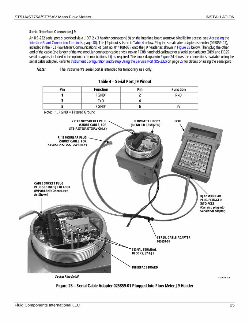
ST51A/ST75A/ST75AV Mass Flow Meters INSTALLATION
Fluid Components International LLC 25
Serial Interface Connector J9 An RS-232 serial port is provided via a .100″ 2 x 3 header connector (J9) on the interface board (remove blind lid for access, see Accessing the Interface Board Connection Terminals, page 18). The J9 pinout is listed in Table 4 below. Plug the serial cable adapter assembly (025859-01), included in the FCI Flow Meter Communications kit (part no. 014108-03), onto the J9 header as shown in Figure 23 below. Then plug the other end of the cable (the longer of the two modular connector cable ends) into an FC88 handheld calibrator or a serial port adapter (DB9 and DB25 serial adapters included in the optional communications kit) as required. The block diagram in Figure 24 shows the connections available using the serial cable adapter. Refer to Instrument Configuration and Setup Using the Service Port (RS-232) on page 27 for details on using the serial port.
Note: The instrument’s serial port is intended for temporary use only.
Table 4 – Serial Port J9 Pinout Pin Function Pin Function 1 FGND1 2 RxD 3 TxD 4 — 5 FGND1 6 5V
Note: 1. FGND = Filtered Ground
Figure 23 – Serial Cable Adapter 025859-01 Plugged Into Flow Meter J9 Header
2 x 3 0.100" SOCKET PLUG (SHORT CABLE, FOR
ST51A/ST75A/ST75AV ONLY)
RJ12 MODULAR PLUG (SHORT CABLE, FOR
ST50/ST51/ST75/ST75V ONLY)
FLOW METER BODY (BLIND LID REMOVED)
FC88
RJ12 MODULAR PLUG PLUGGED INTO FC88 (Can also plug into Serial/USB adapter)
SERIAL CABLE ADAPTER 025859-01
SIGNAL TERMINAL BLOCKS, J7 & J8
CABLE SOCKET PLUG PLUGGED INTO J9 HEADER (IMPORTANT: Orient Latch As Shown)
INTERFACE BOARD
Socket Plug Detail

INSTALLATION ST51A/ST75A/ST75AV Mass Flow Meters
26 Fluid Components International LLC
Figure 24 – Block Diagram: Flow Meter Serial Port Connections, FC88 and Computer
Caution: To avoid spurious reset remove power to the flow meter first before attaching the FC88. Reapply power to the flow
meter after the FC88 is connected.
= Supplied in Optional PC Communications Kit C01168-1-2
Flow MeterSerial Port
(J9)
RJ12Cable
Adapter(025859-01)
FC88Calibrator
Flow MeterSerial Port
(J9)
RJ12 toDB-25 (F)Adapter
(013831-01)
PC DB-25Serial Port
Flow MeterSerial Port
(J9)
RJ12 toDB-9 (F)Adapter
(013830-01)
PC DB-9Serial Port
Flow MeterSerial Port
(J9)
RJ12 toDB-9 (F)Adapter
(013830-01)
PC USBPort
USB toRS-232 DB-9Serial Adapter
Cable(User-Supplied)
Flow Meter to FC88 Connection
Flow Meter to PC DB-25 Serial Port Connection
Flow Meter to PC DB-9 Serial Port Connection
Flow Meter to PC USB Port Connection
RJ12Cable
Adapter(025859-01)
RJ12Cable
Adapter(025859-01)
RJ12Cable
Adapter(025859-01)

ST51A/ST75A/ST75AV Mass Flow Meters OPERATION
Fluid Components International LLC 27
3 OPERATION
Overview The ST51A/75A Series flow meters are configured at the factory for the customer-specified display and output settings. See the calibration information shipped with the instrument to review this information. Follow the steps in this section to change the display and outputs if desired.
Note: ST51A/ST75A units with a “Standard Calibration” (0 or A in Block 6 of the part number) are delivered in flow units of Standard Feet per Second (SFPS). Follow the steps in this section to customize the display and outputs if needed.
Instrument Configuration and Setup Using the Service Port (RS-232) If configuration or setup changes are needed, the ST51A/ST75A/ST75AV is provided with a serial interface for displaying or changing its configuration using FCI’s handheld FC88 Calibrator or a computer running a terminal program (for a serial console setup). See Serial Interface Connector J9 page 25 for serial port connection details.
Note: The serial port is intended for temporary use only.
Caution: Only factory-trained personnel are to configure or make setup changes to this instrument.
Caution: To avoid spurious reset, remove power to the flow meter first before attaching the FC88. Reapply power to the flow
meter after making the FC88 connection.
To make a serial console connection to the flow meter use your preferred terminal program (e.g., Tera Term Pro or equivalent) to configure the PC’s serial port using the parameters summarized in Table 5 below. For PC USB port: Use Windows’ Device Manager to see the virtual COM port number that Windows assigned to the USB-to-serial adapter. Specify this virtual COM port number in the terminal program configuration.
Table 5 – Serial (COM) Port Configuration COM Port Number: Number of COM port connected to instrument (see text above)
Baud Rate: 9600 Number of Bits: 8
Stop Bits: 1 Parity: None
Flow Control: None Terminal Emulation: VT100
Plug the FC88 into the instrument before power is applied. If the FC88 is plugged in while the instrument power is on and the FC88 does not respond, press [ENTER]. If there is still no response press [N] or cycle the power.
Most entries require at least two keystrokes: a capital letter or number and the [ENTER] key. User entries begin at the input mode prompt “>”, except when the instrument is in the Main Function Mode (just press/enter the desired function letter followed by [ENTER] to make an entry).
Backspaces are made using the [BKSP] key. Letters are case sensitive. For PC serial console: Use upper case letters only (for this application the Caps Lock key is helpful). For FC88: Use the [SHIFT] key to alternate between letters and numbers. A square after the prompt caret indicates the FC88 is in letter mode. A slightly elevated rectangle indicates the FC88 is in number mode.

OPERATION ST51A/ST75A/ST75AV Mass Flow Meters
28 Fluid Components International LLC
Main Menu The serial interface provides a main menu, shown below, to access various functions. The FC88 shows this menu by scrolling through the lines. Mode? 1=RS-232 2=Modbus 3=HART 4=Config 5=Update Firmware >
Choose a mode by entering its number.
RS-232 (1) – Enter “1” to place the instrument in the RS-232 serial pass-through mode. The display responds with: ST51A/75A Pass Thru (ESC to exit)
In this mode the console or FC88 display shows the same information displayed by the instrument. This is the normal mode when using the instrument’s serial port (for temporary programming access or parameter review or both). Once in the RS-232 mode press ESC (FC88: SHIFT+ESC) to return to the main menu.
Modbus (2) – Enter “2” to operate the instrument in the Modbus mode. HART (3) – Enter “3” to operate the instrument in the HART mode. Config (4) – Enter “4” to select the configuration menu for ST51A/ST75A (1), Modbus (2), or HART (3). Update Firmware (5) – Reserved for factory-use only.
Enter “ESC” (FC88: SHIFT+ESC) at any time within a mode to return to the main menu.
Top Level Menu Commands Place the instrument in the RS-232 mode to access the serial interface top level menu commands. These commands are listed in Table 8, page 33. Enter (or for FC88, press) the uppercase letter as listed in the table followed by [ENTER] to run the command. These commands can be exited at any time by entering “Q” followed by [ENTER]: D, F, G, L, S, V and W. Some commands cannot be exited until an entry/choice is made or the power is recycled.
Some commands result in a prompt asking for a factory pass code. If this occurs, contact FCI Field Service. Do not change any parameters that require this code without understanding the instrument’s operation.
Secondary Commands: CLI The instrument can be accessed with a secondary set of CLI (command line interface) commands. Access these commands using the “Y” command (passcode = 357). With CLI commands an internal parameter is assigned a 2-character command mnemonic for reading or writing its value. The basic command format (syntax) for a CLI command is:
Ryz [ENTER] Read
Wyz = <value> [ENTER] Write
…where R (Read) or W (Write) is followed by the 2-character (yz) command mnemonic followed by [ENTER]. When writing a value, the 2-character command mnemonic is followed by an equals sign or space, the data value and then [ENTER]. To exit CLI command mode press [ENTER] twice. See Table 9, page 34 for the complete list of CLI commands. In this table the parameter’s command function shows whether it can be written or read (WR), write-only (W) or read-only (R).
Start-up and Commissioning 1. Verify all input power and output signal wiring is correct and ready for initial power start-up. 2. If displaying/configuring instrument programming connect the FC88/computer to the flow meter (Power OFF first). See Serial Interface
Connector J9 page 25 for serial port connection details. 3. Apply power to instrument. The instrument initializes in the Normal Operation Mode with all outputs active. For instruments with the
display option: Observe that the display shows flow with the factory-set flow units. The instrument indicates 0.000 for zero or no process flow. Allow 10 minutes for the instrument to reach thermal equilibrium.
Table 6 below lists the most often used top level serial interface commands for configuring the instrument. Refer to Table 8, page 33 for the complete list of commands.

ST51A/ST75A/ST75AV Mass Flow Meters OPERATION
Fluid Components International LLC 29
Table 6 – Typical Serial Interface Top Level Commands for Flow Meter Configuration Command Name Description
T Normal Operation Mode Normal operating mode: All outputs are active. Z Flow Unit Set-up Set English/Metric flow units; set up pipe dimensions for volumetric units. V Output Configuration Set 4-20 mA and pulse output configuration. S Totalizer Menu Enables W menu (option) W Totalizer Enable/Disable F K-Factor (default=1) Flow factor N Warm Reset Reinitialize Instrument
Z Menu: Configure Flow Units and 4-20 mA Output Scaling
Use the Z menu to change flow units. Note, however, that changing units requires rescaling of the unit (set new zero and span). The 4-20 mA Zero and Span can be changed from the original calibration, provided the new values are within the original calibrated range; i.e., if the original calibration was 1 to 100 SCFM (4-20 mA), the new zero (4 mA) must be equal to or greater than 1 SCFM and the new span (20 mA) must be equal to or less than 100 SCFM. The flowchart in Figure 25 below gives an overview of the instrument’s Z menu programming.
Note: The Z menu is passcode protected when the totalizer function is enabled. Contact the factory for details.
Figure 25 – Z Menu Command Structure: Units and Scaling Setup

OPERATION ST51A/ST75A/ST75AV Mass Flow Meters
30 Fluid Components International LLC
Changing Flow Units, Example Table 7 below lists the steps for making a flow units change with these example parameters: SCFM Flow Units and 3-inch Schedule 40 round pipe size set-up:
Table 7 – Flow Unit Example Command Display Description
ENTER Menu: > Starting from Normal Operation Mode. Z E for English, M for Metric After entering Flow Unit Set-up menu (Z), select
English or Metric units. E 0=SFPS, 1=SCFM, 2=SCFH, 3=LB/H,
4=GPM After selecting English units (E), select specific type units. For this example: SCFM (1) which is a volumetric unit.
1 R Round duct or S rectangular After selecting Standard Cubic Feet, select round or rectangular duct.
R Dia.: 4.0260000 Change? (Y/N)>
After selecting Round duct (R), change displayed Diameter parameter?
Y Enter value: # After responding “Y” to diameter change, enter diameter value.
3.068 Area: 7.3926572 CMinflow: 0.0000000 Change? (Y/N)>
After entering value for diameter, the computed area is displayed. Change displayed CMinflow parameter?
N Maximum flow: 462.04 Enter to continue
After responding “N” to CMinflow parameter change, the max. flow is displayed. Press ENTER to continue.
ENTER CMaxflow: 462.04 Change? (Y/N)
Change displayed CMaxflow parameter?
Y Enter value: # After responding “Y” to CMaxflow change, enter CMaxflow value. (Note: Instrument checks if resulting max. flow is too large.)
462.04 CMintemp (F): -40.00000 Change? (Y/N)>
After entering value for CMaxflow, change CMintemp (F) parameter?
N CMaxtemp (F): 250.00000 Change? (Y/N)>
After responding “N” to CMintemp change, change CMaxtemp (F) value?
N Percent of Range is: OFF Change to ON?>
After responding “N” to CMaxtemp change, change Percent of Range On/Off status?
N 100.0 SCFM After responding “N” to Percent of Range On/Off status change, instrument returns to Normal Operation Mode.
V Menu: Configure Outputs (4-20 mA and Source/Sink Outputs) Use the V menu to configure the analog and source/sink outputs. The flowchart in Figure 26 below gives an overview of the V menu programming.
Note: Press [ENTER] as required to loop through all numbered choices. You cannot exit a number loop (Select 1, Select 2, etc.) without making a valid number choice.

ST51A/ST75A/ST75AV Mass Flow Meters OPERATION
Fluid Components International LLC 31
Figure 26 – V Menu Command Structure: Output Configuration Setup
1 2 3 4
1
1 2 3 4
2 3
C01171-1-1
Select4-20 mA OutputConfiguration
Menu StopNormal Oper.
SetSource state
SetSource state
SetSwitchpoint0
SetSwitchpoint1
SetSink state
SetSwitchpoint1
SetSource state
SetSink state
SetSink state
SetSink state
Select 1:4-20mA #1: Flow4-20mA #2: Temp
Select 2:4-20mA #1: Flow4-20mA #2: Flow
Select 3:4-20mA #1: Temp4-20mA #2: Flow
Select 4:4-20mA #1: Temp4-20mA #2: Temp
SelectNAMUR
Mode (4-20 mA)
Menu Start“V” Command
Select 1:NAMUR: OFF
Select 2:NAMUR: Low
Select 3:NAMUR: High
SelectSource/Sink
OutputConfiguration
Select HARTDamping Value
(0.1–100 s)
Select 1:Source: Pulse
Sink: Pulse
SetPFactor
Select 2:Source: PulseSink: Alarm1
Select 3:Source: Alarm0
Sink: Pulse
Select 4:Source: Alarm0
Sink: Alarm1
SetPFactor
SetPFactor
SetSwitchpoint0
SetSample Period
SetSample Period
SetSample Period
SetSource state

OPERATION ST51A/ST75A/ST75AV Mass Flow Meters
32 Fluid Components International LLC
4-20 mA Configuration Flow/Temperature Assignment Use the “V” menu to assign 4-20 mA current loop channels 1 and 2 to one of four flow/temperature configurations as required (see Figure 26). The default assignment is: Ch. 1 = Flow, Ch. 2 = Temp. Once the assignment is set or confirmed the “V” menu continues to NAMUR mode configuration.
Note: For HART use only: The 4-20mA #1 parameter must remain at its default assignment of flow to comply with the HART protocol. Do not change this assignment when using HART.
NAMUR Mode The NAMUR feature globally drives the current loop to a predetermined state when a sensor fault is detected. NAMUR can be turned OFF (disabled, default), set Low (current loop driven to 3.6 mA on sensor fault) or set High (current loop driven to 21 mA on sensor fault). Once NAMUR is set or confirmed the “V” menu continues to HART Damping configuration.
HART Damping Value The HART damping value configures the response time of the HART 4-20 mA output. The range is 0.1 second (no damping with update every 0.1 s, default) to 100 seconds (max. damping with update every 100 s). HART damping prevents rapid flow changes from affecting HART communications. HART damping can also be set via the CLI DV command (see CLI Commands, page 34). For most applications, the factory-set HART damping value can be left unchanged. Once HART Damping is set or confirmed the “V” menu continues to Digital Output Configuration.
Note: The HART damping configuration menu always displays whether or not the HART option is present. The damping value can be safely ignored on non-HART instruments since the setting has no effect on the output.
Source/Sink Output Configuration ST51A/ST75A/ST75AV instruments provide a source output and a sink output.
Source: The instrument supplies the DC voltage and current for the level output/pulse (22 V, 25 mA max.) Sink: The instrument accepts an external customer-supplied DC power source for the level output/pulse (40 V, 150 mA max.)
The source and sink outputs can either be a pulse signal or alarm (level) signal. For alarm configurations, the source output is dedicated to Alarm0 and the sink output is dedicated to Alarm1.
Source/Sink Output Functions Use the source/sink outputs for the following functions.
Alarm: A level signal is generated (from High to Low or Low to High, depending on the Sink/Source state configuration) when the flow crosses the corresponding SWITCH_point0 (for Alarm0) or SWITCH_point1 (for Alarm1) threshold (setpoint).
Pulse: For pulse mode the user specifies a Pulse Factor and a Sample Period (0.5 to 5.0 seconds). Basically, each pulse represents 1 Pulse_Factor amount of flow in the current units. The pulses are clamped to 500 per second. The pulse output is well suited to being connected to a pulse counter where the counted pulses could be converted to display information similar to a gas station pump display. The length of the pulses is adjusted so that they fill a sample period, thus approximating a frequency output. There are, however, no distinct pulse mode types (counter/frequency/etc.) as only one mode is provided.
Source/Sink Output Programming Parameters Use the “V” menu to set up the following source/sink output parameters:
Pulse factor: Number of pulses per selected engineering unit. Default =1 Example in NCMH: 1 = 1 pulse per NCM 0.1 = 1 pulse per 0.1 NCM (10 pulses per 1 NCM) 10 = 1 pulse per 10 NCM Range pulse factor 0.001 – 1000
Sample time: Time in seconds before calculating the next number of pulses. Sink/Source state: Sets the pulse/level output polarity: High to Low or Low to High.
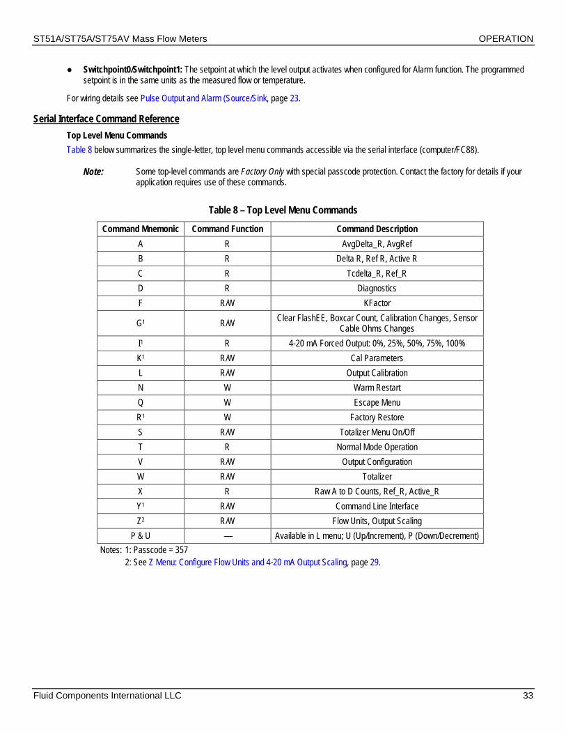
ST51A/ST75A/ST75AV Mass Flow Meters OPERATION
Fluid Components International LLC 33
Switchpoint0/Switchpoint1: The setpoint at which the level output activates when configured for Alarm function. The programmed setpoint is in the same units as the measured flow or temperature.
For wiring details see Pulse Output and Alarm (Source/Sink, page 23.
Serial Interface Command Reference Top Level Menu Commands Table 8 below summarizes the single-letter, top level menu commands accessible via the serial interface (computer/FC88).
Note: Some top-level commands are Factory Only with special passcode protection. Contact the factory for details if your application requires use of these commands.
Table 8 – Top Level Menu Commands
Command Mnemonic Command Function Command Description A R AvgDelta_R, AvgRef B R Delta R, Ref R, Active R C R Tcdelta_R, Ref_R D R Diagnostics F R/W KFactor
G1 R/W Clear FlashEE, Boxcar Count, Calibration Changes, Sensor Cable Ohms Changes
I1 R 4-20 mA Forced Output: 0%, 25%, 50%, 75%, 100% K1 R/W Cal Parameters L R/W Output Calibration N W Warm Restart Q W Escape Menu R1 W Factory Restore S R/W Totalizer Menu On/Off T R Normal Mode Operation V R/W Output Configuration W R/W Totalizer X R Raw A to D Counts, Ref_R, Active_R Y1 R/W Command Line Interface Z2 R/W Flow Units, Output Scaling
P & U — Available in L menu; U (Up/Increment), P (Down/Decrement) Notes: 1: Passcode = 357 2: See Z Menu: Configure Flow Units and 4-20 mA Output Scaling, page 29.
OPERATION ST51A/ST75A/ST75AV Mass Flow Meters
34 Fluid Components International LLC
CLI Commands Table 9 below summarizes the command line interface (CLI) commands accessible via the serial interface (computer/FC88).
Note: When invoking a CLI write function separate the command mnemonic and the data value with a space. All Read and Write Functions are completed by pressing [ENTER]. To exit CLI, press [ENTER] following the last Command [ENTER] (i.e., press [ENTER] twice). Refer also to Secondary Commands: CLI on page 28.
Examples: RBK[ENTER] (Read Breakpoint) WBK 2222 [ENTER] (Write Breakpoint 2222) RC11 [ENTER] (Read Coefficient C1,1) WC11 -234.567[ENTER] (Write Coefficient C1,1, -234.567)
Table 9 – List of CLI Commands Command Mnemonic Command Function Command Description Data Type
12 R/W Coefficient_Array1-2 Float 13 R/W Coefficient_Array1-3 Float 14 R/W Coefficient_Array1-4 Float 15 R/W Coefficient_Array1-5 Float 22 R/W Coefficient_Array2-2 Float 23 R/W Coefficient_Array2-3 Float 24 R/W Coefficient_Array2-4 Float 25 R/W Coefficient_Array2-5 Float
A[1-7] R/W Temp Comp, ACT_Tslope set Float AA R ADC ActR Integer AF R/W ActR Offset Float AR R ADC RefR Integer AS R/W ActR Slope Float AT R/W ADC IntTemp Integer AZ R/W ActR Ohm Adjust Float BK R/W Break Point Float BM R/W Boxcar Filter Max Integer C1 R/W Coefficient_Array1-1 Float C2 R/W Coefficient_Array2-1 Float
CM1 R/W Cminflow Float CR R/W Calibration Ref Float CX1 R/W Cmaxflow Float DI R Diagnostics Null
DM R/W DeltaR Minimum Float DN R/W Density Float DR R DeltaR Float DV R/W HART Damping Value Float DX R/W DeltaR Maximum Float EU1 R/W Engineering Units Enum F0 R/W Pulse Out State0 Enum F1 R/W Pulse Out State1 Enum FF1 R/W Flow Factor Float HC R/W Heater Current Adjust Integer HD R/W Heater DAC Integer HR R/W Tot Dump Hours Cntr Integer IL R/W IFactorLim Float
K[1-4] 1 R/W K Factor 1–4 Float L01 R/W Line Size0 Float L11 R/W Line Size1 Float MN R/W Minflow Float MO R/W Model# Integer MX R/W Maxflow Float NM R/W DeltaR NAMUR Min Float

ST51A/ST75A/ST75AV Mass Flow Meters OPERATION
Fluid Components International LLC 35
Command Mnemonic Command Function Command Description Data Type NN R/W NAMUR Mode Enum NX R/W DeltaR NAMUR Max Float
O[1-7] R/W Temp Comp, ACT_Toffst set Float OM R/W Outmode Enum P0 R/W Switch Point0 Integer P1 R/W Switch Point1 Integer PC R PCDeltaR Integer PF R/W Pulse Factor Float PL R/W Pulse Out Enum PR1 R/W % of Range Boolean PS R/W Pulse Sample period Float
Q[1-7] R/W Temp Comp, REF_Toffst set Float R[1-7] R/W Temp Comp, REF_Tslope set Float
RC R/W Ref Curve Adjust Integer RF R/W RefR Offset Float RO R/W RollOver Cntr Long RR R Reference R Float RS R/W RefR Slope Float RT R/W RTD_SLP_385 Boolean RZ R/W RefR Ohm Adjust Float S0 R/W SpanDAC0 for 4-20 mA #1 Integer S2 W Save FACTORY N/A S3 R/W SpanDAC1 for 4-20 mA #2 Integer SF R SFPS Flow Float SN R/W Serial Number String (16 chars max) SO R/W Shop Order Number String (16 chars max) T0 R/W Tcslp0 Float T2 R/W Tcslp2 Float T3 R/W TSpanDAC0 for 4-20 mA #1 Integer T5 R/W TZeroDAC0 for 4-20 mA #1 Integer T7 R/W TSpanDAC1 for 4-20 mA #2 Integer T8 R/W TZeroDAC1 for 4-20 mA #2 Integer TC R TCDeltaR Float TD R/W Tcslp Float TF R/W Totalizer ON/OFF Flag Boolean
TM1 R/W Cmintemp Float TP1 R/W Totalizer Temperature Flag Boolean TR R ActR Float TT R/W Totalizer Value Float TU R/W Totalizer Menu Boolean TX1 R/W Cmaxtemp Float TZ R Temperature Float UF R User Flow Float UK R User FlowK Float UN R/W User Name String (16 chars max) VN R Version Number String (16 chars max) XX R/W Test Flow Rate ON (SFPS) Float XY W Test Flow Rate OFF Float Z0 R/W ZeroDAC0 for 4-20 mA #1 Integer Z2 R/W ZeroDAC1 for 4-20 mA #2 Integer
Note: 1. This command is passcode protected if the totalizer is enabled. Contact the factory for details if your application requires use of this command.

OPERATION ST51A/ST75A/ST75AV Mass Flow Meters
36 Fluid Components International LLC
HART Operation HART (Highway Addressable Remote Transducer) is a communication protocol that superimposes a low level digital data signal on a 4-20 mA current loop. The primary function of the instrument’s HART interface is to present process data via process data commands 1, 3 and 9.
The ST51A/ST75A/ST75AV does not implement the HART Burst mode. A HART master that supports HART 7.0 and higher is required. If using a HART communicator, a unit that supports HART 7.0 or higher is required (i.e. Emerson 475 Communicator). Connect the installation (factory/plant) HART wiring to the instrument as described in HART Connection, page 22.
Process Data Operation The ST51A/ST75A/ST75AV implements HART 7.0 while maintaining compatibility with earlier versions of the HART protocol. However, HART commands 1 and 3 have been simplified to only report the primary variable Flow. Use command 9 to access the full suite of available dynamic variables including temperature, totalizer, and others.
ST51A/ST75A/ST75AV HART Process Data Organization This section describes how the instrument process data is organized under the HART command 9. For details on command 9 see the HART Specification “Universal Commands Specification” HCF_SPEC-127, Revision 7.1 and the command 9 description on page 42.
ST51A/ST75A/ST75AV Process Variable Slots Table 10 below lists the instrument’s 6 process variables that are read by HART command 9, with each process variable assigned a slot number.
Not all the variables described in this section are available in all configurations of the flow meter. For example, the Flow Totalizer may be turned ON or OFF.
The process variables include 3 flow classes or types of which only one class of flow is active at a time.
Table 10 – ST51A/ST75A/ST75AV HART Process Variables Slot # Process Variable HART Variable Code
Description Device Variable Code Device Variable
Classification 0 Volumetric Flow1 Primary Variable 0 66 1 Volume (Totalizer) Secondary Variable 1 68 2 Mass Flow1 Primary Variable 2 72 3 Mass (Totalizer) Secondary Variable 3 71 4 Velocity Flow1 Primary Variable 4 67 5 Temperature Tertiary Variable 5 64
Note: 1. Only one flow variable active at a time. Primary Variable Classifications The instrument can provide flow data in unit types that span several HART classifications. Commands 50 and 51 are used to read and set, respectively, which flow variable will be mapped to the primary variable. The PV device variable classification can only be one of the following:
0: Volumetric Flow 2: Mass Flow 4: Velocity Flow Since only PV is used in this manner, command 50 returns 250 for SV, TV, and QV. The setting of the device variable classification determines which class of flow-related variables is valid, and therefore displayed as implemented when variable slots are read by command 9.
Device Description Files A Device Description (DD) file lets the HART handheld or host software application fully configure any HART device for which it has a DD installed. The ST51A/ST75A/ST75AV DD files are available for download from the FieldComm Group website:
https://fieldcommgroup.org/registered-products/
Search by Manufacturer (Fluid Components International LLC) to find the instrument’s files under the product name: FCI ST51A/ST75A Series. The posted DD files are contained in a zip archive with FCI’s manufacturer ID and product device type hex values embedded in the filename (e.g., hart.0000a6.a67e.zip).

ST51A/ST75A/ST75AV Mass Flow Meters OPERATION
Fluid Components International LLC 37
Table 11 below summarizes the instrument’s FieldComm Group device registration information.
Table 11 – ST51A/ST75A/ST75AV HART Device Registration Information Product Name Product Type HART Version Mfgr. ID Device Type Dev. Revision
FCI ST51A/ST75A Series Flow 7 0x00A6 0xA67E 01
EDDL Files The ST Series EDDL (Electronic Device Description Language) files are support files that provide an extended description of each object in the Virtual Field Device (VFD), and provide information needed for a control system or host to understand the meaning of the data in the VFD including the human interface. The EDDL file can be thought as a “driver” for the device.
FCI provides two types of files: the standard EDDL files, and the Emerson 375 and 475 Communicator DD files.
Loading the DD Files to the 475 Field Communicator Use the “Easy Upgrade Utility” from EMERSON to load the DDPs into the Field Communicator. Below is the procedure for how to load DD files into the 475-Field communicator.
Open the Field Communicator Easy Upgrade Utility program and click Utilities on the left hand menu. Select Import DDs from a local source. Then select the FCI files from the resulting List dialog, and then and click OK. See Figure 27 below.
Figure 27 – Field Communicator Easy Upgrade Utility, Import DD
Service Data Operation The Service Data functions are organized into 3 areas:
1. ST51 Product Family Basic Setup 2. ST51 Product Family Configuration 3. ST51 Product Family Factory Calibration Limits
Shown below is service information as seen through the Emerson 475 HART communicator with FCI’s DD files loaded. The same information seen by the 475 is shown in the DCS (Distributed Control System) when the ST51 Product Family HART DD files are loaded.

OPERATION ST51A/ST75A/ST75AV Mass Flow Meters
38 Fluid Components International LLC
ST51 Product Family Basic Setup The Basic Setup function lets you review and change the engineering units of the process variables, review and change the Plenum or pipe size, enable or disable the Totalizer, review and change device information, reset the operation of the ST51A/ST75A/ST75AV to the factory settings, review and change PV Setup and review and change K Factors.
Engineering Units Information
Plenum The ST51A/ST75A/ST75AV Plenum function lets you review and edit the plenum data that have been set.

ST51A/ST75A/ST75AV Mass Flow Meters OPERATION
Fluid Components International LLC 39
Totalizer The ST51A/ST75A/ST75AV Totalizer function lets you turn the totalizer ON or OFF.
Factory Reset WARNING – The factory Reset command re-loads the configuration and calibration parameters that were loaded into the instrument during the original calibration and setup. Any changes made to the configuration of calibration parameters will be lost when the Factory Reset command is executed.
ST51 Product Family Calibration Limits (Example) The ST51A/ST75A/ST75AV Calibration Limits function lets you review the limits that have been set for the Flow and Temperature process parameters.

OPERATION ST51A/ST75A/ST75AV Mass Flow Meters
40 Fluid Components International LLC
HART Command List Reference The HART commands are divided into three classes.
Universal Commands Common Practice Commands Device Specific Commands
Barring no communication error, a field or slave device returns a response code as part of the 2-byte status response to a command. Refer to Command Status Bytes on page 52. The ST51A/ST75A/ST75AV response codes listed in the following command summaries are a subset of the response codes listed in the HART specification.
ST51A/ST75A/ST75AV HART Universal Commands The ST51A/ST75A/ST75AV HART supports Universal Commands 0 through 22 and 38 and 48. Commands 4 and 5 are reserved under Universal Command Specification Rev. 7.1 (HCF_SPEC-127, Revision 7.1) and not implemented in this specification. There is no HART command 10. Table 12 below summarizes the instrument’s HART Universal command set and the data associated with each command.
Table 12 – HART Universal Commands Command 0: Read Unique Identifier Byte Format Description Request Data Bytes None Response Data Bytes 0 Unsigned-8 254 1–2 Enum Expanded Device Type 3 Unsigned-8 Minimum number of preambles from master to slave 4 Unsigned-8 HART Protocol Revision Number: 7 5 Unsigned-8 Device Revision Number 6 Unsigned-8 Software Revision Number 7 Unsigned-5 (Most Significant 5 Bits) Hardware Revision Level: 1 7 Enum Physical Signaling Code: 00 = Bell 202 Current (4-20 mA) 8 Bits Flags: 01 = Multisensor 9–11 Unsigned-24 Device ID 12 Unsigned-8 Minimum number of preambles from the slave to master 13 Unsigned-8 Maximum Number of Device Variables 14–15 Unsigned-16 Configuration Change Counter 16 Bits Extended Field Device Status 17–18 Enum Manufacturer ID Code: 166DEC/00A6HEX (FCI) 19–20 Enum Private Label Distributor Code 21 Enum Device Profile = 1 “HART Process Automation Device” Response Codes: See Table 16, page 53, for response code list.
Command 1: Read Primary Variable (Flow Units, & Flow Value) Byte Format Description Request Data Bytes None Response Data Bytes 0 Enum Primary Variable Units Code 1–4 Float Primary Variable Value Response Codes: See Table 16, page 53, for response code list.
Command 2: Read Primary Variable Loop Current and Percent of Range Byte Format Description Request Data Bytes None Response Data Bytes 0–3 Float Primary Variable Loop Current (mA) 4–7 Float Primary Variable Percent of Range (%) Response Codes: See Table 16, page 53, for response code list.

ST51A/ST75A/ST75AV Mass Flow Meters OPERATION
Fluid Components International LLC 41
Command 3: Read Dynamic Variable (Flow) and Loop Current Byte Format Description Request Data Bytes None Response Data Bytes 0–3 Float PV Loop Current: 4-20 mA 4 Enum PV HART Unit Code, Flow 5–8 Float PV Flow Value Response Codes: See Table 16, page 53, for response code list.
Command 6: Write Polling Address Byte Format Description Request Data Bytes 0 Unsigned-8 Polling Address of Device 1 Enum Loop Current Mode Response Data Bytes 0 Unsigned-8 Polling Address of Device 1 Enum Loop Current Mode Response Codes: See Table 16, page 53, for response code list.
Command 7: Read Loop Configuration Byte Format Description Request Data Bytes None Response Data Bytes 0 Unsigned-8 Polling Address of Device 1 Enum Loop Current Mode Response Codes: See Table 16, page 53, for response code list.
Command 8: Read Dynamic Variable Classifications Byte Format Description Request Data Bytes None Response Data Bytes 0 Enum Primary Variable Classification 1 Enum Secondary Variable Classification 2 Enum Tertiary Variable Classification 3 Enum Quaternary Variable Classification Response Codes: See Table 16, page 53, for response code list.
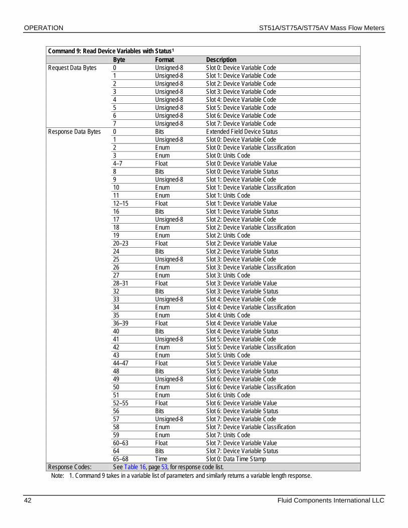
OPERATION ST51A/ST75A/ST75AV Mass Flow Meters
42 Fluid Components International LLC
Command 9: Read Device Variables with Status1 Byte Format Description Request Data Bytes 0 Unsigned-8 Slot 0: Device Variable Code 1 Unsigned-8 Slot 1: Device Variable Code 2 Unsigned-8 Slot 2: Device Variable Code 3 Unsigned-8 Slot 3: Device Variable Code 4 Unsigned-8 Slot 4: Device Variable Code 5 Unsigned-8 Slot 5: Device Variable Code 6 Unsigned-8 Slot 6: Device Variable Code 7 Unsigned-8 Slot 7: Device Variable Code Response Data Bytes 0 Bits Extended Field Device Status 1 Unsigned-8 Slot 0: Device Variable Code 2 Enum Slot 0: Device Variable Classification 3 Enum Slot 0: Units Code 4–7 Float Slot 0: Device Variable Value 8 Bits Slot 0: Device Variable Status 9 Unsigned-8 Slot 1: Device Variable Code 10 Enum Slot 1: Device Variable Classification 11 Enum Slot 1: Units Code 12–15 Float Slot 1: Device Variable Value 16 Bits Slot 1: Device Variable Status 17 Unsigned-8 Slot 2: Device Variable Code 18 Enum Slot 2: Device Variable Classification 19 Enum Slot 2: Units Code 20–23 Float Slot 2: Device Variable Value 24 Bits Slot 2: Device Variable Status 25 Unsigned-8 Slot 3: Device Variable Code 26 Enum Slot 3: Device Variable Classification 27 Enum Slot 3: Units Code 28–31 Float Slot 3: Device Variable Value 32 Bits Slot 3: Device Variable Status 33 Unsigned-8 Slot 4: Device Variable Code 34 Enum Slot 4: Device Variable Classification 35 Enum Slot 4: Units Code 36–39 Float Slot 4: Device Variable Value 40 Bits Slot 4: Device Variable Status 41 Unsigned-8 Slot 5: Device Variable Code 42 Enum Slot 5: Device Variable Classification 43 Enum Slot 5: Units Code 44–47 Float Slot 5: Device Variable Value 48 Bits Slot 5: Device Variable Status 49 Unsigned-8 Slot 6: Device Variable Code 50 Enum Slot 6: Device Variable Classification 51 Enum Slot 6: Units Code 52–55 Float Slot 6: Device Variable Value 56 Bits Slot 6: Device Variable Status 57 Unsigned-8 Slot 7: Device Variable Code 58 Enum Slot 7: Device Variable Classification 59 Enum Slot 7: Units Code 60–63 Float Slot 7: Device Variable Value 64 Bits Slot 7: Device Variable Status 65–68 Time Slot 0: Data Time Stamp Response Codes: See Table 16, page 53, for response code list.
Note: 1. Command 9 takes in a variable list of parameters and similarly returns a variable length response.

ST51A/ST75A/ST75AV Mass Flow Meters OPERATION
Fluid Components International LLC 43
Command 11: Read Unique Identifier Associated with Tag Byte Format Description Request Data Bytes 0–5 Packed Tag, Packed ASCII Response Data Bytes 0 Unsigned-8 254 1–2 Enum Expanded Device Type 3 Unsigned-8 Minimum number of preambles from master to slave 4 Unsigned-8 HART Protocol Revision Number: 7 5 Unsigned-8 Device Revision Number 6 Unsigned-8 Software Revision Number 7 Unsigned-5 (Most Significant 5 Bits) Hardware Revision Level: 1 7 Enum Physical Signaling Code: 00 = Bell 202 Current (4-20 mA) 8 Bits Flags: 01 = Multisensor 9–11 Unsigned-24 Device ID 12 Unsigned-8 Minimum number of preambles from the slave to master 13 Unsigned-8 Maximum Number of Device Variables 14–15 Unsigned-16 Configuration Change Counter 16 Bits Extended Field Device Status 17–18 Enum Manufacturer ID Code: 166DEC/00A6HEX (FCI) 19–20 Enum Private Label Distributor Code 21 Enum Device Profile = 1 “HART Process Automation Device” Response Codes: See Table 16, page 53, for response code list.
Command 12: Read Message Contained Within Device Byte Format Description Request Data Bytes None Response Data Bytes 0–11 Bitstring Device ID No. Response Codes: See Table 16, page 53, for response code list.
Command 13: Read Tag, Descriptor, Date Byte Format Description Request Data Bytes None Response Data Bytes 0–5 Packed Tag 6–17 Packed Descriptor 18–20 Date Date Code: Day, Month, Year Response Codes: See Table 16, page 53, for response code list.
Command 14: Read Primary Variable (Flow) Transducer Information Byte Format Description Request Data Bytes None Response Data Bytes 0–2 Unsigned-24 Transducer Serial Number 3 Enum Transducer Limits and Minimum Span Units Code 4–7 Float Upper Transducer Limit 8–11 Float Lower Transducer Limit 12–15 Float Minimum Span Response Codes: See Table 16, page 53, for response code list.

OPERATION ST51A/ST75A/ST75AV Mass Flow Meters
44 Fluid Components International LLC
Command 15: Read Device Information Byte Format Description Request Data Bytes None Response Data Bytes 0 Enum Flow Alarm Selection Code 1 Enum Flow Transfer Function Code (not supported) 2 Enum Flow Upper and Lower Range Value Units Code 3–6 Float Flow Upper Range Value 7–10 Float Flow Lower Range Value 11–14 Float Flow Damping Value1 15 Enum Write Protect Code (not supported) 16 Enum Reserved 17 Bits Flow Analog Channel Flags (not supported) Response Codes: See Table 16, page 53, for response code list.
Note: 1. Refer to HART Damping Value on page 32 for details on flow damping within HART. The damping value can only be adjusted using the serial interface “V” command or the CLI “DV” command.
Command 16: Read Final Assembly Number Byte Format Description Request Data Bytes None Response Data Bytes 0–2 Unsigned-24 Final Assembly No. Response Codes: See Table 16, page 53, for response code list.
Command 17: Write Message Into Device Byte Format Description Request Data Bytes 0–23 Packed Message String Used by Master Response Data Bytes1 0–23 Packed Message String Response Codes: See Table 16, page 53, for response code list.
Note: 1. The value returned in the response data bytes reflects the value actually used by the field device.
Command 18: Write Tag, Descriptor, Date Byte Format Description Request Data Bytes 0–5 Packed Tag 6–17 Packed Descriptor Used by Master 18–20 Date Date Code Used by Master Response Data Bytes1 0–5 Packed Tag 6–17 Packed Descriptor 18–20 Date Date Code: Day, Month, Year Response Codes: See Table 16, page 53, for response code list.
Note: 1. The value returned in the response data bytes reflects the value actually used by the field device.
Command 19: Write Final Assembly Number Byte Format Description Request Data Bytes 0–2 Unsigned-24 Final Assembly No. Response Data Bytes1 0–2 Unsigned-24 Final Assembly No. Response Codes: See Table 16, page 53, for response code list.
Note: 1. The value returned in the response data bytes reflects the value actually used by the field device.
Command 20: Read Long Tag Byte Format Description Request Data Bytes None Response Data Bytes 0–31 Latin-1 Long Tag Response Codes: See Table 16, page 53, for response code list.

ST51A/ST75A/ST75AV Mass Flow Meters OPERATION
Fluid Components International LLC 45
Command 21: Read Unique Identifier Associated with Long Tag Byte Format Description Request Data Bytes 0–31 Latin-1 Long Tag Response Data Bytes 0 Unsigned-8 254 1–2 Enum Expanded Device Type 3 Unsigned-8 Minimum Number Of Preambles From Master to Slave 4 Unsigned-8 HART Protocol Revision Number: 7 5 Unsigned-8 Device Revision Number 6 Unsigned-8 Software Revision Number 7 Unsigned-5 (Most Significant 5 Bits) Hardware Revision Level: 1 7 Enum Physical Signaling Code: 00 = Bell 202 Current (4-20 mA) 8 Bits Flags: 01 = Multisensor 9–11 Unsigned-24 Device ID 12 Unsigned-8 Minimum Number Of Preambles From Slave to Master 13 Unsigned-8 Maximum Number of Device Variables 14–15 Unsigned-16 Configuration Change Counter 16 Bits Extended Field Device Status 17–18 Enum Manufacturer ID Code: 166DEC/00A6HEX (FCI) 19–20 Enum Private Label Distributor Code 21 Enum Device Profile = 1 “HART Process Automation Device” Response Codes: See Table 16, page 53, for response code list.
Command 22: Write Long Tag Byte Format Description Request Data Bytes 0–31 Latin-1 Long Tag Response Data Bytes 0–31 Latin-1 Long Tag Response Codes: See Table 16, page 53, for response code list.
Command 38: Reset Configuration Changed Flag Byte Format Description Request Data Bytes 0–1 Unsigned-16 Configuration Change Counter Response Data Bytes 0–1 Unsigned-16 Configuration Change Counter Response Codes: See Table 16, page 53, for response code list.

OPERATION ST51A/ST75A/ST75AV Mass Flow Meters
46 Fluid Components International LLC
Command 48: Read Additional Device Status Byte Format Description Request Data Bytes 0–5 Bits Device-Specific Status (only first 2 bytes used, see page 54 for
additional info) 6 Bits Extended Device Status. Normally “0”; set to “1” (0x01) if
maintenance is required. 7 Bits Device Operating Mode (not used, bit cleared to 0) 8 Bits Standardized Status 0 (not used, bit cleared to 0) 9 Bits Standardized Status 1 (not used, bit cleared to 0) 10 Bits Analog Channel Saturated (not used, bit cleared to 0) 11 Bits Standardized Status 2 (not used, bit cleared to 0) 12 Bits Standardized Status 3 (not used, bit cleared to 0) 13 Bits Analog Channel Fixed 14–24 Bits Device-Specific Status2 (not used, bit cleared to 0) Response Data Bytes 0–5 Bits Device-Specific Status (only first 2 bytes used, see page 54) 6 Bits Extended Device Status. Normally “0”; set to “1” (0x01) if
maintenance is required. 7 Bits Device Operating Mode (not used, bit cleared to 0) 8 Bits Standardized Status 0 (not used, bit cleared to 0) 9 Bits Standardized Status 1 (not used, bit cleared to 0) 10 Bits Analog Channel Saturated (not used, bit cleared to 0) 11 Bits Standardized Status 2 (not used, bit cleared to 0) 12 Bits Standardized Status 3 (not used, bit cleared to 0) 13 Bits Analog Channel Fixed 14–24 Bits Device-Specific Status2 (not used, bit cleared to 0) Response Codes: See Table 16, page 53, for response code list.

ST51A/ST75A/ST75AV Mass Flow Meters OPERATION
Fluid Components International LLC 47
ST51A/ST75A/ST75AV HART Common Practice Commands The ST51A/ST75A/ST75AV supports Common Practice commands 35, 40, 42, 44, 45, 46, 50 and 51. Table 13 below summarizes the instrument’s HART Common Practice command set and the data associated with each command.
Table 13 – HART Common Practice Commands Command 35: Write Primary Variable (PV) Range Values Byte Format Description Request Data Bytes 0 Unsigned-8 PV Upper and Lower Range Values Units Code 1–4 Float PV Upper Range Value (Customer Max. Flow Limit) 5–8 Float PV Lower Range Value (Customer Min. Flow Limit) Response Data Bytes1 0 Unsigned-8 PV Upper and Lower Range Values Units Code 1–4 Float PV Upper Range Value 5–8 Float PV Lower Range Value Response Codes: See Table 16, page 53, for response code list.
Note: 1. The value returned in the response data bytes reflects the rounded or truncated value actually used by the device.
Command 40: Enter/Exit Fixed Current Mode Byte Format Description Request Data Bytes1 0–3 Float PV Fixed Current Level (mA units); “0” to Exit Fixed Current Response Data Bytes 0–3 Float Actual PV Current Level Response Codes: See Table 16, page 53, for response code list.
Notes: 1. Specify a value (in mA) to drive Ch. 1 to a particular output value. Specify “0” to exit the fixed current mode.
Command 42: Perform Device Reset (Soft Reset of Flow Meter)1 Byte Format Description Request Data Bytes None Response Data Bytes None Response Codes: See Table 16, page 53, for response code list.
Note: 1. Send Command 42 (no data) to reset the instrument. No response is returned due to reboot.
Command 44: Write Primary Variable Units Byte Format Description Request Data Bytes 0 Enum PV Units Code Response Data Bytes1 0 Enum PV Units Code Response Codes: See Table 16, page 53, for response code list.
Note: 1. The value returned in the response data bytes reflects the value actually used by the device.
Command 45: Trim DAC Zero – Measured Current Chan #1 (in mA) Byte Format Description Request Data Bytes 0–3 Float Ext. Measured Current Ch. #1 Level (mA units) Response Data Bytes1 0–3 Float Actual Measured Current Ch. #1 Level (mA units) Response Codes: See Table 16, page 53, for response code list.
Note: 1. The value returned in the response data bytes reflects the rounded or truncated value actually used by the device.
Command 46: Trim DAC Gain – Measured Current Chan #1 (in mA) Byte Format Description Request Data Bytes 0–3 Float Ext. Measured Current Ch. #1 Level (mA units) Response Data Bytes1 0–3 Float Actual Measured Current Ch. #1 Level (mA units) Response Codes: See Table 16, page 53, for response code list.
Note: 1. The value returned in the response data bytes reflects the rounded or truncated value actually used by the device.
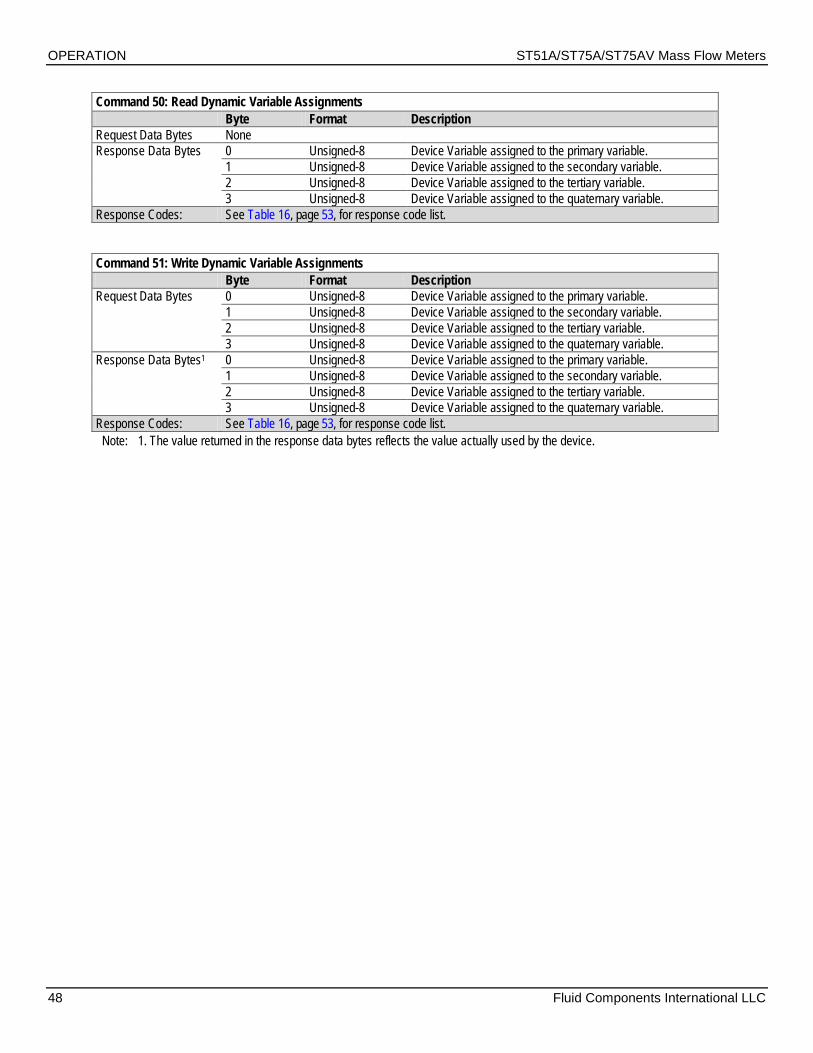
OPERATION ST51A/ST75A/ST75AV Mass Flow Meters
48 Fluid Components International LLC
Command 50: Read Dynamic Variable Assignments Byte Format Description Request Data Bytes None Response Data Bytes 0 Unsigned-8 Device Variable assigned to the primary variable. 1 Unsigned-8 Device Variable assigned to the secondary variable. 2 Unsigned-8 Device Variable assigned to the tertiary variable. 3 Unsigned-8 Device Variable assigned to the quaternary variable. Response Codes: See Table 16, page 53, for response code list.
Command 51: Write Dynamic Variable Assignments Byte Format Description Request Data Bytes 0 Unsigned-8 Device Variable assigned to the primary variable. 1 Unsigned-8 Device Variable assigned to the secondary variable. 2 Unsigned-8 Device Variable assigned to the tertiary variable. 3 Unsigned-8 Device Variable assigned to the quaternary variable. Response Data Bytes1 0 Unsigned-8 Device Variable assigned to the primary variable. 1 Unsigned-8 Device Variable assigned to the secondary variable. 2 Unsigned-8 Device Variable assigned to the tertiary variable. 3 Unsigned-8 Device Variable assigned to the quaternary variable. Response Codes: See Table 16, page 53, for response code list.
Note: 1. The value returned in the response data bytes reflects the value actually used by the device.

ST51A/ST75A/ST75AV Mass Flow Meters OPERATION
Fluid Components International LLC 49
ST51A/ST75A/ST75AV HART Device Specific Commands In the HART protocol all commands defined as Manufacturer Specific, or Device Specific start at command 128. Use the device specific commands to setup and configure the ST51A/ST75A/ST75AV instrument via HART.
Table 14 below summarizes the instrument’s HART Device Specific command set and the data associated with each command.
Table 14 – HART Device Specific Commands
Command 137: Read Totalizer And Rollover Values Byte Format Description Request Data Bytes None Response Data Bytes 0–3 Float Totalizer 4–7 Integer Rollover Response Codes: See Table 16, page 53, for response code list.
Command 138: Read Totalizer State Byte Format Description Request Data Bytes None Response Data Bytes 0 Unsigned-8 Totalizer State: 0 = OFF; 1 = ON Response Codes: See Table 16, page 53, for response code list.
Command 139: Write Totalizer State Byte Format Description Request Data Bytes 0 Unsigned-8 Totalizer State: 0 = OFF; 1 = ON Response Data Bytes 0 Unsigned-8 Totalizer State: 0 = OFF; 1 = ON Response Codes: See Table 16, page 53, for response code list.
Command 140: Read Device Information Byte Format Description Request Data Bytes None Response Data Bytes 0–9 Bits Device CO 10–19 Bits Device Serial Number 19–22 Bits Device Software Version Response Codes: See Table 16, page 53, for response code list.
Command 141: Write Totalizer Reset Byte Format Description Request Data Bytes 0–1 Unsigned-16 Reset Key = 0xABCD Response Data Bytes 0–1 Unsigned-16 Reset Key = 0xABCD 10–19 Bits Device Serial Number 19–22 Bits Device Software Version Response Codes: See Table 16, page 53, for response code list.
Command 145: Read Customer Engineering Units Byte Format Description Request Data Bytes None Response Data Bytes 0 Unsigned-8 Units Code for Flow 1 Unsigned-8 Units Code for Temperature 2 Unsigned-8 Units Code for Totalizer Response Codes: See Table 16, page 53, for response code list.

OPERATION ST51A/ST75A/ST75AV Mass Flow Meters
50 Fluid Components International LLC
Command 146: Write Customer Flow Units Byte Format Description Request Data Bytes 0 Unsigned-8 Units Code for Flow Response Data Bytes 0 Unsigned-8 Units Code for Flow Response Codes: See Table 16, page 53, for response code list.
Command 148: Read Plenum Information (Pipe Size) Byte Format Description Request Data Bytes None Response Data Bytes 0-3 Float Pipe Height Value 4–7 Float Pipe Width (Diameter) Value 8 Unsigned-8 Plenum Units Code Response Codes: See Table 16, page 53, for response code list.
Command 149: Write Plenum Information (Pipe Size) Byte Format Description Request Data Bytes 0–3 Float Pipe Height Value 4–7 Float Pipe Width (Diameter) Value 8 Unsigned-8 Plenum Units Code Response Data Bytes 0-3 Float Pipe Height Value 4–7 Float Pipe Width (Diameter) Value 8 Unsigned-8 Plenum Units Code Response Codes: See Table 16, page 53, for response code list.
Command 151: Read Calibration Flow Limits Byte Format Description Request Data Bytes None Response Data Bytes 0–3 Float Flow Lower Limit Value 4–7 Float Flow Upper Limit Value Response Codes: See Table 16, page 53, for response code list.
Command 152: Write Calibration Flow Limits Byte Format Description Request Data Bytes 0–3 Float Flow Lower Limit Value 4–7 Float Flow Upper Limit Value Response Data Bytes 0–3 Float Flow Lower Limit Value 4–7 Float Flow Upper Limit Value Response Codes: See Table 16, page 53, for response code list.
Command 153: Read Calibration Temperature Limits Byte Format Description Request Data Bytes None Response Data Bytes 0–3 Float Temperature Lower Limit Value 4–7 Float Temperature Upper Limit Value Response Codes: See Table 16, page 53, for response code list.
Command 154: Write Calibration Temperature Limits Byte Format Description Request Data Bytes None Response Data Bytes 0–3 Float Temperature Lower Limit Value 4–7 Float Temperature Upper Limit Value Response Codes: See Table 16, page 53, for response code list.

ST51A/ST75A/ST75AV Mass Flow Meters OPERATION
Fluid Components International LLC 51
Command 155: Read KFactors Byte Format Description Request Data Bytes None Response Data Bytes 0–3 Float KFactor1 4–7 Float KFactor2 8–11 Float KFactor3 12–15 Float KFactor4 Response Codes: See Table 16, page 53, for response code list.
Command 156: Write KFactors Byte Format Description Request Data Bytes 0–3 Float KFactor1 4–7 Float KFactor2 8–11 Float KFactor3 12–15 Float KFactor4 Response Data Bytes 0–3 Float KFactor1 4–7 Float KFactor2 8–11 Float KFactor3 12–15 Float KFactor4 Response Codes: See Table 16, page 53, for response code list.
Command 159: Write Factory Restore Byte Format Description Request Data Bytes1 0 Unsigned-8 0x00 for Factory Restore Response Data Bytes 0 Unsigned-8 0x00 for Factory Restore Response Codes: See Table 16, page 53, for response code list.
Note: 1. Send Command 159 with a “0” byte to reload the instrument’s factory default programming.
Command 160: Read Secondary Output Current Mode Byte Format Description Request Data Bytes None Response Data Bytes 0–1 Word Ch2 4-20 mA Source (1 = Flow, 2 = Temperature) Response Codes: See Table 16, page 53, for response code list.
Command 161: Write Secondary Output Current Mode Byte Format Description Request Data Bytes 0–1 Word Ch2 4-20 mA Source (1 = Flow, 2 = Temperature) Response Data Bytes 0–1 Word Ch2 4-20 mA Source (1 = Flow, 2 = Temperature) Response Codes: See Table 16, page 53, for response code list.
Command 162: Enter/Exit Ch2 Fixed Current Mode (in mA) Byte Format Description Request Data Bytes1 0–3 Float Ch. 2 Fixed Current Level (mA units); “0” to Exit Fixed Current Response Data Bytes 0–3 Float Ch. 2 Actual Current Level Response Codes: See Table 16, page 53, for response code list.
Note: 1. Specify a value (in mA) to drive Ch. 2 to a particular output value. Specify “0” to exit the fixed current mode.

OPERATION ST51A/ST75A/ST75AV Mass Flow Meters
52 Fluid Components International LLC
Command 163: Trim DAC Zero – Measured Current Chan #2 (in mA) Byte Format Description Request Data Bytes 0–3 Float Ext. Measured Current Ch. #2 Level (mA units) Response Data Bytes1 0–3 Float Actual Measured Current Ch. #2 Level (mA units) Response Codes: See Table 16, page 53, for response code list.
Note: 1. The value returned in the response data bytes reflects the rounded or truncated value actually used by the device.
Command 164: Trim DAC Gain – Measured Current Chan #2 (in mA) Byte Format Description Request Data Bytes 0–3 Float Ext. Measured Current Ch. #2 Level (mA units) Response Data Bytes1 0–3 Float Actual Measured Current Ch. #2 Level (mA units) Response Codes: See Table 16, page 53, for response code list. Note: 1. The value returned in the response data bytes reflects the rounded or truncated value actually used by the device.
HART Command Bit Assignments Command Status Bytes The HART command response data field includes a status message in the first two bytes. The first byte (0) is the Comm Error/Response code. The second byte (1) is the Device status. Byte 0 indicates either a communication error or a command-specific response code if no communication error exists. Note that within the first byte, bit b7 is either set or cleared to indicate that the byte indicates a comm error or a command-specific response code, respectively. Table 15 summarizes the command status bytes. Table 16 summarizes the command-specific response codes.

ST51A/ST75A/ST75AV Mass Flow Meters OPERATION
Fluid Components International LLC 53
Table 15 – Command Status Bytes, Bit Assignments
Byte Bit Error/Status Description Communication Error Response Code (No Comm Error)
Byte 0
0 Reserved – Bit cleared to zero.
Command-Specific Response Code (0-127) See Table 16 below.
1 Buffer Overflow – The message was too long for the received buffer of the device.
2 Reserved – Bit cleared to zero. 3 Longitudinal Parity Error – The longitudinal parity
calculated by the device did not match the check byte at the end of the message.
4 Framing Error – The stop bit of one or more bytes received by the device was not detected by the UART (i.e., a mark or 1 was not detected when a stop bit should have occurred).
5 Overrun Error – At least one byte of data in the receive buffer of the UART was overwritten before it was read (i.e. the slave did not process incoming byte fast enough).
6 Vertical Parity Error – The parity of one or more of the bytes received by the device was not odd
7 1: Set bit means byte represents communications error. 0: Cleared bit means byte represents response code.
Byte 1 Device Status
0 Primary Variable Out of Limits – The PV is beyond its operating limit. 1 Non-Primary Variable Out of Limits – A device variable not mapped to the PV is beyond its operating limits. 2 Loop Current Saturated – The loop current has reached its upper (or lower) endpoint limit and cannot increase (or
decease) any further. 3 Loop Current Fixed – The loop current is being held at a fixed value and is not responding to process variations. 4 More Status Available – More status information is available via Command 48, Additional Device Status Bytes
(next section). 5 Cold Start – A power failure or device reset has occurred. 6 Configuration Changed – An operation was performed that changed the device’s configuration. 7 Device Malfunction – The device detected a serious error or failure that compromises device operation.
Table 16 – Command-Specific Response Codes Code (Class) Description Code (Class) Description
00 (Success) No command-specific errors 12 (Error) Upper Range value too low/Invalid mode 02 (Error) Invalid selection/Invalid Poll Address 13 (Error) Upper and Lower Range values out of
limit 03 (Error) Passed parameter too large 14 (Warning) Span too small/Status byte mismatch 04 (Error) Passed parameter too small 16 (Mode Error) Access restricted 05 (Error) Too few data bytes received 18 (Error) Invalid units code 06 (Misc Error) Device-specific command error 29 (Error) Invalid Span 07 (Mode Error) In Write-Protect mode 30 (Error) Command response truncated 09 (Error) Invalid date code/Configuration change
counter mismatch/Lower range value too high/Incorrect loop current mode or value
32 (Error) Busy
10 (Error) Lower Range value too low 64 (Error) Command not implemented 11 (Error) Upper Range value too high/Loop
current not active (device in multidrop mode) — —

OPERATION ST51A/ST75A/ST75AV Mass Flow Meters
54 Fluid Components International LLC
Command 48, Additional Device Status Bytes Table 17 below summarizes the Command 48 Additional Device Status bytes. This is a 6-byte field of which only the first 2 bytes (bytes 0 and 1) are used by the instrument. The remaining bytes (2–5) are unused/reserved. A status bit is cleared (0) for no error. A status bit is set (1) when an error (or condition) is detected.
Table 17 – Command 48, Additional Device Status Bytes Bit Assignments Byte Bit Error/Status Description
Byte 0
0 Flow < Min Flow 1 Flow > Min Flow 2 Unused/Reserved 3 Flow > Customer Max Flow 4 Temperature < Customer Min Temperature 5 Temperature > Customer Max Temperature 6 Unused/Reserved 7 tcDelta_r < dr_min
Byte 1
0 tcDelta_r > dr_max 1 Unused/Reserved 2 Unused/Reserved 3 Unused/Reserved 4 Unused/Reserved 5 Unused/Reserved 6 Unused/Reserved 7 Delta_r > drNamur_max OR Delta_r < drNamur_min
Bytes 2–5 Unused/Reserved
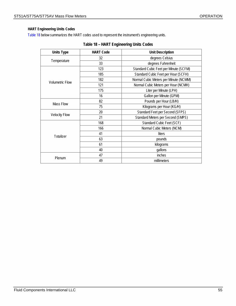
ST51A/ST75A/ST75AV Mass Flow Meters OPERATION
Fluid Components International LLC 55
HART Engineering Units Codes Table 18 below summarizes the HART codes used to represent the instrument’s engineering units.
Table 18 – HART Engineering Units Codes
Units Type HART Code Unit Description
Temperature 32 degrees Celsius 33 degrees Fahrenheit
Volumetric Flow
123 Standard Cubic Feet per Minute (SCFM) 185 Standard Cubic Feet per Hour (SCFH) 182 Normal Cubic Meters per Minute (NCMM) 121 Normal Cubic Meters per Hour (NCMH) 175 Liter per Minute (LPH) 16 Gallon per Minute (GPM)
Mass Flow 82 Pounds per Hour (LB/H) 75 Kilograms per Hour (KG/H)
Velocity Flow 20 Standard Feet per Second (SFPS) 21 Standard Meters per Second (SMPS)
Totalizer
168 Standard Cubic Feet (SCF) 166 Normal Cubic Meters (NCM) 41 liters 63 pounds 61 kilograms 40 gallons
Plenum 47 inches 49 millimeters

OPERATION ST51A/ST75A/ST75AV Mass Flow Meters
56 Fluid Components International LLC
Modbus Operation The ST51A/ST75A/ST75AV offers Modbus as one of its digital communication protocol, but unlike the other digital communication protocols Modbus only offers set up and configuration for the totalizer variables and K Factor corrections. Refer to Modbus Connections on page 24 for Modbus wiring details.
The Modbus physical layer uses the flow meter’s asynchronous RS-485 serial port. There is no high speed Modbus over Ethernet. The flow meter is configurable to operate in one of two basic traditional transmission serial interface modes: RTU and ASCII message coding.
The ST51A/ST75A/ST75AV offers the process variable parameters (value) in floating point form, which are organized as single or double precision floating point registers. These registers are the 4000 and the 5000 group registers, both of which are accessed using Modbus 03 and 04 function codes. Refer to Table 20, page 58, for an overview of the registers.
Setting Up the ST51A/ST75A/ST75AV for Modbus Operation 1. Use an FC88 or PC (see Instrument Configuration and Setup Using the Service Port (RS-232), page 27 for details) to access the
instrument’s main menu: Mode? 1=RS-232 2=Modbus 3=HART 4=Config 5=Update Firmware >
2. Enter 4 to select the instrument’s configuration menu: **Configure** Configure? 1=ST51A/75A 2=Modbus 3=HART >
3. Enter 2 to select Modbus configuration. The first configurable parameter in the Modbus configuration menu sequence, Modbus Node, displays: **Modbus Setup** Modbus Node: 1 Change? (Y/N)
4. Each parameter is displayed with its currently programmed value, followed by a “Change?” prompt asking whether or not to change it. Accept the existing parameter by entering N or ENTER to go to the next parameter. Or, enter Y to make a change. **Modbus Setup** Modbus Node: 1 Change? (Y/N)
5. Mode (ASCII or RTU), Baud Rate (9600 or 19200), Data Bits (7 or 8), Parity (No Parity, Odd, or Even), and Stop Bits (1 or 2), in that order, follow the Modbus Node parameter. Make changes to any of these parameters as required for your application.
6. After stepping through all parameters in the sequence, the serial interface display indicates Modbus setup completion as shown below. Enter ESC to exit the Modbus setup menu. **Modbus** (ESC to exit) MB_CommPortCfg Modbus setup OK. Modbus Init Done
7. With the main menu on display (as shown above in step 1) select the Modbus option (2) to operate the instrument in the Modbus mode. The serial interface responds with the lines shown below. The instrument is now ready to be used with the Modbus software of your choice. **Modbus** (ESC to exit) Modbus Init Done

ST51A/ST75A/ST75AV Mass Flow Meters OPERATION
Fluid Components International LLC 57
ST51A/ST75A/ST75AV Modbus Commands With the Modbus protocol the instrument data is read and written via multiple register access. The following public function numbers are defined for communication with the ST51A/ST75A/ST75AV: 03 and 04.
Table 19 – ST51A/ST75A/ST75AV Modbus Function Codes Function Code Description
03 Holding Register Read Only – Process Data Holding Register Read/Write – Service Data
04 Read Input Register for all Process Data
Read Input Register for all Service “Start/Stop” Totalizer and Adjust K Factor Parameters
Refer to Table 20 (page 58), and Table 22 (page 64) for Modbus register information and engineering unit codes, respectively.
ST51A/ST75A/ST75AV Process Data Registers Two data type registers are set up in the ST51A/ST75A/ST75AV to access the process data. One uses integer data registers (4000) and the other uses the Daniel extension data registers (5000).
All designated registers must be read for each variable value to extract the floating-point number. Conversion must be started manually with the 4000 registers. The Daniel extension handles the read and conversion automatically. To use the Daniel extension the master must support the Daniel extension function.

OPERATION ST51A/ST75A/ST75AV Mass Flow Meters
58 Fluid Components International LLC
Totalizer Register Description The instrument’s Modbus interface offers the flow Totalizer value through two different register groups each providing a single precision floating point data type. Register 5103 offers the flow Totalizer as a single precision floating point value in the Modbus Daniel extension protocol. Registers 4105 and 4106 offer the flow totalizer as a single precision floating point value in the standard Modbus register form.
Table 20 – ST51A/ST75A/ST75AV Modbus Process Data Process Variable Values – Daniel Extension
Variable/Parameter Modbus Slave Register Data Type1 Access Flow (Value) 5101 Special1 Read Temp (Value) 5102 Special1 Read
Totalizer (Value) 5103 Special1 Read K Factor 1 (Value) 5104 Special1 Read/Write K Factor 2 (Value) 5105 Special1 Read/Write K Factor 3 (Value) 5106 Special1 Read/Write
Process Variable Values – Integral Registers Variable/Parameter Modbus Slave Register Data Type1 Access
Flow MS (Value) 4101 Special2 Read Flow LS (Value) 4102 Special2 Read
Temperature MS (Value) 4103 Special2 Read Temperature LS (Value) 4104 Special2 Read
Totalizer MS (Value) 4105 Special2 Read Totalizer LS (Value) 4106 Special2 Read
K Factor 1_MS 4107 Special2 Read/Write K Factor 1_LS 4108 Special2 Read/Write K Factor 2_MS 4109 Special2 Read/Write K Factor 2_LS 4110 Special2 Read/Write K Factor3_MS 4111 Special2 Read/Write K Factor 3_LS 4112 Special2 Read/Write K Factor 4_MS 4113 Special2 Read/Write K Factor 4_LS 4114 Special2 Read/Write
Process Variables – Engineering Unit Codes Variable/Parameter Modbus Slave Register Data Type Access
Flow Eng. Units Code 4020 Integer Read Temp Eng. Units Code 4021 Integer Read
Totalizer Eng. Units Code 4022 Integer Read Totalizer Single Precision Floating Point – Service Registers
Variable/Parameter Modbus Slave Register Data Type Access IROLL MS 4023 Integer Read IROLL LS 4024 Integer Read
Totalizer_Flag 4026 Integer Read/Write Device Status Code
Variable/Parameter Modbus Slave Register Data Type Access Device Status Code2 4025 Integer Read
Notes: 1. Data Type: Special1 is a collection of discrete registers that contain a 32-bit floating point value, and must be treated and interpreted as a floating point number by the DCS or the PLC. Special2 is a collection of discrete registers that contain a 16-bit floating point value, and must be treated and interpreted as a concatenated floating point number by the DCS or the PLC.
2. Refer to Table 23, page 64 for status register bit assignment details.

ST51A/ST75A/ST75AV Mass Flow Meters OPERATION
Fluid Components International LLC 59
ST51A/ST75A/ST75AV Modbus Service Registers The ST51A/ST75A/ST75AV Modbus supports service registers Totalizer Reset and Totalizer Start/Stop.
Reset Command for Totalizer – Use the Function 03 holding command via 4027 integer register to manually reset the instrument’s totalizer count. This is a write only command.
Start/Stop Command for Totalizer – Use the Function 03 holding command via 4026 integer register to manually start or stop the totalizer count. This is a read/write command.
Table 21 –Modbus Service Data
Service and Setup Functions Variable/Parameter Modbus Slave Register Data Type Access
Totalizer Reset – To reset the Totalizer write the value of 0xABCD 4027 Integer Write
Totalizer Start/Stop To start the totalizer write 0x1 To stop the totalizer write 0x0
4026 Integer Read/Write
Totalizer MS 4105 Float Read Totalizer LS 4106 Float Read
Examples of Totalizer Service Register Access using ModScan32 The ST51A Modbus supports enable and reset registers. Using any Modbus master/tester software such as ModScan32 or equivalent, the user can set parameters.
ModScan32 is a Windows-based utility by WinTECH Software that lets a PC operate as a Modbus master device for testing Modbus systems. Connect the instrument’s Modbus terminals to one of the host PC’s COM/USB port (a USB connection will require a USB to RS-485 Serial Adapter).
Note: Modbus protocol addresses are zero-based, which means the public address values will be offset by “1” relative to the protocol address value.
Checking the Totalizer Value
1. To read the totalizer value, open ModScan32 program and set the data definition (Registers 4105 and 4106) in the Display Definition dialog box as shown in figure at right (Pull down Data Definition from Setup menu or click the Data Definition icon in the toolbar). (Set Length value to “2” to include the 2nd subsequent register, 4106.) Click OK when done.

OPERATION ST51A/ST75A/ST75AV Mass Flow Meters
60 Fluid Components International LLC
2. Once data is defined, select Connect from the Connection pull-down menu, which displays the Connection Details dialog at right. Set the serial parameters and protocol (click Protocol Selections) as required for your application.
3. After entering the appropriate connection details the ModScan32 master then attaches itself to the Modbus device (ST51A/ST75A/ST75AV) as shown in figure at right. The register values display in the bottom, gray part of the program’s child window.

ST51A/ST75A/ST75AV Mass Flow Meters OPERATION
Fluid Components International LLC 61
Resetting the Totalizer Value
Referring to Checking the Totalizer Value above, repeat step 1, but specify register #4027 instead (Length = 1).
Repeat step 2 above (skip if already connected and configured).
Double click on the register number (see figure at right). A pop-up Write Register dialog displays as shown in figure at right. Enter the defined hex value, 0xABCD, in the window’s value field, and then click Update.
Starting/Stopping the Totalizer Count
Referring to Checking the Totalizer Value above, repeat step 1, but specify register #4026 instead (Length = 1).
Repeat step 2 above (skip if already connected and configured).
Double click on the register number (see figure at right). A pop-up Write Register window displays. Enter the defined value (1 = start or 0 = stop) in the window’s value field, and then click Update.
ENTER VALUE
DOUBLE CLICK
ENTER VALUE
DOUBLE CLICK
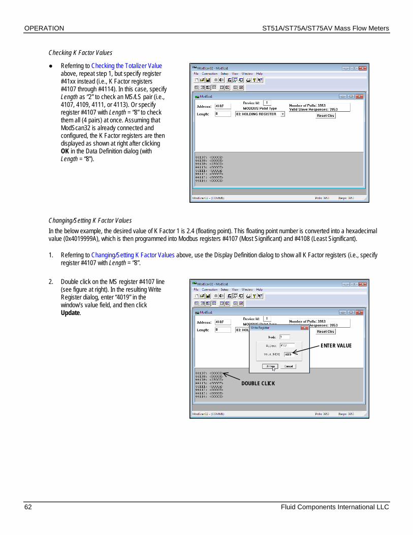
OPERATION ST51A/ST75A/ST75AV Mass Flow Meters
62 Fluid Components International LLC
Checking K Factor Values
Referring to Checking the Totalizer Value above, repeat step 1, but specify register #41xx instead (i.e., K Factor registers #4107 through #4114). In this case, specify Length as “2” to check an MS/LS pair (i.e., 4107, 4109, 4111, or 4113). Or specify register #4107 with Length = “8” to check them all (4 pairs) at once. Assuming that ModScan32 is already connected and configured, the K Factor registers are then displayed as shown at right after clicking OK in the Data Definition dialog (with Length = “8”).
Changing/Setting K Factor Values In the below example, the desired value of K Factor 1 is 2.4 (floating point). This floating point number is converted into a hexadecimal value (0x4019999A), which is then programmed into Modbus registers #4107 (Most Significant) and #4108 (Least Significant).
1. Referring to Changing/Setting K Factor Values above, use the Display Definition dialog to show all K Factor registers (i.e., specify register #4107 with Length = “8”.
2. Double click on the MS register #4107 line (see figure at right). In the resulting Write Register dialog, enter “4019” in the window’s value field, and then click Update.
DOUBLE CLICK
ENTER VALUE

ST51A/ST75A/ST75AV Mass Flow Meters OPERATION
Fluid Components International LLC 63
3. Double click on the LS register #4108 line (see figure at right). In the resulting Write Register dialog, enter “999A” in the window’s value field, and then click Update.
4. Verify that the upper 8 bits are programmed into register #4107 (0x4019) and that the lower 8 bits are programmed into register #4108 (0x999A). See figure at right. Repeat steps 2 and 3 to change other K Factor registers as required.
To finalize any K Factor register change, update register #4114 last even if the register needs no changes (click Update with the existing value shown in the Write Register dialog). It is a requirement that any K Factor register change includes an update of register #4114.
DOUBLE CLICK
ENTER VALUE
LAST STEP: DOUBLE CLICK AND UPDATE REGISTER #4114

OPERATION ST51A/ST75A/ST75AV Mass Flow Meters
64 Fluid Components International LLC
Modbus Engineering Units Codes Table
Table 22 – Modbus Engineering Units Codes Units Type Modbus Code Unit Description
Temperature 32 degrees Celsius 33 degrees Fahrenheit
Volumetric Flow
123 Standard Cubic Feet per Minute (SCFM) 185 Standard Cubic Feet per Hour 182 Normal Cubic Meters per Minute 121 Normal Cubic Meters per Hour 175 Liter per Minute (LPM) 16 Gallons per Minute (GPM)
Mass Flow 82 Pounds per Hour (LB/H) 75 Kilograms per Hour (KG/H)
Velocity Flow 20 Standard Feet per Second (SFPS) 21 Standard Meters per Second (SMPS)
Totalizer
168 Standard Cubic Feet 166 Normal Cubic Meters 41 Liters 63 Pounds per Hour (LB/H) 61 Kilograms per Hour (KG/H) 40 Gallons
Modbus Device Status Code Table Register #4025 is a 16-bit flag register that shows device status. A set bit (1) indicates a particular condition as listed in the table below.
Table 23 – Device Status Code Bit Assignments, Register #4025 Bit Error/Status Description
0 (LSB) Flow < Min Flow 1 Flow > Min Flow 2 Unused/Reserved 3 Flow > Customer Max Flow 4 Temperature < Customer Min Temperature 5 Temperature > Customer Max Temperature 6 Unused/Reserved 7 tcDelta_r < dr_min 8 tcDelta_r > dr_max 9 Unused/Reserved
10 Unused/Reserved 11 Unused/Reserved 12 Unused/Reserved 13 Unused/Reserved 14 Unused/Reserved
15 (MSB) Delta_r > drNamur_max OR Delta_r < drNamur_min

ST51A/ST75A/ST75AV Mass Flow Meters MAINTENANCE
Fluid Components International LLC 65
4 MAINTENANCE
The FCI instrument requires little maintenance. There are no moving parts subject to wear in the instrument. The sensor assembly exposed to the process media is composed of 316 SS and Hastelloy C.
Without detailed knowledge of the application surroundings and process media, FCI cannot make specific recommendations for periodic inspection, cleaning or testing procedures. However, some general maintenance is offered below. Use operating experience to establish frequency of maintenance.
Calibration Verify the calibration of the output and recalibrate every 18 months at a minimum.
Electrical Connections Inspect cable connections on terminal strips and terminal blocks. Verify that terminal connections are tight and physically sound with no sign of corrosion.
Remote Enclosure Verify that the moisture barriers and seals protecting the electronics in the local enclosure are adequate and that no moisture is entering the enclosure.
Electrical Wiring Inspect the system’s interconnecting cable, power wiring and flow element wiring on a common sense basis. Inspect the conductors for corrosion and the cable insulation for signs of deterioration.
Flow Element Connections Verify the seals are performing properly and that there is no leakage of the process media. Check for deterioration of the gaskets and environmental seals.
Flow Element Assembly Remove the flow element (insertion type, ST51A) or instrument/tee assembly (inline type, ST75A/ST75AV) for inspection based on historical evidence of debris, foreign matter or scale build-up, or plant shutdown schedules. Check for corrosion, stress cracking and build-up of oxides, salts or foreign substances. The thermowells must be physically intact and free of contaminants. Any debris or residue build-up could cause inaccurate flow indication. If necessary, clean the flow element with a soft brush and available solvents (compatible with stainless steel). Apply thread sealant to pipe threads before reinstalling the ST75A/ST75AV.

MAINTENANCE ST51A/ST75A/ST75AV Mass Flow Meters
66 Fluid Components International LLC
This Page Intentionally Left Blank

ST51A/ST75A/ST75AV Mass Flow Meters TROUBLESHOOTING
Fluid Components International LLC 67
5 TROUBLESHOOTING
Application Verification After verifying that the flow meter is functioning, review the application parameters below to verify the calibration matches the process media.
Equipment Needed Flow Instrument Calibration Data Process Parameters and Limits
Check Serial Numbers Verify that the serial number of the flow element and the flow transmitter electronics are the same. The flow element and the flow transmitter are a matched set and cannot be operated independently.
Check the Instrument Installation Verify correct mechanical and electrical installation. Check for secure wire/terminal connections (tighten as required). Verify the flow element is mounted at least 20 diameters downstream and 10 diameters upstream from any bends or interference in the process pipe or duct.
Check for Moisture Check for moisture on the flow transmitter. Moisture may cause intermittent operation. Check for moisture on the flow element. If a component of the process media is near its saturation temperature it may condense on the flow element.
Check Application Design Requirements 1. Review the application design with plant operation personnel and plant engineers. 2. Ensure that plant equipment conforms to the actual conditions. 3. Verify operating temperature, operating pressure, line size and gas medium.
Verify Standard Versus Actual Process Conditions The flow meter measures the mass flow rate. The mass flow rate is the mass of the gas flowing through a pipe per time. Other flow meters, such as an orifice plate or a pitot tube, measure the volumetric flow rate. The volumetric flow rate is the volume of gas per time. If the readings displayed do not agree with another instrument, some calculations may be necessary before comparing them. To calculate the mass flow rate, the volumetric flow rate and the pressure and temperature, the point of measurement must be known. Use the following equation to calculate the mass flow rate (Standard Volumetric Flow rate) for the other instrument:
Equation:
𝑄𝑆 = 𝑄𝐴 𝑥 𝑃𝐴𝑇𝐴𝑥 𝑇𝑆𝑃𝑆
Where: QA= Volumetric Flow QS= Standard Volumetric Flow PA= Actual Pressure TA= Actual Temperature PS= Standard Pressure TS= Standard Temperature PSIA and °R are used for pressure and temperature units. [Metric: Where bar(a) and °K are used for pressure and temperature.]
Example: QA = 1212.7 ACFM QS = 1485 SCFM PA = 19.7 PSIA TA = 120 °F (580 °R) PS = 14.7 PSIA TS = 70 °F (530 °R) [Metric: PS = 1.01325 bar(a), TS = 21.1 °C (294.1 °K)]
1212.7 𝐴𝐶𝐹𝑀1
19.7 𝑃𝑆𝐼𝐴580 °𝑅
530 °𝑅14.7 𝑃𝑆𝐼𝐴
= 1485 SCFM

TROUBLESHOOTING ST51A/ST75A/ST75AV Mass Flow Meters
68 Fluid Components International LLC
Verifying Calibration Parameters (Diagnostics) The instrument uses a set of predetermined calibration parameters to process flow signals. Most of these parameters typically do not change. A Delta R Data Sheet, provided with the instrument, contains the factory-set parameters. To verify that these parameters have not changed, complete the following:
1. Identify the instrument’s Delta R Data Sheet via its serial number. 2. To examine the stored parameters use the serial interface “D” menu. FC88: After entering the “D” menu press the [ENTER] key
repeatedly as required to step through each parameter one line at a time. Table 24 below lists the parameters with space to record the instrument’s actual values (print this page). Verify the instrument’s parameters with the Delta R Data Sheet.
Table 24 – Diagnostic Test Sequence Cust. Flow Data Totalizer/Pulse Output CB Setup (cont.) CB Setup (cont.)
S/W Version: Tot Menu: KFactor 4: Temp Flag: Flow Factor: Tot Flag: ACT_Tslope 1: Out Mode: Cmin Flow: Totalizer: ACT_Tslope 2: Namur Mode: Cmax flow: Rollover Cnt: ACT_Tslope 3: dR Namur Min: Eng Units: Pulse Factor: ACT_Tslope 4: dR Namur Max: Line Size 0: Pulse Out: ACT_Tslope 5: Boxcar Max: Line Size 1: Hours: ACT_Tslope 6: HART Damping: Cmin Temp: Sample Period: ACT_Tslope 7: RTD-SLP-385: Cmax Temp: CB Setup REF_Tslope 1: Heater DAC:
Cal Flow Data ActR Slope: REF_Tslope 2: Htr Cur Adj: Min Flow: ActR Offset: REF_Tslope 3: Ref Cur Adj: Max Flow: ActR Ohm Adj.: REF_Tslope 4: % of Range: Density: RefR Slope: REF_Tslope 5: User Name: *C1 [1]: RefR Offset: REF_Tslope 6: Shop Order #: *C1 [2]: RefR Ohm Adj.: REF_Tslope 7: Serial No.: *C1 [3]: SpanIDAC 0: ACT_Toffst 1: Model#: *C1 [4]: ZeroIDAC 0: ACT_Toffst 2: *C1 [5]: SpanIDAC 1: ACT_Toffst 3: Break Pt: ZeroIDAC 1: ACT_Toffst 4: *C2 [1]: TSpanIDAC 0: ACT_Toffst 5: *C2 [2]: TZero IDAC 0: ACT_Toffst 6: *C2 [3]: TSpanIDAC 1: ACT_Toffst 7: *C2 [4]: TZeroIDAC 1: REF_Toffst 1: *C2 [5]: State 0: REF_Toffst 2: dR Min: Switch Pt 0: REF_Toffst 3: dR Max: State 1: REF_Toffst 4: Cal Ref: Switch Pt 1: REF_Toffst 5: Tcslp: KFactor 1: REF_Toffst 6: Tcslp 0: KFactor 2: REF_Toffst 7: Tcslp 2: KFactor 3: I Factor Lim:
An issue may exist if change is noted for any coefficient set parameter marked with an asterisk (*). Contact Customer Service if this is the case. If the parameters have not changed, continue with the next section.

ST51A/ST75A/ST75AV Mass Flow Meters TROUBLESHOOTING
Fluid Components International LLC 69
Hardware Verification Equipment Required:
Digital Multimeter (DMM)
Fuse Check Verify that fuse F1, located on the interface board, is in normal working condition. Refer to Power Fuse Replacement, page 20 for details on fuse access/location. Check the fuse for continuity. If fuse reads open, replace it with Littelfuse 454 Series fuse, part no. 045401.5.
Sensor Check Verify sensor element continuity and resistance (integral unit only).
1. Remove power from the instrument. 2. Remove enclosure housing blind lid, exposing interface board and its power and signal connections. See Accessing the Interface
Board Connection Terminals, page 18. 3. Remove sensor plug from interface board J4 (squeeze plug’s latch at top of connector, and then pull up). 4. Using an ohmmeter measure resistance between socket pins 1 & 3 (active) and socket pins 5 & 7 (reference). Verify that both readings are
within 1100 Ω ±20 Ω. The resistance is temperature dependent. The resistance at 70 °F is approximately 1082 Ω. Refer to Figure 28 below.
Figure 28 – Reference and Active Sensor Resistance Check (AC Version Shown)
FCI provides full in-house technical support. Additional technical representation is also provided by FCI field representatives. Before contacting a field or in-house representative perform the troubleshooting techniques outlined in this manual. If problems persist, contact the FCI Customer Service department at 1-800-854-1993 or 1-760-744-6950.
If the instrument is to be returned to FCI, first obtain a Return Authorization (RA) number from the factory. The RA form (see pages 103 and 104) includes a declaration of decontamination clearing information with which the instrument must comply before shipment to FCI.
PIN 1
NOTCH FORPLUG KEY
J4 SENSORCONNECTOR
INTERFACE BOARD, TOP(AC VERSION SHOWN)
SENSOR CONNECTOR PIN SOCKET PLUG SENSOR CHECK: Measure resistance between
pins 1 & 3 (active) and 5 & 7 (reference).
REFERENCE RTD(Black Wires)
KEY, PLUG
LATCH, CONNECTOR CONNECTORSIDE VIEW
C01172-1-2

TROUBLESHOOTING ST51A/ST75A/ST75AV Mass Flow Meters
70 Fluid Components International LLC
Transmitter Circuit Calibration Check (Delta R Verification) References Delta R Data Sheet Equipment Serial console connection to instrument via FC88 or PC (see Instrument Configuration and Setup Using the Service Port (RS-232), page 27) DMM Delta R data sheet (matched to serial number of instrument under test) Two precision decade resistance boxes, 0.1% (largest steps: 1 KΩ, smallest steps: 0.01 Ω) 250 Ω axial lead precision resistor, 0.1% or better, 1 W Small flat-blade screwdriver, 3/32″ width blade Banana plug jumper cable FCI Normalization Cable (FCI part number 022610-0x, unit part number 022517)
Procedure 1. Verify all “D” mode calibration parameters are correct according to the meter’s Delta R Data Sheet before starting. See Verifying
Calibration Parameters , page 68. 2. Turn instrument power OFF. 3. Remove enclosure housing blind lid, exposing interface board and its power and signal connections. See Accessing the Interface
Board Connection Terminals, page 18. 4. Install 250 Ω precision resistor across instrument’s Ch.1 4-20 mA output (INT_HART- & INT_HART+/J8-4 & J8-1). 5. Connect normalization cable plug to interface board J4. Connect other end of normalization cable (with 2 pair of dual banana plugs) to
resistance decade boxes as shown in Figure 29 below.
Note: Interconnector wiring (resistance decade box to electronics) must be 24 AWG and less than 36 inches long to avoid any inaccuracies caused by improper wire lengths or wire gauges.
6. Connect both resistance decade box LOW terminals together with banana plug jumper cable (stack onto dual plug). 7. Set both decade boxes for nominal resistance value (1000 Ω) ±0.01%. 8. Connect DMM, set for volts DC, across 250 Ω resistor and monitor voltage output. 9. Turn power ON and allow 5 minutes for stabilization. 10. At serial console main menu enter “1” to place instrument in “RS-232” mode (which puts instrument in “Normal Mode Operation”).
(See Main Menu, page 28.) 11. Adjust Active decade box (Reference decade box remains fixed @ 1000 ohms) to achieve the appropriate Delta R for displayed flow
value and output, noted on meter’s Delta R Data Sheet. 12. Enter “C” at console. Verify meter’s displayed TCDR and REFR values correspond to displayed flow rate per meter’s Delta R Data Sheet. 13. Return to Normal Mode Operation (“T” menu).

ST51A/ST75A/ST75AV Mass Flow Meters TROUBLESHOOTING
Fluid Components International LLC 71
Figure 29 – Transmitter Circuit Calibration Diagram
ACTIVE
REFERENCE
PIN 1INTERFACE BOARD, TOP
(AC VERSION SHOWN)
SIDE VIEW
GREEN(DISCONNECTED)
BANANA PLUG JUMPER,TYP. 4-IN LENGTH, 18 AWG
OR BETTER (LOWER NUMBER)
PLUG KEY
LATCH
To J4
KEYJ4 SENSORCONNECTOR
PIN 1
NOTCH FORPLUG KEY
NORMALIZATION CABLEFCI P/N 022610-0x
CABLE WIRING SCHEMATICCABLE PINOUT
HTR EXC+HTR SEN+HTR SEN-HTR EXC-SNSR EXC +SNSR SEN+SNSR SEN-CABLE SHIELD
C01173-1-2

TROUBLESHOOTING ST51A/ST75A/ST75AV Mass Flow Meters
72 Fluid Components International LLC
This Page Intentionally Left Blank

ST51A/ST75A/ST75AV Mass Flow Meters APPENDIX A – DRAWINGS
Fluid Components International LLC 73
APPENDIX A DRAWINGS
This appendix contains ST51A/ST75A/ST75AV technical drawings, which are summarized in Table 25 below.
Table 25 – Appendix A, List of Drawings
Dwg. No. Dwg. Type Page No. Description C01210-1-1 Exploded Assy. 74 Basic Instrument Assembly: ST51A, ST75A and ST75AV
021263C Configuration 75 ST50/ST51 Assembly Orientation 004997A Outline/
Installation 76 Flow Transmitter, ST51A, Local Hazardous Location,
Aluminum, Type 4x Enclosure 004999A Outline/
Installation 77 Flow Transmitter, ST51A, Hazardous Locations, Local And
Remote, Aluminum, Type 4X Enclosures 405005A Outline/
Installation 78 Flow Transmitter, ST51A, Hazardous Locations, Local And
Remote, Stainless Steel, Type 4X Enclosures 405006A Outline/
Installation 79 Flow Transmitter, ST51A, Local Hazardous Location, Stainless
Steel, Type 4X Enclosure 020943B Configuration 80 ST75/ST75V Assembly Orientation
405000A Outline/ Installation
81 Flow Transmitter, ST75A, 150-lb Pipe Tee, Local Hazardous Location, Aluminum, Type 4X Enclosure
405003A Outline/ Installation
82 Flow Transmitter, ST75A, 150-lb Pipe Tee, Hazardous Locations, Local And Remote, Aluminum, Type 4X Enclosures
405017A Outline/ Installation
83 Flow Transmitter, ST75AV, Male NPT, Local Hazardous Location, Aluminum, Type 4X Enclosure
405018A Outline/ Installation
84 Flow Transmitter, ST75AV, Female NPT, Local Hazardous Location, Aluminum, Type 4X Enclosure
405019A Outline/ Installation
85 Flow Transmitter, ST75AV, Flanged, Local Hazardous Location, Aluminum, Type 4X Enclosure
025611C Wiring Diagram 86 Wiring Diagram, Third Generation, ST51A/ST75A/ST75AV

APPENDIX A – DRAWINGS ST51A/ST75A/ST75AV Mass Flow Meters
74 Fluid Components International LLC
Figure 30 – Basic Instrument Assembly: ST51A, ST75A and ST75AV

ST51A/ST75A/ST75AV Mass Flow Meters APPENDIX A – DRAWINGS
Fluid Components International LLC 75

APPENDIX A – DRAWINGS ST51A/ST75A/ST75AV Mass Flow Meters
76 Fluid Components International LLC

ST51A/ST75A/ST75AV Mass Flow Meters APPENDIX A – DRAWINGS
Fluid Components International LLC 77

APPENDIX A – DRAWINGS ST51A/ST75A/ST75AV Mass Flow Meters
78 Fluid Components International LLC

ST51A/ST75A/ST75AV Mass Flow Meters APPENDIX A – DRAWINGS
Fluid Components International LLC 79

APPENDIX A – DRAWINGS ST51A/ST75A/ST75AV Mass Flow Meters
80 Fluid Components International LLC

ST51A/ST75A/ST75AV Mass Flow Meters APPENDIX A – DRAWINGS
Fluid Components International LLC 81

APPENDIX A – DRAWINGS ST51A/ST75A/ST75AV Mass Flow Meters
82 Fluid Components International LLC

ST51A/ST75A/ST75AV Mass Flow Meters APPENDIX A – DRAWINGS
Fluid Components International LLC 83

APPENDIX A – DRAWINGS ST51A/ST75A/ST75AV Mass Flow Meters
84 Fluid Components International LLC

ST51A/ST75A/ST75AV Mass Flow Meters APPENDIX A – DRAWINGS
Fluid Components International LLC 85

APPENDIX A – DRAWINGS ST51A/ST75A/ST75AV Mass Flow Meters
86 Fluid Components International LLC

ST51A/ST75A/ST75AV Mass Flow Meters APPENDIX A – DRAWINGS
Fluid Components International LLC 87

APPENDIX A – DRAWINGS ST51A/ST75A/ST75AV Mass Flow Meters
88 Fluid Components International LLC

ST51A/ST75A/ST75AV Mass Flow Meters APPENDIX A – DRAWINGS
Fluid Components International LLC 89

APPENDIX A – DRAWINGS ST51A/ST75A/ST75AV Mass Flow Meters
90 Fluid Components International LLC
This Page Intentionally Left Blank

ST51A/ST75A/ST75AV Mass Flow Meters APPENDIX B – GLOSSARY
Fluid Components International LLC 91
APPENDIX B GLOSSARY
Abbreviations Delta-R (ΔR) Resistance differential
Delta-T (ΔT) Temperature differential
DMM Digital Multimeter
FCI Fluid Components International
HTR Heater
LCD Liquid Crystal Display
LED Light Emitting Diode
OIS Ordering Information Sheet
RA Repair Authorization
RTD Resistance Temperature Detector
SFPS Standard Feet Per Second
Definitions
Active RTD The sensing element that is heated by the heater. The active RTD is cooled due to increases in the process fluid flow rate or density (level sensing).
Control circuit The portion of the level switch that conditions, converts, and scales the sensing point (head) signal.
Level element The portion of the level switch that contains the sensing points and process connection.
Heater (HTR) The part of the sensing element that heats the active RTD.
Local enclosure The enclosure attached to the level element.
Reference RTD The level element part that senses the fluid temperature.
Resistance differential Delta-R (ΔR)
The difference in resistance between the active and reference RTDs.
Resistance Temperature Detector (RTD)
A sensor whose resistance changes proportionally to detector temperature changes.
Sensing element The transducer portion of the instrument. The sensing element produces an electrical signal that is related to the flow rate, density (level sensing), and temperature of the process media.
Temperature differential Delta-T (ΔT)
The difference in temperature between the active and reference RTDs.
Thermowell The sensor element part that protects the heater and RTDs from the process media.
Turndown ratio The ratio of minimum flow rate to maximum flow rate.

APPENDIX B – GLOSSARY ST51A/ST75A/ST75AV Mass Flow Meters
92 Fluid Components International LLC
This Page Intentionally Left Blank

ST51A/ST75A/ST75AV Mass Flow Meters APPENDIX C – APPROVAL INFORMATION
Fluid Components International LLC 93
APPENDIX C APPROVAL INFORMATION
EU Information

APPENDIX C – APPROVAL INFORMATION ST51A/ST75A/ST75AV Mass Flow Meters
94 Fluid Components International LLC
Specific Conditions of Use per FM16ATEX0008X 1. The ambient temperature range and applicable temperature class of the sensor probe is based on the maximum process temperature
for the particular application as follows; T6…T1 for Tambient of -40 °C to +65 and Tprocess of -40 °C to +260 °C. Probe assembly design temperatures are part number dependent. Low temperature models have design temperatures from -40°C to +121°C. Medium temperature models have design temperatures from -40 °C to +260 °C.
2. Process Temperature: Maximum process temperature range is -40 °C to +260 °C. Process temperature varies for flow element installed. The relationship between the temperature class, the maximum surface temperature and the process temperature is as follows:
Sensing Element: T6 / T85°C for a process temperature range of -40 °C to +39 °C. T5 / T100°C for a process temperature range of -40 °C to +54 °C. T4 / T135°C for a process temperature range of -40 °C to +89 °C. T3 / T200°C for a process temperature range of -40 °C to +154 °C. T2 / T300°C for a process temperature range of -40 °C to +177 °C. T1 for a process temperature range of -40 °C to +260 °C.
3. Consult the manufacturer if dimensional information on the flameproof joints is necessary. 4. The painted surfaces of the Mass Flow Meter may store electrostatic charge and become a source of ignition in applications with a
low relative humidity <~30% relative humidity where the painted surface is relatively free of surface contamination such as dirt, dust, or oil. Guidance on protection against the risk of ignition due to electrostatic discharge can be found in IEC TR60079-32 (in preparation). Clean painted/unpainted surfaces using a water dampened cloth only.
5. The probe when remotely located from the enclosure has flying lead conductors that requires the remote probe to be connected to a suitably certified Ex d or Ex e terminal box for connecting to the external supply circuit.
6. Customer to supply wire rated 10 °C minimum above maximum ambient temperature of installation location to a suitably certified Ex d or Ex e terminal box.
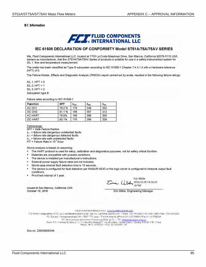
ST51A/ST75A/ST75AV Mass Flow Meters APPENDIX C – APPROVAL INFORMATION
Fluid Components International LLC 95
IEC Information

APPENDIX C – APPROVAL INFORMATION ST51A/ST75A/ST75AV Mass Flow Meters
96 Fluid Components International LLC
Safety Instructions for the use of the ST51A/ST75A/ST75AV flow meter in Hazardous Areas Approval FM16ATEX0008X/IECEX FMG 16.0009X:
Category II 2 G for Gas protection Ex db IIC T6...T1 Gb Category II 2 D for Dust protection Ex tb IIIC T85°C...T300°C Db; IP66/IP67
The ST51/75 series consist of a sensing element and associated integral or remote mounted electronics mounted in a type “d” flameproof enclosure. Relation between ambient temperature, process temperature and temperature class is as follows:
T-code, Gas T-code, Dust Ambient Temperature Process Temperature
T6 T85°C -40°C to +65°C -40°C to +39°C T5 T100°C — -40°C to +54°C T4 T135°C — -40°C to +89°C T3 T200°C — -40°C to +154°C T2 T300°C — -40°C to +177°C T1 — — -40°C to +260°C
Electrical data: Power supply: 85 to 265 VAC, 50/60 Hz, 12 Watt max; 24 VDC, 12 VA Max
Dansk Sikkerhedsforskrifter Italiano Normative di sicurezza Deutsch Sicherheitshinweise Nederlands Veiligheidsinstructies English Safety instructions Português Normas de segurança Ελληνικά Υποδείξεις ασφαλείας Español Instrucciones de seguridad Suomi Turvallisuusohjeet Svenska Säkerhetsanvisningar Français Consignes de sécurité
DK Dansk - Sikkerhedsforskrifter Disse sikkerhedsforskrifter gælder for Fluid Components, ST51A/75A/75AV EF-typeafprøvningsattest-nr. FM16ATEX0008X/IECEX FMG 16.0009X (attestens nummer på typeskiltet) er egnet til at blive benyttet i eksplosiv atmosfære kategori II 2 GD. 1) Ex-anlæg skal principielt opstilles af specialiseret personale. 2) ST51A/75A/75AV skal jordforbindes. 3) Klemmerne og elektronikken er monteret i et hus, som er beskyttet af en eksplosionssikker kapsling med følgende noter: • Gevindspalten mellem huset og låget er på en sådan måde, at ild ikke kan brede sig inden i det. • Ex-„d“ tilslutningshuset er forsynet med et 1/2" NPT eller M20x1.5 gevind for montering af en Ex-„d“ kabelindføring, der er attesteret iht. IEC/EN 60079-1 • Det er vigtigt at sørge for, at forsyningsledningen er uden spænding eller eksplosiv atmosfære ikke er til stede, før låget åbnes og når låget er åbent på „d” huset (f.eks. ved tilslutning eller servicearbejde). • Låget på „d” huset skal være skruet helt ind, når apparatet er i brug. Det skal sikres ved at dreje en af låseskruerne på låget ud.
D A Deutsch - Sicherheitshinweise Diese Sicherheitshinweise gelten für die Fluid Components, ST51A/75A/75AV flow meter gemäß der EG-Baumusterprüfbescheinigung Nr. FM16ATEX0008X/IECEX FMG 16.0009X (Bescheinigungsnummer auf dem Typschild) der Kategorie II 2 GD. 1) Die Errichtung von Ex-Anlagen muss grundsätzlich durch Fachpersonal vorgenommen werden. 2) Der ST51A/75A/75AV muß geerdet werden. 3) Die Klemmen und Elektroniken sind in einem Gehäuse in der Zündschutzart druckfeste Kapselung („d“ ) eingebaut. • Der Gewindespalt zwischen dem Gehäuse und dem Deckel ist ein zünddurchschlagsicherer Spalt. • Das Ex-“d“ Anschlussgehäuse besitzt ein 1/2“ NPT oder M20x1.5 Gewinde für den Einbau einer nach IEC/EN 60079-1 bescheinigten Ex-“d“ Kabeleinführung. • Es ist sicherzustellen, dass vor dem Öffnen und bei geöffnetem Deckel des „d“ Gehäuses (z.B. bei Anschluss oder Service- Arbeiten) entweder die Versorgungsleitung spannungsfrei oder keine explosionsfähige Atmosphäre vorhanden ist. • Der Deckel des „d“ Gehäuses muss im Betrieb bis zum Anschlag hineingedreht sein. Er ist durch eine der Deckelarretierungsschrauben zu sichern.

ST51A/ST75A/ST75AV Mass Flow Meters APPENDIX C – APPROVAL INFORMATION
Fluid Components International LLC 97
GB IRL English - Safety instructions These safety instructions are valid for the Fluid Components, ST51A/75A/75AV flow meter to the EC type approval certificate no FM16ATEX0008X/IECEX FMG 16.0009X (certificate number on the type label) for use in potentially explosive atmospheres in Category II 2 GD. 1) The installation of Ex-instruments must be made by trained personnel. 2) The ST51A/75A/75AV must be grounded. 3) The terminals and electronics are installed in a flame proof and pressure-tight housing with following notes: • The gap between the housing and cover is an ignition-proof gap. • The Ex-“d“ housing connection has a 1/2” NPT or M20x1.5 cable entry for mounting an Ex-d cable entry certified acc. to IEC/EN 60079-1. • Make sure that before opening the cover of the Ex”d“ housing, the power supply is disconnected or there is no explosive atmosphere present (e.g. during connection or service work). • During normal operation: The cover of the “d“ housing must be screwed in completely and locked by tightening one of the cover locking screws.
GR Ελληνικά - Υποδείξεις ασφαλείας Αυτές οι οδηγίες ασφαλείας ισχύουν για τα Ροόµετρα της Fluid Components τύπου ST51A/75A/75AV που φέρουν Πιστοποιητικό Εγκρίσεως Ευρωπαϊκής Ένωσης, µε αριθµό πιστοποίησης FM16ATEX0008X/IECEX FMG 16.0009X (ο αριθµός πιστοποίησης βρίσκεται πάνω στην ετικέτα τύπου του οργάνου) για χρήση σε εκρηκτικές ατµόσφαιρες της κατηγορίας II 2 GD. 1) Η εγκατάσταση των οργάνων µε αντιεκρηκτική προστασία πρέπει να γίνει από εξειδικευµένο προσωπικό. 2) Το όργανο τύπου ST51A/75A/75AV πρέπει να είναι γειωµένο. 3) Τα τερµατικά ηλεκτρικών συνδέσεων (κλέµες) και τα ηλεκτρονικά κυκλώµατα είναι εγκατεστηµένα σε περίβληµα αντιεκρηκτικό και αεροστεγές σύµφωνα µε τις ακόλουθες παρατηρήσεις: • Το κενό ανάµεσα στο περίβληµα και στο κάλυµµα είναι τέτοιο που αποτρέπει την διάδοση σπινθήρα. • Το “Ex-d” αντιεκρηκτικό περίβληµα, έχει ανοίγµατα εισόδου καλωδίου µε διάµετρο ½” NPT ή M20x1.5, κατάλληλα για τοποθέτηση υποδοχής αντιεκρηκτικού καλωδίου πιστοποιηµένης κατά IEC/EN 60079-1 • Βεβαιωθείτε ότι πριν το άνοιγµα καλύµµατος του του “Ex-d” αντιεκρηκτικού περιβλήµατος, η τάση τροφοδοσίας είναι αποσυνδεδεµένη ή ότι δεν υφίσταται στη περιοχή εκρηκτική ατµόσφαιρα (π.χ. κατά τη διάρκεια της σύνδεσης ή εργασιών συντήρησης) • Κατά τη διάρκεια οµαλής λειτουργίας: Το κάλυµα του “d” καλύµµατος αντιεκρηκτικού περιβλήµατος πρέπει να είναι εντελώς βιδωµένο και ασφαλισµένο, σφίγγοντας µία από τις βίδες ασφαλείας του περιβλήµατος.
FIN Suomi - Turvallisuusohjeet Nämä turvallisuusohjeet koskevat Fluid Components, ST51A/75A/75AV EY-tyyppitarkastustodistuksen nro. FM16ATEX0008X/IECEX FMG 16.0009X (todistuksen numero näkyy tyyppikilvestä) käytettäessä räjähdysvaarallisissa tiloissa luokassa II 2GD. 1) Ex-laitteet on aina asennettava ammattihenkilökunnan toimesta. 2) ST51A/75A/75AV on maadoitettava. 3) Syöttöjännitteen kytkemisessä tarvittavat liittimet ja elektroniikka on asennettu koteloon jonka rakenne kestää räjähdyspaineen seuraavin lisäyksin : • Kotelon ja kannen välissä on räjähdyksen purkausväli. • Ex-d liitäntäkotelossa on 1/2“ NPT tai M20x1.5 kierre IEC/EN 60079-1 mukaisen Ex-d kaapeliläpiviennin asennusta varten • Kun “d“-kotelon kansi avataan (esim. liitännän tai huollon yhteydessä), on varmistettava, että joko syöttöjohto on jännitteetön tai ympäristössä ei ole räjähtäviä aineita. • “d“ -kotelon kansi on kierrettävä aivan kiinni käytön yhteydessä ja on varmistettava kiertämällä yksi kannen lukitusruuveista kiinni.

APPENDIX C – APPROVAL INFORMATION ST51A/ST75A/ST75AV Mass Flow Meters
98 Fluid Components International LLC
F B L Consignes de sécurité Ces consignes de sécurité sont valables pour le modèle ST51A/75A/75AV de la société Fluid Components (FCI) conforme au certificat d’épreuves de type FM16ATEX0008X/IECEX FMG 16.0009X (numéro du certificat sur l’étiquette signalétique) conçu pour les applications dans lesquelles un matériel de la catégorie II2GD est nécessaire. 1) Seul un personnel spécialisé et qualifié est autorisé à installer le matériel Ex. 2) Les ST51A/75A/75AV doivent être reliés à la terre. 3) Les bornes pour le branchement de la tension d’alimentation et l’électronique sont logées dans un boîtier à enveloppe antidéflagrante avec les notes suivantes : • Le volume entre le boîtier et le couvercle est protégé en cas d’amorçage. • Le boîtier de raccordement Ex-d dispose d’un filetage1/2’’ NPT ou M20x1.5 pour le montage d’un presse-étoupe Ex-d certifié selon la IEC/EN 60079-1. • Avant d’ouvrir le couvercle du boîtier « d » et pendant toute la durée où il le restera (pour des travaux de raccordement, d’entretien ou de dépannage par exemple), il faut veiller à ce que la ligne d’alimentation soit hors tension ou à ce qu’il n’y ait pas d’atmosphère explosive. • Pendant le fonctionnement de l’appareil, le couvercle du boîtier « d » doit être vissé et serré jusqu’en butée. La bonne fixation du couvercle doit être assurée en serrant une des vis d’arrêt du couvercle.
I Italiano - Normative di sicurezza Queste normative di sicurezza si riferiscono ai Fluid Components, ST51A/75A/75AV secondo il certificato CE di prova di omologazione n° FM16ATEX0008X/IECEX FMG 16.0009X (numero del certificato sulla targhetta d’identificazione) sono idonei all’impiego in atmosfere esplosive applicazioni che richiedono apparecchiature elettriche della Categoria II 2 GD. 1) L’installazione di sistemi Ex deve essere eseguita esclusivamente da personale specializzato. 2) I ST51A/75A/75AV devono essere collegati a terra. 3) I morsetti per il collegamento e l’elettronica sono incorporati in una custodia a prova di esplosione („d“) con le seguenti note: • La sicurezza si ottiene grazie ai cosidetti „interstizi sperimentali massimi“, attraverso i quali una eventuale accensione all’interno della custodia non può propagarsi all’esterno oraggiungere altre parti dell’impianto. • La scatola di collegamento Ex-d ha una filettatura 3/4“ o 1“ NPT per il montaggio di un passacavo omologato Ex-d secondo IEC/EN 60079-1. • Prima di aprire il coperchio della custodia „d“ (per es. durante operazioni di collegamento o di manutenzione) accertarsi che l’apparecchio sia disinserito o che non si trovi in presenza di atmosfere esplosive. • Avvitare il coperchio della custodia „d“ fino all’arresto. Per impedire lo svitamento del coperchio é possibile allentare una delle 2 viti esagonali poste sul corpo della custodia, incastrandola nella sagoma del coperchio.
NL B Nederlands - Veiligheidsinstructies Deze veiligheidsinstructies gelden voor de Fluid Components, ST51A/75A/75AV overeenkomstig de EG-typeverklaring nr. FM16ATEX0008X/IECEX FMG 16.0009X (nummer van de verklaring op het typeplaatje) voor gebruik in een explosieve atmosfeer volgens Categorie II 2GD. 1) Installatie van Ex-instrumenten dient altijd te geschieden door geschoold personeel. 2) De ST51A/75A/75AV moet geaard worden. 3) De aansluitklemmen en de electronika zijn ingebouwd in een drukvaste behuizing met de volgende opmerkingen: • De schroefdraadspleet tussen de behuizing en de deksel is een ontstekingsdoorslagveilige spleet. • De Ex-d aansluitbehuizing heeft een 1/2” of een M20x1.5 schroefdraad voor aansluiting van een volgens IEC/EN 60079-1 goedgekeurde Ex- ‘d’ kabelinvoer. • Er moet worden veilig gesteld dat vóór het openen bij een geopende deksel van de ‘d’ behuizing (bijv. bij aansluit- of servicewerkzaamheden) hetzij de voedingsleiding spanningsvrij is, hetzij geen explosieve atmosfeer aanwezig is. • De deksel van de ‘d’ behuizing moet tijdens bedrijf tot aan de aanslag erin geschroefd zijn. Hij moet door het eruit draaien van een van de dekselborgschroeven worden geborgd.

ST51A/ST75A/ST75AV Mass Flow Meters APPENDIX C – APPROVAL INFORMATION
Fluid Components International LLC 99
P Português - Normas de segurança Estas normas de segurança são válidas para os Fluid Components, ST51A/75A/75AV conforme o certificado de teste de modelo N.º FM16ATEX0008X/IECEX FMG 16.0009X (número do certificado na plaqueta com os dados do equipamento) são apropriados para utilização em atmosferas explosivas categoria II 2 GD. 1) A instalação de equipamentos em zonas sujeitas a explosão deve, por princípio, ser executada por técnicos qualificados. 2) Os ST51A/75A/75AV precisam ser ligados à terra. 3) Os terminais e a electrónica para a conexão da tensão de alimentação estão instalados num envólucro com protecção contra ignição á prova de sobrepressão com as seguintes notas : • A fenda entre o envólucro e a tampa deve ser á prova de passagem de centelha. • O envólucro de conexão Ex-“d“ possui uma rosca 1/2“ NPT ou M20x1.5 para a entrada de cabos Ex-“d“ certificado conforme a norma IEC/EN60079-1. • Deve-se assegurar que, antes de abrir a tampa do armário „d“ ( por exemplo, ao efectuar a conexão ou durante trabalhos de manutenção), o cabo de alimentação esteja sem tensão ou que a atmosfera não seja explosíva. • Durante a operação, a tampa do envólucro „d“ deve estar aparafusada até o encosto. A tampa deve ser bloqueada, por um dos parafusos de fixação.
E Español - Instrucciones de seguridad Estas indicaciones de seguridad son de aplicación para el modelo ST51A/75A/75AV de Fluid Components, según la certificación CE de modelo Nº FM16ATEX0008X/IECEX FMG 16.0009X para aplicaciones en atmósferas potencialmente explosivas según la categoría II 2 GD (el número decertificación se indica sobre la placa informativa del equipo). 1) La instalación de equipos Ex tiene que ser realizada por personal especializado. 2) Los ST51A/75A/75AV tienen que ser conectados a tierra. 3) Los bornes de conexión y la unidad electrónica están montados dentro de una caja con protección antideflagrante y resistente a presión, considerándose los siguientes puntos: • La holgura entre la rosca de la tapa y la propia de la caja está diseñada a prueba contra ignición. • La caja tiene conexiones eléctricas para entrada de cables con rosca 1/2” NPT o M20x1.5, donde deberán conectarse prensaestopas certificados Exd según IEC/EN60079-1. • Antes de la apertura de la tapa de la caja "Exd“ (p. ej. durante los trabajos de conexionado o de puesta en marcha) hay que asegurar que el equipo se halle sin tensión o que no exista presencia de atmósfera explosiva. • Durante el funcionamiento normal: la tapa de la caja antideflagrante tiene que estar cerrada, roscada hasta el tope, debiendose asegurar apretando los tornillos de bloqueo.
S Svenska - Säkerhetsanvisningar Säkerhetsanvisningarna gäller för Fluid Components, Flödesmätare typ ST51A/75A/75AV enligt EG-typkontrollintyg nr FM16ATEX0008X/IECEX FMG 16.0009X (intygsnumret återfinns på typskylten) är lämpad för användning i explosiv gasblandning i kategori II 2 GD. 1) Installation av Ex- klassade instrument måste alltid utföras av fackpersonal. 2) ST51A/75A/75AV måste jordas. 3) Anslutningsklämmorna och elektroniken är inbyggda i en explosions och trycktät kapsling med följande kommentar: • Spalten mellan kapslingen och lockets gänga är flamsäker. • Ex-d kapslingen har en 1/2“ NPT eller M20x1.5 gänga för montering av en IEC/EN 60079-1 typkontrollerad Ex- „d“ kabel förskruvning • När Ex- „d“-kapslingens lock är öppet (t.ex. vid inkoppling - eller servicearbeten) ska man se till att enheten är spänningslös eller att ingen explosiv gasblandning förekommer. • Under drift måste Ex - d“-kapslingens lock vara iskruvad till anslaget. För att säkra locket skruvar man i en av lockets insex låsskruvar .

APPENDIX C – APPROVAL INFORMATION ST51A/ST75A/ST75AV Mass Flow Meters
100 Fluid Components International LLC
This Page Intentionally Left Blank

ST51A/ST75A/ST75AV Mass Flow Meters APPENDIX D – CUSTOMER SERVICE
Fluid Components International LLC 101
APPENDIX D CUSTOMER SERVICE
Customer Service/Technical Support FCI provides full in-house technical support. Additional technical representation is also provided by FCI field representatives. Before contacting a field or in-house representative, perform the troubleshooting techniques outlined in this document.
By Mail Fluid Components International LLC 1755 La Costa Meadows Dr. San Marcos, CA 92078-5115 USA Attn: Customer Service Department
By Phone Contact the area FCI regional representative. If a field representative is unable to be contacted or if a situation is unable to be resolved, contact the FCI Customer Service Department toll free at 1 (800) 854-1993.
By Fax To describe problems in a graphical or pictorial manner, send a fax including a phone or fax number to the regional representative. Again, FCI is available by facsimile if all possibilities have been exhausted with the authorized factory representative. Our fax number is 1 (760) 736-6250; it is available 7 days a week, 24 hours a day.
By Email FCI Customer Service can be contacted by email at: [email protected].
Describe the problem in detail making sure a telephone number and best time to be contacted is stated in the email.
International Support For product information or product support outside the contiguous United States, Alaska, or Hawaii, contact your country’s FCI International Representative or the one nearest to you.
After Hours Support For product information visit FCI at www.fluidcomponents.com. For product support call 1 (800) 854-1993 and follow the prerecorded instructions.
Point of Contact The point of contact for service, or return of equipment to FCI is your authorized FCI sales/service office. To locate the office nearest you, visit the FCI website at www.fluidcomponents.com.
Warranty Repairs or Returns FCI prepays ground transportation charges for return of freight to the customer’s door. FCI reserves the right to return equipment by the carrier of our choice.
International freight, handling charges, duty/entry fees for return of equipment are paid by the customer.
Non-Warranty Repairs or Returns FCI returns repaired equipment to the customer either collect or prepaid and adds freight charges to the customer invoice.
Extended Warranty An extended warranty is available. Contact the factory for details.
Return to Stock Equipment The customer is responsible for all shipping and freight charges for equipment that is returned to FCI stock from the customer site. These items will not be credited to the customer’s account until all freight charges are cleared, along with applicable return to stock charges, from the credit invoice. (Exceptions are made for duplicate shipments made by FCI.)
If any repair or return equipment is received at FCI, freight collect, without prior factory consent, FCI bills the sender for these charges.

APPENDIX D – CUSTOMER SERVICE ST51A/ST75A/ST75AV Mass Flow Meters
102 Fluid Components International LLC
Field Service Procedures Contact an FCI field representative to request field service.
A field service technician is dispatched to the site from either the FCI factory or one of the FCI representative offices. After the work is com-plete, the technician completes a preliminary field service report at the customer site and leaves a copy with the customer.
Following the service call, the technician completes a formal, detailed service report. The formal report is mailed to the customer after the technician’s return to the factory or office.
Field Service Rates All field service calls are billed at the prevailing rates as listed in the FCI Price Book unless previous arrangements have been made with the FCI Customer Service Manager.
Customers are charged for all travel expenses including airfare, auto rental, meals and lodging. In addition, the customer shall pay all costs of transporting parts, tools or goods to and from the job site. Invoicing travel time, field service work and other expenses will be performed by FCI’s Accounting Department.

ST51A/ST75A/ST75AV Mass Flow Meters APPENDIX D – CUSTOMER SERVICE
Fluid Components International LLC 103

APPENDIX D – CUSTOMER SERVICE ST51A/ST75A/ST75AV Mass Flow Meters
104 Fluid Components International LLC

ST51A/ST75A/ST75AV Mass Flow Meters APPENDIX D – CUSTOMER SERVICE
Fluid Components International LLC 105
WARRANTIES
Goods furnished by the Seller are to be within the limits and of the sizes published by the Seller and subject to the Seller’s standard tolerances for variations. All items made by the Seller are inspected before shipment, and should any of said items prove defective due to faults in manufacture or performance under Seller approved applications, or fail to meet the written specifications accepted by the Seller, they will be replaced or repaired by Seller at no charge to Buyer provided return or notice of rejection of such material is made within a reasonable period but in no event longer than two (2) years from date of shipment to Buyer, and provided further, that an examination by Seller discloses to Seller’s reasonable satisfaction that the defect is covered by this warranty and that the Buyer has not returned the equipment in a damaged condition due to Buyer’s or Buyer’s employees’, agents’, or representatives’ negligence and Buyer has not tampered, modified, redesigned, misapplied, abused, or misused the goods as to cause the goods to fail. In addition, this warranty shall not cover damage caused by Buyer’s exposure of the goods to corrosive or abrasive environments. Moreover, Seller shall in no event be responsible for (1) the cost or repair of any work done by Buyer on material furnished hereunder (unless specifically authorized in writing in each instance by Seller), (2) the cost or repair of any modifications added by a Distributor or a third party, (3) any consequential or incidental damages, losses, or expenses in connection with or by reason of the use of or inability to use goods purchased for any purpose, and Seller’s liability shall be specifically limited to free replacement, or refund of the purchase price, at Seller’s option, provided return or rejection of the goods is made consistent with this paragraph, and the Seller shall in no event be liable for transportation, installation, adjustment, loss of good will or profits, or other expenses which may arise in connection with such returned goods, or (4) the design of products or their suitability for the purpose for which they are intended or used. Should the Buyer receive defective goods as defined by this paragraph, the Buyer shall notify the Seller immediately, stating full particulars in support of his claim, and should the Seller agree to a return of the goods, the Buyer shall follow Seller’s packaging and transportation directions explicitly. In no case are the goods to be returned without first obtaining a return authorization from the Seller. Any repair or replacement shall be at Seller’s factory, unless otherwise directed, and shall be returned to Seller transportation prepaid by Buyer. If the returned goods shall prove defective under this clause they will be replaced or repaired by Seller at no charge to Buyer provided the return or rejection of such material is made within a reasonable period, but in no event longer than (2) years from the date of shipment of the returned goods or the unexpired terms of the original warranty period whichever is later. If the goods prove to be defective under this paragraph, the Buyer shall remove the goods immediately from the process and prepare the goods for shipment to Seller. Continued use or operation of defective goods is not warranted by Seller and damage occurring due to continued use or operation shall be for Buyer’s account. Any description of the goods contained in this offer is for the sole purpose of identifying them, and any such description is not part of the basis of the bargain, and does not constitute a warranty that the goods will conform to that description. The use of any sample or model in connection with this offer is for illustrative purposes only, is not part of the basis of the bargain, and is not to be construed as a warranty that the goods will conform to the sample or model. No affirmation of that fact or promise made by the Seller, whether or not in this offer, will constitute a warranty that the goods will conform to the affirmation or promise. THIS WARRANTY IS EXPRESSLY IN LIEU OF ANY AND ALL OTHER EXPRESS OR IMPLIED WARRANTIES WITH RESPECT TO THE GOODS OR THEIR INSTALLATION, USE, OPERATION, REPLACEMENT OR REPAIR, INCLUDING ANY IMPLIED WARRANTY OF MERCHANTABILITY OR FITNESS OF PURPOSE; AND THE GOODS ARE BEING PURCHASED BY BUYER “AS IS”. SELLER WILL NOT BE LIABLE BY VIRTUE OF THIS WARRANTY OR OTHERWISE FOR ANY SPECIAL, INCIDENTAL OR CONSEQUENTIAL LOSS OR DAMAGE RESULTING FROM THE USE OR LOSS OF USE OF THE GOODS.

ST51A/ST75A/ST75AV Mass Flow Meters
Fluid Components International LLC 06EN003426 Rev. C
Visit FCI on the Worldwide Web: www.fluidcomponents.com
FCI World Headquarters 1755 La Costa Meadows Drive | San Marcos, California 92078 USA | Phone: 760-744-6950 Toll Free (US): 800-854-1993 Fax: 760-736-6250
FCI Europe Persephonestraat 3-01 | 5047 TT Tilburg, The Netherlands | Phone: 31-13-5159989 Fax: 31-13-5799036
FCI Measurement and Control Technology (Beijing) Co., LTD | www.fluidcomponents.cn Room 107, Xianfeng Building II, No.7 Kaituo Road, Shangdi IT Industry Base, Haidian District | Beijing 100085, P. R. China Phone: 86-10-82782381 Fax: 86-10-58851152
Notice of Proprietary Rights This document contains confidential technical data, including trade secrets and proprietary information which is the property of Fluid Components International LLC (FCI).Disclosure of this data to you is expressly conditioned upon your assent that its use is limited to use within your company only (and does not include manufacture or processing uses). Any other use is strictly prohibited without the prior written consent of FCI.
© Copyright 2019 by Fluid Components International LLC. All rights reserved. FCI is a registered trademark of Fluid Components International LLC. Information subject to change without notice.
Copyright © 2022 FDOKUMEN