Installation, Operation & Maintenance of Solar PV Microgrid ...
139
Installation, Operation & Maintenance of Solar PV Microgrid Systems A Handbook for Technicians First Edition
-
Upload
khangminh22 -
Category
Documents
-
view
0 -
download
0
Transcript of Installation, Operation & Maintenance of Solar PV Microgrid ...

Installation, Operation & Maintenance of Solar PV Microgrid Systems
A Handbook for Technicians
First Edition

Installation, Operation & Maintenance of
Solar PV Microgrid Systems
A Handbook for Technicians
First Edition

Installation, Operation & Maintenance of Solar PV Microgrid Systems
-A Handbook for technicians
ii
Prepared by: GSES India Sustainable Energy Pvt. Ltd.
for Clean Energy Access Network (CLEAN)
Disclaimer: This handbook for solar microgrid technicians is for training and reference purpose only. While views expressed in this manual are believed to be accurate at the time of writing, such information and suggestions do not constitute a warranty, expressed or implied. GSES India Sustainable Energy Pvt. Ltd. and Clean Energy Access Network (CLEAN) do not assume responsibility and expressly disclaims liability for loss, injury, damage, expense or inconvenience sustained by any users of this manual or in relation to any information or data contained in this publication.
Edition: First Edition December 2015
ISBN: 978-81-931645-1-8

Installation, Operation & Maintenance of Solar PV Microgrid Systems
-A Handbook for technicians
iii
About this Handbook: This Technicians Handbook for Installation, Operation & Maintenance of Solar PV Microgrid Systems has been compiled with the help of different training materials and resources available in GSES library, reference of relevant IEC, NEC and ANZ standards, and GSES India’s in-house expertise and experience.
This handbook is designed to give the skills and knowledge required for installation, operation & maintenance of solar PV microgrid systems. The handbook contains OH& safety aspects of PV systems, basic working principles of solar PV systems, overview and configurations of solar microgrid systems, matrix of system sizing for different load and site specific solar radiation, system Design overview and Safety aspects, complete installation and commissioning procedure of solar microgrid system and operation and maintenance of microgrid system. The handbook also briefly covers commercial and management aspects managing microgrid business.
The main desired outcome of this manual is to integrating skills required to specify appropriate electrical and mechanical components as per international best practices on installation, operation and maintenance of standalone and microgrid PV systems. We hope that this handbook for technicians will provide solar PV technicians with specialized knowledge of solar photovoltaic standalone and microgrid system that will enhance their existing skills and enable them to take part more actively in the growing solar photovoltaic market.

Installation, Operation & Maintenance of Solar PV Microgrid Systems
-A Handbook for technicians
iv
Table of Content
1 Working safely with PV system 1 1.1 Potential risks from solar PV system 1 1.2 Safety equipments 3
2 Overview of solar micro systems 4 2.1 What is solar energy? 4 2.2 What is a solar microgrid system? 7 2.3 Components of solar microgrid system 8
3 How solar system works 14 3.1. Movement of sun across sky 14 3.2 Geometric effect 15 3.3 Tilt angle 16 3.4 Peak sun-hours (energy from sun) 17 3.3 Operations of PV module 18
4 Configurations of solar microgrid system 25 4.1 Small DC microgrid system 25 4.2 Large DC microgrid system 26 4.3 AC power microgrid system 27 4.4 AC-DC combined microgrid system 27 4.5 PV-Generator hybrid microgrid system 28 4.6 Connecting microgrid system to grid 29
5 System design overview and safety aspects 30 5.1 Basic design principles for solar microgrid system 30 5.2 Determining solar array and battery capacity 33 5.3 DC bus and AC bus 36 5.4 System protection and safety issues 37
6 Installation and commissioning of microgrid system 44 6.1 Site survey & planning 44 6.2 Tools for installation 50 6.4 Installation process 51 6.5 Power distribution system 66 6.6 System commissioning 73 6.7 Marking and signage 73 6.8 Documentation 74 6.7 Applicable standards 74
7 Operation and maintenance of microgrid system (Technical) 75 7.1 Tools required for operation and maintenance 75
7.2 Preventive maintenance 78 7.3 Maintenance of earthing and lightening protection 82 7.4 Maintenance of system wiring 82

Installation, Operation & Maintenance of Solar PV Microgrid Systems
-A Handbook for technicians
v
7.5 Maintenance of batteries 83 7.6 Inspection of solar array 85 7.7 Inspection of Inverters 86 7.8 Maintenance of hybrid system 86 7.9 Maintenance of distribution system 87 7.10 Troubleshooting and repair 88
8 Operation and maintenance of microgrid system (Commercial) 97 8.1 Day-to-day operation 97 8.2 Maintaining service manual 97 8.3 Billing and revenue collection 98
9 Challenges & risks solar microgrid projects 101 9.1 Issues related to standards and compliances 101 9.2 Quality of component and workmanship 102 9.3 System protection and safety 103 9.4 Issues related to appropriate use 105 9.5 Issues related to revenue collection 106 9.6 Issues related to handling customers 106 9.7 Issues related variation in energy supply 107
10 Managing microgrid business 108 10.1 What an entrepreneur need to set up microgrid business? 108 10.2 Economics of a microgrid system 108 10.3 Developing of a Business Plan 109 10.4 Understanding government policy and plan 109 10.5 Building relationship with the suppliers 110 10.6 Where and how does an entrepreneur raise the finance? 110 10.7 Day-to-day operations of a business 111 10.8 Marketing and sales skill 111 10.9 Handling questions from clients and consumers 111 10.10 Business expansion plan 111
11 Use of mobile application for troubleshooting 112 12 Reference video clips 113 13 Charts and tables for reference 114

Installation, Operation & Maintenance of Solar PV Microgrid Systems
- A Handbook for Technicians
1
CHAPTER 1
1 Working safely with solar PV system Safety is a full-time job and everyone working with PV systems is responsible for it. To work safely with a PV system one must have:
• Good work habits; • A clean and orderly work area; • Proper equipment and training in its use; • An awareness of potential hazards and how to avoid them; • Periodic review of safety procedures; and • Instruction in cardio-pulmonary resuscitation (CPR) and basic first aid.
Prior to any installation or maintenance work of PV system it is necessary to:
• Identify all the possible risks; • Determine the work practices that will be undertaken to remove the risk, or to
minimise the risk if it cannot be removed altogether; and • Communicate to other colleagues working in that site about these risks and how they
will be removed or minimised. 1.1 Potential Risks from solar PV systems
1.1.1 PV Modules
PV modules generate electricity as long as light falls on them. Attempting to cover them, using a blanket or cardboard for example, is not a safe practice. Light could still reach the PV module, or the cover may come off. In many PV systems, the PV array is in excess of 120V DC. This voltage level is dangerous and any installation or maintenance work must be undertaken with extreme care. PV modules generally have aluminium frames and are mounted on metal array frames, which are often located on metal roofs. All these metal objects can become very hot during the day and touching these could causes burns on the skin; wear gloves and suitable clothing.

Installation, Operation & Maintenance of Solar PV Microgrid Systems
- A Handbook for Technicians
2
1.1.2 Battery Hazards
Standalone PV systems contain batteries. A large percentage of the batteries are the lead-acid type and the sulphuric acid which is hazardous. Chemical burns will occur if the acid makes contact with an unprotected part of the body - eyes are particularly vulnerable. Anytime you are working around lead-acid batteries you should wear non-absorbent gloves, protective eyewear, and apron. Even though the total voltage of battery banks in photovoltaic systems may be low, there can be lethal levels of electrical power present. Never smoke or have open flames or sparks around batteries. As the batteries charge, explosive hydrogen gas is produced. Always make sure battery banks are adequately vented and that a No Smoking sign is posted in a highly visible place. When measuring the short-circuit current of either the modules or the entire array, be careful not to short circuit the battery bank. An explosion can result. To prevent this, open the battery disconnect switch between the short circuit and the batteries. Never allow tools to fall onto the terminals or connections. Never allow the construction or use of shelves above the batteries, as objects can fall off the shelves onto the batteries. Battery banks must always be adequately vented. If the battery bank does not have a disconnect switch, be very careful when removing a wire from right at the batteries. If the batteries are charging, and the hydrogen gas being given off has not been properly vented, it can be ignited by the spark, resulting in an explosion. Make sure the battery enclosure is properly vented. Batteries are generally heavy. Proper care must be taken when handling and carrying the batteries. Appropriate lifting device should be used while installing the batteries and to shift the batteries from one place to another.

Installation, Operation & Maintenance of Solar PV Microgrid Systems
- A Handbook for Technicians
3
1.1.3 Inverters Inverters are generally heavy. Care should be taken when carrying an inverter and installing an inverter, particularly if it is to be mounted in a high location. The output of the inverter is 230V or 415V AC, which is potentially a deadly voltage.
1.1.4 Insects, snakes, and other vermin Spiders, wasps, and other insects often move in and inhabit junction boxes in PV systems. Some wasp build nest in the array framing. Rattlesnake uses the shades provide by the array and fire ants are commonly found under arrays or near battery storage boxes. Always be prepared for the unexpected when you open the junction box. Look carefully before you crawl under the array. It may sound funny, but fire ants or black widow spiders (let alone rattlesnake) can cause painful injury. 1.2 Safety Equipment Following is a list of recommended safety equipment that you should have available. Check these items against a site safety plan and check to make sure all equipment is in working order before beginning a job. 1.2.1 Personal Safety Resources
• A work partner (never work alone!) • An understanding of safety practices, equipment, and emergency procedures • Safety checklists • Safety helmets & eye protection • Battery safety accessories • Appropriate safety harnesses, if working on elevated sites • Proper measuring equipment: electrical and dimensional • Tape and use wire nuts or cable connectors on end of cables
1.2.2 Site Safety Resources
• First-aid kit • Fire extinguisher • Appropriate ladders • Appropriate lifting equipment • Safety goggles, apron, gloves • Use suitable labels on all equipment’s, wiring, etc. • Remove all jewelry that might come in contact with electrical components • Do not wear loose clothing or have loose hair

Installation, Operation & Maintenance of Solar PV Microgrid Systems
- A Handbook for Technicians
4
CHAPTER 2
2 Overview of solar microgrid system 2.1 What is solar energy?
Solar Photovoltaic (PV) Systems: Solar PV systems directly convert sunlight into electricity. There are two types of solar PV systems exists. Standalone or off-grid PV systems and grid connected or on-grid PV systems. Standalone systems are generally smaller in size and distributed.
Examples of Standalone PV systems: solar water pumping system, street lighting, rural micro grid and solar home system
Solar power is energy from the sun and is a form of renewable energy. It will never be exhausted and can be used again and again at free of cost. A simple example of the Sun’s power can be seen by using a magnifying glass to focus the Sun’s rays on a piece of paper which burns it easily.
There are many different ways of harnessing solar energy. The most commonly available technologies are:
Solar Photovoltaic (PV) Systems
Solar Hot Water Systems
Concentrated Solar Power (CSP)
Passive Solar Design

Installation, Operation & Maintenance of Solar PV Microgrid Systems
- A Handbook for Technicians
5
Grid connected PV systems can be small distributed systems installed in building rooftops or ground and connected at 230V or 440V grid. Large utility scale PV projects are generally connected to grid substation at a voltage level of 11KV or higher.
Solar Hot Water Systems: Solar hot water is one of the most common applications to use solar energy. Solar energy is used to heat water through a “flat plate solar collector” or “evacuated tube collector”. Solar collectors should not be confused with solar modules which produce electricity.
Concentrated Solar Power (CSP) CSP is a centralized form of solar thermal power that uses sunlight to make steam and then uses this steam to supply heat or drive a turbine to make electricity. CSP uses large mirrors to concentrate the Sun’s rays towards a central point which is normally transparent tube carrying water. This concentrated energy is used to boil water and create steam, which can be directly used for heating/ cooking, or to drive a steam turbine and create electricity. In order that the concentrators work effectively throughout the day, tracking systems are used to track the concentrators.
Examples of grid connected PV systems: Rooftop distributed systems and MW scale project

Installation, Operation & Maintenance of Solar PV Microgrid Systems
- A Handbook for Technicians
6
Passive Solar Design Passive solar design refers to designing a building in order to utilize the sun’s energy as intelligently as possible. Techniques will vary significantly throughout the world; however the central idea is to keep the sun’s rays out of the house in the summer and to trap the sun’s rays inside the house during winter
• Lower energy needs
• Cool in summer
• Warm in winter
• Orientation
• Window sizes
• Insulation
• Site specific

Installation, Operation & Maintenance of Solar PV Microgrid Systems
- A Handbook for Technicians
7
2.2 What is a Solar Microgrid System?
Size of a microgrid system depends on the number of consumers and corresponding energy demands. Capacity of a microgrid system can be as small as 100W to supply basic lighting load for few adjacent households or even more than 100kW to supply residential and commercial load in a village. The IEC62257 Part 9-1:2008: Micropower systems technical specifications covers low-voltage AC, three-phase or single-phase, with rated capacity of the power plant at the electrical output less than, or equal to, 100kVA. The voltage levels covered under this IEC technical specification are:
(i) Low Voltage (LV) AC systems at voltage level of 120-240V single phase /208-415V three phase at 50Hz or 60Hz
(ii) Extra low voltage IELV) DC systems less than 120V DC
A solar microgrid is a small-scale solar powered grid that can operate independently to supply energy for limited number of consumers in a village or a hamlet. A solar microgrid generally consist of a solar PV array, a battery bank, charge controller or control system, inverter (in case of AC supply), cables for power distribution and safety devices.

Installation, Operation & Maintenance of Solar PV Microgrid Systems
- A Handbook for Technicians
8
A conceptual schematic of solar microgrid system
2.3 Components of a solar microgrid system PV Module – variations on size/wattages PV modules are the device that captures the Sun’s energy and converts it into electricity. There are a wide variety of modules available today which differ in the type of silicon used, the manufacturing process, and the product quality. The vast majorities of commercially available PV modules are made from silicon and differentiate into the three main varieties; mono-crystalline, polycrystalline and thin-film solar cells. The different types of PV module vary significantly by cost, efficiency and appearance. The choice is highly dependent on the application, however the most important thing is to ensure that they are compliant to the relevant codes and standards as will be discussed.
PV Combiner Box DC Isolator
Battery Bank
Energy Meter DC Cabling AC Isolator
AC Cabling Inverter AC
Distribution Line
Lightning Rod PV Array

Installation, Operation & Maintenance of Solar PV Microgrid Systems
- A Handbook for Technicians
9
Rated Capacity at STC (Wp) Isc Imp Voc Vmp Length
(mm) Width (mm)
Weight (kg)
50Wp 3.04 2.8 21.77 17.89 608 666 4.6
100Wp 6.11 5.57 21.84 17.99 1152 666 8
200Wp 8.1 7.48 32.65 26.74 1486 982 15.5
250Wp 8.71 8.18 37.55 30.58 1639 982 17.45
300Wp 8.74 8.05 45.1 37.28 1956 992 27
Battery storage – type and classifications In a standalone PV system, battery storage is required if electrical loads are required to operate at night time, or during extended periods of cloudy or overcast weather when the PV array by itself cannot supply enough power. The primary functions of a storage battery in a PV system are:
(i) Energy Storage Capacity and Autonomy
(ii) Voltage and Current Stabilization
PV Modules Storage Battery Inverter & Electronics
Charge Controller Solar Array Mounting System
Cables & Connectors

Installation, Operation & Maintenance of Solar PV Microgrid Systems
- A Handbook for Technicians
10
(iii) Supply Surge Currents
The number of days the battery storage capacity is available to operate the electrical loads directly from the battery, without any energy input from the PV array is called days of “autonomy” in a standalone PV system. For common, less critical PV applications, autonomy periods are typically designed for between two and six days. For critical applications involving essential loads or public safety autonomy periods may be greater than ten days.
In general, electrical storage batteries are broadly classified as Primary and Secondary Batteries. Primary batteries are not used in PV systems because they cannot be recharged. A secondary battery can store and deliver electrical energy, and can also be recharged by passing a current through it in an opposite direction to the discharge current.
The batteries that are commercially available and viable for use in photovoltaic system include:
• Flooded Lead Acid Batteries • Valve Regulated Lead Acid (VRLA) Batteries • Nickel Cadmium (NiCd) • Nickel metal Hydride (NiMH) • Lithium Ion (Li-ion)
There are several types of lead-acid batteries manufactured. The following sections describe the types of lead-acid batteries commonly used in PV systems. Flooded Lead-Acid Batteries Flooded lead-acid batteries are the most common lead-acid batteries. They contain vents which allow the resulting hydrogen gas from electrolysis escape. As a result, the electrolyte level will fall over a period of time, and must be monitored and topped up with water, preferably demineralised water.
Flooded Electrolyte
LA battery VRLA battery Lithium Ion battery

Installation, Operation & Maintenance of Solar PV Microgrid Systems
- A Handbook for Technicians
11
The hydrogen gas produced is highly flammable. Care must be taken to ensure that there is adequate ventilation above and around flooded batteries. Valve Regulated Lead-Acid (VRLA) Valve regulated lead acid (VRLA) batteries are also known as captive electrolyte batteries and as the name implies, the electrolyte is immobilized in some manner and the battery is sealed under normal operating conditions. Under excessive overcharge, the normally sealed vents open under gas pressure through a pressure regulating mechanism. Electrolyte cannot be replenished in these battery designs; therefore they are intolerant of excessive overcharge. VRLA batteries are available in two different technologies: Absorbed Glass Mat (AGM) and Gelled Electrolyte. Lithium Ion Batteries Lithium ion batteries are an emerging technology and have a number of advantages over other batteries, especially lead acid batteries. They are generally smaller and lighter for the same capacity, are faster at charging, and are less susceptible to degradation due to charging and discharging. However, lithium ion batteries have a very high up-front cost and they can be sensitive to extreme temperature and voltages. Inverters & other electronic equipment The photovoltaic array and battery produce DC current and voltage. The purpose of an inverter is to convert the DC electricity into a form suitable for AC electrical appliances and/or exportable to the AC grid. The typical low voltage (LV) supply into a domestic dwelling or small commercial building will be either 230V AC single phase or 415V AC three phase. Higher voltages may be supplied to larger commercial buildings which will then have transformers for stepping down to 230V or 415V.
Standalone PV System with inverter Grid Connect PV System with inverter
Page | 63Chapter 6 - Inverters
Grid-Connected PV Systems Design and Installation© GSES Pty Ltd. ver. 1.0 India
String InverterGrid
Figure 6.2 Schematic for Grid Connect PV System
The grid connected inverter is the device which delivers the solar power to the AC power grid. The PV array is configured so that it operates within a specific range of DC voltages to suit the grid-connected inverter’s specifications. The inverter will convert the solar DC power to an AC sine wave that matches the AC supply in voltage and frequency to which it is connected.
Grid-connected inverters cannot independently produce a grid equivalent AC sine wave: the inverter must see and reference the grid to be able to operate. The grid’s voltage and frequency must fall within the predetermined range required under Central Electricity Authority (Grid Standards) Regulations, 2010 to be able to output any power to the grid.
If the AC grid is not present, the inverter will simply not function.
InverterBattery
DC Load
AC Load
PV Array
Charge Controller
Stand-alone inverters, or off-grid inverters, are very different from grid-connected inverters. Stand-alone inverters do not include the same MPPT function as grid-connected inverters because in stand-alone systems, the PV array is not usually connected to the inverter but is wired through a system controller to the batteries as shown in Figure 6.3. The inverter in a stand-alone power system takes its power from the batteries to supply the AC circuit(s). The system controller (voltage regulator) itself can be a MPPT. The advantage of the MPPT controller is to optimise the battery charging. This function has no impact on whether the inverter itself will supply power to any AC circuits. Stand-alone inverters are typically voltage-specific, i.e. they are manufactured to operate from a specific nominal battery voltage e.g. 12V, 24V, 48V or 120V DC.
Table 6.2 summarises the general differences between the two types of inverter.
Installation, Operation & Maintenance of Solar PV Microgrid Systems
- A Handbook for Technicians
12
Stand-alone inverters, or off-grid inverters, are very different from grid-connected inverters. Stand-alone inverters do not include the same MPPT function as grid-connected inverters because in stand-alone systems, the PV array is not usually connected to the inverter but is wired through a system controller to the batteries as shown in Figure above. The inverter in a stand-alone power system takes its power from the batteries to supply the AC circuit(s). The system controller (voltage regulator) itself can be a MPPT. The advantage of the MPPT controller is to optimise the battery charging. This function has no impact on whether the inverter itself will supply power to any AC circuits. Stand-alone inverters are typically voltage-specific, i.e. they are manufactured to operate from a specific nominal battery voltage e.g. 12V, 24V, 48V or 120V DC. In a grid-connected PV system, the PV array is directly connected to the grid-connected inverter. The grid-connected inverter is the device which delivers the solar power to the AC power grid. The PV array is configured so that it operates within specific range of DC voltages to suit the grid-connected inverter’s specifications. The inverter will convert the solar DC power to an AC sine wave that matches the AC supply in voltage and frequency to which it is connected. Grid-connected inverters cannot independently produce a grid equivalent AC sine wave: the inverter must see and reference the grid to be able to operate. If the AC grid is not present, the inverter will simply not function. Charge controller Battery charge regulation and control of the energy produced by the PV array is a critical function in PV systems. The most important functions of battery charge regulators and system controls are listed below.
(i) Prevent Battery Overcharge (ii) Prevent Battery Over discharge (iii) Provide Load Control Functions (iv) Provide Status Information to System Users/Operators (v) Interface and Control Backup (vi) Energy Sources (vii) Divert PV Energy to an Auxiliary Load (viii) Serve as a Wiring Centre

Installation, Operation & Maintenance of Solar PV Microgrid Systems
- A Handbook for Technicians
13
Balance of Systems Equipment In addition to the PV modules, battery, inverter and charge controller there are other components required in a solar PV microgrid system; these components are referred to as Balance of Systems (BoS) equipment. BoS equipment includes:
• Solar Array Mounting System: The equipment used to safely secure the PV modules to the mounting surface or ground.
• Cabling: Both DC and AC cabling is required to connect components. • Array Junction Box: This may or may not be required depending on the PV array; it
is used to combine the different array strings. • Protection and Disconnect Switches: These components ensure the safety of the
system. • Lightning Protection: May or may not be required (depending on criteria in
IEC62305-2/IEC 62305-3) to protect the system from lighting strikes. • Metering: Measures the quantity of electricity generated by solar or quantity of
electricity consumed by a customer. • System Monitoring: Shows the system owner exactly how much electricity their
system is producing and can be helpful in detecting a problem within the system. • Signage: PV systems installed requires various signs to ensure safety.

Installation, Operation & Maintenance of Solar PV Microgrid Systems
- A Handbook for Technicians
14
CHAPTER 3
3 How solar system works? A PV module’s performance is directly related to the amount of sunlight it receives. If a PV module is shaded, even partially, its performance will be very poor. PV modules should never be installed in a location, where they will be shaded all the time as they will produce little to no power and prolonged shading can damage the module. On overcast days as well as on sunny days, PV modules will not perform because the clouds reduce the amount of sunlight hitting the modules.
3.1 Movement of Sun across the sky On 21st June the Sun reaches highest position in the northern hemisphere sky and on the 21st December the Sun position is lowest in the sky. In the summer season the days are long and the Sun is high in the sky. The days during summer are longer than the days during the winter season.
The solar panel converts sunlight into direct current (“DC”) electricity. This DC electricity is used to charge a battery through a charge controller. The inverter converts that "DC" power from the solar panel or battery into alternating current or "AC" power. AC power output from inverter can be used to operate light, fan, TV, computer etc. It is also possible to operate DC loads like DC lights, DC pump, computer, mobile charger, etc. directly from the solar panel or battery.

Installation, Operation & Maintenance of Solar PV Microgrid Systems
- A Handbook for Technicians
15
Seasonal variation of solar radiation due to earth’s movement
3.2 GeometricEffectThe direction that a solar panel faces is referred to as its orientation. The orientation of the solar array is very important as it affects the amount of sunlight hitting the array and hence the amount of power the array will produce. The orientation generally includes the direction the solar module is facing (i.e. due south) and the tilt angle which is the angle between the base of the solar panel and the horizontal. The amount of sunlight hitting the array also varies with the time of day because of the sun’s movement across the sky. Picture shows a flat plate collector having an area, A, of 1 m2 tilted at an angle, β, from the horizontal and is perpendicular to the incoming radiation. At some time during the day, there are 12 “rays” of the sun's beam coming from an altitude angle, denoted γ (gamma), that strike the collector at this position.
SOLAR ELECTRIC INSTALLATION COURSE – OFF-GRID APPLICATIONS
THE SOLAR RESOURCE2-2Solar Resources - Solar Radiation
21 December
21 September 21 June
21 March

Installation, Operation & Maintenance of Solar PV Microgrid Systems
- A Handbook for Technicians
16
3.3 TiltAnglesSolar modules should be installed so that as much radiation as possible is collected. Ideally the solar modules should be tilted at an angle to the horizontal (β°) as shown, facing true south (if installed in the northern hemisphere such that there is 90 degrees between the sun (at solar noon) and the solar module. To have a module face directly towards the sun at all times would require a solar tracking frame to be installed. This can be expensive, so it is not common practice for most PV applications.
Solar radiation available at a particular location keeps changing during the day and also during the year. Amount of solar radiation received by a solar array is not same during all the time of the day and it is also not the same in different months of a year. Solar modules should be installed so that as much radiation is collected as possible. Ideally, the solar modules should be tilted at an angle to the horizontal (β°) as shown, facing true south (if installed in the northern hemisphere) such that there is 90 degrees between the sun (at solar noon) and the solar module.

Installation, Operation & Maintenance of Solar PV Microgrid Systems
- A Handbook for Technicians
17
To have a module face directly towards the sun at all times would require a solar tracking frame to be installed. This can be expensive, so it is not common practice for most PV applications. Modules mounted on a fixed structure should be tilted up from the horizontal. The correct tilt angle varies with the times of year the system is used, and the latitude of the site. The tilt should be within 10 degrees of the listed angle. For example, a system used throughout the year at a latitude of 25° can have a tilt angle of 15° to 35° without a noticeable decrease in annual performance.
3.4 Peak Sun Hour In solar PV system design practice, the average daily solar insolation in units of kWh/m2/day is referred to as "peak sun hours". Since the peak solar radiation is 1kW/m2, the number of peak sun hours is numerically identical to the average daily solar insolation. For example, a location that receives 5kWh/m2 per day can be said to have received 5hours of sun per day at 1kW/m2. This helps to calculate energy generation from a PV power plant as PV modules are rated at an input rating of 1kW/m2.
• Solar energy available in a given location is expressed as kWh/m2/day. This is commonly referred as Peak Sun Hours (PSH).
• For example, if solar radiation for a particular location is 5kWh/m2/day then PSH for that location will be 5 hours.
• Now, if you install 1kW solar panel on that location, it will produce 1kW x
5h = 5kWh energy per day without considering any losses.

Installation, Operation & Maintenance of Solar PV Microgrid Systems
- A Handbook for Technicians
18
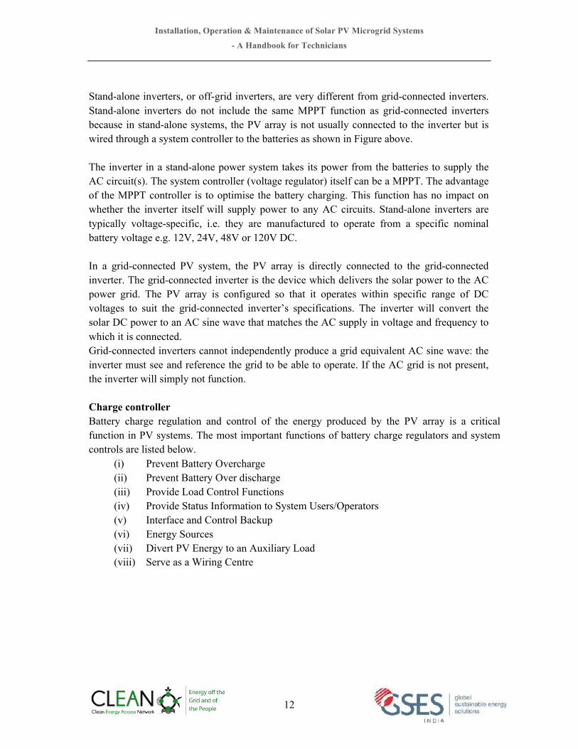
3.5 OperationsofaPVModuleA typical silicon solar cell produce only about 0.5 volt. A solar module is basic building block of any solar system where multiple cells are connected in series. Usually 36 solar cells are connected together to give a voltage of about 17V, which is enough to charge 12V battery. Similarly, a 72 cells module produces about 34V, which can be used to charge a 24V battery.
Cells are connected in series to make a PV module In many applications the power available from one module is inadequate for the load. Individual modules can be connected in series, parallel, or both to increase either output voltage or current. This also increases the output power. When a number of modules are connected in series, it is called a PV string. Voltage of a string is addition of voltages of individual module. If 10 modules of 34V are connected to make one string, voltage of the string will be 340V. When modules or PV strings are connected in parallel, the current increases. For example, three modules which produce 34V and 5A, connected in parallel, will produce 34V and 15A. If three PV strings of 340V are connected in parallel, will produce 340V and 15A. The collective of multiple strings connected in parallel for greater power is called PV Array.
!""""""+"Voc =0.50 x 36 = 18V DC
Installation, Operation & Maintenance of Solar PV Microgrid Systems
- A Handbook for Technicians
19
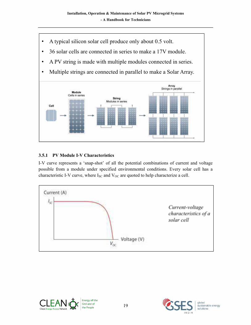
3.5.1 PV Module I-V Characteristics I-V curve represents a ‘snap-shot’ of all the potential combinations of current and voltage possible from a module under specified environmental conditions. Every solar cell has a characteristic I-V curve, where ISC and VOC are quoted to help characterize a cell.
• A typical silicon solar cell produce only about 0.5 volt.
• 36 solar cells are connected in series to make a 17V module.
• A PV string is made with multiple modules connected in series.
• Multiple strings are connected in parallel to make a Solar Array.

Installation, Operation & Maintenance of Solar PV Microgrid Systems
- A Handbook for Technicians
20
Short Circuit Current (Isc): A photovoltaic module will produce its maximum current when there is essentially no resistance in the circuit. This would be a short circuit between its positive and negative terminals. This maximum current is called the short circuit current (Isc). When the module is shorted, the voltage in the circuit is zero. Open Circuit Voltage (Voc): The maximum voltage in a PV module is produced when there is a break in the circuit. This is called the open circuit voltage (Voc). Under this condition the resistance is infinitely high and there is no current, since the circuit is incomplete. Maximum Power (Pmax): The power available from a photovoltaic module at any point along the curve is expressed in watts (W). Watts are calculated by multiplying the voltage times the current (W = VA). At the short circuit current point, the power output is zero, since the voltage is zero. At the open circuit voltage point, the power output is also zero, since the current is zero. There is a point on the “knee” of the curve where the maximum power output is located. Maximum power (Pmax) is the product of current at maximum power times the voltage at maximum power.
!!"# = !!" ! !!" Current at Maximum Power (Imp): The current that results in maximum power under given conditions of light and temperature, used as the “rated” current of a device. This value occurs at the “knee” of the I-V curve. Voltage at Maximum Power (Vmp): The voltage that results in maximum power under given conditions of light and temperature, used as the “rated” current of a device and to determine how many cells or modules are needed to match a load voltage requirement. This value occurs at the “knee” of the I-V curve.
3.5.2 Module Energy Output For a specific load, PV module output depends on the following factors:
• Irradiance or light intensity • Temperature
Solar irradiance directly affects the module energy output. If light falling on a solar module increases twice, it will produce twice as much current. The open circuit voltage does not change dramatically with irradiance; however it increases slightly with higher irradiance. This is why modules should be completely unshaded during operation. A shadow across a module can almost stop electricity production.

Installation, Operation & Maintenance of Solar PV Microgrid Systems
- A Handbook for Technicians
21
Module temperature affects the output voltage inversely. Higher module temperatures will reduce the voltage by 0.04V/°C to 0.1V/°C, for every one degree centigrade rise in temperature. This is why the modules should be installed in such way that there is enough air circulation in the back of each module, so that its temperature does not rise and reducing its output. An air space of 4 – 6 inches is usually required to provide proper ventilation. Standard Test Conditions (STC): The specifications in manufacturers’ data sheets are all determined using standard test conditions (STC) which are considered as below:
• Cell Temperature 25°C • Irradiance of 1000 W/m2 • Air Mass of 1.5
Example: On a clear sunny day a 1kWp PV array received 6 Peak Sun Hours. Expected output can be determined as follows:
Peak Power Output x Peak Sun Hours = Expected Output 1kW x 6PSH = 6kWh
The calculation above shows the maximum theoretical energy output, which will never be produced in a real PV system. The actual output would be a lot lower than calculated
For a specific load, PV module output depends on two major factors:
• Irradiance or light intensity • Temperature
The higher the solar radiation it receives, the higher is the current a module will produce. The voltage will remain the same. As the temperature of a solar cell increases, the open circuit voltage Voc decreases but the short circuit current Isc increases marginally.

Installation, Operation & Maintenance of Solar PV Microgrid Systems
- A Handbook for Technicians
22
because of inefficiencies of and losses in the PV system (known as derating factors). Losses in a solar PV system arise from weather factors, site constraints and voltage drop. A summary of typical losses is provided in the following table. Estimated loss for a solar microgrid system depends on system design, component selection and site operating temperature and normally total loss is around 30%.
Cause of loss *Estimated Loss (%) De-rating Factor Temperature 10% 0.90 Dirt 3% 0.97 Manufacturer’s Tolerance 3% 0.97 Shading 2% 0.95 Orientation 0% 1.00 Tilt Angle 1% 0.99 Voltage Drop 2% 0.98 Inverter 5% 0.95 Loss due to irradiance level 3% 0.97 Distribution & transmission 2% 0.98 Total de-rating factor (multiplying all de-rating factors) 0.70
* Typical losses in PV systems. Actual loss will be as per site conditions
Example:
On a clear and a sunny day, a 1kWp PV array received 6 Peak Sun Hours. Expected output can be determined as follows: Expected Output = Peak Sun Hours x Peak Power Output x Total derating factor
= 1kWp x 6 x 70%
= 4.2kWh
Energy Yield
Peak Sun Hour
Module Rated Power
Total Derating Factor

Installation, Operation & Maintenance of Solar PV Microgrid Systems
- A Handbook for Technicians
23
Performance degradation over life cycle: The performance of a PV module will decrease over time. The degradation rate is typically higher in the first year upon initial exposure to light and then stabilizes. Factors affecting the degree of degradation include the quality of materials used in manufacture, the manufacturing process, the quality of assembly and packaging of the cells into the module, as well as maintenance levels employed at the site. Generally degradation of a good quality module is considered to be about 20% during the module life of 25 years @ 0.7% to 1% per year.
Example of PV module degradation
Example: On a clear and a sunny day, a 1kWp PV array received 6 Peak Sun Hours (hours). Total loss (de-rating factor) in the system is estimated as 0.70 (70%) Expected output can be determined as follows: Expected Output = Peak Sun Hours x Peak Power Output x Total derating factor = 1kWp x 6 hour/day x 0.70 = 4.2kWh per day (1st year) Now considering degradation of module as per the indicative profile above (example only, actual degradation of module will be based on module quality and climatic conditions) Energy generation: = 3.83kWh per day (on 10th year) = 3.39kWh per day (on 25th year)
PERFORMANCE
1000V maximum system voltage improves PV system energy yield by reducing resistive line losses
SAVINGS
Larger string sizes lower balance-of-system costs by decreasing the required number of wire runs and combiner boxes
SAFETY
ULcertification conveysconfidence in product safety to authorities having jurisdiction throughout the US and Canada
YINGlISOlAR.COM/US Yingli Americas
the YGE-U 72 Cell Series.introducing
Yl305P-35b
Yl300P-35b
Yl295P-35b
Yl290P-35b
Yl285P-35b
YGE-U 72 CELL SERIES
Designed specifically for utility-scale projects and certified by UL for system voltages up to 1000V.
warranties
10-year Limited Product Warranty also applies.*
* In compliance with our warranty terms and conditions.
qualifications & certificates
UL 1703 and ULC 1703, UL Fire Safety Class C, CEC, FSEC, ISO 9001:2008, ISO 14001 :2004, BS OHSAS 18001:2007, SA8000
SA8000 REGISTERED FIRM
DET NORSKE VERITAS
preferred partner
The YGE-U 72 Cell Series is fully compatible
with single-axis solar tracking systems
manufactured by Array Technologies, which
can boost system performance by up to
25% depending on site location.
Yingli’s Linear Performance Warranty
25Years
Gua
rant
eed
Per
form
ance Yingli’s Value-Added Linear Warranty Now Available
201510500%
97.5%
91.2%
80.7%
Yingli’s Standard Warranty

Installation, Operation & Maintenance of Solar PV Microgrid Systems
- A Handbook for Technicians
24
3.5.3 Bypass Diodes When a cell in photovoltaic module is damaged or a part of module is shaded, the shaded cells will not be able to produce as much current as the unshaded cells. Since all the cells are connected in series, the same amount of current will flow through the damaged or shaded cell that will now act as a resistance and become hot and energy generated in the module will be lost. This is known as ‘hotspot’ phenomenon. This can be avoided by using a bypass diode in the module in parallel to the output terminal as shown in the diagram below.
3.5.4 Blocking Diodes During daylight, an array has more voltage potential than the battery, so current flows from the array into the battery. But at night, the module potential drops to zero, and the battery could discharge all night backwards through the module. This would not be harmful to the module, but would result in loss of precious energy from the battery bank. Diodes placed in the circuit between the module and the battery can block any night time leakage flow.
To protect the loss of energy flowing from the battery through the
module during night, blocking diodes are used in series.

Installation, Operation & Maintenance of Solar PV Microgrid Systems
- A Handbook for Technicians
25
CHAPTER 4
4 Configurations of solar PV microgrid system Solar PV microgrid systems are custom designed for their particular situation. The following factors are generally taken into account while determining the system configuration for solar microgrid system.
• Target consumer and type of electrical appliances to be operated • Load size and daily energy demand • Time of operation • Correlation with load on a daily, weekly and seasonal scale • Installed cost and maintenance costs • User specific preferences • Local regulations/ constraints/ benefits • Photovoltaic only or hybrid generation
The system configuration should be chosen so as to satisfy the design criteria, to make it most cost-effective, efficient, reliable system operation and long life. Economic evaluation of different options, if required, may be carried out on the basis of life cycle costing. For reference purpose, we can group solar micropower or microgrid system types into five broad categories:
• Small DC microgrid (Pico-grid) system • Large DC microgrid system • AC Power microgrid system • AC – DC combined microgrid system • PV-Generator hybrid microgrid system
In the following pages typical system configurations are described.
4.1 Small DC microgrid system This configuration is similar to a solar home system shared by 3-5 houses to meet basic electricity demand for 2-3 LED lighting per house, mobile charging and charging of solar lanterns, etc. Typical battery capacity could be 75-200Ah, 12V and array capacity shall be 50-200Wp based on availability of solar radiation on the site. Generally, a typical charge regulator is used to protect the battery from deep discharge and overcharge.

Installation, Operation & Maintenance of Solar PV Microgrid Systems
- A Handbook for Technicians
26
4.2 Large DC microgrid system This type of system can be designed by adding more modules and batteries. A large single charge controller or multiple charge controllers would be needed to handle the increased current from the array. If number of loads is more, a DC circuit breaker distribution box could be used. Typical array size of these types of systems may be 500 watts to few kilowatts with nominal system voltage 12, 24 or 48V based on size of the system. Similarly battery bank capacity may be of 300Ah to 600Ah.
Small DC Microgrid (Picogrid) System
DC Loads for 3-5 Houses LED Lights,
Mobile Phones, Solar Lantern
Charge Regulator
Battery
PV Modules 50 - 200Wp
Deep Cycle Battery 75-200Ah, 12V
Large DC Microgrid Systems
Battery
MPPT/Charge Controller
PV Modules 500-1000Wp
DC Loads for 10 -15 Houses LED Lights, DC Fans,
Mobile Phones, Solar Lantern
Deep Cycle Battery 300-600Ah, 12/24V

Installation, Operation & Maintenance of Solar PV Microgrid Systems
- A Handbook for Technicians
27
4.3 AC Power microgrid system AC appliances can be powered by adding a DC-to-AC inverter. In general, system size more than 1000 watts can be designed for standalone AC operation. Depending on the capacity of the system and type of inverter, various types of AC appliances could be operated by this type of system. Using an AC standalone system is convenient as most of the electrical and electronic appliances available in the market run on AC. However, care has to be taken, particularly in small system for overloading of the system and inverter, as the users may not be aware of limitation of the system and they may tend to think as conventional AC system and end up discharging the complete battery capacity using the loads continuously or damage the inverter connecting loads of larger than the inverter capacity. When low quality or inverters with square wave or modified square wave form are used, some electrical or electronic equipment may not function or even get damaged.
4.4 AC – DC combined microgrid system Design and operational features of this configuration is similar to the AC power system as mentioned in the previous section. The only additional feature in this configuration is facility to use DC appliances directly from the regulator without going through the inverter. If the user has some DC loads and these are efficient, it is recommended that DC loads be used directly from the DC bus bar. This might reduce the size of the inverter and also increase overall efficiency of the system, as there is no conversion loss for DC loads.
AC Power Microgrid System
Battery
DC AC
PV Modules 1000-5000Wp
Deep Cycle Battery 300-900Ah, 12/24/48V
MPPT/Charge Controller
AC Loads for 20 -30 Houses LED Lights, Fans, TV,
Mobile Phones, etc.

Installation, Operation & Maintenance of Solar PV Microgrid Systems
- A Handbook for Technicians
28
4.5 PV-Generator hybrid microgrid system Solar microgrid system can be integrated to other renewable energy generator such as wind turbines or micro hydro generator. A common choice is a diesel, kerosene or petrol fuel based generator. By combining a generator, the reliability of solar microgrid system can be assured with availability power during any season or weather condition during the year.
AC-DC Combined Microgrid System
AC Loads for 20 -30 Houses LED Lights, Fans, TV, Mobile Phone,
etc. Deep Cycle Battery 600-900Ah, 24/48V
Battery
DC AC
PV Modules 50-100Wp
DC Loads Solar Lanterns, Small DC Pump
MPPT/Charge Controller
PV-DG Hybrid Microgrid System
MPPT/Charge Controller
Battery
PV Modules 50-100Wp
AC Loads for 50-100 Houses LED Lights, Fans, TV
Mobile Phones, Community and Commercial Loads Deep Cycle Battery
600-900Ah, 24/48V
DC AC
Generator

Installation, Operation & Maintenance of Solar PV Microgrid Systems
- A Handbook for Technicians
29
Generator AC power output can be directly connected to AC loads. A transfer switch is needed to prevent generator power from feeding backwards in the inverter. The transfer switch can be electronically operated or a manual change over switch. The generator can also be used to recharge the batteries. 4.6 Connecting microgrid system to grid In general, solar microgrid is standalone and installed in such areas where there is no grid. As and when the main grid is extended to these areas, microgrid systems may become obsolete or have less importance due to its limited power generation capacity in comparison to the main grid. The best way to avoid such situation is to make the microgrid systems compatible to interface the main grid. A solar microgrid system can be connected to the main grid through different methods. However, such integration must be as per requirement of local grid code and provision from IEEE1547 need to be followed. Connecting microgrid system to the main grid may provide multiple benefits as below:
(i) Solar microgrids are typically designed with extra capacity to take care of energy demand during the months when solar radiation is low. If microgrid system is connected to the main grid, surplus power can be injected into the grid, which will increase capacity utilization factor of the plant.
(ii) The consumers connected to microgrid system will have more flexibility in use of electrical appliances when microgrid is connected to the main grid.
(iii) Due to availability of grid, battery capacity may be reduced or even removed if grid is reliable.
Microgrid System connected to main grid
MPPT/Charge Controller
Battery
PV Array
Loads connected to microgrid
Battery Storage
DC AC
Generator
Point of Common Connection
Main Grid

Installation, Operation & Maintenance of Solar PV Microgrid Systems
- A Handbook for Technicians
30
CHAPTER 5
5 System Design Overview and Safety Aspects 5.1 Basic Design Principles for Solar Microgrid Systems Appropriate system design and component sizing is fundamental requirement for reliable operation, better performance, safety and longevity of solar PV based micro grid system. Therefore correct approach towards designing a standalone microgrid PV system is critical. 5.1.1 Design Criteria: A solar microgrid system is designed based on the following criteria:
• Average daily load demand; • Maximum and surge power demand; • System voltage and service (distribution) voltage • System cost and availability of fund; • Power quality (for example, waveform quality or continuity of supply); • Only solar or combination of other backup source (such as diesel/ wind hybrid); • Use of efficient electrical appliances • Availability of spare parts and maintenance service; • Type of control system
Major system parameters for designing solar microgrid systems are:
• Energy supply strategy and how to manage supply of electricity with respect to demand;
• Whether distribution is for DC loads or AC loads • Maximum and surge demand; • System voltage; • Days of autonomy; • In case of a hybrid system size and optimized run time of generator • Size or capacity of solar array; • Size or capacity of battery bank; • Ratings of major components.

Installation, Operation & Maintenance of Solar PV Microgrid Systems
- A Handbook for Technicians
31
5.1.2 System Voltage: Distribution system voltage AC distribution system voltage of a microgrid system is designed for single-phase 230V or three phase 415V at 50Htz frequency. For small DC systems, electricity may be distributed at extra low voltage (ELV) such as 12V, 24V, 48V etc. but it should be lower than 120V DC for safety reason. Actual voltage of DC systems is decided based on size of the system, distance from battery room to load point and availability of DC electrical appliances and control systems. Solar system (Battery) voltage
Voltage of solar system (battery voltage) may be different from the voltage power distribution system. Voltage level at solar system depends on the system size, battery and solar array capacity and skill level of operating staff at the site. IEC-62257-6 suggests that if the local level skill is relatively low, the system voltage should be of Extra Low Voltage i.e. lower than 120V DC. Systems of higher capacity (500Wp and above) may use MPPT or AC bus configuration where solar array voltage likely to be higher than 120V DC. Technicians working with voltage level higher than 120V must have appropriate training to work with such system. For small microgrid system, solar system voltages are generally 12, 24 or 48 V based on requirement. In larger systems, 120V or 240V DC could be used.
5.1.3 Module tilt angle For standalone PV system, optimum tilt angle of solar array (panel) is decided based on the latitude of the location. Since India is a large country laying on the latitude of 8oN to 36oN, optimum tilt will be different for different states/ locations. The table below provides rules of thumb to determine optimum tilt angle for any location. It may be noted that slight variation in the tilt angle does not effect on the system.
Use 12V System Voltage
Use 24V System Voltage
Use 48V System Voltage
1 kWh 3-4 kWh

Installation, Operation & Maintenance of Solar PV Microgrid Systems
- A Handbook for Technicians
32
India map with latitude and longitude
Latitude Recommended Tilt Angle No Seasonal Load
Variation Winter Summer
5o to 25 o Lat to Lat +5 o Lat +5 o to Lat +15 o Lat - 5 o to Lat+5 o
25 o to 45 o Lat +5 o to Lat +10 o Lat +10 o to Lat +20 o Lat to Lat +10 o

Installation, Operation & Maintenance of Solar PV Microgrid Systems
- A Handbook for Technicians
33
Example: Recommended Tilt angle for different states of India and neighbouring countries
States/location Latitude Fixed array Array with seasonal tilt
Recommended Fixed Tilt
Recommended tilt in winter
Recommended tilt in Summer
Jammu &Kashmir, Punjab, Himachal and Uttarakhand
30oN to 36oN
35 - 40 40 - 50 30 - 40
Rajasthan, Haryana, UP, Assam, Arunachal, Nagaland, Nepal & Bhutan
26oN to 30oN 30 - 35 35 - 45 25 - 35
Gujarat, MP, Bihar, Jharkhand, Meghalaya, Mizoram, West Bengal, Manipur, Bangladesh
22oN to 26oN 25 - 30 30 - 35 20 - 25
Maharashtra, Telangana Chhattisgarh, Odisha
18oN to 22oN 20 - 25 25 - 30 15 - 20
North Karnataka, Goa, South Telangana, Andhra Pradesh
14oN to 18oN 15 - 20 20 - 25 10 - 15
South Karnataka, Kerala, Tamilnadu, Pondicherry
10oN to 14oN 10 -15 15 - 20 10 - 15
South Kerala, South Tamilnadu, Sri Lanka
6oN to 12oN 10 - 15 10 - 15 10 - 15
5.1.4 Module orientation For best output from solar array, the modules must be oriented as close as possible toward the equator. In the Northern Hemisphere, this direction is true south. An array with fixed orientation should be set up to face within ± 20° of true south unless system or site requirements dictate otherwise.
5.2 Determining solar array and battery capacity Solar array size and capacity of battery storage is determined by the following parameters:
(i) Daily energy demand (connected load and operating time) (ii) Solar radiation received in the site and (iii) Days of battery storage autonomy meaning for how many days system will work
if there is a cloudy weather.
A minimum tilt angle of 10° is recommended under any circumstances, to ensure adequate self-cleaning of solar array

Installation, Operation & Maintenance of Solar PV Microgrid Systems
- A Handbook for Technicians
34
5.2.1 Capacity of solar array PV array should be sized to allow full recharge of the batteries from maximum depth of discharge in an acceptable time frame, e.g. 14 days, as well as the capacity to provide an equalizing charge. For microgrid systems without generator backup, solar radiation available in the worst month of the year may be considered for sizing the array capacity. The worst month may be determined by finding the month in which the ratio of renewable generator output to load energy is smallest. The array size should as such that solar energy fraction should be atleast 75%, for satisfactory performance of the plant.
5.2.2 Battery capacity and hours of backup Batteries should be capable of meeting both the power and energy requirements of the system. For microgrid system without generator backup, minimum autonomy should be kept as 3 days for regular loads. For critical loads autonomy should be more than 3 days based on weather conditions of the particular area. In a hybrid system with generator backup, autonomy of 1-2 days may be considered.
5.2.3 Example of solar array and battery capacity sizing for typical microgrid systems
Configuration 1 Indicative
Capacity of Array & Battery
Annual average solar radiation (kWh/m2/day)
3.50 4.50 5.50 6.50 No. of households: 3 Connected load: 50Watt Average daily energy demand: 260Wh/day Days of Autonomy: 3 Over supply co-efficient: 1 Typical loads: 2 LED lights/ house, mobile charging and lantern charging in all houses
Battery Voltage (V)
12 12 12 12
Battery Capacity (Ah)
100 100 100 100
PV Array capacity (Wp)
100 75 60 50
Configuration 2 Indicative Capacity of Array & Battery
Annual average solar radiation (kWh/m2/day)
3.50 4.50 5.50 6.50 No. of households: 5 Connected load: 85Watt Average daily energy demand: 450Wh/day Days of Autonomy: 3 Over supply co-efficient: 1 Typical loads: 2 LED lights/ house, mobile charging and lantern charging in all houses
Battery Voltage (V) 12 12 12 12
Battery Capacity (Ah) 150 150 150 150
PV Array capacity (Wp) 175 140 120 100

Installation, Operation & Maintenance of Solar PV Microgrid Systems
- A Handbook for Technicians
35
Configuration 3
Indicative Capacity of
Array & Battery
Annual average solar radiation (kWh/m2/day)
3.50 4.50 5.50 6.50
No. of households: 10 Connected load: 170Watt Average daily energy demand: 900Wh/day Days of Autonomy: 3 Over supply co-efficient: 1 Typical loads: 2 LED lights/ house, mobile charging and lantern charging in all houses
Battery Voltage (V)
12 12 12 12
Battery Capacity (Ah)
360 360 360 360
PV Array capacity (Wp)
400 300 250 200
Configuration 4
Indicative Capacity of
Array & Battery
Annual average solar radiation (kWh/m2/day)
3.50 4.50 5.50 6.50
No. of households: 10 Connected load: 600Watt Average daily energy demand: 3000Wh/day Days of Autonomy: 3 Over supply co-efficient: 1 Typical loads: LED lights, DC fans, mobile & lantern charging, computer and LCD/LED TV
Battery Voltage (V)
24 24 24 24
Battery Capacity (Ah)
600 600 600 600
PV Array capacity (Wp)
1300 1000 800 700
Configuration 5
Indicative Capacity of
Array & Battery
Annual average solar radiation (kWh/m2/day)
3.50 4.50 5.50 6.50
No. of households: 20 Connected load: 1200Watt Average daily energy demand: 6000Wh/day Days of Autonomy: 3 Over supply co-efficient: 1 Typical loads: LED lights, DC fans, mobile & lantern charging, computer and LCD/LED TV
Battery Voltage (V)
48 48 48 48
Battery Capacity (Ah)
600 600 600 600
PV Array capacity (Wp)
2600 2000 1650 1400

Installation, Operation & Maintenance of Solar PV Microgrid Systems
- A Handbook for Technicians
36
Configuration 6
Indicative Capacity of
Array & Battery
Annual average solar radiation (kWh/m2/day)
3.50 4.50 5.50 6.50
No. of households: 30 Connected load: 1800Watt Average daily energy demand: 9000Wh/day Days of Autonomy: 3 Over supply co-efficient: 1 Typical loads: LED lights, DC fans, mobile & lantern charging, computer and LCD/LED TV, commercial loads
Battery Voltage (V)
48 48 48 48
Battery Capacity (Ah)
900 900 900 900
PV Array capacity (Wp)
3900 3000 2500 2100
5.3 DC Bus and AC Bus In a hybrid microgrid system, more than one generating devices are used, the system can be configured in a DC bus or AC Bus system. The following figures illustrate hybrid system interconnection in DC Bus and AC Bus system.
Interconnection configuration with DC bus and AC bus
DC G1
DC G2
AC G3
=
=
DC bus
=
~ AC bus
DC-DC converter if necessary
G - generator
IEC 1532/08

Installation, Operation & Maintenance of Solar PV Microgrid Systems
- A Handbook for Technicians
37
Interconnection configuration with AC bus only
5.4 System Protection and Safety Aspects 5.4.1 Cables & Wiring Improper wiring of the components can sabotage all the precise calculations in the PV system design. Poor choice of wire size can restrict battery charging and eventually cause system failure.
Proper wiring and design of safe, user-friendly photovoltaic systems are the most overlooked aspect of PV system designs. Adherence to the relevant electrical codes and standards and safe practices will result in reduced hazards associated with electrical installations. Careful design of the wiring subsystem will result in efficient and reliable PV systems that are safely and easily serviced.
Important considerations on cables
• Cable should be selected as per IEC 62548: Design requirements for Photovoltaic (PV) arrays
• Array cables be suitable for DC application, • String cables shall be UV-resistant, • Be water resistant, • Reinforced or double-insulated cables should be used when laid in metallic tray or
conduit, • Cable shall have ability to carry current safely without overheating in specified
conditions that cable will be laid/ installed, • Total voltage drop in all DC cables will be less than 3% • Total voltage drop in all AC cables will be less than 2% • Cables are to be laid/ installed in such a way that all connections and wiring should
be protected from inadvertent contact and mechanical damage.
DC G1
DC G2
AC G3
=
~
=
~
AC bus
IEC 1533/08

Installation, Operation & Maintenance of Solar PV Microgrid Systems
- A Handbook for Technicians
38
5.4.2 PV Array Maximum Voltage All system protection devices (and cables) must have a voltage rating of at least the 'PV Array Maximum Voltage' of the system. IEC 62548 defines the 'PV Array Maximum Voltage' as the voltage of the array at the lowest expected temperature at the installation site. Since voltage increases as temperature decreases, therefore, array voltage will be its' highest when array is at its coldest temperature. IEC 62548 states two ways in which the PV Array Maximum Voltage can be calculated:
(i) Using the temperature coefficient given by the manufacturer. (ii) Using the voltage correction factors in given Table 2 in IEC 62548.
Using temperature coefficients:
The PV Array Maximum Voltage can be calculated using the following formula:
!" !""#$ !"#$!%! !"#$%&' = ! ! !!" − !!!" ! !!"# − !!"# Where: N = Number of modules in series !!" = Open circuit voltage of the module at STC, in Volts Υ!!" = Open circuit voltage coefficient in V/°C (absolute value) !!"# = Lowest expected cell temperature in °C !!"# = Stand Test Conditions (STC) temperature, which is 25°C Using correction factor:
The correction factor needs to be multiplied by the array open circuit voltage. That is:
!" !""#$ !"#$!%! !"#$%&' = !!" ! ! ! !!" Where,
V!" = The voltage correction factor from Table 2 in IEC 62548 N = Number of modules in series !!" = Open circuit voltage of the module at STC, in Volts
Voltage Correction Factors Crystalline Silicon PV Modules
Lowest expected operating temperature (°C)
Correction factor
24 to 20 1.02 19 to 15 1.04 14 to 10 1.06 9 to 5 1.08 4 to 0 1.1

Installation, Operation & Maintenance of Solar PV Microgrid Systems
- A Handbook for Technicians
39
−1 to −5 1.12 −6 to −10 1.14 −11 to −15 1.16 −16 to −20 1.18 −21 to −25 1.2 −26 to −30 1.21 −31 to −35 1.23 −36 to −40 1.25
5.4.3 Overcurrent Protection Whenever there are voltage sources such as batteries, photovoltaic systems, or generators, there is the potential for dangerously large currents. A battery bank in a short circuit condition can discharge hundreds or thousands of amps causing damage to equipment and even physical harm or death. Care must be taken to protect equipment from such high current conditions. Array Fault Current Protection When multiple strings are connected in parallel and there is a risk of feeding high current from combined strings to a fault string due to short circuit or shading condition. Whether fault current protection is required is determined with the help of the following formula. If:
!!" = (!"#$%& !" !"#$%&'− !) ≥ !"#$%& !"#"$%" !"##$%& !"#$%& Then, fault current protection is required. For most modules, reverse current rating is between 10A and 20A. If the current generated by the other strings is greater than current rating of the module then there is a risk of damage to that string and over current protection is required. Example:
Module: ISC: 5.5A Number of strings: 4 Module Reverse Current /Maximum series fuse rating: 15A
In the above configuration, if one string is faulty or shaded it will produce 0A as it is in short circuit. Currents from other strings without fault current protection will freely flow through it instead of through the inverter, as it is the path of least resistance. Combined current of three strings will be 5.5A x 3 = 16.5A which is higher than the module reverse current rating. Therefore, fault current protection must be provided in the array.

Installation, Operation & Maintenance of Solar PV Microgrid Systems
- A Handbook for Technicians
40
Sizing Fault Current Protection Devices: Unless specified by the module manufacturer the rated trip current (Itrip) of over current protection for the PV string is determined by the following formula from IEC 62548: Design requirements for Photovoltaic (PV) arrays:
!.! ! !!"!!"# !"#$ ≤ !!"#$ ≤ !.! ! !!" !"# Where, !!" !"#= Short circuit current of the module !!"#$ = Rated trip current of the fault current protection device
Battery Overcurrent Protection The output conductors of the battery bank shall be protected against overcurrent, by high rupturing capacity (HRC) fuses or DC rated circuit breakers, as follows:
(i) Where the battery bank is electrically floating (i.e. neither side of the battery is
earthed), protection shall be provided in both positive and negative battery leads. (ii) Where one side of the battery bank is earthed, protection shall be provided in the
unearthed battery lead.
5.5A
11A
16.5A !!
Maximum fault current is 16.5A which is larger than the module reverse current (15A). Therefore, fault current protection (Fuse) must be installed in each string
Faulty module/ string

Installation, Operation & Maintenance of Solar PV Microgrid Systems
- A Handbook for Technicians
41
5.4.4 Disconnection Devices Safety disconnects or switches are placed into power systems to allow equipment to be safely installed and maintained. Typically there are four locations where disconnect devices are needed in photovoltaic systems. They are:
(i) Between the array and the charge regulator; (ii) Between the regulator and the battery; (iii) Between the battery and any DC loads or load centre; and (iv) Between the battery and the inverter.
In many cases the disconnection means can be combined with the over-current protection in the form of a DC circuit breaker. If this is done, care needs to be taken to ensure that the circuit breaker chosen is fit for purpose; for example polarised DC circuit breakers cannot be used in many situations. As per EC 62548: Photovoltaic Arrays –Design Requirement, the location of fault current protection related to battery systems is generally between the battery and charge controller. The protection should be mounted as close as practicable to the battery terminals while offering no possibility for spark ignition of any hydrogen emitted from the batteries during charging.
+ +
+ +
+ +
Grounded System Ungrounded System
From Charging Circuit
From Charging Circuit
To#Load#Circuit
To#Load#Circuit
Battery Battery
Current Limiting Fuses
Disconnect Switches
Battery Overcurrent and Disconnect Requirement

Installation, Operation & Maintenance of Solar PV Microgrid Systems
- A Handbook for Technicians
42
Main Battery Protection: The main battery protection is generally sized to cope with the requirements of a connected inverter. The required rating for battery current (Ib) is then calculated as follows:
!! =!"#$%&$% !"#$% !"#$%& (!)
!"#$%&$% !""#$#!%$& ! !"#$%&' !"##$%& !"#$%&'
Where, an inverter is not used, the main battery protection is sized for the DC maximum demand. In this case, separate DC mains protection is not required. The protection size is never to exceed the current carrying capacity of the battery cabling or inverter cabling. 5.4.5 Protection against effects of lightningFor small microgrid systems, lightning risk is, often low, and protection is usually not needed. The exceptions are installations on high ground and in lightning-prone areas, wind generator towers or masts, and aerial wiring where any part is exposed to a lightning risk. In order to asses the necessity of providing protection to micropower plants against effects of lightning methodologies are provided in Annex B of IEC62257-9-1. As the cost of installing surge protection devices could be high, this assessment shall be made carefully. If the risk assessed is quoted as being higher than 14 (Clause B.3) of IEC62257-9-1 or if the number of thunderstorm days per year is higher than 25 days per year (Clause B.2), special provision shall be made in order to protect the micropower plant from the effect of lightning. Whether the lightening arrestors are installed or not, an equipotential bonding shall be made using a copper conductor (or conductor of other material e.g. aluminium and stainless steel, which has the resistivity equivalent to 16mm2 copper) with a sectional area of at least 16mm² installed between the solar array and the “control room”. This conductor shall be installed direct in the earth, in the same earth pit as the power cable as close as possible to it. One of the ends shall be connected to the earthing electrode of the PV array and the other shall be connected to a special terminal provided for this purpose in the control room. This creates an equipotential bonding system as shown in the figure. If the distance between the PV array and the control room (inverter room) is greater than 15m, surge arresters shall be installed as shown in the figure. Surge protective devices shall be installed between each live conductor (AC or DC) and between each live conductor and the earth at the two ends of the bonding conductor. If the distance between the PV array and the control room is less than 15m, no additional special measure is required.

Installation, Operation & Maintenance of Solar PV Microgrid Systems
- A Handbook for Technicians
43
Example of the selectivity of protection against overcurrent, lightning and overvoltage
Charge controller
~ –
Discharge protection
~ –
A
A
A D
C 3
D
2 B
2
1
d id
A
Coupling panel
(5) (5)
(5)
A 1
B 2
C 3
D 4
DC AC
Overload protection d Protection against direct contact id Protection against indirect contact
Production sub-system
(2)
(2)
(3) (4)
(4)
(3) (3)
User sub-system
Equipment site
Equipment site’s equipotential bonding
Equipotential bonding
Lightning conductor wire
DC jonction panel
AC jonction panel
Selectivity of short-circuit protections
(1) Device that could serve as cut-off point in case of non-payment (2) (4) Depending on junction panel device can be upstream or downstream (3) One or the other depending on wire cross-section (5) Optional device NOTE The equipment’s possible internal protections have not been taken into account
Client site
Battery enclosures grounding links
A
A A
Discharge protection
1 1
Key
IEC 1540/08
Installation, Operation & Maintenance of Solar PV Microgrid Systems - A Handbook for Technicians
44
CHAPTER 6
6 Installation & commissioning 6.1 Site survey & planning The installer shall gather all design documents and engineering drawings of the system including site layout, system schematic, single line diagrams, drawings for structure and foundations, distribution systems, module and battery interconnection drawings, control system drawing, etc. The installer shall also have information (data sheet) on the major components such as modules, controls, inverter, and batteries and must be familiar with the instruction manual for installation of such equipments. The first step of installation is to visit the site and finalize the layout of the equipments. If site layout is already given, this should be verified at site identifying actual locations for installation of equipments and verify the distances and dimensions. 6.1.1 Occupational Health & Safety Assessment: Prior to starting any on-site work it is recommended that the installer undertake an on-site risk assessment. This requires:
• The identification of all possible risks; • Determination of the work practices that will be undertaken to remove the risk, or to
minimise the risk if it cannot be removed altogether; and • Communicating with all the staff working on-site about these risks and how they will
be removed or minimised. Typical risks with respect to the installation of PV systems are discussed in the Chapter 1. 6.1.2 Solar Array Location For a solar photovoltaic system, it is crucial that the solar array is installed at a location that is free from any shading throughout the day. Finding a shadow free location for placement of array is usually not an issue for remote sites, where ample space and options for locating may be available. Shadow during winter season is much longer that the shadow during summer season due to change in earth’s altitude. There may be shadow from nearby trees and houses or even shadow from mountains, which is not very far from the site. Sometime shadow in the early morning and late afternoon cannot be avoided due to very low altitude of sun. In such situation arrays must be placed in such a way that there is no shading between the hours of best insolation, usually from 8 a.m. to 4 p.m., on the day with the longest shadows, December 21 in the Northern Hemisphere.

Installation, Operation & Maintenance of Solar PV Microgrid Systems - A Handbook for Technicians
45
Placement of solar arrays considering summer and winter sun position Using Solar Pathfinder The most accurate and convenient way to place the array away from any tall object that can possibly cause shadow is to use the solar pathfinder. When you use a solar pathfinder there is no need to measure distance or height of any objects that can create shadow at any point of time during the year. Just placing the solar pathfinder in the potential array location, you will understand if there is any shadow. If there is any shadow image seen in the pathfinder, move away from that point to the direction where the shadow can be avoided. Solar pathfinder should be located at the four corners of the array to ensure that the complete array is shadow free.
Shadow analysis using a Sunpath finder and sunpath diagram

Installation, Operation & Maintenance of Solar PV Microgrid Systems - A Handbook for Technicians
46
If you do not have access to a solar pathfinder, use the following calculations to ensure that the array will be located away from potential shading. However, these methods require some measurement, calculation and good assumptions to decide whether the array will be shadow free for all days of the year. Using Spacing Factor Graph One easy approach is to use the “spacing factor graph” given in the figure below. This graph will help in deciding where to place an array for no winter shading. Read up from the latitude of the site to the curve for the hour when no shadows are to reach the array (again usually 8 a.m. to 9 a.m.). Then read across to find the Spacing Factor. Multiply this factor times the height of the object to calculate the distance the array must be placed away from the object.
Graph to determine array Spacing Factor The proper distance depends on the latitude, the time, and the height of the nearest tall object. With the help of the graph now calculate the minimum distance from object to the array using the following formula.
!"#$%&'( !"#$ !"#$%& !" !""!# = !"#$%& !"#$ℎ! ! !"#$%&' !"#$%&
0
4
8
12
16
20
24
28
0 5 10 15 20 25 30 35 40 45 50 55 60
Spacing Factor for No Array Shading
9:00 AM 8:00 AM 7:00 AM
!! !! !! !! !! !!!! !! !! !! !! !!!! !! !! !! !! !!!! !! !! !! !! !!!! !! !! !! !! !!!! !! !! !! !! !!!! !! !! !! !! !!!! !! !! !! !! !!!! !! !! !! !! !!!! !! !! !! !! !!!! !! !! !! !! !!!! !! !! !! !! !!
Latitude (degrees)
Spac
ing
Fact
or

Installation, Operation & Maintenance of Solar PV Microgrid Systems - A Handbook for Technicians
47
Applying Rule of Thumb The general rule of thumb is locate the array at a distance away from the object that is atleast twice the height of the object. This will ensure that the object will not cast a shadow for 4 hours either side of solar noon.
Placing of array away from objects Space Between Two Rows When PV modules are installed in multiple rows, consideration must be given so that one row of modules does not cast a shadow on the row behind. Calculations need to be done to find the minimum distance between PV Array rows to avoid winter mid-day shading. This can be calculated using basic trigonometry as shown in the figure below.
!"! !"#$%&' ! = ! ! !"# (!"#$%&' !"#$%)!"# (!"#$#%&' !"#$%)
Row in the South Row in the North

Installation, Operation & Maintenance of Solar PV Microgrid Systems - A Handbook for Technicians
48
Calculating the minimum distance between rows Example: The PV array is located in New Delhi: Latitude 28.5°N. The row spacing should avoid shading at solar noon on December 21. Azimuth = 173° Altitude = 38° at solar noon on December 21
! = ! ! !"# (173!)!"# (38!) = ! ! 0.990.78 = ! ! 1.27
If height of the row is 1m, distance between two rows shall be 1m x 1.27 = 1.27m 6.1.3 Other Equipment Location The next step of site survey is to determine the location of the control equipment, inverter, battery bank, earth pits and cable route.
• Controls and inverter should be placed in such a way that access is controlled • Switches are to be located in a place which is easily accessible
Example of location for inverter, control and switching devices

Installation, Operation & Maintenance of Solar PV Microgrid Systems - A Handbook for Technicians
49
• Batteries should be installed in a separate room closed to the inverter /control room and access to the room should be controlled.
• Batteries to be located in cool and dry and well ventilated place
Location of battery bank in a separate well ventilated room
Power distribution lines connecting the load centres

Installation, Operation & Maintenance of Solar PV Microgrid Systems - A Handbook for Technicians
50
6.2 Tools for Installation
Some tools for installing and maintaining photovoltaic power systems are listed below. Sl. No. Tools and equipments for Installation
1 First aid kit 2 System service logbook 3 Datasheet & O&M manual 4 This manual 5 Paper/Pencil 6 Multimeter, digital voltmeter, with at least 10A current capability, spare batteries 7 Clampon DC ammeter
8 Wrenches: Specific sizes, for all mounting bolts; Adjustable, for unexpected on-site problems; Vise-Grips for variable and heavy duty
9 Compass and Sun Pathfinder
10 Screw Drivers: flat Blade, in sizes for all mounting hardware; Phillips, in sizes for all mounting hardware; Small jewelry size, for adjusting controls
11 Linesman pliers, nose pliers 12 Nut drivers 1/4in and 5/16in 13 Measuring tape (25m) 14 Tilt Angle indicator, or plumb line and protractor 15 Hydrometer 16 Safety goggles 17 Rubber gloves 18 Electrical Tape 19 Wire Crimping, Stripping and Cutting Tool (s) 20 Miscellaneous for connections: Split bolts, wire nuts, lugs, solder-less connectors 21 A hand drill or DC operated electric drill 22 DC soldering iron 23 Hacksaw 24 Utility knife 25 Hammer 26 Ladder

Installation, Operation & Maintenance of Solar PV Microgrid Systems - A Handbook for Technicians
51
6.3 Installation Processes
6.3.1 Installation of Mounting Structure
Generally, PV arrays for solar microgrid system are installed in the ground as there is ample of space available in rural area and finding a appropriate roof for installation of PV arrays may not be easy. The ground mounting system has the following advantages:
(1) It is easier to have seasonal or daily tracking provision in a ground mounted structure (2) Easy cleaning and maintenance access of PC array (3) Better air flow keep the modules cool hence will have better performance (4) Easy maintenance of structure, cable tray, electrical connectors and cable etc. (5) Easy to expand PV array capacity if required
Array mounting structure could be different types depending upon site, system capacity maintenance plan, type of soil, wind velocity, waterlogging possibility etc. Conceptual drawing of few commonly used array structures are presented below:
Double pole structure with fixed tilt angle
Fixed tilt angle based on latitude of the location
Single pole structure with adjustable tilt angle
Adjustable tilt angle based on the season of the year
Double pole structure with adjustable tilt angle
Adjustable tilt angle based on the season of the year
Single pole structure with fixed tilt angle
Fixed tilt angle based on latitude of the location

Installation, Operation & Maintenance of Solar PV Microgrid Systems - A Handbook for Technicians
52
Foundation and Structural Alignment The most critical element of foundation and structure installation is alignment. The points where the mounting structure is to meet the foundation must be level, and any mounting bolts must be spaced correctly. It is critical that careful measurements be made both for spacing and for flatness. The orientation of the foundation must face true south.
Determining and marking the north-south direction with the help of a compass
Aligning the locations for foundation for mounting structure

Installation, Operation & Maintenance of Solar PV Microgrid Systems - A Handbook for Technicians
53
6.3.2 Type of foundations for mounting structure Foundation for array mounting structure may be different for different sites, type and load bearing capacity of soil, wind velocity, waterlogging possibility and type of mounting structure. Conceptual drawing of foundation type generally used to hold PV array structure are presented below:
Example of block type foundation
Block type foundation Slab type foundation
Beam type foundation Pile foundation

Installation, Operation & Maintenance of Solar PV Microgrid Systems - A Handbook for Technicians
54
Example of array installed on a RCC roof of the control room
Example of slab foundation

Installation, Operation & Maintenance of Solar PV Microgrid Systems - A Handbook for Technicians
55
Example of beam type foundation
Example of pile foundation
6.3.3 Array Installation and Wiring Once the mounting structure is in place, modules are place on to it and fixed properly. Modules pre-wired with MC4 connector before fixing to the structure. Modules are connected together in series and parallel as per design. It is necessary to draw the module
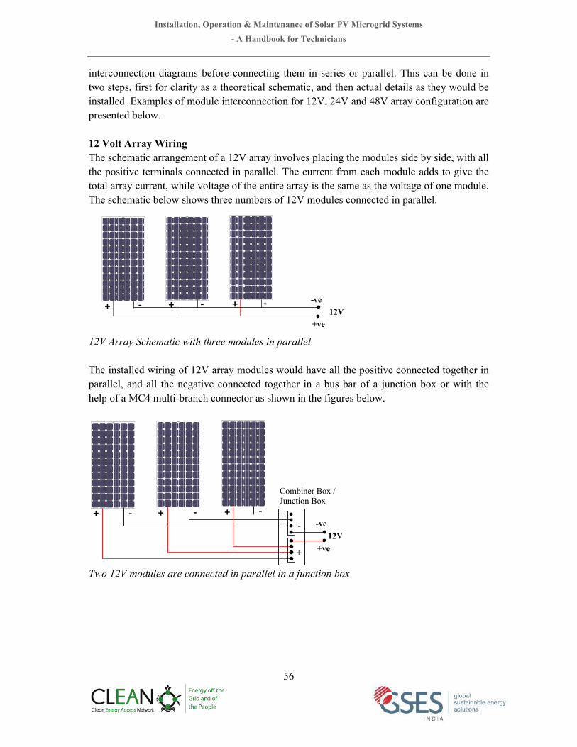
Installation, Operation & Maintenance of Solar PV Microgrid Systems - A Handbook for Technicians
56
interconnection diagrams before connecting them in series or parallel. This can be done in two steps, first for clarity as a theoretical schematic, and then actual details as they would be installed. Examples of module interconnection for 12V, 24V and 48V array configuration are presented below. 12 Volt Array Wiring The schematic arrangement of a 12V array involves placing the modules side by side, with all the positive terminals connected in parallel. The current from each module adds to give the total array current, while voltage of the entire array is the same as the voltage of one module. The schematic below shows three numbers of 12V modules connected in parallel.
12V Array Schematic with three modules in parallel The installed wiring of 12V array modules would have all the positive connected together in parallel, and all the negative connected together in a bus bar of a junction box or with the help of a MC4 multi-branch connector as shown in the figures below.
Two 12V modules are connected in parallel in a junction box
+" #" +" #" +" #" -ve
+ve 12V
+" #" +" #" +" #"-ve
+ve 12V
+
-
Combiner Box / Junction Box

Installation, Operation & Maintenance of Solar PV Microgrid Systems - A Handbook for Technicians
57
Two 12V modules are connected in parallel with the help of MC4 connectors
Three 12V modules are connected in parallel with the help of MC4 connectors 24 Volt Array Wiring For a 24V array, two modules are connected in series (string). Any number of such series strings can then be connected in parallel to give the required current. A schematic view of a 24V array is shown below. In this example, two 12V modules are connected in series string to produce 24V and two such strings are connected in parallel to get required current.
12V
MC4 Multi-branch connector
12V !
+" +"+"_" _"_"
+"
_"

Installation, Operation & Maintenance of Solar PV Microgrid Systems - A Handbook for Technicians
58
24 Volt Array Wiring Schematic In actual field installation two 24V strings will be connected parallel in a common bus bar of a combiner box/ junction box or with the help of a MC4 multi-branch connector as shown in the figure below.
Two modules in series string and two strings in parallel connected through a junction box
Two modules are connected in series with the help of MC4 connectors
+" #" +" #" +" #" -ve
+ve 24V
+" #"
+" #" +" #" +" #" +" #"
-ve
+ve 24V
+
-
Combiner Box / Junction Box
!!!

Installation, Operation & Maintenance of Solar PV Microgrid Systems - A Handbook for Technicians
59
Two modules are connected in series and two strings are connected in parallel with the help of MC4 connectors 48 Volt Array Wiring In the case of 48V system, we need four modules connected in series. Strings of four modules can be combined in parallel to give final array current. Example in the figure below shows two strings of 48V are connected in parallel.
48 Volt Array Schematic with 4 modules connected in series and two strings connected in parallel
Extension Cable
""""
24V
+" #" +" +" #" +" #" +" #"+"#" +" #" +" #"#"
-ve
+ve
48V

Installation, Operation & Maintenance of Solar PV Microgrid Systems - A Handbook for Technicians
60
Four modules are connected in series string and two strings are connected in parallel through a junction box
Four modules connected in series string with the help of MC4 connectors
-ve
+ve 48V
+
-
+" #" +" +" #" +" #" +" #"+"#" +" #" +" #"#" Combiner Box / Junction Box
48V
It is recommended that modules in series should be connected first to produce the required voltage, and then connecting similar series string in parallel to produce the required current. In that case, if a series string is removed from the circuit, the rest of the strings still operate at the normal system voltage, and the array continues to charge the batteries or operate the load.
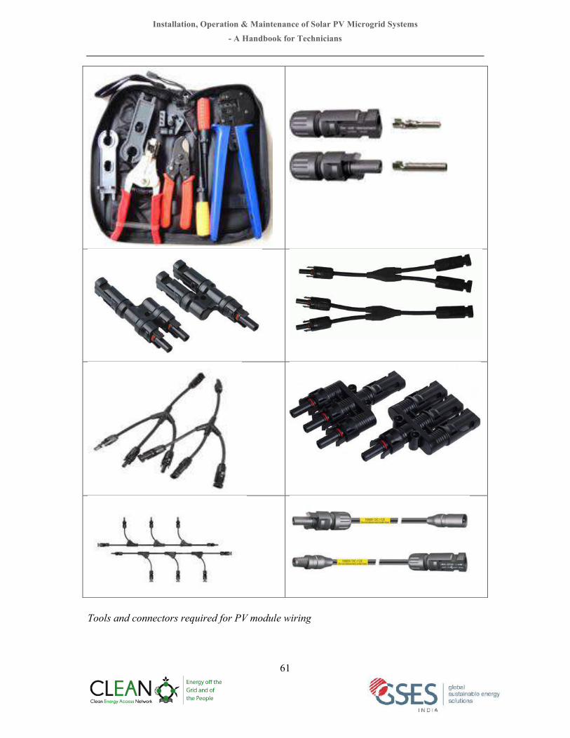
Installation, Operation & Maintenance of Solar PV Microgrid Systems - A Handbook for Technicians
61
Tools and connectors required for PV module wiring

Installation, Operation & Maintenance of Solar PV Microgrid Systems - A Handbook for Technicians
62
Correct Wiring Loops The PV array wiring should be installed in a way to minimise any conductive loops as shown in the figure below.
Example of correct wiring loop for a PV array 6.3.4 Battery InstallationIt is essential to check the following before installation of batteries:
• Review battery safety procedures • Do not mount the batteries directly on a concrete floor. Mount onto wooden or other
non-conducting rails. • Make sure the batteries are fully charged, and that the electrolyte level is at
manufacturer's recommended level. • Check all cell voltages and write down on a status sheet for later comparison. • Handle batteries with extreme care, and use tools carefully. The greatest danger will
occur if wires are hastily connected, or if tools are dropped onto the bare battery terminals.
• All connections should be “walked through” a few times, perhaps with another installer present to confirm, before actual wiring is done.
• Make sure to place a sign at the batteries warning unauthorized personnel about the dangers.
Battery Wiring: Similar to solar modules, batteries are connected in series and parallel to achieve required voltage and capacity. To operate at a higher voltage, batteries are connected in series. Examples of wiring of battery bank at different voltage configurations and capacity are shown below.

Installation, Operation & Maintenance of Solar PV Microgrid Systems - A Handbook for Technicians
63
Two 12V, 100AH batteries are connected in parallel to get 12V, 200AH and three 12V batteries are connected in parallel to get 12V, 300AH
Two 12V, 100AH batteries are connected in series to get 24V, 100AH and two 24V strings are connected to get 24V, 200AH
Four 12V, 100AH batteries are connected in series to get 48V, 100AH and two 48V strings are connected to get 48V, 200AH
+
-
+
- 100 AH
12V
100 AH
12V
200 AH 12V
+
-
+
-
+
- 100 AH
12V
100 AH
12V
300 AH 12V
+
-
+
- 100 AH
12V
+
-
+
- 100 AH
12V
100 AH
12V
200 AH 24V
- +
-
+
- 100 AH
12V
100 AH
12V
+
+
- 100 AH
12V
100 AH 24V
- +
- 100 AH
12V
+
+
-
+
- 100 AH
12V
100 AH
12V
200 AH 12V
+
-
+
-
+
- 100 AH
12V
100 AH
12V
300 AH 12V
+
-
+
- 100 AH
12V
+
-
+
- 100 AH
12V
100 AH
12V
200 AH 24V
- +
-
+
- 100 AH
12V
100 AH
12V
+
+
- 100 AH
12V
100 AH 24V
- +
- 100 AH
12V
+
+
- 100 AH
12V
100 AH 48V
-
+
- 100 AH
12V
+
+
- 100 AH
12V
+
- 100 AH
12V
+
- 100 AH
12V
+
- 100 AH
12V
+
- 100 AH
12V
+
- 100 AH
12V
+
- 100 AH
12V
+
- 100 AH
12V
+
- 100 AH
12V
+
- 100 AH
12V
200 AH 48V
-
+

Installation, Operation & Maintenance of Solar PV Microgrid Systems - A Handbook for Technicians
64
Six 2V, 200AH batteries are connected in series to get 12V, 200AH
Six 2V, 200AH batteries are connected in series and two 12V strings are connected to get 12V, 400AH
Twelve 2V, 200AH batteries are connected in series to get 24V, 200AH
+" #" +" #" +" #" +" #" +" #" +" #"2V""200AH"
"
2V""200AH"
"
2V""200AH"
"
2V""200AH"
"
2V""200AH"
"
2V""200AH"
"
12V "200AH "
+" #"
+" #" +" #" +" #" +" #" +" #" +" #"2V""200AH"
"
2V""200AH"
"
2V""200AH"
"
2V""200AH"
"
2V""200AH"
"
2V""200AH"
"
12V 400AH
"
400AH "
+" #" +" #" +" #" +" #" +" #" +" #"2V""200AH"
"
2V""200AH"
"
2V""200AH"
"
2V""200AH"
"
2V""200AH"
"
2V""200AH"
"+" #"
+" #" +" #" +" #" +" #" +" #" +" #"2V""200AH"
"
2V""200AH"
"
2V""200AH"
"
2V""200AH"
"
2V""200AH"
"
2V""200AH"
"
+" #" +" #" +" #" +" #" +" #" +" #"2V""200AH"
"
2V""200AH"
"
2V""200AH"
"
2V""200AH"
"
2V""200AH"
"
2V""200AH"
"
24V "200AH "
+" #"
24V "400AH
"
+" #" +" #" +" #" +" #" +" #" +" #"2V""200AH"
"
2V""200AH"
"
2V""200AH"
"
2V""200AH"
"
2V""200AH"
"
2V""200AH"
"
+" #" +" #" +" #" +" #" +" #" +" #"2V""200AH"
"
2V""200AH"
"
2V""200AH"
"
2V""200AH"
"
2V""200AH"
"
2V""200AH"
"
+" #"
+" #" +" #" +" #" +" #" +" #" +" #"2V""200AH"
"
2V""200AH"
"
2V""200AH"
"
2V""200AH"
"
2V""200AH"
"
2V""200AH"
"
+" #" +" #" +" #" +" #" +" #" +" #"2V""200AH"
"
2V""200AH"
"
2V""200AH"
"
2V""200AH"
"
2V""200AH"
"
2V""200AH"
"

Installation, Operation & Maintenance of Solar PV Microgrid Systems - A Handbook for Technicians
65
Twelve 2V, 200AH batteries are connected in series and two 24V strings are connected to get 24V, 400AH
Twenty-four 2V batteries are connected in series and to get 48V battery bank
6.3.5 Control Centre Pre-Wiring
• Understand and follow the schematic diagram of the system wiring • Assemble all controls, disconnect switches, alarms and meters and load centres as
pre-planned. • Make sure there is the required safe space between any boxes and walls or pipes or
other equipment.
+" #" +" #" +" #" +" #" +" #" +" #"2V""200AH"
"
2V""200AH"
"
2V""200AH"
"
2V""200AH"
"
2V""200AH"
"
2V""200AH"
"
+" #" +" #" +" #" +" #" +" #" +" #"2V""200AH"
"
2V""200AH"
"
2V""200AH"
"
2V""200AH"
"
2V""200AH"
"
2V""200AH"
"
24V "200AH "
+" #"
24V "400AH
"
+" #" +" #" +" #" +" #" +" #" +" #"2V""200AH"
"
2V""200AH"
"
2V""200AH"
"
2V""200AH"
"
2V""200AH"
"
2V""200AH"
"
+" #" +" #" +" #" +" #" +" #" +" #"2V""200AH"
"
2V""200AH"
"
2V""200AH"
"
2V""200AH"
"
2V""200AH"
"
2V""200AH"
"
+" #"
+" #" +" #" +" #" +" #" +" #" +" #"2V""200AH"
"
2V""200AH"
"
2V""200AH"
"
2V""200AH"
"
2V""200AH"
"
2V""200AH"
"
+" #" +" #" +" #" +" #" +" #" +" #"2V""200AH"
"
2V""200AH"
"
2V""200AH"
"
2V""200AH"
"
2V""200AH"
"
2V""200AH"
"
Important to note: • Not more than four parallel connections should be made in a battery bank • Tap off the battery at opposite corners when batteries are connected in combination of
series and parallel

Installation, Operation & Maintenance of Solar PV Microgrid Systems - A Handbook for Technicians
66
• Check that all connections are secure and clean, that all wiring is colour coded or marked for correct polarity and that all wire lugs are fastened tight to their wires.
• Before connecting the inverter, make sure the polarity is correct. Most inverters can be damaged if connected with the wrong polarity.
• Label all main switches so that an uninformed person with the operation guide can safely and easily disconnect the system in an emergency.
Example of control centre wiring
6.4 Power distribution system Three basic configurations could be applied for distribution of power in solar microgrid systems. Applicability and techno-economic feasibility of these configurations depend on system capacity, configuration, equipment type and distribution of loads.
(i) DC distribution system; (ii) AC single phase distribution system; (iii) AC three phase distribution system;
Recommended conductor size for different configurations is presented in the next pages.

Installation, Operation & Maintenance of Solar PV Microgrid Systems - A Handbook for Technicians
67
Table 6.1: Maximum cable route length of copper cable with different cross-section area for 12V DC power distribution system considering 2% voltage drop. Maximum cable route distance (m) with different cross section area of cable with 2% voltage drop
Current (A) 1.5mm2 2.5mm2 4mm2 6mm2 10mm2 16mm2 25mm2
1 10 16 26 39 66 105 164
2 5 8 13 20 33 52 82
3 3 5 9 13 22 35 55
4 2 4 7 10 16 26 41
5 2 3 5 8 13 21 33
6 2 3 4 7 11 17 27
7 1 2 4 6 9 15 23
8 1 2 3 5 8 13 20
9 1 2 3 4 7 12 18
10 1 2 3 4 7 10 16
Table 6.2: Maximum cable route length of copper cable with different cross-section area for 24V DC power distribution system considering 2% voltage drop.
Cable route distance (m) with different cross section area of cable with 2% voltage drop
Current (A) 1.5mm2 2.5mm2 4mm2 6mm2 10mm2 16mm2 25mm2
1 20 33 52 79 131 210 328
2 10 16 26 39 66 105 164
3 7 11 17 26 44 70 109
4 5 8 13 20 33 52 82
5 4 7 10 16 26 42 66
6 3 5 9 13 22 35 55
7 3 5 7 11 19 30 47
8 2 4 7 10 16 26 41
9 2 4 6 9 15 23 36
10 2 3 5 8 13 21 33

Installation, Operation & Maintenance of Solar PV Microgrid Systems - A Handbook for Technicians
68
Table 6.3: Maximum cable route length of copper cable with different cross-section area for 48V DC power distribution system considering 2% voltage drop.
Cable route distance (m) with different cross section area of cable with 2% voltage drop
Current (A) 1.5mm2 2.5mm2 4mm2 6mm2 10mm2 16mm2 25mm2
1 39 66 105 157 262 420 656
2 20 33 52 79 131 210 328
3 13 22 35 52 87 140 219
4 10 16 26 39 66 105 164
5 8 13 21 31 52 84 131
6 7 11 17 26 44 70 109
7 6 9 15 22 37 60 94
8 5 8 13 20 33 52 82
9 4 7 12 17 29 47 73
10 4 7 10 16 26 42 66
Table 6.4: Maximum cable route length of aluminums cable with different cross-section area for 230V AC power distribution system considering 2% voltage drop.
Cable route distance (m) with different cross section area of cable with 2% voltage drop
Current (A) 1.5mm2 2.5mm2 4mm2 6mm2 10mm2 16mm2
1.0 1.5 117 195 313 469 782
2.0 1.5 59 98 156 235 391
3.0 1.5 39 65 104 156 261
4 1.5 29 49 78 117 195
5.0 1.5 23 39 63 94 156
6.0 1.5 20 33 52 78 130
7.0 1.5 17 28 45 67 112
8 1.5 15 24 39 59 98
9.0 1.5 13 22 35 52 87
10.0 1.5 12 20 31 47 78

Installation, Operation & Maintenance of Solar PV Microgrid Systems - A Handbook for Technicians
69
Example of 12V DC distribution system for reference
164m
82m
41m
16m
0m
25mm² C
u.ca
ble,
12V
DC
Load
poi
nt 1
,
10 A
mp
Load
poi
nt 2
,
4 A
mp
Load
poi
nt 3
,
2 A
mp
Load
poi
nt 4
,
1 A
mp
105m
52m
26m
10m
0m
16mm² C
u.ca
ble,
12V
DC
Load
poi
nt 1
,
10 A
mp
Load
poi
nt 2
,
4 A
mp
Load
poi
nt 3
,
2 A
mp
Load
poi
nt 4
,
1 A
mp
33m
16m
0m
10mm² C
u.ca
ble,
12V
DC
Load
poi
nt 1
,
4 A
mp
Load
poi
nt 2
,
2 A
mp
66m
Load
poi
nt 3
,
1 A
mp
20m
10m
0m
6mm² C
u.ca
ble,
12V
DC
Load
poi
nt 1
,
4 A
mp
Load
poi
nt 2
,
2 A
mp
39m
Load
poi
nt 3
,
1 A
mp
7m0m
4mm² C
u.ca
ble,
12V
DC Lo
ad p
oint
1,
4
Am
p
26m
Load
poi
nt 2
,
1 A
mp

Installation, Operation & Maintenance of Solar PV Microgrid Systems - A Handbook for Technicians
70
Example of 24V DC distribution system for reference
328m
164m
82m
33m
0m
25mm² C
u.ca
ble,
24V
DC
Load
poi
nt 1
,
10 A
mp
Load
poi
nt 2
,
4 A
mp
Load
poi
nt 3
,
2 A
mp
Load
poi
nt 4
,
1 A
mp
210m
105m
52m
21m
0m
16mm² C
u.ca
ble,
24V
DC
Load
poi
nt 1
,
10 A
mp
Load
poi
nt 2
,
4 A
mp
Load
poi
nt 3
,
2 A
mp
Load
poi
nt 4
,
1 A
mp
66m
33m
0m
10mm² C
u.ca
ble,
24V
DC
Load
poi
nt 1
,
4 A
mp
Load
poi
nt 2
,
2 A
mp
131m
Load
poi
nt 3
,
1 A
mp
39m
20m
0m
6mm² C
u.ca
ble,
24V
DC Lo
ad p
oint
1,
4
Am
pLo
ad p
oint
2,
2
Am
p
79m
Load
poi
nt 3
,
1 A
mp
13m
0m
4mm² C
u.ca
ble,
24V
DC Lo
ad p
oint
1,
4
Am
p
52m
Load
poi
nt 2
,
1 A
mp

Installation, Operation & Maintenance of Solar PV Microgrid Systems - A Handbook for Technicians
71
Example of 48V DC distribution system for reference
656m
328m
164m
66m
0m
25mm² C
u.ca
ble,
48V
DC
Load
poi
nt 1
,
10 A
mp
Load
poi
nt 2
,
4 A
mp
Load
poi
nt 3
,
2 A
mp
Load
poi
nt 4
,
1 A
mp
420m
210m
105m
42m
0m
16mm² C
u.ca
ble,
48V
DC
Load
poi
nt 1
,
10 A
mp
Load
poi
nt 2
,
4 A
mp
Load
poi
nt 3
,
2 A
mp
Load
poi
nt 4
,
1 A
mp
131m
66m
0m
10mm² C
u.ca
ble,
48V
DC
Load
poi
nt 1
,
4 A
mp
Load
poi
nt 2
,
2 A
mp
262m
Load
poi
nt 3
,
1 A
mp
79m
39m
0m
6mm² C
u.ca
ble,
48V
DC Lo
ad p
oint
1,
4
Am
pLo
ad p
oint
2,
2
Am
p
157m
0m
4mm² C
u.ca
ble,
48V
DC
Load
poi
nt 3
,
1 A
mp
26m
Load
poi
nt 1
,
4 A
mp
105m
Load
poi
nt 2
,
1 A
mp

Installation, Operation & Maintenance of Solar PV Microgrid Systems - A Handbook for Technicians
72
Example of 230V AC distribution system for reference
782m
391m
195m
78m
0m
16mm² A
l.ca
ble,
230V
AC
Load
poi
nt 1
,
10 A
mp
Load
poi
nt 2
,
4 A
mp
Load
poi
nt 3
,
2 A
mp
Load
poi
nt 4
,
1 A
mp
469m
235m
117m
47m
0m
Load
poi
nt 1
,
10 A
mp
Load
poi
nt 2
,
4 A
mp
Load
poi
nt 3
,
2 A
mp
Load
poi
nt 4
,
1 A
mp
156m
78m
0m
Load
poi
nt 1
,
4 A
mp
Load
poi
nt 2
,
2 A
mp
313m
Load
poi
nt 3
,
1 A
mp
98m
49m
0m
Load
poi
nt 1
,
4 A
mp
Load
poi
nt 2
,
2 A
mp
195m
Load
poi
nt 3
,
1 A
mp
29m
0m
Load
poi
nt 1
,
4 A
mp
117m
Load
poi
nt 2
,
1 A
mp
10mm² A
l.ca
ble,
230V
AC
6mm² A
l.ca
ble,
230V
AC
4mm² A
l.ca
ble,
230V
AC
2.5m
m² A
l.ca
ble,
230V
AC

Installation, Operation & Maintenance of Solar PV Microgrid Systems - A Handbook for Technicians
73
6.5 System Commissioning All equipments and items must be tested for its correct operation before commissioning a system. Testing should be started with the array connection followed by battery connections and wiring to check continuity, voltage and polarity. Testing of individual equipment must be done as per the manufacturer’s recommendations. Test results should be recorded and kept as a part of documentation. The following tests are to be carried out before start up the system:
• Measure output voltage of each string and check if there is deviation; • Measure battery voltage; • Measure output voltage and frequency of inverter; • Test all functions of inverter controller; • Measure voltages at all major points in the system to check if there is excess voltage
drop; • Measure the resistance of the earth system; • Start up the system
6.6 Marking and signage According to IEC 62257 the following marking and signs are to be placed with micropower system.
(i) Emergency de-energisation procedure to isolate the system (ii) Isolation of the battery bank (iii) Isolation of the PV power inputs (iv) Isolation of the generator set (if any) (v) Sign at the battery room should include “WARNING: SPARK HAZARD. Follow
shutdown procedure before connecting or disconnecting any equipment.”
Example of signage to be used near battery bank

Installation, Operation & Maintenance of Solar PV Microgrid Systems - A Handbook for Technicians
74
6.7 Documentation
The following information should be included in the documentation of a solar microgrid system.
(i) List of equipment installed with rated power, models, manufacturers and quantity (ii) Wiring Diagrams (Single line diagram with equipment information) (iii) Data sheets (Module, batteries, charge controller and inverter) (iv) Operating instructions (systems and components) (v) A checklist of what to do in case of a system failure (vi) Emergency shutdown and isolation procedures. (vii) Maintenance procedure and timetable (viii) Test results and commission data (ix) Battery record logbook (x) Generator set record logbook
6.8 Applicable Standards The following standards are relevant to design, installation and safety of standalone and hybrid solar microgrid systems:
• IEC 62548: Design requirements for Photovoltaic (PV) arrays • IEC 62257: Standards for small renewable energy and hybrid systems for rural
electrification • IEC 60364: PV power supply systems • IEC 62305: Lightning Protection • IS 3403: Code of practice for earthing • IS 2309: Code of practice for Protection of buildings and allied Structures against
lightning. • IS 732/IEC 60364: Wiring Rules • IS 875: Minimum design loads on structures - Part 2: Wind Loads.

Installation, Operation & Maintenance of Solar PV Microgrid Systems
- A Handbook for Technicians
75
CHAPTER 7 7 Operation and Maintenance
7.1 ToolsrequiredforoperationandmaintenanceSolar microgrid systems are generally installed in remote locations. Therefore, it is important that all essential tools, spares and consumables are kept in the site ready for use. A list of such tools and materials are listed below. Some systems may require special tools not listed here. In such cases, tools required as per site condition or special tools recommended by the equipment manufacturer should be used. Person responsible for O&M of solar microgrid systems must familiar and equipped with these tools & equipment. Also, they must be kept in a secured location and maintained properly. Measuring instrument must be checked regularly for its functionality and accuracy. Table 7.a: List of tools and materials required for O&M of solar microgrid systems
Tools Needed for
Inspection Troubleshooting Maintenance Repair First aid kit X X X X System service logbook X X X X Datasheet & O&M manual X X X X This manual X X X X Paper/Pencil X X X X Multimeter X X X X Clampon ammeter X X X X Hydrometer X X X X Screwdrivers X X X X Nut drivers 1/4in and 5/16in X X X X Measuring tape (25m) X X X X Angle measuring device X X X X Compass X X X X Flashlight X X X X Sun Pathfinder X X X X Safety goggles X X X Rubber gloves X X X Combination square X X X Wire strippers X X Crimping tool X X Needle nose pliers X X Linesman pliers X X

Installation, Operation & Maintenance of Solar PV Microgrid Systems
- A Handbook for Technicians
76
Tools Needed for
Inspection Troubleshooting Maintenance Repair Diagonal cutters X X DC soldering iron X X Hacksaw X X Battery terminal cleaner X X Battery terminal puller X X Clamp spreader X X Utility knife X X Hammer X X Cell water filler X X Cleaning brush X X Small container X X Caulking gun X X
Recommended materials and supplies list for repair or maintenance
• Distilled water • Baking soda • Wire nuts • Crimp connectors • Ring, spade, and lug terminals • Load, inverter, and charge controller fuses • Rosin core electrical solder • Conduit connectors • Cable ties • Rags or paper towels • Dish soap or pulling grease • Red and black electrical tape • Assorted screws and nails • Cable, wire and/or conduit, as needed • Silicone sealant

Installation, Operation & Maintenance of Solar PV Microgrid Systems
- A Handbook for Technicians
77
Multimeter Clampon ammeter Hydrometer
Screwdrivers Nut drivers Crimping tool set
Measuring tape Angle gauge Laser distance/ angle meter
Compass Sun Pathfinder Combination square
Battery Safety accessories Battery water filler Battery Maintenance kit
Tools and accessories for O&M and troubleshooting of microgrid system

Installation, Operation & Maintenance of Solar PV Microgrid Systems
- A Handbook for Technicians
78
7.2 Preventive Maintenance A sample maintenance schedule is presented below to indicate typical frequencies of maintenance actions. Weekly Maintenance:
• Clean PV array from dust, birds drop. Use clean water and avoid hard water.
• Observe battery state of charge (SOC) using hydrometer. In case of VRLA battery use voltmeter to measure voltage to check corresponding SOC.
Hold tube vertical
Do not suck in too much electrolyte
Take reading at eye level
100% 25%
Sate of Charge

Installation, Operation & Maintenance of Solar PV Microgrid Systems
- A Handbook for Technicians
79
Table 7.b: Typical Battery Voltages as Function of State of Charge
SOC Specific Gravity Battery Voltage
12 volt 24 volt 100% 1.265 12.68 25.35 90% 1.250 12.60 25.20 80% 1.235 12.52 25.05 70% 1.225 12.44 24.88 60% 1.210 12.36 24.72 50% 1.190 12.28 24.56 40% 1.175 12.20 24.40 30% 1.160 12.10 24.20 20% 1.145 12.00 24.00 10% 1.130 11.85 23.70 0 % 1.120 11.70 23.40
Monthly Maintenance:
• If flooded lead acid batteries are use check electrolyte level and top up if required. Wipe electrolyte residue from the top of the battery.
• Inspect all terminals for corrosion and loosened cable connections. Clean and tighten as necessary. After cleaning, add anti-oxidant to exposed wire and terminals.
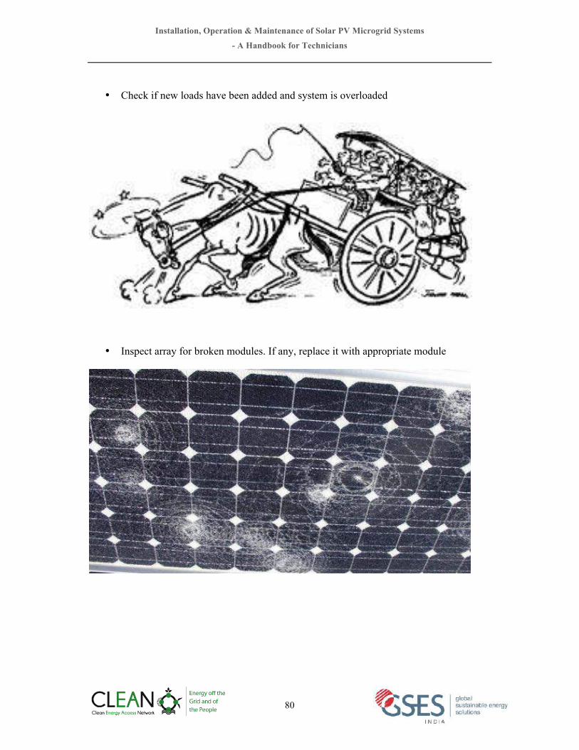
Installation, Operation & Maintenance of Solar PV Microgrid Systems
- A Handbook for Technicians
80
• Check if new loads have been added and system is overloaded
• Inspect array for broken modules. If any, replace it with appropriate module

Installation, Operation & Maintenance of Solar PV Microgrid Systems
- A Handbook for Technicians
81
Annual Maintenance: • Check array wiring for physical damage and wind chafing
• Check array mounting hardware for tightness
• Inspect inverter - remove dust or dirt, inspect system wiring for poor connections. Look for signs of excessive heating, inspect controller for proper operation

Installation, Operation & Maintenance of Solar PV Microgrid Systems
- A Handbook for Technicians
82
• Verify output from the array (Isc and Voc and if possible Imp and Vmp)
7.3 Inspection and maintenance of Earthing and Lightening Protection • Use an ohmmeter to check the continuity of the entire grounding system. • Make sure that all module frames, metal conduit and connectors, junction boxes,
and electrical components chassis are earth grounded.
Finding a ground fault
7.4 Inspection and maintenance of System Wiring • Visually check all conduit and wire insulation for damage. • Check for loose, broken, corroded, or burnt wiring connections. • Check if all equipments are connected with proper wire and conduit • Make sure all wiring is secured, by gently but firmly pulling on all connections. • Check all terminals and wires for loose, broken, corroded, or burnt connections or
components.
18.60V
4.10A
00 Ω
Point of ground fault touching the
metallic conduit

Installation, Operation & Maintenance of Solar PV Microgrid Systems
- A Handbook for Technicians
83
Finding a short circuit
7.5 Inspection and maintenance of Batteries
Checking state of charge A hydrometer describes the state of charge by determining the specific gravity of the electrolyte. Usually, the specific gravity of electrolyte is between 1.120 and 1.265. At 1.120, the battery is fully discharged. At 1.265, it is fully charged. Table 7.c: Battery specific gravity and corresponding state of charge
00 Ω
Point of short circuit
Electrolyte Temperature
(oC)
Specific Gravity Reading and State of Charge
SG Reading at 100% SOC
SG Reading at 75% SOC
SG Reading at 50% SOC
SG Reading at 25% SOC
SG Reading at 0% SOC
48.9 1.249 1.209 1.174 1.139 1.104 43.3 1.253 1.213 1.178 1.143 1.106 37.8 1.257 1.217 1.182 1.147 1.112 32.2 1.261 1.221 1.186 1.151 1.116 26.7 1.265 1.225 1.190 1.155 1.120 21.1 1.269 1.229 1.194 1.159 1.124 15.6 1.273 1.233 1.198 1.163 1.128 10.0 1.277 1.237 1.202 1.167 1.132 4.4 1.281 1.241 1.206 1.171 1.136 -1.1 1.285 1.245 1.210 1.175 1.140 -6.7 1.289 1.249 1.214 1.179 1.144
-12.2 1.293 1.253 1.218 1.183 1.148 -17.8 1.297 1.257 1.222 1.187 1.152

Installation, Operation & Maintenance of Solar PV Microgrid Systems
- A Handbook for Technicians
84
Battery load test: For this test, an accurate DC voltmeter is required.
• Operate the system loads from the batteries for five minutes. This will remove any minor "surface charge" the battery plates may have. Turn off the loads and disconnect the batteries from the rest of the system.
• Measure the voltage across the terminals of every battery, as shown in Figure below. If external cell connectors are used, measure the voltage across each cell, as shown in Figure. Do not attempt to measure individual cell voltages unless the connectors are external.
Measuring the Open Circuit Voltage of Cells with External Connections
Measuring the Batteries' Open Circuit Voltage
!" V DC !"
!"
Battery disconnect switch (Open)
V DC
L#"# L#+#
CHARGE CONTROLLER

Installation, Operation & Maintenance of Solar PV Microgrid Systems
- A Handbook for Technicians
85
Table 7.d: Battery open circuit voltages and corresponding states of charge
Open Circuit Voltages State of Charge
2 Volt Battery 6 Volt Battery 12 Volt Battery
2.12 or more 6.36 or more 12.72 or more 100%
2.10 to 2.12 6.30 to 6.36 12.60 to 12.72 75-100%
2.08 to 2.10 6.24 to 6.30 12.48 to 12.60 50-75%
2.03 to 2.08 6.90 to 6.24 12.12 to 12.48 25-50%
1.95 to 2.03 5.85 to 6.90 11.70 to 12.12 0-25%
1.95 or less 5.85 or less 11.70 or less 0%
7.6 Inspection and maintenance of Solar Arrays • Use a DC clamp-on ammeter to determine the array output current during a sunny
weather. • Conduit and connections must all be tight and undamaged. Look for loose, broken,
corroded, vandalized, and otherwise damaged components. Check close to the ground for animal damage.
Measuring open circuit voltage
• Measure the open circuit voltage of the array as shown in the figure below. Compare the measured amount of open circuit voltage from the array against the manufacturer's specifications.
Measuring the open circuit voltage of array
Measuring the open circuit voltage of module
Charge controller D+"
D!" Array disconnect Switch (open)
V DC
V"DC"

Installation, Operation & Maintenance of Solar PV Microgrid Systems
- A Handbook for Technicians
86
Short circuit current: • If your DC meter has leads, connect them to the positive and negative terminals of
each module and set the meter to the 10A range.
Measuring module short circuit current
7.7 Inspection and maintenance of Inverters• Check the operation of the inverter at the time of the inspection. • Measure and record the current draw of the inverter in both idling and operating states. • Check all inverter wiring for loose, broken, corroded, or burnt connections or wires.
Look for potential accidental short circuits or ground faults.
7.8 Hybrid system maintenance A typical maintenance schedule of diesel engine based generators is given below. Table 7.e: Example maintenance frequencies- hybrid vs. prime
Maintenance Task
Interval PV-DG hybrid
(500 hours) Only diesel
(8760 hours)
Oil change 250 2 per year 35 per year
Decoke 1,500 1 every 3 years 6 per year
Overhaul 6,000 1 every 12 year 3 every 2 year

Installation, Operation & Maintenance of Solar PV Microgrid Systems
- A Handbook for Technicians
87
7.9 Maintenance of distribution system Appropriate design and use of good quality components in a microgrid power distribution system is extremely important for overall performance and revenue generation. Undersized distribution cable may cause voltage drop and energy loss in the distribution and low quality components will cause frequent breakdown in power distribution. Both will contribute towards low system performance, revenue loss and poor services to the users. A periodic verifications and maintenance of distribution system is also essential. The distribution lines, power connections, switchboard and all its equipment may get physically damaged and also continue to degrade whether they operate or not. The following verification has to be made by a qualified person during installation:
(1) The distribution cables and its components are not exposed to extreme optimum environmental and operating conditions.
(2) There distribution cables, poles, guy wires and isolators and are not subject to any excessive stress and physical damage.
(3) Outdoor joints, connectors, fuses and switches are placed in IP65 rated boxes. (4) If insulated cables are used, ensure that cables are UV stabilizes and certified to use in
outdoor. (5) Ensure that provision for expansion and contraction is considered for distribution
cables due to change in temperature. (6) Ensure that a galvanized steel wire is used to supports the entire route of distribution
line. (7) Ensure that all safety requirement and regulations are followed based on the voltage
level of the distribution system Preventive maintenance
The table below indicates monthly and annual maintenance operations for microgrid distribution system:
Interval Maintenance operations
Monthly Check if there any physical damage to cables, poles or guy wires
1 year Visual inspection and functional testing, replacement of faulty components, accessories

Installation, Operation & Maintenance of Solar PV Microgrid Systems
- A Handbook for Technicians
88
7.10 Troubleshooting&RepairThe following guidelines are presented for troubleshooting of generic solar microgrid system. A more detailed and project specific guidelines should be created for a specific system with input from the system designer and component manufacturers. Use the troubleshooting tables given below to understand the symptoms, probable cause, results and remedial actions.
Table 7-1: Reference for troubleshooting tables Table 7-2: Wiring, switches, and fuses Table 7-3: Loads Table 7-4: Batteries with low voltage Table 7-5: Batteries that will not accept a charge Table 7-6: Batteries with high voltage Table 7-7: Charge controllers Table 7-8: Inverters Table 7-9: Solar arrays
Table 7.1: Reference for troubleshooting tables
Symptom Refer to the Table
Battery voltage is low
Table 7-2: Wiring, switches, and fuses Table 7-3: Loads Table 7-4: Batteries with low voltage Table 7-5: Batteries that will not accept a charge Table 7-7: Charge controllers
Batteries will not accept a charge
Table 7-2: troubleshooting wiring, switches, and fuses Table 7-3: troubleshooting loads Table 7-7: Charge controllers
Battery voltage is high Table 7-6: Batteries with high voltage Table 7-7: Charge controllers
Load does not operate at all Table 7-2: Wiring, switches, and fuses Table 7-3: Loads Table 7-8: Inverters
Load operates poorly
Table 7-1: Reference for troubleshooting tables Table 7-2: Wiring, switches, and fuses Table 7-3: Loads Table 7-5: Batteries that will not accept a charge Table 7-7: Charge controllers Table 7-8: Inverters
Array voltage is zero Table 7-2: Wiring, switches, and fuses Table 7-7: Charge controllers Table 7-9: Solar arrays
Array voltage is low Table 7-2: Wiring, switches, and fuses Table 7-9: Solar arrays

Installation, Operation & Maintenance of Solar PV Microgrid Systems
- A Handbook for Technicians
89
Table 7-2: Wiring, switches, and fuses
Symptom Cause Result Action
Load does not operate at all
Switches in the system are turned off or are in the wrong position PV array
electricity cannot be supplied to loads or batteries
Put all switches in correct position
System circuit breakers or fuses are blown
Determine why fuses or circuit breakers blew or tripped & Reset circuit breaker or replace fuse
Load operates poorly or not at all
There is a high voltage drop in the system
Inadequate voltage to charge batteries or operate loads
Check for undersized or too long wiring.
Oversized loads a ground fault, or a defective diode
Increase wire size, reduce load size, find and correct ground faults or defective didoes
Wiring or connections are loose, broken burned or corroded
Repair or replace damaged wiring or Connections.
Wiring or connections are short-circuited or have a ground fault
Repair short circuits or ground faults
Table 7-3: Loads
Symptom Cause Result Action
Load does not operate at all
Load is too large for the system or Inadequate sun
Shortened battery life, possible damage to loads
Reduce load size or Increase array or battery Size
The load is turned off Inadvertently breakers tripped
Load does not operate
Repair or replace load Reset switches
The load is in poor condition. Check for short circuits in load, a broken load, or an open circuit in the load
Shortened battery life, possible further damage to loads
Repair or replace load Check load manufacturer for service information
Load operates poorly or not at all
There is Inadequate voltage at load. Inadequate
voltage to charge batteries or operate loads
Increase wire size reduce load size, find and correct ground faults
Wiring or connections are loose, broken burned or corroded
Repair or replace damaged wiring
Small “phantom” load keeps inverter idling, draining battery
Turn off phantom load or replace it with one not requiring PV power
Wiring polarity is reversed Loads operate backwards or not at all
Correct wiring polarity

Installation, Operation & Maintenance of Solar PV Microgrid Systems
- A Handbook for Technicians
90
Table 7-4: Batteries with low voltage
Symptom Cause Result Action
No apparent battery defect
Load too large, on too long or Inadequate sun
Battery is always at a low state of charge
Reduce load size or Increase system size
Batteries too cold A higher voltage is required to reach full charge
Insulate battery enclosure
Low electrolyte level Overcharging Loss of battery capacity Add distilled water
Voltage below charging resumption setting
Faulty charge controller
Excessive discharge depth
Adjust settings or repair or replace charge controller
Voltage below low voltage disconnect setting
Faulty charge controller
Excessive discharge depth.
Adjust settings or repair or replace charge controller
Voltage loss overnight even when no loads are on
Faulty blocking diode
Reverse current flow at night discharging batteries
Replace diode
Voltage Increasing very slowly even when no loads are on
Controller not in full charge, stuck in float charge
Inadequate current flow to charge fully charge
Repair or replace batteries controller
Voltage not increasing even when no loads are on and system is charging
Otherwise faulty charge controller
Inadequate current flow to charge fully charge
Repair or replace batteries controller
Loose corroded or broken wiring
No power from array going into batteries
Close switch, reset circuit breaker, or replace fuse
Switch, circuit breaker, or fuse open, tripped or blown
Less power from array going into batteries
Repair or replace damaged wiring
Shaded modules broken cell or disoriented modules
Array output reduced Remove source of shading, replace module or correct module orientation
Wiring too long or undersized
Voltage reduced Increase wire size
Voltage just above charge resumption setting but controller not charging batteries
Faulty or misplaced temperature probe or poor connection at “battery sense” terminals on charge controller
Charge controller thinks batteries are cooler than their actual temperature
Repair, replace or reposition probe Reset controller dial or replace controller

Installation, Operation & Maintenance of Solar PV Microgrid Systems
- A Handbook for Technicians
91
Table 7-5: Batteries that will not accept a charge
Symptom Cause Result Action
No apparent battery defect
Load too large, on too long or Inadequate sun
Battery is always at a low state of charge
Reduce load size or Increase system size
High water loss Overcharging Heat damage to plates and separators
Replace battery, repair or replace charge controller
Electrolyte leakage shorts
Broken, leaking container
Sulphation, lead sulfate Replace battery
Muddy electrolyte material, shorts between plates
Age Shedding of plate Replace battery
Discolored or odorous electrolyte
Contaminated electrolyte Battery failure Replace battery
No symptoms other than not accepting a charge
Undercharging, usually without adding water
Sulphation, possibly lead sulfate shorts between plates
Replace battery
Left uncharged too long
Sulphation, or plates hard when scratched Replace battery
Cracked partition between cells
Discharge between adjacent Replace battery cells
Replace battery
Hammering cable connections on to terminal posts
Shorts between terminal post strap and plates, electrolyte leak
Replace battery
Misaligned plates and separators
Treeing shorts between bottoms of plates
Replace battery
Plate material carried to top of plates
Mossing shorts between tops of plates Replace battery
Shorts between plates and straps
Grid top broken and moved upward to strap. Lead rundown from strap to plate
Replace battery
Overcharging Disintegration of positive plates Replace battery
Specific gravity and temperature too high for too long
Soft negative plates Replace battery
Too many shallow charging cycles
Cracked negative plates Replace battery

Installation, Operation & Maintenance of Solar PV Microgrid Systems
- A Handbook for Technicians
92
Table 7-6: Batteries with high voltage
Symptom Cause Result Action
Voltage over charge termination setting and/or high water loss
Faulty or nonexistent charge controller
Shortened battery life, possible damage to loads
Replace with charge controller with lower charge termination setting
Battery storage too small for array
Shortened battery life, possible damage to loads and batteries
Install more batteries
Misadjusted charge controller
Shortened battery life, possible damage to loads and batteries
Adjust charge controller
Mismatched battery and voltage regulator
Shortened battery life, possible damage to loads and batteries
Replace charge controller, or change setting on adjustable units
Batteries are cold and charge controller has temperature compensation
Shortened battery life, possible damage to loads
Insulate batteries, or move to warm environment
High water loss Batteries are too hot
Voltage at which gassing starts is lower than normal
Insulate battery enclosure, and /or provide ventilation
Infrequent maintenance Low water levels, battery damage
Shorten maintenance interval
Voltage only slightly above charge termination setting
Faulty or misplaced temperature probe or poor connection at “battery sense” terminals on charge controller
Charge controller thinks batteries are warmer than their actual temperature
Repair, replace, or reposition probe

Installation, Operation & Maintenance of Solar PV Microgrid Systems
- A Handbook for Technicians
93
Table 7-7: Charge controllers
Symptom Cause Result Action Battery voltage below charge resumption setting
Faulty charge resumption function in charge controller
Excessive battery discharge.
Repair, readjust or replace charge controller
Battery voltage just below charge resumption setting, but controller not charging batteries
Faulty or misplaced temperature probe or poor connection at "battery sense" terminals on charge controller
Charge controller thinks batteries are cooler than their actual temperature
Repair, reposition or replace probe
Battery voltage below low voltage disconnect setting
Faulty low voltage cut-off in charge controller
Excessive battery discharge
Repair or replace charge controller
Battery voltage are low overnight even when no loads are ON
Faulty blocking diode, no diode or faulty charge controller
Reverse current flow at night, discharging battery
Replace or add diode, or repair or replace series relay charge controller
Old or faulty batteries Batteries self discharging Replace batteries
Battery voltage not increasing even when no loads are on and system is charging
Otherwise faulty charge controller
No power from array going into batteries
Repair, replace charge controller
Battery voltage over charge termination setting and/or high water loss
Faulty or non existing charge controller
Shorten battery life, possible damage to loads and batteries
Repair or replace charge controller and possibly batteries
Misadjusted charge controller
Shorten battery life, possible damage to loads and batteries
Repair or replace charge controller and possibly batteries
Mismatched battery and voltage regulator
Shorten battery life, possible damage to loads and batteries
Change charge controller or change setting on adjustable units
Controller always in full charge, never in float charge
Shorten battery life, possible damage to loads
Repair or replace charge controller and possibly batteries
Battery voltage just above charge termination setting, but controller still charging batteries
Faulty or misplaced temperature probe or poor connection at "battery sense" terminals on charge controller
Charge controller thinks batteries are cooler than their actual temperature
Repair, replace or reposition temperature probe or change charge controller
Buzzing relays
Too few batteries in series Voltage is low Reconfigure or add
batteries Loose or corroded battery connections High voltage drop Repair or replace cables
Low batter voltage See table 7-4 for more information
Repair or replace batteries
Erratic controller operation and/or loads being
Timer not synchronized with actual time of day
Controller turn on and off at wrong times
Either wait until automatic reset nest day or disconnect array wait

Installation, Operation & Maintenance of Solar PV Microgrid Systems
- A Handbook for Technicians
94
disconnected improperly
10seconds and reconnect array
Electrical "noise" from the inverter
Rapid on and off cycling
Connect inverter directly to batteries, put filters on load
Low battery voltage System shutdown Repair, replace battery
Erratic controller operation and/or improper load disconnection
Faulty or misplaced temperature probe or poor connection at "battery sense" terminals on charge controller.
Charge controller thinks batteries are cooler than their actual temperature
Repair, reposition or replace temperature probe or charge controller
High surge from load Battery voltage drops during surge
Use large wire to load or add batteries in parallel
Otherwise faulty charge controller, possibly from lightning damage
Loads disconnected improperly, other erratic operation
Repair or replace charge controller and check system grounding
Adjustable low voltage disconnect set incorrectly
Loads disconnected improperly Reset low voltage setting
Load switch in wrong position on controller
Loads never disconnected
Reset switch to correct position
Charge controller has low voltage disconnect feature
Loads never disconnected
If necessary replace charge controller with one with a low voltage disconnect feature
Fuse to array blows
Array short circuited with batteries still connected
Too much current through charge controller
Disconnect batteries when testing array's short circuit current
Current output of array too high for charge controller
Too much current through charge controller
Replace charge controller with one with a higher rating
Fuse to load blows
Short circuit in load Unlimited current Repair short circuit or replace load
Current draw of load too high for charge controller
Too much current through charge controller
Reduce load size or Increase charge controller size
Surge current draw of load too high for charge controller
Too much current through charge controller
Reduce load size or Increase charge controller size
"Charging" at night
Normal operation for some charge controller upto two hours after dark
No appreciable energy loss
Check the system later that night
Timer not synchronized with actual time of day
Controller turn on and off at wrong times
Either wait until automatic reset next day or disconnect array, wait 10 seconds and reconnect

Installation, Operation & Maintenance of Solar PV Microgrid Systems
- A Handbook for Technicians
95
Table 7-8: Inverters
Symptom Cause Result Action
No output from the inverter
Switch, fuse or circuit breaker open, blown or tripped or wiring broken or corroded
No power can move through inverter
Close switch, replace or reset fuse or circuit breaker or repair wiring or connections
Low voltage disconnect on inverter or charge controller open
No power available to inverter Allow batteries to recharge
Time delay on inverter start-up from idle
Few seconds delay after starting load
Wait a few seconds after starting loads
High battery voltage disconnect on inverter open
Inverter does not start
Connect load to batteries and operate it long enough to bring down battery voltage. Adjust high voltage disconnect on charge controllers
Motors running hot Square wave inverter used
Harmonics of wave form rejected as heat
Change to DC motors or use inverters with quasi-sine or sinusoidal waveform
Loads operating improperly
Excessive current draw by load
Voltage from inverter too low for load
Reduce size or loads or replace inverter with one of large capacity
Square wave inverter used
Load operate improperly
Change to DC motors or use inverters with quasi-sine or sinusoidal waveform
Defective inverter Load do not operate Replace inverter
Motors operating at wrong speeds
Inverter not equipped with frequency control
AC frequency varies with battery voltage
Replace inverter with one equipped with frequency control
Inverter circuit breaker trips
Load operating or surge current too high
Excessive current draw by load
Reduce size of loads or replace inverter with one of larger capacity
Inverter DC circuit breaker trips
Inverter capacitors not charged up on initial start up
Excessive current draw by inverter
Install momentary contact switch and 15ohm, 50 watt resistor in parallel with the circuit breaker, use it for a few seconds to charge capacitors on first start up

Installation, Operation & Maintenance of Solar PV Microgrid Systems
- A Handbook for Technicians
96
Table 7-9: Solar arrays
Symptom Cause Result Action
No current from array
Switches, fuses or circuit breaker open, blown or tipped or wiring broken or corroded
No current can flow from array
Close switches, replace fuses, reset circuit breakers, repair or replace damaged wiring
Array voltage low
Some modules shaded Drop in output current Repair source of shading
Some array interconnections broken or corroded
Drop in output current Repair interconnections
Defective bypass or blocking diode
Drop in output current Repair defective diodes
Some modules damage or defective
Drop in output current Replace affected modules
Full sun not available Drop in output current Wait for sunny weather
Modules are dirty Drop in output current Wash modules
Array tilt or orientation incorrect
Drop in output current
Correct tilt and/or orientation
No voltage from array
Switches, fuses or circuit breaker open, blown or tipped or wiring broken or corroded
No power can move from array
Close switches, replace fuses, reset circuit breakers, repair or replace damaged wiring
Array voltage low
Some modules in series with others disconnected or bypass diode defective
Drop in array voltage
Repair, replace modules, connections or diodes
Wiring from array to balance of system undersized or too long
Drop in array voltage
Reduced undersized wiring

Installation, Operation & Maintenance of Solar PV Microgrid Systems
- A Handbook for Technicians
97
CHAPTER 8
8 Operation & maintenance of microgrid system (commercial) 8.1 Day-to-day operations A microgrid facility runs smoothly on the freely available sunshine. Power thus generated is distributed over a small distance from the battery bank to households. The number of hours for which the power is supplied may vary between 5-8 hours per day. Each household gets lighting via the highly energy efficient light emitting diodes. These are expected to last for up to 50,000 hours. LED lighting brings down the power consumption by as much as 90%. Each household gets between 2-4 such lamps besides a charging point for the mobile phone. This is the way a typical village based micro grid operates on a daily basis. Rural electrification committee may help in running a micro grid alongside the entrepreneur and franchise company. Microgrid presents a wholesome opportunity to take up the following few types of business activities. All of these however, may not be exactly fit to locate closest to the microgrid facility.
• Small businesses like grocery shops • Weaving and crafting • Mobile money transfer outlets • Water pumping for micro irrigation • Poultry firms • Automatic teller machines (ATM) • Mobile communication towers • Petrol Pumps • Computer kiosk • Rice huller and thresher • Flour and spice milling machines
8.2 Maintaining service manual
A service manual is kept at the micro grid facility. It list the steps needed to keep the facility in a good condition. There are different types of service manuals such as a) instructional manual, b) repair manual and c) record manual. It is very important to maintain a service manual which may include information under the following few heads mainly:

Installation, Operation & Maintenance of Solar PV Microgrid Systems
- A Handbook for Technicians
98
• Type of system installed • Key components of the system • Brief function of each such component • Technical details i.e. specifications of these components • Operating principle of the system • Reference values of key parameters • Do’s and Don’ts
8.3 Billing and revenue collection
Micro-grids use different revenue models. These models take into account the daily electricity consumption. Users choose one such model out of many. There is a choice of buying the electricity in advance. It is much like the pre-payment facility for the mobile phones. Electricity that is used by each user is kept track of. On the basis of which, billing amount is worked out. Electricity fees is thus collected from the users on a regular basis. At present, multiple models and tools such as the pre-payment and digital meters are being made use of. This brings down the cost of transaction and increases payment rates and revenues. In totality the billing together with revenue collection forms a very important part of a solar micro grid in India. Table: Record of Revenue Collection from the beneficiaries of Solar Micro Grid at----------- A: Fixed Type Load
Sl. No.
Customer ID
Daily Load under use
Monthly payment fixed
Monthly Amount Paid
1 2 3 4
B: Non-fixed type Load
Sl. No.
Customer ID
Daily Energy Consumption
No. of units consumed
Total monthly amount due
1 2 3 4

Installation, Operation & Maintenance of Solar PV Microgrid Systems
- A Handbook for Technicians
99
8.4 Settlement of billing issues
Microgrid business is basically a service business. It requires a robust operation and maintenance along with a payment collection setup. The microgrids are mainly the plants running often in remote areas. There are virtually little or no facilities in the villages. The poorest of the poor are expected to spend between Rs.100 - Rs.200 per month. It can be termed as a low spending on electricity. Thus the customer profile is very demanding. Bill settlement Do’s
• Carry out a background check of the customers-even though it may sound a weird idea.
• Verify if, the load being used is being utilized in full or partially. • If, partially, seek to reduce it so as to keep the bill amount low.
Don’ts • Try not to cut off the power supply to the customer with genuine difficulty to pay the
bill. • Try not to publicize the name of such a non-paying household amongst the other
beneficiaries. • Try not to show some special favour to a community headman via the micro grid in
any manner. 8.5 Maintaining complaint book from client
A customer is key element of a micro grid system. After all, he is the one to use it on a daily basis. The entrepreneur of a micro grid is expected to keep a complaint book. It encourages the users to note down any issues, problems or even doubts about the daily use of a micro grid facility. A well maintained micro grid facility is a good enough record. Entry. Every complaint booked by a client is generally looked into for an early solution.
Sl.
No.
Dat
e of
Com
plai
nt
Reg
istra
tion
Nam
e of
the
Com
plai
nant
Type
of C
ompl
aint
m
ade
Estim
ated
Tim
e fo
r R
epai
rs e
tc.
Nam
e of
the
Te
chni
cian
/ Eng
inee
r en
trust
ed w
ith th
e co
mpl
aint
Dat
e/ T
ime
of
Atte
ndin
g th
e fa
ult
Type
of f
ault
actu
ally
de
tect
ed
Brie
f det
ails
abo
ut th
e fa
ult r
epai
rs
Func
tiona
l sta
tus
of
the
conn
ecte
d lo
ad a
t ho
useh
old
leve
l
1
2

Installation, Operation & Maintenance of Solar PV Microgrid Systems
- A Handbook for Technicians
100
8.6 Communicating to the users regarding variation of solar energy availability and dependence of performance of system accordingly
• The amount of sunlight varies across the day. • The amount of solar radiation received is the highest at noon time. • Solar module is the power producing part of a micro grid system. • Solar module surface should always be kept clean. • Solar module should not be shaded in any way. • Solar module should not have any kind of shadow on it. • Dust, dirt, shading, shadowing all reduce the amount of power that is finally
available from a solar module.

Installation, Operation & Maintenance of Solar PV Microgrid Systems
- A Handbook for Technicians
101
CHAPTER 9
9 Challenges & risks of solar microgrid projects A solar microgrid is not entirely a new idea in the making. In fact, facility of this kind was put years before in the Sundarbans islands of the eastern state of West Bengal. However, there are several issues which need to be resolved sooner than later. A brief treatment of the identified issues is presented below for a serious consideration by the stakeholders. 9.1 Issues related standards and compliances
A micro grid usually comprises of a distributed energy resource (i.e. solar in this case) together with advanced control system, load management, energy storage and importantly, network communication. There is design cum performance available in respect of these components, which are to be complied with so as to ensure real gain from the microgrid. Issues due to non-adherence of standards:
• Amount of power available from a solar module may reduce • Solar module may not last long • System may not work in a reliable manner • System may not be safe to use in full
Poor quality solar modules degrades fast
Following is a brief run-through of the applicable standards for the power producing part i.e. the solar modules and balance of system components:

Installation, Operation & Maintenance of Solar PV Microgrid Systems
- A Handbook for Technicians
102
Solar Module The solar modules must confirm to the latest edition of any of the following IEC/equivalent BIS standard for PV module design qualification and type approval.
a) Crystalline Silicon terrestrial Modules IEC 61215 b) Thin film terrestrial Modules IEC 61646 c) Concentrator Modules & Assemblies IEC 62108
BoS Item/ Component Applicable IEC/ Equivalent BIS Standards
Standard Description Standard Number
Inverters Efficient measurement environmental testing
IEC 61683 IEC 60068 2
Charge Controller Design qualifications environmental testing
IEC 62093 IEC 60068
Storage Batteries General requirements and methods of test tubular lead-acid
IEC 61427 IS 1651/IS 13369
Cables
General test and measuring methods PVC insulated cables for working voltages up to and including 1100 V
1EC 60189 IS 694/IS 1554 IS/IEC 69947
Switches/Circuit Breakers/Connectors
General requirements Connectors-safety
IS/IEC 60947 EN 50521
Junction Boxes/Enclosures General requirements IP 65 (for outdoor) IP 21 (for indoors)
SPV System design PV Standalone system Design verification
IEC 62124
Installation practices Electrical installation of building requirement for SPV power supply system
IEC 60364-7-712
9.2 Quality of component and workmanship
Majority of micro grid developers happen to be the private entrepreneurs. Quality component selection, well-designed component assembly and reliable component engineering are very important factors to ensure good quality of a solar micro grid facility. Suitable quality workmanship also ensures smooth operation of the micro grid over its expected lifetime
• Solar microgrid is usually positioned in a remote area. Thus, it all the more important to design and develop fully reliable working system.
• Quality components if, not used may lead to their frequent replacement. • Frequent replacement may make the system operation and maintenance cost higher.

Installation, Operation & Maintenance of Solar PV Microgrid Systems
- A Handbook for Technicians
103
• Poor workmanship does not result in a well performing system.
Poor quality structure and foundation 9.3 System protection and safety
A micro grid is made of a low voltage distribution system with a distributed energy source. Such a source could well be solar PV in the present case. It is very important to protect a micro grid in both the grid connected and the island mode of operation against different types of defects. The safety design concept is equally important in a micro grid protection and their fault analysis. The safety model offers suitable level of confidence in protection system. Further the intelligent control and monitoring unit need to meet the safety requirements on the basis of a safety design criteria. For a micro grid safety design, six type of parameters are to be considered. These include:
• Sensitivity It simply means there should be some nominal threshold value. Further the control/protection system is able to identify any abnormal condition.
• Selectivity It means that when any fault is detected in a system based on voltage, current and power direction fault zone is determined. Simply put, smallest part containing the fault should be disconnected.

Installation, Operation & Maintenance of Solar PV Microgrid Systems
- A Handbook for Technicians
104
• Speed It simply means to act in the least possible time in any abnormal condition. The purpose is to avoid any damage to equipment and maintain stability.
• Security It simply means that security level should be high. The protection/control system should run only when there is a need to operate.
• Redundancy The redundant systems are planned and simply mean backup protection. Simple idea is to ensure the desired level of safety.
• Reliability The distributed generation systems i.e. a Micro grid is becoming a more dynamic structure. So reliability should be high while dealing with control and protection system analysis.
Improper design and installation can cause fire in a PV system
Do’s • Use a good quality load limiting device to stop misuse • Use a pre-payment card which can not be changed in any manner • Maintain voltage level for equipment safety • Use a cluster based household feature so as to identify a wrong doer easily • Make the users aware about not fiddling with the Micro grid system more so in the
absence of a technician. • Do keep the system installed area safe and secure i.e. via fencing etc. • Do keep the safety and protective features related spares available at the system area.

Installation, Operation & Maintenance of Solar PV Microgrid Systems
- A Handbook for Technicians
105
Don’ts • Do not allow any one to tamper with the distribution line • Do not think of laying the wires/cables underground • Do not use the lighting device i.e. LED’s of miniscule power capacity • Do not allow any user to repair any broken link etc. when the technician may not be
present in the plant area
9.4 Issues related to appropriate use
Majority of standalone PV systems are generally put up in the rural areas. These are designed to meet a bare minimum load of an individual household. The load thus powered could be lights, fan, TV or lately a cell phone charger. Few households at times may like to run a tape recorder for example. This cannot be called as an appropriate or suitable use of a micro grid facility. In a few cases, few may try to connect directly some non-designated load to a battery for example. This can lead to some damage to the battery. On a micro grid community level, wire/cable may be snapped just for a small tiff off with an entrepreneur. Well, novel technological solutions have been found to problems like these. The simple idea is to keep the system running smoothly.
• Installations of a solar microgrid say for example for a household sample of between 20-30 households takes just a day or two. So, it is very important to do this appropriately.
• A micro grid facility can be scaled up much faster than any other power option. Thus, it is desired practice to test each and every component suitably.
• It is far better for a user to get connected to a micro grid rather than go for a solar lantern use. The lantern means having a high initial cost for the user. Thus it is more appropriate not to buy a lantern.
• Only such loads as have been initially recommended should be put to use. • Any occasional demand for more power should be requested for in appropriate
terms/situations. Explain how microgrid system can be affected by inappropriate use of appliances due to limited source of energy and battery storage and provide some bullet points what should not be done in terms of using loads. 9.5 Issues related to battery storage capacity and limitation
Rural areas generally need lighting after the sunset. This leads to the use of batteries in a micro grid facility. Batteries store solar power during the daytime. Several issues exist with the use of battery storage. These mainly include the following few:

Installation, Operation & Maintenance of Solar PV Microgrid Systems
- A Handbook for Technicians
106
• Lead-acid battery has been the most widely used battery in rural areas. Be it for a standalone system like an indoor or outdoor lighting system.
• Lead-acid battery does not last longer. However, the flooded lead-acid type cost less than lithium-ion batteries.
• Batteries need to be topped up with distilled water and thus not so easy to maintain. • 2V cells are suitable for a higher capacity micro grid. However, these are quite heavy
to move and place in a typical rural surrounding. Battery is still thought of as a weak link in a solar system. Today, a wide range of batteries are available in varying designs, capacities, charging/discharge efficiencies, daily hours of use, etc.
• Battery unit should be of a standard make only. Do not try to use a non-standard make battery.
• Battery is prone to explosion if, made with any sub-standard material. Battery should be housed properly in a well-ventilated environment.
9.6 Issues related to revenue collection Any user of a micro grid facility is expected to pay the monthly bill. He also has the choice of buying an electricity card in advance. This is more commonly known as a pre-payment card. However, every user may not be willing to do so. They may like to pay the electricity bill on a monthly basis but refuse to do so later on. Thus it leads to a serious issue in a regular collection of revenue. The revenue collection could also get affected if; the system fails to work properly?
• Selection of the user community should be done with sufficient care. • Individual user attention is important to understand the load choice, any additional
load demand, capacity to pay on a regular basis etc. • Identification of any such user from a chosen cluster as may be different from the rest
in terms of a) affordability, b) availability of appliances, c) habitation etc. The intention is to determine the possibility of system misuse in any possible manner
• Any customer failing to make the monthly payment must be encouraged to keep on paying even on extended timelines.
• Customers need to be made aware about the revenue stream and the critical need to collect the revenue as per a laid out time cycle.
9.7 Issues related to handling customers A micro grid can be run in several ways. It offers the facility of buying electricity in advance. A pre-payment card does this trick much like the working of a mobile phone. However, non-customers can steal the electricity. Flat monthly rates can also be fixed. Some customers

Installation, Operation & Maintenance of Solar PV Microgrid Systems
- A Handbook for Technicians
107
may not pay at the end of a normal billing cycle. A ready solution is to make use of load limiting devices etc.
• Make an on-the-spot assessment of demand fulfilment of power at an individual level • Make the user understand about grid power not landing up any time soon • Make the user know about the disadvantages of using energy choices such as candles,
kerosene oil lanterns etc. in quite clear terms. • Try to understand difficulties if, any being faced by the non-paying customer? • Make all out efforts at removing the conveyed difficulty.
9.8 Issues related to variation of energy supply due to variable weather conditions The amount of energy got from a solar micro grid can vary on a day-to-day basis. Several reasons could lead to one change or the other in the amount of energy generated. There are two main types of uncertainties which have some effect on the power system operation. One of these is the outage of generation unit and b) departure from the forecasts. The first one could possibly lead to a supply shortage in a system. Any deviation from the forecasts due to uncertain loads and integration of renewable energy sources may add additional operational uncertainty. Wind and solar generation usually depend on wind speed and solar generation. These are more important in micro grids owing to the high penetration levels of such resources. Variable weather conditions Solar energy generation at a location does not depend only on solar irradiation. Several factors affect the amount of energy generation on a daily/weekly/monthly /yearly basis. These may be listed below as:
• Altitude of the place • Ambient temperature • Wind velocity • General weather conditions • Soil conditions
A technician is the force behind keeping a micro grid facility in a good working condition. He does not have any control over the sunshine availability as such. However, he can keep the solar modules clean so as not to lose any power due to dust/dirt.

Installation, Operation & Maintenance of Solar PV Microgrid Systems
- A Handbook for Technicians
108
CHAPTER 10
10 Managing microgrid business 10.1 What does an entrepreneur need to set up a microgrid business? A micro grid is generally set up in a rural area. Rural area offers its own opportunities and challenges. Thus it is not an easy task for an entrepreneur. Anyway he needs to take up the following type of activities:
• Finding a suitable location • Collection of baseline data • Site selection • Preparation of detailed project report • Installation of system • System upkeep (i.e. operation and maintenance) • Collection of revenue
10.2 Economics of a microgrid system Many factors have one effect or the other on economics of a microgrid. The life cycle costs, tariffs and bills depend on the following few parameters:
• Load • Capital cost of the system • Running cost • Financing (which also includes in how much time the capital cost can be got back) • Tax related benefits • Tariff structure
Economic feasibility is about the willingness to pay. Willingness for the essential services generally ranges from Rs.100 to Rs.200 per month. While as for higher service (i.e. more electricity use), it ranges between Rs.300 – Rs.500 per month. Case specific example on setting up a Microgrid
A micro grid is basically a standalone unit. It usually meets the bare minimum power requirements for household sizes ranging between 25-60 households. Key components of a micro grid are the solar modules, battery besides a control cum monitoring device. Take a case specific example of a micro grid design requirements for a household size of 35. Two

Installation, Operation & Maintenance of Solar PV Microgrid Systems
- A Handbook for Technicians
109
modules of 120Wp each together with two storage batteries would suffice. The estimated system cost comes to around Rs.35000. The households can get power access for about 7 hours daily. The load appliances in this case are 2 LED lamps with a connection for charging of mobile phone. As per the available information, operational costs for a microgrid like this do not count much. Yes maintenance is needed on an occasional basis. It generally takes anywhere between 3-5 years for a micro grid developer to recover his cost. These micro grids in a way do not face much competition in a typical rural environment. This is so as the user community does not have any other choice (s) in terms of energy use. 10.3 Developing of a Business Plan A business plan is a very important part of a Micro grid activity. There are several models available today to set up a micro grid as under:
• Purchase of the product: A consumer makes a down payment for the small amount of electricity. Electricity thus received is to be commonly used for lighting and charging a mobile phone. The facility is linked with a smart meter.
• Regular payment: The consumer makes a cash payment to a designated payment point. It could well be a local shop or entrepreneur.
• Credit Recharge- The payment point sends entrepreneur the customer identification and recharge information. In turn, consumer receives the recharge code
• System unlock: The consumer uses the recharge code to unlock the system and gets energy credits. The consumer can use the facility for as long as the energy credits allow.
• System lock: The meter simply locks the system after the consumers energy credits have run out
10.4 Understanding government policy and plan A micro grid came into being several years back. Many policies have been put into place to support rural area electrification by the government. Special attention was given to decentralized models such as the Micro grids. The concerned govt. departments are providing subsidies and grants etc. Simple purpose is to make the micro grids useful within the rural areas. The government is keen to provide all Indians with reliable 24×7 power. There are still 300-400 million Indians without any electricity benefit at all. The govt. is planning to extend the grid to electrified households as far as possible. It is also trying to develop the micro grids on a large scale. However, it is important to keep in view the following few factors:
• Speed of development • Cost of reliable power (kWh) • Climate effect of each choice

Installation, Operation & Maintenance of Solar PV Microgrid Systems
- A Handbook for Technicians
110
The Govt. of India has put in place various schemes and programmes for rural electrification from time to time. Table below lists such initiatives along with the implementation agency
Initiative Implementation Agency
Electricity Act 2003 Ministry of Power
Remote Village Electrification Programme Ministry of New and Renewable Energy
Rajiv Gandhi Grammen Vaidyutic Yojanan Ministry of Power
Village Energy Security Programme (VESP) Ministry of New and Renewable Energy
Jawaharlal Nehru National Solar Mission Ministry of New and Renewable Energy
10.5 Building relationship with the suppliers Today there are many suppliers of energy solutions in the country. It is important for an entrepreneur to develop good business relationship with the suppliers. An entrepreneur gets and assembles different components and installs the complete facility. The suppliers on their part are trying to offer the quality component use. So, relationship between a micro grid developer and supplier is growing by the day.
• Frame carefully the technical specifications for the intended range of equipment with the supplier
• Carry out a basic check on the market standing of a supplier • Match the rated values of the components/sub-components with the actual
requirements. • Discuss the comparative availability of the best available micro grid specifics with
other suppliers. • Put together the needed micro grid system configuration for extensive pre-testing
before actual installation. 10.6 Where and how does an entrepreneur raise the finance?
A simple challenge for the entrepreneur is to have some funds. The micro grid is still evolving. The banks are not quite willing to lend money to an entrepreneur. Present day trend is to raise the finance via a mixture of grants and equity. The micro grid business is a low revenue one. It makes sense to have more micro grids to put up. In a few cases, entrepreneurs have got access to bilateral and multi-lateral funding sources. It has also helped them to work closely with some more experienced organisations too.

Installation, Operation & Maintenance of Solar PV Microgrid Systems
- A Handbook for Technicians
111
10.7 Day-to-day operations of a business
• Make a daily note of the key activities related with micro grid operation through the day and night.
• Display prominently the list of customers associated with the micro grid facility. • Raise awareness about the gains available from the system in the surrounding areas. • Analyze the system operation data to generate daily/weekly/monthly performance
reports. This is needed to know the strengths and weaknesses alike under the actual field operating conditions.
10.8 Marketing and sales skill
• A grass root worker is best suited to take up the role of a marketing and sales person • Familiarize the worker with the manner in which the system actually works • Identify the weak learning skills from an extensive field check of the worker • Do not necessarily seek the services of those who can neither understand nor
communicate easily with the user community. • Do not try to convince the users about using more loads than they feel is necessary
10.9 Handling questions from clients and consumers
• Listen to the questions minutely • Try to note down the same in a register that may be specifically kept for the purpose • Use the interactive sessions to understand the adequacy/inadequacy of the system
related gains perceived by the client • Do not discourage the consumer from putting up even the very basic questions • Do not try to put up the solution without a verification check that may well be needed
for the purpose 10.10 Business expansion plan A microgrid is best suited to a rural environment. However, it is also the one where the affordability amongst the potential user community is a big issue. There is an increasing migration of the rural youth into the city areas. It also leads to availability of more appliances within a household at times. Importantly, the business expansion plan may derive its main strength by some income generating activities for the community. Following few type of activities may make some business sense:
• Flour grinding • Oil extraction • Yarn spinning • Cash crop irrigation • Any such activity that can be based on local resource availability whether from the
field or an adjoining forest for that matter.

Installation, Operation & Maintenance of Solar PV Microgrid Systems
- A Handbook for Technicians
112
CHAPTER 11
11 Use of mobile application for troubleshooting & repair
The application is available at google play store and one can download at free of cost. Search at google play store using key word “solar troubleshooting app” or click in the link below:
https://play.google.com/store/apps/details?id=com.netsoftsolution.tatasky&hl=en
Troubleshooting Master Sheet Symptom Refer to
Load operates poorly or not at all TR-1
Battery voltage constantly remain low TR-2
Batteries do not accept charge TR-2
Battery voltage constantly remain high TR-2
Buzzing relay TR-3
Erratic controller operation TR-3
Fuse blown TR-3
Showing charging at night TR-3
No output from inverter TR-4
Problem with inductive loads TR-4
Tripping of inverter/ switch TR-4
No current from array TR-5
No voltage from array TR-5
Low voltage from array TR-5
A mobile application has been developed in android platform to address troubleshooting and repair procedure as discussed in the chapter 7. Technicians will require a smart phone to operate this application. The first screen of the application is the “Troubleshooting master sheet” where technician will select the reference table based on the symptoms given in the left side of the screen. There are five troubleshooting & repair tables referred as TR-1, TR-2, TR-3, TR-4 and TR-5. Corresponding area of troubleshooting and repair has been indicated in the table below. Respective tables will guide the technicians to check and understand the cause of problem and take necessary remedial action to make the system functional.

Installation, Operation & Maintenance of Solar PV Microgrid Systems
- A Handbook for Technicians
113
CHAPTER 12 12 Reference video clips The following selected videos clips are referred as useful audio-visual learning tool in the context of this manual. These videos clips are sourced from www.youtube.com. 12.1 Use of multimeter This video clip demonstrates how to use an analog and a digital multimeter. 12.2 Tools and procedures for MC4 connection This video clip demonstrates step-by-step procedure and tools required for making an MC4 and/or equivalent connector. 12.3 Module interconnection This video clip demonstrates how to connect two modules in series and parallel with the help of MC4 connectors 12.4 Batteries interconnection This video clip shows how to make battery series and parallel connections 12.5 Battery maintenance This video clip demonstrates step-by-step procedure and tools required for maintaining flooded electrolyte deep cycle batteries. 12.6 Installation of earth pit This video shows how to install an earth pit 12.7 AC arc vs. DC arc This video shows the difference between AC arc and DC arc and why DC current arc can potentially cause fire if not installed properly. 12.8 AC circuit breaker vs. DC circuit breaker This video shows difference between AC and DC circuit breakers and why AC circuit breaker does not qualify to be used in DC applications. 12.9 Sun pathfinder This video demonstrates the use of a sun pathfinder for site analysis and how to find a shadow free location for installation of solar array.

Installation, Operation & Maintenance of Solar PV Microgrid Systems
- A Handbook for Technicians
114
CHAPTER 13 13 Reference datasheet and tables The datasheets and tables presented below are for reference purpose only. For actual practice in the field technicians are to use datasheet of actual equipment and tables need to be customised according to the system type and configuration. 13.1 Typical datasheet for PV module
www.suntech-power.com | E-mail: [email protected]
HiPerforma™ Module PLUTO200-AdePLUTO195-Ade
EN-PLU-Ade-NO1.01-Rev 2010
Electrical CharacteristicsSTC PLUTO200-Ade PLUTO195-Ade
Optimum Operating Voltage (Vmp) 37.9 V 37.6 V
Optimum Operating Current (Imp) 5.28 A 5.19 A
Open - Circuit Voltage (Voc) 45.7 V 45.4 V
Short - Circuit Current (Isc) 5.62 A 5.52 A
Maximum Power at STC (Pmax) 200 W 195 W
Module Efficiency 15.7% 15.3%
Operating Temperature -40°C to +85°C -40°C to +85°C
Maximum System Voltage 1000 V DC 1000 V DC
Maximum Series Fuse Rating 15 A 15 A
Power Tolerance 0 / +5 W 0 / +5 W
STC: lrradiance 1000 W/m2, module temperature 25°C, AM=1.5
NOCT PLUTO200-Ade PLUTO195-Ade
Maximum Power (W) 148 W 144 W
Maximum Power Voltage (V) 34.8 V 34.3 V
Maximum Power Current (A) 4.26 A 4.20 A
Open Circuit Voltage (Voc) 41.1 V 40.9 V
Short Circuit Current (Isc) 4.60 A 4.50 A
Efficiency Reduction(from 1000 W/m2 to 200 W/m2) <4% <4%
NOCT: Irradiance 800 W/m2, ambient temperature 20 °C, wind speed 1 m/s
Mechanical CharacteristicsSolar Cell Monocrystalline 125 × 125 mm (5 inches)
No. of Cells 72 (6 × 12)
Dimensions 1580 × 808 × 35 mm (62.2 × 31.8 × 1.4 inches)
Weight 15.5 kgs (34.1 lbs.)
Front Glass 3.2 mm (0.13 inches) tempered glass
Frame Anodized aluminium alloy
Junction Box IP67 rated
Output CablesH+S Radox Solar Cable 4.0 mm2 (0.006 inches2), symmetrical lengths (-) 1000 mm (39.4 inches) and (+) 1000 mm (39.4 inches), Radox Solar connectors
Packing ConfigurationContainer 20’ GP 40’ GP
Pieces per pallet 26 26
Pallets per container 12 28
Pieces per container 312 728
Specifications are subject to change without further notication.
Current-Voltage & Power-Voltage Curve (195 W)
Note: mm [inch]
Temperature CharacteristicsNominal Operating Cell Temperature (NOCT) 45±2°C
Temperature Coefficient of Pmax -0.38 %/°C
Temperature Coefficient of Voc -0.29 %/°C
Temperature Coefficient of Isc 0.046 %/°C
Dealer information box
Curr
ent (
A)
Voltage (V)
Pow
er (W
)
0 5 10 15 20 35 25 30 40 45 500
35
70
105
140
175
210
0
1
2
3
4
5
6
1000 W/m2 800 W/m2 600 W/m2 400 W/m2 200 W/m2
Junction box
(Back View)
Ground holes2 places
Mounting slots 8 places
1580
[62.
2]13
00[5
1.2]
800[
31.5
]
2-Ø5.1[Ø0.2]
14×9[0.55×0.35]
758[29.8]
808[31.8]
Drainage holes
(Front View)1.5
35
11Section A-A
A A
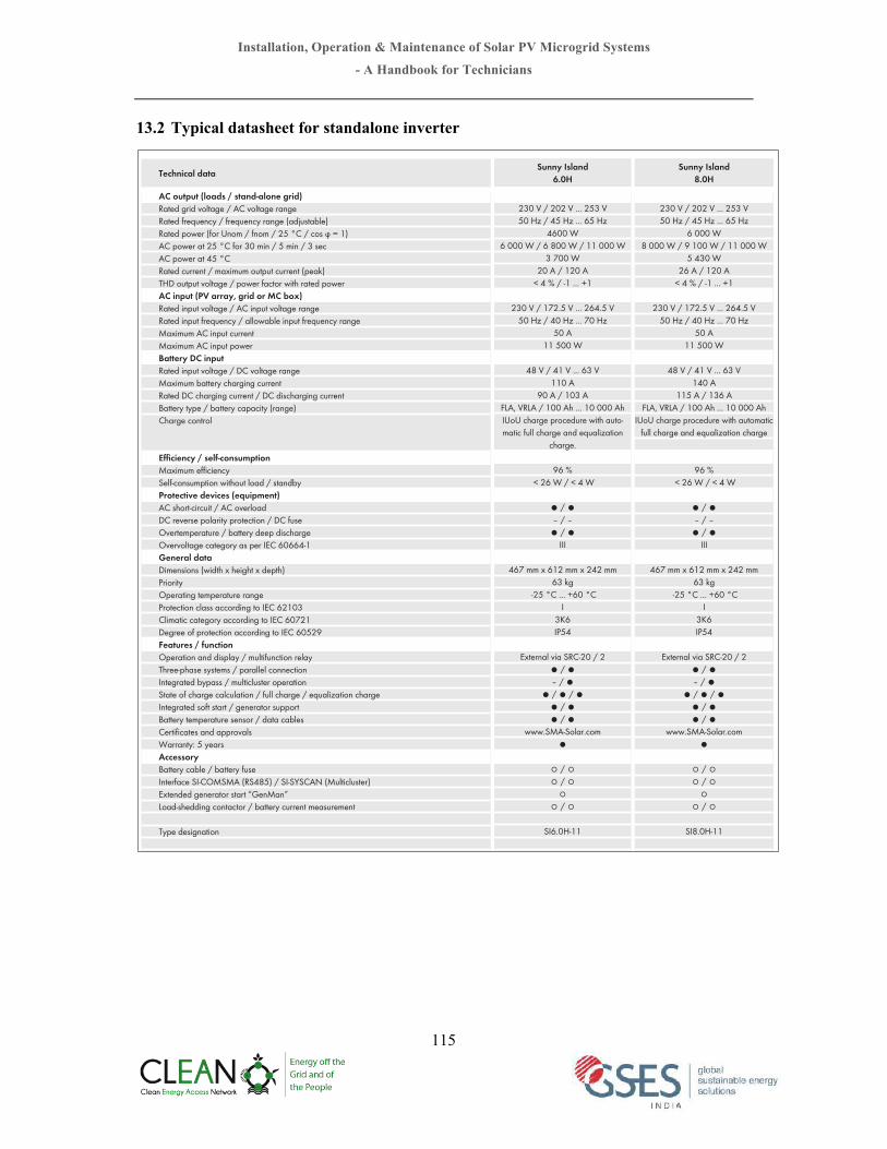
Installation, Operation & Maintenance of Solar PV Microgrid Systems
- A Handbook for Technicians
115
13.2 Typical datasheet for standalone inverter
Sunny Island 6.0H
Sunny Island 8.0H
����7�������7���������7���)[������)[��������)[
�����8������8���������8����������8
������8���"�������"�����������������
����7���������7�����������7���)[������)[��������)[
���"�������8
���7������7��������7����"�
���"�������"'-" �73-"�������"I������������"I*6P6�DIBSHF�QSPDFEVSF�XJUI�BVUP-NBUJD�GVMM�DIBSHF�BOE�FRVBMJ[BUJPO�
DIBSHF�
����������8�������8
ല���ല���ല���ല
***
����NN�Y�����NN�Y�����NN���LH
�����p$���������p$*
�,�*1��
&YUFSOBM�WJB�43$�������ല���ല���ല
ല���ല���ലല���ലല���ല
XXX�4."�4PMBS�DPNല�
മ���മമ���മ�
മമ���മ
4*���)���
�
����7�������7���������7���)[������)[��������)[
������8������8���������8����������8
������8���"�������"�����������������
����7���������7�����������7���)[������)[��������)[
���"�������8
���7������7��������7����"�
����"�������"'-" �73-"�������"I������������"I
*6P6�DIBSHF�QSPDFEVSF�XJUI�BVUPNBUJD�GVMM�DIBSHF�BOE�FRVBMJ[BUJPO�DIBSHF
����������8�������8
ല���ല���ല���ല
***
����NN�Y�����NN�Y�����NN���LH
�����p$���������p$*
�,�*1��
&YUFSOBM�WJB�43$�������ല���ല���ല
ല���ല���ലല���ലല���ല
XXX�4."�4PMBS�DPNല
മ���മമ���മ�
മമ���മ
4*���)���
�
Ac output (loads / stand-alone grid)3BUFE�HSJE�WPMUBHF���"$�WPMUBHF�SBOHF3BUFE�GSFRVFODZ���GSFRVFODZ�SBOHF�BEKVTUBCMF3BUFE�QPXFS�GPS�6OPN���GOPN������p$���DPT�̃����"$�QPXFS�BU����p$�GPS����NJO�����NJO�����TFD"$�QPXFS�BU����p$3BUFE�DVSSFOU���NBYJNVN�PVUQVU�DVSSFOU�QFBL5)%�PVUQVU�WPMUBHF���QPXFS�GBDUPS�XJUI�SBUFE�QPXFSAc input (pV array, grid or Mc box)3BUFE�JOQVU�WPMUBHF���"$�JOQVU�WPMUBHF�SBOHF3BUFE�JOQVU�GSFRVFODZ���BMMPXBCMF�JOQVU�GSFRVFODZ�SBOHF.BYJNVN�"$�JOQVU�DVSSFOU�.BYJNVN�"$�JOQVU�QPXFS�Battery Dc input3BUFE�JOQVU�WPMUBHF���%$�WPMUBHF�SBOHF.BYJNVN�CBUUFSZ�DIBSHJOH�DVSSFOU�3BUFE�%$�DIBSHJOH�DVSSFOU���%$�EJTDIBSHJOH�DVSSFOU#BUUFSZ�UZQF���CBUUFSZ�DBQBDJUZ�SBOHF$IBSHF�DPOUSPM��
&ꤕDJFODZ���TFMG�DPOTVNQUJPO.BYJNVN�F꽎DJFODZ4FMG�DPOTVNQUJPO�XJUIPVU�MPBE���TUBOECZ1SPUFDUJWF�EFWJDFT�FRVJQNFOU"$�TIPSU�DJSDVJU���"$�PWFSMPBE%$�SFWFSTF�QPMBSJUZ�QSPUFDUJPO���%$�GVTF0WFSUFNQFSBUVSF���CBUUFSZ�EFFQ�EJTDIBSHF0WFSWPMUBHF�DBUFHPSZ�BT�QFS�*&$���������general data%JNFOTJPOT�XJEUI�Y�IFJHIU�Y�EFQUI1SJPSJUZ0QFSBUJOH�UFNQFSBUVSF�SBOHF1SPUFDUJPO�DMBTT�BDDPSEJOH�UP�*&$������$MJNBUJD�DBUFHPSZ�BDDPSEJOH�UP�*&$������%FHSFF�PG�QSPUFDUJPO�BDDPSEJOH�UP�*&$�������'FBUVSFT���GVODUJPO0QFSBUJPO�BOE�EJTQMBZ���NVMUJGVODUJPO�SFMBZ5ISFF�QIBTF�TZTUFNT���QBSBMMFM�DPOOFDUJPO*OUFHSBUFE�CZQBTT���NVMUJDMVTUFS�PQFSBUJPO4UBUF�PG�DIBSHF�DBMDVMBUJPO���GVMM�DIBSHF���FRVBMJ[BUJPO�DIBSHF*OUFHSBUFE�TPGU�TUBSU���HFOFSBUPS�TVQQPSU#BUUFSZ�UFNQFSBUVSF�TFOTPS���EBUB�DBCMFT$FSUJ꽌DBUFT�BOE�BQQSPWBMT8BSSBOUZ����ZFBST"DDFTTPSZ#BUUFSZ�DBCMF���CBUUFSZ�GVTF*OUFSGBDF�4*�$0.4."�34������4*�4:4$"/�.VMUJDMVTUFS&YUFOEFE�HFOFSBUPS�TUBSU�ࣕ(FO.BOࣖ�-PBE�TIFEEJOH�DPOUBDUPS���CBUUFSZ�DVSSFOU�NFBTVSFNFOU�
5ZQF�EFTJHOBUJPO
ല�4UBOEBSE�GFBUVSFT�മ�0QUJPOBM�GFBUVSFT��/PU�BWBJMBCMF%BUB�BU�OPNJOBM�DPOEJUJPOT�
5FDIOJDBM�EBUB
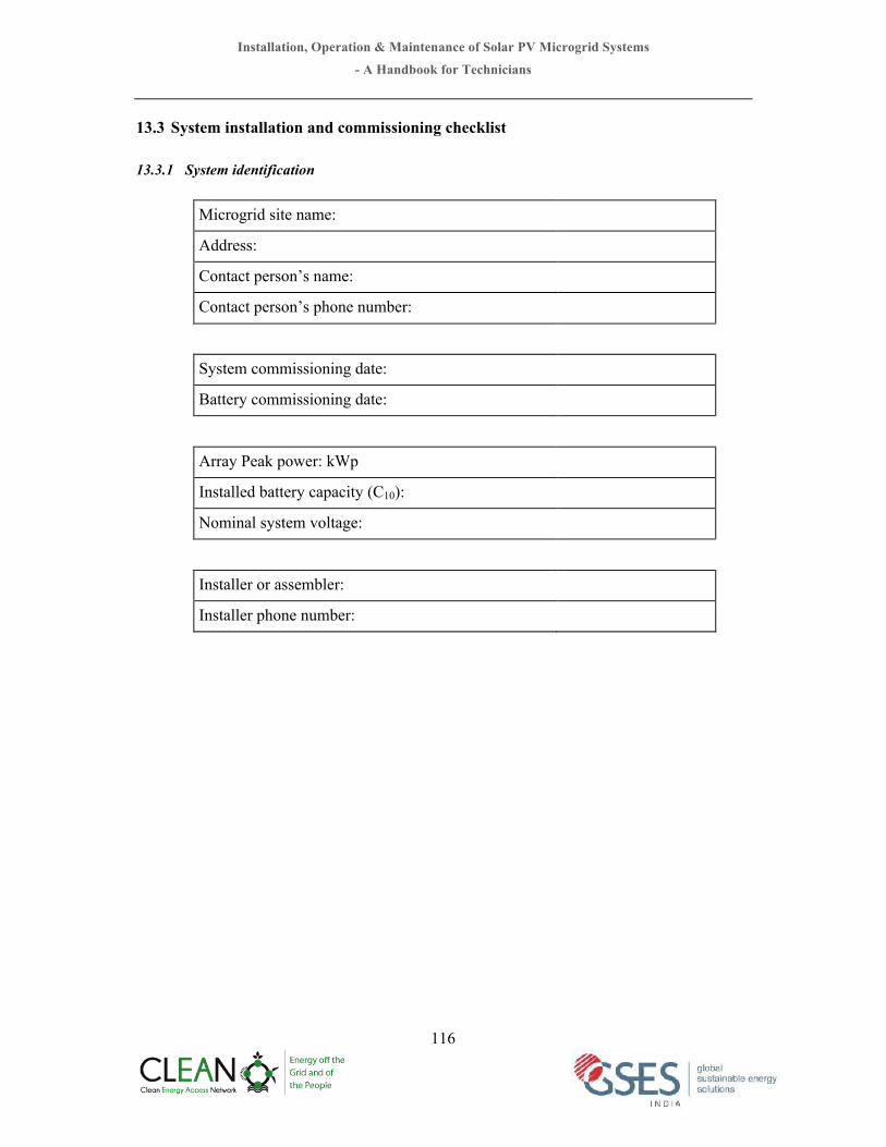
Installation, Operation & Maintenance of Solar PV Microgrid Systems
- A Handbook for Technicians
116
13.3 System installation and commissioning checklist
13.3.1 System identification
Microgrid site name:
Address:
Contact person’s name:
Contact person’s phone number:
System commissioning date:
Battery commissioning date:
Array Peak power: kWp
Installed battery capacity (C10):
Nominal system voltage:
Installer or assembler:
Installer phone number:

Installation, Operation & Maintenance of Solar PV Microgrid Systems
- A Handbook for Technicians
117
13.4.2 PV array installation checklist
PV Array Reference value
Measured value
Conform to reference
Y/N
Modules
Unit peak power
Technology
Quantity
Manufacturer
Power tolerance
Efficiency
Sealing of junction boxes
Bypass diodes
Assembly Orientation
Inclined/horizontal
Structures
Type of structure
Structure material
Mechanical strength
Bolts and nuts material
Resistance to corrosion
Theft prevention device
Quality of fittings
Quality of anchors
Earthing

Installation, Operation & Maintenance of Solar PV Microgrid Systems
- A Handbook for Technicians
118
13.4.3 Cables and connections checklist
Cabling Reference value
Measured value
Conform to reference
Y/N
Interconnections of modules
Cable type
Cross-section area (mm2)
Length (m)
Protection of junction
Junction attachment
Modules-to-junction boxes
connections
Cable type
Cross-section
Length
Quantity
Protection of junctions
Attachment of junctions
Junction boxes
Quantity of boxes
Number of strings per box
AR diode specifications
Control of diodes
Sealing efficiency of cable junction and penetrations
Torque value for terminal strips
Protection of contacts (grease)
Box attachment quality

Installation, Operation & Maintenance of Solar PV Microgrid Systems
- A Handbook for Technicians
119
13.4.4 Acceptance test of PV array
Cabling Reference value
Measured value
Conform to reference
Y/N
Cabling Control through Disconnected
string
Voc and Isc per string Voc Isc Voc Isc String 1 String 2 String 3 String 4 String 5 String 6 String 7 String 8 String 9 String 10
Total generator current
PV field/control Junction
Cable type Cross-section area Length Number of junctions Protection of junctions Lighting arrestors Attachment of junctions
Voltage drop at I max
Cabling control by input
regulator on load
Control input V I Input 1 Input 2 Input 3 Input 4 Total generator
Control/ Battery
Junctions
Cable type Cross-section Length Number of junctions Protection of junctions Attachment of junctions Voltage drop at I max

Installation, Operation & Maintenance of Solar PV Microgrid Systems
- A Handbook for Technicians
120
13.4.5 Acceptance of batteries
Battery Bank Reference value
Measured value
Conform to reference
Y/N Commissioning date:
Type Type of battery
Manufacturer
Specifications status
Rated voltage
Rated voltage per cell
Capacity per cell (C10)
Number of cells
Status of cleanliness
Connections status
Electrolyte level
Legibility of levels Existing deposits in vats
Inspection of Battery
Voltage and density cell Vcell Dcell
Cell 1
Cell 2
Cell 3
Cell 4
Cell 5
Cell 6
Cell ----
Total battery (voltage)
Ambient temperature
Accessories Battery maintenance tools
Battery safety accessories
Battery room
Location and access
Hazard sign
Ventilation
Thermal insulation
Acid retention tank
Room padlocking

Installation, Operation & Maintenance of Solar PV Microgrid Systems
- A Handbook for Technicians
121
13.4.6 Acceptance of measuring and control equipments
Measuring and control equipments Reference value
Measured value
Conform to reference
Y/N
Location of installation
Visibility and legibility
Ventilation
Control room lighting
Type
Manufacturer
Reference
Rated voltage
Serial number
General schematics present
Terminal strip marking
Charge setting
Maximum allowable current
Threshold of forced charge
High threshold
Load reconnection threshold
High alarm threshold
Discharge limitation
Maximum allowable current
Limiting threshold
Reconnection threshold
Low alarm threshold
Displays
Array current measurement
Load current measurement
Battery voltage measurement
Energy generation measurement
Energy consumption measurement
Data acquisition
Manufacturer
Reference
Rated voltage
Serial number

Installation, Operation & Maintenance of Solar PV Microgrid Systems
- A Handbook for Technicians
122
13.4.7 Acceptance of Inverter
Inverter Reference
value Measured
value
Conform to reference
Y/N Commissioning date:
Inverter (DC-AC
converter)
Manufacturer Reference Serial number Rated AC power or current Peak AC power or current Rated voltage input Input voltage range Rated output frequency Output frequency range Output signal type (wave) Consumption at zero load Overcurrent protection Technical documentation
AC/DC converter/ rectifier
Rated output voltage Rated output current Output voltage range Consumption at zero load Adaptability to battery capacity Technical documentation
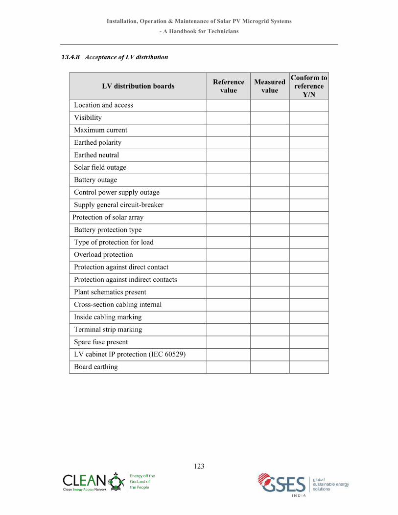
Installation, Operation & Maintenance of Solar PV Microgrid Systems
- A Handbook for Technicians
123
13.4.8 Acceptance of LV distribution
LV distribution boards Reference value
Measured value
Conform to reference
Y/N Location and access
Visibility
Maximum current
Earthed polarity
Earthed neutral
Solar field outage
Battery outage
Control power supply outage
Supply general circuit-breaker
Protection of solar array
Battery protection type
Type of protection for load
Overload protection
Protection against direct contact
Protection against indirect contacts
Plant schematics present
Cross-section cabling internal
Inside cabling marking
Terminal strip marking
Spare fuse present
LV cabinet IP protection (IEC 60529)
Board earthing

Installation, Operation & Maintenance of Solar PV Microgrid Systems
- A Handbook for Technicians
124
13.4.9 Acceptance of ELV distribution
ELV distribution boards Reference value
Measured value
Conform to reference
Y/N Location and access
Visibility
Maximum current
Earthed polarity
Solar field outage
Battery outage
Control power supply outage
General supply cut out
Solar field protection type
Battery protection type
Utilities protection type
Overload protection
Protection against direct contact
Plant schematics present
Cabling inside cross-section
Inside cabling marking
Terminal strip marking
Spare fuse present
ELV cabinet IP protection (IEC 60529)
Board earthing

Installation, Operation & Maintenance of Solar PV Microgrid Systems
- A Handbook for Technicians
125
13.5 System inspection and troubleshooting worksheet
Date:_______________ Inspector Name:__________________Name of the Owner: ____________________________________________________System Location: ____________________________________________________System Description: ____________________________________________________ Reference: ____________________________________________________
Manufacturer:_________________________ Model #:______________Array Configuration: __________series X __________parallelTotal No. of Modules: ____________ (#)Array Mount Type: _______________________________(ground/roof, rack, tracking)Array Tilt Angle: __________(degree) Array Azimuth: __________(degree)Seasonal or daily adjustable Tilt or Tracking (describe): __________________________
Module/ Array Specification @STC (1000W/m2, 25oC)Module Array
Open Circuit Voltage (Voc) _________(V) _________(V)Short Circuit Current (Isc) _________(A) _________(A)Maximum Power Voltage (Vmp) _________(V) _________(V)Maximum Power Current (Imp) _________(A) _________(A)Maximum Power (Pmp) _________(W) _________(W)
Manufacturer:_________________________ Model #:______________Battery Chemistry Type: ___________________ (antimony, calcium, VRLA)Battery Bank Configuration: __________series X __________parallelTotal No. of Batteries __________ (#)
Battery Specification @ 25oCCell/Battery Bank
Capacity at Rate ____________ C/#) _________(Ah) _________(Ah)Nominal Voltage _________(V) _________(V)Open Circuit Voltage at 100% SOC _________(V) _________(V)Open Circuit Voltage at 50% SOC _________(V) _________(V)Specific Gravity at 100% SOC _________(#) _________(#)Specific Gravity at 50% SOC _________(#) _________(#)Cycle Life at 20% DOD ________(cycles)Cycle Life at 50% DOD ________(cycles)Cycle Life at 80% DOD ________(cycles)
PRELIMINARY INFORMATION
PHOTOVOLTAIC MODEULES AND ARRAY
PHOTOVOLTAIC SYSTEM FIELD EVALUATION WORKSHEET (Page 1)
BATTERY SUB-SYSTEM

Installation, Operation & Maintenance of Solar PV Microgrid Systems
- A Handbook for Technicians
126
Devices DC/AC Amps/Watts Hours/Day Ah/Day1. ___________________ ____ ____ ____ ____2.___________________ ____ ____ ____ ____3. ___________________ ____ ____ ____ ____4.___________________ ____ ____ ____ ____5. ___________________ ____ ____ ____ ____6.___________________ ____ ____ ____ ____7. ___________________ ____ ____ ____ ____8.___________________ ____ ____ ____ ____9. ___________________ ____ ____ ____ ____10.__________________ ____ ____ ____ ____11. __________________ ____ ____ ____ ____12. __________________ ____ ____ ____ ____
Seasonal Variation in Load ? ___________________________________________________Total Electrical LoadDC Loads: Peak Amps _________(A) Average Daily ________(Ah)AC Loads: Peak Watts _________(W) Average Daily ________(Wh) _______(Ah)Total Average Daily Loads DC & AC _______(Ah)
Manufacturer:_________________________ Model #:______________Regulator Type: ___________________ (series, shunt, PWM, constant voltage)Controller Specifications:Nominal Voltage _________(V)Maximum Rated Currents: PV Array ______(A) Load_______(V)Array Regulator Set Points: VR__________(V) VRH________(V)Array Regulation Switching Element: _______(SS/EM) ______(pos/neg)Load Disconnect Set Points: LVD_________(V) LVDH_______(V)Load Disconnect Switching Element: _______(SS/EM) ______(pos/neg)Temperature Compensation: ________(mV/oC/cell) Type______(probe/board)Other Controller Functions/ Characteristics (meters, indicators, alarms, etc)_________________________________________________________________________
PHOTOVOLTAIC SYSTEM FIELD EVALUATION WORKSHEET (Page 2)
ELECTRICAL LOADS
CHARGE CONTROLLER/ VOLTAGE REGULATOR

Installation, Operation & Maintenance of Solar PV Microgrid Systems
- A Handbook for Technicians
127
Manufacturer:_________________________ Model #:______________Waveform: ___________________ (sine, quasi -sine, square)Output Voltage Regulation: __________ (%)Harmonic Distortion __________ (%)Minimum Input/Operating Voltage __________ (V)LVD function on Inverter DC Input__________ (yes) _________No __________ (V)
Inverter Specifications:Nominal DC Input Voltage: _________(V)Nomilan AC Output Voltage: _________(V) Frequency______(Hz)Maximum Continuous Output Power: _________(W)Standby Power Requirement: _________(W) ______(pos/neg)Charge Capacity: _________(W) _______(minutes)
_________(W) _______(minutes)Nominal Efficiency (resistive load): _________(%) at 25% Load
_________(%) at 50% Load_________(%) at 75% Load_________(%) at 100% Load
Other Inverter Features: (Battery Charger, disconnect, reverse polarity, overcurrent protection etc)________________________________________________________________________________________________________________________________________________________________
Mounting Structure:Mounting Structure Materials: ___________________ (MS, Aluminium, SS etc)Mounting Structure Coating: ___________________ (Galvenised, painted, annealed etc)Fasteners/Nut/Bolts/Clamps ___________________ (MS, SS etc)Type of foundation/ fixing: ____________________________________________ (describe)Conductors and Wirings:
Type (Cu/Al, Insul, core) Size (sqmm) Length (m)PV Array interconnectionPV Array J-Box to PCU/Controller:___________________________(sqmm) _______(m)PCU/Controller to DC Loads: ___________________________(sqmm) _______(m)PCU/Controller to Battery: ___________________________(sqmm) _______(m)Battery to Inverter: ___________________________(sqmm) _______(m)Inverter to AC Loads: ___________________________(sqmm) _______(m)Overcurrent Protection and Disconnect Devices (List Types, location and ratings):____________________________________________________________________________________________________________________________________________________________________Grounding (System Grounding, equipment grounding, earth electrode):____________________________________________________________________________________________________________________________________________________________________Surge Protection Devices (List Types, locations and ratings):__________________________________________________________________________________Blocking and Bypass Diodes (List Types, locations and Ratings):____________________________________________________________________________________________________________________________________________________________________Other Information:____________________________________________________________________________________________________________________________________________________________________
PHOTOVOLTAIC SYSTEM FIELD EVALUATION WORKSHEET (Page 3)
INVERTER/ POWER CONDITIONER
OTHER SYSTEM SPECIFICATIONS AND INFORMATION

Installation, Operation & Maintenance of Solar PV Microgrid Systems
- A Handbook for Technicians
128
13.6 DCvoltage drop tables
2.5 4 6 10 16 25 35 50 70 95 120 150
Amps
1 15 24 35 63 99 154 217 311 441 583 745 930
2 7 12 18 31 50 77 108 155 221 291 373 465
3 5 8 12 21 33 51 72 104 147 194 248 310
4 4 6 9 16 25 38 54 78 110 146 186 233
5 3 5 7 13 20 31 43 62 88 117 149 186
6 2 4 6 10 17 26 36 52 74 97 124 155
7 2 3 5 9 14 22 31 44 63 83 106 133
8 2 3 4 8 12 19 27 39 55 73 93 116
9 2 3 4 7 11 17 24 35 49 65 83 103
10 1 2 4 6 10 15 22 31 44 58 75 93
15 1 2 2 4 7 10 14 21 29 39 50 62
20 1 1 2 3 5 8 11 16 22 29 37 47
25 1 1 1 3 4 6 9 12 18 23 30 37
30 0 1 1 2 3 5 7 10 15 19 25 31
35 0 1 1 2 3 4 6 9 13 17 21 27
40 0 1 1 2 2 4 5 8 11 15 19 23
45 0 1 1 1 2 3 5 7 10 13 17 21
50 0 0 1 1 2 3 4 6 9 12 15 19
60 0 0 1 1 2 3 4 5 7 10 12 16
70 0 0 1 1 1 2 3 4 6 8 11 13
80 0 0 0 1 1 2 3 4 6 7 9 12
90 0 0 0 1 1 2 2 3 5 6 8 10
100 0 0 0 1 1 2 2 3 4 6 7 9
Wire4Size4(mm2)4444[distance4in4meters]
Voltage4Drop4Table4G4124Volt4Nominal4
Maximum4oneGway4distance4for42%4voltage4drop4in4124volt4systems

Installation, Operation & Maintenance of Solar PV Microgrid Systems
- A Handbook for Technicians
129
2.5 4 6 10 16 25 35 50 70 95 120 150Amps
1 29 47 71 126 198 308 433 622 882 1165 1491 1860
2 15 24 35 63 99 154 217 311 441 583 745 930
3 10 16 24 42 66 103 144 207 294 388 497 620
4 7 12 18 31 50 77 108 155 221 291 373 465
5 6 9 14 25 40 62 87 124 176 233 298 372
6 5 8 12 21 33 51 72 104 147 194 248 310
7 4 7 10 18 28 44 62 89 126 166 213 266
8 4 6 9 16 25 38 54 78 110 146 186 233
9 3 5 8 14 22 34 48 69 98 129 166 207
10 3 5 7 13 20 31 43 62 88 117 149 186
15 2 3 5 8 13 21 29 41 59 78 99 124
20 1 2 4 6 10 15 22 31 44 58 75 93
25 1 2 3 5 8 12 17 25 35 47 60 74
30 1 2 2 4 7 10 14 21 29 39 50 62
35 + 1 2 4 6 9 12 18 25 33 43 53
40 + 1 2 3 5 8 11 16 22 29 37 47
45 + + 2 3 4 7 10 14 20 26 33 41
50 + + 1 3 4 6 9 12 18 23 30 37
60 + + 1 2 3 5 7 10 15 19 25 31
70 + + 1 2 3 4 6 9 13 17 21 27
80 + + 1 2 2 4 5 8 11 15 19 23
90 + + 1 1 2 3 5 7 10 13 17 21
100 + + 1 1 2 3 4 6 9 12 15 19
Wire4Size4(mm2)4444[distance4in4meters]
Voltage4Drop4Table4G4244Volt4Nominal4
Maximum4oneGway4distance4for42%4voltage4drop4in4244volt4systems

Installation, Operation & Maintenance of Solar PV Microgrid Systems
- A Handbook for Technicians
130
2.5 4 6 10 16 25 35 50 70 95 120 150Amps
1 44 71 106 188 298 462 650 933 1324 1748 2236 2791
2 22 35 53 94 149 231 325 466 662 874 1118 1395
3 15 24 35 63 99 154 217 311 441 583 745 930
4 11 18 27 47 74 115 162 233 331 437 559 698
5 9 14 21 38 60 92 130 187 265 350 447 558
6 7 12 18 31 50 77 108 155 221 291 373 465
7 6 10 15 27 43 66 93 133 189 250 319 399
8 5 9 13 24 37 58 81 117 165 218 280 349
9 5 8 12 21 33 51 72 104 147 194 248 310
10 4 7 11 19 30 46 65 93 132 175 224 279
15 3 5 7 13 20 31 43 62 88 117 149 186
20 2 4 5 9 15 23 32 47 66 87 112 140
25 2 3 4 8 12 18 26 37 53 70 89 112
30 1 2 4 6 10 15 22 31 44 58 75 93
35 1 2 3 5 9 13 19 27 38 50 64 80
40 1 2 3 5 7 12 16 23 33 44 56 70
45 1 2 2 4 7 10 14 21 29 39 50 62
50 1 1 2 4 6 9 13 19 26 35 45 56
60 1 1 2 3 5 8 11 16 22 29 37 47
70 1 1 2 3 4 7 9 13 19 25 32 40
80 1 1 1 2 4 6 8 12 17 22 28 35
90 0 1 1 2 3 5 7 10 15 19 25 31
100 0 1 1 2 3 5 6 9 13 17 22 28
Wire4Size4(mm2)4444[distances4in4meters]
Voltage4Drop4Table4G4364Volt4Nominal4Maximum4oneGway4distance4for42%4voltage4drop4in4364volt4systems

Installation, Operation & Maintenance of Solar PV Microgrid Systems
- A Handbook for Technicians
131
2.5 4 6 10 16 25 35 50 70 95 120 150Amps
1 58 94 142 251 397 615 866 1244 1765 2330 2981 3721
2 29 47 71 126 198 308 433 622 882 1165 1491 1860
3 19 31 47 84 132 205 289 415 588 777 994 1240
4 15 24 35 63 99 154 217 311 441 583 745 930
5 12 19 28 50 79 123 173 249 353 466 596 744
6 19 16 24 42 66 103 144 207 294 388 497 620
7 8 13 20 36 57 88 124 178 252 333 426 532
8 7 12 18 31 50 77 108 155 221 291 373 465
9 6 10 16 28 44 68 96 138 196 259 331 413
10 6 9 14 25 40 62 87 124 176 233 298 372
15 4 6 9 17 26 41 58 83 118 155 199 248
20 3 5 7 13 20 31 43 62 88 117 149 186
25 2 4 6 10 16 25 35 50 71 93 119 149
30 2 3 5 8 13 21 29 41 59 78 99 124
35 2 3 4 7 11 18 25 36 50 67 85 106
40 1 2 4 6 10 15 22 31 44 58 75 93
45 1 2 3 6 9 14 19 28 39 52 66 83
50 1 2 3 5 8 12 17 25 35 47 60 74
60 1 2 2 4 7 10 14 21 29 39 50 62
70 1 1 2 4 6 9 12 18 25 33 43 53
80 1 1 2 3 5 8 11 16 22 29 37 47
90 1 1 2 3 4 7 10 14 20 26 33 41
100 1 1 1 3 4 6 9 12 18 23 30 37
Wire4Size4(mm2)4444[distances4in4meters]
Voltage4Drop4Table4G4484Volt4Nominal4
Maximum4oneGway4distance4for42%4voltage4drop4in4484volt4systems

Installation, Operation & Maintenance of Solar PV Microgrid Systems
- A Handbook for Technicians
132
2.5 4 6 10 16 25 35 50 70 95 120 150Amps
1 146 236 354 628 992 1538 2166 3109 4412 5825 7453 9302
2 73 118 177 314 496 769 1083 1554 2206 2913 3727 4651
3 49 79 118 209 331 513 722 1036 1471 1942 2484 3101
4 37 59 88 157 248 385 542 777 1103 1456 1863 2326
5 29 47 71 126 198 308 433 622 882 1165 1491 1860
6 24 39 59 105 165 256 361 518 735 971 1242 1550
7 21 34 51 90 142 220 309 444 630 832 1065 1329
8 18 29 44 79 124 192 271 389 551 728 932 1163
9 16 26 39 70 110 171 241 345 490 647 828 1034
10 15 24 35 63 99 154 217 311 441 583 745 930
15 10 16 24 42 66 103 144 207 294 388 497 620
20 7 12 18 31 50 77 108 155 221 291 373 465
25 6 9 14 25 40 62 87 124 176 233 298 372
30 5 8 12 21 33 51 72 104 147 194 248 310
35 4 7 10 18 28 44 62 89 126 166 213 266
40 4 6 9 16 25 38 54 78 110 146 186 233
45 3 5 8 14 22 34 48 69 98 129 166 207
50 3 5 7 13 20 31 43 62 88 117 149 186
60 2 4 6 10 17 26 36 52 74 97 124 155
70 2 3 5 9 14 22 31 44 63 83 106 133
80 2 3 4 8 12 19 27 39 55 73 93 116
90 2 3 4 7 11 17 24 35 49 65 83 103
100 1 2 4 6 10 15 22 31 44 58 75 93
Wire4Size4(mm2)4444[distances4in4meters]
Voltage4Drop4Table4G41204Volt4Nominal4
Maximum4oneGway4distance4for42%4voltage4drop4in41204volt4systems

Clean Energy Access Network (CLEAN)
A: 2nd Floor, E-18, Green Park Extension, New Delhi-110016 P: +91-11-41601543 W: thecleannetwork.org