
Fault Current Control for DC Microgrid Protection Using an ...
6
Fault Current Control for DC Microgrid Protection Using an Adaptive Droop Sijo Augustine * , Sukumar M. Brahma † , Matthew J. Reno ‡ * Klipsch School of Electrical Computer Engineering, New Mexico State University, USA † Holcombe Department of Electrical Computer Engineering, Clemson University, USA ‡ Electric Power Systems Research, Sandia National Laboratories, USA Abstract—Successful system protection is critical to the per- formance of the DC microgrid system. This paper proposes an adaptive droop based fault current control for a standalone low voltage (LV) solar-photovoltaic (PV) based DC microgrid protection. In the proposed method, a DC microgrid fault is detected by the current and voltage thresholds. Generally, the droop method is used to control the power sharing between the converters by controlling the reference voltage. In this paper, this scheme is extended to control the fault current by calculating an adaptive virtual resistance R droop , and to control the converter output reference voltage. This effectively controls the converter pulse width, and reduces the flow of source current from a particular converter which helps to increase the fault clearing time. Additionally, a trip signal is sent to the corresponding DC circuit breaker (DCCB), to isolate the faulted converter, feeder or a DC bus. The design procedure is detailed, and the effectiveness of proposed method is verified by simulation analysis. Index Terms—DC Microgrid, droop control, fault current, islanded, low voltage, protection, solar-PV, voltage control. I. I NTRODUCTION Currently, the distribution systems are increasingly utilizing DC components and associated power electronics interfaces. Consequently, DC microgrids are emerging as an attractive solution allowing customers to maintain electrical service inde- pendent of the main grid. Microgrids also enable customers to generate, control, and store energy. These aspects additionally present customers some potential economic benefits for local power generation [1], [2]. The major concerns related to the design and control of DC microgrids are the selection of converter topologies, maximum power point tracking (MPPT), voltage control, power sharing, energy management and pro- tection [3]. Considering system components and configura- tions, faults in a solar-PV DC microgrid system are classified as either short circuit (line-line and line-ground) or PV arc faults [4]. Generally, a DC microgrid covers a small geographical area and the distribution line length is short compared to AC distribution systems. Therefore, DC microgrids can be treated as resistive networks [5]. Unlike conventional power system generators, microgrids utilize power electronic con- verters to integrate energy sources like solar-PV, wind, fuel cells, microturbines, energy storage devices, and loads. In standalone mode, small-scale distribution generators and in- verted DC sources offer little to no rotational inertia, and this affects the system stability during disturbances or faults. DC microgrid disturbances are mainly due to fluctuations in load, input power variations, changes in load sharing proportions, oscillations in MPPT [6], temporary faults, communication failures or delays, disturbances in the AC grid. These technical and operational issues have potential to degrade the system performance. Therefore, DC microgrid protection is a critical component for safety, reliability, and asset protection. The objectives for DC microgrid protection are reliability, speed, selectivity, simplicity and cost [7]. One of the major challenges associated with DC micro- grid protection is the fault clearing time. Fault clearing time depends on (i) system configuration and converter topologies (ii) fault location (iii) signal processing and communication delay and (iv) speed of DCCB’s [8]. In a DC microgrid, the capacitive filters connected to the output side of the converters will rapidly discharge into a fault, resulting in large current surges within a very short duration. This may lead to an unstable operation of the converters, since the converters are designed to operate in some particular voltage range. Therefore, this paper focuses on the control of fault current in an islanded DC microgrid to increase the fault clearing time. As discussed in [4], [8]–[16], the simplest and most cost effective method for microgrid protection involves using the voltage and current thresholds. For example, when a fault occurs, there is a drop in the bus voltage and a rise in the converter current. These changes are used to generate a trip signal by comparing the magnitudes of these signals to some predefined thresholds. This method relies solely on current and voltage magnitudes, allowing for fast fault detection. Another scheme in this category is the active impedance method detailed in [13], [14]. In this method, if there is any abnormality in the system the circuit injects a short-duration spread frequency current spikes to estimate the line impedance. The main drawback of this scheme is the accuracy of the estimated fault location and it may vary with the sensing parameters and mathematical formulations derived. Also, the cost of the system increases with the number of probing arrangements in multiple locations and high bandwidth sensing units. A non-iterative fault detection scheme is proposed for LVDC microgrid systems in [15]. The algorithm involves using an external probe unit to analyze the fault without the need to de-energize the system. The power probe unit consists of a power source, capacitor, inductor and CB’s. In this method, the DC microgrid is divided into zones. If a fault occurs, intelligent electronic devices (IEDs) are used to detect and
-
Upload
khangminh22 -
Category
Documents
-
view
0 -
download
0
Transcript of Fault Current Control for DC Microgrid Protection Using an ...

Fault Current Control for DC Microgrid ProtectionUsing an Adaptive Droop
Sijo Augustine∗, Sukumar M. Brahma†, Matthew J. Reno‡∗Klipsch School of Electrical Computer Engineering, New Mexico State University, USA†Holcombe Department of Electrical Computer Engineering, Clemson University, USA
‡Electric Power Systems Research, Sandia National Laboratories, USA
Abstract—Successful system protection is critical to the per-formance of the DC microgrid system. This paper proposes anadaptive droop based fault current control for a standalonelow voltage (LV) solar-photovoltaic (PV) based DC microgridprotection. In the proposed method, a DC microgrid fault isdetected by the current and voltage thresholds. Generally, thedroop method is used to control the power sharing between theconverters by controlling the reference voltage. In this paper, thisscheme is extended to control the fault current by calculating anadaptive virtual resistance Rdroop, and to control the converteroutput reference voltage. This effectively controls the converterpulse width, and reduces the flow of source current from aparticular converter which helps to increase the fault clearingtime. Additionally, a trip signal is sent to the corresponding DCcircuit breaker (DCCB), to isolate the faulted converter, feeder ora DC bus. The design procedure is detailed, and the effectivenessof proposed method is verified by simulation analysis.
Index Terms—DC Microgrid, droop control, fault current,islanded, low voltage, protection, solar-PV, voltage control.
I. INTRODUCTION
Currently, the distribution systems are increasingly utilizingDC components and associated power electronics interfaces.Consequently, DC microgrids are emerging as an attractivesolution allowing customers to maintain electrical service inde-pendent of the main grid. Microgrids also enable customers togenerate, control, and store energy. These aspects additionallypresent customers some potential economic benefits for localpower generation [1], [2]. The major concerns related to thedesign and control of DC microgrids are the selection ofconverter topologies, maximum power point tracking (MPPT),voltage control, power sharing, energy management and pro-tection [3]. Considering system components and configura-tions, faults in a solar-PV DC microgrid system are classifiedas either short circuit (line-line and line-ground) or PV arcfaults [4].
Generally, a DC microgrid covers a small geographicalarea and the distribution line length is short compared toAC distribution systems. Therefore, DC microgrids can betreated as resistive networks [5]. Unlike conventional powersystem generators, microgrids utilize power electronic con-verters to integrate energy sources like solar-PV, wind, fuelcells, microturbines, energy storage devices, and loads. Instandalone mode, small-scale distribution generators and in-verted DC sources offer little to no rotational inertia, and thisaffects the system stability during disturbances or faults. DCmicrogrid disturbances are mainly due to fluctuations in load,
input power variations, changes in load sharing proportions,oscillations in MPPT [6], temporary faults, communicationfailures or delays, disturbances in the AC grid. These technicaland operational issues have potential to degrade the systemperformance. Therefore, DC microgrid protection is a criticalcomponent for safety, reliability, and asset protection. Theobjectives for DC microgrid protection are reliability, speed,selectivity, simplicity and cost [7].
One of the major challenges associated with DC micro-grid protection is the fault clearing time. Fault clearing timedepends on (i) system configuration and converter topologies(ii) fault location (iii) signal processing and communicationdelay and (iv) speed of DCCB’s [8]. In a DC microgrid,the capacitive filters connected to the output side of theconverters will rapidly discharge into a fault, resulting in largecurrent surges within a very short duration. This may lead toan unstable operation of the converters, since the convertersare designed to operate in some particular voltage range.Therefore, this paper focuses on the control of fault current inan islanded DC microgrid to increase the fault clearing time.
As discussed in [4], [8]–[16], the simplest and most costeffective method for microgrid protection involves using thevoltage and current thresholds. For example, when a faultoccurs, there is a drop in the bus voltage and a rise in theconverter current. These changes are used to generate a tripsignal by comparing the magnitudes of these signals to somepredefined thresholds. This method relies solely on currentand voltage magnitudes, allowing for fast fault detection.Another scheme in this category is the active impedancemethod detailed in [13], [14]. In this method, if there is anyabnormality in the system the circuit injects a short-durationspread frequency current spikes to estimate the line impedance.The main drawback of this scheme is the accuracy of theestimated fault location and it may vary with the sensingparameters and mathematical formulations derived. Also, thecost of the system increases with the number of probingarrangements in multiple locations and high bandwidth sensingunits. A non-iterative fault detection scheme is proposed forLVDC microgrid systems in [15]. The algorithm involves usingan external probe unit to analyze the fault without the needto de-energize the system. The power probe unit consists of apower source, capacitor, inductor and CB’s. In this method,the DC microgrid is divided into zones. If a fault occurs,intelligent electronic devices (IEDs) are used to detect and
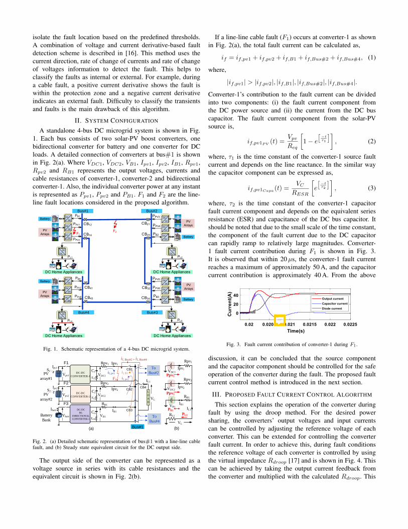
isolate the fault location based on the predefined thresholds.A combination of voltage and current derivative-based faultdetection scheme is described in [16]. This method uses thecurrent direction, rate of change of currents and rate of changeof voltages information to detect the fault. This helps toclassify the faults as internal or external. For example, duringa cable fault, a positive current derivative shows the fault iswithin the protection zone and a negative current derivativeindicates an external fault. Difficulty to classify the transientsand faults is the main drawback of this algorithm.
II. SYSTEM CONFIGURATION
A standalone 4-bus DC microgrid system is shown in Fig.1. Each bus consists of two solar-PV boost converters, onebidirectional converter for battery and one converter for DCloads. A detailed connection of converters at bus#1 is shownin Fig. 2(a). Where VDC1, VDC2, VB1, Ipv1, Ipv2, IB1, Rpv1,Rpv2 and RB1 represents the output voltages, currents andcable resistances of converter-1, converter-2 and bidirectionalconverter-1. Also, the individual converter power at any instantis represented as Ppv1, Ppv2 and PB1. F1 and F2 are the line-line fault locations considered in the proposed algorithm.
DC
DC
AC
DC
DCBattery
PPV2
PB1
Bus#1
PV Arrays
PPV1
DC
DC
DC
PPV5
PB3
PL3
PPV6
DC
DC
DC
DC
DC
DC
DC
DC
PPV3
PB2
PL2
PPV4
DC
DC
DC
DC
DC
DC
DC
DC
DC
DC Home Appliances
PL1
DC
DC
AC
DC
DCBattery
PPV8
PB4
PPV7
DC
DC
DC
DC
PL4
CB43 CB34
CB32CB41
CB14
CB12 CB21
CB23
F2
PV Arrays
PV Arrays
Battery
Battery
PV Arrays
DC Home Appliances DC Home Appliances
DC Home Appliances
Bus#2
Bus#3Bus#4
F1
Fig. 1. Schematic representation of a 4-bus DC microgrid system.
VDC1
C1
Ipv2
VDC2
Rpv2
Ipv1Rpv1
DC-DC
CONVERTER-1
DC-DC
CONVERTER-2
rc1
C2
rc2
Vpv1
Vpv2
Ipv1
IL1
VL
Bus#1
PV
array#1
PV
array#2
VDC1
VDC2
IL1
VL
RL1
(a) (b)
Ppv1
Ppv2
PL1
Ipv2
IB1
VB1
RB1
DC-DC
BI-
DIRECTIONAL
CONVERTER-1
CB1
rcB1
VbattBattery
Bank
Ibatt
VB1
PB1
L
O
A
D
S1
S2
F1
F2
F3
CB1
CB2
CB3
CB4
if, pv1
if, pv2
if, B1
To
Bus#4
To
Bus#2
if, Bus#2 + if, Bus#4
Ipv1
Ipv2
IB1
Rpv1
Rpv2
RB1
F1
Fig. 2. (a) Detailed schematic representation of bus#1 with a line-line cablefault, and (b) Steady state equivalent circuit for the DC output side.
The output side of the converter can be represented as avoltage source in series with its cable resistances and theequivalent circuit is shown in Fig. 2(b).
If a line-line cable fault (F1) occurs at converter-1 as shownin Fig. 2(a), the total fault current can be calculated as,
if = if,pv1 + if,pv2 + if,B1 + if,Bus#2 + if,Bus#4, (1)
where,
|if,pv1| > |if,pv2|, |if,B1|, |if,Bus#2|, |if,Bus#4|.
Converter-1’s contribution to the fault current can be dividedinto two components: (i) the fault current component fromthe DC power source and (ii) the current from the DC buscapacitor. The fault current component from the solar-PVsource is,
if,pv1PV (t) =VpvReq
[1− e
[−tτ1
]], (2)
where, τ1 is the time constant of the converter-1 source faultcurrent and depends on the line reactance. In the similar waythe capacitor component can be expressed as,
if,pv1Capa(t) =VC
RESR
[e
[−tτ2
]], (3)
where, τ2 is the time constant of the converter-1 capacitorfault current component and depends on the equivalent seriesresistance (ESR) and capacitance of the DC bus capacitor. Itshould be noted that due to the small scale of the time constant,the component of the fault current due to the DC capacitorcan rapidly ramp to relatively large magnitudes. Converter-1 fault current contribution during F1 is shown in Fig. 3.It is observed that within 20µs, the converter-1 fault currentreaches a maximum of approximately 50 A, and the capacitorcurrent contribution is approximately 40 A. From the above
Fig. 3. Fault current contribution of converter-1 during F1.
discussion, it can be concluded that the source componentand the capacitor component should be controlled for the safeoperation of the converter during the fault. The proposed faultcurrent control method is introduced in the next section.
III. PROPOSED FAULT CURRENT CONTROL ALGORITHM
This section explains the operation of the converter duringfault by using the droop method. For the desired powersharing, the converters’ output voltages and input currentscan be controlled by adjusting the reference voltage of eachconverter. This can be extended for controlling the converterfault current. In order to achieve this, during fault conditionsthe reference voltage of each converter is controlled by usingthe virtual impedance Rdroop [17] and is shown in Fig. 4. Thiscan be achieved by taking the output current feedback fromthe converter and multiplied with the calculated Rdroop. This
sijo
Sticky Note
In this fig. PWM is still ON and MOSFET is switching. Therefore, the capacitor will continue its chagrining and discharging process after the fault discharge. (After time 0.0205s)

PI
controller
PI
controller
vDCB
iLb
PWM
generation
Bi-directional
converter
PI
controllerPI
controller
vDC1
i1
VDC
iL1
PWM
generationVDC1
Converter-1
Rdroop1ipv1
ib
Proposed
droop
calculation
VDC1 VDCj
VL
ij
vpv1
vb
PV
array#1
Battery
bank
S1
Sj
** *
PI
controller
PI
controller
vDCj
ij
iLj
PWM
generationVDCj
Converter-2
VDC1
i1
VDCj
VL
Rdroopj
ij
ipvj
VDC
vpvjPV
array#j S1
Sj
** *
DC bus
Coupling
point
DC bus
Coupling
point
DC bus
Coupling
point
Proposed
droop
calculation
DC bus
voltage
restoration
VL
VDCj VDC** *
i1
SOCb
SOCb
SOCb
Rdroop_b
Fig. 4. Control diagram of bus#1 converters with the proposed algorithm.
resultant signal is subtracted from the reference voltage (V ∗DC)
of the converter and the new reference signal is now (V ∗∗DCj)
and is given as,
V ∗∗DCj = V ∗
DC − ij × (±Rdroopj ). (4)
In the proposed adaptive droop based algorithm, the faultdetection is based on the voltage and current thresholds. Usingthe proposed adaptive droop protection method, the outputconverter voltage is controlled during the fault. Therefore,the complete shutdown of the DC microgrid may not berequired during the fault. This can be explained with Fig. 1.In the considered system each bus consists of six CB’s andall converters and loads can be isolated based on the faultlocation. The proposed protection schemes consist of mainprotection and backup protection schemes. The algorithm isdiscussed as follows, and the flowcharts are given in Fig. 5and Fig. 6.
1) The thresholds are calculated based on the convertertopology, rating, DC bus voltage limits and load param-eters. In the proposed method, the current thresholdsare based on converter current rating, topology andvoltage thresholds defined by the allowable limits ofDC grid voltage. These current thresholds are selectedby considering the converter input current or device(MOSFET or IGBT) current or the output current. Ifthe current or voltage magnitude crosses the threshold,the controller activates the proposed algorithm and anda trip signal is sent to the DCCB if necessary.
2) The implementation of the proposed algorithm is basedon two current thresholds and two voltage thresholds,an upper threshold (UTI & UTV ) and a lower threshold(LTI & LTV ) as shown in Fig. 7. For example, the uppercurrent threshold can be selected as 150% of the fullload current and the lower threshold as 120% of the fullload value. Similarly, the voltage thresholds are based
Start
Measure
local VDCj, Ij
Set
Droop Flag=1
Fault Flag=1
Ij < LTI
LTV < Vj < UTV
Droop Flag=0
Fault Flag=1
Activate adaptive
droop control
Yes
No
Yes
No
No fault
condition,
Fault Flag=0
No
Yes
UTI < Ij < LTI
LTV < Vj < UTVDelay
Ij > UTI or
Vj < LTV
VDCj=0
Ij=0
VDCbusj=VBUS
Trip the DCCB and Stop the PWM
Fault Flag=0
Droop Flag=1
Fault Flag=1
Yes
No
Yes
No
Delay
YesNo
Delay
Reclose the DCCBStop
Fig. 5. Flowchart for converter-j (j = 1, 2..n) fault protection algorithm.
on the allowable DC bus voltage deviation. If the DCbus voltage is 48 V, then the thresholds can be selectedas 48±2.5%V (lower threshold) and 48±20%V (upperthreshold). It should be noted that a small change in theconverter output voltage will affect the current sharingproportion among the converters.
3) The proposed method is activated only if the currentor voltage magnitude crosses lower threshold as shownin Fig. 7. If the current magnitude crosses the lowerthreshold, the algorithm identifies that there is chanceof disturbance or fault.
4) The adaptive droop algorithm adjusts the converteroutput voltage and reduces the total converter outputcurrent. If the current again exceeds the threshold UTI ,then the algorithm generates a trip signal to the particularDCCB.
IV. SIMULATION STUDIES
The 4-bus DC microgrid system as shown in the Fig. 1 wassimulated, using MATLAB/Simulink. The nominal parameters

Start
Set
Droop Flagj=1
Fault Flagj=1
Rdroopj=0
Measure
local VDCj, Ij
UTI > Ij > LTI or
LTV < Vj < UTV
Droop Flagj=0
Yes
Yes
No
No
UTI > Ij > LTI or
Vj < LTV
Rdroopj_ne w = Rdroopj + (k × Ij )
V DCj = V
DC Ij×Rdroopj_ne w
Yes
No
Vj > UTV Ij < UTI
Yes
No
Trip the DCCB and Stop the PWM
Fault Flag=0
Yes
No
No
Yes
Stop
Fig. 6. Flowchart for converter-j (j = 1, 2..n) adaptive droop algorithm.
Volt
age (
V)
Before fault After fault
UTI
Curr
ent (A
)
Before fault After fault
LTI
without droop
with droop
without droop
with droop
Time(s)
UTV
LTV
Time(s)
X
Y
Fig. 7. Voltage and current profile of converter-j (j = 1, 2..n) with andwithout adaptive droop algorithm.
of the system are given in the Table I.
TABLE INOMINAL PARAMETERS OF SYSTEM
Parameters Symbol ValueDC bus voltage VDC 48 VBoost converter power Pboost 240 WBattery converter power Pbatt 240 WCable resistance Rcable 0.1 ΩCable inductance Lcable 0.1 mHFilter inductor L 100µHESR of filter inductor rL 0.03 ΩFilter capacitor C 440µFESR of filter capacitor rC 0.05 ΩNominal switching frequency fsw 10 kHz
A. Normal operation of the DC microgrid
The normal operation of the DC microgrid is simulated andthe voltages and currents are shown in Fig. 8. The converteroutput voltages and load voltage are shown in the Fig. 8(a).
(a)
(b)
Fig. 8. Voltage and current of bus#1 converters during normal operation.
It can be observed in Fig. 8(b) that the PV converters eachcontribute 2.2 A to the total 5 A load current. The remainingportion of the load current is contributed by the batteryconverter.
B. Cable fault (F1) with adaptive droop algorithm
At 0.02 s, a line-line fault is created in the converter-1 tobus#1 cable. The corresponding simulation results are shownin Fig. 9. The proposed adaptive droop control is implemented,and the voltage and current thresholds are defined in TableII. Fig. 9(a) shows the converter-1 output voltage and thereference voltage. The converter-1 output current is shownin Fig. 9(b). The droop flag is activated when output currentreaches 6 A, and the droop values are shown in the Fig. 9(d).The change in the converter-1 reference voltage as shown inthe the Fig. 9(a) controls the fault current contribution fromconverter-1.
TABLE IIVOLTAGE AND CURRENT THRESHOLDS
Parameter MagnitudeVoltage UTV = 46 V LTV = 35 VCurrent UTI = 10 A LTI = 6 A
(a)
(b)
(c)
(d)
Fig. 9. Converter-1 results for fault F1 at 0.02 s (a) Output voltage (b) Outputcurrent (c) Droop flag (d) Calculated adaptive droop.
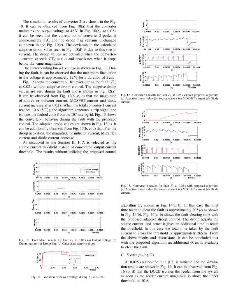
The simulation results of converter-2 are shown in the Fig.10. It can be observed from Fig. 10(a) that the convertermaintains the output voltage at 48 V. In Fig. 10(b), at 0.02 sit can be seen that the current out of converter-2 peaks atapproximately 3 A, and the droop flag remains unchangedas shown in the Fig. 10(c). The deviation in the calculatedadaptive droop value seen in Fig. 10(d) is due to this rise incurrent. The droop values are activated when the converter-1 current exceeds LTI = 6A and deactivates when it dropsbelow the same magnitude.
The corresponding bus#1 voltage is shown in Fig. 11. Dur-ing the fault, it can be observed that the maximum fluctuationin the voltage is approximately 12% for a duration of 2µs.
Fig. 12 shows the converter-1 behavior during the fault (F1)at 0.02 s without adaptive droop control. The adaptive droopvalues are zero during the fault and is shown in Fig. 12(a).It can be observed from Fig. 12(b, c, d) that the magnitudeof source or inductor current, MOSFET current and diodecurrent increase after 0.02 s. When the total converter-1 currentreaches 10 A (UTI ), the algorithm generates a trip signal andisolates the faulted zone from the DC microgrid. Fig. 13 showsthe converter-1 behavior during the fault with the proposedcontrol. The adaptive droop values are shown in Fig. 13(a). Itcan be additionally observed from Fig. 13(b, c, d) that after thedroop activation, the magnitude of inductor current, MOSFETcurrent and diode current decrease.
As discussed in the Section II, 10 A is selected as thesource current threshold instead of converter-1 output currentthreshold. The results without utilizing the proposed control
(a)
(b)
(c)
(d) Time(s)
Fig. 10. Converter-1 results for fault F1 at 0.02 s (a) Output voltage (b)Output current (c) Droop flag (d) Calculated adaptive droop.
Fig. 11. Variation of bus#1 voltage during F1 at 0.02s.
(a)
(b)
(c)
(d)
Fig. 12. Converter-1 results for fault F1 at 0.02 s without proposed algorithm(a) Adaptive droop value (b) Source current (c) MOSFET current (d) Diodecurrent.
(a)
(b)
(c)
(d)
Fig. 13. Converter-1 results for fault F1 at 0.02 s with proposed algorithm(a) Adaptive droop value (b) Source current (c) MOSFET current (d) Diodecurrent.
algorithm are shown in Fig. 14(a, b). In this case the totaltime taken to clear the fault is approximately 205µs as shownin Fig. 14(b). Fig. 15(a, b) shows the fault clearing time withthe proposed adaptive droop control. The droop adjusts thesource current, and hence it gives an additional time to reachthe threshold. In this case the total time taken by the faultcurrent to cross the threshold is approximately 265µs. Fromthe above results and discussions, it can be concluded thatwith the proposed algorithm an additional 60µs is availableto clear the fault.
C. Feeder fault (F2)
At 0.025 s a line-line fault (F2) is initiated and the simula-tion results are shown in Fig. 16. It can be observed from Fig.16 (b, d) that the DCCB isolates the feeder from the systemas soon as the feeder current magnitude is above the upperthreshold of 10 A.

(a)
(b)
Fig. 14. Converter-1 results for fault F1 at 0.02 s without proposed algorithm(a) Output voltage (b) Source and capacitor currents.
(a)
(b)
Fig. 15. Converter-1 results for fault F1 at 0.02 s at 0.02 s with proposedalgorithm (a) Output voltage (b) Source and capacitor currents.
(a)
(b)
(c)
(d)
Fig. 16. Results for fault F2 at 0.025 s (a) Fault signal (b) Breaker signal (c)Feeder voltage (d) Feeder current.
V. CONCLUSION
Problems like fault clearing time and the bus voltage fluctu-ation during faults or disturbances will affect the safe operationof the DC microgrids. To address these concerns, in this paperan adaptive droop algorithm for a low voltage DC microgrid isproposed. This method uses voltage and current thresholds tolocalize the fault. After locating the fault, the proposed methodcontrols the source current instantaneously by adjusting theconverter output voltage using virtual resistance Rdroop. It isalso found that the proposed algorithm gives an additional time
of 60µs to clear the fault, and it helps the controller to operatethe corresponding DCCB safely. Therefore, the analysis andresults indicate that the proposed method is also suitable forthe islanded DC microgrids with communication.
ACKNOWLEDGMENT
Sandia National Laboratories is a multimission laboratorymanaged and operated by National Technology & EngineeringSolutions of Sandia, LLC, a wholly owned subsidiary of Hon-eywell International Inc., for the U.S. Department of EnergysNational Nuclear Security Administration under contract DE-NA0003525.
REFERENCES
[1] J. Guerrero, A. Davoudi, F. Aminifar, J. Jatskevich, and H. Kakigano,“Guest Editorial: Special section on smart DC distribution systems,”IEEE Trans. Smart Grid, vol. 5, no. 5, pp. 2473–2475, Sept. 2014.
[2] S. Augustine, M. K. Mishra, and N. Lakshminarasamma, “Adaptivedroop control strategy for load sharing and circulating current mini-mization in low-voltage standalone DC microgrid,” IEEE Trans. on Sust.Energy, vol. 6, no. 1, pp. 132–141, Jan 2015.
[3] V. Nasirian, S. Moayedi, A. Davoudi, and F. Lewis, “Distributedcooperative control of DC microgrids,” IEEE Trans. Power Electron.,vol. 30, no. 4, pp. 2288–2303, Apr. 2015.
[4] D. M. Bui, S. Chen, C. Wu, K. Lien, C. Huang, and K. Jen, “Reviewon protection coordination strategies and development of an effectiveprotection coordination system for DC microgrid,” in 2014 IEEE PESAsia-Pacific Power and Energy Engineering Conference (APPEEC), Dec2014, pp. 1–10.
[5] T. Dragicevic, J. Vasquez, J. Guerrero, and D. Skrlec, “Advanced LVDCelectrical power architectures and microgrids: A step toward a newgeneration of power distribution networks.” IEEE, Electri. Mag., vol. 2,no. 1, pp. 54–65, Mar. 2014.
[6] B. Subudhi and R. Pradhan, “A comparative study on maximum powerpoint tracking techniques for photovoltaic power systems,” IEEE Trans.Sust. Energy,, vol. 4, no. 1, pp. 89–98, Jan. 2013.
[7] R. M. Cuzner and G. Venkataramanan, “The status of DC micro-gridprotection,” in 2008 IEEE Industry Applications Society Annual Meeting,Oct 2008, pp. 1–8.
[8] S. Augustine, J. E. Quiroz, M. J. Reno, and S. Brahma, “DC microgridprotection: Review and challenges,” in Sandia National Laboratories,SAND2018-8853, 2018.
[9] J. Park and J. Candelaria, “Fault detection and isolation in low-voltageDC-bus microgrid system,” IEEE Trans. on Power Delivery, vol. 28,no. 2, pp. 779–787, April 2013.
[10] S. Dhar, R. K. Patnaik, and P. K. Dash, “Fault detection and location ofphotovoltaic based DC microgrid using differential protection strategy,”IEEE Trans. on Smart Grid, vol. 9, no. 5, pp. 4303–4312, Sept 2018.
[11] C. Yuan, M. A. Haj-ahmed, and M. S. Illindala, “Protection strategiesfor medium-voltage direct-current microgrid at a remote area mine site,”IEEE Trans. on Ind. Appli., vol. 51, no. 4, pp. 2846–2853, July 2015.
[12] L. Zhang, N. Tai, W. Huang, J. Liu, and Y. Wang, “A review onprotection of DC microgrids,” Journal of Modern Power Systems andClean Energy, vol. 6, no. 6, pp. 1113–1127, Nov 2018.
[13] E. Christopher, M. Sumner, D. W. P. Thomas, X. Wang, and F. de Wildt,“Fault location in a zonal DC marine power system using activeimpedance estimation,” IEEE Trans. on Ind. Appli., vol. 49, no. 2, pp.860–865, March 2013.
[14] D. Thomas, M. Sumner, D. Coggins, X. Wang, J. Wang, andR. Geertsma, “Fault location for DC marine power systems,” in 2009IEEE Electric Ship Technologies Symposium, April 2009, pp. 456–460.
[15] R. Mohanty, U. S. M. Balaji, and A. K. Pradhan, “An accurate non-iterative fault-location technique for low-voltage DC microgrid,” IEEETrans. on Power Deli., vol. 31, no. 2, pp. 475–481, April 2016.
[16] J. Wang, B. Berggren, K. Linden, J. Pan, and R. Nuqui, “Multi-terminalDC system line protection requirement and high speed protectionsolutions,” CIGRE International Symposium, pp. 1–9, 2015.
[17] S. Augustine, N. Lakshminarasamma, and M. K. Mishra, “Control ofphotovoltaic-based low-voltage DC microgrid system for power sharingwith modified droop algorithm,” IET Power Elect., vol. 9, pp. 1132–1143(11), May 2016.
View publication statsView publication stats