Multiple-Output DC–DC Converters: Applications and Solutions
34
Citation: Litrán, S.P.; Durán, E.; Semião, J.; Díaz-Martín, C. Multiple-Output DC–DC Converters: Applications and Solutions. Electronics 2022, 11, 1258. https:// doi.org/10.3390/electronics11081258 Academic Editor: Kai Fu Received: 10 March 2022 Accepted: 13 April 2022 Published: 15 April 2022 Publisher’s Note: MDPI stays neutral with regard to jurisdictional claims in published maps and institutional affil- iations. Copyright: © 2022 by the authors. Licensee MDPI, Basel, Switzerland. This article is an open access article distributed under the terms and conditions of the Creative Commons Attribution (CC BY) license (https:// creativecommons.org/licenses/by/ 4.0/). electronics Review Multiple-Output DC–DC Converters: Applications and Solutions Salvador P. Litrán 1,2 , Eladio Durán 2,3, * , Jorge Semião 4 and Cristian Díaz-Martín 2 1 Department of Electrical and Thermal Engineering, Design and Projects, University of Huelva, 21007 Huelva, Spain; [email protected] 2 Centro Científico-Tecnológico de Huelva (CCTH), University of Huelva, 21007 Huelva, Spain; [email protected] 3 Department of Electronic Engineering, Computer Systems and Automation, University of Huelva, 21007 Huelva, Spain 4 Instituto Superior de Engenharia (ISE), Universidade do Algarve, 8005-139 Faro, Portugal/INESC-ID, 1000 Lisboa, Portugal; [email protected] * Correspondence: [email protected]; Tel.: +34-959217655 Abstract: Multiple-output DC–DC converters are essential in a multitude of applications where different DC output voltages are required. The interest and importance of this type of multiport configuration is also reflected in that many electronics manufacturers currently develop integrated solutions. Traditionally, the different output voltages required are obtained by means of a transformer with several windings, which are in addition to providing electrical isolation. However, the current trend in the development of multiple-output DC–DC converters follows general aspects, such as low losses, high-power density, and high efficiency, as well as the development of new architectures and control strategies. Certainly, simple structures with a reduced number of components and power switches will be one of the new trends, especially to reduce the size. In this sense, the incorporation of devices with a Wide Band Gap (WBG), particularly Gallium Nitride (GaN) and Silicon Carbide (SiC), will establish future trends, advantages, and disadvantages in the development and applications of multiple-output DC–DC converters. In this paper, we present a review of the most important topics related to multiple-output DC–DC converters based on their main topologies and configurations, applications, solutions, and trends. A wide variety of configurations and topologies of multiple-output DC–DC converters are shown (more than 30), isolated and non-isolated, single and multiple switches, and based on soft and hard switching techniques, which are used in many different applications and solutions. Keywords: DC–DC converters; multiple outputs; applications; solutions 1. Introduction Multiple-output DC–DC converters are fundamental in electric power supply, distri- bution, management, and power delivery systems. They are essential in applications such as: Intermediate Bus Architecture (IBA), Distributed Power Architectures (DPA), Dynamic Bus Architecture (DBA), Central Control Architecture (CCA), Datacom and Telecom, Light- Emitting Diodes (LEDs), consumer electronics products, battery chargers, or even Electric Vehicles (EV). These converters are used for USB power delivery, I/O, CPUs, FPGAs, ASICs, and other low-voltage devices, applications where controllability, efficiency, reliability, and miniaturization are critical. Undoubtedly, the development of power switch semiconductor technologies has also contributed significantly to more efficient switching and has facilitated a higher frequency operation. This has allowed the development of applications where multiple-output DC–DC converters are used, considering mainly three aspects: high-power density, high efficiency, and small size. The increase in the rating of power devices, such as Insulated Electronics 2022, 11, 1258. https://doi.org/10.3390/electronics11081258 https://www.mdpi.com/journal/electronics
-
Upload
khangminh22 -
Category
Documents
-
view
2 -
download
0
Transcript of Multiple-Output DC–DC Converters: Applications and Solutions

�����������������
Citation: Litrán, S.P.; Durán, E.;
Semião, J.; Díaz-Martín, C.
Multiple-Output DC–DC Converters:
Applications and Solutions.
Electronics 2022, 11, 1258. https://
doi.org/10.3390/electronics11081258
Academic Editor: Kai Fu
Received: 10 March 2022
Accepted: 13 April 2022
Published: 15 April 2022
Publisher’s Note: MDPI stays neutral
with regard to jurisdictional claims in
published maps and institutional affil-
iations.
Copyright: © 2022 by the authors.
Licensee MDPI, Basel, Switzerland.
This article is an open access article
distributed under the terms and
conditions of the Creative Commons
Attribution (CC BY) license (https://
creativecommons.org/licenses/by/
4.0/).
electronics
Review
Multiple-Output DC–DC Converters: Applicationsand SolutionsSalvador P. Litrán 1,2 , Eladio Durán 2,3,* , Jorge Semião 4 and Cristian Díaz-Martín 2
1 Department of Electrical and Thermal Engineering, Design and Projects, University of Huelva,21007 Huelva, Spain; [email protected]
2 Centro Científico-Tecnológico de Huelva (CCTH), University of Huelva, 21007 Huelva, Spain;[email protected]
3 Department of Electronic Engineering, Computer Systems and Automation, University of Huelva,21007 Huelva, Spain
4 Instituto Superior de Engenharia (ISE), Universidade do Algarve, 8005-139 Faro, Portugal/INESC-ID,1000 Lisboa, Portugal; [email protected]
* Correspondence: [email protected]; Tel.: +34-959217655
Abstract: Multiple-output DC–DC converters are essential in a multitude of applications wheredifferent DC output voltages are required. The interest and importance of this type of multiportconfiguration is also reflected in that many electronics manufacturers currently develop integratedsolutions. Traditionally, the different output voltages required are obtained by means of a transformerwith several windings, which are in addition to providing electrical isolation. However, the currenttrend in the development of multiple-output DC–DC converters follows general aspects, such aslow losses, high-power density, and high efficiency, as well as the development of new architecturesand control strategies. Certainly, simple structures with a reduced number of components andpower switches will be one of the new trends, especially to reduce the size. In this sense, theincorporation of devices with a Wide Band Gap (WBG), particularly Gallium Nitride (GaN) andSilicon Carbide (SiC), will establish future trends, advantages, and disadvantages in the developmentand applications of multiple-output DC–DC converters. In this paper, we present a review of the mostimportant topics related to multiple-output DC–DC converters based on their main topologies andconfigurations, applications, solutions, and trends. A wide variety of configurations and topologiesof multiple-output DC–DC converters are shown (more than 30), isolated and non-isolated, singleand multiple switches, and based on soft and hard switching techniques, which are used in manydifferent applications and solutions.
Keywords: DC–DC converters; multiple outputs; applications; solutions
1. Introduction
Multiple-output DC–DC converters are fundamental in electric power supply, distri-bution, management, and power delivery systems. They are essential in applications suchas: Intermediate Bus Architecture (IBA), Distributed Power Architectures (DPA), DynamicBus Architecture (DBA), Central Control Architecture (CCA), Datacom and Telecom, Light-Emitting Diodes (LEDs), consumer electronics products, battery chargers, or even ElectricVehicles (EV). These converters are used for USB power delivery, I/O, CPUs, FPGAs, ASICs,and other low-voltage devices, applications where controllability, efficiency, reliability, andminiaturization are critical.
Undoubtedly, the development of power switch semiconductor technologies has alsocontributed significantly to more efficient switching and has facilitated a higher frequencyoperation. This has allowed the development of applications where multiple-outputDC–DC converters are used, considering mainly three aspects: high-power density, highefficiency, and small size. The increase in the rating of power devices, such as Insulated
Electronics 2022, 11, 1258. https://doi.org/10.3390/electronics11081258 https://www.mdpi.com/journal/electronics

Electronics 2022, 11, 1258 2 of 34
Gate Bipolar Transistors (IGBT) and Metal-Oxide-Semiconductor Field-Effect Transistor(MOSFET) technologies, has allowed innumerable applications to be addressed in thelast 40 years. They have helped to improve energy efficiency and CO2 reductions, incommercial, residential, transportation systems, industrial, military, aerospace, computersystems, lighting, and vehicle applications. MOSFET and IGBT, either as power modules orwithin discrete devices, have been the preferred technologies for high and medium powerapplications. IGBTs are used in applications of high-current, with voltages over 1 kV andup to 10 kVA, while MOSFETs are used in applications below 1 kV, but they are the mostsuitable in applications of high switching frequency, between 10–100 kHz.
Although silicon-based technologies have improved enormously in the recent years,and still continue to improve, this development will be restricted, ultimately, by silicontechnology limitations [1]. Among the semiconductor materials with the greatest futurepotential are those with a Wide Band Gap (WBG), particularly Gallium Nitride (GaN) andSilicon Carbide (SiC). The physical properties of WBG materials make them especiallysuitable for high switching frequency and high-power applications, also giving them highresistance to high temperatures, lower switching losses, with low reverse recovery and lowon-resistance, a better relationship between breakdown voltage (VBD) and on-resistance(RDS(ON)), lower cooling requirements, and with low parasitic inductance. Applicationswhere broadband technology is experiencing a considerable growth are: in the lightingsector (using GaN based LEDs); in the generation (transmission and distribution of electricalenergy, where SiC devices present significant improvements in energy efficiency of theelectrical network); and hybrid and fully electric vehicles (where GaN and SiC-baseddevices are essential elements, both in the propulsion and energy distribution systems ofthe vehicle).
The interest in DC–DC converters with multiple outputs is reflected in the sub-citedanalysis and numerous publications, both from the academic, research, and economic/business world [2–11], as well as from industry and manufacturer publications [12–17].The most recent forecasts estimate that the market for DC–DC converters is expected toincrease at a CAGR (Compound Annual Growth Rate) of 12.1% in the next five years, from$9.9 billion in 2021 to $17.6 billion in 2026, and that the market for industrial power supplyis expected to increase at a CAGR of 6.9% in the same period, from $7.0 billion in 2021 to$9.7 billion in 2026, with multiple-output DC–DC converters being one of the segments withthe highest growth rate during the same period [18–30]. This growth is due to very differentsectors and applications, such as storage and servers, battery management, healthcare andmedical equipment, railway traction, beverage and food, information technology andtelecom, transportation, consumer electronics, energy and utilities, defense and aerospace,machine tools, and security systems. Mobile Phone Industry and Internet of Things (IoT)are applications where DC–DC converters help to extend battery life. Also, the lightingsector through technology Light-Emitting Diode (LED) and Organic LED (OLED), whichhas provided more reliable and efficient light sources, is also an important sector. Moreover,the demand for DC–DC converters with multiple outputs in the automotive industryis driven by electric vehicles, such as Fuel Cell Electric Vehicle (FCEV), Battery ElectricVehicles (BEV), Plug-in Hybrid Vehicles (PHEV), and Hybrid Electric Vehicle (HEV).
All these applications contemplate various aspects and types of DC–DC converters,such as output number (dual-output, bipolar output, three- and four-output-type convert-ers), power (<1 kW, 1–10 kW, 10–20 kW, and >20 kW) including low, medium, and highpower, input voltage (<40 V, 40–70 V, and >70 V), output voltage (24 V, 15 V, 12 V, 5 V, and3.3 V), isolated (one switch, two switches, and four switches converters) and non-isolated(one switch or several switches) DC–DC converters. In low-power applications, the twomain trends are related to high-power density and low voltage, while in high power, withhigh efficiency and reliability. But the main trend is related to miniaturization for integra-tion. Small size and weight, together with high-power density are very important itemsin power supplies for small format applications, mobile electronic systems, and onboardsystems, driven by applications with facilities with space restrictions such as More-Electric

Electronics 2022, 11, 1258 3 of 34
Aircraft (MEA), Electric Vehicle (EV), Robotics, Electric Ship (ES), Robotics, Solid-StateLighting, Integrated DC–DC Power Supply and Monolithic Power Systems, IntelligentDC–DC Power Distribution (micro or nano grids), On-chip Power Supply, Wireless RemoteSensing Node and Power Transfer, New Transport Technologies, Energy Harvesting, andIoT. In these applications, multiple or single power systems are used, which distributeenergy to different loads, with converters operating in power ranging from hundreds ofkilowatts to a few watts. This focus on multiple-output DC–DC converter applicationshas also led to the development and commercialization of integrated solutions by manyelectronic manufacturers [31–42], and to different tutorials, webinars, on-line publica-tions, white papers and some surveys, reviews, and overviews papers being reported inthe literature.
In this paper, an overview of the most important topics related to multiple-outputDC–DC converters based on their main topologies and configurations, applications, so-lutions, and trends are presented. The work is organized as follows: Section 2 reviewsmultiple-output DC–DC converters: topologies and configurations and some of their maincharacteristics are analyzed. Section 3 presents some of the most important applicationsand solutions of multiple-output DC–DC converters. Finally, in Section 4 some conclusionsare presented.
2. Multiple-Output DC–DC Converters: Topologies and Configurations
The main objective of DC–DC power conversion is to transfer electric power from a DCsource into another DC source, which can be a load, with the highest efficiency and thereforelowest losses. The DC–DC converters are widely used at all power levels (from mW to kW),current levels (from nA to hundreds of amps) and voltage levels (from mV to kV) and havebeen very popular for the last three decades, they can invert the polarity of the DC voltageand increase or decrease its magnitude. The topologies and properties of DC–DC convertersare reported in the literature and are well known. Topology describes how source, load,inductive and capacitive elements, and switches are interconnected in the converter, whilethe configuration establishes the DC conversion relation between the input and outputcurrent/voltage and according to the operating mode and the converter topology. Efficiencydepends on how close converter elements are to ideal condition; assuming that the sameelements are available, efficiency is related to the converter topology. Switch electricalstress (current and voltage) decides the choice of semiconductor devices used to implementthe switches. For lower losses on parasitic resistances, lower generated noise, and moreefficient filtering, it is preferred that input and output waveforms be continuous (ideally,DC only). Complexity of a converter is measured by the number of inductors, capacitors,and switches. Efficiency and density (watts/volume) have long been the metrics used tocompare the performance of power converters.
DC–DC converters can be classified depending on the number of inputs as Multiple-Input and Single-Output (MISO), or Single-Input and Single-Output (SISO), dependingon the number of outputs as Single-Input and Multiple-Output (SIMO), or Multiple-Inputand Multiple-Output (MIMO). In all cases, they can provide one or more output voltages,from one or more input voltages. Multiple-output DC–DC converters are of interest inapplications that require several outputs, from one or more input voltages, which includeconfigurations MIMO [43–46] and SIMO [47–51].
As it is showed in Figure 1, SIMO DC–DC converters can be classified into isolated andnon-isolated, depending on whether they are implemented with or without an electrical iso-lation, by means of a transformer, generally operated at high frequency. The output/inputpower range is often used as the main aspect when selecting a topology. However, thereare many other factors that influence the topology selection for an isolated multi-outputDC–DC power converter, such as: electrical stress, size, cost, input voltage range, andoutput noise. The size of an isolated multi-output power converter mainly depends on thetransformer size and the number of active switches employed, while for a non-isolatedconverter depends on the number of active switches employed. The utilization of the

Electronics 2022, 11, 1258 4 of 34
power transformer affects the size of the power converter. A high-frequency transformerprovides galvanic isolation between input and output, and allows increasing the step-upconversion ratio, while coupled inductors can also be used to increase the step-up ratio in aDC conversion and provide different output voltages from several secondary windings.
Electronics 2022, 11, x FOR PEER REVIEW 4 of 35
lated multi-output DC–DC power converter, such as: electrical stress, size, cost, input
voltage range, and output noise. The size of an isolated multi-output power converter
mainly depends on the transformer size and the number of active switches employed,
while for a non-isolated converter depends on the number of active switches employed.
The utilization of the power transformer affects the size of the power converter. A high-
frequency transformer provides galvanic isolation between input and output, and allows
increasing the step-up conversion ratio, while coupled inductors can also be used to in-
crease the step-up ratio in a DC conversion and provide different output voltages from
several secondary windings.
Single-Input Multiple-Output
DC-DC Converters
Single-Input Single-Output
DC-DC Converters
DC-DC Converters
Multiple-Input Single-Output
DC-DC Converters
Multiple-Input Multiple-Output
DC-DC Converters
Multiple-SwitchSingle-Switch
Forward
Converter
Flyback
Converter
SIMO DC-DC Converters
Non-Isolated
SIMO DC-DC Converters
Isolated
MIMO DC-DC Converters
Non-Isolated
MIMO DC-DC Converters
Isolated
Two-Switch Forward
Converter
Two-Switch Flyback
Converter
Fly-Buck
Converter
Active Clamp Forward
Converter
Push-Pull Converter Full-Bridge ConverterHalf-Bridge Converter
Resonant Converters
LLC, LCC, LCL, CLC
Converters
Single-Switch
Multiple-Switch
Multiple-Switch Multiple-Switch
The most common multiple-output converters
Figure 1. Multiple-Output DC–DC Converters Classification.
Control over DC conversion relation can be obtained by PWM (Pulse-Width Modu-
lation) technique, usually using a Constant Frequency (CF). D (Duty Cycle) is the ratio
between TON (Conduction Time) of switch/es and TS (Switching Period). In PWM, the
output voltage regulation is corrected (adjusted) by changing the TON of the switching
element in the converter. Other control strategies used in DC–DC converters are: Varia-
ble Frequency and Constant on-Time (VF-C-on-T), Variable Frequency and Constant off-
Time (VF-C-off-T), and variable frequency and variable pulse width. In VF-C-on-T, the
operating frequency varies as a function of the input and load current. In VF-C-off-T
conduction, the operating frequency varies (implying variable on-time conduction) as a
function of the input and load current. CF is usually preferred over VF control since fil-
tering components can be optimized to suppress voltage and current ripples at switch-
ing frequency and its harmonics. Also, noise generated by VF converters is more diffi-
cult to handle, and, in some applications, it cannot be tolerated. There is a wide variety
of modes, techniques (linear and nonlinear), and types of controllers used for DC–DC
converters: Voltage Mode Control (VMC), Current Mode Control (CMC), Sliding Mode
(SM) or Hysteretic Mode (HM), and Band-Band Control (BBC), and controllers such as
PID (Proportional-Integral-Derivative), Fuzzy Logic (FL), and Neural Network (NN) in
different variants and their advantages and disadvantages are well understood and de-
scribed in the literature.
Figure 1. Multiple-Output DC–DC Converters Classification.
Control over DC conversion relation can be obtained by PWM (Pulse-Width Modu-lation) technique, usually using a Constant Frequency (CF). D (Duty Cycle) is the ratiobetween TON (Conduction Time) of switch/es and TS (Switching Period). In PWM, theoutput voltage regulation is corrected (adjusted) by changing the TON of the switchingelement in the converter. Other control strategies used in DC–DC converters are: VariableFrequency and Constant on-Time (VF-C-on-T), Variable Frequency and Constant off-Time(VF-C-off-T), and variable frequency and variable pulse width. In VF-C-on-T, the operatingfrequency varies as a function of the input and load current. In VF-C-off-T conduction,the operating frequency varies (implying variable on-time conduction) as a function of theinput and load current. CF is usually preferred over VF control since filtering componentscan be optimized to suppress voltage and current ripples at switching frequency and itsharmonics. Also, noise generated by VF converters is more difficult to handle, and, in someapplications, it cannot be tolerated. There is a wide variety of modes, techniques (linearand nonlinear), and types of controllers used for DC–DC converters: Voltage Mode Control(VMC), Current Mode Control (CMC), Sliding Mode (SM) or Hysteretic Mode (HM), andBand-Band Control (BBC), and controllers such as PID (Proportional-Integral-Derivative),Fuzzy Logic (FL), and Neural Network (NN) in different variants and their advantages anddisadvantages are well understood and described in the literature.
When several outputs must be regulated it appears a mutual Cross Regulation (CR)effect, and this is one of the critical challenges in multi-output converters, when there is aload change in any one or more of its outputs. Among the different techniques implementedto regulate multiple DC outputs, cross regulation technique is very used by its simplicity. Inthis technique, one of the output voltages is directly sensed by the controller and regulatedto the desired value. The other output voltages are indirectly regulated (quasi-regulated) by

Electronics 2022, 11, 1258 5 of 34
the main inductor and switch. Of course, the non-controlled outputs have lower regulationcapacity and can present a variation with respect to their nominal values (CR =4Voi/4Ioj).On the other hand, cross regulation allows the reduction in size, weight, and cost, andcircuitry simplicity in several applications since it shows many advantages in terms offlexibility and integration in power-management systems. To suppress cross regulation,some methods have been reported in the literature [52,53].
2.1. SIMO DC–DC Converters Isolated
Isolated SIMO DC–DC converter topologies can be denominated as either double-ended or single-ended, based on the use of the magnetization curve (B-H curve, flux densityversus magnetic field strength), as shown in Figure 2. During the operation, if the fluxoscillates in two quadrants of the B-H curve (Figure 2a), then the topology is called asdouble-ended. While, if the flux oscillates in only one quadrant of the B-H curve (Figure 2b),then the topology is called as single-ended. In general, for given operating conditions, asingle-ended topology requires a greater core than a double-ended topology and needs anadditional reset winding.
Electronics 2022, 11, x FOR PEER REVIEW 5 of 35
When several outputs must be regulated it appears a mutual Cross Regulation (CR)
effect, and this is one of the critical challenges in multi-output converters, when there is
a load change in any one or more of its outputs. Among the different techniques imple-
mented to regulate multiple DC outputs, cross regulation technique is very used by its
simplicity. In this technique, one of the output voltages is directly sensed by the control-
ler and regulated to the desired value. The other output voltages are indirectly regulated
(quasi-regulated) by the main inductor and switch. Of course, the non-controlled out-
puts have lower regulation capacity and can present a variation with respect to their
nominal values (CR = △Voi/△Ioj). On the other hand, cross regulation allows the reduc-
tion in size, weight, and cost, and circuitry simplicity in several applications since it
shows many advantages in terms of flexibility and integration in power-management
systems. To suppress cross regulation, some methods have been reported in the litera-
ture [52,53].
2.1. SIMO DC–DC Converters Isolated
Isolated SIMO DC–DC converter topologies can be denominated as either double-
ended or single-ended, based on the use of the magnetization curve (B-H curve, flux
density versus magnetic field strength), as shown in Figure 2. During the operation, if
the flux oscillates in two quadrants of the B-H curve (Figure 2a), then the topology is
called as double-ended. While, if the flux oscillates in only one quadrant of the B-H
curve (Figure 2b), then the topology is called as single-ended. In general, for given oper-
ating conditions, a single-ended topology requires a greater core than a double-ended
topology and needs an additional reset winding.
( )B t
m
Bm L
H
= =
( )H t
Core Saturation
Bidirectional Core Excitation
(Quadrants I and III)
maxB .
Hmax .
Core Saturation
Quadrant I
Quadrant III
maxB− .
H− max .
( )B t
m
Bm L
H
= =
( )H t
Core Saturation
Unidirectional Core Excitation
(Quadrant I)
maxB .
Hmax .
Core Saturation
Quadrant I
Quadrant III
maxB− .
H− max .
(a) (b)
Figure 2. B-H Curve (without hysteresis) of Transformer Core. (a) Bidirectional Core Excitation.
(b) Unidirectional Core Excitation.
Among Buck and Buck–Boost derived DC–DC converters, the most popular single-
switch are Forward and Flyback converter, while those employing multiple switches in-
clude Full-Bridge, Half-Bridge, and Push–Pull converter. Figures 3–5, show the basic iso-
lated SIMO DC–DC converters. The conversion relations for DCM (Discontinuous Con-
duction Mode) and CCM (Continuous Conduction Mode) are summarized in Table 1.
The output filter inductor in Full-Bridge, Half-Bridge, and Push–Pull converters acts as
the inductance in a Buck converter, and thus the equation for critical inductance for the
Buck is valid for these Buck-Derived converters, as long as the appropriate transfor-
mation of the input voltage due to the transformer turns ratio and topology is applied.
Figure 2. B-H Curve (without hysteresis) of Transformer Core. (a) Bidirectional Core Excitation.(b) Unidirectional Core Excitation.
Among Buck and Buck–Boost derived DC–DC converters, the most popular single-switch are Forward and Flyback converter, while those employing multiple switchesinclude Full-Bridge, Half-Bridge, and Push–Pull converter. Figures 3–5, show the basicisolated SIMO DC–DC converters. The conversion relations for DCM (DiscontinuousConduction Mode) and CCM (Continuous Conduction Mode) are summarized in Table 1.The output filter inductor in Full-Bridge, Half-Bridge, and Push–Pull converters acts asthe inductance in a Buck converter, and thus the equation for critical inductance for theBuck is valid for these Buck-Derived converters, as long as the appropriate transformationof the input voltage due to the transformer turns ratio and topology is applied. As aresult, Isolated Buck (Fly-Buck) converter is used in applications below 15 W, Flyback, andBuck-Derived converters in 10–100 W, Forward in 50–300 W, Half-Bridge, and Push–Pullconverters in more than 500 W, while Full-Bridge is used in applications with a power rangeof 1 to 5 kW. Table 2 summarizes some features of the converters shown in Figures 3–5.

Electronics 2022, 11, 1258 6 of 34
Electronics 2022, 11, x FOR PEER REVIEW 6 of 35
As a result, Isolated Buck (Fly-Buck) converter is used in applications below 15 W, Fly-
back, and Buck-Derived converters in 10–100 W, Forward in 50–300 W, Half-Bridge, and
Push–Pull converters in more than 500 W, while Full-Bridge is used in applications with
a power range of 1 to 5 kW. Table 2 summarizes some features of the converters shown
in Figures 3–5.
gV
1N( )1i t
1mL
( )1i t
( )1V t
PWM Q
( )gi t ( )21V t
2N ( )21i t
1R
1oI
1oV1oC1D
( )2NV t
NN ( )2Ni t
NR
oNI
oNVoNCND
( )21V t
2N ( )21i t
1R
1oI
1oV1oC1D
( )2NV t
NN ( )2Ni t
NR
oNI
oNVoNCND
gV
1N
( )1i t
1mL
( )1i t
( )1V t
( )gi t
PWM
1Q
2Q
(a) (b)
(c) (d)
Figure 3. Multiple-Output Isolated DC–DC Converters Topologies. (a) Single-Switch Flyback
Converter. (b) Two-Switch Flyback Converter. (c) Single-Switch Forward Converter. (d) Two-
Switch Forward Converter.
gV1N
( )1i t
1mL
( )1i t
( )1V t( )gi t
PWM 2Q
cC
PWM 1Q
( )2Ni t
( )2NV t
2NN
NR
oNI
oNVoNC1ND
2ND
NL
( )NLi t
( )21V t
21N
1R
1oI
1oV1oC11D
21D
1L
( )1Li t( )21i t
gV
1N( )1i t
1mL
( )1i t
( )1V t
PWM Q
( )gi t
( )2Ni t
( )2NV t
2NN
NR
oNI
oNVoNC2ND
NL
( )NLi t
( )21V t
21N
1R
1oI
1oV1oC21D
1L
( )1Li t( )21i t2C
2CV
2NC
2NCV
(a) (b)
gV1N
( )1i t
( )2Ni t
1mL
( )1i t
( )1V t
PWM Q
3N
( )3V t
( )3i t
3D
( )2NV t
2NN
NR
oNI
oNVoNC1ND
2ND
NL
( )NLi t
( )21V t
21N
1R
1oI
1oV1oC11D
21D
1L
( )1Li t( )21i t
gV
3D
1N
( )1i t
1mL
( )1i t
( )1V t
PWM
4D
1Q
2Q
( )2Ni t
( )2NV t
2NN
NR
oNI
oNVoNC1ND
2ND
NL
( )NLi t
( )21V t
21N
1R
1oI
1oV1oC11D
21D
1L
( )1Li t( )21i t
Figure 3. Multiple-Output Isolated DC–DC Converters Topologies. (a) Single-Switch Flyback Con-verter. (b) Two-Switch Flyback Converter. (c) Single-Switch Forward Converter. (d) Two-SwitchForward Converter.
Electronics 2022, 11, x FOR PEER REVIEW 6 of 35
As a result, Isolated Buck (Fly-Buck) converter is used in applications below 15 W, Fly-
back, and Buck-Derived converters in 10–100 W, Forward in 50–300 W, Half-Bridge, and
Push–Pull converters in more than 500 W, while Full-Bridge is used in applications with
a power range of 1 to 5 kW. Table 2 summarizes some features of the converters shown
in Figures 3–5.
gV
1N( )1i t
1mL
( )1i t
( )1V t
PWM Q
( )gi t ( )21V t
2N ( )21i t
1R
1oI
1oV1oC1D
( )2NV t
NN ( )2Ni t
NR
oNI
oNVoNCND
( )21V t
2N ( )21i t
1R
1oI
1oV1oC1D
( )2NV t
NN ( )2Ni t
NR
oNI
oNVoNCND
gV
1N
( )1i t
1mL
( )1i t
( )1V t
( )gi t
PWM
1Q
2Q
(a) (b)
(c) (d)
Figure 3. Multiple-Output Isolated DC–DC Converters Topologies. (a) Single-Switch Flyback
Converter. (b) Two-Switch Flyback Converter. (c) Single-Switch Forward Converter. (d) Two-
Switch Forward Converter.
gV1N
( )1i t
1mL
( )1i t
( )1V t( )gi t
PWM 2Q
cC
PWM 1Q
( )2Ni t
( )2NV t
2NN
NR
oNI
oNVoNC1ND
2ND
NL
( )NLi t
( )21V t
21N
1R
1oI
1oV1oC11D
21D
1L
( )1Li t( )21i t
gV
1N( )1i t
1mL
( )1i t
( )1V t
PWM Q
( )gi t
( )2Ni t
( )2NV t
2NN
NR
oNI
oNVoNC2ND
NL
( )NLi t
( )21V t
21N
1R
1oI
1oV1oC21D
1L
( )1Li t( )21i t2C
2CV
2NC
2NCV
(a) (b)
gV1N
( )1i t
( )2Ni t
1mL
( )1i t
( )1V t
PWM Q
3N
( )3V t
( )3i t
3D
( )2NV t
2NN
NR
oNI
oNVoNC1ND
2ND
NL
( )NLi t
( )21V t
21N
1R
1oI
1oV1oC11D
21D
1L
( )1Li t( )21i t
gV
3D
1N
( )1i t
1mL
( )1i t
( )1V t
PWM
4D
1Q
2Q
( )2Ni t
( )2NV t
2NN
NR
oNI
oNVoNC1ND
2ND
NL
( )NLi t
( )21V t
21N
1R
1oI
1oV1oC11D
21D
1L
( )1Li t( )21i t
Figure 4. Cont.

Electronics 2022, 11, 1258 7 of 34Electronics 2022, 11, x FOR PEER REVIEW 7 of 35
(c) (d)
Figure 4. Multiple-Output Isolated DC–DC Converters Topologies. (a) Active Clamp Forward
Converter. (b) Isolated Zeta Converter. (c) Isolated SEPIC Converter. (d) Isolated Ćuk Converter.
gV
( )gi t
1N( )1i t
1mL
( )1i t
( )1V tPWM
2Q
1R
1oI
1oV1oC
1D
( )21V t
2N ( )21i t
2R
2oI
2oV2oC
( )2NV t
NN ( )2Ni t
NR
oNI
oNVoNCND
2D
1N
1mL( )1PV t
1R
1oI
1oV1oC
1D
2D
1L
( )1Li t
( )1SV t
2N
2N
( )2SV t
( )1i t
( )2i t
Q
( )1i t
( )2i t
gV
( )gi t
C
C
gV
2gV
2gV
PWM 1Q
PWM 2Q
NR
oNI
oNVoNC
1ND
2ND
NL
( )LNi t
( )1S NV t
NN
NN
( )2S NV t
( )1Ni t
( )2Ni t
(a) (b)
(c) (d)
Figure 5. Multiple-Output Isolated DC–DC Converters Topologies. (a) Isolated Buck (Fly-Buck)
Converter. (b) Half-Bridge Converter. (c) Push–Pull Converter. (d) Full-Bridge Converter.
1N1Li1C
1CV
gV
gi
1L
1LV
( )1i t
1VPWM Q ( )21V t
2N ( )21i t
1R
1oI
1oV1oC1D
( )2NV t
NN ( )2Ni t
NR
oNI
oNVoNCND
1N1Li1C
1CVgi
1L
1LV
( )1i t
1VPWM Q ( )2Ni t
( )2NV t
2NN
NR
oNI
oNVoNC2ND
NL
( )NLi t
( )21V t
21N
1R
1oI
1oV1oC21D
1L
( )1Li t( )21i t2C
2CV
2NC
2NCV
gV
1R
1oI
1oV1oC
1D
2D
1L
( )1Li t
( )1SV t
2N
2N
( )2SV t
( )1i t
( )2i t
NR
oNI
oNVoNC
1ND
2ND
NL
( )LNi t
( )1S NV t
NN
NN
( )2S NV t
( )1Ni t
( )2Ni t
1N
( )2i t
1mL
( )2PV t
1N
( )1i t
( )1PV t
Q
gV
( )gi t
PWM 2Q
PWM
1Q
1R
1oI
1oV1oC
1D
2D
1L
( )1Li t
( )1SV t
2N
2N
( )2SV t
( )1i t
( )2i t
NR
oNI
oNVoNC
1ND
2ND
NL
( )LNi t
( )1S NV t
NN
NN
( )2S NV t
( )1Ni t
( )2Ni t
gV
1N
1mL( )1PV t
( )gi t
gV
Q2
3
( )1i t
( )2i t
Q Q1PWM1 1Q PWM2 2Q
Q Q1PWM2 3Q PWM1 4Q
Figure 4. Multiple-Output Isolated DC–DC Converters Topologies. (a) Active Clamp ForwardConverter. (b) Isolated Zeta Converter. (c) Isolated SEPIC Converter. (d) Isolated Cuk Converter.
Electronics 2022, 11, x FOR PEER REVIEW 7 of 35
(c) (d)
Figure 4. Multiple-Output Isolated DC–DC Converters Topologies. (a) Active Clamp Forward
Converter. (b) Isolated Zeta Converter. (c) Isolated SEPIC Converter. (d) Isolated Ćuk Converter.
gV
( )gi t
1N( )1i t
1mL
( )1i t
( )1V tPWM
2Q
1R
1oI
1oV1oC
1D
( )21V t
2N ( )21i t
2R
2oI
2oV2oC
( )2NV t
NN ( )2Ni t
NR
oNI
oNVoNCND
2D
1N
1mL( )1PV t
1R
1oI
1oV1oC
1D
2D
1L
( )1Li t
( )1SV t
2N
2N
( )2SV t
( )1i t
( )2i t
Q
( )1i t
( )2i t
gV
( )gi t
C
C
gV
2gV
2gV
PWM 1Q
PWM 2Q
NR
oNI
oNVoNC
1ND
2ND
NL
( )LNi t
( )1S NV t
NN
NN
( )2S NV t
( )1Ni t
( )2Ni t
(a) (b)
(c) (d)
Figure 5. Multiple-Output Isolated DC–DC Converters Topologies. (a) Isolated Buck (Fly-Buck)
Converter. (b) Half-Bridge Converter. (c) Push–Pull Converter. (d) Full-Bridge Converter.
1N1Li1C
1CV
gV
gi
1L
1LV
( )1i t
1VPWM Q ( )21V t
2N ( )21i t
1R
1oI
1oV1oC1D
( )2NV t
NN ( )2Ni t
NR
oNI
oNVoNCND
1N1Li1C
1CVgi
1L
1LV
( )1i t
1VPWM Q ( )2Ni t
( )2NV t
2NN
NR
oNI
oNVoNC2ND
NL
( )NLi t
( )21V t
21N
1R
1oI
1oV1oC21D
1L
( )1Li t( )21i t2C
2CV
2NC
2NCV
gV
1R
1oI
1oV1oC
1D
2D
1L
( )1Li t
( )1SV t
2N
2N
( )2SV t
( )1i t
( )2i t
NR
oNI
oNVoNC
1ND
2ND
NL
( )LNi t
( )1S NV t
NN
NN
( )2S NV t
( )1Ni t
( )2Ni t
1N
( )2i t
1mL
( )2PV t
1N
( )1i t
( )1PV t
Q
gV
( )gi t
PWM 2Q
PWM
1Q
1R
1oI
1oV1oC
1D
2D
1L
( )1Li t
( )1SV t
2N
2N
( )2SV t
( )1i t
( )2i t
NR
oNI
oNVoNC
1ND
2ND
NL
( )LNi t
( )1S NV t
NN
NN
( )2S NV t
( )1Ni t
( )2Ni t
gV
1N
1mL( )1PV t
( )gi t
gV
Q2
3
( )1i t
( )2i t
Q Q1PWM1 1Q PWM2 2Q
Q Q1PWM2 3Q PWM1 4Q
Figure 5. Multiple-Output Isolated DC–DC Converters Topologies. (a) Isolated Buck (Fly-Buck)Converter. (b) Half-Bridge Converter. (c) Push–Pull Converter. (d) Full-Bridge Converter.

Electronics 2022, 11, 1258 8 of 34
Table 1. Conversion relations for Multiple-Output Isolated DC–DC Converters.
Converter CCM DCM
FlybackConverter
(Figure 3a,b)
Vo1 = Vg · N2N1· D
1−D , . . . ,
VoN = Vg · NNN1· D
1−D
Vo1 = D ·Vg
√Req.1·Ts2·Lm1
, . . . , VoN = D ·Vg
√Req.N ·Ts2·Lm1
With : 1Req.1
= 1R1
+ 1R2
(N3N2
)2+ · · ·+ 1
RN
(NN+1
N2
)2, . . .
. . . , 1Req.N
= 1R1
(N2
NN+1
)2+ 1
R2
(N3
NN+1
)2· · ·+ 1
RN
0 < D < 1
Isolated BuckConverter(Figure 5a)
Vo1 = D · VgVo2 = N2
N1·Vo1, . . . , VoN = NN
N1· Vo1
Vo1 =2·Vg(
1+√
1+ 8·Lm1R1 ·D2 ·Ts
)Vo2 = N2
N1·Vo1, . . . , VoN = NN
N1· Vo1
0 < D < 1
ForwardConverter
(Figure 3c,d)
Vo1 = N21N1· D · Vg, . . . , VoN = N2N
N1· D · Vg Vo1 =
(N21N1
)·2·Vg(
1+√
1+ 8·L1R1 ·D2 ·Ts
) , . . . , VoN =
(N2NN1
)·2·Vg(
1+√
1+ 8·LNRN ·D2 ·Ts
)0 < D < 0.5 f or N1 = N3
Active ClampForward Converter
(Figure 4a)
Vo1 = N21N1· D · Vg, . . . , VoN = N2N
N1· D · Vg Vo1 =
(N21N1
)·2·Vg(
1+√
1+ 8·L1R1 ·D2 ·Ts
) , . . . , VoN =
(N2NN1
)·2·Vg(
1+√
1+ 8·LNRN ·D2 ·Ts
)0 < D < 0.5
Push–Pull Converter(Figure 5c)
Vo1 = 2 · N21N1· D · Vg, . . . ,
VoN = 2 · N2NN1· D · Vg
Vo1 =
(N21N1
)·4·Vg(
1+√
1+ 8·L1R1 ·D2 ·Ts
) , . . . , VoN =
(N2NN1
)·4·Vg(
1+√
1+ 8·LNRN ·D2 ·Ts
)0 < D < 0.5
Half-Bridge Converter(Figure 5b)
Vo1 = N21N1· D · Vg, . . . , VoN = N2N
N1· D · Vg
Vo1 =
(N21N1
)·2·Vg(
1+√
1+ 8·L1R1 ·D2 ·Ts
) , . . . , VoN =
(N2NN1
)·2·Vg(
1+√
1+ 8·LNRN ·D2 ·Ts
)0 < D < 0.5
Full-Bridge Converter(Figure 5d)
Vo1 = N21N1· D · Vg, . . . , VoN = N2N
N1· D · Vg Vo1 =
(N21N1
)·4·Vg(
1+√
1+ 8·L1R1 ·D2 ·Ts
) , . . . , VoN =
(N2NN1
)·4·Vg(
1+√
1+ 8·LNRN ·D2 ·Ts
)0 < D < 0.5
Buck–Boost-DerivedIsolated Converters
(Figure 4b–d)
Vo1 = Vg · N2N1· D
1−D , . . . ,
VoN = Vg · NNN1· D
1−D
Vo1 = D ·Vg
√Req.1·Ts2·Lm1
, . . . , VoN = D ·Vg
√Req.N ·Ts2·Lm1
With : 1Req.1
= 1R1
+ 1R2
(N3N2
)2+ · · ·+ 1
RN
(NN+1
N2
)2, . . .
. . . , 1Req.N
= 1R1
(N2
NN+1
)2+ 1
R2
(N3
NN+1
)2· · ·+ 1
RN
0 < D < 1
Nomenclature:Vg: Source voltage
N: Winding turn numberD: Duty cycle
R: Load resistanceL: Inductance
Ts: Switching period
Other classification of isolated multiple-output DC–DC converters can be realized de-pending on the switching technique: hard-switching (PWM converters) and soft-switching(resonant converters) [54–56]. They are traditionally used in applications such as veryhigh frequency power supplies, induction heating, ballasts for fluorescent lamps, sonartransmitters, ultrasonic generators, and power supplies for laser cutting machines. Isolatedresonant converters can be defined as converter networks to which resonant (L and C)

Electronics 2022, 11, 1258 9 of 34
elements are added. In contrast to square wave switch waveforms in PWM converters,resonant topologies exhibit smooth quasi-sinusoidal waveforms and, therefore, reducedswitching losses. The incentive to increase the frequency at which DC–DC converters areoperated is motivated by the fact that correspondingly smaller values and, hence, weightsand sizes of energy storage components should result in lighter and smaller converters.However, the inevitable increase in power losses due to switching establishes a practicalupper limit in the frequency range. Resonant isolated converter topologies overcome someof the switching loss mechanisms attributed to PWM converters and offer the possibility ofextending the usable frequency range toward higher frequencies (typically 100 to 500 kHz).In contrast to sharp transitions in current and voltage waveforms of PWM converters, theresonant converters operate with smooth, quasi-sinusoidal, resonant waveforms, leadingto reduced losses ascribed to switching transitions. Soft-switching converters can exhibitreduced switching loss, at the expense of increased conduction loss.
Table 2. Comparative summary of SIMO Isolated DC–DC Converters.
TypeConverter
NumberSwitches
NumberComponents
VoltageStress
TransformerUtility
FloatingSwitches
Input/OutputFeature
Single-SwitchFlyback Low Low High Moderate No Discontinuous input current
Discontinuous output currents
Two-SwitchFlyback Medium Low Medium Moderate Yes Discontinuous input current
Discontinuous output currents
Single-SwitchForward Low Medium High Moderate No Discontinuous input current
Continuous output currents
Two-SwitchForward Medium Medium Medium Moderate Yes Discontinuous input current
Continuous output currents
Active ClampForward Medium High Medium Moderate Yes Discontinuous input current
Continuous output currents
Isolated Zeta Low Medium High Moderate No Discontinuous input currentContinuous output currents
Isolated SEPIC Low Medium High Moderate No Continuous input currentDiscontinuous output currents
Isolated Cuk Low Medium High Moderate No Continuous input currentContinuous output currents
Isolated Buck(Fly–Buck) Low Low Medium Moderate Yes Discontinuous input current
Discontinuous output currents
Half-Bridge Medium Medium Medium Good Yes Continuous input currentContinuous output currents
Push–Pull Medium High Medium Good No Continuous input currentContinuous output currents
Full-Bridge High High Low Good Yes Continuous input currentContinuous output currents
Resonant converters use resonant L-C elements that cause sinusoidal variation ofvoltage and current waveforms in order to reduce switching losses. They were developed asan alternative to simple rectangular switching, the power devices switch at high frequency,maintaining acceptable converter efficiency by minimizing the significant switching lossesassociated with hard-switching. In these converters, the size and weight are reduced(mainly, magnetic and filtering components) and the power density is increased, with lowstress on the switching devices. In addition, the soft-switching technique utilizes VariableFrequency (VF) for regulation, with constant on-time or constant off-time, which createsan oscillating circuit that allows power device transitions to occur at zero voltage (ZeroVoltage Switching, ZVS) or zero current (Zero Current Switching, ZCS), eliminating or

Electronics 2022, 11, 1258 10 of 34
reducing the switching losses in the converter, higher-frequency operation and reducingthe size of magnetic and filter components. Both resonant techniques are widely used inmany applications.
In isolated multiple-output DC–DC converters, the resonant components can be placedeither on the primary or on the secondary side. When a resonant capacitor is placed onin some winding, the leakage inductance and magnetizing inductance of the transformercan be used as a resonant element in order to reduce the number of discrete magneticcomponents and, therefore, increase the power density of the converter.
Although there is a wide variety of isolated multiple-output resonant converter topolo-gies, the most widely used are those based on three reactive elements, being LLC and LCC,shown in Figure 6, the most popular. The conversion relations for these topologies aresummarized in Table 3 [56]. Table 4 shows some features of the LLC and LCC converters.
Electronics 2022, 11, x FOR PEER REVIEW 11 of 35
1N
1mL( )PV t
RLRC
( )1mLi t
( )RLV t ( )
RCV t
( )RLi t
( )2QV t
gVgV
( )gi t
VF-COT 1Q
2QVF-COT
1R
1oI
1oV1oC
1D
2D
( )1SV t
2N
2N
( )2SV t
( )1i t
( )2i t
NR
oNI
oNVoNC
1ND
2ND
( )1S NV t
NN
NN
( )2S NV t
( )1Ni t
( )2Ni t
(a)
RLRC
( )pi t
( )RLV t ( )
RCV t
( )RLi t
( )2QV t
( )PV t
1N
1mLpC
( )gi t
1Q
2Q
gVgV
VF-COT
VF-COT
1R
1oI
1oV1oC
1D
2D
( )1SV t
2N
2N
( )2SV t
( )1i t
( )2i t
NR
oNI
oNVoNC
1ND
2ND
( )1S NV t
NN
NN
( )2S NV t
( )1Ni t
( )2Ni t
(b)
Figure 6. Three-element Multiple-Output Isolated Resonant DC–DC Converters: LLC and LCC. (a)
LLC Resonant DC–DC Converter. (b) LCC Resonant DC–DC Converter.
Figure 6. Three-element Multiple-Output Isolated Resonant DC–DC Converters: LLC and LCC.(a) LLC Resonant DC–DC Converter. (b) LCC Resonant DC–DC Converter.

Electronics 2022, 11, 1258 11 of 34
Table 3. Conversion relations for Multiple-Output Isolated Resonant DC–DC Converters.
Converter Output Voltages
LLC ResonantDC–DC Converter
(Figure 6a)
Vo1 =N2N1· Vg
2√[(Ln+1)− 1
f 2n
]2
· 1L2
n+(
fn− 1fn
)2·Q2
, . . . , VoN =NNN1· Vg
2√[(Ln+1)− 1
f 2n
]2
· 1L2
n+(
fn− 1fn
)2·Q2
VoN = NNN1· Vg
2 ← Mode I ( fS = fR1
).
VoN = NNN1· Vg
2 ← Mode II ( fS > fR1
).
VoN > / < NNN1· Vg
2 ← Mode III ( fS < fR1
).
fs = Switching Frequency, fR1 =1
2π√
LRCRand fR2 =
12π√(LR+Lm1 )CR
fn =fS
fR1, Ln = LR
Lm1, Q = π2
8Req.·√
LRCR
and 1Req.
= 1R1
(N2N1
)2+ · · ·+ 1
RN
(NN+1
N1
)2
LCC ResonantDC–DC Converter
(Figure 6b)
Vo1 =N2N1· Vg
2√[ Cn+1
Cn− f 2
n ]2·C2
n+(
fn− 1fn
)2·Q2
, . . . , VoN =NNN1· Vg
2√[ Cn+1
Cn− f 2
n ]2·C2
n+(
fn− 1fn
)2·Q2
VoN = NNN1· Vg
2 ← Mode I ( fS = fR1
).
VoN = NNN1· Vg
2 ← Mode II ( fS < fR1
).
VoN > / < NNN1· Vg
2 ← Mode III ( fS > fR1
).
fs = Switching Frequency, fR1 =1
2π√
LRCRand fR2 =
1
2π
√LR
(CR ·CP
CR+CP
)fn =
fSfR1
, Cn = CPCR
, Q = π2
8Req.·√
LR(CR+CP)CR ·CP
and 1Req.
= 1R1
(N2N1
)2+ · · ·+ 1
RN
(NN+1
N1
)2
Nomenclature:Vg: Source voltage
N: Winding turn numberD: Duty cycle
R: Load resistance
L: Inductancefs: Switching frequencyfR: Resonance frequency
Q = Quality factor
Table 4. Comparative summary of SIMO Isolated DC–DC Resonant Converters.
TypeConverter
NumberSwitches
NumberComponents
VoltageStress
TransformerUtility
FloatingSwitches
Input/OutputFeature
LLC Resonant Medium Medium Medium Good Yes Discontinuous input currentContinuous output currents
LCC Resonant Medium High Medium Good Yes Discontinuous input currentContinuous output currents
2.2. SIMO DC–DC Converters Non-Isolated
Multiple-output converters without transformers are an alternative in applicationswhere galvanic isolation is not required. In this sense, non-isolated multiple-output convert-ers can be implemented with single switch or multiple switches, with their advantages anddisadvantages. As an example, multiple switches require several control switches, whichincreases the cost, losses, and number of gate drivers in the converter, while single-switchconverters cause higher stress in terms of voltage and current.
SIMO non-isolated with multiple switches converters have been developed for manyapplications and in different configurations and topologies [57–64]. They can providespace savings, while maintaining high efficiency. They are generally based on traditionalSingle-Input Single-Output (SISO) structures such as Buck, Boost, Buck–Boost and cascadeBuck–Boost, as shown in Figure 7. Each output voltage is a function of a fraction of the duty

Electronics 2022, 11, 1258 12 of 34
cycle of the switch to which it is connected. By having several switches, different switchingstrategies (time sequencing [65] and time-multiplexing [66]) and operation modes (CCMand DCM) are applicable.
Electronics 2022, 11, x FOR PEER REVIEW 13 of 35
Table 4. Comparative summary of SIMO Isolated DC–DC Resonant Converters.
Type
Converter
Number
Switches
Number
Components
Voltage
Stress
Transformer
Utility
Floating
Switches
Input/Output
Feature
LLC Resonant Medium Medium Medium Good Yes Discontinuous input current
Continuous output currents
LCC Resonant Medium High Medium Good Yes Discontinuous input current
Continuous output currents
2.2. SIMO DC–DC Converters Non-Isolated
Multiple-output converters without transformers are an alternative in applications
where galvanic isolation is not required. In this sense, non-isolated multiple-output con-
verters can be implemented with single switch or multiple switches, with their ad-
vantages and disadvantages. As an example, multiple switches require several control
switches, which increases the cost, losses, and number of gate drivers in the converter,
while single-switch converters cause higher stress in terms of voltage and current.
SIMO non-isolated with multiple switches converters have been developed for
many applications and in different configurations and topologies [57–64]. They can pro-
vide space savings, while maintaining high efficiency. They are generally based on tradi-
tional Single-Input Single-Output (SISO) structures such as Buck, Boost, Buck–Boost and
cascade Buck–Boost, as shown in Figure 7. Each output voltage is a function of a fraction
of the duty cycle of the switch to which it is connected. By having several switches, dif-
ferent switching strategies (time sequencing [65] and time-multiplexing [66]) and opera-
tion modes (CCM and DCM) are applicable.
Within SIMO non-isolated with multiple-switch converters, special attention should
be paid to Single Input Dual Output (SIDO), Symmetric Outputs DC–DC Converters or
Bipolar Output DC–DC Converters, as shown in Figure 8. Not only because of the inter-
est of its applications, but also because of the different topologies that have been devel-
oped [67–77]. The conversion relations SIDO Boost and Buck–Boost converters based are
summarized in Table 5 [67].
Controller
D
1oV
1oD
1oC
1oi
1R
NoV
NoD
NoC
Noi
NR
LiL
LV
1S
gV
gi
1oi
NoS
gi
1oS
D
1Li 1L
1LV
1S
gV
gi
1C1oV
1D1oC
1oi
1R1oS
2L
2LV
NoVND
NoCNoi
NRNoSNLV
NC
NL
Controller
(a)
1oV
1oi
1R
NoV
Noi
NRgV
gi
1S
1oS
LiL
LV
1oD
NoD
NoS
1oC
NoC
Controller
gV
gi
1C1o
V1o
C1o
i
1R
NoVNoC
Noi
NRNC
1S
1Li 1L
1LV
1D
2L
2LV
NLV
NL
NoS
Controller
1oD
NoD
1oS
(b)
Electronics 2022, 11, x FOR PEER REVIEW 14 of 35
Li
LLV
1oV
1oD
C
1oi
1R
1S
NoV
NoD
C
Noi
NRgV
gi
1oS
NoS
Controller
1S
gV
gi
1C1oV
1oC1oi
1R1oS
NoVNoC
Noi
NRNoSNC
1Li
1L1LV
1D 2D
ND
NLVNL
2L2LV
Controller
(c)
Figure 7. Single Input Multiple-Output (SIMO) non-isolated multiple switches DC–DC converters.
(a) SIMO Buck Converter versions [57]. (b) SIMO Boost Converter versions. (c) SIMO Buck–Boost
Converter versions.
1oC
2oC
2oi
1oi
LR−
LR+
LRoV
1oV
2oV
cc
oi1D
gi
gV
L
LVLi
2D
2S
1S
Controller
1oC
2oC
2oi
1oi
LR−
LR+
LRoV
1oV
2oV
cc
oi
1D
gi
gV
2D
2S
1S
1L
1LV1Li
2L
2LV2Li
Controller
(a) (b)
(c) (d)
1oC
2oC
2oi
1oi
LR−
LR+
LRoV
1oV
2oV
cc
oi2Dgi
L
LVLi
3D
2SgV
c
1S
1D
Controller
(e)
1oC
2oC
2oi
1oi
LR−
LR+
LRoV
1oV
2oV
cc
oi
2L2LV
2Li
c
2S
1L1LV
1Li
c
gi
gV
Controller
1S
3S
4S
1
1oC
2oC
2oi
1oi
LR−
LR+
LRoV
1oV
2oV
cc
oi1Dgi
1L
1LV1Li
2D
1SgV
2L2LV
2Li
2S
c
c
Controller
Figure 7. Single Input Multiple-Output (SIMO) non-isolated multiple switches DC–DC converters.(a) SIMO Buck Converter versions [57]. (b) SIMO Boost Converter versions. (c) SIMO Buck–BoostConverter versions.

Electronics 2022, 11, 1258 13 of 34
Within SIMO non-isolated with multiple-switch converters, special attention should bepaid to Single Input Dual Output (SIDO), Symmetric Outputs DC–DC Converters or BipolarOutput DC–DC Converters, as shown in Figure 8. Not only because of the interest of itsapplications, but also because of the different topologies that have been developed [67–77].The conversion relations SIDO Boost and Buck–Boost converters based are summarized inTable 5 [67].
Electronics 2022, 11, x FOR PEER REVIEW 14 of 35
Li
LLV
1oV
1oD
C
1oi
1R
1S
NoV
NoD
C
Noi
NRgV
gi
1oS
NoS
Controller
1S
gV
gi
1C1oV
1oC1oi
1R1oS
NoVNoC
Noi
NRNoSNC
1Li
1L1LV
1D 2D
ND
NLVNL
2L2LV
Controller
(c)
Figure 7. Single Input Multiple-Output (SIMO) non-isolated multiple switches DC–DC converters.
(a) SIMO Buck Converter versions [57]. (b) SIMO Boost Converter versions. (c) SIMO Buck–Boost
Converter versions.
1oC
2oC
2oi
1oi
LR−
LR+
LRoV
1oV
2oV
cc
oi1D
gi
gV
L
LVLi
2D
2S
1S
Controller
1oC
2oC
2oi
1oi
LR−
LR+
LRoV
1oV
2oV
cc
oi
1D
gi
gV
2D
2S
1S
1L
1LV1Li
2L
2LV2Li
Controller
(a) (b)
(c) (d)
1oC
2oC
2oi
1oi
LR−
LR+
LRoV
1oV
2oV
cc
oi2Dgi
L
LVLi
3D
2SgV
c
1S
1D
Controller
(e)
1oC
2oC
2oi
1oi
LR−
LR+
LRoV
1oV
2oV
cc
oi
2L2LV
2Li
c
2S
1L1LV
1Li
c
gi
gV
Controller
1S
3S
4S
1
1oC
2oC
2oi
1oi
LR−
LR+
LRoV
1oV
2oV
cc
oi1Dgi
1L
1LV1Li
2D
1SgV
2L2LV
2Li
2S
c
c
Controller
Figure 8. Single Input Dual Output (SIDO) DC–DC Converters. (a) Three-level Single-inductorBoost Converter [69]. (b) Three-level Two-inductors Boost Converter [70]. (c) Dual-output DC–DCBoost Converter [71]. (d) Series-combined Boost and Buck–Boost Converter [72]. (e) Single-inductorBuck–Boost Converter [73].

Electronics 2022, 11, 1258 14 of 34
SIMO non-isolated with single-switch converters [78–80] try to avoid some of the dis-advantages of using multiple controlled switches. They are also based on the combinationof SISO structures, using their front end, as shown in Figures 9 and 10. In these cases, eachoutput voltage is a function of the duty cycle of the single switch, operation modes (CCMand DCM) and of the combined configuration.
Table 5. Conversion relations for SIDO DC–DC Converters.
Converter CCM DCM
Boost Converter(Figure 8a) Vo =
Vg1−D = 2Vo1 = 2Vo2
Ig = Io1−D
Vo =Vg2
(1 +
√1 + 2RL ·D2·Ts
L
)Ig = Io
2
(1 +
√1 + 2RL ·D2·Ts
L
)Buck–Boost Converter
(Figure 8e) Vo =Vg D1−D = 2Vo1 = 2Vo2
Ig = Io D1−D
Vo = D ·Vg
√RL ·TS
2·L
Ig = D · Io
√RL ·TS
2·L
Nomenclature:Vg: Source voltageIg: Source curren
D: Duty cycle
R: Load resistanceL: Inductance
Ts: Switching period
Electronics 2022, 11, x FOR PEER REVIEW 16 of 35
Boost–SEPIC
combination Low Low High No
Continuous input current
Discontinuous output currents
Buck–Boost–Zeta
combination Low Low High Yes
Discontinuous input current
Discontinuous/Continuous
output currents
SEPIC–Ćuk
combination Low Low High No
Continuous input current
Discontinuous/Continuous
output currents
Three-output-type
converter
for six loads
Low Medium High No
Continuous input current
Discontinuous/Continuous
output currents
2oV
D
C
2oi
2R
1C
1CV
2Li
D
2L2LV
2C
1oi
1oV1R
( )
( )
1
2
1
1
1
o g
o g
DV V CCM
D
V V CCMD
=−
=−
S
1Li
gV
gi
1L
1LV
PWM
(a) (b)
(c) (d)
Figure 9. Two-output-type converter combinations. (a) Boost–Ćuk converter combination. (b)
Boost–SEPIC converter combination. (c) Buck–Boost–Zeta converter combination. (d) SEPIC–Ćuk
converter combination.
1C
2oV
D2oi
2R
2Li2L
1oVD
2LV
1oC
1oi
1R1CV
2oC( )
( )
1
2
1
1
1
o g
o g
DV V CCM
D
V V CCMD
=−
=−
S
1Li
gV
gi
1L
1LV
PWM
( )1 2 1
o o g
DV V V CCM
D= =
−
2Li 2L
1Li
1L1LV
1C
1oVD
2LV
2C
1oi
1R1CV
2oV
D
C
2oi
2R
S
gV
gi
PWM
1C
D
2oi
2oV
2Li2L
1oVD
2LV
1oC
1oi
1R1CV
2R3LV
3L2oC
2C
2CV
3Li
( )
( )
1
2
1
1
o g
o g
DV V CCM
D
DV V CCM
D
=−
=−
S
1Li
gV
gi
1L
1LV
PWM
Figure 9. Two-output-type converter combinations. (a) Boost–Cuk converter combination. (b) Boost–SEPIC converter combination. (c) Buck–Boost–Zeta converter combination. (d) SEPIC–Cuk con-verter combination.

Electronics 2022, 11, 1258 15 of 34
Table 6 summarizes some features of the converters shown in Figures 7–10.
Electronics 2022, 11, x FOR PEER REVIEW 17 of 35
( )
( )
1 3
1 2
2 3
2
1
1
1
o g
o g
o g
DV V CCM
D
DV V CCM
D
V V
−
−
−
=−
+=
−
=
gVgi
1Li
1LV1L
S
3LV3L
3oC2CV
3Li
2C
3D
2Li2L
1D
2LV
1oC1CV
1C
2oC
2D
2oV
3oi
1oi
2oi
1 3R −
1R1 2oV− 1oV
2R
3R
1 2R −
2 3R −
2 3oV− 3oV
1 3oV−
2oV
3oV
1oV
( )
( )
1 3
2
1
1
1
o o g
o g
DV V V CCM
D
V V CCMD
= =−
=−
PWM
Figure 10. Three-output-type converter combination for six loads.
2.3. MIMO DC–DC Converters Isolated
In the same way, MIMO DC–DC converters for combining various output loads
and input sources, they have become an interesting alternative in recent years, especially
because they allow the integration of different sources, such as: Rectifiers, Photovoltaic
Systems, Fuel Cells, Batteries, Supercapacitors, and, in some cases, Wind Energy Sys-
tems. Fundamentally, MIMO converters are implemented according with two struc-
tures: sharing a high voltage or low voltage common DC bus; and sharing one or more
transformers; or both architectures are also possible.
MIMO isolated configurations use a multi-winding transformer to transfer the en-
ergy from the primary side to the secondary side and to couple the different sources and
loads, with several power switches and centralized or distributed control signals. Sever-
al configurations can be derived from Full-Bridge, Half-Bridge Push–Pull Forward and
Flyback topologies, and other such as those shown in Figure 11 [81,82]. These converters
consist of Boost, Half-Bridge, or the called Boost–Dual-Half-Bridge (BDHB) topologies.
In these converters, the conversion ratio and output voltages depend on the control
strategy of the power switches, operation modes, and the turns ratio between the trans-
former windings. Normally, the power switches are controlled by phase-shifted PWM
operating at 50% duty cycle, in CCM and DCM. Table 7 shows some features of the
MIMO isolated converters.
1gV
1gi
1
´S
1Li 1L
1LV
1S
2gV
2gi
2
´S
2Li 2L
2LV
2S
gNV
gNi
´
NS
LNi L
LNV
NS
C
C
1N1
´
oS
1oS
1oC
1oC2N
1R
1oI
1oV
´
oNS
oNS
oNC
oNCNN
NR
oNI
oNV
Controller
Controller
Controller
(a)
Figure 10. Three-output-type converter combination for six loads.
Table 6. Comparative summary of SIMO DC–DC Converters Non-Isolated.
TypeConverter
NumberSwitches
NumberComponents
VoltageStress
FloatingSwitches
Input/OutputFeature
SIMO Buck Medium Medium High Yes Discontinuous input currentDiscontinuous output currents
SIMO Boost Medium Medium High Yes Continuous input currentDiscontinuous output currents
SIMO Buck–Boost Medium Medium High Yes Discontinuous input currentDiscontinuous output currents
Three-level Single-inductor Boost Medium Low Medium Yes Continuous input current
Discontinuous output currents
Three-level Two-inductors Boost Medium Low Medium Yes Continuous input current
Discontinuous output currents
Dual-outputDC–DC Boost Medium Low Medium No Continuous input current
Discontinuous output currents
Series-combined Boostand Buck–Boost Medium Low Medium Yes Continuous input current
Discontinuous output currents
Single-inductorBuck–Boost Medium Medium Medium Yes Discontinuous input current
Discontinuous output currents
Boost–Cukcombination
Low Low High NoContinuous input current
Discontinuous/Continuousoutput currents

Electronics 2022, 11, 1258 16 of 34
Table 6. Cont.
TypeConverter
NumberSwitches
NumberComponents
VoltageStress
FloatingSwitches
Input/OutputFeature
Boost–SEPICcombination Low Low High No Continuous input current
Discontinuous output currents
Buck–Boost–Zetacombination Low Low High Yes
Discontinuous input currentDiscontinuous/Continuous
output currents
SEPIC–Cukcombination
Low Low High NoContinuous input current
Discontinuous/Continuousoutput currents
Three-output-typeconverter
for six loadsLow Medium High No
Continuous input currentDiscontinuous/Continuous
output currents
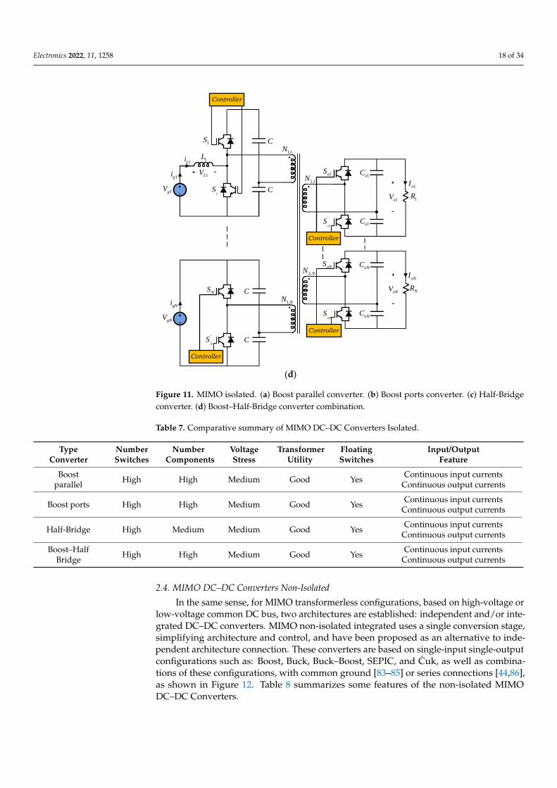
2.3. MIMO DC–DC Converters Isolated
In the same way, MIMO DC–DC converters for combining various output loadsand input sources, they have become an interesting alternative in recent years, especiallybecause they allow the integration of different sources, such as: Rectifiers, PhotovoltaicSystems, Fuel Cells, Batteries, Supercapacitors, and, in some cases, Wind Energy Systems.Fundamentally, MIMO converters are implemented according with two structures: sharinga high voltage or low voltage common DC bus; and sharing one or more transformers; orboth architectures are also possible.
MIMO isolated configurations use a multi-winding transformer to transfer the energyfrom the primary side to the secondary side and to couple the different sources and loads,with several power switches and centralized or distributed control signals. Several con-figurations can be derived from Full-Bridge, Half-Bridge Push–Pull Forward and Flybacktopologies, and other such as those shown in Figure 11 [81,82]. These converters consistof Boost, Half-Bridge, or the called Boost–Dual-Half-Bridge (BDHB) topologies. In theseconverters, the conversion ratio and output voltages depend on the control strategy of thepower switches, operation modes, and the turns ratio between the transformer windings.Normally, the power switches are controlled by phase-shifted PWM operating at 50% dutycycle, in CCM and DCM. Table 7 shows some features of the MIMO isolated converters.
Electronics 2022, 11, x FOR PEER REVIEW 17 of 35
( )
( )
1 3
1 2
2 3
2
1
1
1
o g
o g
o g
DV V CCM
D
DV V CCM
D
V V
−
−
−
=−
+=
−
=
gVgi
1Li
1LV1L
S
3LV3L
3oC2CV
3Li
2C
3D
2Li2L
1D
2LV
1oC1CV
1C
2oC
2D
2oV
3oi
1oi
2oi
1 3R −
1R1 2oV− 1oV
2R
3R
1 2R −
2 3R −
2 3oV− 3oV
1 3oV−
2oV
3oV
1oV
( )
( )
1 3
2
1
1
1
o o g
o g
DV V V CCM
D
V V CCMD
= =−
=−
PWM
Figure 10. Three-output-type converter combination for six loads.
2.3. MIMO DC–DC Converters Isolated
In the same way, MIMO DC–DC converters for combining various output loads
and input sources, they have become an interesting alternative in recent years, especially
because they allow the integration of different sources, such as: Rectifiers, Photovoltaic
Systems, Fuel Cells, Batteries, Supercapacitors, and, in some cases, Wind Energy Sys-
tems. Fundamentally, MIMO converters are implemented according with two struc-
tures: sharing a high voltage or low voltage common DC bus; and sharing one or more
transformers; or both architectures are also possible.
MIMO isolated configurations use a multi-winding transformer to transfer the en-
ergy from the primary side to the secondary side and to couple the different sources and
loads, with several power switches and centralized or distributed control signals. Sever-
al configurations can be derived from Full-Bridge, Half-Bridge Push–Pull Forward and
Flyback topologies, and other such as those shown in Figure 11 [81,82]. These converters
consist of Boost, Half-Bridge, or the called Boost–Dual-Half-Bridge (BDHB) topologies.
In these converters, the conversion ratio and output voltages depend on the control
strategy of the power switches, operation modes, and the turns ratio between the trans-
former windings. Normally, the power switches are controlled by phase-shifted PWM
operating at 50% duty cycle, in CCM and DCM. Table 7 shows some features of the
MIMO isolated converters.
1gV
1gi
1
´S
1Li 1L
1LV
1S
2gV
2gi
2
´S
2Li 2L
2LV
2S
gNV
gNi
´
NS
LNi L
LNV
NS
C
C
1N1
´
oS
1oS
1oC
1oC2N
1R
1oI
1oV
´
oNS
oNS
oNC
oNCNN
NR
oNI
oNV
Controller
Controller
Controller
(a)
Figure 11. Cont.

Electronics 2022, 11, 1258 17 of 34Electronics 2022, 11, x FOR PEER REVIEW 18 of 35
1
´
oS
1oS
1oC
1oC2 1N ,
1R
1oI
1oV
´
oNS
oNS
oNC
oNC2 NN ,
NR
oNI
oNV
Controller
Controller
1gV
1gi
1S´
1Li 1L
1LV
1S
C
C
11N ,
Controller
gNV
gNi
´
NS
LNi NL
LNV
NS
C
C
1 NN ,
Controller
(b)
1gV
1gi
C
C
11,N
gNV
gNi
C
C
1,NN
1oC
1oC2 1N ,
1R
1oI
1oV
´
oNS
oNS
oNC
oNC2 NN ,
NR
oNI
oNV
Controller
1
´
oS
1oS
Controller
1S´
1S
Controller
NS´
NS
Controller
(c)
Figure 11. Cont.
Electronics 2022, 11, 1258 18 of 34Electronics 2022, 11, x FOR PEER REVIEW 19 of 35
1
´
oS
1oS
1oC
1oC2 1N ,
1R
1oI
1oV
´
oNS
oNS
oNC
oNC2 NN ,
NR
oNI
oNV
Controller
Controller
1gV
1gi
1S´
1Li 1L
1LV
1S
C
C
11N ,
Controller
gNV
gNi
C
C
1,NN
NS´
NS
Controller
(d)
Figure 11. MIMO isolated. (a) Boost parallel converter. (b) Boost ports converter. (c) Half-Bridge
converter. (d) Boost–Half-Bridge converter combination.
Table 7. Comparative summary of MIMO DC–DC Converters Isolated.
Type
Converter
Number
Switches
Number
Components
Voltage
Stress
Transformer
Utility
Floating
Switches
Input/Output
Feature
Boost
parallel High High Medium Good Yes
Continuous input currents
Continuous output currents
Boost ports High High Medium Good Yes Continuous input currents
Continuous output currents
Half-Bridge High Medium Medium Good Yes Continuous input currents
Continuous output currents
Boost–Half
Bridge High High Medium Good Yes
Continuous input currents
Continuous output currents
2.4. MIMO DC–DC Converters Non-Isolated
In the same sense, for MIMO transformerless configurations, based on high-voltage
or low-voltage common DC bus, two architectures are established: independent and/or
integrated DC–DC converters. MIMO non-isolated integrated uses a single conversion
stage, simplifying architecture and control, and have been proposed as an alternative to
independent architecture connection. These converters are based on single-input single-
output configurations such as: Boost, Buck, Buck–Boost, SEPIC, and Ćuk, as well as
combinations of these configurations, with common ground [83–85] or series connec-
tions [44,86], as shown in Figure 12. Table 8 summarizes some features of the non-
isolated MIMO DC–DC Converters.
Figure 11. MIMO isolated. (a) Boost parallel converter. (b) Boost ports converter. (c) Half-Bridgeconverter. (d) Boost–Half-Bridge converter combination.
Table 7. Comparative summary of MIMO DC–DC Converters Isolated.
TypeConverter
NumberSwitches
NumberComponents
VoltageStress
TransformerUtility
FloatingSwitches
Input/OutputFeature
Boostparallel High High Medium Good Yes Continuous input currents
Continuous output currents
Boost ports High High Medium Good Yes Continuous input currentsContinuous output currents
Half-Bridge High Medium Medium Good Yes Continuous input currentsContinuous output currents
Boost–HalfBridge High High Medium Good Yes Continuous input currents
Continuous output currents
2.4. MIMO DC–DC Converters Non-Isolated
In the same sense, for MIMO transformerless configurations, based on high-voltage orlow-voltage common DC bus, two architectures are established: independent and/or inte-grated DC–DC converters. MIMO non-isolated integrated uses a single conversion stage,simplifying architecture and control, and have been proposed as an alternative to inde-pendent architecture connection. These converters are based on single-input single-outputconfigurations such as: Boost, Buck, Buck–Boost, SEPIC, and Cuk, as well as combina-tions of these configurations, with common ground [83–85] or series connections [44,86],as shown in Figure 12. Table 8 summarizes some features of the non-isolated MIMODC–DC Converters.

Electronics 2022, 11, 1258 19 of 34Electronics 2022, 11, x FOR PEER REVIEW 20 of 35
1oC
1oi
1R1oV
1D1gi
L
LVLi
1gV
2oC
2oi
2R2oV
2gi
2gV
NoC
Noi
NRNoV
Ngi
1
´
NS
+1gVND
c
1S
2D
2S2
´D
2
´S
ND
NS
c
cc
cc
´
ND
´
NS
c
Controller
1oC
1oi
1R1oV
1
´D1gi
L
LVLi
1
´S1gV
1S
1D
2oC
2oi
2R2oV
2
´D2gi
2
´S2gV
2S
2D
NoC
Noi
NRNoV
´
NDNgi
´
NS1gV
NS
ND
Controller
(a) (b)
Figure 12. Non-isolated single-inductor MIMO Converters. (a) Series outputs [83–85]. (b) Series
inputs and series outputs [44,86].
Table 8. Comparative summary of MIMO DC–DC Converters Non-Isolated.
Type
Converter
Number
Switches
Number
Components
Voltage
Stress
Floating
Switches
Input/Output
Feature
Series outputs Medium Low High Yes Discontinuous input/
output currents
Series inputs and
series outputs Medium High High Yes
Discontinuous input/
output currents
Compared with independent architecture connection, integrated MIMO DC–DC
converters have the advantage of smaller size, fewer power conversion stages, and lower
cost. On the other hand, both the series inputs and the series inputs and series outputs
connection, with a single inductor, require a complex control system to avoid cross-
regulation problems, and the simultaneous application of different voltages coming
from the input sources, which limits the connection of a large number of sources and
loads.
The current trend in the development of DC–DC converters with multiple outputs
follows general aspects, such as low losses, high-power density, and high efficiency, as
well as the development of new architectures and control strategies. Certainly, simple
structures with a reduced number of components and power switches will be one of the
new trends, especially to reduce the size. However, the incorporation of devices with a
Wide Band Gap (WBG), particularly Gallium Nitride (GaN) and Silicon Carbide (SiC),
will establish future trends, advantages and disadvantages, in the development and ap-
plications of DC–DC converters with multiple outputs.
3. Multiple-Output DC–DC Converters Applications and Solutions
In this section, we present the applications of multiple-output DC–DC converters.
Although it’s impossible to list all type of applications, we try to present a wide variety
that can represent the most important types of applications and solutions that use mul-
tiple-output DC–DC converters. Figure summarizes some DC–DC converters’ applica-
tions, grouped in three major categories: High Power, Medium Power, and Low Power.
Figure 12. Non-isolated single-inductor MIMO Converters. (a) Series outputs [83–85]. (b) Seriesinputs and series outputs [44,86].
Table 8. Comparative summary of MIMO DC–DC Converters Non-Isolated.
TypeConverter
NumberSwitches
NumberComponents
VoltageStress
FloatingSwitches
Input/OutputFeature
Series outputs Medium Low High Yes Discontinuous input/output currents
Series inputs andseries outputs Medium High High Yes Discontinuous input/
output currents
Compared with independent architecture connection, integrated MIMO DC–DC con-verters have the advantage of smaller size, fewer power conversion stages, and lower cost.On the other hand, both the series inputs and the series inputs and series outputs connec-tion, with a single inductor, require a complex control system to avoid cross-regulationproblems, and the simultaneous application of different voltages coming from the inputsources, which limits the connection of a large number of sources and loads.
The current trend in the development of DC–DC converters with multiple outputsfollows general aspects, such as low losses, high-power density, and high efficiency, as wellas the development of new architectures and control strategies. Certainly, simple structureswith a reduced number of components and power switches will be one of the new trends,especially to reduce the size. However, the incorporation of devices with a Wide Band Gap(WBG), particularly Gallium Nitride (GaN) and Silicon Carbide (SiC), will establish futuretrends, advantages and disadvantages, in the development and applications of DC–DCconverters with multiple outputs.
3. Multiple-Output DC–DC Converters Applications and Solutions
In this section, we present the applications of multiple-output DC–DC converters.Although it’s impossible to list all type of applications, we try to present a wide varietythat can represent the most important types of applications and solutions that use multiple-output DC–DC converters. Figure summarizes some DC–DC converters’ applications,grouped in three major categories: High Power, Medium Power, and Low Power. Again,a partition like this will never be straightforward or even definitive, but it represents thetypical mindset when one thinks of general DC–DC converters.

Electronics 2022, 11, 1258 20 of 34
Also, in Figure 13, we can identify areas of applications like: telecommunication,medical, automotive, energy and power, robotic, UAVs, and drones. In the next sections,some of these areas are detailed, giving concrete examples of applications and solutionsused with multiple DC–DC converters.
Electronics 2022, 11, x FOR PEER REVIEW 21 of 35
Again, a partition like this will never be straightforward or even definitive, but it repre-
sents the typical mindset when one thinks of general DC–DC converters.
Also, in Figure 13, we can identify areas of applications like: telecommunication,
medical, automotive, energy and power, robotic, UAVs, and drones. In the next sections,
some of these areas are detailed, giving concrete examples of applications and solutions
used with multiple DC–DC converters.
Figure 13. Multiple-Output DC–DC Converters Applications.
3.1. Converters for More Electric Aircraft
In an airplane, the necessary power generated by an engine is converted into four
types of energy: hydraulic, mechanical, pneumatic, and electrical. In addition to the
power required for pushing, the current trend is to replace mechanical, pneumatic, and
hydraulic systems with an electric alternative [87,88]. This has led to a significant in-
crease in the electrical power of an aircraft, reaching values of the order of megawatts in
some models [89]. As a consequence, the electrical system has increased in complexity
with a large number of electronic converters, electrical machines, switches, protections,
and a variety of loads [90,91]. These systems are similar to a ground-based microgrid,
although there are some differences that make them unique. In this sense, a system with
a high level of reliability and safety is required with the advantage of having more pre-
dictable loads, changing their priority during the flight.
The electrical power system of an airplane is a system of multiple voltage levels,
connected through electronic power converters. The different voltage levels are stand-
ardized [92]:
— DC Voltages: 28 V, 270 V (±135 V) and 540 V (±270 V); and
Multiple Output DC-DC Converters
Se
gm
en
ted
Vo
lum
e o
f A
pp
lic
ati
on
s
High Power
Medium Power
Low Power
Medical
Charging Stations
E-Mobility
FCVs HEVsPHEVsBEVs
Passenger Vehicles Commercial Vehicles
Automotive
Robots, UAVs and DronesEnergy & Power
Telecommunication
Satellite Communication: Small Satellite, Nano Satellite, Mini Satellite
Renewable Energy
HVDC
Railway
More Electric Aircraft
Electric Ships
Aerial Robots Mobile Robots Marine Robots
Industrial Robots
IoT
Towers, Data Centres, Infrastructure and Data Security
Servers, Storage and Networking
(More than 10 kW)
(1 kW – 10 kW)
(1 kW and below)
Industry 4.0 IIoT
Non-Electric Vehicles/Electric Vehicles
Power Supply
Wireless Sensors
TherapeuticDiagnostic
Healthcare Devices
LVDC
Lighting
Figure 13. Multiple-Output DC–DC Converters Applications.
3.1. Converters for More Electric Aircraft
In an airplane, the necessary power generated by an engine is converted into fourtypes of energy: hydraulic, mechanical, pneumatic, and electrical. In addition to thepower required for pushing, the current trend is to replace mechanical, pneumatic, andhydraulic systems with an electric alternative [87,88]. This has led to a significant increasein the electrical power of an aircraft, reaching values of the order of megawatts in somemodels [89]. As a consequence, the electrical system has increased in complexity with alarge number of electronic converters, electrical machines, switches, protections, and avariety of loads [90,91]. These systems are similar to a ground-based microgrid, althoughthere are some differences that make them unique. In this sense, a system with a high levelof reliability and safety is required with the advantage of having more predictable loads,changing their priority during the flight.

Electronics 2022, 11, 1258 21 of 34
The electrical power system of an airplane is a system of multiple voltage levels,connected through electronic power converters. The different voltage levels are standard-ized [92]:
- DC Voltages: 28 V, 270 V (±135 V) and 540 V (±270 V); and- AC Voltages: 230/115 V with fixed frequency of 400 Hz and 230/115 V with variable
frequency (350–800 Hz).
There are different configurations of power systems for this type of application, one ofthem is the one shown in Figure 14. The two generators (coupled to each motor) and theAuxiliary Power Unit (APU) are connected to a three-phase AC 230 V network at variablefrequencies (350–800 Hz). Several AC–DC converters supply the ±270 V DC bus from thisnetwork. High power loads are directly fed from this bus, a low-voltage DC bus (28 V) andan AC network at a frequency of 400 Hz, by means a DC-AC converter.
Electronics 2022, 11, x FOR PEER REVIEW 22 of 35
— AC Voltages: 230/115 V with fixed frequency of 400 Hz and 230/115 V with variable
frequency (350–800 Hz).
There are different configurations of power systems for this type of application, one
of them is the one shown in Figure 14. The two generators (coupled to each motor) and
the Auxiliary Power Unit (APU) are connected to a three-phase AC 230 V network at
variable frequencies (350–800 Hz). Several AC–DC converters supply the ±270 V DC bus
from this network. High power loads are directly fed from this bus, a low-voltage DC
bus (28 V) and an AC network at a frequency of 400 Hz, by means a DC-AC converter.
In theses type of applications, the converters used are numerous and different, but
they all have in common that they are reliable, that they have high efficiency, and in
their designs the weight and size of the converter must be reduced [93,94]. In this sense,
multi-port converters are a solution that meets these design restrictions [95–97].
AC
DC
ESS
DC
AC
AC Three-Phase 230/115 V
G2APUS2G1 S1
350-800 Hz
AC
DC
HVDC
DC±270 V
DC
AC
DC
AC
DC
DC
DC
DC
DC
DC
Loads
S
S
DC
Loads
LVDC
S
DC 28 V
AC Three-Phase 230/115 V
400 Hz
AC
Loads
AC
Loads
AC Three-Phase 230/115 V
350-800 Hz
HVDC
DC±270 V
LVDC
DC 28 V
AC Three-Phase 230/115 V
400 Hz
Figure 14. Electric scheme for a More Electric Aircraft.
3.2. Converters for All Electric Ships
Recently, in ship design, the concept of All Electric Ship (AES) has emerged [98,99].
These types of applications include different loads, electric generators governed by die-
sel engines, energy storage systems, renewable energy sources, and a distribution net-
work that manages the energy of the entire system [100].
Traditionally, systems based on the AC system have been used, however, recently,
there is a trend towards the use of DC distribution systems, due to the advantages that
these present compared to AC distribution systems [101–103].
An example of a ship’s electrical system topology based on a DC distribution is
shown in Figure 15. Generally, the main power source is based on Synchronous Genera-
tors (GS) driven by diesel engines (fuel). The AC-DC converters feed the DC network
that can be monopolar or bipolar [104]. Virtually the entire system is powered from the
DC bus. Through DC–DC converters, the Renewable Energy Sources (RES), Energy
Storage System (ESS), and different loads of the DC type are connected. The Electric
Propulsion (EP) system is connected via a DC–AC converter. This can also have a small
isolated AC network.
Therefore, the electrical system of an AES is made up of a microgrid where the
power converters are a fundamental part of the system [105,106]. An adequate control
allows the system to function properly, with suitable DC bus voltage regulation and bal-
ancing the power flow between sources and loads. In this sense, the use of multiple-
output converters plays an important role since they allow the control of the system
when the DC network is bipolar type or to establish a common power strategy to differ-
ent loads through the converter itself.
Figure 14. Electric scheme for a More Electric Aircraft.
In theses type of applications, the converters used are numerous and different, but theyall have in common that they are reliable, that they have high efficiency, and in their designsthe weight and size of the converter must be reduced [93,94]. In this sense, multi-portconverters are a solution that meets these design restrictions [95–97].
3.2. Converters for All Electric Ships
Recently, in ship design, the concept of All Electric Ship (AES) has emerged [98,99].These types of applications include different loads, electric generators governed by dieselengines, energy storage systems, renewable energy sources, and a distribution networkthat manages the energy of the entire system [100].
Traditionally, systems based on the AC system have been used, however, recently,there is a trend towards the use of DC distribution systems, due to the advantages thatthese present compared to AC distribution systems [101–103].
An example of a ship’s electrical system topology based on a DC distribution is shownin Figure 15. Generally, the main power source is based on Synchronous Generators (GS)driven by diesel engines (fuel). The AC-DC converters feed the DC network that canbe monopolar or bipolar [104]. Virtually the entire system is powered from the DC bus.Through DC–DC converters, the Renewable Energy Sources (RES), Energy Storage System(ESS), and different loads of the DC type are connected. The Electric Propulsion (EP) systemis connected via a DC–AC converter. This can also have a small isolated AC network.

Electronics 2022, 11, 1258 22 of 34Electronics 2022, 11, x FOR PEER REVIEW 23 of 35
DC Bus
AC
DC
GFuel
AC
DC
GFuel
ESS
DC
DC
RES
DC
DC
AC
Microgrid
DC
AC
EP
DC
AC
RES
DC
DC
Loads
Figure 15. Electric scheme for all Electric Ships.
3.3. Converters for Electric/Hybrid Vehicles
The number of electric/hybrid vehicles is increasing considerably every year. In this
type of application, power electronics plays a fundamental role, both from the point of
view of efficiency and having lighter and smaller systems [107,108].
An important evolution has been the development of new semiconductor devices
that have made it possible to increase power, switching frequencies, and performance, at
the same time with reduced losses, weight, and cost [109,110].
Modern vehicles often have similar power schemes. Figure 16 represents a simpli-
fied diagram of an electric vehicle. The main source of energy is the battery, which is
usually of relatively high voltage. This feeds the traction motor of the vehicle through a
DC–DC converter and the traction control converter [111,112]. These converters are usu-
ally bidirectional to return energy in the event of vehicle braking [113,114]. In some cas-
es, there are several sources of energy storage (Li-Ion batteries, fuel cells, etc.) so the DC
converter is usually of the type of multiple input and single output [115,116].
A DC–DC converter makes it possible to supply vehicle auxiliary elements, such as
pumps, heaters, cooling system, lighting, etc., at lower voltages [117]. In addition, a low-
voltage auxiliary battery is usually included to power the entire control and safety sys-
tem of the vehicle.
In the case of electric or plug-in hybrid vehicles, the design of electronic systems for
charging batteries is of special interest. This has probably been one of the main reasons
why the electric vehicle has not been widely used in many countries. This has given rise
to research in two lines: the development of efficient and fast charging systems and the
development of network infrastructures that integrate the generation, transmission, dis-
tribution, and charging of vehicles [118]. In this sense, the possibility of designing smart
battery charging systems that are bi-directional is being studied, so that they not only act
as loads connected to the grid but at some point they can inject energy into the grid and,
thus, can contribute to the stability of the electrical system [119,120], such as Grid to Ve-
hicle (G2V) and Home to Vehicle (H2V), as well as Vehicle to Vehicle (V2V), Vehicle to
Home (V2H), Vehicle to Building (V2B), Vehicle to Grid (V2G), and Vehicle to Every-
thing (V2X) concepts.
Figure 15. Electric scheme for all Electric Ships.
Therefore, the electrical system of an AES is made up of a microgrid where the powerconverters are a fundamental part of the system [105,106]. An adequate control allows thesystem to function properly, with suitable DC bus voltage regulation and balancing thepower flow between sources and loads. In this sense, the use of multiple-output convertersplays an important role since they allow the control of the system when the DC networkis bipolar type or to establish a common power strategy to different loads through theconverter itself.
3.3. Converters for Electric/Hybrid Vehicles
The number of electric/hybrid vehicles is increasing considerably every year. In thistype of application, power electronics plays a fundamental role, both from the point ofview of efficiency and having lighter and smaller systems [107,108].
An important evolution has been the development of new semiconductor devices thathave made it possible to increase power, switching frequencies, and performance, at thesame time with reduced losses, weight, and cost [109,110].
Modern vehicles often have similar power schemes. Figure 16 represents a simplifieddiagram of an electric vehicle. The main source of energy is the battery, which is usuallyof relatively high voltage. This feeds the traction motor of the vehicle through a DC–DC converter and the traction control converter [111,112]. These converters are usuallybidirectional to return energy in the event of vehicle braking [113,114]. In some cases, thereare several sources of energy storage (Li-Ion batteries, fuel cells, etc.) so the DC converter isusually of the type of multiple input and single output [115,116].
A DC–DC converter makes it possible to supply vehicle auxiliary elements, suchas pumps, heaters, cooling system, lighting, etc., at lower voltages [117]. In addition, alow-voltage auxiliary battery is usually included to power the entire control and safetysystem of the vehicle.
In the case of electric or plug-in hybrid vehicles, the design of electronic systems forcharging batteries is of special interest. This has probably been one of the main reasonswhy the electric vehicle has not been widely used in many countries. This has givenrise to research in two lines: the development of efficient and fast charging systems andthe development of network infrastructures that integrate the generation, transmission,distribution, and charging of vehicles [118]. In this sense, the possibility of designing smartbattery charging systems that are bi-directional is being studied, so that they not only

Electronics 2022, 11, 1258 23 of 34
act as loads connected to the grid but at some point they can inject energy into the gridand, thus, can contribute to the stability of the electrical system [119,120], such as Grid toVehicle (G2V) and Home to Vehicle (H2V), as well as Vehicle to Vehicle (V2V), Vehicle toHome (V2H), Vehicle to Building (V2B), Vehicle to Grid (V2G), and Vehicle to Everything(V2X) concepts.
Electronics 2022, 11, x FOR PEER REVIEW 24 of 35
Figure 16. Scheme of an electric vehicle.
3.4. Converters for DC Microgrids
For almost a century, an electrical system model based on AC system has been fol-
lowed. In this model, the energy is generated in large power plants and is transported
through transmission networks to the places of consumption, which are usually far from
the production centers. The advantage of AC is that it is easy to modify the voltage lev-
els, which is necessary to reduce losses in energy transport.
With the proliferation of renewable energies, the electrical system has changed to-
wards a system in which small power generators are incorporated, located close to con-
sumers. This new model has been called a distributed generation system. Recently, a
system has been proposed in which consumers have a net balance of zero energy. For
this, electrical microgrids are proposed [121–123], where together with the loads and
generators, energy storage systems are added to make the system self-sufficient and
manageable. In many cases, the storage system is replaced by the public electricity grid
so that energy is injected into it if it exceeds the microgrid and is absorbed from the grid
if necessary.
Microgrids can be of the AC or DC type [124,125]. In this case, the debate between
these two systems has been raised again, since most of the generation systems with re-
newable energies work in DC and on the other hand, currently, most of the loads work
in DC form [126]. In addition, DC networks have the following advantages from a tech-
nical point of view:
• DC networks are more efficient, they have less loss in the transmission of energy,
because the effective resistance, for equal section, is lower;
• Fewer conductors are required for distribution;
• They are more stable than AC networks;
• There are no line reactances, which results in lower voltage drops;
• The frequency is zero, thus eliminating the need for a synchronization system when
connecting a generation system to the grid;
• There is no transient stability problem as in AC networks; and
• No electromagnetic interference is generated.
However, from an implementation point of view, it has two clear drawbacks
[127,128]:
• Currently there are no infrastructures for this type of networks; and
• The protection of DC systems is usually more complex due to the constant value of
the voltage.
Figure 16. Scheme of an electric vehicle.
3.4. Converters for DC Microgrids
For almost a century, an electrical system model based on AC system has been fol-lowed. In this model, the energy is generated in large power plants and is transportedthrough transmission networks to the places of consumption, which are usually far fromthe production centers. The advantage of AC is that it is easy to modify the voltage levels,which is necessary to reduce losses in energy transport.
With the proliferation of renewable energies, the electrical system has changed towardsa system in which small power generators are incorporated, located close to consumers.This new model has been called a distributed generation system. Recently, a system hasbeen proposed in which consumers have a net balance of zero energy. For this, electricalmicrogrids are proposed [121–123], where together with the loads and generators, energystorage systems are added to make the system self-sufficient and manageable. In manycases, the storage system is replaced by the public electricity grid so that energy is injectedinto it if it exceeds the microgrid and is absorbed from the grid if necessary.
Microgrids can be of the AC or DC type [124,125]. In this case, the debate between thesetwo systems has been raised again, since most of the generation systems with renewableenergies work in DC and on the other hand, currently, most of the loads work in DCform [126]. In addition, DC networks have the following advantages from a technical pointof view:
• DC networks are more efficient, they have less loss in the transmission of energy,because the effective resistance, for equal section, is lower;
• Fewer conductors are required for distribution;• They are more stable than AC networks;• There are no line reactances, which results in lower voltage drops;• The frequency is zero, thus eliminating the need for a synchronization system when
connecting a generation system to the grid;• There is no transient stability problem as in AC networks; and• No electromagnetic interference is generated.
However, from an implementation point of view, it has two clear drawbacks [127,128]:
• Currently there are no infrastructures for this type of networks; and

Electronics 2022, 11, 1258 24 of 34
• The protection of DC systems is usually more complex due to the constant value ofthe voltage.
It can be concluded that DC networks can be an alternative to AC networks whenthere are distributed generation systems and high quality and efficiency are sought inthe system.
There are three different topologies for DC networks: homopolar, bipolar, and monopo-lar [69]. Among these topologies, the most versatile is the bipolar DC network, despitepresenting greater complexity. In a bipolar DC network, there are three conductors “+”,“−”, and “0”, Figure 17. The loads can be connected to two voltage levels. This is interestingin the case of loads with high consumption that, if connected to the highest voltage, reducethe absorbed current by half. On the other hand, part of the network could continue tofunction when a failure occurs in the other part. It is also interesting to note that the currentthrough the “0” conductor is much smaller than through the other conductors, so thesystem could be designed for a smaller section of this conductor.
Electronics 2022, 11, x FOR PEER REVIEW 25 of 35
It can be concluded that DC networks can be an alternative to AC networks when
there are distributed generation systems and high quality and efficiency are sought in
the system.
There are three different topologies for DC networks: homopolar, bipolar, and
monopolar [69]. Among these topologies, the most versatile is the bipolar DC network,
despite presenting greater complexity. In a bipolar DC network, there are three conduc-
tors “+”, “−”, and “0”, Figure 17. The loads can be connected to two voltage levels. This
is interesting in the case of loads with high consumption that, if connected to the highest
voltage, reduce the absorbed current by half. On the other hand, part of the network
could continue to function when a failure occurs in the other part. It is also interesting to
note that the current through the “0” conductor is much smaller than through the other
conductors, so the system could be designed for a smaller section of this conductor.
For the connection of distributed generation systems to a bipolar network, reliable
and efficient DC–DC converters with a bipolar input and output are required. The con-
verter will make it possible to adapt the output voltage of the source and control the
power flow between the source and the microgrid. Its design and control play a funda-
mental role for the proper functioning of the microgrid. There are many topologies pro-
posed in the literature, both in their non-isolated and isolated versions, unidirectional or
bidirectional, for applications in DC microgrids [129–131]. There are also many control
strategies proposed, so as to ensure adequate power quality or the balance of system
voltages [76,132].
Bipolar
DC
ConsumerDC
DC
+0
-
DC
DC
DC
DC
Storage
Energy
DC
DC
Small
Consumer
AC
Microgrid
AC
DC
Win
Energy
Figure 17. Bipolar DC microgrid.
3.5. Converters for LED Ilumination Systems
LED (Light Emitting Diode) lighting has become the main source of artificial light
today. It is expected to be the primary source for decades to come due to its long service
life, high luminous efficacy, and flexibility in color mixing. Above all this is the great en-
ergy savings compared to traditional light sources that together with the reduction in
the cost of LEDs have made them widely used in the lighting of streets, buildings,
homes, monuments, traffic signs, screens, etc. [133].
In LED lighting, the driver circuit plays a fundamental role, mainly in the efficiency
of the system [134,135]. The driver circuit basically consists of a DC–DC converter and a
Power Factor Correction (PFC) circuit. A current loop is included in the converter in or-
der to obtain a constant current control. The function of the PFC circuit is to eliminate
possible current harmonics and to correct the power factor, which turns out to be an in-
dispensable component in this type of system. Both circuits can be implemented in a
single stage, in two stages or in integrated stages. The single stage LED driver is a DC–
Figure 17. Bipolar DC microgrid.
For the connection of distributed generation systems to a bipolar network, reliable andefficient DC–DC converters with a bipolar input and output are required. The converterwill make it possible to adapt the output voltage of the source and control the power flowbetween the source and the microgrid. Its design and control play a fundamental role forthe proper functioning of the microgrid. There are many topologies proposed in the litera-ture, both in their non-isolated and isolated versions, unidirectional or bidirectional, forapplications in DC microgrids [129–131]. There are also many control strategies proposed,so as to ensure adequate power quality or the balance of system voltages [76,132].
3.5. Converters for LED Ilumination Systems
LED (Light Emitting Diode) lighting has become the main source of artificial lighttoday. It is expected to be the primary source for decades to come due to its long servicelife, high luminous efficacy, and flexibility in color mixing. Above all this is the great energysavings compared to traditional light sources that together with the reduction in the cost ofLEDs have made them widely used in the lighting of streets, buildings, homes, monuments,traffic signs, screens, etc. [133].
In LED lighting, the driver circuit plays a fundamental role, mainly in the efficiencyof the system [134,135]. The driver circuit basically consists of a DC–DC converter and aPower Factor Correction (PFC) circuit. A current loop is included in the converter in order

Electronics 2022, 11, 1258 25 of 34
to obtain a constant current control. The function of the PFC circuit is to eliminate possiblecurrent harmonics and to correct the power factor, which turns out to be an indispensablecomponent in this type of system. Both circuits can be implemented in a single stage, intwo stages or in integrated stages. The single stage LED driver is a DC–DC converter withconstant current output that includes the power factor correction function [136–138]. Thetwo-stage LED driver consists of a PFC circuit plus a separate DC–DC converter [139,140].As an example, Figure 18 presents a block diagram of a LED illumination system. In theintegrated stage topology, the PFC circuit and the DC–DC converter can be simplified in asingle stage, sharing the active power switches and the control circuits [141,142].
Electronics 2022, 11, x FOR PEER REVIEW 26 of 35
DC converter with constant current output that includes the power factor correction
function [136–138]. The two-stage LED driver consists of a PFC circuit plus a separate
DC–DC converter [139,140]. As an example, Figure 18 presents a block diagram of a LED
illumination system. In the integrated stage topology, the PFC circuit and the DC–DC
converter can be simplified in a single stage, sharing the active power switches and the
control circuits [141,142].
Multichannel LEDs are used to ensure a high intensity of illumination. In this way,
high tensions of structures connected in series are avoided. This consists of several
branches each made up of several LEDs connected in series (LED Matrix). In each
branch the intensity is controlled from a DC–DC converter. There are several converter
topologies that have been proposed, both in isolated and non-isolated versions, in order
to obtain the maximum efficiency of the system [143–145]. In this situation it is where
the DC–DC converters with multiple outputs can have a special relevance, which allows
the power supply of each chain of LEDs and their control [146,147].
LED Matrix
Controller
LED Matrix
AC
LED Matrix
Driver
Figure 18. Block Diagram of LED illumination systems.
3.6. Multiple-Output DC–DC Converters for Satellite and Aerospace Applications
In aerospace and satellite applications, because it is an inhospitable and remote en-
vironment, power supplies should meet some important requirements, like size, weight,
impossible/costly online repairs, severe radiation, a wide range of temperatures they
have to withstand, and being a self-sustainable energy system, as the satellite should
generate, distribute, and convert power to different levels in order to provide power to
all the different blocks in the system, and they must have several different power-supply
output voltage levels. Therefore, very often DC–DC converters with multiple outputs
are used in this type of application.
Satellites are usually equipped with solar panels and rechargeable battery cells as
their energy source and storage. Both are complementary to each other during two al-
ternate phases. First, when a satellite faces the sun, photovoltaics in solar panels convert
sunlight into electrical energy; the generated power is supplied to the satellite’s sub-
systems, and, then, the remaining power is stored in battery cells. On the other hand,
during the eclipse phase (or the sun phase with a peak power demand), the stored ener-
gy in battery cells is used to operate the satellite sub-systems [148]. Moreover, power
management is critical because power demands must never exceed the generated power.
Regarding the energy usage in satellites, each sub-system’s power consumption is,
typically, a periodic consumption task, repeatedly in a specified amount of time. As
satellites are indispensable for navigation, weather forecast, broadcast, and many other
applications, several switching and linear regulators are used, according to the sub-
Figure 18. Block Diagram of LED illumination systems.
Multichannel LEDs are used to ensure a high intensity of illumination. In this way,high tensions of structures connected in series are avoided. This consists of several brancheseach made up of several LEDs connected in series (LED Matrix). In each branch the intensityis controlled from a DC–DC converter. There are several converter topologies that havebeen proposed, both in isolated and non-isolated versions, in order to obtain the maximumefficiency of the system [143–145]. In this situation it is where the DC–DC converters withmultiple outputs can have a special relevance, which allows the power supply of each chainof LEDs and their control [146,147].
3.6. Multiple-Output DC–DC Converters for Satellite and Aerospace Applications
In aerospace and satellite applications, because it is an inhospitable and remote en-vironment, power supplies should meet some important requirements, like size, weight,impossible/costly online repairs, severe radiation, a wide range of temperatures they haveto withstand, and being a self-sustainable energy system, as the satellite should generate,distribute, and convert power to different levels in order to provide power to all the dif-ferent blocks in the system, and they must have several different power-supply outputvoltage levels. Therefore, very often DC–DC converters with multiple outputs are used inthis type of application.
Satellites are usually equipped with solar panels and rechargeable battery cells as theirenergy source and storage. Both are complementary to each other during two alternatephases. First, when a satellite faces the sun, photovoltaics in solar panels convert sunlightinto electrical energy; the generated power is supplied to the satellite’s sub-systems, and,then, the remaining power is stored in battery cells. On the other hand, during the eclipsephase (or the sun phase with a peak power demand), the stored energy in battery cells is

Electronics 2022, 11, 1258 26 of 34
used to operate the satellite sub-systems [148]. Moreover, power management is criticalbecause power demands must never exceed the generated power.
Regarding the energy usage in satellites, each sub-system’s power consumption is,typically, a periodic consumption task, repeatedly in a specified amount of time. Assatellites are indispensable for navigation, weather forecast, broadcast, and many otherapplications, several switching and linear regulators are used, according to the sub-systemto which they provide power. Figure 19 represents a typical block diagram of an ElectricPower Supply subsystem of a satellite, in this case the CUBEsat [149]. As it can be seen, theElectric Power Supply subsystem contains solar panels, Boost converter with MaximumPower Point Tracker (MPPT), switching and linear regulators, over voltage protection anddifferent load switches on the input of each subsystem. Boost converter steps up the solarpanel voltage (4.4 V) to Power Distribution Bus (PDB) voltage level (14 ± 2 V). MPPToperates solar cells at maximum power point. Over voltage protection circuit keeps thePDB voltage within the operation limits. Switching and linear regulators step down thePDB voltage to different voltage levels required for all the subsystem components. Loadswitches supply and cutoff power from the subsystems through enable signal from anon-board processor.
Electronics 2022, 11, x FOR PEER REVIEW 27 of 35
system to which they provide power. Figure 19 represents a typical block diagram of an
Electric Power Supply subsystem of a satellite, in this case the CUBEsat [149]. As it can
be seen, the Electric Power Supply subsystem contains solar panels, Boost converter
with Maximum Power Point Tracker (MPPT), switching and linear regulators, over
voltage protection and different load switches on the input of each subsystem. Boost
converter steps up the solar panel voltage (4.4 V) to Power Distribution Bus (PDB)
voltage level (14 2 V). MPPT operates solar cells at maximum power point. Over
voltage protection circuit keeps the PDB voltage within the operation limits. Switching
and linear regulators step down the PDB voltage to different voltage levels required for
all the subsystem components. Load switches supply and cutoff power from the
subsystems through enable signal from an on-board processor.
CubeSat
Subsystems
External
Batteries
Over Voltage
Proteccion
Linear
Regulator
1
Linear
Regulator
2
Switching
Regulator
Switching
Regulator
Ref_3 V
3.3 V
3.3 V
5 V
Step-Up
Converter
(MPPT)
Load Switch
1
2
4
3
Load Switch
Load Switch
Load Switch
2
1
PDB4.4 V
Sola
r P
anel
Figure 19. Block diagram of Electric Power Supply subsystem of a satellite (CUBEsat).
3.7. Multiple-Output DC–DC Converters in Computer Applications
Computer systems are probably the most important and widely used systems now-
adays. Like any other electronic systems, computer systems need a Power Supply Unit
(PSU) to convert an input voltage into one or several power supply voltages appropriate
for its circuits. Systems like data centers, modems and communication networks, or even
desktop computers, include some of the major applications and give support to the in-
ter-net, provide data storage, support websites and databases, and support virtually al-
most every corporation and institution.
A computer system power-supply unit is a good example of application of
multiple-output DC–DC converters, as every computer system needs to supply energy
to different modules and, typically, several DC output values are needed. The most
common type of today’s PSU for computer systems is the Switch Mode Power Supply
(SMPS). Regarding this type of PSU, there is a wide variety of topologies used by PSU
manufacturers. However, all topologies use the same basic concepts [150]. For example,
considering the application of DC–DC converters for a common desktop computer,
Figure 20 presents a typical block diagram of a PSU. Usually, it consists of a front-end
Power Factor Correction (PFC) stage and an isolated DC–DC stage [151]. The output
blocks, as it can be seen, present multiple-output converters where three output DC
voltages are available: 3 V, 5 V, and 12 V.
Figure 19. Block diagram of Electric Power Supply subsystem of a satellite (CUBEsat).
3.7. Multiple-Output DC–DC Converters in Computer Applications
Computer systems are probably the most important and widely used systems nowa-days. Like any other electronic systems, computer systems need a Power Supply Unit (PSU)to convert an input voltage into one or several power supply voltages appropriate for itscircuits. Systems like data centers, modems and communication networks, or even desk-top computers, include some of the major applications and give support to the inter-net,provide data storage, support websites and databases, and support virtually almost everycorporation and institution.
A computer system power-supply unit is a good example of application of multiple-output DC–DC converters, as every computer system needs to supply energy to differentmodules and, typically, several DC output values are needed. The most common type oftoday’s PSU for computer systems is the Switch Mode Power Supply (SMPS). Regardingthis type of PSU, there is a wide variety of topologies used by PSU manufacturers. However,all topologies use the same basic concepts [150]. For example, considering the applicationof DC–DC converters for a common desktop computer, Figure 20 presents a typical blockdiagram of a PSU. Usually, it consists of a front-end Power Factor Correction (PFC) stageand an isolated DC–DC stage [151]. The output blocks, as it can be seen, present multiple-output converters where three output DC voltages are available: 3 V, 5 V, and 12 V.

Electronics 2022, 11, 1258 27 of 34Electronics 2022, 11, x FOR PEER REVIEW 28 of 35
AC 85-265 V
Linear
Regulator
12 V
Power Factor
Correction
Rectifier and
EMI Filter
Voltage and
Current Sense Controller
LLC
Converter
Controller
Step-Up
Converter
Half-Bridge
Converter
AC
DC
Linear
Regulator
Synchronous
Rectifier
Controller
Half-Bridge
Rectifier
Step-Down
Converter
Two Outputs
Converter1ª Power
2ª PowerAuxiliar Power Supply
Multi-Output
Converter5 V Standby
5 V
3 V
Figure 20. Desktop computer power-supply unit.
3.8. Multiple-Output DC–DC Converters in Systems-on-a-Chip (SoC)
The increase complexity of today’s Systems-on-a-Chip (SoC) imposes the need to
integrate in a single chip all the major features that in the past were only available in
computer systems, which includes a power-management unit and, most likely, DC–DC
converters. In fact, a SoC is an electronic circuit that can integrate all the necessary com-
ponents present in a computer and other electronic systems, like a GPU (graphics-
processor unit), memory, power management circuits, CPU (central processing unit), a
USB controller, wireless radios (2G/3G/4G LTE, GPS, WiFi, FM radio, and Bluetooth)
and many more, but all integrated in a single chip. Being a very complex circuit, an SoC
needs a dedicated power-management unit that can be similar to typical computer sys-
tems, but although all integrated in silicon.
Several publications present PMU for SoC applications that have similar
architectures to PSU in computer systems (e.g., [152]). Figure 21 presents a typical block
diagram of a SoC and we can see the need of several linear regulators to supply different
building blocks with different power-supply voltage levels.
Step-Down
ConverterPower
Supply
Linear
Regulator
Linear
Regulator
RF
Module
Digital
Module
3.3 VStep-Down
Converter
Linear
Regulator
Linear
Regulator
Reference
Module
Analog
Module
1.8 V
1.2 V Linear
RegulatorDigital
Module
Step-Down
Converter
Linear
Regulator
Wake-up
Module
Power
Management IC
System-on-Chip
5 V
Figure 20. Desktop computer power-supply unit.
3.8. Multiple-Output DC–DC Converters in Systems-on-a-Chip (SoC)
The increase complexity of today’s Systems-on-a-Chip (SoC) imposes the need to inte-grate in a single chip all the major features that in the past were only available in computersystems, which includes a power-management unit and, most likely, DC–DC converters. Infact, a SoC is an electronic circuit that can integrate all the necessary components present ina computer and other electronic systems, like a GPU (graphics-processor unit), memory,power management circuits, CPU (central processing unit), a USB controller, wireless radios(2G/3G/4G LTE, GPS, WiFi, FM radio, and Bluetooth) and many more, but all integrated ina single chip. Being a very complex circuit, an SoC needs a dedicated power-managementunit that can be similar to typical computer systems, but although all integrated in silicon.
Several publications present PMU for SoC applications that have similar architecturesto PSU in computer systems (e.g., [152]). Figure 21 presents a typical block diagram of aSoC and we can see the need of several linear regulators to supply different building blockswith different power-supply voltage levels.
Electronics 2022, 11, x FOR PEER REVIEW 28 of 35
AC 85-265 V
Linear
Regulator
12 V
Power Factor
Correction
Rectifier and
EMI Filter
Voltage and
Current Sense Controller
LLC
Converter
Controller
Step-Up
Converter
Half-Bridge
Converter
AC
DC
Linear
Regulator
Synchronous
Rectifier
Controller
Half-Bridge
Rectifier
Step-Down
Converter
Two Outputs
Converter1ª Power
2ª PowerAuxiliar Power Supply
Multi-Output
Converter5 V Standby
5 V
3 V
Figure 20. Desktop computer power-supply unit.
3.8. Multiple-Output DC–DC Converters in Systems-on-a-Chip (SoC)
The increase complexity of today’s Systems-on-a-Chip (SoC) imposes the need to
integrate in a single chip all the major features that in the past were only available in
computer systems, which includes a power-management unit and, most likely, DC–DC
converters. In fact, a SoC is an electronic circuit that can integrate all the necessary com-
ponents present in a computer and other electronic systems, like a GPU (graphics-
processor unit), memory, power management circuits, CPU (central processing unit), a
USB controller, wireless radios (2G/3G/4G LTE, GPS, WiFi, FM radio, and Bluetooth)
and many more, but all integrated in a single chip. Being a very complex circuit, an SoC
needs a dedicated power-management unit that can be similar to typical computer sys-
tems, but although all integrated in silicon.
Several publications present PMU for SoC applications that have similar
architectures to PSU in computer systems (e.g., [152]). Figure 21 presents a typical block
diagram of a SoC and we can see the need of several linear regulators to supply different
building blocks with different power-supply voltage levels.
Step-Down
ConverterPower
Supply
Linear
Regulator
Linear
Regulator
RF
Module
Digital
Module
3.3 VStep-Down
Converter
Linear
Regulator
Linear
Regulator
Reference
Module
Analog
Module
1.8 V
1.2 V Linear
RegulatorDigital
Module
Step-Down
Converter
Linear
Regulator
Wake-up
Module
Power
Management IC
System-on-Chip
5 V
Figure 21. Block diagram showing general architecture of power supply in a SoC (System-on-a-Chip).

Electronics 2022, 11, 1258 28 of 34
However, to facilitate the integration of all blocks, other type of DC–DC convert-ers are used, like Switched-Capacitor (SC) based DC–DC converters, because they allowmonolithic substrate integration due to the reduction of silicon surface required and size,and contribute towards reduced electromagnetic effects and power losses. As an exam-ple, in [153], Multiple-Output Switched-Capacitor DC–DC Combination Converters arepresented, for use in SoC focusing IoT applications.
Moreover, the need to reduce power consumption in today’s chips brings the use ofaggressive power-reduction techniques, and multi-domain power supplies are increasinglybeing used to accomplish power reduction [154]. To achieve ultra-low-power consumptionlevels, especially in new SoC for IoT, Dynamic Voltage and Frequency Scaling (DVFS)techniques should be used, to work at different power-supply voltage (VDD) and clockfrequency levels (as explained in [155]). These new low-power techniques demand newDC–DC converters, with adjustable output-voltage values, or with multiple simultane-ous output values available. Therefore, SoC applications are a good example to showthat DC–DC converters with multiple outputs have still a long way ahead for researchand development.
4. Conclusions
In this paper, we present an overview of the most important topics related to multiple-output DC–DC converters based on their main topologies and configurations, applications,solutions, and trends. Our goal is to highlight a wide variety of configurations and topolo-gies of multiple-output DC–DC converters. We show more than 30 topologies, isolated andnon-isolated, single and multiple switched, based on soft- and hard-switching techniques,which are used in many different applications and solutions. However, the current trendin the development of multiple-output DC–DC converters follows general aspects, suchas high-power density, high efficiency, and low losses, as well as the development of newarchitectures and control strategies. Certainly, simple structures with a reduced number ofcomponents and power switches are one of the new trends, especially to reduce the size.
Also, several applications of multiple-output DC–DC converters were presented in thispaper. A wide variety of examples were presented, to characterize the most important typesof applications and solutions that use these converters, showing High Power, MediumPower, and Low Power application examples.
Author Contributions: S.P.L., E.D., J.S. and C.D.-M. have written the original draft and have reviewedand edited the paper, the conceptualization, the methodology, and the analysis of the state of the art.All authors have read and agreed to the published version of the manuscript.
Funding: This research received no external funding.
Conflicts of Interest: The authors declare no conflict of interest.
References1. Ballestín-Fuertes, J.; Muñoz-Cruzado-Alba, J.; Sanz-Osorio, J.F.; Laporta-Puyal, E. Role of Wide Bandgap Materials in Power
Electronics for Smart Grids Applications. Electronics 2021, 10, 677. [CrossRef]2. 360 Market Updates. Available online: https://www.360marketupdates.com/ (accessed on 1 April 2022).3. Absolute Reports. Available online: https://www.absolutereports.com/ (accessed on 1 April 2022).4. Allied Market Research. Available online: https://www.alliedmarketresearch.com/ (accessed on 1 April 2022).5. DataM Intelligence. Available online: https://www.datamintelligence.com/ (accessed on 1 April 2022).6. IDTechEx Research Reports. Available online: https://www.idtechex.com/ (accessed on 1 April 2022).7. Market Research Future. Available online: https://www.marketresearchfuture.com/ (accessed on 1 April 2022).8. Market Research Reports, Business Communications Company (BCC). Available online: https://www.bccresearch.com/ (ac-
cessed on 1 April 2022).9. Omdia Research by Market. Available online: https://omdia.tech.informa.com/ (accessed on 1 April 2022).10. Report Linker. Available online: https://www.reportlinker.com/ (accessed on 1 April 2022).11. Valuates Reports. Available online: https://reports.valuates.com/ (accessed on 1 April 2022).12. eeNews Europe (Electronics Europe News). Available online: https://www.eenewseurope.com/search/node/multiple%20
output%20dc-dc%20converters (accessed on 1 April 2022).
Electronics 2022, 11, 1258 29 of 34
13. eeNews Embedded. Available online: https://www.eenewsembedded.com/search/node/multiple%20output%20dc-dc%20converters (accessed on 1 April 2022).
14. Electronics Design eNewsletter. Available online: https://www.electronicdesign.com/search?ebm_electronicdesign%5Bquery%5D=multiple%20output%20dc-dc%20converters (accessed on 1 April 2022).
15. EE Times Europe Magazine. Available online: https://www.eetimes.eu/?s=multiple+output+dc-dc+converters (accessed on1 April 2022).
16. Power Electronics News. Available online: https://www.powerelectronicsnews.com/?s=multiple+output+dc-dc+converters(accessed on 1 April 2022).
17. Smart2.0. Available online: https://www.smart2zero.com/search/node/multiple%20output%20dc-dc%20converters (accessedon 1 April 2022).
18. DC–DC Converter Market by Vertical, Form Factor (SIP, DIP, DIN Rail, Box, Chassis Mount, Discreter, Brick), Input Voltage,Output Voltage, Output Power, Output Number, Product Type, Isolation Working Voltage and Region-Forecast to 2026.Available online: https://www.researchandmarkets.com/reports/5401801/dc-dc-converter-market-by-vertical-form-factor?utm_source=MC&utm_medium=Email&utm_code=mzrfk4g55&utm_ss=44&utm_campaign=1589384+-+dc-dc+converter+Market+-+Forecast+to+2026&utm_exec=cono266mtd (accessed on 1 April 2022).
19. Global Switching Power Supply Market Size, Trends & Growth Opportunity, by Voltage Rating, by Application, by Region andForecast to 2027. Available online: https://www.researchandmarkets.com/reports/5437868/global-switching-power-supply-market-size-trends?utm_source=MC&utm_medium=Email&utm_code=mzrj5rgey&utm_ss=44&utm_campaign=1587831+-+Global+Switching+Power+Supply+Market+Size%2c+Trends+%26+Growth+Opportunity%2c+and+Forecast+to+2027&utm_exec=cono266mtd (accessed on 1 April 2022).
20. Global DC–DC Converters Market Research Report 2021, Forecast to 2026. Available online: https://www.360marketupdates.com/global-DC--DC-converters-market-19159087 (accessed on 1 April 2022).
21. Rugged Power Supply Market Global Industry Analysis, Size, Share, Growth, Trends, and Forecast 2017–2025. Availableonline: https://www.bccresearch.com/partners/transparency/rugged-power-supply-market-global-industry-analysis-size-share-growth-trends-and-forecast.html (accessed on 1 April 2022).
22. Medical Power Supply Market, Size, Share, Growth, Trends, Insight and Industry Forecast 2021–2028. Available online: https://www.datamintelligence.com/research-report/medical-power-supply-market (accessed on 1 April 2022).
23. DC–DC Converter Market by Vertical, Form Factor, Input Voltage, Output Voltage, Output Power, Output Number, Product Type,Isolation Working Voltage and Region-Forecast to 2026. Available online: https://www.reportlinker.com/p04180622/Global-dc-dc-Converters-Market-by-Application-Output-Number-Input-Voltage-Output-Voltage-Output-Power-Sales-Channel-Form-Factor-Product-Type-and-Region-Forecast-to.html (accessed on 1 April 2022).
24. 5G Small Cells 2021–2031: Technologies, Markets, Forecast. Available online: https://www.idtechex.com/en/research-report/5g-small-cells-2021-2031-technologies-markets-forecast/825 (accessed on 1 April 2022).
25. LED Supply & Demand Market Tracker—1Q21 Analysis. Available online: https://omdia.tech.informa.com/OM018423/LED-Supply--Demand-Market-Tracker--1Q21-Analysis (accessed on 1 April 2022).
26. Rugged Power Supply Market Research Report, by Component (Hardware and Software), System Type (Discrete and Integrated),Industry Vertical (Defense, Aerospace, Telecommunications, Manufacturing, Healthcare, and Transportation)—Forecast till2027. Available online: https://www.marketresearchfuture.com/reports/rugged-power-supply-market-7150 (accessed on1 April 2022).
27. DC–DC Converter Market by Input Voltage (5–36 V, 36–75 V, 75 V and Above), Output Voltage (3.3 V, 5 V, 12 V, 15 V and Above),Mounting Style (Surface Mount and Through Hole), Application (Smartphone, Servers & Storage, EV Battery ManagementUnit, Railway, and Medical Equipment): Global Opportunity Analysis and Industry Forecast, 2020–2027. Available online:https://www.alliedmarketresearch.com/dc-dc-converter-market (accessed on 1 April 2022).
28. Massive Multiple-Input Multiple-Output (MIMO) Market-Growth, Trends, COVID-19 Impact, and Forecasts (2021–2026). Avail-able online: https://www.mordorintelligence.com/industry-reports/massive-multiple-input-multiple-output-mimo-market(accessed on 1 April 2022).
29. Global Power Supply Unit for Servers Market Size, Manufacturers, Supply Chain, Sales Channel and Clients, 2021–2027. Availableonline: https://reports.valuates.com/market-reports/QYRE-Auto-15M6756/global-power-supply-unit-for-servers (accessedon 1 April 2022).
30. Global Switching Power Supply Market 2021 by Manufacturers, Regions, Type and Application, Forecast to 2026. Availableonline: https://www.absolutereports.com/global-switching-power-supply-market-19180193 (accessed on 1 April 2022).
31. Aimtec. Available online: http://www.aimtec.com/manufacture-modular-ac-dc-dc-dc-switching-power-supplies (accessed on1 April 2022).
32. CUI. Available online: https://www.cui.com/catalog/dc-dc-converters (accessed on 1 April 2022).33. Delta Electronics. Available online: https://www.deltaww.com/en-US/products/dc-dc/ALL/ (accessed on 1 April 2022).34. Flex Ltd. Available online: https://flexpowermodules.com/ (accessed on 1 April 2022).35. Infineon Technologies AG. Available online: https://www.infineon.com/cms/en/product/power/dc-dc-converters/ (accessed
on 1 April 2022).
Electronics 2022, 11, 1258 30 of 34
36. Maxim Integrated. Available online: https://www.maximintegrated.com/en/products/power/switching-regulators.html(accessed on 1 April 2022).
37. MORNSUN Power. Available online: https://www.mornsun-power.com/html/products/1986/switching-regulator.html (ac-cessed on 1 April 2022).
38. Murata Power Solutions. Available online: https://www.murata.com/products/power (accessed on 1 April 2022).39. TDK Lambda. Available online: https://www.us.lambda.tdk.com/products/dcdc-converters/ (accessed on 1 April 2022).40. Texas Instruments. Available online: https://www.ti.com/power-management/overview.html (accessed on 1 April 2022).41. Traco Power. Available online: https://www.tracopower.com/dc-dc-converters (accessed on 1 April 2022).42. Vicor Corporation. Available online: https://www.vicorpower.com/dc-dc (accessed on 1 April 2022).43. Saman, D.T.; Peng, Z.; Lu, X.; Mohsen, H. Mutual Interactions and Stability Analysis of Bipolar DC Microgrids. CSEE J. Power
Energy Syst. 2019, 5, 444–453.44. Behjati, H.; Davoudi, A. A Multiple-Input Multiple Output DC–DC Converter. IEEE Trans. Ind. Appl. 2013, 49, 1464–1479.45. Tong, Y.; Shan, Z.; Jatskevich, J.; Davoudi, A. Anonisolated multiple-input multiple-output dc–dc converter for dc distribution of
future energy efficient homes. In Proceedings of the IEEE 40th Annual Conference of the Industrial Electronics Society, Dallas, TX,USA, 29 October–1 November 2014; pp. 4126–4132.
46. Taehyung, K.; Sangshin, K. Single pole switch leg based multi-port converter with an energy storage. Power Electron. IET 2016,9, 1322–1330.
47. Patra, P.; Patra, A.; Misra, N. A single-inductor multiple-output switcher with simultaneous Buck, Boost, and inverted out-puts.IEEE Trans. Power Electron. 2012, 27, 1936–1951. [CrossRef]
48. Huang, M.H.; Chen, K.H. Single-inductor multi-output (SIMO) DC–DC converters with high light-load efficiency and mini-mizedcross regulation for portable devices. IEEE J. Solid-State Circuits 2009, 44, 1099–1111. [CrossRef]
49. Dhananjaya, M.; Swapnajit, P. Design and implementation of a SIMO DC–DC converter. IET Power Electron. 2019, 12, 1868–1879.[CrossRef]
50. Dietrich, S.; Strache, S.; Wunderlich, R.; Heinen, S. Get the LED out: Experimental validation of a capacitor-free single-inductor,multiple-output LED driver topology. IEEE. Ind. Electron. Mag. 2015, 9, 24–35. [CrossRef]
51. Nami, A.; Zare, F.; Ghosh, A.; Blaabjerg, F. Multi-output dc–dc converters based on diode clamped converters configuration:Topology and control strategy. IET Power Electron. 2010, 3, 197–208. [CrossRef]
52. Lindiya, S.A.; Subashini, N.; Vijayarekha, K. Cross Regulation Reduced Optimal Multivariable Controller Design for SingleInductor DC–DC Converters. Energies 2019, 12, 477. [CrossRef]
53. Abraham, D.S.; Verma, R.; Kanagaraj, L.; Raman, S.G.T.; Rajamanickam, N.; Chokkalingam, B.; Sekar, K.M.; Mihet-Popa, L.Electric Vehicles Charging Stations’ Architectures, Criteria, Power Converters, and Control Strategies in Microgrids. Electronics2021, 10, 1895. [CrossRef]
54. Bose, B. Need a Switch? IEEE Ind. Electron. Mag. 2007, 1, 30–39. [CrossRef]55. Outeiro, M.T.; Buja, G.; Czarkowski, D. Resonant Power Converters: An Overview with Multiple Elements in the Reso-nant Tank
Network. IEEE Ind. Electron. Mag. 2016, 10, 21–45. [CrossRef]56. Salem, M.; Jusoh, A.; Idris, N.R.; Das, H.S.; Alhamrouni, I. Resonant power converters with respect to passive storage (LC)
ele-ments and control techniques—An overview. Renew. Sustain. Energy Rev. 2018, 91, 504–520. [CrossRef]57. Li, T. Single Inductor Multiple Output Boost Regulator. U.S. Patent 6,075,295A, 13 June 2000.58. Ma, D.; Ki, W.-H.; Mok, P.K.T.; Tsui, C.-Y. Single-inductor multiple-output switching converters. Proc. IEEE PESC 2001, 1, 226–231.59. Ma, D.; Ki, W.-H.; Tsui, C.-Y. A pseudo-CCM/DCM SIMO switching converter with freewheel switching. IEEE J. Solid-State
Circuits 2003, 38, 1007–1014.60. Soyka, R.; Rall, W.; Schnaubelt, J.; Sieger, P.; Kulinna, C. Process for Preparing Amino Crotonyl Compounds. U.S. Patent
20,050,085,495A1, 21 April 2005.61. Le, H.-P.; Chae, C.-S.; Lee, K.-C.; Wang, S.-W.; Cho, G.-H. A Single-Inductor Switching DC–DC Converter with Five Outputs and
Ordered Power-Distributive Control. IEEE J. Solid-State Circuits 2007, 42, 2706–2714. [CrossRef]62. Seol, K.-S.; Woo, Y.-J.; Cho, G.-H.; Gho, G.-H.; Lee, J.-W. A synchronous multioutput step-up/down dc–dc converter with return
current control. IEEE Trans. Circuits Syst. II Exp. Briefs 2009, 56, 210–214. [CrossRef]63. Kwon, D.; Rincon-Mora, G.A. Single-Inductor–Multiple-Output Switching DC–DC Converters. IEEE Trans. Circuits Syst. II
Express Briefs 2009, 56, 614–618. [CrossRef]64. Goder, D.; Santo, H. Multiple Output Regulator with Time Sequencing. U.S. Patent 5,617,015, 1 April 1997.65. Ma, D.; Ki, W.-H.; Tsui, C.Y.; Mok, P.K.T. Single-inductor multiple-output switching converters with time-multiplexing control in
discontinuous conduction mode. IEEE J. Solid-State Circuits 2003, 38, 89–100. [CrossRef]66. Li, X.L.; Dong, Z.; Tse, C.K. Complete family of two-stage singleinput multi-output configurations of interconnected power
converters. IEEE Trans. Power Electron. 2020, 35, 3713–3728. [CrossRef]67. Litrán, S.P.; Durán, E.; Barroso, R.S.; Semião, J.; Ferrera, M.B. Analysis of Converters with Bipolar Output for DC Mi-crogrid.
In Proceedings of the 2020 IEEE 14th International Conference on Compatibility, Power Electronics and Power Engineering(CPE-POWERENG), Setubal, Portugal, 8–10 July 2020; pp. 13–18.
68. Kakigano, H.; Miura, Y.; Ise, T. Low-Voltage Bipolar-Type DC Microgrid for Super High Quality Distribution. IEEE Trans. PowerElectron. 2010, 25, 3066–3075. [CrossRef]

Electronics 2022, 11, 1258 31 of 34
69. Zhang, M.; Jiang, Y.; Lee, F.; Jovanovic, M. Single-phase three-level boost power factor correction converter. In Proceedings ofthe 1995 IEEE Applied Power Electronics Conference and Exposition-APEC’95, Dallas, TX, USA, 5–9 March 1995; Volume 1,pp. 434–439.
70. Haddad, K. Three level DC–DC converters as efficient interface in two stage PV power systems. In Proceedings of the 2012 IEEEEnergytech, San Diego, CA, USA, 29–31 May 2012; pp. 1–6.
71. Rezayi, S.; Iman-Eini, H.; Hamzeh, M.; Bacha, S.; Farzamkia, S. Dual-output DC/DC boost converter for bipolar DC microgrids.IET Renew. Power Gener. 2019, 13, 1402–1410. [CrossRef]
72. Durán-Gómez, J.L.; García-Cervantes, E.; López-Flores, D.R.; Enjeti, P.N.; Palma, L. Analysis and evaluation of a series-combinedconnected boost and buck-boost DC–DC converter for photovoltaic application. In Proceedings of the Twenty-First Annual IEEEApplied Power Electronics Conference and Exposition, 2006, APEC’06, Dallas, TX, USA, 19–23 March 2006; pp. 19–23.
73. Schoenbauer, S.; Martin-Lopez, F.R. Single Inductor Buck Boost Converter with Positive and Negative Outputs. U.S. Patent20,100,039,080, 18 February 2010.
74. Kang, H.; Cha, H. A New Nonisolated High-Voltage-Gain Boost Converter with Inherent Output Voltage Balancing. IEEE Trans.Ind. Electron. 2017, 65, 2189–2198. [CrossRef]
75. Prabhakaran, P.; Agarwal, V. Novel Boost-SEPIC Type Interleaved DC–DC Converter for Mitigation of Voltage Imbalance in aLow-Voltage Bipolar DC Microgrid. IEEE Trans. Ind. Electron. 2019, 67, 6494–6504. [CrossRef]
76. Kumar, P.; Singh, R.K.; Mahanty, R. Performance of MPPT-Based Minimum Phase Bipolar Converter for Photovoltaic Systems.IEEE Trans. Power Electron. 2021, 36, 5594–5609. [CrossRef]
77. Zhou, X.; Wang, Y.; Wang, L.; Liu, Y.-F.; Sen, P.C. A Soft-Switching Transformerless DC−DC Converter with Single-Input BipolarSymmetric Outputs. IEEE Trans. Power Electron. 2021, 36, 8640–8646. [CrossRef]
78. Sanjeevikumar, P.; Bhaskar, M.S.; Dhond, P.; Blaabjerg, F.; Pecht, M. Non-isolated Sextuple Output Hybrid Triad ConverterConfigurations for High Step-Up Renewable Energy Applications. In Advances in Power Systems and Energy Management. LectureNotes in Electrical Engineering; Springer: Singapore, 2018; Volume 436, pp. 1–12.
79. Durán, E.; Litrán, S.P.; Ferrera, M.B. Configuration of DC–DC converters of one input and multiple outputs without trans-former.IET Power Electron. 2020, 13, 2658–2670. [CrossRef]
80. Ferrera Prieto, M.B.; Litran, S.P.; Aranda, E.D.; Gomez, J.M.E. New Single-Input, Multiple-Output Converter Topologies:Combining Single-Switch Nonisolated DC–DC Converters for Single-Input, Multiple-Output Applications. IEEE Ind. Electron.Mag. 2016, 10, 6–20. [CrossRef]
81. Tao, H.; Kotsopoulos, A.; Duarte, J.; Hendrix, M. Family of multiport bidirectional DC–DC converters. IEE Proc.-Electr. PowerAppl. 2006, 153, 451–458. [CrossRef]
82. Tao, H.; Kotsopoulos, A.; Duarte, J.; Hendrix, M. Multi-input bidirectional DC–DC converter combining DC-link and magnetic-coupling for fuel cell systems. In Proceedings of the Fourtieth IAS Annual Meeting. Conference Record of the 2005 IndustryApplications Conference, Hong Kong, China, 2–6 October 2005.
83. Li, X.L.; Dong, Z.; Tse, C.K.; Lu, D.D.-C. Single-Inductor Multi-Input Multi-Output DC–DC Converter with High Flexi-bility andSimple Control. IEEE Trans. Power Electron. 2020, 35, 13104–13114. [CrossRef]
84. Dong, Z.; Li, Z.; Lucia, X.; Chi, L.; Tse, K.; Zhang, Z. Single-Inductor Multiple-Input Multiple-Output Con-verter With CommonGround High Scalability and No Cross-Regulation. Power Electron. IEEE Trans. 2021, 36, 6750–6760. [CrossRef]
85. Chen, G.; Liu, Y.; Qing, X.; Ma, M.; Lin, Z. Principle and Topology Derivation of Single-Inductor Multi-Input Multi-OutputDC–DC Converters. IEEE Trans. Ind. Electron. 2021, 68, 25–36. [CrossRef]
86. Nguyen, B.L.-H.; Cha, H.; Nguyen, T.T.; Kim, H.G. Family of integrated multi-input multi-output DC–DC power converters. InProceedings of the 2018 International Power Electronics Conference (IPEC-Niigata 2018-ECCE Asia), Niigata, Japan, 20–24 May2018; pp. 3134–3139.
87. Roboam, X.; Sareni, B.; De Andrade, A. More Electricity in the Air: Toward Optimized Electrical Networks Embedded inMore-Electrical Aircraft. IEEE Ind. Electron. Mag. 2012, 6, 6–17. [CrossRef]
88. Ansell, P.J.; Haran, K.S. Electrified Airplanes: A Path to Zero-Emission Air Travel. IEEE Electrif. Mag. 2020, 8, 18–26. [CrossRef]89. Madonna, V.; Giangrande, P.; Galea, M. Electrical Power Generation in Aircraft: Review, Challenges, and Opportunities. IEEE
Trans. Transp. Electrif. 2018, 4, 646–659. [CrossRef]90. Wheeler, P.; Bozhko, S. The More Electric Aircraft: Technology and challenges. IEEE Electrif. Mag. 2014, 2, 6–12. [CrossRef]91. Brelje, B.J.; Martins, J.R. Electric, hybrid, and turboelectric fixed-wing aircraft: A review of concepts, models, and design
approaches. Prog. Aerosp. Sci. 2019, 104, 1–19. [CrossRef]92. Buticchi, G.; Bozhko, S.; Liserre, M.; Wheeler, P.; Al-Haddad, K. On-Board Microgrids for the More Electric Aircraft—Technology
Review. IEEE Trans. Ind. Electron. 2019, 66, 5588–5599. [CrossRef]93. Buticchi, G.; Costa, L.; Liserre, M. Improving System Efficiency for the More Electric Aircraft: A Look at dc\/dc Converters for
the Avionic Onboard dc Microgrid. IEEE Ind. Electron. Mag. 2017, 11, 26–36. [CrossRef]94. Rojas-Duenas, G.; Riba, J.-R.; Moreno-Eguilaz, M. A Deep Learning-Based Modeling of a 270 V-to-28 V DC–DC Converter Used
in More Electric Aircrafts. IEEE Trans. Power Electron. 2021, 37, 509–518. [CrossRef]95. Gu, C.; Yan, H.; Yang, J.; Sala, G.; De Gaetano, D.; Wang, X.; Galassini, A.; Degano, M.; Zhang, X.; Buticchi, G. A Multiport Power
Conversion System for the More Electric Aircraft. IEEE Trans. Transp. Electrif. 2020, 6, 1707–1720. [CrossRef]
Electronics 2022, 11, 1258 32 of 34
96. Yang, J.; Buticchi, G.; Gu, C.; Gunter, S.; Zhang, H.; Wheeler, P. A Generalized Input Impedance Model of Multiple Active BridgeConverter. IEEE Trans. Transp. Electrif. 2020, 6, 1695–1706. [CrossRef]
97. Buticchi, G.; Costa, L.F.; Liserre, M. Multi-port DC/DC converter for the electrical power distribution system of the more electricaircraft. Math. Comput. Simul. 2018, 158, 387–402. [CrossRef]
98. Khersonsky, Y.; Hingorani, N.; Peterson, K.L. IEEE Electric Ship Technologies initiative. In Proceedings of the 2009 Record ofConference Papers-Industry Applications Society 56th Annual Petruleum and Chemical Industry Conference, Anaheim, CA,USA, 14–16 September 2009; pp. 1–10. [CrossRef]
99. Mukund, R.P. Shipboard Electrical Power Systems; CRC Press: Boca Raton, FL, USA, 2012.100. Kim, K.; Park, K.; Roh, G.; Chun, K. DC-grid system for ships: A study of benefits and technical considerations. J. Int. Marit. Saf.
Environ. Aff. Shipp. 2018, 2, 1–12. [CrossRef]101. Thongam, J.S.; Tarbouchi, M.; Okou, A.F.; Bouchard, D.; Beguenane, R. Trends in naval ship propulsion drive motor technology. In
Proceedings of the 2013 IEEE Electrical Power & Energy Conference, Halifax, NS, Canada, 21–23 August 2013; pp. 1–5. [CrossRef]102. Su, C.-L.; Lin, K.-L.; Chen, C.-J. Power Flow and Generator-Converter Schemes Studies in Ship MVDC Distribution Systems.
IEEE Trans. Ind. Appl. 2015, 52, 50–59. [CrossRef]103. Skjong, E.; Volden, R.; Rodskar, E.; Molinas, M.; Johansen, T.A.; Cunningham, J. Past, Present, and Future Challenges of the
Marine Vessel’s Electrical Power System. IEEE Trans. Transp. Electrif. 2016, 2, 522–537. [CrossRef]104. Dai, J.; Nam, S.W.; Pande, M.; Esmaeili, G. Medium-Voltage Current-Source Converter Drives for Marine Propulsion System
Using a Dual-Winding Synchronous Machine. IEEE Trans. Ind. Appl. 2014, 50, 3971–3976. [CrossRef]105. Moradisizkoohi, H.; Elsayad, N.; Mohammed, O.A. A Bipolar DC–DC Converter with Wide Voltage-Gain Range for Energy
Storage Integration in Ship Power Systems. In Proceedings of the 2019 IEEE Electric Ship Technologies Symposium (ESTS),Washington, DC, USA, 14–16 August 2019; pp. 511–517.
106. Steinsland, V.; Kristensen, L.M.; Arghandeh, R.; Zhang, S. Design of Modular Multilevel Converters for the Shipnet in MediumVoltage DC All-Electric Ships. In Proceedings of the 2020 IEEE 21st Workshop on Control and Modeling for Power Electronics(COMPEL), Aalborg, Denmark, 9–12 November 2020; pp. 1–8.
107. Bazzi, A.M.; Liu, Y.; Fay, D.S. Electric Machines and Energy Storage: Over a Century of Technologies in Electric and HybridElectric Vehicles. IEEE Electrif. Mag. 2018, 6, 49–53. [CrossRef]
108. Ehsani, M.; Singh, K.V.; Bansal, H.O.; Mehrjardi, R.T. State of the Art and Trends in Electric and Hybrid Electric Vehicles. Proc.IEEE 2021, 109, 967–984. [CrossRef]
109. Saponara, S.; Lee, C.H.; Wang, N.X.; Kirtley, J.L. Electric Drives and Power Chargers: Recent Solutions to Improve Performanceand Energy Efficiency for Hybrid and Fully Electric Vehicles. IEEE Veh. Technol. Mag. 2020, 15, 73–83. [CrossRef]
110. Zhou, X.; Sheng, B.; Liu, W.; Chen, Y.; Wang, L.; Liu, Y.-F.; Sen, P.C. A High-Efficiency High-Power-Density On-Board Low-VoltageDC–DC Converter for Electric Vehicles Application. IEEE Trans. Power Electron. 2021, 36, 12781–12794. [CrossRef]
111. Elsayad, N.; Moradisizkoohi, H.; Mohammed, O.A. A Single-Switch Transformerless DC–DC Converter with Universal InputVoltage for Fuel Cell Vehicles: Analysis and Design. IEEE Trans. Veh. Technol. 2019, 68, 4537–4549. [CrossRef]
112. Janabi, A.; Wang, B. Switched-Capacitor Voltage Boost Converter for Electric and Hybrid Electric Vehicle Drives. IEEE Trans.Power Electron. 2019, 35, 5615–5624. [CrossRef]
113. Elsayad, N.; Moradisizkoohi, H.; Mohammed, O.A. A New Hybrid Structure of a Bidirectional DC–DC Converter with HighConversion Ratios for Electric Vehicles. IEEE Trans. Veh. Technol. 2019, 69, 194–206. [CrossRef]
114. Zhang, Y.; Gao, Y.; Zhou, L.; Sumner, M. A Switched-Capacitor Bidirectional DC–DC Converter with Wide Voltage Gain Rangefor Electric Vehicles With Hybrid Energy Sources. IEEE Trans. Power Electron. 2018, 33, 9459–9469. [CrossRef]
115. Gu, C.; Zheng, Z.; Xu, L.; Wang, K.; Li, Y. Modeling and Control of a Multiport Power Electronic Transformer (PET) for ElectricTraction Applications. IEEE Trans. Power Electron. 2016, 31, 915–927. [CrossRef]
116. Ahrabi, R.R.; Ardi, H.; Elmi, M.; Ajami, A. A Novel Step-Up Multiinput DC–DC Converter for Hybrid Electric VehiclesApplication. IEEE Trans. Power Electron. 2017, 32, 3549–3561. [CrossRef]
117. Saponara, S.; Tisserand, P.; Chassard, P.; My-Ton, D. DC/DC converter integrated architecture for 48V supplies in micro/mildhybrid vehicle electrical engine control module. In Proceedings of the 2016 IEEE 16th International Conference on Environmentand Electrical Engineering (EEEIC), Florence, Italy, 7–10 June 2016; pp. 1–5.
118. Rivera, S.; Kouro, S.; Vazquez, S.; Goetz, S.M.; Lizana, R.; Romero-Cadaval, E. Electric Vehicle Charging Infrastructure: From Gridto Battery. IEEE Ind. Electron. Mag. 2021, 15, 37–51. [CrossRef]
119. Khaligh, A.; D’Antonio, M. Global Trends in High-Power On-Board Chargers for Electric Vehicles. IEEE Trans. Veh. Technol. 2019,68, 3306–3324. [CrossRef]
120. Mehta, R.; Srinivasan, D.; Khambadkone, A.M.; Yang, J.; Trivedi, A. Smart Charging Strategies for Optimal Integration of Plug-InElectric Vehicles Within Existing Distribution System Infrastructure. IEEE Trans. Smart Grid 2018, 9, 299–312. [CrossRef]
121. Shahidehpour, M. Role of smart microgrid in a perfect power system. In Proceedings of the IEEE PES General Meeting,Minneapolis, MN, USA, 25–29 July 2010; p. 1.
122. Kroposki, B.; Lasseter, R.; Ise, T.; Morozumi, S.; Papathanassiou, S.; Hatziargyriou, N. Making microgrids work. IEEE PowerEnergy Mag. 2008, 6, 40–53. [CrossRef]
123. Wang, H.; Li, W.; Yue, Y.; Zhao, H. Distributed Economic Control for AC/DC Hybrid Microgrid. Electronics 2021, 11, 13. [CrossRef]

Electronics 2022, 11, 1258 33 of 34
124. Eghtedarpour, N.; Farjah, E. Power Control and Management in a Hybrid AC/DC Microgrid. IEEE Trans. Smart Grid 2014, 5,1494–1505. [CrossRef]
125. Patterson, B.T. DC, Come Home: DC Microgrids and the Birth of the “Enernet”. IEEE Power Energy Mag. 2012, 10, 60–69.[CrossRef]
126. Lotfi, H.; Khodaei, A. AC versus DC Microgrid Planning. IEEE Trans. Smart Grid 2017, 8, 296–304. [CrossRef]127. Salonen, P.; Kaipia, T.; Nuutinen, P.; Peltoniemi, P.; Partanen, J. An LVDC Distribution System Concept. In Proceedings of the
Nordic Workshop on Power and Industrial Electronics, Espoo, Finland, 9–11 June 2008.128. Lv, J.; Wang, X.; Wang, G.; Song, Y. Research on Control Strategy of Isolated DC Microgrid Based on SOC of Energy Storage
System. Electronics 2021, 10, 834. [CrossRef]129. Prabhakaran, P.; Agarwal, V. Novel Four-Port DC–DC Converter for Interfacing Solar PV–Fuel Cell Hybrid Sources With
Low-Voltage Bipolar DC Microgrids. IEEE J. Emerg. Sel. Top. Power Electron. 2020, 8, 1330–1340. [CrossRef]130. Tian, Q.; Zhou, G.; Leng, M.; Xu, G.; Fan, X. A Nonisolated Symmetric Bipolar Output Four-Port Converter Interfacing PV-Battery
System. IEEE Trans. Power Electron. 2020, 35, 11731–11744. [CrossRef]131. Kolahian, P.; Tarzamni, H.; Nikafrooz, A.; Hamzeh, M. Multi-port DC–DC converter for bipolar medium voltage DC micro-grid
applications. IET Power Electron. 2019, 12, 1841–1849. [CrossRef]132. Lee, J.-O.; Kim, Y.-S.; Moon, S.-I. Current Injection Power Flow Analysis and Optimal Generation Dispatch for Bipolar DC
Microgrids. IEEE Trans. Smart Grid 2021, 12, 1918–1928. [CrossRef]133. Alonso, J.M. LED Lighting and Drivers; Amazon KDP: Seattle, WA, USA, 2019.134. Wang, Y.; Alonso, J.M.; Ruan, X. A Review of LED Drivers and Related Technologies. IEEE Trans. Ind. Electron. 2017, 64, 5754–5765.
[CrossRef]135. Almeida, P.; Camponogara, D.; Costa, M.D.; Braga, H.A.C.; Alonso, J.M. Matching LED and Driver Life Spans: A Review of
Different Techniques. IEEE Ind. Electron. Mag. 2015, 9, 36–47. [CrossRef]136. Cheng, C.-A.; Chang, C.-H.; Chung, T.-Y.; Yang, F.-L. Design and Implementation of a Single-Stage Driver for Supplying an LED
Street-Lighting Module with Power Factor Corrections. IEEE Trans. Power Electron. 2014, 30, 956–966. [CrossRef]137. Poorali, B.; Adib, E. Analysis of the Integrated SEPIC-Flyback Converter as a Single-Stage Single-Switch Power-Factor-Correction
LED Driver. IEEE Trans. Ind. Electron. 2016, 63, 3562–3570. [CrossRef]138. Zhang, F.; Ni, J.; Yu, Y. High Power Factor AC–DC LED Driver with Film Capacitors. IEEE Trans. Power Electron. 2012, 28,
4831–4840. [CrossRef]139. Wang, Y.; Guan, Y.; Xu, D.; Wang, W. A CLCL Resonant DC/DC Converter for Two-Stage LED Driver System. IEEE Trans. Ind.
Electron. 2016, 63, 2883–2891. [CrossRef]140. Camponogara, D.; Vargas, D.R.; Costa, M.D.; Alonso, J.M.; Garcia, J.; Marchesan, T. Capacitance Reduction With An Optimized
Converter Connection Applied to LED Drivers. IEEE Trans. Ind. Electron. 2014, 62, 184–192. [CrossRef]141. Wang, Y.; Huang, J.; Wang, W.; Xu, D. A Single-Stage Single-Switch LED Driver Based on Class-E Converter. IEEE Trans. Ind.
Appl. 2016, 52, 2618–2626. [CrossRef]142. Pouladi, F.; Farzanehfard, H.; Adib, E. Battery operated soft switching resonant buck–boost LED driver with single magnetic
element. IEEE Trans. Power Electron 2019, 34, 2704–2711. [CrossRef]143. Mukherjee, S.; Yousefzadeh, V.; Sepahvand, A.; Doshi, M.; Maksimovic, D. A Two-Stage Automotive LED Driver with Multiple
Outputs. IEEE Trans. Power Electron. 2021, 36, 14175–14186. [CrossRef]144. Pinto, R.A.; Alonso, J.M.; Perdigao, M.S.; Da Silva, M.F.; Prado, R.N.D. A New Technique to Equalize Branch Currents in
Multiarray LED Lamps Based on Variable Inductors. IEEE Trans. Ind. Appl. 2015, 52, 521–530. [CrossRef]145. He, Q.; Luo, Q.; Huang, J.; Cao, C.; Sun, P. Analysis and design of modular open-loop LED driver with multi-channel output
currents. IET Power Electron. 2019, 12, 1721–1729. [CrossRef]146. He, Q.; Luo, Q.; Wei, Y.; Sun, P. A Variable Inductor Controlled Single-Stage AC/DC Converter for Modular Multi-Channel LED
Driver. IEEE Trans. Energy Convers. 2021, 36, 2912–2923. [CrossRef]147. Zhang, Y.; Rong, G.; Qu, S.; Song, Q.; Tang, X.; Zhang, Y. A High-Power LED Driver Based on Single Inductor-Multiple Output
DC–DC Converter With High Dimming Frequency and Wide Dimming Range. IEEE Trans. Power Electron. 2020, 35, 8501–8511.[CrossRef]
148. Lee, J.; Kim, E.; Shin, K.G. Design and Management of Satellite Power Systems. In Proceedings of the 2013 IEEE 34th Real-TimeSystems Symposium, Vancouver, BC, Canada, 3–6 December 2013; pp. 97–106.
149. Ali, A.; Mughal, M.R.; Ali, H.; Reyneri, L. Innovative power management, attitude determination and control tile for CubeSatstandard NanoSatellites. Acta Astronaut. 2014, 96, 116–127. [CrossRef]
150. SMPS POWER SUPPLY for ATX COMPUTERS. Available online: https://www.smpspowersupply.com/power-supply.html(accessed on 1 April 2022).
151. Liu, C. Gain Top-Notch Efficiency for Your Desktop PSU. Industrial-Technical Articles-TI E2E Support Forums. 30 October2017. Available online: https://e2e.ti.com/blogs_/b/industrial_strength/posts/gain-top-notch-efficiency-for-your-desktop-psu(accessed on 1 April 2022).
152. Dasgupta, A.; Potta, M.; Vaishaka, N.R.; Meghana, D.R.; Kendaganna, S.S. SoC Power Management Unit for IoI Applications. Sci.Technol. Dev. 2021, 10, 169.

Electronics 2022, 11, 1258 34 of 34
153. Semiao, J.; Duran, E.; Litrán, S.P.; Ferrera, M.B. Multiple-Output Switched-Capacitor DC-DC Combination Converters for IoTApplications. In Proceedings of the 2020 IEEE 14th International Conference on Compatibility, Power Electronics and PowerEngineering (CPE-POWERENG), Setúbal, Portugal, 8–10 July 2020; Volume 1, pp. 143–148.
154. Semião, J.; Cabral, R.; Santos, M.B.; Teixeira, I.C.; Teixeira, J.P. Performance Sensor for Reliable Operation. In Proceedings of theUAHCI: 12th International Conference on Universal Access in Human-Computer Interaction, Integrated in the 20th HCII, LasVegas, NV, USA, 15–20 July 2018; pp. 347–365.
155. Semião, R.J.; Cabral, H.; Cavalaria, M.; Santos, I.C.; Teixeira, J.; Teixeira, P. Ultra-Low-Power Strategy for Reliable IoE Na-noscaleIntegrated Circuits. In Harnessing the Internet of Everything (IoE) for Accelerated Innovation Opportunities; IGI Global: Hershey, PA,USA, 2019.