
Design and practical implementation of a back-EMF sliding-mode observer for a brushless DC motor
Hindawi Publishing CorporationJournal of EnergyVolume 2013, Article ID 871025, 7 pageshttp://dx.doi.org/10.1155/2013/871025
Research ArticleA New Sliding Mode Controller forDC/DC Converters in Photovoltaic Systems
M. Sarvi, I. Soltani, N. NamazyPour, and N. Rabbani
Faculty of Electrical Engineering, Imam Khomeini International University, Qazvin 34149-16818, Iran
Correspondence should be addressed to I. Soltani; i [email protected]
Received 11 December 2012; Revised 13 February 2013; Accepted 5 March 2013
Academic Editor: Kamaruzzaman Sopian
Copyright © 2013 M. Sarvi et al.This is an open access article distributed under the Creative Commons Attribution License, whichpermits unrestricted use, distribution, and reproduction in any medium, provided the original work is properly cited.
DC/DC converters are widely used in many industrial and electrical systems. As DC/DC converters are nonlinear and time-variant systems, the application of linear control techniques for the control of these converters is not suitable. In this paper, anew sliding mode controller is proposed as the indirect control method and compared to a simple direct control method inorder to control a buck converter in photovoltaic applications. The solar arrays are dependent power sources with nonlinearvoltage-current characteristics under different environmental conditions (insolation and temperature). From this point of view, theDC/DC converter is particularly suitable for the application of the sliding mode control in photovoltaic application, because of itscontrollable states. Simulations are performed in Matlab/Simulink software. The simulation results are presented for a step changein reference voltage and input voltage as well as step load variations.The simulations results of proposedmethod are compared withthe conventional PID controller. The results show the good performance of the proposed sliding mode controller. The proposedmethod can be used for the other DC/DC converter.
1. Introduction
Modern electronic systems require high-quality, small, light-weight, reliable, and efficient power supplies. So, the DC/DCconverters are widely used in many industrial and electricalsystems. The most familiar are switching power supplies, DCdrives, and photovoltaic systems.The stability is an importantaspect in the design of switch mode power supplies; afeedback control is used to achieve the required performance.Ideally the circuit is in steady state, but actually the circuitis affected by line and load variations (disturbances), as wellas variation of the circuit component (robustness). Theseparameters have a severe effect on the behavior of switchmode power supply and may cause instability. Design ofcontroller for these converters is a major concern in powerconverters design [1–3].
Different control techniques are applied to regulate theDC-DC converters, especially buck converters, in order toobtain a robust output voltage [4, 5].
As DC/DC converters are nonlinear and time-variantsystems, the application of linear control techniques for thecontrol of these converters is not suitable. In order to design
linear control systemusing classical linear control techniques,the small signal model is derived by the linearization arounda precise operating point from the state space average model[4]. The controllers based on these techniques are simple toimplement; however, it is difficult to account the variation ofsystem parameters, because of the dependence of small signalmodel parameters on the converter operating point [6].
Sliding mode control is a well-known discontinuousfeedback control technique which has been exhaustivelyexplored in many books and journal articles. The techniqueis naturally suited for the regulation of switched controlledsystems, such as power electronics devices, in general, andDC/DC power converters, in particular [2]. Many slidingmode controllers have been proposed and used for DC/DCconverters [6–9]. These controllers are direct [6] or indirectcontrol method [6, 7]. The direct method is proposed in [6].In [7], the output capacitor current of DC/DC converter isused to control the output voltage. The differences of theDC/DC output voltage and the reference voltage enter theproportional-Integrator (PI) type controller, and then theoutput capacitor current of DC/DC converter is decreasedfrom the output of controller [8]. The output voltage and
2 Journal of Energy
inductor current are used to control of DC/DC converter in[9]. These references [6–9] have not completely investigatedthe load and line as well as reference regulations.
In this paper, a new sliding mode controller is introducedfor DC/DC buck converter as the indirect control method.The proposed controller is compared with a simple directcontrol method as well as the conventional PID controller.The simulation results are presented for a step change inreference voltage and input voltage as well as for a stepload variation. The main contribution of this paper is thepresentation of a new indirect sliding mode controller withgood accuracy and performance against load and line as wellas reference regulations.
2. DC/DC Converters
The DC-DC converters can be divided into two main types:(1) hard-switching pulse widthmodulated (PWM) convertersand (2) resonant and soft-switching converters [1].
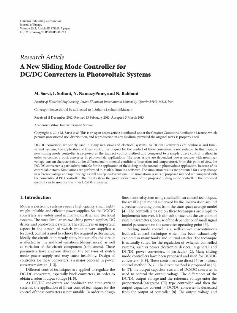
Advantages of PWM converters include low componentcount, high efficiency, constant frequency operation, rela-tively simple control and commercial availability of integratedcircuit controllers, and ability to achieve high conversionratios for both step-down and step-up applications. Thecircuit diagram of the DC/DC buck converter is shown inFigure 1. In this figure, the circuit schematic is depicted withthe transistor-diode symbols.
By sensing of the DC output and controlling of the switchduty cycle in a negative-feedback loop, the DC output voltagecould be regulated against input line and output load changes[3].
3. Solar Array Characteristic
The solar arrays have nonlinear V-I characteristics which de-pend on the environmental conditions: ambient temperatureand insolation.
The nonlinear characteristic of a solar sell is obtained asthe following equation [10, 11]:
𝑖SA = 𝐼ph − 𝐼𝑜 {exp((𝑞
𝐴𝐾𝑇) ⋅ (VSA + 𝑅𝑆𝑖SA)) − 1} ,
(1)
where 𝐼ph is the generated current under a given insolationcondition, 𝐼
𝑜is the reverse saturation current, 𝑞 is the charge
of an electron, VSA and 𝑖SA are the output voltage and currentof the solar cell, respectively, 𝐴 is the ideality factor for a p-n junction, 𝐾 is Boltzmann’s constant, 𝑇 is the temperature,and 𝑅
𝑆is the series resistance of the solar cell. Figures 2 and 3
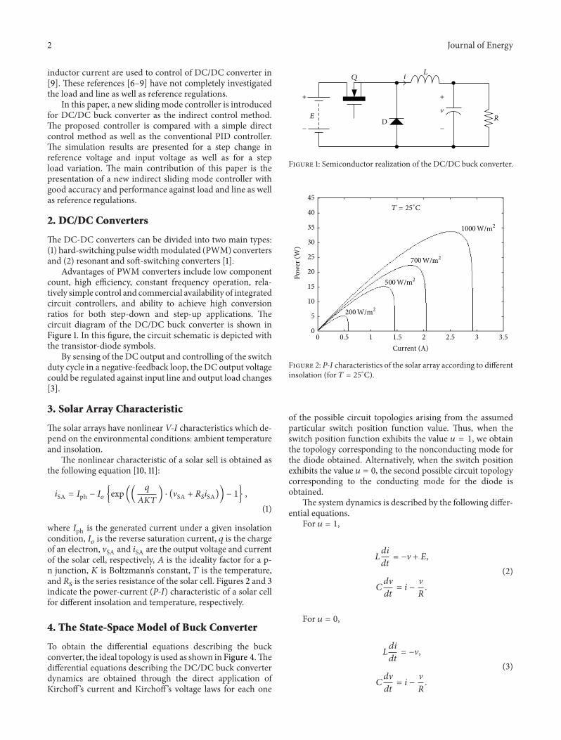
indicate the power-current (P-I) characteristic of a solar cellfor different insolation and temperature, respectively.
4. The State-Space Model of Buck Converter
To obtain the differential equations describing the buckconverter, the ideal topology is used as shown in Figure 4.Thedifferential equations describing the DC/DC buck converterdynamics are obtained through the direct application ofKirchoff ’s current and Kirchoff ’s voltage laws for each one
𝐸
𝑄 𝑖𝐿
�𝑅
+
−
+
−D
Figure 1: Semiconductor realization of the DC/DC buck converter.
0 0.5 1 1.5 2 2.5 3 3.5Current (A)
Pow
er (W
)
𝑇 = 25∘C
1000
45
40
35
30
25
20
15
10
5
0
700W/m2
500W/m2
200W/m2
W/m2
Figure 2: P-I characteristics of the solar array according to differentinsolation (for 𝑇 = 25∘C).
of the possible circuit topologies arising from the assumedparticular switch position function value. Thus, when theswitch position function exhibits the value 𝑢 = 1, we obtainthe topology corresponding to the nonconducting mode forthe diode obtained. Alternatively, when the switch positionexhibits the value 𝑢 = 0, the second possible circuit topologycorresponding to the conducting mode for the diode isobtained.
The system dynamics is described by the following differ-ential equations.
For 𝑢 = 1,
𝐿𝑑𝑖
𝑑𝑡= −V + 𝐸,
𝐶𝑑V
𝑑𝑡= 𝑖 −
V
𝑅.
(2)
For 𝑢 = 0,
𝐿𝑑𝑖
𝑑𝑡= −V,
𝐶𝑑V
𝑑𝑡= 𝑖 −
V
𝑅.
(3)
Journal of Energy 3
𝑆 = 1000 −20∘C
0∘C
25∘C
60∘C
W/m2
0∘C
25∘C
60∘C
0 0.5 1 1.5 2 2.5 3 3.5Current (A)
Pow
er (W
)
45
40
35
30
25
20
15
10
5
0
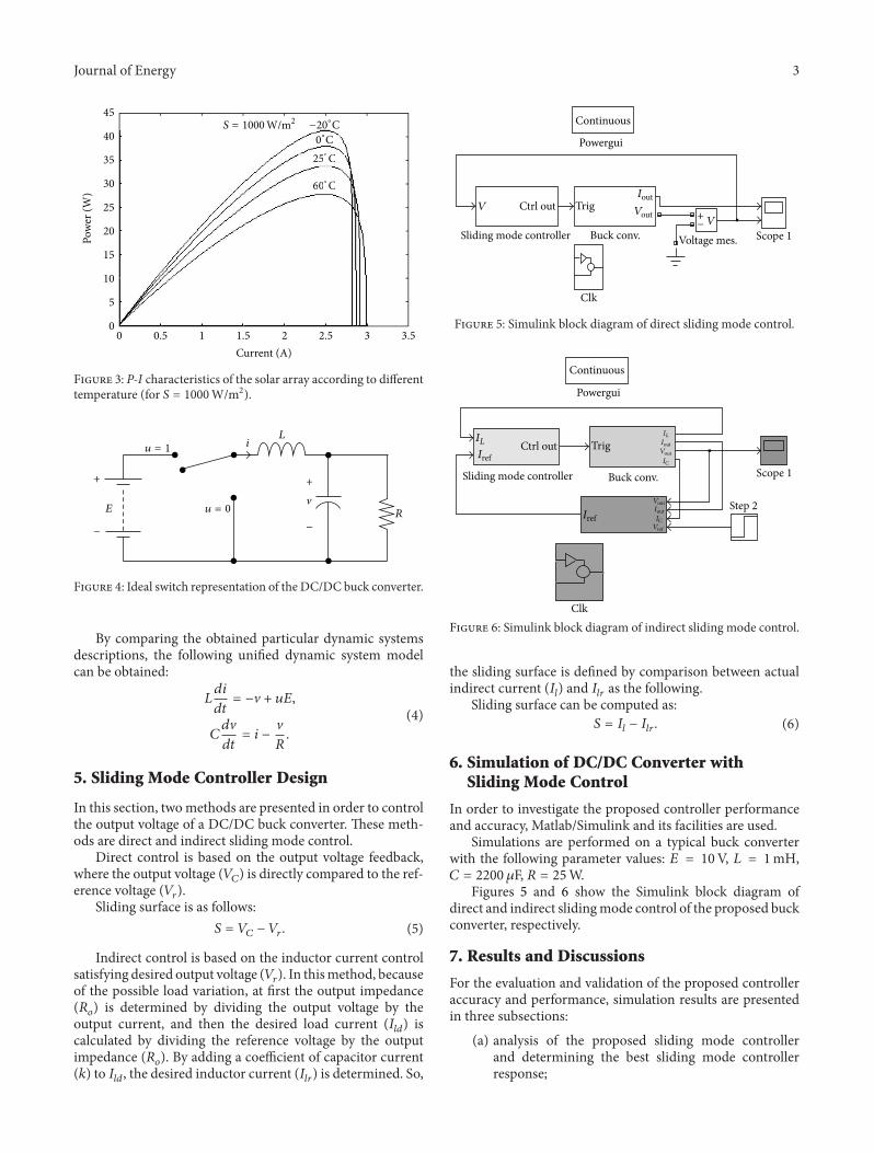
Figure 3: P-I characteristics of the solar array according to differenttemperature (for 𝑆 = 1000W/m2).
𝐸
𝑖𝐿
�
𝑅
+
−
+
−
𝑢 = 1
𝑢 = 0
Figure 4: Ideal switch representation of the DC/DC buck converter.
By comparing the obtained particular dynamic systemsdescriptions, the following unified dynamic system modelcan be obtained:
𝐿𝑑𝑖
𝑑𝑡= −V + 𝑢𝐸,
𝐶𝑑V
𝑑𝑡= 𝑖 −
V
𝑅.
(4)
5. Sliding Mode Controller Design
In this section, twomethods are presented in order to controlthe output voltage of a DC/DC buck converter. These meth-ods are direct and indirect sliding mode control.
Direct control is based on the output voltage feedback,where the output voltage (𝑉
𝐶) is directly compared to the ref-
erence voltage (𝑉𝑟).
Sliding surface is as follows:𝑆 = 𝑉𝐶− 𝑉𝑟. (5)
Indirect control is based on the inductor current controlsatisfying desired output voltage (𝑉
𝑟). In thismethod, because
of the possible load variation, at first the output impedance(𝑅𝑜) is determined by dividing the output voltage by the
output current, and then the desired load current (𝐼𝑙𝑑) is
calculated by dividing the reference voltage by the outputimpedance (𝑅
𝑜). By adding a coefficient of capacitor current
(𝑘) to 𝐼𝑙𝑑, the desired inductor current (𝐼
𝑙𝑟) is determined. So,
Sliding mode controller
𝑉 Ctrl out Trig
Buck conv.
Clk
Voltage mes. Scope 1
Powergui
Continuous
+−
𝐼out
𝑉out𝑉
Figure 5: Simulink block diagram of direct sliding mode control.
Powergui
Continuous
𝐼ref
Scope 1
Step 2
𝐼𝐿
Sliding mode controller Buck conv.
TrigCtrl out
Clk
𝐼ref
𝐼𝐿𝐼out𝑉out𝐼𝐶
𝑉out𝐼out𝐼𝐶𝑉ref
Figure 6: Simulink block diagram of indirect sliding mode control.
the sliding surface is defined by comparison between actualindirect current (𝐼
𝑙) and 𝐼
𝑙𝑟as the following.
Sliding surface can be computed as:𝑆 = 𝐼𝑙− 𝐼𝑙𝑟. (6)
6. Simulation of DC/DC Converter withSliding Mode Control
In order to investigate the proposed controller performanceand accuracy, Matlab/Simulink and its facilities are used.
Simulations are performed on a typical buck converterwith the following parameter values: 𝐸 = 10V, 𝐿 = 1mH,𝐶 = 2200 𝜇F, 𝑅 = 25W.
Figures 5 and 6 show the Simulink block diagram ofdirect and indirect slidingmode control of the proposed buckconverter, respectively.
7. Results and Discussions
For the evaluation and validation of the proposed controlleraccuracy and performance, simulation results are presentedin three subsections:
(a) analysis of the proposed sliding mode controllerand determining the best sliding mode controllerresponse;
4 Journal of Energy
8
7
6
5
4
3
2
1
00.01 0.02 0.03 0.04 0.05 0.06 0.07 0.08 0.09 0.1
Time (s)
Out
put v
olta
ge (V
)
0
Figure 7: The DC/DC output voltage for a step change in referencevoltage in direct control method.
0.01 0.02 0.03 0.04 0.05 0.06 0.07 0.08 0.09 0.1Time (s)
0
Out
put v
olta
ge (V
)
7
6
5
4
3
2
1
𝑘 = 0.6
𝑘 = 0.5
𝑘 = 0.4
Figure 8: The DC/DC output voltage for a step change in referencevoltage with respect to different values of 𝑘 in indirect controlmethod.
(b) comparison of the proposed sliding mode controllerwith the conventional PID controller;
(c) investigation of the proposed siding mode controllerunder environmental (insolation and temperature)conditions.
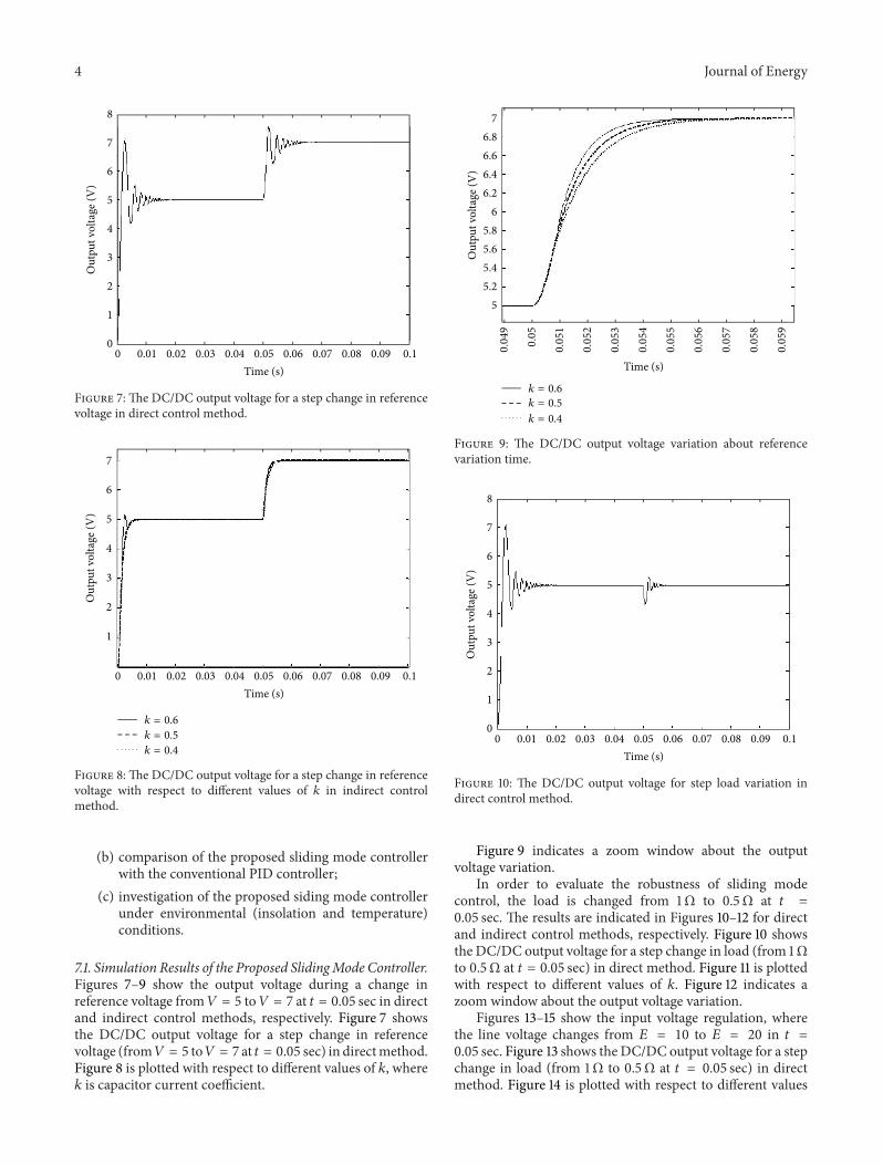
7.1. Simulation Results of the Proposed SlidingMode Controller.Figures 7–9 show the output voltage during a change inreference voltage from𝑉 = 5 to𝑉 = 7 at 𝑡 = 0.05 sec in directand indirect control methods, respectively. Figure 7 showsthe DC/DC output voltage for a step change in referencevoltage (from𝑉 = 5 to𝑉 = 7 at 𝑡 = 0.05 sec) in directmethod.Figure 8 is plotted with respect to different values of 𝑘, where𝑘 is capacitor current coefficient.
0.04
9
0.05
0.05
1
0.05
2
0.05
3
0.05
4
0.05
5
0.05
6
0.05
7
0.05
8
0.05
9
Time (s)
76.86.66.46.2
65.85.65.45.2
5
Out
put v
olta
ge (V
)
𝑘 = 0.6
𝑘 = 0.5
𝑘 = 0.4
Figure 9: The DC/DC output voltage variation about referencevariation time.
8
7
6
5
4
3
2
1
0
Out
put v
olta
ge (V
)
0.01 0.02 0.03 0.04 0.05 0.06 0.07 0.08 0.09 0.1Time (s)
0
Figure 10: The DC/DC output voltage for step load variation indirect control method.
Figure 9 indicates a zoom window about the outputvoltage variation.
In order to evaluate the robustness of sliding modecontrol, the load is changed from 1Ω to 0.5Ω at 𝑡 =0.05 sec. The results are indicated in Figures 10–12 for directand indirect control methods, respectively. Figure 10 showsthe DC/DC output voltage for a step change in load (from 1Ωto 0.5Ω at 𝑡 = 0.05 sec) in direct method. Figure 11 is plottedwith respect to different values of 𝑘. Figure 12 indicates azoom window about the output voltage variation.
Figures 13–15 show the input voltage regulation, wherethe line voltage changes from 𝐸 = 10 to 𝐸 = 20 in 𝑡 =0.05 sec. Figure 13 shows the DC/DC output voltage for a stepchange in load (from 1Ω to 0.5Ω at 𝑡 = 0.05 sec) in directmethod. Figure 14 is plotted with respect to different values

Journal of Energy 5
6
5
4
3
2
1
0
Out
put v
olta
ge (V
)
0.01 0.02 0.03 0.04 0.05 0.06 0.07 0.08 0.09 0.1Time (s)
0
𝑘 = 0.6
𝑘 = 0.5
𝑘 = 0.4
Figure 11: The DC/DC output voltage for step load variation withrespect to different values of 𝑘 in indirect control method.
0.05 0.0505 0.051 0.0515 0.052 0.0525 0.053 0.0535
5
4.9
4.8
4.7
4.6
4.5
4.4
4.3
Out
put v
olta
ge (V
)
Time (s)
𝑘 = 0.6
𝑘 = 0.5
𝑘 = 0.4
Figure 12: The DC/DC output voltage variation about step loadvariation time.
of 𝑘. Figure 15 indicates a zoom window about the outputvoltage variation.
These results (Figures 7–15) show that the direct controlmethod does not have a good performance. On the otherhand, indirect control performance is good but it is related tothe 𝑘 value. By the selection of suitable value of 𝑘, the indirectmethod performance is very good. The results show that thebest performance is obtained for 𝑘 = 0.5.
7.2. Comparison of Proposed Sliding Mode and PID Controller.For the validation of the proposed sliding mode controller,the best simulated result compares with conventional PIDcontroller.
0.01 0.02 0.03 0.04 0.05 0.06 0.07 0.08 0.09 0.1Time (s)
0
8
7
6
5
4
3
2
1
0
Out
put v
olta
ge (V
)
Figure 13:The DC/DC output voltage variation for a step change inline voltage in direct control method.
6
5
4
3
2
1
0
Out
put v
olta
ge (V
)
0.01 0.02 0.03 0.04 0.05 0.06 0.07 0.08 0.09 0.1Time (s)
0
𝑘 = 0.6
𝑘 = 0.5
𝑘 = 0.4
Figure 14:The DC/DC output voltage variation for a step change inLine voltage with respect to different values of 𝑘 in indirect controlmethod.
The best result is the one with the wave forms of indirectsliding mode control with capacitor current coefficient (𝑘)equal to 0.5.
The noninteracting structure of PID controller is used.This is described by the following equation:
𝐺PID = 𝑘𝑃 (1 +1
𝑠𝑇𝑖
+ 𝑠𝑇𝑑) , (7)
where 𝑘𝑃is proportional gain and 𝑇
𝑖, 𝑇𝑑are integrator and
derivative time constants, respectively.The simulation results of comparison between the pro-
posed sliding mode controller and PID controller are indi-cated in Figures 16–19.
Figures 16 and 17 show the output voltage of buck con-verter with sliding mode and PID controller with a step
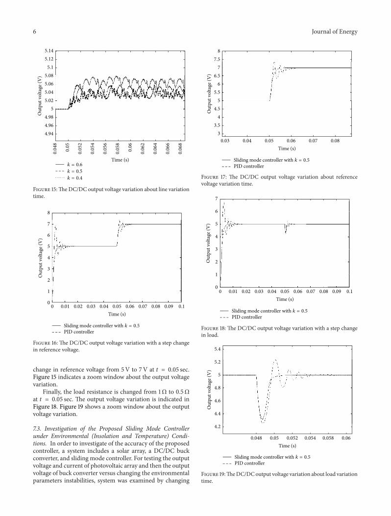
6 Journal of Energy
0.04
8
0.05
0.05
2
0.05
4
0.05
6
0.05
8
0.06
0.06
2
0.06
4
0.06
6
0.06
8
5.145.12
5.15.085.065.045.02
54.984.964.94
Out
put v
olta
ge (V
)
Time (s)𝑘 = 0.6
𝑘 = 0.5
𝑘 = 0.4
Figure 15:TheDC/DC output voltage variation about line variationtime.
0.01 0.02 0.03 0.04 0.05 0.06 0.07 0.08 0.09 0.1Time (s)
0
8
7
6
5
4
3
2
1
0
Out
put v
olta
ge (V
)
Sliding mode controller with 𝑘 = 0.5
PID controller
Figure 16: The DC/DC output voltage variation with a step changein reference voltage.
change in reference voltage from 5V to 7V at 𝑡 = 0.05 sec.Figure 15 indicates a zoom window about the output voltagevariation.
Finally, the load resistance is changed from 1Ω to 0.5Ωat 𝑡 = 0.05 sec. The output voltage variation is indicated inFigure 18. Figure 19 shows a zoom window about the outputvoltage variation.
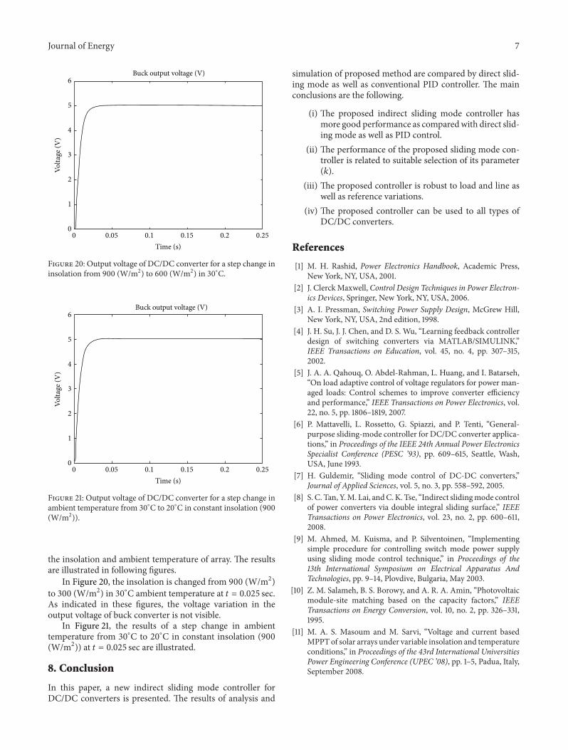
7.3. Investigation of the Proposed Sliding Mode Controllerunder Environmental (Insolation and Temperature) Condi-tions. In order to investigate of the accuracy of the proposedcontroller, a system includes a solar array, a DC/DC buckconverter, and sliding mode controller. For testing the outputvoltage and current of photovoltaic array and then the outputvoltage of buck converter versus changing the environmentalparameters instabilities, system was examined by changing
76.5
87.5
65.5
54.5
43.5
30.03 0.04 0.05 0.06 0.07 0.08
Out
put v
olta
ge (V
)
Time (s)
Sliding mode controller with 𝑘 = 0.5
PID controller
Figure 17: The DC/DC output voltage variation about referencevoltage variation time.
7
6
5
4
3
2
1
0
Out
put v
olta
ge (V
)
0.01 0.02 0.03 0.04 0.05 0.06 0.07 0.08 0.09 0.1Time (s)
0
Sliding mode controller with 𝑘 = 0.5
PID controller
Figure 18: The DC/DC output voltage variation with a step changein load.
0.048 0.05 0.052 0.054 0.058 0.06
5.4
5.2
5
4.8
4.6
4.4
4.2
Out
put v
olta
ge (V
)
Time (s)
Sliding mode controller with 𝑘 = 0.5
PID controller
Figure 19:TheDC/DCoutput voltage variation about load variationtime.
Journal of Energy 7
6
5
4
3
2
1
00 0.05 0.1 0.15 0.2 0.25
Time (s)
Volta
ge (V
)
Buck output voltage (V)
Figure 20: Output voltage of DC/DC converter for a step change ininsolation from 900 (W/m2) to 600 (W/m2) in 30∘C.
6
5
4
3
2
1
00 0.05 0.1 0.15 0.2 0.25
Time (s)
Volta
ge (V
)
Buck output voltage (V)
Figure 21: Output voltage of DC/DC converter for a step change inambient temperature from 30∘C to 20∘C in constant insolation (900(W/m2)).
the insolation and ambient temperature of array. The resultsare illustrated in following figures.
In Figure 20, the insolation is changed from 900 (W/m2)to 300 (W/m2) in 30∘C ambient temperature at 𝑡 = 0.025 sec.As indicated in these figures, the voltage variation in theoutput voltage of buck converter is not visible.
In Figure 21, the results of a step change in ambienttemperature from 30∘C to 20∘C in constant insolation (900(W/m2)) at 𝑡 = 0.025 sec are illustrated.
8. Conclusion
In this paper, a new indirect sliding mode controller forDC/DC converters is presented. The results of analysis and
simulation of proposed method are compared by direct slid-ing mode as well as conventional PID controller. The mainconclusions are the following.
(i) The proposed indirect sliding mode controller hasmore good performance as comparedwith direct slid-ing mode as well as PID control.
(ii) The performance of the proposed sliding mode con-troller is related to suitable selection of its parameter(𝑘).
(iii) The proposed controller is robust to load and line aswell as reference variations.
(iv) The proposed controller can be used to all types ofDC/DC converters.
References
[1] M. H. Rashid, Power Electronics Handbook, Academic Press,New York, NY, USA, 2001.
[2] J. ClerckMaxwell, Control Design Techniques in Power Electron-ics Devices, Springer, New York, NY, USA, 2006.
[3] A. I. Pressman, Switching Power Supply Design, McGrew Hill,New York, NY, USA, 2nd edition, 1998.
[4] J. H. Su, J. J. Chen, and D. S. Wu, “Learning feedback controllerdesign of switching converters via MATLAB/SIMULINK,”IEEE Transactions on Education, vol. 45, no. 4, pp. 307–315,2002.
[5] J. A. A. Qahouq, O. Abdel-Rahman, L. Huang, and I. Batarseh,“On load adaptive control of voltage regulators for power man-aged loads: Control schemes to improve converter efficiencyand performance,” IEEE Transactions on Power Electronics, vol.22, no. 5, pp. 1806–1819, 2007.
[6] P. Mattavelli, L. Rossetto, G. Spiazzi, and P. Tenti, “General-purpose sliding-mode controller for DC/DC converter applica-tions,” in Proceedings of the IEEE 24th Annual Power ElectronicsSpecialist Conference (PESC ’93), pp. 609–615, Seattle, Wash,USA, June 1993.
[7] H. Guldemir, “Sliding mode control of DC-DC converters,”Journal of Applied Sciences, vol. 5, no. 3, pp. 558–592, 2005.
[8] S. C. Tan, Y.M. Lai, andC.K. Tse, “Indirect slidingmode controlof power converters via double integral sliding surface,” IEEETransactions on Power Electronics, vol. 23, no. 2, pp. 600–611,2008.
[9] M. Ahmed, M. Kuisma, and P. Silventoinen, “Implementingsimple procedure for controlling switch mode power supplyusing sliding mode control technique,” in Proceedings of the13th International Symposium on Electrical Apparatus AndTechnologies, pp. 9–14, Plovdive, Bulgaria, May 2003.
[10] Z. M. Salameh, B. S. Borowy, and A. R. A. Amin, “Photovoltaicmodule-site matching based on the capacity factors,” IEEETransactions on Energy Conversion, vol. 10, no. 2, pp. 326–331,1995.
[11] M. A. S. Masoum and M. Sarvi, “Voltage and current basedMPPTof solar arrays under variable insolation and temperatureconditions,” in Proceedings of the 43rd International UniversitiesPower Engineering Conference (UPEC ’08), pp. 1–5, Padua, Italy,September 2008.
Copyright © 2022 FDOKUMEN