
Nonlinear single-loop control of the parallel converters for a fuel cell power source used in DC...
8
Nonlinear single-loop control of the parallel converters for a fuel cell power source used in DC grid applications Warit Thammasiriroj a,⇑ , Viboon Chunkag a , Matheepot Phattanasak b , Serge Pierfederici c , Bernard Davat c , Phatiphat Thounthong b a Department of Electrical and Computer Engineering, Faculty of Engineering, King Mongkut’s University of Technology North Bangkok, Bangkok, Thailand b Renewable Energy Research Centre, Department of Teacher Training in Electrical Engineering, King Mongkut’s University of Technology North Bangkok, Bangkok 10800, Thailand c Groupe de Recherche en Electrotechnique et Electronique de Nancy, Université de Lorraine, 2 avenue de la Forêt de Haye, 54518 Vandoeuvre-les-Nancy, France article info Article history: Received 24 October 2013 Received in revised form 9 July 2014 Accepted 4 September 2014 Available online 8 October 2014 Keywords: Fuel cells Interleaved converters Nonlinear control Single-loop feedback control abstract This paper presents an innovative control law for a multiphase interleaved converter in the distribution of power supply in fuel cell (FC) generators. Traditionally, to control the DC output power, voltage, or current in a converter, a linear multiple-loop feedback control technique is used. The nonlinear multi- ple-loop feedback control approach offers several techniques that help to improve the system response. In this paper, an alternative nonlinear single-loop feedback control scheme is proposed. This scheme is based on the differential flatness concept, which provides a solution to achieve the preferred response using a less sophisticated algorithm. To validate the proposed technique, a prototype of a FC power con- verter (a 600-W two-phase interleaved boost DC–DC converter) was constructed in the laboratory, and the control algorithm was implemented to control the prototype using a dSPACE 1104 controller card. The control scheme exhibited excellent experimental results for use with a 1.2-kW Nexa Ballard polymer electrolyte membrane fuel cell (PEMFC) regarding the steady state and dynamic responses as well as the control robustness. Ó 2014 Elsevier Ltd. All rights reserved. Introduction Renewable energy sources are predicted to become competitive with conventional power generation systems in the near future. As shown in Fig. 1, FCs, which play an important role in supporting electricity demand because of their significant advantages of energy efficiency and emission control, normally require a con- verter to regulate the DC output voltage when applied to variable power loads [1–3]. In such applications, a parallel DC–DC converter shown in Fig. 2 is a competitive option. The DC–DC converter operates under a feedback control to regulate the output voltage and to enable load sharing. This DC–DC converter with closed-loop control is essen- tially a nonlinear system. However, the common technique used to control the current and voltage in this nonlinear DC–DC con- verter is the use of two-loop feedback PI compensators, as shown in Fig. 3(a) (the outer loop is for voltage control and the inner loop is for current control), which is based on linear control theory [4,5]. The subsequent development of nonlinear control techniques, such as the sliding mode control (SMC) and the differential flatness control approaches shown in Fig. 3(b), has introduced effective means of controlling responses and improving system robustness [6–11]. Multiple-loop feedback control, which is primarily used in complex systems, can increase the sophistication in the design. Two loops are generally required because that is the minimum number of loops required for a set of voltage and current controls. This paper presents an alternative nonlinear single-loop feed- back control based on the differential flatness principle, as shown in Fig. 3(c). This type of feedback control reduces the complexity compared to the common multiple-loop feedback control approach. The most important advantage of the single-loop feed- back control is to increase the bandwidth of the feedback control system. The bandwidth of the single-loop feedback control should be limited to about 1/4–1/5 of the switching frequency. On the other hand, the bandwidth of the second loop of the two-loop feed- back control should be 1/16–1/25 times of the switching frequency in order to prevent the disturbance, which may impact the stability of the controller [12]. However, the complexity of the single-loop control equations can be easily calculated the duty ratios by a con- troller. By applying the single-loop feedback control based on the differential flatness concept, the dynamic response of the inductor current and the total static energy changes according to its refer- ence; as a result, the inductor current of any phase is maintained http://dx.doi.org/10.1016/j.ijepes.2014.09.025 0142-0615/Ó 2014 Elsevier Ltd. All rights reserved. ⇑ Corresponding author. Tel.: +66 89414 9994; fax: +66 29122070. E-mail address: [email protected] (W. Thammasiriroj). Electrical Power and Energy Systems 65 (2015) 41–48 Contents lists available at ScienceDirect Electrical Power and Energy Systems journal homepage: www.elsevier.com/locate/ijepes
Transcript of Nonlinear single-loop control of the parallel converters for a fuel cell power source used in DC...

Electrical Power and Energy Systems 65 (2015) 41–48
Contents lists available at ScienceDirect
Electrical Power and Energy Systems
journal homepage: www.elsevier .com/locate / i jepes
Nonlinear single-loop control of the parallel converters for a fuel cellpower source used in DC grid applications
http://dx.doi.org/10.1016/j.ijepes.2014.09.0250142-0615/� 2014 Elsevier Ltd. All rights reserved.
⇑ Corresponding author. Tel.: +66 89414 9994; fax: +66 29122070.E-mail address: [email protected] (W. Thammasiriroj).
Warit Thammasiriroj a,⇑, Viboon Chunkag a, Matheepot Phattanasak b, Serge Pierfederici c, Bernard Davat c,Phatiphat Thounthong b
a Department of Electrical and Computer Engineering, Faculty of Engineering, King Mongkut’s University of Technology North Bangkok, Bangkok, Thailandb Renewable Energy Research Centre, Department of Teacher Training in Electrical Engineering, King Mongkut’s University of Technology North Bangkok, Bangkok 10800, Thailandc Groupe de Recherche en Electrotechnique et Electronique de Nancy, Université de Lorraine, 2 avenue de la Forêt de Haye, 54518 Vandoeuvre-les-Nancy, France
a r t i c l e i n f o
Article history:Received 24 October 2013Received in revised form 9 July 2014Accepted 4 September 2014Available online 8 October 2014
Keywords:Fuel cellsInterleaved convertersNonlinear controlSingle-loop feedback control
a b s t r a c t
This paper presents an innovative control law for a multiphase interleaved converter in the distributionof power supply in fuel cell (FC) generators. Traditionally, to control the DC output power, voltage, orcurrent in a converter, a linear multiple-loop feedback control technique is used. The nonlinear multi-ple-loop feedback control approach offers several techniques that help to improve the system response.In this paper, an alternative nonlinear single-loop feedback control scheme is proposed. This scheme isbased on the differential flatness concept, which provides a solution to achieve the preferred responseusing a less sophisticated algorithm. To validate the proposed technique, a prototype of a FC power con-verter (a 600-W two-phase interleaved boost DC–DC converter) was constructed in the laboratory, andthe control algorithm was implemented to control the prototype using a dSPACE 1104 controller card.The control scheme exhibited excellent experimental results for use with a 1.2-kW Nexa Ballard polymerelectrolyte membrane fuel cell (PEMFC) regarding the steady state and dynamic responses as well as thecontrol robustness.
� 2014 Elsevier Ltd. All rights reserved.
Introduction
Renewable energy sources are predicted to become competitivewith conventional power generation systems in the near future. Asshown in Fig. 1, FCs, which play an important role in supportingelectricity demand because of their significant advantages ofenergy efficiency and emission control, normally require a con-verter to regulate the DC output voltage when applied to variablepower loads [1–3].
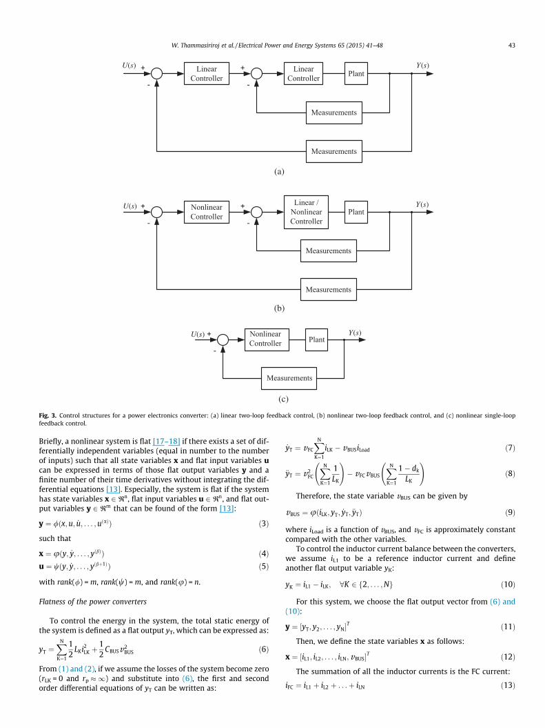
In such applications, a parallel DC–DC converter shown in Fig. 2is a competitive option. The DC–DC converter operates under afeedback control to regulate the output voltage and to enable loadsharing. This DC–DC converter with closed-loop control is essen-tially a nonlinear system. However, the common technique usedto control the current and voltage in this nonlinear DC–DC con-verter is the use of two-loop feedback PI compensators, as shownin Fig. 3(a) (the outer loop is for voltage control and the inner loopis for current control), which is based on linear control theory [4,5].
The subsequent development of nonlinear control techniques,such as the sliding mode control (SMC) and the differential flatness
control approaches shown in Fig. 3(b), has introduced effectivemeans of controlling responses and improving system robustness[6–11]. Multiple-loop feedback control, which is primarily usedin complex systems, can increase the sophistication in the design.Two loops are generally required because that is the minimumnumber of loops required for a set of voltage and current controls.
This paper presents an alternative nonlinear single-loop feed-back control based on the differential flatness principle, as shownin Fig. 3(c). This type of feedback control reduces the complexitycompared to the common multiple-loop feedback controlapproach. The most important advantage of the single-loop feed-back control is to increase the bandwidth of the feedback controlsystem. The bandwidth of the single-loop feedback control shouldbe limited to about 1/4–1/5 of the switching frequency. On theother hand, the bandwidth of the second loop of the two-loop feed-back control should be 1/16–1/25 times of the switching frequencyin order to prevent the disturbance, which may impact the stabilityof the controller [12]. However, the complexity of the single-loopcontrol equations can be easily calculated the duty ratios by a con-troller. By applying the single-loop feedback control based on thedifferential flatness concept, the dynamic response of the inductorcurrent and the total static energy changes according to its refer-ence; as a result, the inductor current of any phase is maintained
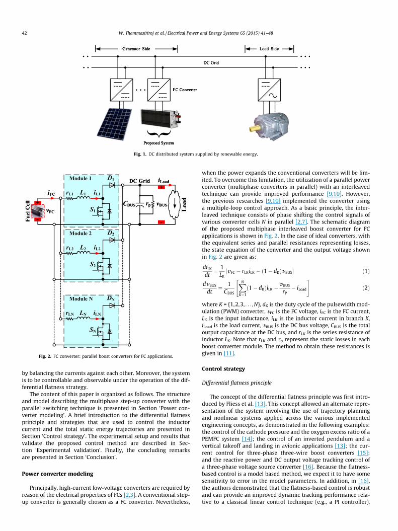
Fig. 1. DC distributed system supplied by renewable energy.
Fig. 2. FC converter: parallel boost converters for FC applications.
42 W. Thammasiriroj et al. / Electrical Power and Energy Systems 65 (2015) 41–48
by balancing the currents against each other. Moreover, the systemis to be controllable and observable under the operation of the dif-ferential flatness strategy.
The content of this paper is organized as follows. The structureand model describing the multiphase step-up converter with theparallel switching technique is presented in Section ‘Power con-verter modeling’. A brief introduction to the differential flatnessprinciple and strategies that are used to control the inductorcurrent and the total static energy trajectories are presented inSection ‘Control strategy’. The experimental setup and results thatvalidate the proposed control method are described in Sec-tion ‘Experimental validation’. Finally, the concluding remarksare presented in Section ‘Conclusion’.
Power converter modeling
Principally, high-current low-voltage converters are required byreason of the electrical properties of FCs [2,3]. A conventional step-up converter is generally chosen as a FC converter. Nevertheless,
when the power expands the conventional converters will be lim-ited. To overcome this limitation, the utilization of a parallel powerconverter (multiphase converters in parallel) with an interleavedtechnique can provide improved performance [9,10]. However,the previous researches [9,10] implemented the converter usinga multiple-loop control approach. As a basic principle, the inter-leaved technique consists of phase shifting the control signals ofvarious converter cells N in parallel [2,7]. The schematic diagramof the proposed multiphase interleaved boost converter for FCapplications is shown in Fig. 2. In the case of ideal converters, withthe equivalent series and parallel resistances representing losses,the state equation of the converter and the output voltage shownin Fig. 2 are given as:
diLK
dt¼ 1
LKvFC � rLKiLK � ð1� dKÞvBUS½ � ð1Þ
dvBUS
dt¼ 1
CBUS
XN
K¼1
ð1� dKÞiLK �vBUS
rP� iLoad
" #ð2Þ
where K = {1,2,3, . . . ,N}, dK is the duty cycle of the pulsewidth mod-ulation (PWM) converter, vFC is the FC voltage, iFC is the FC current,LK is the input inductance, iLK is the inductor current in branch K,iLoad is the load current, vBUS is the DC bus voltage, CBUS is the totaloutput capacitance at the DC bus, and rLK is the series resistance ofinductor LK. Note that rLK and rp represent the static losses in eachboost converter module. The method to obtain these resistances isgiven in [11].
Control strategy
Differential flatness principle
The concept of the differential flatness principle was first intro-duced by Fliess et al. [13]. This concept allowed an alternate repre-sentation of the system involving the use of trajectory planningand nonlinear systems applied across the various implementedengineering concepts, as demonstrated in the following examples:the control of the cathode pressure and the oxygen excess ratio of aPEMFC system [14]; the control of an inverted pendulum and avertical takeoff and landing in avionic applications [13]; the cur-rent control for three-phase three-wire boost converters [15];and the reactive power and DC output voltage tracking control ofa three-phase voltage source converter [16]. Because the flatness-based control is a model based method, we expect it to have somesensitivity to error in the model parameters. In addition, in [16],the authors demonstrated that the flatness-based control is robustand can provide an improved dynamic tracking performance rela-tive to a classical linear control technique (e.g., a PI controller).
U(s) Y(s)
(a)
(b)
(c)
U(s)
U(s)
Y(s)
Y(s)
Fig. 3. Control structures for a power electronics converter: (a) linear two-loop feedback control, (b) nonlinear two-loop feedback control, and (c) nonlinear single-loopfeedback control.
W. Thammasiriroj et al. / Electrical Power and Energy Systems 65 (2015) 41–48 43
Briefly, a nonlinear system is flat [17–18] if there exists a set of dif-ferentially independent variables (equal in number to the numberof inputs) such that all state variables x and flat input variables ucan be expressed in terms of those flat output variables y and afinite number of their time derivatives without integrating the dif-ferential equations [13]. Especially, the system is flat if the systemhas state variables x 2 Rn, flat input variables u 2 Rn, and flat out-put variables y 2 Rm that can be found of the form [13]:
y ¼ /ðx;u; _u; . . . ;uðaÞÞ ð3Þ
such that
x ¼ uðy; _y; . . . ; yðbÞÞ ð4Þu ¼ wðy; _y; . . . ; yðbþ1ÞÞ ð5Þ
with rank(/) = m, rank(w) = m, and rank(u) = n.
Flatness of the power converters
To control the energy in the system, the total static energy ofthe system is defined as a flat output yT, which can be expressed as:
yT ¼XN
K¼1
12
LKi2LK þ
12
CBUSv2BUS ð6Þ
From (1) and (2), if we assume the losses of the system become zero(rLK = 0 and rp �1) and substitute into (6), the first and secondorder differential equations of yT can be written as:
_yT ¼ vFC
XN
K¼1
iLK � vBUSiLoad ð7Þ
€yT ¼ v2FC
XN
K¼1
1LK
!� vFCvBUS
XN
K¼1
1� dk
LK
!ð8Þ
Therefore, the state variable vBUS can be given by
vBUS ¼ uðiLK; yT; _yT; €yTÞ ð9Þ
where iLoad is a function of vBUS, and vFC is approximately constantcompared with the other variables.
To control the inductor current balance between the converters,we assume iL1 to be a reference inductor current and defineanother flat output variable yK:
yK ¼ iL1 � iLK; 8K 2 f2; . . . ;Ng ð10Þ
For this system, we choose the flat output vector from (6) and(10):
y ¼ ½yT; y2; . . . ; yN�T ð11Þ
Then, we define the state variables x as follows:
x ¼ ½iL1; iL2; . . . ; iLN;vBUS�T ð12Þ
The summation of all the inductor currents is the FC current:
iFC ¼ iL1 þ iL2 þ . . .þ iLN ð13Þ
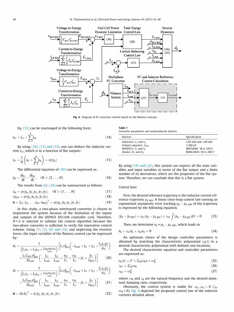
Table 1Converter parameters and semiconductor devices.
Devices Specification
Inductors: L1 and L2 1.85 mH and 1.80 mHOutput capacitor: CBUS 1,360 lFMOSFETs: S1 and S2 IRFP264N: 38 A, 250 VDiodes: D1 and D2 RURG3020: 30 A, 200 V
Fig. 4. Diagram of FC converter control based on the flatness concept.
44 W. Thammasiriroj et al. / Electrical Power and Energy Systems 65 (2015) 41–48
Eq. (13) can be rearranged in the following form:
iFC ¼ iL1 þXN
K¼2
iLK ð14Þ
By using (10), (13) and (14), one can deduce the inductor cur-rent iL1, which is in a function of flat outputs:
iL1 ¼1N
iFC þXN
K¼2
yK
!¼ uðyKÞ ð15Þ
The differential equation of (10) can be expressed as:
_yK ¼diL1
dt� diLK
dt; 8K 2 f2; . . . ;Ng ð16Þ
The results from (6)–(16) can be summarized as follows:
iLK ¼ uðyK; _yK; yT; _yT; €yTÞ; 8K 2 f1; . . . ;Ng ð17ÞvBUS ¼ uðyK _yK yT _yT €yTÞ ð18Þx ¼ ½iL1; iL2; . . . ; iLN; vBUS�T ¼ uðyK; _yK; yT; _yT; €yTÞ ð19Þ
In this study, a two-phase interleaved converter is chosen toimplement the system because of the limitation of the inputsand outputs of the dSPACE DS1104 controller card. Therefore,N = 2 is selected to validate the control algorithm because thetwo-phase converter is sufficient to verify the innovative controlscheme. Using (1), (2), (8) and (16) and neglecting the resistivelosses, the input variables of the flatness control can be expressedby:
d1 ¼1
L1iL1 þ L2iL2 þ CBUSvBUSvFCiLoad
� � L1v2BUS �iLoad þ iL1 þ iL2 þ
L2iL2 _y2
vFC
� ��
þ L1CBUSv2BUS
2iLoad� iL1
iLoad� iL2
iLoadþ vFC
L1þ vFC
L2þ _y2 þ
€yT
vBUS
� ��ð20Þ
d2 ¼1
L1iL1 þ L2iL2 þ CBUSvBUSvFCiLoad
� � L2v2BUS �iLoad þ iL1 þ iL2 �
L1iL1 _y2
vFC
� ��
þ L2CBUSv2BUS
2iLoad� iL1
iLoad� iL2
iLoadþ vFC
L1þ vFC
L2� _y2 þ
€yT
vBUS
� ��ð21Þ
u ¼ ½d1d2�T ¼ wðyK; _yK; yT; _yT; €yTÞ ð22Þ
By using (19) and (22), this system can express all the state vari-ables and input variables in terms of the flat output and a finitenumber of its derivatives, which are the properties of the flat sys-tem. Therefore, we can conclude that this is a flat system.
Control laws
First, the desired reference trajectory is the inductor current ref-erence trajectory yK REF. A linear close-loop control law earning anexponential asymptotic error tracking yK � yK REF of the trajectoryis expressed by the following equation.
ð _yK � _yK REFÞ þ kK1ðyK � yK REFÞ þ kK2
ZðyK � yK REFÞds ¼ 0 ð23Þ
Then, we determine eK = yK � yK REF, which leads to
€eK þ kK1 _eK þ kK2eK ¼ 0 ð24Þ
An optimum choice of the design controller parameters isobtained by matching the characteristic polynomial cK(s) to adesired characteristic polynomial with defined root locations.
The desired characteristic equation and controller parametersare expressed as:
cKðsÞ ¼ s2 þ 2fKxKsþx2K ð25Þ
kK1 ¼ 2fKxK ð26ÞkK2 ¼ x2
K ð27Þ
where xK and fK are the natural frequency and the desired domi-nant damping ratio, respectively.
Obviously, the control system is stable for kK1; kK2 > 0 (fK,xK > 0). Fig. 4 depicted the proposed control law of the inductorcurrents detailed above.
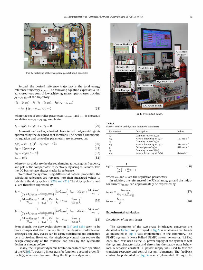
Fig. 6. System test bench.
Table 2Flatness control and dynamic limitation parameters.
Parameters Descriptions Values
f2 Damping ratio of c2(s) 1x2 Natural frequency of c2(s) 157 rad s�1
fT Damping ratio of cT(s) 1xT Natural frequency of cT(s) 314 rad s�1
p Desired pole of cT(s) 628 rad s�1
fF Damping ratio of GF(s) 1xF Natural frequency of GF(s) 0.4 rad s�1
Fig. 5. Prototype of the two-phase parallel boost converter.
W. Thammasiriroj et al. / Electrical Power and Energy Systems 65 (2015) 41–48 45
Second, the desired reference trajectory is the total energyreference trajectory yT REF. The following equation expresses a lin-ear closed-loop control law achieving an asymptotic error trackingyT � yT REF of the trajectory.
ð€yT � €yT REFÞ þ kT1ð _yT � _yT REFÞ þ kT2ðyT � yT REFÞ
þ kT3
ZðyT � yT REFÞds ¼ 0 ð28Þ
where the set of controller parameters ðkT1; kT2 and kT3Þ is chosen. Ifwe define eT = yT � yT REF, we obtain
ev
T þ kT1€eT þ kT2 _eT þ kT3eT ¼ 0 ð29Þ
As mentioned earlier, a desired characteristic polynomial cT(s) isoptimized by the designed root locations. The desired characteris-tic equation and controller parameters are expressed as:
cTðsÞ ¼ ðsþ pÞðs2 þ 2fTxTsþx2TÞ ð30Þ
kT1 ¼ 2fTxT þ p ð31ÞkT2 ¼ 2fTxTpþx2
T ð32ÞkT3 ¼ x2
Tp ð33Þ
where fT, xT and p are the desired damping ratio, angular frequencyand pole of the compensator, respectively. By using this control law,the DC bus voltage always tracks its reference.
To control the system using differential flatness properties, thecalculated references are replaced into their measured values tocalculate the duty cycles in (20) and (21). The duty cycles d1 andd2 are therefore expressed by:
d1 ¼1
ðL1 þ L2ÞiLK REF þ CBUSvBUS REFvFCiLoad
� � L1v2BUS REF �iLoad þ 2iLK REF þ
L2iLK _y2REF
vFC
� ��
þ L1CBUSv2BUS REF
2iLoad� 2iLK
iLoadþ vFC
L1þ vFC
L2þ _y2REF þ
€yT REF
vBUS REF
� ��ð34Þ
d2 ¼1
ðL1 þ L2ÞiLK REF þ CBUSvBUS REFvFCiLoad
� � L2v2BUS REF �iLoad þ 2iLK REF �
L1iLK _y2REF
vFC
� ��
þ L2CBUSv2BUS REF
2iLoad� 2iLK
iLoadþ vFC
L1þ vFC
L2� _y2REF þ
€yT REF
vBUS REF
� ��ð35Þ
Even though, the duty cycles shown in (34) and (35) seem to bemore complicated than the results of the classical multiple-loopstrategies, the duty cycles can be easily substituted and calculatedby a controller. However, the single-loop control can reduce thedesign complexity of the multiple-loop ones by the systematicdesign as shown before.
Finally, the FC power dynamic limitation enables safe operationof the FC [9]. To obtain a linear transfer function, a second-order fil-ter GF(s) is selected for controlling the FC power dynamics.
GFðsÞ ¼1
sxF
� �2þ 2fF
xFsþ 1
ð36Þ
where xF and fF are the regulation parameters.In addition, the reference of the FC current iFC REF and the induc-
tor current iLK REF can approximately be expressed by
iFC REF ¼vBusiLoad
vFC �PN
k¼11
rLK
ð37Þ
iLK REF ¼iFC REF
Nð38Þ
Experimental validation
Description of the test bench
The parameters of the two-phase interleaved converter aredetailed in Table 1 and portrayed in Fig. 5. A small-scale test benchas illustrated in Fig. 6 was implemented in the laboratory. ThePEMFC system (a Nexa Ballard PEMFC power generator: 1.2 kW,26 V, 46 A) was used as the DC power supply of the system to testthe system characteristics and determine the steady state behav-iors. A separate constant DC power supply was used to test thetransient response and control system robustness. The feedbackcontrol loop detailed in Fig. 4 was implemented through the
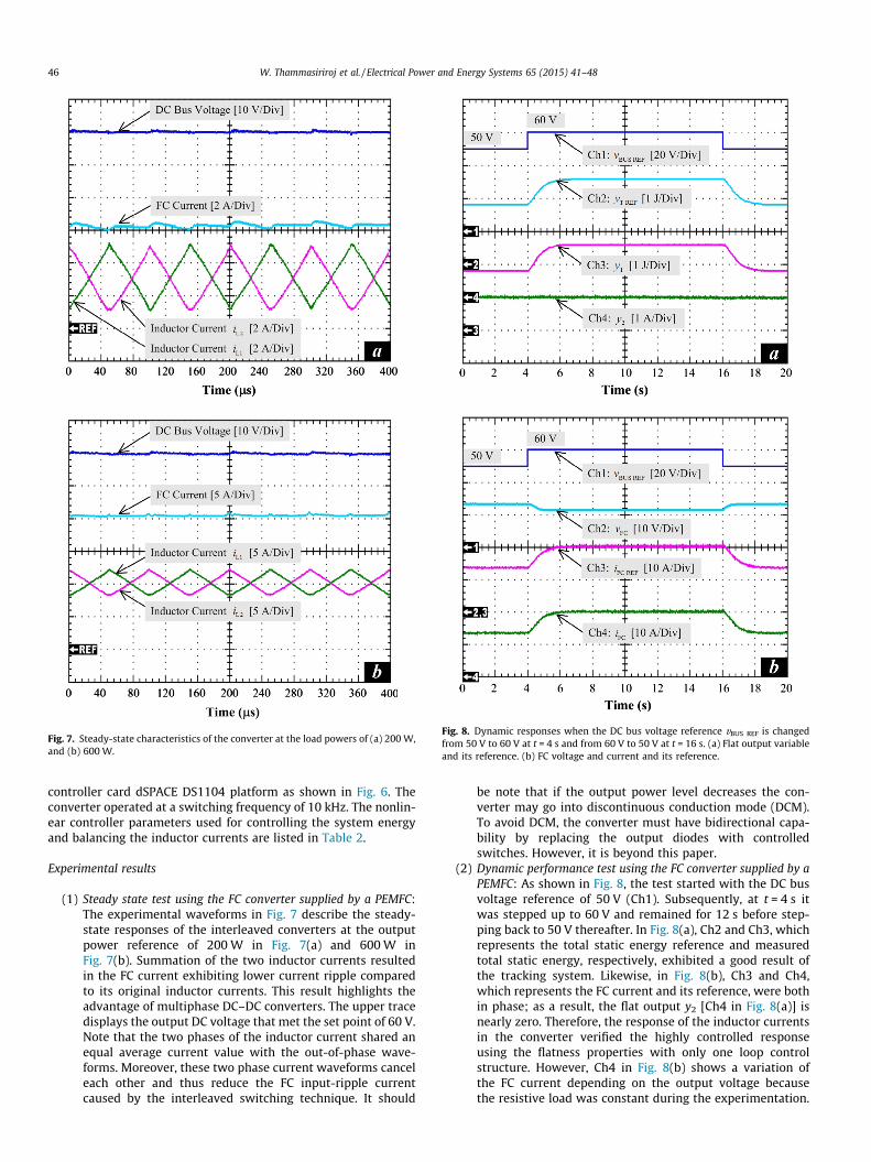
Fig. 7. Steady-state characteristics of the converter at the load powers of (a) 200 W,and (b) 600 W.
Fig. 8. Dynamic responses when the DC bus voltage reference vBUS REF is changedfrom 50 V to 60 V at t = 4 s and from 60 V to 50 V at t = 16 s. (a) Flat output variableand its reference. (b) FC voltage and current and its reference.
46 W. Thammasiriroj et al. / Electrical Power and Energy Systems 65 (2015) 41–48
controller card dSPACE DS1104 platform as shown in Fig. 6. Theconverter operated at a switching frequency of 10 kHz. The nonlin-ear controller parameters used for controlling the system energyand balancing the inductor currents are listed in Table 2.
Experimental results
(1) Steady state test using the FC converter supplied by a PEMFC:The experimental waveforms in Fig. 7 describe the steady-state responses of the interleaved converters at the outputpower reference of 200 W in Fig. 7(a) and 600 W inFig. 7(b). Summation of the two inductor currents resultedin the FC current exhibiting lower current ripple comparedto its original inductor currents. This result highlights theadvantage of multiphase DC–DC converters. The upper tracedisplays the output DC voltage that met the set point of 60 V.Note that the two phases of the inductor current shared anequal average current value with the out-of-phase wave-forms. Moreover, these two phase current waveforms canceleach other and thus reduce the FC input-ripple currentcaused by the interleaved switching technique. It should
be note that if the output power level decreases the con-verter may go into discontinuous conduction mode (DCM).To avoid DCM, the converter must have bidirectional capa-bility by replacing the output diodes with controlledswitches. However, it is beyond this paper.
(2) Dynamic performance test using the FC converter supplied by aPEMFC: As shown in Fig. 8, the test started with the DC busvoltage reference of 50 V (Ch1). Subsequently, at t = 4 s itwas stepped up to 60 V and remained for 12 s before step-ping back to 50 V thereafter. In Fig. 8(a), Ch2 and Ch3, whichrepresents the total static energy reference and measuredtotal static energy, respectively, exhibited a good result ofthe tracking system. Likewise, in Fig. 8(b), Ch3 and Ch4,which represents the FC current and its reference, were bothin phase; as a result, the flat output y2 [Ch4 in Fig. 8(a)] isnearly zero. Therefore, the response of the inductor currentsin the converter verified the highly controlled responseusing the flatness properties with only one loop controlstructure. However, Ch4 in Fig. 8(b) shows a variation ofthe FC current depending on the output voltage becausethe resistive load was constant during the experimentation.
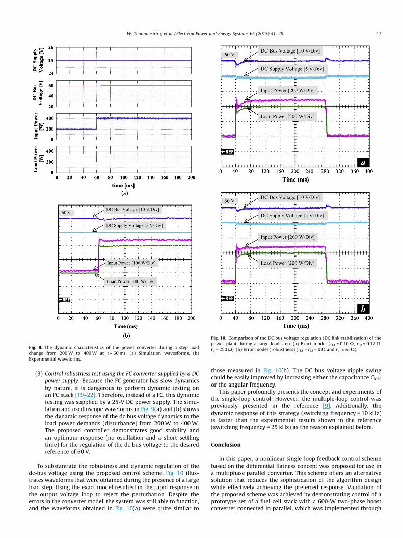
Fig. 9. The dynamic characteristics of the power converter during a step loadchange from 200 W to 400 W at t = 60 ms. (a) Simulation wavesforms. (b)Experimental waveforms.
Fig. 10. Comparison of the DC bus voltage regulation (DC link stabilization) of thepower plant during a large load step. (a) Exact model (rL1 = 0.10 X, rL2 = 0.12 X,rp = 250 X). (b) Error model (robustness) (rL1 = rL2 = 0 X and rp �1X).
W. Thammasiriroj et al. / Electrical Power and Energy Systems 65 (2015) 41–48 47
(3) Control robustness test using the FC converter supplied by a DCpower supply: Because the FC generator has slow dynamicsby nature, it is dangerous to perform dynamic testing onan FC stack [19–22]. Therefore, instead of a FC, this dynamictesting was supplied by a 25-V DC power supply. The simu-lation and oscilloscope waveforms in Fig. 9(a) and (b) showsthe dynamic response of the dc bus voltage dynamics to theload power demands (disturbance) from 200 W to 400 W.The proposed controller demonstrates good stability andan optimum response (no oscillation and a short settlingtime) for the regulation of the dc bus voltage to the desiredreference of 60 V.
To substantiate the robustness and dynamic regulation of thedc-bus voltage using the proposed control scheme, Fig. 10 illus-trates waveforms that were obtained during the presence of a largeload step. Using the exact model resulted in the rapid response inthe output voltage loop to reject the perturbation. Despite theerrors in the converter model, the system was still able to function,and the waveforms obtained in Fig. 10(a) were quite similar to
those measured in Fig. 10(b). The DC bus voltage ripple swingcould be easily improved by increasing either the capacitance CBUS
or the angular frequency.This paper profoundly presents the concept and experiments of
the single-loop control. However, the multiple-loop control waspreviously presented in the reference [9]. Additionally, thedynamic response of this strategy (switching frequency = 10 kHz)is faster than the experimental results shown in the reference(switching frequency = 25 kHz) as the reason explained before.
Conclusion
In this paper, a nonlinear single-loop feedback control schemebased on the differential flatness concept was proposed for use ina multiphase parallel converter. This scheme offers an alternativesolution that reduces the sophistication of the algorithm designwhile effectively achieving the preferred response. Validation ofthe proposed scheme was achieved by demonstrating control of aprototype set of a fuel cell stack with a 600-W two-phase boostconverter connected in parallel, which was implemented through

48 W. Thammasiriroj et al. / Electrical Power and Energy Systems 65 (2015) 41–48
a dSPACE 1104 controller card. Three aspects of the control schemewere verified, including steady state response, dynamic response,and control robustness. The experiments exhibited overall goodresults, which implied that this designed scheme has the potentialto be applied in FC generator applications, as well as in a hybridpower source system, such as hybrid electric vehicles.
Acknowledgments
This work was supported in part by the research program incooperation with the Thai-French Innovation Institute (TFII), KingMongkut’s University of Technology North Bangkok (KMUTNB)with Université de Lorraine, in part by the Energy ConservationPromotion Fund under Grant 049/2556 and in part by the ThailandResearch Fund (TRF) and Faculty of Technical Education (ResearchGrant for Mid-Career University Faculty) under Grant RSA5580009.
References
[1] Dursun E, Kilic O. Comparative evaluation of different power managementstrategies of a stand-alone PV/Wind/PEMFC hybrid power system. Int J ElectrPower Energy Syst 2012;34:81–9.
[2] Thounthong P, Tricoli P, Davat B. Performance investigation of linear andnonlinear controls for a fuel cell/supercapacitor hybrid power plant. Int J ElectrPower Energy Syst 2014;54:454–64.
[3] Hajizadeh A, Golkar MA. Control of hybrid fuel cell/energy storage distributedgeneration system against voltage sag. Int J Electr Power Energy Syst2010;32:488–97.
[4] Ramasamy M, Thangavel S. Photovoltaic based dynamic voltage restorer withpower saver capability using PI controller. Int J Electr Power Energy Syst2012;36:51–9.
[5] Mahery HM, Babaei E. Mathematical modeling of buck–boost dc–dc converterand investigation of converter elements on transient and steady stateresponses. Int J Electr Power Energy Syst 2013;44:949–63.
[6] Chen Z. PI and sliding mode control of a Cuk converter. IEEE Trans PowerElectron 2012;27(8):3695–703.
[7] Giral R, Calvente J, Utkin VI, Martinez-Salamero L. Interleaved converters basedon sliding-mode control in a ring configuration. IEEE Trans Circuits Syst I RegPapers 2011;58(10):2566–77.
[8] Thammasiriroj W, Nuchkrua T, Ruayariyasub S. Sliding mode control forstabilizing DC-link of DC–DC converter in photovoltaic systems. Proc PEDG2010:347–51.
[9] Thounthong P, Pierfederici S. A new control law based on the differentialflatness principle for multiphase interleaved DC–DC converter. IEEE TransCircuits Syst II Exp Brief 2010;57(11):903–7.
[10] Payman A, Pierfederici S, Meibody-Tabar F. Energy management in a fuel cell/supercapacitor multisource/multiload electrical hybrid system. IEEE TransPower Electron 2009;24(12):2681–91.
[11] Zandi M, Gavagsaz R, Phattanasak M, Martin JP, Nahidmobarakeh B,Pierfederici S, et al. Flatness based control of a non-ideal DC/DC boostconverter. Proc IECON 2011:1360–5.
[12] Middlebrook RD. Topics in multiple-loop regulators and current-modeprogramming. IEEE Trans Power Electron 1987;PE-2(2):109–24.
[13] Fliess M, Lévine J, Martin Ph, Rouchon P. Flatness and defect of non-linearsystems: introductory theory and examples. Int J Cont 1995;61(6):1327–61.
[14] Danzer MA, Wilhelm J, Aschemann H, Hofer EP. Model-based control ofcathode pressure and oxygen excess ratio of a PEM fuel cell system. J PowerSources 2008;176(2):515–22.
[15] Gensior A, Sira-Ramirez H, Rudolph J, Guldner H. On some nonlinear currentcontrollers for three-phase boost rectifiers. IEEE Trans Ind Electron2009;56(2):360–70.
[16] Song E, Lynch AF, Dinavahi V. Experimental validation of nonlinear control fora voltage source converter. IEEE Trans Control Syst Technol2009;17(5):1135–44.
[17] Rabbani T, Munier S, Dorchies D, Malaterre P, Bayen A, Litrico X. Flatness-based control of open-channel flow in an irrigation canal using SCADA. IEEEControl Syst Mag 2009;29(5):22–30.
[18] Agrawal SK, Pathak K, Franch J, Lampariello R, Hirzinger G. A differentially flatopen-chain space robot with arbitrarily oriented joint axes and twomomentum wheels at the base. IEEE Trans Autom Control2009;54(9):2185–91.
[19] Thounthong P, Davat B, Raël S, Sethakul P. Fuel starvation: analysis of a PEMfuel cell system. IEEE Ind Appl Mag 2009;15(4):52–9.
[20] Thounthong P, Pierfederici S, Davat B. Analysis of differential flatness-basedcontrol for a fuel cell hybrid power source. IEEE Trans Energy Convers2010;25(3):909–20.
[21] Zhu GR, Loo KH, Lai YM, Tse CK. Quasi-maximum efficiency point tracking fordirect methanol fuel cell in DMFC/supercapacitor hybrid energy system. IEEETrans Energy Convers 2012;27(3):561–71.
[22] Haruni AMO, Negnevitsky M, Haque MdE, Gargoom A. A novel operation andcontrol strategy for a standalone hybrid renewable power system. IEEE TransSustain Energy 2013;4(2):402–13.