
PKM 4000NH Series DC-DC Converters Input 45-60 V, Output ...
25
Flex internal PRODUCT SPECIFICATION 1 (4) Prepared (also subject responsible if other) No. Marshall Wang 1/1301-BMR669 04 Uen Approved Checked Date Rev Reference 11/22/2017 C Y Key Features Optimized for Parallel operation (Droop Load Sharing) Turn-on at 45V to limit input current at start-up Optimized for 51-58Vin applications Support for very Low ESR filter configurations 2250V input to output functional isolation Input overvoltage suppression Soft-start for handling of high capacitance loads Optional 12.7 mm baseplate Optional single output pins Delayed hiccup OCP, OTP, OVP and under voltage lockout General Characteristics Technical Data Input voltage range: 45-60 V Output voltage range*: 9.0-11 V (45-60 Vin); 10-11V (51-60 Vin); Max output current: 80A Efficiency: typical 97.1 % at 60% load Weight 52 grams Mechanical Dimensions LxWxH Footprint: 57.9 x 36.8 x 11.4 mm (2.28 x 1.45 x 0.45 inch) *) Regulated for optimum efficiency Safety Approvals Design for Environment Meets requirements in high- temperature lead-free soldering processes. Ericsson Internal TABLE OF CONTENTS 1 (1) Prepared (also subject responsible if other) No. SEC/S Marshall Wang Approved Checked Date Rev Reference 2014-07-14 A Contents Ordering Information ............................................................. 2 General Information ............................................................. 2 Safety Specification ............................................................. 3 Absolute Maximum Ratings ............................................................. 4 Electrical Specification 11.0 V, 80 A / 820 W PKM 4817LNH PI ................................. 5 EMC Specification ........................................................... 13 Operating Information ........................................................... 14 Thermal Consideration ........................................................... 18 Connections ........................................................... 20 Mechanical Information ........................................................... 21 Soldering Information ........................................................... 24 Delivery Information ........................................................... 24 Product Qualification Specification ........................................................... 25 PKM 4000NH Series DC-DC Converters Input 45-60 V, Output up to 80 A / 820 W 28701-BMR669 04 Rev E November 2017 © Flex Technical Specification
-
Upload
khangminh22 -
Category
Documents
-
view
4 -
download
0
Transcript of PKM 4000NH Series DC-DC Converters Input 45-60 V, Output ...

Flex internal
PRODUCT SPECIFICATION
1 (4) Prepared (also subject responsible if other) No.
Marshall Wang 1/1301-BMR669 04 Uen Approved Checked Date Rev Reference
11/22/2017 C Y
Key Features Optimized for Parallel operation (Droop Load Sharing)
Turn-on at 45V to limit input current at start-up
Optimized for 51-58Vin applications
Support for very Low ESR filter configurations
2250V input to output functional isolation
Input overvoltage suppression
Soft-start for handling of high capacitance loads
Optional 12.7 mm baseplate
Optional single output pins
Delayed hiccup OCP, OTP, OVP and under voltage lockout
General Characteristics Technical Data
Input voltage range: 45-60 V
Output voltage range*: 9.0-11 V (45-60 Vin); 10-11V (51-60 Vin);
Max output current: 80A
Efficiency: typical 97.1 % at 60% load
Weight 52 grams
Mechanical Dimensions LxWxH
Footprint: 57.9 x 36.8 x 11.4 mm (2.28 x 1.45 x 0.45 inch) *) Regulated for optimum efficiency
Safety Approvals Design for Environment
Meets requirements in high-
temperature lead-free soldering processes.
Ericsson Internal TABLE OF CONTENTS 1 (1)
Prepared (also subject responsible if other) No.
SEC/S Marshall Wang Approved Checked Date Rev Reference
2014-07-14 A
Contents
Ordering Information ............................................................. 2 General Information ............................................................. 2 Safety Specification ............................................................. 3 Absolute Maximum Ratings ............................................................. 4 Electrical Specification 11.0 V, 80 A / 820 W PKM 4817LNH PI ................................. 5 EMC Specification ........................................................... 13 Operating Information ........................................................... 14 Thermal Consideration ........................................................... 18 Connections ........................................................... 20 Mechanical Information ........................................................... 21 Soldering Information ........................................................... 24 Delivery Information ........................................................... 24 Product Qualification Specification ........................................................... 25
PKM 4000NH Series DC-DC Converters Input 45-60 V, Output up to 80 A / 820 W
28701-BMR669 04 Rev E November 2017
© Flex
Technical Specification

Flex internal
PRODUCT SPECIFICATION
2 (4) Prepared (also subject responsible if other) No.
Marshall Wang 1/1301-BMR669 04 Uen Approved Checked Date Rev Reference
11/22/2017 C Y
Ordering Information
Product program Output
PKM 4817LNH PI 11 V @ 80 A
Product number and Packaging
PKM 4x1x NH n1n2n3n4
Options n1 n2 n3 n4
Mounting option
Baseplate
Power pinning
Lead length
Options Description
n1
n2
n3 n4
PI HS SP LA LB LW LWA LWB
Through hole Open frame* Baseplate Double power pin* Single power pin** 5.33 mm* 3.69 mm 4.57 mm 5.33 mm, wide shoulder** 3.69 mm, wide shoulder 4.57 mm, wide shoulder
* Standard variant (i.e. no option selected). **Wide shoulder is only available for single output pins For example, the through hole version product with baseplate, double power pin, LB pin length is PKM4817LNH PIHSLB The through hole version product with baseplate, single power pin, wide shoulder is PKM 4817LNH PIHSSPLW.
General Information
Reliability
The failure rate () and mean time between failures
(MTBF= 1/) is calculated at max output power and an operating ambient temperature (TA) of +40°C. Flex Power Modules uses Telcordia SR-332 Issue 3 Method 1 to calculate the mean steady-state failure rate and standard
deviation (). Telcordia SR-332 Issue 3 also provides techniques to estimate the upper confidence levels of failure rates based on the mean and standard deviation. Mean steady-state failure rate, Std. deviation,
130 nFailures/h 12 nFailures/h
MTBF (mean value) for the PKM NH series = 7.70 Mh. MTBF at 90% confidence level = 6.88 Mh Compatibility with RoHS requirements
The products are compatible with the relevant clauses and requirements of the RoHS directive 2002/95/EC and have a
maximum concentration value of 0.1% by weight in homogeneous materials for lead, mercury, hexavalent chromium, PBB and PBDE and of 0.01% by weight in homogeneous materials for cadmium. Exemptions in the RoHS directive utilized in Flex Power Modules products are found in the Statement of Compliance document. Flex Power Modules fulfills and will continuously fulfill all its obligations under regulation (EC) No 1907/2006 concerning the registration, evaluation, authorization and restriction of chemicals (REACH) as they enter into force and is through product materials declarations preparing for the obligations to communicate information on substances in the products.
Quality Statement
The products are designed and manufactured in an industrial environment where quality systems and methods like ISO 9000, Six Sigma, and SPC are intensively in use to boost the continuous improvements strategy. Infant mortality or early failures in the products are screened out and they are subjected to an ATE-based final test. Conservative design rules, design reviews and product qualifications, plus the high competence of an engaged work force, contribute to the high quality of the products. Warranty
Warranty period and conditions are defined in Flex Power Modules General Terms and Conditions of Sale. Limitation of Liability
Flex Power Modules does not make any other warranties, expressed or implied including any warranty of merchantability or fitness for a particular purpose (including, but not limited to, use in life support applications, where malfunctions of product can cause injury to a person’s health or life). © Flex 2017
The information and specifications in this technical specification is believed to be correct at the time of publication. However, no liability is accepted for inaccuracies, printing errors or for any consequences thereof. Flex reserves the right to change the contents of this technical specification at any time without prior notice.
PKM 4000NH Series DC-DC Converters Input 45-60 V, Output up to 80 A / 820 W
28701-BMR669 04 Rev E November 2017
© Flex
Technical Specification
2

Flex internal
PRODUCT SPECIFICATION
3 (4) Prepared (also subject responsible if other) No.
Marshall Wang 1/1301-BMR669 04 Uen Approved Checked Date Rev Reference
11/22/2017 C Y
Safety Specification
General information
Flex Power Modules DC/DC converters and DC/DC regulators are designed in accordance with the safety standards IEC 60950-1, EN 60950-1 and UL 60950-1 Safety of Information Technology Equipment. IEC/EN/UL 60950-1 contains requirements to prevent injury or damage due to the following hazards:
Electrical shock
Energy hazards
Fire
Mechanical and heat hazards
Radiation hazards
Chemical hazards On-board DC/DC converters, Power interface modules and DC/DC regulators are defined as component power supplies. As components they cannot fully comply with the provisions of any safety requirements without “conditions of acceptability”. Clearance between conductors and between conductive parts of the component power supply and conductors on the board in the final product must meet the applicable safety requirements. Certain conditions of acceptability apply for component power supplies with limited stand-off (see Mechanical Information and Safety Certificate for further information). It is the responsibility of the installer to ensure that the final product housing these components complies with the requirements of all applicable safety standards and regulations for the final product. Component power supplies for general use should comply with the requirements in IEC/EN/UL 60950/1 Safety of Information Technology Equipment. Product related standards, e.g. IEEE 802.3af Power over Ethernet, and ETS-300132-2 Power interface at the input to telecom equipment, operated by direct current (dc) are based on IEC/EN/UL 60950-1 with regards to safety. Flex Power Modules DC/DC converters, Power interface modules and DC/DC regulators are UL 60950-1 recognized and certified in accordance with EN 60950-1. The flammability rating for all construction parts of the products meet requirements for V-0 class material according to IEC 60695-11-10, Fire hazard testing, test flames – 50 W horizontal and vertical flame test methods. Isolated DC/DC converters & Power interface modules
The product may provide basic or functional insulation between input and output according to IEC/EN/UL 60950-1 (see Safety Certificate), different conditions shall be met if the output of a basic or a functional insulated product shall be considered as safety extra low voltage (SELV).
For basic insulated products (see Safety Certificate) the output is considered as safety extra low voltage (SELV) if one of the following conditions is met:
The input source provides supplementary or double or reinforced insulation from the AC mains according to IEC/EN/UL 60950-1.
The input source provides functional or basic insulation from the AC mains and the product’s output is reliably connected to protective earth according to IEC/EN/UL 60950-1.
For functional insulated products (see Safety Certificate) the output is considered as safety extra low voltage (SELV) if one of the following conditions is met:
The input source provides double or reinforced insulation from the AC mains according to IEC/EN/UL 60950-1.
The input source provides basic or supplementary insulation from the AC mains and the product’s output is reliably connected to protective earth according to IEC/EN/UL 60950-1.
The input source is reliably connected to protective earth and provides basic or supplementary insulation according to IEC/EN/UL 60950-1 and the maximum input source voltage is 60 Vdc.
Galvanic isolation between input and output is verified in an electric strength test and the isolation voltage (Viso) meets the voltage strength requirement for basic insulation according to IEC/EN/UL 60950-1. It is recommended to use a slow blow fuse at the input of each product. If an input filter is used in the circuit the fuse should be placed in front of the input filter. In the rare event of a component problem that imposes a short circuit on the input source, this fuse will provide the following functions:
Isolate the fault from the input power source so as not to affect the operation of other parts of the system
Protect the distribution wiring from excessive current and power loss thus preventing hazardous overheating
Non-isolated DC/DC regulators
The DC/DC regulator output is SELV if the input source meets the requirements for SELV circuits according to IEC/EN/UL 60950-1.
PKM 4000NH Series DC-DC Converters Input 45-60 V, Output up to 80 A / 820 W
28701-BMR669 04 Rev E November 2017
© Flex
Technical Specification
3

Ericsson Confidential PRODUCT SPECIFICATION 1 (10)
Prepared (also subject responsible if other) No.
QMICPAL 2/1301-BMR 669 04 Uen Approved Checked Date Rev Reference
EAB/FJB/GM (Anders Källkvist) EMICNYS 2015-04-29 B
Absolute Maximum Ratings
Characteristics min typ max Unit
TP1 Operating Temperature (see Thermal Consideration section) -40 +125 °C
TS Storage temperature -55 +125 °C
VI Input voltage -0.5 +72 V
Viso Isolation voltage (input to output qualification test voltage) 2250 Vdc
Viso Isolation voltage (input to baseplate qualification test voltage) 1500 Vdc
Viso Isolation voltage (baseplate to output qualification test voltage) 750 Vdc
Vtr Input voltage transient (according to ETSI EN 300 132-2 and Telcordia GR-1089-CORE), See note 1
100 V
VRC Remote Control pin voltage (see Operating Information section)
Positive logic option -0.5 6 V
Negative logic option -0.5 6 V
Stresses above those listed under Absolute Maximum Ratings may cause permanent damage to the device. This is a stress rating only; functional operation of the device at these or any other conditions above those indicated in the Electrical Specification section of this specification is not implied. Exposure to absolute maximum rating conditions for extended periods may affect device reliability.
Fundamental Circuit Diagram
Note 1: With additional Cin = 470 µF.
PKM 4000NH Series DC-DC Converters Input 45-60 V, Output up to 80 A / 820 W
28701-BMR669 04 Rev E November 2017
© Flex
Technical Specification
4

Ericsson Confidential PRODUCT SPECIFICATION 2 (10)
Prepared (also subject responsible if other) No.
QMICPAL 2/1301-BMR 669 04 Uen Approved Checked Date Rev Reference
EAB/FJB/GM (Anders Källkvist) EMICNYS 2015-04-29 B
Electrical Specification 11.0 V, 80 A / 800 W
PKM 4817LNH PI
TP1 = -30 to +90°C, VI =45 to 60 V, unless otherwise specified under Conditions. Typical values given at: TP1 = +25°C, VI = 53 V, max IO = 80 A, unless otherwise specified under Conditions. Additional Cin = 470 µF, Cout = 3000 µF. See Operating Information section for selection of capacitor types.
Characteristics Conditions min Typ max Unit
VI Input voltage range 45 60 V
VIoff Turn-off input voltage Decreasing input voltage 37 39 43 V
VIon Turn-on input voltage Increasing input voltage 41 43 45 V
CI Internal input capacitance VI = 53 V 15 μF
PO Output power VI = 51-60 V, TP1 = 25ºC / 90ºC, see note 3
0 820 / 800 W
POm Output power maximum VI = 45-51 V see Note 1 700 800 W
η Efficiency see Note 2
50% of max IO 97.0
% max IO 96.2
50% of max IO, VI = 51 V 97.0
max IO, VI = 51 V 96.2
Pd Power Dissipation max IO 33.5 40 W
Pli Input idling power IO = 0 A, VI = 53 V 5.3 W
PRC Input standby power VI = 53 V (turned off with RC) 0.3 W
fs Switching frequency (Ripple fs) 0-100 % of max IO 375 400 425 kHz
VOi Output voltage initial setting VI = 53 V, IO = 0 A, TP1 = 25ºC 10.94 11.00 11.06 V
VO
Output voltage tolerance band 0-100% of max IO, VI = 51-60 V 10.00 11.15 V
Line regulation VI = 51-60 V, IO = 0 5 9 mV
Load regulation VI = 51-60 V, 0-100% of max IO 0.45 0.65 0.85 V
Vtr Load transient voltage deviation
VI = 53 V, Load step 25-75-25% of max IO, di/dt = 5 A/μs
0.23 0.36 V
ttr Load transient recovery time 200 µs
tr Ramp-up time (from 10−90% of VOi) 3-100% of max IO, VI = 53 V
4.5 ms
ts Start-up time (from VI connection to 90% of VOi)
6 ms
tf VI shut-down fall time (from VI off to 10% of VO)
max IO 1.8 ms IO = 0 A 34 s
tRC
RC start-up time max IO 6 ms
RC shut-down fall time (from RC off to 10% of VO)
max IO 1.8 ms
IO = 0 A 21 s
IO Output current 0 80 A
Ilim Current limit threshold TP1 < max TP1 90 104 120 A
Isc Short circuit current TP1 = 25ºC, see Note 4 20 ARMS
Cout Recommended Capacitive Load TP1 = 25ºC, see Note 5 1000 10000 µF
VOac Output ripple & noise See ripple & noise section, VOi 14 20 mVp-p
OVPin Input Overvoltage Protection 0-100% of max IO 72 78 V
OVP Over voltage protection 12.3 V
RC
Sink current See operating information 0.5 mA
Trigger level VO turning on. 0.7 1.4 V
Response time 0.1 0.5 ms
Note 1: Represented by available power graph, power limited by maximum output current at low Vin.
Note 2: Efficiency data measured with half load on each pin pair.
Note 3: Vo negative temperature coefficient causes lower maximum power at high temperature.
Note 4: Delayed hiccup OCP, stated values indicates RMS value.
Note 5: Detailed information in Output Decoupling Capacitors.
PKM 4000NH Series DC-DC Converters Input 45-60 V, Output up to 80 A / 820 W
28701-BMR669 04 Rev E November 2017
© Flex
Technical Specification
5
Ericsson Confidential PRODUCT SPECIFICATION 3 (10)
Prepared (also subject responsible if other) No.
QMICPAL 2/1301-BMR 669 04 Uen Approved Checked Date Rev Reference
EAB/FJB/GM (Anders Källkvist) EMICNYS 2015-04-29 B
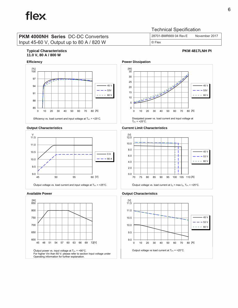
Typical Characteristics 11.0 V, 80 A / 800 W
PKM 4817LNH PI
Efficiency Power Dissipation
Efficiency vs. load current and input voltage at TP1 = +25C. Dissipated power vs. load current and input voltage at TP1 = +25°C.
Output Characteristics Current Limit Characteristics
Output voltage vs. load current and input voltage at TP1 = +25°C. Output voltage vs. load current at IO > max IO, TP1 = +25°C.
Available Power Output Characteristics
Output power vs. input voltage at TP1 = +90°C. For higher Vin than 60 V; please refer to section Input voltage under Operating information for further explanation.
Output voltage vs load current at TP1 = +25°C.
85
88
91
94
97
100
0 10 20 30 40 50 60 70 80
[%]
[A]
45 V
53V
60 V
0
5
10
15
20
25
30
35
0 10 20 30 40 50 60 70 80
[W]
[A]
45 V
53V
60 V
9.0
9.5
10.0
10.5
11.0
11.5
45 50 55 60
V
[V]
0 A
80 A
0.0
2.0
4.0
6.0
8.0
10.0
12.0
70 75 80 85 90 95 100 105 110
[V]
[A]
45 V
53 V
60 V
600
650
700
750
800
850
45 48 51 54 57 60 63 66 69 72
[W]
[V]9.0
9.5
10.0
10.5
11.0
11.5
0 10 20 30 40 50 60 70 80
[V]
[A]
45 V
53 V
60 V
PKM 4000NH Series DC-DC Converters Input 45-60 V, Output up to 80 A / 820 W
28701-BMR669 04 Rev E November 2017
© Flex
Technical Specification
6

Ericsson Confidential PRODUCT SPECIFICATION 4 (10)
Prepared (also subject responsible if other) No.
QMICPAL 2/1301-BMR 669 04 Uen Approved Checked Date Rev Reference
EAB/FJB/GM (Anders Källkvist) EMICNYS 2015-04-29 B
Typical Characteristics 11.0 V, 80 A / 800 W
PKM 4817LNH PI
Start-up Shut-down
Start-up enabled by connecting VI at: TP1 = +25°C, VI = 53 V, Cout = 3000 µF IO = 80 A resistive load.
Top trace: output voltage (5 V/div.). Bottom trace: input voltage (50 V/div.). Time scale: (5 ms/div.).
Shut-down enabled by disconnecting VI at: TP1 = +25°C, VI = 53 V, Cout = 3000 µF IO = 80 A resistive load.
Top trace: output voltage (5 V/div.). Bottom trace: input voltage (50 V/div.). Time scale: (1 ms/div.).
Output Ripple & Noise Output Load Transient Response
Output voltage ripple at: TP1 = +25°C, VI = 53 V, Cout = 3000 µF IO = 80 A resistive load.
Trace: output voltage (20 mV/div.). Time scale: (2 µs/div.). Detailed information in Operating information.
Output voltage response to load current step-change (20–60-20 A) at: TP1 =+25°C, VI = 53 V, Cout = 3000 µF
Top trace: output voltage (500 mV/div.). Bottom trace: load current (50 A/div.). Time scale: (2 ms/div.).
PKM 4000NH Series DC-DC Converters Input 45-60 V, Output up to 80 A / 820 W
28701-BMR669 04 Rev E November 2017
© Flex
Technical Specification
7

Ericsson Confidential PRODUCT SPECIFICATION 5 (10)
Prepared (also subject responsible if other) No.
QMICPAL 2/1301-BMR 669 04 Uen Approved Checked Date Rev Reference
EAB/FJB/GM (Anders Källkvist) EMICNYS 2015-04-29 B
Typical Characteristics 11.0 V, 80 A / 800 W
PKM 4817LNH PI
Output Power Derating – Single pin, open frame Thermal Resistance – Single pin, open frame
Available power vs. ambient air temperature and airflow at VI = 53 V. See Thermal Consideration section.
Thermal resistance vs. airspeed measured at the converter. Tested in wind tunnel with airflow and test conditions as per the Thermal consideration section. VI = 53 V.
Output Power Derating – Single pin, base plate Thermal Resistance – Single pin, base plate
Available power vs. ambient air temperature and airflow at VI = 53 V. See Thermal Consideration section.
Thermal resistance vs. airspeed measured at the converter. Tested in wind tunnel with airflow and test conditions as per the Thermal consideration section. VI = 53 V.
Output Power Derating – Single pin, heatsink 0.45” Thermal Resistance – Single pin, heatsink 0.45”
Available power vs. ambient air temperature and airflow at VI = 53 V. See Thermal Consideration section.
Thermal resistance vs. airspeed measured at the converter. Tested in wind tunnel with airflow and test conditions as per the Thermal consideration section. VI = 53 V.
0
100
200
300
400
500
600
700
800
0 20 40 60 80 100 120
W]
[°C]
4.0 m/s
3.0 m/s
2.0 m/s
1.5 m/s
1.0 m/s
0.5 m/s
nat conv
0.5
1.5
2.5
3.5
4.5
5.5
0.0 1.0 2.0 3.0 4.0
[°C/W]
[m/s]
21 A
42 A
56 A
63 A
70 A
75 A
80 A
0
100
200
300
400
500
600
700
800
0 20 40 60 80 100 120
W]
[°C]
4.0 m/s
3.0 m/s
2.0 m/s
1.5 m/s
1.0 m/s
0.5 m/s
nat conv
0.5
1.5
2.5
3.5
4.5
5.5
0.0 1.0 2.0 3.0 4.0
[°C/W]
[m/s]
21 A
42 A
56 A
63 A
70 A
75 A
80 A
0
100
200
300
400
500
600
700
800
0 20 40 60 80 100 120
W]
[°C]
4.0 m/s
3.0 m/s
2.0 m/s
1.5 m/s
1.0 m/s
0.5 m/s
nat conv
0.5
1.5
2.5
3.5
4.5
5.5
0.0 1.0 2.0 3.0 4.0
[°C/W]
[m/s]
21 A
42 A
56 A
63 A
70 A
75 A
80 A
PKM 4000NH Series DC-DC Converters Input 45-60 V, Output up to 80 A / 820 W
28701-BMR669 04 Rev E November 2017
© Flex
Technical Specification
8

Ericsson Confidential PRODUCT SPECIFICATION 6 (10)
Prepared (also subject responsible if other) No.
QMICPAL 2/1301-BMR 669 04 Uen Approved Checked Date Rev Reference
EAB/FJB/GM (Anders Källkvist) EMICNYS 2015-04-29 B
Typical Characteristics 11.0 V, 80 A / 800 W
PKM 4817LNH PI
Output Power Derating – Dual pin, open frame Thermal Resistance – Dual pin, open frame
Available power vs. ambient air temperature and airflow at VI = 53 V. See Thermal Consideration section.
Thermal resistance vs. airspeed measured at the converter. Tested in wind tunnel with airflow and test conditions as per the Thermal consideration section. VI = 53 V.
Output Power Derating – Dual pin, base plate Thermal Resistance – Dual pin, base plate
Available power vs. ambient air temperature and airflow at VI = 53 V. See Thermal Consideration section.
Thermal resistance vs. airspeed measured at the converter. Tested in wind tunnel with airflow and test conditions as per the Thermal consideration section. VI = 53 V.
Output Power Derating – Dual pin, heatsink 0.45” Thermal Resistance – Dual pin, heatsink 0.45”
Available power vs. ambient air temperature and airflow at VI = 53 V. See Thermal Consideration section.
Thermal resistance vs. airspeed measured at the converter. Tested in wind tunnel with airflow and test conditions as per the Thermal consideration section. VI = 53 V.
0
100
200
300
400
500
600
700
800
0 20 40 60 80 100 120
[W]
[°C]
4.0 m/s
3.0 m/s
2.0 m/s
1.5 m/s
1.0 m/s
0.5 m/s
nat conv
0.5
1.5
2.5
3.5
4.5
5.5
0.0 1.0 2.0 3.0 4.0
[°C/W]
[m/s]
21 A
42 A
56 A
63 A
70 A
75 A
80 A
0
100
200
300
400
500
600
700
800
0 20 40 60 80 100 120
[W]
[°C]
4.0 m/s
3.0 m/s
2.0 m/s
1.5 m/s
1.0 m/s
0.5 m/s
nat conv
0.5
1.5
2.5
3.5
4.5
5.5
0.0 1.0 2.0 3.0 4.0
[°C/W]
[m/s]
21 A
42 A
56 A
63 A
70 A
75 A
80 A
0
100
200
300
400
500
600
700
800
0 20 40 60 80 100 120
[W]
[°C]
4.0 m/s
3.0 m/s
2.0 m/s
1.5 m/s
1.0 m/s
0.5 m/s
nat conv
0.5
1.5
2.5
3.5
4.5
5.5
0.0 1.0 2.0 3.0 4.0
[°C/W]
[m/s]
21 A
42 A
56 A
63 A
70 A
75 A
80 A
PKM 4000NH Series DC-DC Converters Input 45-60 V, Output up to 80 A / 820 W
28701-BMR669 04 Rev E November 2017
© Flex
Technical Specification
9

Ericsson Confidential PRODUCT SPECIFICATION 7 (10)
Prepared (also subject responsible if other) No.
QMICPAL 2/1301-BMR 669 04 Uen Approved Checked Date Rev Reference
EAB/FJB/GM (Anders Källkvist) EMICNYS 2015-04-29 B
Electrical Specification 11.0 V, 150 A / 1500 W, two products in parallel
2 x PKM 4817LNH PI in parallel operation
TP1 = -30 to +90°C, VI =45 to 60 V, unless otherwise specified under Conditions. Typical values given at: TP1 = +25°C, VI = 53 V, max IO = 150 A, unless otherwise specified under Conditions. Additional Cin = 2x470 µF, Cout = 2x3000 µF. See Operating Information section for selection of capacitor types.
Characteristics Conditions min Typ max Unit
VI Input voltage range 45 60 V
VIoff Turn-off input voltage Decreasing input voltage 37 39 43 V
VIon Turn-on input voltage Increasing input voltage 41 43 45 V
CI Internal input capacitance VI = 53 V 30 μF
PO Output power VI = 51-60 V, see Note 1. 0 1500 W
POm Output power maximum VI = 45-51 V, see Note 1,3. 1350 1500 W
η Efficiency see Note 2
50% of max IO 96.8
% max IO 96.1
50% of max IO, VI = 51 V 96.9
max IO, VI = 51 V 96.1
Pd Power Dissipation max IO 68 W
Pli Input idling power IO = 0 A, VI = 53 V 12 W
PRC Input standby power VI = 53 V (turned off with RC) 0.6 W
fs Switching frequency (Ripple fs) 0-100 % of max IO 375 400 425 kHz
VOi Output voltage initial setting VI = 53 V, IO = 0 A, TP1 = 25ºC 10.94 11.00 11.06 V
VO
Output voltage tolerance band 0-100% of max IO, VI = 51-60 V 10.00 11.15 V
Line regulation VI = 51-60 V, IO = 0 5 9 mV
Load regulation VI = 51-60 V, 0-100% of max IO 0.45 0.65 0.85 V
Vtr Load transient voltage deviation
VI = 53 V, Load step 25-75-25% of max IO, di/dt = 5 A/μs
0.25 V
ttr Load transient recovery time 200 µs
tr Ramp-up time (from 10−90% of VOi) 3-100% of max IO, VI = 53 V
4.5 ms
ts Start-up time (from VI connection to 90% of VOi)
6 ms
tf VI shut-down fall time (from VI off to 10% of VO)
max IO 1.8 ms IO = 0 A 22 s
tRC
RC start-up time max IO 6 ms
RC shut-down fall time (from RC off to 10% of VO)
max IO 1.8 ms
IO = 0 A 20 s
IO Output current 0 150 A
Ilim Current limit threshold TP1 < max TP1 206 A
Idiff Current share difference VI = 51-60 V, IO > 64 A, See Note 6 8 A
Isc Short circuit current TP1 = 25ºC, see Note 4 14 ARMS
Cout Recommended Capacitive Load TP1 = 25ºC, see Note 5 1000 10000 µF
VOac Output ripple & noise See ripple & noise section, VOi 100 mVp-p
OVPin Input Overvoltage Protection 0-100% of max IO 72 78 V
OVP Over voltage protection 12.3 V
RC See single module See single module See single module
Note 1: Max output power stated at TP1 = 25 °C. See Parallel operation in the Operating information section.
Note 2: Output voltage measured on the test board, about 75 mm away from the modules output pins.
Note 3: Min output power require that modules are equal regarding pins, baseplates etc and that they are used and placed within the exact same conditions.
Note 4: Delayed hiccup OCP, stated values indicates RMS value.
Note 5: Detailed information in Output Decoupling Capacitors.
Note 6: According to IPC9592B. See also operating information.
PKM 4000NH Series DC-DC Converters Input 45-60 V, Output up to 80 A / 820 W
28701-BMR669 04 Rev E November 2017
© Flex
Technical Specification
10
Ericsson Confidential PRODUCT SPECIFICATION 8 (10)
Prepared (also subject responsible if other) No.
QMICPAL 2/1301-BMR 669 04 Uen Approved Checked Date Rev Reference
EAB/FJB/GM (Anders Källkvist) EMICNYS 2015-04-29 B
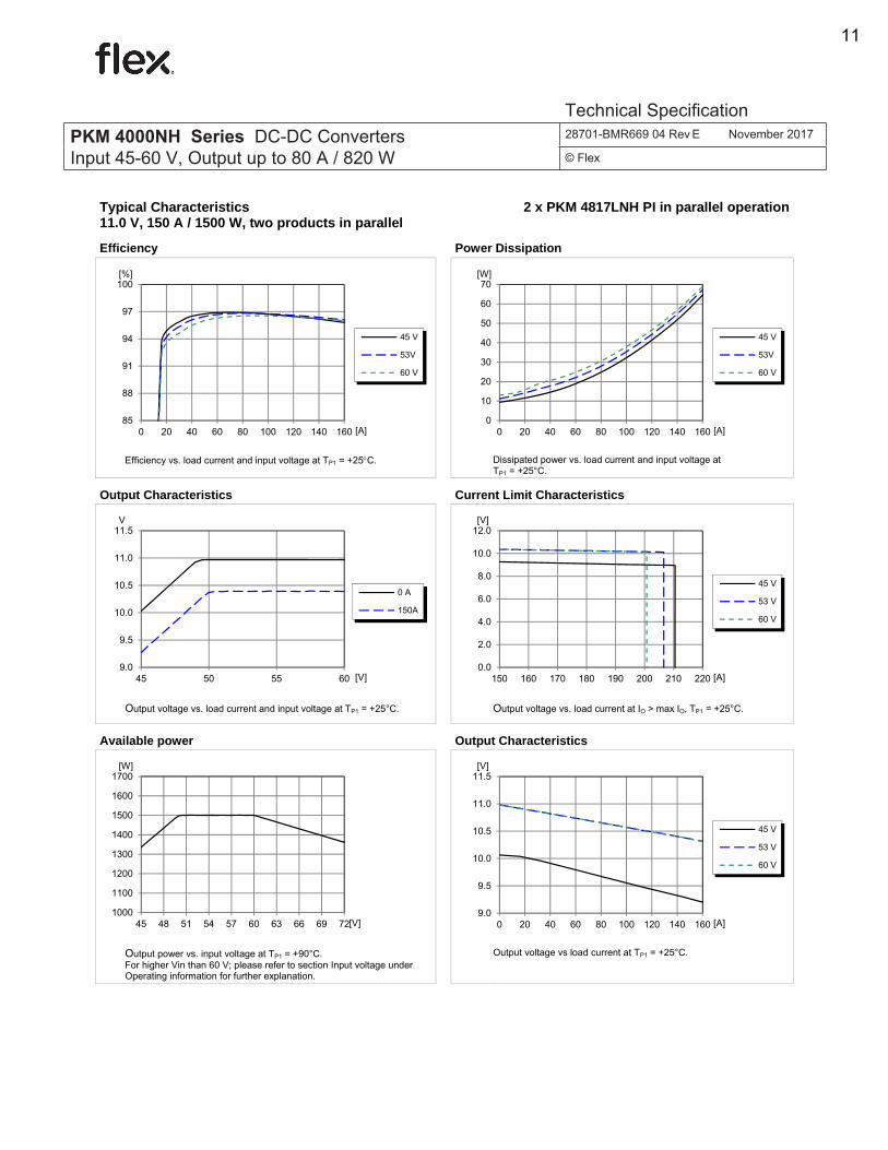
Typical Characteristics 11.0 V, 150 A / 1500 W, two products in parallel
2 x PKM 4817LNH PI in parallel operation
Efficiency Power Dissipation
Efficiency vs. load current and input voltage at TP1 = +25C. Dissipated power vs. load current and input voltage at TP1 = +25°C.
Output Characteristics Current Limit Characteristics
Output voltage vs. load current and input voltage at TP1 = +25°C. Output voltage vs. load current at IO > max IO, TP1 = +25°C.
Available power Output Characteristics
Output power vs. input voltage at TP1 = +90°C. For higher Vin than 60 V; please refer to section Input voltage under Operating information for further explanation.
Output voltage vs load current at TP1 = +25°C.
85
88
91
94
97
100
0 20 40 60 80 100 120 140 160
[%]
[A]
45 V
53V
60 V
0
10
20
30
40
50
60
70
0 20 40 60 80 100 120 140 160
[W]
[A]
45 V
53V
60 V
9.0
9.5
10.0
10.5
11.0
11.5
45 50 55 60
V
[V]
0 A
150A
0.0
2.0
4.0
6.0
8.0
10.0
12.0
150 160 170 180 190 200 210 220
[V]
[A]
45 V
53 V
60 V
1000
1100
1200
1300
1400
1500
1600
1700
45 48 51 54 57 60 63 66 69 72
[W]
[V]9.0
9.5
10.0
10.5
11.0
11.5
0 20 40 60 80 100 120 140 160
[V]
[A]
45 V
53 V
60 V
PKM 4000NH Series DC-DC Converters Input 45-60 V, Output up to 80 A / 820 W
28701-BMR669 04 Rev E November 2017
© Flex
Technical Specification
11

Ericsson Confidential PRODUCT SPECIFICATION 9 (10)
Prepared (also subject responsible if other) No.
QMICPAL 2/1301-BMR 669 04 Uen Approved Checked Date Rev Reference
EAB/FJB/GM (Anders Källkvist) EMICNYS 2015-04-29 B
Typical Characteristics 11.0 V, 150 A / 1500 W, two products in parallel
2 x PKM 4817LNH PI in parallel operation
Start-up Shut-down
Start-up enabled by connecting VI at: TP1 = +25°C, VI = 53 V, Cout = 6000 µF IO = 160 A resistive load.
Top trace: output voltage (5 V/div.). Bottom trace: input voltage (50 V/div.). Time scale: (5 ms/div.).
Shut-down enabled by disconnecting VI at: TP1 = +25°C, VI = 53 V, Cout = 6000 µF IO = 160 A resistive load.
Top trace: output voltage (5 V/div.). Bottom trace: input voltage (50 V/div.). Time scale: (1 ms/div.).
Output Ripple & Noise Output Load Transient Response
Output voltage ripple at: TP1 = +25°C, VI = 53 V, Cout = 6000 µF IO = 160 A resistive load.
Trace: output voltage (100 mV/div.). Time scale: (2 µs/div.).
Output voltage response to load current step-change (40–120-40 A) at: TP1 =+25°C, VI = 53 V, Cout = 6000 µF
Top trace: output voltage (500 mV/div.). Bottom trace: load current (50 A/div.). Time scale: (2 ms/div.).
PKM 4000NH Series DC-DC Converters Input 45-60 V, Output up to 80 A / 820 W
28701-BMR669 04 Rev E November 2017
© Flex
Technical Specification
12

Flex Internal PRODUCT SPECIFICATION
1 (9)
Prepared (also subject responsible if other) No.
QMICPAL 3/1301-BMR 669 04 Uen Approved Checked Date Rev Reference
EAB/FJB/GM (Anders Källkvist) (EMICNYS) 2017-09-27 D
EMC Specification
Conducted EMI measured according to EN55022, CISPR 22 and FCC part 15J (see test set-up). See Design Note 009 for further information. The fundamental ripple frequency is 400 kHz. Conducted EMI Input terminal value (typ)
EMI without filter (1 x PKM 4817LNH PI)
Optional external filter for class B Suggested external input filter in order to meet class B in EN 55022, CISPR 22 and FCC part 15J.
EMI filter for 1 x PKM 4817LNH PI
EMI with filter (1 x PKM 4817LNH PI)
Test set-up
Layout recommendations The radiated EMI performance of the product will depend on the PCB layout and ground layer design. It is also important to consider the stand-off of the product. If a ground layer is used, it should be connected to the output of the product and the equipment ground or chassis. A ground layer will increase the stray capacitance in the PCB and improve the high frequency EMC performance. Output ripple and noise Output ripple and noise measured according to figure below. See Design Note 022 for detailed information.
Output ripple and noise test setup This product is designed to have a large amount of ceramic (low ESR and low ESL) capacitors on the output. These capacitors can make a very effective filter for high frequencies.
PKM 4000NH Series DC-DC Converters Input 45-60 V, Output up to 80 A / 820 W
28701-BMR669 04 Rev E November 2017
© Flex
Technical Specification
13

Flex Internal PRODUCT SPECIFICATION
2 (9)
Prepared (also subject responsible if other) No.
QMICPAL 3/1301-BMR 669 04 Uen Approved Checked Date Rev Reference
EAB/FJB/GM (Anders Källkvist) (EMICNYS) 2017-09-27 D
Operating information Product Overview The product provides the power capability of a fixed-ratio product and retains most of the features from a fully regulated DC/DC design . Below 50 V the product changes mode of operation and decreases the target output voltage with the input voltage level using feedback based regulation. It is primarily intended to power down stream Point of Load (POL) products. Input Voltage The long term operational input voltage range is 45 to 60 Vdc and meets the requirements of the European Telecom Standard ETS 300 132-2, transitional -60 Vdc systems input voltage -50.0 to -72.0 V (with derated power and increased output voltage ripple above 60 V). The power loss will increase when operating at input voltages above 60 V and that reduces the available output power according to the chart “Available Power Graph”. Care must be exercised when operating above 60 V to maintain the applied load below the appropriate power level. Tp1 (see the thermal management section) must be limited to an absolute max +125°C. Operation within the derated power levels ensures all design rules for power dissipation and flux density are maintained. Operation above the derated power level is not allowed as it will result in overheating and activation the Over Temperature Protection (OTP). The output voltage is fully regulated when operating in the 60-72 Vdc range but the higher input voltage increases the output voltage ripple. This input voltage range is intended to be used only for limited periods such as in boosted hold-up applications. Output voltage vs. input voltage typical characteristics
Over approximately 50 V the product operates with a regulated output voltage that is independent of the input voltage Below 50 V the product changes mode of operation and decreases the target output voltage proportionally to the input voltage level but maintaining the feedback based regulation, with maintained transient response performance to line and load changes.
Available Power vs. input voltage, single product
TP1 +90 °C. See the Thermal Consideration section. Input transient Voltage transient disturbances can occur on the input of the product because of short circuit fault event in the equipment. The voltage level, duration and energy of the disturbance are dependent on the particular DC distribution network characteristics and can be sufficient to damage the product unless measures are taken to suppress or absorb this energy. The transient voltage can be limited by capacitors and other energy absorbing devices like transient voltage suppression diodes connected across the positive and negative input conductors at a number of strategic points in the distribution network. The end-user must secure that the transient voltage will not exceed the value stated in the Absolute maximum ratings. ETSI TR 100 283 examines the parameters of DC distribution networks and provides guidelines for controlling the transient and reduce its harmful effect. Turn-on/off Input Voltage The product monitors the input voltage and will turn on and turn off at predetermined levels that are stated in the Electrical Specification for the specific product. The hysteresis between turn on and turn off input voltage is 2.5 V and helps to avoid start-up oscillations and repeated restarts. Remote Control (RC)
7
8
9
10
11
12
45 50 55 60
[Vo]
[Vi]
600
650
700
750
800
850
45 48 51 54 57 60 63 66 69 72
[W]
[V]
PKM 4000NH Series DC-DC Converters Input 45-60 V, Output up to 80 A / 820 W
28701-BMR669 04 Rev E November 2017
© Flex
Technical Specification
14

Flex Internal PRODUCT SPECIFICATION
3 (9)
Prepared (also subject responsible if other) No.
QMICPAL 3/1301-BMR 669 04 Uen Approved Checked Date Rev Reference
EAB/FJB/GM (Anders Källkvist) (EMICNYS) 2017-09-27 D
The products includes a remote control function referenced to the primary negative input connection (-In), with negative and positive logic options available. The RC function allows the product to be turned on/off by an external device like a semiconductor, or a mechanical switch placed close to the product. The RC pin has an internal pull up resistor of 10 kΩ to +5 V. The threshold level has a hysteresis reducing sensitivity to noise.
The external device must provide a minimum required sink current to guarantee a voltage lower than the trigger level on the RC pin (see Electrical characteristics table). When the RC pin is left open, the voltage generated on the RC pin is 5 V. The leakage current of the external open drain circuit must be less than 50 µA at 3.8 V to guarantee turn-off. The highest RC turn-off level is 3.8 V. The standard product is provided with “negative logic” RC and will be off until the RC pin is connected to -In. To turn off the product the RC pin should be left open. To power up the product automatically, without the need for control signals or a switch, the RC pin can be wired directly to -In. The second option is “positive logic” RC, which can be ordered by adding the suffix “P” to the end of the part number. When the RC pin is left open, the product starts up automatically when the input voltage is applied. Turn off is achieved by connecting the RC pin to -In. The product will restart automatically when this connection is opened. The RC function incorporates a short delay to not trigger on glitches. Typically this filter has a settling time of 0.1-0.5 ms. This setup significantly reduces the risk for noise causing the converter to shutdown or power up accidently. See Design Note 021 for detailed information. Input and Output Impedance
Recommended de-coupling setup C1 = 470 µF 100 V; UPJ2A470MHD from Nichicon or similar. C2 = 22 µF 100 V; KRM55WR71J226MH01K from Murata or similar close to the pins. C11,C13 = 50 parallel 47 µF 16 V; C1210C47M4PAC from Kemet or similar. C12,C14 = 470 µF 16 V; 16SEPC470M from Panasonic or similar close to the pins. If single output pins are used all C11-C14 capacitors are to be used and connected between them.
The components used in the recommended de-coupling setup are typical components and could be replaced with components from different manufacturers with similar characteristics. The ceramic capacitors will handle high frequency noise from swithcing and the OS-CON will secure de-coupling capacitance if Tamb <-10°C. The impedance of both the input source and the load will interact with the impedance of the product. The application must be designed to meet the criteriea of both ESR and capacitance for all Tamb temperatures and voltages. This means that it may not be sufficient to mount a capacitor rated within the tolerances of minimum capacitance and ESR limits if these values derate due to temperature or voltage. Input Decoupling Capacitors The input ripple current to the product is 1.4 A at 60 V in, at 800 W (1.1 A at 54 V in, at 800 W). It is important that the input source has low characteristic impedance. Recommended source impedance is below 100 mΩ over the Tamb temperature range or input oscillations may occur at start-up or at a high load current surge. Recommended minimum external capacitance for the input is 470 µF if it is of the electrolytic type to cater for the impedance over the temperature range. Modern stacked ceramics provide high capacitance with low ESR over a wide range of temperatures and might be considered. Recommended input capacitors connected in parallel for one product are as follows: 470 µF 100 V; UPJ2A470MHD from Nichicon or similar, 22 µF 100 V stacked ceramics; KRM55WR71J226MH01K from Murata or similar. This means the input capacitor value may need to be larger than the specified minimum capacitance, if the ESR increase at lower temperatures, to maintain a stable input condition. Output Decoupling Capacitors When powering loads with significant dynamic current requirements, the voltage regulation at the point of load, can be improved by adding decoupling capacitors close to the load. The most effective technique is to locate very low ESR capacitors as close to the load as possible and, if needed, the bulk capacitance with low ESR close to the converter output. OS-CON type capacitors have very low ESR and very good performance in both hot and cold conditions and are therefore recommended to be placed as close as possible to the point of load de-coupling. Ceramic type capacitors also have very low ESR and they are less expensive than the OS-CON type. Drawbacks are derated capacitance due to bias voltage and temperature. The ceramic capacitors will handle high-frequency dynamic load changes while the electrolytic capacitors handles low frequency dynamic load changes. It is equally important to use low resistance and low inductance PCB layouts and cabling.
PKM 4000NH Series DC-DC Converters Input 45-60 V, Output up to 80 A / 820 W
28701-BMR669 04 Rev E November 2017
© Flex
Technical Specification
15

Flex Internal PRODUCT SPECIFICATION
4 (9)
Prepared (also subject responsible if other) No.
QMICPAL 3/1301-BMR 669 04 Uen Approved Checked Date Rev Reference
EAB/FJB/GM (Anders Källkvist) (EMICNYS) 2017-09-27 D
External decoupling capacitors will become part of the product’s control loop which is optimized for a range of external capacitance. The recommended values that can be used without any additional analysis is found in the Electrical Specification. Recommended output capacitors, per product, are as follows: 2 x 470 µF 16 V; 16SEPC470M from Panasonic or similar, 100 x 47 µF 16 V; C1210C476M4PAC from Kemet or similar.
Vin [V] 51 54 60 I(Cout) [Arms] 2.8 3.7 5.3
External output capacitor ripple current
Paralleled products have the same minimum and maximum output capacitance as the single product. For further information please contact your local Flex Power Modules representative. Hybrid Regulated Ratio (HRR) The product uses two regulation modes. The regulated ratio mode let the regulator track Vin with a fixed proportion, still with a guard band for load and transient regulation. The hybrid regulated mode swaps seamlessly from a ratio-regulated mode to a regulated output voltage mode, above a certain input voltage. See Output Characteristics in the Electrical Specification. HRR uses a fast adaption system and a slow adaption system to react to both fast and slow input voltage changes to provide an input voltage feed-forward function. The fast adaption system prevents the converter to change output voltage very rapid. It filters sudden input voltage changes. The slow adaption system does not let fast input voltage transients through in the regulated ratio mode, it just slowly adapts to the new input voltage. When the input voltage changes the tracking system needs up to 3 ms to fully respond. In the regulated output voltage mode, the converter regulates towards a precision reference voltage making it unsusceptible to input voltage changes. Controlled low external output capacitor charge current at input voltage step Due to the slow adaption system, the HRR product efficiently reduces charge currents for the external capacitors during an input voltage transient or level shift. Input voltage transient suppression The hybrid regulated product suppress a 45-72 V input voltage transient down to less than 1 V above the regulated output, or only rising the output voltage to around 11 V if it is a voltage level shift and not just a transient. With a HRR product a point-of-load converter does not have to be optimized for fast input voltage detection. Output Voltage The 11 V setpoint is choosen to match the efficiency “sweetspot” of PoL:s, while still provide very high power levels even in parallel
operation. 11 V will in most applications increase system efficiency over a 12 V Intermediate Bus Voltage. In higher power, Adaptive Bus Voltage systems, at mid to high load, it shows that the system efficiency is best at approximately 8-11 V on the bus. Parallel Operation, Droop Load Share The PKM 4817LNH products can be connected in parallel with up to three products of the same type. It is only allowed to connect the PKM 4817LNH product with a product of the same type. This product has an output voltage droop, i.e. the output voltage will decrease when the load current is increased. (See graph below).
Typical output current from two products with 60mV output voltage initial setting tolerances. Output power of paralleled products will be derated compared to two separate products. This is because of variations between the paralleled products. To maximise output power from paralleled products ensure equal cooling for each product but avoid thermal connection between them. In the layout, avoid direct low impedance path between outputs of paralleled products but have low impedance connection from each product to the load (see picture below). Never connect diodes or other current blocking devices between the inputs of paralleled products and try to keep the resistance and inductance here as low as possible.
For further information se application note AN 318.
Over Temperature Protection (OTP) The products are protected from thermal overload by an internal over temperature shutdown circuit.
10.3
10.8
0 20 40 60 80 100 120 140
[Vout]
[Iout]
module 1
module 2
Module 1+2
PKM 4000NH Series DC-DC Converters Input 45-60 V, Output up to 80 A / 820 W
28701-BMR669 04 Rev E November 2017
© Flex
Technical Specification
16

Flex Internal PRODUCT SPECIFICATION
5 (9)
Prepared (also subject responsible if other) No.
QMICPAL 3/1301-BMR 669 04 Uen Approved Checked Date Rev Reference
EAB/FJB/GM (Anders Källkvist) (EMICNYS) 2017-09-27 D
When TP1 as defined in the thermal consideration section exceeds 125-150°C, the product will shut down. The product will make continuous attempts to start (non-latching mode) and resumes normal operation when the temperature has dropped >10°C below the temperature threshold. For parallel products, the load must be less than the maximum load for a single product. Over Voltage Protection (OVP) The products have output over voltage protection that will shut down the product in over voltage conditions. The product will resume normal operation automatically after removal of the over voltage condition. The OVP setpoint can be found in the Electrical Specification. The input over voltage protection will stop the switching, and the output capacitors is left as is, when the converter reach the input voltage specified in the Electrical Specification. The converter will resume normal operation when Vin drop below the voltage specified in the Electrical Specification. For parallel products, the load must be less than the maximum load for a single product to restart. Over Current Protection (OCP) The product has a current limit circuit for continuous overload protection. It is made up of one real-time (peak) current monitor that constitutes a power limiter and another part, which detects longer overloads and enters a delayed hiccup. At output currents in excess of maximum output current (max IO) the output voltage decrease towards zero and the current increase. If the overload persists the converter will, after ~1.6 ms, enter hiccup, disable the output and then make continuous restart attempts after a first timeout period, creating a delayed hiccup. The delay is set to a significantly longer time than the activation time (~200:1) in order to create low rms-currents in a fault condition. The timer and OCP set point are set to not trig on capacitive load during start-up, or cut-in during input voltage transients. The product will resume normal operation after removal of the overload. For parallel products, the load must be less than the maximum loads for a single product at re-start. The load distribution should be designed for the maximum output OCP current specified in the Electrical Specification. Pre-bias Start-up A pre-bias start-up condition is created when a module is turned on when there is already a voltage present on its output terminals. This voltage can come from a paralleled module or from the slow discharge of the output capacitance, after the module was turned
off (via RC, Vin turnoff, or the activation of OVP or OTP protections). There is no issue to turn-off and turn-on one of several products operating in parallel configuration, while at least one product is up and running. Although the product prevents reverse current during all types of pre-bias operation and start-up sequences, there is a risk that some conditions can generate an output voltage overshoot that triggers the OVP and activates an OVP hiccup mode of operation, see table below. Usually a POL converter can continue to work during this OVP hiccup and normally the product resumes stable output voltage when the load or temperature changes.
Vin [V] Prebias Risk for overshoot that trigger OVP
Any Other parallel module up and running
No
<53 Any No >53 <4V for >200ms No >53 >4V or
<4V for <200ms Yes, if outside ROA, see figure below.
Pre-bias start ROA for pre-bias voltage > 4 V at Vin > 53 V. (ROA=Recommended Operating Area) At input voltage above 53 V, a 200 ms minimum delay at <4 V output voltage is recommended between shutdown and restart at pre-bias conditions to avoid the OVP hiccup mode of operation. For further information, please contact your local Flex Power Modules representative. Soft Start The soft start function ramps up the output voltage. The main purpose is to control the charging current to the external output capacitors. The ramp-up is however pretty fast so there is a significant inrush current at the maximum capacitive load. The inrush current could lower the input rail, if the input impedance is
0
1
2
3
4
5
0 2 4 6 8 10
A
Cout (mF/module)
Tot load current at prebias start
ROA below line
PKM 4000NH Series DC-DC Converters Input 45-60 V, Output up to 80 A / 820 W
28701-BMR669 04 Rev E November 2017
© Flex
Technical Specification
17

Flex Internal PRODUCT SPECIFICATION
6 (9)
Prepared (also subject responsible if other) No.
QMICPAL 3/1301-BMR 669 04 Uen Approved Checked Date Rev Reference
EAB/FJB/GM (Anders Källkvist) (EMICNYS) 2017-09-27 D
too high. See the Input and Output impedance section. If the input voltage drops below the turn-off threshold, the converter stops and makes new start-attempts when the input voltage bounces back up. Boosted hold-up applications These products are intended to support hold up solutions with boosted hold-up capacitors that is hot-swapped to the input voltage rail at power-off of the original feed. Flex offers Power Input Module, PIM 4820B with such functionality. PIM modules from Flex Power Modules shall be set to their highest set point and the boost level shall be adjusted to reach 72 V in the application. I.e. the level needs to be adjusted to more than 72 V, approximately to 75 V. Consult the technical specification for the PIM-product regarding PIM-setting possibilities and features. For further information please contact your local Flex Power Modules representative. Isolation The open frame products have 2250 V input to output functional isolation. Leaving the baseplate free-floating means that the 2250 V input to output isolation voltage is kept. In order to keep the 2250 V functional isolation voltage between the product and the host board the keep away areas for components and traces must be according to the Mechanical Information section. The minimum stand-off is 0.5 mm and the corresponding functional isolation voltage is 1500 V. The clearance must be increased or the product insulated with approved insulation material if higher isolation voltage levels are needed. See the Mechanical Information section for more information. Baseplate grounding
Variants with baseplate have the baseplate floating. The baseplate can be grounded externally via the threaded holes in the baseplate. In the latter case the isolation voltage is reduced and qualified values are staded in the Absolute Maximum Ratings. Variants with the baseplate grounded either to +In or –Out might be added to the program.
Thermal Consideration General The products are designed to operate in different thermal environments and sufficient cooling must be provided to ensure reliable operation. The converter needs some air flow, a baseplate or to be soldered to a host PCB to be operated even if just in idle mode. For products mounted on a PCB without a heat sink attached,
cooling is achieved mainly by conduction, from the pins to the host board, and convection, which is dependant on the airflow across the product. Increased airflow enhances the cooling of the product. The Output Power Derating graph found in the Typical Characteristics section for each model provides the available output power vs. ambient air temperature and air velocity at 53 Vin. To enhance the thermal transfer the products are available with a baseplate as well as with dual output pins. The products respond well on cooling methods due to its low internal thermal resistance. Convection cooling The products power density is up to 540 W/cubic inch leaving a limited area for convection cooling and the heat generated is significant at high load. In the section Typical characteristics, Output Power derating – Different cooling, the benefits of base plate and heat sink is clearly visualized. The absolute best performance can be obtained by using the highest heat sink possible that allows the most air to be forced through and thereby increase cooling. Conduction cooling The thermal design is made to ease the transfer of heat from the product via both the input and the output power pins. The optional baseplate can be connected to a cold wall. See the Typical Characteristics section for graphs. Dual output pins Products with dual output pins have from 2 and up to 20°C better thermal derating than single pin products. As well as decreasing the power losses in the pins, dual pins will spread both the current and the heat better on the host board reducing the stress on the solder joints. For backward compability and designs using less than 50 A/pin the single pin products can be used with up to 5 °C worse derating. See Typical Characteristics section for more details. Layout considerations Recommended host board footprint and plated through hole dimensions are defined by best practices to combine low resistance current/power distribution, standard mounting assembly techniques and relevant tolerances. Products equipped with single output pins use a wide shoulder to accommodate for larger PCB holes. See the Mechanical Information for details. Inappropriate assembly techniques can stress the interconnection leads of the product and reduce the thermal coupling between e.g. the product's base plate and cold wall. Special care should be paid to the current distribution flow within the host board by appropriate amount of copper layers/ traces and /interconnecting vias. If the pins are connected to a plane in the host board this will become an efficient heat sink and significantly increase the
PKM 4000NH Series DC-DC Converters Input 45-60 V, Output up to 80 A / 820 W
28701-BMR669 04 Rev E November 2017
© Flex
Technical Specification
18

Flex Internal PRODUCT SPECIFICATION
7 (9)
Prepared (also subject responsible if other) No.
QMICPAL 3/1301-BMR 669 04 Uen Approved Checked Date Rev Reference
EAB/FJB/GM (Anders Källkvist) (EMICNYS) 2017-09-27 D
maximum power before maximum temperature is reached. The outer layer on the host board should have a large number of vias close to the outside of the pins’ shoulders in order to improve current and heat spreading between the host board and the product. The current and heat bottleneck is often close to the pin and it might be good to use extra PCB layers to connect to the pin and let the vias around the standoff spread the power to the power planes.For further information please contact your local Flex Power Modules representative.
Baseplate The baseplate itself improves the performance by smoothening out the local hotspots on the converter. The other advantage is that it is an efficient way to dissipate heat from the product. Connected to a heatsink or a coldwall higher power can be delivered at high ambient temperatures. This also opens up for the use of advanced cooling technologies such as heatpipes or liquid cooling. See the Typical Charactersistics section for graphs on different cooling and pinning options. The product is tested on a 254 x 254 mm, 35 µm (1 oz), 16-layer test board mounted vertically in a wind tunnel with a cross-section of 608 x 203 mm.
For products with base plate used in a sealed box/cold wall application, cooling is, achieved mainly by conduction through the cold wall. The Output Current Derating graphs are found in the Output section for each model. The product is tested in a sealed box test set up with ambient temperatures 85°C at different output power conditions. See Design Note 028 for further details.
Definition of product operating temperature The product operating temperatures is used to monitor the temperature of the product, and proper thermal conditions can be verified by measuring the temperature at positions P1, P2, P3 and P4. The temperature at these positions (TP1, TP2, TP3, TP4) should not exceed the maximum temperatures in the table below. The number of measurement points may vary with different thermal design and topology. Temperatures above maximum TP1, TP2, TP3 and TP4, measured at the reference points P1, P2, P3 and P4 are not allowed and may cause permanent damage. Position Description Max Temp.
P1 Pcb prim TP1=125º C
P2 M300 TP2=125º C
P3 T203 TP3=125º C
P4 N305 TP4=125º C
Open frame reference points
PKM 4000NH Series DC-DC Converters Input 45-60 V, Output up to 80 A / 820 W
28701-BMR669 04 Rev E November 2017
© Flex
Technical Specification
19

Flex Internal PRODUCT SPECIFICATION
8 (9)
Prepared (also subject responsible if other) No.
QMICPAL 3/1301-BMR 669 04 Uen Approved Checked Date Rev Reference
EAB/FJB/GM (Anders Källkvist) (EMICNYS) 2017-09-27 D
Reference points on a product equipped with a baseplate Ambient Temperature Calculation For products with baseplate, the maximum allowed ambient temperature could be calculated by using the thermal resistance. 1. The power loss is calculated by using the formula 1η
1 ∗
η = efficiency of product 2. Find the thermal resistance (Rth) in the Thermal Resistance graph found in the Output section for each model. Note that the thermal resistance can be significantly reduced, if a heat sink is mounted on the top of the base plate. Calculate the temperature increase (T). T R ∗ 3. Max allowed ambient temperature is: Max TP1 - T. E.g. PKM 4717NH PI, open frame at 1m/s:
1.1
0.9641 ∗ 756 28.2
2.28.2 ∗ 2.9° C W⁄ 81.8°C
3.125°C 81.8°C max 43.2°C
4. The thermal performance can be significantly improved by mounting a heat sink on top of the base plate.
The thermal resistance between base plate and heat sink, Rth, b-h is calculated as:
,
The actual temperature will be dependent on several factors such as the PCB size, number of layers and direction of airflow. Connections
Pin Designation Function
1 +In Positive Input
2 RC Remote Control
3 -In Negative Input
4 +Out Positive Output
5 -Out Negative Output
9 +Out Positive output
10 -Out Negative output Optionally pins 4 and 10 can be omitted but for thermal reasons and optimal current distribution, this is not recommended. See Typical Characteristics for thermal information.
PKM 4000NH Series DC-DC Converters Input 45-60 V, Output up to 80 A / 820 W
28701-BMR669 04 Rev E November 2017
© Flex
Technical Specification
20

Ericsson Internal PRODUCT SPEC. MECHANICAL 1 (4)
Prepared (also subject responsible if other) No.
MICUPEZ/EPEIHLI 4/1301- BMR 669 04 Uen Approved Checked Date Rev Reference
FJB/GMF [Ksenia Harrisen] See §1 2015-04-16 A F
Mechanical Information - Hole Mount, Open Frame Version
All component placements – whether shown as physical components or symbolical outline – are for reference only and are subject to change throughout the product’s life cycle, unless explicitly described and dimensioned in this drawing.
PKM 4000NH Series DC-DC Converters Input 45-60 V, Output up to 80 A / 820 W
28701-BMR669 04 Rev E November 2017
© Flex
Technical Specification
21

Ericsson Internal PRODUCT SPEC. MECHANICAL 2 (4)
Prepared (also subject responsible if other) No.
MICUPEZ/EPEIHLI 4/1301- BMR 669 04 Uen Approved Checked Date Rev Reference
FJB/GMF [Ksenia Harrisen] See §1 2015-04-16 A F
Mechanical Information- Hole Mount, Base Plate Version
All component placements – whether shown as physical components or symbolical outline – are for reference only and are subject to change throughout the product’s life cycle, unless explicitly described and dimensioned in this drawing.
PKM 4000NH Series DC-DC Converters Input 45-60 V, Output up to 80 A / 820 W
28701-BMR669 04 Rev E November 2017
© Flex
Technical Specification
22

Ericsson Internal PRODUCT SPEC. MECHANICAL 3 (4)
Prepared (also subject responsible if other) No.
MICUPEZ/EPEIHLI 4/1301- BMR 669 04 Uen Approved Checked Date Rev Reference
FJB/GMF [Ksenia Harrisen] See §1 2015-04-16 A F
Mechanical Information- Layout information
All component placements – whether shown as physical components or symbolical outline – are for reference only and are subject to change throughout the product’s life cycle, unless explicitly described and dimensioned in this drawing.
PKM 4000NH Series DC-DC Converters Input 45-60 V, Output up to 80 A / 820 W
28701-BMR669 04 Rev E November 2017
© Flex
Technical Specification
23

Ericsson Internal PRODUCT SPEC. 1 (3)
Prepared (also subject responsible if other) No.
EAB/FJB/GMJ Igor Perez-Uria 5/1301-BMR 669 Approved Checked Date Rev Reference
EAB/FJB/GMF [Ksenia Harrisen] See §1 2013-05-07 A J
Soldering Information - Hole Mounting The hole mounted product is intended for plated through hole mounting by wave or manual soldering. The pin temperature is specified to maximum to 270°C for maximum 10 seconds. A maximum preheat rate of 4°C/s and maximum preheat temperature of 150°C is suggested. When soldering by hand, care should be taken to avoid direct contact between the hot soldering iron tip and the pins for more than a few seconds in order to prevent overheating. A no-clean flux is recommended to avoid entrapment of cleaning fluids in cavities inside the product or between the product and the host board. The cleaning residues may affect long time reliability and isolation voltage.
Delivery Package Information The products are delivered in antistatic trays.
Tray Specifications
Material Antistatic PE Foam
Surface resistance 105 < Ohm/square < 1012
Bakability The trays are not bakable
Box capacity 20 products (1 full tray/box)
Tray weight
Product – Open Frame Version 140 g empty, 1220 g full tray Product – Base Plate Version 140 g empty, 1760 g full tray
PKM 4000NH Series DC-DC Converters Input 45-60 V, Output up to 80 A / 820 W
28701-BMR669 04 Rev E November 2017
© Flex
Technical Specification
24
Ericsson Internal PRODUCT SPEC. 2 (3)
Prepared (also subject responsible if other) No.
EAB/FJB/GMJ Igor Perez-Uria 5/1301-BMR 669 Approved Checked Date Rev Reference
EAB/FJB/GMF [Ksenia Harrisen] See §1 2013-05-07 A J
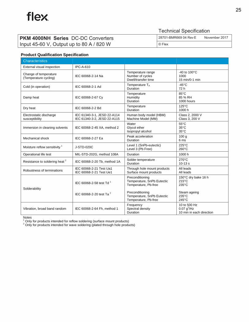
Product Qualification Specification
Characteristics
External visual inspection IPC-A-610
Change of temperature (Temperature cycling)
IEC 60068-2-14 Na Temperature range Number of cycles Dwell/transfer time
-40 to 100°C 1000 15 min/0-1 min
Cold (in operation) IEC 60068-2-1 Ad Temperature TA Duration
-45°C 72 h
Damp heat IEC 60068-2-67 Cy Temperature Humidity Duration
85°C 85 % RH 1000 hours
Dry heat IEC 60068-2-2 Bd Temperature Duration
125°C 1000 h
Electrostatic discharge susceptibility
IEC 61340-3-1, JESD 22-A114 IEC 61340-3-2, JESD 22-A115
Human body model (HBM) Machine Model (MM)
Class 2, 2000 V Class 3, 200 V
Immersion in cleaning solvents IEC 60068-2-45 XA, method 2 Water Glycol ether Isopropyl alcohol
55°C 35°C 35°C
Mechanical shock IEC 60068-2-27 Ea Peak acceleration Duration
100 g 6 ms
Moisture reflow sensitivity 1 J-STD-020C Level 1 (SnPb-eutectic) Level 3 (Pb Free)
225°C 260°C
Operational life test MIL-STD-202G, method 108A Duration 1000 h
Resistance to soldering heat 2 IEC 60068-2-20 Tb, method 1A Solder temperature Duration
270°C 10-13 s
Robustness of terminations IEC 60068-2-21 Test Ua1 IEC 60068-2-21 Test Ue1
Through hole mount products Surface mount products
All leads All leads
Solderability
IEC 60068-2-58 test Td 1 IEC 60068-2-20 test Ta 2
Preconditioning Temperature, SnPb Eutectic Temperature, Pb-free Preconditioning Temperature, SnPb Eutectic Temperature, Pb-free
150°C dry bake 16 h 215°C 235°C Steam ageing 235°C 245°C
Vibration, broad band random IEC 60068-2-64 Fh, method 1 Frequency Spectral density Duration
10 to 500 Hz 0.07 g2/Hz 10 min in each direction
Notes 1 Only for products intended for reflow soldering (surface mount products) 2 Only for products intended for wave soldering (plated through hole products)
PKM 4000NH Series DC-DC Converters Input 45-60 V, Output up to 80 A / 820 W
28701-BMR669 04 Rev E November 2017
© Flex
Technical Specification
25