
Operation and Maintenance Manual
137
6902610-EN (08-06) Printed in Europe ©Bobcat Europe 2006 Operation and Maintenance Manual 325 328 325 - S/N 234111001 and Above 328 - S/N 234211001 and Above (G Series) EN
-
Upload
khangminh22 -
Category
Documents
-
view
0 -
download
0
Transcript of Operation and Maintenance Manual

6902610-EN (08-06) Printed in Europe ©Bobcat Europe 2006
Operationand
MaintenanceManual
325328
325 - S/N 234111001 and Above328 - S/N 234211001 and Above
(G Series)
EN
U.S. Publication 6902610 (11-05) Revised (3-06) (8)
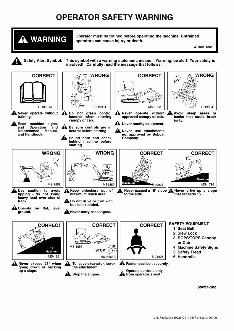
Never operate withouttraining.
Read machine signs,and Operation andMaintenance Manual,and Handbook.
Do not grasp controlhandles when enteringcanopy or cab.
Be sure controls are inneutral before starting.
Sound horn and checkbehind machine beforestarting.
Never operate withoutapproved canopy or cab.
Never modify equipment.
Never use attachmentsnot approved by BobcatCompany.
Avoid steep areas orbanks that could breakaway.
WARNINGOperator must be trained before operating the machine. Untrained operators can cause injury or death.
OPERATOR SAFETY WARNING
CORRECT
MS-1861
25° Maximum
Never exceed 25° whengoing down or backingup a slope.
OSW24-0805
To leave excavator, lowerthe attachment.
Stop the engine.
W-2001-1285
6808261A
CORRECT
MS-1853STOP
B-21928
CORRECT SAFETY EQUIPMENT 1. Seat Belt 2. Slew Lock 3. ROPS/TOPS Canopy or Cab 4. Machine Safety Signs 5. Safety Tread 6. Handrails
Fasten seat belt securely.
Operate controls only from operator’s seat.
Use caution to avoidtipping - do not swingheavy load over side oftrack.
Operate on flat, levelground.
Keep onlookers out ofmaximum reach area.
Do not drive or turn withbucket extended.
Never carry passengers.
Never exceed a 15° slopeto the side.
Never drive up a slopethat exceeds 15°.
WRONG
MS-1858
WRONG
MS1859 B-19936
CORRECT
15° Maximum
CORRECT
MS-1786
15° Maximum
CORRECT WRONG
B-19961
CORRECT WRONG
B-10731A MS-1853 B-19934
Safety Alert Symbol: This symbol with a warning statement, means: “Warning, be alert! Your safety isinvolved!” Carefully read the message that follows.

325/328 ExcavatorI Operation and Maintenance Manual
CONTENTS
FOREWORD . . . . . . . . . . . . . . . . . . . . . . . . . . . . . . . . . . . . . . . . . . III
SAFETY . . . . . . . . . . . . . . . . . . . . . . . . . . . . . . . . . . . . . . . . . . . . . XIII
OPERATING INSTRUCTIONS. . . . . . . . . . . . . . . . . . . . . . . . . . . . . .1
PREVENTIVE MAINTENANCE . . . . . . . . . . . . . . . . . . . . . . . . . . . .55
SYSTEM SETUP AND ANALYSIS . . . . . . . . . . . . . . . . . . . . . . . . . .91
SPECIFICATIONS . . . . . . . . . . . . . . . . . . . . . . . . . . . . . . . . . . . . . . 97
REFERENCE INFORMATION
Write the correct information for YOUR excavator in the spaces below. Always usethese numbers when referring to your Bobcat Excavator.
Bobcat Company EuropeDrève Richelle 167B-1410 WATERLOOBelgium
Bobcat Excavator Serial Number
Engine Serial Number
NOTES
YOUR BOBCAT EXCAVATOR DEALER:
ADDRESS:
PHONE:
FOREWORD
OPERATINGINSTRUCTIONS
MAINTENANCEPREVENTIVE
SPECIFICATIONS
AND ANALYSISSYSTEM SETUP
SAFETY

325/328 ExcavatorOperation and Maintenance Manual II
325/328 ExcavatorIII Operation and Maintenance Manual
FOREWORD
This Operation and Maintenance Manual was written to give the owner/operatorinstructions on the safe operation and maintenance of the Bobcat Excavator. READ ANDUNDERSTAND THIS OPERATION and MAINTENANCE MANUAL BEFOREOPERATING YOUR BOBCAT EXCAVATOR. If you have any questions, see your BobcatExcavator dealer.
BOBCAT COMPANY IS ISO 9001:2000 CERTIFIED. . . . . . . . . . . . . . . .V
BOBCAT EXCAVATOR IDENTIFICATION . . . . . . . . . . . . . . . . . . . . . . . IX
DELIVERY REPORT . . . . . . . . . . . . . . . . . . . . . . . . . . . . . . . . . . . . . . VIII
FEATURES AND ACCESSORIES: 2341 11001 - 2341 99999. . . . . . . . .XAttachments . . . . . . . . . . . . . . . . . . . . . . . . . . . . . . . . . . . . . . . . . . . .XBuckets . . . . . . . . . . . . . . . . . . . . . . . . . . . . . . . . . . . . . . . . . . . . . . . .XOptions and Accessories. . . . . . . . . . . . . . . . . . . . . . . . . . . . . . . . . . .XStandard Items . . . . . . . . . . . . . . . . . . . . . . . . . . . . . . . . . . . . . . . . . .X
FEATURES AND ACCESSORIES: 2342 11001 - 2342 99999 . . . . . . . XIAttachments . . . . . . . . . . . . . . . . . . . . . . . . . . . . . . . . . . . . . . . . . . . XIBuckets . . . . . . . . . . . . . . . . . . . . . . . . . . . . . . . . . . . . . . . . . . . . . . . XIOptions and Accessories. . . . . . . . . . . . . . . . . . . . . . . . . . . . . . . . . . XIStandard Items . . . . . . . . . . . . . . . . . . . . . . . . . . . . . . . . . . . . . . . . . XI
MOTOR OIL . . . . . . . . . . . . . . . . . . . . . . . . . . . . . . . . . . . . . . . . . . . . . . .V
REGULAR MAINTENANCE ITEMS . . . . . . . . . . . . . . . . . . . . . . . . . . . . .V
SERIAL NUMBER LOCATIONS. . . . . . . . . . . . . . . . . . . . . . . . . . . . . . .VIIEngine Serial Number . . . . . . . . . . . . . . . . . . . . . . . . . . . . . . . . . . . .VIIExcavator Serial Number . . . . . . . . . . . . . . . . . . . . . . . . . . . . . . . . .VII
FOREWORD
AND ANALYSIS
TRANSLATIONS
SYSTEM SETUP

325/328 ExcavatorOperation and Maintenance Manual IV
325/328 ExcavatorV Operation and Maintenance Manual
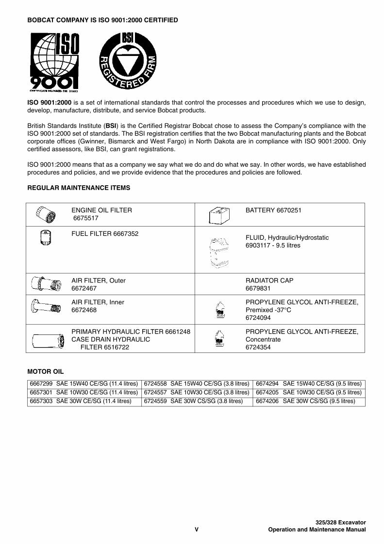
BOBCAT COMPANY IS ISO 9001:2000 CERTIFIED
ISO 9001:2000 is a set of international standards that control the processes and procedures which we use to design,develop, manufacture, distribute, and service Bobcat products.
British Standards Institute (BSI) is the Certified Registrar Bobcat chose to assess the Company’s compliance with theISO 9001:2000 set of standards. The BSI registration certifies that the two Bobcat manufacturing plants and the Bobcatcorporate offices (Gwinner, Bismarck and West Fargo) in North Dakota are in compliance with ISO 9001:2000. Onlycertified assessors, like BSI, can grant registrations.
ISO 9001:2000 means that as a company we say what we do and do what we say. In other words, we have establishedprocedures and policies, and we provide evidence that the procedures and policies are followed.
REGULAR MAINTENANCE ITEMS
MOTOR OIL
ENGINE OIL FILTER 6675517
BATTERY 6670251
FUEL FILTER 6667352FLUID, Hydraulic/Hydrostatic 6903117 - 9.5 litres
AIR FILTER, Outer6672467
RADIATOR CAP6679831
AIR FILTER, Inner 6672468
PROPYLENE GLYCOL ANTI-FREEZE, Premixed -37°C6724094
PRIMARY HYDRAULIC FILTER 6661248 CASE DRAIN HYDRAULIC FILTER 6516722
PROPYLENE GLYCOL ANTI-FREEZE, Concentrate6724354
6667299 SAE 15W40 CE/SG (11.4 litres) 6724558 SAE 15W40 CE/SG (3.8 litres) 6674294 SAE 15W40 CE/SG (9.5 litres)6657301 SAE 10W30 CE/SG (11.4 litres) 6724557 SAE 10W30 CE/SG (3.8 litres) 6674205 SAE 10W30 CE/SG (9.5 litres)6657303 SAE 30W CE/SG (11.4 litres) 6724559 SAE 30W CS/SG (3.8 litres) 6674206 SAE 30W CS/SG (9.5 litres)

325/328 ExcavatorOperation and Maintenance Manual VI
325/328 ExcavatorVII Operation and Maintenance Manual
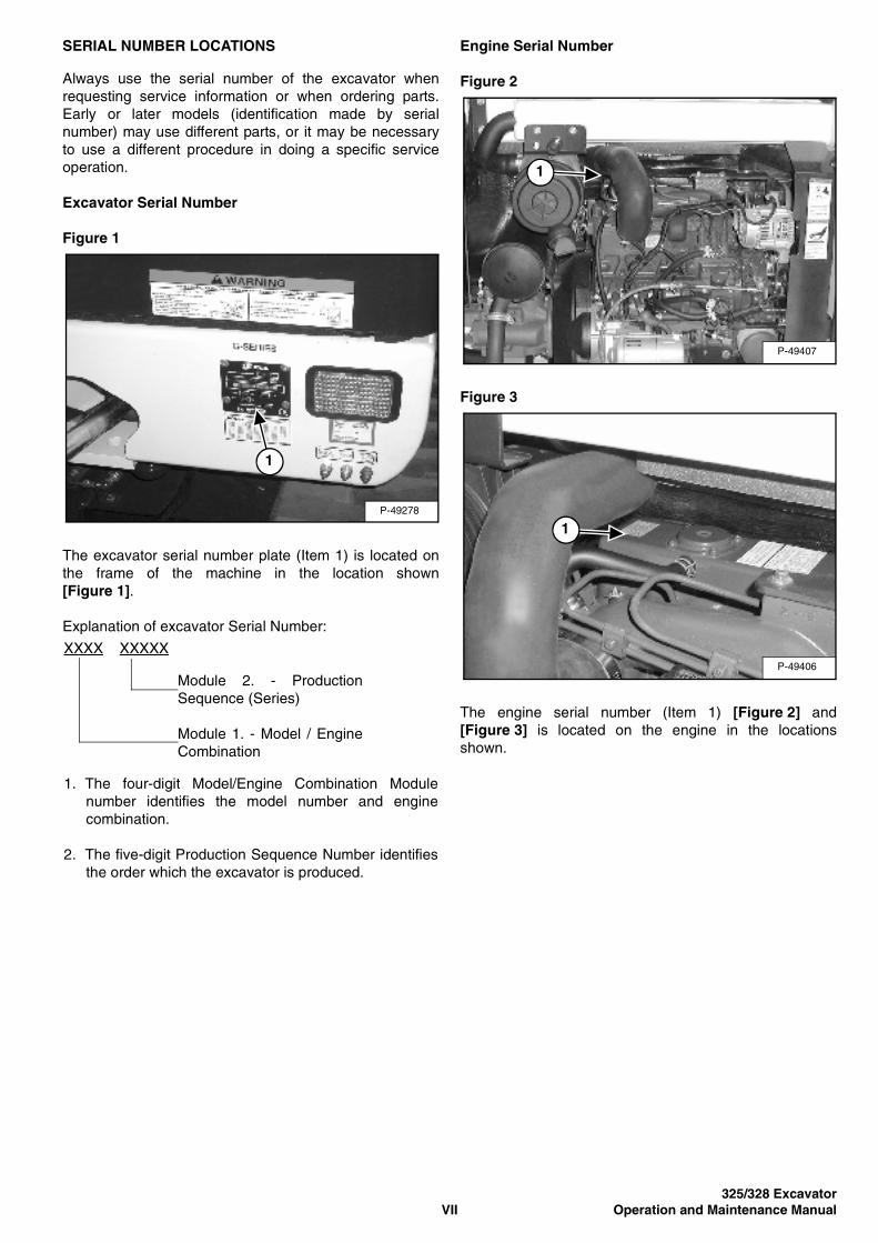
SERIAL NUMBER LOCATIONS
Always use the serial number of the excavator whenrequesting service information or when ordering parts.Early or later models (identification made by serialnumber) may use different parts, or it may be necessaryto use a different procedure in doing a specific serviceoperation.
Excavator Serial Number
Figure 1
The excavator serial number plate (Item 1) is located onthe frame of the machine in the location shown[Figure 1].
Explanation of excavator Serial Number:
Engine Serial Number
Figure 2
Figure 3
The engine serial number (Item 1) [Figure 2] and[Figure 3] is located on the engine in the locationsshown.
P-49278
1
XXXX XXXXX
Module 2. - ProductionSequence (Series)
Module 1. - Model / EngineCombination
1. The four-digit Model/Engine Combination Modulenumber identifies the model number and enginecombination.
2. The five-digit Production Sequence Number identifiesthe order which the excavator is produced.
P-49407
1
P-49406
1

325/328 ExcavatorOperation and Maintenance Manual VIII
DELIVERY REPORT
Figure 4
The delivery report must be completed out by the dealerand signed by the owner or operator when the BobcatExcavator is delivered. An explanation of the form mustbe given to the owner. Make sure it is completed[Figure 4].
B-16315
325/328 ExcavatorIX Operation and Maintenance Manual
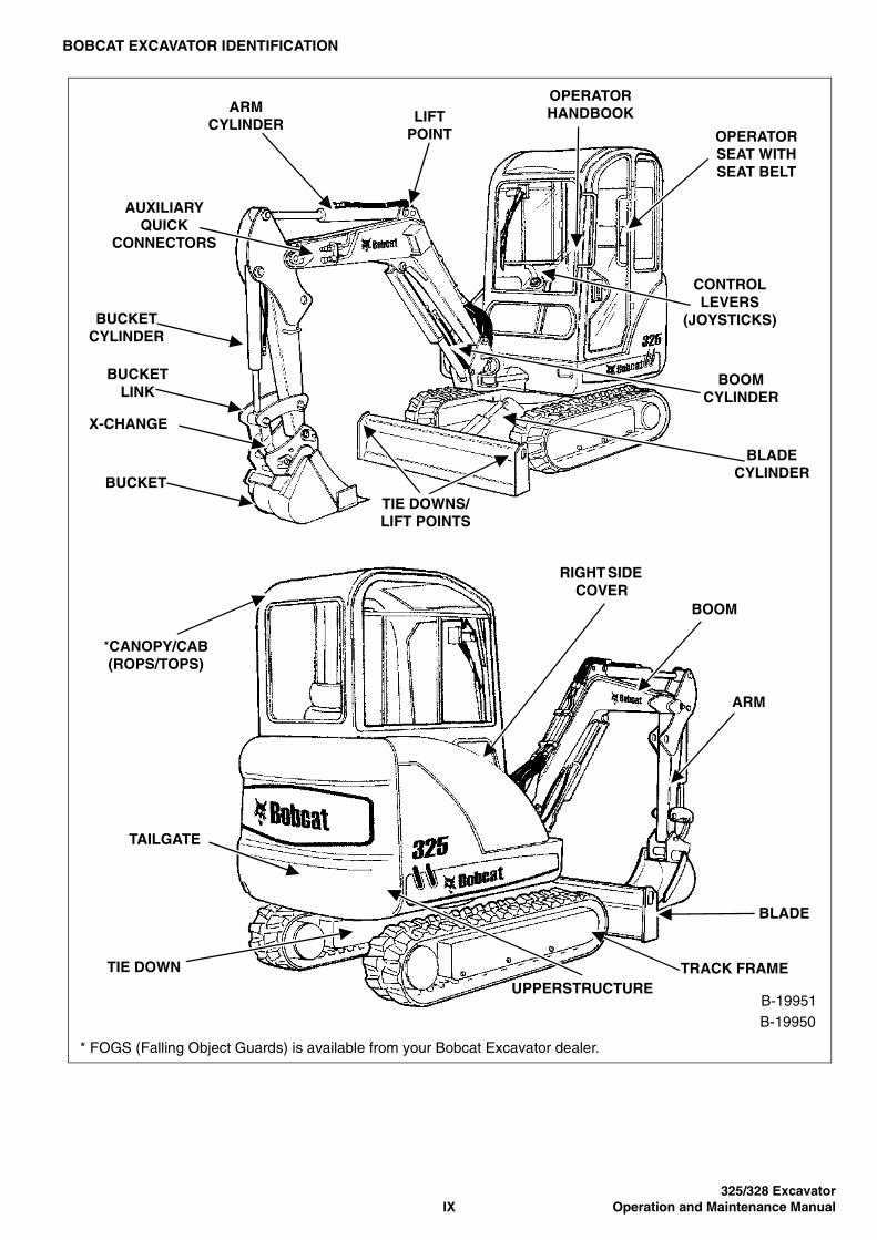
BOBCAT EXCAVATOR IDENTIFICATION
*CANOPY/CAB(ROPS/TOPS)
* FOGS (Falling Object Guards) is available from your Bobcat Excavator dealer.
B-19950B-19951
LIFTPOINT OPERATOR
SEAT WITH SEAT BELT
OPERATOR HANDBOOK
CONTROL LEVERS
(JOYSTICKS)
BOOM CYLINDER
BLADE CYLINDER
TIE DOWNS/ LIFT POINTS
BUCKET
X-CHANGE
BUCKET LINK
BUCKET CYLINDER
AUXILIARY QUICK
CONNECTORS
ARM CYLINDER
TAILGATE
TIE DOWNUPPERSTRUCTURE
TRACK FRAME
BLADE
RIGHT SIDE COVER
BOOM
ARM
325/328 ExcavatorOperation and Maintenance Manual X
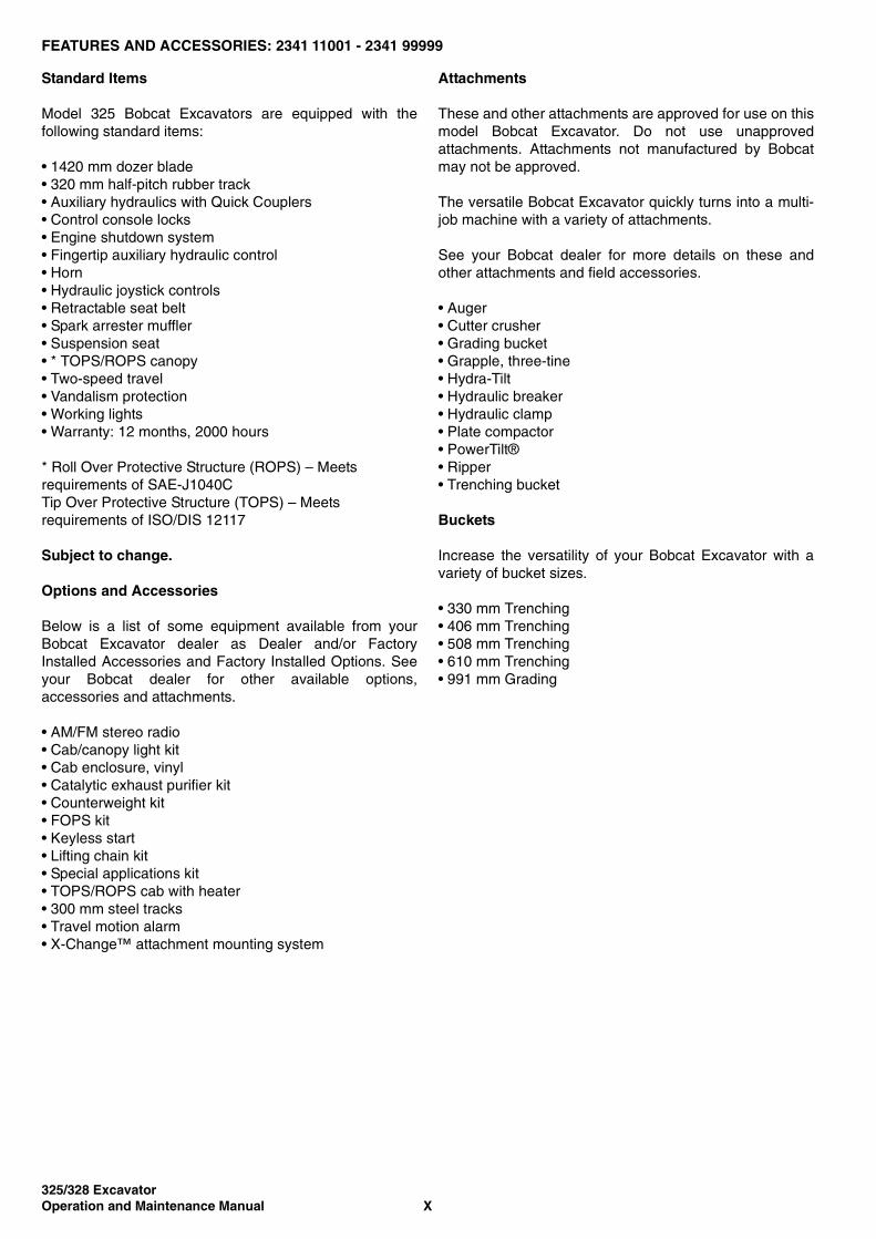
FEATURES AND ACCESSORIES: 2341 11001 - 2341 99999
Standard Items
Model 325 Bobcat Excavators are equipped with thefollowing standard items:
• 1420 mm dozer blade• 320 mm half-pitch rubber track• Auxiliary hydraulics with Quick Couplers• Control console locks• Engine shutdown system• Fingertip auxiliary hydraulic control• Horn• Hydraulic joystick controls• Retractable seat belt• Spark arrester muffler• Suspension seat• * TOPS/ROPS canopy• Two-speed travel• Vandalism protection• Working lights• Warranty: 12 months, 2000 hours
* Roll Over Protective Structure (ROPS) – Meets requirements of SAE-J1040CTip Over Protective Structure (TOPS) – Meets requirements of ISO/DIS 12117
Subject to change.
Options and Accessories
Below is a list of some equipment available from yourBobcat Excavator dealer as Dealer and/or FactoryInstalled Accessories and Factory Installed Options. Seeyour Bobcat dealer for other available options,accessories and attachments.
• AM/FM stereo radio• Cab/canopy light kit• Cab enclosure, vinyl• Catalytic exhaust purifier kit• Counterweight kit• FOPS kit• Keyless start• Lifting chain kit• Special applications kit• TOPS/ROPS cab with heater• 300 mm steel tracks• Travel motion alarm• X-Change™ attachment mounting system
Attachments
These and other attachments are approved for use on thismodel Bobcat Excavator. Do not use unapprovedattachments. Attachments not manufactured by Bobcatmay not be approved.
The versatile Bobcat Excavator quickly turns into a multi-job machine with a variety of attachments.
See your Bobcat dealer for more details on these andother attachments and field accessories.
• Auger• Cutter crusher• Grading bucket• Grapple, three-tine• Hydra-Tilt• Hydraulic breaker• Hydraulic clamp• Plate compactor• PowerTilt®• Ripper• Trenching bucket
Buckets
Increase the versatility of your Bobcat Excavator with avariety of bucket sizes.
• 330 mm Trenching• 406 mm Trenching• 508 mm Trenching• 610 mm Trenching• 991 mm Grading
325/328 ExcavatorXI Operation and Maintenance Manual
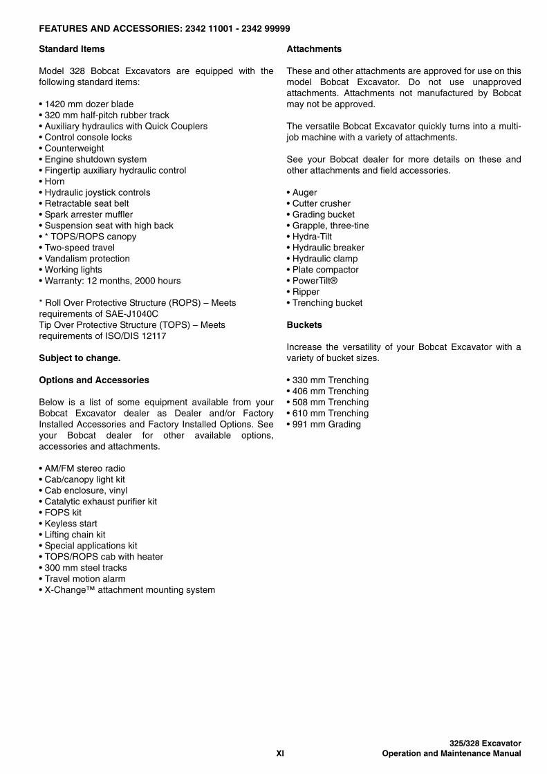
FEATURES AND ACCESSORIES: 2342 11001 - 2342 99999
Standard Items
Model 328 Bobcat Excavators are equipped with thefollowing standard items:
• 1420 mm dozer blade• 320 mm half-pitch rubber track• Auxiliary hydraulics with Quick Couplers• Control console locks• Counterweight• Engine shutdown system• Fingertip auxiliary hydraulic control• Horn• Hydraulic joystick controls• Retractable seat belt• Spark arrester muffler• Suspension seat with high back• * TOPS/ROPS canopy• Two-speed travel• Vandalism protection• Working lights• Warranty: 12 months, 2000 hours
* Roll Over Protective Structure (ROPS) – Meets requirements of SAE-J1040CTip Over Protective Structure (TOPS) – Meets requirements of ISO/DIS 12117
Subject to change.
Options and Accessories
Below is a list of some equipment available from yourBobcat Excavator dealer as Dealer and/or FactoryInstalled Accessories and Factory Installed Options. Seeyour Bobcat dealer for other available options,accessories and attachments.
• AM/FM stereo radio• Cab/canopy light kit• Cab enclosure, vinyl• Catalytic exhaust purifier kit• FOPS kit• Keyless start• Lifting chain kit• Special applications kit• TOPS/ROPS cab with heater• 300 mm steel tracks• Travel motion alarm• X-Change™ attachment mounting system
Attachments
These and other attachments are approved for use on thismodel Bobcat Excavator. Do not use unapprovedattachments. Attachments not manufactured by Bobcatmay not be approved.
The versatile Bobcat Excavator quickly turns into a multi-job machine with a variety of attachments.
See your Bobcat dealer for more details on these andother attachments and field accessories.
• Auger• Cutter crusher• Grading bucket• Grapple, three-tine• Hydra-Tilt• Hydraulic breaker• Hydraulic clamp• Plate compactor• PowerTilt®• Ripper• Trenching bucket
Buckets
Increase the versatility of your Bobcat Excavator with avariety of bucket sizes.
• 330 mm Trenching• 406 mm Trenching• 508 mm Trenching• 610 mm Trenching• 991 mm Grading

325/328 ExcavatorOperation and Maintenance Manual XII

325/328 ExcavatorXIII Operation and Maintenance Manual
SAFETY
MACHINE SIGNS (STICKERS) . . . . . . . . . . . . . . . . . . . . . . . . . . XVIII
SAFETY INSTRUCTIONS . . . . . . . . . . . . . . . . . . . . . . . . . . . . . . . XVBefore Operation . . . . . . . . . . . . . . . . . . . . . . . . . . . . . . . . . . . . XVFire Prevention . . . . . . . . . . . . . . . . . . . . . . . . . . . . . . . . . . . . XVIISafe Operation Is The Operator’s Responsibility . . . . . . . . . . . XVISafe Operation Needs A Qualified Operator . . . . . . . . . . . . . . . XVI
AND ANALYSIS
TRANSLATIONS
SYSTEM SETUP
SAFETY

325/328 ExcavatorOperation and Maintenance Manual XIV
325/328 ExcavatorXV Operation and Maintenance Manual
SAFETY INSTRUCTIONS
Before Operation
Carefully follow the operating and maintenanceinstructions in this manual.
The Bobcat Excavator is highly manoeuvrable andcompact. It is rugged and useful under a wide variety ofconditions. This presents an operator with hazardsassociated with off-road, rough terrain applications,common with Bobcat Excavator usage.
The Bobcat Excavator has an internal combustion enginewith resultant heat and exhaust. All exhaust gases can killor cause illness so use the Excavator with adequateventilation.
The dealer explains the capabilities and restrictions of theBobcat Excavator and attachment for each application.The dealer demonstrates the safe operation according toBobcat instructional materials, which are also available tooperators. The dealer can also identify unsafemodifications or use of unapproved attachments. Theattachments and buckets are designed for a Rated LiftCapacity. They are designed for secure fastening to theBobcat Excavator. The user must check with the dealer,or Bobcat literature, to determine safe loads of materialsof specified densities for the machine - attachmentcombination.
The following publications provide information on the safeuse and maintenance of the Bobcat machine andattachments:
• The Delivery Report is used to assure that completeinstructions have been given to the new owner andthat the machine and attachment is in safe operatingcondition.
• The Operation and Maintenance Manual deliveredwith the machine or attachment gives operatinginformation as well as routine maintenance andservice procedures. It is a part of the machine and canbe stored in a container provided on the machine.Replacement Operation and Maintenance Manualscan be ordered from your Bobcat dealer.
• Machine signs (stickers) instruct on the safe operationand care of your Bobcat machine or attachment. Thesigns and their locations are shown in the Operationand Maintenance Manual. Replacement signs areavailable from your Bobcat dealer.
• An Operator’s Handbook is attached to the operatorcab of the Excavator. Its brief instructions areconvenient to the operator.
The dealer and owner/operator review the recommendeduses of the product when delivered. If the owners/operators will be using the machine for a differentapplication(s) they must ask the dealer forrecommendations on the new use.

325/328 ExcavatorOperation and Maintenance Manual XVI
SAFETY INSTRUCTIONS (CONT’D)
Safe Operation Is The Operator’s Responsibility
WARNINGWARNINGOperators must be trained before operating themachine. Untrained operators can cause injury ordeath.
W-2001-1285
IMPORTANTThis notice identifies procedures which must befollowed to avoid damage to the machine.
I-2019-0284
WARNINGWARNINGWarnings on the machine and in the manuals are foryour safety. Failure to obey warnings can cause injuryor death.
W-2044-1285
The Bobcat Excavator and attachment must be in goodoperating condition before use.
Check all of the items on the Bobcat Service ScheduleSticker under the 8-10 hour column or as shown in theOperation and Maintenance Manual.
Safe Operation Needs A Qualified Operator
For operators to be qualified, they must not use drugs oralcoholic drinks which impair their alertness orcoordination while working. Operators who are takingprescription drugs must get medical advice to determine ifthey can safely operate a machine.
A Qualified Operator Must Do The Following:
Understand the Written Instructions, Rules andRegulations
• The written instructions from Bobcat Company includethe Delivery Report, Operation and MaintenanceManual, Operator’s Handbook and machine signs(stickers).
• Check the rules and regulations at your location. Therules may include an employer’s work safetyrequirements. Regulations may apply to local drivingrequirements or use of a Slow Moving Vehicle (SMV)symbol. Regulations may identify a hazard such as apowerline.
Have Training with Actual Operation
• Operator training must consist of a demonstration andverbal instruction. This training is given by your Bobcatdealer before the product is delivered.
• New operators must start in an area without onlookersand use all the controls until they can operate themachine and attachment safely under all conditions ofthe work area. Always fasten seat belt beforeoperating.
Know the Work Conditions
• Know the weight of the materials being handled. Avoidexceeding the Rated Lift Capacity of the machine.Material which is very dense will be heavier than thesame volume of less dense material. Reduce the sizeof load if handling dense material.
• Operators must know any prohibited uses or workareas, for example, they need to know aboutexcessive slopes.
• Know the location of any underground lines.
• Wear tight fitting clothing. Always wear safety glasseswhen doing maintenance or service. Safety glasses,hearing protection or Special Applications Kits arerequired for some work. See your Bobcat dealer aboutBobcat Safety Equipment for your model.
SI EXC-0206
This symbol with a warning statement means:“Warning, be alert! Your safety is involved!”Carefully read the message that follows.
Safety Alert Symbol
325/328 ExcavatorXVII Operation and Maintenance Manual
SAFETY INSTRUCTIONS (CONT’D)
Fire Prevention
The machines and some attachments have componentsthat are at high temperatures under normal operatingconditions. The primary source of high temperatures isthe engine and exhaust system. The electrical system, ifdamaged or incorrectly maintained, can be a source ofarcs or sparks.
Flammable debris (leaves, straw, etc.) must be removedregularly. If flammable debris is allowed to accumulate, itcan cause a fire hazard. Clean often to avoid thisaccumulation. Flammable debris in the enginecompartment is a potential fire hazard.
The spark arrester exhaust system is designed to controlthe emission of hot particles from the engine and exhaustsystem, but the silencer and the exhaust gases are stillhot.
• Do not use the machine where exhaust, arcs, sparksor hot components can make contact with flammablematerial, explosive dust or gases.
• The operator cab, engine compartment and enginecooling system must be inspected every day andcleaned if necessary to prevent fire hazards andoverheating.
• Check all electrical wiring and connections fordamage. Keep the battery terminals clean and tight.Repair or replace any damaged part.
• Check fuel and hydraulic tubes, hoses and fittings fordamage and leakage. Never use open flame or bareskin to check for leaks. Tighten or replace any partsthat show leakage. Always clean fluid spills. Do notuse petrol or diesel fuel for cleaning parts. Usecommercial nonflammable solvents.
• Do not use ethyl spirits or starting fluids on any enginethat has glow plugs. These starting aids can causeexplosion and injure you or onlookers.
• Always clean the machine, disconnect the battery, anddisconnect the wiring from the controllers beforewelding. Cover rubber hoses, battery and all otherflammable parts. Keep a fire extinguisher near themachine when welding. Have good ventilation whengrinding or welding painted parts. Wear dust maskwhen grinding painted parts. Toxic dust or gas can beproduced.
• Stop the engine and let it cool down before adding fuel.No smoking!
• Use the procedure in the Operation and MaintenanceManual for connecting the battery and for jumpstarting.
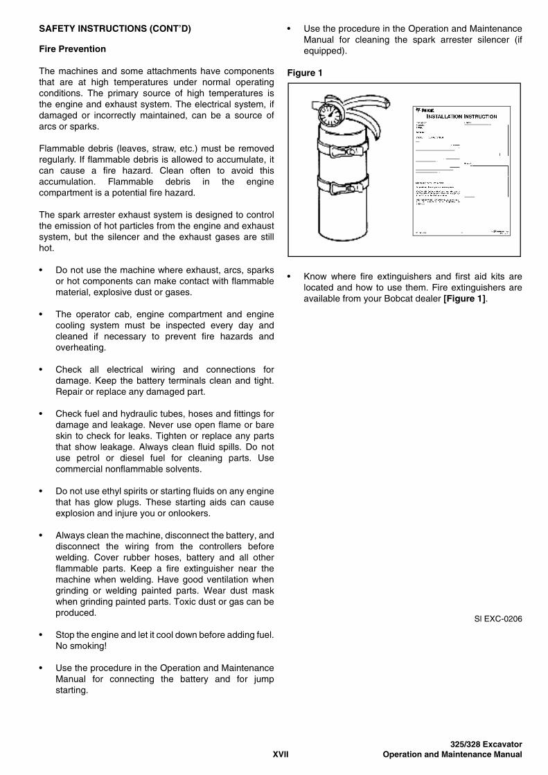
• Use the procedure in the Operation and MaintenanceManual for cleaning the spark arrester silencer (ifequipped).
Figure 1
• Know where fire extinguishers and first aid kits arelocated and how to use them. Fire extinguishers areavailable from your Bobcat dealer [Figure 1].
Sl EXC-0206
325/328 ExcavatorOperation and Maintenance Manual XVIII
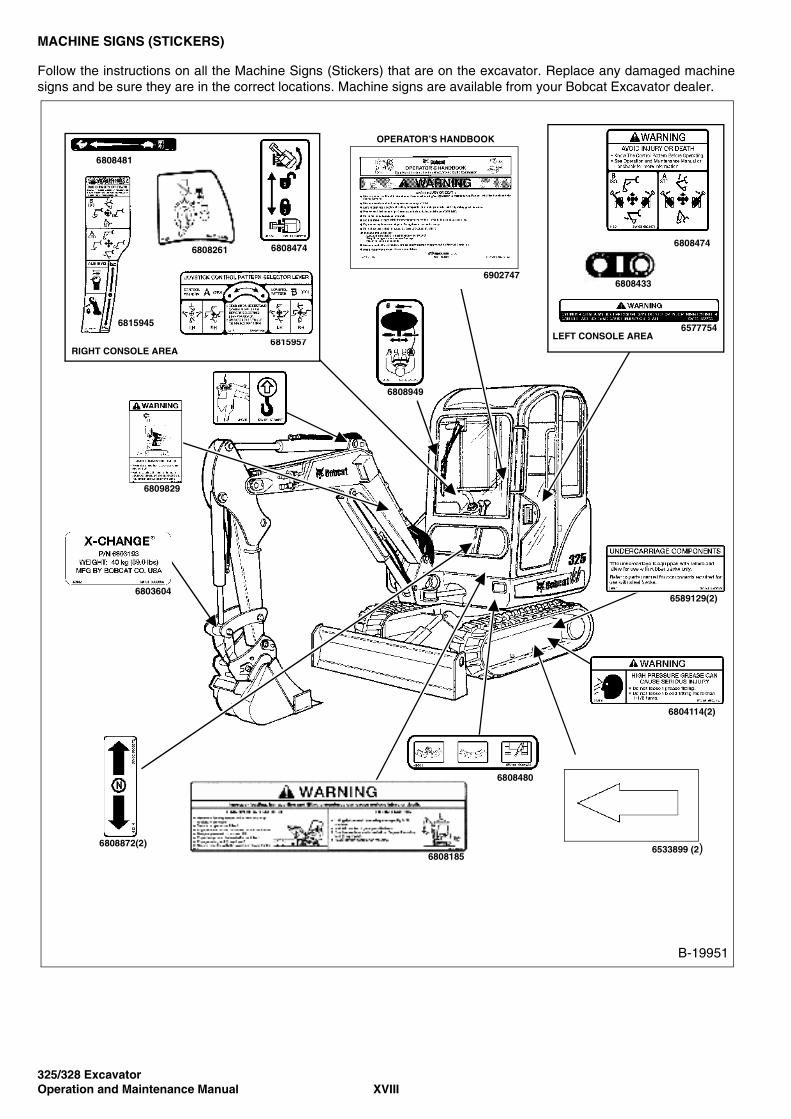
MACHINE SIGNS (STICKERS)
Follow the instructions on all the Machine Signs (Stickers) that are on the excavator. Replace any damaged machinesigns and be sure they are in the correct locations. Machine signs are available from your Bobcat Excavator dealer.
6589129(2)
6804114(2)
6533899 (2)
6803604
6809829
6808872(2)
6808480
6902747
OPERATOR’S HANDBOOK
6808949
LEFT CONSOLE AREA
6808474
6577754
6808433
6808261
6815957RIGHT CONSOLE AREA
6808481
6808474
6815945
6808185
B-19951
325/328 ExcavatorXIX Operation and Maintenance Manual
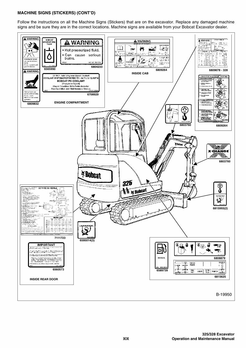
MACHINE SIGNS (STICKERS) (CONT’D)
Follow the instructions on all the Machine Signs (Stickers) that are on the excavator. Replace any damaged machinesigns and be sure they are in the correct locations. Machine signs are available from your Bobcat Excavator dealer.
6808879
6815625
6589739
6815993(2)
6803760
INSIDE CAB6809264
7111723
6560573
INSIDE REAR DOOR
6595014(3)
68042336565990
6809832
6708929
ENGINE COMPARTMENT
B-19950
68092646803760
6809678 - 328

325/328 ExcavatorOperation and Maintenance Manual XX
325/328 Excavator1 Operation and Maintenance Manual
OPERATING INSTRUCTIONS
ATTACHMENTS . . . . . . . . . . . . . . . . . . . . . . . . . . . . . . . . . . . . . . . .26Auxiliary Hydraulics . . . . . . . . . . . . . . . . . . . . . . . . . . . . . . . . . . .42Installing Bucket Or Attachment (Bolt-On X-Change) . . . . . . . . .32Installing Bucket Or Attachment (Pin On X-Change) . . . . . . . . .26Installing Bucket Or Attachment (X-Change System) . . . . . . . . .38Quick Connectors . . . . . . . . . . . . . . . . . . . . . . . . . . . . . . . . . . . .41Relieving Hydraulic Pressure . . . . . . . . . . . . . . . . . . . . . . . . . . .42Removing Bucket Or Attachment (Bolt On X-Change) . . . . . . . .36Removing Bucket Or Attachment (Pin On X-Change) . . . . . . . .29Removing Bucket Or Attachment (X-Change System) . . . . . . . .40Return To Tank Valve (If Equipped). . . . . . . . . . . . . . . . . . . . . . .42
BLADE CONTROL LEVER. . . . . . . . . . . . . . . . . . . . . . . . . . . . . . . .17Operation. . . . . . . . . . . . . . . . . . . . . . . . . . . . . . . . . . . . . . . . . . .17
BOOM SWING PEDAL. . . . . . . . . . . . . . . . . . . . . . . . . . . . . . . . . . .17Operation. . . . . . . . . . . . . . . . . . . . . . . . . . . . . . . . . . . . . . . . . . .17
DAILY INSPECTION. . . . . . . . . . . . . . . . . . . . . . . . . . . . . . . . . . . . .18Procedure . . . . . . . . . . . . . . . . . . . . . . . . . . . . . . . . . . . . . . . . . .18Service Schedule . . . . . . . . . . . . . . . . . . . . . . . . . . . . . . . . . . . .19
FALLING OBJECT GUARDS (FOGS) . . . . . . . . . . . . . . . . . . . . . . . .8Description . . . . . . . . . . . . . . . . . . . . . . . . . . . . . . . . . . . . . . . . . .8
HYDRAULIC CONTROLS . . . . . . . . . . . . . . . . . . . . . . . . . . . . . . . .16BLADE CONTROL LEVER . . . . . . . . . . . . . . . . . . . . . . . . . . . . .17ISO Control Pattern . . . . . . . . . . . . . . . . . . . . . . . . . . . . . . . . . . .16
INSTRUMENTS AND CONSOLES . . . . . . . . . . . . . . . . . . . . . . . . . .3Cab Interior Light (If Equipped) . . . . . . . . . . . . . . . . . . . . . . . . . . .3Function Icons . . . . . . . . . . . . . . . . . . . . . . . . . . . . . . . . . . . . . . . .5Left Console . . . . . . . . . . . . . . . . . . . . . . . . . . . . . . . . . . . . . . . . .3Raising And Lowering The Console . . . . . . . . . . . . . . . . . . . . . . .6Right Console . . . . . . . . . . . . . . . . . . . . . . . . . . . . . . . . . . . . . . . .4Two-Speed Driving . . . . . . . . . . . . . . . . . . . . . . . . . . . . . . . . . . . .7Upperstructure Slew Lock . . . . . . . . . . . . . . . . . . . . . . . . . . . . . . .6
LIFTING THE EXCAVATOR . . . . . . . . . . . . . . . . . . . . . . . . . . . . . . .53Procedure . . . . . . . . . . . . . . . . . . . . . . . . . . . . . . . . . . . . . . . . . .53
OPERATINGINSTRUCTIONS
325/328 ExcavatorOperation and Maintenance Manual 2
OPERATING INSTRUCTIONS (CONT’D)
OPERATOR CAB (ROPS/TOPS) . . . . . . . . . . . . . . . . . . . . . . . . . . . .9Cab Door . . . . . . . . . . . . . . . . . . . . . . . . . . . . . . . . . . . . . . . . . . .10Emergency Exit . . . . . . . . . . . . . . . . . . . . . . . . . . . . . . . . . . . . . . .9Front Window . . . . . . . . . . . . . . . . . . . . . . . . . . . . . . . . . . . . . . .11Heating and Ventilation . . . . . . . . . . . . . . . . . . . . . . . . . . . . . . . .13Right Side Windows . . . . . . . . . . . . . . . . . . . . . . . . . . . . . . . . . .12
OPERATOR CANOPY (ROPS/TOPS) . . . . . . . . . . . . . . . . . . . . . . . .7Description. . . . . . . . . . . . . . . . . . . . . . . . . . . . . . . . . . . . . . . . . . .7
OPERATING PROCEDURE . . . . . . . . . . . . . . . . . . . . . . . . . . . . . . .43Backfilling . . . . . . . . . . . . . . . . . . . . . . . . . . . . . . . . . . . . . . . . . .47Boom Swing . . . . . . . . . . . . . . . . . . . . . . . . . . . . . . . . . . . . . . . .46Driving The Excavator . . . . . . . . . . . . . . . . . . . . . . . . . . . . . . . . .47Excavating . . . . . . . . . . . . . . . . . . . . . . . . . . . . . . . . . . . . . . . . . .44Lifting A Load. . . . . . . . . . . . . . . . . . . . . . . . . . . . . . . . . . . . . . . .43Lowering The Work Equipment With Engine Stopped. . . . . . . . .43Operating In Water . . . . . . . . . . . . . . . . . . . . . . . . . . . . . . . . . . .50Operating On Public Roads. . . . . . . . . . . . . . . . . . . . . . . . . . . . .43Operating On Slopes . . . . . . . . . . . . . . . . . . . . . . . . . . . . . . . . . .48
PARKING THE EXCAVATOR . . . . . . . . . . . . . . . . . . . . . . . . . . . . . .51Procedure . . . . . . . . . . . . . . . . . . . . . . . . . . . . . . . . . . . . . . . . . .51
PRE-STARTING PROCEDURE . . . . . . . . . . . . . . . . . . . . . . . . . . . .20Before Starting The Engine . . . . . . . . . . . . . . . . . . . . . . . . . . . . .20
STARTING THE ENGINE . . . . . . . . . . . . . . . . . . . . . . . . . . . . . . . . .22Cold Temperature Starting Procedure . . . . . . . . . . . . . . . . . . . . .24Keyless Start . . . . . . . . . . . . . . . . . . . . . . . . . . . . . . . . . . . . . . . .23Key Switch. . . . . . . . . . . . . . . . . . . . . . . . . . . . . . . . . . . . . . . . . .22
STEERING COLUMNS/FOOT PEDALS . . . . . . . . . . . . . . . . . . . . .14Driving Forwards And Reversing. . . . . . . . . . . . . . . . . . . . . . . . .14Turning. . . . . . . . . . . . . . . . . . . . . . . . . . . . . . . . . . . . . . . . . . . . .14
TRANSPORTING THE EXCAVATOR. . . . . . . . . . . . . . . . . . . . . . . .52Procedure . . . . . . . . . . . . . . . . . . . . . . . . . . . . . . . . . . . . . . . . . .52
WARMING UP THE HYDRAULIC SYSTEM. . . . . . . . . . . . . . . . . . .25Procedure . . . . . . . . . . . . . . . . . . . . . . . . . . . . . . . . . . . . . . . . . .25
325/328 Excavator3 Operation and Maintenance Manual
INSTRUMENTS AND CONSOLES
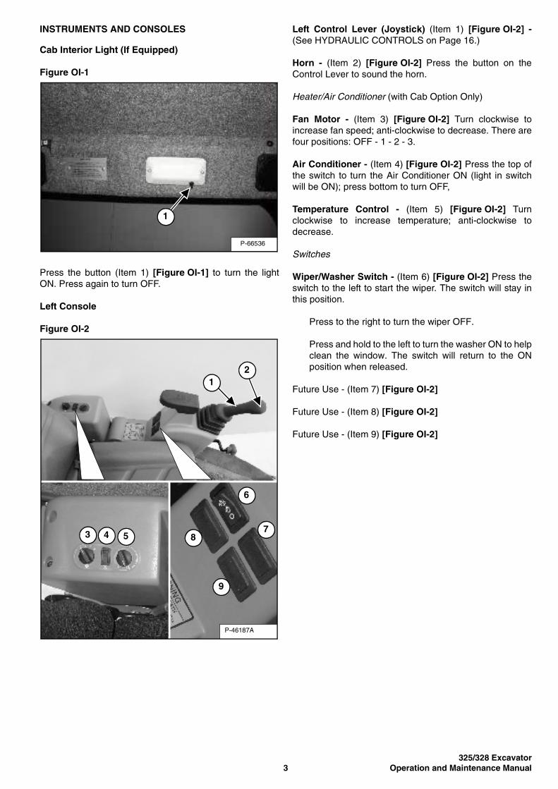
Cab Interior Light (If Equipped)
Figure OI-1
Press the button (Item 1) [Figure OI-1] to turn the lightON. Press again to turn OFF.
Left Console
Figure OI-2
Left Control Lever (Joystick) (Item 1) [Figure OI-2] -(See HYDRAULIC CONTROLS on Page 16.)
Horn - (Item 2) [Figure OI-2] Press the button on theControl Lever to sound the horn.
Heater/Air Conditioner (with Cab Option Only)
Fan Motor - (Item 3) [Figure OI-2] Turn clockwise toincrease fan speed; anti-clockwise to decrease. There arefour positions: OFF - 1 - 2 - 3.
Air Conditioner - (Item 4) [Figure OI-2] Press the top ofthe switch to turn the Air Conditioner ON (light in switchwill be ON); press bottom to turn OFF,
Temperature Control - (Item 5) [Figure OI-2] Turnclockwise to increase temperature; anti-clockwise todecrease.
Switches
Wiper/Washer Switch - (Item 6) [Figure OI-2] Press theswitch to the left to start the wiper. The switch will stay inthis position.
Press to the right to turn the wiper OFF.
Press and hold to the left to turn the washer ON to helpclean the window. The switch will return to the ONposition when released.
Future Use - (Item 7) [Figure OI-2]
Future Use - (Item 8) [Figure OI-2]
Future Use - (Item 9) [Figure OI-2]
P-66536
1
P-46187A
12
6
78
9
3 4 5
325/328 ExcavatorOperation and Maintenance Manual 4
INSTRUMENTS AND CONSOLES (CONT’D)
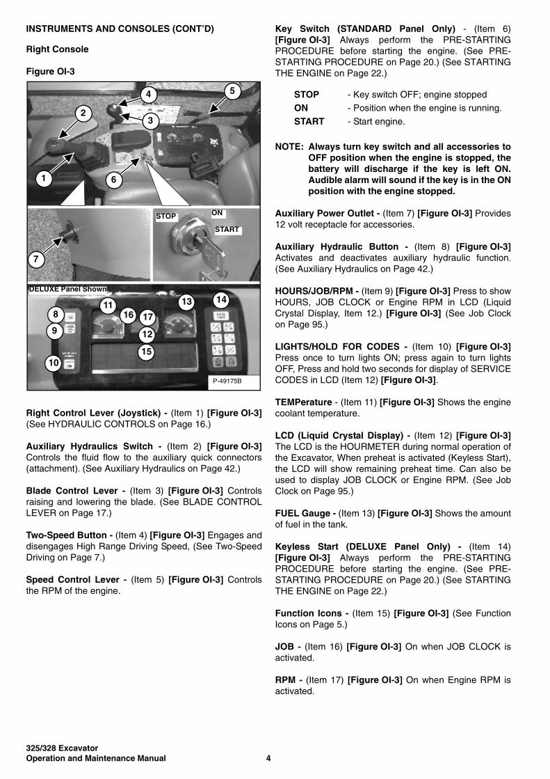
Right Console
Figure OI-3
Right Control Lever (Joystick) - (Item 1) [Figure OI-3](See HYDRAULIC CONTROLS on Page 16.)
Auxiliary Hydraulics Switch - (Item 2) [Figure OI-3]Controls the fluid flow to the auxiliary quick connectors(attachment). (See Auxiliary Hydraulics on Page 42.)
Blade Control Lever - (Item 3) [Figure OI-3] Controlsraising and lowering the blade. (See BLADE CONTROLLEVER on Page 17.)
Two-Speed Button - (Item 4) [Figure OI-3] Engages anddisengages High Range Driving Speed, (See Two-SpeedDriving on Page 7.)
Speed Control Lever - (Item 5) [Figure OI-3] Controlsthe RPM of the engine.
Key Switch (STANDARD Panel Only) - (Item 6)[Figure OI-3] Always perform the PRE-STARTINGPROCEDURE before starting the engine. (See PRE-STARTING PROCEDURE on Page 20.) (See STARTINGTHE ENGINE on Page 22.)
NOTE: Always turn key switch and all accessories toOFF position when the engine is stopped, thebattery will discharge if the key is left ON.Audible alarm will sound if the key is in the ONposition with the engine stopped.
Auxiliary Power Outlet - (Item 7) [Figure OI-3] Provides12 volt receptacle for accessories.
Auxiliary Hydraulic Button - (Item 8) [Figure OI-3]Activates and deactivates auxiliary hydraulic function.(See Auxiliary Hydraulics on Page 42.)
HOURS/JOB/RPM - (Item 9) [Figure OI-3] Press to showHOURS, JOB CLOCK or Engine RPM in LCD (LiquidCrystal Display, Item 12.) [Figure OI-3] (See Job Clockon Page 95.)
LIGHTS/HOLD FOR CODES - (Item 10) [Figure OI-3]Press once to turn lights ON; press again to turn lightsOFF, Press and hold two seconds for display of SERVICECODES in LCD (Item 12) [Figure OI-3].
TEMPerature - (Item 11) [Figure OI-3] Shows the enginecoolant temperature.
LCD (Liquid Crystal Display) - (Item 12) [Figure OI-3]The LCD is the HOURMETER during normal operation ofthe Excavator, When preheat is activated (Keyless Start),the LCD will show remaining preheat time. Can also beused to display JOB CLOCK or Engine RPM. (See JobClock on Page 95.)
FUEL Gauge - (Item 13) [Figure OI-3] Shows the amountof fuel in the tank.
Keyless Start (DELUXE Panel Only) - (Item 14)[Figure OI-3] Always perform the PRE-STARTINGPROCEDURE before starting the engine. (See PRE-STARTING PROCEDURE on Page 20.) (See STARTINGTHE ENGINE on Page 22.)
Function Icons - (Item 15) [Figure OI-3] (See FunctionIcons on Page 5.)
JOB - (Item 16) [Figure OI-3] On when JOB CLOCK isactivated.
RPM - (Item 17) [Figure OI-3] On when Engine RPM isactivated.
P-49175B
8
9
10
1116 17
12
15
13 14DELUXE Panel Shown
STOP ON
START
7
5
3
4
2
1 6
STOP - Key switch OFF; engine stopped
ON - Position when the engine is running.
START - Start engine.
325/328 Excavator5 Operation and Maintenance Manual
INSTRUMENTS AND CONSOLES (CONT’D)
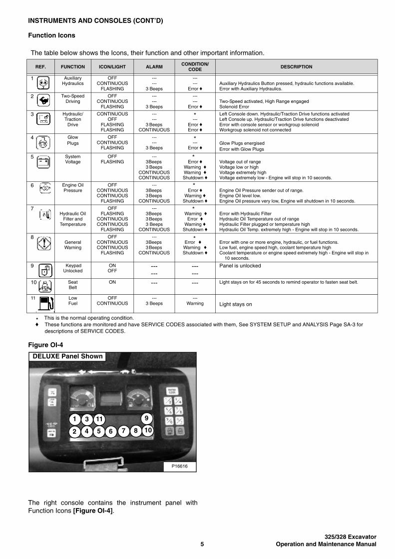
Function Icons
Figure OI-4
The right console contains the instrument panel withFunction Icons [Figure OI-4].
The table below shows the Icons, their function and other important information.
REF. FUNCTION ICON/LIGHT ALARM CONDITION/CODE DESCRIPTION
1 Auxiliary Hydraulics
OFFCONTINUOUS
FLASHING
--- ---
3 Beeps
------
Error ♦Auxiliary Hydraulics Button pressed, hydraulic functions available.Error with Auxiliary Hydraulics.
2 Two-Speed Driving
OFF CONTINUOUS
FLASHING
--- ---
3 Beeps
------
Error ♦Two-Speed activated, High Range engaged Solenoid Error
3 Hydraulic/Traction
Drive
CONTINUOUS OFF
FLASHING FLASHING
--- ---
3 Beeps CONTINUOUS
--- Error ♦Error ♦
Left Console down. Hydraulic/Traction Drive functions activatedLeft Console up. Hydraulic/Traction Drive functions deactivatedError with console sensor or workgroup solenoidWorkgroup solenoid not connected
4 Glow Plugs
OFF CONTINUOUS
FLASHING
--- ---
3 Beeps ---
Error ♦Glow Plugs energisedError with Glow Plugs
5 System Voltage
OFF FLASHING
--- 3 Beeps 3 Beeps
CONTINUOUS CONTINUOUS
Error ♦Warning ♦Warning ♦Shutdown ♦
Voltage out of range Voltage low or highVoltage extremely highVoltage extremely low - Engine will stop in 10 seconds.
6 Engine Oil Pressure
OFF CONTINUOUS CONTINUOUS
FLASHING
--- 3 Beeps 3 Beeps
CONTINUOUS
Error ♦Warning ♦
Shutdown ♦
Engine Oil Pressure sender out of range. Engine Oil level low. Engine Oil pressure very low, Engine will shutdown in 10 seconds.
7 Hydraulic Oil
Filter and Temperature
OFF FLASHING
CONTINUOUS CONTINUOUS
FLASHING
--- 3 Beeps 3 Beeps 3 Beeps
CONTINUOUS
Warning ♦Error ♦
Warning ♦Shutdown ♦
Error with Hydraulic Filter Hydraulic Oil Temperature out of range Hydraulic Filter plugged or temperature high Hydraulic Oil Temp. extremely high - Engine will stop in 10 seconds.
8 General Warning
OFF CONTINUOUS CONTINUOUS
FLASHING
--- 3 Beeps 3 Beeps
CONTINUOUS
Error ♦ Warning ♦ Shutdown ♦
Error with one or more engine, hydraulic, or fuel functions.Low fuel, engine speed high, coolant temperature high Coolant temperature or engine speed extremely high - Engine will stop in 10 seconds.
9 Keypad Unlocked
ONOFF
------
------
Panel is unlocked
10 Seat Belt
ON --- --- Light stays on for 45 seconds to remind operator to fasten seat belt.
11 Low Fuel
OFFCONTINUOUS
---3 Beeps
---Warning Light stays on
This is the normal operating condition. ♦ These functions are monitored and have SERVICE CODES associated with them, See SYSTEM SETUP and ANALYSIS Page SA-3 for
descriptions of SERVICE CODES.
*
*
*
*
*
*
*
P16616
DELUXE Panel Shown
1 3
2 4 5 6 7 8
911
10
325/328 ExcavatorOperation and Maintenance Manual 6
INSTRUMENTS AND CONTROLS (CONT’D)
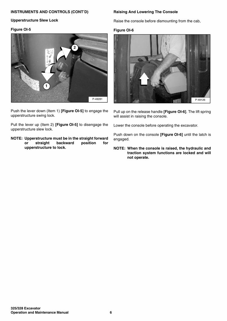
Upperstructure Slew Lock
Figure OI-5
Push the lever down (Item 1) [Figure OI-5] to engage theupperstructure swing lock.
Pull the lever up (Item 2) [Figure OI-5] to disengage theupperstructure slew lock.
NOTE: Upperstructure must be in the straight forwardor straight backward position forupperstructure to lock.
Raising And Lowering The Console
Raise the console before dismounting from the cab,
Figure OI-6
Pull up on the release handle [Figure OI-6]. The lift springwill assist in raising the console.
Lower the console before operating the excavator.
Push down on the console [Figure OI-6] until the latch isengaged.
NOTE: When the console is raised, the hydraulic andtraction system functions are locked and willnot operate.
P-49281
1
2
P-49126

325/328 Excavator7 Operation and Maintenance Manual
INSTRUMENTS AND CONTROLS (CONT’D)
Two-Speed Driving
Figure OI-7
Figure OI-8
Push the button (Item 1) [Figure OI-7] to engage the HighRange.
When High Range is engaged, the two speed driving icon(Item 2) [Figure OI-8] will light up.
Press the button again to disengage.
OPERATOR CANOPY (ROPS/TOPS)
Description
WARNINGNever modify operator cab by welding, grinding,drilling holes or adding attachments unlessinstructed to do so by Bobcat. Changes to the cabcan cause loss of operator protection from rolloverand falling objects, and result in injury or death.
W-2069-1299
The excavator has an operator canopy (ROPS/TOPS -Roll Over Protective Structure/Tip Over ProtectiveStructure) as standard equipment. The ROPS/TOPSmeets ROPS ISO 3471 and TOPS ISO 12117.
An enclosed cab (ROPS/TOPS) is an Option or can beinstalled as a Field Accessory.
Both the cab and canopy provide operator protection if theexcavator is tipped over. The seat belt must be worn forROPS/TOPS protection.
P-49128
1
P16616
2
325/328 ExcavatorOperation and Maintenance Manual 8
FALLING OBJECT GUARDS (FOGS)
Description
Figure OI-9
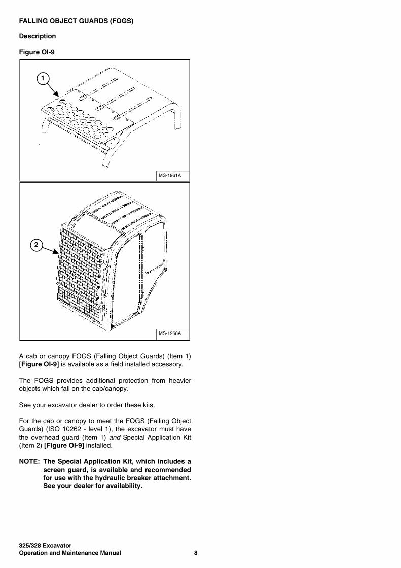
A cab or canopy FOGS (Falling Object Guards) (Item 1)[Figure OI-9] is available as a field installed accessory.
The FOGS provides additional protection from heavierobjects which fall on the cab/canopy.
See your excavator dealer to order these kits.
For the cab or canopy to meet the FOGS (Falling ObjectGuards) (ISO 10262 - level 1), the excavator must havethe overhead guard (Item 1) and Special Application Kit(Item 2) [Figure OI-9] installed.
NOTE: The Special Application Kit, which includes ascreen guard, is available and recommendedfor use with the hydraulic breaker attachment.See your dealer for availability.
MS-1961A
1
MS-1968A
2
325/328 Excavator9 Operation and Maintenance Manual
OPERATOR CAB (ROPS/TOPS)
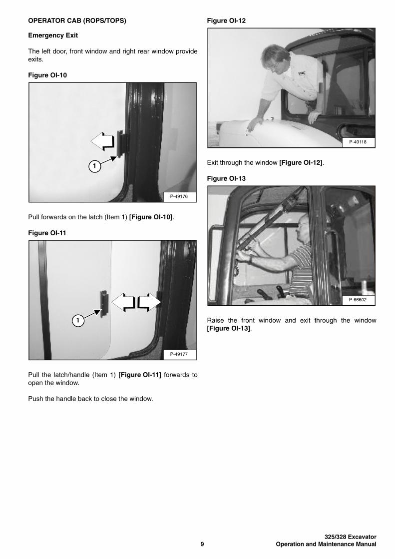
Emergency Exit
The left door, front window and right rear window provideexits.
Figure OI-10
Pull forwards on the latch (Item 1) [Figure OI-10].
Figure OI-11
Pull the latch/handle (Item 1) [Figure OI-11] forwards toopen the window.
Push the handle back to close the window.
Figure OI-12
Exit through the window [Figure OI-12].
Figure OI-13
Raise the front window and exit through the window[Figure OI-13].
P-49176
1
P-49177
1
P-49118
P-66602

325/328 ExcavatorOperation and Maintenance Manual 10
OPERATOR CAB (ROPS/TOPS) (CONT’D)
Cab Door
Early Models
Figure OI-14
The cab door (Item 1) [Figure OI-14] can be locked withthe same key as the starter switch (if equipped).
Figure OI-15
Push the door fully open until the latch engages to holdthe door in the open position.
Firmly pull the door away from the cab to disengage thelatch and close the door [Figure OI-15].
From inside the cab, open the door using handle (Item 1)[Figure OI-15].
Later Models
Figure OI-16
The cab door can be locked (Item 1) [Figure OI-16] withthe same key as the starter switch.
Push the door fully open (Item 2) [Figure OI-16] until thelatch engages to hold the door in the open position.
Figure OI-17
When the door is in the open position, push down on thelatch (Item 1) [Figure OI-17] and close the door.
From inside the cab, open the door using handle (Item 2)[Figure OI-17].
P-42570
1
P-49096
1
P-68192
1
2
P-68193
1
2
325/328 Excavator11 Operation and Maintenance Manual
OPERATOR CAB (ROPS/TOPS) (CONT’D)
Front Window
Figure OI-18
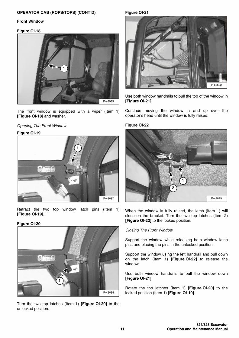
The front window is equipped with a wiper (Item 1)[Figure OI-18] and washer.
Opening The Front Window
Figure OI-19
Retract the two top window latch pins (Item 1)[Figure OI-19].
Figure OI-20
Turn the two top latches (Item 1) [Figure OI-20] to theunlocked position.
Figure OI-21
Use both window handrails to pull the top of the window in[Figure OI-21].
Continue moving the window in and up over theoperator’s head until the window is fully raised.
Figure OI-22
When the window is fully raised, the latch (Item 1) willclose on the bracket. Turn the two top latches (Item 2)[Figure OI-22] to the locked position.
Closing The Front Window
Support the window while releasing both window latchpins and placing the pins in the unlocked position.
Support the window using the left handrail and pull downon the latch (Item 1) [Figure OI-22] to release thewindow.
Use both window handrails to pull the window down[Figure OI-21].
Rotate the top latches (Item 1) [Figure OI-20] to thelocked position (Item 1) [Figure OI-19].
P-49095
1
P-49097
1
P-49098
1
P-66602
P-49099
1
2
325/328 ExcavatorOperation and Maintenance Manual 12
OPERATOR CAB (ROPS/TOPS) (CONT’D)
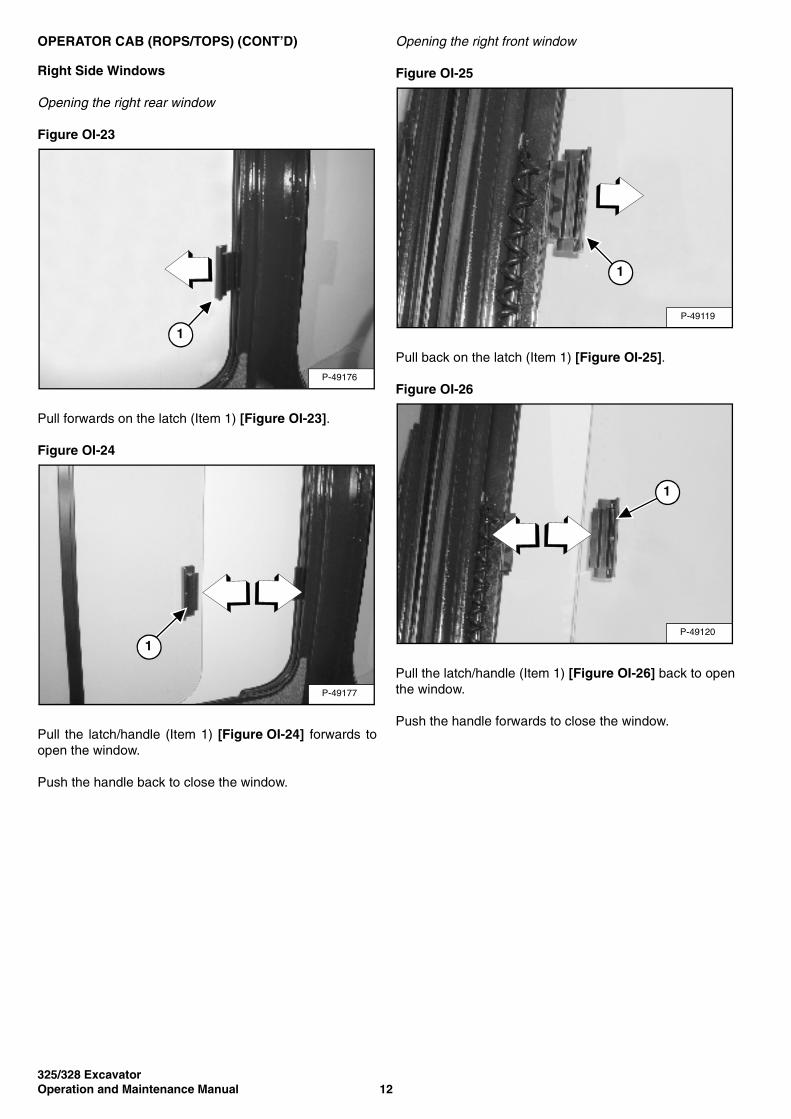
Right Side Windows
Opening the right rear window
Figure OI-23
Pull forwards on the latch (Item 1) [Figure OI-23].
Figure OI-24
Pull the latch/handle (Item 1) [Figure OI-24] forwards toopen the window.
Push the handle back to close the window.
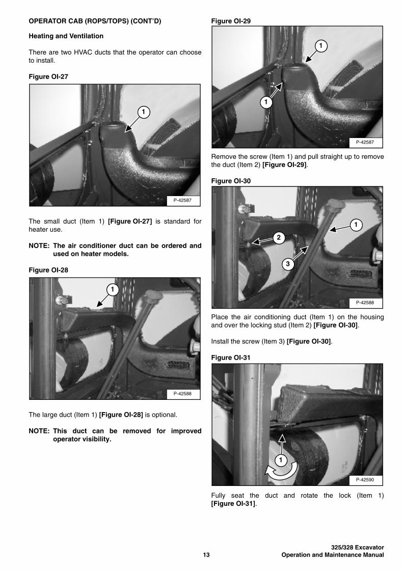
Opening the right front window
Figure OI-25
Pull back on the latch (Item 1) [Figure OI-25].
Figure OI-26
Pull the latch/handle (Item 1) [Figure OI-26] back to openthe window.
Push the handle forwards to close the window.
P-49176
1
P-49177
1
P-49119
1
P-49120
1
325/328 Excavator13 Operation and Maintenance Manual
OPERATOR CAB (ROPS/TOPS) (CONT’D)
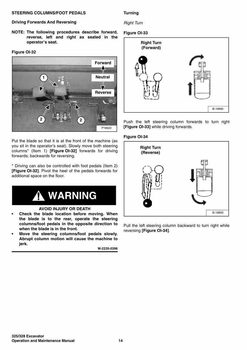
Heating and Ventilation
There are two HVAC ducts that the operator can chooseto install.
Figure OI-27
The small duct (Item 1) [Figure OI-27] is standard forheater use.
NOTE: The air conditioner duct can be ordered andused on heater models.
Figure OI-28
The large duct (Item 1) [Figure OI-28] is optional.
NOTE: This duct can be removed for improvedoperator visibility.
Figure OI-29
Remove the screw (Item 1) and pull straight up to removethe duct (Item 2) [Figure OI-29].
Figure OI-30
Place the air conditioning duct (Item 1) on the housingand over the locking stud (Item 2) [Figure OI-30].
Install the screw (Item 3) [Figure OI-30].
Figure OI-31
Fully seat the duct and rotate the lock (Item 1)[Figure OI-31].
P-42587
1
P-42588
1
P-42587
1
1
P-42588
2
1
3
P-42590
1
325/328 ExcavatorOperation and Maintenance Manual 14
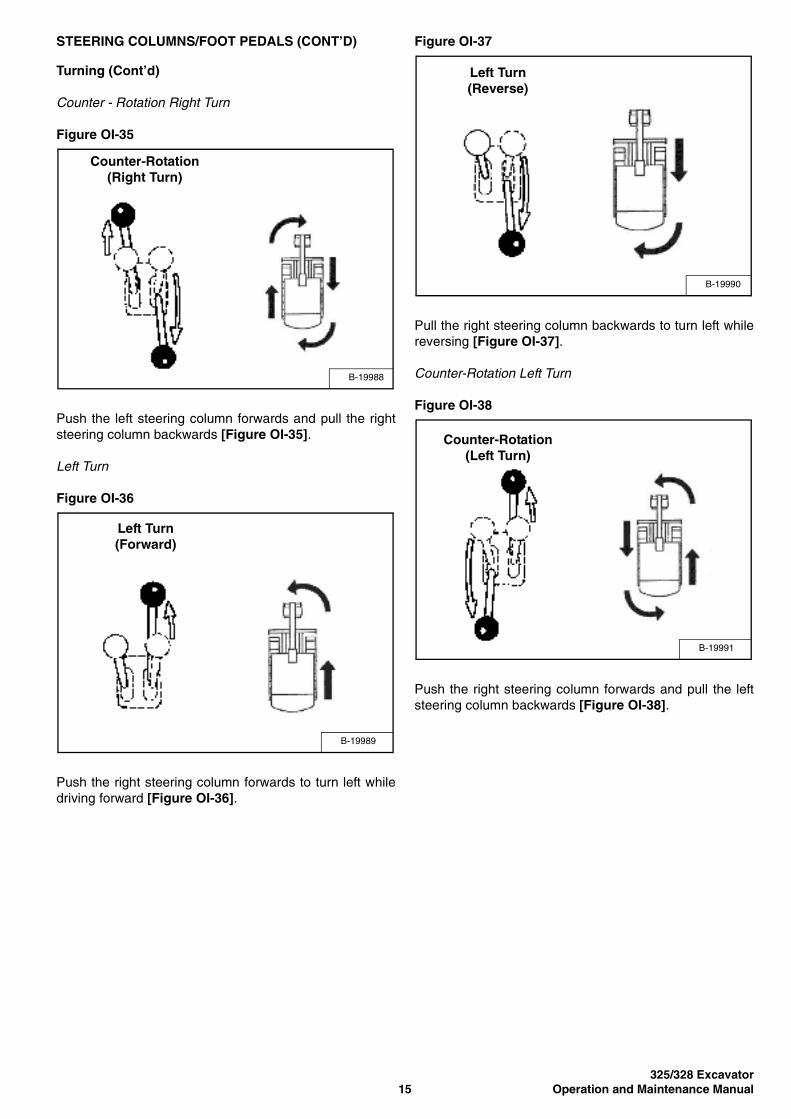
STEERING COLUMNS/FOOT PEDALS
Driving Forwards And Reversing
NOTE: The following procedures describe forward,reverse, left and right as seated in theoperator’s seat.
Figure OI-32
Put the blade so that it is at the front of the machine (asyou sit in the operator’s seat). Slowly move both steeringcolumns* (Item 1) [Figure OI-32] forwards for drivingforwards; backwards for reversing.
* Driving can also be controlled with foot pedals (Item 2)[Figure OI-32]. Pivot the heel of the pedals forwards foradditional space on the floor.
WARNINGAVOID INJURY OR DEATH
• Check the blade location before moving. Whenthe blade is to the rear, operate the steeringcolumns/foot pedals in the opposite direction towhen the blade is in the front.
• Move the steering columns/foot pedals slowly.Abrupt column motion will cause the machine tojerk.
W-2235-0396
Turning
Right Turn
Figure OI-33
Push the left steering column forwards to turn right[Figure OI-33] while driving forwards.
Figure OI-34
Pull the left steering column backward to turn right whilereversing [Figure OI-34].
P16622
1
2
Forward
Reverse
Neutral
2
B-19992
Right Turn (Forward)
B-19993
Right Turn (Reverse)
325/328 Excavator15 Operation and Maintenance Manual
STEERING COLUMNS/FOOT PEDALS (CONT’D)
Turning (Cont’d)
Counter - Rotation Right Turn
Figure OI-35
Push the left steering column forwards and pull the rightsteering column backwards [Figure OI-35].
Left Turn
Figure OI-36
Push the right steering column forwards to turn left whiledriving forward [Figure OI-36].
Figure OI-37
Pull the right steering column backwards to turn left whilereversing [Figure OI-37].
Counter-Rotation Left Turn
Figure OI-38
Push the right steering column forwards and pull the leftsteering column backwards [Figure OI-38].
B-19988
Counter-Rotation (Right Turn)
B-19989
Left Turn (Forward)
B-19990
Left Turn (Reverse)
B-19991
Counter-Rotation (Left Turn)
325/328 ExcavatorOperation and Maintenance Manual 16
HYDRAULIC CONTROLS
ISO Control Pattern
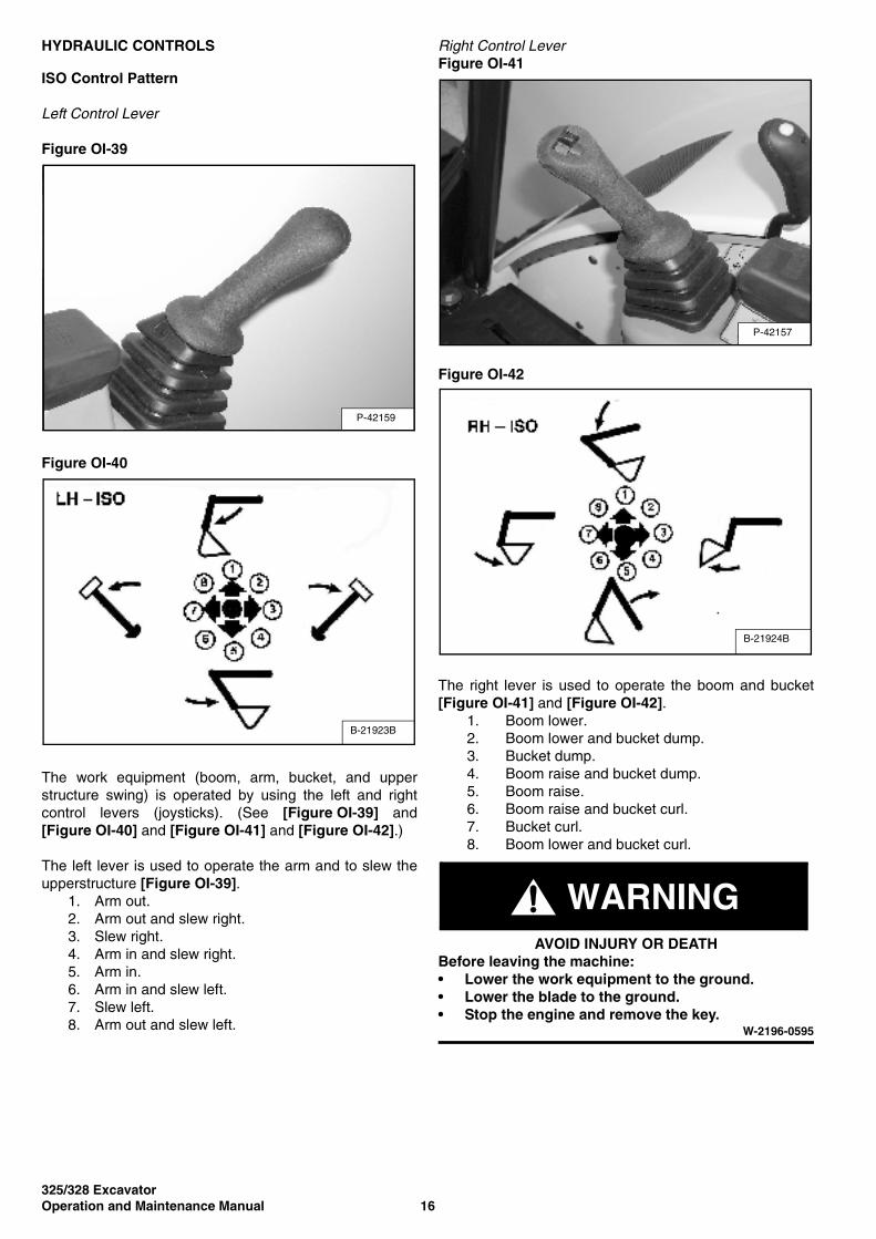
Left Control Lever
Figure OI-39
Figure OI-40
The work equipment (boom, arm, bucket, and upperstructure swing) is operated by using the left and rightcontrol levers (joysticks). (See [Figure OI-39] and[Figure OI-40] and [Figure OI-41] and [Figure OI-42].)
The left lever is used to operate the arm and to slew theupperstructure [Figure OI-39].
1. Arm out.2. Arm out and slew right.3. Slew right.4. Arm in and slew right.5. Arm in.6. Arm in and slew left.7. Slew left.8. Arm out and slew left.
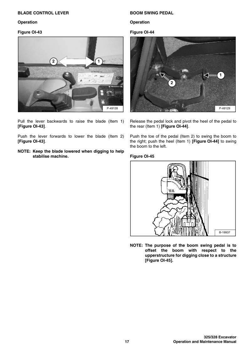
Right Control LeverFigure OI-41
Figure OI-42
The right lever is used to operate the boom and bucket[Figure OI-41] and [Figure OI-42].
1. Boom lower.2. Boom lower and bucket dump.3. Bucket dump.4. Boom raise and bucket dump.5. Boom raise.6. Boom raise and bucket curl.7. Bucket curl.8. Boom lower and bucket curl.
WARNINGAVOID INJURY OR DEATH
Before leaving the machine:• Lower the work equipment to the ground.• Lower the blade to the ground.• Stop the engine and remove the key.
W-2196-0595
P-16615
1
P-42159
B-21923B
P-16615
1
P-42157
B-21924B
325/328 Excavator17 Operation and Maintenance Manual
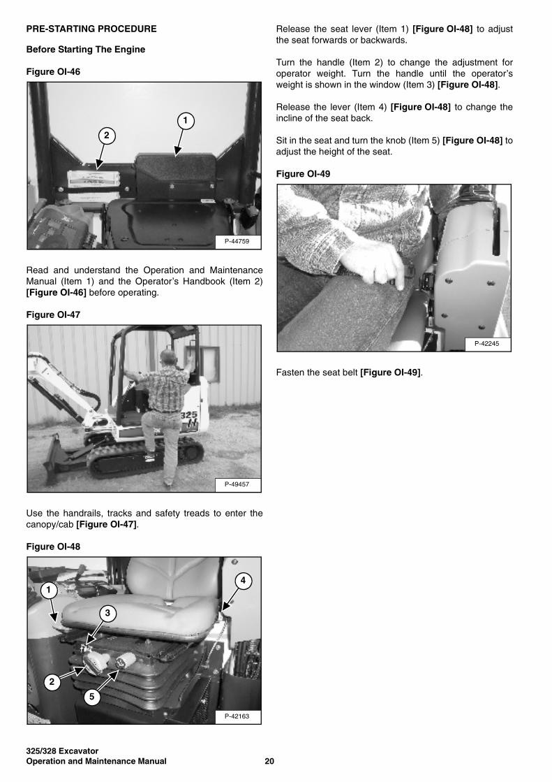
BLADE CONTROL LEVER
Operation
Figure OI-43
Pull the lever backwards to raise the blade (Item 1)[Figure OI-43].
Push the lever forwards to lower the blade (Item 2)[Figure OI-43].
NOTE: Keep the blade lowered when digging to helpstabilise machine.
BOOM SWING PEDAL
Operation
Figure OI-44
Release the pedal lock and pivot the heel of the pedal tothe rear (Item 1) [Figure OI-44].
Push the toe of the pedal (Item 2) to swing the boom tothe right; push the heel (Item 1) [Figure OI-44] to swingthe boom to the left.
Figure OI-45
NOTE: The purpose of the boom swing pedal is tooffset the boom with respect to theupperstructure for digging close to a structure[Figure OI-45].
P-49128
2 1
P-49129
1
2
B-19937
325/328 ExcavatorOperation and Maintenance Manual 18
DAILY INSPECTION
Procedure
Maintenance work must be carried out at regular intervals.Failure to do so will result in excessive wear and earlyfailures. The Service Schedule is a guide for correctmaintenance of the Bobcat Excavator. It is located insidethe rear door of the excavator and also in the MACHINESIGN TRANSLATION SECTION.
Check the following items before each day of operation:
• Operator Canopy or Cab (ROPS/TOPS) and mountinghardware.
• Seat belt and mounting hardware.
• Damaged stickers, replace as needed.
• Check control console lockout.
• Air cleaner and intake hoses/clamps.
• Engine oil level and engine for leaks.
• Hydraulic fluid level and system for leaks.
• Grease all pivot points.
• Cylinder and attachment pivot points.
• Track tension.
• Repair broken and loose parts.
WARNINGTraining is necessary before operating or servicingmachine. Read and understand the Operation andMaintenance Manual, Operator’s Handbook and signs(stickers) on machine. Follow warnings andinstructions in the manuals when making repairs,adjustments or servicing. Check for correct functionafter adjustments, repairs or service. Untrainedoperators and failure to follow instructions can causeinjury or death.
W-2003-0903
Fluids such as engine oil, hydraulic fluid, coolants, etc.must be disposed of in an environmentally safe manner.Some regulations require that certain spills and leaks onthe ground must be cleaned in a specific manner. Seelocal regulations for correct disposal.

325/328 Excavator19 Operation and Maintenance Manual
DAILY INSPECTION (CONT’D)
Service Schedule
71111723
325/328 ExcavatorOperation and Maintenance Manual 20
PRE-STARTING PROCEDURE
Before Starting The Engine
Figure OI-46
Read and understand the Operation and MaintenanceManual (Item 1) and the Operator’s Handbook (Item 2)[Figure OI-46] before operating.
Figure OI-47
Use the handrails, tracks and safety treads to enter thecanopy/cab [Figure OI-47].
Figure OI-48
Release the seat lever (Item 1) [Figure OI-48] to adjustthe seat forwards or backwards.
Turn the handle (Item 2) to change the adjustment foroperator weight. Turn the handle until the operator’sweight is shown in the window (Item 3) [Figure OI-48].
Release the lever (Item 4) [Figure OI-48] to change theincline of the seat back.
Sit in the seat and turn the knob (Item 5) [Figure OI-48] toadjust the height of the seat.
Figure OI-49
Fasten the seat belt [Figure OI-49].
P-44759
1
2
P-49457
P-42163
1
3
2
5
4
P-42245
325/328 Excavator21 Operation and Maintenance Manual
PRE-STARTING PROCEDURE (CONT’D)
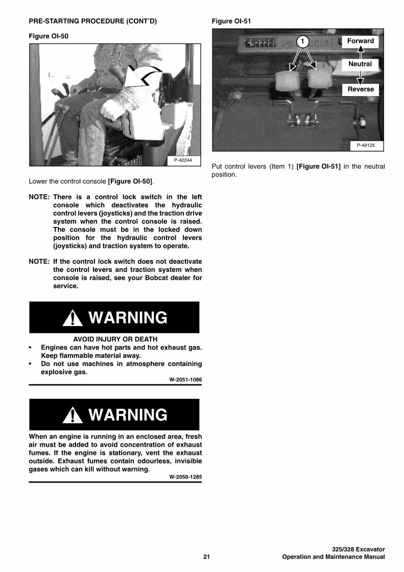
Figure OI-50
Lower the control console [Figure OI-50].
NOTE: There is a control lock switch in the leftconsole which deactivates the hydrauliccontrol levers (joysticks) and the traction drivesystem when the control console is raised.The console must be in the locked downposition for the hydraulic control levers(joysticks) and traction system to operate.
NOTE: If the control lock switch does not deactivatethe control levers and traction system whenconsole is raised, see your Bobcat dealer forservice.
WARNINGAVOID INJURY OR DEATH
• Engines can have hot parts and hot exhaust gas.Keep flammable material away.
• Do not use machines in atmosphere containingexplosive gas.
W-2051-1086
WARNINGWhen an engine is running in an enclosed area, freshair must be added to avoid concentration of exhaustfumes. If the engine is stationary, vent the exhaustoutside. Exhaust fumes contain odourless, invisiblegases which can kill without warning.
W-2050-1285
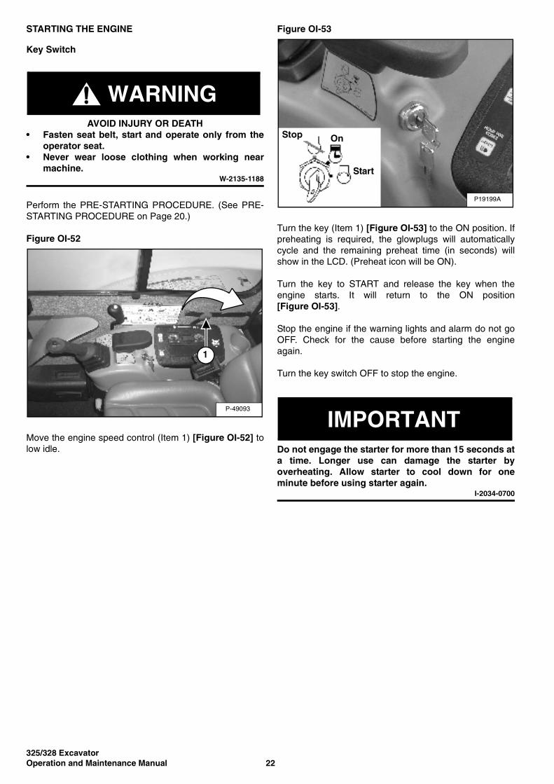
Figure OI-51
Put control levers (Item 1) [Figure OI-51] in the neutralposition.
P-42244
P-49125
Forward
Reverse
Neutral
1
325/328 ExcavatorOperation and Maintenance Manual 22
STARTING THE ENGINE
Key Switch
WARNINGAVOID INJURY OR DEATH
• Fasten seat belt, start and operate only from theoperator seat.
• Never wear loose clothing when working nearmachine.
W-2135-1188
Perform the PRE-STARTING PROCEDURE. (See PRE-STARTING PROCEDURE on Page 20.)
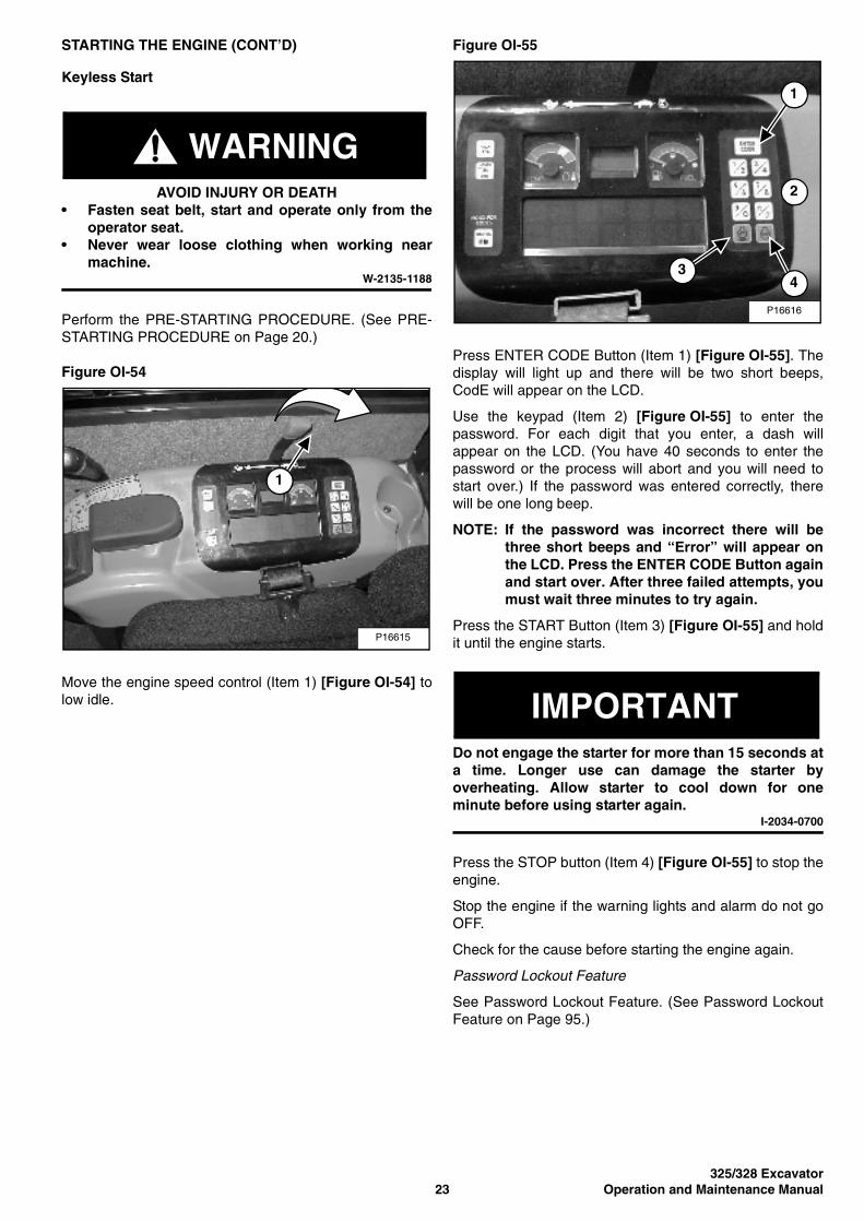
Figure OI-52
Move the engine speed control (Item 1) [Figure OI-52] tolow idle.
Figure OI-53
Turn the key (Item 1) [Figure OI-53] to the ON position. Ifpreheating is required, the glowplugs will automaticallycycle and the remaining preheat time (in seconds) willshow in the LCD. (Preheat icon will be ON).
Turn the key to START and release the key when theengine starts. It will return to the ON position[Figure OI-53].
Stop the engine if the warning lights and alarm do not goOFF. Check for the cause before starting the engineagain.
Turn the key switch OFF to stop the engine.
IMPORTANTDo not engage the starter for more than 15 seconds ata time. Longer use can damage the starter byoverheating. Allow starter to cool down for oneminute before using starter again.
I-2034-0700
P-49093
1
P19199A
Stop On
Start
325/328 Excavator23 Operation and Maintenance Manual
STARTING THE ENGINE (CONT’D)
Keyless Start
WARNINGAVOID INJURY OR DEATH
• Fasten seat belt, start and operate only from theoperator seat.
• Never wear loose clothing when working nearmachine.
W-2135-1188
Perform the PRE-STARTING PROCEDURE. (See PRE-STARTING PROCEDURE on Page 20.)
Figure OI-54
Move the engine speed control (Item 1) [Figure OI-54] tolow idle.
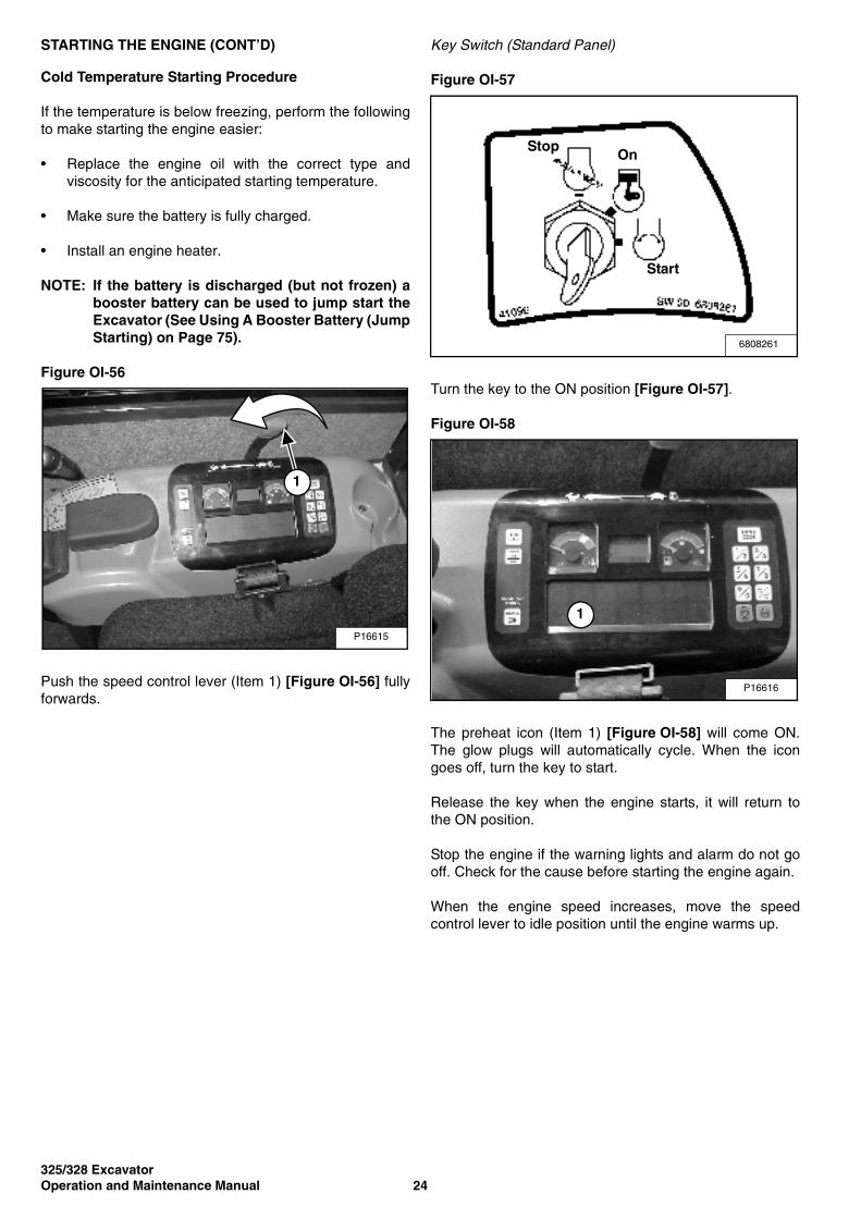
Figure OI-55
Press ENTER CODE Button (Item 1) [Figure OI-55]. Thedisplay will light up and there will be two short beeps,CodE will appear on the LCD.
Use the keypad (Item 2) [Figure OI-55] to enter thepassword. For each digit that you enter, a dash willappear on the LCD. (You have 40 seconds to enter thepassword or the process will abort and you will need tostart over.) If the password was entered correctly, therewill be one long beep.
NOTE: If the password was incorrect there will bethree short beeps and “Error” will appear onthe LCD. Press the ENTER CODE Button againand start over. After three failed attempts, youmust wait three minutes to try again.
Press the START Button (Item 3) [Figure OI-55] and holdit until the engine starts.
IMPORTANTDo not engage the starter for more than 15 seconds ata time. Longer use can damage the starter byoverheating. Allow starter to cool down for oneminute before using starter again.
I-2034-0700
Press the STOP button (Item 4) [Figure OI-55] to stop theengine.
Stop the engine if the warning lights and alarm do not goOFF.
Check for the cause before starting the engine again.
Password Lockout Feature
See Password Lockout Feature. (See Password LockoutFeature on Page 95.)
P16615
1
P16616
1
34
2
325/328 ExcavatorOperation and Maintenance Manual 24
STARTING THE ENGINE (CONT’D)
Cold Temperature Starting Procedure
If the temperature is below freezing, perform the followingto make starting the engine easier:
• Replace the engine oil with the correct type andviscosity for the anticipated starting temperature.
• Make sure the battery is fully charged.
• Install an engine heater.
NOTE: If the battery is discharged (but not frozen) abooster battery can be used to jump start theExcavator (See Using A Booster Battery (JumpStarting) on Page 75).
Figure OI-56
Push the speed control lever (Item 1) [Figure OI-56] fullyforwards.
Key Switch (Standard Panel)
Figure OI-57
Turn the key to the ON position [Figure OI-57].
Figure OI-58
The preheat icon (Item 1) [Figure OI-58] will come ON.The glow plugs will automatically cycle. When the icongoes off, turn the key to start.
Release the key when the engine starts, it will return tothe ON position.
Stop the engine if the warning lights and alarm do not gooff. Check for the cause before starting the engine again.
When the engine speed increases, move the speedcontrol lever to idle position until the engine warms up.
P16615
1
6808261
StopOn
Start
P16616
1
325/328 Excavator25 Operation and Maintenance Manual
STARTING THE ENGINE (CONT’D)
Cold Temperature Starting Procedure (Cont’d)
Keyless Start (Deluxe Panel)
Follow STARTING PROCEDURE. (See Keyless Start onPage 23.)
If the preheat icon comes ON, wait for it to go off beforepressing the START Button [Figure OI-57 on Page 24].
The remaining preheat time (in seconds) will count downin the LCD.
IMPORTANTDo not engage the starter for more than 15 seconds ata time. Longer use can damage the starter byoverheating. Allow starter to cool down for oneminute before using starter again.
I-2034-0700
IMPORTANTMachines warmed up with moderate engine speedand light load have longer life.
I-2015-0284
WARNINGDo not use ethyl spirits with glow plug (preheat)systems. Explosion can result which can causeinjury, death, or severe engine damage.
W-2071-0903
WARMING UP THE HYDRAULIC SYSTEM
Procedure
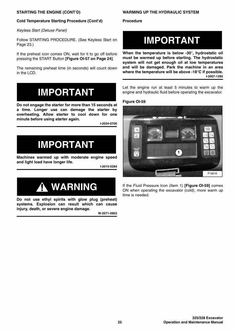
IMPORTANTWhen the temperature is below -30°, hydrostatic oilmust be warmed up before starting. The hydrostaticsystem will not get enough oil at low temperaturesand will be damaged. Park the machine in an areawhere the temperature will be above -18°C if possible.
I-2007-1285
Let the engine run at least 5 minutes to warm up theengine and hydraulic fluid before operating the excavator.
Figure OI-59
If the Fluid Pressure Icon (Item 1) [Figure OI-59] comesON when operating the excavator (cold), more warm uptime is needed.
P16616
1
325/328 ExcavatorOperation and Maintenance Manual 26
ATTACHMENTS
Using The X-Change System
Installing Bucket Or Attachment (Pin On X-Change)
WARNINGNever use attachments or buckets which are notapproved by Bobcat Company. Buckets andattachments for safe loads of specified densities areapproved for each model. Unapproved attachmentscan cause injury or death.
W-2052-0500
Figure OI-60
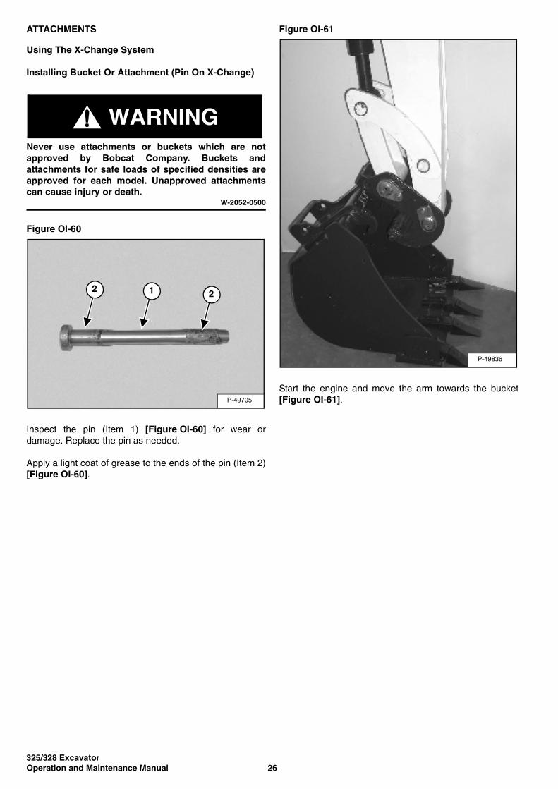
Inspect the pin (Item 1) [Figure OI-60] for wear ordamage. Replace the pin as needed.
Apply a light coat of grease to the ends of the pin (Item 2)[Figure OI-60].
Figure OI-61
Start the engine and move the arm towards the bucket[Figure OI-61].P-49705
2 1 2
P-49836
325/328 Excavator27 Operation and Maintenance Manual
ATTACHMENTS (CONT’D)
Using The X-Change System (Cont’d)
Installing Bucket Or Attachment (Pin On X-Change) (Cont’d)
Figure OI-62
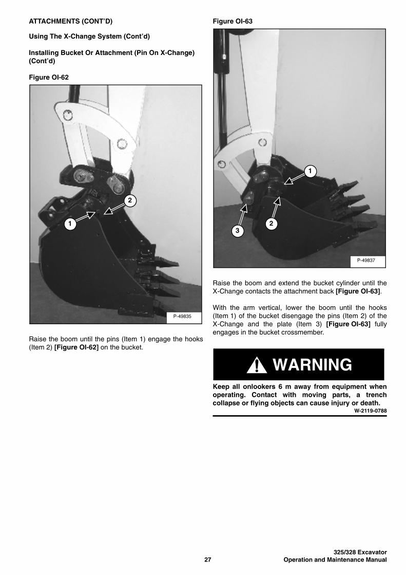
Raise the boom until the pins (Item 1) engage the hooks(Item 2) [Figure OI-62] on the bucket.
Figure OI-63
Raise the boom and extend the bucket cylinder until theX-Change contacts the attachment back [Figure OI-63].
With the arm vertical, lower the boom until the hooks(Item 1) of the bucket disengage the pins (Item 2) of theX-Change and the plate (Item 3) [Figure OI-63] fullyengages in the bucket crossmember.
WARNINGKeep all onlookers 6 m away from equipment whenoperating. Contact with moving parts, a trenchcollapse or flying objects can cause injury or death.
W-2119-0788
P-49835
2
1
P-49837
1
23
325/328 ExcavatorOperation and Maintenance Manual 28
ATTACHMENTS (CONT’D)
Using The X-Change System (Cont’d)
Installing Bucket Or Attachment (Pin On X-Change) (Cont’d)
Figure OI-64
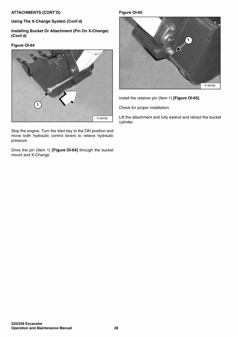
Stop the engine. Turn the start key to the ON position andmove both hydraulic control levers to relieve hydraulicpressure.
Drive the pin (Item 1) [Figure OI-64] through the bucketmount and X-Change.
Figure OI-65
Install the retainer pin (Item 1) [Figure OI-65].
Check for proper installation.
Lift the attachment and fully extend and retract the bucketcylinder.
P-49706
1
P-49708
1
325/328 Excavator29 Operation and Maintenance Manual
ATTACHMENTS (CONT’D)
Using The X-Change System (Cont’d)
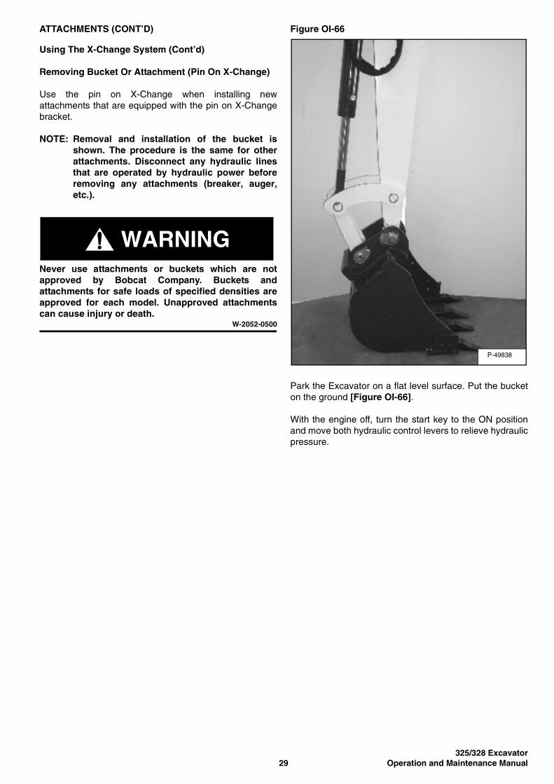
Removing Bucket Or Attachment (Pin On X-Change)
Use the pin on X-Change when installing newattachments that are equipped with the pin on X-Changebracket.
NOTE: Removal and installation of the bucket isshown. The procedure is the same for otherattachments. Disconnect any hydraulic linesthat are operated by hydraulic power beforeremoving any attachments (breaker, auger,etc.).
WARNINGNever use attachments or buckets which are notapproved by Bobcat Company. Buckets andattachments for safe loads of specified densities areapproved for each model. Unapproved attachmentscan cause injury or death.
W-2052-0500
Figure OI-66
Park the Excavator on a flat level surface. Put the bucketon the ground [Figure OI-66].
With the engine off, turn the start key to the ON positionand move both hydraulic control levers to relieve hydraulicpressure.
P-49838
325/328 ExcavatorOperation and Maintenance Manual 30
ATTACHMENTS (CONT’D)
Using The X-Change System (Cont’d)
Removing Bucket Or Attachment (Pin On X-Change) (Cont’d)
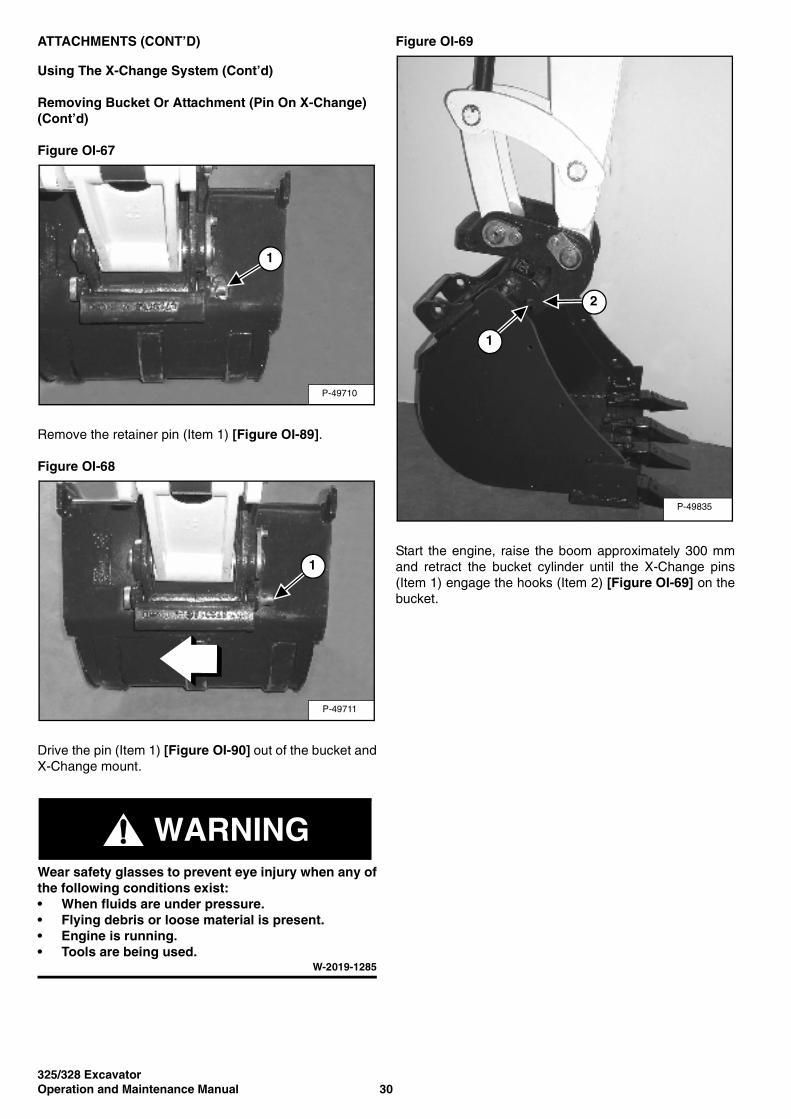
Figure OI-67
Remove the retainer pin (Item 1) [Figure OI-89].
Figure OI-68
Drive the pin (Item 1) [Figure OI-90] out of the bucket andX-Change mount.
WARNINGWear safety glasses to prevent eye injury when any ofthe following conditions exist:• When fluids are under pressure.• Flying debris or loose material is present.• Engine is running.• Tools are being used.
W-2019-1285
Figure OI-69
Start the engine, raise the boom approximately 300 mmand retract the bucket cylinder until the X-Change pins(Item 1) engage the hooks (Item 2) [Figure OI-69] on thebucket.
P-49710
1
P-49711
1
P-49835
1
2

325/328 Excavator31 Operation and Maintenance Manual
ATTACHMENTS (CONT’D)
Using The X-Change System (Cont’d)
Removing Bucket Or Attachment (Pin On X-Change) (Cont’d)
Figure OI-70
Fully retract the bucket cylinder and lower the boom andarm until the bucket is on the ground, and the X-Changepins (Item 1) are disengaged from the hooks (Item 2)[Figure OI-70].
Move the arm towards the Excavator until the X-Changepins are clear of the bucket.
P-49836
1
2
325/328 ExcavatorOperation and Maintenance Manual 32
ATTACHMENTS (CONT’D)
Using The X-Change System (Cont’d)
Installing Bucket Or Attachment (Bolt-On X-Change)
Use the bolt-on X-Change components wheninstalling older attachments that do not have the pinretention provision. Bolt-on components are suppliedwith the excavator and are stored under the right sidecover.
NOTE: Removal and installation of the bucket isshown. The procedure is the same for otherattachments. Disconnect any hydraulic linesthat are operated by hydraulic power beforeremoving any attachments (breaker, auger,etc.).
WARNINGNever use attachments or buckets which are notapproved by Bobcat Company. Buckets andattachments for safe loads of specified densities areapproved for each model. Unapproved attachmentscan cause injury or death.
W-2052-0500
Figure OI-71
Fully retract the bucket cylinder and lower the arm to theground [Figure OI-71].
With the engine off, turn the start key to the ON positionand move both hydraulic control levers to relieve hydraulicpressure.
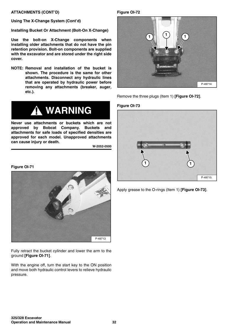
Figure OI-72
Remove the three plugs (Item 1) [Figure OI-72].
Figure OI-73
Apply grease to the O-rings (Item 1) [Figure OI-73].
P-49713
P-49714
1 1 1
P-49715
1 1
325/328 Excavator33 Operation and Maintenance Manual
ATTACHMENTS (CONT’D)
Using The X-Change System (Cont’d)
Installing Bucket Or Attachment (Bolt On X-Change) (Cont’d)
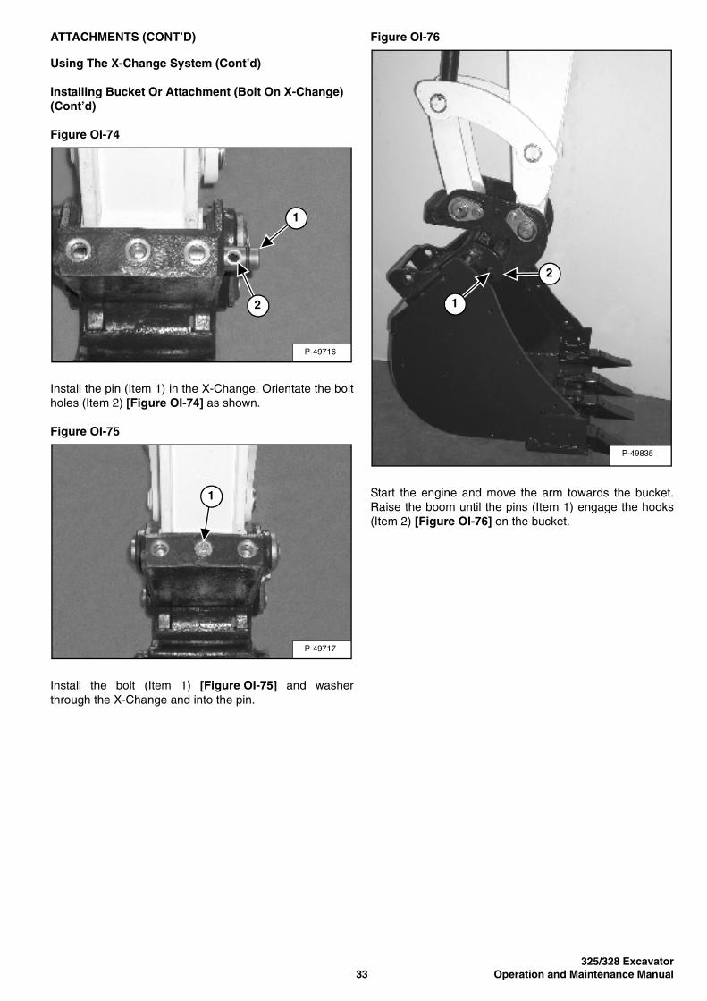
Figure OI-74
Install the pin (Item 1) in the X-Change. Orientate the boltholes (Item 2) [Figure OI-74] as shown.
Figure OI-75
Install the bolt (Item 1) [Figure OI-75] and washerthrough the X-Change and into the pin.
Figure OI-76
Start the engine and move the arm towards the bucket.Raise the boom until the pins (Item 1) engage the hooks(Item 2) [Figure OI-76] on the bucket.
P-49716
2
1
P-49717
1
P-49835
1
2
325/328 ExcavatorOperation and Maintenance Manual 34
ATTACHMENTS (CONT’D)
Using The X-Change System (Cont’d)
Installing Bucket Or Attachment (Bolt On X-Change) (Cont’d)
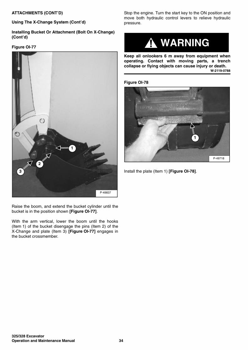
Figure OI-77
Raise the boom, and extend the bucket cylinder until thebucket is in the position shown [Figure OI-77].
With the arm vertical, lower the boom until the hooks(Item 1) of the bucket disengage the pins (Item 2) of theX-Change and plate (Item 3) [Figure OI-77] engages inthe bucket crossmember.
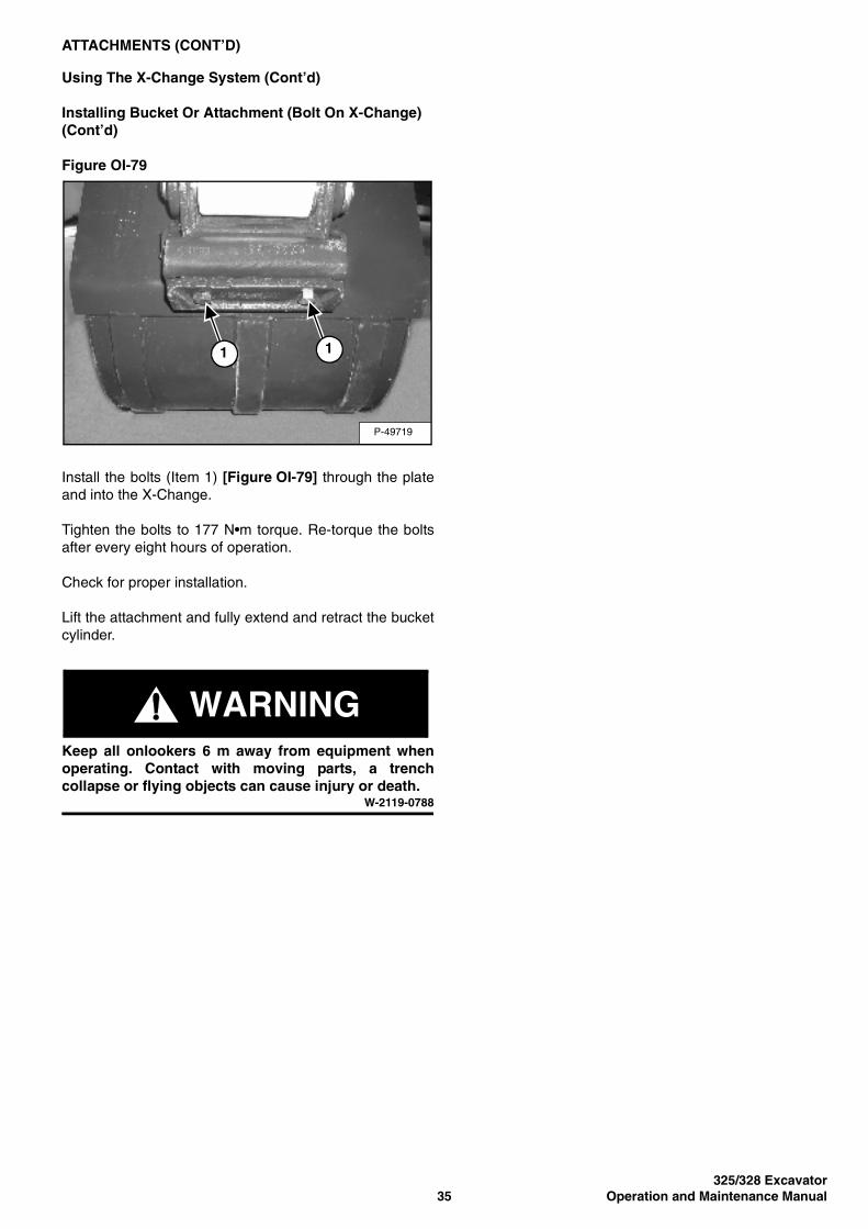
Stop the engine. Turn the start key to the ON position andmove both hydraulic control levers to relieve hydraulicpressure.
WARNINGKeep all onlookers 6 m away from equipment whenoperating. Contact with moving parts, a trenchcollapse or flying objects can cause injury or death.
W-2119-0788
Figure OI-78
Install the plate (Item 1) [Figure OI-78].
P-49837
1
2
3
P-49718
1
325/328 Excavator35 Operation and Maintenance Manual
ATTACHMENTS (CONT’D)
Using The X-Change System (Cont’d)
Installing Bucket Or Attachment (Bolt On X-Change) (Cont’d)
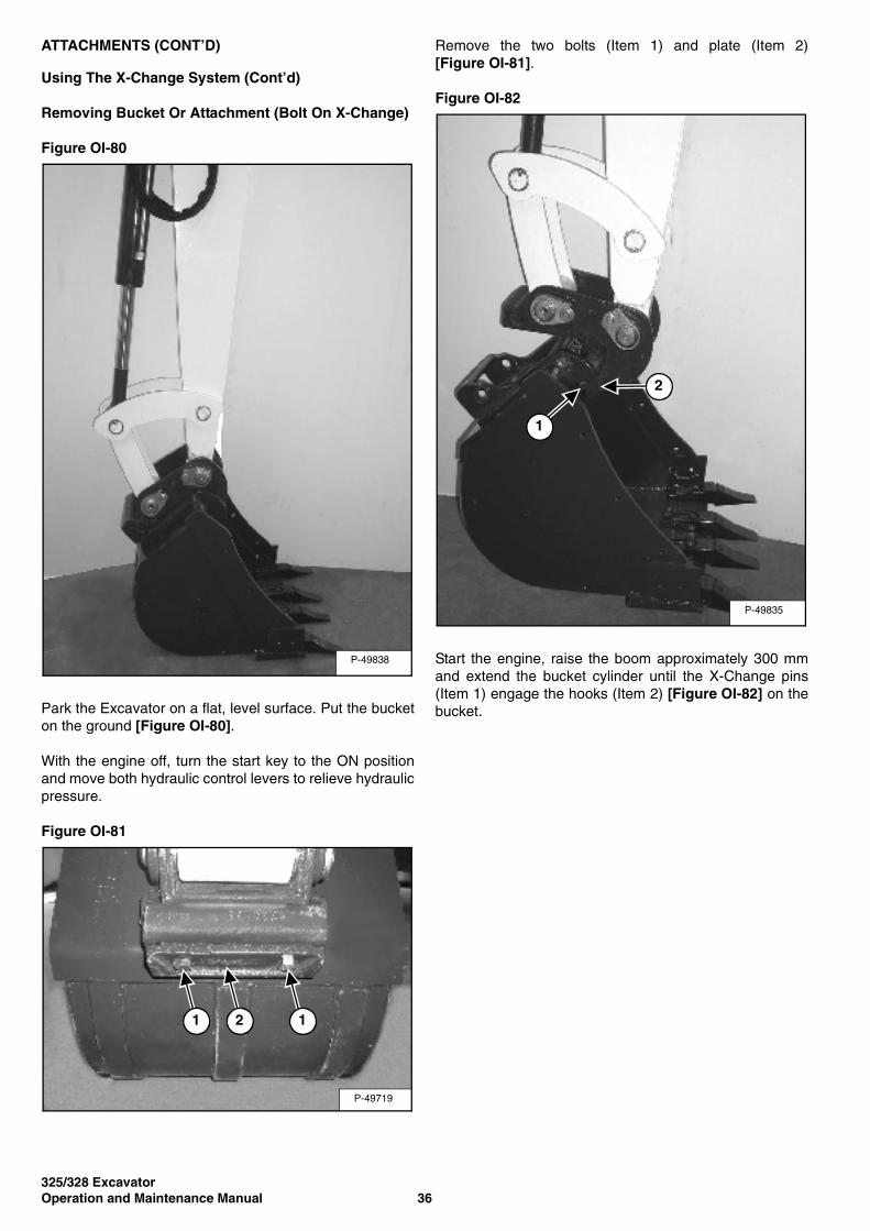
Figure OI-79
Install the bolts (Item 1) [Figure OI-79] through the plateand into the X-Change.
Tighten the bolts to 177 N•m torque. Re-torque the boltsafter every eight hours of operation.
Check for proper installation.
Lift the attachment and fully extend and retract the bucketcylinder.
WARNINGKeep all onlookers 6 m away from equipment whenoperating. Contact with moving parts, a trenchcollapse or flying objects can cause injury or death.
W-2119-0788
P-49719
1 1
325/328 ExcavatorOperation and Maintenance Manual 36
ATTACHMENTS (CONT’D)
Using The X-Change System (Cont’d)
Removing Bucket Or Attachment (Bolt On X-Change)
Figure OI-80
Park the Excavator on a flat, level surface. Put the bucketon the ground [Figure OI-80].
With the engine off, turn the start key to the ON positionand move both hydraulic control levers to relieve hydraulicpressure.
Figure OI-81
Remove the two bolts (Item 1) and plate (Item 2)[Figure OI-81].
Figure OI-82
Start the engine, raise the boom approximately 300 mmand extend the bucket cylinder until the X-Change pins(Item 1) engage the hooks (Item 2) [Figure OI-82] on thebucket.
P-49838
P-49719
1 2 1
P-49835
2
1
325/328 Excavator37 Operation and Maintenance Manual
ATTACHMENTS (CONT’D)
Using The X-Change System (Cont’d)
Removing Bucket Or Attachment (Bolt On X-Change) (Cont’d)
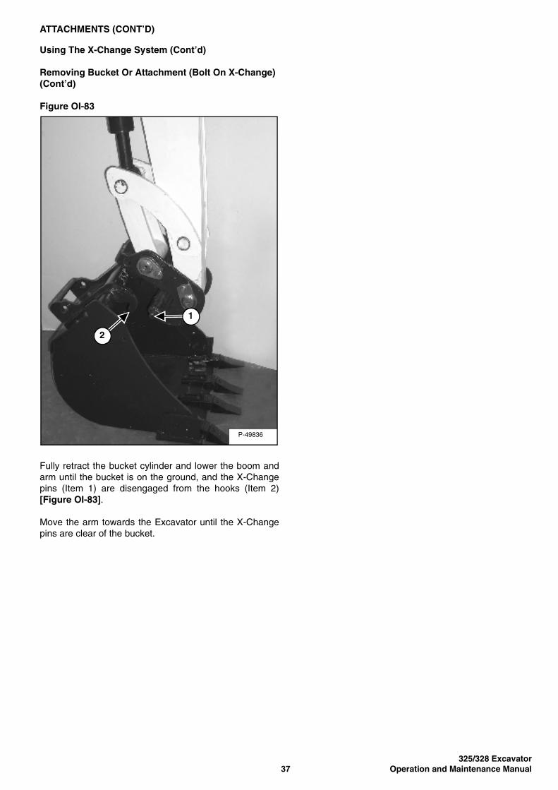
Figure OI-83
Fully retract the bucket cylinder and lower the boom andarm until the bucket is on the ground, and the X-Changepins (Item 1) are disengaged from the hooks (Item 2)[Figure OI-83].
Move the arm towards the Excavator until the X-Changepins are clear of the bucket.
P-49836
2
1
325/328 ExcavatorOperation and Maintenance Manual 38
ATTACHMENTS (CONT’D)
Using The X-Change System (Cont’d)
Installing Bucket Or Attachment (X-Change System)
WARNINGNever use attachments or buckets which are notapproved by Bobcat Company. Buckets andattachments for safe loads of specified densities areapproved for each model. Unapproved attachmentscan cause injury or death.
W-2052-0500
Figure OI-84
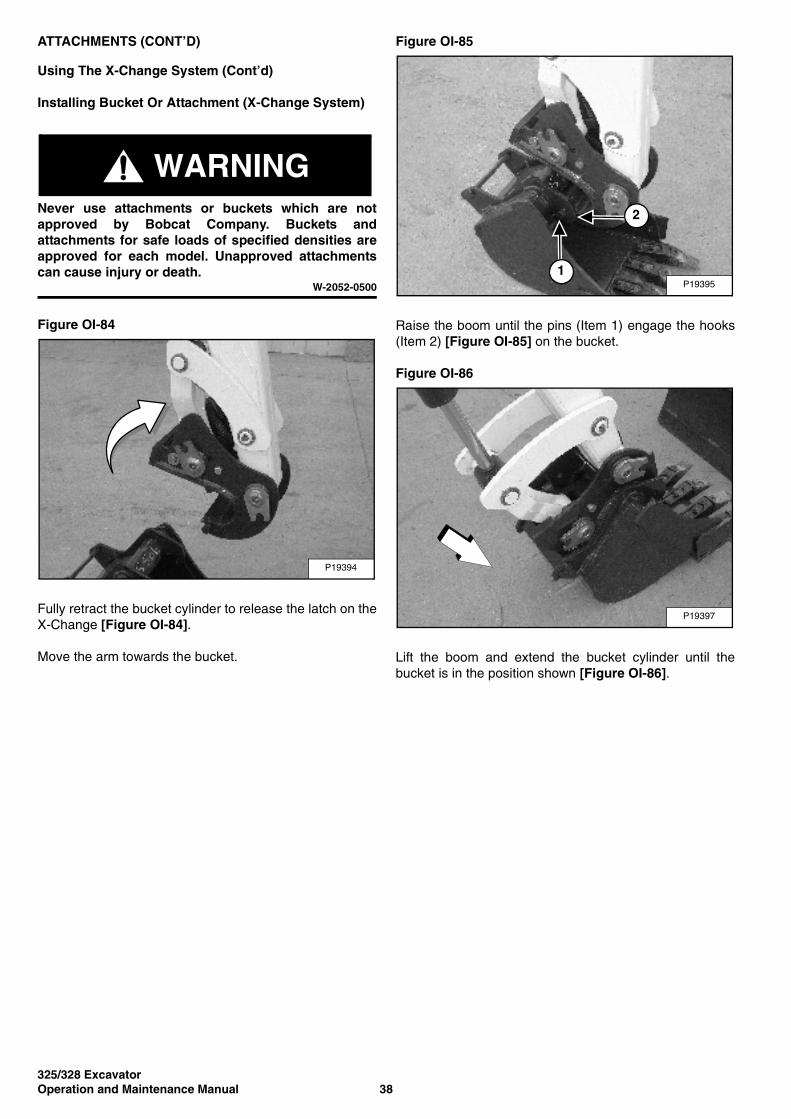
Fully retract the bucket cylinder to release the latch on theX-Change [Figure OI-84].
Move the arm towards the bucket.
Figure OI-85
Raise the boom until the pins (Item 1) engage the hooks(Item 2) [Figure OI-85] on the bucket.
Figure OI-86
Lift the boom and extend the bucket cylinder until thebucket is in the position shown [Figure OI-86].
P19394
P19395
2
1
P19397
325/328 Excavator39 Operation and Maintenance Manual
ATTACHMENTS (CONT’D)
Using The X-Change System (Cont’d)
Installing Bucket Or Attachment (X-Change System) (Cont’d)
Figure OI-87
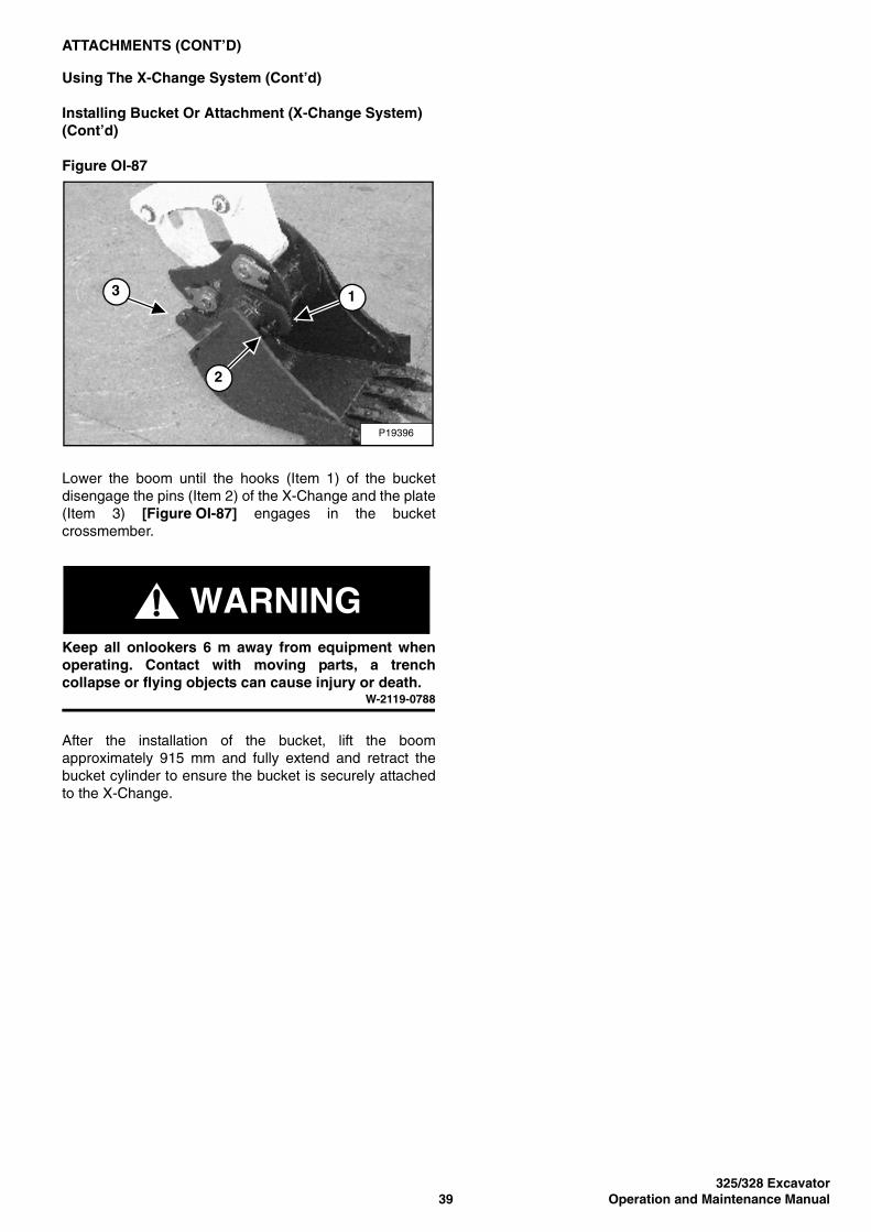
Lower the boom until the hooks (Item 1) of the bucketdisengage the pins (Item 2) of the X-Change and the plate(Item 3) [Figure OI-87] engages in the bucketcrossmember.
WARNINGKeep all onlookers 6 m away from equipment whenoperating. Contact with moving parts, a trenchcollapse or flying objects can cause injury or death.
W-2119-0788
After the installation of the bucket, lift the boomapproximately 915 mm and fully extend and retract thebucket cylinder to ensure the bucket is securely attachedto the X-Change.
P19396
3
2
1
325/328 ExcavatorOperation and Maintenance Manual 40
ATTACHMENTS (CONT’D)
Using The X-Change System (Cont’d)
Removing Bucket Or Attachment (X-Change System)
The excavator is equipped with the X-Change system.The X-Change is used for fast changing of buckets andattachments.
NOTE: Removal and installation of the bucket isshown. The procedure is the same for otherattachments. Disconnect any hydraulic linesthat are operated by hydraulic power beforeremoving any attachments (breaker, auger,etc.).
WARNINGNever use attachments or buckets which are notapproved by Bobcat Company. Buckets andattachments for safe loads of specified densities areapproved for each model. Unapproved attachmentscan cause injury or death.
W-2052-0500
Stop the machine on a flat level surface. Put the bucketon the ground.
Figure OI-88
Install the X-Change tool (Item 1) [Figure OI-88] in thelatch.
Pull the tool (Item 1) [Figure OI-88] to unlock the latch.Remove the tool.
Figure OI-89
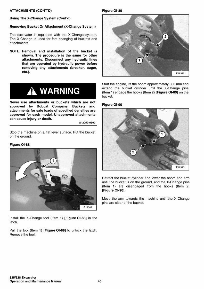
Start the engine, lift the boom approximately 300 mm andextend the bucket cylinder until the X-Change pins(Item 1) engage the hooks (Item 2) [Figure OI-89] on thebucket.
Figure OI-90
Retract the bucket cylinder and lower the boom and armuntil the bucket is on the ground, and the X-Change pins(Item 1) are disengaged from the hooks (Item 2)[Figure OI-90].
Move the arm towards the machine until the X-Changepins are clear of the bucket.
P19382
1
P19392
2
1
P19393
2
1
325/328 Excavator41 Operation and Maintenance Manual
ATTACHMENTS (CONT’D)
Quick Connectors
WARNINGAVOID BURNS
Hydraulic fluid, tubes, fittings and quick connectorscan become hot when running machine andattachments. Be careful when connecting anddisconnecting quick connectors.
W-2220-0396
Figure OI-91
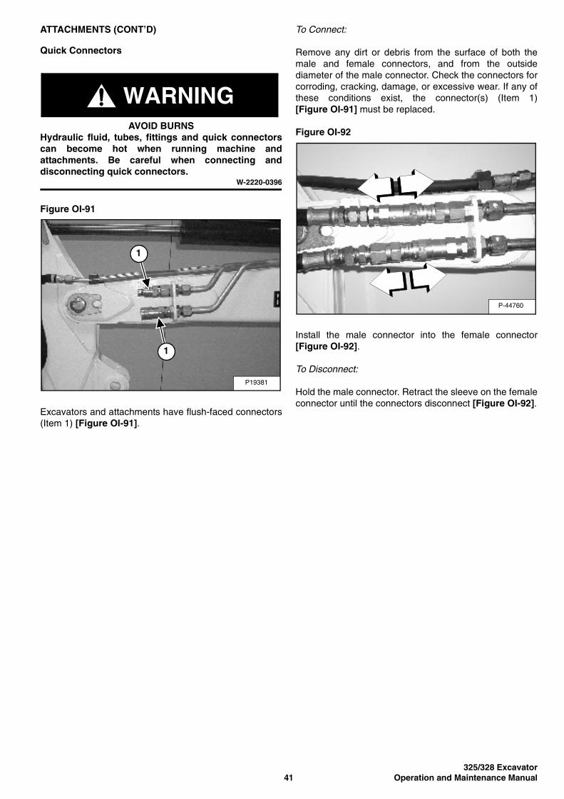
Excavators and attachments have flush-faced connectors(Item 1) [Figure OI-91].
To Connect:
Remove any dirt or debris from the surface of both themale and female connectors, and from the outsidediameter of the male connector. Check the connectors forcorroding, cracking, damage, or excessive wear. If any ofthese conditions exist, the connector(s) (Item 1)[Figure OI-91] must be replaced.
Figure OI-92
Install the male connector into the female connector[Figure OI-92].
To Disconnect:
Hold the male connector. Retract the sleeve on the femaleconnector until the connectors disconnect [Figure OI-92].
P19381
1
1
P-44760
325/328 ExcavatorOperation and Maintenance Manual 42
ATTACHMENTS (CONT’D)
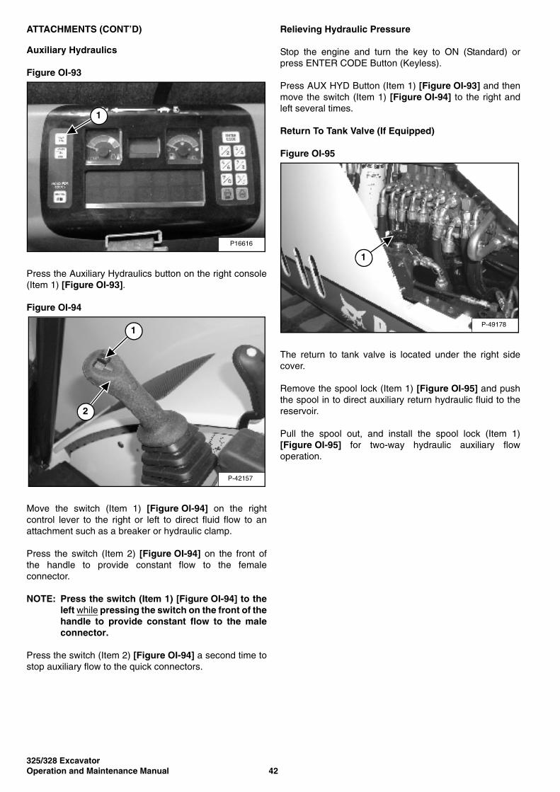
Auxiliary Hydraulics
Figure OI-93
Press the Auxiliary Hydraulics button on the right console(Item 1) [Figure OI-93].
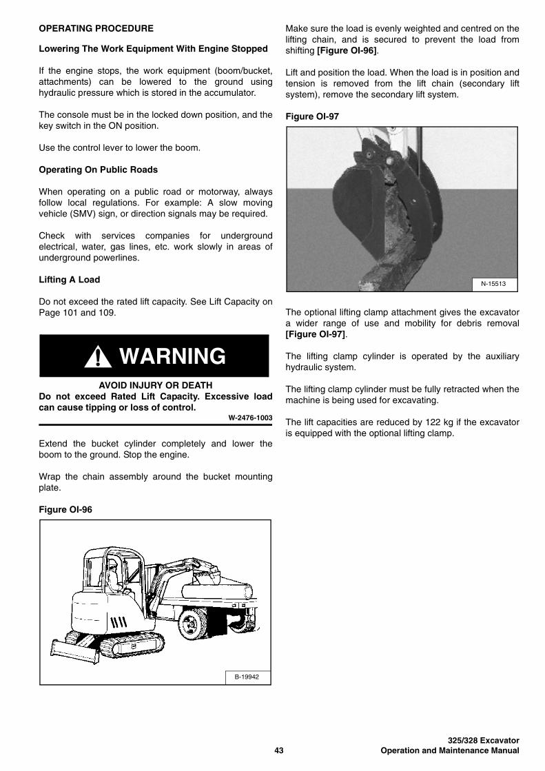
Figure OI-94
Move the switch (Item 1) [Figure OI-94] on the rightcontrol lever to the right or left to direct fluid flow to anattachment such as a breaker or hydraulic clamp.
Press the switch (Item 2) [Figure OI-94] on the front ofthe handle to provide constant flow to the femaleconnector.
NOTE: Press the switch (Item 1) [Figure OI-94] to theleft while pressing the switch on the front of thehandle to provide constant flow to the maleconnector.
Press the switch (Item 2) [Figure OI-94] a second time tostop auxiliary flow to the quick connectors.
Relieving Hydraulic Pressure
Stop the engine and turn the key to ON (Standard) orpress ENTER CODE Button (Keyless).
Press AUX HYD Button (Item 1) [Figure OI-93] and thenmove the switch (Item 1) [Figure OI-94] to the right andleft several times.
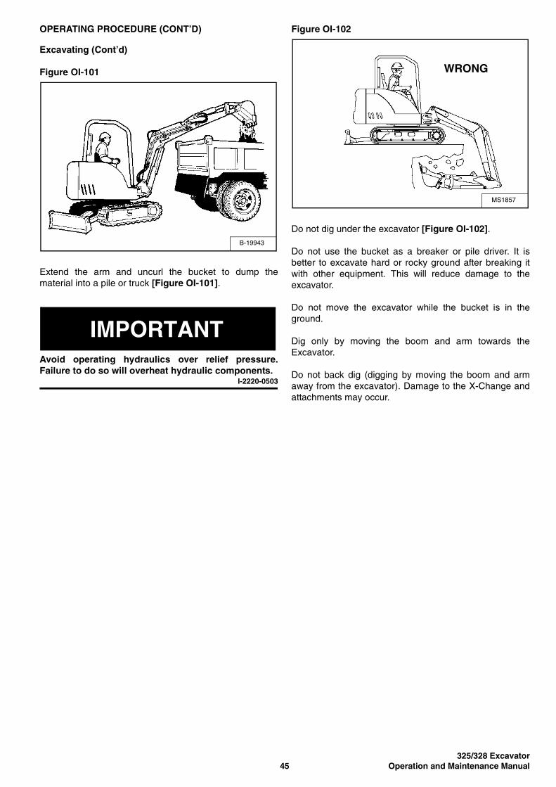
Return To Tank Valve (If Equipped)
Figure OI-95
The return to tank valve is located under the right sidecover.
Remove the spool lock (Item 1) [Figure OI-95] and pushthe spool in to direct auxiliary return hydraulic fluid to thereservoir.
Pull the spool out, and install the spool lock (Item 1)[Figure OI-95] for two-way hydraulic auxiliary flowoperation.
P16616
1
P-42157
1
2
P-49178
1
325/328 Excavator43 Operation and Maintenance Manual
OPERATING PROCEDURE
Lowering The Work Equipment With Engine Stopped
If the engine stops, the work equipment (boom/bucket,attachments) can be lowered to the ground usinghydraulic pressure which is stored in the accumulator.
The console must be in the locked down position, and thekey switch in the ON position.
Use the control lever to lower the boom.
Operating On Public Roads
When operating on a public road or motorway, alwaysfollow local regulations. For example: A slow movingvehicle (SMV) sign, or direction signals may be required.
Check with services companies for undergroundelectrical, water, gas lines, etc. work slowly in areas ofunderground powerlines.
Lifting A Load
Do not exceed the rated lift capacity. See Lift Capacity onPage 101 and 109.
WARNINGAVOID INJURY OR DEATH
Do not exceed Rated Lift Capacity. Excessive loadcan cause tipping or loss of control.
W-2476-1003
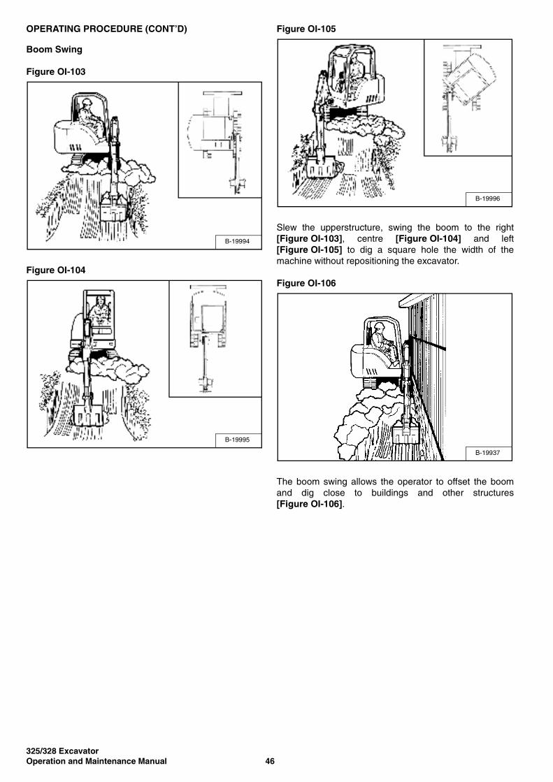
Extend the bucket cylinder completely and lower theboom to the ground. Stop the engine.
Wrap the chain assembly around the bucket mountingplate.
Figure OI-96
Make sure the load is evenly weighted and centred on thelifting chain, and is secured to prevent the load fromshifting [Figure OI-96].
Lift and position the load. When the load is in position andtension is removed from the lift chain (secondary liftsystem), remove the secondary lift system.
Figure OI-97
The optional lifting clamp attachment gives the excavatora wider range of use and mobility for debris removal[Figure OI-97].
The lifting clamp cylinder is operated by the auxiliaryhydraulic system.
The lifting clamp cylinder must be fully retracted when themachine is being used for excavating.
The lift capacities are reduced by 122 kg if the excavatoris equipped with the optional lifting clamp.
B-19942
N-15513

325/328 ExcavatorOperation and Maintenance Manual 44
OPERATING PROCEDURE (CONT’D)
Excavating
Lower the blade to provide stability.
Figure OI-98
Extend the arm, lower the boom, and open the bucket[Figure OI-98].
Figure OI-99
Retract the arm, while lowering boom and curling thebucket [Figure OI-99].
Figure OI-100
Raise the boom, retract the arm and curl the bucket[Figure OI-100].
Rotate the upperstructure.
NOTE: Do not allow the bucket teeth to make contactwith the ground when slewing theupperstructure.
WARNINGKeep all onlookers 6 m away from equipment whenoperating. Contact with moving parts, a trenchcollapse or flying objects can cause injury or death.
W-2119-0788
MS1855
MS1856
MS-1854
325/328 Excavator45 Operation and Maintenance Manual
OPERATING PROCEDURE (CONT’D)
Excavating (Cont’d)
Figure OI-101
Extend the arm and uncurl the bucket to dump thematerial into a pile or truck [Figure OI-101].
IMPORTANTAvoid operating hydraulics over relief pressure.Failure to do so will overheat hydraulic components.
I-2220-0503
Figure OI-102
Do not dig under the excavator [Figure OI-102].
Do not use the bucket as a breaker or pile driver. It isbetter to excavate hard or rocky ground after breaking itwith other equipment. This will reduce damage to theexcavator.
Do not move the excavator while the bucket is in theground.
Dig only by moving the boom and arm towards theExcavator.
Do not back dig (digging by moving the boom and armaway from the excavator). Damage to the X-Change andattachments may occur.
B-19943
MS1857
WRONG
325/328 ExcavatorOperation and Maintenance Manual 46
OPERATING PROCEDURE (CONT’D)
Boom Swing
Figure OI-103
Figure OI-104
Figure OI-105
Slew the upperstructure, swing the boom to the right[Figure OI-103], centre [Figure OI-104] and left[Figure OI-105] to dig a square hole the width of themachine without repositioning the excavator.
Figure OI-106
The boom swing allows the operator to offset the boomand dig close to buildings and other structures[Figure OI-106].
B-19994
B-19995
B-19996
B-19937
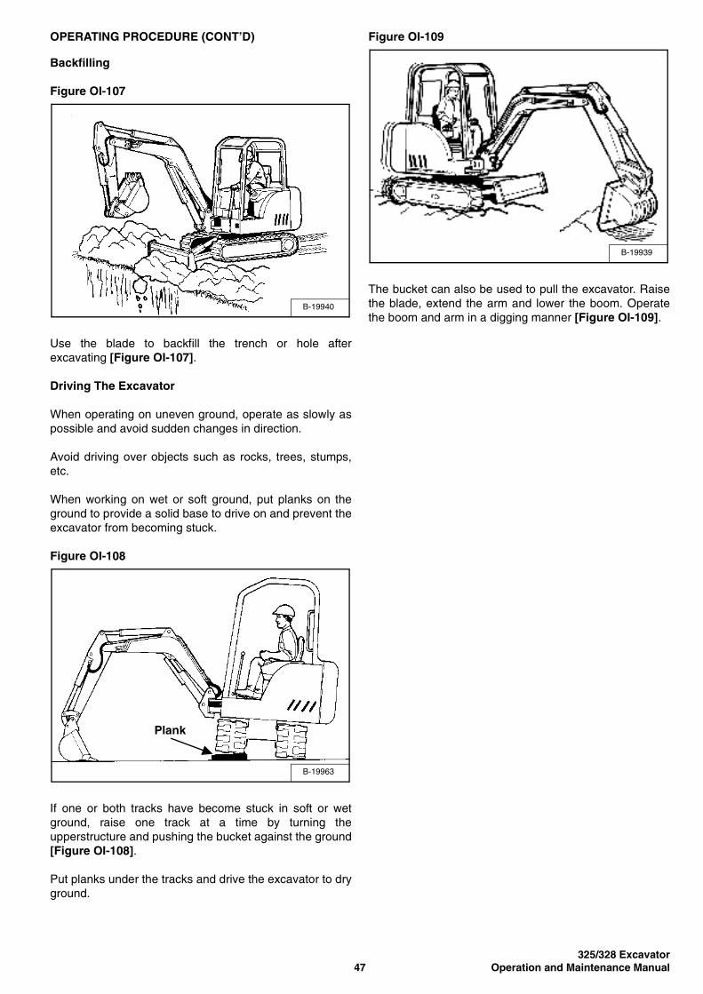
325/328 Excavator47 Operation and Maintenance Manual
OPERATING PROCEDURE (CONT’D)
Backfilling
Figure OI-107
Use the blade to backfill the trench or hole afterexcavating [Figure OI-107].
Driving The Excavator
When operating on uneven ground, operate as slowly aspossible and avoid sudden changes in direction.
Avoid driving over objects such as rocks, trees, stumps,etc.
When working on wet or soft ground, put planks on theground to provide a solid base to drive on and prevent theexcavator from becoming stuck.
Figure OI-108
If one or both tracks have become stuck in soft or wetground, raise one track at a time by turning theupperstructure and pushing the bucket against the ground[Figure OI-108].
Put planks under the tracks and drive the excavator to dryground.
Figure OI-109
The bucket can also be used to pull the excavator. Raisethe blade, extend the arm and lower the boom. Operatethe boom and arm in a digging manner [Figure OI-109].
B-19940
B-19963
Plank
B-19939
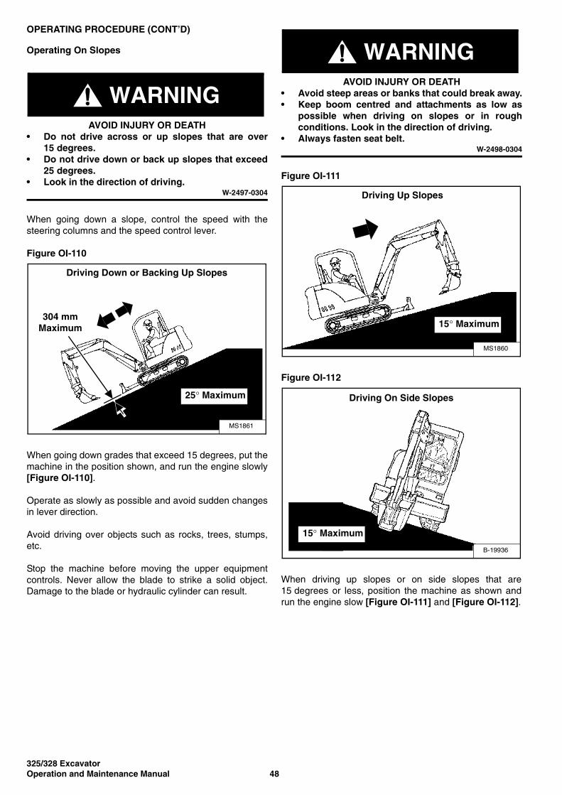
325/328 ExcavatorOperation and Maintenance Manual 48
OPERATING PROCEDURE (CONT’D)
Operating On Slopes
WARNINGAVOID INJURY OR DEATH
• Do not drive across or up slopes that are over15 degrees.
• Do not drive down or back up slopes that exceed25 degrees.
• Look in the direction of driving.W-2497-0304
When going down a slope, control the speed with thesteering columns and the speed control lever.
Figure OI-110
When going down grades that exceed 15 degrees, put themachine in the position shown, and run the engine slowly[Figure OI-110].
Operate as slowly as possible and avoid sudden changesin lever direction.
Avoid driving over objects such as rocks, trees, stumps,etc.
Stop the machine before moving the upper equipmentcontrols. Never allow the blade to strike a solid object.Damage to the blade or hydraulic cylinder can result.
WARNINGAVOID INJURY OR DEATH
• Avoid steep areas or banks that could break away.• Keep boom centred and attachments as low as
possible when driving on slopes or in roughconditions. Look in the direction of driving.
• Always fasten seat belt.W-2498-0304
Figure OI-111
Figure OI-112
When driving up slopes or on side slopes that are15 degrees or less, position the machine as shown andrun the engine slow [Figure OI-111] and [Figure OI-112].
304 mm Maximum
Driving Down or Backing Up Slopes
MS1861
25° Maximum
MS1860
Driving Up Slopes
15° Maximum
B-19936
Driving On Side Slopes
15° Maximum
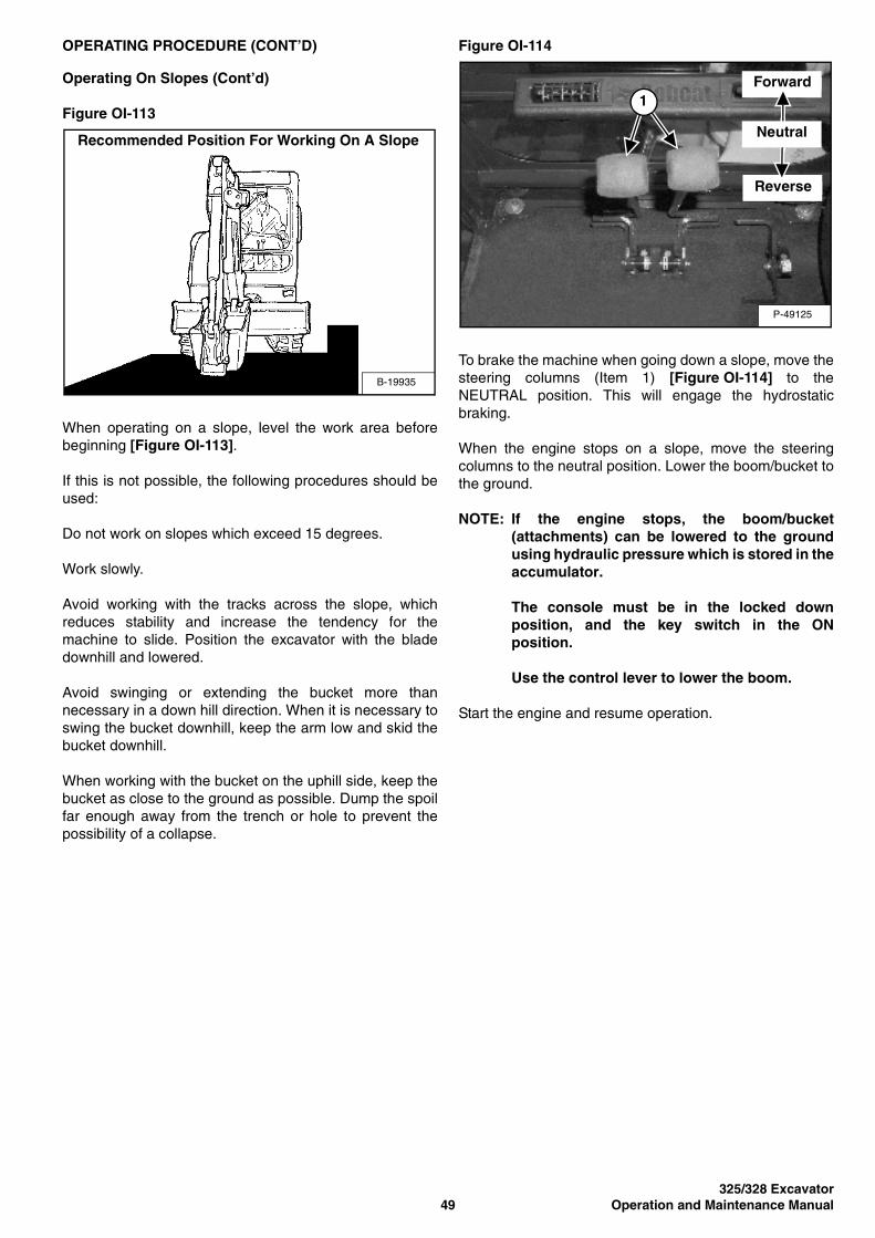
325/328 Excavator49 Operation and Maintenance Manual
OPERATING PROCEDURE (CONT’D)
Operating On Slopes (Cont’d)
Figure OI-113
When operating on a slope, level the work area beforebeginning [Figure OI-113].
If this is not possible, the following procedures should beused:
Do not work on slopes which exceed 15 degrees.
Work slowly.
Avoid working with the tracks across the slope, whichreduces stability and increase the tendency for themachine to slide. Position the excavator with the bladedownhill and lowered.
Avoid swinging or extending the bucket more thannecessary in a down hill direction. When it is necessary toswing the bucket downhill, keep the arm low and skid thebucket downhill.
When working with the bucket on the uphill side, keep thebucket as close to the ground as possible. Dump the spoilfar enough away from the trench or hole to prevent thepossibility of a collapse.
Figure OI-114
To brake the machine when going down a slope, move thesteering columns (Item 1) [Figure OI-114] to theNEUTRAL position. This will engage the hydrostaticbraking.
When the engine stops on a slope, move the steeringcolumns to the neutral position. Lower the boom/bucket tothe ground.
NOTE: If the engine stops, the boom/bucket(attachments) can be lowered to the groundusing hydraulic pressure which is stored in theaccumulator.
The console must be in the locked downposition, and the key switch in the ONposition.
Use the control lever to lower the boom.
Start the engine and resume operation.
B-19935
Recommended Position For Working On A Slope
P-49125
Forward
Reverse
Neutral
1
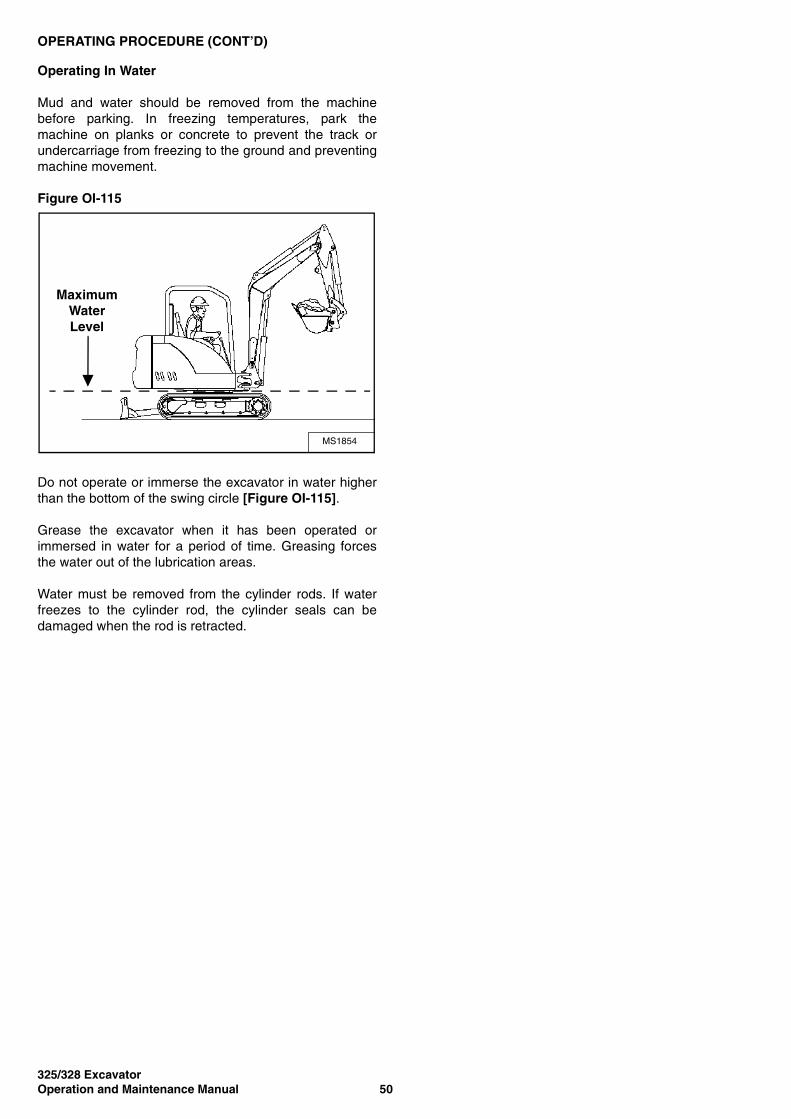
325/328 ExcavatorOperation and Maintenance Manual 50
OPERATING PROCEDURE (CONT’D)
Operating In Water
Mud and water should be removed from the machinebefore parking. In freezing temperatures, park themachine on planks or concrete to prevent the track orundercarriage from freezing to the ground and preventingmachine movement.
Figure OI-115
Do not operate or immerse the excavator in water higherthan the bottom of the swing circle [Figure OI-115].
Grease the excavator when it has been operated orimmersed in water for a period of time. Greasing forcesthe water out of the lubrication areas.
Water must be removed from the cylinder rods. If waterfreezes to the cylinder rod, the cylinder seals can bedamaged when the rod is retracted.
MS1854
Maximum Water Level
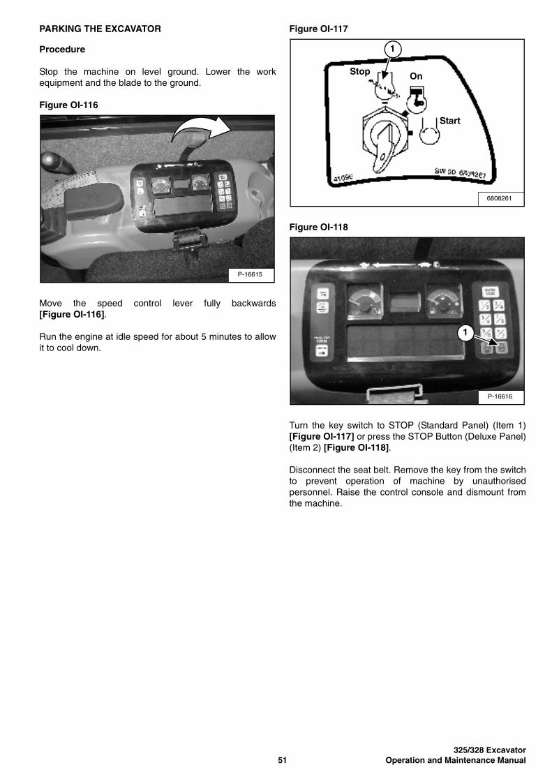
325/328 Excavator51 Operation and Maintenance Manual
PARKING THE EXCAVATOR
Procedure
Stop the machine on level ground. Lower the workequipment and the blade to the ground.
Figure OI-116
Move the speed control lever fully backwards[Figure OI-116].
Run the engine at idle speed for about 5 minutes to allowit to cool down.
Figure OI-117
Figure OI-118
Turn the key switch to STOP (Standard Panel) (Item 1)[Figure OI-117] or press the STOP Button (Deluxe Panel)(Item 2) [Figure OI-118].
Disconnect the seat belt. Remove the key from the switchto prevent operation of machine by unauthorisedpersonnel. Raise the control console and dismount fromthe machine.
P-16615
6808261
Stop On
Start
1
P-16616
1
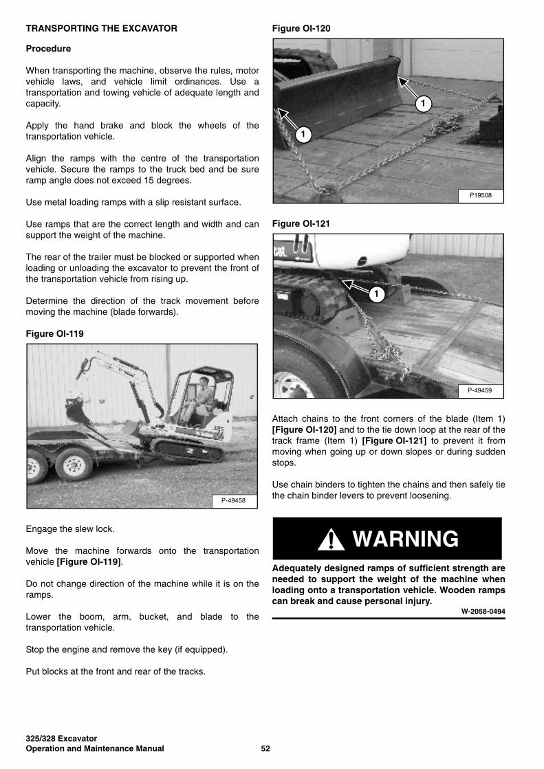
325/328 ExcavatorOperation and Maintenance Manual 52
TRANSPORTING THE EXCAVATOR
Procedure
When transporting the machine, observe the rules, motorvehicle laws, and vehicle limit ordinances. Use atransportation and towing vehicle of adequate length andcapacity.
Apply the hand brake and block the wheels of thetransportation vehicle.
Align the ramps with the centre of the transportationvehicle. Secure the ramps to the truck bed and be sureramp angle does not exceed 15 degrees.
Use metal loading ramps with a slip resistant surface.
Use ramps that are the correct length and width and cansupport the weight of the machine.
The rear of the trailer must be blocked or supported whenloading or unloading the excavator to prevent the front ofthe transportation vehicle from rising up.
Determine the direction of the track movement beforemoving the machine (blade forwards).
Figure OI-119
Engage the slew lock.
Move the machine forwards onto the transportationvehicle [Figure OI-119].
Do not change direction of the machine while it is on theramps.
Lower the boom, arm, bucket, and blade to thetransportation vehicle.
Stop the engine and remove the key (if equipped).
Put blocks at the front and rear of the tracks.
Figure OI-120
Figure OI-121
Attach chains to the front corners of the blade (Item 1)[Figure OI-120] and to the tie down loop at the rear of thetrack frame (Item 1) [Figure OI-121] to prevent it frommoving when going up or down slopes or during suddenstops.
Use chain binders to tighten the chains and then safely tiethe chain binder levers to prevent loosening.
WARNINGAdequately designed ramps of sufficient strength areneeded to support the weight of the machine whenloading onto a transportation vehicle. Wooden rampscan break and cause personal injury.
W-2058-0494
P-49458
P19508
1
1
P-49459
1
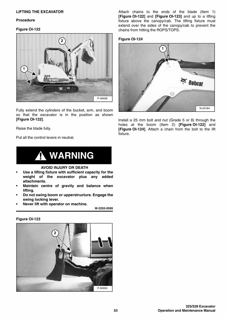
325/328 Excavator53 Operation and Maintenance Manual
LIFTING THE EXCAVATOR
Procedure
Figure OI-122
Fully extend the cylinders of the bucket, arm, and boomso that the excavator is in the position as shown[Figure OI-122].
Raise the blade fully.
Put all the control levers in neutral.
WARNINGAVOID INJURY OR DEATH
• Use a lifting fixture with sufficient capacity for theweight of the excavator plus any addedattachments.
• Maintain centre of gravity and balance whenlifting.
• Do not swing boom or upperstructure. Engage theswing locking lever.
• Never lift with operator on machine.W-2202-0595
Figure OI-123
Attach chains to the ends of the blade (Item 1)[Figure OI-122] and [Figure OI-123] and up to a liftingfixture above the canopy/cab. The lifting fixture mustextend over the sides of the canopy/cab to prevent thechains from hitting the ROPS/TOPS.
Figure OI-124
Install a 25 mm bolt and nut (Grade 5 or 8) through theholes at the boom (Item 2) [Figure OI-122] and[Figure OI-124]. Attach a chain from the bolt to the liftfixture.
P-49456
1
2
P-50050
2
N-23184
1

325/328 ExcavatorOperation and Maintenance Manual 54
325/328 Excavator55 Operation and Maintenance Manual
PREVENTIVE MAINTENANCE
AIR CLEANER . . . . . . . . . . . . . . . . . . . . . . . . . . . . . . . . . . . . . . . . .62Daily Check . . . . . . . . . . . . . . . . . . . . . . . . . . . . . . . . . . . . . . . . . 62Replacing The Filters . . . . . . . . . . . . . . . . . . . . . . . . . . . . . . . . .62
BUCKET . . . . . . . . . . . . . . . . . . . . . . . . . . . . . . . . . . . . . . . . . . . . . .86Bucket Teeth Removal And Installation. . . . . . . . . . . . . . . . . . . . 86
COOLING SYSTEM . . . . . . . . . . . . . . . . . . . . . . . . . . . . . . . . . . . . .71Checking Coolant Level . . . . . . . . . . . . . . . . . . . . . . . . . . . . . . . 72Cleaning The Cooling System. . . . . . . . . . . . . . . . . . . . . . . . . . . 71Replacing The Coolant . . . . . . . . . . . . . . . . . . . . . . . . . . . . . . . .73
DRIVE MOTOR . . . . . . . . . . . . . . . . . . . . . . . . . . . . . . . . . . . . . . . .84Checking Oil Level . . . . . . . . . . . . . . . . . . . . . . . . . . . . . . . . . . .84Draining The Drive Motor . . . . . . . . . . . . . . . . . . . . . . . . . . . . . .84
ELECTRICAL SYSTEM . . . . . . . . . . . . . . . . . . . . . . . . . . . . . . . . . .74Description . . . . . . . . . . . . . . . . . . . . . . . . . . . . . . . . . . . . . . . . .74Fuse And Relay Location . . . . . . . . . . . . . . . . . . . . . . . . . . . . . .74Removing And Installing The Battery . . . . . . . . . . . . . . . . . . . . .76Using A Booster Battery (Jump Starting). . . . . . . . . . . . . . . . . . .75
ENGINE ACCESSORY DRIVE BELT. . . . . . . . . . . . . . . . . . . . . . . .83Belt Adjustment . . . . . . . . . . . . . . . . . . . . . . . . . . . . . . . . . . . . . .83Belt Tension. . . . . . . . . . . . . . . . . . . . . . . . . . . . . . . . . . . . . . . . . 83
ENGINE LUBRICATION SYSTEM . . . . . . . . . . . . . . . . . . . . . . . . . .69Checking Engine Oil . . . . . . . . . . . . . . . . . . . . . . . . . . . . . . . . . .69Replacing Oil And Filter. . . . . . . . . . . . . . . . . . . . . . . . . . . . . . . .70
FUEL SYSTEM. . . . . . . . . . . . . . . . . . . . . . . . . . . . . . . . . . . . . . . . . 66Draining The Fuel Tank . . . . . . . . . . . . . . . . . . . . . . . . . . . . . . . .67Filling The Fuel Tank . . . . . . . . . . . . . . . . . . . . . . . . . . . . . . . . . . 66Fuel Filter . . . . . . . . . . . . . . . . . . . . . . . . . . . . . . . . . . . . . . . . . .68Fuel Specifications . . . . . . . . . . . . . . . . . . . . . . . . . . . . . . . . . . .66Removing Air From The Fuel System . . . . . . . . . . . . . . . . . . . . .68Removing Water From The Fuel Filter . . . . . . . . . . . . . . . . . . . .67
HEATER AIR FILTER (WITH CAB OPTION ONLY) . . . . . . . . . . . . . 65Removal And Installation. . . . . . . . . . . . . . . . . . . . . . . . . . . . . . .65
HYDRAULIC SYSTEM . . . . . . . . . . . . . . . . . . . . . . . . . . . . . . . . . . .77Checking And Adding Hydraulic Oil . . . . . . . . . . . . . . . . . . . . . .77Diagnostic Connectors . . . . . . . . . . . . . . . . . . . . . . . . . . . . . . . .79Replacing The Case Drain Filter . . . . . . . . . . . . . . . . . . . . . . . . .79Replacing The Hydraulic Filter . . . . . . . . . . . . . . . . . . . . . . . . . .79Replacing The Hydraulic Oil . . . . . . . . . . . . . . . . . . . . . . . . . . . .78
MAINTENANCEPREVENTIVE

325/328 ExcavatorOperation and Maintenance Manual 56
PREVENTIVE MAINTENANCE (CONT’D)
LUBRICATION OF THE HYDRAULIC EXCAVATOR . . . . . . . . . . . .87Procedure . . . . . . . . . . . . . . . . . . . . . . . . . . . . . . . . . . . . . . . . . .87
MAINTENANCE SAFETY. . . . . . . . . . . . . . . . . . . . . . . . . . . . . . . . .57
RIGHT SIDE COVER . . . . . . . . . . . . . . . . . . . . . . . . . . . . . . . . . . . .61Opening And Closing The Right Side Cover . . . . . . . . . . . . . . . .61
SEAT BELT . . . . . . . . . . . . . . . . . . . . . . . . . . . . . . . . . . . . . . . . . . . .64Inspection And Maintenance . . . . . . . . . . . . . . . . . . . . . . . . . . . .64
SERVICE SCHEDULE . . . . . . . . . . . . . . . . . . . . . . . . . . . . . . . . . . .59Chart . . . . . . . . . . . . . . . . . . . . . . . . . . . . . . . . . . . . . . . . . . . . . .59
SPARK ARRESTER SILENCER . . . . . . . . . . . . . . . . . . . . . . . . . . .80Cleaning Procedure. . . . . . . . . . . . . . . . . . . . . . . . . . . . . . . . . . .80
TAILGATE . . . . . . . . . . . . . . . . . . . . . . . . . . . . . . . . . . . . . . . . . . . . .60Adjusting The Bumper . . . . . . . . . . . . . . . . . . . . . . . . . . . . . . . . .60Adjusting The Latch. . . . . . . . . . . . . . . . . . . . . . . . . . . . . . . . . . .60Opening And Closing The Tailgate . . . . . . . . . . . . . . . . . . . . . . .60
TRACK TENSION. . . . . . . . . . . . . . . . . . . . . . . . . . . . . . . . . . . . . . .81Adjustment. . . . . . . . . . . . . . . . . . . . . . . . . . . . . . . . . . . . . . . . . .82
X-CHANGE . . . . . . . . . . . . . . . . . . . . . . . . . . . . . . . . . . . . . . . . . . . .85Inspection And Maintenance . . . . . . . . . . . . . . . . . . . . . . . . . . . .85
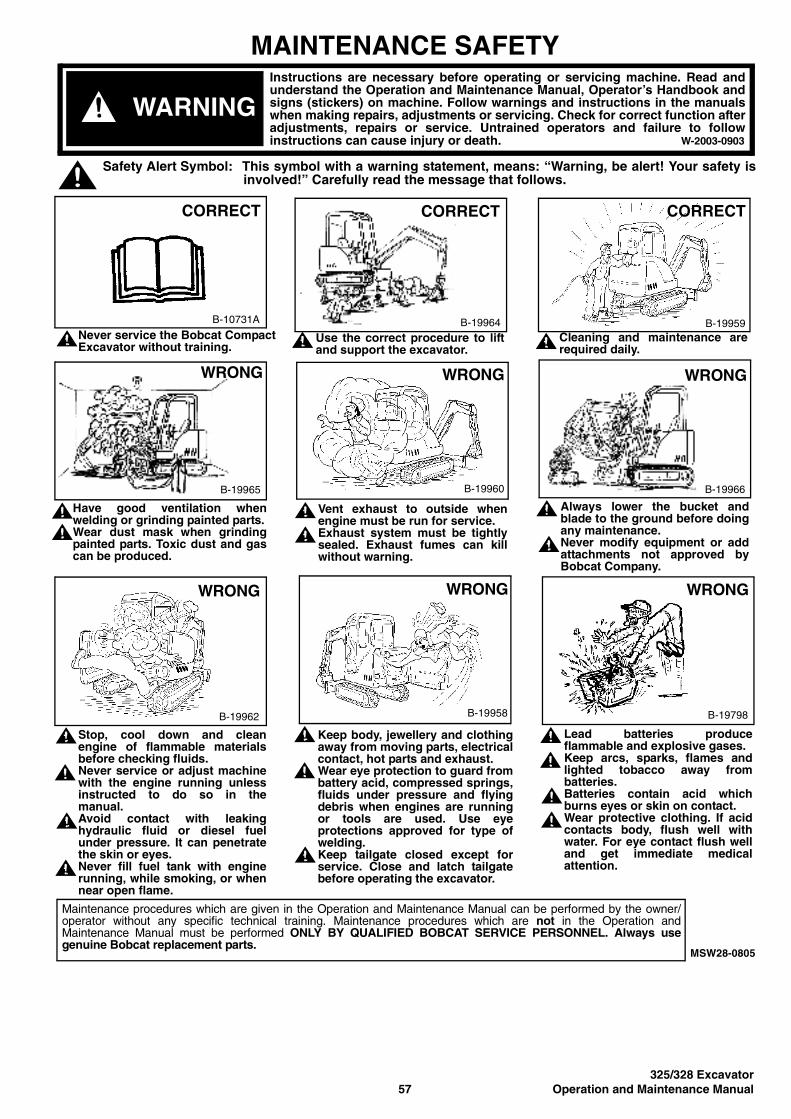
325/328 Excavator57 Operation and Maintenance Manual
MAINTENANCE SAFETY
Never service the Bobcat CompactExcavator without training.
Have good ventilation whenwelding or grinding painted parts.Wear dust mask when grindingpainted parts. Toxic dust and gascan be produced.
Stop, cool down and cleanengine of flammable materialsbefore checking fluids.Never service or adjust machinewith the engine running unlessinstructed to do so in themanual.Avoid contact with leakinghydraulic fluid or diesel fuelunder pressure. It can penetratethe skin or eyes.Never fill fuel tank with enginerunning, while smoking, or whennear open flame.
Always lower the bucket andblade to the ground before doingany maintenance.Never modify equipment or addattachments not approved byBobcat Company.
Keep body, jewellery and clothingaway from moving parts, electricalcontact, hot parts and exhaust. Wear eye protection to guard frombattery acid, compressed springs,fluids under pressure and flyingdebris when engines are runningor tools are used. Use eyeprotections approved for type ofwelding.Keep tailgate closed except forservice. Close and latch tailgatebefore operating the excavator.
Vent exhaust to outside whenengine must be run for service.Exhaust system must be tightlysealed. Exhaust fumes can killwithout warning.
Cleaning and maintenance arerequired daily.
MSW28-0805
Use the correct procedure to liftand support the excavator.
Lead batteries produceflammable and explosive gases.Keep arcs, sparks, flames andlighted tobacco away frombatteries.Batteries contain acid whichburns eyes or skin on contact.Wear protective clothing. If acidcontacts body, flush well withwater. For eye contact flush welland get immediate medicalattention.
WARNINGInstructions are necessary before operating or servicing machine. Read andunderstand the Operation and Maintenance Manual, Operator’s Handbook andsigns (stickers) on machine. Follow warnings and instructions in the manualswhen making repairs, adjustments or servicing. Check for correct function afteradjustments, repairs or service. Untrained operators and failure to followinstructions can cause injury or death. W-2003-0903
Maintenance procedures which are given in the Operation and Maintenance Manual can be performed by the owner/operator without any specific technical training. Maintenance procedures which are not in the Operation andMaintenance Manual must be performed ONLY BY QUALIFIED BOBCAT SERVICE PERSONNEL. Always usegenuine Bobcat replacement parts.
Safety Alert Symbol: This symbol with a warning statement, means: “Warning, be alert! Your safety isinvolved!” Carefully read the message that follows.
B-10731A
CORRECT
B-19964
CORRECT CORRECT
B-19959
B-19965
WRONG WRONG
B-19960 B-19966
WRONG
WRONG
B-19962 B-19958
WRONG
B-19798
WRONG

325/328 ExcavatorOperation and Maintenance Manual 58
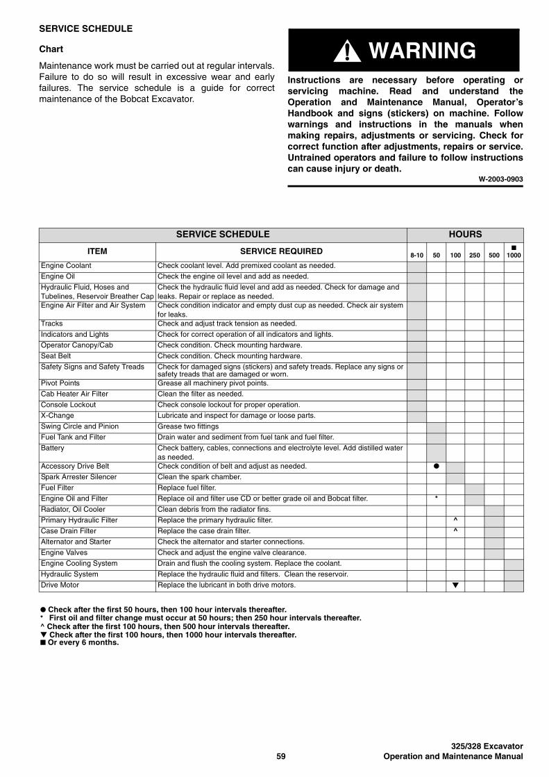
325/328 Excavator59 Operation and Maintenance Manual
SERVICE SCHEDULE
Chart
Maintenance work must be carried out at regular intervals.Failure to do so will result in excessive wear and earlyfailures. The service schedule is a guide for correctmaintenance of the Bobcat Excavator.
WARNINGInstructions are necessary before operating orservicing machine. Read and understand theOperation and Maintenance Manual, Operator’sHandbook and signs (stickers) on machine. Followwarnings and instructions in the manuals whenmaking repairs, adjustments or servicing. Check forcorrect function after adjustments, repairs or service.Untrained operators and failure to follow instructionscan cause injury or death.
W-2003-0903
SERVICE SCHEDULE HOURS
ITEM SERVICE REQUIRED 8-10 50 100 250 500■
1000
Engine Coolant Check coolant level. Add premixed coolant as needed.
Engine Oil Check the engine oil level and add as needed.
Hydraulic Fluid, Hoses and Tubelines, Reservoir Breather Cap
Check the hydraulic fluid level and add as needed. Check for damage and leaks. Repair or replace as needed.
Engine Air Filter and Air System Check condition indicator and empty dust cup as needed. Check air system for leaks.
Tracks Check and adjust track tension as needed.
Indicators and Lights Check for correct operation of all indicators and lights.
Operator Canopy/Cab Check condition. Check mounting hardware.
Seat Belt Check condition. Check mounting hardware.
Safety Signs and Safety Treads Check for damaged signs (stickers) and safety treads. Replace any signs or safety treads that are damaged or worn.
Pivot Points Grease all machinery pivot points.
Cab Heater Air Filter Clean the filter as needed.
Console Lockout Check console lockout for proper operation.
X-Change Lubricate and inspect for damage or loose parts.
Swing Circle and Pinion Grease two fittings
Fuel Tank and Filter Drain water and sediment from fuel tank and fuel filter.
Battery Check battery, cables, connections and electrolyte level. Add distilled water as needed.
Accessory Drive Belt Check condition of belt and adjust as needed. ●
Spark Arrester Silencer Clean the spark chamber.
Fuel Filter Replace fuel filter.
Engine Oil and Filter Replace oil and filter use CD or better grade oil and Bobcat filter. *Radiator, Oil Cooler Clean debris from the radiator fins.
Primary Hydraulic Filter Replace the primary hydraulic filter. ^Case Drain Filter Replace the case drain filter. ^Alternator and Starter Check the alternator and starter connections.
Engine Valves Check and adjust the engine valve clearance.
Engine Cooling System Drain and flush the cooling system. Replace the coolant.
Hydraulic System Replace the hydraulic fluid and filters. Clean the reservoir.
Drive Motor Replace the lubricant in both drive motors. ▼
● Check after the first 50 hours, then 100 hour intervals thereafter.* First oil and filter change must occur at 50 hours; then 250 hour intervals thereafter.^ Check after the first 100 hours, then 500 hour intervals thereafter.▼ Check after the first 100 hours, then 1000 hour intervals thereafter.■ Or every 6 months.
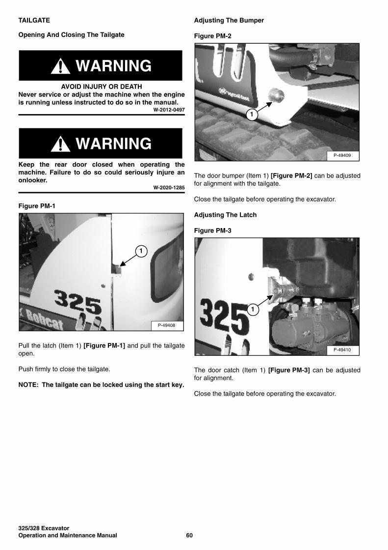
325/328 ExcavatorOperation and Maintenance Manual 60
TAILGATE
Opening And Closing The Tailgate
WARNINGAVOID INJURY OR DEATH
Never service or adjust the machine when the engineis running unless instructed to do so in the manual.
W-2012-0497
WARNINGKeep the rear door closed when operating themachine. Failure to do so could seriously injure anonlooker.
W-2020-1285
Figure PM-1
Pull the latch (Item 1) [Figure PM-1] and pull the tailgateopen.
Push firmly to close the tailgate.
NOTE: The tailgate can be locked using the start key.
Adjusting The Bumper
Figure PM-2
The door bumper (Item 1) [Figure PM-2] can be adjustedfor alignment with the tailgate.
Close the tailgate before operating the excavator.
Adjusting The Latch
Figure PM-3
The door catch (Item 1) [Figure PM-3] can be adjustedfor alignment.
Close the tailgate before operating the excavator.
P-49408
1
P-49409
1
P-49410
1

325/328 Excavator61 Operation and Maintenance Manual
RIGHT SIDE COVER
Opening And Closing The Right Side Cover
Figure PM-4
Pull the latch (Item 1) [Figure PM-4] and raise the rightside cover.
NOTE: The right side cover can be locked using thestart key.
P-49411
1
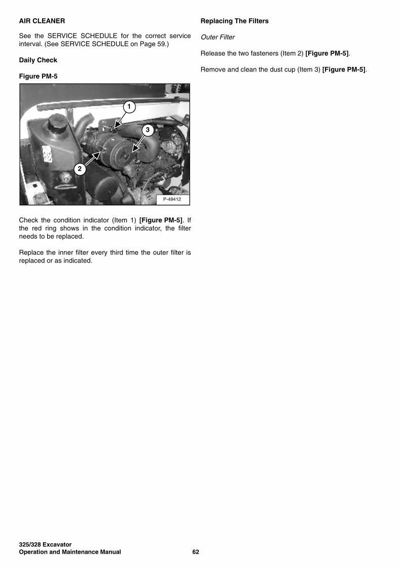
325/328 ExcavatorOperation and Maintenance Manual 62
AIR CLEANER
See the SERVICE SCHEDULE for the correct serviceinterval. (See SERVICE SCHEDULE on Page 59.)
Daily Check
Figure PM-5
Check the condition indicator (Item 1) [Figure PM-5]. Ifthe red ring shows in the condition indicator, the filterneeds to be replaced.
Replace the inner filter every third time the outer filter isreplaced or as indicated.
Replacing The Filters
Outer Filter
Release the two fasteners (Item 2) [Figure PM-5].
Remove and clean the dust cup (Item 3) [Figure PM-5].
P-49412
1
2
3
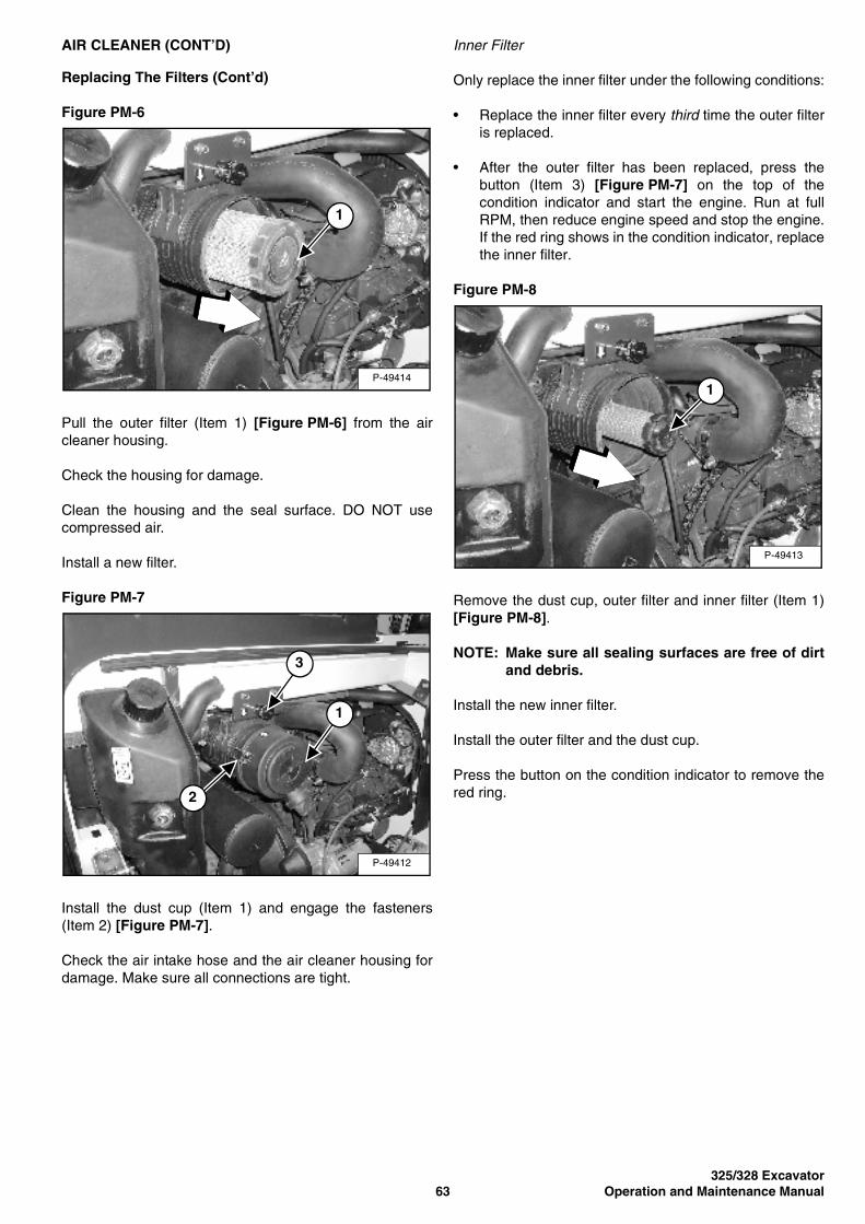
325/328 Excavator63 Operation and Maintenance Manual
AIR CLEANER (CONT’D)
Replacing The Filters (Cont’d)
Figure PM-6
Pull the outer filter (Item 1) [Figure PM-6] from the aircleaner housing.
Check the housing for damage.
Clean the housing and the seal surface. DO NOT usecompressed air.
Install a new filter.
Figure PM-7
Install the dust cup (Item 1) and engage the fasteners(Item 2) [Figure PM-7].
Check the air intake hose and the air cleaner housing fordamage. Make sure all connections are tight.
Inner Filter
Only replace the inner filter under the following conditions:
• Replace the inner filter every third time the outer filteris replaced.
• After the outer filter has been replaced, press thebutton (Item 3) [Figure PM-7] on the top of thecondition indicator and start the engine. Run at fullRPM, then reduce engine speed and stop the engine.If the red ring shows in the condition indicator, replacethe inner filter.
Figure PM-8
Remove the dust cup, outer filter and inner filter (Item 1)[Figure PM-8].
NOTE: Make sure all sealing surfaces are free of dirtand debris.
Install the new inner filter.
Install the outer filter and the dust cup.
Press the button on the condition indicator to remove thered ring.
P-49414
1
P-49412
3
2
1
P-49413
1
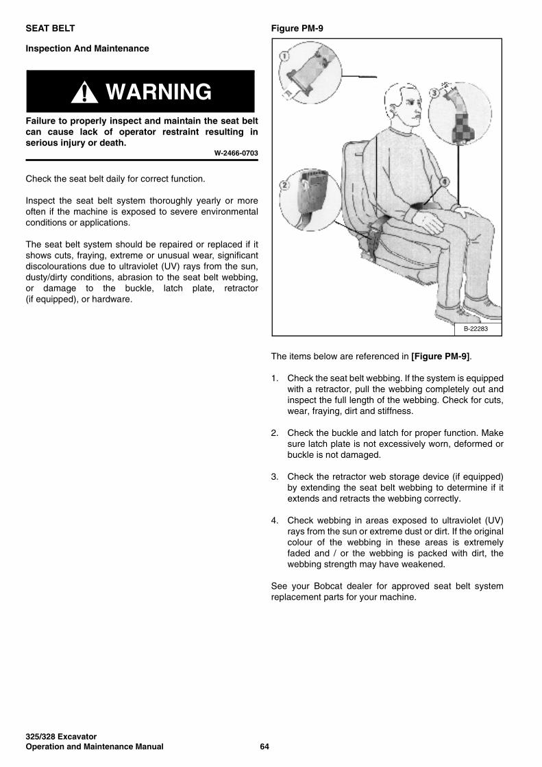
325/328 ExcavatorOperation and Maintenance Manual 64
SEAT BELT
Inspection And Maintenance
WARNINGFailure to properly inspect and maintain the seat beltcan cause lack of operator restraint resulting inserious injury or death.
W-2466-0703
Check the seat belt daily for correct function.
Inspect the seat belt system thoroughly yearly or moreoften if the machine is exposed to severe environmentalconditions or applications.
The seat belt system should be repaired or replaced if itshows cuts, fraying, extreme or unusual wear, significantdiscolourations due to ultraviolet (UV) rays from the sun,dusty/dirty conditions, abrasion to the seat belt webbing,or damage to the buckle, latch plate, retractor(if equipped), or hardware.
Figure PM-9
The items below are referenced in [Figure PM-9].
1. Check the seat belt webbing. If the system is equippedwith a retractor, pull the webbing completely out andinspect the full length of the webbing. Check for cuts,wear, fraying, dirt and stiffness.
2. Check the buckle and latch for proper function. Makesure latch plate is not excessively worn, deformed orbuckle is not damaged.
3. Check the retractor web storage device (if equipped)by extending the seat belt webbing to determine if itextends and retracts the webbing correctly.
4. Check webbing in areas exposed to ultraviolet (UV)rays from the sun or extreme dust or dirt. If the originalcolour of the webbing in these areas is extremelyfaded and / or the webbing is packed with dirt, thewebbing strength may have weakened.
See your Bobcat dealer for approved seat belt systemreplacement parts for your machine.
B-22283
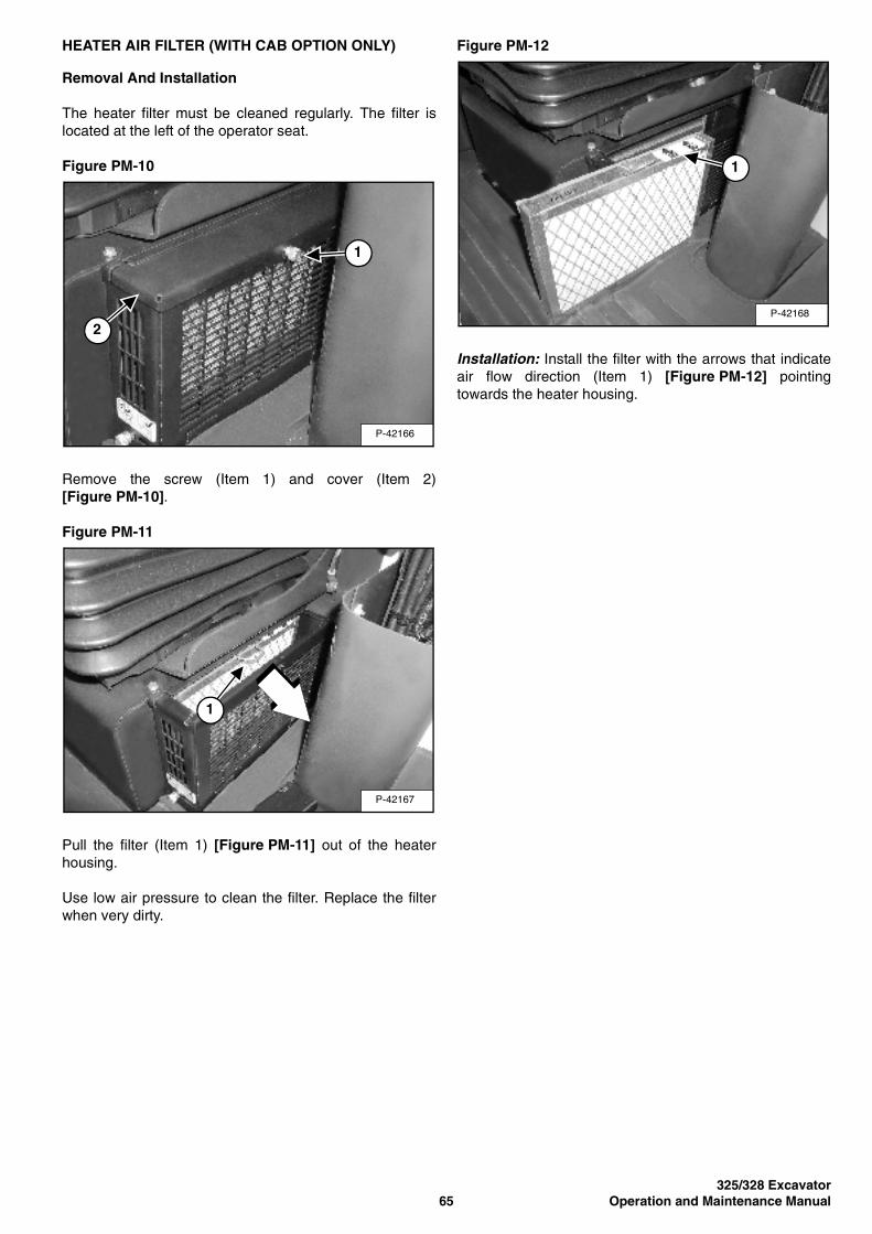
325/328 Excavator65 Operation and Maintenance Manual
HEATER AIR FILTER (WITH CAB OPTION ONLY)
Removal And Installation
The heater filter must be cleaned regularly. The filter islocated at the left of the operator seat.
Figure PM-10
Remove the screw (Item 1) and cover (Item 2)[Figure PM-10].
Figure PM-11
Pull the filter (Item 1) [Figure PM-11] out of the heaterhousing.
Use low air pressure to clean the filter. Replace the filterwhen very dirty.
Figure PM-12
Installation: Install the filter with the arrows that indicateair flow direction (Item 1) [Figure PM-12] pointingtowards the heater housing.
P-42166
1
2
P-42167
1
P-42168
1
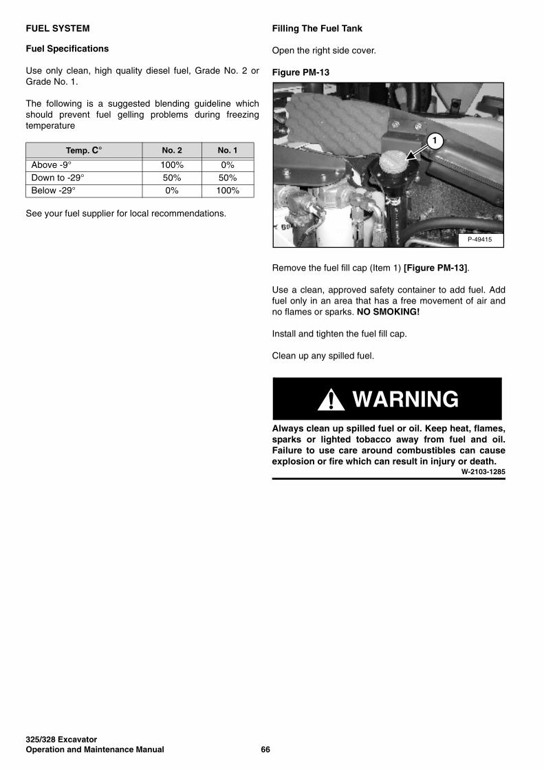
325/328 ExcavatorOperation and Maintenance Manual 66
FUEL SYSTEM
Fuel Specifications
Use only clean, high quality diesel fuel, Grade No. 2 orGrade No. 1.
The following is a suggested blending guideline whichshould prevent fuel gelling problems during freezingtemperature
See your fuel supplier for local recommendations.
Filling The Fuel Tank
Open the right side cover.
Figure PM-13
Remove the fuel fill cap (Item 1) [Figure PM-13].
Use a clean, approved safety container to add fuel. Addfuel only in an area that has a free movement of air andno flames or sparks. NO SMOKING!
Install and tighten the fuel fill cap.
Clean up any spilled fuel.
WARNINGAlways clean up spilled fuel or oil. Keep heat, flames,sparks or lighted tobacco away from fuel and oil.Failure to use care around combustibles can causeexplosion or fire which can result in injury or death.
W-2103-1285
Temp. C° No. 2 No. 1
Above -9° 100% 0%Down to -29° 50% 50%Below -29° 0% 100%
P-49415
1
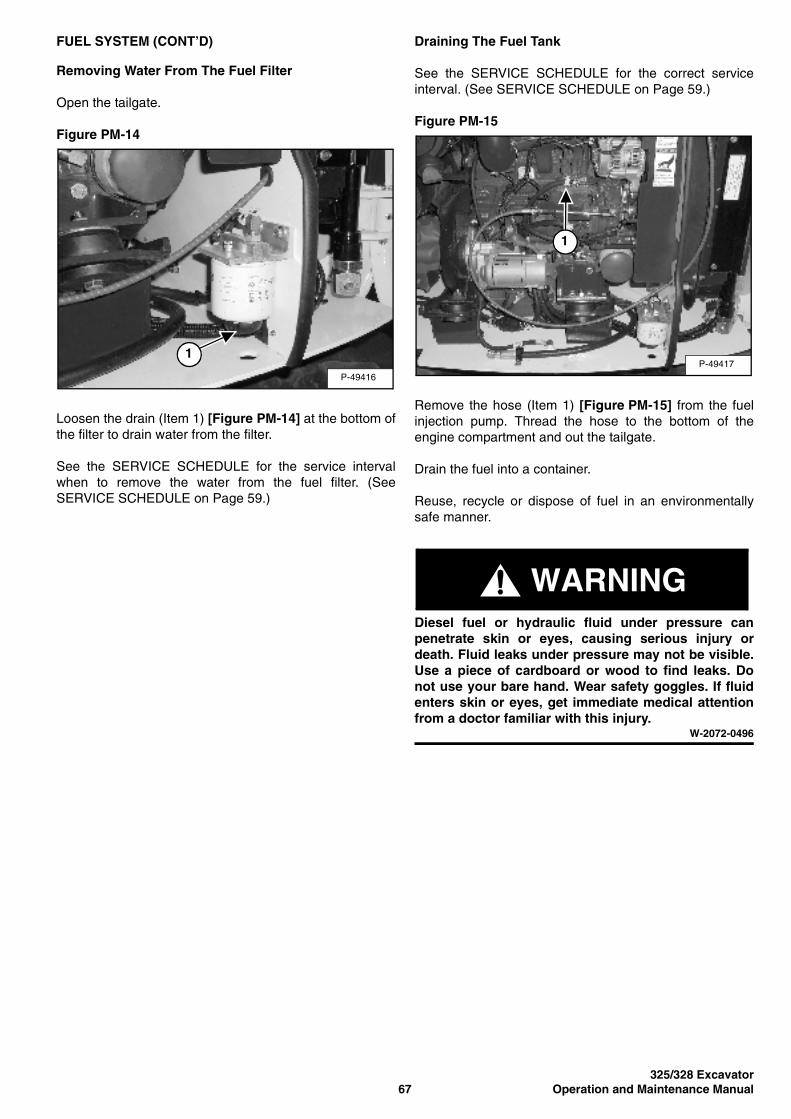
325/328 Excavator67 Operation and Maintenance Manual
FUEL SYSTEM (CONT’D)
Removing Water From The Fuel Filter
Open the tailgate.
Figure PM-14
Loosen the drain (Item 1) [Figure PM-14] at the bottom ofthe filter to drain water from the filter.
See the SERVICE SCHEDULE for the service intervalwhen to remove the water from the fuel filter. (SeeSERVICE SCHEDULE on Page 59.)
Draining The Fuel Tank
See the SERVICE SCHEDULE for the correct serviceinterval. (See SERVICE SCHEDULE on Page 59.)
Figure PM-15
Remove the hose (Item 1) [Figure PM-15] from the fuelinjection pump. Thread the hose to the bottom of theengine compartment and out the tailgate.
Drain the fuel into a container.
Reuse, recycle or dispose of fuel in an environmentallysafe manner.
WARNINGDiesel fuel or hydraulic fluid under pressure canpenetrate skin or eyes, causing serious injury ordeath. Fluid leaks under pressure may not be visible.Use a piece of cardboard or wood to find leaks. Donot use your bare hand. Wear safety goggles. If fluidenters skin or eyes, get immediate medical attentionfrom a doctor familiar with this injury.
W-2072-0496
P-49416
1P-49417
1

325/328 ExcavatorOperation and Maintenance Manual 68
FUEL SYSTEM (CONT’D)
Fuel Filter
See the SERVICE SCHEDULE for the service intervalwhen to replace the fuel filter. (See SERVICESCHEDULE on Page 59.)
Figure PM-16
Remove the filter (Item 1) [Figure PM-16].
Clean the area around the filter housing.
Put oil on the seal of the new filter.
Install the fuel filter, and tighten by hand.
Removing Air From The Fuel System
After replacing the fuel filter or when the fuel tank has runout of fuel, air must be removed from the fuel systembefore starting the engine.
Figure PM-17
Open the fuel filter vent (Item 1) [Figure PM-17].
Operate the hand pump (priming bulb) (Item 2)[Figure PM-17] until the fuel flows from the vent with noair bubbles.
Close the vent (Item 1) [Figure PM-17].
Start the engine. It may be necessary to open the vent(Item 3) [Figure PM-17] (at the fuel injection pump) brieflyuntil the engine runs smoothly.
P-49416
1
P-49417
2
3
1
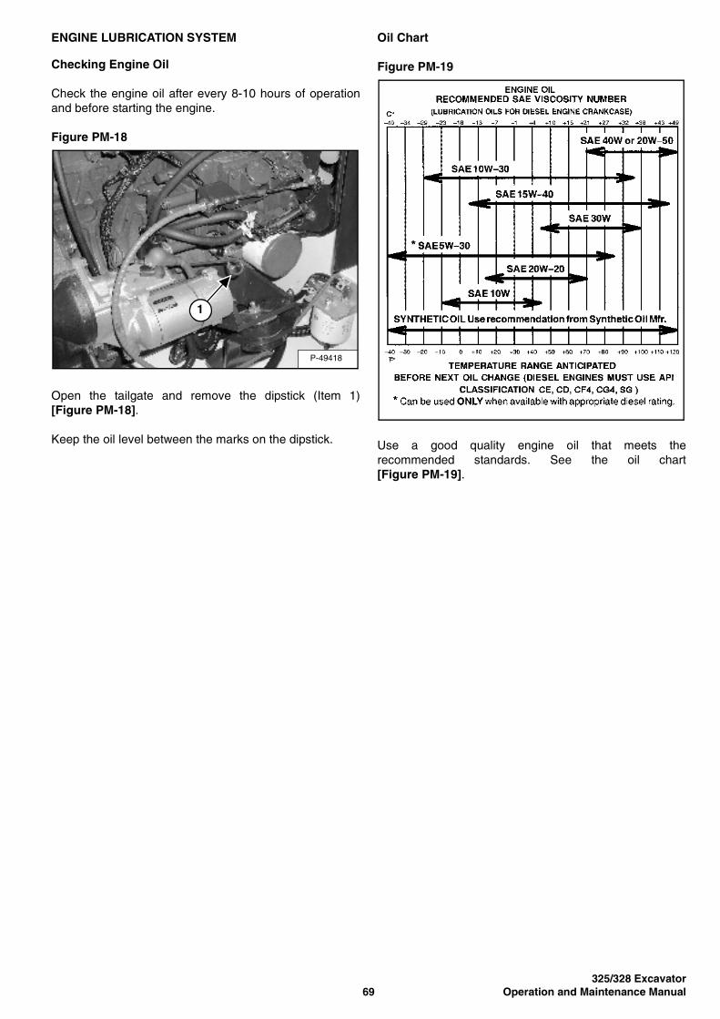
325/328 Excavator69 Operation and Maintenance Manual
ENGINE LUBRICATION SYSTEM
Checking Engine Oil
Check the engine oil after every 8-10 hours of operationand before starting the engine.
Figure PM-18
Open the tailgate and remove the dipstick (Item 1)[Figure PM-18].
Keep the oil level between the marks on the dipstick.
Oil Chart
Figure PM-19
Use a good quality engine oil that meets therecommended standards. See the oil chart[Figure PM-19].
P-49418
1
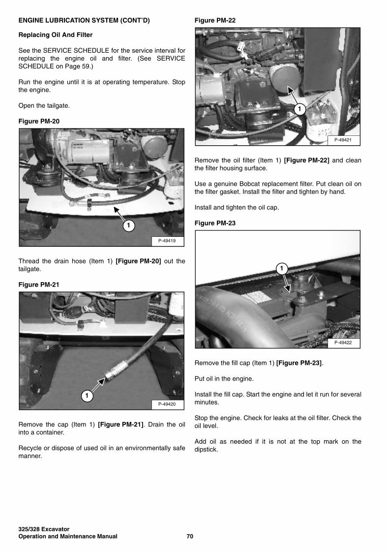
325/328 ExcavatorOperation and Maintenance Manual 70
ENGINE LUBRICATION SYSTEM (CONT’D)
Replacing Oil And Filter
See the SERVICE SCHEDULE for the service interval forreplacing the engine oil and filter. (See SERVICESCHEDULE on Page 59.)
Run the engine until it is at operating temperature. Stopthe engine.
Open the tailgate.
Figure PM-20
Thread the drain hose (Item 1) [Figure PM-20] out thetailgate.
Figure PM-21
Remove the cap (Item 1) [Figure PM-21]. Drain the oilinto a container.
Recycle or dispose of used oil in an environmentally safemanner.
Figure PM-22
Remove the oil filter (Item 1) [Figure PM-22] and cleanthe filter housing surface.
Use a genuine Bobcat replacement filter. Put clean oil onthe filter gasket. Install the filter and tighten by hand.
Install and tighten the oil cap.
Figure PM-23
Remove the fill cap (Item 1) [Figure PM-23].
Put oil in the engine.
Install the fill cap. Start the engine and let it run for severalminutes.
Stop the engine. Check for leaks at the oil filter. Check theoil level.
Add oil as needed if it is not at the top mark on thedipstick.
P-49419
1
P-49420
1
P-49421
1
P-49422
1
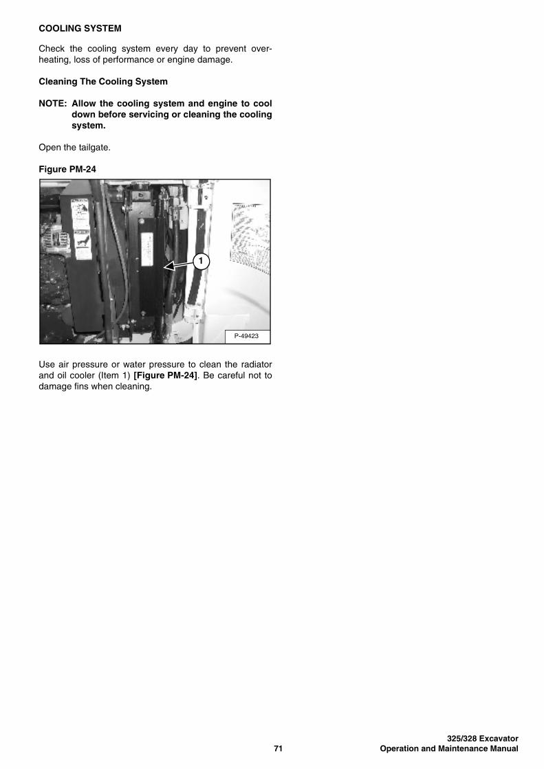
325/328 Excavator71 Operation and Maintenance Manual
COOLING SYSTEM
Check the cooling system every day to prevent over-heating, loss of performance or engine damage.
Cleaning The Cooling System
NOTE: Allow the cooling system and engine to cooldown before servicing or cleaning the coolingsystem.
Open the tailgate.
Figure PM-24
Use air pressure or water pressure to clean the radiatorand oil cooler (Item 1) [Figure PM-24]. Be careful not todamage fins when cleaning.
P-49423
1
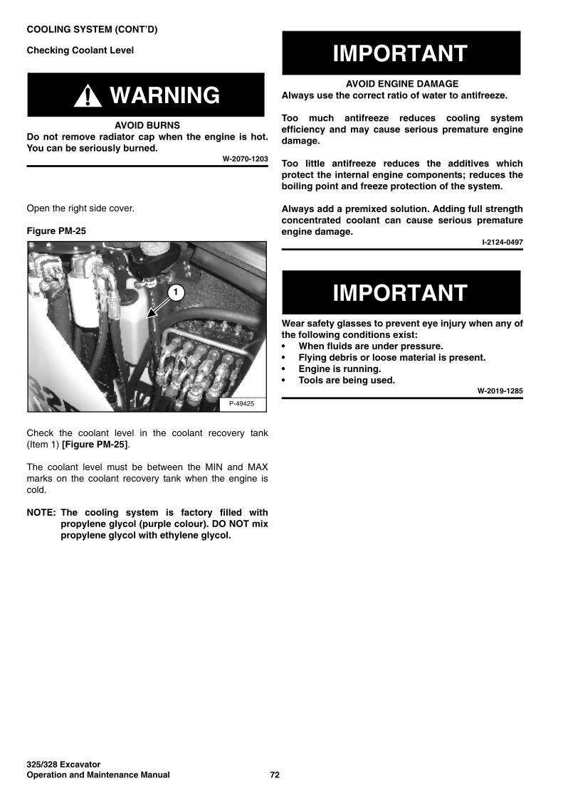
325/328 ExcavatorOperation and Maintenance Manual 72
COOLING SYSTEM (CONT’D)
Checking Coolant Level
WARNINGAVOID BURNS
Do not remove radiator cap when the engine is hot.You can be seriously burned.
W-2070-1203
Open the right side cover.
Figure PM-25
Check the coolant level in the coolant recovery tank(Item 1) [Figure PM-25].
The coolant level must be between the MIN and MAXmarks on the coolant recovery tank when the engine iscold.
NOTE: The cooling system is factory filled withpropylene glycol (purple colour). DO NOT mixpropylene glycol with ethylene glycol.
IMPORTANTAVOID ENGINE DAMAGE
Always use the correct ratio of water to antifreeze.
Too much antifreeze reduces cooling systemefficiency and may cause serious premature enginedamage.
Too little antifreeze reduces the additives whichprotect the internal engine components; reduces theboiling point and freeze protection of the system.
Always add a premixed solution. Adding full strengthconcentrated coolant can cause serious prematureengine damage.
I-2124-0497
IMPORTANTWear safety glasses to prevent eye injury when any ofthe following conditions exist:• When fluids are under pressure.• Flying debris or loose material is present.• Engine is running.• Tools are being used.
W-2019-1285
P-49425
1
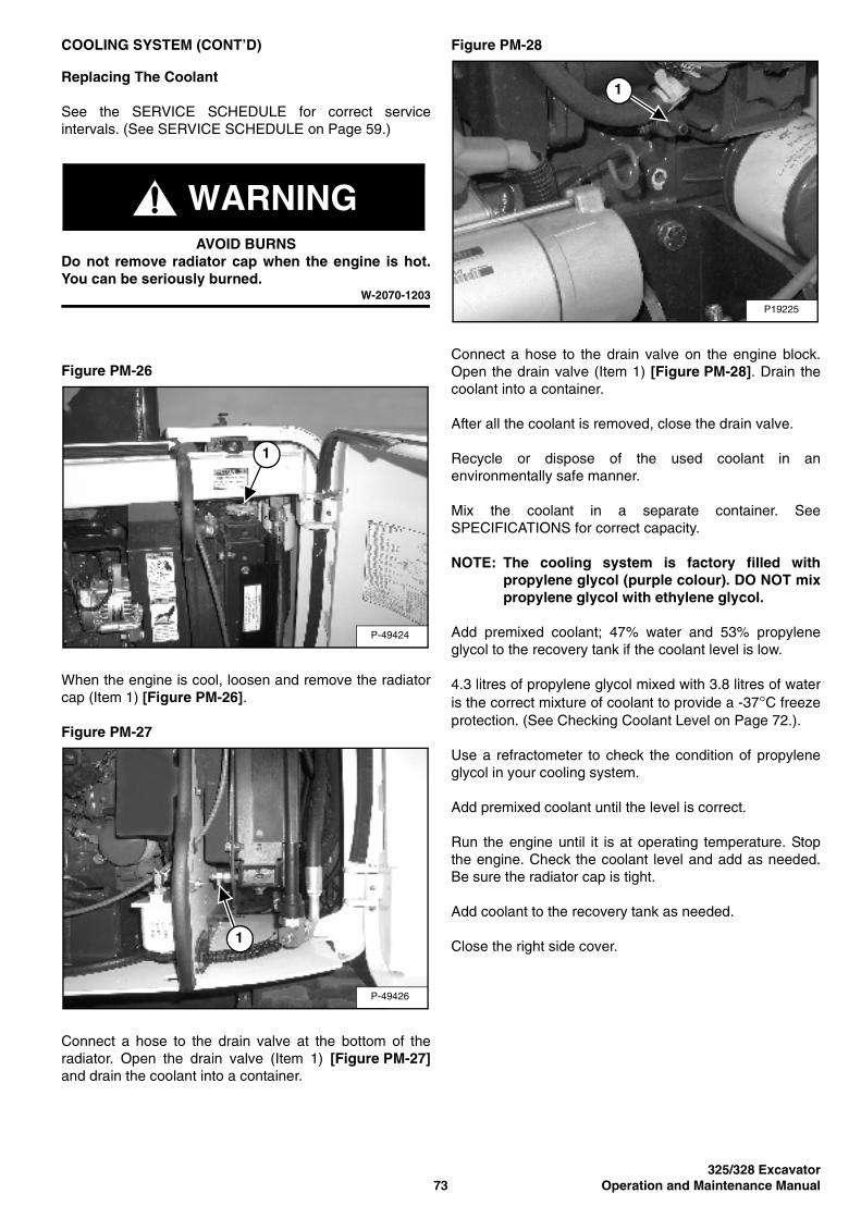
325/328 Excavator73 Operation and Maintenance Manual
COOLING SYSTEM (CONT’D)
Replacing The Coolant
See the SERVICE SCHEDULE for correct serviceintervals. (See SERVICE SCHEDULE on Page 59.)
WARNINGAVOID BURNS
Do not remove radiator cap when the engine is hot.You can be seriously burned.
W-2070-1203
Figure PM-26
When the engine is cool, loosen and remove the radiatorcap (Item 1) [Figure PM-26].
Figure PM-27
Connect a hose to the drain valve at the bottom of theradiator. Open the drain valve (Item 1) [Figure PM-27]and drain the coolant into a container.
Figure PM-28
Connect a hose to the drain valve on the engine block.Open the drain valve (Item 1) [Figure PM-28]. Drain thecoolant into a container.
After all the coolant is removed, close the drain valve.
Recycle or dispose of the used coolant in anenvironmentally safe manner.
Mix the coolant in a separate container. SeeSPECIFICATIONS for correct capacity.
NOTE: The cooling system is factory filled withpropylene glycol (purple colour). DO NOT mixpropylene glycol with ethylene glycol.
Add premixed coolant; 47% water and 53% propyleneglycol to the recovery tank if the coolant level is low.
4.3 litres of propylene glycol mixed with 3.8 litres of wateris the correct mixture of coolant to provide a -37°C freezeprotection. (See Checking Coolant Level on Page 72.).
Use a refractometer to check the condition of propyleneglycol in your cooling system.
Add premixed coolant until the level is correct.
Run the engine until it is at operating temperature. Stopthe engine. Check the coolant level and add as needed.Be sure the radiator cap is tight.
Add coolant to the recovery tank as needed.
Close the right side cover.
P-49424
1
P-49426
1
P19225
1
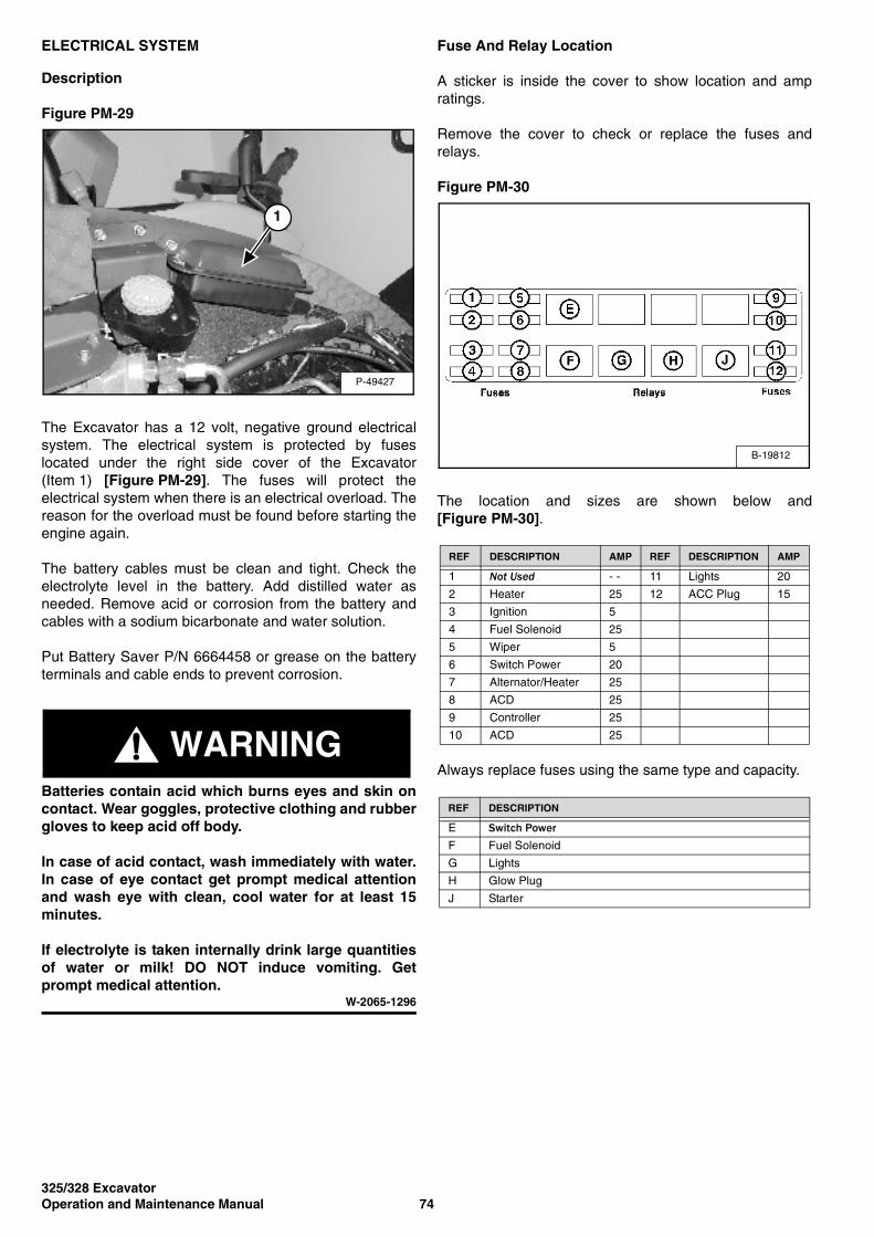
325/328 ExcavatorOperation and Maintenance Manual 74
ELECTRICAL SYSTEM
Description
Figure PM-29
The Excavator has a 12 volt, negative ground electricalsystem. The electrical system is protected by fuseslocated under the right side cover of the Excavator(Item 1) [Figure PM-29]. The fuses will protect theelectrical system when there is an electrical overload. Thereason for the overload must be found before starting theengine again.
The battery cables must be clean and tight. Check theelectrolyte level in the battery. Add distilled water asneeded. Remove acid or corrosion from the battery andcables with a sodium bicarbonate and water solution.
Put Battery Saver P/N 6664458 or grease on the batteryterminals and cable ends to prevent corrosion.
WARNINGBatteries contain acid which burns eyes and skin oncontact. Wear goggles, protective clothing and rubbergloves to keep acid off body.
In case of acid contact, wash immediately with water.In case of eye contact get prompt medical attentionand wash eye with clean, cool water for at least 15minutes.
If electrolyte is taken internally drink large quantitiesof water or milk! DO NOT induce vomiting. Getprompt medical attention.
W-2065-1296
Fuse And Relay Location
A sticker is inside the cover to show location and ampratings.
Remove the cover to check or replace the fuses andrelays.
Figure PM-30
The location and sizes are shown below and[Figure PM-30].
Always replace fuses using the same type and capacity.
P-49427
1
REF DESCRIPTION AMP REF DESCRIPTION AMP
1 Not Used - - 11 Lights 20
2 Heater 25 12 ACC Plug 15
3 Ignition 5
4 Fuel Solenoid 25
5 Wiper 5
6 Switch Power 20
7 Alternator/Heater 25
8 ACD 25
9 Controller 25
10 ACD 25
REF DESCRIPTION
E Switch PowerF Fuel Solenoid
G Lights
H Glow Plug
J Starter
B-19812
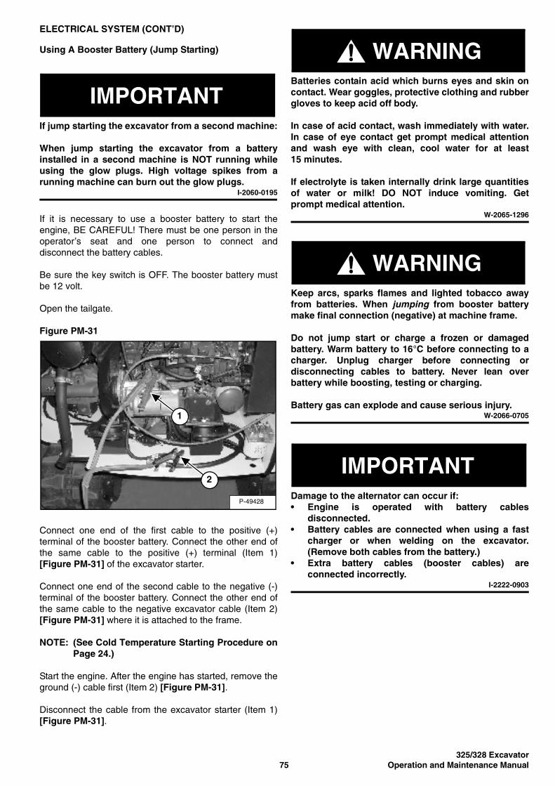
325/328 Excavator75 Operation and Maintenance Manual
ELECTRICAL SYSTEM (CONT’D)
Using A Booster Battery (Jump Starting)
IMPORTANTIf jump starting the excavator from a second machine:
When jump starting the excavator from a batteryinstalled in a second machine is NOT running whileusing the glow plugs. High voltage spikes from arunning machine can burn out the glow plugs.
I-2060-0195
If it is necessary to use a booster battery to start theengine, BE CAREFUL! There must be one person in theoperator’s seat and one person to connect anddisconnect the battery cables.
Be sure the key switch is OFF. The booster battery mustbe 12 volt.
Open the tailgate.
Figure PM-31
Connect one end of the first cable to the positive (+)terminal of the booster battery. Connect the other end ofthe same cable to the positive (+) terminal (Item 1)[Figure PM-31] of the excavator starter.
Connect one end of the second cable to the negative (-)terminal of the booster battery. Connect the other end ofthe same cable to the negative excavator cable (Item 2)[Figure PM-31] where it is attached to the frame.
NOTE: (See Cold Temperature Starting Procedure onPage 24.)
Start the engine. After the engine has started, remove theground (-) cable first (Item 2) [Figure PM-31].
Disconnect the cable from the excavator starter (Item 1)[Figure PM-31].
WARNINGBatteries contain acid which burns eyes and skin oncontact. Wear goggles, protective clothing and rubbergloves to keep acid off body.
In case of acid contact, wash immediately with water.In case of eye contact get prompt medical attentionand wash eye with clean, cool water for at least15 minutes.
If electrolyte is taken internally drink large quantitiesof water or milk! DO NOT induce vomiting. Getprompt medical attention.
W-2065-1296
WARNINGKeep arcs, sparks flames and lighted tobacco awayfrom batteries. When jumping from booster batterymake final connection (negative) at machine frame.
Do not jump start or charge a frozen or damagedbattery. Warm battery to 16°C before connecting to acharger. Unplug charger before connecting ordisconnecting cables to battery. Never lean overbattery while boosting, testing or charging.
Battery gas can explode and cause serious injury.W-2066-0705
IMPORTANTDamage to the alternator can occur if:• Engine is operated with battery cables
disconnected.• Battery cables are connected when using a fast
charger or when welding on the excavator.(Remove both cables from the battery.)
• Extra battery cables (booster cables) areconnected incorrectly.
I-2222-0903
P-49428
1
2
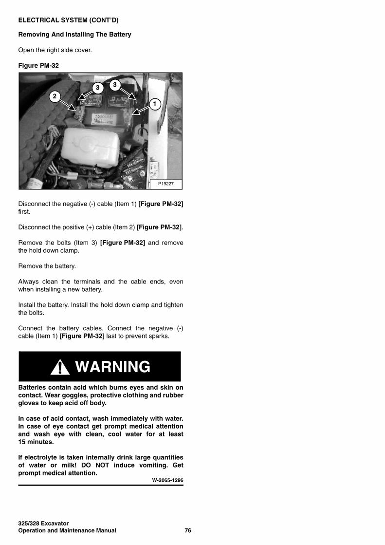
325/328 ExcavatorOperation and Maintenance Manual 76
ELECTRICAL SYSTEM (CONT’D)
Removing And Installing The Battery
Open the right side cover.
Figure PM-32
Disconnect the negative (-) cable (Item 1) [Figure PM-32]first.
Disconnect the positive (+) cable (Item 2) [Figure PM-32].
Remove the bolts (Item 3) [Figure PM-32] and removethe hold down clamp.
Remove the battery.
Always clean the terminals and the cable ends, evenwhen installing a new battery.
Install the battery. Install the hold down clamp and tightenthe bolts.
Connect the battery cables. Connect the negative (-)cable (Item 1) [Figure PM-32] last to prevent sparks.
WARNINGBatteries contain acid which burns eyes and skin oncontact. Wear goggles, protective clothing and rubbergloves to keep acid off body.
In case of acid contact, wash immediately with water.In case of eye contact get prompt medical attentionand wash eye with clean, cool water for at least15 minutes.
If electrolyte is taken internally drink large quantitiesof water or milk! DO NOT induce vomiting. Getprompt medical attention.
W-2065-1296
P19227
1
3 3
2
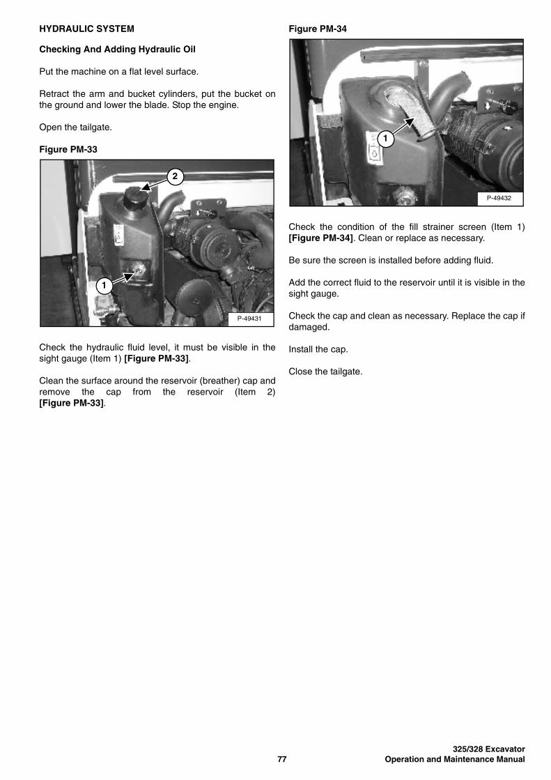
325/328 Excavator77 Operation and Maintenance Manual
HYDRAULIC SYSTEM
Checking And Adding Hydraulic Oil
Put the machine on a flat level surface.
Retract the arm and bucket cylinders, put the bucket onthe ground and lower the blade. Stop the engine.
Open the tailgate.
Figure PM-33
Check the hydraulic fluid level, it must be visible in thesight gauge (Item 1) [Figure PM-33].
Clean the surface around the reservoir (breather) cap andremove the cap from the reservoir (Item 2)[Figure PM-33].
Figure PM-34
Check the condition of the fill strainer screen (Item 1)[Figure PM-34]. Clean or replace as necessary.
Be sure the screen is installed before adding fluid.
Add the correct fluid to the reservoir until it is visible in thesight gauge.
Check the cap and clean as necessary. Replace the cap ifdamaged.
Install the cap.
Close the tailgate.
P-49431
2
1
P-49432
1
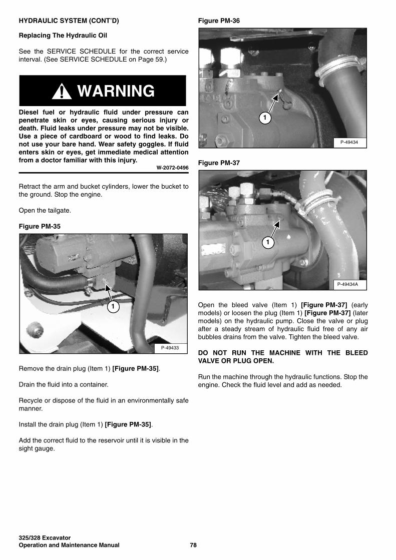
325/328 ExcavatorOperation and Maintenance Manual 78
HYDRAULIC SYSTEM (CONT’D)
Replacing The Hydraulic Oil
See the SERVICE SCHEDULE for the correct serviceinterval. (See SERVICE SCHEDULE on Page 59.)
WARNINGDiesel fuel or hydraulic fluid under pressure canpenetrate skin or eyes, causing serious injury ordeath. Fluid leaks under pressure may not be visible.Use a piece of cardboard or wood to find leaks. Donot use your bare hand. Wear safety goggles. If fluidenters skin or eyes, get immediate medical attentionfrom a doctor familiar with this injury.
W-2072-0496
Retract the arm and bucket cylinders, lower the bucket tothe ground. Stop the engine.
Open the tailgate.
Figure PM-35
Remove the drain plug (Item 1) [Figure PM-35].
Drain the fluid into a container.
Recycle or dispose of the fluid in an environmentally safemanner.
Install the drain plug (Item 1) [Figure PM-35].
Add the correct fluid to the reservoir until it is visible in thesight gauge.
Figure PM-36
Figure PM-37
Open the bleed valve (Item 1) [Figure PM-37] (earlymodels) or loosen the plug (Item 1) [Figure PM-37] (latermodels) on the hydraulic pump. Close the valve or plugafter a steady stream of hydraulic fluid free of any airbubbles drains from the valve. Tighten the bleed valve.
DO NOT RUN THE MACHINE WITH THE BLEEDVALVE OR PLUG OPEN.
Run the machine through the hydraulic functions. Stop theengine. Check the fluid level and add as needed.
P-49433
1
P-49434
1
P-49434A
1
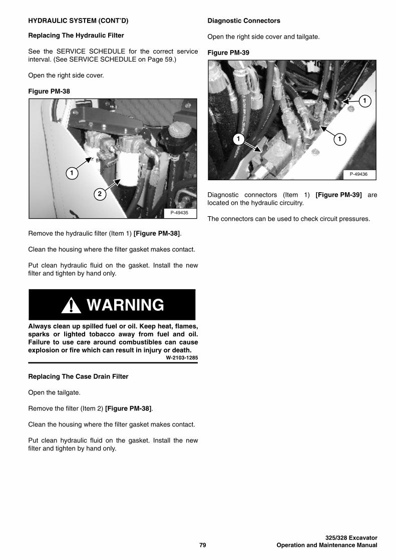
325/328 Excavator79 Operation and Maintenance Manual
HYDRAULIC SYSTEM (CONT’D)
Replacing The Hydraulic Filter
See the SERVICE SCHEDULE for the correct serviceinterval. (See SERVICE SCHEDULE on Page 59.)
Open the right side cover.
Figure PM-38
Remove the hydraulic filter (Item 1) [Figure PM-38].
Clean the housing where the filter gasket makes contact.
Put clean hydraulic fluid on the gasket. Install the newfilter and tighten by hand only.
WARNINGAlways clean up spilled fuel or oil. Keep heat, flames,sparks or lighted tobacco away from fuel and oil.Failure to use care around combustibles can causeexplosion or fire which can result in injury or death.
W-2103-1285
Replacing The Case Drain Filter
Open the tailgate.
Remove the filter (Item 2) [Figure PM-38].
Clean the housing where the filter gasket makes contact.
Put clean hydraulic fluid on the gasket. Install the newfilter and tighten by hand only.
Diagnostic Connectors
Open the right side cover and tailgate.
Figure PM-39
Diagnostic connectors (Item 1) [Figure PM-39] arelocated on the hydraulic circuitry.
The connectors can be used to check circuit pressures.P-49435
1
2
P-49436
11
1

325/328 ExcavatorOperation and Maintenance Manual 80
SPARK ARRESTER SILENCER
Cleaning Procedure
See the SERVICE SCHEDULE for the correct serviceinterval. (See SERVICE SCHEDULE on Page 59.)
Do not operate the excavator with a defective exhaustsystem.
IMPORTANTThis excavator is factory equipped with an approvedspark arrester silencer. It is necessary to domaintenance on this spark arrestor muffler to keep itin working condition. The spark arrester silencermust be serviced by dumping the spark chamberevery 100 hours of operation.
If this machine is operated on flammable forest, brushor grass covered land, it must be equipped with aspark arrester attached to the exhaust system andmaintained in working order.
Check local laws for spark arrester requirements.I-2061-0195
WARNINGWhen the engine is running during service, thesteering columns must be in neutral.
Failure to do so can cause injury or death.W-2203-0595
Stop the engine. Open the tailgate.
Figure PM-40
Remove the plug (Item 1) [Figure PM-40] from thebottom of the silencer.
Start the engine and run for about 10 seconds while asecond person, wearing safety glasses, holds a piece ofwood over the outlet of the silencer. The carbon depositswill be forced out of the silencer plug hole (Item 1)[Figure PM-40].
Stop the engine. Install and tighten the plug.
Close the tailgate.
P-49437
1

325/328 Excavator81 Operation and Maintenance Manual
TRACK TENSION
NOTE: The wear of the pins and bushings on theundercarriage vary with the workingconditions and the different types of soilconditions. It is necessary to inspect tracktension and maintain the correct tension. Seethe SERVICE SCHEDULE for the correctservice interval. (See SERVICE SCHEDULE onPage 59.)
Figure PM-41
Raise one side of the machine approximately 100 mmusing the boom and arm [Figure PM-41].
Raise the blade fully and install jackstands under theblade and track frame (Item 1) [Figure PM-41]. Lower theboom until all machine weight is on the jackstands.
Stop the engine.
WARNINGAVOID INJURY
Keep fingers and hands out of pinch points whenchecking the track tension.
W-2142-0903
Rubber Track Clearance
Figure PM-42
Figure PM-43
Measure the clearance at the middle track roller. Do notget fingers into pinch points between the track and thetrack roller. Use a bolt or a dowel of the appropriate size tocheck the gap between the contact edge of the roller andthe top edge of the track guide [Figure PM-42] and[Figure PM-43].
Rubber Track Clearance - 10-15 mm.
P-49460
1
1
P-49187
10-15 mm
B-14067
Track Frame
10-15 mm
Track
TrackRoller
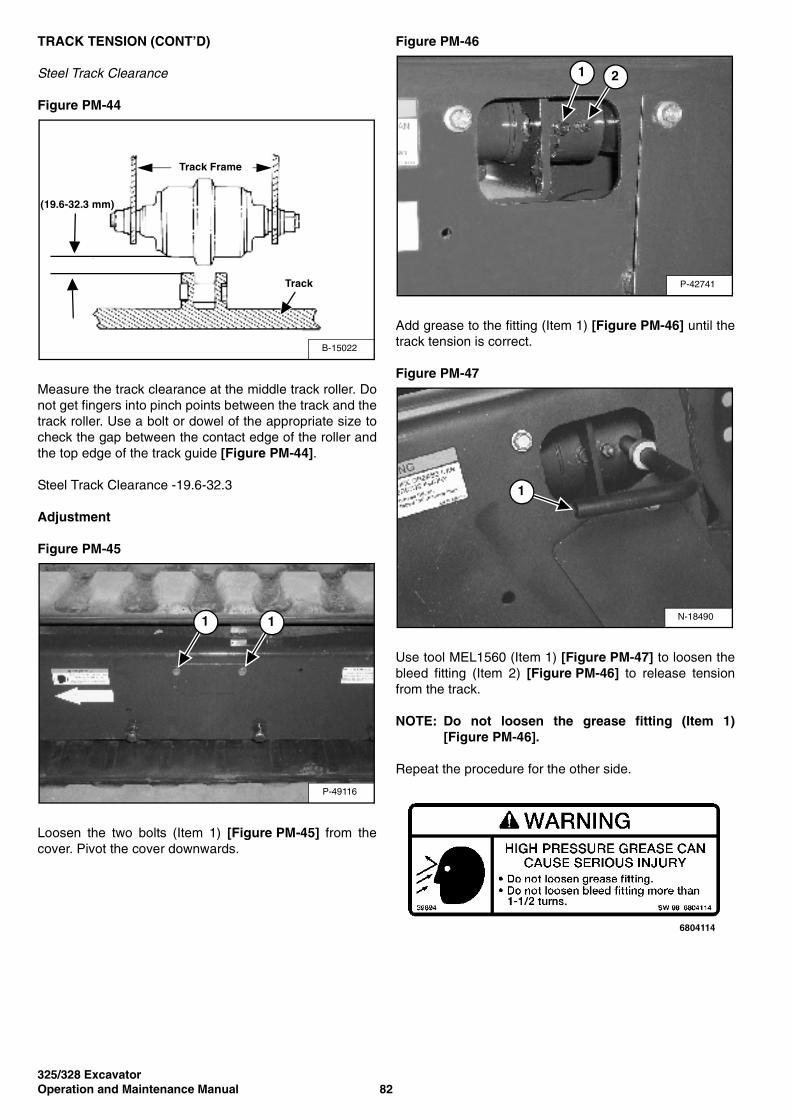
325/328 ExcavatorOperation and Maintenance Manual 82
TRACK TENSION (CONT’D)
Steel Track Clearance
Figure PM-44
Measure the track clearance at the middle track roller. Donot get fingers into pinch points between the track and thetrack roller. Use a bolt or dowel of the appropriate size tocheck the gap between the contact edge of the roller andthe top edge of the track guide [Figure PM-44].
Steel Track Clearance -19.6-32.3
Adjustment
Figure PM-45
Loosen the two bolts (Item 1) [Figure PM-45] from thecover. Pivot the cover downwards.
Figure PM-46
Add grease to the fitting (Item 1) [Figure PM-46] until thetrack tension is correct.
Figure PM-47
Use tool MEL1560 (Item 1) [Figure PM-47] to loosen thebleed fitting (Item 2) [Figure PM-46] to release tensionfrom the track.
NOTE: Do not loosen the grease fitting (Item 1)[Figure PM-46].
Repeat the procedure for the other side.
B-15022
Track Frame
(19.6-32.3 mm)
Track
P-49116
11
P-42741
21
N-18490
1
6804114

325/328 Excavator83 Operation and Maintenance Manual
ENGINE ACCESSORY DRIVE BELT
Belt Tension
Open the tailgate.
Figure PM-48
Check the belt tension (Item 1) [Figure PM-48] midwaybetween the alternator and belt tensioner. The beltdeflection should be 13 mm.
Belt Adjustment
Figure PM-49
Loosen the belt tensioner bolt (Item 1) [Figure PM-49]and move the tensioner away from the engine until thebelt tension is correct.
Tighten the bolt to 20-25 N•m torque.
P-49429
1
P-49430
1
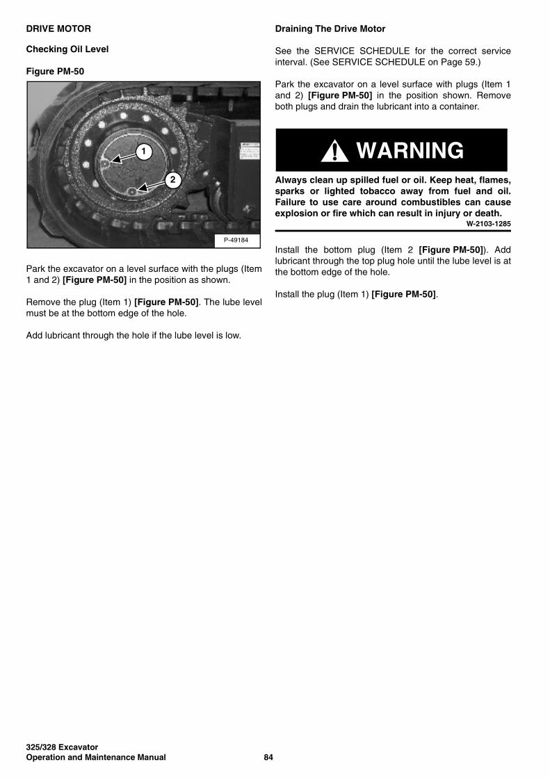
325/328 ExcavatorOperation and Maintenance Manual 84
DRIVE MOTOR
Checking Oil Level
Figure PM-50
Park the excavator on a level surface with the plugs (Item1 and 2) [Figure PM-50] in the position as shown.
Remove the plug (Item 1) [Figure PM-50]. The lube levelmust be at the bottom edge of the hole.
Add lubricant through the hole if the lube level is low.
Draining The Drive Motor
See the SERVICE SCHEDULE for the correct serviceinterval. (See SERVICE SCHEDULE on Page 59.)
Park the excavator on a level surface with plugs (Item 1and 2) [Figure PM-50] in the position shown. Removeboth plugs and drain the lubricant into a container.
WARNINGAlways clean up spilled fuel or oil. Keep heat, flames,sparks or lighted tobacco away from fuel and oil.Failure to use care around combustibles can causeexplosion or fire which can result in injury or death.
W-2103-1285
Install the bottom plug (Item 2 [Figure PM-50]). Addlubricant through the top plug hole until the lube level is atthe bottom edge of the hole.
Install the plug (Item 1) [Figure PM-50].
P-49184
1
2
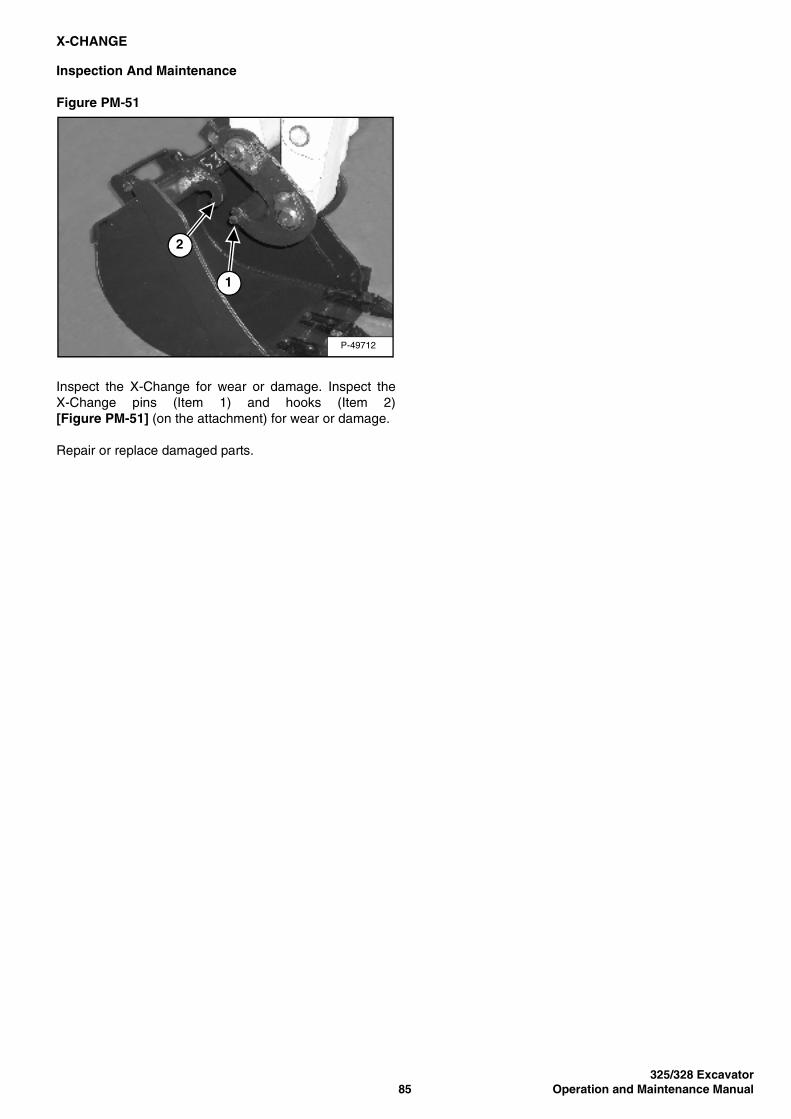
325/328 Excavator85 Operation and Maintenance Manual
X-CHANGE
Inspection And Maintenance
Figure PM-51
Inspect the X-Change for wear or damage. Inspect theX-Change pins (Item 1) and hooks (Item 2)[Figure PM-51] (on the attachment) for wear or damage.
Repair or replace damaged parts.
P-49712
2
1
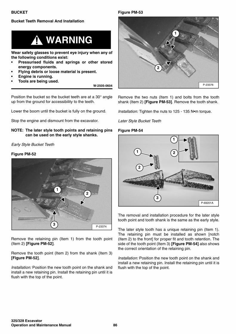
325/328 ExcavatorOperation and Maintenance Manual 86
BUCKET
Bucket Teeth Removal And Installation
WARNINGWear safety glasses to prevent eye injury when any ofthe following conditions exist:• Pressurised fluids and springs or other stored
energy components.• Flying debris or loose material is present.• Engine is running.• Tools are being used.
W-2505-0604
Position the bucket so the bucket teeth are at a 30° angleup from the ground for accessibility to the teeth.
Lower the boom until the bucket is fully on the ground.
Stop the engine and dismount from the excavator.
NOTE: The later style tooth points and retaining pinscan be used on the early style shanks.
Early Style Bucket Teeth
Figure PM-52
Remove the retaining pin (Item 1) from the tooth point(Item 2) [Figure PM-52].
Remove the tooth point (Item 2) from the shank (Item 3)[Figure PM-52].
Installation: Position the new tooth point on the shank andinstall a new retaining pin. Install the retaining pin until it isflush with the top of the point.
Figure PM-53
Remove the two nuts (Item 1) and bolts from the toothshank (Item 2) [Figure PM-53]. Remove the tooth shank.
Installation: Tighten the nuts to 125 - 135 N•m torque.
Later Style Bucket Teeth
Figure PM-54
The removal and installation procedure for the later styletooth point and tooth shank is the same as the early style.
The later style tooth has a unique retaining pin (Item 1).The retaining pin must be installed as shown [notch(Item 2) to the front] for proper fit and tooth retention. Theside of the tooth point (Item 3) [Figure PM-54] also showsthe correct orientation of the retaining pin.
Installation: Position the new tooth point on the shank andinstall a new retaining pin. Install the retaining pin until it isflush with the top of the point.
P-23374
21
3
P-23376
2
1
P-69201A
1
3
2
2
1
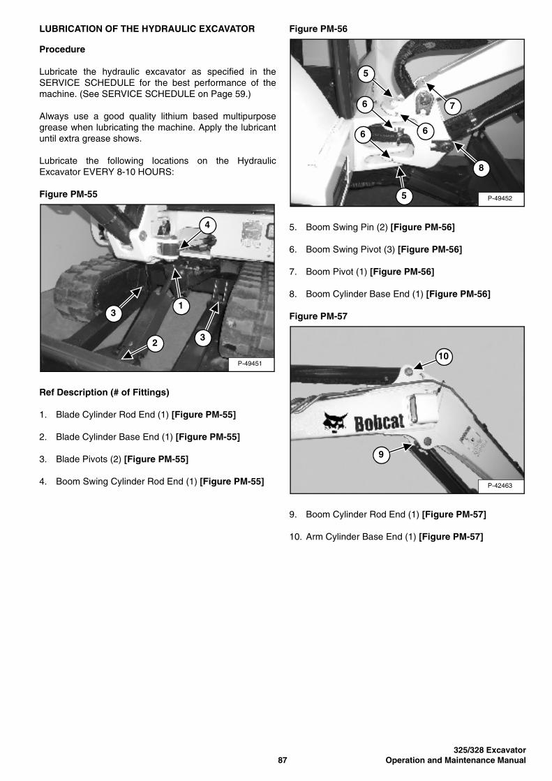
325/328 Excavator87 Operation and Maintenance Manual
LUBRICATION OF THE HYDRAULIC EXCAVATOR
Procedure
Lubricate the hydraulic excavator as specified in theSERVICE SCHEDULE for the best performance of themachine. (See SERVICE SCHEDULE on Page 59.)
Always use a good quality lithium based multipurposegrease when lubricating the machine. Apply the lubricantuntil extra grease shows.
Lubricate the following locations on the HydraulicExcavator EVERY 8-10 HOURS:
Figure PM-55
Ref Description (# of Fittings)
1. Blade Cylinder Rod End (1) [Figure PM-55]
2. Blade Cylinder Base End (1) [Figure PM-55]
3. Blade Pivots (2) [Figure PM-55]
4. Boom Swing Cylinder Rod End (1) [Figure PM-55]
Figure PM-56
5. Boom Swing Pin (2) [Figure PM-56]
6. Boom Swing Pivot (3) [Figure PM-56]
7. Boom Pivot (1) [Figure PM-56]
8. Boom Cylinder Base End (1) [Figure PM-56]
Figure PM-57
9. Boom Cylinder Rod End (1) [Figure PM-57]
10. Arm Cylinder Base End (1) [Figure PM-57]
P-49451
4
1
32
3
P-49452
7
8
5
6
6
5
6
P-42463
10
9

325/328 ExcavatorOperation and Maintenance Manual 88
LUBRICATION OF THE HYDRAULIC EXCAVATOR (CONT’D)
Figure PM-58
11. Arm Cylinder Rod End (1) [Figure PM-58]
12. Arm Pivot (1) [Figure PM-58]
13. Bucket Cylinder Base End (1) [Figure PM-58]
Figure PM-59
14. Bucket Cylinder Rod End (1) [Figure PM-59]
15. Bucket Link Pin (1) [Figure PM-59]
16. Bucket Pivot (1) [Figure PM-59]
17. Bucket Link (2) [Figure PM-59]
Figure PM-60
18. X-Change Latch (1) [Figure PM-60]
19. X-Change Pivot Pin (2) [Figure PM-60]
Figure PM-61
20. Boom Swing Cylinder Base End (1) [Figure PM-61]
Lubricate the following locations on the hydraulicexcavator EVERY 50 HOURS:
21. Slew Circle (1) [Figure PM-61]
22. Swing Pinion (1) [Figure PM-61]. (Install 3 to 4 pumpsof grease then rotate the upperstructure 90°. Install 3to 4 pumps of grease and again rotate theupperstructure 90°. Repeat this until the slew pinionhas been greased at four positions.)
P-49453
11
13
12
P19384
14
15
16
17
P-19385
1819
19
P-49454
2221
20
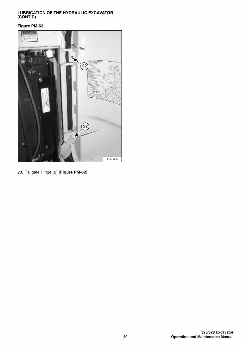
325/328 Excavator89 Operation and Maintenance Manual
LUBRICATION OF THE HYDRAULIC EXCAVATOR (CONT’D)
Figure PM-62
23. Tailgate Hinge (2) [Figure PM-62]
P-49455
22
22

325/328 ExcavatorOperation and Maintenance Manual 90

325/328 Excavator91 Operation and Maintenance Manual
SYSTEM SETUP AND ANALYSIS
DELUXE INSTRUMENT PANEL SETUP . . . . . . . . . . . . . . . . . . . . .94Changing The Operator Password . . . . . . . . . . . . . . . . . . . . . . .94Job Clock. . . . . . . . . . . . . . . . . . . . . . . . . . . . . . . . . . . . . . . . . . .95Password Entry (For Starting and Operating the Machine). . . . .94Password Lockout Feature . . . . . . . . . . . . . . . . . . . . . . . . . . . . .95Passwords. . . . . . . . . . . . . . . . . . . . . . . . . . . . . . . . . . . . . . . . . .94RPM . . . . . . . . . . . . . . . . . . . . . . . . . . . . . . . . . . . . . . . . . . . . . .95
DIAGNOSTICS SERVICE CODE. . . . . . . . . . . . . . . . . . . . . . . . . . . 93Number Codes List . . . . . . . . . . . . . . . . . . . . . . . . . . . . . . . . . . .93
AND ANALYSISSYSTEM SETUP

325/328 ExcavatorOperation and Maintenance Manual 92
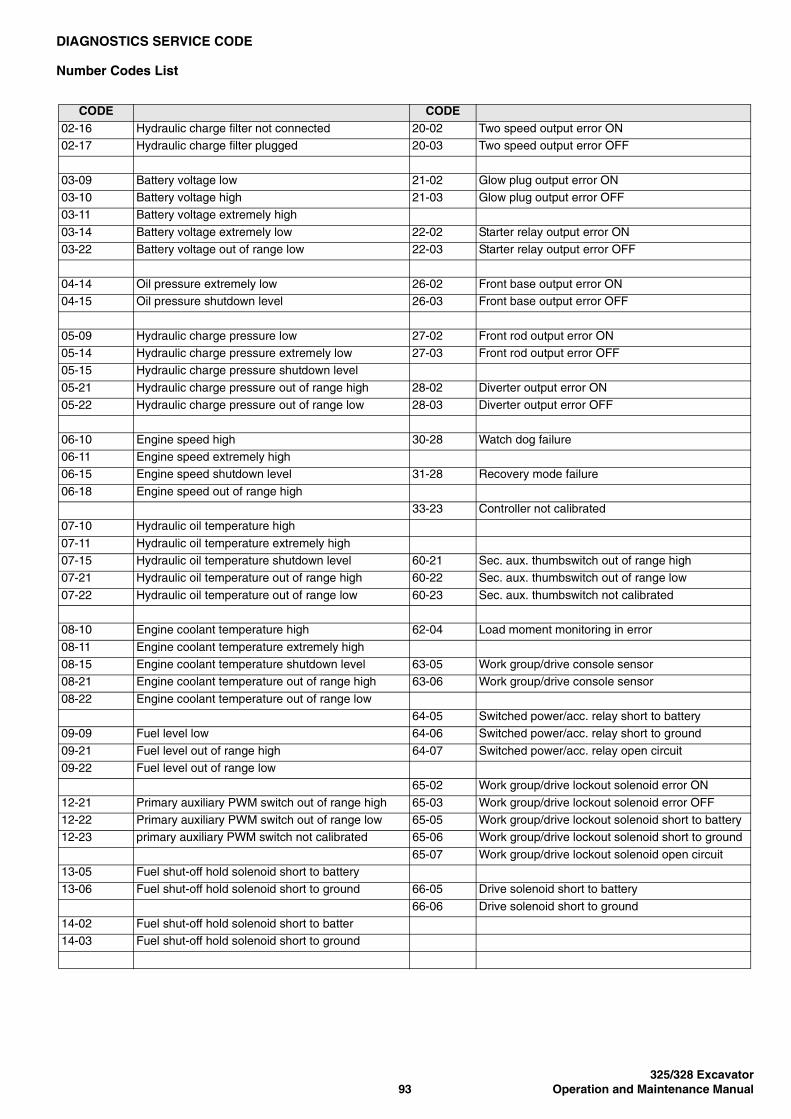
325/328 Excavator93 Operation and Maintenance Manual
DIAGNOSTICS SERVICE CODE
Number Codes List
CODE CODE02-16 Hydraulic charge filter not connected 20-02 Two speed output error ON02-17 Hydraulic charge filter plugged 20-03 Two speed output error OFF
03-09 Battery voltage low 21-02 Glow plug output error ON03-10 Battery voltage high 21-03 Glow plug output error OFF03-11 Battery voltage extremely high
03-14 Battery voltage extremely low 22-02 Starter relay output error ON03-22 Battery voltage out of range low 22-03 Starter relay output error OFF
04-14 Oil pressure extremely low 26-02 Front base output error ON04-15 Oil pressure shutdown level 26-03 Front base output error OFF
05-09 Hydraulic charge pressure low 27-02 Front rod output error ON05-14 Hydraulic charge pressure extremely low 27-03 Front rod output error OFF05-15 Hydraulic charge pressure shutdown level
05-21 Hydraulic charge pressure out of range high 28-02 Diverter output error ON05-22 Hydraulic charge pressure out of range low 28-03 Diverter output error OFF
06-10 Engine speed high 30-28 Watch dog failure06-11 Engine speed extremely high06-15 Engine speed shutdown level 31-28 Recovery mode failure
06-18 Engine speed out of range high33-23 Controller not calibrated
07-10 Hydraulic oil temperature high
07-11 Hydraulic oil temperature extremely high07-15 Hydraulic oil temperature shutdown level 60-21 Sec. aux. thumbswitch out of range high07-21 Hydraulic oil temperature out of range high 60-22 Sec. aux. thumbswitch out of range low
07-22 Hydraulic oil temperature out of range low 60-23 Sec. aux. thumbswitch not calibrated
08-10 Engine coolant temperature high 62-04 Load moment monitoring in error
08-11 Engine coolant temperature extremely high08-15 Engine coolant temperature shutdown level 63-05 Work group/drive console sensor08-21 Engine coolant temperature out of range high 63-06 Work group/drive console sensor
08-22 Engine coolant temperature out of range low64-05 Switched power/acc. relay short to battery
09-09 Fuel level low 64-06 Switched power/acc. relay short to ground
09-21 Fuel level out of range high 64-07 Switched power/acc. relay open circuit09-22 Fuel level out of range low
65-02 Work group/drive lockout solenoid error ON
12-21 Primary auxiliary PWM switch out of range high 65-03 Work group/drive lockout solenoid error OFF12-22 Primary auxiliary PWM switch out of range low 65-05 Work group/drive lockout solenoid short to battery12-23 primary auxiliary PWM switch not calibrated 65-06 Work group/drive lockout solenoid short to ground
65-07 Work group/drive lockout solenoid open circuit13-05 Fuel shut-off hold solenoid short to battery13-06 Fuel shut-off hold solenoid short to ground 66-05 Drive solenoid short to battery
66-06 Drive solenoid short to ground14-02 Fuel shut-off hold solenoid short to batter14-03 Fuel shut-off hold solenoid short to ground

325/328 ExcavatorOperation and Maintenance Manual 94
DELUXE INSTRUMENT PANEL SETUP
Passwords
All new machines with Deluxe Instrumentation arrive atBobcat dealerships with the panel in locked mode. Thismeans that a password must be used to start the engine.
For security purposes, your dealer may change thepassword and also set it in the locked mode. Yourdealer will provide you with the password.
Master Password:A permanent, randomly selected password is set atthe factory which cannot be changed. This passwordis used for service by the Bobcat dealer if the OwnerPassword is not known; or to change the OwnerPassword.
Owner Password:There is only one Owner Password (CodE 0). It mustbe used to change the owner or operator passwords.See below for changing the Owner Password.
Operator Password:There can be up to three operator Passwords(CodE 1, CodE 2, CodE 3). See below for changingthe Operator Password.
Password Entry (For Starting and Operating the Machine)
Press ENTER CODE button (Item 1). The panel will lightup and there will be two short beeps. CodE will appear onthe LCD (Item 2) [Figure SA-1].
NOTE: After you press ENTER CODE you have 40seconds to use the keypad (Item 3)[Figure SA-1] to enter the password. (If morethan 40 seconds is used, the process will abortand you will need to start over.
Enter the password. For each digit that you enter, a dashwill appear on the LCD. If the password was enteredcorrectly, there will be one long beep.
NOTE: If the password was incorrect there will bethree short beeps and Error will appear on theLCD. Press the ENTER CODE button again andstart over. After three failed attempts, youmust wait three minutes to try again.
You are now ready to start and operate the machine.
If you will be changing the operator password, do not startthe engine. (See Changing The Operator Password onPage 94.)
Figure SA-1
Changing The Operator Password
Perform Password Entry at left, but do not start theengine.
Press and hold the ENTER CODE button (Item 1) forthree seconds. CodE 1 will appear on the LCD (Item 2)[Figure SA-1].
Press the ENTER CODE button until the desired operatorCode (CodE 1, CodE 2, CodE 3) appears. You now have40 seconds to use the keypad (Item 3) [Figure SA-1] toenter each digit of a new four-digit password.
Enter the new four-digit password. After the fourth digit isentered, there will be two short beeps and rPEAt willappear.
Re-enter the new four-digit password to verify. If the newpasswords match, there will be two short beeps, Code willappear for 1 second and then the LCD will return toHOURMETER function.
NOTE: If the new passwords do not match, there willbe one long beep and Error will appear for1 second and then the LCD will return toHOURMETER function.
21
3
B-15819
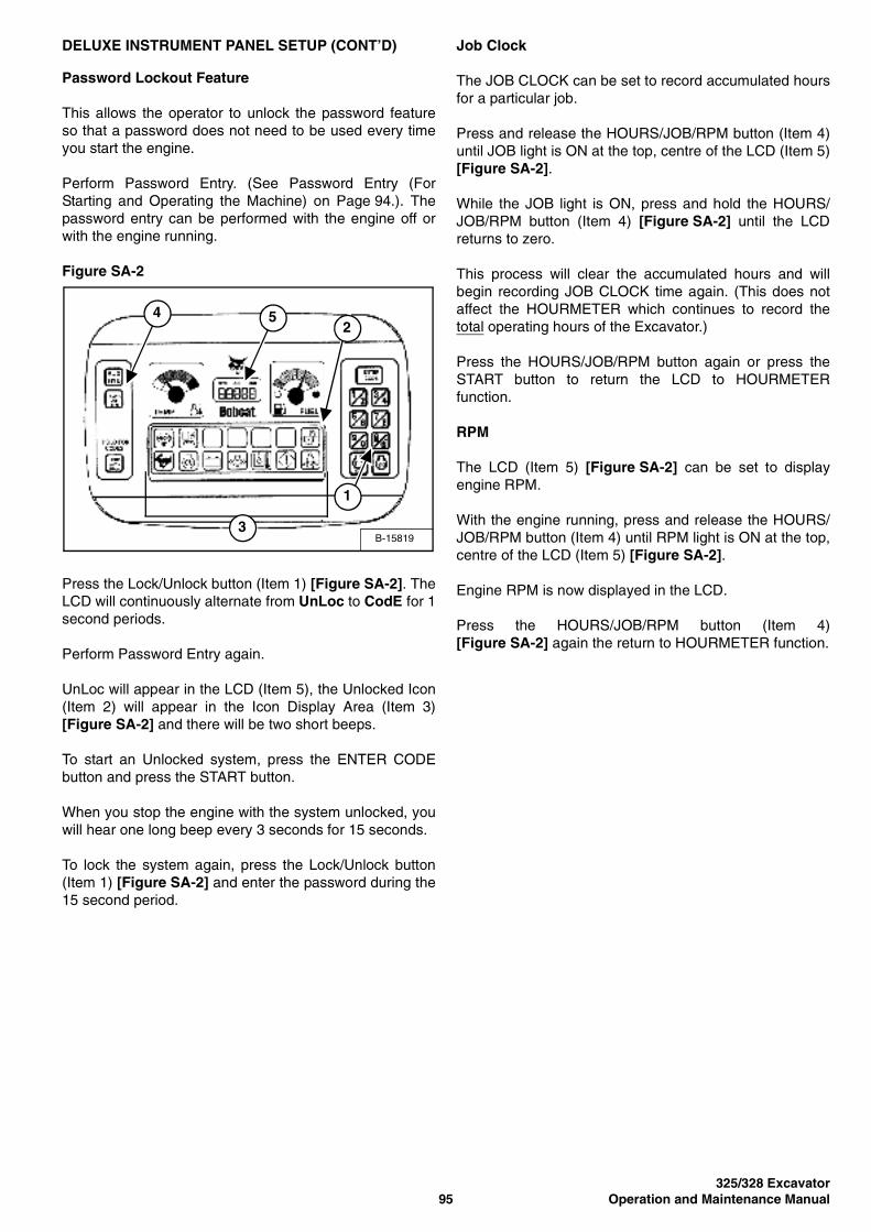
325/328 Excavator95 Operation and Maintenance Manual
DELUXE INSTRUMENT PANEL SETUP (CONT’D)
Password Lockout Feature
This allows the operator to unlock the password featureso that a password does not need to be used every timeyou start the engine.
Perform Password Entry. (See Password Entry (ForStarting and Operating the Machine) on Page 94.). Thepassword entry can be performed with the engine off orwith the engine running.
Figure SA-2
Press the Lock/Unlock button (Item 1) [Figure SA-2]. TheLCD will continuously alternate from UnLoc to CodE for 1second periods.
Perform Password Entry again.
UnLoc will appear in the LCD (Item 5), the Unlocked Icon(Item 2) will appear in the Icon Display Area (Item 3)[Figure SA-2] and there will be two short beeps.
To start an Unlocked system, press the ENTER CODEbutton and press the START button.
When you stop the engine with the system unlocked, youwill hear one long beep every 3 seconds for 15 seconds.
To lock the system again, press the Lock/Unlock button(Item 1) [Figure SA-2] and enter the password during the15 second period.
Job Clock
The JOB CLOCK can be set to record accumulated hoursfor a particular job.
Press and release the HOURS/JOB/RPM button (Item 4)until JOB light is ON at the top, centre of the LCD (Item 5)[Figure SA-2].
While the JOB light is ON, press and hold the HOURS/JOB/RPM button (Item 4) [Figure SA-2] until the LCDreturns to zero.
This process will clear the accumulated hours and willbegin recording JOB CLOCK time again. (This does notaffect the HOURMETER which continues to record thetotal operating hours of the Excavator.)
Press the HOURS/JOB/RPM button again or press theSTART button to return the LCD to HOURMETERfunction.
RPM
The LCD (Item 5) [Figure SA-2] can be set to displayengine RPM.
With the engine running, press and release the HOURS/JOB/RPM button (Item 4) until RPM light is ON at the top,centre of the LCD (Item 5) [Figure SA-2].
Engine RPM is now displayed in the LCD.
Press the HOURS/JOB/RPM button (Item 4)[Figure SA-2] again the return to HOURMETER function.
B-15819
42
1
3
5

325/328 ExcavatorOperation and Maintenance Manual 96
325/328 Excavator97 Operation and Maintenance Manual
SPECIFICATIONS
325 EXCAVATOR: 2341 11001 - 2341 99999 . . . . . . . . . . . . . . . . . . 99Dimensions . . . . . . . . . . . . . . . . . . . . . . . . . . . . . . . . . . . . . . . . . . 99Working Range . . . . . . . . . . . . . . . . . . . . . . . . . . . . . . . . . . . . . . 100Lift Capacity . . . . . . . . . . . . . . . . . . . . . . . . . . . . . . . . . . . . . . . . 101Performance . . . . . . . . . . . . . . . . . . . . . . . . . . . . . . . . . . . . . . . . 102Function Time . . . . . . . . . . . . . . . . . . . . . . . . . . . . . . . . . . . . . . . 102Weights . . . . . . . . . . . . . . . . . . . . . . . . . . . . . . . . . . . . . . . . . . . 102Controls . . . . . . . . . . . . . . . . . . . . . . . . . . . . . . . . . . . . . . . . . . . 102Engine . . . . . . . . . . . . . . . . . . . . . . . . . . . . . . . . . . . . . . . . . . . . 103Electrical . . . . . . . . . . . . . . . . . . . . . . . . . . . . . . . . . . . . . . . . . . . 103Hydraulic System . . . . . . . . . . . . . . . . . . . . . . . . . . . . . . . . . . . . 103Hydraulic Cylinders . . . . . . . . . . . . . . . . . . . . . . . . . . . . . . . . . . 104Drive System . . . . . . . . . . . . . . . . . . . . . . . . . . . . . . . . . . . . . . . 104Traction . . . . . . . . . . . . . . . . . . . . . . . . . . . . . . . . . . . . . . . . . . . 104Instrumentation . . . . . . . . . . . . . . . . . . . . . . . . . . . . . . . . . . . . . . 105Fluid Capacities . . . . . . . . . . . . . . . . . . . . . . . . . . . . . . . . . . . . . 105Fluid Specifications . . . . . . . . . . . . . . . . . . . . . . . . . . . . . . . . . . . 105Environmental . . . . . . . . . . . . . . . . . . . . . . . . . . . . . . . . . . . . . . 106Standard Features . . . . . . . . . . . . . . . . . . . . . . . . . . . . . . . . . . . 106Options . . . . . . . . . . . . . . . . . . . . . . . . . . . . . . . . . . . . . . . . . . . . 106Attachments . . . . . . . . . . . . . . . . . . . . . . . . . . . . . . . . . . . . . . . . 106
328 EXCAVATOR: 2342 11001 - 2342 99999 . . . . . . . . . . . . . . . . . 107Dimensions . . . . . . . . . . . . . . . . . . . . . . . . . . . . . . . . . . . . . . . . . 107Working Range . . . . . . . . . . . . . . . . . . . . . . . . . . . . . . . . . . . . . . 108Lift Capacity . . . . . . . . . . . . . . . . . . . . . . . . . . . . . . . . . . . . . . . . 109Performance . . . . . . . . . . . . . . . . . . . . . . . . . . . . . . . . . . . . . . . . 110Function Time . . . . . . . . . . . . . . . . . . . . . . . . . . . . . . . . . . . . . . . 110Weights . . . . . . . . . . . . . . . . . . . . . . . . . . . . . . . . . . . . . . . . . . . 110Controls . . . . . . . . . . . . . . . . . . . . . . . . . . . . . . . . . . . . . . . . . . . 110Engine . . . . . . . . . . . . . . . . . . . . . . . . . . . . . . . . . . . . . . . . . . . . 111Electrical . . . . . . . . . . . . . . . . . . . . . . . . . . . . . . . . . . . . . . . . . . . 111Hydraulic System . . . . . . . . . . . . . . . . . . . . . . . . . . . . . . . . . . . . 111Hydraulic Cylinders . . . . . . . . . . . . . . . . . . . . . . . . . . . . . . . . . . 112Drive System . . . . . . . . . . . . . . . . . . . . . . . . . . . . . . . . . . . . . . . 112Traction . . . . . . . . . . . . . . . . . . . . . . . . . . . . . . . . . . . . . . . . . . . 112Instrumentation . . . . . . . . . . . . . . . . . . . . . . . . . . . . . . . . . . . . . . 113Fluid Capacities . . . . . . . . . . . . . . . . . . . . . . . . . . . . . . . . . . . . . 113Fluid Specifications . . . . . . . . . . . . . . . . . . . . . . . . . . . . . . . . . . . 113Environmental . . . . . . . . . . . . . . . . . . . . . . . . . . . . . . . . . . . . . . 114Standard Features . . . . . . . . . . . . . . . . . . . . . . . . . . . . . . . . . . . 114Options . . . . . . . . . . . . . . . . . . . . . . . . . . . . . . . . . . . . . . . . . . . . 114Attachments . . . . . . . . . . . . . . . . . . . . . . . . . . . . . . . . . . . . . . . . 114
SPECIFICATIONS

325/328 ExcavatorOperation and Maintenance Manual 98
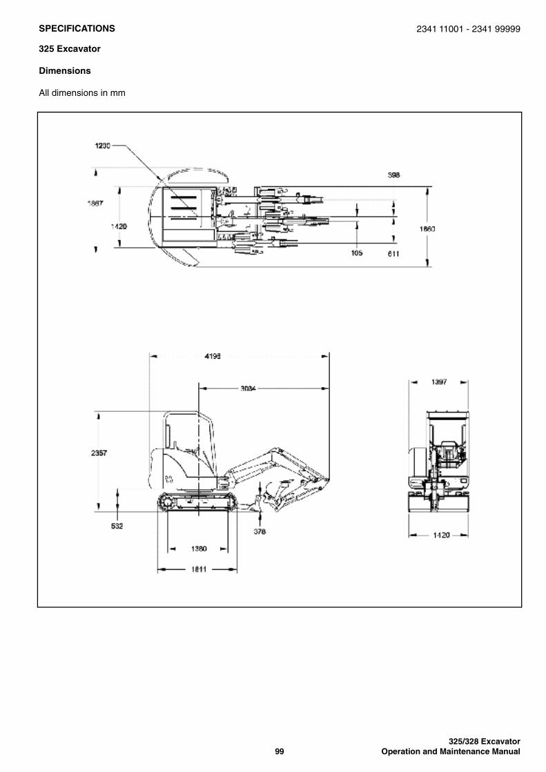
325/328 Excavator99 Operation and Maintenance Manual
SPECIFICATIONS
325 Excavator
Dimensions
All dimensions in mm
2341 11001 - 2341 99999
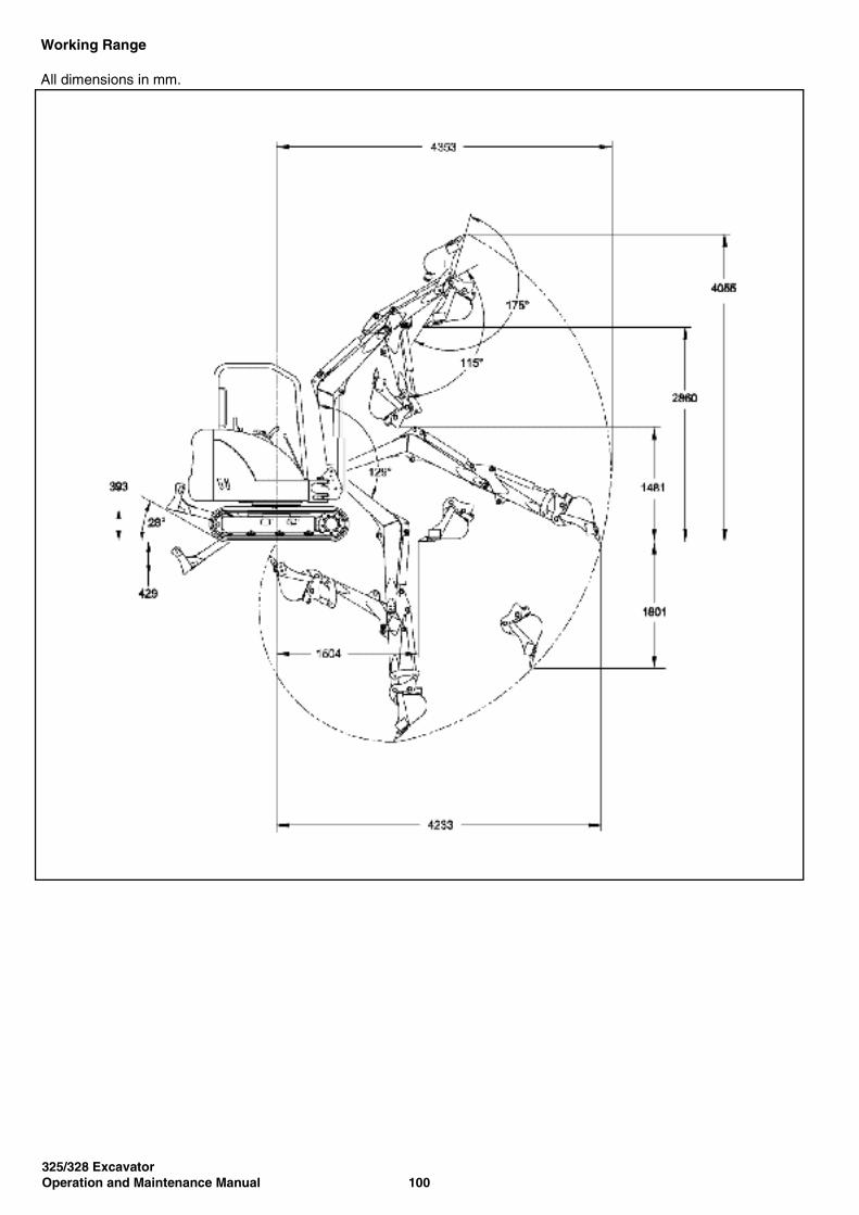
325/328 ExcavatorOperation and Maintenance Manual 100
Working Range
All dimensions in mm.
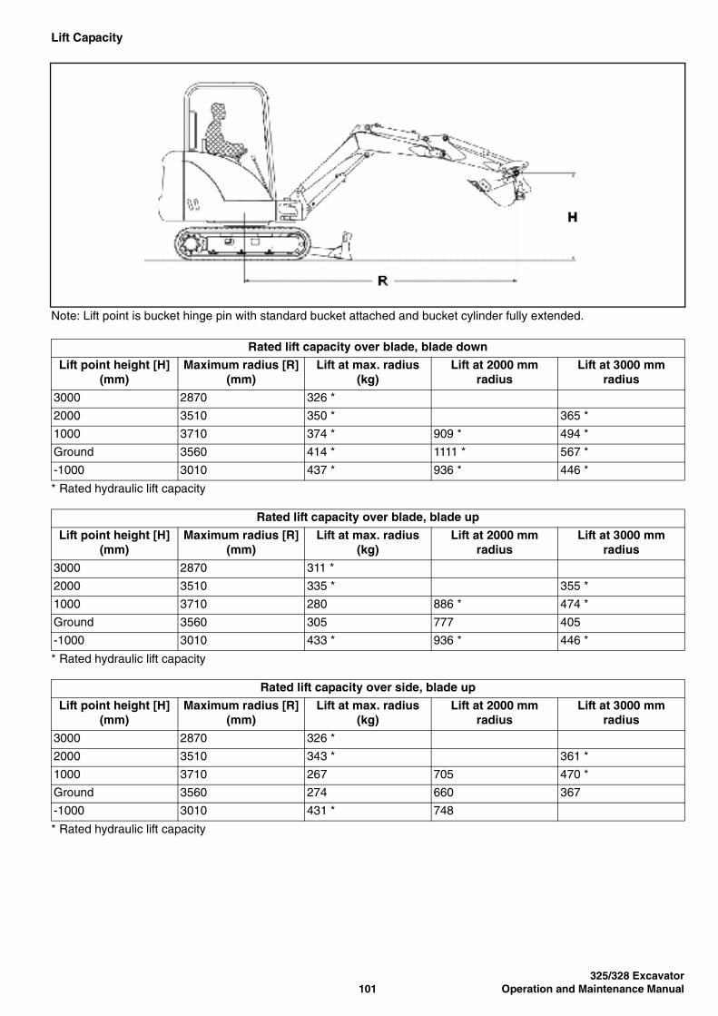
325/328 Excavator101 Operation and Maintenance Manual
Lift Capacity
Note: Lift point is bucket hinge pin with standard bucket attached and bucket cylinder fully extended.
* Rated hydraulic lift capacity
* Rated hydraulic lift capacity
* Rated hydraulic lift capacity
Rated lift capacity over blade, blade down
Lift point height [H] (mm)
Maximum radius [R] (mm)
Lift at max. radius (kg)
Lift at 2000 mm radius
Lift at 3000 mm radius
3000 2870 326 *
2000 3510 350 * 365 *
1000 3710 374 * 909 * 494 *
Ground 3560 414 * 1111 * 567 *
-1000 3010 437 * 936 * 446 *
Rated lift capacity over blade, blade up
Lift point height [H] (mm)
Maximum radius [R] (mm)
Lift at max. radius (kg)
Lift at 2000 mm radius
Lift at 3000 mm radius
3000 2870 311 *
2000 3510 335 * 355 *
1000 3710 280 886 * 474 *
Ground 3560 305 777 405
-1000 3010 433 * 936 * 446 *
Rated lift capacity over side, blade up
Lift point height [H] (mm)
Maximum radius [R] (mm)
Lift at max. radius (kg)
Lift at 2000 mm radius
Lift at 3000 mm radius
3000 2870 326 *
2000 3510 343 * 361 *
1000 3710 267 705 470 *
Ground 3560 274 660 367
-1000 3010 431 * 748

325/328 ExcavatorOperation and Maintenance Manual 102
Performance
Function Time
Weights
Controls
Digging force, dipperstick (ISO 6015) 12544 N
Digging force, bucket (ISO 6015) 21200 N
Drawbar pull (theoretical at 90% efficiency) 24376 N
Ground pressure with ROPS canopy and rubber tracks
28.4 kPa
Ground pressure with ROPS cab and rubber tracks
29.1 kPa
Ground pressure with steel tracks 29.1 kPa
Boom raise time 3.4 s
Boom lower time 4.5 s
Bucket curl time 2.0 s
Bucket dump time 1.5 s
Dipperstick retract time 3.0 s
Dipperstick extend time 2.2 s
Boom swing left time 4.9 s
Boom swing right time 4.4 s
Blade raise time 2.4 s
Blade lower time 2.4 s
Slew rate 9.2 RPM
Operating weight with ROPS canopy, rubber tracks, 508 mm bucket
2788 kg
Additional weight for cab with heater 119 kg
Additional weight for steel tracks 66 kg
Reduction for shipping weight 82 kg
Engine Hand lever on right-hand side
Starting Key-type starter switch and shutdown
Blade Right hand lever
Boom swing Right foot pedal
Hydraulics Two joysticks control boom, bucket, dipperstick and upper structure slew
Auxiliary hydraulics Electric switch in right joystick
Upper structure slew brake Hydraulic lock on motor
Holding brake for upper structure slew Pin lock
Steering Direction and speed controlled by two hand levers or foot pedals
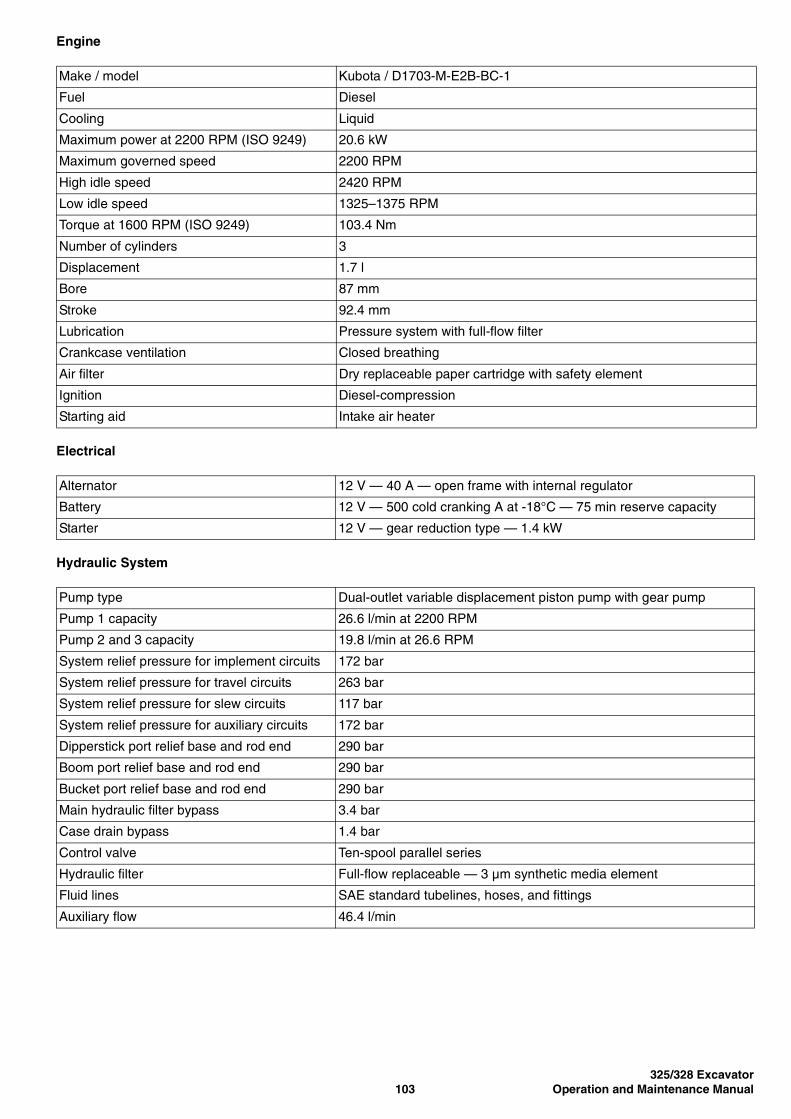
325/328 Excavator103 Operation and Maintenance Manual
Engine
Electrical
Hydraulic System
Make / model Kubota / D1703-M-E2B-BC-1
Fuel Diesel
Cooling Liquid
Maximum power at 2200 RPM (ISO 9249) 20.6 kW
Maximum governed speed 2200 RPM
High idle speed 2420 RPM
Low idle speed 1325–1375 RPM
Torque at 1600 RPM (ISO 9249) 103.4 Nm
Number of cylinders 3
Displacement 1.7 l
Bore 87 mm
Stroke 92.4 mm
Lubrication Pressure system with full-flow filter
Crankcase ventilation Closed breathing
Air filter Dry replaceable paper cartridge with safety element
Ignition Diesel-compression
Starting aid Intake air heater
Alternator 12 V — 40 A — open frame with internal regulator
Battery 12 V — 500 cold cranking A at -18°C — 75 min reserve capacity
Starter 12 V — gear reduction type — 1.4 kW
Pump type Dual-outlet variable displacement piston pump with gear pump
Pump 1 capacity 26.6 l/min at 2200 RPM
Pump 2 and 3 capacity 19.8 l/min at 26.6 RPM
System relief pressure for implement circuits 172 bar
System relief pressure for travel circuits 263 bar
System relief pressure for slew circuits 117 bar
System relief pressure for auxiliary circuits 172 bar
Dipperstick port relief base and rod end 290 bar
Boom port relief base and rod end 290 bar
Bucket port relief base and rod end 290 bar
Main hydraulic filter bypass 3.4 bar
Case drain bypass 1.4 bar
Control valve Ten-spool parallel series
Hydraulic filter Full-flow replaceable — 3 µm synthetic media element
Fluid lines SAE standard tubelines, hoses, and fittings
Auxiliary flow 46.4 l/min

325/328 ExcavatorOperation and Maintenance Manual 104
Hydraulic Cylinders
Drive System
Traction
Boom cylinder Cushion up
Boom cylinder bore 76 mm
Boom cylinder rod 41 mm
Boom cylinder stroke 424 mm
Dipperstick cylinder Cushion extend
Dipperstick cylinder bore 76 mm
Dipperstick cylinder rod 38 mm
Dipperstick cylinder stroke 485 mm
Bucket cylinder No cushion
Bucket cylinder bore 64 mm
Bucket cylinder rod 35 mm
Bucket cylinder stroke 466 mm
Boom swing cylinder Cushion left and right
Boom swing cylinder bore 60 mm
Boom swing cylinder rod 35 mm
Boom swing cylinder stroke 400 mm
Blade cylinder No cushion
Blade cylinder bore 70 mm
Blade cylinder rod 38 mm
Blade cylinder stroke 195 mm
Travel motor Each track is driven by a hydrostatic axial piston motor
Drive reduction Two-stage planetary gear reduction 44.3:1
Track width, rubber, standard 320 mm
Track width, steel, optional 300 mm
Track adjusters Grease type with shock absorbing recoil springs
Track type, standard Half-pitch, rubber
Track type, optional Steel
Travel speed, low range 1.9 km/h
Travel speed, high range 3.1 km/h
Undercarriage Crawler-type tractor design with reinforced box-section track roller frame and sealed track rollers
Number of track rollers per side 3
Gradeability 30°

325/328 Excavator105 Operation and Maintenance Manual
Instrumentation
Fluid Capacities
Fluid Specifications
• Hour meter• Job clock• Tachometer• Fuel gauge• Low fuel indicator• Engine temperature gauge• Air intake heater indicator• Console indicator• Auxiliary mode indicator• Two-speed range indicator• Engine/hydraulic service warning indicator
Cooling system 5.2 l
Engine lubrication plus oil filter 5.4 l
Fuel reservoir 53.3 l
Hydraulic reservoir 18.2 l
Hydraulic system with bucket and dipper cylinder retracted, bucket on the ground, and blade down
36.0 l
Travel motor (each) 0.5 l
Engine coolant Polypropylene glycol/water mix (53% – 47%) with freeze protection to -37°C
Engine oil Oil must meet API Service Classification of CD, CE, CF4, CG4, or better.Recommended SAE viscosity number for anticipated temperature range.
* Can by used only when available with appropriate diesel rating.For synthetic oil use the recommendation from the oil manufacturer.
Hydraulic fluid Bobcat Fluid (P/N 6563328)
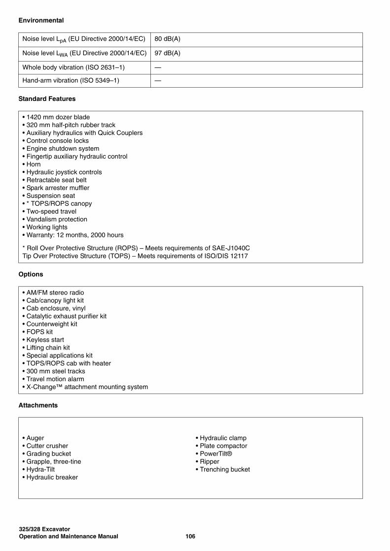
325/328 ExcavatorOperation and Maintenance Manual 106
Environmental
Standard Features
Options
Attachments
Noise level LpA (EU Directive 2000/14/EC) 80 dB(A)
Noise level LWA (EU Directive 2000/14/EC) 97 dB(A)
Whole body vibration (ISO 2631–1) —
Hand-arm vibration (ISO 5349–1) —
• 1420 mm dozer blade• 320 mm half-pitch rubber track• Auxiliary hydraulics with Quick Couplers• Control console locks• Engine shutdown system• Fingertip auxiliary hydraulic control• Horn• Hydraulic joystick controls• Retractable seat belt• Spark arrester muffler• Suspension seat• * TOPS/ROPS canopy• Two-speed travel• Vandalism protection• Working lights• Warranty: 12 months, 2000 hours
* Roll Over Protective Structure (ROPS) – Meets requirements of SAE-J1040CTip Over Protective Structure (TOPS) – Meets requirements of ISO/DIS 12117
• AM/FM stereo radio• Cab/canopy light kit• Cab enclosure, vinyl• Catalytic exhaust purifier kit• Counterweight kit• FOPS kit• Keyless start• Lifting chain kit• Special applications kit• TOPS/ROPS cab with heater• 300 mm steel tracks• Travel motion alarm• X-Change™ attachment mounting system
• Auger• Cutter crusher• Grading bucket• Grapple, three-tine• Hydra-Tilt• Hydraulic breaker
• Hydraulic clamp• Plate compactor• PowerTilt®• Ripper• Trenching bucket

325/328 Excavator107 Operation and Maintenance Manual
SPECIFICATIONS
328 Excavator
Dimensions
All dimensions in mm
2342 11001 - 2342 99999
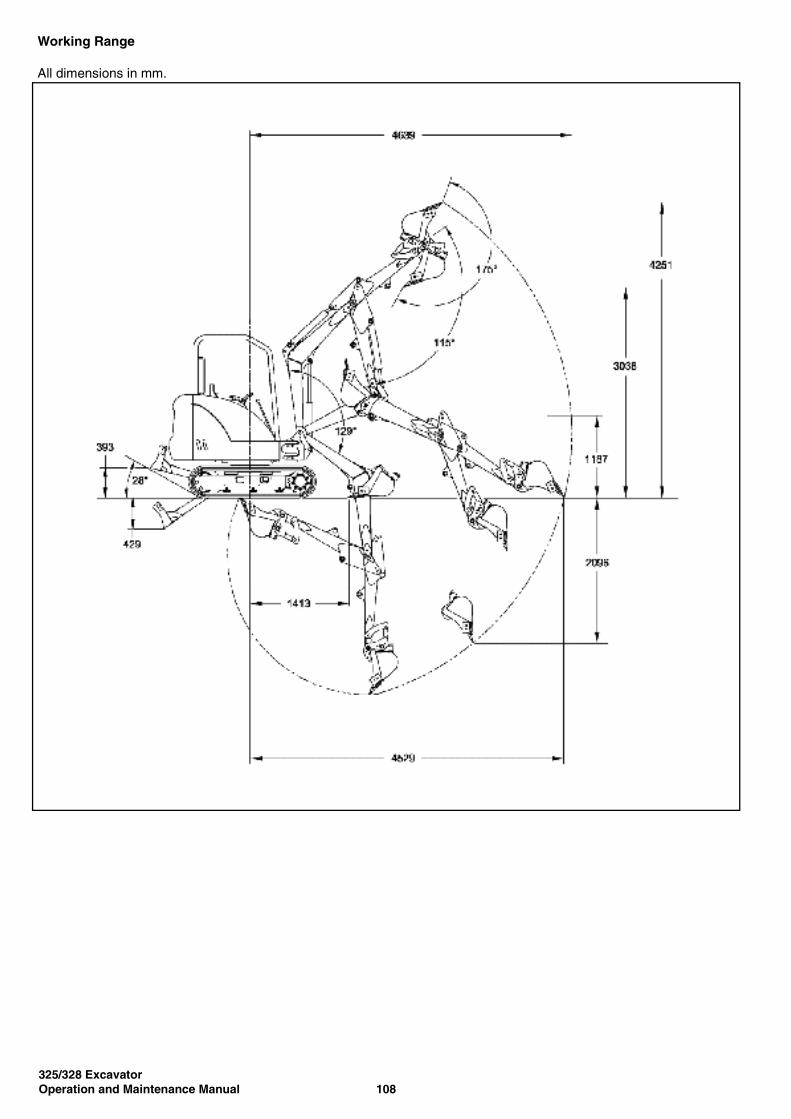
325/328 ExcavatorOperation and Maintenance Manual 108
Working Range
All dimensions in mm.

325/328 Excavator109 Operation and Maintenance Manual
Lift Capacity
Note: Lift point is bucket hinge pin with standard bucket attached and bucket cylinder fully extended.
* Rated hydraulic lift capacity
* Rated hydraulic lift capacity
* Rated hydraulic lift capacity
Rated lift capacity over blade, blade down
Lift point height [H] (mm)
Maximum radius [R] (mm)
Lift at max. radius (kg)
Lift at 2000 mm radius
Lift at 3000 mm radius
3000 3240 270 *
2000 3800 296 * 295 *
1000 3990 322 * 785 * 425 *
Ground 3850 346 * 1049 * 532 *
-1000 3360 379 * 975 * 479 *
Rated lift capacity over blade, blade up
Lift point height [H] (mm)
Maximum radius [R] (mm)
Lift at max. radius (kg)
Lift at 2000 mm radius
Lift at 3000 mm radius
3000 3240 266 *
2000 3800 285 * 287 *
1000 3990 313 756 * 412 *
Ground 3850 345 827 516
-1000 3360 378 * 964 * 481 *
Rated lift capacity over side, blade up
Lift point height [H] (mm)
Maximum radius [R] (mm)
Lift at max. radius (kg)
Lift at 2000 mm radius
Lift at 3000 mm radius
3000 3240 270 *
2000 3800 294 * 290 *
1000 3990 320 768 422 *
Ground 3850 279 781 399
-1000 3360 374 * 783 484 *
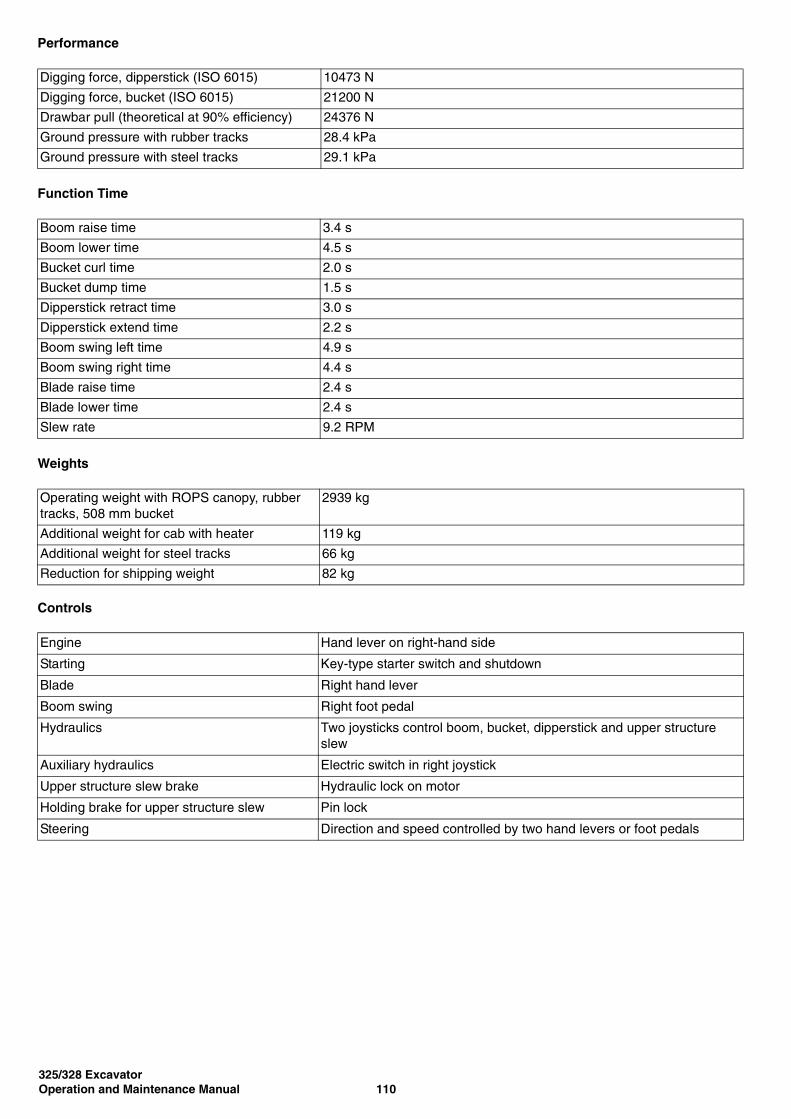
325/328 ExcavatorOperation and Maintenance Manual 110
Performance
Function Time
Weights
Controls
Digging force, dipperstick (ISO 6015) 10473 N
Digging force, bucket (ISO 6015) 21200 N
Drawbar pull (theoretical at 90% efficiency) 24376 N
Ground pressure with rubber tracks 28.4 kPa
Ground pressure with steel tracks 29.1 kPa
Boom raise time 3.4 s
Boom lower time 4.5 s
Bucket curl time 2.0 s
Bucket dump time 1.5 s
Dipperstick retract time 3.0 s
Dipperstick extend time 2.2 s
Boom swing left time 4.9 s
Boom swing right time 4.4 s
Blade raise time 2.4 s
Blade lower time 2.4 s
Slew rate 9.2 RPM
Operating weight with ROPS canopy, rubber tracks, 508 mm bucket
2939 kg
Additional weight for cab with heater 119 kg
Additional weight for steel tracks 66 kg
Reduction for shipping weight 82 kg
Engine Hand lever on right-hand side
Starting Key-type starter switch and shutdown
Blade Right hand lever
Boom swing Right foot pedal
Hydraulics Two joysticks control boom, bucket, dipperstick and upper structure slew
Auxiliary hydraulics Electric switch in right joystick
Upper structure slew brake Hydraulic lock on motor
Holding brake for upper structure slew Pin lock
Steering Direction and speed controlled by two hand levers or foot pedals

325/328 Excavator111 Operation and Maintenance Manual
Engine
Electrical
Hydraulic System
Make / model Kubota / D1703-M-E2B-BC-1
Fuel Diesel
Cooling Liquid
Maximum power at 2200 RPM (ISO 9249) 20.6 kW
Maximum governed speed 2200 RPM
High idle speed 2420 RPM
Low idle speed 1325–1375 RPM
Torque at 1600 RPM (ISO 9249) 103.4 Nm
Number of cylinders 3
Displacement 1.7 l
Bore 87 mm
Stroke 92.4 mm
Lubrication Pressure system with full-flow filter
Crankcase ventilation Closed breathing
Air filter Dry replaceable paper cartridge with safety element
Ignition Diesel-compression
Starting aid Intake air heater
Alternator 12 V — 40 A — open frame with internal regulator
Battery 12 V — 500 cold cranking A at -18°C — 75 min reserve capacity
Starter 12 V — gear reduction type — 1.4 kW
Pump type Dual-outlet variable displacement piston pump with gear pump
Pump 1 capacity 26.6 l/min at 2200 RPM
Pump 2 and 3 capacity 19.8 l/min at 2200 RPM
System relief pressure for implement circuits 172 bar
System relief pressure for travel circuits 263 bar
System relief pressure for slew circuits 117 bar
System relief pressure for auxiliary circuits 172 bar
Dipperstick port relief base and rod end 290 bar
Boom port relief base and rod end 290 bar
Bucket port relief base and rod end 290 bar
Main hydraulic filter bypass 3.4 bar
Case drain bypass 1.4 bar
Control valve Ten-spool parallel series
Hydraulic filter Full-flow replaceable — 3 µm synthetic media element
Fluid lines SAE standard tubelines, hoses, and fittings
Auxiliary flow 46.4 l/min

325/328 ExcavatorOperation and Maintenance Manual 112
Hydraulic Cylinders
Drive System
Traction
Boom cylinder Cushion up
Boom cylinder bore 76 mm
Boom cylinder rod 41 mm
Boom cylinder stroke 424 mm
Dipperstick cylinder Cushion extend
Dipperstick cylinder bore 76 mm
Dipperstick cylinder rod 38 mm
Dipperstick cylinder stroke 485 mm
Bucket cylinder No cushion
Bucket cylinder bore 64 mm
Bucket cylinder rod 35 mm
Bucket cylinder stroke 466 mm
Boom swing cylinder Cushion left and right
Boom swing cylinder bore 60 mm
Boom swing cylinder rod 35 mm
Boom swing cylinder stroke 400 mm
Blade cylinder No cushion
Blade cylinder bore 70 mm
Blade cylinder rod 38 mm
Blade cylinder stroke 195 mm
Travel motor Each track is driven by a hydrostatic axial piston motor
Drive reduction Two-stage planetary gear reduction 44.3:1
Track width, rubber, standard 320 mm
Track width, steel, optional 300 mm
Track adjusters Grease type with shock absorbing recoil springs
Track type, standard Half-pitch, rubber
Track type, optional Steel
Travel speed, low range 1.9 km/h
Travel speed, high range 3.1 km/h
Undercarriage Crawler-type tractor design with reinforced box-section track roller frame and sealed track rollers
Number of track rollers per side 3
Gradeability 30°
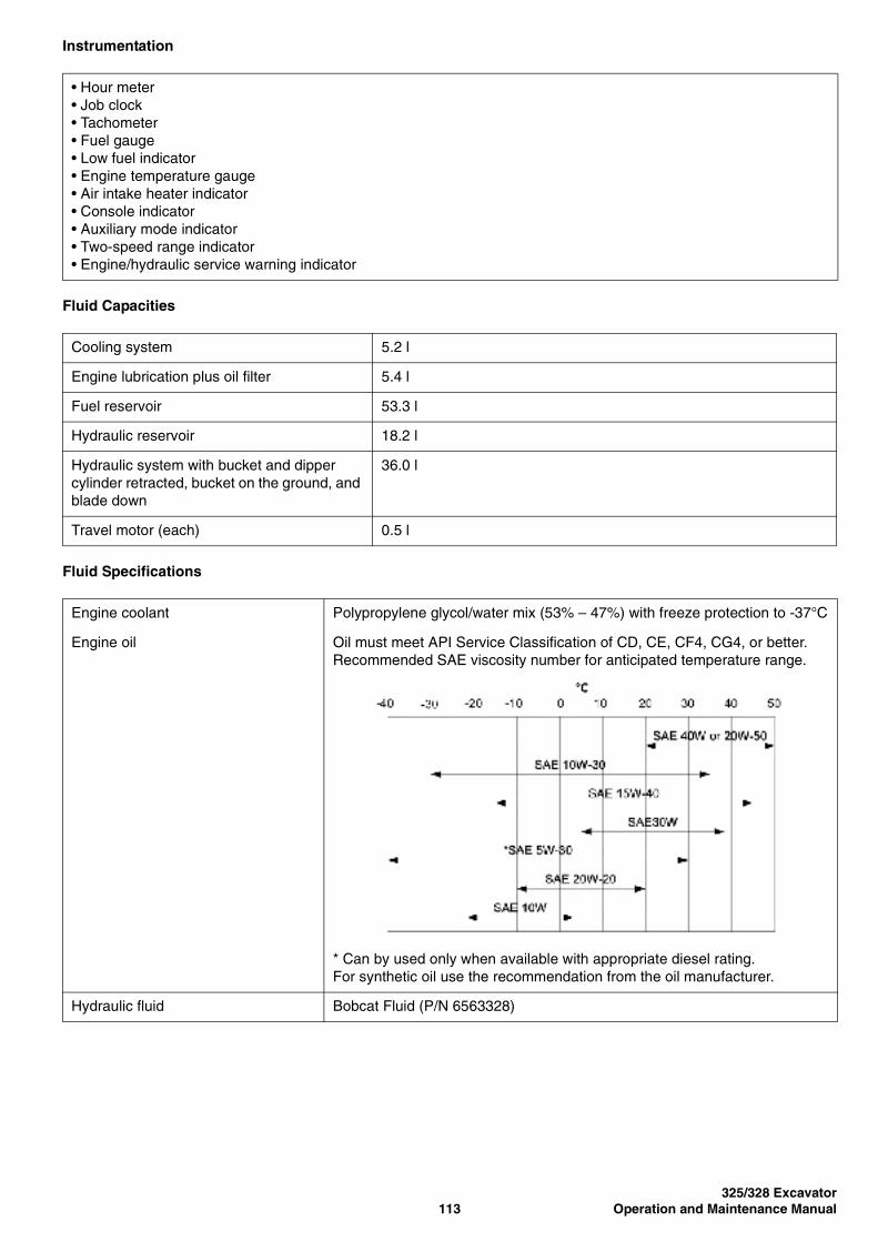
325/328 Excavator113 Operation and Maintenance Manual
Instrumentation
Fluid Capacities
Fluid Specifications
• Hour meter• Job clock• Tachometer• Fuel gauge• Low fuel indicator• Engine temperature gauge• Air intake heater indicator• Console indicator• Auxiliary mode indicator• Two-speed range indicator• Engine/hydraulic service warning indicator
Cooling system 5.2 l
Engine lubrication plus oil filter 5.4 l
Fuel reservoir 53.3 l
Hydraulic reservoir 18.2 l
Hydraulic system with bucket and dipper cylinder retracted, bucket on the ground, and blade down
36.0 l
Travel motor (each) 0.5 l
Engine coolant Polypropylene glycol/water mix (53% – 47%) with freeze protection to -37°C
Engine oil Oil must meet API Service Classification of CD, CE, CF4, CG4, or better.Recommended SAE viscosity number for anticipated temperature range.
* Can by used only when available with appropriate diesel rating.For synthetic oil use the recommendation from the oil manufacturer.
Hydraulic fluid Bobcat Fluid (P/N 6563328)
325/328 ExcavatorOperation and Maintenance Manual 114
Environmental
Standard Features
Options
Attachments
Noise level LpA (EU Directive 2000/14/EC) 80 dB(A)
Noise level LWA (EU Directive 2000/14/EC) 97 dB(A)
Whole body vibration (ISO 2631–1) —
Hand-arm vibration (ISO 5349–1) —
• 1420 mm dozer blade• 320 mm half-pitch rubber track• Auxiliary hydraulics with Quick Couplers• Control console locks• Counterweight• Engine shutdown system• Fingertip auxiliary hydraulic control• Horn• Hydraulic joystick controls• Retractable seat belt• Spark arrester muffler• Suspension seat with high back• * TOPS/ROPS canopy• Two-speed travel• Vandalism protection• Working lights• Warranty: 12 months, 2000 hours
* Roll Over Protective Structure (ROPS) – Meets requirements of SAE-J1040CTip Over Protective Structure (TOPS) – Meets requirements of ISO/DIS 12117
• AM/FM stereo radio• Cab/canopy light kit• Cab enclosure, vinyl• Catalytic exhaust purifier kit• FOPS kit• Keyless start• Lifting chain kit• Special applications kit• TOPS/ROPS cab with heater• 300 mm steel tracks• Travel motion alarm• X-Change™ attachment mounting system
• Auger• Cutter crusher• Grading bucket• Grapple, three-tine• Hydra-Tilt• Hydraulic breaker
• Hydraulic clamp• Plate compactor• PowerTilt®• Ripper• Trenching bucket

WARRANTYBOBCAT EXCAVATORS
INGERSOLL RAND INTERNATIONAL warrants to its authorised dealers who in turn warrant to the end-user/owner,that each new Bobcat excavator will be free from proven defects in material and workmanship for twelve months fromthe date of delivery to the end-user/owner or 2000 hours of machine usage, whichever occurs first, with the exceptionof tracks which are covered for the same initial period on a pro-rated basis based on the remaining depth of the trackat the time any defect is discovered,
During the warranty period, the authorised selling Bobcat dealer shall repair or replace, at INGERSOLL RANDINTERNATIONAL's option, without charge for parts, labour and travel time of mechanics, any part of the Bobcatproduct which fails because of defects in material and workmanship. The end-user/owner shall provide theauthorised dealer with prompt written notice of the defect and allow reasonable time for replacement or repair.INGERSOLL RAND INTERNATIONAL may, at its option, request failed parts to be returned to the factory.Transportation of the Bobcat product to the authorised Bobcat Excavator dealer for warranty work is theresponsibility of the end-user/owner.
The warranty does not cover replacement of scheduled service items such as oil, filters, tune-up parts, and otherhigh-wear items. The warranty does not cover damages resulting from abuse, accidents, alterations, use of theBobcat product with any bucket or attachment not approved by INGERSOLL RAND INTERNATIONAL, air flowobstructions, or failure to maintain or use the Bobcat product according to the instructions applicable to it.
INGERSOLL RAND INTERNATIONAL EXCLUDES OTHER CONDITIONS, WARRANTIES OR REPRESENTATIONS OFALL KINDS, EXPRESSED OR IMPLIED, STATUTORY OR OTHERWISE (EXCEPT THAT OF TITLE) INCLUDING ALLIMPLIED WARRANTIES AND CONDITIONS RELATING TO MERCHANTABILITY, SATISFACTORY QUALITY ANDFITNESS FOR A PARTICULAR PURPOSE.
CORRECTIONS BY INGERSOLL RAND INTERNATIONAL OF NONCONFORMITIES WHETHER PATENT OR LATENT,IN THE MANNER AND FOR THE TIME PERIOD PROVIDED ABOVE, SHALL CONSTITUTE FULFILMENT OF ALLLIABILITIES OF INGERSOLL RAND INTERNATIONAL FOR SUCH NONCONFORMITIES, WHETHER BASED ONCONTRACT, WARRANTY, TORT, NEGLIGENCE, INDEMNITY, STRICT LIABILITY OR OTHERWISE WITH RESPECT TOOR ARISING OUT OF SUCH PRODUCT.
THE REMEDIES OF THE END-USER/OWNER SET FORTH UNDER THE PROVISIONS OF THE WARRANTY OUTLINEDABOVE ARE EXCLUSIVE AND THE TOTAL LIABILITY OF INGERSOLL RAND INTERNATIONAL INCLUDING ANYHOLDING, SUBSIDIARY, ASSOCIATED OR AFFILIATED COMPANY OR DISTRIBUTOR WITH RESPECT TO THISSALE OR THE PRODUCT AND SERVICE FURNISHED HEREUNDER IN CONNECTION WITH THE PERFORMANCE ORBREACH THEREOF, OR FROM DELIVERY, INSTALLATION, REPAIR OR TECHNICAL DIRECTION COVERED BY ORFURNISHED UNDER THIS SALE, WHETHER BASED ON CONTRACT, WARRANTY, TORT, NEGLIGENCE, INDEMNITY,STRICT LIABILITY OR OTHERWISE SHALL NOT EXCEED THE PURCHASE PRICE OF THE PRODUCT UPON WHICHSUCH LIABILITY IS BASED.
INGERSOLL RAND INTERNATIONAL INCLUDING ANY HOLDING, SUBSIDIARY, ASSOCIATED OR AFFILIATEDCOMPANY AND DISTRIBUTOR SHALL IN NO EVENT BE LIABLE TO THE END-USER/OWNER, ANY SUCCESSORS ININTEREST OR ANY BENEFICIARY OR ASSIGNEE RELATING TO THIS SALE FOR ANY CONSEQUENTIAL,INCIDENTAL, INDIRECT, SPECIAL OR PUNITIVE DAMAGES ARISING OUT OF THIS SALE OR BY ANY BREACHTHEREOF, OR ANY DEFECT IN, OR FAILURE OF, OR MALFUNCTION OF THE PRODUCT UNDER THIS SALE,WHETHER BASED UPON LOSS OF USE, LOST PROFITS OR REVENUE, INTEREST, LOST GOODWILL, WORKSTOPPAGE, IMPAIRMENT OF OTHER GOODS, LOSS BY REASON OF SHUTDOWN OR NON-OPERATION,INCREASED EXPENSES OF OPERATION OR CLAIMS OF USER OR CUSTOMERS OF THE USER FOR SERVICEINTERRUPTION WHETHER OR NOT SUCH LOSS OR DAMAGE IS BASED ON CONTRACT, WARRANTY, TORT,NEGLIGENCE, INDEMNITY, STRICT LIABILITY OR OTHERWISE.
4700003-EN (07-06) Printed in Europe