operation, maintenance and service manual - AMADA WELD ...
120
ON CompactY AGem USER’S MANUAL NO. 990-533 REVISION A: September 2001 OPERATION, MAINTENANCE AND SERVICE MANUAL FOR THE LW400E/LW500E PULSED Nd:YAG LASER COMPACT YAG LASER
-
Upload
khangminh22 -
Category
Documents
-
view
0 -
download
0
Transcript of operation, maintenance and service manual - AMADA WELD ...
–ON
Co mpact Y AG Laser S ystem
USER’S MANUAL NO. 990-533 REVISION A: September 2001
OPERATION, MAINTENANCE AND SERVICE MANUAL
FOR THE
LW400E/LW500E PULSED Nd:YAG LASER
COMPACT
YA
G L
AS
ER
LW400E/LW500E PULSED Nd:YAG LASER
ii 990-533
Copyright © 2001, Unitek Miyachi Corporation
The engineering designs, drawings and data contained herein are the proprietary work of UNITEK MIYACHI CORPORATION and may not be reproduced, copied, exhibited or otherwise used without the written authorization of UNITEK MIYACHI CORPORATION.
Printed in the United States of America
Revision Record
Revision EO Date Basis of Revision A 19018 9/01 Production Release
LW400E/LW500E PULSED Nd:YAG LASER
990-533 iii
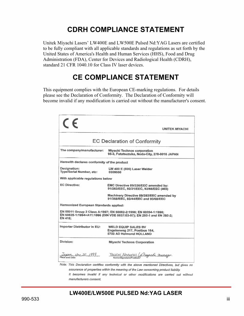
CDRH COMPLIANCE STATEMENT
Unitek Miyachi Lasers’ LW400E and LW500E Pulsed Nd:YAG Lasers are certified to be fully compliant with all applicable standards and regulations as set forth by the United States of America's Health and Human Services (HHS), Food and Drug Administration (FDA), Center for Devices and Radiological Health (CDRH), standard 21 CFR 1040.10 for Class IV laser devices.
CE COMPLIANCE STATEMENT This equipment complies with the European CE-marking regulations. For details please see the Declaration of Conformity. The Declaration of Conformity will become invalid if any modification is carried out without the manufacturer's consent.

LW400E/LW500E PULSED Nd:YAG LASER
iv 990-533
FOREWORD
Thank you for purchasing a Unitek Miyachi Lasers’ LW400E or LW500E Pulsed Nd:YAG Laser.
Upon receipt of the laser, please thoroughly inspect it for shipping damage prior to its installation. Should there be any damage, please immediately contact the shipping company to file a claim, and notify Unitek Miyachi Lasers at:
Unitek Miyachi Lasers 1820 South Myrtle Ave. Monrovia, CA 91017-7135 Phone: (626) 303-5676 FAX: (626) 358-8048 E-mail: [email protected]
The contents of this manual are subject to change without notice.
If you have any questions about the contents of this manual, or find any errors or omissions in it, please notify Unitek Miyachi Lasers.
Unitek Miyachi Lasers is not responsible for any losses due to improper use of this product.

LW400E/LW500E PULSED Nd:YAG LASER
990-533 v
SAFETY PRECAUTIONS
Before using this equipment, read the "Safety Precautions" carefully to understand the correct usage of the equipment.
• These precautions are given for safe use of the
Laser and for prevention injury to operators or others.
• Be sure to read each of the instructions as they are all important for safe operation.
• The meaning of the words and symbols is as follows:
! DANGER
Denotes operations and practices that may imminently result in serious injury or loss of life if not correctly followed.
! CAUTION
Denotes operations and practices that may result in personal injury or damage to the equipment if not correctly followed.
! WARNING
Denotes operations and practices that may result in serious injury or loss of life if not correctly followed.
!
These symbols denote"prohibition". They arewarnings about actionsout of the scope of thewarranty of the products.
Each symbol with atriangle denotes that thecontents gives notice ofDANGER, WARNING orCAUTION to the operator.
These symbols denoteactions which operatorsmust take.
! DANGER
Do not touch the inside of the laser unnecessarily. Since source voltage of three-phase 200V or 220V is applied to the laser, high voltages are applied to its inside. Do not touch the inside of the laser unnecessarily with the power turned on. You may receive an electric shock. Never disassemble , repair or modify the laser. These actions can cause electric shock and fire. Do not do anything other than the maintenance described in the operation manual. Do not look at or touch the beam. Both direct laser beams and scattered laser beams are highly dangerous. If the beam enters the eye directly, it can cause blindness.

LW400E/LW500E PULSED Nd:YAG LASER
vi 990-533
! WARNING
Do not expose your skin to the laser beam.Your skin may be severely burnt.
! Use proper tools (wire strippers, pressure wire connectors, etc.) forterminations of the connecting cables.Do not nick the wire conductor. Doing so can cause a fire or electric shock.
Use only specified cables and connect them securely. Cables of insufficient current capacities and loose connections can causefire and electric shock.!
Wear protective glasses.Be sure to wear protective glasses while using the laser.Even if you wear them, you may lose your sight if the laser beam enters your eyesdirectly.
!
Do not damage, or use a damaged power cable, connecting cables, or plugs.Do not tread on, twist or tense any cable. The power cable and connecting cablesmay be broken, and that can cause electric shock, short circuit and fire. If any partneeds to be repaired or replaced, consult Unitek Miyachi Lasers or your distributor.
Stop the operation if any trouble occurs.Continuous operation after occurrence of a trouble such as burning smell, abnormalsound, abnormal heat, smoke, etc. can cause electric shock and fire. If such a trou-ble occurs, turn off the power immediately and consult Unitek Miyachi Lasers or yourdistributor.
!Ground the Laser Marker.
If the Laser is not grounded, you may get an electric shock when there istrouble or electricity leaks through insulation.
Use a stopper plug.The laser beam is dangerous to human bodies. Prevent accidental leakage ofthe laser beam from the assembly by using a stopper (a heat-resistant, laser beamabsorbing and scattering material).
!Persons with pacemakers must stay clear of the Laser.Those who use a pacemaker must not approach the Laser or walk around thelaser shop while the is in operation, without being permitted byhis/her medical doctor. The Laser generates a magnetic field and has effects onthe operation of the pacemaker while it is turned on.
Laser

LW400E/LW500E PULSED Nd:YAG LASER
990-533 vii
! CAUTION
Do not splash water on the Laser. Water splashed over the electric parts, can cause electric shock and short circuits.
!
Install the Laser on a firm and level surface. If the Laser falls or drops, injury may result.
Do not place a water container on the Laser. If water spills, insulation of the Laser will deteriorate, and that can cause electric leaks and fire.
!
Keep combustible matter away from the Laser. Spatter can ignite combustible matter. If it is impossible to remove all combustible mat- ter, cover it with non-combustible material.
Do not apply the laser beam to combustible materials. To avoid risk of fire never apply the laser beam to flammable or combustible mater i als.
Do not cover the Laser Marker with a blanket, cloth, etc. Do not cover the Laser Marker with a blanket, cloth, etc. while you are using it. The c over may be heated and burn.
!
Protective gear must be worn. Put on protective gear such as protective gloves, long-sleeve jacket, leather apron, etc. Spatter can burn the skin if they touch the skin.
! Keep a fire extinguisher nearby.
Keep a fire extinguisher in the laser shop in case of fire.
Maintain and inspect the Laser periodically, and repair any damage before starting !
Maintain and inspect the Laser periodically.
operation.

LW400E/LW500E PULSED Nd:YAG LASER
viii 990-533
CAUTION
This instruction manual describes how to operate, maintain and service the LW400E/LW500E Lasers, and provides instructions relating to their SAFE use. Procedures described in this manual MUST be performed as detailed by QUALIFIED and TRAINED personnel.
For SAFETY, and to effectively take advantage of the full capabilities of the LW400E/LW500E Lasers, please read this instruction manual and the Laser Safety User’s Manual (990-502) thoroughly before attempting to use the laser.
Procedures other than those described in this manual or not performed as prescribed in this manual, may expose personnel to electrical hazards and/or laser radiation hazards.
After reading this manual, retain it for future reference when any questions arise regarding the proper and SAFE operation of the LW400E/LW500E Lasers.
LW400E/LW500E PULSED Nd:YAG LASER
990-533 ix
CONTENTS
CHAPTER 1: Precautions Prior to Using the LW400E/LW500E Laser........................................................... 1-1 Installation Site and Electrical Supply.................................................................... 1-1 Carrying the LW400E/LW500E Laser ................................................................... 1-1 Handling the Fiber Optic Cables............................................................................. 1-1 Removal of Oscillator Head Hold Down Brackets................................................. 1-2 Environmental Factors ............................................................................................ 1-2 Operation in Cold Weather ..................................................................................... 1-2 Laser Operation Area.............................................................................................. 1-3 Operating the Laser................................................................................................. 1-3 Laser Safety Officer................................................................................................ 1-3 Cautions and Warning Indications.......................................................................... 1-3 Cleanliness .............................................................................................................. 1-3 Design Integrity ...................................................................................................... 1-3 Maintenance............................................................................................................ 1-3
CHAPTER 2: System Description System Features ...................................................................................................... 2-1 Controls, Indicators and Components..................................................................... 2-2 Accessory Kit.......................................................................................................... 2-8
CHAPTER 3: I/O SIGNAL INTERFACE EXT I/O (1) Connector ........................................................................................... 3-1 Typical Connections of Input Signals......................................................... 3-1 Descriptions of Input Signals, EXT. I/O (1) Connector ............................. 3-2 Typical Connections of Output Signals ...................................................... 3-5 Descriptions of Output Signals, EXT. I/O (1) Connector.......................... 3-6 REMOTE INTERLOCK Connector....................................................................... 3-7
CHAPTER 4: SYSTEM TIMING Time Charts............................................................................................................. 4-1 Control with Laser Controller (Energy-Sharing Delivery)......................... 4-1 Control by External Input Signal (Energy-Sharing Delivery) .................... 4-2 Control by External Input Signal (Time-Sharing of Two Energy-Sharing Deliveries) .................................................................. 4-3 Repeated Operation with Two Energy-Sharing Deliveries ........................ 4-4 High Repetition Operation (Greater than 25 PPS)...................................... 4-5

LW400E/LW500E PULSED Nd:YAG LASER
x 990-533
CONTENTS (Continued) CHAPTER 5: GETTING STARTED Removing the Laser Oscillator Fittings .................................................................. 5-1 Connection of Power Supply Cable........................................................................ 5-1 Connection of Cooling Water Hose........................................................................ 5-2 Cooler Unit De-ionized Water Supply.................................................................... 5-2 Optical Fiber Connection........................................................................................ 5-3 Preparing Optical Fiber for Installation ...................................................... 5-3 Connection to Laser Beam Input Unit ........................................................ 5-3 Connection to Output Unit.......................................................................... 5-4 Energy- and Time-Sharing Setup............................................................................ 5-4 Selecting Laser Beam Input Unit Using Laser Controller .......................... 5-4 Selecting Laser Beam Input Unit by Remote Control ................................ 5-4 Energy-Sharing ........................................................................................... 5-4 Time-Sharing .............................................................................................. 5-4 Time-Sharing of Two 2-Energy-Sharing Deliveries................................... 5-5
CHAPTER 6: Operating Instructions Preparation for Operation ....................................................................................... 6-1 Startup Procedure.................................................................................................... 6-1 Turning On the CONTROL Key Switch .................................................... 6-1 Operating Procedure for the Laser Controller ........................................................ 6-4 Screen Operation......................................................................................... 6-4 Contents of Three Main Screens: (SCHEDULE, POWER MONITOR and STATUS) ....................................................................................... 6-5 Setting Procedure ........................................................................................ 6-6 SCHEDULE Screen........................................................................ 6-6 FIXED FORM Screen......................................................... 6-6 FLEXIBLE FORM Screen ................................................. 6-11 STATUS Screen.............................................................................. 6-12 POWER MONITOR Screen ........................................................... 6-14 Shutdown Procedure ............................................................................................... 6-16
Chapter 7: User Maintenance Precautions.............................................................................................................. 7-1 Cooler Maintenance ................................................................................................ 7-1 Air Filter Cleaning ...................................................................................... 7-1 Water Draining Occasions .......................................................................... 7-2 Solenoid Valve Strainer Cleaning............................................................... 7-2 Replacing the Ion-Exchange Cartridge, Water Filter, and De-ionized Water ........................................................................... 7-3 Draining the De-ionized Water .................................................................. 7-4 Draining the De-ionized Water when the Laser is Not Used for a Long Period of Time or Its Temperature Goes Below 32°F (0°C) ................ 7-4 Draining Input Water ................................................................................. 7-5

LW400E/LW500E PULSED Nd:YAG LASER
990-533 xi
CONTENTS (Continued) Chapter 8: Service Precautions.............................................................................................................. 8-1 Flash Lamp Replacement........................................................................................ 8-1 Alignment of the Beam Into the Fiber Optic Cable................................................ 8-3 Preparation .................................................................................................. 8-3 Burn Pattern Adjustment............................................................................. 8-3 Z-Axis Adjustment...................................................................................... 8-3 X-Y Axes Adjustment................................................................................. 8-5 Cleaning the Optics................................................................................................. 8-6 Optical Component Cleaning Tools and Materials..................................... 8-6 Cleaning a Dusty or Dry-Dirt Coated Optic ............................................... 8-6 Cleaning a Contaminated Optic .................................................................. 8-6 Reassembling the Optical Components ...................................................... 8-7 Optical Fiber Cleaning................................................................................ 8-7 Power Source Service ............................................................................................. 8-7 Replacing the Backup Battery .................................................................... 8-7 Replacing the Fuses .................................................................................... 8-7 Troubleshooting ...................................................................................................... 8-9 Malfunction Indications .............................................................................. 8-9 Malfunction Check List .............................................................................. 8-9 Spare Parts Lists...................................................................................................... 8-14 Repair Service......................................................................................................... 8-16
APPENDIX A: TECHNICAL SPECIFICATIONS APPENDIX B: EXTERNAL COMMUNICATIONS INTERFACE
SPECIFICATIONS APPENDIX C: SCHEDULE DATA TABLES ALPHABETICAL SUBJECT INDEX

LW400E/LW500E PULSED Nd:YAG LASER
xii 990-533
ILLUSTRATIONS
Figure Title Page
1-1 Location of Hold Down Brackets ........................................................................... 1-2
2-1 External Controls and Indicators ............................................................................ 2-2 2-2 Internal Controls ..................................................................................................... 2-3 2-3 Top, Side and Rear Components ............................................................................ 2-4 2-4 Laser Controller, Controls and Indicators............................................................... 2-5 2-5 Internal Components............................................................................................... 2-6
3-1 Typical Input Signals with Contact Input ............................................................... 3-1 3-2 Typical Input Signals with Common-Minus Input ................................................. 3-4 3-3 Typical Input Signals with Common-Plus Input .................................................... 3-4 3-4 Typical Connection for an External Power Supply ................................................ 3-5 3-5 Typical Connection for Output Signals .................................................................. 3-5 3-6 REMOTE INTERLOCK Connector....................................................................... 3-7
4-1 Timing Signals for Control of the Laser Using the Laser Controller with Energy Sharing Delivery .................................................................... 4-1 4-2 Timing Signals for Control of the Laser Using External Input Signals with Energy Sharing Delivery .......................................................................... 4-2 4-3 Timing Signals for Control of the Laser Using External Input Signals with Time Sharing of Two Energy Sharing Deliveries .................................... 4-3 4-4 Timing Signals for Repeated Operation of the Laser Using Two Energy Sharing Deliveries ................................................................................ 4-4 4-5 Timing Signals for High Repetition Operation (Greater than 25 PPS) .................. 4-5
5-1 Removal of Laser Oscillator Fittings...................................................................... 5-1 5-2 Power Supply Cable Connections........................................................................... 5-1 5-3 Cooling Water Hose Connections........................................................................... 5-2 5-4 Filling De-ionized Water Tank ............................................................................... 5-2 5-5 Routing the Fiber-optic Cable................................................................................. 5-3 5-6 Connecting the Fiber-optic Cable to the Laser Beam Input Unit ........................... 5-3 5-7 Connecting the Fiber-optic Cable to the Output Unit............................................. 5-4
7-1 Air Filter Removal .................................................................................................. 7-1 7-2 Location of Solenoid Valve .................................................................................... 7-2 7-3 Solenoid Valve Disassembly .................................................................................. 7-2 7-4 Solenoid Valve Bolt................................................................................................ 7-3 7-5 Cartridge Location .................................................................................................. 7-3 7-6 Cartridge Removal .................................................................................................. 7-3 7-7 Hose Connections ................................................................................................... 7-4 7-8 Cooling Water Regulator Valve.............................................................................. 7-5

LW400E/LW500E PULSED Nd:YAG LASER
990-533 xiii
ILLUSTRATIONS (Continued)
Figure Title Page 8-1 Safety Interlock Switches ....................................................................................... 8-1 8-2 Removing Cover and Reflector .............................................................................. 8-1 8-3 Removing the Flashlamp ........................................................................................ 8-2 8-4 Burn Pattern ............................................................................................................ 8-3 8-5 Branch Unit Cover Plate Location.......................................................................... 8-3 8-6 Mounting the Fiberscope ........................................................................................ 8-4 8-7 Adjusting Focus ...................................................................................................... 8-4 8-8 Adjusting the Guide Beam (Z Axis) ....................................................................... 8-4 8-9 Lock Nut Location .................................................................................................. 8-9 8-10 Adjusting the Guide Beam (X-Y Axes).................................................................. 8-9 8-11 Optical Component Servicing Tools and Materials................................................ 8-6 8-12 Cleaning a Dirty Optic ............................................................................................ 8-6 8-13 Cleaning a Contaminated Lens ............................................................................... 8-6 8-14 Cleaning the Optical Fiber ...................................................................................... 8-7 8-15 Replacing Backup Battery ...................................................................................... 8-7 8-16 Replacing 0.5A and 3A Fuses................................................................................. 8-8 8-17 Replacing 5A and 6A Fuses.................................................................................... 8-8
TABLES
Table Title Page
1-1 Minimum Bend Radius for Specified Core Diameter............................................. 1-1
2-1 Accessory Kit Components..................................................................................... 2-8
7-1 Water Draining Occasions ...................................................................................... 7-2
8-1 Adjustment Screw Ring Turns Required for Defocus ............................................ 8-5 8-2 Fuse List.................................................................................................................. 8-8 8-3 Malfunction Check List .......................................................................................... 8-9 8-4 Spare Parts Kits Components.................................................................................. 8-14

LW400E/500E PULSED Nd:YAG LASER
990-533 1-1
CHAPTER 1 PRECAUTIONS
Prior To Using The LW400E/LW500E Laser WARNING: Operating, adjusting, maintaining or servicing the LW400E/LW500E Laser in a manner other than described in this manual may expose personnel to laser radiation or electrical hazards.
NOTE: Please have all personnel who will be working with the LW400E/LW500E Laser read this manual and the Laser Safety User’s Manual, Part No. 990-509, thoroughly before attempting to operate or maintain the laser.
Installation Site And Electrical Supply
CAUTION: When power is turned on, a surge current may be generated. Use a circuit breaker that has a rating of 60 amps or greater.
Install the LW400E/LW500E Laser securely on a firm, level floor that is free from vibration.
Use 3-phase 220VAC 60Hz, or 3-phase 200VAC 50/60Hz 100A (with tap changeover).
Install good grounding.
Carrying the LW400E/LW500E Laser When you carry the laser, hold the bottom of the housing between the front and back casters. Do not hold the laser by the maintenance door; it may break if you try to lift or carry the laser with it.
Handling The Fiber Optic Cables Optical fibers may be damaged and become unusable when they are bent beyond their minimum bend radius or subjected to the shock of a strong impact (refer to Table 1-1).
Table 1-1. Minimum Bend Radius for Specified Core Diameter
Minimum Bend Radius Core Diameter (mm) (Inches) (mm)
0.3 3.9 100
0.4 3.9 100
0.6 5.9 150
0.8 7.8 200
1.0 9.8 250

CHAPTER 1: PRECAUTIONS
LW400E/500E PULSED Nd:YAG LASER
1-2 990-533
Dirty or dusty end surfaces on the optical fibers will cause damage to the fibers. The damaged surfaces of the fibers can also cause contamination to adjacent lenses. Do not remove the rubber fiber end caps until it is necessary.
Removal Of Oscillator Head Hold Down Brackets
To fasten the base of the oscillator head during transportation, yellow hold down brackets are attached as shown in the Figure 1-1. Remove these brackets when installing the LW400E/LW500E Laser. Retain them for future use when transporting or relocating the laser. Use of these brackets will help to prevent misalignment and damage to the laser oscillator caused by severe vibrations.
Environmental Factors Use the laser in a place where the ambient temperature is 41-95°F (5-35°C), the humidity is 85% or less, and there are no sudden temperature fluctuations.
Do not use the laser where there is considerable dirt, dust, oil mist, chemicals or fumes, or moisture; where it may be subjected to vibration or impact; or where there is a nearby high-frequency noise source.
Do not install the laser in any atmosphere having a high concentration of CO2, NOx or SOx, e.g., air containing more than 0.1% CO2. These gases may shorten the life of the ion-exchange resin cartridge. Operation In Cold Weather When the temperature drops below 0°C, the water inside the LW400E/LW500E Lasers’ cooling system can freeze and may damage the laser. In cold regions, take special care to keep the ambient temperature where the laser is located above 0°C. If the temperature drops below 0°C, perform the procedure detailed in Chapter 7 for that. CAUTION: Avoid rapid temperature changes.
When it is cold, a rapid temperature change caused by a heating system, for example, may cause dew condensation on the end faces of the Nd:YAG rod and on other optical surfaces. This will attract dust and can cause damage to the surfaces of the optics.
WARNING: Be sure to turn off high voltage and the laser guide beam when checking the rod end and/or the mirror. If you do not turn them off, you are exposed to the possibility of electric shock or blinding.
Hold Down Brackets
Figure 1-1. Location of Hold Down Brackets

CHAPTER 1: PRECAUTIONS
LW400E/500E PULSED Nd:YAG LASER
990-533 1-3
If dew condensation is suspected, check the end surfaces of the laser rod and the optics. Inspect the rod's end surfaces by placing white paper on one end and using a dental mirror on the other end. You will need to remove the beam path covers on both ends of the laser cavity to do this inspection.
Laser Operation Area
Establish and control a dedicated laser operation area. The person responsible for the area (refer to Laser Safety Officer later in this chapter) must isolate the laser operation area from other work areas and display signs warning that the laser operation area is off limits to unauthorized personnel.
Operating the Laser
When operating the laser unit, always wear protective goggles having an optical density of at least 6 at a wavelength of 1064 nanometers.
Laser Safety Officer
Appoint a Laser Safety Officer. The Laser Safety Officer (LSO) must provide personnel with sufficient training so that personnel can operate, maintain and service the laser safely. The LSO must take charge of the key to the key switch to ensure that the laser is operated only by qualified and authorized personnel.
Caution and Warning Indications
Make sure proper warning signs and warning lights are installed in and around the laser installation. Also, make sure access doors to the laser area are interlocked to the laser. Locate danger labels and other warning/caution notices on the door of the location where this laser will be installed to indicate that a laser will be used in this location.
Cleanliness
The exterior of the laser should be kept clean. Use a dry cloth or, if heavily soiled, use a cloth moistened with a mild detergent or alcohol. Do not use paint thinner, benzene or acetone.
Design Integrity
Do not modify the laser without prior written approval from Unitek Miyachi Corporation.
Maintenance
Before performing any maintenance on the laser, please read Chapter 7, User Maintenance, thoroughly. Use the appropriate tools for terminating the connecting cables, being careful not to nick the wire conductors.

LW400E/LW500E PULSED Nd:YAG LASER
990-533 2-1
CHAPTER 2 SYSTEM DESCRIPTION
System Features The LW400E/LW500E is an ultra-compact, pulsed, Nd:YAG laser designed as a precision spot and seam welder. It incorporates the following features in its design:
• The laser is equipped with a power feedback control to provide reliable operation.
• The laser can handle a wide variety of workpieces. Using waveform control, as many as sixteen different weld schedule settings are available.
• A High-repetition laser output (maximum 500 pps) supports high-speed seam welding and processing.
• Containing an integrated power supply for the laser oscillator head and cooler, the laser is easy to carry and install.
• For greater convenience, piping, wiring and filters are all replaceable from the front of the laser.
• For simplicity and accuracy, the laser contains a liquid crystal display (LCD) for scheduling and operation.
• Input and output terminals allow the laser to be connected to external automatic units.
• The power monitor continuously checks both the oscillator output energy and mean power. To assure quality control, the operator can set upper and lower limits on oscillator output energy.
• In the case of seam welding, output can be set to fade in at the start and fade out at the end of each cycle, to smooth overlaps at both ends of the weld.
• Up to six deliveries of laser output are available, including power-sharing and time-sharing (optional).
• Optical fiber detection is available to check fiber positioning and integrity (optional).
• Through the use of high-precision optic fiber, the optical axis need not be adjusted every time the fiber is removed and reinstalled.
• The communications function allows for the central control of all data, such as parameter settings and laser value monitoring (optional).

CHAPTER 2: SYSTEM DESCRIPTION
LW400E/LW500E PULSED Nd:YAG LASER
2-2 990-533
Controls, Indicators and Components Figure 2-1 illustrates the controls and indicators on the front of the LW400E/LW500E laser.
1 Laser Controller (See figure 2-4) Program unit, used to set various parameters and display the settings on the monitor.
2 MAIN POWER switch Switches power to the laser.
3 CONTROL key switch When MAIN POWER switch is ON, turning this switch to ON will cause the laser to be operable. Shuts down the laser when turned to OFF. When the laser is not in use, the key should be removed and given to the designated safety servisor for safekeeping.
4 Front Door Handle Pressing the button under the handle causes the handle to pop out. Pulling the handle opens the front door. After closing the door, pressing the handle into place causes the door to lock.
5 EMERGENCY STOP switch Pressing this switch will immediately turn off the laser. Releasing the switch, by turning it toward RESET (clockwise), has the same effect as turning off the CONTROL
6 SHUTTER 6 lamp Lights while branch shutter 6 is open. 7 SHUTTER 5 lamp Lights while branch shutter 5 is open. 8 SHUTTER 4 lamp Lights while branch shutter 4 is open. 9 SHUTTER 3 lamp Lights while branch shutter 3 is open. 10 SHUTTER 2 lamp Lights while branch shutter 2 is open. 11 SHUTTER 1 lamp Lights while branch shutter 1 is open. 12 MAIN SHUTTER lamp Lights while resonator shutter is open. 13 READY lamp Lights when charging of capacitor bank is completed. 14 HIGH VOLTAGE lamp Lights when high voltage is applied to laser oscillator. 15 POWER lamp Lights when MAIN POWER switch is on, indicating main power is on.
Figure 2-1. External Controls and Indicators
POWER
HIGH
VOLTAGE
READY
MAIN
SHUTTER
SHUTTER
1
SHUTTER
2
SHUTTER
3
SHUTTER
4
SHUTTER
5
SHUTTER
66789
101112131415
1
2
3
4
5
LW400E
MAIN POWER
CONTROLON
OFF
EMERGENCY INDICA TOR
RESET ENTER
MENUON+_
OF F
EMERGENCYST OP
CHAPTER 2: SYSTEM DESCRIPTION
LW400E/LW500E PULSED Nd:YAG LASER
990-533 2-3
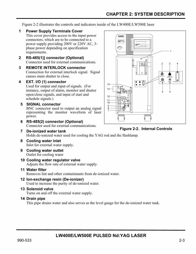
Figure 2-2 illustrates the controls and indicators inside of the LW400E/LW500E laser
1 Power Supply Terminals Cover This cover provides access to the input power connectors, which are to be connected to a power supply providing 200V or 220V AC, 3-phase power depending on specification requirements.
2 RS-485(1)] connector (Optional) Connector used for external communications.
3 REMOTE INTERLOCK connector Connection for external interlock signal. Signal causes main shutter to close.
4 EXT. I/O (1) connector Used for output and input of signals. (For instance, output of alarm, monitor and shutter open/close signals, and input of start and schedule signals.)
5 SIGNAL connector BNC connector used to output an analog signal representing the monitor waveform of laser power.
6 RS-485(2) connector (Optional) Connector used for external communications.
7 De-ionized water tank Holds de-ionized water used for cooling the YAG rod and the flashlamp.
8 Cooling water inlet Inlet for external water supply.
9 Cooling water outlet Outlet for cooling water
10 Cooling water regulator valve Adjusts the flow rate of external water supply.
11 Water filter Removes lint and other contaminants from de-ionized water.
12 Ion-exchange resin (De-ionizer) Used to increase the purity of de-ionized water.
13 Solenoid valve Turns on and off the external water supply.
14 Drain pipe This pipe drains water and also serves as the level gauge for the de-ionized water tank.
Figure 2-2. Internal Controls
RS-485 (1) RS-485 (2)
REMOTE INTERLOCK
SIGNAL EXTERNAL I/O (1)
LW400E
EMERGENCY
RESET ENTER MENU ON + _
OFF EMERGENCY STOP
1
2 3 4
5 6
7 8 9 10 11 12
13 14

CHAPTER 2: SYSTEM DESCRIPTION
LW400E/LW500E PULSED Nd:YAG LASER
2-4 990-533
Figure 2-3 illustrates components on the top, side, and rear of the LW400E/LW500E laser.
1 Head cover
Cover for the laser oscillator.
2 Lamp
replacement cover The flashlamp is fastened to the reverse side of this cover, which is removed for lamp replacement.
3 Controller cover Cover for the control circuit board; provides access for changing the backup battery.
4 Optical fiber inlets Optical fibers are passed through these holes for connection to the laser beam input units. Rubber caps must be pierced to allow passage of optical fiber cables.
5 Optical fiber connector cover Cover for the laser beam input unit; provides access for connecting the optical fibers to the unit.
6 Power supply covers Cover the power supply unit. The covers are installed on both sides and on the rear of the laser.
7 Air filter Air is taken in though this filter.
8 Radiator fans Exhaust fans cool the inside of the laser by removing hot air
Figure 2-3. Top, Side and Rear Components
1 2
34
5
6
7
8

CHAPTER 2: SYSTEM DESCRIPTION
LW400E/LW500E PULSED Nd:YAG LASER
990-533 2-5
Figure 2-4 illustrates controls and indicators on the Laser Controller of the LW400E/LW500E laser.
1 Liquid crystal display panel Displays various data.
2 Line cable connector Provides electrical and signal connections between the Laser Controller and the LW400E/LW500E.
3 EMERGENCY STOP switch Provides immediate shutdown of the laser; it has the same function as the EMERGENCY STOP switch on the laser.
4 MENU key Each time this key is pressed, the next screen appears on the LCD.
5 ENTER key Provides numerical and ON/OFF settings to laser controller. The controller will not recognize set data, unless the ENTER key is pressed.
6 +ON/OFF key This key is used change a numerical value or to provide an ON/OFF setting of the selected item. Pressing the +ON key increases the selected number on the LCD or turns the item on. Pressing the -OFF key decreases the selected number on the LCD or turns the item off.
7 CURSOR keys Move the cursor up and down or right and left to select an item.
8 TROUBLE RESET key Resets (shuts off) any trouble alarm after the trouble has been eliminated.
9 LASER START/STOP button/Emission Indicator When high voltage is supplied to the laser (indicated by the HIGH VOLTAGE lamp being on), pressing this button will activate the laser beam. If the laser is in continuous operation mode, pressing this button once will start the laser output beam and pressing it again will stop the output beam.
•_ _ •
ENTER MENU CURSOR
TROUBLE RESET
ON
OFF
EMERGENCY STOP LASER START/STOP
2 1
3 5 4 6 7 8 9
YAG LASER CONTROLLER M L E-114A
Figure 2-4. Laser Controller, Controls and Indicators

CHAPTER 2: SYSTEM DESCRIPTION
LW400E/LW500E PULSED Nd:YAG LASER
2-6 990-533
Figure 2-5 illustrates internal components of the LW400E/LW500E laser.
1 Broken Optical Fiber Detection Connector (Option)
Used for checking that the optical fiber is correctly connected to the laser beam output unit and is not damaged.
2 Resonator Mirror Holder Holds the resonator mirror. Light excited in the laser chamber is amplified between the two resonator mirrors and transmitted as a laser beam.
3 Resonator Shutter When this shutter is closed, the laser beam will not transmit even if the flashlamp is turned on.
4 Visible Laser Oscillator Transmits a red, visible laser beam. This visible laser beam is used as a guide beam for oscillation adjustment, incident beam adjustment and positioning of welding area.
5 Power Monitor Unit Detects the YAG laser beam and measures its power.
1
7 8
14
15
16
2 3
4 5
6 9 10
11
12
13
2 3
14
Figure 2-5. Internal Components

CHAPTER 2: SYSTEM DESCRIPTION
LW400E/LW500E PULSED Nd:YAG LASER
990-533 2-7
6 Visible Laser Beam Reflecting Mirror Changes the direction of the visible laser beam so that it passes down the center of the YAG laser beam’s optical path.
7 Laser Chamber The laser chamber contains the flashlamp and the YAG rod. The chamber lights up the flashlamp and excites the YAG rod.
8 Scope Holder Holder provided for use with the supplied fiber scope when it is not in use.
9 Laser Beam Input Unit (Up to 6 deliveries) The laser beam input unit sends a laser beam into the optical fiber. Depending on the specification, 1 to 6 laser beam input units are used. The units are numbered in order from front to rear.
10 Power Adjustment Unit The power adjustment unit attenuates the laser output so that, during energy-sharing operation, the output is uniform.
11 Branch Shutter (Up to 6 deliveries) Used to select a desired laser beam input unit. Depending on the specification, 1 to 6 branch shutters are used. The shutters are numbered in order from front to rear.
12 Time-Sharing Unit Moves the mirrors and selects the optical fiber to receive a laser beam.
13 Beam Splitter (Up to 6 deliveries) Splits a laser beam into a number of deliveries and reflects them onto each laser beam input unit. Depending on the specification, 1 to 6 beam splitters are used. The beam splitters are numbered in order from front to rear.
14 Laser Oscillator Fittings Two yellow fittings used for locking the laser oscillator for transport to prevent any damage or loosening during transport.
15 Branch Unit Cover Plate Blocks reflected laser beams from the optical fibers or other parts. Provides access for adjustment of the laser beam input.
16 Branch Unit Cover Cover for the branch unit. Provides access for adjustment of the incident laser beam.

CHAPTER 2: SYSTEM DESCRIPTION
LW400E/LW500E PULSED Nd:YAG LASER
2-8 990-533
Accessory Kit The following components are included in Accesory Kits 4-60646-01 and 4-606476-01. These components will be used for maintenance and repair of the unit.
Table 2-1. Accessory Kit Components Item Part
Number Quantity
Accesory Kit 4-60646-01 Clamp, Band 245-096 4 ea Fiberscope FOS-02 1 ea Fuse 0.5 A, 750 V 330-118 2 ea Fuse 2.0 A, Slow-blow 330-132 1 ea Fuse, 3 A, 250 V, 3AG 330-083 1 ea Fuse, 5.0 A, 250 V, 3AG 330-133 1 ea Fuse, 6.0 A, 250 V, 3AG 033-134 1 ea Grommet, Fiber-optic L3-02155 6 ea Hand pump PH-10 1 ea Hex ball driver, 5 mm 770-038 1 ea Hex ball driver, 4 mm 770-037 1 ea Hex ball driver, 3 mm 770-036 1 ea Hex ball driver, 2.5 mm 770-035 1 ea Hose, Braided, 10M 050-230 1 ea Label, Danger, “Exposure to . . .” 425-131 1 ea Label, Laser, “Danger, Visible . . .” 425-098 1 ea Label, Laser, “Danger, High Voltage . . .” 425-097 1 ea Label, Laser, “Avoid Exposure . . .” 425-096 2 ea Tool, Cartridge removal 451-082 1 ea Wrench, Cartridge MLF-0005A 1 ea
Accesory Kit 4-60647-01 Filter, Density alignment #5 318-011 1 ea Water, Distilled 900-241 1 carton of 6 1-gal. bottles
LW400E/LW500E PULSED Nd:YAG LASER
990-533 3-1
CHAPTER 3 I/O SIGNAL INTERFACE
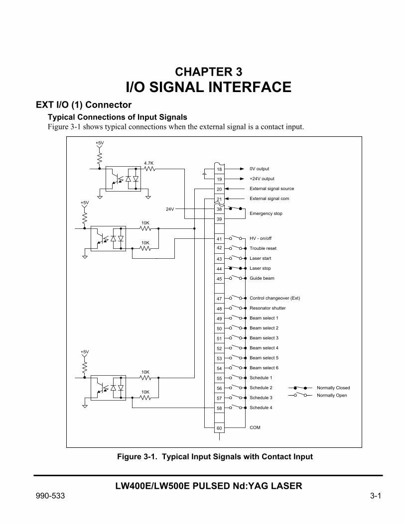
EXT I/O (1) Connector Typical Connections of Input Signals Figure 3-1 shows typical connections when the external signal is a contact input.
20
21
38
39
42
43
44
45
47
49
51
53
54
50
Normally Closed
COM
Beam select 3
Beam select 2
Beam select 1
Control changeover (Ext)
Guide beam
Laser stop
Laser start
Resonator shutter
Trouble reset
+24V output
18
19
41 HV - on/off
48
52 Beam select 4
Normally Open
0V output
External signal source
External signal com
55
56
57
58
60
24V
10K
+5V
10K
4.7K
+5V
10K
+5V
10K
Emergency stop
Beam select 5
Beam select 6
Schedule 1
Schedule 3
Schedule 2
Schedule 4
Figure 3-1. Typical Input Signals with Contact Input
CHAPTER 3: I/O SIGNAL INTERFACE
LW400E/LW500E PULSED Nd:YAG LASER
3-2 990-533
Descriptions of Input Signals, EXT I/O (1) Connector Refer to figures 3-1 through 3-3. Descriptions of the input signals follow:
Pin 18 0 V OUT Power supply for external input signals. This pin is exclusively used for the LW400E/LW500E. Do not use it for any other purpose.
Pin 19 +24 V OUT Power supply for external input signals. This pin is exclusively used for the LW400E/LW500E. Do not use it for any other purpose.
Pin 20 EXTERNAL SIGNAL SOURCE Input terminal for the external signal power supply. Connect it to Pin 18 or Pin 19, depending on the input signal circuit plan.
Pin 21 EXTERNAL SIGNAL COM Common input terminal for external signals. Connect it to Pin 18 or Pin 19, depending on the input signal circuit plan.
Pins 38 and 39 EMERGENCY STOP When the circuit between the pins 38 and 39 is opened, the high voltage circuit is broken and the Laser stops. The emergency-stop function works regardless of the control changeover (external) signal.
Pin 41 HV-ON/OFF When the circuit between this pin and COM is closed, the high voltage is turned on. When the circuit is opened, the high voltage is turned off.
Pin 42 TROUBLE RESET If trouble arises, an alarm is activated. When the cause of trouble has been eliminated and this pin is connected to COM, the alarm will be canceled.
Pin 43 LASER START When the circuit between this pin and COM is closed for at least 40 ms, the laser begins transmitting a laser beam. Repeated Laser Start signals must be spaced a minimum of 40ms apart
Pin 44 LASER STOP Closure of this pin and COM during continuous laser oscillation (that is, when REPEAT is not set to 0, and SHOT is set to 0), the laser oscillation stops.
Pin 45 GUIDE BEAM Closure of this pin and COM causes projection of the guide beam.
Pin 47 CONTROL CHANGEOVER (external) Closure of this pin and COM, causes external input signals to be in effective.

CHAPTER 3: I/O SIGNAL INTERFACE
LW400E/LW500E PULSED Nd:YAG LASER
990-533 3-3
Pin 48 RESONATOR SHUTTER Closure of this pin and COM causes the resonator shutter to open, making the laser ready for oscillation. When the circuit is opened, the resonator shutter closes and the laser will not oscillate.
Pin 49 BEAM SELECT 1 Pin 50 BEAM SELECT 2 Pin 51 BEAM SELECT 3 Pin 52 BEAM SELECT 4. Pin 53 BEAM SELECT 5 Pin 54 BEAM SELECT 6
Pin 55 SCHEDULE 1 Pin 56 SCHEDULE 2 Pin 57 SCHEDULE 4 Pin 58 SCHEDULE 8
Input Signal SCH.#
SCHEDULE 1
SCHEDULE 2
SCHEDULE 4
SCHEDULE 8
0 1 2 3 4 5 6 7 8 9 10 11 12 13 14 15
Each SCHEDULE number is selected by a combination of the schedule signals 1, 2, 4 and/or 8. The connections of these pins to COM represents a binary equivalent of the SCHEDULE number. See the table below.
: Input pin The circuit between the pin and COM is closed. Blank : Input pin The circuit between the pin and COM is open.
Closure of any these pins and COM, causes selection of the respective laser beam unit, making it ready to project a laser beam.
CHAPTER 3: I/O SIGNAL INTERFACE
LW400E/LW500E PULSED Nd:YAG LASER
3-4 990-533
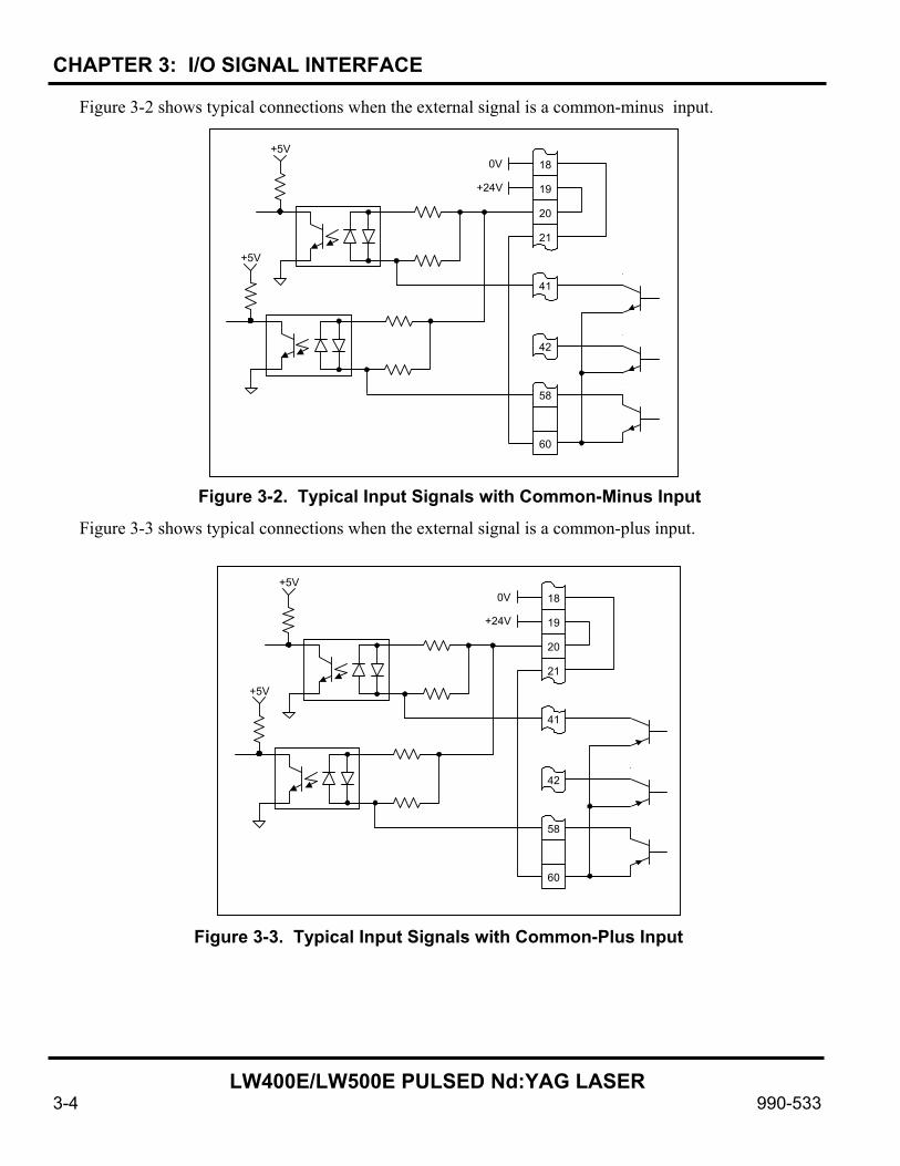
Figure 3-2 shows typical connections when the external signal is a common-minus input.
Figure 3-3 shows typical connections when the external signal is a common-plus input.
20
21
+24V
18
19
0V+5V
+5V
58
60
42
41
Figure 3-2. Typical Input Signals with Common-Minus Input
20
21
+24V
18
19
0V+5V
+5V
58
60
42
41
Figure 3-3. Typical Input Signals with Common-Plus Input
CHAPTER 3: I/O SIGNAL INTERFACE
LW400E/LW500E PULSED Nd:YAG LASER
990-533 3-5
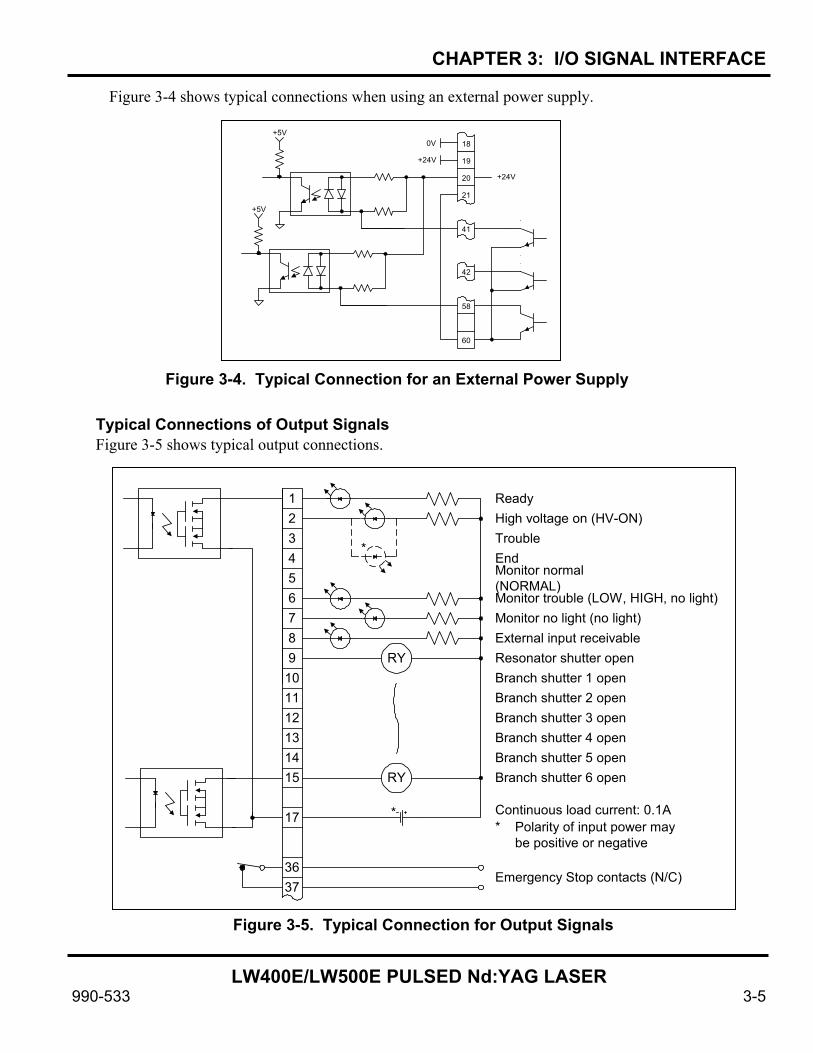
Figure 3-4 shows typical connections when using an external power supply.
Typical Connections of Output Signals Figure 3-5 shows typical output connections.
20
21
+24V
18
19
0V+5V
+5V
58
60
42
41
+24V
Figure 3-4. Typical Connection for an External Power Supply
Figure 3-5. Typical Connection for Output Signals
1234
65
7
98
101112131415
17
*
RY
RY
*
ReadyHigh voltage on (HV-ON)TroubleEndMonitor normal(NORMAL)
External input receivableResonator shutter openBranch shutter 1 open
Monitor trouble (LOW, HIGH, no light)Monitor no light (no light)
Branch shutter 2 openBranch shutter 3 openBranch shutter 4 openBranch shutter 5 openBranch shutter 6 open
Continuous load current: 0.1A* Polarity of input power may
be positive or negative
3637
Emergency Stop contacts (N/C)
CHAPTER 3: I/O SIGNAL INTERFACE
LW400E/LW500E PULSED Nd:YAG LASER
3-6 990-533
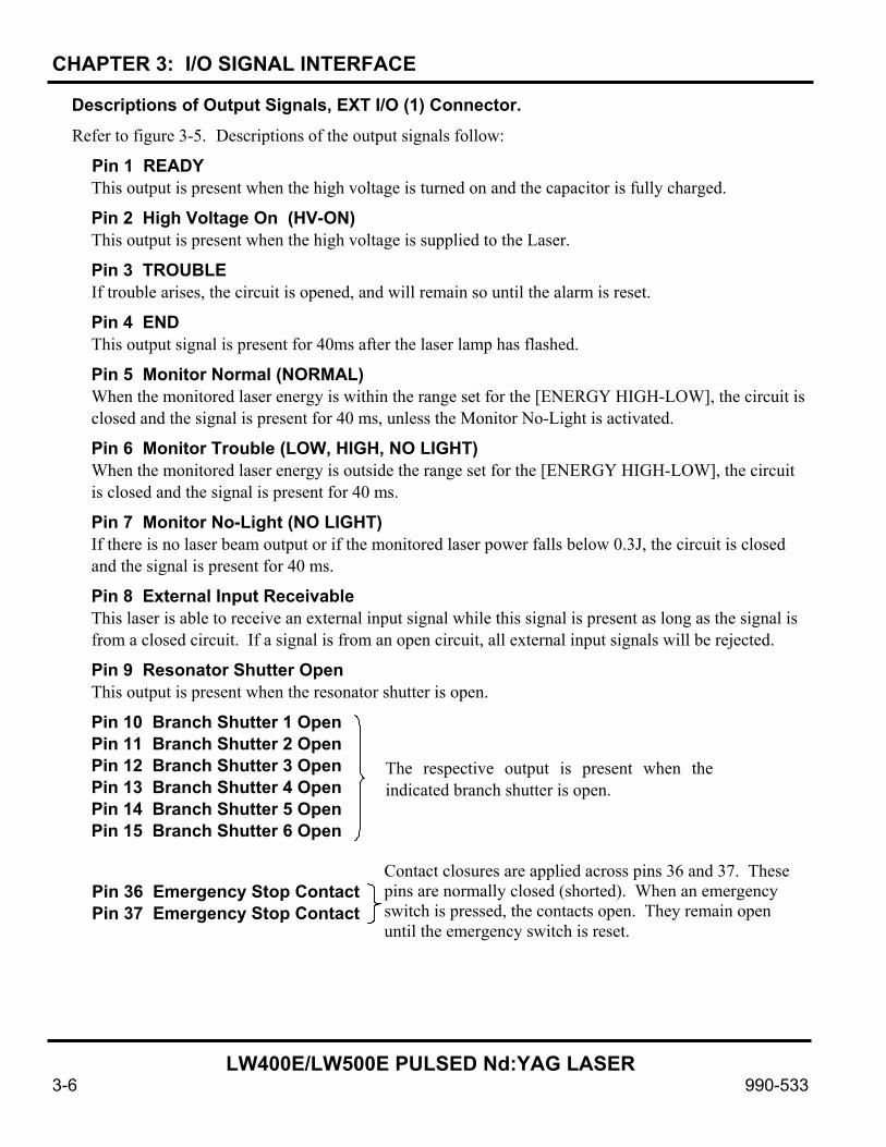
Descriptions of Output Signals, EXT I/O (1) Connector. Refer to figure 3-5. Descriptions of the output signals follow:
Pin 1 READY This output is present when the high voltage is turned on and the capacitor is fully charged.
Pin 2 High Voltage On (HV-ON) This output is present when the high voltage is supplied to the Laser.
Pin 3 TROUBLE If trouble arises, the circuit is opened, and will remain so until the alarm is reset.
Pin 4 END This output signal is present for 40ms after the laser lamp has flashed.
Pin 5 Monitor Normal (NORMAL) When the monitored laser energy is within the range set for the [ENERGY HIGH-LOW], the circuit is closed and the signal is present for 40 ms, unless the Monitor No-Light is activated.
Pin 6 Monitor Trouble (LOW, HIGH, NO LIGHT) When the monitored laser energy is outside the range set for the [ENERGY HIGH-LOW], the circuit is closed and the signal is present for 40 ms.
Pin 7 Monitor No-Light (NO LIGHT) If there is no laser beam output or if the monitored laser power falls below 0.3J, the circuit is closed and the signal is present for 40 ms.
Pin 8 External Input Receivable This laser is able to receive an external input signal while this signal is present as long as the signal is from a closed circuit. If a signal is from an open circuit, all external input signals will be rejected.
Pin 9 Resonator Shutter Open This output is present when the resonator shutter is open.
Pin 10 Branch Shutter 1 Open Pin 11 Branch Shutter 2 Open Pin 12 Branch Shutter 3 Open Pin 13 Branch Shutter 4 Open Pin 14 Branch Shutter 5 Open Pin 15 Branch Shutter 6 Open Pin 36 Emergency Stop Contact Pin 37 Emergency Stop Contact
The respective output is present when theindicated branch shutter is open.
Contact closures are applied across pins 36 and 37. These pins are normally closed (shorted). When an emergency switch is pressed, the contacts open. They remain open until the emergency switch is reset.
CHAPTER 3: I/O SIGNAL INTERFACE
LW400E/LW500E PULSED Nd:YAG LASER
990-533 3-7
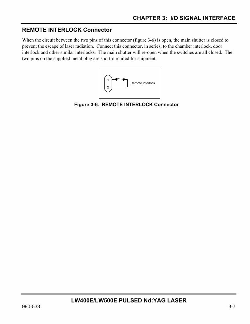
REMOTE INTERLOCK Connector When the circuit between the two pins of this connector (figure 3-6) is open, the main shutter is closed to prevent the escape of laser radiation. Connect this connector, in series, to the chamber interlock, door interlock and other similar interlocks. The main shutter will re-open when the switches are all closed. The two pins on the supplied metal plug are short-circuited for shipment.
Figure 3-6. REMOTE INTERLOCK Connector
1
2 Remote interlock

LW400E/LW500E PULSED Nd:YAG LASER
990-533 4-1
CHAPTER 4 SYSTEM TIMING
Time Charts Control with Laser Controller (Energy-Sharing Delivery) Figure 4-1 shows the timing signals for control of the laser using the Laser Controller with energy sharing delivery.
ONOFFON
OFFON
OFFON
OFF
High Voltage ON Output
Ready Output
Beam Select 1 Input
Beam Select 2 Input
Laser Start Input
Laser Output
End Output
Monitor Output
Charging completed
Max. 31 s
$300 ms $300 ms
Laser beam is projected fromlaser beam input units 1 and 2
Laser beam is projected fromlaser beam input unit 1
40 ms
The laser operates according to the schedule shown on the display panel.
Figure 4-1. Timing Signals for Control of the Laser Using the Laser Controller with Energy Sharing Delivery
CHAPTER 4: SYSTEM TIMING
LW400E/LW500E PULSED Nd:YAG LASER
4-2 990-533
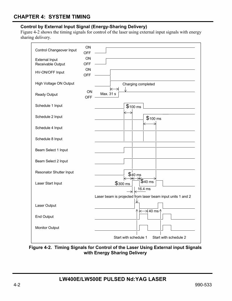
Control by External Input Signal (Energy-Sharing Delivery) Figure 4-2 shows the timing signals for control of the laser using external input signals with energy sharing delivery.
Figure 4-2. Timing Signals for Control of the Laser Using External input Signals with Energy Sharing Delivery
ONOFFON
OFFON
OFF
ONOFF
Control Changeover Input
External InputReceivable Output
HV-ON/OFF Input
High Voltage ON Output
Ready Output
Schedule 1 Input
Beam Select 1 Input
Beam Select 2 Input
Charging completed
Max. 31 s
40 ms
Laser beam is projected from laser beam input units 1 and 2
16.4 ms
Schedule 2 Input
Schedule 4 Input
Schedule 8 Input
Resonator Shutter Input
Laser Start Input
Laser Output
End Output
Monitor Output
$100 ms
$100 ms
$40 ms
$300 ms $40 ms
Start with schedule 1 Start with schedule 2

CHAPTER 4: SYSTEM TIMING
LW400E/LW500E PULSED Nd:YAG LASER
990-533 4-3
Control by External Input Signal (Time-Sharing of Two Energy-Sharing Deliveries) Figure 4-3 shows the timing signals for control of the laser using external input signals with time-sharing of two energy sharing deliveries.
ONOFFON
OFFON
OFF
ONOFF
Control Changeover Input
External Input Receivable Output
HV-ON/OFF Input
High Voltage ON Output
Ready Output
Schedule 1 Input
Beam Select 1
Beam Select 2
Charging completed
Max. 31 s
Schedule 2 Input
Schedule 4 Input
Schedule 8 Input
Resonator Shutter
Laser Start Input
Laser Output
End Output
Monitor Output
$100 ms
Beam Select 3
Beam Select 4
$300 ms$40 ms
16.4 ms
40 ms
units 1 and 2 (schedule 3)Laser beam is projected from laser beam input
Figure 4-3. Timing Signals for Control of the Laser Using External input Signals with Time Sharing of Two Energy Sharing Deliveries

CHAPTER 4: SYSTEM TIMING
LW400E/LW500E PULSED Nd:YAG LASER
4-4 990-533
Repeated Operation with Two Energy-Sharing Deliveries Figure 4-4 shows the timing signals for repeated operation of the laser using two energy sharing deliveries.
High Voltage ON Output
Ready Output
Schedule 1 Input
Beam Select 1
Beam Select 2
Charging completed
Schedule 2 Input
Schedule 4 Input
Schedule 8 Input
Resonator Shutter
Laser Start Input
Laser Output
End Output
Monitor Output
$300 ms$40 ms
40 msLaser Stop Output
Max. 31 s
Laser beam is fired repeatedlyaccording to schedule 7 monitor
Laser output is stopped whenlaser stop signal occurs
Figure 4-4. Timing Signals for Repeated Operation of the Laser Using Two Energy Sharing Deliveries

CHAPTER 4: SYSTEM TIMING
LW400E/LW500E PULSED Nd:YAG LASER
990-533 4-5
High Repetition Operation (Greater than 25 PPS) Figure 4-5 shows the timing signals for high repetition operation (greater than 25 pps).
Figure 4-5. Timing Signals for High Repetition Operation (Greater than 25 pps)
High Voltage ON Output
Ready Output
Schedule 1-8 Input
Beam Select 1-4 Input
Resonator Shutter Input
Laser Start Input
Laser Output
End Output
Monitor Normal Output
$300 ms$40 ms
Monitor No-Light Output
Max. 31 s
Laser Stop Input
Monitor Trouble Output
See CAUTION, below
Min. 2 ms (at 500 pps)
CAUTION - When the laser is controlled by external signals, the laser stops firingwhen the Laser Stop signal circuit is open and starts when the circuit is closed.When controlled with the Program Unit, the laser alternately starts and stops(toggles) when the LASER START/STOP button is pressed.

LW400E/LW500E PULSED Nd:YAG LASER
990-533 5-1
CHAPTER 5 GETTING STARTED
Removal of Laser Oscillator Fittings The oscillator is shipped with two fittings to prevent damage during transit. Refer to figure 5-2. Remove both fittings and store in a secure place for use if the laser is re-shipped.
Connection of Power Supply Cable Open the front door and remove the cover for the power supply input terminals. Pull out the power cable from the bottom of the laser and connect it to the power supply input terminals as shown in figure 5-2.
Figure 5-2. Power Supply Cable Connections
ON
OFF
OFF
MAIN POWER
OFF
CONTROLON
Power cable
Be sure to connect the wires to the correctterminals. The wires are distinguishedfrom each other by differing colors.
MAIN POWER
OFF
CONTROLON
Remove the threescrews to removethe cover.
Green/Yellow Red White Black
Remove the two yellow laser oscillator fittings. Retain for future use when moving laser.
Figure 5-1 Removal of Laser Oscillator Fittings

CHAPTER 5: GETTING STARTED
LW400E/LW500E PULSED Nd:YAG LASER
5-2 990-533
Connection of Cooling Water Hose Refer to figure 5-3. Attach the braided hoses to the cooling water inlet and the outlet connections. Tighten the hoses using the supplied hose band.
For cooling, use municipal or industrial water with a flow rate of at least 6.6 gal/min (25 l/min), a pressure of 14.2 – 42.6 lbf/in2 (98 - 294 kPa or 1 - 3 kgf/cm2) and a temperature of 77°F (25°C) and below.
Cooler Unit De-ionized Water Supply Refer to figure 5-4. Remove the cover of the de-ionized water tank. Fill the tank with de-ionized water up to the line reading HIGH on the level gauge label, using the supplied feed pump. After filling the tank, put the floating panel on top of the water. Make sure that the panel is positioned correctly. Put the cover back on the tank. CAUTION: To prevent contamination, use the feed pump only for de-ionized water. Once you have filled the de-ionized water tank and started the cooler, the water level may drop slightly. If so, add more de-ionized water.
Make sure that the floating panel is removed when adding de-ionized water.
Cooler Unit
Coo
ling
wat
er o
utle
t
Coo
ling
wat
er in
let
Figure 5-3. Cooling Water
Hose Connections
Figure 5-4. Filling De-ionized Water Tank
Ion-
Exch
ange
Res
in C
artri
dge
Wat
er F
ilter
Ion-
Exch
ange
Res
in C
artri
dge
Wat
er F
ilter
Floating Panel Tank Cover
Floating Panel

CHAPTER 5: GETTING STARTED
LW400E/LW500E PULSED Nd:YAG LASER
990-533 5-3
Optical Fiber Connection The laser uses a high-precision optical fiber. Once the optical axis of the incident beam is adjusted, it will not have to be re-adjusted even if the optical fiber is removed and re-installed.
Preparing Optical Fiber for Installation Make sure that the end face of the optical fiber is free of stains and dust. Use the end face checker when checking this. After the check is complete, put the cap back on the optical fiber. If any dust or stains are found, blow the end face clear using an air blower or wipe it off using lens cleaning paper. (See “Cleaning the Optics,” – Chapter 8) Connection to Laser Beam Input Unit Refer to figure 5-5. Open the optical fiber connector cover and insert one end of the optical fiber into the laser through the optical fiber inlet. CAUTION: Make sure that any bends in the optical fiber do not exceed the minimum bending radius for that size fiber. (See table 1-1) Refer to figure 5-6. Remove the cap from the plug of the optical fiber and blow off any dust using an air blower. Connect the plug to the laser beam input unit as shown in figure 5-6. Make sure that the plug is positioned in the correct direction. CAUTION: Tighten the outer ring by hand only. Using a tool could cause excessive tightening of the ring and displacement of the incident laser beam.
Make optical fiber inlet holes. Pass the optical fibers through these holes and lead the fibers in the direction shown by the arrow.
Lead the optical fibers into the Laser and connect them to the laser beam input units.
Figure 5-5 Routing the Fiber-optic Cable
Groove
Cap
Turn
Optical Fiber
Protrusion
Laser Beam Input Unit
Turn the outer ring of the plug in the direction of the arrow
Plug
Figure 5-6 Connecting the Fiber-optic Cable to the Laser
Beam Input Unit
CHAPTER 5: GETTING STARTED
LW400E/LW500E PULSED Nd:YAG LASER
5-4 990-533
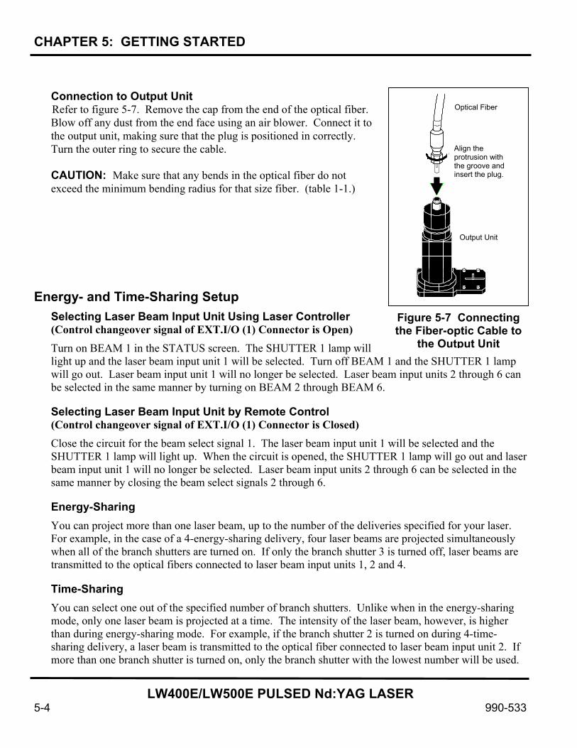
Connection to Output Unit Refer to figure 5-7. Remove the cap from the end of the optical fiber. Blow off any dust from the end face using an air blower. Connect it to the output unit, making sure that the plug is positioned in correctly. Turn the outer ring to secure the cable. CAUTION: Make sure that any bends in the optical fiber do not exceed the minimum bending radius for that size fiber. (table 1-1.)
Energy- and Time-Sharing Setup
Selecting Laser Beam Input Unit Using Laser Controller (Control changeover signal of EXT.I/O (1) Connector is Open) Turn on BEAM 1 in the STATUS screen. The SHUTTER 1 lamp will light up and the laser beam input unit 1 will be selected. Turn off BEAM 1 and the SHUTTER 1 lamp will go out. Laser beam input unit 1 will no longer be selected. Laser beam input units 2 through 6 can be selected in the same manner by turning on BEAM 2 through BEAM 6.
Selecting Laser Beam Input Unit by Remote Control (Control changeover signal of EXT.I/O (1) Connector is Closed) Close the circuit for the beam select signal 1. The laser beam input unit 1 will be selected and the SHUTTER 1 lamp will light up. When the circuit is opened, the SHUTTER 1 lamp will go out and laser beam input unit 1 will no longer be selected. Laser beam input units 2 through 6 can be selected in the same manner by closing the beam select signals 2 through 6.
Energy-Sharing You can project more than one laser beam, up to the number of the deliveries specified for your laser. For example, in the case of a 4-energy-sharing delivery, four laser beams are projected simultaneously when all of the branch shutters are turned on. If only the branch shutter 3 is turned off, laser beams are transmitted to the optical fibers connected to laser beam input units 1, 2 and 4.
Time-Sharing You can select one out of the specified number of branch shutters. Unlike when in the energy-sharing mode, only one laser beam is projected at a time. The intensity of the laser beam, however, is higher than during energy-sharing mode. For example, if the branch shutter 2 is turned on during 4-time-sharing delivery, a laser beam is transmitted to the optical fiber connected to laser beam input unit 2. If more than one branch shutter is turned on, only the branch shutter with the lowest number will be used.
Optical Fiber
Align the protrusion with the groove and insert the plug.
Output Unit
Figure 5-7 Connecting the Fiber-optic Cable to
the Output Unit
CHAPTER 5: GETTING STARTED
LW400E/LW500E PULSED Nd:YAG LASER
990-533 5-5
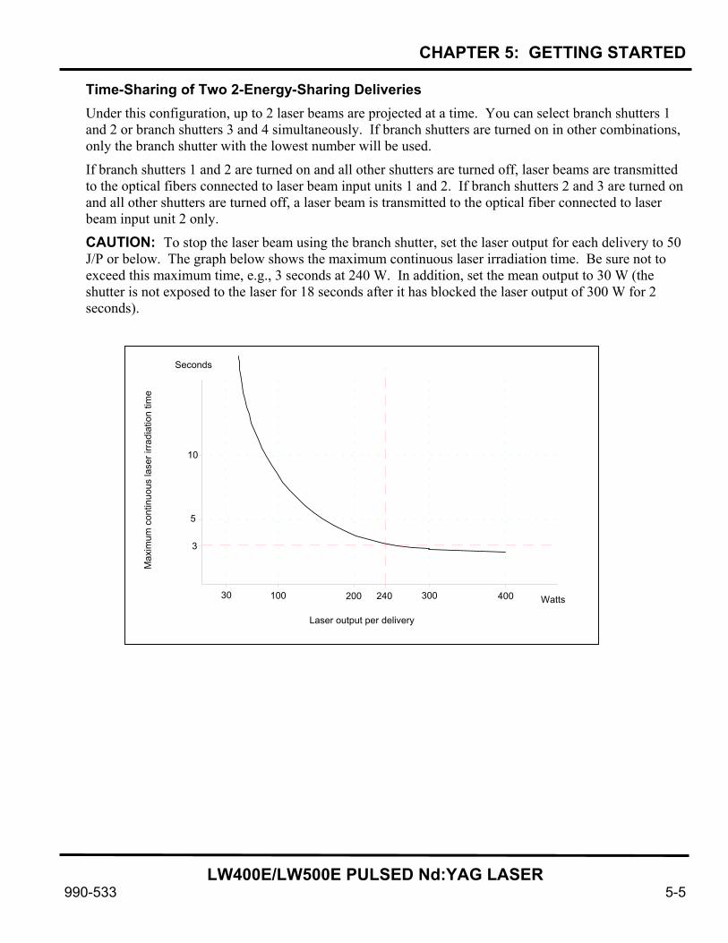
Time-Sharing of Two 2-Energy-Sharing Deliveries Under this configuration, up to 2 laser beams are projected at a time. You can select branch shutters 1 and 2 or branch shutters 3 and 4 simultaneously. If branch shutters are turned on in other combinations, only the branch shutter with the lowest number will be used.
If branch shutters 1 and 2 are turned on and all other shutters are turned off, laser beams are transmitted to the optical fibers connected to laser beam input units 1 and 2. If branch shutters 2 and 3 are turned on and all other shutters are turned off, a laser beam is transmitted to the optical fiber connected to laser beam input unit 2 only. CAUTION: To stop the laser beam using the branch shutter, set the laser output for each delivery to 50 J/P or below. The graph below shows the maximum continuous laser irradiation time. Be sure not to exceed this maximum time, e.g., 3 seconds at 240 W. In addition, set the mean output to 30 W (the shutter is not exposed to the laser for 18 seconds after it has blocked the laser output of 300 W for 2 seconds).
30 100 200 240 300 400 Watts
3
5
10
Max
imum
con
tinuo
us la
ser i
rradi
atio
n tim
e
Laser output per delivery
Seconds

LW400E/LW500E PULSED Nd:YAG LASER
990-533 6-1
CHAPTER 6 OPERATING INSTRUCTIONS
Preparation for Operation Verify that the electrical supply meets the electrical and cooling (water) requirements, as shown in Appendix A. The electrical and water supplies must meet all local, state, and federal safety standards.
Startup Procedure
Turn on the MAIN POWER switch. The POWER lamp will light and this screen will appear on the display of the Program Unit.
The laser automatically checks the following.
• Opening/closing of the shutter on the oscillator side
• Memory (checksum and data space)
• Negative-phase detector relay
• Charging trouble
If there are no problems, this screen will appear.
Turning On the CONTROL Key Switch. Turn on the CONTROL key switch. This screen will appear. The data fields are as follows:
• WATER: This item is the temperature of the cooling water. When the MAIN POWER switch is first turned on the temperature will not change. However, after the CONTROL key switch is turned on, the temperature will begin to rise
Water °C AUTO-START SELF-CHECK >
Water °C AUTO-START <WAIT>
KEY-SWITCH ON > COOLER ON >
DEIONIZE 9.99MS cm (READY) WATER TEMPERATURE (NORMAL) LASER POWER MONITOR (NOT READY)
Water °C AUTO-START KEY-SWITCH ON >

CHAPTER 6: OPERATING INSTRUCTIONS
LW400E/LW500E PULSED Nd:YAG LASER
6-2 990-533
• DEIONIZE: Shows the resistance level of the de-ionized water for cooling. READY or NOT READY will be displayed according to the resistance level, as follows:
READY: Equal to or above 3.00 megohms per centimeter NOT READY: Below 3.00 megohms per centimeter
• WATER TEMPERATURE: Shows the temperature of the de-ionized water. LOW, NORMAL, or HIGH will be displayed according to the temperature level, as follows:
LOW: 24° C (75.2°F) or below MEDIUM: 25°C - 40°C (77°F - 104°F) HIGH: 41°C (105.8°F) or above
NOTE: As the de-ionized water is unstable during initial start-up, NORMAL indication is not displayed unless the temperature is at 27°C (80.6°F). After water stabilization has occurred, the NORMAL indication will be displayed when the temperature at 25°C (77°F).
• LASER POWER MONITOR: Shows the status of the power monitor unit sensor. READY or NOT READY will be displayed according to the state of the power monitor unit, as follows:
NOT READY: Warm-up in progress READY Warm-up completed
When DEIONIZE and LASER POWER MONITOR are READY, and WATER TEMPERATURE is NORMAL, the high voltage is turned on to start charging the power supply. The display will read as shown.
After charging has been completed, READY!! will flash on the screen for one-half second. The display will then return to the screen you had previously used, that is, the SCHEDULE, STATUS or POWER MONITOR screen.
Water °C AUTO-START KEY-SWITCH ON > COOLER ON > HV-ON >
Water °C AUTO-START KEY-SWITCH ON > COOLER ON > HV-ON > READY ! !

CHAPTER 6: OPERATING INSTRUCTIONS
LW400E/LW500E PULSED Nd:YAG LASER
990-533 6-3
SCHEDULE Screen STATUS Screen
POWER MONITOR Screen

CHAPTER 6: OPERATING INSTRUCTIONS
LW400E/LW500E PULSED Nd:YAG LASER
6-4 990-533
Operating Procedure for the Laser Controller NOTE: The following special fonts are used in this section:
000 (Highlighted): These are values that can be changed by the operator. (Outlined): These values cannot be changed by the operator.
Screen Operation You can directly set the laser output level using the laser power feedback control. Also, the waveform control function allows free setting of the waveform. Pressing the MENU key, causes the display to sequence through the three screens shown below.
If the laser is begins to fire when the SCHEDULE screen is displayed, it will automatically change to the POWER MONITOR screen.
SCHEDULE Screen STATUS Screen
POWER MONITOR Screen
If the laser is output, the display automatically changes to this screen.

CHAPTER 6: OPERATING INSTRUCTIONS
LW400E/LW500E PULSED Nd:YAG LASER
990-533 6-5
Contents of Three Main Screens: (SCHEDULE, POWER MONITOR and STATUS)
Contents Screen
Individual Screen Common to Two Screens
Common to Three Screens
SCHEDULE
Waveform (fix/flex) setting Laser energy (approx.) display Laser output peak setting Repetition (pps) setting Number of shots setting Laser output time setting Laser output value setting Seam weld mode ON/OFF
POWER MONITOR
Laser output energy monitor Laser output average power
display Display of the number of laser
outputs Display of the number of
acceptable laser output Laser energy upper/lower limit
setting Lamp input power upper limit
setting
Schedule No. Graph ON/OFF
STATUS
Beam selection (Branch shutter OPEN/CLOSE)
Count reset Count preset Guide beam setting Fiber type, core dia setting
High voltage ON/OFF Main shutter ON/OFF Guide beam ON/OFF Water temperature
CHAPTER 6: OPERATING INSTRUCTIONS
LW400E/LW500E PULSED Nd:YAG LASER
6-6 990-533
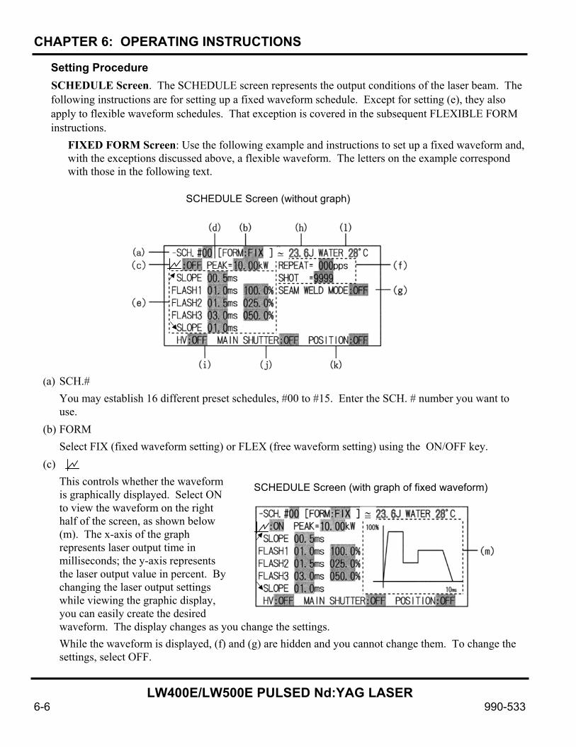
Setting Procedure SCHEDULE Screen. The SCHEDULE screen represents the output conditions of the laser beam. The following instructions are for setting up a fixed waveform schedule. Except for setting (e), they also apply to flexible waveform schedules. That exception is covered in the subsequent FLEXIBLE FORM instructions.
FIXED FORM Screen: Use the following example and instructions to set up a fixed waveform and, with the exceptions discussed above, a flexible waveform. The letters on the example correspond with those in the following text.
(a) SCH.# You may establish 16 different preset schedules, #00 to #15. Enter the SCH. # number you want to use.
(b) FORM Select FIX (fixed waveform setting) or FLEX (free waveform setting) using the ON/OFF key.
(c) This controls whether the waveform is graphically displayed. Select ON to view the waveform on the right half of the screen, as shown below (m). The x-axis of the graph represents laser output time in milliseconds; the y-axis represents the laser output value in percent. By changing the laser output settings while viewing the graphic display, you can easily create the desired waveform. The display changes as you change the settings. While the waveform is displayed, (f) and (g) are hidden and you cannot change them. To change the settings, select OFF.
º ≅
SCHEDULE Screen (without graph)
≅
SCHEDULE Screen (with graph of fixed waveform)
CHAPTER 6: OPERATING INSTRUCTIONS
LW400E/LW500E PULSED Nd:YAG LASER
990-533 6-7
The laser power feedback control ensures that the laser produces a beam with the set waveform (reference waveform).
(d) PEAK
Set the peak laser output. You may set it between between 00.00 kW and the maximum, as shown below. If you set the peak output to 00.00 kW, there will be no laser beam output. The maximum peak output and laser output value are as follows:
LW400E 7.5 kW x 100% = 7.5 kW LW500E 10.0 kW x 100% = 10.0 kW
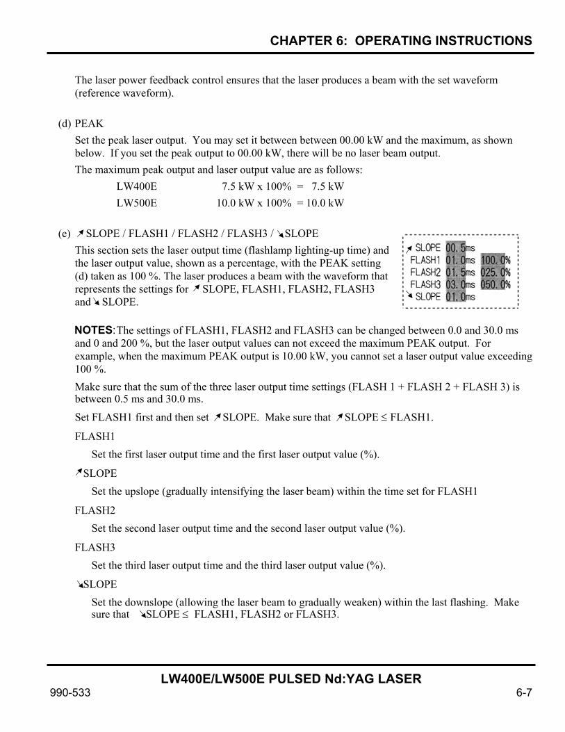
(e) SLOPE / FLASH1 / FLASH2 / FLASH3 / SLOPE
This section sets the laser output time (flashlamp lighting-up time) and the laser output value, shown as a percentage, with the PEAK setting (d) taken as 100 %. The laser produces a beam with the waveform that represents the settings for SLOPE, FLASH1, FLASH2, FLASH3 and SLOPE.
NOTES: The settings of FLASH1, FLASH2 and FLASH3 can be changed between 0.0 and 30.0 ms and 0 and 200 %, but the laser output values can not exceed the maximum PEAK output. For example, when the maximum PEAK output is 10.00 kW, you cannot set a laser output value exceeding 100 %. Make sure that the sum of the three laser output time settings (FLASH 1 + FLASH 2 + FLASH 3) is between 0.5 ms and 30.0 ms.
Set FLASH1 first and then set SLOPE. Make sure that SLOPE ≤ FLASH1.
FLASH1 Set the first laser output time and the first laser output value (%).
SLOPE Set the upslope (gradually intensifying the laser beam) within the time set for FLASH1
FLASH2 Set the second laser output time and the second laser output value (%).
FLASH3 Set the third laser output time and the third laser output value (%).
SLOPE Set the downslope (allowing the laser beam to gradually weaken) within the last flashing. Make sure that SLOPE ≤ FLASH1, FLASH2 or FLASH3.
CHAPTER 6: OPERATING INSTRUCTIONS
LW400E/LW500E PULSED Nd:YAG LASER
6-8 990-533
(f) REPEAT / SHOT
REPEAT. Set the laser pulse repetition rate (pulses per second (pps)). The setting can be between 0 and 500. When it is set to 0, the laser pulse is not repeated.
SHOT. Set the number of consecutive pulses (shots) you want the laser to fire. The setting can be between 0 and 9999.
NOTE: When REPEAT is set to any value other than 0 and SHOT is set to 0, the laser continues to fire (that is, it operates continuously) until it receives a laser-stop signal.
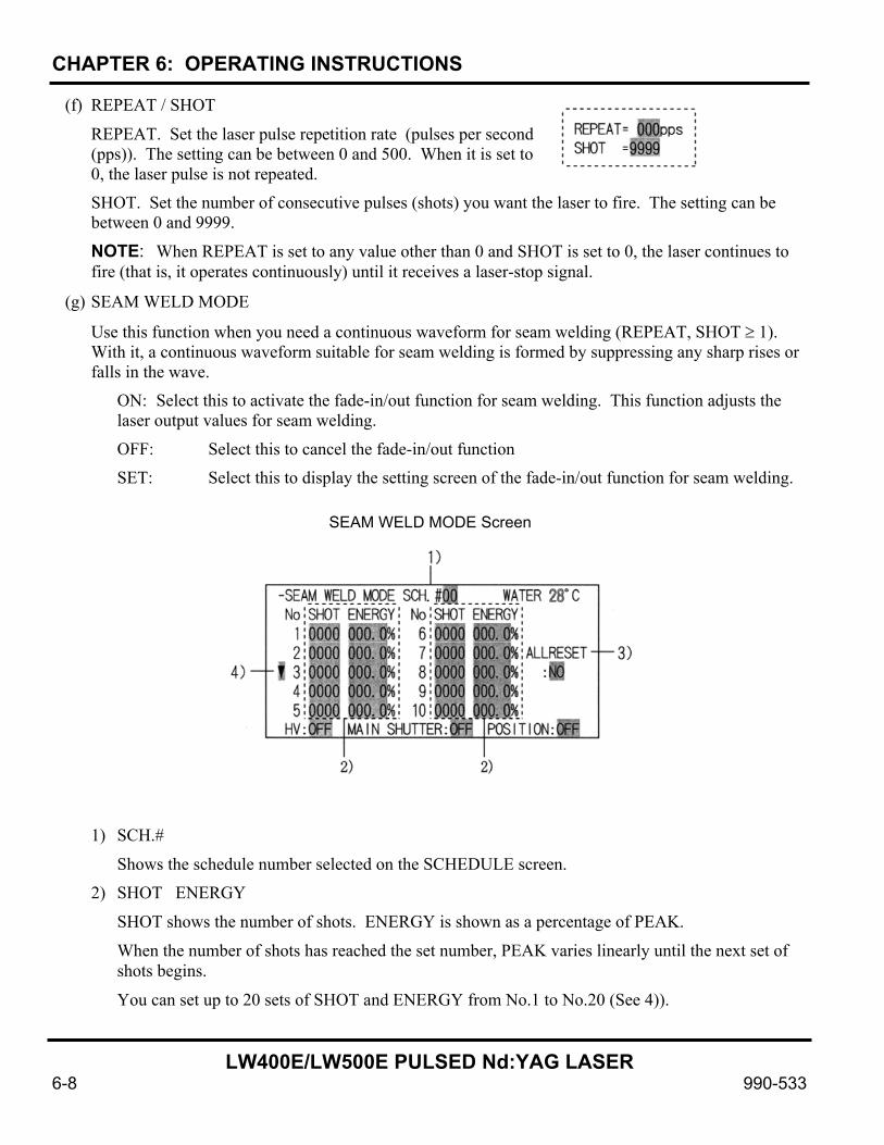
(g) SEAM WELD MODE
Use this function when you need a continuous waveform for seam welding (REPEAT, SHOT ≥ 1). With it, a continuous waveform suitable for seam welding is formed by suppressing any sharp rises or falls in the wave.
ON: Select this to activate the fade-in/out function for seam welding. This function adjusts the laser output values for seam welding.
OFF: Select this to cancel the fade-in/out function
SET: Select this to display the setting screen of the fade-in/out function for seam welding.
1) SCH.#
Shows the schedule number selected on the SCHEDULE screen.
2) SHOT ENERGY
SHOT shows the number of shots. ENERGY is shown as a percentage of PEAK.
When the number of shots has reached the set number, PEAK varies linearly until the next set of shots begins.
You can set up to 20 sets of SHOT and ENERGY from No.1 to No.20 (See 4)).
SEAM WELD MODE Screen

CHAPTER 6: OPERATING INSTRUCTIONS
LW400E/LW500E PULSED Nd:YAG LASER
990-533 6-9
3) ALL RESET
Select yes only if you want to clear all of the settings from SHOT1 to SHOT20.
4) –
Move the cursor to – and press the cursor (up or down) key, and the next 10 sets from SHOT11 to SHOT20 will appear.
To return to the setting screen for SHOT1 to SHOT10, move the cursor to – and press the cursor (up or down) key.
Press the MENU key to return to the SCHEDULE screen.
The example above shows seam welding with 100 consecutive shots of laser beam. It is shown graphically in the figure below.
You can set SHOT on either the SCHEDULE screen or the SEAM WELD MODE screen. If different settings are made on the two screens, the setting on the SCHEDULE screen is used.
Example) In the example above, if SHOT is set to 40 on the SCHEDULE screen, the settings from the 40th shot on the SEAM WELD MODE screen will be ignored.
If SHOT is set to 200 on the SCHEDULE screen, the last setting (SHOT6) on the SEAM WELD MODE screen will apply to the 101st and 200th shots.
50
100
150
040 100 (SHOT)9010 50
i “ j
50
100
150
i “ j
EXAMPLE OF SEAM WELD MODE
CHAPTER 6: OPERATING INSTRUCTIONS
LW400E/LW500E PULSED Nd:YAG LASER
6-10 990-533
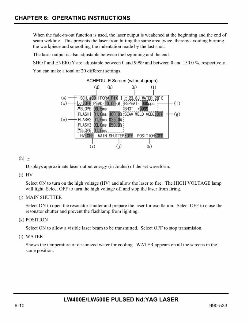
When the fade-in/out function is used, the laser output is weakened at the beginning and the end of seam welding. This prevents the laser from hitting the same area twice, thereby avoiding burning the workpiece and smoothing the indentation made by the last shot.
The laser output is also adjustable between the beginning and the end.
SHOT and ENERGY are adjustable between 0 and 9999 and between 0 and 150.0 %, respectively.
You can make a total of 20 different settings.
(h) ~
Displays approximate laser output energy (in Joules) of the set waveform.
(i) HV
Select ON to turn on the high voltage (HV) and allow the laser to fire. The HIGH VOLTAGE lamp will light. Select OFF to turn the high voltage off and stop the laser from firing.
(j) MAIN SHUTTER
Select ON to open the resonator shutter and prepare the laser for oscillation. Select OFF to close the resonator shutter and prevent the flashlamp from lighting.
(k) POSITION
Select ON to allow a visible laser beam to be transmitted. Select OFF to stop transmision.
(l) WATER
Shows the temperature of de-ionized water for cooling. WATER appears on all the screens in the same position.
~
SCHEDULE Screen (without graph)

CHAPTER 6: OPERATING INSTRUCTIONS
LW400E/LW500E PULSED Nd:YAG LASER
990-533 6-11
FLEXIBLE FORM Screen: In addition to the previous discussion, use the following example and additional instructions to set up a flexible waveform. The letters on the example correspond with those in the following text.
(a) Point
Is used to set the laser output time and laser output value (%) for each point to form a free waveform. You can set up to 20 points. The setting for each point can be changed between 0.1 and 30.0 ms, for laser output time, and between 0 and 200 % for laser output value. However, the last point selected must be between 0.5 and 30 ms.
•, –
Move the cursor to • or – and press the cursor key to move to the next set of points (Points 6 through 10), and successively to Points 16 through 20.
(b)
Select ON for (b) and the set waveform will appear in (d). The x-axis graph represents laser output time in milliseconds; the y-axis represents laser output value in percent.
The laser power feedback control ensures that the laser transmits a laser beam with the set waveform (reference waveform).
An overshoot (i.e., output above the set waveform) may be caused during a rising waveform. In such cases, increase the upslope ( SLOPE) by 0.1 – 1.0 ms.
~
SCHEDULE Screen (without graph)
~
SCHEDULE Screen (with graph)
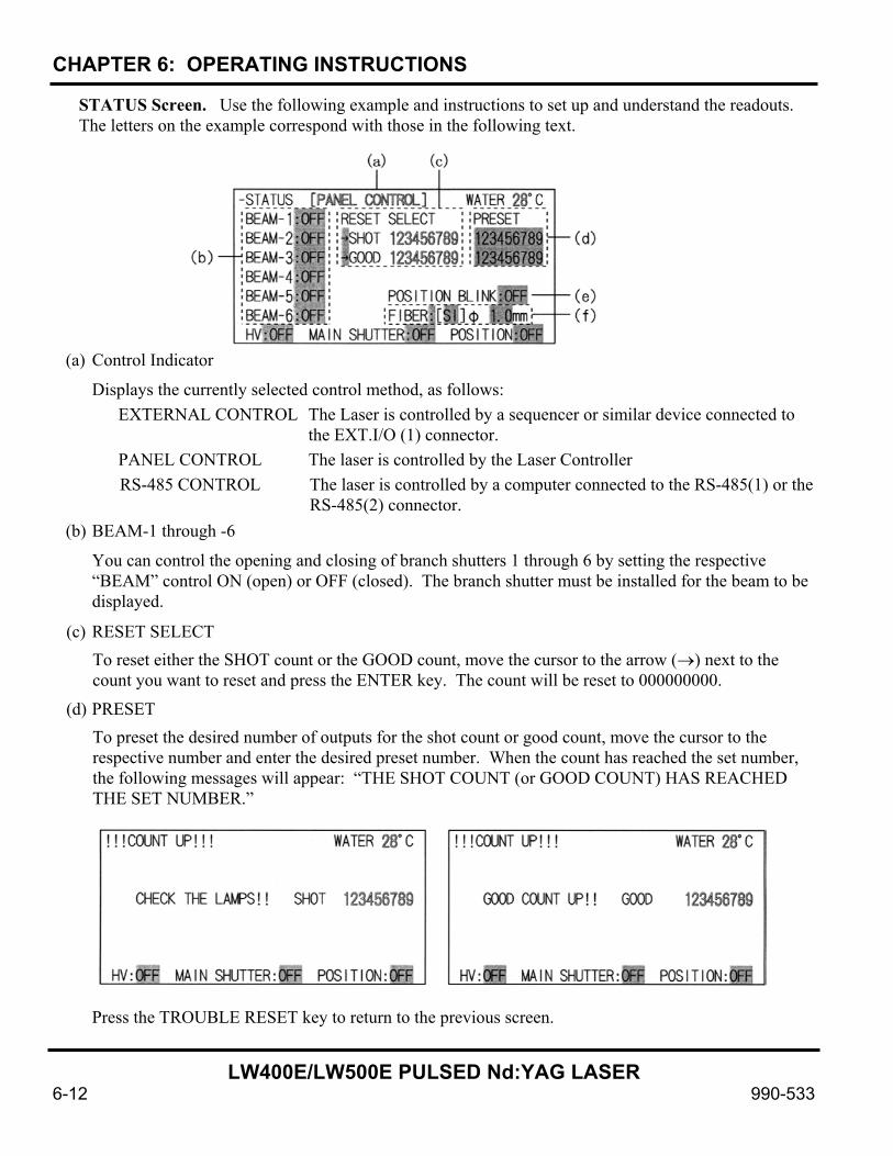
CHAPTER 6: OPERATING INSTRUCTIONS
LW400E/LW500E PULSED Nd:YAG LASER
6-12 990-533
STATUS Screen. Use the following example and instructions to set up and understand the readouts. The letters on the example correspond with those in the following text.
(a) Control Indicator
Displays the currently selected control method, as follows: EXTERNAL CONTROL The Laser is controlled by a sequencer or similar device connected to
the EXT.I/O (1) connector. PANEL CONTROL The laser is controlled by the Laser Controller RS-485 CONTROL The laser is controlled by a computer connected to the RS-485(1) or the
RS-485(2) connector. (b) BEAM-1 through -6
You can control the opening and closing of branch shutters 1 through 6 by setting the respective “BEAM” control ON (open) or OFF (closed). The branch shutter must be installed for the beam to be displayed.
(c) RESET SELECT To reset either the SHOT count or the GOOD count, move the cursor to the arrow (→) next to the count you want to reset and press the ENTER key. The count will be reset to 000000000.
(d) PRESET To preset the desired number of outputs for the shot count or good count, move the cursor to the respective number and enter the desired preset number. When the count has reached the set number, the following messages will appear: “THE SHOT COUNT (or GOOD COUNT) HAS REACHED THE SET NUMBER.”
Press the TROUBLE RESET key to return to the previous screen.

CHAPTER 6: OPERATING INSTRUCTIONS
LW400E/LW500E PULSED Nd:YAG LASER
990-533 6-13
(e) POSITION BLINK
Select ON for blinking output of the visible laser beam, or OFF for continuous output..
(f) FIBER
This function protects the optical fiber by preventing excess input of the laser beam to the fiber. Enter the type (SI/GI) and core diameter of the optical fiber used. The maximum input to the optical fiber will be automatically calculated and the lamp limited, based on this maximum input. (The default setting is SI and φ1.0 mm. The setting range of core diameter for the LW400E is φ 0.3 to 1.0 mm; for the LW500E it is φ0.4 to 1.0 mm..)
If the schedule setting (i.e., the peak power, the laser output time and value, and the number of repetitions set on the SCHEDULE screen) exceeds the maximum input to the optical fiber, the warning, SET ERROR FIBER or OVER RATE FIBER will appear.
Maximum laser input to optical fiber (approximate level for each fiber)
SI/GI optical fiber used for LW400E Delivery
Dia Single delivery 2-energy share 4-energy share
φ 0.3 mm 10 J 200 W 5 J 100 W 2 J 500 W φ 0.4 mm 30 J 400 W 15 J 200 W 8 J 100 W φ 0.6 mm 50 J 400 W 25 J 200 W 12 J 100 W φ 0.8 mm 50 J 400 W 25 J 200 W 12 J 100 W
SI/GI optical fiber used for LW500E
Delivery Dia Single delivery 2-energy share 4-energy share
φ 0.4 mm 30 J 200 W 15 J 100 W 7 J 50 W φ 0.6 mm 70 J 500 W 35 J 250 W 20 J 120 W φ 0.8 mm 70 J 500 W 35 J 250 W 20 J 120 W
*1, *2: The maximum laser inputs for optical fibers with those diameters will be smaller than the levels shown above, for schedules with low laser output efficiency (e.g., the peak power is 1.0 kW or below).
*2: When a GI optical fiber of φ0.4 mm diameter is used, set the laser peak output to 6 kW or below.
CAUTION: Do not use optical fibers smaller than those shown above for each respective laser; they may be easily damaged.
*1
*2
*1
*1

CHAPTER 6: OPERATING INSTRUCTIONS
LW400E/LW500E PULSED Nd:YAG LASER
6-14 990-533
POWER MONITOR Screen. Use the following example and instructions to set up and understand the readouts. The letters on the example correspond with those in the following text.
(a) SCH.#
Select the SCH (schedule) number you want to view. The energy of the last laser output for the selected schedule will be shown (b). When the Laser Controller is again started, the schedule number will automatically change to that schedule currently being used by the laser.
(b) ENERGY
Shows the monitored laser energy (in Joules) each time the laser beam is fired. In the case of high-repetition outputs, the energy is displayed at certain intervals.
(c) AVERAGE
Shows the mean power (in Watts) of the output laser beams.
(d) SHOT COUNT / GOOD COUNT
SHOT COUNT - Shows the total count of laser outputs. Use it as a guide to decide whether you should change the flashlamp. To reset the count, use the STATUS screen.
GOOD COUNT - Shows the number of good laser outputs (output laser beam energy is within the range you have set for energy HIGH / LOW (e)). To reset the count, use the STATUS screen.
(e) HIGH / LOW
Set the upper limit (HIGH) and the lower limit (LOW) for acceptable (GOOD) output laser energy. Use the allowable energy range for the selected schedule. If an output laser beam is outside this range, the monitor alarm will be activated.
POWER MONITOR Screen (without graph)
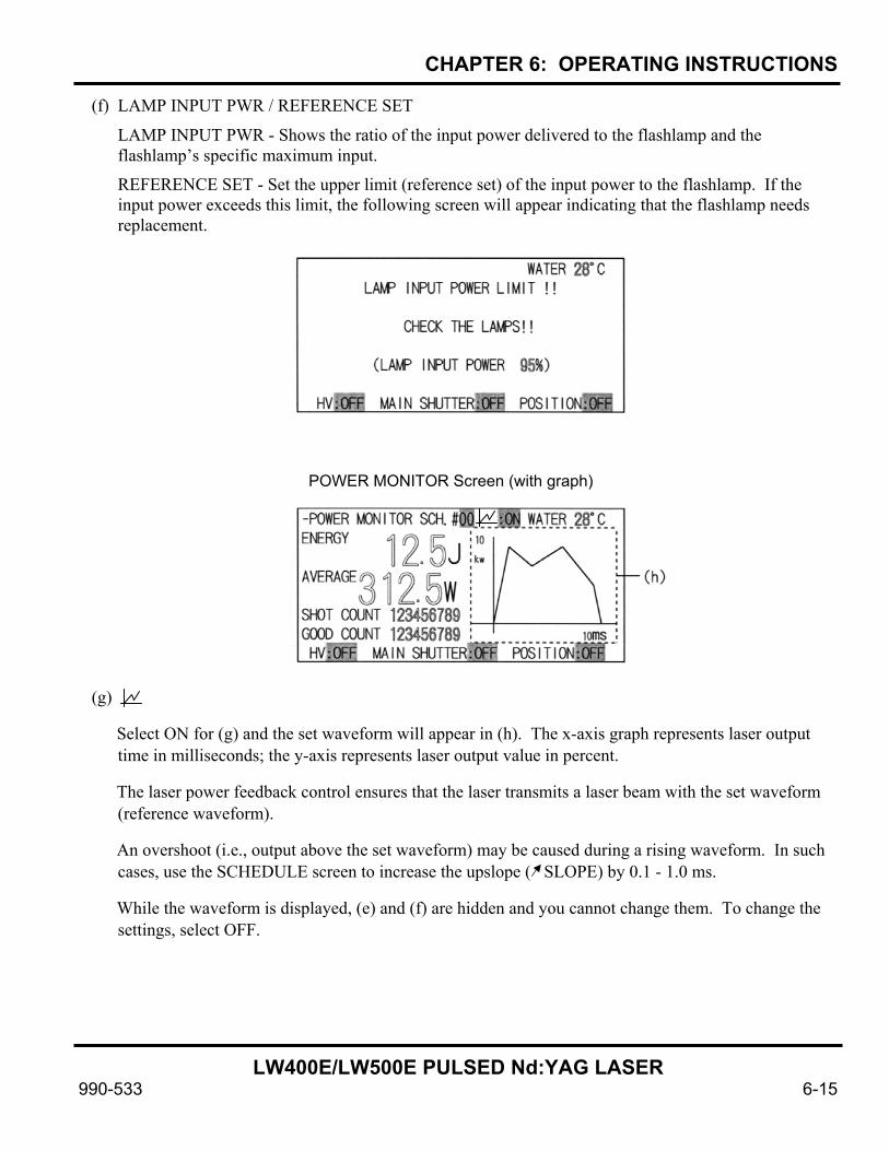
CHAPTER 6: OPERATING INSTRUCTIONS
LW400E/LW500E PULSED Nd:YAG LASER
990-533 6-15
(f) LAMP INPUT PWR / REFERENCE SET
LAMP INPUT PWR - Shows the ratio of the input power delivered to the flashlamp and the flashlamp’s specific maximum input.
REFERENCE SET - Set the upper limit (reference set) of the input power to the flashlamp. If the input power exceeds this limit, the following screen will appear indicating that the flashlamp needs replacement.
(g)
Select ON for (g) and the set waveform will appear in (h). The x-axis graph represents laser output time in milliseconds; the y-axis represents laser output value in percent.
The laser power feedback control ensures that the laser transmits a laser beam with the set waveform (reference waveform).
An overshoot (i.e., output above the set waveform) may be caused during a rising waveform. In such cases, use the SCHEDULE screen to increase the upslope ( SLOPE) by 0.1 - 1.0 ms.
While the waveform is displayed, (e) and (f) are hidden and you cannot change them. To change the settings, select OFF.
POWER MONITOR Screen (with graph)

CHAPTER 6: OPERATING INSTRUCTIONS
LW400E/LW500E PULSED Nd:YAG LASER
6-16 990-533
Shutdown Procedure Turn off the high voltage by either selecting the HV:OFF (a) on any of the three screens (STATUS Screen is shown) or applying an input HV-OFF signal to the EXT. I/O (1) connector.
Turn off the CONTROL key switch.
Turn off the MAIN POWER switch. CAUTION: To prevent damage to the YAG rod and flashlamp, be sure laser is not operating and is sufficiently cool before turning off the MAIN POWER switch
STATUS Screen

LW400E/LW500E PULSED Nd:YAG LASER
990-533 7-1
CHAPTER 7 USER MAINTENANCE
Precautions
NOTE: Before starting any maintenance, read the following precautions carefully: • Read through the entire specific instructions, including all caution and warning messages, BEFORE
starting any maintenance procedure. • Turn OFF the power to the laser before starting maintenance work. Wait for 5 minutes after turning
OFF power before starting work. • The Nd:YAG laser becomes ready for oscillation if the high voltage is turned ON during
maintenance work. Use extreme caution while performing any work on the laser. WARNING: Maintenance workers or anyone who is subject to possible Nd:YAG laser beam exposure must wear safety goggles having a minimum optical density of 6 at 1.064 nanometers wavelength.
Cooler Maintenance WARNING: Before working on the cooler, turn off power to the laser unit. If the high voltage has been ON, wait at least 5 minutes for the capacitor to fully discharge before proceeding.
Air Filter Cleaning. Required Item: You will need a No. 2 Phillips screwdriver.
Refer to Figure 7-1. To clean the air filter:
1. Remove the filter holder panel by removing the screws with a Phillips screwdriver.
2. Remove the filter and rinse it with tap water. If it is extremely dirty, wash it with a mild detergent.
3. Air dry the filter thoroughly. Replace it and secure it with the filter holder panel and screws.
Air filter
Filter retainer
Figure 7-1. Air Filter Removal
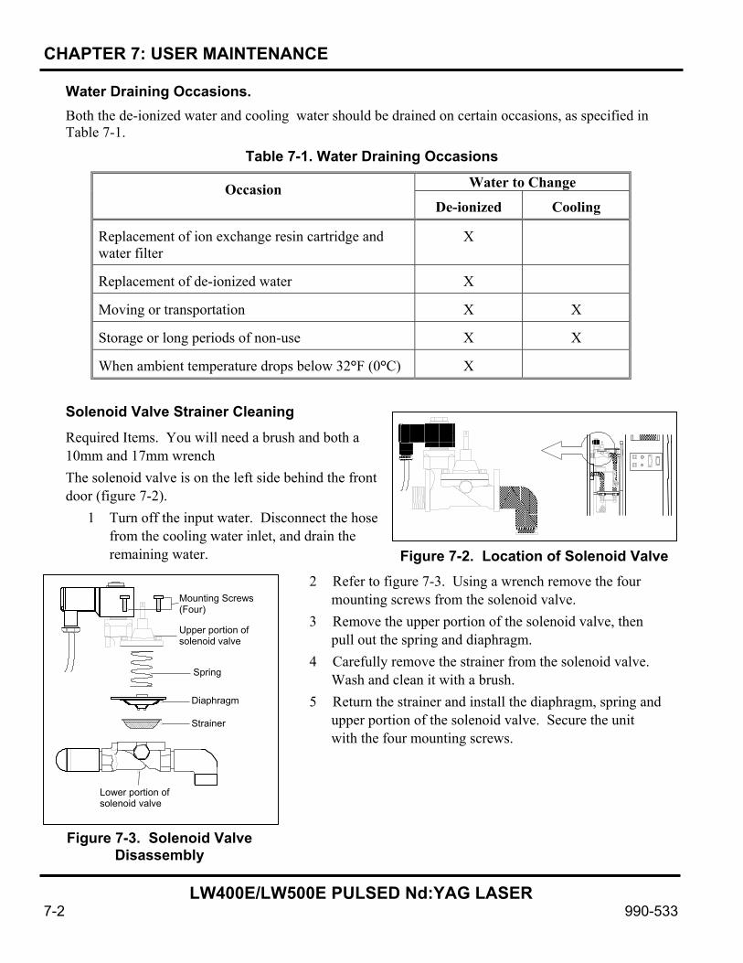
CHAPTER 7: USER MAINTENANCE
LW400E/LW500E PULSED Nd:YAG LASER
7-2 990-533
Water Draining Occasions. Both the de-ionized water and cooling water should be drained on certain occasions, as specified in Table 7-1.
Table 7-1. Water Draining Occasions Water to Change
Occasion De-ionized
Cooling
Replacement of ion exchange resin cartridge and water filter
X
Replacement of de-ionized water
X
Moving or transportation
X
X
Storage or long periods of non-use
X
X
When ambient temperature drops below 32°F (0°C)
X
Solenoid Valve Strainer Cleaning Required Items. You will need a brush and both a 10mm and 17mm wrench The solenoid valve is on the left side behind the front door (figure 7-2).
1 Turn off the input water. Disconnect the hose from the cooling water inlet, and drain the remaining water.
2 Refer to figure 7-3. Using a wrench remove the four mounting screws from the solenoid valve.
3 Remove the upper portion of the solenoid valve, then pull out the spring and diaphragm.
4 Carefully remove the strainer from the solenoid valve. Wash and clean it with a brush.
5 Return the strainer and install the diaphragm, spring and upper portion of the solenoid valve. Secure the unit with the four mounting screws.
Figure 7-2. Location of Solenoid Valve
Mounting Screws (Four)
Upper portion of solenoid valve
Spring
Diaphragm
Strainer
Lower portion of solenoid valve
Figure 7-3. Solenoid Valve Disassembly

CHAPTER 7: USER MAINTENANCE
LW400E/LW500E PULSED Nd:YAG LASER
990-533 7-3
Glove
Removal/installation tool
Ion-exchange resin cartridge
Figure 7-6. Cartridge Removal
6 If the net or the small hole at the bolt end of the solenoid valve (figure 7-4) is clogged, the input water will keep flowing. Check and clean periodically.
7 Connect the disconnected hose and secure it with the band
CAUTION: If the solenoid valve is clogged, the flow rate of the water is lowered and the laser may overheat. If this happens, use a cleaner water supply. Clean the solenoid valve annually
Replacing the Ion-Exchange Cartridge, Water Filter, and De-ionized Water Required Items. You will need vinyl gloves and a cartridge removal/installation tool. NOTE: Replace both ion-exchange cartridges, water filter, and de-ionized water every 6 months. Prevent the cartridges from drying; they will lose their effectivness.
1 Remove the cover of the de-ionized water tank and the floating plate. Keep the floating plate in a clean place. You can use the floating panel until it breaks.
2 Remove the mounting screws of the drain pipe (figure 7-5) on the end cap of the drain pipe to drain off the water.
3 Remove the de-ionized water tank cover. Wearing vinyl gloves, and using the removal/installation tool, turn the screw-in type ion-exchange cartridge in the tank counterclockwise to remove it (figure 7-6).
4 Insert a new ion-exchange cartridge and turn it clockwise with the removal/installation tool. Do not turn it too tightly or you might damage the threads
5 Pull upward on the water filter to remove it. (The water filter is an insertion type.)
6 Insert a new water filter. 7 Return the drain pipe and supply de-ionized water in the
tank.
8 Put the floating panel on the de-ionized water in the tank and put back the tank cover.
Small hole
Net
Figure 7-4. Solenoid Valve Bolt
Figure 7-5. Cartridge Location
Waterfilter
Ion-exchangeresincartridge
Drain plug
LW400E
EM ER GE NCY IN DIC A TOR
RESET ENTER
MENUO N+_
O FF
EMERGENCYSTOP

CHAPTER 7: USER MAINTENANCE
LW400E/LW500E PULSED Nd:YAG LASER
7-4 990-533
Draining the De-ionized Water 1 Remove the cover of the de-ionized water tank and take out the floating panel, then replace the
tank cover. (Keep the floating panel in a clean place.) 2 Remove the drain pipe mounting screw, then remove the end cap to drain the water. 3 Open the top cover of the laser chamber, and let the water drain from the chamber and hose into
the tank. 4 Return and re-install the drain pipe and end cap. 5 Install the top cover of the laser chamber. 6 When the laser is not used for a long time or its temperature goes below 0°C (32°F), perform the
additional steps in following procedure, below. CAUTION: Be sure to replace the top cover of the laser chamber to prevent any damage from water leakage.
Draining the De-ionized Water when the Laser Is Not Used for a Long Period of Time or Its Temperature Goes Below 32°F (0°C) When the Laser is not used for a long time or its temperature goes below 32°F (0°C), all the water must be drained by performing all of the steps in the previous procedure and this procedure.
1 After performing the previous procedure, remove the cover of the de-ionized water tank and remove the ion-exchange resin cartridge. (see that procedure). Then, remove the power supply cover on the cooler side. Locate the three hoses connected to the pump and disconnect the two thicker hoses.
CAUTION: Be sure to remove de-ionized water tank cover prior to following step or you may cause the tank to burst.
2 Supply clean compressed air at 42.6 lbf/in2 (294 kPa or 3 kgf/ cm2) maximum to the hoses and tubes to assure drainage of the water.
3 Supply the compressed air to the hose adapters of the pump to drain the water from the pump.
4 After draining all the water, reconnect the hoses and tubes.
Figure 7-7. Hose Connections
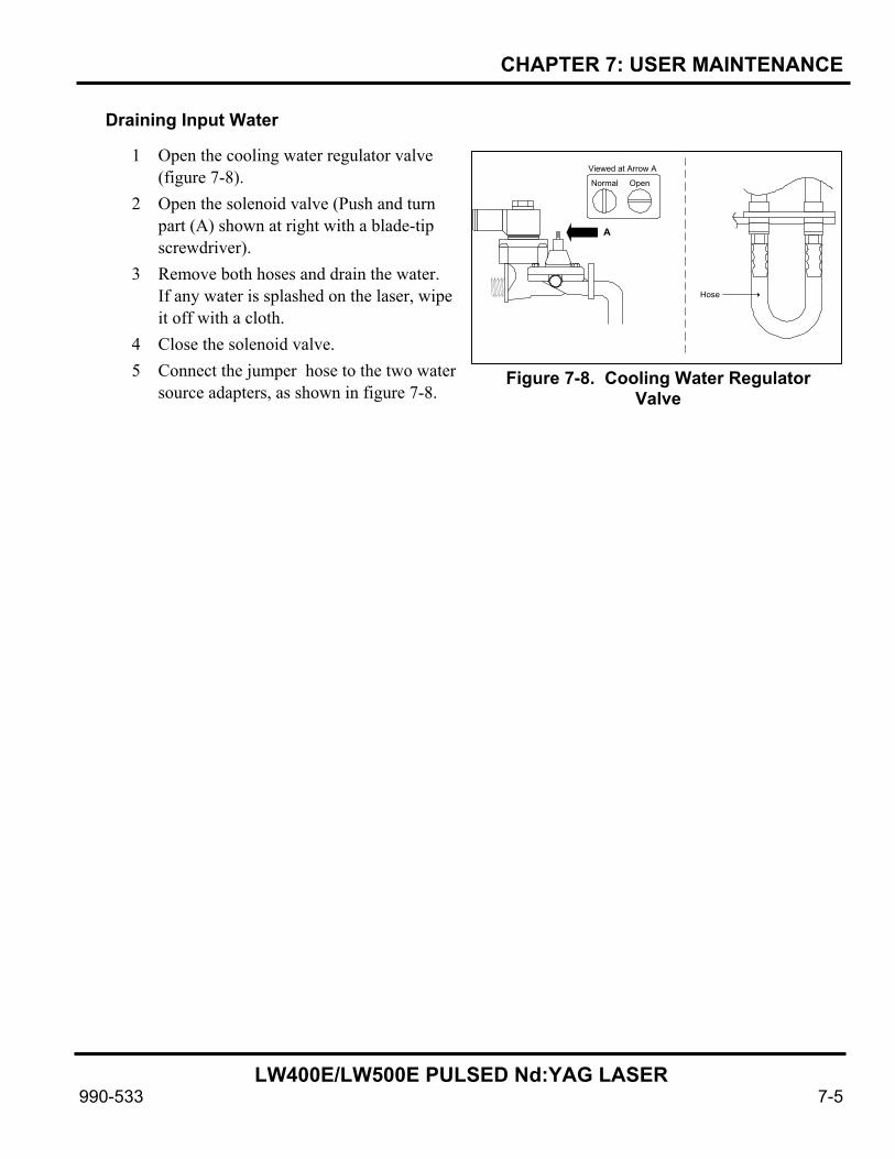
CHAPTER 7: USER MAINTENANCE
LW400E/LW500E PULSED Nd:YAG LASER
990-533 7-5
Draining Input Water
1 Open the cooling water regulator valve (figure 7-8).
2 Open the solenoid valve (Push and turn part (A) shown at right with a blade-tip screwdriver).
3 Remove both hoses and drain the water. If any water is splashed on the laser, wipe it off with a cloth.
4 Close the solenoid valve. 5 Connect the jumper hose to the two water
source adapters, as shown in figure 7-8.
Figure 7-8. Cooling Water Regulator Valve
Normal Open
Viewed at Arrow A
A
Hose

LW400E/LW500E PULSED Nd:YAG LASER
990-533 8-1
CHAPTER 8
SERVICE Precautions Turn OFF the power to the laser before starting service work. If the high voltage has been ON, wait for 5 minutes for the capacitors to discharge after turning OFF power before starting work. To operate the laser without the lamp cover, the head cover and the optical fiber connector cover, release both safety interlock switches. until they are locked (figure 8-1). The switch-on lamp (LED) will light, indicating that the safety interlock has been overridden.
The Nd:YAG laser becomes ready for oscillation if the high voltage is turned ON during service procedures. Use extreme caution while performing any work on the laser.
WARNING: Service personnel or anyone who is subject to possible Nd:YAG laser beam exposure must wear safety goggles having a minimum optical density of 6 at 1,064 nanometers wavelength.
Flash Lamp Replacement WARNING: You can operate the YAG laser with the laser cover removed, but you must use extreme care to avoid touching high voltage parts and being exposed to the laser beam.
CAUTION: Replace both flashlamps at the same time; do not replace just one.
Required Items. cloth, and 3mm, 4mm, and 5mm ball point screwdrivers.
To replace the flash lamp, proceed as follows:
1 Turn off power to the laser. If the high voltage has been on, wait at least 5 minutes for the power capacitor to discharge before proceeding to avoid electric shock.
2 Refer to Figure 8-2. Loosen the eight M6 bolts in the laser chamber top cover and remove the top cover.
3 Insert an M4 bolt into the hole on each side of the upper reflector and turn the bolts clockwise to unseat the reflector and carefully remove it from the laser chamber.
CAUTION: Be careful not to scratch the inside surface of the reflector as you remove it. 4 Place the top cover and mirror cylinder on a clean
cloth to protect them from oil, dust and other contaminants.
Interlock Switches Lamp Off Switch
Switch-On Lamp
Figure 8-1. Safety Interlock Switches
Top Cover
M4 bolt Reflector
M5 bolt Washer
Lamp Flowtube
Figure 8-2. Removing Cover and Reflector

CHAPTER 8: SERVICE
LW400E/LW500E PULSED Nd:YAG LASER
8-2 990-533
5 Refer to Figure 8-3. Remove the four M5 bolts securing the lead wires of each flashlamp.
CAUTION: Do not touch the glass part of the flashlamp or flowtube. 6 Holding both ends of the flash lamp, carefully lift
each flash lamp out of the holders. 7 Place the flashlamps on a clean cloth and separate
each from its flowtube. 8 Clean the glass part of the new flash lamp with
alcohol. CAUTION: Do not touch the glass part of the flashlamp or flowtube. 9 Pass each new flashlamp through a flowtube 10 Note the polarity of the flashlamp. The lead wire
terminal with the red mark is the anode (+). Holding both ends of the new flashlamp, and matching the polarities as shown, carefully set it into the holder. Be sure that the flowtube is properly seated in its groove. Repeat for the second flashlamp.
11 Connect each flashlamp wire to its terminals and tighten the four M5 bolts. 12 Carefully re-install the reflector and laser chamber top cover. CAUTION: Be sure that the eight M6 top cover bolts are tightened securely and that the O-rings are compressed evenly between the top cover and the laser chamber. 13 Pull the end of the oscillator cover interlock switches to release the interlock (figure 8-1). Confirm
that the LED indicator lights. 14 Turn on the CONTROL switch to run the cooler and verify that there is no water leakage from the
cooling system. If there is water leakage: a) Immediately turn off the CONTROL switch and the MAIN POWER switch.
b) Wait for 5 minutes, then repair the site of the leakage (refer to Chapter 7).
c) Dry any water that has leaked.
NOTE: Water may ooze from the O-ring groove in the chamber top cover. Wipe it off with a clean cloth.
15 Install the lamp cover.
Figure 8-3. Removing the Flashlamp
M5 boltHolder
_(Cathode)
side
+(Anode)
side
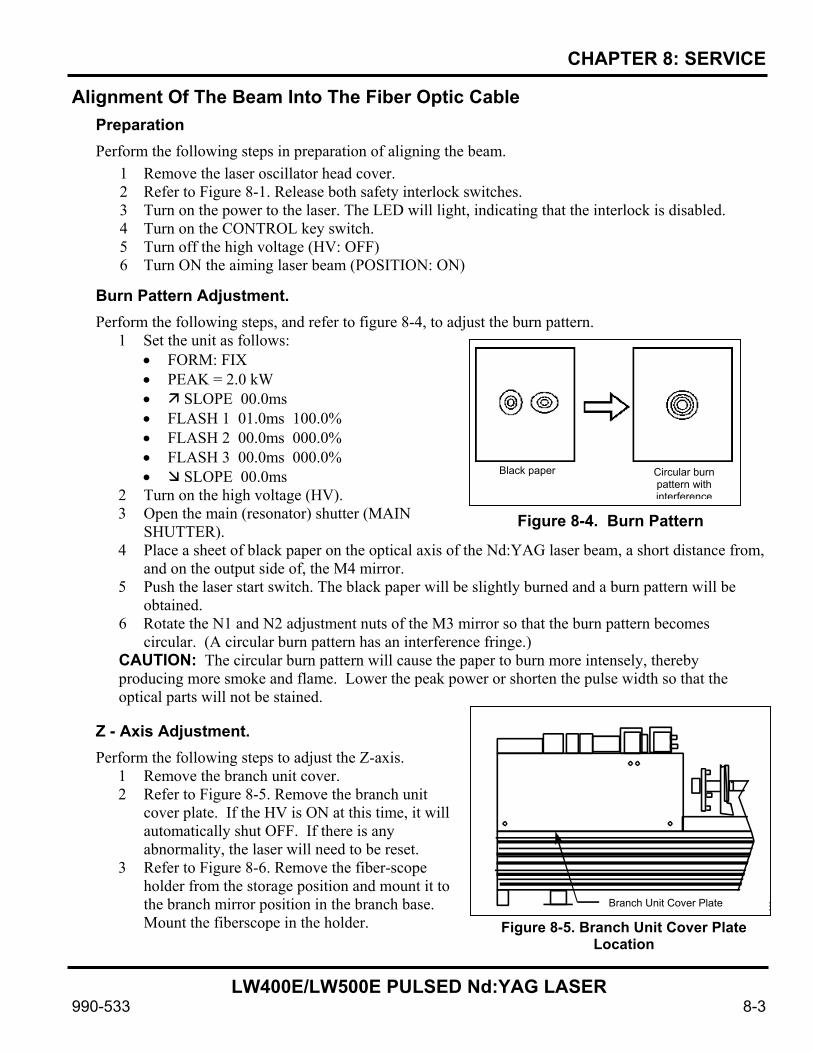
CHAPTER 8: SERVICE
LW400E/LW500E PULSED Nd:YAG LASER
990-533 8-3
Alignment Of The Beam Into The Fiber Optic Cable Preparation Perform the following steps in preparation of aligning the beam.
1 Remove the laser oscillator head cover. 2 Refer to Figure 8-1. Release both safety interlock switches. 3 Turn on the power to the laser. The LED will light, indicating that the interlock is disabled. 4 Turn on the CONTROL key switch. 5 Turn off the high voltage (HV: OFF) 6 Turn ON the aiming laser beam (POSITION: ON)
Burn Pattern Adjustment. Perform the following steps, and refer to figure 8-4, to adjust the burn pattern.
1 Set the unit as follows: • FORM: FIX • PEAK = 2.0 kW • SLOPE 00.0ms • FLASH 1 01.0ms 100.0% • FLASH 2 00.0ms 000.0% • FLASH 3 00.0ms 000.0% • SLOPE 00.0ms
2 Turn on the high voltage (HV). 3 Open the main (resonator) shutter (MAIN
SHUTTER). 4 Place a sheet of black paper on the optical axis of the Nd:YAG laser beam, a short distance from,
and on the output side of, the M4 mirror. 5 Push the laser start switch. The black paper will be slightly burned and a burn pattern will be
obtained. 6 Rotate the N1 and N2 adjustment nuts of the M3 mirror so that the burn pattern becomes
circular. (A circular burn pattern has an interference fringe.) CAUTION: The circular burn pattern will cause the paper to burn more intensely, thereby producing more smoke and flame. Lower the peak power or shorten the pulse width so that the optical parts will not be stained.
Z - Axis Adjustment. Perform the following steps to adjust the Z-axis.
1 Remove the branch unit cover. 2 Refer to Figure 8-5. Remove the branch unit
cover plate. If the HV is ON at this time, it will automatically shut OFF. If there is any abnormality, the laser will need to be reset.
3 Refer to Figure 8-6. Remove the fiber-scope holder from the storage position and mount it to the branch mirror position in the branch base. Mount the fiberscope in the holder.
Circular burn pattern with interference
Black paper Black paper
Figure 8-4. Burn Pattern
Figure 8-5. Branch Unit Cover Plate Location
Branch Unit Cover PlateBranch Unit Cover Plate
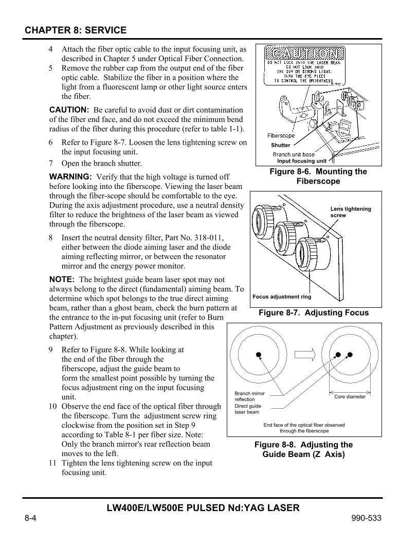
CHAPTER 8: SERVICE
LW400E/LW500E PULSED Nd:YAG LASER
8-4 990-533
4 Attach the fiber optic cable to the input focusing unit, as described in Chapter 5 under Optical Fiber Connection.
5 Remove the rubber cap from the output end of the fiber optic cable. Stabilize the fiber in a position where the light from a fluorescent lamp or other light source enters the fiber.
CAUTION: Be careful to avoid dust or dirt contamination of the fiber end face, and do not exceed the minimum bend radius of the fiber during this procedure (refer to table 1-1).
6 Refer to Figure 8-7. Loosen the lens tightening screw on the input focusing unit.
7 Open the branch shutter.
WARNING: Verify that the high voltage is turned off before looking into the fiberscope. Viewing the laser beam through the fiber-scope should be comfortable to the eye. During the axis adjustment procedure, use a neutral density filter to reduce the brightness of the laser beam as viewed through the fiberscope.
8 Insert the neutral density filter, Part No. 318-011, either between the diode aiming laser and the diode aiming reflecting mirror, or between the resonator mirror and the energy power monitor.
NOTE: The brightest guide beam laser spot may not always belong to the direct (fundamental) aiming beam. To determine which spot belongs to the true direct aiming beam, rather than a ghost beam, check the burn pattern at the entrance to the in-put focusing unit (refer to Burn Pattern Adjustment as previously described in this chapter).
9 Refer to Figure 8-8. While looking at the end of the fiber through the fiberscope, adjust the guide beam to form the smallest point possible by turning the focus adjustment ring on the input focusing unit.
10 Observe the end face of the optical fiber through the fiberscope. Turn the adjustment screw ring clockwise from the position set in Step 9 according to Table 8-1 per fiber size. Note: Only the branch mirror's rear reflection beam moves to the left.
11 Tighten the lens tightening screw on the input focusing unit.
Figure 8-6. Mounting the Fiberscope
Shutter
Input focusing unit
Figure 8-7. Adjusting Focus
Lens tightening screw
Focus adjustment ring
Figure 8-8. Adjusting the Guide Beam (Z Axis)
Core diameterBranch mirrorreflectionDirect guidelaser beam
End face of the optical fiber observedthrough the fiberscope

CHAPTER 8: SERVICE
LW400E/LW500E PULSED Nd:YAG LASER
990-533 8-5
Table 8-1. Adjustment Screw Ring Turns Required for Defocus
Fiber Diameter (mm)
Adjustment Screw Ring Clockwise Turns
0.3 1.0
0.4 1.5
0.6 2.0
0.8 2.0
1.0 2.0
1.2 2.0
CAUTION: If the branch mirror holder is moved, readjust it so that the reflection from the branch mirror enters the center of the lens on the input focusing unit at an input angle of 0o.
CAUTION: The input focusing end surface of the fiber may be burned if the guide beam does not match the YAG laser beam axis and the YAG beam enters the fiber off center.
X - Y Axes Adjustment Perform the following steps to adjust the X and Y axes.
1 Refer to Figure 8-9. Loosen the lock nut on the X - Y axes adjustment screw on the input focusing unit.
NOTE: The brightest guide beam laser spot may not always belong to the direct (fundamental) aiming beam. To determine which spot belongs to the true direct aim-ing beam, rather than a ghost beam, check the burn pattern at the entrance to the in-put focusing unit (refer to Burn Pattern Adjustment as previously described in this chapter). 2 Refer to 8-10. While monitoring the end surface of
the optical fiber through the fiberscope, adjust the X - Y axes adjustment screw so that the guide beam comes to the center of the end surface. The beam on the left is the rear reflection beam from the branch mirror. Do not confuse the beam with the guide beam on the right.
3 Tighten the lock nut and the X - Y axes adjustment screw. Look into the fiberscope and verify that the direct guide laser beam is located at the center of the fiber end face.
Figure 8-10. Adjusting the
Guide Beam (X-Y Axes)
Guide laser beamreflected at rear side
Direct guide laser beamEnd face of the optical fiber
observed through the fiberscope
Figure 8-9. Lock Nut Location

CHAPTER 8: SERVICE
LW400E/LW500E PULSED Nd:YAG LASER
8-6 990-533
Cleaning The Optics Unlike general mechanically processed parts, the surfaces of optical components are unusable when they are scratched or burned. Please use extreme care when handling any optical components. To clean optical components, use the air blower, ring wrench, acetone and lens cleaning paper.
CAUTION: Do not use any other materials for optical component cleaning.
NOTE: Please contact the factory if you wish to do maintenance work on the optical components other than the input focusing unit and the optical fiber.
Optical Component Cleaning Tools and Materials. You will need the optical component cleaning tools and materials illustrated in Figure 8-11.
Cleaning a Dusty Or Dry-Dirt Coated Optic. Refer to Figure 8-12. To clean an optic that is dusty or coated with dried dirt, proceed as follows:
1 Hold the optic horizontally by the edges.
2 Blow off the dust and dry dirt using an air blower.
3 Observe the reflection of fluorescent light on the optic and verify that there is no dust or dry dirt remaining on the optic.
Cleaning a Contaminated Optic. Refer to Figure 8-13. To clean an optic that is fogged or contaminated with other than dust or dry dirt: 1 Hold the optic horizontally by its edges. 2 Place one small drop of acetone in the center of a
sheet of lens paper. 3 Contact the optic completely with the wet part of
the lens paper. Any gap between the optic and the lens paper may result in uneven cleaning.
4 Wipe the optic with the lens paper by pulling one end of the lens paper slowly and steadily until the other end of the lens paper comes off the optic. Any gap created between the lens paper and the optic during wiping, as well as acetone remaining at the end of the lens paper without evaporating, may result in uneven cleaning.
5 Shine a fluorescent lamp onto the cleaned parts to confirm that no dirt or dust remains.
Air Blower Ring Wrench Acetone Lens Cleaning Paper
Figure 8-11. Optical Component Servicing Tools and Materials
Figure 8-12. Cleaning a Dirty Optic
Figure 8-13. Cleaning a Contaminated Lens

CHAPTER 8: SERVICE
LW400E/LW500E PULSED Nd:YAG LASER
990-533 8-7
Reassembling the Optical Components. To reassemble the optical components in the input focusing unit:
1 Assemble the optical components in the reverse order of their removal.
2 After assembling the optical components, verify that there is no dust, dirt or uneven cleaning spots. Be sure that the optics do not collect any dust or dirt during installation.
Optical Fiber Cleaning. To clean the optical fibers:
1 Refer to Figure 8-14. Remove the optical fiber from the mating connector.
2 Blow away any dust on the end surface of the fiber.
3 If Step 2 does not remove the dust on the end surface, softly wipe it with a piece of lens paper.
CAUTION: Do not press the lens paper against the end surface of the optical fiber. It may scratch the fiber end face.
4 Verify that there is no dust or dirt on the end face of the fiber.
NOTE: We recommend a fiber end face checker for viewing the end surfaces of the optical fibers for scratches, dust or burns.
Power Source Service
Replacing the Backup Battery 1 Turn off the MAIN POWER switch.
2 Wait for at least 5 minutes, then remove the controller cover (figure 8-15).
3 Remove the battery from the control board.
4 Observing polarity, install a new battery.
5 Reinstall the controller cover.
Replacing the Fuses NOTE: Before replacing a fuse, try to determine the reason it blew and make repairs 1 Turn off the MAIN POWER switch. 2 Wait for at least 5 minutes, then remove the appropriate cover (table 8-2). 3 Locate the fuse, using the figure cited in table 8-2. 4 Remove the fuse and, if the fuse holder clip is loose, tighten it. 5 Replace the blown fuse with a new one. 6 Re-install the cover removed in step 2.
Optical fiber
Figure 8-14. Cleaning the Optical Fiber
Fron
t sid
e
Rea
r sid
e
Battery Control board Controller cover
Figure 8-15. Replacing Backup Battery

CHAPTER 8: SERVICE
LW400E/LW500E PULSED Nd:YAG LASER
8-8 990-533
Table 8-2. Fuse List
Fuse Location Access Panel Fuse Location Figure Qty Spare
Fuses 0.5 A Charge control board Right-hand laser cover 6 2 3 A Simmer board Right-hand controller cover
Figure 8-16 2 2
5 A 1 1 6 A SSR board Left-hand laser cover Figure 8-17 1 1
Front
EL8-PT1/4-VO EL8-PT1/4-VO EL8-PT1/4-VO EL8-PT1/4-VO
EL8-PT1/4-VO EL8-PT1/4-VO
EL8-PT1/4-VO EL8-PT1/4-VO EL8-PT1/4-VO EL8-PT1/4-VO
EL8-PT1/4-VO EL8-PT1/4-VO ME-1830
3 A/250 V Fuse
Simmer board
0.5 A/250 V Fuses Charge control board
Figure 8-16. Replacing 0.5A and 3A Fuses
Rear
6 A/250 V
6 A/250 VSSR
Figure 8-17. Replacing 5A and 6A Fuses

CHAPTER 8: SERVICE
LW400E/LW500E PULSED Nd:YAG LASER
990-533 8-9
Troubleshooting
Malfunction Indications Any malfunction occurring in the unit is indicated on the control unit display, for example:
!!!TROUBLE!!! E01:POWER SUPPLY COVER OPENED E02:HEAD COVER OPENED E03:EMERGENCY STOP E04:LOW LEVEL OF COOLANT E05:PHASE TROUBLE E06:OVER HEAT OF PUMP HV:OFF MAIN SHUTTER:OFF POSITION:OFF
The first trouble indication line (E01), for example, gives the trouble code number (E01:) and the source of the trouble (POWER SUPPLY COVER OPENED). Malfunction Check List Check the control unit display indication and rectify the trouble according to table 8-3.
Table 8-3. Malfunction Check List
Code No Display on program unit High
voltage Alarm output Corrective actions
00 COMMUNICATION LINE ERROR Trouble has occurred in the communication line between the laser power supply and the program unit. Turn off the circuit breaker. Wait at least 5 seconds and turn it back on again. If there is a noise source near the laser, move it far away or suppress the noise.
01 POWER SUPPLY COVER OPENED OFF ON The controller cover or power supply cover is removed or their mounting screws are loose. Secure the covers with the screws.
02 HEAD COVER OPENED OFF ON The head cover or lamp replacement cover is removed. Mount them.
03 EMERGENCY STOP OFF ON An emergency stop signal is present. Close the emergency stop input of the EXT.I/O(1) connector or reset the emergency stop switch of the program unit and control panel of the controller.
(a)
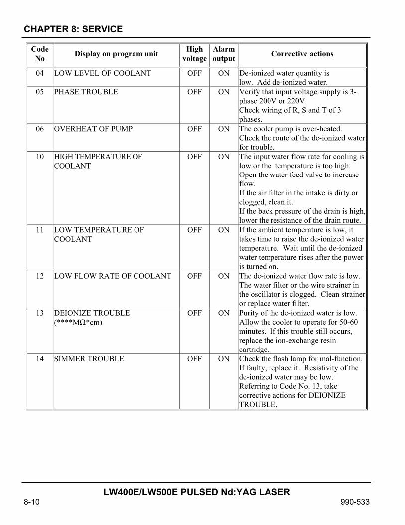
CHAPTER 8: SERVICE
LW400E/LW500E PULSED Nd:YAG LASER
8-10 990-533
Code No Display on program unit High
voltage Alarm output Corrective actions
04 LOW LEVEL OF COOLANT OFF ON De-ionized water quantity is low. Add de-ionized water.
05 PHASE TROUBLE OFF ON Verify that input voltage supply is 3-phase 200V or 220V. Check wiring of R, S and T of 3 phases.
06 OVERHEAT OF PUMP OFF ON The cooler pump is over-heated. Check the route of the de-ionized water for trouble.
10 HIGH TEMPERATURE OF COOLANT
OFF ON The input water flow rate for cooling is low or the temperature is too high. Open the water feed valve to increase flow. If the air filter in the intake is dirty or clogged, clean it. If the back pressure of the drain is high, lower the resistance of the drain route.
11 LOW TEMPERATURE OF COOLANT
OFF ON If the ambient temperature is low, it takes time to raise the de-ionized water temperature. Wait until the de-ionized water temperature rises after the power is turned on.
12 LOW FLOW RATE OF COOLANT OFF ON The de-ionized water flow rate is low. The water filter or the wire strainer in the oscillator is clogged. Clean strainer or replace water filter.
13 DEIONIZE TROUBLE (****MΩ*cm)
OFF ON Purity of the de-ionized water is low. Allow the cooler to operate for 50-60 minutes. If this trouble still occurs, replace the ion-exchange resin cartridge.
14 SIMMER TROUBLE OFF ON Check the flash lamp for mal-function. If faulty, replace it. Resistivity of the de-ionized water may be low. Referring to Code No. 13, take corrective actions for DEIONIZE TROUBLE.
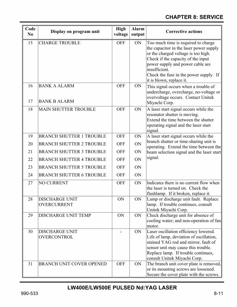
CHAPTER 8: SERVICE
LW400E/LW500E PULSED Nd:YAG LASER
990-533 8-11
Code No Display on program unit High
voltage Alarm output Corrective actions
15 CHARGE TROUBLE OFF ON Too much time is required to charge the capacitor in the laser power supply or the charged voltage is too high. Check if the capacity of the input power supply and power cable are insufficient. Check the fuse in the power supply. If it is blown, replace it.
16
17
BANK A ALARM
BANK B ALARM
OFF ON This signal occurs when a trouble of undercharge, overcharge, no-voltage or overvoltage occurs. Contact Unitek Miyachi Corp.
18 MAIN SHUTTER TROUBLE OFF ON A laser start signal occurs while the resonator shutter is moving. Extend the time between the shutter operating signal and the laser start signal.
19
20
21
22
23
24
BRANCH SHUTTER 1 TROUBLE
BRANCH SHUTTER 2 TROUBLE
BRANCH SHUTTER 3 TROUBLE
BRANCH SHUTTER 4 TROUBLE
BRANCH SHUTTER 5 TROUBLE
BRANCH SHUTTER 6 TROUBLE
OFF
OFF
OFF
OFF
OFF
OFF
ON
ON
ON
ON
ON
ON
A laser start signal occurs while the branch shutter or time-sharing unit is operating. Extend the time between the beam selection signal and the laser start signal.
27 NO CURRENT OFF ON Indicates there is no current flow when the laser is turned on. Check the flashlamp. If it broken, replace it.
28 DISCHARGE UNIT OVERCURRENT
ON ON Lamp or discharge unit fault. Replace lamp. If trouble continues, consult Unitek Miyachi Corp.
29 DISCHARGE UNIT TEMP ON ON Check discharge unit for absence of cooling water; and non-operation of fan motor.
30 DISCHARGE UNIT OVERCONTROL
- ON Laser oscillation efficiency lowered. Life of lamp, deviation of oscillation, stained YAG rod and mirror, fault of sensor unit may cause this trouble. Replace lamp. If trouble continues, consult Unitek Miyachi Corp.
31 BRANCH UNIT COVER OPENED OFF ON The branch unit cover plate is removed, or its mounting screws are loosened. Secure the cover plate with the screws.

CHAPTER 8: SERVICE
LW400E/LW500E PULSED Nd:YAG LASER
8-12 990-533
Code No Display on program unit High
voltage Alarm output Corrective actions
32 33 34 35 36 37
FIBER SWITCH 1 TROUBLE FIBER SWITCH 2 TROUBLE FIBER SWITCH 3 TROUBLE FIBER SWITCH 4 TROUBLE FIBER SWITCH 5 TROUBLE FIBER SWITCH 6 TROUBLE
OFF ON An optical fiber or a trouble detecting cable is disconnect-ed. Connect them securely.
38
39
40
41
42
43
FIBER SENSOR 1 TROUBLE
FIBER SENSOR 2 TROUBLE
FIBER SENSOR 3 TROUBLE
FIBER SENSOR 4 TROUBLE
FIBER SENSOR 5 TROUBLE
FIBER SENSOR 6 TROUBLE
OFF ON A fiber cable may be broken; or end face damaged. Check the fiber cable for breakage.
45 LASER START IS NOT READY - ON A start signal occurs before charging is finished. Change the interval of the start signal, or extend the time between the charge and the start signal. If possible, apply the start signal after confirming READY signal.
46 POWER MONITOR TEMP - ON The power monitor unit may be broken. Consult Unitek Miyachi Corp.
47 OVERRATE - ON The turn-on power of the flashlamp is too high. Lower the set value of PEAK, pulse width or pps.
48 OVERRATE FIBER - ON Incident beam exceeds the limit. Lower the set value of PEAK, pulse width or pps,
49 SET ERROR
(TOO SHORT DURATION)
- ON Pulse width setting is below 0.5 ms; set it to a minimum of 0.5 ms.
50 SET ERROR
(OVER LIMIT OF MAX POWER)
- ON A set value of supplied power (PEAK, pulse width, pps) exceeds the capacity. The set value is reset to the value before the change.
51 SET ERROR TO FIBER Input power setting (PEAK, pulse width, ppm) exceeds the capacity. The set value is reset to the value before the change.
52 MEMORY TROUBLE - ON The voltage of the memory backup lithium battery is low. Replace it.

CHAPTER 8: SERVICE
LW400E/LW500E PULSED Nd:YAG LASER
990-533 8-13
Code No Display on program unit High
voltage Alarm output Corrective actions
54 DEIONIZE CAUTION (****MΩ*cm)
OFF ON Purity of the de-ionized water is low. Allow the cooler to operate for 50 - 60 minutes. If this trouble still occurs, replace the ion-exchange resin cartridge.
55 NO LIGHT - - See if the resonator shutter is closed and if the energy is below 0.3 J.
56 OVERLIMIT LASER POWER - - Check the set value of ENERGY HIGH. If it is wrong, correct it.
57 UNDERLIMIT OF LASER POWER - - Check the set value of ENERGY LOW or lamp. If the set value is wrong, correct it. If the lamp is broken, replace it.

CHAPTER 8: SERVICE
LW400E/LW500E PULSED Nd:YAG LASER
8-14 990-533
Spare Parts Kits Spare parts kits are obtainable from Unitek Miyachi Lasers in three levels, as follows:
LW400E Level I, Kit PN 08-659-01 LW400E Level II, Kit PN 08-659-01-01 LW400E Level III, Kit PN 08-659-01-01-02
Table 8-4. Spare Parts Kits Componentst
Part Part No. Qty Kit Level
Battery, lithium cell, 3V, 560mAh 145-014 1 I, II, III
Circuit breaker, magnetic, 100A, 3 pole 240-081 1 III
Contactor, 11A, ac, non-reversing 555-140 1 III
De-ionized water heater, 1kW 4-60037-01 1 III
Display module, LCD (LW400E) A4-02680 1 III
Fan, 300 f3/m, 3350 rpm, 230Vac 305-029 2 II, III
Fan, 95 f3/m, 3100 rpm, 200Vac 305-028 4 II, III
Filter, water particle 4-60081-01 2 I, II, III
Flashlamp 435-138 2 I, II, III
Flowtube, flashlamp (LW400E) A4-04957 1 I, II, III
Flowtube, YAG rod (LW400E) A4-05995 1 I, II, III
Fuse, 20A, 250V, fast-acting 330-138 3 I, II, III
Fuse, 3AG, 0.5A, 750V, fast-acting 330-118 2 I, II, III
Fuse, 3AG, 3A, 250V, fast-acting 330-083 1 I, II, III
Fuse, 3AG, 6A, 250V, fast-acting 330-134 2 I, II, III
Ion exchange cartridge set 318-027 2 I, II, III
Laser, diode aiming 4-60301-01 1 III
Latch, door, push open/push close 30016459 1 II, III
O-ring, 15.00mm I.D. 570-162 2 I, II, III
O-ring, 260mm, cover (LW400E) G260-4-C50 1 I, II, III
O-ring, 75mm, water input chamber (LW400E) G75-4-C50 1 I, II, III
O-ring, 8mm I.D. 570-153 5 I, II, III
Plug, power, 6 conductor, male 520-134 6 III
Power supply, 24V dc 525-001 1 III
Printed Circuit Board, charge control (LW400E) ME-1830 1 III

CHAPTER 8: SERVICE
LW400E/LW500E PULSED Nd:YAG LASER
990-533 8-15
Part Part No. Qty Kit Level
Printed Circuit Board, discharge control (LW400E) ME-1828 1 III
Printed Circuit Board, laser power sensor (LW400E) ME-1837 1 III
Printed Circuit Board, main CPU (LW400E) ME-1822 1 III
Printed Circuit Board, program box control ME-1785 1 III
Printed Circuit Board, program box switch (LW400E) ME-1786 1 III
Printed Circuit Board, shutter sensor (LW400E) ME-1861 1 III
Printed Circuit Board, snubber (LW400E) ME-1893 1 III
Printed Circuit Board, SSR (LW400E) ME-1868 1 III
Printed Circuit Board, trigger module ME-1670 2 III
Receptacle, male, 6 conductor, panel mount 550-092 6 III
Regulator and solenoid valve assembly 720-133 1 III
Sensor, flow, laser LD-20-PATAAA 1 III
Solenoid, rotary 4-60039-01 2 III
Solenoid, rotary, branch shutter (LW400E) A4-03826 1 III
Solenoid, rotary, laser time-share shutter 4-60040-01 1 III
Switch, emergency stop, mushroom head, push off/twist on, SPST. 0.1A, 125V AC
680-316 2 II, III
Switch, key, 3A, 125V, 2 position S-9-90-B-1 1 II, III
Switch, pushbutton, momentary, interlock, DPDT, 10A, 125V AC, panel mount
680-171 15 II, III
Switch, pushbutton, momentary, interlock, DPDT, 10A, 125V AC, panel mount
680-317 2 II, III
Switch, pushbutton, momentary, SPST, 120V AC, lighted (red) 680-318 1 II, III
Terminal, female, 1mm diam., crimp-on 253-072 36 III
Terminal, male, 1mm diam., crimp-on 253-071 36 III
YAG rod assembly, 8mm Nd MLU-0436 1 I, II, III

CHAPTER 8: SERVICE
LW400E/LW500E PULSED Nd:YAG LASER
8-16 990-533
Repair Service If you have problems with your LW400E/LW500E Laser that you cannot resolve, please contact our laser service department at:
Unitek Miyachi Lasers 1820 So. Myrtle Avenue Monrovia, CA 91017-7133 Phone: (626) 303-5676 FAX: (626) 358-8048 e-mail: [email protected]

LW400E/LW500E PULSED Nd:YAG LASER
990-533 A-1
APPENDIX A TECHNICAL SPECIFICATIONS

APPENDIX A: TECHNICAL SPECIFICATIONS
LW400E/LW500E PULSED Nd:YAG LASER
A-2 990-533
Laser Specifications Items Specifications
Oscillator Average power Pulse energy (@ 10 ms) Pulse width Pulse repetition rate Oscillation wavelength Resonator shutter Positioning guide beam
LW400E LW500E 400W 500W 50 J/P 70 J/P 0.5 – 30.0 ms (0.1 ms step) 1 – 500 pps 1.064 µm With open/close sensor Built-in visible (red) laser diode
Power Supply 3-phase 400VAC ± 10% 50/60Hz,50A Laser Controller
Schedule setting:
Monitor:
Counter:
Alarm indication:
Remote control:
Up to 16 schedules can be set by combining:
Laser output waveform Upper and lower limits of power monitor and alarm
(Energy monitor [J]) Repetition speed Number of repeats
Energy monitor (J) Average power (W)
9-digit total (preset) counter 9-digit good (preset) counter
Messages are displayed on liquid crystal display.
Remote control through standard 3-m cable Cooler
Heat exchange method:
Required input water:
Inner diameter of hose:
Water-Water
Pressure: 42.6 lbf/in2(294 kPa or3 kgf/cm2)maximum Flow rate: 6.6 gal/min (25 liters/min) minimum Pressure difference: 14.2 – 42.6 lbf/in2
(98-294 kPa or1-3 kgf/cm2) Water temperature: 41-77°F (5-25°C)
φ0.75 in. (19 mm) When chiller is employed, cooling capability of 19,000 kcal/h is required for the chiller cooler maximum rating.
Weight: Approx. 1323 lbs. (600 kg) Dimensions: 47.2 in. (H) x 21.7 in. (W) x 68.1 in. (D) (1200mm (H) x 550mm (W) x 1760mm (D))

APPENDIX A: TECHNICAL SPECIFICATIONS
LW400E/LW500E PULSED Nd:YAG LASER
990-533 A-3
Outline Main unit
NOTE: All measurements are in millimeters.
1740 1760
204
550
450
555
1200
11Holddown
594

APPENDIX A: TECHNICAL SPECIFICATIONS
LW400E/LW500E PULSED Nd:YAG LASER
A-4 990-533
Adjuster pressure plate
4-Ad
just
er p
ress
ure
plat
es
59 94
50
19
48
33
20
ƒÓ14
(74.5)
19.5
555
550
1240
204
4
Adju
ster
pre
ssur
e pl
ates
N 1
4
Adju
ster
pre
ssur
e pl
ate
Fix
on fl
oor u
sing
anc
hor b
olt*
Lock
nut
Ad
just
er
*Anc
hor u
ser-p
rovi
ded
Adju
ster
pre
ssur
e pl
ate
deta
il
Fixi
ng h
ole
to fl
oor

APPENDIX A: TECHNICAL SPECIFICATIONS
LW400E/LW500E PULSED Nd:YAG LASER
990-533 A-5
Laser controller (with 3 m standard cable behind front panel) Contents of labels
M L E-114A MIY A C HI
222 33.5
126
45
Y A G L A S E R C O N T R O L L E R
4
1 2
3
4
1 2
3
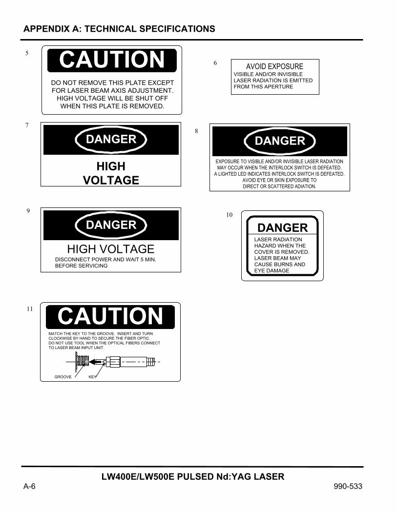
APPENDIX A: TECHNICAL SPECIFICATIONS
LW400E/LW500E PULSED Nd:YAG LASER
A-6 990-533
CAUTIONDO NOT REMOVE THIS PLATE EXCEPTFOR LASER BEAM AXIS ADJUSTMENT.
HIGH VOLTAGE WILL BE SHUT OFFWHEN THIS PLATE IS REMOVED.
AVOID EXPOSUREVISIBLE AND/OR INVISIBLELASER RADIATION IS EMITTEDFROM THIS APERTURE
DANGER
HIGHVOLTAGE
DANGEREXPOSURE TO VISIBLE AND/OR INVISIBLE LASER RADIATIONMAY OCCUR WHEN THE INTERLOCK SWITCH IS DEFEATED.
A LIGHTED LED INDICATES INTERLOCK SWITCH IS DEFEATED.AVOID EYE OR SKIN EXPOSURE TODIRECT OR SCATTERED ADIATION.
DANGER
HIGH VOLTAGEDISCONNECT POWER AND WAIT 5 MIN.BEFORE SERVICING
DANGERLASER RADIATIONHAZARD WHEN THECOVER IS REMOVED.LASER BEAM MAYCAUSE BURNS ANDEYE DAMAGE
CAUTIONMATCH THE KEY TO THE GROOVE. INSERT AND TURNCLOCKWISE BY HAND TO SECURE THE FIBER OPTIC.DO NOT USE TOOL WHEN THE OPTICAL FIBERS CONNECTTO LASER BEAM INPUT UNIT.
GROOVE KEY
5 6
7 8
9 10
11

APPENDIX A: TECHNICAL SPECIFICATIONS
LW400E/LW500E PULSED Nd:YAG LASER
990-533 A-7
Options Sharing optics
The sharing optics built in the main unit include the branch shutters with the open/close sensor. The number of the shutters is the same as the number of the specified deliveries.
Sharing method Specifications Single 2 energy-sharing 3 energy-sharing 4 energy-sharing 2 time-sharing 3 time-sharing 4 time-sharing 5 time-sharing 6 time-sharing Time-sharing of two 2-energy-sharing deliveries Time-sharing of three 2-energy-sharing deliveries Time-sharing of two 3-energy-sharing deliveries
Outputs through a single fiber. Outputs through 2 fibers simultaneously. Outputs through 3 fibers simultaneously. Outputs through 4 fibers simultaneously. Selects 1 of 2 fibers and outputs. Selects 1 of 3 fibers and outputs. Selects 1 of 4 fibers and outputs. Selects 1 of 5 fibers and outputs. Selects 1 of 6 fibers and outputs. Four optical fibers are divided into two blocks, consisting of two front fibers and two rear fibers. After one of the blocks is selected, the laser beam is transmitted from the selected two fibers. Six optical fibers are divided into three blocks, consisting of two front fibers, two middle fibers and two rear fibers. Again, one of the blocks is selected and the laser beam is transmitted from the selected two fibers. Six optical fibers are divided into two blocks, consisting of three front fibers and three rear fibers. One of the blocks is selected and the laser beam is transmitted from the selected three fibers.

LW400E/LW500E PULSED Nd:YAG LASER
990-533 B-1
APPENDIX B
EXTERNAL COMMUNICATIONS INTERFACE SPECIFICATIONS

APPENDIX B: EXTERNAL COMMUNICATIONS INTERFACE SPECIFICATION
LW400E/LW500E PULSED Nd:YAG LASER
B-2 990-533
CONTENTS 1. Introduction ............................................................................ B-3
2. Connections .................................................................. B-3
3. Data Transfer ............................................................... B-4 (1) Type.................................................................................. B-4 (2) Baud Rate ......................................................................... B-4 (3) Data Format...................................................................... B-4 (4) Character Code................................................................. B-4 (5) Communication Control Code ......................................... B-5 (6) Text Format ...................................................................... B-5 (7) BCC Calculation .............................................................. B-5
4. System Configuration.................................................. B-8
5. Command Description ................................................ B-9 (1) Write Data ........................................................................ B-9 (2) Read Data ......................................................................... B-10 (3) Write Status, Control Mode and Schedule No. ................ B-11 (4) Read Status....................................................................... B-12 (5) Laser Start Command....................................................... B-13 (6) Laser Stop Command ....................................................... B-13 (7) Trouble Reset .................................................................. B-14 (8) Total Count Reset Command ........................................... B-14 (9) GOOD Count Reset Command ........................................ B-15 (10) Read Trouble (Error)...................................................... B-15
6. Setting and Monitor Data ........................................... B-16
7. Error (Trouble) List .................................................... B-24
LW400E/LW500E External Communication List ........ B-25

APPENDIX B: EXTERNAL COMMUNICATIONS INTERFACE SPECIFICATION
LW400E/LW500E PULSED Nd:YAG LASER
990-533 B-3
1. Introduction
An RS-485 interface is used for reading and setting schedules; and monitoring data and status of the LW400E/LW500E Laser Unit from an external computer.
2. Connections To connect a host PC to the laser or several lasers:
ù Host Computer
ú Serial Cable. Connects between the host computer serial port and the RS-232/RS-485 converter (û). Depending on the serial port to be used, the cable may be terminated as either:
C Standard female 9-pin to female 25-pin, or C Standard female 25-pin to female 25-pin.
û RS-232/RS-485 Converter. The converter is a Telebyte Model 285. The manufacturer may be contacted at 1-800-835-3298. The converter DIP switch settings for this application are as illustrated at the right.
Laser 1
Laser 2
Laser 3
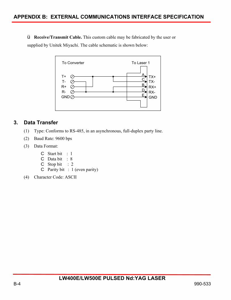
APPENDIX B: EXTERNAL COMMUNICATIONS INTERFACE SPECIFICATION
LW400E/LW500E PULSED Nd:YAG LASER
B-4 990-533
ü Receive/Transmit Cable. This custom cable may be fabricated by the user or
supplied by Unitek Miyachi. The cable schematic is shown below:
3. Data Transfer
(1) Type: Conforms to RS-485, in an asynchronous, full-duplex party line.
(2) Baud Rate: 9600 bps
(3) Data Format:
C Start bit : 1 C Data bit : 8 C Stop bit : 2 C Parity bit : 1 (even parity)
(4) Character Code: ASCII
To Converter To Laser 1
T+T-R+R-GND
TX+TX-RX+RX-GND
ACBDE

APPENDIX B: EXTERNAL COMMUNICATIONS INTERFACE SPECIFICATION
LW400E/LW500E PULSED Nd:YAG LASER
990-533 B-5
(5) Communication Control Code:
Command Code
Hex Value
Description STX
02H
Start of Text
ETX
03H
End of Text
EOT
04H
End of Transmission
ENQ
05H
Enquiry
ID$ENQ
50H$30H$05H
Identification Enquiry
ACK
06H
Acknowledge
ID$ACK
54H$31H$06H
Identification Acknowledge
NAK
15H
Not Acknowledge
(6) Text Format:
(7) BCC Calculation: BCC is the binary coded check sum. It is calculated by adding all bytes after STX and through ETX as listed in the following example C-program:
STX
Text BlockETX
BCC
Variable TextLength
BCC CalculationRange

APPENDIX B: EXTERNAL COMMUNICATIONS INTERFACE SPECIFICATION
LW400E/LW500E PULSED Nd:YAG LASER
B-6 990-533
#include <stdio.h> #define STX 0x02 #define ETX 0x03 char command[300]; /* calbcc: used to calculate BCC and concatinate BCC to the end of the string. NOTE: printf statement is only to help debugging. */ char calbcc(bf) char *bf; char bcc; int n; printf(ACommand: %02X @, bf[0]); bcc = 0; for (n = 1; ; n++) printf(A%02X @, bf[n]); bcc ^= bf[n]; if (bf[n] == ETX) break; printf(A BCC: %02X\n@, bcc); bf[++n] = bcc; ] main() /* Following statement compose a command string to read Repeated PPS of schedule 5 */ sprintf(command, A%c%02d%s%02d%02d%c@, /* String Format */ STX, /* Start of transmission code */ 0, /* Network Number = 0 */ AR@, /* Code for reading the data */ 5, /* Schedule Number = 5 */ 4, /* Data No = 4 (Repeated PPS) */ ETX); /* End of transmission code */ calbcc ( command ); /* Following statement compose a command string to read the status of shutters. */ sprintf( command,

APPENDIX B: EXTERNAL COMMUNICATIONS INTERFACE SPECIFICATION
LW400E/LW500E PULSED Nd:YAG LASER
990-533 B-7
A%c%02d%s%c@, /* String Format */ STX, /* Start of transmission code */ 0, /* Network Number = 0 */ ARS@, /* Code for reading status */ ETX); /* End of transmission code */ calbbc( command ); /* Following statement compose a command string to set schedule 1 the pulse width to 2.0 ms. */ sprintf( command, A%c%02d%s%02d%02d%3d%c@, /* String Format */ STX, /* Start of transmission code */ 0, /* Network Number = 0 */ AW@ /* Code for reading status */ 1, /* Schedule Number = 1 */ 1, /* Data No = 1 (pulse width) */ 20, /* Data value = 20 92.0 msec) */ ETX); /* End of transmission code */ clbcc( command );
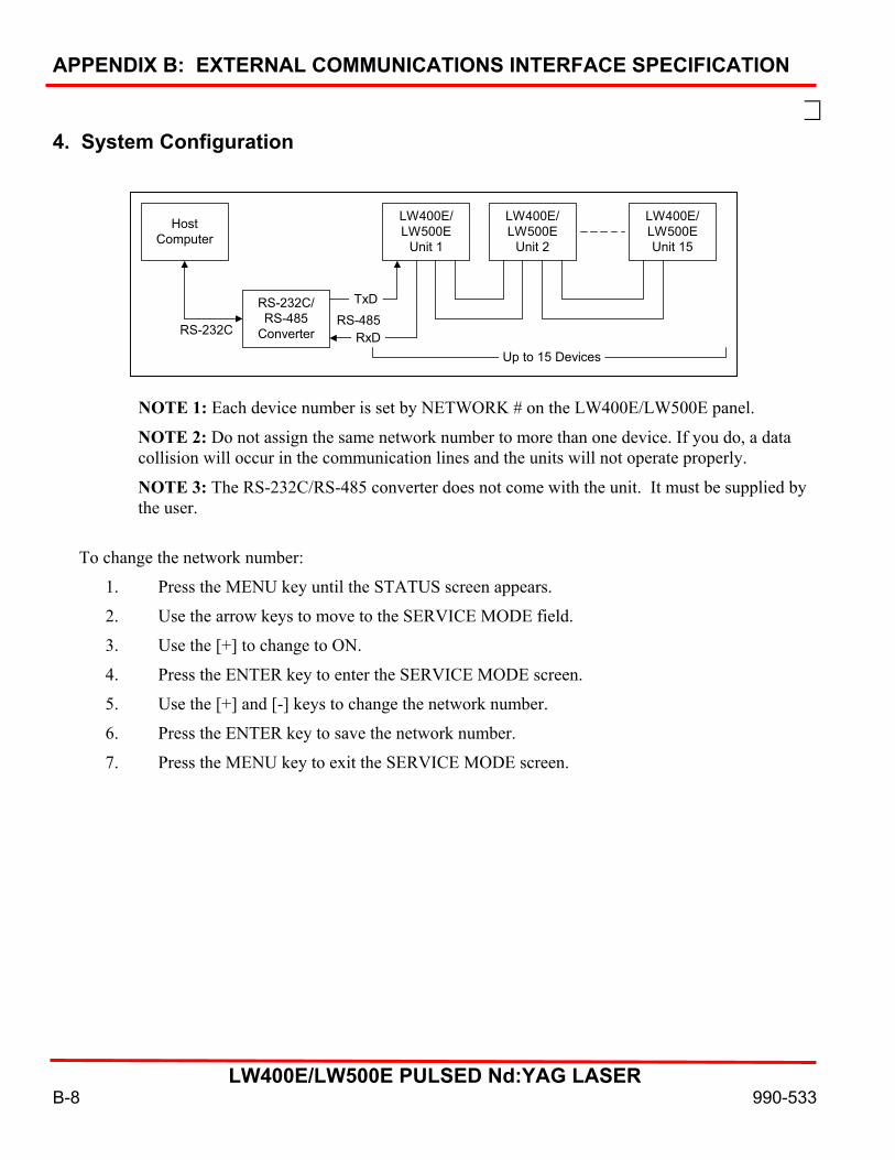
APPENDIX B: EXTERNAL COMMUNICATIONS INTERFACE SPECIFICATION
LW400E/LW500E PULSED Nd:YAG LASER
B-8 990-533
4. System Configuration
NOTE 1: Each device number is set by NETWORK # on the LW400E/LW500E panel.
NOTE 2: Do not assign the same network number to more than one device. If you do, a data collision will occur in the communication lines and the units will not operate properly.
NOTE 3: The RS-232C/RS-485 converter does not come with the unit. It must be supplied by the user.
To change the network number:
1. Press the MENU key until the STATUS screen appears.
2. Use the arrow keys to move to the SERVICE MODE field.
3. Use the [+] to change to ON.
4. Press the ENTER key to enter the SERVICE MODE screen.
5. Use the [+] and [-] keys to change the network number.
6. Press the ENTER key to save the network number.
7. Press the MENU key to exit the SERVICE MODE screen.
HostComputer
RS-232C/RS-485
ConverterRS-232CRS-485
TxD
RxD
LW400E/LW500E
Unit 1
LW400E/LW500EUnit 15
LW400E/LW500E
Unit 2
Up to 15 Devices

APPENDIX B: EXTERNAL COMMUNICATIONS INTERFACE SPECIFICATION
LW400E/LW500E PULSED Nd:YAG LASER
990-533 B-9
5. Command Description 1.
Write Data
Code: W
STX
CH1
CH0
WLA1
LA0
SH1
SH0
DT1
DT0
: DATAETX
BCC
CH1
CH0
ACK
CH1
CH0
NAK
HostComputerSideLaser Side
(1) CH1 and CH0 represent the unit number. (CH1 = unit of ten, CH0 = unit of one)
(2) LA1 and LA0 represent the classification number of the setting. (LA1 = unit of ten, LA0 = unit of one) • 99: Cooler-related setting (Keep the schedule number “SH1, SH0” to “00.”) • 84: SCHEDULE setting for both FIX and FLEX • 85: SCHEDULE setting for FIX only • 86: SCHEDULE setting for FLEX only – TIME 01 ~ 10 • 87: SCHEDULE setting for FLEX only – TIME 11 ~ 20 • 88: SCHEDULE setting for FLEX only – WATT 01 ~ 10 • 89: SCHEDULE setting for FLEX only – WATT 11 ~ 20 • 75: SEAM setting – WAVE ON/OFF • 76: SEAM setting – No. of shots: 01 ~ 10 • 77 SEAM setting – No. of shots: 11 ~ 20 • 78: SEAM setting – Laser Power: 01 ~ 10 • 79: SEAM setting – Laser Power: 11 ~ 20
(3) SH1 and SH0 represent the schedule number. Available range is “00” through “15.” Input the desired Schedule No. 2 spaces ( ) indicate the Schedule No. currently being used.
(4) DT1 and DT0 represent the data number. (DT1 = unit of ten, DT0 = unit of one) • See 5, “Setting and Monitor Data” in this document. • The data number “99” indicates writing all data. Data: (data #1), (data #2), (data #3), …. (last data #) Insert a comma and a space as in “, “ between each data. This does not apply to the monitored values (such as Pure Water Temp., Total Count, Good Count, and Energy Monitor value).
(5) If the data setting is within the setting range, [ACK] will be returned. If it is out of range, then [NAK] will be returned.
(6) Used only in the communication line control mode. In other control modes, [NAK] will be returned.

APPENDIX B: EXTERNAL COMMUNICATIONS INTERFACE SPECIFICATION
LW400E/LW500E PULSED Nd:YAG LASER
B-10 990-533
2. Read Data Code: R
STX
CH1
CH0
RLA1
LA0
SH1
SH0
DT1
DT0
ETX
DATAETX
BCC
CH1
CH0
NAK
STX
BCC
HostComputerSideLaser Side
(1) CH1 and CH0 represent the unit number. (CH1 = unit of ten, CH0 = unit of one)
(2) LA1 and LA0 represent the classification number of the setting. (LA1 = unit of ten, LA0 = unit of one) • 99: Cooler-related setting (Keep the schedule number “SH1, SH0” to “00.”) • 84: SCHEDULE setting for both FIX and FLEX • 85: SCHEDULE setting for FIX only • 86: SCHEDULE setting for FLEX only – TIME 01 ~ 10 • 87: SCHEDULE setting for FLEX only – TIME 11 ~ 20 • 88: SCHEDULE setting for FLEX only – WATT 01 ~ 10 • 89: SCHEDULE setting for FLEX only – WATT 11 ~ 20 • 75: SEAM setting – WAVE ON/OFF • 76: SEAM setting – No. of shots: 01 ~ 10 • 77 SEAM setting – No. of shots: 11 ~ 20 • 78: SEAM setting – Laser Power: 01 ~ 10 • 79: SEAM setting – Laser Power: 11 ~ 20 • 95: Laser Power Monitor – Shot count, AVERAGE • 00: Laser Power Monitor – ENERGY, waveform data count • 01: Laser Power Monitor – Waveform data 000 ~ 004 • 22: Laser Power Monitor – Waveform data 105 ~ 109
(3) SH1 and SH0 represent the schedule number. Available data range is “00” through “15.” Input the desired Schedule No. to read. 2 spaces ( ) indicate the Schedule No. currently being used.
(4) DT1 and DT0 represent the data number. (DT1 = unit of ten, DT0 = unit of one) • See 5, “Setting and Monitor Data” in this document. • The data number “99” indicates read all data. Data: (data #1), (data #2), (data #3), …. (last data #) Insert a comma and a space as in “, “ between each data. This does not apply to the monitored values (such as Pure Water Temp., Total Count, Good Count, and Energy Monitor value).
(5) If the classification number, schedule number or data number is out of range, then [NAK] will be returned.

APPENDIX B: EXTERNAL COMMUNICATIONS INTERFACE SPECIFICATION
LW400E/LW500E PULSED Nd:YAG LASER
990-533 B-11
3.
Write Status, Control Mode and Schedule No.
Code: W S
STX
CH1
CH0
W SCNT
S
1
S
2
S
3
S
4
ETX
CH0
BCC
CH1
CH0
NAK
CH1
ACK
S
5
S
6
S
7
S
8
S
9
HostComputerSideLaser Side
(1) CH1 and CH0 represent the unit number. (CH1 = unit of ten, CH0 = unit of one) (2) SH1 and SH0 represent the schedule number.
Available data range is “00” through “15.” The Schedule No. currently being used can be changed. 2 spaces ( ) indicate making no change.
(3) cnt = Control mode Cannot be set to “external control” or “maintenance mode.” ( : Keep current setting; 0: Panel control; 1: external control; 2: communication line control; 3: maintenance mode) Note cnt: Other value must be set as a space (9) to change the control mode.
P.Box
Ext I/O
Maint Mode
Ext
Control
Control Mode From Communication Line
Resulting Control Mode
Off
Off
0: Panel Control
0: Panel Control
Off
Off
1: External Control
Not available
Off
Off
2: Communication Line Control
2: Communication Line Control
Off
Off
3: Maintenance
Not available
Off
On
Ignore
1: External Control
On
Ignore
Ignore
3: Maintenance
(4) s1 = HV (0: OFF 1: 0N : Keep current status) s2 = LD (0: OFF 1: 0N : Keep current status) s3 = Main shutter (0: OFF 1: 0N : Keep current status) s4 = Branch shutter 1 (0: OFF 1: 0N : Keep current status) s5 = Branch shutter 2 (0: OFF 1: 0N : Keep current status) s6 = Branch shutter 3 (0: OFF 1: 0N : Keep current status) s7 = Branch shutter 4 (0: OFF 1: 0N : Keep current status) s8 = Branch shutter 5 (0: OFF 1: 0N : Keep current status) s9 = Branch shutter 6 (0: OFF 1: 0N : Keep current status)
(5) Effective only in the communication line control mode. All settings become invalid and [NAK] is returned if just one setting cannot be changed.
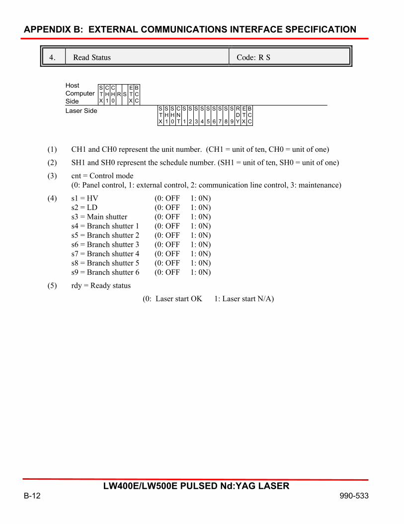
APPENDIX B: EXTERNAL COMMUNICATIONS INTERFACE SPECIFICATION
LW400E/LW500E PULSED Nd:YAG LASER
B-12 990-533
4.
Read Status
Code: R S
STX
CH1
CH0
R SETX
BCC
STX
SH1
SH0
CNT
S
1
S
2
S
3
S
4
ETX
BCC
S
5
S
6
S
7
S
8
S
9
RDY
HostComputerSideLaser Side
(1) CH1 and CH0 represent the unit number. (CH1 = unit of ten, CH0 = unit of one)
(2) SH1 and SH0 represent the schedule number. (SH1 = unit of ten, SH0 = unit of one)
(3) cnt = Control mode (0: Panel control, 1: external control, 2: communication line control, 3: maintenance)
(4) s1 = HV (0: OFF 1: 0N) s2 = LD (0: OFF 1: 0N) s3 = Main shutter (0: OFF 1: 0N) s4 = Branch shutter 1 (0: OFF 1: 0N) s5 = Branch shutter 2 (0: OFF 1: 0N) s6 = Branch shutter 3 (0: OFF 1: 0N) s7 = Branch shutter 4 (0: OFF 1: 0N) s8 = Branch shutter 5 (0: OFF 1: 0N) s9 = Branch shutter 6 (0: OFF 1: 0N)
(5) rdy = Ready status
(0: Laser start OK 1: Laser start N/A)
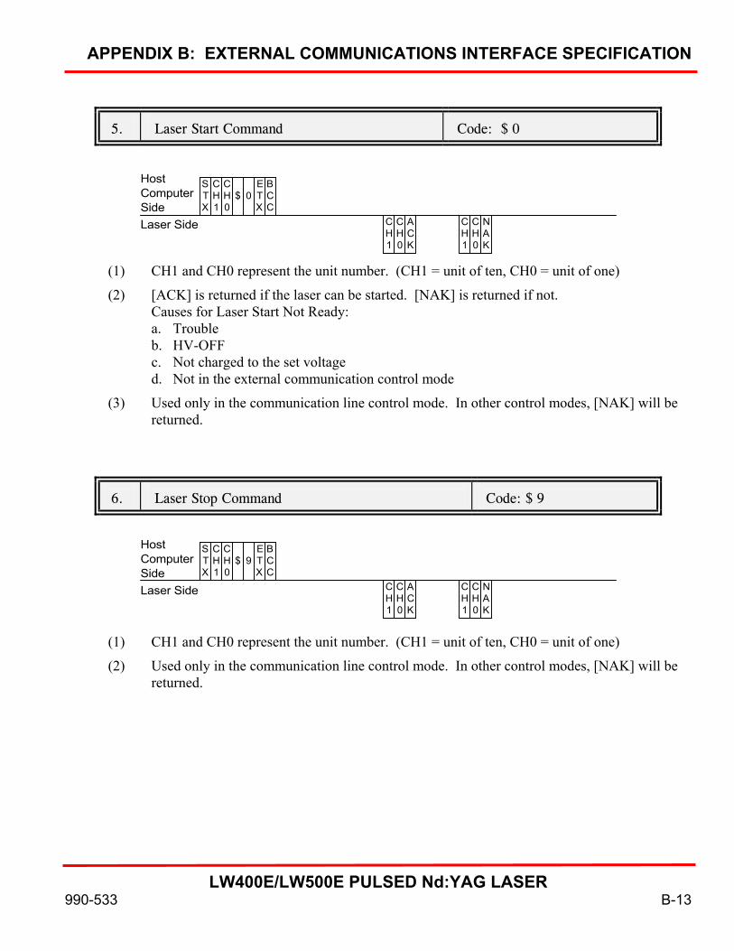
APPENDIX B: EXTERNAL COMMUNICATIONS INTERFACE SPECIFICATION
LW400E/LW500E PULSED Nd:YAG LASER
990-533 B-13
5.
Laser Start Command
Code: $ 0
STX
CH1
CH0
$ 0ETX
BCC
CH1
CH0
ACK
CH1
CH0
NAK
HostComputerSideLaser Side
(1) CH1 and CH0 represent the unit number. (CH1 = unit of ten, CH0 = unit of one)
(2) [ACK] is returned if the laser can be started. [NAK] is returned if not. Causes for Laser Start Not Ready: a. Trouble b. HV-OFF c. Not charged to the set voltage d. Not in the external communication control mode
(3) Used only in the communication line control mode. In other control modes, [NAK] will be returned.
6.
Laser Stop Command
Code: $ 9
STX
CH1
CH0
$ 9ETX
BCC
CH1
CH0
ACK
CH1
CH0
NAK
HostComputerSideLaser Side
(1) CH1 and CH0 represent the unit number. (CH1 = unit of ten, CH0 = unit of one)
(2) Used only in the communication line control mode. In other control modes, [NAK] will be returned.

APPENDIX B: EXTERNAL COMMUNICATIONS INTERFACE SPECIFICATION
LW400E/LW500E PULSED Nd:YAG LASER
B-14 990-533
7.
Trouble Reset
Code: C 0
STX
CH1
CH0
C 0ETX
BCC
CH1
CH0
ACK
CH1
CH0
NAK
HostComputerSideLaser Side
(1) CH1 and CH0 represent the unit number. (CH1 = unit of ten, CH0 = unit of one)
(2) After receiving the command, the laser unit resets the Trouble status.
(3) Used only in the communication line control mode. In other control modes, [NAK] will be returned.
8.
Total Count Reset Command
Code: C 1
STX
CH1
CH0
C 1ETX
BCC
CH1
CH0
ACK
CH1
CH0
NAK
(1) After receiving the command, the laser unit resets the total counter to zero.
(2) Used only in the communication line control mode. In other control modes, [NAK] will be returned.

APPENDIX B: EXTERNAL COMMUNICATIONS INTERFACE SPECIFICATION
LW400E/LW500E PULSED Nd:YAG LASER
990-533 B-15
9.
GOOD Count Reset Command
Code: C 2
STX
CH1
CH0
C 2ETX
BCC
CH1
CH0
ACK
CH1
CH0
NAK
HostComputerSideLaser Side
(1) CH1 and CH0 represent the unit number. (CH1 = unit of ten, CH0 = unit of one)
(2) After receiving the command, the laser unit resets the GODD counter to zero.
(3) Used only in the communication line control mode. In other control modes, [NAK] will be returned.
10.
Read Trouble (Error)
Code: R T
STX
CH1
CH0
R TETX
BCC
E
1
STX
E
0,
E
1
E
0,
E
1
E
0
ETX
BCC
HostComputerSideLaser Side
(1) CH1 and CH0 represent the unit number. (CH1 = unit of ten, CH0 = unit of one)
(2) E1 and E0 represent the error number. (E1 = unit of ten, E0 = unit of one)
(3) Transmits all error numbers. When normal, the error number is [00].
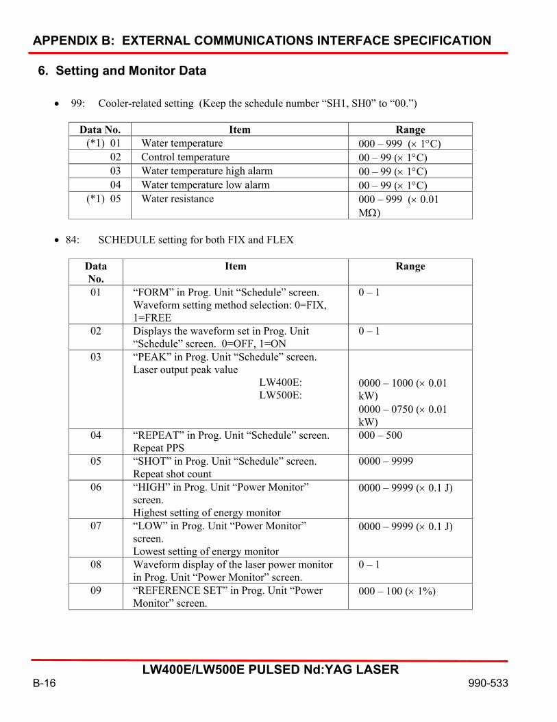
APPENDIX B: EXTERNAL COMMUNICATIONS INTERFACE SPECIFICATION
LW400E/LW500E PULSED Nd:YAG LASER
B-16 990-533
6. Setting and Monitor Data
• 99: Cooler-related setting (Keep the schedule number “SH1, SH0” to “00.”)
Data No. Item Range (*1) 01 Water temperature 000 – 999 (× 1°C)
02 Control temperature 00 – 99 (× 1°C) 03 Water temperature high alarm 00 – 99 (× 1°C) 04 Water temperature low alarm 00 – 99 (× 1°C)
(*1) 05 Water resistance 000 – 999 (× 0.01 MΩ)
• 84: SCHEDULE setting for both FIX and FLEX
Data No.
Item Range
01 “FORM” in Prog. Unit “Schedule” screen. Waveform setting method selection: 0=FIX, 1=FREE
0 – 1
02 Displays the waveform set in Prog. Unit “Schedule” screen. 0=OFF, 1=ON
0 – 1
03 “PEAK” in Prog. Unit “Schedule” screen. Laser output peak value LW400E: LW500E:
0000 – 1000 (× 0.01 kW) 0000 – 0750 (× 0.01 kW)
04 “REPEAT” in Prog. Unit “Schedule” screen. Repeat PPS
000 – 500
05 “SHOT” in Prog. Unit “Schedule” screen. Repeat shot count
0000 – 9999
06 “HIGH” in Prog. Unit “Power Monitor” screen. Highest setting of energy monitor
0000 – 9999 (× 0.1 J)
07 “LOW” in Prog. Unit “Power Monitor” screen. Lowest setting of energy monitor
0000 – 9999 (× 0.1 J)
08 Waveform display of the laser power monitor in Prog. Unit “Power Monitor” screen.
0 – 1
09 “REFERENCE SET” in Prog. Unit “Power Monitor” screen.
000 – 100 (× 1%)

APPENDIX B: EXTERNAL COMMUNICATIONS INTERFACE SPECIFICATION
LW400E/LW500E PULSED Nd:YAG LASER
990-533 B-17
• 85: SCHEDULE setting for FIX only
Data No. Item Range 01 “UP SLOPE” time in Prog. Unit “Schedule” screen. 000 – 300 (× 0.1 ms) 02 “FLASH 1” time in Prog. Unit “Schedule” screen. 000 – 300 (× 0.1 ms) 03 “FLASH 2” time in Prog. Unit “Schedule” screen. 000 – 300 (× 0.1 ms) 04 “FLASH 3” time in Prog. Unit “Schedule” screen. 000 – 300 (× 0.1 ms) 05 “DOWN SLOPE” time in Prog. Unit “Schedule”
screen. 000 – 300 (× 0.1 ms)
06 Not used Remain at 0000 07 “FLASH 1” watt in Prog. Unit “Schedule” screen. 0000 – 2000 (× 0.1%) 08 “FLASH 2” watt in Prog. Unit “Schedule” screen. 0000 – 2000 (× 0.1%) 09 “FLASH 3” watt in Prog. Unit “Schedule” screen. 0000 – 2000 (× 0.1%) 10 Not used Remain at 0000
(*1) 11 “~” in Prog. Unit “Schedule” screen. Approximate laser output energy for the specified waveform
0000 – 2000 (× 0.1%)
• 86: SCHEDULE setting for FLEX only – TIME 01 ~ 10
Data No.
Item Range
01 “Point 1” time in Prog. Unit “Schedule” screen. 000 – 300 (× 0.1 ms) 02 “Point 2” time in Prog. Unit “Schedule” screen. 000 – 300 (× 0.1 ms) 03 “Point 3” time in Prog. Unit “Schedule” screen. 000 – 300 (× 0.1 ms) 04 “Point 4” time in Prog. Unit “Schedule” screen. 000 – 300 (× 0.1 ms) 05 “Point 5” time in Prog. Unit “Schedule” screen. 000 – 300 (× 0.1 ms) 06 “Point 6” time in Prog. Unit “Schedule” screen. 000 – 300 (× 0.1 ms) 07 “Point 7” time in Prog. Unit “Schedule” screen. 000 – 300 (× 0.1 ms) 08 “Point 8” time in Prog. Unit “Schedule” screen. 000 – 300 (× 0.1 ms) 09 “Point 9” time in Prog. Unit “Schedule” screen. 000 – 300 (× 0.1 ms) 10 “Point 10” time in Prog. Unit “Schedule” screen. 000 – 300 (× 0.1 ms)
(*1) 11 “~” in Prog. Unit “Power Monitor” screen. Approximate laser output energy for the specified waveform
0000 – 9999 (× 0.1 J)
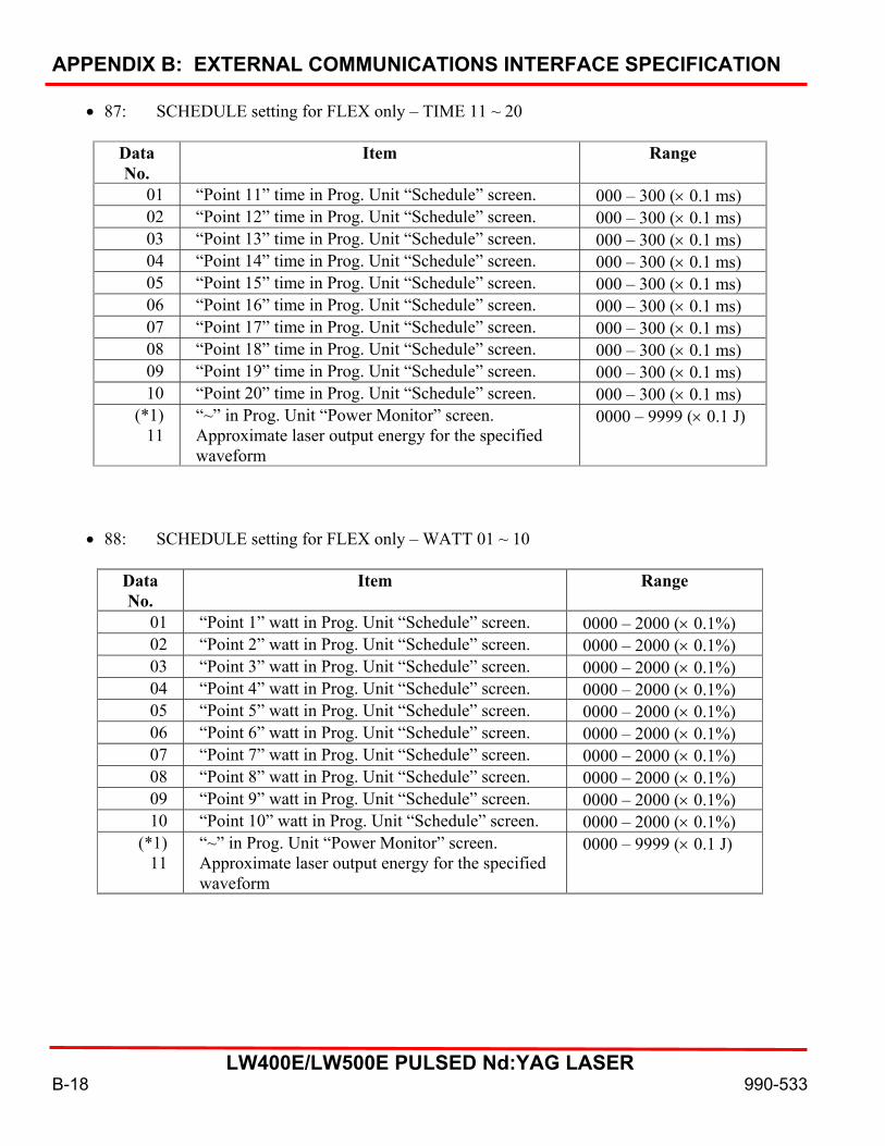
APPENDIX B: EXTERNAL COMMUNICATIONS INTERFACE SPECIFICATION
LW400E/LW500E PULSED Nd:YAG LASER
B-18 990-533
• 87: SCHEDULE setting for FLEX only – TIME 11 ~ 20
Data No.
Item Range
01 “Point 11” time in Prog. Unit “Schedule” screen. 000 – 300 (× 0.1 ms) 02 “Point 12” time in Prog. Unit “Schedule” screen. 000 – 300 (× 0.1 ms) 03 “Point 13” time in Prog. Unit “Schedule” screen. 000 – 300 (× 0.1 ms) 04 “Point 14” time in Prog. Unit “Schedule” screen. 000 – 300 (× 0.1 ms) 05 “Point 15” time in Prog. Unit “Schedule” screen. 000 – 300 (× 0.1 ms) 06 “Point 16” time in Prog. Unit “Schedule” screen. 000 – 300 (× 0.1 ms) 07 “Point 17” time in Prog. Unit “Schedule” screen. 000 – 300 (× 0.1 ms) 08 “Point 18” time in Prog. Unit “Schedule” screen. 000 – 300 (× 0.1 ms) 09 “Point 19” time in Prog. Unit “Schedule” screen. 000 – 300 (× 0.1 ms) 10 “Point 20” time in Prog. Unit “Schedule” screen. 000 – 300 (× 0.1 ms)
(*1) 11
“~” in Prog. Unit “Power Monitor” screen. Approximate laser output energy for the specified waveform
0000 – 9999 (× 0.1 J)
• 88: SCHEDULE setting for FLEX only – WATT 01 ~ 10
Data No.
Item Range
01 “Point 1” watt in Prog. Unit “Schedule” screen. 0000 – 2000 (× 0.1%) 02 “Point 2” watt in Prog. Unit “Schedule” screen. 0000 – 2000 (× 0.1%) 03 “Point 3” watt in Prog. Unit “Schedule” screen. 0000 – 2000 (× 0.1%) 04 “Point 4” watt in Prog. Unit “Schedule” screen. 0000 – 2000 (× 0.1%) 05 “Point 5” watt in Prog. Unit “Schedule” screen. 0000 – 2000 (× 0.1%) 06 “Point 6” watt in Prog. Unit “Schedule” screen. 0000 – 2000 (× 0.1%) 07 “Point 7” watt in Prog. Unit “Schedule” screen. 0000 – 2000 (× 0.1%) 08 “Point 8” watt in Prog. Unit “Schedule” screen. 0000 – 2000 (× 0.1%) 09 “Point 9” watt in Prog. Unit “Schedule” screen. 0000 – 2000 (× 0.1%) 10 “Point 10” watt in Prog. Unit “Schedule” screen. 0000 – 2000 (× 0.1%)
(*1) 11
“~” in Prog. Unit “Power Monitor” screen. Approximate laser output energy for the specified waveform
0000 – 9999 (× 0.1 J)

APPENDIX B: EXTERNAL COMMUNICATIONS INTERFACE SPECIFICATION
LW400E/LW500E PULSED Nd:YAG LASER
990-533 B-19
• 89: SCHEDULE setting for FLEX only – WATT 11 ~ 20 Data No. Item Range
01 “Point 11” watt in Prog. Unit “Schedule” screen.
0000 – 2000 (× 0.1%)
02 “Point 12” watt in Prog. Unit “Schedule” screen.
0000 – 2000 (× 0.1%)
03 “Point 13” watt in Prog. Unit “Schedule” screen.
0000 – 2000 (× 0.1%)
04 “Point 14” watt in Prog. Unit “Schedule” screen.
0000 – 2000 (× 0.1%)
05 “Point 15” watt in Prog. Unit “Schedule” screen.
0000 – 2000 (× 0.1%)
06 “Point 16” watt in Prog. Unit “Schedule” screen.
0000 – 2000 (× 0.1%)
07 “Point 17” watt in Prog. Unit “Schedule” screen.
0000 – 2000 (× 0.1%)
08 “Point 18” watt in Prog. Unit “Schedule” screen.
0000 – 2000 (× 0.1%)
09 “Point 19” watt in Prog. Unit “Schedule” screen.
0000 – 2000 (× 0.1%)
10 “Point 20” watt in Prog. Unit “Schedule” screen.
0000 – 2000 (× 0.1%)
(*1) 11 “~” in Prog. Unit “Power Monitor” screen. Approximate laser output energy for the specified waveform
0000 – 9999 (× 0.1 J)
Note: •86, 87, 88, and 89 share the same value in Data No. 11.
• 75: SEAM setting – WAVE ON/OFF Data No. Item Range
01 “SEAM WELD MODE” in Prog. Unit “Schedule” screen. 0=OFF, 1=ON
0 – 1
• 76: SEAM setting – No. of shots: 01 ~ 10 Data No. Item Range
01 “No. 1” shot in Prog. Unit “SEAM WELD MODE” screen.
0000 – 9999
02 “No. 2” shot in Prog. Unit “SEAM WELD MODE” screen.
0000 – 9999
03 “No. 3” shot in Prog. Unit “SEAM WELD MODE” screen.
0000 – 9999
04 “No. 4” shot in Prog. Unit “SEAM WELD MODE” screen.
0000 – 9999
05 “No. 5” shot in Prog. Unit “SEAM WELD MODE” screen.
0000 – 9999
06 “No. 6” shot in Prog. Unit “SEAM WELD 0000 – 9999
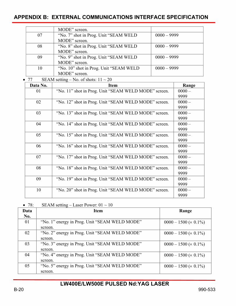
APPENDIX B: EXTERNAL COMMUNICATIONS INTERFACE SPECIFICATION
LW400E/LW500E PULSED Nd:YAG LASER
B-20 990-533
MODE” screen. 07 “No. 7” shot in Prog. Unit “SEAM WELD
MODE” screen. 0000 – 9999
08 “No. 8” shot in Prog. Unit “SEAM WELD MODE” screen.
0000 – 9999
09 “No. 9” shot in Prog. Unit “SEAM WELD MODE” screen.
0000 – 9999
10 “No. 10” shot in Prog. Unit “SEAM WELD MODE” screen.
0000 – 9999
• 77 SEAM setting – No. of shots: 11 ~ 20 Data No. Item Range
01 “No. 11” shot in Prog. Unit “SEAM WELD MODE” screen. 0000 – 9999
02 “No. 12” shot in Prog. Unit “SEAM WELD MODE” screen. 0000 – 9999
03 “No. 13” shot in Prog. Unit “SEAM WELD MODE” screen. 0000 – 9999
04 “No. 14” shot in Prog. Unit “SEAM WELD MODE” screen. 0000 – 9999
05 “No. 15” shot in Prog. Unit “SEAM WELD MODE” screen. 0000 – 9999
06 “No. 16” shot in Prog. Unit “SEAM WELD MODE” screen. 0000 – 9999
07 “No. 17” shot in Prog. Unit “SEAM WELD MODE” screen. 0000 – 9999
08 “No. 18” shot in Prog. Unit “SEAM WELD MODE” screen. 0000 – 9999
09 “No. 19” shot in Prog. Unit “SEAM WELD MODE” screen. 0000 – 9999
10 “No. 20” shot in Prog. Unit “SEAM WELD MODE” screen. 0000 – 9999
• 78: SEAM setting – Laser Power: 01 ~ 10 Data No.
Item Range
01 “No. 1” energy in Prog. Unit “SEAM WELD MODE” screen.
0000 – 1500 (× 0.1%)
02 “No. 2” energy in Prog. Unit “SEAM WELD MODE” screen.
0000 – 1500 (× 0.1%)
03 “No. 3” energy in Prog. Unit “SEAM WELD MODE” screen.
0000 – 1500 (× 0.1%)
04 “No. 4” energy in Prog. Unit “SEAM WELD MODE” screen.
0000 – 1500 (× 0.1%)
05 “No. 5” energy in Prog. Unit “SEAM WELD MODE” screen.
0000 – 1500 (× 0.1%)

APPENDIX B: EXTERNAL COMMUNICATIONS INTERFACE SPECIFICATION
LW400E/LW500E PULSED Nd:YAG LASER
990-533 B-21
06 “No. 6” energy in Prog. Unit “SEAM WELD MODE” screen.
0000 – 1500 (× 0.1%)
07 “No. 7” energy in Prog. Unit “SEAM WELD MODE” screen.
0000 – 1500 (× 0.1%)
08 “No. 8” energy in Prog. Unit “SEAM WELD MODE” screen.
0000 – 1500 (× 0.1%)
09 “No. 9” energy in Prog. Unit “SEAM WELD MODE” screen.
0000 – 1500 (× 0.1%)
10 “No. 10” energy in Prog. Unit “SEAM WELD MODE” screen.
0000 – 1500 (× 0.1%)
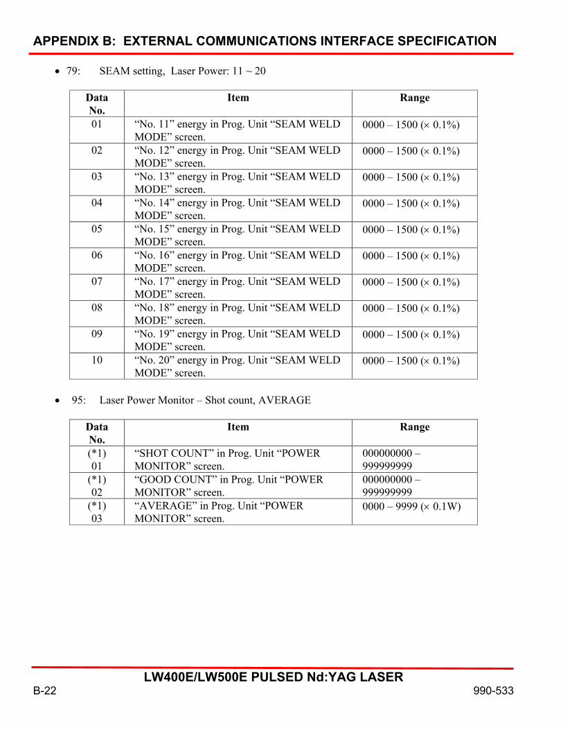
APPENDIX B: EXTERNAL COMMUNICATIONS INTERFACE SPECIFICATION
LW400E/LW500E PULSED Nd:YAG LASER
B-22 990-533
• 79: SEAM setting, Laser Power: 11 ~ 20
Data No.
Item Range
01 “No. 11” energy in Prog. Unit “SEAM WELD MODE” screen.
0000 – 1500 (× 0.1%)
02 “No. 12” energy in Prog. Unit “SEAM WELD MODE” screen.
0000 – 1500 (× 0.1%)
03 “No. 13” energy in Prog. Unit “SEAM WELD MODE” screen.
0000 – 1500 (× 0.1%)
04 “No. 14” energy in Prog. Unit “SEAM WELD MODE” screen.
0000 – 1500 (× 0.1%)
05 “No. 15” energy in Prog. Unit “SEAM WELD MODE” screen.
0000 – 1500 (× 0.1%)
06 “No. 16” energy in Prog. Unit “SEAM WELD MODE” screen.
0000 – 1500 (× 0.1%)
07 “No. 17” energy in Prog. Unit “SEAM WELD MODE” screen.
0000 – 1500 (× 0.1%)
08 “No. 18” energy in Prog. Unit “SEAM WELD MODE” screen.
0000 – 1500 (× 0.1%)
09 “No. 19” energy in Prog. Unit “SEAM WELD MODE” screen.
0000 – 1500 (× 0.1%)
10 “No. 20” energy in Prog. Unit “SEAM WELD MODE” screen.
0000 – 1500 (× 0.1%)
• 95: Laser Power Monitor – Shot count, AVERAGE
Data No.
Item Range
(*1) 01
“SHOT COUNT” in Prog. Unit “POWER MONITOR” screen.
000000000 – 999999999
(*1) 02
“GOOD COUNT” in Prog. Unit “POWER MONITOR” screen.
000000000 – 999999999
(*1) 03
“AVERAGE” in Prog. Unit “POWER MONITOR” screen.
0000 – 9999 (× 0.1W)

APPENDIX B: EXTERNAL COMMUNICATIONS INTERFACE SPECIFICATION
LW400E/LW500E PULSED Nd:YAG LASER
990-533 B-23
• 00: Laser Power Monitor – ENERGY, waveform data count
Data No. Item Range (*1) 01 Schedule No. of laser power monitor data 00 – 15 (*1) 02 “LAMP INPUT PWR” in Prog. Unit
“POWER MONITOR” screen. Lamp input power
000 – 999 (× 1%)
(*1) 03 “ENERGY” in Prog. Unit “POWER MONITOR” screen
0000 – 9999 (× 0.1J)
(*1) 04 Waveform data count of laser power monitor. No. of data sent by classification Nos. 00 – 22
0000 – 108
(*1) 05 Pulse width that flashed 0000 – 300 (× 0.1 ms)
• 01: Laser Power Monitor – Waveform data 000 ~ 004 : : :
• 22: Laser Power Monitor – Waveform data 105 ~ 109
Data No.
Item Range
(*1) 01 Schedule No. of laser power monitor data 00 – 15 02 Laser power monitor’s waveform data 1/5 0000 – 9999 (× 0.1 kW) 03 Laser power monitor’s waveform data 2/5 0000 – 9999 (× 0.1 kW) 04 Laser power monitor’s waveform data 3/5 0000 – 9999 (× 0.1 kW) 05 Laser power monitor’s waveform data 4/5 0000 – 9999 (× 0.1 kW) 06 Laser power monitor’s waveform data 5/5 0000 – 9999 (× 0.1 kW)
As the pulse width gets longer, the measuring interval gets longer so that the total number of waveform data does not exceed 108, as explained by examples below. • When the pulse width is 00.5ms to 05.0ms, the measured value in increments of 0.05ms is
returned. • When the pulse width is 05.1ms to 10.0ms, the measured value in increments of 0.10ms is
returned. • When the pulse width is 10.1ms to 20.0ms, the measured value in increments of 0.20ms is
returned. • When the pulse width is 20.1ms to 30.0ms, the measured value in increments of 0.40ms is
returned.
Only 5 data are transmitted each time. It is required to read repeatedly for the number of times according to the “waveform data count of laser power monitor” returned in a form of “R003 nn 03” by using different classification number.
Note: The data numbers marked by (*1) are monitored values. They are for reading only, and cannot be written.
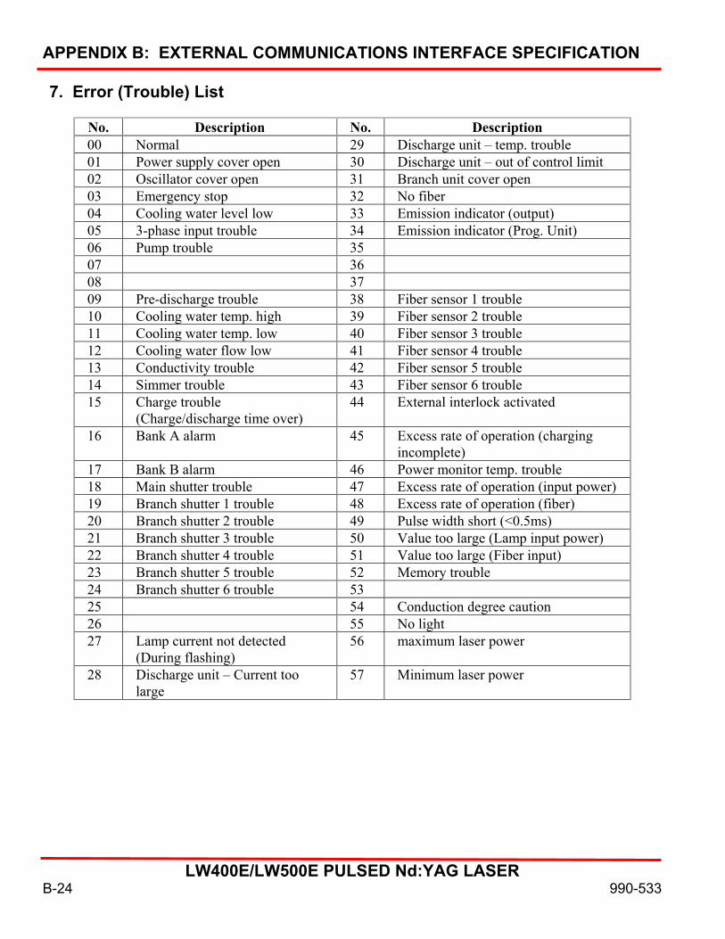
APPENDIX B: EXTERNAL COMMUNICATIONS INTERFACE SPECIFICATION
LW400E/LW500E PULSED Nd:YAG LASER
B-24 990-533
7. Error (Trouble) List
No. Description No. Description 00 Normal 29 Discharge unit – temp. trouble 01 Power supply cover open 30 Discharge unit – out of control limit 02 Oscillator cover open 31 Branch unit cover open 03 Emergency stop 32 No fiber 04 Cooling water level low 33 Emission indicator (output) 05 3-phase input trouble 34 Emission indicator (Prog. Unit) 06 Pump trouble 35 07 36 08 37 09 Pre-discharge trouble 38 Fiber sensor 1 trouble 10 Cooling water temp. high 39 Fiber sensor 2 trouble 11 Cooling water temp. low 40 Fiber sensor 3 trouble 12 Cooling water flow low 41 Fiber sensor 4 trouble 13 Conductivity trouble 42 Fiber sensor 5 trouble 14 Simmer trouble 43 Fiber sensor 6 trouble 15 Charge trouble
(Charge/discharge time over) 44 External interlock activated
16 Bank A alarm 45 Excess rate of operation (charging incomplete)
17 Bank B alarm 46 Power monitor temp. trouble 18 Main shutter trouble 47 Excess rate of operation (input power) 19 Branch shutter 1 trouble 48 Excess rate of operation (fiber) 20 Branch shutter 2 trouble 49 Pulse width short (<0.5ms) 21 Branch shutter 3 trouble 50 Value too large (Lamp input power) 22 Branch shutter 4 trouble 51 Value too large (Fiber input) 23 Branch shutter 5 trouble 52 Memory trouble 24 Branch shutter 6 trouble 53 25 54 Conduction degree caution 26 55 No light 27 Lamp current not detected
(During flashing) 56 maximum laser power
28 Discharge unit – Current too large
57 Minimum laser power
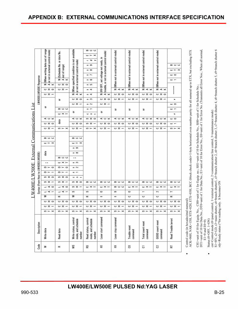
APPENDIX B: EXTERNAL COMMUNICATIONS INTERFACE SPECIFICATION
LW400E/LW500E PULSED Nd:YAG LASER
990-533 B-25
B C C
E T X
r d y
s 9 B C C
s 8 E T X
(Sch
edul
e No
. or d
ata
No.
out o
f ran
ge)
s 7 E 0
(Whe
n w
ritin
g da
ta o
ut o
f ran
ge
or n
ot in
ext
erna
l con
trol m
ode)
N A K s 6 E 1
N A K C H 0 s 5
(Whe
n no
t in
exte
rnal
con
trol m
ode)
(Whe
n no
t in
exte
rnal
con
trol m
ode)
(Whe
n no
t in
exte
rnal
con
trol m
ode)
(Whe
n no
t in
exte
rnal
con
trol m
ode)
C H 0 C H 1
(Whe
n sp
ecifi
ed c
ondi
tion
is no
t ava
ilabl
e or
not
in e
xter
nal c
ontro
l mod
e)
s 4
(HV-
OFF,
set v
olta
ge n
ot re
ady,
in
troub
le, o
r not
in e
xter
nal c
ontro
l mod
e)
N A K N A K N A K N A K
C H 1 N A K s 4 N A K C H 0 C H 0 C H 0 C H 0 ……
..
C H 0 s 3 C H 0 C H 1 C H 1 C H 1 C H 1 , or
C H 1 s 2 C H 1 E 0
B C C s 1 E 1 or
E X T or
c n t or or
or
or
,
A C K A C K S H 0 A C K A C K A C K A C K A C K E 0
C H 0 data
C H 0 S H 1 C H 0 C H 0 C H 0 C H 0 C H 0 E 1
LW40
0E/L
W50
0E R
espo
nse
C H 1 S T X C H 1 S T X C H 1 C H 1 C H 1 C H 1 C H 1 S T X
B C C B C C
E T X E T X
s 9
s 8
data
B C C :
: E X T s 3
D T 0 D T 0 s 2
D T 1 D T 1 s 1
S H 0 S H 0 c n t
S H 1 S H 1 S H 0 B C C B C C B C C B C C B C C B C C B C C
L A 0 L A 0 S H 1 E X T E X T B C C E X T E X T E X T E X T
L A 1 L A 1 S S 0 9 0 1 2 T
W
R W
R $ $ C C C R
C H 0 C H 0 C H 0 C H 0 C H 0 C H 0 C H 0 C H 0 C H 0 C H 0
C H 1 C H 1 C H 1 C H 1 C H 1 C H 1 C H 1 C H 1 C H 1 C H 1
Synt
ax (F
rom
Hos
t to
LW40
0E/L
W50
0E)
S T X S T X S T X S T X S T X S T X S T X S T X S T X S T X
Desc
riptio
n
Writ
e da
ta
Read
dat
a
Writ
e st
atus
, con
trol
mod
e, a
nd sc
hedu
le nu
mbe
r
Read
stat
us, c
ontro
l m
ode,
and
sche
dule
num
ber
Lase
r sta
rt co
mm
and
Lase
r sto
p co
mm
and
Trou
ble
rese
t co
mm
and
Tota
l cou
nt re
set
com
man
d
GOOD
cou
nt re
set
com
man
d
Read
Tro
uble
(erro
r)
LW40
0E/L
W50
0E E
xter
nal C
omm
unic
atio
ns L
ist
Code
W R W
S RS
$0
$9
C0
C1
C2
RT
• C
ontro
l cod
e (in
hex
adec
imal
num
eral
) A
CK
=06H
, NA
K=1
5H, S
TX=0
2H, E
TX=0
3H, B
CC
(blo
ck c
heck
cod
e)=1
-byt
e ho
rizon
tal e
ven
num
ber p
arity
for a
ll nu
mer
al u
p to
ETX
, but
exc
ludi
ng S
TX
CH
1=un
it of
10
for E
quip
. No.
, C
H0=
unit
of 1
for E
quip
. no.
; SH
1=un
it of
10
for S
ched
ule
No.
, SH
0=un
it of
1 fo
r Sch
edul
e N
o.;
DT1
=uni
t of 1
0 fo
r Dat
a N
o., D
T0=u
nit o
f 1 fo
r Dat
a N
o.; E
1=un
it of
10
for E
rror
No.
, E0=
unit
of 1
for E
rror
No.
(Tra
nsm
its a
ll Er
ror N
os.;
Whe
n al
l nor
mal
, E1
=0 a
nd E
0=0)
•
Stat
us (0
=OFF
, 1=O
N)
cnt=
Con
trol m
ode
(0=p
anel
con
trol,
1=ex
tern
al c
ontro
l, 2=
com
mun
icat
ion
line
cont
rol,
3=m
aint
enan
ce m
ode)
S1
=HV
, s2=
LD, s
3=m
ain
shut
ter,
s4=b
ranc
h sh
utte
r1, s
5=br
anch
shut
ter 2
, s6=
bran
ch sh
utte
r 3, s
7=br
anch
shut
ter 4
, s8=
bran
ch sh
utte
r 5, s
9=br
anch
shut
ter 6
rd
y=R
eady
stat
us (*
for r
eadi
ng o
nly.
It b
ecom
es O
N

LW400E/LW500E PULSED Nd:YAG LASER
990-533 C1
APPENDIX C SCHEDULE DATA TABLES
You may use the LW400E/LW500E Laser Schedule Data Tables on the following pages to record the values set in each weld schedule

Schedule Data Table
SCHEDULE ITEM SETTING RANGE UNIT
00 01 02 03 04 05 06 07 08 09 10 11 12 13 14 15
SLOPE TIME 00.0 to 30.0 ms
TIME 00.0 to 30.0 ms FLASH1
% 000.0 to 200.0 %
TIME 00.0 to 30.0 ms FLASH2
% 000.0 to 200.0 %
TIME 00.0 to 30.0 ms FLASH3
% 000.0 to 200.0 %
SLOPE TIME 00.0 to 30.0 ms
PEAK 00.00 to 10.00 kW
PPS 000 to 500
SHOT 0000 to 9999
HIGH 000.0 to 999.9 J ENERGY
LOW 000.0 to 999.9 J
NETWORK #
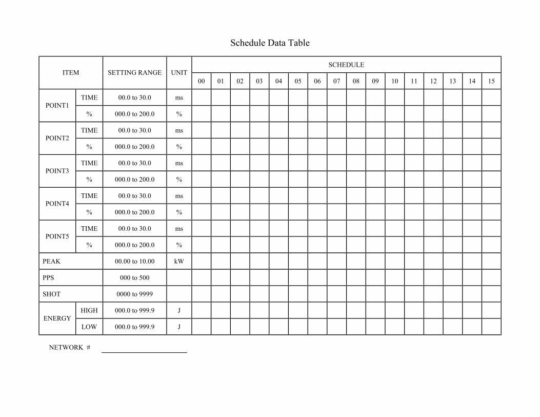
Schedule Data Table
SCHEDULE ITEM SETTING RANGE UNIT
00 01 02 03 04 05 06 07 08 09 10 11 12 13 14 15
TIME 00.0 to 30.0 ms POINT1
% 000.0 to 200.0 %
TIME 00.0 to 30.0 ms POINT2
% 000.0 to 200.0 %
TIME 00.0 to 30.0 ms POINT3
% 000.0 to 200.0 %
TIME 00.0 to 30.0 ms POINT4
% 000.0 to 200.0 %
TIME 00.0 to 30.0 ms POINT5
% 000.0 to 200.0 %
PEAK 00.00 to 10.00 kW
PPS 000 to 500
SHOT 0000 to 9999
HIGH 000.0 to 999.9 J ENERGY
LOW 000.0 to 999.9 J
NETWORK #

Schedule Data Table
SCHEDULE ITEM SETTING RANGE UNIT
00 01 02 03 04 05 06 07 08 09 10 11 12 13 14 15
TIME 00.0 to 30.0 ms POINT
% 000.0 to 200.0 %
TIME 00.0 to 30.0 ms POINT
% 000.0 to 200.0 %
TIME 00.0 to 30.0 ms POINT
% 000.0 to 200.0 %
TIME 00.0 to 30.0 ms POINT
% 000.0 to 200.0 %
TIME 00.0 to 30.0 ms POINT
% 000.0 to 200.0 %
PEAK 00.00 to 10.00 kW
PPS 000 to 500
SHOT 0000 to 9999
HIGH 000.0 to 999.9 J ENERGY
LOW 000.0 to 999.9 J
NETWORK #

Schedule Data Table
SCHEDULE ITEM SETTING RANGE UNIT
00 01 02 03 04 05 06 07 08 09 10 11 12 13 14 15
SHOT 0000 to 9999 No. 1
ENERGY 000.0 to 150.0 %
SHOT 0000 to 9999 No. 2
ENERGY 000.0 to 150.0 %
SHOT 0000 to 9999 No. 3
ENERGY 000.0 to 150.0 %
SHOT 0000 to 9999 No. 4
ENERGY 000.0 to 150.0 %
SHOT 0000 to 9999 No. 5
ENERGY 000.0 to 150.0 %
SHOT 0000 to 9999 No. 6
ENERGY 000.0 to 150.0 %
SHOT 0000 to 9999 No. 7
ENERGY 000.0 to 150.0 %
NETWORK #

Schedule Data Table
SCHEDULE ITEM SETTING RANGE UNIT
00 01 02 03 04 05 06 07 08 09 10 11 12 13 14 15
SHOT 0000 to 9999 No.
ENERGY 000.0 to 150.0 %
SHOT 0000 to 9999 No.
ENERGY 000.0 to 150.0 %
SHOT 0000 to 9999 No.
ENERGY 000.0 to 150.0 %
SHOT 0000 to 9999 No.
ENERGY 000.0 to 150.0 %
SHOT 0000 to 9999 No.
ENERGY 000.0 to 150.0 %
SHOT 0000 to 9999 No.
ENERGY 000.0 to 150.0 %
SHOT 0000 to 9999 No.
ENERGY 000.0 to 150.0 %
NETWORK #

LW400E/LW500E PULSED Nd:YAG LASER
990-533 INDEX-1
Alphabetical Subject Index

ALPHABETICAL SUBJECT INDEX
LW400E/LW500E PULSED Nd:YAG LASER
INDEX-2 990-533
-A- Accessory Kit ...................................... 2-8 Adjusting the Burn Pattern .................. 8-3 Adjusting the X-Y axes ....................... 8-5 Adjusting the Z-axis ............................ 8-3 Air filter cleaning ................................ 7-1 Aligning the Beam .............................. 8-3
-B- Backup battery replacement ................ 8-7 Burn pattern adjustment ...................... 8-3
-C- Carrying the laser precautions ............. 1-1 Cautions and warnings indications ..... 1-3 Cautions page ...................................... viii CDRH compliance statement .............. iii CE compliance statement..................... iii Cleaning: Optical fiber .................................. 8-7 Optics ............................................ 8-6 Solenoid valve strainer ................. 7-2 Cleanliness .......................................... 1-3 Cold weather operation ....................... 1-2 Contact input signals ........................... 3-1 Controls and indicators: External ........................................ 2-2 Internal .......................................... 2-3 Laser controller ............................. 2-2, 2-5 Cooler maintenance ............................. 7-1 Cooling system: Air filter cleaning ......................... 7-1 Components and controls ............ 2-3, 2-4 Draining cooling water ................. 7-5 Filter replacement ......................... 7-1 Ion exchange resin cartridge replacement ............................ 7-2 Preparation .................................... 5-2 Replacing D.I. water ..................... 7-2, 7-3, 7-4 Solenoid valve strainer cleaning ... 7-2 Cooling water draining ....................... 7-2, 7-5
-D- Design integrity ................................... 1-3 Display screens: Power monitor .............................. 6-14 Schedule ....................................... 6-6 Status ............................................ 6-12 De-ionized water supply: Replacing ...................................... 7-2, 7-3, 7-4 Replenishing ................................. 5-2 Draining input cooling water .............. 7-5
-E- Electrical supply precautions .............. 1-1 Energy- and time-sharing setup .......... 5-4 External Communications Interface Specifications ...................................... B-1 External controls and indicators .......... 2-2 External panels .................................... 2-4 External power supply ........................ 3-5
-F- Features of system ............................... 2-1 Fiber optic cable: Minimum bend radius .................. 1-1 Precautions ................................... 1-1 Filter replacement, cooling system ..... 7-1 Flash lamp replacement ...................... 8-1 Foreword, manual ............................... iv Fuse replacement ................................ 8-7
-G- Getting started ..................................... 5-1
-H- Hold down brackets, oscillator head ... 1-2
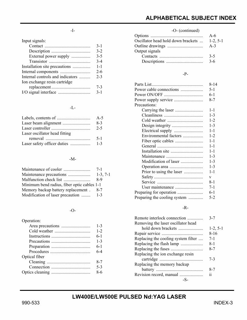
ALPHABETICAL SUBJECT INDEX
LW400E/LW500E PULSED Nd:YAG LASER
990-533 INDEX-3
-I- Input signals: Contact ......................................... 3-1 Description ................................... 3-2 External power supply ................. 3-5 Transistor ..................................... 3-4 Installation site precautions ................ 1-1 Internal components ........................... 2-6 Internal controls and indicators .......... 2-3 Ion exchange resin cartridge replacement ................................... 7-3 I/O signal interface ............................. 3-1
-L- Labels, contents of .............................. A-5 Laser beam alignment ......................... 8-3 Laser controller ................................... 2-5 Laser oscillator head fitting removal ........................................ 5-1 Laser safety officer duties .................. 1-3
-M- Maintenance of cooler ........................ 7-1 Maintenance precautions .................... 1-3, 7-1 Malfunction check list ........................ 8-9 Minimum bend radius, fiber optic cables 1-1 Memory backup battery replacement . 8-7 Modification of laser precaution ........ 1-3
-O- Operation: Area precautions .......................... 1-3 Cold weather ................................ 1-2 Instructions ................................... 6-1 Precautions ................................... 1-3 Preparation ................................... 6-1 Procedures .................................... 6-4 Optical fiber Cleaning ....................................... 8-7 Connection ................................... 5-3 Optics cleaning ................................... 8-6
-O- (continued) Options ............................................... A-6 Oscillator head hold down brackets ... 1-2, 5-1 Outline drawings ................................ A-3 Output signals Contacts ....................................... 3-5 Descriptions ................................. 3-6
-P- Parts List.............................................. 8-14 Power cable connections .................... 5-1 Power ON/OFF ................................... 6-1 Power supply service .......................... 8-7 Precautions: Carrying the laser ......................... 1-1 Cleanliness ................................... 1-3 Cold weather ................................ 1-2 Design integrity ............................ 1-3 Electrical supply .......................... 1-1 Environmental factors .................. 1-2 Fiber optic cables ......................... 1-1 General ......................................... 1-1 Installation site ............................. 1-1 Maintenance ................................. 1-3 Modification of laser .................... 1-3 Operation area .............................. 1-3 Prior to using the laser ................. 1-1 Safety ............................................ v Service ......................................... 8-1 User maintenance ......................... 7-1 Preparing for operation ....................... 6-1 Preparing the cooling system ............. 5-2
-R- Remote interlock connection .............. 3-7 Removing the laser oscillator head hold down brackets ...................... 1-2, 5-1 Repair service ..................................... 8-16 Replacing the cooling system filter .... 7-1 Replacing the flash lamp .................... 8-1 Replacing the fuses ............................. 8-7 Replacing the ion exchange resin cartridge ....................................... 7-3 Replacing the memory backup battery .......................................... 8-7 Revision record, manual ..................... ii
-S-

ALPHABETICAL SUBJECT INDEX
LW400E/LW500E PULSED Nd:YAG LASER
INDEX-4 990-533
Safety Precautions................................ v Schedule data table ............................. C-1 Screen selection .................................. 6-4 Schedule ....................................... 6-6 Status ............................................ 6-12 Power Monitor .............................. 6-14 Service: General ......................................... 8-1 Power supply ................................ 8-7 Precautions ................................... 8-1 Sharing options ................................... A-6 Shutdown procedure ........................... 6-16 Solenoid valve strainer cleaning ......... 7-2 Spare Parts Kits.................................... 8-14 System description: Controls and indicators ................. 2-2 Coolant system ............................. 2-3 Features ........................................ 2-1 Timing .......................................... 4-1 System timing ..................................... 4-1
-T- Technical specifications ...................... A-1, A-2 Time-sharing set-up ............................ 5-4 Timing diagrams ................................. 4-1 Transistor input signals ....................... 3-4 Troubleshooting .................................. 8-9 Turning power ON/OFF ..................... 6-1
-U- User maintenance ................................ 7-1
-W- Water drainage schedule ..................... 7-2 Waveform control ............................... 6-6, 6-11, 6-15
-X- X-Y axes adjustment ........................... 8-5
-Z- Z-axis adjustment ................................ 8-3