BD Aria Fusion Standard Operation Protocol – Basic Operation
41
Centre for PanorOmic Sciences – Imaging and Cytometry Core 1 BD Aria Fusion Standard Operation Protocol – Basic Operation A. Laser 1. Check if the laser needed is turned ON. * Turn off laser(s) not required may improve cell viability ** Blue Laser MUST be turned ON. B. User Login 1. Login to FACSDiva Software with your username and password. *If you do not have account, please contact our staff for assistance. 2. Click Use CST Settings if the window below pops up. Violet Blue YG Red
-
Upload
khangminh22 -
Category
Documents
-
view
2 -
download
0
Transcript of BD Aria Fusion Standard Operation Protocol – Basic Operation

Centre for PanorOmic Sciences – Imaging and Cytometry Core
1
BD Aria Fusion Standard Operation Protocol – Basic Operation
A. Laser
1. Check if the laser needed is turned ON.
* Turn off laser(s) not required may improve cell viability
** Blue Laser MUST be turned ON.
B. User Login
1. Login to FACSDiva Software with your username and password.
*If you do not have account, please contact our staff for assistance.
2. Click Use CST Settings if the window below pops up.
Violet
Blue
YG
Red

Centre for PanorOmic Sciences – Imaging and Cytometry Core
2
C. Stream Optimization
1. Go to 100 micron window (upper monitor)
2. Adjust the Freq (Starting Value 29.2) so the “neck” of a drop is
formed
3. Adjust the Ampl (Starting Value 3.0) so the Drop 1 is close to
120 and Gap is close to 10
4. Click Sweet spot
3.
2.
4.

Centre for PanorOmic Sciences – Imaging and Cytometry Core
3
D. Accudrop Delay Assay
1. To Import Accudrop Drop Delay template, click Experiment > New Experiment.
Select Accudrop Drop Delay, then click OK
- OR -
2. To open existing Accudrop Drop Delay experiment, double click Accudrop Drop Delay on
the Browser window

Centre for PanorOmic Sciences – Imaging and Cytometry Core
4
3. Expend Specimen_001
4. Click the tube pointer and expend Tube_001
5. Double click Sort Layout_001. Sort Layout window will pop up

Centre for PanorOmic Sciences – Imaging and Cytometry Core
5
6. Go to Sort Layout Window, Select Precision > Initial
7. Go to 100 micron window (lower monitor), set the slider reading as 0 - 26 - 0 - 0
8. Go to Acquisition Dashboard window, Set Flow rate to 1.0
9. Close upper flow cell access door.

Centre for PanorOmic Sciences – Imaging and Cytometry Core
6
10. Load a tube of Accudrop beads (1 mL of PBS + 1 drop of stock) on the sample stage
11. Go to Acquisition Dashboard, Click Load
12. Adjust Flow rate if needed to obtain threshold rate constantly 1000-1500 events per sec
13. Go to Sort Layout window, click Sort
14. Click Cancel on the confirm window
15. Go to 100 micron window (lower monitor), Click Voltage and Optical Filter

Centre for PanorOmic Sciences – Imaging and Cytometry Core
7
16. Adjust Drop Delay value (starting value: 25.00) so that the reading on the left reach 100
17. Go to Sort Layout window, Select Precision > Fine Tune
18. Adjust Drop Delay value bit by bit so that the reading on the left reach >97

Centre for PanorOmic Sciences – Imaging and Cytometry Core
8
19. Go to Sort Layout Window, Click Sort again.
20. Click Cancel on the confirm window
21. Go to Acquisition Dashboard, Click Unload
22. Return the Accudrop beads to 4 degree refrigerator

Centre for PanorOmic Sciences – Imaging and Cytometry Core
9
E. Experiment Setup
1. Setup New Experiment
1.1 Go to Browser, Click New Experiment icon. A new experiment will be created
1.2 Click Cytometer Settings under the newly created Experiment
1.3 Go to Inspector Window, highlight unwanted channels and click Delete.

Centre for PanorOmic Sciences – Imaging and Cytometry Core
10
1.4 Check H and W boxes of FSC and SSC
1.5 Keep Log boxes of FSC and SSC unchecked
1.6 Keep Log boxes of all fluorescence channels checked
* If you are doing cell cycle or DNA content analysis, please keep log box of your
DNA specific fluorescence channel unchecked.
2. Setup Compensation (for Multi-colour panel)
2.1 Click Experiment > Compensation Setup > Create Compensation Control

Centre for PanorOmic Sciences – Imaging and Cytometry Core
11
2.2 If any one of your single stain controls is known to be 100% positive, i.e. no
negative population, check the box “Include separate unstained control tube/well”.
2.3 Click OK

Centre for PanorOmic Sciences – Imaging and Cytometry Core
12
2.4 Expand the Compensation Control Specimen
2.5 Click the tube pointer of the first tube
2.6 Load the single stain controls on the sample stage according to the tube label, i.e.
run FITC single stain when the tube pointer is pointing at “FITC Stained Control”
2.7 Go to Acquisition Dashboard, Click Load.
2.8 Go to Normal Worksheet, move the P1 gate to include major cluster.
Adjust FSC and SSC PMT Voltage if needed

Centre for PanorOmic Sciences – Imaging and Cytometry Core
13
2.9 Go to Cytometer window, Fine tune the corresponding fluorescence PMT voltage
to have best separation of negative and positive peak
2.10 Move the interval gate (P2) to include the positive peak
2.11 Use interval gate to gate out negative peak (P3)
2.12 Go to Acquisition Dashboard, Click Unload. *DO NOT Record Data at this point
2.13 Repeat step 2.5 – 2.12 with all the single stain controls.

Centre for PanorOmic Sciences – Imaging and Cytometry Core
14
2.14 After optimising the PMT voltage of ALL the fluorescence channel, load each single
stained control and click Record Data for ALL single stain controls
2.15 Click Experiment > Compensation Setup > Calculate Compensation
2.16 Click Link and Save for the most stringent practice, i.e. cannot adjust PMT voltage
anymore OR Click Apply Only for some flexibility on PMT voltage adjustment of
your samples.
2.17 Switch Normal worksheet to Global worksheet

Centre for PanorOmic Sciences – Imaging and Cytometry Core
15
3. Setup Plots and Tables
3.1 Go to Browser, Click New Specimen icon
3.2 Expand Specimen_001
3.3 Click the tube pointer of Tube_001

Centre for PanorOmic Sciences – Imaging and Cytometry Core
16
3.4 Go to Global Sheet Window, Click the graph type icon
Icon Type
Dot Plot
Contour Plot
Histogram
3.5 Click on the blank area of Global Worksheet window to create a new plot.
3.6 Mouse over the axis label and right click. Select the parameters of interest from the
list.
3.7 Repeat step 3.4 – 3.6 until all plots needed is created.
* Essential Plots: FSC-A VS SSC-A; FSC-H VS FSC-W; SSC-H VS SSC-W

Centre for PanorOmic Sciences – Imaging and Cytometry Core
17
3.8 Click on any plot and right click. Click Show Population Hierarchy
3.9 Click on any plot and right click. Click Create Statistics View

Centre for PanorOmic Sciences – Imaging and Cytometry Core
18
3.10 Click on Statistics View table and right click, Click Edit Statistics View to select
statistics of interest to be shown in the table.
3.11 Click Statistics Tab, check the boxes of interested statistics and then click OK
Centre for PanorOmic Sciences – Imaging and Cytometry Core
19
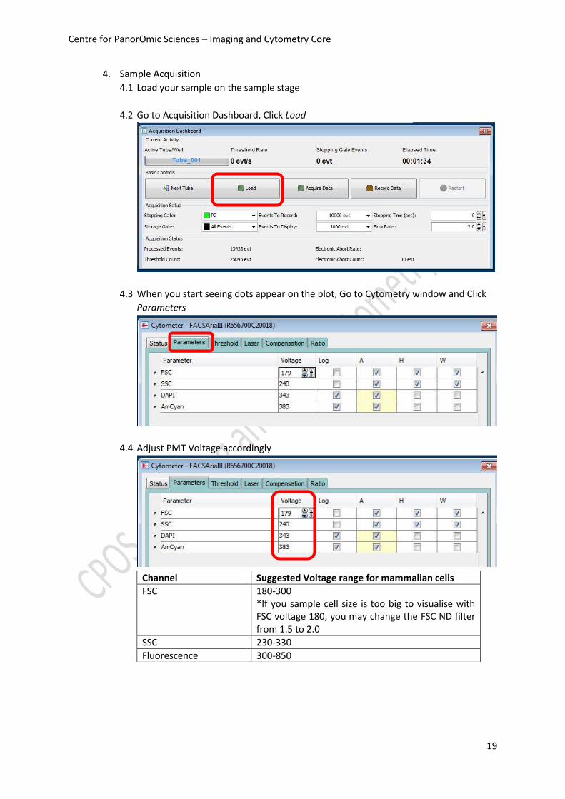
4. Sample Acquisition
4.1 Load your sample on the sample stage
4.2 Go to Acquisition Dashboard, Click Load
4.3 When you start seeing dots appear on the plot, Go to Cytometry window and Click
Parameters
4.4 Adjust PMT Voltage accordingly
Channel Suggested Voltage range for mammalian cells
FSC 180-300 *If you sample cell size is too big to visualise with FSC voltage 180, you may change the FSC ND filter from 1.5 to 2.0
SSC 230-330
Fluorescence 300-850

Centre for PanorOmic Sciences – Imaging and Cytometry Core
20
4.5 Adjust Flow rate if needed (optimum Threshold rate 2000 – 5000 evt/s)
* If you perform sorting, DO NOT set flow rate > 5.0 or threshold rate > 5000 event/s
5. Create Gates
5.1 Go to Global Sheet Window, Click the type of gate needed
Icon Type
Polygon Area Gate
Rectangle Area Gate
Quantrad Gate
Interval Gate
5.2 Draw the gate on the plot of interest to gate out target cluster /peak
Centre for PanorOmic Sciences – Imaging and Cytometry Core
21
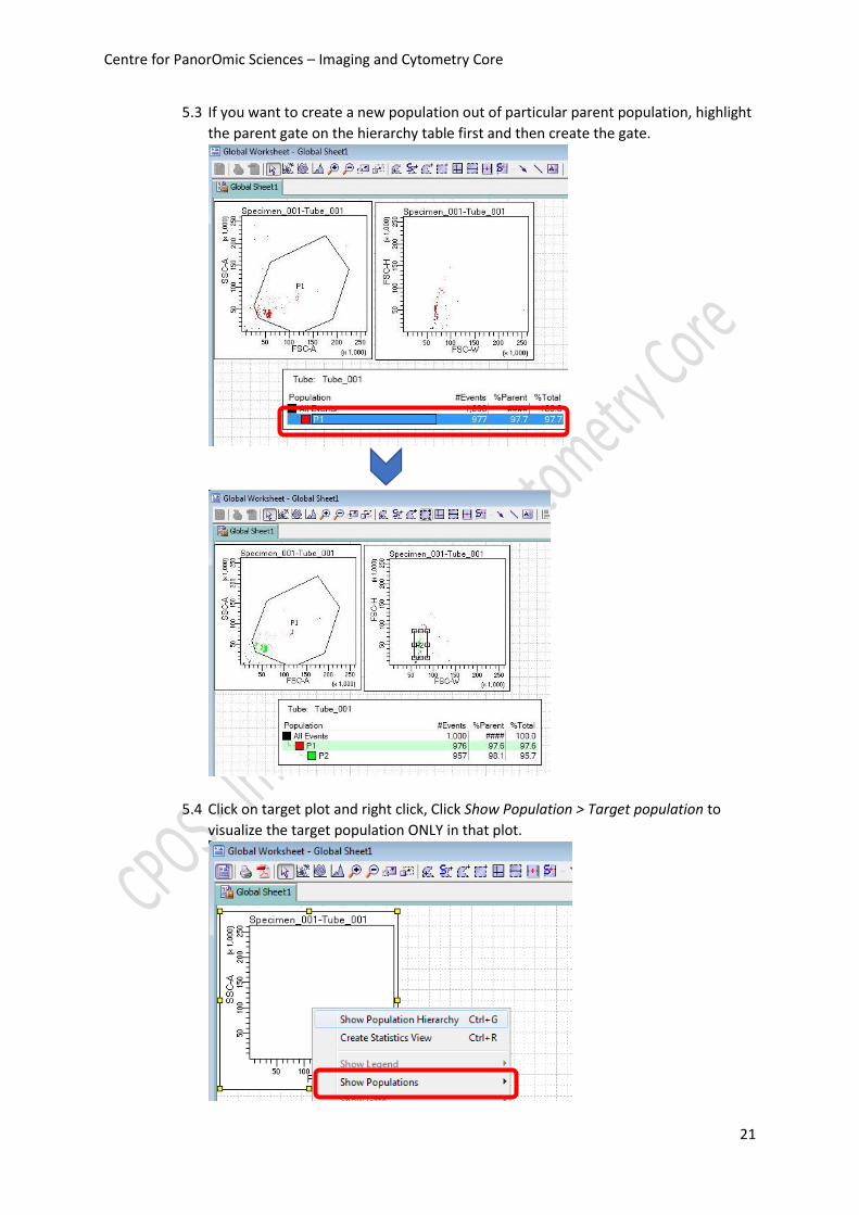
5.3 If you want to create a new population out of particular parent population, highlight
the parent gate on the hierarchy table first and then create the gate.
5.4 Click on target plot and right click, Click Show Population > Target population to
visualize the target population ONLY in that plot.

Centre for PanorOmic Sciences – Imaging and Cytometry Core
22
6. Data Recording
6.1 Go to Acquisition Dashboard, set Stopping gate to singlet gate or live cell gate
6.2 Set the Storage gate to All Events
6.3 Set Events To Record, i.e. events number out of stopping gate to be recorded
(suggested number 10,000 – 50,000)
6.4 if the sample is Unload or Acquisition is stopped, Click Load or Acquire Data
6.5 Click Record Data
6.6 Click Next Tube to create a new sample

Centre for PanorOmic Sciences – Imaging and Cytometry Core
23
F. Sort Device Alignment
1. Tube Holder
1.1 Assemble the tube holder as picture below
1.2 Put dummy tubes into the position
1.3 Slide the tube holder right under the sort chamber. Plug in water tubing if cooling
is needed.
1.4 Click Select Device icon on the lower right corner of the upper monitor
OR

Centre for PanorOmic Sciences – Imaging and Cytometry Core
24
1.5 Select collection device of interest
1.6 Go to 100 micron window (lower monitor). Adjust the Slider
Device Suggested Slider reading
2-tube 15 ml 0 – 49 – 41 – 0
4-tube 1.5ml / 2.0ml 71 – 30 – 25 – 68
4-tube 5 ml 80 – 30 – 25 – 74
1.7 Click Voltage. Wait 2 seconds and then Click Test Sort.
1.8 Adjust the slider so the side stream dot lines within the target lines

Centre for PanorOmic Sciences – Imaging and Cytometry Core
25
1.9 Click Waste Drawer
1.10 Open the sort chamber door
1.11 Check if the side streams can entre the dummy tubes. Adjust the slider if needed
1.12 Click Waste Drawer and then Voltage
1.13 Close the sort chamber door
1.14 Slide out the tube holder and Put collection tubes into position

Centre for PanorOmic Sciences – Imaging and Cytometry Core
26
2. ACDU (Culture plate)
2.1 Slide the ACDU adaptor right under the sort chamber
ACDU adaptor
2.2 Select the device (ACDU) on the lower right corner of the upper monitor
2.3 Go to 100 micron window (lower monitor). Adjust the Slider
Device Suggested Slider reading
96-well plate 33 – 0 – 0 – 0

Centre for PanorOmic Sciences – Imaging and Cytometry Core
27
2.4 Click Voltage. Wait 2 seconds and then Click Test Sort
2.5 Adjust the slider so the side stream dot lines within the target lines
2.6 Click Voltage again to stop test sort
2.7 Click Sort > New Sort Layout

Centre for PanorOmic Sciences – Imaging and Cytometry Core
28
2.8 Click the Eject button on the Sort Layout window
2.9 Plug in water tubing if cooling of the ACDU stage is needed
2.10 Load a dummy plate on the ACDU stage with A1 on the outer left corner
A1

Centre for PanorOmic Sciences – Imaging and Cytometry Core
29
2.11 Click Sort > Home Device
2.12 Select plate type and then click Go to Home
2.13 Go to 100 micron window (lower monitor), Click Voltage and Waste Drawer

Centre for PanorOmic Sciences – Imaging and Cytometry Core
30
2.14 Double Click Test sort to shot a small drop of sheath on the dummy plate cover
- OR –

Centre for PanorOmic Sciences – Imaging and Cytometry Core
31
2.15 Move the stage accordingly in order to shot the drop of sheath on A1 position
2.16 Go to Home Device Window, Click Set Home and Apply
2.17 Remove Dummy plate from the stage and Load the collection plate
left right
in
out

Centre for PanorOmic Sciences – Imaging and Cytometry Core
32
G. Sort Setup
1. Click Sort > New Sort Layout
2. Select appropriate Device:
Name Supported Device
2 tube 2-way 15 mL, 5.0 mL, 2.0 mL, 1.5mL
4 tube 4-way 5.0 mL, 2.0 mL, 1.5 mL
96-well Falcon 96-well culture plate
3. Select appropriate Precision:
Name Suitable Application
Purity Sorting target population higher than 20%
Yield Sorting target population less than 20%
Single Cell Single cell sorting into 96-well plate / Single cell sequencing
4-way Purity 4-way sorting target population higher than 20%

Centre for PanorOmic Sciences – Imaging and Cytometry Core
33
4. Assign target population to position by clicking the position > Add > Target gate
5. Input Target Events (sorting will stop when the sorted cell number reached the target
event) for each target population if needed.
Select Continuous for unlimited number.
6. Load your Sample onto the sample stage.
7. Go to Acquisition Dashboard window, click Load
8. Go to Sort layout window, Click Sort

Centre for PanorOmic Sciences – Imaging and Cytometry Core
34
9. Click OK on Confirm window
10. During the sort keep monitoring Threshold Rate and Drop 1 value
11. Click Pause if you wish to pause the sort and replace new collection tube. Click Resume
after finish replacement.
12. Click Sort to end the sort
13. Click OK to save sort report
14. Go to Acquisition Dashboard window, click Unload.

Centre for PanorOmic Sciences – Imaging and Cytometry Core
35
H. Data Export
1. FCS file
1.1 Go to Browser window, Select the Tubes / Specimen of interest.
1.2 Right Click over the selection and click Export > FCS file
1.3 Select FCS 3.0 and keep all parameters Linear. Click OK
Centre for PanorOmic Sciences – Imaging and Cytometry Core
36
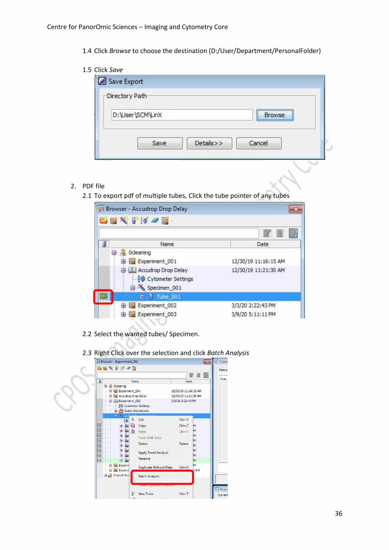
1.4 Click Browse to choose the destination (D:/User/Department/PersonalFolder)
1.5 Click Save
2. PDF file
2.1 To export pdf of multiple tubes, Click the tube pointer of any tubes
2.2 Select the wanted tubes/ Specimen.
2.3 Right Click over the selection and click Batch Analysis

Centre for PanorOmic Sciences – Imaging and Cytometry Core
37
2.4 Check the boxes as picture below
2.5 Click Browse to choose the destination (D:/User/Department/PersonalFolder)
2.6 Click Start and then OK.

Centre for PanorOmic Sciences – Imaging and Cytometry Core
38
3. Sort Report
3.1 To export sort report, select Sort Layout and then right click. Click Sort Reports
3.2 Select the sort from the list and then click OK

Centre for PanorOmic Sciences – Imaging and Cytometry Core
39
3.3 Click File > Save As PDF
3.4 Choose the destination (D:/User/Department/PersonalFolder) and click Save

Centre for PanorOmic Sciences – Imaging and Cytometry Core
40
I. Cleaning
1. Go to Browser window, click the tube pointer of any tube
2. Load a tube of 2 mL of cleaning solution No. 1 (FACSClean) on the sample stage
3. Go to Acquisition Dashboard window, set Flow rate to 11.0
4. Click Load.
5. Acquire the solution for 5 minutes.

Centre for PanorOmic Sciences – Imaging and Cytometry Core
41
6. Click Unload.
7. Load a tube of 2 mL of cleaning solution No.2 (FACSRinse) on the sample stage
8. Repeat step 3-5.
9. Load a tube of 2 mL of cleaning solution No.3 (MilliQ water) on the sample stage
10. Repeat step 3-5.
J. User Logout
1. Click File > Logout
2. Open the upper flow cell access door of the system before you leave.