Wear behaviour of a steel weld-joint
10
Wear 260 (2006) 1285–1294 Wear behaviour of a steel weld-joint S.N. Krishnan 1 , V. Toppo 2 , A. Basak, K.K. Ray ∗ Department of Metallurgical and Materials Engineering, Indian Institute of Technology, Kharagpur 721302, West Bengal, India Received 5 January 2005; received in revised form 16 August 2005; accepted 23 August 2005 Available online 6 October 2005 Abstract A series of experiments has been carried out to examine the dry sliding wear behaviour of the different regimes of a single pass steel weld-joint vis-` a-vis their microstructures and micro-hardness characteristics. Wear tests have been performed on two types of specimen configurations: first, on limited regions of the weld-joint exhibiting a specific microstructure, and second, continuously from the weld metal to the base metal via the heat affected zone (HAZ). The former type of experiments was found capable in delineating the wear characteristics of the base metal, weld metal and the different regimes of the HAZ. The wear behaviour of the varied regimes of the weld-joint, specifically that of the different sub-zones of the HAZ, has been explained using their microstructures, initial micro-hardness, work hardening during wear and their inherent residual stresses. This is a first report on the sequential wear behaviour of a weld-joint. © 2005 Elsevier B.V. All rights reserved. Keywords: Wear; Weld-joint; Heat affected zone; Steel; Coefficient of wear resistance 1. Introduction A weld-joint comprises of base metal, heat affected zone (HAZ) and weld metal. The HAZ of mild steel weldments, which has width of approximately a few millimeters, is commonly cate- gorized into four sub-zones each exhibiting different microstruc- tures [1,2]. These sub-zones are known as sub critical (SCHAZ), inter critical (ICHAZ), fine grain (FGHAZ) and coarse grain (CGHAZ) heat affected zones in the order of their location from the base metal to the weld metal [2]. The role of microstructure on the mechanical properties of the sub-zones is well known [3,4]. For example, the fracture toughness of the CGHAZ has been reported to be significantly lower compared to its adjacent FGHAZ for weld-joints fabricated from low carbon–manganese steels [5,6]. However, any systematic investigation related to the wear behaviour of this gradient microstructure is lacking, which comprises the primary content of this investigation. That materials with different hardness values will result in different wear behaviour, originates from the early report of ∗ Corresponding author. Tel.: +91 3222 283278; fax: +91 3222 282280/255303. E-mail address: [email protected] (K.K. Ray). 1 Currently with Directorate of Naval Design, New Delhi, India. 2 On study leave from National Institute of Foundry and Forge Technology, Ranchi, India. Archard [7], indicating that wear rate is inversely proportional to the hardness of a material. Since the microstructural constituents govern the hardness of a material, it is a natural expectation that a gradient microstructure like that in a weld-joint should lead to a variation in wear rate across its profile. This expectation is further substantiated by the report of Wang et al. [8], who emphasized that microstructure plays a more significant role than original hardness of a material. On the other hand, it is also known that the wear behaviour is a system response rather than the response of the characteristics of a specific material [9]. So the influence of the microstructure of a material on its wear rate would also depend to some extent on the selection of the system. An attempt is made here to examine whether the wear behaviour of the different sub-zones of a weld-joint can be distinguished under identical test conditions. The inherent aim of this investi- gation is, however, to understand the wear behaviour of gradient microstructures. 2. Experimental procedure 2.1. Material, processing and microstructures The base metal selected for fabricating the weld-joint is a low carbon–manganese steel, used for manufacturing hull structures of ships. The chemical composition of the selected 0043-1648/$ – see front matter © 2005 Elsevier B.V. All rights reserved. doi:10.1016/j.wear.2005.08.007
-
Upload
independent -
Category
Documents
-
view
0 -
download
0
Transcript of Wear behaviour of a steel weld-joint

Wear 260 (2006) 1285–1294
Wear behaviour of a steel weld-joint
S.N. Krishnan 1, V. Toppo 2, A. Basak, K.K. Ray ∗Department of Metallurgical and Materials Engineering, Indian Institute of Technology, Kharagpur 721302, West Bengal, India
Received 5 January 2005; received in revised form 16 August 2005; accepted 23 August 2005Available online 6 October 2005
Abstract
A series of experiments has been carried out to examine the dry sliding wear behaviour of the different regimes of a single pass steel weld-jointvis-a-vis their microstructures and micro-hardness characteristics. Wear tests have been performed on two types of specimen configurations: first,on limited regions of the weld-joint exhibiting a specific microstructure, and second, continuously from the weld metal to the base metal via theheat affected zone (HAZ). The former type of experiments was found capable in delineating the wear characteristics of the base metal, weld metaland the different regimes of the HAZ. The wear behaviour of the varied regimes of the weld-joint, specifically that of the different sub-zones ofthe HAZ, has been explained using their microstructures, initial micro-hardness, work hardening during wear and their inherent residual stresses.This is a first report on the sequential wear behaviour of a weld-joint.©
K
1
(hgti(to[bFswc
d
f
R
0d
2005 Elsevier B.V. All rights reserved.
eywords: Wear; Weld-joint; Heat affected zone; Steel; Coefficient of wear resistance
. Introduction
A weld-joint comprises of base metal, heat affected zoneHAZ) and weld metal. The HAZ of mild steel weldments, whichas width of approximately a few millimeters, is commonly cate-orized into four sub-zones each exhibiting different microstruc-ures [1,2]. These sub-zones are known as sub critical (SCHAZ),nter critical (ICHAZ), fine grain (FGHAZ) and coarse grainCGHAZ) heat affected zones in the order of their location fromhe base metal to the weld metal [2]. The role of microstructuren the mechanical properties of the sub-zones is well known3,4]. For example, the fracture toughness of the CGHAZ haseen reported to be significantly lower compared to its adjacentGHAZ for weld-joints fabricated from low carbon–manganeseteels [5,6]. However, any systematic investigation related to theear behaviour of this gradient microstructure is lacking, which
omprises the primary content of this investigation.That materials with different hardness values will result in
ifferent wear behaviour, originates from the early report of
∗ Corresponding author. Tel.: +91 3222 283278;
Archard [7], indicating that wear rate is inversely proportional tothe hardness of a material. Since the microstructural constituentsgovern the hardness of a material, it is a natural expectation thata gradient microstructure like that in a weld-joint should leadto a variation in wear rate across its profile. This expectationis further substantiated by the report of Wang et al. [8], whoemphasized that microstructure plays a more significant rolethan original hardness of a material. On the other hand, it is alsoknown that the wear behaviour is a system response rather thanthe response of the characteristics of a specific material [9]. Sothe influence of the microstructure of a material on its wear ratewould also depend to some extent on the selection of the system.An attempt is made here to examine whether the wear behaviourof the different sub-zones of a weld-joint can be distinguishedunder identical test conditions. The inherent aim of this investi-gation is, however, to understand the wear behaviour of gradientmicrostructures.
2. Experimental procedure
2.1. Material, processing and microstructures
ax: +91 3222 282280/255303.E-mail address: [email protected] (K.K. Ray).1 Currently with Directorate of Naval Design, New Delhi, India.2 On study leave from National Institute of Foundry and Forge Technology,anchi, India.
The base metal selected for fabricating the weld-joint isa low carbon–manganese steel, used for manufacturing hullstructures of ships. The chemical composition of the selected
043-1648/$ – see front matter © 2005 Elsevier B.V. All rights reserved.oi:10.1016/j.wear.2005.08.007

1286 S.N. Krishnan et al. / Wear 260 (2006) 1285–1294
Table 1Chemical composition of the base metal (in weight percentage)
Elements Amount
C 0.14Mn 1.10Si 0.32S 0.009P 0.018Cr 0.02Al 0.045Ni, Mo, V TraceFe Bal.
Fig. 1. Schematic diagram of a weld plate indicating the various types of testspecimens. The T-S plane of specimen coupon-1 was used for determining hard-ness profile along the weld joint, L-S plane of specimen coupons 2 and 3 wereused for wear studies and both T-S and L-S planes were used for microstructuralstudies.
steel is shown in Table 1. The weld-joint was fabricated bysingle pass butt-welding from 10 mm thick sample blanks ofapproximately 150 mm × 400 mm size using metal active gas(MAG) welding process. The important welding parametersadopted are summarized in Table 2. The fabricated weld-jointswere not subjected to any post-weld heat treatment (PWHT).Specimen blanks for microstructure, hardness and wear stud-ies were cut from the weld-joint as illustrated in Fig. 1. Thelength, width and thickness of the plate are referred hereas L, T and S, respectively for convenience of further dis-cussion. Microstructural studies were carried out on the T-S and L-S planes. The microstructures were prepared withstandard metallographic practice, followed by etching in 2%Nital.
Table 3Some pertinent details of the pin-on-disc wear machine used in this study
Machine particulars Details
Disc material and hardness EN 31steel, hardness: Rc 58–62Disc size 160 mm diameter and 8 mm thickTrack diameter 10–140 mmRange of sliding speed 0.26–10 m/sWear measurement range ±2 mmMaximum normal load 196.1 N
2.2. Hardness and tensile tests
The microhardness measurements were carried out on pol-ished T-S and L-S planes of a few specimens using a digitalmicrohardness tester (LECO DM 400). These tests were carriedout at a load of 0.3 kg for indentation duration of 10 s using aVickers pyramid indenter. Microhardness profiles were deter-mined by taking hardness readings at 500 �m intervals alongseveral lines perpendicular to the weld-joint (T direction) withthe distance between each line being 500 �m. Tensile propertiesof the base and the weld-joint along the T direction were obtainedas per ASTM standard 8M-03 [10]. Flat sub-size tensile speci-mens of 6 mm width, 3 mm thickness and 25 mm gauge lengthwere tested at a nominal strain rate of 6.67 × 10⁻⁴ s−1 using a5 kN capacity screw driven Shimadzu (model: AG 5000G) uni-versal testing machine at room temperature.
2.3. Wear tests
Wear tests were carried out on a pin-on-disc machine (model:Ducom TR 20) following ASTM standard G 99-03 [11]. Somepertinent details of this machine are summarized in Table 3.The pins for the wear tests were cut from the weld plates asshown in Fig. 1. Wear pins of both round and rectangular crosssections were fabricated. The cylindrical pins were approxi-m4iss
ohwtcp
Table 2Some pertinent details of the single pass welding process
Parameters Description
Electrode 1.2 mm diameter wire electrode, AP = 0.02, Cu = 0.2, and Fe-bal. (all
Weld metal Composition: C = 0.1, Mn = 1.6, SNature of weld-joint Single V groove with an includedWelding parameters Current: 195–205 A, voltage: 27.3
ately 4.6 mm in diameter whereas the rectangular pins were.2 × 4.0 mm in cross section; both types of pins were approx-mately 30 mm in length. The L-S plane of the weld-joint waselected for the wear test, so that the gradient microstructure isubjected to wear.
To understand the wear behaviour of the different regimesf the weld-joint vis-a-vis that of the base metal, wear studiesave been carried out using pins of rectangular cross section,hich are easy to fabricate from the weld-joints and in which
he microstructures on the transverse sections can be examinedonveniently. But ASTM standard [11] suggests that cylindricalins should be used for pin-on-disk type wear tests. So a series of
WS code: A5.18-ER 70 S-6 composition: C = 0.09, Mn = 1.55, Si = 0.8, S andin weight percentage)i = 0.9, S and P = 0.02, Cu = 0.2 and Fe-bal. (all in weight percentage)angle of 60◦ and root gap of 6–8 mmV, speed: 120 mm/min shielding gas: CO2, backing strip: ceramic

S.N. Krishnan et al. / Wear 260 (2006) 1285–1294 1287
Fig. 2. Typical microstructure of the investigated steel.
experiments have been carried out on pins (made of base metal)having both round and rectangular cross sections for examiningthe suitability of the latter ones. The cross sectional areas of boththe cylindrical and the rectangular pins were kept constant, sothat the contact pressures (CP) are equal and wear volume lossfor both types of pins is the same for identical height loss.
All wear tests were carried out at the sliding speed (SS)of 1 m s−1. Four different sets of wear tests were carried out.These are: (a) wear of cylindrical and rectangular pins of basemetal at applied normal loads (NL) of 19.6, 29.4, 49, 58.8,68.6 and 78.4 N (corresponding CP were 1.2, 1.8, 2.9, 3.5, 4.1,and 4.7 MPa, respectively); (b) wear of rectangular pins whosesurface exhibits only weld metal microstructure; (c) wear ofrectangular pins whose surface exhibits only one of the differ-ent regimes of HAZ, and (d) wear of rectangular pins whosesurface initially exhibits microstructure of the base metal butwhile the test is continued, the surface microstructure sequen-tially changes to those of HAZs and finally to that of the weldmetal. Tests (b) and (c) were performed for short duration so thateach test remains confined only to the microstructure of inter-est, whereas test (d) was done for a long duration so that eachmicrostructure present in the weld-joint is sequentially subjectedto wear. Tests (b), (c) and (d) were done only at NL = 58.8 N(CP = 3.5 MPa). All these tests were carried out at room tem-perature under dry sliding condition. The average initial surfaceroughness of the disc was 0.35 �m and that of the pins was bettert
tsw5
3
3
ttb
Fig. 3. Typical macrostructure of the single pass weld-joint.
is due to the combined effect of high manganese [12] and priorhot rolling of the steel [13].
The macrostructure of the single pass weld-joint on the T-Splane distinctly revealed the base metal, HAZ and the solidifiedweld metal in sequence as depicted in Fig. 3. Representativemicrostructures for the different regimes of the weld-joint exceptthat for the base metal (Fig. 2), are depicted in Fig. 4. Themicrostructures in Fig. 4(a)–(d) correspond to inter critical, finegrain and coarse grain HAZ and the weld zone, respectively.The salient microstructural features of these zones are: (a) mix-ture of ferrite and pearlite with distorted banding (Fig. 4a) in theICHAZ; (b) well-distributed ferrite and pearlite (Fig. 4b) in theFGHAZ; (c) a mixture of predominantly Widmanstatten ferriteand martensite (Fig. 4c) with traces of pearlite in the CGHAZ;and (d) columnar ferrite grains (Fig. 4d) in the solidified weldmetal. However, the weld metal also exhibits planar, cellular andcellular dendritic structures at alternate locations. The observedmicrostructures in the HAZ and that in the weld metal are inline with several earlier reports for steels of similar composition[2,6,14]. Approximate estimates of the width of each regime ofHAZ are shown in Table 4.
3.2. Microhardness variation across the weld-joint
The microhardness values (HV 0.3) of the base metal, HAZa1nphdTi
TW
P
MM
H
han 0.25 �m.The microhardness of each pin before and after the wear
ests were determined. In addition, the worn out surfaces of thepecimens and the fractured surfaces of the tensile specimensere studied using a scanning electron microscope (model JEOL800).
. Results and discussions
.1. Microstructural analysis
A typical representative microstructure of the base metal (onhe T-S plane of a specimen) is shown in Fig. 2. The microstruc-ure exhibits ferrite and pearlite in the banded form. Banding haseen observed also on the L-S plane. The presence of banding
nd the solidified weld metal were observed to be in the ranges59–173, 155–241 and 161–218, respectively. The microhard-ess profile across the weld-joint is shown in Fig. 5(a). Eachoint in Fig. 5(a) represents an average of two/three individualardness-readings falling within a specific sub-zone at a specificepth of the weldment as indicted by the legends in the figure.he average distance of these points from an arbitrary reference
ndicates their abscissa. The results in Fig. 5(a) infer that: (a)
able 4idth of the different regimes of the heat affected zone
arameters ICHAZ FGHAZ CGHAZ HAZ
ean widtha—left side (mm) 0.83 1.83 2.8 5.5ean widtha—right side (mm) 1.18 1.67 1.13 3.98
a Three measurements were made on each region at different heights in theAZ and the mean values are reported.

1288 S.N. Krishnan et al. / Wear 260 (2006) 1285–1294
Fig. 4. Microstructures at different regions of a single pass weld-joint: (a) distorted banded ferrite–pearlite aggregate (ICHAZ); (b) well-distributed ferrite and pearlite(FGHAZ); (c) Widmanstatten ferrite and martensite (CGHAZ); (d) columnar ferrite grains in weld zone.
each regime of HAZ has different hardness values, which fluc-tuate along the depth of the weldment, and (b) the magnitude ofhardness of a regime increases from ICHAZ to CGHAZ. Thehighest hardness of CGHAZ is due to: (a) its close proximity tothe fusion line, which causes this zone to experience the fastestcooling rate [2], which in turn, leads to the formation of hardermicrostructural constituents like martensite or bainite togetherwith Widmanstatten ferrite [1], and (b) the presence of highresidual stresses.
The variation of microhardness along the solidified weldpool is shown in Fig. 5(b). The weld metal appears to indi-cate the highest hardness at its centerline, where it solidifieslast. The average hardness values (HV 0.3) of the base metal,ICHAZ, FGHAZ, CGHAZ and that of the weld metal canbe ascribed as 166, 171, 176, 203 and 184, respectively. Thehardness of the weld metal is higher than that of the base
metal though it contains lower carbon (Table 2) than the lat-ter. Inhomogeneity of microstructure and considerable residualstresses [2] in the weld metal are considered to lead to thisobservation.
3.3. Tensile properties of base metal and weld-joint
Tensile properties of the base metal and the weld-joint weredetermined from their engineering stress–strain diagrams. Theyield strength (YS), tensile strength (TS) and the percentageelongation (%EL) of the base metal are found to be 329 MPa,464 MPa and 47.2%, respectively, and those for the weld-jointare obtained as 334 MPa, 479 MPa and 29.6%, respectively.The weld-joint thus possesses almost similar YS, marginallyhigher TS and significantly lower %EL compared to the basemetal. Tensile specimens with weld-joint at the center of the
F S = 0t ion of
ig. 5. Variation of microhardness: (a) at different sub-zones in a weld-joint forhe bottom surface of the weld-joint. S indicates distance along thickness direct
.5 to 4.5 mm and (b) within the solidified weld region for S = 0.5 to 3 mm fromthe weld joint.

S.N. Krishnan et al. / Wear 260 (2006) 1285–1294 1289
Fig. 6. Fracture surface after tension test of: (a) base metal, and (b) weld metalspecimen.
gauge length were observed to fail at the weld metal. On S.E.M.examination, the fractured surface of the base metal indicatedmixed cleavage and dimples, whereas that of the weld metalrevealed primarily dimples as shown in Fig. 6. But the size ofthe dimples in the weld metal was found to be smaller thanthat of the base metal. Higher void growth in the base metal isconsidered responsible for its higher %EL compared to that ofthe weld metal.
3.4. Wear behaviour of base metal
The wear tests on base metal specimens have been done usinga sliding speed (SS) of 1 m s−1 under different normal loads (NL)
for both types of pins. The average values of wear rate and fric-tional force were estimated for sliding distance (SD) rangingbetween 500 and 1000 m. The variations of wear rate and fric-tional force with normal load for cylindrical and rectangular pinsare shown in Fig. 7(a) and (b), respectively. The results in thesefigures assist to infer:
(a) For cylindrical pins, the wear rate remains almost constantfor loads upto 29.4 N (CP = 1.8 MPa), then sharply increasesin-between 29.4 and 49 N (CP = 1.8–2.9 MPa), followed by agradual fall upto 68.6 N (CP = 4.1 MPa) load, beyond whichit remains almost invariant with further increase in NL.For rectangular specimens, the wear rate increases up toNL = 58.8 N (CP = 3.5 MPa), beyond which its variation withNL is similar to that for cylindrical specimens.
(b) At lower NL, the wear rate for rectangular pins is higher thanthat of cylindrical specimens, but at higher NL it is similarto that of the latter.
(c) The frictional force increases with increasing NL for bothtypes of pins almost in a similar manner.
The nature of variation in wear rate with NL, as shown inFig. 7(a), reveals that transition from mild to severe wear (com-monly termed as T1 transition) occurs between NL of 29.4 and49 N (CP = 1.8–2.9 MPa) for both types of specimens. TypicalwtTt(rslistnmwtm
force
Fig. 7. Variation of: (a) average wear rate, and (b) average frictionalorn out surfaces of specimens made from the base metal andested at two different contact pressures are shown in Fig. 8.he difference in the morphology of the worn out surfaces
ested at the normal loads of 19.6 N (CP = 1.2 MPa) and 58.8 NCP = 3.5 MPa), representative of mild and severe wear regimes,espectively, are obvious. The worn out surface at low load isignificantly smoother compared to the other, but it exhibitsess metallic lustre. The higher wear rate of rectangular spec-mens at lower NL can be attributed to higher inhomogeneity intress distribution on their contact surfaces compared to that ofhe cylindrical specimens. But the influence of such inhomoge-eous stress distribution on wear rate is significant only duringild wear. In summary, it can be inferred that: (i) specimensith rectangular cross section can be used for wear studies in
he severe wear regime for comparative assessment of differentaterials/microstructures, and (ii) the severe wear regime for the
with normal load for cylindrical and rectangular pins of base metal.
1290 S.N. Krishnan et al. / Wear 260 (2006) 1285–1294
Fig. 8. Typical wear surfaces generated at: (a) 19.6 N (CP = 1.2 MPa), and at (b)58.8 N (CP = 3.5 MPa). (a) and (b) exhibit smooth oxidised surface and roughsurface with deep tearing marks, respectively, indicating mild and severe wearregimes.
investigated steel at the selected sliding speed appears to start atNL ≥ 49 N (CP = 2.9 MPa).
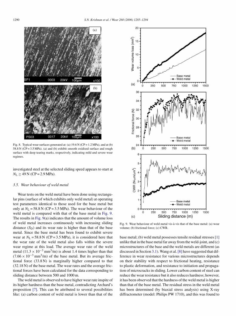
3.5. Wear behaviour of weld metal
Wear tests on the weld metal have been done using rectangu-lar pins (surface of which exhibits only weld metal) at operatingtest parameters identical to those used for the base metal butonly at NL = 58.8 N (CP = 3.5 MPa). The wear behaviour of theweld metal is compared with that of the base metal in Fig. 9.The results in Fig. 9(a) indicates that the amount of volume lossof weld metal increases continuously with increasing slidingdistance (SD) and its wear rate is higher than that of the basemetal. Since the base metal has been found to exhibit severewear at NL = 58.8 N (CP = 3.5 MPa), it is considered here thatthe wear rate of the weld metal also falls within the severewear regime at this load. The average wear rate of the weldmetal (11.3 × 10⁻³ mm3/m) is about 1.4 times higher than that(7.66 × 10⁻³ mm3/m) of the base metal. But its average fric-tional force (33.8 N) is marginally higher compared to that(32.18 N) of the base metal. The wear rates and the average fric-tional forces have been calculated for the data corresponding tosliding distance between 500 and 1000 m.
The weld metal is observed to have higher wear rate inspite ofits higher hardness than the base metal, contradicting Archard’spl
Fig. 9. Wear behaviour of weld metal vis-a-vis that of the base metal: (a) wearvolume; (b) frictional force; (c) CWR.
base metal; (b) weld metal possesses tensile residual stresses [1]unlike that in the base metal far away from the weld-joint, and (c)microstructures of the base and the weld metals are different (asdiscussed in Section 3.1). Wang et al. [8] have suggested that dif-ference in wear resistance for various microstructures dependson their stability with respect to frictional heating, resistanceto plastic deformation, and resistance to initiation and propaga-tion of microcracks in sliding. Lower carbon content of steel canreduce the wear resistance but it also reduces hardness; however,it has been observed that the hardness of the weld metal is higherthan that of the base metal. The residual stress in the weld metalhas been determined (by biaxial stress analysis) using X-raydiffractometer (model: Philips PW 1710), and this was found to
roposition [7]. This can be attributed to several possibilitiesike: (a) carbon content of weld metal is lower than that of the

S.N. Krishnan et al. / Wear 260 (2006) 1285–1294 1291
be tensile in nature, with the magnitudes of the normal and shearstress components as 233.3 and −135.2 MPa, respectively. Thusa combination of the reasons (b) and (c) appears responsible forthe observed higher wear rate of the weld metal.
Several authors have pointed out that the frictional force is aresponse of a tribo-system [9]. The combined influence of fric-tional force and wear volume loss can be used to understand theeffect of different microstructures on wear behaviour. A parame-ter, termed as coefficient of wear resistance (CWR), can be usedto differentiate wear behaviour of different microstructures. Thisis expressed as:
CWR = FF × SD
V, (1)
where FF is the frictional force in N. SD = (2 πrt) (Nt/60), thesliding distance in m, where rt is the wear track radius in m, Nthe revolutions/min of the disc, and t the time in s. V = π r2h,wear volume loss in mm3, where r is the radius of test pin inmm and h the height loss of the pin in mm. The expression forCWR as given by Eq. (1) can also be rewritten as:
CWR = FF
V/SD= FF
WR, (2)
where WR is wear rate = (V/SD). The values of CWR calculatedby Eq. (2) give marginally different values when compared withthose obtained by Eq. (1). The difference originates due to direct(vs
tmaframcm
apfrtfTts
3
osle
Fig. 10. Variation of CWR of cylindrical and square pins of base metal withnormal load.
is encountered (these are termed here as “continuous” experi-ments). Wear pins used for these two types of experiments areillustrated schematically in Fig. 11. The depth of each regime ofHAZ was measured on the side surface of the rectangular pinsby prior revelation of the microstructure using standard polish-ing and etching techniques. The continuous experiments wereperformed with five or six interruptions because of the limita-tion of recording a maximum of 2 mm of height loss in the wearmachine in each run. The data collected at all the stages in thecontinuous experiments were combined to obtain the total wearbehaviour of the weld-joint. The microstructures of the pin sur-faces were examined and their hardness values were determinedprior to all wear tests. All these tests were performed with oper-ating parameters similar to those used for the weld metal, i.e.SS = 1 m s−1, SD = 1500 m and NL = 58.8 N (CP = 3.5 MPa).
The wear volume loss, frictional force and coefficient of wearresistance (CWR) for different regimes of the HAZ obtainedfrom isolated experiments and that of the base metal are plot-
Fww
V/SD) and indirect calculations (using slope of the wear volumeersus SD) of wear rate by the two equations. In this report, allubsequent calculation of CWR has been made using Eq. (1).
A typical plot indicating the variations of CWR with respecto SD for the base and the weld metal is illustrated in Fig. 9(c). Itay be observed that CWR appears to stabilize for SD > 500 m
nd the average values of CWR for SD between 500 and 1000 mor the weld and the base metal are 2.55 and 4.4 N �m/�m3,espectively. The magnitude of CWR for the base metal ispproximately 1.7 times larger than that of the weld metal. Itay thus be inferred that CWR is an interesting parameter to
ompare wear behaviour of the base metal with that of the weldetal.Additionally, the applicability of the CWR was examined by
comparison of its magnitude for cylindrical and rectangularins of base metal for a range of applied normal loads (NL) usedor the wear tests. It can be observed in Fig. 10 that in severe wearegime, both types of pins exhibit similar values of CWR. Thushe use of rectangular pins to differentiate wear behaviour of dif-erent microstructures in the severe wear regime can be justified.his observation is in line with that of Wang’s [8] proposition
hat different microstructures are better differentiated only in theevere wear regime.
.6. Wear behvaiour of HAZ
Wear behaviour of HAZ was studied by performing two typesf experiments: (a) experiments started and completed within apecific microstructure of HAZ (these are termed here as “iso-ated” experiments), and (b) experiments started on a surfacexhibiting weld metal and continued till the base metal structure
ig. 11. Schematic layout of microstructure on T-S plane of weld-joint fromhich rectangular wear pins fabricated for: (a) isolated, and (b) continuousear tests.

1292 S.N. Krishnan et al. / Wear 260 (2006) 1285–1294
ted against SD in Fig. 12. The following inferences can bedrawn from the results in Fig. 12: (a) all the regimes of HAZexhibit severe wear, (b) CGHAZ exhibits the highest wear rate(12.3 × 10⁻³ mm3/m), whereas, the ICHAZ exhibits the lowestwear rate (8.84 × 10⁻³ mm3/m), (c) it is difficult to distinguishthe different sub-zones in terms of frictional force during wearbecause of the associated high magnitude of scatter; apparentlythe highest and the lowest frictional forces are generated by theCGHAZ and ICHAZ, respectively, and (d) CWR distinguishesthe sub-zones of HAZ; the average values of CWR for ICHAZ,FGHAZ and CGHAZ are 4.4, 3.04 and 2.32 N �m/�m3, respec-tively. It may be mentioned at this stage that wear rate and CWRvalues have been calculated for SD between 500 and 1000 m.
The different wear rates that the various sub-zones of theweld-joint exhibit can be understood on the basis of theirmicrostructures and their response to frictional heating. Fric-tional heating causes a change in hardness of a microstructureand this phenomenon is related to “microstructural thermal sta-bility” as suggested by Wang et al. [8]. The hardness of acontact surface during wear is often termed as dynamic hard-ness. A pearlite phase can retain its hardness upto a temperatureof 700 ◦C, while the hardness of martensite starts to decreaseat about 200 ◦C [8]. The hardness of martensite-containingmicrostructure becomes less than that of ferrite–pearlite struc-tures at a temperature of 650 ◦C. The martensite present in theCGHAZ softens during wear and exhibits higher wear rate,wpbtwvItabit
(wmzr
Fig. 12. A comparative assessment of the wear results of CGHAZ, FGHAZ,ICHAZ, and base metal obtained from isolated wear tests: (a) wear volume loss;(b) frictional force; and (c) CWR against sliding distance.
F WR. The arrows in (b) indicate restart of the various stages of the continuous test.
hereas the lowest wear rate exhibited by the base metal isossibly due to its banded pearlite. The ICHAZ with distortedands of ferrite and pearlite indicates similar wear rate and CWRo those of the base metal, whereas the FGHAZ, containing theell-distributed ferrite and pearlite, possesses an intermediatealue of wear rate and CWR between those of CGHAZ andCHAZ. Thus it can be concluded that the nature of distribu-ion of ferrite and pearlite in FGHAZ, ICHAZ and base metal,nd the martensite content in CGHAZ lead to different wearehaviour of the sub-zones of a weld-joint. Interestingly for thenvestigated steel, the CGHAZ with the highest room tempera-ure hardness yields the highest wear rate.
The salient observations from the continuous wear testsFig. 13) are: (a) the wear rates of all the sub-zones of theeld-joint appear to be similar except for ICHAZ showing aarginally low wear rate, and (b) the transition from one sub-
one to the other (weld to CGHAZ and so on) gets apparentlyeflected in the variation of CWR. A comparison of the wear
ig. 13. Wear behaviour of the different sub-zones of HAZ: (a) wear rate, (b) C

S.N. Krishnan et al. / Wear 260 (2006) 1285–1294 1293
Fig. 14. Effect of work-hardening on the different regimes of the weld-joint:(a) microhardness before and after wear, and (b) percentage increase in micro-hardness. The error bands indicated in (a) refer to the standard deviations of themean values.
rates obtained from isolated and continuous wear tests indi-cates that different regimes of the HAZ can be distinguishedonly by carrying out “isolated” wear tests. The inability of thecontinuous wear tests to demarcate the various regimes of theHAZ can be attributed to the combined effect of work harden-ing and the degree of microstructural instability [8] of a layerby its adjacent upper layer. The lower wear rate of ICHAZin the continuous experiment is in agreement with its wearbehaviour in “isolated” experiments and is probably less influ-enced by the wear characteristics of its adjacent upper layer inFGHAZ.
3.7. Work-hardening of wear surface
Any metallic surface subjected to wear gets work hard-ened [15], and thus comparing the hardness of a surface ofinterest before and after wear one can assess the degree ofwork-hardening. The degree of work-hardening of the differentsub-zones of the weld-joint has been examined for the specimenssubjected to isolated wear tests. The microhardness values forthe different regimes of the weld-joint before and after the weartest are shown in Fig. 14(a) and the percentage change in hard-ness due to wear is depicted in Fig. 14(b). These results indicatethat the percentage increase in hardness is maximum for the base
and the weld metal and minimum for the CGHAZ. There is a sud-den jump in the percentage increase in hardness from CGHAZto the weld metal. The base metal which shows the highest work-hardening (indexed through increase in hardness) is observedto exhibit the lowest wear rate while the CGHAZ which showsthe least work-hardening exhibits the highest wear rate. As thewear rate of base metal and that of the different sub-zones ofHAZ can be related to the dynamic hardness of their respectivemicrostructures, it is suggested that the observed nature of work-hardening can be considered as index for dynamic hardness.However, the same explanation cannot be extended to the weldmetal, which shows high work-hardening as well as relativelyhigh wear rate compared to that of the base metal (Fig. 9). Thecharacteristic wear behaviour of the weld metal can plausibly beattributed to the fact that it generally possesses tensile residualstress, unlike compressive residual stress in HAZ [1] or no resid-
Fig. 15. Variation of average values of: (a) wear rate; (b) frictional force; (c)CWR across the single pass weld-joint. The error bands indicated in the figuresrefer to the standard deviations of the mean values.

1294 S.N. Krishnan et al. / Wear 260 (2006) 1285–1294
ual stress in base metal, apart from its different composition andmicrostructure.
3.8. Some generalization about wear behaviour of theweld-joint
The discussions on the wear behaviour of the base metal,weld metal and the HAZ in Sections 3.4–3.6 are based ontypical results. The experiments on isolated microstructureshave been repeated and the average values of wear rate, fric-tional force and the coefficient of wear resistance (CWR) havebeen estimated for each sub-zone. The average values of thesewear parameters for the different regimes of the weld-jointare depicted in Fig. 15. The estimated wear parameters dodemarcate subtle variation between the wear behaviour of thevarious sub-zones of HAZ, but their associated standard devi-ation values appear to suppress the clarity. It may be inferred,however, that the base metal and the ICHAZ indicates high-est value of CWR, in contrast to the lowest value of CWRexhibited by the weld metal and the CGHAZ. Finally, it maybe concluded that CWR brings out the characteristic wearbehaviour of the different sub-zones of a weld-joint in a distinctmanner.
4. Conclusions
1
2
3
4
the base metal and when these are done on isolated regionsexhibiting only a specific sub-zone. This difference originatesdue to the varying effect of work hardening and microstruc-tural thermal stability.
5. The difference between the hardness values of a sub-zonebefore and after a wear test (under identical conditions)depends on its nature. This has been attributed to the charac-teristic work hardening behaviour of each sub-zone.
References
[1] J.F. Lancaster, Metallurgy of Welding, Chapman & Hall, London, 1993,p. 187.
[2] K. Easterling, Introduction to Physical Metallurgy of Welding, Butter-worths Heinemann, Oxford, 1993, p. 126.
[3] C. Liu, S.D. Bhole, Fracture behaviour in a pressure vessel steel weld,Mater. Design 23 (2002) 371–376.
[4] J.H. Kim, Y.J. Oh, I. Hwang, D.J. Kim, J.T. Kim, Fracture behaviourof heat-affected zone in low alloy steels, J. Nucl. Mater. 299 (2001)132–139.
[5] A. Seshu Kumar, Studies on simulated HAZ condition in a structuralsteel, Ph.D thesis, IIT Kharagpur, 1999, p. 183.
[6] R.E. Dolby, Factors controlling HAZ and weld metal toughness in C–Mnsteels, in: G.G. Garrett, D.L. Marriott (Eds.), Engineering Applicationof Fracture Analysis, Pergamon Press, 1979, pp. 117–134.
[7] J.F. Archard, Contact and rubbing of flat surfaces, J. Appl. Phys. 24 (8)(1953) 981–988.
[8] Y. Wang, T. Lei, J. Liu, Tribo-metallographic behaviour of high carbonsteel in dry sliding II. Microstructure and wear, Wear 231 (1999) 12–19.
[
[
[
[
[
[
. The sub-zones of a weld-joint exhibiting differentmicrostructures indicate subtle difference in the wear ratesand frictional forces though these exhibit prominent variationin hardness values.
. The product of frictional force, sliding distance and inverseof wear rate has been suggested as a parameter to character-ize wear behaviour of gradient microstructures. Using thisparameter the differences in the wear behaviour amongst thebase metal, weld metal and the varied regimes of a HAZ havebeen brought forward in a distinct manner.
. The transition from one microstructure to another can berevealed using ‘continuous’ wear tests of a HAZ, with thehelp of the variation of CWR.
. The wear behaviour of the different regimes of a HAZ (pos-sessing varied microstructure) is found different when weartests are carried out continuously from the weld metal to
[9] K. Kato, Wear in relation to friction—a review, Wear 241 (2000)151–157.
10] ASTM standard E 8M-03, Standard test method for tension testingof metallic materials (Metric), ASTM Annual Book of Standards, vol.03.01, West Conshohocken, PA, 2003.
11] ASTM standard G 99-03, Standard test method for wear testing witha pin-on-disc apparatus, ASTM Annual Book of Standards, vol. 03.02,West Conshohocken, PA, 2003.
12] R. Ramanathan, R.P. Foley, Effect of prior microstructure on austen-ite decomposition and associated distortion, Report, Illinois Institute ofTechnology, Chicago, Illinois, USA, August 2001, p. 6.
13] D. Chae, D.A. Koss, A.L. Wilson, P.R. Howell, The effect of microstruc-tural banding on failure initiation of HY-100 steel, Met. Mater. Trans.A 31A (2000) 995–1005.
14] S.N. Krishnan, A. Basak, K.K. Ray, Wear characteristics of a multi-pass weld-joint of a plane carbon steel, Met. Mater. Process. 16 (2004)375–384.
15] H. Goto, Y. Amamoto, Effects of varying load on wear resistance ofcarbon steel under unlubricated conditions, Wear 254 (2003) 1256–1266.