GTA Weld Brazing a Joint of Aluminum to Stainless Steel
14
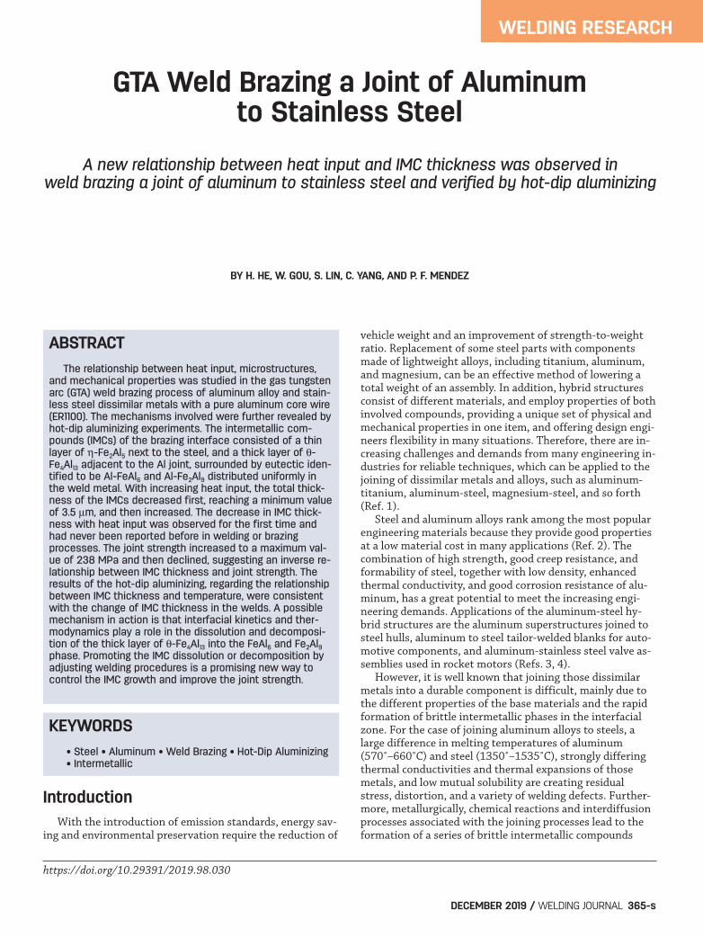
Introduction With the introduction of emission standards, energy sav- ing and environmental preservation require the reduction of vehicle weight and an improvement of strength-to-weight ratio. Replacement of some steel parts with components made of lightweight alloys, including titanium, aluminum, and magnesium, can be an effective method of lowering a total weight of an assembly. In addition, hybrid structures consist of different materials, and employ properties of both involved compounds, providing a unique set of physical and mechanical properties in one item, and offering design engi- neers flexibility in many situations. Therefore, there are in- creasing challenges and demands from many engineering in- dustries for reliable techniques, which can be applied to the joining of dissimilar metals and alloys, such as aluminum- titanium, aluminum-steel, magnesium-steel, and so forth (Ref. 1). Steel and aluminum alloys rank among the most popular engineering materials because they provide good properties at a low material cost in many applications (Ref. 2). The combination of high strength, good creep resistance, and formability of steel, together with low density, enhanced thermal conductivity, and good corrosion resistance of alu- minum, has a great potential to meet the increasing engi- neering demands. Applications of the aluminum-steel hy- brid structures are the aluminum superstructures joined to steel hulls, aluminum to steel tailor-welded blanks for auto- motive components, and aluminum-stainless steel valve as- semblies used in rocket motors (Refs. 3, 4). However, it is well known that joining those dissimilar metals into a durable component is difficult, mainly due to the different properties of the base materials and the rapid formation of brittle intermetallic phases in the interfacial zone. For the case of joining aluminum alloys to steels, a large difference in melting temperatures of aluminum (570˚–660˚C) and steel (1350˚–1535˚C), strongly differing thermal conductivities and thermal expansions of those metals, and low mutual solubility are creating residual stress, distortion, and a variety of welding defects. Further- more, metallurgically, chemical reactions and interdiffusion processes associated with the joining processes lead to the formation of a series of brittle intermetallic compounds WELDING RESEARCH GTA Weld Brazing a Joint of Aluminum to Stainless Steel A new relationship between heat input and IMC thickness was observed in weld brazing a joint of aluminum to stainless steel and verified by hot-dip aluminizing BY H. HE, W. GOU, S. LIN, C. YANG, AND P. F. MENDEZ ABSTRACT The relationship between heat input, microstructures, and mechanical properties was studied in the gas tungsten arc (GTA) weld brazing process of aluminum alloy and stain- less steel dissimilar metals with a pure aluminum core wire (ER1100). The mechanisms involved were further revealed by hot-dip aluminizing experiments. The intermetallic com- pounds (IMCs) of the brazing interface consisted of a thin layer of -Fe 2 Al 5 next to the steel, and a thick layer of - Fe 4 Al 13 adjacent to the Al joint, surrounded by eutectic iden- tified to be Al-FeAl 6 and Al-Fe 2 Al 9 distributed uniformly in the weld metal. With increasing heat input, the total thick- ness of the IMCs decreased first, reaching a minimum value of 3.5 m, and then increased. The decrease in IMC thick- ness with heat input was observed for the first time and had never been reported before in welding or brazing processes. The joint strength increased to a maximum val- ue of 238 MPa and then declined, suggesting an inverse re- lationship between IMC thickness and joint strength. The results of the hot-dip aluminizing, regarding the relationship between IMC thickness and temperature, were consistent with the change of IMC thickness in the welds. A possible mechanism in action is that interfacial kinetics and ther- modynamics play a role in the dissolution and decomposi- tion of the thick layer of -Fe 4 Al 13 into the FeAl 6 and Fe 2 Al 9 phase. Promoting the IMC dissolution or decomposition by adjusting welding procedures is a promising new way to control the IMC growth and improve the joint strength. KEYWORDS • Steel • Aluminum • Weld Brazing • Hot-Dip Aluminizing • Intermetallic DECEMBER 2019 / WELDING JOURNAL 365-s https://doi.org/10.29391/2019.98.030
-
Upload
khangminh22 -
Category
Documents
-
view
1 -
download
0
Transcript of GTA Weld Brazing a Joint of Aluminum to Stainless Steel
Introduction With the introduction of emission standards, energy sav-ing and environmental preservation require the reduction of
vehicle weight and an improvement of strength-to-weightratio. Replacement of some steel parts with componentsmade of lightweight alloys, including titanium, aluminum,and magnesium, can be an effective method of lowering atotal weight of an assembly. In addition, hybrid structuresconsist of different materials, and employ properties of bothinvolved compounds, providing a unique set of physical andmechanical properties in one item, and offering design engi-neers flexibility in many situations. Therefore, there are in-creasing challenges and demands from many engineering in-dustries for reliable techniques, which can be applied to thejoining of dissimilar metals and alloys, such as aluminum-titanium, aluminum-steel, magnesium-steel, and so forth(Ref. 1). Steel and aluminum alloys rank among the most popularengineering materials because they provide good propertiesat a low material cost in many applications (Ref. 2). Thecombination of high strength, good creep resistance, andformability of steel, together with low density, enhancedthermal conductivity, and good corrosion resistance of alu-minum, has a great potential to meet the increasing engi-neering demands. Applications of the aluminum-steel hy-brid structures are the aluminum superstructures joined tosteel hulls, aluminum to steel tailor-welded blanks for auto-motive components, and aluminum-stainless steel valve as-semblies used in rocket motors (Refs. 3, 4). However, it is well known that joining those dissimilarmetals into a durable component is difficult, mainly due tothe different properties of the base materials and the rapidformation of brittle intermetallic phases in the interfacialzone. For the case of joining aluminum alloys to steels, alarge difference in melting temperatures of aluminum(570˚–660˚C) and steel (1350˚–1535˚C), strongly differingthermal conductivities and thermal expansions of thosemetals, and low mutual solubility are creating residualstress, distortion, and a variety of welding defects. Further-more, metallurgically, chemical reactions and interdiffusionprocesses associated with the joining processes lead to theformation of a series of brittle intermetallic compounds
WELDING RESEARCH
GTA Weld Brazing a Joint of Aluminum to Stainless Steel
A new relationship between heat input and IMC thickness was observed in weld brazing a joint of aluminum to stainless steel and verified by hot-dip aluminizing
BY H. HE, W. GOU, S. LIN, C. YANG, AND P. F. MENDEZ
ABSTRACT The relationship between heat input, microstructures,and mechanical properties was studied in the gas tungstenarc (GTA) weld brazing process of aluminum alloy and stain-less steel dissimilar metals with a pure aluminum core wire(ER1100). The mechanisms involved were further revealed byhot-dip aluminizing experiments. The intermetallic com-pounds (IMCs) of the brazing interface consisted of a thinlayer of -Fe2Al5 next to the steel, and a thick layer of -Fe4Al13 adjacent to the Al joint, surrounded by eutectic iden-tified to be Al-FeAl6 and Al-Fe2Al9 distributed uniformly inthe weld metal. With increasing heat input, the total thick-ness of the IMCs decreased first, reaching a minimum valueof 3.5 m, and then increased. The decrease in IMC thick-ness with heat input was observed for the first time andhad never been reported before in welding or brazingprocesses. The joint strength increased to a maximum val-ue of 238 MPa and then declined, suggesting an inverse re-lationship between IMC thickness and joint strength. Theresults of the hot-dip aluminizing, regarding the relationshipbetween IMC thickness and temperature, were consistentwith the change of IMC thickness in the welds. A possiblemechanism in action is that interfacial kinetics and ther-modynamics play a role in the dissolution and decomposi-tion of the thick layer of -Fe4Al13 into the FeAl6 and Fe2Al9phase. Promoting the IMC dissolution or decomposition byadjusting welding procedures is a promising new way tocontrol the IMC growth and improve the joint strength.
KEYWORDS • Steel • Aluminum • Weld Brazing • Hot-Dip Aluminizing • Intermetallic
DECEMBER 2019 / WELDING JOURNAL 365-s
https://doi.org/10.29391/2019.98.030
HE ET AL SUPP DEC 19 WJ 201935.qxp_Layout 1 11/5/19 3:55 PM Page 365
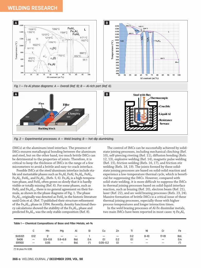
(IMCs) at the aluminum/steel interface. The presence ofIMCs ensures metallurgical bonding between the aluminumand steel, but on the other hand, too much brittle IMCs canbe detrimental to the properties of joints. Therefore, it iscritical to keep the thickness of IMCs in the range of a fewmicrometers to avoid a brittle and easy-to-crack interface. Possible IMCs at the steel/aluminum interface include sta-ble and metastable phases such as Fe3Al, FeAl, Fe5Al8, FeAl2,Fe2Al5, FeAl3, and Fe4Al13 (Refs. 5, 6). Fe5Al8 is a high-tempera-ture phase, and FeAl2 often grows so slowly that it is hardlyvisible or totally missing (Ref. 6). For some phases, such asFeAl3 and Fe4Al13, there is no general agreement on their for-mula, as shown in the phase diagrams of Fig. 1. The phaseFe4Al13 originally was denoted as FeAl3 in the historic literatureuntil Grin et al. (Ref. 7) published their structure refinementof the Fe4Al13 phase in 1994. Recently, density functional theo-ry calculations showed the stability of the Fe4Al13 phase andpredicted Fe4Al13 was the only stable composition (Ref. 8).
The control of IMCs can be successfully achieved by solid-state joining processes, including mechanical clinching (Ref.10), self-piercing riveting (Ref. 11), diffusion bonding (Refs.12, 13), explosive welding (Ref. 14), magnetic pulse welding(Ref. 15), friction welding (Refs. 16, 17), and friction stirwelding (Refs. 18, 19). The joints formed by these solid-state joining processes are based on solid-solid reaction andexperience a low-temperature thermal cycle, which is benefi-cial for suppressing the IMCs. However, compared with solid-state welding, it is more difficult to suppress the IMCsin thermal joining processes based on solid-liquid interfacereaction, such as brazing (Ref. 20), electron beam (Ref. 21),laser (Ref. 22), and arc weld brazing processes (Refs. 23, 24).Massive formation of brittle IMCs is a critical issue of thesethermal joining processes, especially those with higherprocess temperatures and longer interaction times. In the weld brazing processes of Al-Fe dissimilar metals,two main IMCs have been reported in most cases: -Fe2Al5
WELDING RESEARCH
WELDING JOURNAL / DECEMBER 2019, VOL. 98366-s
Fig. 1 — Fe-Al phase diagrams: A — Overall (Ref. 9); B — Al-rich part (Ref. 6).
Fig. 2 — Experimental processes: A — Weld brazing; B — hot-dip aluminizing.
Table 1 — Chemical Compositions of Base and Filler Metals, wt-%
C Mn Mg Al Si Cu Zn Ti Ni Cr Fe
SUS321 0.12 2 — — 1 — — 0.2 8–10 17–19 Bal. 5A06 — 0.5–0.8 5.8–6.8 Bal. 0.4 0.1 0.2 0.1 — — 0.4 ER1100 — 0.05 — Bal. (a) 0.05–0.2 0.1 — — — (a)
(a) Si plus Fe 0.95
BA
BA
HE ET AL SUPP DEC 19 WJ 201935.qxp_Layout 1 11/5/19 3:55 PM Page 366

and -FeAl3 (also referred to as Fe4Al13). With using basemetals of galvanized and low-alloy steels, the Fe2Al5 domi-nates the interface IMC, and its growth is governed by thediffusion mechanism (Refs. 25–27). In such case, the thick-ness of the IMC increases with increasing heat input. Reduc-ing heat input is an effective way to control the growth ofthe IMC layer. It has been proved in many joining methods,such as traditional arc weld brazing (Refs. 24, 28, 29), coldmetal transfer weld brazing (Refs. 30, 31), laser weld brazing(Refs. 32–36), electron beam welding (Ref. 37), and laser-archybrid welding (Ref. 38). Nevertheless, with employing basemetal of stainless steel, the FeAl3 (Fe4Al13) becomes thedominant IMC instead of the Fe2Al5. Previous reported ki-netics of the phase are based on interface reactions of pureiron or carbon steel with molten aluminum. Their conclu-sions about the kinetics vary between diffusion (Ref. 25), in-terface reaction (Ref. 26), precipitation, and reaction diffu-sion (Ref. 27), which provided confused information of thegrowth mechanism of the phase. Dybkov proposed a pointthat the growth of an IMC layer at the solid-liquid interfaceand its dissolution into the liquid aluminum take place si-multaneously (Ref. 39). It is promising to reveal the kineticof the phase and provide a potential approach of suppress-ing an IMC layer by increasing heat input in a reasonablerange to promote the dissolution of the IMC. In this study, considering both the formation and decom-position of the interfacial IMCs, the relationship betweenheat input, microstructures, and mechanical behavior of aluminum-stainless steel gas tungsten arc (GTA) weld braz-ing a joint were studied. Furthermore, hot-dip aluminizingof stainless steel was conducted to reveal the influence of re-action temperature and time on IMCs. The results of weldbrazing and hot-dip aluminizing were compared, and themechanisms involved were analyzed.
Experimental
Weld Brazing Experiments
Base materials for this study included a 3.0-mm-thick5A06 aluminum (similar to 5456 in the United States) andSUS321 stainless steel sheets. The filler was an ER1100 purealuminum welding wire with a diameter of 1.6 mm. Thechemical compositions of the base and filler metals are list-ed in Table 1. The solidus and liquidus temperatures of theER1100 filler metal are 643˚ and 657˚C, respectively. Thesolidus and liquidus temperatures of the 5A06 aluminum
base metal are 570˚ and 638˚C, respectively (Ref. 40). Thesolidus and liquidus temperatures of the SUS 321 stainlesssteel base metal are 1398˚ and 1446˚C, respectively. The size of the specimen was 100 by 50 mm, with a 45-deg,single-V groove, in both the steel and aluminum side. The sur-faces of the steel and aluminum base metals were cleaned byabrasive papers and a scraper knife (a tool for cleaning the alu-minum surface), respectively, and then rinsed and cleaned byethanol. A modified flux layer (KAlF4 + Al powder), approxi-mately 0.2–0.5 mm thick, was coated on the groove, front, andback surfaces of the steel in a 10 mm width to prevent oxidiza-tion of the steel and improve wettability of the molten alu-minum on it. Butt joint GTA weld brazing experiments of alu-minum to steel were carried out using a standard weldingpower source. The welding parameters were an alternatingcurrent (AC) square wave of 100 Hz, a 4:1 AC balance, an arclength of 3.0–4.0 mm, a welding speed of 150 mm/min, andan argon gas flow rate of 8–10 L/min. The weld brazingprocess is illustrated in Fig. 2A. To analyze the thermal cycling curves at the interfaces, aconduction-based, heat-transfer finite element method(FEM) model with the Marc software was used as a coarseapproximation of temperature fields at the Fe/Al interfaceduring weld brazing. A general double-ellipsoid welding heatsource proposed by Goldak et al. was employed, in whichheat flux is distributed in a Gaussian manner throughoutthe heat source’s volume and can accurately simulate differ-ent types of welding processes with shallow and deep pene-tration (Ref. 41). An elements birth-death technique wasalso applied in this study. The elements in the welding pow-er source are considered as “dead” elements; this wasachieved by multiplying their conductivity or other analo-gous quantities by a severe reduction. When the weldingjoint is generated, the corresponding elements start to beconsidered as “live” elements by allowing their properties toreturn to original values (Ref. 42). The FEM model was veri-fied by a thermocouple instrument made in-house.
Hot-Dip Aluminizing Experiments
The SUS321 stainless steel (40 by 10 mm) and pure alu-minum ingots (50 mm in diameter and 50 mm in length)were employed to conduct hot-dip aluminizing experiments.Before dipping, the surface of the stainless steel and alu-minum ingot were cleaned the same as the weld brazingprocess. The KAlF4 flux was coated on the steel surface toprevent oxidization of the steel and improve the wettabilityof the molten aluminum on it. The hot-dipping system consisted of a box-type resist-ance furnace, an alumina crucible with an inner diameter of75 mm, and a thermocouple. The steel sheets were im-mersed in molten aluminum for 4–10 s, at 700˚–1000˚C, re-spectively. The reaction temperatures were measured by the
WELDING RESEARCH
DECEMBER 2019 / WELDING JOURNAL 367-s
Fig. 3 — Schematic of tensile test samples.
Table 2 — Analysis of EDS (at.-%)
Elements Al Fe Cr Ni
Fe2Al5 71.93 21.17 5.05 1.85 Fe4Al13 77.11 17.04 4.21 1.64
HE ET AL SUPP DEC 19 WJ 201935.qxp_Layout 1 11/5/19 3:55 PM Page 367
thermocouple and were monitored in real time by a temper-ature controller. The hot-dip aluminizing process is illustrat-ed in Fig. 2B.
Characterization and Tensile Testing
After welding or dipping experiments, the microstruc-ture and IMC composition at the interfaces were examinedby optical microscope, scanning electron microscopy(SEM), and energy-dispersive x-ray spectrometer (EDS). Athin-foil specimen for transmission electron microscope(TEM) was extracted from the interface area using a fo-cused ion beam (FIB) system. The IMCs were identified byTEM. The SEM images were processed using an image pro-cessing software to obtain the areas by selecting the IMCswith a Magnetic Lasso Tool and further calculate the thick-nesses of the IMCs, and also to obtain the proportion ofmicrostructures in the weld joint. Tensile tests were con-ducted using an INSTRON-5569 testing machine with aloading speed of 0.5 mm/min. The dimensions of tensiletest samples are shown in Fig. 3. All the area/thicknessmeasurements and tensile tests were performed in tripli-cate with different samples.
Results
Macrostructure and Microstructure of theWeld Brazing Joint
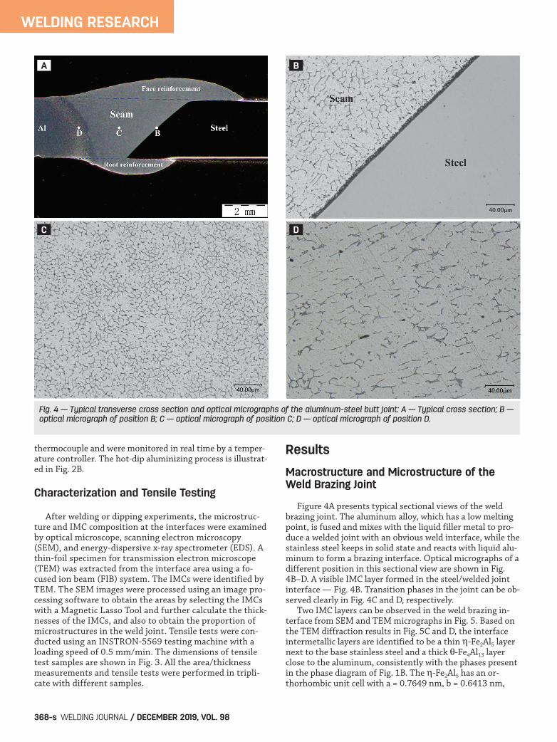
Figure 4A presents typical sectional views of the weldbrazing joint. The aluminum alloy, which has a low meltingpoint, is fused and mixes with the liquid filler metal to pro-duce a welded joint with an obvious weld interface, while thestainless steel keeps in solid state and reacts with liquid alu-minum to form a brazing interface. Optical micrographs of adifferent position in this sectional view are shown in Fig.4B–D. A visible IMC layer formed in the steel/welded jointinterface — Fig. 4B. Transition phases in the joint can be ob-served clearly in Fig. 4C and D, respectively. Two IMC layers can be observed in the weld brazing in-terface from SEM and TEM micrographs in Fig. 5. Based onthe TEM diffraction results in Fig. 5C and D, the interfaceintermetallic layers are identified to be a thin -Fe2Al5 layernext to the base stainless steel and a thick -Fe4Al13 layerclose to the aluminum, consistently with the phases presentin the phase diagram of Fig. 1B. The -Fe2Al5 has an or-thorhombic unit cell with a = 0.7649 nm, b = 0.6413 nm,
WELDING RESEARCH
WELDING JOURNAL / DECEMBER 2019, VOL. 98368-s
Fig. 4 — Typical transverse cross section and optical micrographs of the aluminum-steel butt joint: A — Typical cross section; B —optical micrograph of position B; C — optical micrograph of position C; D — optical micrograph of position D.
BA
DC
HE ET AL SUPP DEC 19 WJ 201935.qxp_Layout 1 11/5/19 3:55 PM Page 368

and c = 0.4217 nm (Ref. 43). The -Fe4Al13 phase has a mon-oclinic unit cell with a = 1.548 nm, b = 0.8083 nm, c =1.2476 nm, and = 107.72 deg (Refs. 44–46). The phases inthe welded joint have been identified to be FeAl6 and Fe2Al9,as shown in Fig. 6. The FeAl6 has an orthorhombic unit cellwith a = 0.646 nm, b = 0.744 nm, and c = 0.878 nm (Refs.47, 48). The Fe2Al9 has a monoclinic lattice of the Co2Al9
type with parameters a = 0.8598 nm, b = 0.6271 nm, c =0.6207 nm, and = 94.66 deg (Ref. 49). The composition of the intermetallic layers was meas-ured in at least three points in each IMC layer using EDS ofthe TEM foils, and is summarized in Table 2. The results
show that a small quantity of Cr and Ni is contained in thetwo IMCs. The IMCs are solid solution based upon theFe4Al13 and Fe2Al5, and can also be expressed as (Fe, Cr,Ni)4Al13 and (Fe, Cr, Ni)2Al5, respectively (Ref. 50).
Effect of Heat Input on Microstructure
To obtain a reliable joint of aluminum and steel with sat-isfactory appearance, a reasonable range of welding currentshould be adopted to ensure the fusion of the base alu-minum and filler without overheating and melting of thebase steel. For the present experiments, the reasonable
WELDING RESEARCH
DECEMBER 2019 / WELDING JOURNAL 369-s
Fig. 5 — IMC morphology and TEM diffraction spots: A — SEM image; B — TEM morphology; C — TEM diffraction spot of Fe2Al5; D —TEM diffraction spot of Fe4Al13.
BA
DC
HE ET AL SUPP DEC 19 WJ 201935.qxp_Layout 1 11/5/19 3:55 PM Page 369
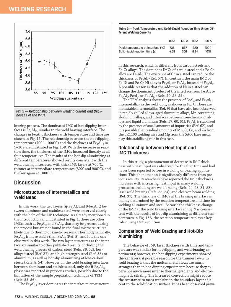
welding current is from 86.5 to 120 A. If the welding currentis lower than 86.5 A or higher than 120 A, welding defectssuch as incomplete fusion, incomplete penetration, under-cutting, and melt-through will occur. SEM and TEM images of the interfacial IMCs are shown inFigs. 7 and 8. With increasing heat input, the total thicknessesof IMCs at the interface changed significantly, while the thick-nesses of Fe2Al5 kept in approximately 200 nm under a differ-ent welding current. Two distinct periods can be observed inFig. 9. With the increase in welding current from 86.5 to 120A, the thickness of IMCs decreased first, reached a minimumvalue of 3.5 m at 110 A, and then increased. SEM images of the microstructures in the weld joints un-der different welding currents are shown in Fig. 10. The pro-portion of FeAl6 and Fe2Al9 in the weld joints are illustratedin Fig. 11. With increasing welding current, the proportionof FeAl6 and Fe2Al9 in the weld increased constantly.
Effects of Heat Input on Joint Properties
Tensile tests were carried out to evaluate the joint tensilestrength. The results with and without reinforcement areshown in Fig. 12. The tensile strength of the joint with rein-forcement increased from 172 to 238 MPa between 86.5 and110 A, then decreased to 173 MPa between 110 and 120 A.The joint strength without reinforcement increased from117 to 158 MPa between 86.5 and 110 A, then decreased to102 MPa between 110 and 120 A. The existence of rein-forcement increases the joint strength by 47–70%, yet doesnot influence the strength variation tendencies. The opti-mal weld brazing appearance of an aluminum-steel weld al-ways has face and root reinforcement (Refs. 39, 51). The ex-istence of the reinforcement increases the joint thicknessand enlarges the brazing area. These two aspects both posi-tively impact the joint strength.
WELDING RESEARCH
WELDING JOURNAL / DECEMBER 2019, VOL. 98370-s
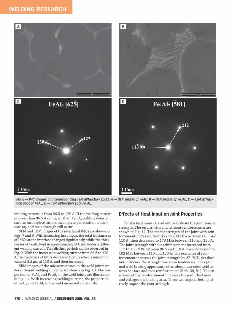
Fig. 6 — IMC images and corresponding TEM diffraction spots: A — SEM image of FeAl6; B — SEM image of Fe2Al9; C — TEM diffrac-tion spot of FeAl6; D — TEM diffraction spot Fe2Al9.
BA
DC
HE ET AL SUPP DEC 19 WJ 201935.qxp_Layout 1 11/5/19 3:55 PM Page 370

Temperature Field and Thermal Cycles of the Interfaces
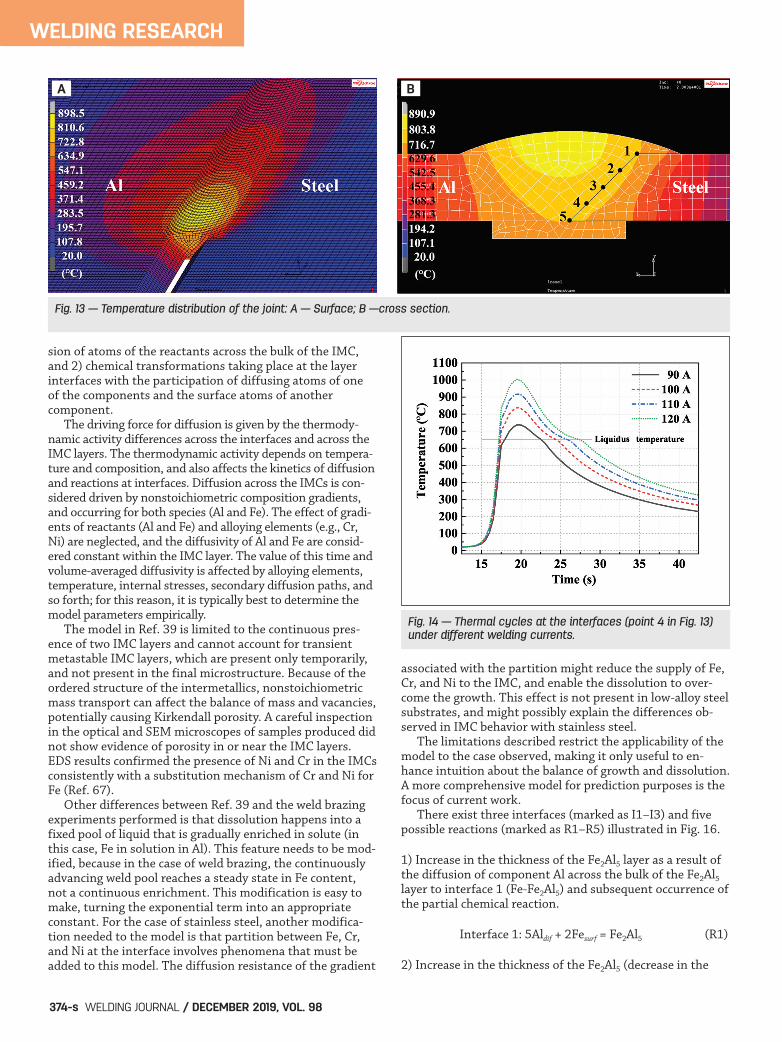
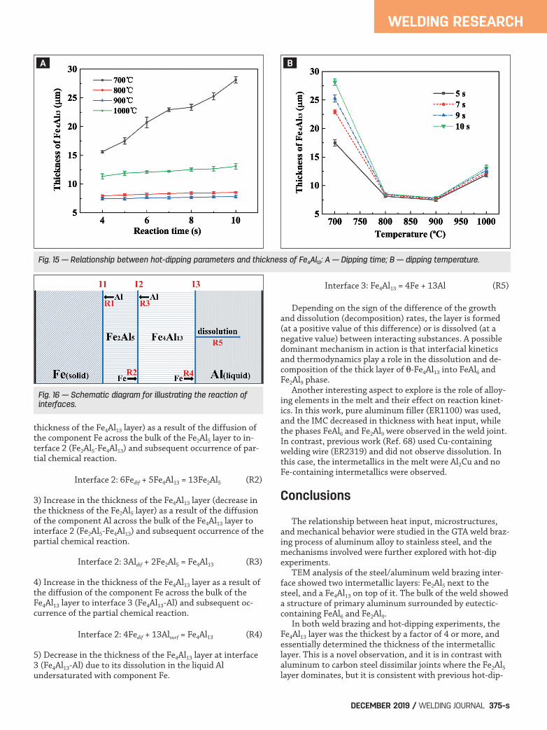
Figure 13 shows a typical temperature field of the GTAweld brazing process between aluminum and stainless steel.The temperature distribution exhibits an obviously asymmet-ric characteristic. Because the heat conductivity of the Al alloyoutclasses that of stainless steel, the high-temperature area atthe Al side is wider than the steel side. Figure 14 shows ther-mal cycle curves extracted from FEM simulation results, cor-responding to the point 4 (in Fig. 13B) for the joints with dif-ferent welding currents. The change in welding current influ-ences the thermal cycles of the interfaces. With the increase
in welding current from 90 to 120 A, as illustrated in Table 3,peak temperature at the interface increased from 736˚ to1004˚C, and the solid steel-liquid aluminum reaction time in-creased from 4.59 to 10.10 s. As the liquid pool is a mixture ofER1100 filler and 5A06 base alloy, the liquidus temperature inthis study was estimated to be approximately 650˚C based onthe liquid temperatures of the aforementioned materials(657˚C of ER1100 and 638˚C of 5A06).
Hot-Dip Aluminizing
The hot-dipping experiments were conducted at differenttemperatures, estimated by the FEM modeling of the weld
WELDING RESEARCH
DECEMBER 2019 / WELDING JOURNAL 371-s
Fig. 7 — SEM images of the IMCs under different welding currents: A — 86.5 A; B — 90 A; C — 95 A; D — 100 A; E — 105 A; F — 110 A;G — 115 A; H — 120 A.
Fig. 8 — TEM morphology of Fe2Al5 under different welding currents: A — 90 A; B — 110 A.
A B C D
E F G H
A B
HE ET AL SUPP DEC 19 WJ 201935.qxp_Layout 1 11/5/19 3:55 PM Page 371
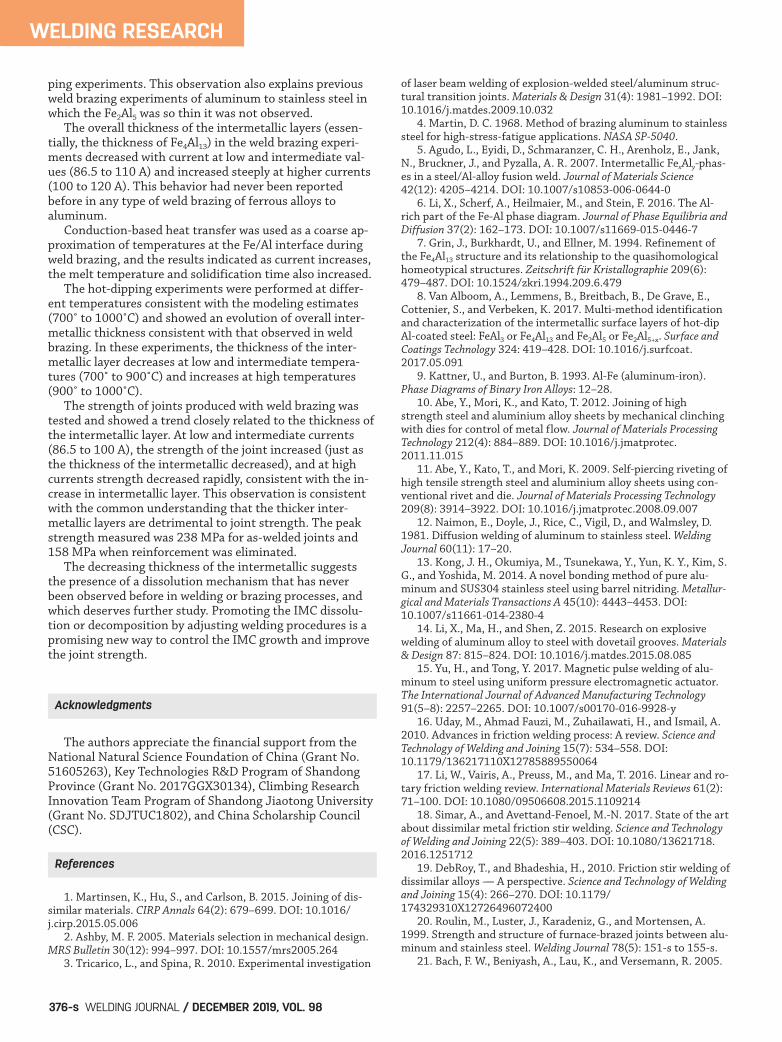
brazing process. The dominated IMC of hot-dipping inter-faces is Fe4Al13, similar to the weld brazing interface. Thechanges in Fe4Al13 thickness with temperature and time areshown in Fig. 15. The relationship between the hot-dippingtemperature (700˚–1000˚C) and the thickness of Fe4Al13 in5–10 s are illustrated in Fig. 15B. With the increase in reac-tion time, the thickness of the IMCs increased linearly at allfour temperatures. The results of the hot-dip aluminizing atdifferent temperatures showed results consistent with theweld brazing interfaces, with thick IMC layers at 700˚C,thinner at intermediate temperatures (800˚ and 900˚C), andthicker again at 1000˚C.
Discussion
Microstructure of Intermetallics and Weld Bead
In this work, the two layers (-Fe2Al5 and -Fe4Al13) be-tween aluminum and stainless steel were observed clearlywith the help of the FIB technique. As already mentioned inthe introduction and illustrated in Fig. 1, there are otherIMCs, such as Fe5Al8 and FeAl2, that may be present duringthe process but are not found in the final microstructureslikely due to thermo or kinetic reasons. Thermodynamically,Fe4Al13 is more stable than FeAl3 (Ref. 8), and it is the oneobserved in this work. The two-layer structures at the inter-face are similar to other published results, including theweld brazing process of carbon steel (Refs. 36, 52), low-alloyed steel (Ref. 37), and high-strength steel (Ref. 53) toaluminum, as well as hot-dip aluminizing of low-carbonsteels (Refs. 8, 54). However, in the weld brazing interfacesbetween aluminum and stainless steel, only the -Fe4Al13
phase was reported in previous studies, possibly due to thelimitation of the sample preparation technique of TEM(Refs. 55, 56). The Fe4Al13 layer dominates the interface microstructure
in this research, which is different from carbon steels andFe-Cr alloys. The dominant IMCs of a mild steel and a Fe-Cralloy are Fe2Al5. The existence of Cr in a steel can reduce thethickness of Fe2Al5 (Ref. 57). In contrast, the main IMC ofFe-Ni and Fe-Cr-Ni alloy is Fe2Al7 or FeAl3, instead of Fe2Al5.A possible reason is that the addition of Ni in a steel canchange the dominant product of the interface from Fe2Al5 toFe2Al7, FeAl3, or Fe4Al13 (Refs. 50, 58, 59). The TEM analysis shows the presence of FeAl6 and Fe2Al9
intermetallics in the weld joint, as shown in Fig. 6. These aremetastable intermetallics (Ref. 9) that have also been observedin rapidly chilled alloys, aged aluminum alloys, Mn-containingaluminum alloys, and interfaces between iron-chromium al-loys and liquid aluminum (Refs. 57, 60, 61). Fe2Al9 is stabilizedby the presence of small amounts of impurities (Ref. 62), andit is possible that residual amounts of Mn, Si, Cu, and Zn fromthe ER1100 welding wire and Mg from the 5A06 base metalplay this stabilizing role in this case.
Relationship between Heat Input and IMC Thickness
In this study, a phenomenon of decrease in IMC thick-ness with heat input was observed for the first time and hadnever been reported before in welding or brazing applica-tions. This phenomenon is significantly different from pre-vious results. Researchers have reported the IMC thicknessincreases with increasing heat input in many weldingprocesses, including arc weld brazing (Refs. 24, 28, 31, 53),laser weld brazing (Refs. 33, 34), and electron beam welding(Ref. 37). The thickness of IMCs at the brazing interface ismainly determined by the reaction temperature and time forwelding aluminum and steel. Because the thickness changeof the IMC at the weld brazing interface in Fig. 9 is consis-tent with the results of hot-dip aluminizing at different tem-peratures in Fig. 15B, the reaction temperature plays a keyrole during IMC evolution.
Comparison of Weld Brazing and Hot-DipAluminizing
The behavior of IMC layer thickness with time and tem-perature was similar for hot-dipping and weld-brazing ex-periments; however, the hot-dipping experiments showedthicker layers. A possible reason for the thinner layers inweld brazing is that the molten metal flows are muchstronger than in hot-dipping experiments because they ex-perience much more intense thermal gradients and electro-magnetic stirring. The increased convection might reducethe resistance to mass transfer on the boundary layer adja-cent to the solidification surface. It has been observed previ-
WELDING RESEARCH
WELDING JOURNAL / DECEMBER 2019, VOL. 98372-s
Fig. 9 — Relationship between welding current and thick-nesses of the IMCs.
Table 3 — Peak Temperature and Solid-Liquid Reaction Time Under Dif-ferent Welding Currents
90 A 100 A 110 A 120 A
Peak temperature at interface (C) 736 837 920 1004Solid-liquid reaction time (s) 4.59 7.06 8.64 10.10
HE ET AL SUPP DEC 19 WJ 201935.qxp_Layout 1 11/5/19 3:55 PM Page 372

ously that a rapid agitation of melt adjacent to the inter-metallic layer prevents thickening of the outer IMC layer(Ref. 63). Another possible mechanism, which might coexistwith that mentioned before, is the effect of electrochemicalreactions at the interface. Such effects were reported to en-hance the dissolution of IMC in Ni-based alloys (Refs.64–66). Furthermore, the hot-dipped geometry provides aninfinite amount of Al where the weld braze geometry has alimited amount of Al, which may affect the rate kinetics atthe steel/filler metal interface. Another possible mechanismcontributing to the observed difference in thickness is thepresence of 5A06 base aluminum on the other side of theweld joint. The molten 5A06 aluminum mixed into the poolduring the weld brazing process possibly changes the chemi-cal potential for the reaction on the steel side. The relativeimportance of these mechanisms is currently unknown andthe subject of current research.
Growth and Dissolution Mechanism of the IMCs
The experiments performed suggest the growth of a com-pound layer at the solid-liquid interface and its dissolutioninto the liquid might take place simultaneously. Such behav-
ior has already been studied in the reaction-diffusion theoryfield and applied to the case of growth-dissolution of thegrowth kinetics of the Fe-Al intermetallics in moltenaluminum (Ref. 39) for a system similar (but with essentialdifferences) to the one in this paper. The idealized model of Dybkov (Ref. 39) can yield someintuitive understanding into the conditions under whichgrowth or dissolution happen in IMCs. This model ac-counts for bulk kinetics as volume-averaged diffusion andinterface kinetics in the form of reaction rates. The modelconsiders growth of IMCs at constant temperature, andneglects the effect of composition, stoichiometry, and in-ternal stresses on diffusivity. The temperature dependenceof thermodynamics and kinetics factors is included with-out problem for each case. The parameters involved in thismodel are typically best determined experimentally to ac-count for the presence of metastable IMCs not present inthe equilibrium phase diagram, internal stresses, second-ary diffusion paths, and effect of alloying elements and im-purities. When the parameters can be predicted for desiredtemperatures and compositions, the behavior under newconditions can be estimated. The mathematical formulation in Ref. 39 considers theIMC layer growth by two simultaneous processes: 1) diffu-
WELDING RESEARCH
DECEMBER 2019 / WELDING JOURNAL 373-s
Fig. 11 — Relationship between welding current and proportionof (FeAl6 + Fe2Al9).
Fig. 12 — Relationship between joint strength and weldingcurrent.
Fig. 10 — Images of FeAl6/Fe2Al9 in the welded joints under different welding currents: A — 90 A; B — 105 A; C — 120 A.
A B C
HE ET AL SUPP DEC 19 WJ 201935.qxp_Layout 1 11/5/19 3:55 PM Page 373
sion of atoms of the reactants across the bulk of the IMC,and 2) chemical transformations taking place at the layer interfaces with the participation of diffusing atoms of oneof the components and the surface atoms of another component. The driving force for diffusion is given by the thermody-namic activity differences across the interfaces and across theIMC layers. The thermodynamic activity depends on tempera-ture and composition, and also affects the kinetics of diffusionand reactions at interfaces. Diffusion across the IMCs is con-sidered driven by nonstoichiometric composition gradients,and occurring for both species (Al and Fe). The effect of gradi-ents of reactants (Al and Fe) and alloying elements (e.g., Cr,Ni) are neglected, and the diffusivity of Al and Fe are consid-ered constant within the IMC layer. The value of this time andvolume-averaged diffusivity is affected by alloying elements,temperature, internal stresses, secondary diffusion paths, andso forth; for this reason, it is typically best to determine themodel parameters empirically. The model in Ref. 39 is limited to the continuous pres-ence of two IMC layers and cannot account for transientmetastable IMC layers, which are present only temporarily,and not present in the final microstructure. Because of theordered structure of the intermetallics, nonstoichiometricmass transport can affect the balance of mass and vacancies,potentially causing Kirkendall porosity. A careful inspectionin the optical and SEM microscopes of samples produced didnot show evidence of porosity in or near the IMC layers.EDS results confirmed the presence of Ni and Cr in the IMCsconsistently with a substitution mechanism of Cr and Ni forFe (Ref. 67). Other differences between Ref. 39 and the weld brazingexperiments performed is that dissolution happens into afixed pool of liquid that is gradually enriched in solute (inthis case, Fe in solution in Al). This feature needs to be mod-ified, because in the case of weld brazing, the continuouslyadvancing weld pool reaches a steady state in Fe content,not a continuous enrichment. This modification is easy tomake, turning the exponential term into an appropriateconstant. For the case of stainless steel, another modifica-tion needed to the model is that partition between Fe, Cr,and Ni at the interface involves phenomena that must beadded to this model. The diffusion resistance of the gradient
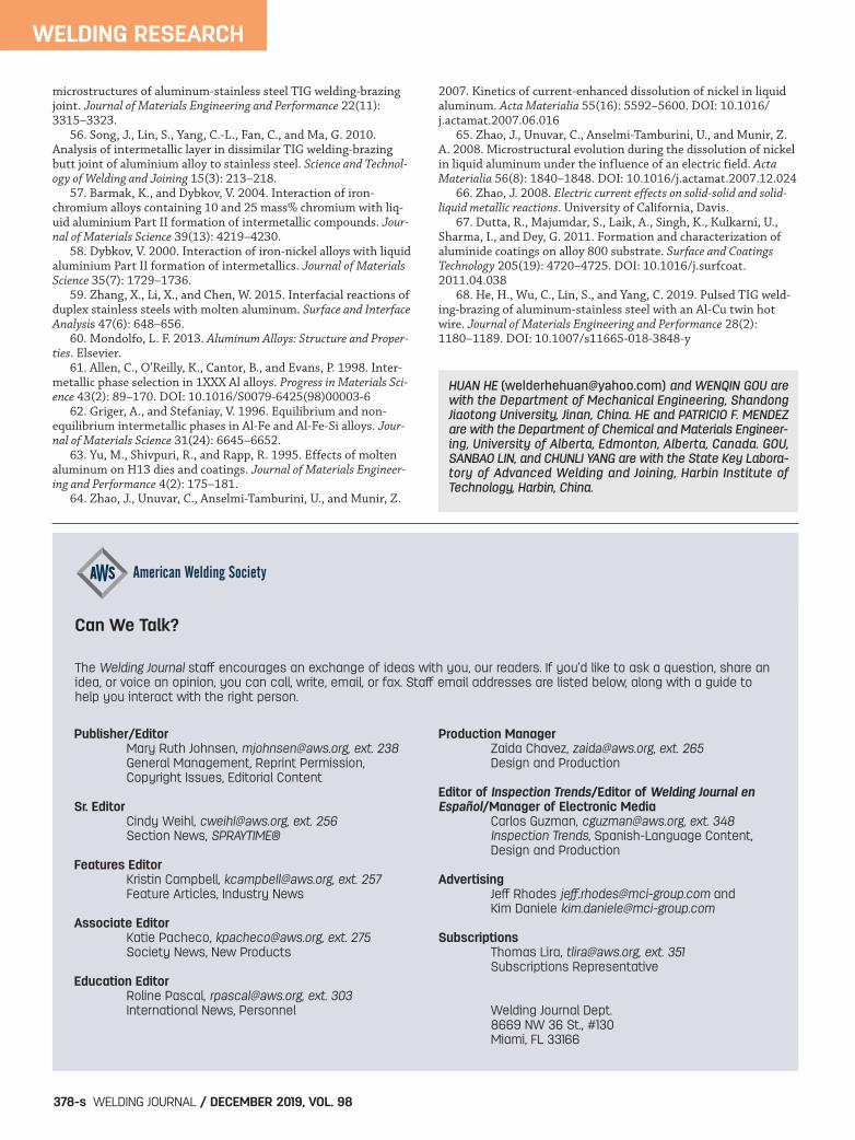
associated with the partition might reduce the supply of Fe,Cr, and Ni to the IMC, and enable the dissolution to over-come the growth. This effect is not present in low-alloy steelsubstrates, and might possibly explain the differences ob-served in IMC behavior with stainless steel. The limitations described restrict the applicability of themodel to the case observed, making it only useful to en-hance intuition about the balance of growth and dissolution.A more comprehensive model for prediction purposes is thefocus of current work. There exist three interfaces (marked as I1–I3) and fivepossible reactions (marked as R1–R5) illustrated in Fig. 16.
1) Increase in the thickness of the Fe2Al5 layer as a result ofthe diffusion of component Al across the bulk of the Fe2Al5
layer to interface 1 (Fe-Fe2Al5) and subsequent occurrence ofthe partial chemical reaction.
Interface 1: 5Aldif + 2Fesurf = Fe2Al5 (R1)
2) Increase in the thickness of the Fe2Al5 (decrease in the
WELDING RESEARCH
WELDING JOURNAL / DECEMBER 2019, VOL. 98374-s
A B
Fig. 13 — Temperature distribution of the joint: A — Surface; B —cross section.
Fig. 14 — Thermal cycles at the interfaces (point 4 in Fig. 13)under different welding currents.
HE ET AL SUPP DEC 19 WJ 201935.qxp_Layout 1 11/5/19 3:55 PM Page 374
thickness of the Fe4Al13 layer) as a result of the diffusion ofthe component Fe across the bulk of the Fe2Al5 layer to in-terface 2 (Fe2Al5-Fe4Al13) and subsequent occurrence of par-tial chemical reaction.
Interface 2: 6Fedif + 5Fe4Al13 = 13Fe2Al5 (R2)
3) Increase in the thickness of the Fe4Al13 layer (decrease inthe thickness of the Fe2Al5 layer) as a result of the diffusionof the component Al across the bulk of the Fe4Al13 layer tointerface 2 (Fe2Al5-Fe4Al13) and subsequent occurrence of thepartial chemical reaction.
Interface 2: 3Aldif + 2Fe2Al5 = Fe4Al13 (R3)
4) Increase in the thickness of the Fe4Al13 layer as a result ofthe diffusion of the component Fe across the bulk of theFe4Al13 layer to interface 3 (Fe4Al13-Al) and subsequent oc-currence of the partial chemical reaction.
Interface 2: 4Fedif + 13Alsurf = Fe4Al13 (R4)
5) Decrease in the thickness of the Fe4Al13 layer at interface3 (Fe4Al13-Al) due to its dissolution in the liquid Al undersaturated with component Fe.
Interface 3: Fe4Al13 = 4Fe + 13Al (R5)
Depending on the sign of the difference of the growthand dissolution (decomposition) rates, the layer is formed(at a positive value of this difference) or is dissolved (at anegative value) between interacting substances. A possibledominant mechanism in action is that interfacial kineticsand thermodynamics play a role in the dissolution and de-composition of the thick layer of -Fe4Al13 into FeAl6 andFe2Al9 phase. Another interesting aspect to explore is the role of alloy-ing elements in the melt and their effect on reaction kinet-ics. In this work, pure aluminum filler (ER1100) was used,and the IMC decreased in thickness with heat input, whilethe phases FeAl6 and Fe2Al9 were observed in the weld joint.In contrast, previous work (Ref. 68) used Cu-containingwelding wire (ER2319) and did not observe dissolution. Inthis case, the intermetallics in the melt were Al2Cu and noFe-containing intermetallics were observed.
Conclusions
The relationship between heat input, microstructures,and mechanical behavior were studied in the GTA weld braz-ing process of aluminum alloy to stainless steel, and themechanisms involved were further explored with hot-dip experiments. TEM analysis of the steel/aluminum weld brazing inter-face showed two intermetallic layers: Fe2Al5 next to thesteel, and a Fe4Al13 on top of it. The bulk of the weld showeda structure of primary aluminum surrounded by eutectic-containing FeAl6 and Fe2Al9. In both weld brazing and hot-dipping experiments, theFe4Al13 layer was the thickest by a factor of 4 or more, andessentially determined the thickness of the intermetalliclayer. This is a novel observation, and it is in contrast withaluminum to carbon steel dissimilar joints where the Fe2Al5
layer dominates, but it is consistent with previous hot-dip-
WELDING RESEARCH
DECEMBER 2019 / WELDING JOURNAL 375-s
A B
Fig. 15 — Relationship between hot-dipping parameters and thickness of Fe4Al13: A — Dipping time; B — dipping temperature.
Fig. 16 — Schematic diagram for illustrating the reaction of interfaces.
HE ET AL SUPP DEC 19 WJ 201935.qxp_Layout 1 11/5/19 3:55 PM Page 375
ping experiments. This observation also explains previousweld brazing experiments of aluminum to stainless steel inwhich the Fe2Al5 was so thin it was not observed. The overall thickness of the intermetallic layers (essen-tially, the thickness of Fe4Al13) in the weld brazing experi-ments decreased with current at low and intermediate val-ues (86.5 to 110 A) and increased steeply at higher currents(100 to 120 A). This behavior had never been reported before in any type of weld brazing of ferrous alloys to aluminum. Conduction-based heat transfer was used as a coarse ap-proximation of temperatures at the Fe/Al interface duringweld brazing, and the results indicated as current increases,the melt temperature and solidification time also increased. The hot-dipping experiments were performed at differ-ent temperatures consistent with the modeling estimates(700˚ to 1000˚C) and showed an evolution of overall inter-metallic thickness consistent with that observed in weldbrazing. In these experiments, the thickness of the inter-metallic layer decreases at low and intermediate tempera-tures (700˚ to 900˚C) and increases at high temperatures(900˚ to 1000˚C). The strength of joints produced with weld brazing wastested and showed a trend closely related to the thickness ofthe intermetallic layer. At low and intermediate currents(86.5 to 100 A), the strength of the joint increased (just asthe thickness of the intermetallic decreased), and at highcurrents strength decreased rapidly, consistent with the in-crease in intermetallic layer. This observation is consistentwith the common understanding that the thicker inter-metallic layers are detrimental to joint strength. The peakstrength measured was 238 MPa for as-welded joints and158 MPa when reinforcement was eliminated. The decreasing thickness of the intermetallic suggeststhe presence of a dissolution mechanism that has neverbeen observed before in welding or brazing processes, andwhich deserves further study. Promoting the IMC dissolu-tion or decomposition by adjusting welding procedures is apromising new way to control the IMC growth and improvethe joint strength.
The authors appreciate the financial support from theNational Natural Science Foundation of China (Grant No.51605263), Key Technologies R&D Program of ShandongProvince (Grant No. 2017GGX30134), Climbing ResearchInnovation Team Program of Shandong Jiaotong University(Grant No. SDJTUC1802), and China Scholarship Council(CSC).
1. Martinsen, K., Hu, S., and Carlson, B. 2015. Joining of dis-similar materials. CIRP Annals 64(2): 679–699. DOI: 10.1016/j.cirp.2015.05.006 2. Ashby, M. F. 2005. Materials selection in mechanical design.MRS Bulletin 30(12): 994–997. DOI: 10.1557/mrs2005.264 3. Tricarico, L., and Spina, R. 2010. Experimental investigation
of laser beam welding of explosion-welded steel/aluminum struc-tural transition joints. Materials & Design 31(4): 1981–1992. DOI:10.1016/j.matdes.2009.10.032 4. Martin, D. C. 1968. Method of brazing aluminum to stainlesssteel for high-stress-fatigue applications. NASA SP-5040. 5. Agudo, L., Eyidi, D., Schmaranzer, C. H., Arenholz, E., Jank,N., Bruckner, J., and Pyzalla, A. R. 2007. Intermetallic FexAly-phas-es in a steel/Al-alloy fusion weld. Journal of Materials Science42(12): 4205–4214. DOI: 10.1007/s10853-006-0644-0 6. Li, X., Scherf, A., Heilmaier, M., and Stein, F. 2016. The Al-rich part of the Fe-Al phase diagram. Journal of Phase Equilibria andDiffusion 37(2): 162–173. DOI: 10.1007/s11669-015-0446-7 7. Grin, J., Burkhardt, U., and Ellner, M. 1994. Refinement ofthe Fe4Al13 structure and its relationship to the quasihomologicalhomeotypical structures. Zeitschrift für Kristallographie 209(6):479–487. DOI: 10.1524/zkri.1994.209.6.479 8. Van Alboom, A., Lemmens, B., Breitbach, B., De Grave, E.,Cottenier, S., and Verbeken, K. 2017. Multi-method identificationand characterization of the intermetallic surface layers of hot-dipAl-coated steel: FeAl3 or Fe4Al13 and Fe2Al5 or Fe2Al5+x. Surface andCoatings Technology 324: 419–428. DOI: 10.1016/j.surfcoat.2017.05.091 9. Kattner, U., and Burton, B. 1993. Al-Fe (aluminum-iron).Phase Diagrams of Binary Iron Alloys: 12–28. 10. Abe, Y., Mori, K., and Kato, T. 2012. Joining of highstrength steel and aluminium alloy sheets by mechanical clinchingwith dies for control of metal flow. Journal of Materials ProcessingTechnology 212(4): 884–889. DOI: 10.1016/j.jmatprotec.2011.11.015 11. Abe, Y., Kato, T., and Mori, K. 2009. Self-piercing riveting ofhigh tensile strength steel and aluminium alloy sheets using con-ventional rivet and die. Journal of Materials Processing Technology209(8): 3914–3922. DOI: 10.1016/j.jmatprotec.2008.09.007 12. Naimon, E., Doyle, J., Rice, C., Vigil, D., and Walmsley, D.1981. Diffusion welding of aluminum to stainless steel. WeldingJournal 60(11): 17–20. 13. Kong, J. H., Okumiya, M., Tsunekawa, Y., Yun, K. Y., Kim, S.G., and Yoshida, M. 2014. A novel bonding method of pure alu-minum and SUS304 stainless steel using barrel nitriding. Metallur-gical and Materials Transactions A 45(10): 4443–4453. DOI:10.1007/s11661-014-2380-4 14. Li, X., Ma, H., and Shen, Z. 2015. Research on explosivewelding of aluminum alloy to steel with dovetail grooves. Materials& Design 87: 815–824. DOI: 10.1016/j.matdes.2015.08.085 15. Yu, H., and Tong, Y. 2017. Magnetic pulse welding of alu-minum to steel using uniform pressure electromagnetic actuator.The International Journal of Advanced Manufacturing Technology91(5–8): 2257–2265. DOI: 10.1007/s00170-016-9928-y 16. Uday, M., Ahmad Fauzi, M., Zuhailawati, H., and Ismail, A.2010. Advances in friction welding process: A review. Science andTechnology of Welding and Joining 15(7): 534–558. DOI:10.1179/136217110X12785889550064 17. Li, W., Vairis, A., Preuss, M., and Ma, T. 2016. Linear and ro-tary friction welding review. International Materials Reviews 61(2):71–100. DOI: 10.1080/09506608.2015.1109214 18. Simar, A., and Avettand-Feno �el, M.-N. 2017. State of the artabout dissimilar metal friction stir welding. Science and Technologyof Welding and Joining 22(5): 389–403. DOI: 10.1080/13621718.2016.1251712 19. DebRoy, T., and Bhadeshia, H., 2010. Friction stir welding ofdissimilar alloys — A perspective. Science and Technology of Weldingand Joining 15(4): 266–270. DOI: 10.1179/174329310X12726496072400 20. Roulin, M., Luster, J., Karadeniz, G., and Mortensen, A.1999. Strength and structure of furnace-brazed joints between alu-minum and stainless steel. Welding Journal 78(5): 151-s to 155-s. 21. Bach, F. W., Beniyash, A., Lau, K., and Versemann, R. 2005.
WELDING RESEARCH
WELDING JOURNAL / DECEMBER 2019, VOL. 98376-s
Acknowledgments
References
HE ET AL SUPP DEC 19 WJ 201935.qxp_Layout 1 11/5/19 3:55 PM Page 376

Joining of steel-aluminium hybrid structures with electron beamon atmosphere. Advanced Materials Research 6: 143–150. TransTech Publ. DOI: 10.4028/www.scientific.net/AMR.6-8.143 22. Wang, P., Chen, X., Pan, Q., Madigan, B., and Long, J. 2016.Laser welding dissimilar materials of aluminum to steel: Anoverview. The International Journal of Advanced Manufacturing Tech-nology 87(9–12): 3081–3090. DOI: 10.1007/s00170-016-8725-y 23. Shi, Y., Zhang, G., Huang, Y., Lu, L., Huang, J., and Shao, Y.2014. Pulsed double electrode GMAW brazing for joining of alu-minum to steel. Welding Journal 93(6): 216-s to 224-s. 24. Ma, H., Qin, G., Bai, X., Wang, L., and Liang, Z. 2016. Effectof initial temperature on joint of aluminum alloy to galvanizedsteel welded by MIG arc brazing-fusion welding process. The Inter-national Journal of Advanced Manufacturing Technology 86(9–12):3135–3143. DOI: 10.1007/s00170-016-8425-7 25. Bouche, K., Barbier, F., and Coulet, A. 1998. Intermetalliccompound layer growth between solid iron and molten aluminium.Materials Science and Engineering A 249(1–2): 167–175. DOI:10.1016/S0921-5093(98)00573-5 26. Bouayad, A., Gerometta, C., Belkebir, A., and Ambari, A.2003. Kinetic interactions between solid iron and molten alumini-um. Materials Science and Engineering A 363(1–2): 53–61. DOI:10.1016/S0921-5093(03)00469-6 27. Chen, S., Yang, D., Zhang, M., Huang, J., and Zhao, X. 2016.Interaction between the growth and dissolution of intermetalliccompounds in the interfacial reaction between solid iron and liquidaluminum. Metallurgical and Materials Transactions A 47(10):5088–5100. DOI: 10.1007/s11661-016-3667-4 28. Shao, L., Shi, Y., Huang, J., and Wu, S. 2015. Effect of join-ing parameters on microstructure of dissimilar metal joints be-tween aluminum and galvanized steel. Materials & Design 66:453–458. DOI: 10.1016/j.matdes.2014.06.026 29. Das, A., Shome, M., Das, C., Goecke, S.-F., and De, A. 2015.Joining of galvannealed steel and aluminium alloy using controlledshort circuiting gas metal arc welding process. Science and Technolo-gy of Welding and Joining 20(5): 402–408. DOI: 10.1179/1362171815Y.0000000032 30. Mezrag, B., Deschaux-Beaume, F., and Benachour, M. 2015.Control of mass and heat transfer for steel/aluminium joining us-ing cold metal transfer process. Science and Technology of Weldingand Joining 20(3): 189–198. DOI: 10.1179/1362171814Y.0000000271 31. �Ünel, E., and Taban, E. 2017. Properties and optimization ofdissimilar aluminum steel CMT welds. Welding in the World 61(1):1–9. DOI: 10.1007/s40194-016-0386-9 32. Meco, S., Pardal, G., Ganguly, S., Williams, S., and McPher-son, N. 2015. Application of laser in seam welding of dissimilarsteel to aluminium joints for thick structural components. Opticsand Lasers in Engineering 67: 22–30. DOI: 10.1016/j.optlaseng.2014.10.006 33. Meco, S., Ganguly, S., Williams, S., and McPherson, N. 2014.Effect of laser processing parameters on the formation of inter-metallic compounds in Fe-Al dissimilar welding. Journal of Materi-als Engineering and Performance 23(9): 3361–3370. DOI: 10.1007/s11665-014-1106-5 34. Sun, J., Yan, Q., Gao, W., and Huang, J. 2015. Investigationof laser welding on butt joints of Al/steel dissimilar materials. Ma-terials & Design 83: 120–128. DOI: 10.1016/j.matdes.2015.05.069 35. Liu, J., Jiang, S., Shi, Y., Kuang, Y., Huang, G., and Zhang, H.2015. Laser fusion-brazing of aluminum alloy to galvanized steelwith pure Al filler powder. Optics & Laser Technology 66: 1–8. DOI:10.1016/j.optlastec.2014.08.004 36. Szczepaniak, A., Fan, J., Kostka, A., and Raabe, D. 2012. Onthe correlation between thermal cycle and formation of intermetal-lic phases at the interface of laser-welded aluminum-steel overlapjoints. Advanced Engineering Materials 14(7): 464–472. DOI:10.1002/adem.201200075
37. Reisgen, U., Otten, C., and Schoenberger, J. 2014. Investiga-tions about the influence of the time-temperature curve on the for-mation of intermetallic phases during electron beam welding ofsteel-aluminium material combinations. Welding in the World 58(4):443–454. DOI: 10.1007/s40194-014-0128-9 38. Gao, M., Chen, C., Mei, S., Wang, L., and Zeng, X. 2014. Pa-rameter optimization and mechanism of laser-arc hybrid weldingof dissimilar Al alloy and stainless steel. The International Journal ofAdvanced Manufacturing Technology 74(1–4): 199–208. DOI:10.1007/s00170-014-5996-z 39. Dybkov, V. Reaction Diffusion and Solid State Chemical Kinet-ics: Handbook. 40. ASM International. 1990. Properties of wrought aluminumand aluminum alloys. ASM International Handbook Committee 2:62–122. 41. Goldak, J., Chakravarti, A., and Bibby, M. 1984. A new finiteelement model for welding heat sources. Metallurgical TransactionsB 15(2): 299–305. DOI: 10.1007/BF02667333 42. Chen, B.-Q., Hashemzadeh, M., and Soares, C. G. 2014. Nu-merical and experimental studies on temperature and distortionpatterns in butt-welded plates. The International Journal of Ad-vanced Manufacturing Technology 72(5–8): 1121–1131. DOI:10.1007/s00170-014-5740-8 43. Burkhardt, U., Grin, Y., Ellner, M., and Peters, K. 1994.Structure refinement of the iron-aluminium phase with the ap-proximate composition Fe2Al5. Acta Crystallographica Section B50(3): 313–316. 44. Black, P. 1955. The structure of FeAl3. I. Acta Crystallographi-ca 8(1): 43–48. 45. Black, P. 1955. The structure of FeAl3. II. Acta Crystallo-graphica 8(3): 175–182. 46. Ellner, M. 1995. Polymorphic phase transformation ofFe4Al13 causing multiple twinning with decagonal pseudosymme-try. Acta Crystallographica Section B 51(1): 31–36. 47. Walford, L. 1965. The structure of the intermetallic phasefeal6. Acta Crystallographica 18(2): 287–291. DOI: 10.1107/S0365110X65000610 48. Putyatin, A., Davydov, V., and Nesterenko, S. 1992. Hightemperature interactions in the Fe-Al-C system at 6 gpa pressure.Journal of Alloys and Compounds 179(1–2): 165–175. DOI:10.1016/0925-8388(92)90216-V 49. Bostr�öm, M., Rosner, H., Prots, Y., Burkhardt, U., and Grin,Y. 2005. The Co2Al9 structure type revisited. Zeitschrift für anorgan-ische und allgemeine Chemie 631(2–3): 534–541. 50. Dybkov, V. 1990. Interaction of 18Cr-10Ni stainless steelwith liquid aluminium. Journal of Materials Science 25(8):3615–3633. 51. Springer, H., Kostka, A., Dos Santos, J., and Raabe, D. 2011.Influence of intermetallic phases and Kirkendall-porosity on themechanical properties of joints between steel and aluminium al-loys. Materials Science and Engineering: A 528(13–14): 4630–4642. 52. Jácome, L. A., Weber, S., Leitner, A., Arenholz, E., Bruckner,J., Hackl, H., and Pyzalla, A. R. 2009. Influence of filler composi-tion on the microstructure and mechanical properties of steel-aluminum joints produced by metal arc joining. Advanced Engineer-ing Materials 11(5): 350–358. 53. Geng, W., Wu, D., Sun, D., Li, H., and Che, Y. 2018. Mi-crostructures and mechanical properties of plasma arc weldedjoints of ultra-high strength steel and aluminum alloy using Al-Siand Al-Cu fillers. ISIJ International 58(6): 1108–1116. 54. He, H., Gou, W., Wang, S., Hou, Y., Ma, C., and Mendez, P. F.2019. Kinetics of intermetallic compound layers during initial peri-od of reaction between mild steel and molten aluminum. Interna-tional Journal of Materials Research 110(3): 194–201. DOI:10.3139/146.111735 55. He, H., Lin, S., Yang, C., Fan, C., and Chen, Z. 2013. Combi-nation effects of Nocolok flux with Ni powder on properties and
WELDING RESEARCH
DECEMBER 2019 / WELDING JOURNAL 377-s
HE ET AL SUPP DEC 19 WJ 201935.qxp_Layout 1 11/5/19 3:55 PM Page 377
microstructures of aluminum-stainless steel TIG welding-brazingjoint. Journal of Materials Engineering and Performance 22(11):3315–3323. 56. Song, J., Lin, S., Yang, C.-L., Fan, C., and Ma, G. 2010.Analysis of intermetallic layer in dissimilar TIG welding-brazingbutt joint of aluminium alloy to stainless steel. Science and Technol-ogy of Welding and Joining 15(3): 213–218. 57. Barmak, K., and Dybkov, V. 2004. Interaction of iron-chromium alloys containing 10 and 25 mass% chromium with liq-uid aluminium Part II formation of intermetallic compounds. Jour-nal of Materials Science 39(13): 4219–4230. 58. Dybkov, V. 2000. Interaction of iron-nickel alloys with liquidaluminium Part II formation of intermetallics. Journal of MaterialsScience 35(7): 1729–1736. 59. Zhang, X., Li, X., and Chen, W. 2015. Interfacial reactions ofduplex stainless steels with molten aluminum. Surface and InterfaceAnalysis 47(6): 648–656. 60. Mondolfo, L. F. 2013. Aluminum Alloys: Structure and Proper-ties. Elsevier. 61. Allen, C., O’Reilly, K., Cantor, B., and Evans, P. 1998. Inter-metallic phase selection in 1XXX Al alloys. Progress in Materials Sci-ence 43(2): 89–170. DOI: 10.1016/S0079-6425(98)00003-6 62. Griger, A., and Stefaniay, V. 1996. Equilibrium and non-equilibrium intermetallic phases in Al-Fe and Al-Fe-Si alloys. Jour-nal of Materials Science 31(24): 6645–6652. 63. Yu, M., Shivpuri, R., and Rapp, R. 1995. Effects of moltenaluminum on H13 dies and coatings. Journal of Materials Engineer-ing and Performance 4(2): 175–181. 64. Zhao, J., Unuvar, C., Anselmi-Tamburini, U., and Munir, Z.
2007. Kinetics of current-enhanced dissolution of nickel in liquidaluminum. Acta Materialia 55(16): 5592–5600. DOI: 10.1016/j.actamat.2007.06.016 65. Zhao, J., Unuvar, C., Anselmi-Tamburini, U., and Munir, Z.A. 2008. Microstructural evolution during the dissolution of nickelin liquid aluminum under the influence of an electric field. ActaMaterialia 56(8): 1840–1848. DOI: 10.1016/j.actamat.2007.12.024 66. Zhao, J. 2008. Electric current effects on solid-solid and solid-liquid metallic reactions. University of California, Davis. 67. Dutta, R., Majumdar, S., Laik, A., Singh, K., Kulkarni, U.,Sharma, I., and Dey, G. 2011. Formation and characterization ofaluminide coatings on alloy 800 substrate. Surface and CoatingsTechnology 205(19): 4720–4725. DOI: 10.1016/j.surfcoat.2011.04.038 68. He, H., Wu, C., Lin, S., and Yang, C. 2019. Pulsed TIG weld-ing-brazing of aluminum-stainless steel with an Al-Cu twin hotwire. Journal of Materials Engineering and Performance 28(2):1180–1189. DOI: 10.1007/s11665-018-3848-y
WELDING RESEARCH
WELDING JOURNAL / DECEMBER 2019, VOL. 98378-s
HUAN HE ([email protected]) and WENQIN GOU arewith the Department of Mechanical Engineering, ShandongJiaotong University, Jinan, China. HE and PATRICIO F. MENDEZare with the Department of Chemical and Materials Engineer-ing, University of Alberta, Edmonton, Alberta, Canada. GOU,SANBAO LIN, and CHUNLI YANG are with the State Key Labora-tory of Advanced Welding and Joining, Harbin Institute ofTechnology, Harbin, China.
Publisher/EditorMary Ruth Johnsen, [email protected], ext. 238General Management, Reprint Permission,Copyright Issues, Editorial Content
Sr. EditorCindy Weihl, [email protected], ext. 256Section News, SPRAYTIME®
Features EditorKristin Campbell, [email protected], ext. 257Feature Articles, Industry News
Associate EditorKatie Pacheco, [email protected], ext. 275Society News, New Products
Education EditorRoline Pascal, [email protected], ext. 303International News, Personnel
Production ManagerZaida Chavez, [email protected], ext. 265Design and Production
Editor of Inspection Trends/Editor of Welding Journal en Español/Manager of Electronic Media
Carlos Guzman, [email protected], ext. 348Inspection Trends, Spanish-Language Content,Design and Production
AdvertisingJeff Rhodes [email protected] and Kim Daniele [email protected]
SubscriptionsThomas Lira, [email protected], ext. 351Subscriptions Representative
Welding Journal Dept.8669 NW 36 St., #130Miami, FL 33166
The Welding Journal staff encourages an exchange of ideas with you, our readers. If you’d like to ask a question, share anidea, or voice an opinion, you can call, write, email, or fax. Staff email addresses are listed below, along with a guide tohelp you interact with the right person.
Can We Talk?
HE ET AL SUPP DEC 19 WJ 201935.qxp_Layout 1 11/8/19 1:31 PM Page 378