Solvent Weld uPVC Above Ground Drainage System
48
PRODUCT & TECHNICAL GUIDE Solvent Weld uPVC Above Ground Drainage System Manufactured by Hepworth
-
Upload
khangminh22 -
Category
Documents
-
view
0 -
download
0
Transcript of Solvent Weld uPVC Above Ground Drainage System

1.
PRODUCT & TECHNICAL GUIDE
Solvent Weld uPVC Above Ground Drainage SystemManufactured by Hepworth
DACTA PRODUCT & TECHNICAL GUIDE
2.
Terms of use All information is correct at the time of going to press. However, we reserve the right to alter, amend or update any product, system and services described in this brochure. We accept no responsibility for the wrong interpretation of statements made.
© Copyright Hepworth PME LLC
This document contains confidential and proprietary information. Reproduction or disclosure of any part is only allowed with written authorization by Hepworth PME LLC.
All rights are vested at Hepworth PME LLC

DACTA PRODUCT & TECHNICAL GUIDE
3.
Section Page
Introduction 4-5
Manufacturing Standards 6
Dacta uPVC Soil & Vent System 7
uPVC Above Ground Pipes & Fittings 8-12
Dacta ABS Water & Vent System 13
ABS Above Ground Waste Pipes and Fittings 14-15
Floor Trap 16-17
Soil Waste & Vent Drainage System 18-21
Considerations for Designing Above Ground Drainage 22-23
Soil & Waste Stack Sizing 24-25
Control of Thermal Movement – Expansion and Contraction 26-29
Traps 30
Gradients – Falls 31
Access 32-33
Noise in the Above Ground Drainage System 34
Drainage in High Rise Buildings 34
Floor Gullies 35-36
Offsets 37
Handling, Transport and Storage 38-39
Pipe Cutting and Jointing Instructions 40-41
Solvent Welding In Hot Weather Conditions 41
Push-Fit Jointing 42
Gravity Pipework Testing Procedure 43-44
uPVC, PE & GRP Fabrication 45
Warranty&Certificates 45-47
Table of contents

DACTA PRODUCT & TECHNICAL GUIDE
4.
Introduction
Hepworth PME LLC is the Middle East’s premier manufacturer and supplier of plastic piping solutions. The company was established over 40 years ago in Dubai and manufactures pipes and fittings in the UAE, Oman and Qatar. Moreover, Hepworth trades through operating companies in Oman and Bahrain and exports its products globally.
As part of its strategy to grow its products portfolio, the company recently launched its own brand under the name of Dacta, a locally-manufactured range of uPVC solvent cement piping system, along with two sub-brands, Dacta Therm (PPR piping system) and Dacta Silent (Polypropylene sound proof piping system) to cater to the civil and building construction sectors. The new range of Dacta products is synonymous with quality and availability and allows the company to be present throughout all segments of the building materials industry.
Hepworth currently employs over 600 people in the Middle East, providing many years of experience and expertise in plastics processing.
Hepworth is the holding company of Corys Geosynthetics, the leading supplier of world-class Geomembrane, HDPE Liners, Geotextiles, Geogrids, Geocells and GCL. The company also counts among its companies Corys MDS, GF Corys and Corys Plastic Industries in Abu Dhabi.
Hepworth is a subsidiary of Green Coast Enterprises, a Dubai-based private family business owned by the Abdul Ghaffar Hussain family.
SustainabilityHepworth translates global challenges into sustainable business activities and product solutions. Combining this responsibility with excellent performance has always been part of our corporate culture.
Hepworth was formed, with its practical commitment to the social welfare of employees and society alike - loyal to this tradition, our company has always vigorously pioneered improvements in energy efficiency and protection of natural resources.
Today, Hepworth continues to put these ideals into practice – worldwide and through the value chain – thus holding leading positions in pipework and fittings manufacturing both technologically and environmentally. In particular Hepworth strives for:
• The efficient utilization of energy resources and active climate protection• The conservation of available water resources• The efficient utilization of available raw materials and the avoidance of waste• Improved social welfare of our employees and customers• A safe and healthy environment for our employees, neighbours, customers and consumers
Hepworth ensures environmental protection in both its production processes and product solutions. Continuous optimization of energy and water use combined with less raw material waste reduces resource consumption and minimizes CO2 emissions during the production cycle
• Optimized production processes for the efficient use of resources• Products and system solutions for sustainable construction work• Healthy working conditions for users• Healthy living environment for occupants
DACTA PRODUCT & TECHNICAL GUIDE
5.
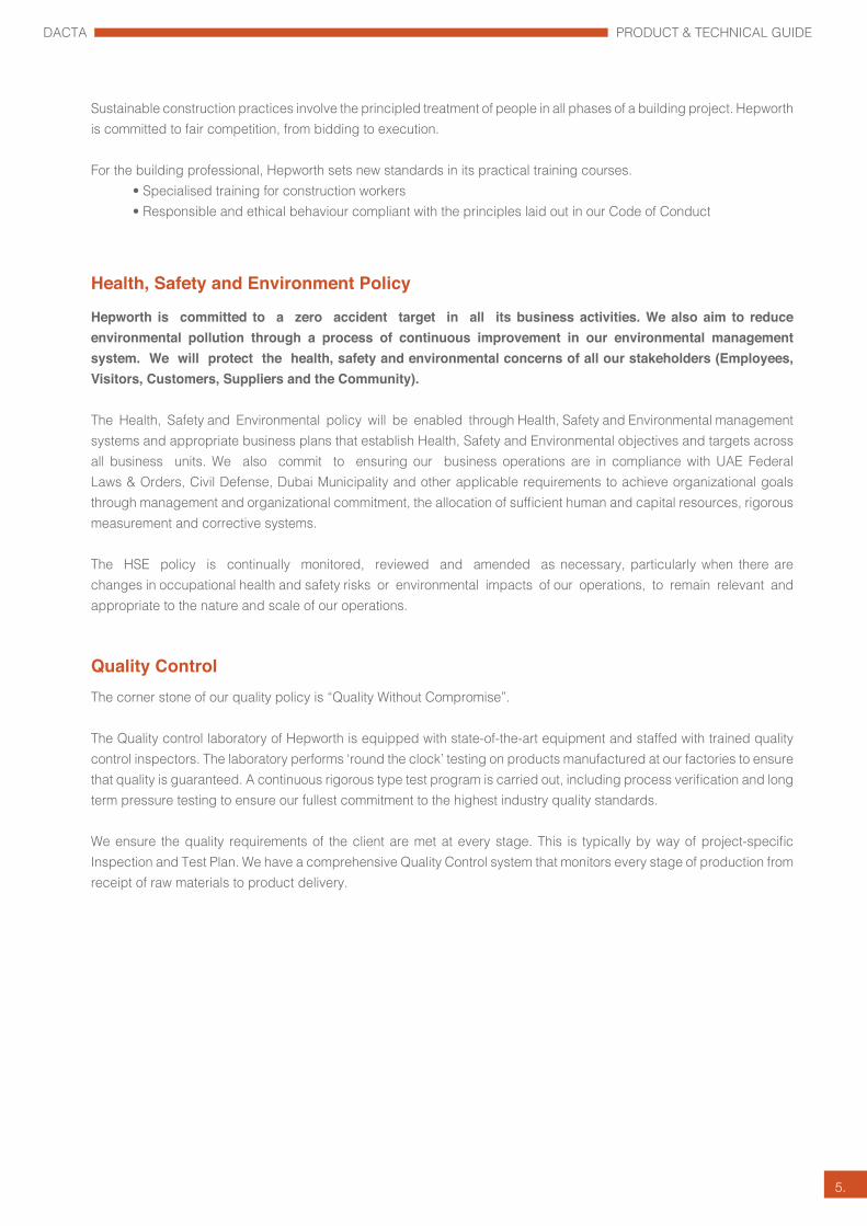
Sustainable construction practices involve the principled treatment of people in all phases of a building project. Hepworth is committed to fair competition, from bidding to execution.
For the building professional, Hepworth sets new standards in its practical training courses. • Specialised training for construction workers• Responsible and ethical behaviour compliant with the principles laid out in our Code of Conduct
Health, Safety and Environment Policy
Hepworth is committed to a zero accident target in all its business activities. We also aim to reduce environmental pollution through a process of continuous improvement in our environmental management system. We will protect the health, safety and environmental concerns of all our stakeholders (Employees, Visitors, Customers, Suppliers and the Community).
The Health, Safety and Environmental policy will be enabled through Health, Safety and Environmental management systems and appropriate business plans that establish Health, Safety and Environmental objectives and targets across all business units. We also commit to ensuring our business operations are in compliance with UAE Federal Laws & Orders, Civil Defense, Dubai Municipality and other applicable requirements to achieve organizational goals through management and organizational commitment, the allocation of sufficient human and capital resources, rigorous measurement and corrective systems.
The HSE policy is continually monitored, reviewed and amended as necessary, particularly when there are changes in occupational health and safety risks or environmental impacts of our operations, to remain relevant and appropriate to the nature and scale of our operations.
Quality ControlThe corner stone of our quality policy is “Quality Without Compromise”.
The Quality control laboratory of Hepworth is equipped with state-of-the-art equipment and staffed with trained quality control inspectors. The laboratory performs ‘round the clock’ testing on products manufactured at our factories to ensure that quality is guaranteed. A continuous rigorous type test program is carried out, including process verification and long term pressure testing to ensure our fullest commitment to the highest industry quality standards.
We ensure the quality requirements of the client are met at every stage. This is typically by way of project-specific Inspection and Test Plan. We have a comprehensive Quality Control system that monitors every stage of production from receipt of raw materials to product delivery.
DACTA PRODUCT & TECHNICAL GUIDE
6.
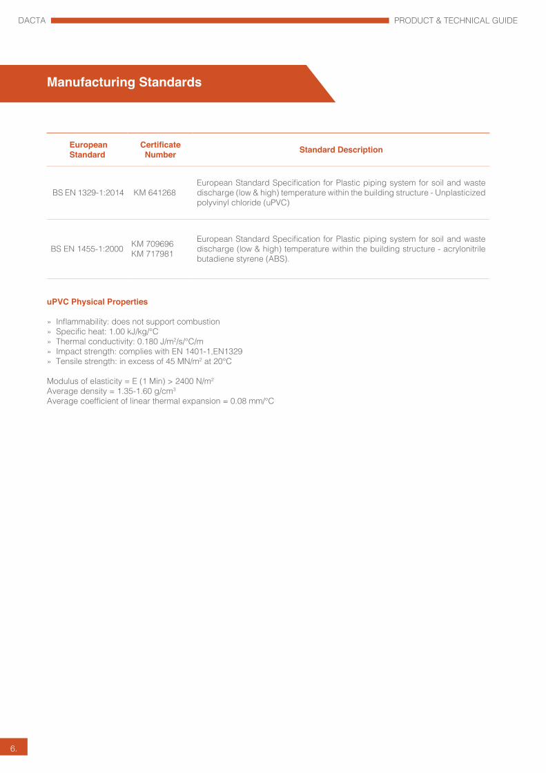
European Standard
Certificate Number Standard Description
BS EN 1329-1:2014 KM 641268 European Standard Specification for Plastic piping system for soil and waste discharge (low & high) temperature within the building structure - Unplasticized polyvinyl chloride (uPVC)
BS EN 1455-1:2000 KM 709696 KM 717981
European Standard Specification for Plastic piping system for soil and waste discharge (low & high) temperature within the building structure - acrylonitrile butadiene styrene (ABS).
uPVC Physical Properties
» Inflammability: does not support combustion» Specific heat: 1.00 kJ/kg/°C» Thermal conductivity: 0.180 J/m2/s/°C/m» Impact strength: complies with EN 1401-1,EN1329» Tensile strength: in excess of 45 MN/m2 at 20°C
Modulus of elasticity = E (1 Min) > 2400 N/m2
Average density = 1.35-1.60 g/cm3
Average coefficient of linear thermal expansion = 0.08 mm/°C
Manufacturing Standards

DACTA PRODUCT & TECHNICAL GUIDE
7.
Dacta uPVC piping system advantages
Corrosion resistance Dacta uPVC pipe does not corrode and is resistant to acids, alkalis and
electrolytic corrosion from any source. uPVC, being a non-conductor, is resistant to all types of galvanic and electromechanical influences which might corrode it. In this respect, it outclasses most other pipe materials including stainless steel.
Lightweight, quick and easy to install Dacta uPVC pipes are only about 20% the weight of an equivalent cast
iron pipe and from 25 - 33% of the weight of an equivalent cement pipe. Thus the cost of transportation and installation is cut down dramatically.
Long service life Since uPVC does not corrode and is resistant to most chemicals,
this pipe does not lose strength from sewer gas corrosion or external galvanic soil conditions.The design of the pipe allows for a long-term deflection of 7.5%, without failure or damage.
Internal pipe smoothness Due to the smoothness of the inner surface of Dacta uPVC pipes, the
growth of algae, bacteria and fungi inside the pipe is reduced and flow rates are increased.
Effect of solar radiation Prolonged exposure to sunlight will cause the colour to fade. It may also
result in a slight loss of impact strength. We would not expect this to seriously affect the performance of the system. However, it is advisable to protect any exposed parts by painting them with exterior water based paints.
Flame resistance Dacta PVC pipes are difficult to ignite and will not continue burning in
the absence of an external ignition source. The spontaneous ignition temperature is 450°C.
Sustainability Dacta PVC pipe, fittings and packaging materials are sourced and
manufactured locally for distribution within the MENA region therefore leaving a smaller carbon footprint.
Applications
• Hospitality• Healthcare• Commercial • Residential• Education• Industry
Dacta uPVC Soil & Vent System

DACTA PRODUCT & TECHNICAL GUIDE
8.
uPVC Above Ground Pipes & Fittings
BS EN 1329-1Product Dimensions
Product Size Wall Thickness Min. Wall Thickness Max OD Min. OD Max.
u-PVC Dia. 82mm Soil Pipe 3.00 3.50 82.0 82.3
u-PVC Dia. 110mm Soil Pipe 3.20 3.80 110.0 110.3
u-PVC Dia. 160mm Soil Pipe 3.20 3.80 160.0 160.4
u-PVC Dia. 200mm Soil Pipe 4.90 5.60 200.0 200.5
u-PVC Dia. 250mm Soil Pipe 6.20 7.10 250.0 250.5
u-PVC Dia. 315mm Soil Pipe 7.70 8.70 315.0 315.6
Dacta solvent weld joints provide a rigid joint connection for use in applications where restraint of the joint may be needed. This allows the whole run of the pipe to act as one piece of pipe regardless of the number of joints. This is accomplished by fusing material from both the spigot end and the bell end (or coupling) together. Once this is properly done and the joint has cured, the result is a “zero-leak” joint that is structurally sound. Solvent weld joints are most often used in applications above ground and/or indoor but can also be used in underground applications. During installation, it is important to remember that the finished product will function as a single span of pipe.

DACTA PRODUCT & TECHNICAL GUIDE
9.
Elbow Double Socket 87.5°
D (mm) H (mm) H1 (mm) Item Code82 109 109 DIS12 - 113/LF110 136 136 DIS12 - 114/LF160 187 187 DIS12 - 116/LF200 200 200 DIS12 - 118/LF
Elbow Double Socket 45°
D (mm) H (mm) Item Code82 145.3 DIS15 - 113/LF110 174 DIS15 - 114/LF160 237 DIS15 - 116/LF200 265 DIS15 - 118/LF
Standard EN 1329
Socket
Socket (Coupler)
D (mm) H (mm) Item Code82 92 DIS1 - 113/LF110 102 DIS1 - 114/LF160 123 DIS1 - 116/LF200 127 DIS1 - 118/LF
D
D (mm) A (mm) Item Code82 97 S2-DS-113/LF110 113 S2-DS-114/LF160 139 S2-DS-116/LF
Expansion Coupler - Double lip seal

DACTA PRODUCT & TECHNICAL GUIDE
10.
Equal Tee (3 x Sockets) 87.5° with Access Connection
D (mm) H (mm) L (mm) Item Code110 240 133 DIS24 - I0114/LF
D
Unequal Tee (3 x Sockets) 87.5°
D x D1 (mm) H (mm) L (mm) Item Code82 x 56 165 78 DIS24 - 517/LF110 x 56 175 93 DIS24 - 520/LF160 x 110 242 138 DIS24 - 526/LF
D
D1
Sweep Branch Connection
Sweep Tee (3 x Sockets) 87.5°
D (mm) H (mm) L (mm) Item Code82 200 108 DIS24 - 113/LF110 240 133 DIS24 - 114/LF160 332 184 DIS24 - 116/LF200 400 209 DIS24 - 118/LFD
Y (Equal) 45° (3 x Sockets)
Y Branch
D (mm) H (mm) H1 (mm) L (mm) Item Code82 216 173 104 DIS27 - 113/LF110 265 211 132 DIS27 - 114/LF160 360 285 183 DIS27 - 116/LF200 420 330 218 DIS27 - 118/LF
H H1
D
DACTA PRODUCT & TECHNICAL GUIDE
11.
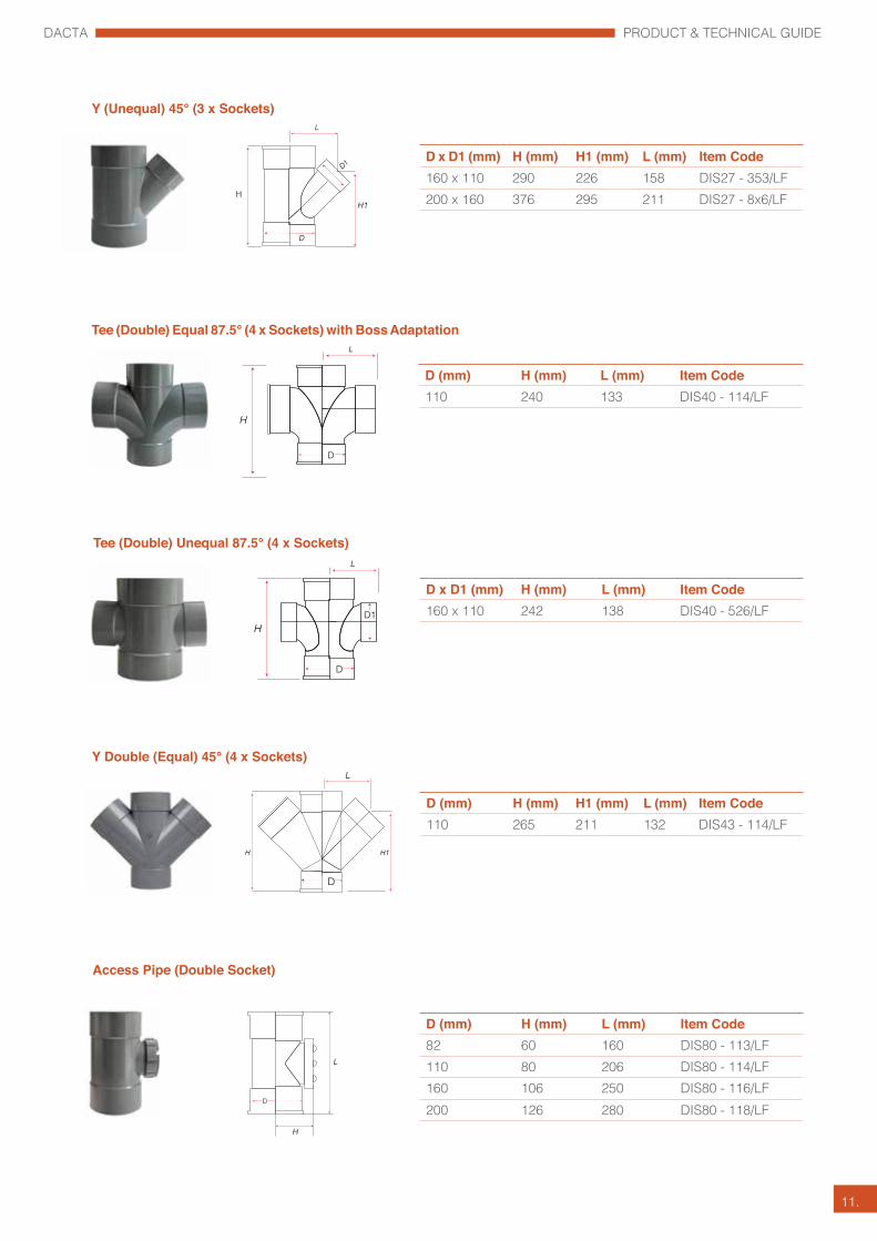
Tee (Double) Unequal 87.5° (4 x Sockets)
Tee (Double) Equal 87.5° (4 x Sockets) with Boss Adaptation
Y (Unequal) 45° (3 x Sockets)
Y Double (Equal) 45° (4 x Sockets)
D x D1 (mm) H (mm) H1 (mm) L (mm) Item Code160 x 110 290 226 158 DIS27 - 353/LF200 x 160 376 295 211 DIS27 - 8x6/LFH
D (mm) H (mm) H1 (mm) L (mm) Item Code110 265 211 132 DIS43 - 114/LF
D
D (mm) H (mm) L (mm) Item Code110 240 133 DIS40 - 114/LF
D
D x D1 (mm) H (mm) L (mm) Item Code160 x 110 242 138 DIS40 - 526/LF
D
D1
Access Pipe (Double Socket)
D (mm) H (mm) L (mm) Item Code82 60 160 DIS80 - 113/LF110 80 206 DIS80 - 114/LF160 106 250 DIS80 - 116/LF200 126 280 DIS80 - 118/LF
D

DACTA PRODUCT & TECHNICAL GUIDE
12.
Patch Boss
D x D1 (mm) H (mm) Item Code82 x 56 48 DIS95 - 333/LF110 x 56 48 DIS95 - 343/LF160 x 56 48 DIS95 - 116/LF
D1
Reducing Bush
D x D1 (mm) H (mm) H1 (mm) Item Code200 x 160 71 60 DIS94 - 8x6/LF
D
H1D1
Access Plug (Screwed)
D (mm) H (mm) H1 (mm) Item Code82 92 53 S84/4-113/LF 110 119 60 S84/4-114/LF
H
H1
Level Inverter (reducer)
D x D1 (mm) H (mm) H1 (mm) Item Code82 x 56 96 55 DIS84 - 339/LF110 x 82 132 74 DIS94 - 345/LF160 x 110 187 91 DIS84 - 353/LF
Vent Cowl (Terminal)
D (mm) H (mm) H1 (mm) Item Code82 76 26 DIS86 - 113/LF110 89 26 DIS86 - 114/LF160 115 32 DIS86 - 116/LF
Note: Dacta pipe and fittings are available in Lead free content. “LF” will be added to item codes to mean lead free fitting.Code of 82mm Elbow Double Socket 87.5° in Lead free is DIS12 – 113 – LF

DACTA PRODUCT & TECHNICAL GUIDE
13.
Material : Acrylonitrile Butadiene Styrene (ABS)Colour : GreySizes : Nominal OD 1.25’’ (36mm), 1.50’’ (44mm), 2’’ (55mm) Standards : The Dacta Solvent Weld Waste Systems conform where applicable to
the standards laid down by BS EN 1455-1 and are entitled to carry the Kitemark. (See note on Quality Assurance).
Solvent Waste Socket Detail
Dacta ABS piping system advantages
Quality AssuranceAll products manufactured by Hepworth have to pass our stringent quality control procedures. A substantial majority also satisfy continuous assessment schemes operated by the British Standards Institution and are entitled to carry the KitemarkProducts which bear a British Standard number have been made in accordance with the appropriate specification. Where no relevant British Standards exist products are manufactured to our own high standards.
ApplicationTo provide an efficient means of drainage of waste water, to either a gully or soil stack, from single or multi-story buildings.
Thermal MovementCoefficient of linear expansion 0.5 x 10⁻⁴ /°C temperature rise. (See fixing instructions for further details).
Effect of Solar RadiationThe performance of ABS waste systems is unaffected by solar radiation. The painting of external pipework, however, is recommended to give protection against the discolouring effects of strong sunlight.
FlammabilityFlammability = 1.3 inches per minute. Test method BS 2782 508A
Effect of ChemicalsABS is resistant to most organic acids, alkalis and aqueous solutions although subject to attack by some inorganic acids and concentrates.
Reaction with other MaterialsABS has not been found to react adversely with any traditional building materials.
MaintenanceDesigners should provide adequate access for periodic cleaning. It is advisable to paint pipes fixed externally for protection against the effect of strong sunlight.
Prefabricated ItemsFor installations that require special products, a prefabrication service is available. Information on these items is available through the Technical Services Department.Operating temperature60 - 750C
Dacta ABS Waste & Vent System
Applications
• Hospitality• Healthcare• Commercial • Residential• Education• Industry

DACTA PRODUCT & TECHNICAL GUIDE
14.
Socket Reducers
D1 (mm) A Item Code
43 x36 28 DISCBW2G32455 x 36 34 DISDCW2G32855 x 43 33 DISDCW2G329
Straight Connector
D (mm) A B Item Code
36 52 4 DISBW1G109
43 59 4 DISCW1G11055 63 4 DISDW1G111
D (mm) A Item Code
36 33 DISBW10G10943 45 DISCW10G11055 57 DISDW10G111
Bend 45°
BS EN 1455-1
Product Dimensions
D (mm) Length Wall Thickness Min. Wall Thickness Max OD Min. OD Max.
36 4M 1.80 2.20 36.1 36.5
43 4M 1.90 2.30 42.7 43.1
55 4M 2.00 2.40 55.7 56.1
ABS Above Ground Waste Pipes and Fittings
DACTA PRODUCT & TECHNICAL GUIDE
15.
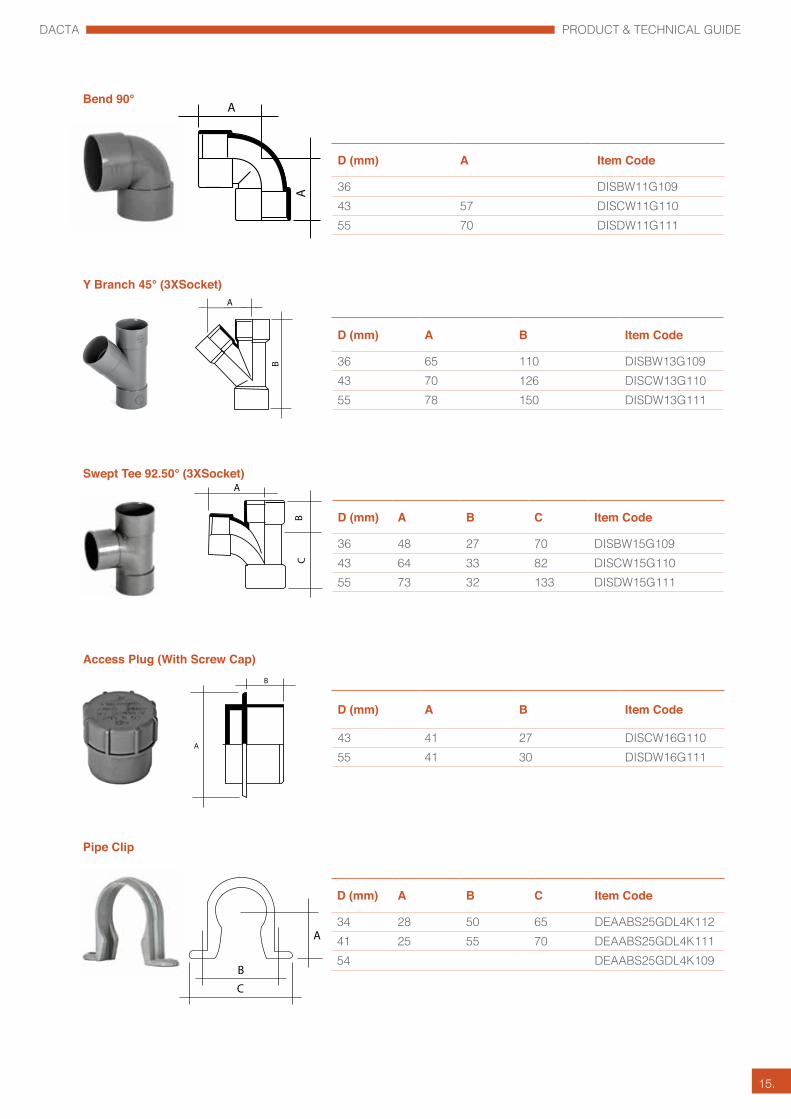
Bend 90°
D (mm) A Item Code
36 DISBW11G10943 57 DISCW11G11055 70 DISDW11G111
Y Branch 45° (3XSocket)
D (mm) A B Item Code
36 65 110 DISBW13G10943 70 126 DISCW13G11055 78 150 DISDW13G111
Swept Tee 92.50° (3XSocket)
D (mm) A B C Item Code
36 48 27 70 DISBW15G10943 64 33 82 DISCW15G11055 73 32 133 DISDW15G111
Access Plug (With Screw Cap)
D (mm) A B Item Code
43 41 27 DISCW16G11055 41 30 DISDW16G111
Pipe Clip
D (mm) A B C Item Code
34 28 50 65 DEAABS25GDL4K112 41 25 55 70 DEAABS25GDL4K11154 DEAABS25GDL4K109

DACTA PRODUCT & TECHNICAL GUIDE
16.
• The floor trap is manufactured in robust ABS and dimensionally complies with the relevant sections of standards EN 1455
• 50mm and 70mm deep-water seal providing maximum protection against seal loss due to evaporation and siphonage. Prevents possibility of foul air escape.
• Redesigned boss shoulders eliminate the use of adaptors for inlet connections.
• Can be used with both imperial and metric sized pipework.
• Accepts either plastic or stainless steel tile and grating.
• Simply extended by using 110mm plain ended pipe.
• The floor trap will not rust or corrode and is unaffected by domestic detergents.
• High temperature resistance.
• The unique design allows for the floor trap to be reduced in height when installed in shallow floor slabs.

DACTA PRODUCT & TECHNICAL GUIDE
17.
Details A B C DDIFT-50-S/W431 110mm 82mm 56mm 165DIFT-50-S/W432 110mm 82mm 56mm 185
Details A B C DDIFT-70-S/W431 110mm 82mm 56mm 165DIFT-70-S/W432 110mm 82mm 56mm 185
Floor Trap 4” x 3” x 2” - SOLVENT
Floor Trap 4” x 3” x 1 1/2” - SOLVENT
Recommended Cement
*For further information about working safely with Dacta Durabond Solvent Cement P917, ask for a safety data sheet.
Dacta Durabond PVC Cement Size: 473 m/l
DACTA PRODUCT & TECHNICAL GUIDE
18.
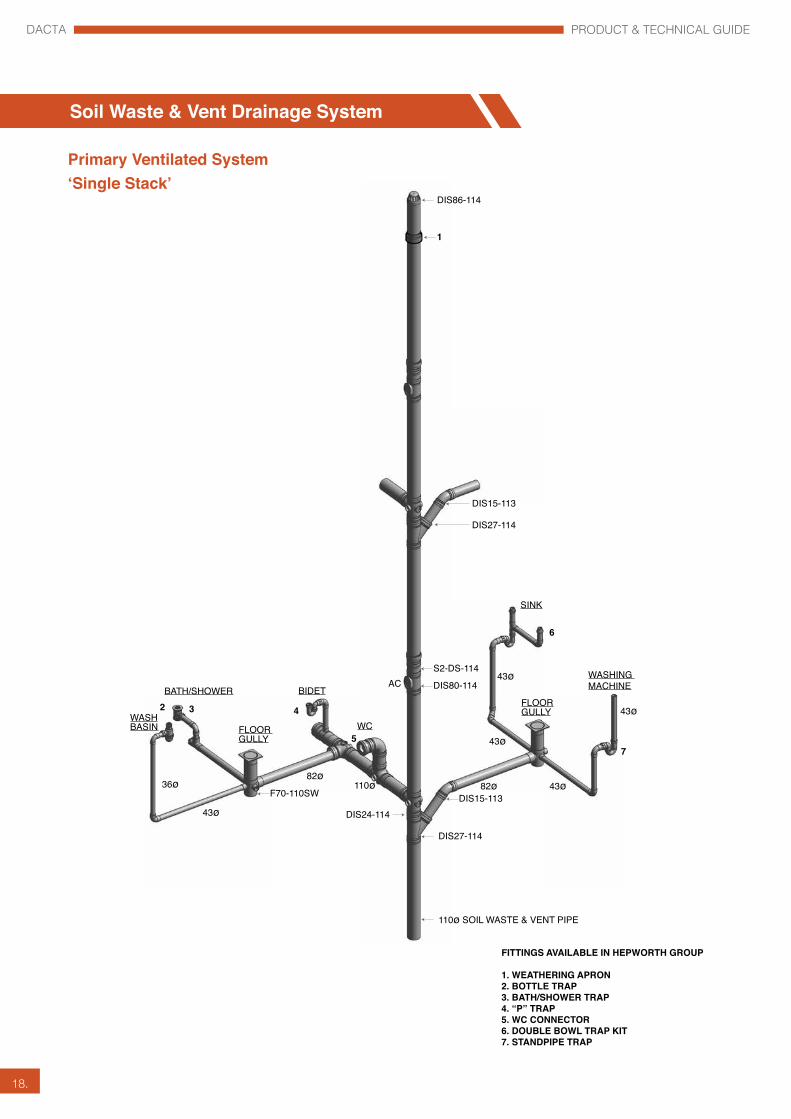
Soil Waste & Vent Drainage System
FITTINGS AVAILABLE IN HEPWORTH GROUP
1. WEATHERING APRON2. BOTTLE TRAP3. BATH/SHOWER TRAP4. “P” TRAP5. WC CONNECTOR6. DOUBLE BOWL TRAP KIT7. STANDPIPE TRAP
DIS86-114
SINK
6
WASHING MACHINE
FLOOR GULLYWASH
BASIN
BATH/SHOWER BIDET
WC
43ø
43ø
36ø
43ø
82ø110ø 82ø
43ø
43ø
DIS24-114
DIS27-114
DIS15-113
1
S2-DS-114
DIS80-114
DIS27-114
F70-110SW
110ø SOIL WASTE & VENT PIPE
FLOOR GULLY
DIS15-113
7
4
5
32
Primary Ventilated System‘Single Stack’
AC

DACTA PRODUCT & TECHNICAL GUIDE
19.
Single Stack Secondary Ventilated System‘Two Pipe System’
EXPANSION JOINT
ACCESS PIPE
OFFSET
DIS15-114
ROOF COWL
36ø
36ø
36ø
36ø36ø
36ø
36ø 82ø 82ø43ø
43ø
43ø
110ø
110ø
43ø
43ø
43ø
43ø
43ø
43ø
SINK
WASHING MACHINEFLOOR GULLYWASH
BASIN
BATH/SHOWERBIDET
WCACFLOOR GULLY
110ø SOIL WASTE PIPE
110ø VENT PIPE
AC

DACTA PRODUCT & TECHNICAL GUIDE
20.
Double Stack Secondary Ventilated System‘Three Pipe System’
EXPANSION JOINT
ACCESS PIPE
CROSS VENT
36ø
36ø
36ø
36ø36ø
36ø
82ø82ø
82ø
43ø
43ø
43ø
110ø
43ø
43ø43ø
43ø
SINK
WASHING MACHINE
FLOOR GULLY
WASHBASIN
BATH/SHOWERBIDET
WCAC
AC
AC
ACFLOOR GULLY
110ø SOIL PIPE
110ø WASTE PIPE
110ø VENT PIPE

DACTA PRODUCT & TECHNICAL GUIDE
21.
Above Ground to Underground Drainage Connection with Long Radius Bend- Alternative Installation
Base of Stack Details
Above Ground to Underground Drainage Connection with 2 No 45° Bends - Preferred Installation
AG AG
AG AG
UG UG
DIS24-114
D4112
R - ID X 2 MINIMUMAG - ABOVE GROUND DRAINAGE SYSTEMUG - UNDERGROUND DRAINAGE SYSTEM
AG - ABOVE GROUND DRAINAGE SYSTEMUG - UNDERGROUND DRAINAGE SYSTEM
R
45°
45°
DIS24-114
D6019
D6019
Trapped Floor Gully
Drainage Velocity Breaker
VELOCITY BREAKER USE AND FREQUENCY AS REQUIRED BY LOCAL AUTHORITY REGULATIONS
VELOCITY BREAKER
DRAINAGE PIPE
DRAINAGE PIPERELIEF VENT
RELIEF VENT TO BE EQUAL SIZE TO DRAINAGE PIPE
TO DRAINAGE STACK
APPLIANCE
APPLIANCE
APPLIANCE
F50-110 S/W - 50MM TRAPF70-110 S/W - 70MM TRAP
NOTE:
1. SOIL, WASTE & RAIN WATER DISCHARGE STACKS FOR UPPER FLOOR SHALL BE PROVIDED WITH UPVC CLASS E PIPE & FITTINGS WITH SOLVENT WELDED JOINTS AT THE BASE OF THE STACK & TO TWO METERS DOWN STREAM & UPSTREAM OF THE FOOT.
2. MAXIMUM DISTANCE BETWEEN SUPPORTS SHALL NOT BE MORE THAN 1 MTR.
3. DETAILS SHOWN ARE INDICATIVE FOR GUIDANCE. CONTRACTORS ARE REQUIRED TO SUITABLE ADAPT TO MATCH SITE CONDITIONS.
DRAINAGE STACK
CHANNEL BRACKET
RUBBER CUSHION AS IMPACT PAD
U-CLAMP
CLEANING EYE WITH LOCKING ARRANGEMENTS
CUSTOM MADE ANGLE IRON BRACKET
ADJUSTABLE CLEVIS HANGERS (CUSTOM MADE)
RUBBER CUSHIONRUBBER CUSHION AS IMPACT PAD
U-CLAMP
RUBBER CUSHION AS IMPACT PAD
CHANNEL BRACKET

DACTA PRODUCT & TECHNICAL GUIDE
22.
Local Municipality Requirements
All sanitary pipework and drainage installations must satisfy the requirements of the local Municipality and Sewage Company.
Installations in accordance with BS EN 12056:2 Code of Practice for Sanitary Pipework will meet all relevant requirements.
Ventilation
The discharge stack must be ventilated in order to prevent pressure building up within the system and drawing the water seals in the traps.
Separate ventilation of branch pipes is required only if the length and slope of the branch exceeds the following dimensions:
Maximum length:(36mm) 1.7 metres(43mm) 3 metres(55mm) 4 metresSlope: 18-90mm per metre
In these cases, the branch pipe should be ventilated by a branch ventilating pipe or an anti-siphon trap should be fitted.
Thermal expansion
Within a solvent-weld system you need to make adequate allowance for thermal movement. This is most easily achieved by fitting an expansion ring seal joint between two fixed solvent-weld joints. The expansion gap should be created by pushing the spigot fully into the ring seal socket, and marking the position at the socket face. Then withdraw the spigot by 12mm. Check subsequently to ensure that the expansion gap is not lost during further installation work.
Branch connections
The distance between the centre-line of the lowest branch connection to the discharge stack and the invert of the bend at the foot of the stack should be in accordance with the following: • ≤3 storeys - 450mm min • ≤5 storeys - 750mm min • 5 storeys + - Ground floor connections should discharge direct to drain or into their own stack • 20 storeys + - Ground floor and first floor connections should discharge into their own stack
A branch pipe should not discharge into a stack in a way which could cause crossflow into any other branch pipe.
Working temperatures
Dacta systems may be used to convey liquids with a maximum temperature of 60°C - 75°C when subjected to continuous flow.
Chemical discharges
Dacta Soil and Waste systems are generally resistant to most commonly used acids and those that may be discharged to the public sewer system. Rubber seals, however, are less resistant and it is advised that before any chemicals are conveyed through the systems, checks are made to establish their effects on the product. Refer to BS CP 312 Part 1 Code of Practice for Plastic Pipework for further information.
Access
Sufficient and suitable access must be provided to enable all pipework to be tested and maintained effectively. Access covers, plugs or caps should be installed in positions to facilitate use of testing equipment and removal of blockages.
Considerations for Designing Above Ground Drainage

DACTA PRODUCT & TECHNICAL GUIDE
23.
Fire spread
In large commercial or housing developments, compartmentation may be required. In such cases, any penetrations by sanitary pipework must be suitably fire stopped. Suitable measures include the containment of pipes from floor to ceiling in a fire resistant enclosure (with appropriate fire rating).
Pipe support
Pipes need to be adequately supported when installed vertically or horizontally (to falls).
Notes:
1.Gradients
Gradients need to be between 1 and 5 degrees with a maximum distance of 3 metres. Distances over 3 metres are prone to blockage and should therefore be provided with access.
2.Ventilation
Maximum distance from stack for unvented system is 1.7 metres. Above 1.7 metres, venting is required, and if this is impractical then a suitable re-sealing trap should be used.
3.Distances
Distance must be a minimum of 450mm for single houses up to 3 storeys, or a minimum of 750mm up to 5 storeys, or one storey height for 5 storey buildings and over. Minimum radius of bend 200mm or alternative of 2 No. 45 degree bends.
4.Support and Expansion
Expansion should be allowed every 4.0 metres for 82mm, 110mm and 160mm and 2.0mtrs for 36mm, 43mm & 56mm respectively both vertically and horizontally.
BRANCHES AT THE BASE OF SOIL STACKS
1. FOR SINGLE DWELLINGS UP TO THREE STOREYS HIGH, THE DISTANCE BETWEEN THE CENTRE LINE OF THE LOWEST BRANCH CONNECTION & THE INVERT OF THE DRAIN SHOULD BE 450MM MINIMUM.
2. FOR MULTI-STOREY SYSTEMS UP TO FIVE STOREYS THE MINIMUM DISTANCE IS 740MM
3. FOR MULTI-STOREY UP TO TWENTY STOREYS A SEPARATE DRAIN CONNECTION IS REQUIRED TO LEVEL ONE.
4. FOR OVER TWENTY STOREYS A SEPARATE DRAIN CONNECTION IS REQUIRED SERVING LEVELS ONE AND TWO.
R
30
29
28
27
26
25
4
3
2
1
R
20
19
18
4
3
2
1
R
5
4
3
2
1
3
2
1
4321
450
min
740
min
740
min
740
min
۱
MINIMUM DISTANCE FROM LOWEST CONNECTION TO INVERT OF DRAIN

DACTA PRODUCT & TECHNICAL GUIDE
24.
BS EN 12056-2:2000 is the standard generally used when sizing Soil and Waste Stacks. It is based on Discharge Units and Probability for probably system loading. Prior to calculating the Soil and Waste Stack there are a few items the designer should know: • Building Height (assuming known) • Building Use (assuming known) • Number of Appliances (assuming known) • Discharge Units • Typical Frequency • Venting System
Architects Plans and Sections can be used to calculate the building height and number of sanitary appliances. Discharge units, frequency of use and soil and waste ventilation require to be developed and calculated by the drainage engineer.
Most sanitary appliances have a discharge unit that has been determined mathematically to consider the discharge and probability of use. The discharge units can be used in a mathematical formula to determine an acceptable flow rate.
Appliance System III DU l/sWash basin, bidet 0.3Shower without plug 0.4Shower with plug 1.3Single urinal with cistern 0.4Urinal with flushing valve-Slab urinal 0.2*Bath 1.3Kitchen sink 1.3Dishwasher (household) 0.2Washing machine up to 6kg 0.6Washing machine up to 12Kg 1.2WC with 4.0L cistern **WC with 6.0L cistern 1.2 to 1.7***WC with 7.5L cistern 1.4 to 1.8***WC with 9.0L cistern 1.6 to 2.0***Floor gully DN 50 0.3Floor gully DN 70 1.0Floor gully DN 100 1.3
Table 1.
Soil and Waste Stack Sizing

DACTA PRODUCT & TECHNICAL GUIDE
25.
The frequency factor should be used when determining the pipework system flow rate. Each building type has different frequency of use.
Usage of appliances KIntermittent use, e.g. in dwelling, guest-house, office
0.5
Frequent use, e.g. in hospital, school, restaurant, hotel
0.7
Congestred use, e.g. in toilets and/or show-ers open to public
1.0
Special use, e.g. laboratory 1.2
Table 2.
Calculation of Flowrate
Waste water flowrate Qww is the expected flowrate of waste water in a part or in the whole drainage system where only domestic sanitary appliances are connected to the system.
Qww = K√ΣDU Where: Qww = waste water flowrate (1/s) K = Frequency factor (table 2) IDU = Sum of discharge units (table 1)
Stacks should not flow at more than 0.25% to 0.33% full to ensure that a maximum negative pressure is maintained within the system.
Based on experience Dubai Municipality have recommended the following minimum stack sizes for buildings greater than 7 storeys’:Soil Pipe 150mm Waste Pipe 150mm Vent Pipe 100mm
Ventilation of the drainage system In order to ensure the functioning of the drainage system and sewers, ventilation shall be provided. The top of open stacks shall terminate outside the building structure and be positioned where odours and vapours from the system will not enter the building. Ventilating pipes shall only serve the drainage system. Where air admittance valves are used, they shall be installed in accordance with national and local regulations and practice.

DACTA PRODUCT & TECHNICAL GUIDE
26.
1 Introduction
This section describes the principals of expansion and contraction design.
2 Design
2.1 Calculate Expansion
Dacta uPVC above ground system coefficient of expansion, 0.08 (mm/m/°C), which is to be taken into consideration using the formula below.
The calculation is based on straight pipework lengths between fixed anchors. Fixed anchor points, Expansion joints and Pipe guides to be identified on the design drawings.
ΔL = α LΔT
Where: ΔL - expansion (mm)α - co-efficient of linear expansion (mm/m/°C) . Dacta uPVC, 0.08L - length of the pipe (m) ΔT - temperature difference (°C)
NB. For waste discharges ΔT should always be calculated from 0°C, so if the temperature of the water in the pipe is to be 60°C, then ΔT is 60°C.
Example A
Soil Waste System - 20 storey foul drainage stack will collect and convey domestic waste (max temperature 60°C) and connect directly to drain. Each storey is 3.5 m high.
ΔL = α LΔTΔL = 0.08 x 70 x 60 = 336mm
Example B
Rainwater System - A 40 metre high level lateral run has been designed in an open car park area, the ambient air temperature will vary from 10°C to 45°C
ΔL = α LΔTΔL = 0.08 x 40 x 35 = 112mm
Pipe Supports to control Thermal Movement
uPVC and ABS pipework expands and contracts due to the ambient temperature where the system is installed or the various temperatures of fluids passing through the system. Both uPVC and ABS have expansion coefficients so the amount of expansion/contraction can be calculated. To compensate for the expansion/contraction of the system pipework Expansion Joints (EJ)are installed as table below.
At Expansion Joints (EJ) the pipework must be fixed to stop movement with a clamp which is called a Fixed Point (F). The clamp is fixed between the ridges on the expansion joint to stop any movement.
Control of Thermal Movement – Expansion and Contraction

DACTA PRODUCT & TECHNICAL GUIDE
27.
FIXED POINT
If a Fixed Point (F) is required on horizontal pipework extra bracing may be required to stop any movement. Intermediate supports between fixed points are Pipe Guides (G) that allow the pipe to expand/contract. Please contact Dacta Technical Support if you require project any specific information.
Support and Expansion Distances
Unless there is an alternative provision for thermal movement, pipework should be fitted with expansion joints in the following locations:
1) At spacing’s no greater than 4m for pipework 82mm and above.
2) Where the maximum distance between fixed points exceeds 1m
Maximum Distance between expansion joint
Pipe Size - Soil82mm 4m110mm 4m160mm 4mPipe Size - Waste36mm 2m43mm 2m56mm 2m
EJ
1000 1000 1000 1000
4000
G G G GG GF EJ F
Fig 1
EJ F EJ F
ADDITIONAL SUPPORT/BRACING TO CONSULTANT SPECIFICATION
ADDITIONAL SUPPORT/BRACING TO CONSULTANT SPECIFICATION
DACTA PRODUCT & TECHNICAL GUIDE
28.
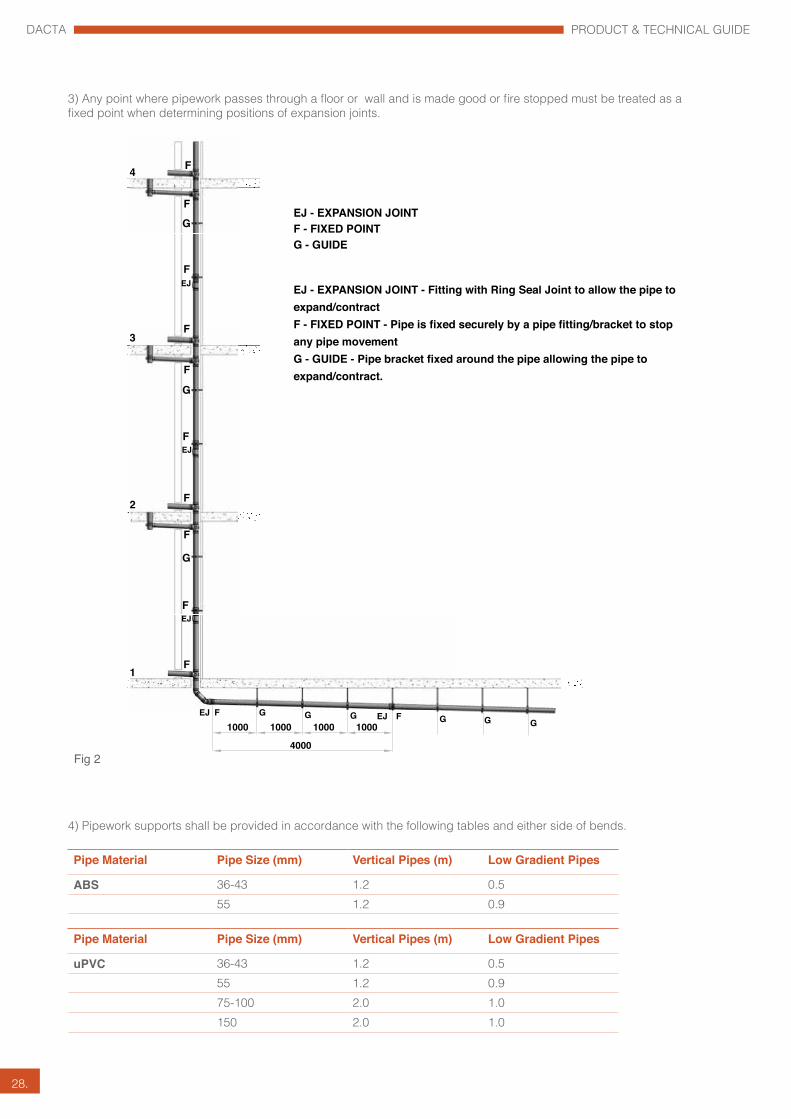
4) Pipework supports shall be provided in accordance with the following tables and either side of bends.
Pipe Material Pipe Size (mm) Vertical Pipes (m) Low Gradient Pipes
ABS 36-43 1.2 0.555 1.2 0.9
Pipe Material Pipe Size (mm) Vertical Pipes (m) Low Gradient Pipes
uPVC 36-43 1.2 0.555 1.2 0.975-100 2.0 1.0150 2.0 1.0
4
3
1
2
F
F
G
F
F
EJ
F
G
F
F
EJ
F
G
F
F
EJ
EJ1000 1000 1000 1000
4000
G G G GG GF EJ F
EJ - EXPANSION JOINTF - FIXED POINTG - GUIDE
Fig 2
EJ - EXPANSION JOINT - Fitting with Ring Seal Joint to allow the pipe to expand/contractF - FIXED POINT - Pipe is fixed securely by a pipe fitting/bracket to stop any pipe movementG - GUIDE - Pipe bracket fixed around the pipe allowing the pipe to expand/contract.
3) Any point where pipework passes through a floor or wall and is made good or fire stopped must be treated as a fixed point when determining positions of expansion joints.
DACTA PRODUCT & TECHNICAL GUIDE
29.
Stacks and Branches
When designing and installing uPVC stacks in multi-storey buildings is is recommended that an expansion joint is incorporated at each floor level.
Where a branch is taken off the stack, the expansion movement within the stack is going to affect the branch.
1. Calculate the distance between the branch and the nearest anchor 2. Calculate the movement at the point where the branch joins the stack 3. Establish the opening size through the wall and make sure that there is enough space for the branch to naturally flex, taking into account that the movement of the branch will be limited where it passes through a wall opening. 4. Add expansion joints and anchor points to the main stack to reduce the amount of movement experienced by the branch
R
G
FEJ
G
FEJ
2
EJ١
FIG 3
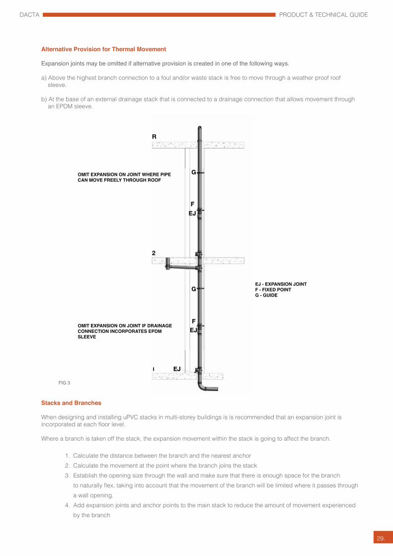
EJ - EXPANSION JOINTF - FIXED POINTG - GUIDE
OMIT EXPANSION ON JOINT IF DRAINAGE CONNECTION INCORPORATES EPDM SLEEVE
OMIT EXPANSION ON JOINT WHERE PIPE CAN MOVE FREELY THROUGH ROOF
Alternative Provision for Thermal Movement
Expansion joints may be omitted if alternative provision is created in one of the following ways.
a) Above the highest branch connection to a foul and/or waste stack is free to move through a weather proof roof sleeve.
b) At the base of an external drainage stack that is connected to a drainage connection that allows movement through an EPDM sleeve.

DACTA PRODUCT & TECHNICAL GUIDE
30.
Minimum Depth of Trap Seals
70mm – WHB – SINK – BIDET – URINAL – WM – DW 50mm – SHOWER – BATH - FLOOR GULLY – WC
Traps to be located in the Soil and Waste Drainage System to ensure that:
• they are easily and fully accessible • can be removed/dismantled • no more than one trap in the discharge line from an appliance • they are self-cleansing • they are attached direct to sanitary appliance outlet – or as close as possible • there is no reduction in cross-sectional area of waste pipe
A minimum water depth of 50mm is all that protects the built environment from potentially harmful sewer gases and particles. The designer must always consider the trap seal and prevent it from being compromised.
Induced siphonage is a common problem when more than one appliance is connected to a branch waste pipe. When another appliance is discharge full bore it can create negative air pressure causing suction on the other appliance – resulting in the trap being pulled (siphoned).
DEPTH OF WATER SEAL
SANITARY APPLIANCE
NEGATIVE PRESSURE AREA
PIPE RUNNING FULL
WATER LEVEL BEFORE DISCHARGE
WATER LEVEL AFTER SELF SIPHONAGE
AIR PASSING THROUGH TRAP CAUSES FURTHER WATER LOSS DUE TO PUMPING ACTION
Traps
FIG 1
FIG 2

DACTA PRODUCT & TECHNICAL GUIDE
31.
All horizontal drainage pipes, both above and below ground, should be laid to an adequate gradient.
Gradients
Gradients from 1 in 40 to 1 in 110 will normally give adequate flow velocities. If the gradient is steeper than 1 in 40, the liquid may run faster than the solids in the sloping foul water pipe thus leaving the solids stranded, which could then block the pipe.
A gradient of 1 in 80 is suitable for commencing calculations for pipe schemes. If the gradient is less than 1 in 110, then the pipe could still block if the solids slow down and become stranded.
A gradient may be defined as fall divided by distance.
GRADIENT = FALL / DISTANCE
If a 48 metre section of drainage pipe has a fall of 0.60 metres, the gradient would be calculated as follows. Gradient = 0.60 / 48 - Gradient = 0.0125 This can be converted into a gradient written as a ratio. Gradient = 1 / 0.0125 = 80. Gradient = 1 in 80
Falls
The fall in a pipe may be defined as the vertical amount by which the pipe drops over a distance. The distance can be between sections of pipe or between fittings. The diagram below shows pipe fall and distance.
FALL = GRADIENT X DISTANCE
For example, calculate the fall in a 10 metre section of foul water pipe work if the gradient is to be 1 in 60. A gradient of 1 in 60 is converted to a number instead of a ratio - 1 / 60 = 0.0166 Fall = 0.0166 x 10 Fall = 0.166 metres or 166mm.
Gradients - Falls
1:40
DISTANCE
FALL
FLOW DIRECTION GRADIENT
FALL AND GRADIENT IN DRAINAGE PIPE
FIG 1
DACTA PRODUCT & TECHNICAL GUIDE
32.
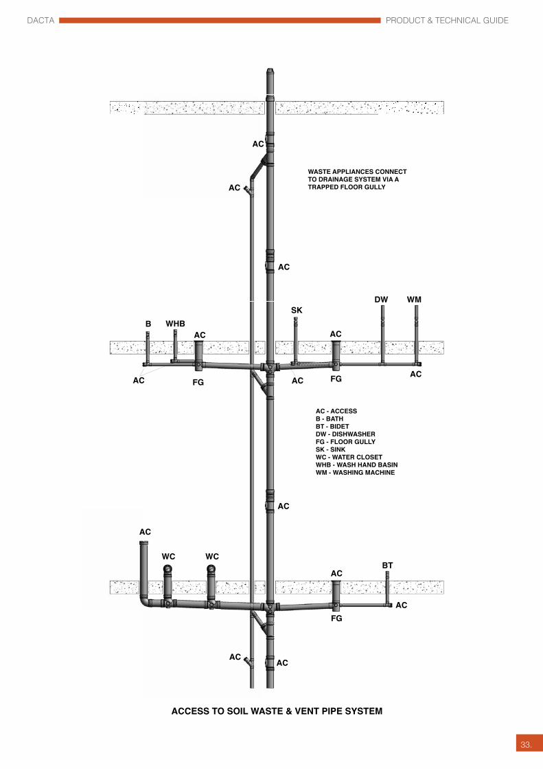
It is essential that adequate provision is made for the testing and maintenance of the above-ground drainage system. Suitable accessibility via access covers, plugs and caps should be provided to enable all traps, discharge pipes and stacks to be tested, cleaned and cleared of any obstructions as and when necessary.
Access points must be:
• air and watertight • quick and easy to remove • fully accessible to facilitate cleansing.
Access points should be located:
• at the base of all soil and waste stacks above the spill-over level of the highest connection on a branch run, typically1200mm above finished floor level • at every change of direction, on vertical stacks and horizontal pipe runs • at regular intervals on long horizontal runs, typically, - at 15m intervals on pipework up to110mm - at 24m intervals on pipework 160mm and above • where more than 1 WC is connected to a branch. • on all appliances, either via the trap or adjacent to the trap • on multi-storey buildings at each floor level. The size of the access point within a building should generally be the same size as the pipework, up to 160mm. For larger pipework, 160mm access points should be adequate.
See FIG.1
To summarize, a drainage system needs to be airtight and watertight; dirty water leaking or contaminated air entering into the built environment should be avoided at all costs.
• Leakages can be mitigated by ensuring that the product of choice is a robust engineered drainage system, fit for the purpose and installed correctly. • Contaminated air within a habitable space can be prevented by ensuring that the drainage pipework system design is properly engineered to protect its prime function, the water trap seal.
To ensure that the pipework system is airtight and water tight the installation should be tested in accordance with the requirements of the local governing body and the code/standard that the system has been designed to.
Access
DACTA PRODUCT & TECHNICAL GUIDE
33.
AC
AC
AC
ACAC
FG
BT
AC
WC WC
AC
AC
AC
SKWHBB
AC
AC FG FG
AC
ACAC
DW WM
AC - ACCESSB - BATHBT - BIDETDW - DISHWASHERFG - FLOOR GULLYSK - SINKWC - WATER CLOSETWHB - WASH HAND BASINWM - WASHING MACHINE
WASTE APPLIANCES CONNECT TO DRAINAGE SYSTEM VIA A TRAPPED FLOOR GULLY
ACCESS TO SOIL WASTE & VENT PIPE SYSTEM

DACTA PRODUCT & TECHNICAL GUIDE
34.
Noise reduction is increasingly a factor in residential and commercial construction. Multi-occupancy homes, hotels, hospitals and libraries are just some of the buildings where noise reduction is paramount. This need for soundproofing has placed a demand on the construction supply chain to design in good noise reducing practices both in the construction of a building and the building fit-out. In endeavouring to meet sound controls within buildings, additional materials and labour are required, increasing the cost and time on site.
Noise from drainage pipes is just one area where the right product can make a huge difference in soundproofing the pipework within a building.
What causes excessive waste and drain pipe noise?
The sound from soil and waste pipes can transfer into the occupied space: directly from the surface of the pipe as airborne sound; through the building structure where the pipe is not isolated from the adjacent surfaces (either through pipe supports or by direct interference); or along the pipe to and from a connected appliance.
Using the correct drainage system can dramatically reduce these noise levels
If you are designing the drainage system for a very high quality development where sound levels are an issue - consider Dacta Polypropylene Silent Piping System.
Drainage in High Rise Buildings
Drainage system considerations In the drainage system for a multi-storey building, the drains from the plumbing fixtures are connected to vertical drain stacks that convey the waste and sewage to below the lowest floor of the building.
The fixture drain traps must be vented to prevent their water trap seal from being siphoned by negative pressure or blown out by positive pressure in the drain piping. The fixture vent pipes must extend through the roof to outdoors.
They can be run individually or be combined into one or more vents through the roof. Where buildings are over 10 storeys high, the drainage stacks require relief vent connections at specified intervals from the top, and connected to a vent stack that terminates above the roof. This relieves and equalizes the pressure in the drainage stack to maintain the water seal in traps serving plumbing fixtures. Wherever possible, the sanitary drainage system from a building should discharge to the public sewer by gravity.
Noise in Above Ground Drainage Systems

DACTA PRODUCT & TECHNICAL GUIDE
35.
Floor Gullies
Floor gullies are widely used within the Middle East region to collect waste discharge from sinks, basins, baths, showers etc.
Floor gullies should be fully charged with water to prevent foul air from the drainage system escaping into the built environment.
Generally, floor gullies are located at the head of a branch drain and access should be provided through the gully or adjacent to the gully at the head of the pipework run.
DETAIL A To make a direct connection from one floor gully to another floor gully is not permitted.
DETAIL B Floor gullies should connect direct to a stack or as Detail C.
DETAIL C Floor Gullies to discharge separately into a branch drain.
FIG 1
WASTE PIPEWHB WHB
FG FG
DETAIL ‘C’
DETAIL ‘A’
WASTE PIPE
WASTE PIPE
FG
FG FG
DETAIL ‘B’
WHB
WHB

DACTA PRODUCT & TECHNICAL GUIDE
36.
Depending on the structure of the building the floor gully waste connections can be made within or below the structural slab.
FIG 2
ACCESS DOOR
36ø TRAPPED BASIN WASTE
110ø SOIL WASTE STACK
110ø WC CONNECTION
110ø RAISING PIECE
40ø BATH WASTE(BATH TRAP OPTIONAL)
110X82X55ø FLOOR TRAP
110X82X55ø FLOOR TRAP
36ø TRAPPED BASIN WASTE
110ø SOIL WASTE STACK
110ø WC CONNECTION
40ø BATH WASTE(BATH TRAP OPTIONAL)
110X82X55ø FLOOR TRAP
FLOOR TRAP BELOW SLAB
FLOOR TRAP IN SLAB
TYPICAL BATHROOM LAYOUT

DACTA PRODUCT & TECHNICAL GUIDE
37.
Offsets
Offsets in the wet portion of a stack should be avoided. If offsets are to be introduced, large radius bends should be used; venting should be provided above and below the offset.
Offsets above the top most sanitary appliance or branch connection do not require venting.
FIG 1
EXPANSION JOINT
ACCESS PIPE
FROM WASTE SYSTEM
VENT PIPE
WASTE PIPE

DACTA PRODUCT & TECHNICAL GUIDE
38.
Dacta pipes and fittings are manufactured from uPVC, a material approximately one-fifth the weight of ductile iron. Pipes and fittings made from this material are therefore light in weight and there may be a tendency to employ improper handling techniques, which result in damage to the pipes and fittings. Reasonable care should be taken in the handling and transportation which should be undertaken according to the following recommendations.
Handling
a) Pipes should not be dropped onto hard surfaces and should not be dragged along the ground. This is particularly important where the pipe ends have been prepared in the form of spigots (eg. chamfered ends) and integral sockets.
b) Where ever possible, the loading and unloading of pipes should be carried out by hand and can be carried by two men in normal site conditions.
c) If mechanical lifting equipment is used, no metallic slings, hooks or chains should be used in direct contact with the pipe. Rope or web slings are preferred, which will not gouge or cut the pipe wall. Gouges and cuts in the pipe wall can affect the pressure resisting capabilities of the pipe.
d) When pipes are being handled at freezing or near freezing conditions, they should never be dropped or have objects dropped on them. The impact strength of the material is high but is reduced somewhat at lower temperatures and extra care is required. Pipes and fittings, which have been subjected to abuse must be thoroughly examined before use for any evidence of structural damage.
Transport
a) If the pipe is to be transported the vehicles used should have a flatbed free from sharp projections of any kind.
Incorrect way to load pipes Correct way to load pipes
b) The pipes should be evenly supported throughout their length and should not overhang the vehicle bed by more than 1 metre. Pipes should be loaded with sockets at alternate ends.
c) Larger diameter and/or thicker walled pipes should be loaded first and the vehicle should be fitted with side supports at no greater than 1.5 metre centres or continuously supported. These supports should be free of sharp edges.
Handling, Transport and Storage
WRONG CORRECT way to off load

DACTA PRODUCT & TECHNICAL GUIDE
39.
Storage
To ensure that the deterioration of pipe and fittings does not occur during storage, it is imperative that the following recommendations are adhered to.
Bundled pipes
Pipes supplied in factory made bundles should be stored on a flat surface; bundles should not be stored on top of each other. The bundles should remain undisturbed until the pipe is required and any loose pipe should be stored according to the following recommendations.
Loose pipes
a) Loose pipes should be stacked on a flat surface free from sharp projections, stones or other protuberances likely to cause point loading or pipe deformation.
b) It may be necessary to level the ground at the storage point in order that pipes may be uniformly supported throughout their length. An alternative means of storage is to lay the pipes on stout timber bearers not less than 75mm wide, placed at not greater than 1.5 metre centres along the length of the pipe.
c) Side supports should be provided in the form of stout timber posts, not less than 75mm square, placed at not greater than 1.5 metre centers along the length of the pipe. The width of stacked pipes should not exceed 3 meters.
When socketed pipes are stacked, the sockets should be placed at alternate ends of the stack with the socket
protruding so that pipes are evenly supported along their entire length. Pipes of different sizes or wall thicknesses, should be stored separately. Where this is not possible, those with larger diameters and/or thicker walls should be placed at the bottom of the stack.
d) The height of pipe stacks should never exceed seven layers or 2 metres. If prolonged storage (greater than one month) or storage in areas of high temperature (above 23° C) is anticipated,
the stack height should never exceed 4 layers or 1 metre. Such stacks should be protected from the effects of weathering (particularly ultra violet exposure) by placing tarpaulins or similar sheets over them, secularly fixed to the timber support posts, to provide protected and shaded conditions, which allow free passage of air around the pipes.
e) Pipe fittings may be subjected to damage and/or the effects of corrosion or weathering if stored for long periods. For this reason, fittings should be stored in sheltered conditions in such a way that they are protected from the effects of weathering and accidental damage.
Note: Fittings should be stored in sheltered conditions in the boxes as supplied, to protect them from weathering and accidental damage.

DACTA PRODUCT & TECHNICAL GUIDE
40.
Pipe Cutting and Jointing Instructions
Solvent Weld Jointing:
Step 1 The pipe spigot should be cut square, then cleaned and all burrs removed. Ensure that both surfaces to be jointed are dry and free from dust or other debris. A chamfer to the depth of half the wall thickness at 150 inclination should be applied to each spigot.
Step 2 All joints should be made with an approved solvent/cleaner, such as Dacta Durabond P917 Solvent Cement and Parabond C-70 Cleaner. This removes all dirt and machine release agents and softens the surface ready for the chemical solvent weld. Failure to do this can result in joint failure.
Step 3 The spigot and socket to be jointed should be carefully examined for any damage, which could impair the jointing procedure.
Step 4 The spigot insertion depth should be measured as the depth from the mouth to the root of the socket.The insertion depth should then be marked on the spigot using an indelible marker.
Step 5 Using a brush apply an even layer of solvent cement to the spigot and socket mating surfaces. The cement should be applied in a lengthwise direction and NOT with a circular motion. For joints of nominal diameter 82mm and above, the cement should be applied simultaneously to the spigot and socket by two people.

DACTA PRODUCT & TECHNICAL GUIDE
41.
Step 6 Immediately following cement application, ensure that the parent pipe is suitably anchored, and push the spigot fully home in the socket without turning the pipe.
Step 7 The spigot should be inserted with a steady, continuous motion and held in place for 20 seconds.
Step 8 Remove the surplus cement from around the mouth of the socket.
* Leave the joints to fully cure for 24 hours if hydrotesting is required.
During hot weather conditions of 35°C and above, special consideration should be given when Solvent Welding uPVC pipes and fittings to ensure a leak proof joint. Solvent cements contain high strength chemical solvent which evaporates faster in hotter temperatures and windy conditions.
When uPVC pipes stored in open areas or under direct sunlight, the surface temperature will be approximately 15°C higher than the ambient temperature. The solvent cement reacts on the hot surface faster and deeper. Therefore, it is very important not to use excess cement during the jointing process to avoid creating pools of cement inside the fitting and pipe sockets. Excess solvent cement should be wiped off the surface quickly.
Recommendations for solvent welding during hot weather conditions:
• Solvent cement and cleaners to be stored in cool area.
• Pipes/fittings should be stored in shaded area prior to solvent welding.
• Surfaces to be jointed should be cooled with a wet cloth and dried before applying the solvent cement.
• Solvent welding to be carried out in the cooler morning hours.
• The two surfaces should be joined quickly while still wet with cement.
• Shake or stir the solvent cement before use.
• Allow at least 24 hours for the joints to cure before pressurizing the system. 48hours for sizes 200mm and
above.
Solvent Welding In Hot Weather Conditions
DACTA PRODUCT & TECHNICAL GUIDE
42.
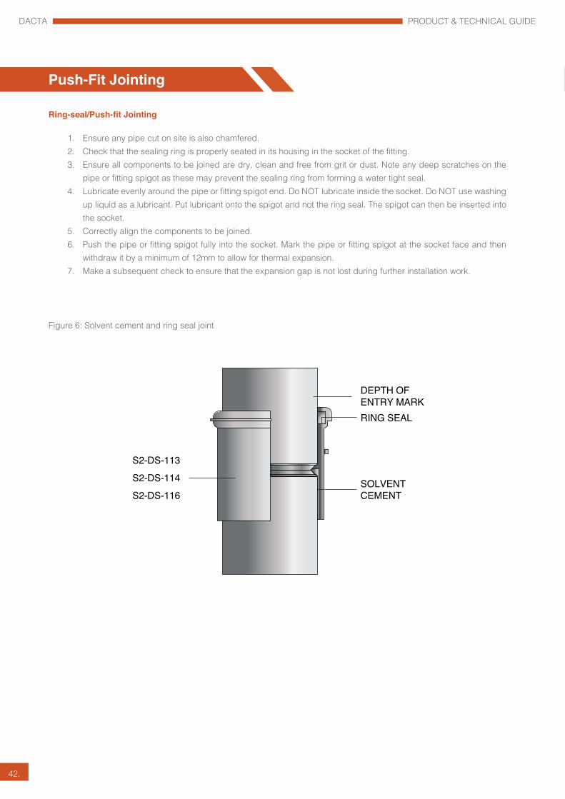
Ring-seal/Push-fit Jointing
1. Ensure any pipe cut on site is also chamfered.2. Check that the sealing ring is properly seated in its housing in the socket of the fitting.3. Ensure all components to be joined are dry, clean and free from grit or dust. Note any deep scratches on the
pipe or fitting spigot as these may prevent the sealing ring from forming a water tight seal.4. Lubricate evenly around the pipe or fitting spigot end. Do NOT lubricate inside the socket. Do NOT use washing
up liquid as a lubricant. Put lubricant onto the spigot and not the ring seal. The spigot can then be inserted into the socket.
5. Correctly align the components to be joined.6. Push the pipe or fitting spigot fully into the socket. Mark the pipe or fitting spigot at the socket face and then
withdraw it by a minimum of 12mm to allow for thermal expansion.7. Make a subsequent check to ensure that the expansion gap is not lost during further installation work.
Figure 6: Solvent cement and ring seal joint
DEPTH OFENTRY MARK
SOLVENTCEMENT
S2-DS-113
S2-DS-114
S2-DS-116
RING SEAL
Push-Fit Jointing

DACTA PRODUCT & TECHNICAL GUIDE
43.
All Soil, Waste and Vent Systems are tested to ensure they are watertight and airtight to make sure there are no fluids, gases or pathogens entering the building.
(a) The installer to inform design team sufficiently in advance to givethem a reasonable opportunity to observe tests.
(b) Check that all sections of installation are securely fixed andfree from obstruction and debris.
(c) Ensure that all traps are filled with clean water.
(d) Carry out tests as specified. After testing, locate andremedy all defects without delay, and retest as instructed.Do not use smoke to trace leaks.
Keep a record of all tests and provide a copy of each to the Engineer.
The Installer is to allow for intermediate testing where work is to be concealed by other installations, final finishes and to suit phased hand over of areas. Water Test
• All pipe ends, connections and access points must be plugged using suitable testing plugs and bags.
• Where possible, the inside of the pipe should be cleaned before fitting the drain plugs, to ensure no grit or other detritus is present that could impair the air-tight seal required for an effective test.
• Install vertical pipe length to the drain to provide the the required head of water.
• Fill the system with water to maximum height of 3M (30kPa).
• The maximum head at the lower parts of the system should never exceed 4.0M, therefore in case of steep gradients the system should be tested in sections.
• The filled system should be left for 2 hours under testing, the system should be inspected by measuring the drop in water height.
• The system should be checked for any leakage and all defects should be made good and tested again.
Air Test
• One drain plug, normally at the head of the run, is fitted with the nipple that connects to the flexible hose, which in turn, is connected to the manometer, which has been partially filled with water equal to the 0mm level.
• Air is pumped into the pipeline, via the hand-pump, until the reading on the manometer is around 120mm.
• The set-up is left for 5 -10 minutes to allow for temperature stabilisation within the pipe, then the pressure is reduced (via the control valve) to exactly 100mm on the manometer scale.
• The manometer is then monitored for a period of five minutes; the level of water in the manometer should not fall below the 75mm mark during this period. This is deemed to ‘pass’ and the pipeline is declared satisfactory.
Leak Test Report
The testing is to be witnessed by Consultant, and QC Engineer with test results and comments are recorded on Leak Test Report sheet. Leak Test Report to be issued to the Construction Team as dictated by the Client.
Gravity Pipework Testing Procedure
Drain Test Plug Drain Test Bag Drain Test Air Pump Drain Test Manometer

DACTA PRODUCT & TECHNICAL GUIDE
44.

DACTA PRODUCT & TECHNICAL GUIDE
45.
uPVC, PE & GRP Fabrication
Hepworth ‘One stop solution’ for specialist fabrication.
Hepworth PME LLC have been fabricating specialized plastic fittings since the inception of the company. Many of our specialist fabricators have been with the company over 15 years & highly experienced in a wide range of products & materials. We fabricate in many forms of plastic - standard uPVC & PE, CPVC, PB (polybutylene) as well as other specialist plastics. Our new purpose-built fabrication plant includes uPVC, PE & GRP workshops using innovative hi-tech machinery & equipment to ensure quality & precision are maintained. Our team of 120 experienced Technicians are ready to meet any urgent requirement to achieve project deadlines. Onsite specialist fabrication, lamination & fusion jointing projects can be carried out on a ‘turn-key project’ basis. Fabricated products are inspected & tested under stringent quality control in our in-house state-of-art Testing Laboratory. Onsite Technical Design, Estimation & Supervision undertaken. We have supplied specialized products to many prestigious projects in the middle east including: Burj Khalifa Emirates Tower Dubai Airport Expansion Atlantis, Pal Jumeirah Dubai Sports City The Lagoons Dubai Festival City We manufacture high pressure GRP PN16 rated fittings for SEWA, DEWA & FEWA pumping stations, desalinisation plants & water networks. We are the largest UAE approved manufacturer of uPVC Grease Traps to the hospitality and food industry as well as uPVC street lighting cable duct/bends for Dubai RTA. We are the sole DM approved manufacturer for PP Road Gullies & accessories for infrastructure projects.
Warranty
To Whom It May Concern
The u-PVC and ABS pipes and fittings manufactured and supplied by HEPWORTH PME, are guaranteed to be free from material an workmanship defects for a period of 5 (Five) years from the date of delivery.
This guarantee shall be rendered null and void should the u-PVC pipes be used for any application other than that for which they were designed. Furthermore HEPWORTH PME (LLC) shall not be liable if such products have not been handled, stored, installed or utilized in accordance with our express instructions or in conjunction with products or components not of our manufacture or supply. HEPWORTH PME (LLC) shall not be responsible for any claim for consequential loss or damage, and our liability shall not exceed the value of the invoiced amount on which the reputedly defective goods are based.
Technical Support & Training
Hepworth offer high quality Technical Support to your Design, Procurement & Construction Departments. For any Technical, Product or Installation queries contact your local representative.
DACTA PRODUCT & TECHNICAL GUIDE
46.
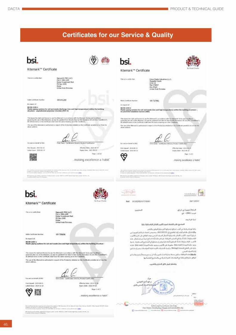
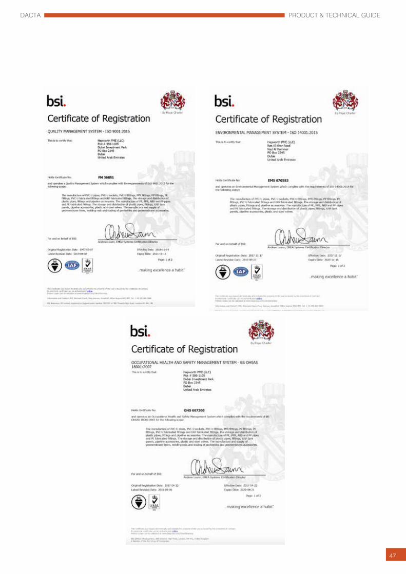
Certificates for our Service & Quality
DACTA PRODUCT & TECHNICAL GUIDE
47.

U.A.E OFFICEABU DHABIP.O. Box: 4894, Abu Dhabi, UAETel: +971 2 6727585Fax: +971 2 6783578Email: [email protected]
QATAR OFFICESDOHAHEPWORTH PME (QATAR) W.L.LP.O. Box 50207, Doha, QatarTel: +974 44506810Fax: +974 44506811Email: [email protected]
MESAIEEDHEPWORTH PME (QATAR) W.L.L.P.O. Box 50207, Mesaieed, QatarTel: +974 44760588Fax: +974 44760525
OMANCORYS PIPE INDUSTRY LLCP.O. Box 117, PC 130,Muscat, Sultanate of OmanTel: +968 24217626/20Fax: +968 24210032Email: [email protected] [email protected]
BAHRAINHEPWORTH W.L.LBuilding 1, Avenue 0010P.O. Box 143, Manama, BahrainTel: +973 17672050Fax: +973 17672583Email: [email protected] OFFICE
HEPWORTH PME LLCDUBAIP.O.Box 2345, Dubai, UAETel: +971 4 2894670Fax: +971 4 2894620 / 1Email: [email protected]
SALES/CUSTOMER [email protected]
DAC
TA/Above Ground D
rainage System-001/09-2020