
Operation and Maintenance Manual for Narayanpur Dam of ...
274
1 Operation and Maintenance Manual for Narayanpur Dam of Karnataka State Doc. No. CDSO_O&M_KA06MH0142_NARAYANPUR_DAM KAWRD_01_v2.0 MAY 2020 Central Water Commission Ministry of Water Resources, River Development & Ganga Rejuvenation
-
Upload
khangminh22 -
Category
Documents
-
view
4 -
download
0
Transcript of Operation and Maintenance Manual for Narayanpur Dam of ...

1
Operation and Maintenance Manual for Narayanpur Dam of Karnataka State Doc. No. CDSO_O&M_KA06MH0142_NARAYANPUR_DAM KAWRD_01_v2.0 MAY 2020
Central Water Commission Ministry of Water Resources, River Development & Ganga Rejuvenation

Front Cover Photograph: Downstream view of Narayanpur Dam during rehabilitation works carried out under the Dam Rehabilitation & Improvement Project (DRIP). The Scope of work includes Treatment using polyurethane based elastic resin to reduce leakages in wall plate area, Ogee & Pier area and Treatment using acrylic based injection resin, Pointing etc at masonry portion on upstream and downstream portion of masonry dam for reducing the leakages. Providing apron concrete below flip bucket and treatment of eroded portion of spillway ogee using micro concrete works etc.

i
Operation and Maintenance Manual for Narayanpur Dam
KRISHNA BHAGYA JALA NIGAM LIMITED (A Government of Karnataka undertaking)
STATE OF KARNATAKA
O/o Managing Director, KBJNL, PWD Office Annex , 3rd Floor, KR Circle,
Bangalore
JUNE 2020 Bangalore

ii
KRISHNA BHAGYA JALA NIGAM LIMITED
Government of Karnataka
Following the intrinsic requirements in the Guidelines for Preparing Operation and Maintenance Manuals for Dams published in January 2018, this manual has been developed to clearly illustrate the complexity and importance of managing operations, inspections and maintenance of any large dam. This manual has been developed under the Dam Rehabilitation and Improvement Project (DRIP) in collaboration with SPMU Bangalore duly attending the observations.
Disclaimer
The content of this Operation and Maintenance Manual for Narayanpur Dam in no way restricts the dam owner in digressing from her/his responsibilities.
The manual serves as a guide for managing the operation, inspection and mainten- ance required to be carried out to reduce risks and optimizing performance of the dam.
For any information, please contact: The Managing Director Krishna Bhagya Jala Nigam limited PWD Office Annex , 3rd Floor, KR Circle, Bangalore Email: [email protected]
iii
MESSAGE
India has more than 5200 large dams. Their health and safety are of paramount importance for
sustainable use of the valuable assets, besides providing protection to the people and property in
the downstream areas. The Ministry of Water Resources, River Development & Ganga Rejuve-
nation through the Central Water Commission (CWC), with financial assistance from the World
Bank, started the Dam Rehabilitation and Improvement Project (DRIP) to rehabilitate 198 large
dam projects in seven states.
For managing a dam in a sustainable and scientific manner, it is very crucial for each dam owner
to have dam specific Operation and Maintenance Manual that lays down procedures for the daily
upkeep of the dam. An Operation and Maintenance Manual for a dam is essential for ensuring its
safe functioning and for deriving continued benefits. This Operation and Maintenance Manual for
Narayanpur Dam has been prepared following the Guideline for Preparation Operation and
Maintenance Manuals published in January 2018 under DRIP and covers requirements for
project Operation, Inspection, Maintenance, Instrumentation and Monitoring the health of Na-
rayanpur Dam both during monsoon and non-monsoon periods.
I recommend the dam officials to use this manual for the efficient and safe Operation and Main-
tenance of the Narayanpur Dam on regular basis.
I compliment all the experts who have contributed to the development of this manual and congra-
tulate the Ministry of Water Resources, River Development & Ganga Rejuvenation, CWC for the
initiation of such important policy protocol to address dam safety management in India.
Shri. Rakesh Singh, IAS
Principal Secretary
Water Resources Department,
Karnataka.

iv
FORWARD
This Operation and Maintenance (O&M) Manual developed exclusively for Narayanpur Dam
and is a detailed set of written descriptions with step-by-step procedures for ensuring that the
dam is safely operated, frequently inspected and properly maintained. In this era of shrinking
budgets, timely inspection and preventative maintenance is necessary for the safe functioning of
the dam and continued productive use of the dam and reservoir.
The format of this manual was prepared following the principles published 2018 CWC guide-
lines for operation and maintenance of dam for the use by all Dam Owners in developing their
own site-specific manuals. Each section of the document provides the necessary instructions to
operate, inspect and maintain their dam.
It is recommended that all dam officials charged with the operation of the Narayanpur dam to
use this manual to ensure their dam is operated and maintained in a sustainable manner and will
continue to derive benefits.
Shri. N Jayaram, IAS
Managing Director, KBJNL,
Bengaluru

v
TEAM INVOLVED IN PREPARATION OF O&M MANUAL
Sri.S.H. Nayakodi Executive Engineer, KBJNL, Dam Division, Narayanpur
Sri . R.L.Hallur Assistant Executive Engineer, KBJNL, Gates Sub Division, Narayanpur
Shri.. T N Ramchandra Assistant Executive Engineer(I/c), KBJNL, Dam Sub Division No-3, Narayanpur
Sri. Vijaya kumar Arali Assistant Engineer, KBJNL, Gates Sub Division, Narayanpur
Sri. V.L.Kambar Assistant Engineer, KBJNL, Gates Sub Division, Narayanpur
Kumari. Sneha R K Assistant Engineer, KBJNL, Gates Sub Division, Narayanpur
Sri. Balasubramanya M Junior Engineer, KBJNL, Gates Sub Division, Narayanpur

vi
TABLE OF CONTENTS
CHAPTER 1. - GENERAL INFORMATION 1
1.1 Introduction ........................................................................................................................... 1
1.2 Purpose, Location & Description of Narayanpur Dam ...................................................... 1
1.3 Background Details of the Project ...................................................................................... 2
1.4 Main Design Features and Components of Narayanpur Dam: ......................................... 9
1.5 Salient Features of Narayanpur Dam ................................................................................ 13
1.6 Assignment of Responsibility ........................................................................................... 15
1.7 Collection & Reporting of Dam and Reservoir Data ........................................................ 18
1.8 Public and Project Staff - Health and Safety .................................................................... 20
1.9 Distribution of Operation & Maintenance Manuals .......................................................... 32
1.10 Supporting Documents & Reference Material ................................................................. 32
CHAPTER 2. PROJECT OPERATION ........................................................................................... 34
2.1 Basic Data ........................................................................................................................... 34
2.2 Reservoir Operation: .......................................................................................................... 34
2.3 Flood Routing Criteria ........................................................................................................ 34
2.4 Revised Flood Routing study of Narayanpur Dam .......................................................... 35
2.5 Sequence of Opening or Closing of Gates ....................................................................... 49
2.6 Gate Operation at Narayanpur ........................................................................................... 49
2.7 Inflow Forecasting .............................................................................................................. 49
2.8 Exchange of data regarding rainfall, releases from dams, reservoir water levels ........ 50
2.9 Flood warning system in catchment area ........................................................................ 50
2.10 Flood communication system: .......................................................................................... 50
2.11 Methodology of Flood Regulation .................................................................................... 51
2.12 Operation of Radial Crest Gates of Narayanpur Dam .................................................... 64
2.13 Stoplog gate (3 set i.e.21 elements) for main spillway gates ........................................ 74
2.14 84 TON Capacity moving Gantry for main spillway gates ............................................ 77
2.15 New Stoplog gates for Additional Spillway Gates(one set) .......................................... 79
2.16 84 Ton Capacity new Gantry Crane for new Stoplog gates ......................................... 81
2.17 Right Bank Head Regulator Radial Gates ..................................................................... 87
2.18 Stoplog Gate for Right Bank Head Regulator Gates ..................................................... 95
2.19 15 TON Capacity Gantry for Right Bank Head Regulator Gates (RBHR) .................... 97
2.20 Left Bank Head Regulator Radial Gates ................................................................... 102
2.21 Stoplog Gate for Left Bank Head Regulator Gates(LBHR) ......................................... 109

vii
2.22 15 TON capacity moving Gantry for Left Bank Head Regulator Gates ....................... 111
2.23 River Sluice Gates ........................................................................................................... 115
2.24 Lubrication Schedule ...................................................................................................... 121
CHAPTER 3 - PROJECT INSPECTIONS 124
3.1 Types of Inspections ........................................................................................................ 124
CHAPTER 4 - PROJECT MAINTENANCE 138
4.1 Maintenance Priorities ..................................................................................................... 138
4.2 Procedures for Routine Maintenance ............................................................................. 149
4.3 General List of Maintenance Records ............................................................................. 171
4.4 Preparation of O&M budget ............................................................................................. 171
4.5 Maintenance Records ...................................................................................................... 174
CHAPTER 5 - INSTRUMENTATION AND MONITORING 176
5.1. Dam Instrumentation·....................................................................................................... 176
CHAPTER 6 - PREVIOUS REHABILITATION EFFORTS 180
6.1. Previous Rehabilitation Efforts: ..................................................................................... 180
CHAPTER 7 - UPDATING THE MANUAL 181
7.1. Updating the Manual ........................................................................................................ 181
APPENDIX 1 – BASIC DRAWINGS OF NARAYANPUR DAM 183
APPENDIX 2- KEY ELEMENTS OF THE EAP 206
APPENDIX 3 - MATERIAL REQUIRED FOR MAINTENANCE DURING MONSOON 222
APPENDIX 4-SCHEDULED OR UNSCHEDULED DAM SAFETY INSPECTION FORM 224
APPENDIX 5 - GLOSSARY 249

viii
LIST OF TABLES
Table 1- Details of Distributed Water to Karnataka 2
Table 2 – Overall Responsibilities for Narayanpur Dam 15
Table 3 – Roles & Responsibilities of AEE & AE 16
Table 4 – Roles & Responsibilities of SE & EE 17
Table 5 – Roles & Responsibilities of the Chief Engineer 17
Table 6– Example Proforma for recording Flow Data 19
Table 7 - Distribution of O&M Manual and Revisions 32
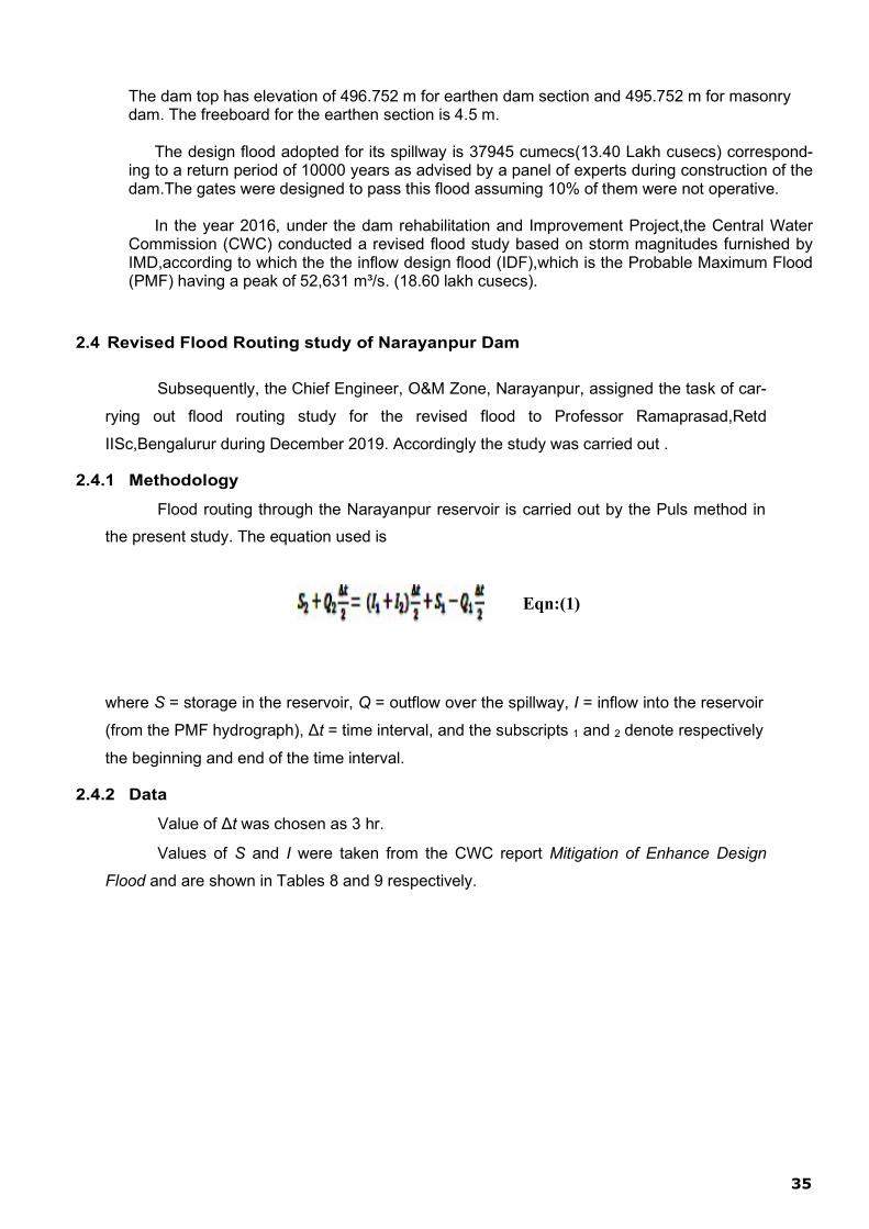
Table 8 - Elevation-Storage Data of Narayanpur Dam (from CWC Report) 36
Table 9- Table 9. Inflow Hydrograph of PMF (from CWC Report) 36
Table 10- Table 10. Free Flow Discharges over Narayanpur Spillways (ModelStudies)
(Crest Level=480.252 m for All Gates) 37
Table 11. Maximum Reservoir Level for free flow to Occur under different gate lip levels
(from Model Studies) 41
Table 12: Parameters used for routing 42
Table 13: Routing Results with reservoir outflow and elevation Hydrographs 44
Table 14. Calculation of Effective Fetch 46
Table 15. Computation of Required Freeboard 48
Table 16 – Area- Capacity table of Narayanpur Dam 55
Table 17 – Spillway discharge of one gate operation in (Q in cumecs ) 59
Table 18 - O&M budget costs (annual) 172
Table 19 – Structural components of the dam 176
Table 20 –Instrument Locations 177

ix
LIST OF FIGURES
Figure1 - Krishna Basin Map 04
Figure 2 - Map of Narayanpur reservoir 06
Figure 3 – Index Map and Command area map of NLBC main canal 07
Figure 4- Layout of Narayanpur Dam Premises 21
Figure 5 - Organisation Chart 25
Figure 6 - Free discharge through 25 main gates over Narayanpur spillway. 38
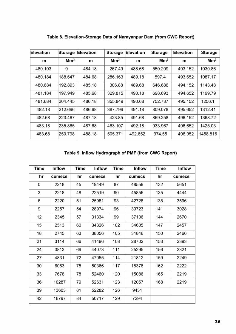
Figure 7 - Free Discharge through 5 Saddle Gates over Narayanpur Spillway 39
Figure 8 - Relation between Free Flow Reservoir Elevation and Main Gate Opening 40
Figure 9 - Inflow and Outflow Hydrographs for 52631 cumecs Flood 43
Figure 10- Reservoir Elevation Hydrograph for 52631 cumecs Flood 44
Figure 11- Fetch Lines 47
x
LIST OF DRAWINGS
1. Over Flow section of Narayanpur Dam--- Drawing-1 184
2. Non-Over Flow section of Narayanpur Dam--- Drawing-2 185
3. Left Bank Head Regulator Gate --- Drawing-3 186
4. Right Bank Head Regulator Gate --- Drawing-4 187
5. River Sluice Gate --- Drawing-5 188
6. Narayanpur Right Bank Earthen Dam--- Drawing-6 189
7. L-Section and plan of Narayanpur Dam from 121.92m to 5120.64m--- Drawing-7 190
8. L-Section and plan of Narayanpur Dam from 5120.64m to 10759.44m--- Drawing-8 191
9. Piezometer at Ch.35 Left Bank Earthen Dam--- Drawing-9 192
10. Piezometer at Ch.45 Left Bank Earthen Dam--- Drawing-10 193
11. Piezometer at Ch.97 Right Bank Earthen Dam--- Drawing-11 194
12. Piezometer at Ch.105 Right Bank Earthen Dam--- Drawing-12 195
13. Piezometer at Ch.142 Right Bank Earthen Dam--- Drawing-13 196
14. Piezometer at Ch.305 of Dyke --- Drawing-14 197
15. Piezometer at Ch.316 of Dyke --- Drawing-15 198
16. Piezometer at Ch.330 of Dyke --- Drawing-16 199
17. Head V/s Discharge curves of one spillway gate --- Drawing-17 200
18. Rule curve of Narayanpur Reservoir --- Drawing-18 201
19. Head V/s Discharge curves of NLBC Head regulator gates --- Drawing-19 202
20. Head V/s Discharge curves of River sluice gates of Narayanpur Dam --Drawing-20 203
xi
Acronyms used in this publication are as follows:
BIS Bureau of Indian Standards
CDSO Central Dam Safety Organisation
CWC Central Water Commission
SDSO State Dam Safety Organisation
O&M Operation and Maintenance
DRIP Dam Rehabilitation and Improvement Project
DSRP Dam Safety Review Panel
EAP Emergency Action Plan
GPS Global Positioning System (uses GPRS for data transmission like browsing the web)
FRL Full Reservoir Level
MWL Maximum Water Level
MDDL Minimum Draw Down Level
DSL Dead Storage Level
SCADA Supervisory Control and Data Acquisition
EDA Energy Dissipation Arrangement
HM works Hydro-Mechanical works
DG set Diesel Generator set
RMU Remote Monitoring Unit
PC Personal Computer
TMC Thousand-Million cubic feet

xii
THIS PAGE LEFT BLANK INTENTIONALLY

1
1.1 Introduction
This document represents a detailed Operation and Maintenance (O&M) Manual for Na- rayanpur Dam, Karnataka, providing written descriptions of procedures for ensuring that the dam operates safely and is kept in a good condition by periodic inspections, repairs, maintenance in a sustainable manner. Timely maintenance is important for the continued safe functioning and productive use of the dam and reservoir.
The Manual has been prepared primarily for the dam operation‟s staff and their supervi- sors who are assigned the responsibility for the physical operations and maintenance of the dam. It contains, as a minimum, all information and instructions necessary for them to perform their allotted tasks in a safe manner. In addition to instructions for dam opera- tions staff, the Manual includes all necessary instructions for other staff directly or indi- rectly involved in operating and maintaining the dam.
It is essential that the Manual or a copy of the Manual along with supporting data includ- ing the atlas of all drawings and manufacturer‟s technical documents is available at site for ready reference.
1.2 Purpose, Location & Description of Narayanpur Dam
The Krishna river being an inter-state river, water utilization as of now is in accordance with the KWDT (Krishna Water Disputes Tribunal) award of 1976 based on the estimated 75% dependable yield with return flows. The water allocated to Karnataka was 734 TMC (20785 MCM).Government of Karnataka has approved a Master plan to utilize 734 TMC of water in Krishna basin. Out of this, an allocation made for Upper Krishna Project is 4,871.04 MCM (173 TMC).
In Krishna basin, major Irrigation Projects such as Ghataprabha Project and Malaprabha Project were taken up for implementation to provide irrigation facilities to the drought prone areas of Dharwad and Belgaum Districts. Reservoirs were constructed across the Ghataprabha and Malaprabha Rivers .Gravity canal network and lift irrigation schemes were provided in the command area.
The Narayanpur project was planned under Upper Krishna Stage I and Stage II for utilization of 4,871.04 MCM (173) TMC. Stage I and Stage II of the project has been completed and the total area proposed for irrigation in Stage I and Stage II is 6,22,023 Ha in Shorapur, Shahapur Taluks of Yadgir District, Jewargi taluk of Kalaburgi District, Sindagi, Indi, Vijayapur, Muddebihal and Basavana Bagewadi taluks of Vijayapur District, Bagalkot, Hungund and Jamakhandi taluks of Bagalkot District and , Devadurga taluks of Raichur District.
KWDT – II award passed in December 2010, based on assessed 65 % dependable yield and surplus yield has been allocated to Karnataka is given below:
CHAPTER 1. - GENERAL INFORMATION

2
Table 1- Details of Distributed Water to Karnataka
i) Out of assessed 65% yield 65 TMC
ii) Out of surplus flows 105 TMC
iii) Flows made available for Minimum flows in the stream 7 TMC
Total 177TMC
Out of the Karnataka's share of water, the Government of Karnataka has allocated 130 TMC of water to UKP Stage III schemes. This allocation is to be utilized by way of storing additional water in the Reservoir by duly raising the FRL from EL: 519.60 m to EL: 524.256 m at Almatti Dam for irrigating an area of 5,30,475 ha in Vijayapur , Bagalkot, Gulbarga, Raichur and Kop- pal Districts (25 TMC under 65% dependability allocation and 105 TMC under surplus flows). The total utilisation of water for Upper Krishna Project will be (173 + 130) 303 TMC.
1.3 Background Details of the Project
The River Krishna is the second biggest river in the peninsular India. It rises in the Western Ghats at an altitude of 1,338.0-M (4385 ft) above M.S.L near Mahabaleshwar in the Maha- rashtra State and flows across the peninsular from West to East for a length of about 1.392 kilometers (870 miles) through Maharashtra, Karnataka and Andhra Pradesh before it falls into the Bay of Bengal. In the Upper reaches the river runs through hilly terrain receiving plentiful rainfall varying from 3800 mm to 6350 mm (150 inches to 250 inches) and the rain fall dwindles down to about 500 mm (20 inches ) in the plains.
The districts of Belgaum, Vijayapur, Kalburgi and Raichur through which the river flows in Karnataka State are in a rainfall shadows area where the rainfall is very meager and un- evenly distributed. The population in this area subsists mainly on agriculture. Due to vaga- ries of rainfall, the area has been subjected to frequently recurring conditions of scarcity and famine. As a redeeming feature, as the high fertility of the agricultural land, if water is made available by irrigation, the entire economic picture of the area will be changed contributing to the economic development of this region in particular and Karnataka State in general.
Investigations to exploit the bountiful water potential of Krishna River to irrigate vast tracts of land in Kalburgi and Raichur Districts were taken up by the erstwhile Hyderabad State along with lower Krishna Project (then Nandikonda and now Nagarjunasagar Project). The Bom- bay State was contemplating providing irrigation to a part of Vijayapur District by Lift Irriga- tion from the river and a scheme was prepared in 1950 to this effect. After the Re- organization of the States in 1956, the three Districts were integrated in the Karnataka State, the scope of the project was re-examined, alternative dam sites and off-take points for can- als were considered and the present project is the result of the investigations carried out through several years since then.
1.3.1. Dam site Location:
Narayanpur dam also called as Basavasagara Dam serves as a balancing reservoir, constructed for irrigation purpose. It is built across Krishna River between village Ba- chihal & Siddapur of Muddebihal Taluk of Bijapur district and Hirejavoor of Lingasugur ta- luk of Raichur district with Lat.16° 12‟ 43‟‟ N Long.76° 20‟ 04‟‟ E and located at 60 km downstream of the Almatti dam.

3
1.3.2. Narayanpur Reservoir Planning:
i). Catchment:
The catchment area of the Krishna River at Narayanpur dam site is 47,850 sq.- km. (18,475 Sq-miles). The upper most reaches consisting of hilly track with for- est growth and the lower reach in plane country. It has many tributaries. Mean annual precipitation varying from 635 cm at ghats to about 50 cm average at dam site and the bulk of the rainfall occurs in the months of June to October and the river will be in floods during these months when almost the entire yield is re- ceived.
ii) Yield:
The average annual yield at 75% dependable is 22824 MCUM (806.5 TMC)
iii) Storage:
The dam is designed to pass a probable maximum flood of 37,945 cumec (13, 40,000 Cusecs). The present gross storage capacity at FRL of 492.25 m is 943.31 MCM (33.313 TMC) and a live storage of 740.28 MCM. (26.143 TMC) and a dead storage of 202.94 MCM (7.167 TMC) at canal sill level of 481.584 m.
iv) Water Spread:
The reservoir has water spread area of 13,450 Ha. (38,857 acres) displacing a population of 48,125 persons of about 77 villages.

4
Narayanpur Dam
Figure 1 - Krishna Basin Map

5
THIS PAGE LEFT BLANK INTENTIONALLY
6
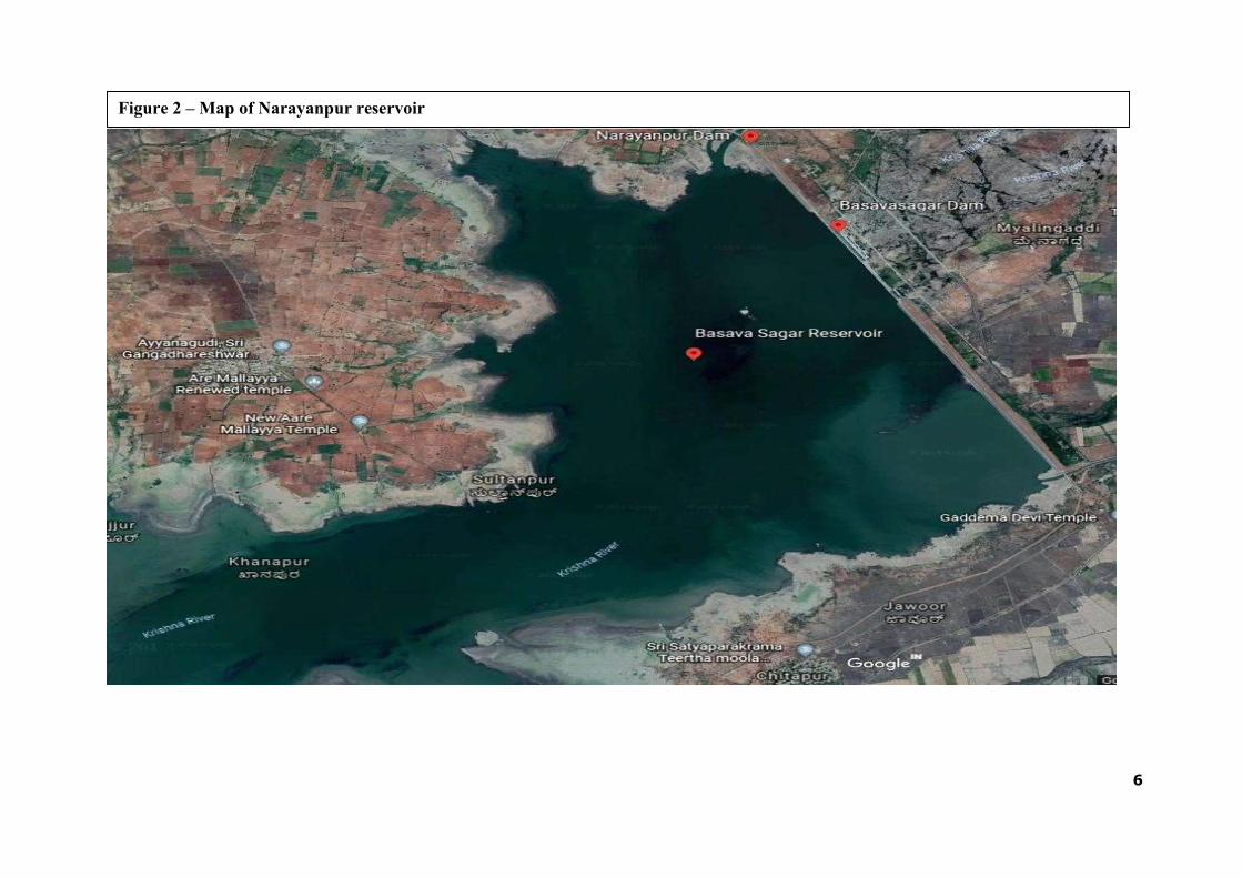
Figure 2 – Map of Narayanpur reservoir

7
Figure 3 – Index Map and Command area map of NLBC main canal

8
THIS PAGE LEFT BLANK INTENTIONALLY

9
1.4 Main Design Features and Components of Narayanpur Dam:
i. Left Bank Earth Dam. ii. Non over flow masonry Dam. iii. Over flow Section of Dam: Main & Additional Spillway gates. iv. Drainage Gallery v. River Sluice Gates. vi. Irrigation canal Head regulator gates vii. Right Bank Earthen Dam. viii. Dyke Portion of Dam. ix. Dam Instrumentation x. Discharging Facilities xi. 84 T Gantry Crane xii. 15 T Gantry Crane
i. Left Bank Earth Dam(LBED):
A portion of the river gorge and right and left flank comprises of earthen section. The length of earthen dam on the left flank is 1.388 km. The earth dam compris- es of a zonal section with semi pervious casing and impervious hearting.The top width is 7.50 m with 2.5:1 slope on upstream and 2:1 slope on downstream with a berm of 3.50m at RL 487.752 m. The left bank earthen dam section is provided with necessary cut off trench, transition filter, cross drains, toe drain and rock toe etc.A rock Toe is provided with top width of 1.50m with outer slope 1.5:1.The central core has a top width of 2.50m at RL.493.752 m with slope of 0.50:1 on both sides. The upstream of LBED is provided with hand packed stone revet- ment 60cm thick over a filter bed of 45 cm thick to resist wave action.
The Left Bank Head regulator gates are located at ch.518.00 m- at the Head reach of NLBC main canal. The head regulator consists of 6 Nos radial gates of size 6.00 m x 6.00 m. The top R L of earthen dam is 496.752 m. The seepage in the Left earthen dam is measured by V-Notch provided at Ch.48.50 below the earthen Dam.
The variations in the saturated level on the embankment portion is being meas- ured with the help of piezometers provided on the earthen Dam portion at Ch 35 & 45.
ii. Non over flow masonry Dam:
The non-overflow masonry Dam is provided from Ch.1.510km to 1.724 km(214m) and 2.183 km to 2.552.88 km(369.88m). A Free board of 3.5m is provided over the FRL 492.250m. Hence the top level of the dam is 495.750m. The maximum height of the dam above the lowest river bed is 28.80m.The structural design of the gravity section of the non spillway is based on the same assumption as made in the case of spillway. The hearting of non spillway is of uncoursed rubble masonry with cement mortar class B having 28 days strength of 100kg/Sq cm. The upstream and downstream faces are of coursed rubble masonry using hammer dressed and chisel drafted face stones set in cement mortar Class A and Class B respectively. The rubble stone hearting behind the upstream face is constructed using cement mortar Class A having 28days compressive strength of 125 kg/sq cm for a thickness of 99 cm.

10
iii. Over Flow Section of Dam: Main & Additional Spillway gates:
A central overflow spillway is provided in the gorge portion from ch.1.724 km to 2.183 km(459m) and 2.552km to 2.641km (89m) Total 548m .It consists of 30 nos radial gates of size 15m x 12m for passing the design flood of 37945 Cumec (13,40,000 cusecs).The nappe is provided with USBR curve corresponding to the design head over the crest. Hd=39.417 feet (12m) and Approach Velocity Head: Ha=0.047 feet(0.012m).
At the foot of the spillway ,a circular upturned bucket of 12 m radius is provided for throwing the high velocity jet of water away from the toe of the dam. The spillway piers are 3.50m thick and carry a RCC bridge with 7.5 m wide roadway. The spillway is of mass concrete placed at controlled temperature. The hearting is designed for concrete of designation having 28 days cylinder strength of 140 kg/sq cm. The spillway crest glacis and bucket area are topped with richer con- crete of designation having 28 days cylinder strength of 210 kg/sqcm. using 80mm maximum size concrete. The concrete for the spillway crest glacis and bucket are provided with suitable reinforcement. The spillway is designed as a gravity section to resist water thrust of the reservoir and tail water uplift, wind pressure , wave pressure and silt pressure. Seismic force arising due to the as- sumed seismic acceleration of 0.10 horizontally ,has been considered. In addi- tion the overflow section is designed to resist the stresses due to its action as a cantilever footing of piers. These stresses are ascertained from photo elastic model studies.
iv. Drainage Gallery:
Drainage cum grouting gallery has been provided for the entire length of the ma- sonry and concrete dam, the size adopted being 1.6 mt x 2.4 mt. Three Audits have been provided for access to the drainage gallery, porous blocks have been provided in the non-over flow section of the masonry Dam. Three sump wells have been provided in each audit. The water collected in sump wells due to see- page is pumped out regularly. The discharge in each audits are being monitored and records have been maintained. The gallery water samples are also being tested for its lime content.
v. Drainage Holes:
Drainage holes are provided in the floor of drainage gallery for an approximate depth of 9.00 mt. at an interval of 9.00 mtrs. These holes are provided to release the up lift pressure. The foundation Seepage in each drainage holes is being col- lected and records have been maintained. The Drainage holes have been main- tained by periodical flushing to avoid chocking of these holes.
vi. Porous Holes:
Porous holes have been provided in the non-spillway portion of Narayanpur Dam with an approximate depth of 22 mt from the road level to top portion of drainage gallery. The seepage water in each porous holes is being collected and records have been maintained. The porous holes have maintained by periodical flushing to avoid chocking of these holes.
11
vii. River Sluice Gates:
Four river sluices of size 1.5m x 2.5 m are provided in the sluice blocks with in- dependent energy dissipating arrangements.
viii. Irrigation Canal Head regulator gates :
6Nos irrigation sluice gates of size 6.00 m x 6.00m height at head reach of Left Bank Canal at Ch.0.50 KM and 3Nos sluice gates of size 6.00 m x 5.00m height at head reach of Right Bank Canal at Ch.5.20KM are provided for irrigation pur- pose and gates are electrically operated with the rope drum hoist mechanism . Maintenance of these gates is taken up annually on tender basis which in- cludes items such as lubrication and filling of Gear oil, Cardium com- pound, etc. and periodical maintenance works such as replacements of wire ropes, replacements of rubber seals and painting of irrigation head regulator gates are taken up as and when required . The sill level of NLBC & NRBC is kept at RL. 481.584 mt
ix. Right Bank Earthen Dam:
A portion of the river gorge and right and left flank comprises of earthen section. The length of the earthen dam on right flank is 5.712 km(from Ch.2.731 km to 8.443km). The earth dam comprises of a zonal section with semi pervious casing and impervious hearting. The top width is 7.50 m with 3:1 slope on the upstream and 2.5:1 on downstream side with a berm of 3.50m at RL 487.752m and 478.752m respectively. The earthen dam section is provided with necessary cut off trench, transition filter, cross drains, toe drain and rock toe etc.A rock toe is provided on the downstream with top width of 1.50m with an outer slope 2:1.The central core has a top width of 2.50 m at RL 493.752 m and with slope 0.5:1 on either sides. An inclined filter of 1.2m thickness is provided adjacent to the downstream slope of core. Cross drains are provided at 30m c/c with a size of 0.80m bottom width and 2.00m top width with depth of 1.20m. The upstream of RBED is provided with dumped stone riprap of 90 cm thick over a filter bed of 45 cm thick to resist wave action.
.
x. Dyke Portion of Dam:
An erthen dyke is constructed across a low saddle existing on right bank just af- ter the right bank earthen dam.The Saddle dam provided on the right flank from Ch.8.443 km to 10.637 km (2194m) has a maximum height of 12 mts. The top width is 7.50m with upstream slope 2.5:1 upto RL.489.252 m and 15:1 for inter- mediate portion upto RL 488.252m and then 5:1 below and on downstream side slope is 2:1 with an intermediate berm of 3.75m width at RL 489.25m and then sloping 15:1 upto RL 488.252m there after sloping with rock toe slope of 2:1.The seepage in the dyke portion of dam is being measured with the help of V-Notch provided on d/s toe of Dam at Ch. 311 .
xi. Dam Instrumentation :
The piezometers (Foundation as well as embankment) embedded at the time of construction of dam at Ch 91.97, 143.20 and 320 are not in working condition and other instruments such as Stress meter, Strain meter, Jointmeter, Thermo- meter, provided in the body of the Dam are also not in working condition.

12
The Dam Safety Review Panel(DSRP) have suggested for providing piezome- ters in the embankment portion at Ch.35 & 45 on Left Bank Earthen Dam, at Ch 97,105 & 142 on Right Bank Earthen Dam and at Ch.305, 316 and 330 on Dyke portion of Dam.
Piezometers have been installed at the respective chainages as per the sugges- tions of DSRP and the variations of water level in the piezometers are being reg- ularly monitored & measured with reference to reservoir levels. The water level in the piezometers are varying in accordance with the variations of the reservoir level.
xii. Discharging Facilities :
The following facilities are available in Narayanpur dam for surplus flows on the downstream side of Dam.
a. River out let (Scouring sluices)
There are 4Nos river outlets of size 1.5m x 2.5 m with sill level at RL.472.252 m. The maximum discharge that passes through the single vent is 59.40 Cu- mec (2098 Cusecs ) at FRL 492.252m.
b. Spillway Gate:-
The spillway has a discharging Length of 548 m having 30 Nos crest gates each of size 15m x 12 m. The Crest level at the spillway is at RL 480.252 m. The radial gates are provided, for regulation of surplusing of flood for PMF of 13.40 Lakh cusecs .The gates are being electrically operated with rope drum hoist mechanism.
The maximum reservoir level is at RL 492.252 M. The water level in the re- servoir is being maintained by judicial control with regulation of spillway gates and river outlets. The rating curves and discharge calculation through spillway and River sluice gates supplied by KERS authorities by model studies, are be- ing adopted.
c. Stop log gates (For main spillway gates):-
i) Three sets of Stop log Gates consists of 07 elements in each set have been
provided for taking up Annual/Periodical maintenance works and repairs of radial crest gates by closing the vent when the reservoir is filled with water.
ii) Stop log gates(For additional spillway gates):-
One set of new Stop log Gates consists of 07 elements have been provided under DRIP Project for taking up Annual/Periodical maintenance works and repairs of radial crest gates by closing the vent when the reservoir is filled with water.
xiii. 84 T Gantry Crane(For main spillway gate) :
i) 84 Ton capacity Gantry Crane has been provided for operation of stop log elements. The Gantry Crane is being kept in operating condition by taking up the Annual/ periodical maintenance.

13
ii) 84 T New Gantry Crane(For additional spillway gate) :
84 Ton capacity new Gantry Crane has been provided under DRIP Project for operation of stop log elements. The Gantry Crane is being kept in oper- ating condition by taking up the Annual/ periodical maintenance.
xiv. 15 T Gantry Crane :
Two Nos of 15T Gantry Cranes have been provided for operation of stop log elements both at left bank head regulator (LBHR) and Right bank head regu- lator (RBHR) respectively, for carrying out annual/periodical maintenance works of LBHR/RBHR gates.
Maintenance of radial spillway Gates, Head regulator gates, river sluice gates, and Gantry Cranes are being carried out as per manual prepared by M/s T.S.P Hospet ,at the time of commissioning and operating of these units.
1.5 Salient Features of Narayanpur Dam
Sl. No
Items Description
A. General
1
Location of Dam
Between village Bachihal, Siddapur of Muddebihal Tq. Vijayapur District and Hi- rejavoor of Lingasugur Tq. Raichur Dis- trict Lat. 160 10' Long.76021' E
2
Means of Access
Right Bank is approachable at 22km from Lingasugur of Raichur District.and The Left Bank approachable at 6.40km from Narayanpur village of Tq. Hunasagi and Yadgir District. Nearest railway station at 120 Km from Raichur and 60 Km from Alamatti.
B. Geophysical Features
1
Catchment area
47,850 Sq. Km.
( 18,475 Sq. Miles)
2 Nature of catchment
The upper most reaches consisting of hilly track with forest growth and the lower reach is in plain country.
3 Climate Moderate ( Tending to hot)
4 Annual mean temperature 24.60 °C ( 76.40 °F )
5 Mean annual precipitation Varying from 635cm (250") at Ghats to about 50cms (20") average at Dam site
6 Net yield at Dam site at 75 % depen- dability
22824 MCM (806.5 TMC)
7 Silt charge per year 0.88 MCM (0.031 TMC)

14
8 Geological features at dam site Massive granite rock is exposed in the river bed
C. Technical Details of Dam
1 Present Gross storage capacity 943.31 MCM (33.313 TMC )
2 Live Storage capacity 740.28 MCM (26.143 TMC)
3
Dead storage at R.L. 481.584 (1580.00) (Canal Bed Level of NLBC & NRBC)
202.94 MCM (7.167 TMC)
4 Storage at M.D.D.L of 487.10m
(1598.09) (481.58m + 5.50m )
417.95 MCM ( 14.760 TMC )
4.a Lowest foundation level 466.032 m (1528.976 ft)
4.b Lowest river bed level 469.940 m (1541.797 ft)
5 Crest level 480.252 m (1575.623 ft)
6 Full Reservoir level 492.252 m (1615.00 ft)
7 Maximum flood level 492.252 m (1615.00 ft)
8
Top level of Dam 496.752 m (1629.752 ft)
for earthen dam section 495.752 m (1626.482 ft) for masonry dam
9 Maximum area for Water spread 132 Sq. Km. (50.94 Sq. Miles)
D. Length of Dam
11 Length of concrete spillway dam 548.00 m ( 1797.86 ft )
a. Length of masonry non spillway dam 673.00 m ( 2208.00 ft)
b.
Length of earthen dam including dyke 9,416 m (30,892.01 ft) (Dyke 2,194.10m and Earthen dam 7,222m)
c.
Total length of dam including dyke 10,637 m (34,898.29 ft )
Sl. No Items Description
E. Other
12 Maximum height of Dam above the lowest foundation level
29.72 m ( 97.50 ft )
13 Maximum Height of Dam above the lowest river bed level
25.812 m ( 84.685 ft )
14 Top width of dam 7.50 m (24.60 ft)
15 Designed flood Intensity 37,945 Cumec ( 13,40,000 Cusecs )
16
Number and size of crest gates 30 Nos of 15M x 12M ( Radial gates) (25 Nos Main spillway gates and 5 Nos Additional spillway gates)
17 Crest level 480.252 m (1575.62 ft)
18 Number and size of river sluice gates 4 Nos & 1.5 m x 2.5 m

15
19 Number and size of Irrigation HR gates 6 Nos 6 m x 6 m –Left Bank Canal
3 Nos 5 m x 6 m – Right Bank Canal
F. Details of submergence
1 Total area of submergence 134.50 Ha
2 Villages submerged 77 Nos
3 Population affected 48,125 No (Aprox.)
4 Houses affected 9625 (Aprox.)
1.6 Assignment of Responsibility
The Krishna Bhagya Jala Nigam is the owner and has the final responsible authority for the operation and maintenance of the dam. The Identification of all areas connected with the operation and maintenance of the dam are covered in this section. The officer‟s responsibilities for the various functions are identified by their designation and in particular, the responsibilities of operating personnel are specifically identified which includes regularly scheduled duties of staff personnel required to perform as outlined in the following tables:
Table 2 – Overall Responsibilities for Narayanpur Dam
Sl No Particulars Remarks
1.
Implementing Agency
Krishna Bhagya Jala Nigam (A Govt of Karnataka Undertaking) Water Resource Department, Karnataka
2. Project Administration Officer in charge
Managing Director, KBJNL, Bengaluru
3. Operations of Equipment at the Dam
Chief Engineer, KBJNL, O & M Zone, Narayanpur
4. Reservoir inflow and Flood forecasting
Executive Engineer, KBJNL, Dam Division, Narayanpur
5. Authorising spillway flood re- leases
Chief Engineer, KBJNL, O & M Zone, Narayanpur
6.
Authorising releases for vari- ous purposes like irrigation, water supply,hydro-power, etc
Chief Engineer, KBJNL, O & M Zone, Narayanpur as per the proceedings of the Irrigation Consulta- tive Committee meeting (ICC) and in consultation with Managing Director,KBJNL Bengaluru
7.
Recording reservoir Data
Executive Engineer, KBJNL, Dam Division, Narayanpur
8.
Routine inspection
1) Superintedent Engineer,KBJNL, O&M Circle No-1,Narayanpur
2) Executive Engineer, KBJNL, Dam Division, Narayanpur
9. Maintenance Executive Engineer KBJNL, Dam Division, Narayanpur
10. Instrumentation Executive Engineer KBJNL, Dam Division, Narayanpur

16
1.6.1 Roles and Responsibilities of the AEE and AE during Monsoon
Table 3 – Roles & Responsibilities of AEE & AE
Sl No Flood condition assessment, warning, flood mitigation, and other responsibilities
1.
Coordinate with the upstream side dam Project Engineers (Almatti dam and Malaprabha dam) to get the information in email on the rainfall in the catchment and inflow status and getting the information regarding outflow status at Narayanpur dam to bring it to the notice of the EE/SE/CE
2. Assist the EE/SE/CE to issue notification to the villagers downstream in Newspapers, Ra- dio, TV News channel to alert regarding the flood situation
3.
Assist the EE/SE/CE to coordinate with the Revenue authorities (District Administration) to alert the downstream villagers to evacuate the flood zone to prevent loss of life and live stock
4. Assist the EE/SE/CE to coordinate with the CWC flood monitoring authorities on the flood condition
5. Maintain the reservoir water level gauge register and to update on hourly basis during mansoon. and to bring to the notice of EE/SE/CE
6.
Assess the inflows in the reservoir as per the approved reservoir operation and to prepare proforma consisting of the status of the reservoir capacity and releases from the reservoir as per the standard Performa and to submit to the EE/SE/CE
7. Submit to the EE/SE/CE on the inflows and releases from the reservoir and status of the reservoir twice in the day
8. Maintain the spillway crest gate operation log book
9. Operate the Spillway crest gates for flood mitigation as per the instructions of the EE/SE/CE and to update the Gate operation Log book
10.
Observe the seepages in the drainage Gallery with respect to the reservoir head and record the seepages in the infiltration gallery and to bring immediately to the notice of the EE/SE/CE in case of excessive seepage ,leakage in any specific blocks and porous drains,Earthen embankments etc
11. Maintain the pump operation log books for the dewatering pumps in the drainage gallery and to submit to EE/SE/CE
12. Observe the spillway gates and to see that the drain holes are not clogged and floating de- bris is not deposited in the gate components
13.
Monitor the conditions of the Welding transformers, gas cutting sets, umbrellas, tool kits torches chain blocks ropes ballies etc on daily basis and to see that things are in place to handle any emergency situation
14.
Observe the Spillway Gates ,hoists and handling equipments during operation for the smooth movements and to immediately report any untoward excessive sounds in the mo- tors, pumps or vibrations in the gate
15. Observe the dam top, embankment, catwalk, approach roads are well maintained by house keeping personnel
16.
Observe the performance of the Dam and its appurtenant structures / Gates and Hoists during flood water releases and to report to the EE/SE/CE in case of any untoward inci- dents or malfunctioning of the gates of excessive seepages, leakages etc
17.
Assist EE/SE/CE to coordinate with the downstream Google barrage & Jurala Dam Project Engineers and informing the releases from the Narayanpur dam from time to time.
18. Assist EE/SE/CE to share the flow data and the reservoir storage details to the Media on day to day basis
19.
Assist EE/SE/CE to coordinate with the Project Engineers of the State of Andhra Pra- desh/Telangana and sharing the details of the flood condition in the river and the reservoir releases

17
1.6.2 Roles and Responsibilities of the SE and EE during Monsoon
Table 4 – Roles & Responsibilities of SE & EE
Step Flood condition assessment, warning, flood mitigation and other responsibilities
1.
Coordinate with the upstream side dam Project Engineers (Almatti dam and Malaprabha dam) to get the information in email on the rainfall in the catchment and inflow status and getting the information regarding outflow status at Narayanpur dam to bring it to the notice of the CE
2. To issue notification to the villagers downstream in Newspapers, Radio, TV News chan-
nel to be alert regarding the flood situation
3. Assist the CE to coordinate with the Revenue authorities (District Administration) to alert the downstream villagers to evacuate the flood zone to prevent loss of life and live stock
4. Assist the CE to coordinate with the CWC flood monitoring authorities on the flood condi- tion
5. Submit to the CE on the inflows and releases from the reservoir and status of the reservoir twice in the day
6. Operate the Spillway crest gates for flood mitigation as per the instructions of the CE
7. Observe the seepages in the drainage Gallery with respect to the reservoir head and record the seepages in the infiltration gallery and to immediately bring to the notice of the CE in case of excessive seepage ,leakage in any specific blocks and porous drains
8.
Observe the Gates ,hoists and handling equipment during operation for the smooth movements and to immediately report any untoward excessive sounds in the motors, pumps or vibrations in the gate
9. Observe the dam top, embankment, catwalk, approach roads are well maintained by housekeeping personnel
10.
Observe the performance of the Dam and its appurtenant structures / Gates and Hoists during flood water releases and to report to the CE incase of any untoward incidents or malfunctioning of the gates of excessive seepages, leakages etc
11. Assist CE to share the flow data and the reservoir storage details to the Media on day to day basis
12.
Assist CE to coordinate with the Project Engineers of the State of Andhra Pra- desh/Telangana and sharing the details of the flood condition in the river and the reservoir releases
1.6.3 Roles and Responsibilities of the Chief Engineer during Monsoon
Table 5 – Roles & Responsibilities of the Chief Engineer
Step Flood condition assessment, warning and flood mitigation
1.
To issue notification to the villagers downstream in Newspapers, Radio, TV News channel to be alert regarding the flood situation based on the input by Project Engineers of Almatti dam and also to Coordinate with the Revenue authorities (District Administration)
2. Coordinate with the CWC flood monitoring authorities on the flood condition
3. Issue necessary instructions to the engineers to Operate the reservoir based on the inflows, rainfall data, releases from the upstream reservoirs and status of the reservoir
4.
Observe the performance of the Dam and its appurtenant structures / Gates and Hoists during flood water releases and to issue necessary instructions to the AEE/EE/SE
5. Coordinate with the downstream Jurala Project Dam Project Engineers 6. Conduct Pre and Post Monsoon inspections of the Dam

18
1.7 Collection & Reporting of Dam and Reservoir Data
A proforma is provided to ensure that dates and times for the collection and reporting of vital information is recorded and documented for the record.
Reservoir water surface elevation.
Reservoir inflow.
Spillway outflow.
River releases.
Irrigation, water supply and hydropower releases.
Weather related data
Instrumentation data
Water quality
Instructions and a standard proforma for collection and reporting of inflow and outflow data, and other pertinent data, is shown in table 6 below.
Records [Logbooks] of the following operations at Narayanpur Dam are to be main- tained in a chronological manner for reference. These records are helpful for identify- ing preventative maintenance measures that may need to be taken up, troubleshoot- ing the cause of potential equipment failure and documenting development of any unusual conditions.
Date and Time Attendance statement during normal operations – both during monsoon and non-
monsoon periods. Operations of the spillway gates and outlet works. Operating hours of mechanical equipment. Testing / Operation of spillway gates, stop-logs and associated controls. Testing/operation of Outlet gates, valves and associated controls, Maintenance activities carried out. Reservoir and dam inspections. Unusual conditions or occurrences, including acts of vandalism. Attendance statement at the dam during emergency operations. Changes to normal operating procedures.
Communication network checks.
Safety and special instructions. Names of officers and staff carrying out inspections and maintenance. Any other item pertaining to the operation and maintenance of the dam.
19
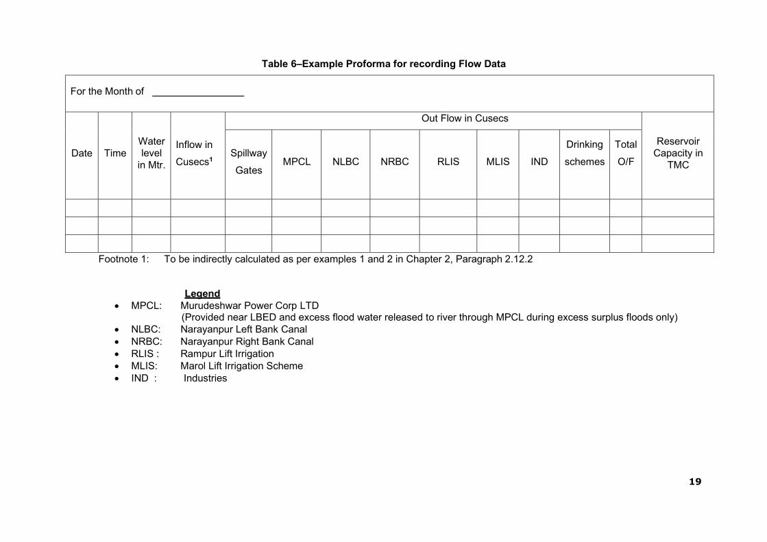
Table 6–Example Proforma for recording Flow Data
For the Month of
Date
Time
Water level
in Mtr.
Inflow in
Cusecs1
Out Flow in Cusecs
Reservoir Capacity in
TMC
Spillway
Gates
MPCL
NLBC
NRBC
RLIS
MLIS
IND
Drinking
schemes
Total
O/F
Footnote 1: To be indirectly calculated as per examples 1 and 2 in Chapter 2, Paragraph 2.12.2
Legend MPCL: Murudeshwar Power Corp LTD
(Provided near LBED and excess flood water released to river through MPCL during excess surplus floods only) NLBC: Narayanpur Left Bank Canal NRBC: Narayanpur Right Bank Canal RLIS : Rampur Lift Irrigation MLIS: Marol Lift Irrigation Scheme IND : Industries

20
1.8 Public and Project Staff - Health and Safety
As safety of Project Staff is of prime concern, safety instructions & protection measures at the dam site are carried out by all staff / project personnel.
1.8.1 Restricted Areas
The Narayanpur Dam comes under the revenue jurisdiction of Vijayapur, Yadgir and Raichur districts.The dam from ch.0.00 km to ch.2.55 km is under the revenue juris- diction of Vijayapur District, from ch.2.55 km to 4.62 km is under the revenue jurisdic- tion Yadgir district and from ch.4.62 km to 10.63km is under the revenue jurisdiction of Raichur district. In view of the safety and security aspects, the dam premises and its surrounding area has been declared as prohibited areas by the concerned district authorities during 2006.
Security arrangement :
i) Vijayapur Police check post at ch.0.46 km :
1 Head constable and 4 nos Police constables
ii) Yadgir Police check post at ch.2.76 km
1 Head constable and 4 nos Police constables
iii) Raichur Police check post at ch.4.90 km :
1 Head constable and 4 nos Police constables
Private Security arrangement:
In addition to this, private security (Ex-serviceman personal) have been deployed in three shifts, each shift consists of 2 supervisors and 15 nos guards at key locations of dam from ch.0.00 km to 10.63 km.

21
Figure 4: Layout of Narayanpur Dam Premises

THIS PAGE LEFT BLANK INTENTIONALLY
22

23
1.8.2 Staff Position, Communication & Warning System
The number & description of operating unit personnel posted/placed at different locations of the dam are noted in supporting documents and referenced in this Manual. Staff positions vary according to requirement during monsoon / non- monsoon periods. An Engineering organisational chart is shown in Figure 5 below.
A utility room located on the downstream side of LBED has an equipment room with all essential small tools, welders, gas cutter sets, chain blocks and ropes, dewatering pumps and consumables to facilitate O&M requirements.
A brief description of the warning systems including Siren is provided at the dam site. This includes communicating information on downstream inundation areas during scheduled or unscheduled release of flood outflows from the spillway.

24
THIS PAGE LEFT BLANK INTENTIONALLY

25
Figure 5 - Organisation Chart
Chief Engineer,
KBJNL, Operation & Maintenance Zone
Narayanpur, Email: [email protected]
Superintendent Engineer, KBJNL,
Operation & Maintenance Circle No-01, Narayanpur
Email: [email protected]
Executive Engineer, KBJNL, Dam Division, Narayanpur
Email: [email protected]
Assistant Executive Engineer, KBJNL, Narayanpur Gates Sub Division, Narayanpur
Email: [email protected]
Assistant Executive Engineer, KBJNL, Dam Sub Division No-3, Narayanpur
Email: [email protected]
Assistant Engineer (5No)
Junior Engineer (6No)
Assistant Engineer (3No)
Junior Engineer (2No)

26
1.8.3 Schedule of General Duties for Project Engineers
Schedules of duties being performed by the staff assigned to various locations and components of Narayanpur Dam are provided in this section. All activities are to be recorded daily in the Logbook and site registers.
DAILY
Visual inspection of dam
Crest of dam (Dam top)
Upstream and downstream faces
Visible portions of foundation and abutments contacts
Galleries
Record water surface elevation. (during monsoon on hourly basis)
Record reservoir inflow and spillway discharge. (during monsoon on hourly basis)
Record releases from outlets /sluices.
Record seepage from drainage systems-Toe drains, Gallery drains etc. on daily basis
Record meteorological data.
Check security and safety devices.
Complete logbook / site registers which should include the above information
WEEKLY
Electrical System
Standby generator (DG Sets)
Run for 15-30 min to achieve recommended operating temperature
Check status of batteries and keep them charged.
Check Fuel Supply
Drainage systems - Toe drains, Gallery drains etc., and, during any reservoir filling operations
MONTHLY
Check condition of:
Dam and Reservoir
Reservoir periphery (During Monsoon)
Drainage systems - Toe Drains, Gallery drains etc.
Measuring devices/Instruments
Security and safety devices – rectification, if needed.
Communication Devices
Status of Vegetation growth
Check Sign/Warning display boards near vulnerable locations are in place and updated as necessary

27
Mechanical/Electrical System
Replace fuses/light bulbs, as necessary
Inspect and maintain ventilation system; check for and remove any obstructions
Cleaning of control panel boards
QUARTERLY
Outlet Works
Availability of updated operating instruction
Check gate air vents
Clean gate control switchboxes
Check operation of gates and valves
Grease gate hanger / dogging arrangements
Check
Check condition of trash rack of intake structure
Check condition of Outlet works &the Energy Dissipation Arrangement (EDA)
Spillway
Check for debris in inlet channel
Check operation of gates
Check for damages in spillway glacis, EDA, d/s area, etc.
Check and clear spillway bridge drains
Clean inside of motor control cabinet and remove debris, insect (bee nests), nests, rodents and bird nests
Other works
Check for adherence to instrumentation schedule
Record pertinent information in Operation Log
Check conditions of V-notch weirs/other seepage measuring devices
BI-ANNUAL
Spillway & outlet works
Check paint on gates and other areas of corrosion
Check lubrication of wire ropes and application of cardium compound.
Check mechanical hoist bearings and flexible coupling bearings
Check gear systems
Exercise gate and valves for operational efficiency
Check oil reservoir level in hydraulic system and top up as necessary
Check pressure release valve and clean any debris, dirt, other foreign objects as necessary
Lubricate gate rollers

28
Check rubber seals and seal clamp bar
Electrical System and Equipment
Change oil in stand by generator
Check exposed electrical wiring of :
Operating equipment of gates/valves/hoists of Outlet works.
Operating equipment of gates and hoists of Spillway
Operating equipment of any other gates and hoists in dam
Spillway catwalk / bridge
Dam Gallery
Check Gate limit switches and adjust
ANNUAL
Spillway &Outlet works
Paint
Metalwork, Gate, Hoists and all exposed metal parts for corrosion
Valves / Control valves
Hydraulic power pack system
Exercise Gates and Valves
Examine stilling basin / energy dissipation arrangement and d/s channel & carry out rectification works, as necessary.
Check metal welds for damages/cracks in Gates, Hoist platform, Radial Gate Tie flats, Trunnion Girders/supports etc.
Electrical
Check electrical conduits, pull-boxes and switches for:
Outlet works valve house
Gates & hoists
Spillway bridge
Gallery
FIVE YEAR (PERIODIC)
Inspect intake structures, trash racks and stilling basin / energy dissipation arrangement, which normally are underwater; less frequent if experience indicates. This may need to be done by carrying out dewatering or by divers/remote operated vehicle(ROV) as necessary.
Review Dam operation procedures and EAP and update as necessary.

29
Sl. No. General Frequency
1
Check up the electrodes quality i.e. type of electrodes to be used in case of repairs or modification to be done keeping in view the quality of parts to be welded together.
Half Yearly
2 Checkup gates and counter weights for corrosion, broken or worn out parts, and condition of protective coating.
Half Yearly
3
Metal seats and seals should be checked for damages due to cavita- tion, wear, misalignments, corrosion and leakage. Check the conditions of stoplogs bulk head gates lifting beams etc
Half Yearly
4
Check the operating procedures and history of problems during the previous years of service and the operation and maintenance ma- nuals and if any modifications are needed in the existing provision in view of the experience shall be checked.
Half Yearly
5
The operation and maintenance manuals for gates and hoists shall be kept with the operating personnel at site and with the Engineers connected with the equipment and their design and operation ma- nuals..
Half Yearly
1.8.4 Hydro-Mechanical Inspections / Checks
Special duties performed for H-M operating personnels are given in this section.
1. Radial Crest Gates - 30 Nos.
a. Embedded Parts
Sl. No. Embedded Part Frequency
1
Checking of sill beams. Seal Seats, Guide track & all other exposed embedded parts with respect to their alignment, distortion :if any due to continuous use, pitting and cracks due to wear & to carry out re- quisite repairs, rectification by welding, grinding etc.
Half Yearly
2 Removing debris & other foreign material deposited on embedded parts & cleaning the same
Monthly
3 All cracks & defective weld joints to be ascertained & rectified. Half Yearly
4
All dirt, debris, grit, foreign material etc. to be removed from trunnion assemblies as well as trunnion chair, arms, Horizontal girders and lubricate trunnion bearing & the sliding surface on trunnion chair with specified lubricant/ grade to ensure smooth sliding movement of trunnion.
Monthly
5
All nuts,bolts connecting Trunnion Assembly & Trunnion Chair and Trunnion & Yoke, girder Trunnion pin lock plate to be checked & Tightened and replacement the same if found defective.
Monthly
30
b. Gate Structure
Sl. No. Description Frequency
1
Regular inspection of the gate along with the hoist to be carried out daily to ensure that there is no unusual development of sound
Daily
2 Check all welding for soundness & rectify defects Quarterly
3
Check welding between arms & horizontal girders as well as arms & Trunnion with the help of magnifying glass for cracks/ defects and rectify the defects.
Quarterly
4 Clean all drain holes including those in end arms, horizontal girders & Trunnion.
Quarterly
5 Check all nuts & bolts provided and tighten them, and replace the defective nuts & bolts
Quarterly
6
Check upstream face of Skin plate for pitting, scaling and corrosion. Scaling formation are to be removed. Pitting shall be filled with weld & ground. Corroded surface shall be cleaned & painted
Yearly
7
Joints of side & bottom rubber seals to be checked for their proper alignment and fixing & to be rectified/ adjusted if there is leakage through joints
Monthly
8
Nuts & bolts for rubber seal connection to be tightened and dam- aged nuts and bolts to be replaced
Quarterly
9
The excessive or wide spread leakages if any shall be reported to the Engineer-in-charge. If the seals are required to be replaced the same shall-be carried out after supply of rubber seal by the depart- ment
Quarterly
10 The guide roller pin is to be lubricated Quarterly
c. Rope Drum Hoists:
Sl. No. Hoists Frequency
1 Check the condition of rope sockets, turn buckles, equalizer plate‟s links plates for damages or defects and corrosion.
Half Yearly
2 Check the gears for proper meshing, the supporting shafts and plummer blocks with bearings for good condition and lubrication.
Half Yearly
3 Check the rope drum for correct grooves, correct fixing of the end of rope on the drum and lubrication.
Half Yearly
4
Check up ,if the ropes on either side of the gates are equal in length and if fixing of ropes is such that level of bottom gate is horizontal and not inclined during travel. Any tilt may lead to differences in
Half Yearly
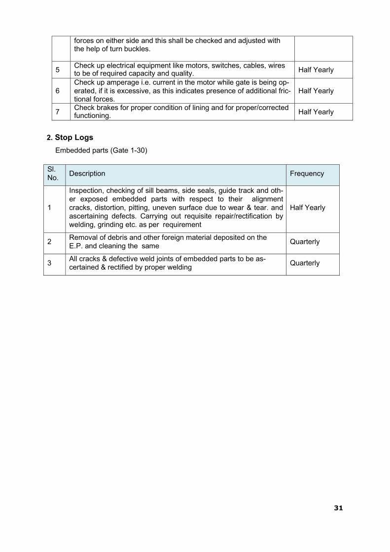
31
forces on either side and this shall be checked and adjusted with the help of turn buckles.
5 Check up electrical equipment like motors, switches, cables, wires to be of required capacity and quality. Half Yearly
6
Check up amperage i.e. current in the motor while gate is being op- erated, if it is excessive, as this indicates presence of additional fric- tional forces.
Half Yearly
7 Check brakes for proper condition of lining and for proper/corrected functioning. Half Yearly
2. Stop Logs
Embedded parts (Gate 1-30)
Sl. No.
Description Frequency
1
Inspection, checking of sill beams, side seals, guide track and oth- er exposed embedded parts with respect to their alignment cracks, distortion, pitting, uneven surface due to wear & tear. and ascertaining defects. Carrying out requisite repair/rectification by welding, grinding etc. as per requirement
Half Yearly
2 Removal of debris and other foreign material deposited on the E.P. and cleaning the same
Quarterly
3 All cracks & defective weld joints of embedded parts to be as- certained & rectified by proper welding
Quarterly

32
1.9 Distribution of Operation & Maintenance Manuals
The list of unit officers to whom the O&M Manual is required to be distributed is shown in the table below.
Table 7 - Distribution of O&M Manual and Revisions
Sl No Unit Officers Number of Manual
Distribution
1. Secretary to Govt, Water Resources Department, Vikas Soudha, Bengaluru
3
2. Managing Director,KBJNL, Bengaluru 2 3. Chief Engineer, KBJNL, O&M Zone, Narayanpur 2
4. Chief Engineer, Water Resources Development Or- ganization, Bengaluru.
1
5. Director, KERS, K R Sagar. 1 6. Superintending Engineer, SPMU, WRDO, Bengaluru 1
7. Superintending Engineer, KBJNL, O&M Circle, Na- rayanpur.
1
8. Executive Engineer, SPMU, DRIP Bengaluru 1
9. Executive Engineer, KBJNL, Dam Division, Na- rayanpur
1
10. Executive Engineer, Monitoring and Evaluation, Bengaluru
1
11. TA to CE, O&M Zone, Narayanpur 1 12. TA to SE, O&M Circle, Narayanpur 1
13. Assistant Executive Engineer, KBJNL, Gates Sub Division, Narayanpur
5
14. Assistant Executive Engineer, KBJNL, Dam Sub Division-3, Narayanpur
5
15. Assistant Engineers, KBJNL, Dam Sub Division -3 , Narayanpur
3
16. Assistant Engineers, KBJNL, Gates Sub Division, Narayanpur
6
17. Technical Section of Central Office 1
18. Technical Section of Circle Office 1
19. Technical Section of Division Office 1
1.10 Supporting Documents & Reference Material
This O&M Manual is the key instruction document. Supporting documents and necessary instructions for all phases of the operation, inspection and maintenance of the dam, reservoir and appurtenant works shown below are available at the dam control room:
Emergency Action Plan (EAP) Flood forecasting and operating
criteria Basin or river operating plan Interstate agreements Agreements with other user agencies

33
Power station operation plan Irrigation operation plan Domestic / industrial water supply
operating instructions Administrative procedures Reservoir / River Pollution Continge-
ny Plan Maintenance Schedules Gate Manufacturer‟s instructions and
drawings Regional communication directory Instrumentation reports / results

]
2.1 Basic Data
The Narayanpur operation plan consists of step-by-step instructions for operating the dam and reservoir during routine (normal) and emergency conditions. The operating procedures for normal operations are discussed in this chapter including operating criteria for the reservoir, spillway &outlets. The operation of a dam involves regulation of its reservoir as per project specific requirements. This includes the use of area capacity curves and design flood; both are described below.
2.1.1 Area Capacity curves.
The area capacity curves for Narayanpur Dam tabular form is shown in Table 16. 2.1.2 Design Flood and Features Related to Safety
The World Bank Consultants made a design flood study for Almatti and Narayanpur Dams on Krishna River and recommended the following peak discharge values with certain assumptions for Narayanpur Dam:
i) As per IBRD storm : 31,000 Cumec (10,94,754 cusecs)
ii) As per Hydro meteorological report : 43,282 Cumec (15,28,489 cusecs)
Consequently, the expert panel under the Chairmanship of Shri.Y.K Murthy the then chairman CWC New Delhi reviewed the report of World Bank Consultant during 1978 and recommended to adopt design flood of 37,945 Cumec (13,40,000 cusecs) for a return period of 10,000 years which is ade- quate on the basis of rational analysis of the frequency studies for Indian conditions.
2.2 Reservoir Operation:
2.2.1. During Monsoon Period
The Narayanpur reservoir is being operated based on the outflow of Almatti Dam and Malaprabha river flow (Intermittent catchment) keeping the irrigation requirements of Narayanpur Left bank canal and Narayanpur Right bank canal.
The spillway gates shall be operated to maintain the reservoir level constant i.e. such that the outflow equals inflow when inflow is below one lakh cusecs. For inflow more than one lakh cusecs, the reservoir level is being maintained below FRL to avoid back water effect at confluence of Malaprabha river course.
The maximum inflow received since inspection is 650000 cusecs i.e. during Aug-2019 and Max releases from spillway gates is 635000 cusecs.
2.3 Flood Routing Criteria:
The Narayanpur Dam was constructed between 1969 and 1982. It is a large dam with height of 29.72 m above the lowest foundation level and initial gross storage capacity of 1,066 Mm³ (37.646TMC). The catchment area of the dam is 47,850 km². The Full Reservoir Level (FRL) / Maximum Water Level (MWL) is 492.252 m above the mean sea level.
34
CHAPTER 2. PROJECT OPERATION
35
The dam top has elevation of 496.752 m for earthen dam section and 495.752 m for masonry dam. The freeboard for the earthen section is 4.5 m.
The design flood adopted for its spillway is 37945 cumecs(13.40 Lakh cusecs) correspond-
ing to a return period of 10000 years as advised by a panel of experts during construction of the dam.The gates were designed to pass this flood assuming 10% of them were not operative.
In the year 2016, under the dam rehabilitation and Improvement Project,the Central Water
Commission (CWC) conducted a revised flood study based on storm magnitudes furnished by IMD,according to which the the inflow design flood (IDF),which is the Probable Maximum Flood (PMF) having a peak of 52,631 m³/s. (18.60 lakh cusecs).
2.4 Revised Flood Routing study of Narayanpur Dam
Subsequently, the Chief Engineer, O&M Zone, Narayanpur, assigned the task of car-
rying out flood routing study for the revised flood to Professor Ramaprasad,Retd
IISc,Bengalurur during December 2019. Accordingly the study was carried out .
2.4.1 Methodology
Flood routing through the Narayanpur reservoir is carried out by the Puls method in
the present study. The equation used is
Eqn:(1)
where S = storage in the reservoir, Q = outflow over the spillway, I = inflow into the reservoir
(from the PMF hydrograph), Δt = time interval, and the subscripts 1 and 2 denote respectively
the beginning and end of the time interval.
2.4.2 Data
Value of Δt was chosen as 3 hr.
Values of S and I were taken from the CWC report Mitigation of Enhance Design
Flood and are shown in Tables 8 and 9 respectively.
36
Table 8. Elevation-Storage Data of Narayanpur Dam (from CWC Report)
Elevation Storage Elevation Storage Elevation Storage Elevation Storage
m Mm3 m Mm3 m Mm3 m Mm3
480.103 0 484.18 267.49 488.68 550.209 493.152 1030.86
480.184 188.647 484.68 286.163 489.18 597.4 493.652 1087.17
480.684 192.893 485.18 306.88 489.68 646.686 494.152 1143.48
481.184 197.949 485.68 329.815 490.18 698.693 494.652 1199.79
481.684 204.445 486.18 355.849 490.68 752.737 495.152 1256.1
482.18 212.696 486.68 387.799 491.18 809.078 495.652 1312.41
482.68 223.467 487.18 423.85 491.68 869.258 496.152 1368.72
483.18 235.865 487.68 463.107 492.18 933.967 496.652 1425.03
483.68 250.798 488.18 505.371 492.652 974.55 496.952 1458.816
Table 9. Inflow Hydrograph of PMF (from CWC Report)
Time Inflow Time Inflow Time Inflow Time Inflow
hr cumecs hr cumecs hr cumecs hr cumecs
0 2218 45 19449 87 48559 132 5651
3 2218 48 22519 90 45856 135 4444
6 2220 51 25981 93 42728 138 3596
9 2257 54 28974 96 39723 141 3028
12 2345 57 31334 99 37106 144 2670
15 2513 60 34326 102 34605 147 2457
18 2745 63 38056 105 31846 150 2466
21 3114 66 41496 108 28702 153 2393
24 3813 69 44073 111 25295 156 2321
27 4831 72 47055 114 21812 159 2249
30 6063 75 50366 117 18378 162 2222
33 7678 78 52460 120 15086 165 2219
36 10287 79 52631 123 12057 168 2219
39 13603 81 52282 126 9431
42 16797 84 50717 129 7294

37
Regarding Q, the outflow over the spillway, results of spillway model studies conducted at
Karnataka Engineering Research Station (KERS) are available as described below.
There are 30 spillway gates, each of size 15 m × 12 m. Of these, 25 gates (called main
gates) are located between Chainages 1.724 km and 2.183 km. The remaining 5 gates
(called saddle gates) are located between Chainages 2.530 km and 2.630 km. There is thus
an intervening distance of 347 m between the two sets of gates. Separate model studies
were conducted for the main and saddle gates. From the results, free flow discharges for
different reservoir levels were extracted and are shown in Table 10.
Table 10. Free Flow Discharges over Narayanpur Spillways (Model
Studies) (Crest Level=480.252 m for All Gates)
25 Main Gates 5 Saddle Gates
Reservoir
Level
Head over
Crest
Free
Dis- charge
Reservoir
Level
Head over
Crest
Free
Discharge
m m cumecs m m cumecs
480.752 0.5 380 482.252 2 680
481.252 1 1230 484.252 4 1540
481.752 1.5 1843 486.252 6 2530
482.252 2 3400 488.252 8 3665
482.752 2.5 4000 490.252 10 4985
483.252 3 5291 492.252 12 6740
483.752 3.5 5800
484.252 4 8400
484.752 4.5 8800
485.252 5 11620
485.752 5.5 12400
486.252 6 14500
486.752 6.5 15200
487.252 7 18045
487.752 7.5 19800
488.252 8 22400
488.752 8.5 24400
489.252 9 25240
489.752 9.5 27900
490.252 10 29800
490.752 10.5 31200

38
Note: In the case of main gates, the study did not extend to the FRL (492.25 m), possibly
because of model limitations. The maximum gate opening achieved was 7.65 m (in
prototype equivalent), which points to model limitations,since prototype gates can be opened
to 10.50 m.
Figs. 6 and 7 show the plots of free discharge against gate opening for the 25 main gates
and 5 saddle gates respectively. Equations of the type Q = LHn were fitted to the
measurements, where H is the head over crest:
Main Gates: Qmain = 1098.8H1.4323 Eqn:(2)
Saddle Gates: Qsadddle = 272.68H1.2651 Eqn:(3)
For both sets of gates, the fit shows very good correlation. Hence free flow discharge
through all 30 gates can be calculated by the equation
Q = Qmain + Qsadddle = 1098.8H1.4323 + 272.68H1.2651 Eqn:(4)
The above equation is assumed to be valid for extrapolation also, i.e., for reservoir
levels beyond the measured range.
Figure 6 - Free discharge through 25 main gates over Narayanpur spillway.
39
Figure 7 - Free Discharge through 5 Saddle Gates over Narayanpur Spillway
40
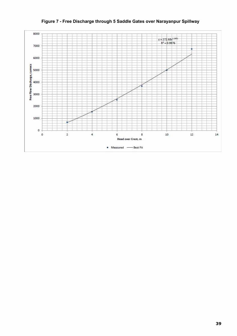
2.4.3 Maximum Gate Opening
The CWC draft report assumes that the gates cannot be opened to the full extent
(which is 10.5 m), but only to the extent of 7.65 m. This impression appears to have been
created because the model studies have been done only up to 7.65 m. The gates can in fact
be opened up to 10.50 m.
When there is free flow over the spillway, the water surface profile follows a
drawdown curve where the water level at the spillway can be considerably lower than the
reservoir level. Thus it is possible for free flow to occur even when the reservoir level is
higher than the gate lip level. Table 11 shows the measurements derived from the model
study of main gates. Gate opening in this Table is the vertical distance from the gate seat to
gate lip. Gate seat level is RL 480.103 m, and the gate lip level is arrived at by adding the
gate opening to gate seat level.
It is seen from the Table 11 that when the gate opening is 7.65 m, free flow over the
spillway will occur even if the reservoir level is 3 m above the gate lip. The relation is shown
graphically in Fig. 8, and is linear. The maximum gate opening is 10.5 m as ascertained
from the project authorities. For this opening, by extrapolation, the maximum reservoir level
for free flow is 494.4 m from Fig. 8. Hence, in the routing computations, free flow is assumed
to occur as long as the reservoir level is within 494.40 m.
Figure 8 - Relation between Free Flow Reservoir Elevation and Main Gate Opening
(Gate Opening Defined as Vertical Distance from Gate Seat to Gate Lip)

41
Table 11. Maximum Reservoir Level for free flow to Occur under different gate lip levels (from Model Studies)
Ope- ning
Maxi- mum Free Flow
Pool
Level
Gate Lip Level
Ope nin g
Maxi- mum Free Flow
Pool Level
Gate Lip
Level
Ope- ning
Maxi- mum Free Flow
Pool Level
Gate Lip
Level
m m m m m m m m m
0.40 481.252 480.503 3.00 484.552 483.103 5.40 487.752 485.503
0.60 481.552 480.703 3.15 484.652 483.253 5.60 488.002 485.703
0.80 481.752 480.903 3.20 484.752 483.303 5.80 488.352 485.903
0.90 481.829 481.003 3.40 485.252 483.503 6.00 488.602 486.103
1.00 482.102 481.103 3.60 485.422 483.703 6.15 488.852 486.253
1.20 482.252 481.303 3.80 485.752 483.903 6.20 488.902 486.303
1.40 482.502 481.503 3.90 485.852 484.003 6.40 489.152 486.503
1.60 482.652 481.703 4.00 485.972 484.103 6.60 489.402 486.703
1.65 482.721 481.753 4.20 486.252 484.303 6.80 489.802 486.903
1.80 482.972 481.903 4.40 486.352 484.503 6.90 489.952 487.003
2.00 483.252 482.103 4.60 486.562 484.703 7.00 490.100 487.103
2.20 483.552 482.303 4.65 486.722 484.753 7.20 490.422 487.303
2.4 483.752 482.503 4.80 486.802 484.903 7.40 490.602 487.503
2.6 484.052 482.703 5.00 487.252 485.103 7.60 490.902 487.703
2.8 484.252 482.903 5.20 487.552 485.303 7.65 490.942 487.753
2.4.4 Routing
In the Puls method of routing, a suitable time step Δt is first chosen depending on the time
base of the inflow hydrograph. A Table is then prepared that shows the parameters
appearing in eq (1), viz storage, outflow, S – QΔt/2 and S + QΔt/2 for different elevations
from crest to the maximum expected reservoir level. In the present case, since the time
base is long, Δt is chosen as 3 hours (0.0108 Msec). For preparing this Table, S was taken
from Table 1 and outflow Q was calculated from eq (4), in which H = Reservoir Elevation –
Crest Level. This eq (4) is valid for free flow over the spillway, and its use is justified by
hindsight since the results indicate that the maximum level attained by the reservoir is less
than 494.4 m, which is the limit for free flow. Table 12 shows these parameters.
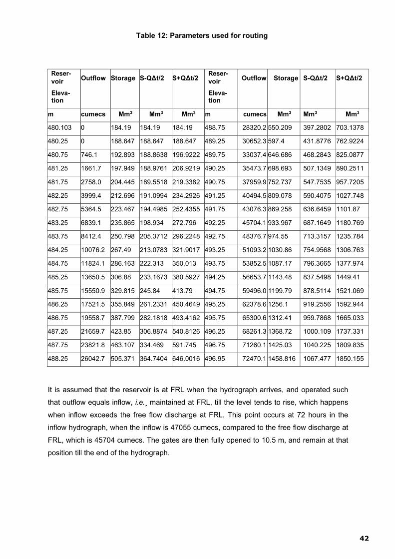
42
Table 12: Parameters used for routing
Reser- voir
Eleva- tion
Outflow Storage S-QΔt/2 S+QΔt/2 Reser- voir
Eleva- tion
Outflow Storage S-QΔt/2 S+QΔt/2
m cumecs Mm3 Mm3 Mm3 m cumecs Mm3 Mm3 Mm3
480.103 0 184.19 184.19 184.19 488.75 28320.2 550.209 397.2802 703.1378
480.25 0 188.647 188.647 188.647 489.25 30652.3 597.4 431.8776 762.9224
480.75 746.1 192.893 188.8638 196.9222 489.75 33037.4 646.686 468.2843 825.0877
481.25 1661.7 197.949 188.9761 206.9219 490.25 35473.7 698.693 507.1349 890.2511
481.75 2758.0 204.445 189.5518 219.3382 490.75 37959.9 752.737 547.7535 957.7205
482.25 3999.4 212.696 191.0994 234.2926 491.25 40494.5 809.078 590.4075 1027.748
482.75 5364.5 223.467 194.4985 252.4355 491.75 43076.3 869.258 636.6459 1101.87
483.25 6839.1 235.865 198.934 272.796 492.25 45704.1 933.967 687.1649 1180.769
483.75 8412.4 250.798 205.3712 296.2248 492.75 48376.7 974.55 713.3157 1235.784
484.25 10076.2 267.49 213.0783 321.9017 493.25 51093.2 1030.86 754.9568 1306.763
484.75 11824.1 286.163 222.313 350.013 493.75 53852.5 1087.17 796.3665 1377.974
485.25 13650.5 306.88 233.1673 380.5927 494.25 56653.7 1143.48 837.5498 1449.41
485.75 15550.9 329.815 245.84 413.79 494.75 59496.0 1199.79 878.5114 1521.069
486.25 17521.5 355.849 261.2331 450.4649 495.25 62378.6 1256.1 919.2556 1592.944
486.75 19558.7 387.799 282.1818 493.4162 495.75 65300.6 1312.41 959.7868 1665.033
487.25 21659.7 423.85 306.8874 540.8126 496.25 68261.3 1368.72 1000.109 1737.331
487.75 23821.8 463.107 334.469 591.745 496.75 71260.1 1425.03 1040.225 1809.835
488.25 26042.7 505.371 364.7404 646.0016 496.95 72470.1 1458.816 1067.477 1850.155
It is assumed that the reservoir is at FRL when the hydrograph arrives, and operated such
that outflow equals inflow, i.e.¸ maintained at FRL, till the level tends to rise, which happens
when inflow exceeds the free flow discharge at FRL. This point occurs at 72 hours in the
inflow hydrograph, when the inflow is 47055 cumecs, compared to the free flow discharge at
FRL, which is 45704 cumecs. The gates are then fully opened to 10.5 m, and remain at that
position till the end of the hydrograph.

43
Routing is done using eq (1). The right hand side quantities are all known at the beginning
of the first time interval (72 hr to 75 hr) and have the following values:
I1 = 47055 cumecs, I2 = 50366 cumecs (both from Table 9), Δt = 0.0108 Msec, Q1 = I1 =
47055 cumecs, and S1 – Q1 Δt/2 = 700.383 Mm3 read by interpolation from Table 12
corresponding to outflow of 47055 cumecs.
With these values, the right hand side calculates to 1226.456 Mm3. This will be the value of
(S2 + Q2 Δt/2). The outflow and the reservoir elevation at the end of the interval can be read
as 47923.6 cumecs and 492.67 m respectively from Table 12
corresponding to this value of (S2 + Q2 Δt/2) using interpolation. This outflow becomes Q1 for
the next time interval and the procedure is repeated to get successive values of the outflow
and reservoir elevation.
Figure 9- Inflow and Outflow Hydrographs for 52631 cumecs Flood

44
Figure 10- Reservoir Elevation Hydrograph for 52631 cumecs Flood
Table 13: Routing Results with reservoir outflow and elevation Hydrographs
Time Inflow (I1+I2)Δt/2 S1-Q1Δt/2 S2+Q2Δt/2 Outflow Elevation
hr cumecs Mcum Mcum Mcum cumecs m
72 47055 700.383 47055 492.50
75 50366 526.0734 708.8818 1226.4564 47923.58 492.67
78 52460 555.2604 729.9523 1264.1422 49462.02 492.95
79 52631 567.4914 749.4893 1297.4437 50736.52 493.18
81 52282 566.5302 760.3394 1316.0195 51451.86 493.31
84 50717 556.1946 760.6386 1316.534 51471.8 493.32
87 48559 536.0904 749.07 1296.729 50709.17 493.18
90 45856 509.841 726.8834 1258.911 49261.82 492.91
93 42728 478.3536 698.7954 1205.237 46892.74 492.47
96 39723 445.2354 663.6413 1144.0308 44480.51 492.02
99 37106 414.8766 622.0784 1078.5179 42262.92 491.59
102 34605 387.2394 579.1814 1009.3178 39827.44 491.12
105 31846 358.8354 535.8913 938.01677 37233.84 490.60
108 28702 326.9592 490.7985 862.85046 34449.25 490.04
111 25295 291.5838 443.2742 782.38233 31398.91 489.41
114 21812 254.3778 394.1559 697.65195 28101.49 488.70
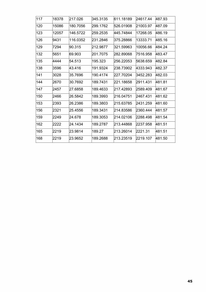
45
117 18378 217.026 345.3135 611.18189 24617.44 487.93
120 15086 180.7056 299.1762 526.01908 21003.97 487.09
123 12057 146.5722 259.2535 445.74844 17268.05 486.19
126 9431 116.0352 231.2846 375.28866 13333.71 485.16
129 7294 90.315 212.9877 321.59963 10056.66 484.24
132 5651 69.903 201.7075 282.89068 7516.958 483.47
135 4444 54.513 195.323 256.22053 5638.659 482.84
138 3596 43.416 191.9324 238.73902 4333.943 482.37
141 3028 35.7696 190.4174 227.70204 3452.283 482.03
144 2670 30.7692 189.7431 221.18658 2911.431 481.81
147 2457 27.6858 189.4633 217.42893 2589.409 481.67
150 2466 26.5842 189.3993 216.04751 2467.431 481.62
153 2393 26.2386 189.3803 215.63785 2431.259 481.60
156 2321 25.4556 189.3431 214.83586 2360.444 481.57
159 2249 24.678 189.3053 214.02106 2288.498 481.54
162 2222 24.1434 189.2787 213.44868 2237.958 481.51
165 2219 23.9814 189.27 213.26014 2221.31 481.51
168 2219 23.9652 189.2688 213.23519 2219.107 481.50

46
Table 13 shows the results of routing. It is seen that the maximum reservoir level is 493.32
m, occurring at 84 hr, i.e., five hours after the peak inflow. Since free flow occurs up to
reservoir level of 494.4 m for 10.5 m gate opening, the maximum level of 493.32 m is also
a free flow situation. The maximum outflow is 51471.8 cumecs, about 2.2% less than
peak inflow. The outflow hydrograph is shown in Fig. 9 and the elevation hydrograph in Fig.
10.
Top level of the masonry dam is 495.752 m and that of the earth dam is 496.752 m (ignoring
the 0.5 m high parapet on it). Thus there is a freeboard of 2.43 m for the masonry dam and
3.43 m for the earth dam. Adequacy of this will now be checked for wave height. 2.4.5 Freeboard Requirement
IS 6512 (Criteria for Design of Solid Gravity Dams) specifies how freeboard requirement is
calculated and it is followed here.
2.4.6 Fetch
Effective Fetch is calculated by the method given in Fig. 4 of IS 6512. Radial lines at 60
intervals are drawn from the dam axis (last page of this report) and their lengths (x) are
measured. The calculations are shown in Table 14.
Table 14. Calculation of Effective Fetch
α (deg) cos α x (km) x cos α (km)
42 0.743 5.89 4.38
36 0.809 4.94 3.99
30 0.866 5.25 4.55
24 0.914 6.21 5.67
18 0.951 5.89 5.60
12 0.978 6.21 6.07
6 0.995 5.57 5.54
0 1 8.12 8.12
6 0.995 15.92 15.83
12 0.978 23.09 22.58
18 0.951 19.42 18.47
24 0.914 10.51 9.60
30 0.866 10.67 9.24
36 0.809 11.78 9.53
42 0.743 7.01 5.21
Total 13.51 134.40
Effective fetch = 134.4/13.51 = 9.947
The effective fetch is thus 9.947 km.

47
Fig. 11. Fetch Lines

48
2.4.7 Wind Speed
There is a meteorological laboratory at the dam. The maximum wind speed recorded there
during the past several years is around 12 km/h. However, As per Clause 5.8.3.2 of IS 6512,
wind speed of 80 km/h over water should be assumed for wave height calculation at MWL.
This is adopted here.
2.4.8 Average Depth
The lowest river bed level at the reservoir is 469.940 m. Hence the maximum depth is
492.25 – 469.94 = 22.31 m. Depth at the end of the maximum fetch line is zero, so the
average depth can be taken as 11.15 m to a good approximation.
2.4.9 Wind Setup
When wind blows over the reservoir surface, it exerts shear force on the water because of
which the water surface moves towards the dam and “tilts”. This is called wind setup. Its
magnitude depends on the wind speed V, effective fetch F and average depth D, and is
given by the equation
Eqn:(6)
Appendix A of IS 6512 describes the method for computing freeboard and gives a proforma
for its calculation in Clause A-1.10. Three of the parameters required for the computation,
viz effective fetch, average depth and wind setup, are calculated above. The remaining steps
in the proforma computation are shown in Table 15. It is seen that the freeboard is adequate.
Table 15. Computation of Required Freeboard
FRL 492.25 m
Effective Fetch F 9.947 km
Wind Speed V 80 km/h
Significant Wave Height Hs from Fig. 5 of IS 6512 (Pl see below)
1.32 m
Design Wave Height H = 1.27Hs (Clause A-1.7 of IS 6512) 1.6764 m
Average Depth D 11.15 m
Wind Setup W 0.092 m
Freeboard Required = 4H/3 + W 2.327 m
Freeboard Available for Masonry Dam 2.43 m
Freeboard Available for Earth Dam 3.43 m

49
2.4.10 Conclusion on Spillway Discharge Capacity.
Maximum level attained by the reservoir when passing 52631 cumecs is 493.32 m. Freeboard available is a little more than required at both masonry and earth sections. Hence the existing 25 + 5 spillway gates are adequate to pass the flood without compromising on the freeboard requirement. It is not necessary to construct additional gates.
2.5 Sequence of Opening or Closing of Gates.
The crest gates should be opened, starting with the end gates first (i.e., gate No.1 and 25, A1 and A5), then the gates at the center (gates 12 and 13,A3). and then the remaining gates in a systematic manner, such that the no gate· is opened more than 0.2m. If the release over the spillway is to be further increased, the gates are opened further in a similar manner, no gate opening being more than 0.4m. Further opening of gates, if required is done in the same way, keeping the difference in the openings if any two adjacent gates• not more than 0.2m.
During the recession part of the inflow hydrograph, it may be necessary to close the crest gates .In such a case, the closure of the gates should be done in the reverse order; the gate opened last being closed first, the entire operation being such that the difference between the adjacent gate openings never exceed 0.2 m.
2.6 Gate Operation at Narayanpur
Since the capacity of Narayanpur Reservoir is small, the gates be operated at Narayanpur dam to maintain the reservoir level constant i.e., such that the outflow equals inflow.
2.7 Inflow Forecasting
The gross storage of Almatti Dam at FRL 519.6m is 123.08 TMC and Present Gross sto- rage of Narayanpur Dam is 33.313 TMC at FRL-492.252m. The Almatti and Narayanpur Dams have been designed for a probable maximum flood (PMF of 31,007 Cumec 10.95 lakhs cusecs) and 37,945 Cumec (13.40 lakhs cusecs) respectively. The storage in Na- rayanpur Dam has commenced during 1982 and Almatti Dam in year 2000.
During monsoon, incessant rains in the catchment area cause the flash floods in Krishna river. These floods may lead to problems like people getting displaced from their homes, huge damage to crops and other assets. The floods can have disastrous impact on the en- vironment also. Adequate measures are required to be taken up in advance to control and regulate the flow water in the river.
The regulation of flood water released from the Dams in Maharashtra is very important and has a most impact in Karnataka.
50
The following measures are essential for effective management of floods in Krishna River during the monsoons.
1) Nomination of liaison officers for respective reservoirs. 2) Sharing of Sub-basin wise directory of concerned officers responsible for flood
management. 3) Exchange of data regarding rainfall, releases from dams, reservoir water levels. 4) Reservoir operation schedules.
2.8 Exchange of data regarding rainfall, releases from dams, reservoir
water levels.
The Central water Commission has established office at Narayanpur during 1985 for as- sisting in flood warning in the Krishna River Basin. Based on the rainfall in the catchment and flow in the river and tributaries, CWC office will furnish flood forecasting reports to Dam Sub Division No-3,Narayanpur office , indicating the trend of flows in the Krishna river (Raising, steady or Falling)
The list of rain gauges in the upstream catchment of Krishna basin and daily rainfall is to be collected by concerned offices. It will helpful for prediction of probable floods in the river.
During monsoon daily water releases from the Dams at 8 hrs & 16 hrs in normal situa- tion and hourly data exchange during heavy floods is necessary. In this regard, the data is required to be established. The data regarding exchange floods is made available to the Revenue authorities and public by broadcasting in AIR,TV and publication in News papers.
2.9 Flood warning system in catchment area:
The regulation of flood from the dams on upstream of Narayanpur reservoir is very crucial to quantify the inflows.The Central Water Commission staff will be coordinated to assist in the flood forecasting .Accordingly, sequence of opening or closing of gates will be taken up in accordance with the approved gate operation schedule.
2.10 Flood communication system:
The widely time-tested Communication to reach every corner of the flood affected zones are through radio and television and private media, for the people to move to safer places by themselves in an emergency.
Communication is very important in such occasions. Nowdays,advantage of mobile network is being used by collecting the Mobile numbers of all staff , who have been assigned in the duty of flood management and disaster management.
Following Liaison officers for flood co-ordination of Narayanpur Dam are as listed below
Karnataka State:
1) Chief Engineer,KBJNL,O&M Zone Narayanpur Sri Sri.S Rangaram(I/c), Phone No. 08444229635 / Mob:9483545669
2) Superintending Engineer,KBJNL,O&M Circle No1 Narayanpur Sri.S Rangaram Phone No. 08444229635 / Mob:9483545669
3) Executive Engineer, KBJNL Dam Division,Narayanpur Sri.S.S.Naikodi Mob:9448751466
4) Assistant Executive Engr. KBJNL Dam Sub Division No.3 Sri.T N Ramachandra(I/C) Mobile:9448957364

51
5) Assistant.Executive Engr. KBJNL Gates Sub Division Sri.R L Hallur Mobile No. 9449143184
6) Assistant. .Engr (1) Sri.V L Kambar Mobile No. 9164155995 Assistant. .Engr (2) Sri.Vijayakumar S Arali Mobile No. 9901846364 Junior .Engr (3) Sri.Balasubramnya J Mobile No. 9916804441
7) District Administration Yadgir, Raichur
Up Stream of Narayanpur Dam
1) Chief Engineer ,KNNL,Malaprabha Project Zone,Dharwad Office No: 0836-2447793 Email: [email protected]
2) Chief Engineer ,KBJNL,Dam Zone,Almatti Office No: 08426-281038 Email: [email protected]
Down Stream of Narayanpur Dam
1) Chief Engineer,Raichur Thermal Power Projects,RTPS,Raichur Sri.Rajmudi Mob:9449596578, Email:[email protected]
2) Executive Engineer,Gugal Barrage Sri.Sanna Parashuram ,KBJNL NRBC DIVN4,Chikkahonnakuni, Mob:9482638666, Email:[email protected]
Andhra Pradesh/Telangana State
1) Chief Engineer (Projects), Mahaboobnagar,I&CADD,Godwal-509125, Godwal(dt),
Telangana, : Shri.L Anantha Reddy, Mob:8374566255 Email: [email protected]
2) Superintedent Engineer Engineer , I&CADD, Godwal-509125, Godwal(dt), Telangana Shri.V Raghunatha Rao , Mob: 9182562400,Email: [email protected]
3) Executive Engineer,,I&CADD,PJP Dam Division,Nandimalla-509131, Wanaparthy (Dt),Telangana, Sri.B Parthasarathi Mob:7337393081,Email: [email protected]
4) Govt of Telangana, Deputy Collector & District Magistrate, Jogulamba Gadwal district, Godwal-509125,Telangana Smt.Shruthi Ojha, IAS Mobile: 9100901600,+917993499501 Email:[email protected]
2.11 Methodology of Flood Regulation
2.11.1 Inflow Computation
Inflow into reservoirs is normally estimated by the reservoir gauging method (also called the rise and fall method or inflow-outflow method). All the outflows are added together and to it the rate of rise in storage (Positive if the level rises, and negative if it falls) is added . Expressed as an equation, this will be.
Inflow (cusecs) = Total outflow(cusecs)+Rate of increase in
storage(cusecs) + Evaporation Loss(cusecs)
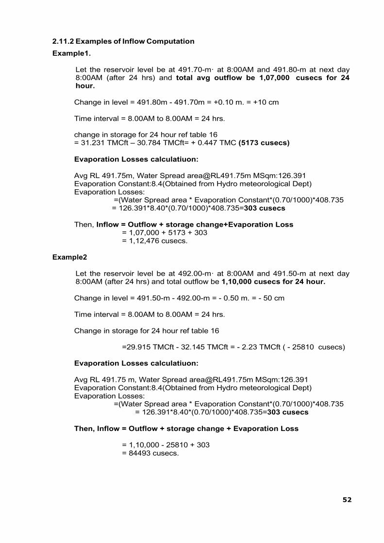
52
2.11.2 Examples of Inflow Computation
Example1.
Let the reservoir level be at 491.70-m· at 8:00AM and 491.80-m at next day 8:00AM (after 24 hrs) and total avg outflow be 1,07,000 cusecs for 24 hour.
Change in level = 491.80m - 491.70m = +0.10 m. = +10 cm
Time interval = 8.00AM to 8.00AM = 24 hrs.
change in storage for 24 hour ref table 16 = 31.231 TMCft – 30.784 TMCft= + 0.447 TMC (5173 cusecs)
Evaporation Losses calculatiuon:
Avg RL 491.75m, Water Spread [email protected] MSqm:126.391 Evaporation Constant:8.4(Obtained from Hydro meteorological Dept) Evaporation Losses:
=(Water Spread area * Evaporation Constant*(0.70/1000)*408.735 = 126.391*8.40*(0.70/1000)*408.735=303 cusecs
Then, Inflow = Outflow + storage change+Evaporation Loss
= 1,07,000 + 5173 + 303 = 1,12,476 cusecs.
Example2
Let the reservoir level be at 492.00-m· at 8:00AM and 491.50-m at next day 8:00AM (after 24 hrs) and total outflow be 1,10,000 cusecs for 24 hour.
Change in level = 491.50-m - 492.00-m = - 0.50 m. = - 50 cm
Time interval = 8.00AM to 8.00AM = 24 hrs.
Change in storage for 24 hour ref table 16
=29.915 TMCft - 32.145 TMCft = - 2.23 TMCft ( - 25810 cusecs)
Evaporation Losses calculatiuon:
Avg RL 491.75 m, Water Spread [email protected] MSqm:126.391 Evaporation Constant:8.4(Obtained from Hydro meteorological Dept) Evaporation Losses:
=(Water Spread area * Evaporation Constant*(0.70/1000)*408.735 = 126.391*8.40*(0.70/1000)*408.735=303 cusecs
Then, Inflow = Outflow + storage change + Evaporation Loss
= 1,10,000 - 25810 + 303 = 84493 cusecs.
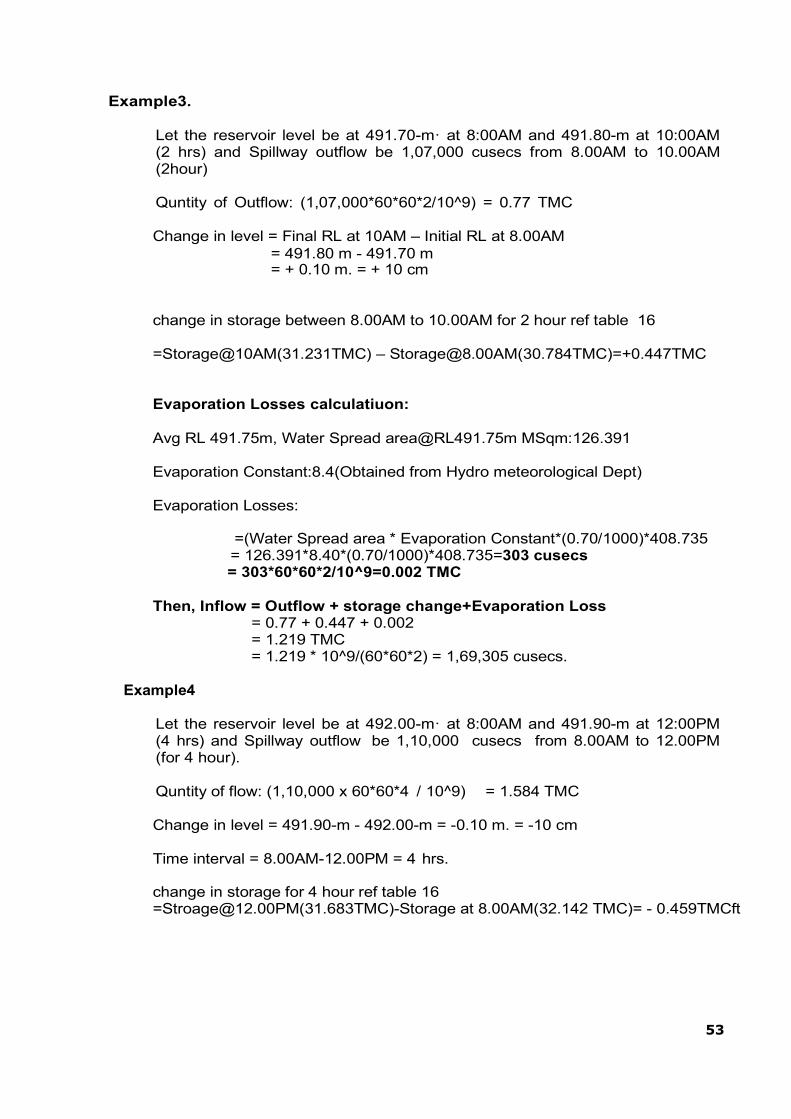
53
Example3.
Let the reservoir level be at 491.70-m· at 8:00AM and 491.80-m at 10:00AM (2 hrs) and Spillway outflow be 1,07,000 cusecs from 8.00AM to 10.00AM (2hour)
Quntity of Outflow: (1,07,000*60*60*2/10^9) = 0.77 TMC
Change in level = Final RL at 10AM – Initial RL at 8.00AM = 491.80 m - 491.70 m = + 0.10 m. = + 10 cm
change in storage between 8.00AM to 10.00AM for 2 hour ref table 16
=Storage@10AM(31.231TMC) – [email protected](30.784TMC)=+0.447TMC
Evaporation Losses calculatiuon:
Avg RL 491.75m, Water Spread [email protected] MSqm:126.391
Evaporation Constant:8.4(Obtained from Hydro meteorological Dept)
Evaporation Losses:
=(Water Spread area * Evaporation Constant*(0.70/1000)*408.735 = 126.391*8.40*(0.70/1000)*408.735=303 cusecs = 303*60*60*2/10^9=0.002 TMC
Then, Inflow = Outflow + storage change+Evaporation Loss
= 0.77 + 0.447 + 0.002 = 1.219 TMC = 1.219 * 10^9/(60*60*2) = 1,69,305 cusecs.
Example4
Let the reservoir level be at 492.00-m· at 8:00AM and 491.90-m at 12:00PM (4 hrs) and Spillway outflow be 1,10,000 cusecs from 8.00AM to 12.00PM (for 4 hour).
Quntity of flow: (1,10,000 x 60*60*4 / 10^9) = 1.584 TMC
Change in level = 491.90-m - 492.00-m = -0.10 m. = -10 cm
Time interval = 8.00AM-12.00PM = 4 hrs.
change in storage for 4 hour ref table 16 [email protected](31.683TMC)-Storage at 8.00AM(32.142 TMC)= - 0.459TMCft

54
Evaporation Losses calculatiuon:
Avg RL 491.95 m, Water Spread [email protected] MSqm:129.785 Evaporation Constant:6.00(Obtained from Hydro meteorological Dept) Evaporation Losses:
=(Water Spread area * Evaporation Constant*(0.70/1000)*408.735 = 129.785*6.00*(0.70/1000)*408.735=222 cusecs = 222*60*60*4/10^9=0.003 TMC
Then, Inflow = Outflow + storage change + Evaporation Loss
= 1.584 – 0.459 + 0.003 = 1.128 TMC = 1.128 * 10^9/(60*60*4) = 78,333 cusecs.
2.11.3 Example of Computation for Required Gate Opening
Let FRL be 492.250 m, the reservoir level be at 491.70m at 8· A.M., 491.80m at 10 A.M (2 hrs). and total outflow between 8 AM to 10 AM be 1,07,000 cusecs.Then, from Example 3 above, the inflow is 1,69,305 cusecs (4794 cumecs).
From Table 17 spillway discharge table ,all the 30 the gate to be kept at 0.80m opening(each gate 179 cumecs/6300 cusecs) for safely passing surplus inflow and observe the RL for the next hour.Repeat the same procedure for rise or fall of RL so as to pass surplus water from the reservoir).
2.11.4 Summary of Flood Regulation Procedure.
The flood regulation procedures at Narayanpur can be summarized in the following steps:
1. Observe the reservoir level at 1 hour intervals. 2. Determine the total outflow occurring at all outlets (including river
sluices, canals, spillway, turbines) 3. Estimate the inflow by the method given in 2.11.2 4. Determine the desired gate opening required for passing the
surplus water from (Refer Table 17 ) 5. Open all 25 main spillway and then 5 nos additional spillway gates
to the extent of outflow required in the proper sequence to maintain the safe reservoir level by making inflows and outflows equal .
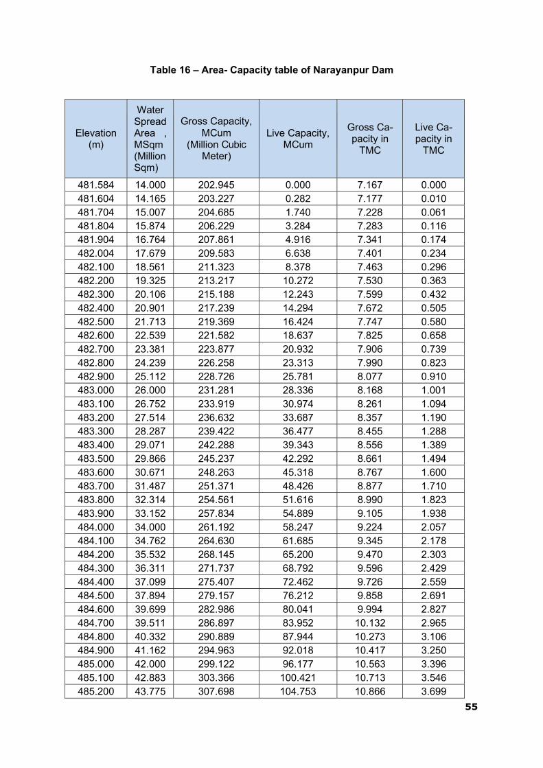
55
Table 16 – Area- Capacity table of Narayanpur Dam
Elevation (m)
Water Spread Area , MSqm (Million Sqm)
Gross Capacity, MCum
(Million Cubic Meter)
Live Capacity, MCum
Gross Ca- pacity in
TMC
Live Ca- pacity in
TMC
481.584 14.000 202.945 0.000 7.167 0.000 481.604 14.165 203.227 0.282 7.177 0.010 481.704 15.007 204.685 1.740 7.228 0.061 481.804 15.874 206.229 3.284 7.283 0.116 481.904 16.764 207.861 4.916 7.341 0.174 482.004 17.679 209.583 6.638 7.401 0.234 482.100 18.561 211.323 8.378 7.463 0.296 482.200 19.325 213.217 10.272 7.530 0.363 482.300 20.106 215.188 12.243 7.599 0.432 482.400 20.901 217.239 14.294 7.672 0.505 482.500 21.713 219.369 16.424 7.747 0.580 482.600 22.539 221.582 18.637 7.825 0.658 482.700 23.381 223.877 20.932 7.906 0.739 482.800 24.239 226.258 23.313 7.990 0.823 482.900 25.112 228.726 25.781 8.077 0.910 483.000 26.000 231.281 28.336 8.168 1.001 483.100 26.752 233.919 30.974 8.261 1.094 483.200 27.514 236.632 33.687 8.357 1.190 483.300 28.287 239.422 36.477 8.455 1.288 483.400 29.071 242.288 39.343 8.556 1.389 483.500 29.866 245.237 42.292 8.661 1.494 483.600 30.671 248.263 45.318 8.767 1.600 483.700 31.487 251.371 48.426 8.877 1.710 483.800 32.314 254.561 51.616 8.990 1.823 483.900 33.152 257.834 54.889 9.105 1.938 484.000 34.000 261.192 58.247 9.224 2.057 484.100 34.762 264.630 61.685 9.345 2.178 484.200 35.532 268.145 65.200 9.470 2.303 484.300 36.311 271.737 68.792 9.596 2.429 484.400 37.099 275.407 72.462 9.726 2.559 484.500 37.894 279.157 76.212 9.858 2.691 484.600 39.699 282.986 80.041 9.994 2.827 484.700 39.511 286.897 83.952 10.132 2.965 484.800 40.332 290.889 87.944 10.273 3.106 484.900 41.162 294.963 92.018 10.417 3.250 485.000 42.000 299.122 96.177 10.563 3.396 485.100 42.883 303.366 100.421 10.713 3.546 485.200 43.775 307.698 104.753 10.866 3.699

56
Elevation (m)
Water Spread Area , MSqm (Million Sqm)
Gross Capacity,
MCum (Million Cubic
Meter)
Live Capacity, MCum
Gross Ca- pacity in
TMC
Live Ca- pacity in
TMC
485.300 44.676 312.120 109.175 11.023 3.856 485.400 45.587 316.634 113.689 11.182 4.015 485.500 46.506 321.239 118.294 11.345 4.178 485.600 47.435 325.936 122.991 11.510 4.343 485.700 48.373 330.726 127.781 11.680 4.513 485.800 49.320 335.611 132.666 11.852 4.685 485.900 50.729 340.598 137.653 12.028 4.861 486.000 53.233 345.795 142.850 12.212 5.045 486.100 55.798 351.246 148.301 12.404 5.237 486.200 58.423 356.957 154.012 12.606 5.439 486.300 61.108 362.933 159.988 12.817 5.650 486.400 63.854 369.181 166.236 13.038 5.871 486.500 65.590 375.653 172.708 13.266 6.099 486.600 67.349 382.299 179.354 13.501 6.334 486.700 69.131 389.123 186.178 13.742 6.575 486.800 70.478 396.109 193.164 13.989 6.822 486.900 71.723 403.219 200.274 14.240 7.073 487.000 72.979 410.454 207.509 14.495 7.328 487.100 74.245 417.815 214.870 14.755 7.588 487.200 75.523 425.303 222.358 15.020 7.853 487.300 76.811 432.920 229.975 15.289 8.122 487.400 78.111 440.666 237.721 15.562 8.395 487.500 79.421 448.542 245.597 15.840 8.673 487.600 80.742 456.550 253.605 16.123 8.956 487.700 82.074 464.691 261.746 16.411 9.244 487.800 83.215 472.959 270.014 16.703 9.536 487.900 84.228 481.331 278.386 16.998 9.831 488.000 85.246 489.805 286.860 17.297 10.130 488.100 86.271 498.381 295.436 17.600 10.433 488.200 87.303 507.060 304.115 17.907 10.740 488.300 88.340 515.842 312.897 18.217 11.050 488.400 89.383 524.728 321.783 18.531 11.364 488.500 90.433 533.719 330.774 18.848 11.681 488.600 91.406 542.813 339.868 19.169 12.002 488.700 92.301 551.998 349.053 19.494 12.327 488.800 93.201 561.274 358.329 19.821 12.654 488.900 94.105 570.639 367.694 20.152 12.985 489.000 95.013 580.095 377.150 20.486 13.319

57
Elevation (m)
Water Spread Area , MSqm (Million Sqm)
Gross Capacity, MCum
(Million Cubic Meter)
Live Capacity, MCum
Gross Ca- pacity in
TMC
Live Ca- pacity in
TMC
489.100 95.926 589.642 386.697 20.823 13.656 489.200 96.843 599.280 396.335 21.164 13.997 489.300 97.764 609.010 406.065 21.507 14.340 489.400 98.690 618.833 415.888 21.854 14.687 489.500 99.620 628.748 425.803 22.204 15.037 489.600 100.554 638.757 435.812 22.558 15.391 489.700 101.493 648.859 445.914 22.914 15.747 489.800 102.436 659.056 456.111 23.275 16.108 489.900 103.377 669.347 466.402 23.638 16.471 490.000 104.257 679.728 476.783 24.005 16.838 490.100 105.141 690.198 487.253 24.374 17.207 490.200 106.028 700.757 497.812 24.747 17.580 490.300 106.920 711.404 508.459 25.123 17.956 490.400 107.815 722.141 519.196 25.502 18.335 490.500 108.713 732.967 530.022 25.885 18.718 490.600 109.616 743.883 540.938 26.270 19.103 490.700 110.522 754.890 551.945 26.659 19.492 490.800 111.432 765.988 563.043 27.051 19.884 490.900 112.345 777.177 574.232 27.446 20.279 491.000 113.263 788.457 585.512 27.844 20.677 491.100 114.184 799.829 596.884 28.246 21.079 491.200 116.033 811.340 608.395 28.652 21.485 491.300 117.898 823.037 620.092 29.066 21.899 491.400 119.777 834.920 631.975 29.485 22.318 491.500 121.671 846.992 644.047 29.912 22.745 491.600 123.580 859.255 656.310 30.345 23.178 491.700 125.503 871.709 668.764 30.784 23.617 491.800 127.279 884.351 681.406 31.231 24.064 491.900 128.950 897.161 694.216 31.683 24.516 492.000 130.621 910.138 707.193 32.142 24.975 492.100 132.258 923.283 720.338 32.606 25.439 492.200 133.750 936.584 733.639 33.075 25.908 492.250 134.500 943.290 740.345 33.312 26.145

Elevation - Area- Capacity Curve of Narayanpur Dam
58

59
Table 17 – Spillway discharge of one gate operation in (Q in cumecs )
No. of Gates : 30(25+5) Size: 15m X 12.0 m FRL : 492.252m Crest: 480.252m Gate Seal 480.103m
Gate opening Sl No in meter
0.20
0.40
0.60
0.80
0.90
1.00
1.20
1.40
1.60
1.65
1.80
2.00
2.20
2.40
2.60
2.80
3.00
3.15
3.20
3.40
3.60
3.80 RL in meter 1 2 3 4 5 6 7 8 9 10 11 12 13 14 15 16 17 18 19 20 21 22
1 492.252 46.28 92.56 138.84 185.08 208.00 224.68 257.76 290.84 323.88 332.00 356.96 390.04 423.08 456.00 493.16 530.16 567.16 594.72 601.60 628.60 655.64 682.64 2 492.002 45.56 91.12 136.70 182.24 204.80 221.66 255.04 288.44 321.82 330.00 354.64 387.28 419.92 452.40 488.88 525.20 561.50 588.56 595.38 622.10 648.84 675.58 3 491.752 44.84 89.68 134.56 179.40 201.60 218.64 252.32 286.04 319.76 328.00 352.32 384.52 416.76 448.80 484.60 520.24 555.84 582.40 589.16 615.60 642.04 668.52 4 491.502 44.66 89.34 134.02 178.68 200.80 217.40 250.24 283.10 315.96 324.00 348.24 380.34 412.46 444.40 479.46 514.34 549.20 575.20 582.06 608.94 635.80 662.70 5 491.252 44.48 89.00 133.48 177.96 200.00 216.16 248.16 280.16 312.16 320.00 344.16 376.16 408.16 440.00 474.32 508.44 542.56 568.00 574.96 602.28 629.56 656.88 6 491.002 43.60 87.22 130.82 174.40 196.00 212.16 244.16 276.16 308.16 316.00 340.16 372.16 404.16 436.00 469.78 503.36 536.96 562.00 568.86 595.74 622.60 649.50 7 490.752 42.72 85.44 128.16 170.84 192.00 208.16 240.16 272.16 304.16 312.00 336.16 368.16 400.16 432.00 465.24 498.28 531.36 556.00 562.76 589.20 615.64 642.12 8 490.502 42.28 84.54 126.82 169.06 190.00 205.96 237.58 269.20 300.82 308.56 332.60 364.46 396.30 428.00 460.16 492.16 524.16 548.00 554.78 581.34 607.88 634.46 9 490.252 41.84 83.64 125.48 167.28 188.00 203.76 235.00 266.24 297.48 305.12 329.04 360.76 392.44 424.00 455.08 486.04 516.96 540.00 546.80 573.48 600.12 626.80
10 490.002 41.30 82.58 123.88 165.16 185.60 201.08 231.74 262.40 293.06 300.56 324.20 355.52 386.84 418.00 449.08 480.04 510.96 534.00 540.66 566.80 592.92 619.06 11 489.752 40.76 81.52 122.28 163.04 183.20 198.40 228.48 258.56 288.64 296.00 319.36 350.28 381.24 412.00 443.08 474.04 504.96 528.00 534.52 560.12 585.72 611.32 12 489.502 39.96 79.92 119.88 159.82 179.60 194.74 224.72 254.68 284.66 292.00 314.96 345.34 375.76 226.00 436.54 466.96 497.36 520.00 526.52 552.12 577.72 603.32 13 489.252 39.16 78.32 117.48 156.60 176.00 191.08 220.96 250.80 280.68 288.00 310.56 340.40 370.28 40.00 430.00 459.88 489.76 512.00 518.52 544.12 569.72 595.32 14 489.002 38.54 77.06 115.60 154.12 173.20 188.12 217.68 247.20 276.76 284.00 306.40 336.04 365.70 215.20 424.36 453.38 482.40 504.00 510.52 536.12 561.72 587.32 15 488.752 37.92 75.80 113.72 151.64 170.40 185.16 214.40 243.60 272.84 280.00 302.24 331.68 361.12 390.40 418.72 446.88 475.04 496.00 502.52 528.12 553.72 579.32 16 488.502 37.44 74.84 112.28 149.72 168.24 182.62 211.10 239.54 268.02 275.00 297.00 326.12 355.24 384.20 412.02 439.70 467.38 488.00 494.46 519.86 545.24 570.62 17 488.252 36.96 73.88 110.84 147.80 166.08 180.08 207.80 235.48 263.20 270.00 291.76 320.56 349.36 378.00 405.32 432.52 459.72 480.00 486.40 511.60 536.76 561.92 18 488.002 36.18 73.88 108.54 144.74 162.64 176.56 204.12 231.68 259.24 266.00 287.22 315.34 343.44 371.40 398.36 425.18 452.00 472.00 478.24 502.80 527.32 551.84 19 487.752 35.40 70.84 106.24 141.68 159.20 173.04 200.44 227.88 255.28 262.00 282.68 310.12 337.52 364.80 391.40 417.84 444.28 464.00 470.08 494.00 517.88 541.76 20 487.502 34.60 69.24 103.84 138.48 155.60 169.36 196.60 223.88 251.12 257.80 278.04 304.88 331.70 358.40 384.34 410.16 435.96 455.20 461.28 485.20 509.08 532.96 21 487.252 33.80 67.64 101.44 135.28 152.00 165.68 192.76 219.88 246.96 253.60 273.40 299.64 325.88 352.00 377.28 402.48 427.64 446.40 452.48 476.40 500.28 524.16 22 487.002 32.92 65.86 98.78 131.72 148.00 161.30 187.64 214.00 240.34 246.80 266.36 292.28 318.20 344.00 368.64 393.20 417.72 436.00 442.12 466.12 490.12 514.12 23 486.752 32.04 64.08 96.12 128.16 144.00 156.92 182.52 208.12 233.72 240.00 259.32 284.92 310.52 336.00 360.00 383.92 407.80 425.60 431.76 455.84 479.96 504.08 24 486.502 31.68 63.36 95.04 126.72 142.40 154.84 179.50 204.16 228.82 234.86 253.44 278.06 302.68 327.18 350.92 374.56 398.20 415.80 421.88 445.72 469.56 493.40 25 486.252 31.32 62.64 93.96 125.28 140.80 152.76 176.48 200.20 223.92 229.72 247.56 271.20 294.84 318.36 341.84 365.20 388.60 406.00 412.00 435.60 459.16 482.72 26 486.002 30.44 60.86 91.30 121.72 136.80 148.54 171.82 195.10 218.36 224.06 241.60 264.84 288.06 311.18 333.96 356.62 379.32 396.20 402.38 426.66 450.92 475.18 27 485.752 29.56 59.08 88.64 118.16 132.80 144.32 167.16 190.00 212.80 218.40 235.64 258.48 281.28 304.00 326.08 348.04 370.04 386.40 392.76 417.72 442.68 467.64 28 485.502 28.80 57.58 86.36 115.14 129.40 140.68 163.04 185.38 207.72 213.20 230.04 252.34 274.62 296.80 317.92 338.92 359.96 375.60 382.70 410.54 433.74 466.22 29 485.252 28.04 56.08 84.08 112.12 126.00 137.04 158.92 180.76 202.64 208.00 224.44 246.20 267.96 289.60 309.76 329.80 349.88 364.80 372.64 403.36 424.80 464.80 30 485.002 27.06 54.12 81.16 108.20 121.60 132.42 153.88 175.30 196.74 202.00 217.88 238.88 259.90 280.80 300.10 319.30 338.50 352.80 362.32
31 484.752 26.08 52.16 78.24 104.28 117.20 127.80 148.84 169.84 190.84 196.00 211.32 231.56 251.84 272.00 290.44 308.80 327.12 340.80 352.00 485.25 485.42 485.75 32 484.502 25.50 51.00 76.50 101.98 114.60 124.72 144.78 164.82 184.86 189.78 204.54 224.06 243.58 263.02 283.22 303.34 323.42 338.40
33 484.252 24.92 49.84 74.76 99.68 112.00 121.64 140.72 159.80 178.88 183.56 197.76 216.56 235.32 254.04 276.00 297.88 319.72 336.00 484.75
34 484.002 24.02 48.06 72.08 96.12 108.00 117.12 135.20 153.28 171.34 175.78 189.32 207.26 225.16 243.02 271.20
35 483.752 23.12 46.28 69.40 92.56 104.00 112.60 129.68 146.76 163.80 168.00 180.88 197.96 215.00 232.00 266.40 484.25 484.55 484.65
36 483.502 22.24 44.50 66.74 89.00 100.00 108.28 124.72 141.16 157.56 161.60 175.78 191.78 213.32
37 483.252 21.36 42.72 64.08 85.44 96.00 103.96 119.76 135.56 151.32 155.20 170.68 185.60 211.64 483.75 484.05
38 483.002 20.46 40.94 61.40 81.88 92.00 99.42 114.16 128.88 143.58 147.20 165.34
39 482.752 19.56 39.16 58.72 78.32 88.00 94.88 108.56 122.20 135.84 139.20 160.00 483.25 483.55
40 482.502 18.68 37.38 56.06 74.76 84.00 91.22 105.52 119.80 134.10 137.60
41 482.252 17.80 35.60 53.40 71.20 80.00 87.56 102.48 117.40 132.36 136.00 482.97
42 482.002 17.30 35.00 51.70 67.60 76.86
43 481.752 16.80 34.40 50.00 64.00 73.72 482.1 482.25 482.5 482.65 482.72
44 481.502 16.60 33.60 49.60
45 481.252 16.40 32.80 49.20 481.75 481.83
46 481.002 15.80
47 480.752 15.20 481.25 481.55
48 480.502
49 480.252 480.8

60
Table 17 – Spillway discharge of one gate operation in (Q in cumecs ) Continued...
Sl No
Gate opening in meter
3.90
4.00
4.20
4.40
4.60
4.65
4.80
5.00
5.20
5.40
5.60
5.80
6.00
6.15
6.2
6.4
6.6
6.8
6.9
7
7.2
7.4
7.6
7.65
RL in meter 23 24 25 26 27 28 29 30 31 32 33 34 35 36 37 38 39 40 41 42 43 44 45 46
1 492.252 696.00 713.52 748.24 782.92 817.60 826.12 847.04 874.72 902.44 930.00 965.04 999.92 1034.80 1060.80 1068.36 1098.00 1127.68 1157.32 1172.00 1188.16 1220.16 1252.16 1284.16 1292.002 492.002 688.80 706.02 740.12 774.22 808.30 816.66 837.66 865.48 893.32 921.00 955.84 990.50 1025.16 1051.00 1058.60 1088.40 1118.24 1148.04 1162.80 1178.86 1210.64 1242.42 1274.22 1282.003 491.752 681.60 698.52 732.00 765.52 799.00 807.20 828.28 856.24 884.20 912.00 946.64 981.08 1015.52 1041.20 1048.84 1078.80 1108.80 1138.76 1153.60 1169.56 1201.12 1232.68 1264.28 1272.004 491.502 676.00 692.64 725.60 758.58 791.52 799.60 820.44 848.08 875.72 903.20 937.88 972.38 1006.88 1032.60 1040.36 1070.82 1101.28 1131.72 1146.80 1162.60 1193.84 1225.08 1256.36 1264.005 491.252 670.40 686.76 719.20 751.64 784.04 792.00 812.60 839.92 867.24 894.40 929.12 963.68 998.24 1024.00 1031.88 1062.84 1093.76 1124.68 1140.00 1155.64 1186.56 1217.48 1248.44 1256.006 491.002 662.80 678.80 710.48 742.16 773.84 781.60 802.44 830.08 857.72 885.20 920.24 955.12 990.00 1016.00 1023.84 1054.62 1085.40 1116.16 1131.40 1146.62 1179.68 1208.34 1244.22 1252.007 490.752 655.20 670.84 701.76 732.68 763.64 771.20 792.28 820.24 848.20 876.00 911.36 946.56 981.76 1008.00 1015.80 1046.40 1077.04 1107.64 1122.80 1137.60 1172.80 1199.20 1240.00 1248.008 490.502 647.60 662.96 693.36 723.74 754.16 761.60 782.76 810.80 838.84 866.74 901.64 936.38 971.12 997.00 1004.92 1035.94 1067.00 1098.04 1113.40 1130.50 1167.30 1195.60
9 490.252 640.00 655.08 684.96 714.80 744.68 752.00 773.24 801.36 829.48 857.48 891.92 926.20 960.48 986.00 994.04 1025.48 1056.96 1088.44 1104.00 1123.40 1161.80 1192.00 490.90 490.9410 490.002 632.00 646.82 676.16 705.48 734.82 742.00 763.50 791.96 820.42 848.74 883.12 917.32 951.52 977.00 985.02 1012.74 1040.48 1080.22 1098.00 1119.70
11 489.752 624.00 638.56 667.36 696.16 724.96 732.00 753.76 782.56 811.36 840.00 874.32 908.44 942.56 968.00 976.00 1000.00 1024.00 1072.00 1092.00 1116.00 490.42 490.60
12 489.502 616.00 630.28 658.54 686.82 715.08 722.00 743.76 772.56 801.36 830.00 863.78 897.36 930.96 956.00 964.00 990.80 1016.80
13 489.252 608.00 622.00 649.72 677.48 705.20 712.00 733.76 762.56 791.36 820.00 853.24 886.28 919.36 944.00 952.00 981.60 1009.60 489.80 489.95 490.10
14 489.002 600.00 613.46 640.12 666.80 693.46 700.00 722.16 751.48 780.82 810.00 839.62 875.94 910.08 936.00 948.00 978.80
15 488.752 592.00 604.92 630.52 656.12 681.72 688.00 710.56 740.40 770.28 800.00 826.00 865.60 900.80 928.00 944.00 976.00 489.40
16 488.502 583.20 595.76 620.64 645.54 670.42 676.52 699.80 730.64 761.48 792.16 815.40 860.80 898.40
17 488.252 574.40 586.60 610.76 634.96 659.12 665.04 689.04 720.88 752.68 784.32 804.80 856.00 896.00 488.85 488.90 489.15
18 488.002 564.00 576.02 599.84 623.68 647.48 653.32 677.24 708.94 740.64 772.16 798.40
19 487.752 553.60 565.44 588.92 612.40 635.84 641.60 665.44 697.00 728.60 760.00 792.00 488.35 488.60
20 487.502 544.80 556.10 578.52 600.92 623.30 628.80 655.22 686.50 725.20
21 487.252 536.00 546.76 568.12 589.44 610.76 616.00 645.00 676.00 721.80 487.75 488.00
22 487.002 526.00 536.34 556.82 577.30 597.78 602.80 626.50
23 486.752 516.00 525.92 545.52 565.16 584.80 589.60 608.00 487.25 487.55
24 486.502 505.20 515.92 537.14 552.58 579.60 584.80
25 486.252 494.40 505.92 528.76 540.00 574.40 580.00 486.80
26 486.002 487.20 500.96
27 485.752 480.00 496.00 486.25 486.35 486.56 486.72
28 485.502
29 485.252 485.85 485.97
30 485.002
31 484.752
32 484.502
33 484.252
34 484.002
35 483.752
36 483.502
37 483.252
38 483.002
39 482.752
40 482.502
41 482.252
42 482.002
43 481.752
44 481.502
45 481.252
46 481.002
47 480.752
48 480.502
49 480.252

61
Table 17 – Spillway discharge of one gate operation in (Q in cumecs ) Continued...
Sl No
Gate opening
in meter
7.70
7.80
8.00
8.20
8.40
8.60
8.80
9.00
9.20
9.40
9.60
9.80
10.00
10.20
10.40
10.50 47 48 49 50 51 52 53 54 55 56 57 58 59 60 61 62 RL in meter
1 492.252 1136.03 1149.23 1175.50 1201.60 1227.43 1253.10 1278.57 1303.80 1328.83 1353.63 1443.10 1443.10 1443.10 1443.10 1443.10 1443.10 2 492.002 1122.32 1135.32 1161.18 1186.85 1212.28 1237.53 1262.57 1287.37 1346.55 1358.95 1403.68 1403.68 1403.68 1403.68 1403.68 1403.68 3 491.752 1108.60 1121.40 1146.87 1172.10 1197.13 1221.97 1246.57 1270.93 1364.27 1364.27 1364.27 1364.27 1364.27 1364.27 1364.27 1364.27 4 491.502 1094.55 1107.13 1132.17 1156.98 1181.58 1205.98 1266.68 1278.87 1189.77 1189.77 1189.77 1189.77 1189.77 1189.77 1189.77 1189.77 5 491.252 1080.50 1092.87 1117.47 1141.87 1166.03 1190.00 1286.80 1286.80 1015.27 1015.27 1015.27 1015.27 1015.27 1015.27 1015.27 1015.27 6 491.002 1066.05 1078.22 1102.38 1126.33 1188.37 1200.35 1248.75 1248.75 1028.18 1028.18 1028.18 1028.18 1028.18 1028.18 1028.18 1028.18 7 490.752 1051.60 1063.57 1087.30 1110.80 1210.70 1210.70 1210.70 1210.70 1041.10 1041.10 1041.10 1041.10 1041.10 1041.10 1041.10 1041.10 8 490.502 1036.77 1063.57 1111.65 1123.40 1173.35 1173.35 1173.35 1173.35 1088.55 1088.55 1088.55 1088.55 1088.55 1088.55 1088.55 1088.55 9 490.252 1021.93 1063.57 1136.00 1136.00 1136.00 1136.00 1136.00 1136.00 1136.00 1136.00 1136.00 1136.00 1136.00 1136.00 1136.00 1136.00
10 490.002 1042.37 1063.57 1099.40 1099.40 1099.40 1099.40 1099.40 1099.40 1099.40 1099.40 1099.40 1099.40 1099.40 1099.40 1099.40 1099.40 11 489.752 1062.80 1062.80 1062.80 1062.80 1062.80 1062.80 1062.80 1062.80 1062.80 1062.80 1062.80 1062.80 1062.80 1062.80 1062.80 1062.80 12 489.502 1026.93 1026.93 1026.93 1026.93 1026.93 1026.93 1026.93 1026.93 1026.93 1026.93 1026.93 1026.93 1026.93 1026.93 1026.93 1026.93 13 489.252 991.07 991.07 991.07 991.07 991.07 991.07 991.07 991.07 991.07 991.07 991.07 991.07 991.07 991.07 991.07 991.07
Note : Highlighted figures are gate controlled discharges . Non-highlighted figure are free discharges

62
This Page left blank intentionally

63
THIS PAGE LEFT BLANK INTENTIONALLY

64
2.12 Operation of Radial Crest Gates of Narayanpur Dam
2.12.1 Brief Description.
The spillway Radial Gates of Narayanpur Project are 30 Nos ,having size of 15M x 12 M used to regulate the flood discharge in the reservoir corresponding to MWL 492.252 M. The gates operated by rope drum hoists mounted on hoist chassis. The hoists are having Rope Drums over which wire ropes wound and connected to gates on upstream side of skin plate. The design of the Gate parts and hoists confirm to IS : 4623 – 1967 The Gates provided with side and bottom rubber seals to prevent leakage.
2.12.2 TECHNICAL DATA
1. No. of Gates 2. Size of Gates 3. Radius of Gates 4. Top of Gate 5. Maximum Water Level 6. Full Reservoir Level 7. Clear width of opening 8. Elevation of Spillway Crest 9. Elevation of sill 10. Elevation of Trunnion pin centre
: 30 Nos : 15 m x 12 m : 12.00 m : 492. 652 m. : 492. 252 m : 492. 252 m : 15 m : 480.252 m : 480.103 m : 484.650 m

65
2.12.3 HOIST DETAILS
1. Capacity of Hoist : 100 M. T 2. Type of hoist : Rope Drum Hoist 3. Lifting/ Lowering speed of the Gate : 0.426 M / Minutes 4. Braking device : Electro-magnetic brake
250mm dia 440V AC Single phase. 5. Maximum Lift of Gate : 7.65 M. 6. Hoisting Rope : 6x37 Const. Hemp main core
40mm dia 7. Drive : Squirrel cage induction motor
15Hp.960RPM 440/400V. Cycles power factor 0.8
8. Control : Reversible type push button starter Located in thedrive unit

66
2.12.4 EMBEDDED PARTS
The Embedded parts consists of vertical anchor Rods, Rest Beam, Thrust Pads, Trunnion Bracket, Yoke Girder, Tie Flats, Anchor Girder etc.
The vertical Rod is 80mm dia meter and 2.400 M. Long, 12 Nos. per pier, embedded in the concrete and projected above the concrete from 482.653 to 483.790 M.
The Rest Beam made out of 40mm, 18mm, 10mm M.S plates inserted on to the vertical rods and fixed in position by means of nuts.
The anchor girder and yoke girder connected by means of 50mm thick 200 mm width Tie flats made out of mild steel confirm to IS:226. The Anchor Girders fully welded to the tie flats and embedded in the concrete.
The yoke Girder welded to Tie Flats after pretensioning to the pressure of 40 kg/cm2 provided between bracket and yoke girder for preventing bulking of yoke girder under load. The pad plate welded to yoke Girder and fixed to brackets by means of 50mm dia Bolts. A 10mm gap maintained between pad plate and yoke Girder and filled with zinc to ensure perfect bearing transmission of load.
The Thrust pads made out of Mild Steel and fixed with 12mm thick gun metal flats. The gun metal flats are provided to minimize the frictional forces during the movement of Pedestal when the Gate is under hydraulic thrust. The Thrust pads transmits the horizontal components of the thrust.

67
2.12.5 GATE LEAF:
The trunnions made out of cast steel confirm to IS : 1030-1962 fixed on to the thrust pad and connected to the Bracket (Pedestal) by means of trunnion Pin made out of cast steel. The bore of the Trunnion provided with gun metal bush and Trunnion Pin machined to the standard tolerance of H7/h6 (Running fit). The bracket (pedestal) fabricated out of M.S. Plates and suitable stiffeners are provided to resist bending of bracket under load.
The arms fabricated out of ISMB 600 and flanges strengthened by welding with 20 mm plates. The arms fixed to the Trunnions by means of 32 mm dia bolts. The other end of the Arms welded to termination plates provided in the Horizontal girder. The Bolts also provided to take up side thrust in the Gates. The Arm works as a column and transmits load from Horizontal Girder to Trunnion. The bracings fabricated out of ISMC 200 provided to increase rigidity in arms. The bracings are so provided so that I/r ratio is equal both in transverse and longitudinal directions. The Horizontal Girders welded to arms one side and vertical girders on upstream side. The Horizontal girders are so provided that chord length between the centre line of Horizontal Girders is kept up in order to maintain radius of 12M. The horizontal girders fabricated out of 25 mm, 10mm and 8mm MS Plates, vertical girders fabricated out of 25mm and 20mm plates bent to required curvature of 11.210 M. 10 No Vertical girders spaced equally on horizontal girder length wise.
The skin plates fabricated out of 14mm,12mm and 10mm M.S plates and Tees out of ISMB 450. The plates and Tees bent to required curvature of 12M. radius. The tees of the skin plates are welded to vertical girders.
An auxiliary girder provided on either side of the Gate to fix the lifting hook. The lifting hook fabricated out of 40mm and 10mm plates. The bore of the lifting hook machined to accommodate 115 mm dia lifting pin. The lifting Hook in the Gate and lifting Arrangement connected by means of connecting link on one

68
side and by turn Buckle on the other side. The turn Buckle provided for rope adjustments. The lifting arrangement consists of connecting plate, equalizer plates, rope sockets and wire ropes.
The wire rope fixed to rope sockets by pouring molten zinc in the bore of the rope socket after fixing rope in the bore.
A sill beam provided below the bottom of the skin plate which is embedded in the concrete. The sill beam fabricated out of ISMB 250 and provided with 3.15 mm thick Stainless Steel plates for seating the rubber seal fixed to the bottom of the Gate.
Wall plates fixed to the side of the gate and embedded in concrete maintaining proper clearance between gate and wall plate. The wall plates fabricated out of 12mm M.S plates with suitable ribs. It is also provided 3.15 mm stainless steel plate for movement of side rubber seal. The side rubber seal fixed to the side of the skin plate by means of Angles and G.I Bolts. „ Z ‟type seals provided for side rubber seals.
The tie beam trunnions is provided in order to make side thrust of the gate. The tie between trunnions fabricated out of ISMB 600. The Guide rollers are provided in the gate to prevent swaying of the gate.
2.12.6 HOIST:
The 8 Nos wire ropes of gate fixed to the rope drum by means of rope clamps and bolts. The rope drum made out of cast steel. Grooves are provided on rope drum for winding of rope. Rope drum fixed to W1 gear wheel made out of cast steel and meshes with pinion P1. The wheel W3 fixed on pinion P2 shaft and meshes with P3 pinion. Pinion P3 shaft having a flange coupling on both sides fixed to the line shaft one side and to worm reducer on another side. The line shaft over line shaft support girder with suitable supporting brackets and plumber block bearings. The line shaft support girder embedded in the pier concrete.
The 15 HP 960 RPM induction motor drives the worm reducer having reduction ratio 60:1 reduces the speed to 16 RPM. 16 RPM speed transmitted to gear boxes through line shaft to pinion P3. The speed further reduces in the gear box by reduction gears and the final speed of rope drum is 0.1695.
The lifting and lowering speed of the gate is 0.426M/min.
2.12.7 ELECTRO MAGNETIC BRAKE
The Electro magnetic brake provided to control the gates movement. It is provided between motor and worm reducer. Brake shoes open when power supply passes in the brake coils and shoe closes when supply disconnected. This facilities to stop the gate at any desired intermediate position. The brake needs frequent adjustments.
Special care should be taken especially for the following features:-
i. The gap between brake shoe and brake drum in the open position (with
electro magnet switched on) is checked with a feeder guage and should be nearly equal on both sides. The adjustment is done by means of screw 4. The sum total opening on both sides (between brake drum and shoes) is adjusted with nut 1.
69
ii. Braking moment:- The braking moment is adjusted with the spring forces by tightening or loosening the nut.
iii. Brake liners :-
The brake liners needs replacement when liners wear out is more and if the brake slips under load.
iv. Worm Reducer :-
The oil level as indicated in the level gauge provided in the worm reducer may be maintained always.
2.12.8 LIMIT SWITCHES :
3 Nos limit switches are provided in each gate. Two limit switches in the gate position indicator gear box and one limit switch for hand operation in drive unit.
2.12.9 DIAL INDICATOR :
Dial indicator is provided to show the actual lift of the gate from the sill. The dial unit consists of reduction gear unit and connection to shaft P2 of the main gear box by means of chain driver. Extension provided for the output shaft in the dial unit. One lever meant for operating limit switch for cutting power supply automatically when the gate rests on the sill beam. Another lever meant for cutting off power supply when gate reaches to maximum height. The second limit switch can be adjusted to the required height by trial and error. The dial will indicate the height upto 0.10 Mtr.
2.12.10 HAND OPERATION :
Hand operation is provided to operate the gates during power failure. A dog clutch is provided in the driver unit. When hand operation is engaged a lever operates a limit switch and power supply to the motor is cut off. These arrangements prevent power supply to motor during hand operation.

70
2.12.11 LUBRICATION
i. DRUM SHAFT: Grease nipples are provided on both sides of drum shaft having a hole leading to bush bearing of Rope Drum. The greasing is to be done profusely once in three months by means of pressure grease gun.
ii. SHAFT I, II, III:-
24 Ball bearings and bush bearings are provided with grease cups. It shall be ensured that grease cup must be filled with grease always. Grease to be applied by means of grease gun once in three months.
iii. LINE SHAFT SUPPORT BEARING: All the line shaft supports provided with plumber block and a grease cup on plumber block. Profuse greasing to be done regularly once in 3 months.
iv. WORMS REDUCER:- Oil level in the radicon must be maintained to the
gauge level indicated by the gauge provided in each worm reducer. The oil level is to be checked before starting the hoist.
v. GEAR WHEELS :- All the gear wheels shall be profuse greasing done
with thick MP Grease or Cardium compound.
vi. GUIDE ROLLERS:- All the guide rollers provided with grease nipples for greasing. Greasing is to be done with pressure grease gun once in three months.
vii. TRUNNION PIN:- Grease nipples provided for greasing bush bearings
provided in the trunnion hub. It shall be ensured that the pin should not be dried at any circumstances. Greasing is to be done by means of pressure grease gun once in three months
viii. WIRE ROPE:- Wire rope greasing shall be carried out once in a year
before monsoon sets in. Cardium Compound or Servocoat-S may be used for wire rope greasing.
2.12.12 PRECAUTIONS BEFORE STARTING THE MOTOR
I. HOISTS:- a] It shall be ensured before starting that no foreign materials like metal
piece bolts, nuts, wooden pieces, etc. Found in the gear teeth. b] All the bearing and grease cups shall be filled with grease. c] Grease shall be applied for all the gear wheels profusely before
starting.
d] Worm reducer shall be filled with oil up to the level of the gauge provided.
e] It shall be ensured that handles of the hand operation removed from the shaft.
The dog clutch is to disconnected properly.

71
II. GATES:- a] Proper greasing for trunnions shall be ensured.
b] The Guide Rollers must be free from concrete, dirt, stones etc.
c] The concrete, stones, wooden pieces etc. Shall not be allowed to fall on rubber seals. If they fell on the rubber seals there is a possibility of jamming of gate as the pieces clogged between rubber seal and stainless steel plate.
III. ELECTRICAL EQUIPMENT :- a] It shall be ensured that power supply is 430 volts in all the three
phases sequence of supply.
b] It shall be ensured that dog clutch is disengaged properly so that the limit switch will be in off position.
2.12.13 OPERATION OF GATES
1] The main switch fuse unit provided in the Drive unit should be put in “ON” position.
2] Three “Push Button” provided the starter/the forwarded push button shall be operated for lowering of the Gate. (The gate automatically stops if motor over-loaded)
3] If jerky motion observed during Gate operation, Gate shall be stoped immediately and the electro-magnetic brake adjusted slightly. Possible materials shall checked and rectified.
WARNING:-
1] Brake shoes are to be adjusted to the correct braking force.
2] Motor shall not be operated under any circumstances when supply voltage below 380 volts during motor operated ; otherwise motor winding burns.
72
2.12.14 MANUAL OPERATION OF GATE:
In the case of power failure, the dog clutch shall be engaged by the handle provided for that purpose. By rotating the dog clutch shaft, the limit switch, operated by the link system connected to dog clutch shaft will cut off power supply to motor. This will also mechanically release the brake and in turn the brake drum will become free. The gate can be operated by operating the handle manually.
Essential tools required for maintenance work:-
1] D.E. Spanners ( 6mm to 32mm) 01 set 2] Screw Driver 12” 01 No 3] Screw Driver 6” 01 No 4] Cutting flair 8” 01 No 5] Nose flair 01 No 6] Electric Tester 01 No 7] Fuse wire 25 Amp 01 coil 8] Hammer 2 & 6Ib 01 each 9] Hacksaw frame with blade 01 No 10] Grease gun (Teclamite) 01 No 11] Hand lamp 01 No 12] Adjustable screw spanner 01 No 13] Ring spanner set 01 No 14] D.E spanner 50mm size 01 No 15] D.E Spanner 40mm size 01 No
2.12.15 SPECIFICATION OF PARTS USED
i. STARTER/SWITCH
a] Type : DOL Reverseable starter b] Make : TSP c] Capacity :440V 15/11.5HP 20-32A
63A TPN ML 2
ii. MOTOR : a] Type : Squirral cage induction motor b] Make : N.G.E.F. (Licence AEG) c] Capacity :440V 720RPM PF 0.8
double extension shaft d] Frame size : AM 180 L8
iii. ELECTROMAGNETIC BRAKE:
a] Type : PERI GRIP BRAKE (300 dia) b] Make : G.E.C. c] Capacity :440V S.Phase 50cycles 100% coil rating d] Torque capacity :20kg/m
iv. WORM REDUCER: a] Type : U 1200 b] Make : DAVID BROWN c] Ratio : 50:1 d] Capacity : 15 HP
73
v. WIRE ROPE: a] Make : M/s Usha Martin Co.
M/s Fort William Co. b]Size : 40mm dia 6*37 constn.
R.H. Lay, Hemp Core c]Length : 23.88m of 8Nos per gate d]Tensile strength: 180 kg/mm2
vi. BALL BEARINGS IN GEAR BOX :
a] SN 520 PI. Bloc with 1220K Bearing and H 220 sleeve-2 Nos. Per Gear box.
b] SN 522 PI. Bloc with 2222K Bearing and H 322 sleeve-2 Nos.
per Gear box.
c] PBX 140 standard plummer block fitted with Gun metal bush bearing TSP Make 01 No. per Gear box.
d] PBX 160 STANDARD Plummer block fitted with Gun metal bush
bearing TSP Make :01 No. per Gear Box.
vii. PLUMBER BLOCK BEARING FOR LINE SHAFT:- PBX 95 Standard Plummer block fitted with Gun metal bush Bearing TSP Make 08 Nos per Gear box.
viii. RUBBER SEAL :
a) Side Rubber seal : Length : 13480mm Long Type/Make : RSL 5 TSP Make Nos. reqd. : 2 Nos per Gate.
b) Bottom Rubber Seal:
Length : 14732mm Long Type /Make : RSL 27 TSP Make Nos. reqd. : 1 Nos per Gate.
ix. BOLTS FOR RUBBER SEAL :
Size : 16mm dia 80mm long Type : Galvanised Iron Nos. required : (Per Gate) Bottom : 150 Nos. Sides : 266 Nos.
x. LIMIT SWITCHES :
Make : M.B.I. Type : Roller Lever Type Capacity : 500 v. 10A Nos. required : 03 Nos. per Gate.
xi. SPOCKET CHAIN :
Size : ½” pitch Length : 3.5 Mtr. Per Gate

74
U/s Stoplog elements
Stoplog Groove for placing elements
xii. HAND OPERATION SPROCKET CHAIN : Size : 3/4” pitch Length : 2370 mm long
2.13 Stoplog gate (3 set i.e.21 elements) for main spillway gates:
The stoplog gates are provided in order to take up repair of radial crest gates by closing the vent when reservoir filled with water. The stoplog gates operated by means of moving gantry crane mounted on rails embedded in Road Bridge concrete.
The Stop log gate consists of (1) Embedded parts (2) Gate Leaf (3) Lifting Beam.
2.13.1 EMBEDDED PARTS:-
i. Sill Beam:- The sill beam fabricated out of ISMB 250 provided with suitable anchorages and embedded in the concrete. A Stainless Steel plates of having 3.15mm thick welded on the girder flange for providing smooth and even surface for seating of the rubber seal.

75
ii. Roller Track:- The roller track is a load bearing member on which rollers of gate which transfers the water pressure. Then the water pressure transfers to the concrete. The hardness of roller track always maintained 50% more than that the wheel. The roller track fabricated out of ISMB 600 over which forged steel track plates confirm to IS 1575 Class III of air resisting quality suitably welded. The track machined to even surface for smooth movement of roller on the track. The roller track provided with suitable anchorages and embedded in the concrete. The roller track provided upto gate height plus one meter extra.
iii. Side Seal seat :- The side seal seat made out of ISMC 200. The stainless steel clad plate welded on to the channel to provide smooth and even surface for movement of side rubber seal. The side seal seating provided upto 1 gate height plus one meter extra. The side seal channel provided with suitable anchorages and embedded in the concrete.
iv. Side Guide:-
The side guides fabricated out of 25mm plates. These are provided with suitable anchorage and embedded in the concrete. The side guide provided throughout the travel of the gate.
2.13.2 GATE LEAF:-
The water thrust on skin plate transmitted on to the horizontal girder and vertical stiffners. The horizontal girders transmits the load to the end girder which is supported continuously on rollers. Ultimately load transfers on roller track and then to concrete.
The gate leaf consists of skin plates, end box, rollers and lifting check plates.
Skin Plate:-
The skin plates fabricated out of 32mm, 18mm, 14mm 12mm & 10mm Plates. The thickness of plates varies from bottom element to top element as per the variation of thrust from bottom to top. The skin plate suitably supported by truss type of horizontal girders and vertical stiffners. The truss type girder and stiffners welded to skin plate. The truss fabricated out of 75x 75x 8 L: 100x 100x10 L ; 110x110x10 L ; 150x150x12 L ; 150x150x16L ; 150x150x20 L ; & 200 x 200x 20 L ; Each element consists 4 Nos rollers assembled in the end box. The end box fabricated out of 20mm and 10mm plates. The rollers made out of cast steel confirm to IS : 1030. The roller assembled with stainless steel axle machines out of stainless steel rounds confirm to ISI 304 specification. Grease nipples are provided in the axle for lubrication of roller bearing. Spherical roller bearings are provided for assembling of axle with roller. The axle mounted on rollers with an eccentricity. The eccentricity provided in the axle for proper adjustment of rollers get continuous contact of roller with roller track. The vernier plate fixed to axle for adjustment of eccentricity.

76
2.13.3 SPECIFICATION OF SPARES
i. RUBBER SEAL :- Side Seal
Type : RSL 24c Make : TSP
Length/ Nos required : Element No 1 - 1630mm long / 2 Nos Element No 2 - 1610mm long / 2 Nos Element No 3 - 1626mm long / 2 Nos Element No 4 - 1876mm long / 2 Nos Element No 5 - 2006mm long / 2 Nos Element No 6 - 2009mm long / 2 Nos Element No 7 - 2003mm long / 2 Nos
Bottom Seal:-
Type : RSL 33 C Make : TSP Length : 15400mm Nos. required : 1 No for each element
ii. Bolts for Rubber seal :
Type : Galvanized hex bolts and nuts
Nos. Required :
For Side seal
Element No 1 - 16mm dia 90mm long 18 Nos - 16mm dia 110mm long 16Nos
Element No 2 - 16mm dia 110mm long 16 Nos
- 16mm dia 110mm long 16 Nos Element No 3 - 16mm dia 80 mm long 32 Nos
Element No 4 - 16mm dia 92 mm long 16 Nos - 16mm dia 72 mm long 26 Nos
Element No 5 - 16mm dia 72 mm long 30 Nos
- 16mm dia 88 mm long 16 Nos
Element No 6 - 16mm dia 80 mm long 16 Nos - 16mm dia 70 mm long 34 Nos
Element No 7 - 16mm dia 72 mm long 30 Nos
- 16mm dia 88 mm long 16 Nos

77
For Bottom gate :
Element No 1 - 16mm dia 82 mm long 155 Nos
Element No 2 - 16mm dia 72 mm long 154 Nos
Element No 3 - 16mm dia 65 mm long 154 Nos
Element No 4 - 16mm dia 60 mm long 152 Nos
Element No 5 - 16mm dia 64 mm long 152 Nos
Element No 6 - 16mm dia 62 mm long 156 Nos
Element No 7 - 16mm dia 64 mm long 152 Nos
iii. SPHERICAL ROLLER BEARING
No. 23234 : 72 Nos. No. 22234 : 12 Nos
2.14 84 TON Capacity moving Gantry for main spillway gates:
The gantry provided for operation of stop log gates of Main and additional Spillway gates. The 84 ton capacity Gantry crane move on the rails fixed on the road bridge.
The Gantry consists of the following parts:-
1] Gantry track 2] Gantry travel assembly 3] Columns 4] Crane girder 5] Tie girder 6] Counter weight 7] Crab assembly
78
2.14.1 CHARACTERISTIC OF 84 TON GANTRY CRANE
i. Capacity : 84 Ton. ii. Duty : Class II-out door as per IS 3177& IS
807 iii. Speed iv. Long Travel : 8 M/Min +/-10% v. Cross Traverse : 3 M/Min +/-10%
vi. Hoist : 2 M/Min +/-10% vii. Height of lift : 25 Mtrs
viii. Rope : 32mm dia wire rope 6x37 const. Fiber main core four falls. Tensile strength 180kg/mm sq Minimum breaking load 30.6 T length 120 mtrs
ix. Motor Long Travel : 12.5 HP: 960PRM: Squiral cage-2 Nos. Cross Traverse : 5 HP: 960PRM: Squiral cage – 1 No. Hoist : 27 Hp: 715PRM : Slipring 40% DF - 1No.
x. Worm Reducer
Long Travel : Ratio 60:1 ; Type „0‟ ; Size 5” -2 Nos. Cross Traverse : Ratio 60:1 ; Type „0‟ ; Size 5” -1 No. Hoist : Ratio 60: 1 ; Type „0‟ ; Size 10” -1 No.
xi. Brakes
Long Travel : 150 dia E.M.Brake -2 Nos. Cross Traverse : 150 dia E.M.Brake -1 No. Hoist : 200 dia E.M. Brake -1 No.
xii. Control : Pendent operation xiii. Lubrication : Point lubrication system xiv. Crane rail size : 90 lbs xv. Counter weight required : 84 Ton ( Concrete with MS scrap)
xvi. Cable reeling drum : Spring operated cable rely drum suitable for 30 M. cable.
79
2.15 New Stoplog gates for Additional Spillway Gates(one set):
2.15.1 Technical Details :
i. No. of vents : 5 Nos ii. Vent width : 15000mm
iii. C/C of side seals : 15150mm iv. C/C of roller tracks : 15700mm v. Face to face of side guide : 16200mm
vi. Sill level : EL 479.510m vii. FRL : EL 492.252m
viii. Top of Pier : EL 495.752m ix. Top of road bridge : EL 495.752m x. Design head : EL 492.252 – EL 479.510 =
12.742m xi. Top of stoplog in assembled position : EL 492.410m ie., 12900 mm height
xii. No. of stoplog elements : 8 Elements xiii. Location of skin plate : Up stream xiv. Location of seals : Up stream xv. Operated by : Gantry crane
xvi. Type of Gate : Roller type vertical lift gate xvii. Designed : As per IS 4622 -2003

80
2.15.2 Materials :
S.No Components Material Specification
1 All structural members such as skin plate, Horizontal girders, Vertical stiffeners, End box etc.,
Structural Steel IS 2062 – 2006 Grade E250 Quality A / B
2 Wheels Cast steel IS 1030 Grade 340 - 570W
3 Wheel track & Wheel Pin Stainless Steel 20Cr13 IS1570
Part-V
4 Seals Rubber : Bulb seal for sides and flat seals for bottom
IS 11855
5 Seal seats Stainless steel 0.4CR18Ni10 IS1570 Part-V
6 Seal base, Seal clamp guide
Structural steel IS 2062
7 Bearings Antifriction Standard make SKF/ZKL
2.15.3 RUBBER SEALS:-
The rubber seals for gates shall be filed as shown in the drawings or as directed. The tenderer shall carefully spot and accurately drill the holes in the rubber seals. In order to effect a water seal at the junction of the side seal and bottom seal, a special corner pice or any other suitable device shall be used.
The rubber seals shall be moulded from natural synthetic rubber containing not less than one percent of weight of copper inhibiter and shall have the following minimum physical properties.
Shores durometer hardness. -- 65+5 Minimum elongation -- 450% Ultimate tensile strength -- 14.50 kg/mm2 The rubber compound shall not absorb more than 10% by weight in a seven day test. The tensile strength of test specimen after being subjected to an accelerated ageing of 48 hours in oxygen at 700 C and 2.1 mm2 pressure shall be not less than 80% if the strength of the test specimen before ageing.
Details of Rubber Seals Required for Stoplog Gates.
i. Side Rubber seal : Type/ Make Dia 44 X 127 width Teflon claded seal. Size:
Element No. 1 (Bottom element) – 1656 mm long 2 No‟s per Element
Element No. 2 to 7 – 1881 mm long 2 No‟s per Element
81
ii. Bottom Rubber seal: Type/Make RSL - 33 Type (90X14
Size:
Element No. 1 (Bottom element) – 15360 mm long 1 No. per Element Element No. 2 to 7 – 16130 mm long 1 No. per Element
2.15.4 Bolts for rubber seals.
i. Element No. 1 (Non-Interchangeable - Bottom element) 16mm Dia 90 mm LG = 170 No's
16mm Dia 100 mm LG = 40 No's
16mm Dia 115 mm LG = 25 No's
ii. Element No. 2 to 7 (Interchangeable – For one element)
16mm Dia 90 mm LG = 180 No's
16mm Dia 100 mm LG = 50 No's
16mm Dia 115 mm LG = 25 No's
2.16 84 Ton Capacity new Gantry Crane for new Stoplog gates:

82
2.16.1 Technical details:
i. Class and duty : Class II of IS 807 – 2006, IS 3177 – 1999 out door duty & hoist mechanism as per IS 6938 – 2005 and mechanism Class M5
ii. Type of crane : Gantry crane with fixed hoist on D/S and
moving trolley.
iii. Span of the crane : 5500mm
iv. Column: C/C at top : 10000mm
v. C/C at bottom : 11500mm
vi. Total lift : 21.0M i.e., (EL494.250 – EL 479.51)+6.36
vii. Operating speeds : Hoist : 1.20 M/min Crab travel : 3.00 M/min
viii. Gantry travel : 6.00 M/min
ix. Design of crane : Designed as per IS 807 – 2006. IS 3177 – 1999
&IS 6938 - 2005
x. Power supply : 400 / 440V A.C 3 phase 50cycles/sec. Power supply is made available from plug recipticals located at 25.0M intervals along the crane runway
xi. Cross travel rail size : 105lb/yard (52kg/m) tread with 67mm xii. Gantry travel rail size : 105lb/yard (52kg/m) tread width 67mm
xiii. C/C span of CT rail : 10000mm
xiv. Cl of C.G of stop log from Cl of U/S rail : 2582mm adopted 2600mm
Considering variation allowance
xv. Total length of crane Travel :The crane is proposed to mount on
existing rails.
xvi. Motors& controls :Crane duty squirrel cage motors of S4 duty with variable frequency drive controls
2.16.2 Materials:
i. Rope drum and crane wheels : Cast steel IS 1030 – 89 Grade 340 – 570W
ii. Pulleys : Cast steel IS 1030 Grade 280 - 520 iii. Gear wheels : Cast steel IS 1030 – 89 Grade 340 – 570W iv. Pinion : Forged steel
5 C8 IS 2004 or En 9 Yp: 3700kg/cm2 UTS :7242kg/cm2
v. Shafts : Forged steel 45 C8 IS 2004 or En 8 Yp 3200kg/cm2 UTS : 6324kg/cm2
vi. Rolled steel IS 2062 Yp : 2350kg/cm2 UTS : 4180kg/cm2 vii. Structural steel IS 2062 Yp : 2350kg/cm2 UTS : 4180kg/cm2
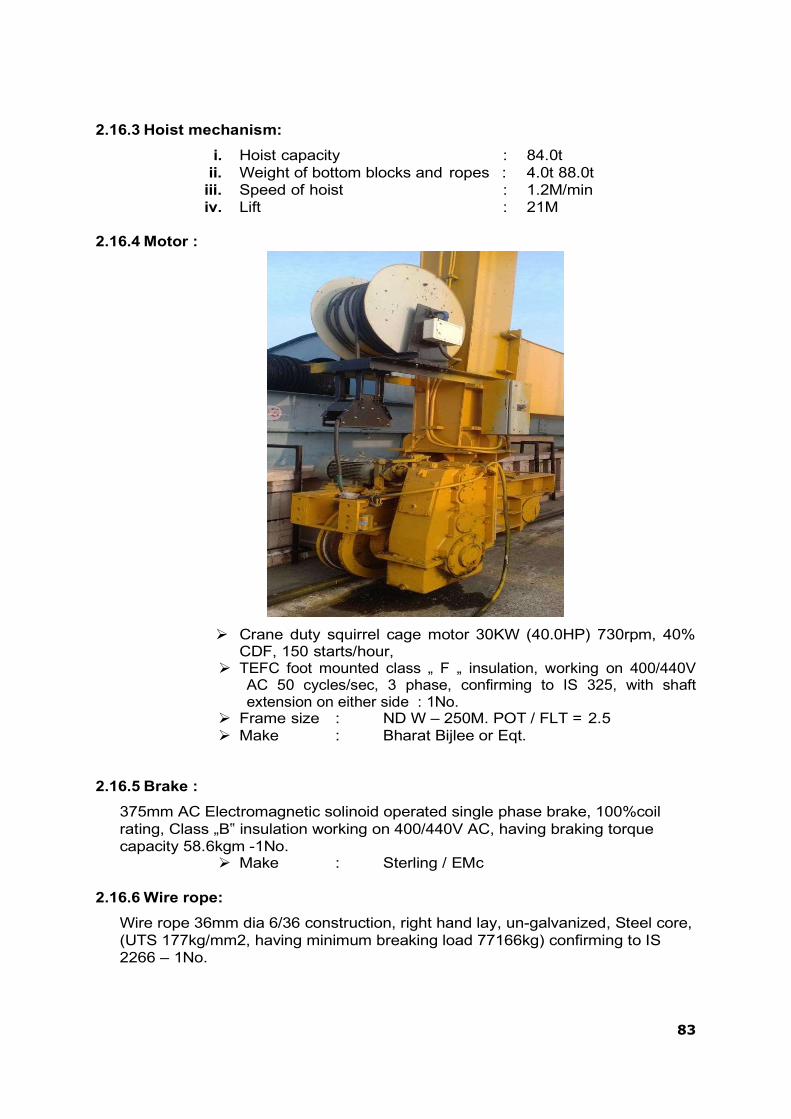
83
2.16.3 Hoist mechanism:
i. Hoist capacity : 84.0t ii. Weight of bottom blocks and ropes : 4.0t 88.0t
iii. Speed of hoist : 1.2M/min iv. Lift : 21M
2.16.4 Motor :
Crane duty squirrel cage motor 30KW (40.0HP) 730rpm, 40% CDF, 150 starts/hour,
TEFC foot mounted class „ F „ insulation, working on 400/440V AC 50 cycles/sec, 3 phase, confirming to IS 325, with shaft extension on either side : 1No.
Frame size : ND W – 250M. POT / FLT = 2.5 Make : Bharat Bijlee or Eqt.
2.16.5 Brake :
375mm AC Electromagnetic solinoid operated single phase brake, 100%coil rating, Class „B‟ insulation working on 400/440V AC, having braking torque capacity 58.6kgm -1No.
Make : Sterling / EMc
2.16.6 Wire rope:
Wire rope 36mm dia 6/36 construction, right hand lay, un-galvanized, Steel core, (UTS 177kg/mm2, having minimum breaking load 77166kg) confirming to IS 2266 – 1No.

84
2.16.7 Rope drum :
Dia of Drum 800mm PCD. Circumference = 2.513M, Lift 21M. Material: Cast steel IS 1030 Grade 340 – 570W.
2.16.8 Reduction unit :
Worm reducer : Worm reducer ratio 50 : 1 ; Type „U‟, size 14” (centre distance), input H.P 42.0, Input speed : 750rpm. Shaft extension on either side, Output torque: 1650 kgm with self locking – 1No. (Premier / Shanthi / Elecon make).
2.16.9 Joint between Rope drum and wheel W1 connection :
6 No. of bolts M20 fit bolts as per IS 3640 Material :Cl 4.6 of IS 1367 YP = 2448kg/cm2 UTS =
4080kg/cm2
2.16.10 Pulley :
720 pulley PCD (36 X 26 = 720Pcd) Material : Cast steel IS 1030 Grade 280 – 520W Bush bearing ID : 140, OD: 170, long: 140 Material : Al Bronze IS305 – Grade AB1
2.16.11 Shafts for Hoist :
Rope Drum Shaft: 11cm shaft Material Forged steel 45 C8 of IS 2004
2.16.12 Bearings :
Bush bearing Aluminum Bronze IS 305 Grade AB1, UTS = 500MPa
W1 side : ID: 110, OD: 135 and 200 long Drum hub side : ID: 110, OD: 135 and 90mm long
2.16.13 Pinion P1 shaft:
Shaft 110mm at key way and 100 at bearing Material Forged steel 45 C 8 IS 2004 or En 8
2.16.14 Bearing: Plummer block SNA 522 TC to suit 100Φ shaft with 22222EK bearing +
H-322 adopter sleeve having Dynamic Capacity: 560KN, Static Capacity : 640KN
2.16.15 Cross Travel Mechanism :
Speed : 3.0 M /min Weight of trolley : 15.0t SWL : 84.0t

85
2.16.16 Motor:
3.7 KW (5HP) 710rpm, squirrel cage, crane duty, 40% CDF, 150 starts / hour,working on 400/440V AC. 3 phase, 50cycles/sec, class „F‟ insulation, TEFC,foot mounted, confirming to IS 325 - 1No. Frame size = ND 160 M
Make : Bharat Bijlee or Eqt.
2.16.17 Brake :
200 AC Electromagnetic solinoid operated single phase brake, 100% coil rating,class „B‟ insulation, working on 400/440V AC 50 cycles/sec having braking torque capacity 15kgM – 1No.
2.16.18 Trolley Wheel:
500 mm wheel Material: Carbon Cast steel IS – 2707 Grade 1 tread hardness
= 350 BHN 2.16.19 Reduction unit :
Speed 3M/min wheel 500mm circumference = 1.5708M Speed of the wheel = 1.91rpm Motor speed = 710rpm, Total reduction required = 710 / 1.91
= 371.728 : 1 2.16.20 Gear Reduction:
stage vertical gear box with ratio 355 : 1, Transmission capacity: 4.5KW at 750rpm input size: SDN – 250 or equivalent with input
and output shaft extension on both sides.
2.16.21 Coupling: Shaft = 110mm (gear box output shaft) Half rigid and Half geared couplings. Size: 44 – X – 105 with torque transmission capacity: 1300kgM. Make : Sterling or EMC or Nuteck
2.16.22 Crane Wheel : Axles : Shaft 120mm, Material: Forged steel 45C8
IS 2004 Bearing No. : 22222E having ID–110, OD–200 and 53thick
having Static capacity : 640KN and Dynamic capacity: 560KN.
Standard 500 wheel with L type bearings to facilitate easy replacement of wheels during maintenance with shortest time.
2.16.23 Trolley Arrangement with fixed pulley :
Pulley : Rope = 36mm, PCD of the pulley = 720 , OD of the pulley =
828mm Shaft : 140mm, Hub length 140mm
2.16.24 Bearing : Bush bearing ID-140, OD-170 and 140 long

86
2.16.25 Material : Al.Bronze IS-305, Grade AB1 UTS: 500Mpa, Permissible stress: 204kg/cm2
2.16.26 Fixed pulleys: 150mm shaft Material: Forged steel 55C8 IS2004 having YP = 350MPa UTS =
710MPa 2.16.27 Wheel Bogie and Column Connection :
Pin : 120 Φ shaft Material : Forged steel IS 2004 or En 8 Area = 177cm2 Zxx = 331cm3
2.16.28 Connection between Rail Girder and Column : 25 Φ reamed holes for M24 fit bolts confirming to IS 3640 Shank area of each bolt = π X 2.52 / 4 = 4.9cm2
2.16.29 Gantry travel mechanism: Gantry travel speed = 6.0M/min Total moving weight of crane = SWL + wt. Of crane + counter
weight = 85+ 90 + 55 = 230t
2.16.30 Motor: 5.5KW (7.5 HP) 710rpm, squirrel cage, crane duty, 40% CDF,
150starts/hour, working on 400/440 V AC. 3 phase, 50cycles/sec, class „B‟/‟F‟
insulation, TEFC foot mounted, confirming to IS 325 – Frame size ND 160 M - 4Nos.
2.16.31 Brake : 200 AC Electromagnetic solenoid operated, single phase brake,
100% coil rating,class „B‟ insulation, working on 400 / 440 V AC. having braking torque capacity 15.0kgm – 2Nos.
2.16.32 Gantry Wheel: 710 wheel having tread width 150mm. No. of wheels provided per
column: 2Nos 2.16.33 Material :
Carbon Cast steel IS 2707 Grade 2 with 350BHN tread hardness.UTS=690kg/cm2
2.16.34 Reduction unit : Nutech vertical gear box having ratio 200 : 1 rating 5.5KW at 710rpm, output shaft with hollow and center distance of input and output shaft required is 705mm. Projection restriction from center line of output shaft to bottom most point is 340mm
2.16.35 Wheel Mechanism : Shaft = 16cm at keyway and 150 at bearing Material forged steel 45 C 8 IS 2004 or En 8
2.16.36 Bearing: Two numbers of 22230CC bearings having dynamic capacity 850KN and static capacity 1200KN.
2.16.37 Bearing size:
ID 150, OD 270 and 73 thickness. Make : SKF or Equivalent

87
2.16.38 Bottom block and lifting beam: Bottom Block :
Pulley Shaft:
shaft : 14 cm Material : Forged steel 45C8 IS 2004
Bearing in Bush :
Size: : ID-140, OD-170, 140 long Material : Aluminum bronze : IS 305 Grade AB1 UTS : 500MPa
Lifting Beam:
2 Nos. of fabricted channels having the following properties. Area = 299.2 cm2 IXX = 237043 cm4 ZXX = 7901 cm3
Hook: Material : IS 2006 Gr E410 YP: 380, MPa = 3876kg / cm2 UTS : 540MPa = 5508kg/cm2
2.17 Right Bank Head Regulator Radial Gates
2.17.1 INTRODUCTION
The Radial Gates for Right Bank Head Regulator are installed to regulate the water in the Right canal. There are 03 Nos Radial Gates of size 6m x 5m operated by 50 ton capacity Rope Drum hoist. There are three vents of stoplog embedded parts. The stoplog gate being operated by 15 ton Gantry moving over the rail embedded in road bridge concrete.
2.17.2 TECHNICAL DATA
1. No. of Gates : 03 Nos 2. Size of Gate : 6 M x 5 M 3. Radius of the Gate : 7.5 M
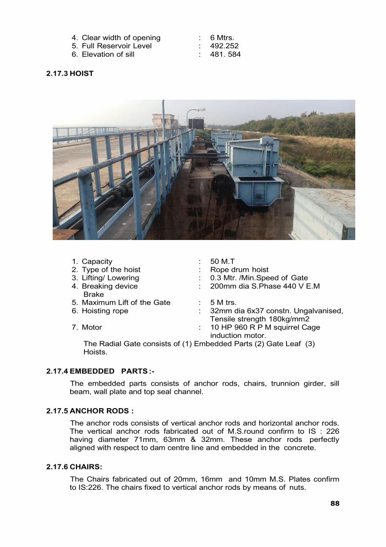
88
4. Clear width of opening : 6 Mtrs. 5. Full Reservoir Level : 492.252 6. Elevation of sill : 481. 584
2.17.3 HOIST
1. Capacity : 50 M.T 2. Type of the hoist : Rope drum hoist 3. Lifting/ Lowering : 0.3 Mtr. /Min.Speed of Gate 4. Breaking device : 200mm dia S.Phase 440 V E.M
Brake 5. Maximum Lift of the Gate : 5 M trs. 6. Hoisting rope : 32mm dia 6x37 constn. Ungalvanised,
Tensile strength 180kg/mm2 7. Motor : 10 HP 960 R P M squirrel Cage
induction motor. The Radial Gate consists of (1) Embedded Parts (2) Gate Leaf (3) Hoists.
2.17.4 EMBEDDED PARTS :-
The embedded parts consists of anchor rods, chairs, trunnion girder, sill beam, wall plate and top seal channel.
2.17.5 ANCHOR RODS :
The anchor rods consists of vertical anchor rods and horizontal anchor rods. The vertical anchor rods fabricated out of M.S.round confirm to IS : 226 having diameter 71mm, 63mm & 32mm. These anchor rods perfectly aligned with respect to dam centre line and embedded in the concrete.
2.17.6 CHAIRS:
The Chairs fabricated out of 20mm, 16mm and 10mm M.S. Plates confirm to IS:226. The chairs fixed to vertical anchor rods by means of nuts.

89
2.17.7 TRUNNION GIRDER :
Trunnion girders are fabricated out of 25mm, 20mm 16mm, 14mm MS plates fixed on to the inclined horizontal anchor rods. The bottom of trunnion girder rests on chairs and fixed by means of bolts and nuts. Horizontal anchor rods made out of 90mm dia M. S. rounds and embedded in the concrete in inclined position. Trunnion girder designed so as to resist compressive, tensile and torsion loads under worst condition.
2.17.8 SILL BEAM :
Sill beam made out of ISMB 250x120 provided with suitable anchorages and embedded in the concrete. A stainless steel clad plate of 3.15mm thick welded on the top flange to provide smooth and even seating of rubber seal which is fixed to the bottom of the gate.
2.17.9 WALL PLATE:
The wall plate fabricated out of 10mm and 12mm M.S. Plates to the required radius of the Gate. Suitable anchorages are provided and embedded in the concrete. Stainless steel plate having 3.15mm thickness welded to the flange plates to provide smooth and even seating of rubber seal which is fixed to the sides of skin plate.
2.17.10 TOP SEAL CHANNEL :
The top seal channel fabricated out of 32mm and 16mm plates confirm to IS 226. Suitable Anchorages provided and embedded in the breast wall concreting. A stainless steel plate of 3.15mm thick is welded on top of web plate to provide smooth and even seating of top seal. Top rubber seal fixed to the top of the gate.
2.17.11 GATE LEAF :
The gate leaf consists of skin plate fabricated out of 14mm, 12mm and 10mm plate depending on intensity of thrust from the sill beam. The plate bent to required radius of 7.5mts. The skin plates welded with stiffeners cut out of ISMB 450 x 150. The flanges welded to two Nos. horizontal girders. The horizontal girders fabricated out of 20mm, 12mm, 10mm and 8mm plates. Horizontal girders are supported by arms which projects from Trunnion. Arms welded to the termination plates of horizontal girders. Bolts connection also provided to take side thrust. The arms are fabricated out of ISMB 500 x 180. The arms designed as a column fixed at two ends. The other end of the arm welded to the ternmination plate in trunnion. Bolts also provided to take side thrust. Arms provided with suitable bracings of ISMC 125 x 65 to increase the rigidity in arm. Bracings are so provided that l/r ratio equal both in transverse and longitudinal directions.
The trunnions mounted on trunnion pin fixed to the bracket. Bracket in turn fixed to trunnion girder. Trunnions made out of Cast Steel confirm to IS: 1030 fixed with gun metal bushes to provide bearings surface of trunnion pin. The trunnion pin also made out of cast steel. The fit provided between

90
trunnion pin also made out of cast steel. The fit provided between trunnion bore and pin in H7/h6 (Running fit). The bracket fabricated out of 40mm, 32mm and 20mm M.S.Plates. Suitable stiffners are provided to resist bending of the bracket under load.
2.17.12 HOIST:
The hoist channel fabricated out of 20mm, 16mm 12mm and 10mm plates & ISMB 600x10. The channels fixed on to 32mm dia anchor bolts embedded in the pier concrete having overhang on both sides of the piers. The rope drum with W1 wheel fixed in the overhang position of the chassis. The rope drum having gun metal bush bearing to provide bearing surface for drum shaft which is fixed to the chassis. P1 pinion mounted on the shaft 1 meshes with W1 wheel. W2 Wheel is also mounted on shaft 1 meshes with P2 pinion which is mounted on shaft 2. The shaft 2 also fixed with bevel gear and a flange coupling. The flange coupling fixed to drive unit. Drive unit consists of worm reducer which is connected to motor by another flange coupling. Electro Magnetic brake provided for controlling the operation of the Gate. It is provided between motor and worm reducer. Break shoe open when supply passes in the break coil and shoe closes when supply disconnected. The bevel gear which is fixed on shaft 2 of gear box No. 1 meshes with bevel gear of Line shaft A. The bevel gear of the other end of the Line shaft A meshes with bevel gear of Line shaft B. The line shaft B mounted on plumber block bearings which are fixed on line shaft supporting girder. The bevel gear of the other end of the line shaft B mounted on plumber block bearings which are fixed on line shaft supporting girder. The bevel gear of the other end of Line shaft B meshes with bevel gear of Line shaft C. The bevel gear of other end of Line shaft C meshes with bevel gear fixed in the shaft 2 of gear box 2.
The Power from motor transmitted to worm reducer having reduction ratio 50:1. The power then transmitted to shaft 2., the Gear wheel W1 receives power from Pinion P2 mounted on shaft 2. The gear box 2 receives power from bevel gear fixed on shaft 2 and through line shaft A, B, and C.
The fixed end support fabricated out of 40mm, 20mm, 16mm and 10mm plates and ISMB 450 x 150 fixed to 40mm dia anchor bolts which are embedded in the pier concrete. Two shafts are provided on either side of the fixed end support for assembling of slack and overload limiter and wire rope pulleys.
Two check plates are welded on either side of the gates for fixing two wire rope pulleys by means of pulley pins on either sides.
32mm dia wire rope fixed to the rope drum, passes over one pulley fixed in the gate, then passes over the pulley in the fixed end support, then through the second pulley in the gate and finally fixed to the slack and over load limiter. One turn buckle is provided to adjust slackness of wire rope.
2.17.13 HAND OPERATION :
Hand operation is provided to operate the gates during power failure. The dog clutch is provided in the driver unit. When hand operation is engaged, the lever operates the limit switch, the power supply to motor to be cut off. This arrangement prevents supply to motor during hand operation.

91
2.17.14 DIAL INDICATOR:
Dial indicator is provided to show the actual lift of the gate from the sill. The dial unit consists of reduction gear unit and connection to shaft 2 of main gear box by means of chair drive. 2 levers provided in the output shaft in the dial unit. One lever meant for operating limit switch for cutting off power supply automatically when the gate rests on sill beam. Another lever meant for cutting off power supply when gate reaches to maximum height. The second limit switch can be adjusted to the required height by trail. The dial unit indicates height up to 0.1 mtr.
2.17.15 LUBRICATION:-
i. DRUM SHAFT :
Grease nipples are provided on both sides of drum shaft having a hole leading to bush bearing of drum. The greasing is to be done profusely once in three months by means of pressure grease gun.
ii. SHAFT 1,2 & 3:
The ball bearings and bush bearings are provided with grease cups. It shall be ensured that the grease cups must be filled with grease always. Grease to be applied by means of grease gun once in three months.
iii. LINE SHAFT SUPPORT BEARING :
All the line shaft supports provided with plumber block and a grease cup on plumber block. Profuse greasing is to be done regularly once in three months.
iv. WORM REDUCER :
Oil level in the worm reducer must be maintained to the guage level indicated by the needle provided in each worm reducer. The oil level is to be checked before starting the hoist.
v. GEAR WHEELS:
Profuse greasing is to be done with thick M.P. Grease or cardium compound for all the gear wheels.
vi. GUIDE ROLLERS :
Guide rollers provided with grease nipples for greasing. Hence greasing is to be done with pressure grease gun once in three months.
vii. TRUNNION PIN: Grease nipples provided for greasing bush bearing provided in the trunnion hub. It shall be ensured that the pin should not be operated without greasing under any circumstance. Greasing is to be done by means of pressure grease gun once in three months.
viii. WIRE ROPE:
Wire rope greasing shall be carried out once in a year before monsoon sets in. Cardium compound or Servo-coat 120 may be used for wire rope greasing.
2.17.16 PRECAUTIONS BEFORE STARTING THE MOTOR
i. It shall be ensured before starting that no foreign materials like metal piece,bolts, nuts, wooden pieces, etc. Found in the gear teeth.
ii. All the bearings and grease cups shall be filled with grease.

92
iii. Grease Shall be applied for all the gear wheels profusely before starting. iv. Worm reducer shall be filled with oil upto the level of the guage provided. v. It shall be ensured that handles of the hand operation removed from the
shaft. vi. The dog clutch is to disconnected properly.
i. GATE:
a. Proper greasing for trunnions shall be ensured.
b. The Guide Rollers must be free from concrete, dirt, stones etc.
c. The concrete, stones, wooden pieces, etc. Shall not be allowed to fall on rubber seals.
If they fell on the rubber seals there is a possibility of jamming of gate as the pieces clogged between rubber seal and stainless steel plate.
ii. ELECTRICAL EQUIPMENT:- a. It shall be ensured that power supply is 430 volts in all the three
phase sequence of supply. b. It shall be ensured that dog clutch is disengaged properly so that the
limit switch will be in off position.
2.17.17 OPERATION OF GATES
1] The main switch fuse unit provided in the Drive unit should be put in „ON‟ Position.
2] Three “Push Button” provided in the Starter. The forward push button
shall be operated for lifting of Gate and Reverse push button shall be operated for lowering of the Gate. (The Gate automatically stops if motor over-loaded)
3] If jerky motion observed during Gate operation, Gate shall be stopped
immediately and the Electro-magnetic brake adjusted slightly. Possible jamming of rubber seal the stainless steel plate due to foreign materials shall be checked and rectified.
2.17.18 MANUAL OPERATION OF GATE:-
In the case of power failure, the dog clutch shall be engaged by the handle provided for that purpose. By rotating the dog clutch shaft the limit switch, operated by the link system connected to dog clutch shaft will cut off power supply to motor. This will also mechanically release the brake and in turn the brake drum will become free. The gate can be operated by rotating the handle clock-wise manually.
2.17.19 ESSENTIAL TOOLS REQUIRED FOR MAINTENANCE WORK:
1] D.E. Spanner (6mm to 32mm) : 1 Set 2] Ring spanner set : 1 Set 3] D.E.Spanner 40mm : 1 No 4] Adjustable screw spanner 18” : 1 No 5] Cutting Flair 8” : 1 No 6] Screw driver 6” & 8” : 1 Each 7] Nose flair : 1 No 8] Electrical tester : 1 No 9] Fuse wire : 1 Coil 10] Hammer 2lbs, 6lbs : 1 Each 11] Grease gun : 1 No
93
12] Hack saw frame with blade : 1 No 13] Hand lamp : 1 No 14] Battery torch (3 cell) : 1 No
2.17.20 SPECIFICATION OF PARTS USED :
i. STARTER Make : seimens Type : LBO/K 985 Capacity : 7.5 KV; 415V ; 3ph ; 50 Cycles
ii. MOTOR
Make : NGEF ( License AEG) Type : Squirrel cage induction motor Capacity : 440 V; 720 RPM: Double extension shaft. Frame size : AM 160 M6
iii. SWITCH
Make : G.E.C. Type : T.P.Switch Capacity : 30 Amps
iv. WORM REDUCER Make : M/s Devid Brown Greaves Ltd. Type : RH U 700 Ratio : 50:1 Capacity : 10 HP
v. ELECTRO MAGNETIC BRAKES
Make : M/s Mango Contols Bombay. Type : 200 mm dia Capacity : 440 V AC S Phase
vi. WIRE ROPE
Make : M/s Usha Martin (Black) wire ropes. Size : 32 mm dia 6 x37 Constn ungalvanised
fibre main core Tensile Strength : 180kg /mmsquare Length : Mtr/ Gate
vii. BALL BEARINGS IN GEAR BOX
Make : SKF Size : SN 512 1274K + H212 1No/G.Box
: SN 518 1218K + H218 2 No/G.Box : Plumber block bearing (TSP Make)
PBH - 1 No.per Gear Box. PBH70 -1No.per Gear Box.
94
viii. PLUMBER BLOCK BEARING FOR LINE SHAFT Make : TSP Type : PBS 65 Nos Required : 8.Nos. per set
ix. RUBBER SEAL a) Side Seal:
Make : TSP Type : RSL 28-5696 long. Nos Required : 2 Nos. per gate
b) BOTTOM SEAL
Make /Type : TSP /Make RSL 6 Length : 5904mm Nos Required : 1 Nos. per gate
c) TOP SEAL
Make /Type : TSP /RSL 28 Length : 5280mm Nos Required : 1 Nos. per gate
d) CORNER SEAL
Make : TSP Type : RSL 28 Nos Required : R H-1 No: LH-1 No Size : 350mm X 350 mm
x. BOLTS FOR RUBBER SEALS
a) Side seals:- Size : 12 mm dia 56mm long Type : G.I.
Nos Required : 196 Nos /Gate
b) Bottom seals:- Size : 12mm dia 57 mm long Type : G.I.
Nos Required : 70 Nos/ Gate
c) Top and Corner seals Size : 12mm dia 75mm long Type : G.I. Nos Required : 68 Nos/ Gate
xi. LIMIT SWITCH Make : M.E.I. Type : Roller lever type Capacity : 500 V ; 10 Amps Nos Required : 3 Nos / Gate
xii. SPROKET CHAIN Size : 1/2” pitch Length : 2370 mm
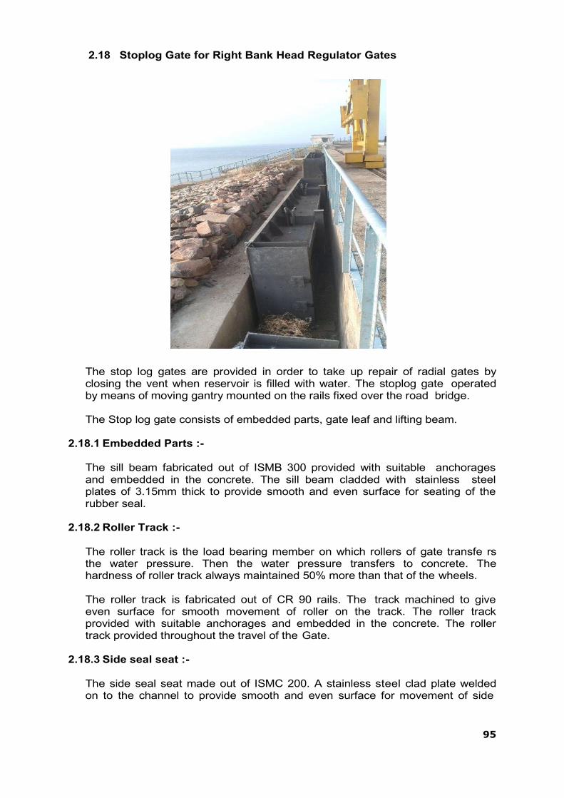
95
2.18 Stoplog Gate for Right Bank Head Regulator Gates
The stop log gates are provided in order to take up repair of radial gates by closing the vent when reservoir is filled with water. The stoplog gate operated by means of moving gantry mounted on the rails fixed over the road bridge.
The Stop log gate consists of embedded parts, gate leaf and lifting beam.
2.18.1 Embedded Parts :-
The sill beam fabricated out of ISMB 300 provided with suitable anchorages and embedded in the concrete. The sill beam cladded with stainless steel plates of 3.15mm thick to provide smooth and even surface for seating of the rubber seal.
2.18.2 Roller Track :-
The roller track is the load bearing member on which rollers of gate transfe rs the water pressure. Then the water pressure transfers to concrete. The hardness of roller track always maintained 50% more than that of the wheels.
The roller track is fabricated out of CR 90 rails. The track machined to give even surface for smooth movement of roller on the track. The roller track provided with suitable anchorages and embedded in the concrete. The roller track provided throughout the travel of the Gate.
2.18.3 Side seal seat :-
The side seal seat made out of ISMC 200. A stainless steel clad plate welded on to the channel to provide smooth and even surface for movement of side
96
rubber seal. The side rubber seal seating provided upto one gate height and one meter as extra.
The side seal channel provided with suitable anchorages and embedded in the concrete.
2.18.4 Side Guide :-
The side guide fabricated out of CR 30 Rails. These are provided with suitable anchorages and embedded in the concrete. The side guide provided throughout the travel of the Gate.
2.18.5 Gate Leaf :-
The water thrust on skin plate transmitted on to the horizontal girders and vertical stiffeners and then on the end girder which is supported continuously on rollers. Ultimately load transferred on to the roller track through rollers and then on to the concrete. The gate leaf consists of skin plate, end box, rollers, and lifting check plate. The gate is fabricated in 6 elements such that the self weight of the element shall be sufficient to operate the gate in unbalanced conditions.
The skin plate fabricated out of 14mm, 10mm and 12mm plates. The thickness of plates varies from bottom element to top element as per the variation of thrust from bottom to top. The skin plate suitably support by horizontal girders and vertical stiffners. The horizontal girders and vertical stiffners welded to the skin plate. Each element consists of 4 Nos rollers assembled in the end boxes. The end boxes are fabricated out of 12mm plates. The roller assembled with stainless steel axles. Grease nipples provided in the axle for lubrication of roller bearings. Spherical roller bearings are provided for assembling of axle with roller. The axle mounted on rollers with an eccentricity. The eccentricity provided in the axle for proper adjustment of roller to get continuous contact of roller with roller track. A vernier plate fixed to the axle for adjustment of accentricity. The side seal consists of „Music Nose‟ type cladded rubber seal and flat type for bottom seal. The seals fitted on to the Gate by means of galvanized bolts and nuts.
2.18.6 SPECIFICATION OF SPARES
i. RUBBER SEAL a) SIDE SEAL:
Type/ Make : RSL 24 C/ TSP Make Size : Element No 1,2,3 - 1106 mm long : 2 Nos/
Element,Element No 4,5,6 – 1528 mm long: 2 Nos/ Element
b) BOTTOM SEAL Type/ Make : RSL 7/ TSP Make Length : 6346mm Nos. required : 1 No. per gate.
ii. BOLTS FOR RUBBER SEAL a) For bottom seal
Type : G. I. Bolts and nuts Size : 16mm dia 70mm long Nos.of required : 60 Nos. per element

97
b) For side seal Type : G.I. Bolts and nuts Length : 16mm dia 60 mm long Nos. required : 73 Nos. per element
i) SPHERICAL ROLER BEARING
No. 23234 : 72 Nos. No. 22234 : 12 Nos.
2.19 15 TON Capacity Gantry for Right Bank Head Regulator Gates
(RBHR)
The gantry provided for operation of stop log gates of right bank head regulator. The 15 ton capacity Gantry crane move on the rails fixed on the road bridge.
2.19.1 CHARACTERISTIC OF 15 TON GANTRY CRANE i. Capacity : 15 Ton. ii. Duty : Class I-out door as per IS 317& IS 807 iii. Speed iv. Travel : 8 M/Min +/-10% v. Traverse : 4 M/Min +/-10% vi. Hoist : 1.5 M/Min +/-10% vii. Height of lift : 25 Mtrs viii. Rope : 24mm dia wire rope 6x37 const.
Fiber main core four falls. Tensile strength 180kg/mm sq Minimum breaking load 30.6 T length 120 mtrs
ix. Motor
Travel : 3.3 HP: 860PRM: Squiral cage -2 Nos. Traverse : 3.3 HP: 860PRM: Squiral cage – 1 No. Hoist : 9.5Hp: 715PRM : Slipring 40% DF -1No.

98
x. Worm Reducer Travel : Ratio 60:1 ; Type „0‟ ; Size 5” -2 Nos. Traverse : Ratio 60:1 ; Type „0‟ ; Size 5” -1 No. Hoist : Ratio 60: 1 ; Type „0‟ ; Size 10” -1 No.
xi. Brakes
Travel : 150 dia E.M.Brake -2 Nos. Traverse : 150 dia E.M.Brake -1 No. Hoist : 200 dia E.M. Brake -1 No. Control : Pendent operation
Lubrication : Poin lubrication system xii. Crane rail size : 90 lbs xiii. Counter weight required : 20 Ton ( Concrete with MS scrap) xiv. Cable reeling drum : Spring operated cable rely drum suitable for
30 M cable. 2.19.2 Components of 15Ton Gantry consists of the following parts:-
1. Gantry track 2. Gantry travel assembly 3. Columns 4. Crane girder 5. Tie girder 6. Counter weight 7. Crab assembly
1. GANTRY TRACK
The gantry track fabricated out of 60 lbs rails fixed on road bridge to the anchorages provided in the road bridge concrete.
2. GANTRY TRAVEL ASSEMBLY
The gantry travel assembly consists of 2 independent bogies connected at the center by connecting beam. The bogies fabricated out of ISMC 300. It is provided with holes machined to a tolerance for fixing gantry track wheels, by means of pins. 2 holes provided in the centre for fixing columns, by means of pins having 120mm diameter 520mm long. The connecting beam made out of ISMC 200, connected to the bogies by means of pins having diameter 50mm and 500mm long. All the pins fixed to the bogies by means of lock plates. The gantry wheels having gear wheel assembled in the bogies by means of shaft having diameter 120mm, 520mm long. Bush bearings are provided for the wheels. Grease nipples provided for lubrication of bush bearings.
The gear wheel mounted on the gantry wheel meshes with pinion mounted on shaft which is directly coupled to worm reducer having reduction ratio 60:1. The worm reducer connected to motor by means of coupling. An electro magnetic brake fixed between motor and worm reducer for controlling the gantry travel. 2 Independent drives are provided on either side for movement of gantry.
99
3. COLUMNS
Four columns fixed on the centre of the bogies by means of pins. The verticality and diagonal of columns are properly maintained.
4. CRANE GIRDER
The crane girder is a built up structure fixed on to the columns by means of machined bolts. 90 lbs rails welded over the top flange of crane girder for movement of crab assembly. The crane girder project beyond the columns on the upstream side. Stoppers are provided at the end of the crane girder to resists the crab movement.
5. TIE GIRDER
The tie girder also provided at the cantilever position of the crane girder on upstream side and one tie girder provided on downstream side end of crane girder. The tie girders are provided to resist lateral movement of crane girder under load.
6. COUNTER WEIGHT
A counter weight box is provided in between the downstream columns. The counter box and all the columns are to be filled with concrete to provide 20 ton counter weight to the gantry.
7. CRAB ASSEMBLY
The crab assembly consists a base frame and end logic for providing crane wheel for movement of crab over the crane girder.
The crane wheel fixed with gear wheel meshes with pinion fixed on shaft
which is coupled to one of the shaft of worm reducer. The worm reducer connected to motor by means of flange coupling. The other shaft of the worm reducer connected to line shaft having pinion meshes with the gear wheels mounted on the other side of crane wheel. An electro-magnetic brake connected between motor and worm reducer to control the movement of crane.
The power from the motor transfers to worm reducer which reduces the speed to 18.33 RPM and transfers to mounted on crane wheels. Thus the crab moves on rail provided on crane girder.
8. HOIST:
The hoist assembly consists of cast steel rope drum fixed with gear wheel. The gear wheel meshes with pinion mounted on shaft connected to worm reducer. The worm reducer in turn connected to motor. An electro-magnetic brake is provided between the motor and worm reducer. It controls the hoisting arrangement. The power from motor transmits to worm reducer through flange coupling which reduces the speed to 17.875 RPM. This speed transfers to gear wheel on the rope drum through pinion which further reduces the speed and giving a lifting speed of 1.5 M/min.
The wire rope fixed to the rope drum passes through the pulley fixed in the lifting beam and through the pulley fixed in the base frame and finally

100
through the second pulley in the lifting beam. The other end of the rope fixed to the other end of the rope drum.
2.19.3 SPECIFICATION OF PARTS USED
i. Gantry travel assembly Motor Type : Squirrel cage induction motor Make : N.G.E.F. Capacity : 3.3 HP ; 860 RPM ; 40% CDF Frame No : ANK 112 M6 Nos. required : 2 Nos.
ii. Worm reducer
Make : M/s Devi Brown Greaves Ltd, Type : „0‟ Double extension shaft Ratio : 60:1 Out put torque : 150 Kg/m Nos. required : 2 Nos.
iii. Electric Magnetic Brake
Make : Magoo Controls Size : 150 dia E.M.Brake Capacity : A C S. Phase ; 440 V
iv. CRAB ASSEMBLY v. Hoisting Motor
Make : N.G.E.F. Capacity : 9.5 Hp ; 715 RPM ; 440 v, class B
insulation 40% CDF. Frame No : ANK 160 I8 RI Nos. required : 1 No.
vi. Worm reducer
Make : M/s Devi Brown Greaves Ltd, Type : „0‟ Double extension shaft /10” Ratio : 60:1 Out put torque : 150 kg/m Nos. required : 1 No.
vii. Electric Magnetic Brake
Make : M/s. Mago Controls Size : 200 dia E.M.Brake Capacity : 440 V AC S. Phase Nos. required : 1 No.
viii. Crab Travel.
Motor Make : Squirrel cage induction motor Type : N.G.E.F. Capacity : 3.3 HP ; 960 RPM ; 30% CDF 440 V Frame No. : ANK 112 M 6 Nos. required : 1 No.

101
ix. Worm reducer Make : M/s Devi Brown Greaves Ltd, Type : „0‟ Double extension shaft Ratio : 60:1 Out put torque : 150 kg/m
x. Electro Magnetic Brake
Make : Magoo Controls Size : 150 dia E.M.Brake Capacity : 440 V ; ACS. Phase. Nos. required : 1 No.
xi. WIRE ROPE
Make : M/s Usha Martin (Black) wire ropes. Size : 24mm dia 6 x 37 Constn fiber main core four
falls. Tensile Strength : 180 kg/ mm sq. Main breaking load : 306 T. Length : 120 Mtr.
xii. COUPLINGS Flexible coupling : FXC 56 - 3 Nos Brake drum coupling : BDC 150 -1 No
BDC 200 -1 No Flexible coupling : FXC 90 - 2 Nos
Travel Brake drum coupling : BDC 150 2 Nos Flexible coupling : FXC 56 2 Nos
xiii. BEARINGS.
Gantry Travel Assembly SN 511 with 121 1K bearing and H221 sleeve …4 Nos Crab Assembly Plumber block SN 511 with 121 1 K brg with H211 sleeve .. 7 Nos Plumber block SN 518 with 221 18K brg with H328 sleeve ..2 Nos
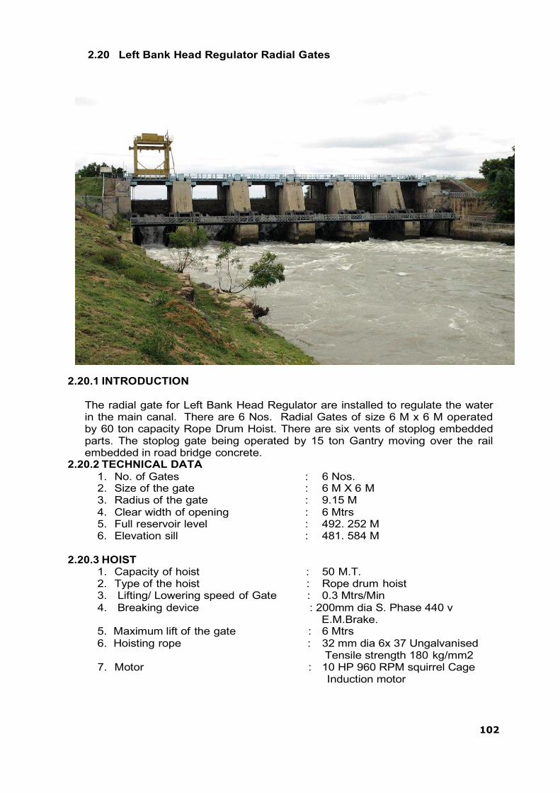
102
2.20 Left Bank Head Regulator Radial Gates
2.20.1 INTRODUCTION
The radial gate for Left Bank Head Regulator are installed to regulate the water in the main canal. There are 6 Nos. Radial Gates of size 6 M x 6 M operated by 60 ton capacity Rope Drum Hoist. There are six vents of stoplog embedded parts. The stoplog gate being operated by 15 ton Gantry moving over the rail embedded in road bridge concrete.
2.20.2 TECHNICAL DATA 1. No. of Gates : 6 Nos. 2. Size of the gate : 6 M X 6 M 3. Radius of the gate : 9.15 M 4. Clear width of opening : 6 Mtrs 5. Full reservoir level : 492. 252 M 6. Elevation sill : 481. 584 M
2.20.3 HOIST
1. Capacity of hoist : 50 M.T. 2. Type of the hoist : Rope drum hoist 3. Lifting/ Lowering speed of Gate : 0.3 Mtrs/Min 4. Breaking device : 200mm dia S. Phase 440 v
E.M.Brake. 5. Maximum lift of the gate : 6 Mtrs 6. Hoisting rope : 32 mm dia 6x 37 Ungalvanised
Tensile strength 180 kg/mm2 7. Motor : 10 HP 960 RPM squirrel Cage
Induction motor
103
The radial Gate consists of (1) Embedded parts (2) Gate leaf and (3) hoists.
2.20.4 Embedded Parts :- The embedded part consists of anchor rods. Chairs, trunnion girder sill beam wall plate and top seal channel.
2.20.5 Anchor Rod :
The anchor rods consists of vertical anchor rods and horizontal anchor rods. The vertical anchor rods fabricated out of M S round confirm to IS:226 having diameter 71mm, 63mm and 32mm. These anchor rods perfectly aligned with respect to dam centre line and embedded in the concrete.
2.20.6 Chairs :-
The chairs fabricated out of 20mm, 16mm, and 10mm M.S. plates confirm to IS:226. The chairs fixed to vertical anchor rods by means of nuts.
2.20.7 Trunnion Girder :-
Trunnion girders are fabricated out of 25mm, 20mm, 16mm, 14mm. M.S. plates fixed on to the inclined horizontal anchor rods. The bottom of trunnion girder rests on chair and fixed by means of bolts and nuts. Horizontal anchor rods made out of 90mm dia M.S. rounds and embedded in the concrete in inclined position. Trunnion girder designed so as to resist compressive, tensile and torsional loads under worst conditions.
2.20.8 Sill Beam :-
Sill beam made out of ISMB 300 x 140 provided with suitable anchorages and embedded in the concrete. A stainless steel clad plate of 3.15 mm thick welded on the top flange to provide smooth and even seating of rubber seal which is fixed to the bottom of the gate.
2.20.9 Wall Plates:-
The wall plate fabricated out of 10mm and 12mm M.S. plates to the required radius of the Gate. Suitable anchorages are provided and embedded in the concrete Stainless Steel plate having 3.15mm thickness welded to the flange plate to provide smooth and even seating of rubber seal which is fixed to the sides of skin plate.
2.20.10 Top Seal Channel :-
The top seal channel fabricated out of 32mm and 16mm plates confirm to IS 226. Suitable anchorages provided and embedded in the breast wall concreting. A stainless steel plate of 3.15mm thick is welded on top of web plates to provide smooth and even seating of top seal. Top rubber seal fixed to the top of the gate.
2.20.11 Gate Leaf :-
The Gate leaf consists of skin plate fabricated out of 14mm, 12mm and 10mm plate bent to required radius of 9.15 Mtrs. The skin plate welded with stiffeners out of ISMB 450 x 150. The flange welded to two Nos. Horizontal girders fabricated out of 20mm, 12mm, 10mm and 8mm plates. Horizontal girders are supported by arms which are projected from Trunnion. Arms welded to the termination plates of horizontal girders. Bolts connection also provided to take side thrust. The arm fabricated out of ISMB 500 x 180. The arm designed as a column fixed at two end. The other end of the arm welded to the termination plate in trunnion. Bolts also provided to take side thrust Arms provided with suitable bracings of ISMC 125 x 65 to increase

104
the rigidity in arm. Bracings are so provided that 1/r ratio equal both in transverse and longitudinal directions.
The trunnions mounted to trunnion pin fixed to the Bracket. Bracket in turn fixed to trunnion girder. Trunnions made out of Cast Steel confirm to IS 1030 fixed with gun metal bushes to provide bearing surface of trunnion pin. The trunnion pin also made out of cast steel. The fit provided between trunnion bore and pin is H7/h6 (Running fit). The bracket fabricated out of 40mm, 32mm and 20mm M.S. Plates. Suitable stiffners are provided to resist bending of the bracket under load.
2.20.12 Hoist
The hoist chassis fabricated out 20mm, 16mm, 12mm, and 10mm plates and ISMB 600x 210. The chassis fixed on to 32mm dia anchor bolts embedded in the pier concrete having overhang on both sides of the piers. The rope drum with W 1 wheel fixed in the overhang position of the chassis. The rope drum having gun metal bush bearing to provide bearing surface for drum shaft which is fixed to chassis. The drum rotates on drum shaft. The p1 pinion mounted on the shaft 1 meshes with W1 wheel. W2 wheel is also mounted on shaft 1 meshes with P2 pinion which is mounted on shaft 2. The shaft 2 also fixed with bevel gear and a flange coupling. The flange coupling fixed to drive unit. Drive unit consists of worm reducer which is connected to motor by another flange coupling. Electro-Magnetic brake provided for controlling the operation of the Gate. It is provided between motor and worm reducer. Break shoe open when supply passes in the break coil and shoe closes when supply disconnected. The bevel gear which is fixed on shaft 2 of gear box No. 1 meshes with bevel gear of Line Shaft A. The bevel gear of the other end of the Line Shaft A meshes with bevel gear of Line shaft B. The line shaft B meshes with bevel gear of Line shaft C. The bevel gear of other end of line shaft C meshes with bevel gear fixed in the shaft 2 of gear box 2.
The power from motor transmitted to worm reducer having reduction motor 50:1. The power then transmitted to shaft 2. The Gear wheel W 1 receives power from Pinion P2 mounted on shaft 2. The gear box 2 receives power from bevel gear fixed on shaft 2 and through line shaft A, B and C.
The fixed end support fabricated out of 40mm, 20mm, 16mm and 10mm plates and ISMB 450 x 150 fixed to 40mm dia anchor bolts which are embedded in the pier concrete. Two shaft are provided on either side of the fixed end support for assembling of slack and overload limiter and wire rope pulleys.
Two check plates are welded on either side of the gate for fixing two wire rope pulleys by means of pulley pins on either sides
32mm dia wire rope fixed to the rope drum, passes over one pulley fixed in the gate, then passes over the pulley in the fixed end support, then through the second pulley in the gate and finally fixed to the slack and over load limiter. One turn buckle is provided to adjust slackness of wire rope.
2.20.13 Hand Operation:-
Hand operation is provided to operate the gates during power failure. The dog clutch is provided in the drive unit. When hand operation is engaged, the lever operation, the limit switch, the power supply to motor to be cut off. This arrangement prevents supply to motor during hand operation.

105
2.20.14 Dial indicator : Dial indicator is provided to show the actual lift of the gate from the sill. The dial unit consists of reduction gear unit and connection to shaft 2 of main gear box by means of chain drive. 2 levers provided in the output shaft in the dial unit. One lever meant for operating limit switch for cutting off power supply automatically when the gate rests on sill beam. Another lever meant for cutting off power supply when gate reaches to maximum height. The second limit switch can be adjusted to the required height by trial. The dial unit indicates height up to 0.1 mtr.
2.20.15 Lubrication:
i. Drum shaft :- Grease nipples are provided on both sides of drum shaft
having a hole leading to bush bearing of drum. The greasing is to be done profusely once in three months by means of pressure grease gun.
ii. Shaft 1,2 and 3:- The ball bearings and bush bearings are provided with
grease cups. It shall be ensured that the grease cups must be filled with grease always. Grease to be applied by means of grease gun once in three months.
iii. Line Shaft support Bearings :- All the line shaft supports provided with
plumber block and a grease cup on plumber block. Profuse greasing is to be done regularly once in three months.
iv. Worm Reducer:- Oil level in the worm reducer must be maintained to
the gauge level indicated by the needle provided in each worm to the gauge level indicated by the needle provided in each worm reducer. The oil level is to be checked before starting the hoist.
v. Gear Wheels :- Profuse greasing is to be done with thick W.P. Grease
or cardium compound for all the gear wheels.
vi. Guide rollers :- Guide rollers provided with grease nipples for greasing. Hence greasing is to be done with pressure grease gun once in three months.
vii. Trunnion Pin :- Grease nipples provided for greasing bush bearings
provided in the trunnion hub. It shall be ensured that the pin should not be operated without greasing under any circumstance. Greasing is to be done by means of pressure grease gun once in three months.
viii. Wire Rope:- Wire rope greasing shall be carried out once in a year
before monsoon sets in. Cardium compound or Servocoat-120 may be used for wire rope greasing.
2.20.16 PRECAUTIONS BEFORE STARTING OF MOTOR:-
HOISTS:-
i. It shall be ensured before starting that no foreign materials like metal piece bolts and nuts, wooden pieces etc. Found in the gear teeth.

106
ii. All the bearings and grease cups shall be filled with grease.
iii. Grease shall be applied for all the gear wheels profusely before starting.
iv. Worm reducer shall be filled with oil up to indicator provided.
v. It shall be ensured that handles for hand operation removed from the
shaft. i. The dog clutch is to disengaged properly.
GATES :- i. Proper greasing for trunnions shall be ensured.
ii. The guide rollers must be free from concrete, dirt, stone, etc.
iii. The concrete stone, wooden pieces, etc. Shall not be allowed to fall
on rubber seals. If they fall on the rubber seals there is a possibility of jamming of gate as the pieces clog between rubber seal and stainless steel plate.
ELECTRICAL EQUIPMENT :- i. It shall be ensured that power supply is 430 volts in all the three
phases of supply and also phase of supply and also phase sequence of supply.
ii. It shall be ensured that dog clutch disengaged properly so that the
limit switch will be in off position.
2.20.17 OPERATION OF GATES :-
1. The main switch fuse unit provided in the drive unit should be put in the „ON‟ position.
2. Three “Push Buttons” provided in the starter. The „forward‟ push button shall be operated for lifting of gate and „reverse‟ push button shall be operated for lowering the gate. The gate automatically stops if the motor overloaded.
3. If jerky motion observed during gate operation, gate shall be stopped
immediately and electro-magnetic brake adjusted slightly. Possible jamming of rubber seal with stainless steel plate due to foreign materials shall be checked and rectified.
4. In case of power failure the dog clutch shall be engaged by the
handle provided for this purpose. By rotating the dog clutch shaft the limit switch operated by link system connected to dog clutch shall cut off power supply to motor. This will also mechanically release the brake and in turn the brake drum will become free. The gate can be operated by rotating the handle clock-wise manually.

107
2.20.18 ESSENTIAL TOOLS REQUIRED FOR MAINTENANCE WORK : 1) D.E.Spanner (6mm to 32mm) : 2) Ring spanner set :
1 Set 1 Set
3) D.E.Spanner 40mm : 1 No 4) Adjustable screw spanner 18” : 1 No 5) Cutting flair 8” : 1 No 6) Screw driver 6” & 8” : 1 Each 7) Nose flair : 1 No 8) Electrical tester : 1 No 9) fuse wire : 1 Coil 10) Hammer 21lbs, 6lbs : 1 Each 11) Grease gun : 1 No 12) Hack saw frame with blade : 1 No 13) Hand lamp : 1 No 14) Battery torch(3 cell) : 1 No
2.20.19 SPECIFICATION OF PARTS USED :
i. STARTER Make : Seimens Type : LBO / K 985 Capacity : 7.5 KV ; 415 V; 3ph ; 50 Cycles
ii. MOTOR
Make : NGEF ( License AEG) Type : Squirrel cage induction motor Capacity. : 440V; 720 RPM : Double Extension shaft. Frame size : AM 160 M 6
iii. SWITCH Make : G.E.C. Type : T.P. Switch Capacity : 30 Amps
iv. WORM REDUCER Make : M/s David Brown Greaves Ltd. Type : RHU 700 Ratio : 50:1 Capacity : 10 HP
v. ELECTRO MAGNETIC BARAKES
Make : M/s Mango Controls Bombay. Type : 200mm dia Capacity : 440 V AC S Phase
vi. WIRE ROPE Make : M/s Usha Martin (Black) wire ropes. Size : 32mm dia 6 x 37 Constn
Ungalvanised fiber main core. Tensile Strength : 180 Kg / mm sq Length : Mtr / Gate
vii. BALL BEARINGS IN GEAR BOX Make : SKF Size : i) SN 512 1272K+ H 212 -1No/ G.Box
: ii) SN 518 1218K+ H 218 -2No/G.Box Plumber block bearing (TSP Make)
PBH- 1 No. per Gear Box. PBH70 - 1 No. per Gear Box.
108
viii. PLUMBER BLOCK BEARING FOR LINE SHAFT Make : TSP Type : PBS 65 Nos Required : 8 Nos. per set
ix. RUBBER SEAL a) SIDE SEAL
Make : TSP Type : RSL 28 Nos Required : 2 Nos. per gate
b) BOTTOM SEAL
Make / Type : TSP/Make RSL 6 Type : 5904 mm Nos Required : 1 Nos. per gate.
c) TOP SEAL
Make/ Type : TSP / RSL 28 Type : 5280 mm Nos Required : 1 Nos. per gate
d) CORNER SEAL
Make : TSP Type : RSL 28 Nos Required : RH-1 No : LH – 1 No Size : 350 mm X 350 mm
x. BOLTS FOR RUBBER SEALS a) Side seals
Size : 12mm dia 56mm long Type : G.I. Nos Required : 196 Nos/ Gate
b) Bottom seals Size : 12mm dia 57mm long Type : G.I. Nos Required : 70 Nos / Gate
c) Top and Corner seals Size : 12mm dia 75mm long Type : G.I. Nos Required : 68 Nos / Gate
xi. LIMIT SWITCH
i. Make : M.E.I. ii. Type : Roller lever type iii. Capacity : 500 V; 10 Amps iv. Nos Required : 3 Nos / Gate
xii. SPROKET CHAIN
i. Size : ½” Pitch ii. Length : 2370 mm

109
2.21 Stoplog Gate for Left Bank Head Regulator Gates(LBHR)
The stop log gates are provided in order to take up repair of radial gates by closing the vent when reservoir is filled with water. The stoplog gate operated by means of moving gantry mounted on the rails fixed over the road bridge.
The Stop log gate consists of embedded parts, gate leaf and lifting beam.
2.21.1 Embedded Parts :- The sill beam fabricated out of ISMB 300 provided with suitable anchorages and embedded in the concrete. The sill beam cladded with stainless steel plates of 3.15mm thick to provide smooth and even surface for seating of the rubber seal.
2.21.2 Roller Track :-
The roller track is the load bearing member on which rollers of gate transfers the water pressure. Then the water pressure transfers to concrete. The hardness of roller track always maintained 50% more than that of the wheels.
The roller track is fabricated out of CR 90 rails. The track machined to give even surface for smooth movement of roller on the track. The roller track provided with suitable anchorages and embedded in the concrete. The roller track provided throughout the travel of the Gate.
2.21.3 Side seal seat :-
The side seal seat made out of ISMC 200. A stainless steel clad plate welded on to the channel to provide smooth and even surface for movement of side rubber seal. The side rubber seal seating provided upto one gate height and one meter as extra.
The side seal channel provided with suitable anchorages and embedded in the concrete.
2.21.4 Side Guide :-
The side guide fabricated out of CR 30 Rails. These are provided with suitable anchorages and embedded in the concrete. The side guide provided throughout the travel of the Gate.
2.21.5 Gate Leaf :-
The water thrust on skin plate transmitted on to the horizontal girders and vertical stiffeners and then on the end girder which is supported continuously on rollers. Ultimately load transferred on to the roller track through rollers and then on to the concrete. The gate leaf consists of skin plate, end box, rollers, and lifting check plate. The gate is fabricated in 6 elements such that the self weight of the element shall be sufficient to operate the gate in unbalanced conditions.
The skin plate fabricated out of 14mm, 10mm and 12mm plates. The thickness of plates varies from bottom element to top element as per the variation of thrust from bottom to top. The skin plate suitably support by horizontal girders and vertical stiffners. The horizontal girders and vertical stiffners welded to the skin plate. Each element consists of 4 Nos rollers

110
assembled in the end boxes. The end boxes are fabricated out of 12mm plates. The roller assembled with stainless steel axles. Grease nipples provided in the axle for lubrication of roller bearings. Spherical roller bearings are provided for assembling of axle with roller. The axle mounted on rollers with an eccentricity. The eccentricity provided in the axle for proper adjustment of roller to get continuous contact of roller with roller track. A vernier plate fixed to the axle for adjustment of accentricity. The side seal consists of „Music Nose‟ type cladded rubber seal and flat type for bottom seal. The seals fitted on to the Gate by means of galvanized bolts and nuts.
2.21.6 SPECIFICATION OF SPARES
i) RUBBER SEAL a) SIDE SEAL:
Type/ Make : RSL 24 C/ TSP Make Size : a) Element No 1,2,3 - 1106 mm long : 2 Nos/
Element b) Element No 4,5,6 – 1528 mm long: 2 Nos/
Element b) BOTTOM SEAL
Type/ Make : RSL 7/ TSP Make Length : 6346mm Nos. required : 1 No. per gate.
ii) BOLTS FOR RUBBER SEAL a) For bottom seal
Type : G. I. Bolts and nuts Size : 16mm dia 70mm long Nos.of required : 60 Nos. per element
b) For side seal
Type : G.I. Bolts and nuts Length : 16mm dia 60 mm long Nos. required : 73 Nos. per element
iii) SPHERICAL ROLER BEARING
No. 23234 : 72 Nos. No. 22234 : 12 Nos.

111
2.22 15 TON capacity moving Gantry for Left Bank Head Regulator Gates
The gantry provided for operation of stop log gates of right bank head regulator. The 15 ton capacity Gantry crane move on the rails fixed on the road bridge.
2.22.1 CHARACTERISTIC OF 15 TON GANTRY CRANE
i. Capacity : 15 Ton. ii. Duty : Class I-out door as per IS 317& IS 807 iii. Speed iv. Travel : 8 M/Min +/-10% v. Traverse : 4 M/Min +/-10% vi. Hoist : 1.5 M/Min +/-10% vii. Height of lift : 25 Mtrs viii. Rope : 24mm dia wire rope 6x37 const.
Fiber main core four falls. Tensile strength 180kg/mm sq Minimum breaking load 30.6 T length 120 mtrs
ix. Motor Travel : 3.3 HP: 860PRM: Squiral cage -2 Nos. Traverse : 3.3 HP: 860PRM: Squiral cage -1 No. Hoist : 9.5Hp: 715PRM : Slipring 40% DF - 1No.
x. Worm Reducer
Travel : Ratio 60:1 ; Type „0‟ ; Size 5” -2 Nos.
Traverse : Ratio 60:1 ; Type „0‟ ; Size 5” -1 No.
Hoist : Ratio 60: 1 ; Type „0‟ ; Size 10” -1 No.

112
xi. Brakes Travel : 150 dia E.M.Brake -2 Nos. Traverse : 150 dia E.M.Brake -1 No. Hoist : 200 dia E.M. Brake -1 No. Control : Pendent operation Lubrication : Poin lubrication system
xii. Crane rail size : 90 lbs xiii. Counter weight required : 20 Ton ( Concrete with MS scrap)
xiv. Cable reeling drum : Spring operated cable rely drum suitable for 30 M.cable.
2.22.2 Components of 15 Ton Gantry :- 1. Gantry track 2. Gantry travel assembly 3. Columns 4. Crane girder 5. Tie girder 6. Counter weight 7. Crab assembly
1. GANTRY TRACK
The gantry track fabricated out of 60 lbs rails fixed on road bridge to the anchorages provided in the road bridge concrete.
2. GANTRY TRAVEL ASSEMBLY
The gantry travel assembly consists of 2 independent bogies connected at the center by connecting beam. The bogies fabricated out of ISMC 300. It is provided with holes machined to a tolerance for fixing gantry track wheels, by means of pins. 2 holes provided in the centre for fixing columns, by means of pins having 120mm diameter 520mm long. The connecting beam made out of ISMC 200, connected to the bogies by means of pins having diameter 50mm and 500mm long. All the pins fixed to the bogies by means of lock plates. The gantry wheels having gear wheel assembled in the bogies by means of shaft having diameter 120mm, 520mm long. Bush bearings are provided for the wheels. Grease nipples provided for lubrication of bush bearings.
The gear wheel mounted on the gantry wheel meshes with pinion mounted on shaft which is directly coupled to worm reducer having reduction ratio 60:1. The worm reducer connected to motor by means of coupling. An electro magnetic brake fixed between motor and worm reducer for controlling the gantry travel. 2 Independent drives are provided on either side for movement of gantry.
3. COLUMNS
Four columns fixed on the centre of the bogies by means of pins. The verticality and diagonal of columns are properly maintained.

113
4. CRANE GIRDER
The crane girder is a built up structure fixed on to the columns by means of machined bolts. 90 lbs rails welded over the top flange of crane girder for movement of crab assembly. The crane girder project beyond the columns on the upstream side. Stoppers are provided at the end of the crane girder to resists the crab movement.
5. TIE GIRDER
The tie girder also provided at the cantilever position of the crane girder on upstream side and one tie girder provided on downstream side end of crane girder. The tie girders are provided to resist lateral movement of crane girder under load.
6. COUNTER WEIGHT
A counter weight box is provided in between the downstream columns. The counter box and all the columns are to be filled with concrete to provide 20 ton counter weight to the gantry.
7. CRAB ASSEMBLY
The crab assembly consists a base frame and end logic for providing crane wheel for movement of crab over the crane girder.
The crane wheel fixed with gear wheel meshes with pinion fixed on shaft which is coupled to one of the shaft of worm reducer. The worm reducer connected to motor by means of flange coupling. The other shaft of the worm reducer connected to line shaft having pinion meshes with the gear wheels mounted on the other side of crane wheel. An electro-magnetic brake connected between motor and worm reducer to control the movement of crane.
The power from the motor transfers to worm reducer which reduces the speed to 18.33 RPM and transfers to mounted on crane wheels. Thus the crab moves on rail provided on crane girder.
8. HOIST:
The hoist assembly consists of cast steel rope drum fixed with gear wheel. The gear wheel meshes with pinion mounted on shaft connected to worm reducer. The worm reducer in turn connected to motor. An electro-magnetic brake is provided between the motor and worm reducer. It controls the hoisting arrangement. The power from motor transmits to worm reducer through flangecoupling which reduces the speed to 17.875 RPM. This speed transfers to gear wheel on the rope drum through pinion which further reduces the speed and giving a lifting speed of 1.5 M/min.
The wire rope fixed to the rope drum passes through the pulley fixed in the lifting beam and through the pulley fixed in the base frame and finally through the second pulley in the lifting beam. The other end of the rope fixed to the other end of the rope drum.

114
2.22.3 SPECIFICATION OF PARTS USED
i. Gantry travel assembly ii. Motor
Type : Squirrel cage induction motor Make : N.G.E.F. Capacity : 3.3 HP ; 860 RPM ; 40% CDF Frame No : ANK 112 M6 Nos. required : 2 Nos.
iii. Worm reducer
Make : M/s Devi Brown Greaves Ltd, Type : „0‟ Double extension shaft Ratio : 60:1 Out put torque : 150 Kg/m Nos. required : 2 Nos.
iv. Electric Magnetic Brake
Make : Magoo Controls Size : 150 dia E.M.Brake Capacity : A C S. Phase ; 440 V
v. CRAB ASSEMBLY
Hoisting Motor Make : N.G.E.F. Capacity : 9.5 Hp ; 715 RPM ; 440 v, class B
insulation40% CDF. Frame No : ANK 160 I8 RI Nos. required : 1 No.
vi. Worm reducer Make : M/s Devi Brown Greaves Ltd, Type : „0‟ Double extension shaft /10” Ratio : 60:1 Out put torque : 150 kg/m Nos. required : 1 No.
vii. Electric Magnetic Brake
Make : M/s. Mago Controls Size : 200 dia E.M.Brake Capacity : 440 V AC S. Phase Nos. required : 1 No.
viii. Crab Travel.
Motor Make : Squirrel cage induction motor Type : N.G.E.F. Capacity : 3.3 HP ; 960 RPM ; 30% CDF 440 V Frame No. : ANK 112 M 6 Nos. required : 1 No.
ix. Worm reducer
Make : M/s Devi Brown Greaves Ltd, Type : „0‟ Double extension shaft Ratio : 60:1 Out put torque : 150 kg/m

115
x. Electro Magnetic Brake Make : Magoo Controls Size : 150 dia E.M.Brake Capacity : 440 V ; ACS. Phase. Nos. required : 1 No.
xi. WIRE ROPE
Make : M/s Usha Martin (Black) wire ropes. Size : 24mm dia 6 x 37 Constn fiber main core four falls. Tensile Strength : 180 kg/ mm sq. Main breaking load : 306 T. Length : 120 Mtr.
xii. COUPLINGS
Flexible coupling : FXC 56 - 3 Nos Brake drum coupling : BDC 150 -1 No
BDC 200 -1 No Flexible coupling : FXC 90 - 2 Nos
Travel Brake drum coupling : BDC 150 2 Nos Flexible coupling : FXC 56 2 Nos
xiii. BEARINGS.
Gantry Travel Assembly SN 511 with 121 1K bearing and H221 sleeve ..4 Nos
Crab Assembly Plumber block SN 511 with 121 1 K brg with H211 sleeve .. 7 Nos Plumber block SN 518 with 221 18K brg with H328 sleeve ..2 Nos
2.23 River Sluice Gates
The river sluice gates consists of 1 set of emergency gates and 4 sets of service gates with hoists provided in the non-spillway masonry Dam. The size of the gates is 2.5 M x 1.5 M vertical type gates with sill level being 472.252 M. The gates is designed for a static head corresponding to MWL 492.252 M. The total head coming on the gate is 20 Mtrs. The service gates operated by independent 15 Ton capacity hoist, where as emergency gates operated by the main spillway moving gantry.
2.23.1 TECHNICAL DATA
i. No. of Gates : Service gates : 4 Nos Emergency gates : 1 Nos
ii. Size of Gates : 2.5 M x 1.5 M iii. Sill level : 472.252 M iv. M.W.L : 492. 252 M v. Hoist
i) Type of the hoist : Rope drum hoist ii) Capacity : 15 Ton iii) Hoisting wire rope : 6 x37 Const. 22mm dia length 80 mtr
(imp. Plow steel wire rope)

116
vi. Motor : 5 HP, 960 RPM squirrel cage induction motor N.G.E.F. make
The river sluice Gate consists the following parts
1)Embedded parts 2)Gate 3)Hoists
2.23.2 Embedded Parts :- The sill beam fabricated out of ISMB 300 provided with suitable anchorages and embedded in the concrete. The sill beam cladded with stainless steel plates of 3.15 mm thick to provide smooth and even surface for seating of the rubber seal.
2.23.3 Roller Track :
The roller track consists of CR 100 rails upto a height of 2.5 times of the gate height. The rails provided with suitable anchorage and embed in the concrete. ISMB 200 x 100 provided to the height of 9.5 mtr over CR 100 RAILS. The girder also provided with suitable anchorages and embedded in the concrete. The hardness of the rails and hardness of the girder maintained same. The top edge of the roller track is tapered for smooth insertion of the gates into the vent.
2.23.4 Side guide :-
The side guide track made out of CR 30 Rails provided throughout the gates travel. The rails provided with suitable anchorages and embedded in the concrete. The top of side guide tapered for smooth insertion of gate into the vent. The guides are provided in the gates moves over the side guide track to prevent counter, lateral movement of gate while in operation.
2.23.5 Side seal seat and liner :-
The liner fabricated out of 12mm M.S. Plates provided with suitable stiffners and anchorages and embedded in the concrete of the upstream side of emergency gate groove and upto 3 M at the upstream side of service gate groove. To provide smooth surface for side seal and top seal a stainless steel plate welded to the liner plate in either side of the vent and top of the vent. This facilitates smooth surface for rubber seal seating.
2.23.6 Gate:-
The gate consists of skin plates, end box, roller and side guide.
2.23.6.1 Skin Plate: The skin plates fabricated out of 14mm plates, 3 horizontal girders equally placed on the skin plate so that the load coming on the skin plate equally shared by the horizontal girder. Ribs also provided in the skin plate to resist the water thrust.
The load from skin plate transmitted to vertical stiffners and horizontal girder. The load from the horizontal girder transmitted on to the end girder which is supported in a continuous manner over the wheel. Ultimately load transmitted on to the roller track then on to the pier.
117
2.23.6.2 End Box :- The end box is fabricated out of 20mm plate. Suitable stiffners of 12mm thick plates provided. Slots are provided for assembling roller.
2.23.6.3 Roller:- The rollers made out of cast steel confirm to IS 1030 quality or IRS M 2 grade First quality. The roller mounted on stainless steel axle machined out of stainless steel round confirm to AISI specification spherical roller bearings are provided for assembling axle with roller. The axle is provided with an eccentricity to facilitate adjustment of roller during erection. A vernier plate and lock plate provided on either side of axle for adjustment and locking of roller on the end box.
Check plates are welded on either side of the gates to fix wire rope pulley which receives wire rope from the hoist. The gun metal bush is provided in the pulley.
The gate provided with „Music nose‟ type rubber seal for side and top; on upstream side of skin plate. Flat rubber seal provided for bottom.
The side guide is welded to the end box on either side.
Two M.T. counter weight made out of cast iron is provided for closing of the gate under water head to neutralize buoyancy effect due to water force.
2.23.7 H O I S T The hoist consists of Hoist platform, gear boxes and drive unit.
2.23.7.1 Hoist platform:-
Hoist plate form is supporting structure for hoisting unit. It is fabricated out of ISMB 350 AND ISMC 200. It is provided with base plates which are fixed to the foundation bolts provided in the masonry dam.
2.23.7.2 Gear box :-
The gear box consists of rope drum, for which W 1 wheel fixed. W1 wheel meshes with P 1 pinion mounted on shaft 1. W 2 wheel mounted on shaft 1 meshes with P2 pinion which is mounted shaft 1 and shaft 3 connected to drive unit by means of flange coupling.
The rope drum and gear wheels made out of cast steel confirm to IS 1030. The rope drum provided with bush bearings and mounted on drum shaft. The gear wheels fixed on M.S shafts which are mounted on plumber block bearings.
2.23.7.3 Drive Unit:-
A 5 HP ; 960 RPM : Squirrel cage induction motor drives the worm reducer having reduction ratio 50 : 1 reduces the speed to 19.2 RPM. This speed further reduces in the gear box through reduction gears. The lifting speed of the gate is 0.3 M/min.
Electro-magnetic brake is provided to control the movement of gate. It is provided between motor and worm reducer. Brake shoe opens when supply passes through brake coil and shoe closes when supply

118
disconnected. This facilitates to stop the gate at any desired intermediate position. The brake needs frequent adjustments.
2.23.8 DIAL INDICATIOR :- Dial indicator is provided to show the actual lift of the Gate from the sill. The dial unit consists of reduction gear unit and connection to shaft P2 of the main gear box by means of chain driver. Extension provided for the output shaft in the dial unit. One lever meant for operating limit switch for cu tting power supply automatically when the Gate rests on the sill beam. Another lever meant for cutting off power supply when gate reaches to maximum height. The second limit switch can be adjusted to the required height by trial and error. The dial will indicate the height up to 0.10 Mtr.
2.23.9 HAND OPERATION:
Hand operation is provided to operate the Gates during power failure. A dog clutch is provided in the Drive Unit. When hand operation is engaged a lever operates a limit switch and power supply to the motor is cut off. These arrangements prevent power supply to motor during hand operation.
2.23.10 LUBRICATION i. DRUM SHAFT:-
Grease nipples are provided on both sides of drum shaft having a hole leading to bush bearing of Rope Drum. The greasing is to be applied profusely once in 3 months by means of pressure grease gun.
ii. SHAFT I, II, :-
Ball bearings are provided with grease cups on plumber blocks in gear box. It shall be ensured that grease cup must be filled with grease always. Grease is to be applied by means of grease gun once in 3 months.
iii. Worms Reducer:-
Oil level in the radicon must be maintained to the gauge level indicated by the gauge provided in each worm reducer. The oil level is to be checked before starting the hoist.
iv. Gear Wheels:-
Profuse greasing is to be done with thick M.P Grease or cardium compound for all the gear wheels once in three months.
v. Wire Rope:-
Wire rope greasing shall be carried out once in a year before monsoon sets in Cardium Compound or Servocoat-S may be used for wire rope greasing.
2.23.11 PRECAUTIONS BEFORE STARTING THE MOTOR
i. It shall be ensured before starting that no foreign materials like metal piece, bolts, nuts, wooden pieces, etc. found in the gear teeth.
ii. All the bearing and grease cups shall be filled with grease.
iii. Grease shall be applied for all the gear wheels profusely before starting.
iv. Worm reducer shall be filled with oil upto the level of the gauge provided.

119
v. It shall be ensured that handles of the hand operation removed from the shaft. The dog clutch is to be disconnected properly.
vi. The concrete stones, wooden pieces etc. shall not be allowed to fall on rubber seals. If they fall on the rubber seals there is a possibility of jamming the gate as the pieces clog between rubber seal and stainless steel plate.
vii. It shall be ensured that power supply is 430 V in all the three phases of supply and also phase sequence of supply.
2.23.12 Essential tools required for maintenance work :- i. D.E.Spanners (6mm to 32mm) ii. Ring spanners
01 set 01 Set
iii. Screw Driver 12” 01 No iv. Screw Driver 6” 01 No v. Cutting flair 01 No vi. Nose flair 01 No vii. Adjustable screw spanner 01 No viii. Electric Tester 01 No ix. Fuse wire 01 coil x. Hammer 2 & 6 lb 01 each xi. Hacksaw frame with blade 01 No xii. Grease gun (Teclamite) 01 No xiii. Hand lamp 01 No xiv. Battery torch (3 cell) 01 No
2.23.13 SPECIFICATION OF PARTS USED i. MOTOR
Type : Squirrel cage Induction Motor Make : N.G.E.F. Capacity : 5 HP : 960 rpm : 440 V
ii. WORM REDUCER :
Type : RH u Double extn. Shaft Make : DAVID BROWN Ratio : 50:1
iii. ELECTRO – MAGNETIC BRAKE :-
Type : ASM 20 Make : M/S. Magoo Controls Size : 8” AC Brake S. Phase 440 V
iv. WIRE ROPE :-
Make : M/s. Usha Martin Co., & Fort Willaim co. Size : 22mm dia 6 x 37 constn. Impr. Plow steel Length : 80 M trs.
v. RUBBER SEAL :- a) BOTTOM SEAL
Type : RSL 7 Make : TSP Length : 1826mm

120
Nos Required : 1 Nos. per gate b) Side Seal
Type : RSL 24 C Make : TSP Length : 2332mm Nos Required : 2 Nos. per gate
c) Top Seal Type : RSL 24 C. Make : TSP Length : 1225 mm
d) Corner Seal Type : RSL 24 C Make : TSP Nos Required : LH -1 ; RH -1
vi. SEAL BOLT
a) Bottom Seal :- 16mm dia - 55mm long 16 Nos per Gate
b) Side Seal :- 16mm dia - 85mm long 12 Nos per Gate 16mm dia - 55mm long 38 Nos per Gate
c) Top Seal :- 16mm dia - 70mm long 12 Nos per Gate
d) Corner Seal :- 16mm dia - 70mm long 12 Nos per Gate
vii. Limit Switches:-
Make : M.E.I. Type : Roller lever type Capacity : 500 V; 10 Amps
viii. Starter:-
Make : Culter hammer India Ltd Capacity : 16A; 500V; 50cy, Reversible
ix. Switch :-
Make : G.E.C Type : H.D. Switch fuse units Capacity : 415 V 3 phase. 50 cy: 15 amp.

121
2.24 Lubrication Schedule
The Oil grades mentioned above are confirm to SERVO grade of M/S Indian Oil
SI. No
Parts to lubricated
Mode of Lubrication
Lubricant
Frequency
1
Hoisting Wire Rope
Hand applied
Servecoat- 120
Once in a year before monsoon
sets
2
Worm Reducer
Oil bath Servo HP -30
Indicator Level to be maintained
always
3 Trunnion pin bush bearing
Pressure grease gun
Servo gear-2 or Chassis
Grease
Once in 3 Months/as per site
conditions 4
Guide rollers Pressure Grease
gun - Do - - Do –
5 Spur gear bearings
Pressure gear gun
- Do - - Do -
6 Line shaft bearings
Pressure gear gun
- Do - - Do -
7 Gear wheels Hand applied - Do - - Do -
8 Drum shaft
Pressure grease gun
- Do - - Do -
9 Lifting arrangement and turn buckles
Hand applied M. P. Grease - Do -
10 Electric motor ball bearings
Grease passed by Grease
Servo gear-2 - Do -
11 Chain & sprocket drive Oil lubrication Servo gear-2 - Do -
12 Hand operation mechanism & other
rotating parts
Hand applied
Servo gear-2
- Do -
Corporation.
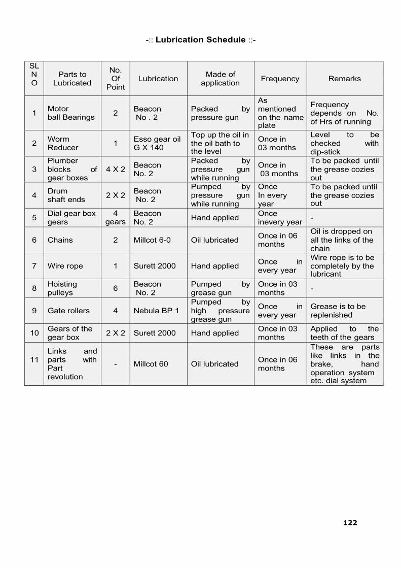
122
-:: Lubrication Schedule ::-
SL N O
Parts to
Lubricated
No. Of
Point
Lubrication
Made of
application
Frequency
Remarks
1
Motor ball Bearings
2
Beacon No . 2
Packed by pressure gun
As mentioned on the name plate
Frequency depends on No. of Hrs of running
2
Worm Reducer
1
Esso gear oil G X 140
Top up the oil in the oil bath to the level
Once in 03 months
Level to be checked with dip-stick
3
Plumber blocks of gear boxes
4 X 2
Beacon No. 2
Packed by pressure gun while running
Once in 03 months
To be packed until the grease cozies out
4
Drum shaft ends
2 X 2
Beacon No. 2
Pumped by pressure gun while running
Once In every year
To be packed until the grease cozies out
5 Dial gear box gears
4 gears
Beacon No. 2
Hand applied Once inevery year
-
6
Chains
2
Millcot 6-0
Oil lubricated
Once in 06 months
Oil is dropped on all the links of the chain
7
Wire rope
1
Surett 2000
Hand applied
Once in every year
Wire rope is to be completely by the lubricant
8 Hoisting pulleys
6 Beacon No. 2
Pumped by grease gun
Once in 03 months
-
9
Gate rollers
4
Nebula BP 1
Pumped by high pressure grease gun
Once in every year
Grease is to be replenished
10 Gears of the gear box
2 X 2 Surett 2000 Hand applied Once in 03 months
Applied to the teeth of the gears
11
Links and parts with Part revolution
-
Millcot 60
Oil lubricated
Once in 06 months
These are parts like links in the brake, hand operation system etc. dial system

123
EQUIVALENT CHART
SL No FSSO VEEDOL
BARMAH SHELL
LOC
1 Beacon No . 2 Ali tho 20 Alvania Greeve
2 Mobil Greave No
2
2 Millcot 60
Apcot 60 Carnea 51 Vactra Ex Heavy
3 Seerett 2000 Gem 94 Cardimum F Viscolits 20
4 Nebula EP Alithex 10 Alvania Greave
EP Sovarex L
5 ESSO Gear oil
140 Multigear 140 Spirax 140 Mobilube G X 140

124
The current practice of Inspection at Narayanpur dam envisages the Subdivision Officers to carryout pre-monsoon and post-monsoon inspections. The checklist proforma included in this chapter is currently in use at Narayanpur dam.
Detailed description on project inspections is available in the Guideline for Safety Inspection of dams (Doc No. CDSO_GUD_DS_07_ v1.0), CWC 2018 (https://damsafety.in/ecm includes/PDFs/Guidelines_for_Safety_Inspection_of_Dams.pdf).
However an overview of the various types of inspections to be carried out at Narayanpur dam is given below. Note that for uploading Inspection Data into DHARMA, the Inspection Instructions & Forms given in the aforementioned Guideline for Safety Inspection of Dams must be used. An effective inspection program is essential to identify problems and to keep Narayanpur Dam in a good and healthy condition This Chapter provides guidance on carrying out other inspections.
3.1 Types of Inspections
Four different types of dam safety inspections are being carried out at Narayanpur Dam. These include, but not limited, to the following:
Comprehensive evaluation inspections
Scheduled inspections (Pre & Post monsoon inspections & other scheduled inspections)
Special (unscheduled) inspections
Informal inspections
The frequency of each type of inspection depends on the condition of the dam and State DSO regulations, etc.
Typical inspection elements and the detail of the safety inspections are provided below. More detailed descriptions are given in the „Guideline for Safety Inspection of Dams’ (CWC 2018). A checklist has been modified from the guideline to fit Narayanpur dam requirements.This comphrehensive checklist allows for recording the status of each item being inspected and the overall condition of the equipment along with any consequential risks the condition may have on the health of the dam.
3.1.1 Comprehensive Evaluation Inspections
For comprehensive dam safety evaluation, an independent panel of experts known as Dam Safety Review Panel (DSRP) needs to be constituted for determining the condition of the dam and appurtenant works. The panel will undertake evaluation of the dam once in 10 years or on occurrence of any extreme hydrological or seismic event or any unusual condition of the dam or in the reservoir rim. The terms of reference of the comprehensive dam safety evaluation shall include but not be limited to;
General assessment of hydrologic and hydraulic conditions, review of design flood, flood routing for revised design flood and mitigation measures.
Review and analysis of available data of dam design including seismic safety, construction, operation maintenance and performance of dam structure and ap- purtenant works.
CHAPTER 3 - PROJECT INSPECTIONS

125
Evaluation of procedures for operation, maintenance and inspection of dam and to suggest improvements / modifications.
Evaluation of any possible hazardous threat to the dam structure such as dam abutment slope stability failure or slope failures along the reservoir periphery.
A comprehensive evaluation inspection of Narayanpur consists of five major parts:
Review of project records (i.e. study of all design / construction records/drawings, history of the dam‟s performance, past inspection notes/reports, notes on distress observed/ any rehabilitation measures undertaken earlier, instrumentation data and its interpretation including .
Inspection of the dam and its appurtenant works.
To review the results and reports of additional field investigations & laboratory testing as required.
Review of design studies e.g. review of design flood, checking of the adequacy of spillway capacity, freeboard requirements, dam stability , any special study as required.
Preparation of a detailed report of the inspection. 3.1.2 Scheduled Inspections
Scheduled inspections shall consist of Pre-monsoon & Post-monsoon inspection and any other inspections carried out by the State Dam Safety Organisation / any Expert panels constituted by the dam owner.
These inspections are performed to gather information on the current condition of the dam and its appurtenant works. This information is then used to establish needed repairs and repair schedules, and to assess the safety and operational adequacy of the dam. Scheduled inspections are also performed to evaluate previous repairs.
The purpose of scheduled inspections is to keep the dam and its appurtenant structures in good operating condition and to maintain a safe structure. As such, these inspections and timely maintenance will minimize long-term costs and will extend the life of the dam. Scheduled inspections are performed more frequently than comprehensive evaluation inspections to detect at an early stage any developments that may be detrimental to the dam. These inspections involve assessing operational capability as well as structural stability and detection of any problems and to correct them before the conditions worsen. The field examinations should be made by the personnel assigned responsibility for monitoring the safety of the dam. If the dam or appurtenant works have instrumentation, the individual responsible for monitoring should analyze measurements as they are received and include an evaluation of that data. Dam Inspection Report or an inspection brief should be prepared following the field visit (Dam Inspection Report is recommended).

126
Scheduled inspections include the following four components as a minimum:
File review of past inspection reports, monitoring data, photographs, maintenance records, or other pertinent data as may be required;
Visual inspection of the dam and its appurtenant works;
Preparation of a report or inspection brief, with relevant documentation and photographs. The report should be filed in the dam owner‟s project files.
3.1.3 Special (Unscheduled) Inspections
Special inspections may need to be performed to resolve specific concerns or conditions at the site on an unscheduled basis. Special inspections are not regularly scheduled activities, but are usually made before or immediately after the dam or appurtenant works have been subjected to unusual events or conditions, such as an unusually high flood or a significant earthquake. These inspections are to be carried out after an initial assessment based on informal inspection carried out by project personnel reveal dam safety related concerns like cracking in the dam, damages, erosion/ scour, undermining/ piping/ sink holes/ liquefaction or any such undesirable feature. A special inspection may also be performed during an emergency, such as an impending dam breach, to evaluate specific areas or concerns. They are also made when the ongoing surveillance program identifies a condition or a trend that appears to warrant a special evaluation. Special inspections should focus on those dam components that are affected by the unusual event and should include at least three elements: 1) review of relevant files or data, 2) visual inspection, and 3) report preparation.
More detailed site investigations / studies may be required (such as drilling, surveys, or seepage flow estimates) if the special inspection reveals the need for the same. Photographic documentation is to be included as part of the inspection.
3.1.4 Informal Inspections
The last type of inspection, an informal inspection, is a continuing effort by on- site personnel (dam owners/operators and maintenance personnel) performed during their routine duties. Informal inspections are critical to the proper operation and maintenance of the dam. They consist of frequent observations of the general appearance and functioning of the dam and appurtenant structures.
Operators, maintenance crews, or other staff who are posted at Narayanpur dam site conduct informal inspections. These people are the “first-line of defense” in assuring safe dam conditions, and it is their responsibility to be familiar with all aspects of the dam. Their vigilance in walking the dam, checking the operating equipment, and noting changes in conditions may prevent serious mishaps or even dam failures.
Informal inspections are important and are performed at every available opportunity. These inspections may only cover one or two dam components as the occasion presents itself, or they may cover the entire dam and its appurtenant structures. The informal inspections are not as detailed as comprehensive evaluation, scheduled, and special inspections and will only require that a formal report is submitted to the dam owner‟s project files if a condition is detected that might endanger the dam. Report is to be submitted

127
detailing the condition discovered along with photographs, time, reservoir water level (RWL), etc.
3.1.5 Pre- and Post-Monsoon Checklist and Example of Report Proforma
Detailed checklists are required to ensure the health of the dam continues to operates in satisfactory and safe condition. Details of the inspection must be in alignment with the DHARMA approved checklist attached to this document.

128
PRO-FORMA FOR PERIODICAL INSPECTION OF
LARGE DAMS
GENERAL Date of Inspection:
Sl. No.
Item of Inspection Remarks
1 1a 1b 2 3
1. Name of project Upper Krishna Project
2. Purpose of Project Multi-Purpose
3. Name of Dam NARAYANPUR DAM.
4. Year of Completion 1982
5. First filling (years / levels) 1982 RL-492.25 m
6. Benefits accrued:
a) Irrigation Irrigation
b) Water Supply Yes
c)
Power
Yes ( i .e.during surplus dis- charge to river and canal out- flows- generated by Pvt agency)
d) Other benefits Industries
7. Important Controlling Levels ( in meters)
a)
Top of dam
496.752 m. Earthen Dam portion 495.752 m concrete & Masonary dam portion.
b) Maximum Water Level 492.25 m
c) Full Reservoir Level 492.25 m
d) Sill level of Irrigation sluices 481.58 m
e) Sill level of scouring sluices 472.25 m
f) Spillway crest level 480.250 m
g) Minimum draw down level 487.10 m
h) Lowest river bed level 469.94 m
i) Deepest foundation level 466.032 m
8. Important Salient Features
a) Dead Storage Capacity
203.00 MCM ( 7.167 TMC ) (at sill level, 481.58 m)
b) Area of foreshore at F.R.L 132.00 Sq Km
c)
Design flood adopted (PMF / SPF / Any other) Give relevant magnitude
PMF-37945 Cumec.
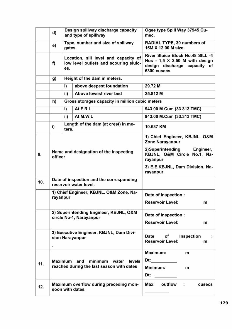
129
d)
Design spillway discharge capacity and type of spillway
Ogee type Spill Way 37945 Cu- mec.
e)
Type, number and size of spillway gates.
RADIAL TYPE, 30 numbers of 15M X 12.00 M size.
f)
Location, sill level and capacity of low level outlets and scouring sluic- es.
River Sluice Block No.48 SILL -4 Nos - 1.5 X 2.50 M with design design discharge capacity of 6300 cusecs.
g) Height of the dam in meters.
i) above deepest foundation 29.72 M
ii) Above lowest river bed 25.812 M
h) Gross storages capacity in million cubic meters
i) At F.R.L. 943.00 M.Cum (33.313 TMC)
ii) At M.W.L 943.00 M.Cum (33.313 TMC)
i)
Length of the dam (at crest) in me- ters.
10.637 KM
9.
Name and designation of the inspecting officer
1) Chief Engineer, KBJNL, O&M Zone Narayanpur
2) Superintending Engineer, KBJNL, O&M Circle No.1, Na- rayanpur
3) E.E.KBJNL, Dam Division. Na- rayanpur.
10. Date of inspection and the corresponding reservoir water level.
1) Chief Engineer, KBJNL, O&M Zone, Na- rayanpur
Date of Inspection :
Reservoir Level: m
2) Superintending Engineer, KBJNL, O&M circle No-1, Narayanpur
Date of Inspection :
Reservoir Level: m
3) Executive Engineer, KBJNL, Dam Divi- sion Narayanpur
.
Date of Inspection : Reservoir Level: m
11.
Maximum and minimum water levels reached during the last season with dates
Maximum: m
Dt:
Minimum: m
Dt:
12.
Maximum overflow during preceding mon- soon with dates.
Max. outflow : cusecs
130
Dt:
13. History of past distress, if any, and brief details of remedial measures carried out.
14.
Does the officer-in-charge of the operation and maintenance of dam possess all the records as required
15. When and by whom the dam was inspected immediately preceding this inspection?
16.
Are the items pointed out during the last inspection properly attended to?
(If not state deficiencies yet to be cor- rected).

131
REVISED PRO-FORMAT
FOR
HEALTH STATUS REPORT OF LARGE DAMS
(Keeping in view CWC letter No. 627-56 dt. 28-08-2002)
Sl.
No.
Items of the
“Health Status Report” Reply
1 Name of Dam Narayanpur Dam
2 Sl. No. in the National Register of Large Dam Project Identification Code PIC KA06MH0142
3 Dam features
a) Date of Completion July 1982
b)
Location
i) Longitude 76° 21' N
ii) Latitude 16° 10' E
c) Height of Dam 29.72 m above the lowest foundation
d) Gross Capacity
(Gated/Un gated)
33.313 TMC (0.943 TMCUM)
Gated
e) Whether the Dam is provided with Drai- nage Gallery or not.
Provided with Drainage Gallery of size
1.60 m X 2.40 m
4
Main Component of Dam
Type of Dam: Composite Dam:
Spillway: Gated spillway with 30 No s of Radial Crest gates of size 15m X 12m.
Length of concrete spillway dam- 548.00mtr.
Length of Masonry non-overflow Dam- 673.00 m.
Length of earthen Dam: 9416.00m
(Including Dyke).
5 Date of Inspection
6 Inspecting Officer Chief Engineer, KBJNL O&M Zone, Narayanpur.

132
7 Observations/Significant Deficiencies Noticed
I Inadequate Spillway.
II Inadequate free-board
III
Cracks in Masonry / Concrete / Earth Dam
a) Masonry/concrete dams and
b) Structural cracking in earth dams
IV Inadequate
a) Flood forecasting system
b) Flood warning system
c) Communication
V Excessive seepage through,
a) Drainage holes
b) Porous pipes
c) Downstream face of dam
d) Downstream area etc.
e) Development of high uplift pressure
VI Excessive leaching
VII Choking of porous drains.
VIII Choking of drainage holes

133
IX Mal-operation of gates
X
Non-availability of standby/ alternative source of power
XI
Structural Review indicating tension on the upstream face of dam
XII
Non-availability of Emergency Action Plan.
8 Performance of Dam
Based on Instruments installed in the dam (Water Level Recorder, V-notch, etc.,)
Of Meteorological Instruments installed in the cat- chment area and reservoirs of Dams.
Is the hydraulic performance in agreement with the results of model studies?
Any other issue / issues pertaining to performance of dam which the Engineer-in-Chief / Chief Engi- neer in-charge of dam desires to include.
9 Remedial Measures Suggested.
10 Remarks
11 Action Taken Report.
Assistant Exe. Engineer , Executive Engineer
In charge of dam, in-charge of dam. Superintending Engineer
in-charge of dam.
Certified that the Health Status Report of NARAYANPUR DAM is furnished after a thorough re- view of the same by the technical wing of the zone (this has reference to para 18.3.5 of the Pro- ceedings of 18th meeting of SLDSC).
Chief Engineer
In-charge of dam.

134

135
Performance of Dam Instruments
Sl. No.
Name of Dam with location
Name of Instrument No. of Instru- ments
Performance Status of data Analysis Remarks
1 2 3 4 5 6 7
Asst Exe Engr, Executive Engineer Superintending Engineer Chief Engineer
In-Charge of dam. KBJNL,Dam Division. KBJNL,O&M Circle No1 KBJNL,O&M Zone
Narayanpur Narayanpur Narayanpur Narayanpur

136
Performance of Meteorological Instruments pertaining to Large Dams in Karnataka
Sl. No.
Name of Dam with location
Name of Instrument
No. of In- struments
Performance
Status of data Analysis
Remarks
1 2 3 4 5 6 7
Engineer-in-Chief, Water Resources Development Organization, Bangalore.
Categorization of Deficiencies
(Keeping in view CWC letter No. 627-56 dt. 28-08-2002)
Category No.* Criteria for categorization
Category No. (1) Dams with major deficiency which may lead to dam failure
Category No. (2)
Dams with rectifiable deficiency which needs immediate attention.
Category No. (3) Dams with minor / no deficiencies has been noticed.
* Category Number is to be furnished in the „remarks‟ column of the Health Status Report.

137
THIS PAGE LEFT BLANK INTENSIONALLY

138
A good maintenance program protects Narayanpur Dam against accelerating deterioration, prolongs its life, and greatly reduce the chance of failure. Nearly all the components of Narayanpur Dam and its materials are susceptible to damage and deterioration if not well maintained. Moreover, the cost of a proper maintenance program is small compared to the costs of major repairs, loss of life and property and litigation. Preventative maintenance not only protects the dam and its owner but the public as well. If maintenance of a dam is neglected the consequences and costs will multiply.
Preventive maintenance assures that a dam and reservoir are in good working condition and prevents more harmful conditions from developing. Individual maintenance tasks are noted, with a description of the area where the maintenance is to be performed, the schedule for performing the tasks, and reporting procedures. Typical routine maintenance tasks performed includes mowing grass, removing vegetation, bushes and trees, removing litter and other debris, re-grading the crest and/or access roads, repairing fencing to keep livestock off the dam, etc. Other maintenance works that need to be performed on the embankment includes restoration of embankment to its design section, seepage problems, erosion, displaced riprap, cracking in embankment etc. In concrete / masonry dams there may be issues like cracking and disintegration in concrete, choking of drainage holes in dam body/ foundation, damages to spillway glacis/piers/energy dissipaters due to abrasion/ cavitation/unsymmetrical flows, damages to pointing on upstream & downstream faces of masonry dams, heavy seepages through some drains in foundation/inspection galleries etc.
A basic maintenance program has been developed primarily based on systematic and frequent inspections.
4.1 Maintenance Priorities
For Narayanpur Dam, maintenance activities require to be prioriitized as immediate maintenance or preventative maintenance.
4.1.1 Immediate Maintenance
The following conditions are critical and call for immediate attention & reservoir lowering, if warranted. These conditions may include, but are not limited to:
The dam is about to be overtopped or being overtopped during high flood.
The dam is about to be breached by erosion, slope failure etc. The dam showing signs of piping or internal erosion indicated by
increasingly cloudy seepage or other symptoms. The spillway being blocked or with some inoperable gates.
Evidence of excessive seepage appearing anywhere on the dam site,e.g.,the Embankment becomes saturated, defective water stops, etc., and seepage exiting on the downstream face is increasing in volume.
Although the remedy for some critical problems may be obvious (such as clearing a blocked spillway or repairing the spillway gates so that they are in working condition), the problems listed above generally demand the services of experienced engineers/expert
CHAPTER 4 - PROJECT MAINTENANCE

139
panels familiar with the design, construction and maintenance of dams. The emergency action plan (EAP) should be activated when any of the above conditions are noted.
4.1.2 Preventive Maintenance
This can be further classified as Condition based Maintenance and Routine Maintenance.
4.1.3 Condition Based Maintenance
The following maintenance should be completed as soon as possible after the defective condition is noted. These includes but are not limited to:
Remove all vegetation and bushes from the dam and restoring any eroded areas and to establish a good grass cover.
Fill animal burrows. Restore and reseed eroded areas and gullies on embankment. Repair of defective gates, valves, and other hydro-mechanical equipment. Repair any concrete or metal components that have deteriorated.
As per the recommendations Cleaning of the choked drainage holes in the dam body/ foundations in concrete /
masonry dams. Controlling any heavy seepage in the foundation/ inspection galleries in
Concrete/Masonry dams from drainage holes. Repairs of any cracks/cavities/joints in concrete/masonry dams/structures.
However many of these works will require the services of experienced engineers/expert panels.
As per recommendations of DSRP and inspection report of Director, CWC,(Design Wing) New Delhi for spillway gates ,following rehabilitation and Improvement works mentioned vide chapter 6 of this manual have been taken up and completed under DRIP –I from 2016 to 2019.
Repair of metal components of main spillway gates
Photo showing rusted parts replaced by new plates and T- sections Photo showing rusted horizontal stiffener
plates and half cut T-sections

140
Photo showing two coats of cold applied coaltar epoxy paint each 100 micron thick applied after zinc rich
epoxy primer paint.
Photo showing Zinc rich epoxy pri- mer paint 40 micron applied over Zinc metalized surface
Photo showing zinc metalizing treatment 200 micron thick followed by sand blasting and copper blasting

141
Treatment to the observed eroded portion of Spillway Ogee and Bucket portion by applying 6mm thick abrasive resistance coating/Placing Micro concrete
treatment etc.
Treatment to the observed eroded spillway Ogee using high strength abrasion resistant protective coat

142
Ogee portion:Laying of Microconcrete Bucket portion: Laying of Microconcrete
Bucket portion : Laying of micro concrete
Bucket portion: Laying of polymer based free flow micro concrete with high bond strength concrete for ho- neycombed/ Spalled area
Surface preparation by hacking (not less than 25mm deep) loose/honeycombed second stage
Eroded portion of Bucket

143
Treatment carried out to the observed leakages by polyure- thene grouting treatment
Leakages observed in the Pier wall portion
Leakages observed in the Ogee portion Wall plate &Sill beam portion
Treatment carried out to the observed lea- kages by polyurethene grouting treatment

144
.
Excavation by removing top layer of wea- thered rock including removal of boulders
Providing Apron concrete below flip bucket by Anchorage in the bed rock with 5 mtr. Deep using 25 mm dowel bars spaced at 1.1 mtr c/c and filling 40 M-15 concrete and top layer provided with 30 cm thick high strength M 60 silica fume based steel fiber reinforced concrete with bed anchorage & drainage ar- rangement to release uplift.
Repair Energy Dissipaters: Providing apron concrete below flip bucket

145
Before pointing work U/S face
Repairs on the upstream face of masonry dams, in case the pointing is damaged, due to which there is increased seepage.
Repair on the upstream face of masonry dam,

146
Surface preparation by removing old mortar joints and cleaning with water jet U/s
Application of bonding agent on the prepared surface and pointing work U/s
Drilling of holes for fixing and cement grouting with admixtures

147
Pointing work D/s Before and after
After pointing work U/s face

148
Reaming works masonry portion
4.1.4 Routine Maintenance
Several tasks should be performed on a continuous basis. These include but are not limited to the following:
Routine mowing, restore and reseed eroded areas and gullies on downstream face of the left flank embankment and general maintenance including repairs/cleaning of surface drains on downstream face and in the downstream area.
Final Chemical injection treatment to leaked masonry joints

149
Maintenance and treatment of any cracks/joints/ cavities in Concrete/Masonry dams and spillways based on the recommendations of experienced engineers / expert panels.
Observation of any springs or seepage areas, comparing quantity and quality (clarity) with prior observations in the embankment.
Monitoring of downstream development which could have an impact on the dam and its hazard category.
Maintenance of Electrical & Hydro-Mechanical equipment and systems e. g. Servicing of spillway gates & stop logs, hoisting arrangements, gantry crane, gates/hoist of outlet works/sluices & stand by generator.
Maintaining proper lighting at dam top, galleries, etc. Monitoring of seepage in galleries. Monitoring/ cleaning & removal of leached deposits in porous concrete / formed
drains in dam body and foundation drainage holes. Maintenance of all dam roads & access roads. Operation of electrical and mechanical equipment and systems including exercising
gates & valves. To keep the gate slots clear of silt/debris. Maintenance/testing of monitoring equipment (instruments) and safety alarms. Testing of security equipment. Testing of communication equipment. Any other maintenance considered necessary.
4.2 Procedures for Routine Maintenance
The O&M Manual includes detailed instructions and schedules for performing periodic maintenance works at the site. This include maintenance of the dam, the appurtenant works, and the reservoir areas. Methodology / Specifications for carrying out maintenance works of general & recurring nature should be included in the Manual.
Dam repairs are scheduled based on severity of the problem, available resources, and weather conditions. For example, if a severe settlement problem (more than envisaged in designs) or cracking is detected on the crest of the dam, it should have a high priority since further degradation could lead to dam breaching. The causes of all major issues / problems should be identified and evaluated by experienced engineers/ Expert Panels so that appropriate remedial measures can be finalized. Correcting minor rill erosion on the downstream slope could be assigned a low priority since it is not a dam safety concern. This type of repair will also be weather dependent, since grass can only be planted during specific times of the year, and the embankment should be dry so that more damage is not inflicted to the embankment slopes.
4.2.1 Earthwork
The surfaces of an earthen dam may deteriorate due to several reasons. For example, wave action may cut into the upstream slope, vehicles may cause ruts in the crest or slopes, trails left by livestock can result in erosion, or runoff waters may leave erosion gullies on the downstream slope. Other special problems, such as shrinkage cracks or rodent damage, may also occur. Damage of this nature must be repaired constantly.
The maintenance procedures described here are effective in repairing minor earthwork problems. However, this section is not intended to be a technical guide, and the methods discussed should not be used to solve serious problems. Conditions such as embankment slides, structural cracking, and sinkholes threaten

150
the immediate safety of a dam and require immediate repair under the directions of experienced engineers/Expert panels.
The material selected for repairing embankments should be free from vegetation, organic materials, trash, and large rocks.
If flow-resistant portions such as the core of an embankment dam are being repaired, materials that are high in clay or silt content should be used. If the area is to be free draining or highly permeable (such as pervious shell of an embankment dam) the material should have a higher percentage of sand and gravel. It is usually satisfactory to replace or repair damaged areas with soils like those originally in place.
An important soil property affecting compaction is moisture content. Soils that are too dry or too wet do not compact well. One may test repair material by squeezing it into a tight ball. If the sample keeps its shape without cracking and falling apart (which means it is too dry), and without depositing excess water onto the hand (which means it is too wet), the moisture content is near the proper level.
Before placement of earth, the repair area needs to be prepared by removing all inappropriate material. All vegetation, such as bushes, roots, and tree stumps, along with any large rocks or trash need to be removed. Also, unsuitable earth, such as organic or loose soils, should be removed, so that the work surface consists of exposed, firm, clean embankment material.
Following cleanup, shape and dress the affected area so that the new fill can be placed and compacted in horizontal lifts to the level specified in the technical specifications. Also it must be properly keyed (benched) with the existing material for which proper construction practices ae carried out to “knit” the new fill in to the existing soils to ensure proper bonding. This can be accomplished by using the following simple procedures
1. Scarify the existing soil layer
2. Place new moisturized soils in loose layers up to 20 centimeters thick
3. Compact to required density at optimum moisture content (OMC)
4. Scarify compacted layer 10 centimeters
5. Moisturize the layer before placement of soils
6. Compact
7. Continue process until lines and grades are accomplished. Overbuild can be trimmed back to design lines and grades
8. Seed of turf the fill to minimize erosion processes
9. Water routinely to ensure turf root system is fully developed.
Erosion is one of the most common maintenance problems at embankment structures. Erosion is a natural process and its continuous forces will eventually wear down almost any surface or structure. Periodic and prompt maintenance is essential to prevent continuous deterioration and possible failure.Turfing, free from weeds and deleterious materials, is an effective means of preventing erosion.Rills and gullies should be filled with suitable soil, compacted, and then seeded or turfed as necessary. Large eroded gullies can be slowed by stacking bales of hay or straw across the gully until permanent repairs can be made.
Erosion is also common at the point where an embankment and the concrete walls of a spillway or other structure meet. Poor compaction adjacent to such walls during construction and later settlement can result in an area along the wall that is lower
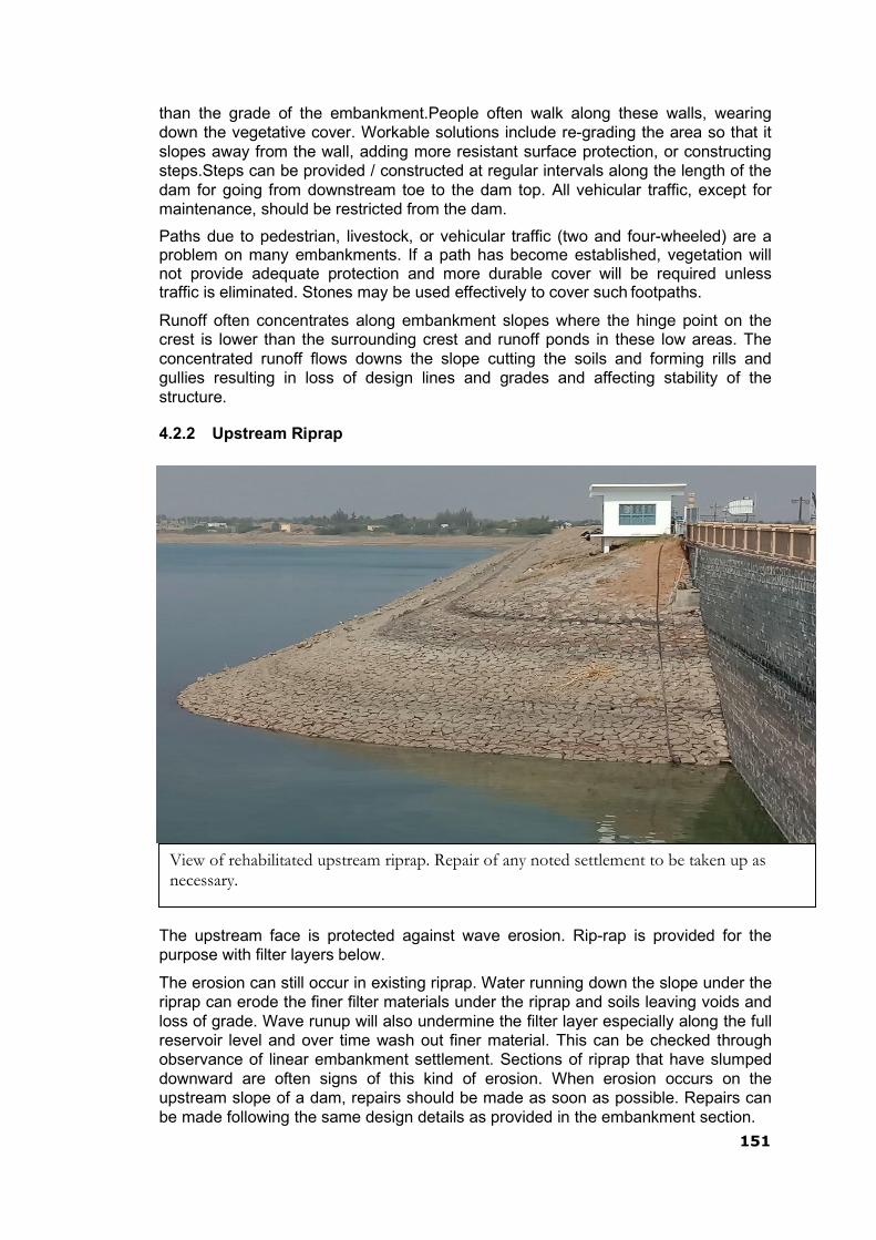
151
View of rehabilitated upstream riprap. Repair of any noted settlement to be taken up as necessary.
than the grade of the embankment.People often walk along these walls, wearing down the vegetative cover. Workable solutions include re-grading the area so that it slopes away from the wall, adding more resistant surface protection, or constructing steps.Steps can be provided / constructed at regular intervals along the length of the dam for going from downstream toe to the dam top. All vehicular traffic, except for maintenance, should be restricted from the dam.
Paths due to pedestrian, livestock, or vehicular traffic (two and four-wheeled) are a problem on many embankments. If a path has become established, vegetation will not provide adequate protection and more durable cover will be required unless traffic is eliminated. Stones may be used effectively to cover such footpaths.
Runoff often concentrates along embankment slopes where the hinge point on the crest is lower than the surrounding crest and runoff ponds in these low areas. The concentrated runoff flows downs the slope cutting the soils and forming rills and gullies resulting in loss of design lines and grades and affecting stability of the structure.
4.2.2 Upstream Riprap
The upstream face is protected against wave erosion. Rip-rap is provided for the purpose with filter layers below.
The erosion can still occur in existing riprap. Water running down the slope under the riprap can erode the finer filter materials under the riprap and soils leaving voids and loss of grade. Wave runup will also undermine the filter layer especially along the full reservoir level and over time wash out finer material. This can be checked through observance of linear embankment settlement. Sections of riprap that have slumped downward are often signs of this kind of erosion. When erosion occurs on the upstream slope of a dam, repairs should be made as soon as possible. Repairs can be made following the same design details as provided in the embankment section.

152
proper preparation of the surfaces of the existing embankment as described in the earlier paragraph for placement and compaction of embankment. Please refer to IS 8237- Code of practice for protection of Slopes for Reservoir Embankments is recommended to be reviewed and followed for carrying out this repair work.
4.2.3 Controlling Vegetation
Keep the entire dam clear of unwanted vegetation such as bushes or trees. Excessive growth may cause several problems:
It can obscure the surface of an embankment and not allow proper inspection of the dam.
Large trees can be uprooted by high wind or erosion and leave large voids that can lead to breaching of the dam.
Some root systems can decay and rot, creating passageways for water, leading topiping erosion.
Growing root systems can lift concrete slabs or structures.
Rodent habitats can develop undetected.
All bushes/trees should be as far as possible removed by root to prevent regrowth. The resulting voids must be backfilled with suitable, well-compacted soils. It is recommended to remove the plants/vegetation at their early stage to prevent or minimize their growing into big trees/bushes, etc. In cases where trees and bushes cannot be removed, the root systems should be treated with environmentally-friendly herbicides (properly selected and applied) to retard further growth. Concerned Government Agencies must be consulted for selection of appropriate herbicides & their use for control of vegetation on dam structures or any water bodies.
4.2.4 Controlling Animal Damage
Livestock are not allowed to graze on the embankment section of the dam. When soil is wet, livestock can damage vegetation and disrupt the uniformity of the surface. Moreover, livestock tend to walk in established paths and thus can promote erosion.
The burrows and tunnels of burrowing animals (beaver, muskrat, groundhogs and others) weaken earthen embankments and serve as pathways for seepage from the reservoir. Large burrows found on the embankment should be filled by mud packing. This method involves placing vent pipe in a vertical position over the entrance of the den. Making sure that the pipe connection to the den does not leak, the mud-pack mixture is poured into the pipe until the burrow and pipe are filled with the soil-water mixture. The pipe is removed and more dry earth is tamped into the entrance. As per some US publications, the mud pack is generally made by adding water to 90% earth & 10% cement mixture until a slurry or thin cement consistency is attained. For bigger holes, bentonite coated stones can also be used. All entrances should be plugged with well-compacted earth and grassy vegetation re-established. Dens should be eliminated without delay. Different repair measures will be necessary if a dam has been damaged by extensive small or large rodent tunneling activity. The area around the entrance can be excavated and then backfilled with impervious material. This will plug the passage entrance to prevent water entry and saturation of the embankment.
4.2.5 Controlling Ants and Termites (White Ants)
Ants and termites have become one of the most serious pests for Embankment dams. They both need water to survive and have been found on most of the
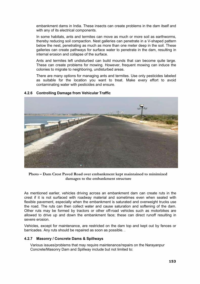
153
embankment dams in India. These insects can create problems in the dam itself and with any of its electrical components.
In some habitats, ants and termites can move as much or more soil as earthworms, thereby reducing soil compaction. Nest galleries can penetrate in a V-shaped pattern below the nest, penetrating as much as more than one meter deep in the soil. These galleries can create pathways for surface water to penetrate in the dam, resulting in internal erosion and collapse of the surface.
Ants and termites left undisturbed can build mounds that can become quite large. These can create problems for mowing. However, frequent mowing can induce the colonies to migrate to neighboring, undisturbed areas.
There are many options for managing ants and termites. Use only pesticides labeled as suitable for the location you want to treat. Make every effort to avoid contaminating water with pesticides and ensure.
4.2.6 Controlling Damage from Vehicular Traffic
Photo – Dam Crest Paved Road over embankment kept maintained to minimized
damages to the embankment structure
As mentioned earlier, vehicles driving across an embankment dam can create ruts in the crest if it is not surfaced with roadway material and sometimes even when sealed with flexible pavement, especially when the embankment is saturated and overweight trucks use the road. The ruts can then collect water and cause saturation and softening of the dam. Other ruts may be formed by tractors or other off-road vehicles such as motorbikes are allowed to drive up and down the embankment face; these can direct runoff resulting in severe erosion.
Vehicles, except for maintenance, are restricted on the dam top and kept out by fences or barricades. Any ruts should be repaired as soon as possible. .
4.2.7 Masonry / Concrete Dams & Spillways
Various issues/problems that may require maintenance/repairs on the Narayanpur Concrete/Masonry Dam and Spillway include but not limited to:

154
Damages on spillway glacis, spillway piers, training/divide walls, energy dissipa- ters, downstream areas (probable causes are cavitations, abrasion, un- symmetrical flows, unfavorable down-stream conditions)
Vegetation growth in unattended areas such as spillway, spillway channel, etc.
Seepage in the galleries and on the downstream face of the dam.
Cleaning and removal of leached deposits from choked porous and foundation drains.
Repair to upstream face of masonry dams in case the pointing is damaged, lead- ing to increased seepage.
Ensuring safe access to and within the gallery, lighting is also required as well as all outside areas during the evening hours.
Ensuring the dam is behaving as designed based on instrumentation programs.
Periodic maintenance should be performed of all concrete surfaces which are approachable to repair deteriorated areas.
For remedial measures of problems of special nature advice of experienced engineers /Panel of Experts needs to be obtained
4.2.8 River Sluices
The sluices should be inspected thoroughly once a year for any damages such as cracks and seepage. As regards to Hydro-mechanical works, reference may be referred to the appropriate paragraphs in this chapter.
4.2.9 Gates & Hoisting Equipment
The safe and satisfactory operation of Narayanpur Dam depends on proper operation of its Gates &Hoisting Equipment. Maintaining spillway gates in working condition is critical for dam safety and is to be assigned the highest priority and taken care for protection of technical staff conducting maintenance above ground without fall protection, goggles, gloves, hardhats etc.
If routine inspection of the Hydro-Mechanical Equipment shows the need for maintenance, the work should be completed as soon as possible. The simplest procedure to ensure smooth operation of gates is to operate them through their full range at least once, and preferably twice annually (before monsoon & after monsoon keeping a gap of at least six months). Because operating gates under full reservoir pressure can result in large discharges, exercising of gates should preferably be carried out during dry conditions or lean times of the year using the stop-logs/ emergency gates.
Commonly used Gates and Hoists including their inspection / maintenance requirements are discussed below.
The aspects to be inspected and maintained periodically for ensuring proper operation of these gates are as under:
i) The gate slot and bottom platform/sill beam should be cleaned periodically. Scales formed over the embedded parts should be removed. Second-stage concrete should be checked for any development of cracks / leakages and repairs should be attended to immediately.
ii) The gate leaf should be thoroughly cleaned and repainted as and when necessary according to the procedure or guidelines- indicated in IS: 14177 or as per the recommendations of the paint manufacturer. All drain holes provided in the gate assembly should be cleaned.
155
iii) Rubber seals should be smoothed, if required, for proper alignment. All nuts and bolts fixing the seal to the gate should be tightened uniformly to required torques. Seals, if found damaged or found leaking excessively should be adjusted, repaired or replaced as considered necessary.
iv) The wheel shall be rotated to check their free movement. Gate roller bearings and guide roller bushes should be properly lubricated. Whenever necessary these should be opened for rectifications of defects, cleaning and lubrication and should thereafter be refitted. These may be replaced if repairs are not possible.
v) Hoisting connection of the gate leaf should be lubricated where necessary and defects if any should be rectified.
vi) All nuts, bolts, check nuts and cotter pins of the lifting devices should be checked periodically.
vii) All components should be greased and lubricated. Recommended and approved oils and grease only should be used.
viii) Roller assembly should be adjusted by the eccentricity arrangement to ensure all rollers rest uniformly on the track plates particularly in the closed position of the gate.
ix) Where filling valves are provided as part of the gate structure, all the nuts, bolts, check nuts etc. should be tightened.
x) All welds shall be checked for cracks/ damages. Any weld that might have become defective should be chipped out and redone following the relevant codal provisions. Damaged nuts, bolts, rivets, screws etc. should be replaced without delay.
xi) The filling-in valves allow passage of water when it is lifted by lifting beam & crane due to creation of space between stem seat and exit passage liner. The springs and associated components should be checked periodically for damages and replaced if necessary.
xii) The guide-assemblies, wheel-assemblies and sealing-assemblies shall be cleared off grit, sand or any other foreign material.
xiii) The wheel pin shall be coated with corrosion resistant compound.
xiv) All nuts and bolts shall be tightened.
The aspects to be inspected and maintained periodically for ensuring proper operation of these gates are as under :
a) Rubber Seals:
i) Seals shall be inspected for leakages. Locations of excessive leakages shall be recorded for taking remedial measures. Weeping or slight flow in localized area will not require immediate remedial measures. However, measures like tightening of bolts are carried out. Further adjustment is carried out during annual maintenance.
ii) If leakage is excessive & immediate repair is considered necessary, the stop log gates shall be dropped and seals repaired or replaced.
NOTE: - During monsoon period, stop log gates shall NEVER be lowered in spite of heavy leakage through seals.

156
b) Trunnion block assembly and anchorages:
(i) All the nuts and bolts of Trunnion block assembly and its anchorages shall be checked for tightness.
(ii) Check all the welds for soundness and rectify defects.
(iii) Check whether the Yoke girder and thrust block is covered on not. If not, cover it with mild steel plates.
(iv) Cover the trunnion pin with anti- corrosive jelly.
(v) Remove all dirt, grit etc. from trunnion assembly and lubricate trunnion bearings of the gate with suitable water resisting grease as recommended by bearing manufacturers.
c) Gate structures:
i) Check all the welds for soundness and rectify defects.
ii) Check welds between arms and horizontal girders as well as between latching bracket and skin plate with the help of magnifying glass for cracks/defects and rectify the defects.
iii) Clean all drain holes including those in end arms and horizontal girders.
iv) Check all the nuts and bolts and tighten them. Replace damaged ones.
v) Check upstream face of skin plate for pitting, scaling and corrosion. Scaling may be filled with weld and grinded. Corroded surface shall be cleaned and painted.
d) Embedded Parts:
i) All the sill beams and wall plates shall be inspected for crack, pitting etc. and defects shall be rectified.
ii) The guide roller pins shall be lubricated.
e) General Maintenance:
i) Defective welding should be chipped out and it should be re-welded duly following the relevant codal provision (IS: 10096, Part-3).
ii) Damaged nuts, bolts, rivets, screws etc. should be replaced.
iii) Any pitting should be filled up by welding and finished by grinding if necessary.
iv) The gate leaf, exposed embedded metal parts, hoists and hoist supporting structure etc., should be thoroughly cleaned and repainted when required keeping in view the original painting system adopted and as per the guidelines contained in IS: 14177.
v) Trunnion bearing should be greased as and when required. Keeping trunnion bearings in perfect working condition is very important. All other bolted connections should also be checked up for proper tightness.
vi) Bolts and trunnion bearing housing should be tightened wherever required.
vii) The seals of the gate should be checked for wear and tear and deterioration. These should be adjusted/replaced as and when necessary.
viii) The wall plates, sill beams shall be checked and repaired if necessary.
ix) Wire ropes should be properly lubricated.
157
x) Oil level in the worm reduction unit should be maintained by suitable replenishment. Oil seals should also be replaced if required. Lubrication of other parts of hoists such as chains, position indicators and limit switches should also be done.
xi) The stroke of the brake should be reset to compensate for lining wear. Worn out brake linings should be replaced in time.
xii) Flexible couplings should be adjusted if required.
xiii) Repairs and replacements of all electrical relays and controls should be attended to.
xiv) Maintenance of alternative sources of Power such as Diesel Generating sets and alternative drives wherever provided should be carried out.
xv) The list of essential spare parts to be kept available should be reviewed and updated periodically. The condition of spares should be checked periodically and protective coating given for use.
4.2.10 Electrically operated fixed hoists
1. General Instructions:
a) Operation of fixed hoist without lifting the gate is not possible and need not therefore be attempted. It will be possible to operate the unit and observe operation of load carrying hoist component when gate is being lifted or lowered.
b) Never open any bolt or nut on motor, gear boxes, rope drums and other load carrying hoist components when the gate is in raised position. The gate should be fully closed or rested on the gate latches before carrying out any work on hoist components including motor brake and other electrical equipment.
c) The aspects to be inspected and maintained periodically for ensuring proper operation of Rope drum hoists are as under;
i. Entrance to all hoist platforms shall be kept locked. All keys shall remain with the shift supervisor.
ii. A cursory daily inspection shall be made of hoist and gate to ensure that there is no unusual happening.
iii. Clean all hoisting equipment and hoist platform.
iv. Check oil level in gearboxes and replenish as and when required with oil of proper grade.
vi. Apply grease of suitable grade by grease gun.
vi. Lubricate all bearings, bushings, pins, linkages etc.
viii. Check all the fuses on the power lines.
ix. All bolts and nuts on gear boxes, hoist drum and shaft couplings should be checked for tightness.
ix. Check the supply voltage.

158
x. Drain sample gear oil from each of the gear boxes. If excessive foreign particles or sludge is found, the gear box shall be drained, flushed and filled with new oil.
xi. All the geared couplings shall be greased.
xiii. Raise and lower the gate by hoist motor and check for smooth, and trouble free operation of gate without excessive vibration.
xiv. Observe current drawn by motor at the time of lifting and check if it is more than normal. If so, stop the hoist and investigate the cause and rectify.
xv. Check the condition of painting of various components and remove rust wherever noticed and repaint the portion after proper cleaning as per painting schedule.
xvi. All trash, sediments and any other foreign material shall be cleared off the lifting rope and lifting attachment.
xvii. All ropes shall be checked for wear and tear and if broken wires are noticed, the rope shall be replaced.
xviii. All the wire ropes shall be checked and all visible oxidation shall be removed.
xix. All wire ropes shall be greased with cardium compound.
xx. Check the overload relays for proper functioning.
xxi. Check all the nuts, bolts, rivets, welds and structural components for hoisting platform and its supporting structure for wear, tear and damage. All damages shall be rectified. All bolts shall be tightened. The portion with damaged painting shall be touched up.
xxii. Check the pulleys, sheaves and turn-buckles.
xxiii. Raise and lower the gate for its full lift several time (at least three to four) and observe the following:
a) Check the limit switches and adjust for design limits.
b) The effectiveness and slip of the breaks shall be checked by stopping the gate in raising and lowering operations. The brakes shall be adjusted if needed.
c) When the gate is operated, there should not be any noise or chatter in the gears.
xxiv. Adjust the rope tension of wires if unequal.
xxv. Check for all gears and pinions for uneven wear and adjust for proper con tact. Grease the gears.
xxvi. Repaint the hoist components, hoisting platform and its supporting struc tures as per requirement.
xxvii. The periodic maintenance of commercial equipment like motors, brakes,

159
thrusts etc. shall be carried out as per manufacturers operation and maintenance manual.
4.2.11 Maintenance of Electrical components of Fixed Rope Drum Hoists:
a).The electrical components to be inspected and maintained periodically are as under;
i) Starters should be cleaned free of moisture and dust.
ii) Each individual contactor should be tried by hand to make sure that it operates freely.
iii) All wearing parts should be examined in order to take note of any wear which may have occurred during operation.
iv) If the contactor hums, the contact faces should be cleaned.
(v) Examine all connections to see that no wires are broken and no connections are loose.
vi) Clean the surface of the moving armature and magnet core which comes together when the contactor closes, free of dust or grease of any kind.
vii) Examine the mechanical interlocks between the reversing contactor and see when the contact tips of one of the contactor units are touching, it is impossible to get the contact tips of the other unit to touch.
viii) The contact tips should be kept free from burns or pits by smoothening with fine sand paper or emery paper.
ix) Replace the contact tips which have worn away half-way.
x) Do not lubricate the contacts.
160
xi) Blow out windings thoroughly by clean and dry air to clear air passage in the stator and the rotor of any accumulated dirt. The air pressure shall not be too high to damage the insulation.
xii) Examine earth connections and motor leads.
xiii) Examine motor windings for overheating
xiv) Examine control equipment‟s
xv) Examine starting equipment for burnt contacts
xvi) Check and tighten all nuts and bolts
xvii) Clean and tighten all terminals and screw connections all contact surfaces shall be made clean and smooth.
xviii) Lubricate the bearings
xix) Overhaul the controllers
xx) Inspect and clean circuit breakers.
xxi) Wipe brush holders and check bedding of brushes.
xxii) Blow out windings thoroughly by clean and dry air. The pressure shall not be so high that insulation may get damaged.
xxiii) Check the insulation resistance of the motor between any terminal and the frame. If the measured resistance is less than the prescribed value, then steps shall be taken to dry- out the motors either by passing a low voltage current through the windings or by placing the stator and rotor only in a warm dry place for a day or so.
WARNING: The complete motor shall never be put in an oven for drying as that may melt the grease out of bearings.
xxiv) Coat the windings with an approved high temperature resisting insulation enamel or varnish.
xxv) Over haul the motor, if required.
xxvi) Check the switch fuse units and renew, if required.
xxvii) Check resistance or earth connections.
xxviii) Check air gap.
b) Solenoid Operated Brakes
i) All fixing bolts shall be checked and tightened at least once in three months.
ii) The magnet stroke should be reset to compensate for wear.
iii) Re-adjust the brake when the magnet stroke reaches the value given on the instruction plate.
iv) Brake lining should be checked and replaced when required.
v) Examine all electrical leads and connections.
vi) Rubber bushes or couplings should be checked and replaced if defective.
vii) The pins should be tightened.
161
viii) Brake drum shall be cleaned to remove any dust or grease.
Stop logs, lifting beam & gantry crane
4.2.12 Spillway Stoplogs, Lifting Beam &Radial Gate
A. MAINTENANCE OF STOPLOGS a. Regular Maintenance
1. For gear and pinion, grease or lubricating compound shall be frequently used for the smooth operation
2. Wire Rope should be kept lubricated on regular basis with cardium com- pound.
3. Damaged nuts, bolts etc. should be replaced
4. Oil level in the gear box and worm reducer should maintained.
5. Electromagnetic brake should be checked regularly and plunger to be cleaned dry to ensure proper functioning. The break shop to be cleaned.
b. Periodical Maintenance
1. Wire Rope should be examined for rusting, broken strands etc. and the wire rope at both the ends of the gate should have equal initial tension.
2. All nuts, bolts and screws shall be checked for wear, tear and tight- ness
3. Drain oil from gear box once in every 6 months and replace with rele- vant grade.
4. Ensure proper meshing of gear and pinion.
5. Location and adjustment of guide shoe should be checked.
6. Check E.M. Brake and thruster brake properly functioning.
7. All the moving parts should be properly lubricated.
8. The fuses are to be checked and replaced when they are worn-out. Replacements of fuses are necessary when they emit smell or get over heated. Care should be taken to select the correct size of fus- es.
4.2.13 Maintenance Gantry Crane
Hoisting trolley of the Gantry cranes is built on top of a wheeled mobile gantry structure travelling over fixed rails and is used to straddle an object or load over a workspace.
Following aspects need to be considered and attended to during maintenance;
1. Oil level in the gear boxes. It is very important to ensure that the correct oil level is maintained. Over filling causes overheating and leakage, therefore, care should be taken that the breather holes are not clogged by any foreign material like dust, paint etc.
162
2. The insulation resistance of motor windings.In case it is found to have dropped below a prescribed value, the motor should be dried prior to putting back in service. If weak insulation becomes a regular feature, the winding should be given a good coat of insulating varnish after the motor has been dried.
3. Checking of all the electrical connections.
4. Lubrication of each part of crane
5. Removal of any loose/foreign material along the rail track
6. Actuating tests of limit switches
7. Actuating tests of brakes.
8. All fuses in the control panel should be checked and if necessary, it should be replaced.
9. Necessary terminal connections of motors, brakes etc. is to be checked.
10. Overload relay should be checked.
11. Visual inspection of wire ropes for any snapped loose wire and its proper lubrication.
12. Checking of rope clamps on the drum and tightening of bolts if required.
13. Gearbox assembly should not have any leakage of oil.
14. Unusual noise/vibration if any should be checked and rectified before operation.
4.2.14 MAINTENANCE OF MOTOR
1. Motors shall be blown out at regularly intervals to keep its ventilating pas- sage clear, particularly when operating in dirty atmosphere.
2. Moisture, oil, dirt, grease and carbon or metallic dust are the principal causes of break down. The motor therefore be kept clean and dry and must be kept free from oil and greases, damp and dirt, periodical cleaning with dry compressed air with a brush is necessary.
3. The motor required be examining and dismantling from time to time and frequency of service cleaning will depend upon the conditions under which the motor operates. During periodical cleaning care shall be taken to clean air passage in the starter and motor of any accumulated dirt.
4. Terminals and screw connections shall be kept clean and tight. If they be- come dirty or corroded, they shall be disconnected and all contact surfac- es made clean and smooth. Bad contact leads to sparking and ultimate breakdown.
163
4.2.15 LUBRICATION AND MAINTENANCE OF REDUCTION GEAR UNIT
1. Satisfactory performance of grease required that the lubricating oil kept be clean, and free from dirt, grit, moisture and sludge. Depending upon oper- ating conditions the oil eventually becomes contaminated and should be drained periodically. During operation the oil level should be periodically checked, too high level results loss of power and oil leakage, too low oil results in friction in bearings and on gear teeth causing overheating. Use proper graded oil.
2. Oil level should be checked with the help of dipstick or the oil indicator and should be topped up, if necessary.
3. Where the bearings of the unit are greases lubricated, the same should be filled with the top of grease gun.
4. Care should be taken that the breather holes are not clogged by any for- eign materials, like dust, paint etc.
5. During cleaning gear casing should be flushed with the same sort oil that is used under working Conditions. If encasing is opened for cleaning all sealing compound must be removed.

164
4.2.16 LUBRICATION CHART
PART LUBRICATION FOR FREQUENCY
1. Hoist Brake Hand oiled points One in a month
Fulcrum pins
2. Long travel Hand oiled points One in a month
Brake fulcrum
Pins
3. Motors:
Hoist Long End Bearing Replace once in six
Months and renew
Once in a year.
4. Long travel Grease Nipples Repack once in Six
Shaft Plummer Blocks Months and renew
Once in a year .
5. Gear Boxes Gear Boxes Check oil level once
A month and top up
As necessary.
6. Pinion & Gear Gears & Pinions Every 3 Months .
Wheels
7. Wire Rope Full Wire (Cardium Every year preferably
Compound) before onset of Monsoon
4.2.17 MAINTENANCE OF BEARING
Like all other important machine components ball and roller bearings must occasio- nally be cleaned and examined.
In many cases it is permissible to let the bearing run for considerable / longer time before carrying out inspections, especially the conditions of the bearings can be as- certained, during service for example, by listening to the sound produced during run- ning, checking the temperature of noting the colour of the lubricant.
While spirit good quality paraffin, petrol or benzene may be recommended as suita- ble for cleaning roller bearings.
Bearing should not be allowed to stand dry for any length of time after they have cleaned out, should be oiled and greased immediately when this is done, the bear- ings should be rotated several times to that oil or grease can reach all vital parts and thereby protect the bearings from rust.
For sheaves, oiling the bearing at frequent interval and checking that they rotate free- ly must be done. A seized up sheaves may ruin a rope very speedily. Care should be taken to see that the rope does not foul in flat against any obstacle in its way.

165
4.2.18 MAINTENANCE OF WIRE ROPE
Frequently the inspection of the entire length of rope is necessary. Watch constantly for broken wires, excessive wear and lubrication, see that the number of broken wires does not exceed as laid down in different regulation.
Prompt attention must be given to a broken wire in a rope otherwise damage to other wires and serious accidents may results.
Cleaning wire rope with brush or compressed air and giving it a light coating of spe- cial wire rope dressing is essential. This lubricant puts a protective film on each indi- vidual wire, repels water and stops corrosion.
4.2.19 CHECK FOR THE TIGHTNESS OF THE BOLTS
1. Fixing bolts of motor and reduction gears.
2. Plummer Block base Bolts.
3. Bolts of all Coupling.
4. Inspect the keys in the Couplings for its correct position once in every six months .
5. The wire Rope and is fixed over the winding drum by weans of clamps and bolts. These are to be checked for its tightness periodically.
4.2.20 ADDITIONAL MAINTENANCE ITEMS FOR STOPLOGS
The stop log units being in pieces, the top non-interchangeable unit with unique fea- tures as well as the other interchangeable units arestored in the grooves in various spans / bays.The following aspects are to be considered and attended to during maintenance:
1. Defective / damaged / cracked welding should be cutout and re-welded.
2. Damaged nuts, bolts, screws etc. should be replaced.
3. The gate leaf should be thoroughly cleaned and repainted whenever necessary
4. Rubber seals should be ground, if required to bring it in to alignment. All nuts and bolts for fixing seals to gate should be tightened uniformly. Seals when damaged or found leaking excessively should be adjusted or replaced as and when considered necessary.
5. All components should be greased and lubricated with the recommended oil and grease only.
6. The roller assembly should be adjusted by the eccentricity provision to ensure that all the rollers rest uniformly on track plates particularly in the closed position of the stop log gate.
7. The drain holes in horizontal girders should be cleaned.
8. It should be ensured that no bearing is overheated.
9. The gate slots should be kept cleaned. The scaling over the embedded parts should be removed.
Since normally the stop logs remain in hanging position, for any routine maintenance, these are required to be raised up to the top of pier or deck level to rest on the dog- ging beam with the help of the gantry crane andlifting beam. Thereafter, if required, it is further raised at a slow speed from safety point of view, it is to be ensured that

166
these units do not foul or hit legs / columns of the gantry crane. Thereafter, the gate can be rested on the deck level for necessary maintenance, servicing, repairs or re- placement of its component parts. After completion of maintenance, the stop log units are shifted back to their original dogged position.
4.2.21 LIFTING BEAM
Lifting beam is used for both raising& lowering of Spillway stop log units with the use of Gantry crane. Lifting Beam shall mainly comprise of two number structural steel channels or fabricated channels with back to back connection to make it a single fa- bricated structural frame. Two side guide rollers/shoes shall be provided on each side of the lifting beam. The depth of lifting beam /frame should be sufficient to ac- commodate to rollers on each side located at sufficient distance from one another to enable proper guided movement. The depth of lifting beam shall not be less than one tenth of the length / span of the lifting beam or 500 mm whichever is more.
Lifting beam hook mechanism shall provide for automatic engagement and release of the equipment to be handled manually by movement of the hook block. The two hooks shall be mechanically linked together for simultaneous operation. All rotating parts of the lifting beam shall be provided with corrosion resistant steel pins and alu- minum bronze bushing /roller bearings. All nuts, bolts and washers and retaining de- vices for pins shall be of corrosion resistant steel.
Following issues need to be considered and attended to during maintenance;
1. Bush bearing of lifting attachment and various pulleys /sheaves wheel gears etc. should be properly lubricated.
2. Whenever it is felt that friction in the bearing has increased, these should be taken out for cleaning and lubrication and should be refitted properly. These should be replaced, if found beyond repair.
4.2.22 MAINTENANCE OF BEARING
Like all other important machine components ball and roller bearings must occasio- nally be cleaned and examined.
In many cases it is permissible to let the bearing run for considerable / longer time before carrying out inspections, especially the conditions of the bearings can be as- certained, during service for example, by listening to the sound produced during run- ning, checking the temperature of noting the colour of the lubricant.
While spirit good quality paraffin, petrol or benzene may be recommended as suita- ble for cleaning roller bearings.
Bearing should not be allowed to stand dry for any length of time after they have cleaned out, should be oiled and greased immediately when this is done, the bear- ings should be rotated several times to that oil or grease can reach all vital parts and thereby protect the bearings from rust.
For sheaves, oiling the bearing at frequent interval and checking that they rotate free- ly must be done. A seized up sheaves may ruin a rope very speedily. Care should be taken to see that the rope does not foul in flat against any obstacle in its way.

167
4.2.23 Surface Preparation and Painting of HM Works
i) Protection of painted surfaces is considered essential for protection & enhancement of service life. Gates, their embedded parts, gate leaf, hoists and its supporting structures need to be protected against corrosion due to climatic condition, weathering, biochemical reaction and abrasion etc. This equipment is likely to deteriorate or get damaged to any extent that the replacement of parts may become necessary and such replacement may become difficult and costly.
ii) Surface preparation & Painting requirements:
Painting for hydro-mechanical works is to be carried out as prescribed in IS 14177 for both newly manufactured as well as old & used gates, hoists and associated works after proper surface preparation. The preparation includes thorough cleaning, smoothing irregular surfaces, rusted surfaces, weld spatters, oil, grease, dirt, earlier applied damaged layers of primers/ paint by use of mechanical tools, by use of solvents, wire brush etc. The sand / grit blasting process is used for surface preparation to a level of Sa 2½ of the Swedish standard.
iii) Surfaces not requiring painting & their protection during surface preparation, painting & transportation process:
a) The following surfaces are not to be painted unless or otherwise specified:
• Machine finished or similar surface
• Surfaces which will be in contact with concrete
• Stainless steel overlay surfaces.
• Surfaces in sliding or rolling contact
• Galvanized surfaces, brass and bronze surfaces.
• Aluminum alloy surfaces
b) The Surfaces of stainless steel, nickel, bronze and machined surface adjacent to metal work being cleaned or painted shall be protected by using sticky protective tape or by other suitable means over the surfaces not to be painted.
c) All embedded parts which come in contact with concrete shall be cleaned as detailed above and given two coats of cement latex to prevent rusting during the shipment while awaiting installation.
iv) Application of primer &finish coats on embedded parts and gates:
a) EMBEDDED PARTS:
• The prescribed primer shall be applied as soon as the surface preparation is complete and prior to the development of surface rusting and within the specified time prescribed by Indian Standards or the Paint Manufacturer. In case there is lapse of considerable time beyond the prescribed time limit, the surfaces shall be again cleaned prior to priming.
• Two coats of zinc rich primer with epoxy resin shall be applied to all embedded parts surfaces which are not in contact with concrete and shall remain exposed to atmosphere or submerged in water to obtain a dry film thickness of 75 microns.

168
• This shall be followed by three coats at an interval of 24hours of coal-tar blend epoxy resin so as to get a dry film thickness of 80 microns in each coat. Total dry film thickness of paint shall not be less than 300 microns.
b) GATES:
Primer Coat:
• Over the prepared surface one coat of inorganic zinc silicate primer giving a dry film thickness of 70 ± 5 microns should be applied. Alternatively two coats of zinc rich primer, which should contain not less than 85% zinc on dry film should be applied to give a total dry film thickness of 75 ± 5 microns.
Finished paint:
• Two coats of solvent less coal tar epoxy paints. These shall be applied at an interval of about 24 hours. Each coat shall give a dry film thickness of 150±5 microns. The total dry film thickness of all the coats including primer coating shall not be less than 350 microns.
v) Hoist and supporting structure:
a) Structural components:
Primer coats of zinc phosphate primer shall be applied to give a dry film thickness of 40±5 microns.
Final Coats: One coat of alkalized based micaceous iron oxide paint to give a dry film thickness of 65 ± 5 microns followed by two coats of synthetic enamel paint confirming to IS 2932 – 1974 to give a dry film thickness of 25 ± 5 microns per coat. The interval between each coat shall be 24hours. The total dry thickness of all coats of paint including the primer coat shall not be less than 175 microns.
b) Machinery: Except machined surfaces all surfaces of machinery including gearing, housing, shafting, bearing pedestals etc., shall be given:
Primer coats: One coat of zinc phosphate primer paint to give minimum film thickness of 50 microns. Motors and other bought out items shall be painted if necessary.
Finished coats: The finished paint shall consists of three coats of aluminum paint confirming to IS2339 – 1963 or synthetic enamel paint confirming to IS 2932 – 1977 to give a dry film thickness of 25±5 microns per coat to obtain a total minimum dry film thickness of 125 microns.
c) Machined surfaces:
All machined surfaces of ferrous metal including screw threads which will be exposed during shipment or installation shall be cleaned by suitable solvent and given a heavy uniform coating of gasoline soluble removable rust preventive compound or equivalent. Machined surfaces shall be protected with the adhesive tapes or other suitable means during the cleaning and painting operation of other components.

169
vi) Application of paint:
Mix the contents thoroughly as directed by paint manufacturer before and during use.
Painting at shop can be done by any of the three methods namely Brush / roller, Conventional spray, Airless spray etc.
The paint can be made to suit the adopted method. But once the gate and equipment is in erected position the general method adopted is only brush / roller. In case of spray lot of precautions are to be taken.
For More details: Refer IS: 14177 Part (II) – 1971.
Appendix A – Brushing of paint
Appendix B – Spraying of paint
Appendix C – Spray painting defects: Causes and remedies.
Removal of old paint / rust and carrying out fresh painting:
The carrying out of fresh painting is to be considered under the following conditions:
• The rusting is noticed all over the surface or
• Rusting is severe or
• Cracking and blistering has damaged the primer coat exposing the metal and is noticed all over the surface or
• The paint film has eroded badly, the scrap of entire paint film to the base metal and carry out fresh painting.
Note: In case of maintenance and renovation: Refer IS 14177 (Part II) – 1971 for checking and repainting.
vii) Removal of old paint for repainting:
Caution should be exercised while removing the old paint. The surfaces shall be de- rusted and descaled by either mechanically by one or more of the methods, namely:
a) Wire brushing, Scraping, and chipping. Sand papering or cleaning with steel wool or abrasive paper
b) Power tool cleaning
c) Flame cleaning
d) Sand blasting or shot blasting and
e) Chemical rust removal.
Note: The method of application shall be decided based on conditions existing. After cleaning painting is to be carried out as originally proposed.
Some are painted without removal of old paint and rusting this will amounts to no painting and deteriorate faster than the original one.

170
viii) Inspection and testing of painting of H. M works:
a) The following steps are involved in inspection of painting:
General inspection before and during painting
Viscosity test of paints
Paint thickness test – using Elco-meter.
Inspection of general appearance of finished work.
b) General:
The aim of inspection and testing is to ascertain whether the recommended practice is being employed correctly during every stage of application and whether the final results fulfill the object of painting. Any test carried out should be of non – destructive nature or, if it is of destructive nature, it should be either restricted to areas which can be restored without marring the general appearances or be such that it is possible to restore easily without necessitating a complete repetition of the work.
c) Inspection of surfaces prior to painting:
Inspection methods will depend on whether it is to be painted for the first time or is to be repainted.
d) New Works (Not previously painted): The following shall be decided by inspection:
The method of pre cleaning feasible or recommended;
The intermediate protective treatments to be applied, if found necessary;
The final painting schedule and the specifications for the paint for ensuring the particular performance;
The method of application, whether by brush, roller or spray.
e) Old Work (Which requires repainting):
The following shall be decided by inspection:
Whether the entire existing paint requires removal; and/or
Whether repainting without paint removal would be adequate.
4.2.24 ELECTRICAL SYSTEM
Electricity is typically used at a dam for lighting and to operate the gates, hoists, recording equipment, and other miscellaneous equipment. It is important that the Electrical system be well maintained, including a thorough check of fuses and a test of the system to ensure that all parts are properly functioning. The system should be free from moisture and dirt, and wiring should be checked for corrosion and mineral deposits.
All necessary repairs should be carried out immediately and records of the works kept. Maintain generators used for auxiliary emergency power -- change the oil, check the batteries and antifreeze and make sure fuel is readily available.
Monitoring devices usually do not need routine maintenance. Open areas are particularly susceptible to vandalism. As such all electrical fittings like bulbs, lights,
171
loose wires etc. in open areas should be checked routinely and replaced / repaired where needed. The recommendations of the manufacturer should also be referred to.
4.2.25 Maintenance of Metal Gate Components
All exposed, bare ferrous metal of an outlet installation, whether submerged or exposed to air, will tend to rust. To prevent corrosion, exposed ferrous metals must be either appropriately painted (following the paint manufacturer‟s directions) or heavily greased in respect of moving parts & on surfaces like guides & track seats on which there is movement of gates. When areas are repainted, it should be ensured that paint is not applied to gate seats, wedges, or stems (where they pass through the stem guides), or on other friction surfaces where paint could cause binding. Heavy grease should be applied on friction surfaces to avoid binding. As rust is especially damaging to contact surfaces, existing rust is to be removed before periodic application of grease.
4.2.26 Access Roads
For a dam to be operated and maintained, there must be a safe means of access to it at all times. Access road surfaces must be maintained to allow safe passage of automobiles and any required equipment for servicing the dam in any weather conditions. Routine observations of any cut and fill slopes along the sides of the road should be made. If unstable conditions develop assistance of experienced Engineers/Expert Panels should be obtained and remedial measures initiated.
Drains are required to be provided and maintained along roads to remove surface and subsurface drainage. This will prolong the life of the road and help reduce deterioration from rutting. Road surfacing should be repaired or replaced as necessary to maintain the required traffic loadings. In most cases, specialized contractors will be required to perform this maintenance.
4.2.27 General Cleaning
As already suggested, for proper operation of spillways, sluiceways, approach channels, inlet and outlet structures, stilling basin / energy dissipation arrangements, discharge conduit, dam slopes, trash racks, debris control devices etc., regular and thorough cleaning and removal of debris is necessary. Cleaning is especially important after large floods, which tend to send more debris into the reservoir.
4.2.28 Materials and Establishment Requirements during Monsoon Period
Materials required during monsoon period for both immediate maintenance and preventive maintenance must be stocked in adequate quantities for emergency situations that may arise.Needful instructions in this regard is enclosed in the O&M Manual. At Almatti Dam, a 24/7 hour patrol schedule is carried out during monsoon period. At the same time the additional management requirements during monsoon period are enhanced.

171
4.3 General List of Maintenance Records
Maintenance records are of utmost importance. Records are kept of all maintenance activities, both immediate and preventive maintenance works. Essential information to be recorded include the following:
Date and time of maintenance, Weather conditions, Type of maintenance, Name of person, title and / or contractor performing maintenance, Description of work performed, Length of time it took to complete the work with dates, Equipment and materials used, and Before and after dated photographs.
The data is recorded by the person responsible for maintenance.
4.4 Preparation of O&M budget
O&M budget for Narayanpur dam included to the following items:
i) Establishment Cost of Regular Staff - Salaries and allowances, Bonus, Medical Reim- bursement, LTC, Leave Encashment, pension benefits, etc. (as applicable).
ii) Establishment Cost of Work charged Staff - Salaries and allowances, Bonus, Medical Reimbursement, LTC, Leave Encashment, Pension benefits, TA and DA , etc. (as ap- plicable).
iii) Establishment Cost of Daily wage Staff - Salaries and allowances, TA and DA etc. (as applicable).
iv) Office Expenses – Rent for office, Telephone/Mobile/any other Telecommunication bills, Electricity bills, water bills, Office stationery, Day to day office requirements.
v) Motor Vehicles - Running and Maintenance cost of inspection vehicles, Cost of hiring of vehicles as required
vi) Maintenance of Colony - Maintenance of staff quarters, colony roads, Electricity, Sani- tary and Water supply systems etc.
vii) T&P - T&P requirements for offices, colony, works etc. as applicable.
viii) Works -Painting, oiling, greasing, overhauling of HM equipment‟s, Repair/replacement of gates seals & wire ropes, POL for pumps & generator sets, Electricity charges and maintenance of Electric systems of dam site, specific requirements for all Civil, H.M & Electrical maintenance works, vegetation removal and mowing of turfing on earth dams, maintenance/cleaning of drains in dam, maintenance of lift/elevators in dam (as applicable), maintenance of access roads & basic facilities, provision for flood contin- gency works during monsoon, unforeseen events/items (about 10% of the cost of works) etc.

172
Table 18 - O&M BUDGET COSTS (ANNUAL)
SL. NO.
BUDGET ITEM PREVIOUS
YEAR COST (Rs)Lakhs
CURRENT YEAR BUDGET
(YR-2019-20 (Rs) Lakhs
REMARKS
A. ESTABLISHMENT
1
SALARY OF REGULAR STAFF INCLUDING ALL OTHER BENEFITS
125.00
130.00
2
TRAVEL EXPENSES
7.50
7.00
3
OFFICE EXPENSES
7.00
7.00
4
MOTOR VEHICLE EXPENSES
9.50
6.14
5
MAINTENANCE OF OFFICE & COLONY COMPLEX
1.00
1.00
SUB-TOTAL - A
150.00
151.14
B. WORKS
1
CIVIL
1.1
CONCRETE / MASONRY DAM
8.00
5.00
1.2
EARTHEN DAM
18.00
20.00
1.3
INTAKE / OUTLETS IN EARTHEN DAMS
-
-
1.4
SLUICES IN CONCRETE / MASONRY DAMS
1.00
1.00
1.5
APPROACH / INSPECTION ROADS WITHIN DAM AREA
-
2
HYDRO-MECHANICAL
2.1
SPILLWAY GATES & HOISTS
55.00
48.00
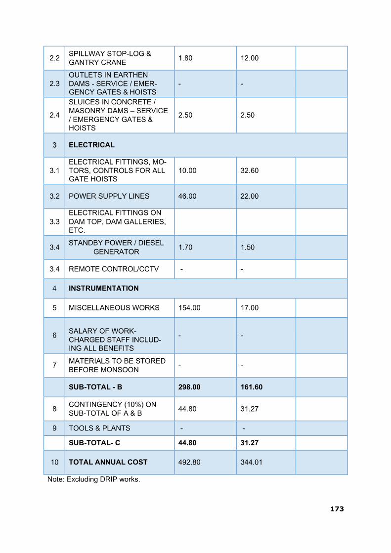
173
2.2
SPILLWAY STOP-LOG & GANTRY CRANE
1.80
12.00
2.3
OUTLETS IN EARTHEN DAMS - SERVICE / EMER- GENCY GATES & HOISTS
-
-
2.4
SLUICES IN CONCRETE / MASONRY DAMS – SERVICE / EMERGENCY GATES & HOISTS
2.50
2.50
3
ELECTRICAL
3.1
ELECTRICAL FITTINGS, MO- TORS, CONTROLS FOR ALL GATE HOISTS
10.00
32.60
3.2
POWER SUPPLY LINES
46.00
22.00
3.3
ELECTRICAL FITTINGS ON DAM TOP, DAM GALLERIES, ETC.
3.4
STANDBY POWER / DIESEL GENERATOR
1.70
1.50
3.4 REMOTE CONTROL/CCTV - -
4 INSTRUMENTATION
5 MISCELLANEOUS WORKS 154.00 17.00
6
SALARY OF WORK- CHARGED STAFF INCLUD- ING ALL BENEFITS
-
-
7
MATERIALS TO BE STORED BEFORE MONSOON
-
-
SUB-TOTAL - B 298.00 161.60
8
CONTINGENCY (10%) ON SUB-TOTAL OF A & B
44.80
31.27
9 TOOLS & PLANTS - -
SUB-TOTAL- C 44.80 31.27
10
TOTAL ANNUAL COST
492.80
344.01
Note: Excluding DRIP works.

174
4.5 Maintenance Records
Maintenance records are of utmost importance. A record shall be kept for all mainten- ance activities, both immediate and preventive maintenance works. Information that must be recorded includes,but not limited to, the following:
date and time of maintenance,
weather conditions,
the type of maintenance,
name of person or contractor performing maintenance,
description of work performed,
the length of time it took to complete the work with dates,
equipment and materials used, and
before and after photographs.
The data should be recorded by the person responsible for maintenance.

175
THIS PAGE LEFT BLANK INTENTIONALLY

176
5.1. Dam Instrumentation·
5.1.1 General Information
This section identifies the location and chainages of each of the 4 structural compo- nents of the dam:
Table 19 – structural components of the dam:
Components From Chainage,m To Chainage,m
Left side Earthen Embankment 00.00 1510.00
Non-Overflow Section (left of overflow section)
1510.00
1724.00
Over-flow Section 1724.00 2183.00
Non-Overflow Section (right of overflow section)
2183.00
2552.00
Additional over-flow Section 2552.00 2641.00
Non-Overflow Section
(right of overflow section)
2641.00
2731.00
Right side Earthen Embank- ment .
2731.00
5219.00
Dyke Earthen Embankment (Saddle Dam)
5219.00
10637.00
5.1.2 Structural :
Instrumentation is not taken up for masonry dam. In spillway block No.20 of Narayanpur dam following instrumentation are provided. Stress meters and Strain meters. No stress strain meters joint meters and thermometers have been embedded at ch. 1,864.75 at RL.471.75, 475.00, 478.275 and 480.00 Mtrs. The maximum height of the dam is ap- proximately 30 mtrs. For earthen dam at ch.90, 97, 143.20 and 320.00 of RBED & Dyke of Narayanpur Dam. Embankment and foundation type Piezometer are installed. Ter- minal building at respective changes have been constructed and bourdon type pressure gauge have been fitted to record the pore pressure reading. Settlement devices at re- spective chainages have been installed.
At ch.91 twenty two Nos. of embankment type Piezometers are embedded in five rows, vertical settlement the centre of dam. At Chainage 97 fifteen Nos. of embankment type pizeometers are embedded two rows. Settlement devices have been installed, one at
CHAPTER 5 - INSTRUMENTATION AND MONITORING

177
mtrs. From C/L at upstream side another at 13 mtrs. From C/L of dam at downstream. At Ch.143.20 twenty six Nos. of embankment type Piezometers have been embedded in two settlement devices one at 3.75 mtrs upstream and another at 13mtrs Description of Instruments
5.1.3 Spillway:
All the instrument embedded in spillway block No.22 are of unburdened resistance type instrument. Few of the instrument are imported Carson type manufactured by M/s KYow Electronic Japan.
Table 20 – Instrument Locations
Sl. No
No of tiers
Description No Ch RL Remarks
I
Thermometer 3 1864.75 471.75
Tier Stress meter 5 1864.75 471.75
Strain meter 25 1864.75 471.75
No stress meter 5 1864.75 471.75
II Tier Joint meter 1 1879.50 475.00
III Tier Thermometer 5 1864.75 478.525
Joint meter 1 1864.75 478.525
IV Tier Thermometer 2 1864.75 480.00
5.1.4 Earthen Dam Portion:
Downstream from C/L of dam. At Ch.320 embankment type Piezometers have been embedded one row, settlement devices at downstream is provided 8.75 mtrs from C/L of dam.
5.1.5 Evaluation of results:
For spillway block No.20. The cables from all the instrument in spillway block No.20 have been connected to box located in the notch of the pier. There was impounding of reservoir up to the, level of 488.00 there is no much variations in the readings are observed.
5.1.6 For earthen Dam
Pore pressure reading observed are taken monthly. P/H ratio in all the four sections are within permissible limits. Settlement reading are within the permissible limits.
5.1.7 Seepage:
Description
The maximum seepage observed in spillway drainage gallery during 2019-20 is 75 LPM, and in additional spillway drainage gallery is maximum 0.57 LPM.

178
There is 30cm dia drain at downstream rock toe and same is connected to the wall at the downstream. “V” notches are provided in the toe drain of Left Bank Earthen dyke of Right Bank Earthen Dam Narayanpur.
Evaluation results:
The seepage OBSERVED IN Left Bank Earthen Dam “V” notch provided downstream at the toe drain is 0.2 cusecs (maximum). Similarly the seepage observed in dyke of Right Bank Earthen Dam through “V” – is 0.643 cusecs (maximum), clear water is coming through “V” earth particulars are observed coming through the drain water.
Frequency of readings:
Piezometers : monthly. Seepage :weekly
Current Provisions:
All the obligatory and optional are embedded. The location etc., are fixed at as per the IS recommendation and project requirement as below. Spillway concrete dam block No.20
Sl. No
No of tiers
Description No Ch RL Remarks
I Tier Thermometer 3 1864.75 471.75
Stress meter 5 1864.75 471.75
Strain meter 25 1864.75 471.75
No stress meter 5 1864.75 471.75
II Tier Joint meter 1 1879.50 475.00
III Tier Thermometer 5 1864.75 478.525
Joint meter 1 1864.75 478.525
IV Tier Thermometer 2 1864.75 480.00
Remarks:
Instrument is provided in four tiers as per drawing enclosed. Except for the first group of strain meters, spiders are provided for other strain meter group, earth dam.
The Piezometers and settlement devices are embedded at ch.91,97,143.20 and 320 of Right Bank Earthen Dam and dyke portion of Dam.

179
5.1.8 PRESENT STATUS OF DAM INSTRUMENTATION
Piezometers (Foundation as well as embankment) embedded at ch.91, 97, 143.20 & 320 of Right flank earth dam and dyke of dam site are not in working condition and other instruments such as Stress meter, Strain meter. Joint meter, Thermo meter, provided in the body of the dam are also not in working condition
The Dam Safety Review Panel(DSRP) have suggested for providing Piezometers in the embankment portions at ch.305, 316, 330 on dyke portion dam.
The Piezometers have been installed at respective chainages as per the suggestions of DSRP and records are being maintained. As per the records the Piezometers are showing water levels in accordance with the reservoir water levels.
NOTE: Please note that all instruments i.e. Thermometer,Stress meter,Strain meter, Joint meter indicated in above Tables are not in working order.
5.1.9 New Instrumentation Proposed under DRIP
The Narayanpur Dam is one of the major dam in Karnataka state that has been selected for availing World Bank assistance for implementation of Dam Rehabilitation & Im- provement Project (DRIP). The following instruments have been proposed for Narayanpur as per the suggestions of SPMU & CPMU under DRIP.
1. Seismometer 2. Accelograph 3. Automatic weather Station 4. Automatic Plumb line 5. Plumb line (Inverted & Normal) 6. Thermometers 7. Tilt meters 8. Joint meters 9. Uplift Gauges 10. V- Notchs 11. Settlement plate/ Survey markers

180
6.1. Previous Rehabilitation Efforts:
Before DRIP, maintenance activities were limited to routine greasing, oiling, and re- placement of wire ropes, rubber seal and painting of hydro-mechanical devices; routine repair of electrical systems; gallery drainage; routine monitoring, vegetation removal, re- pair of eroded section, etc. Apart from these routine/periodical maintenance activities, no major rehabilitation works was carried out before the involvement of DRIP.
Under DRIP, major Rehabilitation works have been carried out at a total cost of about INR 112.07 Crores (with some activities still ongoing during the preparation of this O&M manual).
The rehabilitation works under DRIP include:
Costs (INR) Name of Work
Original Contract Amount
(in Millions)
Supplementary Contract Amount
(in Millions)
Revised Agreement
amount (in Millions)
Providing apron concrete below flip bucket and Providing roadway drainage, cross drains, correction to stone revet- ment wrap around portion of earthen dam of Narayanpur Dam – (Package-I)
392.417
36.414
428.831
Treatment of second stage honeycombed concrete and honeycombed pier regions, leaked construction joints of spillway piers and bucket portion for vent Nos 1 to 25 of main spillway and A1 to A5 of additional spillway of Narayanpur Dam. (Package-II)
357.019
39.81
396.829
Treatment of the upstream face of Ma- sonry portion above MDDL including reaming, cleaning and flushing of clogged porous drain holes in Masonry section of Narayanpur Dam (Package-III).
120.156
17.943
138.099
Providing strengthening measures in- cluding zinc metalizing to the corroded gate components of radial spillway gates and Providing 84 Ton capacity gantry crane with one set of stop log elements to Narayanpur Dam – (Package-IV)
140.913
16.111
157.023
TOTAL
1010.505
110.277
1120.782
Other non-structural measures under DRIP include preparation of inundation maps and Emergency Action Plan (EAP).
CHAPTER 6 - PREVIOUS REHABILITATION EFFORTS

181
7.1. Updating the Manual:
As features of the dam and appurtenant structures change occasionally, the O&M Ma- nual must be edited and portions rewritten to reflect these changes. This important task is often ignored. Updating information in the O&M Manual should be done whenever ma- jor changes like construction of an additional spillway, construction of dam on the up- stream etc. take place. Aspects to be considered when updating include:
Increase/decrease in the frequency of an inspection or the maintenance routine based on additional data/ experience acquired.
Changes in the operation and/or maintenance procedures based on additional da- ta/experience acquired.
Alterations to the project data because of changes/modifications in the dam by way of additional spillway etc.
All up-dates/revisions of the O&M Manual need to be sent to all the locations/addresses to whom the copies of the original O&M Manual had been sent earlier. It is recommend- ed that O&M Manuals be reviewed/ updated after every 10 years by the respective Dam Owners.
CHAPTER 7 - UPDATING THE MANUAL

182
THIS PAGE LEFT BLANK INTENTIONALLY

183
APPENDIX 1 – BASIC DRAWINGS OF NARAYANPUR DAM

184
Over Flow section of Narayanpur Dam--- Drawing-1
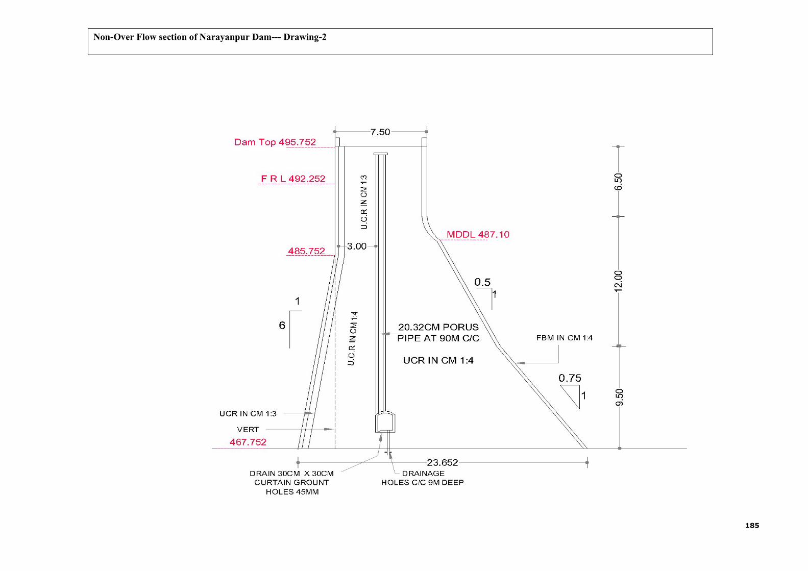
185
Non-Over Flow section of Narayanpur Dam--- Drawing-2

186
Left Bank Head Regulator Gate --- Drawing-3

187
Right Bank Head Regulator Gate --- Drawing-4

188
River Sluice Gate --- Drawing-5
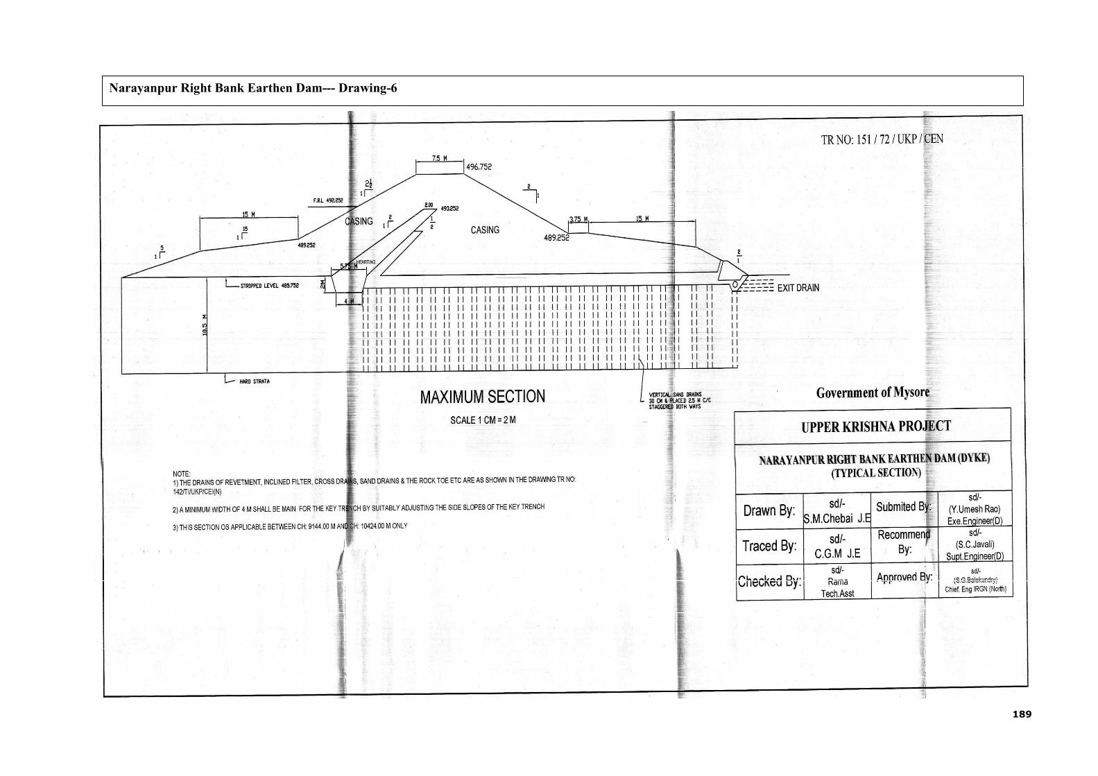
189
Narayanpur Right Bank Earthen Dam--- Drawing-6

190
L-Section and plan of Narayanpur Dam from 121.92m to 5120.64m--- Drawing-7

191
L-Section and plan of Narayanpur Dam from 5120.64m to 10759.44m--- Drawing-8

192
Piezometer at Ch.35 Left Bank Earthen Dam--- Drawing-9
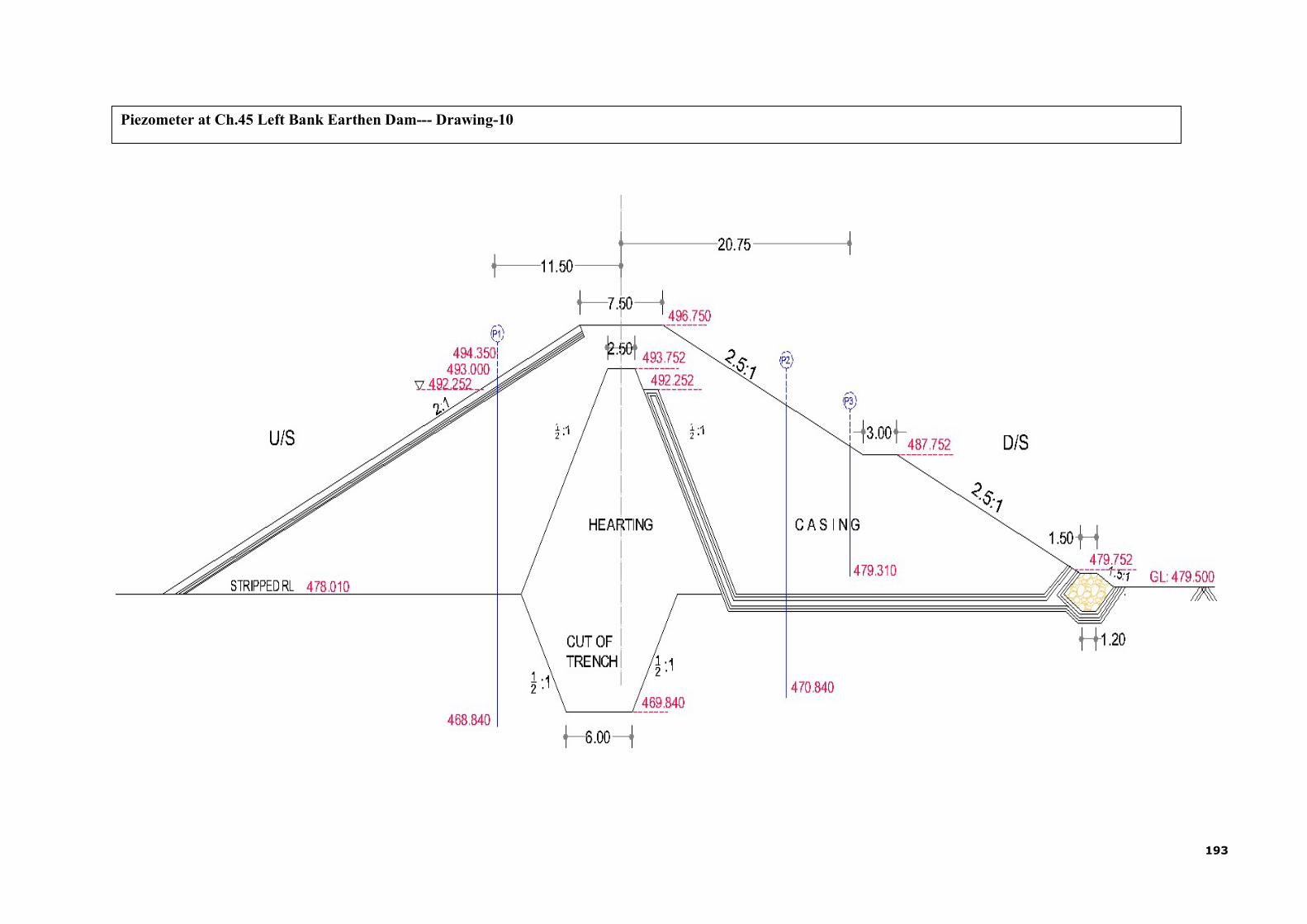
193
Piezometer at Ch.45 Left Bank Earthen Dam--- Drawing-10

194
Piezometer at Ch.97 Right Bank Earthen Dam--- Drawing-11

195
Piezometer at Ch.105 Right Bank Earthen Dam--- Drawing-12

196
Piezometer at Ch.142 Right Bank Earthen Dam--- Drawing-13
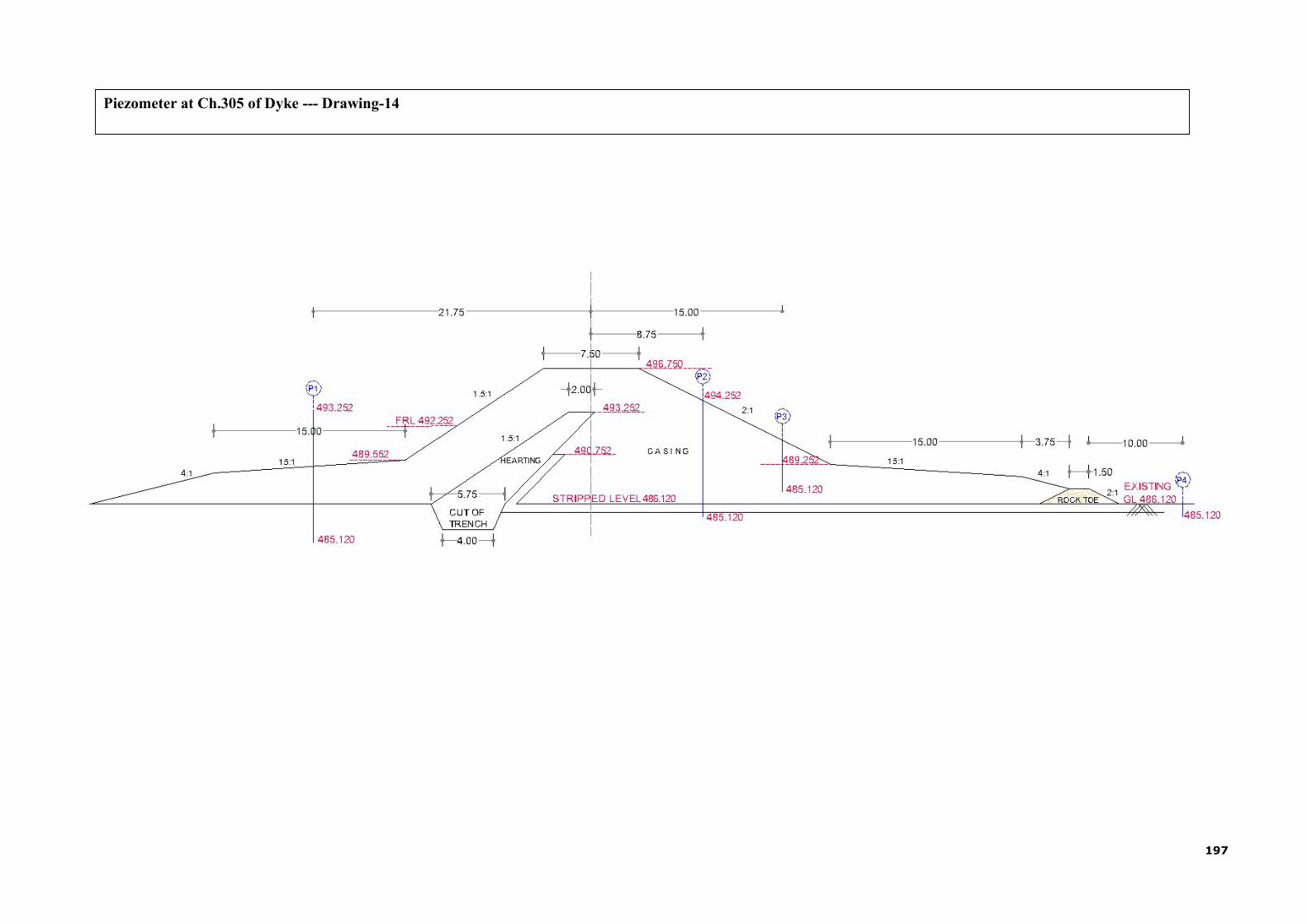
197
Piezometer at Ch.305 of Dyke --- Drawing-14

198
Piezometer at Ch.316 of Dyke --- Drawing-15
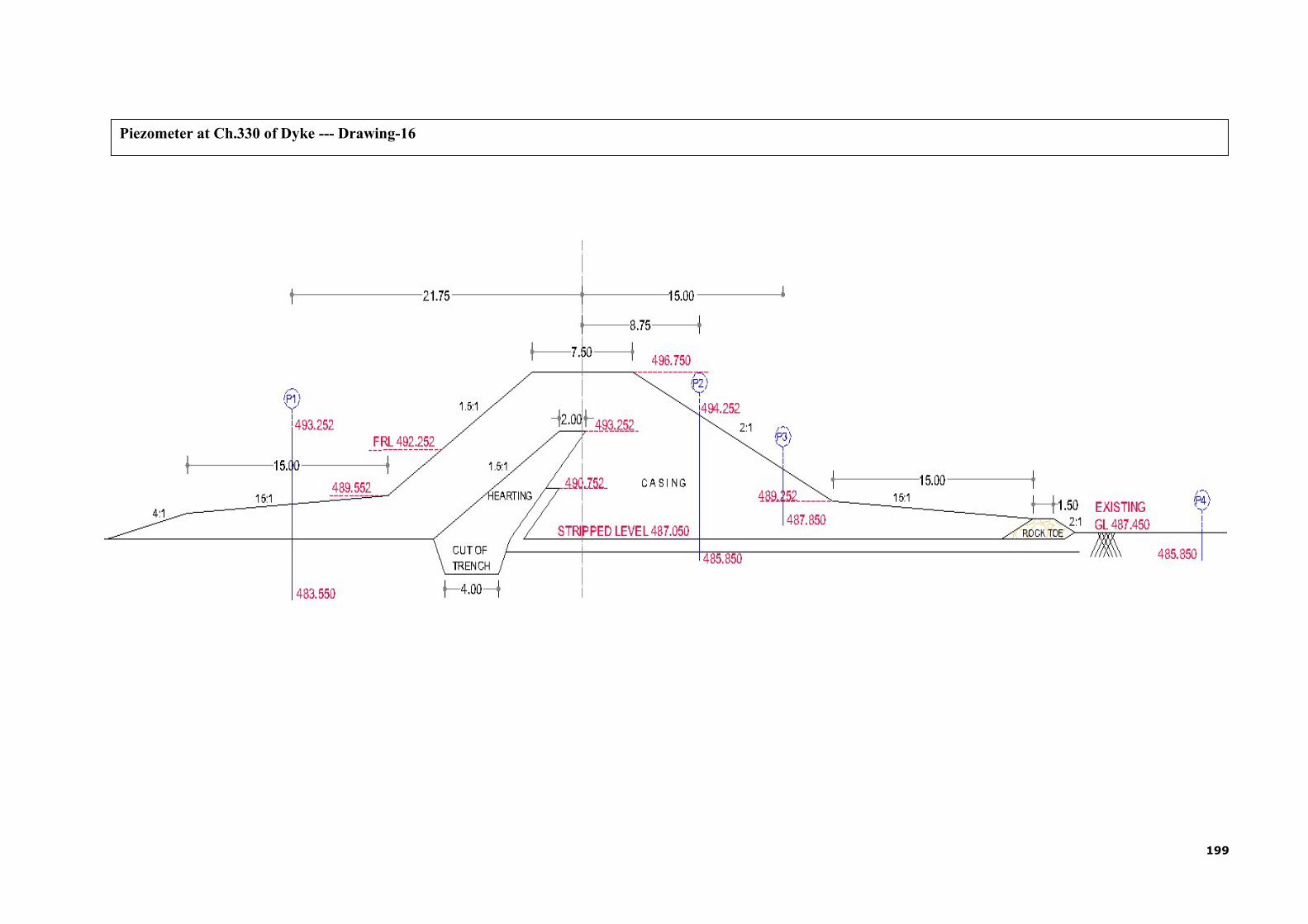
199
Piezometer at Ch.330 of Dyke --- Drawing-16

200
Head V/s Discharge curves of one spillway gate --- Drawing-17

201
Dam
RL
in M
eter
Rule curve of Narayanpur Reservoir --- Drawing-18
493.00
Nov
Month
492.50
492.00
491.50
491.00
490.50
490.00
489.50
489.00
488.50
488.00
487.50
487.00
486.50
486.00
485.50
485.00 484.50
RL in Meter
484.00
483.50
483.00
482.50
482.00
481.50
481.00
480.50
480.00
Jun 1st Jun 2nd Jul Aug Sept Oct Dec Jan Feb Mar Apr May
FN FN
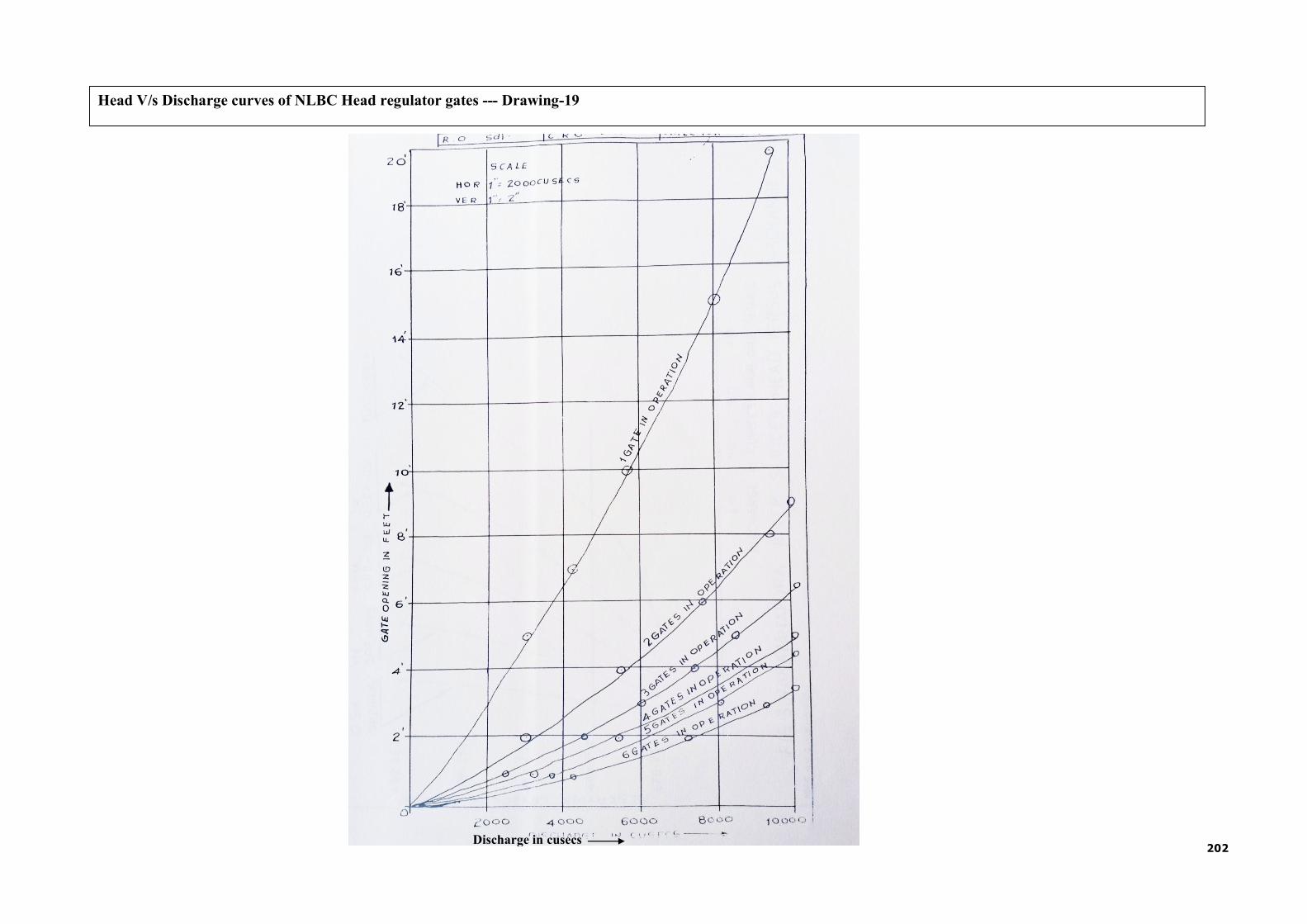
202
Head V/s Discharge curves of NLBC Head regulator gates --- Drawing-19
Discharge in cusecs

203
Head V/s Discharge curves of River sluice gates of Narayanpur Dam --- Drawing-20

204
THIS PAGE LEFT BLANK INTENTIONALLY

205
THIS PAGE LEFT BLANK INTENTIONALLY

206
OBSERVER OF EVENT
Dam Site Office:
Assistant Executive Engineer, KBJNL,Dam Sub Division No-3, Narayanpur
Shri.T N Ramchandra (I/c)
Mob :9448957364
Email: [email protected]
Dam Site Office: Assistant Executive Engineer,KBJNL,Gates Sub Division,Narayanpur Shri.R L Hallur Mob :9449143184
Email: [email protected]
Resources Available
APPENDIX 2- KEY ELEMENTS OF THE EAP WATCH CONDITION NOTIFICATION FLOWCHART
Ready Mix Concrete Supply M/s Aditya Construction Company Pvt Ltd ,Belgaum
Shri. Purandar,Mob : 9448112966 Shri.Hundekar Mob:9448273169 Email:[email protected]
Email:[email protected]
Heavy Equipment Service Sand and Gravel Supply NDW Construction Company Pvt Ltd Shri. Nagappa Waddar,
Class I Contractor,Wajjal Mob : 8296424242
Ramesh,Engr:9611635222
Email:[email protected]
Mechanical Works M/s Murudeshwar Power Corpora- tion Ltd,Narayanpur Shri.Samuel Chelliah Office No :9483679372/9481705820 Email:[email protected]
Shri. Shri.Devanand ,Manager
Mob: 9972606310
M/s Boruka Power Corporation Ltd,Narayanpur Shri.Mallikarjun ,Manager
Office No:9972578183
Karnataka Water Resource De- partment, KBJNL, PWD Offices Annexe Building,3rd Floor, KR Circle,Bangalore Shri.N Jayaram,
Managing Director, Office No:080 -22244484,22245328
22277488 Email: [email protected]
[email protected] Office of Superintending Engineer KBJNL,PWD Offices Annexe Build- ing,3rd Floor,KR Circle Bangalore Shri.K.G.Mahesh Superintending Engineer, Office No:080 -22244484,22245328 Mob No:9164663884 Email: [email protected]
Geotechnical Expert Prof:T G Sitharam IISC,Bangalore Mob:9448273751 Office:080-23602261 Email:[email protected]
Office of Chief Engineer ,KBJNL,O & M Zone, Narayanpur
Shri. S Rangaram Chief Engineer(I/c) Mob:+91 9483545669 Office No: 08444-229653 Email: [email protected]
Karnataka Water Resource Devel- opment Organisation,State Project Monitoring Unit(SPMU),Bangalore
Shri.Jagannath Reddy Mob:9448456877 Chief Engineer
& Nodal Officer(DRIP)
Office No: 080-22871094/ 22875519
Email: [email protected]
Structural Elements repairs
M/s Hardware tools and Plants,Ahmedabad,
Office No :91-79-26871804,26872107
Email:[email protected]
Office of Superintending Engi-
neer ,KBJNL,O&M Circle No-1,
Narayanpur
Shri. S Rangaram
Superintending Engineer
Mob:+91 9483545669
Office No: 08444-229635
Email: [email protected]
Karnataka State Natural Disaster
Monitoring centre
Shri.Dr.G.S.Srinivasa Reddy
Director ,Bangalore
Off:080-67355000
Fax:+918067355198
Varuna Mitra Help Desk:9243345433
Email : [email protected]
Office of the Executive Engineer, KBJNL,Dam Division, Narayanpur Shri. Shankar H Naikodi Emergency Planning Manager Mob:+91 9448751466 Off:08444-229615
Email: [email protected]

O/o Assistant Engeer, KBJNL,Dam Sub Divn No-3,Narayanpur Shri.T N Ramchandra (I/c) Assistant Engineer Mob :9448957364 Email: [email protected]
O/o Assistant Executive Engi- neer,KBJNL,Gates Sub Divn, Narayanpur
Shri.R L Hallur (I/c) Assistant Engineer Mob :9449143184 Email: [email protected]
Central Water Commission(CWC)
Pramod Narayan Singh Project Director DRIP& Head CPMU Mob:9958975921 Off:011-26192633/29583480 Email : [email protected]
Office of the Executive Engineer, KBJNL,Dam Division, Narayanpur
Shri. Shankar S Naikodi Emergency Planning Manager Mob:+91 9448751466 Off:08444-229615 Email: [email protected]
National Disaster Management Authori- ty,NDMA Bhavan,NewDelhi
Shri.T M Vijayabhaskar,IAS Chief Secretary for Karnataka State Mob:9482131476 Off:08022253716 F:08022258913 Email :[email protected]
Control room: +91-11-26701700/26701728 Fax:+91-11-26701729 Email : [email protected]
Office of the Superintending Engineer KBJNL, O&M Circle No- 1,Narayanpur
Shri. S Rangaram Superintending Engineer
Mob:+91 9483545669 Office No: 08444-229635 Email: [email protected]
Karnataka State Natural Disaster, Monitor- ing centre
Shri.Dr.G.S.Srinivasa Reddy Director ,Bangalore Off:080-67355000 Fax:+918067355198 Varuna Mitra Help Desk:9243345433 Email : [email protected]
Govt of Telangana
Smt.Shruthi Ojha Collector and District Magistrate, Jogulamba Gadwal district, Godwal-509125,Telangana Mob:9100901600,+917993499501 Email:[email protected]
NARAYANPUR DAM: FAILURE CONDITION NOTIFICATION FLOW CHART
207
Telangana State Disaster Response & Fire Servic- es,BRKR Bhavan,Hyderabad
Shri.Rajiv Trivedi,IPS Principle Secretary, Office No:040-23452143, 23450426,23442944 Email:[email protected]
Off :08532-229011(O) 220033(R) Email: [email protected]
IAS Gautham,
Deputy Commissioner, Raichur District Shri.Dr.Bagadi Mob:8971860808
Karnataka Water Resource Department (KWRD) WRDO,SPMU,Bangalore
Shri.Jagannath Reddy Chief Engineer & Nodal Officer(DRIP) Mob:9448456877 Off: 080-22871094/ 22875519 Email:[email protected] [email protected]
Deputy Commissioner, Yadgiri District
Shri.Kurma Rao M, IAS Off: 08473-253700(O) Mob:9482570780 Email: [email protected]
Office of the Chief Engineer ,KBJNL,O & M Zone,Narayanpur
Shri. S Rangaram Chief Engineer (I/c) Mob:+91 9886351288,Office No: 08444-229653
Email: [email protected]
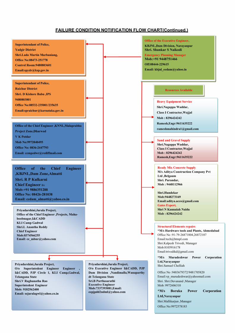
208
FAILURE CONDITION NOTIFICATION FLOW CHART(Continued.)
Office of the Executive Engineer,
KBJNL,Dam Division, Narayanpur Shri. Shankar S Naikodi
Emergency Planning Manager Mob:+91 9448751466
Off:08444-229615
Email: [email protected]
Priyadarshini,Jurala Project, O/o Executive Engineer I&CADD, PJP Dam Division ,Nandimalla,Wanaparthy dt Telangana State Sri.B Parthasarathi Executive Engineer Mob:7337393081,Email: [email protected]
Priyadarshini,Jurala Project, O/o Superintedent Engineer Engineer , I&CADD, PJP Circle 1, KLI Camp,Gadwal, Telangana State Shri.V Raghunatha Rao Superintedent Engineer Mob: 9182562400 Email: [email protected]
Structural Elements repairs *M/s Hardware tools and Plants, Ahmedabad Office No :91-79-26871804,26872107 Email:[email protected] Shri.Kalpesh Trivedi, Manager Mob:8105916178 Email:[email protected]
*M/s Murudeshwar Power Corporation Ltd,Narayanpur Shri.Samuel Chelliah
Office No :9483679372/9481705820 Email:[email protected]
Shri. Shri.Devanand ,Manager Mob: 9972606310
*M/s Boruka Power Corporation
Ltd,Narayanpur
Shri.Mallikarjun ,Manager
Office No:9972578183
Priyadarshini,Jurala Project, Office of the Chief Engineer ,Projects, Maha- boobnagar,I&CADD KLI Camp Gadwal Shri.L Anantha Reddy Chief Engineer Mob:8374566255 Email: [email protected]
Ready Mix Concrete Supply M/s Aditya Construction Company Pvt Ltd ,Belgaum Shri. Purandar, Mob : 9448112966
Shri.Hundekar Mob:9448273169 Email:[email protected] Gates Expert, Shri N Kannaiah Naidu Mob : 8296424242
Office of the Chief Engineer ,KBJNL,Dam Zone,Almatti
Shri. R P Kulkarni Chief Engineer I/c
Mob:+91 9886351288 Office No: 08426-281038 Email: [email protected]
Sand and Gravel Supply Shri.Nagappa Waddar, Class I Contractor,Wajjal Mob : 8296424242 Ramesh,Engr:9611635222
Office of the Chief Engineer ,KNNL,Malaprabha
Project Zone,Dharwad
V K Potdar
Mob No:9972040495
Office No: 0836-2447793
Email: [email protected]
Heavy Equipment Service
Shri.Nagappa Waddar,
Class I Contractor,Wajjal
Mob : 8296424242
Ramesh,Engr:9611635222
Superintendant of Police,
Raichur District
Shri. D Kishore Babu ,IPS
9480803801
Office No:08532-235001/235635
Email:[email protected]
Superintendant of Police,
Yadgir District
Shri.Lada Martin Marbaniang,
Office No:08473-251778
Control Room:9480803601
Email:[email protected]
Resources Available

200
Sample Public Announcements
Note: These messages are communicated to downstream residents to alert the public of im- pending danger. The Executive Engineer,KBJNL,Dam division,Narayanpur should coordi- nate with the India Meteorological Department, the Karnataka State Disaster Management Authority and the Yadgir/Raichur District Magistrates/Collectors for prior to release. Messag- es can be communicated via radio, television, bulk SMSs of local mobile networks, and other media outlets.
Announcement for a Slowly Developing “Watch” Condition (BLUE Emergency Level)
The Executive Engineer,KBJNL,Dam division,Narayanpur has declared a BLUE Level “Watch” condition for Narayanpur Dam, Project Identification Code KA06MH0142 as of [12:00 am ,dd/mm/yyyy]. [Brief description of the problem or condition.] Although there is no immediate danger of the dam failing, [Brief descriptions of actions that are being taken to monitor and control the situation].
Announcement for a Worsening “Watch” Condition (BLUEEmergency Level)
The Executive Engineer,KBJNL,Dam division,Narayanpur has declared a BLUE Level “Watch” condition for Narayanpur Dam Dam, Project Identification Code KA06MH0142 as of [time and date]. [Brief description of the problem or condition.] Although there is no imme- diate danger of the dam failing a possibility now exists that the dam will fail if correction ef- forts are unsuccessful. Description of what actions are being taken to monitor and correct the situation.]. Additional news will be made available as soon as it is received.
Announcement for a Probable“Failure” Condition (ORANGE Emergency Level)
Urgent! This is an emergency message. The Executive Engineer,KBJNL,Dam divi- sion,Narayanpur has announced that Narayanpur Dam Dam, Project Identification Code KA06MH0142 is probably going to fail. [Description og actions that are being taken to moni- tor and control the situation.] It is possible that the dam will fail in [##] hours. Residents in low lying areas along the Krishna river, as well as the town of [Name], should prepare for immediate evacuation. Additional news will be made available as soon as it is received.
Announcement of an Impending“Failure” Condition (REDEmergency Level)
Emergency! This is an emergency message. Narayanpur Dam, Project Identification Code KA06MH0142 is going to fail at any moment. Residents who have not yet done so should immediately evacuate the city of [Name] and low-lying areas along the Krishna River.The flood waters have already reached NH/SH No …. Additional news will be made available as soon as it is received.
Announcement of an Ongoing “Failure” Condition (REDEmergency Level)
Emergency! This is an emergency message. Narayanpur Dam, Project Identification Code KA06MH0142 failed at [12.00 a.m dd/mm/yyyy]. Residents who have not yet done so should immediately evacuate the city of [Name] and low-lying areas along the Krishna River. The flood waters have already reached NH/SH….. . Additional news will be made available as soon as it is received.

210
Evidence of Distress
General obser- vation
Specific
observation
Emergency condition
level
Emergency action Equip- ment,
material, and
supplies
Data to record
B
oil
s
Small boils, no in- crease of water flow, flowing clear water.
BLUE
Closely check all of down- stream toe, especially in the vicinity of boil for additional boils, wet spots, sinkholes, or seepage. Closely moni- tor entire area for changes or flow rate increases.
None Site and location, approx- imate flow
Large or additional boils near previous- ly identified ones, without increasing flow rate, but carry- ing small amount of soil particles.
BLUE
Initiate 24-hour surveil- lance. Monitor as described above. Construct sandbag ring dikes around boils, to cover them with water to retard the movement of soil particles. Filter cloth may be used to retard soil movement, but do not re- tard the flow of water.
Sand- bags, filter cloth
Site and location, approx- imate flow
Large or additional boils near previous- ly identified ones, increasing flow rate, carrying soil particles.
ORANGE
Continue 24-hour surveil- lance. Continue monitoring and remedial action as de- scribed above. Initiate emergency lowering of the reservoir. Issue a warning to downstream residents.
Sand- bags, pump
Site and location, approx- imate flow
Rapidly increasing size of boils and flow increasing and muddy water.
RED
Downstream evacuation. Employ all available equip- ment to attempt to construct a large ring dike around the boil area.
Dozer, shovels, source of earth fill
Site and location, approx- imate flow
S
eep
age
Minor seepage of clear water at toe, on slope of em- bankment, or at the abutments.
BLUE
Closely check entire em- bankment for other see- page areas. Use wooden stakes or flagging to deli- neate seepage area. Try to channel and measure flow. Look for upstream whirl- pools.
Wooden stakes, flagging
Site, location, approx- imate flow
Additional seepage areas observed flowing clear water and/or increasing
BLUE
Initiate 24-hour surveil- lance. Monitor as described above. Construct measur- ing weir and channel all seepage through weir. At-
Dozer, shovels
Site, location, approx- imate

211
General obser- vation
Specific
observation
Emergency condition
level
Emergency action Equip- ment,
material, and
supplies
Data to record
flow rate. tempt to determine source of seepage.
flow
Seriously or rapidly increasing see- page, under- seepage, or drain flow.
ORANGE
Continue 24-hour monitor- ing and remedial action as described above. Initiate emergency lowering of the reservoir. Construct a large ring dike around the see- page area.
Dozer, shovels, source of fill ma- terial
Site lo- cation, approx- imate flow
Additional seepage areas with rapid increase in flow and muddy water.
RED
Downstream evacuation. Employ all available equip- ment to attempt to construct a large ring dike around the seepage area.
Dozer, shovels, source of fill ma- terial
Site lo- cation, approx- imate flow
S
lid
es o
r se
vere
ero
sio
n
Skin slide or slough on slope of em- bankment. No fur- ther movement of slide and embank- ment crest not de- graded.
BLUE
Examine rest of embank- ment for other slides. Place stakes in slide material and adjacent to it for determin- ing if further movement is taking place.
Stakes, tape measure
Dis- tance between stakes
Slide or erosion involving large mass of material, crest of embank- ment is degraded, no movement or very slow continu- ing movement.
BLUE
Initiate 24-hour surveil- lance. Mobilize all available resources and equipment for repair operations to in- crease freeboard and to protect the exposed em- bankment material. Start filling sandbags and stock- pile near slide area.
Dozer, shovels, sources of fill ma- terial, sand- bags
Dis- tance between stakes
Slide or erosion involving large mass of material, crest of embank- ment is degraded, progressively in- creasing in size.
ORANGE
Continue monitoring and remedial actions as de- scribed above. Place addi- tional material at the toe of the slope to stop the slide.
Dozer, shovels, source of fill ma- terial, pump
Dis- tance between stakes
Slide or erosion involving large mass of material, crest of embank- ment is severely degraded, move-
RED
Downstream evacuation. Utilize all available equip- ment and personnel to sandbag the degraded slide area to prevent it from over- topping.
Dozer, shovels, sand- bags, pump
Dis- tance between stakes

212
General obser- vation
Specific
observation
Emergency condition
level
Emergency action Equip- ment,
material, and
supplies
Data to record
ment of slide is continuing and may reach pool level.
S
ink
ho
les
Sinkholes any- whereon the em- bankmentor within 150 metres- downstream from the toe.
BLUE
Carefully walk the entire embankment and down- stream area looking for ad- ditional sinkholes, move- ment, or seepage.
Stakes, flagging
Size, location
Sinkholes with cor- responding see- page anywhere on the embankment or downstream from the toe.
BLUE
Initiate 24-hour surveil- lance. Monitor as above. Construct sandbag dike around the seepage exit point to reduce the flow rate. Start filling sandbags and stockpile near sinkhole.
Dozer, shovels, pump
Size, location
Large sinkholes with corresponding seepage anywhere on the embank- ment or down- streamfrom the toe.
ORANGE
Continue monitoring and remedial action as de- scribed above. Utilize sandbags to increase the freeboard on the dam if ne- cessary.
Sand- bags, dozer, pump
Size, location
Sinkholes rapidly getting worse, see- page flowing mud- dy water and in- creasing flow.
RED
Downstream evacuation. Utilize all available equip- ment and personnel to at- tempt to construct a large ring dike around the area.
Dozer, shovels, pump
Size, location
S
ett
lem
ent
Obvious settlement of the crest of the embankment, es- pecially adjacent to concrete struc- tures.
BLUE
Look for bulges on slope or changes in crest alignment.
None Size, location
Settlement of crest of embankment that is progressing, especially adjacent to concrete struc- tures or if any cor- responding see- page is present.
BLUE
Initiate 24-hour surveil- lance. Mobilize all available resources for repair opera- tions to increase freeboard. Fill and stockpile sandbags. Identify any boils near set- tlement points for flowing material and pursue action for boils.
Sand- bags, dozer, shovels, source of fill ma- terial
Size, location
Settlement of crest of embankment
ORANGE Continue monitoring and remedial actions as de-
Sand- bags,
Size,
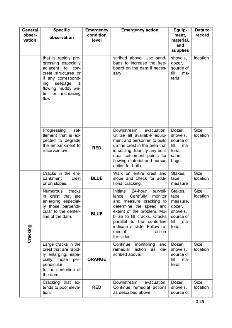
213
General obser- vation
Specific
observation
Emergency condition
level
Emergency action Equip- ment,
material, and
supplies
Data to record
that is rapidly pro- gressing especially adjacent to con- crete structures or if any correspond- ing seepage is flowing muddy wa- ter or increasing flow.
scribed above. Use sand- bags to increase the free- board on the dam if neces- sary.
shovels, dozer, source of fill ma- terial
location
Progressing set- tlement that is ex- pected to degrade the embankment to reservoir level.
RED
Downstream evacuation. Utilize all available equip- ment and personnel to build up the crest in the area that is settling. Identify any boils near settlement points for flowing material and pursue action for boils.
Dozer, shovels, source of fill ma- terial, sand- bags
Size, location
C
rac
kin
g
Cracks in the em- bankment crest or on slopes.
BLUE
Walk on entire crest and slope and check for addi- tional cracking.
Stakes, tape measure
Size, location
Numerous cracks in crest that are enlarging, especial- ly those perpendi- cular to the center- line of the dam.
BLUE
Initiate 24-hour surveil- lance. Carefully monitor and measure cracking to determine the speed and extent of the problem. Mo- bilize to fill cracks. Cracks parallel to the centerline indicate a slide. Follow re- medial action for slides.
Stakes, tape measure, dozer, shovels, source of fill ma- terial
Size, location
Large cracks in the crest that are rapid- ly enlarging, espe- cially those per- pendicular to the centerline of the dam.
ORANGE
Continue monitoring and remedial action as de- scribed above.
Dozer, shovels, source of fill ma- terial
Size, location
Cracking that ex- tends to pool eleva- tion.
RED
Downstream evacuation. Continue remedial actions as described above.
Dozer, shovels, source of
Size, location

214
General obser- vation
Specific
observation
Emergency condition
level
Emergency action Equip- ment,
material, and
supplies
Data to record
fill ma- terial
C
rac
kin
g o
r m
ov
eme
nt
of
co
ncr
ete
str
uct
ure
Minor cracking and/or movement.
BLUE
Immediately install measur- ing device to monitor movement.
Crack Monitors, stakes, tape measure
Size, location
Significant cracking and/or movement.
BLUE
Initiate 24-hour surveil- lance. Lower burlap on up- stream face of crack to re- duce flow of soil particles. Dump large rock on down- stream of moving concrete structure monolith to resist the movement.
Burlap, rock, dozer, shovels
Size, location, flow rate
Serious cracking and/or movement
ORANGE
Prepare for evacuation. Continue monitoring and remedial action as de- scribed above.
Dozer, rock, bur- lap, crack monitors
Size, move- ment, flow rate
Major cracking and/or movement
RED
Downstream evacuation. Dam failure is imminent. Continue monitoring and remedial actions as de- scribed above.
Dozer, shovels, rock
Size, location, flow rate
U
pst
rea
m w
hir
lpo
ol Whirlpool in the
lake in the vicinity of the embankment
RED
Downstream evacuation. Attempt to plug the en- trance of the whirlpool with riprap from the slope of the embankment. Search downstream for an exit point and construct a ring dike to retard the flow of soil particles.
Dozer, fill material, sand- bags, filter cloth, straw, rocks
Size, location, flow rate
Mal
fun
ctio
n o
f g
ate
Structural member of a gate or gate operator broken or severely damaged so as to prevent operation of the gate
ORANGE
Initiate 24-hour surveil- lance. Immediately place stop logs in front of gate and initiate necessary ac- tions to get gate repaired.
Crane and welder
Type of prob- lem, lo- cation
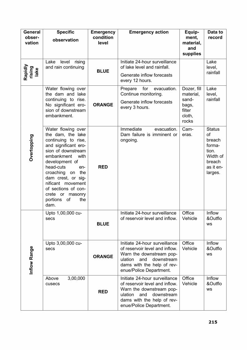
215
General obser- vation
Specific
observation
Emergency condition
level
Emergency action Equip- ment,
material, and
supplies
Data to record
Rap
idly
ri
sin
g
lake
Lake level rising and rain continuing
BLUE
Initiate 24-hour surveillance of lake level and rainfall.
Generate inflow forecasts every 12 hours.
Lake level, rainfall
O
ver
top
pin
g
Water flowing over the dam and lake continuing to rise. No significant ero- sion of downstream embankment.
ORANGE
Prepare for evacuation. Continue monitoring.
Generate inflow forecasts every 3 hours.
Dozer, fill material, sand- bags, filter cloth, rocks
Lake level, rainfall
Water flowing over the dam, the lake continuing to rise, and significant ero- sion of downstream embankment with development of head-cuts en- croaching on the dam crest, or sig- nificant movement of sections of con- crete or masonry portions of the dam.
RED
Immediate evacuation. Dam failure is imminent or ongoing.
Cam- eras.
Status of breach forma- tion. Width of breach as it en- larges.
In
flo
w R
ang
e
Upto 1,00,000 cu- secs
BLUE
Initiate 24-hour surveillance of reservoir level and inflow.
Office Vehicle
Inflow &Outflo ws
Upto 3,00,000 cu- secs
ORANGE
Initiate 24-hour surveillance of reservoir level and inflow. Warn the downstream pop- ulation and downstream dams with the help of rev- enue/Police Department.
Office Vehicle
Inflow &Outflo ws
Above 3,00,000 cusecs
RED
Initiate 24-hour surveillance of reservoir level and inflow. Warn the downstream pop- ulation and downstream dams with the help of rev- enue/Police Department.
Office Vehicle
Inflow &Outflo ws
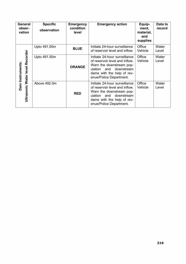
216
General obser- vation
Specific
observation
Emergency condition
level
Emergency action Equip- ment,
material, and
supplies
Data to record
Dam
In
stru
men
ts:
Ult
ras
on
ic W
ater
lev
el R
eco
rder
Upto 491.00m BLUE
Initiate 24-hour surveillance of reservoir level and inflow.
Office Vehicle
Water Level
Upto 491.50m
ORANGE
Initiate 24-hour surveillance of reservoir level and inflow. Warn the downstream pop- ulation and downstream dams with the help of rev- enue/Police Department.
Office Vehicle
Water Level
Above 492.0m
RED
Initiate 24-hour surveillance of reservoir level and inflow. Warn the downstream pop- ulation and downstream dams with the help of rev- enue/Police Department.
Office Vehicle
Water Level
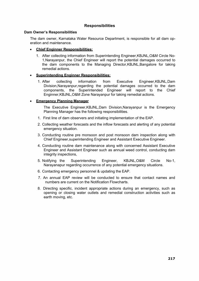
217
Responsibilities
Dam Owner’s Responsibilities
The dam owner, Karnataka Water Resource Department, is responsible for all dam op- eration and maintenance.
Chief Enginner Responsibilities:
1. After collecting information from Superintending Engineer,KBJNL,O&M Circle No- 1,Narayanpur, the Chief Engineer will report the potential damages occurred to the dam components to the Managing Director,KBJNL,Bangalore for taking remedial actions.
Superintending Enginner Responsibilities:
1. After collecting information from Executive Engineer,KBJNL,Dam Division,Narayanpur,regarding the potential damages occurred to the dam components, the Superintended Engineer will report to the Chief Enginner,KBJNL,O&M Zone Narayanpur for taking remedial actions.
Emergency Planning Manager
The Executive Engineer,KBJNL,Dam Division,Narayanpur is the Emergency Planning Manager has the following responsibilities.
1. First line of dam observers and initiating implementation of the EAP.
2. Collecting weather forecasts and the inflow forecasts and alerting of any potential emergency situation.
3. Conducting routine pre monsoon and post monsoon dam inspection along with Chief Engineer,superintending Engineer and Assistant Executive Engineer.
4. Conducting routine dam maintenance along with concerned Assistant Executive Engineer and Assistant Engineer such as annual weed control, conducting dam integrity inspections,
5. Notifying the Superintending Engineer, KBJNL,O&M Circle No-1, Narayanapur regarding occurrence of any potential emergency situations.
6. Contacting emergency personnel & updating the EAP.
7. An annual EAP review will be conducted to ensure that contact names and numbers are current on the Notification Flowcharts.
8. Directing specific, incident appropriate actions during an emergency, such as opening or closing water outlets and remedial construction activities such as earth moving, etc.
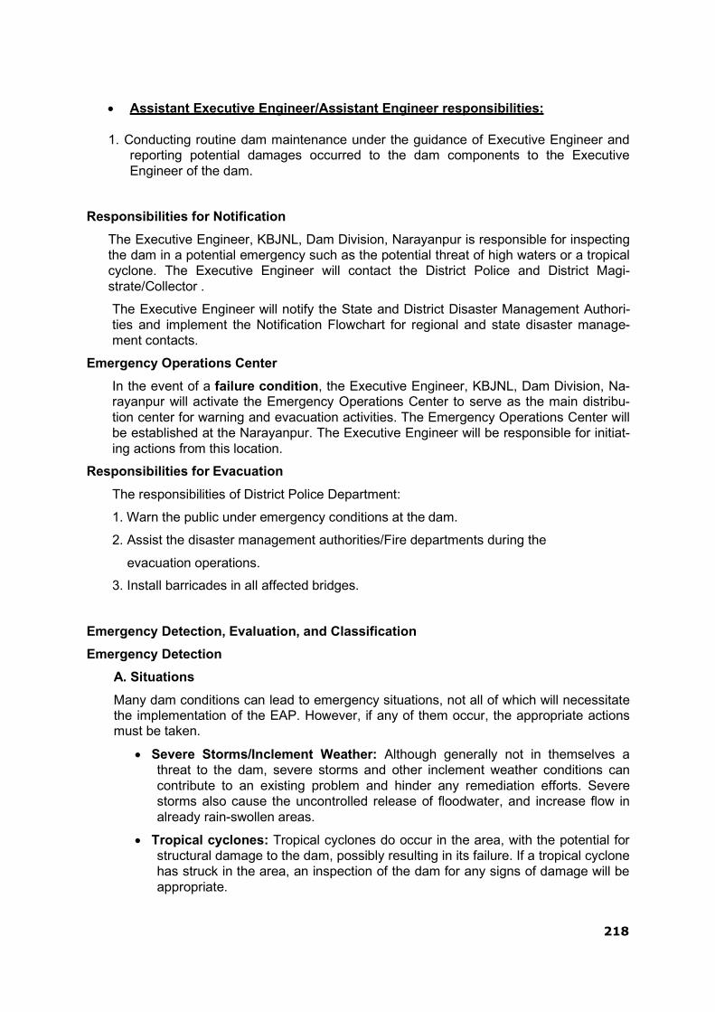
218
Assistant Executive Engineer/Assistant Engineer responsibilities:
1. Conducting routine dam maintenance under the guidance of Executive Engineer and reporting potential damages occurred to the dam components to the Executive Engineer of the dam.
Responsibilities for Notification
The Executive Engineer, KBJNL, Dam Division, Narayanpur is responsible for inspecting the dam in a potential emergency such as the potential threat of high waters or a tropical cyclone. The Executive Engineer will contact the District Police and District Magi- strate/Collector .
The Executive Engineer will notify the State and District Disaster Management Authori- ties and implement the Notification Flowchart for regional and state disaster manage- ment contacts.
Emergency Operations Center
In the event of a failure condition, the Executive Engineer, KBJNL, Dam Division, Na- rayanpur will activate the Emergency Operations Center to serve as the main distribu- tion center for warning and evacuation activities. The Emergency Operations Center will be established at the Narayanpur. The Executive Engineer will be responsible for initiat- ing actions from this location.
Responsibilities for Evacuation
The responsibilities of District Police Department:
1. Warn the public under emergency conditions at the dam.
2. Assist the disaster management authorities/Fire departments during the
evacuation operations.
3. Install barricades in all affected bridges.
Emergency Detection, Evaluation, and Classification
Emergency Detection
A. Situations
Many dam conditions can lead to emergency situations, not all of which will necessitate the implementation of the EAP. However, if any of them occur, the appropriate actions must be taken.
Severe Storms/Inclement Weather: Although generally not in themselves a threat to the dam, severe storms and other inclement weather conditions can contribute to an existing problem and hinder any remediation efforts. Severe storms also cause the uncontrolled release of floodwater, and increase flow in already rain-swollen areas.
Tropical cyclones: Tropical cyclones do occur in the area, with the potential for structural damage to the dam, possibly resulting in its failure. If a tropical cyclone has struck in the area, an inspection of the dam for any signs of damage will be appropriate.

219
Earthquakes: Narayanpur dam is located in the seismic zone II. An earthquake is a possibility, and appropriate post-earthquake inspections should be performed.
Sabotage: A threat to damage the dam has been made. Appropriate actions must be taken to protect the dam.
B. Signs of Failure
The Executive Engineer of dam is responsible for conducting routine inspections and identifying conditions that could indicate the onset of problems leading to a dam fail- ure. The early identification of potentially dangerous conditions can allow time for the implementation of EAPs. It is important to understand how distress can develop into failure. With appropriate action, distress need not lead to a catastrophic failure of the dam. The following sections describe some of the different types of failure which could lead to a dam failure.
Seepage Failure: Although all earthen embankments allow some minor seepage through the dam or the foundation, excessive, uncontrolled seepage can result in piping (the movement of embankment material in the seepage flow) and lead to failure. Piping can occur for years at a slow rate. If the piping has progressed to a dangerous level, it will be evident by increased flow or the discharge of muddy water (or both). At that stage, immediate action to stop the piping is needed. Fully developed piping is difficult to control and is very likely to result in failure. A whirlpool in the reservoir is a sign of uncontrollable piping and necessitates immediate emergency action.
Embankment or Foundation Sliding: Sliding is usually first apparent when cracks or bulges in the embankment appear. Slides with progressive movement can cause failure of the embankment.
Structural Failure: The structural failure or collapse of any non-overflow portion of the dam, spillway or spillway gates could result in loss of the reservoir. A structural failure of a portion of the spillway could cause piping and possibly embankment failure.
Overtopping Failure: Overtopping of the embankment results in erosion of the dam crest. Once erosion begins, it is very difficult to stop.
Emergency Evaluation and Classification
This section lists the conditions and actions which may be used to classify the level of emergency response, as a guide for the Dam Owner‟s/ Emergency Planning Manager
Internal Alert Condition BLUE –A “watch” condition. A problem has been detected at the dam that requires constant monitoring. At this time, the distress condition is manageable by dam personnel. The Executive Engineer of dam will be responsible for monitoring and repair as soon as possible and implementing the appropriate Notification Flowchart. The following is a list of conditions that would initiate this condition:
Cloudy or dirty seepage or seepage with an increase in flow, boils, piping, or bogs
Seepage around conduits
Large sinkholes with corresponding seepage anywhere on the embankment or downstream from the toe
Any slide that degrades the crest of the embankment or that is progressively increasing in size
Cracking or movement of any concrete structure

220
An increase in the reservoir level leading to engagement of the emergency spillway
Exceptionally heavy rainfall in the catchment of the dam reservoir
External Alert Condition ORANGE– This is indicative of a dam condition that is progres- sively getting worse; and there is a high probability of dam failure. Although there is no im- mediate danger, the dam could fail if conditions continue to deteriorate. The Executive Engi- neer of dam will be responsible for initiating immediate repairs, including lowering the reser- voir if appropriate and implementing the appropriate Notification Flowchart. The following is a list of conditions that would initiate this condition:
Large boils, increasing in size and flow rate, especially if there is flowing muddy water
Significantly increasing seepage, especially flowing muddy water
Slides involving a large mass of material that impairs the crest of the dam and is continuing to move
Sinkholes with seepage flowing muddy water
Large cracks, movement or failure of a portion of any major concrete structure that forms an integral part of the dam
An increase in the reservoir level to near the top of the dam
Overtopping of a dam that is not designed for overtopping
Near to „Design Flood‟ inflow forecast
External Alert Conditions RED – These are “failure” conditions. Either the dam is in imme- diate danger of failing or has already failed. No time remains to implement measures to pre- vent failure. Evacuate immediately. Evacuation efforts will continue until the situation is stabi- lized. The Executive Engineer of dam is responsible for implementing the appropriate Notifi- cation Flowchart. The following is a list of conditions that would initiate “imminent dam fail- ure” or “dam failure” conditions:
Rapidly increasing boils or the presence of new, significantly flowing boils, particularly muddy ones near previously identified ones
Rapidly increasing seepage, especially flowing muddy water
Slides involving a large mass of material or which have degraded the crest of the embankment to a level that approaches the water surface level, or if significant seepage is observed through the slide area
Settlement that is predicted to degrade to the reservoir level
Cracks that extend to the reservoir level
Significant movement or failure of any structure that forms an integral part of the dam
Overtopping of an earthen dam
Uncontrollable release of the reservoir

221
THIS PAGE LEFT BLANK INTENTIONALLY

222
APPENDIX 3 - MATERIAL REQUIRED FOR MAINTENANCE DURING
MONSOON
Materials during monsoon period should be stocked in adequate quantity as experience shows
them to be necessary. Particular care should be taken that the required materials are distributed with careful fore-thought so as to be readily available everywhere, particularly at dangerous sites. The quantity of materials required depends on importance or dangerousness of the dam and the distances of the dam from the nearest stations at which these can be purchased. This will need to be worked out by the respective dam owners / state govt. as per their experience & documented in the O & M Manual for the dams. The following norms have been prescribed by the Govt. of Karnataka for their projects during monsoon period.
1. Patrolling
i. Torches: 1 for each Executive Engineer, Assistant Engineer, Sub-Engineer and 2 in spare.
ii. Cells: 1fill and 2spare sets
iii. Binoculars 6
iv. Night Vision Goggles 2
v. Dragon Lights 10
vi. Search Lights 15
vii. Communication Systems (local walkie-talkie) 8
viii. Rain coat: 20
ix. Gum boots: 20
x. Danger Zone Light: Strips 10
xi. Flares
2. Leaks
50
i Gunny Bags 500 ii. Stakes 60 to 120 stakes per km. iii. Baskets 1 Basket of toot per beldar &one spare. iv. Sutli (Twine) 0.5kg per 100bags
v. Needles ½ dozen with each work mestry
vi. Sand Collection of 2to4 m3every km.for

223
THIS PAGE LEFT INTERNTIOANLLY BLANK

224
APPENDIX 4-Scheduled Or Unscheduled Dam Safety Inspection Form
A form designed for use during scheduled dam safety inspections – which includes pre- and post-monsoon inspections – follows. The form contains a comprehensive checklist (Part 2a) of items that are found at dams that need to be evaluated during a safety inspection. The checklist consists of
(1) a series of questions that need to be answered as Yes/No/Not Applicable for each
inspection item,
(2) a remarks box in which critical aspects can be commented upon following each question, and
(3) a final condition assessment (Unsatisfactory/Poor/Fair/Satisfactory) for that inspection
item. Not all inspection items will be found at a dam. The form concludes with a Consolidated Dam Health Status Report (Part 2b)

225
Scheduled / Unscheduled Dam Safety Inspection Form
Part 1a - Inspection Details:
Dam Name: Project ID Code
(PIC):
Dam Type: Dam Purpose:
Dam Owner: Hazard Classifica-
tion:
Dam Operator: Inspection by:
City/State/PIN: Date of Inspection:
District: Reservoir Level:
Latitude: Auxiliary Spillway
Level:
Longitude: Weather Condi-
tions:
Part 1b - Inspection Remarks:
Please provide any additional information or comments not covered by Part 1a form above.
226
Part 2a - Inspection Checklist:
SN Inspection Item Responsea Remarks Conditionb
Y N NA
A Reservoir
A1.1 General Condition
U
nsatisfactory/P
oor/
Fair/S
atisfactory
1.1.1 Is the reservoir water level unusually high or low?
1.1.2 Are there signs of decline in water quali- ty?
1.1.3 Are there signs of recent sediment depo- sition?
1.1.4 Is floating debris present?
1.1.5 Are there people or livestock in and around reservoir?
1.1.6 Any other issues?
B Dam and Dam Reach (Embankment)
B1.1 General Condition
1.1.1 Any major alterations or changes to the dam since the last inspection?
1.1.2 Is there any new nearby development in the downstream floodplain?
1.1.3 Any misalignment of poles, fencing or walls due to dam movement?

227
SN Inspection Item Responsea Remarks Conditionb
B1.2 Upstream Slope
1.2.1 Any signs of bulging or concavity (depres- sions)?
1.2.2 Presence of longitudinal or transverse cracks?
1.2.3 Any signs of distress to the stability of slopes?
1.2.4 Any other signs of structural distress or insta- bility?
1.2.5 Trees or profuse growth of weeds/bushes at any location?
1.2.6 Is there evidence of livestock on the upstream slope?
1.2.7 Are ants, termites, crabs or other burrowing animals present?
1.2.8 Any degradation to slope protection (rip-rap)?
1.2.9 Any other issues?
B1.3 Crest of Dam
1.3.1 Any signs of excessive or uneven settlement?
1.3.2 Presence of longitudinal or transverse cracks?
1.3.3 Presence of undulations, local depressions or heaving?

228
SN Inspection Item Responsea Remarks Conditionb
1.3.4 Any degradation to access road (sealed/unsealed)?
1.3.5 Evidence of livestock on dam crest?
1.3.6 Trees or profuse growth of weeds/bushes at any location?
1.3.7 Any degradation to edges of dam crest or re- duction in width?
1.3.8 Any degradation to upstream parapet or down- stream curb wall?
1.3.9 Any other issues?
B1.4 Downstream Slope
1.4.1 Any signs of bulging or concavity (depres- sions)?
1.4.2 Any wet patches (seepage), concentrated leaks or evidence of boiling?
1.4.3 Presence of longitudinal or transverse cracks?
1.4.4 Any signs of distress to the stability of slopes?
1.4.5 Are of rain cuts/erosion channels present at any location?
1.4.6 Any other signs of structural distress or insta- bility?
1.4.7 Trees or profuse growth of weeds/bushes at any location?

229
SN Inspection Item Responsea Remarks Conditionb
1.4.8 Is there evidence of livestock on the downstream slope?
1.4.9 Are ants, termites, crabs or other burrowing animals present?
1.4.10 Any other degradation to slope protection (turf- ing)?
1.4.11 Any other issues?
B1.5 Breaching Section
1.5.1 Any difficulties in accessing the breaching sec- tion?
1.5.2 Evidence of recent degradation?
1.5.3 Any other issues?
B1.6 Junction with Masonry/Concrete Dam Section
1.6.1 Any presence of leaks, springs or wet spots in the vicinity of the junction?
1.6.2 Any presence of cracking, settlement or upheaval of earthwork?
1.6.3 Any evidence of erosion or slope instability?
1.6.4
Any other issues?
230
SN Inspection Item Responsea Remarks Conditionb
B1.7 Abutment Contacts
1.7.1 Any presence of leaks, springs or wet spots in the vicinity of the abutment?
1.7.2 Any presence of cracking, settlement or upheaval of earthwork?
1.7.3 Any evidence of erosion or slope instability?
1.7.4 Trees or profuse growth of weeds/bushes?
1.7.5 Any degradation to up/downstream slope pro- tection (rip-rap, turfing)?
1.7.6 Any other issues?
B2 Dam and Dam Block/Reach (Concrete/Masonry)
B2.1 General Condition
2.1.1 Any major alterations or changes to the dam since the last inspection?
2.1.2 Is there any new nearby development in the downstream floodplain?
2.1.3 Any misalignment of poles, fencing or walls due to dam movement?
B2.2 Upstream Face
2.2.1 Evidence of surface defects (honeycombing, staining, stratification)?
2.2.2 Concrete/masonry deterioration (spalling, leaching, disintegration)?

231
SN Inspection Item Responsea Remarks Conditionb
2.2.3 Is cracking present (structural, thermal, along joints)?
2.2.4 Evidence of differential settlement (dis- placed/offset/open joints)?
2.2.5 Presence of vegetation (growth in joints be- tween blocks)?
2.2.6 Evidence of any other damage to joints and/or waterstops?
2.2.7 Any other issues?
B2.3 Crest of Dam
2.3.1 Evidence of differential settlement (dis- placed/offset/open joints)?
2.3.2 Presence of cracking (structural, thermal, along joints)?
2.3.3 Profuse growth of weeds/grass/plants at any location?
2.3.4 Any degradation to access road?
2.3.5 Any degradation to upstream parapet or down- stream curb wall?
2.3.6
Any other issues?
B2.4 Downstream Face
2.4.1 Evidence of surface defects (honey-combing, staining, stratification)?
232
SN Inspection Item Responsea Remarks Conditionb
2.4.2 Concrete/masonry deterioration (spalling, leaching, disintegration)?
2.4.3 Presence of cracking (structural, thermal, along joints)?
2.4.4 Evidence of differential settlement (dis- placed/offset/open joints)?
2.4.5 Presence of vegetation (growth in joints be- tween blocks)?
2.4.6 Evidence of any other damage to joints and/or waterstops?
2.4.7 Excessive seepage/sweating at any location on downstream face?
2.4.8 Significant leakage at any location on down- stream face?
2.4.9 Any other issues?
B2.5 Abutment Contacts
2.5.1 Any presence of leaks, springs or wet spots in vicinity of abutment?
2.5.2 Any presence of cracking or settlement?
2.5.3 Profuse growth of weeds/grass/plants at any location?
2.5.4
Any other issues?

233
SN Inspection Item Responsea Remarks Conditionb
C1 Gallery/Shaft and Drainage (Embankment)
C1.1 General Condition
1.1.1 Slushy condition or water logging immediately downstream of dam?
1.1.2 Any evidence of boiling in vicinity of dam toe?
C1.2 Gallery/Shaft Condition
1.2.1 Any problems accessing or inspecting gal- lery/shaft (obstruction)?
1.2.2 Any safety issues (inadequate handrails, light- ing or ventilation)?
1.2.3 Problems of inadequate drainage (slippery stairs, water logging of gallery)?
1.2.4 Evidence of differential settlement (dis- placed/offset/open joints)?
1.2.5 Excessive seepage/sweating at any location along gallery/shaft?
1.2.6 Significant leakage at any location along gal- lery/shaft?
1.2.7
Any other issues?
C1.3 Drain Condition
1.3.1 Is the flow in the drain unusually high or low?

234
SN Inspection Item Responsea Remarks Conditionb
1.3.2 Any reduction/deterioration in the drain section or slope?
1.3.3 Presence of debris or profuse growth of weeds/bushes at any location?
1.3.4 Any other obstruction to the flow of the drain?
1.3.5 Is the flow in the drain noticeably sporad- ic/irregular?
1.3.6 Does the drainage water have high turbidity (high sediment load)?
1.3.7 Any other issues?
C2 Gallery/Shaft and Drainage (Concrete/Masonry)
C2.1 General Condition
2.1.1 Slushy condition or water logging just down- stream of dam?
C2.2 Gallery/Shaft Condition
2.2.1 Any problems accessing or inspecting gal- lery/shaft (obstruction)?
2.2.2 Any safety issues (inadequate handrails, light- ing or ventilation)?
2.2.3 Problems of inadequate drainage (slippery stairs, water logging of gallery)?
2.2.4 Evidence of surface defects (honeycombing, staining, stratification)?

235
SN Inspection Item Responsea Remarks Conditionb
2.2.5 Concrete/masonry deterioration (spalling, leaching, disintegration)?
2.2.6 Presence of cracking (structural, thermal, along joints)?
2.2.7 Evidence of differential settlement (dis- placed/offset/open joints)?
2.2.8 Evidence of any other damage to joints and/or waterstops?
2.2.9 Excessive seepage/sweating at any location along gallery/shaft?
2.2.10 Significant leakage at any location along gal- lery/shaft?
2.2.11 Any other issues?
C2.3 Drain Condition
2.3.1 Is the flow in the drain unusually high or low?
2.3.2 Presence of calcium or other deposits in drain?
2.3.3 Any other evidence of the drain being blocked/having reduced section?
2.3.4 Is the flow in the drain noticeably sporad- ic/irregular?
2.3.5 Does the drainage water have unusual color (leachate)?
2.3.6 Any other issues?
236
SN Inspection Item Responsea Remarks Conditionb
D1 Spillway and Energy Dissipation Structure
1.1 Spillway
1.1.1 Any problems inspecting spillway (obstructed access, damaged catwalk)?
1.1.2 Any obstructions in or immediately down- stream of the spillway?
1.1.3 Evidence of abrasion, cavitation or scour on glacis (e.g. exposed reinforcement)?
1.1.4 Presence of displaced, offset or open joints?
1.1.5 Presence of cracking (structural, thermal, along joints)?
1.1.6 Evidence of surface defects (honeycombing, staining, stratification)?
1.1.7 Concrete/masonry deterioration (spalling, leaching, disintegration)?
1.1.8 Presence of vegetation (growth in joints be- tween blocks)?
1.1.9 Evidence of any other damage to joints and/or water stops?
1.1.10 Excessive seepage/sweating at any location on spillway glacis?
1.1.11 Significant leakage at any location on spillway glacis?
1.1.12 Any other issues?

237
SN Inspection Item Responsea Remarks Conditionb
D1.2 Energy Dissipation Structure
1.2.1 Any problems inspecting energy dissipation structure?
1.2.2 Any obstructions in or immediately down- stream of dissipation structure?
1.2.3 Evidence of abrasion, cavitation or scour on dissipation structure?
1.2.4 Presence of displaced, offset or open joints?
1.2.5 Presence of cracking (structural, thermal, along joints)?
1.2.6 Evidence of surface defects (honeycombing, staining, stratification)?
1.2.7 Concrete/masonry deterioration (spalling, leaching, disintegration)?
1.2.8 Presence of vegetation (growth in joints be- tween blocks)?
1.2.9 Evidence of any other damage to joints and/or waterstops?
1.2.10 Any problems with under-drainage (blockage of open drain holes)?
1.2.11 Any other issues?
E1 Intake/Outlet and Water Conveyance Structure
E1.1 Intake/Outlet Structure

238
SN Inspection Item Responsea Remarks Conditionb
1.1.1 Any problems inspecting intake/outlet struc- ture (obstructed/unsafe access)?
1.1.2 Any obstructions in, upstream or downstream of intake/outlet structure?
1.1.3 Evidence of abrasion, cavitation or scour on intake/outlet structure?
1.1.4 Any evidence of structural distress (dis- placed/offset/open joints, cracking)?
1.1.5 Any evidence of surface defects and/or con- crete/masonry deterioration?
1.1.6 Any other issues?
E1.2 Water Conveyance Structure
1.2.1 Any problems inspecting intake/outlet struc- ture (obstructed/unsafe access)?
1.2.2 Any obstructions in, upstream or downstream of water conveyance structure?
1.2.3 Evidence of abrasion, cavitation or scour on structure?
1.2.4 Any evidence of structural distress (dis- placed/offset/open joints, cracking)?
1.2.5 Any evidence of surface defects and/or ma- terial deterioration?
1.2.6 Any evidence of seepage or leakage from water conveyance structure?
1.2.7 Any other issues?

239
SN Inspection Item Responsea Remarks Conditionb
F1 Hydro-Mechanical Component
F1.1 Gates, Stop Logs and Bulk Heads
1.1.1 Any problems inspecting gate/stop log/bulk head (obstructed/unsafe access)?
1.1.2 Any issues with storage of equipment (emer- gency stop logs, and gate leaves)?
1.1.3 Missing or inadequate spare parts (particular- ly requiring regular replacement)?
1.1.4 Any deterioration of equipment (connecting bolts, welds, surface, paint work?)
1.1.5 Any obstructions preventing or impairing smooth operation?
1.1.6 Any problems with the rollers (not touching tracks, inadequate lubrication)?
1.1.7 Any problems with the seals (damage, wea- thering, gaps with bearing surface)?
1.1.8
Any other issues?
F1.2 Hoists, Cranes and Operating Mechanisms
1.2.1 Any problems inspecting hoist/crane/operating mechanism?
1.2.2 Missing or inadequate spare parts (particular- ly requiring regular replacement)?
1.2.3 Any deterioration of equipment (connecting bolts, welds, surface, paint work?)
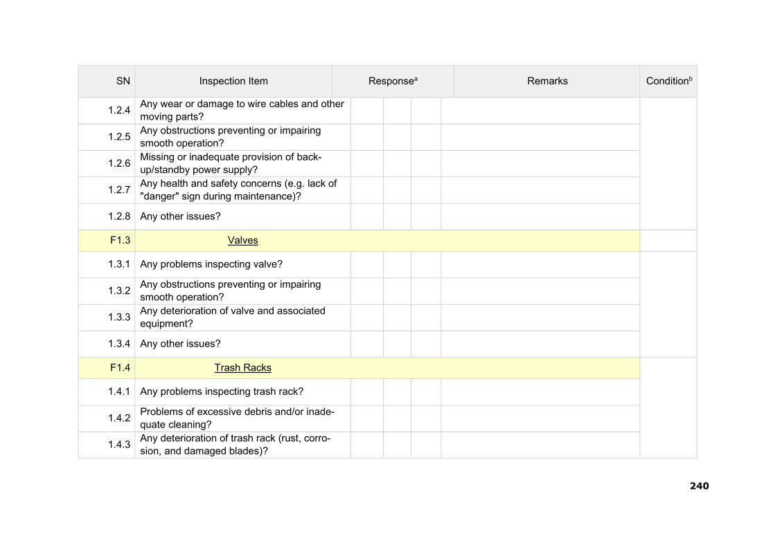
240
SN Inspection Item Responsea Remarks Conditionb
1.2.4 Any wear or damage to wire cables and other moving parts?
1.2.5 Any obstructions preventing or impairing smooth operation?
1.2.6 Missing or inadequate provision of back- up/standby power supply?
1.2.7 Any health and safety concerns (e.g. lack of "danger" sign during maintenance)?
1.2.8 Any other issues?
F1.3 Valves
1.3.1 Any problems inspecting valve?
1.3.2 Any obstructions preventing or impairing smooth operation?
1.3.3 Any deterioration of valve and associated equipment?
1.3.4 Any other issues?
F1.4 Trash Racks
1.4.1 Any problems inspecting trash rack?
1.4.2 Problems of excessive debris and/or inade- quate cleaning?
1.4.3 Any deterioration of trash rack (rust, corro- sion, and damaged blades)?

241
SN Inspection Item Responsea Remarks Conditionb
1.4.4 Any other issues?
F1.5 Trash Rack Cleaning Machines
1.5.1 Any problems inspecting trash rack cleaning machine?
1.5.2 Missing or inadequate spare parts (particular- ly requiring regular replacement)?
1.5.3 Any deterioration of equipment (connecting bolts, welds, surface, paint work?)
1.5.4 Any wear or damage to wire cables and other moving parts?
1.5.5 Any obstructions preventing or impairing smooth operation?
1.5.6 Missing or inadequate provision of back- up/standby power supply?
1.5.7 Any health and safety concerns (e.g. lack of "danger" sign during maintenance)?
1.5.8 Any other issues?

242
SN Inspection Item Responsea Remarks Conditionb
G1 Access Road
G1.1 General Condition
1.1.1 Any problems ensuring security of dam site (including gates and fencing)?
1.1.2 Any obstructions along or at entrance to access road (temporary or long-term)?
1.1.3 Any slope stability issues (road embankment or adjacent slopes)?
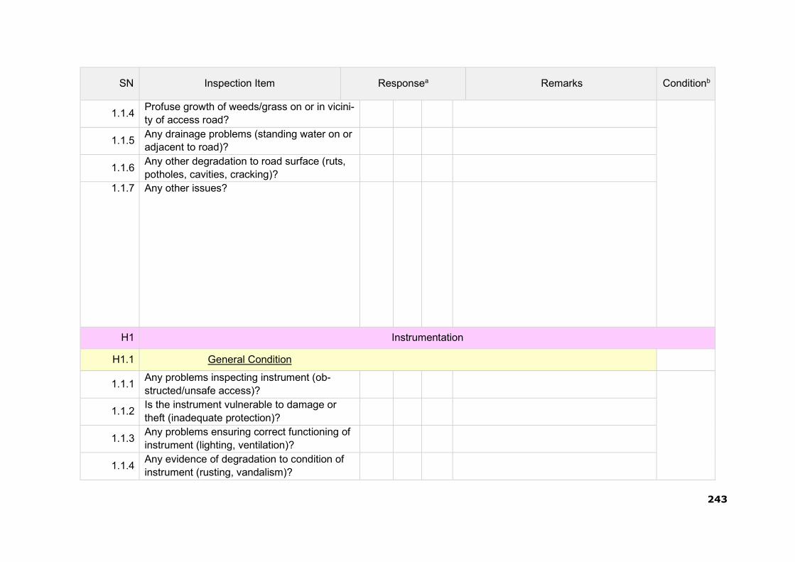
243
SN Inspection Item Responsea Remarks Conditionb
1.1.4 Profuse growth of weeds/grass on or in vicini- ty of access road?
1.1.5 Any drainage problems (standing water on or adjacent to road)?
1.1.6 Any other degradation to road surface (ruts, potholes, cavities, cracking)?
1.1.7 Any other issues?
H1 Instrumentation
H1.1 General Condition
1.1.1 Any problems inspecting instrument (ob- structed/unsafe access)?
1.1.2 Is the instrument vulnerable to damage or theft (inadequate protection)?
1.1.3 Any problems ensuring correct functioning of instrument (lighting, ventilation)?
1.1.4 Any evidence of degradation to condition of instrument (rusting, vandalism)?

244
SN Inspection Item Responsea Remarks Conditionb
1.1.5 Any evidence of instrument not working (de- commissioned, broken)?
1.1.6 Any other issues?
I1 Other Appurtenant Structures (Flexi-Component)
I1.1 Bridges and Catwalks
1.1.1 Any problems inspecting bridge or catwalk (obstructed/unsafe access)?
1.1.2 Any security issues relating to unauthorized access (e.g. for gate operation)?
1.1.3 Are the decking, girders and supports structu- rally sound?
1.1.4 Any evidence of defects or deterioration of steel, concrete or paint work?
1.1.5 Any other issues?
I1.2 Guide Walls
1.2.1 Any problems inspecting guide wall (ob- structed/unsafe access)?
1.2.2 Any problem with drainage from behind wall (e.g. blocked weep holes)?
1.2.3 Any evidence of scour, foundation erosion or undercutting?
1.2.4 Any signs of differential settlement, cracking or tilting?
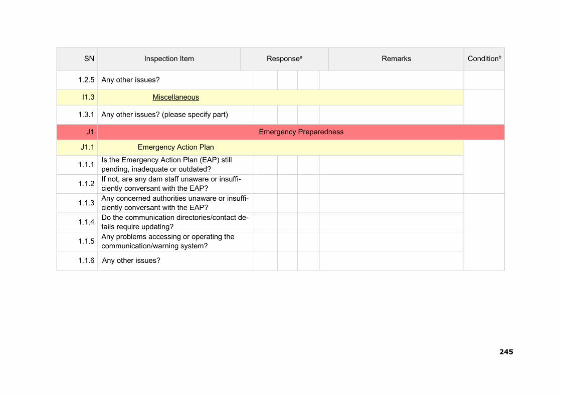
245
SN Inspection Item Responsea Remarks Conditionb
1.2.5 Any other issues?
I1.3 Miscellaneous
1.3.1 Any other issues? (please specify part)
J1 Emergency Preparedness
J1.1 Emergency Action Plan
1.1.1 Is the Emergency Action Plan (EAP) still pending, inadequate or outdated?
1.1.2 If not, are any dam staff unaware or insuffi- ciently conversant with the EAP?
1.1.3 Any concerned authorities unaware or insuffi- ciently conversant with the EAP?
1.1.4 Do the communication directories/contact de- tails require updating?
1.1.5 Any problems accessing or operating the communication/warning system?
1.1.6 Any other issues?

246
SN Inspection Item Responsea Remarks Conditionb
aRespond either yes (Y), no (N) or not applicable (NA). condition: Please rate the condition as either Satisfactory, Fair, Poor or Unsatisfactory as described below:
1. Satisfactory - No existing or potential dam safety deficiencies are recognized. Acceptable performance is expected under all loading conditions (static, hydrologic, seismic) in accordance with the applicable regulatory criteria or tolerable risk guide-
lines. 2. Fair - No existing dam safety deficiencies are recognized for normal loading conditions. Rare or extreme hydrologic and/or
seismic events may result in a dam safety deficiency. Risk may be in the range to take further action. 3. Poor - A dam safety deficiency is recognized for loading conditions which may realistically occur. Remedial action is neces
sary. Poor may also be used when uncertainties exist as to critical analysis parameters which identify a potential dam safety deficiency. Further investigations and studies are necessary.
4. Unsatisfactory - A dam safety deficiency is recognized that requires immediate or emergency remedial action for problem resolution.

247
Part 2b – Consolidated Dam Health Status Report:
SN Observations/Significant
Deficiencies Noticed Remedial Measures Suggested Categorya
1
2
3
4
aCategory I – deficiencies which may lead to failure; Category II – major deficiencies requiring prompt remedial measures; Category III – minor remedial measures which are rectifiable during the year

THIS PAGE LEFT BLANK INTENTIONALLY
248

249
APPENDIX 5 - GLOSSARY
Dam – any artificial barrier including ap- purtenant works constructed across rivers or tributaries thereof with a view to im- pound or divert water; includes barrage, weir and similar water impounding struc- tures but does not include water con- veyance structures such as canal, aque- duct and navigation channel and flow reg- ulation structures such as flood embank- ments, dikes, and guide bunds.
Dam failure – failures in the structures or operation of a dam which may lead to theuncontrolled release of impounded wa- ter resulting in downstream flooding affect- ing the life and property of the people.
Dam incident – all problems occurring to a dam that has not degraded into „dam failure‟ and including the following:
a) Structural damage to the dam and appurtenant works;
b) Unusual readings of instruments in the dam;
c) Unusual seepage or leakage through the dam body;
d) Change in the seepage or leakage regime;
e) Boiling or artesian conditions noticed below an earth dam;
f) Stoppage or reduction in seepage or leakage from the foundation or body of the dam into any of the galleries, for dams with such galleries;
g) Malfunctioning or inappropriate operation of gates;
h) Occurrence of any flood, the peak of which exceeds the available flood discharge capacity or 70% of the ap- proved design flood;
i) Occurrence of a flood, which resulted in encroachment on the available freeboard, or the adopted design freeboard;
j) Erosion in the near vicinity, up to five hundred meters, downstream of the spillway, waste weir, etc.; and
k) Any other event that prudence sug- gests would have a significant unfa- vorable impact on dam safety.
Dam inspection – on-site visual examina- tion of all components of dam and its ap- purtenances by one or more persons trained in this respect and includes inves- tigation of the non-overflow portion, spill- ways, abutments, stilling basin, piers, bridge, downstream toe, drainage galle- ries, operation of mechanical systems (in- cluding gates and its components, drive units, cranes), interior of outlet conduits, instrumentation records, and record- keeping arrangements.
Dam owner – the Central Government or a State Government or public sector un- dertaking or local authority or company and any or all of such persons or organizations, who own, control, operate or maintain a specified dam.
Dam safety – the practice of ensuring the integrity and viability of dams such that they do not present unacceptable risks to the public, property, and the environment. It requires the collective application of en- gineering principles and experience, and a philosophy of risk management that re- cognizes that a dam is a structure whose safe function is not explicitly determined by its original design and construction. It also includes all actions taken to identify or predict deficiencies and consequences related to failure, and to document, public- ize, and reduce, eliminate, or remediate to the extent reasonably possible, any unac- ceptable risks.
Decommission― Taking a dam out of service in an environmentally sound and safe manner or converting it to another purpose.
Design life― the intended period that the dam will function successfully with only routine maintenance; determined during design phase.

259
Distress condition – the occurrence or potential development of such conditions in the dam or appurtenance or its reservoir or reservoir rim, which if left unattended to, may impede the safe operation of dam for its intended benefits or may pose un- acceptable risks to the life and property of people downstream.
Documentation – all permanent records concerning investigation, design, con- struction, operation, performance, main- tenance and safety of dams and includes design memorandum, construction draw- ings, geological reports, reports of specia- lized studies simulating structural and hy- draulic response of the dam, changes made in design and drawings, quality con- trol records, emergency action plan, oper- ation and maintenance manual, instru- mentation readings, inspection and testing reports, operational reports, and dam safety review reports;
Emergency Action Plan(EAP)― a plan of action to be taken to reduce the poten- tial for damage to property and loss of life in the area affected by failure of a dam or other potentially hazardous practice.
Hazard Classification― a system that categorizes dams according to the degree of adverse incremental consequences of a failure or improper operation of the dam. CWC classifies dam hazards as “low”, “significant”, or “high”.
Maintenance― the recurring activities necessary to retain or restore a dam in a safe and functioning condition, including the management of vegetation, the repair or replacement of failed components, the prevention or treatment of deterioration, and the repair of damages caused by flooding or vandalism.
Operation― the administration, man- agement, and performance of mainten- ance activities necessary to keep a dam safe and functioning as planned.
Program ― any authorized activity used to implement and carry out goals, actions, and objectives contained within the autho- rizing legislation.
Program Life― the period in a contract, conservation plan, or plan during which the conservation practice or conservation system shall be maintained and used for the intended purpose; determined by pro- gram requirements.
Rehabilitation― the completion of all work necessary to extend the service life of the practice or component and meet applicable safety and performance stan- dards.
Repair― actions to restore deteriorated, damaged, or failed damor its component to an acceptable by meeting functional condition.
Replacement― the removal of a structure or component and installation of a similar, functional structure or component.
Service Life― the actual period after construction of a dam, during which the practice functions adequately and safely with only routine maintenance; determined by on-site review.
Abutment―that part of a valley side against which a dam is constructed. Right and left abutments are those on respective sides of the of an observer looking downstream.
Air-Vent Pipe―a pipe designed to provide air to the outlet conduit to reduce turbulence during release of water and safeguard against damages due to cavitation.
Appurtenant Structures―ancillary features of a dam, such as the outlet, spillway, energy dissipation arrangement powerhouse, tunnels, etc.
Arch Dam―a concrete or masonry dam that is curved to transmit the major part of the water pressure to the abutments.
Backwater Curve―the longitudinal profile of the water surface in an open channel where the depth of flow has been increased by an obstruction, an increase in channel roughness, a decrease in channel width, or a flattening of the bed slope.

251
Base Width (Base Thickness)―the maximum width or thickness of a dam measured horizontally between upstream and downstream faces and normal (perpendicular) to the axis of the dam but excluding projections for outlets, etc.
Berm―a horizontal step or bench in the sloping profile of an embankment dam.
Upstream Blanket―an impervious layer placed on the reservoir floor upstream of a dam. In case of an embankment dam, the blanket may be connected to the impermeable element in a dam.
Buttress dam―a dam consisting of a watertight upstream face supported at intervals on the downstream side by a series of buttresses.
Cofferdam―a temporary structure enclosing all or part of a construction area so that construction can proceed in a dry area.
Concrete Lift―in concrete works the vertical distance between successive horizontal construction joints.
ConduitOutlet Works―a closed conduit for conveying discharge through or under a dam for different project purposes.
Consolidation Grouting (Blanket Grouting)―theinjection of grout to consolidate a layer of the foundation, resulting in greater impermeability, strength, or both.
Construction Joint―the interface between two successive placings or pours of concrete where a bond, not permanent separation, is intended.
Core Wall―a wall built of impervious material, usually concrete or asphaltic concrete, in the body of an embankment dam to prevent leakage.
Crest Length―the length of the dam at its crest (dam top) top of a dam, including the length of the spillway, powerhouse, navigation lock, fish pass, etc., where these structures form part of the length of a dam. If detached from a dam, these structures should not be included.
Crest of dam―Used to indicate the “top of dam”. To avoid confusion to indicate the crest of spillway and top of dam may be used.
Culvert―a drain or waterway built under a road, railway, or embankment, usually consisting of a pipe or covered conduits
Cutoff―an impervious construction or material which reduces seepage through the foundation material.
Cutoff trench―an excavation later to be filled with impervious material to form a cutoff.
Cutoff wall―a wall of impervious material (e.g., concrete, asphaltic concrete, steel- sheet piling) built into the foundation to reduce seepage under the dam.
Dead storage―the storage that lies below the invert of the lowest outlet and that, therefore, cannot be withdrawn from the reservoir.
Design flood―see spillway design flood.
Diaphragm―see membrane.
Dike (Levee)―a long low embankment whose height is usually less than 5 m and whose length is more than 10 times the maximum height. Usually applied to embankments or structures built to protect land from flooding. If built of concrete or masonry, the structure is usually referred to as a flood wall. Also, used to describe embankments that block areas on a reservoir rim that are lower than the top of the main dam and that are quite long. In the Mississippi River basin, where the old French word levee has survived, the term now applies to flood-protecting embankments whose height can average up to 15 m.
Diversion channel, canal, or tunnel―a waterway used to divert water from its natural course. These terms are generally applied to temporary structures such as those designed to bypass water around a dam site during construction. “Channel‟ is normally used instead of “canal” when the waterway is short.Occasionally these terms are applied to permanent structures.

252
Drainage area―an area that drains naturally to a point on a river.
Drainage layer or blanket―a layer of permeable material in a dam to relieve pore pressure or to facilitate drainage of fill.
Relief well―vertical wells or boreholes, constructed downstream of an embankment dam to relieve the pressure from confined pervious layers in foundation overlaid by an impervious layer to arrest boiling.
Drawdown―the lowering of water surface level due to release of water from a reservoir.
Earthen dam or earth filleddam―see embankment dam.
Embankment dam (Fill dam)― any dam constructed of excavated natural materials.
Earth dam (Earth filldam)―An embankment dam in which more than 50 percent of the total volume is formed of compacted fine-grained material obtained from a borrow area.
Homogeneous earth filldam― an embankment dam constructed of similar earth material throughout, except internal drains or drainage blankets; distinguished from a zoned earth fill dam.
Hydraulic fill dam―an embankment dam constructed of materials, often dredged, that are conveyed and placed by suspension in flowing water.
Rock fill dam―an embankment dam in which more than 50 percent of the total volume comprises compacted or dumped pervious natural or crushed rock.
Rolled fill dam―an embankment dam of earth or rock in which the material is placed in layers and compacted using rollers or rolling equipment.
Zoned embankment dam―an embankment damcomposed of zones of materials selected for different degrees of porosity, permeability and density.
Emergency spillway―see spillway.
Face―the external surface of a structure, e.g., the surface of a wall of a dam.
Failure―the uncontrolled release of water from a dam.
Filter (filter zone)―A band or zone of granular material that is incorporated into a dam and is graded (either naturally or by selection) to allow seepage to flow across or down the filter without causing the migration of material from zones adjacent to it.
Flashboards―a length of timber, concrete, or steel placed on the crest of a spillway to raise the retention water level but that may be quickly removed in the event of a flood, either by a tripping device or by deliberately designed failure of the flashboard or its supports.
Floodplain―an area adjoining a body of water or natural stream that has been, or may be, covered by flood water.
Floodplain management―a management program to reduce the consequences of flooding, either by natural runoff or by dam failure, to existing and future properties in a floodplain.
Flood routing―the determination of the attenuating effect of storage on a flood passing through a valley, channel, or reservoir.
Flood surcharge―the volume or space in a reservoir between the controlled retention water level (Full Reservoir Level) and the maximum water level. Flood surcharge cannot be retained in the reservoir but will flow over the spillway until the controlled retention water level is reached.
Flood wall―a concrete wall constructed adjacent to a stream to prevent flooding of property on the landward side of the wall, normally constructed in lieu of or to supplement a levee where the land required for levee construction is expensive or not available.

253
Foundation of dam―the natural material on which the dam structure is placed.
Freeboard―the vertical distance between a stated reservoir level and the top of a dam.Normal freeboard is the vertical distance between Full Reservoir Level (FRL) and the top of the dam. Minimum freeboard is the verticaldistance between the Maximum Water Level (MWL) and the top of the dam.
Gallery―(a) a passageway within the body of a dam or abutment, hence the terms grouting gallery, inspection galleryand drainage gallery (b) a long and rather narrow hall, hence the following terms for a power plant viz.valve gallery, transformer gallery andbus bar gallery.
Gate―a device in which a leaf or member is moved across the waterway from an external position to control or stop the flow.
Bulkhead gate―a gate used either for temporary closure of a channel or conduit to empty it for inspection or maintenance or for closure against flowing water when the head difference is small, e.g., for diversion tunnel closure. Although a bulkhead gate is usually opened and closed under nearly balanced pressures, it nevertheless may be capable of withstanding a high pressure differential when in the closed position.
Crest gate (spillway gate)―a gate on the crest of a spillway to control overflow or reservoir water level.
Emergency gate―a standby or reserve gate which is lowers only for repairing / servicing of the service gate.
Fixed wheel gate (fixed-roller gate, fixed-axle gate)―a gate having wheels or rollers mounted on the end posts of the gate. The wheels move against rails fixed in side grooves or gate guides.
Flap gate―a gate hinged along one edge, usually either the top or bottom edge. Examples of bottom-hinged flap gates are tilting gates and belly gates, so called due to their shape in cross-section.
Flood gate―a gate to control flood release from a reservoir.
Guard gate(guard valve)―a gate or valve that operates fully open or closed. It may function as a secondary device for shutting off the flow of water in case the primary closure device becomes inoperable but is usually operated under conditions of balanced pressure and no flow.
Outlet gate―a gate controlling the outflow of water from a reservoir.
Radial gate (Tainter gate)―a gate with a curved upstream plate and radial arms hinged to piers or other supporting structures.
Service/Regulating gate(regulating valve)―a gate or valve that operates under full pressure and flow to throttle and vary the rate of discharge.
Slide gate (sluice gate)―a gate that can be opened or closed by sliding it in supporting guides.
Gravity dam―a dam constructed of concrete, masonry, or both that relies on its weight for stability.
Grout cap―a pad or wall constructed to facilitate pressure grouting of the grout curtain beneath it.
Grout curtain (grout cutoff)―a barrier produced byinjecting grout into a vertical zone, usually narrow horizontally, in the foundation to reduce seepage under a dam.
Height above lowest foundation―the maximum heightfrom the lowest point of the general foundation to the top of the dam.
Hydraulic height―the height to which water rises behind a dam and the difference between the lowest point in the original streambed at the axis of the dam and the maximum controllable water surface.
Hydrograph―a graphic representation of discharge, stage, or other hydraulic property with respect to time for a point on

254
a stream. (At times the term is applied to the phenomenon the graphic representation describes; hence a flood hydrograph is the passage of a flood discharge past the observation point.)
Inclinometer―an instrument, usually consisting of a metal or plastic tube inserted in a drill hole and a sensitized monitor either lowered into the tube or fixed within it. The monitor measures at different points the tube‟s inclination to the vertical. By integration, the lateral position at various levels of the tube may be found relative to a point, usually the top or bottom of the tube, assumed to be fixed. The system may be used to measure settlement.
Intake―any structure in a reservoir, dam, or river through which water can be drawn into an aqueduct.
Internal Erosion―see piping.
Inundation map―a map delineating the area that would be inundated in case of a failure.
Leakage―Uncontrolled loss of water by flow through a hole or crack.
Lining― a coating of asphaltic concrete, reinforced or unreinforced concrete, shotcrete, rubber or plastic on a canal, tunnel etc. to provide water tightness, prevent erosion, reduce friction, or support the periphery of structure. May also refer to lining, such as steel or concrete, of outlet pipe or conduit.
Low-level outlet (bottom outlet)―an opening at a lowlevel from a reservoir generally used for emptying or for scouring sediment and sometimes for irrigation releases.
Masonry dam―a dam constructed mainly of stone, brick, or concrete blocks that may or may not be joined with mortar. A dam having only a masonry facing should not be referred to as a masonry dam.
Maximum cross-section of dam―a cross-section of a dam at the point of its maximum height.
Maximum water level―the maximum water level, including flood surcharge, the dam is designed to withstand.
Membrane (Diaphragm)―a sheet or thin zone or facing made of a flexible material, sometimes referred to as a diaphragm wall or diaphragm.
Minimum operating level―the lowest level to which the reservoir is drawn down under normal operating conditions.
Morning glory spillway―see spillway.
Full Reservoir Level (FRL)/Normal water level―for a reservoir with un-gated spillway it is the spillway crest level. For a reservoir, whose outflow is controlled wholly or partly by movable gates, siphons or other means, it is the maximum level to which water can be stored under normal operating conditions, exclusive of any provision for flood surcharge.
One-Hundred Year (100-Year) Exceedance Interval― the flood magnitude expected to be equaled or exceeded on the average of once in 100 years. It may also be expressed as an exceedance frequency, i.e. a percent chance of being exceeded in any given year.
Outlet―an opening through which water can be freely discharged from a reservoir.
Overflow dam―a dam designed to be overtopped.
Parapet Wall―a solid wall built along the top of a dam for ornament, for the safety of vehicles and pedestrians, or to prevent overtopping.
Peak Flow―the maximum instantaneous discharge that occurs during a flood. It coincides with the peak of a flood hydrograph.
Pervious Zone―a part of the cross- section of an embankment dam comprising material of high permeability.
Phreatic Surface―thetop most flow line in an embankment dam.

255
Piezometer―an instrument for measuring pore water pressure within soil, rock, or concrete.
Piping―the progressive development of internal erosion by seepage, appearing downstream as a hole or seam discharging water that contains soil particles.
Pore Pressure―the interstitial pressure of water within a mass of soil, rock, or concrete.
Pressure Cell―an instrument for measuring pressure within a mass of soil, rock, or concrete or at an interface between one and the other.
Pressure Relief Pipes―Pipes used to relieve uplift or pore water pressure in a dam‟s foundation or structure.
Probable Maximum Flood (PMF)―a flood that would result from the most severe combination of critical meteorologic and hydrologic conditions possible in the region.
Probable Maximum Precipitation (PMP)―the maximum amount and duration of precipitation that can be expected to occur on a drainage basin.
Pumped storage reservoir―a reservoir filled entirely or mainly with water pumped from outside its natural drainage area.
Regulating dam―a dam impounding a reservoir from which water is released to regulate
Reservoir area―the surface area of a reservoir when filled to controlled retention level.
Reservoir routing―the computation by which the interrelated effects of the inflow hydrograph, reservoir storage, and discharge from the reservoir are evaluated.
Reservoir surface―the surface of a reservoir at any level.
Riprap―a layer of large stones, broken rock, or precast blocks placed randomly on the upstream slope of an embankment
dam, on a reservoir shore, or on the sides of a channel as a protection against wave action. Large riprap is sometimes referred to as armoring.
Risk assessment―as applied to dam safety, the process of identifying the likelihood and consequences of dam failure to provide the basis for informed decisions on a course of action.
Rock fill Dam―see embankment dam.
Roll Crete or Roller-Compacted ConcreteAno-slump concrete that can be hauled in dump trucks, spread with a bulldozer or grader, and compacted with a vibratory roller.
Seepage―the interstitial movement of water that may take place through a dam, its foundation, or its abutments.
Sill―(a) A submerged structure across a river to control the water level upstream. (b) The crest of a spillway. (c) A horizontal gate seating, made of wood, stone, concrete or metal at the invert of any opening or gap in a structure, hence the expressions gate sill and stop log sill.
Slope―(a) the side of a hill or mountain. (b) The inclined face of a cutting or canal or embankment. (c) Inclination from the horizontal. In the United States, it is measured as the ratio of the number of units of horizontal distance to the number of corresponding units of vertical distance. The term is used in English for any inclination and is expressed as a percentage when the slope is gentle, in which case the term gradient is also used.
Slope Protection―the protection of a slope against wave action or erosion.
Sluiceway―see low-level outlet.
Spillway―a structure over or through which flood flows are discharged. If the flow is controlled by gates, it is a controlled spillway; if the elevation of the spillway crest is the only control, it is an uncontrolled spillway.
Auxiliary Spillway (Emergency Spillway)―a secondary spillway
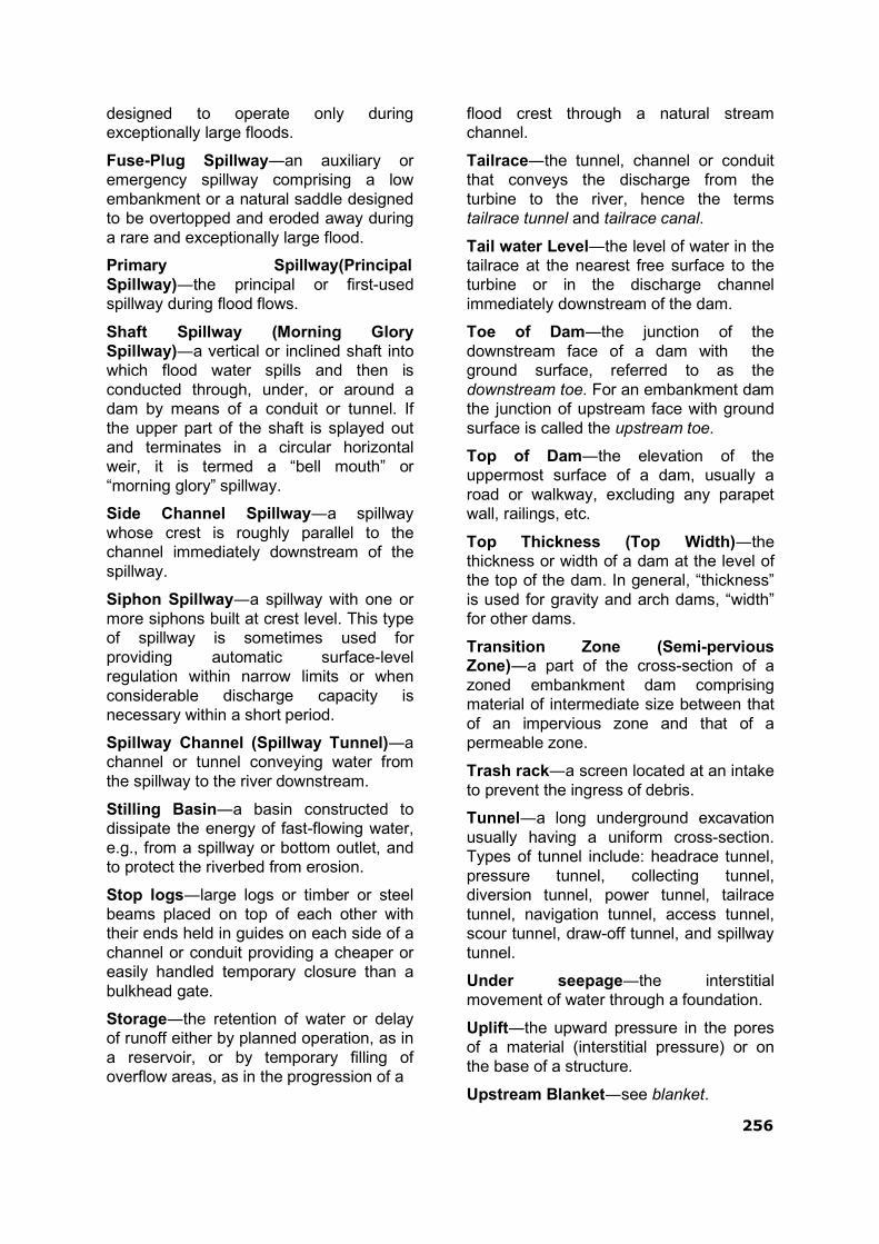
256
designed to operate only during exceptionally large floods.
Fuse-Plug Spillway―an auxiliary or emergency spillway comprising a low embankment or a natural saddle designed to be overtopped and eroded away during a rare and exceptionally large flood.
Primary Spillway(Principal Spillway)―the principal or first-used spillway during flood flows.
Shaft Spillway (Morning Glory Spillway)―a vertical or inclined shaft into which flood water spills and then is conducted through, under, or around a dam by means of a conduit or tunnel. If the upper part of the shaft is splayed out and terminates in a circular horizontal weir, it is termed a “bell mouth” or “morning glory” spillway.
Side Channel Spillway―a spillway whose crest is roughly parallel to the channel immediately downstream of the spillway.
Siphon Spillway―a spillway with one or more siphons built at crest level. This type of spillway is sometimes used for providing automatic surface-level regulation within narrow limits or when considerable discharge capacity is necessary within a short period.
Spillway Channel (Spillway Tunnel)―a channel or tunnel conveying water from the spillway to the river downstream.
Stilling Basin―a basin constructed to dissipate the energy of fast-flowing water, e.g., from a spillway or bottom outlet, and to protect the riverbed from erosion.
Stop logs―large logs or timber or steel beams placed on top of each other with their ends held in guides on each side of a channel or conduit providing a cheaper or easily handled temporary closure than a bulkhead gate.
Storage―the retention of water or delay of runoff either by planned operation, as in a reservoir, or by temporary filling of overflow areas, as in the progression of a
flood crest through a natural stream channel.
Tailrace―the tunnel, channel or conduit that conveys the discharge from the turbine to the river, hence the terms tailrace tunnel and tailrace canal.
Tail water Level―the level of water in the tailrace at the nearest free surface to the turbine or in the discharge channel immediately downstream of the dam.
Toe of Dam―the junction of the downstream face of a dam with the ground surface, referred to as the downstream toe. For an embankment dam the junction of upstream face with ground surface is called the upstream toe.
Top of Dam―the elevation of the uppermost surface of a dam, usually a road or walkway, excluding any parapet wall, railings, etc.
Top Thickness (Top Width)―the thickness or width of a dam at the level of the top of the dam. In general, “thickness” is used for gravity and arch dams, “width” for other dams.
Transition Zone (Semi-pervious Zone)―a part of the cross-section of a zoned embankment dam comprising material of intermediate size between that of an impervious zone and that of a permeable zone.
Trash rack―a screen located at an intake to prevent the ingress of debris.
Tunnel―a long underground excavation usually having a uniform cross-section. Types of tunnel include: headrace tunnel, pressure tunnel, collecting tunnel, diversion tunnel, power tunnel, tailrace tunnel, navigation tunnel, access tunnel, scour tunnel, draw-off tunnel, and spillway tunnel.
Under seepage―the interstitial movement of water through a foundation.
Uplift―the upward pressure in the pores of a material (interstitial pressure) or on the base of a structure.
Upstream Blanket―see blanket.

257
Valve―a device fitted to a pipeline or orifice in which the closure member is either rotated or moved transversely or longitudinally in the waterway to control or stop the flow.
Water stop―a strip of metal, rubber or other material used to prevent leakage through joints between adjacent sections of concrete.
Weir―(a) a low dam or wall built across a stream to raise the upstream water level, called fixed-crest weir when uncontrolled. (b) A structure built across a stream or channel for measuring flow, sometimes called a measuring weir or gauging weir. Types of weir include broad-crested weir, sharp-crested weir, drowned weir, and submerged weir.


Vision
To remain as a premier organisation with best technical and managerial ex- pertise for providing advisory services on matters relating to dam safety.
Mission
To provide expert services to State Dam Safety Organisations, dam owners, dam operating agencies and others concerned for ensuring safe functioning of dams with a view to protect human life, property and the environment.
Values
Integrity: Act with integrity and honesty in all our actions and practices.
Commitment: Ensure good working conditions for employees and encour- age professional excellence.
Transparency: Ensure clear, accurate and complete information in commu- nications with stakeholders and take all decisions openly based on reliable information.
Quality of service: Provide state-of-the-art technical and managerial ser- vices within agreed time frame.
Striving towards excellence: Promote continual improvement as an integral part of our working and strive towards excellence in all our endeavours.
Quality Policy
We provide technical and managerial assistance to dam owners and State Dam Safety Organizations for proper surveillance, inspection, operation and maintenance of all dams and appurtenant works in India to ensure safe func- tioning of dams and protecting human life, property and the environment.
We develop and nurture competent manpower and equip ourselves with state of the art technical infrastructure to provide expert services to all stakeholders.
We continually improve our systems, processes and services to ensure satis- faction of our customers.
Central Dam Safety Organisation
Central Water Commission